Diagram sections — 30 (61 total)
AIR CONDITIONING ANTI-LOCK BRAKES ANTI-THEFT BODY CONTROL MODULES COMPUTER DATA LINES COOLING FAN CRUISE CONTROL DEFOGGERS ENGINE PERFORMANCE EXTERIOR LIGHTS GROUND DISTRIBUTION HEADLIGHTS HORN INSTRUMENT CLUSTER INTERIOR LIGHTS NAVIGATION POWER DISTRIBUTION POWER DOOR LOCKS POWER MIRRORS POWER SEATS POWER TOP/SUNROOF POWER WINDOWS RADIO SHIFT INTERLOCK STARTING/CHARGING SUPPLEMENTAL RESTRAINTS TRANSMISSION TRUNK, TAILGATE, FUEL DOOR WARNING SYSTEMS WIPER/WASHER
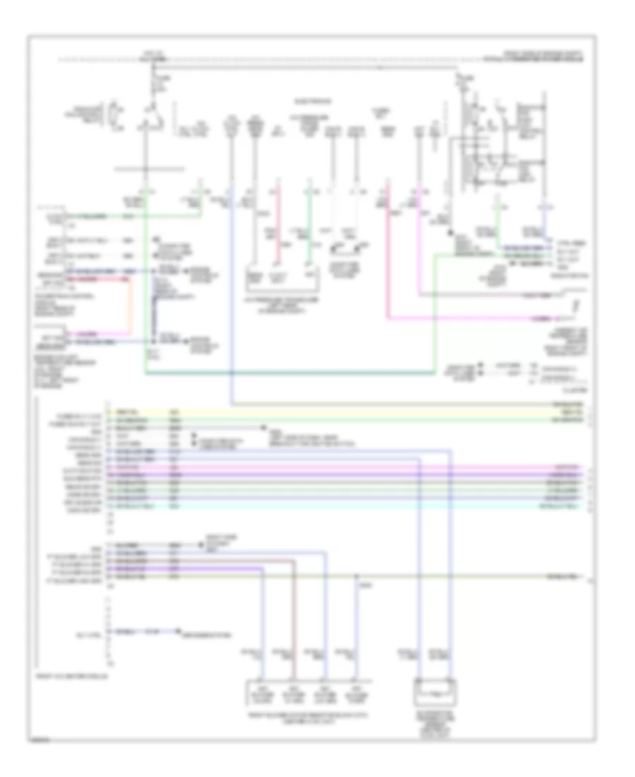
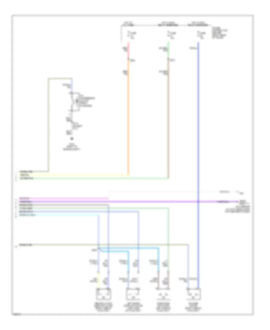
AIR CONDITIONING Manual A/C Wiring Diagram (1 of 2) for Dodge Challenger SRT-8 2008 List of elements for Manual A/C Wiring Diagram (1 of 2) for Dodge Challenger SRT-8 2008: 96 (right side of dash) g201 (right side of engine compt) totally integrated power module 5 volt sply 5v sply 87a A/c cltch ctrl A/c cltch ctrl out A/c press sens gnd A/c pressure trans- ducer sig A/c pressure transducer (left rear of engine compt) A23 Aat sig Ambient air temperature sensor (right front of engine compt) Auto hdlp sig Bus (+) Bus (-) C115 C121 C13 C18 C21 C32 C34 C35 C61 C70 C71 C72 C73 C918 Can b bus (+) Can b bus (-) Can c Cltch Cluster Comm dr drv Computer data lines system Ctrl Ctrl feed D54 D55 D64 D65 Defogger system Drv blend dr Ect sig Electronics Engine controls system Engine coolant temperature sensor (3.5l: front of engine) (6.1l: left front of engine) Evaporator temperature sensor (center of hvac unit) F500 F891 Front a/c heater module Front blower motor resistor block (mtc) (center hvac unit) Frt blower hi spd Frt blower low spd Frt blower m1 spd Frt blower m2 spd Ft blower high spd Ft blower low spd Ft blower m1 spd Ft blower m2 spd Fuse 40a Fuse 50a Fused b (+) (i.o.d) Fused b(+) Fused run rly out G101 (right front of engine compt) G102 (right of engine compt) G200 (left side of dash, near breakout for ignition switch) G31 G931 G939 Gnd Hi rly ctrl Hot at all times K900 L24 Mode dr drv Powertrain control module (right rear of engine compt) Radiator fan Radiator fan control relay Radiator fan high relay Radiator fan high/ low control relay Recir dr drv Rly ctrl Rly out S110 (right rear of engine compt) S111 (3.5l) S240 Sens gnd Sens sig Sig Sun sens rtn Z908 Z909 Manual A/C Wiring Diagram (2 of 2) for Dodge Challenger SRT-8 2008 List of elements for Manual A/C Wiring Diagram (2 of 2) for Dodge Challenger SRT-8 2008: 18 A/c compressor clutch (front of engine) Blower motor (right side of hvac unit) Fuse 10a G102 (right of engine compt) Hot at all times Hot w/ run relay energized Left blend door actuator (left side of hvac unit) Mode door actuator (left side of hvac unit) Power distribution center (right rear of trunk) Recirculation door actuator (right side of hvac unit) Rtn S115 (except 6.1l) S200 S210 S238 Sens Sig Sun sensor (w/ auto headlamps) (top center of dash)
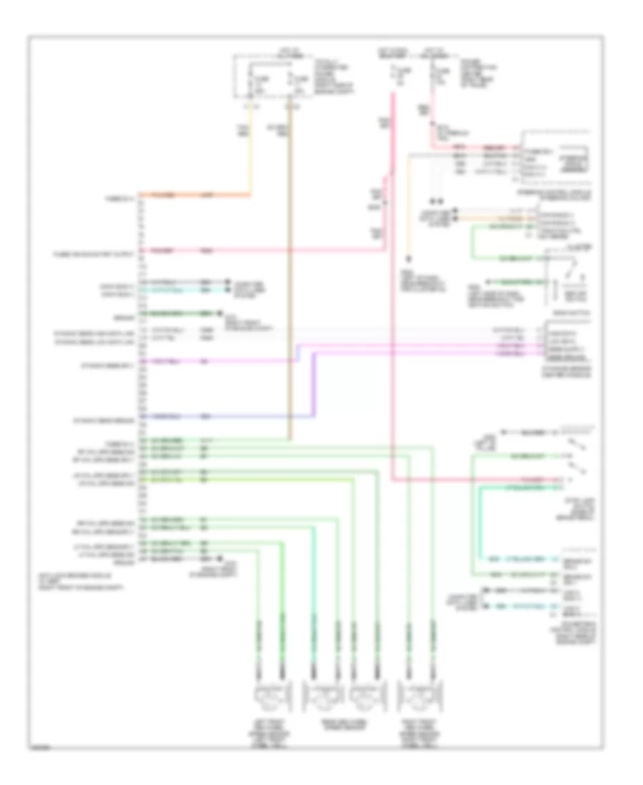
ANTI-LOCK BRAKES Anti-lock Brakes Wiring Diagram for Dodge Challenger SRT-8 2008 List of elements for Anti-lock Brakes Wiring Diagram for Dodge Challenger SRT-8 2008: 72 30a 50a A107 A111 A913 Anti-lock brakes module (w/ esp) (right front of engine compt) B15 B16 Bank switch Brake sw sig 1 Brake sw sig 2 Can b bus (+) Can b bus (-) Can c (+) Can c (-) Can c bus (+) Can c bus (-) Cluster Computer data lines system D464 D465 D64 D65 Dynamic sens ground Dynamic sens high data link Dynamic sens low data link Dynamic sens sply Dynamics sensor (center console) Esp off switch F202 Fuse Fuse 10a Fused b (+) Fused b(+) Fused ign run-start output G101 (right front of engine compt) G200 (left side of dash, near breakout for ignition switch) G202 (left of dash, near breakout for cluster c3) G300 (left "b" pillar) G94 Gnd Ground High data Hot at all times Hot in run or start Left front abs wheel speed sensor (left front wheel well) Lf whl spd sens sig Lf whl spd sens sply Low data Lr whl spd sens sig Lr whl spd sens sply Nca Power distribution center (right rear of trunk) Powertrain control module (right rear of engine compt) Rear abs wheel speed sensor Rf whl spd sens sig Rf whl spd sens sply Right front abs wheel speed sensor (right front wheel well) Rr whl spd sens sig Rr whl spd sens sply S209 S310 (w/ premium tpm) Sens ground Steering angle sensor Steering control module (steering column) Stop lamp switch (base of brake pedal) Tan/ red Tan/red Totally integrated power module (right side of engine compt) Traction ctrl sw sense Z910 Z931
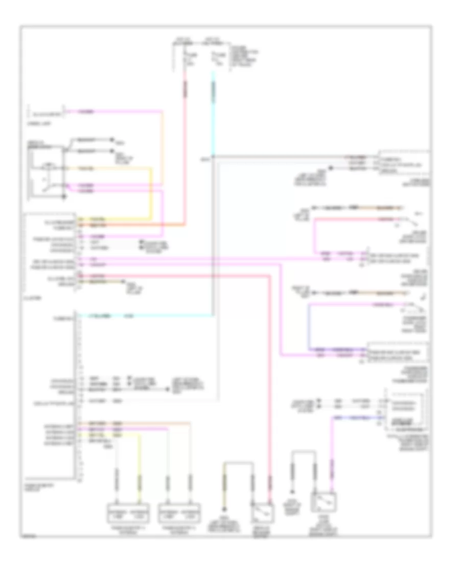
ANTI-THEFT Anti-theft Wiring Diagram for Dodge Challenger SRT-8 2008 List of elements for Anti-theft Wiring Diagram for Dodge Challenger SRT-8 2008: 66 (left of dash, near breakout for cluster c3) g202 (right "b" pillar) g301 A106 Antenna 2 ret Antenna 2 sig Antenna 3 ret Antenna 3 sig Can b bus(+) Can b bus(+) c1 Can b bus(-) Cargo lamp Cluster Com-lin tp mntr lan Computer data lines system D508 D54 D55 D922 D923 D924 D925 Decklid door latch Decklid release switch Dl/lg ajar sw Dl/lg rel sw Dl/lg release Driver door latch (driver door) Driver door module (middle of driver door) Drv dr 2nd ajar sw sns Drv dr ajar sw sns Electronics Fuse 15a Fuse 20a Fused b(+) G102 (right of engine compt) G202 (left of dash, near breakout for cluster c3) G300 (left "b" pillar) G301 (right "b" pillar) G304 G54 G55 G70 G74 G745 G75 G755 Ground Hood ajar sw sense Hood ajar switch (right side of engine compt) Hot at all times Pass dr 2nd ajar sw sns Pass dr ajar sw sns Pass dr lck sw mux Passenger door latch (right front door) Passenger door module (middle of passenger door) Passive entry 2 antenna Passive entry 3 antenna Passive entry module Power distribution center (right rear of trunk) Red/tan S215 S355 S360 Totally integrated power module (right side of engine compt) Wireless ignition node Z910
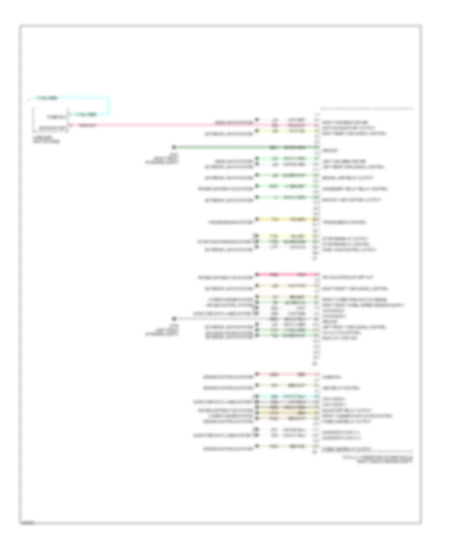
BODY CONTROL MODULES Body Control Modules Wiring Diagram (1 of 2) for Dodge Challenger SRT-8 2008 List of elements for Body Control Modules Wiring Diagram (1 of 2) for Dodge Challenger SRT-8 2008: 75 (right front of engine compt) g101 A/c clutch control output A/c pressure sensor ground A/c pressure transducer signal A107 A11 A111 A117 A22 Aat signal Air conditioning system Anti-lock brakes system Anti-theft system B(+) B20 Battery Brake fluid level switch sense C18 C918 Cooling fans system Cruise control system Exterior lights system F891 F923 Front fog lamp control output Front wiper high/low relay high speed output Front wiper high/low relay low speed output Fuse 10a Fuse 15a Fuse 40a Fused b(+) Fused b(+) (i.o.d.) Fused b(+) (pump) Fused b(+) (valve) G31 G70 G931 Ground Hazard switch sense Headlights system Hood ajar switch sense Horn control output Horns system Hot at all times Instrument cluster system L43 L44 L89 L91 Left low beam driver N210 N23 N24 Pass through post Power distribution center (right rear of trunk) Power distribution system Rad fan control relay output Rad fan high relay output Rad fan high/low control feed Red Right front wheel speed sensor signal Right low beam driver Run relay control S138 S215 S374 Sensor ground T16 Tan/red Totally integrated power module (right side of engine compt) Transmission control output Transmissions system Washer fluid level switch sense Wiper/washer system Z901 Body Control Modules Wiring Diagram (2 of 2) for Dodge Challenger SRT-8 2008 List of elements for Body Control Modules Wiring Diagram (2 of 2) for Dodge Challenger SRT-8 2008: 77 A/c clutch control A209 Accessory delay relay control Air conditioning system exterior lights system Asd relay control Back up lp sw sig Backup lamp control output Brake lamp relay output C13 Can b bus (+) Can b bus (-) Can c bus (+) Can c bus (-) Computer data lines system Cruise control system D54 D55 D64 D65 D71 D72 Diagnostic can c (+) Diagnostic can c (-) Engine controls system Exterior lights system F20 F342 F343 F902 F950 Front washer pump motor control Front wiper park switch sense Fused asd relay output Fused b(+) G100 (left front of engine compt) G101 (right front of engine compt) Ground Headlights system Ign run-start Ign unlock-run-start out Ignition run-start output K51 L33 L34 L53 L60 L61 L62 L63 L777 Left front turn signal control Left high beam driver Left rear turn signal control P307 Park lamp control output Pnk Power distribution system Red Right front turn signal control Right high beam driver Right rear turn signal control Run/start relay output Starter relay control Starter relay output Starting/charging system T15 T22 T750 T752 Totally integrated power module (right side of engine compt) Transmission control Transmissions system W10 Wiper/washer system Wireless ignition node Z901 Z902
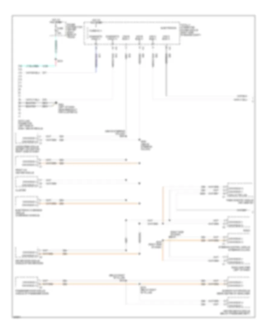
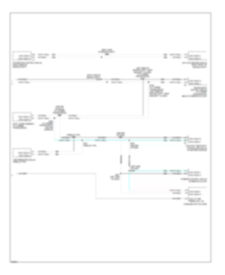
COMPUTER DATA LINES Computer Data Lines Wiring Diagram (1 of 2) for Dodge Challenger SRT-8 2008 List of elements for Computer Data Lines Wiring Diagram (1 of 2) for Dodge Challenger SRT-8 2008: 43 (above steering column) s204 (below right "b" pillar) s318 (right side of dash) s218 A106 Can b bus (+) Can b bus (-) Can c bus (+) Can c bus (-) Cluster Com-lin tpm lan D508 D54 D55 D64 D65 D71 D72 Data link connector (left side of dash, above pedals) Diagnostic can c (+) Diagnostic can c (-) Driver door module (middle of driver door) Electronic overhead module (overhead console) Electronics Front a/c heater module Fuse 15a Fused b (+) G202 (left of dash, near breakout for cluster c3) Hands free module (except navigation) (right side of dash) Heated seats module (below passenger seat) Hot at all times Passenger door module (middle of passenger door) Passive entry module (keyless go) Power distribution center (right rear of trunk) Radio Radio amplifier (left of dash) S205 (above steering column) S215 S219 (right side of dash) S319 (below right "b" pillar) Steering control module (steering column) Sunroof motor/module (rear center of headliner) Totally integrated power module (right side of engine compt) Z910 Computer Data Lines Wiring Diagram (2 of 2) for Dodge Challenger SRT-8 2008 List of elements for Computer Data Lines Wiring Diagram (2 of 2) for Dodge Challenger SRT-8 2008: 25 (center console) (w/ 5 speed transmission) s391 (center of dash) s237 (left rear of engine compt, near grommet to dash) (w/ 5 speed transmission) s171 (left side of dash) s206 (premium tpm) s336 (right side of engine compt) s122 (right side of engine compt) s124 Antilock brakes module (right front of engine compt) Can c bus (+) Can c bus (-) Com-lin tire press moni lan D64 D65 Occupant restraint controller module (in center console) Powertrain control module (right rear of engine compt) S169 (w/ 5 speed transmission) (left rear of engine compt, near grommet to dash) S207 (left side of dash) S235 (center of dash) S337 (premium tpm) S390 (w/ 5 speed transmission) (center console) Shift lever assembly (w/ 5 speed transmission) Steering control module (steering column) Tire pressure module (premium tpm) Transmission control module (w/ 5 speed transmission) (below steering column) Wireless ignition node
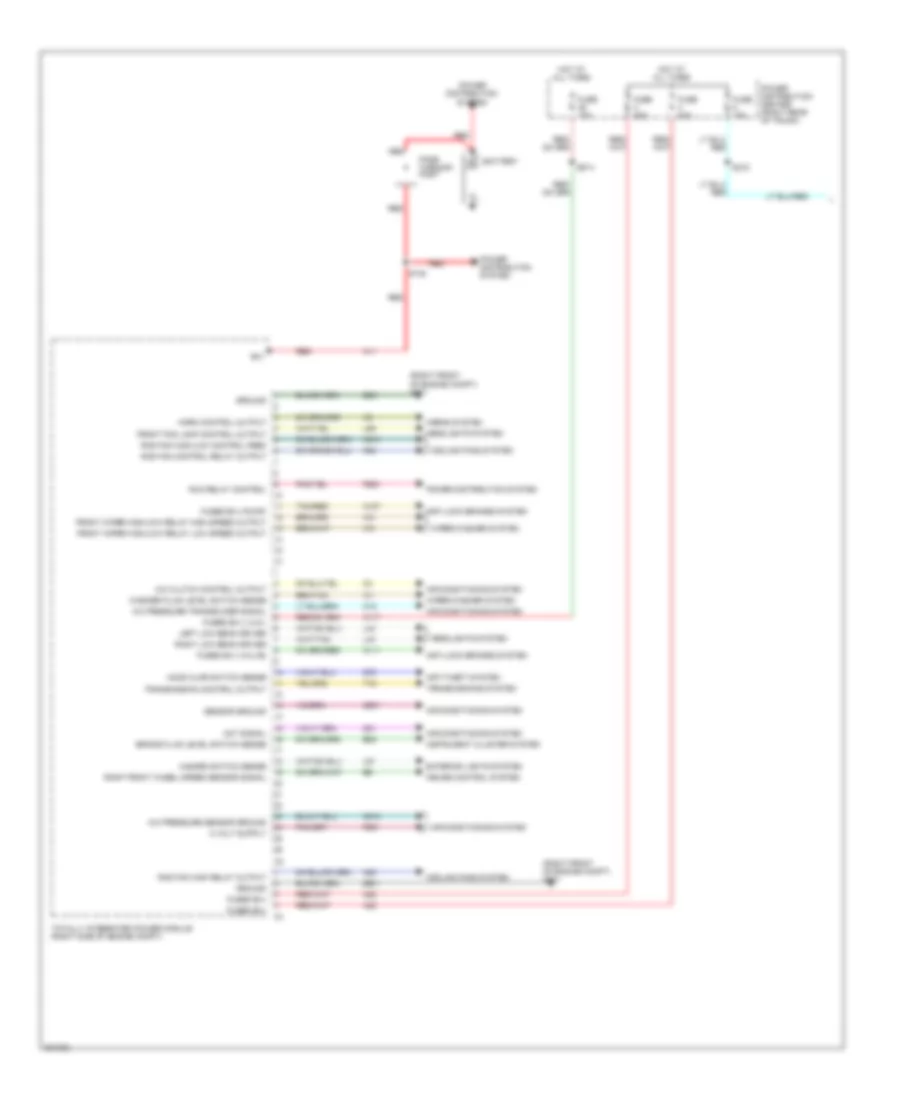
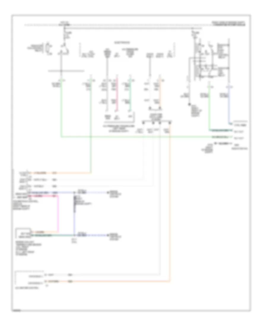
COOLING FAN Cooling Fan Wiring Diagram for Dodge Challenger SRT-8 2008 List of elements for Cooling Fan Wiring Diagram for Dodge Challenger SRT-8 2008: 47 (right side of engine compt) integrated power module 5v sply 87a A/c cltch ctrl A/c heater control A/c press sens gnd A/c pressure trans- ducer sig A/c pressure transducer (left rear of engine compt) Bus (+) Bus (-) C13 C18 C918 Can b bus (+) Can b bus (-) Can c Cltch Computer data lines system Ctrl Ctrl feed D54 D55 D64 D65 Ect sig Electronics Engine controls system Engine coolant temperature sensor (3.5l: front of engine) (6.1l: left front of engine) F891 Fuse 40a Fuse 50a G101 (right front of engine compt) G102 (right of engine compt) Gnd Hi rly ctrl Hot at all times K900 Powertrain control module (right rear of engine compt) Radiator fan Radiator fan control relay Radiator fan high relay Radiator fan high/ low control relay Rly ctrl Rly out S111 (3.5l) Sens gnd Sig
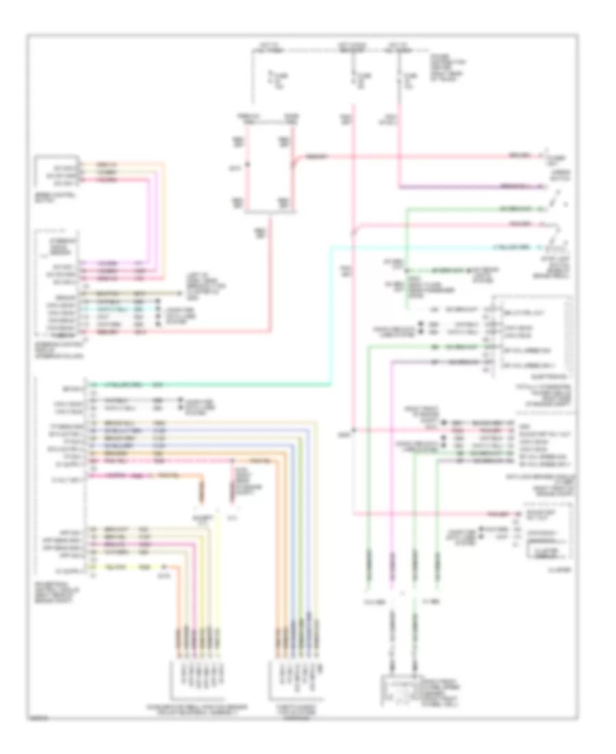
CRUISE CONTROL Cruise Control Wiring Diagram for Dodge Challenger SRT-8 2008 List of elements for Cruise Control Wiring Diagram for Dodge Challenger SRT-8 2008: 94 (left of dash, near breakout for cluster c3) g202 (right front of engine compt) 5 volt sply 5.7l 5v sply A913 Accelerator pedal position sensor (adjustable pedal assembly) Anti-lock brakes module (w/ esp) (right front of engine compt) App gnd 1 App gnd 2 App sens gnd 1 App sens gnd 2 App sig 1 App sig 2 B16 Base tpm Br lp ctrl out Br sig 2 Can b bus + Can b bus - Can b bus+ Can b bus- Can c bus+ Can c bus- Cluster Cluster display Computer data lines system D54 D55 D64 D65 Electronics Etc motor (+) Etc motor (-) Etc mtr (+) Etc mtr (-) Except 5.7l Exterior lights system F202 F852 F855 F856 Fuse 10a Fuse 5a Fused b(+) Fused b+ G101 Gnd Ground Hot at all times Hot in run or start K122 K124 K126 K167 K22 K23 K29 K400 K922 L53 Mirror switch Nca Power distribution center (right rear of trunk) Powertrain control module (right rear of engine compt) Premium tpm Rf whl speed sig Rf whl speed sply Right front wheel speed sensor (right front wheel well) Run/start rly out S/c sig 1 S/c sig 2 S/c sw gnd S105 (right rear of engine compt) S175 S209 S302 (body floor, near passenger door) S310 Speed control switch Steering angle sensor Steering control module (steering column) Stop lamp switch (base of brake pedal) Throttle body (top of intake manifold) Totally integrated power module (right side of engine compt) Tp sens gnd Tp sig 1 Tp sig 2 V71 V72 V937 W/ abs W/o abs Z910 Z931
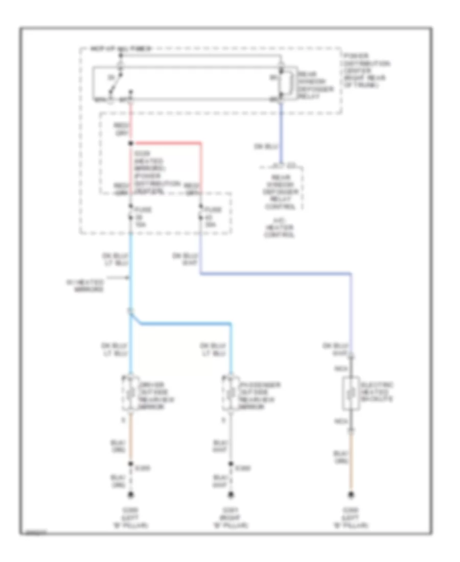
DEFOGGERS Defoggers Wiring Diagram for Dodge Challenger SRT-8 2008 List of elements for Defoggers Wiring Diagram for Dodge Challenger SRT-8 2008: 17 87a A/c- heater control Driver outside rearview mirror Electric heated backlite Fuse 10a Fuse 30a G300 (left "b" pillar) G301 (right "b" pillar) Hot at all times Nca Passenger outside rearview mirror Power distribution center (right rear of trunk) Rear window defogger relay Rear window defogger relay control S355 S360 W/ heated mirrors
ENGINE PERFORMANCE
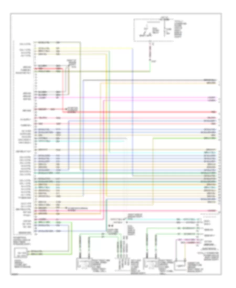
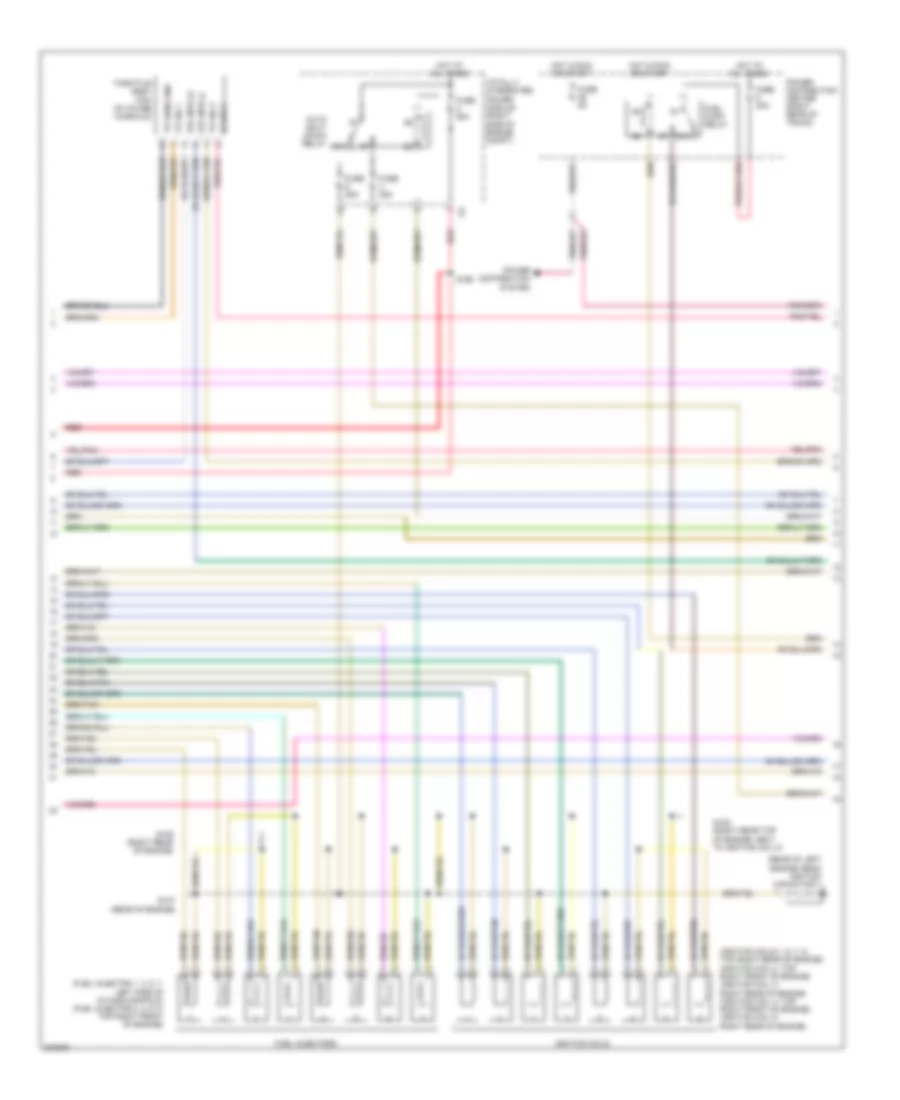
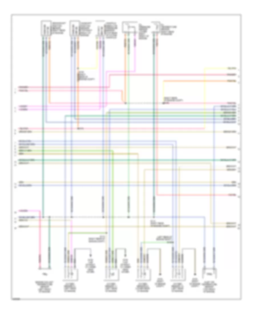
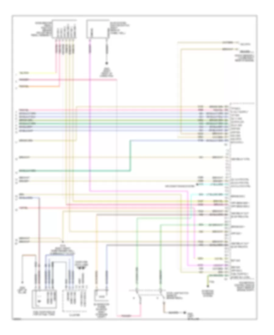
6.1L 6.1L, Engine Performance Wiring Diagram (2 of 4) for Dodge Challenger SRT-8 2008 List of elements for 6.1L, Engine Performance Wiring Diagram (2 of 4) for Dodge Challenger SRT-8 2008: 28 (fuel injector 1, 3, 5, 7: left side of intake manifold) (fuel injector 2, 4, 6, 8: top right front of engine) (ignition coils 1, 6, 7, 8: top right rear of engine) (ignition coil 2: top right front of engine) (ignition coil 3: right rear of engine) (ignition coil 4: top right front of engine) (ignition coil 5: right rear of engine) (rear of left engine head) ignition capacitor 1 5v sply 87a Auto shut down relay Etc mtr (+) Etc mtr (-) Fuel injectors Fuel pump relay Fuse 20a Fuse 25a Fuse 5a Hot at all times Hot in run or start Ignition coils Power distribution center (right rear of trunk) Power distribution system Red S107 (rear of engine) S108 (right rear top of engine, next to ignition coil 8) S109 (right rear of engine) S166 Throttle body (top of intake manifold) Totally integrated power module (right side of engine compt) Tp sens gnd Tp sig 1 Tp sig 2 6.1L, Engine Performance Wiring Diagram (3 of 4) for Dodge Challenger SRT-8 2008 List of elements for 6.1L, Engine Performance Wiring Diagram (3 of 4) for Dodge Challenger SRT-8 2008: 26 (left rear of engine compt) (right rear of engine compt) s105 5v sply Camshaft position sensor (top right front of engine) 5v sply Ckp sig Cmp sig Crankshaft position sensor (right rear of engine) Engine coolant temperature sensor (left front of engine) G102 (right of engine compt) G109 (top of right cylinder head cover) Inlet air temperature sensor (top front of engine) Manifold absolute pressure sensor (top rear of intake sens gnd Manifold) Map sig Oil pressure sensor (lower right front of engine) Oil temperature sensor (right rear of engine) Oxygen sensor 1/1 (left rear of engine) Oxygen sensor 1/2 (left rear of engine) Oxygen sensor 2/1 (left rear of engine) Oxygen sensor 2/2 (lower rear of engine) S106 (right rear of engine compt) S110 (right rear of engine compt) S112 (right rear of engine compt) S125 S175 Sens gnd 6.1L, Engine Performance Wiring Diagram (4 of 4) for Dodge Challenger SRT-8 2008 List of elements for 6.1L, Engine Performance Wiring Diagram (4 of 4) for Dodge Challenger SRT-8 2008: 80 5v sply A/c clutch ctrl Accelerator pedal position sensor (adjustable pedal assembly) Air conditioning system App sens gnd 1 App sens gnd 2 App sig 1 App sig 2 Asd relay ctrl Asd relay out B15 B16 Brake sig 1 Brake sig 2 C13 Can b bus (+) Can b bus (-) Ckp sig Cluster Cmp sig Computer data lines system Eot sig Esm sig Etc mtr (-) Evap prg ctrl Evap prg rtn Evap system monitor switch (right rear of wheel well) Evaporator purge solenoid (right of engine compt) F342 F855 Fuel pump module (top of fuel tank) Fuel pump rly G224 G300 (left "b" pillar) G302 (right front of cargo pan) Ground Iat sig In breakout to c100) K107 K122 K126 K167 K21 K23 K24 K242 K29 K299 K31 K399 K400 K41 K43 K44 K51 K52 K70 K902 K924 Knock sensor 2 (lower right rear of engine) Ks 2 rtn Ks 2 sig O2 1/1 sig O2 1/2 htr ctrl O2 2/1 sig O2 2/2 htr ctrl O2 rtn (up) Powertrain control module (right rear of engine compt) S143 (right front inner fender well, Sens 1 sig Sens 2 sig Sens gnd 1 Sens gnd 2 Start rly ctrl Starting/ charging system Stop lamp switch (base of brake pedal) T752 Tp sig 2 Z210 Z912
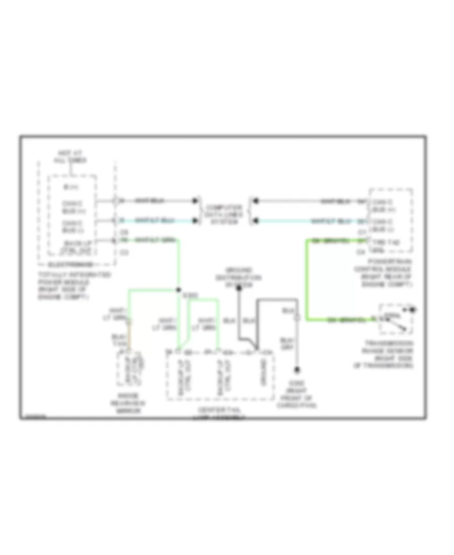
EXTERIOR LIGHTS Backup Lamps Wiring Diagram for Dodge Challenger SRT-8 2008 List of elements for Backup Lamps Wiring Diagram for Dodge Challenger SRT-8 2008: 22 B (+) Back lp ctrl out Backup Can c bus (+) Can c bus (-) Can c bus (-) c1 Center tail lamp assembly Computer data lines system Ctrl out backup lp Electronics G302 (right front of cargo pan) Ground Ground distribution system Hot at all times Inside rearview mirror Out lp ctrl Powertrain control module (right rear of engine compt) Prnl S303 Totally integrated power module (right side of engine compt) Transmission range sensor (right side of transmission) Trs t42 sig Exterior Lamps Wiring Diagram (1 of 2) for Dodge Challenger SRT-8 2008 List of elements for Exterior Lamps Wiring Diagram (1 of 2) for Dodge Challenger SRT-8 2008: 54 (body floor, near passenger door) s302 Backup lamp ctrl out Backup lp ctrl out Bank switch Brk lamp ctrl out Brk lp ctrl out Bus (+) can b Bus (-) can b Can b bus (+) Can b bus (-) Center high mounted stop lamp Cluster Computer data lines system Dimmer sig panel lp Electronics Flash Fused b (+) G100 (left front of engine compt) G101 (right front of engine compt) G200 (left side of dash, near breakout for ignition switch) G301 (right "b" pillar) Ground Hazard switch Hazard switch sense Hdlp sw mux High beam Hot at all times Inside rearview mirror Lamps drv panel Left front fog lamp Left front lamp assembly Left front side marker lamp Left front turn signal ctrl Left rear turn signal ctrl Left turn Lh frt turn sig ctrl Mux rtn hdlp sw Park lamp ctrl out Prk lp ctrl out Processor Rh frt turn sig ctrl Right front fog lamp Right front lamp assembly Right front side marker lamp Right rear turn signal ctrl Right turn S127 (right side of engine compt) S208 (left side of dash) S303 Steering control module (steering column) Switch Totally integrated power module (right side of engine compt) Turn signal Wireless ignition node Exterior Lamps Wiring Diagram (2 of 2) for Dodge Challenger SRT-8 2008 List of elements for Exterior Lamps Wiring Diagram (2 of 2) for Dodge Challenger SRT-8 2008: 35 Brk sig 1 Brk sig 2 Center tail lamp assembly Ctrl out backup lp Ctrl out prk lp Dimmer sig panel lp Fuse 10a Fuse 5a G202 (left of dash, near breakout for cluster c3) G300 (left "b" pillar) G302 (right front of cargo pan) Gnd Ground Hdlp sw mux Headlamp switch Hot at all times Lamps drv panel Left tail lamp assembly License lamp Maj Maj lh rr turn sig ctrl Maj lh rr turn sig ctrl c2 Min Min prk lp ctrl out Mux rtn hdlp sw Power distribution center (right rear of trunk) Powertrain control module (right rear of engine compt) Prk lamp ctrl out Prk lp ctrl out Rh rr turn sig ctrl Rh rr turn sig ctrl c2 Right rear side marker lamp Right tail lamp assembly S304 Stop lamp switch (base of brake pedal)
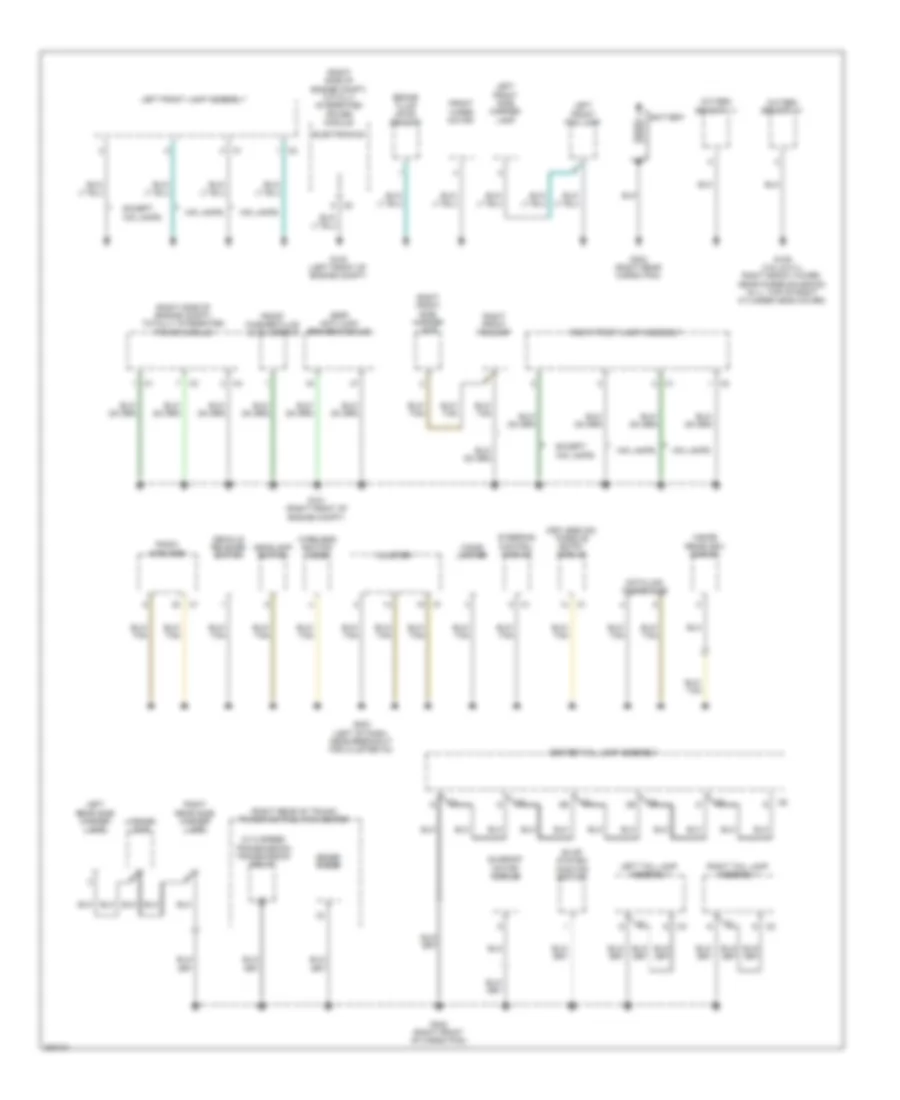
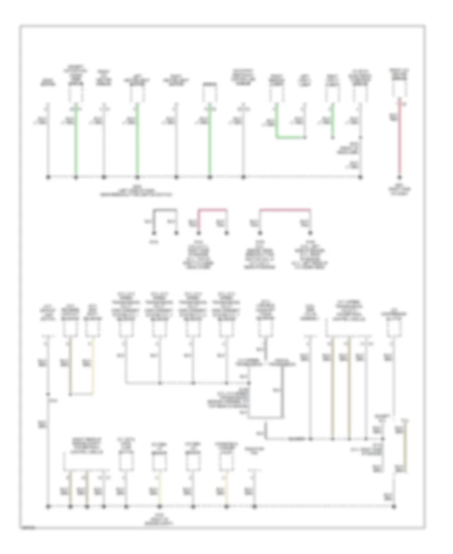
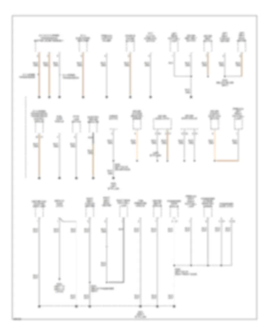
GROUND DISTRIBUTION Ground Distribution Wiring Diagram (1 of 3) for Dodge Challenger SRT-8 2008 List of elements for Ground Distribution Wiring Diagram (1 of 3) for Dodge Challenger SRT-8 2008: 44 (esp) anti-lock brakes module (keyless go) passive entry module (right rear of trunk) power distribution center (right side of engine compt) totally integrated power module (w/ 5 speed transmission) transmission relay Battery Brake fluid level sensor Center tail lamp assembly Cigar lighter Cluster Data link connector Decklid release switch Electronics Evap system monitor switch Except hid lamps Front washer fluid level sensor Front wiper motor G100 (left front of engine compt) G101 (right front of engine compt) G109 (3.5l & 5.7l: right shock tower, near purge solenoid) (6.1l: top of right cylinder head cover) G202 (left of dash, near breakout for cluster c3) G302 (right front of cargo pan) G303 (right rear cargo pan) Headlamp switch Hid lamps Inside rearview mirror Left front fog lamp Left front lamp assembly Left front side marker lamp Left rear side marker lamp Left tail lamp assembly License lamp Oxygen sensor 1/1 Oxygen sensor 2/1 Radio amplifier Right front fog lamp Right front lamp assembly Right front side marker lamp Right rear side marker lamp Right tail lamp assembly Steering control module Sunroof motor/ module Wireless ignition node Zener diode Ground Distribution Wiring Diagram (2 of 3) for Dodge Challenger SRT-8 2008 List of elements for Ground Distribution Wiring Diagram (2 of 3) for Dodge Challenger SRT-8 2008: 43 (3.5l) egr valve assembly (5.7l w/ 5 speed transmission) multi displacement system cyl 1 solenoid (5.7l w/ 5 speed transmission) multi displacement system cyl 4 solenoid (5.7l w/ 5 speed transmission) multi displacement system cyl 6 solenoid (5.7l w/ 5 speed transmission) multi displacement system cyl 7 solenoid (5.7l) variable camshaft timing solenoid (except navigation) hands free module (m/t) backup lamp switch (m/t) reverse lock-out solenoid (m/t) skip shift solenoid (right rear of engine compt) powertrain control module (w/ 4 speed transmission 3.5l/5.7l) powertrain control module (w/ evic) electronic overhead module (w/ vsta) hood ajar switch 6.1l A/c compressor clutch Bank switch Except 6.1l Front a/c heater module Front reading lamp G102 (right of engine compt) G103 G104 (3.5l & 5.7l: right side of engine) (6.1l: top of right cylinder head cover) G105 (3.5l: engine, near breakout for ignition coil 5) (5.7l & 6.1l: rear of engine) G106 (3.5l: left side of engine) (5.7l: rear of engine) (6.1l: left rear of cylinder head) G200 (left side of dash, near breakout for ignition switch) G201 (right side of dash) Left heated seat switch Left vanity lamp Manual transmission Occupant restraint controller module Oxygen 1/2 sensor Oxygen 2/2 sensor Radiator fan Radio Right heated seat switch Right vanity lamp S115 (5.7l: right side of engine) S136 (5.7l w/ 5 speed transmission) (engine harness, at top rear of engine) S181 S342 (front of headliner) W/ 5 speed transmission Windshield washer pump Ground Distribution Wiring Diagram (3 of 3) for Dodge Challenger SRT-8 2008 List of elements for Ground Distribution Wiring Diagram (3 of 3) for Dodge Challenger SRT-8 2008: 41 (6.1l) subwoofer amplifier (left "b" pillar) (m/t) clutch interlock switch (premium) lamp-cup holder (premium) left front footwell lamp (premium) right front footwell lamp (w/ 4 & w/ 5 speed transmission) shifter lever assembly (w/ 5 speed transmission) transmission control module Center high mounted stop lamp Console power outlet Decklid door latch Driver door latch Driver door module Driver outside rearview mirror Driver seat belt switch Driver seat switch Driver window/ door lock switch Electric heated backlite Fuel pump module G300 (left "b" pillar) G301 (right "b" pillar) G304 (next to deck lid latch) Heated seats module Left rear footwell lamp Left seat back heater Left seat cushion heater Mirror switch Nca Passenger door latch Passenger door module Passenger outside rearview mirror Right rear footwell lamp Right seat back heater Right seat cushion heater S333 (below driver seat) S334 (below passenger seat) S355 (bottom of driver door) S360 (bottom of right front door) Stop lamp switch Tire pressure module W/ 4 speed transmission
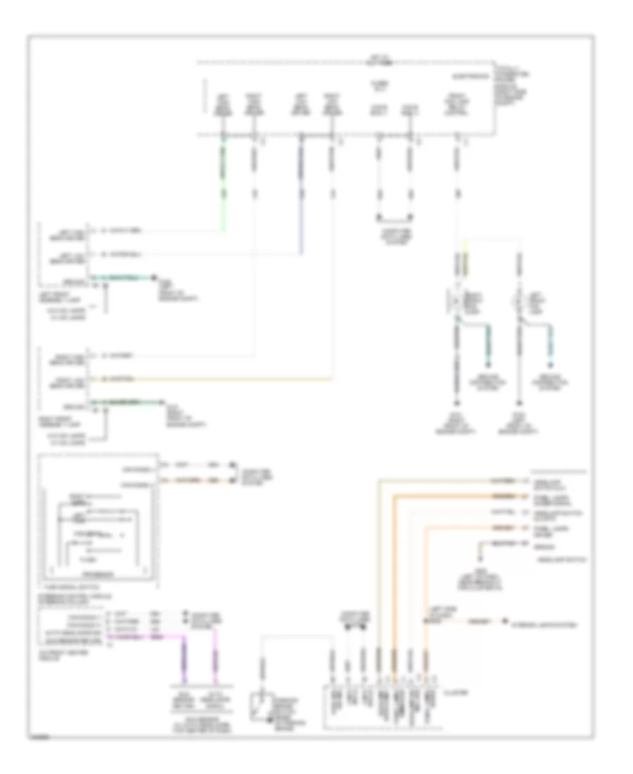
HEADLIGHTS Headlights Wiring Diagram for Dodge Challenger SRT-8 2008 List of elements for Headlights Wiring Diagram for Dodge Challenger SRT-8 2008: 59 (left side of dash) s208 A/c front heater module Auto headlamps sig Auto headlamps signal Bus (+) can b Bus (-) can b Can b bus (+) Can b bus (-) Cluster Computer data lines system D54 D55 Electronics Flash Front fog lamp relay control Fused b (+) G100 (left front of engine compt) G101 (right front of engine compt) G202 (left of dash, near breakout for cluster c3) G939 Ground Ground distribution system Headlamp sw mux rtn Headlamp switch Headlamp switch mux Headlamp switch mux rtn High beam Hot at all times Interior lights system L24 L33 L34 L43 L44 L89 Left front assembly lamp Left front fog lamp Left high beam driver Left low beam driver Left turn Panel lamps dimmer sig Panel lamps dimmer signal Panel lamps driver Park brk sw sns Parking brake switch (base of parking brake) Processor Right front assembly lamp Right front fog lamp Right high beam driver Right low beam driver Right turn Steering control module (steering column) Sun sensor (w/ auto headlamps) (top center of dash) Sun sensor return Switch mux headlamp Totally integrated power module (right side of engine compt) Turn signal switch W/ hid lamps W/o hid lamps
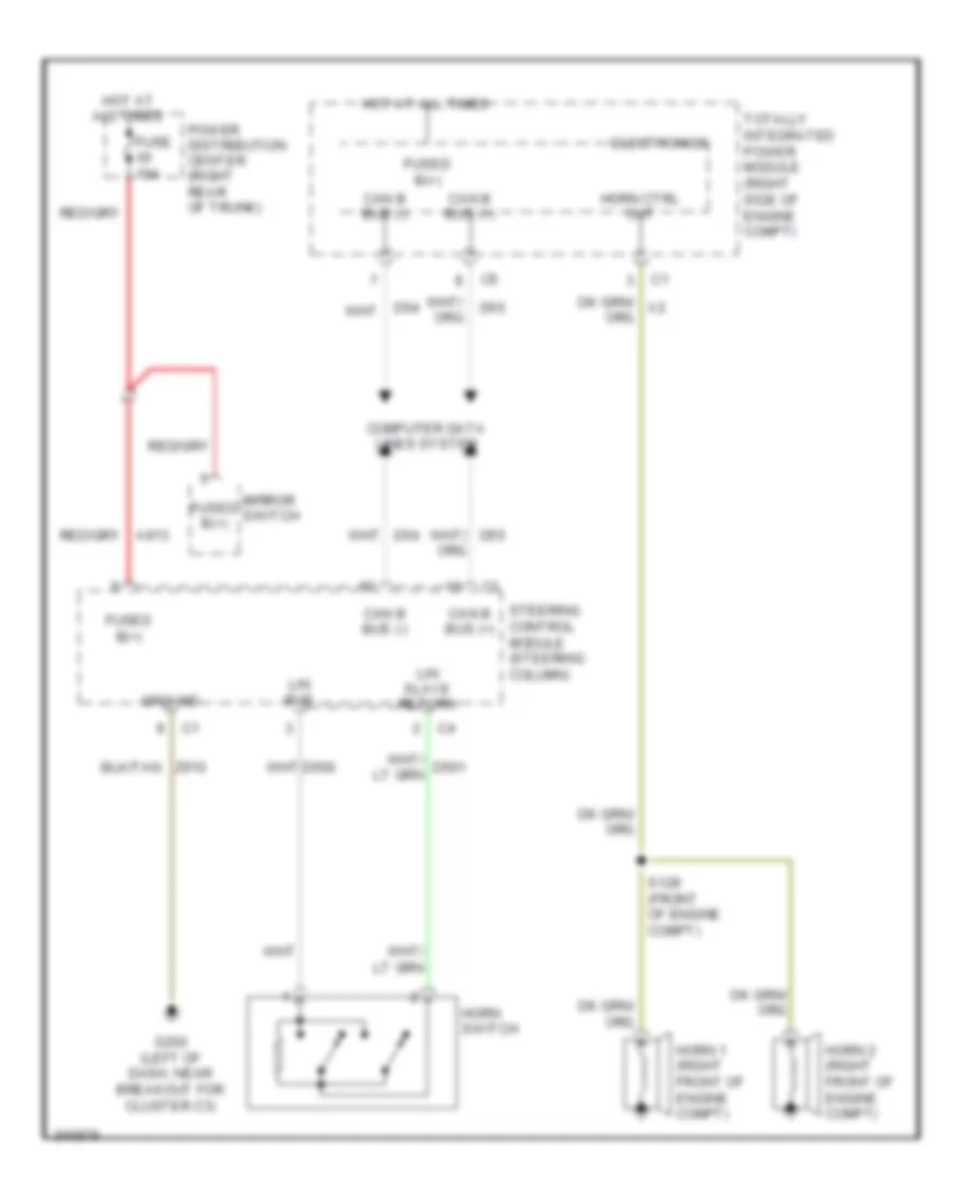
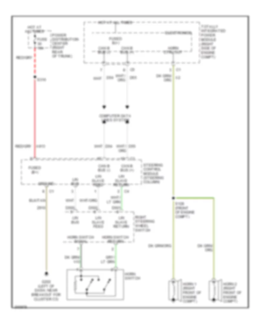
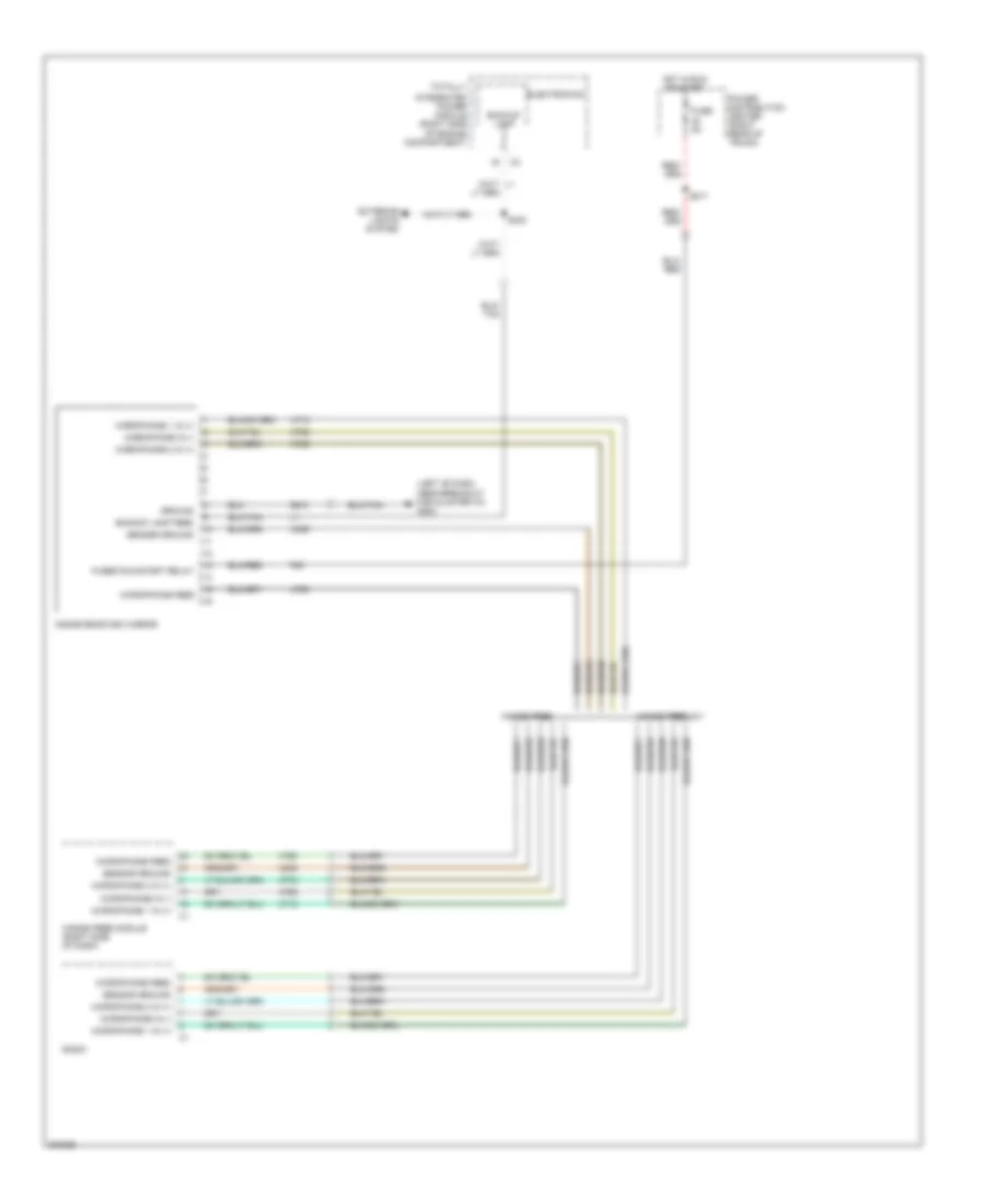
HORN Horn Wiring Diagram, Base for Dodge Challenger SRT-8 2008 List of elements for Horn Wiring Diagram, Base for Dodge Challenger SRT-8 2008: 24 Can b bus (+) Can b bus (-) Computer data lines system D500 D54 D55 Electronics Fuse 10a Fused b(+) G202 (left of dash, near breakout for cluster c3) Ground Horn 1 (right front of engine compt) Horn 2 (right front of engine compt) Horn ctrl out Horn switch Hot at all times Lin bus Lin slave return Mirror switch Power distribution center (right rear of trunk) S128 (front of engine compt) Steering control module (steering column) Totally integrated power module (right side of engine compt) Z910 Horn Wiring Diagram, Premium for Dodge Challenger SRT-8 2008 List of elements for Horn Wiring Diagram, Premium for Dodge Challenger SRT-8 2008: 32 A913 Can b bus (+) Can b bus (-) Computer data lines system D500 D501 D502 D54 D55 Electronics Fuse 10a Fused (b+) Fused b(+) G202 (left of dash, near breakout for cluster c3) Ground Horn 1 (right front of engine compt) Horn 2 (right front of engine compt) Horn ctrl out Horn switch Horn switch return Horn switch signal Hot at all times Lin bus Lin slave feed Lin slave return Power distribution center (right rear of trunk) Right steering wheel switch S128 (front of engine compt) S310 Steering control module (steering column) Totally integrated power module (right side of engine compt) Z910
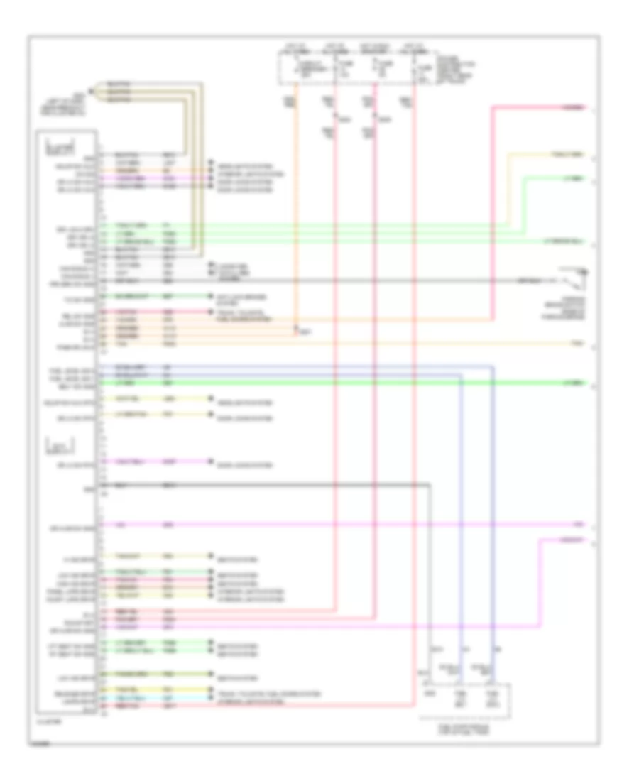
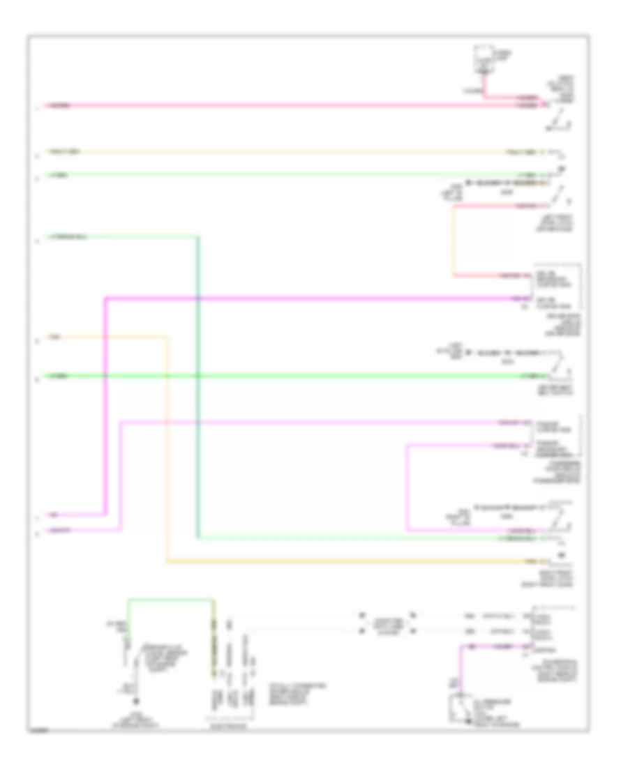
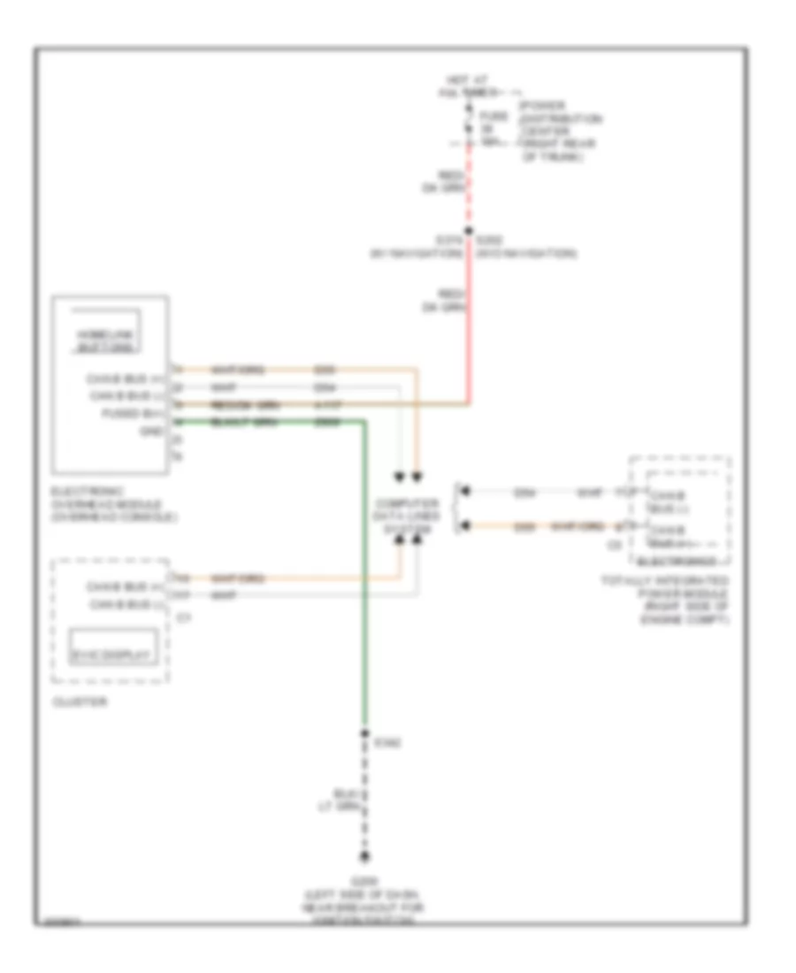
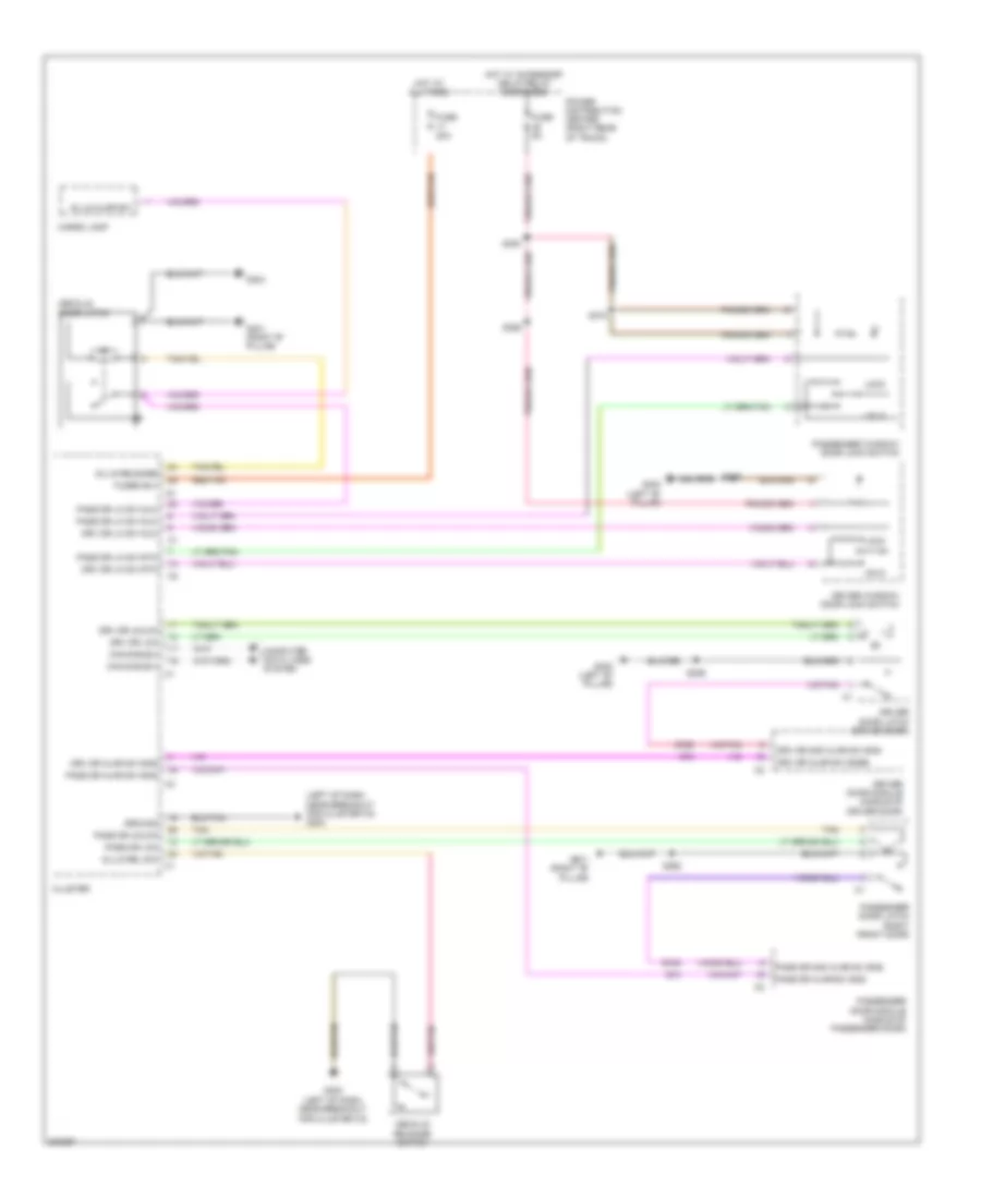
INSTRUMENT CLUSTER Instrument Cluster Wiring Diagram (1 of 2) for Dodge Challenger SRT-8 2008 List of elements for Instrument Cluster Wiring Diagram (1 of 2) for Dodge Challenger SRT-8 2008: 92 A110 A23 A917 Ajar sw sns Anti-lock brakes system B (+) B25 B27 Belt sw sns Can b bus (+) Can b bus (-) Circuit breaker 1 25a Cluster Cluster display Computer data lines system Court lmps drvr D54 D55 Dim sig Door locks system Dr ajar sw sns Dr lk sw mux Dr lk sw rtn Drv dr lk Drv unlk drv E12 Evic display F202 Fuel level sig 1 Fuel level sig 2 Fuel lvl sig 1 Fuel lvl sig 2 Fuel pump module (top of fuel tank) Fuse 10a Fuse 20a Fuse 5a G160 G161 G167 G202 (left of dash, near breakout for cluster c3) G25 G74 G75 G78 Gnd Hdlmp sw mux Hdlmp sw mux rtn Headlights system Hi ind drvr High ind drvr Hot at all times Hot in run or start Interior lights system L307 L900 Lamps drvr Lft seat sw sns Low ind drvr M24 M27 P303 P31 P365 P366 P37 P392 P393 P81 P82 P83 P84 Panel lmps drvr Parking brake switch (base of parking brake) Pass dr unlk Power distribution center (right rear of trunk) Prk brk sw sns R57 Red/ tan Red/tan Rel sw sns Release drvr Rt seat sw sns Run-start S200 S201 S209 Seats system T/c sw sns Tan Trunk, tailgate, fuel doors system Z210 Z910 Instrument Cluster Wiring Diagram (2 of 2) for Dodge Challenger SRT-8 2008 List of elements for Instrument Cluster Wiring Diagram (2 of 2) for Dodge Challenger SRT-8 2008: 35 (deck lid latch) deck lid door latch (left "b" pillar) g300 Ajar sw sns B20 Brake fluid level sensor (left rear of engine compt) Bus (+) can c Bus(-) can c Can c bus (+) Can c bus (-) Cargo lamp Computer data lines system D64 D65 Driver door module (middle of driver door) Driver seat belt switch Drv dr ajar sw sns Drv dr secondary ajar sw sns Electronics Eop sig G100 (left front of engine compt) G300 (left "b" pillar) G301 (right "b" pillar) Left front door latch (driver door) Oil pressure switch (3.5l) (lower left front of engine) Pass dr ajar sw sns Pass dr secondary ajar sw sns Passenger door module (middle of passenger door) Powertrain control module (right rear of engine compt) Right front door latch (right front door) S333 S355 S360 Sens switch Tan Totally integrated power module (right side of engine compt) Overhead Console Wiring Diagram for Dodge Challenger SRT-8 2008 List of elements for Overhead Console Wiring Diagram for Dodge Challenger SRT-8 2008: 22 (w/o navigation) A117 Can b bus (+) Can b bus (-) Cluster Computer data lines system D54 D55 Electronic overhead module (overhead console) Electronics Evic display Fuse 10a Fused b(+) G200 (left side of dash, near breakout for ignition switch) Gnd Homelink buttons Hot at all times Power distribution center (right rear of trunk) S202 s374 (w/ navigation) S342 Totally integrated power module (right side of engine compt) Z909
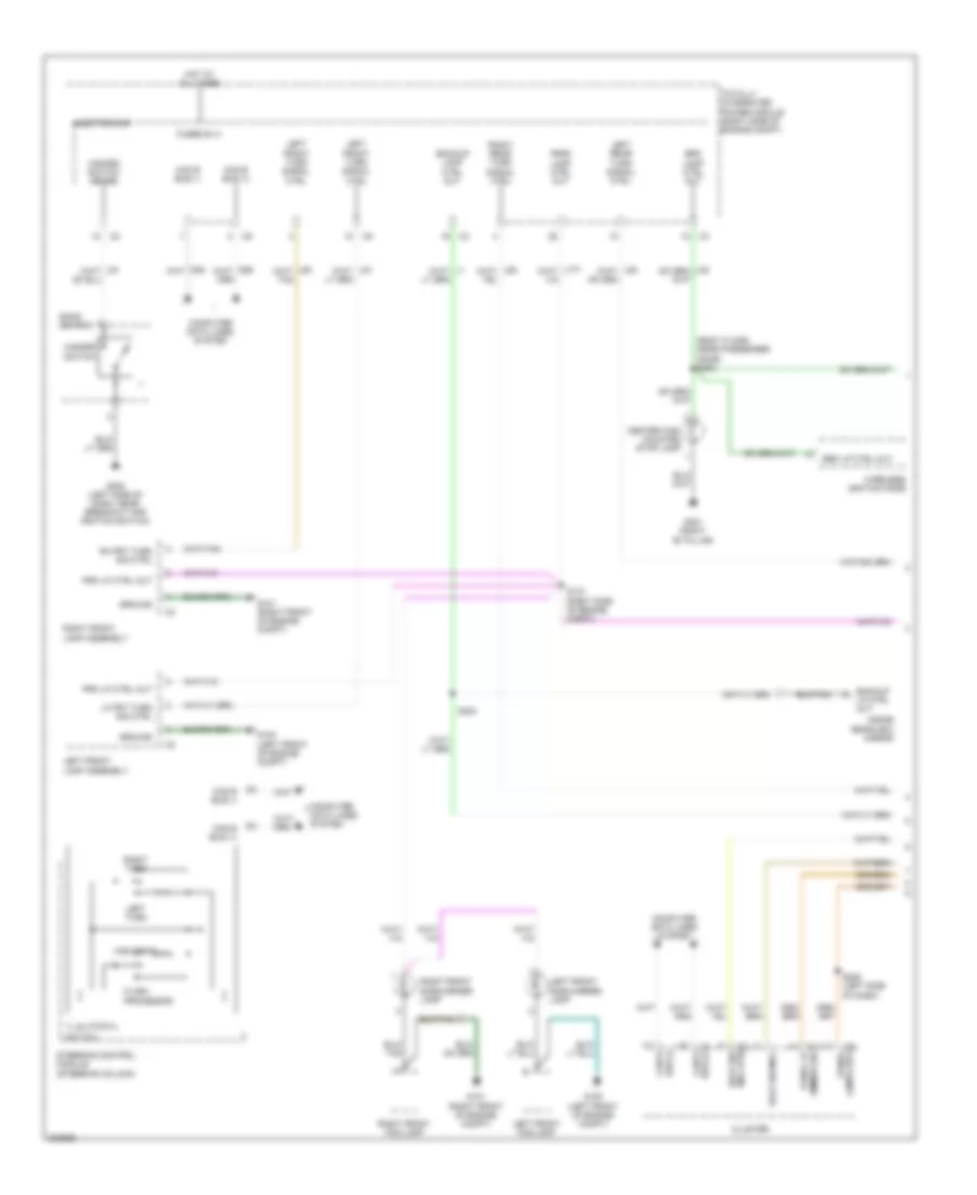
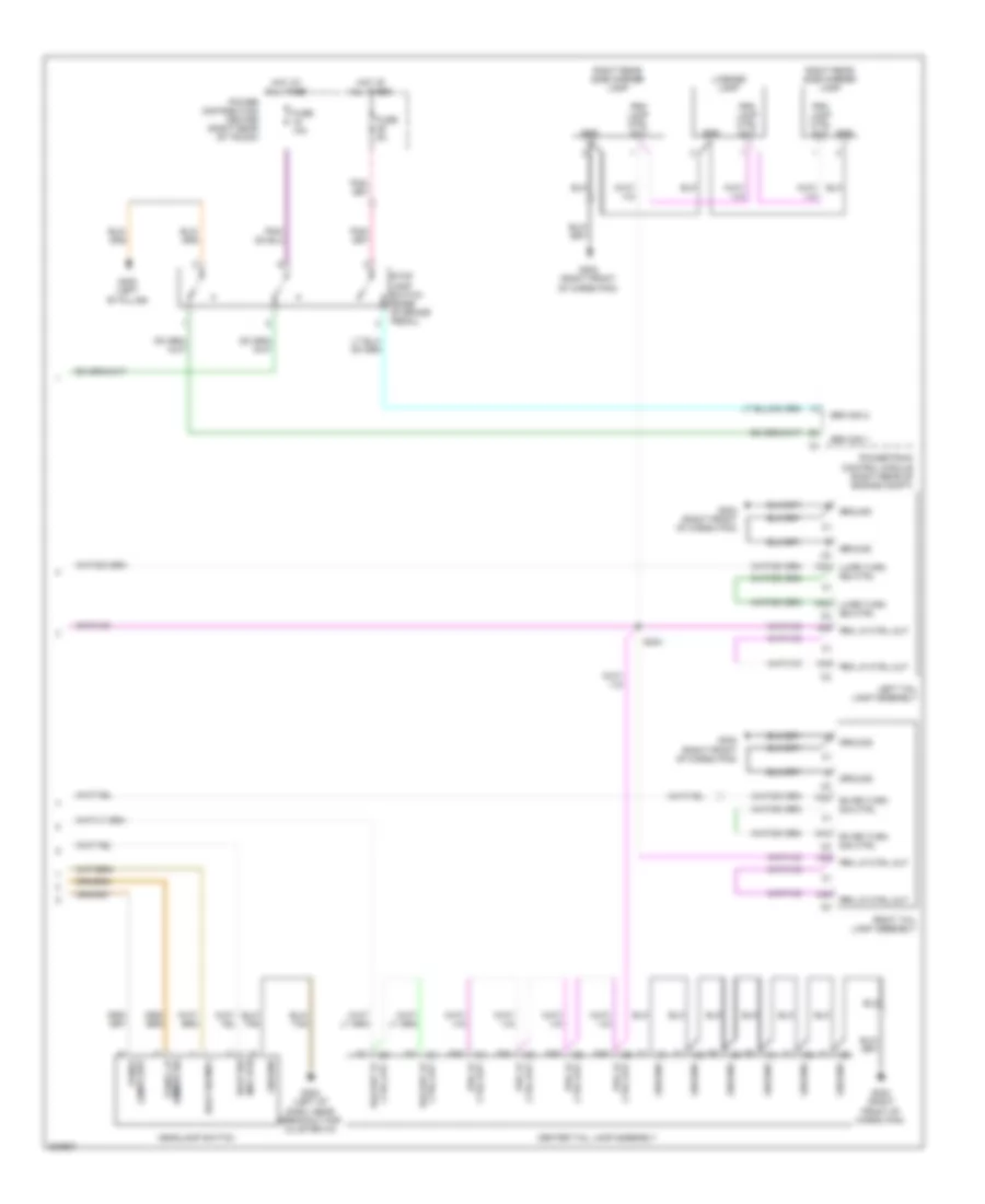
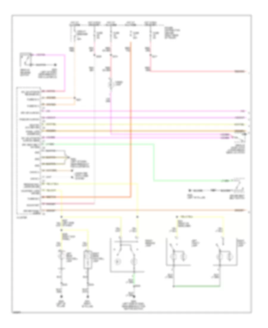
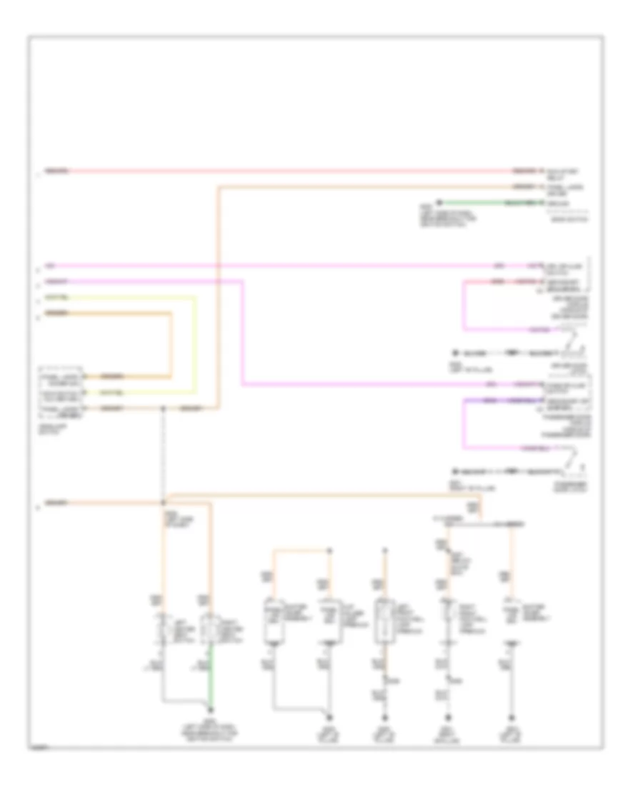
INTERIOR LIGHTS Interior Lights Wiring Diagram (1 of 2) for Dodge Challenger SRT-8 2008 List of elements for Interior Lights Wiring Diagram (1 of 2) for Dodge Challenger SRT-8 2008: 49 Can b (+) Can b (-) Cargo lamp Circuit breaker 25a Cluster Computer data lines system Courtesy lmps driver Decklid door latch (4 door sedan) (deck lid latch) Decklid release switch Dk lid/liftgate ajar sw sens Dk lid/liftgate release sw Driver panel lamps Driver seat belt switch Drv dr ajar sw Drv seat belt sw sns Front reading lamp Fuse 10a Fuse 20a Fuse 5a Fused b (+) Fused b(+) G200 (left side of dash, near breakout for ignition switch) G202 (left of dash, near breakout for cluster c3) G300 (left "b" pillar) G301 (right "b" pillar) Gnd Hdlp sw mux return Hot at all times Hot in run or start Left rear footwell lamp Left vanity lamp Panel lmps dimmer sig Pass dr ajar sw Power distribution center (right rear of trunk) Reading/ rail lamps driver Red/ tan Red/tan Right rear footwell lamp Right vanity lamp Run-start S201 S209 S217 S306 (right kick panel) S333 S334 S341 (front of headliner) S342 S374 Interior Lights Wiring Diagram (2 of 2) for Dodge Challenger SRT-8 2008 List of elements for Interior Lights Wiring Diagram (2 of 2) for Dodge Challenger SRT-8 2008: 38 (premium) Bank switch Cup holder lamp (premium) Driver door latch Driver door module (middle of driver door) Drv dr ajar switch G200 (left side of dash, near breakout for ignition switch) G300 (left "b" pillar) G301 (right "b" pillar) G301 (right "b"pillar) G74 G745 G75 G755 Gnd Ground Hdlp switch mux return Headlamp switch Left front footwell lamp Left heated seat switch Panel lamps dimmer sig Panel lamps driver Panel lps drv Pass dr ajar switch Passenger door latch Passenger door module (middle of passenger door) Right front footwell lamp (premium) Right heated seat switch Run/ start relay S208 (left side of dash) S355 S360 S387 (below glove box) Secondary dr ajar sw c2 Secondary dr ajar sw c2 Shifter lever assembly W/ 4 speed W/ 5 speed m/t
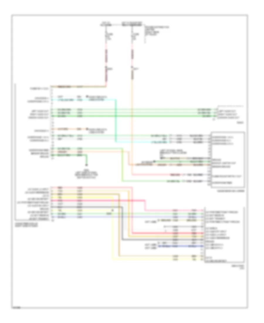
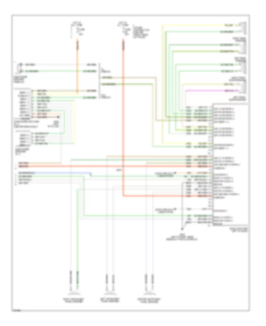
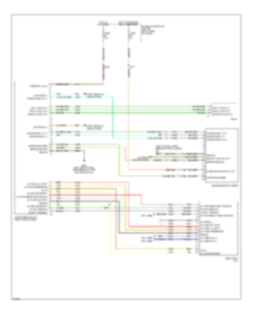
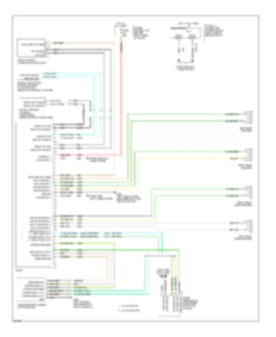
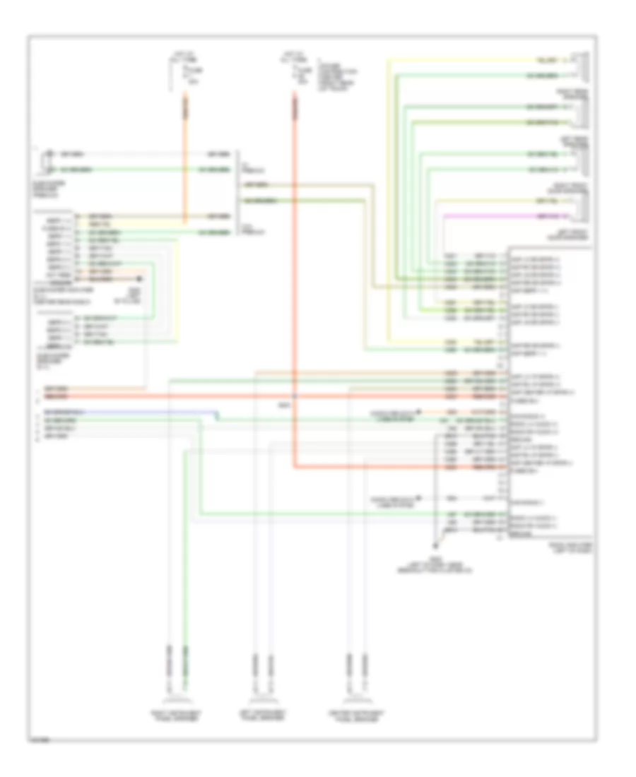
NAVIGATION Hands Free Module Wiring Diagram for Dodge Challenger SRT-8 2008 List of elements for Hands Free Module Wiring Diagram for Dodge Challenger SRT-8 2008: 77 (left of dash, near breakout for cluster c3) g202 (not used) (not used) (not used) A117 Backup lamp sw out Can b bus (+) Can b bus (-) Common audio out Computer data D54 D55 Exterior lights system F23 Fuse 10a Fuse 5a Fused b(+) (i.o.d.) Fused run/start rly out G200 (left side of dash, near breakout for ignition switch) Ground Hands free module (right side of dash) Hot at all times Hot w/ run/start relay energized Inside rearview mirror Left audio out Lines system Media port (uci) Microphone 1 in (+) Microphone 2 in (+) Microphone feed Microphone in (-) Nca Pnk Power distribution center (right rear of trunk) Radio Red Right audio out S217 S250 Sensor ground Tan Uci audio lh input Uci audio reference Uci audio rh input Uci audio rt input Uci device detect Uci ext receive Uci ext transmit Uci id Uci pwr feed 2 pass through Uci pwr feed pass through Uci pwr feed passthrough Uci shield Uci usb data (+) Uci usb data (-) X430 X431 X434 X435 X436 X437 X439 X440 X441 X444 X445 X446 X703 X704 X712 X722 X792 X793 X795 X835 Z433 Z909 Z910 Navigation Wiring Diagram, Base for Dodge Challenger SRT-8 2008 List of elements for Navigation Wiring Diagram, Base for Dodge Challenger SRT-8 2008: 78 (or x703) (or x704) A300 Amp lf dr spkr (+) Amp lf dr spkr (-) Amp lr spkr (+) Amp lr spkr (-) Amp rf dr spkr (+) Amp rf dr spkr (-) Amp rr spkr (+) Amp rr spkr (-) Amplified ant feed Ant shield Ant sig B (+) Can b bus (+) Can b bus (-) Com audio out Com audio output Computer data lines system D106 D108 D126 D54 D55 D931 Electronics Fuse 20a Fused b (+) G200 (left side of dash, near breakout for ignition switch) G202 (left of dash, near breakout for cluster c3) Global positioning system antenna (w/ navigation) (behind instrument cluster) Gnd Gps ant shield Gps ant sig Ground Hands free module (if equipped) (right side of dash) Hot at all times Inside rearview mirror (w/ navigation) Left front door speaker Left rear speaker Lh audio out Microphone 1 in (+) Microphone 1 in (+) right audio out Microphone 2 in (+) Microphone 2 in (+) left audio out Microphone feed Microphone in (-) Power distribution center (right rear of trunk) Radio Radio ant shield Radio ant sig Radio ant signal Radio antenna (upper right backlight) Rh audio out Right front door speaker Right rear speaker Satellite radio antenna (if equipped) (rear center of headliner) Sens ground Totally integrated power module (right side of engine compt) W/ navigation W/o navigation X201 X202 X291 X292 X303 X304 X393 X394 X62 X712 X722 X792 X793 X795 X835 Z909 Navigation Wiring Diagram, Premium (2 of 2) for Dodge Challenger SRT-8 2008 List of elements for Navigation Wiring Diagram, Premium (2 of 2) for Dodge Challenger SRT-8 2008: 74 A300 Amp center i/p spkr (+) Amp center i/p spkr (-) Amp lf dr spkr (+) Amp lf dr spkr (-) Amp lh i/p spkr (+) Amp lh i/p spkr (-) Amp lr dr spkr (+) Amp lr dr spkr (-) Amp rf dr spkr (+) Amp rf dr spkr (-) Amp rh i/p spkr (+) Amp rh i/p spkr (-) Amp rr dr spkr (+) Amp rr dr spkr (-) Amp sbfr 1 (+) Amp sbfr 1 (-) Ant feed Can b bus (+) Can b bus (-) Center instrument panel speaker Computer data lines system D54 D55 Fuse 20a Fused b (+) Fused b(+) G202 (left of dash, near breakout for cluster c3) G300 (left "b" pillar) Ground Hot at all times Left front door speaker Left instrument panel speaker Left rear speaker Power distribution center (right rear of trunk) Radio amplifier (left of dash) Radio lh audio (+) Radio lh audio (-) Radio rh audio (+) Radio rh audio (-) Right front door speaker Right instrument panel speaker Right rear speaker S203 Sbfr 1 (+) Sbfr 1 (-) Sbfr 2 (+) Sbfr 2 (-) Subwoofer amplifier (6.1l) (center rear shelf) Subwoofer speaker (6.1l) Subwoofer speaker (premium) W/ premium W/o premium X200 X201 X202 X208 X209 X290 X291 X292 X298 X299 X300 X303 X304 X390 X393 X394 X51 X52 X57 X58 Z910
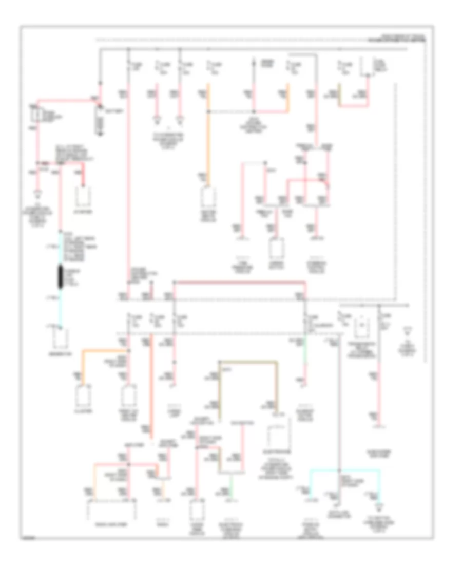
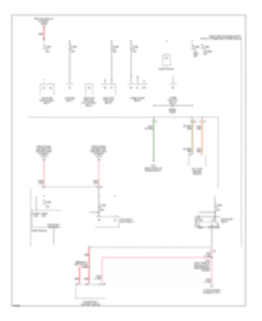
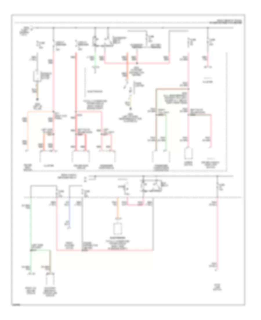
POWER DISTRIBUTION Power Distribution Wiring Diagram (1 of 4) for Dodge Challenger SRT-8 2008 List of elements for Power Distribution Wiring Diagram (1 of 4) for Dodge Challenger SRT-8 2008: 54 (power distribution center) s322 (right rear of trunk) power distribution center 15a Amplifier Base tpm Battery Cargo lamp Cluster Data link connector Electronic overhead module (w/ evic) Electronics Except amplifier Except navigation Front a/c heater module Fuel pump relay Fuse Fuse (6.1l) 20a Fuse (w/ sunroof) 20a Fuse 10a Fuse 20a Fuse 30a Fuse 40a Fuse lod Generator Hands free module Heated seats module Mirror switch Navigation Pass through post Passive entry module (keyless go) Premium tpm Radio Radio amplifier Red S100 (3.5l: left rear of engine) (5.7l: right rear of engine) (6.1l: rear of engine) S138 red S200 (right side of dash) S203 (right side of dash) S215 (right side of dash) S310 S315 (power distribution center) S374 Starter Steering control module Subwoofer amplifier Sunroof motor/ module Tire pressure module To fuse 9 (diagram 3 of 4) To ignition wireless node (diagram 4 of 4) To integrated power module (diagram 2 of 4) To integrated power module fuse 12 (diagram 2 of 4) Totally integrated power module (right side of engine compt) Transmission relay (w/ 5 speed transmission) Zener diode Power Distribution Wiring Diagram (2 of 4) for Dodge Challenger SRT-8 2008 List of elements for Power Distribution Wiring Diagram (2 of 4) for Dodge Challenger SRT-8 2008: 32 (breakout for tipm c6) s166 (right side of engine compt) totally integrated power module 87a Anti-lock brakes module Auto shut down relay Electronics From power distribution center fuse 2 (diagram 1 of 4) From power distribution center fuse 4 (diagram 1 of 4) From splice s138 (diagram 1 of 4) Fuse (w/ esp) 30a Fuse (w/ esp) 50a Fuse 15a Fuse 25a Fuse 30a Fuse 40a Fuse 50a Fused b(+) G101 (right front of engine compt) Powertrain control module Radiator fan control relay Radiator fan high relay Radiator fan high/ low control relay Red Run/start relay Run/start rly ctrl S167 (right rear of engine compt, near grommet to dash) Starter relay Tan/ red To splice s389 (diagram 4 of 4) Wiper high/low relay Wiper on/off relay Zener diode Power Distribution Wiring Diagram (3 of 4) for Dodge Challenger SRT-8 2008 List of elements for Power Distribution Wiring Diagram (3 of 4) for Dodge Challenger SRT-8 2008: 47 (bottom of driver door) s356 (bottom of red (diagram 1 of 4) (left red (left side of dash) s201 (left side of dash) s210 (power distribution center) s321 (right rear of trunk) power distribution center (right taillight) s372 87a Accessory delay relay Accessory position Battery position Cigar lighter Circuit breaker 25a Cluster Console power outlet Diode Driver door module Driver door) s359 Driver seat switch Driver window/ door lock switch Electronics From Front a/c heater module Front blower motor Fuse 10a Fuse 20a Fuse 30a Fuse 5a Fuse 7 G202 (left of dash, near breakout for cluster c3) G300 (left "b" pillar) Mirror switch Occupant restraint controller module Passenger door module Passenger window/door lock switch Rear window defogger relay Red Red/ tan Run relay S300 (6.1l: near breakout for rigth taillight) (except 6.1l: below right front door) S305 S323 (in power distribution center) Stop lamp switch Taillight) s371 Totally integrated power module (right side of engine compt) Power Distribution Wiring Diagram (4 of 4) for Dodge Challenger SRT-8 2008 List of elements for Power Distribution Wiring Diagram (4 of 4) for Dodge Challenger SRT-8 2008: 44 (body floor, near passenger door) s302 Anti-lock brakes module (w/ esp) Bank switch Brake lamp control output Brk lp ctrl out Btsi control Btsi ctrl Can c bus (+) Can c bus (-) Cluster Clutch interock sig Clutch interock st ctrl Com-lin Computer data lines system Diode (w/ 5 speed transmission) Electronics From power distribution center fuse 8 (diagram 1 of 4) From splice s167 (diagram 2 of 4) Fuel pump relay Fuse 10a Fuse 5a Fused b(+) G202 (left of dash, near breakout for cluster c3) Ground Ign run-start Ign run-start output Inside rearview mirror Interlock clutch switch (m/t) Left heated seat switch Occupant restraint controller module Power distribution center (right rear of trunk) Powertrain control module (m/t) Right heated seat switch S209 (left side of dash) S217 (right side of dash) S389 (power distribution center) Shifter lever assembly (a/t) Stop lamp switch Totally integrated power module (right side of engine compt) Transmission relay Trs park sig W/ 4 speed transmission W/ 5 speed transmission Wireless ignition node
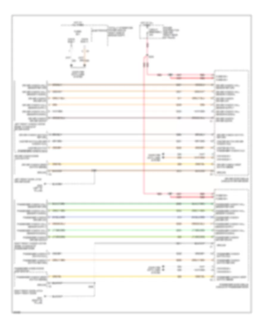
POWER DOOR LOCKS Power Door Locks Wiring Diagram for Dodge Challenger SRT-8 2008 List of elements for Power Door Locks Wiring Diagram for Dodge Challenger SRT-8 2008: 55 (left of dash, near breakout for cluster c3) g202 Can b bus(+) Can b bus(-) Cargo lamp Cluster Computer data lines system Decklid door latch Decklid release switch Dl/lg ajar sw Dl/lg rel sw Dl/lg release Driver door latch (driver door) Driver door module (middle of driver door) Driver window/ door lock switch Drv dr 2nd ajar sw sns Drv dr ajar sw sns Drv dr ajar sw snse Drv dr lck Drv dr lk sw mux Drv dr lk sw rtn Drv dr unlck For cluster c3) Fuse 20a Fuse 5a Fused b(+) G202 (left of dash, near breakout G300 (left "b" pillar) G301 (right "b" pillar) G304 G74 G745 G75 G755 Ground Hot at all times Hot w/ accessory delay relay energized Lock Pass dr 2nd ajar sw sns Pass dr ajar sw sns Pass dr lck Pass dr lk sw mux Pass dr lk sw rtn Pass dr unlck Passenger door latch (right front door) Passenger door module (middle of passenger door) Passenger window/ door lock switch Power distribution center (right rear of trunk) Red/tan S300 S355 S356 S360 S372 Tan Unlk
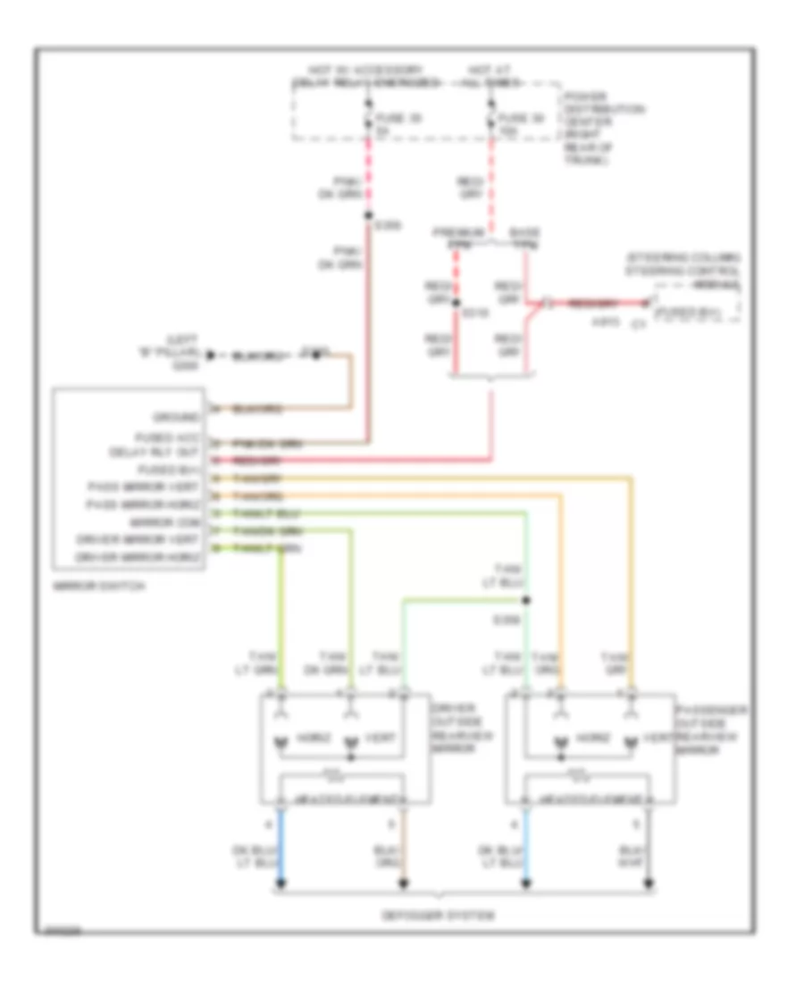
POWER MIRRORS Automatic Day/Night Mirror Wiring Diagram for Dodge Challenger SRT-8 2008 List of elements for Automatic Day/Night Mirror Wiring Diagram for Dodge Challenger SRT-8 2008: 32 (left of dash, near breakout for cluster c3) g202 Backup lamp Backup lamp feed Electronics Exterior lights system F23 Fuse 5a Fused run/start relay Ground Hands free Hands free module (right side of dash) Hands free/uc1 Hot in run or start Inside rearview mirror Integrated power module (right side of engine compartment) Microphone 1 in (+) Microphone 2 in (+) Microphone feed Microphone in (-) Power distribution center (right rear of trunk) Radio S217 S303 Sensor ground Totally X712 X722 X772 X792 X793 X835 Z910 Power Mirrors Wiring Diagram for Dodge Challenger SRT-8 2008 List of elements for Power Mirrors Wiring Diagram for Dodge Challenger SRT-8 2008: 30 (left "b" pillar) g300 (steering column) steering control module A913 c1 Base tpm Defogger system Delay rly out Driver mirror horiz Driver mirror vert Driver outside rearview mirror Fuse 30 10a Fuse 35 5a Fused acc Fused b(+) Ground Heated element Horiz Hot at all times Hot w/ accessory delay relay energized Mirror com Mirror switch Pass mirror horiz Pass mirror vert Passenger outside rearview mirror Power distribution center (right rear of trunk) Premium tpm S310 S356 S358 Vert Vert m
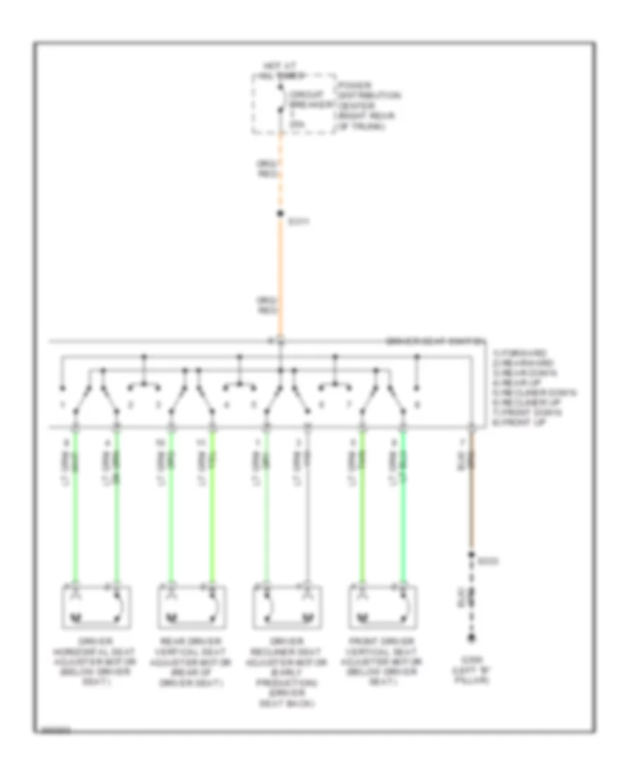
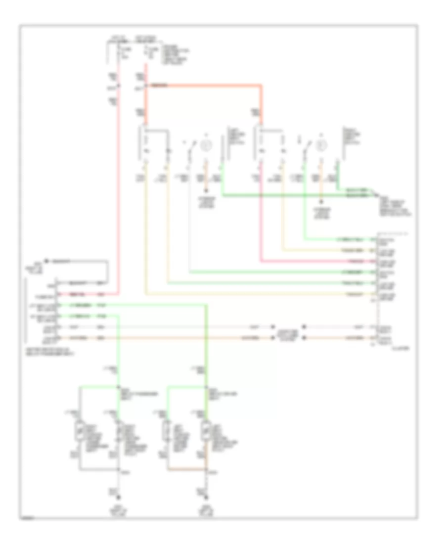
POWER SEATS Driver Power Seat Wiring Diagram for Dodge Challenger SRT-8 2008 List of elements for Driver Power Seat Wiring Diagram for Dodge Challenger SRT-8 2008: 13 1) forward 2) rearward 3) rear down 4) rear up 5) recliner down 6) recliner up 7) front down 8) front up All times Circuit breaker 25a Driver horizontal seat adjuster motor (below driver seat) Driver recliner seat adjuster motor (early production) (driver seat back) Driver seat switch Front driver vertical seat adjuster motor (below driver seat) G300 (left "b" pillar) Hot at Power distribution center (right rear of trunk) Rear driver vertical seat adjuster motor (rear of driver seat) S311 S333 Heated Seats Wiring Diagram for Dodge Challenger SRT-8 2008 List of elements for Heated Seats Wiring Diagram for Dodge Challenger SRT-8 2008: 39 A33 Can b bus (+) Can b bus (-) Cluster Computer data lines system D54 D55 Fuse 30a Fuse 5a Fused b(+) G200 (left side of dash, near breakout for ignition switch) G300 (left "b" pillar) G301 (right "b" pillar) Gnd Heated seats module (below passenger seat) High ind driver Hot at all times Hot in run or start Interior lights system Left heated seat switch Left seat back heater (near driver seat back pivot) Left seat cushion heater (under driver seat) Lft seat htr b(+) drvr Low ind driver P187 P188 Power distribution center (right rear of trunk) Right heated seat switch Right seat back heater (near passenger seat back pivot) Right seat cushion heater (under passenger seat) Rt seat htr b(+) drvr S217 S315 S332 (below driver seat) S333 S334 S335 (below passenger seat) Switch sns Z911
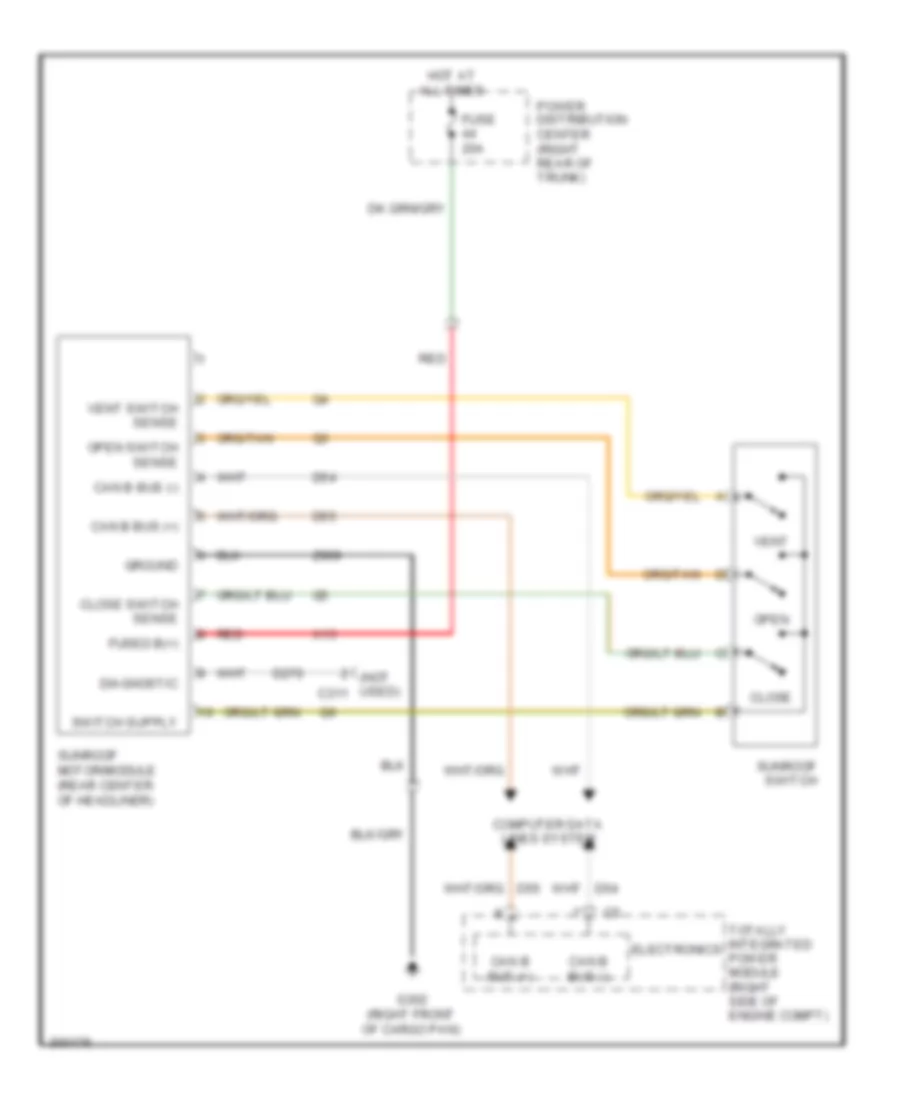
POWER TOP/SUNROOF Power Top/Sunroof Wiring Diagram for Dodge Challenger SRT-8 2008 List of elements for Power Top/Sunroof Wiring Diagram for Dodge Challenger SRT-8 2008: 27 (not used) c311 Can b bus (+) Can b bus (-) Close Close switch sense Computer data lines system D270 D54 D55 Diagnostic Electronics Fuse 20a Fused b(+) G302 (right front of cargo pan) Ground Hot at all times Open Open switch sense Power distribution center (right rear of trunk) Red Sunroof motor/module (rear center of headliner) Sunroof switch Totally integrated power module (right side of engine compt) Vent Vent switch sense X13 Z909
POWER WINDOWS Power Windows Wiring Diagram for Dodge Challenger SRT-8 2008 List of elements for Power Windows Wiring Diagram for Dodge Challenger SRT-8 2008: 67 A937 Can b bus (+) Can b bus (-) Circuit breaker 2 25a Computer data lines system D54 D55 Driver door module (middle of driver door) Driver window driver (down) Driver window driver (up) Driver window drop switch sense Driver window hall sensor a signal Driver window hall sensor b signal Driver window hall sensor return Driver window switch return Driver window/door lock switch Electronics Fused b(+) G300 (left "b" pillar) G301 (right "b" pillar) Ground Hot at all times Left front door latch (driver door) Left front window motor (base: in middle of driver door) Master switch driver window mux Master switch passenger window mux Passenger door module (middle of passenger door) Passenger window driver (down) Passenger window driver (up) Passenger window drop switch sense Passenger window hall sensor a signal Passenger window hall sensor b signal Passenger window hall sensor return Passenger window switch mux Passenger window switch return Passenger window/door lock switch Power distribution center (right rear of trunk) Q11 Q12 Q21 Q22 Q221 Q222 Q301 Q302 Q303 Q304 Q305 Q306 Q336 Q58 Q59 Q936 Q990 Q991 Q994 Red Right front door latch (right front door) Right front window motor (base: in middle of passenger door) S305 S355 S359 S360 S371 Totally integrated power module (right side of engine compt) Z911 Z912
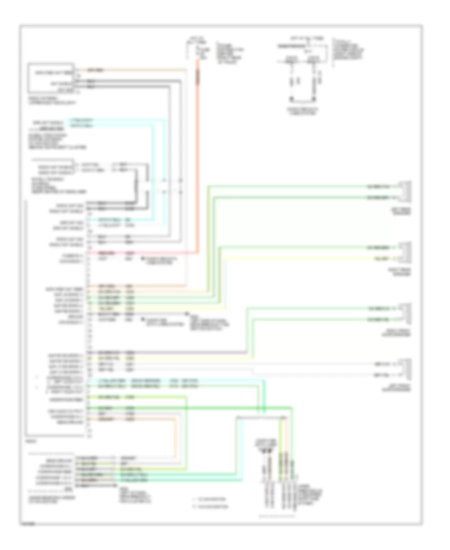
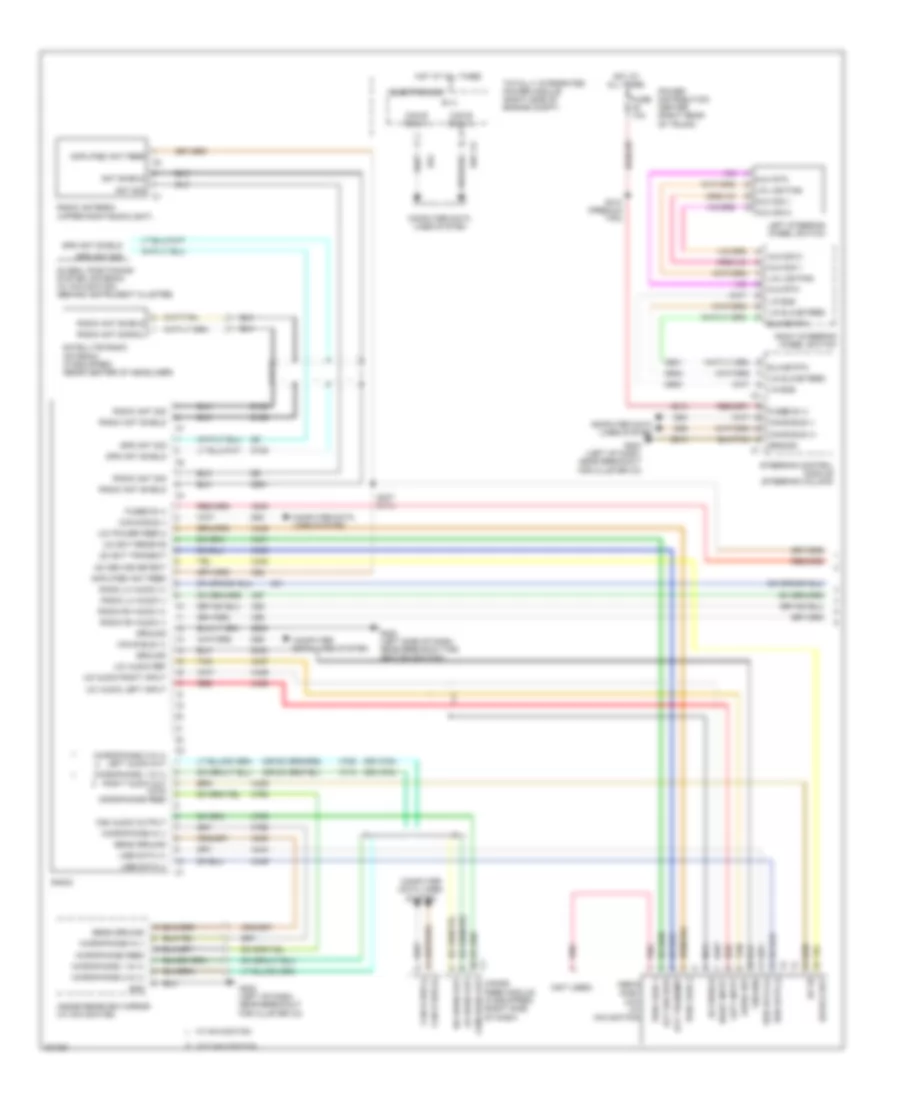
RADIO Hands Free Module Wiring Diagram for Dodge Challenger SRT-8 2008 List of elements for Hands Free Module Wiring Diagram for Dodge Challenger SRT-8 2008: 77 (left of dash, near breakout for cluster c3) g202 (not used) (not used) (not used) A117 Backup lamp sw out Can b bus (+) Can b bus (-) Common audio out Computer data D54 D55 Exterior lights system F23 Fuse 10a Fuse 5a Fused b(+) (i.o.d.) Fused run/start rly out G200 (left side of dash, near breakout for ignition switch) Ground Hands free module (right side of dash) Hot at all times Hot w/ run/start relay energized Inside rearview mirror Left audio out Lines system Media port (uci) Microphone 1 in (+) Microphone 2 in (+) Microphone feed Microphone in (-) Nca Pnk Power distribution center (right rear of trunk) Radio Red Right audio out S217 S250 Sensor ground Tan Uci audio lh input Uci audio reference Uci audio rh input Uci audio rt input Uci device detect Uci ext receive Uci ext transmit Uci id Uci pwr feed 2 pass through Uci pwr feed pass through Uci pwr feed passthrough Uci shield Uci usb data (+) Uci usb data (-) X430 X431 X434 X435 X436 X437 X439 X440 X441 X444 X445 X446 X703 X704 X712 X722 X792 X793 X795 X835 Z433 Z909 Z910 Radio Wiring Diagram, Base for Dodge Challenger SRT-8 2008 List of elements for Radio Wiring Diagram, Base for Dodge Challenger SRT-8 2008: 78 (or x703) (or x704) A300 Amp lf dr spkr (+) Amp lf dr spkr (-) Amp lr spkr (+) Amp lr spkr (-) Amp rf dr spkr (+) Amp rf dr spkr (-) Amp rr spkr (+) Amp rr spkr (-) Amplified ant feed Ant shield Ant sig B (+) Can b bus (+) Can b bus (-) Com audio out Com audio output Computer data lines system D106 D108 D126 D54 D55 D931 Electronics Fuse 20a Fused b (+) G200 (left side of dash, near breakout for ignition switch) G202 (left of dash, near breakout for cluster c3) Global positioning system antenna (w/ navigation) (behind instrument cluster) Gnd Gps ant shield Gps ant sig Ground Hands free module (if equipped) (right side of dash) Hot at all times Inside rearview mirror (w/ navigation) Left front door speaker Left rear speaker Lh audio out Microphone 1 in (+) Microphone 1 in (+) right audio out Microphone 2 in (+) Microphone 2 in (+) left audio out Microphone feed Microphone in (-) Power distribution center (right rear of trunk) Radio Radio ant shield Radio ant sig Radio ant signal Radio antenna (upper right backlight) Rh audio out Right front door speaker Right rear speaker Satellite radio antenna (if equipped) (rear center of headliner) Sens ground Totally integrated power module (right side of engine compt) W/ navigation W/o navigation X201 X202 X291 X292 X303 X304 X393 X394 X62 X712 X722 X792 X793 X795 X835 Z909 Radio Wiring Diagram, Premium (2 of 2) for Dodge Challenger SRT-8 2008 List of elements for Radio Wiring Diagram, Premium (2 of 2) for Dodge Challenger SRT-8 2008: 74 A300 Amp center i/p spkr (+) Amp center i/p spkr (-) Amp lf dr spkr (+) Amp lf dr spkr (-) Amp lh i/p spkr (+) Amp lh i/p spkr (-) Amp lr dr spkr (+) Amp lr dr spkr (-) Amp rf dr spkr (+) Amp rf dr spkr (-) Amp rh i/p spkr (+) Amp rh i/p spkr (-) Amp rr dr spkr (+) Amp rr dr spkr (-) Amp sbfr 1 (+) Amp sbfr 1 (-) Ant feed Can b bus (+) Can b bus (-) Center instrument panel speaker Computer data lines system D54 D55 Fuse 20a Fused b (+) Fused b(+) G202 (left of dash, near breakout for cluster c3) G300 (left "b" pillar) Ground Hot at all times Left front door speaker Left instrument panel speaker Left rear speaker Power distribution center (right rear of trunk) Radio amplifier (left of dash) Radio lh audio (+) Radio lh audio (-) Radio rh audio (+) Radio rh audio (-) Right front door speaker Right instrument panel speaker Right rear speaker S203 Sbfr 1 (+) Sbfr 1 (-) Sbfr 2 (+) Sbfr 2 (-) Subwoofer amplifier (6.1l) (center rear shelf) Subwoofer speaker (6.1l) Subwoofer speaker (premium) W/ premium W/o premium X200 X201 X202 X208 X209 X290 X291 X292 X298 X299 X300 X303 X304 X390 X393 X394 X51 X52 X57 X58 Z910
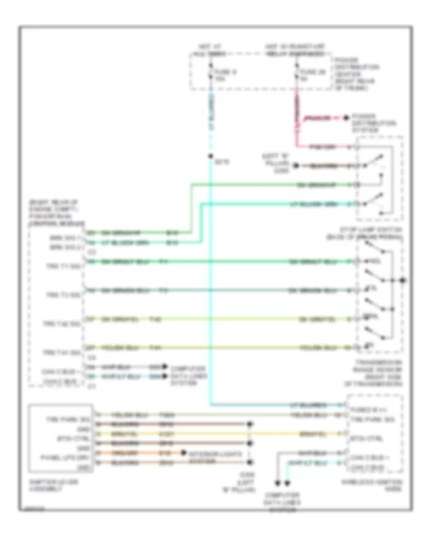
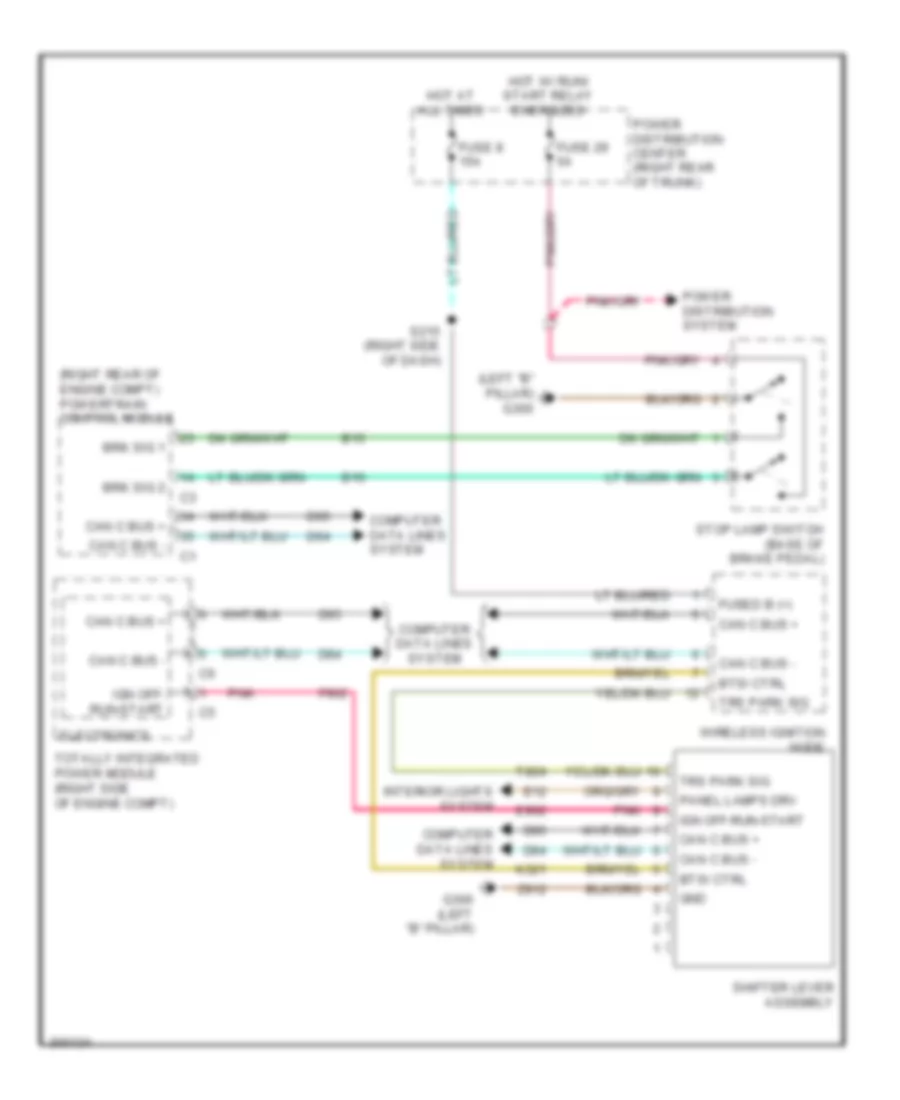
SHIFT INTERLOCK Shift Interlock Wiring Diagram, 4 Speed A/T for Dodge Challenger SRT-8 2008 List of elements for Shift Interlock Wiring Diagram, 4 Speed A/T for Dodge Challenger SRT-8 2008: 43 (left "b" pillar) (left "b" pillar) g300 (right rear of engine compt) powertrain control module B15 B16 Brk sig 1 Brk sig 2 Btsi ctrl Can c bus + Can c bus - Computer data lines system D64 D65 E12 Fuse 29 5a Fuse 8 15a Fused b (+) G300 Gnd Hot at all times Hot w/ run/start relay energized Interior lights system K321 Nol P3l Panel lps drv Power distribution center (right rear of trunk) Power distribution system Prnl S215 Shifter lever assembly Stop lamp switch (base of brake pedal) T41 T42 T824 Transmission range sensor (right side of transmission) Trs park sig Trs t1 sig Trs t3 sig Trs t41 sig Trs t42 sig Wireless ignition node Z912 Shift Interlock Wiring Diagram, 5 Speed A/T for Dodge Challenger SRT-8 2008 List of elements for Shift Interlock Wiring Diagram, 5 Speed A/T for Dodge Challenger SRT-8 2008: 39 (left "b" pillar) g300 (right rear of engine compt) powertrain control module B15 B16 Brk sig 1 Brk sig 2 Btsi ctrl Can c bus + Can c bus - Computer data lines system D64 D65 E12 E902 Electronics F902 Fuse 29 5a Fuse 8 15a Fused b (+) G300 (left "b" pillar) Gnd Hot at all times Hot w/ run/ start relay energized Ign off- run-start Ign off-run-start Interior lights system K321 Panel lamps drv Pnk Power distribution center (right rear of trunk) Power distribution system S215 (right side of dash) Shifter lever assembly Stop lamp switch (base of brake pedal) T824 Totally integrated power module (right side of engine compt) Trs park sig Wireless ignition node Z912
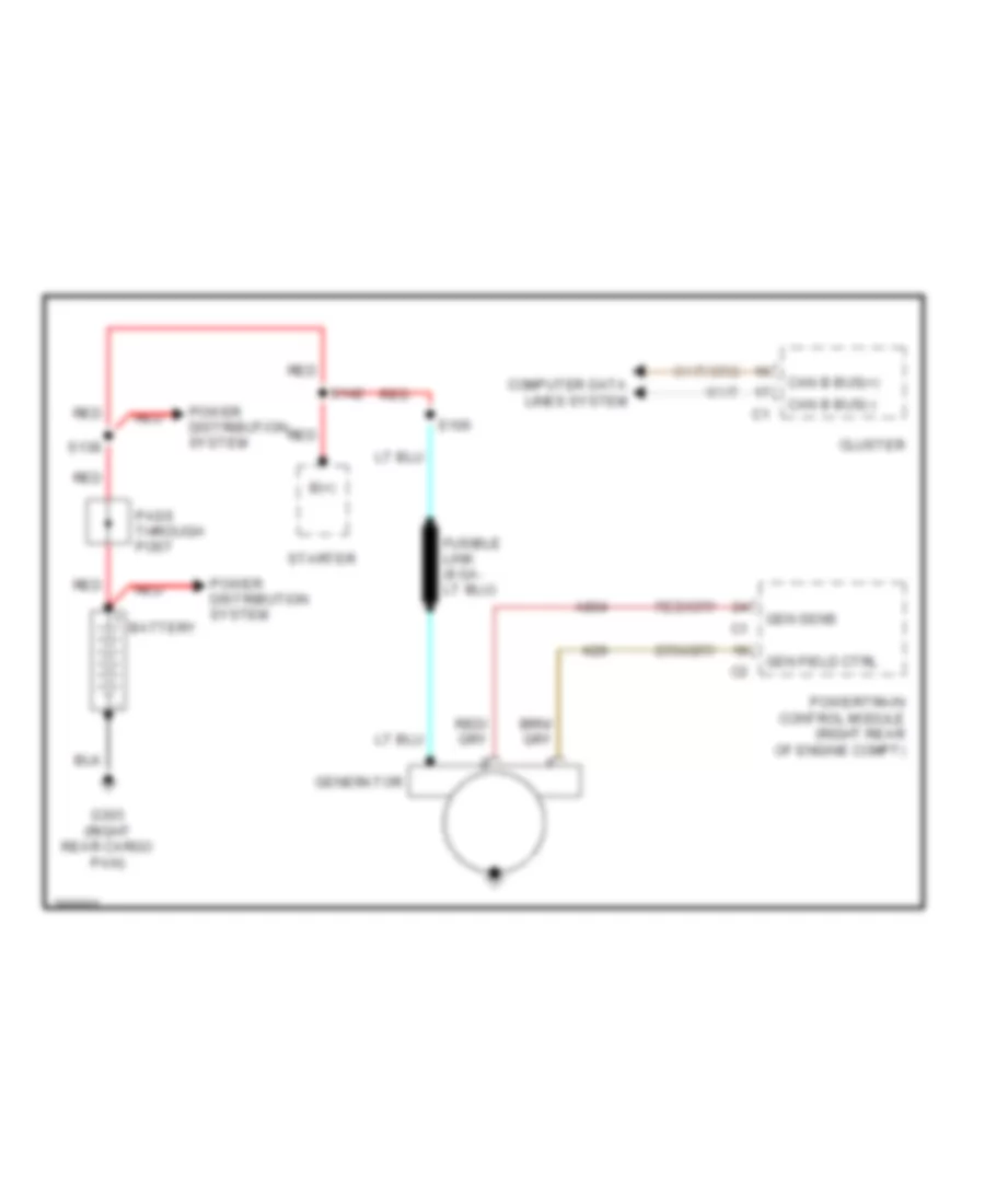
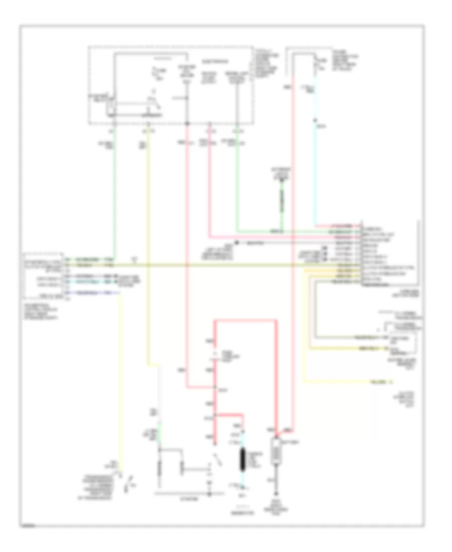
STARTING/CHARGING Charging Wiring Diagram for Dodge Challenger SRT-8 2008 List of elements for Charging Wiring Diagram for Dodge Challenger SRT-8 2008: 20 A804 B(+) Battery Can b bus(+) Can b bus(-) Cluster Computer data lines system G303 (right rear cargo pan) Gen field ctrl Gen sens Generator K20 Pass through post Power distribution system Powertrain control module (right rear of engine compt) Red S100 S138 S142 Starter Starting Wiring Diagram for Dodge Challenger SRT-8 2008 List of elements for Starting Wiring Diagram for Dodge Challenger SRT-8 2008: 58 (a/t) 15a 87a B (+) B(+) Battery Brake lamp control output Brk lp ctrl out Btsi control Btsi ctrl Can c bus (+) Can c bus (-) Clutch interlock sig Clutch interlock st ctrl Clutch interlock switch (m/t) Com-lin Computer data lines system D64 D65 Electronics Exterior lights system Fuse Fuse 25a Fused b(+) G202 (left of dash, near breakout for cluster c3) G303 (right rear cargo pan) Generator Ground Hold-in Ign run- start output Ign run-start M/t Pass through post Power distribution center (right rear of trunk) Powertrain control module (right rear of engine compt) Pull-in Red Red a11 S100 S138 S142 S215 S302 Shifter lever assembly Starter Starter coil driver Starter relay Starter rly ctrl clutch interlock st ctrl c3 T142 T41 T752 Totally integrated power module (right side of engine compt) Transmission range sensor (w/ 4 speed transmission) (right side of transmission) Trs park sig Trs t41 sig W/ 4 speed transmission W/ 5 speed transmission Wireless ignition node
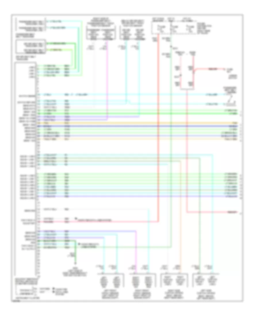
SUPPLEMENTAL RESTRAINTS Supplemental Restraints Wiring Diagram (1 of 2) for Dodge Challenger SRT-8 2008 List of elements for Supplemental Restraints Wiring Diagram (1 of 2) for Dodge Challenger SRT-8 2008: 99 (below driver seat) driver seat track position sensor (body, behind left rear seat) (right side of passenger seat) passenger seat track position sensor B(+) Base tpm Can bus (+) Can bus (-) Can c bus (+) Can c bus (-) Computer data lines system D64 D65 Driver seat belt tensioner Driver seat belt tensioner line 1 Driver seat belt tensioner line 2 Driver seat position sens data Driver seat position sens voltage F201 F500 Fuse Fuse 10a G200 (left side of dash, near breakout for ignition switch) Gnd Hot at all times Hot in run Hot in run or start Instrument cluster Left curtain squib 1 line 1 Left curtain squib 1 line 2 Left front impact sens gnd Left front impact sens sig Left front impact sensor (left front of engine compt) Left side curtain air bag Line 1 Line 2 Mirror switch Occupant restraint controller module (in center console) Passenger seat belt switch Passenger seat belt tensioner Passenger seat belt tensioner line 1 Passenger seat belt tensioner line 2 Passenger seat position sens data Passenger seat position sens voltage Power distribution center (right rear of trunk) Premium tpm R13 R130 R14 R140 R15 R150 R16 R160 R261 R262 R263 R264 R42 R43 R44 R45 R503 R504 R505 R506 R58 R60 R61 R62 R63 R64 R79 R80 R81 R82 Right curtain squib 1 line 1 Right curtain squib 1 line 2 Right front impact sens gnd Right front impact sens sig Right front impact sensor (right front of engine compt) Right side curtain air bag (body, behind right rear seat) Rly output Run/start S210 S310 Sens 1 gnd Sens 1 sig Sens data Sens gnd Sens sig Sens voltage Squib 1 line 1 Squib 1 line 2 Squib 2 line 1 Squib 2 line 2 Switch return Switch sense Tan Z939 Supplemental Restraints Wiring Diagram (2 of 2) for Dodge Challenger SRT-8 2008 List of elements for Supplemental Restraints Wiring Diagram (2 of 2) for Dodge Challenger SRT-8 2008: 45 (left "b" pillar) left side impact sensor 1 (left of dash, near breakout for cluster c3) g202 (right "b" pillar) right side impact sensor 1 (steering wheel) driver air bag squib 1 (steering wheel) driver air bag squib 2 A913 Can b bus (+) Can b bus (-) Can c bus (+) Can c bus (-) Computer data lines system D54 D55 D64 D65 Driver squib 1 line 1 Driver squib 1 line 2 Driver squib 2 line 1 Driver squib 2 line 2 Fused b(+) Gnd Left side impact pressure sens gnd Left side impact pressure sens sig Left side impact pressure sensor Left side impact sens 1 gnd Left side impact sens 1 sig Passenger air bag squib (right side of dash) Pressure R43 R45 R61 R63 Right side impact Right side impact pressure sens sig Right side impact pressure sensor Right side impact sens 1 gnd Right side impact sens 1 sig Sens gnd Squib 1 line 1 Squib 1 line 2 Squib 2 line 1 Squib 2 line 2 Steering control module (steering column) Tan Z910
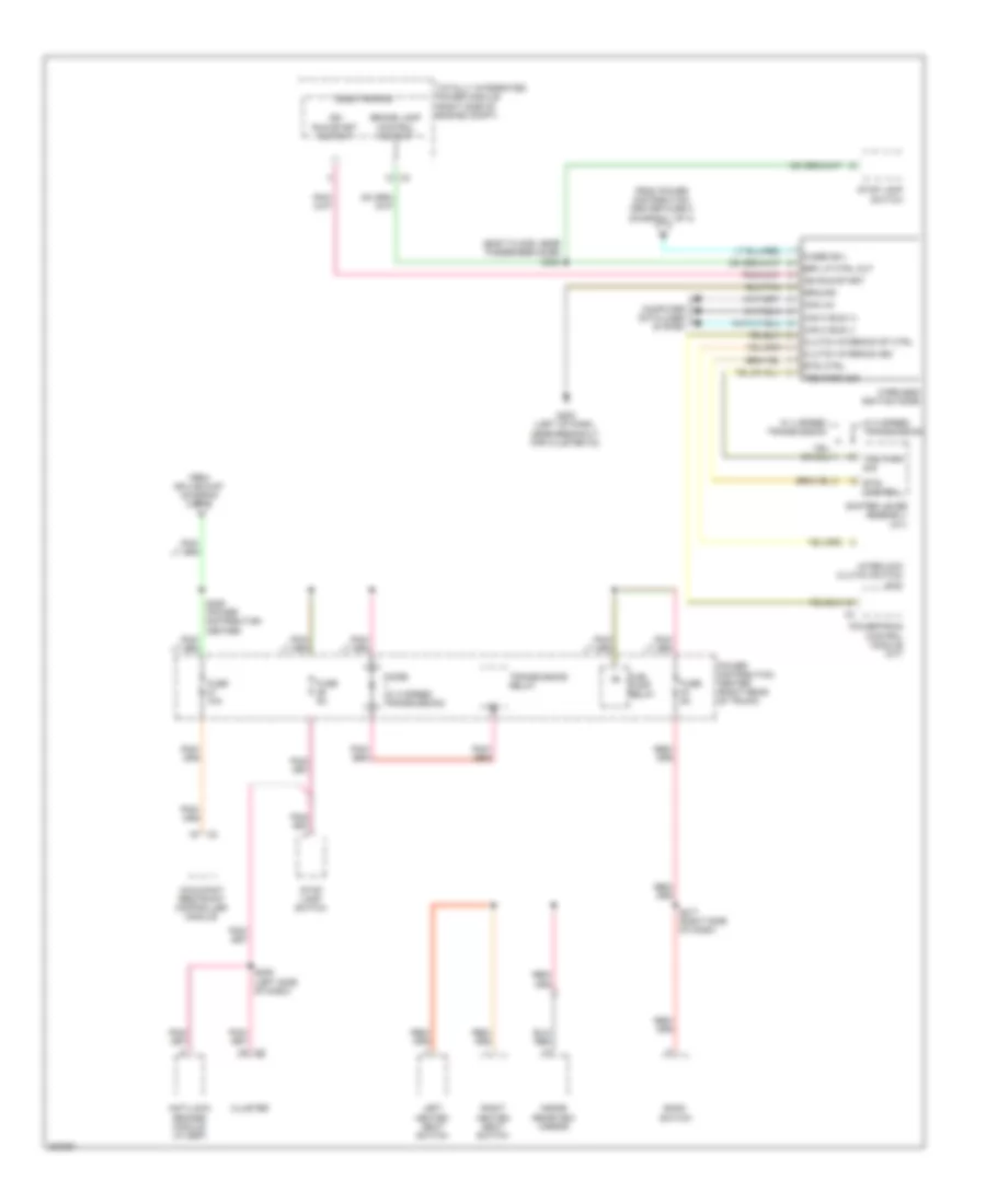
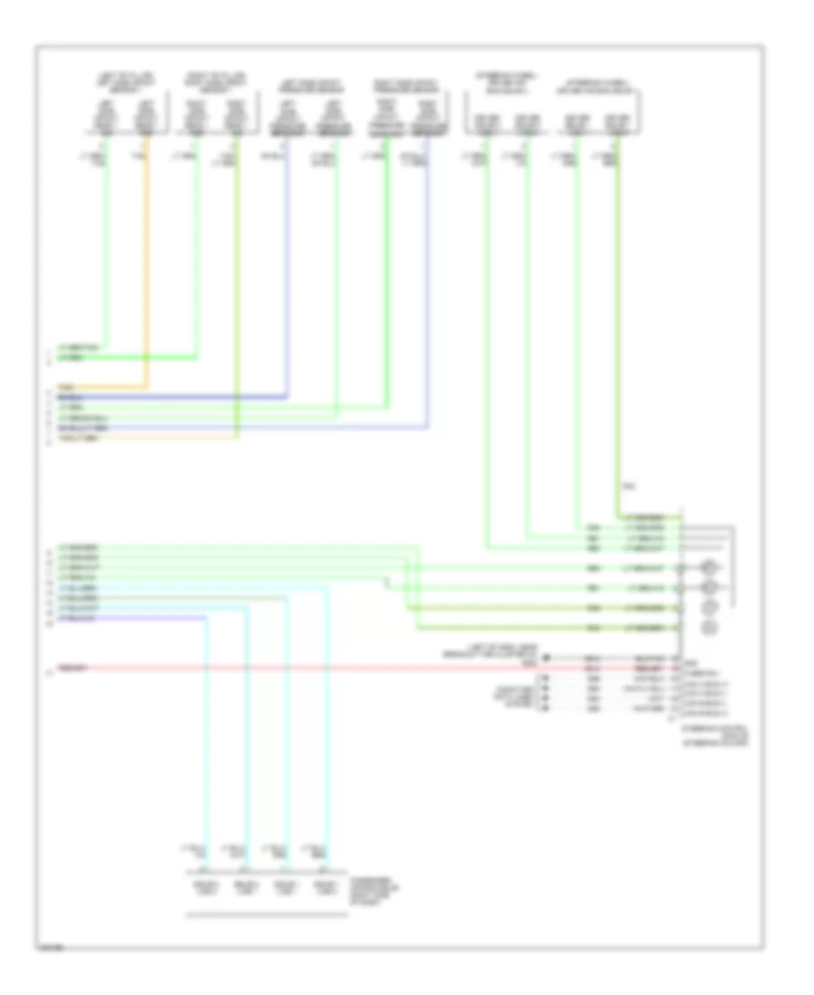
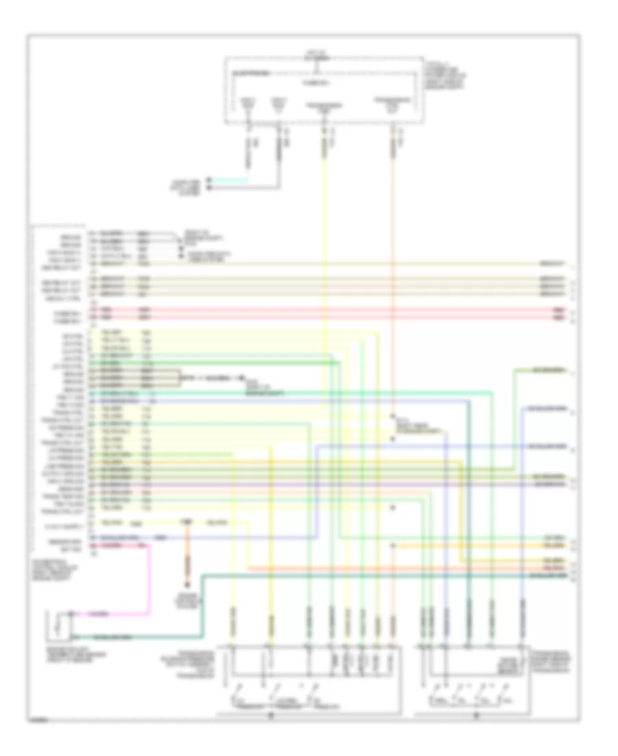
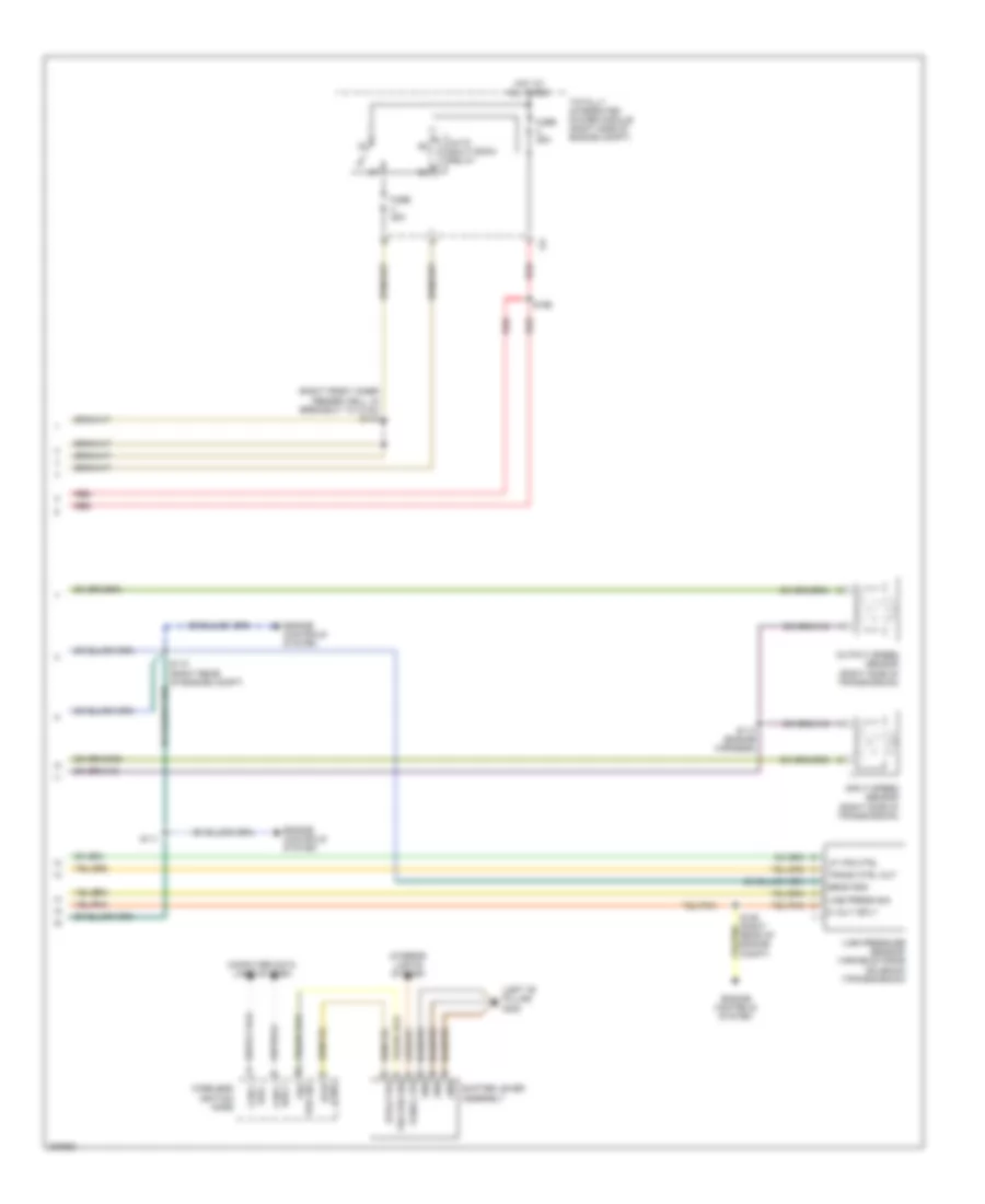
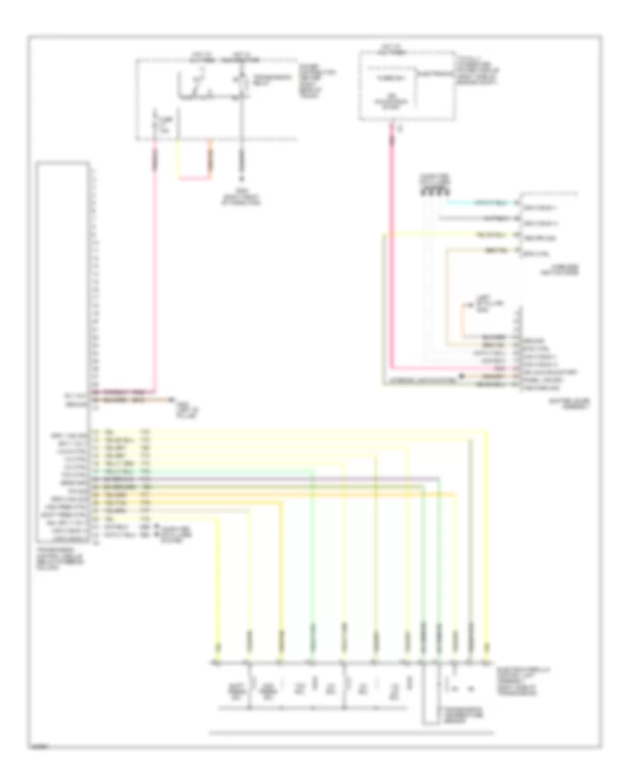
TRANSMISSION Transmission Wiring Diagram, 4 Speed (1 of 2) for Dodge Challenger SRT-8 2008 List of elements for Transmission Wiring Diagram, 4 Speed (1 of 2) for Dodge Challenger SRT-8 2008: 79 (right of engine compt) g102 2/4 ctrl 2/4 press sig 2/4 press sw 2/4 sol A209 Asd relay out Asd rly ctrl Can c bus (+) Can c bus (-) Computer data lines system D64 D65 Ect sig Electronics Engine controls system Engine coolant temperature sensor (front of engine) F342 F856 Fused b(+) G102 (right of engine compt) Ground Hot at all times Input spd sig K51 K900 L/r ctrl L/r press sig L/r sol Line press sig Low/rev press sw Lp vfs ctrl Nol Od ctrl Od press sig Od press sw Od sol Output spd sig P3l Powertrain control module (right rear of engine compt) Prnl Red S114 (right rear of engine compt) S115 S175 Sens gnd Sensor gnd T118 T13 T14 T15 T16 T19 T20 T38 T41 T42 T47 T50 T52 T54 T59 T60 Tempe- rature sensor Totally integrated power module (right side of engine compt) Trans ctrl Trans ctrl out Trans temp sig Transmission ctrl Transmission ctrl out Transmission range sensor (right side of transmission) Transmission solenoid/pressure switch assembly (top of transmission) Trs t1 sig Trs t3 sig Trs t41 sig Trs t42 sig Ud ctrl Ud sol Z904 Transmission Wiring Diagram, 4 Speed (2 of 2) for Dodge Challenger SRT-8 2008 List of elements for Transmission Wiring Diagram, 4 Speed (2 of 2) for Dodge Challenger SRT-8 2008: 31 (left "b" pillar) g300 (right front inner fender well, in breakout to c100) s143 5 volt sply Auto shut down relay Btsi ctrl Bus - can c Can c bus + Computer data lines system Engine controls system Fuse 25a Gnd Hot at all times Input speed sensor (right side of transmission) Interior lights system Line press sig Line pressure sensor/ variable force solenoid (transmission) Lp vfs ctrl Output speed sensor (right side of transmission) Panel lps Red S106 (right rear of engine compt) S110 (right rear of engine compt) S111 S113 (engine harness) S166 Sens gnd Shifter lever assembly Totally integrated power module (right side of engine compt) Trans ctrl out Trs prk sig Wireless ignition node Transmission Wiring Diagram, 5 Speed for Dodge Challenger SRT-8 2008 List of elements for Transmission Wiring Diagram, 5 Speed for Dodge Challenger SRT-8 2008: 64 (left "b" pillar) g300 1-2/ 4-5 sol 1-2/4-5 ctrl 2-3 ctrl 2-3 sol 3-4 ctrl 3-4 sol 87a Btsi ctrl Can c bus (+) Can c bus (-) Computer data lines system D64 D65 Electrohydraulic control unit assembly (right side of transmission) Electronics F942 Fuse 15a Fused b(+) G300 (left "b" pillar) G302 (right front of cargo pan) Ground Hot at all times Hot in run or start Ign unlk-run-start Ign unlock-run- start Interior lights system Mod pres ctrl Mod press sol P/n sig Panel lps drv Pnk Power distribution center (right rear of trunk) Rly out Sens gnd Shift pres ctrl Shift press sol Shifter lever assembly Sol sply volt Spd 1 (n2) sig Spd 2 (n3) sig Sply volt T13 T54 T60 T70 T71 T72 T73 T74 T75 T76 T77 T78 Tcc ctrl Tcc sol Totally integrated power module (right side of engine compt) Transmission control module (below steering column) Transmission relay Transmission temperature sensor Trs park sig Trs prk sig Wireless ignition node Z912
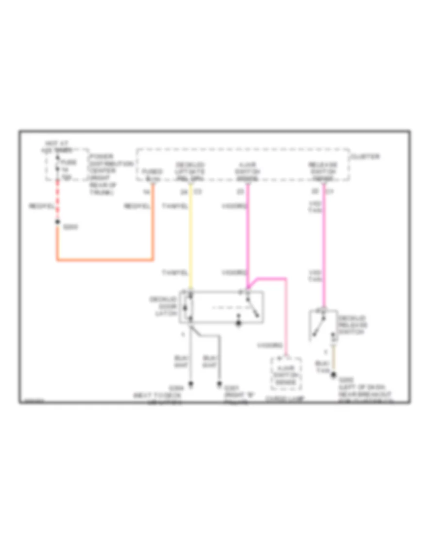
TRUNK, TAILGATE, FUEL DOOR Deck Lid Release Wiring Diagram for Dodge Challenger SRT-8 2008 List of elements for Deck Lid Release Wiring Diagram for Dodge Challenger SRT-8 2008: 15 Ajar switch sense Cargo lamp Cluster Decklid door latch Decklid release switch Decklid/ liftgate rel drv Fuse 10a Fused b (+) G202 (left of dash, near breakout for cluster c3) G301 (right "b" pillar) G304 (next to deck lid latch) Hot at all times Power distribution center (right rear of trunk) Release switch sense S200
WARNING SYSTEMS Chime Wiring Diagram for Dodge Challenger SRT-8 2008 List of elements for Chime Wiring Diagram for Dodge Challenger SRT-8 2008: 45 (deck lid latch) decklid door latch B20 Brake fluid level sensor (left rear of engine compt) Brake fluid level sig Can b bus (+) Can b bus (-) Can c bus (+) Can c bus(-) Cluster Computer data lines system D64 D65 Dk lid/lftgate ajar sw sens c1 Driver door module (middle of driver door) Driver seat belt switch Drv dr ajar sw sense Drv dr secondary ajar sw sense Drv seat belt sw sense Electronics Fuse 10a Fused b (+) G100 (left front of engine compt) G202 (left of dash, near breakout for cluster c3) G300 (left "b" pillar) G301 (right "b" pillar) Ground Headlamp sw mux Headlamp sw mux rtn Headlamp switch Hot at all times Interior lights system Left front door latch (driver door) Park brk sw sns Parking brake switch (base of parking brake) Pass dr ajar sw sense Pass dr secondary ajar sw sense Passenger door module (middle of passenger door) Power distribution center (right rear of trunk) Right front door latch (right front door) S200 S333 S355 S360 Tan Totally integrated power module (right side of engine compt) Tire Pressure Monitoring Wiring Diagram for Dodge Challenger SRT-8 2008 List of elements for Tire Pressure Monitoring Wiring Diagram for Dodge Challenger SRT-8 2008: 15 A913 Can c bus (+) Can c bus (-) Computer data lines system D64 D65 Fuse 10a Fused b(+) G301 (right "b" pillar) Gnd Hot at all times Power distribution center (right rear of trunk) S310 Tire pressure module Z911
WIPER/WASHER Wiper/Washer Wiring Diagram for Dodge Challenger SRT-8 2008 List of elements for Wiper/Washer Wiring Diagram for Dodge Challenger SRT-8 2008: 38 (right of engine compt) g102 (right side of engine compt) totally integrated power module 0 off 1 intermittent 2 intermittent 3 intermittent 4 intermittent 5 intermittent 6 intermittent 7 low 8 high 9 mist 10 wash 87a Can b bus (+) Can b bus (-) Cluster Computer data lines system D54 D55 Electronics Front washer fluid level sensor (right front of engine compt) Front washer pmp mtr ctrl Front wiper motor (left rear of engine compt) Front wiper switch Fuse 10a Fuse 30a Fused b (+) Fused b(+) G100 (left front of engine compt) G101 (right front of engine compt) G202 (left of dash, near breakout for cluster c3) Gnd Hot at all times Mirror switch Park sw sen Power distribution center (right rear of trunk) Processor Red/ a913 Rly ctrl S310 (premium tpm) Steering control module (steering column) W10 Washer fluid lvl sw sen Windshield washer pump (right front of engine compt) Wiper high/low relay Wiper on/off relay Wiper on/off relay control