AIR CONDITIONING
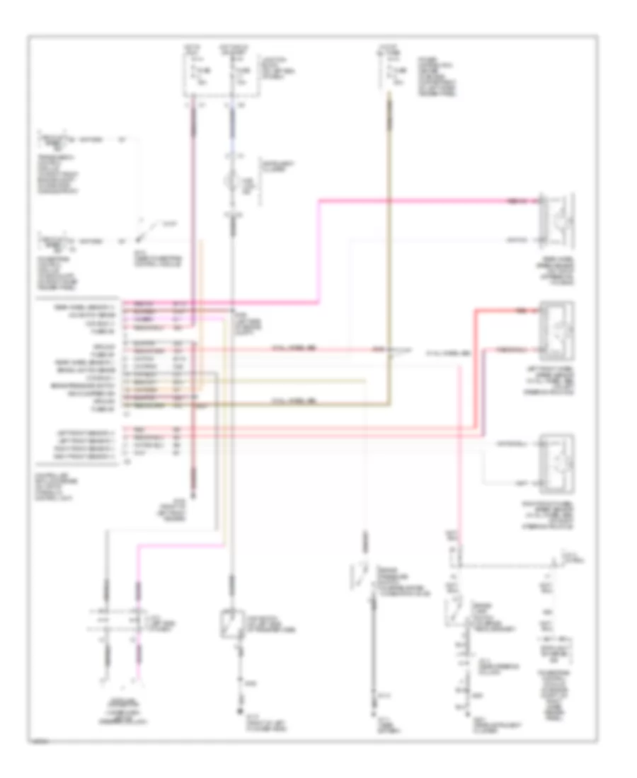
Heater Wiring Diagram for Dodge Dakota 2000

List of elements for Heater Wiring Diagram for Dodge Dakota 2000:
- (near battery) g111
- (next to breakout for chassis harness) s113
- (right side of dash) g201
- 87a
- Blower motor (right side of hvac housing)
- Blower motor relay (inside of glove box opening, next to energy absorbing bracket)
- Blower motor relay control
- Blower resistor block (in firewall plenum panel, below right side of windshield)
- C90
- Defrost
- Fan switch
- Fuse 10a
- Fuse 40a
- Fuse d 10a
- Fuse/relay block (mounted on junction block, left end of dash)
- Heat
- Heater control
- Hevac relay (in power distribution center)
- High
- High/low
- Hot at all times
- Hot in run
- Hot in run or start
- Illum
- Interior lights system
- Junction block (on left end of dash)
- Low
- Med 1
- Med 2
- Mode switch
- Off
- Power distribution center (in engine compartment, on left inner fender panel)
- Powertrain control module (in engine compartment, on right inner fender panel)
- S221 (right side of dash)
- S258 (near instrument cluster connector c2 breakout)
- Tan
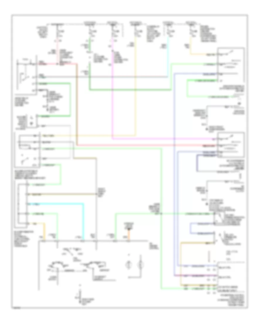
Manual A/C Wiring Diagram for Dodge Dakota 2000
List of elements for Manual A/C Wiring Diagram for Dodge Dakota 2000:
- (near battery) g111
- (near breakout for chassis harness) s113
- (near breakout for cigar lighter) s217
- (near instrument cluster connector c2 breakout) s258
- (near right headlamp breakout) s109
- (rear of engine) s108
- (right front inner fender) g101
- (right side of dash) g201
- (right side of dash) s221
- (top rear of valve cover) g114 (2.5l) g119 (3.9l, 4.7l & 5.9l) (right front of engine)
- 2.5l
- 3.9l, 4.7l & 5.9l
- 87a
- A/c compressor clutch
- A/c compressor clutch relay (in power distribution center)
- A/c heater control
- A/c high pressure switch (on discharge line, near a/c compressor)
- A/c low pressure switch (on accumulator)
- A/c select input
- A/c select switch
- A/c switch sense
- Blower motor (right side of hvac housing)
- Blower motor relay (inside of glove box opening, next to energy absorbing bracket)
- Blower resistor block (in firewall plenum panel, below right side of windshield)
- C13
- C20
- C27
- C90
- Defrost
- Fan switch
- Fuse 10a
- Fuse 20a
- Fuse 30a
- Fuse 40a
- Fuse d 10a
- Fuse/relay block (mounted on junction block, left end of dash)
- Heat
- Hevac relay (in power distribution center)
- Hi/lo a/c
- High
- Hot at all times
- Hot in run
- Hot in run or start
- Interior lights system
- J/c 1 (in power distribution center)
- Junction block (on left end of dash)
- Low
- Max
- Med 1
- Med 2
- Mode switch
- Off
- Power distribution center (in engine compartment, on left inner fender panel)
- Powertrain control module (pcm) (in engine compartment, on right inner fender panel)
- Radiator fan motor
- Radiator fan relay (in power distribution center)
- Red/ tan
- Red/tan
- Relay ctrl
- S159 (near power distribution center)
- Tan
ANTI-LOCK BRAKES
Anti-lock Brake Wiring Diagrams for Dodge Dakota 2000
List of elements for Anti-lock Brake Wiring Diagrams for Dodge Dakota 2000:
- (under dash, left of steering column)
- 4wd lock ind
- 4wd switch (on left side of transfer case)
- 4x4 switch sense
- A10
- A20
- B10
- B113
- B114
- Brake lamp switch (on brake pedal bracket)
- Brake light sw sense
- Brake pressure switch
- Brake pressure switch (in brake system combination valve)
- Ccd bus (+)
- Ccd bus (-)
- Controller anti-lock brake (on top of hydraulic control unit)
- Data link connector
- Fuse 10a
- Fuse 15a
- Fuse 40a
- Fused b+
- G100 (front of left front fender)
- G107
- G110 (front of left cylinder head)
- G111 (near battery)
- G201 (near instrument cluster)
- Ground
- Hot at all times
- Hot in run
- Hot in run or start
- Instrument cluster
- J/c 2 (in pdc)
- J/c 3 (left side of dash)
- J/c 4 (near steering column)
- Junction block (on left end of dash)
- K29
- Left front sensor (+)
- Left front sensor (-)
- Left front wheel speed sensor (w/ all wheel abs) (on left steering knuckle)
- Power distribution center (in engine compartment, on left inner fender panel)
- Powertrain control module (in eng compt, on right inner fender panel)
- Powertrain control module (in engine compt, on right inner fender panel)
- Rear wheel sensor (+)
- Rear wheel sensor (-)
- Rear wheel speed sensor (on top of differential housing)
- Red
- Right front sensor (+)
- Right front sensor (-)
- Right front wheel speed sensor (w/ all wheel abs) (on right steering knuckle)
- S108
- S113
- S126
- S127
- S156 (left side of engine compt)
- S174 (near powertrain control module)
- S201
- Stoplight sw sense sig
- Transmission control module (in right front engine compt, on radiator core support)
- Vehicle speed sig
- W/ a/t
- W/ all wheel abs
- Z22
ANTI-THEFT
Anti-theft Wiring Diagram (1 of 2) for Dodge Dakota 2000
List of elements for Anti-theft Wiring Diagram (1 of 2) for Dodge Dakota 2000:
- (right side of dash) g201
- 4.7l
- A base
- Ccd bus (+)
- Ccd bus (-)
- Central timer module (behind right side of dash)
- Data link connector (under dash, left of steering column)
- Disarm sense
- Door ajar sense
- Door lk sense
- Door locks system
- Door unlk sense
- F12
- F35
- Fuse 10a
- Fuse 20a
- Fused b(+)
- Fused ign
- G101 (right front inner fender)
- G16
- G50
- G69
- G73
- G74
- Ground
- Hdlmp relay ctrl
- Headlights system (headlamp flasher relay)
- High note horn (right front fender)
- Horn relay
- Horn relay ctrl
- Horns system (horn switch)
- Hot at all times
- Hot in run or acc
- Hot in run or start
- Instrument cluster
- J/c 3 (left side of dash)
- Junction block (on left end of dash)
- Low note horn (right front fender)
- Of engine compt) s125
- P37
- P38
- Powertrain control module (in engine compt, on right inner fender panel)
- Premium
- Red
- S109
- S170
- S189 (4.7l) (near right headlamp breakout)
- S190 (4.7l) (near right headlamp breakout)
- S218 (right side of dash)
- S225
- Tan/red
- Transmission control module (in right front engine compt, on radiator core support)
- Vtss ind ctrl
- Vtss lamp
Anti-theft Wiring Diagram (2 of 2) for Dodge Dakota 2000
List of elements for Anti-theft Wiring Diagram (2 of 2) for Dodge Dakota 2000:
- (right side of dash) g201
- 2 door
- 4 door
- Base
- Driver door ajar switch
- Driver door key cylinder switch
- Driver door lock motor/ ajar switch
- Left door sill)
- Left rear door ajar switch
- Left rear door lock motor/ ajar switch
- Nca
- Other
- Passenger door ajar switch
- Passenger door key cylinder switch
- Passenger door lock motor/ ajar switch
- Premium
- Right rear door ajar switch
- Right rear door lock motor/ ajar switch
- S344
- S345 (left door sill)
- S347
- S349
- Tan/ red
- Tan/red
- Vtss
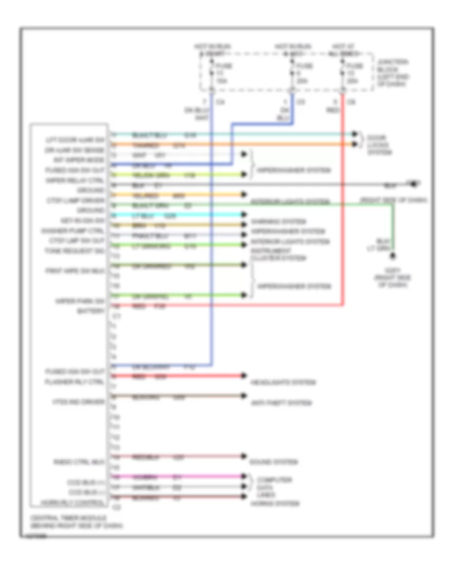
BODY COMPUTER
Body Computer Wiring Diagrams, Base for Dodge Dakota 2000
List of elements for Body Computer Wiring Diagrams, Base for Dodge Dakota 2000:
- (right side of dash)
- Anti-theft system
- Battery
- Ccd bus (+)
- Ccd bus (-)
- Central timer module (behind right side of dash)
- Computer data lines
- Ctsy lamp driver
- Ctsy lmp sw out
- Door locks system
- Dr ajar sw sense
- F12
- F35
- Flasher rly ctrl
- Frnt wipe sw mux
- Fuse 10a
- Fuse 20a
- Fused ign sw out
- G10
- G16
- G201
- G201 (right side of dash)
- G26
- G50
- G69
- G74
- Ground
- Headlights system
- Horn rly control
- Horns system
- Hot at all times
- Hot in run & acc
- Hot in run & start
- Instrument cluster system
- Int wiper mode
- Interior lights system
- Junction block (left end of dash)
- Key-in ign sw
- Lft door ajar sw
- M11
- M50
- Radio ctrl mux
- Red
- Sound system
- Tan/red
- Tone request sig
- V10
- V18
- V51
- V52
- Vtss ind driver
- Warning system
- Washer pump ctrl
- Wiper park sw
- Wiper relay ctrl
- Wiper/washer system
- X20
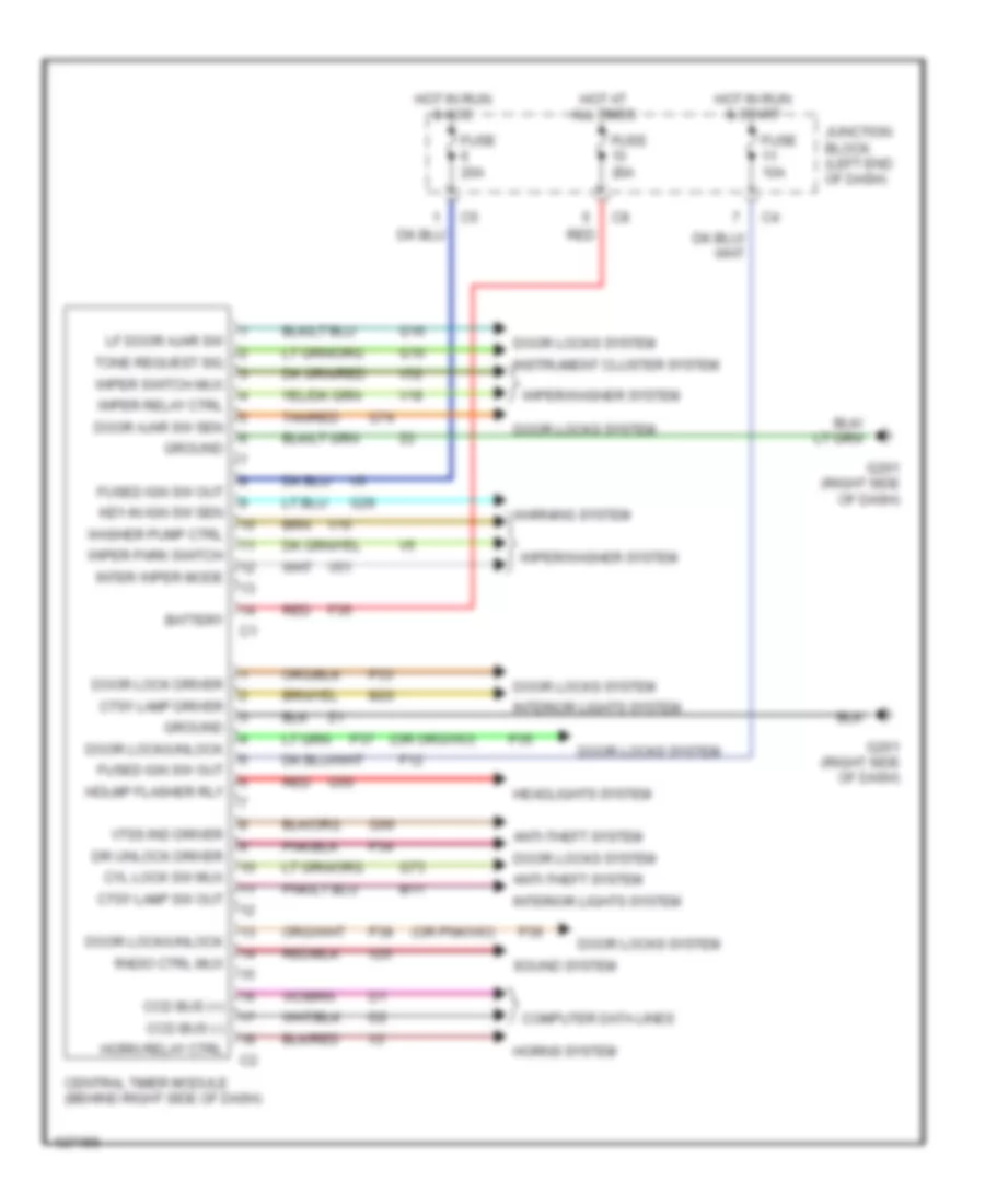
Body Computer Wiring Diagrams, Premium Model for Dodge Dakota 2000
List of elements for Body Computer Wiring Diagrams, Premium Model for Dodge Dakota 2000:
- Anti-theft system
- Battery
- Ccd bus (+)
- Ccd bus (-)
- Central timer module (behind right side of dash)
- Computer data lines
- Ctsy lamp driver
- Ctsy lamp sw out
- Cyl lock sw mux
- Door ajar sw sen
- Door lock driver
- Door lock/unlock
- Door locks system
- Dr unlock driver
- F12
- F35
- Fuse 10a
- Fuse 20a
- Fused ign sw out
- G10
- G16
- G201 (right side of dash)
- G26
- G50
- G69
- G73
- G74
- Ground
- Hdlmp flasher rly
- Headlights system
- Horn relay ctrl
- Horns system
- Hot at all times
- Hot in run & acc
- Hot in run & start
- Instrument cluster system
- Inter wiper mode
- Interior lights system
- Junction block (left end of dash)
- Key-in ign sw sen
- Lf door ajar sw
- M11
- M20
- P33
- P34
- P35
- P36
- P37
- P38
- Radio ctrl mux
- Red
- Sound system
- Tan/red
- Tone request sig
- V10
- V18
- V51
- V52
- Vtss ind driver
- Warning system
- Washer pump ctrl
- Wiper park switch
- Wiper relay ctrl
- Wiper switch mux
- Wiper/washer system
- X20
COMPUTER DATA LINES
Computer Data Lines for Dodge Dakota 2000
List of elements for Computer Data Lines for Dodge Dakota 2000:
- (near right headlamp breakout) s190
- Air bag control module (on floor panel transmission tunnel)
- Ccd bus (+)
- Ccd bus (-)
- Central timer module (behind right side of dash)
- Controller anti-lock brake (on top of hydraulic control unit)
- D20
- D21
- D22
- Data link connector (left of steering column)
- Fuse 15a
- G119 (front of right cylinder head)
- G202 (left side of dash)
- Hot at all times
- Instrument cluster
- J/c 3 (left side of dash)
- J/c 4 (left side of dash)
- Junction block (left end of dash)
- Overhead console
- Pnk
- Powertrain control module (right front inner fender panel)
- Radio
- S105
- S189 (near right headlamp breakout)
- S191 (near right headlamp breakout)
- S201
- Sci receive
- Sci transmit
- Transmission control module (on radiator core right support)
- W/ 4.7l only
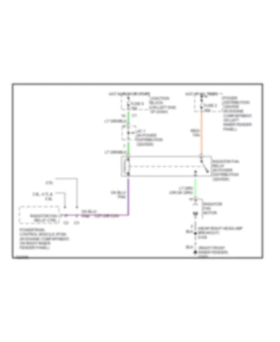
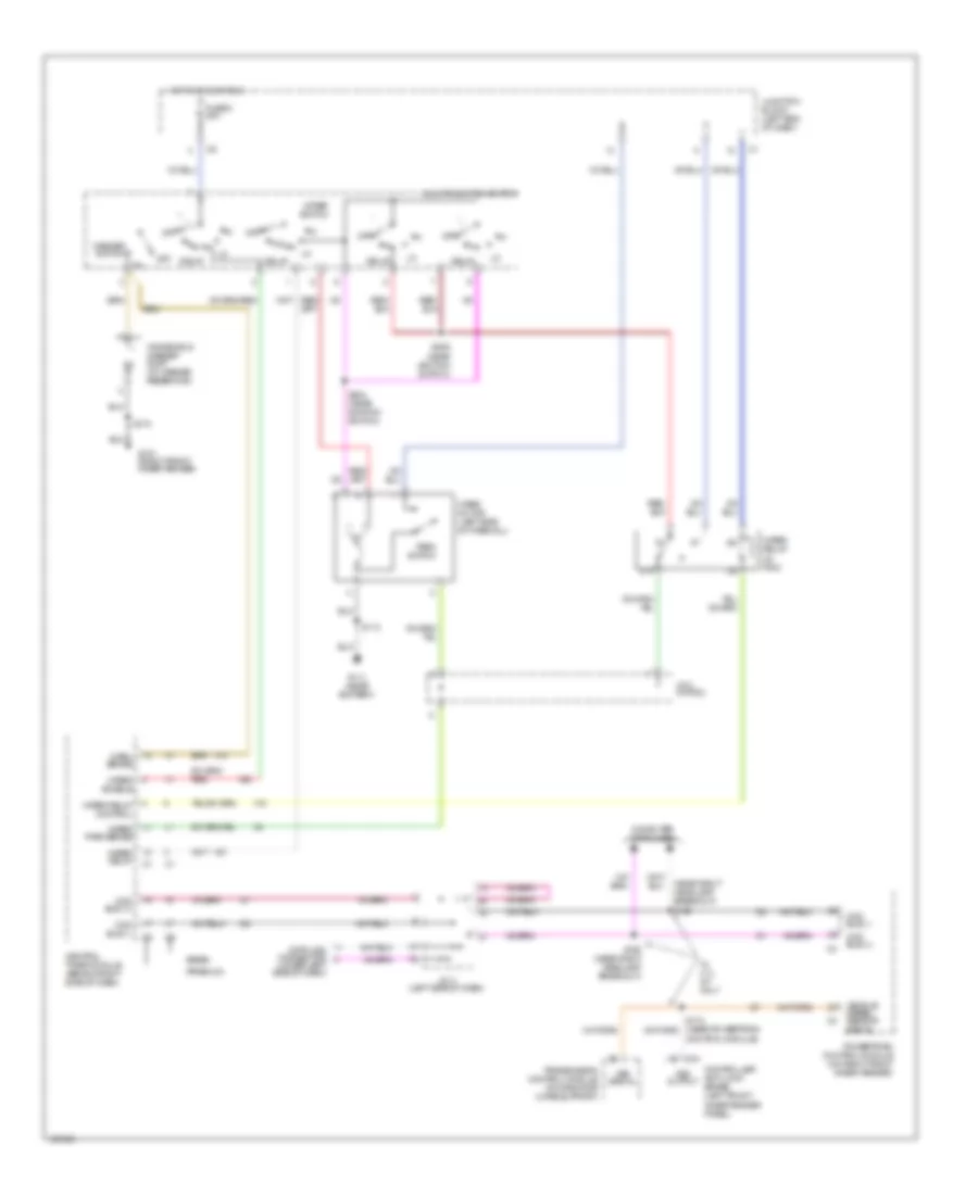
COOLING FAN
Cooling Fan Wiring Diagram for Dodge Dakota 2000
List of elements for Cooling Fan Wiring Diagram for Dodge Dakota 2000:
- (near right headlamp breakout) s109
- (right front inner fender) g101
- 2.5l
- 3.9l, 4.7l & 5.9l
- C27 (or c24)
- Fuse 2 30a
- Fuse 9 10a
- Hot at all times
- Hot in run or start
- J/c 1 (in power distribution center)
- Junction block (on left end of dash)
- Power distribution center (in engine compartment, on left inner fender panel)
- Powertrain control module (pcm) (in engine compartment, on right inner fender panel)
- Radiator fan motor
- Radiator fan relay (in power distribution center)
- Radiator fan relay ctrl
- Red/ tan
CRUISE CONTROL
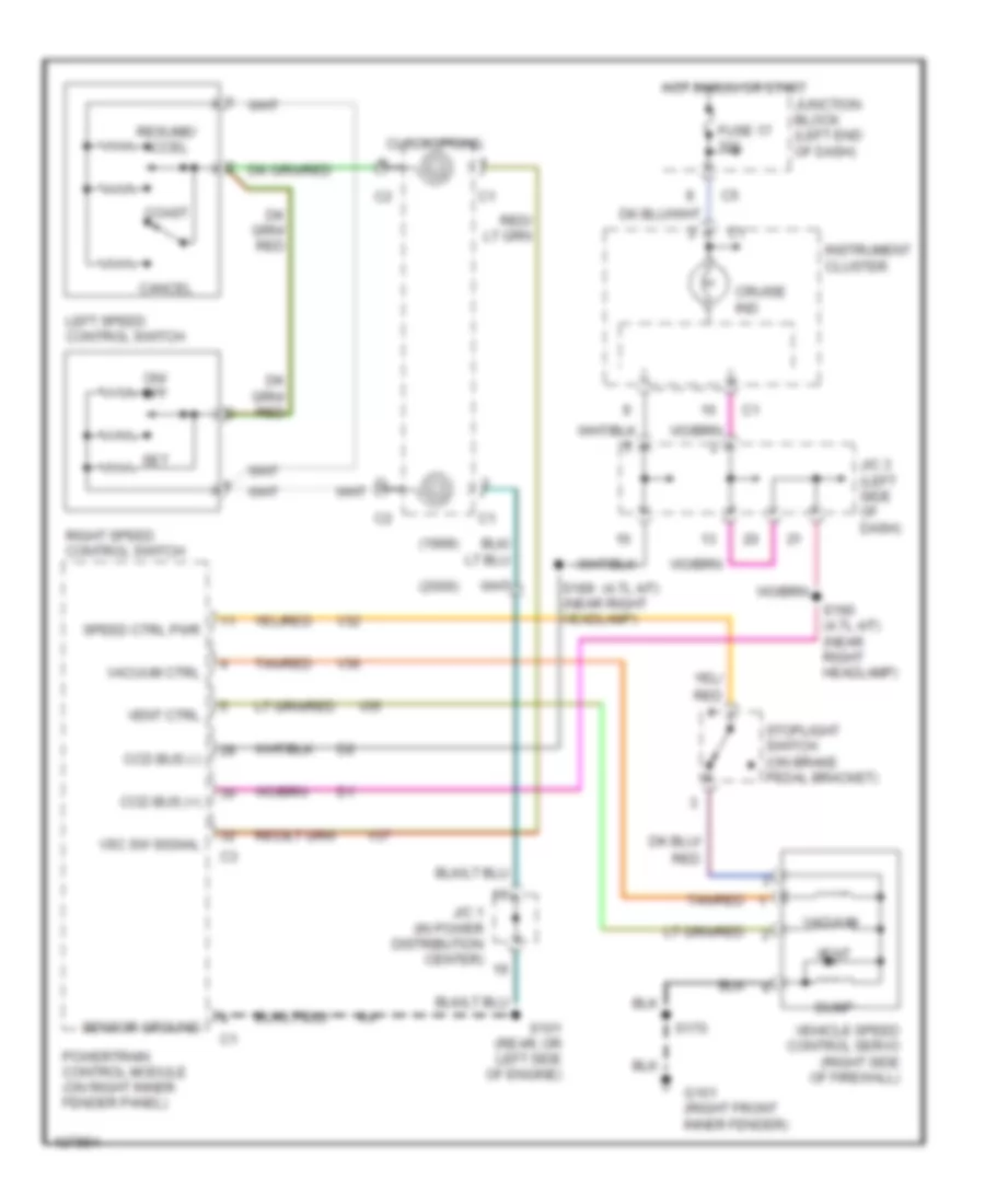
Cruise Control Wiring Diagram for Dodge Dakota 2000
List of elements for Cruise Control Wiring Diagram for Dodge Dakota 2000:
- (1999)
- (2000)
- (4.7l a/t)
- Cancel
- Ccd bus (+)
- Ccd bus (-)
- Clockspring
- Coast
- Cruise ind
- Dump
- Fuse 17 10a
- G101 (right front inner fender)
- Hot in run or start
- Instrument cluster
- J/c 1 (in power distribution center)
- J/c 3 (left side of dash)
- Junction block (left end of dash)
- Left speed control switch
- On/ off
- Powertrain control module (on right inner fender panel)
- Red
- Resume/ accel
- Right speed control switch
- S101 (rear, or left side of engine)
- S170
- S189 (near right headlamp)
- S190 (4.7l a/t) (near right headlamp)
- Sensor ground
- Set
- Speed ctrl pwr
- Stoplight switch (on brake pedal bracket)
- Tan/red
- V32
- V35
- V36
- V37
- Vacuum
- Vacuum ctrl
- Vehicle speed control servo (right side of firewall)
- Vent
- Vent ctrl
- Vsc sw signal
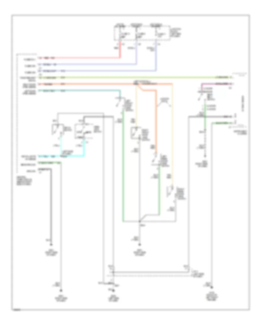
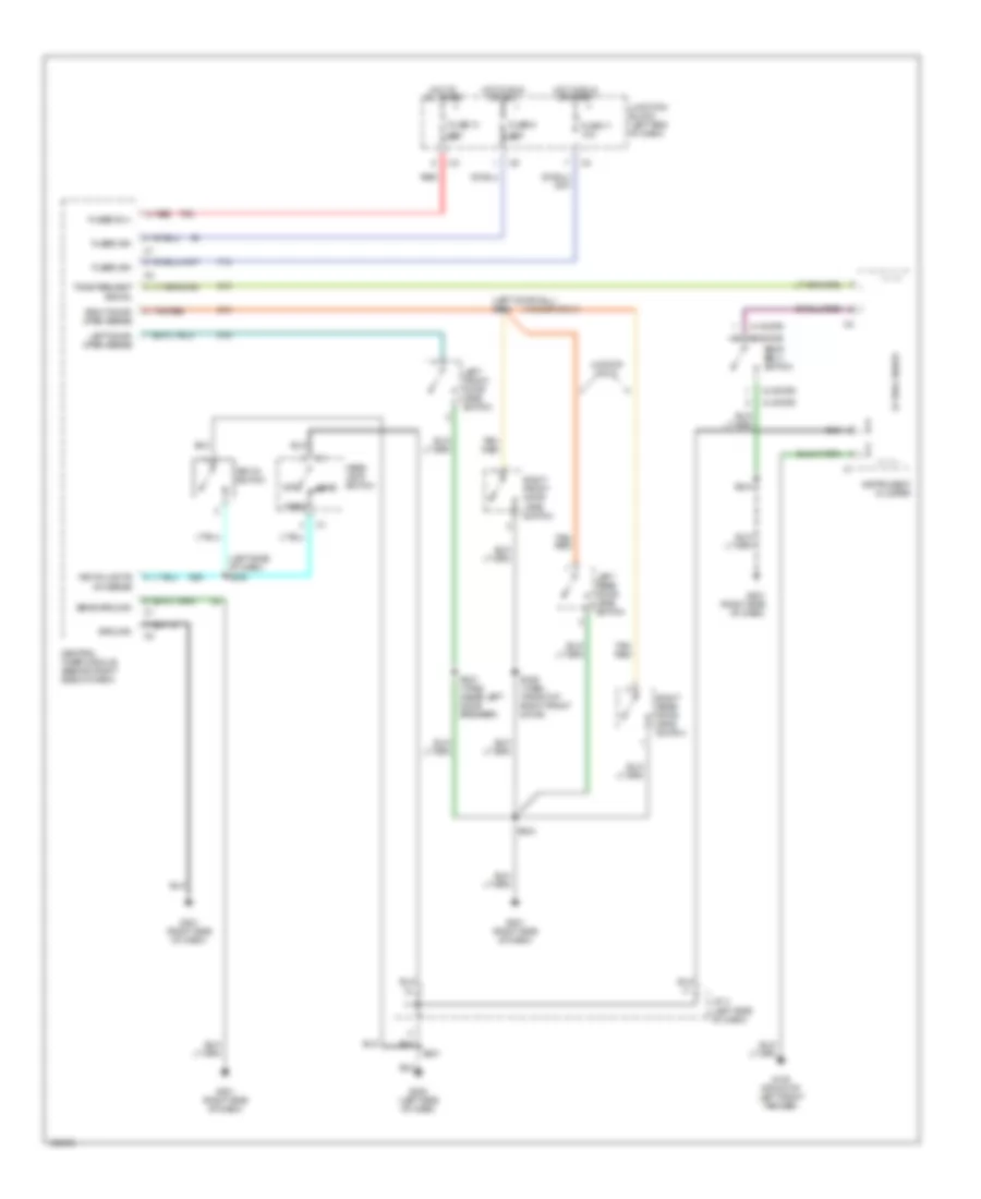
DEFOGGERS
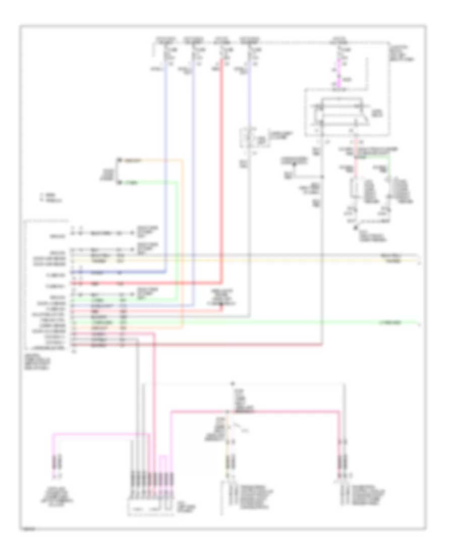
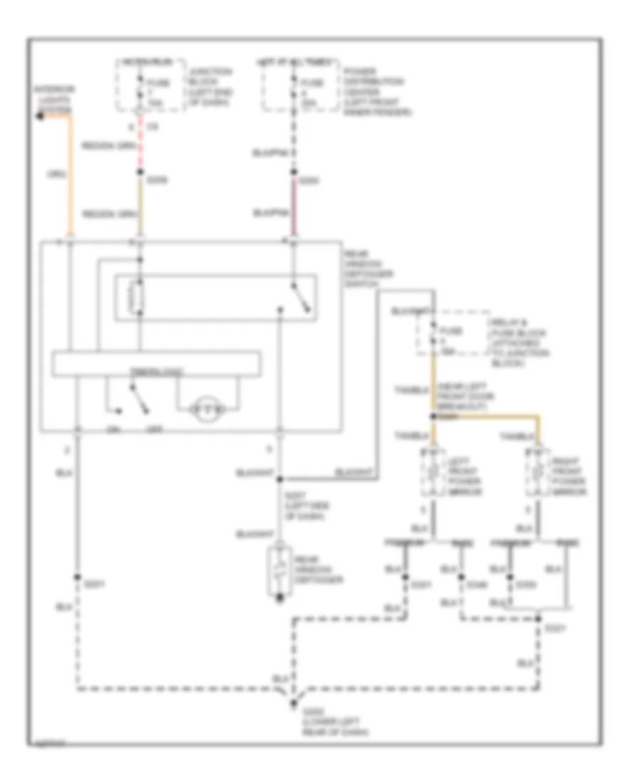
Defogger Wiring Diagram for Dodge Dakota 2000
List of elements for Defogger Wiring Diagram for Dodge Dakota 2000:
- Base
- Fuse 10a
- Fuse 20a
- Fuse a 10a
- G202 (lower left rear of dash)
- Hot at all times
- Hot in run
- Interior lights system
- Junction block (left end of dash)
- Left front power mirror
- Off
- Power distribution center (left front inner fender)
- Premium
- Rear window defogger
- Rear window defogger switch
- Relay & fuse block (attached to junction block)
- Right front power mirror
- S201
- S257 (left side of dash)
- S258
- S260
- S301
- S321
- S348
- S350
- Timer/logic
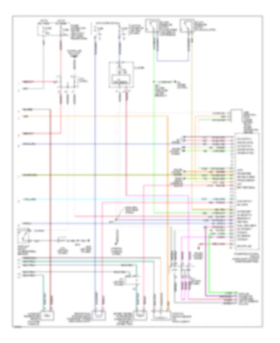
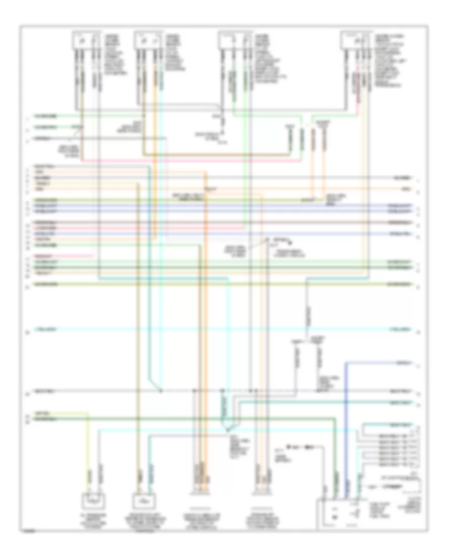
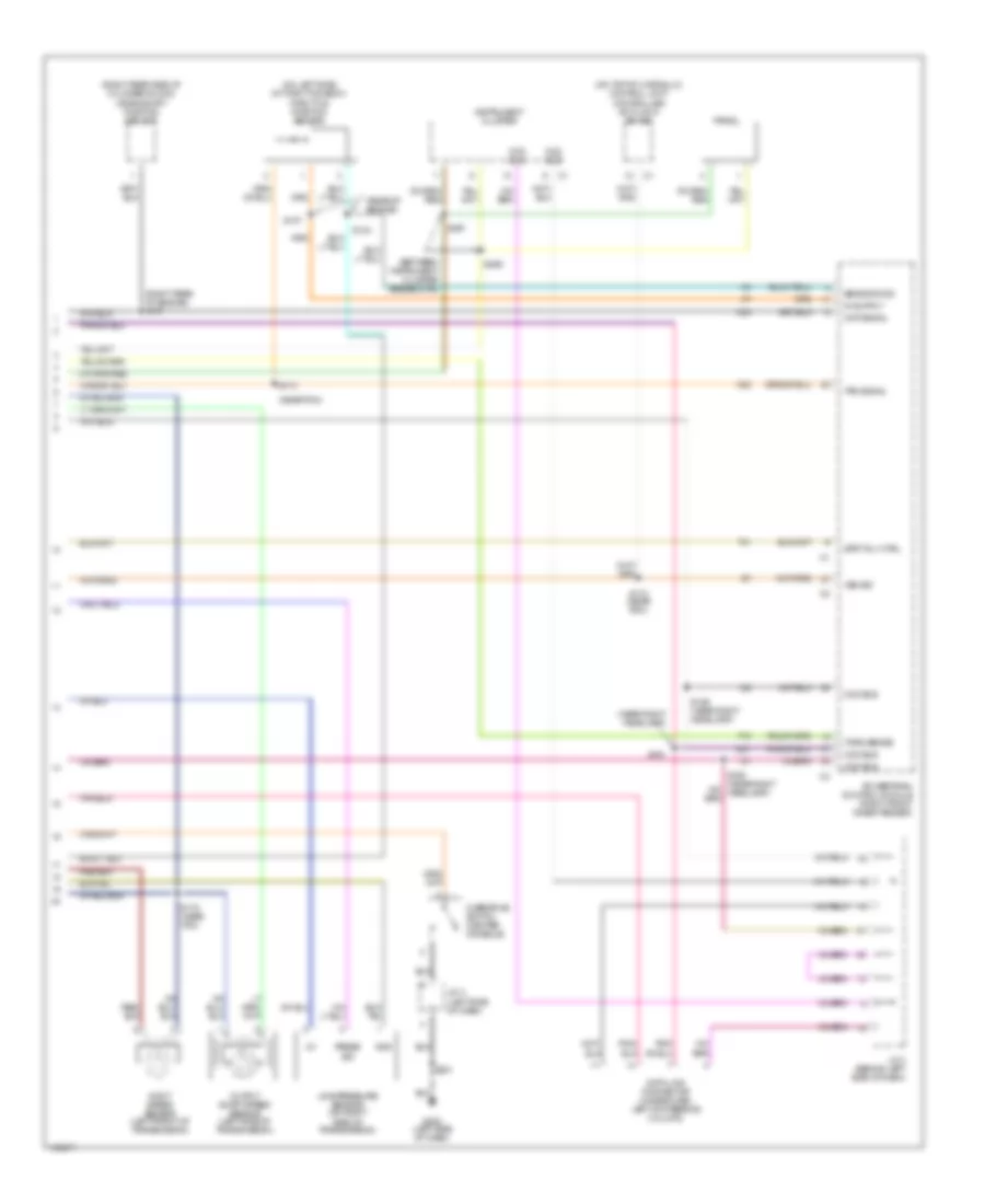
ENGINE PERFORMANCE
2.5L
2.5L, Engine Performance Wiring Diagrams (1 of 3) for Dodge Dakota 2000
List of elements for 2.5L, Engine Performance Wiring Diagrams (1 of 3) for Dodge Dakota 2000:
- (in distributor)
- (rear of right front fender)
- (top left rear of eng)
- A14
- Anti-lock brakes system
- Automatic shutdown relay
- Cam pos sns
- Camshaft position sensor
- Coil 1 driver
- Crnk pos sns
- Distributor
- Dn ho2s in
- Ect sens in
- F18
- Fuel injectors
- Fuel pump relay
- Fused b(+)
- G105
- G114
- G60
- Gen field drv
- Ground
- Iat sens in
- Idle air 1
- Idle air 2
- Idle air 3
- Idle air 4
- Ign power
- Ignition coil (near distributor)
- Inj 1 driver
- Inj 2 driver
- Inj 3 driver
- Inj 4 driver
- J/c 1 (left end of dash)
- J/c 2 (in pdc)
- K10
- K11
- K12
- K13
- K14
- K141
- K19
- K20
- K21
- K22
- K24
- K30
- K341
- K39
- K40
- K44
- K59
- K60
- Map sens in
- Nca
- Oil pres sns
- Oil pressure sensor (on right side of eng block, near distributor)
- Pnk
- Power distribution center (eng compt, left inner fender panel)
- Power steering pressure switch (in power steering pressure line)
- Powertrain control module (in eng compt, on right inner fender panel)
- Psp sw
- S105
- S106 (eng harn, rear of eng)
- S108
- Sensor grd
- Starting/ charging system
- Tan
- Tps sens in
- Trans ctrl rly
- Transmissions system
- Up ho2s in
- Vss in
- Z12
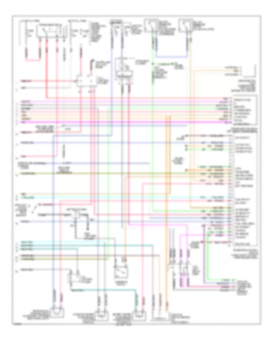
2.5L, Engine Performance Wiring Diagrams (2 of 3) for Dodge Dakota 2000
List of elements for 2.5L, Engine Performance Wiring Diagrams (2 of 3) for Dodge Dakota 2000:
- (eng harn, rear of eng)
- (near battery)
- (top left rear of eng)
- Crankshaft position sensor (in transmission bellhousing, at left rear side of eng)
- Engine coolant temperature sensor (on thermostat housing)
- Fuel pump module (top of fuel tank)
- Fuse 10a
- Fuse a 15a
- G111
- G114
- Heated oxygen sensor (downstream) (near oulet end of catalyic converter)
- Heated oxygen sensor (upstream) (near left side of eng, in exhaust downpipe)
- Hot in run & start
- Idle air control motor (on throttle body)
- Junction connector (left end of dash)
- Manifold absolute pressure sensor (on side of throttle body)
- Nca
- Power distribution center (eng compt, left inner fender panel)
- S101 (eng harn, near beakout for inj 3)
- S103
- S107
- S108
- S172
- S306
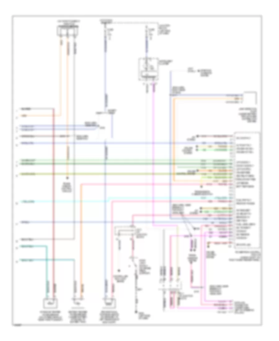
2.5L, Engine Performance Wiring Diagrams (3 of 3) for Dodge Dakota 2000
List of elements for 2.5L, Engine Performance Wiring Diagrams (3 of 3) for Dodge Dakota 2000:
- (eng harn, right rear of eng)
- 10a
- A/c comp rly
- A/c heater control
- A/c high pressure switch (on discharge line, near a/c compressor)
- A/c low pressure switch (on accumulator)
- A/c request
- A/c select in
- A/c system
- A142
- Asd relay sens
- Auto sht rly
- Batt temp sens
- Battery temper- ature sensor (under battery, attached to battery tray)
- Brake sw in
- C13
- C20
- C27
- C90
- Ccd bus +
- Ccd bus -
- Cluster
- Controller anti-lock brake
- Cruise control system
- Cruise feed
- Cruise vac sol
- Cruise vnt sol
- D20
- D21
- Data link connector (under dash, left of steering column)
- Fuel level sens
- Fuel pmp rly
- Fuse
- Fuse 20a
- Fuse 30a
- G202 (left side of dash)
- Gen field
- Hot at all times
- Hot in start or run
- I/o
- Intake air temperature sensor (on intake manifold)
- J/c 1 (left end of dash)
- J/c 2 (in pdc)
- J/c 3 (left end of dash)
- J/c 4 (left end of dash)
- Junction connector (left end of dash)
- K106
- K107
- K118
- K125
- K151
- K29
- K51
- K52
- Ldp
- Ldpa
- Leak detection pump (under battery tray & power distribution center)
- Mil ind.
- Power distribution center (eng compt, left inner fender panel)
- Powertrain control module (in eng compt, on right inner fender panel)
- Processor
- Proportional purge solenoid (on bracket, at rear side of eng compt)
- Rad fan cntrl
- S171
- S216
- S217 (i/p harn, near cigar lighter breakout)
- Sci receive
- Sci transmit
- Sol drvr
- Sp cntrl sig
- Starting/ charging system
- Stoplight switch (on brake pedal bracket)
- T10
- Tan/red
- Throttle position sensor (on throtlle body)
- Trans overdrv
- Trans- mission overdrive switch
- V32
- V35
- V36
- V37
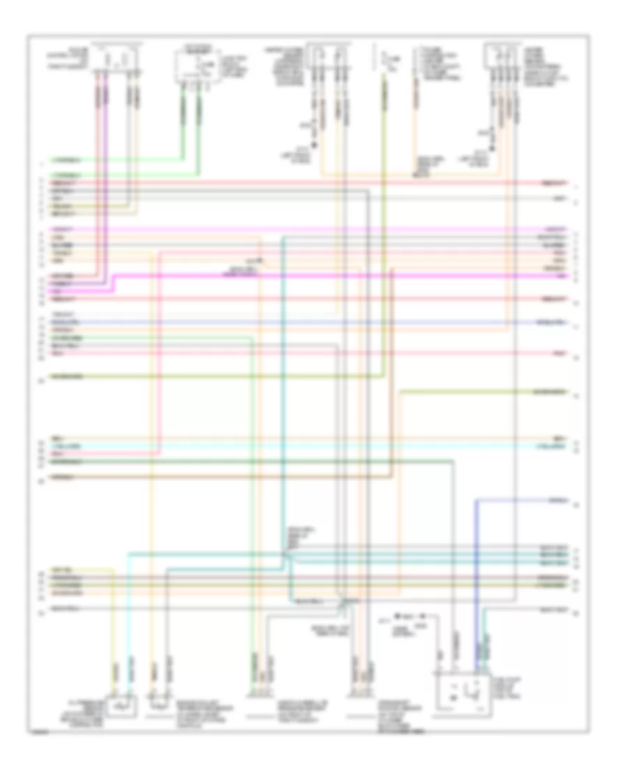
3.9L
3.9L, Engine Performance Wiring Diagrams (1 of 3) for Dodge Dakota 2000
List of elements for 3.9L, Engine Performance Wiring Diagrams (1 of 3) for Dodge Dakota 2000:
- (eng harn, near inj 4) s106
- (in distributor)
- 3-4 shift
- 5.9l only
- A/t sen sig
- A/t temp sig
- A14
- Anti-lock brakes system
- Automatic shutdown relay
- C24
- Cam pos sns
- Camshaft position sensor
- Coil driver
- Cooling fans system
- Crnk pos sns
- Distributor (3.9l)
- Distributor (5.9l)
- Dn ho2s in
- Ect sens in
- F18
- Fuel injectors
- Fuel pump relay
- Fused b(+)
- G105 (rear of right front fender)
- G60
- Gen field drv
- Ground
- Iat sens in
- Idle air 1
- Idle air 2
- Idle air 3
- Idle air 4
- Ign power
- Ignition coil (near distributor)
- Inj 1 driver
- Inj 2 driver
- Inj 3 driver
- Inj 4 driver
- Inj 5 driver
- Inj 6 driver
- Inj 7 driver
- Inj 8 driver
- J/c 1 (left end of dash)
- J/c 2 (left end of dash)
- K11
- K12
- K13
- K14
- K19
- K20
- K21
- K22
- K24
- K26
- K28
- K30
- K341
- K38
- K39
- K40
- K44
- K441
- K54
- K58
- K59
- K60
- Map sens in
- Nca
- Oil pres sns
- Output speed sensor (on left rear of transmission)
- P/n signal
- Pnk
- Power distribution center (in eng compt, on inner fender panel)
- Powertrain control module (in eng compt, on right inner fender panel)
- Rad fan ctrl
- Relay control
- S105
- S110 (eng harn, near breakout for inj 5)
- S111
- Sensor grd
- Speed sig (+)
- Speed sig (-)
- Starting/ charging system
- Starting/charging system
- T13
- T14
- T25
- T41
- T54
- T60
- Tan
- Tcc sol cntrl
- Tps sens in
- Up ho2s in
- Var frce cntr
- Vss in
- Z14
3.9L, Engine Performance Wiring Diagrams (2 of 3) for Dodge Dakota 2000
List of elements for 3.9L, Engine Performance Wiring Diagrams (2 of 3) for Dodge Dakota 2000:
- (eng harn, rear of eng)
- (eng harn, rear of eng) s101
- (eng harn, rear of eng) s172
- (eng harn, top rear of eng)
- (left front of eng)
- (near battery)
- Crankshaft position sensor (on top of cylinder block, rear of cylinder head)
- Engine coolant temperature sensor (in water jacket, at front of intake manifold)
- Fuel pump module (top of fuel tank)
- Fuse 10a
- Fuse a 15a
- G110
- G111
- Heated oxygen sensor (downstream) (near outlet end of catalytic converter)
- Heated oxygen sensor (upstream) (near right side of eng, in exhaust downpipe)
- Hot in run or start
- Idle air control motor (on throttle body)
- Junction block (left end of dash)
- Manifold absolute pressure sensor (on front of throttle body)
- Nca
- Oil pressure sensor (on top rear of eng block, near distributor)
- Pnk
- Power distribution center (in eng compt, on inner fender panel)
- S103
- S107
- S108
- S306
3.9L, Engine Performance Wiring Diagrams (3 of 3) for Dodge Dakota 2000
List of elements for 3.9L, Engine Performance Wiring Diagrams (3 of 3) for Dodge Dakota 2000:
- (eng harn, near a/c compressor)
- (eng harn, near power distri- bution center)
- (left end of dash)
- 20a
- 3-4 shft sol
- A/c comp rly
- A/c heater control
- A/c high pressure switch (on discharge line, near a/c compressor)
- A/c low pressure switch (on accumulator)
- A/c request
- A/c select in
- A/c system
- A/t press sens
- A/t temp sens
- A142
- Asd relay sens
- Auto sht rly
- Batt temp sens
- Battery temper- ature sensor (under battery, attached to battery tray)
- Brake sw in
- C13
- C20
- C90
- Ccd bus +
- Ccd bus -
- Controller anti-lock brake
- Cruise control system
- Cruise feed
- Cruise vac sol
- Cruise vnt sol
- D20
- D21
- Data link connector (under dash, left of steering column)
- Fuel level sens
- Fuel pmp rly
- Fuse
- Fuse 10a
- Fuse 30a
- Fuse f 20a
- G202 (left side of dash)
- Gen field
- Hot at all times
- Hot in run or start
- I/o
- Instrument cluster
- Intake air temper- ature sensor (on intake manifold)
- J/c 1 (left end of dash)
- J/c 2 (left end of dash)
- J/c 3 (left end of dash)
- J/c 4
- Junction block (left end of dash)
- K106
- K107
- K118
- K125
- K151
- K29
- K51
- K52
- Ldp
- Ldpa
- Leak detection pump (under battery tray & power distribution center)
- Mil ind.
- Overdrive switch
- Pnk
- Power distribution center (in eng compt, on inner fender panel)
- Powertrain control module (in eng compt, on right inner fender panel)
- Processor
- Proportional purge solenoid (on bracket, left rear side of eng compt)
- Red
- S171
- S186
- S201
- S217 (i/p harn, near cigar lighter breakout)
- Sci receive
- Sci transmit
- Sens grd
- Sol drvr
- Sp cntrl sig
- Starting/ charging system
- Stoplight switch (on brake pedal bracket)
- Tan/red
- Tcc sol
- Throttle position sensor (on throttle body)
- Trans overdrv
- Trans rly ctrl
- Transmission relay
- Transmission solenoid (left side of transmission)
- V32
- V35
- V36
- V37
- Var force sol
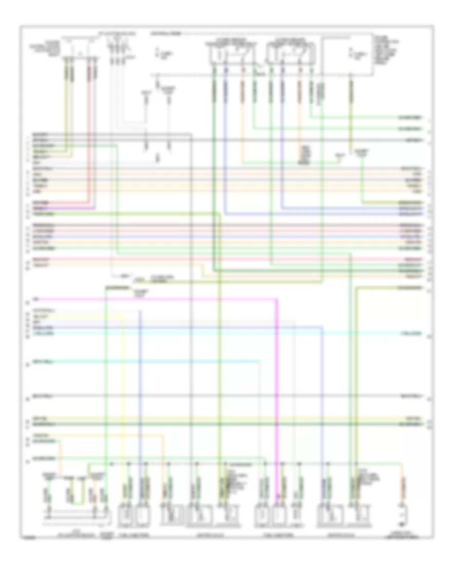
4.7L
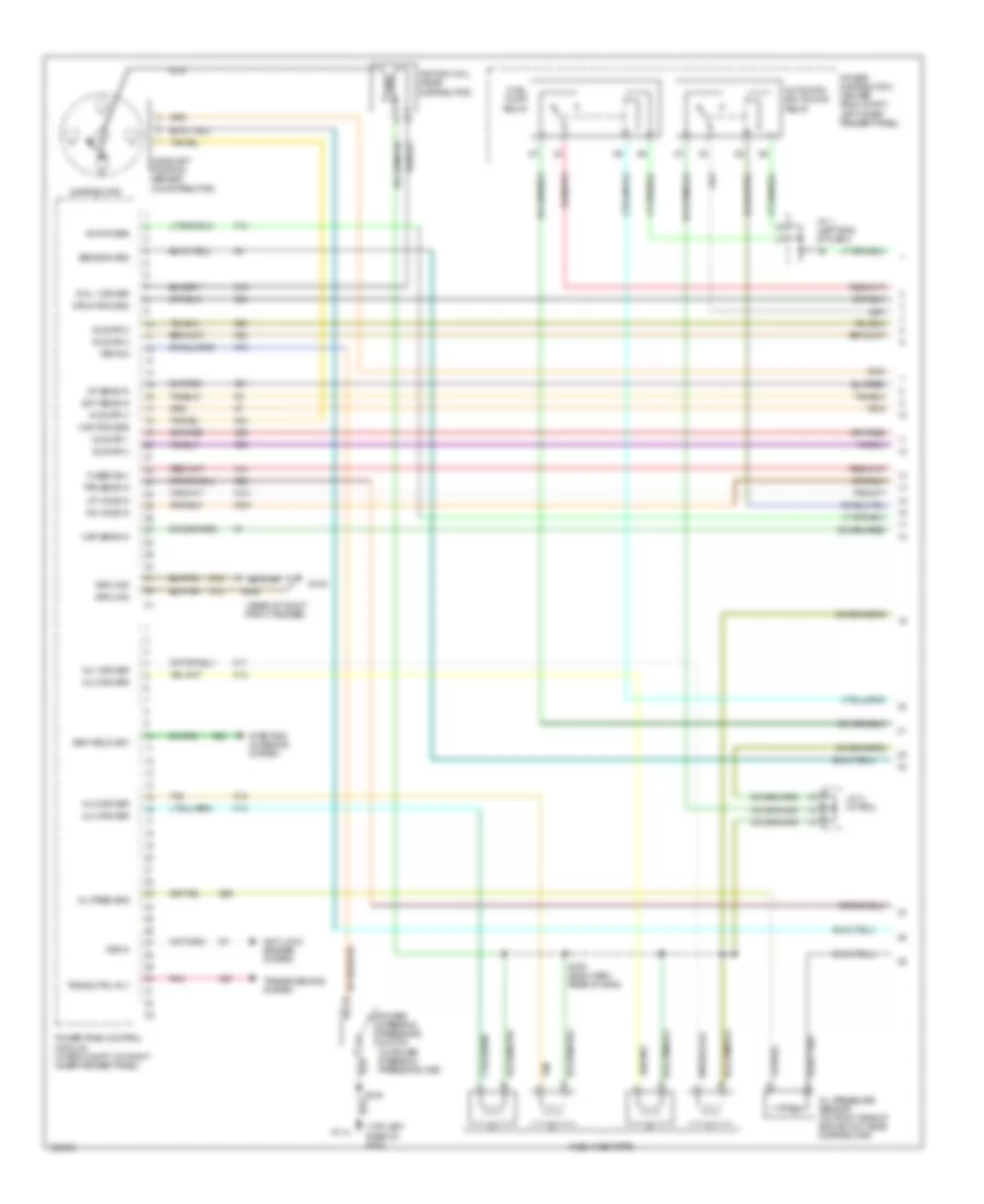
4.7L, Engine Performance Wiring Diagrams (1 of 4) for Dodge Dakota 2000
List of elements for 4.7L, Engine Performance Wiring Diagrams (1 of 4) for Dodge Dakota 2000:
- (calif)
- 1/1 up ho2s in
- 2/1 up ho2s in
- 2/2 up ho2s in
- A14
- Anti-lock brakes or transmissions system
- Automatic shutdown relay
- C24
- Cam pos sns
- Camshaft position sensor (front of right cylinder head)
- Capacitor 2 (right side of eng)
- Coil driver 1
- Coil driver 2
- Coil driver 3
- Coil driver 4
- Coil driver 5
- Coil driver 6
- Coil driver 7
- Coil driver 8
- Cooling fans system
- Crnk pos sns
- Dn ho2s in
- Ect sens in
- F18
- Fuel injectors
- Fuel pump relay
- Fuse 1 20a
- Fuse 9 10a
- Fused b(+)
- G105 (rear of right front fender)
- G119 (right front of eng)
- G60
- Gen field drv
- Ground
- Hot at all times
- Hot in run or start
- Iat sens in
- Idle air 1
- Idle air 2
- Idle air 3
- Idle air 4
- Ign power
- Ignition coils
- Inj 1 driver
- Inj 2 driver
- Inj 3 driver
- Inj 4 driver
- Inj 5 driver
- Inj 6 driver
- Inj 7 driver
- Inj 8 driver
- J/c 1 (at junction block)
- J/c 2 (at junction block)
- Junction block (left end of dash)
- K10
- K11
- K12
- K13
- K14
- K141
- K17
- K18
- K19
- K20
- K21
- K22
- K24
- K241
- K26
- K28
- K341
- K38
- K39
- K40
- K44
- K441
- K58
- K59
- K60
- K92
- K93
- K94
- K95
- K96
- Map sens in
- Oil pres sns
- P/n signal
- Power distribution center (eng compt, left inner fender panel)
- Power steering pressure switch (in power steering pressure line)
- Powertrain control module (in eng compt, on right inner fender panel)
- Pwr steering
- Rad fan ctrl
- S105
- S108
- S183 (eng harn, near breakout for fuel inj 6)
- Sensor grd
- Starting/ charging system
- Starting/charging system
- T41
- Tan
- Tan/pnk
- Tps sens in
- Vss in
- Z12
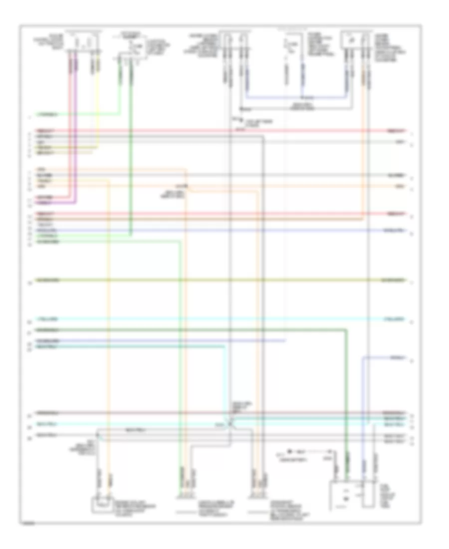
4.7L, Engine Performance Wiring Diagrams (2 of 4) for Dodge Dakota 2000
List of elements for 4.7L, Engine Performance Wiring Diagrams (2 of 4) for Dodge Dakota 2000:
- (at junction block) j/c 2
- (eng harn, near pdc) s188
- Calif
- Capacitor 1 (left side of eng)
- Except calif
- Fuel injectors
- Fuse 3 30a
- Fuse a 15a
- Hot at all times
- Idle air control motor (on throttle body)
- Ignition coils
- J/c 2 (at junction block)
- Oxygen sensor downstream heater relay
- Oxygen sensor upstream heater relay
- Power distribution center (eng compt, left inner fender panel)
- S181 (eng harn, near breakout for fuel inj 3)
- S182 (eng harn, right rear of eng)
4.7L, Engine Performance Wiring Diagrams (3 of 4) for Dodge Dakota 2000
List of elements for 4.7L, Engine Performance Wiring Diagrams (3 of 4) for Dodge Dakota 2000:
- (eng harn, rear of eng)
- (eng harn, rear of eng) s103
- (eng harn, right rear of eng)
- (near battery)
- (right front of eng)
- Calif
- Clock spring (in steering column)
- Crankshaft position sensor (on right rear of cylinder head)
- Engine coolant temperature sensor (in water jacket, at front of intake manifold)
- Except calif
- Fuel pump module (top of fuel tank)
- G111
- G119
- Heated oxygen sensor (1/1 up- stream) (calif: on left exhaust downpipe, except calif: near outlet end of catalytic converter)
- Heated oxygen sensor (1/2-calif or 2/2 except calif downstream) (calif: on outlet end left catalytic converter, except calif: near right side of transmission)
- Heated oxygen sensor (calif) (2/1 up- stream) (on right exhaust downpipe)
- Heated oxygen sensor (calif) (2/2 down- stream) (on oulet end, right catalytic converter)
- J/c 1 (at junction block)
- Manifold absolute pressure sensor (on front of intake manifold)
- Nca
- Oil pressure sensor (on oil filter housing)
- S101 (eng harn, near breakout for fuel inj 7)
- S107
- S108
- S172
- S177
- S179
- S180 (eng harn, rear of eng)
- S306
- Transmission conrol module
4.7L, Engine Performance Wiring Diagrams (4 of 4) for Dodge Dakota 2000
List of elements for 4.7L, Engine Performance Wiring Diagrams (4 of 4) for Dodge Dakota 2000:
- (eng harn, near breakout for right headlamp)
- (eng harn, near pcm)
- (eng harn, right rear
- (on throttle body) throttle position sensor
- A/c comp rly
- A/c request
- A/c select in
- A/c system
- A141
- A142
- A145
- Asd relay sens
- Auto sht rly
- Batt temp sens
- Battery temper- ature sensor (under battery, attached to battery tray)
- Block)
- Brake sw in
- C13
- C20
- C90
- Calif
- Ccd bus +
- Ccd bus -
- Controller anti-lock brake
- Cruise control system
- Cruise feed
- Cruise vac sol
- Cruise vnt sol
- D20
- D21
- Data link connector (under dash, left of steering column)
- Down ho2s rly
- Except calif
- Fuel level sens
- Fuel pmp rly
- Fuse 10a
- Fuse 15a
- G202 (left side of dash)
- Gen field
- Hot in run or start
- I/o
- Instrument cluster
- Intake air temper- ature sensor (on intake manifold near throttle body)
- J/c 2 (at junction block)
- J/c 3 (at junction
- Junction block (left end of dash)
- K106
- K107
- K118
- K125
- K151
- K29
- K51
- K52
- Ldp control
- Ldp sense
- Leak detection pump (under battery tray & power distribution center)
- Mil ind.
- Of eng) s171
- Powertrain control module (in eng compt, on right inner fender panel)
- Processor
- Proport purge
- Proportional purge solenoid (on bracket, at left rear side of eng compt)
- S173
- S185
- S189
- S190
- S191
- S201
- Sci receive
- Sci transmit
- Sp cntrl sig
- Starting/ charging system
- Stop- light switch (on brake pedal support)
- T10
- Tan/red
- Trans- mission control module
- Trans- missions system
- Transmission overdrive switch
- Up ho2s rly
- V32
- V35
- V36
- V37
5.9L
5.9L, Engine Performance Wiring Diagrams (1 of 3) for Dodge Dakota 2000
List of elements for 5.9L, Engine Performance Wiring Diagrams (1 of 3) for Dodge Dakota 2000:
- (eng harn, near inj 4) s106
- (in distributor)
- 3-4 shift
- 5.9l only
- A/t sen sig
- A/t temp sig
- A14
- Anti-lock brakes system
- Automatic shutdown relay
- C24
- Cam pos sns
- Camshaft position sensor
- Coil driver
- Cooling fans system
- Crnk pos sns
- Distributor (3.9l)
- Distributor (5.9l)
- Dn ho2s in
- Ect sens in
- F18
- Fuel injectors
- Fuel pump relay
- Fused b(+)
- G105 (rear of right front fender)
- G60
- Gen field drv
- Ground
- Iat sens in
- Idle air 1
- Idle air 2
- Idle air 3
- Idle air 4
- Ign power
- Ignition coil (near distributor)
- Inj 1 driver
- Inj 2 driver
- Inj 3 driver
- Inj 4 driver
- Inj 5 driver
- Inj 6 driver
- Inj 7 driver
- Inj 8 driver
- J/c 1 (left end of dash)
- J/c 2 (left end of dash)
- K11
- K12
- K13
- K14
- K19
- K20
- K21
- K22
- K24
- K26
- K28
- K30
- K341
- K38
- K39
- K40
- K44
- K441
- K54
- K58
- K59
- K60
- Map sens in
- Nca
- Oil pres sns
- Output speed sensor (on left rear of transmission)
- P/n signal
- Pnk
- Power distribution center (in eng compt, on inner fender panel)
- Powertrain control module (in eng compt, on right inner fender panel)
- Rad fan ctrl
- Relay control
- S105
- S110 (eng harn, near breakout for inj 5)
- S111
- Sensor grd
- Speed sig (+)
- Speed sig (-)
- Starting/ charging system
- Starting/charging system
- T13
- T14
- T25
- T41
- T54
- T60
- Tan
- Tcc sol cntrl
- Tps sens in
- Up ho2s in
- Var frce cntr
- Vss in
- Z14
5.9L, Engine Performance Wiring Diagrams (2 of 3) for Dodge Dakota 2000
List of elements for 5.9L, Engine Performance Wiring Diagrams (2 of 3) for Dodge Dakota 2000:
- (eng harn, rear of eng)
- (eng harn, rear of eng) s101
- (eng harn, rear of eng) s172
- (eng harn, top rear of eng)
- (left front of eng)
- (near battery)
- Crankshaft position sensor (on top of cylinder block, rear of cylinder head)
- Engine coolant temperature sensor (in water jacket, at front of intake manifold)
- Fuel pump module (top of fuel tank)
- Fuse 10a
- Fuse a 15a
- G110
- G111
- Heated oxygen sensor (downstream) (near outlet end of catalytic converter)
- Heated oxygen sensor (upstream) (near right side of eng, in exhaust downpipe)
- Hot in run or start
- Idle air control motor (on throttle body)
- Junction block (left end of dash)
- Manifold absolute pressure sensor (on front of throttle body)
- Nca
- Oil pressure sensor (on top rear of eng block, near distributor)
- Pnk
- Power distribution center (in eng compt, on inner fender panel)
- S103
- S107
- S108
- S306
5.9L, Engine Performance Wiring Diagrams (3 of 3) for Dodge Dakota 2000
List of elements for 5.9L, Engine Performance Wiring Diagrams (3 of 3) for Dodge Dakota 2000:
- (eng harn, near a/c compressor)
- (eng harn, near power distri- bution center)
- (left end of dash)
- 20a
- 3-4 shft sol
- A/c comp rly
- A/c heater control
- A/c high pressure switch (on discharge line, near a/c compressor)
- A/c low pressure switch (on accumulator)
- A/c request
- A/c select in
- A/c system
- A/t press sens
- A/t temp sens
- A142
- Asd relay sens
- Auto sht rly
- Batt temp sens
- Battery temper- ature sensor (under battery, attached to battery tray)
- Brake sw in
- C13
- C20
- C90
- Ccd bus +
- Ccd bus -
- Controller anti-lock brake
- Cruise control system
- Cruise feed
- Cruise vac sol
- Cruise vnt sol
- D20
- D21
- Data link connector (under dash, left of steering column)
- Fuel level sens
- Fuel pmp rly
- Fuse
- Fuse 10a
- Fuse 30a
- Fuse f 20a
- G202 (left side of dash)
- Gen field
- Hot at all times
- Hot in run or start
- I/o
- Instrument cluster
- Intake air temper- ature sensor (on intake manifold)
- J/c 1 (left end of dash)
- J/c 2 (left end of dash)
- J/c 3 (left end of dash)
- J/c 4
- Junction block (left end of dash)
- K106
- K107
- K118
- K125
- K151
- K29
- K51
- K52
- Ldp
- Ldpa
- Leak detection pump (under battery tray & power distribution center)
- Mil ind.
- Overdrive switch
- Pnk
- Power distribution center (in eng compt, on inner fender panel)
- Powertrain control module (in eng compt, on right inner fender panel)
- Processor
- Proportional purge solenoid (on bracket, left rear side of eng compt)
- Red
- S171
- S186
- S201
- S217 (i/p harn, near cigar lighter breakout)
- Sci receive
- Sci transmit
- Sens grd
- Sol drvr
- Sp cntrl sig
- Starting/ charging system
- Stoplight switch (on brake pedal bracket)
- Tan/red
- Tcc sol
- Throttle position sensor (on throttle body)
- Trans overdrv
- Trans rly ctrl
- Transmission relay
- Transmission solenoid (left side of transmission)
- V32
- V35
- V36
- V37
- Var force sol
EXTERIOR LIGHTS
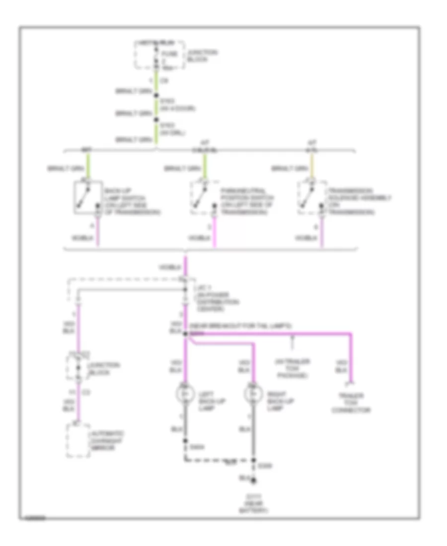
Back-up Lamps Wiring Diagram for Dodge Dakota 2000
List of elements for Back-up Lamps Wiring Diagram for Dodge Dakota 2000:
- (w/ trailer tow package)
- A/t 3.9l/5.9l
- A/t 4.7l
- Automatic day/night mirror
- Back-up lamp switch (on left side of transmission)
- Fuse 15a
- G111 (near battery)
- Hot in run
- J/c 1 (in power distribution center)
- Junction block
- Left back-up lamp
- M/t
- Park/neutral position switch (on left side of transmission)
- Right back-up lamp
- S163 (w/ 4 door)
- S163 (w/ drl)
- S306
- S404
- Trailer tow connector
- Transmission solenoid assembly (on transmission)
Exterior Lamps & Trailer connector Wiring Diagram for Dodge Dakota 2000
List of elements for Exterior Lamps & Trailer connector Wiring Diagram for Dodge Dakota 2000:
- (center of dash) s213
- (left rear frame rail) s316
- (near aftermarket chmsl connector)
- (near aftermarket chmsl connector) s318
- (near junction block) s128
- (near right license lamp) s405
- (w/ trailer tow) (wires taped together) electric brake
- Aftermarket chmsl connector
- Back-up lamps circuit
- Center high mounted stop lamp
- Combin- ation flasher
- Fuse 15a
- Fuse 20a
- Fuse 40a
- Fuse d 25a
- G101 (right front fender)
- G111 (near battery)
- G113 (left front frame)
- G202 (left side of dash)
- Hazard
- Hazard switch
- Head
- Headlamp switch
- Hot at all times
- Instrument cluster
- Interior lights system
- J/c 1 (in power distribution center)
- J/c 2 (in pdc)
- J/c 4 (left side of dash)
- Junction block
- Left
- Left front side marker lamp
- Left lic- ense lamp
- Left park/ turn signal lamp
- Left tail/ stop/ turn lamp
- Left turn ind
- Lic- ense lamp
- Multi- function switch (at steering column)
- Normal
- Off
- Park
- Pnk
- Pnk/red
- Power distribution center
- Red/ tan
- Red/tan
- Relay & fuse block
- Right
- Right front side marker lamp
- Right lic- ense lamp
- Right park/ turn signal lamp
- Right tail/ stop/ turn lamp
- Right turn ind
- S109
- S162
- S166
- S201
- S306
- S317
- S321
- S351
- S401
- S404
- S406
- Sport bumper
- Step bumper
- Stoplight switch
- Tan
- Timing circuit
- Trailer tow connector
- Trailer tow relay (in power distribution center)
- Turn signal switch
GROUND DISTRIBUTION
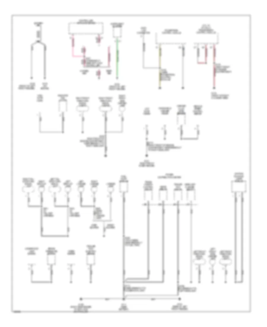
Ground Distribution Wiring Diagram (1 of 3) for Dodge Dakota 2000
List of elements for Ground Distribution Wiring Diagram (1 of 3) for Dodge Dakota 2000:
- (4.7l w/ a/t only) transmission control module
- (trailer tow) electric brake
- 32 c1
- 4-wheel abs
- Battery
- Brake pressure switch
- Controller anti-lock brake
- Data link connector
- Daytime running lamps module
- Fuel pump module
- G100 (front of left front fender)
- G101 (right front inner fender)
- G104 (rear of left front fender)
- G105 (right side fender, at anti-lock controller)
- G111 (near battery)
- G119 (front of right cylinder head)
- G133 (on engine)
- Headlamp flasher relay
- Hevac relay
- High note horn
- Instrument cluster
- Left back-up lamp
- Left front park/turn signal lamp 1
- Left front park/turn signal lamp 2
- Left front side marker lamp
- Left license lamp
- Left tail/ stop/turn signal lamp
- License lamp
- Low note horn
- Near anti-lock controller)
- Power distribution center
- Powertrain control module
- Radiator fan motor
- Rear abs
- Right back-up lamp
- Right front park/turn signal lamp 1
- Right front park/turn signal lamp 2
- Right front side marker lamp
- Right license lamp
- Right tail/ stop/turn signal lamp
- S127 (at breakout, pnk
- S306 (on chassis, near breakout to fuel tank)
- S401 (in taillamp harness)
- S404 (in taillamp harness)
- Sport bumper
- Step bumper
- Trailer tow relay
- Trans- mission control relay
- Underhood lamp/ switch
- Vehicle speed control servo
- Washer fluid level sensor
- Windshield washer pump
- Wiper motor
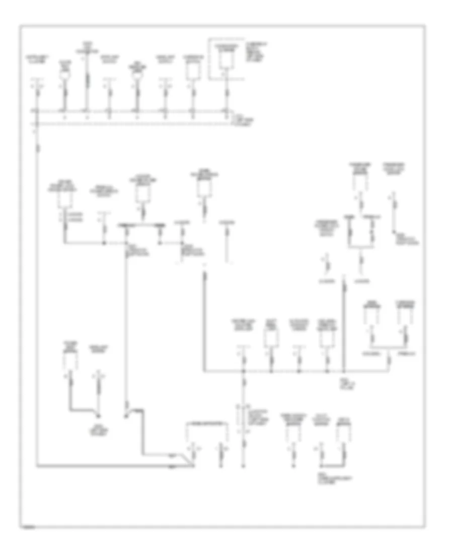
Ground Distribution Wiring Diagram (2 of 3) for Dodge Dakota 2000
List of elements for Ground Distribution Wiring Diagram (2 of 3) for Dodge Dakota 2000:
- (2-door)
- (2.5l/3.9l & 5.9l)
- (2.5l/4.7l) power steering pressure switch
- (4-door)
- (4.7l calif)
- (4.7l calif) oxygen sensor 2/1 upstream
- (4.7l only)
- (4.7l only) oxygen sensor 2/2 downstream
- (a/c)
- (except 2.5l) 4wd switch
- (except 2.5l) a/c compressor clutch
- (except 4.7l)
- (other)
- A/c heater control
- Air bag control module
- Base level
- Central timer module
- Cigar lighter
- Clock- spring
- Door disarm
- Driver door ajar switch
- Driver door key cylinder switch
- Driver door lock motor/ajar switch
- Engine starter motor relay
- G110 (front of left cylinder head)
- G113 (left front frame)
- G201 (right side of dash)
- G206 (lower center of dash)
- Heater control
- Left rear door ajar switch
- Left rear door lock motor/ajar switch
- M/t only
- Not used
- Other
- Overhead console
- Oxygen sensor 1/1 upstream
- Oxygen sensor 1/2 downstream
- Passenger air bag on/off switch
- Passenger door ajar switch
- Passenger door key cylinder switch
- Passenger door lock motor/ajar switch
- Power amplifier
- Power distibution center
- Power outlet
- Premium level
- Radio
- Right rear door ajar switch
- Right rear door lock motor/ajar switch
- S344 (left door sill)
- S347 (front of left door)
- S349 (front of right door)
- Seat belt switch
- Trailer tow connector
Ground Distribution Wiring Diagram (3 of 3) for Dodge Dakota 2000
List of elements for Ground Distribution Wiring Diagram (3 of 3) for Dodge Dakota 2000:
- (2-door)
- (4-door)
- (4-door) driver power mirror
- (base)
- (base) power mirror switch
- (midlevel)
- (midlevel/ premium) dome lamp
- (premium)
- (premium) power mirror switch
- Ash receiver lamp
- Automatic day/night mirror
- Base console
- Center high mounted stoplamp
- Combination flasher
- Data link connector
- Driver
- Fuse/relay block (behind left side of dash)
- G202 (left side of dash)
- Glove box lamp
- Headlamp switch
- Instrument cluster
- J/c 4 (left side of dash)
- Junction block (left side of dash)
- Key-in switch
- Multi- function switch
- Overdrive switch
- Overhead console
- Passenger door lock switch
- Passenger power lock/ window switch
- Passenger power mirror
- Power lock/ window switch
- Power seat switch
- Rear window defogger switch
- S201 (near instrument cluster)
- S321 (left "a" pillar)
- S348 (front of left door)
- S350 (front of right door)
- Shift bezel lamp
- Stoplamp switch
HEADLIGHTS
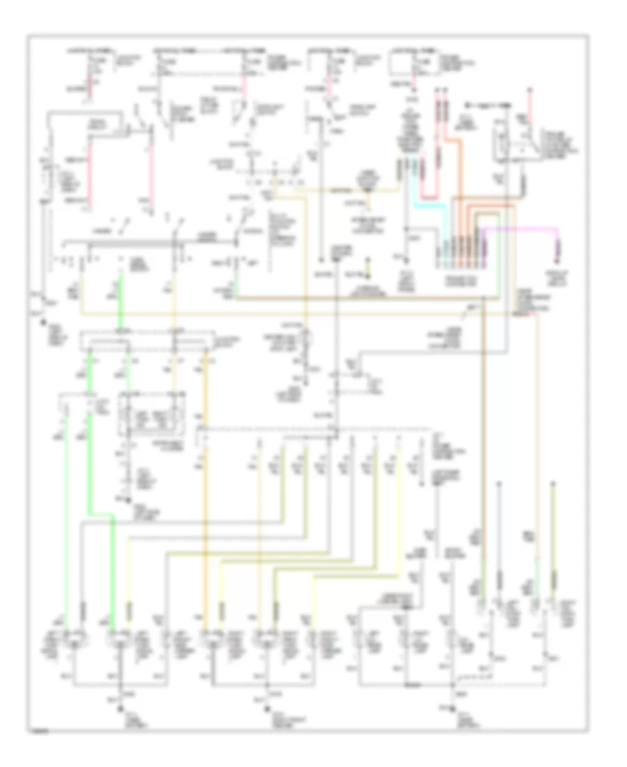
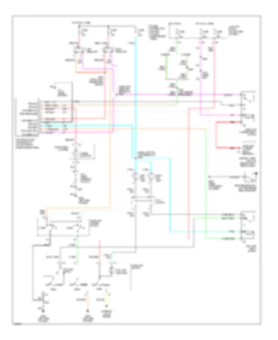
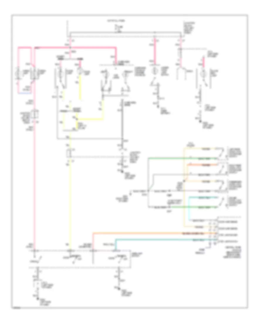
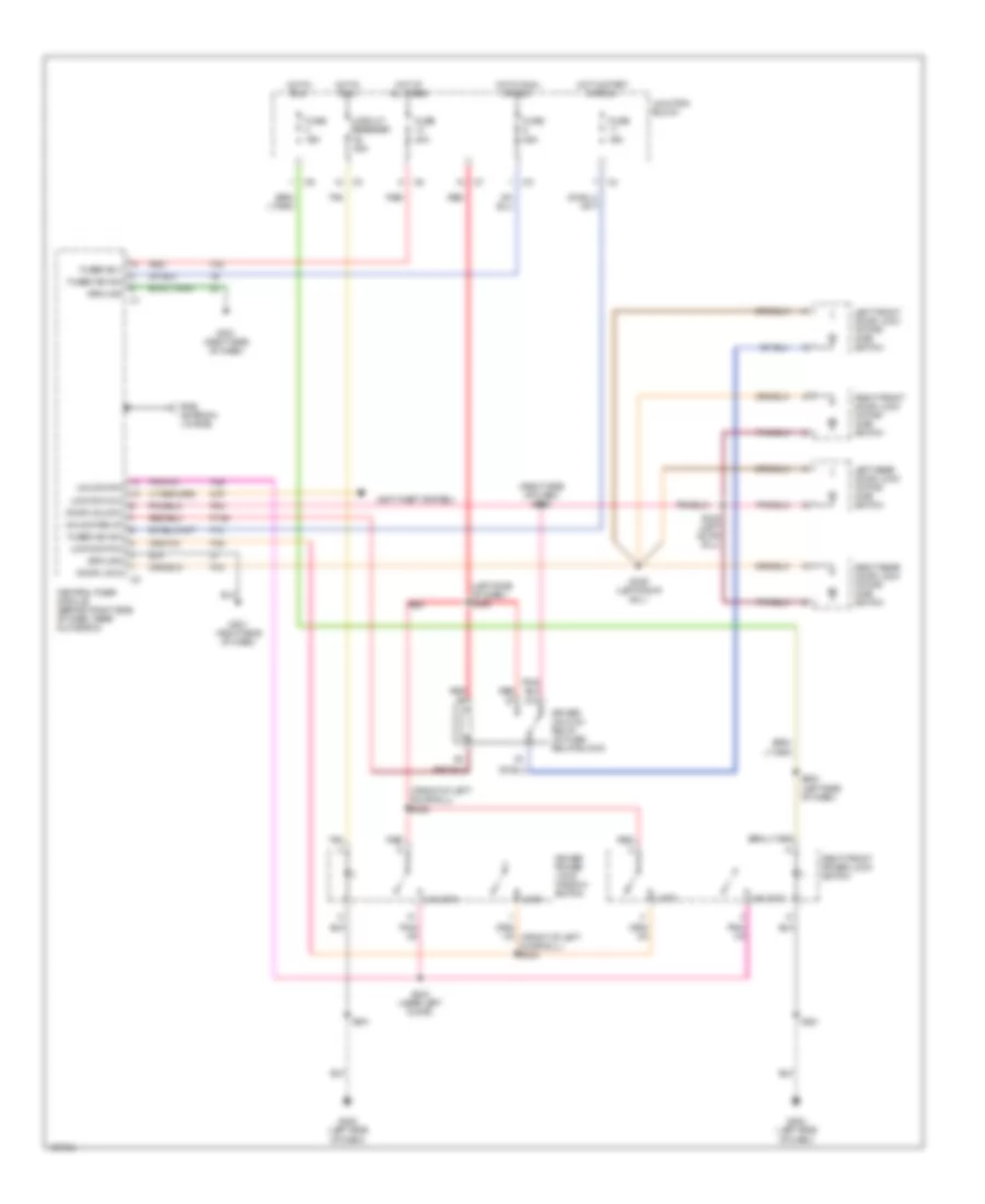
Headlight Wiring Diagram, with DRL for Dodge Dakota 2000
List of elements for Headlight Wiring Diagram, with DRL for Dodge Dakota 2000:
- (2-door)
- (4-door)
- (near left fog lamp breakout) s169
- (near left headlamp breakout) s168
- 87a
- Battery
- Central timer module (behind right side of dash)
- Control
- Daytime running lamps module (on left front inner fender panel)
- Exterior lights system
- Flash
- Fog lamp ctrl
- Fog lamp indicator
- Fog lamp relay (in pdc)
- Fog lamp switch
- Fuse 15a
- Fuse 20a
- Fuse b 15a
- Fuse c 20a
- Fuse g 15a
- G11
- G111 (near battery)
- G202 (left side of dash)
- G34
- Ground
- Head
- Headlamp dimmer switch
- Headlamp flasher relay (in pdc)
- Headlamp flasher relay c2
- Headlamp switch
- Hi beam indicator
- High beam ind
- High beam out
- Hot at all times
- Hot in run
- Ignition
- Instrument cluster
- J/c 1 (in pdc)
- J/c 4 (near steering column)
- Junction block (on left end of dash)
- L10
- L161
- L39
- Left fog lamp
- Left headlamp
- Low beam out
- Off
- Park
- Park brake sen
- Park brake switch (on park brake pedal bracket)
- Pnk/ red
- Pnk/red
- Power distribution center (on left inner fender panel)
- Red
- Red/tan
- Right fog lamp
- Right headlamp
- S159 (near pdc)
- S163 (left fender side shield)
- S164 (front left fender side shield)
- S166
- S200 (near instrument cluster)
- S201
- S225
- S254
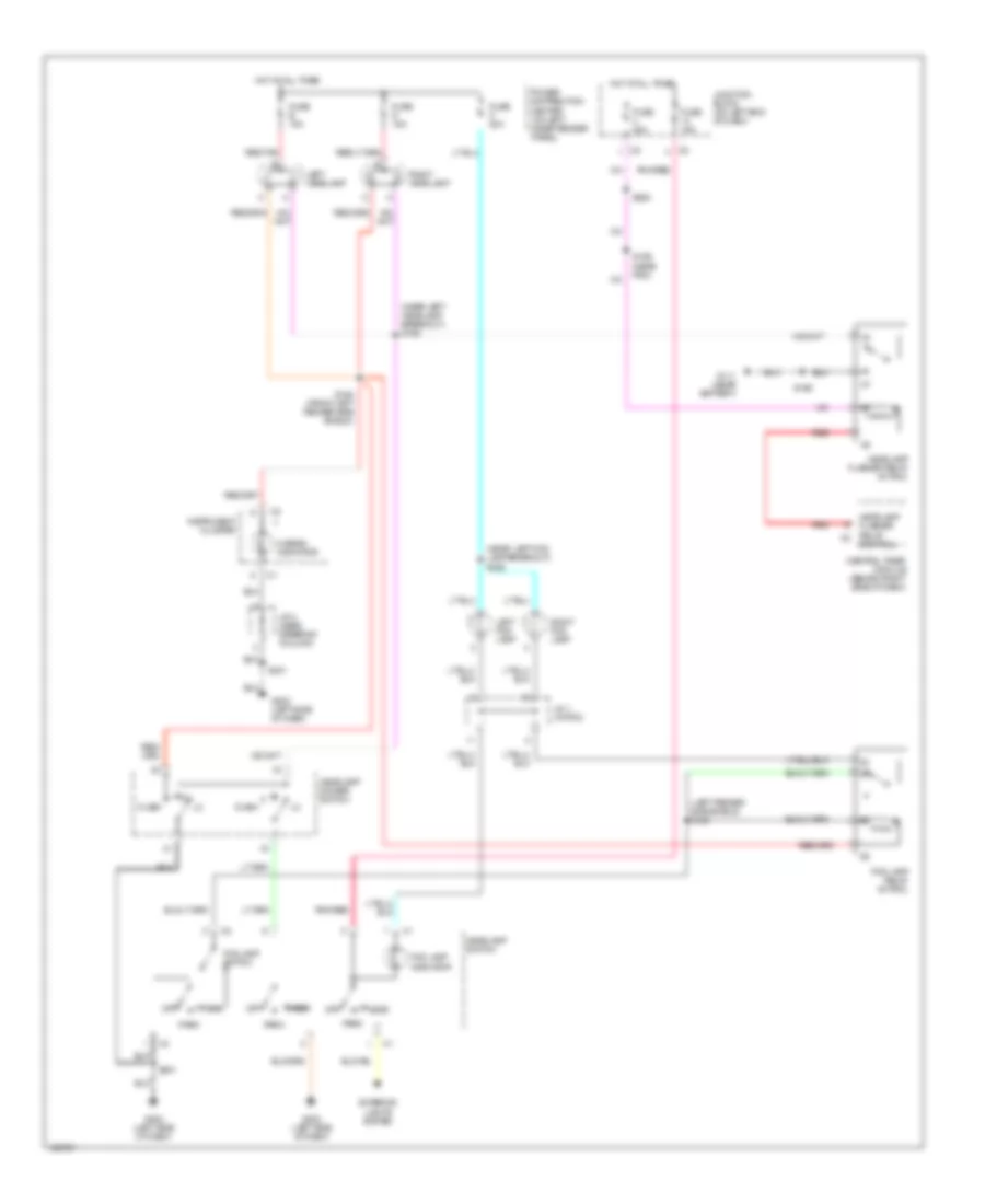
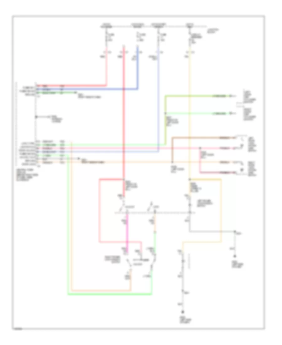
Headlight Wiring Diagram, without DRL for Dodge Dakota 2000
List of elements for Headlight Wiring Diagram, without DRL for Dodge Dakota 2000:
- (left fender side shield) s124
- (near left fog lamp breakout) s169
- (near left headlamp breakout) s168
- Central timer module (behind right side of dash)
- Control
- Exterior lights system
- Flash
- Fog lamp indicator
- Fog lamp relay (in pdc)
- Fog lamp switch
- Fuse 15a
- Fuse 20a
- Fuse b 15a
- Fuse c 20a
- Fuse g 15a
- G111 (near battery)
- G202 (left side of dash)
- Head
- Headlamp dimmer switch
- Headlamp flasher relay (in pdc)
- Headlamp flasher relay c2
- Headlamp switch
- Hi beam indicator
- Hot at all times
- Instrument cluster
- J/c 1 (in pdc)
- J/c 4 (near steering column)
- Junction block (on left end of dash)
- Left fog lamp
- Left headlamp
- Off
- Park
- Pnk/red
- Power distribution center (on left inner fender panel)
- Red
- Red/tan
- Right fog lamp
- Right headlamp
- S159 (near pdc)
- S164 (front left fender side shield)
- S166
- S201
- S225
HORN
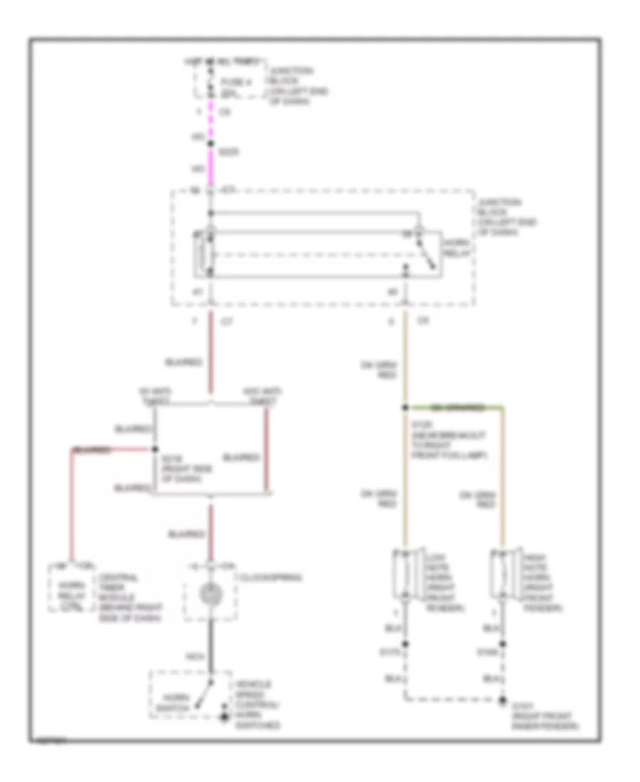
Horn Wiring Diagram for Dodge Dakota 2000
List of elements for Horn Wiring Diagram for Dodge Dakota 2000:
- Central timer module (behind right side of dash)
- Clockspring
- Fuse 4 20a
- G101 (right front inner fender)
- High note horn (right front fender)
- Horn relay
- Horn relay ctrl
- Horn switch
- Hot at all times
- Junction block (on left end of dash)
- Low note horn (right front fender)
- Nca
- S109
- S125 (near breakout to right front fog lamp)
- S170
- S218 (right side of dash)
- S225
- Vehicle speed control/ horn switches
- W/ anti- theft
- W/o anti- theft
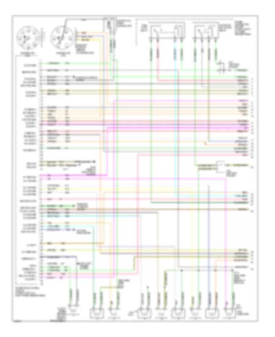
INSTRUMENT CLUSTER
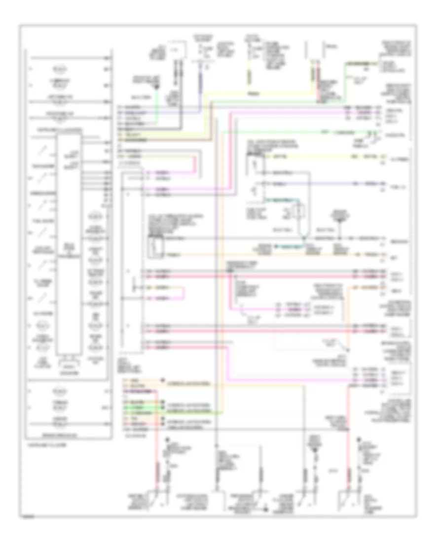
Instrument Cluster Wiring Diagram for Dodge Dakota 2000
List of elements for Instrument Cluster Wiring Diagram for Dodge Dakota 2000:
- (2.5l: on thermostat housing) (other: in water jacket, front of intake manifold) engine coolant temperature sensor
- (2.5l: right side of engine) (other: top rear of engine) oil pressure sensor
- (behind right side of dash, near glove box) central timer module
- (between instru- ment cluster breakouts) s261
- (body harn, in wiring trough) s156
- (front of left front fender) g100
- (near right head- lamp breakout) s189
- (right front fender) g101
- (right front of engine compt) transmission control module
- 4.7l a/t only
- 4wd ind
- 4wd switch (on transfer case)
- A/t trans temp ind
- A10
- A81
- Abs ind
- Air bag control module (under center of dash on trans tunnel)
- Air bag ind
- B10
- Base
- Brake warning ind
- C1 (conn a)
- C2 (conn b)
- Ccd (+)
- Ccd (-)
- Ccd bus (+)
- Ccd bus (-)
- Ccd buss (+)
- Ccd buss (-)
- Check engine ind
- Check gauges ind
- Chime ctrl
- Controller anti-lock brake (4 wheel: top of hydraulic control unit) (2 wheel: on left front fender panel)
- Coolant temp gauge
- Cruise ind
- Daytime running lamp module (left front inner fender)
- Ect
- Engine controls system
- Exterior lights system
- Fuel gauge
- Fuel lvl
- Fuel pump module (fuel tank)
- Fuse 10a
- Fuse f 20a
- G10
- G107
- G110 (except 2.5l) (front of left cyl head)
- G201 (right side of dash)
- G202 (lower left of dash)
- G60
- G69
- Headlights system
- Hi beam ind
- Hot at all times
- Hot in run or start
- Ign sw output (st-run-off)
- Instrument cluster
- Instrument illumination
- Interior lights system
- J/c 1 (in pdc)
- J/c 4 (behind left side of dash)
- Joint conn 3 (behind left side of dash)
- Junction block (left end of dash)
- Left turn ind
- Low fuel ind
- Low wash fluid ind
- Odometer
- Oil press
- Oil press gauge
- Park brake switch (on park brake pedal bracket)
- Power distribution center (in engine compt, on left inner fender)
- Powertrain control module (right front inner fender)
- Premium
- Prndl
- Right turn ind
- S101 (rear of engine)
- S103 (rear of engine)
- S108
- S170
- S174 (near powertrain contrl module)
- S190 (near right headlamp breakout)
- S200 (body harn, behind cluster assembly)
- S259
- S344
- Seat belt switch (buckle assembly)
- Sens gnd
- Solid state i/o processor
- Speedometer
- Tachometer
- Tan
- Upshift ind
- Voltmeter
- Vss in
- Vss out
- Vtss ctrl
- Vtss ind
- Washer fluid level sensor (washer reservoir)
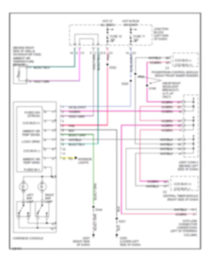
Overhead Console Wiring Diagram for Dodge Dakota 2000
List of elements for Overhead Console Wiring Diagram for Dodge Dakota 2000:
- (behind right side of grille, on radiator yoke) ambient air temperature sensor
- (near right headlight breakout) (4.7l a/t only)
- All times
- Ambient air temp sense
- Ccd bus (+)
- Ccd bus (-)
- Central timer module (right side of dash)
- Column)
- Data link connector (under dash left of steering
- Fuse 11 10a
- Fuse 12 15a
- Fused b(+)
- Fused ign (st/run)
- G201 (right side of dash)
- G202 (lower left side of dash)
- Hot at
- Hot in run
- Interior lights
- Joint conn 3 (behind left side of dash)
- Junction block (left end of dash)
- Left map lamp
- Or start
- Overhead console
- Pnk
- Powertrain control module (right front inner fender)
- Right map lamp
- S189
- S190
- S320
- S321
- S322
- S344
INTERIOR LIGHTS
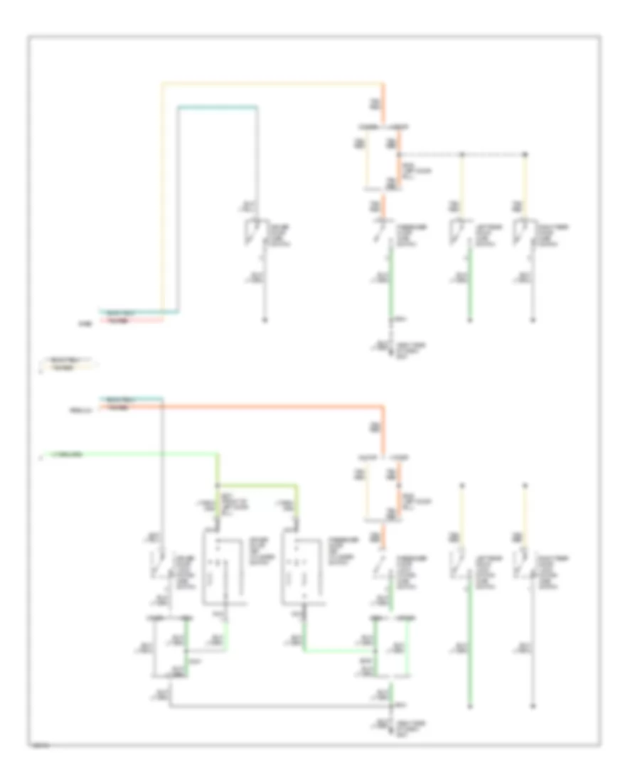
Courtesy Lamps Wiring Diagram for Dodge Dakota 2000
List of elements for Courtesy Lamps Wiring Diagram for Dodge Dakota 2000:
- (overhead) (base)
- Base
- Cargo
- Cargo lamp
- Central timer module (behind right side of dash, near glove box)
- Ctsy lamp driver
- Ctsy lamp switch
- Dome
- Dome lamp
- Door ajar sense
- Driver door lock motor/ajar switch
- Except base
- Except track
- Funeral
- Fuse 15a
- G111 (near battery)
- G201 (right side of dash)
- G202 (left side of dash)
- Glove box lamp
- Headlamp switch
- Hot at all times
- J/c 4 (left side of dash)
- Junction block (on left end of dash)
- Left
- Left rear door lock motor/ajar switch
- Map lamps
- Off
- Overhead console (or base console)
- Passenger door lock motor/ajar switch
- Pnk
- Premium
- Radio
- Right
- Right rear door lock motor/ajar switch
- S113
- S201
- S321
- S322
- S344
- S345 (left door sill)
- S347
- S349
- Tan/red
- Track
- Under- hood lamp switch
- W/ 4 doors
- W/ anti-theft system only
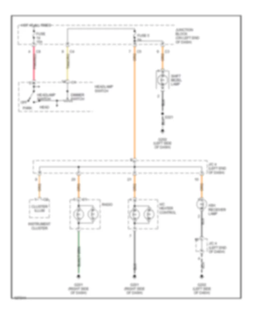
Instrument Illumination Wiring Diagram for Dodge Dakota 2000
List of elements for Instrument Illumination Wiring Diagram for Dodge Dakota 2000:
- A/c heater control
- Ash receiver lamp
- Cluster illum
- Dimmer switch
- Fuse 15a
- Fuse 5 5a
- G201 (right side of dash)
- G202 (left side of dash)
- Head
- Headlamp switch
- Hot at all times
- Instrument cluster
- J/c 4 (left end of dash)
- Junction block (on left end of dash)
- Off
- Park
- Pnk/red
- Radio
- Shift bezel lamp
POWER DISTRIBUTION
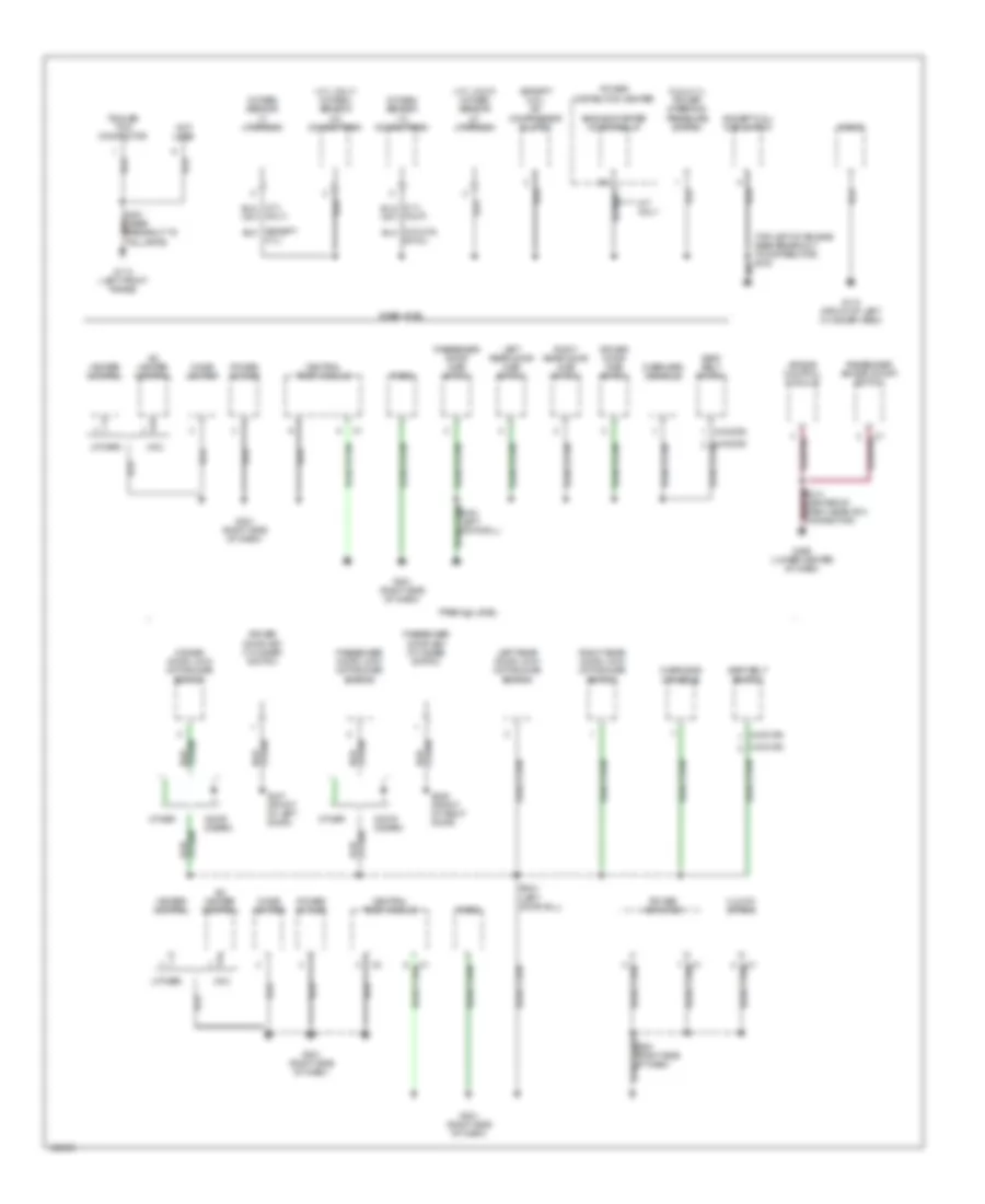
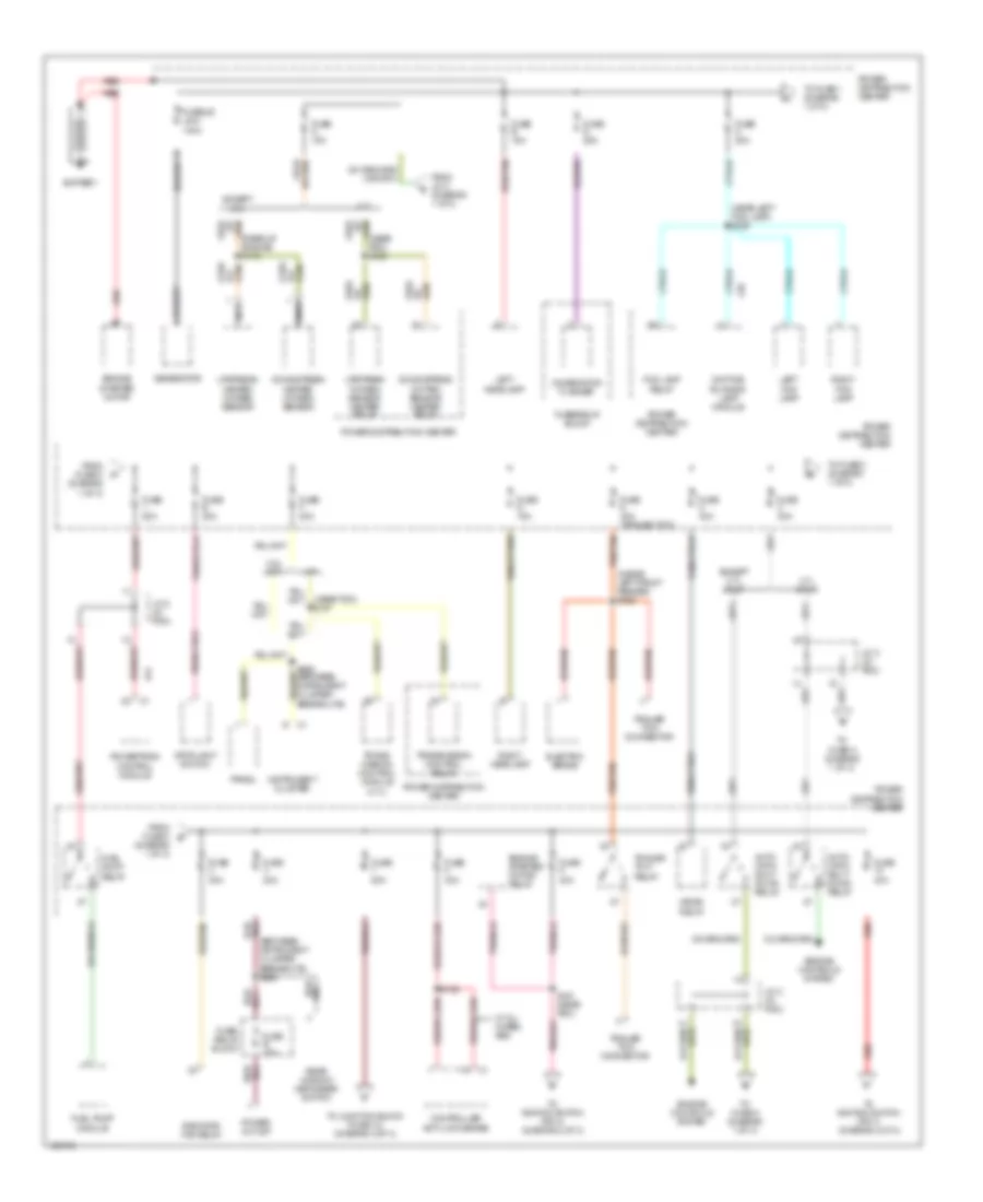
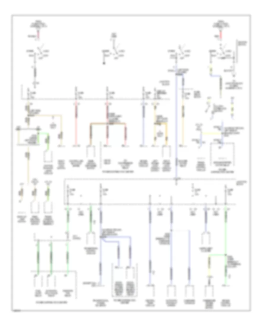
Power Distribution Wiring Diagram (1 of 3) for Dodge Dakota 2000
List of elements for Power Distribution Wiring Diagram (1 of 3) for Dodge Dakota 2000:
- (between instrument cluster breakouts) s260
- (diagram 1 of 3)
- (inside left front fender) s162
- (near left fog lamp) s169
- (near pdc) s187
- (near pdc) s188
- (rear of engine) s172
- 2.5l m/t
- 4.7l
- 4.7l calif
- A/t
- A14
- Auto- matic shut down relay
- Battery
- Combination flasher
- Controller anti-lock brake
- Daytime running lamp module
- Downstream heated oxygen sensor
- Downstream oxyten sensor heater relay
- Electric brake
- Engine controls system
- Engine starter motor
- Engine starter motor relay
- Except 4.7l
- Except 4.7l calif
- Fog lamp relay
- From fuse 3 b
- From fuse c (diagram 1 of 3)
- From j/c 2 (diagram 1 of 3)
- Fuel pump module
- Fuel pump relay
- Fuse 20a
- Fuse 30a
- Fuse 40a
- Fuse 40a (trailer tow)
- Fuse 50a
- Fuse a 15a
- Fuse b 15a
- Fuse b 20a
- Fuse c 20a
- Fuse d 25a
- Fuse e 20a
- Fuse f 20a
- Fuse g 15a
- Fuse/ relay block
- Fuse/relay block
- Fusible link 140a
- Generator
- Hevac relay
- Instrument cluster
- J/c 2 (in pdc)
- L39
- Left fog lamp
- Left headlamp
- Nca
- Pnk
- Power distribution center
- Power outlet
- Powertrain control module
- Prndl
- Radiator fan relay
- Rear window defogger switch
- Red
- Red/tan
- Right fog lamp
- Right headlamp
- S129
- S161 (near pdc)
- Stoplight switch
- To fuse 1 (diagram 1 of 3)
- To fuse 2 (diagram 1 of 3)
- To fuse a (diagram 1 of 3)
- To ignition switch (pin 4) (diagram 2 of 3)
- To ignition switch (pin 7) (diagram 2 of 3)
- To junction block (fuse 13) (diagram 3 of 3)
- Trailer tow connector
- Trailer tow relay
- Trans- mission control module (4.7l)
- Transmission control relay
- Upstream heated oxygen sensor
- Upstream oxygen sensor heater relay
- W/ all wheel abs
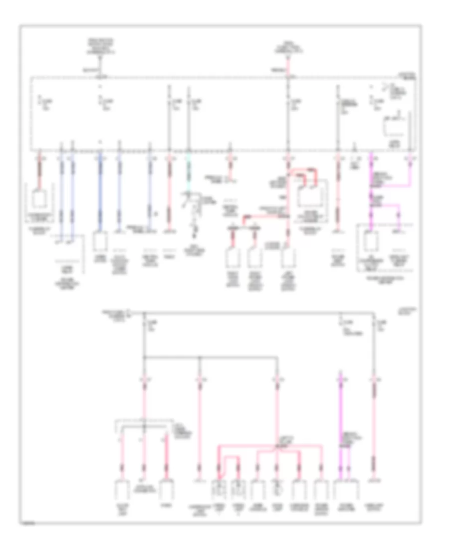
Power Distribution Wiring Diagram (2 of 3) for Dodge Dakota 2000
List of elements for Power Distribution Wiring Diagram (2 of 3) for Dodge Dakota 2000:
- (except 2.5l) (2.5l)
- (in wiring trough, left side of engine compt) s184
- (in wiring trough, left side of engine compt) s185
- (left side of dash) s254
- (near instrument cluster breakout) s258
- (near left door breakout) s336
- 3.9l/ 5.9l w/ a/t
- 4.7l w/ a/t
- 4.7l w/ a/t only
- A/c compressor clutch relay
- A/t
- A41
- Acc
- Air bag control module
- Automatic day/night mirror
- Automatic shut down relay
- Back-up lamp switch
- Blower motor relay
- Central timer module
- Circuit breaker 20a
- Clutch interlock switch
- Controller anti-lock brake
- Daytime running lamps module
- Door only
- Down- stream oxygen sensor heater relay
- Engine starter motor relay
- F12
- F14
- F18
- From fuse 10 (pdc) (diagram 1 of 3)
- From fuse 9 (pdc) (diagram 1 of 3)
- Fuel pump relay
- Fuse 10a
- Fuse 15a
- Fuse d 10a
- Fuse/ relay block
- Hevac relay
- Ignition switch
- Instrument cluster
- J/c 1 (in pdc)
- Junction block
- Left power lock/ window switch
- Lock off
- M/t
- Nca
- Not used
- Overhead console
- Park/ neutral position switch
- Passenger air bag disarm switch
- Power distribution center
- Powertrain control module
- Proportional purge solenoid
- Radiator fan relay
- Rear window defogger switch
- Red
- Right door lock switch
- Right power lock/ window switch
- Run
- S163 (inside left front fender)
- S252 (near breakout to steering column)
- S320 (near breakout to overhead console)
- Start
- Tan
- To junction block (fuse 6) (diagram 3 of 3)
- Trans- mission control module
- Trans- mission solenoid assembly
- W/ drl
- W/o drl
Power Distribution Wiring Diagram (3 of 3) for Dodge Dakota 2000
List of elements for Power Distribution Wiring Diagram (3 of 3) for Dodge Dakota 2000:
- driver unlock relay (4 door)
- (4 door) (2 door)
- (behind right kick panel) s225
- (front of left door sill) s338
- (left "a" pillar) s322
- (premium) (base)
- A/c compressor clutch relay
- Base console
- Cargo lamp
- Central timer module
- Cigar lighter
- Circuit breaker 20a
- Combination flasher
- Data link connector
- Dome lamp
- Door
- From fuse 4 (diagram 3 of 3)
- From fuse 7 (pdc) (diagram 1 of 3)
- From ignition switch (pin 6) (run/acc) (diagram 2 of 3)
- Fuse 10a
- Fuse 15a
- Fuse 20a
- Fuse 20a (amplifier)
- Fuse/relay block
- G201 (right side of dash)
- Glove box lamp
- Headlamp switch
- Headlight flasher relay
- Horn relay
- J/c 4 (near steering column)
- Junction block
- Left power lock/ window switch
- Multi- function switch (wiper switch)
- Not used
- Overhead console
- Pnk
- Pnk/red
- Power amplifier
- Power distribution center
- Power mirror switch
- Power seat switch
- Radio
- Red
- Red/pnk
- Right door lock switch
- Right power lock/ window switch
- S256 left side of dash)
- To fuse 12 (diagram 3 of 3)
- Underhood lamp switch
- Wiper motor
- Wiper relay
POWER DOOR LOCKS
Power Door Lock Wiring Diagram, 2 Door for Dodge Dakota 2000
List of elements for Power Door Lock Wiring Diagram, 2 Door for Dodge Dakota 2000:
- Central timer module (behind right side of dash, near glove box)
- Circuit breaker 25a
- Door lock
- Door unlock
- F12
- F35
- Fuse 10a
- Fuse 20a
- Fused b(+)
- Fused ign sw
- G201 (right side of dash)
- G202 (left side of dash)
- G73
- Ground
- Hot at all times
- Hot in run
- Hot in run or acc
- Hot in start or run
- Junction block
- Left door key cylinder switch
- Left door lock motor/ ajar switch
- Left power lock/window switch
- Lk rly ctrl
- Lock
- Lock sw mux
- P33
- P34
- P37
- P38
- Red
- Right door key cylinder switch
- Right door lock motor/ ajar switch
- Right power lock/window switch
- Rke antenna (w/ rke)
- S301
- S321
- S336 (near upper "a" pillar)
- S337 (front of left door sill)
- S338 (front of left door sill)
- S339 (left door sill)
- S340 (left door sill)
- Tan
- Unlk rly out
- Unlock
Power Door Lock Wiring Diagram, 4 Door for Dodge Dakota 2000
List of elements for Power Door Lock Wiring Diagram, 4 Door for Dodge Dakota 2000:
- (anti-theft system)
- (front of left door sill) s338
- (left side of dash) s256
- (right side of dash) s222
- 87a
- Central timer module (behind right side of dash, near glove box)
- Circuit breaker 25a
- Door lock
- Door unlock
- Driver power lock/ window switch
- Driver unlock relay (in fuse/ relay block)
- F12
- F35
- Fuse 10a
- Fuse 15a
- Fuse 20a
- Fused b(+)
- Fused ign sw
- G201 (right side of dash)
- G202 (left side of dash)
- G73
- Ground
- Hot at all times
- Hot in run
- Hot in run or acc
- Hot in start or run
- Junction block
- Left front door lock motor/ ajar switch
- Left rear door lock motor/ ajar switch
- Lock
- Lock sw mux
- Lock switch
- P109
- P33
- P34
- P35
- P36
- Red
- Right front door lock motor/ ajar switch
- Right front power lock switch
- Right rear door lock motor/ ajar switch
- Rke antenna (w/ rke)
- S254 (left side of dash)
- S301
- S321
- S339 (left door sill)
- S340 (left door sill)
- S342 (near left door)
- Tan
- Unlock
- Unlock relay
- Unlock sw
POWER MIRRORS
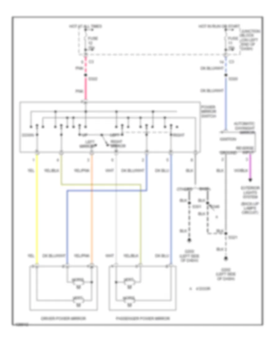
Power Mirror Wiring Diagram for Dodge Dakota 2000
List of elements for Power Mirror Wiring Diagram for Dodge Dakota 2000:
- (back-up lamps circuit)
- 4 door
- Automatic day/night mirror
- Base
- Down
- Driver power mirror
- Exterior lights system
- Fuse 10a
- Fuse 15a
- G202 (left side of dash)
- Ground
- Horiz
- Hot at all times
- Hot in run or start
- Ignition
- Junction block (on left end of dash)
- Left
- Left mirror
- Others
- Passenger power mirror
- Pnk
- Power mirror switch
- Reverse input
- Right
- Right mirror
- S301
- S320
- S321
- S322
- S348
- Vert
POWER SEATS
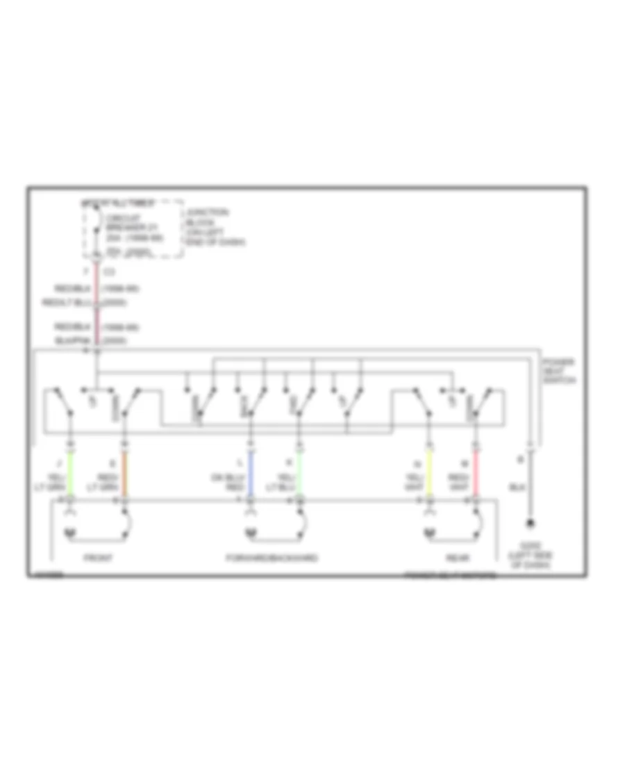
Power Seat Wiring Diagrams for Dodge Dakota 2000
List of elements for Power Seat Wiring Diagrams for Dodge Dakota 2000:
- (1998-99)
- (2000)
- 25a
- Back
- Circuit breaker 21 20a
- Down
- Forward/backward
- Front
- Fwd
- G202 (left side of dash)
- Hot at all times
- Junction block (on left end of dash)
- Power seat motors
- Power seat switch
- Rear
POWER WINDOWS
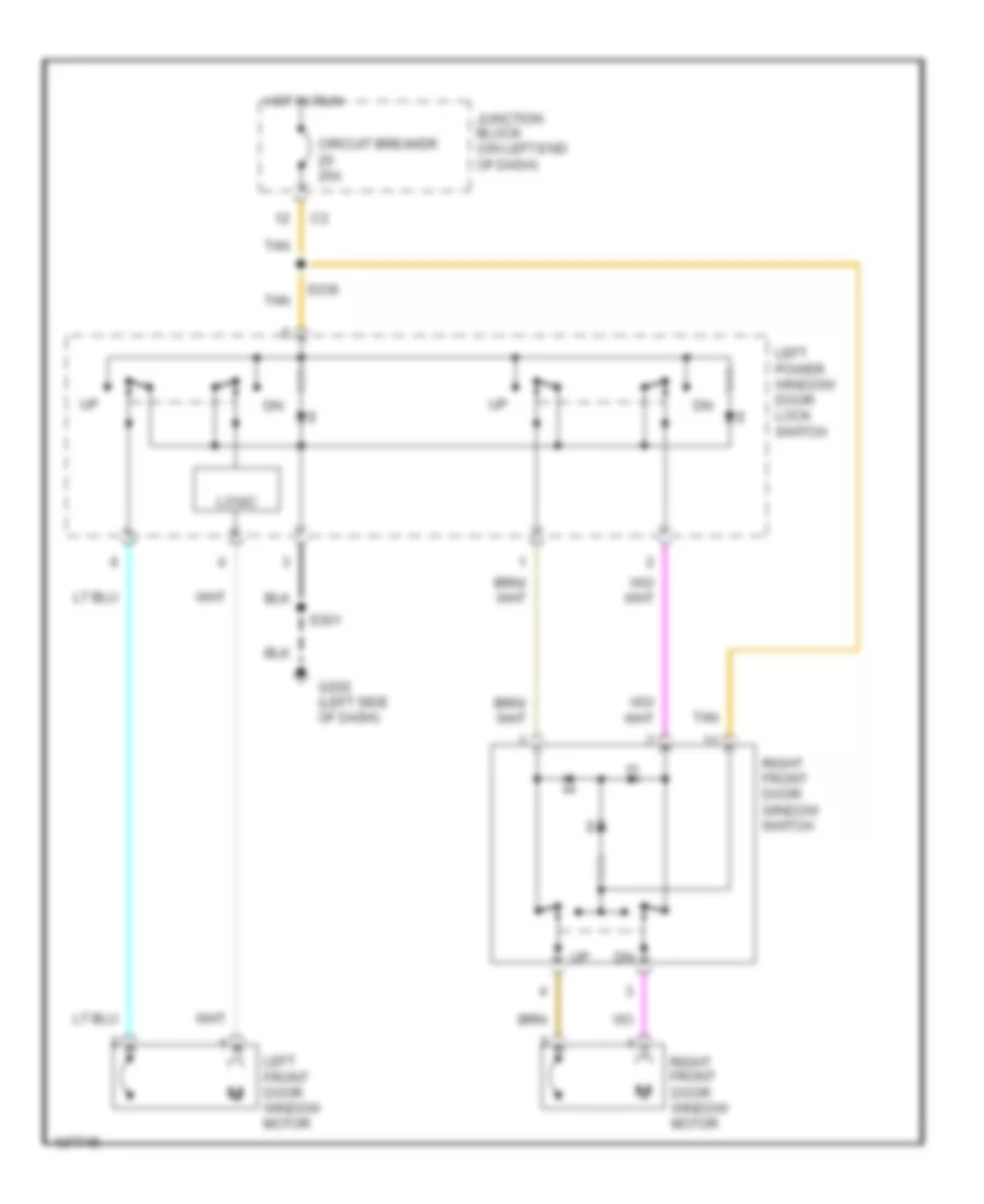
Power Window Wiring Diagram, 2 Door for Dodge Dakota 2000
List of elements for Power Window Wiring Diagram, 2 Door for Dodge Dakota 2000:
- Circuit breaker 25a
- G202 (left side of dash)
- Hot in run
- Junction block (on left end of dash)
- Left front door window motor
- Left power window/ door lock switch
- Logic
- Right front door window motor
- Right front door window switch
- S301
- S336
- Tan
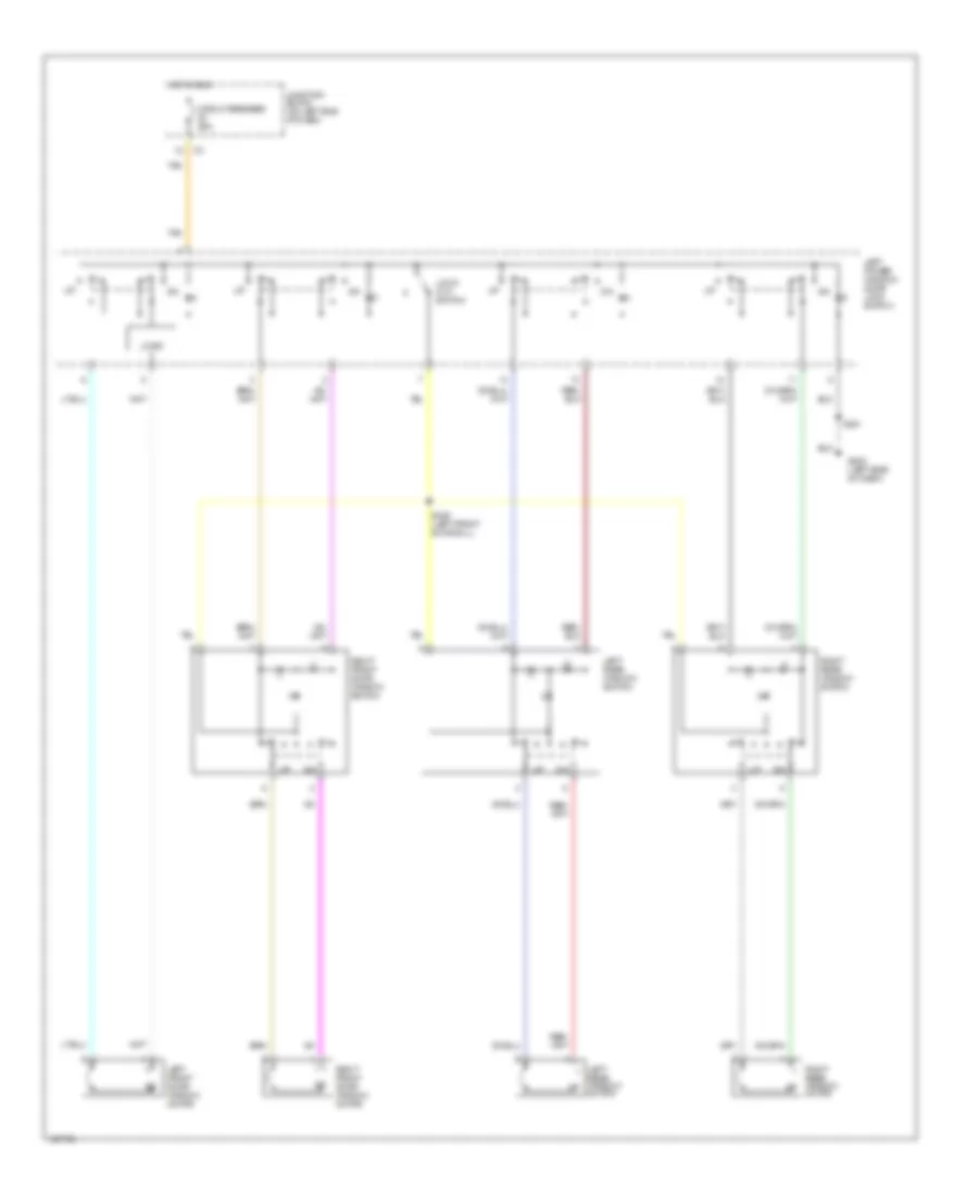
Power Window Wiring Diagram, 4 Door for Dodge Dakota 2000
List of elements for Power Window Wiring Diagram, 4 Door for Dodge Dakota 2000:
- Circuit breaker 25a
- G202 (left side of dash)
- Hot in run
- Junction block (on left end of dash)
- Left front door window motor
- Left power window/ door lock switch
- Left rear window motor
- Left rear window switch
- Lock- out switch
- Logic
- Right front door window motor
- Right front door window switch
- Right rear window motor
- Right rear window switch
- S301
- S346 (left front door sill)
- Tan
RADIO
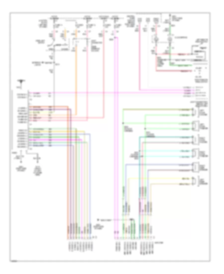
Premium Sound Radio Wiring Diagram for Dodge Dakota 2000
List of elements for Premium Sound Radio Wiring Diagram for Dodge Dakota 2000:
- Amp l door (+)
- Amp l door (-)
- Amp l rear (+)
- Amp l rear (-)
- Amp r door (+)
- Amp r door (-)
- Amp r rear (+)
- Amp r rear (-)
- Amplifier
- Antenna
- Ccd bus (+)
- Ccd bus (-)
- Central timer module (behind right side of dash)
- Clockspring
- Dimmer
- Dimmer sig
- Exterior lights
- Fuse 1 20a
- Fuse 12 15a
- Fuse 14 15a
- Fuse 5 5a
- Fuse 8 10a
- Fused b(+)
- Fused ign
- G110 (front of left cylinder head)
- G201 (right side of dash)
- Ground
- Head
- Headlamp switch
- Hot at all times
- Hot in run or acc
- Joint connector (near steering column)
- Joint connector 3 (behind left side of dash)
- Junction block (left end of dash)
- L front (+)
- L front (-)
- L rear (+)
- L rear (-)
- L107
- Left door tweeter
- Left door woofer
- Left rear speaker
- Left remote radio switch
- Lf spkr (+)
- Lf spkr (-)
- Lr spkr (+)
- Lr spkr (-)
- Nca
- Off
- Park
- Parklamp
- Pnk
- Pnk/ red
- Preset
- R front (+)
- R front (-)
- R rear (+)
- R rear (-)
- Radio
- Radio 12v
- Radio cntrl mux
- Rf spkr (+)
- Rf spkr (-)
- Right door tweeter
- Right door woofer
- Right rear speaker
- Right remote radio switch
- Rr spkr (+)
- Rr spkr (-)
- S207
- S208 (steering wheel jumper harn)
- S213
- S223
- S225
- S330 (in door harness)
- S331 (in door harness)
- S333 (in door harness) s332
- Seek dn
- Seek up
- Vol dn
- Vol up
- X12
- X51
- X52
- X53
- X54
- X55
- X56
- X57
- X58
- X60
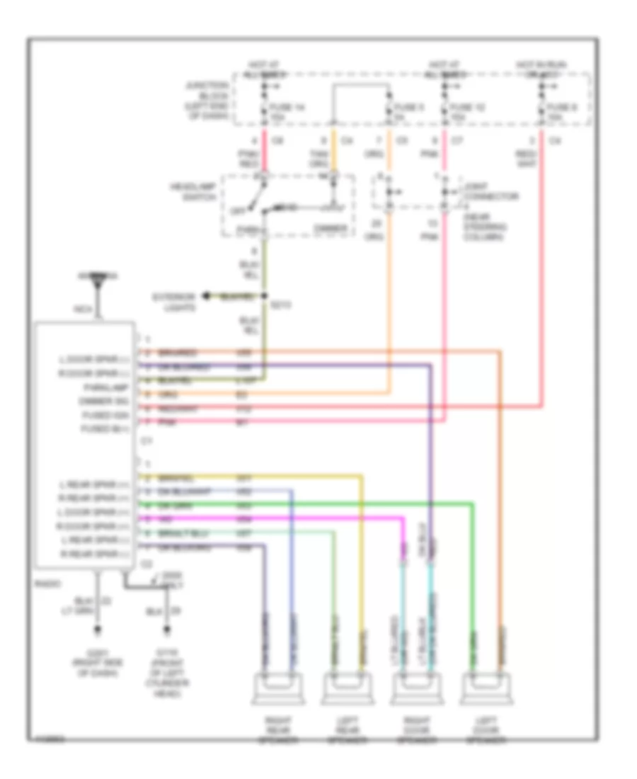
Radio Wiring Diagrams, without Amplifier for Dodge Dakota 2000
List of elements for Radio Wiring Diagrams, without Amplifier for Dodge Dakota 2000:
- Antenna
- Dimmer
- Dimmer sig
- Exterior lights
- Fuse 12 15a
- Fuse 14 15a
- Fuse 5 5a
- Fuse 8 10a
- Fused b(+)
- Fused ign
- G110 (front of left cylinder head)
- G201 (right side of dash)
- Head
- Headlamp switch
- Hot at all times
- Hot in run or acc
- Joint connector (near steering column)
- Junction block (left end of dash)
- L door spkr (+)
- L door spkr (-)
- L rear spkr (+)
- L rear spkr (-)
- L107
- Left door speaker
- Left rear speaker
- Nca
- Off
- Only
- Park
- Parklamp
- Pnk
- Pnk/ red
- R door spkr (+)
- R door spkr (-)
- R rear spkr (+)
- R rear spkr (-)
- Radio
- Right door speaker
- Right rear speaker
- S213
- X12
- X51
- X52
- X53
- X54
- X55
- X56
- X57
- X58
STARTING/CHARGING
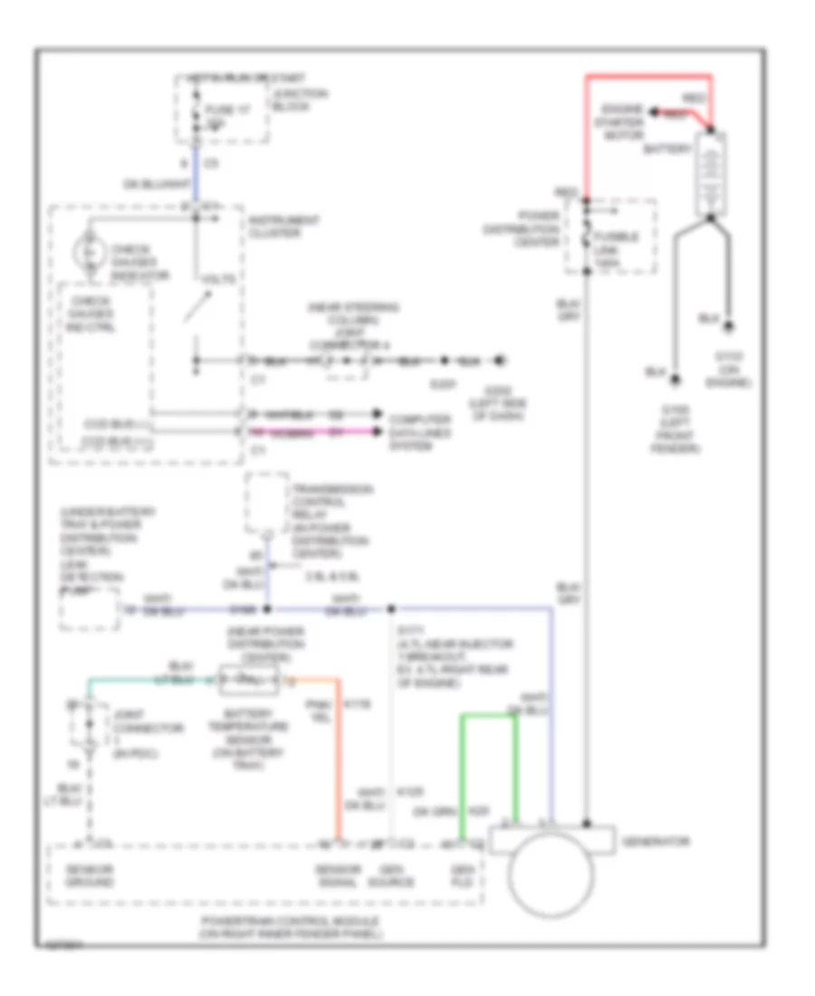
Charging Wiring Diagram for Dodge Dakota 2000
List of elements for Charging Wiring Diagram for Dodge Dakota 2000:
- (near power distribution center)
- (near steering column) joint connector 4
- (under battery tray & power distribution center) leak detection pump
- 3.9l & 5.9l
- Battery
- Battery temperature sensor (on battery tray)
- Ccd bus (+)
- Ccd bus (-)
- Check gauges ind ctrl
- Check gauges indicator
- Computer data lines system
- Engine starter motor
- Fuse 17 10a
- Fusible link 140a
- G100 (left front fender)
- G133 (on engine)
- G202 (left side of dash)
- Gen fld
- Gen source
- Generator
- Hot in run or start
- Instrument cluster
- Joint connector (in pdc)
- Junction block
- Power distribution center
- Powertrain control module (on right inner fender panel)
- Red
- S171 (4.7l-near injector 1 breakout, ex. 4.7l-right rear of engine)
- S186
- S201
- Sensor ground
- Sensor signal
- Transmission control relay (in power distribution center)
- Volts
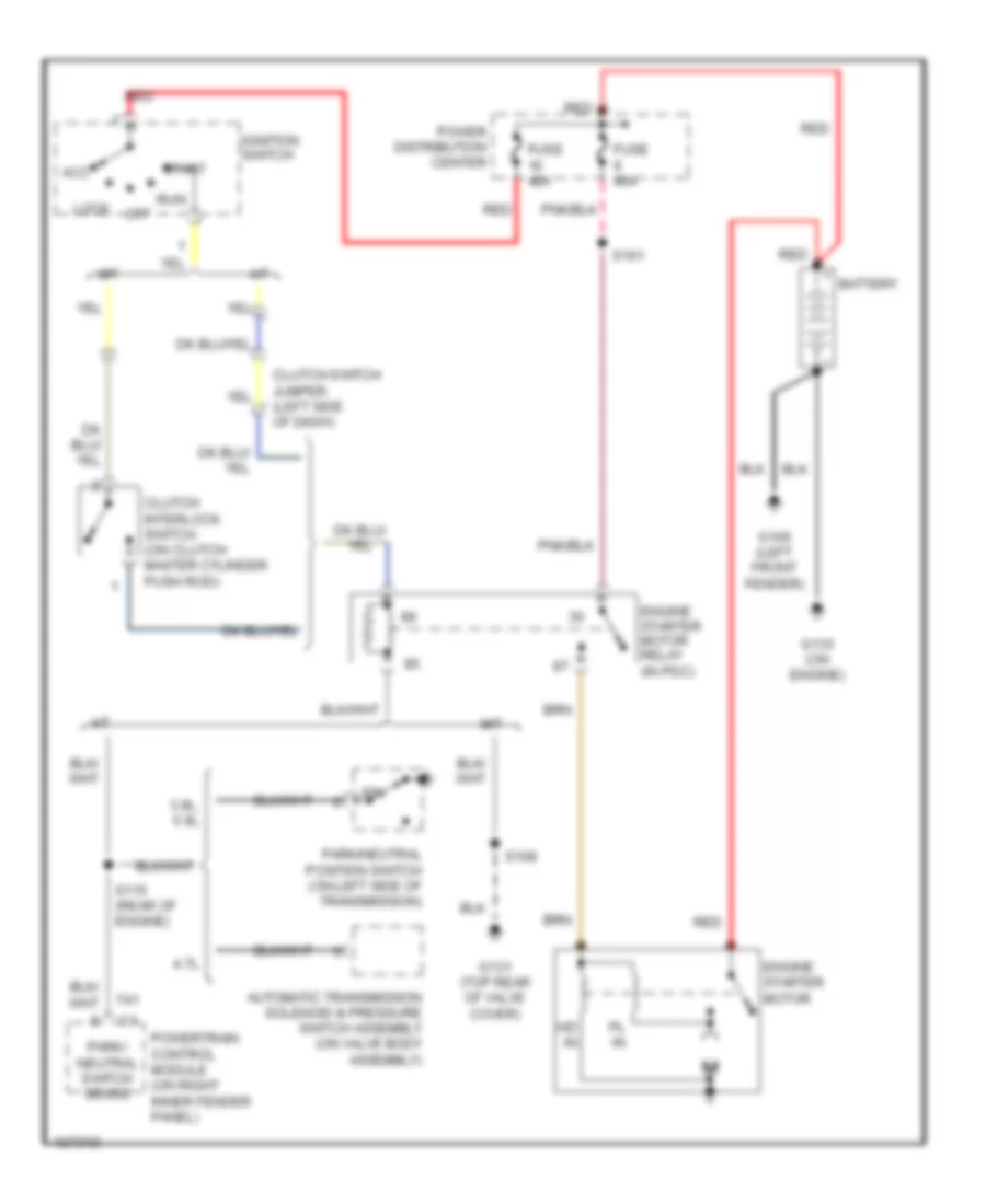
Starting Wiring Diagram for Dodge Dakota 2000
List of elements for Starting Wiring Diagram for Dodge Dakota 2000:
- 3.9l, 5.9l
- 4.7l
- A/t
- Acc
- Automatic transmission solenoid & pressure switch assembly (on valve body assembly)
- Battery
- Clutch interlock switch (on clutch master cylinder push rod)
- Clutch switch jumper (left side of dash)
- Engine starter motor
- Engine starter motor relay (in pdc)
- Fuse 40a
- G100 (left front fender)
- G131 (top rear of valve cover)
- G133 (on engine)
- Hd in
- Ignition switch
- Lock
- M/t
- Off
- P/n
- Park/ neutral switch sense
- Park/neutral position switch (on left side of transmission)
- Pl in
- Power distribution center
- Powertrain control module (on right inner fender panel)
- Red
- Run
- S108
- S115 (rear of engine)
- S161
- Start
- T41
SUPPLEMENTAL RESTRAINTS
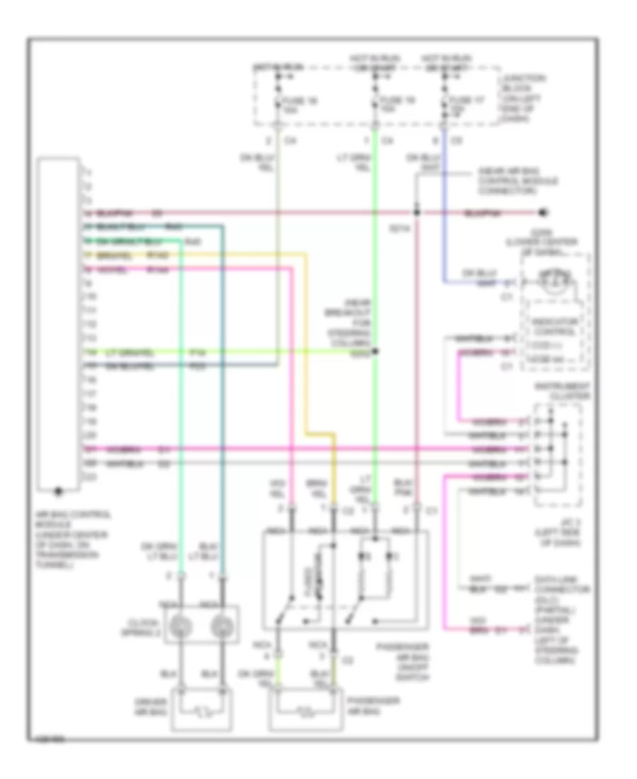
Supplemental Restraint Wiring Diagram, 2 Door for Dodge Dakota 2000
List of elements for Supplemental Restraint Wiring Diagram, 2 Door for Dodge Dakota 2000:
- (near air bag control module connector)
- (near breakout for steering column) s252
- Air bag
- Air bag control module (under center of dash, on transmission tunnel)
- Ccd (+)
- Ccd (-)
- Clock- spring 2
- Data link connector (dlc) (partial) (under dash, left of steering column)
- Driver air bag
- F14
- F23
- Fuse 17 10a
- Fuse 18 10a
- Fuse 19 10a
- G206 (lower center of dash)
- Hot in run
- Hot in run or start
- Indicator control
- Instrument cluster
- J/c 3 (left side of dash)
- Junction block (on left end of dash)
- Nca
- Passenger air bag
- Passenger air bag on/off switch
- R142
- R144
- R43
- R45
- Resistor fused
- S214
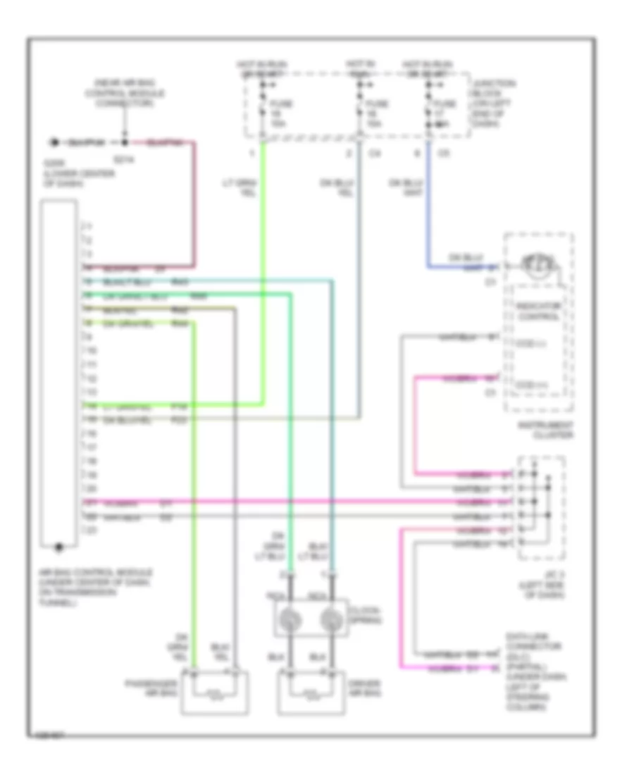
Supplemental Restraint Wiring Diagram, 4 Door for Dodge Dakota 2000
List of elements for Supplemental Restraint Wiring Diagram, 4 Door for Dodge Dakota 2000:
- (near air bag control module connector)
- (under dash, left of steering column)
- Air bag
- Air bag control module (under center of dash, on transmission tunnel)
- Ccd (+)
- Ccd (-)
- Clock- spring
- Data link connector (dlc) (partial)
- Driver air bag
- F14
- F23
- Fuse 10a
- G206 (lower center of dash)
- Hot in run
- Hot in run or start
- Indicator control
- Instrument cluster
- J/c 3 (left side of dash)
- Junction block (on left end of dash)
- Nca
- Passenger air bag
- R42
- R43
- R44
- R45
- S214
TRANSMISSION
3.9L
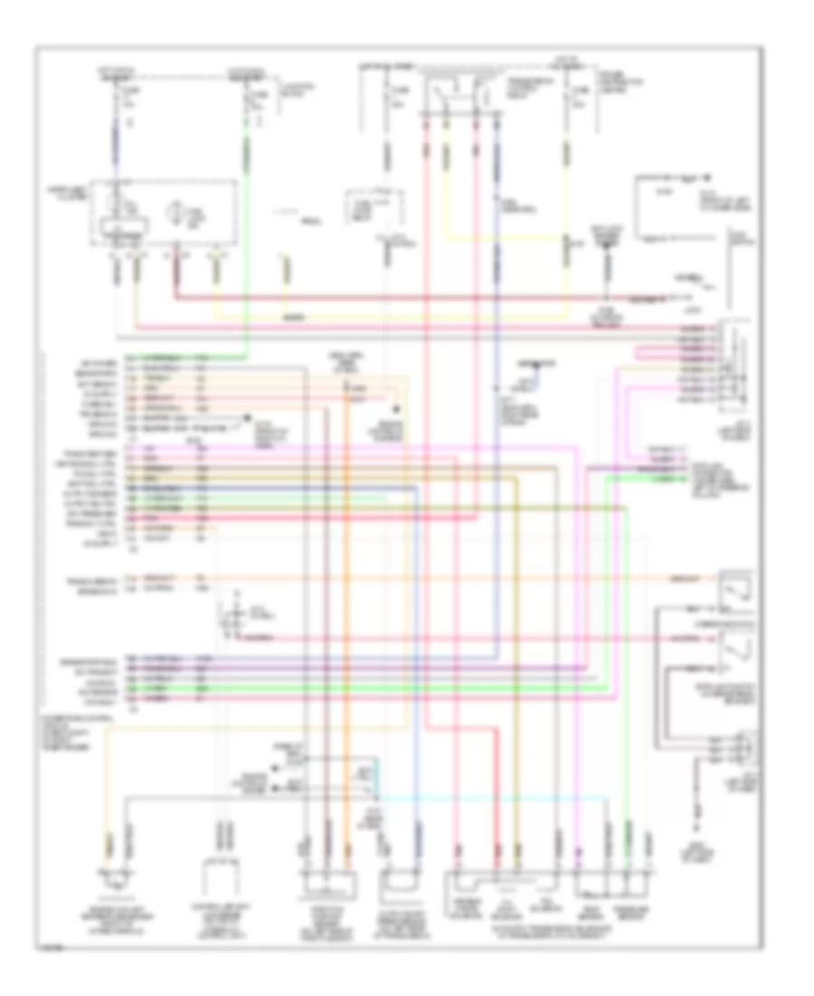
3.9L, A/T Wiring Diagram for Dodge Dakota 2000
List of elements for 3.9L, A/T Wiring Diagram for Dodge Dakota 2000:
- (eng harn, rear of eng)
- (eng harn, right rear of eng)
- (rear of eng)
- 3-4 shift solenoid
- 4wd lock ind
- 4wd switch
- A14
- Anti-lock brakes system
- Automatic transmission solenoids (in transmission, on valve body)
- Brake sw in
- Ccd bus +
- Ccd bus -
- Controller anti- lock brake (on top of hydraulic control unit)
- D20
- D21
- Data link connector (under dash, left of steering column)
- Ect sens in
- Engine controls system
- Engine controls systems
- Engine coolant temperature sensor (front of intake manifold)
- F18
- Fuel pump relay
- Fuse 10a
- Fuse 20a
- Fuse f 20a
- Fused b(+)
- G110 (front of left cylinder head)
- G119 (front of right cyl head)
- G202 (left side of dash)
- Generator
- Generator field
- Gov press sen
- Ground
- Hot at all times
- Hot in run and start
- Hot in run or start
- I/o
- Ign power
- Instrument cluster
- J/c 2 (in pdc)
- J/c 3 (left side of dash)
- J/c 4 (left side of dash)
- Junction block
- K125
- K22
- K29
- K30
- K54
- Lock
- Mil ind
- Neutral
- Output shaft speed sensor (on left rear of transmission)
- Output ss ctrl
- Output ss sens
- Overdrive switch
- Pnk
- Power distribution center
- Powertrain control module (in eng compt, on right inner fender)
- Pressure sensor
- Prndl
- Processor
- Red
- S101 (rear of eng)
- S103
- S105
- S107
- S108
- S156 (in wiring trough)
- S171
- S186 (near pdc)
- S187
- S259
- Sci receive
- Sci transmit
- Sensor grd
- Shift sol ctrl
- Stoplight switch (on brake pedal bracket)
- T13
- T14
- T25
- T54
- T60
- Tcc sol ctrl
- Tcc solenoid
- Temp sensor
- Throttle position sensor (on left side of throttle body)
- Tps sens in
- Trans overdrv
- Trans rly ctrl
- Trans temp sen
- Transmission control relay
- Var frce sol ctrl
- Variable force solenoid
- Vss in
- Z12
4.7L
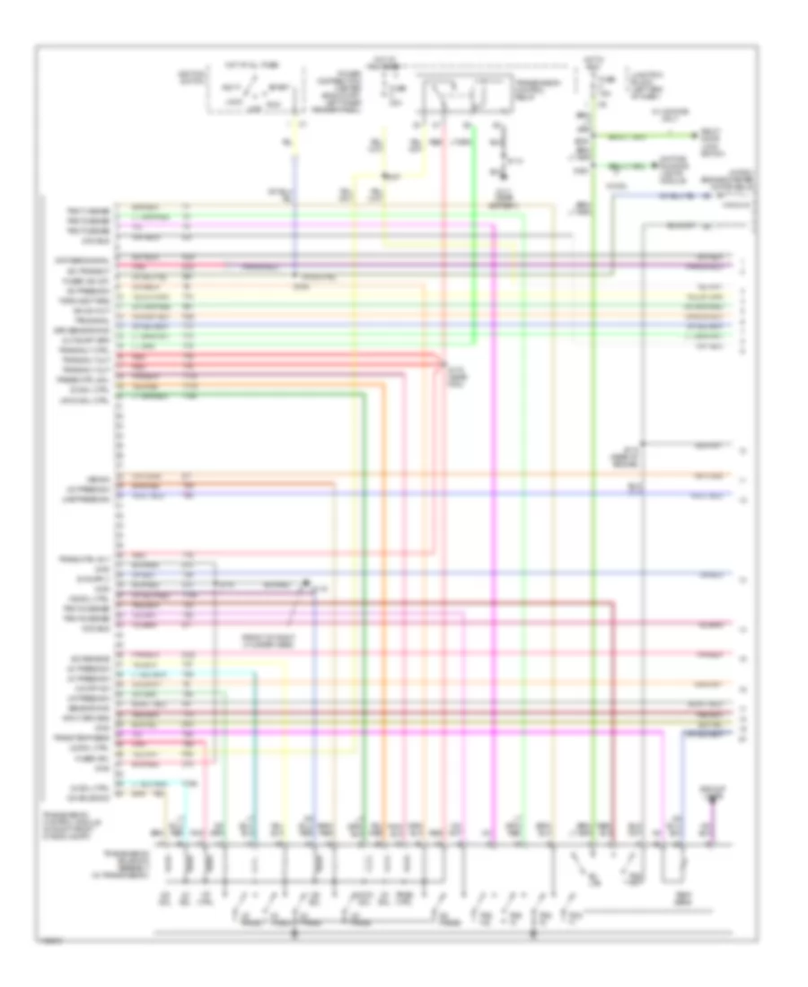
4.7L, A/T Wiring Diagram (1 of 2) for Dodge Dakota 2000
List of elements for 4.7L, A/T Wiring Diagram (1 of 2) for Dodge Dakota 2000:
- (front of right cylinder head)
- (in pdc) engine starter motor relay
- 2c press
- 2c press sw
- 2c sol
- 2c sol ctrl
- 4c press
- 4c press sw
- 4c sol
- 4c sol ctrl
- A41
- A81
- Acc
- Backup lamps
- Bu lps
- Ccd bus
- Ckp sens signal
- D21
- D22
- Daytime running lights module
- F84
- Fuse 15a
- Fuse f 20a
- Fused (b+)
- Fused ign (st)
- G111 (near battery)
- G119
- Gnd
- Hot at all times
- Hot in run
- Ign sw out
- Ignition switch
- Input spd sns
- Junction block (left end of dash)
- K22
- K24
- Line press sig
- Lock
- Lr press
- Lr press sw
- Lr/cc sol
- Lr/cc sol ctrl
- Ms sol
- Ms sol ctrl
- Od off sw
- Od press
- Od press sw
- Od sol
- Od solenoid
- Off
- Out shaft spd
- Pnk
- Power distribution center (eng compt, left inner fender panel)
- Pres ctrl
- Press ctrl sol
- Red
- Right door lock switch
- Run
- S113
- S115 (rear of engine)
- S163
- S175 (near pcm)
- S176
- S184
- S187
- S230
- Sci receive
- Sci transmit
- Sensor gnd
- Spd sensor gnd
- Start
- T10
- T118
- T119
- T13
- T14
- T140
- T15
- T150
- T159
- T16
- T29
- T30
- T38
- T42
- T43
- T47
- T48
- T50
- T54
- T59
- T60
- Temp sens
- Torq mgmt req
- Tps signal
- Trans ctrl rly
- Trans rly ctrl
- Trans rly out
- Trans temp sens
- Transmission control module (in right front of eng compt)
- Transmission control relay
- Transmission solenoid assembly (in transmission)
- Trs t1
- Trs t1 sense
- Trs t2
- Trs t2 sense
- Trs t3
- Trs t3 sense
- Trs t41
- Trs t42
- Trs t42 sense
- Trs t43 sense
- Ud ctrl
- Ud press
- Ud press sw
- Ud sol ctrl
- Vss sig
- W/ 4 doors only
- W/ drl
- Z13
- Z14
4.7L, A/T Wiring Diagram (2 of 2) for Dodge Dakota 2000
List of elements for 4.7L, A/T Wiring Diagram (2 of 2) for Dodge Dakota 2000:
- (between instrument cluster breakouts)
- (near pcm)
- (near right headlamp)
- (on left side of throttle body) throttle position sensor
- (on top of hydraulic control unit) controller anti-lock brake
- (rear of engine)
- (right rear of engine) s177
- (right rear side of cylinder block) crankshaft position sensor
- Ccd bus
- Ckp signal
- D21
- Data link connector (under dash, left of steering column)
- G202 (left side of dash)
- Gnd
- Input speed sensor (left front of transmission)
- Instrument cluster
- J/c 3 (behind left side of dash)
- J/c 4 (left side of dash)
- K22
- K24
- Line pressure sensor (on right side of transmission)
- Output shaft speed sensor (left side of transmission)
- Overdrive switch (center console)
- Powertrain control module (right front inner fender)
- Press sig
- Prndl
- S103
- S107
- S173
- S174 (near pcm)
- S178 (near tcm)
- S189 (near right headlamp)
- S191
- S201
- S259
- S261
- Sensor gnd
- Strt rly ctrl
- T10
- T41
- Torq sense
- Tps signal
- Vss sig
5.9L
5.9L, A/T Wiring Diagram for Dodge Dakota 2000
List of elements for 5.9L, A/T Wiring Diagram for Dodge Dakota 2000:
- (eng harn, rear of eng)
- (eng harn, right rear of eng)
- (rear of eng)
- 3-4 shift solenoid
- 4wd lock ind
- 4wd switch
- A14
- Anti-lock brakes system
- Automatic transmission solenoids (in transmission, on valve body)
- Brake sw in
- Ccd bus +
- Ccd bus -
- Controller anti- lock brake (on top of hydraulic control unit)
- D20
- D21
- Data link connector (under dash, left of steering column)
- Ect sens in
- Engine controls system
- Engine controls systems
- Engine coolant temperature sensor (front of intake manifold)
- F18
- Fuel pump relay
- Fuse 10a
- Fuse 20a
- Fuse f 20a
- Fused b(+)
- G110 (front of left cylinder head)
- G119 (front of right cyl head)
- G202 (left side of dash)
- Generator
- Generator field
- Gov press sen
- Ground
- Hot at all times
- Hot in run and start
- Hot in run or start
- I/o
- Ign power
- Instrument cluster
- J/c 2 (in pdc)
- J/c 3 (left side of dash)
- J/c 4 (left side of dash)
- Junction block
- K125
- K22
- K29
- K30
- K54
- Lock
- Mil ind
- Neutral
- Output shaft speed sensor (on left rear of transmission)
- Output ss ctrl
- Output ss sens
- Overdrive switch
- Pnk
- Power distribution center
- Powertrain control module (in eng compt, on right inner fender)
- Pressure sensor
- Prndl
- Processor
- Red
- S101 (rear of eng)
- S103
- S105
- S107
- S108
- S156 (in wiring trough)
- S171
- S186 (near pdc)
- S187
- S259
- Sci receive
- Sci transmit
- Sensor grd
- Shift sol ctrl
- Stoplight switch (on brake pedal bracket)
- T13
- T14
- T25
- T54
- T60
- Tcc sol ctrl
- Tcc solenoid
- Temp sensor
- Throttle position sensor (on left side of throttle body)
- Tps sens in
- Trans overdrv
- Trans rly ctrl
- Trans temp sen
- Transmission control relay
- Var frce sol ctrl
- Variable force solenoid
- Vss in
- Z12
WARNING SYSTEMS
Warning System Wiring Diagrams, Base for Dodge Dakota 2000
List of elements for Warning System Wiring Diagrams, Base for Dodge Dakota 2000:
- (2-door)
- (4-door only)
- (4-door)
- (left door sill) s345
- (left side of dash) s202
- Central timer module (behind right side of dash)
- F12
- F35
- Fuse 11 10a
- Fuse 13 20a
- Fuse 6 20a
- Fused b (+)
- Fused ign
- G10
- G100 (front of left front fender)
- G16
- G201 (right side of dash)
- G202 (left side of dash)
- G26
- G74
- Ground
- Head- lamp switch head
- Hot at all times
- Hot in run or acc
- Hot in run or start
- I/o processor
- Instrument cluster
- J/c 4 (left side of dash)
- Junction block (left end of dash)
- Key-in switch
- Key-in/lights on sense
- Left door open sense
- Left front door jamb switch
- Left rear door jamb switch
- Off
- Park
- Red
- Right door open sense
- Right front door jamb switch
- Right rear door jamb switch
- S201
- S344
- Seat- belt switch
- Sens ground
- Tan/ red
- Tan/red
- Tone request signal
Warning System Wiring Diagrams, Premium Model for Dodge Dakota 2000
List of elements for Warning System Wiring Diagrams, Premium Model for Dodge Dakota 2000:
- (2-door)
- (4-door only)
- (4-door)
- (left door sill) s345
- (left side of dash) s202
- Central timer module (behind right side of dash)
- F12
- F35
- Fuse 11 10a
- Fuse 13 20a
- Fuse 6 20a
- Fused b (+)
- Fused ign
- G10
- G100 (front of left front fender)
- G16
- G201 (right side of dash)
- G202 (left side of dash)
- G26
- G74
- Ground
- Head- lamp switch head
- Hot at all times
- Hot in run or acc
- Hot in run or start
- I/o processor
- Instrument cluster
- J/c 4 (left side of dash)
- Junction block (left end of dash)
- Key-in switch
- Key-in/lights on sense
- Left door open sense
- Left front door jamb switch
- Left rear door jamb switch
- Off
- Park
- Red
- Right door open sense
- Right front door jamb switch
- Right rear door jamb switch
- S201
- S344
- S347 (vtss) (near left door speaker)
- S349 (vtss) (front of right front door)
- Seat- belt switch
- Sens ground
- Tan/ red
- Tan/red
- Tone request signal
WIPER/WASHER
Wiper/Washer Wiring Diagram for Dodge Dakota 2000
List of elements for Wiper/Washer Wiring Diagram for Dodge Dakota 2000:
- (base)
- (near right headlamp breakout) s189
- (premium)
- 87a
- Ccd bus (+)
- Ccd bus (-)
- Central timer module (behind right side of dash)
- Computer data lines
- Control module)
- Controller anti-lock brake (left front inner fender panel)
- Data link connector (lower left side of dash)
- Delay
- Fuse 6 20a
- G101 (right front inner fender)
- G111 (near battery)
- Hot in acc or run
- J/c 2 (in pdc)
- J/c 3 (left side of dash)
- Junction block (left end of dash)
- Multi-function switch
- Off
- Park switch
- Powertrain control module (on right front inner fender)
- S113
- S170
- S190 (near right headlamp breakout)
- S204 (near ignition switch)
- S205 (near ignition switch)
- Transmission control module (on radiator core support)
- V10
- V18
- V51
- V52
- Vehicle speed sensor signal
- Vss output
- Vss signal
- W/ 4.7l a/t only
- Wash sense
- Washer switch
- Windshield washer pump (at washer reservoir)
- Wiper delay
- Wiper enable
- Wiper park sense
- Wiper relay (in pdc)
- Wiper relay control
- Wiper switch
- Wper motor (left side of firewall)