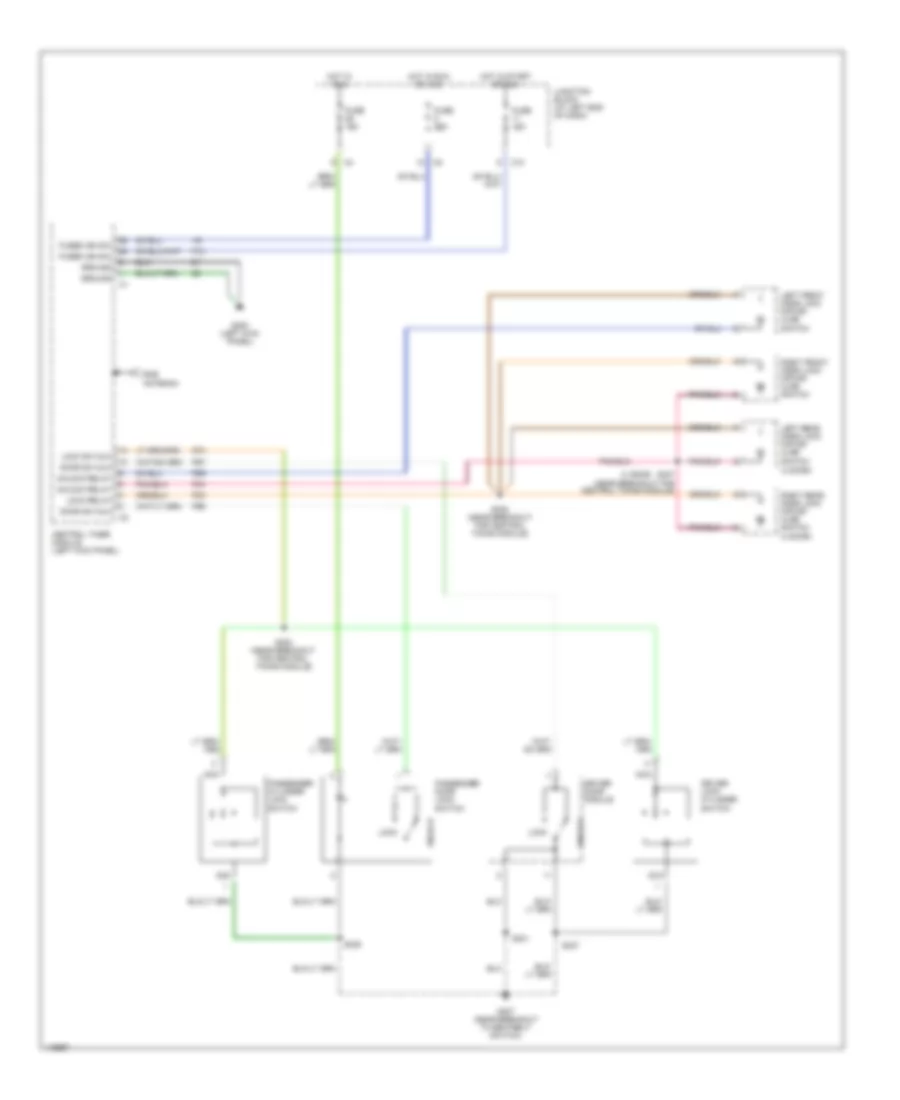
AIR CONDITIONING
Manual A/C Wiring Diagram for Dodge Dakota 2002

List of elements for Manual A/C Wiring Diagram for Dodge Dakota 2002:
- (lower center of dash) g207
- (near powertrain control module) s135
- (rear of engine) s103
- (right fender side shield) g112
- (top rear of valve cover, right front of engine) g105
- 1: vent 2: vent/floor 3: floor 4: defrost/floor 5: defrost
- A/c
- A/c clutch relay ctrl
- A/c compressor clutch
- A/c compressor clutch relay
- A/c heater control
- A/c low pressure switch
- A/c pressure signal
- A/c pressure transducer
- A/c select
- A/c switch sense
- Acc
- Ambient temp sens signal
- Ambient temperature sensor (behind right side of grille on radiator support)
- Blend door actuator
- Blend door driver
- Blower motor (in passenger side end of heater-a/c housing, below glove box)
- Blower motor resistor block (above passenger's footwell)
- Blower switch
- C11
- Common door driver
- Data link connector (dlc) (under dash, left of steering column)
- Defogger system
- Diagnostic junction port (under dash, right of steering column)
- Evaporator temperature sensor (on upper center of dash)
- Except 3.9l, 5.9l a/t
- Fuse 10a
- Fuse 40a
- Fuse b 10a
- Ground
- Heated mirror
- High
- Hot at all times
- Hot in run
- Hot in run or start
- Htd mir
- Hvac controller
- Ignition switch
- Interior lights system
- J/c 2 (in power distribution center)
- J/c 3 (in power distribution center)
- Junction block (on left end of dash)
- Lock
- Low
- Med 1
- Med 2
- Mode door actuator
- Off
- Pci bus
- Power distribution center (in engine compartment, on left inner fender panel)
- Powertrain control module (in engine compartment, on right inner fender panel)
- Radiator fan motor (behind radiator)
- Radiator fan relay
- Radiator fan relay ctrl
- Recirc
- Recirc door driver
- Recirculation door actuator
- Run
- S121 (near mode door motor)
- Sensor ground
- Sensor signal
- Signal
- Start
- Tan
- W/3.9l, 5.9l a/t
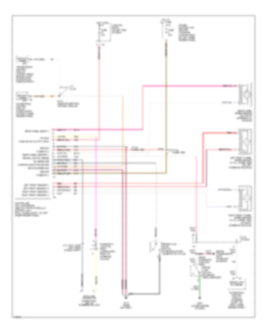
ANTI-LOCK BRAKES
Anti-lock Brake Wiring Diagrams for Dodge Dakota 2002
List of elements for Anti-lock Brake Wiring Diagrams for Dodge Dakota 2002:
- (4.7l only)
- (near diagnostic junction port)
- (under dash, left of steering column)
- 4.7l w/ a/t
- A10
- A20
- B113
- B114
- Brake fluid level switch (in brake system combination valve)
- Brake lamp sw sense
- Brake lamp switch (on brake pedal bracket)
- Brake transmission shift interlock solenoid
- Controller anti-lock brake (abs: on top of hydraulic control unit, rwal: in eng compt, on left inner fender panel)
- D25
- Data link connector
- Diagnostic junction port (under dash, right of steering column)
- Fuse 10a
- Fuse 40a
- Fuse ign sw output (run)
- Fused b (+)
- G113 (near battery)
- G207 (lower center of dash)
- Ground
- Hot at all times
- Hot in run
- J/c 2 (in pdc)
- Junction block (on left end of dash)
- Left front sensor (+)
- Left front sensor (-)
- Left front wheel speed sensor (w/ all wheel abs) (on left steering knuckle)
- Pci bus
- Power distribution center (in engine compartment, on left inner fender panel)
- Powertrain control module (in eng compt, on right inner fender panel)
- Powertrain control module (in engine compt, on right inner fender panel)
- Rear wheel sens (+)
- Rear wheel sensor (-)
- Rear wheel speed sensor (on top of differential housing)
- Red
- Right front sensor (+)
- Right front sensor (-)
- Right front wheel speed sensor (w/ all wheel abs) (on right steering knuckle)
- S126
- S174 (near powertrain control module)
- S190 (left rear of eng compt)
- Sci receiver
- Transmission control module (in right front engine compt, on radiator core support)
- V40
- Vehicle speed sig
- W/ all wheel abs
- Warning indicator driver
- Z19
ANTI-THEFT
Anti-theft Wiring Diagram (1 of 2) for Dodge Dakota 2002
List of elements for Anti-theft Wiring Diagram (1 of 2) for Dodge Dakota 2002:
- A301
- A302
- Base
- Base 2 door
- Base 4 door
- C10
- Central timer module (left kick panel)
- Cyl lock sw mux
- D25
- Door ajar sw
- Door sw mux
- Driver cylinder lock switch
- Driver door ajar switch
- F12
- Fuse 10a
- Fuse 15a
- Fuse 20a
- Fused b+
- Fused ign
- Fused ign sw
- G112 (right fender side shield)
- G113 (near battery)
- G208 (left kick panel)
- G307 (near breakout to seatbelt switch)
- G69
- G73
- G74
- G75
- Ground
- High beam driver
- High note horn (at front left center of vehicle)
- Horn relay
- Horn relay cntrl
- Hot at all times
- Hot in run
- Hot in run or acc
- Hot in run or start
- Instrument cluster
- Junction block (on left end of dash)
- L33
- L34
- Left headlamp
- Left rear door ajar switch
- Lh high beam
- Lock
- Low note horn (at front left center of vehicle)
- Nca
- P96
- P97
- Passenger cylinder lock switch
- Passenger door ajar switch
- Pci bus
- Pnk
- Premium
- Red/tan
- Rh high beam
- Right headlamp
- Right rear door ajar switch
- S303 (near breakout for central tan/ red
- S327
- S328
- Sentry key immobilizer module (right side of steering column)
- Tan
- Tan/ red
- Tan/red
- Timer module)
- Unlock
- Vtss ind driv
- Vtss lamp
- Wiper park sw
Anti-theft Wiring Diagram (2 of 2) for Dodge Dakota 2002
List of elements for Anti-theft Wiring Diagram (2 of 2) for Dodge Dakota 2002:
- (under dash, left of steering column) data link connector (dlc)
- Diagnostic junction port (under dash, right of steering column)
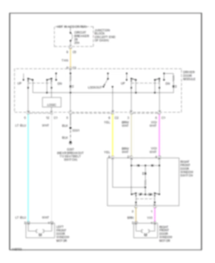
- Driver door module
- Driver door power lock motor/ ajar switch
- Fuse 20a
- G307 (near breakout to seatbelt switch)
- Hot at all times
- Instrument cluster
- Left rear door power lock motor/ ajar switch
- Lock
- Passenger door power lock motor/ ajar switch
- Passenger door power lock switch
- Pci bus
- Power distribution center (on left inner fender panel)
- Powertrain control module (on right inner fender panel)
- Premium
- Premium 2 door
- Premium 4 door
- Red/ tan
- Red/tan
- Right rear door power lock motor/ ajar switch
- S301
- S303 (near breakout for central timer module)
- S327
- S328
- Tan
- Tan/ red
- Tan/red
- Unlock
BODY COMPUTER
Body Computer Wiring Diagrams for Dodge Dakota 2002
List of elements for Body Computer Wiring Diagrams for Dodge Dakota 2002:
- A301
- A302
- C10
- Cargo lamp
- Cargo lamp sw
- Central timer module (left kick panel)
- Computer data lines system
- Courtesy lamp
- Courtesy lamp sw
- Cyl lock sw
- D25
- Door lock rly
- Door locks system
- Door unlock rly
- Drvr door ajar
- Drvr door sw
- Drvr door unlk rly
- Exterior lights system
- F12
- Fog lamp rly
- Fog lamp sw
- Frt washer motor
- Frt wiper motor
- Frt wiper park sw
- Frt wiper rly
- Fuse 10a
- Fuse 20a
- Fused b+
- G11
- G207 (lower center of dash) instrument cluster system
- G208 (left kick panel)
- G26
- G34
- G69
- G73
- G74
- G75
- Glove box lamp
- Ground
- Headlamp sw off
- Headlamps system
- High beam ind
- High beam rly
- Horn rly
- Horns system
- Hot at all times
- Hot in run or acc
- Hot in run or start
- Ignition (run/acc)
- Ignition (run/start)
- Instrument cluster system
- Int frt wiper mode
- Int frt wiper sw
- Interior lamp defeat
- Interior lamps
- Interior lights system
- Junction block (left end of dash)
- Key-in ignition sw
- L26
- L27
- L308
- L33
- L34
- L43
- L44
- L79
- L80
- Left high beam
- Left low beam
- Low beam sw
- M11
- P33
- P34
- P59
- P96
- P97
- Park brake sw
- Park brake switch (on park brake pedal bracket)
- Park lamp rly
- Park lamp sw
- Pass door ajar sw
- Pass door sw
- Pci bus
- Power distribution center (left front inner fender panel)
- Radio ctrl mux
- Red/ tan
- Red/tan
- Right high beam
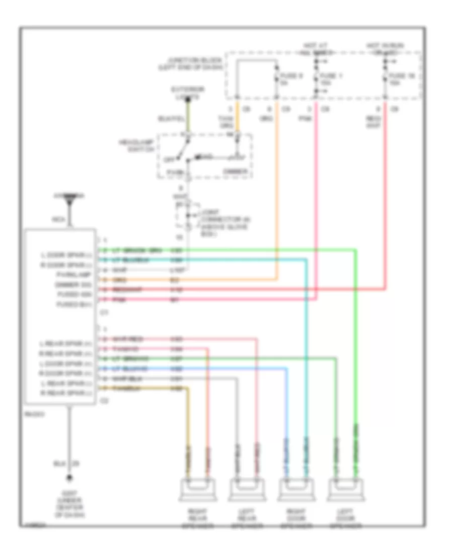
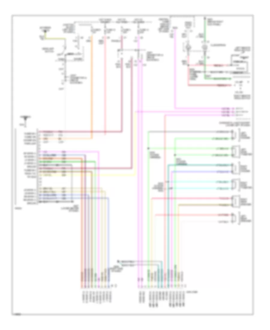
- Right low beam
- Sound systems
- Tan
- Tan/red
- V10
- V18
- V51
- V52
- Vtss ind
- Warning systems
- Wiper/washer system
- X20
- Y158
- Y192
COMPUTER DATA LINES
Computer Data Lines for Dodge Dakota 2002
List of elements for Computer Data Lines for Dodge Dakota 2002:
- (4.7l (jtec) only)
- (dakota)
- (durango)
- (left rear of engine compt)
- (other)
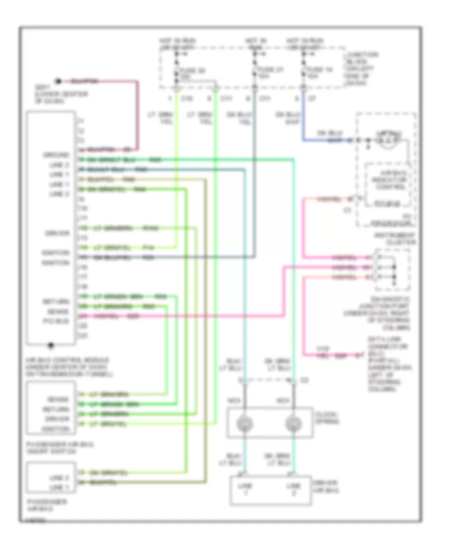
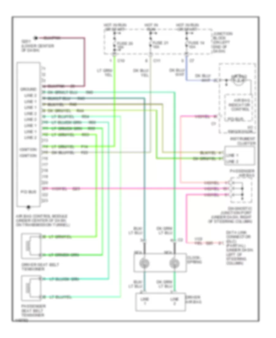
- A/c-heater control
- Air bag control module (under center of dash, on trans tunnel)
- Amplifier (behind right kick panel)
- C10
- Central timer module (durango: behind left side of dash) (dakota: left kick panel)
- Controller anti-lock brake (w/ abs: on top of hydraulic control unit) (w/ rwal: in engine compt, on left inner fender panel)
- D15
- D20
- D21
- D22
- D25
- Data link connector (dlc) (under dash, left of steering column)
- Diagnostic junction port (durango: under left side of dash) (dakota: under dash, right of steering column)
- Fuse 15a
- G208 (left kick panel)
- Hot at all times
- Instrument cluster
- Joint connector 1 (in pdc)
- Jtec
- Junction block (on left end of dash)
- Left side impact air bag control module (durango only) (at base of left "b" pillar, behind trim)
- Ngc
- Overhead console
- Pci bus
- Pnk
- Powertrain control module (in engine compt, on right inner fender panel)
- Radio
- Right side impact air bag control module (durango only) (at base of right "b" pillar, behind trim)
- S124
- S190
- Sci receive
- Sci transmit
- Sentry key immobilizer module (durango: on steering column) (dakota: behind left side of dash, right of steering column)
- Transfer case control module (right side of steering column)
- Transmission control module (on radiator core right support)
- W/ 4.7l (jtec) only
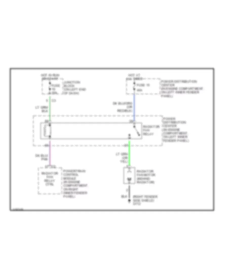
COOLING FAN
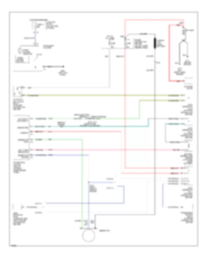
Cooling Fan Wiring Diagram for Dodge Dakota 2002
List of elements for Cooling Fan Wiring Diagram for Dodge Dakota 2002:
- (right fender side shield) g112
- 40a
- Fuse 10a
- Fuse 15
- Hot at all times
- Hot in run or start
- Junction block (on left end of dash)
- Power distribution center (in engine compartment, on left inner fender panel)
- Powertrain control module (in engine compartment, on right inner fender panel)
- Radiator fan motor (behind radiator)
- Radiator fan relay
- Radiator fan relay ctrl
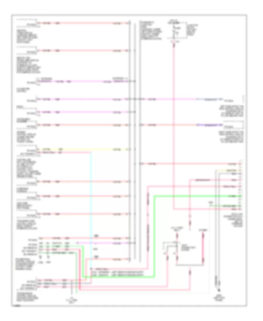
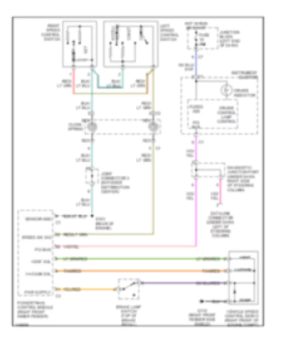
CRUISE CONTROL
Cruise Control Wiring Diagram for Dodge Dakota 2002
List of elements for Cruise Control Wiring Diagram for Dodge Dakota 2002:
- Accel/ resume
- Brake lamp switch (top of brake pedal)
- Cancl
- Clock- spring
- Coast
- Cruise control lamp control
- Cruise indicator
- Datalink connector (under dash, left of steering column)
- Diagnostic junction port (under dash, right side of steering column)
- Dump
- Fuse 10a
- Fused ign
- G112 (right front fender side shield)
- Hot in run or start
- Instrument cluster
- Joint connector 3 (in power distribution center)
- Junction block (left end of dash)
- Left speed control switch
- Nca
- On/off
- Pci bus
- Powertrain control module (right front inner fender)
- Right speed control switch
- S103 (rear of engine)
- Sensor gnd
- Set
- Speed sw sig
- Tan/red
- Vacuum
- Vacuum sol
- Vehicle speed control servo (right front of engine compt)
- Vent
- Vent sol
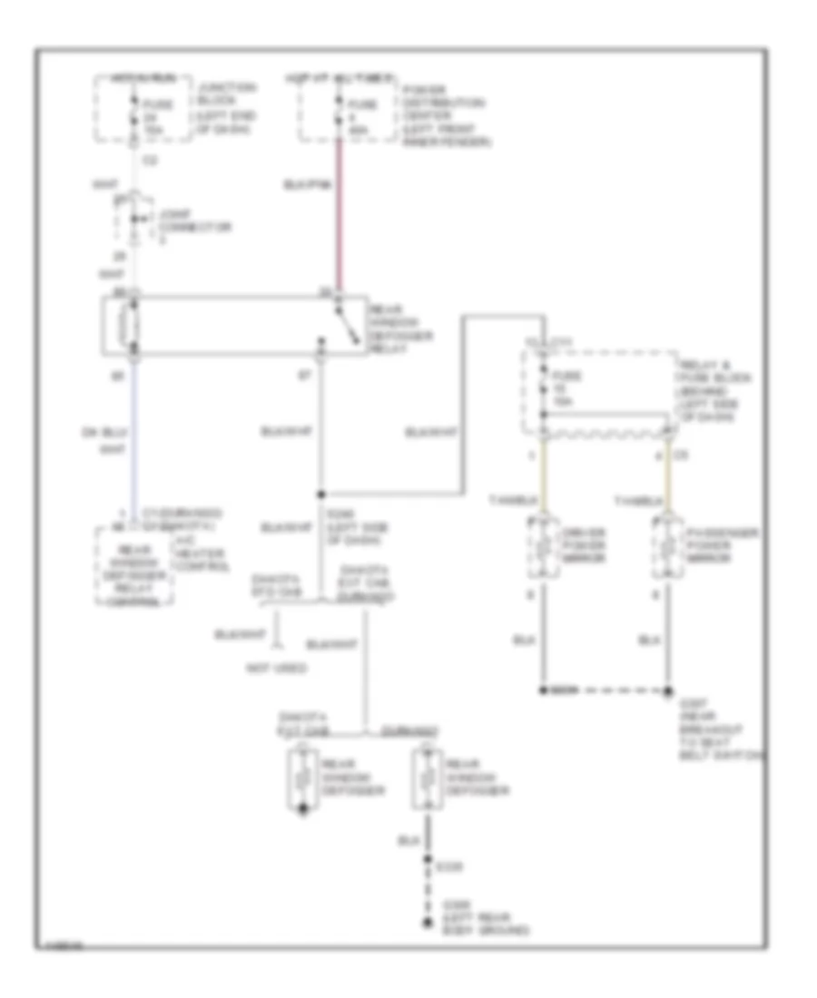
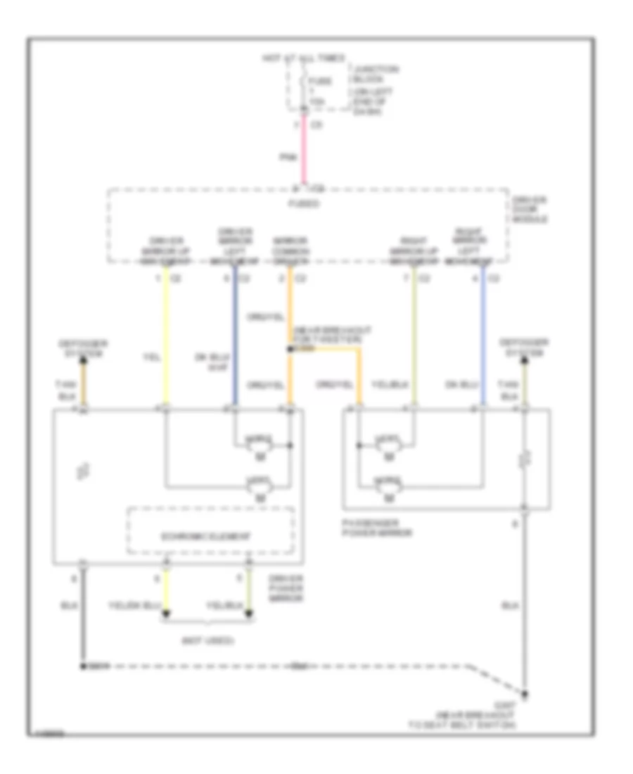
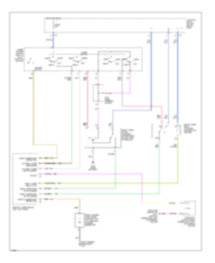
DEFOGGERS
Defogger Wiring Diagram for Dodge Dakota 2002
List of elements for Defogger Wiring Diagram for Dodge Dakota 2002:
- (durango) (dakota)
- (left end of dash)
- A/c heater control
- C1 c1
- C11
- Dakota ext cab
- Dakota ext cab, durango
- Dakota std cab
- Driver power mirror
- Durango
- Fuse 10a
- Fuse 15a
- Fuse 40a
- G306 (left rear body ground)
- G307 (near breakout to seat belt switch)
- Hot at all times
- Hot in run
- Joint connector
- Junction block
- Not used
- Passenger power mirror
- Power distribution center (left front inner fender)
- Rear window defogger
- Rear window defogger relay
- Rear window defogger relay control
- Relay & fuse block (behind left side of dash)
- S240 (left side of dash)
- S301
- S335
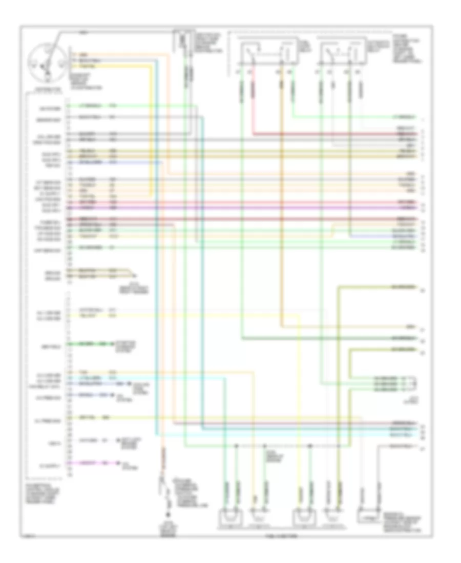
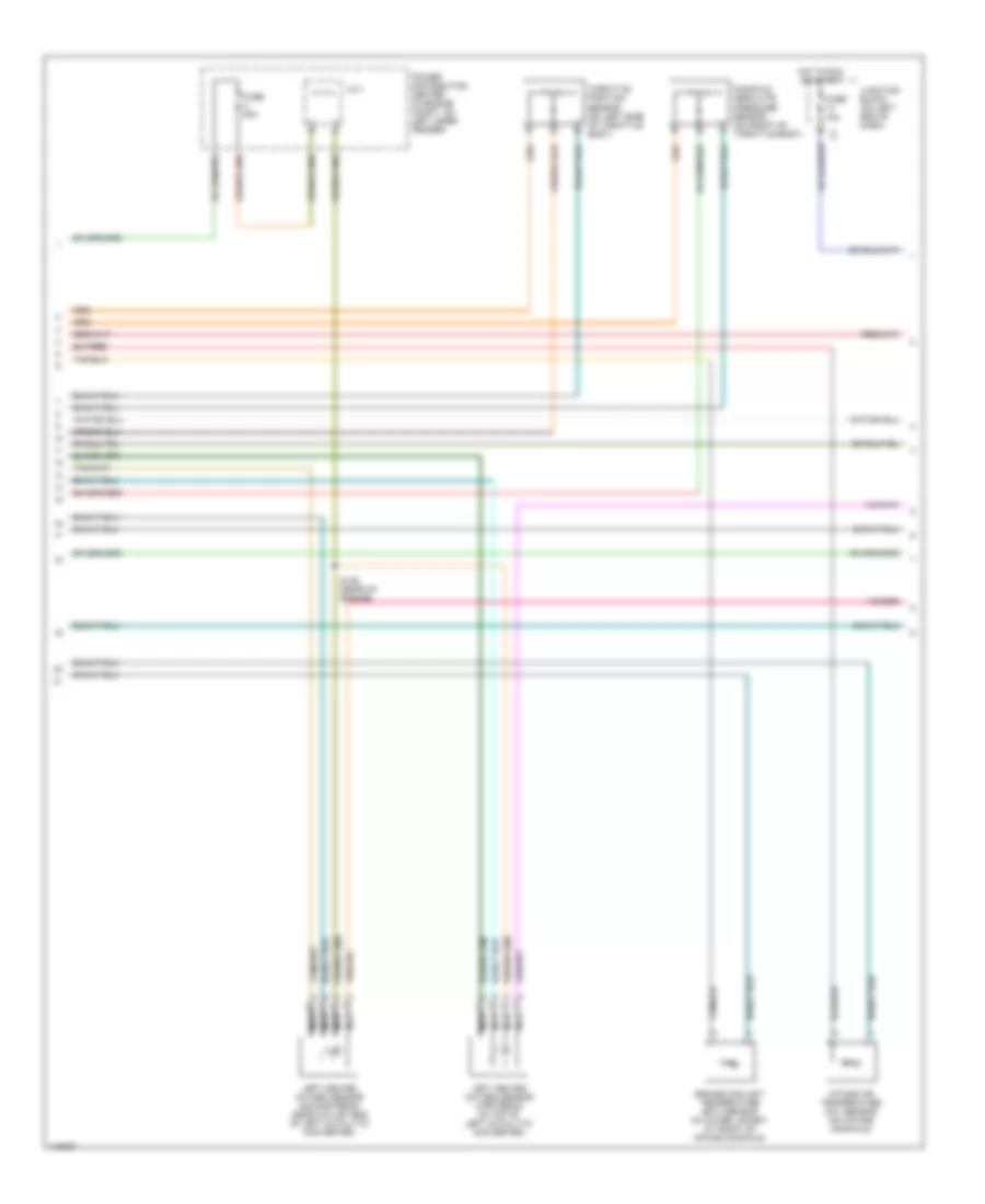
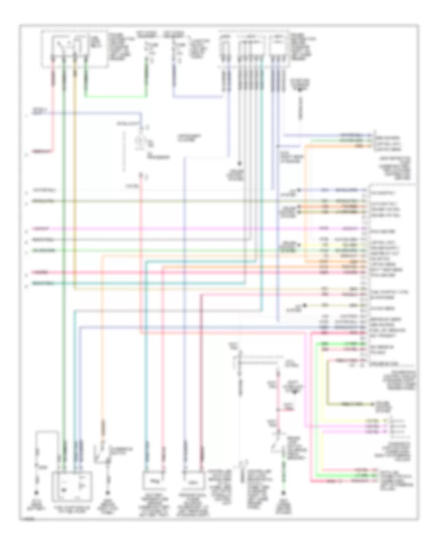
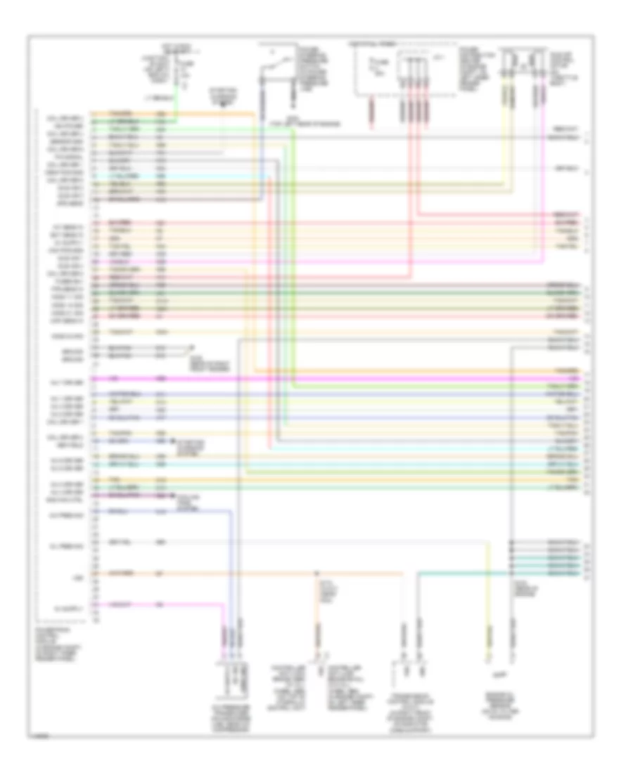
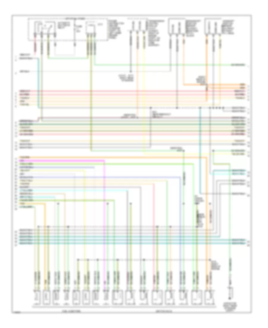
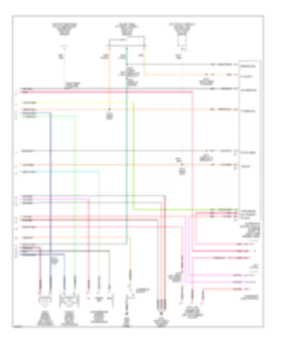
ENGINE PERFORMANCE
2.5L
2.5L, Engine Performance Wiring Diagrams (1 of 3) for Dodge Dakota 2002
List of elements for 2.5L, Engine Performance Wiring Diagrams (1 of 3) for Dodge Dakota 2002:
- (in distributor)
- A/c pres sig
- A/c system
- A14
- Anti-lock brakes system
- Automatic shutdown relay
- C18
- C24
- Cam pos sns
- Camshaft position sensor
- Coil driver
- Cooling fans system
- Crnk pos sns
- Distributor
- Dn ho2s sig
- Ect sens sig
- Engine oil pressure sensor (on right side of engine block, near distributor)
- F18
- Fan relay cntl
- Fuel injectors
- Fuel pump relay
- Fused b(+)
- G105 (top left rear of engine)
- G115 (rear of right front fender)
- G60
- Gen field
- Ground
- Iat sens sig
- Idle air 1
- Idle air 2
- Idle air 3
- Idle air 4
- Ign power
- Ignition coil (right side of engine, behind distributor)
- Inj 1 driver
- Inj 2 driver
- Inj 3 driver
- Inj 4 driver
- J/c 2 (in pdc)
- K10
- K11
- K12
- K13
- K14
- K141
- K19
- K20
- K21
- K22
- K24
- K39
- K40
- K41
- K44
- K59
- K60
- Map sens sig
- Nca
- Oil pres sns
- Power distribution center (in engine compt, on left inner fender panel)
- Power steering pressure switch (in power steering pressure line)
- Powertrain control module (in engine compt, on right inner fender panel)
- Psp sw
- S106 (rear of engine)
- Sensor gnd
- Starting/ charging system
- Tan
- Tps sens sig
- Up ho2s sig
- Vss in
- Z12
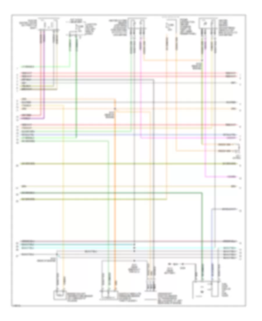
2.5L, Engine Performance Wiring Diagrams (2 of 3) for Dodge Dakota 2002
List of elements for 2.5L, Engine Performance Wiring Diagrams (2 of 3) for Dodge Dakota 2002:
- Crankshaft position sensor (in transmission bellhousing, at left rear side of engine)
- Engine coolant temperature sensor (on thermostat housing)
- Fuel pump module (at fuel pump)
- Fuse 10a
- Fuse u 20a
- G113 (near battery)
- Heated oxygen sensor (downstream) (near outlet end of catalyic converter)
- Heated oxygen sensor (upstream) (in exhaust pipe forward of catalytic converter)
- Hot in run or start
- Idle air control motor (on throttle body)
- J/c 1 (in pdc)
- Junction block (on left end of dash)
- Manifold absolute pressure sensor (on side of throttle body)
- Nca
- Power distribution center (in engine compt, on left inner fender panel)
- S101 (near breakout for inj 3)
- S103 (rear of engine)
- S107 (rear of engine)
- S122 (rear of engine)
- S306
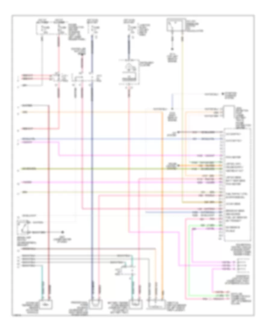
2.5L, Engine Performance Wiring Diagrams (3 of 3) for Dodge Dakota 2002
List of elements for 2.5L, Engine Performance Wiring Diagrams (3 of 3) for Dodge Dakota 2002:
- A/c comp rly
- A/c low pressure switch (on accumulator)
- A/c sw sens
- A/c system
- A142
- Asd relay out
- Auto sht rly
- Batt temp sens
- Battery temper- ature sensor (under battery, attached to battery tray)
- Brake lamp switch (on brake pedal bracket)
- Brake sw sens
- C13
- C20
- Controller anti-lock brake
- Cruise control system
- D20
- D21
- D25
- Data link connector (dlc) (under dash, left of steering column)
- Diagnostic junction port (under dash, right of steering column)
- Evap/purge sol
- Fuel lev sens sig
- Fuel pmp rly ctrl
- Fuse 10a
- Fuse 20a
- Fuse 30a
- G114 (top left rear of engine)
- G207 (under center of dash)
- Gen source
- Hot at all times
- Hot in on or start
- I/o processor
- Instrument cluster
- Intake air temperature sensor (on intake manifold)
- J/c 1 (in pdc)
- J/c 2 (in pdc)
- J/c 3 (in pdc)
- Junction block (on left end of dash)
- K100
- K106
- K107
- K118
- K125
- K200
- K226
- K31
- K51
- K52
- Ldp sol cntl
- Ldp sw sens
- Leak detection pump (under battery tray & power distribution center)
- Mil ind
- Pci bus
- Pnk
- Power distribution center (in engine compt, on left inner fender panel)
- Powertrain control module (in engine compt, on right inner fender panel)
- Proportional purge solenoid (on bracket, at right rear side of eng compt)
- Pwm heater
- S123 (right rear of engine)
- Sci receive
- Sci transmit
- Starting/ charging system
- Throttle position sensor (on left side of throtlle body)
- V32
- V40
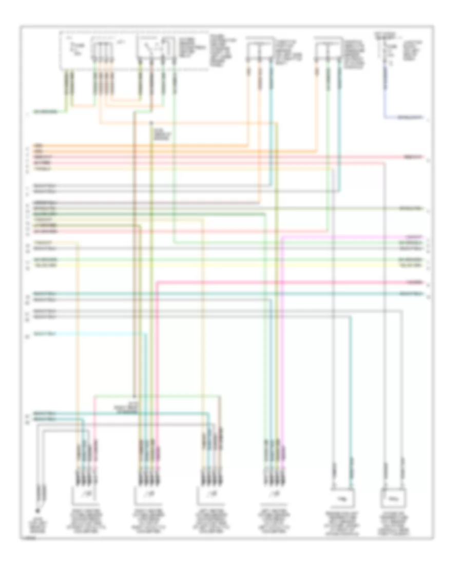
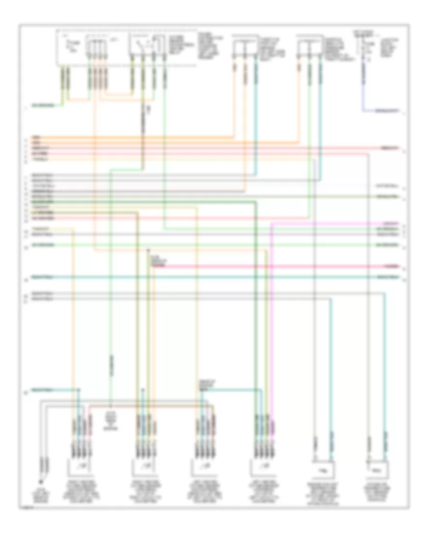
3.9L
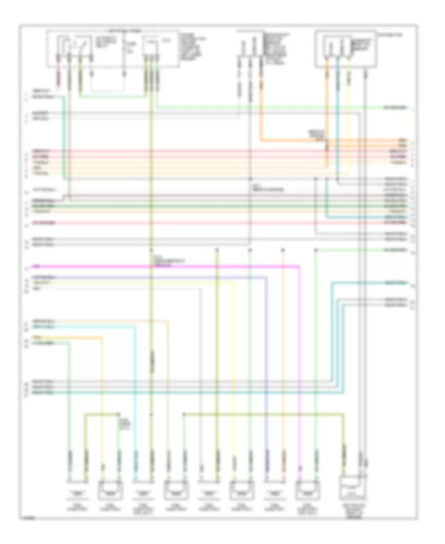
3.9L, Engine Performance Wiring Diagrams, California (1 of 4) for Dodge Dakota 2002
List of elements for 3.9L, Engine Performance Wiring Diagrams, California (1 of 4) for Dodge Dakota 2002:
- (5.9l only)
- (near pcm)
- 3-4 shift
- A/c pres sig
- A/c pressure transducer (on discharge line, near a/c compressor)
- A/c sig
- A/t temp sig
- A14
- C106
- C18
- C24
- Cam pos sns
- Coil driver
- Controller anti-lock brake (abs) (w/ all- wheel abs) (on top of hydraulic control unit)
- Controller anti-lock brake (rwal) (w/o all- wheel abs) (in engine compt, on left inner fender panel)
- Cooling fans system
- Crnk pos sns
- Ect sens in
- Engine oil pressure sensor (on top rear of engine block, near distributor)
- F18
- Fuse 10a
- Fuse 20a
- Fuse f 20a
- Fused b(+)
- G115 (rear of right front fender)
- G60
- Gen field
- Gov pres cntl
- Gov pres sig
- Ground
- Ho2s 1/1 sig
- Ho2s 1/2 sig
- Ho2s 2/1 sig
- Ho2s 2/2 sig
- Hot at all times
- Hot in run or start
- Iat sens in
- Idle air 1
- Idle air 2
- Idle air 3
- Idle air 4
- Idle air control motor (on throttle body)
- Ign power
- Inj 1 driver
- Inj 2 driver
- Inj 3 driver
- Inj 4 driver
- Inj 5 driver
- Inj 6 driver
- Inj 7 driver
- Inj 8 driver
- J/c 1
- Junction block (on left end of dash)
- K11
- K12
- K13
- K14
- K141
- K19
- K20
- K21
- K22
- K24
- K241
- K26
- K28
- K30
- K341
- K38
- K39
- K40
- K41
- K44
- K54
- K58
- K59
- K60
- K88
- Map sens in
- Od sol cntl
- Oil pres sig
- Out spd sig
- Output speed sensor (on lower left rear of trans)
- P/n signal
- Pnk
- Power distribution center (in engine compt, on left inner fender)
- Powertrain control module (in engine compt, on right inner fender panel)
- Rad fan ctrl
- Red
- S103 (rear of engine)
- S135
- Sens gnd
- Sensor gnd
- Spd sens gnd
- Starting/ charging system
- T13
- T14
- T25
- T34
- T41
- T60
- Tan
- Tcc sol cntl
- Tps sens in
- Trans rly cntl
- Trans rly out
- Transmission control relay
- Transmission solenoid assembly (in transmission, on valve body)
- Vss
- Z12
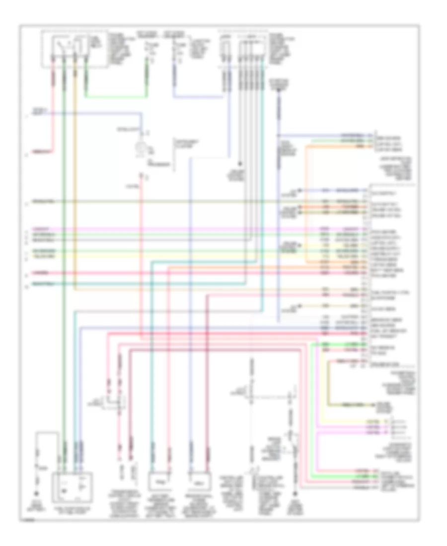
3.9L, Engine Performance Wiring Diagrams, California (2 of 4) for Dodge Dakota 2002
List of elements for 3.9L, Engine Performance Wiring Diagrams, California (2 of 4) for Dodge Dakota 2002:
- (rear of engine) s107
- 5v sup
- Automatic shutdown relay
- Camshaft position sensor
- Cps sig
- Distributor
- Fuel injector 1
- Fuel injector 2
- Fuel injector 3
- Fuel injector 4
- Fuel injector 5
- Fuel injector 6
- Fuel injector 7 (5.9l only)
- Fuel injector 8 (5.9l only)
- Fuse 30a
- Hot at all times
- Ignition coil (on right front of engine)
- J/c 2
- Nca
- Power distribution center (in engine compt, on left inner fender)
- S101 (rear of engine)
- S106 (near inj 4)
- S110 (near breakout for inj 5)
- Sens gd
- Sens gnd
- Tan
3.9L, Engine Performance Wiring Diagrams, California (3 of 4) for Dodge Dakota 2002
List of elements for 3.9L, Engine Performance Wiring Diagrams, California (3 of 4) for Dodge Dakota 2002:
- (rear of engine) s139
- C106
- Engine coolant temperature (ect) sensor (in water jacket, at front of intake manifold)
- Fuse 10a
- Fuse u 20a
- G105 (top left rear of engine)
- Hot in run or start
- Intake air temperature (iat) sensor (on intake manifold)
- J/c 1
- Junction block (on left end of dash)
- Left heated oxygen sensor (downstream) (near outlet end of left catalytic converter)
- Left heated oxygen sensor (upstream) (in top of left catalytic converter)
- Manifold absolute pressure sensor (on front of throttle body)
- Nca
- Oxygen sensor downstream heater relay
- Power distribution center (in engine compt, on left inner fender)
- Right heated oxygen sensor (downstream) (near outlet end of right catalytic converter)
- Right heated oxygen sensor (upstream) (in top of right catalytic converter)
- S136 (rear of engine)
- S179 (right rear of engine)
- Throttle position sensor (on left side of throttle body)
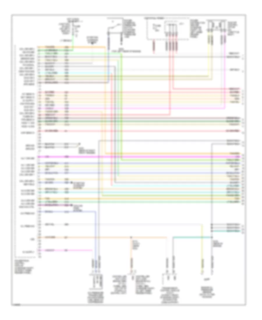
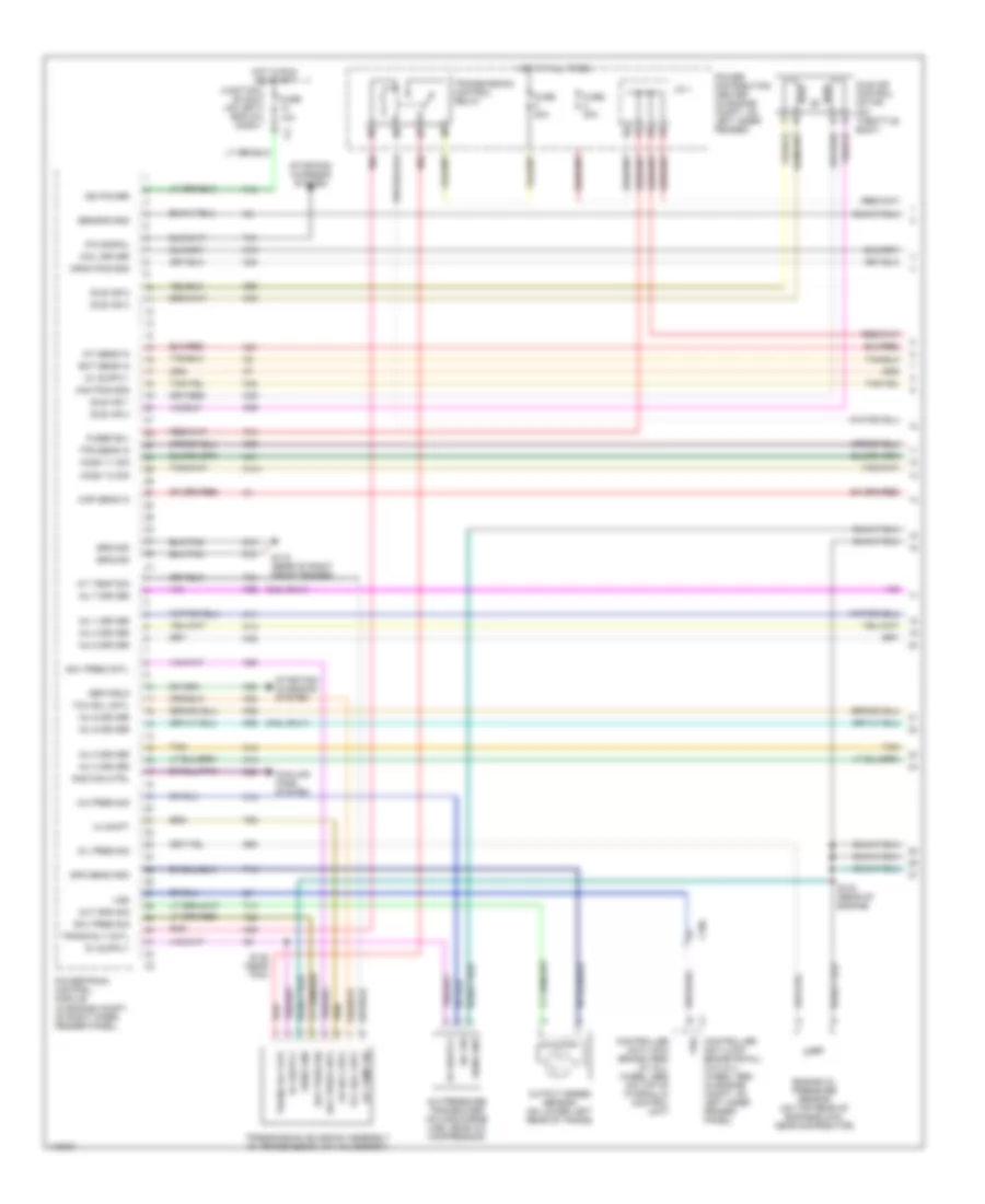
3.9L, Engine Performance Wiring Diagrams, California (4 of 4) for Dodge Dakota 2002
List of elements for 3.9L, Engine Performance Wiring Diagrams, California (4 of 4) for Dodge Dakota 2002:
- A/c comp rly
- A/c sw sens
- A/c system
- A142
- Asd relay out
- Auto sht rly
- Batt temp sens
- Battery temperature sensor (under battery, attached to battery tray)
- Brake lamp switch (on brake pedal bracket)
- Brake sw sens
- C13
- C20
- Controller anti-lock brake (abs) (w/ all- wheel abs) (on top of hydraulic control unit)
- Controller anti-lock brake (rwal) (w/o all- wheel abs) (in engine compt, on left inner fender panel)
- Cruise control system
- Cruise sw sig
- Cruise vac sol
- Cruise vnt sol
- D20
- D21
- D25
- Data link connector (dlc) (under dash, left of steering column)
- Diagnostic junction port (under dash, right of steering column)
- Evap/purge
- Fuel lev sens sig
- Fuel pump module (at fuel pump)
- Fuel pump relay
- Fuel pump rly ctrl
- Fuse 10a
- G113 (near battery)
- G207 (under center of dash)
- G208 (behind right kick panel)
- Gen source
- Ho2s dwn cntl
- Hot in run or start
- I/o processor
- Instrument cluster
- J/c 1
- J/c 2
- J/c 2 (in pdc)
- J/c 3
- Junction block (on left end of dash)
- K100
- K106
- K107
- K118
- K125
- K200
- K226
- K31
- K51
- K512
- K52
- Ldp sol cntl
- Ldp sw sens
- Leak detection pump (under battery tray & power distribution center)
- Mil ind
- Od off sw
- Overdrive switch
- Pci bus
- Pnk
- Power distribution center (in engine compt, on left inner fender)
- Powertrain control module (in engine compt, on right inner fender panel)
- Proportional purge solenoid (on bracket, at left rear side of engine compt)
- Pwm heater
- S123 (right rear of engine)
- S306
- Sci receive
- Sci transmit
- Sensor
- Shift interlock system
- Starting/ charging system
- Tan/red
- V32
- V35
- V36
- V37
- V40
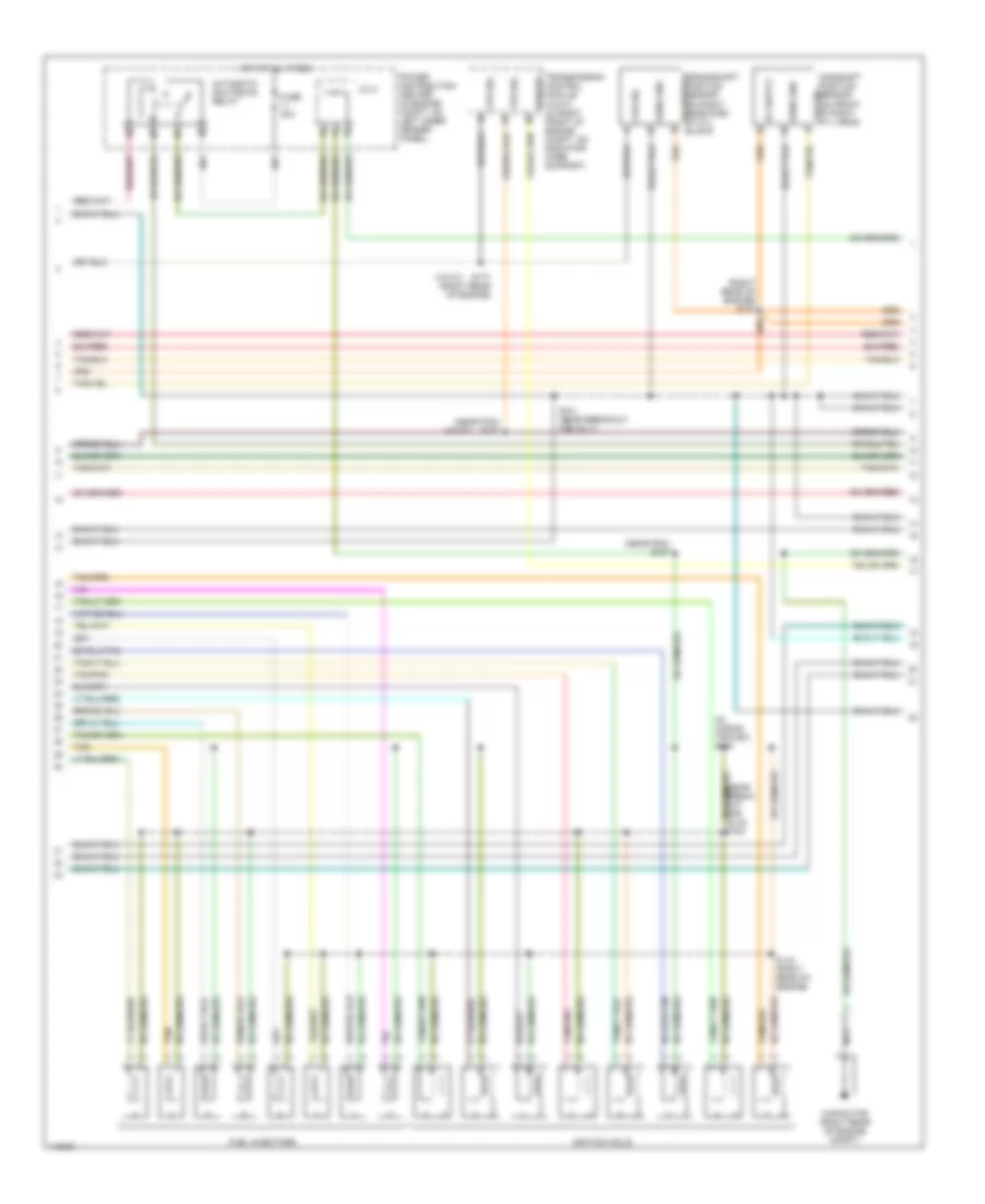
3.9L, Engine Performance Wiring Diagrams, Federal (1 of 4) for Dodge Dakota 2002
List of elements for 3.9L, Engine Performance Wiring Diagrams, Federal (1 of 4) for Dodge Dakota 2002:
- (5.9l only)
- 3-4 shift
- A/c pres sig
- A/c pressure transducer (on discharge line, near a/c compressor)
- A/c sig
- A/t temp sig
- A14
- C106
- C18
- C24
- Cam pos sns
- Coil driver
- Controller anti-lock brake (abs) (w/ all- wheel abs) (on top of hydraulic control unit)
- Controller anti-lock brake (rwal) (w/o all- wheel abs) (in engine compt, on left inner fender panel)
- Cooling fans system
- Crnk pos sns
- Ect sens in
- Engine oil pressure sensor (on top rear of engine block, near distributor)
- F18
- Fuse 10a
- Fuse 20a
- Fuse f 20a
- Fused b(+)
- G115 (rear of right front fender)
- G60
- Gen field
- Gov pres cntl
- Gov pres sig
- Ground
- Ho2s 1/1 sig
- Ho2s 1/2 sig
- Hot at all times
- Hot in run or start
- Iat sens in
- Idle air 1
- Idle air 2
- Idle air 3
- Idle air 4
- Idle air control motor (on throttle body)
- Ign power
- Inj 1 driver
- Inj 2 driver
- Inj 3 driver
- Inj 4 driver
- Inj 5 driver
- Inj 6 driver
- Inj 7 driver
- Inj 8 driver
- J/c 1
- Junction block (on left end of dash)
- K11
- K12
- K13
- K14
- K141
- K19
- K20
- K21
- K22
- K24
- K26
- K28
- K30
- K38
- K39
- K40
- K41
- K44
- K54
- K58
- K59
- K60
- K88
- Map sens in
- Od sol cntl
- Oil pres sig
- Out spd sig
- Output speed sensor (on lower left rear of trans)
- P/n signal
- Pnk
- Power distribution center (in engine compt, on left inner fender)
- Powertrain control module (in engine compt, on right inner fender panel)
- Rad fan ctrl
- Red
- S103 (rear of engine)
- S135 (near pcm)
- Sens gnd
- Sensor gnd
- Spd sens gnd
- Starting/ charging system
- T13
- T14
- T25
- T34
- T41
- T60
- Tan
- Tcc sol cntl
- Tps sens in
- Trans rly cntl
- Trans rly out
- Transmission control relay
- Transmission solenoid assembly (in transmission, on valve body)
- Vss
- Z12
3.9L, Engine Performance Wiring Diagrams, Federal (2 of 4) for Dodge Dakota 2002
List of elements for 3.9L, Engine Performance Wiring Diagrams, Federal (2 of 4) for Dodge Dakota 2002:
- (rear of engine) s107
- 5v sup
- Automatic shutdown relay
- Camshaft position sensor
- Cps sig
- Distributor
- Fuel injector 1
- Fuel injector 2
- Fuel injector 3
- Fuel injector 4
- Fuel injector 5
- Fuel injector 6
- Fuel injector 7 (5.9l only)
- Fuel injector 8 (5.9l only)
- Fuse 30a
- Hot at all times
- Ignition coil (on right front of engine)
- J/c 2
- Nca
- Power distribution center (in engine compt, on left inner fender)
- S101 (rear of engine)
- S106 (near inj 4)
- S110 (near breakout for inj 5)
- Sens gd
- Sens gnd
- Tan
3.9L, Engine Performance Wiring Diagrams, Federal (3 of 4) for Dodge Dakota 2002
List of elements for 3.9L, Engine Performance Wiring Diagrams, Federal (3 of 4) for Dodge Dakota 2002:
- Engine coolant temperature (ect) sensor (in water jacket, at front of intake manifold)
- Fuse 10a
- Fuse u 20a
- Hot in run or start
- Intake air temperature (iat) sensor (on intake manifold)
- J/c 1
- Junction block (on left end of dash)
- Left heated oxygen sensor (downstream) (near outlet end of left catalytic converter)
- Left heated oxygen sensor (upstream) (in top of left catalytic converter)
- Manifold absolute pressure sensor (on front of throttle body)
- Nca
- Power distribution center (in engine compt, on left inner fender)
- S136 (rear of engine)
- Throttle position sensor (on left side of throttle body)
3.9L, Engine Performance Wiring Diagrams, Federal (4 of 4) for Dodge Dakota 2002
List of elements for 3.9L, Engine Performance Wiring Diagrams, Federal (4 of 4) for Dodge Dakota 2002:
- A/c comp rly
- A/c sw sens
- A/c system
- A142
- Asd relay out
- Auto sht rly
- Batt temp sens
- Battery temperature sensor (under battery, attached to battery tray)
- Brake lamp switch (on brake pedal bracket)
- Brake sw sens
- C13
- C20
- Controller anti-lock brake (abs) (w/ all- wheel abs) (on top of hydraulic control unit)
- Controller anti-lock brake (rwal) (w/o all- wheel abs) (in engine compt, on left inner fender panel)
- Cruise control system
- Cruise sw sig
- Cruise vac sol
- Cruise vnt sol
- D20
- D21
- D25
- Data link connector (dlc) (under dash, left of steering column)
- Diagnostic junction port (under dash, right of steering column)
- Evap/purge
- Fuel lev sens sig
- Fuel pump module (at fuel pump)
- Fuel pump relay
- Fuel pump rly ctrl
- Fuse 10a
- G113 (near battery)
- G207 (under center of dash)
- G208 (behind right kick panel)
- Gen source
- Hot in run or start
- I/o processor
- Instrument cluster
- J/c 1
- J/c 2
- J/c 2 (in pdc)
- J/c 3
- Junction block (on left end of dash)
- K100
- K106
- K107
- K118
- K125
- K200
- K226
- K31
- K51
- K52
- Ldp sol cntl
- Ldp sw sens
- Leak detection pump (under battery tray & power distribution center)
- Mil ind
- Od off sw
- Overdrive switch
- Pci bus
- Pnk
- Power distribution center (in engine compt, on left inner fender)
- Powertrain control module (in engine compt, on right inner fender panel)
- Proportional purge solenoid (on bracket, at left rear side of engine compt)
- Pwm heater
- S123 (right rear of engine)
- S306
- Sci receive
- Sci transmit
- Sensor
- Shift interlock system
- Starting/ charging system
- Tan/red
- V32
- V35
- V36
- V37
- V40
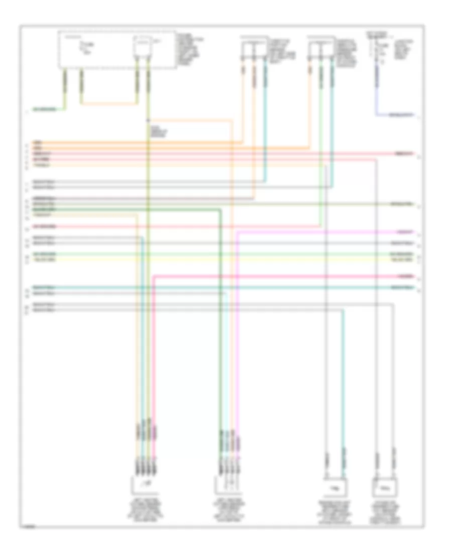
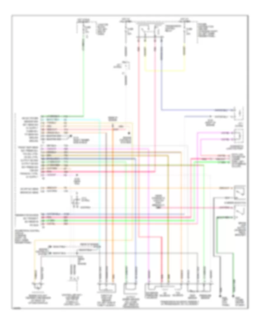
4.7L
4.7L, Engine Performance Wiring Diagrams, California (1 of 4) for Dodge Dakota 2002
List of elements for 4.7L, Engine Performance Wiring Diagrams, California (1 of 4) for Dodge Dakota 2002:
- (top left rear of engine)
- A/c pres sig
- A/c pressure transducer (on discharge line, near a/c compressor)
- A/c sig
- A14
- C18
- C24
- Cam pos sns
- Coil driver 1
- Coil driver 2
- Coil driver 3
- Coil driver 4
- Coil driver 5
- Coil driver 6
- Coil driver 7
- Coil driver 8
- Controller anti-lock brake (abs) (w/ all- wheel abs) (on top of hydraulic control unit)
- Controller anti-lock brake (rwal) (w/o all- wheel abs) (in engine compt, on left inner fender panel)
- Cooling fans system
- Crnk pos sns
- Ect sens in
- Engine oil pressure sensor (on oil filter housing)
- F18
- Fuse 10a
- Fuse 20a
- Fused b(+)
- G105
- G105 (rear of right front fender)
- G60
- Gen field
- Gnd
- Ground
- Ho2s 1/1 sig
- Ho2s 1/2 sig
- Ho2s 2/1 sig
- Ho2s 2/2 sig
- Hot at all times
- Hot in run or start
- Iat sens in
- Idle air 1
- Idle air 2
- Idle air 3
- Idle air 4
- Idle air control motor (on throttle body)
- Ign power
- Inj 1 driver
- Inj 2 driver
- Inj 3 driver
- Inj 4 driver
- Inj 5 driver
- Inj 6 driver
- Inj 7 driver
- Inj 8 driver
- J/c 1
- Junction block (on left end of dash)
- K10
- K11
- K12
- K13
- K14
- K141
- K17
- K19
- K20
- K21
- K22
- K24
- K241
- K26
- K28
- K341
- K38
- K39
- K40
- K41
- K44
- K58
- K59
- K60
- K92
- K93
- K94
- K95
- K96
- K98
- Map sens in
- Oil pres sig
- P/n signal
- Power distribution center (in engine compt, on left inner fender panel)
- Power steering pressure switch (in power steering pressure line)
- Powertrain control module (in engine compt, on right inner fender panel)
- Rad fan ctrl
- S103 (rear of engine)
- S174 (w/a/t) (near pcm)
- Sens gnd
- Sensor gnd
- Sps sens
- Starting/ charging system
- T41
- Tan
- Tan/pnk
- Tps sens in
- Transmission control module (w/a/t) (in right front of engine compt, on radiator core support)
- Vss
- Z12
4.7L, Engine Performance Wiring Diagrams, California (2 of 4) for Dodge Dakota 2002
List of elements for 4.7L, Engine Performance Wiring Diagrams, California (2 of 4) for Dodge Dakota 2002:
- (in wiring trough) s184
- (near pcm) s173
- (near pdc) s187
- (right rear of engine) s107
- (w/a/t)
- Automatic shutdown relay
- Camshaft position sensor (on front of right cyl head) cps sig
- Capacitor (right rear of engine compt)
- Cps sig
- Fuel injectors
- Fuse 30a
- Hot at all times
- Ignition coils
- J/c 2
- Nca
- Power distribution center (in engine compt, on left inner fender panel)
- S101 (near breakout for inj 7)
- S134 (right rear of engine)
- S177 (right rear of engine)
- Sens gnd
- Tan
- Tan/pnk
- Torque
- Tps sig
- Transmission control module (w/a/t) (in right front of engine compt, on radiator core support)
4.7L, Engine Performance Wiring Diagrams, California (3 of 4) for Dodge Dakota 2002
List of elements for 4.7L, Engine Performance Wiring Diagrams, California (3 of 4) for Dodge Dakota 2002:
- Engine coolant temperature (ect) sensor (in water jacket, at front of intake manifold)
- Fuse 10a
- Fuse u 20a
- G105 (top left rear of engine)
- Hot in run or start
- Intake air temperature (iat) sensor (on intake manifold, near throttle body)
- J/c 1
- Junction block (on left end of dash)
- Left heated oxygen sensor (downstream) (on outlet end of left catalytic converter)
- Left heated oxygen sensor (upstream) (in top of left catalytic converter)
- Manifold absolute pressure sensor (on front of intake) manifold)
- Nca
- Oxygen sensor downstream heater relay
- Power distribution center (in engine compt, on left inner fender panel)
- Right heated oxygen sensor (downstream) (on outlet end of right catalytic converter)
- Right heated oxygen sensor (upstream) (in top of right catalytic converter)
- S136 (rear of engine)
- S179 (right rear of engine)
- Throttle position sensor (on left side of throttle body)
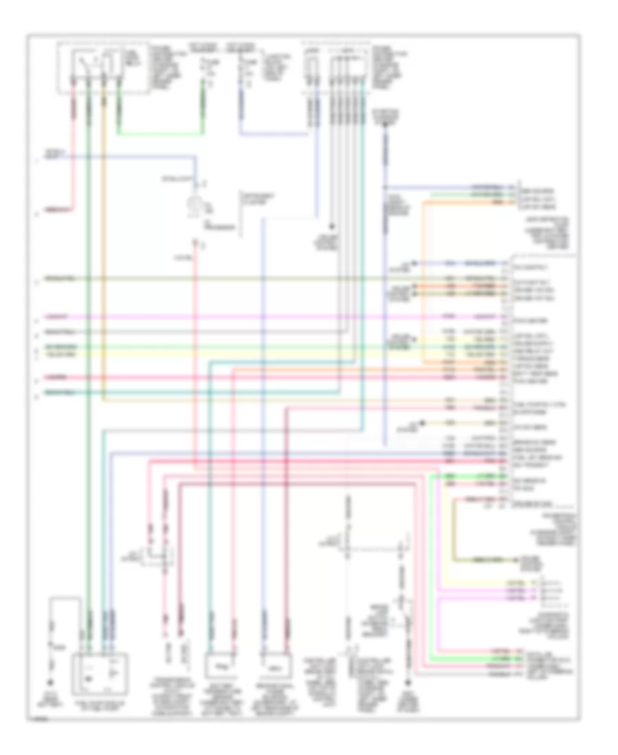
4.7L, Engine Performance Wiring Diagrams, California (4 of 4) for Dodge Dakota 2002
List of elements for 4.7L, Engine Performance Wiring Diagrams, California (4 of 4) for Dodge Dakota 2002:
- A/c comp rly
- A/c sw sens
- A/c system
- A142
- Asd relay out
- Auto sht rly
- Batt temp sens
- Battery temperature sensor (under battery, attached to battery tray)
- Brake lamp switch (on brake pedal bracket)
- Brake sw sens
- C13
- C20
- Controller anti-lock brake (abs) (w/ all- wheel abs) (on top of hydraulic control unit)
- Controller anti-lock brake (rwal) (w/o all- wheel abs) (in engine compt, on left inner fender panel)
- Cruise control system
- Cruise sw sig
- Cruise vac sol
- Cruise vnt sol
- D20
- D21
- D25
- Data link connector (dlc) (under dash, left of steering column)
- Diagnostic junction port (under dash, right of steering column)
- Evap/purge
- Fuel lev sens sig
- Fuel pump module (at fuel pump)
- Fuel pump relay
- Fuel pump rly ctrl
- Fuse 10a
- G113 (near battery)
- G207 (under center of dash)
- Gen source
- Ho2s dwn cntl
- Hot in run or start
- I/o processor
- Instrument cluster
- J/c 1 (in pdc)
- J/c 2
- J/c 2 (in pdc)
- J/c 3
- Junction block (on left end of dash)
- K100
- K106
- K107
- K118
- K125
- K200
- K226
- K31
- K51
- K512
- K52
- Ldp sol cntl
- Ldp sw sens
- Leak detection pump (under battery tray & power distribution center)
- Mil ind
- Pci bus
- Pnk
- Power distribution center (in engine compt, on left inner fender panel)
- Powertrain control module (in engine compt, on right inner fender panel)
- Proportional purge solenoid (on bracket, at left rear side of engine compt)
- Pwm heater
- S123 (right rear of engine)
- S306
- Sci rec
- Sci receive
- Sci transmit
- Sci trn
- Sensor
- Starting/ charging system
- T10
- Tan/red
- Transmission control module (w/a/t) (in right front of eng compt, on radiator core support)
- V32
- V35
- V36
- V37
- V40
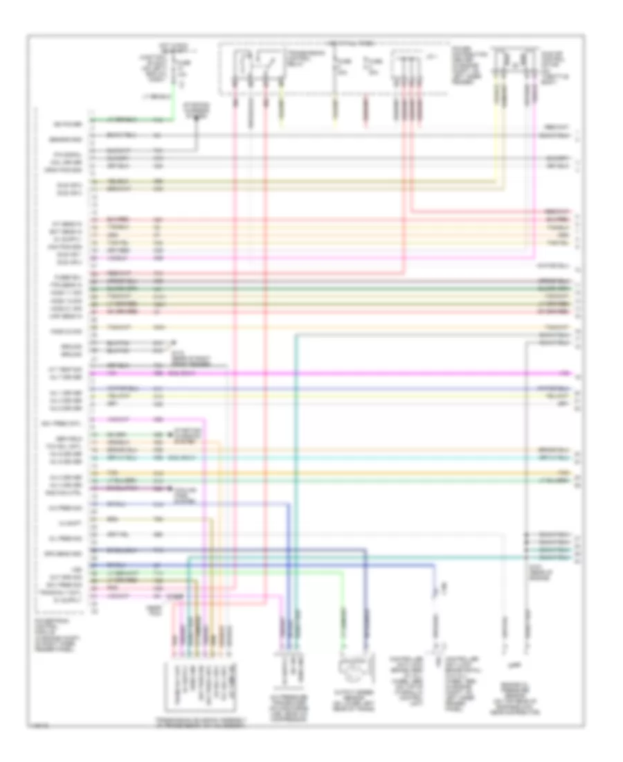
4.7L, Engine Performance Wiring Diagrams, Federal (1 of 4) for Dodge Dakota 2002
List of elements for 4.7L, Engine Performance Wiring Diagrams, Federal (1 of 4) for Dodge Dakota 2002:
- (top left rear of engine)
- A/c pres sig
- A/c pressure transducer (on discharge line, near a/c compressor)
- A/c sig
- A14
- C18
- C24
- Cam pos sns
- Coil driver 1
- Coil driver 2
- Coil driver 3
- Coil driver 4
- Coil driver 5
- Coil driver 6
- Coil driver 7
- Coil driver 8
- Controller anti-lock brake (abs) (w/ all- wheel abs) (on top of hydraulic control unit)
- Controller anti-lock brake (rwal) (w/o all- wheel abs) (in engine compt, on left inner fender panel)
- Cooling fans system
- Crnk pos sns
- Ect sens in
- Engine oil pressure sensor (on oil filter housing)
- F18
- Fuse 10a
- Fuse 20a
- Fused b(+)
- G100 (rear of right front fender)
- G105
- G60
- Gen field
- Gnd
- Ground
- Ho2s 1/1 sig
- Ho2s 1/2 sig
- Hot at all times
- Hot in run or start
- Iat sens in
- Idle air 1
- Idle air 2
- Idle air 3
- Idle air 4
- Idle air control motor (on throttle body)
- Ign power
- Inj 1 driver
- Inj 2 driver
- Inj 3 driver
- Inj 4 driver
- Inj 5 driver
- Inj 6 driver
- Inj 7 driver
- Inj 8 driver
- J/c 1
- Junction block (on left end of dash)
- K10
- K11
- K12
- K13
- K14
- K141
- K17
- K19
- K20
- K21
- K22
- K24
- K26
- K28
- K38
- K39
- K40
- K41
- K44
- K58
- K59
- K60
- K92
- K93
- K94
- K95
- K96
- K98
- Map sens in
- Oil pres sig
- P/n signal
- Power distribution center (in engine compt, on left inner fender panel)
- Power steering pressure switch (in power steering pressure line)
- Powertrain control module (in engine compt, on right inner fender panel)
- Rad fan ctrl
- S103 (rear of engine)
- S174 (w/a/t) (near pcm)
- Sens gnd
- Sensor gnd
- Sps sens
- Starting/ charging system
- T41
- Tan
- Tan/pnk
- Tps sens in
- Transmission control module (w/a/t) (in right front of engine compt, on radiator core support)
- Vss
- Z12
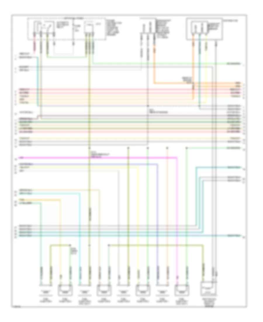
4.7L, Engine Performance Wiring Diagrams, Federal (2 of 4) for Dodge Dakota 2002
List of elements for 4.7L, Engine Performance Wiring Diagrams, Federal (2 of 4) for Dodge Dakota 2002:
- (in wiring trough) s184
- (near pcm) s173
- (near pdc) s187
- (right rear of engine) s107
- (w/a/t)
- Automatic shutdown relay
- Camshaft position sensor (on front of right cyl head) cps sig
- Capacitor (right rear of engine compt)
- Cps sig
- Fuel injectors
- Fuse 30a
- Hot at all times
- Ignition coils
- J/c 2
- Nca
- Power distribution center (in engine compt, on left inner fender panel)
- S101 (near breakout for inj 7)
- S134 (right rear of engine)
- S177 (right rear of engine)
- Sens gnd
- Tan
- Tan/pnk
- Torque
- Tps sig
- Transmission control module (w/a/t) (in right front of engine compt, on radiator core support)
4.7L, Engine Performance Wiring Diagrams, Federal (3 of 4) for Dodge Dakota 2002
List of elements for 4.7L, Engine Performance Wiring Diagrams, Federal (3 of 4) for Dodge Dakota 2002:
- Engine coolant temperature (ect) sensor (in water jacket, at front of intake manifold)
- Fuse 10a
- Fuse u 20a
- Hot in run or start
- Intake air temperature (iat) sensor (on intake manifold, near throttle body)
- J/c 1
- Junction block (on left end of dash)
- Left heated oxygen sensor (downstream) (on outlet end of left catalytic converter)
- Left heated oxygen sensor (upstream) (in top of left catalytic converter)
- Manifold absolute pressure sensor (on front of intake) manifold)
- Nca
- Power distribution center (in engine compt, on left inner fender panel)
- S122 (rear of engine)
- Throttle position sensor (on left side of throttle body)
4.7L, Engine Performance Wiring Diagrams, Federal (4 of 4) for Dodge Dakota 2002
List of elements for 4.7L, Engine Performance Wiring Diagrams, Federal (4 of 4) for Dodge Dakota 2002:
- A/c comp rly
- A/c sw sens
- A/c system
- A142
- Asd relay out
- Auto sht rly
- Batt temp sens
- Battery temperature sensor (under battery, attached to battery tray)
- Brake lamp switch (on brake pedal bracket)
- Brake sw sens
- C13
- C20
- Controller anti-lock brake (abs) (w/ all- wheel abs) (on top of hydraulic control unit)
- Controller anti-lock brake (rwal) (w/o all- wheel abs) (in engine compt, on left inner fender panel)
- Cruise control system
- Cruise sw sig
- Cruise vac sol
- Cruise vnt sol
- D20
- D21
- D25
- Data link connector (dlc) (under dash, left of steering column)
- Diagnostic junction port (under dash, right of steering column)
- Evap/purge
- Fuel lev sens sig
- Fuel pump module (at fuel pump)
- Fuel pump relay
- Fuel pump rly ctrl
- Fuse 10a
- G113 (near battery)
- G207 (under center of dash)
- Gen source
- Hot in run or start
- I/o processor
- Instrument cluster
- J/c 1 (in pdc)
- J/c 2
- J/c 2 (in pdc)
- J/c 3
- Junction block (on left end of dash)
- K100
- K106
- K107
- K118
- K125
- K200
- K226
- K31
- K51
- K52
- Ldp sol cntl
- Ldp sw sens
- Leak detection pump (under battery tray & power distribution center)
- Mil ind
- Pci bus
- Pnk
- Power distribution center (in engine compt, on left inner fender panel)
- Powertrain control module (in engine compt, on right inner fender panel)
- Proportional purge solenoid (on bracket, at left rear side of engine compt)
- Pwm heater
- S123 (right rear of engine)
- S306
- Sci rec
- Sci receive
- Sci transmit
- Sci trn
- Sensor
- Starting/ charging system
- T10
- Tan/red
- Transmission control module (w/a/t) (in right front of eng compt, on radiator core support)
- V32
- V35
- V36
- V37
- V40
5.9L
5.9L, Engine Performance Wiring Diagrams, California (1 of 4) for Dodge Dakota 2002
List of elements for 5.9L, Engine Performance Wiring Diagrams, California (1 of 4) for Dodge Dakota 2002:
- (5.9l only)
- (near pcm)
- 3-4 shift
- A/c pres sig
- A/c pressure transducer (on discharge line, near a/c compressor)
- A/c sig
- A/t temp sig
- A14
- C106
- C18
- C24
- Cam pos sns
- Coil driver
- Controller anti-lock brake (abs) (w/ all- wheel abs) (on top of hydraulic control unit)
- Controller anti-lock brake (rwal) (w/o all- wheel abs) (in engine compt, on left inner fender panel)
- Cooling fans system
- Crnk pos sns
- Ect sens in
- Engine oil pressure sensor (on top rear of engine block, near distributor)
- F18
- Fuse 10a
- Fuse 20a
- Fuse f 20a
- Fused b(+)
- G115 (rear of right front fender)
- G60
- Gen field
- Gov pres cntl
- Gov pres sig
- Ground
- Ho2s 1/1 sig
- Ho2s 1/2 sig
- Ho2s 2/1 sig
- Ho2s 2/2 sig
- Hot at all times
- Hot in run or start
- Iat sens in
- Idle air 1
- Idle air 2
- Idle air 3
- Idle air 4
- Idle air control motor (on throttle body)
- Ign power
- Inj 1 driver
- Inj 2 driver
- Inj 3 driver
- Inj 4 driver
- Inj 5 driver
- Inj 6 driver
- Inj 7 driver
- Inj 8 driver
- J/c 1
- Junction block (on left end of dash)
- K11
- K12
- K13
- K14
- K141
- K19
- K20
- K21
- K22
- K24
- K241
- K26
- K28
- K30
- K341
- K38
- K39
- K40
- K41
- K44
- K54
- K58
- K59
- K60
- K88
- Map sens in
- Od sol cntl
- Oil pres sig
- Out spd sig
- Output speed sensor (on lower left rear of trans)
- P/n signal
- Pnk
- Power distribution center (in engine compt, on left inner fender)
- Powertrain control module (in engine compt, on right inner fender panel)
- Rad fan ctrl
- Red
- S103 (rear of engine)
- S135
- Sens gnd
- Sensor gnd
- Spd sens gnd
- Starting/ charging system
- T13
- T14
- T25
- T34
- T41
- T60
- Tan
- Tcc sol cntl
- Tps sens in
- Trans rly cntl
- Trans rly out
- Transmission control relay
- Transmission solenoid assembly (in transmission, on valve body)
- Vss
- Z12
5.9L, Engine Performance Wiring Diagrams, California (2 of 4) for Dodge Dakota 2002
List of elements for 5.9L, Engine Performance Wiring Diagrams, California (2 of 4) for Dodge Dakota 2002:
- (rear of engine) s107
- 5v sup
- Automatic shutdown relay
- Camshaft position sensor
- Cps sig
- Distributor
- Fuel injector 1
- Fuel injector 2
- Fuel injector 3
- Fuel injector 4
- Fuel injector 5
- Fuel injector 6
- Fuel injector 7 (5.9l only)
- Fuel injector 8 (5.9l only)
- Fuse 30a
- Hot at all times
- Ignition coil (on right front of engine)
- J/c 2
- Nca
- Power distribution center (in engine compt, on left inner fender)
- S101 (rear of engine)
- S106 (near inj 4)
- S110 (near breakout for inj 5)
- Sens gd
- Sens gnd
- Tan
5.9L, Engine Performance Wiring Diagrams, California (3 of 4) for Dodge Dakota 2002
List of elements for 5.9L, Engine Performance Wiring Diagrams, California (3 of 4) for Dodge Dakota 2002:
- (rear of engine) s139
- C106
- Engine coolant temperature (ect) sensor (in water jacket, at front of intake manifold)
- Fuse 10a
- Fuse u 20a
- G105 (top left rear of engine)
- Hot in run or start
- Intake air temperature (iat) sensor (on intake manifold)
- J/c 1
- Junction block (on left end of dash)
- Left heated oxygen sensor (downstream) (near outlet end of left catalytic converter)
- Left heated oxygen sensor (upstream) (in top of left catalytic converter)
- Manifold absolute pressure sensor (on front of throttle body)
- Nca
- Oxygen sensor downstream heater relay
- Power distribution center (in engine compt, on left inner fender)
- Right heated oxygen sensor (downstream) (near outlet end of right catalytic converter)
- Right heated oxygen sensor (upstream) (in top of right catalytic converter)
- S136 (rear of engine)
- S179 (right rear of engine)
- Throttle position sensor (on left side of throttle body)
5.9L, Engine Performance Wiring Diagrams, California (4 of 4) for Dodge Dakota 2002
List of elements for 5.9L, Engine Performance Wiring Diagrams, California (4 of 4) for Dodge Dakota 2002:
- A/c comp rly
- A/c sw sens
- A/c system
- A142
- Asd relay out
- Auto sht rly
- Batt temp sens
- Battery temperature sensor (under battery, attached to battery tray)
- Brake lamp switch (on brake pedal bracket)
- Brake sw sens
- C13
- C20
- Controller anti-lock brake (abs) (w/ all- wheel abs) (on top of hydraulic control unit)
- Controller anti-lock brake (rwal) (w/o all- wheel abs) (in engine compt, on left inner fender panel)
- Cruise control system
- Cruise sw sig
- Cruise vac sol
- Cruise vnt sol
- D20
- D21
- D25
- Data link connector (dlc) (under dash, left of steering column)
- Diagnostic junction port (under dash, right of steering column)
- Evap/purge
- Fuel lev sens sig
- Fuel pump module (at fuel pump)
- Fuel pump relay
- Fuel pump rly ctrl
- Fuse 10a
- G113 (near battery)
- G207 (under center of dash)
- G208 (behind right kick panel)
- Gen source
- Ho2s dwn cntl
- Hot in run or start
- I/o processor
- Instrument cluster
- J/c 1
- J/c 2
- J/c 2 (in pdc)
- J/c 3
- Junction block (on left end of dash)
- K100
- K106
- K107
- K118
- K125
- K200
- K226
- K31
- K51
- K512
- K52
- Ldp sol cntl
- Ldp sw sens
- Leak detection pump (under battery tray & power distribution center)
- Mil ind
- Od off sw
- Overdrive switch
- Pci bus
- Pnk
- Power distribution center (in engine compt, on left inner fender)
- Powertrain control module (in engine compt, on right inner fender panel)
- Proportional purge solenoid (on bracket, at left rear side of engine compt)
- Pwm heater
- S123 (right rear of engine)
- S306
- Sci receive
- Sci transmit
- Sensor
- Shift interlock system
- Starting/ charging system
- Tan/red
- V32
- V35
- V36
- V37
- V40
5.9L, Engine Performance Wiring Diagrams, Federal (1 of 4) for Dodge Dakota 2002
List of elements for 5.9L, Engine Performance Wiring Diagrams, Federal (1 of 4) for Dodge Dakota 2002:
- (5.9l only)
- 3-4 shift
- A/c pres sig
- A/c pressure transducer (on discharge line, near a/c compressor)
- A/c sig
- A/t temp sig
- A14
- C106
- C18
- C24
- Cam pos sns
- Coil driver
- Controller anti-lock brake (abs) (w/ all- wheel abs) (on top of hydraulic control unit)
- Controller anti-lock brake (rwal) (w/o all- wheel abs) (in engine compt, on left inner fender panel)
- Cooling fans system
- Crnk pos sns
- Ect sens in
- Engine oil pressure sensor (on top rear of engine block, near distributor)
- F18
- Fuse 10a
- Fuse 20a
- Fuse f 20a
- Fused b(+)
- G115 (rear of right front fender)
- G60
- Gen field
- Gov pres cntl
- Gov pres sig
- Ground
- Ho2s 1/1 sig
- Ho2s 1/2 sig
- Hot at all times
- Hot in run or start
- Iat sens in
- Idle air 1
- Idle air 2
- Idle air 3
- Idle air 4
- Idle air control motor (on throttle body)
- Ign power
- Inj 1 driver
- Inj 2 driver
- Inj 3 driver
- Inj 4 driver
- Inj 5 driver
- Inj 6 driver
- Inj 7 driver
- Inj 8 driver
- J/c 1
- Junction block (on left end of dash)
- K11
- K12
- K13
- K14
- K141
- K19
- K20
- K21
- K22
- K24
- K26
- K28
- K30
- K38
- K39
- K40
- K41
- K44
- K54
- K58
- K59
- K60
- K88
- Map sens in
- Od sol cntl
- Oil pres sig
- Out spd sig
- Output speed sensor (on lower left rear of trans)
- P/n signal
- Pnk
- Power distribution center (in engine compt, on left inner fender)
- Powertrain control module (in engine compt, on right inner fender panel)
- Rad fan ctrl
- Red
- S103 (rear of engine)
- S135 (near pcm)
- Sens gnd
- Sensor gnd
- Spd sens gnd
- Starting/ charging system
- T13
- T14
- T25
- T34
- T41
- T60
- Tan
- Tcc sol cntl
- Tps sens in
- Trans rly cntl
- Trans rly out
- Transmission control relay
- Transmission solenoid assembly (in transmission, on valve body)
- Vss
- Z12
5.9L, Engine Performance Wiring Diagrams, Federal (2 of 4) for Dodge Dakota 2002
List of elements for 5.9L, Engine Performance Wiring Diagrams, Federal (2 of 4) for Dodge Dakota 2002:
- (rear of engine) s107
- 5v sup
- Automatic shutdown relay
- Camshaft position sensor
- Cps sig
- Distributor
- Fuel injector 1
- Fuel injector 2
- Fuel injector 3
- Fuel injector 4
- Fuel injector 5
- Fuel injector 6
- Fuel injector 7 (5.9l only)
- Fuel injector 8 (5.9l only)
- Fuse 30a
- Hot at all times
- Ignition coil (on right front of engine)
- J/c 2
- Nca
- Power distribution center (in engine compt, on left inner fender)
- S101 (rear of engine)
- S106 (near inj 4)
- S110 (near breakout for inj 5)
- Sens gd
- Sens gnd
- Tan
5.9L, Engine Performance Wiring Diagrams, Federal (3 of 4) for Dodge Dakota 2002
List of elements for 5.9L, Engine Performance Wiring Diagrams, Federal (3 of 4) for Dodge Dakota 2002:
- Engine coolant temperature (ect) sensor (in water jacket, at front of intake manifold)
- Fuse 10a
- Fuse u 20a
- Hot in run or start
- Intake air temperature (iat) sensor (on intake manifold)
- J/c 1
- Junction block (on left end of dash)
- Left heated oxygen sensor (downstream) (near outlet end of left catalytic converter)
- Left heated oxygen sensor (upstream) (in top of left catalytic converter)
- Manifold absolute pressure sensor (on front of throttle body)
- Nca
- Power distribution center (in engine compt, on left inner fender)
- S136 (rear of engine)
- Throttle position sensor (on left side of throttle body)
5.9L, Engine Performance Wiring Diagrams, Federal (4 of 4) for Dodge Dakota 2002
List of elements for 5.9L, Engine Performance Wiring Diagrams, Federal (4 of 4) for Dodge Dakota 2002:
- A/c comp rly
- A/c sw sens
- A/c system
- A142
- Asd relay out
- Auto sht rly
- Batt temp sens
- Battery temperature sensor (under battery, attached to battery tray)
- Brake lamp switch (on brake pedal bracket)
- Brake sw sens
- C13
- C20
- Controller anti-lock brake (abs) (w/ all- wheel abs) (on top of hydraulic control unit)
- Controller anti-lock brake (rwal) (w/o all- wheel abs) (in engine compt, on left inner fender panel)
- Cruise control system
- Cruise sw sig
- Cruise vac sol
- Cruise vnt sol
- D20
- D21
- D25
- Data link connector (dlc) (under dash, left of steering column)
- Diagnostic junction port (under dash, right of steering column)
- Evap/purge
- Fuel lev sens sig
- Fuel pump module (at fuel pump)
- Fuel pump relay
- Fuel pump rly ctrl
- Fuse 10a
- G113 (near battery)
- G207 (under center of dash)
- G208 (behind right kick panel)
- Gen source
- Hot in run or start
- I/o processor
- Instrument cluster
- J/c 1
- J/c 2
- J/c 2 (in pdc)
- J/c 3
- Junction block (on left end of dash)
- K100
- K106
- K107
- K118
- K125
- K200
- K226
- K31
- K51
- K52
- Ldp sol cntl
- Ldp sw sens
- Leak detection pump (under battery tray & power distribution center)
- Mil ind
- Od off sw
- Overdrive switch
- Pci bus
- Pnk
- Power distribution center (in engine compt, on left inner fender)
- Powertrain control module (in engine compt, on right inner fender panel)
- Proportional purge solenoid (on bracket, at left rear side of engine compt)
- Pwm heater
- S123 (right rear of engine)
- S306
- Sci receive
- Sci transmit
- Sensor
- Shift interlock system
- Starting/ charging system
- Tan/red
- V32
- V35
- V36
- V37
- V40
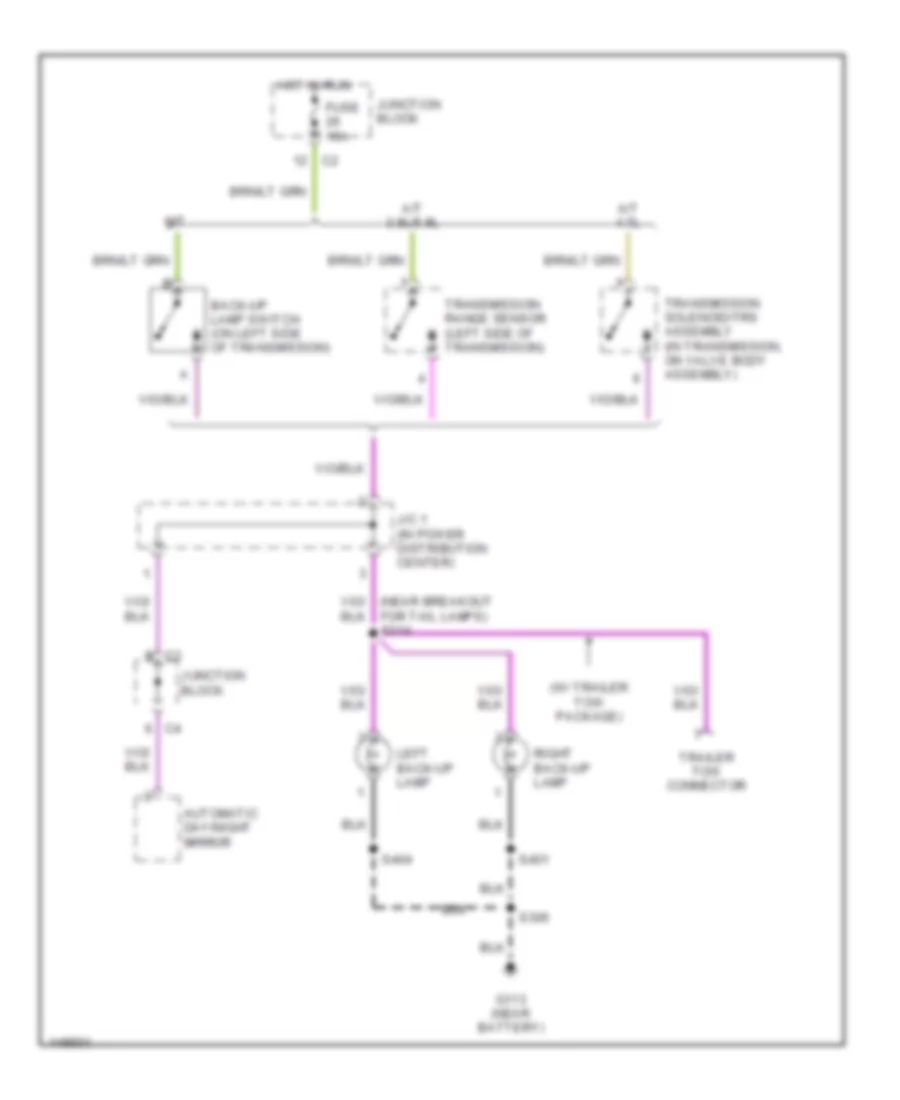
EXTERIOR LIGHTS
Back-up Lamps Wiring Diagram for Dodge Dakota 2002
List of elements for Back-up Lamps Wiring Diagram for Dodge Dakota 2002:
- (w/ trailer tow package)
- A/t 3.9l/5.9l
- A/t 4.7l
- Automatic day/night mirror
- Back-up lamp switch (on left side of transmission)
- Fuse 15a
- G113 (near battery)
- Hot in run
- J/c 1 (in power distribution center)
- Junction block
- Left back-up lamp
- M/t
- Right back-up lamp
- S306
- S401
- S404
- Trailer tow connector
- Transmission range sensor (left side of transmission)
- Transmission solenoid/trs assembly (in transmission, on valve body assembly)
Exterior Lamps Wiring Diagram for Dodge Dakota 2002
List of elements for Exterior Lamps Wiring Diagram for Dodge Dakota 2002:
- (in power distribution center) j/c 3
- (near left frame rail) s316
- (near rt license lamp) s405
- (near tail lamps breakout) s317
- Aftermarket chmsl connector
- B(+)
- Back-up lamps circuit
- Brake lamp switch (on park brake bracket)
- Brake lp sw
- C11
- C12
- Center high mounted stop lamp
- Central timer module (left kick panel)
- Combination flasher (left of steering column)
- Electric brake (taped ends)
- Fuse 10a
- Fuse 20a
- Fuse 6 30a
- Fuse c 20a
- Fuse t 10a
- G112 (right fender side shield)
- G113 (near battery)
- G208 (left kick panel)
- G305 (left front fender frame ground)
- G307 (near breakout to seatbelt switch)
- Hazard
- Hazard signal
- Hazard switch
- Hdlp sw off
- Head
- Head- lights system
- Headlamp switch
- Hot at all times
- Hot in run or acc
- Ign pwr
- Instrument cluster
- J/c 1 (in pdc)
- J/c 2 (in pdc)
- Junction block
- L308
- L79
- L80
- Left
- Left front park/ turn signal lamp 1
- Left front park/ turn signal lamp 2
- Left front side marker lamp
- Left license lamp
- Left tail/ stop/ turn signal lamp
- Left turn ind
- Left turn sig
- Lt turn sense
- Multi-function switch
- Off
- Park
- Park lamp relay
- Park sw sense
- Pk lp rl ctrl
- Pnk
- Power distribution center
- Red/ tan
- Right
- Right front park/ turn signal lamp 1
- Right front park/ turn signal lamp 2
- Right front side marker lamp
- Right license lamp
- Right tail/ stop/ turn signal lamp
- Right turn ind
- Right turn sig
- Rt turn sense
- S306
- S318 (left rear frame rail)
- S351
- S401
- S404
- S406
- Tan
- Trailer tow connector
- Turn/signal
- W/ electric brake
- W/ trailer tow connector
- W/o electric brake
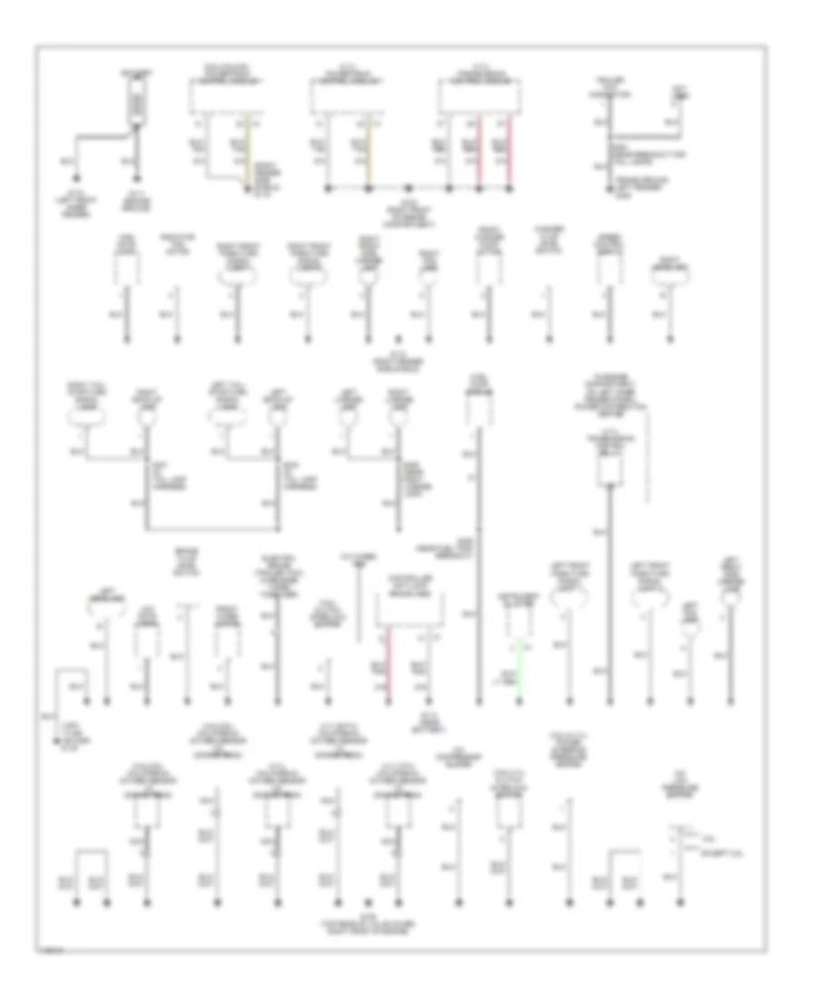
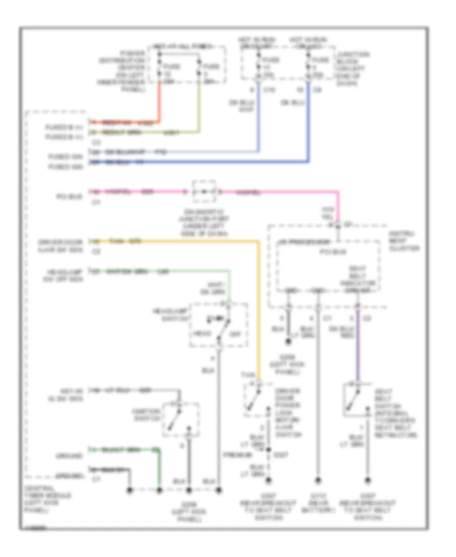
GROUND DISTRIBUTION
Ground Distribution Wiring Diagram (1 of 2) for Dodge Dakota 2002
List of elements for Ground Distribution Wiring Diagram (1 of 2) for Dodge Dakota 2002:
- (2.5l & 4.7l) power steering pressure switch
- (2.5l) clutch interlock switch
- (2.5l/3.9l/5.9l) powertrain control module
- (3.9l/4.7l) clutch interlock switch
- (3.9l/5.9l) (california) oxygen sensor 1/2 downstream
- (3.9l/5.9l) (california) oxygen sensor 2/2 downstream
- (4.7l eatx) (california) oxygen sensor 1/2 downstream
- (4.7l mtx) (california) oxygen sensor 1/2 downstream
- (4.7l) (california) oxygen sensor 2/2 downstream
- (4.7l) powertrain control module
- (4.7l) transmission control module
- (4.7l) transmission control relay
- (frame ground left fender) g305
- (in engine compartment, on left inner fender panel) power distribution center
- (left inner fender) g102
- (right fender side shield) g115
- 2.5l
- A/c compressor clutch
- A/c low pressure switch
- Battery
- Brake fluid level switch
- Controller anti-lock brake (abs)
- Electric brake (trailer tow) (wire ends taped together)
- Except 2.5l
- Front washer pump/ motor
- Front wiper motor
- Fuel pump module
- G100 (right front of engine compartment)
- G105 (top rear of valve cover, right front of engine)
- G110 (left front inner fender)
- G111 (engine ground)
- G112 (right fender side shield)
- G113 (near battery)
- High note horn
- Instrument cluster
- Left back-up lamp
- Left fog lamp
- Left front park/turn signal lamp 1
- Left front park/turn signal lamp 2
- Left front side marker lamp
- Left headlamp
- Left license lamp
- Left tail/ stop/turn signal lamp
- Low note horn
- Nca
- Not used
- Radiator fan motor
- Right back-up lamp
- Right fog lamp
- Right front park/turn signal lamp 1
- Right front park/turn signal lamp 2
- Right front side marker lamp
- Right headlamp
- Right license lamp
- Right tail/ stop/turn signal lamp
- S306 (near fuel tank breakout)
- S401 (in tail lamp harness)
- S404 (in tail lamp harness)
- S406 (near right license lamp)
- Speed control servo
- Trailer tow connector
- W/4 wheel abs
- Washer fluid level switch
- Z12
- Z13
- Z19
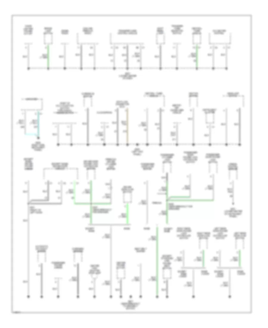
Ground Distribution Wiring Diagram (2 of 2) for Dodge Dakota 2002
List of elements for Ground Distribution Wiring Diagram (2 of 2) for Dodge Dakota 2002:
- (base) radio
- (except base) driver door module
- (except base) driver power mirror
- (except standard cab) power seat switch
- (midline/ premium) radio
- (part of multi-function switch) turn signal/ hazard switch
- (premium) driver cylinder lock switch
- A/c heater control
- Airbag control module
- Amplifier
- Automatic day/night mirror
- Base
- Base 4 door
- Brake lamp switch
- Center high mounted stop lamp
- Center power outlet
- Central timer module
- Cigar lighter/ power outlet
- Clockspring
- Data link connector (dlc)
- Driver door ajar switch
- Driver door power lock motor/ajar switch
- Except base
- Except base 4 door
- G201 (lower center of instrument panel)
- G205 (right side instrument panel)
- G207 (lower center of dash)
- G208 (left kick panel)
- G307 (near breakout to seatbelt switch)
- Headlamp switch
- Ignition switch
- Instrument cluster
- Left rear door ajar switch
- Left rear door power lock motor/ajar switch
- Nca
- Overdrive switch
- Overhead console
- Passenger cylinder lock switch
- Passenger door ajar switch
- Passenger door power lock motor/ajar switch
- Passenger door power lock switch
- Passenger power mirror
- Premium
- Right rear door ajar switch
- Right rear door power lock motor/ajar switch
- S301 (front of left door)
- S327 (near breakout for speaker)
- S328 (near breakout for speaker)
- Seat belt switch
- Sentry key immobilizer module
- Shift bezel lamp
- Transfer case control module
- Transfer case selector switch
- Z11
- Z12
- Z46
- Z47
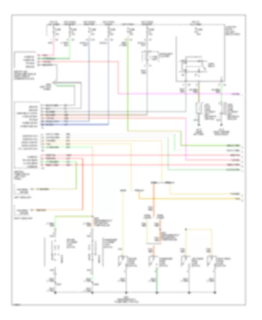
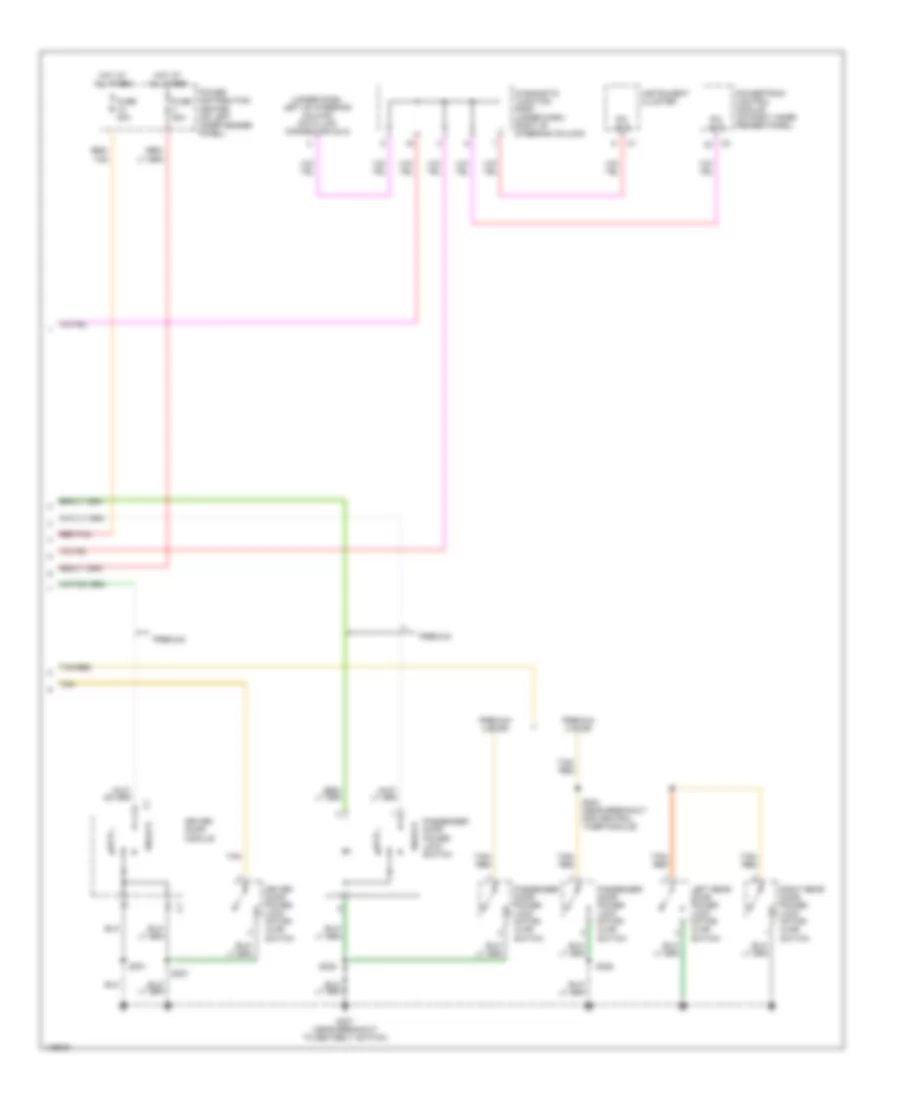
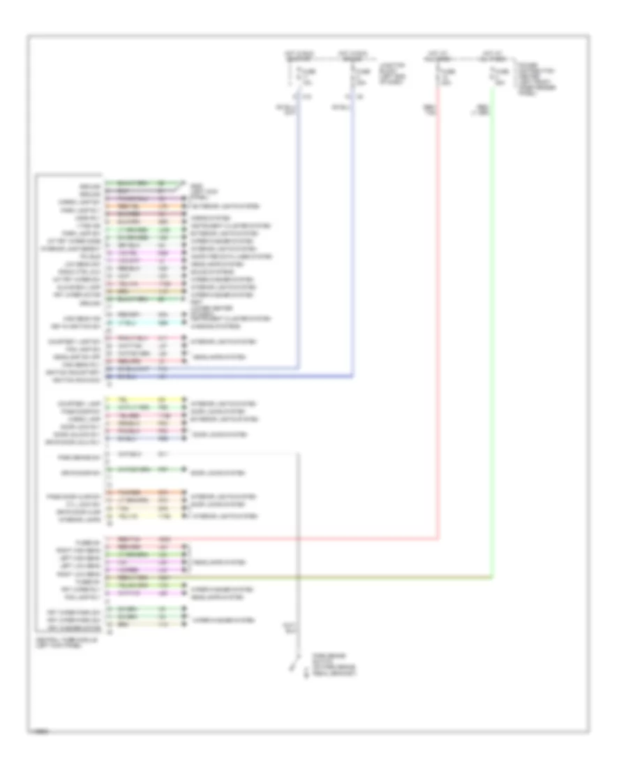
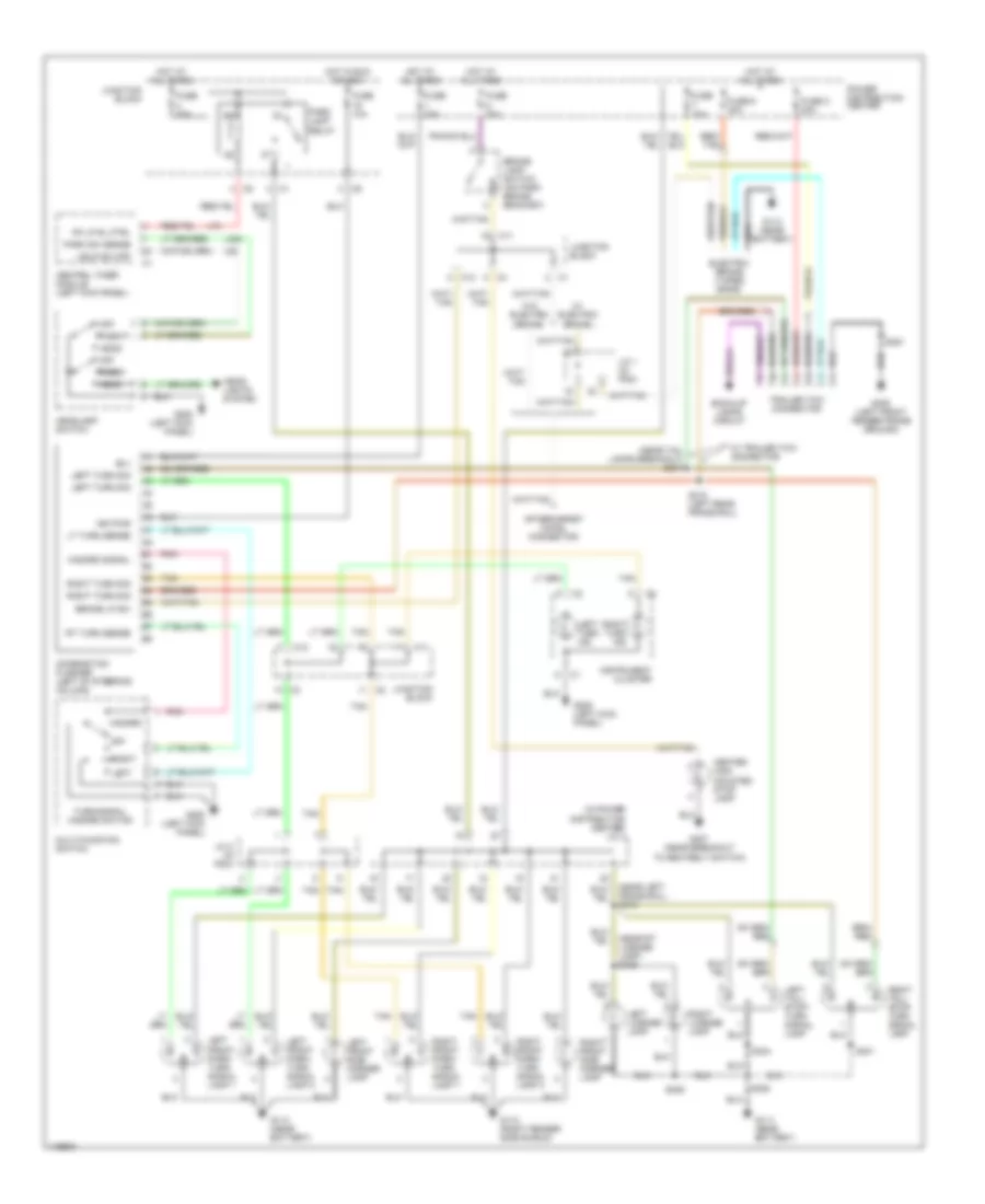
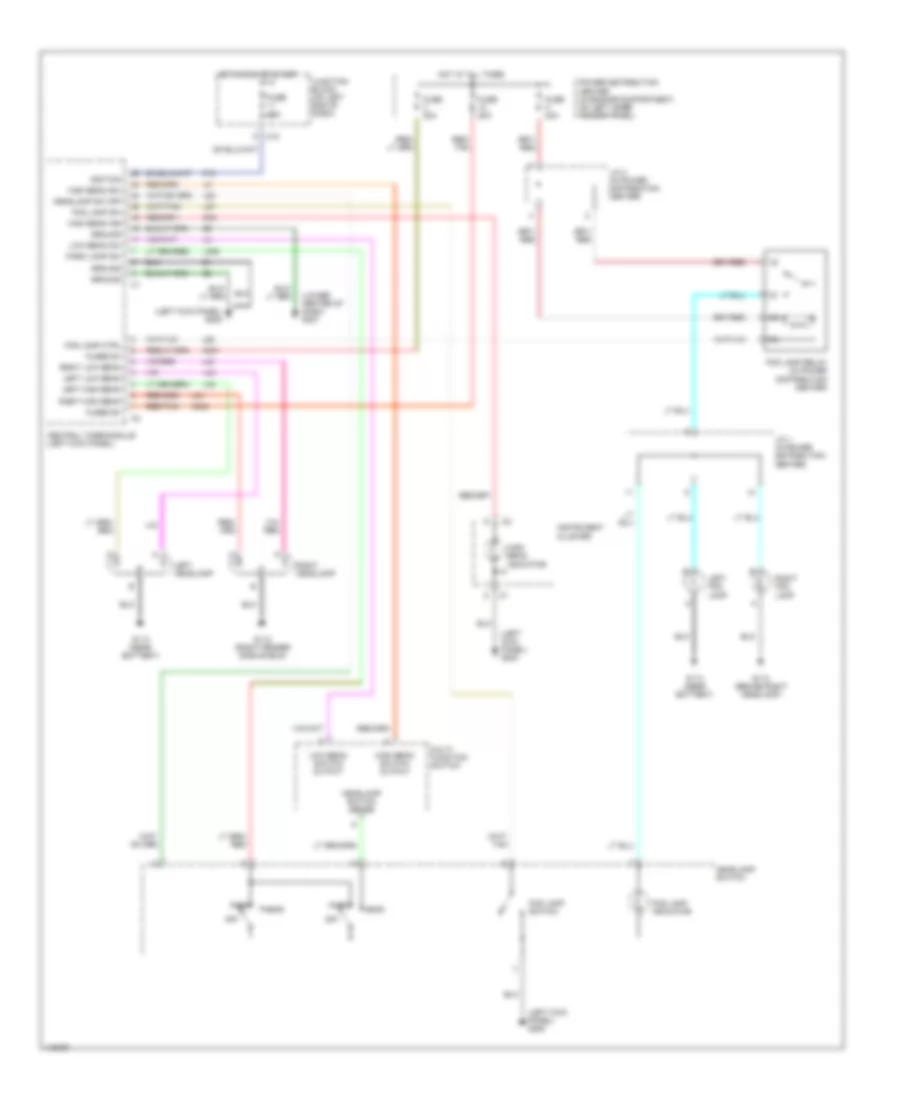
HEADLIGHTS
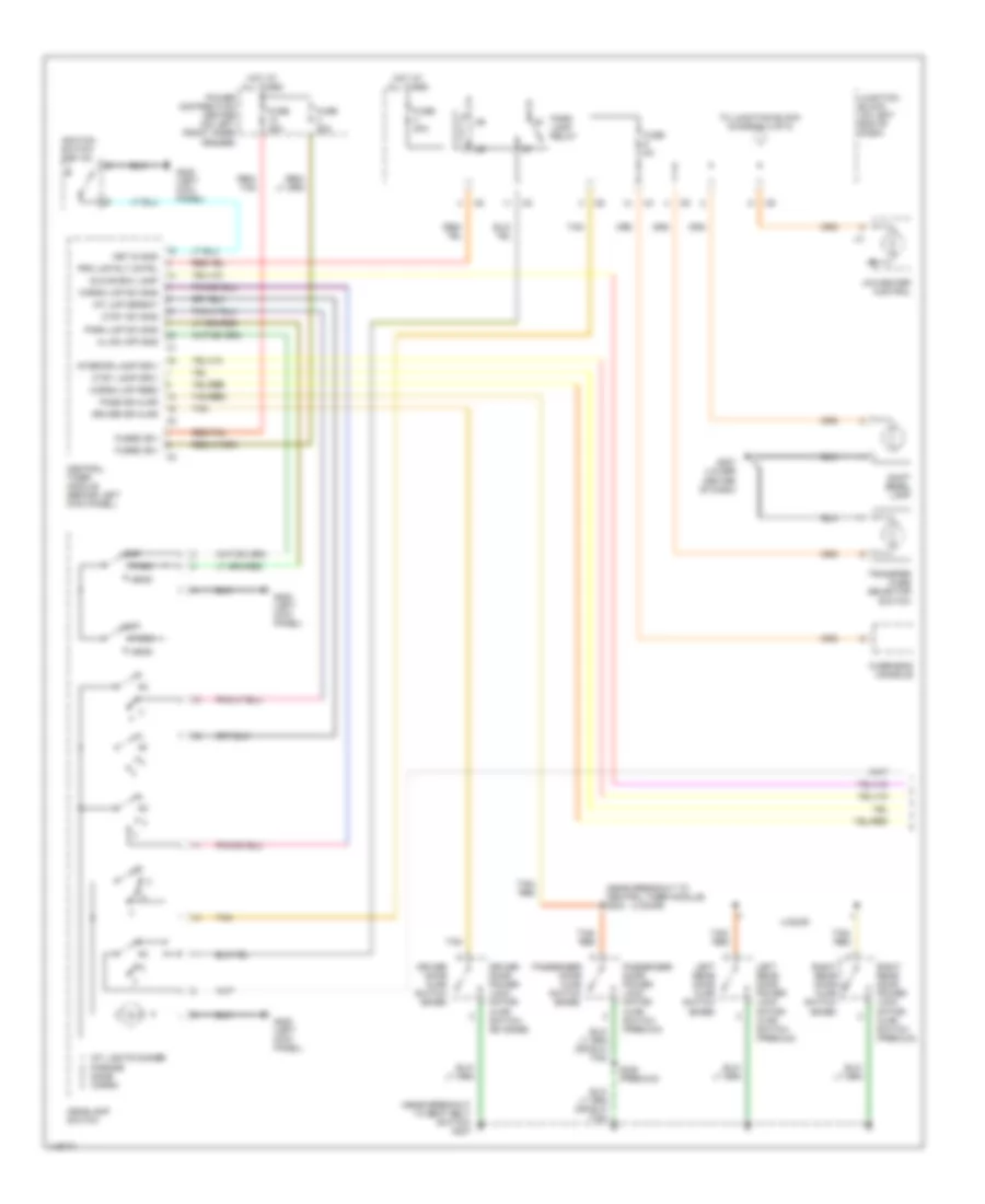
Headlight Wiring Diagram for Dodge Dakota 2002
List of elements for Headlight Wiring Diagram for Dodge Dakota 2002:
- (left kick panel) g208
- (lower center of dash) g207
- A301
- A302
- C10
- Central timer module (left kick panel)
- F12
- Fog lamp ctrl
- Fog lamp indicator
- Fog lamp relay (in power distribution center)
- Fog lamp sw
- Fog lamp switch
- Fuse 10a
- Fuse 20a
- Fuse h 20a
- Fused b+
- G112 (behind right headlamp)
- G112 (right fender side shield)
- G113 (near battery)
- G34
- Ground
- Head
- Headlamp sw off
- Headlamp switch
- Headlamp switch sense
- High beam ind
- High beam indicator
- High beam sw
- High beam switch output
- Hot at all times
- Hot in run or start
- Ignition
- Instrument cluster
- J/c 1 (in power distribution center)
- J/c 3 (in power distribution center)
- Junction block (on left end of dash)
- L26
- L27
- L308
- L33
- L34
- L43
- L44
- L80
- Left fog lamp
- Left headlamp
- Left high beam
- Left low beam
- Low beam sw
- Low beam switch output
- Multi- function switch
- Off
- Park
- Park lamp sw
- Power distribution center (in engine compartment, on left inner fender panel)
- Red/ tan
- Red/tan
- Right fog lamp
- Right headlamp
- Right high beam
- Right low beam
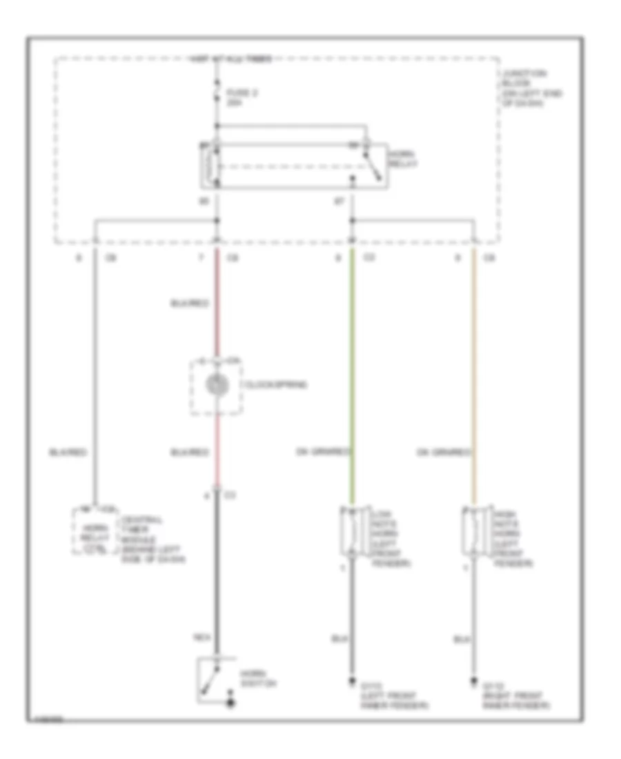
HORN
Horn Wiring Diagram for Dodge Dakota 2002
List of elements for Horn Wiring Diagram for Dodge Dakota 2002:
- Central timer module (behind left side of dash)
- Clockspring
- Fuse 2 20a
- G112 (right front inner fender)
- G113 (left front inner fender)
- High note horn (left front fender)
- Horn relay
- Horn relay ctrl
- Horn switch
- Hot at all times
- Junction block (on left end of dash)
- Low note horn (left front fender)
- Nca
INSTRUMENT CLUSTER
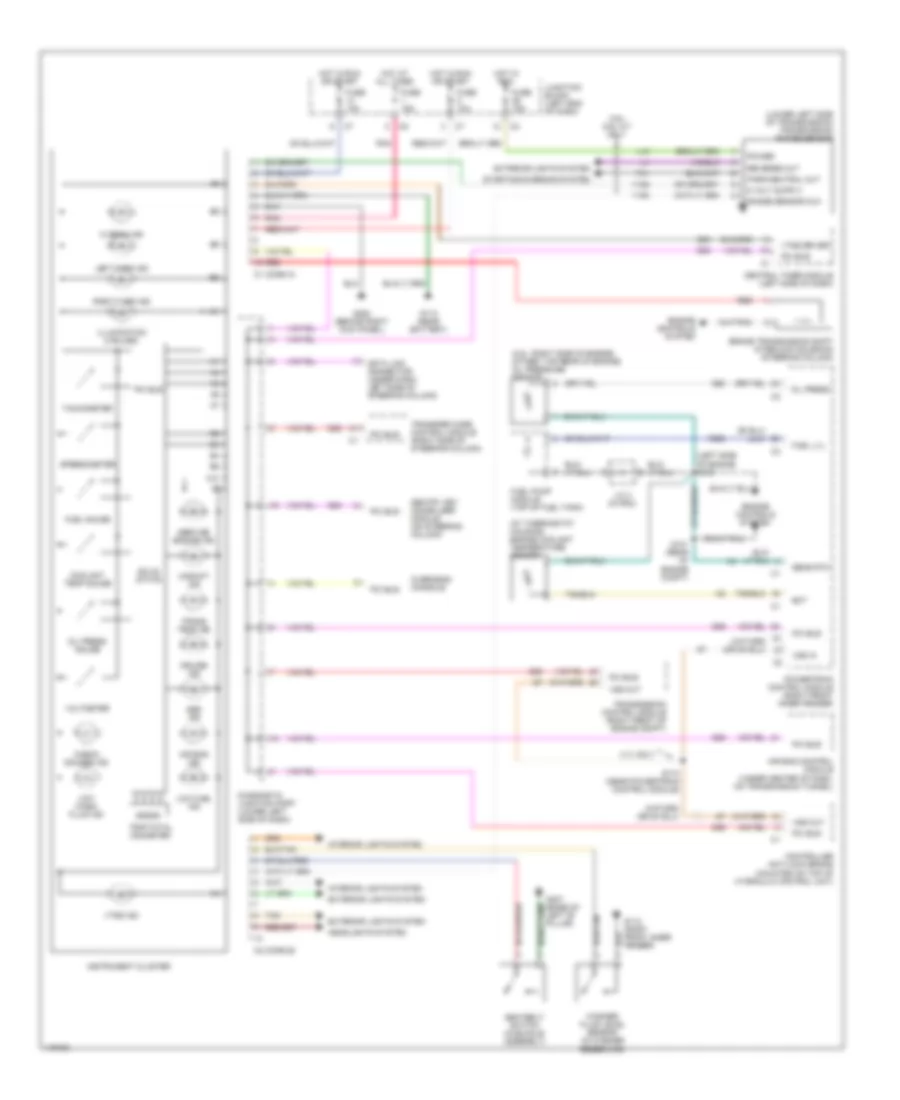
Instrument Cluster Wiring Diagram for Dodge Dakota 2002
List of elements for Instrument Cluster Wiring Diagram for Dodge Dakota 2002:
- (2.5l: right side of engine) (other: top rear of engine) oil pressure sensor
- (at thermostat housing) engine coolant temperature sensor
- (left side of engine s103
- (lower left side of transmission) transmission range sensor
- 3.9l/ 5.9l a/t only
- 4.7l only
- A10
- Abs ind
- Air bag control module (under center of dash, on transmission tunnel)
- Air bag ind
- Brake transmission shift interlock solenoid (steering column)
- C1 (conn a)
- C2 (conn b)
- Central timer module (left side of dash)
- Check gauges ind
- Controller anti-lock brake (mounted on top of hydraulic control unit)
- Coolant temp gauge
- Cruise ind
- D25
- Data link connector (under dash, left side of steering column)
- Diagnostic junction port (lower left side of dash)
- Ect
- Engine controls system
- Exterior lights system
- Fuel gauge
- Fuel lvl
- Fuel pump module (top of fuel tank)
- Fuse 10a
- Fuse 15a
- G112 (right front inner fender)
- G113 (near battery)
- G208 (behind right kick panel)
- G307 (base of left "b" pillar)
- G60
- G69
- Headlights system
- Hi beam ind
- Hot at all times
- Hot in run
- Hot in run or start
- Illumination (4 bulbs)
- Instrument cluster
- Interior lights system
- J/c 3 (in pdc)
- Junction block (left end of dash)
- K226
- L10
- Left turn ind
- Low fuel ind
- Low wash fluid ind
- Oil press
- Oil press gauge
- Overhead console
- Park/neutral out
- Pci bus
- Pnk
- Power
- Powertrain control module (right front inner fender)
- Range sensor mux
- Red
- Reverse out
- Right turn ind
- S101 (rear of engine compt)
- S174 (near powertrain control module)
- Seatbelt switch (in buckle assembly)
- Sens rtn
- Sentry key immobilizer module (on steering column)
- Service engine ind
- Solid state
- Speedometer
- Starting/charging system
- T41
- Tachometer
- Tan
- Trans temp ind
- Transfer case control module (right side of steering column)
- Transmission control module (right front of engine compt)
- Trip/total odometer
- Upshift ind
- Voltmeter
- Vss in
- Vss out
- Vtss driver
- Vtss ind
- Washer fluid level sensor (in washer reservoir)
- Y128
- Y193
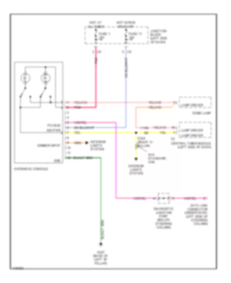
Overhead Console Wiring Diagram for Dodge Dakota 2002
List of elements for Overhead Console Wiring Diagram for Dodge Dakota 2002:
- All times
- Central timer module (left side of dash)
- Data link connector (under dash, left side of steering column)
- Diagnostic junction port (below steering column)
- Dimmer input
- Dome lamp
- Fuse 1 15a
- Fuse 11 10a
- G307 (base of left "b" pillar)
- Gnd
- Hot at
- Hot in run
- Ign pwr
- Interior lights system
- Junction block (left end of dash)
- Lamp driver
- Or start
- Overhead console
- Pci bus
- Pnk
- S324 (right "a" pillar)
- W/o standard cab
- Y158
INTERIOR LIGHTS
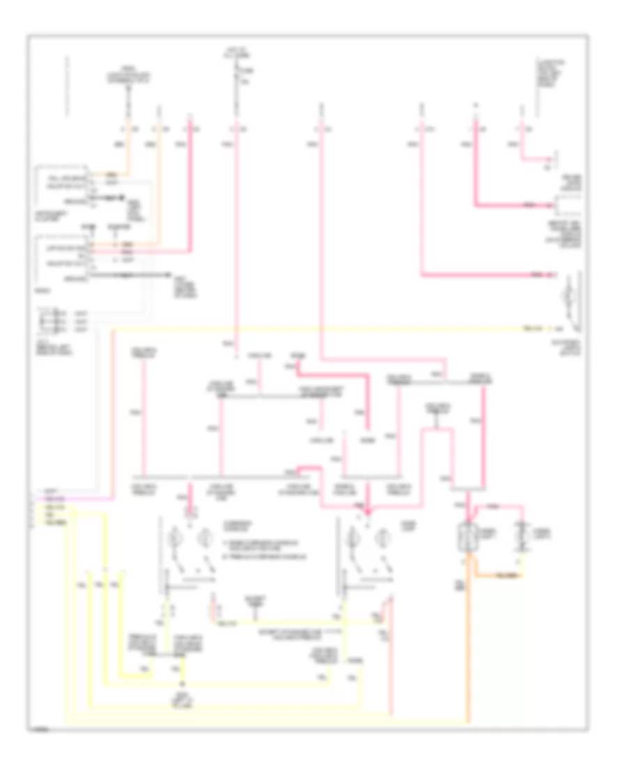
Interior Light Wiring Diagram (1 of 2) for Dodge Dakota 2002
List of elements for Interior Light Wiring Diagram (1 of 2) for Dodge Dakota 2002:
- (4 door)
- (near breakout to central timer module) s303
- (near breakout to seat belt switch) g307
- 4 door
- A/c-heater control
- Cargo lmp feed
- Cargo lmp sw sns
- Central timer module (behind left kick panel)
- Ctsy lamp driv
- Ctsy sw sns
- Driver door ajar switch (base)
- Driver door power lock motor/ ajar switch (ex base)
- Driver dr ajar
- Fuse 20a
- Fuse 5a
- Fused (b+)
- G207 (lower center of dash)
- G208 (left kick panel)
- Glove box lamp
- Head
- Headlamp switch
- Hl sw off sns
- Hot at all times
- Ignition switch (key-in)
- Int lights dimmer parade dome cargo
- Int lmp defeat
- Interior lamp driv
- Junction block (on left end of dash)
- Key-in sns
- Left rear door ajar switch (base)
- Left rear door power lock motor/ ajar switch (premium)
- Off
- Overhead console
- Park
- Park lamp relay
- Park lmp sw sns
- Pass dr ajar
- Passenger door ajar switch (base)
- Passenger door power lock motor/ ajar switch (premium)
- Power distribution center (on left front inner fender)
- Prk lmp rly cntrl
- Red/ tan
- Red/tan
- Right rear door ajar switch (base)
- Right rear door power lock motor/ ajar switch (premium)
- S328 (premium)
- Shift bezel lamp
- Tan
- Tan/ red
- Tan/red
- To junction block (diagram 2 of 2)
- Transfer case selector switch
Interior Light Wiring Diagram (2 of 2) for Dodge Dakota 2002
List of elements for Interior Light Wiring Diagram (2 of 2) for Dodge Dakota 2002:
- A base overhead console (midline & highline)
- Base
- Base & highline
- C10
- Cargo lamp 1
- Cargo lamp 2
- Dome lamp
- Driver door module
- Ex base
- Except base
- Except standard cab midline & premium
- From junction block (diagram 1 of 2)
- Fuse 15a
- G207 (lower center of dash)
- G208 (left kick panel)
- Glove box lamp & switch
- Ground
- Hdlmp sw out
- Highline
- Highline & midline ex standard cab
- Highline except standard cab
- Highline standard cab
- Hot at all times
- Instrument cluster
- J/c 4 (behind left side of dash)
- Junction block (on left end of dash)
- Lmp dim sw sig
- Midline & highline & premium
- Midline & premium
- Overhead console
- Pnk
- Pnl lps drvr
- Premium & midline w/ standard cabs
- Premium overhead console b
- Radio
- S324 (left "a" pillar)
- Sentry key immobilizer module (on steering column)
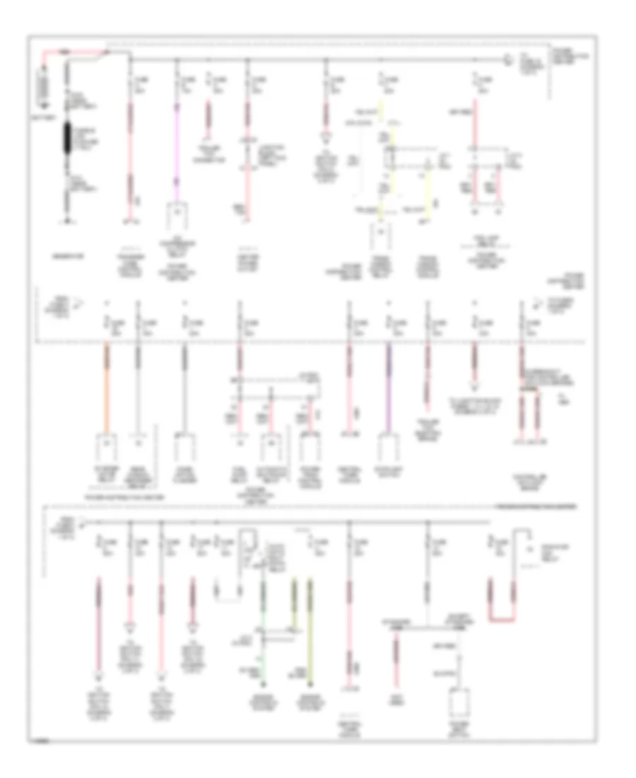
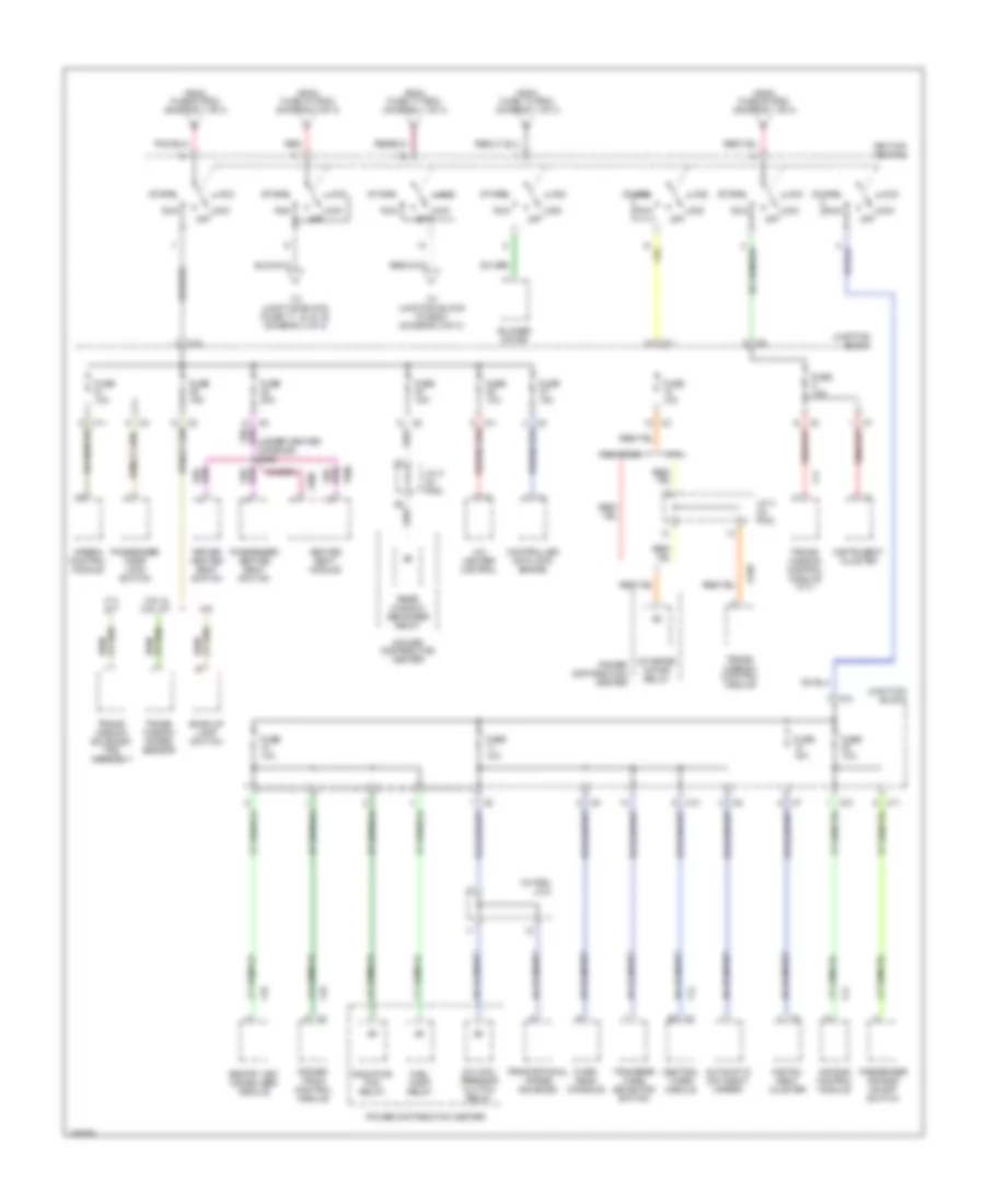
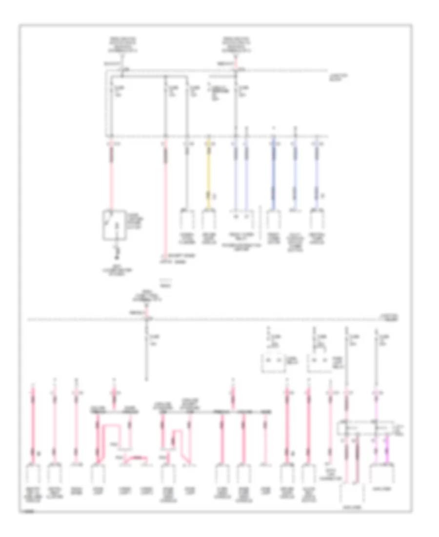
POWER DISTRIBUTION
Power Distribution Wiring Diagram (1 of 3) for Dodge Dakota 2002
List of elements for Power Distribution Wiring Diagram (1 of 3) for Dodge Dakota 2002:
- (diagram 1 of 3)
- (in breakout for controller antilock brakes) s126
- (in pdc) j/c 1
- (not used)
- 3.9l & 5.9l
- 4.7l
- A/c compressor clutch relay
- A14
- A301
- A302
- A34
- Auto- matic shut down relay
- Automatic shutdown relay
- B c3
- Battery
- Center power outlet
- Central timer module
- Combi- nation flasher
- Controller antilock brake
- Engine controls system
- Except standard cab
- F84
- Fog lamp relay
- From fuse 8 b
- From fuse h (diagram 1 of 3)
- Fuel pump relay
- Fuse 20a
- Fuse 30a
- Fuse 40a
- Fuse 50a
- Fuse a 20a
- Fuse b 10a
- Fuse c 20a
- Fuse d 20a
- Fuse e 20a
- Fuse f 20a
- Fuse h 20a
- Fuse u 20a
- Generator
- J/c 1 (in pdc)
- J/c 2 (in pdc)
- J/c 3 (in pdc)
- Junction block (left kick panel)
- Nca
- Power distribution center
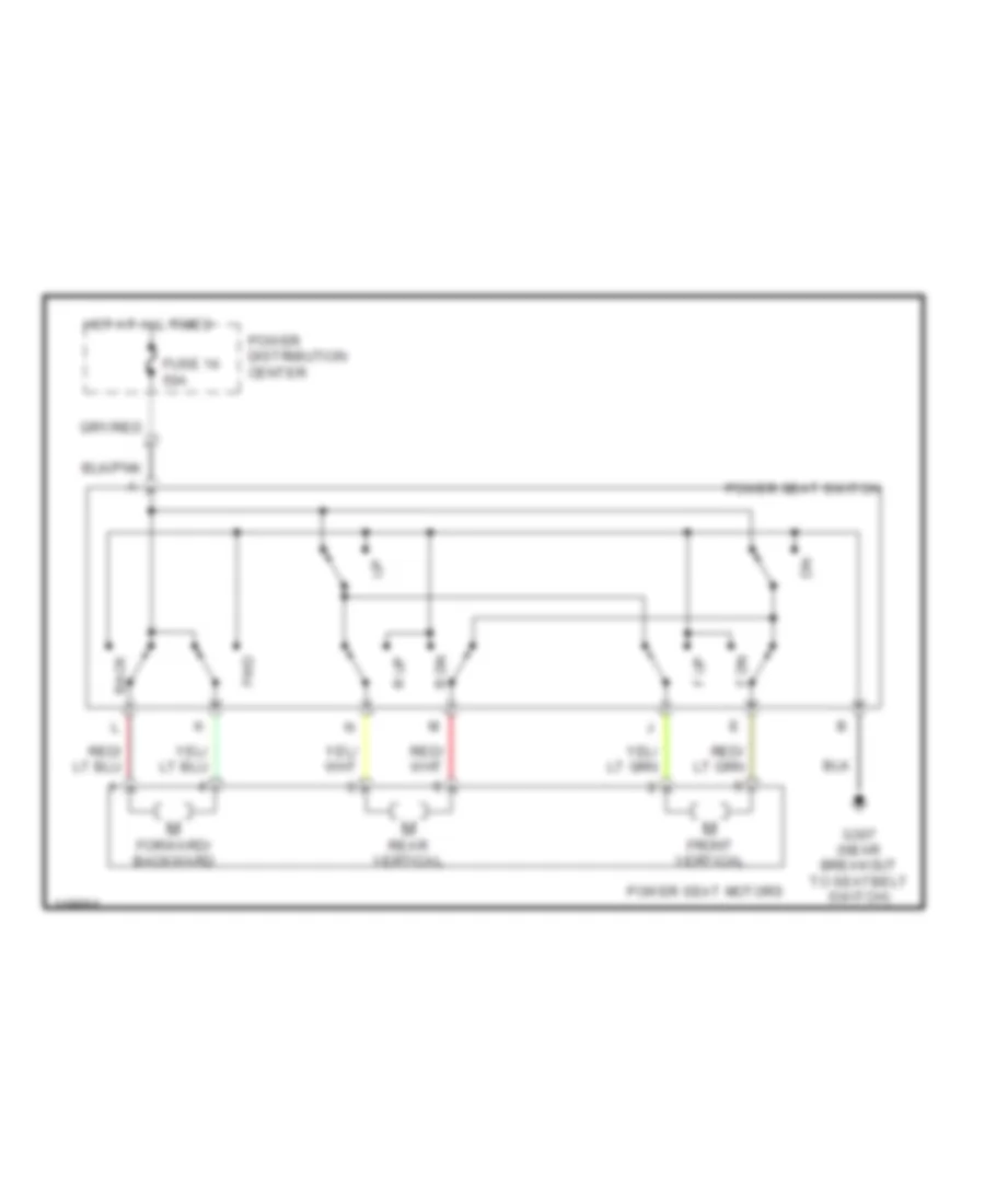
- Power seat switch
- Power- train control module
- Radiator fan relay
- Rear window defogger relay
- Red
- Red/ tan
- Red/tan
- S100 (near battery)
- S141 (near battery)
- Standard cab
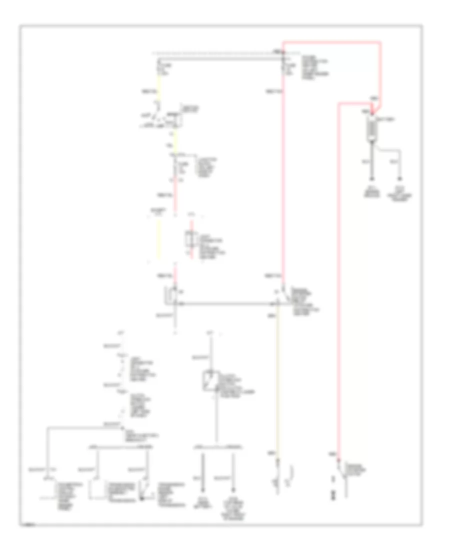
- Starter motor relay
- Stoplight switch
- To fuse 16 (diagram 1 of 3)
- To fuse 9 (diagram 1 of 3)
- To ignition switch (pin 1) (diagram 2 of 3)
- To ignition switch (pin 11) (diagram 2 of 3)
- To ignition switch (pin 12) (diagram 2 of 3)
- To ignition switch (pin 14) (diagram 2 of 3)
- To ignition switch (pin 4) (diagram 2 of 3)
- To junction block (fuses 1, 2, 4, & 13) (diagram 3 of 3)
- Trailer tow (electric brake)
- Trailer tow connector
- Trans- mission control module
- Trans- mission control relay
- Transfer case control module
- W/ abs
Power Distribution Wiring Diagram (2 of 3) for Dodge Dakota 2002
List of elements for Power Distribution Wiring Diagram (2 of 3) for Dodge Dakota 2002:
- (in pdc) j/c 2
- (under center console) s356
- 3.9l & 5.9l
- 3.9l & 5.9l a/t
- 4.7l
- 4.7l a/t
- A/c com- pressor clutch relay
- A/c heater control
- A169
- Acc
- Air bag control module
- Airbag control module
- Automatic day/night mirror
- Back-up lamp switch
- Blower motor
- C10
- C11
- C12
- Central timer module
- Controller anti-lock brake
- Driver heated seat switch
- F11
- F12
- F14
- F18
- F500
- From fuse 10 (pdc) (diagram 3 of 3)
- From fuse 13 (pdc) (diagram 1 of 3)
- From fuse 17 (pdc) (diagram 1 of 3)
- From fuse 9 (pdc) (diagram 1 of 3)
- From fuse e (pdc) (diagram 1 of 3)
- Fuel pump relay
- Fuse 10a
- Fuse 15a
- Fuse 20a
- Heated seat module
- Ignition switch
- Instru- ment cluster
- Instrunent cluster
- J/c 3 (in pdc)
- Junction block
- Lock off
- M/t
- Over- head console
- Passenger air bag on/off switch
- Passenger door lock switch
- Passenger heated seat switch
- Power distribution center
- Power- train control module
- Proportional purge solenoid
- Radiator fan relay
- Rear window defogger relay
- Red
- Run
- Sentry key immobilizer module
- Start
- Starter motor relay
- To junction block (fuse 17, 18, & 19) (diagram 3 of 3)
- To junction block (fuse 5) (diagram 3 of 3)
- Trans- mission control module
- Trans- mission control module (4.7l)
- Trans- mission range sensor
- Trans- mission solenoid/ trs assembly
- Transfer case selector switch
Power Distribution Wiring Diagram (3 of 3) for Dodge Dakota 2002
List of elements for Power Distribution Wiring Diagram (3 of 3) for Dodge Dakota 2002:
- (base)
- (except base)
- Amplifier
- Base
- Base over- head console
- Base/ highline
- C10
- C12
- Cargo lamp 1
- Cargo lamp 2
- Central timer module
- Cigar lighter/ power outlet
- Circuit breaker 25a
- Combin- ation flasher
- Data link connector
- Dome lamp
- Driver door module
- F21
- From fuse 7 (pdc) (diagram 1 of 3)
- From ignition switch (pin 10) (run/acc) (diagram 2 of 3)
- From ignition switch (pin 9) (run/acc) (diagram 2 of 3)
- Front wiper motor
- Front wiper relay
- Fuse 10a
- Fuse 15a
- Fuse 20a
- G207 (lower center of dash)
- Glove box lamp & switch
- Highline except standard cab
- Highline standard cab
- Horn relay
- Instru- ment cluster
- J/c 4 (in pdc)
- Junction block
- Midline
- Midline/ premium
- Multi- function switch (wiper switch)
- Over- head console
- Park lamp relay
- Pnk
- Pnk pnk
- Power distribution center
- Premium
- Radio
- Radio (base)
- Red/tan
- Sentry key im- mobilizer module
- Tan
POWER DOOR LOCKS
Power Door Lock Wiring Diagram for Dodge Dakota 2002
List of elements for Power Door Lock Wiring Diagram for Dodge Dakota 2002:
- (4 door)
- C10
- Central timer module (left kick panel)
- Door sw mux
- Driver door module
- Driver lock cylinder switch
- F12
- Fuse 10a
- Fuse 15a
- Fuse 20a
- Fused ign sw
- G208 (left kick panel)
- G307 (near breakout to seatbelt switch)
- G73
- Ground
- Hot in run
- Hot in run or acc
- Hot in start or run
- Junction block (at left end of dash)
- Left front door lock motor/ ajar switch
- Left rear door lock motor/ ajar switch
- Lock
- Lock relay
- Lock sw mux
- Nca
- P33
- P34
- P59
- P96
- P97
- Passenger cylinder lock switch
- Passenger door lock switch
- Right front door lock motor/ ajar switch
- Right rear door lock motor/ ajar switch
- Rke antenna
- S301
- S302 (near breakout for central timing module)
- S305 (near breakout for central timing module)
- S307 (near breakout for central timing module)
- S327
- S328
- Unlock
- Unlock relay
POWER MIRRORS
Power Mirror Wiring Diagram for Dodge Dakota 2002
List of elements for Power Mirror Wiring Diagram for Dodge Dakota 2002:
- (near breakout for tweeter) s300
- (not used)
- (on left end of dash)
- Defogger system
- Driver door module
- Driver mirror left movement
- Driver mirror up movement
- Driver power mirror
- Echromic element
- Fuse 15a
- Fused
- G307 (near breakout to seat belt switch)
- Horiz
- Hot at all times
- Junction block
- Mirror common driver
- Passenger power mirror
- Pnk
- Right mirror left movement
- Right mirror up movement
- S301
- Tan/
- Vert
POWER SEATS
Power Seat Wiring Diagrams for Dodge Dakota 2002
List of elements for Power Seat Wiring Diagrams for Dodge Dakota 2002:
- Back
- F dn
- F up
- Forward/ backward
- Front vertical
- Fuse 14 50a
- Fwd
- G307 (near breakout to seatbelt switch)
- Hot at all times
- Power distribution center
- Power seat motors
- Power seat switch
- R dn
- R up
- Rear vertical
POWER WINDOWS
Power Window Wiring Diagram, 2 Door for Dodge Dakota 2002
List of elements for Power Window Wiring Diagram, 2 Door for Dodge Dakota 2002:
- Circuit breaker 25a
- Driver door module
- G307 (near breakout to seatbelt switch)
- Hot in acc or run
- Junction block (on left end of dash)
- Left front door window motor
- Lockout
- Logic
- Right front door window motor
- Right front door window switch
- S301
- Tan
Power Window Wiring Diagram, 4 Door for Dodge Dakota 2002
List of elements for Power Window Wiring Diagram, 4 Door for Dodge Dakota 2002:
- (durango: (dakota: at left kick panel)
- Circuit breaker 25a
- Driver door module
- G307 (near breakout to seatbelt switch)
- Hot in acc or run
- Junction block (on left end of dash)
- Left front door window motor
- Left rear window motor
- Left rear window switch
- Lock- out
- Logic
- Right front door window motor
- Right front door window switch
- Right rear window motor
- Right rear window switch
- S301
- S319
- Tan
- Under left front seat)
RADIO
Radio Wiring Diagrams, Base Radio for Dodge Dakota 2002
List of elements for Radio Wiring Diagrams, Base Radio for Dodge Dakota 2002:
- Antenna
- Dimmer
- Dimmer sig
- Exterior lights
- Fuse 1 15a
- Fuse 18 10a
- Fuse 9 5a
- Fused b(+)
- Fused ign
- G207 (under center of dash)
- Head
- Headlamp switch
- Hot at all times
- Hot in run or acc
- Joint connector (4) (above glove box)
- Junction block (left end of dash)
- L door spkr (+)
- L door spkr (-)
- L rear spkr (+)
- L rear spkr (-)
- L107
- Left door speaker
- Left rear speaker
- Nca
- Off
- Park
- Parklamp
- Pnk
- R door spkr (+)
- R door spkr (-)
- R rear spkr (+)
- R rear spkr (-)
- Radio
- Right door speaker
- Right rear speaker
- X12
- X80
- X82
- X85
- X87
- X91
- X92
- X93
- X94
Radio Wiring Diagrams, Midline Radio for Dodge Dakota 2002
List of elements for Radio Wiring Diagrams, Midline Radio for Dodge Dakota 2002:
- Antenna
- Bus
- Central timer module (behind left side of dash)
- Clockspring
- D25
- Diagnostic junction port (lower left of dash)
- Dimmer
- Dimmer sig
- Exterior lights
- F70
- Fuse 18 10a
- Fuse 3 20a
- Fuse 9 5a
- Fused b(+)
- Fused ign
- G203 (behind right kick panel)
- G207 (lower center of dash)
- Ground
- Head
- Headlamp switch
- Hot at all times
- Hot in run or acc
- Joint (connector (4) (above glove box)
- Junction block (left end of dash)
- L107
- Left front door speaker
- Left rear speaker
- Left remote radio switch
- Lf spkr (+)
- Lf spkr (-)
- Lr spkr (+)
- Lr spkr (-)
- Nca
- Off
- Park
- Parklamp
- Pci bus
- Preset
- Radio
- Radio cntrl mux
- Rf spkr (+)
- Rf spkr (-)
- Right front door speaker
- Right rear speaker
- Right remote radio switch
- Rr spkr (+)
- Rr spkr (-)
- S207
- S208 (steering wheel jumper harn)
- Seek dn
- Seek up
- Tan
- Vol dn
- Vol up
- X12
- X80
- X82
- X85
- X87
- X91
- X92
- X93
- X94
Radio Wiring Diagrams, Premium Radio for Dodge Dakota 2002
List of elements for Radio Wiring Diagrams, Premium Radio for Dodge Dakota 2002:
- Amp l door (+)
- Amp l door (-)
- Amp l rear (+)
- Amp l rear (-)
- Amp r door (+)
- Amp r door (-)
- Amp r rear (+)
- Amp r rear (-)
- Amplifier
- Antenna
- Bus
- Central timer module (behind left side of dash)
- Clockspring
- D25
- Diagnostic junction port (lower left of dash)
- Dimmer
- Dimmer sig
- Exterior lights
- F70
- Fuse 13 20a
- Fuse 18 10a
- Fuse 3 20a
- Fuse 9 5a
- Fused b(+)
- Fused ign
- G203 (behind right kick panel)
- G205 (right side of dash)
- G207 (lower center of dash)
- Ground
- Head
- Headlamp switch
- Hot at all times
- Hot in run or acc
- Joint (connector (4) (above glove box)
- Junction block (left end of dash)
- L front (+)
- L front (-)
- L rear (+)
- L rear (-)
- L107
- Left door tweeter
- Left door woofer
- Left rear speaker
- Left remote radio switch
- Lf spkr (+)
- Lf spkr (-)
- Lr spkr (+)
- Lr spkr (-)
- Nca
- Off
- Park
- Parklamp
- Pci bus
- Preset
- R front (+)
- R front (-)
- R rear (+)
- R rear (-)
- Radio
- Radio 12v
- Radio cntrl mux
- Rf spkr (+)
- Rf spkr (-)
- Right door tweeter
- Right door woofer
- Right rear speaker
- Right remote radio switch
- Rr spkr (+)
- Rr spkr (-)
- S207
- S208 (steering wheel jumper harn)
- S330 (in door harness)
- S331 (in door harness)
- S333 (in door harness) s332
- Seek dn
- Seek up
- Tan
- Vol dn
- Vol up
- X12
- X51
- X52
- X53
- X54
- X55
- X56
- X57
- X58
- X60
STARTING/CHARGING
Charging Wiring Diagram for Dodge Dakota 2002
List of elements for Charging Wiring Diagram for Dodge Dakota 2002:
- (2.5l)
- (3.9l/5.9l)
- (4.7l)
- (near injector 5 breakout) s110
- (rear of engine) s103
- (rear of engine) s106
- 2.5l/4.7l
- 3.9l/5.9l
- A14
- A142
- Auto shut- down relay
- Automatic shut down relay (in power distribution center)
- Batt temp sensor sig
- Battery
- Battery temperature sensor (attached under battery)
- Check gauges ind ctrl
- Check gauges indicator
- Fuse 14 10a
- Fuse 20a
- Fuse 30a
- Fused b+
- Fusible link (near battery)
- G110 (left front inner fender)
- G111 (engine ground)
- G208 (left kick panel)
- Generator
- Generator field
- Generator source
- Hot at all times
- Hot in run or start
- Instrument cluster
- Joint connector no. 1 (in power distribution center)
- Joint connector no. 2 (in power distribution center)
- Joint connector no. 3 (in power distribution center)
- Junction block (on left end of dash)
- K118
- K125
- K20
- Leak detection pump (under battery tray & power distribution center)
- Power distribution center (on left inner fender panel)
- Powertrain control module (on right inner fender panel)
- Red
- S100
- S123 (right rear of engine)
- S187 (near power distribution center)
- Sensor grd
- Starter motor
- Transmission control relay (in power distribution center)
- Volts
Starting Wiring Diagram for Dodge Dakota 2002
List of elements for Starting Wiring Diagram for Dodge Dakota 2002:
- 2.5l
- 3.9l/4.7l
- 3.9l/5.9l
- 4.7l
- A/t
- Acc
- Battery
- C11
- Clutch interlock switch (on clutch master cylinder push rod)
- Clutch interlock switch jumper (left side of dash)
- Engine starter motor
- Engine starter motor relay (in power distribution center)
- Except 4.7l
- Fuse 10a
- Fuse 50a
- Fuse e 20a
- G105 (top rear of valve cover, right front of engine)
- G110 (left front inner fender)
- G111 (engine ground)
- G113 (near battery)
- Hd in
- Ignition switch
- Joint connector no. 2 (in power distribution center)
- Joint connector no. 3 (in power distribution center)
- Junction block (on left side of dash)
- Lock
- M/t
- Off
- Pl in
- Power distribution center (on left inner fender panel)
- Powertrain control module (on right inner fender panel)
- Red
- Red/tan
- Run
- S181 (near injector 3 breakout)
- Start
- T41
- Transmission range sensor (left side of transmission)
- Transmission solenoid/trs assembly (in transmission)
SUPPLEMENTAL RESTRAINTS
Supplemental Restraint Wiring Diagram, 2 Door for Dodge Dakota 2002
List of elements for Supplemental Restraint Wiring Diagram, 2 Door for Dodge Dakota 2002:
- Air bag
- Air bag control module (under center of dash, on transmission tunnel)
- Air bag indicator control
- C10
- C11
- Clock- spring
- D25
- Data link connector (dlc) (partial) (under dash, left of steering column)
- Diagnostic junction port (under dash, right of steering column)
- Driver
- Driver air bag
- F14
- F23
- Fuse 14 10a
- Fuse 20 10a
- Fuse 21 10a
- G201 (lower center of dash)
- Ground
- Hot in run
- Hot in run or start
- I/o processor
- Ignition
- Instrument cluster
- Junction block (on left end of dash)
- Line
- Line 1
- Line 2
- Nca
- Passenger air bag
- Passenger air bag on/off switch
- Pci bus
- R166
- R42
- R43
- R44
- R45
- R65
- R66
- Return
- Sense
Supplemental Restraint Wiring Diagram, 4 Door for Dodge Dakota 2002
List of elements for Supplemental Restraint Wiring Diagram, 4 Door for Dodge Dakota 2002:
- Air bag
- Air bag control module (under center of dash, on transmission tunnel)
- Air bag indicator control
- C10
- C11
- Clock- spring
- D25
- Data link connector (dlc) (partial) (under dash, left of steering column)
- Diagnostic junction port (under dash, right of steering column)
- Driver air bag
- Driver seat belt tensioner
- F14
- F23
- Fuse 14 10a
- Fuse 20 10a
- Fuse 21 10a
- G201 (lower center of dash)
- Ground
- Hot in run
- Hot in run or start
- I/o processor
- Ignition
- Instrument cluster
- Junction block (on left end of dash)
- Line
- Line 1
- Line 2
- Nca
- Passenger air bag
- Passenger seat belt tensioner
- Pci bus
- R42
- R43
- R44
- R45
- R53
- R54
- R55
- R56
TRANSMISSION
3.9L
3.9L, A/T Wiring Diagram for Dodge Dakota 2002
List of elements for 3.9L, A/T Wiring Diagram for Dodge Dakota 2002:
- (near diagnostic junction port breakout) s206
- (rear of engine)
- (rear of engine) s101
- A14
- Brake lamp switch (on brake pedal bracket)
- Brake sw sens
- Controller anti- lock brake (on top of hydraulic control unit)
- D20
- D21
- D25
- Data link connector (under dash, left
- Diagnostic junction port
- Ect sens sig
- Engine controls system
- Engine controls systems
- Engine coolant temperature sensor (at front of intake manifold)
- F18
- Fuse 10a
- Fuse 20a
- Fuse f 20a
- Fused b(+)
- G115 (right fender side shield)
- G207 (lower center of dash)
- G208 (left kick panel)
- Generator source
- Gov press sig
- Gov press sol
- Governor pressure solenoid
- Ground
- Hot at all times
- Hot in run or start
- Ign sw power
- J/c 1 (in pdc)
- J/c 2 (in pdc)
- Junction block (on left end of dash)
- K125
- K22
- K30
- K54
- K88
- Od off sw sens
- Od sol ctrl
- Od solenoid
- Of steering column)
- Output speed sensor (on lower left rear of transmission)
- Output ss gnd
- Output ss sig
- Overdrive switch
- Pci bus
- Pnk
- Power distribution center (in engine compt, on left inner fender panel)
- Powertrain control module (in engine compt, on right inner fender panel)
- Pressure sensor
- Red
- S103 (rear of engine)
- S107
- S123 (right of engine)
- S135 (near pcm)
- Sci receive
- Sci transmit
- Sensor gnd
- T13
- T14
- T25
- T34
- T60
- Tcc sol ctrl
- Tcc solenoid
- Temp sensor
- Throttle position sensor (on left side of throttle body)
- Tp sens sig
- Trans rly ctrl
- Trans temp sens
- Transmission control relay
- Transmission solenoid assembly (in transmission, on valve body)
- V40
- Vss sig
- Z12
Transfer Case Wiring Diagram for Dodge Dakota 2002
List of elements for Transfer Case Wiring Diagram for Dodge Dakota 2002:
- 2wd high
- 2wd/awd ind
- 4.7l
- 4wd high
- 4wd high ind
- 4wd high lamp
- 4wd low
- 4wd low ind
- 4wd low lamp
- A34
- C10
- D25
- Data link connector (under dash, left of steering column)
- Default lamp
- Diagnostic junction port (under dash, right of steering column)
- Engine starter motor relay (in pdc)
- Except 4.7l
- Fuse 11 10a
- Fuse 12 10a
- Fuse a 20a
- Fused (b+)
- G207 (lower center of dash)
- Ground
- Hot at all times
- Hot in run or start
- Hot in start
- Illumination lamp
- Interior lights system
- Joint connector no 2 (in pdc)
- Joint connector no 3 (in pdc)
- Junction block
- Mode select
- Mode sensor a
- Mode sensor b
- Mode sensor c
- Mode sensor d
- Mode sensor gnd
- Neutral
- Neutral ind
- Neutral lamp
- Pci bus
- Pnp sens (t41)
- Power distribution center
- Shift motor ctrl a
- Shift motor ctrl b
- T41
- Transfer case control module (right side of steering column)
- Transfer case mode sensor (on left rear of transmission) 1-mode sensor c 2-mode sensor b 3-mode sensor a 4-mode sensor d
- Transfer case selector switch
- Transfer case shift motor (at base of transfer case) 1-4wd low 2-4wd high 3-2wd high
- Y112
- Y113
- Y114
- Y115
- Y117
- Y118
- Y119
- Y120
- Y121
- Y122
- Y123
- Y124
- Y125
- Y187
4.7L
4.7L, A/T Wiring Diagram (1 of 2) for Dodge Dakota 2002
List of elements for 4.7L, A/T Wiring Diagram (1 of 2) for Dodge Dakota 2002:
- (in pdc) j/c 1
- (in pdc) j/c 3
- 2c press
- 2c press sw
- 2c sol
- 2c sol ctrl
- 4c press
- 4c press sw
- 4c sol
- 4c sol ctrl
- A169
- Back-up lamps system, mirrors system
- Ckp sens sig
- D21
- D25
- F11
- F84
- Fuse 10a
- Fuse 15a
- Fuse f 20a
- Fused (b+)
- G113 (near battery)
- Gnd
- Hot at all times
- Hot in run
- Hot in run or start
- Hot in start
- Ign sw in
- Input spd sens
- Junction block (on left end of dash)
- K22
- K24
- L/r press
- L/r press sw
- Line press sens
- Lr sol
- Lr sol ctrl
- Ms sol
- Ms sol ctrl
- Od off sw
- Od press
- Od press sw
- Od shift sol
- Od sol
- Output spd sens
- Pci bus
- Pnk
- Power distribution center (in engine compt, on left inner fender panel)
- Press ctrl sol
- Red
- S175 (near pcm)
- Sci receive
- Sci transmit
- Sensor gnd
- Speed sens gnd
- T10
- T118
- T119
- T120
- T13
- T14
- T140
- T15
- T159
- T16
- T29
- T38
- T39
- T42
- T47
- T48
- T50
- T52
- T54
- T59
- T60
- Temp sens
- Torq mgmt req
- Tp sens sig
- Trans rly ctrl
- Trans rly in
- Trans temp sens
- Transmission control module (in right front of engine compt)
- Transmission control relay
- Transmission solenoid/trs assembly (in transmission, on valve body assembly)
- Trs t1
- Trs t1 sense
- Trs t2
- Trs t2 sense
- Trs t3
- Trs t3 sense
- Trs t41
- Trs t42
- Trs t42 sense
- Trs t43 sense
- Ud press
- Ud press sw
- Ud sol
- Ud sol ctrl
- Vss sig
- Y43
- Z113
- Z13
4.7L, A/T Wiring Diagram (2 of 2) for Dodge Dakota 2002
List of elements for 4.7L, A/T Wiring Diagram (2 of 2) for Dodge Dakota 2002:
- (on left side of throttle body) throttle position sensor
- (on right rear side of cylinder block) crankshaft position sensor
- (on top of hydraulic control unit) controller anti-lock brake
- (right rear of engine) s177
- Ckp sens sig
- D21
- D25
- Data link connector (under dash, left of steering column)
- Diagnostic junction port
- G100 (right front of engine compt)
- G208 (left kick panel)
- Gnd
- Input speed sensor (on front left side of transmission)
- J/c 1 (in pdc)
- K22
- K24
- Line pressure sensor (on right side of transmission)
- Output speed sensor (on left side of transmission)
- Overdrive switch
- P/n sw sens
- Pci bus
- Pnk
- Powertrain control module (in engine compt, on right inner fender panel)
- Press sig
- S103 (rear of engine)
- S107 (right rear of engine)
- S173 (near pcm)
- S174 (near pcm)
- S178 (near tcm)
- S181 (near inj 3 breakout)
- S190 (left rear of engine compt)
- Sci transmit
- Sensor gnd
- T10
- T41
- Torq sense
- Tp sens sig
- Vss sig
Transfer Case Wiring Diagram for Dodge Dakota 2002
List of elements for Transfer Case Wiring Diagram for Dodge Dakota 2002:
- 2wd high
- 2wd/awd ind
- 4.7l
- 4wd high
- 4wd high ind
- 4wd high lamp
- 4wd low
- 4wd low ind
- 4wd low lamp
- A34
- C10
- D25
- Data link connector (under dash, left of steering column)
- Default lamp
- Diagnostic junction port (under dash, right of steering column)
- Engine starter motor relay (in pdc)
- Except 4.7l
- Fuse 11 10a
- Fuse 12 10a
- Fuse a 20a
- Fused (b+)
- G207 (lower center of dash)
- Ground
- Hot at all times
- Hot in run or start
- Hot in start
- Illumination lamp
- Interior lights system
- Joint connector no 2 (in pdc)
- Joint connector no 3 (in pdc)
- Junction block
- Mode select
- Mode sensor a
- Mode sensor b
- Mode sensor c
- Mode sensor d
- Mode sensor gnd
- Neutral
- Neutral ind
- Neutral lamp
- Pci bus
- Pnp sens (t41)
- Power distribution center
- Shift motor ctrl a
- Shift motor ctrl b
- T41
- Transfer case control module (right side of steering column)
- Transfer case mode sensor (on left rear of transmission) 1-mode sensor c 2-mode sensor b 3-mode sensor a 4-mode sensor d
- Transfer case selector switch
- Transfer case shift motor (at base of transfer case) 1-4wd low 2-4wd high 3-2wd high
- Y112
- Y113
- Y114
- Y115
- Y117
- Y118
- Y119
- Y120
- Y121
- Y122
- Y123
- Y124
- Y125
- Y187
5.9L
5.9L, A/T Wiring Diagram for Dodge Dakota 2002
List of elements for 5.9L, A/T Wiring Diagram for Dodge Dakota 2002:
- (near diagnostic junction port breakout) s206
- (rear of engine)
- (rear of engine) s101
- A14
- Brake lamp switch (on brake pedal bracket)
- Brake sw sens
- Controller anti- lock brake (on top of hydraulic control unit)
- D20
- D21
- D25
- Data link connector (under dash, left
- Diagnostic junction port
- Ect sens sig
- Engine controls system
- Engine controls systems
- Engine coolant temperature sensor (at front of intake manifold)
- F18
- Fuse 10a
- Fuse 20a
- Fuse f 20a
- Fused b(+)
- G115 (right fender side shield)
- G207 (lower center of dash)
- G208 (left kick panel)
- Generator source
- Gov press sig
- Gov press sol
- Governor pressure solenoid
- Ground
- Hot at all times
- Hot in run or start
- Ign sw power
- J/c 1 (in pdc)
- J/c 2 (in pdc)
- Junction block (on left end of dash)
- K125
- K22
- K30
- K54
- K88
- Od off sw sens
- Od sol ctrl
- Od solenoid
- Of steering column)
- Output speed sensor (on lower left rear of transmission)
- Output ss gnd
- Output ss sig
- Overdrive switch
- Pci bus
- Pnk
- Power distribution center (in engine compt, on left inner fender panel)
- Powertrain control module (in engine compt, on right inner fender panel)
- Pressure sensor
- Red
- S103 (rear of engine)
- S107
- S123 (right of engine)
- S135 (near pcm)
- Sci receive
- Sci transmit
- Sensor gnd
- T13
- T14
- T25
- T34
- T60
- Tcc sol ctrl
- Tcc solenoid
- Temp sensor
- Throttle position sensor (on left side of throttle body)
- Tp sens sig
- Trans rly ctrl
- Trans temp sens
- Transmission control relay
- Transmission solenoid assembly (in transmission, on valve body)
- V40
- Vss sig
- Z12
Transfer Case Wiring Diagram for Dodge Dakota 2002
List of elements for Transfer Case Wiring Diagram for Dodge Dakota 2002:
- 2wd high
- 2wd/awd ind
- 4.7l
- 4wd high
- 4wd high ind
- 4wd high lamp
- 4wd low
- 4wd low ind
- 4wd low lamp
- A34
- C10
- D25
- Data link connector (under dash, left of steering column)
- Default lamp
- Diagnostic junction port (under dash, right of steering column)
- Engine starter motor relay (in pdc)
- Except 4.7l
- Fuse 11 10a
- Fuse 12 10a
- Fuse a 20a
- Fused (b+)
- G207 (lower center of dash)
- Ground
- Hot at all times
- Hot in run or start
- Hot in start
- Illumination lamp
- Interior lights system
- Joint connector no 2 (in pdc)
- Joint connector no 3 (in pdc)
- Junction block
- Mode select
- Mode sensor a
- Mode sensor b
- Mode sensor c
- Mode sensor d
- Mode sensor gnd
- Neutral
- Neutral ind
- Neutral lamp
- Pci bus
- Pnp sens (t41)
- Power distribution center
- Shift motor ctrl a
- Shift motor ctrl b
- T41
- Transfer case control module (right side of steering column)
- Transfer case mode sensor (on left rear of transmission) 1-mode sensor c 2-mode sensor b 3-mode sensor a 4-mode sensor d
- Transfer case selector switch
- Transfer case shift motor (at base of transfer case) 1-4wd low 2-4wd high 3-2wd high
- Y112
- Y113
- Y114
- Y115
- Y117
- Y118
- Y119
- Y120
- Y121
- Y122
- Y123
- Y124
- Y125
- Y187
WARNING SYSTEMS
Warning System Wiring Diagrams for Dodge Dakota 2002
List of elements for Warning System Wiring Diagrams for Dodge Dakota 2002:
- A301
- A302
- C10
- Central timer module (left kick panel)
- D25
- Diagnostic junction port (under left side of dash)
- Driver door ajar sw sen
- Driver door power lock motor/ ajar switch
- F12
- Fuse 10a
- Fuse 20a
- Fused b (+)
- Fused ign
- G113 (near battery)
- G208 (left kick panel)
- G26
- G307 (near breakout to seat belt switch)
- G75
- Gnd
- Ground
- Head
- Headlamp sw off sen
- Headlamp switch
- Hot at all times
- Hot in run or acc
- Hot in run or start
- I/o processor
- Ignition switch
- Instru- ment cluster
- Junction block (on left end of dash)
- Key-in ig sw sen
- L80
- Off
- Park
- Pci bus
- Power distribution center (on left inner fender panel)
- Premium
- Red/tan
- S327
- Seat belt indicator driver
- Seat belt switch (integral to driver's seat belt retractor)
- Tan
WIPER/WASHER
Wiper/Washer Wiring Diagram for Dodge Dakota 2002
List of elements for Wiper/Washer Wiring Diagram for Dodge Dakota 2002:
- (right fender side shield) g112
- 87a
- Central timer module (left kick panel)
- D25
- Data link connector (dlc) (partial) (under dash, left of steering column)
- Delay
- Diagnostic junction port (under dash, right of steering column)
- Front washer pump motor (near bottom of windshield washer reservoir)
- Front washer pump motor ctrl
- Front wiper motor (in engine compartment on left side of firewall)
- Front wiper park switch sense
- Front wiper pump/ motor ctrl
- Front wiper relay (in power distribution center)
- Front wiper relay ctrl
- Fuse 5 20a
- G113 (near battery)
- High
- Hot in acc or on
- Int front wiper mode sense
- Int front wiper switch signal
- J/c 4 (near steering column)
- Junction block (on left end of dash)
- Low
- Off
- Pci bus
- V10
- V18
- V51
- V52
- Washer switch
- Wiper switch
- Wiper/ washer switch (part of multi- function switch)