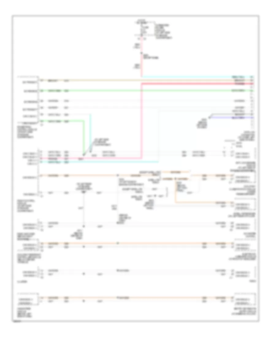
AIR CONDITIONING
Manual A/C Wiring Diagram for Dodge Dakota 2006

List of elements for Manual A/C Wiring Diagram for Dodge Dakota 2006:
- (at left rear of engine compt) s107
- (at left side of engine compt) s105
- (on right front of engine) a/c compressor clutch
- 87a
- A/c clutch ctrl
- A/c clutch relay
- A/c pressure transducer (at right front of engine compt)
- A/c-heater control
- Acc
- Blend door actuator (on right side of hvac unit)
- Blend door drv
- Blower motor (on front of hvac unit)
- Blower motor high speed
- Blower motor low speed
- Blower motor m1 speed blower motor m1 speed
- Blower motor m2 speed
- Blower motor relay
- Blower motor resistor (on right side of hvac unit)
- C121
- C13
- C21
- C29
- C32
- C34
- C61
- C71
- C72 c72
- C73
- C75
- C801
- Can +
- Can -
- Can b bus (+)
- Can b bus (-)
- Center of dash)
- Cluster
- Common door drv
- Computer data lines system
- D54
- D55
- D64
- D65
- Door drv
- E12
- Ect gnd
- Ect sig
- Ects sig
- Engine coolant temperature sensor (on right front side of engine)
- Evap temp sens sig
- Evaporator temp sens sig
- Evaporator temperature sensor (on hvac unit)
- F504
- Fcm sens rtn
- Floor to defrost mode door actuator
- Floor to panel mode door actuator
- Front control module (at left side of engine compt)
- Fuse 11 10a
- Fuse 35 40a
- Fuse 59 10a
- Fuse 7 10a
- Fused ign sw out (run)
- G108 (on lower right front of engine)
- G200 (behind left side of dash)
- G201 (behind right side of dash)
- Ground
- Hot at all times
- Hot in run
- Ignition switch
- Integrated power module (at left side of engine compt)
- Ipm
- K900
- Lock
- Mode door 1 drv
- Mode door 2 drv
- Off
- Panel lamp drv
- Panel lamps drv
- Powertrain control module (at right side of engine compt)
- Pressure sig
- Recirculation
- Recirculation door actuator (on right side of hvac unit)
- Recirulation door drv
- Run
- S114 (at right side of engine compt)
- S115 (at right side of engine compt)
- S123 (at top right of engine)
- S211 (behind center of dash)
- S217
- Sens
- Sens gnd
- Start
- T103
- Transmissions system
- Z24
- Z961
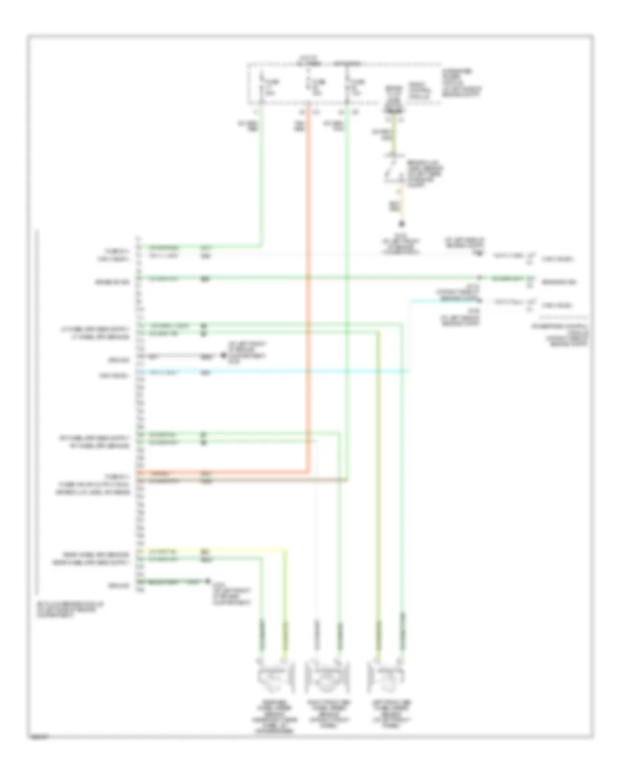
ANTI-LOCK BRAKES
All-Wheel ABS Wiring Diagram for Dodge Dakota 2006
List of elements for All-Wheel ABS Wiring Diagram for Dodge Dakota 2006:
- (at left front of engine compartment) g100
- (at left side of engine compt)
- (at left side of engine compt) s101
- A107
- A111
- Anti-lock brakes module (at left side of engine compartment)
- B22
- B222
- B29
- Brake fluid level sensor (at left rear of engine compt)
- Brake fluid level sw sense
- Brake fluid level switch sense
- Brake sw sig
- Can c bus(+)
- Can c bus(-)
- D64
- D65
- F500
- Front control module
- Fuse 10a
- Fuse 20a
- Fuse 40a
- Fuse b (+)
- Fused ign sw output (run)
- G100 (at left front of engine compartment)
- Ground
- Hot at all times
- Hot in run
- Integrated power module (at left side of engine compt)
- Left front abs wheel speed sensor (at left front wheel)
- Lf wheel spd sens sig
- Powertrain control module (at right side of engine compt)
- Rear abs wheel speed sensor (near right rear wheel, by crossmember)
- Rear wheel spd sens sig
- Rf wheel spd sens sig
- Right front abs wheel speed sensor (at right front wheel)
- S100
- S116 (at right side of engine compt)
- Tan/ red
- Tan/red
- Z107
- Z923
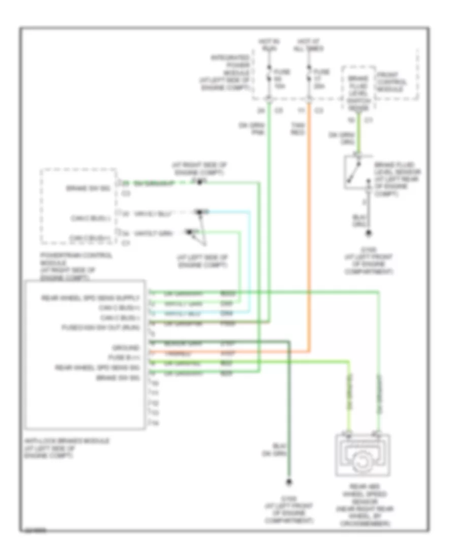
Rear Wheel ABS Wiring Diagram for Dodge Dakota 2006
List of elements for Rear Wheel ABS Wiring Diagram for Dodge Dakota 2006:
- (at left side of engine compt)
- (at right side of engine compt) s116
- A107
- Anti-lock brakes module (at left side of engine compt)
- B22
- B222
- B29
- Brake fluid level sensor (at left rear of engine compt)
- Brake fluid level switch sense
- Brake sw sig
- Can c bus(+)
- Can c bus(-)
- D64
- D65
- F500
- Front control module
- Fuse 10a
- Fuse 20a
- Fuse b (+)
- Fused ign sw out (run)
- G100 (at left front of engine compartment)
- Ground
- Hot at all times
- Hot in run
- Integrated power module (at left side of engine compt)
- Powertrain control module (at right side of engine compt)
- Rear abs wheel speed sensor (near right rear wheel, by crossmember)
- Rear wheel spd sens sig
- S100
- S101
- Tan/ red
- Tan/red
- Z107
ANTI-THEFT
Anti-theft Wiring Diagram for Dodge Dakota 2006
List of elements for Anti-theft Wiring Diagram for Dodge Dakota 2006:
- (at left side of engine compt) s101
- (at left side of engine compt) s105
- (behind center of dash) s212
- (in integrated power module) front control module
- 87a
- A918
- Can b bus b(+)
- Can b bus b(-)
- Can c bus (+)
- Can c bus (-)
- Cluster
- Computer data lines system
- D54
- D55
- D64
- D65
- Driver dr ajar sw
- F202
- Fuse 10a
- Fuse 16 20a
- Fuse 20a
- Fused b(+)
- Fused ign sw out (run-start)
- G200 (behind left side of dash)
- G300 (at center front of body)
- G300 (except highline) (at center front of body)
- G301 (highline) (behind left kick panel)
- Ground
- Headlights system
- Horn relay
- Horns system
- Hot at all times
- Hot in run or start
- Integrated power module (at left side of engine compt)
- Ipm
- L33
- L34
- Left front door latch (in left front door)
- Left rear door latch (in left rear door)
- Left rear sw sns
- Pass sw sns
- Powertrain control module (at right side of engine compt)
- Red
- Right front door latch (in right front door)
- Right rear door latch (in right rear door)
- Right rear sw sns
- S100 (at left side of engine compt)
- S104
- S107 (at left rear of engine compt)
- S206 (except base)
- S211 (behind center of dash)
- S319 (except highline)
- S321 (highline)
- S324 (highline)
- Sentry key remote entry module (at steering column)
- Z109
BODY CONTROL MODULES
Body Control Modules Wiring Diagram for Dodge Dakota 2006
List of elements for Body Control Modules Wiring Diagram for Dodge Dakota 2006:
- (at left front of engine compt) g100
- A/c pressure signal
- Aat sig
- Air conditioning system
- Ambient air temperature sensor (at left front of engine compt)
- Asd rly output
- B20
- Back-up lamp feed
- Brake fluid level sw sense
- Brake lamp sw output
- C18
- Can b bus (+)
- Can b bus (-)
- Can c bus (+)
- Can c bus (-)
- Can c diagnostic (+)
- Can c diagnostic (-)
- Computer data lines system
- D201
- D51
- D52
- D54
- D55
- D64
- D65
- Defogger rly ctrl
- Defogger system
- Driver left high beam
- Driver left low beam
- Driver right high beam
- Driver right low beam
- Engine controls system
- Exterior lights system
- F washer pump motor ctrl
- F202
- Fog lamp rly ctrl
- Front control module
- Fuse 10a
- Fuse 20a
- Fuse 25a
- Fuse 30a
- Fused b(+)
- Fused ign sw out (run)
- G100 (at left front of engine compt)
- G180
- G31
- G931
- Ground
- Headlights system
- High/low wiper rly ctrl
- Horn rly ctrl
- Horns system
- Hot at all times
- Hot in on or start
- Instrument cluster system
- Integrated power module (at left side of engine compt)
- Ipm
- L trailer tow rly
- L33
- L34
- L43
- L44
- L50
- L60
- L61
- L62
- L63
- Lf turn sig ctrl
- Low/rev sol ctrl
- Lr turn sig ctrl
- Mirrors system
- Mode sens a
- On/off wiper rly ctrl
- Park lamp rly ctrl
- Pnk/red
- R trailer tow rly
- Rf turn sig ctrl
- Rr turn sig ctrl
- S104
- Sensor ground
- Shift motor ctrl a
- Shift motor ctrl b
- T103
- T313
- T315
- T316
- Tcm sensor return
- Transfer case mtr lock sig
- Transmissions system
- W10
- Washer fluid level sw sens
- Wiper park sw sens
- Wiper/washer system
- Z116
- Z117
- Z118
- Z909
- Z921
- Z947
- Z965
COMPUTER DATA LINES
Computer Data Lines Wiring Diagram for Dodge Dakota 2006
List of elements for Computer Data Lines Wiring Diagram for Dodge Dakota 2006:
- (at left rear of engine compartment) s107
- (at left side of engine compartment)
- (behind center of dash) s212
- A/c-heater control
- Anti-lock brakes module (at left side of engine compartment)
- Awal
- C1 c1
- Can b bus (+)
- Can b bus (-)
- Can c (+)
- Can c (-)
- Can c bus (+)
- Can c bus (-)
- Cluster
- D15
- D16
- D20
- D21
- D51
- D52
- D54
- D55
- D64
- D65
- Data link connector (at lower left side of dash)
- Electronic overhead module (at front of headliner)
- Except satellite radio
- Front control module (at left side of engine compartment)
- Fuse 20a
- G200 (behind left side of dash)
- Hands free module (behind left side of dash)
- Hot at all times
- Integrated power module (at left side of engine compartment)
- Occupant classification module (under passenger seat)
- Occupant restraint controller module (below center console)
- Pnk/red
- Powertrain control module (at right side of engine compartment)
- Radio
- Radio amplifier (behind right kick panel)
- Rwal
- S100
- S101
- S105 (at left side of engine compartment)
- S206 (except base)
- S211 (behind center of dash)
- S300 (behind left kick panel)
- S303 (behind left kick panel)
- Satellite radio
- Satellite receiver (on left rear of floor)
- Sci receive
- Sci transmit
- Sentry key remote entry module (at steering column)
CRUISE CONTROL
Cruise Control Wiring Diagram for Dodge Dakota 2006
List of elements for Cruise Control Wiring Diagram for Dodge Dakota 2006:
- (not used)
- 5 speed
- A919
- Accel/ resume
- Can c bus (+)
- Cancel
- Clockspring (in steering column)
- Coast
- Computer data lines system
- D65
- Dump
- Engine controls system
- F855
- Fuse 20a
- Fused b (+)
- G103 (at right front of engine compartment)
- Hot at all times
- Instrument cluster
- Integrated power module (at left side of engine compartment)
- K22
- K900
- Left speed control switch
- Nca
- On/ off
- Powertrain control module (at right side of engine compartment)
- Red
- Right speed control switch
- S/c sw 1 sig
- S/c vacuum solenoid ctrl
- S/c vent solenoid ctrl
- S118 (near rear of engine)
- S122 (near top of transmission)
- Sens gnd
- Sensor ground
- Set
- Speed control servo (at right front of engine compartment)
- Stop lamp switch (behind lower left side of dash)
- Throttle position sensor (on throttle body)
- Tp sens 1 sig
- Tp sensor 1 sig
- V32
- V35
- V36
- V37
- Vacuum
- Vent
DEFOGGERS
Defoggers Wiring Diagram for Dodge Dakota 2006
List of elements for Defoggers Wiring Diagram for Dodge Dakota 2006:
- Defogger relay control
- Driver outside rearview mirror
- Front control module
- Fuse 53 40a
- Fuse 56 10a
- Fuse 59 10a
- G300 (at center front of body)
- G301 (quad cab: at left front of body) (except quad cab: behind left kick panel)
- Heated backlite
- Hot at all times
- Hot in run
- Integrated power module (at left side of engine compt)
- Ipm
- Passenger outside rearview mirror
- Rear window defogger relay
- S302 (behind left kick panel)
- S321
- S324
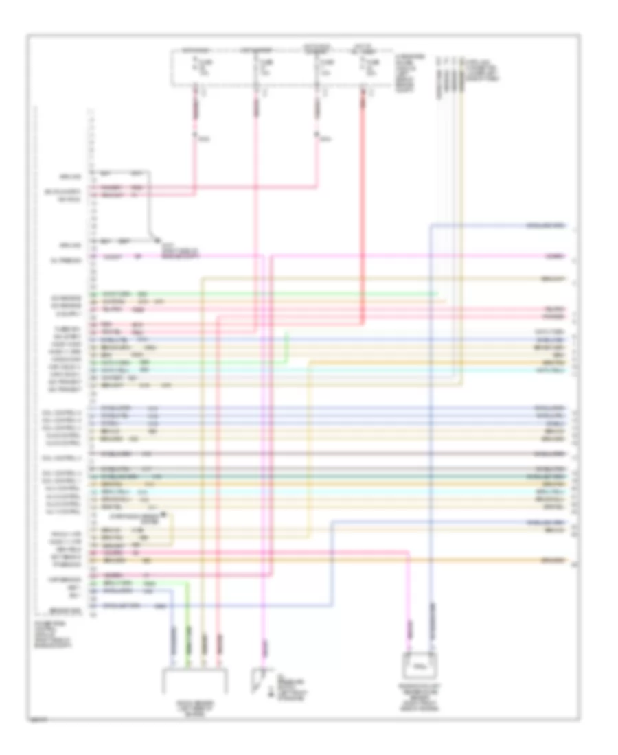
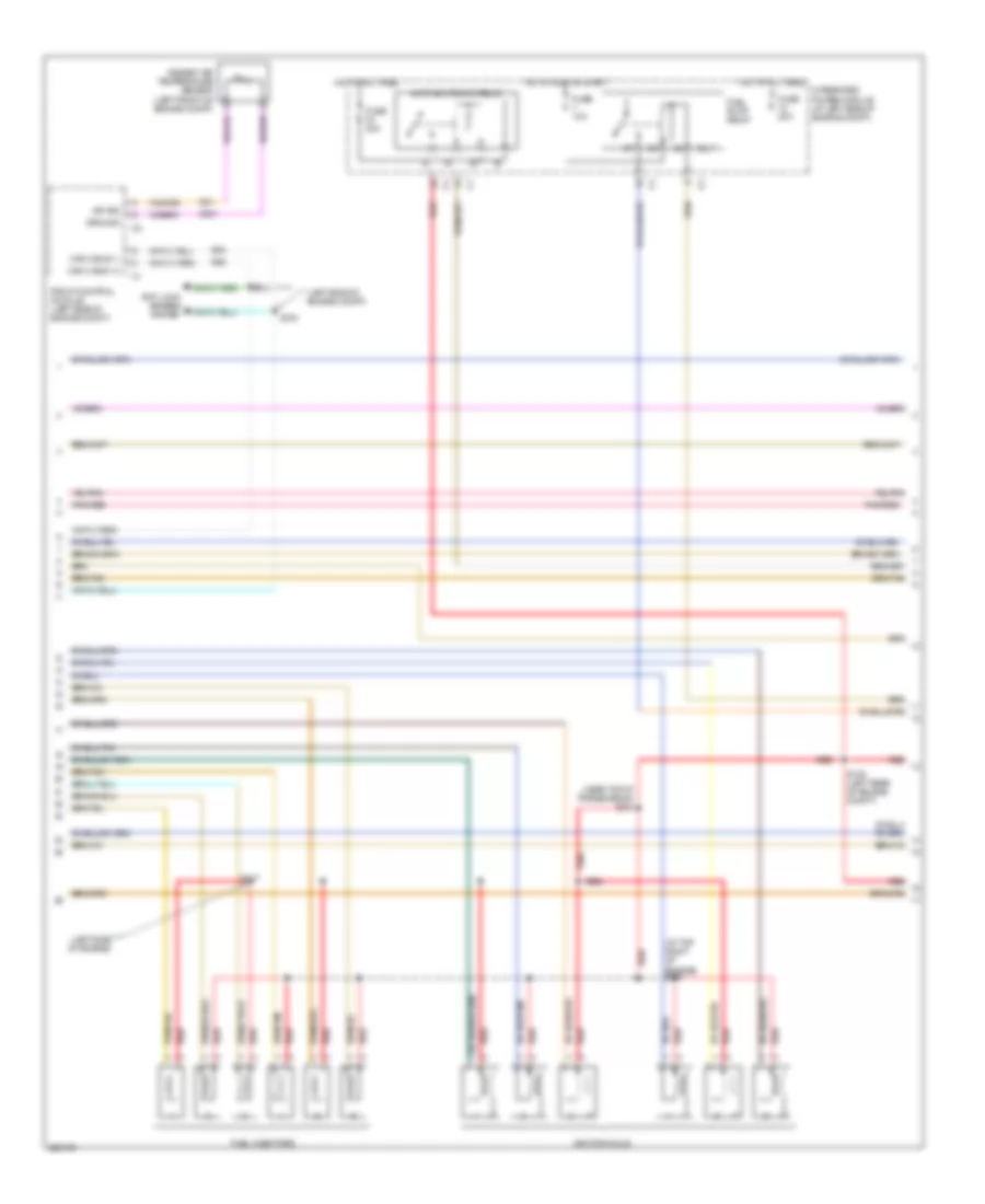
ENGINE PERFORMANCE
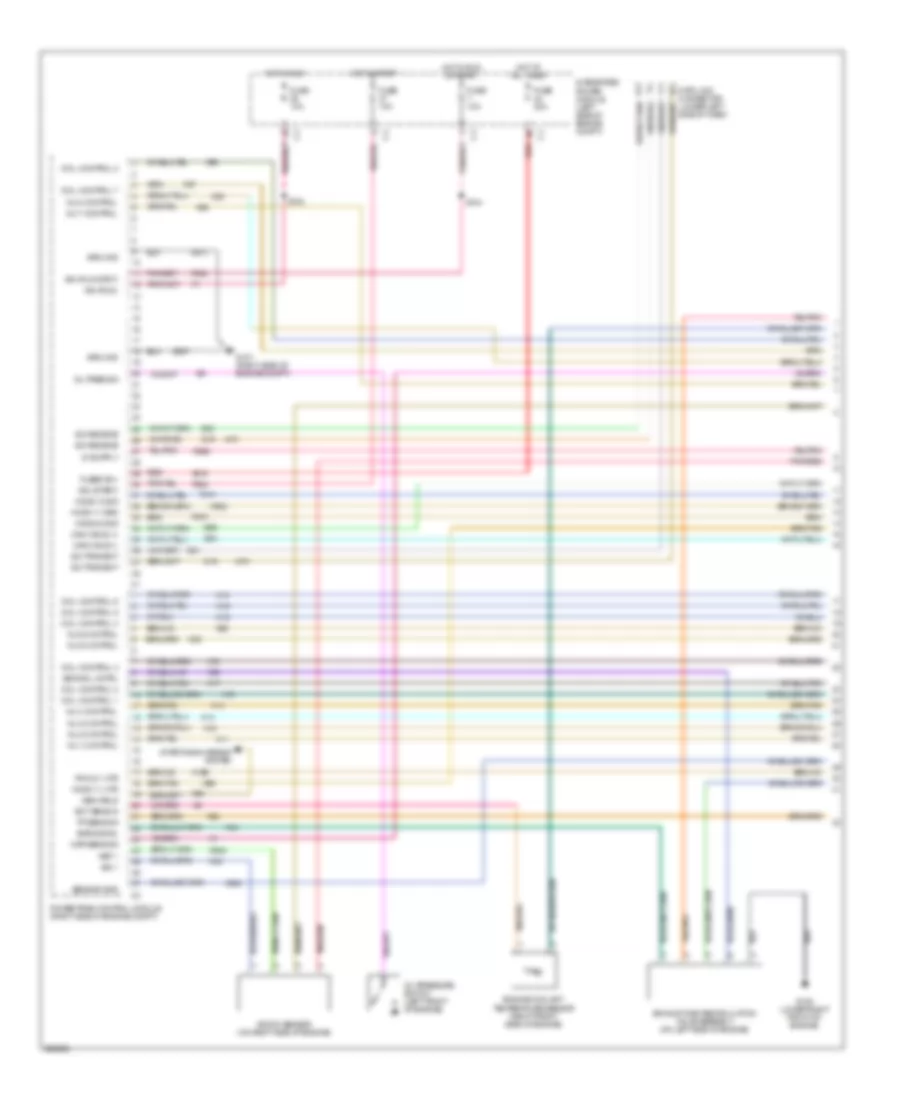
3.7L
3.7L, Engine Performance Wiring Diagram (1 of 5) for Dodge Dakota 2006
List of elements for 3.7L, Engine Performance Wiring Diagram (1 of 5) for Dodge Dakota 2006:
- (a/t)
- A919
- Can c bus (+)
- Can c bus (-)
- Coil control 1
- Coil control 2
- Coil control 3
- Coil control 4
- Coil control 5
- Coil control 6
- D15
- D16
- D20
- D21
- D64
- D65
- Data link connector (lower left side of dash)
- Ect sens in
- Engine coolant temperature sensor (right front side of engine)
- F202
- F856
- F924
- Fuse 10a
- Fuse 20a
- Fused b(+)
- G107 (right side of engine compt)
- Gen field
- Ground
- Ho2s 1/1 grd
- Ho2s 1/1 htr
- Ho2s 1/2 sig
- Ho2s 2/2 sig
- Hot at all times
- Hot in run
- Hot in run or start
- Hot in start
- Ign (run)
- Ign (run-strt)
- Ign (start)
- Inj 1 control
- Inj 2 control
- Inj 3 control
- Inj 4 control
- Inj 5 control
- Inj 6 control
- Integrated power module (left side of engine compt)
- K10
- K11
- K12
- K13
- K14
- K141
- K15
- K16
- K17
- K18
- K19
- K199
- K20
- K22
- K243
- K38
- K42
- K58
- K900
- K902
- K942
- K99
- Knock sensor (left rear of engine)
- Map sens sig
- Oil pres sig
- Oil pressure switch (left front of engine)
- Pnk/red
- Powertrain control module (right side of engine compt)
- Pwm 2/1 htr
- Red
- Ret 1
- S102
- S104
- Sci receive
- Sci transmit
- Sensor gnd
- Sig 1
- Starting/charging system
- Tp sens sig
- Z913
- Z937
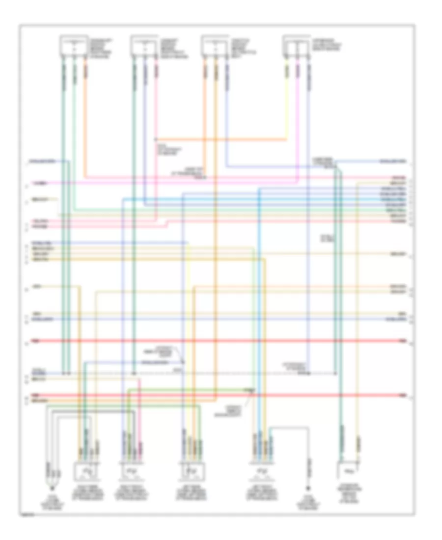
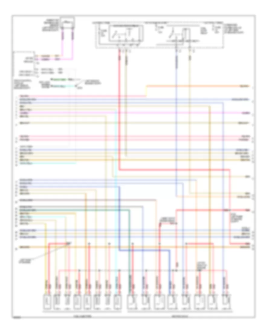
3.7L, Engine Performance Wiring Diagram (2 of 5) for Dodge Dakota 2006
List of elements for 3.7L, Engine Performance Wiring Diagram (2 of 5) for Dodge Dakota 2006:
- (at top right of engine) s127
- (left side of engine compt)
- (left side of engine)
- (near top of transmission) s121
- Aat sig
- Ambient air temperature sensor (left front of engine compt)
- Anti lock brakes system
- Auto shutdown relay
- Can c bus (+)
- Can c bus (-)
- D64
- D65
- Front control module (left side of engine compt)
- Fuel injectors
- Fuel pump relay
- Fuse 10a
- Fuse 20a
- Fuse 30a
- G31
- G931
- Ground
- Hot at all times
- Hot in run or start
- Ignition coils
- Integrated power module (at left side of engine compt)
- Pnk/red
- Red
- S100
- S101
- S108 (left rear of engine compt)
- S117
3.7L, Engine Performance Wiring Diagram (3 of 5) for Dodge Dakota 2006
List of elements for 3.7L, Engine Performance Wiring Diagram (3 of 5) for Dodge Dakota 2006:
- (at right rear of engine compt)
- (at top right of engine) s123
- (near rear of engine) s118
- (near top of transmission) s122
- Camshaft position sensor (right front side of engine)
- Crankshaft position sensor (right rear of engine)
- G108 (lower right front of engine)
- Intake air temperature sensor (on top of engine)
- Left front oxygen sensor (near left front of transmission)
- Left rear oxygen sensor (near left rear of transmission)
- Map sensor (on right front side of engine)
- Pnk/red
- Red
- Right front oxygen sensor (near right front of transmission)
- Right rear oxygen sensor (near right rear of transmission)
- S124 (at top right of engine)
- S125
- S126
- Throttle position sensor (on throttle body)
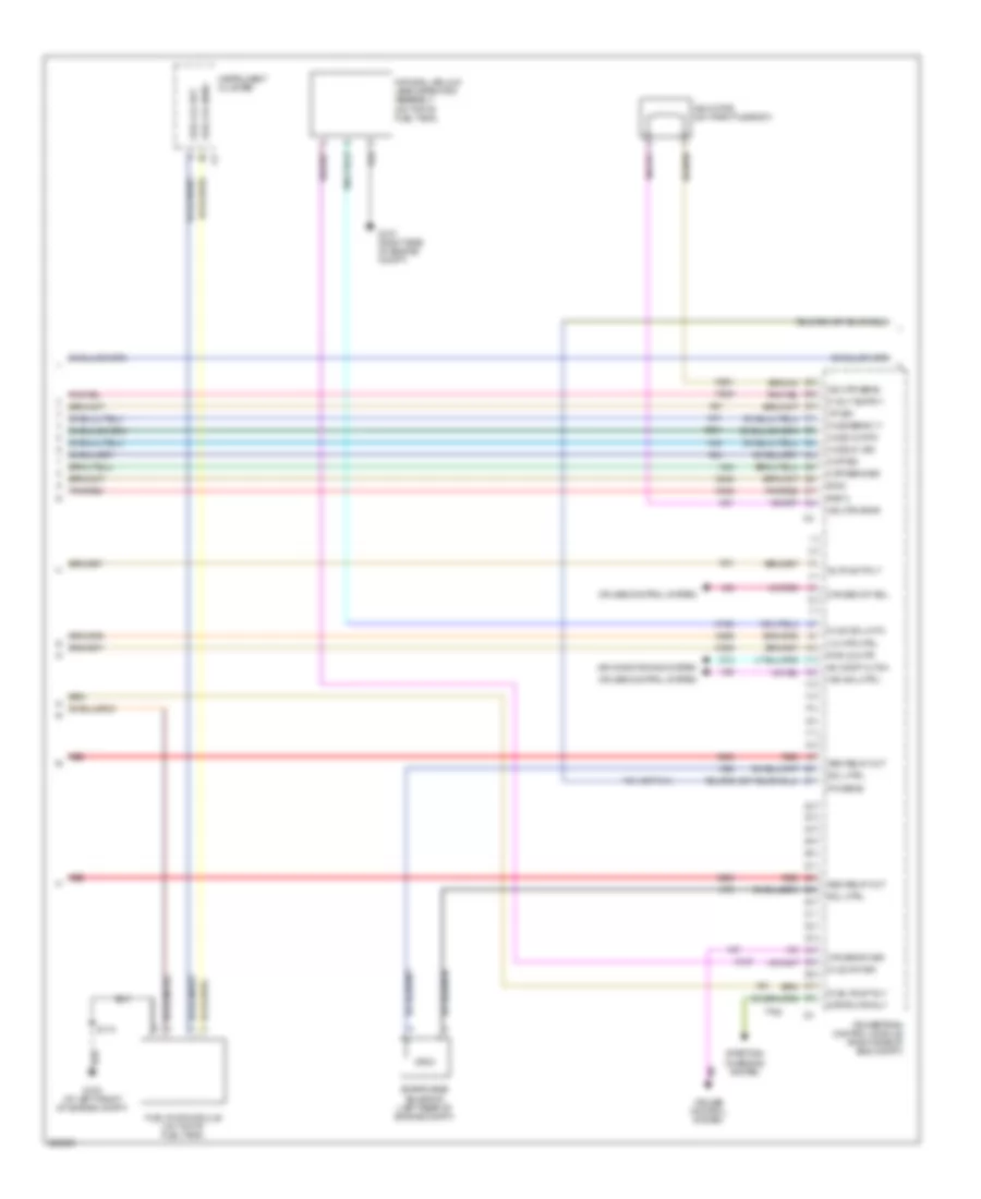
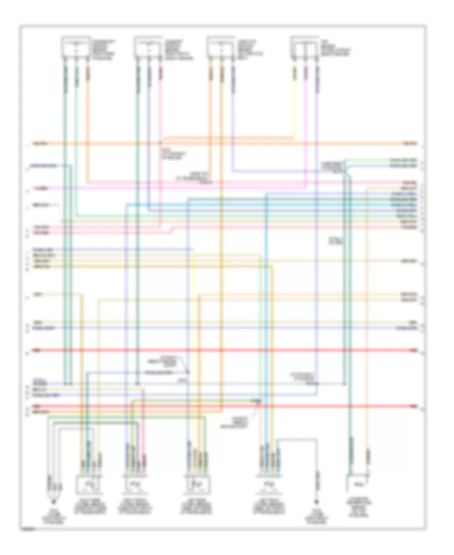
3.7L, Engine Performance Wiring Diagram (4 of 5) for Dodge Dakota 2006
List of elements for 3.7L, Engine Performance Wiring Diagram (4 of 5) for Dodge Dakota 2006:
- 1/2 htr ctrl
- A955
- Ac comp cltch
- Air conditioning system
- Asd relay out
- Auto sht rly
- C13
- Ckp sens sig
- Cmp sig
- Cruise control system
- Cruise sw sig
- Cruise vnt sol
- Evap/purge solenoid (left rear of engine compt)
- F855
- Fuel lvl ret
- Fuel lvl sens
- Fuel pump module (on top of fuel tank)
- Fuel pump rly
- G100 (at left front of engine compt)
- G107 (right side of engine compt)
- Ho2s 1/2 rtn
- Ho2s 2/1 sig
- Ho2s sens 1/1
- Iac motor (on throttle body)
- Iac mtr drvr
- Iac mtr sens
- Iat sig
- Instrument cluster
- K106
- K107
- K21
- K24
- K242
- K299
- K31
- K399
- K41
- K43
- K44
- K51
- K52
- K61
- K70
- K904
- K942
- K961
- Natural vacuum leak detection assembly (on top of fuel tank)
- Nvld sol cntl
- Nvld sw sig
- P/n sens
- Pnk/red
- Powertrain control module (right side of eng compt)
- Pwm 2/2 htr
- Red
- Ret 2
- S113
- Sig 2
- Sol ctrl
- Starting/ charging system
- Strtr mtr rly
- T41 (or t141)
- T752
- V35
- V36
- V37
- Vac sol ctrl
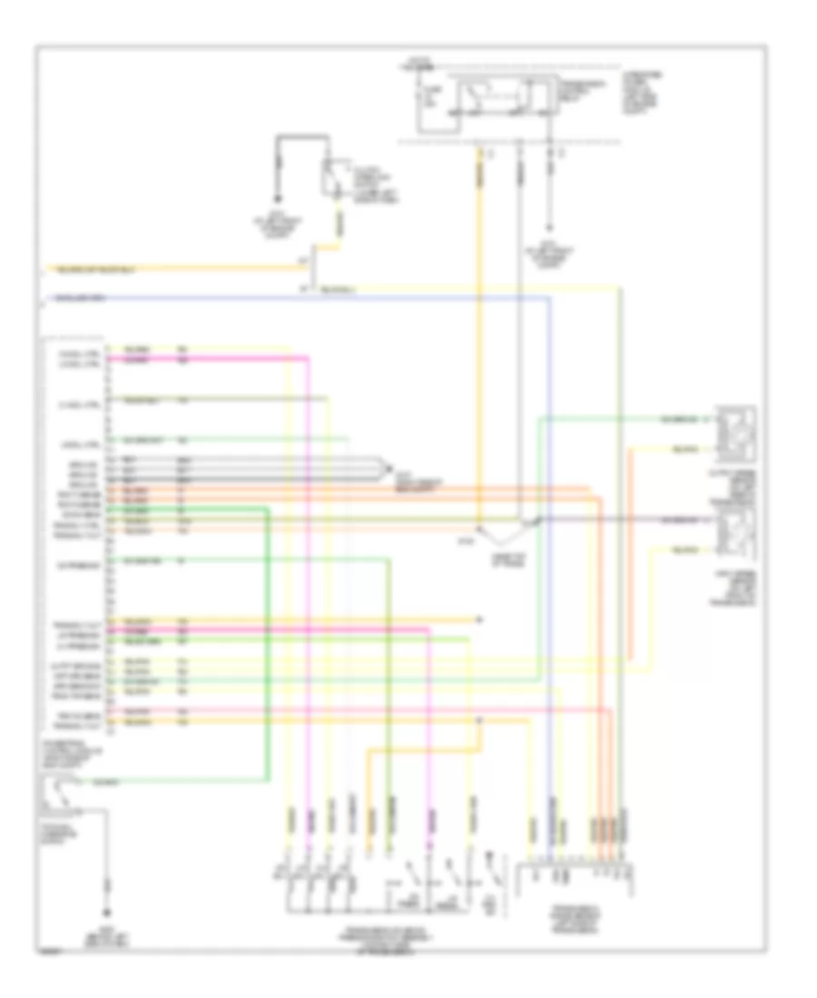
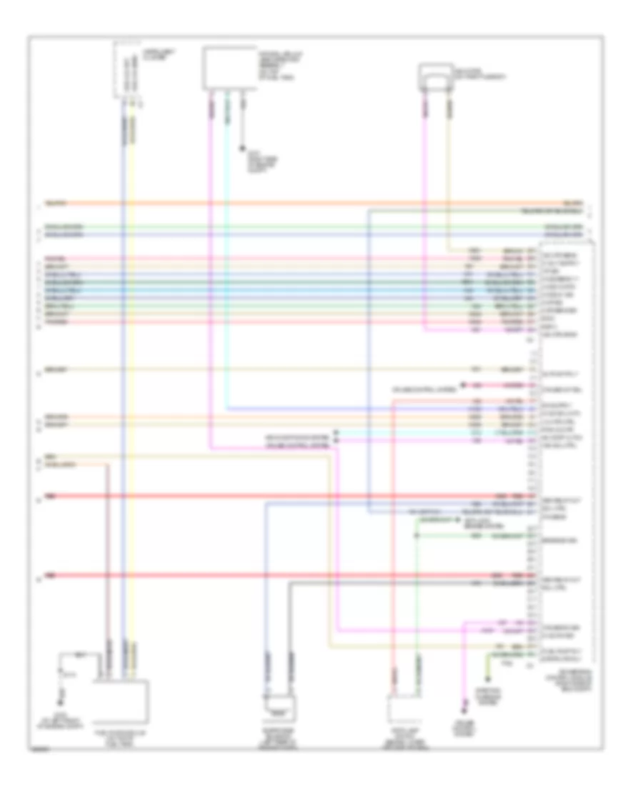
3.7L, Engine Performance Wiring Diagram (5 of 5) for Dodge Dakota 2006
List of elements for 3.7L, Engine Performance Wiring Diagram (5 of 5) for Dodge Dakota 2006:
- (near top of trans)
- 2-4 press sw
- 2-4 prs sw
- 2-4 sol
- 2-4 sol ctrl
- A/t
- Clutch interlock switch (lower left side of dash)
- Fuse 25a
- G101 (at left front of engine compt)
- G107 (right side of eng compt)
- G200 (behind left side of dash)
- Grd
- Ground
- Hot at all times
- Inpt spd sens
- Input speed sensor (on left front of transmission)
- Integrated power module (left side of engine compt)
- L/r press
- L/r press sw
- Lr sol
- Lr sol ctrl
- M/t
- Od press
- Od press sw
- Od sol
- Od sol ctrl
- Od sw sens
- Outpt spd sns
- Output speed sensor (on left rear of transmission)
- Powertrain control module (right side of eng compt)
- Rly
- S119
- S120
- Spd sens gnd
- T13
- T14
- T16
- T19
- T20
- T41
- T42
- T47
- T50
- T515
- T52
- T54
- T59
- T60
- Temp
- Tow/haul overdrive switch
- Trans rly out
- Trans rly out c4
- Transmission control relay
- Transmission range sensor (left side of transmission)
- Transmission solenoid/ pressure switch assembly (on right side of transmission)
- Trns rly ctrl
- Trns tmp sens
- Trs t1 sense
- Trs t3 sense
- Trs t42 sens
- Ud sol
- Ud sol ctrl
- Z904
- Z908
- Z977
4.7L
4.7L, Engine Performance Wiring Diagram (1 of 5) for Dodge Dakota 2006
List of elements for 4.7L, Engine Performance Wiring Diagram (1 of 5) for Dodge Dakota 2006:
- (a/t)
- A919
- Can c bus (+)
- Can c bus (-)
- Coil control 1
- Coil control 2
- Coil control 3
- Coil control 4
- Coil control 5
- Coil control 6
- Coil control 7
- Coil control 8
- D15
- D16
- D20
- D21
- D64
- D65
- Data link connector (lower left side of dash)
- Ect sens in
- Egr signal
- Egr sol cntrl
- Engine coolant temperature sensor (right front side of engine)
- Exhaust gas recirculation valve assembly (on left side of engine)
- F202
- F856
- F924
- Fuse 10a
- Fuse 20a
- Fused b(+)
- G107 (right side of engine compt)
- G108 (lower right front of engine)
- Gen field
- Ground
- Ho2s 1/1 grd
- Ho2s 1/1 htr
- Ho2s 1/2 sig
- Ho2s 2/2 sig
- Hot at all times
- Hot in run
- Hot in run or start
- Hot in start
- Ign (run)
- Ign (run-strt)
- Ign (start)
- Inj 1 control
- Inj 2 control
- Inj 3 control
- Inj 4 control
- Inj 5 control
- Inj 6 control
- Inj 7 control
- Inj 8 control
- Integrated power module (left side of engine compt)
- K10
- K11
- K12
- K13
- K14
- K141
- K15
- K16
- K17
- K18
- K19
- K199
- K20
- K22
- K243
- K26
- K28
- K34
- K35
- K38
- K42
- K58
- K900
- K902
- K942
- K97
- K98
- K99
- Knock sensor (on right side of engine)
- Map sens sig
- Oil pres sig
- Oil pressure switch (left front of engine)
- Pnk/red
- Powertrain control module (right side of engine compt)
- Pwm 2/1 htr
- Red
- Ret 1
- S102
- S104
- Sci receive
- Sci transmit
- Sensor gnd
- Sig 1
- Starting/charging system
- Tp sens sig
- Z913
- Z937
4.7L, Engine Performance Wiring Diagram (2 of 5) for Dodge Dakota 2006
List of elements for 4.7L, Engine Performance Wiring Diagram (2 of 5) for Dodge Dakota 2006:
- (at top right of engine) s127
- (left side of engine compt)
- (left side of engine)
- (near top of transmission) s121
- Aat sig
- Ambient air temperature sensor (left front of engine compt)
- Anti lock brakes system
- Auto shutdown relay
- Can c bus (+)
- Can c bus (-)
- D64
- D65
- Front control module (left side of engine compt)
- Fuel injectors
- Fuel pump relay
- Fuse 10a
- Fuse 20a
- Fuse 30a
- G31
- G931
- Ground
- Hot at all times
- Hot in run or start
- Ignition coils
- Integrated power module (at left side of engine compt)
- Pnk/red
- Red
- S100
- S101
- S108 (left rear of engine compt)
- S117
4.7L, Engine Performance Wiring Diagram (3 of 5) for Dodge Dakota 2006
List of elements for 4.7L, Engine Performance Wiring Diagram (3 of 5) for Dodge Dakota 2006:
- (at right rear of engine compt)
- (at top right of engine) s123
- (near rear of engine) s118
- (near top of transmission) s122
- Camshaft position sensor (right front side of engine)
- Crankshaft position sensor (right rear of engine)
- G108 (lower right front of engine)
- Intake air temperature sensor (on top of engine)
- Left front oxygen sensor (near left front of transmission)
- Left rear oxygen sensor (near left rear of transmission)
- Map sensor (on right front side of engine)
- Pnk/red
- Red
- Right front oxygen sensor (near right front of transmission)
- Right rear oxygen sensor (near right rear of transmission)
- S124 (at top right of engine)
- S125
- S126
- Throttle position sensor (on throttle body)
4.7L, Engine Performance Wiring Diagram (4 of 5) for Dodge Dakota 2006
List of elements for 4.7L, Engine Performance Wiring Diagram (4 of 5) for Dodge Dakota 2006:
- 1/2 htr ctrl
- A955
- Ac comp cltch
- Air conditioning system
- Anti-lock brakes system
- Asd relay out
- Auto sht rly
- B29
- Brake sw sig
- C13
- Ckp sens sig
- Cmp sig
- Cruise control system
- Cruise sw sig
- Cruise vnt sol
- Evap/purge solenoid (left rear of engine compt)
- F855
- Fuel lvl ret
- Fuel lvl sens
- Fuel pump module (on top of fuel tank)
- Fuel pump rly
- G100 (at left front of engine compt)
- G107 (right side of engine compt)
- Ho2s 1/2 rtn
- Ho2s 2/1 sig
- Ho2s sens 1/1
- Iac motor (on throttle body)
- Iac mtr drvr
- Iac mtr sens
- Iat sig
- Instrument cluster
- K106
- K107
- K21
- K24
- K242
- K299
- K31
- K399
- K41
- K43
- K44
- K51
- K52
- K61
- K70
- K904
- K942
- K961
- Natural vacuum leak detection assembly (on top of fuel tank)
- Nvld sol cntl
- Nvld sw sig
- P/n sens
- Pnk/red
- Powertrain control module (right side of eng compt)
- Pwm 2/2 htr
- Red
- Ret 2
- S113
- Sig 2
- Sol ctrl
- Starting/ charging system
- Stop lamp switch (behind lower left side of dash)
- Strtr mtr rly
- T41 (or t141)
- T752
- V32
- V35
- V36
- V37
- Vac sol ctrl
4.7L, Engine Performance Wiring Diagram (5 of 5) for Dodge Dakota 2006
List of elements for 4.7L, Engine Performance Wiring Diagram (5 of 5) for Dodge Dakota 2006:
- (near top of trans)
- (right side of engine compt) g107
- 2c press
- 2c press sw
- 2c sol
- 2c sol ctrl
- 4c press
- 4c press sw
- 4c sol
- 4c sol ctrl
- 5 volt
- A/t
- Clutch interlock switch (lower left side of dash)
- Fuse 25a
- G101 (at left front of engine compt)
- G200 (behind left side of dash)
- Grd
- Ground
- Hot at all times
- Inpt spd sens
- Input speed sensor (on left front of transmission)
- Integrated power module (left side of engine compt)
- L/r press
- L/r press sw
- Line pressure sensor (on right side of transmission)
- Line prs sens
- Lr sol
- Lr sol ctrl
- M/t
- Ms sol
- Ms sol ctrl
- Od press
- Od press sw
- Od sol
- Od sol ctrl
- Od sw sens
- Outpt spd sns
- Output speed sensor (on left rear of transmission)
- Powertrain control module (right side of eng compt)
- Pres ctrl
- Press sig
- Press sol
- S119
- S120
- S128
- Spd sens gnd
- T118
- T13
- T14
- T140
- T147
- T16
- T20
- T219
- T259
- T29
- T38
- T42
- T48
- T50
- T515
- T52
- T54
- T59
- T60
- Temp sens
- Tow/haul overdrive switch
- Trans rly out
- Trans rly out c4
- Transmission control relay
- Transmission solenoid/trs assembly (left side of transmission)
- Trns rly ctrl
- Trns tmp sens
- Trs t1
- Trs t1 sense
- Trs t2
- Trs t2 sense
- Trs t3
- Trs t3 sense
- Trs t42
- Trs t42 sens
- Ud press
- Ud press sw
- Ud sol
- Ud sol ctrl
- Z904
- Z908
- Z977
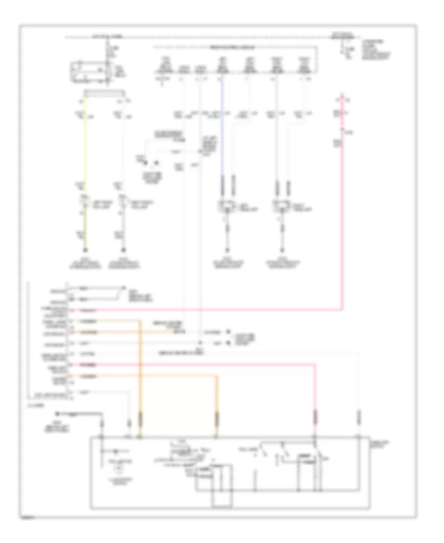
EXTERIOR LIGHTS
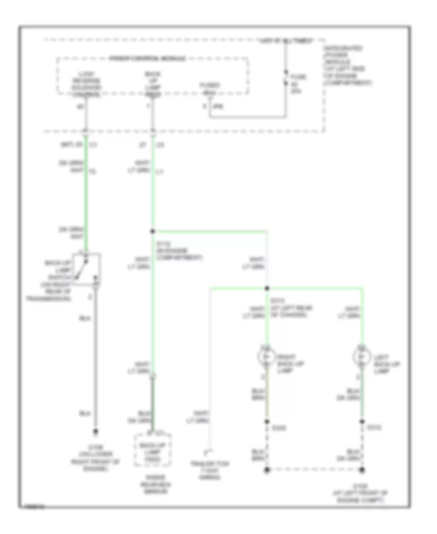
Back-up Lamps Wiring Diagram for Dodge Dakota 2006
List of elements for Back-up Lamps Wiring Diagram for Dodge Dakota 2006:
- (m/t)
- Back up lamp feed
- Back-up lamp feed
- Back-up lamp switch (on right rear of transmission)
- Front control module
- Fuse 25a
- Fused b(+)
- G100 (at left front of engine compt)
- G108 (on lower right front of engine)
- Hot at all times
- Inside rearview mirror
- Integrated power module (at left side of engine compartment)
- Ipm
- Left back-up lamp
- Low/ reverse solenoid control
- Of chassis)
- Right back-up lamp
- S312
- S320
- Trailer tow 7-way wiring
Exterior Lamps Wiring Diagram for Dodge Dakota 2006
List of elements for Exterior Lamps Wiring Diagram for Dodge Dakota 2006:
- (at left side of engine compt) s100
- (at left side of engine compt) s101
- (at right side of engine compt)
- (at right side of engine compt) s116
- (not used)
- 5 speed
- B29
- Brake lamp sw out
- Brake provision module (at lower left side of dash)
- Brake sw out
- Brake sw signal
- Can c bus (+)
- Can c bus (-)
- Can c bus(+)
- Can c bus(-)
- Cargo lamp drv
- Chmsl aftermarket lamp
- Cluster
- Computer data lines system
- D64
- D65
- Front control module
- Front turn signal
- Fuse 10a
- Fuse 15a
- Fuse 51 40a
- G100 (at left front of engine compt)
- G101 (at left front of engine compt)
- G103 (at right front of engine compt)
- G200 (behind left side of dash)
- G301 (behind left kick panel)
- Ground
- Hazard
- Hdlp sw mux
- Hdlp sw mux rtn
- Head
- Headlamp switch
- High mounted stop lamp
- Hot at all times
- Illum sw
- Integrated power module (at left side of engine compartment)
- Ipm
- L50
- L77 pnk/ red
- Left
- Left front park/ turn lamp
- Left license lamp
- Left rear turn signal
- Left turn
- Left turn/ tail/ stop lamp
- Multi-function switch (in steering column)
- Off
- Panel lamps
- Park
- Park lamp relay
- Park lamp relay control
- Park lamp relay output
- Pnk/ red
- Powertrain control module
- Rear turn signal
- Right
- Right front park/ turn lamp
- Right front turn signal
- Right rear turn signal
- Right turn
- Right turn/ tail/ stop lamp
- S/c
- S106 (at left rear of engine compt)
- S205 (remote radio) (behind left side of dash)
- S304
- S312
- S314 (at left rear of chassis)
- S320
- Sound systems
- Speed control servo (at right front of engine compartment)
- Stop lamp switch (behind lower left side of dash)
- Sw mux rtn
- Turn sig input
- V32
Trailer Tow Wiring Diagram for Dodge Dakota 2006
List of elements for Trailer Tow Wiring Diagram for Dodge Dakota 2006:
- (at left rear of chassis) s317
- (in engine compartment) s112
- 87a
- A400
- B400
- Back- up lamp feed
- Back-up lamp feed
- Brake lamp switch out
- Brake lp sw output
- Brake provision module (at lower left side of dash)
- Front control module
- Fuse 12 15a
- Fuse 13 15a
- Fuse 30a
- Fuse 45 10a
- G100 (at left front of engine compartment)
- G302 (at lower right rear of engine compartment)
- High mounted stop lamp
- Hot at all times
- Inside rearview mirror
- Integrated power module (at left side of engine compartment)
- Ipm
- L50
- Left back-up lamp
- Left trailer tow brake lamp relay control
- Left trailer tow relay
- Of chassis)
- Park lamp relay
- Pnk/ red
- Pnk/red
- Right back-up lamp
- Right trailer tow brake lamp relay control
- Right trailer tow relay
- S106 (at left rear of engine compartment)
- S313 (at left rear of chassis)
- S315
- S316 (at left rear of chassis)
- S318 (at left rear
- Stop lamp switch (behind lower left side of dash)
- Tan/ red
- Tan/red
- Trailer tow 4-way wiring
- Trailer tow 7-way wiring
- Z910
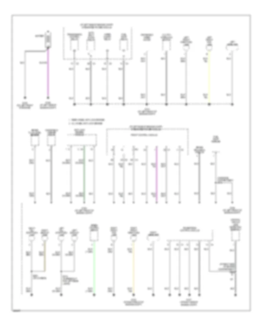
GROUND DISTRIBUTION
Ground Distribution Wiring Diagram (1 of 3) for Dodge Dakota 2006
List of elements for Ground Distribution Wiring Diagram (1 of 3) for Dodge Dakota 2006:
- (at left side of engine compt) integrated power module
- (at right side of engine compartment)
- (in engine compartment) s113
- A/t
- All wheel anti-lock brakes
- Anti-lock brakes module
- Auto shut down relay
- Battery
- Brake fluid level sensor
- Brake provision module
- Clutch
- Front control module
- Fuel pump module
- Fuel pump relay
- G100 (at left front of engine compt)
- G101 (at left front of engine compt)
- G102 (at left front of engine compt)
- G103 (at right front of engine compt)
- G105 (on left front of engine)
- G106 (at left side of engine compt)
- G107 (at right side of engine compt)
- Interlock switch
- Ipm
- Left backup lamp
- Left front fog lamp
- Left front park/turn lamp
- Left headlamp
- Left tail/ stop/turn lamp
- Natural vacuum leak detection assembly
- Powertrain control module
- Rear wheel anti-lock brakes
- Right backup lamp
- Right front fog lamp
- Right front park/turn lamp
- Right headlamp
- Right tail/ stop/turn lamp
- S128
- S312 (in breakout for left rear lamps)
- S320 (on chassis)
- Speed control servo
- Transmission control relay
- Windshield
- Windshield washer pump
- Wiper motor
- Wiper on/off relay
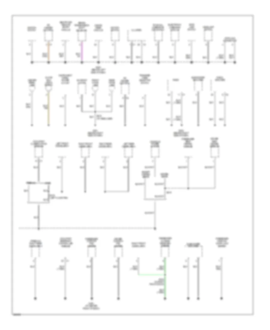
Ground Distribution Wiring Diagram (2 of 3) for Dodge Dakota 2006
List of elements for Ground Distribution Wiring Diagram (2 of 3) for Dodge Dakota 2006:
- (premium) right rear door latch
- A/c heater control
- Base
- Brake transmission shift solenoid
- Center bezel lamp
- Cluster
- Console power outlet
- Data link connector
- Driver cushion pad heater
- Driver seat heated module
- Electronic overhead module
- Except heated seats
- Front dome lamp
- G200 (behind left side of dash)
- G201 (behind right side of dash)
- G202 (behind right side of dash)
- G300 (at center front of body)
- Glove box lamp & switch
- Hands free module
- Headlamp switch
- Heated seats
- Ignition switch
- Instrument panel power outlet
- Left front door latch
- Left rear door latch
- Occupant classification module
- Occupant restraint controller module
- Passenger cushion pad heater
- Passenger outside rearview mirror
- Passenger seat heated module
- Passenger window/ door lock switch
- Premium
- Radio
- Radio amplifier
- Rear dome lamp
- Right front door latch
- Right rear door latch
- S216 (at headliner)
- S219
- S319 (left floor pan)
- S324 (in right front door)
- Sentry key remote entry module
- Stop lamp switch
- Subwoofer amplifier
- Sunroof motor
- Tow/haul overdrive off switch
- Transfer case selector switch
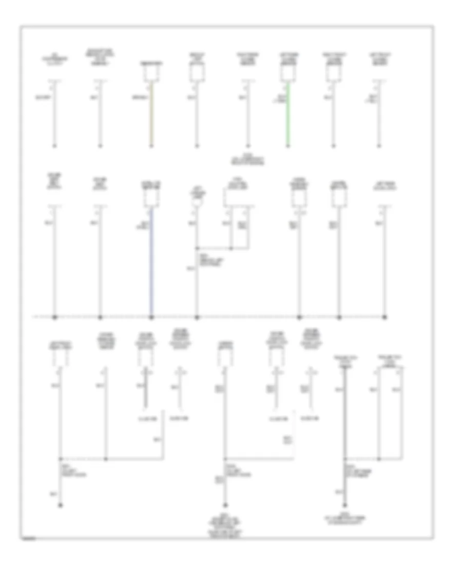
Ground Distribution Wiring Diagram (3 of 3) for Dodge Dakota 2006
List of elements for Ground Distribution Wiring Diagram (3 of 3) for Dodge Dakota 2006:
- A/c compressor clutch
- Backup lamp switch
- Club cab
- Driver express window/ door lock switch
- Driver rearview outside mirror
- Driver seat belt switch
- Driver seat switch
- Driver window/ door lock
- Exhaust gas recirculation valve assembly
- G108 (on lower right front of engine)
- G301 (except quad cab: behind left kick panel) (quad cab: at left front of body)
- G302 (at lower right rear of engine compt)
- Generator
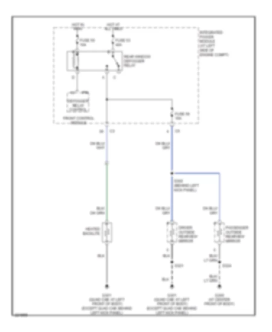
- Heated backlite
- High mounted stop lamp
- Inside rearview mirror
- Left front door latch
- Left front oxygen sensor
- Left license lamp
- Left rear door latch
- Left rear oxygen sensor
- Mirror switch
- Quad cab
- Right front oxygen sensor
- Right rear oxygen sensor
- S304 (behind left kick panel)
- S315 (at left rear of chassis)
- S321 (in left front door)
- S322 (in left front door)
- Satellite receiver
- Switch
- Trailer tow 4-way wiring
- Trailer tow 7-way wiring
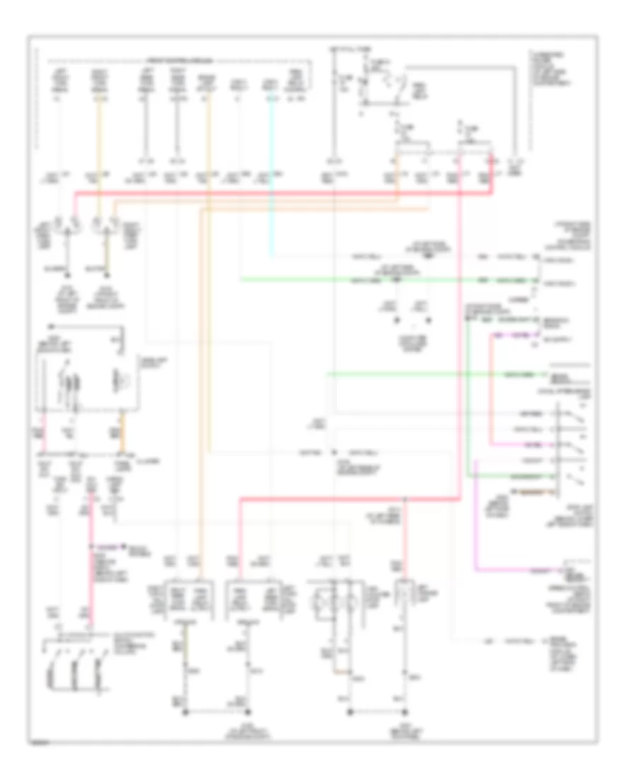
HEADLIGHTS
Headlights Wiring Diagram for Dodge Dakota 2006
List of elements for Headlights Wiring Diagram for Dodge Dakota 2006:
- (at left rear of engine compt) s107
- (at left side of engine compt) s105
- (behind center of dash)
- 87a
- Can b bus(+)
- Can b bus(-)
- Cargo dome
- Cluster
- Computer data lines system
- D55
- Dim 1
- Dim 2
- Dim 3
- Dim 4
- Dim 5
- Dim 6
- Dimmer sig ind
- Fog lamp ind
- Fog lamp ind drv
- Fog lamp relay
- Fog lamp relay control
- Fog lamps
- Front control module
- Fuse 10a
- Fuse 20a
- Fused ign sw output (run-start)
- G101 (at left front of engine compt)
- G103 (at right front of engine compt)
- G200 (behind left side of dash)
- Ground
- Head
- Headlamp sw mux
- Headlamp sw mux return
- Headlamp switch
- Hot at all times
- Hot in run, off or start
- Illumination switch
- Integrated power module (at left side of engine compt)
- Ipm
- L89
- Left front fog lamp
- Left headlamp
- Left high beam driver
- Left low beam driver
- Off
- Panel lamps dimmer sig c3
- Parade
- Park
- Pnk/red
- Right front fog lamp
- Right headlamp
- Right high beam driver
- Right low beam driver
- S102
- S211 (behind center of dash)
- S212
- Tan
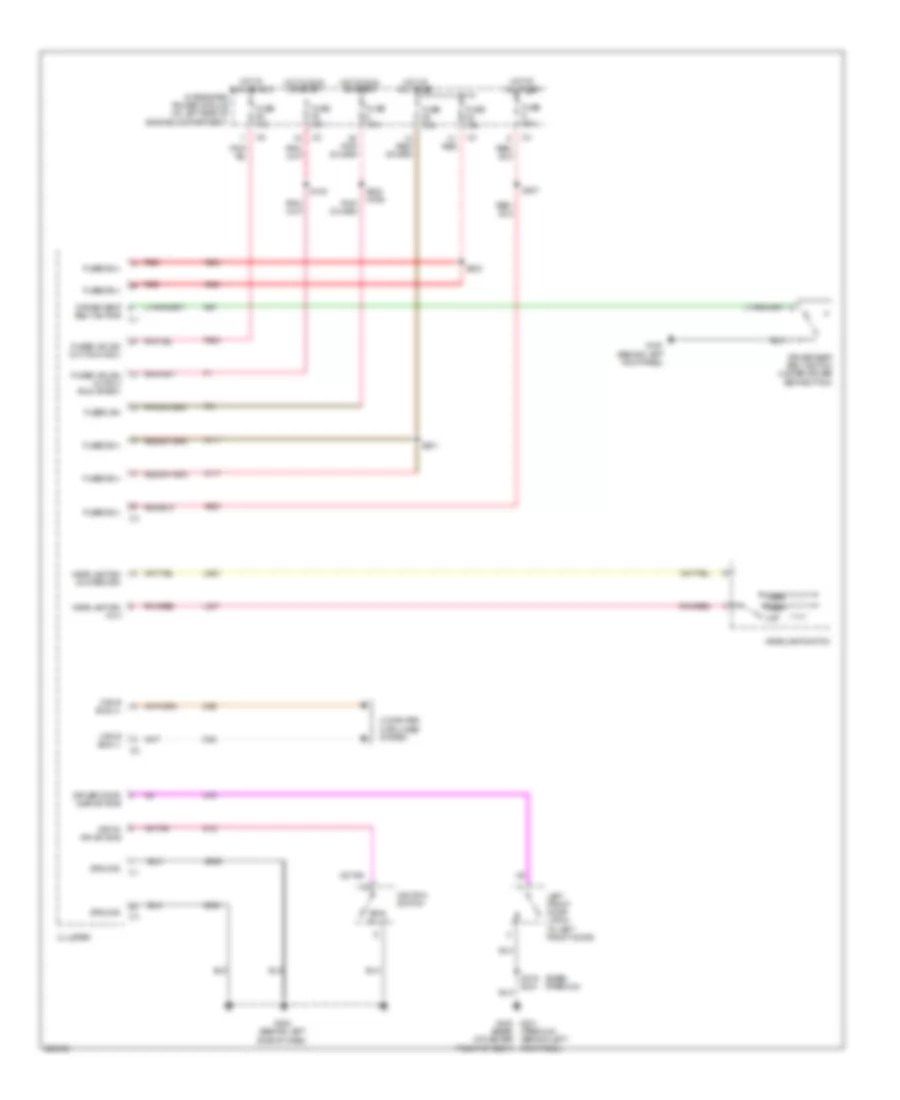
HORN
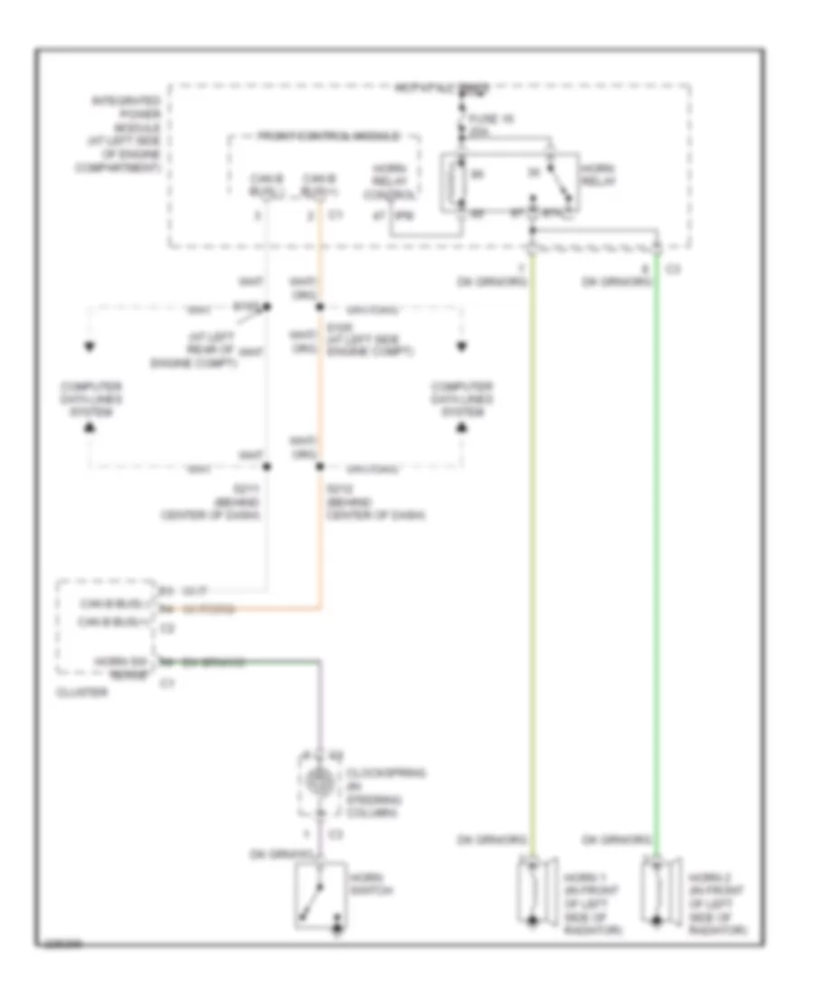
Horn Wiring Diagram for Dodge Dakota 2006
List of elements for Horn Wiring Diagram for Dodge Dakota 2006:
- (at left rear of engine compt)
- 87a
- Can b bus(+)
- Can b bus(+) c2
- Can b bus(-)
- Clockspring (in steering column)
- Cluster
- Computer data lines system
- Front control module
- Fuse 16 20a
- Horn 1 (in front of left side of radiator)
- Horn 2 (in front of left side of radiator)
- Horn relay
- Horn relay control
- Horn sw
- Horn switch
- Hot at all times
- Integrated power module (at left side of engine compartment)
- Ipm
- S107
- S211 (behind center of dash)
- S212 (behind center of dash)
- Sense
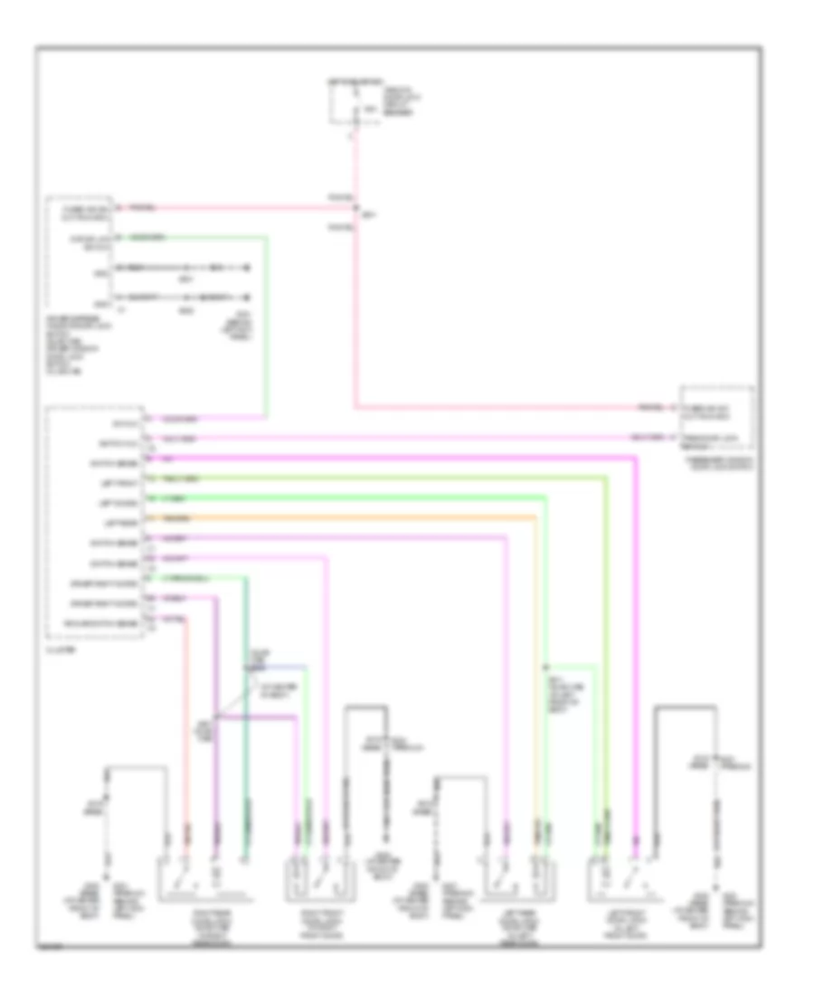
INSTRUMENT CLUSTER
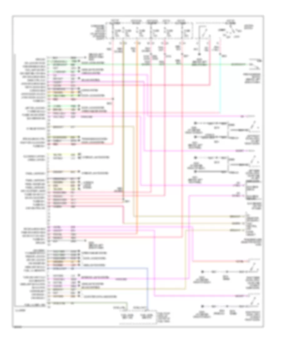
Instrument Cluster Wiring Diagram for Dodge Dakota 2006
List of elements for Instrument Cluster Wiring Diagram for Dodge Dakota 2006:
- (behind left side of dash) g200
- (highline)
- 4wd neutral ind
- 5v selector sw
- A117
- A920
- A924
- Acc
- B25
- B30
- Base
- Btsi solenoid ctrl
- Can b bus(+)
- Can b bus(-)
- Cargo lmp drv
- Cluster
- Computer data lines system
- D54
- D55
- Door locks system
- Dr lock drv r dr
- Drv courtesy lamps
- Drv dr ajar sw sns
- Drv dr lock sw
- Drv seat belt sw sns
- E11
- E12
- E19
- E33
- Exterior lights system
- F washer sw mux
- F wiper sw mux
- F21
- F961
- F983
- Fog lamp ind drv
- Fuel level sen 1 sig
- Fuel level sen rtn
- Fuel lvl sen 1 sig
- Fuel lvl sens rtn
- Fuel pump module (on top of fuel tank)
- Fuse 10a
- Fuse 15a
- Fuse 20a
- Fused b(+)
- Fused ign sw out
- Fused ign sw-start
- G15
- G160
- G161
- G194
- G200 (behind left side of dash)
- G300 (at center front of body)
- G301 (behind left kick panel)
- G39
- G74
- G75
- G76
- G77
- G778
- G902
- G939
- G95
- Glove box lmp drv
- Ground
- Headlamp sw mux
- Headlamp sw mux rtn
- Headlights system
- High beam/
- Horn sw sns
- Horns system
- Hot at all times
- Hot in on
- Hot in on or acc
- Hot in on or start
- Ign sw (on-start)
- Ign sw out (on-acc)
- Ignition switch
- Ind dimmer sig
- Integrated power module (at left side of engine compt)
- Interior lights system
- K77
- K977
- Key-in ign sw sns
- L12
- L14
- L307
- L900
- L914
- Left dr lock drv
- Left front door latch (in left front door)
- Left rear door latch (quad cab) (in left rear door)
- Lf drv door unlock
- Lock
- Lr door ajar sw sns
- Lr drv door unlock
- M22
- M28
- Mode select
- Off
- P392
- P393
- Panel dimmer sig
- Panel lamps drv
- Park brake sw sns
- Parking brake switch (behind left side of dash)
- Pass dr ajar sw sns
- Pass dr lock sw
- Pnk/red
- Premium
- R57
- Radio ctrl mux
- Red
- Right dr unlock drv
- Right front door latch (in right front door)
- Right rear door latch (quad cab) (in right rear door)
- Rr dr ajar sw sns
- S102
- S109 (2wd)
- S201
- S202 (4wd)
- S203
- S204
- S207
- S319
- S319 (base)
- S321
- S324 (premium)
- Sound systems
- Start
- Sun sens return
- Sun sens rtn
- Sun sens signal
- Sun sensor (on top of dash)
- Sun sensor sig
- Sw mux rtn
- Transfer case selector switch (4wd)
- Transmissions system
- Turn sig input mux
- W52
- Warning system
- Wiper/washer system
- X20
- Z946
- Z948
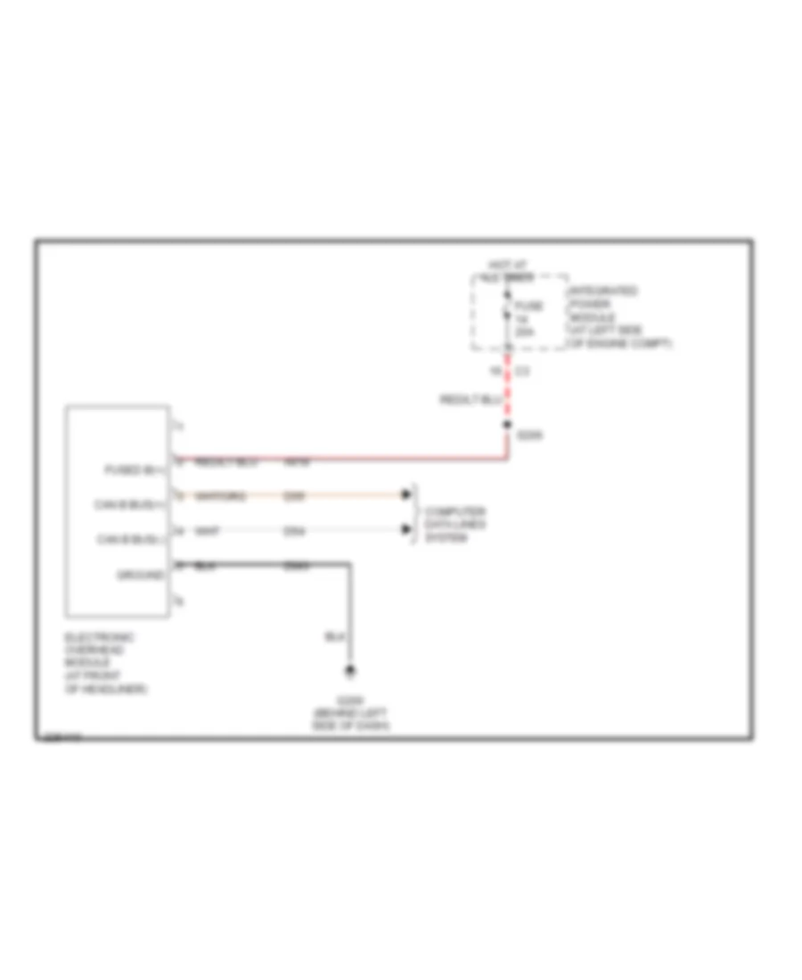
Overhead Console Wiring Diagram for Dodge Dakota 2006
List of elements for Overhead Console Wiring Diagram for Dodge Dakota 2006:
- A918
- Can b bus(+)
- Can b bus(-)
- Computer data lines system
- D54
- D55
- Electronic overhead module (at front of headliner)
- Fuse 20a
- Fused b(+)
- G200 (behind left side of dash)
- Ground
- Hot at all times
- Integrated power module (at left side of engine compt)
- S206
- Z993
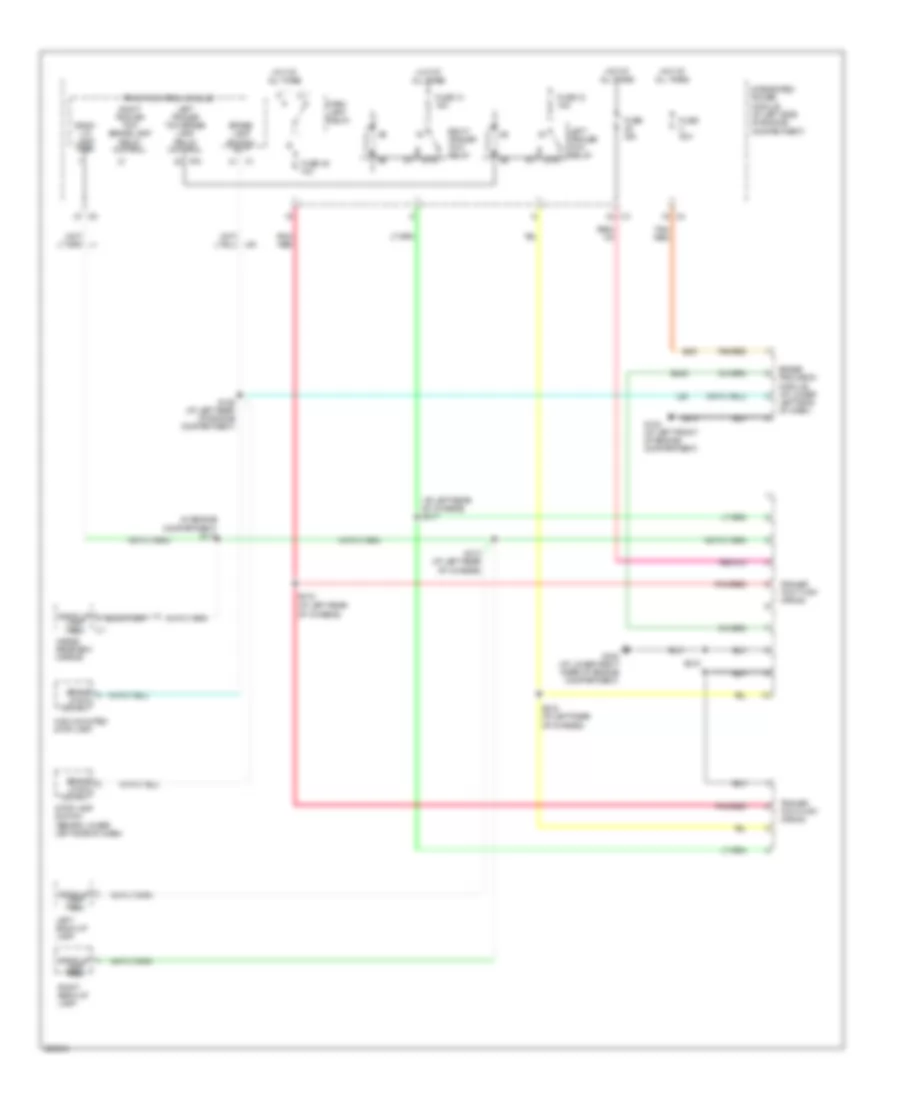
INTERIOR LIGHTS
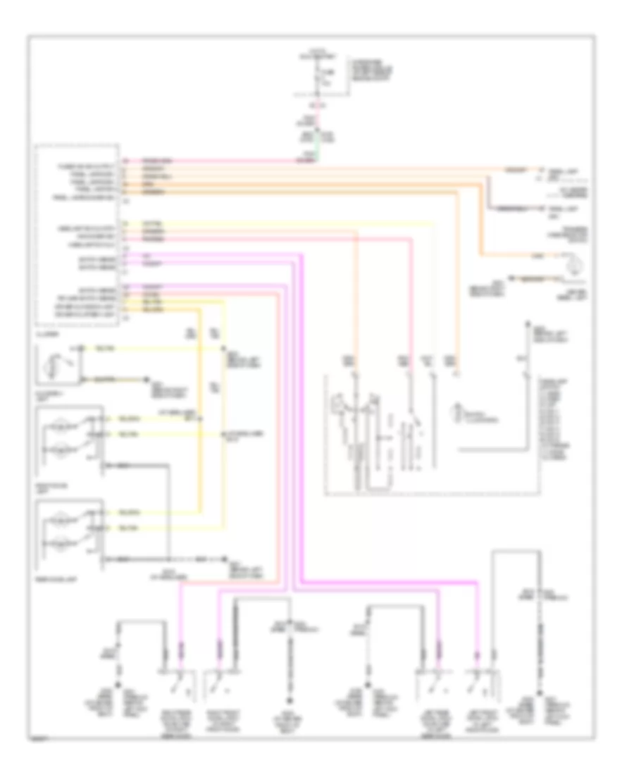
Interior Lights Wiring Diagram for Dodge Dakota 2006
List of elements for Interior Lights Wiring Diagram for Dodge Dakota 2006:
- (at headliner) s214
- (at headliner) s215
- A/c heater control
- Center bezel lamp
- Cluster
- Driver courtesy lamp
- Driver glove box lamp
- Drv
- Front dome lamp
- Fuse 10a
- Fused ign sw output
- G200 (behind left side of dash)
- G201 (behind left side of dash)
- G201 (behind right side of dash)
- G300 (at center front of body)
- G300 (base) (at center front of body)
- G301 (premium) (behind left kick panel)
- Glove box lamp
- Headlamp sw mux
- Headlamp sw mux rtn
- Headlamp switch 1) head 2) park 3) off 4) dim 1 5) dim 2 6) dim 3 7) dim 4 8) dim 5 9) dim 6 10) parade 11) dome 12) cargo
- Hot in run or start
- Ind dimmer sig
- Integrated power module (at left side of engine compt)
- Left front door latch (in left front door)
- Left rear door latch (quad cab) (in left rear door)
- Panel lamp
- Panel lamp drv
- Panel lamps dimmer sig
- Panel lamps drv
- Pnk/ red
- Pnk/red
- Rear dome lamp
- Right front door latch (in right front door)
- Right rear door latch (quad cab) (in right rear door)
- Rr ajar switch sense
- S109 (2wd)
- S202 (4wd)
- S208 (behind left side of dash)
- S216 (at headliner)
- S319 (base)
- S321 (premium)
- S324 (premium)
- Switch illumination
- Switch sense
- Transfer case selector switch
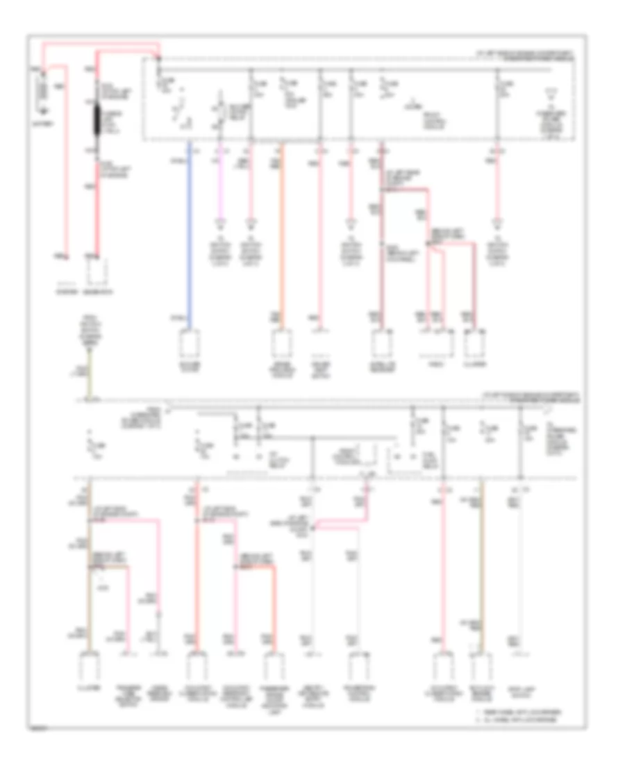
POWER DISTRIBUTION
Power Distribution Wiring Diagram (1 of 3) for Dodge Dakota 2006
List of elements for Power Distribution Wiring Diagram (1 of 3) for Dodge Dakota 2006:
- (at left rear of engine compt) s111
- (at left side of engine compartment) integrated power module
- (at left side of engine compt) s104
- (at left side of engine compt) s109
- (at left side of engine compt) s110
- (behind left side of dash) s202
- (behind left side of dash) s207
- (behind left side of dash) s210
- (diagram
- 2 of 3)
- 4wd
- A/c clutch relay
- All wheel anti-lock brakes
- Anti-lock brakes module
- Battery
- Blower motor
- Blower motor relay
- Brake provision module
- Cluster
- Driver seat switch
- From
- From integrated power module (diagram 1 of 3)
- Front control module
- Fuel pump relay
- Fuse 10a
- Fuse 15a
- Fuse 20a
- Fuse 30a (trailer tow)
- Fuse 40a
- Fuse 50a
- Generator
- Ignition
- Inside rearview mirror
- Ipm
- Nca
- Occupant classification module
- Occupant restraint controller module
- Passenger air bag on/off indicator lamp
- Powertrain control module
- Radio
- Rear wheel anti-lock brakes
- Red
- S129 (at top left of engine)
- S130 (at top left of engine)
- S305 (behind left kick panel)
- Satellite receiver
- Sentry key remote entry module
- Starter
- Stop lamp switch
- Switch
- Tan/ red
- To integrated power module (diagram 1 of 3)
- To integrated power module (diagram 2 of 3)
- Transfer case selector switch
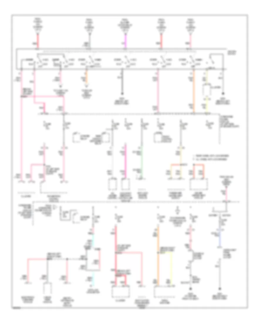
Power Distribution Wiring Diagram (2 of 3) for Dodge Dakota 2006
List of elements for Power Distribution Wiring Diagram (2 of 3) for Dodge Dakota 2006:
- (at left side of engine compt) s103
- (behind left side of dash) s204
- (behind left side of dash) s206
- (behind right side of dash) s213
- (diagram
- 1 of 3)
- 20a
- 3 of 3)
- 40a
- A/c heater control
- Acc
- All wheel anti-lock brakes
- Anti-lock brakes module
- Base
- Battery
- Blower
- Cluster
- Console power outlet
- Data link connector
- Driver heated seat module
- Electronic overhead module
- Except base
- From
- From integrated power module (diagram 1 of 3)
- From splice s200 (diagram 3 of 3)
- Front control module
- Fuse 10a
- Fuse 2
- Fuse 20a
- Fuse 25a
- Fuse 30a
- Fuse 38
- Fuse 47
- Fuse 5
- G200 (behind left side of dash)
- G201 (behind right side of dash)
- G300 (at center front of body)
- Hands free module
- Ignition
- Ignition switch
- Instrument panel power outlet
- Integrated power module (at left side of engine compt)
- Ipm
- Key in
- Lock off
- Motor relay
- Occupant restraint controller module
- Passenger heated seat switch
- Pnk
- Power module (diagram
- Powertrain control module
- Radio amplifier
- Rear wheel anti-lock brakes
- Rear window defogger relay
- Red
- Red (behind left side of dash) s203
- Red/ tan
- Run
- S102 (at left side of engine compt)
- S218
- Sentry key remote entry module
- Shift motor/ mode sensor assembly (4wd)
- Start
- Starter relay
- Tan/ pnk
- To fuse 7 10a (diagram 1 of 3)
- To integrated
- To splice s200 (diagram 3 of 3)
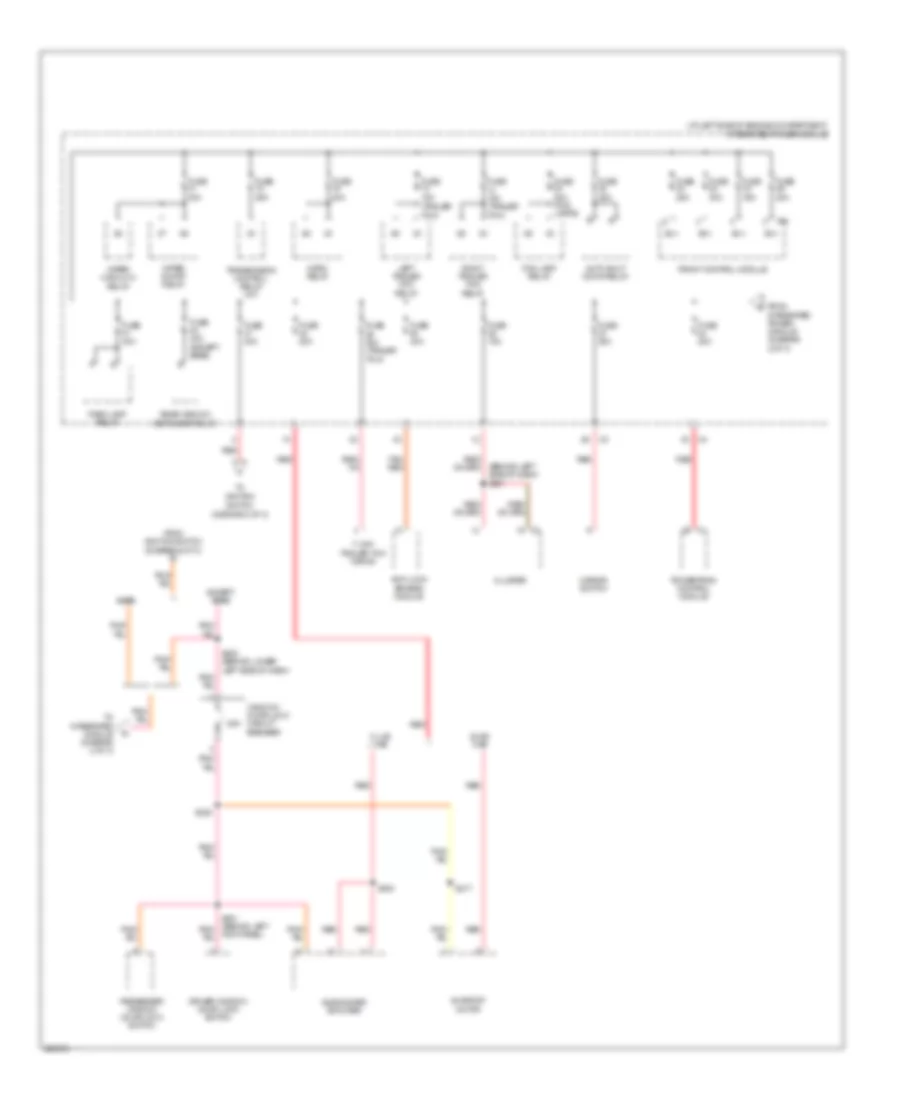
Power Distribution Wiring Diagram (3 of 3) for Dodge Dakota 2006
List of elements for Power Distribution Wiring Diagram (3 of 3) for Dodge Dakota 2006:
- (at left side of engine compartment) integrated power module
- (behind left side of dash) s201
- (diagram 2 of 3)
- (trailer tow)
- 25a
- 7-way trailer tow wiring
- Anti-lock brakes module
- Auto shut down relay
- B(+)
- Base
- Club cab
- Cluster
- Driver window/ door lock switch
- Except base
- Fog lamp relay
- From ignition switch (diagram 2 of 3)
- From integrated power module (diagram 2 of 3)
- Front control module
- Fuse 15a
- Fuse 15a (trailer tow)
- Fuse 20a
- Fuse 20a (fog lamps)
- Fuse 25a
- Fuse 30a
- Fuse 30a (trailer tow)
- Fuse 40a
- Fuse 40a (except base)
- Horn relay
- Ignition
- Ipm
- Kick panel)
- Left trailer tow relay
- Mirror switch
- Park lamp relay
- Passenger/ window door lock switch
- Powertrain control module
- Quad cab
- Rear window defogger relay
- Red
- Right trailer tow relay
- S200 (behind lower left side of dash)
- S217
- S220
- S330
- Subwoofer amplifier
- Sunroof motor
- Switch
- Tan/ red
- To integrated module (diagram 2 of 3)
- Transmission control relay (a/t)
- Window/ door lock circuit breaker
- Wiper high/low relay
- Wiper on/off relay
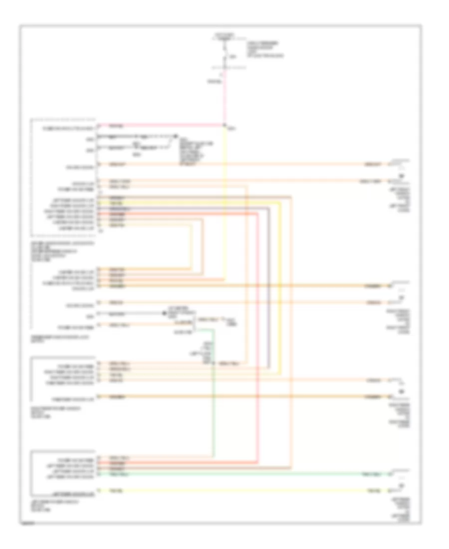
POWER DOOR LOCKS
Power Door Locks Wiring Diagram for Dodge Dakota 2006
List of elements for Power Door Locks Wiring Diagram for Dodge Dakota 2006:
- (at center of body)
- (quad cab) s306
- 25a
- Cluster
- Driver express window/door lock switch (quad cab) driver window/ door lock switch (club cab)
- Driver right doors
- Dvr dr lck sw mux
- Fused ign sw out (run-acc)
- G300 (at center front of body)
- G300 (base) (at center front of body)
- G301 (behind left kick panel)
- G301 (premium) (behind left kick panel)
- Gnd
- Hot in on or acc
- Left doors
- Left front
- Left front door latch (in left front door)
- Left rear
- Left rear door latch (quad cab) (in left rear door)
- Pass door lock sw mux
- Passenger window/ door lock switch
- Right front door latch (in right front door)
- Right rear door latch (quad cab) (in right rear door)
- Rr ajar switch sense
- S301
- S307 (quad cab)
- S311 (quad cab) (at left front of body)
- S319 (base)
- S321
- S321 (premium)
- S322
- S324 (premium)
- Sw mux
- Switch mux
- Switch sense
- Window/ door lock circuit breaker
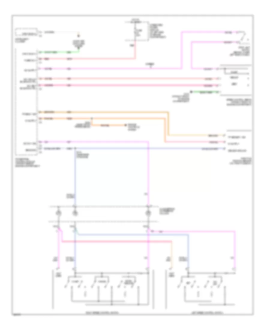
POWER MIRRORS
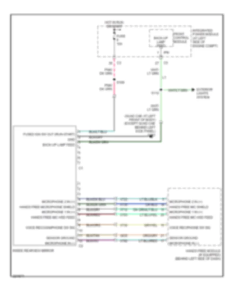
Automatic Day/Night Mirror Wiring Diagram for Dodge Dakota 2006
List of elements for Automatic Day/Night Mirror Wiring Diagram for Dodge Dakota 2006:
- (quad cab: at left front of body) (except quad cab: behind left kick panel) g301
- Back-up lamp feed
- Exterior lights system
- Front control module
- Fuse 10a
- Fused ign sw out (run-start)
- Gnd
- Hands free mic hsd feed
- Hands free mic shield
- Hands free microphone shield
- Hands free module (if equipped) (behind left side of dash)
- Hot in run or start
- Inside rearview mirror
- Integrated power module (at left side of engine compt)
- Ipm
- Microphone 1 in (+)
- Microphone 2 in (+)
- Microphone in (-)
- S109
- S112
- Sensor ground
- Voice rec/phone sw sig
- Voice recogni/phone sw sig
- X712
- X722
- X730
- X735
- X792
- X793
- X835
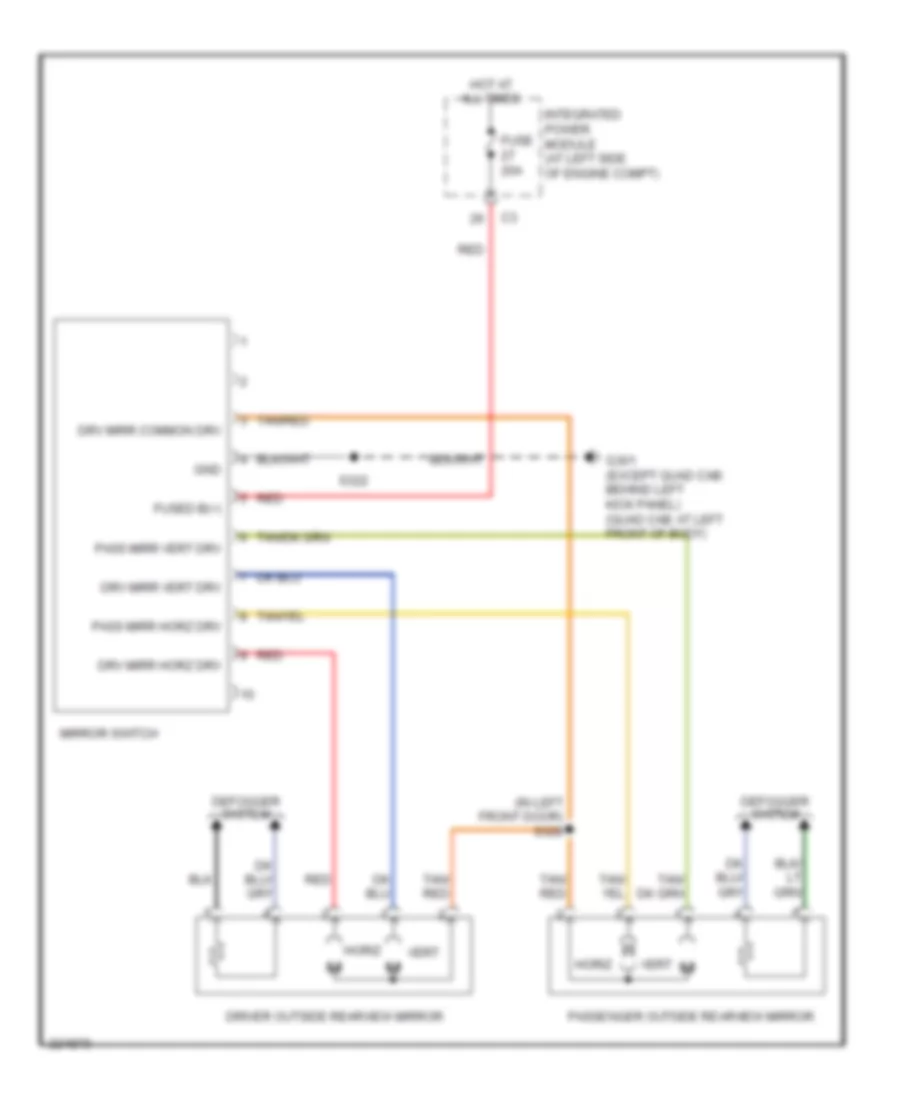
Power Mirrors Wiring Diagram for Dodge Dakota 2006
List of elements for Power Mirrors Wiring Diagram for Dodge Dakota 2006:
- (in left front door) s328
- Defogger system
- Driver outside rearview mirror
- Drv mirr common drv
- Drv mirr horz drv
- Drv mirr vert drv
- Fuse 20a
- Fused b(+)
- G301 (except quad cab: behind left kick panel) (quad cab: at left front of body)
- Gnd
- Horiz
- Hot at all times
- Integrated power module (at left side of engine compt)
- Mirror switch
- Pass mirr horz drv
- Pass mirr vert drv
- Passenger outside rearview mirror
- Red
- S322
- Tan/ red
- Tan/red
- Vert
POWER SEATS
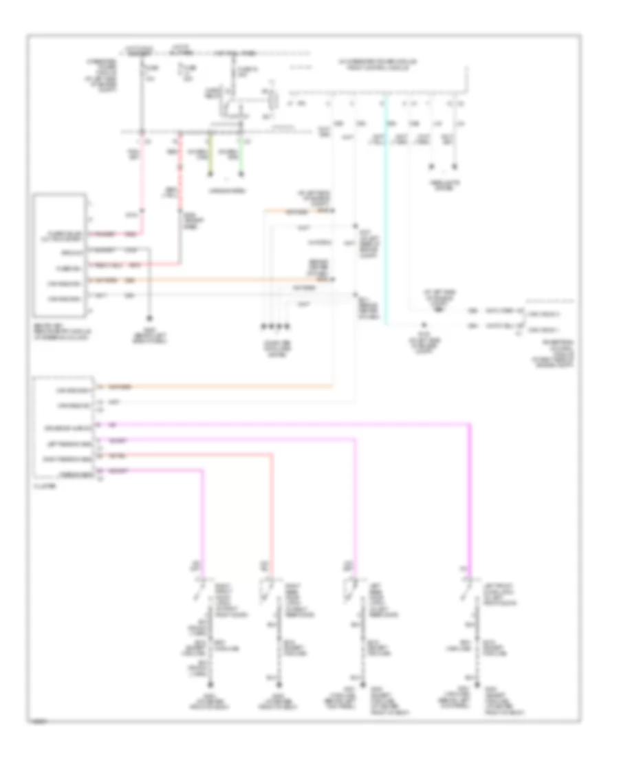
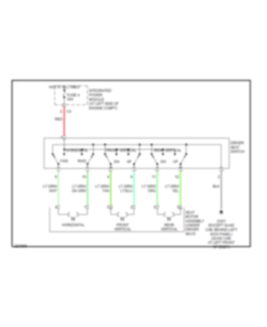
Driver Power Seat Wiring Diagram for Dodge Dakota 2006
List of elements for Driver Power Seat Wiring Diagram for Dodge Dakota 2006:
- Driver seat switch
- Front vertical
- Fuse 4 50a
- Fwd
- G301 (except quad cab: behind left kick panel) (quad cab: at left front of body)
- Horizontal
- Hot at all times
- Integrated power module (at left side of engine compt)
- Rear vertical
- Red
- Rwd
- Seat motor assembly (under driver seat)
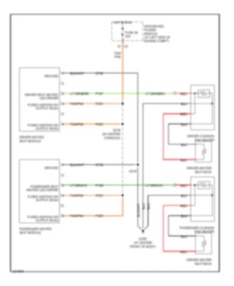
Heated Seats Wiring Diagram for Dodge Dakota 2006
List of elements for Heated Seats Wiring Diagram for Dodge Dakota 2006:
- Driver cushion pad heater
- Driver heated seat module
- Driver heater seat back
- Driver seat heated led driver
- F525
- Fuse 58 20a
- Fused ignition sw output (run)
- G300 (at center front of body)
- Ground
- Hot in run
- Integrated power module (at left side of engine compt)
- P187
- P188
- Passenger cushion pad heater
- Passenger heated seat module
- Passenger seat heated led driver
- Red
- S218 (in center console)
- S219
- Tan/ pnk
- Tan/pnk
- Z738
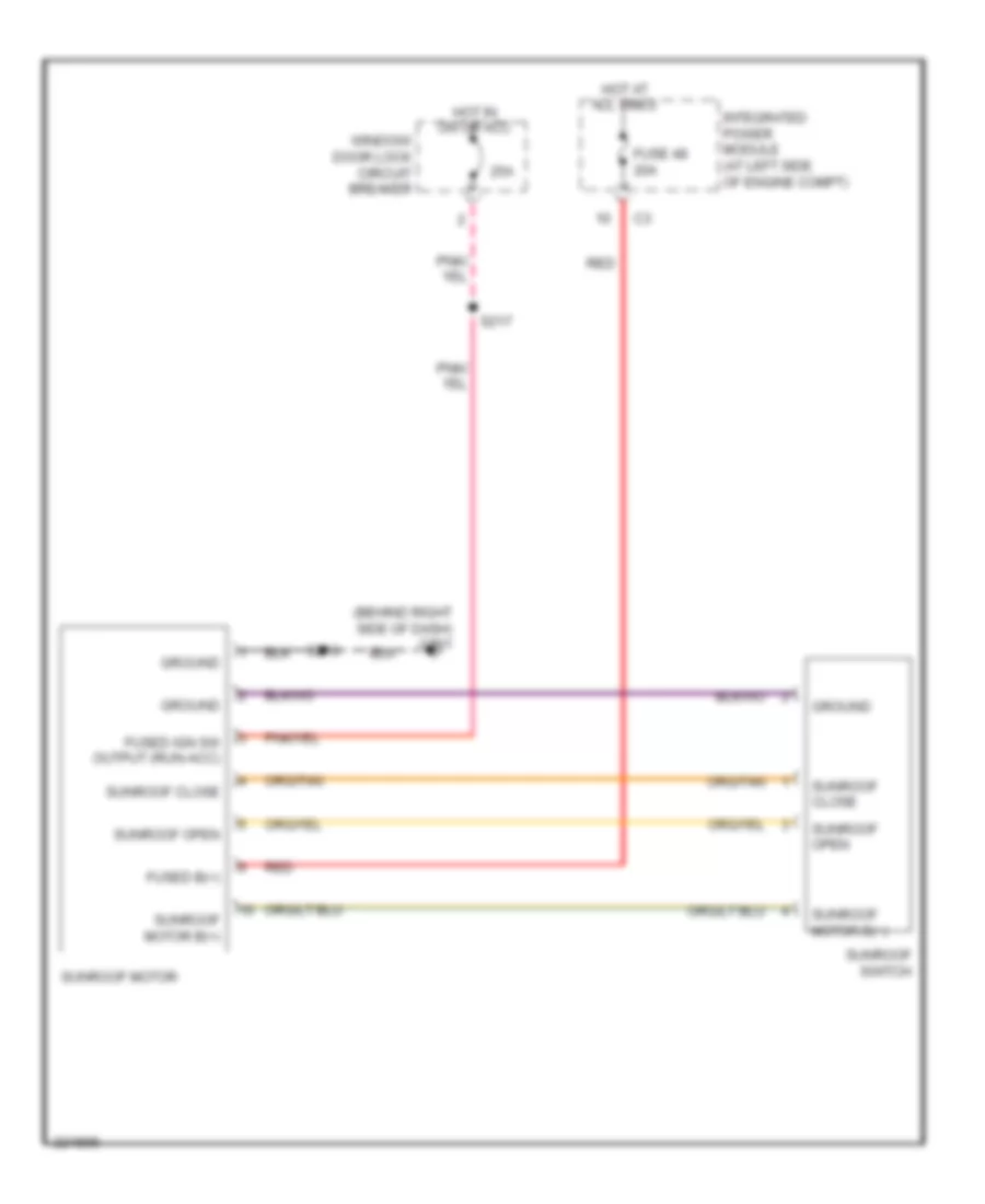
POWER TOP/SUNROOF
Power Top/Sunroof Wiring Diagram for Dodge Dakota 2006
List of elements for Power Top/Sunroof Wiring Diagram for Dodge Dakota 2006:
- (behind right side of dash) g201
- 25a
- Fuse 48 20a
- Fused b(+)
- Fused ign sw output (run-acc)
- Ground
- Hot at all times
- Hot in on or acc
- Integrated power module (at left side of engine compt)
- Red
- S216
- S217
- Sunroof close
- Sunroof motor
- Sunroof motor b(+)
- Sunroof open
- Sunroof switch
- Window/ door lock circuit breaker
POWER WINDOWS
Power Windows Wiring Diagram for Dodge Dakota 2006
List of elements for Power Windows Wiring Diagram for Dodge Dakota 2006:
- (at center front of body) g300
- (left floor pan) s327
- (not used)
- 25a
- Circuit breaker window/door lock (at junction block)
- Club cab
- Driver window/door lock switch (club cab) driver express window/ door lock switch (quad cab)
- Fused ign sw out (run-acc)
- G301 (except quad cab: behind left kick panel) (quad cab: at left front of body)
- Gnd
- Hot in acc or on
- Left front window motor (in left front door)
- Left rear power window switch (quad cab)
- Left rear win drv (down)
- Left rear win drv (up)
- Left rear window motor (in left rear door)
- Master win sw (down)
- Master win sw (up)
- Pass rear win drv (down)
- Pass rear win drv (up)
- Passenger window/door lock switch
- Power win sw feed
- Quad cab
- Right front window motor (in right front door)
- Right rear power window switch (quad cab)
- Right rear win drv (down)
- Right rear win drv (up)
- Right rear window motor (in right rear door)
- S301
- S321
- S322
- Win drv (down)
- Win drv (up)
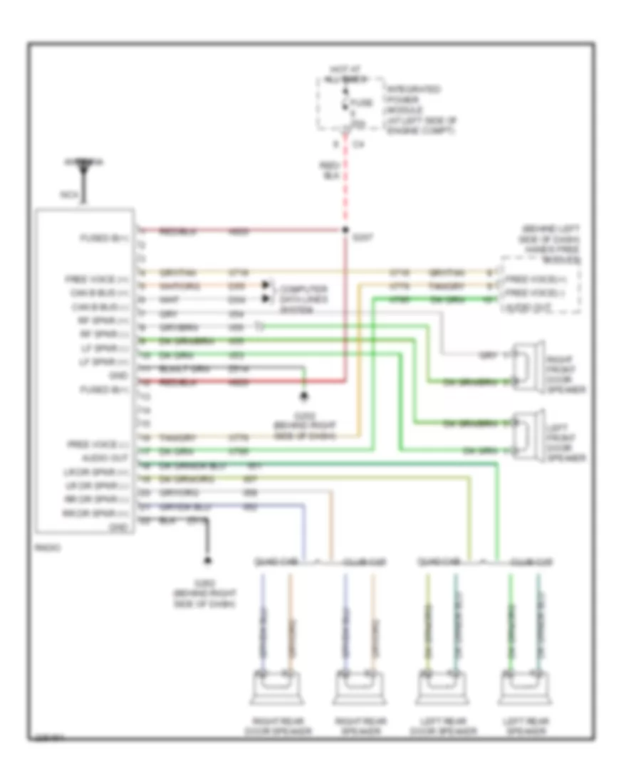
RADIO
Radio Wiring Diagram, Base for Dodge Dakota 2006
List of elements for Radio Wiring Diagram, Base for Dodge Dakota 2006:
- (behind left side of dash) hands free module
- A920
- Antenna
- Audio out
- Can b bus (+)
- Can b bus (-)
- Club cab
- Computer data lines system
- D54
- D55
- Free voice (+)
- Free voice (-)
- Free voice(+)
- Free voice(-)
- Fuse 20a
- Fused b(+)
- G202 (behind right side of dash)
- Gnd
- Hot at all times
- Integrated power module (at left side of engine compt)
- Left front door speaker
- Left rear door speaker
- Left rear speaker
- Lf spkr (+)
- Lf spkr (-)
- Lr dr spkr (+)
- Lr dr spkr (-)
- Nca
- Quad cab
- Radio
- Rf spkr (+)
- Rf spkr (-)
- Right front door speaker
- Right rear door speaker
- Right rear speaker
- Rr dr spkr (+)
- Rr dr spkr (-)
- S207
- X51
- X52
- X53
- X54
- X55
- X56
- X57
- X58
- X716
- X776
- X795
- Z514
- Z515
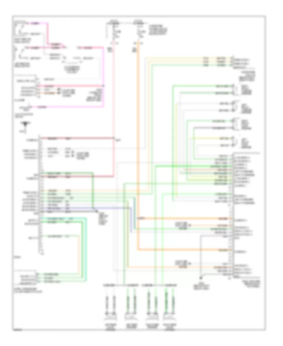
Radio Wiring Diagram, Premium for Dodge Dakota 2006
List of elements for Radio Wiring Diagram, Premium for Dodge Dakota 2006:
- A920
- Antenna
- Aud sig lt (+)
- Aud sig rt (+)
- Audio out
- Can b bus (+)
- Can b bus (-)
- Clockspring (in steering column)
- Club cab
- Cluster
- Computer data lines system
- D54
- D55
- Free voice (+)
- Free voice (-)
- Fuse 20a
- Fuse 25a
- Fused b (+)
- Fused b(+)
- G202 (behind right side of dash)
- Gnd
- Hands free module (behind right side of dash)
- Hot at all times
- Integrated power module (at left side of engine compt)
- Left front door speaker
- Left front tweeter speaker
- Left i/p speaker
- Left rear door speaker
- Left rear speaker
- Left remote radio switch
- Lf dr spkr (+)
- Lf dr spkr (-)
- Lr dr spkr (+)
- Lr dr spkr (-)
- Lr spkr (+)
- Lr spkr (-)
- Multi-function switch
- Nca
- Quad cab
- Radio
- Radio amplifier (behind right kick panel)
- Radio ctrl mux
- Radio lt aud (-)
- Radio rt aud (-)
- Radio-lt aud (+)
- Radio-rt aud (+)
- Rf dr spkr (+)
- Rf dr spkr (-)
- Right front door speaker
- Right front tweeter speaker
- Right i/p speaker
- Right rear door speaker
- Right rear speaker
- Right remote radio switch
- Rr dr spkr (+)
- Rr dr spkr (-)
- Rr spkr (+)
- Rr spkr (-)
- S205 (w/ remote radio) (behind left side of dash)
- S207
- S213
- Satellite receiver (on left rear of floor)
- Sig common
- Sig lt (+)
- Sig rt (+)
- Sw mux rtn
- X16
- X17
- X51
- X52
- X57
- X58
- X716
- X776
- X795
- X917
- Z514
- Z515
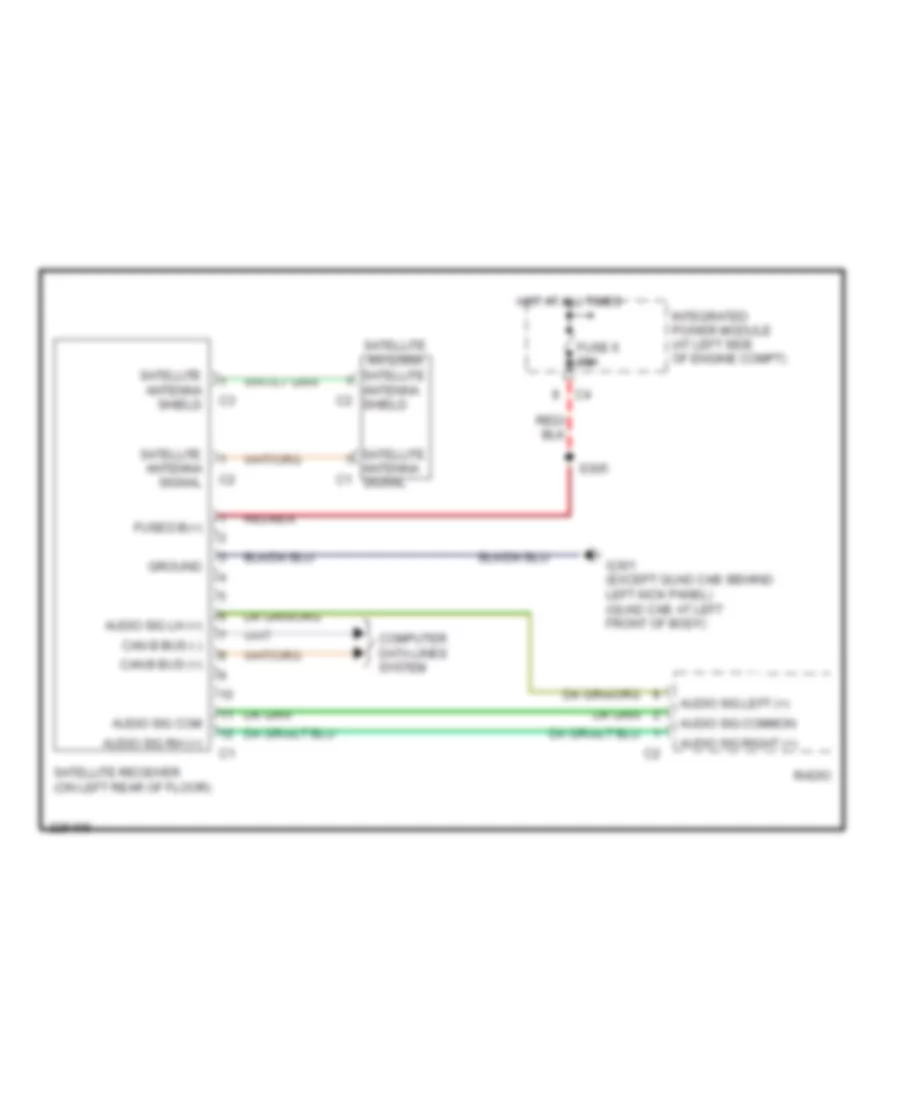
Satellite Radio Wiring Diagram for Dodge Dakota 2006
List of elements for Satellite Radio Wiring Diagram for Dodge Dakota 2006:
- Audio sig com
- Audio sig common
- Audio sig left (+)
- Audio sig lh (+)
- Audio sig rh (+)
- Audio sig right (+)
- Can b bus (+)
- Can b bus (-)
- Computer data lines system
- Fuse 6 20a
- Fused b(+)
- G301 (except quad cab: behind left kick panel) (quad cab: at left front of body)
- Ground
- Hot at all times
- Integrated power module (at left side of engine compt)
- Radio
- S305
- Satellite antenna
- Satellite antenna c1 signal
- Satellite antenna c2 shield
- Satellite antenna shield
- Satellite antenna signal
- Satellite receiver (on left rear of floor)
SHIFT INTERLOCK
3.7L
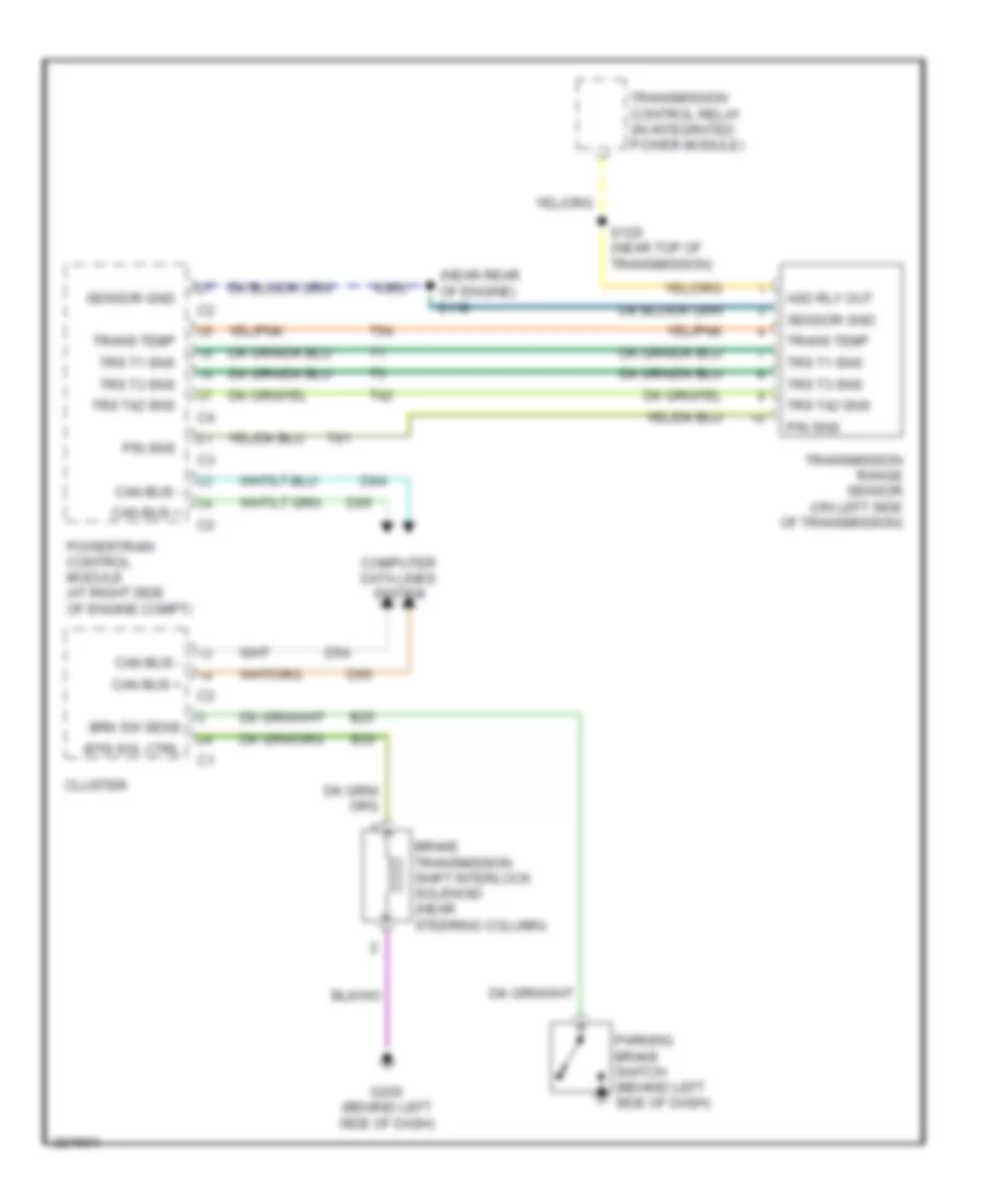
3.7L, Shift Interlock Wiring Diagram for Dodge Dakota 2006
List of elements for 3.7L, Shift Interlock Wiring Diagram for Dodge Dakota 2006:
- (near rear of engine) s118
- Asd rly out
- B25
- B30
- Brake transmission shift interlock solenoid (near steering column)
- Brk sw sens
- Btsi sol ctrl
- Can bus +
- Can bus -
- Cluster
- Computer data lines system
- D54
- D55
- D64
- D65
- G200 (behind left side of dash)
- K900
- P/n sns
- Parking brake switch (behind left side of dash)
- Powertrain control module (at right side of engine compt)
- S120 (near top of transmission)
- Sensor gnd
- T41
- T42
- T54
- Trans temp
- Transmission control relay (in integrated power module)
- Transmission range sensor (on left side of transmission)
- Trs t1 sns
- Trs t3 sns
- Trs t42 sns
4.7L
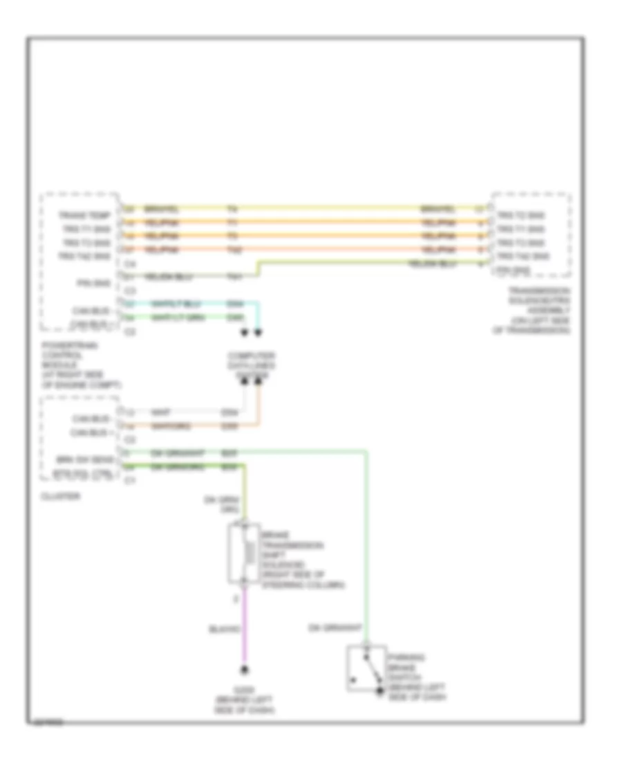
4.7L, Shift Interlock Wiring Diagram for Dodge Dakota 2006
List of elements for 4.7L, Shift Interlock Wiring Diagram for Dodge Dakota 2006:
- B25
- B30
- Brake transmission shift solenoid (right side of steering column)
- Brk sw sens
- Btsi sol ctrl
- Can bus +
- Can bus -
- Cluster
- Computer data lines system
- D54
- D55
- D64
- D65
- G200 (behind left side of dash)
- P/n sns
- Parking brake switch (behind left side of dash
- Powertrain control module (at right side of engine compt)
- T41
- T42
- Trans temp
- Transmission solenoid/trs assembly (on left side of transmission)
- Trs t1 sns
- Trs t2 sns
- Trs t3 sns
- Trs t42 sns
STARTING/CHARGING
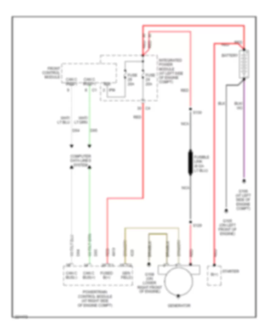
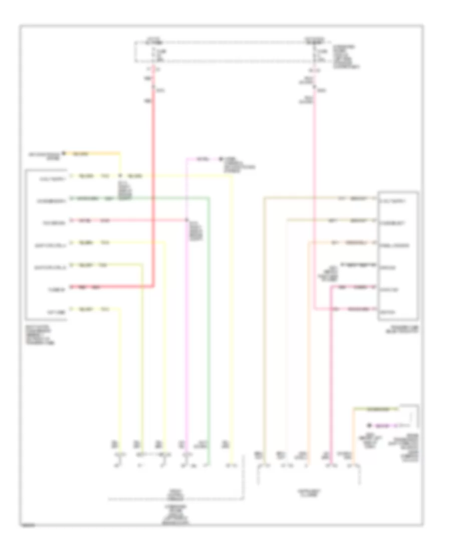
Charging Wiring Diagram for Dodge Dakota 2006
List of elements for Charging Wiring Diagram for Dodge Dakota 2006:
- A1 red
- A919
- B(+)
- Battery
- Can c bus(+)
- Can c bus(-)
- Computer data lines system
- D64
- D65
- Front control module
- Fuse 20a
- Fused b(+)
- G105 (on left front of engine)
- G106 (at left side of engine compt)
- G108 (on lower right front of engine)
- Gen field
- Generator
- Integrated power module (at left side of engine compt)
- Ipm
- K20
- Nca
- Powertrain control module (at right side of engine compt)
- Red
- S129
- S130
- Starter
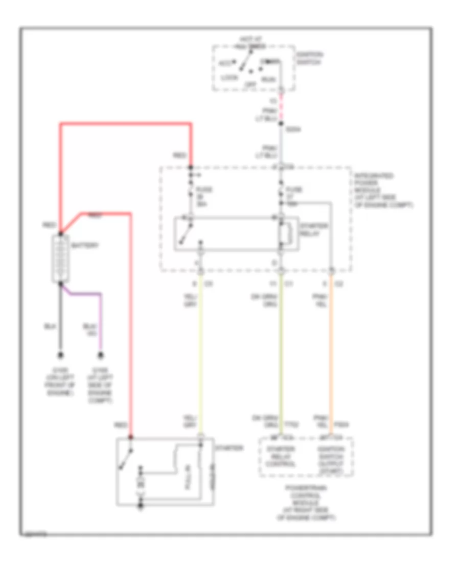
Starting Wiring Diagram for Dodge Dakota 2006
List of elements for Starting Wiring Diagram for Dodge Dakota 2006:
- Acc
- Battery
- F924
- Fuse 10a
- Fuse 30a
- G105 (on left front of engine)
- G106 (at left side of engine compt)
- Hold-in
- Hot at all times
- Ignition switch
- Ignition switch output (start)
- Integrated power module (at left side of engine compt)
- Lock
- Off
- Powertrain control module (at right side of engine compt)
- Pull-in
- Red
- Run
- S204
- Start
- Starter
- Starter relay
- Starter relay control
- T752
SUPPLEMENTAL RESTRAINTS
Supplemental Restraints Wiring Diagram (1 of 2) for Dodge Dakota 2006
List of elements for Supplemental Restraints Wiring Diagram (1 of 2) for Dodge Dakota 2006:
- (at left side of engine compt) s110
- (at top of left "a" pillar) left side air bag squib
- Bus (+)
- Bus (-)
- Clock spring (in steering wheel)
- Computer data lines system
- D54
- D55
- Driver air bag squib 1 (in steering wheel pad)
- Driver air bag squib 2 (in steering wheel pad)
- Driver seat belt tensioner (at base of left "b" pillar)
- F100
- F201
- Fuse 10a
- Fuse 20a
- G104
- G300 (at center front of body)
- Gnd
- Ground
- Hot at all times
- Hot in run
- Hot in run or start
- Ind drv
- Indicator
- Integrated power module (at left side of engine compt)
- Left front impact sensor (at left front of engine compt)
- Left side impact sensor 1 (near left "b" pillar)
- Line
- Line 1
- Line 2
- Occupant restraint controller module (below center console)
- Passenger air bag lamp on/off
- Passenger air bag on/off switch
- Passenger air bag squib (behind right side of dash)
- Passenger seat belt tensioner (at base of right"b" pillar)
- Pnk/ f100
- Pnk/ f201
- R104
- R106
- R13
- R14
- R15
- R16
- R42
- R43
- R44
- R45
- R53
- R54
- R55
- R56
- R61
- R62
- R63
- R64
- R79
- R80
- R81
- R82
- Red
- Red a956
- Return
- Right front impact sensor (at right front of engine compt)
- Right side air bag squib (at top of right "a" pillar)
- Right side impact sensor 1 (near right "b" pillar)
- Run driver
- Run-start
- S210 (behind left side of dash)
- Sens 1 gnd
- Sens 1 sig
- Sens gnd
- Sens sig
- Sense
- Signal
- Sw return
- Sw sense
- Z104
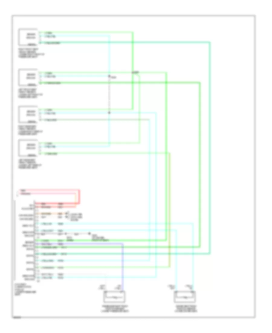
Supplemental Restraints Wiring Diagram (2 of 2) for Dodge Dakota 2006
List of elements for Supplemental Restraints Wiring Diagram (2 of 2) for Dodge Dakota 2006:
- A956
- B(+)
- Can b bus(b+)
- Can b bus(b-)
- Computer data lines
- D54
- D55
- Driver seat track position sensor (under driver seat)
- F201
- G300 (at center front of body)
- Ground
- Left front seat weight sensor (under left front of passenger seat)
- Left rear seat weight sensor (under left rear of passenger seat)
- Occupant classification module (under passenger seat)
- Passenger seat track position sensor (under passenger seat)
- R261
- R262
- R263
- R264
- R701
- R705
- R706
- R717
- R718
- R728
- Red
- Right front seat weight sensor (under right front of passenger seat)
- Right rear seat weight sensor (under right rear of passenger seat)
- Run-start
- S319 (base)
- S325
- S326
- Sens data
- Sens volt
- Sensor
- Signal
- System
- Z917
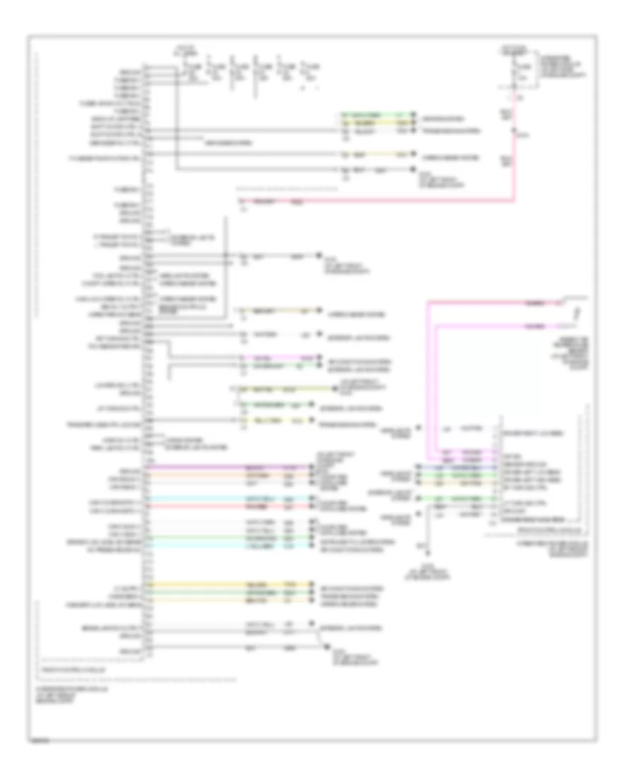
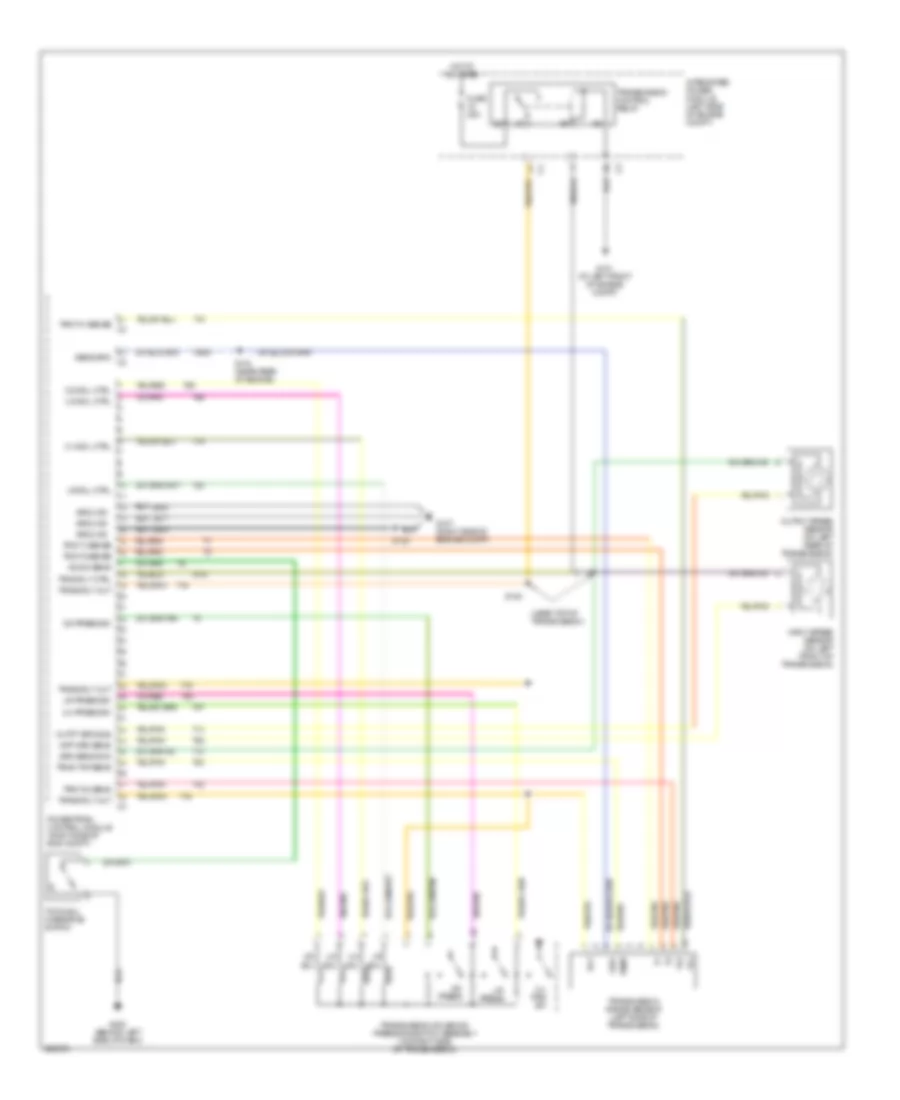
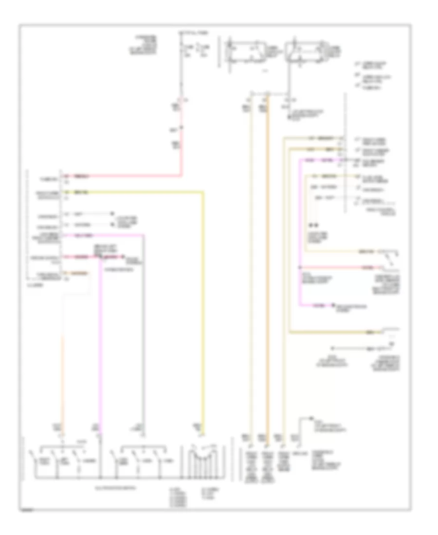
TRANSMISSION
Transfer Case Wiring Diagram for Dodge Dakota 2006
List of elements for Transfer Case Wiring Diagram for Dodge Dakota 2006:
- 4wd n ind
- A924
- Air conditioning system
- Brake transmission shift interlock solenoid (near steering column)
- D201
- E11
- F21
- Fcm return
- Front control module
- Fuse 10a
- Fuse 20a
- Fused b+
- G180
- G200 (behind left side of dash)
- G201 (behind right side of dash)
- G95
- Ground
- Hot at all times
- Hot in run or start
- Ignition
- Instrument cluster
- Integrated power module (left side of engine compartment)
- Integrated power module (left side of engine compt)
- Ipm
- K77
- K977
- Mode select
- Mode sensor a
- Not used
- Panel lps drvr
- Red
- S103
- S114 (right side of engine compt)
- S115 (right side of engine compt)
- S202
- Shift motor/ mode sensor assembly (on front of transfer case)
- Shift mtr ctrl a
- Shift mtr ctrl b
- T103
- T313
- T315
- T316
- Transfer case selector switch
- Wiper/ washer & air conditioning systems
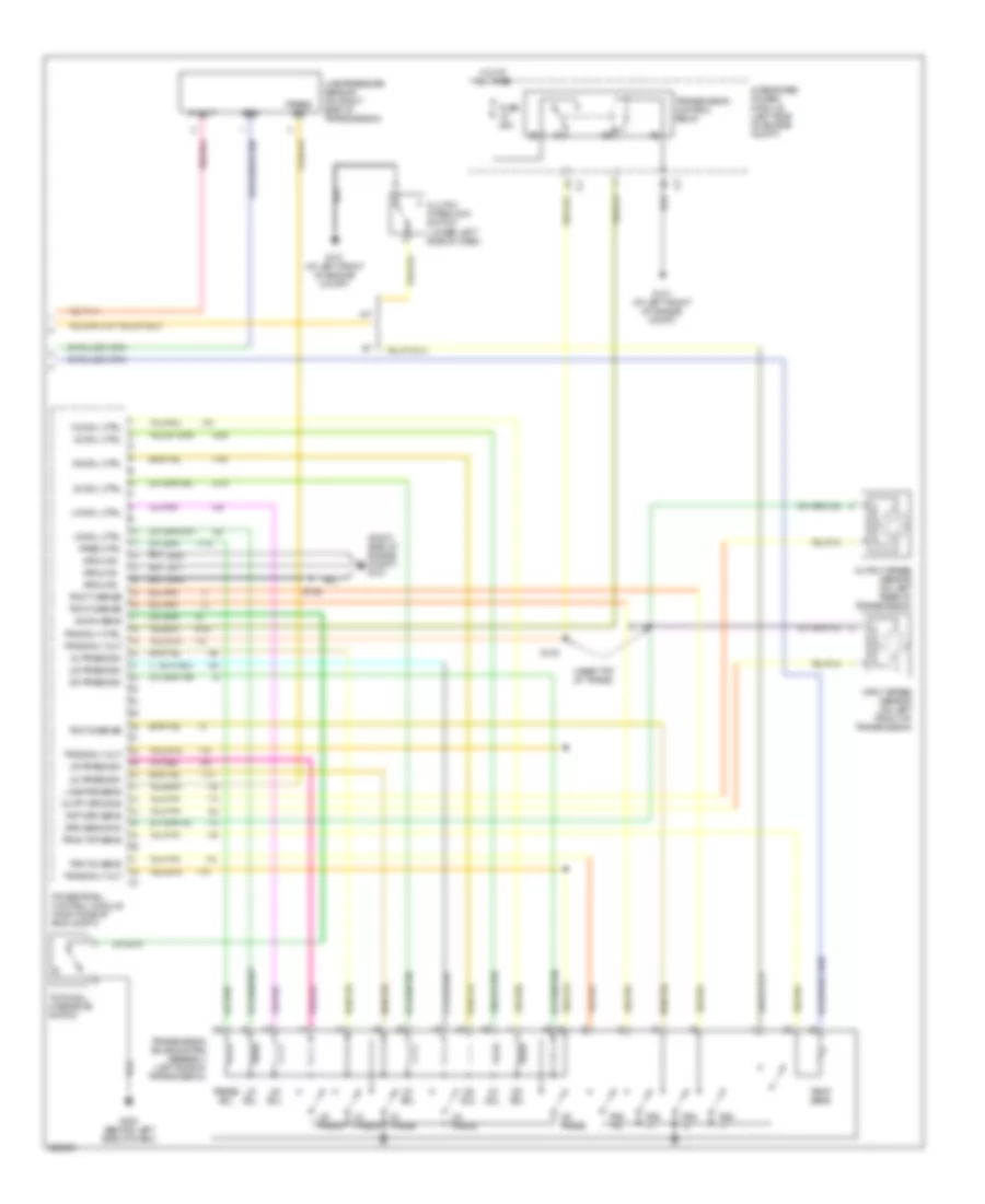
- Z973
3.7L
3.7L, A/T Wiring Diagram for Dodge Dakota 2006
List of elements for 3.7L, A/T Wiring Diagram for Dodge Dakota 2006:
- (near top of transmission)
- 2-4 press sw
- 2-4 prs sw
- 2-4 sol
- 2-4 sol ctrl
- Fuse 25a
- G101 (at left front of engine compt)
- G107 (right side of engine compt)
- G200 (behind left side of dash)
- Grd
- Ground
- Hot at all times
- Inpt spd sens
- Input speed sensor (on left front of transmission)
- Integrated power module (left side of engine compt)
- K900
- L/r press
- L/r press sw
- Lr sol
- Lr sol ctrl
- Od press
- Od press sw
- Od sol
- Od sol ctrl
- Od sw sens
- Outpt spd sns
- Output speed sensor (on left rear of transmission)
- Powertrain control module (right side of eng compt)
- Rly
- S118 (near rear of engine)
- S119
- S120
- S128
- Sens grd c2
- Spd sens gnd
- T13
- T14
- T16
- T19
- T20
- T41
- T42
- T47
- T50
- T515
- T52
- T54
- T59
- T60
- Temp
- Tow/haul overdrive switch
- Trans rly out
- Trans rly out c4
- Transmission control relay
- Transmission range sensor (left side of transmission)
- Transmission solenoid/ pressure switch assembly (on right side of transmission)
- Trns rly ctrl
- Trns tmp sens
- Trs t1 sense
- Trs t3 sense
- Trs t41 sense c3
- Trs t42 sens
- Ud sol
- Ud sol ctrl
- Z904
- Z908
- Z977
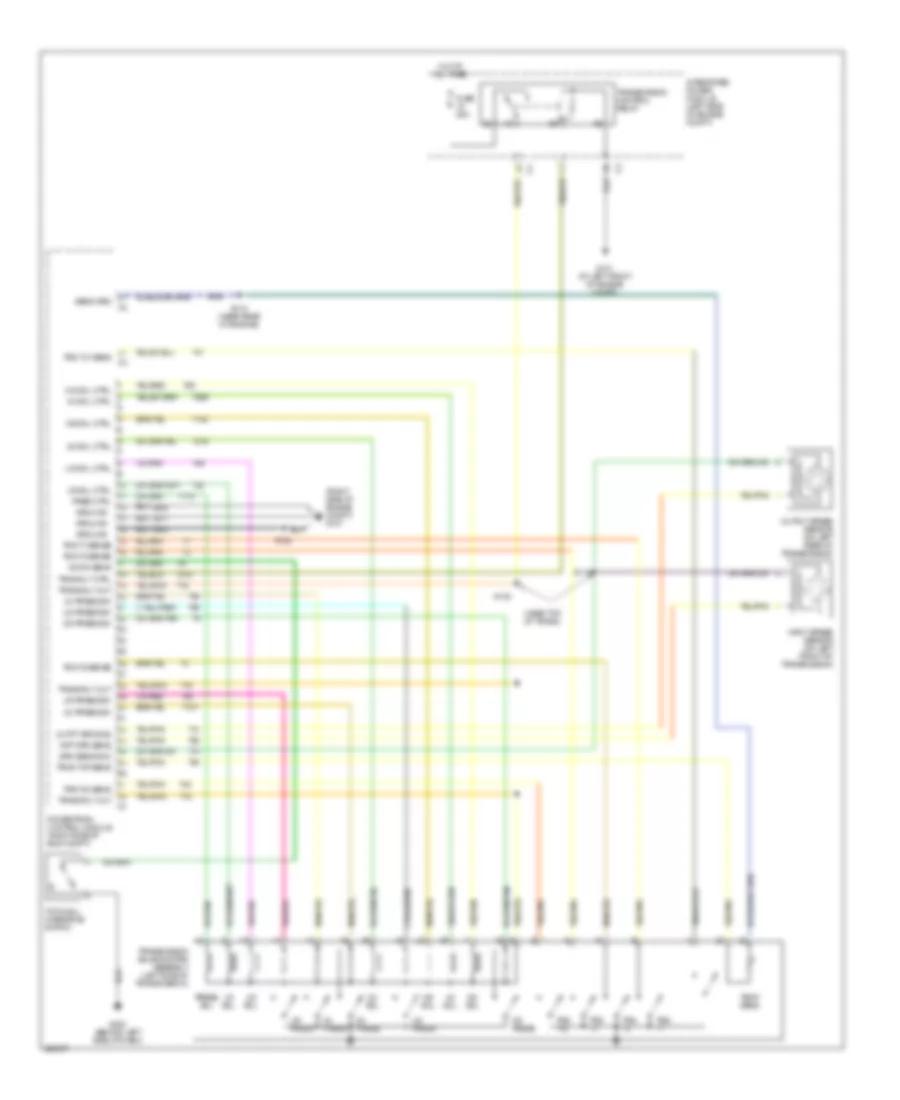
4.7L
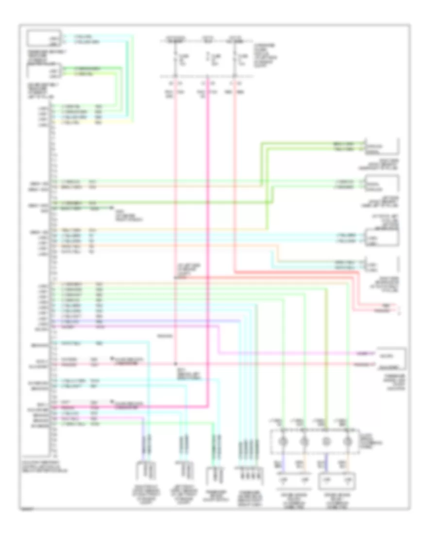
4.7L, A/T Wiring Diagram for Dodge Dakota 2006
List of elements for 4.7L, A/T Wiring Diagram for Dodge Dakota 2006:
- (near top of trans)
- (right side of engine compt) g107
- 2c press
- 2c press sw
- 2c sol
- 2c sol ctrl
- 4c press
- 4c press sw
- 4c sol
- 4c sol ctrl
- Fuse 25a
- G101 (at left front of engine compt)
- G200 (behind left side of dash)
- Ground
- Hot at all times
- Inpt spd sens
- Input speed sensor (on left front of transmission)
- Integrated power module (left side of engine compt)
- K900
- L/r press
- L/r press sw
- Lr sol
- Lr sol ctrl
- Ms sol
- Ms sol ctrl
- Od press
- Od press sw
- Od sol
- Od sol ctrl
- Od sw sens
- Outpt spd sns
- Output speed sensor (on left rear of transmission)
- Powertrain control module (right side of eng compt)
- Pres ctrl
- Press sol
- S118 (near rear of engine)
- S119
- S120
- S128
- Sens grd c2
- Spd sens gnd
- T118
- T13
- T14
- T140
- T147
- T16
- T20
- T219
- T259
- T29
- T41
- T42
- T48
- T50
- T515
- T52
- T54
- T59
- T60
- Temp sens
- Tow/haul overdrive switch
- Trans rly out
- Trans rly out c4
- Transmission control relay
- Transmission solenoid/trs assembly (left side of transmission)
- Trns rly ctrl
- Trns tmp sens
- Trs t1
- Trs t1 sense
- Trs t2
- Trs t2 sense
- Trs t3
- Trs t3 sense
- Trs t41 sens c3
- Trs t42
- Trs t42 sens
- Ud press
- Ud press sw
- Ud sol
- Ud sol ctrl
- Z904
- Z908
- Z977
WARNING SYSTEMS
Warning Systems Wiring Diagram for Dodge Dakota 2006
List of elements for Warning Systems Wiring Diagram for Dodge Dakota 2006:
- (base) (at center front of body)
- (base) (premium)
- A117
- A920
- A924
- Can b bus (+)
- Can b bus (-)
- Cluster
- Computer data lines system
- D54
- D55
- Driver door ajar sw sns
- Driver seat belt sw sns
- Driver seat belt switch (under driver seat bottom)
- F21
- F983
- Fuse 10a
- Fuse 15a
- Fuse 20a
- Fused b(+)
- Fused ign
- Fused ign sw out (run-acc)
- Fused ign sw output (run-start)
- G15
- G200 (behind left side of dash)
- G300 g301 (premium) (behind left kick panel)
- G301 (behind left kick panel)
- G75
- Ground
- Head
- Headlamp sw mux
- Headlamp sw mux return
- Headlamp switch
- Hot at all times
- Hot in run or acc
- Hot in run or start
- Ignition switch
- Integrated power module (at left side of engine compartment)
- Key- in
- Key-in ign sw sns
- L307
- L900
- Left front door latch (in left front door)
- Off
- Park
- Pnk/red
- R57
- Red
- S102
- S201
- S202 (4wd)
- S203
- S207
- S319 s321
- Z946
- Z948
WIPER/WASHER
Wiper/Washer Wiring Diagram for Dodge Dakota 2006
List of elements for Wiper/Washer Wiring Diagram for Dodge Dakota 2006:
- (at left front of engine compt) g101
- (behind left side of dash) s205
- 0) off 1) i/wipe 1 2) i/wipe 2 3) i/wipe 3 4) i/wipe 4
- 5) i/wipe 5 6) low 7) high
- 87a
- Air conditioning system
- Can b bus(+)
- Can b bus(-)
- Cluster
- Computer data lines system
- D54
- D55
- Fcm sensor return ipm
- Fluid level switch sense
- Front control module
- Front washer pump motor
- Front wiper high/ low relay high speed output
- Front wiper park sw sns
- Front wiper park switch sense
- Front wiper switch mux
- Fuse 20a
- Fuse 30a
- Fused b(+)
- G100 (at left front of engine compt)
- G101 (at left front of engine compt)
- G180
- Ground
- Hazard
- High beam
- High beam/ front washer switch mux
- Horn
- Hot at all times
- Integrated power module (at left side of engine compt)
- Left turn
- Multifunction switch
- Relay ctrl
- Return switch mux
- Right turn
- S115 (at right side of engine compt)
- S207
- Sound systems
- Turn signal input mux
- W/ remote radio
- W10
- Wash
- Washer fluid level sensor (at lower right front of engine compt)
- Windshield washer pump (at left rear of engine compt)
- Windshield wiper motor (at left rear of engine compt)
- Wiper high/low
- Wiper high/low relay
- Wiper on/off
- Wiper on/off relay