AIR CONDITIONING
Manual A/C Wiring Diagram for Dodge Dakota 2010

List of elements for Manual A/C Wiring Diagram for Dodge Dakota 2010:
- (a/c compressor) a/c compressor clutch
- 87a
- A/c clutch relay
- A/c clutch rly ctrl
- A/c heater control
- A/c pressure transducer (right front of engine compt)
- Blend door drv
- Blower
- Blower motor (front of hvac unit)
- Blower motor high speed
- Blower motor low speed
- Blower motor m1 speed
- Blower motor m2 speed
- C100
- C121
- C13
- C18
- C201
- C201 c
- C21
- C210
- C29
- C32
- C34
- C61
- C71
- C72
- C73
- C75
- C801
- Can b bus (+)
- Can b bus (-)
- Can c (+)
- Can c (-)
- Cluster
- Common door drv
- Computer data lines system
- D54
- D55
- D64
- D65
- Door drv
- Driver blend door actuator
- E12
- Ect sig
- Engine controls system
- Engine coolant temperature sensor (right front side of engine)
- Evap temp sens sig
- Evaporator temp sens sig
- Evaporator temperature sensor (on hvac unit)
- F504
- Fcm sens rtn
- Floor to defrost mode door actuator
- Front blower motor resistor (right side of hvac unit)
- Front control module (side of power distribution module)
- Ft blw hi spd
- Ft blw lo spd
- Ft blw m1 spd
- Ft blw m2 spd
- Fuse 10a
- Fuse 11 10a
- Fuse 40a
- Fuse 7 10a
- Fused ign sw out (run)
- G107 (right side of engine compt)
- G200 (left side of dash)
- G201 (right side of dash)
- Gnd
- Ground
- Hot at all times
- Hot in run or start
- Hot w/ ignition run relay energized
- Ign sw out (run)
- Integrated power module (left side of engine compt)
- Ipm
- K900
- Mode door 1 drv
- Mode door 2 drv
- Motor relay
- Panel lamps drv
- Passenger blend door actuator
- Pnk
- Powertrain control module (right side of engine compt)
- Pressure sig
- Recirculation
- Recirculation door actuator (right side of hvac unit)
- Recirculation door drv
- Red
- S114 (right side of engine compt)
- S115 (right side of engine compt)
- S123 (top of engine)
- S217 (center of hvac)
- Sens gnd
- T103
- Transmissions system
- Z24
- Z961
ANTI-LOCK BRAKES
Anti-lock Brakes Wiring Diagram for Dodge Dakota 2010
List of elements for Anti-lock Brakes Wiring Diagram for Dodge Dakota 2010:
- (left front of engine compt) g100
- A107
- A111
- Abs pmp fd
- Anti-lock brakes module (left side of engin ecompt)
- B22
- B222
- B29
- Batt fd
- Brake fluid level sensor (left rear of engine compt)
- Brake fluid level switch sense
- C105
- C201
- Can bus (+)
- Can bus (-)
- Can c bus (+)
- Can c bus (-)
- Computer data lines system
- D64
- D65
- F500
- Front control module
- Fuse 20a
- Fuse 40a
- Fused run rly out
- G100 (left front of engine compt)
- G200 (left side of dash)
- Ground
- Hot at all times
- Hot w/ ignition run relay energized
- Instrument cluster
- Integrated power module (left side of engine compt)
- Left front abs wheel speed sensor (left front wheel)
- Lf wheel (+)
- Lf wheel (-)
- Powertrain control module (right side of engine compt)
- Rear abs wheel speed sensor (near right rear wheel, by crossmember)
- Rear veh spd sig1
- Rear veh spd sig2
- Red
- Rh wheel (+)
- Rh wheel (-)
- Right front abs wheel speed sensor (right front wheel)
- Stop lamp switch (lower left side of dash)
- Stp ctrl sig
- Tan/ red
- Tan/red
- Z107
- Z923
ANTI-THEFT
Anti-theft Wiring Diagram for Dodge Dakota 2010
List of elements for Anti-theft Wiring Diagram for Dodge Dakota 2010:
- (3.7l)
- (behind center of dash) s212
- (left rear of engine compt) s107
- (left side of dash) g200
- (left side of engine compt)
- (right front of engine compt) g103
- 4.7l flex fuel
- 87a
- A918
- Acc
- Batt fd
- C101
- C200
- C201
- C300
- C301
- C302
- C303
- C306
- C308
- Can b bus (+)
- Can b bus (-)
- Can c bus (+)
- Can c bus (-)
- Cluster
- Computer data lines system
- Crew cab
- D54
- D55
- D64
- D65
- Drv dr ajar sw in
- Extended cab
- F20
- Front control module
- Fuse 14 20a
- Fuse 16 20a
- G20
- G200 (left side of dash)
- G300 (center front of body)
- G300 (extended cab) (center front of body)
- G301 (crew cab) (left front of body)
- G301 (left front of body)
- Gnd
- Ground
- Headlights system
- Hood ajar switch (left side of engine compt)
- Horn relay
- Horns system
- Hot at all times
- Ign sw sns
- Ignition switch
- Inline eng hlpd2
- Integrated power module (left side of engine compt)
- Ipm
- L33
- L34
- Left front door latch
- Left rear door latch (crew cab)
- Lh hi beam driver
- Lock
- Lr dr ajar sw sig
- Off
- Off lock
- Pass dr ajar sw sig
- Powertrain control module (right side of engine compt)
- Red
- Rh hi beam driver
- Right front door latch
- Right rear door latch (crew cab)
- Rly ctrl
- Rr dr ajar sw sig
- Run
- S100 (left side of engine compt)
- S101
- S204
- S206
- S211 (behind center of dash)
- S230
- S319 (extended cab)
- S321 (crew cab)
- Sig
- Start
- Uhood sw
- Uhood sw sig
- Wireless control module (steering column)
- Z109
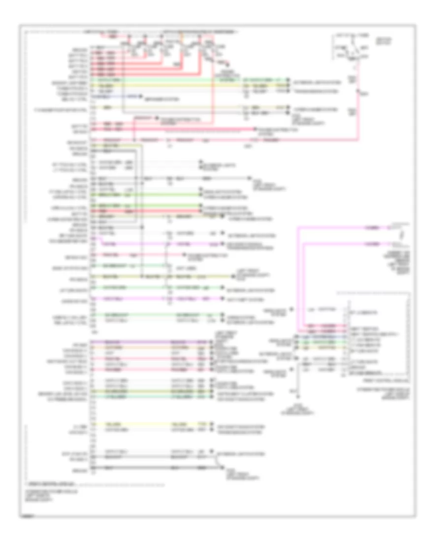
BODY CONTROL MODULES
Body Control Modules Wiring Diagram for Dodge Dakota 2010
List of elements for Body Control Modules Wiring Diagram for Dodge Dakota 2010:
- (left front of engine compt) g100
- (not used)
- 4wd sig a
- 5 v ref
- A/c pressure signal
- A905
- A906
- A907
- A908
- A909
- A920
- A955
- Abmt temp sig
- Abmt temp/fcm sen rtn 1
- Acc
- Air conditioning & transmissions systems
- Air conditioning system
- Ambient air temperature sensor (left front of engine compt)
- Anti-theft system
- B20
- Back up cp 5w sig
- Backup lamp feed
- Batt fd
- Batt fd 5
- Batt fd 6
- Batt fd 8
- Batt fd 9
- Brake fluid level sw sig
- C115
- C18
- C201
- Can b bus (+)
- Can b bus (-)
- Can bus2 (+)
- Can bus2 (-)
- Can c bus (+)
- Can c bus (-)
- Computer data lines system
- D201
- D51
- D52
- D54
- D55
- D64
- D65
- Defogger system
- Ebl rly ctrl
- Engine controls system
- Exterior lights system
- F washer pump motor ctrl
- F20
- F901
- F924
- F981
- Fcm sensor return
- Front control module
- Ft fog lmp rly ctrl
- Fuse 20a
- Fuse 30a
- G100 (left front of engine compt)
- G180
- G31
- G70
- G931
- Ground
- Headlights system
- Horn rly coil drv
- Horns system
- Hot at all times
- Hot w/ ignition run relay energized
- Ign run
- Ign run acc
- Ign run st
- Ignition
- Ignition sw out (run)
- Ignition switch
- Instrument cluster system
- Integrated power module (left side of engine compt)
- Ipm
- Ipm gnd
- Ipm gnd a
- Ipm gnd b
- L139
- L33
- L34
- L43
- L44
- L50
- L60
- L61
- L62
- L63
- L655
- L656
- L779
- Lf turn sig fd
- Lock
- Lr turn sig fd
- Lt high beam fd
- Lt low beam fd
- Lt ttow rly ctrl
- Off
- Pnk
- Pnk/red
- Power distribution system
- Prk lmp rly ctrl
- Red
- Red fuse 20a
- Red fuse 25a
- Rf turn sig fd
- Rr turn sig fd
- Rt high beam fd
- Rt lo beam fd
- Rt ttow rly ctrl
- Run
- S204
- Start
- Starting/charging system
- Stp lp sw fd
- T103
- T315
- T316
- Tcase mtr sig a
- Tcase mtr sig b
- Transmissions system
- Uhood sw sig
- W10
- Wiper motor prk sig
- Wiper/washer system
- Wpr hi/lo rly ctrl
- Wpr prk rly ctrl
- Z116
- Z117
- Z118
- Z909
- Z921
- Z947
- Z965
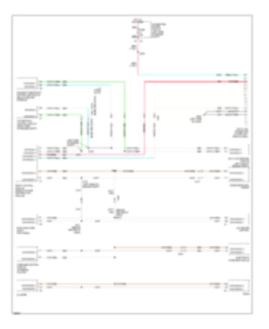
COMPUTER DATA LINES
Computer Data Lines Wiring Diagram for Dodge Dakota 2010
List of elements for Computer Data Lines Wiring Diagram for Dodge Dakota 2010:
- (3.7l)
- (4.7l flex fuel)
- (left side of engine compt)
- A/c heater control
- A918
- Anti-lock brakes module (left side of engine compt)
- C101
- C104
- C201
- C203
- Can b bus (+)
- Can b bus (-)
- Can bus (+)
- Can bus (-)
- Can bus 2 (-)
- Cluster
- D51
- D52
- D54
- D55
- D64
- D65
- Data link connector (lower left side of dash)
- Electronic overhead module
- Front control module (side of power distribution module)
- Fuse 20a
- G200 (left side of dash)
- Hot at all times
- Inline eng hlpd2
- Inside rearview mirror
- Integrated power module (left side of engine compt)
- Occupant restraint controller module (below center console)
- Pnk/red
- Powertrain control module (right side of engine compt)
- Radio
- Radio amplifier (right kick panel)
- Red
- S100
- S101
- S107 (left rear of engine compt)
- S206
- S211 (behind center of dash)
- S230
- Wireless control module (steering column)
- Z11
- Z111
CRUISE CONTROL
Cruise Control Wiring Diagram for Dodge Dakota 2010
List of elements for Cruise Control Wiring Diagram for Dodge Dakota 2010:
- A919
- Accelerator pedal position sensor (left side of dash)
- Anti-lock brakes module (left side of engine compt)
- B22
- B222
- B29
- C105
- C107
- C201
- Can bus (+)
- Can bus (-)
- Clockspring (steering column)
- Computer data lines system
- D64
- D65
- Engine controls system
- Etc mtr (+)
- Etc mtr (-)
- F855
- F856
- Fuse 15a
- Fuse 20a
- Fused b (+)
- G107 (right side of engine compt)
- G200 (left side of dash)
- Gnd
- Gnd stp lmp
- Hot at all times
- In spd sens
- Input speed sensor (a/t) (left front of transmission)
- Instrument cluster
- Integrated power module (left side of engine compt)
- K122
- K22
- K23
- K29
- K400
- K447
- K448
- K922
- Left speed control switch
- Out spd sens
- Output speed sensor (a/t) (left rear of transmission)
- Pnk/red
- Powertrain control module (right side of engine compt)
- Rdnt fd sw cpd ctrl
- Rdnt fd sw spd ctrl
- Rear abs wheel speed sensor (near right rear wheel, by crossmember)
- Red
- Right speed control switch
- S/c sw 1 sig
- S/c sw 2 sig
- S/c sw return
- S119 (breakout to pcm)
- S122 (top right side of engine)
- S124 (top of engine)
- S133
- Sens 1 sig
- Sens gnd
- Sens prim fd
- Sens rtn
- Sens rtn 1
- Sens rtn 2
- Sens sec fd
- Sens sig 1
- Sens sig 2
- Snsr 1 sig
- Snsr rtn 1
- Snsr rtn 2
- Snsr rtn eng ctr2l com
- Snsr rtn eng ctrl com
- Snsr sec fd
- Snsr sig 1
- Snsr sig 2
- Spd ctrl fd to stp lmp sw
- Spd ctrl sw fd
- Stop lamp switch (lower left side of dash)
- Stp lmp spd ctrl sig
- Stp lmp sw batt fd
- T14
- T52
- Throttle body (top front of engine)
- V32
- V71
- V72
- V937
- Veh spd sig 1
- Veh spd sig 2
- Z913
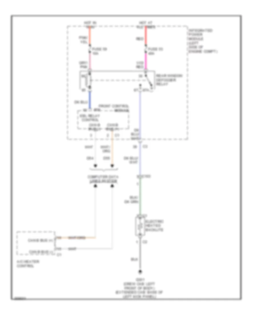
DEFOGGERS
Defoggers Wiring Diagram for Dodge Dakota 2010
List of elements for Defoggers Wiring Diagram for Dodge Dakota 2010:
- 87a
- A/c heater control
- C103
- Can b bus (+)
- Can b bus (-)
- Computer data lines system
- D54
- D55
- Ebl relay control
- Electric heated backlite
- Front control module
- Fuse 53 40a
- Fuse 59 10a
- G301 (crew cab: left front of body) (extended cab: base of left kick panel)
- Hot at all times
- Hot in run
- Integrated power module (left side of engine compt)
- Ipm
- Rear window defogger relay
- Red
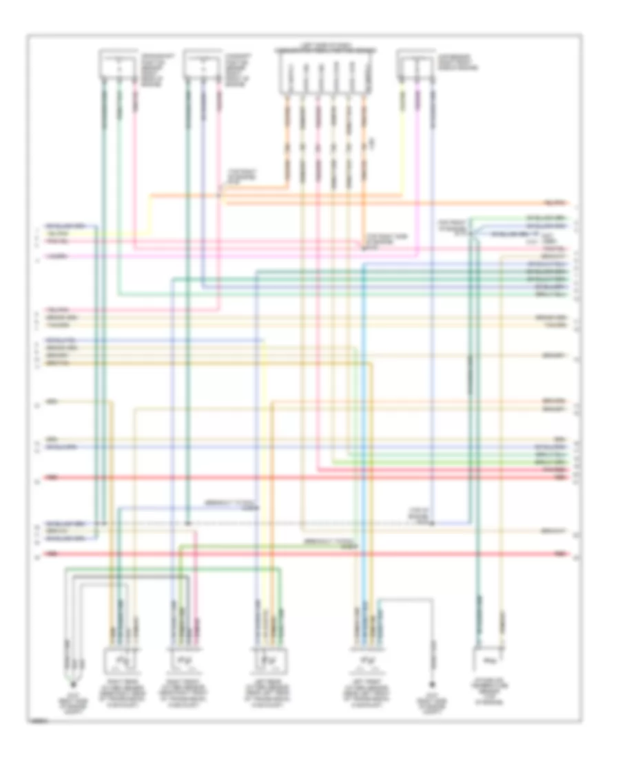
ENGINE PERFORMANCE
3.7L
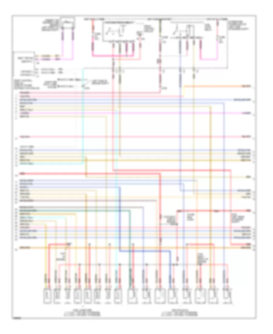
3.7L, Engine Performance Wiring Diagram (1 of 5) for Dodge Dakota 2010
List of elements for 3.7L, Engine Performance Wiring Diagram (1 of 5) for Dodge Dakota 2010:
- 1/1 htr ctrl
- 1/2 sig
- 2/1 htr ctrl
- 2/2 sig
- 5v sply
- A803
- A919
- A955
- Altr snse
- Asd relay out
- C100
- Can c bus (+)
- Can c bus (-)
- Coil control 1
- Coil control 3
- Coil control 5
- Ctrl
- D64
- D65
- Ect sig
- Egr sig
- Egr sol
- Egr sol ctrl
- Egr valve assembly (top rear of engine)
- Engine coolant temperature sensor (right front side of engine)
- Etc motor (+)
- Etc mtr (+)
- Etc mtr (-)
- F202
- F856
- Fuse 20a
- Fused b(+)
- G107 (right side of engine compt)
- Gen field
- Gnd
- Ground
- Hot at all times red
- Ign (run-start)
- Ign ulk/ run/strt
- Ign ulk/run/strt
- Inj 1 control
- Inj 2 control
- Inj 3 control
- Inj 4 control
- Inj 5 control
- Inj 6 control
- Integrated power module (left side of engine compt)
- K11
- K12
- K13
- K14
- K141
- K17
- K18
- K19
- K199
- K20
- K22
- K243
- K34
- K35
- K38
- K42
- K447
- K58
- K900
- K902
- K922
- K942
- K99
- Knock sensor 1 (left rear of engine)
- Map sig
- O2 rtn upstrm
- Oil pres sig
- Oil pressure switch (lower left front of engine)
- Powertrain control module (right side of engine compt)
- Red
- Rtn
- S133
- Sens 1
- Sens 1 rtn
- Sens 1 sig
- Sens gnd
- Sensor gnd
- Starting/ charging system
- Starting/charging system
- Throttle body (top front of engine)
- Tp 1 sig
- Tp 2 sig
- Tp sens return
- Tp sens rtn
- Z913
- Z937
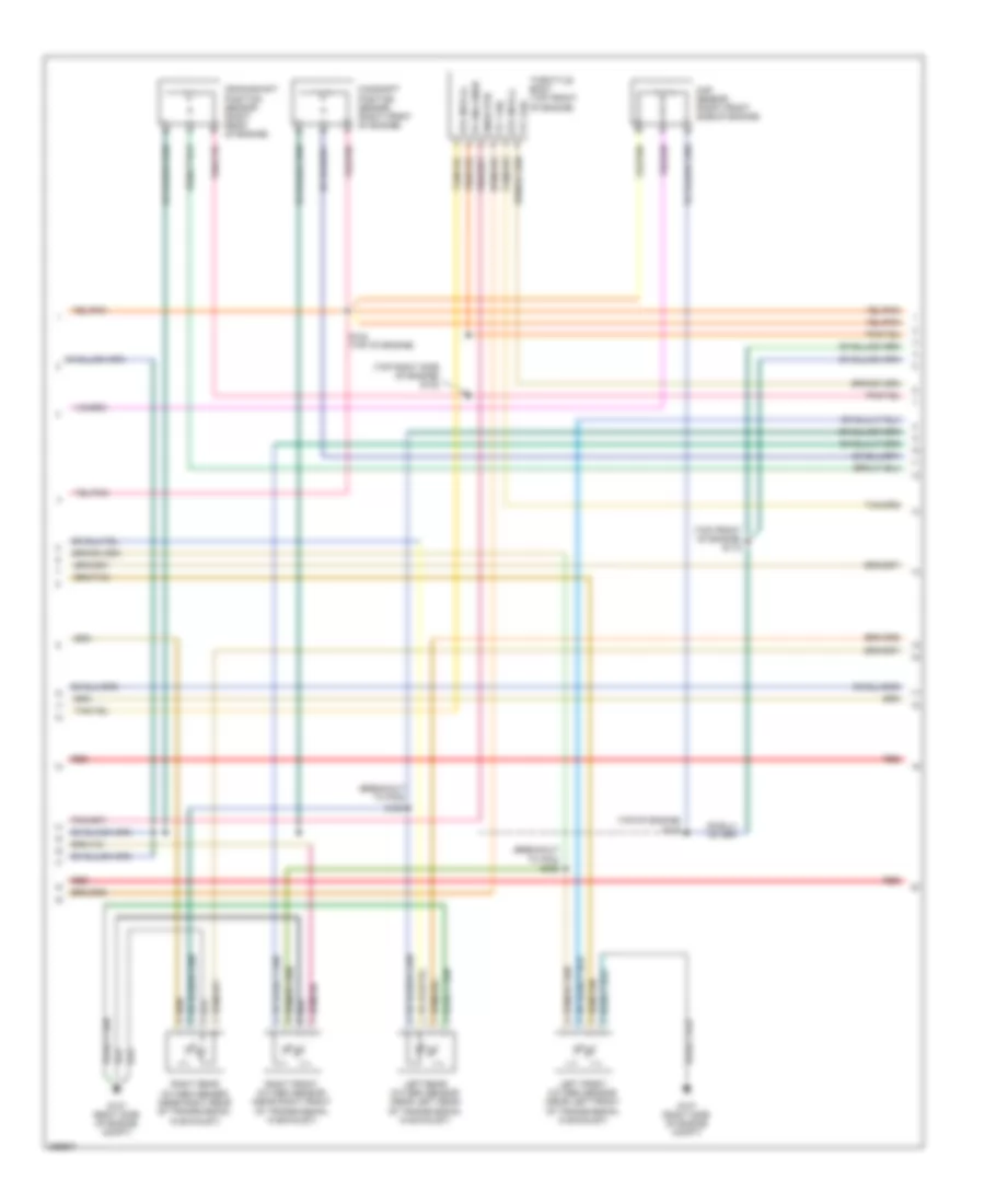
3.7L, Engine Performance Wiring Diagram (2 of 5) for Dodge Dakota 2010
List of elements for 3.7L, Engine Performance Wiring Diagram (2 of 5) for Dodge Dakota 2010:
- (left side of engine compt)
- (top of engine)
- (top right front of engine) s127
- Aat sig
- Ambient air temperature sensor (left front of engine compt)
- Auto shutdown relay
- Batt feed
- C100
- C101
- Can c bus (+)
- Can c bus (-)
- Computer data lines system
- D64
- D65
- Front control module
- Front control module (side of power distribution module)
- Fuel injectors (1, 3 & 5: top left of engine) (2, 4 & 6: top right of engine)
- Fuel pump relay
- Fuse 10a
- Fuse 20a
- Fuse 30a
- G31
- G931
- Ground
- Hot at all times
- Ignition coils (top left of engine)
- Integrated power module (left side of engine compt)
- Ipm red
- Red
- S100
- S101
- S105
- S108 (left rear of engine compt)
- S117
- S121 (top right side of engine)
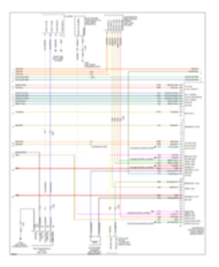
3.7L, Engine Performance Wiring Diagram (3 of 5) for Dodge Dakota 2010
List of elements for 3.7L, Engine Performance Wiring Diagram (3 of 5) for Dodge Dakota 2010:
- (breakout to pcm) s125
- (breakout to pcm) s126
- (left side of dash) accelerator pedal position sensor
- (not used) c101
- (top front of engine) s118
- (top of engine) s123
- (top right of engine) s124
- (top right side of engine) s122
- Apps 1 rtn
- Apps 1 sig
- Apps 2 rtn
- Apps 2 sig
- C201
- Camshaft position sensor (right front of engine)
- Crankshaft position sensor (right rear of engine)
- G107 (right side of engine compt)
- Intake air temperature sensor (top of engine)
- Left front oxygen sensor (near left front of transmission, in exhaust)
- Left rear oxygen sensor (near left rear of transmission, in exhaust)
- Map sensor (right front side of engine)
- Pnk/red
- Red
- Right front oxygen sensor (near right front of transmission, in exhaust)
- Right rear oxygen sensor (near right rear of transmission, in exhaust)
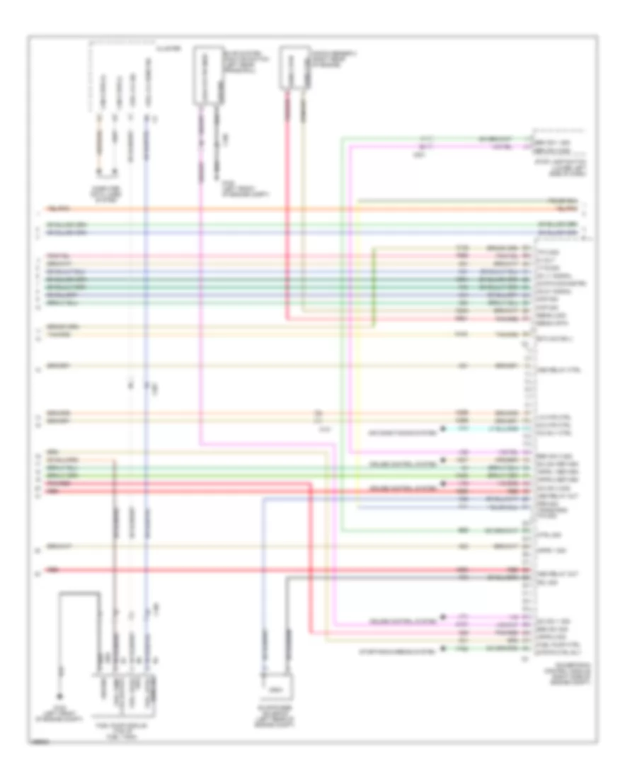
3.7L, Engine Performance Wiring Diagram (4 of 5) for Dodge Dakota 2010
List of elements for 3.7L, Engine Performance Wiring Diagram (4 of 5) for Dodge Dakota 2010:
- 02 rtn downstrm
- 1/2 htr ctrl
- 2/2 htr ctrl
- 5 volt
- A/c rly ctrl
- A955
- Air conditioning system
- Apps 1 return
- Apps 1 sig
- Apps 2 return
- Apps 2 sig
- Asd relay ctrl
- Asd relay out
- B29
- Brk sw 1 sig
- Brk sw 2 sig
- C101
- C105
- C13
- C201
- Can b bus (+)
- Can b bus (-)
- Ckp sig
- Cluster
- Cmp sig
- Computer data lines system
- Cruise control system
- Ctrl sig
- Esm sw sig
- Etc motor (-)
- Evap system monitor switch (left rear frame rail)
- Evap/purge solenoid (left rear of engine compt)
- F855
- Fuel level
- Fuel lvl sens sig
- Fuel lvl sig
- Fuel pump ctrl
- Fuel pump ctrl output
- Fuel pump module (top of fuel tank)
- G100 (left front of engine compt)
- Ground
- Itts sig
- K107
- K122
- K21
- K23
- K24
- K242
- K29
- K299
- K31
- K399
- K400
- K41
- K43
- K44
- K448
- K51
- K52
- K70
- K904
- K924
- Knock sensor 2 (right rear of engine)
- Leak dtctn snse
- O2 1/1 signal
- O2 2/1 signal
- Pnk/red
- Powertrain control module (right side of engine compt)
- Prg sig
- Red
- S/c sw 1 sig
- S/c sw 2 sig
- S/c sw return
- Sens 2 rtn
- Sens 2 sig
- Sens sig
- Sig2
- Sol sig
- Starting/charging system
- Stop lamp switch (lower left side of dash)
- Strtr ctrl rly
- T41
- T752
- Tp 2 sig
- Trans rng p/n sig
- V32
- V71
- V72
- V937
- Z201
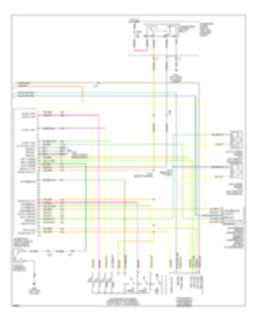
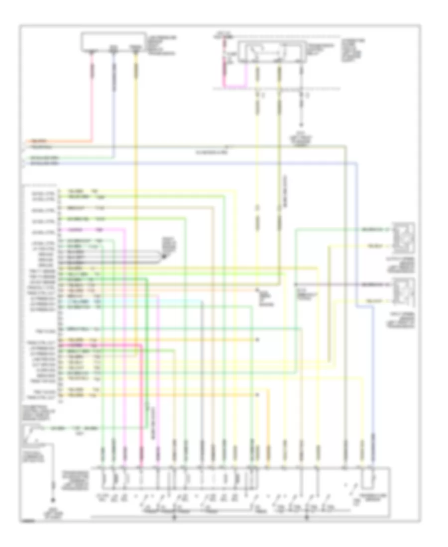
3.7L, Engine Performance Wiring Diagram (5 of 5) for Dodge Dakota 2010
List of elements for 3.7L, Engine Performance Wiring Diagram (5 of 5) for Dodge Dakota 2010:
- 2-4 press sw
- 2-4 prs sw
- 2-4 sol
- 2-4 sol ctrl
- C100
- C101
- C201
- Clutch sol ctrl
- Fuse 25a
- G101 (left front of engine compt)
- G107 (right side of engine compt)
- G200 (left side of dash)
- Ground
- Hot at all times
- Input spd sig
- Input speed sensor (a/t) (left front of transmission)
- Integrated power module (left side of engine compt)
- L/r press
- L/r press sw
- L/r sol
- L/r sol ctrl
- Line press sig
- Line pressure sensor/ variable force solenoid assembly (line pressure sensor: left rear of transmission)
- Od press
- Od press sig
- Od sol
- Od sol ctrl
- Od sw sense
- Output spd sig
- Output speed sensor (a/t) (left rear of transmission)
- Powertrain control module (right side of engine compt)
- Red
- S119 (breakout to pcm)
- S120 (rear of engine)
- Sen gnd
- Sens gnd
- T118
- T13
- T14
- T15
- T16
- T19
- T20
- T38
- T42
- T47
- T50
- T52
- T54
- T59
- T60
- Tow/haul overdrive off switch
- Tran ctrl
- Tran ctrl out
- Trans ctrl out
- Trans temp
- Transmission control relay
- Transmission range sensor (left side of transmission)
- Transmission solenoid/ pressure switch assembly (right side of transmission)
- Trns rly ctrl
- Trns tmp sig
- Trs t1 sense
- Trs t1 sig
- Trs t3 sense
- Trs t3 sig
- Trs t41 sig
- Trs t42 sig
- Ud sol
- Ud sol ctrl
- Z904
- Z908
- Z977
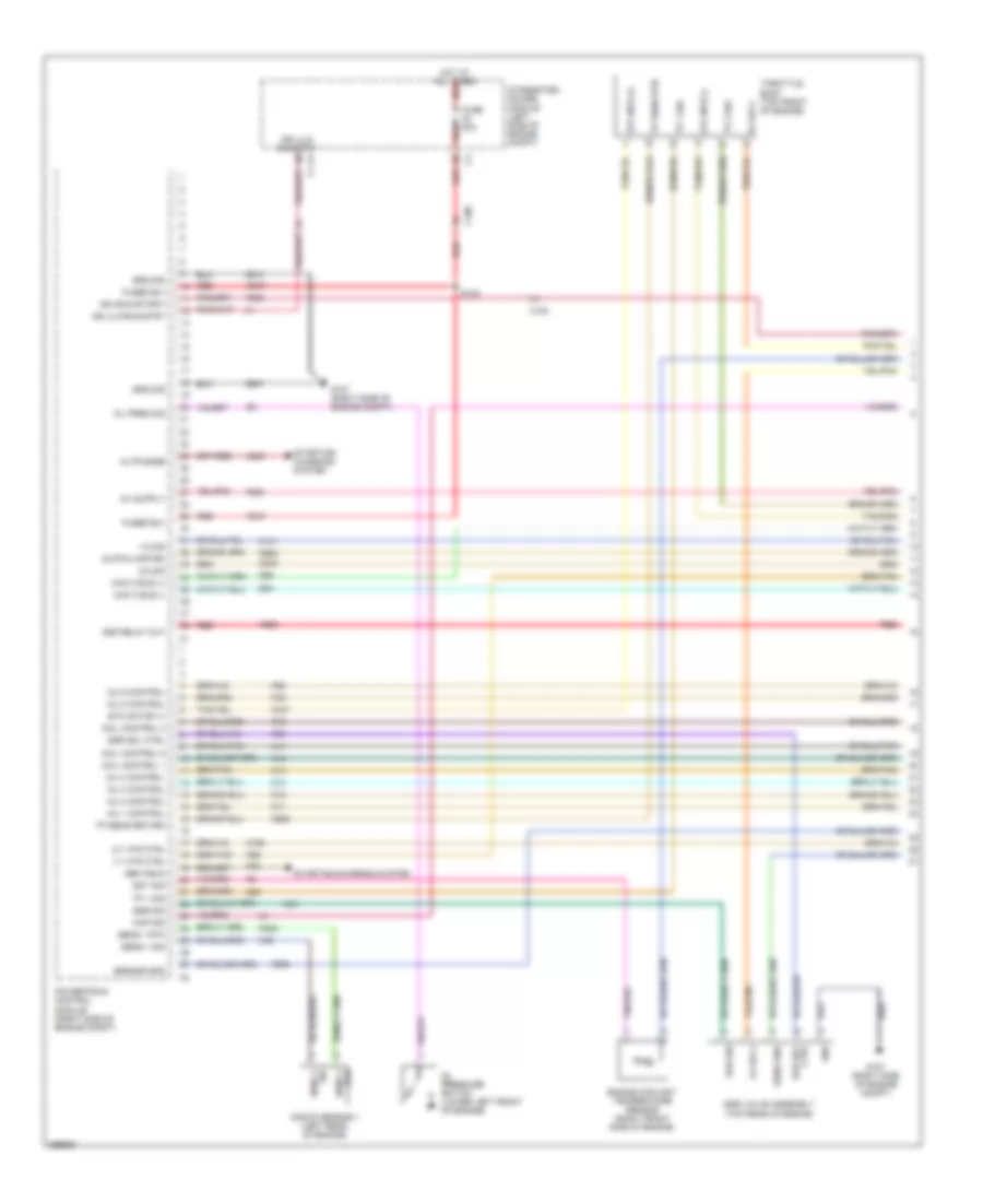
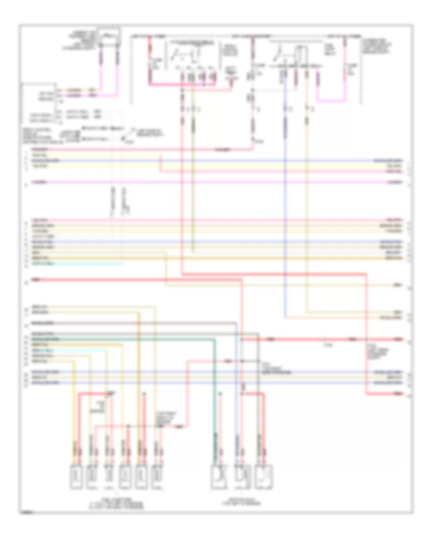
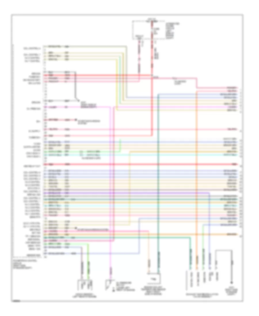
4.7L FLEX FUEL
4.7L Flex Fuel, Engine Performance Wiring Diagram (1 of 5) for Dodge Dakota 2010
List of elements for 4.7L Flex Fuel, Engine Performance Wiring Diagram (1 of 5) for Dodge Dakota 2010:
- 1/2 sig
- 2/2 sig
- 5v eng snsr
- A803
- A919
- A955
- Asd relay out
- B(+)
- Can c bus (+)
- Can c bus (-)
- Coil control 1
- Coil control 2
- Coil control 3
- Coil control 4
- Coil control 5
- Coil control 6
- Coil control 7
- Coil control 8
- D64
- D65
- Ect sig
- Egr signal
- Egr sol fdbk
- Egr sol sig
- Engine coolant temperature sensor (right front side of engine)
- Etc mtr (+)
- Exhaust gas recirculation valve assembly
- F202
- F856
- Fuse 20a
- Fused b(+)
- G107 (right side of engine compt)
- Ground
- Hot at all times red
- Ign (run-start)
- Ign ulk r/s
- Ign/ulk ris
- Inj 1 control
- Inj 2 control
- Inj 3 control
- Inj 4 control
- Inj 5 control
- Inj 6 control
- Inj 7 control
- Inj 8 control
- Inline eng hldp2
- Inline eng hlpd1
- Integrated power module (left side of engine compt)
- K10
- K11
- K12
- K13
- K14
- K141
- K15
- K16
- K17
- K18
- K19
- K199
- K20
- K22
- K243
- K26
- K28
- K34
- K35
- K38
- K42
- K447
- K58
- K900
- K902
- K922
- K942
- K97
- K98
- K99
- Knock sensor 1 (left rear of engine)
- Map sens sig
- O2 1/1 htr ctrl
- O2 2/1 htr ctrl
- O2 rtn upstrm
- Oil pres sig
- Oil pressure switch (lower left front of engine)
- Powertrain control module (right side of engine compt)
- Red
- S133
- Sens 1 rtn
- Sens 1 sig
- Sens rtn
- Sensor gnd
- Sig egr sol
- Starting/charging system
- Tp 1 sens sig
- Z913
- Z937
4.7L Flex Fuel, Engine Performance Wiring Diagram (2 of 5) for Dodge Dakota 2010
List of elements for 4.7L Flex Fuel, Engine Performance Wiring Diagram (2 of 5) for Dodge Dakota 2010:
- (left side of engine compt)
- (top
- (top right front of engine) s127
- (top right side of engine) s121
- Abmt tep sig
- Ambient air temperature sensor (left front of engine compt)
- Auto shutdown relay
- Batt fd
- Can bus (+)
- Can bus (-)
- Computer data lines system
- D64
- D65
- Engine)
- Front control module
- Front control module (side of power distribution module)
- Fuel injectors (1, 3, 5 & 7: top left of engine) (2, 4, 6 & 8: top right of engine)
- Fuel pump relay
- Fuse 10a
- Fuse 20a
- Fuse 30a
- G31
- G931
- Hot at all times
- Ignition coils (1, 3, 5 & 7: top left of engine) (2, 4, 6 & 8: top right of engine)
- Inline eng hlpd1
- Integrated power module (left side of engine compt)
- Ipm
- Red
- S100
- S101
- S105
- S108 (left rear of engine compt)
- S117
- Ssr rtn 1
4.7L Flex Fuel, Engine Performance Wiring Diagram (3 of 5) for Dodge Dakota 2010
List of elements for 4.7L Flex Fuel, Engine Performance Wiring Diagram (3 of 5) for Dodge Dakota 2010:
- (breakout to pcm)
- (breakout to pcm) s126
- (top front of engine) s118
- (top of engine) s123
- (top right side of engine) s122
- 5v eng snsr
- Camshaft position sensor (right front of engine)
- Crankshaft position sensor (right rear of engine)
- Etc mtr (+)
- Etc mtr (-)
- G107 (right side of engine compt)
- Left front oxygen sensor (near left front of transmission, in exhaust)
- Left rear oxygen sensor (near left rear of transmission, in exhaust)
- Map sensor (right front side of engine)
- Red
- Right front oxygen sensor (near right front of transmission, in exhaust)
- Right rear oxygen sensor (near right rear of transmission, in exhaust)
- S124 (top of engine)
- S125
- Snsr rtn
- Throttle body (top front of engine)
- Tp 1 sig
- Tp 2 sig
4.7L Flex Fuel, Engine Performance Wiring Diagram (4 of 5) for Dodge Dakota 2010
List of elements for 4.7L Flex Fuel, Engine Performance Wiring Diagram (4 of 5) for Dodge Dakota 2010:
- 1/2 htr ctrl
- 2/2 htr ctrl
- A/c clutch
- A955
- Accelerator pedal posion sensor (left side of dash)
- Air conditioning system
- Apps 1 ret
- Apps 1 sig
- Apps 2 ret
- Apps 2 sig
- Asd relay ctrl
- Asd relay out
- B29
- Brake sw 1 sig
- Brk sw 1 sig
- Brk sw 2 sig
- C105
- C13
- C201
- Can b bus (+)
- Can b bus (-)
- Ckp sig
- Cluster
- Cmp sig
- Computer data lines system
- Cruise control system
- Esm sw sig
- Etc mtr (-)
- Evap system monitor switch (left rear frame rail)
- Evap/purge solenoid (left rear of engine compt)
- F855
- Fuel level sens 1 sig
- Fuel level sens sig
- Fuel lvl sig
- Fuel pump
- Fuel pump cntrl
- Fuel pump module (top of fuel tank)
- G100 (left front of engine compt)
- Ground
- Inline eng hlpd2
- K107
- K122
- K23
- K24
- K29
- K299
- K31
- K399
- K400
- K41
- K43
- K44
- K448
- K51
- K52
- K70
- K904
- Leak dtctn snsr
- Mtr fd
- O2 1/1 signal
- O2 2/1 signal
- O2 rtn downstrm
- P/n sig
- Pnk/red
- Powertrain control module (right side of engine compt)
- Prg sig
- Red
- Snse2 sw
- Sol sig
- Spd ctrl snse 1 sw
- Starting/charging system
- Stop lamp switch (lower left side of dash)
- Strtr ctrl rly
- Sw return
- T41
- T752
- Tp 2 sig
- V32
- V71
- V72
- V937
- Z201
4.7L Flex Fuel, Engine Performance Wiring Diagram (5 of 5) for Dodge Dakota 2010
List of elements for 4.7L Flex Fuel, Engine Performance Wiring Diagram (5 of 5) for Dodge Dakota 2010:
- (right side of engine compt) g107
- 2c press
- 2c press sw
- 2c sol
- 2c sol ctrl
- 4c press
- 4c press sw
- 4c sol
- 4c sol ctrl
- 5 volt
- C201
- Eng ctrl
- G101 (left front of engine compt)
- G200 (left side of dash)
- Ground
- Hot at all times
- In spd sig
- Inline eng hldp2
- Inline eng hlpd1
- Inline eng hlpd2
- Input speed sensor (left front of transmission)
- Integrated power module (left side of engine compt)
- L/r press
- L/r press sw
- L/r sol
- L/r sol ctrl
- Line pressure sensor (right rear of transmission)
- Line prs sig
- Lp vfs ctrl
- Lp vfs sol
- Ms sol
- Ms sol ctrl
- Od press
- Od press sw
- Od sol
- Od sol ctrl
- Od sw sense
- Out spd sig
- Output speed sensor (left rear of transmission)
- Powertrain control module (right side of engine compt)
- Press sig
- Red
- S119 (breakout to pcm)
- S120 (rear of engine)
- Sens gnd
- T118
- T13
- T14
- T140
- T147
- T15
- T16
- T20
- T219
- T259
- T29
- T38
- T42
- T48
- T50
- T52
- T54
- T59
- T60
- Temperature sensor
- Tow/haul overdrive off switch
- Transmission control relay
- Transmission solenoid/trs assembly (left side of transmission)
- Trns ctrl out
- Trns rly ctrl
- Trns tmp sig
- Trs t1
- Trs t1 sense
- Trs t2
- Trs t2 sig
- Trs t3
- Trs t3 sense
- Trs t41
- Trs t42
- Trs t42 sig
- Ud press
- Ud press sw
- Ud sol
- Ud sol ctrl
- Z904
- Z908
- Z977
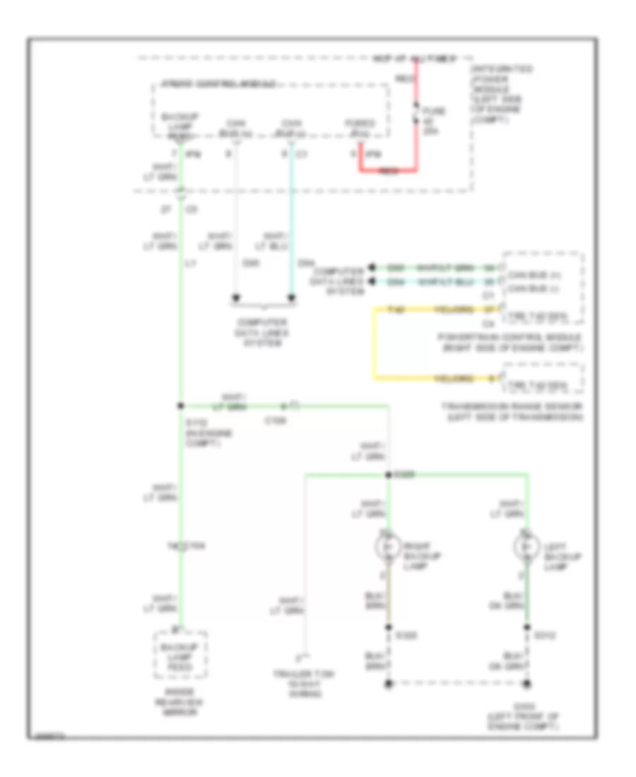
EXTERIOR LIGHTS
Backup Lamps Wiring Diagram for Dodge Dakota 2010
List of elements for Backup Lamps Wiring Diagram for Dodge Dakota 2010:
- Backup lamp feed
- C104
- C106
- Can bus (+)
- Can bus (-)
- Computer data lines system
- D64
- D65
- Front control module
- Fuse 25a
- Fused b(+)
- G100 (left front of engine compt)
- Hot at all times
- Inside rearview mirror
- Integrated power module (left side of engine compt)
- Ipm
- Left backup lamp
- Powertrain control module (right side of engine compt)
- Red
- Right backup lamp
- S112 (in engine compt)
- S312
- S320
- S325
- T42
- Trailer tow 10-way wiring
- Transmission range sensor (left side of transmission)
- Trs t42 sen
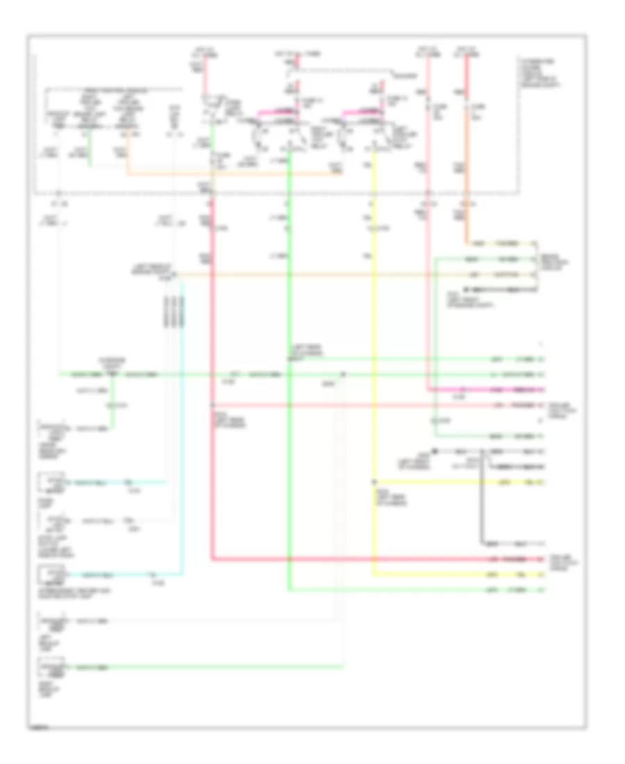
Exterior Lamps Wiring Diagram for Dodge Dakota 2010
List of elements for Exterior Lamps Wiring Diagram for Dodge Dakota 2010:
- (right side of engine compt)
- 87a
- Aftermarket center high mounted stop lamp
- B29
- Brake provision module
- Bus bar
- C100
- C104
- C105
- C106
- C200
- C201
- Can bus (+)
- Can bus (-)
- Can bus(+)
- Can bus(-)
- Cargo lamp fd
- Chmsl lamp
- Cluster
- Computer data
- D64
- D65
- Dimm hdlp
- F202
- Front control module
- Front turn signal ctrl
- Fuse 10a
- Fuse 15a
- Fuse 51 40a
- G100 (left front of engine compt)
- G101 (left front of engine compt)
- G103 (right front of engine compt)
- G200 (left side of dash)
- G301 (crew cab: left front of body) (extended cab: base of left kick panel)
- Ground
- Hazard
- Hdlp sw mux
- Hdlp sw mux rtn
- Head
- Headlamp switch
- Hot at all times
- Hot in run or start
- Ign sw out
- Illum sw
- Integrated power module (left side of engine compt)
- Ipm
- L50
- Left
- Left front park/ turn lamp
- Left license lamp
- Left rear turn signal ctrl
- Left turn
- Left turn/ tail/ stop lamp
- Lines system
- Multi-function switch
- Off
- Park
- Park lamp relay
- Park lamp relay ctrl
- Park lamp relay output
- Pnk/ red
- Powertrain control module
- Rear turn signal ctrl
- Red
- Right
- Right front park/ turn lamp
- Right front turn signal ctrl
- Right rear turn signal ctrl
- Right turn
- Right turn/ tail/ stop lamp
- S/c fd
- S105
- S106 (left rear of engine compt)
- S205 (remote radio) (left side of dash)
- S303
- S312
- S314 (left rear of chassis)
- S320
- Sound systems
- Stop lamp switch (lower left side of dash)
- Stop lp sw fd
- Stp lmp spd ctrl sig
- Sw mux rtn
- Turn sig input mux
- V32
Trailer Tow Wiring Diagram for Dodge Dakota 2010
List of elements for Trailer Tow Wiring Diagram for Dodge Dakota 2010:
- (in engine compt) s112
- (left rear of chassis) s317
- (left rear of engine compt) s106
- 87a
- A100
- A400
- Aftermarket center high mounted stop lamp
- B400
- Backup
- Backup lamp feed
- Brake provision module
- Bus bar
- C104
- C105
- C106
- C201
- Chmsl lamp
- Front control module
- Fuse 12 15a
- Fuse 13 15a
- Fuse 20a
- Fuse 30a
- G101 (left front of engine compt)
- G302 (left front of chassis)
- Hot at all times
- Inside rearview mirror
- Integrated power module (left side of engine compt)
- Ipm
- L50
- L673
- L674
- L76
- Lamp feed
- Left backup lamp
- Left trailer tow brake lamp relay control
- Left trailer tow relay
- Park lamp relay
- Pnk/ red
- Pnk/ red c106
- Pnk/red
- Red
- Right backup lamp
- Right trailer tow brake lamp relay control
- Right trailer tow relay
- S315 (w/ 7-way)
- S316 (left rear of chassis)
- S318 (left rear of chassis)
- S325
- Stop lamp switch (lower left side of dash)
- Stop lmp sw fd
- Stp lmp sw fd
- Tan/ red
- Tan/red
- Tow 7-way wiring
- Trailer
- Trailer tow 4-way wiring
- Z911
- Z976
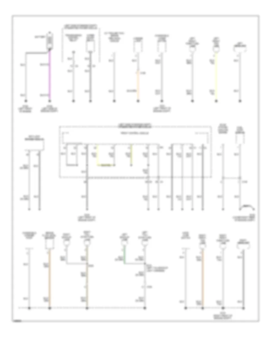
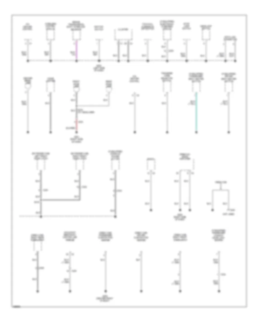
GROUND DISTRIBUTION
Ground Distribution Wiring Diagram (1 of 3) for Dodge Dakota 2010
List of elements for Ground Distribution Wiring Diagram (1 of 3) for Dodge Dakota 2010:
- (left side of engine compt) integrated power module
- (w/ trailer tow) brake provision module
- 87a
- Anti-lock brakes module
- Battery
- Brake fluid level sensor
- C105
- C106
- Evap system monitor switch
- Front control module
- Fuel pump module
- G100 (left front of engine compt)
- G101 (left front of engine compt)
- G102 (lower right rear of engine compt)
- G103 (right front of engine compt)
- G105 (left front of engine)
- G106 (left side of engine compt)
- Hood ajar switch
- Ipm
- Left backup lamp
- Left front fog lamp
- Left front park/turn lamp
- Left headlamp
- Left tail/ stop/turn lamp
- License lamp
- Right backup lamp
- Right front fog lamp
- Right front park/turn lamp
- Right headlamp
- Right tail/ stop/turn lamp
- S312 (left tail/backup light harness)
- S320
- Transmission control relay
- Windshield
- Windshield washer pump
- Wiper motor
- Wiper on/off relay
Ground Distribution Wiring Diagram (2 of 3) for Dodge Dakota 2010
List of elements for Ground Distribution Wiring Diagram (2 of 3) for Dodge Dakota 2010:
- (crew cab) driver cushion pad heater
- (crew cab) passenger cushion pad heater
- (crew cab) right front door latch
- (crew cab) right rear door latch
- (extended cab) left front door latch
- (extended cab) right front door latch
- (if equipped) console power outlet
- (if equipped) driver seat heater switch
- (if equipped) electronic overhead module
- (if equipped) passenger seat heater switch
- (if equipped) passenger window/ door lock switch
- (not used)
- (premium) radio amplifier
- A/c heater control
- Brake transmission shift interlock solenoid
- C200
- C203
- C300
- C302
- C304
- C306
- Center bezel lamp
- Cigar lighter
- Cluster
- Crew cab
- Data link connector
- Front dome lamp
- G200 (left side of dash)
- G201 (right side of dash)
- G202 (right side of dash)
- G300 (center front of body)
- Headlamp switch
- Ignition switch
- Occupant restraint controller module
- Radio
- Rear dome lamp
- S216 (at headliner)
- S319
- Stop lamp switch
- Tow/haul overdrive off switch
- Transfer case selector switch
- Wireless control module
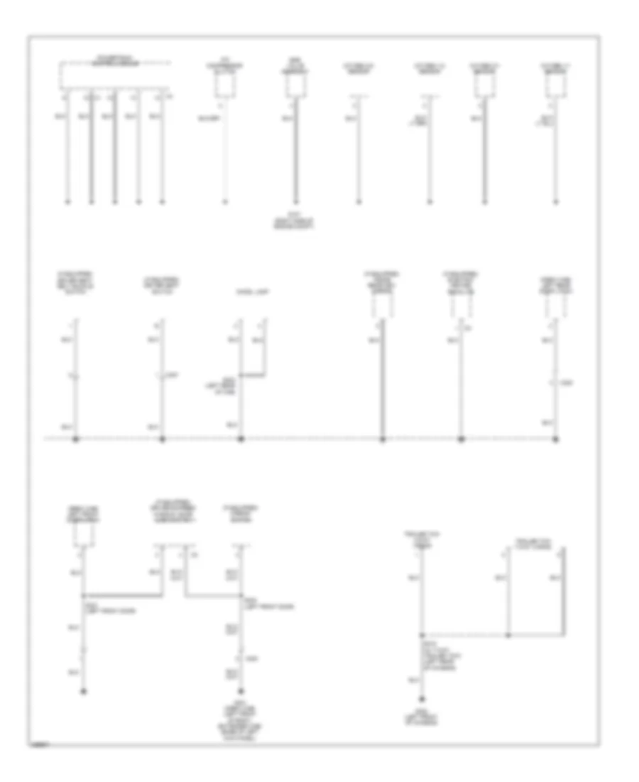
Ground Distribution Wiring Diagram (3 of 3) for Dodge Dakota 2010
List of elements for Ground Distribution Wiring Diagram (3 of 3) for Dodge Dakota 2010:
- (crew cab) left front door latch
- (crew cab) left rear door latch
- (if equipped) driver express window/ door lock switch
- (if equipped) driver seat belt buckle switch
- (if equipped) driver seat switch
- (if equipped) electric heated backlite
- (if equipped) inside rearview mirror
- (if equipped) mirror switch
- A/c compressor clutch
- C300
- C307
- C308
- Chmsl lamp
- Egr valve assembly
- G107 (right side of engine compt)
- G301 (crew cab) (left front of body) (extended cab) (base of left kick panel)
- G302 (left front of chassis)
- Oxygen 1/1 sensor
- Oxygen 1/2 sensor
- Oxygen 2/1 sensor
- Oxygen 2/2 sensor
- Powertrain control module
- S303 (left rear of cab)
- S315 (w/ 7-way trailer tow) (left rear of chassis)
- S321 (left front door)
- S322 (left front door)
- Trailer tow 4-way wiring
- Trailer tow 7-way wiring
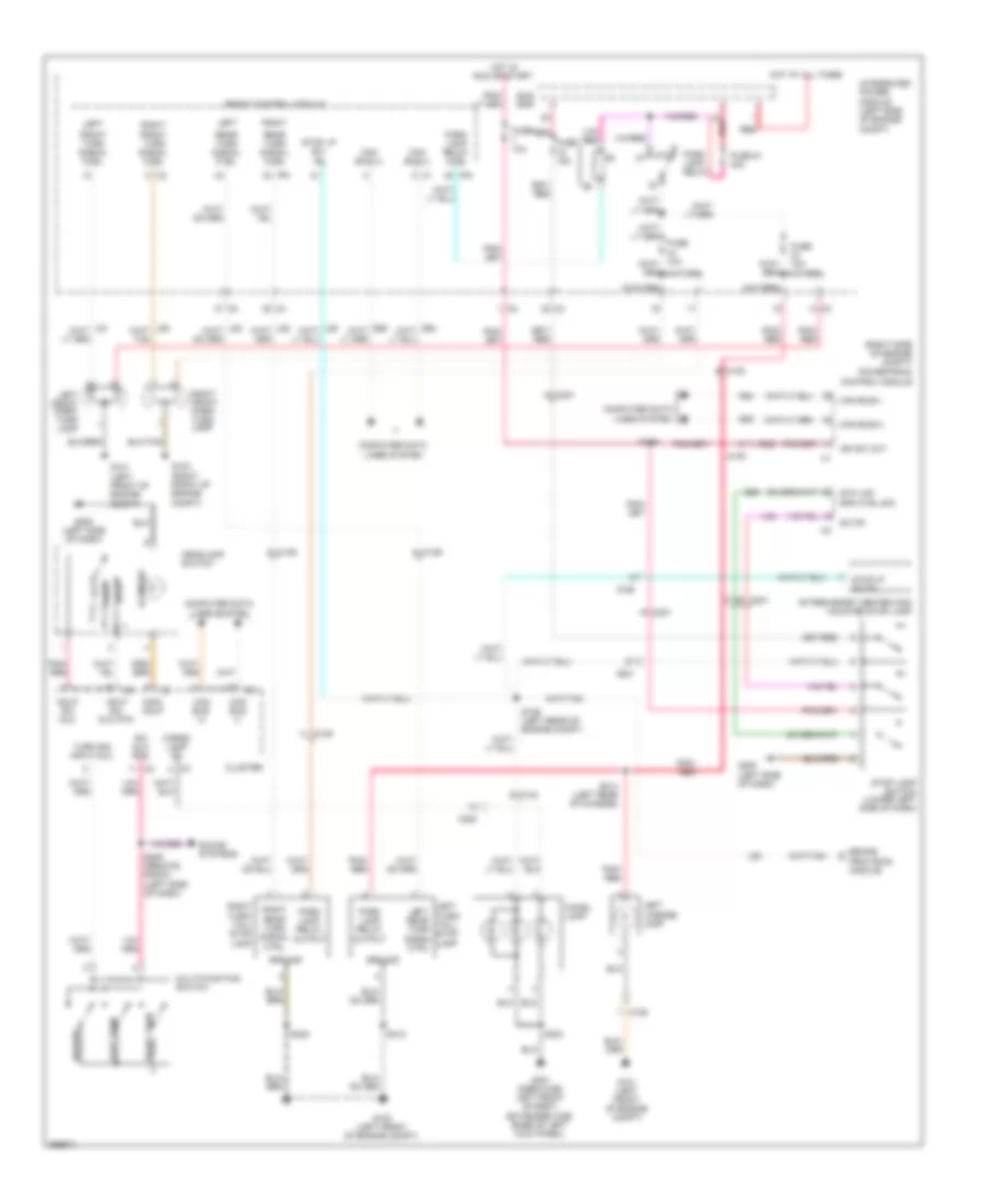
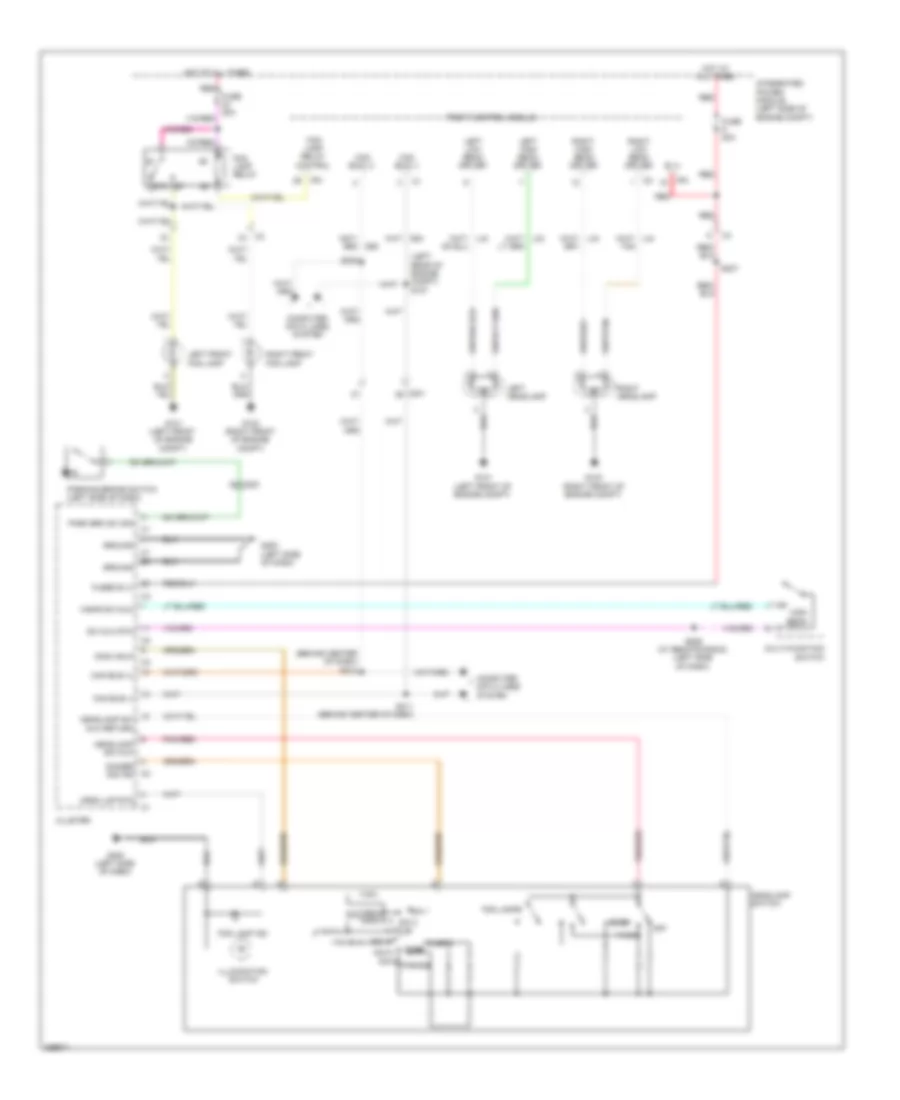
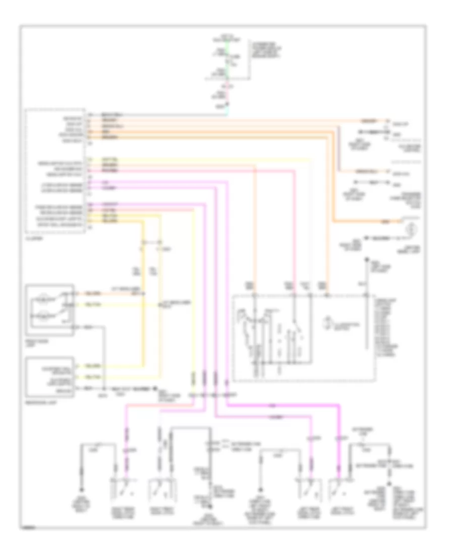
HEADLIGHTS
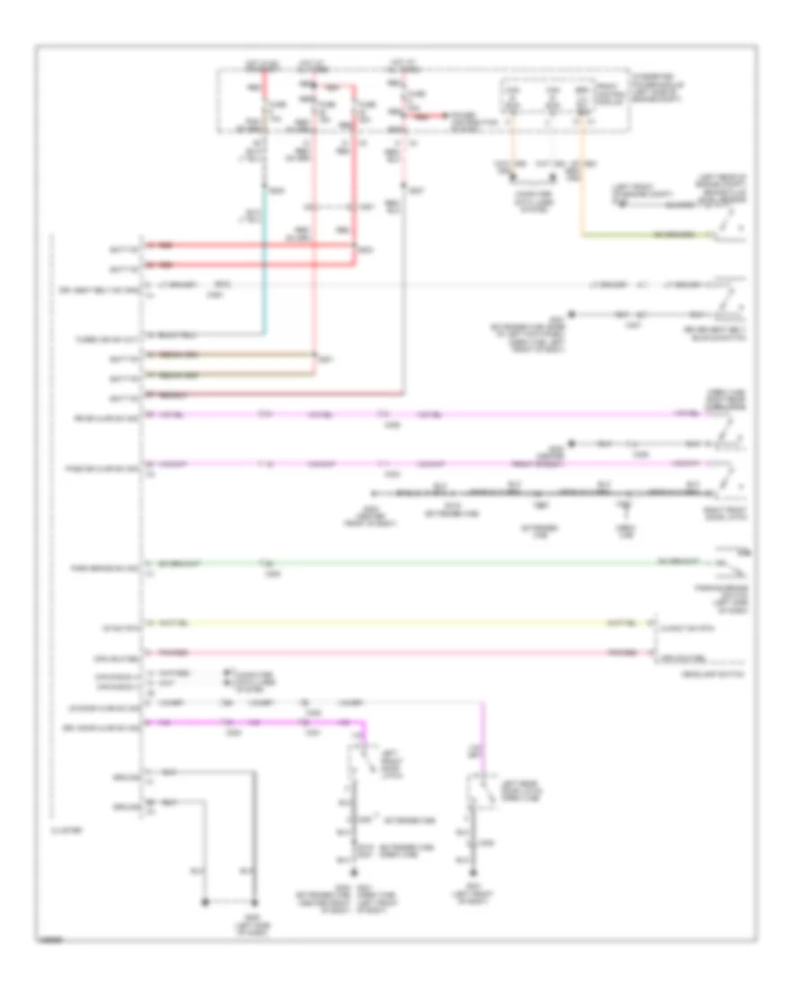
Headlights Wiring Diagram for Dodge Dakota 2010
List of elements for Headlights Wiring Diagram for Dodge Dakota 2010:
- (behind center of dash)
- (left rear of engine compt) s107
- 87a
- B (+)
- C200
- C201
- Can bus (+)
- Can bus (-)
- Cargo dome
- Cluster
- Computer data lines system
- Crgo lmp rtn
- D55
- Dim 1
- Dim 2
- Dim 3
- Dim 4
- Dim 5
- Dim 6
- Dimm hdlp
- Dimmer sig ind
- Fog lamp ind
- Fog lamp relay
- Fog lamp relay control
- Fog lamps
- Front control module
- Fuse 20a
- Fused b (+)
- G101 (left front of engine compt)
- G103 (right front of engine compt)
- G200 (left side of dash)
- Ground
- Head
- Headlamp sw mux
- Headlamp sw mux return
- Headlamp switch
- High beam
- Hot at all times
- Illumination switch
- Integrated power module (left side of engine compt)
- Ipm
- Left front fog lamp
- Left headlamp
- Left high beam driver
- Left low beam driver
- Multi-function switch
- Off
- Parade
- Park
- Park brk sw sig
- Parking brake switch (left side of dash)
- Pnk/red
- Red
- Right front fog lamp
- Right headlamp
- Right high beam driver
- Right low beam driver
- S205 (w/ remote radio) (left side of dash)
- S207
- S211 (behind center of dash)
- S212
- S230
- Sw mux rtn
- Tan
- Wshr sw mux
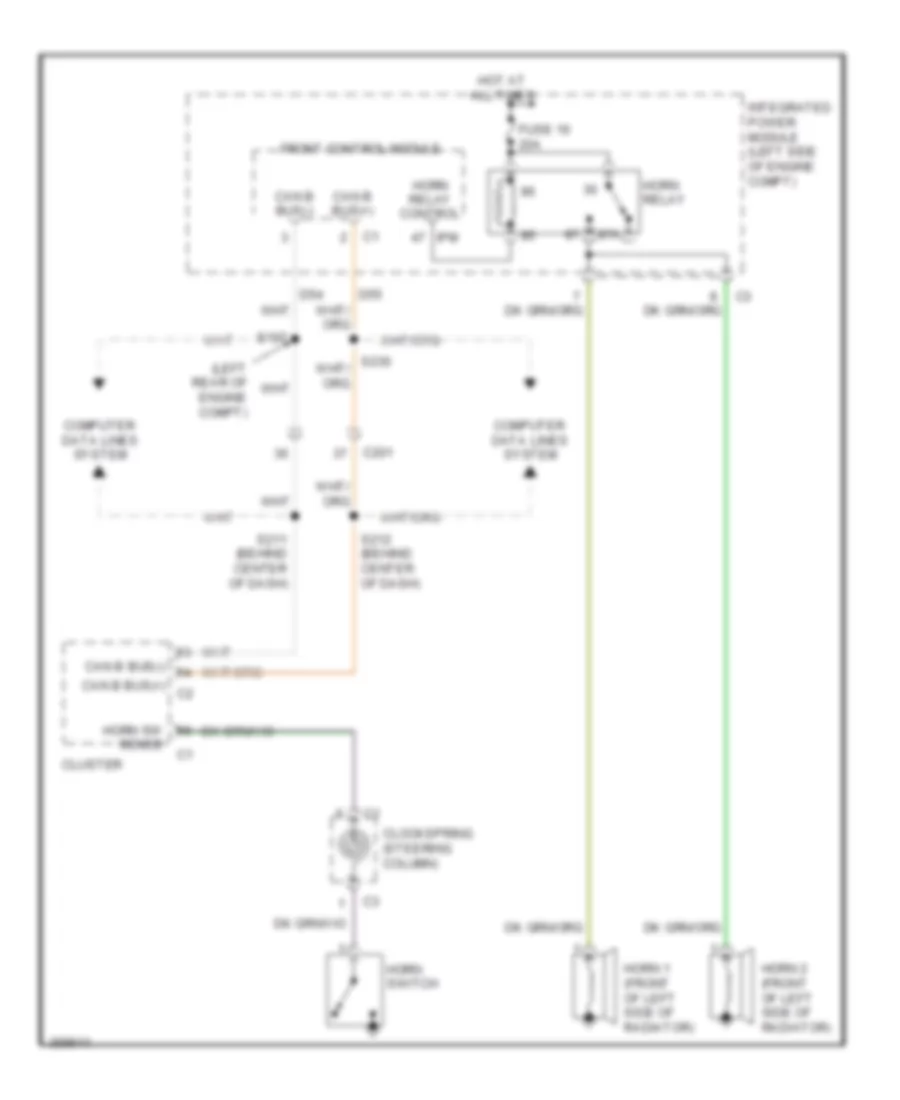
HORN
Horn Wiring Diagram for Dodge Dakota 2010
List of elements for Horn Wiring Diagram for Dodge Dakota 2010:
- (left rear of engine compt)
- 87a
- C201
- Can b bus(+)
- Can b bus(+) c2
- Can b bus(-)
- Clockspring (steering column)
- Cluster
- Computer data lines system
- D54
- D55
- Front control module
- Fuse 16 20a
- Horn 1 (front of left side of radiator)
- Horn 2 (front of left side of radiator)
- Horn relay
- Horn relay control
- Horn sw
- Horn switch
- Hot at all times
- Integrated power module (left side of engine compt)
- Ipm
- S107
- S211 (behind center of dash)
- S212 (behind center of dash)
- Sense
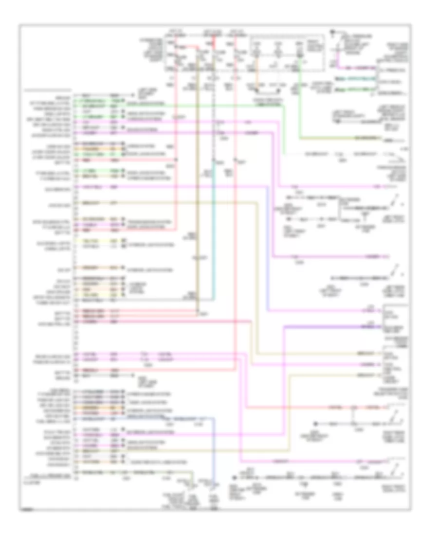
INSTRUMENT CLUSTER
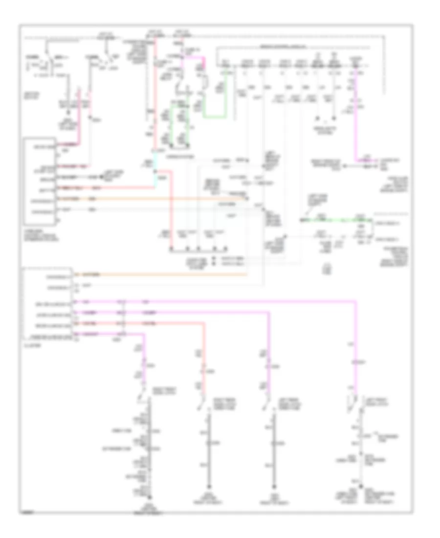
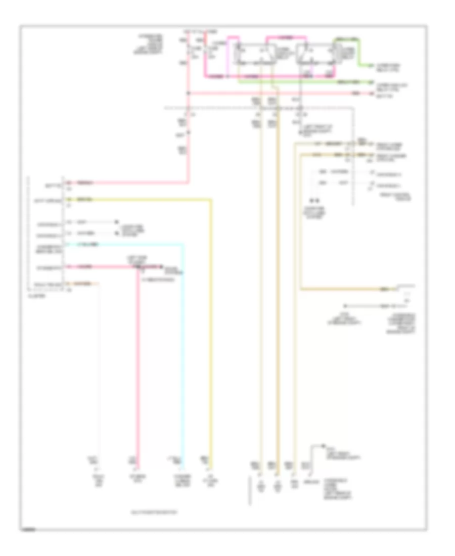
Instrument Cluster Wiring Diagram for Dodge Dakota 2010
List of elements for Instrument Cluster Wiring Diagram for Dodge Dakota 2010:
- (left front of engine compt) g100
- (left rear of engine compt) brake fluid level sensor
- (left side of dash) g200
- (right side of engine compt) powertrain control module
- 4wd mode sel rtn
- 4wd neutral ind
- 4wd sw sig
- A117
- A920
- A924
- B20
- B25
- B30
- Batt fd
- Brk lvl sw sig
- Btsi solenoid ctrl
- C105
- C200
- C201
- C300
- C301
- C302
- C303
- C306
- C308
- Can b bus (+)
- Can b bus (-)
- Can b bus(+)
- Can b bus(-)
- Can c bus(+)
- Can c bus(-)
- Cargo lmp fd
- Cluster
- Computer data lines system
- Crew cab
- Crgo lmp rtn
- Crtsy rail/dome fd
- D54
- D55
- D64
- D65
- Dim 3ip
- Dim 4x4
- Dim hdlp
- Dimm cphldr
- Door locks system
- Drv dr ajar sw sig
- Drv dr lock sw
- Drv seat belt sw sns
- E11
- E12
- E19
- E33
- Extended cab
- Exterior lights system
- F washer sw sig
- F wiper sw mux
- F21
- Front control module
- Ft & rr dr ulk
- Ft/rr drs lk ctrl
- Fuel level primary sig
- Fuel lvl primary sig
- Fuel pump module (top of fuel tank)
- Fuel send lvl sig
- Fuse 10a
- Fuse 15a
- Fuse 20a
- Fused ign sw out
- G160
- G161
- G194
- G200 (left side of dash)
- G300 (center front of body)
- G301 (left front of body)
- G39
- G74
- G75
- G76
- G77
- G778
- G902
- G939
- G95
- Glove box lmp fd
- Gnd
- Ground
- Headlights system
- High beam/
- Horn sw sig
- Horns system
- Hot at all times
- Hot in on or start
- Ind dimmer sig
- Integrated power module (left side of engine compt)
- Interior lights system
- K77
- K977
- L12
- L14
- L307
- L900
- L914
- Left front door latch
- Left rear door latch (crew cab)
- Lf drv door unlock
- Lr door ajar sw sig
- Lr drv door unlock
- M22
- M28
- Mf sens rtn
- Mf sw rtn
- Mfs hdlp sel
- Mode select
- Oil press sig
- Oil pressure switch (lower left front of engine)
- P392
- P393
- Park brake sw sig
- Parking brake switch (left side of dash)
- Pass dr ajar sw in
- Pass dr lock sw
- Pnk/red
- R mux trn sig
- R57
- Radio ctrl sig
- Red
- Red fuse 20a
- Right front door latch
- Right rear door latch (crew cab)
- Rr dr ajar sw sig
- Rt ft/rr drs lk ctrl
- S201
- S202
- S203
- S207
- S319
- S319 (extended cab)
- S321
- Sound systems
- Sun sens return
- Sun sens rtn
- Sun sens sig
- Sun sensor (top of dash)
- Transfer case selector switch (4wd)
- Transmissions system
- W52
- Warning systems
- Wiper/washer system
- X20
- Z946
- Z948
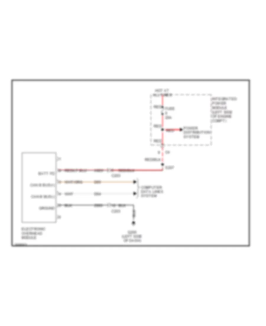
Overhead Console Wiring Diagram for Dodge Dakota 2010
List of elements for Overhead Console Wiring Diagram for Dodge Dakota 2010:
- A920
- Batt fd
- C203
- Can b bus(+)
- Can b bus(-)
- Computer data lines system
- D54
- D55
- Electronic overhead module
- G200 (left side of dash)
- Ground
- Hot at all times
- Integrated power module (left side of engine compt)
- Power distribution system
- Red
- Red fuse 20a
- S207
- Z993
INTERIOR LIGHTS
Interior Lights Wiring Diagram for Dodge Dakota 2010
List of elements for Interior Lights Wiring Diagram for Dodge Dakota 2010:
- (at headliner) s214
- (at headliner) s215
- A/c heater control
- C200
- C203
- C300
- C301
- C302
- C303
- C306
- C308
- Center bezel lamp
- Cluster
- Courtesy rail or dom fd
- Crew cab
- Crtsy rail or dome fd
- Dimm 3ip
- Dimm 4x4
- Dimm cdhldr
- Dimm hdlp
- Extended cab
- Front dome lamp
- Fuse 10a
- G200 (left side of dash)
- G201 (right side of dash)
- G300 (center front of body)
- G300 (extended cab) (center front of body)
- G301 (crew cab) (crew cab: left front of body) (extended cab: base of left kick panel)
- G301 (crew cab: left front of body) (extended cab: base of left kick panel)
- Glove box map/lamp fd
- Glove box/map lamp fd
- Gnd
- Ground
- Headlamp sw mux
- Headlamp sw mux rtn
- Headlamp switch 1) head 2) park 3) off 4) dim 1 5) dim 2 6) dim 3 7) dim 4 8) dim 5 9) dim 6 10) parade 11) dome 12) cargo
- Hot in run or start
- Ign r/s fd
- Illumination switch
- Ind dimmer sig
- Integrated power module (left side of engine compt)
- Left front door latch
- Left rear door latch (crew cab)
- Lf dr ajar sw sense
- Lr dr ajar sw sense
- Pass dr ajar sw sense
- Pnk/ red
- Pnk/red
- Rear dome lamp
- Right front door latch
- Right rear door latch (crew cab)
- Rr dr ajar sw sense
- S202
- S216
- S319 (extended cab)
- S319 (extended crew cab)
- S321 (crew cab)
- Transfer case selector switch (4wd)
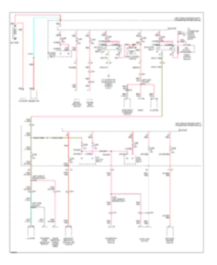
POWER DISTRIBUTION
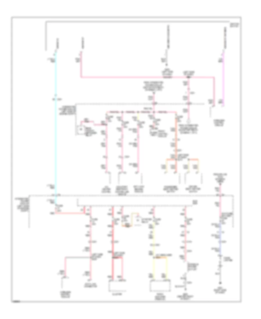
Power Distribution Wiring Diagram (1 of 3) for Dodge Dakota 2010
List of elements for Power Distribution Wiring Diagram (1 of 3) for Dodge Dakota 2010:
- (left side of dash) s202
- (left side of engine compt) integrated power module
- (left side of engine compt) s109
- A/c clutch relay
- Anti-lock brakes module
- Battery
- Blower motor relay
- Brake provision module
- Bus bar
- C100
- C103
- C104
- C201
- C307
- Cluster
- Driver seat switch
- Electronic overhead module
- Front control module
- Fuel pump relay
- Fuse 10a
- Fuse 15a
- Fuse 20a
- Fuse 20a red
- Fuse 30a
- Fuse 50a
- Fused b+
- Generator
- Ign sw out (run-start)
- Ignition run relay
- Inside rearview mirror (hands free)
- Ipm
- Occupant restraint controller module
- Pnk
- Powertrain control module
- Radio
- Red
- Run/start relay
- Starter
- Stop lamp switch
- Tan/ red
- Tan/red
- To integrated power module (diagram 2 of 3)
- To integrated power module fuse 61 (diagram 2 of 3)
- Transfer case selector switch
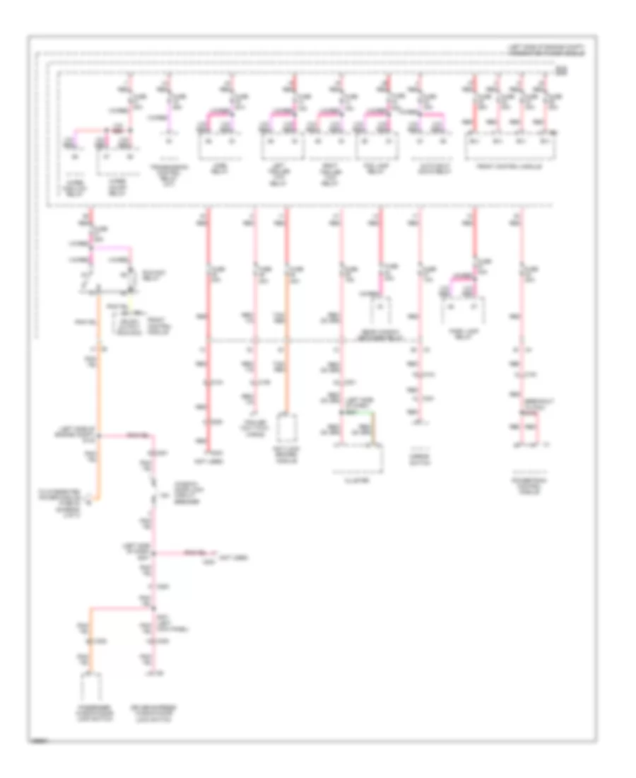
Power Distribution Wiring Diagram (2 of 3) for Dodge Dakota 2010
List of elements for Power Distribution Wiring Diagram (2 of 3) for Dodge Dakota 2010:
- (at headliner) s221
- (left side of dash) s204
- (left side of dash) s206
- (left side tan/ pnk
- A/c heater control
- Anti-lock brakes module
- Bus bar
- C104
- C201
- C304
- Cigar lighter
- Cluster
- Console power outlet
- Data link connector
- Driver seat heater switch
- From integrated power module ignition run relay (diagram 1 of 3)
- From integrated power module run/start relay (diagram 1 of 3)
- From splice s132 (diagram 3 of 3)
- Front control module
- Fuse 20a
- Fuse 25a
- Fuse 30a
- Fused b(+)
- G200 (left side of dash)
- G201 (right side of dash)
- G300 (center front of body)
- Gnd rem kylss entry
- Ign run st
- Ign run st sw snse
- Ign sw fd
- Ignition switch
- Integrated power module (left side of engine compt)
- Occupant restraint controller module
- Of dash) s210
- Passenger seat heater switch
- Radio amplifier (premium)
- Rear window defogger relay
- Red
- Red (left side of dash) s203
- Red ipm
- Red/ tan
- Starter relay
- Tan/ pnk
- Wireless control module
Power Distribution Wiring Diagram (3 of 3) for Dodge Dakota 2010
List of elements for Power Distribution Wiring Diagram (3 of 3) for Dodge Dakota 2010:
- (breakout to pcm) s133
- (left side of dash) s201
- (left side of dash) s231
- (left side of engine compt) integrated power module
- (left side of engine compt) s132
- (not used)
- (not used) c203
- 15a
- Anti-lock brakes module
- Auto shut down relay
- B(+)
- Bus bar
- C100
- C104
- C106
- C200
- C200 a
- C201
- C201 g
- C203
- C300
- C301
- C302
- Cluster
- Driver express window/door lock switch
- Fog lamp relay
- Front control module
- Fuse 10a
- Fuse 15a
- Fuse 20a
- Fuse 25a
- Fuse 30a
- Fuse 40a
- Horn relay
- Ign sw output (run-acc)
- Ipm
- Kick panel)
- Left trailer tow relay
- Mirror switch
- Park lamp relay
- Passenger window/door lock switch
- Powertrain control module
- Rear window defogger relay
- Red
- Right trailer tow relay
- Run-acc relay
- Tan/ red
- To integrated power module fuse 22 (diagram 2 of 3)
- Trailer tow 7-way wiring
- Transmission control relay (a/t)
- Window/ door lock circuit breaker
- Wiper high/low relay
- Wiper on/off relay
POWER DOOR LOCKS
Power Door Locks Wiring Diagram for Dodge Dakota 2010
List of elements for Power Door Locks Wiring Diagram for Dodge Dakota 2010:
- (center front of body) (extended cab) g300
- (center of body)
- (crew cab) s307
- (crew cab) s321
- 15a
- Ajar sw in
- C200
- C300
- C301
- C302
- C303
- C306
- C308
- Cluster
- Crew cab
- Driver express window/door lock switch
- Drv dr lck sw sig
- Extended cab
- Ft & rr dr lck ctrl
- Ft & rr dr unlck
- Ft & rr drs lk ctrl
- Ft & rr drs ulk
- Ft/rr drs lk ctrl
- G300 (center front of body)
- G301 (crew cab) (left front of body)
- G301 (crew cab: left front of body) (extended cab: base of left kick panel)
- G301 (left front of body)
- Gnd
- Hot w/ run/acc relay energized
- Left front door latch
- Left rear door latch (crew cab)
- Lf dr ajar sw in
- Lf dr unlck
- Lh dr lck ctrl
- Lr dr ajar sig
- Lr dr ajar sw sig
- Lr dr unlck
- Lt ft dr ulk
- Lt ft/rr drs lk ctrl
- Lt rr ulk
- Pass dr ajar sw sig
- Pass dr lck sw sig
- Passenger window/ door lock switch
- Right front door latch
- Right rear door latch (crew cab)
- Rr dr ajar sig
- Rr dr ajar sw sig
- S301
- S306 (crew cab)
- S311 (crew cab) (left front of body)
- S319 (extended cab)
- S321
- S322
- Wdw run/acc ign
- Window/ door lock circuit breaker
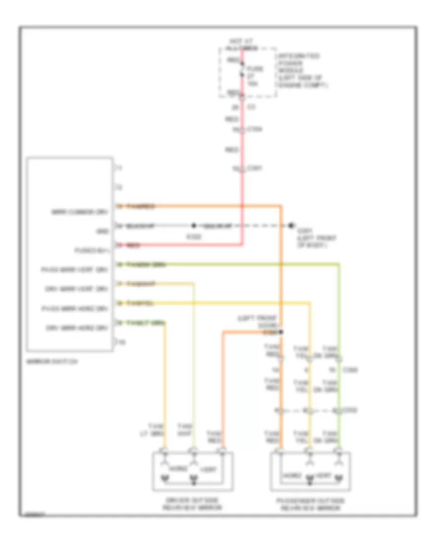
POWER MIRRORS
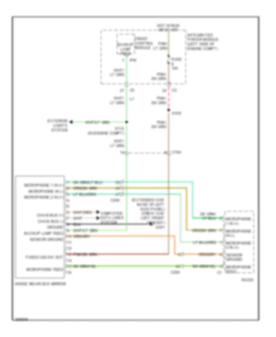
Automatic Day/Night Mirror Wiring Diagram for Dodge Dakota 2010
List of elements for Automatic Day/Night Mirror Wiring Diagram for Dodge Dakota 2010:
- (extended cab: base of left kick panel) (crew cab: left front of body) g301
- Backup lamp feed
- C104
- C200
- Can b bus (+)
- Can b bus (-)
- Computer data lines system
- Exterior lights system
- Front control module
- Fuse 10a
- Fused ign sw out
- Ground
- Hot in run or start
- Inside rearview mirror
- Integrated power module (left side of engine compt)
- Ipm
- Microphone 1 in (+)
- Microphone 2 in (+)
- Microphone feed
- Microphone feed c1
- Microphone in (-)
- Radio
- S109
- S112 (in engine compt)
- Sensor ground
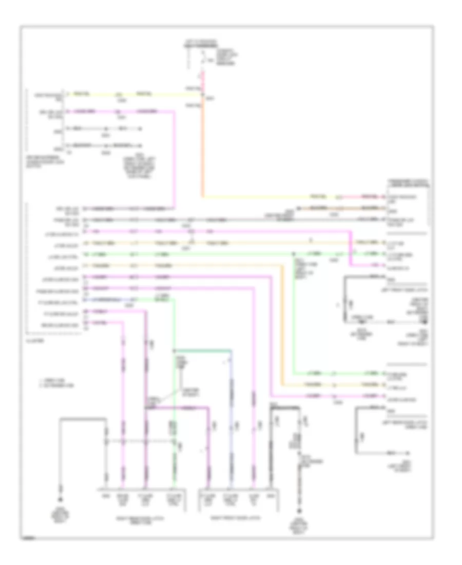
Power Mirrors Wiring Diagram for Dodge Dakota 2010
List of elements for Power Mirrors Wiring Diagram for Dodge Dakota 2010:
- (left front door) s328
- C104
- C300
- C301
- C302
- Driver outside rearview mirror
- Drv mirr horz drv
- Drv mirr vert drv
- Fuse 10a
- Fused b(+)
- G301 (left front of body)
- Gnd
- Horiz
- Hot at all times
- Integrated power module (left side of engine compt)
- Mirr common drv
- Mirror switch
- Pass mirr horz drv
- Pass mirr vert drv
- Passenger outside rearview mirror
- Red
- S322
- Tan/ red
- Tan/red
- Vert
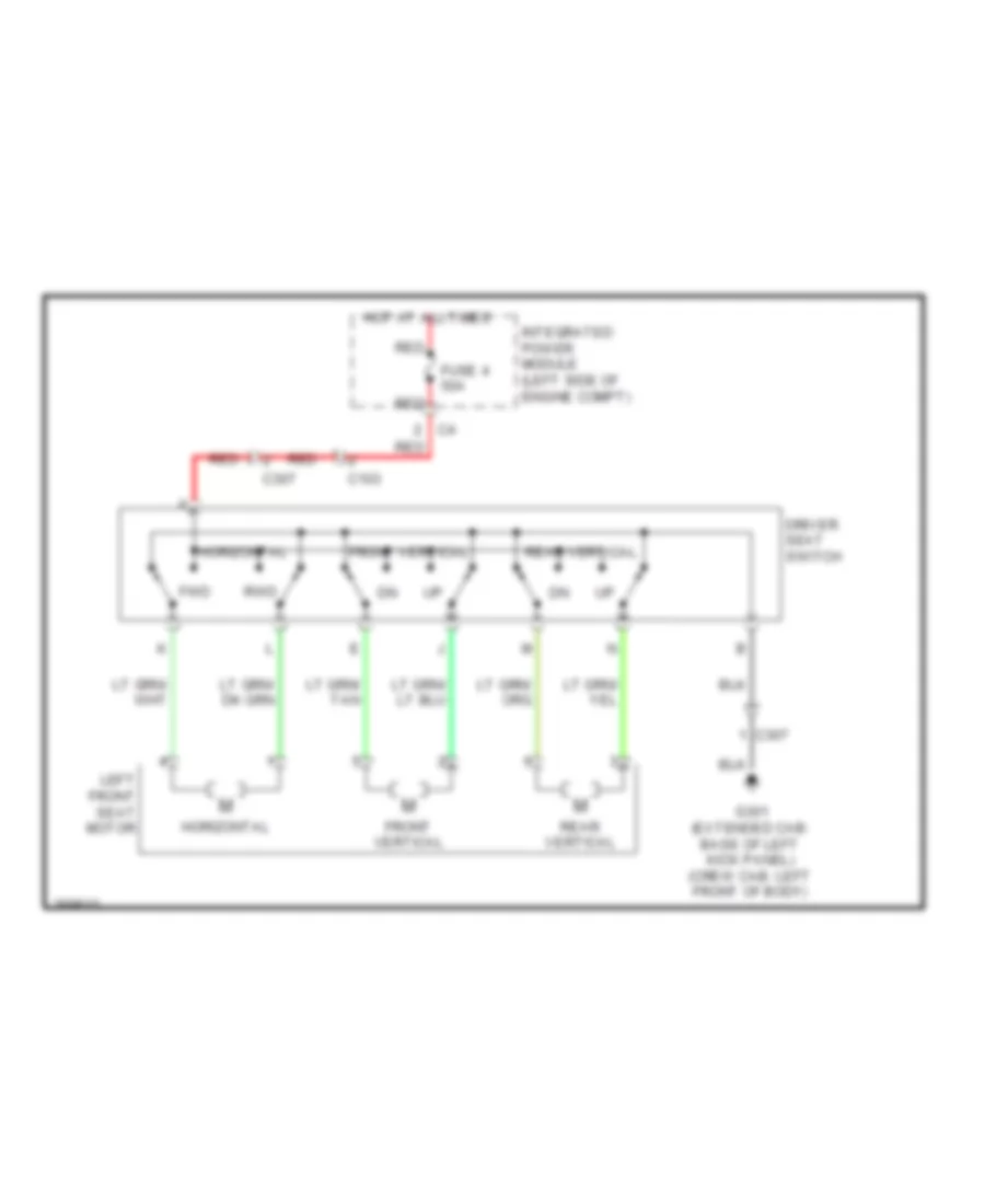
POWER SEATS
Driver Power Seat Wiring Diagram for Dodge Dakota 2010
List of elements for Driver Power Seat Wiring Diagram for Dodge Dakota 2010:
- C103
- C307
- Driver seat switch
- Front vertical
- Fuse 4 50a
- Fwd
- G301 (extended cab: base of left kick panel) (crew cab: left front of body)
- Horizontal
- Hot at all times
- Integrated power module (left side of engine compt)
- Left front seat motor
- Rear vertical
- Red
- Rwd
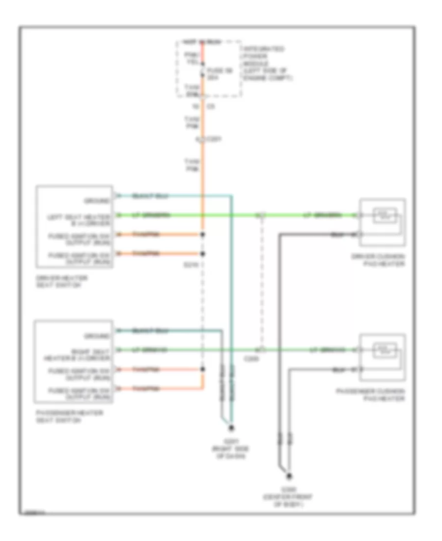
Heated Seats Wiring Diagram for Dodge Dakota 2010
List of elements for Heated Seats Wiring Diagram for Dodge Dakota 2010:
- C200
- C201
- Driver cushion pad heater
- Driver heater seat switch
- Fuse 58 20a
- Fused ignition sw output (run)
- G201 (right side of dash)
- G300 (center front of body)
- Ground
- Hot in run
- Integrated power module (left side of engine compt)
- Left seat heater b (+) driver
- Passenger cushion pad heater
- Passenger heater seat switch
- Right seat heater b (+) driver
- S210
- Tan/ pnk
- Tan/pnk
POWER WINDOWS
Power Windows Wiring Diagram for Dodge Dakota 2010
List of elements for Power Windows Wiring Diagram for Dodge Dakota 2010:
- (center front of body) g300
- (left floor pan) s327
- 15a
- C200
- C300
- C301
- C302
- C303
- C306
- C308
- Cluster
- Driver express window/ door lock switch
- Driver window/ door lock switch
- Ft drv dr lk sw sig
- Ft pass drlk sw sig
- Ft pass win down
- Ft pass win up
- G301 (crew cab: left front of body) (extended cab: base of left kick panel)
- Gnd
- Hot w/ run/ acc relay energized
- Left front window motor
- Left rear mast ctrl (down)
- Left rear mast ctrl (up)
- Left rear mstr ctrl (down)
- Left rear mstr ctrl (up)
- Left rear power window switch (crew cab)
- Left rear window motor
- Lk sw sig
- Passenger window/door lock switch
- Pwr win sw lock out fd
- Right front window motor
- Right rear mast ctrl (down)
- Right rear mast ctrl (up)
- Right rear mstr ctrl (down)
- Right rear mstr ctrl (up)
- Right rear power window switch (crew cab)
- Right rear window motor
- Rt win dn sig
- Rt win sig down
- Rt win sig up
- Rt win up sig
- Run/acc ign
- S301
- S321
- S322
- Wid lock out sw fd
- Win drv (down)
- Win drv (up)
- Win lock out sw fd
- Win run/acc ign
- Window/door lock circuit breaker
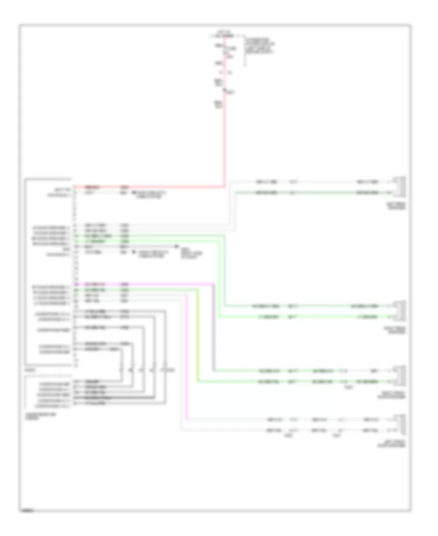
RADIO
Radio Wiring Diagram, Base for Dodge Dakota 2010
List of elements for Radio Wiring Diagram, Base for Dodge Dakota 2010:
- A920
- Batt fd
- C200
- C301
- C303
- Can b bus (+)
- Can b bus (-)
- Computer data lines system
- D54
- D55
- Fuse 20a
- G202 (right side of dash)
- Gnd
- Hot at all times
- Inside rearview mirror
- Integrated power module (left side of engine compt)
- Left front door speaker
- Left rear speaker
- Lf door speaker (+)
- Lf door speaker (-)
- Lr door speaker (+)
- Lr door speaker (-)
- Microphone 2 in (+)
- Microphone feed
- Microphone in (+)
- Microphone in (-)
- Microphone ref
- Radio
- Red
- Rf door speaker (+)
- Rf door speaker (-)
- Right front door speaker
- Right rear speaker
- Rr door speaker (+)
- Rr door speaker (-)
- S207
- X201
- X202
- X205
- X206
- X291
- X292
- X295
- X296
- X712
- X722
- X792
- X793
- X835
- Z914
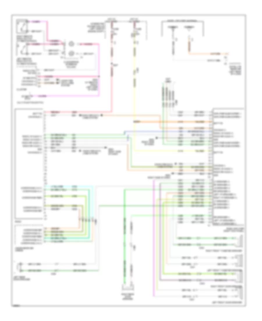
Radio Wiring Diagram, Premium for Dodge Dakota 2010
List of elements for Radio Wiring Diagram, Premium for Dodge Dakota 2010:
- (not used)
- A116
- A920
- Amplifier subwoofer1 +
- Amplifier subwoofer1 -
- Amplifier subwoofer2 +
- Amplifier subwoofer2 -
- Antenna
- Batt fd
- C200
- C201
- C301
- C303
- C306
- C308
- Can b bus (+)
- Can b bus (-)
- Can bus (+)
- Can bus (-)
- Clockspring (steering column)
- Cluster
- Computer data lines system
- D54
- D55
- Fuse 20a red
- G202 (right side of dash)
- Gnd
- Hot at all times red
- Inside rearview mirror
- Integrated power module (left side of engine compt)
- Left front door speaker
- Left front tweeter speaker
- Left i/p speaker (+)
- Left i/p speaker (-)
- Left rear door speaker
- Left remote radio switch (w/ remote radio)
- Lf speaker (+)
- Lf speaker (-)
- Lr speaker (+)
- Lr speaker (-)
- Mf sen rtn
- Microphone 2 in (+)
- Microphone feed
- Microphone in (+)
- Microphone in (-)
- Microphone ref
- Multi-function switch
- Radio
- Radio amplifier (right kick panel)
- Radio ctrl sw sig c1
- Radio lr audio (+)
- Radio lr audio (-)
- Radio rr audio (+)
- Radio rr audio (-)
- Rf speaker (+)
- Rf speaker (-)
- Right front door speaker
- Right front tweeter speaker
- Right i/p speaker (+)
- Right i/p speaker (-)
- Right rear door speaker
- Right remote radio switch (w/ remote radio)
- Rr speaker (+)
- Rr speaker (-)
- S205 (w/ remote radio) (left side of dash)
- S207
- S221
- Satellite receiver (left rear of floor)
- Satellite video antenna
- X201
- X202
- X205
- X206
- X208
- X209
- X291
- X292
- X295
- X296
- X298
- X299
- X300
- X301
- X390
- X391
- X51
- X52
- X57
- X58
- X712
- X722
- X792
- X793
- X835
- Z513
- Z914
- Z980
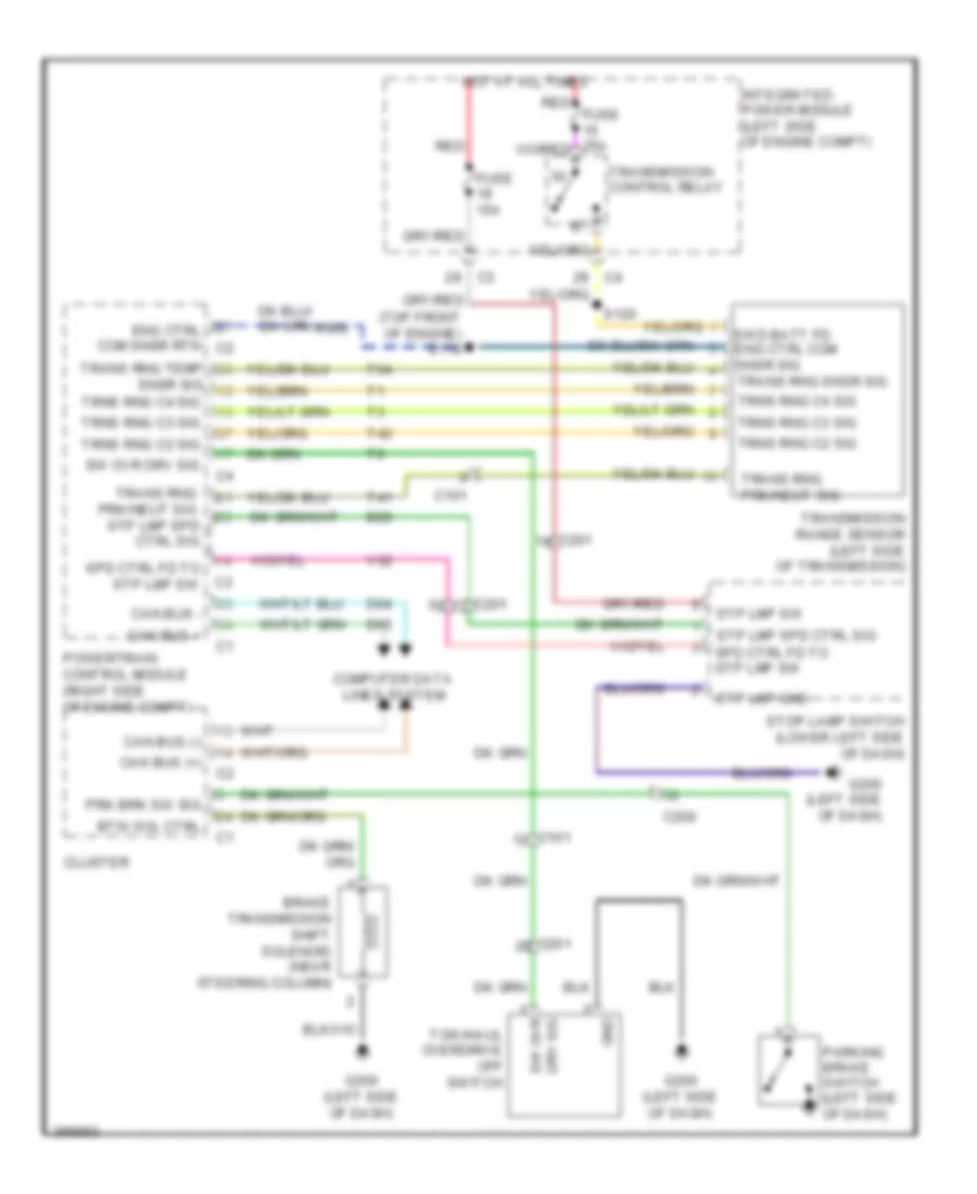
SHIFT INTERLOCK
3.7L
3.7L, Shift Interlock Wiring Diagram for Dodge Dakota 2010
List of elements for 3.7L, Shift Interlock Wiring Diagram for Dodge Dakota 2010:
- (top front of engine) s118
- B29
- Brake transmission shift solenoid (near steering column)
- Btsi sol ctrl
- C101
- C200
- C201
- Can bus (+)
- Can bus (-)
- Can bus +
- Can bus -
- Cluster
- Computer data lines system
- D64
- D65
- Drv sig
- Eng ctrl com snsr rtn c2
- Fuse 15a
- G200 (left side of dash)
- Gnd
- Hot at all times
- Integrated power module (left side of engine compt)
- Parking brake switch (left side of dash)
- Powertrain control module (right side of engine compt)
- Prk brk sw sig
- Red
- S120
- Snsr sig
- Spd ctrl fd to stp lmp sw
- Stop lamp switch (lower left side of dash)
- Stp lmp gnd
- Stp lmp spd ctrl sig
- Stp lmp sw
- Sw ovr
- Sw ovr drv sig
- Swd batt fd eng ctrl com snsr sig trans rng snsr sig
- T41
- T42
- T54
- Tow/haul overdrive off switch
- Trans rng prk/neut sig
- Trans rng prk/neut sig stp lmp spd ctrl sig
- Trans rng temp
- Transmission control relay
- Transmission range sensor (left side of transmission)
- Trns rng c2 sig
- Trns rng c3 sig
- Trns rng c4 sig
- V32
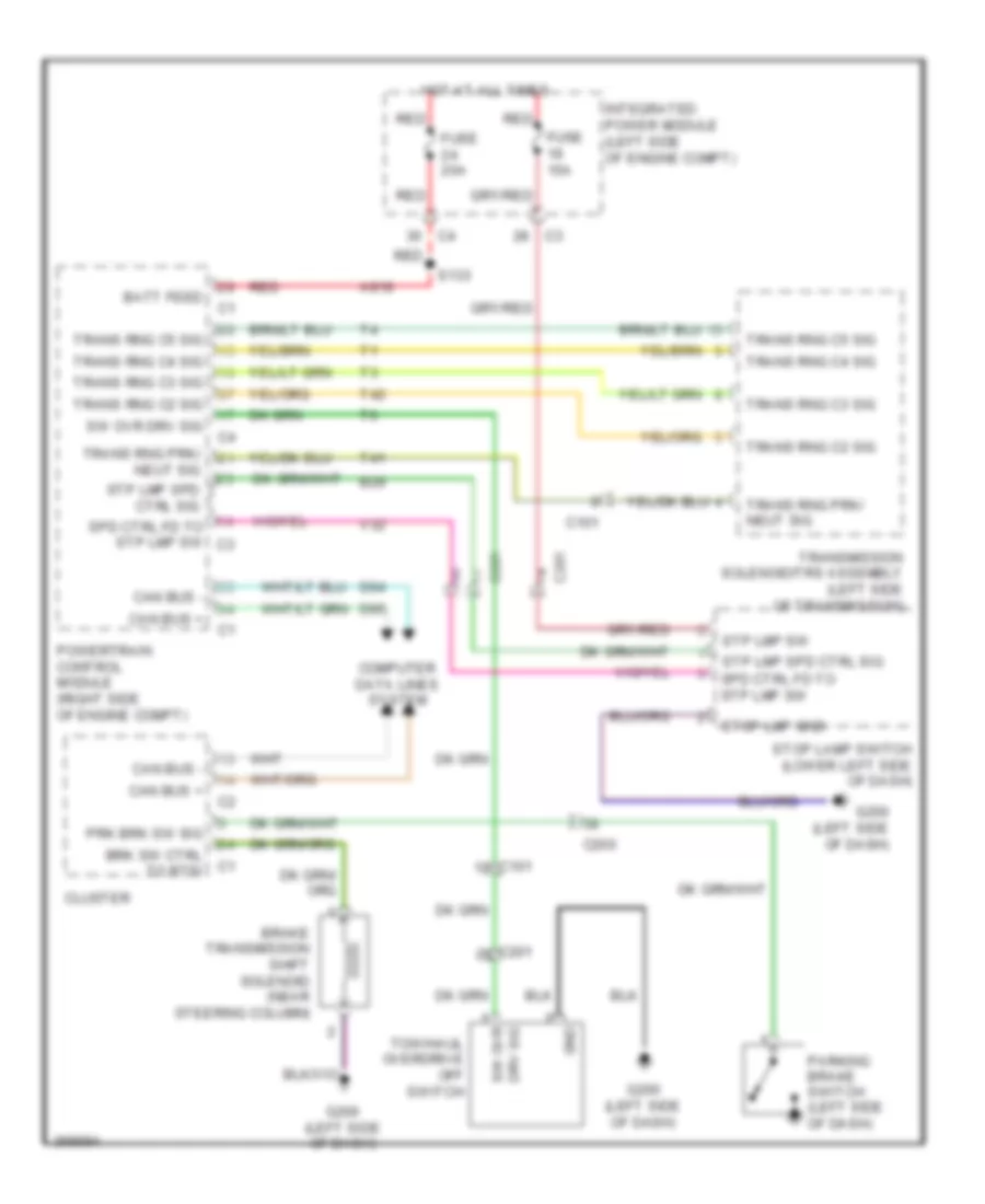
4.7L FLEX FUEL
4.7L Flex Fuel, Shift Interlock Wiring Diagram for Dodge Dakota 2010
List of elements for 4.7L Flex Fuel, Shift Interlock Wiring Diagram for Dodge Dakota 2010:
- A919
- B29
- Batt feed
- Brake transmission shift solenoid (near steering column)
- Brk sw ctrl to btsi
- C101
- C200
- C201
- Can bus +
- Can bus -
- Cluster
- Computer data lines system
- D64
- D65
- Drv sig
- Fuse 15a
- Fuse 20a
- G200 (left side of dash)
- Gnd
- Hot at all times
- Integrated power module (left side of engine compt)
- Parking brake switch (left side of dash)
- Powertrain control module (right side of engine compt)
- Prk brk sw sig
- Red
- S133
- Spd ctrl fd to stp lmp sw
- Spd ctrl fd to stp lmp sw c3
- Stop lamp switch (lower left side of dash)
- Stop lmp gnd
- Stp lmp spd ctrl sig
- Stp lmp sw
- Sw ovr
- Sw ovr drv sig
- T41
- T42
- Tow/haul overdrive off switch
- Trans rng c2 sig
- Trans rng c3 sig
- Trans rng c4 sig
- Trans rng c5 sig
- Trans rng prk/ neut sig
- Transmission solenoid/trs assembly (left side of transmission)
- V32
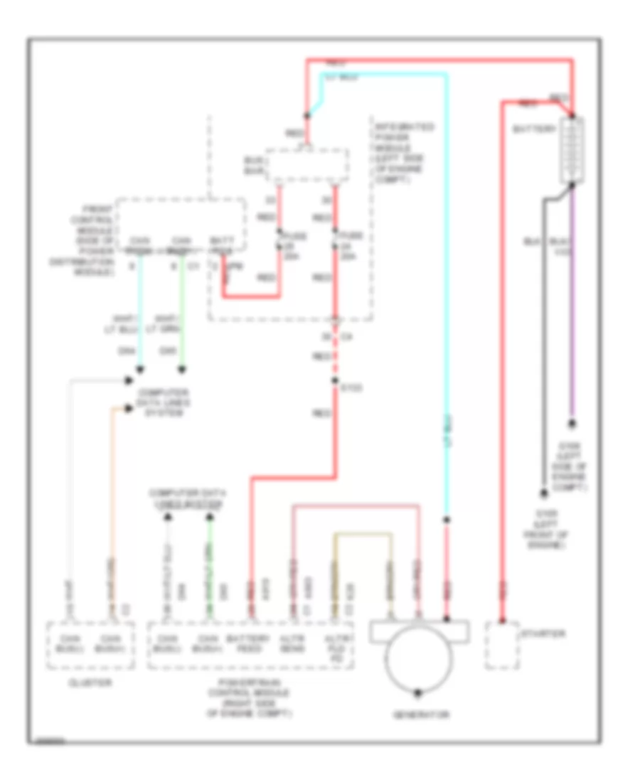
STARTING/CHARGING
Charging Wiring Diagram for Dodge Dakota 2010
List of elements for Charging Wiring Diagram for Dodge Dakota 2010:
- A803 c1
- A919
- Altr fld fd
- Altr sens
- Batt fd 8
- Battery
- Battery feed
- Bus bar
- Can bus(+)
- Can bus(-)
- Cluster
- Computer data lines system
- D64
- D65
- Front control module (side of power distribution module)
- Fuse 20a
- G105 (left front of engine)
- G106 (left side of engine compt)
- Generator
- Integrated power module (left side of engine compt)
- Ipm red
- K20 c2
- Powertrain control module (right side of engine compt)
- Red
- S133
- Starter
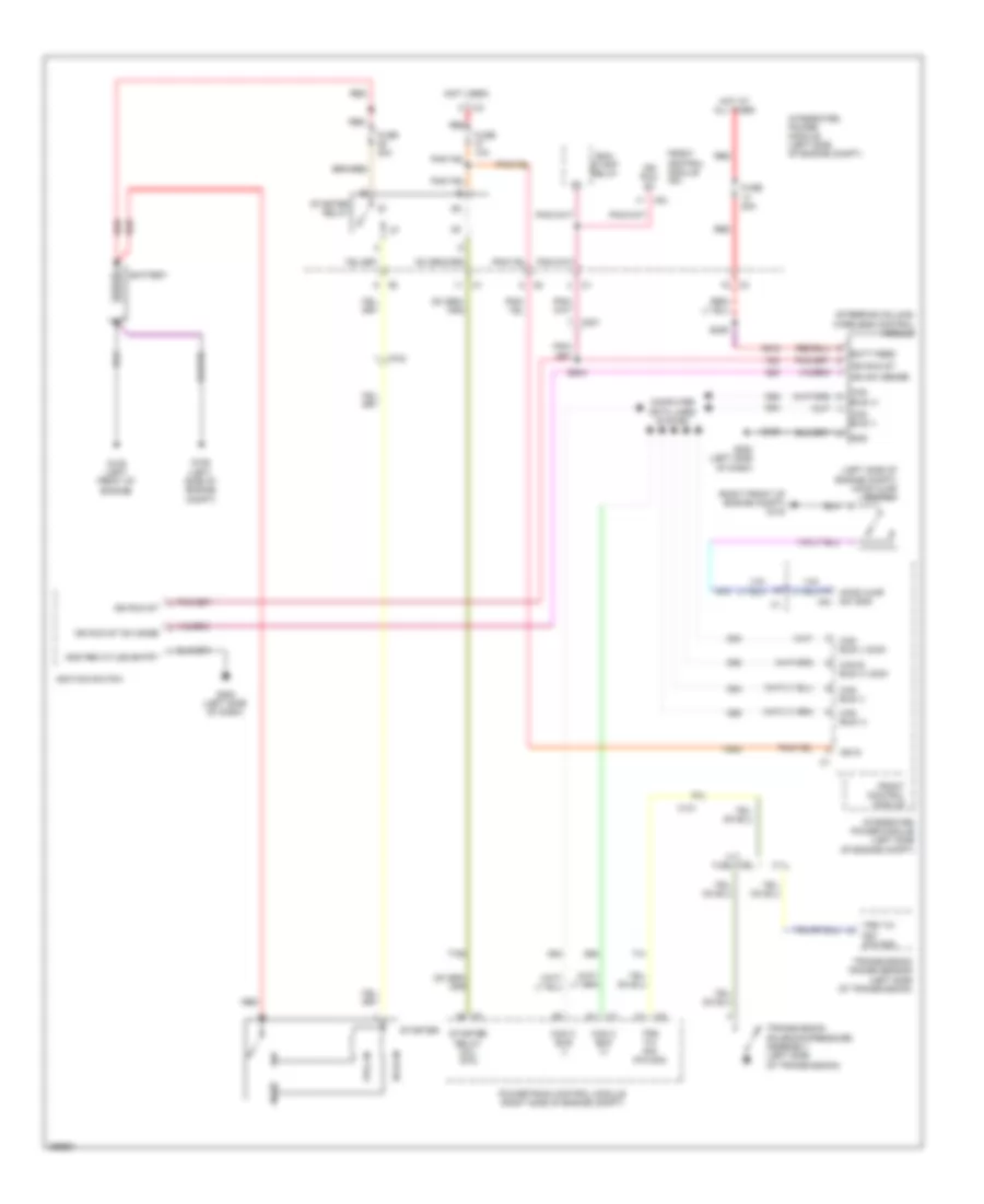
Starting Wiring Diagram for Dodge Dakota 2010
List of elements for Starting Wiring Diagram for Dodge Dakota 2010:
- (left side of engine compt) hood ajar switch
- (not used)
- (right front of engine compt) g103
- (steering column) wireless control module
- 3.7l
- 4.7l flex fuel
- A918
- Batt feed
- Battery
- C101
- C102
- C201
- Can b bus (+) 833k
- Can bus (+)
- Can bus (-)
- Can bus (-) 833k
- Can c bus (+)
- Can c bus (-)
- Computer data lines system
- D54
- D55
- D64
- D65
- F20
- F924
- Front control module
- Front control module ipm
- Fuse 10a
- Fuse 20a
- Fuse 30a
- G105 (left front of engine)
- G106 (left side of engine compt)
- G20
- G200 (left side of dash)
- G70
- Gnd
- Gnd rem kylss entry
- Hold-in
- Hood ajar sw sns ipm
- Hot at all times
- Ign r
- Ign run st
- Ign run st sw snse
- Ign sw sense
- Ignition switch
- Integrated power module (left side of engine compt)
- Ipm
- Powertrain control module (right side of engine compt)
- Pull-in
- Red
- Run/ start relay
- S204
- S206
- Starter
- Starter relay
- Starter relay coil rtn
- T41
- T752
- Transmission range sensor (left side of transmission)
- Transmission solenoid/pressure assembly (left side of transmission)
- Trs t41 sig (p/n sig)
- Z109
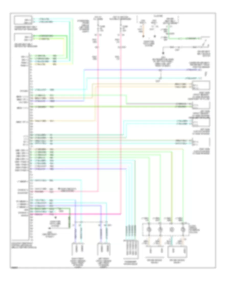
SUPPLEMENTAL RESTRAINTS
Supplemental Restraints Wiring Diagram for Dodge Dakota 2010
List of elements for Supplemental Restraints Wiring Diagram for Dodge Dakota 2010:
- (under driver seat) driver seat track position sensor
- C200
- C201
- C307
- Can bus (+)
- Can bus (-)
- Clock spring (steering column)
- Cluster
- Computer data lines system
- D64
- D65
- Driv (+)
- Driv (-)
- Driv +
- Driv -
- Driver air bag squib 1
- Driver air bag squib 2
- Driver seat belt buckle switch
- Driver seat belt retractor tensioner
- Driver seat belt switch sense
- F100
- F201
- Fuse 10a
- Fuse 20a
- G300 (center front of body)
- G301 (extended cab: base of left kick panel) (crew cab: left front of body)
- Gnd
- Hot at all times
- Hot w/ ignition run relay energized
- Ign run
- Integrated power module (left side of engine compt)
- Left front impact sensor (left front of engine compt)
- Left side curtain air bag (w/ side air bags)
- Left side impact sensor 1 (w/ side air bags) (near left "b" pillar)
- Lt (+)
- Lt (-)
- Lt sensr (+)
- Lt sensr (-)
- Occupant restraint controller module (below center console)
- Pass (+)
- Pass (-)
- Passenger air bag squib
- Passenger seat belt retractor tensioner
- R13
- R14
- R15
- R16
- R261
- R263
- R42
- R43
- R44
- R45
- R53
- R54
- R55
- R56
- R61
- R62
- R63
- R64
- R79
- R80
- R81
- R82
- Right front impact sensor (right front of engine compt)
- Right side curtain air bag (w/ side air bags)
- Right side impact sensor 1 (w/ side air bags) (near right "b" pillar)
- Rt (+)
- Rt (-)
- Rt sensr (+)
- Rtn drv
- Run/start
- Sens 1 lt (+)
- Sens 1 lt (-)
- Sens 1 rt (+)
- Sens 1 rt (-)
- Sensr +
- Sensr -
- Sqb 1 driv (+)
- Sqb 1 driv (-)
- Sqb 1 pass (+)
- Sqb 1 pass (-)
- Sqb 2 driv (+)
- Sqb 2 driv (-)
- Sqb 2 pass (+)
- Sqb 2 pass (-)
- Volt driv
- Z104
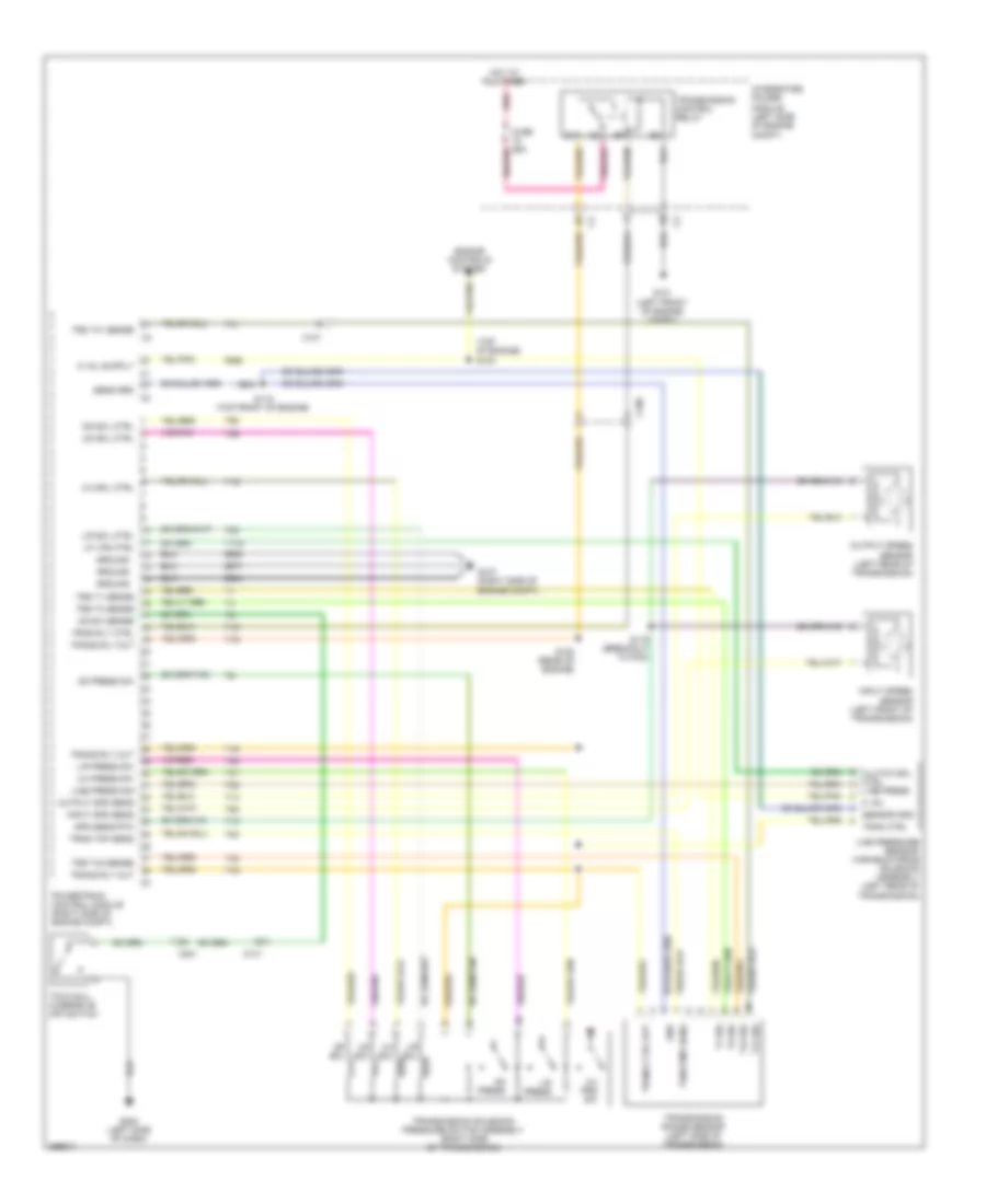
TRANSMISSION
3.7L
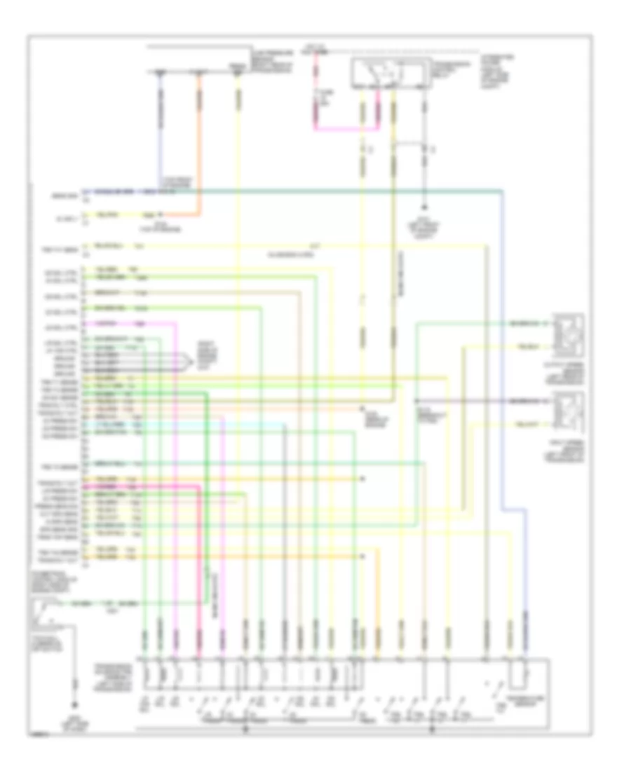
3.7L, A/T Wiring Diagram for Dodge Dakota 2010
List of elements for 3.7L, A/T Wiring Diagram for Dodge Dakota 2010:
- (top of engine) s124
- 2-4 press sw
- 2-4 prs sw
- 2-4 sol
- 2-4 sol ctrl
- 5 vol
- C100
- C101
- C201
- Clutch sol ctrl
- Engine controls system
- F856
- G101 (left front of engine compt)
- G107 (right side of engine compt)
- G200 (left side of dash)
- Gnd
- Ground
- Hot at all times
- Input spd sens
- Input speed sensor (left front of transmission)
- Integrated power module (left side of engine compt)
- K900
- L/r press
- L/r press sw
- L/r sol
- L/r sol ctrl
- Line press
- Line press sig
- Line pressure sensor/ variable force solenoid assembly (left rear of transmission)
- Lp vfs ctrl
- Od press
- Od press sw
- Od sol
- Od sol ctrl
- Od sw sense
- Output spd sens
- Output speed sensor (left rear of transmission)
- Powertrain control module (right side of engine compt)
- Red
- S118 (top front of engine)
- S119 (breakout to pcm)
- S120 (rear of engine)
- Sens grd
- Sensor gnd
- Spd sens rtn
- T1 sig
- T118
- T13
- T14
- T15
- T16
- T19
- T20
- T3 sig
- T38
- T41
- T41 sig
- T42
- T42 sig
- T47
- T50
- T52
- T54
- T59
- T60
- Tow/haul overdrive off switch
- Tran ctrl
- Trans ctrl out
- Trans rly out
- Transmission control relay
- Transmission range sensor (left side of transmission)
- Transmission solenoid/ pressure switch assembly (right side of transmission)
- Trns rly ctrl
- Trns tmp sens
- Trs t1 sense
- Trs t3 sense
- Trs t41 sense
- Trs t42 sense
- Ud sol
- Ud sol ctrl
- Z904
- Z908
- Z977
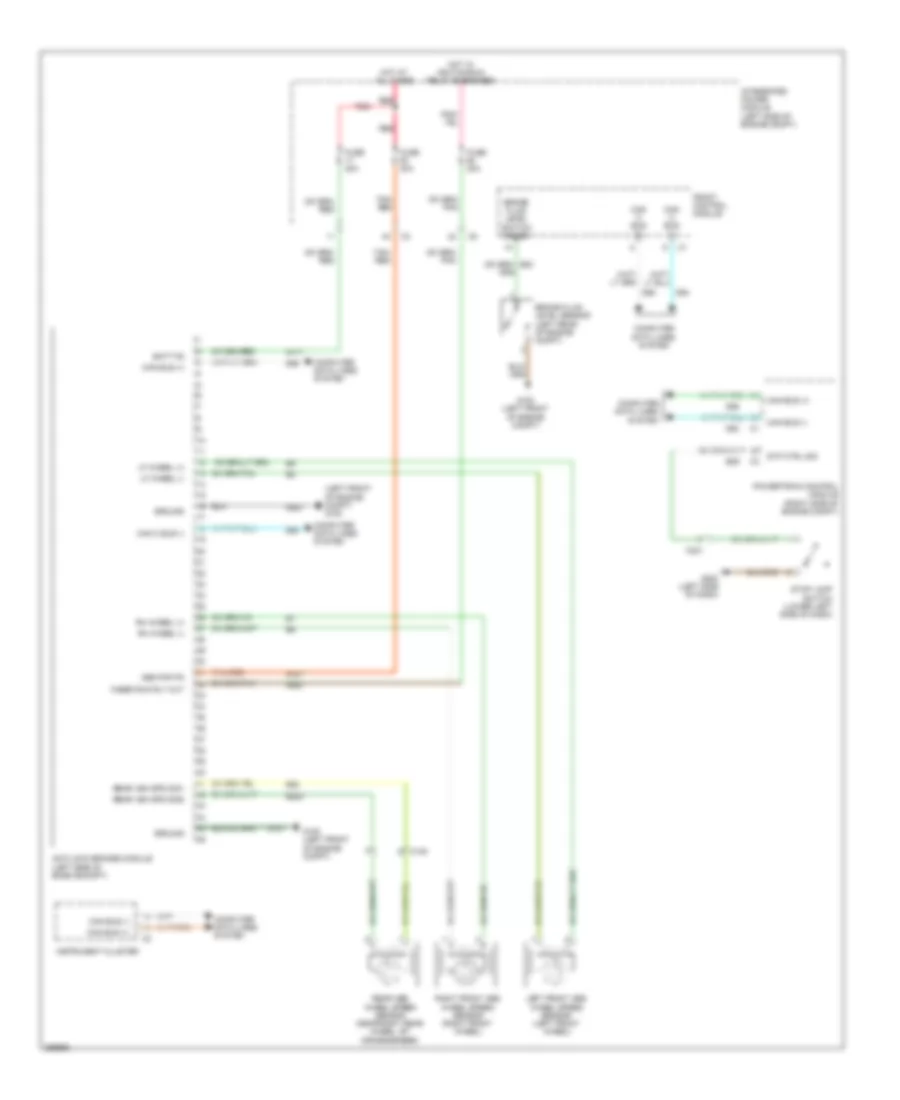
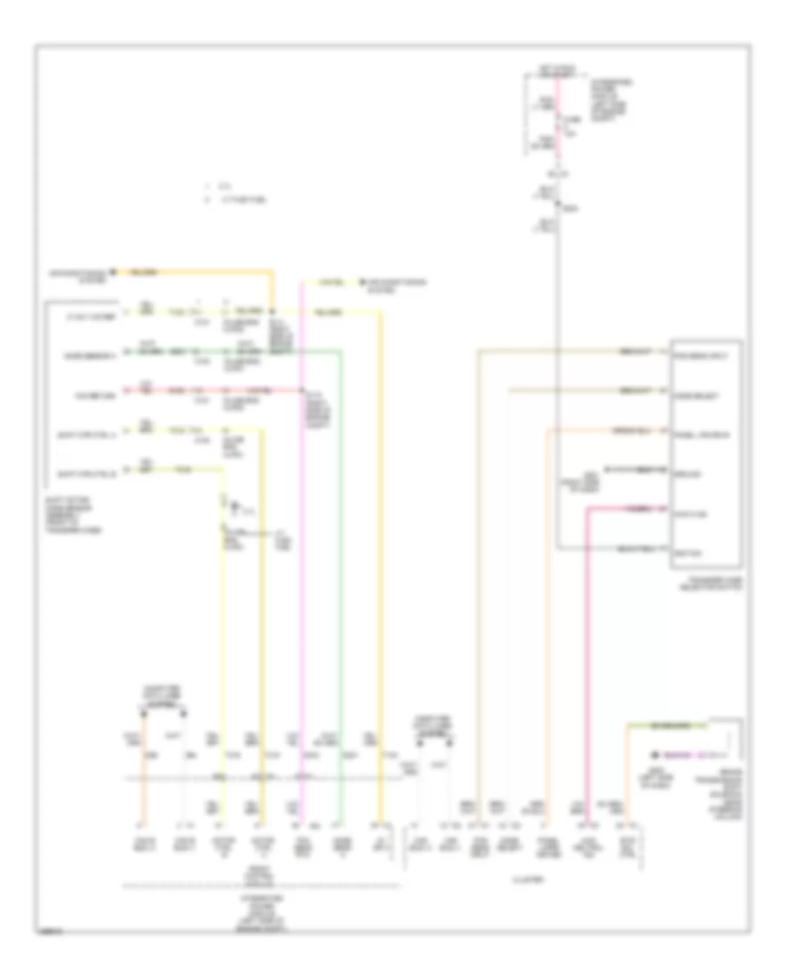
3.7L, Transfer Case Wiring Diagram for Dodge Dakota 2010
List of elements for 3.7L, Transfer Case Wiring Diagram for Dodge Dakota 2010:
- 3.7l
- 4.7 flex fuel
- 4wd n ind
- 4wd neutral ind
- 5 volt a/d ref
- 5v sply
- Air conditioning system
- Brake transmission shift solenoid (near steering column)
- Btsi sol ctrl
- C100
- C101
- Can b bus (+)
- Can b bus (-)
- Can bus (+)
- Can bus (-)
- Cluster
- Computer data lines system
- D201
- D54
- D55
- Fcm return
- Fcm sens rtn
- Front control module
- Fuse 10a
- G180
- G200 (left side of dash)
- G201 (right side of dash)
- Ground
- Hot in run or start
- Ignition
- Inline eng hlpd1
- Inline eng hlpd2
- Integrated power module (left side of engine compt)
- Ipm
- Mode select
- Mode sens a
- Mode sensor a
- Motor ctrl a
- Motor ctrl b
- Panel lamps driver
- Panel lps drvr
- Pos sens input
- S114 (right side of engine compt)
- S115 (right side of engine compt)
- S202
- Shift motor/ mode sensor assembly (front of transfer case)
- Shift mtr ctrl a
- Shift mtr ctrl b
- T103
- T315
- T316
- Transfer case selector switch
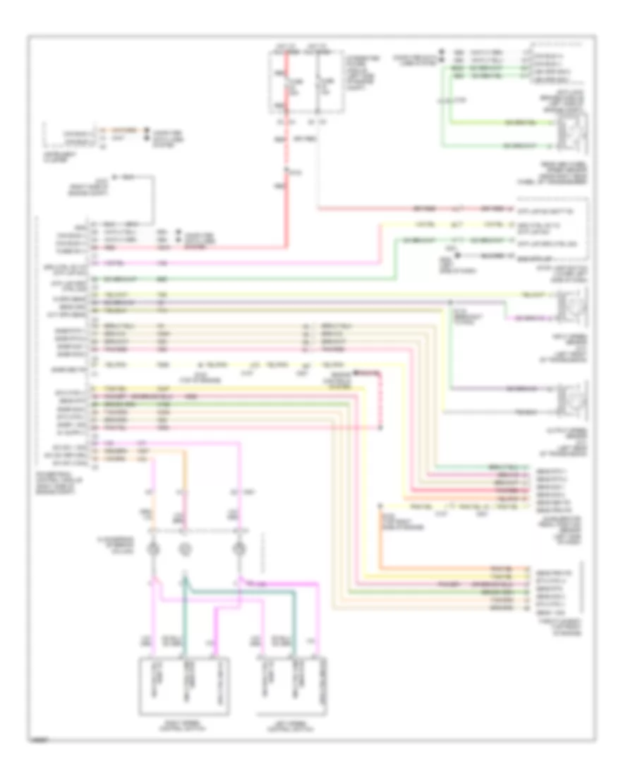
4.7L FLEX FUEL
4.7L Flex Fuel, A/T Wiring Diagram for Dodge Dakota 2010
List of elements for 4.7L Flex Fuel, A/T Wiring Diagram for Dodge Dakota 2010:
- (right side of engine compt) g107
- (top front of engine) s118
- 2c press
- 2c press sw
- 2c sol
- 2c sol ctrl
- 4c press
- 4c press sw
- 4c sol
- 4c sol ctrl
- 5 volt
- 5v sply
- C201
- F856
- Fuse 25a
- G101 (left front of engine compt)
- G200 (left side of dash)
- Gnd
- Ground
- Hot at all times
- In spd sens
- Inline eng hlpd1
- Inline eng hlpd2
- Input speed sensor (left front of transmission)
- Integrated power module (left side of engine compt)
- K900
- L/r press
- L/r press sw
- L/r sol
- L/r sol ctrl
- Line pressure sensor (right rear of transmission)
- Lp vfs ctrl
- Lp vfs sol
- Ms sol
- Ms sol ctrl
- Od press
- Od press sw
- Od sol
- Od sol ctrl
- Od sw sense
- Out spd sens
- Output speed sensor (left rear of transmission)
- Powertrain control module (right side of engine compt)
- Press sens sig
- Press sig
- Red
- S119 (breakout to pcm)
- S120 (rear of engine)
- S124 (top of engine)
- Sens gnd
- Spd sens gnd
- T118
- T13
- T14
- T140
- T147
- T15
- T16
- T20
- T219
- T259
- T29
- T38
- T41
- T42
- T48
- T50
- T52
- T54
- T59
- T60
- Temperature sensor
- Tow/haul overdrive off switch
- Trans rly out
- Transmission control relay
- Transmission solenoid/trs assembly (left side of transmission)
- Trns rly ctrl
- Trns tmp sens
- Trs t1
- Trs t1 sense
- Trs t2
- Trs t2 sense
- Trs t3
- Trs t3 sense
- Trs t41
- Trs t41 sens
- Trs t42
- Trs t42 sense
- Ud press
- Ud press sw
- Ud sol
- Ud sol ctrl
- Z904
- Z908
- Z977
4.7L Flex Fuel, Transfer Case Wiring Diagram for Dodge Dakota 2010
List of elements for 4.7L Flex Fuel, Transfer Case Wiring Diagram for Dodge Dakota 2010:
- 3.7l
- 4.7 flex fuel
- 4wd n ind
- 4wd neutral ind
- 5 volt a/d ref
- 5v sply
- Air conditioning system
- Brake transmission shift solenoid (near steering column)
- Btsi sol ctrl
- C100
- C101
- Can b bus (+)
- Can b bus (-)
- Can bus (+)
- Can bus (-)
- Cluster
- Computer data lines system
- D201
- D54
- D55
- Fcm return
- Fcm sens rtn
- Front control module
- Fuse 10a
- G180
- G200 (left side of dash)
- G201 (right side of dash)
- Ground
- Hot in run or start
- Ignition
- Inline eng hlpd1
- Inline eng hlpd2
- Integrated power module (left side of engine compt)
- Ipm
- Mode select
- Mode sens a
- Mode sensor a
- Motor ctrl a
- Motor ctrl b
- Panel lamps driver
- Panel lps drvr
- Pos sens input
- S114 (right side of engine compt)
- S115 (right side of engine compt)
- S202
- Shift motor/ mode sensor assembly (front of transfer case)
- Shift mtr ctrl a
- Shift mtr ctrl b
- T103
- T315
- T316
- Transfer case selector switch
WARNING SYSTEMS
Warning Systems Wiring Diagram for Dodge Dakota 2010
List of elements for Warning Systems Wiring Diagram for Dodge Dakota 2010:
- (crew cab) right rear door latch
- (extended cab) (center front of body)
- (extended cab) (crew cab)
- (left front of engine compt) g100
- (left rear of engine compt) brake fluid level sensor
- Batt fd
- Brk lvl sw sig
- C200
- C201
- C300
- C301
- C302
- C303
- C306
- C307
- C308
- Can b bus (+)
- Can b bus (-)
- Cluster
- Computer data lines system
- Crew cab
- Dk b20
- Driver seat belt buckle switch
- Drv door ajar sw sig
- Drv seat belt sw sns
- Extended cab
- Front control module
- Fuse 10a
- Fuse 15a
- Fuse 20a
- Fuse 20a red
- Fused ign sw out
- G200 (left side of dash)
- G300 (center front of body)
- G300 g301 (crew cab) (left front of body)
- G301 (extended cab: base of left kick panel) (crew cab: left front of body)
- G301 (left front of body)
- Ground c1
- Ground c3
- Headlamp switch
- Hot at all times
- Hot in on or start
- Integrated power module (left side of engine compt)
- Left front door latch
- Left rear door latch (crew cab)
- Lr door ajar sw sig
- Mf sw rtn
- Mfs hdlp sel
- Mlfnct sw rtn
- Park brake sw sig
- Parking brake switch (left side of dash)
- Pass dr ajar sw sig
- Pnk/red
- Power distribution system
- Red
- Right front door latch
- Rr dr ajar sw sig
- S201
- S202
- S203
- S207
- S319 (extended cab)
- S319 s321
WIPER/WASHER
Wiper/Washer Wiring Diagram for Dodge Dakota 2010
List of elements for Wiper/Washer Wiring Diagram for Dodge Dakota 2010:
- (left front of engine compt) g101
- (left side of dash) s205
- 87a
- Batt fd
- Can b bus (+)
- Can b bus (-)
- Cluster
- Computer data lines system
- D54
- D55
- Front control module
- Front washer mtr ctrl ipm
- Front wiper mtr prk sig
- Fuse 20a
- Fuse 30a
- G100 (left front of engine compt)
- G101 (left front of engine compt)
- Ground
- Hi spd fd
- Hot at all times
- Integrated power module (left side of engine compt)
- Lo spd fd
- Mf ft wpr sig
- Mf sens rtn
- Mf snse rtn
- Multi-function switch
- Prk sig
- R-mux trn sig
- Red
- Relay ctrl
- S207
- Sound systems
- W/ remote radio
- W10
- Washer r/hi beam sel sig
- Washer/ hi beam sel sig
- Windshield washer pump (lower right front of engine compt)
- Windshield wiper motor (left rear of engine compt)
- Wiper high/low
- Wiper high/low relay
- Wiper on/off relay
- Wiper park