AIR CONDITIONING
2.5L
2.5L, A/C Wiring Diagram for Dodge Dakota R/T 1998

List of elements for 2.5L, A/C Wiring Diagram for Dodge Dakota R/T 1998:
- (i/p harness, right side of dash)
- 10a
- 15a
- 40a
- A/c
- A/c clutch
- A/c compressor clutch
- A/c compressor clutch relay (in power distribution center)
- A/c heater control
- A/c high pressure switch (left side of compressor)
- A/c low pressure switch (on accumulator)
- A/c request
- A/c select input
- Blower motor
- Blower motor relay (in power distribution center)
- Blower resistor block (plenum panel, below right side of windshield)
- C13
- C20
- C27
- C90
- Coolant fan relay (in power distribution center)
- Cooling fan
- Def
- Fan relay
- Fuse 4
- Fuse 5
- Fuse 7
- Fuse 9
- Fuse e
- G101 (right front inner fender)
- G111 (near battery)
- G201 (behind right side of dash)
- Heat
- Hi/lo
- High
- Hot at all times
- Hot in run
- Hot in run or start
- Interior lights system
- J/c 1 (in power distribution center)
- Junction block
- Low
- Max
- Off
- Pnk
- Power distribution center
- Powertrain control module (right fender side shield)
- Relay
- S109 (engine compt harn, near right headlamp breakout)
- S113 (engine compt harn, near under hood lamp breakout)
- S167 (engine compt harn, near battery)
- S217 (i/p harn, near cigar lighter breakout)
- S221
- Tan
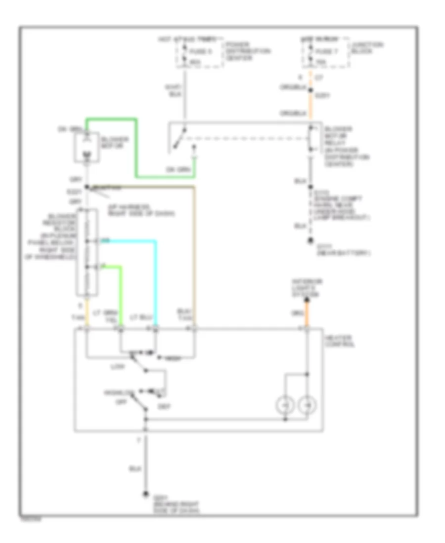
Heater Wiring Diagram for Dodge Dakota R/T 1998
List of elements for Heater Wiring Diagram for Dodge Dakota R/T 1998:
- low
- (i/p harness, right side of dash)
- 10a
- 40a
- Blower motor
- Blower motor relay (in power distribution center)
- Blower resistor block (in plenum panel below, right side of windshield)
- Def
- Fuse 5
- Fuse 7
- G111 (near battery)
- G201 (behind right side of dash)
- Heat
- Heater control
- High
- High/low
- Hot at all times
- Hot in run
- Interior lights system
- Junction block
- Off
- Power distribution center
- S113 (engine compt harn, near under hood lamp breakout)
- S221
- S251
- Tan
3.9L
3.9L, A/C Wiring Diagram for Dodge Dakota R/T 1998
List of elements for 3.9L, A/C Wiring Diagram for Dodge Dakota R/T 1998:
- (i/p harness, right side of dash)
- (right fender side shield)
- 10a
- 15a
- 40a
- A/c
- A/c clutch
- A/c compressor clutch
- A/c compressor clutch relay (in power distribution center)
- A/c heater control
- A/c high pressure switch (left side of compressor)
- A/c low pressure switch (on accumulator)
- A/c request
- A/c select input
- Blower motor
- Blower motor relay (in power distribution center)
- Blower resistor block (in plenum panel, below right side of windshield)
- C13
- C20
- C90
- Def
- Fuse 5
- Fuse 7
- Fuse e
- G100 (front of left front fender)
- G134 (left front of engine)
- G201 (behind right side of dash)
- Heat
- Hi/lo
- High
- Hot at all times
- Hot in run
- Interior lights system
- J/c 1 (in power distribution center)
- Junction block
- Low
- Max
- Off
- Pnk
- Power distribution center
- Powertrain control module
- Relay
- S108 (engine har, near breakout to distributor)
- S113 (engine compt harn, near under hood lamp breakout)
- S217 (i/p harn, near cigar lighter breakout)
- S221
- S251
- Tan
Heater Wiring Diagram for Dodge Dakota R/T 1998
List of elements for Heater Wiring Diagram for Dodge Dakota R/T 1998:
- low
- (i/p harness, right side of dash)
- 10a
- 40a
- Blower motor
- Blower motor relay (in power distribution center)
- Blower resistor block (in plenum panel below, right side of windshield)
- Def
- Fuse 5
- Fuse 7
- G111 (near battery)
- G201 (behind right side of dash)
- Heat
- Heater control
- High
- High/low
- Hot at all times
- Hot in run
- Interior lights system
- Junction block
- Off
- Power distribution center
- S113 (engine compt harn, near under hood lamp breakout)
- S221
- S251
- Tan
5.2L
5.2L, A/C Wiring Diagram for Dodge Dakota R/T 1998
List of elements for 5.2L, A/C Wiring Diagram for Dodge Dakota R/T 1998:
- (i/p harness, right side of dash)
- (right fender side shield)
- 10a
- 15a
- 40a
- A/c
- A/c clutch
- A/c compressor clutch
- A/c compressor clutch relay (in power distribution center)
- A/c heater control
- A/c high pressure switch (left side of compressor)
- A/c low pressure switch (on accumulator)
- A/c request
- A/c select input
- Blower motor
- Blower motor relay (in power distribution center)
- Blower resistor block (in plenum panel, below right side of windshield)
- C13
- C20
- C90
- Def
- Fuse 5
- Fuse 7
- Fuse e
- G100 (front of left front fender)
- G134 (left front of engine)
- G201 (behind right side of dash)
- Heat
- Hi/lo
- High
- Hot at all times
- Hot in run
- Interior lights system
- J/c 1 (in power distribution center)
- Junction block
- Low
- Max
- Off
- Pnk
- Power distribution center
- Powertrain control module
- Relay
- S108 (engine har, near breakout to distributor)
- S113 (engine compt harn, near under hood lamp breakout)
- S217 (i/p harn, near cigar lighter breakout)
- S221
- S251
- Tan
Heater Wiring Diagram for Dodge Dakota R/T 1998
List of elements for Heater Wiring Diagram for Dodge Dakota R/T 1998:
- low
- (i/p harness, right side of dash)
- 10a
- 40a
- Blower motor
- Blower motor relay (in power distribution center)
- Blower resistor block (in plenum panel below, right side of windshield)
- Def
- Fuse 5
- Fuse 7
- G111 (near battery)
- G201 (behind right side of dash)
- Heat
- Heater control
- High
- High/low
- Hot at all times
- Hot in run
- Interior lights system
- Junction block
- Off
- Power distribution center
- S113 (engine compt harn, near under hood lamp breakout)
- S221
- S251
- Tan
5.9L
5.9L, A/C Wiring Diagram for Dodge Dakota R/T 1998
List of elements for 5.9L, A/C Wiring Diagram for Dodge Dakota R/T 1998:
- (i/p harness, right side of dash)
- (right fender side shield)
- 10a
- 15a
- 40a
- A/c
- A/c clutch
- A/c compressor clutch
- A/c compressor clutch relay (in power distribution center)
- A/c heater control
- A/c high pressure switch (left side of compressor)
- A/c low pressure switch (on accumulator)
- A/c request
- A/c select input
- Blower motor
- Blower motor relay (in power distribution center)
- Blower resistor block (in plenum panel, below right side of windshield)
- C13
- C20
- C90
- Def
- Fuse 5
- Fuse 7
- Fuse e
- G100 (front of left front fender)
- G134 (left front of engine)
- G201 (behind right side of dash)
- Heat
- Hi/lo
- High
- Hot at all times
- Hot in run
- Interior lights system
- J/c 1 (in power distribution center)
- Junction block
- Low
- Max
- Off
- Pnk
- Power distribution center
- Powertrain control module
- Relay
- S108 (engine har, near breakout to distributor)
- S113 (engine compt harn, near under hood lamp breakout)
- S217 (i/p harn, near cigar lighter breakout)
- S221
- S251
- Tan
Heater Wiring Diagram for Dodge Dakota R/T 1998
List of elements for Heater Wiring Diagram for Dodge Dakota R/T 1998:
- low
- (i/p harness, right side of dash)
- 10a
- 40a
- Blower motor
- Blower motor relay (in power distribution center)
- Blower resistor block (in plenum panel below, right side of windshield)
- Def
- Fuse 5
- Fuse 7
- G111 (near battery)
- G201 (behind right side of dash)
- Heat
- Heater control
- High
- High/low
- Hot at all times
- Hot in run
- Interior lights system
- Junction block
- Off
- Power distribution center
- S113 (engine compt harn, near under hood lamp breakout)
- S221
- S251
- Tan
ANTI-LOCK BRAKES
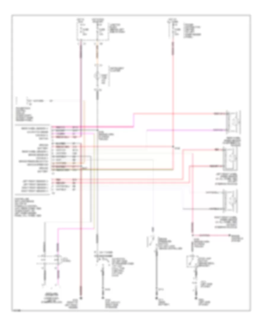
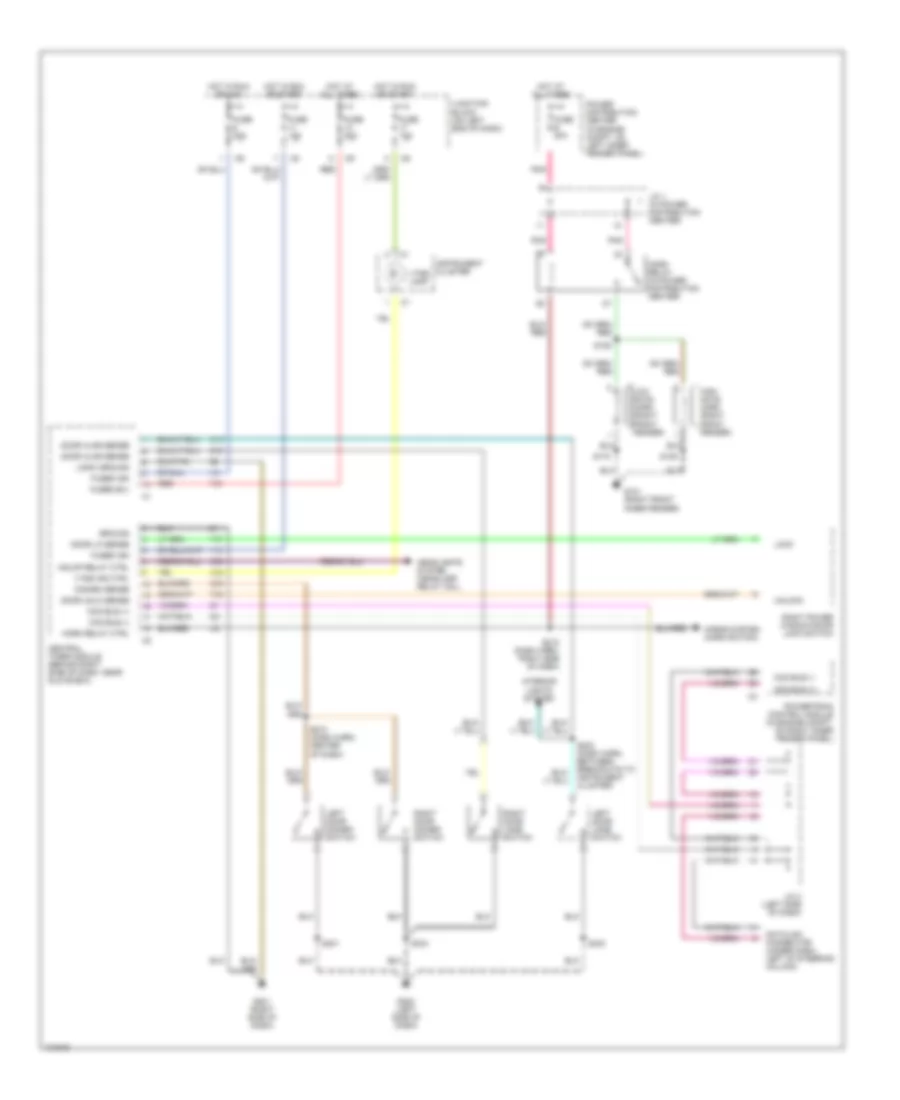
Anti-lock Brake Wiring Diagrams for Dodge Dakota R/T 1998
List of elements for Anti-lock Brake Wiring Diagrams for Dodge Dakota R/T 1998:
- (241 t-case)
- (242 t-case)
- (under dash, left of steering column)
- 4x4 switch (on left side of transfer case) 1 pt low 2 full time 3 neutral 4 pt high 5 2wd
- 4x4 switch sense
- A10
- A20
- B10
- B113
- B114
- Battery
- Brake pressure switch
- Brake pressure switch (at anti-lock brake controller)
- Brake sense sig
- Ccd bus (+)
- Ccd bus (-)
- Controller anti-lock brake (on top of hydraulic control unit) (rear wheel abs) (in eng compt, on left inner fender panel) (all wheel abs)
- Data link connector
- Engine controls system
- Fuse 10a
- Fuse 20a
- Fuse 40a
- G100 (front of left front fender)
- G107
- G111 (near battery)
- G120 (5.9l 4wd a/t) (right side of engine)
- G202 (left side of dash)
- Ground
- Hot at all times
- Hot in run
- Hot in run or start
- Ignition
- Instrument cluster
- J/c 3 (in pdc)
- J/c 4 (left side of dash)
- Junction block (behind left side of dash)
- K29
- Left front sensor (+)
- Left front sensor (-)
- Left front wheel speed sensor (w/ all wheel abs) (on left steering knuckle)
- Part time 4x4 ind
- Power distribution center (on left inner fender panel)
- Powertrain control module (in eng compt, on right inner fender panel)
- Rear wheel sensor (+)
- Rear wheel sensor (-)
- Rear wheel speed sensor (in differential housing)
- Red
- Right front sensor (+)
- Right front sensor (-)
- Right front wheel speed sensor (w/ all wheel abs) (on right steering knuckle)
- S108
- S113
- S126
- S127
- S156 (engine harn, in wiring trough)
- S158 (engine harn, in wiring trough)
- Stop lamp switch (brake pedal bracket)
- Vehicle speed sig
ANTI-THEFT
Anti-theft Wiring Diagram for Dodge Dakota R/T 1998
List of elements for Anti-theft Wiring Diagram for Dodge Dakota R/T 1998:
- Ccd bus (+)
- Ccd bus (-)
- Central timer module (behind right side of dash, near glove box)
- Datalink connector (under dash, left of steering column)
- Disarm sense
- Door ajar sense
- Door lk sense
- Door unlk sense
- F12
- F35
- Fuse 10a
- Fuse 20a
- Fuse e 20a
- Fused b(+)
- Fused ign
- G101 (right front inner fender)
- G16
- G201 (right side of dash)
- G202 (left side of dash)
- G50
- G52
- G69
- Ground
- Hdlmp relay ctrl
- Headlights system (headlamp relay coil)
- High note horn (right front fender)
- Horn relay (in power distribution center)
- Horn relay ctrl
- Horns system (horn switch)
- Hot at all times
- Hot in run or acc
- Hot in run or start
- Instrument cluster
- Interior lights system
- J/c 1 (in power distribution center)
- J/c 3 (left side of dash)
- Junction block (on left end of dash)
- Left door disarm switch
- Left door jamb switch
- Lock
- Logic ground
- Low note horn (right front fender)
- P37
- P38
- Pnk
- Power distribution center (in engine compt, on left inner fender panel)
- Powertrain control module (in engine compt, on right inner fender panel)
- Red
- Right door disarm switch
- Right door jamb switch
- Right power window/door lock switch
- S109
- S125
- S170
- S203 (dash harn, between breakouts to instrument cluster)
- S210 (dash harn, center of dash)
- S218 (dash harn, right side of dash)
- S301
- S334
- S403
- Unlock
- Vtss ind ctrl
- Vtss lamp
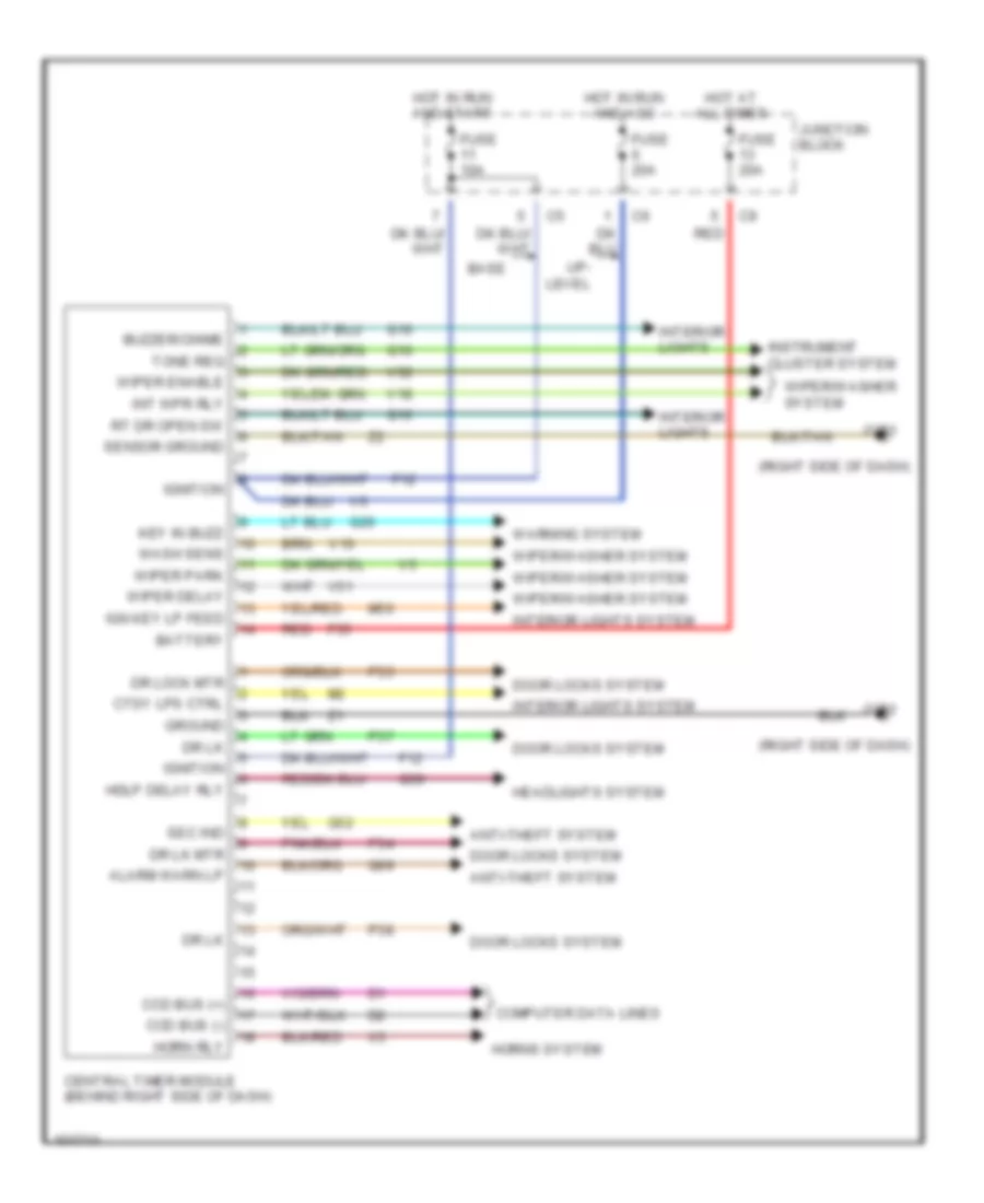
BODY COMPUTER
Body Computer Wiring Diagrams for Dodge Dakota R/T 1998
List of elements for Body Computer Wiring Diagrams for Dodge Dakota R/T 1998:
- (right side of dash)
- Alarm warn lp
- Anti-theft system
- Base
- Battery
- Buzzer/chime
- Ccd bus (+)
- Ccd bus (-)
- Central timer module (behind right side of dash)
- Computer data lines
- Ctsy lps ctrl
- Door locks system
- Dr lk
- Dr lk mtr
- Dr lock mtr
- F12
- F35
- Fuse 10a
- Fuse 20a
- G10
- G16
- G201
- G26
- G50
- G52
- G69
- Ground
- Hdlp delay rly
- Headlights system
- Horn rly
- Horns system
- Hot at all times
- Hot in run and acc
- Hot in run and start
- Ign key lp feed
- Ignition
- Instrument cluster system
- Int wpr rly
- Interior lights
- Interior lights system
- Junction block
- Key in buzz
- M50
- P33
- P34
- P37
- P38
- Red
- Rt dr open sw
- Sec ind
- Sensor ground
- Tone req
- Up- level
- V10
- V18
- V51
- V52
- Warning system
- Wash sens
- Wiper delay
- Wiper enable
- Wiper park
- Wiper/washer system
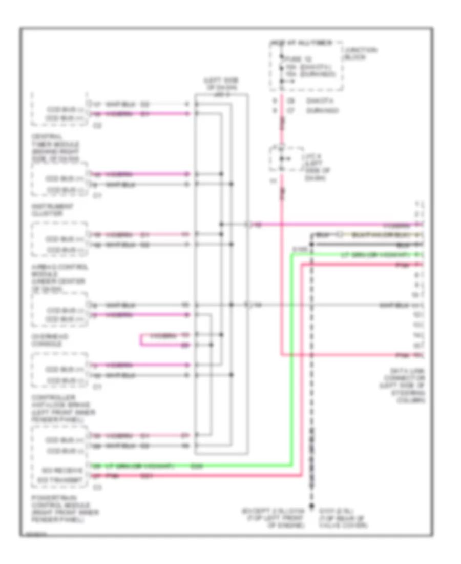
COMPUTER DATA LINES
Computer Data Lines for Dodge Dakota R/T 1998
List of elements for Computer Data Lines for Dodge Dakota R/T 1998:
- (dakota) (durango)
- (except 2.5l) g134 (top left front of engine)
- (left side of dash) j/c 3
- Airbag control module (under center of dash)
- Ccd bus (+)
- Ccd bus (-)
- Central timer module (behind right side of dash)
- Controller anti-lock brake (left front inner fender panel)
- D20
- D21
- Dakota
- Data link connector (left side of steering column)
- Durango
- Fuse 12 10a 15a
- G131 (2.5l) (top rear of valve cover)
- Hot at all times
- Instrument cluster
- J/c 4 (left side of dash)
- Junction block
- Overhead console
- Pnk
- Powertrain control module (right front inner fender panel)
- S105
- Sci receive
- Sci transmit
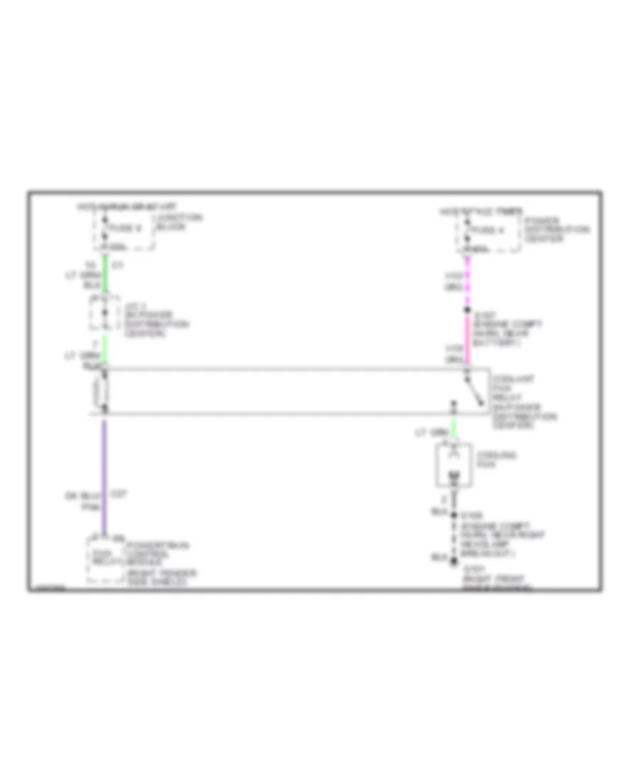
COOLING FAN
2.5L
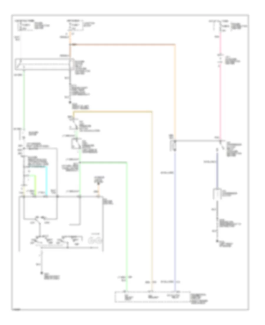
2.5L, Cooling Fan Wiring Diagram for Dodge Dakota R/T 1998
List of elements for 2.5L, Cooling Fan Wiring Diagram for Dodge Dakota R/T 1998:
- (right fender side shield)
- 10a
- 40a
- C27
- C3 powertrain control module
- Coolant fan relay (in power distribution center)
- Cooling fan
- Fan relay
- Fuse 4
- Fuse 9
- G101 (right front inner fender)
- Hot at all times
- Hot in run or start
- J/c 1 (in power distribution center)
- Junction block
- Pnk
- Power distribution center
- S109 (engine compt harn, near right headlamp breakout)
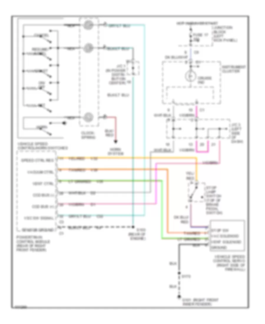
CRUISE CONTROL
Cruise Control Wiring Diagram for Dodge Dakota R/T 1998
List of elements for Cruise Control Wiring Diagram for Dodge Dakota R/T 1998:
- (right front
- C32
- Cancel
- Ccd bus (+)
- Ccd bus (-)
- Clock- spring
- Coast
- Cruise ind
- Fuse 17 10a
- G101 inner fender)
- Ground
- Horn
- Horn system
- Hot in run or start
- Instrument cluster
- J/c 1 (in power distri- bution center)
- J/c 3 (left side of dash)
- Junction block (left kick panel)
- Nca
- On/ off
- Powertrain control module (rear of right front fender)
- Red
- Resume/ accel
- S103 (rear of engine)
- S170
- Sensor ground
- Set
- Speed ctrl res
- Stop lamp switch (top of brake pedal switch)
- Stop sw
- Tan/red
- V32
- V35
- V36
- Vac solenoid
- Vacuum ctrl
- Vehicle speed control servo (right side of firewall)
- Vehicle speed control/horn switches
- Vent ctrl
- Vent solenoid
- Vsc sw signal
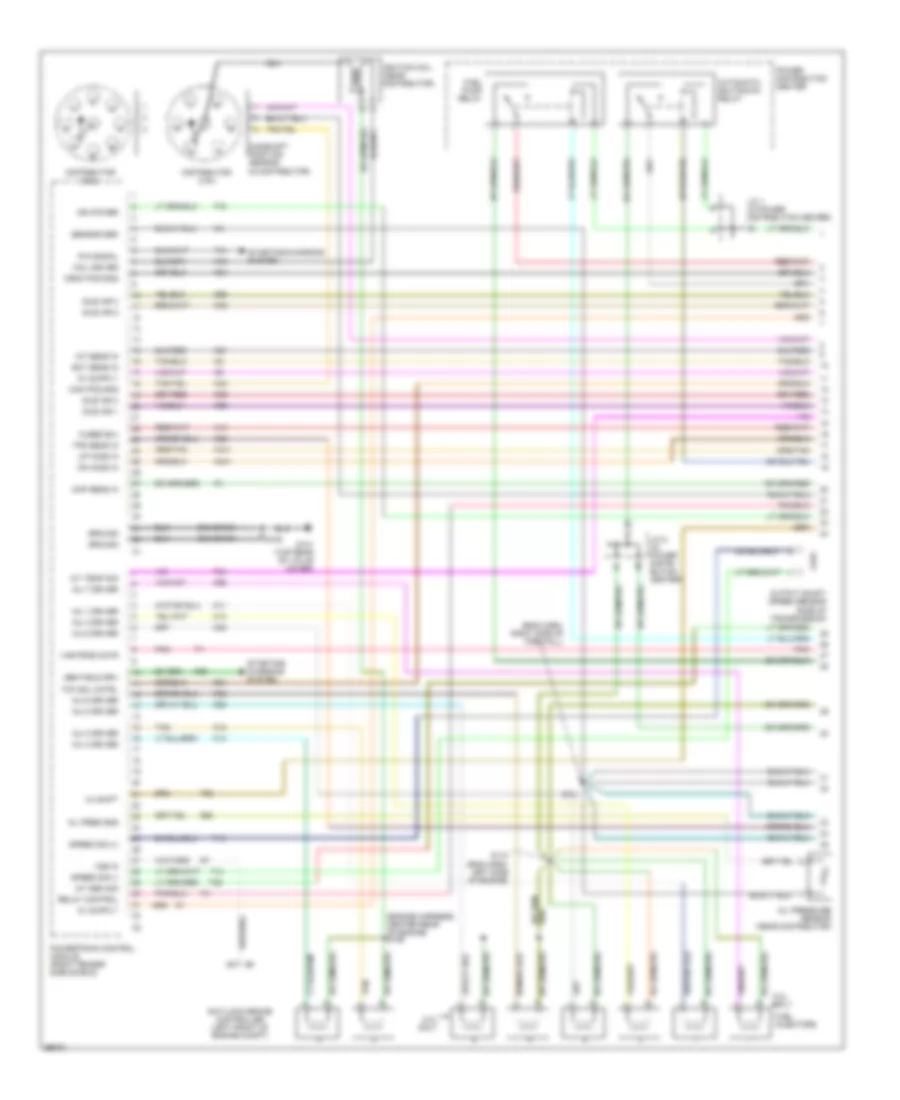
ENGINE PERFORMANCE
2.5L
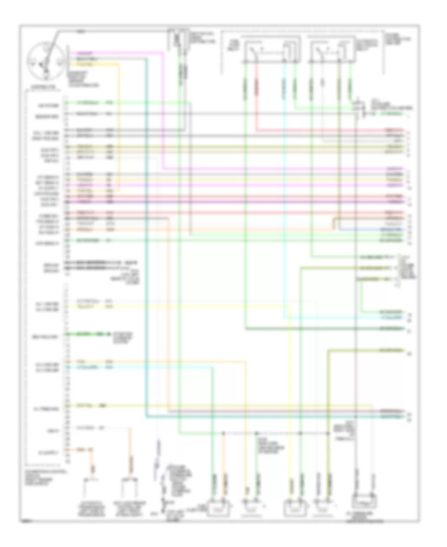
2.5L, Engine Performance Wiring Diagrams (1 of 3) for Dodge Dakota R/T 1998
List of elements for 2.5L, Engine Performance Wiring Diagrams (1 of 3) for Dodge Dakota R/T 1998:
- (in distributor)
- (near distributor)
- (top left of valve cover)
- A14
- Anti-lock brake controller (left front of eng compt)
- Automatic shutdown relay
- Automatic transmission (left side of transmission)
- Cam pos sns
- Camshaft position sensor
- Coil 1 driver
- Crnk pos sns
- Distributor
- Dn ho2s in
- Ect sens in
- F18
- Fuel injectors
- Fuel pump relay
- Fused b(+)
- G131 (top left rear of valve cover)
- G60
- Gen field drv
- Ground
- Iat sens in
- Idle air 1
- Idle air 2
- Idle air 3
- Idle air 4
- Ign power
- Ignition coil (near distributor)
- Inj 1 driver
- Inj 2 driver
- Inj 3 driver
- Inj 4 driver
- J/c 1 (in power distribution center)
- J/c 2 (in power distri- bution center)
- K11
- K12
- K13
- K14
- K141
- K19
- K20
- K21
- K22
- K24
- K341
- K39
- K40
- K44
- K59
- K60
- K99
- Map sens in
- Nca
- Oil pres sns
- Oil pressure sensor
- Power distribution center
- Power steering pressure switch (near power steering pump)
- Powertrain control module (right fender side shield)
- Psp sw
- S101 (eng harn, right side of firewall)
- S105
- S106 (eng harn, center rear of engine)
- S108
- Sensor grd
- Starting/ charging system
- Tan
- Tps sens in
- Up ho2s in
- Vss in
- Z12 (or z1)
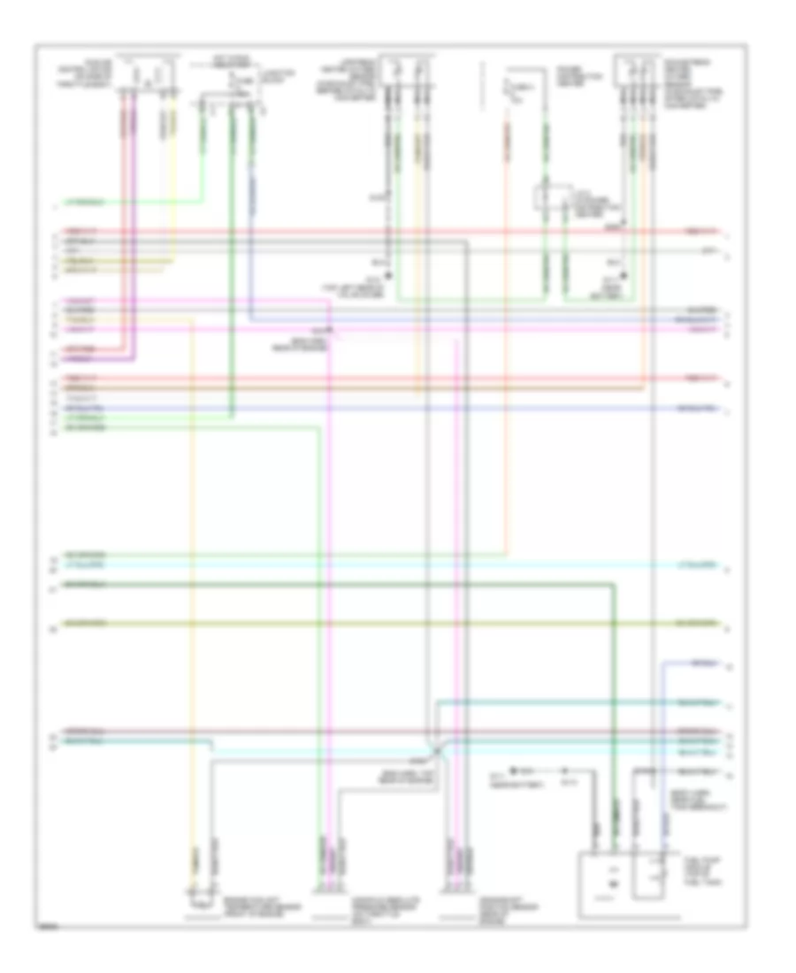
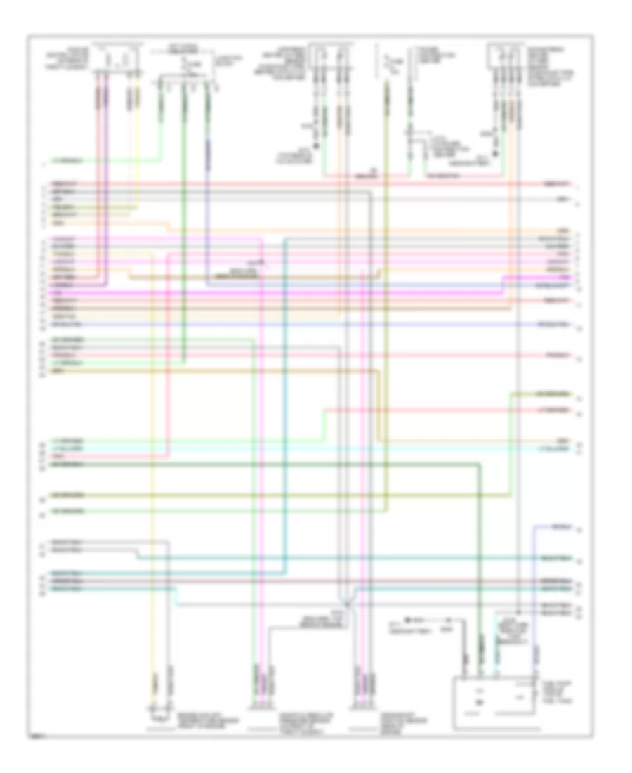
2.5L, Engine Performance Wiring Diagrams (2 of 3) for Dodge Dakota R/T 1998
List of elements for 2.5L, Engine Performance Wiring Diagrams (2 of 3) for Dodge Dakota R/T 1998:
- (body harn, near fuel tank breakout)
- (eng harn, rear of engine)
- (eng harn, top rear of engine)
- (near
- (near battery)
- (top left rear of valve cover)
- Battery)
- Crankshaft position sensor (rear of engine)
- Downstream heated oxygen sensor (in exhaust pipe, after catalyic converter)
- Engine coolant temperature sensor (front of engine)
- Fuel pump module (top of fuel tank)
- Fuse 10a
- Fuse a 10a
- G111
- G131
- Hot in run and start
- Idle air control motor (on side of throttle body)
- J/c 2 (in power distribution center)
- Junction block
- Manifold absolute pressure sensor (on throttle body)
- Nca
- Power distribution center
- S103
- S107
- S108
- S113
- S149
- S306
- Upstream heated oxygen sensor (in exhaust pipe, before catalyic converter)
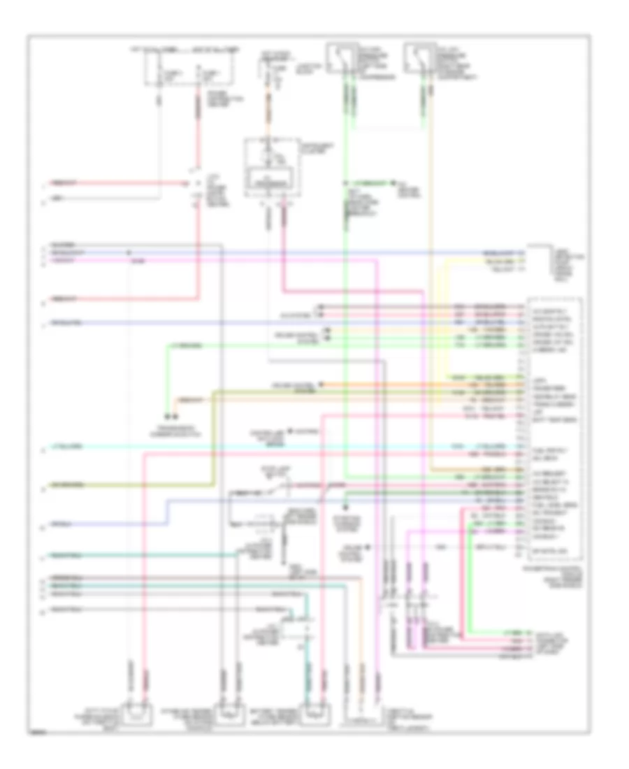
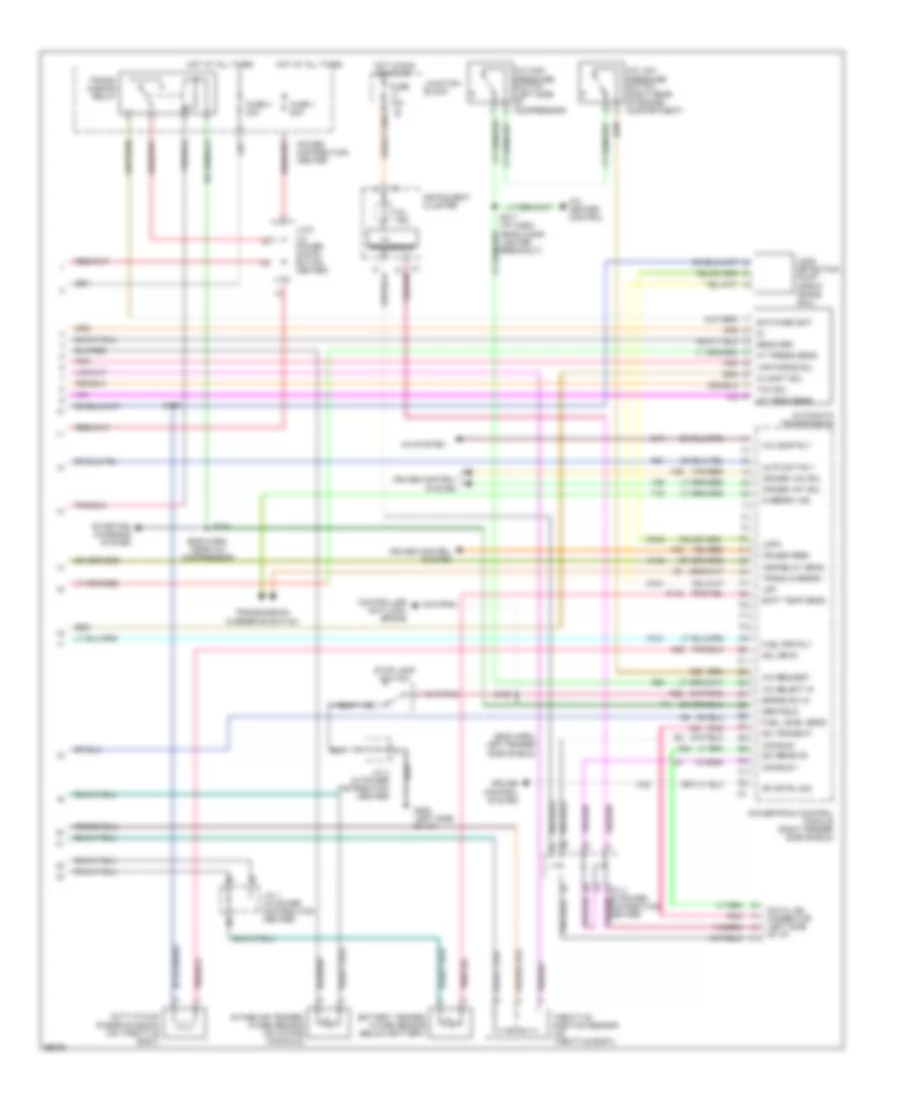
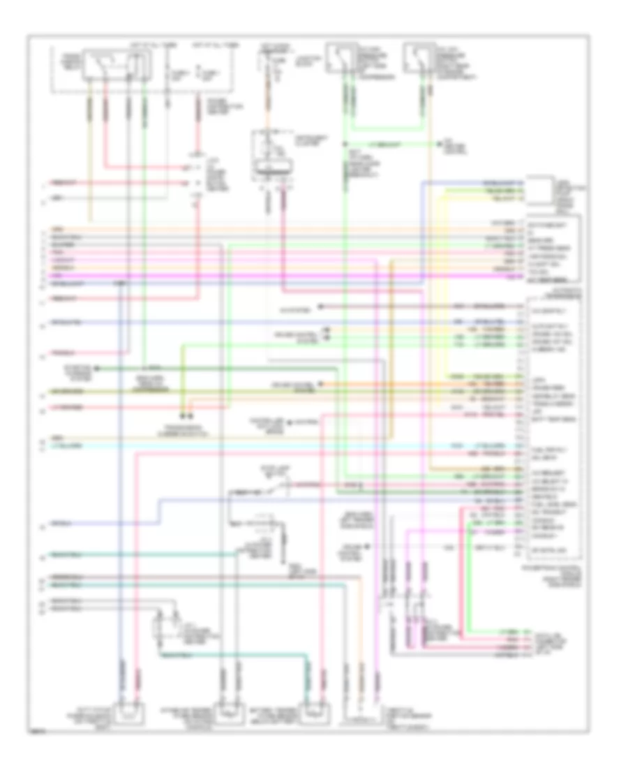
2.5L, Engine Performance Wiring Diagrams (3 of 3) for Dodge Dakota R/T 1998
List of elements for 2.5L, Engine Performance Wiring Diagrams (3 of 3) for Dodge Dakota R/T 1998:
- (eng harn, left fender side shield)
- A/c comp rly
- A/c heater control
- A/c high pressure switch (left side of compressor)
- A/c low pressure switch (right rear of engine compartment)
- A/c request
- A/c select in
- A/c system
- A142
- Asd relay sens
- Auto sht rly
- Batt temp sens
- Battery temper- ature sensor (below battery)
- Brake sw in
- C13
- C20
- C27
- C32
- C90
- Ccd bus +
- Ccd bus -
- Controller anti-lock brake
- Cruise control system
- Cruise feed
- Cruise vac sol
- Cruise vnt sol
- D20
- D21
- Data link connector (left side of dash)
- Duty cycle/ purge solenoid (on throttle body)
- Fuel level sens
- Fuel pmp rly
- Fuse 1 20a
- Fuse 10a
- Fuse 3 30a
- G100
- G101
- G202 (left side of i/p)
- Gen field
- Hot at all times
- Hot in run or start
- I/o
- Instrument cluster
- Intake air temper- ature sensor (on intake manifold)
- J/c 1 (in power distribution center)
- J/c 2 (in power distri- bution center)
- J/c 3 (in power distribution center)
- J/c 4 (in power distribution center)
- Junction block
- K118
- K151
- K29
- K51
- K52
- Ldp
- Ldpa
- Leak detection pump (front frame rail)
- Mil ind.
- Overdrv ind
- Pnk
- Power distribution center
- Powertrain control module (right fender side shield)
- Processor
- Rad fan cntrl
- S129
- S158
- S217 (i/p harn, near cigar lighter breakout)
- Sci receive
- Sci transmit
- Sol drvr
- Sp cntrl sig
- Starting/ charging system
- Stop lamp switch
- T18
- Tan/red
- Throttle position sensor (on throtlle body)
- Trans overdrv
- Transmission overdrive switch
- V32
- V35
- V36
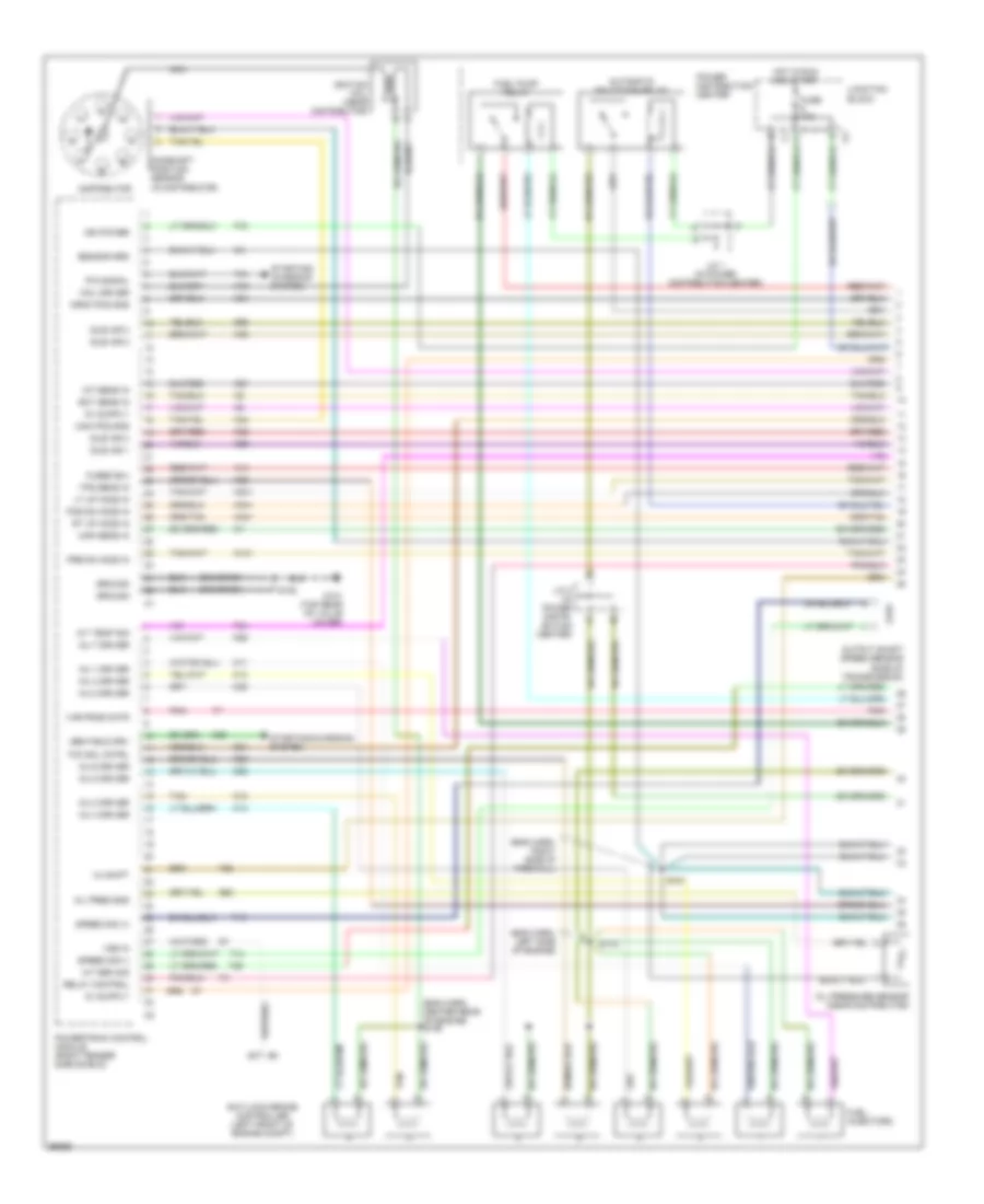
3.9L
3.9L, Engine Performance Wiring Diagrams (1 of 3) for Dodge Dakota R/T 1998
List of elements for 3.9L, Engine Performance Wiring Diagrams (1 of 3) for Dodge Dakota R/T 1998:
- (eng harn, right side of firewall)
- (engine harness, center rear of engine) s106
- (in distributor)
- 3-4 shift
- 5.2l only
- A/t sen sig
- A/t temp sig
- A14
- Anti-lock brake controller (left front of engine compt)
- Automatic shutdown relay
- Cam pos sns
- Camshaft position sensor
- Coil driver
- Crnk pos sns
- Distributor (3.9l)
- Distributor (5.2l)
- Dn ho2s in
- Ect sens in
- F18
- Fuel injectors
- Fuel pump relay
- Fused b(+)
- G131 (top rear of valve cover)
- G60
- Gen field drv
- Ground
- Iat sens in
- Idle air 1
- Idle air 2
- Idle air 3
- Idle air 4
- Ign power
- Ignition coil (near distributor)
- Inj 1 driver
- Inj 2 driver
- Inj 3 driver
- Inj 4 driver
- Inj 5 driver
- Inj 6 driver
- Inj 7 driver
- Inj 8 driver
- J/c 1 (in power distribution center)
- J/c 2 (in power distri- bution center)
- K11
- K12
- K13
- K14
- K19
- K20
- K21
- K22
- K24
- K26
- K28
- K341
- K38
- K39
- K40
- K44
- K441
- K54
- K58
- K59
- K60
- Map sens in
- Nca
- Oil pres sns
- Oil pressure sensor (near distributor)
- Output shaft speed sensor (side of transmission)
- P/n signal
- Pnk
- Power distribution center
- Powertrain control module (right fender side shield)
- Relay control
- S101
- S105
- S110 (eng harn, left side of engine)
- Sensor grd
- Speed sig (+)
- Speed sig (-)
- Starting/ charging system
- Starting/charging system
- T13
- T14
- T25
- T34
- T41
- T60
- Tan
- Tcc sol cntrl
- Tps sens in
- Up ho2s in
- Var frce cntr
- Vss in
- Z12 (or z1)
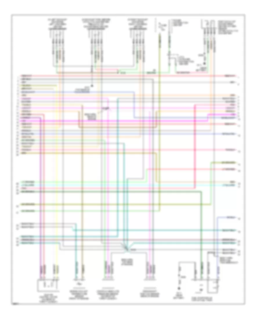
3.9L, Engine Performance Wiring Diagrams (2 of 3) for Dodge Dakota R/T 1998
List of elements for 3.9L, Engine Performance Wiring Diagrams (2 of 3) for Dodge Dakota R/T 1998:
- (eng harn, rear of engine)
- (eng harn, top rear of engine)
- (near battery)
- (top rear of valve cover)
- Crankshaft position sensor (rear of engine)
- Downstream heated oxygen sensor (in exhaust pipe, after catalyic converter)
- Engine coolant temperature sensor (front of engine)
- Fuel pump module (top of fuel tank)
- Fuse 10a
- Fuse a 10a
- G111
- G131
- Hot in run and start
- Idle air control motor (on rear of throttle body)
- J/c 2 (in power distribution center)
- Junction block
- Manifold absolute pressure sensor (on front of throttle body)
- Nca
- Pnk
- Power distribution center
- S103
- S107
- S108
- S149 (body harn, near fuel tank breakout)
- S306
- Upstream heated oxygen sensor (in exhaust pipe, before catatytic converter)
3.9L, Engine Performance Wiring Diagrams (3 of 3) for Dodge Dakota R/T 1998
List of elements for 3.9L, Engine Performance Wiring Diagrams (3 of 3) for Dodge Dakota R/T 1998:
- (eng harn, left fender side shield)
- (eng harn, near a/c compressor)
- 3-4 shft sol
- A/c comp rly
- A/c heater control
- A/c high pressure switch (left side of compressor)
- A/c low pressure switch (right rear of engine compartment)
- A/c request
- A/c select in
- A/c system
- A/t press sens
- A/t temp sens
- A142
- Asd relay sens
- Auto sht rly
- Automatic transmission
- Batt temp sens
- Battery temper- ature sensor (below battery)
- Brake sw in
- C13
- C20
- C32
- C90
- Ccd bus +
- Ccd bus -
- Controller anti-lock brake
- Cruise control system
- Cruise feed
- Cruise vac sol
- Cruise vnt sol
- D20
- D21
- Data link connector (left side of i/p)
- Distribution center)
- Duty cycle/ purge solenoid (on throttle body)
- Fuel level sens
- Fuel pmp rly
- Fuse 1 20a
- Fuse 10a
- Fuse 3 30a
- G100
- G101
- G202 (left side of i/p)
- Gen field
- Hot at all times
- Hot in run or start
- I/o
- Instrument cluster
- Intake air temper- ature sensor (on intake manifold)
- J/c 1 (in power distribution center)
- J/c 2 (in power distri- bution center)
- J/c 3 (in power
- J/c 4 (in power distribution center)
- Junction block
- K118
- K151
- K29
- K51
- K52
- Ldp
- Ldpa
- Leak detection pump (front frame rail)
- Mil ind.
- Overdrv ind
- Pnk
- Power distribution center
- Powertrain control module (right fender side shield)
- Processor
- S104
- S129
- S158
- S217 (i/p harn, near cigar lighter breakout)
- Sci receive
- Sci transmit
- Sens grd
- Sol drvr
- Sp cntrl sig
- Starting/ charging system
- Stop lamp switch
- Switched bat
- T18
- Tan/red
- Tcc sol
- Throttle position sensor (on throttle body)
- Trans overdrv
- Trans- mission relay
- Transmission overdrive switch
- V32
- V35
- V36
- Var force sol
5.2L
5.2L, Engine Performance Wiring Diagrams (1 of 3) for Dodge Dakota R/T 1998
List of elements for 5.2L, Engine Performance Wiring Diagrams (1 of 3) for Dodge Dakota R/T 1998:
- (eng harn, right side of firewall)
- (engine harness, center rear of engine) s106
- (in distributor)
- 3-4 shift
- 5.2l only
- A/t sen sig
- A/t temp sig
- A14
- Anti-lock brake controller (left front of engine compt)
- Automatic shutdown relay
- Cam pos sns
- Camshaft position sensor
- Coil driver
- Crnk pos sns
- Distributor (3.9l)
- Distributor (5.2l)
- Dn ho2s in
- Ect sens in
- F18
- Fuel injectors
- Fuel pump relay
- Fused b(+)
- G131 (top rear of valve cover)
- G60
- Gen field drv
- Ground
- Iat sens in
- Idle air 1
- Idle air 2
- Idle air 3
- Idle air 4
- Ign power
- Ignition coil (near distributor)
- Inj 1 driver
- Inj 2 driver
- Inj 3 driver
- Inj 4 driver
- Inj 5 driver
- Inj 6 driver
- Inj 7 driver
- Inj 8 driver
- J/c 1 (in power distribution center)
- J/c 2 (in power distri- bution center)
- K11
- K12
- K13
- K14
- K19
- K20
- K21
- K22
- K24
- K26
- K28
- K341
- K38
- K39
- K40
- K44
- K441
- K54
- K58
- K59
- K60
- Map sens in
- Nca
- Oil pres sns
- Oil pressure sensor (near distributor)
- Output shaft speed sensor (side of transmission)
- P/n signal
- Pnk
- Power distribution center
- Powertrain control module (right fender side shield)
- Relay control
- S101
- S105
- S110 (eng harn, left side of engine)
- Sensor grd
- Speed sig (+)
- Speed sig (-)
- Starting/ charging system
- Starting/charging system
- T13
- T14
- T25
- T34
- T41
- T60
- Tan
- Tcc sol cntrl
- Tps sens in
- Up ho2s in
- Var frce cntr
- Vss in
- Z12 (or z1)
5.2L, Engine Performance Wiring Diagrams (2 of 3) for Dodge Dakota R/T 1998
List of elements for 5.2L, Engine Performance Wiring Diagrams (2 of 3) for Dodge Dakota R/T 1998:
- (eng harn, rear of engine)
- (eng harn, top rear of engine)
- (near battery)
- (top rear of valve cover)
- Crankshaft position sensor (rear of engine)
- Downstream heated oxygen sensor (in exhaust pipe, after catalyic converter)
- Engine coolant temperature sensor (front of engine)
- Fuel pump module (top of fuel tank)
- Fuse 10a
- Fuse a 10a
- G111
- G131
- Hot in run and start
- Idle air control motor (on rear of throttle body)
- J/c 2 (in power distribution center)
- Junction block
- Manifold absolute pressure sensor (on front of throttle body)
- Nca
- Pnk
- Power distribution center
- S103
- S107
- S108
- S149 (body harn, near fuel tank breakout)
- S306
- Upstream heated oxygen sensor (in exhaust pipe, before catatytic converter)
5.2L, Engine Performance Wiring Diagrams (3 of 3) for Dodge Dakota R/T 1998
List of elements for 5.2L, Engine Performance Wiring Diagrams (3 of 3) for Dodge Dakota R/T 1998:
- (eng harn, left fender side shield)
- (eng harn, near a/c compressor)
- 3-4 shft sol
- A/c comp rly
- A/c heater control
- A/c high pressure switch (left side of compressor)
- A/c low pressure switch (right rear of engine compartment)
- A/c request
- A/c select in
- A/c system
- A/t press sens
- A/t temp sens
- A142
- Asd relay sens
- Auto sht rly
- Automatic transmission
- Batt temp sens
- Battery temper- ature sensor (below battery)
- Brake sw in
- C13
- C20
- C32
- C90
- Ccd bus +
- Ccd bus -
- Controller anti-lock brake
- Cruise control system
- Cruise feed
- Cruise vac sol
- Cruise vnt sol
- D20
- D21
- Data link connector (left side of i/p)
- Distribution center)
- Duty cycle/ purge solenoid (on throttle body)
- Fuel level sens
- Fuel pmp rly
- Fuse 1 20a
- Fuse 10a
- Fuse 3 30a
- G100
- G101
- G202 (left side of i/p)
- Gen field
- Hot at all times
- Hot in run or start
- I/o
- Instrument cluster
- Intake air temper- ature sensor (on intake manifold)
- J/c 1 (in power distribution center)
- J/c 2 (in power distri- bution center)
- J/c 3 (in power
- J/c 4 (in power distribution center)
- Junction block
- K118
- K151
- K29
- K51
- K52
- Ldp
- Ldpa
- Leak detection pump (front frame rail)
- Mil ind.
- Overdrv ind
- Pnk
- Power distribution center
- Powertrain control module (right fender side shield)
- Processor
- S104
- S129
- S158
- S217 (i/p harn, near cigar lighter breakout)
- Sci receive
- Sci transmit
- Sens grd
- Sol drvr
- Sp cntrl sig
- Starting/ charging system
- Stop lamp switch
- Switched bat
- T18
- Tan/red
- Tcc sol
- Throttle position sensor (on throttle body)
- Trans overdrv
- Trans- mission relay
- Transmission overdrive switch
- V32
- V35
- V36
- Var force sol
5.9L
5.9L, Engine Performance Wiring Diagrams (1 of 3) for Dodge Dakota R/T 1998
List of elements for 5.9L, Engine Performance Wiring Diagrams (1 of 3) for Dodge Dakota R/T 1998:
- (eng harn, center rear of engine) s106
- (eng harn, left side of engine)
- (eng harn, right side of firewall)
- (in distributor)
- 3-4 shift
- A/t sen sig
- A/t temp sig
- A14
- Anti-lock brake controller (left front of engine compt)
- Automatic shutdown relay
- Cam pos sns
- Camshaft position sensor
- Coil driver
- Crnk pos sns
- Distributor
- Ect sens in
- F18
- Fuel injectors
- Fuel pump relay
- Fuse 10a
- Fused b(+)
- G131 (top rear of valve cover)
- G60
- Gen field drv
- Ground
- Hot in run and start
- Iat sens in
- Idle air 1
- Idle air 2
- Idle air 3
- Idle air 4
- Ign power
- Ignition coil (near distributor)
- Inj 1 driver
- Inj 2 driver
- Inj 3 driver
- Inj 4 driver
- Inj 5 driver
- Inj 6 driver
- Inj 7 driver
- Inj 8 driver
- J/c 1 (in power distribution center)
- J/c 2 (in power distri- bution center)
- Junction block
- K11
- K12
- K13
- K14
- K141
- K19
- K20
- K21
- K22
- K24
- K241
- K26
- K28
- K341
- K38
- K39
- K40
- K44
- K441
- K54
- K58
- K59
- K60
- Lt up ho2s in
- Map sens in
- Nca
- Oil pres sns
- Oil pressure sensor (near distributor)
- Output shaft speed sensor (side of transmission)
- P/n signal
- Pnk
- Pos dn ho2s in
- Power distribution center
- Powertrain control module (right fender side shield)
- Pre dn ho2s in
- Relay control
- Rt up ho2s in
- S101
- S105
- S110
- Sensor grd
- Speed sig (+)
- Speed sig (-)
- Starting/ charging system
- Starting/charging system
- T13
- T14
- T25
- T34
- T41
- T60
- Tan
- Tcc sol cntrl
- Tps sens in
- Var frce cntr
- Vss in
- Z12 (or z1)
5.9L, Engine Performance Wiring Diagrams (2 of 3) for Dodge Dakota R/T 1998
List of elements for 5.9L, Engine Performance Wiring Diagrams (2 of 3) for Dodge Dakota R/T 1998:
- (body harn, near fuel tank breakout)
- (eng harn, rear of engine)
- (eng harn, top rear of engine)
- (in exhaust pipe, before catalytic converter) pre-catalyst downstream heated oxygen sensor
- (in left exhaust downpipe) left upstream heated oxygen sensor
- (in right exhaust downpipe) right upstream heated oxygen sensor
- (near battery)
- Crankshaft position sensor (rear of engine)
- Engine coolant temperature sensor (front of engine)
- Fuel pump module (top of fuel tank)
- Fuse a 10a
- G111
- G111 (near battery)
- G131 (top rear of valve cover)
- Idle air control motor (on rear of throttle body)
- J/c 2 (in power distribution center)
- Manifold absolute pressure sensor (on front of throttle body)
- Nca
- Pnk
- Post-catalyst downstream heated oxygen sensor (after catalytic converter)
- Power distribution center
- S103
- S107
- S130
- S149
- S306
5.9L, Engine Performance Wiring Diagrams (3 of 3) for Dodge Dakota R/T 1998
List of elements for 5.9L, Engine Performance Wiring Diagrams (3 of 3) for Dodge Dakota R/T 1998:
- (eng harn, left fender side shield)
- (eng harn, near a/c compressor)
- 3-4 shft sol
- A/c comp rly
- A/c heater control
- A/c high pressure switch (left side of compressor)
- A/c low pressure switch (right rear of engine compartment)
- A/c request
- A/c select in
- A/c system
- A/t press sens
- A/t temp sens
- A142
- Asd relay sens
- Auto sht rly
- Automatic transmission
- Batt temp sens
- Battery temper- ature sensor (below battery)
- Brake sw in
- C13
- C20
- C32
- C90
- Ccd bus +
- Ccd bus -
- Controller anti-lock brake
- Cruise control system
- Cruise feed
- Cruise vac sol
- Cruise vnt sol
- D20
- D21
- Data link connector (left side of i/p)
- Distribution center)
- Duty cycle/ purge solenoid (on throttle body)
- Fuel level sens
- Fuel pmp rly
- Fuse 1 20a
- Fuse 10a
- Fuse 3 30a
- G100
- G101
- G202 (left side of i/p)
- Gen field
- Hot at all times
- Hot in run or start
- I/o
- Instrument cluster
- Intake air temper- ature sensor (on intake manifold)
- J/c 1 (in power distribution center)
- J/c 2 (in power distri- bution center)
- J/c 3 (in power
- J/c 4 (in power distribution center)
- Junction block
- K118
- K151
- K29
- K51
- K52
- Ldp
- Ldpa
- Leak detection pump (front frame rail)
- Mil ind.
- Overdrv ind
- Pnk
- Power distribution center
- Powertrain control module (right fender side shield)
- Processor
- S104
- S129
- S158
- S217 (i/p harn, near cigar lighter breakout)
- Sci receive
- Sci transmit
- Sens grd
- Sol drvr
- Sp cntrl sig
- Starting/ charging system
- Stop lamp switch
- Switched bat
- T18
- Tan/red
- Tcc sol
- Throttle position sensor (on throttle body)
- Trans overdrv
- Trans- mission relay
- Transmission overdrive switch
- V32
- V35
- V36
- Var force sol
EXTERIOR LIGHTS
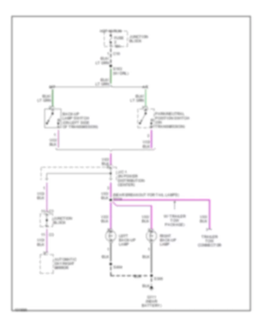
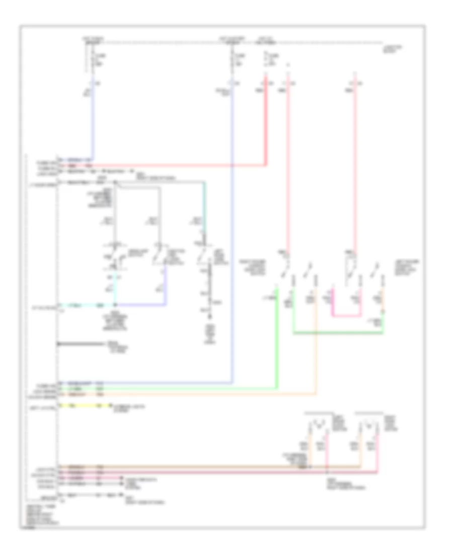
Back-up Lamps Wiring Diagram for Dodge Dakota R/T 1998
List of elements for Back-up Lamps Wiring Diagram for Dodge Dakota R/T 1998:
- A/t
- Automatic day/night mirror
- Back-up lamp switch (on left side of transmission)
- C10
- Fuse 15a
- G111 (near battery)
- Hot in run
- J/c 1 (in power distribution center)
- Junction block
- Left back-up lamp
- M/t
- Park/neutral position switch (on transmission)
- Right back-up lamp
- S163 (w/ drl)
- S306
- S404
- Trailer tow connector
- W/ trailer tow package)
Exterior Lamps Wiring Diagram, with Trailer Tow for Dodge Dakota R/T 1998
List of elements for Exterior Lamps Wiring Diagram, with Trailer Tow for Dodge Dakota R/T 1998:
- (center of dash) s213
- (left rear frame rail) s316
- (near right license lamp) s405
- (rear of frame) g415
- Aftermarket chmsl connector
- B2 c1
- Back-up lamps circuit
- Center high mount- ed stop lamp
- Combin- ation flasher
- Elec- tric brake
- Fuse 15a
- Fuse 40a
- Fuse d 25a
- Fuse g 20a
- G101 (right front fender)
- G111 (near battery)
- G202 (left side of dash)
- Hazard
- Hazard switch
- Head
- Head- lamp switch
- Hot at all times
- Hot in run or acc
- Instru- ment cluster
- Interior lights system
- J/c 1 (in power distribution center)
- J/c 2 (in pdc)
- J/c 4 (left side of dash)
- Junc- tion block
- Junction block
- Left front side marker lamp
- Left lic- ense lamp
- Left park/ turn signal lamp
- Left tail/ stop/ turn lamp
- Left turn ind
- Lic- ense lamp
- Multi- function switch (at steering column)
- Normal
- Off
- Park
- Pnk
- Pnk/ red
- Power distribution center
- Red/ tan
- Red/tan
- Right front side marker lamp
- Right lic- ense lamp
- Right park/ turn signal lamp
- Right tail/ stop/ turn lamp
- Right turn ind
- S109
- S128
- S162
- S166
- S306
- S317 (near aftermarket chmsl conn)
- S318 (near after- market chmsl connector)
- S401
- S403
- S404
- S406
- Sport bumper
- Step bumper
- Stop lamp switch
- Tan
- Timing ckt
- Trailer tow connector
- Trailer tow relay (in power distribution center)
- Turn signal switch
Exterior Lamps Wiring Diagram, without Trailer Tow for Dodge Dakota R/T 1998
List of elements for Exterior Lamps Wiring Diagram, without Trailer Tow for Dodge Dakota R/T 1998:
- (center of dash) s213
- (left rear frame rail) s316
- (near right license lamp) s405
- (not used)
- Aftermarket chmsl connector
- B2 c1
- Center high mount- ed stop lamp
- Combin- ation flasher
- Fuse 15a
- Fuse d 25a
- Fuse g 20a
- G101 (right front fender)
- G111 (near battery)
- G202 (left side of dash)
- Hazard
- Hazard switch
- Head
- Head- lamp switch
- Hot at all times
- Hot in run or acc
- Instru- ment cluster
- Interior lights system
- J/c 1 (in power distribution center)
- J/c 2 (in pdc)
- J/c 4 (left side of dash)
- Junc- tion block
- Junction block
- Left front side marker lamp
- Left lic- ense lamp
- Left park/ turn signal lamp
- Left tail/ stop/ turn lamp
- Left turn ind
- Lic- ense lamp
- Multi- function switch (at steering column)
- Normal
- Off
- Park
- Pnk
- Pnk/ red
- Power distribution center
- Right front side marker lamp
- Right lic- ense lamp
- Right park/ turn signal lamp
- Right tail/ stop/ turn lamp
- Right turn ind
- S109
- S128
- S166
- S306
- S317 (near aftermarket chmsl conn)
- S318 (near after- market chmsl connector)
- S401
- S403
- S404
- S406
- Sport bumper
- Step bumper
- Stop lamp switch
- Tan
- Timing ckt
- Turn signal switch
GROUND DISTRIBUTION
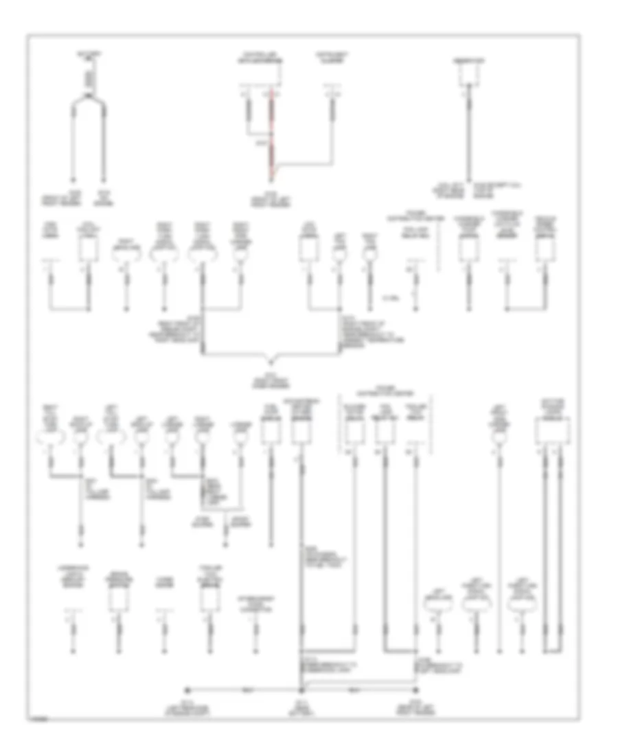
Ground Distribution Wiring Diagram (1 of 2) for Dodge Dakota R/T 1998
List of elements for Ground Distribution Wiring Diagram (1 of 2) for Dodge Dakota R/T 1998:
- (2.5l) coolant fan
- (2.5l) g117 (right rear of engine)
- (trailer tow) electric brake
- Aftermarket chmsl connector
- Battery
- Blower motor relay
- Brake pressure switch
- Controller anti-lock brake
- Daytime running lamps module
- Downstream heated oxygen sensor
- Fog lamp relay no1
- Fog lamp relay no2
- Fuel pump module
- G100 (front of left front fender)
- G101 (right front inner fender)
- G104 (rear of left front fender)
- G111 (near battery)
- G114 (left rear side of engine compt)
- G125 (except 2.5l) (top of engine)
- G133 (on engine)
- Generator
- High note horn
- Instrument cluster
- Left back-up lamp
- Left fog lamp
- Left front side marker lamp
- Left headlamp
- Left license lamp
- Left park/turn signal lamp no1
- Left park/turn signal lamp no2
- Left tail/ stop/ turn lamp
- License lamp
- Low note horn
- Power distribution center
- Right back-up lamp
- Right fog lamp
- Right front side marker lamp
- Right headlamp
- Right license lamp
- Right park/ turn signal lamp no1
- Right park/ turn signal lamp no2
- Right tail/ stop/ turn lamp
- S306 (on chassis, near breakout to fuel tank)
- S401 (in taillamp harness)
- S404 (in taillamp harness)
- Sport bumper
- Step bumper
- Trailer tow relay
- Underhood lamp & mercury switch
- Vehicle speed control servo
- W/ drl
- Windshield washer low fluid level sensor
- Windshield washer pump motor
- Wiper motor
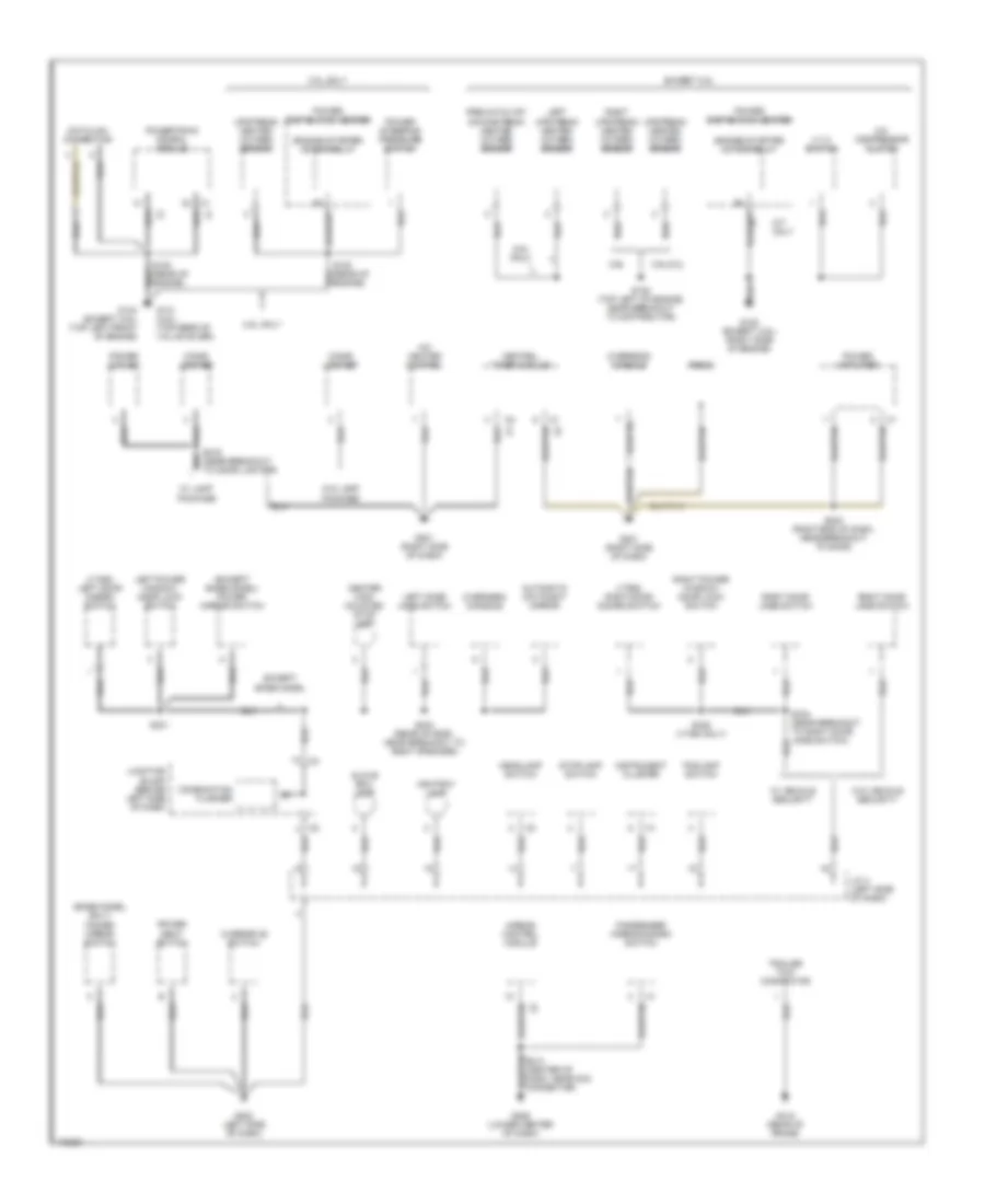
Ground Distribution Wiring Diagram (2 of 2) for Dodge Dakota R/T 1998
List of elements for Ground Distribution Wiring Diagram (2 of 2) for Dodge Dakota R/T 1998:
- (base model only) power mirror switch
- (except base model) power mirror switch
- (vtss) left door disarm switch
- (vtss) right door disarm switch
- 2.5l only
- 3.9l/5.2l
- 4 x 4 switch
- 5.9l
- 5.9l only
- A/c compressor clutch
- A/c heater control
- Airbag control module
- Ashtray lamp
- Automatic day/night mirror
- Center high mounted stop lamp
- Central timer module
- Cigar lighter
- Combination flasher
- Datalink connector
- Engine starter motor relay
- Except 2.5l
- Except base model
- Foglamp switch
- G120 (except 2.5l) (right side of engine)
- G131 (2.5l) (top rear of valve cover)
- G134 (except 2.5l) (top left front of engine)
- G201 (right side of dash)
- G202 (left side of dash)
- G206 (lower center of dash)
- G415 (rear of frame)
- Glove box lamp
- Headlamp switch
- Instrument cluster
- J/c 4 (left side of dash)
- Junction block (behind left side of dash)
- Left door jamb switch
- Left power window/ door lock switch
- Left upstream heated oxygen sensor
- M/t only
- Overdrive switch
- Overhead console
- Passenger airbag disarm switch
- Power amplifier
- Power distibution center
- Power outlet
- Power seat switch
- Power steering pressure switch
- Powertrain conrol module
- Pre-catalyst downstream heated oxygen sensor
- Radio
- Right door jamb switch
- Right power window/ door lock switch
- Right upstream heated oxygen sensor
- S108 (top left of engine, near breakout to distributor)
- S240 (right end of dash, near breakout to door)
- S301
- S335 (vtss only)
- S403 (rear of roof, near breakout to right speaker)
- Stoplamp switch
- Trailer tow connector
- Upstream heated oxygen sensor
- W/ lamp package
- W/ vehicle security
- W/o lamp package
- W/o vehicle security
HEADLIGHTS
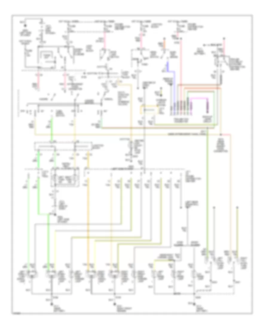
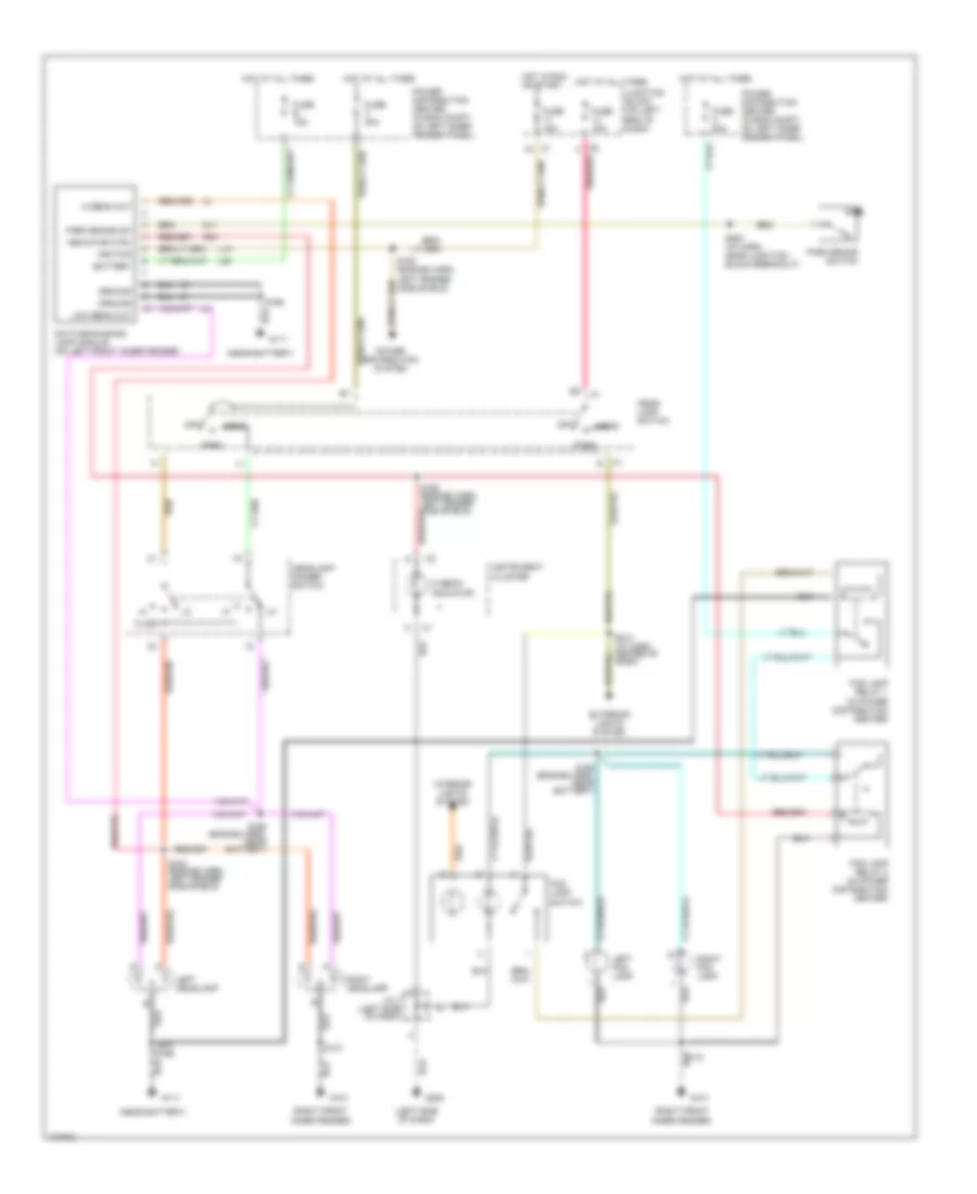
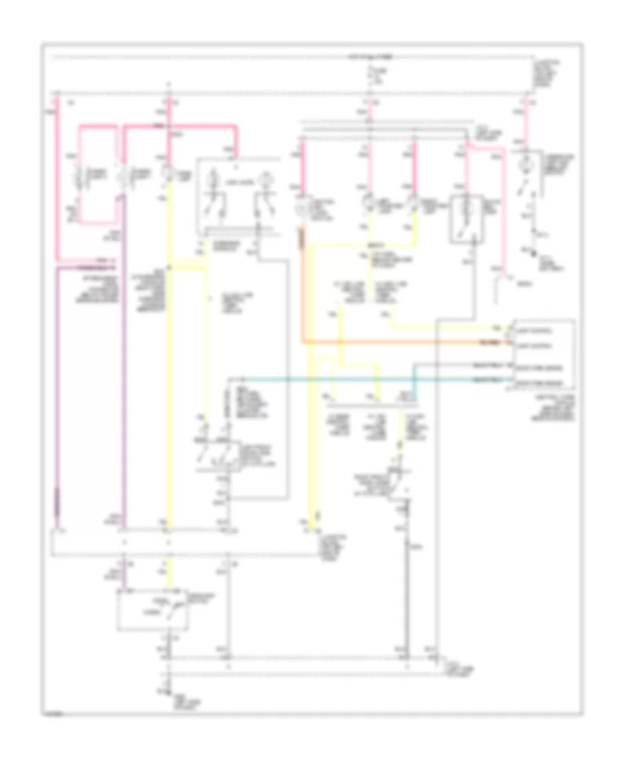
Headlamps/Fog Lamps Wiring Diagram, with DRL for Dodge Dakota R/T 1998
List of elements for Headlamps/Fog Lamps Wiring Diagram, with DRL for Dodge Dakota R/T 1998:
- (left side of dash)
- (near battery)
- (right front inner fender)
- Battery
- Daytime running lamp module (on left front inner fender)
- Exterior lights system
- Flash
- Fog lamp relay 1 (in power distribution center)
- Fog lamp relay 2 (in power distribution center)
- Fog lamp switch
- Fuse 15a
- Fuse 40a
- Fuse b 15a
- Fuse c 20a
- G101
- G11
- G111
- G202
- G34
- Ground
- Head
- Head- lamp switch
- Headlamp dimmer switch
- Hi beam indicator
- Hi beam out
- Hot at all times
- Hot in run or start
- Ignition
- Indicator ctrl
- Instrument cluster
- Interior lights system
- J/c 4 (left side of dash)
- Junction block (on left end of dash)
- L10
- L20
- Left fog lamp
- Left headlamp
- Low beam out
- Off
- Park
- Park brake sw
- Park brake switch
- Pnk/red
- Power distribution center (in eng compt, on left inner fender panel)
- Power distribution system
- Right fog lamp
- Right headlamp
- S101
- S163 (engine harn, left fender side shield)
- S164 (engine harn, left fender side shield)
- S165 (engine harn, left fender side shield)
- S166
- S168 (engine harn, near battery)
- S169 (engine harn, near battery)
- S170
- S200 (i/p harn, near junction block breakout)
- S213 (i/p harn, center of dash)
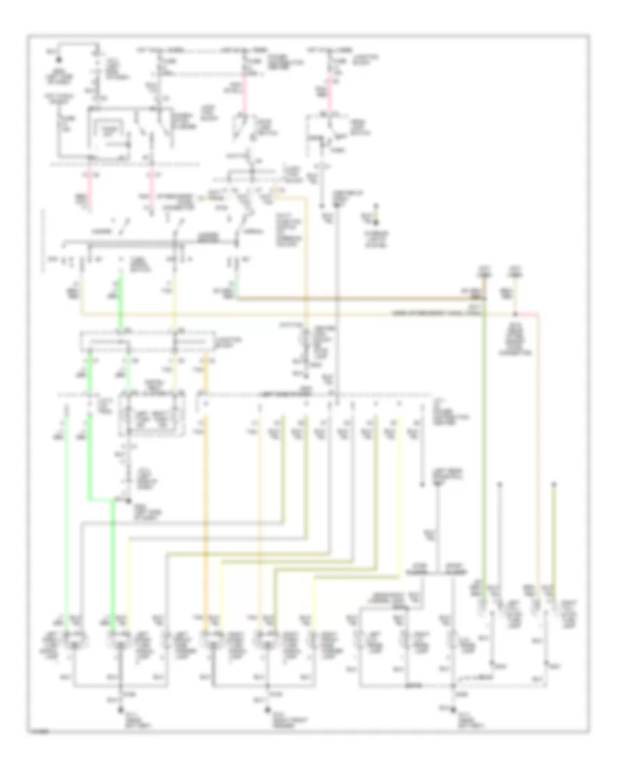
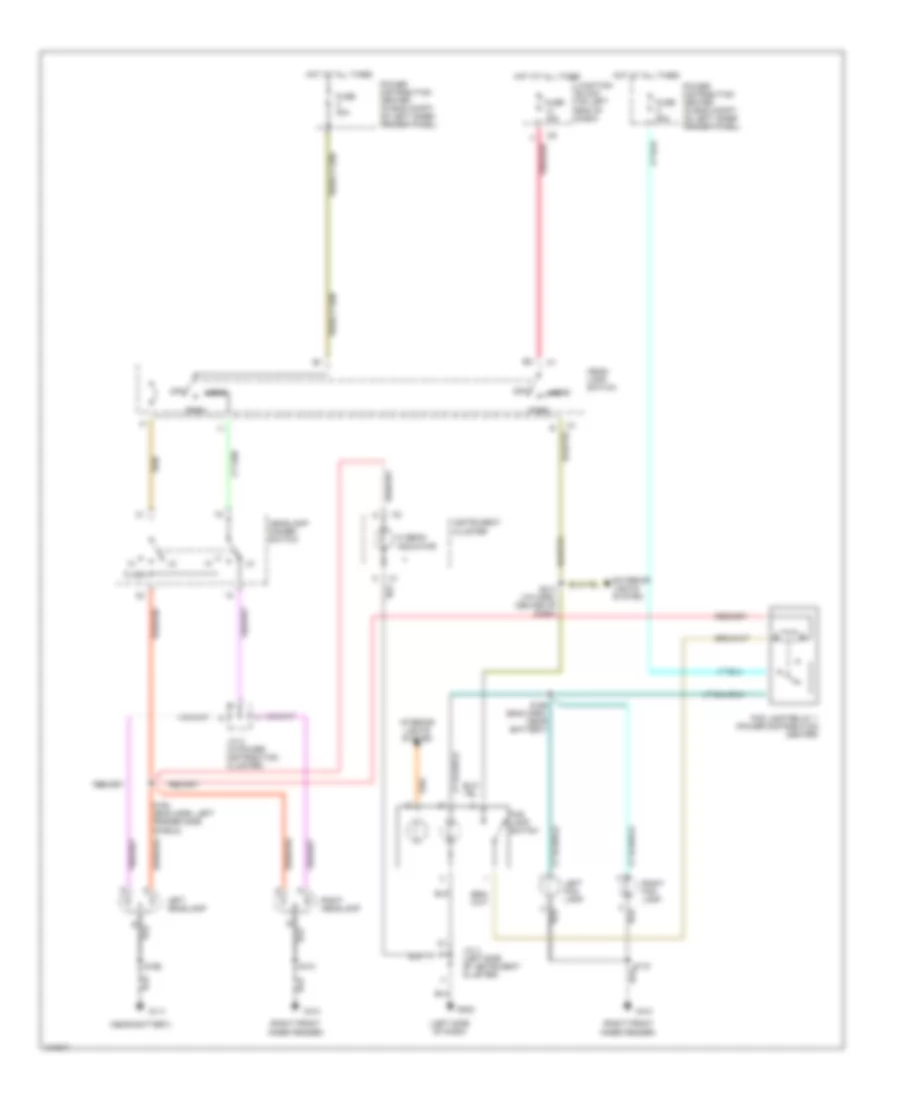
Headlamps/Fog Lamps Wiring Diagram, without DRL for Dodge Dakota R/T 1998
List of elements for Headlamps/Fog Lamps Wiring Diagram, without DRL for Dodge Dakota R/T 1998:
- (left side of dash)
- (near battery)
- (right front inner fender)
- Exterior lights system
- Flash
- Fog lamp relay 1 (power distribution center)
- Fog lamp switch
- Fuse 15a
- Fuse 40a
- Fuse c 20a
- G101
- G111
- G202
- Head
- Head- lamp switch
- Headlamp dimmer switch
- Hi beam indicator
- Hot at all times
- Instrument cluster
- Interior lights system
- J/c 2 (in power distribution cluster)
- J/c 4 (left side of instrument cluster)
- Junction block (on left end of dash)
- Left fog lamp
- Left headlamp
- Off
- Park
- Pnk/red
- Power distribution center (in eng compt, on left inner fender panel)
- Right fog lamp
- Right headlamp
- S101
- S164 (eng harn, left fender side shield)
- S166
- S169 (eng harn, near battery)
- S170
- S213 (i/p harn, center of dash)
HORN
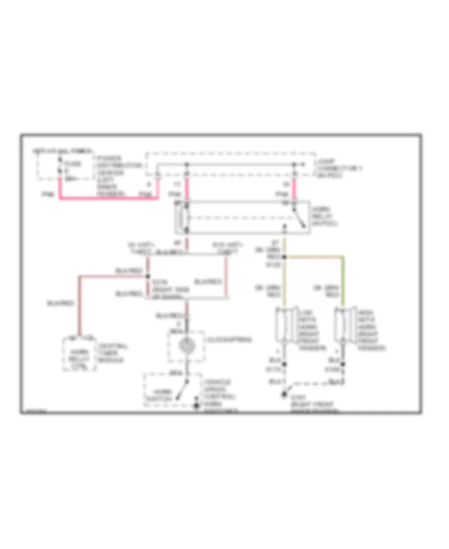
Horn Wiring Diagram for Dodge Dakota R/T 1998
List of elements for Horn Wiring Diagram for Dodge Dakota R/T 1998:
- Central timer module
- Clockspring
- Fuse e 20a
- G101 (right front inner fender)
- High note horn (right front fender)
- Horn relay (in pdc)
- Horn relay ctrl
- Horn switch
- Hot at all times
- Joint connector 1 (in pdc)
- Low note horn (right front fender)
- Nca
- Pnk
- Power distribution center (left inner fender)
- S109
- S125
- S170
- S218 (right side of dash)
- Vehicle speed control/ horn switches
- W/ anti- theft
- W/o anti- theft
INSTRUMENT CLUSTER
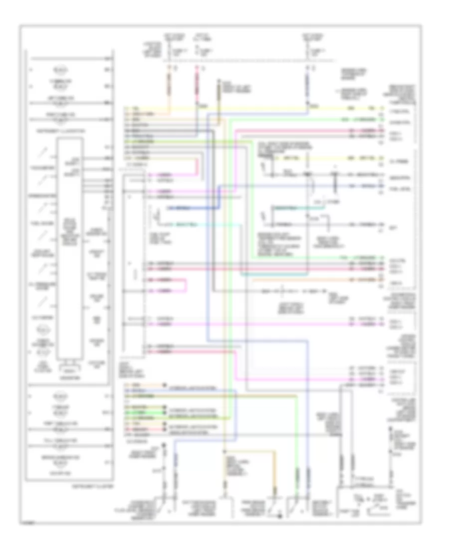
Instrument Cluster Wiring Diagram for Dodge Dakota R/T 1998
List of elements for Instrument Cluster Wiring Diagram for Dodge Dakota R/T 1998:
- (2.5l: right side of engine) (other: top rear of engine) oil pressure sensor
- (behind right side of dash, near glove box) central timer module
- (body harn, left front side of engine compt) s156
- (body harn, near fuel tank breakout)
- (engine harn, right side of firewall)
- (engine harn, top rear of engine)
- (right front inner fender)
- (type 241)
- (type 242)
- 2.5l
- 2wd
- 4x4 switch (on transfer case)
- A/t trans temp ind
- A10
- Abs ind
- Air bag control module (under center of dash on trans tunnel)
- Air bag ind
- B10
- Brake warning ind
- C1 (conn a)
- C2 (conn b)
- Ccd (+)
- Ccd (-)
- Ccd buss (+)
- Ccd buss (-)
- Check engine ind
- Check gauges ind
- Chime ctrl
- Controller anti-lock brake (left side of engine compartment)
- Coolant temp gauge
- Cruise ind
- Daytime running lamp module (left front inner fender)
- Ect
- Engine coolant temperature sensor (2.5l: on thermostat housing (other: top of engine, near gen)
- Exterior lights system
- Fuel gauge
- Fuel level
- Fuel pump module (fuel tank)
- Full time
- Full time 4x4 ind
- Fuse 1 15a
- Fuse 11 10a
- Fuse 17 10a
- G10
- G100 (front of left front fender)
- G101
- G107
- G120 (except 2.5l) (right side of engine)
- G202 (left side of dash)
- G52
- G60
- Headlights system
- Hi beam ind
- Hot at all times
- Hot in run or start
- Instrument cluster
- Instrument illumination
- Interior lights system
- Joint conn 3 (behind left side of dash)
- Joint conn 4 (behind left side of dash)
- Junction block (left end of dash)
- Left turn ind
- Low fuel ind
- Low wash fluid ind
- O/d ctrl
- O/d off ind
- Odometer
- Oil press
- Oil pressure gauge
- Other
- Park brake switch (park brake assembly)
- Part time 4x4 ind
- Part time hi
- Part time low
- Powertrain control module (right front inner fender)
- Right turn ind
- S101
- S103
- S108
- S149
- S170
- S200 (body harn, behind cluster assembly)
- S232
- S250
- Seatbelt switch (buckle assembly)
- Sens rtrn
- Solid state gauge and indicator driver module
- Speedometer
- T18
- Tachometer
- Tan
- Upshift ind
- Voltmeter
- Vss in
- Vss out
- Vtss ctrl
- Vtss ind
- Windshield washer low fluid level sensor (washer reservoir)
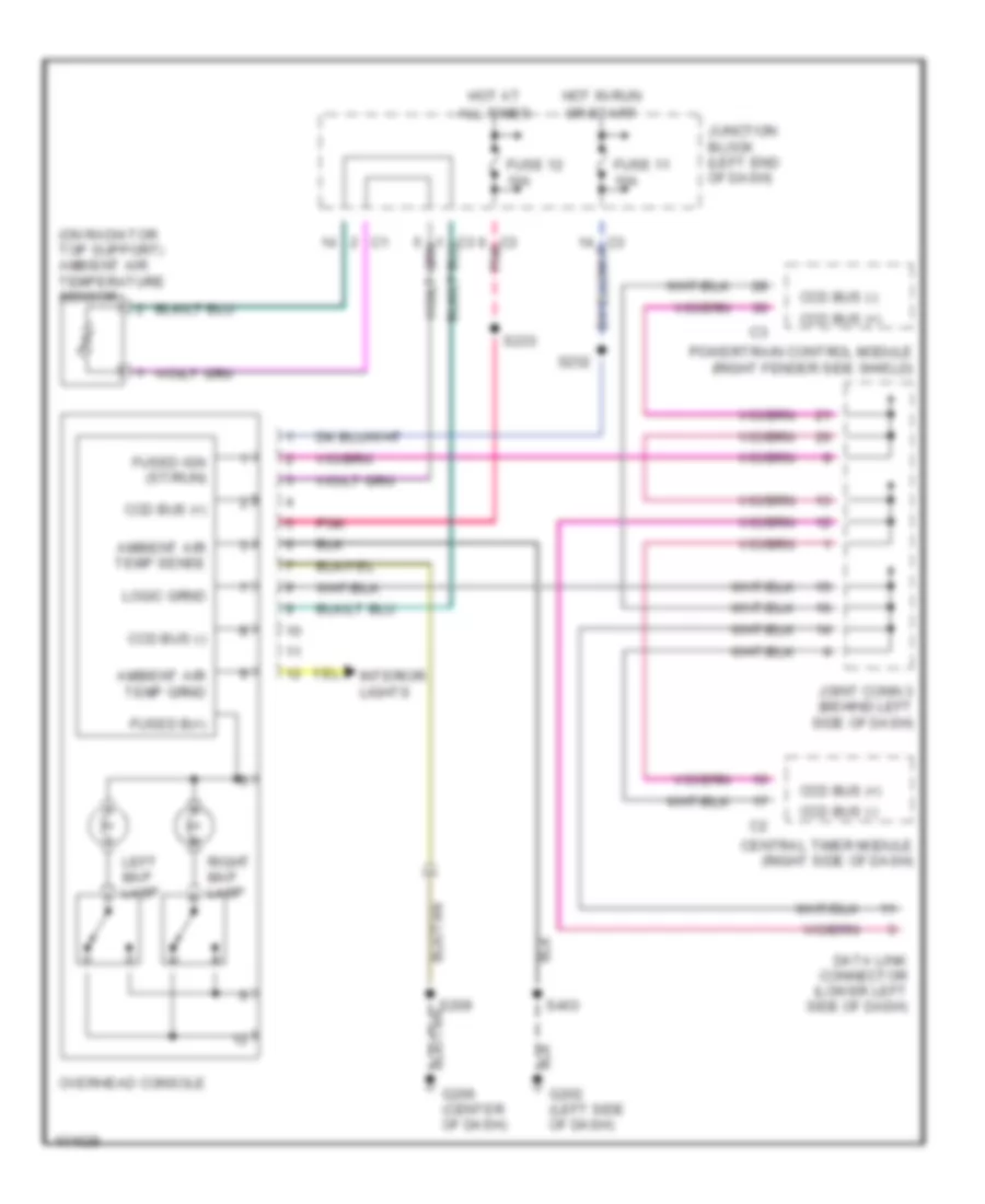
Overhead Console Wiring Diagram for Dodge Dakota R/T 1998
List of elements for Overhead Console Wiring Diagram for Dodge Dakota R/T 1998:
- (on radiator top support) ambient air temperature sensor
- All times
- Ambient air temp sense
- Ccd bus (+)
- Ccd bus (-)
- Central timer module (right side of dash)
- Data link connector (lower left side of dash)
- Fuse 11 10a
- Fuse 12 10a
- Fused b(+)
- Fused ign (st/run)
- G202 (left side of dash)
- G206 (center of dash)
- Hot at
- Hot in run
- Interior lights
- Joint conn 3 (behind left side of dash)
- Junction block (left end of dash)
- Left map lamp
- Or start
- Overhead console
- Pnk
- Powertrain control module (right fender side shield)
- Right map lamp
- S209
- S232
- S233
- S403
INTERIOR LIGHTS
Courtesy Lamp Wiring Diagram for Dodge Dakota R/T 1998
List of elements for Courtesy Lamp Wiring Diagram for Dodge Dakota R/T 1998:
- Aftermarket chmsl connector (below power brake booster)
- Cargo
- Cargo lamp 1
- Cargo lamp 2
- Central timer module (behind left side of dash, near glove box)
- Dome
- Dome lamp
- Door open sense
- Fuse 10a
- G111 (near battery)
- G202 (left side of dash)
- Glove box lamp
- Headlamp switch
- Hot at all times
- Ignition key lamp/ switch
- J/c 4 (left side of dash)
- Junction block (on left end of dash)
- Lamp control
- Left courtesy lamp
- Left front door jamb switch (in "a" pillar)
- Map lamps
- Nca
- Off
- Overhead console
- Pnk
- Radio
- Right courtesy lamp
- Right front door jamb switch (in "a" pillar)
- S113
- S203 (i/p harn, between instrument cluster breakouts)
- S215
- S231 (w/overhead console) (roof harn, near overhead console breakout)
- S233
- S334
- S403
- Underhood lamp and mercury switch
- W/ base central timer module
- W/ high line central timer module
- W/ low line central timer module
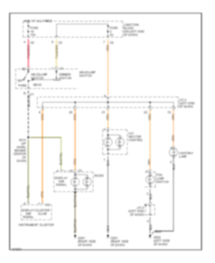
Instrument Illumination Wiring Diagram for Dodge Dakota R/T 1998
List of elements for Instrument Illumination Wiring Diagram for Dodge Dakota R/T 1998:
- A/c heater control
- Ashtray lamp
- Cluster illum
- Dimmer switch
- Display dim signal
- Fog lamp switch
- Fuse 15a
- Fuse 5a
- G201 (right side of dash)
- G202 (left side of dash)
- Head
- Headlamp switch
- Hot at all times
- Instrument cluster
- J/c 4 (left end of dash)
- Junction block (on left end of dash)
- Off
- Park
- Pnk/red
- Radio
- S213 (i/p harn, behind center of dash)
POWER DISTRIBUTION
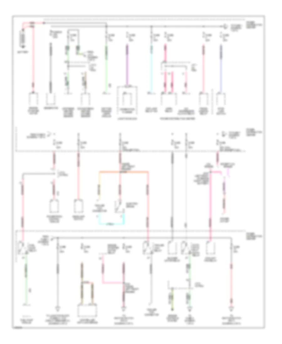
Power Distribution Wiring Diagram (1 of 3) for Dodge Dakota R/T 1998
List of elements for Power Distribution Wiring Diagram (1 of 3) for Dodge Dakota R/T 1998:
- (2.5l) (except 2.5l)
- (diagram 1 of 3)
- (inside left front fender) s162
- 2.5l engine
- A/c compressor clutch relay
- A14
- A61
- Auto- matic shut down relay
- B1 c1
- Battery
- Blower motor relay
- Combination flasher
- Controller anti-lock brake
- Coolant fan relay
- Daytime running lamps module
- Downstream heated oxygen sensor
- Electric brake
- Engine controls system
- Engine starter motor
- Engine starter motor relay
- Except 2.5l engine
- Fog lamp relay no1
- From fuse 4 b
- From fuse g (diagram 1 of 3)
- From j/c 2 (diagram 1 of 3)
- Fuel pump module
- Fuel pump relay
- Fuse 20a
- Fuse 30a
- Fuse 40a
- Fuse 40a (trailer tow)
- Fuse 40a 30a
- Fuse 50a
- Fuse a 10a
- Fuse b 15a
- Fuse c 20a
- Fuse d 25a
- Fuse e 20a
- Fuse f 20a
- Fuse g 20a
- Fusible link 140a
- Generator
- Headlamp switch
- Horn relay
- J/c 1 (in pdc)
- J/c 2 (in pdc)
- Junction block
- L20
- Pnk
- Power distribution center
- Power outlet
- Powertrain control module
- Red
- Red/tan
- S126
- S167 (left front of engine compt, near battery)
- Stop lamp switch
- To fuse 1 (diagram 1 of 3)
- To fuse 7 (diagram 1 of 3)
- To fuse a (diagram 1 of 3)
- To ignition switch (pin 4) (diagram 2 of 3)
- To ignition switch (pin 7) (diagram 2 of 3)
- To junction block (fuses 4, 13 & circuit breaker 21) (diagram 3 of 3)
- Trailer tow connector
- Trailer tow relay
- Trans- mission relay
- Upstream heated oxygen sensor
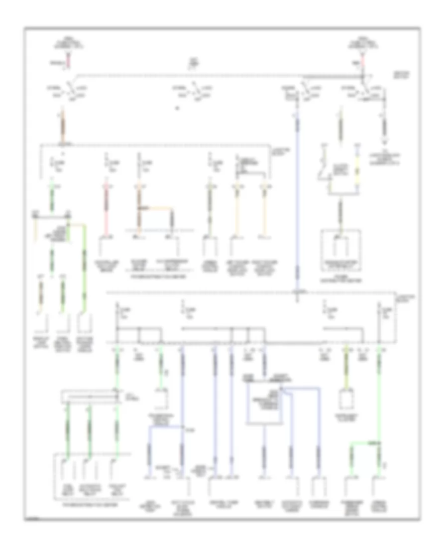
Power Distribution Wiring Diagram (2 of 3) for Dodge Dakota R/T 1998
List of elements for Power Distribution Wiring Diagram (2 of 3) for Dodge Dakota R/T 1998:
- 2.5l
- A/c compressor clutch relay
- A/t
- Acc
- Airbag control module
- Automatic day/night mirror
- Automatic shut down relay
- Back-up lamp switch
- Base model
- Base models only
- Blower motor relay
- C10
- Central timer module
- Circuit breaker 20a
- Clutch safety switch
- Controller anti-lock brake
- Coolant fan relay
- Daytime running lamps module
- Duty cycle evap/ purge solenoid
- Engine starter motor relay
- Except 2.5l
- Except base model
- F12
- F14
- F18
- F24
- From fuse 10 (pdc) (diagram 1 of 3)
- From fuse 9 (pdc) (diagram 1 of 3)
- Fuel pump relay
- Fuse 10a
- Fuse 15a
- Fuse 20a
- Ignition switch
- Instrument cluster
- J/c 1 (in pdc)
- Junction block
- L10
- Leak detection pump
- Left power window/ door lock switch
- Lock off
- M/t
- Not used
- Overhead console
- Park/ neutral position switch
- Passenger airbag disarm switch
- Power distribution center
- Powertrain control module
- Red
- Right power window/ door lock switch
- Run
- S129
- S163 (inside left front fender)
- S232 (near breakout to overhead console)
- S251
- S252
- Seatbelt switch
- Start
- Tan
- To junction block (fuse 6) (diagram 3 of 3)
- W/ drl
- W/o drl
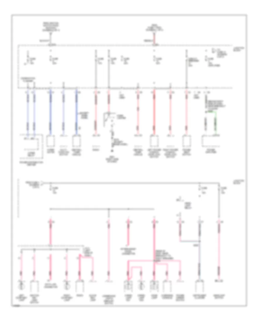
Power Distribution Wiring Diagram (3 of 3) for Dodge Dakota R/T 1998
List of elements for Power Distribution Wiring Diagram (3 of 3) for Dodge Dakota R/T 1998:
- (behind right side of dash, near breakout to door) s225
- (rear of roof, near breakout to right speaker) s233
- Aftermarket chmsl connector
- C1 b2
- C10
- Cargo lamp no1
- Cargo lamp no2
- Central timer module
- Cigar lighter
- Circuit breaker 20a
- Combination flasher
- Data link connector
- Dome lamp
- Except base model
- F35
- From fuse 4 (diagram 3 of 3)
- From fuse 7 (pdc) (diagram 1 of 3)
- From ignition switch (pin 6) (run/acc) (diagram 2 of 3)
- Fuse 10a
- Fuse 15a
- Fuse 15a (amplifier)
- Fuse 20a
- G201 (right side of dash)
- Glove box lamp
- Head- lamp relay
- Headlamp switch
- Ignition key lamp/ switch
- Instrument cluster
- J/c 4 (left side of dash)
- Junction block
- Left courtesy lamp
- Left power window/ door lock switch
- Multi- function switch
- Not used
- Overhead console
- Pnk
- Pnk/red
- Power amplifier
- Power distribution center
- Power mirror switch
- Power seat switch
- Radio
- Red
- Right courtesy lamp
- Right power window/ door lock switch
- S216 (except base model)
- S250
- To fuse 12 (diagram 3 of 3)
- Underhood lamp & mercury switch
- Wiper motor
- Wiper relay
POWER DOOR LOCKS
Power Door Lock Wiring Diagram for Dodge Dakota R/T 1998
List of elements for Power Door Lock Wiring Diagram for Dodge Dakota R/T 1998:
- (i/p harness, right side of dash) s220
- Ccd bus +
- Ccd bus -
- Central timer module (behind right side of dash, near glove box)
- Computer data lines system
- Crty lp ctrl
- F12
- F35
- Fuse 10a
- Fuse 20a
- Fused b+
- Fused ign
- G16
- G201 (right side of dash)
- G202 (left side of dash)
- G26
- Ground
- Headlamp switch
- Hot at all times
- Hot in run or acc
- Hot in start or run
- Ignition key lamp/ switch
- Interior lights system
- Junction block
- Ky in/lts on
- Left door jamb switch
- Left door lock motor
- Left power window/ door lock switch
- Lock ctrl
- Lock sense
- Logic gnd
- Lt door open
- Nca
- Off
- P33
- P34
- P37
- P38
- Red
- Right door lock motor
- Right power window/ door lock switch
- Rke antenna (w/ rke)
- S202 (i/p harness, between cluster breakouts)
- S203 (i/p harness, between cluster breakouts)
- S209
- S222 (i/p harness, right side of dash)
- S403
- Unlock ctrl
- Unlock sense
POWER MIRRORS
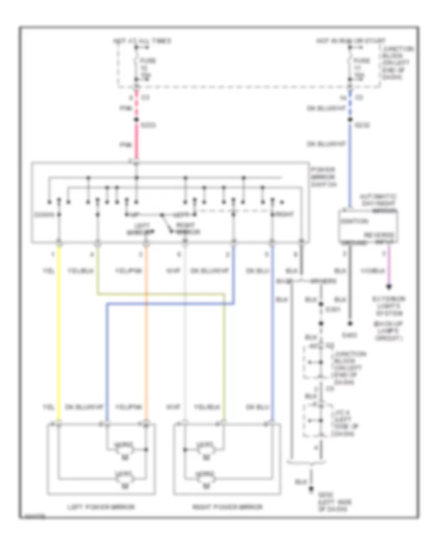
Power Mirror Wiring Diagram for Dodge Dakota R/T 1998
List of elements for Power Mirror Wiring Diagram for Dodge Dakota R/T 1998:
- (back-up lamps circuit)
- Automatic day/night mirror
- Base
- Down
- Exterior lights system
- Fuse 10a
- G202 (left side of dash)
- Ground
- Horiz
- Hot at all times
- Hot in run or start
- Ignition
- J/c 4 (left side of dash)
- Junction block (on left end of dash)
- Left
- Left mirror
- Left power mirror
- Others
- Pnk
- Power mirror switch
- Reverse input
- Right
- Right mirror
- Right power mirror
- S232
- S233
- S301
- S403
- Vert
POWER SEATS
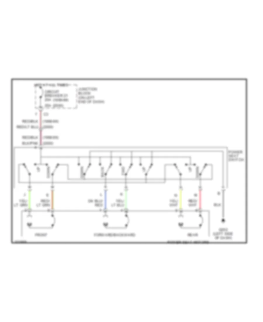
Power Seat Wiring Diagrams for Dodge Dakota R/T 1998
List of elements for Power Seat Wiring Diagrams for Dodge Dakota R/T 1998:
- (1998-99)
- (2000)
- 25a
- Back
- Circuit breaker 21 20a
- Down
- Forward/backward
- Front
- Fwd
- G202 (left side of dash)
- Hot at all times
- Junction block (on left end of dash)
- Power seat motors
- Power seat switch
- Rear
POWER WINDOWS
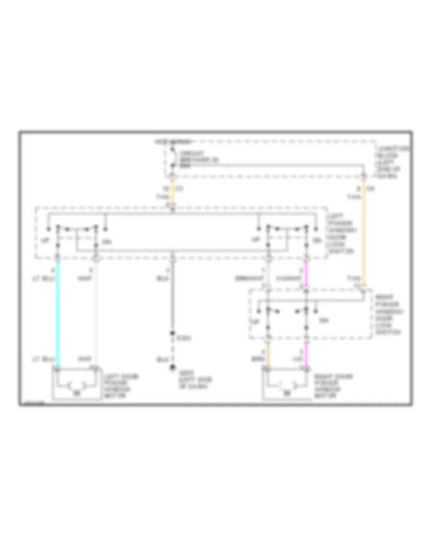
Power Window Wiring Diagram for Dodge Dakota R/T 1998
List of elements for Power Window Wiring Diagram for Dodge Dakota R/T 1998:
- Circuit breaker 20 20a
- G202 (left side of dash)
- Hot in run
- Junction block (left end of dash)
- Left door power window motor
- Left power window/ door lock switch
- Right door power window motor
- Right power window/ door lock switch
- S301
- Tan
RADIO
Radio Wiring Diagrams, with Amplifier for Dodge Dakota R/T 1998
List of elements for Radio Wiring Diagrams, with Amplifier for Dodge Dakota R/T 1998:
- Amp l door (+)
- Amp l door (-)
- Amp l rear (+)
- Amp l rear (-)
- Amp r door (+)
- Amp r door (-)
- Amp r rear (+)
- Amp r rear (-)
- Antenna
- Dimmer
- Dimmer sig
- Exterior lights
- Fuse 12 10a
- Fuse 14 15a
- Fuse 4 15a
- Fuse 5 5a
- Fuse 8 10a
- Fused b(+)
- Fused ign
- G201 (lower right end of dash)
- Ground
- Head
- Headlamp switch
- Hot at all times
- Hot in run or acc
- Illumination
- Joint connector (behind left side of dash)
- Junction block (left end of dash)
- L front (+)
- L front (-)
- L rear (+)
- L rear (-)
- Left door tweeter
- Left door woofer
- Left rear speaker
- Lf spkr (+)
- Lf spkr (-)
- Lr spkr (+)
- Lr spkr (-)
- Nca
- Off
- Park
- Pnk
- Pnk/ red
- Power amplifier (right side kick panel)
- R front (+)
- R front (-)
- R rear (+)
- R rear (-)
- Radio
- Radio 12v
- Rf spkr (+)
- Rf spkr (-)
- Right door tweeter
- Right door woofer
- Right rear speaker
- Rr spkr (+)
- Rr spkr (-)
- S213
- S225
- S240
- S330 (in door harness)
- S331 (in door harness)
- S333 (in door harness) s332
- X12
- X51
- X52
- X53
- X54
- X55
- X56
- X57
- X58
- X60
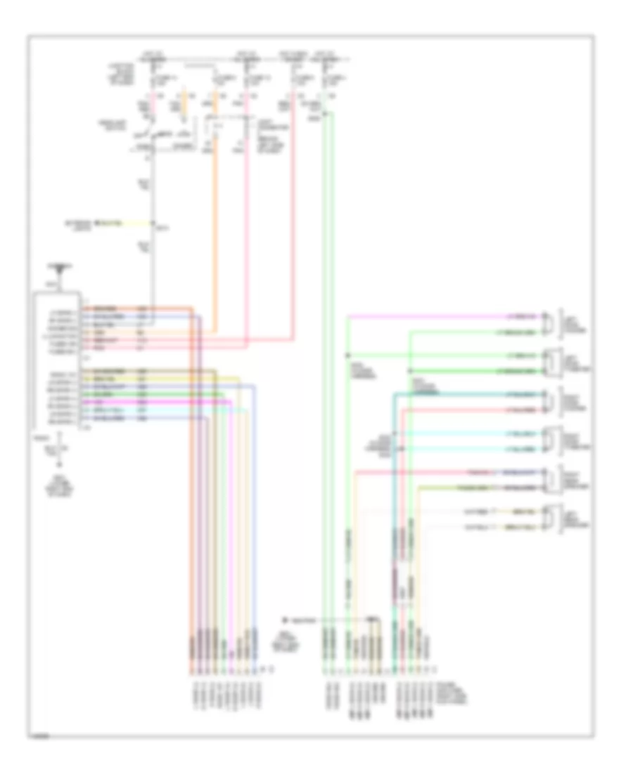
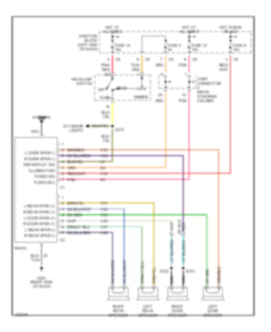
Radio Wiring Diagrams, without Amplifier for Dodge Dakota R/T 1998
List of elements for Radio Wiring Diagrams, without Amplifier for Dodge Dakota R/T 1998:
- Antenna
- Dim display sig
- Dimmer
- Exterior lights
- Fuse 12 10a
- Fuse 14 15a
- Fuse 5 5a
- Fuse 8 10a
- Fused b(+)
- Fused ign
- G201 (right side of dash)
- Head
- Headlamp switch
- Hot at all times
- Hot in run or acc
- Illumination
- Joint connector (near steering column)
- Junction block (left end of dash)
- L door spkr (+)
- L door spkr (-)
- L rear spkr (+)
- L rear spkr (-)
- Left door speaker
- Left rear speaker
- Nca
- Off
- Park
- Pnk
- Pnk/ red
- R door spkr (+)
- R door spkr (-)
- R rear spkr (+)
- R rear spkr (-)
- Radio
- Right door speaker
- Right rear speaker
- S213
- S332
- S333
- X12
- X51
- X52
- X53
- X54
- X55
- X56
- X57
- X58
STARTING/CHARGING
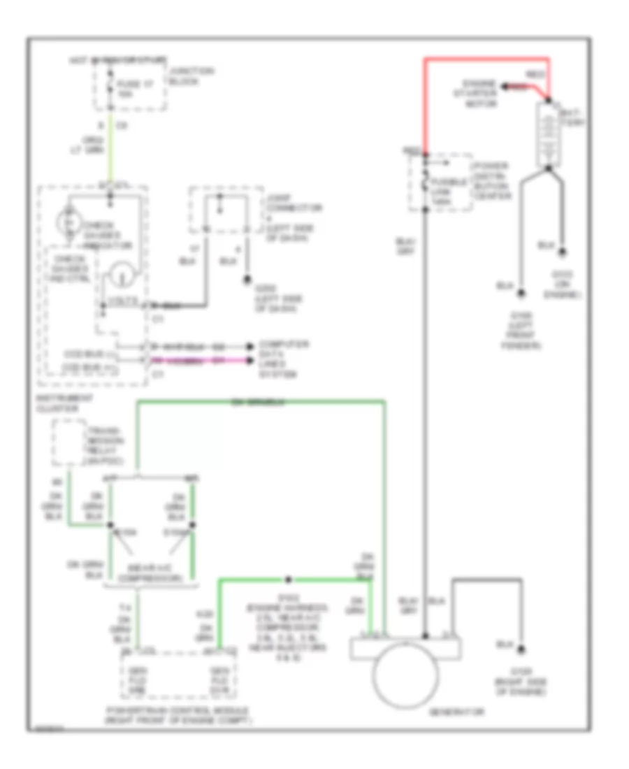
Charging Wiring Diagram for Dodge Dakota R/T 1998
List of elements for Charging Wiring Diagram for Dodge Dakota R/T 1998:
- (near a/c compressor)
- A/t
- Bat- tery
- Ccd bus (+)
- Ccd bus (-)
- Check gauges ind ctrl
- Check gauges indicator
- Computer data lines system
- Engine starter motor
- Fuse 17 10a
- Fusible link 140a
- G100 (left front fender)
- G120 (right side of engine)
- G133 (on engine)
- G202 (left side of dash)
- Gen fld dvr
- Gen fld sre
- Generator
- Hot in run or start
- Instrument cluster
- Joint connector (left side of dash)
- Junction block
- K20
- M/t
- Power distri- bution center
- Powertrain control module (right front of engine compt)
- Red
- S102 (engine harness, 2.5l: near a/c compressor; 3.9l, 5.2l, 5.9l: near injectors 6 & 8)
- S104
- Trans- mission relay (in pdc)
- Volts
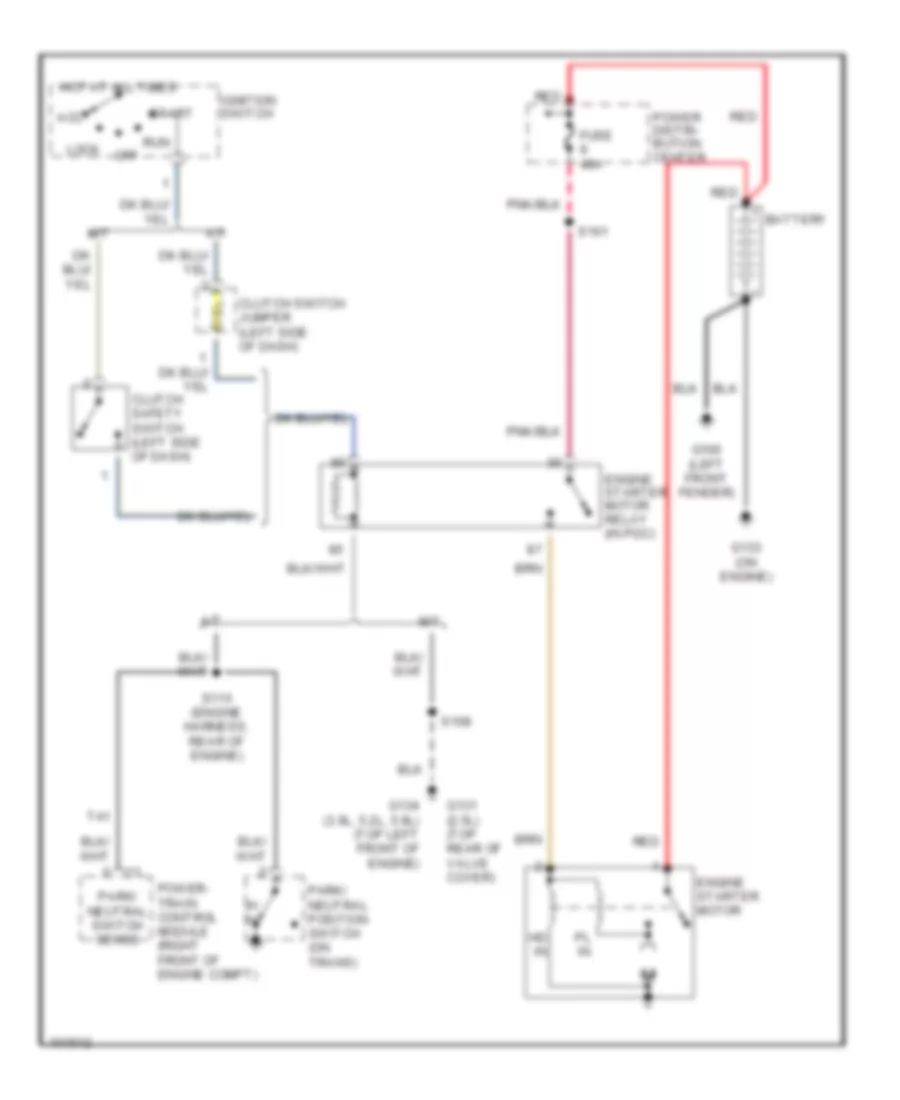
Starting Wiring Diagram for Dodge Dakota R/T 1998
List of elements for Starting Wiring Diagram for Dodge Dakota R/T 1998:
- A/t
- Acc
- Battery
- Clutch safety switch (left side of dash)
- Clutch switch jumper (left side of dash)
- Engine starter motor
- Engine starter motor relay (in pdc)
- Fuse 40a
- G100 (left front fender)
- G131 (2.5l) (top rear of valve cover)
- G133 (on engine)
- G134 (3.9l, 5.2l, 5.9l) (top left front of engine)
- Hd in
- Hot at all times
- Ignition switch
- Lock
- M/t
- Off
- P/ n
- Park/ neutral position switch (on trans)
- Park/ neutral switch sense
- Pl in
- Power distri- bution center
- Power- train control module (right front of engine compt)
- Red
- Run
- S108
- S115 (engine harness, rear of engine)
- S161
- Start
- T41
SUPPLEMENTAL RESTRAINTS
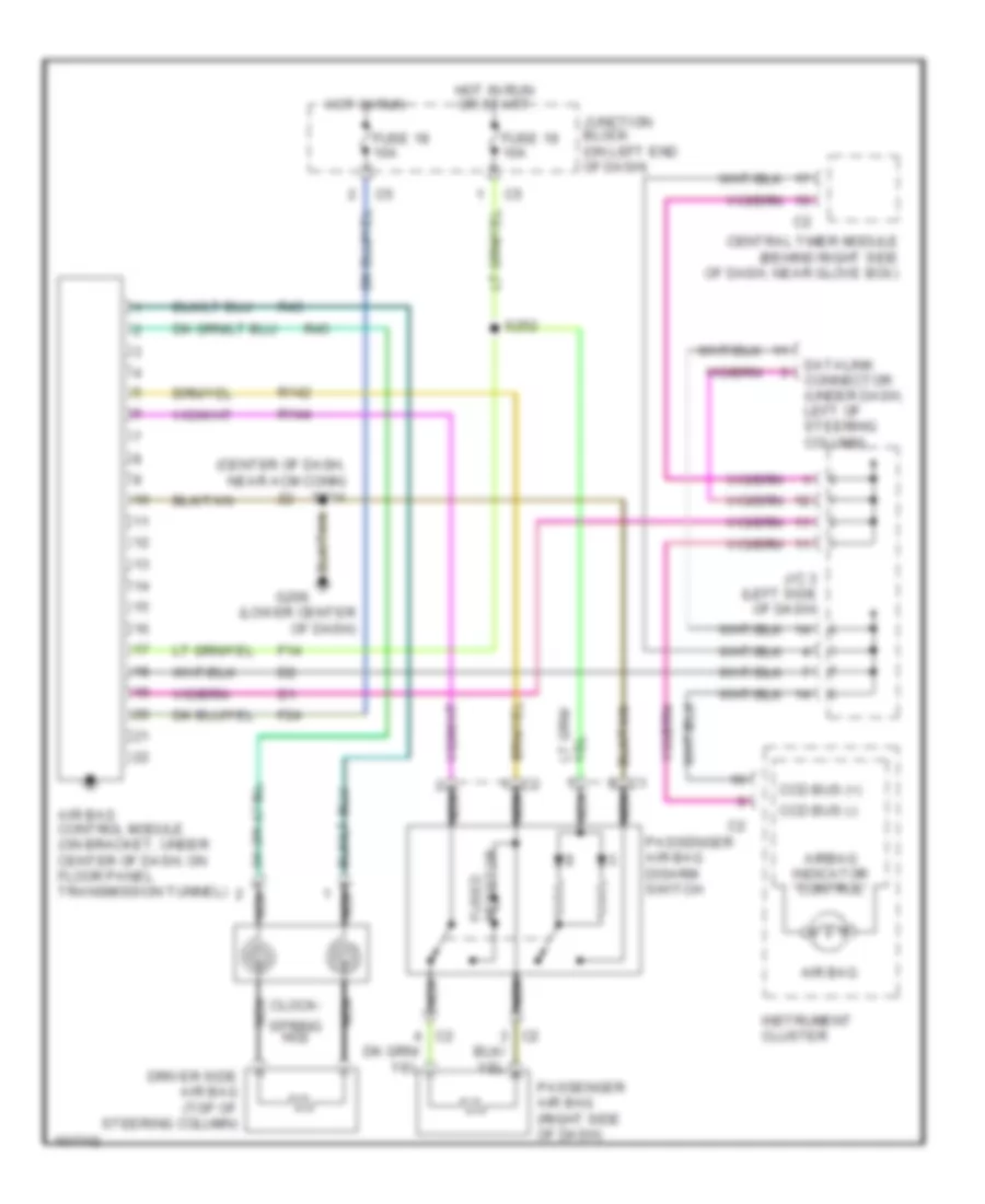
Supplemental Restraint Wiring Diagram for Dodge Dakota R/T 1998
List of elements for Supplemental Restraint Wiring Diagram for Dodge Dakota R/T 1998:
- (center of dash, near acm conn) s214
- (lower center of dash)
- Air bag
- Air bag control module (on bracket, under center of dash, on floor panel transmission tunnel)
- Airbag indicator control
- Ccd bus (+)
- Ccd bus (-)
- Central timer module (behind right side of dash, near glove box)
- Clock-
- Datalink connector (under dash, left of steering column)
- Driver side air bag (top of steering column)
- F14
- F24
- Fuse 18 10a
- Fuse 19 10a
- Fused resistor
- G206
- Hot in run
- Hot in run or start
- Instrument cluster
- J/c 3 (left side of dash)
- Junction block (on left end of dash)
- Nca
- Passenger air bag (right side of dash)
- Passenger air bag disarm switch
- R142
- R144
- R43
- R45
- S252
- Spring no2
TRANSMISSION
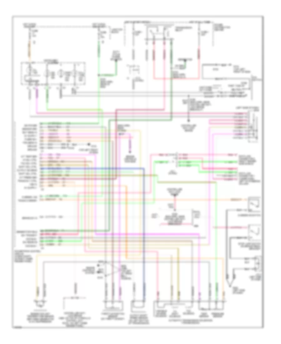
Transmission Wiring Diagram for Dodge Dakota R/T 1998
List of elements for Transmission Wiring Diagram for Dodge Dakota R/T 1998:
- (eng harn, rear of eng)
- (eng harn, top left of trans bell- housing)
- (left side of dash) j/c 3
- (top left front of eng)
- 242t-case 241t-case
- 2wd
- 3-4 shift solenoid
- 4x4 switch
- A/t press sen
- A/t temp sen
- A14
- Abs
- Automatic transmission solenoids (transmission)
- Brake sw in
- Ccd bus +
- Ccd bus -
- Controller anti- lock brake (abs: on top of hydraulic control unit, rwal: on left inner fender panel)
- Controller anti-lock brake
- D20
- D21
- Data link connector 1 (under dash, left of steering column)
- Data link connector 2 (right fender side shield)
- Duty cycle purge solenoid
- Ect sens in
- Engine controls system
- Engine controls systems
- Engine coolant temperature sensor (between generator & a/c compressor)
- F18
- Full time
- Full time 4x4 ind
- Fuse 1 10a
- Fuse 1 20a
- Fuse 10a
- Fused b(+)
- G134
- G134 (top left front of eng)
- G202 (left side of dash)
- Generator
- Generator field
- Ground
- Hot at all times
- Hot in run and start
- Hot in run or start
- Hot in start or run
- I/o
- Ign power
- Instrument cluster
- J/c 1 (in pdc)
- J/c 2 (in pdc)
- J/c 4 (left side of dash)
- Junction block
- K22
- K29
- K54
- Mil ind
- Neutral
- O/d off ind
- Output shaft speed sensor (on left bottom of transmission)
- Output ss sens
- Overdrive switch
- Overdrv ind
- Part time 4x4 ind
- Part time hi
- Part time lo
- Pnk
- Power distribution center
- Powertrain control module (in eng compt, on right inner fender panel)
- Pressure sensor
- Processor
- Rwal
- S100 (eng harn, rear of eng)
- S101
- S103
- S104 (eng harn, near inj 4)
- S105
- S107
- S108
- S158 (eng harn, near controller anti- lock brake breakout)
- Sci receive
- Sci transmit
- Sensor grd
- Shift sol ctrl
- Stop lamp switch (on brake pedal bracket)
- T13
- T14
- T18
- T25
- T34
- T60
- Tcc sol ctrl
- Tcc solenoid
- Temp sensor
- Throttle position sensor (on throttle body)
- Tps sens in
- Trans overdrv
- Trans rly ctrl
- Transmission relay
- Variable source solenoid
- Vf sol ctrl
- Vss in
- Z12
WARNING SYSTEMS
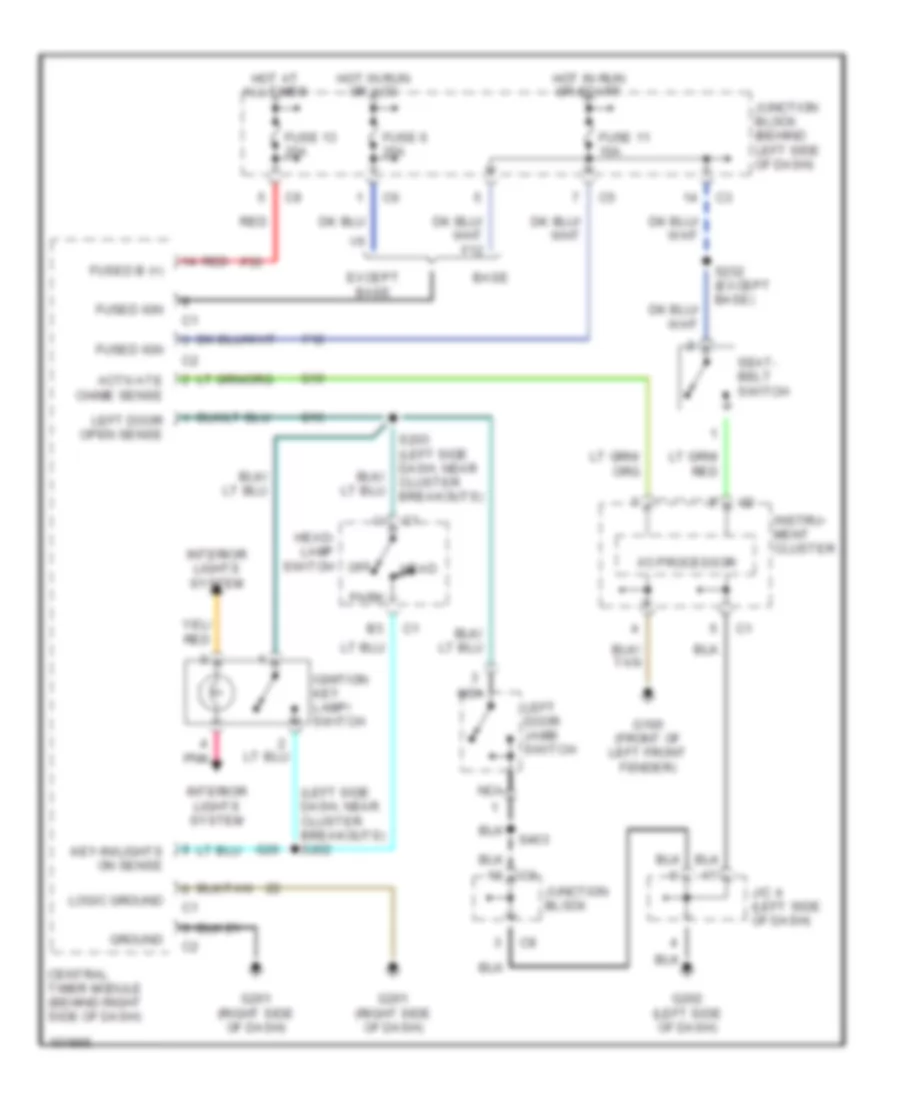
Warning System Wiring Diagrams for Dodge Dakota R/T 1998
List of elements for Warning System Wiring Diagrams for Dodge Dakota R/T 1998:
- (left side dash, near cluster breakouts) s202
- Activate chime sense
- Base
- Central timer module (behind right side of dash)
- Except base
- F12
- F35
- Fuse 11 10a
- Fuse 13 20a
- Fuse 6 20a
- Fused b (+)
- Fused ign
- G10
- G100 (front of left front fender)
- G16
- G201 (right side of dash)
- G202 (left side of dash)
- G26
- Ground
- Head
- Head- lamp switch
- Hot at all times
- Hot in run or acc
- Hot in run or start
- I/o processor
- Ignition key lamp/ switch
- Instru- ment cluster
- Interior lights system
- J/c 4 (left side of dash)
- Junction block
- Junction block (behind left side of dash)
- Key-in/lights on sense
- Left door jamb switch
- Left door open sense
- Logic ground
- Nca
- Off
- Park
- Pnk
- Red
- S203 (left side dash, near cluster breakouts)
- S232 (except base)
- S403
- Seat- belt switch
WIPER/WASHER
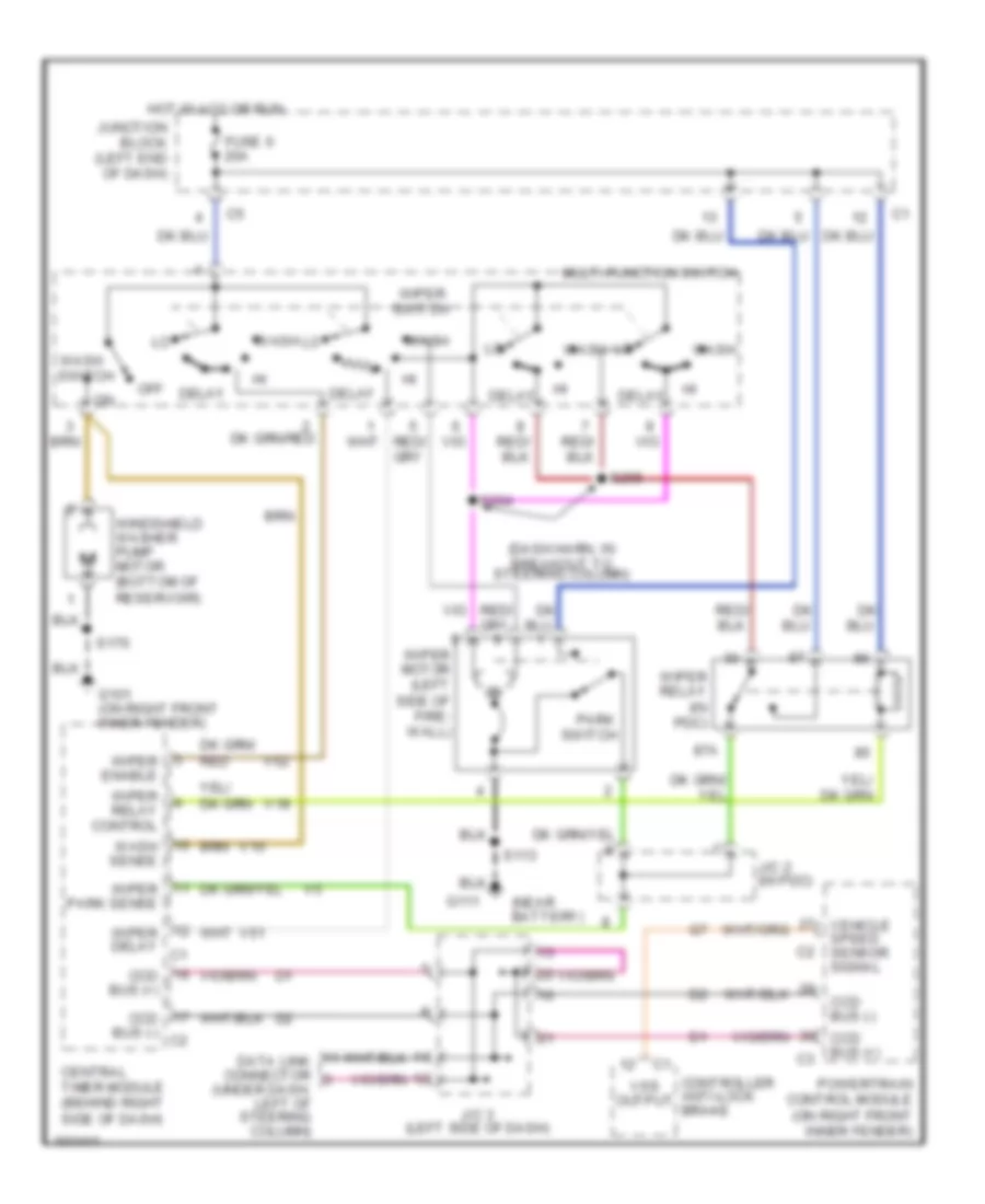
Wiper/Washer Wiring Diagram for Dodge Dakota R/T 1998
List of elements for Wiper/Washer Wiring Diagram for Dodge Dakota R/T 1998:
- (dash harn, in breakout to steering column)
- (near battery)
- 87a
- Ccd bus (+)
- Ccd bus (-)
- Ccd bus (-) c2
- Central timer module (behind right side of dash)
- Controller anti-lock brake
- Data link connector (under dash, left of steering column)
- Delay
- Fuse 6 20a
- G101 (on right front inner fender)
- G111
- Hot in acc or run
- J/c 2 (in pdc)
- J/c 3 (left side of dash)
- Junction block (left end of dash)
- Multi-function switch
- Off
- Park switch
- Powertrain control module (on right front inner fender)
- S113
- S170
- S204
- S205
- V10
- V18
- V51
- V52
- Vehicle speed sensor signal
- Vss output
- Wash
- Wash sense
- Wash switch
- Windshield washer pump motor (bottom of reservoir)
- Wiper delay c1
- Wiper enable
- Wiper motor (left side of fire- wall)
- Wiper park sense
- Wiper relay (in pdc)
- Wiper relay control
- Wiper switch