AIR CONDITIONING
Air Conditioning Wiring Diagram for Dodge Dakota R/T 2003

List of elements for Air Conditioning Wiring Diagram for Dodge Dakota R/T 2003:
- (at right
- (in power distribution center)
- (lower center of dash) g207
- (near mode door motor)
- (near powertrain
- (on discharge line
- (on lower right front of engine) g105
- (rear of engine)
- (right fender side shield) g112
- 1: vent 2: vent/floor 3: floor 4: defrost/floor 5: defrost
- 4.7l 3.9l/5.9l
- 87a
- A/c
- A/c clutch relay ctrl
- A/c compressor clutch
- A/c compressor clutch relay
- A/c heater control
- A/c pressure signal
- A/c pressure transducer
- A/c select
- A/c switch sense
- Acc
- Ambient temp sens signal
- Ambient temperature sensor (behind right side of grille on radiator support)
- Blend door actuator (right center of dash)
- Blend door driver
- Blower motor (in passenger side end of heater-a/c housing, below glove box)
- Blower motor resistor block (above passenger's footwell)
- Blower switch
- C11
- C13
- C18
- C20
- C24
- Common door driver
- Control module) s135
- Data link connector (under dash, left of steering column)
- Defogger system
- Evaporator temperature sensor (on upper center of dash)
- Fuse 10a
- Fuse 40a
- Fuse 40a 50a
- Fuse b 10a
- Ground
- Heated mirror
- High
- Hot at all times
- Hot in run
- Hot in run or start
- Htd mir
- Hvac controller
- Ignition switch
- Interior lights system
- J/c 2
- J/c 3 (in pdc)
- J/c 3 (in power distribution center)
- Junction block (on left end of dash)
- Lock
- Low
- Med 1
- Med 2
- Mode door actuator (behind right center of dash)
- Near a/c compressor)
- Not used
- Off
- Power distribution center (in engine compartment, on left inner fender panel)
- Power distribution center (in engine compt, on left inner fender panel)
- Powertrain control module (in engine compartment, on right inner fender panel)
- Radiator fan motor (behind radiator)
- Radiator fan relay
- Radiator fan relay ctrl
- Recirc
- Recirc door driver
- Recirculation door actuator (behind right center of dash)
- Run
- S101 (4.7l: near breakout for fuel injector 7) (3.9l/5.9l: rear of engine)
- S107
- S121
- S145 (left front of engine compt)
- Sensor ground
- Sensor signal
- Signal
- Start
- Tan
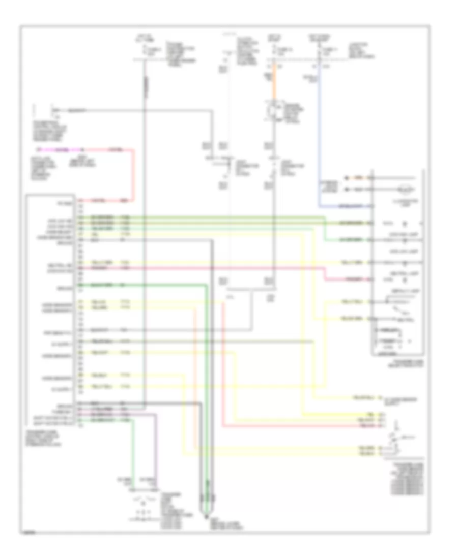
ANTI-LOCK BRAKES
Anti-lock Brakes Wiring Diagram for Dodge Dakota R/T 2003
List of elements for Anti-lock Brakes Wiring Diagram for Dodge Dakota R/T 2003:
- (3.9l/5.9l)
- (4.7l)
- (4wabs)
- (in breakout for controller anti-lock brake) s126
- (left rear of engine pnk/
- (rwabs)
- 3.9l/ 5.9l
- 4.7l
- 4wabs
- A10
- A20
- Abs indicator control
- Abs warning indicator
- B113
- B114
- Brake fluid level switch (in brake system combination valve)
- Brake fluid lvl sw sense
- Brake lamp sw sense
- Brake lamp switch (on brake pedal bracket)
- Brake transmission shift interlock solenoid
- C2 c1
- Controller anti-lock brake (abs: on top of hydraulic control unit, rwal: in eng compt, on left inner fender panel)
- D25
- Data link connector (under dash, left of steering column)
- Fuse 10a
- Fuse 40a
- Fuse ign sw output (run)
- Fused b (+)
- G113 (on left front of engine compartment, near battery)
- G207 (behind lower center of dash)
- Ground
- Hot at all times
- Hot in run
- Hot in run or start
- Instrument cluster
- J/c 2 (in pdc)
- Junction block (on left end of dash)
- Left front sensor (+)
- Left front sensor (-)
- Left front wheel speed sensor (w/ all wheel abs) (on left steering knuckle)
- Pci bus
- Pnk/
- Power distribution center (in engine compartment, on left inner fender panel)
- Powertrain control module (in engine compt, on right inner fender panel)
- Rear wheel sens (+)
- Rear wheel sensor (-)
- Rear wheel speed sensor (on top of differential housing)
- Red
- Right front sensor (+)
- Right front sensor (-)
- Right front wheel speed sensor (w/ all wheel abs) (on right steering knuckle)
- Rwabs
- S124
- S201 (behind left side of dash)
- S202 (behind right side of dash)
- Sci receive
- Sci receiver
- To diagnostic junction port) s206
- V40
- Vehicle speed sen sig
- Vehicle speed sig
- W/ all
- Wheel abs
- Z19
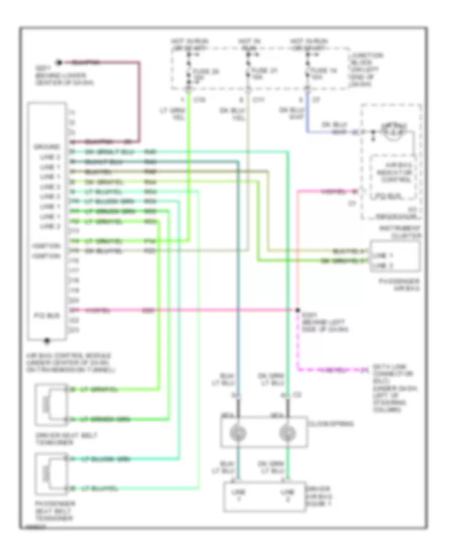
ANTI-THEFT
Anti-theft Wiring Diagram (1 of 2) for Dodge Dakota R/T 2003
List of elements for Anti-theft Wiring Diagram (1 of 2) for Dodge Dakota R/T 2003:
- (or red/tan)
- 2 door
- 4 door
- 87a
- A301
- A302
- Base
- C10
- Central timer module (left kick panel)
- Cyl lock sw mux
- D25
- Driver cylinder lock switch
- Driver door ajar switch
- Drv door ajar sw
- Drv door sw mux
- F12
- F15
- F18
- Fuse 10a
- Fuse 15a
- Fuse 20a
- Fused b(+)
- Fused ign
- Fused ign sw
- G112 (on right fender side shield)
- G113 (left front of engine compt, near battery)
- G208 (left kick panel)
- G307 (base of left ``b" piller)
- G69
- G73
- G74
- G75
- Ground
- High note horn (front left center of vehicle)
- Horn relay
- Horn relay ctrl
- Hot at all times
- Hot in run
- Hot in run or acc
- Hot in run or start
- Instrument cluster
- Junction block (on left end of dash)
- L33
- L34
- Left headlamp
- Left high beam driver
- Left rear door ajar switch
- Lh high beam
- Lock
- Low note horn (front left center of vehicle)
- Nca
- P96
- P97
- Pass dr ajar sw
- Pass dr sw mux
- Passenger cylinder lock switch
- Passenger door ajar switch
- Pci bus
- Pnk
- Premium
- Red/tan
- Rh high beam
- Right headlamp
- Right high beam driver
- Right rear door ajar switch
- S303 (near breakout to central tan/ red
- S327
- S328
- Sentry key immobilizer module (behind left side of dash, right of steering column)
- Tan
- Tan/ red
- Tan/red
- Timer module)
- Unlock
- Vtss ind driv
- Vtss lamp
- Z11
Anti-theft Wiring Diagram (2 of 2) for Dodge Dakota R/T 2003
List of elements for Anti-theft Wiring Diagram (2 of 2) for Dodge Dakota R/T 2003:
- (3.9l/5.9l)
- (4.7l)
- (behind left side of dash) s201
- (or red/tan)
- (under dash, left of steering column) data link connector
- Driver door module
- Driver door power lock motor/ ajar switch
- Fuse 20a
- G307 (base of left ``b" piller)
- Hot at all times
- Instrument cluster
- Left rear door power lock motor/ ajar switch
- Lock
- Passenger door power lock motor/ ajar switch
- Passenger door power lock switch
- Pci bus
- Power distribution center (in engine compt, on left inner fender panel)
- Powertrain control module (in engine compt, on right inner fender panel)
- Premium
- Premium 2 door
- Premium 4 door
- Red/tan
- Right rear door power lock motor/ ajar switch
- S200 (behind left side of dash)
- S202 (behind right side of dash)
- S301
- S303 (near breakout to central timer module)
- S327
- S328
- Tan
- Tan/ red
- Tan/red
- Unlock
BODY CONTROL MODULES
Body Control Modules Wiring Diagram for Dodge Dakota R/T 2003
List of elements for Body Control Modules Wiring Diagram for Dodge Dakota R/T 2003:
- (or red/
- (or red/tan)
- A301
- A302
- Anti-theft system
- C10
- Cargo lamp drv
- Cargo lamp sw sns
- Central timer module (left kick panel)
- Computer data lines system
- Courtesy lamp
- Courtesy lmp sw sns
- Cyl lock sw mux
- D25
- Door lock rly
- Door locks system
- Door unlock rly out
- Drv door unlk rly
- Drv dr ajar sw sns
- Drv dr sw mux
- Exterior lights system
- F12
- Fog lamp rly
- Fog lmp sw sns
- Frt washer motor ctrl
- Frt wiper park sw sns
- Frt wiper rly
- Fuse 10a
- Fuse 20a
- Fused b(+)
- G11
- G207 (behind lower center of dash) instrument cluster system
- G208 (left kick panel)
- G26
- G34
- G69
- G73
- G74
- G75
- Ground
- Headlamp sw off
- Headlamps system
- High beam ind drv
- High beam sw out
- Horn rly ctrl
- Horns system
- Hot at all times
- Hot in run or acc
- Hot in run or start
- Ign sw (run/acc)
- Ign sw (run/start)
- Int frt wiper mode sns
- Int frt wiper sw sig
- Interior lamp defeat
- Interior lights system
- Interior lmp drv
- Interior lmps drv
- Junction block (on left end of dash)
- Key-in ign sw sns
- L26
- L27
- L308
- L33
- L34
- L43
- L44
- L79
- L80
- Left high beam drv
- Left low beam drv
- Low beam sw out
- M11
- P33
- P34
- P59
- P96
- P97
- Park brake sw sns
- Park brake switch (on parking brake pedal bracket)
- Park lamp rly ctrl
- Park lamp sw sns
- Pass dr sw mux
- Pass dr ajar sw sns
- Pci bus
- Power distribution center (in engine compt, on left inner fender panel)
- Premium
- Radio ctrl mux
- Red/tan
- Right high beam drv
- Right low beam drv
- Sound systems
- Tan
- Tan/red
- V10
- V18
- V51
- V52
- Vtss ind drv
- Warning systems
- Wiper/washer system
- X20
- Y158
- Y192
COMPUTER DATA LINES
Computer Data Lines Wiring Diagram for Dodge Dakota R/T 2003
List of elements for Computer Data Lines Wiring Diagram for Dodge Dakota R/T 2003:
- (behind left side of dash) s200
- (behind right side of dash) s202
- (left rear of engine compt,
- 3.9l/5.9l
- 4.7l
- 4.7l only
- A/c-heater control
- Above wheelwell)
- Air bag control module (under center of dash, on transmission tunnel)
- Amplifier (right side kick panel)
- C10
- Central timer module (left kick panel)
- Controller anti-lock brake (w/ abs: on top of hydraulic control unit) (w/ rwal: in engine compt, on left inner fender panel)
- D15
- D20
- D21
- D25
- Data link connector (dlc) (under dash, left of steering column)
- Fuse 15a
- G208 (left kick panel)
- Hot at all times
- Instrument cluster
- Junction block (on left end of dash)
- Overhead console (premium)
- Pci bus
- Pnk
- Powertrain control module (in engine compt, on right inner fender panel)
- Radio
- S124
- S201 (behind left side of dash)
- Sci receive
- Sci transmit
- Sentry key immobilizer module (behind left side of dash, right of steering colimn)
- Transfer case control module (right side of steering column)
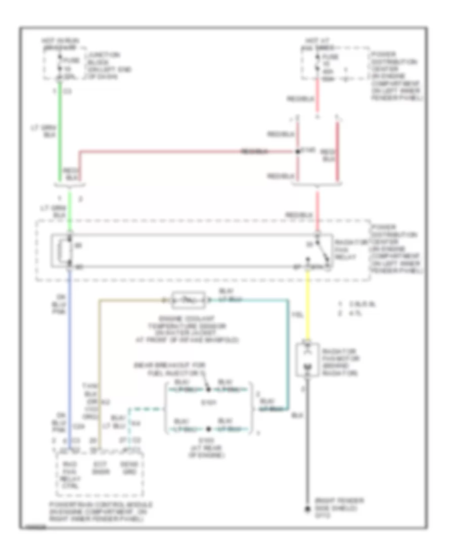
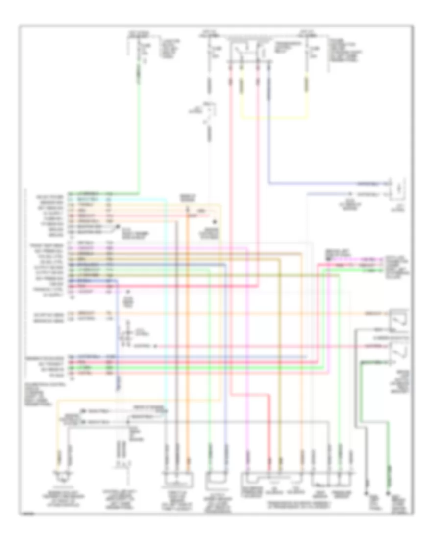
COOLING FAN
Cooling Fan Wiring Diagram for Dodge Dakota R/T 2003
List of elements for Cooling Fan Wiring Diagram for Dodge Dakota R/T 2003:
- (near breakout for
- (right fender side shield) g112
- 10a
- 3.9l/5.9l
- 4.7l
- 50a
- 87a
- C24
- Ect snsr
- Engine coolant temperature sensor (in water jacket, at front of intake manifold)
- Fuel injector 7)
- Fuse
- Fuse 40a
- Hot at all times
- Hot in run or start
- Junction block (on left end of dash)
- Power distribution center (in engine compartment, on left inner fender panel)
- Powertrain control module (in engine compartment, on right inner fender panel)
- Rad fan
- Radiator fan motor (behind radiator)
- Radiator fan relay
- Relay ctrl
- S101
- S103 (at rear of engine)
- S145
- Sens grd
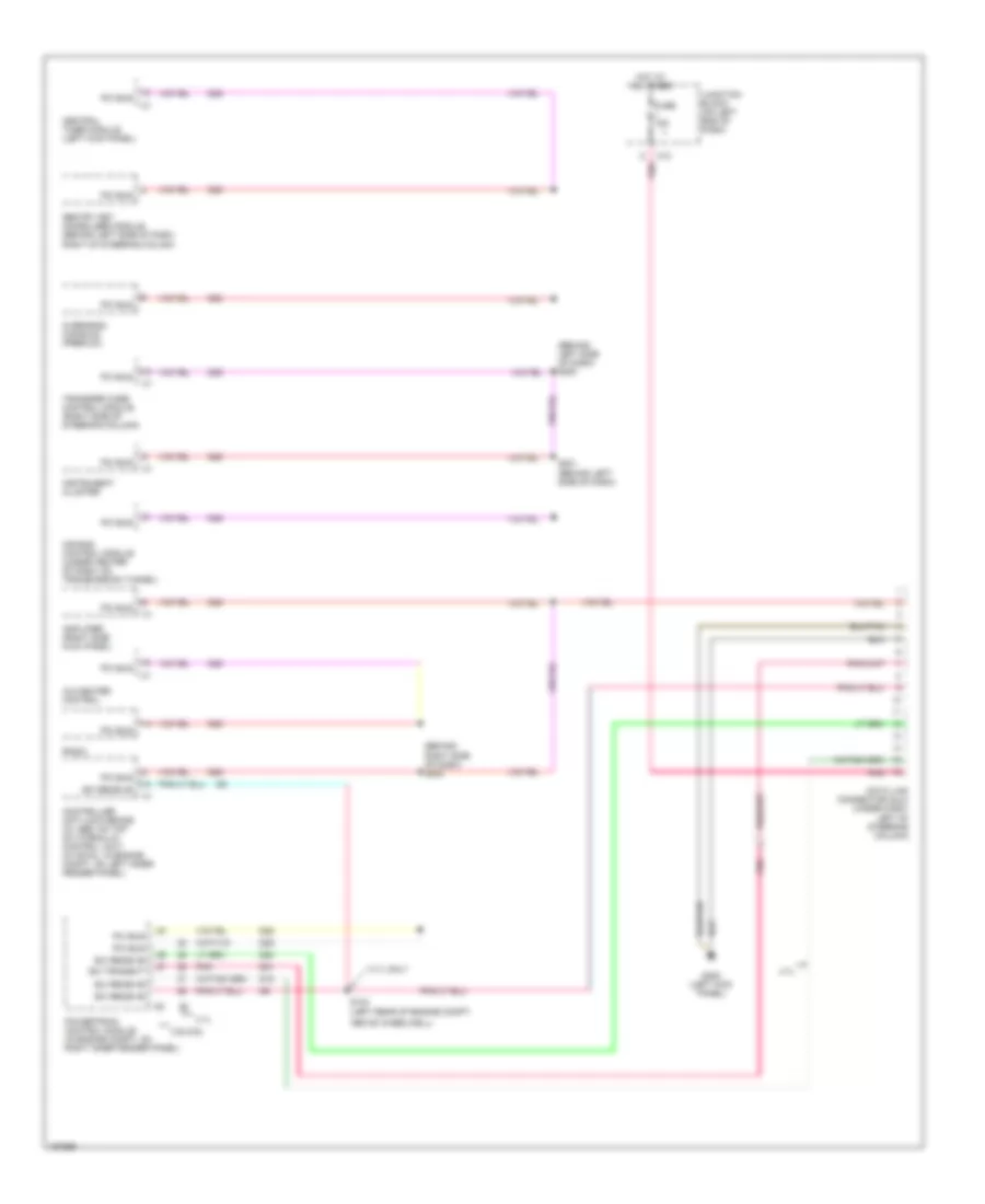
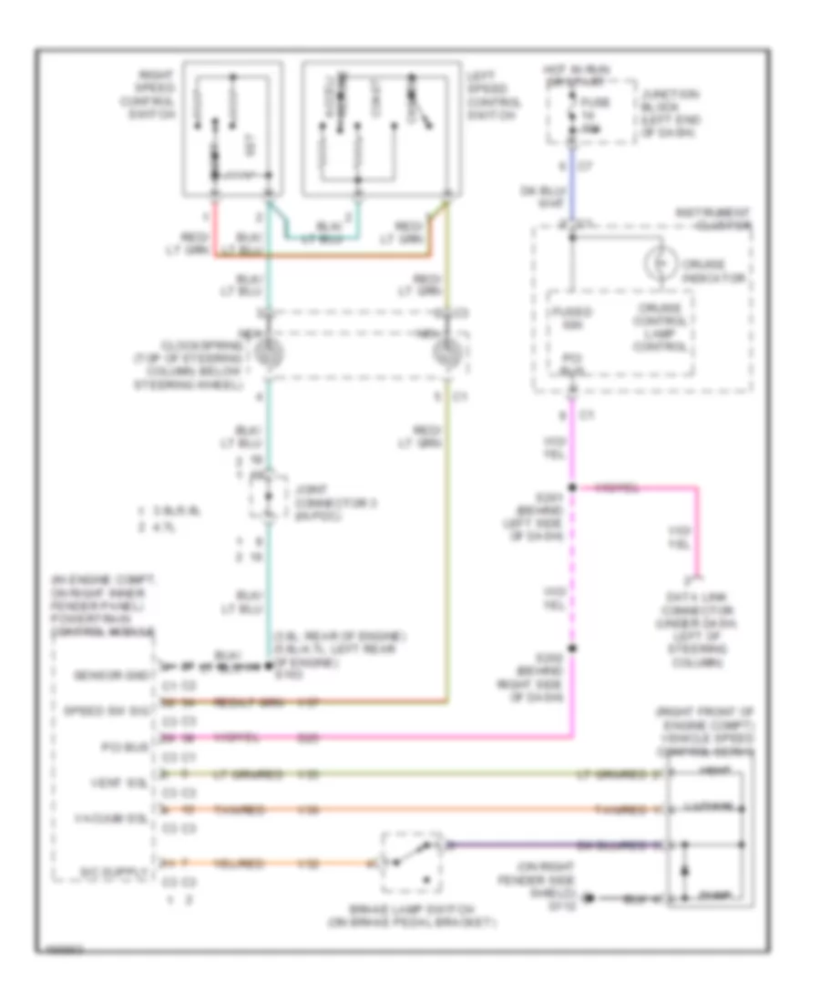
CRUISE CONTROL
Cruise Control Wiring Diagram for Dodge Dakota R/T 2003
List of elements for Cruise Control Wiring Diagram for Dodge Dakota R/T 2003:
- (3.9l: rear of engine) (5.9l/4.7l: left rear of engine) s103
- (in engine compt, on right inner fender panel) powertrain control module
- (on right fender side shield) g112
- (right front of engine compt) vehicle speed control servo
- 3.9l/5.9l
- 4.7l
- Accel/ resume
- Brake lamp switch (on brake pedal bracket)
- Cancel
- Clockspring (top of steering column, below steering wheel)
- Coast
- Cruise control lamp control
- Cruise indicator
- D25
- Data link connector (under dash, left of steering column)
- Dump
- Fuse 10a
- Fused ign
- Hot in run or start
- Instrument cluster
- Joint connector 3 (in pdc)
- Junction block (left end of dash)
- Left speed control switch
- Nca
- On/off
- Pci bus
- Right speed control switch
- S201 (behind left side of dash)
- S202 (behind right side of dash)
- Sensor gnd
- Set
- Speed sw sig
- Tan/red
- V32
- V35
- V36
- V37
- Vacuum
- Vacuum sol
- Vent
- Vent sol
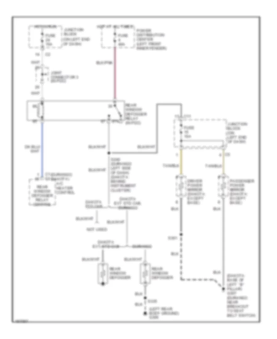
DEFOGGERS
Defoggers Wiring Diagram for Dodge Dakota R/T 2003
List of elements for Defoggers Wiring Diagram for Dodge Dakota R/T 2003:
- (dakota: base of left ``b" pillar) g307 (durango: near breakout to seat belt switch)
- (durango) (dakota)
- (left rear body ground) g306
- (on left end of dash)
- 87a
- A/c heater control
- C1 c1
- C11
- Dakota ext std cab
- Dakota ext std cab, durango
- Dakota std cab
- Driver power mirror (dakota: except base)
- Durango
- Fuse 10a
- Fuse 15a
- Fuse 40a
- Hot at all times
- Hot in run
- Joint connector 3 (in pdc)
- Junction block
- Junction block (on left end of dash)
- Not used
- Of dash) (dakota: behind instrument cluster)
- Passenger power mirror (dakota: except base)
- Power distribution center (left front inner fender)
- Rear window defogger
- Rear window defogger relay (in pdc)
- Rear window defogger relay control
- S301
- S335
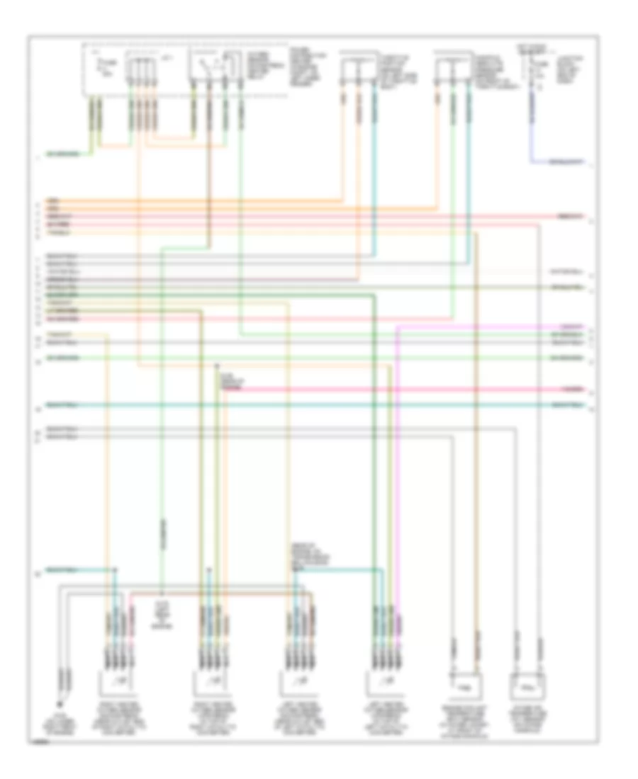
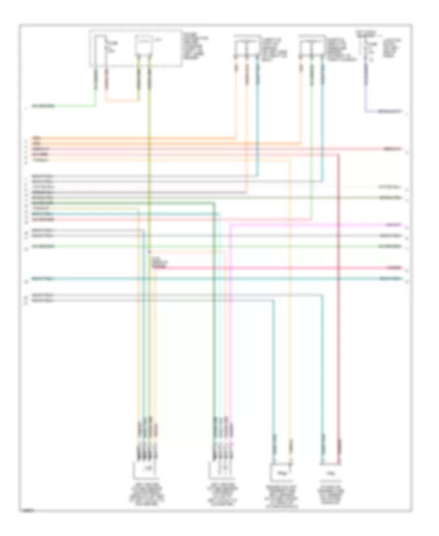
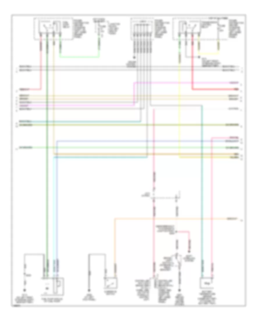
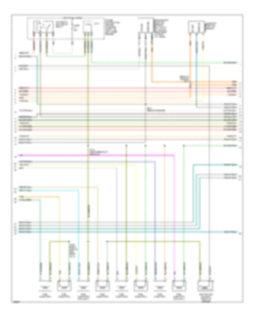
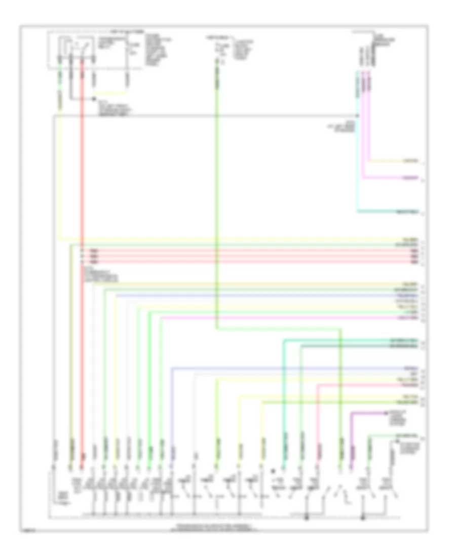
ENGINE PERFORMANCE
3.9L
3.9L, Engine Performance Wiring Diagram, California (1 of 4) for Dodge Dakota R/T 2003
List of elements for 3.9L, Engine Performance Wiring Diagram, California (1 of 4) for Dodge Dakota R/T 2003:
- (5.9l only)
- (near pcm)
- 3-4 shift
- A/c pres sig
- A/c pressure transducer (on discharge line, near a/c compressor)
- A/c sig
- A/t temp sig
- A14
- C106
- C18
- C24
- Cam pos sns
- Coil driver
- Controller anti-lock brake (abs) (w/ all- wheel abs) (on top of hydraulic control unit)
- Controller anti-lock brake (rwal) (w/o all- wheel abs) (in engine compt, on left inner fender panel)
- Cooling fans system
- Crnk pos sns
- Ect sens in
- Engine oil pressure switch
- F18
- Fuse 10a
- Fuse 20a
- Fuse f 20a
- Fused b(+)
- G115 (on right fender side shield)
- G60
- Gen field
- Gov pres cntl
- Gov pres sig
- Ground
- Ho2s 1/1 sig
- Ho2s 1/2 sig
- Ho2s 2/1 sig
- Ho2s 2/2 sig
- Hot at all times
- Hot in run or start
- Iat sens in
- Idle air 1
- Idle air 2
- Idle air 3
- Idle air 4
- Idle air control motor (on throttle body)
- Ign power
- Inj 1 driver
- Inj 2 driver
- Inj 3 driver
- Inj 4 driver
- Inj 5 driver
- Inj 6 driver
- Inj 7 driver
- Inj 8 driver
- J/c 1
- Junction block (on left end of dash)
- K11
- K12
- K13
- K14
- K141
- K19
- K20
- K21
- K22
- K24
- K241
- K26
- K28
- K30
- K341
- K38
- K39
- K40
- K41
- K44
- K54
- K58
- K59
- K60
- K88
- Map sens in
- Od sol cntl
- Oil pres sig
- Out spd sig
- Output speed sensor (on lower left rear of trans)
- P/n signal
- Pnk
- Power distribution center (in engine compt, on left inner fender)
- Powertrain control module (in engine compt, on right inner fender panel)
- Rad fan ctrl
- Red
- S103 (rear of engine)
- S135
- Sens gnd
- Sensor gnd
- Spd sens gnd
- Starting/ charging system
- T13
- T14
- T25
- T34
- T41
- T60
- Tan
- Tcc sol cntl
- Tps sens in
- Trans rly cntl
- Trans rly out
- Transmission control relay
- Transmission solenoid assembly (in transmission, on valve body)
- Vss
- Z12
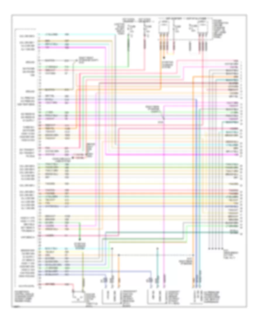
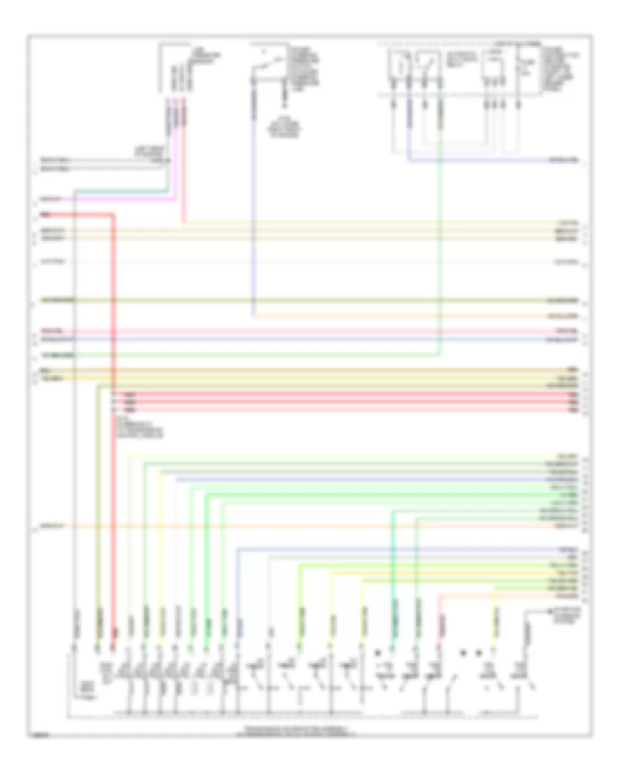
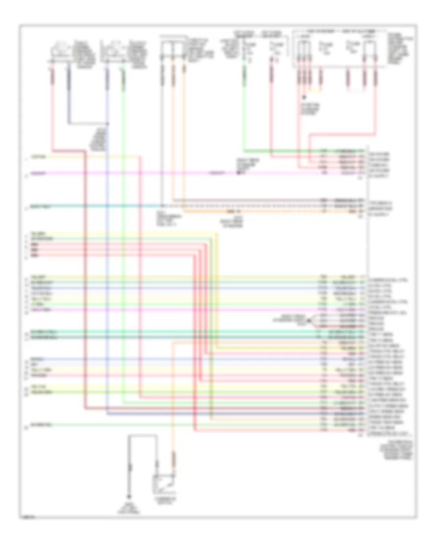
3.9L, Engine Performance Wiring Diagram, California (2 of 4) for Dodge Dakota R/T 2003
List of elements for 3.9L, Engine Performance Wiring Diagram, California (2 of 4) for Dodge Dakota R/T 2003:
- (rear of engine) s107
- 5v sup
- Automatic shutdown relay
- Camshaft position sensor
- Cps sig
- Fuel injector 1
- Fuel injector 2
- Fuel injector 3
- Fuel injector 4
- Fuel injector 5
- Fuel injector 6
- Fuel injector 7 (5.9l only)
- Fuel injector 8 (5.9l only)
- Fuse 30a
- Hot at all times
- Ignition coil (on right front of engine)
- J/c 2
- Nca
- Power distribution center (in engine compt, on left inner fender)
- S101 (rear of engine)
- S106 (right side of eng, near inj 4)
- S110 (near breakout for inj 5)
- Sens gd
- Sens gnd
- Tan
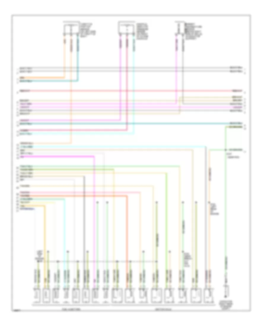
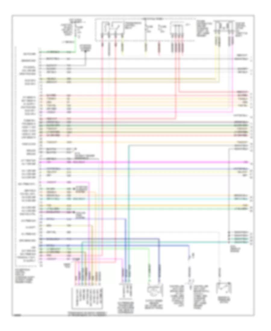
3.9L, Engine Performance Wiring Diagram, California (3 of 4) for Dodge Dakota R/T 2003
List of elements for 3.9L, Engine Performance Wiring Diagram, California (3 of 4) for Dodge Dakota R/T 2003:
- (rear of engine, on transmission bellhousing) s139
- Engine coolant temperature (ect) sensor (in water jacket, at front of intake manifold)
- Fuse 10a
- Fuse u 20a
- G105 (on lower right front of engine)
- Hot in run or start
- Intake air temperature (iat) sensor (on intake manifold)
- J/c 1
- Junction block (on left end of dash)
- Left heated oxygen sensor (downstream) (near outlet end of left catalytic converter)
- Left heated oxygen sensor (upstream) (in top of left catalytic converter)
- Manifold absolute pressure sensor (on front of throttle body)
- Nca
- Oxygen sensor downstream heater relay
- Power distribution center (in engine compt, on left inner fender)
- Right heated oxygen sensor (downstream) (near outlet end of right catalytic converter)
- Right heated oxygen sensor (upstream) (in top of right catalytic converter)
- S136 (rear of engine)
- S179 (left rear of engine)
- Throttle position sensor (on left side of throttle body)
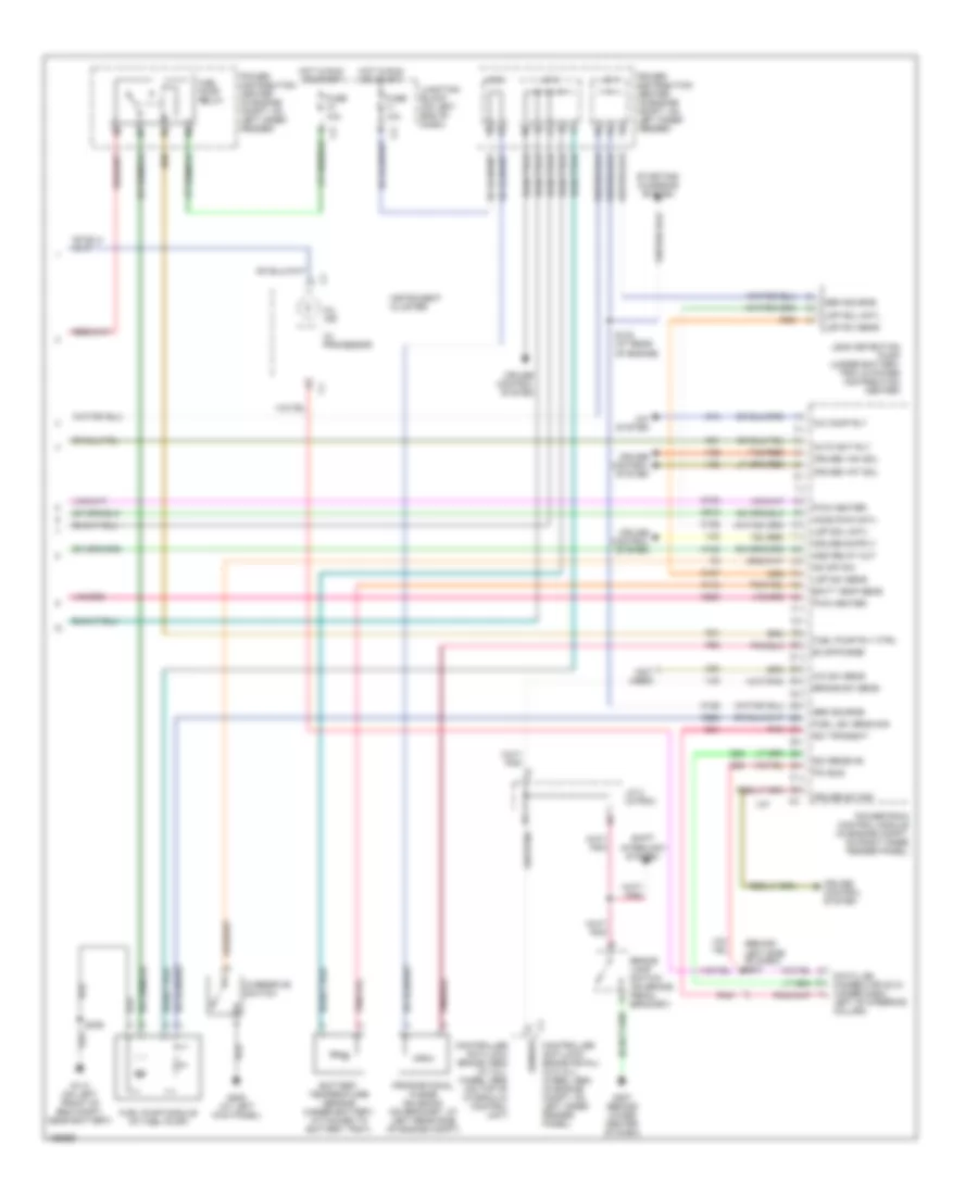
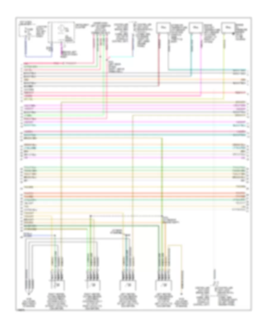
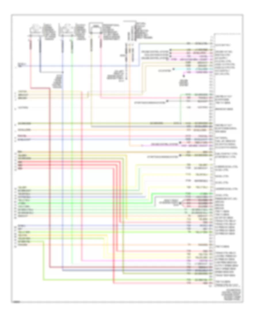
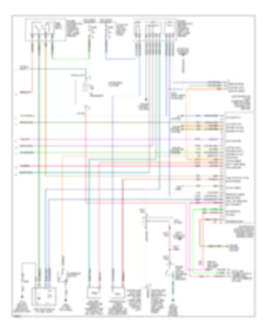
3.9L, Engine Performance Wiring Diagram, California (4 of 4) for Dodge Dakota R/T 2003
List of elements for 3.9L, Engine Performance Wiring Diagram, California (4 of 4) for Dodge Dakota R/T 2003:
- (behind left side of dash) s201
- (not used)
- A/c comp rly
- A/c sw sens
- A/c system
- A142
- Asd relay out
- Auto sht rly
- Batt temp sens
- Battery temperature sensor (under battery, attached to battery tray)
- Brake lamp switch (on brake pedal bracket)
- Brake sw sens
- C13
- C20
- Controller anti-lock brake (abs) (w/ all- wheel abs) (on top of hydraulic control unit)
- Controller anti-lock brake (rwal) (w/o all- wheel abs) (in engine compt, on left inner fender panel)
- Cruise control system
- Cruise sw sig
- Cruise vac sol
- Cruise vnt sol
- D20
- D21
- D25
- Data link connector (dlc) (under dash, left of steering column)
- Evap/purge
- Fuel lev sens sig
- Fuel pump module (at fuel pump)
- Fuel pump relay
- Fuel pump rly ctrl
- Fuse 10a
- G113 (on left front of eng compt, near battery)
- G207 (behind lower center of dash)
- G208 (at left kick panel)
- Gen source
- Ho2s dwn cntl
- Hot in run or start
- I/o processor
- Instrument cluster
- J/c 1
- J/c 2
- J/c 2 (in pdc)
- J/c 3
- Junction block (on left end of dash)
- K100
- K106
- K107
- K118
- K125
- K200
- K226
- K31
- K51
- K512
- K52
- Ldp sol cntl
- Ldp sw sens
- Leak detection pump (under battery tray & power distribution center)
- Mil ind
- Od off sw
- Overdrive switch
- Pci bus
- Pnk
- Power distribution center (in engine compt, on left inner fender)
- Powertrain control module (in engine compt, on right inner fender panel)
- Proportional purge solenoid (on bracket, at left rear side of engine compt)
- Pwm heater
- S123 (at rear of engine)
- S306
- Sci receive
- Sci transmit
- Sensor
- Shift interlock system
- Starting/ charging system
- Tan/red
- V32
- V35
- V36
- V37
- V40
3.9L, Engine Performance Wiring Diagram, Federal (1 of 4) for Dodge Dakota R/T 2003
List of elements for 3.9L, Engine Performance Wiring Diagram, Federal (1 of 4) for Dodge Dakota R/T 2003:
- (5.9l only)
- 3-4 shift
- A/c pres sig
- A/c pressure transducer (on discharge line, near a/c compressor)
- A/c sig
- A/t temp sig
- A14
- C106
- C18
- C24
- Cam pos sns
- Coil driver
- Controller anti-lock brake (abs) (w/ all- wheel abs) (on top of hydraulic control unit)
- Controller anti-lock brake (rwal) (w/o all- wheel abs) (in engine compt, on left inner fender panel)
- Cooling fans system
- Crnk pos sns
- Ect sens in
- Engine oil pressure sensor
- F18
- Fuse 10a
- Fuse 20a
- Fuse f 20a
- Fused b(+)
- G115 (on right fender side shield)
- G60
- Gen field
- Gov pres cntl
- Gov pres sig
- Ground
- Ho2s 1/1 sig
- Ho2s 1/2 sig
- Hot at all times
- Hot in run or start
- Iat sens in
- Idle air 1
- Idle air 2
- Idle air 3
- Idle air 4
- Idle air control motor (on throttle body)
- Ign power
- Inj 1 driver
- Inj 2 driver
- Inj 3 driver
- Inj 4 driver
- Inj 5 driver
- Inj 6 driver
- Inj 7 driver
- Inj 8 driver
- J/c 1
- Junction block (on left end of dash)
- K11
- K12
- K13
- K14
- K141
- K19
- K20
- K21
- K22
- K24
- K26
- K28
- K30
- K38
- K39
- K40
- K41
- K44
- K54
- K58
- K59
- K60
- K88
- Map sens in
- Od sol cntl
- Oil pres sig
- Out spd sig
- Output speed sensor (on lower left rear of trans)
- P/n signal
- Pnk
- Power distribution center (in engine compt, on left inner fender)
- Powertrain control module (in engine compt, on right inner fender panel)
- Rad fan ctrl
- Red
- S103 (rear of engine)
- S135 (near pcm)
- Sens gnd
- Sensor gnd
- Spd sens gnd
- Starting/ charging system
- T13
- T14
- T25
- T34
- T41
- T60
- Tan
- Tcc sol cntl
- Tps sens in
- Trans rly cntl
- Trans rly out
- Transmission control relay
- Transmission solenoid assembly (in transmission, on valve body)
- Vss
- Z12
3.9L, Engine Performance Wiring Diagram, Federal (2 of 4) for Dodge Dakota R/T 2003
List of elements for 3.9L, Engine Performance Wiring Diagram, Federal (2 of 4) for Dodge Dakota R/T 2003:
- (rear of engine) s107
- 5v sup
- Automatic shutdown relay
- Camshaft position sensor
- Cps sig
- Fuel injector 1
- Fuel injector 2
- Fuel injector 3
- Fuel injector 4
- Fuel injector 5
- Fuel injector 6
- Fuel injector 7 (5.9l only)
- Fuel injector 8 (5.9l only)
- Fuse 30a
- Hot at all times
- Ignition coil (on right front of engine)
- J/c 2
- Nca
- Power distribution center (in engine compt, on left inner fender)
- S101 (rear of engine)
- S106 (near inj 4)
- S110 (near breakout for inj 5)
- Sens gd
- Sens gnd
- Tan
3.9L, Engine Performance Wiring Diagram, Federal (3 of 4) for Dodge Dakota R/T 2003
List of elements for 3.9L, Engine Performance Wiring Diagram, Federal (3 of 4) for Dodge Dakota R/T 2003:
- Engine coolant temperature (ect) sensor (in water jacket, at front of intake manifold)
- Fuse 10a
- Fuse u 20a
- Hot in run or start
- Intake air temperature (iat) sensor (on intake manifold)
- J/c 1
- Junction block (on left end of dash)
- Left heated oxygen sensor (downstream) (near outlet end of left catalytic converter)
- Left heated oxygen sensor (upstream) (in top of left catalytic converter)
- Manifold absolute pressure sensor (on front of throttle body)
- Nca
- Power distribution center (in engine compt, on left inner fender)
- S122 (rear of engine)
- Throttle position sensor (on left side of throttle body)
3.9L, Engine Performance Wiring Diagram, Federal (4 of 4) for Dodge Dakota R/T 2003
List of elements for 3.9L, Engine Performance Wiring Diagram, Federal (4 of 4) for Dodge Dakota R/T 2003:
- (behind left side of dash) s201
- (not used)
- A/c comp rly
- A/c sw sens
- A/c system
- A142
- Asd relay out
- Auto sht rly
- Batt temp sens
- Battery temperature sensor (under battery, attached to battery tray)
- Brake lamp switch (on brake pedal bracket)
- Brake sw sens
- C13
- C20
- Controller anti-lock brake (abs) (w/ all- wheel abs) (on top of hydraulic control unit)
- Controller anti-lock brake (rwal) (w/o all- wheel abs) (in engine compt, on left inner fender panel)
- Cruise control system
- Cruise sw sig
- Cruise vac sol
- Cruise vnt sol
- D20
- D21
- D25
- Data link connector (dlc) (under dash, left of steering column)
- Evap/purge
- Fuel lev sens sig
- Fuel pump module (at fuel pump)
- Fuel pump relay
- Fuel pump rly ctrl
- Fuse 10a
- G113 (on left front of eng compt, near battery)
- G207 (behind lower center of dash)
- G208 (at left kick panel)
- Gen source
- Hot in run or start
- I/o processor
- Instrument cluster
- J/c 1
- J/c 2
- J/c 2 (in pdc)
- J/c 3
- Junction block (on left end of dash)
- K100
- K106
- K107
- K118
- K125
- K200
- K226
- K31
- K51
- K52
- Ldp sol cntl
- Ldp sw sens
- Leak detection pump (under battery tray & power distribution center)
- Mil ind
- Od off sw
- Overdrive switch
- Pci bus
- Pnk
- Power distribution center (in engine compt, on left inner fender)
- Powertrain control module (in engine compt, on right inner fender panel)
- Proportional purge solenoid (on bracket, at left rear side of engine compt)
- Pwm heater
- S123 (right rear of engine)
- S306
- Sci receive
- Sci transmit
- Sensor
- Shift interlock system
- Starting/ charging system
- Tan/red
- V32
- V35
- V36
- V37
- V40
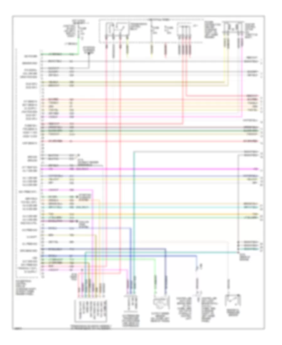
4.7L
4.7L, Engine Performance Wiring Diagram (1 of 6) for Dodge Dakota R/T 2003
List of elements for 4.7L, Engine Performance Wiring Diagram (1 of 6) for Dodge Dakota R/T 2003:
- (behind right side of dash) s202
- (right front of engine compt) g100
- (right rear of engine compt)
- A/c pres sig
- A/c pressure transducer (on discharge line, near a/c compressor)
- A/c sig
- A14
- A169
- Amb temp sens
- C18
- Cam pos sns
- Camshaft position sensor (on front of right cyl head)
- Cmp sig
- Coil driver 1
- Coil driver 2
- Coil driver 3
- Coil driver 4
- Coil driver 5
- Coil driver 6
- Coil driver 7
- Coil driver 8
- Computer data lines system
- Cps sig
- Crankshaft position sensor (on right rear side of cyl block)
- Crnk pos sns
- D15
- D20
- D21
- D25
- Ect sens in
- F11
- F18
- Fuse 10a
- Fuse 20a
- Fused b(+)
- G31
- G60
- Gen field
- Ground
- Ho2s 1/1 htr
- Ho2s 1/1 sig
- Ho2s 1/2 sig
- Ho2s 2/1 htr
- Ho2s 2/1 sig
- Ho2s 2/2 sig
- Ho2s return
- Hot at all times
- Hot at start
- Hot in run or start
- Iac mtr cntrl
- Iac return
- Iat sens in
- Idle air control motor (on throttle body)
- Ign power
- Inj 1 driver
- Inj 2 driver
- Inj 3 driver
- Inj 4 driver
- Inj 5 driver
- Inj 6 driver
- Inj 7 driver
- Inj 8 driver
- J/c 2
- Junction block (on left end of dash)
- K11
- K12
- K13
- K14
- K141
- K199
- K20
- K21
- K22
- K24
- K241
- K26
- K28
- K341
- K38
- K39
- K41
- K44
- K58
- K60
- K902
- K904
- K91
- K92
- K93
- K94
- K95
- K96
- K97
- K98
- K99
- Map sens in
- Oil pres sig
- Pci bus
- Pnk
- Power distribution center (in engine compt, on left inner fender panel)
- Powertrain control module (in engine compt, on right inner fender panel)
- S101 (near break- out for fuel inj 7)
- S102
- S107 (right rear of engine)
- Sci receive
- Sci transmit
- Sens gnd
- Sensor gnd
- Starting/ charging system
- Tan
- Tan/pnk
- Tan/red
- Tps sens in
- Vss
- Z12
4.7L, Engine Performance Wiring Diagram (2 of 6) for Dodge Dakota R/T 2003
List of elements for 4.7L, Engine Performance Wiring Diagram (2 of 6) for Dodge Dakota R/T 2003:
- (at rear of engine)
- (behind left side of dash) s201
- (under dash, left of steering column) data link connector (dlc)
- Controller anti-lock brake (abs) (w/ all- wheel abs) (on top of hydraulic control unit)
- Controller anti-lock brake (rwal) (w/o all- wheel abs) (in engine compt, on left inner fender panel)
- Engine coolant temperature (ect) sensor (in water jacket, at front of intake)
- Engine oil pressure sensor (on oil filter housing)
- Fuse 10a
- G105 (on lower right front of engine)
- Hot in run or start
- I/o proc- essor
- Instrument cluster
- Intake air temperature (iat) sensor (on intake manifold, near throttle body)
- Junction block (on left end of dash)
- Left heated oxygen sensor (downstream) (on outlet end of left catalytic converter)
- Left heated oxygen sensor (upstream) (in top of left catalytic converter)
- Mil ind
- Nca
- Pnk
- Right heated oxygen sensor (downstream) (calfornia only) (on outlet end of right catalytic converter)
- Right heated oxygen sensor (upstream) (california only) (in top of right catalytic converter)
- S104 (at rear of engine compt)
- S105
- S124 (left rear of eng compt, above wheelwell)
- Sci rec
- Tan
- Tan/pnk
- Tan/red
- Vss
4.7L, Engine Performance Wiring Diagram (3 of 6) for Dodge Dakota R/T 2003
List of elements for 4.7L, Engine Performance Wiring Diagram (3 of 6) for Dodge Dakota R/T 2003:
- (left side of engine) s134
- (near pdc)
- Ambient temperature sensor (behind right side of grille, sens gnd on radiator support)
- Capacitor (right rear of engine compt)
- Fuel injectors
- Ignition coils
- Manifold absolute pressure sensor (on front of intake) manifold)
- Nca
- S183 (near break- out for inj 6)
- S184 (left rear of engine)
- S187
- Sens sig
- Tan
- Tan/pnk
- Tan/red
- Throttle position sensor (on left side of throttle body)
4.7L, Engine Performance Wiring Diagram (4 of 6) for Dodge Dakota R/T 2003
List of elements for 4.7L, Engine Performance Wiring Diagram (4 of 6) for Dodge Dakota R/T 2003:
- (near breakout to diagnostic junction port) s206
- Battery temperature sensor (under battery, attached to battery tray)
- Brake lamp switch (on brake pedal bracket)
- Controller anti-lock brake (abs) (w/ all- wheel abs) (on top of hydraulic control unit)
- Controller anti-lock brake (rwal) (w/o all- wheel abs) (in engine compt, on left inner fender panel)
- Cruise control system
- Fuel pump module (at fuel pump)
- Fuel pump relay
- Fuse 10a
- Fuse f 20a
- G113 (on left front of engine compt, near battery)
- G207 (behind lower center of dash)
- G208 (at left kick panel)
- Hot at all times
- Hot in run or start
- J/c 2 (in pdc)
- J/c 3
- Junction block (on left end of dash)
- Overdrive switch
- Power distribution center (in engine compt, on left inner fender panel)
- Red
- S306
- Sensor
- Shift interlock system
- Transmission control relay
4.7L, Engine Performance Wiring Diagram (5 of 6) for Dodge Dakota R/T 2003
List of elements for 4.7L, Engine Performance Wiring Diagram (5 of 6) for Dodge Dakota R/T 2003:
- (left rear of engine)
- 2-4 press
- 2c sol ctrl
- 4c prs sw sens
- 4c sol ctrl
- Automatic shut down relay
- Fuse 30a
- G105 (on lower right front of engine)
- Hot at all times
- J/c 2
- L/r press
- Line pressure sensor
- Lr sol ctrl
- Ms sol ctrl
- Od press
- Od sol ctrl
- Power distribution center (in engine compt, on left inner fender panel)
- Power steering pressure switch (in power steering pressure line)
- Red
- S103
- S175 (in breakout to transmission control module)
- Sens gnd
- Sens signal
- Starting/ charging system
- Temp sens
- Tran ctrl rly out
- Transmission solenoid/trs assembly (in transmission, on valve body assembly)
- Trs t1 sens
- Trs t2 sens
- Trs t3 sens
- Trs t41 sens
- Trs t42 sens
- Ud press
- Ud sol ctrl
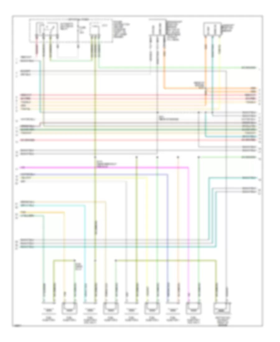
4.7L, Engine Performance Wiring Diagram (6 of 6) for Dodge Dakota R/T 2003
List of elements for 4.7L, Engine Performance Wiring Diagram (6 of 6) for Dodge Dakota R/T 2003:
- (on left front of engine compt, near battery) g113
- (right front of engine compt) g100
- 2c pres sw sens
- 2c sol ctrl
- 4c pres sw sens
- 4c sol ctrl
- A/c comp rly
- A/c system
- A142
- Aat signal
- Asd relay out
- Auto sht rly
- Brake sw sens
- C13
- C24
- Cooling fans system
- Cruise control system
- Cruise vnt sol
- Evap purge signal
- Evap/purge
- Fuel lev sens sig
- Fuel pump rly ctrl
- Ground
- Ho2s 1/2 htr ctrl
- Ho2s 2/2 htr ctrl
- Input speed sens
- Input speed sensor (on front left side of trans- mission)
- K10
- K106
- K107
- K118
- K226
- K299
- K31
- K399
- K51
- K52
- K70
- Line pres sens sig
- Low/rev press sw
- Lr sol ctrl
- Ms sol ctrl
- Natural vacuum leak detection assembly (near left front fender)
- Nvld sol cntl
- Nvld sol ctrl
- Nvld switch
- Nvld switch signal
- Od off sw sens
- Od pres sw sens
- Output speed sens
- Output speed sensor (on left side of trans- mission)
- Overdrive sol ctrl
- Powertrain control module (in engine compt, on right inner fender panel)
- Pressure cntl sol
- Proportional purge solenoid (on bracket, at left rear side of engine compartment)
- Rad fan ctrl
- Red
- S/c switch signal
- S/c vac ctrl
- S176
- S178 (near trans- mission control module)
- S306
- Speed sens gnd
- Sps sens
- Starter rly ctrl
- Starting/charging system
- T118
- T119 t119
- T120
- T13
- T14
- T140
- T15
- T159
- T16
- T29
- T38
- T41
- T42
- T47
- T48
- T50
- T52
- T54
- T59
- T60
- T752
- Trans ctrl relay
- Trans ctrl rly out
- Trans temp sens
- Trs t1 sens
- Trs t2 sens
- Trs t3 sens
- Trs t41 sens
- Trs t42 sens
- Ud pres sw sens
- Undrdrive sol ctrl
- V32
- V35
- V36
- V37
- V40
- Z13
5.9L
5.9L, Engine Performance Wiring Diagram, California (1 of 4) for Dodge Dakota R/T 2003
List of elements for 5.9L, Engine Performance Wiring Diagram, California (1 of 4) for Dodge Dakota R/T 2003:
- (5.9l only)
- (near pcm)
- 3-4 shift
- A/c pres sig
- A/c pressure transducer (on discharge line, near a/c compressor)
- A/c sig
- A/t temp sig
- A14
- C106
- C18
- C24
- Cam pos sns
- Coil driver
- Controller anti-lock brake (abs) (w/ all- wheel abs) (on top of hydraulic control unit)
- Controller anti-lock brake (rwal) (w/o all- wheel abs) (in engine compt, on left inner fender panel)
- Cooling fans system
- Crnk pos sns
- Ect sens in
- Engine oil pressure switch
- F18
- Fuse 10a
- Fuse 20a
- Fuse f 20a
- Fused b(+)
- G115 (on right fender side shield)
- G60
- Gen field
- Gov pres cntl
- Gov pres sig
- Ground
- Ho2s 1/1 sig
- Ho2s 1/2 sig
- Ho2s 2/1 sig
- Ho2s 2/2 sig
- Hot at all times
- Hot in run or start
- Iat sens in
- Idle air 1
- Idle air 2
- Idle air 3
- Idle air 4
- Idle air control motor (on throttle body)
- Ign power
- Inj 1 driver
- Inj 2 driver
- Inj 3 driver
- Inj 4 driver
- Inj 5 driver
- Inj 6 driver
- Inj 7 driver
- Inj 8 driver
- J/c 1
- Junction block (on left end of dash)
- K11
- K12
- K13
- K14
- K141
- K19
- K20
- K21
- K22
- K24
- K241
- K26
- K28
- K30
- K341
- K38
- K39
- K40
- K41
- K44
- K54
- K58
- K59
- K60
- K88
- Map sens in
- Od sol cntl
- Oil pres sig
- Out spd sig
- Output speed sensor (on lower left rear of trans)
- P/n signal
- Pnk
- Power distribution center (in engine compt, on left inner fender)
- Powertrain control module (in engine compt, on right inner fender panel)
- Rad fan ctrl
- Red
- S103 (rear of engine)
- S135
- Sens gnd
- Sensor gnd
- Spd sens gnd
- Starting/ charging system
- T13
- T14
- T25
- T34
- T41
- T60
- Tan
- Tcc sol cntl
- Tps sens in
- Trans rly cntl
- Trans rly out
- Transmission control relay
- Transmission solenoid assembly (in transmission, on valve body)
- Vss
- Z12
5.9L, Engine Performance Wiring Diagram, California (2 of 4) for Dodge Dakota R/T 2003
List of elements for 5.9L, Engine Performance Wiring Diagram, California (2 of 4) for Dodge Dakota R/T 2003:
- (rear of engine) s107
- 5v sup
- Automatic shutdown relay
- Camshaft position sensor
- Cps sig
- Fuel injector 1
- Fuel injector 2
- Fuel injector 3
- Fuel injector 4
- Fuel injector 5
- Fuel injector 6
- Fuel injector 7 (5.9l only)
- Fuel injector 8 (5.9l only)
- Fuse 30a
- Hot at all times
- Ignition coil (on right front of engine)
- J/c 2
- Nca
- Power distribution center (in engine compt, on left inner fender)
- S101 (rear of engine)
- S106 (right side of eng, near inj 4)
- S110 (near breakout for inj 5)
- Sens gd
- Sens gnd
- Tan
5.9L, Engine Performance Wiring Diagram, California (3 of 4) for Dodge Dakota R/T 2003
List of elements for 5.9L, Engine Performance Wiring Diagram, California (3 of 4) for Dodge Dakota R/T 2003:
- (rear of engine, on transmission bellhousing) s139
- Engine coolant temperature (ect) sensor (in water jacket, at front of intake manifold)
- Fuse 10a
- Fuse u 20a
- G105 (on lower right front of engine)
- Hot in run or start
- Intake air temperature (iat) sensor (on intake manifold)
- J/c 1
- Junction block (on left end of dash)
- Left heated oxygen sensor (downstream) (near outlet end of left catalytic converter)
- Left heated oxygen sensor (upstream) (in top of left catalytic converter)
- Manifold absolute pressure sensor (on front of throttle body)
- Nca
- Oxygen sensor downstream heater relay
- Power distribution center (in engine compt, on left inner fender)
- Right heated oxygen sensor (downstream) (near outlet end of right catalytic converter)
- Right heated oxygen sensor (upstream) (in top of right catalytic converter)
- S136 (rear of engine)
- S179 (left rear of engine)
- Throttle position sensor (on left side of throttle body)
5.9L, Engine Performance Wiring Diagram, California (4 of 4) for Dodge Dakota R/T 2003
List of elements for 5.9L, Engine Performance Wiring Diagram, California (4 of 4) for Dodge Dakota R/T 2003:
- (behind left side of dash) s201
- (not used)
- A/c comp rly
- A/c sw sens
- A/c system
- A142
- Asd relay out
- Auto sht rly
- Batt temp sens
- Battery temperature sensor (under battery, attached to battery tray)
- Brake lamp switch (on brake pedal bracket)
- Brake sw sens
- C13
- C20
- Controller anti-lock brake (abs) (w/ all- wheel abs) (on top of hydraulic control unit)
- Controller anti-lock brake (rwal) (w/o all- wheel abs) (in engine compt, on left inner fender panel)
- Cruise control system
- Cruise sw sig
- Cruise vac sol
- Cruise vnt sol
- D20
- D21
- D25
- Data link connector (dlc) (under dash, left of steering column)
- Evap/purge
- Fuel lev sens sig
- Fuel pump module (at fuel pump)
- Fuel pump relay
- Fuel pump rly ctrl
- Fuse 10a
- G113 (on left front of eng compt, near battery)
- G207 (behind lower center of dash)
- G208 (at left kick panel)
- Gen source
- Ho2s dwn cntl
- Hot in run or start
- I/o processor
- Instrument cluster
- J/c 1
- J/c 2
- J/c 2 (in pdc)
- J/c 3
- Junction block (on left end of dash)
- K100
- K106
- K107
- K118
- K125
- K200
- K226
- K31
- K51
- K512
- K52
- Ldp sol cntl
- Ldp sw sens
- Leak detection pump (under battery tray & power distribution center)
- Mil ind
- Od off sw
- Overdrive switch
- Pci bus
- Pnk
- Power distribution center (in engine compt, on left inner fender)
- Powertrain control module (in engine compt, on right inner fender panel)
- Proportional purge solenoid (on bracket, at left rear side of engine compt)
- Pwm heater
- S123 (at rear of engine)
- S306
- Sci receive
- Sci transmit
- Sensor
- Shift interlock system
- Starting/ charging system
- Tan/red
- V32
- V35
- V36
- V37
- V40
5.9L, Engine Performance Wiring Diagram, Federal (1 of 4) for Dodge Dakota R/T 2003
List of elements for 5.9L, Engine Performance Wiring Diagram, Federal (1 of 4) for Dodge Dakota R/T 2003:
- (5.9l only)
- 3-4 shift
- A/c pres sig
- A/c pressure transducer (on discharge line, near a/c compressor)
- A/c sig
- A/t temp sig
- A14
- C106
- C18
- C24
- Cam pos sns
- Coil driver
- Controller anti-lock brake (abs) (w/ all- wheel abs) (on top of hydraulic control unit)
- Controller anti-lock brake (rwal) (w/o all- wheel abs) (in engine compt, on left inner fender panel)
- Cooling fans system
- Crnk pos sns
- Ect sens in
- Engine oil pressure sensor
- F18
- Fuse 10a
- Fuse 20a
- Fuse f 20a
- Fused b(+)
- G115 (on right fender side shield)
- G60
- Gen field
- Gov pres cntl
- Gov pres sig
- Ground
- Ho2s 1/1 sig
- Ho2s 1/2 sig
- Hot at all times
- Hot in run or start
- Iat sens in
- Idle air 1
- Idle air 2
- Idle air 3
- Idle air 4
- Idle air control motor (on throttle body)
- Ign power
- Inj 1 driver
- Inj 2 driver
- Inj 3 driver
- Inj 4 driver
- Inj 5 driver
- Inj 6 driver
- Inj 7 driver
- Inj 8 driver
- J/c 1
- Junction block (on left end of dash)
- K11
- K12
- K13
- K14
- K141
- K19
- K20
- K21
- K22
- K24
- K26
- K28
- K30
- K38
- K39
- K40
- K41
- K44
- K54
- K58
- K59
- K60
- K88
- Map sens in
- Od sol cntl
- Oil pres sig
- Out spd sig
- Output speed sensor (on lower left rear of trans)
- P/n signal
- Pnk
- Power distribution center (in engine compt, on left inner fender)
- Powertrain control module (in engine compt, on right inner fender panel)
- Rad fan ctrl
- Red
- S103 (rear of engine)
- S135 (near pcm)
- Sens gnd
- Sensor gnd
- Spd sens gnd
- Starting/ charging system
- T13
- T14
- T25
- T34
- T41
- T60
- Tan
- Tcc sol cntl
- Tps sens in
- Trans rly cntl
- Trans rly out
- Transmission control relay
- Transmission solenoid assembly (in transmission, on valve body)
- Vss
- Z12
5.9L, Engine Performance Wiring Diagram, Federal (2 of 4) for Dodge Dakota R/T 2003
List of elements for 5.9L, Engine Performance Wiring Diagram, Federal (2 of 4) for Dodge Dakota R/T 2003:
- (rear of engine) s107
- 5v sup
- Automatic shutdown relay
- Camshaft position sensor
- Cps sig
- Fuel injector 1
- Fuel injector 2
- Fuel injector 3
- Fuel injector 4
- Fuel injector 5
- Fuel injector 6
- Fuel injector 7 (5.9l only)
- Fuel injector 8 (5.9l only)
- Fuse 30a
- Hot at all times
- Ignition coil (on right front of engine)
- J/c 2
- Nca
- Power distribution center (in engine compt, on left inner fender)
- S101 (rear of engine)
- S106 (near inj 4)
- S110 (near breakout for inj 5)
- Sens gd
- Sens gnd
- Tan
5.9L, Engine Performance Wiring Diagram, Federal (3 of 4) for Dodge Dakota R/T 2003
List of elements for 5.9L, Engine Performance Wiring Diagram, Federal (3 of 4) for Dodge Dakota R/T 2003:
- Engine coolant temperature (ect) sensor (in water jacket, at front of intake manifold)
- Fuse 10a
- Fuse u 20a
- Hot in run or start
- Intake air temperature (iat) sensor (on intake manifold)
- J/c 1
- Junction block (on left end of dash)
- Left heated oxygen sensor (downstream) (near outlet end of left catalytic converter)
- Left heated oxygen sensor (upstream) (in top of left catalytic converter)
- Manifold absolute pressure sensor (on front of throttle body)
- Nca
- Power distribution center (in engine compt, on left inner fender)
- S122 (rear of engine)
- Throttle position sensor (on left side of throttle body)
5.9L, Engine Performance Wiring Diagram, Federal (4 of 4) for Dodge Dakota R/T 2003
List of elements for 5.9L, Engine Performance Wiring Diagram, Federal (4 of 4) for Dodge Dakota R/T 2003:
- (behind left side of dash) s201
- (not used)
- A/c comp rly
- A/c sw sens
- A/c system
- A142
- Asd relay out
- Auto sht rly
- Batt temp sens
- Battery temperature sensor (under battery, attached to battery tray)
- Brake lamp switch (on brake pedal bracket)
- Brake sw sens
- C13
- C20
- Controller anti-lock brake (abs) (w/ all- wheel abs) (on top of hydraulic control unit)
- Controller anti-lock brake (rwal) (w/o all- wheel abs) (in engine compt, on left inner fender panel)
- Cruise control system
- Cruise sw sig
- Cruise vac sol
- Cruise vnt sol
- D20
- D21
- D25
- Data link connector (dlc) (under dash, left of steering column)
- Evap/purge
- Fuel lev sens sig
- Fuel pump module (at fuel pump)
- Fuel pump relay
- Fuel pump rly ctrl
- Fuse 10a
- G113 (on left front of eng compt, near battery)
- G207 (behind lower center of dash)
- G208 (at left kick panel)
- Gen source
- Hot in run or start
- I/o processor
- Instrument cluster
- J/c 1
- J/c 2
- J/c 2 (in pdc)
- J/c 3
- Junction block (on left end of dash)
- K100
- K106
- K107
- K118
- K125
- K200
- K226
- K31
- K51
- K52
- Ldp sol cntl
- Ldp sw sens
- Leak detection pump (under battery tray & power distribution center)
- Mil ind
- Od off sw
- Overdrive switch
- Pci bus
- Pnk
- Power distribution center (in engine compt, on left inner fender)
- Powertrain control module (in engine compt, on right inner fender panel)
- Proportional purge solenoid (on bracket, at left rear side of engine compt)
- Pwm heater
- S123 (right rear of engine)
- S306
- Sci receive
- Sci transmit
- Sensor
- Shift interlock system
- Starting/ charging system
- Tan/red
- V32
- V35
- V36
- V37
- V40
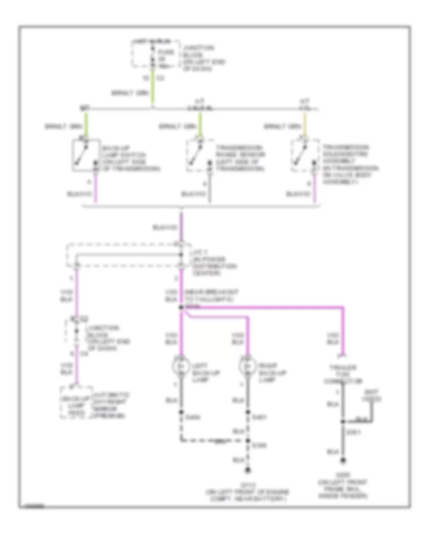
EXTERIOR LIGHTS
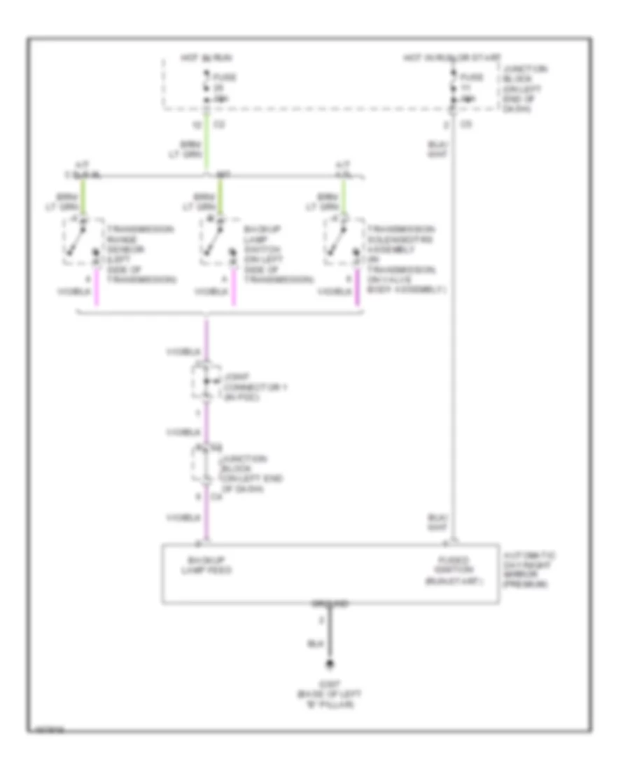
Back-up Lamps Wiring Diagram for Dodge Dakota R/T 2003
List of elements for Back-up Lamps Wiring Diagram for Dodge Dakota R/T 2003:
- (not used)
- A/t 3.9l/5.9l
- A/t 4.7l
- Automatic day/night mirror (premium)
- Back-up lamp feed
- Back-up lamp switch (on left side of transmission)
- Fuse 15a
- G113 (on left front of engine compt, near battery)
- G305 (on left front frame rail, inside fender)
- Hot in run
- J/c 1 (in power distribution center)
- Junction block (on left end of dash)
- Left back-up lamp
- M/t
- Right back-up lamp
- S306
- S351
- S401
- S404
- Trailer tow connector
- Transmission range sensor (left side of transmission)
- Transmission solenoid/trs assembly (in transmission, on valve body assembly)
Exterior Lamps Wiring Diagram for Dodge Dakota R/T 2003
List of elements for Exterior Lamps Wiring Diagram for Dodge Dakota R/T 2003:
- (in power distribution center) j/c 1 j/c 3
- (left rear frame rail) s316
- (near breakout for taillights) s317
- (on left end of dash)
- (or
- 3.9l/5.9l
- 4.7l
- 87a
- Aftermarket chmsl connector
- Back-up lamps circuit
- Brake lamp switch (on brake pedal bracket)
- Brake lp sw
- C11
- C12
- Center high mounted stop lamp
- Central timer module (left kick panel)
- Combination flasher (below left side of dash, left of steering column)
- Electric brake
- Electric brake (trailer tow)
- Except electric brake
- Fuse 10a
- Fuse 20a
- Fuse 6 30a
- Fuse c 20a
- Fuse t 10a
- Fused b(+)
- G112 (on right fender side shield)
- G113 (on left front of engine compt, near battery)
- G208 (left kick panel)
- G305 (on left front frame rail, inside fender)
- G307 (base of left "b" pillar)
- Hazard
- Hazard signal
- Hazard switch
- Hdlp sw off
- Head
- Headlamp switch
- Headlights system
- Hot at all times
- Hot in run or acc
- Ign pwr
- Instrument cluster
- J/c 1 (in pdc)
- J/c 2 (in pdc)
- Junction block
- Junction block (on left end of dash)
- L308
- L79
- L80
- Left
- Left front park/ turn signal lamp 1
- Left front park/ turn signal lamp 2
- Left front side marker lamp
- Left tail/ stop/ turn signal lamp
- Left turn ind
- Left turn sig
- License lamp
- Lt turn sense
- Multi-function switch
- Off
- Park
- Park lamp relay
- Park sw sense
- Pk lp rl ctrl
- Pnk
- Power distribution center (in engine compt, on left inner fender)
- Red/ tan
- Right
- Right front park/ turn signal lamp 1
- Right front park/ turn signal lamp 2
- Right front side marker lamp
- Right tail/ stop/ turn signal lamp
- Right turn ind
- Right turn sig
- Rt turn sense
- S306
- S318 (left rear frame rail)
- S351
- S401
- S404
- Tan
- Trailer tow connector
- Turn/signal
- W/ trailer tow connector
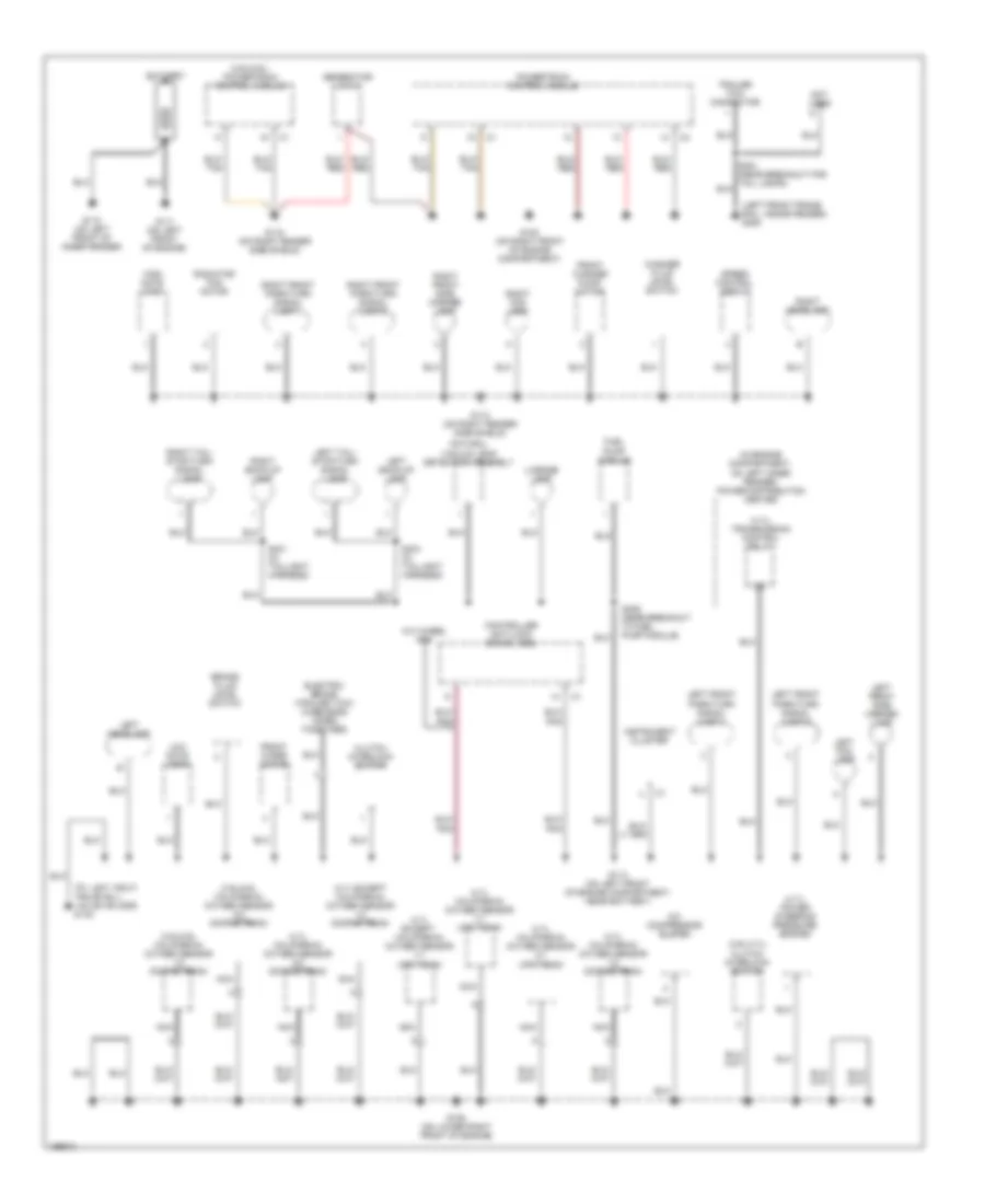
GROUND DISTRIBUTION
Ground Distribution Wiring Diagram (1 of 2) for Dodge Dakota R/T 2003
List of elements for Ground Distribution Wiring Diagram (1 of 2) for Dodge Dakota R/T 2003:
- (3.9l/4.7l) clutch interlock switch
- (3.9l/5.9l california) oxygen sensor 1/2 downstream
- (3.9l/5.9l california) oxygen sensor 2/2 downstream
- (3.9l/5.9l) powertrain control module
- (4.7l california) oxygen sensor 1/1 upstream
- (4.7l california) oxygen sensor 1/2 downstream
- (4.7l california) oxygen sensor 2/1 upstream
- (4.7l california) oxygen sensor 2/2 downstream
- (4.7l except california) oxygen sensor 1/1 upstream
- (4.7l except california) oxygen sensor 1/2 downstream
- (4.7l) power steering pressure switch
- (4.7l) transmission control relay
- (in engine compartment, on left inner fender) power distribution center
- (left front frame rail, inside fender) g305
- (on left front frame rail, inside fender) g102
- A/c compressor clutch
- Battery
- Brake fluid level switch
- Clutch interlock switch
- Controller anti-lock brake (abs)
- Electric brake (trailer tow) (wire ends taped together)
- Front washer pump/ motor
- Front wiper motor
- Fuel pump module
- G100 (on right front of engine compartment)
- G105 (on lower right front of engine)
- G110 (on left front of inner fender)
- G111 (on left front of engine)
- G112 (on right fender side shield)
- G113 (on left front of engine compartment, near battery)
- G115 (on right fender side shield)
- Generator (4.7l)
- High note horn
- Instrument cluster
- Left back-up lamp
- Left fog lamp
- Left front park/turn signal lamp 1
- Left front park/turn signal lamp 2
- Left front side marker lamp
- Left headlamp
- Left tail/ stop/turn signal lamp
- License lamp
- Low note horn
- Natural vacuum leak detection assembly
- Nca
- Not used
- Powertrain control module
- Radiator fan motor
- Right back-up lamp
- Right fog lamp
- Right front park/turn signal lamp 1
- Right front park/turn signal lamp 2
- Right front side marker lamp
- Right headlamp
- Right tail/ stop/turn signal lamp
- S306 (near breakout to fuel pump module)
- S401 (in taillight harness)
- S404 (in taillight harness)
- Speed control servo
- Trailer tow connector
- W/4 wheel abs
- Washer fluid level switch
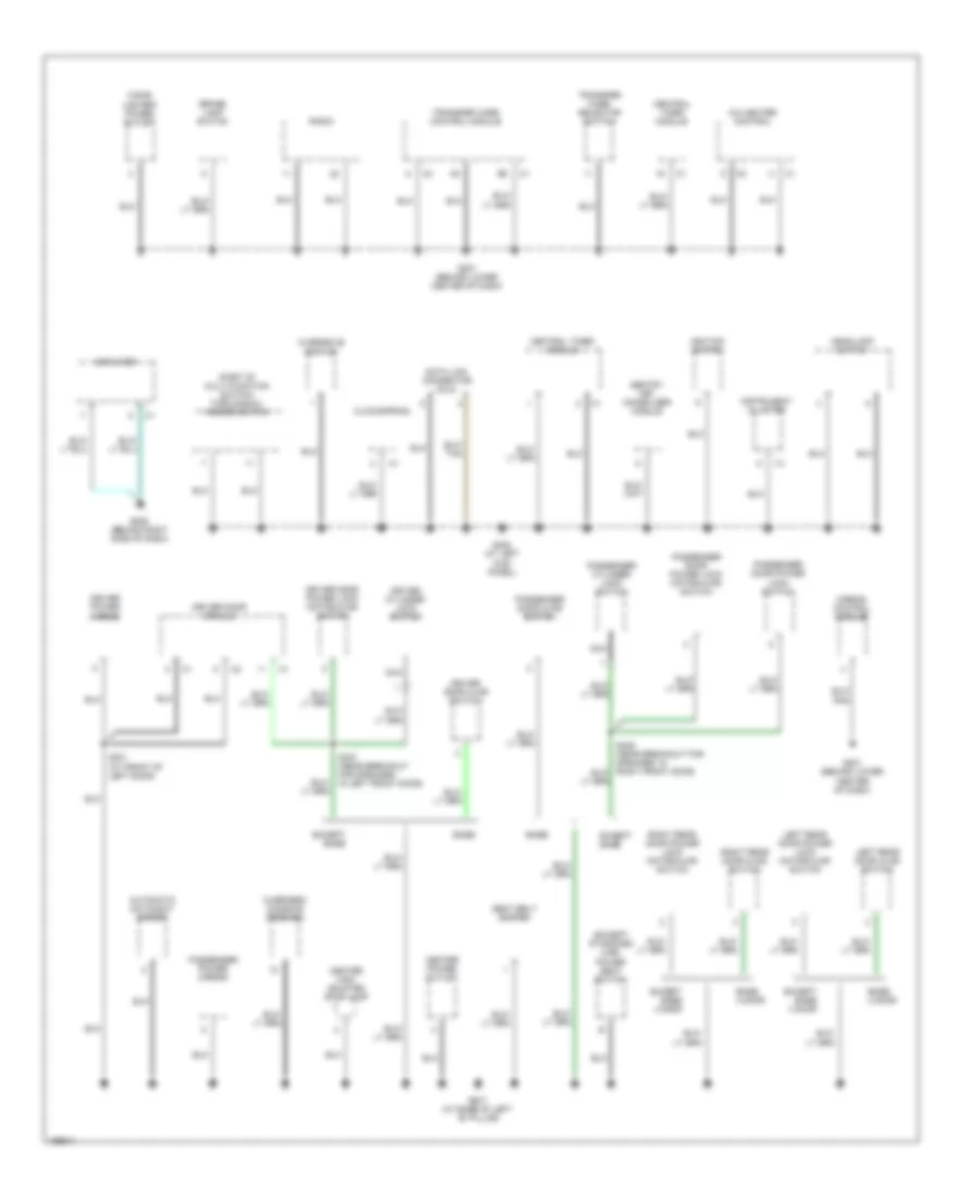
Ground Distribution Wiring Diagram (2 of 2) for Dodge Dakota R/T 2003
List of elements for Ground Distribution Wiring Diagram (2 of 2) for Dodge Dakota R/T 2003:
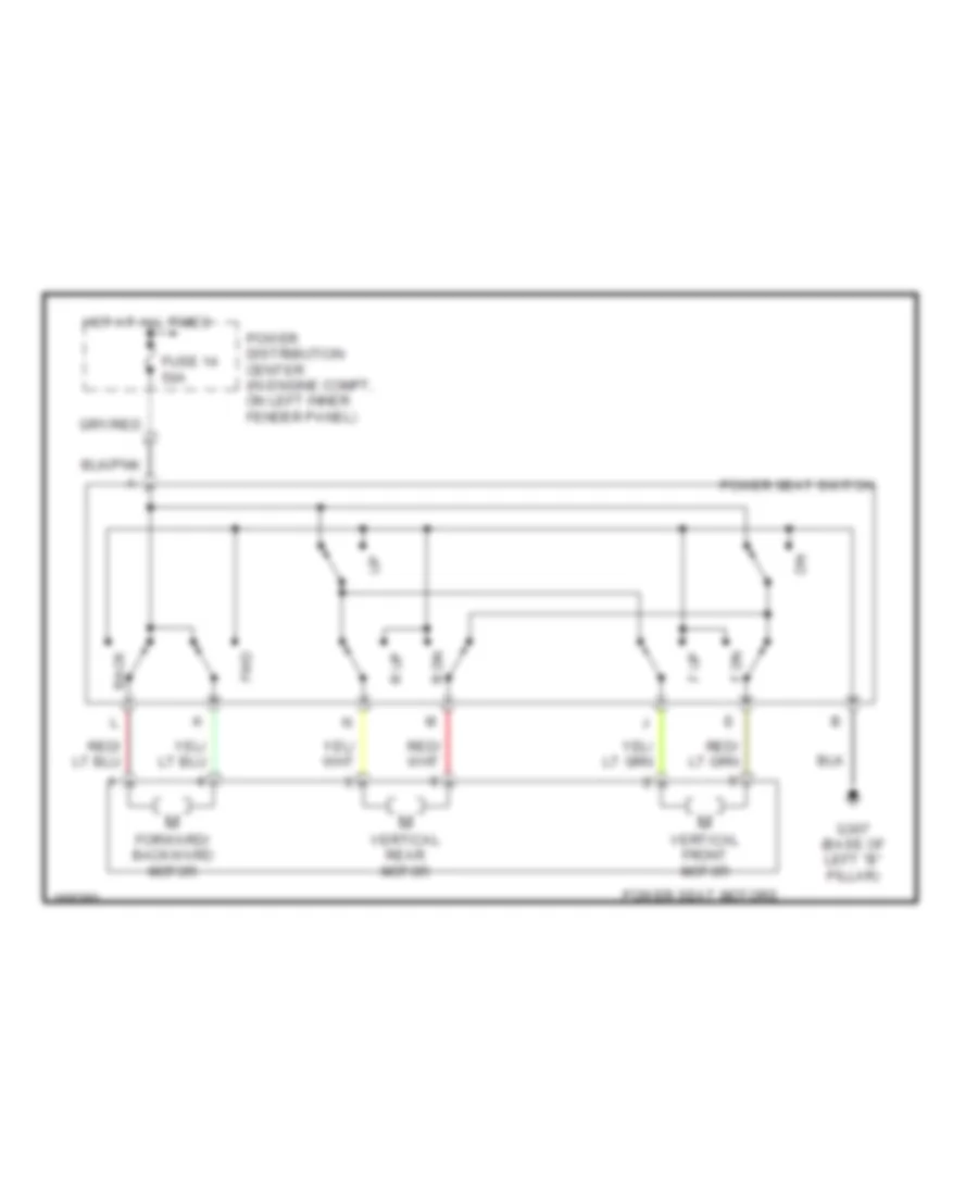
- (except standard cab) power seat switch
- (part of multi-function switch) turn signal/ hazard switch
- A/c heater control
- Airbag control module
- Amplifier
- Automatic day/night mirror
- Base
- Base 4 door
- Brake lamp switch
- Center high mounted stop lamp
- Center power outlet
- Central timer module
- Cigar lighter/ power outlet
- Clockspring
- Data link connector (dlc)
- Driver cylinder lock switch
- Driver door ajar switch
- Driver door module
- Driver door power lock motor/ajar switch
- Driver power mirror
- Except base
- Except base 4 door
- G201 (behind lower center of dash)
- G205 (behind right side of dash)
- G207 (behind lower center of dash)
- G208 (at left kick panel)
- G307 (at base of left ``b" pillar)
- Headlamp switch
- Ignition switch
- Instrument cluster
- Left rear door ajar switch
- Left rear door power lock motor/ajar switch
- Nca
- Overdrive switch
- Overhead console (premium)
- Passenger cylinder lock switch
- Passenger door ajar switch
- Passenger door power lock motor/ajar switch
- Passenger door power lock switch
- Passenger power mirror
- Radio
- Right rear door ajar switch
- Right rear door power lock motor/ajar switch
- S301 (at front of left door)
- S327 (near breakout for speaker, in left front door)
- Seat belt switch
- Sentry key immobilizer module
- Transfer case control module
- Transfer case selector switch
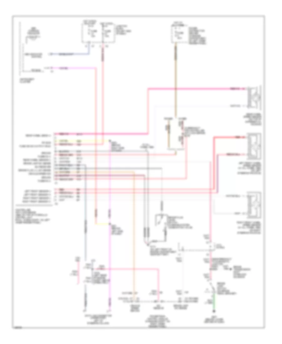
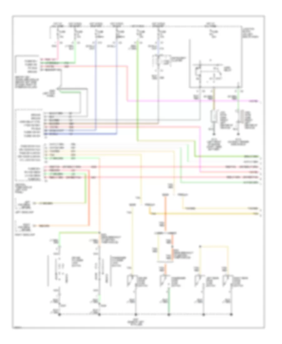
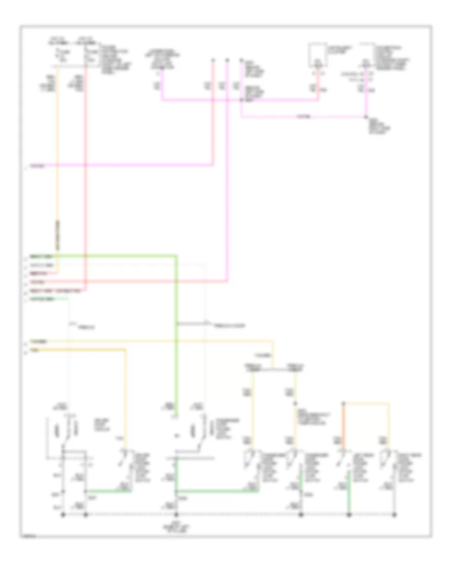
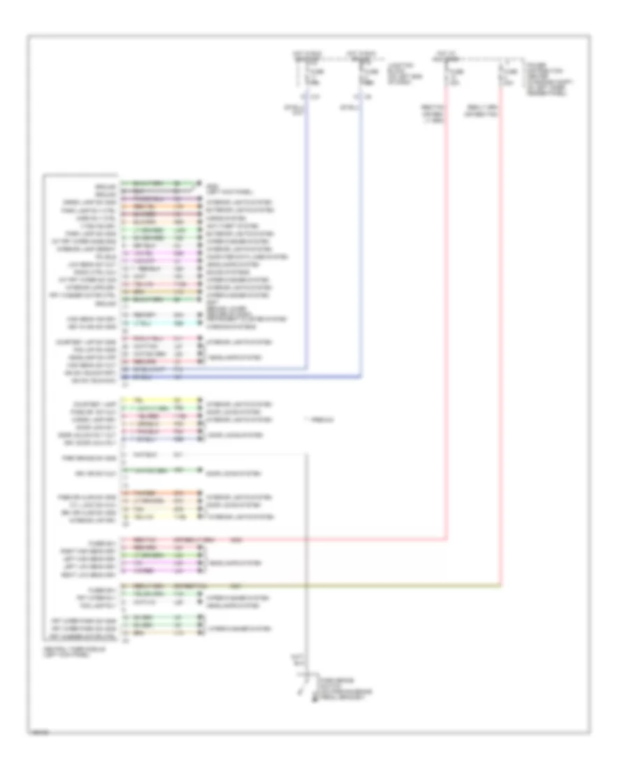
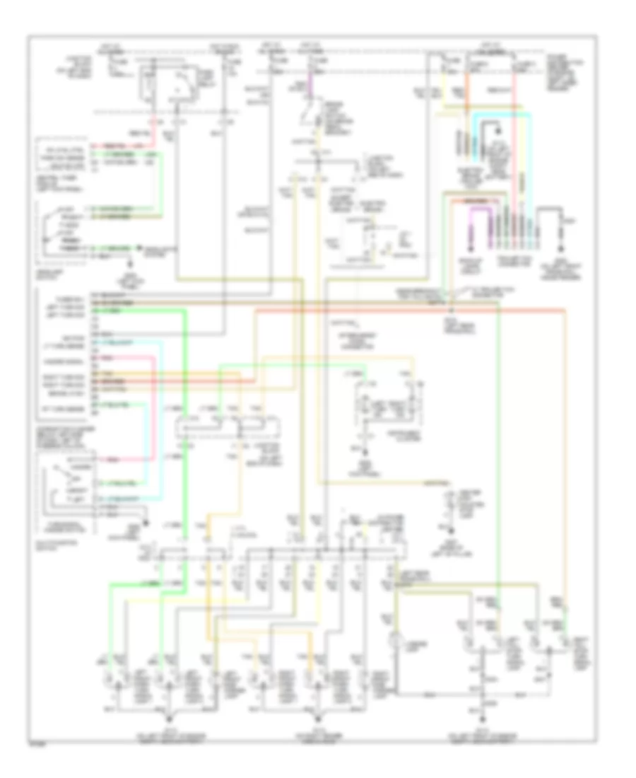
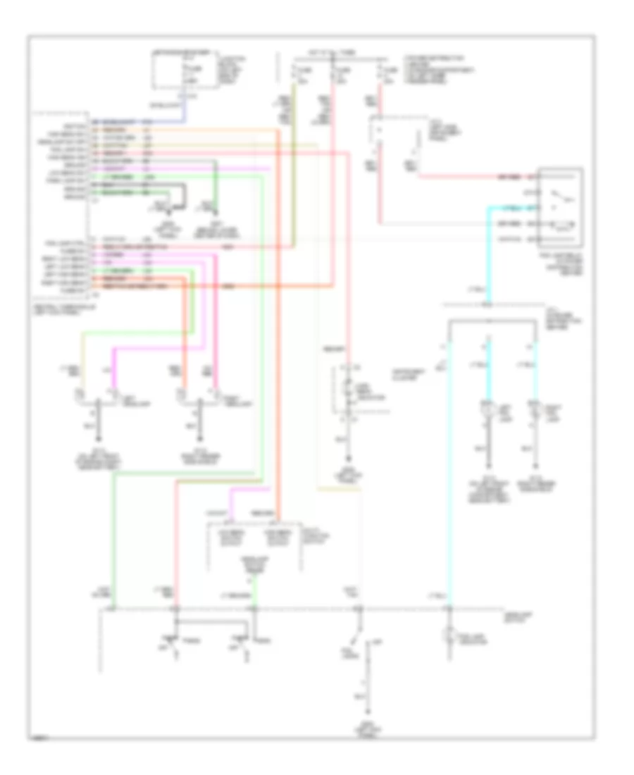
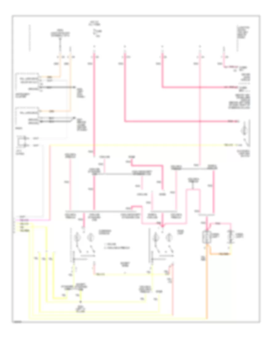
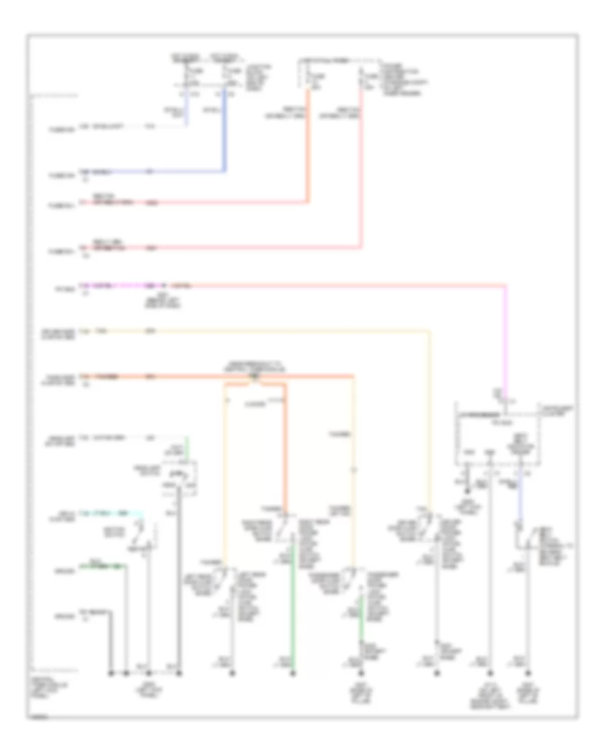
HEADLIGHTS
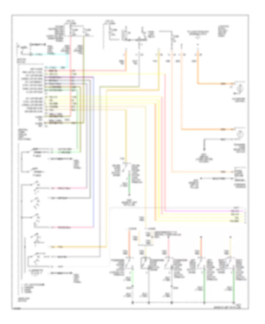
Headlights Wiring Diagram for Dodge Dakota R/T 2003
List of elements for Headlights Wiring Diagram for Dodge Dakota R/T 2003:
- (behind lower center of dash)
- 87a
- A301
- A302
- C10
- Central timer module (left kick panel)
- F12
- Fog lamp ctrl
- Fog lamp indicator
- Fog lamp relay (in power distribution center)
- Fog lamp sw
- Fog lamps
- Fuse 10a
- Fuse 20a
- Fuse h 20a
- Fused b+
- G112 (right fender side shield)
- G113 (on left front of engine compartment, near battery)
- G113 (on left front of engine compt, near battery)
- G207
- G208 (left kick panel)
- G208 (left kick panel)
- G34
- Ground
- Head
- Headlamp sw off
- Headlamp switch
- Headlamp switch sense
- High beam ind
- High beam indicator
- High beam sw
- High beam switch output
- Hot at all times
- Hot in run or start
- Ignition
- Instrument cluster
- J/c 1 (in power distribution center)
- J/c 3 (left side instrument panel)
- Junction block (on left end of dash)
- L26
- L27
- L308
- L33
- L34
- L43
- L44
- L80
- Left fog lamp
- Left headlamp
- Left high beam
- Left low beam
- Low beam sw
- Low beam switch output
- Multi- function switch
- Off
- Park
- Park lamp sw
- Power distribution center (in engine compartment, on left inner fender panel)
- Red/ tan (or
- Red/ tan)
- Right fog lamp
- Right headlamp
- Right high beam
- Right low beam
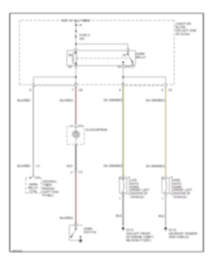
HORN
Horn Wiring Diagram for Dodge Dakota R/T 2003
List of elements for Horn Wiring Diagram for Dodge Dakota R/T 2003:
- 87a
- Central timer module (left kick panel)
- Clockspring
- Fuse 2 20a
- G112 (on right fender side shield)
- G113 (on left front of engine compt, near battery)
- High note horn (front left center of vehicle)
- Horn relay
- Horn relay ctrl
- Horn switch
- Hot at all times
- Junction block (on left end of dash)
- Low note horn (front left center of vehicle)
- Nca
INSTRUMENT CLUSTER
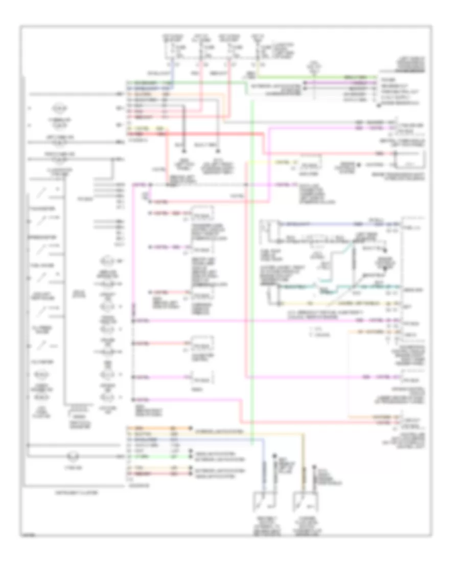
Instrument Cluster Wiring Diagram for Dodge Dakota R/T 2003
List of elements for Instrument Cluster Wiring Diagram for Dodge Dakota R/T 2003:
- (4.7l: breakout for fuel injecteor 7) (3.9l/5.9l: rear of engine)
- (behind left side of dash) s201
- (left rear of engine) s103
- (left side of transmission) transmission range sensor
- (water jacket, front of intake manifold) engine coolant temperature sensor
- 3.9l/ 5.9l a/t only
- 3.9l/5.9l
- 4.7l
- A/c-heater control
- A10
- Abs ind
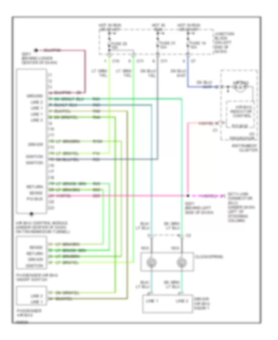
- Air bag control module (under center of dash, on transmission tunnel)
- Air bag ind
- Amplifier
- Brake transmission shift interlock solenoid
- C1conn a
- C2(conn b)
- Central timer module (left kick panel)
- Check gauges ind
- Controller anti-lock brake (on top of hydraulic control unit)
- Coolant temp gauge
- Cruise ind
- D25
- Data link connector (under dash, left side of steering column)
- Driver's seat belt buckle)
- Ect
- Engine controls system
- Exterior lights system
- Exterior lights system starting/ charging system
- F11
- F15
- Fuel gauge
- Fuel lvl
- Fuel pump module (fuel pump)
- Fuse 10a
- Fuse 15a
- G112 (right fender side shield)
- G113 (on left front of engine compt, near battery)
- G13
- G208 (left kick panel)
- G29
- G307 (base of left "b" pillar)
- G34
- G69
- Headlights system
- Hi beam ind
- Hot at all times
- Hot in run
- Hot in run or start
- Illumination (4 bulbs)
- Instrument cluster
- Interior lights system
- J/c 3 (in pdc)
- Junction block (left end of dash)
- K226
- L107
- L60
- L61
- Left turn ind
- Low fuel ind
- Low wash fluid ind
- Oil press gauge
- Overhead console (premuim)
- Park/neutral out
- Pci bus
- Pnk
- Power
- Powertrain control module (engine compt, right inner fender panel)
- Radio
- Range sensor mux
- Red
- Reverse out
- Right turn ind
- S101
- S200 (behind left side of dash)
- S202 (behind right side of dash)
- Seatbelt switch (integral to
- Sens gnd
- Sentry key immobilizer module (behind left side of dash, right of steering column)
- Service engine ind
- Solid state
- Speedometer
- Tachometer
- Tan
- Trans temp ind
- Transfer case control module (right side of steering column)
- Trip/total odometer
- Upshift ind
- Voltmeter
- Vss in
- Vss out
- Vtss driver
- Vtss ind
- Washer fluid level switch (washer fluid reservoir)
- Y128
- Y193
- Y204
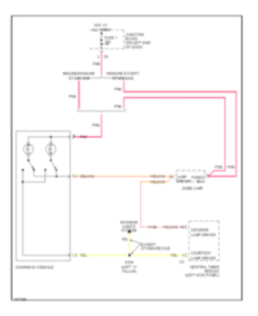
Overhead Console Wiring Diagram, Midline for Dodge Dakota R/T 2003
List of elements for Overhead Console Wiring Diagram, Midline for Dodge Dakota R/T 2003:
- (left "a" pillar)
- All times
- Central timer module (left kick panel)
- Courtesy
- Dome lamp
- Except standard cab
- Fuse 1 15a
- Fused b(+)
- Highline except
- Hot at
- Interior
- Interior lights system
- Junction block (on left end of dash)
- Lamp driver
- Midline/highline
- Overhead console
- Pnk
- S324
- Stand cab
- Y158
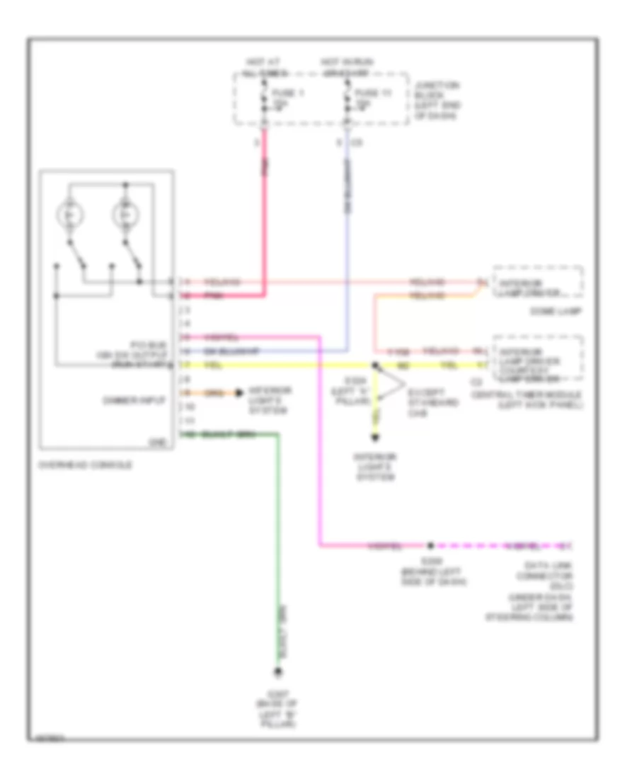
Overhead Console Wiring Diagram, Premium Model for Dodge Dakota R/T 2003
List of elements for Overhead Console Wiring Diagram, Premium Model for Dodge Dakota R/T 2003:
- (behind left side of dash)
- (left "a" pillar)
- All times
- Central timer module (left kick panel)
- Data link connector (dlc) (under dash, left side of steering column)
- Dimmer input
- Dome lamp
- Except standard cab
- Fuse 1 15a
- Fuse 11 10a
- G307 (base of
- Gnd
- Hot at
- Hot in run
- Interior lamp driver
- Interior lamp driver courtesy lamp driver
- Interior lights system
- Junction block (left end of dash)
- Left "b" pillar)
- Or start
- Overhead console
- Pci bus ign sw output (run-start)
- Pnk
- S200
- S324
- Y158
INTERIOR LIGHTS
Interior Lights Wiring Diagram (1 of 2) for Dodge Dakota R/T 2003
List of elements for Interior Lights Wiring Diagram (1 of 2) for Dodge Dakota R/T 2003:
- (b+)
- (near breakout to central timer module) s303
- 2 door
- 4 door
- 87a
- A/c-heater control
- A301
- A302
- Cargo lmp driver
- Cargo lmp sw sns
- Central timer module (left kick panel)
- Ctsy lmp driver
- Ctsy lmp sw sns
- Driver door ajar switch (base)
- Driver door power lock motor/ ajar switch (premium)
- Driver dr ajar
- Fuse 20a
- Fuse 5a
- Fused
- Fused (b+) c3
- G207 (behind lower center of dash)
- G208 (left kick panel)
- G26
- G307 (base of left "b" pillar)
- G74
- G75
- Ground
- Head
- Headlamp switch
- Hl sw off sns
- Hot at all times
- Ignition switch
- Illumination
- Int lights dimmer parade dome cargo
- Int lmp defeat
- Int lmp driver
- Junction block (on left end of dash)
- Key-in
- Key-in sns
- L308
- L79
- L80
- Left rear door ajar switch (base)
- Left rear door power lock motor/ ajar switch (premium)
- M11
- Off
- Overhead console
- Panel lamps driver
- Park
- Park lamp relay
- Park lmp sw sns
- Pass dr ajar
- Passenger door ajar switch (base)
- Passenger door power lock motor/ ajar switch (premium)
- Power distribution center (engine compt,on left inner fender panel)
- Prk lmp rly ctrl
- Right rear door ajar switch (base)
- Right rear door power lock motor/ ajar switch (premium)
- S328
- Tan
- Tan/ red
- Tan/red
- To junction block (diagram 2 of 2)
- Transfer case selector switch
- Y158
- Y192
Interior Lights Wiring Diagram (2 of 2) for Dodge Dakota R/T 2003
List of elements for Interior Lights Wiring Diagram (2 of 2) for Dodge Dakota R/T 2003:
- (in pdc)
- Base
- Base & highline
- C10
- Cargo lamp 1
- Cargo lamp 2
- Dome lamp
- Driver door module
- Except base
- Except standard cab
- From junction block (diagram 1 of 2)
- Fuse 15a
- Fused b(+)
- G207 (behind lower center of dash)
- G208 (left kick panel)
- Glove box lamp and switch
- Ground
- Hdlmp sw out
- Highline
- Highline & premium
- Highline except standard cab
- Highline standard cab
- Hot at all times
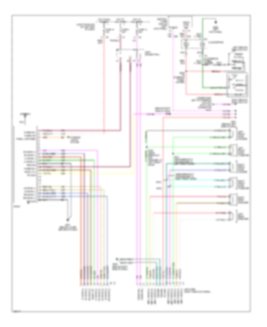
- Instrument cluster
- J/c 4
- Junction block (on left end of dash)
- Midline
- Midline & highline & premium
- Midline & premium
- Overhead console
- Pnk
- Pnl lmps drvr
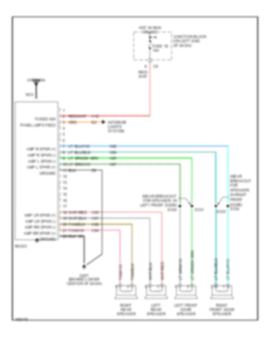
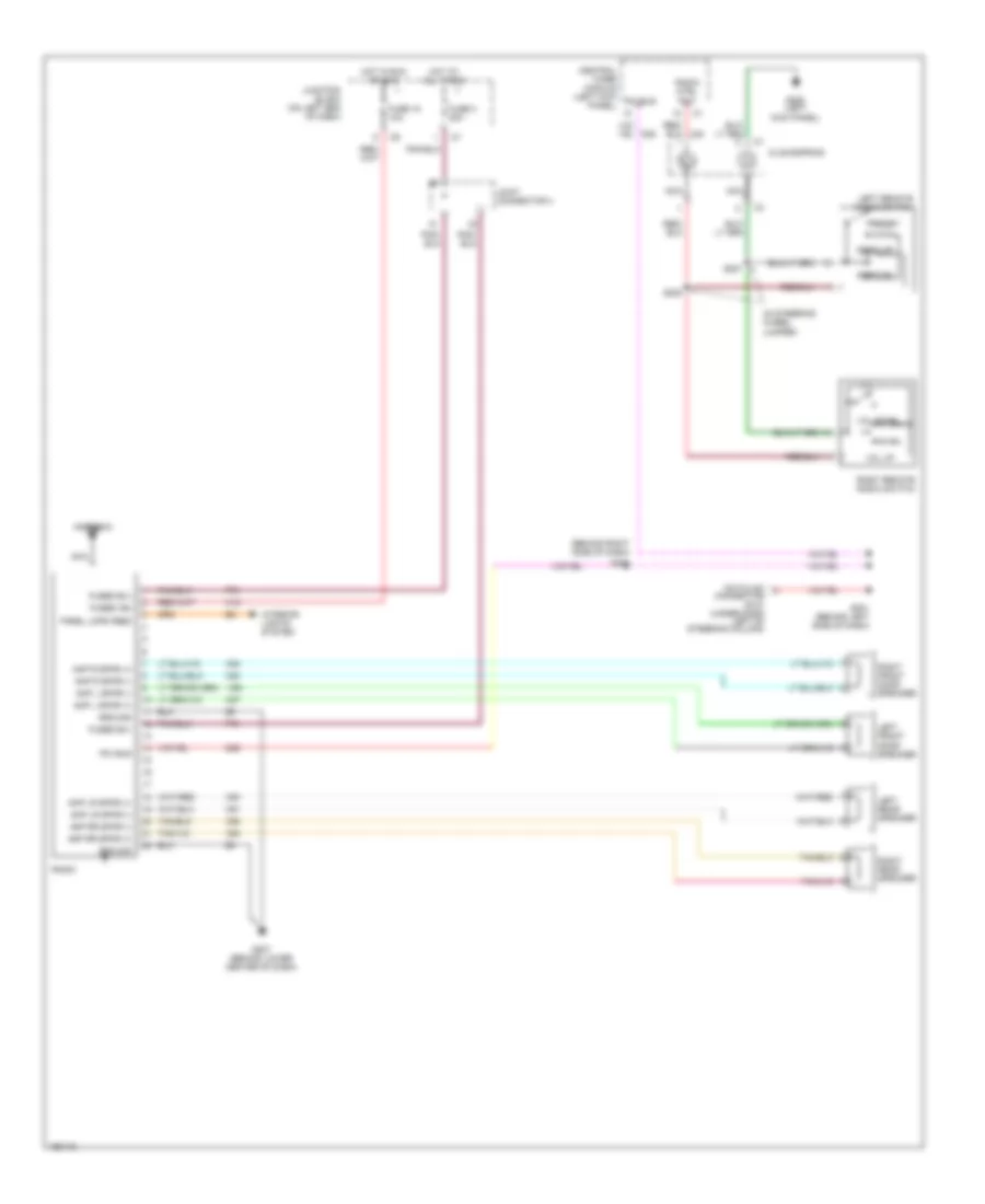
- Radio
- S324 (left "a" pillar)
- Sentry key immobilizer module (behind left side of dash, right of
- Standard cabs
- Steering column)
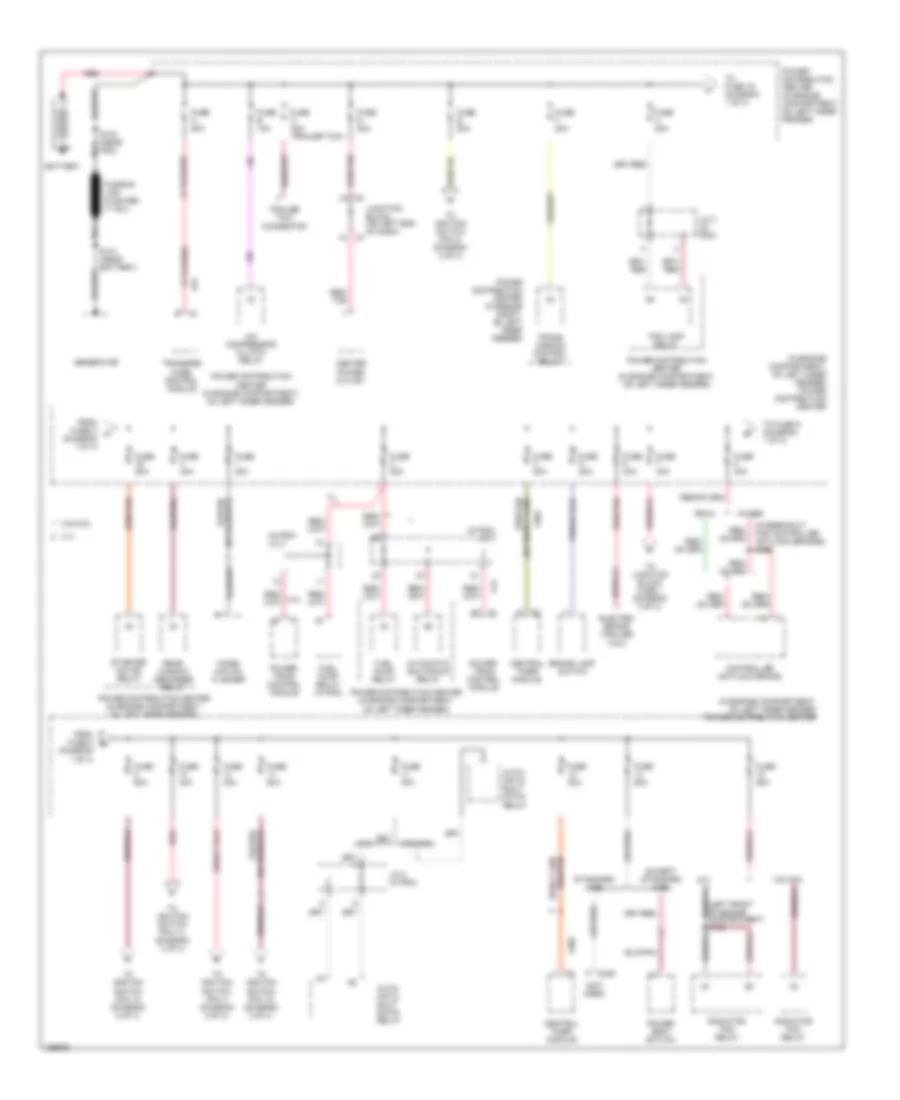
POWER DISTRIBUTION
Power Distribution Wiring Diagram (1 of 3) for Dodge Dakota R/T 2003
List of elements for Power Distribution Wiring Diagram (1 of 3) for Dodge Dakota R/T 2003:
- (diagram 1 of 3)
- (in breakout for controller antilock brakes) s126
- (in engine compartment, on left inner fender) power distribution center
- (in pdc) j/c 1
- (in pdc) j/c 2
- (not used)
- 3.9l/5.9l
- 4.7l
- 4wabs
- A/c compressor clutch relay
- A14
- A301
- A302
- A34
- Auto- matic shut down relay
- Automatic shutdown relay
- B c3
- Battery
- Brake lamp switch
- C246
- Center power outlet
- Central timer module
- Combi- nation flasher
- Controller antilock brake
- Electric brake (trailer tow)
- Except standard cab
- Fog lamp relay
- From fuse 8 b
- From fuse h (diagram 1 of 3)
- Fuel pump relay
- Fuel pump relay (in pdc)
- Fuse 20a
- Fuse 30a
- Fuse 40a
- Fuse 50a
- Fuse a 20a
- Fuse b 10a
- Fuse c 20a (trailer tow)
- Fuse d 20a
- Fuse e 20a
- Fuse f 20a
- Fuse h 20a
- Generator
- J/c 2 (in pdc)
- J/c 3 (in pdc)
- Junction block (on left end of dash)
- Nca
- Power distribution center (in engine compartment, on left inner fender)
- Power distribution center (in engine compt, on left inner fender)
- Power seat switch
- Power- train control module
- Radiator fan relay
- Rear window defogger relay
- Red
- Red/ tan
- Red/tan
- Rwal
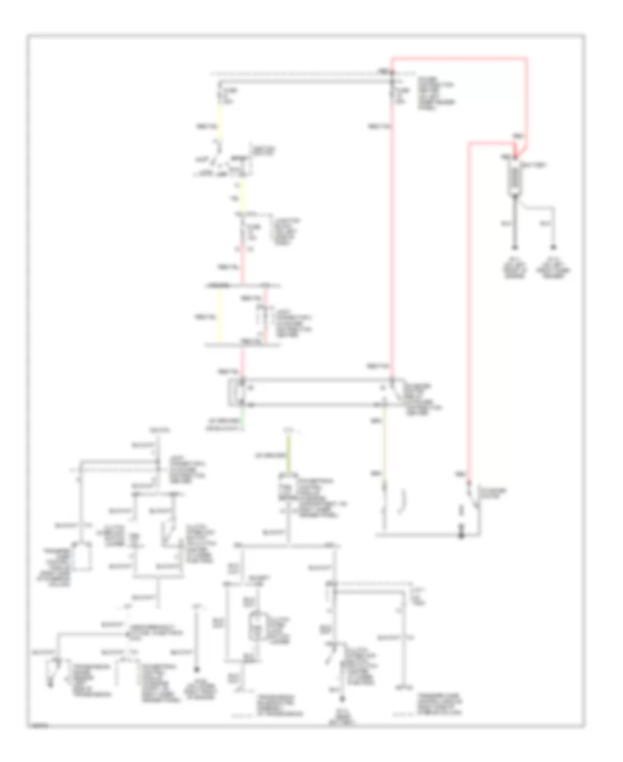
- S100 (near pdc)
- S141 (near battery)
- Standard cab
- Starter motor relay
- To fuse 16 (diagram 1 of 3)
- To fuse 9 (diagram 1 of 3)
- To ignition switch (pin 1) (diagram 2 of 3)
- To ignition switch (pin 11) (diagram 2 of 3)
- To ignition switch (pin 12) (diagram 2 of 3)
- To ignition switch (pin 14) (diagram 2 of 3)
- To ignition switch (pin 4) (diagram 2 of 3)
- To junction block fuse 1 (diagram 3 of 3)
- Trailer tow connector
- Trans- mission control relay
- Transfer case control module
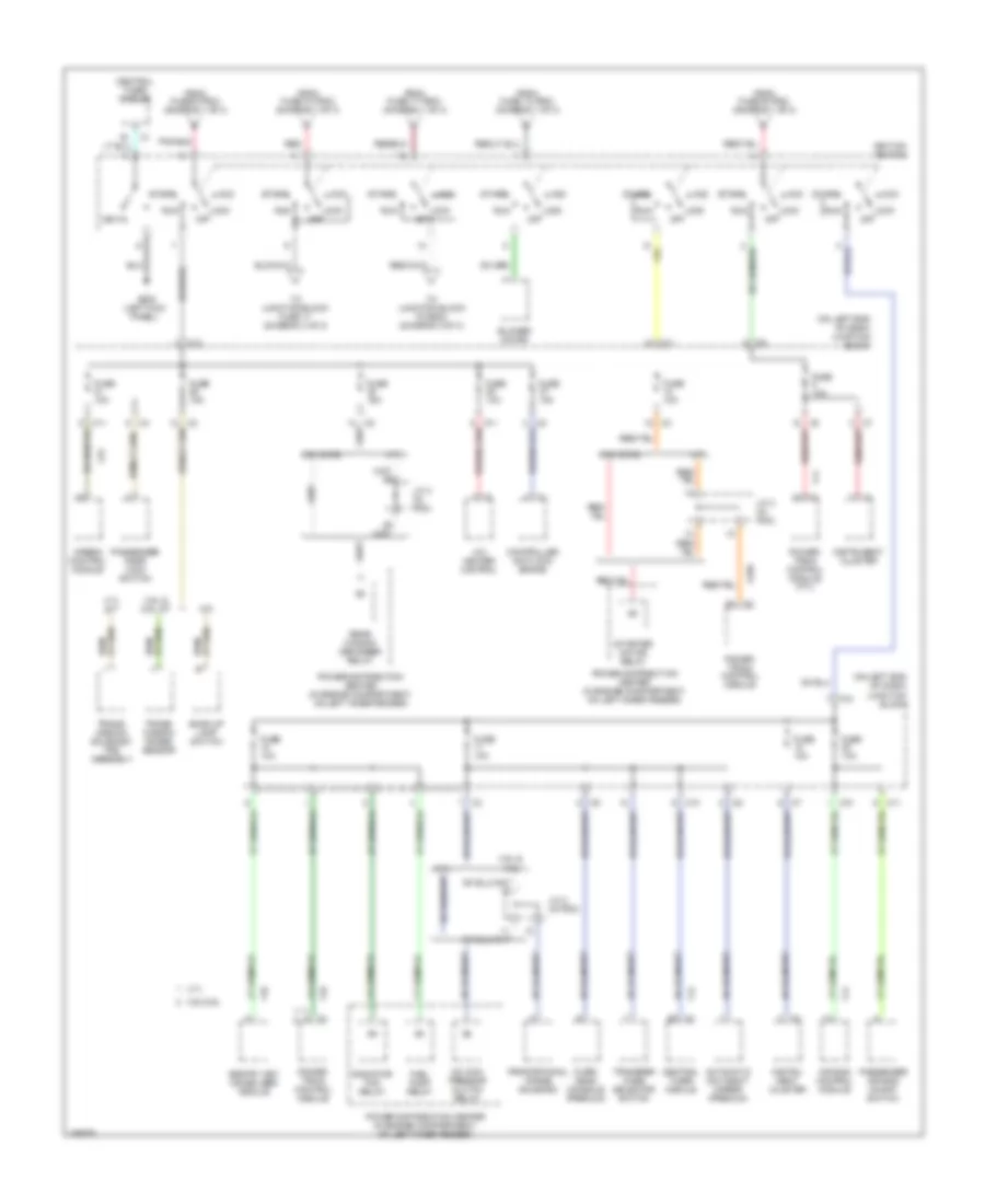
Power Distribution Wiring Diagram (2 of 3) for Dodge Dakota R/T 2003
List of elements for Power Distribution Wiring Diagram (2 of 3) for Dodge Dakota R/T 2003:
- (left kick panel)
- (on left end of dash)
- (on left end of dash) junction block
- 3.9l &
- 3.9l & 5.9l
- 3.9l & 5.9l a/t
- 3.9l/5.9l
- 4.7l
- 4.7l a/t
- 5.9l
- A/c com- pressor clutch relay
- A/c heater control
- A169
- Acc
- Air bag control module
- Airbag control module
- Automatic day/night mirror (premium)
- Back-up lamp switch
- Blower motor
- C10
- C11
- C12
- Central timer module
- Controller anti-lock brake
- F11
- F12
- F14
- F18
- F23
- From fuse 10 (pdc) (diagram 1 of 3)
- From fuse 13 (pdc) (diagram 1 of 3)
- From fuse 17 (pdc) (diagram 1 of 3)
- From fuse 9 (pdc) (diagram 1 of 3)
- From fuse e (pdc) (diagram 1 of 3)
- Fuel pump relay
- Fuse 10a
- Fuse 15a
- G208
- Ignition switch
- Instru- ment cluster
- Instrunent cluster
- J/c 2 (in pdc)
- J/c 3 (in pdc)
- Junction block
- Key-in
- Lock off
- M/t
- Over- head console (premium)
- Passenger air bag on/off switch
- Passenger door lock switch
- Power distribution center (in engine compartment, on left inner fender)
- Power- train control module
- Power- train control module (4.7l)
- Proportional purge solenoid
- Radiator fan relay
- Rear window defogger relay
- Red
- Run
- Sentry key immobilizer module
- Start
- Starter motor relay
- To junction block (fuse 5) (diagram 3 of 3)
- To junction block fuse 17 (diagram 3 of 3)
- Trans- mission range sensor
- Trans- mission solenoid/ trs assembly
- Transfer case selector switch
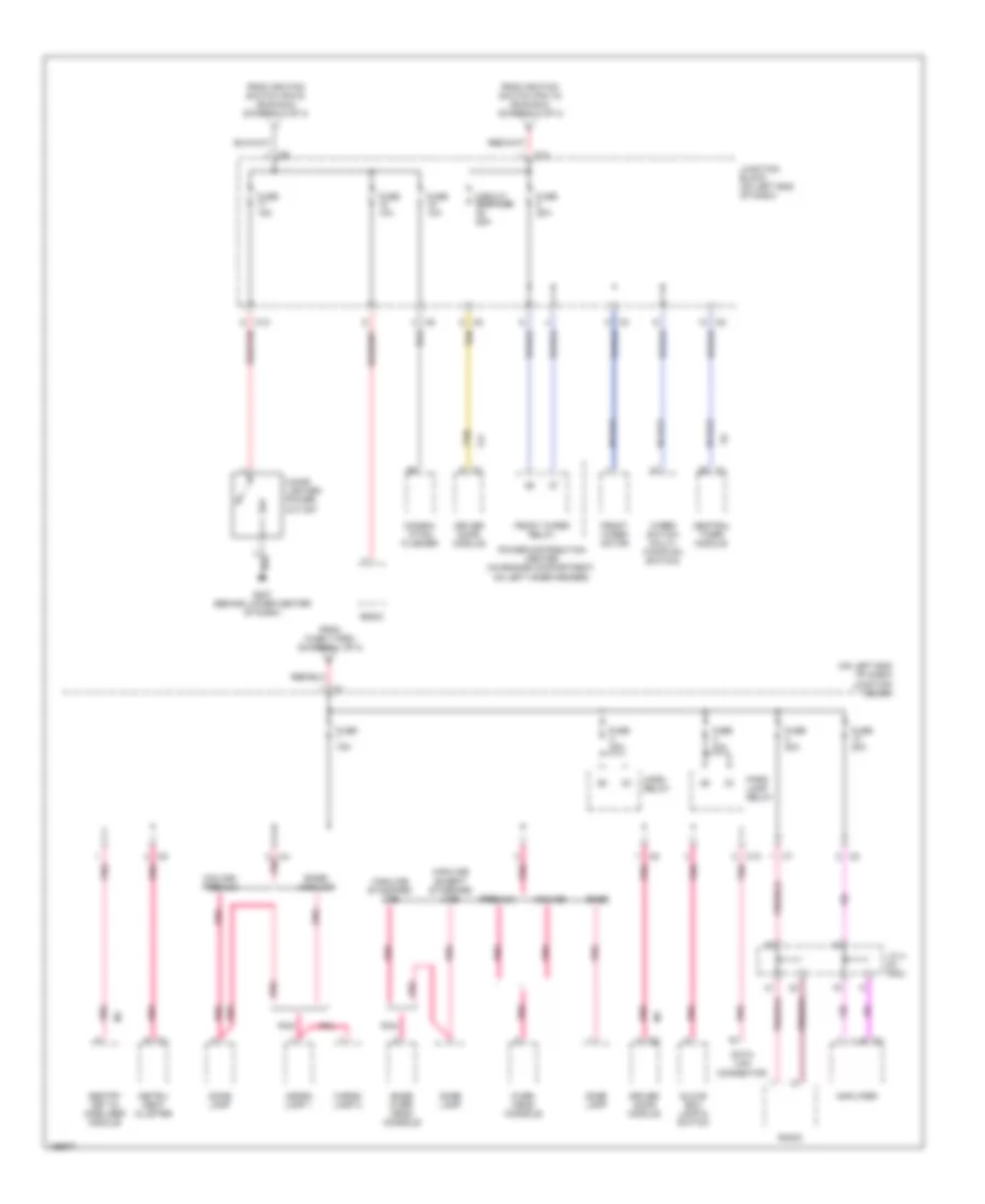
Power Distribution Wiring Diagram (3 of 3) for Dodge Dakota R/T 2003
List of elements for Power Distribution Wiring Diagram (3 of 3) for Dodge Dakota R/T 2003:
- (on left end of dash) junction block
- Amplifier
- Base
- Base over- head console
- Base/ highline
- C10
- C12
- C4 pnk
- Cargo lamp 1
- Cargo lamp 2
- Central timer module
- Cigar lighter/ power outlet
- Circuit breaker 25a
- Combin- ation flasher
- Data link connector
- Dome lamp
- Driver door module
- F21
- From fuse 7 (pdc) (diagram 1 of 3)
- From ignition switch (pin 10) (run/acc) (diagram 2 of 3)
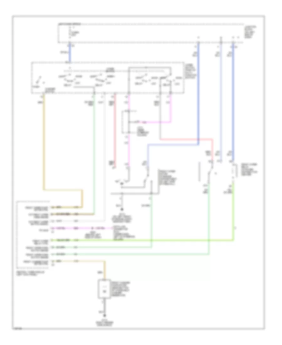
- From ignition switch (pin 9) (run/acc) (diagram 2 of 3)
- Front wiper motor
- Front wiper relay
- Fuse 10a
- Fuse 15a
- Fuse 20a
- G207 (behind lower center of dash)
- Glove box lamp & switch
- Highline except standard cab
- Highline standard cab
- Horn relay
- Instru- ment cluster
- J/c 4 (in pdc)
- Junction block (on left end of dash)
- Midline
- Midline/ premium
- Over- head console
- Park lamp relay
- Pnk
- Power distribution center ((in engine compartment, on left inner fender)
- Premium
- Radio
- Red/tan
- Sentry key im- mobilizer module
- Tan
- Wiper switch (multi- function switch)
POWER DOOR LOCKS
Power Door Locks Wiring Diagram for Dodge Dakota R/T 2003
List of elements for Power Door Locks Wiring Diagram for Dodge Dakota R/T 2003:
- (4 door)
- 2 door
- 4 door
- C10
- Central timer module (left kick panel)
- Door sw mux
- Driver cylinder lock switch
- Driver door module
- Driver door power lock motor/ ajar switch
- F12
- Fuse 10a
- Fuse 15a
- Fuse 20a
- Fused ign sw
- G208 (left kick panel)
- G307 (base of left "b" pillar)
- G73
- Ground
- Hot at all times
- Hot in run
- Hot in run or acc
- Hot in start or run
- Junction block (on left end of dash)
- L79
- Lamo rly
- Left rear door power lock motor/ ajar switch
- Lock
- Lock relay
- Lock sw mux
- Nca
- P33
- P34
- P59
- P96
- P97
- Park
- Park lamp relay
- Passenger cylinder lock switch
- Passenger door power lock motor/ ajar switch
- Passenger door power lock switch
- Right rear door power lock motor/ ajar switch (4 door)
- Rke antenna
- S301
- S302 (near breakout for central timer module)
- S305 (near breakout for central timer module)
- S307 (near breakout to central timer module)
- S327
- S328
- Unlock
- Unlock relay
POWER MIRRORS
Automatic Day/Night Mirror Wiring Diagram for Dodge Dakota R/T 2003
List of elements for Automatic Day/Night Mirror Wiring Diagram for Dodge Dakota R/T 2003:
- (in transmission, on valve body assembly)
- (left side of transmission)
- (on left side of transmission)
- (run-start)
- A/t 3.9l/5.9l
- A/t 4.7l
- Automatic day/night mirror (premium)
- Backup lamp feed
- Backup lamp switch r
- Fuse 10a
- Fuse 15a
- Fused ignition
- G307 (base of left "b" pillar)
- Ground
- Hot in run
- Hot in run or start
- Joint connector 1 (in pdc)
- Junction block (on left end of dash)
- M/t
- Transmission range sensor r
- Transmission solenoid/trs assembly r
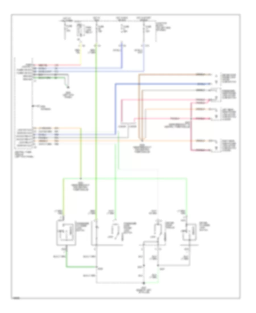
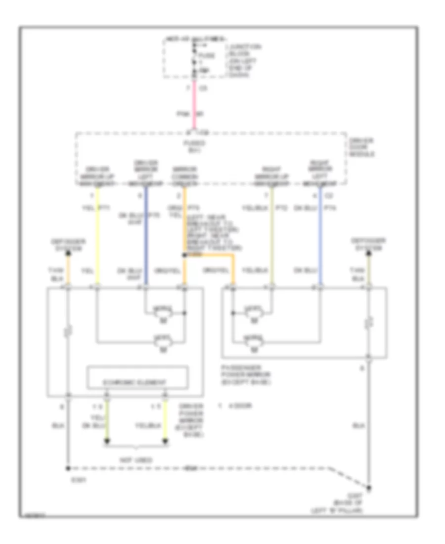
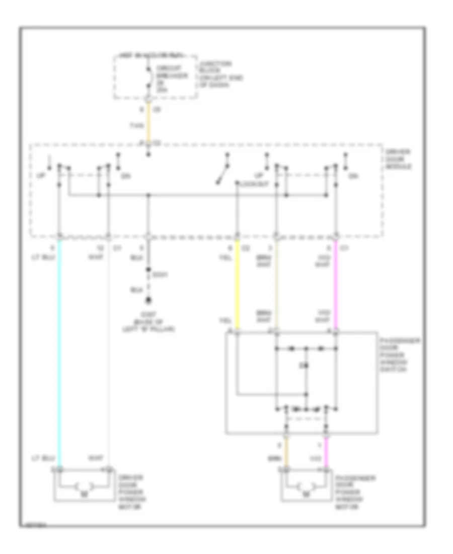
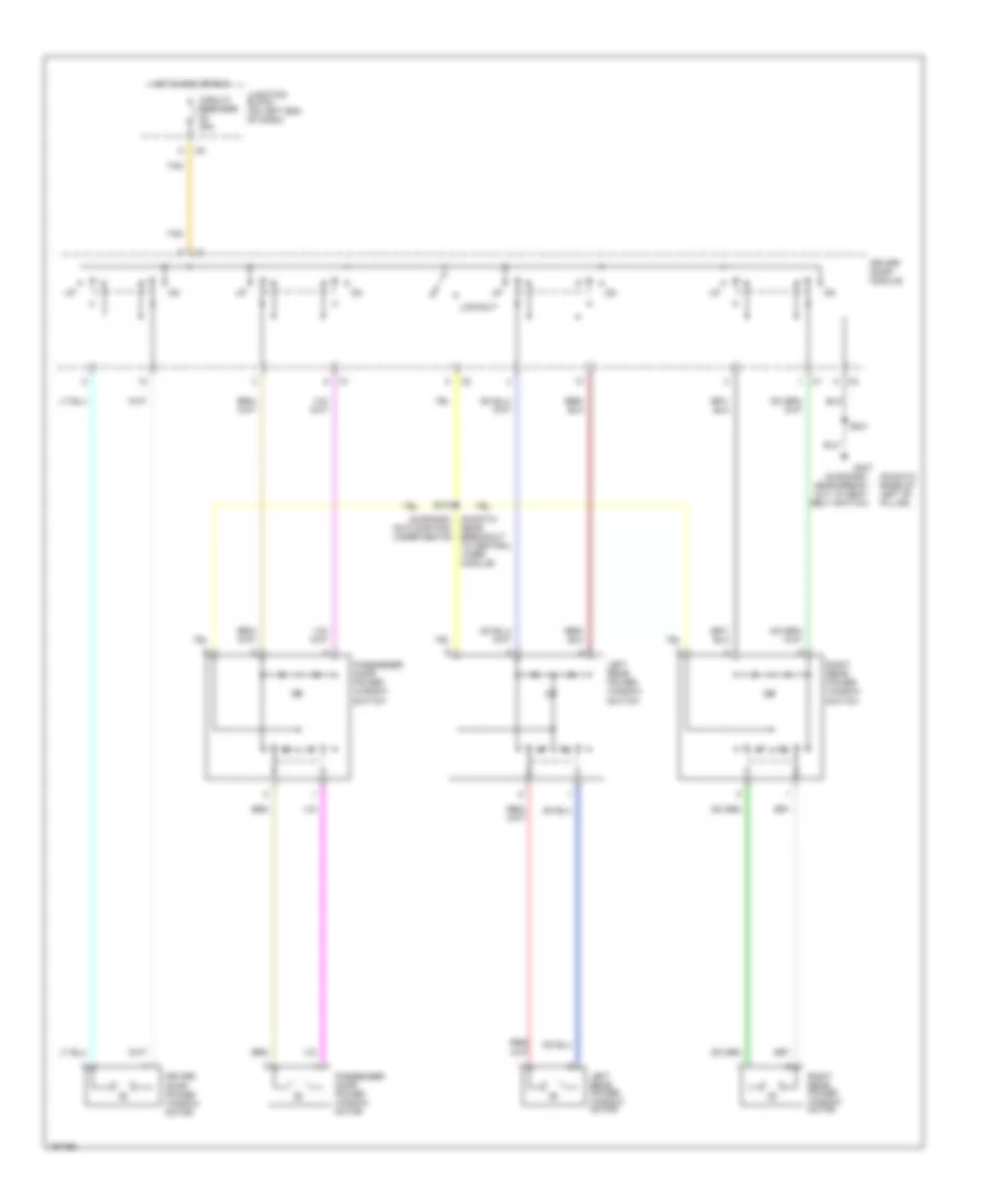
Power Mirrors Wiring Diagram for Dodge Dakota R/T 2003
List of elements for Power Mirrors Wiring Diagram for Dodge Dakota R/T 2003:
- 4 door
- Defogger system
- Driver door module
- Driver mirror left movement
- Driver mirror up movement
- Driver power mirror (except base)
- Echromic element
- Fuse 15a
- Fused b(+)
- G307 (base of
- Horiz
- Hot at all times
- Junction block (on left end of dash)
- Left "b" pillar)
- Mirror common driver
- Not used
- P71
- P72
- P74
- P75
- P76
- Passenger power mirror (except base)
- Pnk
- Right mirror left movement
- Right mirror up movement
- S301
- Tan/
- Vert
POWER SEATS
Power Seats Wiring Diagram for Dodge Dakota R/T 2003
List of elements for Power Seats Wiring Diagram for Dodge Dakota R/T 2003:
- Back
- F dn
- F up
- Forward/ backward motor
- Fuse 14 50a
- Fwd
- G307 (base of left "b" pillar)
- Hot at all times
- Power distribution center (in engine compt, on left inner fender panel)
- Power seat motors
- Power seat switch
- R dn
- R up
- Vertical front motor
- Vertical rear motor
POWER WINDOWS
Power Windows Wiring Diagram, 2 Door for Dodge Dakota R/T 2003
List of elements for Power Windows Wiring Diagram, 2 Door for Dodge Dakota R/T 2003:
- Circuit breaker 25a
- Driver door module
- Driver door power window motor
- G307 (base of left "b" pillar)
- Hot in acc or run
- Junction block (on left end of dash)
- Lockout
- Passenger door power window motor
- Passenger door power window switch
- S301
- Tan
Power Windows Wiring Diagram, 4 Door for Dodge Dakota R/T 2003
List of elements for Power Windows Wiring Diagram, 4 Door for Dodge Dakota R/T 2003:
- (dakota: base of left "b" pillar)
- (durango: (dakota: near breakout to central timer module)
- (durango: near break- out to seat belt switch)
- Circuit breaker 25a
- Driver door module
- Driver door power window motor
- G307
- Hot in acc or run
- Junction block (on left end of dash)
- Left rear power window motor
- Left rear power window switch
- Lockout
- On floor pan, under seats)
- Passenger door power window motor
- Right rear power window motor
- Right rear power window switch
- S301
- S319
- Tan
RADIO
Radio Wiring Diagram, Base Radio for Dodge Dakota R/T 2003
List of elements for Radio Wiring Diagram, Base Radio for Dodge Dakota R/T 2003:
- (near breakout for
- (near breakout for speaker, in left front door) s330
- Amp l spkr (+)
- Amp l spkr (-)
- Amp lr spkr (+)
- Amp lr spkr (-)
- Amp r spkr (+)
- Amp r spkr (-)
- Amp rr spkr (+)
- Amp rr spkr (-)
- Antenna
- Door) s332
- Front
- Fuse 18 10a
- Fused ign
- G207 (behind lower center of dash)
- Ground
- Hot in run or acc
- Interior lights system
- Junction block (on left end of dash)
- Left front door speaker
- Left rear speaker
- Nca
- Panel lmps feed
- Radio
- Right front door speaker
- Right rear speaker
- S331
- S333
- Speaker, in right
- X12
- X80
- X82
- X85
- X87
- X91
- X92
- X93
- X94
Radio Wiring Diagram, Midline Radio for Dodge Dakota R/T 2003
List of elements for Radio Wiring Diagram, Midline Radio for Dodge Dakota R/T 2003:
- (behind right side of dash)
- (in steering wheel jumper)
- Amp l spkr (+)
- Amp l spkr (-)
- Amp lr spkr (+)
- Amp lr spkr (-)
- Amp r spkr (+)
- Amp r spkr (-)
- Amp rr spkr (+)
- Amp rr spkr (-)
- Antenna
- Central timer module (left kick panel)
- Clockspring
- D25
- Datalink connector (dlc) (under dash left of steering column)
- F70
- Fuse 18 10a
- Fuse 3 20a
- Fused b(+)
- Fused ign
- G207 (behind lower center of dash)
- G208 (left kick panel)
- Ground
- Hot at all times
- Hot in run or acc
- Interior lights system
- Joint connector 4
- Junction block (on left end of dash)
- Left front door speaker
- Left rear speaker
- Left remote radio switch
- Nca
- Panel lmps feed
- Pci bus
- Preset
- Radio
- Radio ctrl mux
- Right front door speaker
- Right rear speaker
- Right remote radio switch
- S201 (behind left side of dash)
- S202
- S207
- S208
- Seek dn
- Seek up
- Vol down
- Vol up
- X12
- X80
- X82
- X85
- X87
- X91
- X92
- X93
- X94
Radio Wiring Diagram, Premium Radio for Dodge Dakota R/T 2003
List of elements for Radio Wiring Diagram, Premium Radio for Dodge Dakota R/T 2003:
- (behind right side of dash)
- (in steering wheel jumper) s207
- (near breakout for speaker, in right front door)
- (under dash left of steering column) data link connector (dlc)
- Amp l door (+)
- Amp l door (-)
- Amp l rear (+)
- Amp l rear (-)
- Amp r door (+)
- Amp r door (-)
- Amp r rear (+)
- Amp r rear (-)
- Amplifier (right side kick panel)
- Antenna
- Central timer module (left kick panel)
- Clockspring
- D25
- F70
- Fuse 13 20a
- Fuse 18 10a
- Fuse 3 20a
- Fused b(+)
- Fused ign
- G205
- G207 (behind lower center of dash)
- G208 (left kick panel)
- Ground
- Hot at all times
- Hot in run or acc
- Interior lights system
- Joint connector 4
- Junction block (on left end of dash)
- Left front door tweeter
- Left front door woofer
- Left rear speaker
- Left remote radio switch
- Lf spkr (+)
- Lf spkr (-)
- Lr spkr (+)
- Lr spkr (-)
- Nca
- Panel lmps feed
- Pci bus
- Preset
- Radio
- Radio 12v
- Radio ctrl mux
- Rf spkr (+)
- Rf spkr (-)
- Right front door tweeter
- Right front door woofer
- Right rear speaker
- Right remote radio switch
- Rr spkr (+)
- Rr spkr (-)
- S201 (behind left side of dash)
- S202
- S208 (in steering wheel jumper)
- S330 (near breakout for speaker, in left front door)
- S331 (near breakout for speaker, in left front door)
- S332
- S333
- Seek dn
- Seek up
- Vol down
- Vol up
- X12
- X51
- X52
- X53
- X54
- X55
- X56
- X57
- X58
- X60
STARTING/CHARGING
Charging Wiring Diagram for Dodge Dakota R/T 2003
List of elements for Charging Wiring Diagram for Dodge Dakota R/T 2003:
- (3.9l/5.9l)
- (4.7l/5.9l: at left rear of engine) (3.9l: rear of engine)
- (near breakout to fuel injector 5) s110
- (right fender side shield)
- (right front of engine compt)
- 3.9l/ 5.9l
- 3.9l/5.9l
- 4.7l
- A14
- A142
- Auto shut- down relay
- Auto shut- down relay c3
- Automatic shut down relay (in power distribution center)
- Batt temp sensor sig
- Battery
- Battery temperature sensor (attached under battery)
- Check gauges ind ctrl
- Check gauges indicator
- Fuse 14 10a
- Fuse 20a
- Fuse 30a
- Fused b+
- G100
- G110 (left front inner fender)
- G111 (on left front of engine)
- G115
- G208 (left kick panel)
- Gen field
- Gen source
- Generator
- Generator field
- Hot at all times
- Hot in run or start
- Instrument cluster
- Joint connector 1 (in power distribution center)
- Joint connector 2 (in power distribution center)
- Joint connector 3 (in power distribution center)
- Junction block (on left end of dash)
- K118
- K125
- K20
- Leak detection pump (under battery tray & power distribution center)
- Nca
- Power distribution center (on left inner fender panel)
- Powertrain control module (on right inner fender panel)
- Red
- S103
- S123 (rear of engine)
- S141 (near battery)
- S176
- S187 (near power distribution center)
- Sensor grd
- Source
- Starter motor
- Transmission control relay (in power distribution center)
- Volts
Starting Wiring Diagram for Dodge Dakota R/T 2003
List of elements for Starting Wiring Diagram for Dodge Dakota R/T 2003:
- (in pdc)
- (in power distribution center)
- (near breakout to fuel injector 6) s181
- 3.9l/5.9l
- 4.7l
- 4x4
- A/t
- Acc
- Battery
- C11
- Clutch inter lock switch jumper
- Clutch interlock switch (on clutch master cylinder push rod)
- Clutch interlock switch (on clutch master cylinder push rod)
- Clutch interlock switch jumper
- Except 4x4
- Fuse 10a
- Fuse 50a
- Fuse e 20a
- G105 (on lower right front of engine)
- G110 (on left front inner fender)
- G111 (on left front of engine)
- G113 (near battery)
- Ignition switch
- J/c 1
- Joint connector 2 (in power distribution center)
- Joint connector 3
- Junction block (on left side of dash)
- Lock
- M/t
- Off
- Power distribution center (on left inner fender panel)
- Powertrain control module (in engine compt, on right inner fender panel)
- Powertrain control module sense (in engine compartment, on right inner c3 fender panel)
- Red
- Red/tan
- Run
- Start
- Starter motor
- Starter motor relay (in power distribution center)
- Transfer case control module (right side of steering column)
- Transfer case control module (right side of stering column)
- Transmission range sensor (left side of transmission)
- Transmission solenoid/trs assembly (in transmission)
- Trs t41
SUPPLEMENTAL RESTRAINTS
Supplemental Restraints Wiring Diagram, 2 Door for Dodge Dakota R/T 2003
List of elements for Supplemental Restraints Wiring Diagram, 2 Door for Dodge Dakota R/T 2003:
- Air bag
- Air bag control module (under center of dash, on transmission tunnel)
- Air bag indicator control
- C10
- C11
- Clockspring
- D25
- Data link connector (dlc) (under dash, left of steering column)
- Driver
- Driver air bag squib 1
- F14
- F23
- Fuse 14 10a
- Fuse 20 10a
- Fuse 21 10a
- G201 (behind lower center of dash)
- Ground
- Hot in run
- Hot in run or start
- I/o processor
- Ignition
- Instrument cluster
- Junction block (on left end of dash)
- Line 1
- Line 2
- Nca
- Passenger air bag
- Passenger air bag on/off switch
- Pci bus
- R166
- R42
- R43
- R44
- R45
- R65
- R66
- Return
- S201 (behind left side of dash)
- Sense
Supplemental Restraints Wiring Diagram, 4 Door for Dodge Dakota R/T 2003
List of elements for Supplemental Restraints Wiring Diagram, 4 Door for Dodge Dakota R/T 2003:
- Air bag
- Air bag control module (under center of dash, on transmission tunnel)
- Air bag indicator control
- C10
- C11
- Clockspring
- D25
- Data link connector (dlc) (under dash, left of steering column)
- Driver air bag squib 1
- Driver seat belt tensioner
- F14
- F23
- Fuse 14 10a
- Fuse 20 10a
- Fuse 21 10a
- G201 (behind lower center of dash)
- Ground
- Hot in run
- Hot in run or start
- I/o processor
- Ignition
- Instrument cluster
- Junction block (on left end of dash)
- Line
- Line 1
- Line 2
- Nca
- Passenger air bag
- Passenger seat belt tensioner
- Pci bus
- R42
- R43
- R44
- R45
- R53
- R54
- R55
- R56
- S201 (behind left side of dash)
TRANSMISSION
Transfer Case Wiring Diagram for Dodge Dakota R/T 2003
List of elements for Transfer Case Wiring Diagram for Dodge Dakota R/T 2003:
- 2wd high
- 2wd/awd ind
- 3.9l/ 5.9l
- 4.7l
- 4wd high
- 4wd high ind
- 4wd high lamp
- 4wd low
- 4wd low ind
- 4wd low lamp
- A34
- C10
- Clutch interlock switch (on clutch master cylinder push rod)
- D25
- Data link connector (under dash, left of steering column)
- Default lamp
- Engine starter motor relay (in pdc)
- Fuse 11 10a
- Fuse 12 10a
- Fuse a 20a
- Fused (b+)
- G207 (behind lower center of dash)
- Ground
- Hot at all times
- Hot in run or start
- Hot in start
- Illumination lamp
- Interior lights system
- Joint connector no 1 (in pdc)
- Joint connector no 2 (in pdc)
- Junction block (on left end of dash)
- Mode select
- Mode sensor a
- Mode sensor b
- Mode sensor c
- Mode sensor d
- Mode sensor gnd
- Neutral
- Neutral ind
- Neutral lamp
- Pci bus
- Pnp sens (t41)
- Power distribution center (in left inner fender panel)
- Powertrain control module (in engine compt, on right inner fender panel)
- S200 (behind left side of dash)
- Shift motor ctrl a
- Shift motor ctrl b
- T41
- Transfer case control module (right side of steering column)
- Transfer case mode sensor (on left rear of transmission) 1-mode sensor c 2-mode sensor b 3-mode sensor a 4-mode sensor d
- Transfer case selector switch
- Transfer case shift motor (at base of transfer case) 1-4wd low 2-4wd high 3-2wd high
- Y112
- Y113
- Y114
- Y115
- Y117
- Y118
- Y119
- Y120
- Y121
- Y122
- Y123
- Y124
- Y125
- Y187
3.9L
3.9L, A/T Wiring Diagram for Dodge Dakota R/T 2003
List of elements for 3.9L, A/T Wiring Diagram for Dodge Dakota R/T 2003:
- (behind left side of dash) s201
- (rear of engine)
- (rear of engine) s101
- A14
- Brake lamp switch (on brake pedal bracket)
- Brake sw sens
- Controller anti- lock brake (eng compt, on left inner fender panel)
- D20
- D21
- D25
- Data link connector (under dash, left
- Ect sens sig
- Engine controls system
- Engine controls systems
- Engine coolant temperature sensor (at front of intake manifold)
- F18
- Fuse 10a
- Fuse 20a
- Fuse f 20a
- Fused b(+)
- G115 (right fender side shield)
- G207 (behind lower center of dash)
- G208 (left kick panel)
- Generator source
- Gov press sig
- Gov press sol
- Governor pressure solenoid
- Ground
- Hot at all times
- Hot in run or start
- Ign sw power
- J/c 1 (in pdc)
- J/c 2 (in pdc)
- Junction block (on left end of dash)
- K125
- K22
- K30
- K54
- K88
- Od off sw sens
- Od sol ctrl
- Od solenoid
- Of steering column)
- Output speed sensor (on lower left rear of transmission)
- Output ss gnd
- Output ss sig
- Overdrive switch
- Pci bus
- Pnk
- Power distribution center (in engine compt, on left inner fender panel)
- Powertrain control module (in engine compt, on right inner fender panel)
- Pressure sensor
- Red
- S103 (rear of engine)
- S107
- S123 (at rear of engine)
- S135 (near pcm)
- Sci receive
- Sci transmit
- Sensor gnd
- T13
- T14
- T25
- T34
- T60
- Tcc sol ctrl
- Tcc solenoid
- Temp sensor
- Throttle position sensor (on left side of throttle body)
- Tp sens sig
- Trans rly ctrl
- Trans temp sens
- Transmission control relay
- Transmission solenoid assembly (in transmission, on valve body)
- V40
- Vss sig
- Z12
4.7L
4.7L, A/T Wiring Diagram (1 of 2) for Dodge Dakota R/T 2003
List of elements for 4.7L, A/T Wiring Diagram (1 of 2) for Dodge Dakota R/T 2003:
- 2-4 press
- 2c sol ctrl
- 4c prs sw sens
- 4c sol ctrl
- Back-up lamps, mirrors system
- Fuse 15a
- Fuse f 20a
- G113 (on left front of engine compt, near battery)
- Hot at all times
- Hot in run
- Junction block (on left end of dash)
- L/r press
- Line pressure sensor
- Lr sol ctrl
- Ms sol ctrl
- Od press
- Od sol ctrl
- Power distribution center (in engine compt, on left inner fender panel)
- Prs ctrl sol ctrl
- Red
- S103 (at left rear of engine)
- S175 (in breakout to transmission control module)
- Sens gnd
- Sens signal
- Starting/ charging system
- Temp sens
- Tran ctrl rly out
- Transmission control relay
- Transmission solenoid/trs assembly (in transmission, on valve body assembly)
- Trs t1 sens
- Trs t2 sens
- Trs t3 sens
- Trs t41 sens
- Trs t42 sens
- Ud press
- Ud sol ctrl
4.7L, A/T Wiring Diagram (2 of 2) for Dodge Dakota R/T 2003
List of elements for 4.7L, A/T Wiring Diagram (2 of 2) for Dodge Dakota R/T 2003:
- (right front of engine compt) g100
- (right rear of engine compt) s102
- 2c pres sw sens
- 2c sol ctrl
- 4c pres sw sens
- 4c sol ctrl
- A14
- A169
- F11
- F18
- Fuse 10a
- Fuse 20a
- Fused b(+)
- G208 (at left kick panel)
- Ground
- Hot at all times
- Hot at start
- Hot in run or start
- Ign power
- Input speed sens
- Input speed sensor (on front left side of trans- mission)
- J/c 2
- Junction block (on left end of dash)
- K22
- Line pres sens sig
- Low/rev press sw
- Lr sol ctrl
- Ms sol ctrl
- Od off sw sens
- Od pres sw sens
- Output speed sens
- Output speed sensor (on left side of trans- mission)
- Overdrive sol ctrl
- Overdrive switch
- Power distribution center (in engine compt, on left inner fender panel)
- Powertrain control module (in engine compt, on right inner fender panel)
- Pressure cntl sol
- Red
- S101 (near break- out for fuel inj 7)
- S107 (right rear of engine)
- S178 (near trans- mission control module)
- Sensor gnd
- Speed sens gnd
- Starting/ charging system
- T118
- T119 t119
- T120
- T13
- T14
- T140
- T15
- T159
- T16
- T29
- T38
- T42
- T47
- T48
- T50
- T52
- T54
- T59
- T60
- Throttle position sensor (on left side of throttle body)
- Tps sens in
- Trans ctrl relay
- Trans ctrl rly out
- Trans temp sens
- Trs t1 sens
- Trs t2 sens
- Trs t3 sens
- Trs t42 sens
- Ud pres sw sens
- Undrdrive sol ctrl
- Z13
5.9L
5.9L, A/T Wiring Diagram for Dodge Dakota R/T 2003
List of elements for 5.9L, A/T Wiring Diagram for Dodge Dakota R/T 2003:
- (behind left side of dash) s201
- (rear of engine)
- (rear of engine) s101
- A14
- Brake lamp switch (on brake pedal bracket)
- Brake sw sens
- Controller anti- lock brake (eng compt, on left inner fender panel)
- D20
- D21
- D25
- Data link connector (under dash, left
- Ect sens sig
- Engine controls system
- Engine controls systems
- Engine coolant temperature sensor (at front of intake manifold)
- F18
- Fuse 10a
- Fuse 20a
- Fuse f 20a
- Fused b(+)
- G115 (right fender side shield)
- G207 (behind lower center of dash)
- G208 (left kick panel)
- Generator source
- Gov press sig
- Gov press sol
- Governor pressure solenoid
- Ground
- Hot at all times
- Hot in run or start
- Ign sw power
- J/c 1 (in pdc)
- J/c 2 (in pdc)
- Junction block (on left end of dash)
- K125
- K22
- K30
- K54
- K88
- Od off sw sens
- Od sol ctrl
- Od solenoid
- Of steering column)
- Output speed sensor (on lower left rear of transmission)
- Output ss gnd
- Output ss sig
- Overdrive switch
- Pci bus
- Pnk
- Power distribution center (in engine compt, on left inner fender panel)
- Powertrain control module (in engine compt, on right inner fender panel)
- Pressure sensor
- Red
- S103 (rear of engine)
- S107
- S123 (at rear of engine)
- S135 (near pcm)
- Sci receive
- Sci transmit
- Sensor gnd
- T13
- T14
- T25
- T34
- T60
- Tcc sol ctrl
- Tcc solenoid
- Temp sensor
- Throttle position sensor (on left side of throttle body)
- Tp sens sig
- Trans rly ctrl
- Trans temp sens
- Transmission control relay
- Transmission solenoid assembly (in transmission, on valve body)
- V40
- Vss sig
- Z12
WARNING SYSTEMS
Warning Systems Wiring Diagram for Dodge Dakota R/T 2003
List of elements for Warning Systems Wiring Diagram for Dodge Dakota R/T 2003:
- (4 door)
- (near breakout to central timer module) s303
- A301
- A302
- C10
- Central timer module (left kick panel)
- D25
- Driver door ajar sw sns
- Driver door ajar switch (base)
- Driver door power lock motor/ ajar switch (except base)
- Driver's seat belt buckle)
- F12
- Fuse 10a
- Fuse 20a
- Fused b(+)
- Fused ign
- G113 (on left front of engine compt, near battery)
- G208 (left kick panel)
- G26
- G307 (base of left "b" pillar)
- G74
- G75
- Gnd
- Ground
- Head
- Headlamp sw off sns
- Headlamp switch
- Hot at all times
- Hot in run or acc
- Hot in run or start
- I/o processor
- Ignition switch
- Instrument cluster
- Junction block (on left end of dash)
- Key-in
- Key-in ig sw sns
- L80
- Left rear door ajar switch (base)
- Left rear door power lock motor/ ajar switch (except base)
- Off
- Park
- Pass door ajar sw sns
- Passenger door ajar switch (base)
- Passenger door power lock motor/ ajar switch (except base)
- Pci bus
- Power distribution center (in engine compt, on left inner fender)
- Red/tan
- Right rear door ajar switch (base)
- Right rear door power lock motor/ ajar switch (except base)
- S201 (behind left side of dash)
- S327 (except base)
- Seat belt indicator driver
- Seat belt switch (integral to
- Tan
- Tan/red
- Tan/red (or tan)
WIPER/WASHER
Wiper/Washer Wiring Diagram for Dodge Dakota R/T 2003
List of elements for Wiper/Washer Wiring Diagram for Dodge Dakota R/T 2003:
- 87a
- Central timer module (left kick panel)
- D25
- Data link connector (dlc) (under dash, left of steering column)
- Delay
- Front washer pump motor ctrl
- Front washer pump/motor (near bottom of windshield washer reservoir)
- Front wiper motor (in engine compartment, on left side of firewall)
- Front wiper park switch sense
- Front wiper pump/ motor ctrl
- Front wiper relay (in power distribution center)
- Front wiper relay ctrl
- Fuse 5 20a
- G112 (right fender side shield)
- G113 (on left front of engine compt, near battery)
- High
- Hot in acc or run
- Int front wiper mode sense
- Int front wiper switch signal
- J/c 4 (near steering column)
- Junction block (on left end of dash)
- Low
- Off
- Pci bus
- S200 (behind left side of dash)
- V10
- V18
- V51
- V52
- Wash
- Washer switch
- Wiper switch
- Wiper switch (part of multi- function switch)