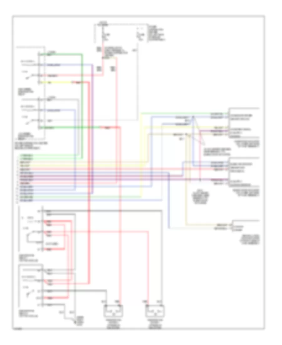
AIR CONDITIONING
Automatic A/C Wiring Diagram (1 of 2) for Dodge Intrepid ES 2004

List of elements for Automatic A/C Wiring Diagram (1 of 2) for Dodge Intrepid ES 2004:
- (at lower center of dash) g200
- (at lower center of dash) g201
- (at rear of engine)
- (between camshaft & coolant sensors)
- (in engine harness, on right side engine)
- (in instrument panel harness, behind instrument cluster) s204
- A/c compressor clutch (on front of a/c compressor)
- A/c compressor clutch relay
- A/c press sig
- A/c pressure transducer (at right front of engine compartment)
- Ambient temperature sensor (at right side of front grille)
- Aspirator motor
- Aspirator mtr dr
- Automatic temperature control head
- Battery
- Blnd dr driver
- Blnd dr fdbk sig
- Blower motor
- Blower motor power module (at lower right side of hvac assembly)
- Blower mtr ctrl
- Body control module (at left end of dash, attached to junction block)
- C10
- C12
- C18
- C24
- C26
- C27
- C28
- C32
- C33
- C34
- C35
- C36
- C37
- C38
- C56
- C57
- Com dr driver
- D25
- Ect signal
- Engine controls system
- Engine coolant temperature sensor (at front of engine, near thermostat housing)
- Evap temp sig
- Evaporator temperature sensor (in hvac assembly, on face of evaporator)
- F20
- Fuse 10a
- Fuse 19 15a
- Fuse 21 10a
- Fuse 30a
- G100
- Ground
- Hot at all times
- Hot in run
- Hot in run or start
- Ignition
- In car temp sens
- In car temp sig
- Interior lights system
- J/b (junction block) (at left end of dash)
- K25
- Mode dr driver
- Mode dr fbck sig
- Nca
- Panel lamps driver
- Pci bus
- Pnk
- Power distribution center (on left side of engine compartment)
- Powertrain control module (at left rear of engine compartment)
- Pressure signal
- Recirc dr driver
- Red/tan
- Relay ctrl
- S104
- S106
- S117 (in headlight & dash harness, at left inner fender)
- S208 (in center instrument panel harness)
- Sensor gnd
- Sensor ground
- Sensor signal
- Sun sens signal
- Sun sensor/ vtss set led (on top of dash)
Automatic A/C Wiring Diagram (2 of 2) for Dodge Intrepid ES 2004
List of elements for Automatic A/C Wiring Diagram (2 of 2) for Dodge Intrepid ES 2004:
- (in a/c heater harness, near breakout to blend door actuator)
- (near right horn) g105
- (not used)
- 87a
- Blend air dr drvr
- Blend door actuator (on lower left side of hvac assembly)
- Common
- Common dr drvr
- Dash harness, in power distribution center) s125
- Driver
- Fbck signal
- Fuse b 40a
- Fuse e 40a
- High speed radiator fan relay
- Hot at all times
- Low speed radiator fan relay
- Mode door actuator (on lower left side of hvac assembly)
- Mode door driver
- Mode fbck signal
- Power distribution center (on left side of engine compartment)
- Radiator fan motor 1 (at rear of fan motor)
- Radiator fan motor 2 (at rear of fan motor)
- Radiator fan relay 1 (on fan module)
- Radiator fan relay 2 (on fan module)
- Recirculation door actuator (on right side of hvac assembly)
- Red
- S210 (in a/c heater harness, near breakout to blend door actuator)
- S211
- S212
- Sensor gnd
- Sensor ground
Manual A/C Wiring Diagram for Dodge Intrepid ES 2004
List of elements for Manual A/C Wiring Diagram for Dodge Intrepid ES 2004:
- (2.7l: at right side of engine) (3.5l: between camshaft & coolant sensors)
- (3.5l: at rear of engine) (2.7l: at right rear side
- (3.5l: in engine harness, on right side of engine) (2.7l: in engine harness, at front of engine)
- (at lower center of dash) g200
- (at rear of fan motor) radiator fan motor 2
- (at right side of front grille) ambient temperature sensor
- (in a/c heater harness, near breakout to blend door actuator)
- (in breakout to a/c heater controls)
- (in center instrument panel harness)
- (in engine harness, near idle air control motor breakout)
- (in headlight & dash harness, in power distribution center) s125
- (in hvac assembly, on face of evaporator) evaporator temperature sensor
- (near right horn) g105
- 2.7l base except 2.7l base
- 87a
- A/c compressor clutch (on front of a/c compressor)
- A/c compressor clutch relay (in power distribution center)
- A/c led ind sig
- A/c mode mux
- A/c mode sw mux
- A/c press sig
- A/c pressure transducer (at right front of engine compt)
- Aat signal
- Blend air dr drvr
- Blend door actuator (on lower left side of hvac assembly)
- Blnd dr driver
- Blnd dr fdbk
- Blower motor
- Blower motor resistor block (on lower right side of hvac assembly)
- Body control module (at left end of dash, attached to junction block)
- C10
- C12
- C18
- C24
- C26
- C27
- C28
- C32
- C33
- C34
- C35
- C36
- C37
- C48
- C57
- C58
- C80
- C82
- Com dr driver
- Common
- Common dr drvr
- D25
- Defogger system
- Driver
- E17
- Ect sig
- Engine controls system
- Engine coolant temperature sensor (at front of engine, near thermostat housing)
- Evap temp sig
- F20
- Fbck signal
- Fuse 10a
- Fuse 30a
- Fuse b 40a
- Fuse e 40a
- G100
- Ground
- High blower mtr
- High blwr mtr
- High speed radiator fan relay
- Hot at all times
- Hot in run
- Hot in run or start
- Ignition
- Interior lights system
- J/b (junction block) (at left end of dash)
- K25
- Low blower mtr
- Low speed radiator fan relay
- M1 blower mtr
- M2 blower mtr
- Manual temperature control head
- Mode door actuator (on lower left side of hvac assembly)
- Mode door driver
- Mode dr driver
- Mode fbck signal
- Mode fdbk sig
- Of engine)
- Panel lamps drvr
- Park lp rly out
- Pci bus
- Pk lp rly out
- Power distribution center (on left side of engine compartment)
- Power distribution center (on left side of engine compt)
- Powertrain control module (at left rear of engine compartment)
- Radiator fan motor (2.7l base) (at rear of fan)
- Radiator fan motor 1 (at rear of fan motor)
- Radiator fan relay 1 (except 2.7l base) (on fan module)
- Radiator fan relay 2 (except 2.7l base) (on fan module)
- Rear wdo defog
- Rear window def
- Recirc dr driver
- Recirculation door actuator (on right side of hvac assembly)
- Red
- Red red
- Red/tan
- Relay ctrl
- S104
- S106
- S110 (2.7l)
- S117 (in headlight& dash harness, at left inner fender)
- S208
- S210
- S211
- S212
- S220
- S222 (in dash harness, behind instrument cluster)
- Sens gnd
- Sensor gnd
- Sensor ground
- Signal
- Sound systems
- Tan
- Temp select
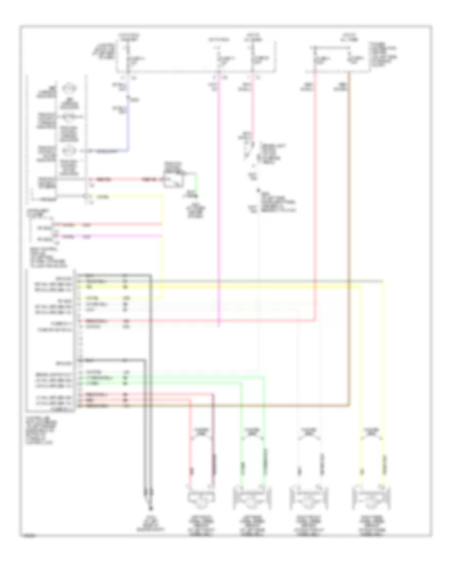
ANTI-LOCK BRAKES
Anti-lock Brakes Wiring Diagram for Dodge Intrepid ES 2004
List of elements for Anti-lock Brakes Wiring Diagram for Dodge Intrepid ES 2004:
- (at lower center of dash)
- A10
- A20
- Abs warning indicator
- Body control module (at left end of dash, attached to junction block)
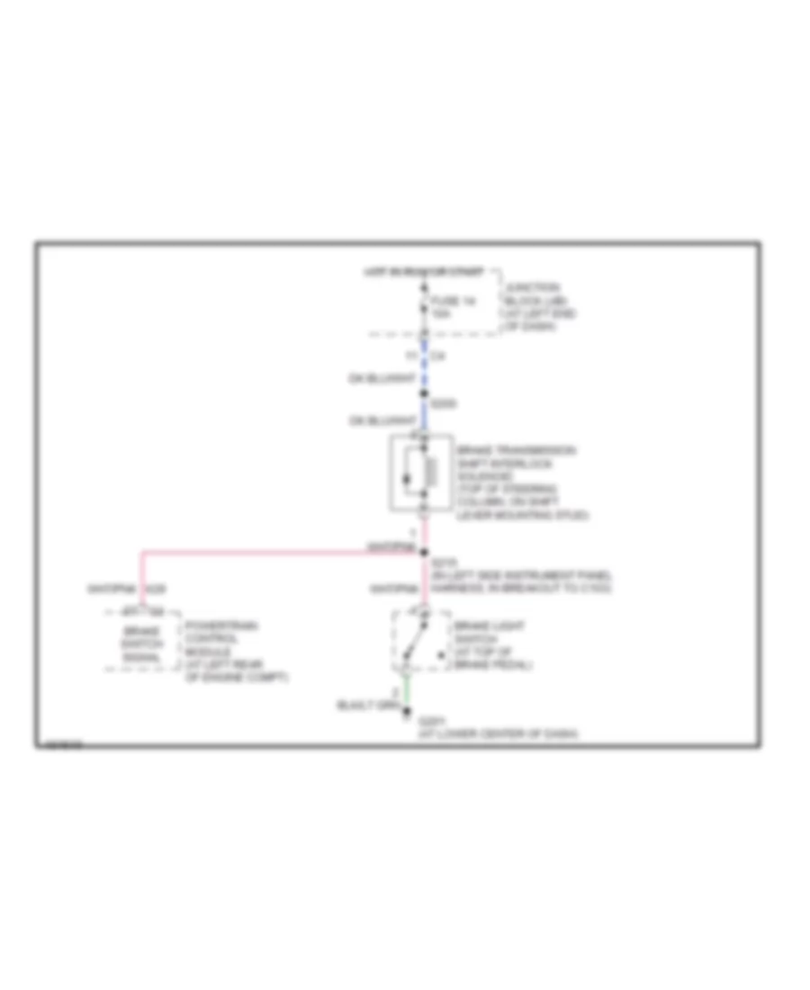
- Brake lamp sw out
- Brake light switch (at top of brake pedal)
- Controller anti-lock brake (at left fender side shield, on bottom of hydraulic control unit)
- D25
- F20
- Fuse 14 10a
- Fuse 17 10a
- Fuse 20 20a
- Fuse h 30a
- Fuse ign sw (run)
- Fuse k 40a
- Fused b (+)
- G103 (at left rear of engine compt)
- G201
- Ground
- Hot at all times
- Hot in run
- Hot in run or start
- Instrument cluster
- Junction block (j/b) (at left end of dash)
- L50
- Left front wheel speed sensor (at left front wheelwell)
- Left rear wheel speed sensor (at left rear wheelwell)
- Lf whl spd sen 12v
- Lf whl spd sen sig
- Lr whl spd sen 12v
- Lr whl spd sen sig
- Pci bus
- Power distribution center (on left side of engine compt)
- Red
- Rf whl spd sen 12v
- Rf whl spd sen sig
- Right front wheel speed sensor (at right front wheelwell)
- Right rear wheel speed sensor (at right rear wheelwell)
- Rr whl spd sen 12v
- Rr whl spd sen sig
- S200
- S205 (at left side instrument panel harness, in breakout to c104)
- Traction control active indicator
- Traction control sw sens
- Traction control switch
- Traction control warning indicator
- Twisted pair
ANTI-THEFT
Anti-theft Wiring Diagram for Dodge Intrepid ES 2004
List of elements for Anti-theft Wiring Diagram for Dodge Intrepid ES 2004:
- (at lower center of dash) g201
- (at rear of right rear door)
- (in center instrument panel harness) s208
- (in front lighting harness, near breakout for left front lights)
- (in rear of driver door)
- (in rear of passenger door)
- Body control module
- C38
- C57
- D25
- Decklid sw sns
- Door ajar sns (lr)
- Door ajar sns (rr)
- Door ajar sw sns
- Driver cylinder lock switch
- Driver door lock motor/ ajar switch
- Drv cyl lock sw
- Drv door ajar sns
- Fuse 10a
- Fuse 15a
- Fuse 20a
- Fused b(+)
- Fused ign
- G106 (near right horn)
- G200 (at lower center of dash)
- G201 (at lower center of dash)
- G26
- G300 (under driver's seat)
- G301 (under passenger's seat)
- G310 (deck lid ground)
- G69
- G71
- G73
- G74
- G75
- Gnd
- Ground
- Horn relay
- Horn rly ctrl
- Hot at all times
- Hot in run or start
- Ignition switch (key-in switch)
- Junction block (at left end of dash)
- Key-in ign sw sns
- Left horn (at left front of vehicle)
- Left rear door lock motor/ajar switch (at rear of left rear door)
- Park lamp relay
- Park lamp rly ctrl
- Passenger door lock motor/ ajar switch
- Pci bus
- Pnk
- Powertrain control module (at left rear of engine compt)
- Right horn (at right front of vehicle)
- Right rear door lock motor/ ajar switch
- S133
- S134
- S135
- S200
- S204
- S311
- S312
- S314
- S365
- Sensor ground
- Sentry key immobilizer module (in steering column)
- Sun sensor sig
- Sun sensor/ vtss set led (except base) (on top of dash)
- Tan
- Tan/red
- Trunk knock out switch (at center rear of deck lid)
- Vtss ind driver
- Z20
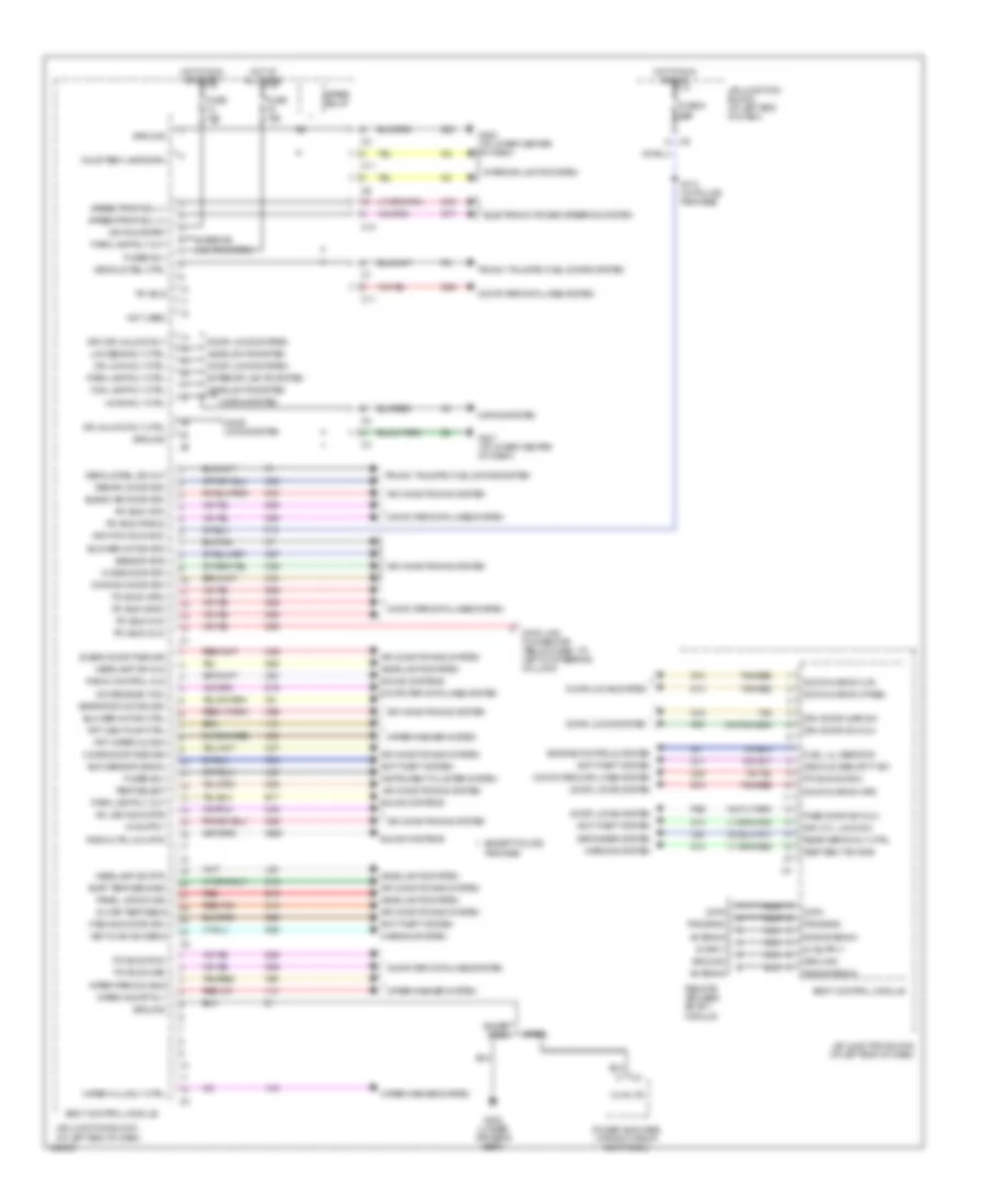
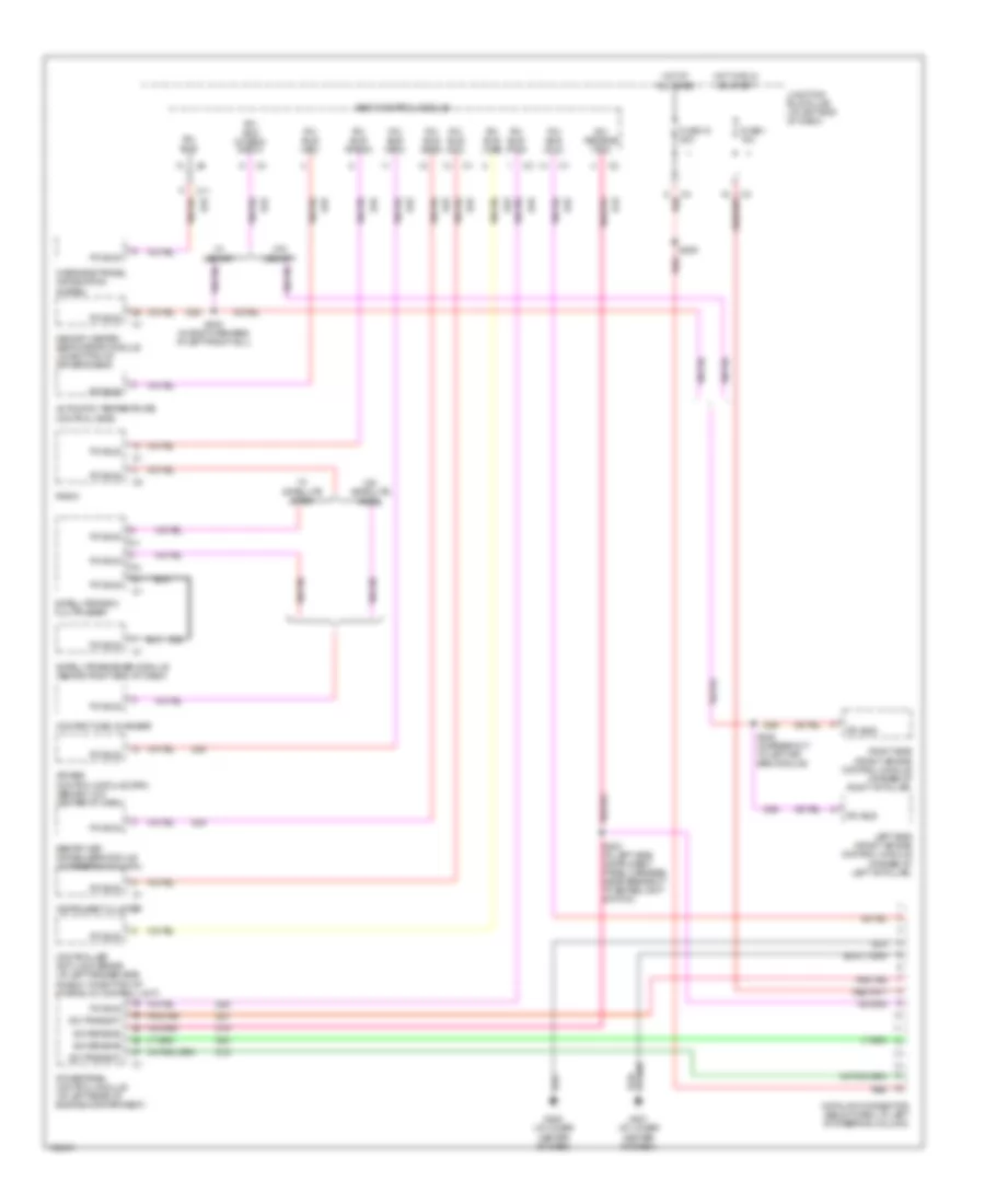
BODY CONTROL MODULES
Body Control Modules Wiring Diagram for Dodge Intrepid ES 2004
List of elements for Body Control Modules Wiring Diagram for Dodge Intrepid ES 2004:
- 12 volts
- 5v sply
- A/c led indicator
- Air conditioning system
- Antenna
- Anti-theft system
- Aspirator motor drv
- Base
- Blend air door drv
- Blend door fdbk sig
- Blower motor ctrl
- Blower motor drv
- Body control module
- C10
- C11
- C12
- C26
- C32
- C33
- C34
- C35
- C36
- C37
- C38
- C48
- C56
- C57
- C80
- C82
- Common door drv
- Computer data lines system
- Courtesy lamps drv
- D19
- D25
- Data
- Data link connector (below dash, to left of steering column)
- Decklid rel ctrl
- Decklid rel sw out
- Decklid security sw
- Defogger system
- Door ajar sw (lr)
- Door ajar sw (pass)
- Door ajar sw (rr)
- Door locks system
- Dr lock rly ctrl
- Dr unlock rly ctrl
- Drv cyl lock sw
- Drv door ajar sw
- Drv door sw mux
- Drv dr unlock rly
- E17
- E19
- Electronic power steering system
- Engine controls system
- Evap temp sens sig
- Except base
- Except police package
- Exterior lights system
- F13
- Fog lamp rly ctrl
- Frt wiper mux sw
- Frt wsh pump ctrl
- Fuel lvl sens sig
- Fuse 10a
- Fuse 15a
- Fuse 5 10a
- Fused b(+)
- G10
- G200 (at lower center of dash)
- G201 (at lower center of dash)
- G26
- G300 (under driver's seat)
- G52
- G69
- G71
- G73
- G74
- G75
- Ground
- Headlamp sw mux
- Headlamp sw rtn
- Headlights system
- Horn rly ctrl
- Horns system
- Hot at all times
- Hot in run or acc
- Hot in run or start
- Ign run/start
- Ignition (run/acc)
- In-car temp sens
- Instrument cluster system
- Interior lights system
- J/b (junction block) (at left end of dash)
- Key-in ign sw sens
- L80
- L99
- Low beam rly ctrl
- Mode door drv
- Mode door fdbk sig
- Nca
- Not used
- P96
- P97
- Panel lps dim sig
- Park lamp rly ctrl
- Park lamp rly out
- Pass door sw mux
- Pci bus
- Pci bus (atc)
- Pci bus (cab)
- Pci bus (dlc)
- Pci bus (mic)
- Pci bus (orc)
- Pci bus (pcm)
- Pci bus (radio)
- Pci bus (siacm)
- Pci bus (skim)
- Power amplifier (at right front kick panel)
- Program
- Radio control mux
- Radio ctrl mux rtn
- Rear defog rly ctrl
- Recirc door drv
- Red
- Red/tan
- Remote keyless entry module
- Rke antenna
- S174 (w/ police package)
- S76
- S77
- Sci receive (tcm)
- Seat belt sw sns
- Sensor gnd
- Sound systems
- Spare relay
- Speed prop sol (+)
- Speed prop sol (-)
- Sun sensor signal
- Tan
- Tan/red
- Temp select
- Trunk, tailgate, fuel doors system
- V10
- V14
- V16
- V52
- V55
- Vtss indicator drv
- Warning system
- Wiper hi/lo rly ctrl
- Wiper on/off rly
- Wiper park sw sns
- Wiper/washer system
- X20
- X920
- Z20
COMPUTER DATA LINES
Computer Data Lines Wiring Diagram for Dodge Intrepid ES 2004
List of elements for Computer Data Lines Wiring Diagram for Dodge Intrepid ES 2004:
- Air bag control module (orc) (behind low center of dash)
- Automatic temperature control head
- Body control module
- C11
- Compact disc changer
- Controller anti-lock brake (at left fender side shield, on bottom of hydraulic control unit)
- D15
- D19
- D20
- D21
- D25
- Data link connector (below dash, to left of steering column)
- Fuse 1 10a
- Fuse 18 20a
- G200 (at lower center of dash)
- G201 (at lower center of dash)
- Hot at all times
- Hot in run or start
- Instrument cluster
- Junction block (j/b) (at left end of dash)
- Left side impact air bag control module (at base of left "b" pillar)
- Memory heated seat/mirror module (on bottom of driver's seat)
- Overhead travel information system
- Pci bus
- Pci bus (atc)
- Pci bus (cab)
- Pci bus (dlc)
- Pci bus (mhsmm/ siacm)
- Pci bus (mic)
- Pci bus (orc)
- Pci bus (pcm)
- Pci bus (radio)
- Pci bus (skim)
- Pnk/tan
- Powertrain control module (at left rear of engine compartment)
- Radio
- Red
- Right side impact air bag control module (at base of right "b" pillar)
- S203 (in left side instrument panel harness, near breakout to brake light switch)
- S209
- S345 (in body harness, at left front sill)
- S349 (in breakout to left air bag module)
- Satellite radio multiplexer
- Satellite receiver module (behind right end of dash)
- Sci receive
- Sci receive (tcm)
- Sci transmit
- Sentry key immobilizer module (in steering column)
- W/ memory
- W/ satellite radio
- W/o memory
- W/o satellite radio
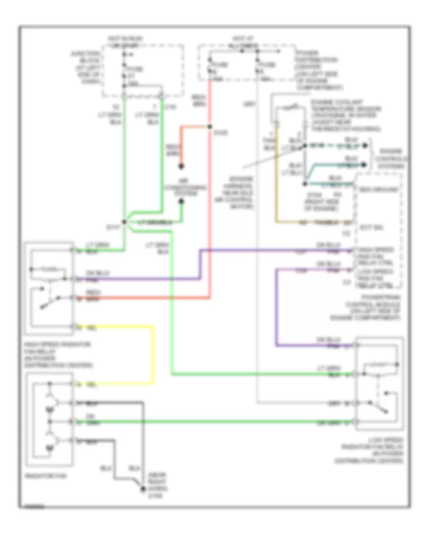
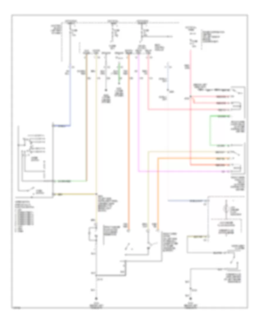
COOLING FAN
2.7L
2.7L, Cooling Fan Wiring Diagram for Dodge Intrepid ES 2004
List of elements for 2.7L, Cooling Fan Wiring Diagram for Dodge Intrepid ES 2004:
- (engine harness, near idle air control motor)
- (near right horn) g105
- (right side of engine)
- Air conditioning system
- C10
- C24
- C27
- Controls systems
- Ect sig
- Engine
- Engine coolant temperature sensor (on engine, in water jacket near thermostat housing)
- Fuse 10a
- Fuse b 40a
- Fuse e 40a
- High speed rad fan relay ctrl
- High speed radiator fan relay (in power distribution center)
- Hot at all times
- Hot in run or start
- Junction block (at left end of dash)
- Low speed rad fan relay ctrl
- Low speed radiator fan relay (in power distribution center)
- Power distribution center (on left side of engine compartment)
- Powertrain control module (on left side of engine compartment)
- Radiator fan
- S104
- S110
- S117
- S125
- Sen ground
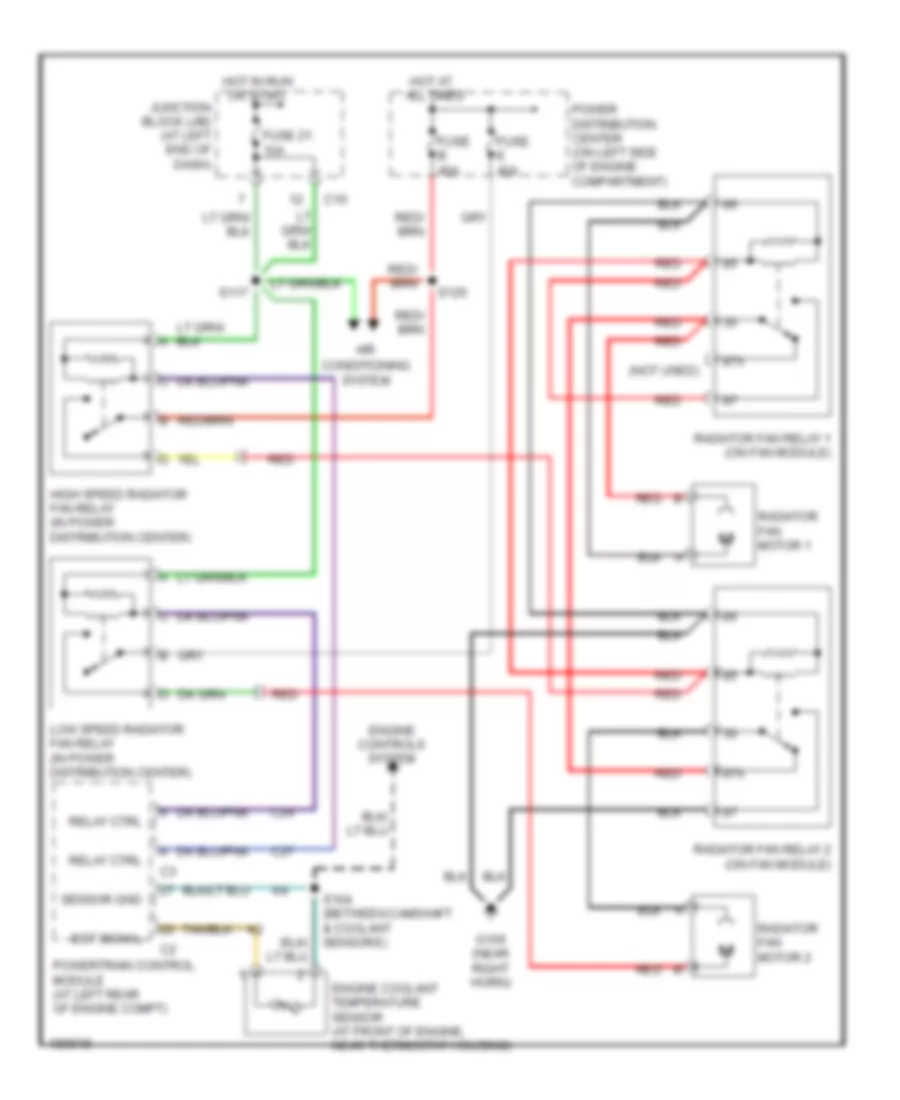
3.5L
3.5L, Cooling Fan Wiring Diagram for Dodge Intrepid ES 2004
List of elements for 3.5L, Cooling Fan Wiring Diagram for Dodge Intrepid ES 2004:
- (not used)
- 87a
- Air
- C10
- C24
- C27
- Conditioning system
- Ect signal
- Engine controls system
- Engine coolant temperature sensor (at front of engine, near thermostat housing)
- Fuse 21 10a
- Fuse b 40a
- Fuse e 40a
- G105 (near right horn)
- High speed radiator fan relay (in power distribution center)
- Hot at all times
- Hot in run or start
- Junction block (j/b) (at left end of dash)
- Low speed radiator fan relay (in power distribution center)
- Power distribution center (on left side of engine compartment)
- Powertrain control module (at left rear of engine compt)
- Radiator fan motor 1
- Radiator fan motor 2
- Radiator fan relay 1 (on fan module)
- Radiator fan relay 2 (on fan module)
- Red
- Relay ctrl
- S104 (between camshaft & coolant sensors)
- S117
- S125
- Sensor gnd
CRUISE CONTROL
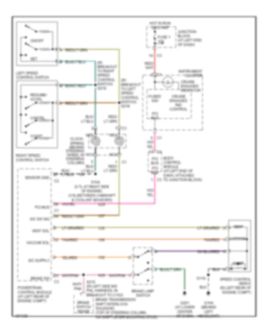
Cruise Control Wiring Diagram for Dodge Intrepid ES 2004
List of elements for Cruise Control Wiring Diagram for Dodge Intrepid ES 2004:
- (2.7l:at right side of engine) (3.5l:between camshaft & coolant sensors)
- (behind steering wheel in steering column)
- (in breakout to left speed control switch) s218
- (in breakout to right speed control switch) s219
- Body control module (at left end of dash, attached to junction block)
- Brake lamp switch
- Brake sw
- Brake switch sense
- Brake transmission shift interlock solenoid (top of steering column, on shift lever mounting stud)
- Cancel
- Clock- spring
- Coast
- Cruise engaged ind control
- Cruise engaged indicator
- D25
- Dump
- Fuse 1 10a
- Fused ign
- G104 (behind left headlight)
- G201 (at lower center of dash)
- Hot in run or start
- Instrument cluster
- Junction block (at left end of dash)
- K29
- Left speed control switch
- Nca
- On/off
- Pci bus
- Powertrain control module (at left rear of engine compt)
- Resume/ accel
- Right speed control switch
- S/c sw sig
- S104
- S119
- S215 (in left side ins pnl harness, in breakout to c103)
- Sensor gnd
- Set
- Speed control servo (in left rear of engine compt)
- Tan/red
- V32
- V35
- V36
- V37
- Vacuum
- Vacuum sol
- Vent
- Vent sol
DEFOGGERS
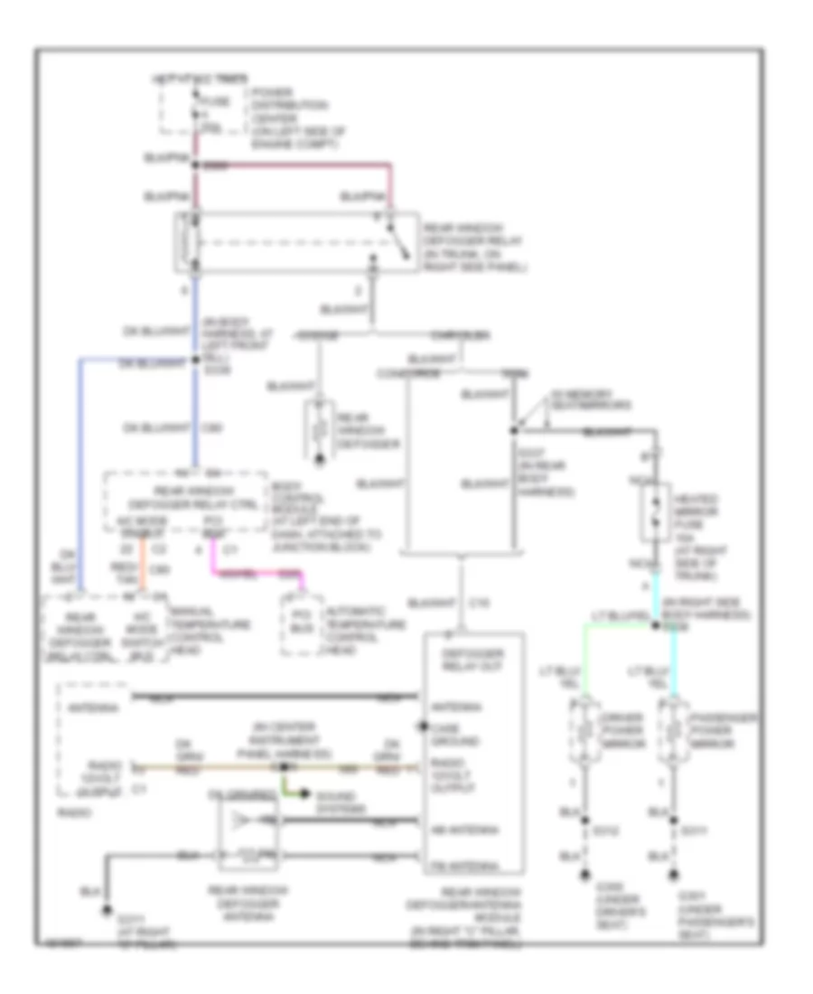
Defoggers Wiring Diagram for Dodge Intrepid ES 2004
List of elements for Defoggers Wiring Diagram for Dodge Intrepid ES 2004:
- (in body harness, at left front sill) s339
- (in center instrument panel harness) s206
- 300m
- A/c mode sw mux
- A/c mode switch mux
- Am antenna
- Antenna
- Automatic temperature control head
- Body control module (at left end of dash, attached to junction block)
- Case ground
- Chrysler
- Concorde
- D25
- Defogger relay out
- Dodge
- Driver power mirror
- Fm antenna
- Fuse a 50a
- G300 (under driver's seat)
- G301 (under passenger's seat)
- G311 (at right "c" pillar)
- Heated mirror fuse 10a (at right side of trunk)
- Hot at all times
- Manual temperature control head
- Nca
- Passenger power mirror
- Pci bus
- Power distribution center (on left side of engine compt)
- Radio
- Radio 12volt output
- Rear window defogger
- Rear window defogger antenna
- Rear window defogger relay (in trunk, on right side panel)
- Rear window defogger relay ctrl
- Rear window defogger/antenna module (in right "c" pillar, behind trim panel)
- Red/ c80
- S311
- S312
- S338
- Sound systems
- Tan
- W/ memory seat/mirrors
- X60
ELECTRONIC POWER STEERING
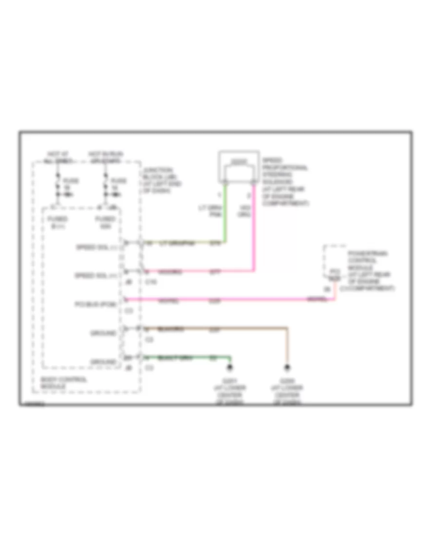
Electronic Power Steering Wiring Diagram for Dodge Intrepid ES 2004
List of elements for Electronic Power Steering Wiring Diagram for Dodge Intrepid ES 2004:
- Body control module
- C10
- D25
- Fuse 10a
- Fuse 15a
- Fused b (+)
- Fused ign
- G200 (at lower center of dash)
- G201 (at lower center of dash)
- Ground
- Hot at all times
- Hot in run or start
- Junction block (j/b) (at left end of dash)
- Pci bus
- Pci bus (pcm)
- Powertrain control module (at left rear of engine compartment)
- S76
- S77
- Speed proportional steering solenoid (at left rear of engine compartment)
- Speed sol (+)
- Speed sol (-)
- Z20
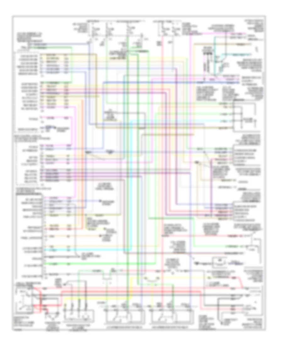
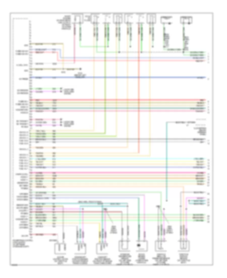
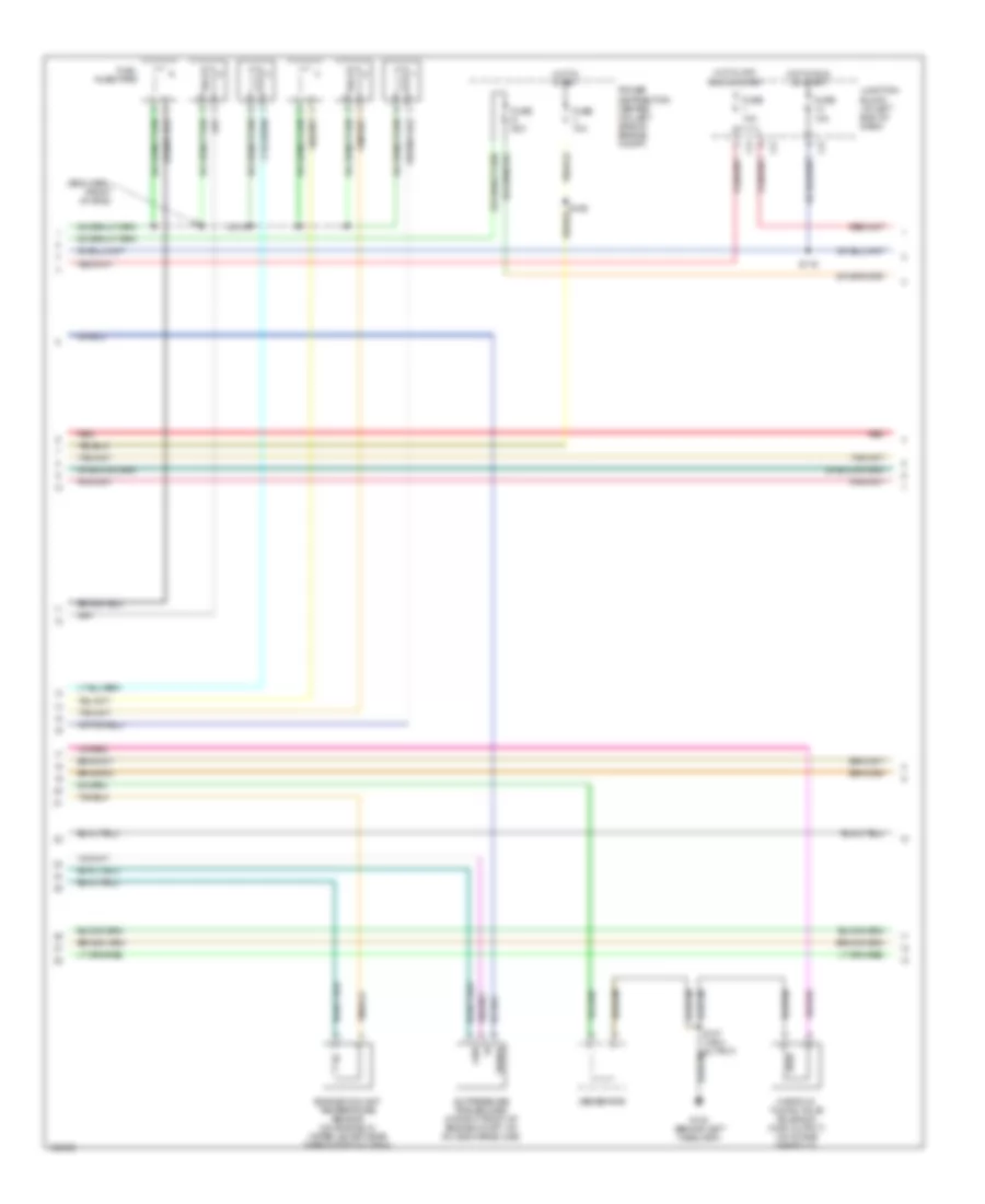
ENGINE PERFORMANCE
2.7L
2.7L, Engine Performance Wiring Diagram (1 of 5) for Dodge Intrepid ES 2004
List of elements for 2.7L, Engine Performance Wiring Diagram (1 of 5) for Dodge Intrepid ES 2004:
- (eng harn, front of eng)
- (eng harn, near fuel injs 1 & 4) s109
- (eng harn, near fuel injs 3 & 5) s111
- (eng harn, near iac motor breakout)
- (eng harn, right side of eng) s104
- A/c press
- A209
- C18
- Camshaft position sensor (on front side of left cyl head)
- Capacitor 1
- Capacitor 2
- Ckp sens
- Clockspring (behind steering wheel)
- Cmp sens
- Coils on plugs
- Computer data lines system
- Crankshaft position sensor (on right side of trans housing)
- D15
- D19
- D20
- D21
- D25
- Driver
- Ect sens
- F11
- F12
- Fuel inj 1
- Fuel inj 2
- Fuel inj 3
- Fuel inj 4
- Fuel inj 5
- Fuel inj 6
- Fused b(+)
- Fused ign sw
- G102 (behind left headlamp)
- Generator
- Gnd
- Ho2s 1/1
- Ho2s 1/2
- Ho2s 2/1
- Ho2s 2/2
- Ho2s return
- Iac mtr
- Iac mtr sens
- Iat sens
- Idle air control motor (on throttle body)
- Ign coil 1
- Ign coil 2
- Ign coil 3
- Ign coil 4
- Ign coil 5
- Ign coil 6
- Intake air temperature sensor (in intake hose before throttle body)
- K11
- K12
- K13
- K14
- K141
- K20
- K21
- K22
- K24
- K241
- K299
- K341
- K38
- K39
- K41
- K42
- K44
- K45
- K58
- K60
- K902
- K904
- K91
- K92
- K93
- K94
- K95
- K96
- K99
- Knock sens
- Knock sensor (under lower intake manifold)
- Manifold absolute pressure sensor (on left rear side of intake manifold plenum)
- Map sens
- Nca
- Pci bus
- Pnk/tan
- Powertrain control module (pcm) (in left rear of engine compt)
- Red
- S106
- S110
- S122
- Sci receive
- Sci transmit
- Sense
- Sensor gnd
- Signal
- T751
- Tan/pnk
- Tan/red
- Throttle position sensor (on throttle body)
- Tp sens
- Z12
2.7L, Engine Performance Wiring Diagram (2 of 5) for Dodge Intrepid ES 2004
List of elements for 2.7L, Engine Performance Wiring Diagram (2 of 5) for Dodge Intrepid ES 2004:
- (eng harn, front of eng) s101
- A/c pressure transducer (in right front of engine compt, on a/c discharge line)
- Engine coolant temperature sensor (on engine, in water jacket near thermostat housing)
- Fuel injectors
- Fuse 10a
- Fuse s 20a
- Fuse v 10a
- G102 (behind left headlamp)
- Generator
- Gnd
- Hot in off, run or start
- Hot in run or start
- Hot in start
- Junction block (at left end of dash)
- Power distribution center (on left side of engine compt)
- Red
- S116
- Signal
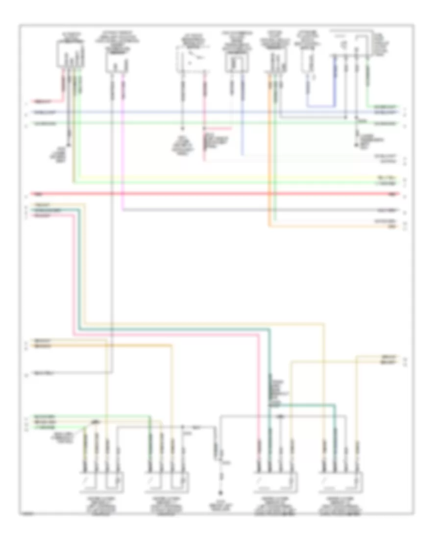
2.7L, Engine Performance Wiring Diagram (3 of 5) for Dodge Intrepid ES 2004
List of elements for 2.7L, Engine Performance Wiring Diagram (3 of 5) for Dodge Intrepid ES 2004:
- (at right side of headlamp mounting module grille opening) ambient temperature sensor
- (at top of brake pedal) brakelight switch
- (attached to junction block) body control module
- (eng harn, in breakout for pcm)
- (on fuel pump) natural vacuum leak detection assembly
- (top of steering column) brake transmission shift interlock solenoid
- (under passenger's seat) g301
- Fuel lvl
- Fuel pump module (in top of fuel tank)
- G103 (behind left headlamp)
- G201 (lower center of instrument panel)
- Gnd
- Heated oxygen sensor 1/1 (right upstream) (in right exhaust manifold)
- Heated oxygen sensor 1/2 (right downstream) (at outlet end of right catalytic converter)
- Heated oxygen sensor 2/1 (left upstream) (in left exhaust manifold)
- Heated oxygen sensor 2/2 (left downstream) (at outlet end of left catalytic converter)
- Nca
- Red
- S100
- S102
- S123
- S142
- S143
- S348
- Signal
- Sol cntl
- Sw sense
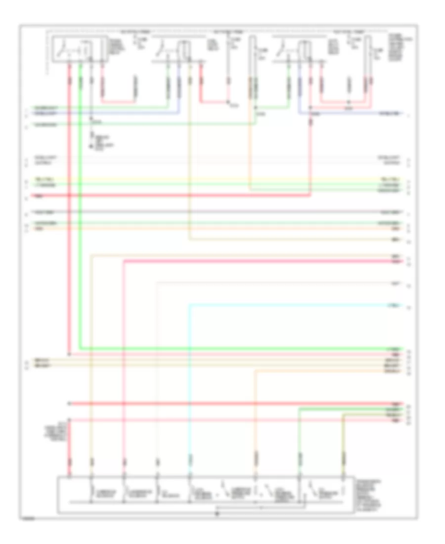
2.7L, Engine Performance Wiring Diagram (4 of 5) for Dodge Intrepid ES 2004
List of elements for 2.7L, Engine Performance Wiring Diagram (4 of 5) for Dodge Intrepid ES 2004:
- (behind left headlamp) g103
- 2-4 pressure switch
- 2-4 solenoid
- Auto shut- down relay
- Fuel pump relay
- Fuse g 40a
- Fuse n 30a
- Fuse q 20a
- Fuse t 20a
- Fuse w 10a
- Hot at all times
- Low/ reverse pressure switch
- Low/ reverse solenoid
- Overdrive pressure switch
- Overdrive solenoid
- Pnk
- Power distribution center (on left side of engine compt)
- Red
- S114 (headlamp & dash harn, in breakout for pcm)
- S119
- S124
- S165
- S166
- S167
- Trans- mission control relay
- Transmission solenoid/ pressure switch assembly (on top side of transaxle valve body)
- Underdrive solenoid
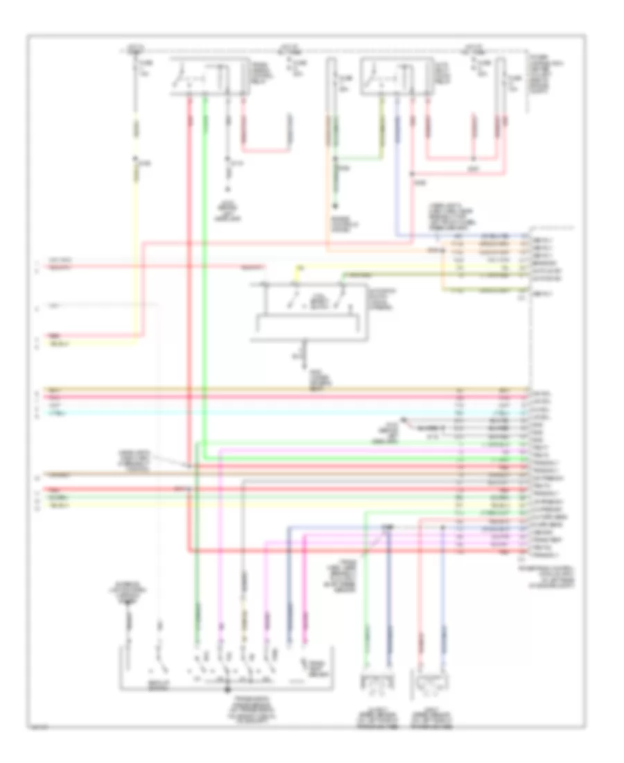
2.7L, Engine Performance Wiring Diagram (5 of 5) for Dodge Intrepid ES 2004
List of elements for 2.7L, Engine Performance Wiring Diagram (5 of 5) for Dodge Intrepid ES 2004:
- (behind left headlamp) g102
- (headlamp & dash harn, near breakout for left front wheel speed sensor) s164
- 2-4 pres sw
- 2-4 sol
- A/c compres
- A/c system
- Amb temp
- Asd rly
- Back-up lamp switch
- Brake sw
- C24
- C27
- C28
- Cooling fans system
- Cruise control system
- Evap sol
- Evap/ purge solenoid (attached to bracket, near air cleaner)
- Exterior lights, mirrors systems
- F142
- Fuel pmp rly
- Fuse 10a
- Gnd
- Hi fan rly
- Ho2s 1/2
- Ho2s 2/2
- Hot in run
- Hot in run or start
- In spd sens
- Input speed sensor (on left side of transaxle case)
- Junction block (at left end of dash)
- K106
- K107
- K108
- K199
- K25
- K29
- K31
- K399
- K51
- K52
- K90
- L/r pres sw
- L/r sol
- Low fan rly
- Nol
- Nvld sol
- Nvld sw
- O/d pres sw
- O/d sol
- Out spd sens
- Output speed sensor (on left side of transaxle case)
- P3l
- Pnk
- Powertrain control module (pcm) (in left rear of engine compt)
- Prnl
- Red
- S118
- S200
- Spd cntl pow
- Spd cntl sw
- Spd cntl vac
- Spd cntl vnt
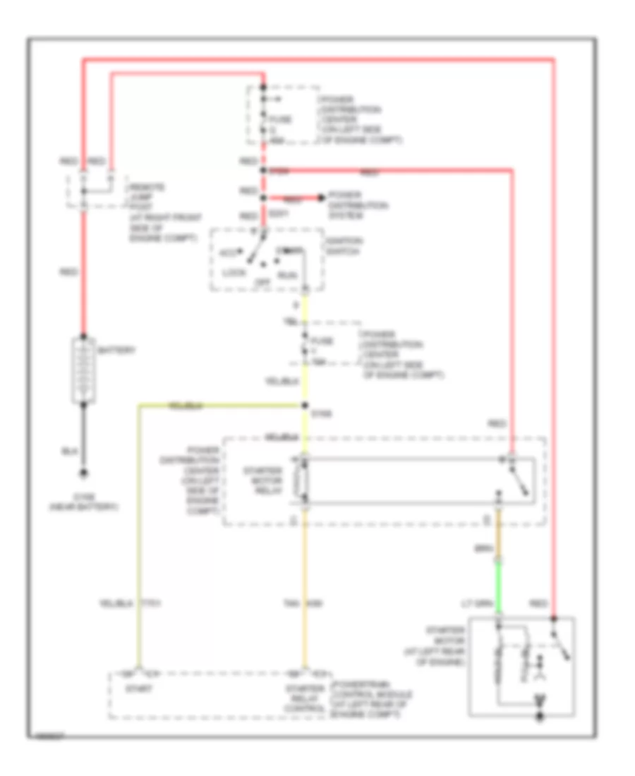
- Starter rly
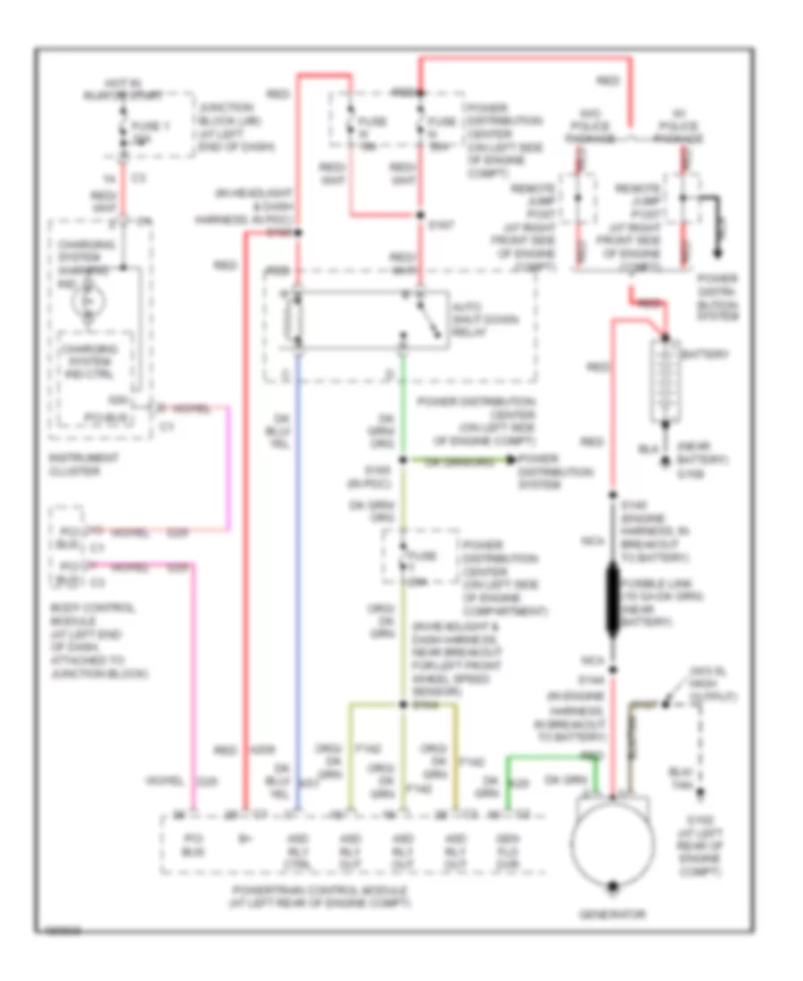
- Starting/charging system
- T13
- T14
- T15
- T16
- T19
- T20
- T41
- T42
- T47
- T50
- T52
- T54
- T59
- T60
- Tan
- Tan/red
- Trans rly
- Trans temp
- Trans temp sensor
- Transmission range sensor (on transmission valve body manual valve shaft)
- Trs t1
- Trs t3
- Trs t41
- Trs t42
- U/d sol
- V32
- V35
- V36
- V37
- Vss gnd
- Z13
- Z14
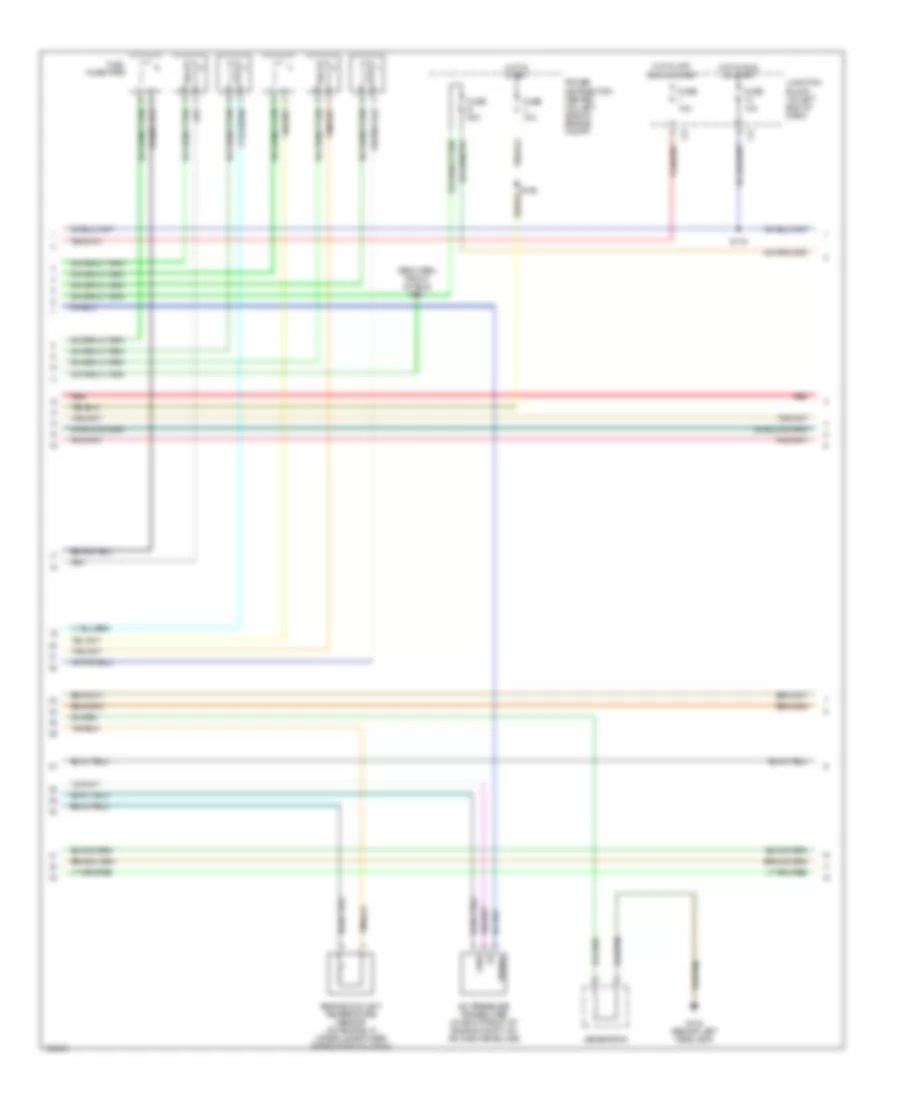
3.5L
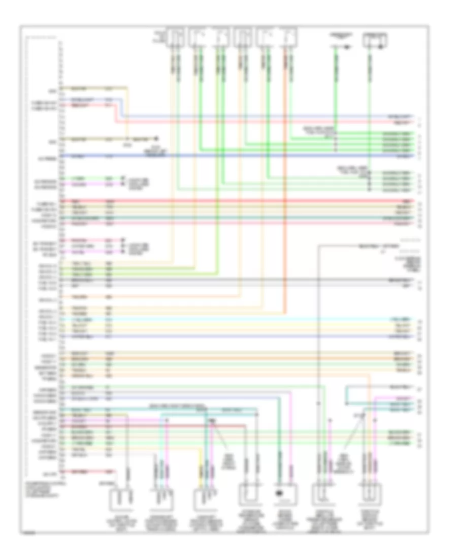
3.5L, Engine Performance Wiring Diagram (1 of 5) for Dodge Intrepid ES 2004
List of elements for 3.5L, Engine Performance Wiring Diagram (1 of 5) for Dodge Intrepid ES 2004:
- (eng harn, front of eng)
- (eng harn, front of eng) s104
- (eng harn, left side of eng) s109
- (eng harn, near fuel injs 1 & 3) s111
- A/c press
- A209
- C18
- Camshaft position sensor (on front of engine timing case cover)
- Capacitor 1
- Capacitor 2
- Ckp sens
- Clockspring (behind steering wheel)
- Cmp sens
- Coils on plugs
- Computer data lines system
- Crankshaft position sensor (on right side of trans housing)
- D15
- D19
- D20
- D21
- D25
- Driver
- Ect sens
- F11
- F12
- Fuel inj 1
- Fuel inj 2
- Fuel inj 3
- Fuel inj 4
- Fuel inj 5
- Fuel inj 6
- Fused b(+)
- Fused ign sw
- G102 (behind left headlamp)
- Generator
- Gnd
- Ho2s 1/1
- Ho2s 1/2
- Ho2s 2/1
- Ho2s 2/2
- Ho2s return
- Iac mtr
- Iac mtr sens
- Iat sens
- Idle air control motor (on throttle body)
- Ign coil 1
- Ign coil 2
- Ign coil 3
- Ign coil 4
- Ign coil 5
- Ign coil 6
- Intake air temperature sensor (on left side of intake manifold plenum)
- K11
- K12
- K13
- K14
- K141
- K20
- K21
- K22
- K236
- K24
- K241
- K299
- K341
- K36
- K38
- K39
- K41
- K42
- K44
- K45
- K58
- K60
- K902
- K904
- K91
- K92
- K93
- K94
- K95
- K96
- K99
- Knock sens
- Knock sensor (under lower intake manifold)
- Manifold absolute pressure sensor (on left side of intake manifold plenum)
- Manifold sol
- Map sens
- Nca
- Pci bus
- Pnk/tan
- Powertrain control module (pcm) (in left rear of engine compt)
- Red
- S106
- S110
- S122
- Sci receive
- Sci transmit
- Sense
- Sensor gnd
- Short runner valve solenoid (high output) (at front of intake manifold)
- Signal
- T751
- Tan/pnk
- Tan/red
- Throttle position sensor (on throttle body)
- Tp sens
- Vlv sol cntl
- Z12
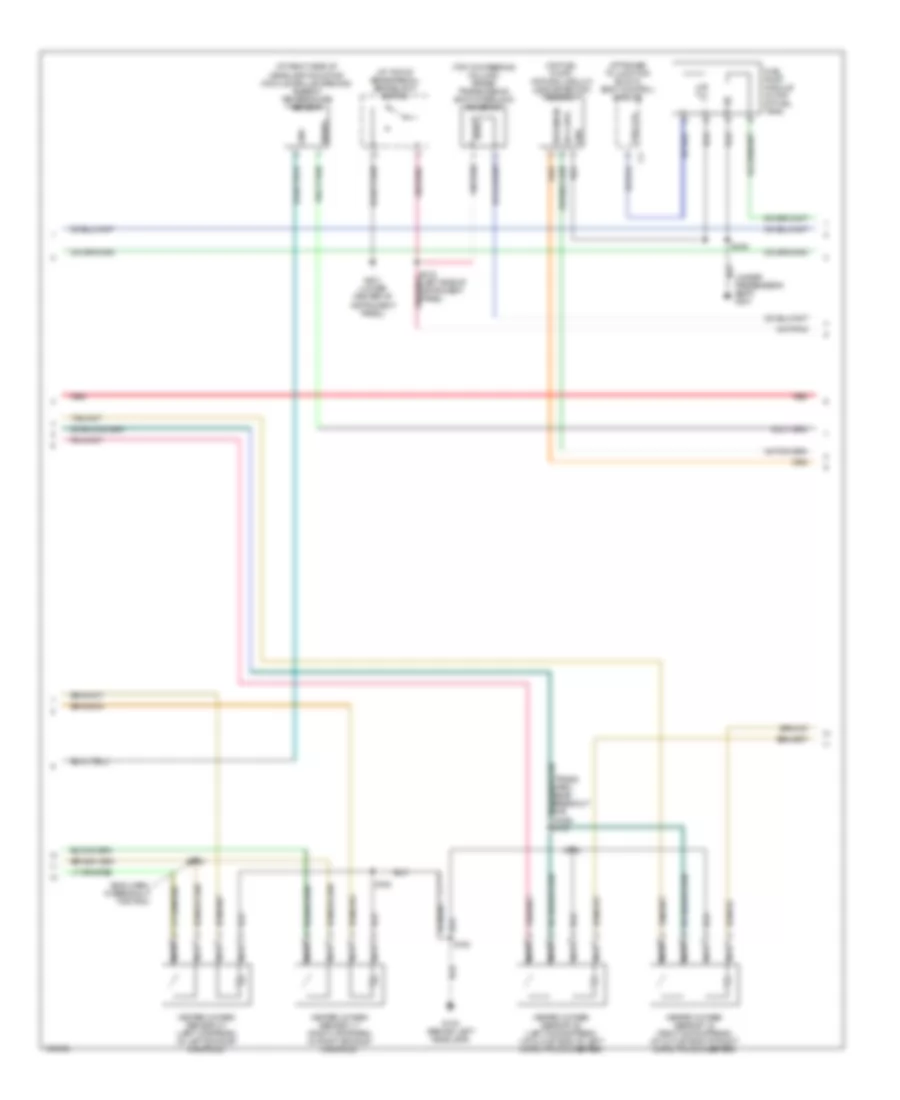
3.5L, Engine Performance Wiring Diagram (2 of 5) for Dodge Intrepid ES 2004
List of elements for 3.5L, Engine Performance Wiring Diagram (2 of 5) for Dodge Intrepid ES 2004:
- (eng harn, front of eng)
- A/c pressure transducer (in right front of engine compt, on a/c discharge line)
- Engine coolant temperature sensor (on engine, in water jacket near thermostat housing)
- Fuel injectors
- Fuse 10a
- Fuse s 20a
- Fuse v 10a
- G102 (behind left headlamp)
- Generator
- Gnd
- Hot in off, run or start
- Hot in run or start
- Hot in start
- Junction block (at left end of dash)
- Manifold tuning valve solenoid (high output) (on intake manifold)
- Power distribution center (on left side of engine compt)
- Red
- S107 (high output)
- S112
- S116
- Signal
3.5L, Engine Performance Wiring Diagram (3 of 5) for Dodge Intrepid ES 2004
List of elements for 3.5L, Engine Performance Wiring Diagram (3 of 5) for Dodge Intrepid ES 2004:
- (at right side of headlamp mounting module grille opening) ambient temperature sensor
- (at top of brake pedal) brakelight switch
- (attached to junction block) body control module
- (eng harn, in breakout for pcm)
- (on fuel pump) natural vacuum leak detection assembly
- (top of steering column) brake transmission shift interlock solenoid
- (under passenger's seat) g301
- Autostick switch (if equipped)
- Downshift
- Fuel lvl
- Fuel pump module (in top of fuel tank)
- G103 (behind left headlamp)
- G201 (lower center of instrument panel)
- G300 (under driver's seat)
- Gnd
- Heated oxygen sensor 1/1 (right upstream) (in right exhaust manifold)
- Heated oxygen sensor 1/2 (right downstream) (at outlet end of right catalytic converter)
- Heated oxygen sensor 2/1 (left upstream) (in left exhaust manifold)
- Heated oxygen sensor 2/2 (left downstream) (at outlet end of left catalytic converter)
- Ign sw
- Nca
- Red
- S100
- S102
- S123
- S142
- S143
- S348
- Signal
- Sol cntl
- Sw sense
- Upshift
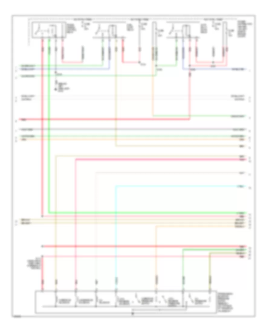
3.5L, Engine Performance Wiring Diagram (4 of 5) for Dodge Intrepid ES 2004
List of elements for 3.5L, Engine Performance Wiring Diagram (4 of 5) for Dodge Intrepid ES 2004:
- (behind left headlamp) g103
- 2-4 pressure switch
- 2-4 solenoid
- Auto shut- down relay
- Fuel pump relay
- Fuse g 40a
- Fuse n 30a
- Fuse q 20a
- Fuse t 20a
- Fuse w 10a
- Hot at all times
- Low/ reverse pressure switch
- Low/ reverse solenoid
- Overdrive pressure switch
- Overdrive solenoid
- Pnk
- Power distribution center (on left side of engine compt)
- Red
- S114 (headlamp & dash harn, in breakout for pcm)
- S119
- S124
- S165
- S166
- S167
- Trans- mission control relay
- Transmission solenoid/ pressure switch assembly (on top side of transaxle valve body)
- Underdrive solenoid
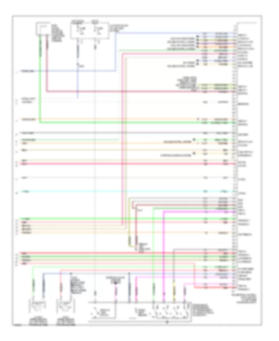
3.5L, Engine Performance Wiring Diagram (5 of 5) for Dodge Intrepid ES 2004
List of elements for 3.5L, Engine Performance Wiring Diagram (5 of 5) for Dodge Intrepid ES 2004:
- (behind left headlamp) g102
- (headlamp & dash harn, near breakout for left front wheel speed sensor) s164
- 2-4 pres sw
- 2-4 sol
- A/c compres
- A/c system
- Amb temp
- Asd rly
- Autostick dn
- Autostick up
- Back-up lamp switch
- Brake sw
- C24
- C27
- C28
- Cooling fans system
- Cruise control system
- Evap sol
- Evap/ purge solenoid (attached to bracket, near air cleaner)
- Exterior lights, mirrors systems
- F142
- Fuel pmp rly
- Fuse 10a
- Gnd
- Hi fan rly
- Ho2s 1/2
- Ho2s 2/2
- Hot in run
- Hot in run or start
- In spd sens
- Input speed sensor (on left side of transaxle case)
- Junction block (at left end of dash)
- K106
- K107
- K108
- K199
- K25
- K29
- K31
- K399
- K51
- K52
- K90
- L/r pres sw
- L/r sol
- Low fan rly
- Nol
- Nvld sol
- Nvld sw
- O/d pres sw
- O/d sol
- Out spd sens
- Output speed sensor (on left side of transaxle case)
- P3l
- Pnk
- Powertrain control module (pcm) (in left rear of engine compt)
- Prnl
- Red
- S118
- S200
- Spd cntl pow
- Spd cntl sw
- Spd cntl vac
- Spd cntl vnt
- Starter rly
- Starting/charging system
- T13
- T14
- T15
- T16
- T19
- T20
- T41
- T42
- T44
- T47
- T50
- T52
- T54
- T59
- T60
- Tan
- Tan/red
- Trans rly
- Trans temp
- Trans temp sensor
- Transmission range sensor (on transmission valve body manual valve shaft)
- Trs t1
- Trs t3
- Trs t41
- Trs t42
- U/d sol
- V32
- V35
- V36
- V37
- Vss gnd
- Z13
- Z14
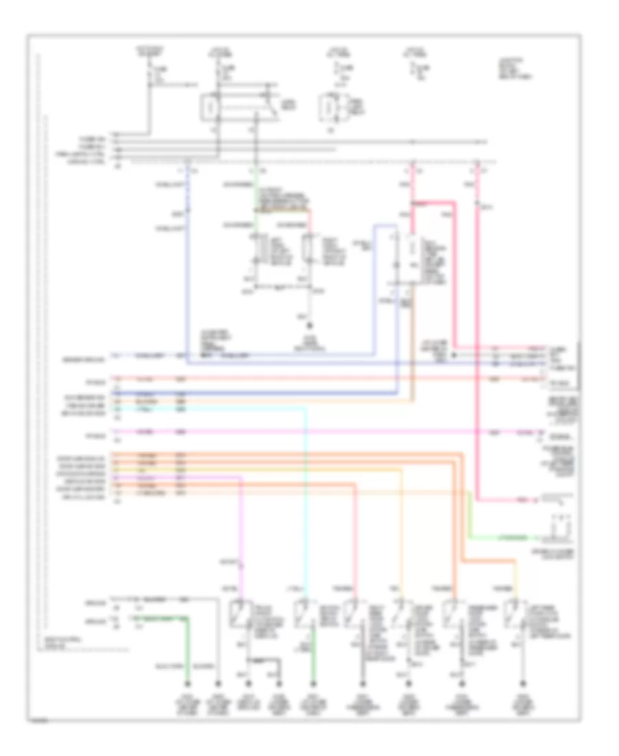
EXTERIOR LIGHTS
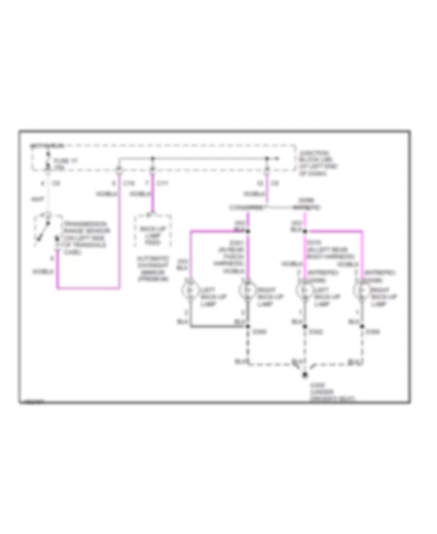
Back-up Lamps Wiring Diagram for Dodge Intrepid ES 2004
List of elements for Back-up Lamps Wiring Diagram for Dodge Intrepid ES 2004:
- (300m)
- (intrepid)
- 300m/ intrepid
- Automatic day/night mirror (premium)
- Back-up lamp feed
- C10
- C11
- Concorde
- Fuse 17 10a
- G300 (under driver's seat)
- Hot in run
- Junction block (j/b) (at left end of dash)
- Left back-up lamp
- Right back-up lamp
- S310 (in left rear body harness)
- S360
- S361 (in rear fascia harness)
- S362
- S369
- Transmission range sensor (on left side of transaxle case)
Exterior Lamps Wiring Diagram for Dodge Intrepid ES 2004
List of elements for Exterior Lamps Wiring Diagram for Dodge Intrepid ES 2004:
- (in front lighting harness, near breakout for left front lights)
- (in taillight harness, at left taillight) s363
- (in taillight harness, at right taillight) s367
- (in trunk deck lid harness) s366
- Body control module
- Brake lamp switch output
- Brakelight switch (at top of brake pedal)
- C10
- Center high mounted stop lamp 1
- Center high mounted stop lamp 2
- Combination flasher (on left side of dash, right of junction block)
- Combo flasher output
- Combo flasher switched ground
- Controller anti-lock brake (at left fender side shield, on bottom of hydraulic control unit)
- Fuse 10a
- Fuse 20a
- Fuse o 20a
- Fused b(+)
- Fused ign
- G106 (near right horn)
- G200 (at lower center of dash)
- G201 (at lower center of dash)
- G300 (under driver's seat)
- G301 (under passenger's seat)
- G310 (deck lid ground)
- Ground
- Hazard switch
- Hot at all times
- Hot in run
- Instrument cluster
- Junction block (j/b) (at left end of dash)
- Left
- Left front lights) s131
- Left front park/ turn signal lamp
- Left rear side marker lamp
- Left rear turn signal lamp
- Left tail/ stop lamp
- Left turn ind
- License lamp
- Off
- Park lamp relay
- Pnk
- Power distribution center (on left side of engine compt)
- Red
- Relay ctrl
- Relay out
- Right
- Right front park/ turn signal lamp
- Right rear side marker lamp
- Right rear turn signal lamp
- Right tail lamp
- Right tail/ stop lamp
- Right turn ind
- S134
- S135
- S362
- S364 (in taillight harness, at left taillight)
- S365
- S368 (in taillight harness, at right taillight)
- S369
- Tan
- Turn signal switch
- Turn signal/ hazard switch
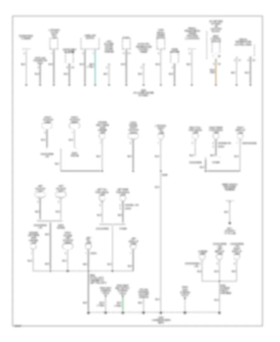
GROUND DISTRIBUTION
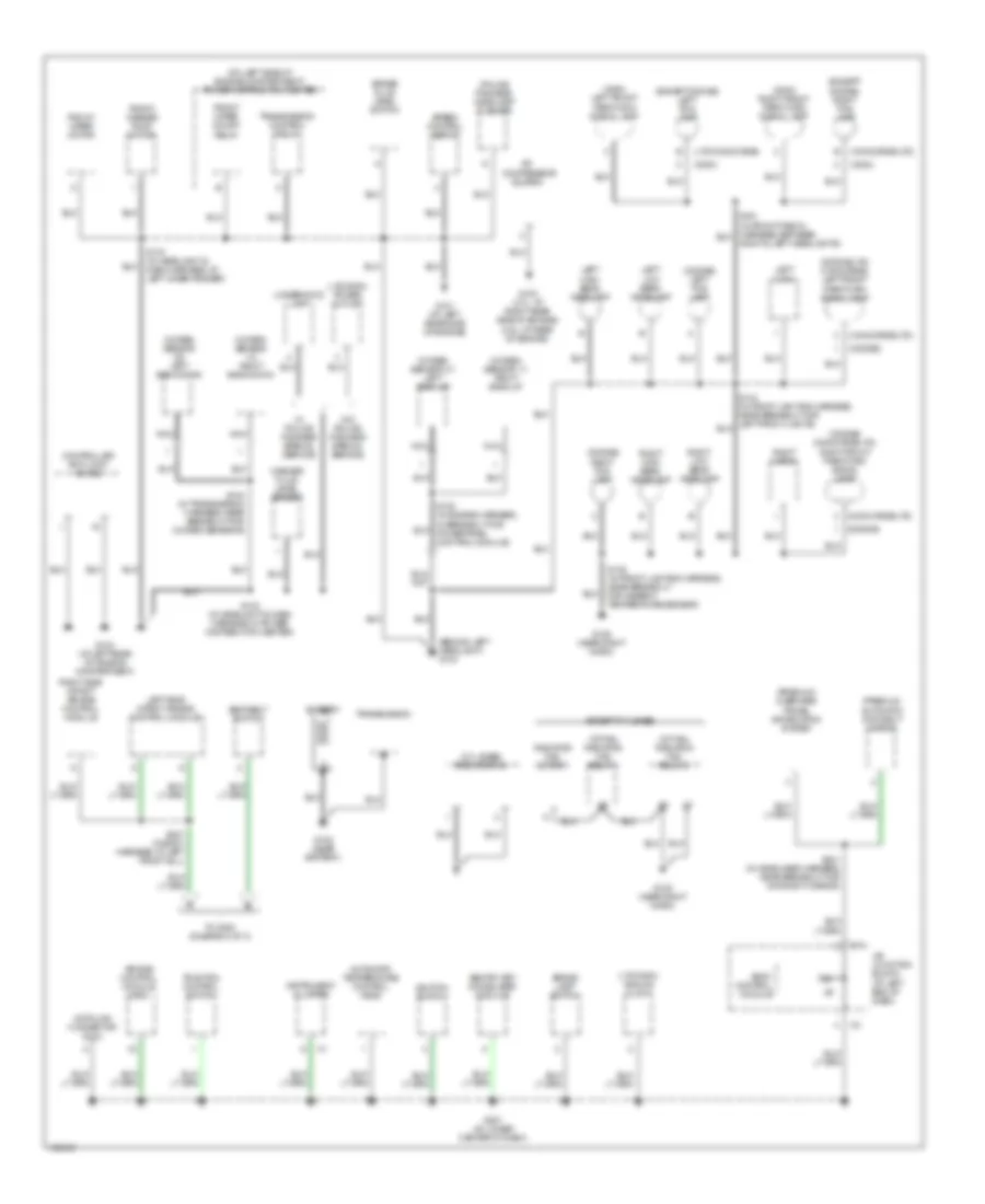
Ground Distribution Wiring Diagram (1 of 3) for Dodge Intrepid ES 2004
List of elements for Ground Distribution Wiring Diagram (1 of 3) for Dodge Intrepid ES 2004:
- (2.7l base) radiator fan
- (300m)
- (300m) left front park/turn signal lamp
- (300m) right front park/turn signal lamp
- (at fan) radiator fan relay 1
- (at fan) radiator fan relay 2
- (behind left headlight) g104
- (concorde/ltd)
- (dodge)
- (dodge) left fog lamp
- (dodge/ concorde/ltd) right front park/turn signal lamp
- (dodge/ltd/ concorde) left front park/turn signal lamp
- (except dodge) left fog lamp
- (except dodge) right fog lamp
- (ltd/300m) analog clock
- (ltd/300m) power outlet
- (ltd/concorde)
- (on left side of engine compartment) power distribution center
- (police package) headlamp flasher
- (premium) automatic day/night mirror
- (premium) overhead travel information system
- A/c compressor clutch
- Air bag control module (orc)
- Automatic temperature control head
- Battery
- Body control module
- Brake fluid level switch
- Brake lamp switch
- C11
- Controller anti-lock brake
- Data link connector (dlc)
- Except 2.7l base
- Front washer pump motor
- Front wiper motor
- Front wiper on/off relay
- G100 (2.7l: at right rear side of engine) (3.5l: at rear of engine)
- G101 (at left rear side of engine)
- G103 (at left rear of engine compartment)
- G105 (near right horn)
- G106 (near right horn)
- G108 (near battery)
- G201 (at lower center of dash)
- Ignition switch
- Instrument cluster
- J/b (junction block) (at left end of dash)
- Left high beam headlamp
- Left horn
- Left low beam headlamp
- Left side impact air bag control module
- Nca
- Oxygen sensor 1/1 right bank up
- Oxygen sensor 1/2 right bank down
- Oxygen sensor 2/1 left bank up
- Oxygen sensor 2/2 left bank down
- Radiator fan motor 1
- Right & left headlights)
- Right fog lamp
- Right high beam headlamp
- Right horn
- Right low beam headlamp
- Right side impact air bag control module
- S100 (in engine harness, in breakout for powertrain control module)
- S119 (in headlight & dash harness, at left inner fender)
- S123 (in headlight & dash harness, in power distribution center)
- S135 (in front lighting harness, near breakout for ambient temperature sensor)
- S142 (in transmission harness, near breakout for oxygen sensors)
- S321 (in headliner harness, near breakout for day/night mirror)
- S347 (in body harness, at left front sill)
- Seat belt switch
- Sentry key immobilizer module
- Speed control servo
- To g300 (diagram 3 of 3)
- Traction control switch
- Transmission
- Transmission control relay
- Underhood lamp
- W/ police package special service
- W/o police package special service
- Washer fluid level sensor
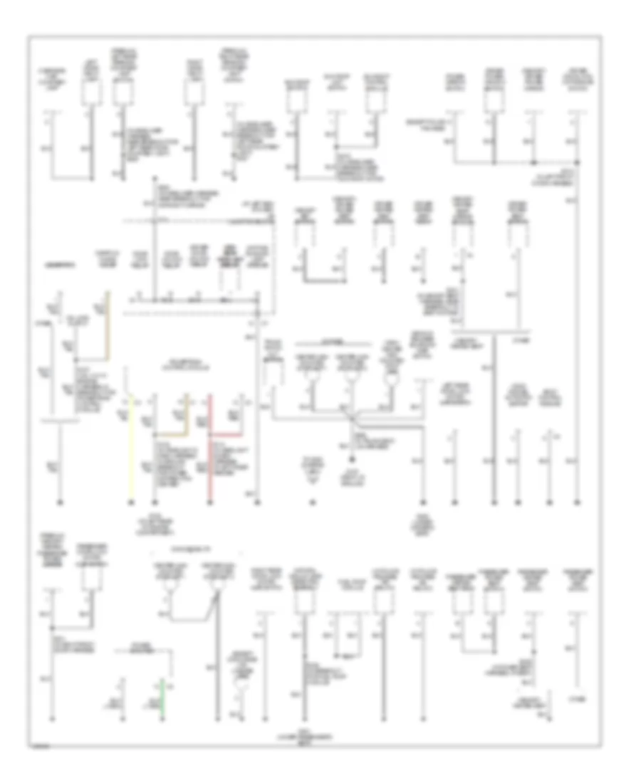
Ground Distribution Wiring Diagram (2 of 3) for Dodge Intrepid ES 2004
List of elements for Ground Distribution Wiring Diagram (2 of 3) for Dodge Intrepid ES 2004:
- (300m) center high mounted stop lamp
- (300m/ dodge) autostick switch
- (at left end of dash) j/b (junction block)
- (dodge)
- (except concorde/ ltd) license lamp
- (except police package)
- (memory) driver power mirror
- (memory) driver power seat switch
- (premium) left rear reading/ courtesy lamp switch
- (premium) right rear reading/ courtesy lamp switch
- (premium/ memory/ heated) passenger power mirror
- (w/ police package) iso relay 1
- (w/ police package) iso relay 2
- 3.5l high output
- At left inner fender)
- Body control module
- Breakout for power distribution center)
- Breakout for powertrain control module)
- C11
- Center high
- Center high mounted stoplamp 1
- Center high mounted stoplamp 2
- Concorde/ltd
- Daytime running lamp module
- Decklid release solenoid/ ajar switch
- Door lock relay
- Door unlock relay
- Driver door lock motor/ajar switch
- Driver door unlock relay
- Driver heated seat back
- Driver heated seat switch
- Driver power seat switch
- Driver power window switch
- Fuel pump module
- G102 (at left rear of engine compartment)
- G300 (under driver's seat)
- G301 (under passenger's seat)
- G310 (deck lid ground)
- Generator
- High high beam beam headlamp headlamp relay relay
- Left rear door lock motor/ ajar switch
- Left visor/ vanity lamp
- Manifold tuning valve
- Memory heated seat/ mirror module
- Memory set switch
- Memory/ heated seat
- Mounted
- Natural vacuum leak detection assembly
- Other
- Overhead map/ courtesy lamp
- Passenger door lock motor/ ajar switch
- Passenger heated seat back
- Passenger heated seat switch
- Passenger power seat switch
- Power amplifier
- Power mirror switch
- Powertrain control module
- Right rear door lock motor/ ajar switch
- Right visor/ vanity lamp
- S311 (in right front door harness)
- S312 (in left front door harness)
- S320 (in headliner harness, near breakout for day/night mirror)
- S328 (in power seat harness, at seat)
- S341 (in memory seat harness, near breakout to seat motors)
- S348 (in breakout for fuel pump module)
- S365 (in trunk deck lid harness)
- Stoplamp 2
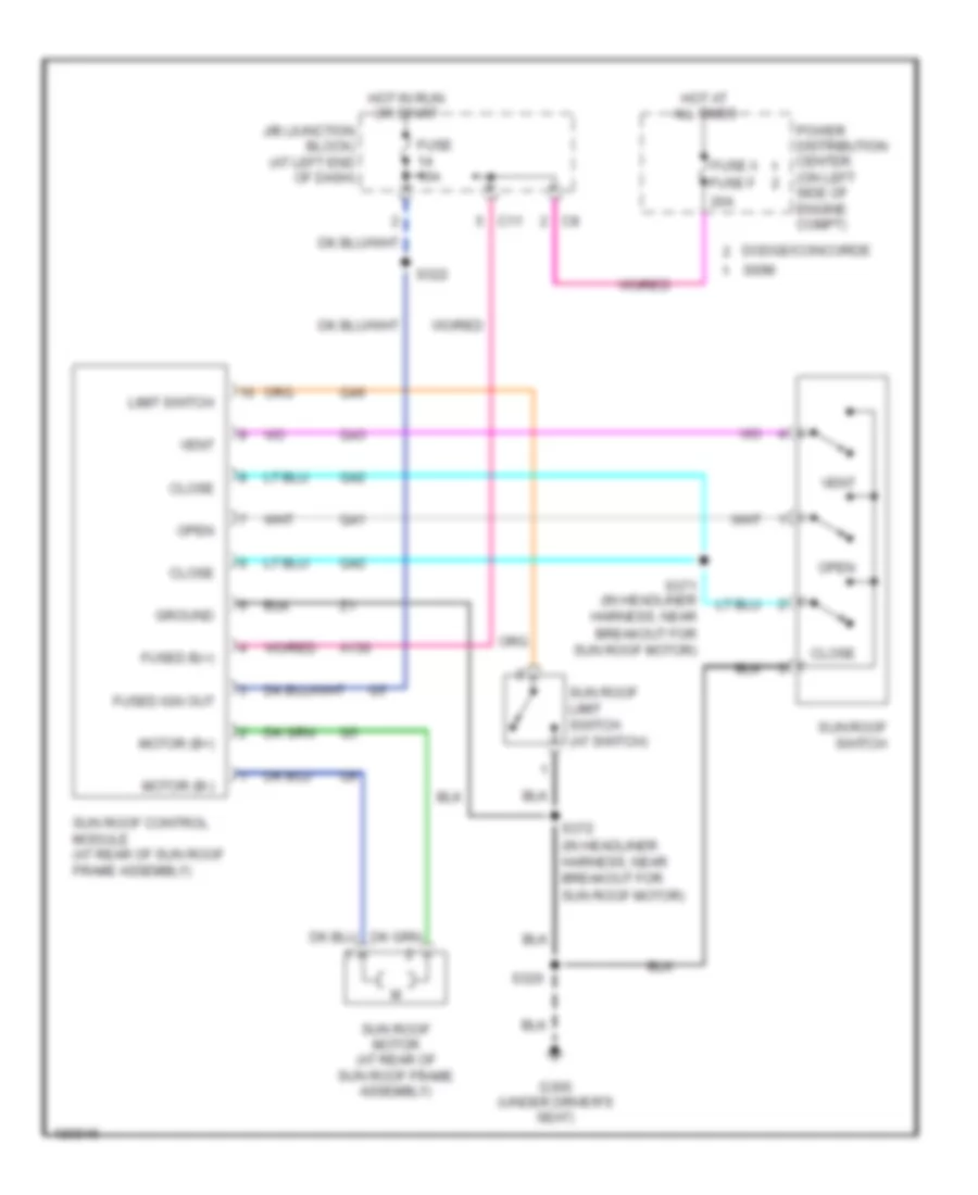
- Sun roof control module
- Sun roof limit switch
- Sun roof switch
- To g300 (diagram 3 of 3)
- Trunk knock out switch
Ground Distribution Wiring Diagram (3 of 3) for Dodge Intrepid ES 2004
List of elements for Ground Distribution Wiring Diagram (3 of 3) for Dodge Intrepid ES 2004:
- (300m)
- (300m/ dodge) left tail/stop lamp 2
- (300m/ dodge) right tail/stop lamp 2
- (300m/dodge)
- (at left end of dash) j/b (junction block)
- (atc) blower motor power module
- (concorde/ ltd)
- (concorde/ ltd) left back-up lamp
- (concorde/ ltd) right back-up lamp
- (dodge) left rear side marker lamp
- (dodge) right rear side marker lamp
- (dodge, ltd)
- (dodge/ltd)
- (ltd/300m) glove box lamp
- (ltd/300m) right tail lamp
- (police package) auxiliary lighting
- (prndl) transmission range indicator illumination
- 300m/ dodge
- Automatic temperature control head
- Body control module
- Cigar lighter
- Combination flasher
- Concorde
- Concorde/ ltd
- Data link connector (dlc)
- From g300 (diagram 2 of 3)
- From s347 (diagram 1 of 3)
- From seat belt switch (diagram 1 of 3)
- G200 (at lower center of dash)
- G300 (under driver's seat)
- G311 (at right ``c" pillar)
- Headlamp switch
- Instrument cluster
- Left back-up lamp
- Left rear turn signal lamp
- Left tail lamp
- Left tail/ turn signal lamp
- Left tail/stop lamp
- Left tail/stop lamp 1
- License lamp
- Manual temperature control head
- Other
- Radio
- Rear window defogger antenna
- Right back-up lamp
- Right rear turn signal lamp
- Right tail/ turn signal lamp
- Right tail/stop lamp
- Right tail/stop lamp 1
- S360 (in rear fascia harness)
- S362 (in taillight harness, at left taillight)
- S369
- Turn signal/ hazard switch
HEADLIGHTS
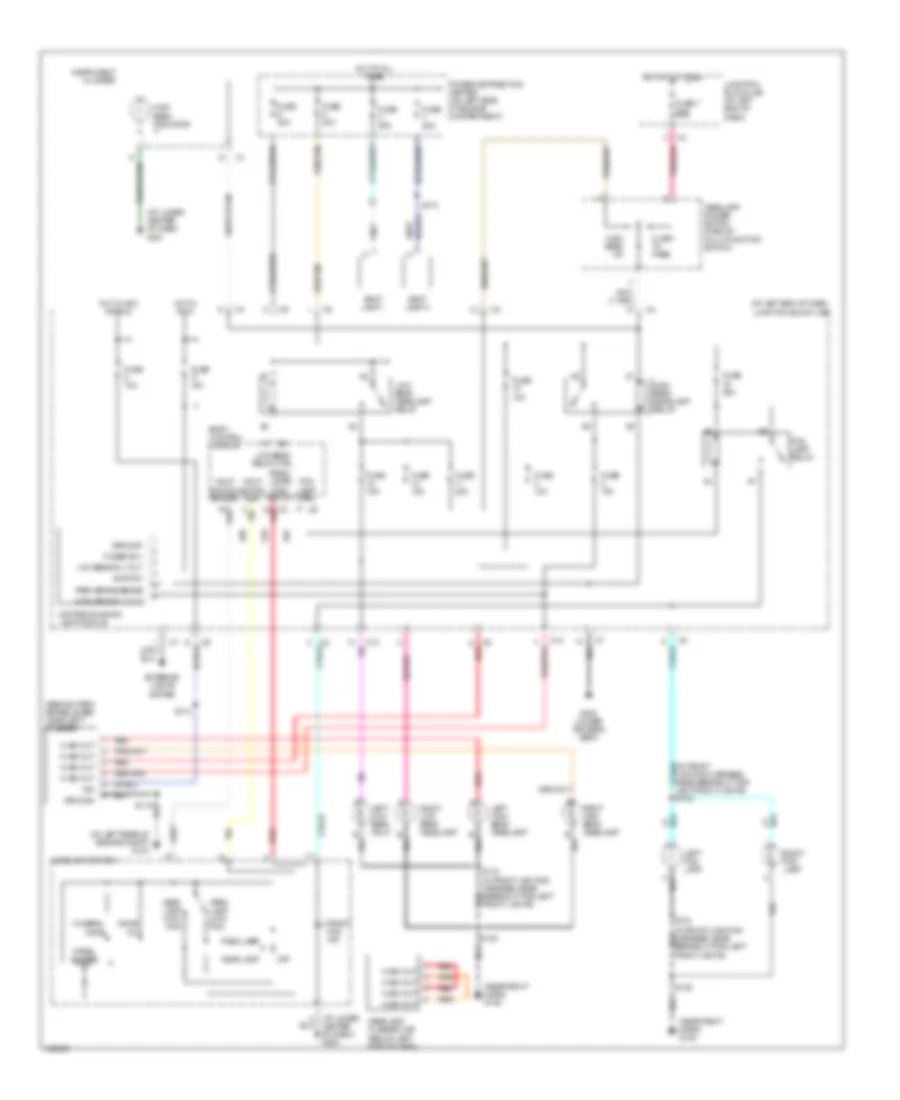
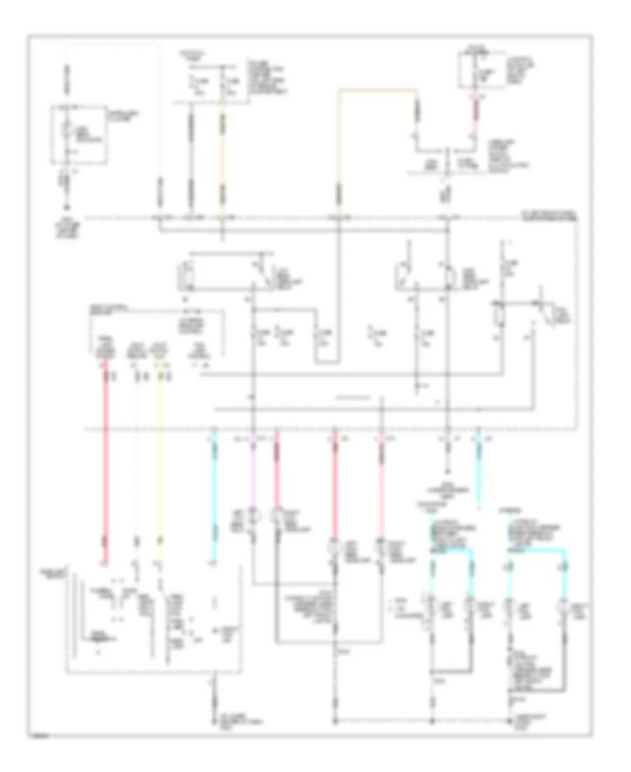
Headlights Wiring Diagram, with DRL with Police Option for Dodge Intrepid ES 2004
List of elements for Headlights Wiring Diagram, with DRL with Police Option for Dodge Intrepid ES 2004:
- (at left end of dash) junction block (j/b)
- (at left rear of engine compt) g103
- (at lower center of dash) g200
- (at lower center of dash) g201
- (behind park brake lever) headlight flasher
- (in front lighting harness, near breakout for left front lights) s132
- (near right horn) g106
- Body control module
- Breakout for left front lights)
- C10
- Daytime running lamp module
- Dome on
- E19
- Exterior lights system
- Flash to pass
- Fog lamp ctrl
- Fog lamp relay
- Front fog ind
- Funeral mode
- Fuse 10a
- Fuse 15a
- Fuse 20a
- Fuse 7 20a
- Fuse c 30a
- Fuse d 40a
- Fuse x 20a
- Fuse y 20a
- Fused b(+)
- G300 (under driver's seat)
- G52
- Ground
- Hdlp switch mux
- Hdlp switch return
- Head lamp
- Head lamp with fog
- Headlamp dimmer switch (part of multi-function switch)
- Headlamp flasher cap (below left side of dash)
- Headlamp switch
- Hi bm out
- High beam headlamp relay
- High beam indicator
- High beam on
- High beam rly out
- Hot at all times
- Hot in acc or run
- Hot in run
- Ign
- Ignition
- Instrument cluster
- Junction block (j/b) (at left end of dash)
- L80
- Left fog lamp
- Left high beam headlamp
- Left low beam hdlp
- Low beam headlamp relay
- Low beam relay ctrl
- Low beam rly out
- Off
- Panel dimmer
- Panel lamps dimm switch
- Park brake sense
- Park lamp
- Park lamp with fog
- Pnk/red
- Power distribution center (on left side of engine compartment)
- Red
- Red/tan
- Right fog lamp
- Right high beam headlamp
- Right low beam headlamp
- S119
- S134
- S134 (in front lighting harness, near breakout for left front lights)
- S135
- S173
- S174
- Spot lamp 1
- Spot lamp 2
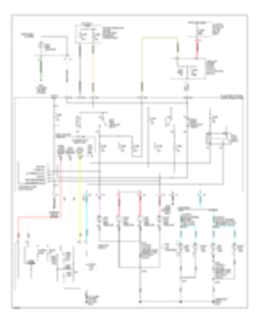
Headlights Wiring Diagram, with DRL for Dodge Intrepid ES 2004
List of elements for Headlights Wiring Diagram, with DRL for Dodge Intrepid ES 2004:
- (at left end of dash) junction block (j/b)
- (in front fascia harness, between right & left headlights) s162
- (in front lighting harness, near breakout for left front lights) s132
- (near right horn) g106
- 300m
- Body control module
- C10
- Concorde/
- Daytime running lamp module
- Dome on
- E19
- Exterior lights system
- Flash to pass
- Fog lamp relay
- Fog lamp rly ctrl
- Front fog ind
- Funeral mode
- Fuse 10a
- Fuse 15a
- Fuse 20a
- Fuse 7 20a
- Fuse c 30a
- Fuse d 40a
- Fused b(+)
- G201 (at lower center of dash)
- G300 (under driver's seat)
- G52
- Ground
- Hdlp switch mux
- Hdlp switch return
- Head lamp
- Head lamp with fog
- Headlamp dimmer switch (part of multi-function switch)
- Headlamp switch
- High beam headlamp relay
- High beam indicator
- High beam on
- High beam rly out
- Hot at all times
- Hot in run
- Ignition
- Instrument cluster
- Intrepid
- Junction block (j/b) (at left end of dash)
- L80
- Left fog lamp
- Left high beam headlamp
- Left low beam headlamp
- Low beam hdlp relay ctrl
- Low beam headlamp relay
- Low beam rly out
- Ltd/ concorde
- Of dash) g200
- Off
- Panel dimmer
- Panel lamps dimmer signal
- Park brake sense
- Park lamp
- Park lamp with fog
- Pnk/red
- Power distribution center (on left side of engine compartment)
- Red
- Red/tan
- Right fog lamp
- Right high beam headlamp
- Right low beam headlamp
- S134 (in front lighting harness, near breakout for left front lights)
- S135
- S161
Headlights Wiring Diagram, without DRL with Police Option for Dodge Intrepid ES 2004
List of elements for Headlights Wiring Diagram, without DRL with Police Option for Dodge Intrepid ES 2004:
- (at left end of dash) junction block (j/b)
- (at lower center of dash) g201
- (in front lighting harness, near breakout for left front lights) s132
- (near right horn)
- Body control module
- C10
- Center of dash) g200
- Dome on
- E19
- Flash to pass
- Fog lamp control
- Fog lamp relay
- Front fog ind
- Funeral mode
- Fuse 10a
- Fuse 15a
- Fuse 20a
- Fuse 7 20a
- Fuse c 30a
- Fuse d 40a
- Fuse x 20a
- Fuse y 20a
- G103 (at left rear of engine compartment)
- G106
- G106 (near right horn)
- G300 (under driver's seat)
- G52
- Ground
- Head lamp
- Head lamp with fog
- Headlamp dimmer switch (part of multi-function switch)
- Headlamp flasher cap (below left side of dash)
- Headlamp switch
- Headlamp switch mux
- Headlamp switch return
- Headlight flasher (behind park brake lever)
- Hi bm out
- High beam headlamp relay
- High beam indicator
- High beam on
- Hot at all times
- Hot in run or acc
- Ign
- Instrument cluster
- Junction block (j/b) (at left end of dash)
- L80
- Left fog lamp
- Left high beam headlamp
- Left low beam headlamp
- Low beam headlamp control
- Low beam headlamp relay
- Near breakout for left front lights)
- Off
- Panel dimmer
- Panel lamp dimmer switch
- Park lamp
- Park lamp with fog
- Pnk/red
- Power distribution center (on left side of engine compartment)
- Red
- Red/tan
- Right fog lamp
- Right high beam headlamp
- Right low beam headlamp
- S119
- S134 (in front lighting harness, near breakout for left front lights)
- S135
- S173
- S174
- Spot lamp 1
- Spot lamp 2
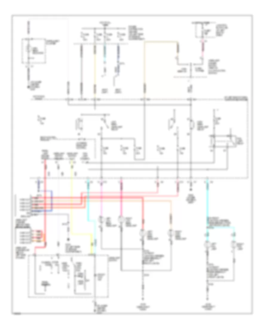
Headlights Wiring Diagram, without DRL for Dodge Intrepid ES 2004
List of elements for Headlights Wiring Diagram, without DRL for Dodge Intrepid ES 2004:
- (at left end of dash) junction block (j/b)
- (at lower center of dash) g200
- (in front lighting harness, near breakout for left front lights)
- (near right horn) g106
- 300m
- Body control module
- C10
- Concorde
- Concorde/
- Dome on
- E19
- Flash to pass
- Fog lamp control
- Fog lamp relay
- Front fog ind
- Funeral mode
- Fuse 10a
- Fuse 15a
- Fuse 20a
- Fuse 7 20a
- Fuse c 30a
- Fuse d 40a
- G201 (at lower center of dash)
- G300 (under driver's seat)
- G52
- Hdlp switch mux
- Hdlp switch return
- Head lamp
- Head lamp with fog
- Headlamp dimmer switch (part of multi-function switch)
- Headlamp switch
- High beam
- High beam headlamp relay
- High beam indicator
- Hot at all times
- Instrument cluster
- Intrepid
- Junction block (j/b) (at left end of dash)
- L80
- Left fog lamp
- Left high beam headlamp
- Left low beam hdlp b
- Low beam headlamp control
- Low beam headlamp relay
- Ltd/
- Off
- Panel dimmer
- Panel lamp dimmer switch
- Park lamp
- Park lamp with fog
- Pnk/red
- Power distribution center (on left side of engine compartment)
- Red
- Red/tan
- Right fog lamp
- Right high beam headlamp
- Right low beam headlamp
- S132
- S134 (in front lighting harness, near breakout for left front lights)
- S135
- S161
HORN
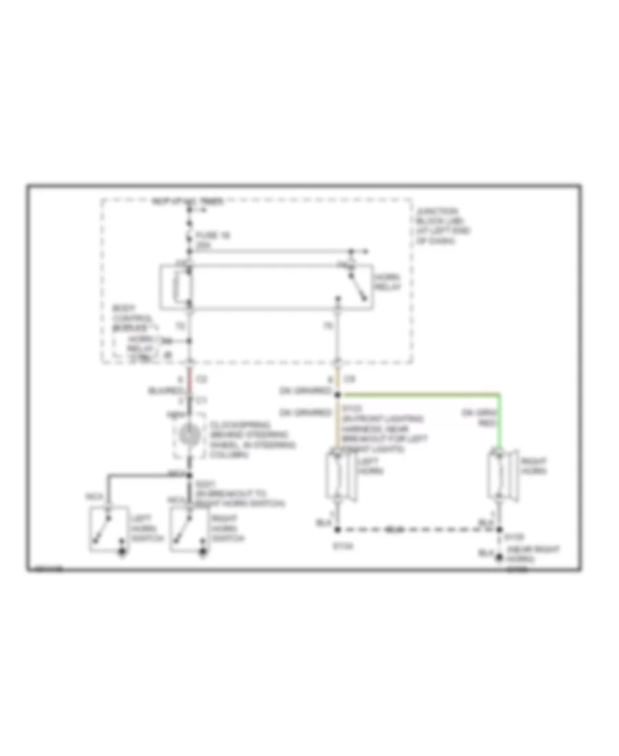
Horn Wiring Diagram for Dodge Intrepid ES 2004
List of elements for Horn Wiring Diagram for Dodge Intrepid ES 2004:
- (in front lighting harness, near breakout for left front lights)
- (near right horn) g106
- Body control module
- Clockspring (behind steering wheel, in steering column)
- Fuse 18 20a
- Horn relay
- Horn relay ctrl
- Hot at all times
- Junction block (j/b) (at left end of dash)
- Left horn
- Left horn switch
- Nca
- Right horn
- Right horn switch
- S134
- S135
- S221 (in breakout to right horn switch)
INSTRUMENT CLUSTER
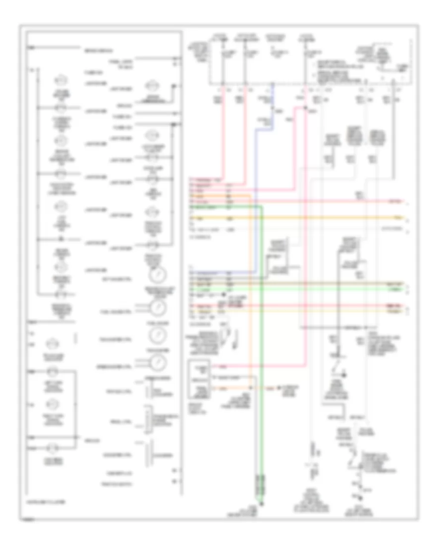
Instrument Cluster Wiring Diagram (1 of 2) for Dodge Intrepid ES 2004
List of elements for Instrument Cluster Wiring Diagram (1 of 2) for Dodge Intrepid ES 2004:
- (at left rear side of engine)
- (at lower center of dash)
- (check engine)
- (in left side dash harness, near breakout for c200)
- A10
- Abs warning ind
- Air bag warning ind
- Analog clock (300m/ltd)
- B10
- B27
- Body control module (at left end of dash, attached to junction block)
- Brake fluid level switch (in master cylinder fluid reservoir)
- Brake warning
- Brake warning ind
- C1 (conn a)
- C10
- C2 (conn b)
- Charging system warning ind
- Cruise engaged ind
- D25
- Daytime running lamp module
- Door ajar ind
- Ect gauge ctrl
- Engine coolant temperature gauge
- Engine coolant temperature ind
- Engine oil pressure switch (2.7l: on right side of engine) (3.5l: on left side of engine)
- Engine oil pressure warning ind
- Except police package
- Except special service/ canadian police
- Except special service/canadian police
- F11
- F33
- Fuel gauge
- Fuel gauge ctrl
- Fuse 1 10a
- Fuse 14 10a
- Fuse 19 15a
- Fuse 7 20a
- Fused (b+)
- Fused b(+)
- Fused ign
- G101
- G200
- G201 (at lower center of dash)
- G29
- G78
- Ground
- High beam indicator
- Hot at all times
- Hot in off, run or start
- Hot in run or start
- Instrument cluster
- Interior lights system
- Junction block (j/b) (at left end of dash)
- L324
- L60
- L61
- L99
- Lamp driver
- Left turn signal indicator
- Low fuel warning ind
- Low washer fluid ind
- Malfunction indicator
- Nca
- Odometer
- Odometer ctrl
- P r n d l
- Panel lamps
- Panel lamps driver
- Park brake switch (on parking brake lever)
- Pci bus
- Pnk
- Pnk/ red
- Pnk/red
- Police package
- Prndl ctrl
- Red brake warning lamp
- Right turn signal indicator
- S119
- S200
- S204
- S207 (in center instrument panel harness)
- S232
- Seat belt warning ind
- Special service/ canadian police
- Special service/ canadian police, except police package
- Speedometer
- Speedometer ctrl
- Tachometer
- Tachometer ctrl
- Tan
- Traction control active ind
- Traction control warning ind
- Traction switch
- Transmission range indicator
- Trip odo ctrl
- Trip odometer
- Trunk ajar indicator
- Washer fluid
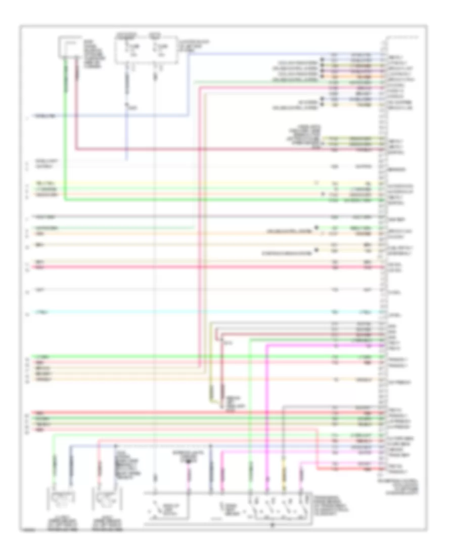
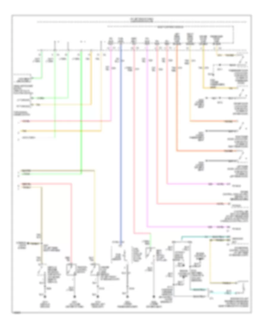
Instrument Cluster Wiring Diagram (2 of 2) for Dodge Intrepid ES 2004
List of elements for Instrument Cluster Wiring Diagram (2 of 2) for Dodge Intrepid ES 2004:
- (at left end of dash) junction block (j/b)
- (at right side of engine) s104
- 2.7l
- 3.5l
- Air bag control module (orc) (behind low center of dash)
- Body control module
- Controller anti-lock brake (at left fender side shield, on bottom of hydraulic control unit)
- D25
- Decklid release solenoid/ ajar switch (at center rear of decklid)
- Door)
- Driver door ajar sw sns
- Driver door lock motor/ ajar switch (in rear of driver door)
- Driver's seat)
- Ect
- Engine controls system
- Engine coolant temperature sensor (at front of engine, near thermostat housing)
- Fuel level in
- Fuel level sensor
- Fuel pump module (in top of fuel tank)
- G10
- G104 (behind left headlight)
- G201 (at lower center of dash)
- G300 (under
- G300 (under driver's seat)
- G301 (under
- G301 (under passenger's seat)
- G310 (decklid ground)
- G74
- Headlamp dimmer switch (part of multi- function switch)
- High beam relay ctrl
- Interior lights system
- Left rear door ajar sw sns
- Left rear door lock motor/ ajar switch (at rear of left rear door)
- Lf turn sig
- Passenger door ajar sw sns
- Passenger door lock motor/ ajar switch (in rear of passenger
- Passenger's seat)
- Pci bus
- Pci bus (mic)
- Pci bus (pcm)
- Powertrain control module (at left rear of engine compt)
- Red
- Right rear door ajar sw sns
- Right rear door lock motor/ ajar switch (at rear of right rear door)
- Rt turn sig
- S104 (between camshaft & coolant sensors)
- S110 (in engine harness, near idle air control motor breakout)
- S123
- S307 (in left rear body harness)
- S311
- S312
- S348
- S365
- Seat belt sw
- Seat belt switch (in left "b" pillar)
- Sens gnd
- Tan
- Tan g75
- Tan/ g74
- Tan/red
- Traction control switch
- Turn signal/ hazard switch
- Washer fluid level sensor (at left front of engine compt)
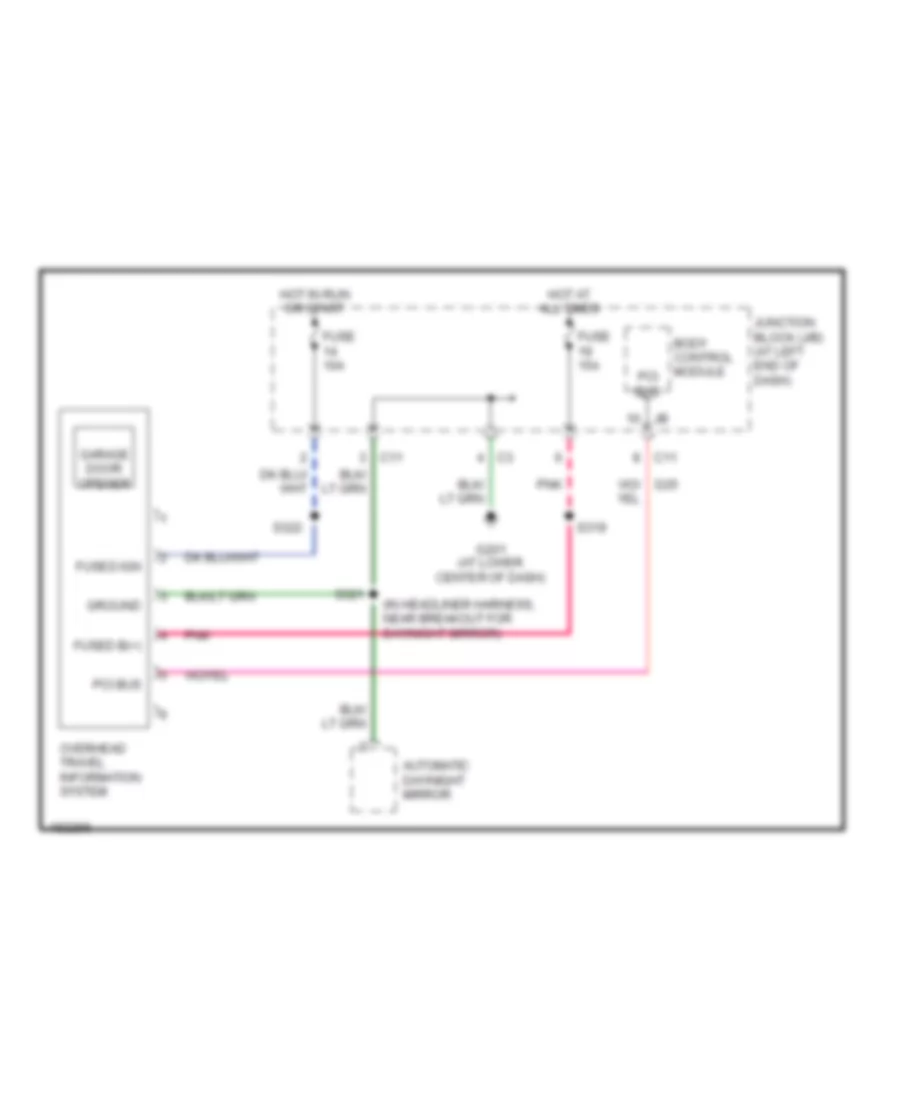
Overhead Console Wiring Diagram for Dodge Intrepid ES 2004
List of elements for Overhead Console Wiring Diagram for Dodge Intrepid ES 2004:
- (in headliner harness, near breakout for day/night mirror)
- Automatic day/night mirror
- Body control module
- C11
- D25
- Fuse 10a
- Fuse 15a
- Fused b(+)
- Fused ign
- G201 (at lower center of dash)
- Garage door opener
- Ground
- Hot at all times
- Hot in run or start
- Junction block (j/b) (at left end of dash)
- Overhead travel information system
- Pci bus
- Pnk
- S319
- S321
- S322
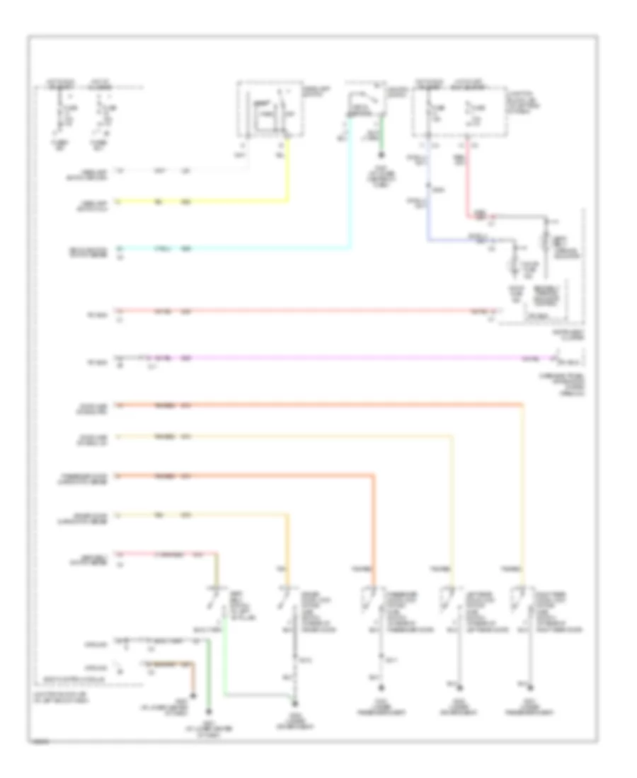
INTERIOR LIGHTS
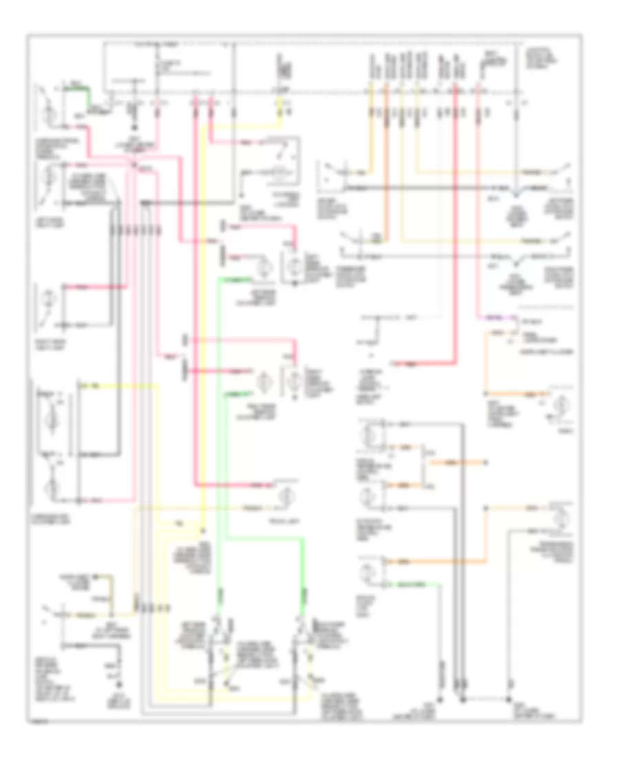
Interior Lights Wiring Diagram for Dodge Intrepid ES 2004
List of elements for Interior Lights Wiring Diagram for Dodge Intrepid ES 2004:
- (in headliner harness, near breakout for day/night mirror)
- (in headliner harness, near breakout for left rear door courtesy light)
- Aj sw
- Analog clock (ltd/ 300m)
- Atc
- Automatic temperature control head
- Base
- Body control module
- C11
- D25
- Decklid release solenoid/ ajar switch (at center of trunk lid, at deck lid latch)
- Dim sig
- Door
- Door ajar
- Driver door lock motor/ajar switch
- Driver lamps courtesy
- Drv door
- E19
- Fuse 19 15a
- G200 (at lower center of dash)
- G201 (at lower center of dash)
- G201 (lower center of dash)
- G300 (under driver's seat)
- G301 (under passenger's seat)
- G310 (deck lid ground)
- G74
- G75
- Glove box lamp (ltd/300m)
- Headlamp
- Headlamp switch
- Hot at all times
- Instrument cluster
- Instrument cluster system
- Interior lamps dimming signal
- Junction block (j/b) (at left end of dash)
- L80
- Left rear door lock motor/ajar switch
- Left rear reading/ courtesy lamp
- Left rear reading/ courtesy lamp switch (premium) a
- Left visor/ vanity lamp
- Manual temperature control head
- Mtc
- Overhead map/ courtesy lamp
- Overhead travel information system (premium)
- Panel lamps driver
- Panel lmp
- Passenger door lock motor/ajar switch
- Pci bus
- Pnk
- Premium
- Radio
- Red
- Right rear door lock motor/ajar switch
- Right rear reading/ courtesy lamp
- Right rear reading/ courtesy lamp switch (premium)
- Right visor/ vanity lamp
- S207 (in center instrument panel harness)
- S307 (in left rear body harness)
- S311
- S312
- S319
- S320
- S321
- S323 (in headliner harness, near breakout for day/night mirror)
- S324
- S325
- S326
- S365
- Sw (pass)
- Sw rtn
- Sw sns(lr)
- Sw sns(rr)
- Tan
- Tan/ red
- Tan/red
- Transmission range indicator illumination (prndl)
- Trunk lamp
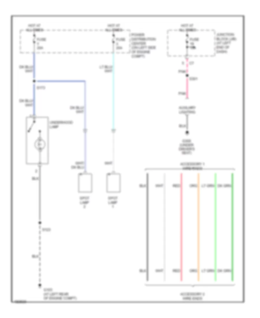
Police Package Lighting Wiring Diagram for Dodge Intrepid ES 2004
List of elements for Police Package Lighting Wiring Diagram for Dodge Intrepid ES 2004:
- Accessory 1 wire ends
- Accessory 2 wire ends
- Auxiliary lighting
- Fuse 15a
- Fuse x 20a
- Fuse y 20a
- G103 (at left rear of engine compt)
- G300 (under driver's seat)
- Hot at all times
- Junction block (j/b) (at left end of dash)
- Pnk
- Power distribution center (on left side of engine compt)
- Red
- S123
- S173
- S301
- Spot lamp
- Underhood lamp
POWER DISTRIBUTION
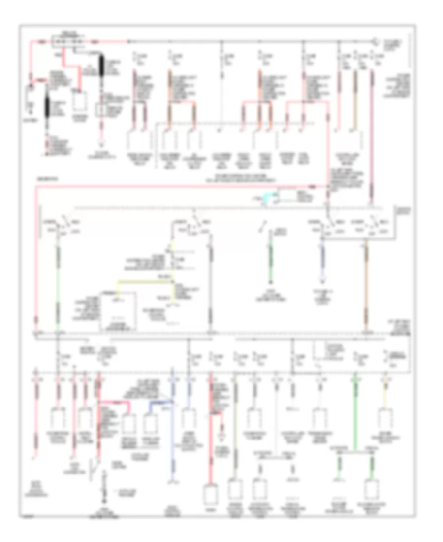
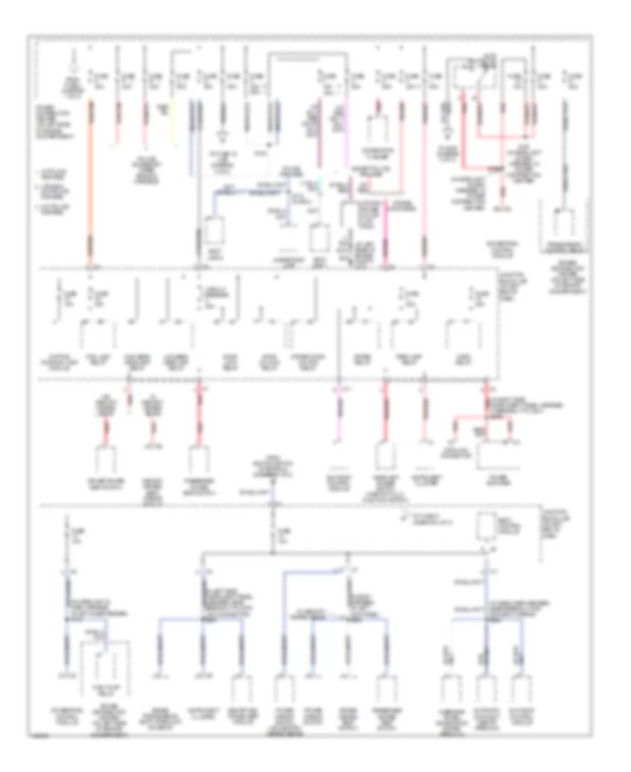
Power Distribution Wiring Diagram (1 of 3) for Dodge Intrepid ES 2004
List of elements for Power Distribution Wiring Diagram (1 of 3) for Dodge Intrepid ES 2004:
- (at left end of dash) junction block (j/b)
- (engine harness, in breakout to battery) s145
- (in headlight & dash harness, in power distribution center) s124
- (in headlight & dash harness, in power distribution center) s125
- (in headlight & dash harness, in power distribution center) s128
- (in left side instrument panel harness, near breakout to data link connector) s201
- (in left side instrument panel harness, near breakout to headlight flasher)
- (in rear body harness, at right side of trunk) s306
- (or pnk)
- A/c compressor clutch relay
- Acc
- Air bag control module (orc)
- Auto- stick switch (dodge/300m)
- Automatic a/c
- Automatic temperature control head
- Battery
- Battery position
- Blower motor power module
- Blower motor resistor block
- Body control module
- C1 red (or pnk)
- Cigar lighter
- Circuit breaker 20a
- Combination flasher
- Controller anti-lock brake
- Data link connector
- Daytime running lamp module
- Decklid release switch
- Driver power window switch
- Front wiper high/low relay
- Front wiper on/off relay
- Fuel pump relay
- Fuse 10a
- Fuse 30a
- Fuse a 50a
- Fuse b 40a
- Fuse e 40a
- Fuse g 40a
- Fuse h 30a (abs)
- Fuse j 40a
- Fuse k 40a (abs)
- Fuse m 40a
- Fuse v 10a
- G200 (at lower center of dash)
- G201 (at lower center of dash)
- Generator
- Headlamp flasher
- High speed radiator fan relay
- Ignition position fuse 15a
- Ignition switch
- Instru- ment cluster
- Key-in switch
- Lock
- Low speed radiator fan relay
- Manual a/c
- Manual temperature control head
- Nca
- Off
- Pnk
- Power distribution center (on left side of engine compartment)
- Powertrain control module
- Radio
- Rear window defogger relay
- Red
- Red (in dash harness, near breakout for junction block) s231
- Remote jump post
- Remote power post
- Run
- S144 (in engine harness, in breakout to battery)
- S168 (in headlight & dash harness)
- S174
- S180 (near remote jump post) red
- S230 (in dash harness, near breakout for junction block)
- Start
- Starter motor
- Starter motor relay
- Tan
- To fuse 14 (j/b) (diagram 2 of 3)
- To fuse c (diagram 2 of 3)
- To s199 (diagram 3 of 3)
- To s354 (diagram 3 of 3)
- Transmission range sensor
- W/ police package
- Wiper switch (part of multi-function switch)
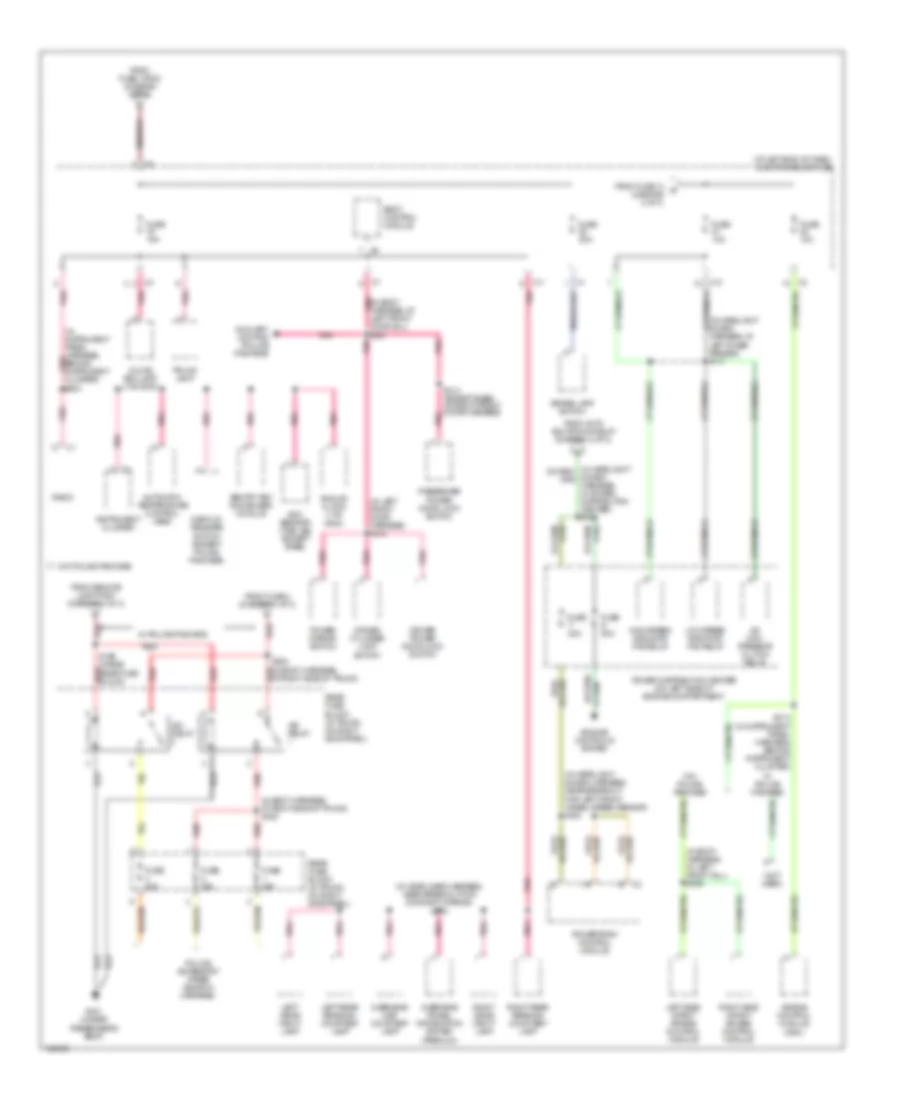
Power Distribution Wiring Diagram (2 of 3) for Dodge Intrepid ES 2004
List of elements for Power Distribution Wiring Diagram (2 of 3) for Dodge Intrepid ES 2004:
- (at left rear of engine compt) g103
- (in body harness, at left kick panel) s300
- (in headlight & dash harness, at left inner fender) s116
- (in headlight & dash harness, in power distribution center)
- (in left side instrument panel harness, near breakout to data link connector) s200
- (in right side red
- Auto shutdown relay
- Automatic day/night mirror (premium)
- Body control module
- Brake transmission shift interlock solenoid
- C11
- Circuit breaker 20a
- Combination flasher
- Data link connector
- Day/night mirror) s322
- Daytime running lamp module
- Dodge/ concorde
- Door lock relay
- Door unlock relay
- Driver door unlock relay
- Driver heated seat switch
- Driver power seat switch
- Except police package
- Fog lamp relay
- From fuse j (diagram 1 of 3)
- From ignition switch (start/run) (diagram 1 of 3)
- Fuel pump relay
- Fuse 10a
- Fuse 20a
- Fuse c 30a
- Fuse d 40a
- Fuse f 20a
- Fuse f 30a 50a
- Fuse i 30a
- Fuse l 40a
- Fuse n 30a
- Fuse o 20a
- Fuse p 30a
- Fuse q 20a
- Fuse r 30a
- Fuse u 20a
- Fuse w 10a
- Fuse x 20a
- Fuse y 15a 20a
- Headlamp dimmer switch (part of multi- function switch)
- High beam headlamp relay
- Horn relay
- Instrument cluster
- Instrument panel harness, in breakout to c201) s209
- Junction block (j/b) (at left end of dash)
- Low beam headlamp relay
- Ltd/300m
- Ltd/300m w/o police package
- Memory heated seat/ mirror module
- Overhead travel information system (premium)
- Package
- Park lamp relay
- Passenger heated seat switch
- Passenger power seat switch
- Pnk
- Pnk/red
- Police accessory wires (ends in harness)
- Police package
- Power amplifier
- Power distribution center (on left side of engine compartment)
- Power mirror switch
- Power mirror switch (w/o memory/ heated seats)
- Power outlet (ltd/ 300m)
- Powertrain control module
- Red
- Red/tan
- S123
- S140
- S166
- S167 (in headlight & dash harness, in power distribution center)
- S173 (in pdc)
- Sentry key immobilizer module
- Spare relay
- Spot lamp 1
- Spot lamp 2
- Sun roof control module
- To fuse 19 (j/b) (diagram 3 of 3)
- To fuse 21 (diagram 3 of 3)
- To s165 (diagram 3 of 3)
- Transmission control relay
- Underhood lamp
- W/ memory/ heated seats
- W/ police package
- W/o memory/ heated seats
- W/o police
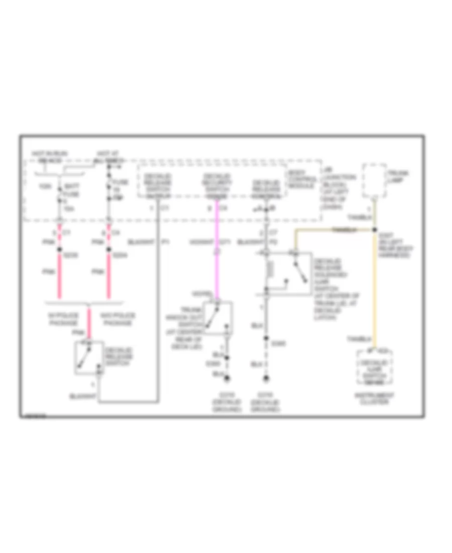
Power Distribution Wiring Diagram (3 of 3) for Dodge Intrepid ES 2004
List of elements for Power Distribution Wiring Diagram (3 of 3) for Dodge Intrepid ES 2004:
- (at left end of dash) junction block (j/b)
- (in body harness, at right side of trunk) s353
- (in body harness, at left front sill) s346
- (in headlight & dash harness, at left inner fender) s117
- (in headlight & dash harness, near breakout for left front wheel speed sensor) s164
- (in headliner harness, near breakout for day/night mirror) s319
- (in instrument panel harness, behind instrument pnk cluster)
- (in left front door harness) s314
- (not used)
- A/c com- pressor clutch relay
- Air bag control module (orc)
- Analog clock (ltd/ 300m)
- Automatic temperature control head
- Auxiliary lighting (police package)
- Body control module
- Brake lamp switch
- C10
- C11
- Decklid release switch (except police package)
- Driver cylinder lock switch
- Driver power door lock switch
- Engine controls system
- From auto shutdown relay (diagram 2 of 3)
- From fuse 14 d (diagram 2 of 3)
- From fuse 4 (diagram 1 of 3)
- From fuse i (pdc) (diagram 2 of 3)
- From remote jump post (diagram 1 of 3)
- Fuse 10a
- Fuse 15a
- Fuse 20a
- Fuse s 20a
- Fuse t 20a
- G301 (under passenger's seat)
- Glove box lamp (ltd/300m)
- High speed radiator fan relay
- Instrument cluster
- Iso relay
- Left rear reading/ courtesy lamp
- Left side impact air bag control module
- Left visor/ vanity lamp
- Low speed radiator fan relay
- Overhead map/ courtesy lamp
- Overhead travel information system (premium)
- Passenger power door lock switch
- Pnk
- Pnk (in body harness, at left front door sill) s301
- Police accessory wires (ends in harness)
- Power distribution center (on left side of engine compartment)
- Power mirror switch
- Powertrain control module
- Radio
- Rear fuse block (in trunk, on right side panel)
- Red
- Right rear reading/ courtesy lamp
- Right side impact air bag control module
- Right visor/ vanity lamp
- S199 (inside red rear fuse block)
- S204
- S214 (in instrument panel harness, behind instrument cluster)
- S313 (except base) (in right front door harness)
- S354 (in body harness, at right side of trunk)
- Sentry key immobilizer module
- Sun sensor/ vtss led (except base)
- Trunk lamp
- W/ police package
- W/o police package
POWER DOOR LOCKS
Power Door Locks Wiring Diagram for Dodge Intrepid ES 2004
List of elements for Power Door Locks Wiring Diagram for Dodge Intrepid ES 2004:
- (in right side body harness)
- (in right side body harness) s303
- Body control module
- Circuit breaker 2 20a
- Door ajar sw sense
- Door lock relay
- Door lock relay control
- Door unlock relay
- Door unlock relay control
- Driver door lock motor/ ajar switch (in rear of driver door)
- Driver door sw mux
- Driver door unlock relay
- Driver power door lock switch
- Driver's door unlock relay control
- Fuse 15a
- G300 (under driver's seat)
- G301 (under passenger's seat)
- G74
- G75
- Hot at all times
- Junction block (at left end of dash)
- Junction block (j/b) (at left end of dash)
- Left rear door lock motor/ajar switch (at rear of left rear door)
- P96
- P97
- Passenger door lock motor/ajar switch (in rear of passenger door)
- Passenger door sw mux
- Passenger power door lock switch
- Pnk
- Right rear door lock motor/ajar switch (at rear of right rear door)
- S301
- S304
- S311
- S312
- S313 (except base)
- S314
- Tan
- Tan/ red
- Tan/red
POWER MIRRORS
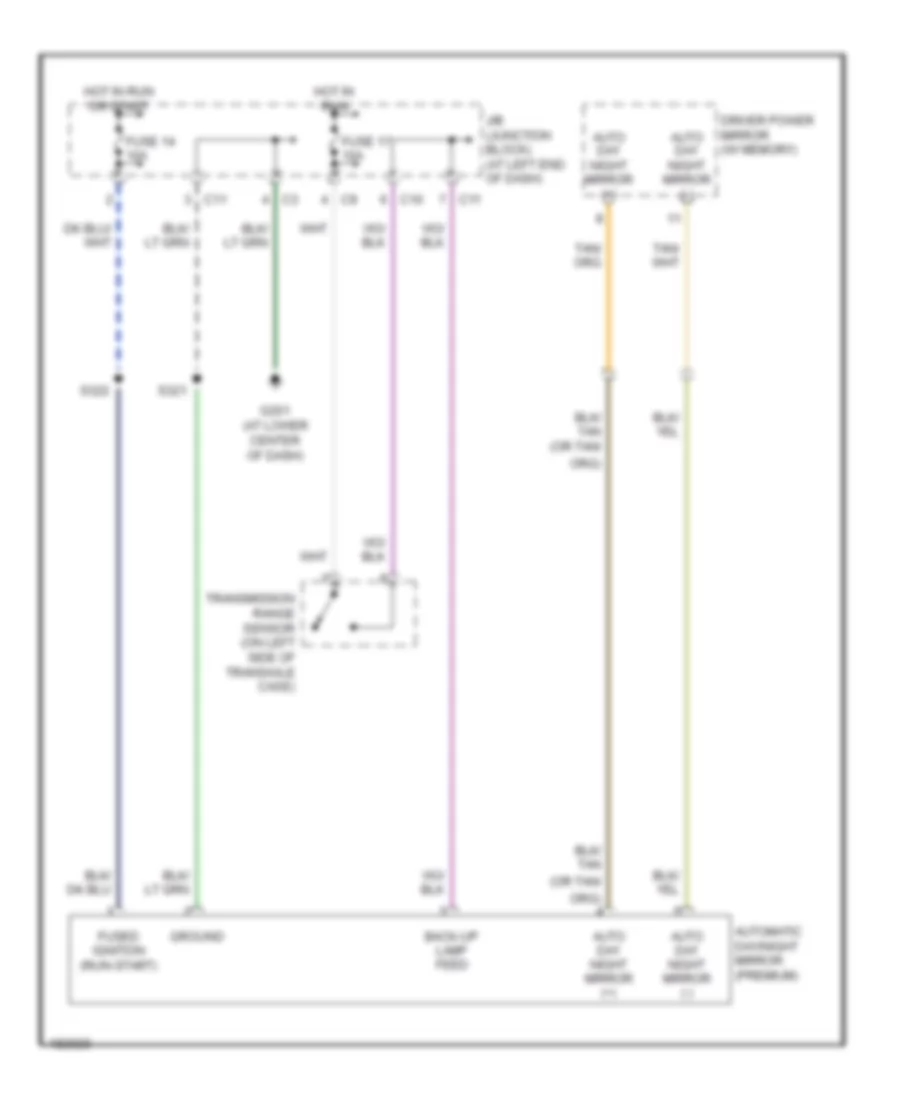
Automatic Day/Night Mirror Wiring Diagram for Dodge Intrepid ES 2004
List of elements for Automatic Day/Night Mirror Wiring Diagram for Dodge Intrepid ES 2004:
- (or tan/
- (run-start)
- Auto day night mirror (+)
- Auto day night mirror (-)
- Automatic day/night mirror (premium)
- Back-up lamp feed
- C10
- C11
- Driver power mirror (w/ memory)
- Fuse 14 10a
- Fuse 17 10a
- Fused ignition
- G201 (at lower center of dash)
- Ground
- Hot in run
- Hot in run or start
- J/b (junction block) (at left end of dash)
- S321
- S322
- Transmission range sensor (on left side of transaxle case)
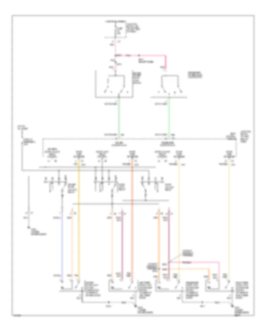
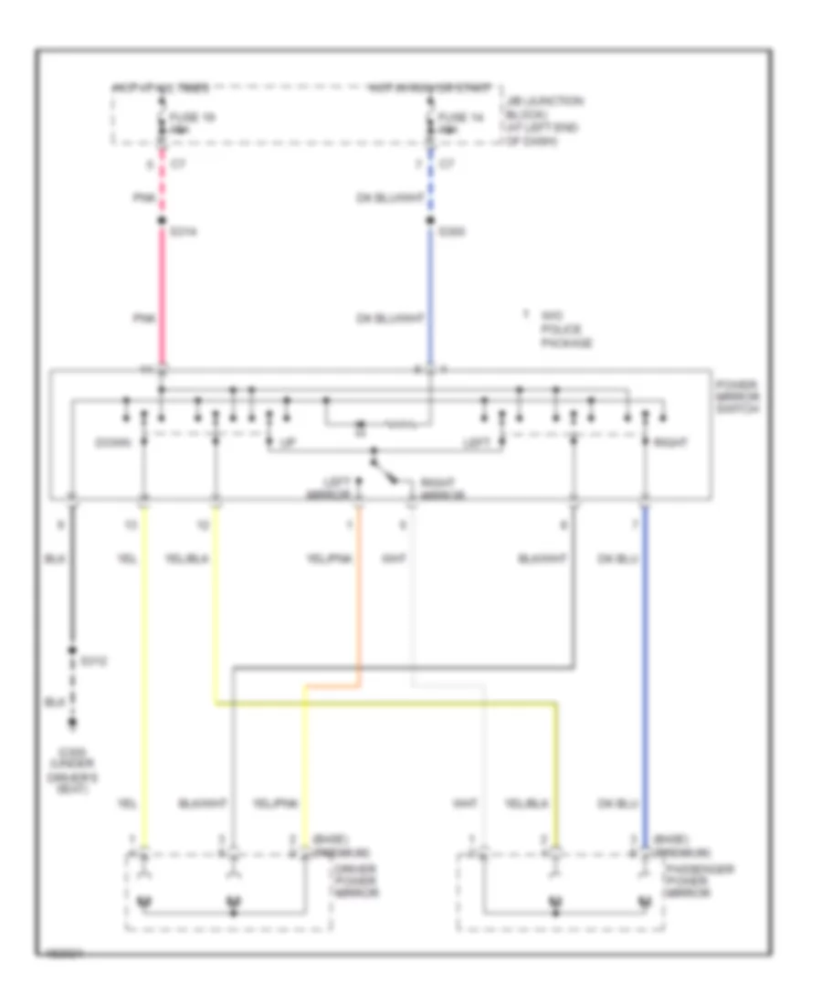
Power Mirrors Wiring Diagram for Dodge Intrepid ES 2004
List of elements for Power Mirrors Wiring Diagram for Dodge Intrepid ES 2004:
- (base) (premium)
- Down
- Driver power mirror
- Driver's seat)
- Fuse 14 10a
- Fuse 19 15a
- G300 (under
- Hot at all times
- Hot in run or start
- J/b (junction block) (at left end of dash)
- Left
- Left mirror
- Passenger power mirror
- Pnk
- Power mirror switch
- Right
- Right mirror
- S300
- S312
- S314
- W/o police package
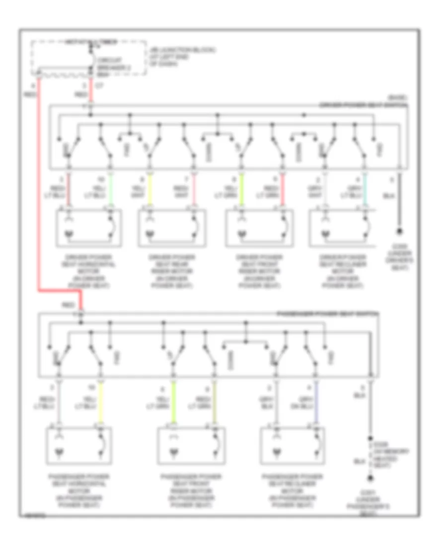
POWER SEATS
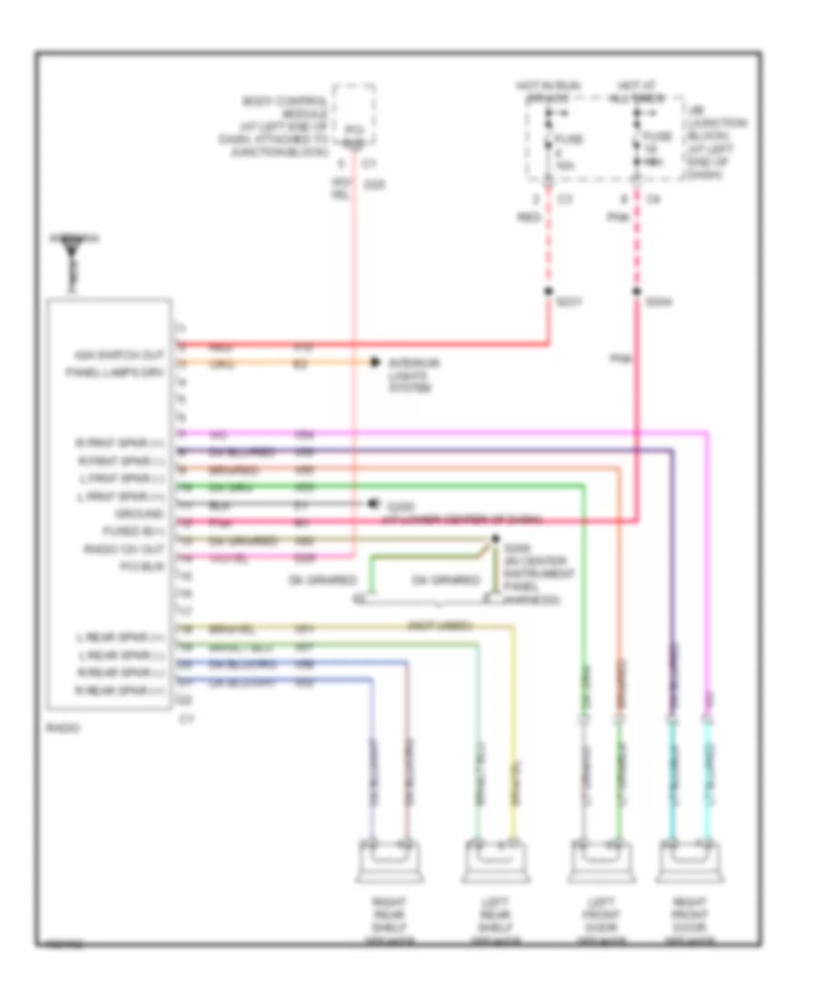
Power Seat Wiring Diagram for Dodge Intrepid ES 2004
List of elements for Power Seat Wiring Diagram for Dodge Intrepid ES 2004:
- (base) driver power seat switch
- Circuit breaker 2 20a
- Down
- Driver power seat front riser motor (in driver power seat)
- Driver power seat horizontal motor (in driver power seat)
- Driver power seat rear riser motor (in driver power seat)
- Driver power seat recliner motor (in driver power seat)
- Fwd
- G300 (under driver's seat)
- G301 (under passenger's seat)
- Hot at all times
- J/b (junction block) (at left end of dash)
- Passenger power seat front riser motor (in passenger power seat)
- Passenger power seat horizontal motor (in passenger power seat)
- Passenger power seat recliner motor (in passenger power seat)
- Passenger power seat switch
- Red
- Rwd
- S328 (w/ memory heated seat)
POWER TOP/SUNROOF
Power Top/Sunroof Wiring Diagram for Dodge Intrepid ES 2004
List of elements for Power Top/Sunroof Wiring Diagram for Dodge Intrepid ES 2004:
- (in headliner harness, near breakout for sun roof motor)
- 20a
- 300m
- A130
- C11
- Close
- Dodge/concorde
- Fuse 10a
- Fuse f
- Fuse x
- Fused b(+)
- Fused ign out
- G300 (under driver's seat)
- Ground
- Hot at all times
- Hot in run or start
- J/b (junction block) (at left end of dash)
- Limit switch
- Motor (b+)
- Motor (b-)
- Open
- Power distribution center (on left side of engine compt)
- Q41
- Q42
- Q43
- Q46
- S320
- S322
- S371 (in headliner harness, near breakout for sun roof motor)
- S372
- Sun roof control module (at rear of sun roof frame assembly)
- Sun roof limit switch (at switch)
- Sun roof motor (at rear of sun roof frame assembly)
- Sun roof switch
- Vent
POWER WINDOWS
Power Windows Wiring Diagram for Dodge Intrepid ES 2004
List of elements for Power Windows Wiring Diagram for Dodge Intrepid ES 2004:
- (in left side body harness, under driver's seat) s305
- Circuit breaker 1 20a
- Down
- Driver power window motor
- Driver power window switch
- Express down
- G300 (under driver's seat)
- Hot in run
- Junction block (at left end of dash)
- Left front
- Left rear
- Left rear power window motor
- Left rear power window switch
- Lock
- Passenger power window motor
- Passenger power window switch
- Right front
- Right rear
- Right rear power window motor
- Right rear power window switch
- S312
- Tan
- Unlock
- W/0 police package
RADIO
Radio Wiring Diagram, with Police Option for Dodge Intrepid ES 2004
List of elements for Radio Wiring Diagram, with Police Option for Dodge Intrepid ES 2004:
- (at lower center of dash)
- (not used)
- Antenna
- Body control module (at left end of dash, attached to junction block)
- D25
- Fuse 10a
- Fuse 15a
- Fused b(+)
- G200
- Ground
- Hot at all times
- Hot in run or acc
- Ign switch out
- Interior lights system
- J/b (junction block) (at left end of dash)
- L frnt spkr (+)
- L frnt spkr (-)
- L rear spkr (+)
- L rear spkr (-)
- Left front door speaker
- Left rear shelf speaker
- Nca
- Panel lamps drv
- Pci bus
- Pnk
- R frnt spkr (+)
- R frnt spkr (-)
- R rear spkr (+)
- R rear spkr (-)
- Radio
- Radio 12v out
- Red
- Right front door speaker
- Right rear shelf speaker
- S204
- S206 (in center instrument panel harness)
- S231
- X12
- X51
- X52
- X53
- X54
- X55
- X56
- X57
- X58
- X60
Radio Wiring Diagram, without Police Option for Dodge Intrepid ES 2004
List of elements for Radio Wiring Diagram, without Police Option for Dodge Intrepid ES 2004:
- (at left end of dash, attached to junction block) body control module
- (at lower center of dash) g200
- (behind steering wheel, in steering column) clockspring
- (in center instrument panel harness)
- (intrepid)
- 12 volts
- Am antenna
- Amp center panel spkr (+)
- Amp center panel spkr (-)
- Amp high l rear spkr (+)
- Amp high l rear spkr (-)
- Amp high r rear spkr (+)
- Amp high r rear spkr (-)
- Amp l front door spkr (+)
- Amp l front door spkr (-)
- Amp l rear door spkr (+)
- Amp l rear door spkr (-)
- Amp lf door sail spkr (+)
- Amp lf door sail spkr (-)
- Amp r door sail spkr (+)
- Amp r door sail spkr (-)
- Amp r front door spkr (+)
- Amp r front door spkr (-)
- Amp r rear door spkr (+)
- Amp r rear door spkr (-)
- Antenna
- Audio out left
- Audio out right
- B(+)
- Base
- Center instrument panel speaker (premium)
- Compact disc changer
- D25
- Defogger system
- E14
- Fm antenna
- Fuse 10a
- Fuse 15a
- Fuse 20a
- Fused b(+)
- G301 (under passenger's seat)
- G311 (at right "c" pillar)
- Ground
- Hot at all times
- Hot in run or acc
- Ign switch out
- Interior lights system
- Junction block (j/b) (at left end of dash)
- L frnt spkr (+)
- L frnt spkr (-)
- L front spkr (+)
- L front spkr (-)
- L rear spkr (+)
- L rear spkr (-)
- Left front door sail speaker
- Left front door speaker
- Left rear door speaker (premium ii) right rear door speaker (premium ii)
- Left rear shelf speaker
- Left remote radio switch (base/ premium ii)
- Nca
- Panel lamps drv
- Panel lmp dim sig
- Pci bus
- Pnk
- Pnk/red
- Power amplifier
- R frnt spkr (+)
- R frnt spkr (-)
- R front spkr (+)
- R front spkr (-)
- R rear spkr (+)
- R rear spkr (-)
- Radio
- Radio 12 volt output
- Radio 12v out
- Radio ctrl mux
- Radio ctrl mux return
- Rear window defogger antenna
- Rear window defogger relay output
- Rear window defogger/ antenna module (in right "c" pillar, behind trim panel)
- Red
- Right front door sail speaker
- Right front door speaker
- Right rear shelf speaker
- Right remote radio switch (base/ premium ii)
- S204
- S206
- S209
- S216 (in breakout to right radio remote switch)
- S217 (in breakout to right radio remote switch)
- Shield
- Standard antenna
- Tan/red
- Volts
- X112
- X12
- X160
- X20
- X40
- X41
- X51
- X52
- X53
- X54
- X55
- X56
- X57
- X58
- X60
- X920
- Z140
- Z141
Satellite Radio Wiring Diagram for Dodge Intrepid ES 2004
List of elements for Satellite Radio Wiring Diagram for Dodge Intrepid ES 2004:
- (behind right end of dash)
- Audio bus 1
- Audio bus 2
- Audio mux
- Audio mux left
- Audio mux left c1
- Audio mux right
- Audio out left
- Audio out right
- Audio return
- Audio sig
- Audio sig (+)
- B(+)
- C235
- Cd shield
- Compact disc changer
- D106
- D109
- D126
- D129
- D25
- E14
- Fused b(+)
- Ground
- Ign sw out
- Ign switch out
- Pci bus
- Pnl lmp dim sig
- Radio
- Receiver module
- Red
- Satellite
- Satellite radio antenna
- Satellite radio multiplexer
- Satellite sig
- Satellite sig c1
- Shield
- Terrestrial sig
- Terrestrial sig c2
- Twisted pair
- X112
- X160
- X166
- X17
- X40
- X407
- X41
- X416
- X417
- X480
- X481
- X607
- X916
- X917
- Z140
SHIFT INTERLOCK
Shift Interlock Wiring Diagram for Dodge Intrepid ES 2004
List of elements for Shift Interlock Wiring Diagram for Dodge Intrepid ES 2004:
- Brake light switch (at top of brake pedal)
- Brake switch signal
- Brake transmission shift interlock solenoid (top of steering column, on shift lever mounting stud)
- Fuse 14 10a
- G201 (at lower center of dash)
- Hot in run or start
- Junction block (j/b) (at left end of dash)
- Powertrain control module (at left rear of engine compt)
- S200
STARTING/CHARGING
Charging Wiring Diagram for Dodge Intrepid ES 2004
List of elements for Charging Wiring Diagram for Dodge Intrepid ES 2004:
- (in engine
- (in headlight & dash harness, in pdc) s166
- (in headlight & dash harness, near breakout for left front wheel speed sensor) s164
- (near battery) g108
- (w/3.5l high output)
- A209 red
- Asd rly ctrl
- Asd rly out
- Auto shut down relay
- Battery
- Body control module (at left end of dash, attached to junction block)
- Charging system ind ctrl
- Charging system warning ind
- D25
- Dk k20
- F142
- Fuse 1 10a
- Fuse n 30a
- Fuse t 20a
- Fuse w 10a
- G102 (at left rear of engine compt)
- Gen fld dvr
- Generator
- Harness, in breakout to battery)
- Hot in run or start
- Ign
- Instrument cluster
- Junction block (j/b) (at left end of dash)
- Nca
- Pci bus
- Pci bus c1
- Pci bus c3
- Power distri- bution system
- Power distribution center (on left side of engine compartment)
- Power distribution center (on left side of engine compt)
- Power distribution system
- Powertrain control module (at left rear of engine compt)
- Red
- Remote jump post (at right front side of engine compt)
- S107
- S144
- S145 (engine harness, in breakout to battery)
- S165 (in pdc)
- S167
- W/ police package
- W/o police package
Starting Wiring Diagram for Dodge Intrepid ES 2004
List of elements for Starting Wiring Diagram for Dodge Intrepid ES 2004:
- Acc
- Battery
- Fuse g 40a
- Fuse v 10a
- G108 (near battery)
- Hold-in
- Ignition switch
- K90 tan
- Lock
- Off
- Power distribution center (on left side of engine compt)
- Power distribution system
- Powertrain control module (at left rear of engine compt)
- Pull-in
- Red
- Remote jump post (at right front side of engine compt)
- Run
- S124
- S168
- S201 red
- Start
- Starter motor (at left rear of engine)
- Starter motor relay
- Starter relay control
SUPPLEMENTAL RESTRAINTS
Supplemental Restraints Wiring Diagram for Dodge Intrepid ES 2004
List of elements for Supplemental Restraints Wiring Diagram for Dodge Intrepid ES 2004:
- (at lower center of dash) g201
- (in body harness, at left front sill) s346
- (in body harness, at left front sill) s347
- (in instrument panel harness, behind instrument cluster) s214
- Air bag control module (orc) (behind low center of dash)
- Air bag warning indicator
- Body control module (at left end of dash, attached to junction block)
- Clock- spring
- D25
- Data link connector (below dash, to left of steering column)
- Driver air bag
- Except memory
- F14
- F23
- Fuse 1 10a
- Fuse 22 10a
- Fuse 8 10a
- G300 (under driver's seat)
- Ground
- Hot in run
- Hot in run or start
- Ign run
- Ign run/start
- Instrument cluster
- J/b(junction block) (at left end of dash)
- Left seat air bag squib (at left seat)
- Left side impact air bag control module (at base of left "b" pillar)
- Line
- Line 1
- Line 2
- Memory
- Memory heated seat/mirror module (on bottom of driver's seat)
- Nca
- Passenger air bag squib (behind right side of dash, near glove box)
- Pci bus
- Powertrain control module (at left rear of engine compartment)
- R31
- R32
- R33
- R34
- R42
- R43
- R44
- R45
- Right seat air bag squib (at seat)
- Right side impact air bag control module (at base of right "b" pillar)
- S345 (in body harness, at left front sill)
- S349 (in breakout to left air bag module)
- Twisted pair
TRANSMISSION
A/T Wiring Diagram (1 of 2) for Dodge Intrepid ES 2004
List of elements for A/T Wiring Diagram (1 of 2) for Dodge Intrepid ES 2004:
- (at top of brake pedal) brakelight switch
- (behind left headlamp) g102
- (engine harn, front of eng)
- (engine harn, front of engine)
- (on top side of transaxle valve body)
- (top of steering column) brake transmission shift interlock solenoid
- 2-4 pressure switch
- 2-4 solenoid
- A209
- Computer data lines system
- D15
- D19
- D20
- D21
- D25
- Ect sens
- Engine controls system
- Engine coolant temperature sensor (on engine, in water jacket near thermostat housing)
- F11
- F12
- Fuse 10a
- Fused b(+)
- Fused ign sw
- G201 (lower center of instrument panel)
- Gnd
- Hot in off, run or start
- Hot in run
- Hot in run or start
- Junction block (at left end of dash)
- K22
- Low/ reverse pressure switch
- Low/ reverse solenoid
- Overdrive pressure switch
- Overdrive solenoid
- Pci bus
- Pnk
- Pnk/tan
- Powertrain control module (pcm) (in left rear of engine compt)
- Red
- S104
- S106 (engine harn, front of engine)
- S110
- S116
- S122
- S200
- S215 (left side of instrument panel)
- Sci receive
- Sci transmit
- Sensor gnd
- T751
- Throttle position sensor (on throttle body)
- Tp sens
- Transmission solenoid/ pressure switch assembly
- Underdrive solenoid
- Z12
A/T Wiring Diagram (2 of 2) for Dodge Intrepid ES 2004
List of elements for A/T Wiring Diagram (2 of 2) for Dodge Intrepid ES 2004:
- (headlamp & dash harn, in breakout for pcm)
- (headlamp & dash harn, near breakout for left front wheel speed sensor)
- (trans harn, near breakout to output shaft speed sensor)
- 2-4 pres sw
- 2-4 sol
- Asd rly
- Auto ds sw
- Auto shut- down relay
- Auto us sw
- Autostick switch (300m & intrepid)
- Back-up switch
- Brake sw
- Engine controls system
- Exterior lights system, mirrors system
- F142
- Fuse n 30a
- Fuse q 20a
- Fuse t 20a
- Fuse v 10a
- Fuse w 10a
- G102 (behind left headlamp)
- G103 (behind left headlamp)
- G300 (under driver's seat)
- Gnd
- Hall effect switch
- Hot at all times
- Hot in start
- In spd sens
- Input speed sensor (on left side of transaxle case)
- K29
- K51
- L/r pres sw
- L/r sol
- Nol
- O/d pres sw
- O/d sol
- Out spd sens
- Output speed sensor (on left side of transaxle case)
- P3l
- Pnk
- Power distribution center (on left side of engine compt)
- Powertrain control module (pcm) (in left rear of engine compt)
- Prnl
- Red
- S114
- S118
- S119
- S146
- S164
- S166
- S167
- S168
- T13
- T14
- T15
- T16
- T19
- T20
- T41
- T42
- T44
- T47
- T50
- T52
- T54
- T59
- T60
- Trans rly
- Trans temp
- Trans temp sensor
- Trans- mission control relay
- Transmission range sensor (on transmission valve body manual valve shaft)
- Trs t1
- Trs t3
- Trs t41
- Trs t42
- U/d sol
- Vss gnd
- Z13
- Z14
TRUNK, TAILGATE, FUEL DOOR
Deck Lid Release Wiring Diagram for Dodge Intrepid ES 2004
List of elements for Deck Lid Release Wiring Diagram for Dodge Intrepid ES 2004:
- 1gn
- Batt
- Body control module
- Decklid ajar switch sense
- Decklid release control
- Decklid release solenoid/ ajar switch (at center of trunk lid, at decklid latch)
- Decklid release switch
- Decklid release switch output
- Decklid security switch sense
- Fuse 15a
- G310 (decklid ground)
- Hot at all times
- Hot in run or acc
- Instrument cluster
- J/b (junction block) (at left end of dash)
- Pnk
- S204
- S230
- S307 (in left rear body harness)
- S365
- Trunk knock out switch (at center rear of deck lid)
- Trunk lamp
- W/ police package
- W/o police package
WARNING SYSTEMS
Warning Systems Wiring Diagram for Dodge Intrepid ES 2004
List of elements for Warning Systems Wiring Diagram for Dodge Intrepid ES 2004:
- Body control module
- C11
- D25
- Door ajar ind
- Door ajar sw sns (lr)
- Door ajar sw sns (rr)
- Driver door ajar switch sense
- Driver door lock motor/ ajar switch (in rear of driver door)
- Fuse 10a
- Fuse 15a
- Fused b(+)
- Fused ign
- G10
- G200 (at lower center of dash)
- G201 (at lower center of dash)
- G26
- G300 (under driver's seat)
- G301 (under passenger's seat)
- G52
- G74
- G75
- Ground
- Head
- Headlamp switch
- Headlamp switch mux
- Headlamp switch return
- Hot at all times
- Hot in off run or start
- Hot in run or start
- Ignition switch
- Instrument cluster
- Junction block (j/b) (at left end of dash)
- Key-in ignition switch sense
- Key-in switch
- L80
- Left rear door lock motor/ ajar switch (at rear of left rear door)
- Off
- Overhead travel information system (premium)
- Park
- Passenger door ajar switch sense
- Passenger door lock motor/ ajar switch (in rear of passenger door)
- Pci bus
- Right rear door lock motor/ ajar switch (at rear of right rear door)
- S200
- S311
- S312
- Seat belt switch (in left "b" pillar)
- Seat belt switch sense
- Seat belt warning indicator
- Seat belt warning indicator control
- Tan
- Tan/red
- Z20
WIPER/WASHER
Wiper/Washer Wiring Diagram for Dodge Intrepid ES 2004
List of elements for Wiper/Washer Wiring Diagram for Dodge Intrepid ES 2004:
- (behind left headlight) g104
- (part of multi- function switch)
- Body control module
- Front washer pump motor (on washer reservoir)
- Front wiper high/low relay (in power distribution center)
- Front wiper motor (on left side of firewall, under tower to tower (crosscar) support)
- Front wiper on/off relay (in power distribution center)
- Fuse 10a
- Fuse 15a
- Fuse m 40a
- Fused b(+)
- G104 (behind left headlight)
- G200 (lower center of dash)
- G201 (lower center of dash)
- Ground
- Hot at all times
- Hot in run or acc
- Hot in run or start
- Ign sw out put
- Instrument cluster
- Intermittent 1 intermittent 2 intermittent 3 intermittent 4 intermittent 5 intermittent 6 low high wash
- Junction block (left end of dash)
- Low washer fluid indicator
- Motor ctrl
- Mux sw sig
- Off
- Power distribution center (on left side of engine compartment)
- Relay ctrl
- S119
- S123
- S128
- S200
- S202 (in left side instrument panel harness, near breakout to brake light switch)
- Switch sense
- Tan/ red
- V10
- V14
- V16
- V52
- V55
- Wash switch
- Washer fluid level sensor (at left fender side shield)
- Washer fluid switch sense
- Wiper switch
- Z20