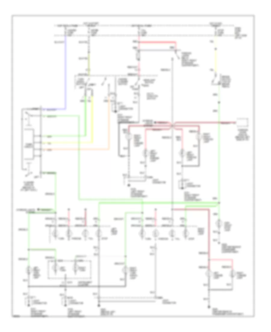
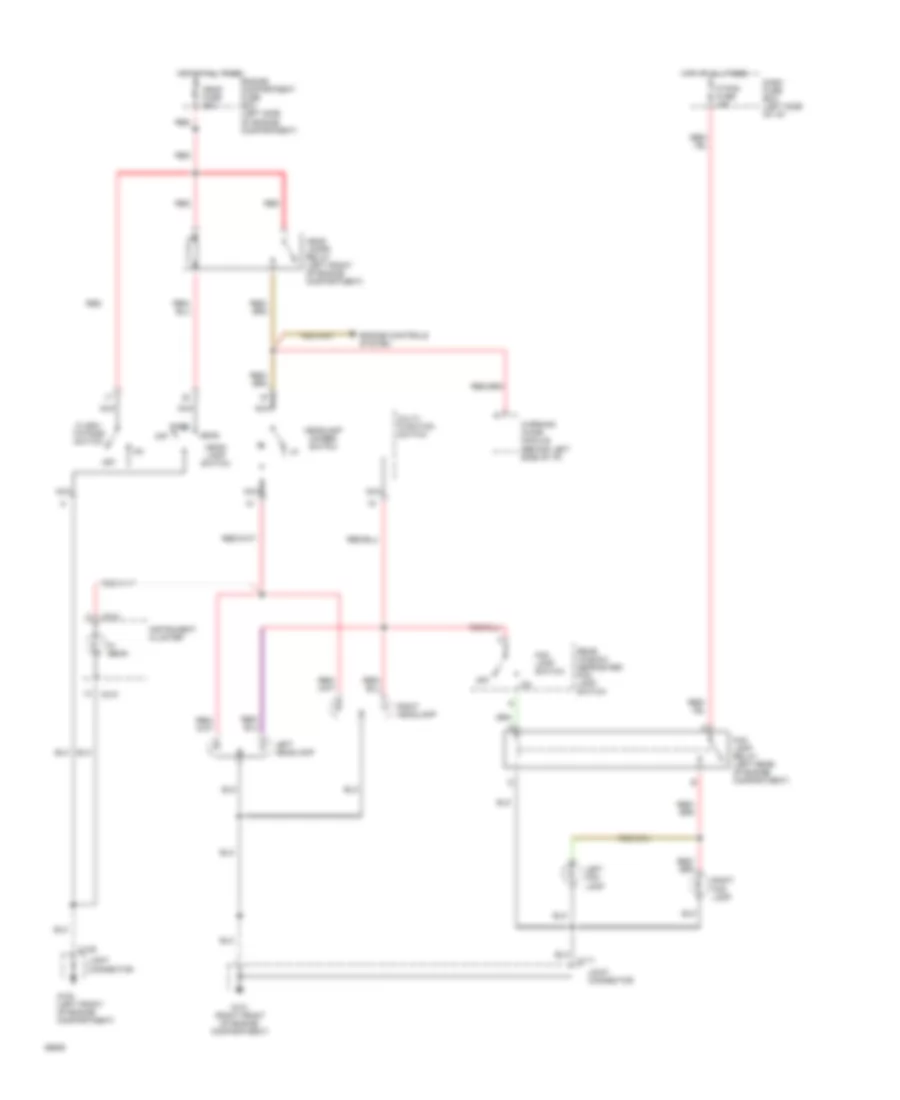
AIR CONDITIONING
Air Conditioning Wiring Diagrams for Ford Aspire 1994

List of elements for Air Conditioning Wiring Diagrams for Ford Aspire 1994:
- A/c compressor clutch
- A/c condenser fan switch (left front of engine)
- A/c evaporator de-icing switch (center of i/p)
- A/c pressure cutoff switch (left front
- A/c relay (center rear of engine compartment)
- A/c switch
- Blower c.b. 30a
- Blower motor
- Blower motor relay (left front of engine compartment)
- Blower motor resistors (behind right side of i/p)
- Btn fuse 30a
- Compartment)
- Condenser fan motor
- Condenser fan relay (right front of engine compartment)
- Cooling fan motor
- Cooling fan relay (left front of engine compartment)
- Dash fuse box
- Engine compartment fuse box
- Engine fuse 10a
- G100 (left front of engine compartment)
- G101 (right front of engine compartment)
- G203 (at right cowl)
- Heater- a/c control unit
- Hot at all times
- Hot in run
- Hot in run or start
- Illumination
- Nca
- Of engine
- Off
- Pnk
- Powertrain control module (behind left side of i/p)
- R wiper fuse 15a
- Red
- Wiper fuse 20a
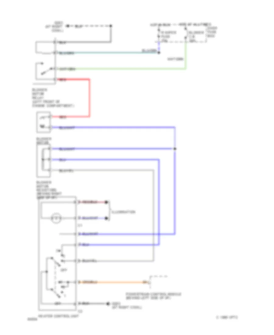
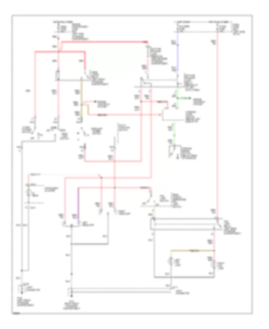
Heater Wiring Diagram for Ford Aspire 1994
List of elements for Heater Wiring Diagram for Ford Aspire 1994:
- Blower c.b. 30a
- Blower motor
- Blower motor relay (left front of engine compartment)
- Blower motor resistors (behind right side of i/p)
- C 1995 vftc
- Dash fuse box
- G203 (at right cowl)
- Heater control unit
- Hot at all times
- Hot in run
- Illumination
- Off
- Powertrain control module (behind left side of i/p)
- R wiper fuse 15a
- Red
ANTI-LOCK BRAKES
Anti-lock Brake Wiring Diagrams for Ford Aspire 1994
List of elements for Anti-lock Brake Wiring Diagrams for Ford Aspire 1994:
- rt rear brake sensor
- Abs fuse 60a
- Abs ind ctrl
- Abs main relay (left rear of engine compartment)
- Anti-lock brake (abs) control module (behind left side of i/p)
- Anti-lock brake (abs) hydraulic actuator unit (lower left front of engine compt)
- Anti-lock brake indicator
- Brake on/off switch (top of brake pedal)
- Brake sw input
- C138
- C139
- C209
- C219
- C220
- Charge ind
- Data link connector (left side of engine compartment)
- Dlc
- Engine fuse 10a
- Fail safe relay
- Fail safe rly ctrl
- Fuse block: i/p
- Fuse block: underhood
- G100 (left front of engine compartment)
- G202 (left side of i/p)
- Ground
- Hot at all times
- Hot in run or start
- Hydraulic pump motor
- Instrument cluster
- J/c
- L fnt brake sensor
- L fnt sol ctrl
- L rear brake sensor
- L rear sol ctrl
- Left front brake sensor
- Left front solenoid
- Left rear brake sensor
- Left rear solenoid
- Meter fuse 10a
- Nca
- Power
- Pump motor relay
- Pump mtr relay
- Pump mtr rly ctrl
- Red
- Right front brake sensor
- Right front solenoid
- Right rear brake sensor
- Right rear solenoid
- Rt fnt brake sensor
- Rt frt sol ctrl
- Rt rear brake sensor
- Rt rear sol cntrl
- Starting/charging system
- Stop fuse 15a
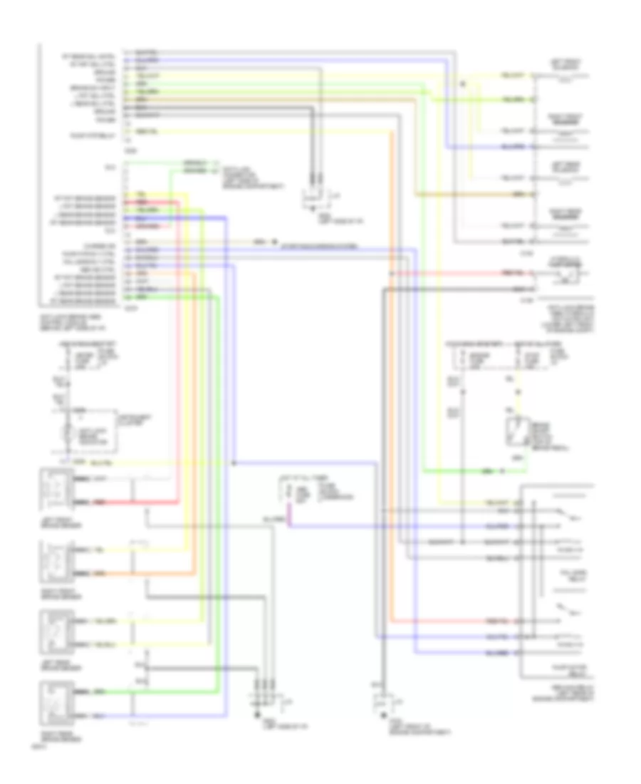
COMPUTER DATA LINES
Computer Data Lines for Ford Aspire 1994
List of elements for Computer Data Lines for Ford Aspire 1994:
- (left side of eng compt)
- (not used)
- 1995 vftc c
- Anti-lock brake control module (behind left side of i/p)
- C118
- C120
- C201
- C210
- C255
- Canister purge solenoid (top left side of eng)
- Data link connector
- Egr control solenoid (center rear of eng compt)
- Egr vent solenoid (center rear of eng compt)
- Fpr
- Fuel injectors
- Fuel pump relay (behind i/p, at left cowl)
- G100
- G101
- Horn relay (behind i/p, at left cowl)
- Horns system
- Idle air control valve (top left rear of eng)
- Ignition control module (left side of eng compt)
- Instrument cluster
- J/c c109 (left front fender)
- J/c c111 (right front fender)
- Main relay (behind i/p, at left cowl)
- No.1
- No.2
- No.3
- No.4
- Powertrain control module (behind left side of i/p)
- Sml
- Sti
- Sto
- Tach
- Vpwr
- Vss
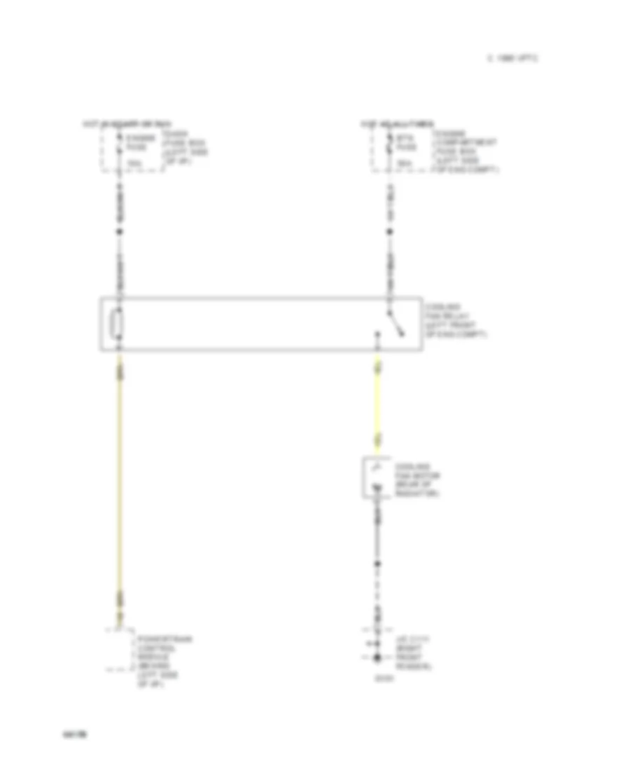
COOLING FAN
Cooling Fan Wiring Diagram for Ford Aspire 1994
List of elements for Cooling Fan Wiring Diagram for Ford Aspire 1994:
- 10a
- 1995 vftc c
- 30a
- Btn fuse
- Cooling fan motor (rear of radiator)
- Cooling fan relay (left front of eng compt)
- Dash fuse box (left side of i/p)
- Engine compartment fuse box (left side of eng compt)
- Engine fuse
- G101
- Hot at all times
- Hot in start or run
- J/c c111 (right front fender)
- Powertrain control module (behind left side of i/p)
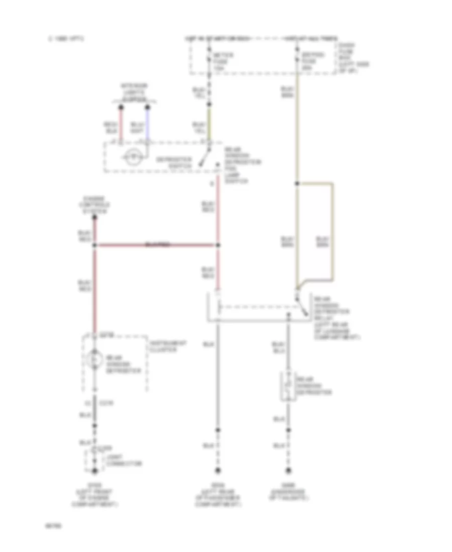
DEFOGGERS
Defogger Wiring Diagram for Ford Aspire 1994
List of elements for Defogger Wiring Diagram for Ford Aspire 1994:
- (defog) fuse 20a
- C 1995 vftc
- C109
- C210
- Dash fuse box (left side of i/p)
- Defroster switch
- Engine controls system
- G100 (left front of engine compartment)
- G304 (left rear of passenger compartment)
- G406 (underside of tailgate)
- Hot at all times
- Hot in start or run
- Instrument cluster
- Interior lights system
- Joint connector
- Meter fuse 15a
- Rear window defroster/ fog lamp switch
- Rear window defroster
- Rear window defroster relay (left rear of luggage compartment)
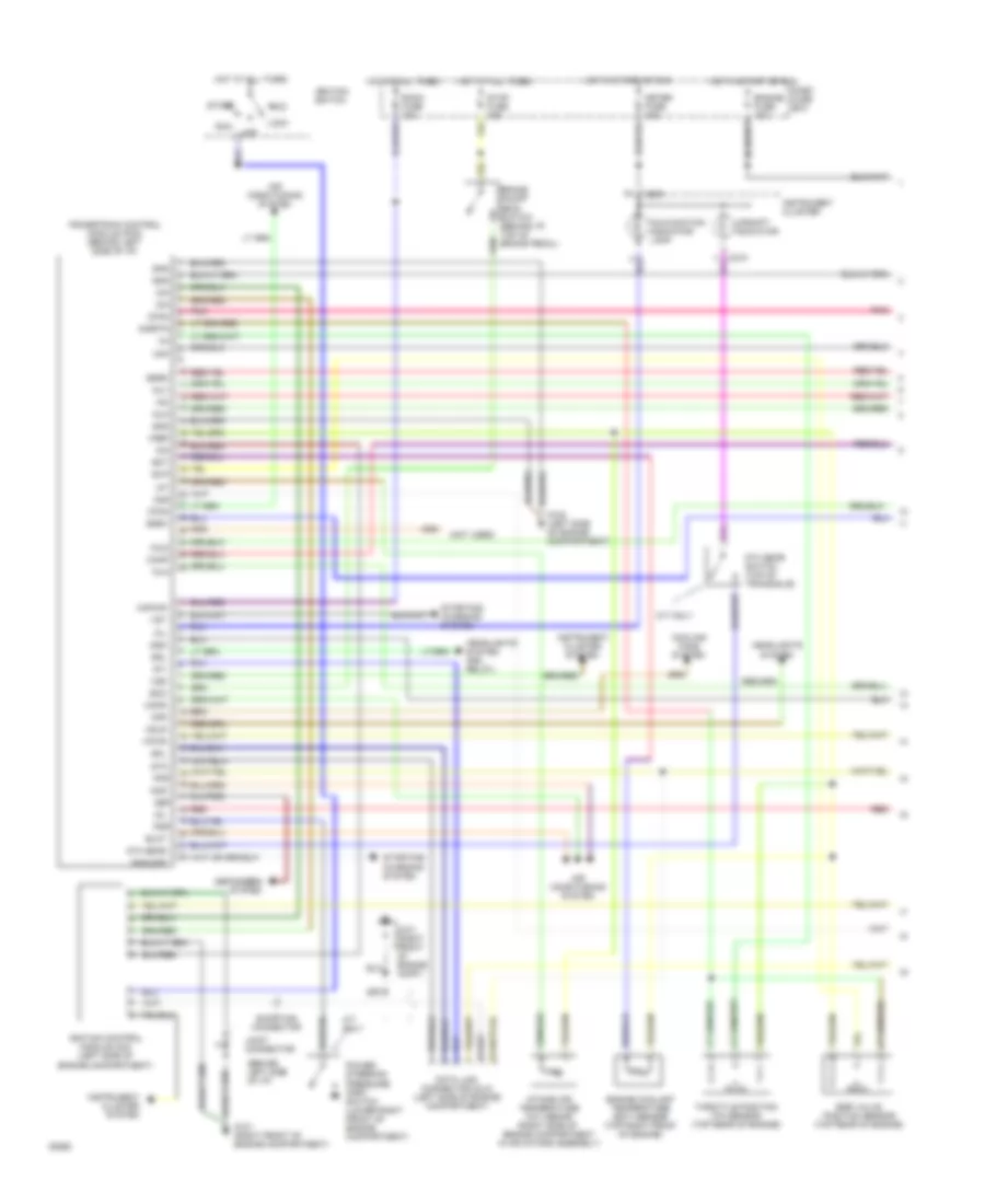
ENGINE PERFORMANCE
1.3L
1.3L, Engine Performance Wiring Diagrams (1 of 2) for Ford Aspire 1994
List of elements for 1.3L, Engine Performance Wiring Diagrams (1 of 2) for Ford Aspire 1994:
- (behind left side of i/p)
- (not used)
- 5th gear
- 5th gear switch (top of transaxle)
- A/t only
- Acc
- Acr
- Air conditioning system
- Blmt
- Boo
- Brake on/off (boo) switch (behind i/p, top of brake pedal)
- C209
- Canp
- Ccps
- Cfan
- Cfr
- Cooling fans system
- Dash fuse box
- Data link connector (dlc) (left side of engine compartment)
- Def
- Defoggers system
- Drl
- Ect
- Egr valve position sensor (top rear of engine)
- Egrc
- Egrv
- Engine coolant temperature (ect) sensor (top right front of engine)
- Engine fuse 10a
- Evp
- Fpr
- G101 (right front of engine comp.)
- G101 (right front of engine compartment)
- G102 (left side of engine compartment)
- Gnd
- Hdlr
- Headlights system
- Headlights system (drl relay)
- Hot at all times
- Hot in start or run
- Iac
- Iat
- Icm
- Idl
- Ignition control module (icm) (left side of engine compartment)
- Ignition switch
- Iinj2
- Inj1
- Inj3
- Inj4
- Instrument cluster
- Instrument cluster system
- Intake air temperature (iat) senor (right side of engine compartment in air intake assembly)
- Joint connector
- Kapwr
- Lock
- M/t only
- Maf
- Malfunction indicator lamp
- Meter fuse 15a
- Mil
- O2s
- Off
- Pnk
- Pnp/cpp
- Power steering pressure (psp) switch (lower right front of engine compartment)
- Powertrain control module (pcm) (behind left side of i/p)
- Psp
- Red
- Room fuse 10a
- Run
- Shorting connector
- Sigrtn
- Sml
- Start
- Starting/ charging system
- Sti
- Sto
- Stop fuse 15a
- Throttle position (tp) sensor (top rear of engine)
- Upshift indicator
- Vpwr
- Vref
- Vss
- Vst
1.3L, Engine Performance Wiring Diagrams (2 of 2) for Ford Aspire 1994
List of elements for 1.3L, Engine Performance Wiring Diagrams (2 of 2) for Ford Aspire 1994:
- (behind left side of i/p)
- (behnd i/p at left cowl)
- A/c condenser fan switch (left front of engine)
- Canister purge (canp) solenoid (top left side of engine)
- Egr control solenoid (center rear of engine compartment)
- Egr vent solenoid (center rear of engine compartment)
- Engine compartment fuse box
- Fuel injector no.1
- Fuel injector no.2
- Fuel injector no.3
- Fuel injector no.4
- Fuel pump relay
- Fuel pump/ fuel gauge sender (below rear seat)
- G100 (left front of engine compartment)
- G101 (right front of engine compartment)
- G102 (left side of engine compartment)
- G202 (left side of i/p)
- Hot at all times
- Idle air control (iac) valve (top left rear of engine)
- Idle switch (top of engine)
- Inertia fuel shutoff (ifs) switch (left rear of passenger's compartment
- Inj fuse 30a
- Joint connector
- Joint connector (behind left side of i/p)
- M/t only
- Main relay (behnd i/p at left cowl)
- Mass air flow (maf) sensor (right side of engine compartment in air intake assembly)
- Nca
- Not used
- Oxygen sensor (os2) (in exhaust manifold)
- Pnk
- Red
EXTERIOR LIGHTS
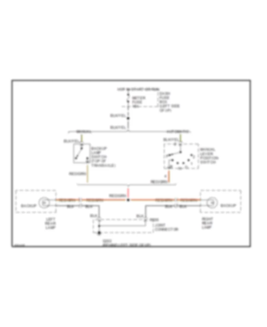
Back-up Lamps Wiring Diagram for Ford Aspire 1994
List of elements for Back-up Lamps Wiring Diagram for Ford Aspire 1994:
- Automatic
- Backup
- Backup lamp switch (top of transaxle)
- C206
- Dash fuse box (left side of i/p)
- G202 (behind left side of i/p)
- Hot in start or run
- Joint connector
- Left rear lamp
- Manual
- Manual lever position switch
- Meter fuse 15a
- Right rear lamp
Exterior Light Wiring Diagram for Ford Aspire 1994
List of elements for Exterior Light Wiring Diagram for Ford Aspire 1994:
- Brake switch (top of brake pedal)
- C109
- C111
- C206
- C209
- C210
- Dash fuse box (left side of i/p)
- Flasher module (behind i/p, at left cowl)
- G100 (left front of engine compartment)
- G101 (right front of engine compartment)
- G202 (behind left side of i/p)
- G306 (center rear of passenger compartment)
- Hazard flasher switch
- Hazard fuse 15a
- Head
- Headlamp switch
- High mount stop lamp
- Hot at all times
- Hot in acc or run
- Hot in start or run
- Instrument cluster
- Interior lights system
- Joint connector
- Left
- Left front parking lamp
- Left front side marker lamp
- Left front turn signal lamp
- Left license lamp
- Left rear lamp
- Left turn
- Meter fuse 15a
- Multi- function switch
- Off
- Park
- Parking
- Parking lamps relay (right front of engine compartment)
- Red
- Right
- Right front parking lamp
- Right front side marker lamp
- Right front turn signal lamp
- Right license lamp
- Right rear lamp
- Right turn
- Stop
- Stop fuse 15a
- Tail
- Tail fuse 15a
- Timer circuit
- Turn
- Turn signal switch
- Warning chime module (behind left side of i/p)
GROUND DISTRIBUTION
Ground Distribution Wiring Diagram (1 of 2) for Ford Aspire 1994
List of elements for Ground Distribution Wiring Diagram (1 of 2) for Ford Aspire 1994:
- (not used)
- A/c condenser fan switch
- Abs main relay
- Anti-lock brake (abs) hydraulic actuator unit
- Blower motor relay
- Brake fluid level switch
- C109
- C111
- C237
- Cigar lighter
- Clutch pedal position (ccp) switch #1
- Condenser fan motor
- Cooling fan motor
- Data link connector (dlc)
- Flasher module
- Fog lamp relay
- G100 (left front of engine compartment)
- G101 (right front of engine compartment)
- G201 (behind i/p, at right cowl)
- Heater- a/c control unit
- Ignition control module (icm) shield
- Instrument cluster
- Instrument panel dimming rheostat
- Joint connector
- Left fog lamp
- Left front parking lamp
- Left front side marker lamp
- Left front turn signal lamp
- Left headlamp
- Main relay
- Multi- function switch
- Power- train control module (pcm)
- Right fog lamp
- Right front parking lamp
- Right front side marker lamp
- Right front turn signal lamp
- Right headlamp
- To g202
- Warning chime module
- Windshield washer pump
Ground Distribution Wiring Diagram (2 of 2) for Ford Aspire 1994
List of elements for Ground Distribution Wiring Diagram (2 of 2) for Ford Aspire 1994:
- (not used)
- Air bag diagnostic module
- Anti- lock brake (abs) control module
- C118
- C200
- C206
- C207
- C208
- C221
- C223
- C224
- Driver's air bag
- From g101
- G102 (left side of engine compartment)
- G110 (top left front of engine)
- G201 (behind right side of i/p)
- G202 (behind left side of i/p)
- G302 (behind front of console)
- G304 (left rear of passenger compartment
- G306 (center rear of passenger compartment)
- G406 (underside of liftgate)
- High mount stop lamp
- Ignition control module (icm)
- Ignition control module (icm) shield
- Inertia fuel shutoff (ifs) switch
- Joint connector
- Left front brake sensor shield
- Left license lamp
- Left rear brake sensor shield
- Left rear lamp
- Mass air flow (maf) sensor
- Oxygen sensor shield
- Park/ neutral position switch
- Passenger's air bag
- Power- train control module (pcm)
- Rear window defroster
- Rear window defroster relay
- Right front brake sensor shield
- Right license lamp
- Right rear brake sensor shield
- Right rear lamp
- Seat belt switch
- Shift lock actuator
- Shorting connector
HEADLIGHTS
Headlight Wiring Diagram, with DRL for Ford Aspire 1994
List of elements for Headlight Wiring Diagram, with DRL for Ford Aspire 1994:
-
-
-
- nca
- (f.fog) fuse 15a
- (r.wiper) fuse 15a
- C109
- C111
- C210
- Dash fuse box (left side of i/p)
- Daytime running lamp relay (behind i/p, at left cowl panel)
- Daytime running lamp resistor (center rear of engine compartment)
- Engine compartment fuse box (left side of engine compartment)
- Engine controls system
- Flash- to-pass- switch
- Fog lamp relay (left rear of engine compartment)
- Fog lamp switch
- G100 (left front of engine compartment)
- G101 (right front of engine compartment)
- Head
- Head fuse 30a
- Head lamps relay (left front of engine compartment)
- Head- lamp switch
- Headlamp dimmer switch
- Hi beam
- Hot at all times
- Hot in run
- Instrument cluster
- Joint connector
- Left fog lamp
- Left headlamp
- Multi- function switch
- Nca
- Off
- Off
- Park
- Parking brake switch (below rear of console)
- Rear window defroster/ fog lamp switch
- Red
- Right fog lamp
- Right headlamp
- Warning chime module (behind left side of i/p)
Headlight Wiring Diagram, without DRL for Ford Aspire 1994
List of elements for Headlight Wiring Diagram, without DRL for Ford Aspire 1994:
-
-
-
- nca
- (f.fog) fuse 15a
- C109
- C111
- C210
- Dash fuse box (left side of i/p)
- Engine compartment fuse box (left side of engine compartment)
- Engine controls system
- Flash- to-pass- switch
- Fog lamp relay (left rear of engine compartment)
- Fog lamp switch
- G100 (left front of engine compartment)
- G101 (right front of engine compartment)
- Head
- Head fuse 30a
- Head lamps relay (left front of engine compartment)
- Head- lamp switch
- Headlamp dimmer switch
- Hi beam
- Hot at all times
- Instrument cluster
- Joint connector
- Left fog lamp
- Left headlamp
- Multi- function switch
- Nca
- Off
- Off
- Park
- Rear window defroster/ fog lamp switch
- Red
- Right fog lamp
- Right headlamp
- Warning chime module (behind left side of i/p)
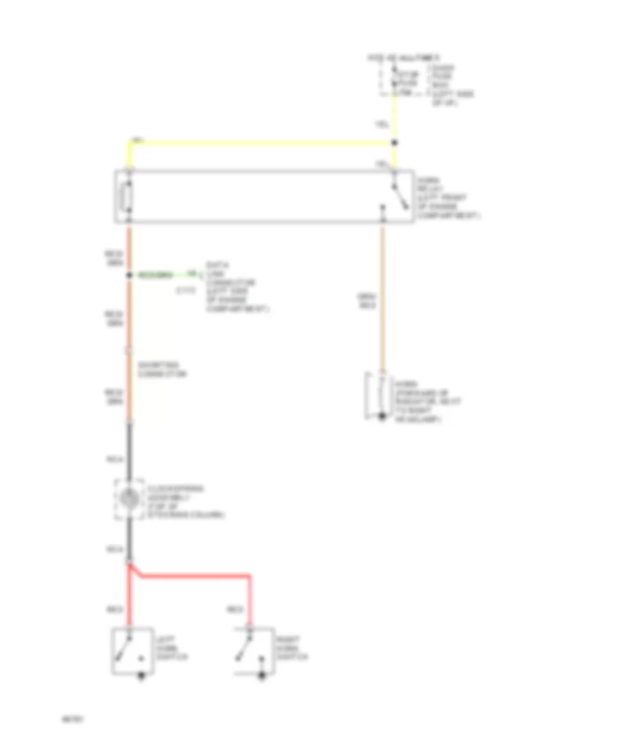
HORN
Horn Wiring Diagram for Ford Aspire 1994
List of elements for Horn Wiring Diagram for Ford Aspire 1994:
-
-
-
-
- C113
- Clockspring assembly (top of steering column)
- Dash fuse box (left side of i/p)
- Data link connector (left side of engine compartment)
- Horn (forward of radiator, next to right headlamp)
- Horn relay (left front of engine compartment)
- Hot at all times
- Left horn switch
- Nca
- Red
- Right horn switch
- Shorting connector
- Stop fuse 15a
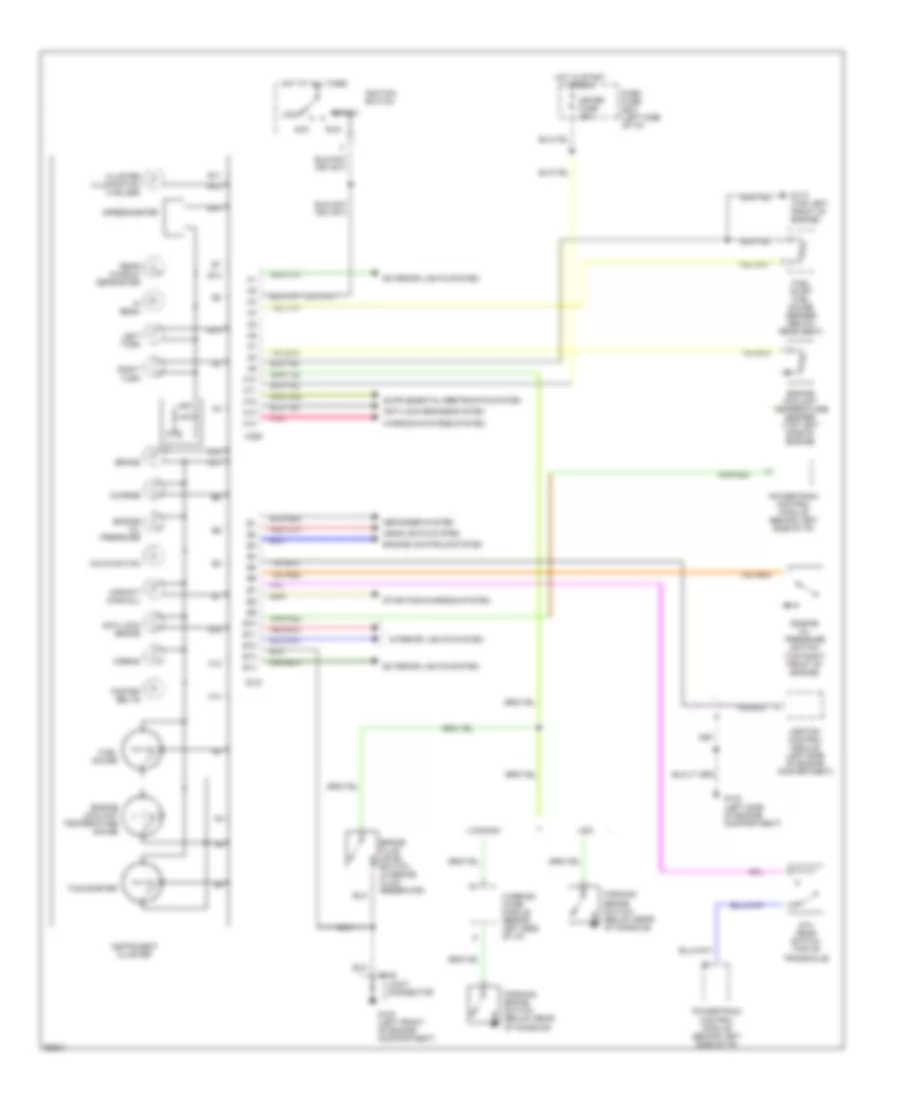
INSTRUMENT CLUSTER
Instrument Cluster Wiring Diagram for Ford Aspire 1994
List of elements for Instrument Cluster Wiring Diagram for Ford Aspire 1994:
- 5th gear switch (top of transaxle)
- A10
- A11
- A12
- A13
- A14
- Acc
- Airbag
- Anti-lock brake
- Anti-lock brakes system
- B10
- B11
- B12
- B13
- B14
- Brake
- Brake fluid level switch (in brake fluid reservoir)
- C109
- C209
- C210
- Canada
- Charge
- Cluster illumination (4 bulbs)
- Dash fuse box (left side of i/p)
- Defogger system
- Engine controls system
- Engine coolant temperature gauge
- Engine coolant temperature sender (top left side of engine)
- Engine oil pressure
- Engine oil pressure switch (top right front of engine)
- Exterior lights system
- Fasten belts
- Fuel gauge
- Fuel pump/ fuel gauge sender (below rear seat)
- G100 (left front of engine compartment)
- G102 (left side of engine compartment)
- G110 (top left front of engine)
- Headlights system
- Hi beam
- Hot at all times
- Hot in start or run
- Ignition control module (left side of engine compartment)
- Ignition switch
- Instrument cluster
- Interior lights system
- Joint connector
- Left turn
- Lock
- Malfunction
- Meter fuse 15a
- Parking brake switch (below rear of console)
- Pnk
- Powertrain control module (behind left side of i/p)
- Rear window defroster
- Right turn
- Run
- Speedometer
- Start
- Starting/charging system
- Tachometer
- Upshift (manual)
- Usa
- Warning chime module (behind left side of i/p)
- Warning systems system
INTERIOR LIGHTS
Interior Light Wiring Diagram for Ford Aspire 1994
List of elements for Interior Light Wiring Diagram for Ford Aspire 1994:
-
- (a/t only)
- C109
- C210
- Dash fuse box (left side of i/p)
- Dome lamp
- Door
- Exterior lights
- G100 (left front of engine compartment)
- G201 (behind i/p, at right cowl)
- Head
- Headlamp switch
- Heater a/c control unit
- Hot at all times
- Instrument cluster
- Instrument panel dimming rheostat
- Joint connector
- Left front door switch
- Liftgate switch
- Luggage compartment switch assembly
- Multi- function switch
- Off
- Park
- Parking lamps relay (right front of engine)
- Prndl illumination
- Radio
- Rear window defroster/ fog lamp switch
- Red
- Right front door switch
- Room fuse 10a
- Stop fuse 15a
- Tail fuse 15a
- Warning chime module (behind left side of i/p)
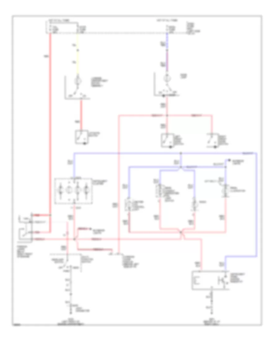
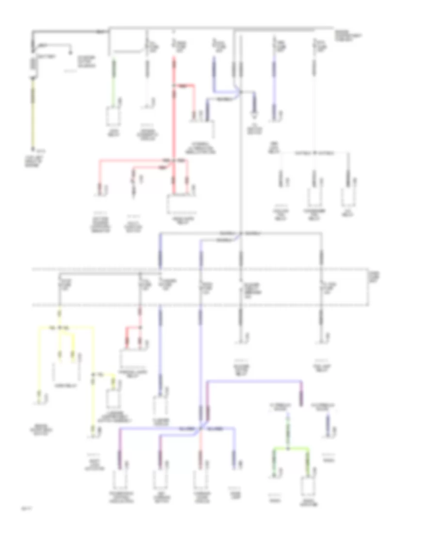
POWER DISTRIBUTION
Power Distribution Wiring Diagram (1 of 2) for Ford Aspire 1994
List of elements for Power Distribution Wiring Diagram (1 of 2) for Ford Aspire 1994:
- (f. fog) fuse 15a
- (top left front of engine)
- A/c relay
- Abs fuse 60a
- Abs main relay
- Air bag diagnostic module
- Battery
- Blower circuit breaker 30a
- Blower motor relay
- Brake on/off (boo) switch
- Btn fuse 30a
- C132
- C133
- C140
- C150
- C152
- C154
- C157
- C159
- C162
- C173
- C201
- C204
- C211
- C215
- C221
- C233
- C235
- C237
- C238
- C242
- C247
- C249
- C300
- C306
- C412
- Condenser fan relay
- Cooling fan relay
- Dash fuse box
- Daytime running lamps (drl) resistor
- Dome lamp
- Engine compartment fuse box
- Flasher module
- Fog lamp relay
- G110
- Hazard fuse 15a
- Head fuse 30a
- Headlamps relay
- Horn relay
- Inj fuse 30a
- Integral alternator/ regulator (iar)
- Key warning switch
- Luggage compartment switch assembly
- Main fuse 80a
- Main relay
- Multi- function switch
- Nca
- Parking lamps relay
- Powertrain control module (pcm)
- Radio
- Radio amplifier
- Red
- Room fuse 10a
- Shift lock actuator
- Starter motor/ solenoid
- Stop fuse 15a
- Tail fuse 15a
- To ignition switch
- W/ premium sound
- W/o premium sound
- Warning chime module
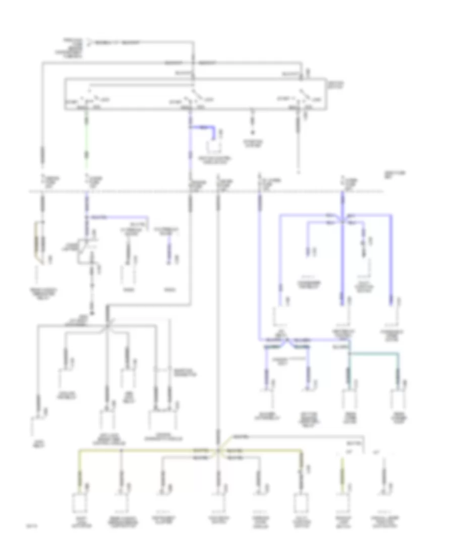
Power Distribution Wiring Diagram (2 of 2) for Ford Aspire 1994
List of elements for Power Distribution Wiring Diagram (2 of 2) for Ford Aspire 1994:
- (cigar) fuse 15a
- (defog) fuse 20a
- (r. wiper) fuse 15a
- A/c relay
- A/t
- Abs main relay
- Acc
- Air bag diagnostic module
- Anti-lock brake (abs) control module
- Backup lamp switch
- Blower motor relay
- C120
- C129
- C133
- C140
- C150
- C152
- C154
- C171
- C172
- C202
- C204
- C209
- C218
- C220
- C221
- C226
- C228
- C233
- C237
- C238
- C241
- C243
- C247
- C300
- C404
- C409
- C411
- Canada only
- Cigar lighter
- Condenser fan relay
- Cooling fan relay
- Dash fuse box
- Daytime running lamps (drl) relay
- Engine fuse 10a
- From main fuse (engine compartment fuse box)
- G203 (at right kick panel)
- Heater-a/c control unit
- Ignition control module (icm)
- Ignition switch
- Instrument cluster
- Kick down switch
- Lock
- M/t
- Main relay
- Manual lever position (mlp) switch
- Meter fuse 15a
- Multi- function switch
- Nca
- Radio
- Rear washer pump
- Rear window defroster relay
- Rear window defroster/fog lamp switch
- Rear wiper motor
- Run
- Shift lock actuator
- Shorting connector
- Start
- Starting system
- W/ premium sound
- W/o premium sound
- Warning chime module
- Windshield wiper motor
- Wiper fuse 20a
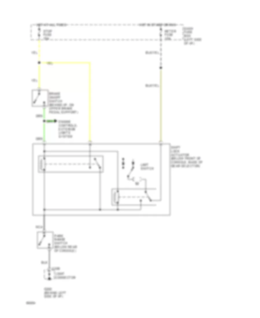
SHIFT INTERLOCKS
Shift Interlock Wiring Diagram for Ford Aspire 1994
List of elements for Shift Interlock Wiring Diagram for Ford Aspire 1994:
- Brake on/off switch (behind i/p, on upper brake pedal support)
- C206
- Dash fuse box (left side of i/p)
- Engine controls, exterior lights system
- G202 (behind left side of i/p)
- Hot at all times
- Hot in start or run
- Joint connector
- Limit switch
- Meter fuse 15a
- Nca
- Park range switch (below rear of console)
- Shift lock actuator (below front of console, base of gear selector)
- Stop fuse 15a
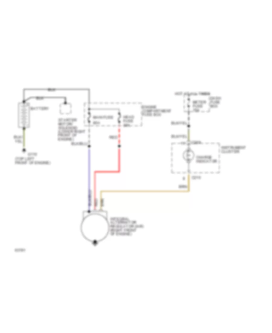
STARTING/CHARGING
Charging Wiring Diagram for Ford Aspire 1994
List of elements for Charging Wiring Diagram for Ford Aspire 1994:
- (top left front of engine)
- 80a
- Battery
- C209
- C210
- Charge indicator
- Dash fuse box
- Engine compartment fuse box
- G110
- Head fuse 30a
- Hot at all times
- Instrument cluster
- Integral alternator regulator (iar) (right front of engine)
- Main fuse
- Meter fuse 15a
- Red
- Starter motor/ solenoid (lower right front of engine)
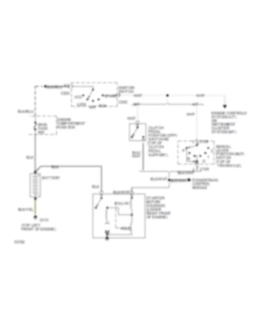
Starting Wiring Diagram for Ford Aspire 1994
List of elements for Starting Wiring Diagram for Ford Aspire 1994:
- (top left front of engine)
- 5,2
- A/t
- Acc
- Battery
- C129
- C202
- Clutch pedal position (cpp) switch #2 (top of clutch pedal support)
- Engine compartment fuse box
- Engine controls system (a/t) or instrument cluster system (m/t)
- G110
- Hold
- Ignition switch
- Lock
- M/t
- Main fuse 80a
- Manual lever position (mlp) switch (top of transaxle)
- Off
- Powertrain control module
- Pull-in
- Run
- Start
- Starter motor/ solenoid (lower right front of engine)
SUPPLEMENTAL RESTRAINTS
Supplemental Restraint Wiring Diagram for Ford Aspire 1994
List of elements for Supplemental Restraint Wiring Diagram for Ford Aspire 1994:
- Air bag
- Air bag diagnostic module (behind front of console)
- Air bag safing sensor (behind center of i/p)
- Assembly
- C209
- C221
- C222
- C223
- C224
- Center forward crash sensor (forward of radiator)
- Clockspring
- Dash fuse box (left side of i/p)
- Data link connector (left side of engine compartment)
- Driver's air bag
- Engine compartment fuse box (left side of engine compartment)
- Engine fuse 10a
- G201 (behind right side of i/p)
- G302 (behind front of console)
- Hot at all times
- Hot in start or run
- Inj fuse 30a
- Instrument cluster
- Joint connector
- Joint connector (behind right side of i/p)
- Left forward crash sensor (lower left front of engine compartment)
- Meter fuse 15a
- Nca
- Passenger's air bag
- Red
- Right forward crash sensor (lower right front of engine compartment)
- Shorting bar
WARNING SYSTEMS
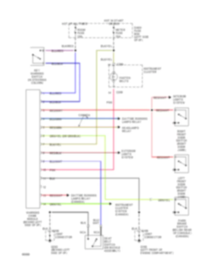
Warning System Wiring Diagrams for Ford Aspire 1994
List of elements for Warning System Wiring Diagrams for Ford Aspire 1994:
- C109
- C206
- C209
- Canada
- Dash fuse box (left side of i/p)
- Daytime running lamps relay
- Daytime running lamps relay (canada)
- Exterior lights system
- Fasten belts
- G100 (left front of engine compartment)
- G202 (behind left side of i/p)
- Headlamps relay
- Hot at all times
- Hot in start or run
- Instrument cluster
- Instrument cluster system (canada)
- Interior lights system
- Joint connector
- Key warning switch (in steering column)
- Left front door switch (right door jamb)
- Meter fuse 15a
- Nca
- Park brake switch (below rear of console) (canada)
- Pnk
- Right front door switch (right door jamb)
- Room fuse 10a
- Seat belt switch (on buckle assembly)
- Warning chime module (behind left side of i/p)
WIPER/WASHER
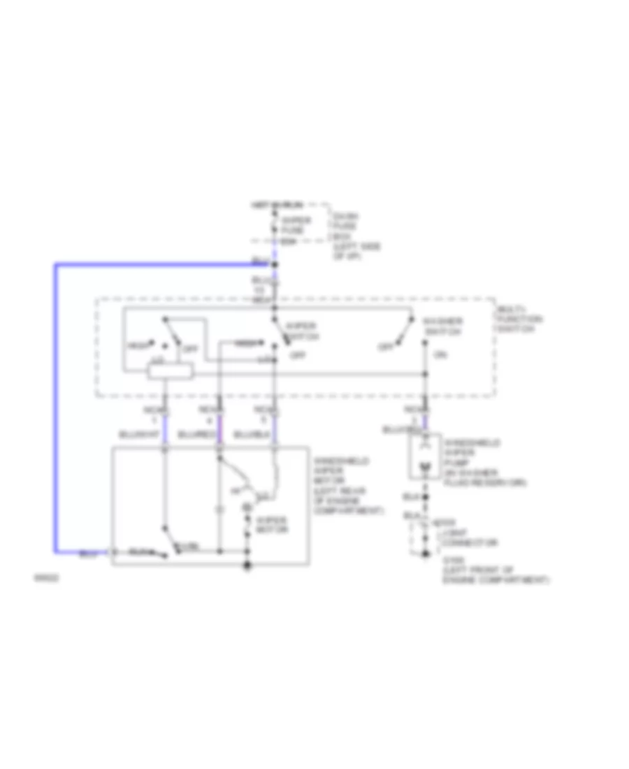
2-Speed Wiper/Washer Wiring Diagram for Ford Aspire 1994
List of elements for 2-Speed Wiper/Washer Wiring Diagram for Ford Aspire 1994:
- C109
- Dash fuse box (left side of i/p)
- G100 (left front of engine compartment)
- High
- Hot in run
- Joint connector
- Multi- function switch
- Nca
- Off
- Park
- Run
- Washer switch
- Windshield wiper motor (left rear of engine compartment)
- Windshield wiper pump (in washer fluid reservoir)
- Wiper fuse 20a
- Wiper motor
- Wiper switch
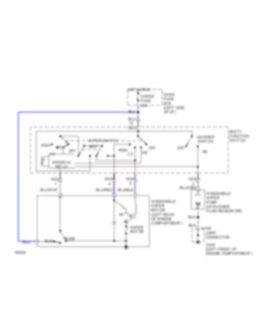
Interval Wiper/Washer Wiring Diagram for Ford Aspire 1994
List of elements for Interval Wiper/Washer Wiring Diagram for Ford Aspire 1994:
- C109
- Dash fuse box (left side of i/p)
- G100 (left front of engine compartment)
- High
- Hot in run
- Int
- Interval relay
- Joint connector
- Mist
- Multi- function switch
- Nca
- Off
- Park
- Run
- Washer switch
- Windshield wiper motor (left rear of engine compartment)
- Windshield wiper pump (in washer fluid reservoir)
- Wiper fuse 20a
- Wiper motor
- Wiper switch
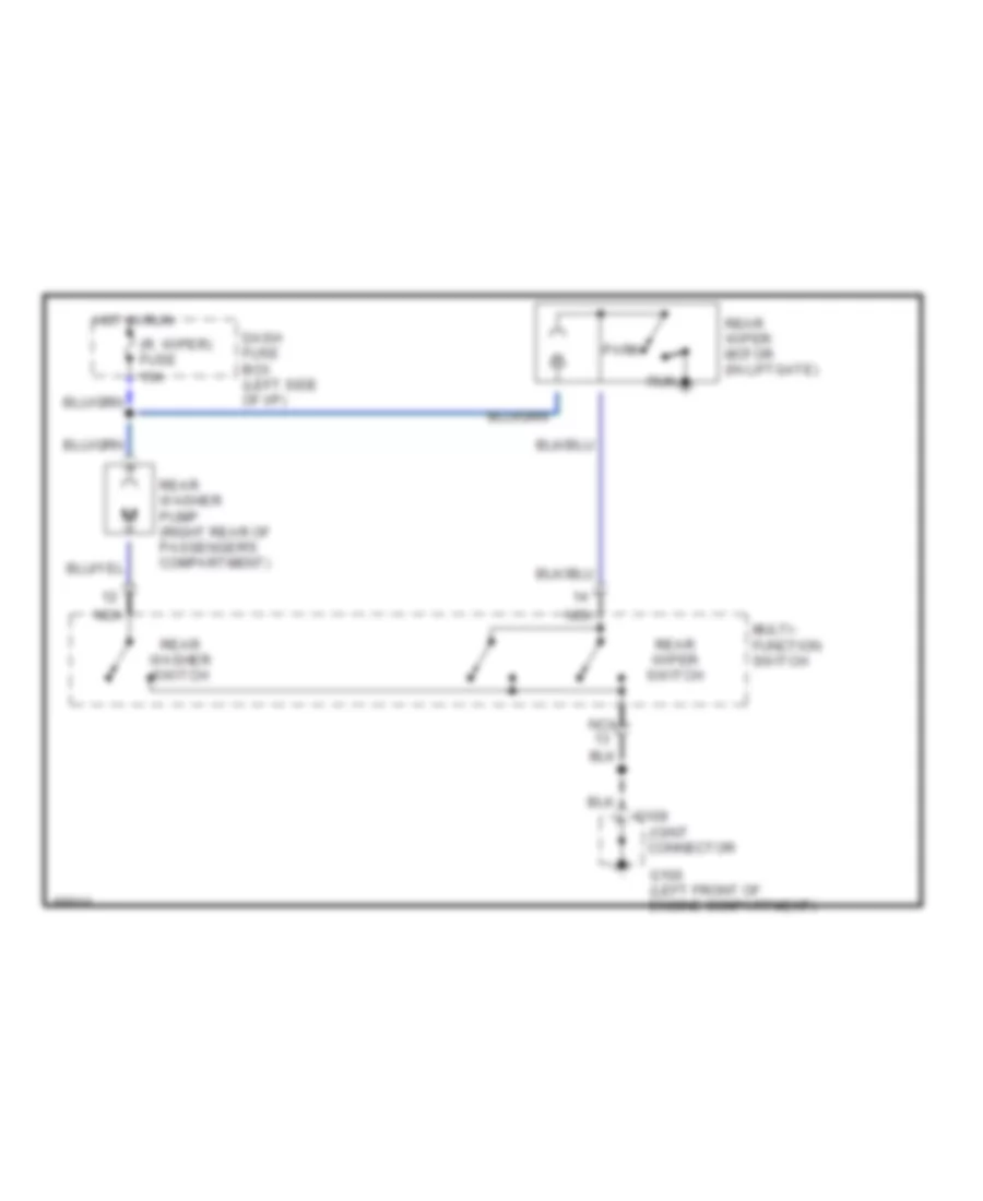
Rear Wiper/Washer Wiring Diagram for Ford Aspire 1994
List of elements for Rear Wiper/Washer Wiring Diagram for Ford Aspire 1994:
- (r. wiper) fuse 15a
- C109
- Dash fuse box (left side of i/p)
- G100 (left front of engine compartment)
- Hot in run
- Joint connector
- Multi- function switch
- Nca
- Park
- Rear washer pump (right rear of passenger's compartment)
- Rear washer switch
- Rear wiper motor (in liftgate)
- Rear wiper switch
- Run