Diagram sections — 24 (56 total)
AIR CONDITIONING ANTI-LOCK BRAKES COMPUTER DATA LINES CRUISE CONTROL DEFOGGERS ENGINE PERFORMANCE EXTERIOR LIGHTS GROUND DISTRIBUTION HEADLIGHTS HORN INSTRUMENT CLUSTER INTERIOR LIGHTS POWER DISTRIBUTION POWER DOOR LOCKS POWER MIRRORS POWER SEATS POWER WINDOWS RADIO SHIFT INTERLOCKS STARTING/CHARGING SUPPLEMENTAL RESTRAINTS TRANSMISSION WARNING SYSTEMS WIPER/WASHER
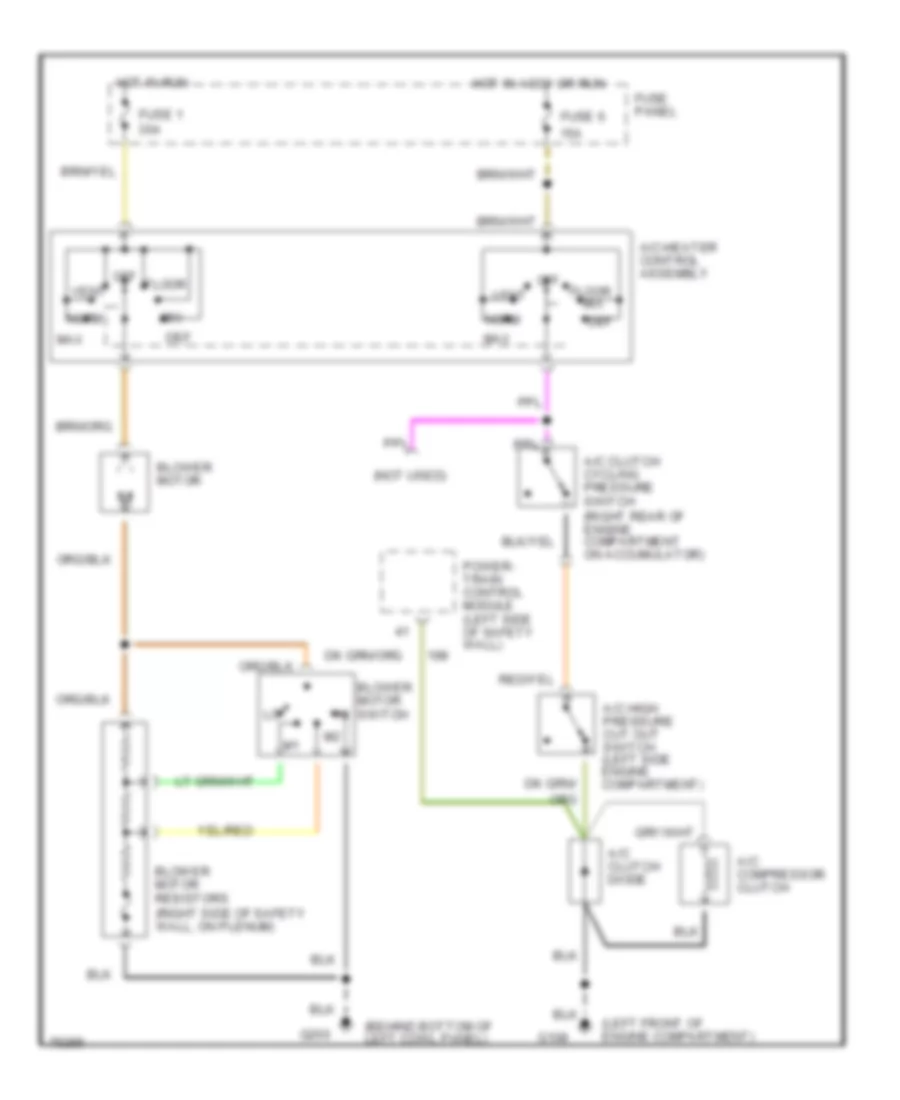
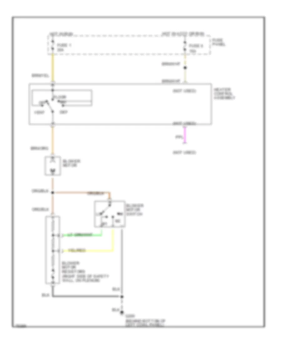
AIR CONDITIONING A/C Wiring Diagram for Ford Bronco 1996 List of elements for A/C Wiring Diagram for Ford Bronco 1996: 27 (behind bottom of left cowl panel) (left front of engine compartment) (not used) 15a A/c clutch cycling pressure switch (right rear of engine compartment on accumulator) A/c clutch diode A/c compressor clutch A/c high pressure cut out switch (left side engine compartment) A/c-heater control assembly Blower motor Blower motor resistors (right side of safety wall, on plenum) Blower motor switch Def Floor Fuse 1 30a Fuse 6 Fuse panel G108 G200 Hot in accy or run Hot in run Max Mix Norm Off Power- train control module (left side of safety wall) Vent Heater Wiring Diagram for Ford Bronco 1996 List of elements for Heater Wiring Diagram for Ford Bronco 1996: 17 (not used) 15a Blower motor Blower motor resistors (right side of safety wall, on plenum) Blower motor switch Def Floor Fuse 1 30a Fuse 6 Fuse panel G200 (behind bottom of left cowl panel) Heater control assembly Hot in accy or run Hot in run Mix Off Vent
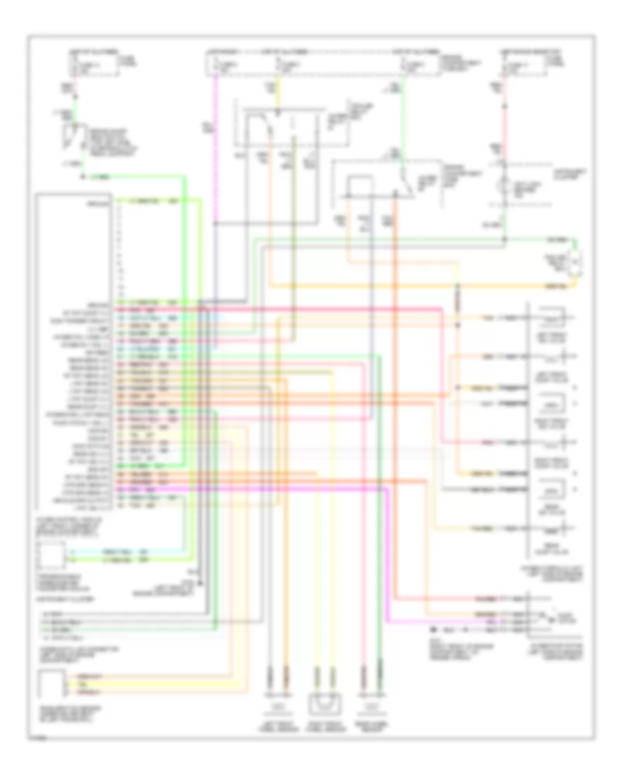
ANTI-LOCK BRAKES Anti-lock Brake Wiring Diagrams for Ford Bronco 1996 List of elements for Anti-lock Brake Wiring Diagrams for Ford Bronco 1996: 67 4wabs control module (left front corner of engine compartment) 4wabs data link connector (left side of engine compartment) 4wabs fail warn lp 4wabs hydraulic unit (left side of engine compartment) 4wabs pump motor (left side of engine compartment) 4wabs relay #1 4wabs relay #2 4wabs rly coil (-) Acceleration sensor (under driver seat, on left frame rail) Anti-lock brakes ind Boo sw Brake on/off (boo) switch (top left side of brake/clutch pedal support) Chassis roll databus Diag trigger circuit Engine compartment fuse box Fuse 13 15a Fuse 17 10a Fuse 2 30a Fuse 5 15a Fuse 8 30a Fuse panel G-sw #1 G-sw #2 G-sw status G101 (right front of engine compartment, on fender apron) G108 (left front of engine compartment) Ground Hot at all times Hot in run Hot in run and start Ign feed Instrument cluster L fnt dump vlv L fnt iso vlv L fnt sens (hi) L fnt sens (lo) Left front dump valve Left front iso valve Left front wheel sensor Mtr spd sens hi Mtr spd sens lo Nca Pnk Programmable speedometer/ odometer module Pump motor Pump mtr rly coil (-) Rear dump valve Rear dump vlv Rear iso valve Rear iso vlv Rear sens (hi) Rear sens (lo) Rear wheel sensor Red/pnk Right front dump valve Right front iso valve Right front wheel sensor Rt fnt dump vlv Rt fnt iso vlv Rt fnt sens (hi) Rt fnt sens (lo) Tan Tan/ red Tan/red Trailer relay box Vehicle spd output Vlv ref
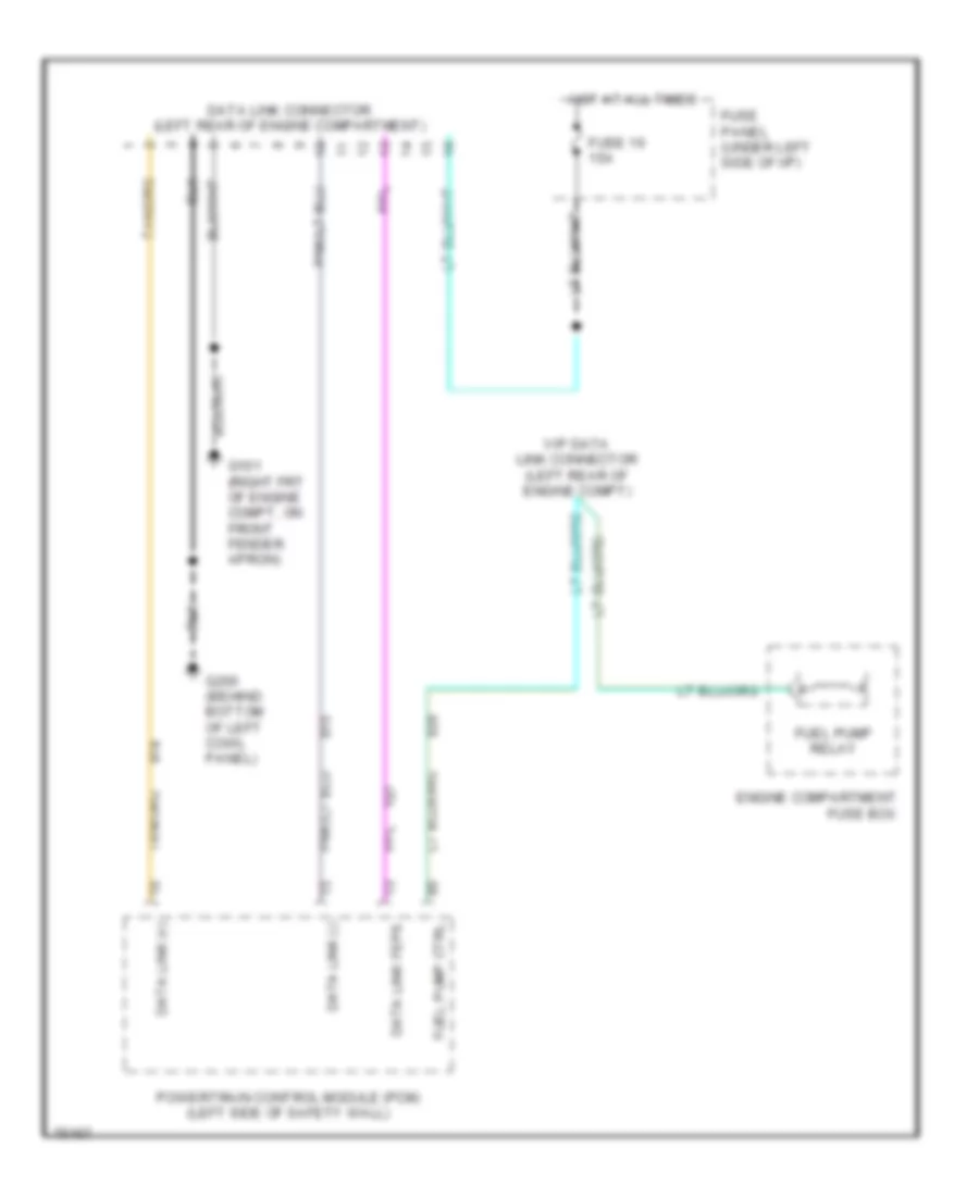
COMPUTER DATA LINES Computer Data Lines for Ford Bronco 1996 List of elements for Computer Data Lines for Ford Bronco 1996: 14 Data link (+) Data link (-) Data link connector (left rear of engine compartment) Data link feps Engine compartment fuse box Fuel pump ctrl Fuel pump relay Fuse 16 15a Fuse panel (under left side of i/p) G101 (right frt of engine compt, on front fender apron) G200 (behind bottom of left cowl panel) Hot at all times Powertrain control module (pcm) (left side of safety wall) Vip data link connector (left rear of engine compt)
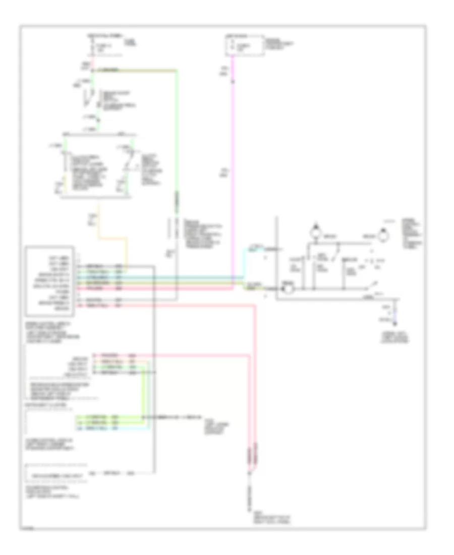
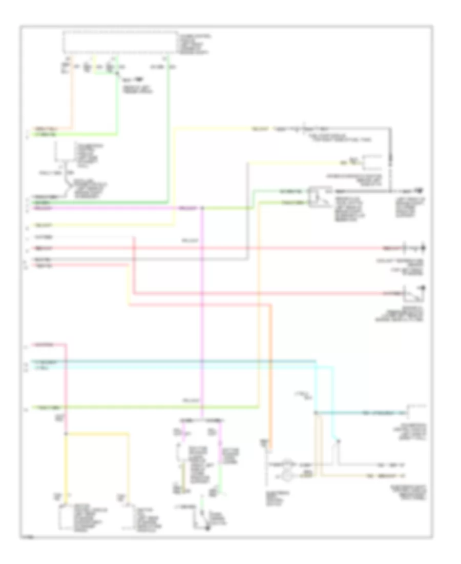
CRUISE CONTROL Cruise Control Wiring Diagram for Ford Bronco 1996 List of elements for Cruise Control Wiring Diagram for Ford Bronco 1996: 51 (behind bottom of right cowl panel) (behind left side of instrument panel, taped to main harness near steering column) (behind left side of instrument panel) (left side of engine compartment, near brake master cylinder) (left side of safety wall) (not used) (on brake pedal support) (on brake/ clutch 15a 4wabs control module (left front corner of engine compartment) A/t Accel Brake on/off (boo) switch Brake on/off in Brake press in Brake pressure switch (near left front frame rail) (opens when brake system is pressurized) Brush Clutch pedal position switch Clutch pedal position switch jumper Coast Engine compartment fuse box Fuse 13 Fuse 5 15a Fuse panel G108 (left upper radiator support) G203 Ground Horn Horns, anti- theft & door locks system Hot at all times Hot in run Instrument cluster M/t Nca Off Ohms Pedal support) Power Powertrain control module (pcm) Programmable speedometer/ odometer module (psom) Red Red/ Resume Set/ Spd ctrl sw rtrn Speed control servo/ amplifier assembly Speed control/ horn switch assembly (in steering wheel) Speed ctrl sw in Vehicle speed (vss) input Vss input Vss output
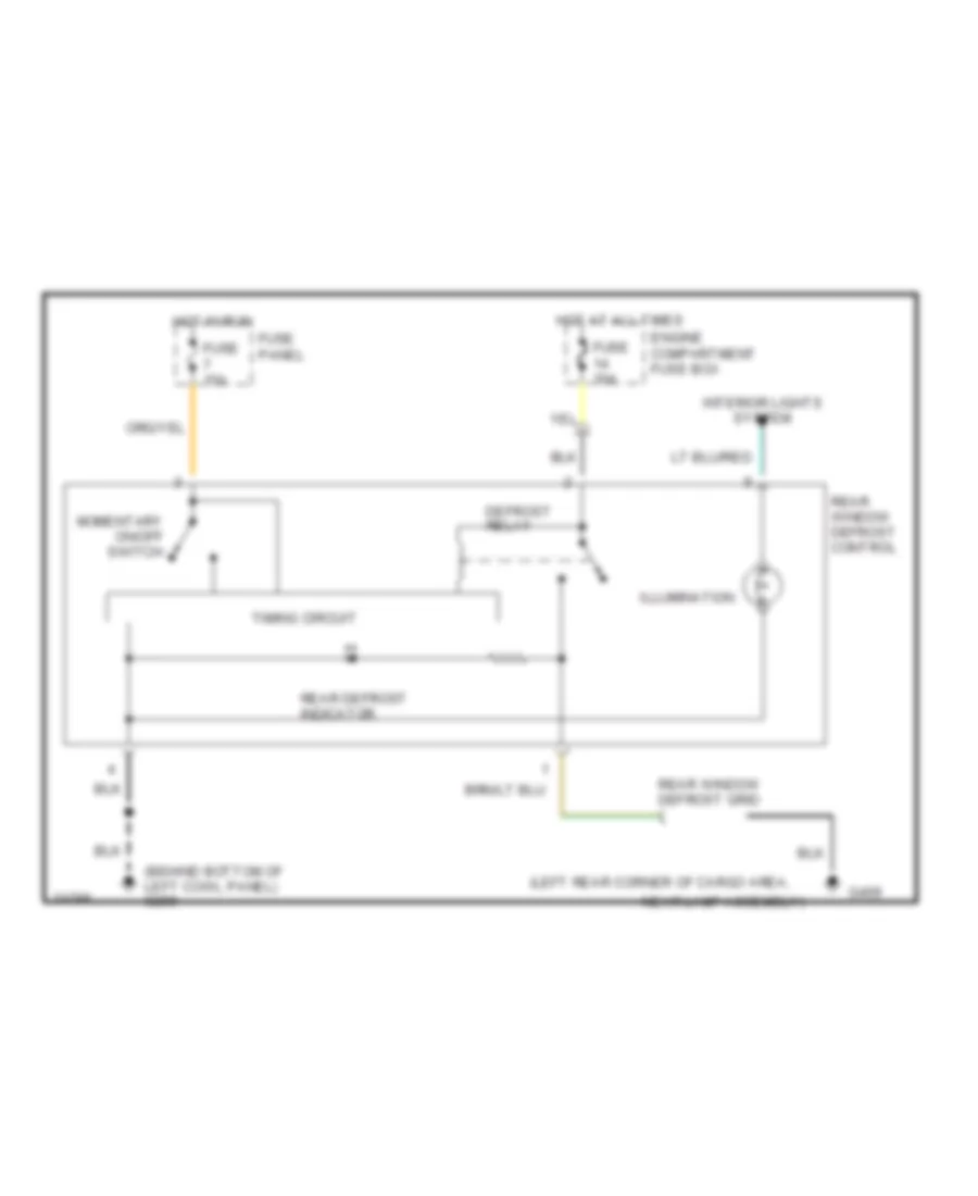
DEFOGGERS Defogger Wiring Diagram for Ford Bronco 1996 List of elements for Defogger Wiring Diagram for Ford Bronco 1996: 18 (behind bottom of left cowl panel) g200 (left rear corner of cargo area, Defrost relay Engine compartment fuse box Fuse 15a Fuse 30a Fuse panel G409 Hot at all times Hot in run Illumination Interior lights system Momentary on/off switch Near lamp assembly) Rear defrost indicator Rear window defrost control Rear window defrost grid Timing circuit
ENGINE PERFORMANCE
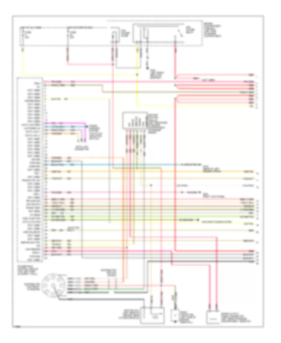
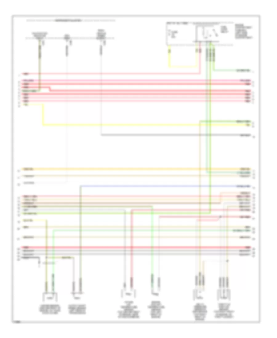
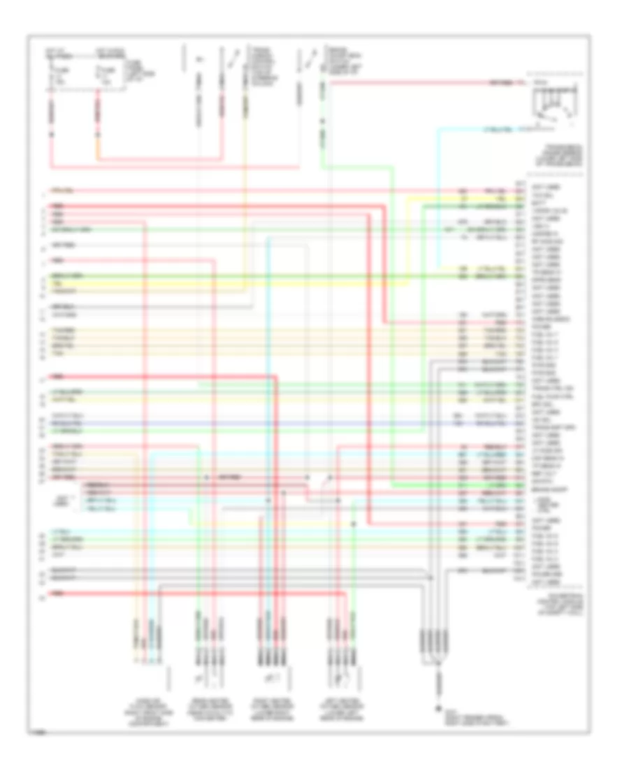
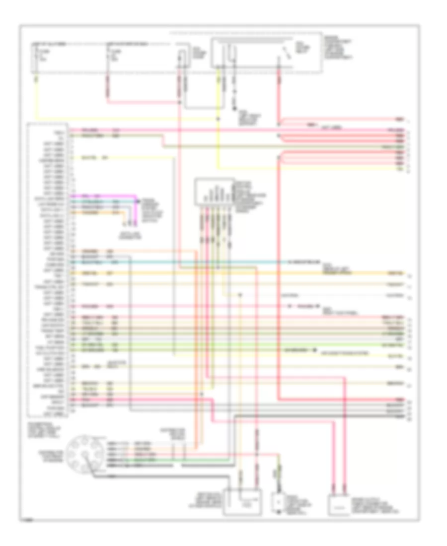
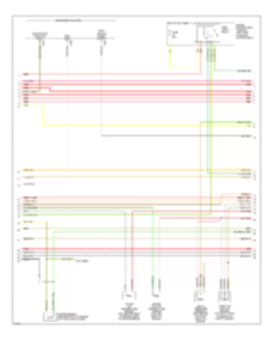
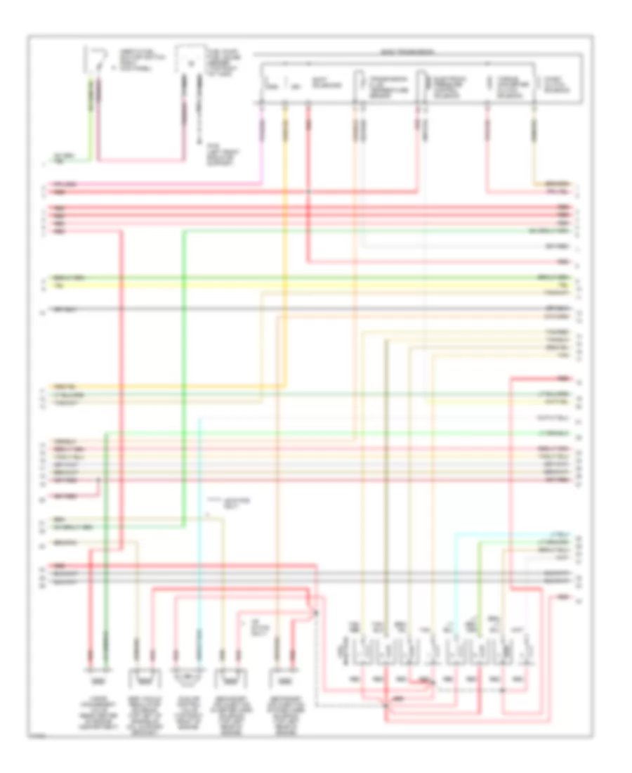
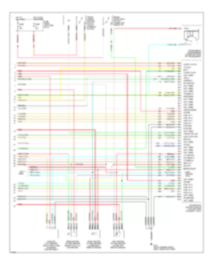
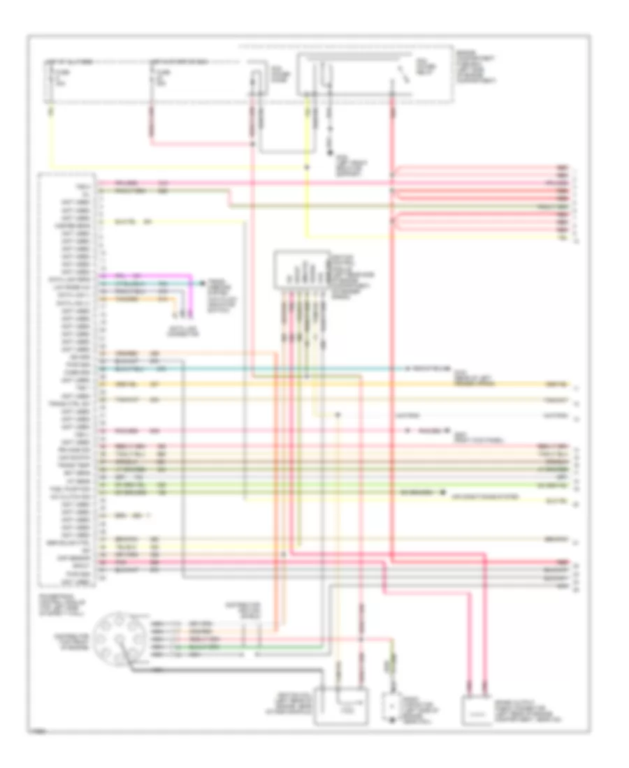
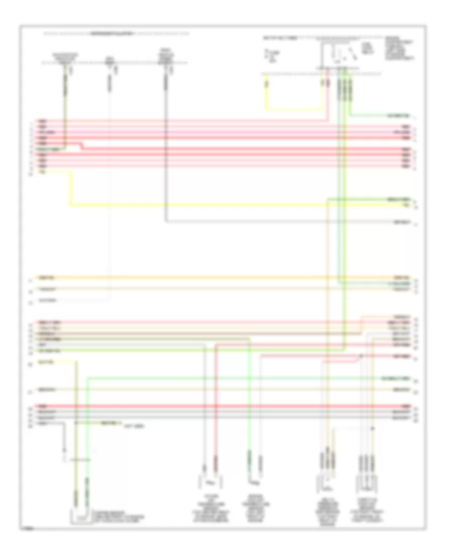
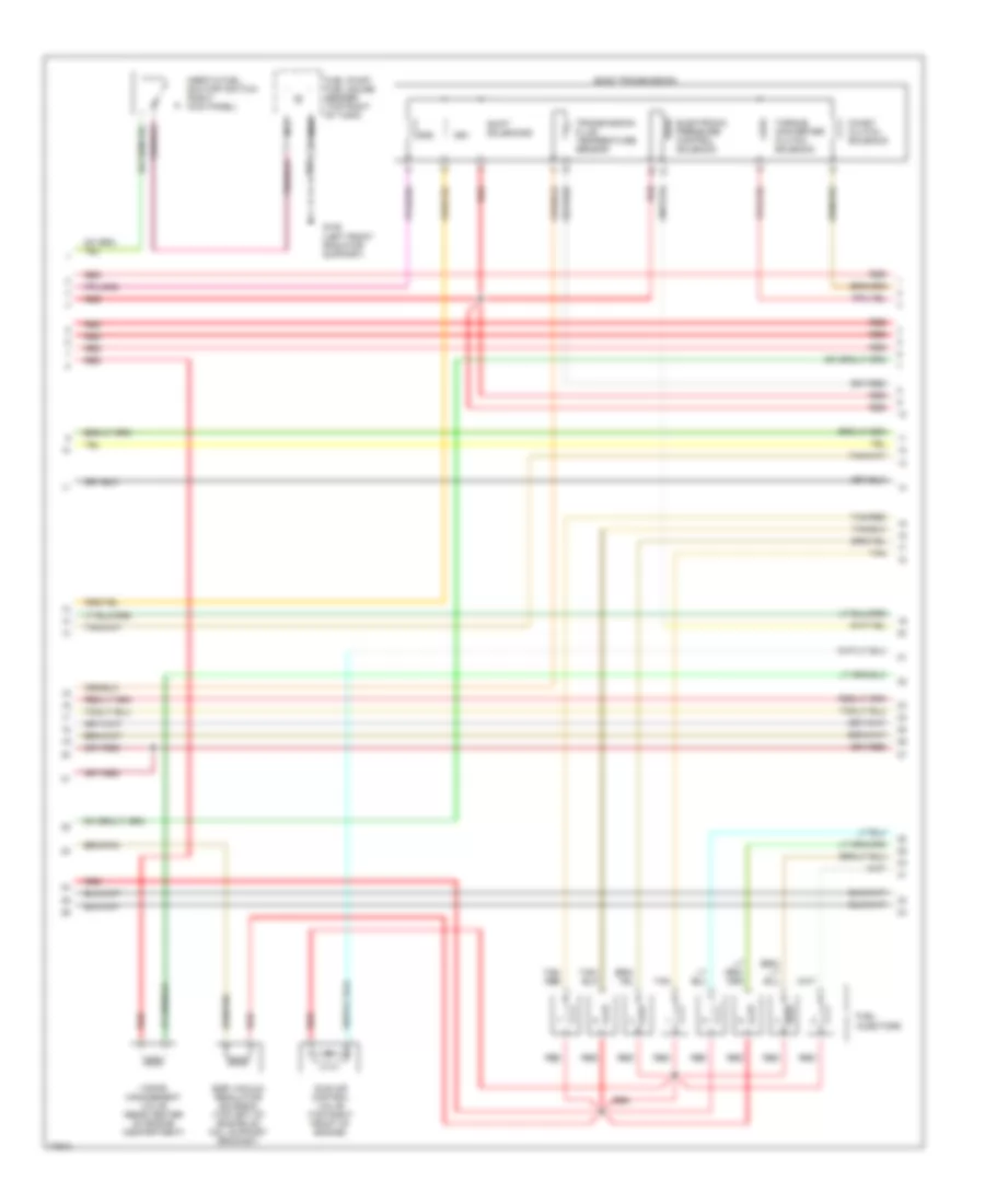
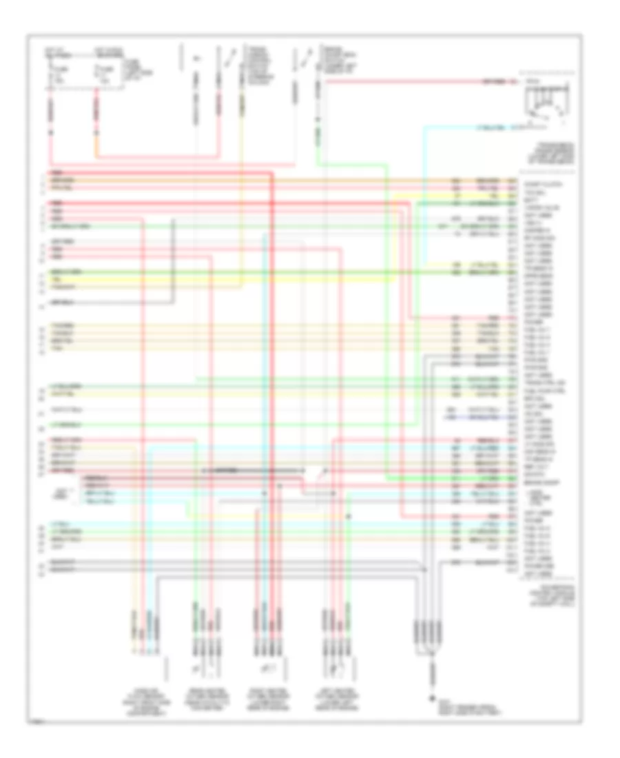
5.0L 5.0L, Engine Performance Wiring Diagrams, with 4R70W Transmission (1 of 4) for Ford Bronco 1996 List of elements for 5.0L, Engine Performance Wiring Diagrams, with 4R70W Transmission (1 of 4) for Ford Bronco 1996: 56 (49 state only) (not used) A/c clutch sig Air conditioning system Aird solenoid Case gnd Ckp sensor Coil Data link (+) Data link (-) Data link connector Data link feps Distributor (top front of engine) Distributor ignition shield Ect sens Egr solnd ctrl Engine compartment fuse box (left side of engine compartment) Fuel pump mon Fuse 20a Fuse 30a G104 (rear of left fender apron) G108 (left front radiator support) G203 (right kick panel) Hot at all times Hot in start or run Iat sens Idm Idm (fto) Ign gnd Ignition coil (left rear of engine, near intake manifold) Ignition control module (left rear side of engine compartment, on fender apron) Low rnge 4x4 Maf sig rtn Mil Misfire sens Nca Pcm power diode Pcm power relay Pip Pnk Power Powertrain control module (top left side of safety wall) Pwr gnd Pwr grd Radio capacitor (left side of engine, near coil) Red Red/ Rr ho2s sig Spark output check connector (left rear of engine compartment, near icm) Spout Trans ctrl sw Trans temp Trans- missions system (4x4 hi/low indicator switch) Tss 1 Tss 2 Vss (-) 5.0L, Engine Performance Wiring Diagrams, with 4R70W Transmission (2 of 4) for Ford Bronco 1996 List of elements for 5.0L, Engine Performance Wiring Diagrams, with 4R70W Transmission (2 of 4) for Ford Bronco 1996: 19 C250 C251 C252 Delta pressure feedback egr sensor (top right front of engine) Engine compartment fuse box (left side of engine compartment) Engine coolant temperature sensor (top left front of engine) Fuel pump relay Fuse 20a Hot at all times Instrument cluster Intake air temperature sensor (top center front of engine, near intake runner #6) Malfunction indicator input Misfire sensor (center front of engine, on timing chain cover) Nca Output shaft speed sensor (left rear of transmission) Psom vehicle speed output Red Rpm input Throttle position sensor (top right front of engine, on throttle body) 5.0L, Engine Performance Wiring Diagrams, with 4R70W Transmission (3 of 4) for Ford Bronco 1996 List of elements for 5.0L, Engine Performance Wiring Diagrams, with 4R70W Transmission (3 of 4) for Ford Bronco 1996: 23 (49 state only) 4r70w transmission Egr vacuum regulator solenoid (top left of engine on coil support bracket) Electronic pressure control solenoid Fuel pump/ fuel gauge sender (top right of tank) G108 (left front radiator support) Idle air control valve (top right front of engine) Inertia fuel shutoff switch (right kick panel) Injectors fuel Nca Power Red Secondary air injection bypass (airb) solenoid (top left rear of engine) Secondary air injection diverter (aird) solenoid (top left rear of engine) Shift solnd #1 Shift solnd #2 Signal return Tan Tan/ red Tan/red Torque converter clutch solenoid Transmission fluid temperature sensor Vapor management valve (rear center of engine compartment) 5.0L, Engine Performance Wiring Diagrams, with 4R70W Transmission (4 of 4) for Ford Bronco 1996 List of elements for 5.0L, Engine Performance Wiring Diagrams, with 4R70W Transmission (4 of 4) for Ford Bronco 1996: 51 (not used) Airb solenoid Batt Brake on/off Brake on/off (boo) switch (under left side of i/p) Dpfe sens Epc sol Fuel inj 1 Fuel inj 2 Fuel inj 3 Fuel inj 4 Fuel inj 5 Fuel inj 6 Fuel inj 7 Fuel inj 8 Fuel pump ctrl Fuse 10a Fuse 15a Fuse panel (left side of i/p) G101 (right fender apron, right side of battery) H02s heater ctrl Hot at all times Hot in run or start Iac sol Left heated oxygen sensor (lower left rear of engine) Lf ho2s sig Maf sens in Mass air flow sensor (right front side of engine compartment) Misfire in Nca Power Power gnd Powertrain control module (top left side of safety wall) Pwr gnd Rear heated oxygen sensor (near catalytic converter) Red Ref volt Rf ho2s sig Right heated oxygen sensor (lower right rear of engine) Sig rtn Tan Tan/red Tcc sol Tp sens in Tr sens in Trans ctrl ind Trans shft spd Trans- mission control switch (top of steering column) Transmission range sensor (lower left side of transmission) Vapor valve Vss (+) 5.0L, Engine Performance Wiring Diagrams, with E4OD Transmission (1 of 4) for Ford Bronco 1996 List of elements for 5.0L, Engine Performance Wiring Diagrams, with E4OD Transmission (1 of 4) for Ford Bronco 1996: 56 (49 state only) (not used) A/c clutch sig Air conditioning system Aird solenoid Case gnd Ckp sensor Coil Data link (+) Data link (-) Data link connector Data link feps Distributor (top front of engine) Distributor ignition shield Ect sens Egr solnd ctrl Engine compartment fuse box (left side of engine compartment) Fuel pump mon Fuse 20a Fuse 30a G104 (rear of left fender apron) G108 (left front radiator support) G203 (right kick panel) Hot at all times Hot in start or run Iat sens Idm Idm (fto) Ign gnd Ignition coil (left rear of engine, near intake manifold) Ignition control module (left rear side of engine compartment, on fender apron) Low rnge 4x4 Maf sig rtn Mil Misfire sens Nca Pcm power diode Pcm power relay Pip Pnk Power Powertrain control module (top left side of safety wall) Pwr gnd Pwr grd Radio capacitor (left side of engine, near coil) Red Red/ Rr ho2s sig Spark output check connector (left rear of engine compartment, near icm) Spout Trans ctrl sw Trans temp Trans- missions system (4x4 hi/low indicator switch) Tss 1 Tss 2 Vss (-) 5.0L, Engine Performance Wiring Diagrams, with E4OD Transmission (2 of 4) for Ford Bronco 1996 List of elements for 5.0L, Engine Performance Wiring Diagrams, with E4OD Transmission (2 of 4) for Ford Bronco 1996: 19 (not used) C250 C251 C252 Delta pressure feedback egr sensor (top right front of engine) Engine compartment fuse box (left side of engine compartment) Engine coolant temperature sensor (top left front of engine) Fuel pump relay Fuse 20a Hot at all times Instrument cluster Intake air temperature sensor (top center front of engine, near intake runner #6) Malfunction indicator input Misfire sensor (center front of engine, on timing chain cover) Nca Psom vehicle speed output Red Rpm input Throttle position sensor (top right front of engine, on throttle body) 5.0L, Engine Performance Wiring Diagrams, with E4OD Transmission (3 of 4) for Ford Bronco 1996 List of elements for 5.0L, Engine Performance Wiring Diagrams, with E4OD Transmission (3 of 4) for Ford Bronco 1996: 23 (49 state only) Coast clutch solenoid E4od transmission Egr vacuum regulator solenoid (top left of engine on coil support bracket) Electronic pressure control solenoid Fuel pump/ fuel gauge sender (top right of tank) G108 (left front radiator support) Idle air control valve (top right front of engine) Inertia fuel shutoff switch (right kick panel) Injectors fuel Nca Red Secondary air injection bypass (airb) solenoid (top left rear of engine) Secondary air injection diverter (aird) solenoid (top left rear of engine) Shift solenoids Ss1 Ss2 Tan Tan/ red Tan/red Torque converter clutch solenoid Transmission fluid temperature sensor Vapor management valve (rear center of engine compartment) 5.0L, Engine Performance Wiring Diagrams, with E4OD Transmission (4 of 4) for Ford Bronco 1996 List of elements for 5.0L, Engine Performance Wiring Diagrams, with E4OD Transmission (4 of 4) for Ford Bronco 1996: 51 (not used) Airb solenoid Batt Brake on/off Brake on/off (boo) switch (under left side of i/p) Coast clutch Dpfe sens Epc sol Fuel inj 1 Fuel inj 2 Fuel inj 3 Fuel inj 4 Fuel inj 5 Fuel inj 6 Fuel inj 7 Fuel inj 8 Fuel pump ctrl Fuse 10a Fuse 15a Fuse panel (left side of i/p) G101 (right fender apron, right side of battery) H02s heater ctrl Hot at all times Hot in run or start Iac sol Left heated oxygen sensor (lower left rear of engine) Lf ho2s sig Maf sens in Mass air flow sensor (right front side of engine compartment) Misfire in Nca Power Power gnd Powertrain control module (top left side of safety wall) Pwr gnd Rear heated oxygen sensor (near catalytic converter) Red Ref volt Rf ho2s sig Right heated oxygen sensor (lower right rear of engine) Sig rtn Tan Tan/red Tcc sol Tp sens in Tr sens in Trans ctrl ind Trans- mission control switch (top of steering column) Transmission range sensor (lower left side of transmission) Vapor valve Vss (+)
5.8L 5.8L, Engine Performance Wiring Diagrams (1 of 4) for Ford Bronco 1996 List of elements for 5.8L, Engine Performance Wiring Diagrams (1 of 4) for Ford Bronco 1996: 54 (not used) A/c clutch sig Air conditioning system Case gnd Ckp sensor Coil Data link (+) Data link (-) Data link connector Data link feps Distributor (top front of engine) Distributor ignition shield Ect sens Egr solnd ctrl Engine compartment fuse box (left side of engine compartment) Fuel pump mon Fuse 20a Fuse 30a G104 (rear of left fender apron) G108 (left front radiator support) G203 (right kick panel) Hot at all times Hot in start or run Iat sens Idm Idm (fto) Ign gnd Ignition coil (left rear of engine, near intake manifold) Ignition control module (left rear side of engine compartment, on fender apron) Low rnge 4x4 Maf sig rtn Mil Misfire sens Nca Pcm power diode Pcm power relay Pip Pnk Power Powertrain control module (top left side of safety wall) Pwr gnd Pwr grd Radio capacitor (left side of engine, near coil) Red Red/ Rr ho2s sig Spark output check connector (left rear of engine compartment, near icm) Spout Trans ctrl sw Trans temp Trans- missions system (4x4 hi/low indicator switch) Tss 1 Tss 2 Vss (-) 5.8L, Engine Performance Wiring Diagrams (2 of 4) for Ford Bronco 1996 List of elements for 5.8L, Engine Performance Wiring Diagrams (2 of 4) for Ford Bronco 1996: 19 (not used) C250 C251 C252 Delta pressure feedback egr sensor (top right front of engine) Engine compartment fuse box (left side of engine compartment) Engine coolant temperature sensor (top left front of engine) Fuel pump relay Fuse 20a Hot at all times Instrument cluster Intake air temperature sensor (top center front of engine, near intake runner #6) Malfunction indicator input Misfire sensor (center front of engine, on timing chain cover) Nca Psom vehicle speed output Red Rpm input Throttle position sensor (top right front of engine, on throttle body) 5.8L, Engine Performance Wiring Diagrams (3 of 4) for Ford Bronco 1996 List of elements for 5.8L, Engine Performance Wiring Diagrams (3 of 4) for Ford Bronco 1996: 20 Coast clutch solenoid E4od transmission Egr vacuum regulator solenoid (top left of engine on coil support bracket) Electronic pressure control solenoid Fuel injectors Fuel pump/ fuel gauge sender (top right of tank) G108 (left front radiator support) Idle air control valve (top right front of engine) Inertia fuel shutoff switch (right kick panel) Nca Red Shift solenoids Ss1 Ss2 Tan Tan/ red Tan/red Torque converter clutch solenoid Transmission fluid temperature sensor Vapor management valve (rear center of engine compartment) 5.8L, Engine Performance Wiring Diagrams (4 of 4) for Ford Bronco 1996 List of elements for 5.8L, Engine Performance Wiring Diagrams (4 of 4) for Ford Bronco 1996: 50 (not used) Batt Brake on/off Brake on/off (boo) switch (under left side of i/p) Coast clutch Dpfe sens Epc sol Fuel inj 1 Fuel inj 2 Fuel inj 3 Fuel inj 4 Fuel inj 5 Fuel inj 6 Fuel inj 7 Fuel inj 8 Fuel pump ctrl Fuse 10a Fuse 15a Fuse panel (left side of i/p) G101 (right fender apron, right side of battery) H02s heater ctrl Hot at all times Hot in run or start Iac sol Left heated oxygen sensor (lower left rear of engine) Lf ho2s sig Maf sens in Mass air flow sensor (right front side of engine compartment) Misfire in Nca Power Power gnd Powertrain control module (top left side of safety wall) Pwr gnd Rear heated oxygen sensor (near catalytic converter) Red Ref volt Rf ho2s sig Right heated oxygen sensor (lower right rear of engine) Sig rtn Tan Tan/red Tcc sol Tp sens in Tr sens in Trans ctrl ind Trans- mission control switch (top of steering column) Transmission range sensor (lower left side of transmission) Vapor valve Vss (+)
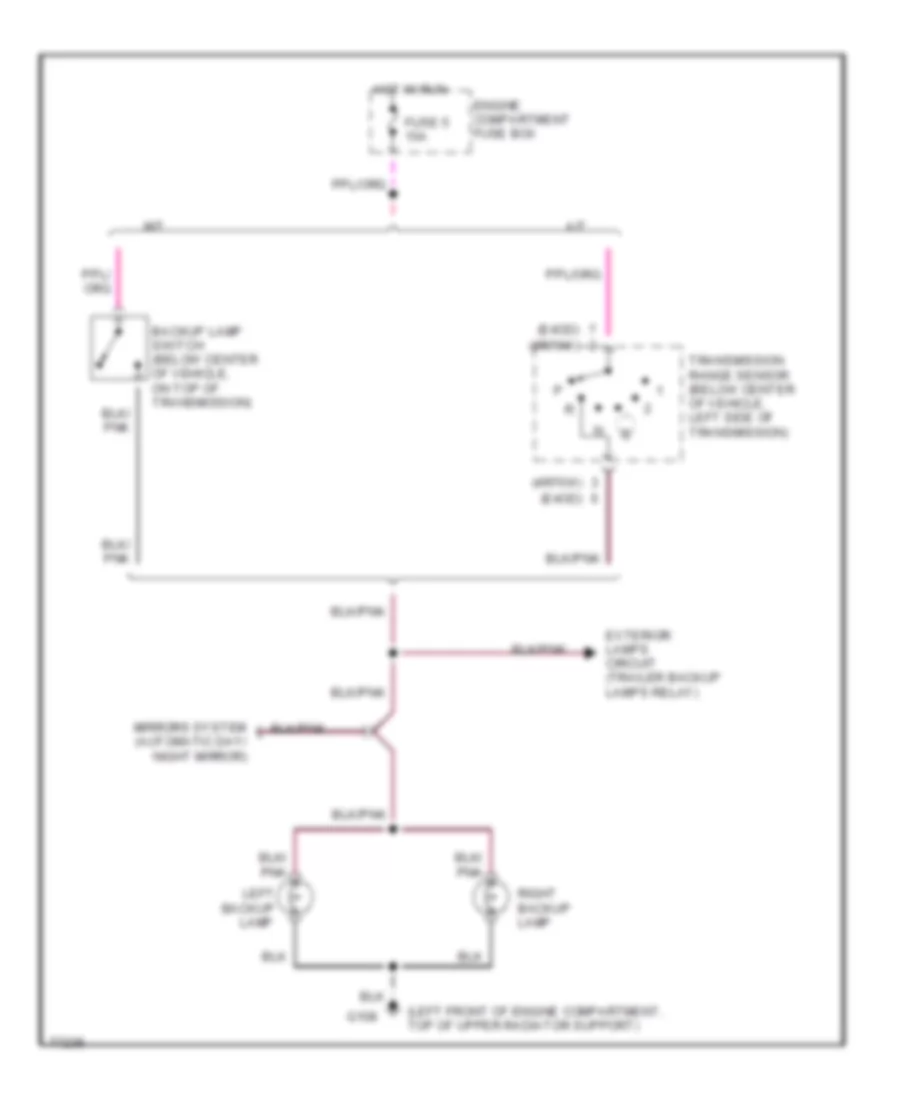
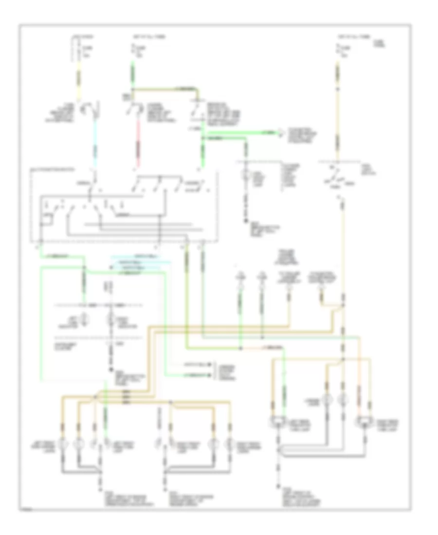
EXTERIOR LIGHTS Backup Lamps Wiring Diagram for Ford Bronco 1996 List of elements for Backup Lamps Wiring Diagram for Ford Bronco 1996: 17 (4r70w) (e4od) (left front of engine compartment, top of upper radiator support) A/t Backup Backup lamp switch (below center of vehicle, on top of transmission) Engine compartment fuse box Exterior lamps circuit (trailer backup lamps relay) Fuse 5 15a G108 Hot in run Lamp Left M/t Mirrors system (automatic day/ night mirror) Right backup lamp Transmission range sensor (below center of vehicle, left side of transmission) Exterior Lamps Wiring Diagram (1 of 2) for Ford Bronco 1996 List of elements for Exterior Lamps Wiring Diagram (1 of 2) for Ford Bronco 1996: 40 Brake on/ off switch (behind left side i/p, top left side of brake/clutch pedal support) C250 C251 Fuse 15a Fuse panel G101 (right front of engine compartment, on fender apron) G108 (left front of engine compart- ment, top of upper radiator support) G108 (left front of engine compartment, top of upper radiator support) G200 (behind bottom of left cowl panel) Hazard Hazard flasher (behind left side of i/p, on fuse panel) Head High mount stop lamp Hot at all times Hot in run Instrument cluster Left Left front park/turn lamp Left front side marker lamps Left rear park/stop/ turn lamp Left turn indicator License lamps Main light switch Mirrors system (muth mirrors) Multi-function switch Normal Off Outside cargo/ high mount stop lamps Park Right Right front park/turn lamp Right front side marker lamps Right rear park/stop/ turn lamp Right turn indicator To electric trailer brake control unit To electric trailer brake control unit (if equipped) To fuse To trailer marker lamps relay Trailer/ camper adapter (if equipped) Turn flasher (behind left side of i/p, on fuse panel) Exterior Lamps Wiring Diagram (2 of 2) for Ford Bronco 1996 List of elements for Exterior Lamps Wiring Diagram (2 of 2) for Ford Bronco 1996: 28 Backup lamp circuit Backup lamps Battery charge Electric brakes Electric trailer brake control unit (if equipped) Engine compartment fuse box From brake on/off switch From main light switch From multi- function switch Fuse 10a Fuse 15a Fuse 25a Fuse 30a G108 (left front of engine compartment, top of upper radiator support) G200 (behind bottom of left kick panel) G409 (under center rear of vehicle, on rear crossmember) Hot at all times Hot in run or start Left turn lamp Main light switch Marker lamps Red Right turn lamp Trailer backup lamps relay (in trailer relay box) Trailer battery charge relay (in trailer relay box) Trailer electrical connector Trailer ground Trailer marker lamps relay (in engine compartment fuse box)
GROUND DISTRIBUTION Ground Distribution Wiring Diagram (1 of 3) for Ford Bronco 1996 List of elements for Ground Distribution Wiring Diagram (1 of 3) for Ford Bronco 1996: 47 (w/4r70w (w/e4od 4 wabs control module 4 wabs data link connector 4 wabs relay #1 4wabs pump motor A/c clutch diode A/c clutch field coil Battery Brake fluid level switch C252 Data link connector Engine com- partment lamp Engine compartment fuse box Front park/ turn lamp Fuel pump module G101 (right front of engine compartment, on fender apron) G104 (rear of left fender apron) G108 (left front of engine compartment) G108 (left front of engine compartment, on upper radiator support) G119 (lower right front of engine) Instrument cluster Left backup lamp Left front side marker lamps Left headlamp Left rear park/ stop/ turn lamp License lamp Mass air flow (maf) sensor Nca Pcm power relay Powertrain control module Programmable speedometer/ odometer module Right backup lamp Right front park/ turn lamp Right front side marker lamps Right headlamp Right rear park/ stop/ turn lamp Trailer relay box Trailer backup lamps relay Trailer battery charge relay Trailer relay box Trailer/ marker lamps relay Transmission range (tr) sensor Transmission) W/ trailer tow Wind- shield wiper motor Windshield washer pump motor Ground Distribution Wiring Diagram (2 of 3) for Ford Bronco 1996 List of elements for Ground Distribution Wiring Diagram (2 of 3) for Ford Bronco 1996: 21 Air bag control module C211 C212 C217 C218 C241 C251 C252 C257 Electronic shift control module G203 (behind bottom of right cowl panel) Instrument cluster Nca Powertrain control module (pcm) Premium sound amplifier Programmable speedometer/ odometer module Radio Remote keyless entry module Speed control servo/ amplifier assembly W/ premium sound W/o premium sound Ground Distribution Wiring Diagram (3 of 3) for Ford Bronco 1996 List of elements for Ground Distribution Wiring Diagram (3 of 3) for Ford Bronco 1996: 46 (behind bottom of right cowl panel) * w/o remote keyless entry Ashtray illumination Auxiliary power socket Blower motor resistor Blower motor switch C242 C250 Captain chairs w/power lumbar bolster only Cigar lighter Compass/ outside temperature module Day/ night mirror autolamp sensor Electronic shift control module Electronic shift control switch G200 Glove compart- ment lamp Gnd Heater control illumination Ignition switch Inside cargo lamp Instrument cluster Left door courtesy lamp Left power lumbar compressor motor Left power mirror Master tailgate window switch Master window/door lock control switch Nca Outside cargo/ high mount stop lamp Power mirror switch Radio Rear window defrost control Remote keyless entry module Right front door courtesy lamp Right power lumbar compressor motor Right power mirror Right window/ door lock control switch Seat belt switch Shift lock actuator Trailer electronic brake control unit W/ electric day/night mirror only W/ power windows/locks W/ remote keyless entry W/ trailer tow only W/o power windows/locks Warning chime module Wiper control module
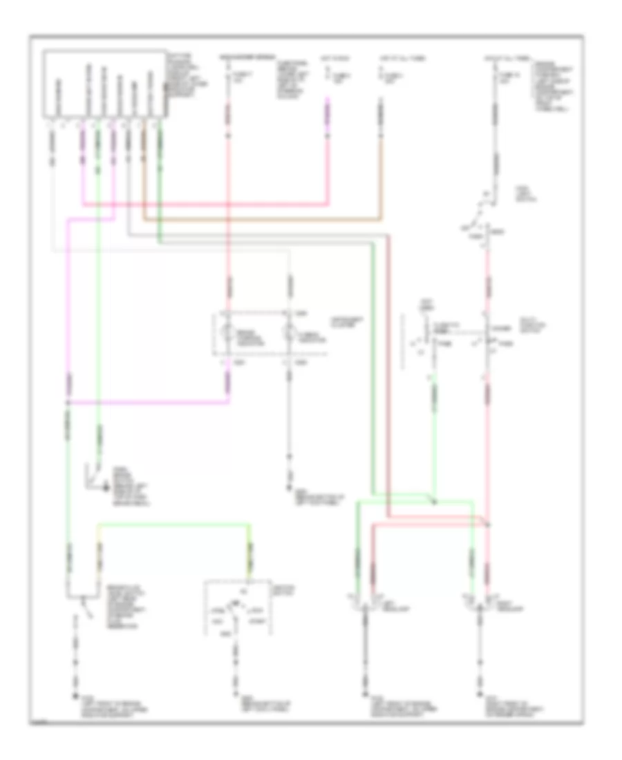
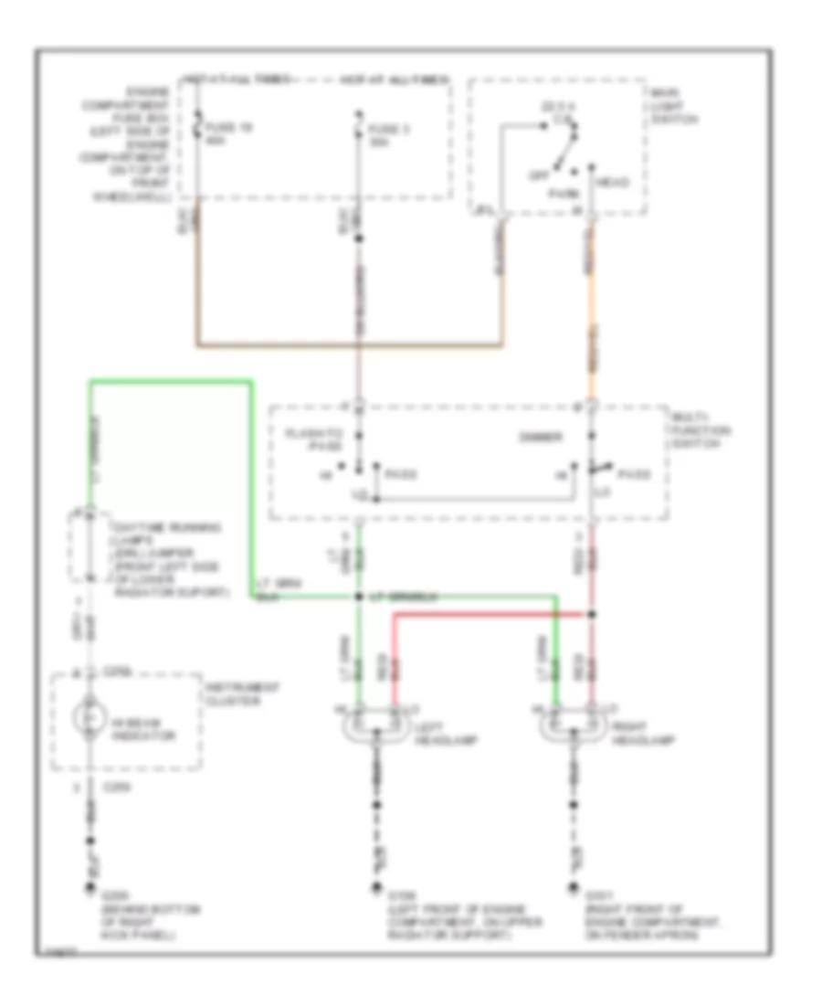
HEADLIGHTS Headlight Wiring Diagram, with DRL for Ford Bronco 1996 List of elements for Headlight Wiring Diagram, with DRL for Ford Bronco 1996: 46 (not used) 40a Acc Battery power Brake fluid level switch (left rear of engine compartment, on brake fluid reservoir) Brake warn in Brake warning indicator C250 C251 Daytime running lamps (drl) module (front left side of lower radiator support) Dimmer Engine compartment fuse box (left side of engine compartment, on top of front wheelwell) Flash-to- pass Fuse 17 10a Fuse 19 Fuse 3 30a Fuse 5 15a Fuse panel (behind lower left side of i/p, left of steering column) G101 (right front of engine compartment, on fender apron) G108 (left front of engine compartment, on upper radiator support) G200 (behind bottom of left cowl panel) G200 (behind bottom of left kick panel) Gnd Head Hi beam indicator Hi headlamp High beam ind Hot at all times Hot in run Hot in start or run Ignition switch Instrument cluster Left headlamp Lo headlamp Lock Main light switch Multi- function switch Off Park Park brake sw in Park brake switch (behind left side of i/p, top of park brake pedal) Pass Power (hot in run) Right headlamp Run Start Headlight Wiring Diagram, without DRL for Ford Bronco 1996 List of elements for Headlight Wiring Diagram, without DRL for Ford Bronco 1996: 22 22.5 a c.b. C250 Daytime running lamps (drl) jumper (front left side of lower radiator suport) Dimmer Engine compartment fuse box (left side of engine compartment, on top of front wheelwell) Flash-to -pass Fuse 19 40a Fuse 3 30a G101 (right front of engine compartment, on fender apron) G108 (left front of engine compartment, on upper radiator support) G200 (behind bottom of right kick panel) Head Hi beam indicator Hot at all times Instrument cluster Left headlamp Main light switch Multi- function switch Off Park Pass Right headlamp
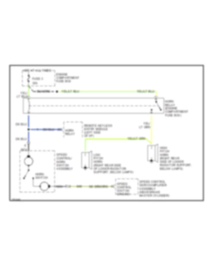
HORN Horn Wiring Diagram for Ford Bronco 1996 List of elements for Horn Wiring Diagram for Ford Bronco 1996: 14 30a Engine compartment fuse box Fuse 3 High pitch horn (right rear side of lower radiator support, below lamps) Horn relay Horn relay (engine compartment fuse box) Horn switch Hot at all times Low pitch horn (right rear side of lower radiator support, below lamps) Nca Remote keyless entry module (left side of i/p) Speed control servo/amplifier assembly (near brake master cylinder) Speed control switch ground Speed control/ horn switch assembly
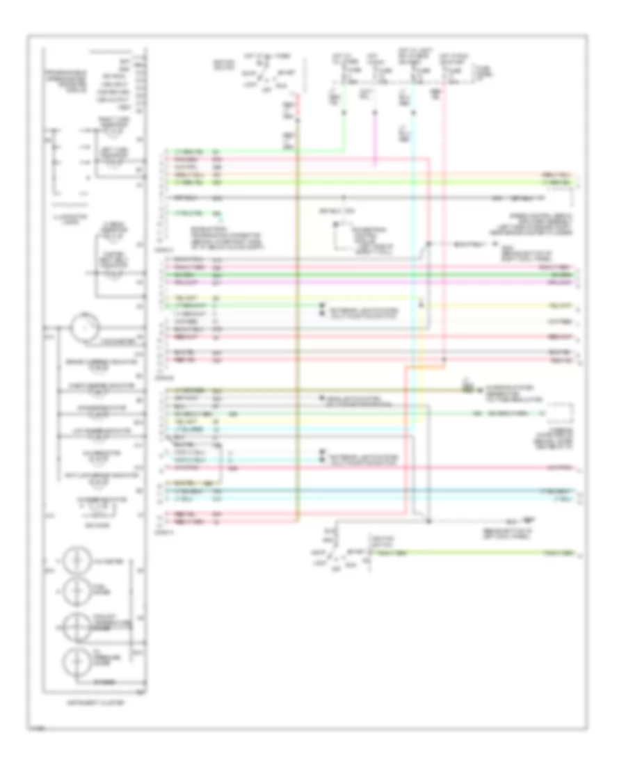
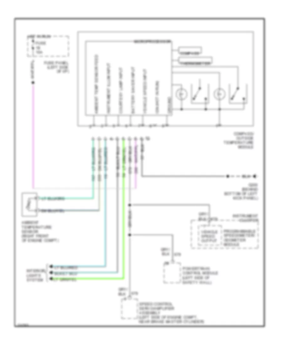
INSTRUMENT CLUSTER Instrument Cluster Wiring Diagram (1 of 2) for Ford Bronco 1996 List of elements for Instrument Cluster Wiring Diagram (1 of 2) for Ford Bronco 1996: 67 (behind bottom of left cowl panel) (behind lower right side of i/p, below glove compt) (left side of safety wall) 20 ohms 4x4 indicator 500 ohms A10 A11 A12 A13 A14 Acc Air bag indicator Anti-lock brake indicator B10 B12 B13 Bat Brake warning indicator Charge indicator Charging system (generator/ voltage regulator) Check engine indicator Conn a Conn b Conn c Control Coolant temperature gauge Enable psom programming connector Exterior lights system (multi-function switch) Fasten seat belt indicator Fuel gauge Fuse 10a Fuse 15a Fuse 4a Fuse panel: i/p G200 G203 (behind bottom of right cowl panel) Gnd Headlights system (multi-function switch) Hi beam indicator Hot at all times Hot in run Hot in run or start Hot w/ light sw in head or park Ign (run) Ignition switch Illumination lamps Instrument cluster Left turn indicator Lock Low range indicator Module Off Oil pressure gauge Powertrain Programmable speedometer/ odometer module Right turn indicator Run Speed control servo/ amplifier assembly (left side of engine compt, near brake master cylinder) Start Tachometer Test Voltmeter Vss input Vss output Vss return Warning chime module (behind lower center of i/p) Instrument Cluster Wiring Diagram (2 of 2) for Ford Bronco 1996 List of elements for Instrument Cluster Wiring Diagram (2 of 2) for Ford Bronco 1996: 27 (left front of engine compt, on upper radiator support) (left rear of engine compt, (rear of left fender apron) (top left front of engine) (top right side of fuel tank) 4wabs control module (left front corner of engine compt) 4x4 Air bag diagnostic monitor (behind left side of i/p) Brake fluid level switch (left rear of engine compt, on brake fluid reservoir) Coolant temperature sensor Data link connector (dlc) Daytime running lamps jumper Daytime running lamps module (front left side of lower radiator support) Electronic shift control module (behind right cowl panel) Electronic shift control switch Engine oil pressure switch (lower left rear of engine, near oil filter) Fuel pump module G104 G108 Ignition coil (left rear of engine, near intake manifold) Ignition control module (left rear of engine compartment, on fender apron) Nca On bracket) Park brake switch Powertrain control module (left side of safety wall) W/ drl W/o drl Overhead Console Wiring Diagram for Ford Bronco 1996 List of elements for Overhead Console Wiring Diagram for Ford Bronco 1996: 22 Ambient temp sensor feed Ambient temperature sensor (right front of engine compt) Battery saver input Compass Compass/ outside temperature module Courtesy lamp input Fuse 10a Fuse panel (left side of i/p) G200 (behind bottom of left kick panel) Ground Hot in run Ign (hot in run) Instrument cluster Instrument illum input Interior lights system Microprocessor Powertrain control module (left side of safety wall) Programmable speedometer/ odometer module Speed control servo/amplifier assembly (left side of engine compt, near brake master cylinder) Thermometer Vehicle speed input Vehicle speed output
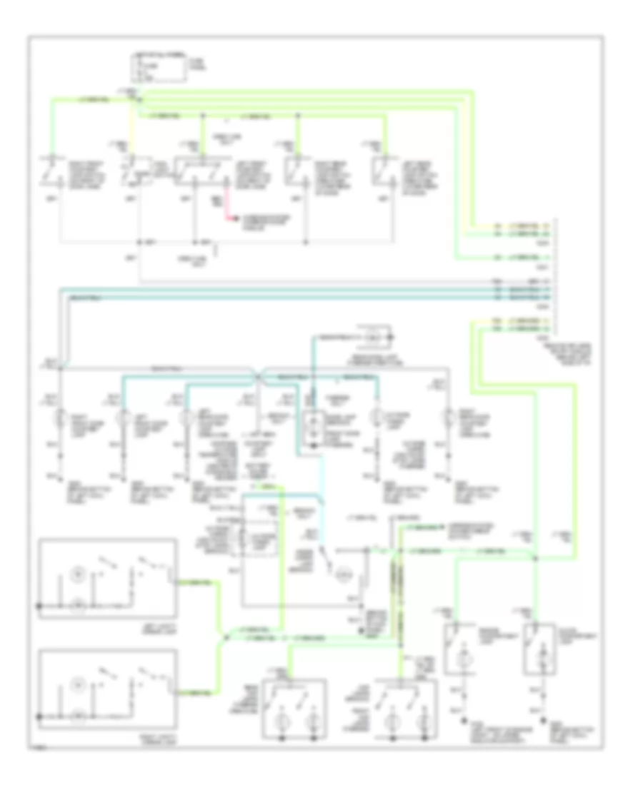
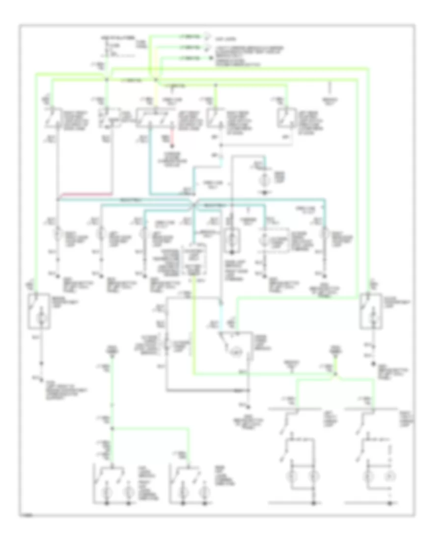
INTERIOR LIGHTS Courtesy Lamps Wiring Diagram, with Keyless Entry for Ford Bronco 1996 List of elements for Courtesy Lamps Wiring Diagram, with Keyless Entry for Ford Bronco 1996: 44 (behind bottom of kick panel) g200 Battery saver input Bronco only C240 C241 C242 C914 Compass/ outside temperature module (center of windshield header) Courtesy lamp input Crew cab only Dome Dome lamp (bronco) Engine compartment lamp F-series only Front dome lamp (f-series) Front map lamps (f-series) Fuse 15a Fuse panel G108 (left front of engine compt., on upper radiator support) G200 (behind bottom of left cowl panel) Glove compartment lamp Hot at all times Inside cargo lamp (bronco) Left front courtesy lamp switch (on front of door jamb) Left front door courtesy lamp Left rear courtesy lamp switch (crew-cab) (lower rear of door) Left rear door courtesy lamp (crew-cab) Left vanity mirror lamp Main light switch Map lamps (bronco) Mirrors system (power mirror switch) Outside cargo lamp Outside cargo/ high mount stop lamps (bronco) Outside cargo/ high mount stop lamps (f-series) Rear dome lamp (f-series crew-cab) Rear map lamps (f-series crew-cab) Red/ pnk Remote keyless entry module (behind left side of i/p) Right front courtesy lamp switch (on front of door jamb) Right front door courtesy lamp Right rear courtesy lamp switch (crew-cab) (lower rear of door) Right rear door courtesy lamp (crew-cab) Right vanity mirror lamp Warning system (warning chime module) Courtesy Lamps Wiring Diagram, without Keyless Entry for Ford Bronco 1996 List of elements for Courtesy Lamps Wiring Diagram, without Keyless Entry for Ford Bronco 1996: 43 Battery saver input Bronco only C914 Compass/ outside temperature module (center of windshield header) Courtesy lamp input Crew cab only Crew cab w/ xlt Dome Dome lamp (bronco) Engine compartment lamp F-series only From fuse 8 Front dome lamp (f-series) Front map lamps (f-series crew-cab) Fuse 15a Fuse panel G108 (left front of engine compartment, upper radiator support) G200 (behind bottom of left cowl panel) Glove compartment lamp Hot at all times Inside cargo lamp (bronco) Left front courtesy lamp switch (on front of door jamb) Left front door courtesy lamp Left rear courtesy lamp switch (crew-cab) (lower rear of door) Left rear door courtesy lamp Left vanity mirror lamp Main light switch Map lamps Map lamps (bronco) Mirror system (power mirror switch) Outside cargo lamp Outside cargo/ high mount stop lamps (bronco) Outside cargo/ high mount stop lamps (f-series) Rear dome lamp Rear map lamps (f-series crew-cab) Red/ pnk Right front courtesy lamp switch (on front of door jamb) Right front door courtesy lamp Right rear courtesy lamp switch (crew-cab) (lower rear of door) Right rear door courtesy lamp Right vanity mirror lamp Vanity mirrors (bronco & f-series) & compass/outside temp. module (bronco only) Warning system (warning chime module) Instrument Illumination Wiring Diagram for Ford Bronco 1996 List of elements for Instrument Illumination Wiring Diagram for Ford Bronco 1996: 36 (premium sound) (standard) Ashtray illumination Auxiliary power socket Bronco only C211 C250 C257 C267 C278 C914 Cigar lighter Compass/ outside temperature module Electronic shift control switch Exterior lights system Fuse 15a Fuse 4a Fuse panel G200 (behind bottom of left cowl panel) G203 (behind bottom of right cowl panel) Gnd Head Heater control illumination Hot at all times I/p feed I/p illum feed Ign Instrument cluster (5 bulbs) Main light switch Off Park Power distribution system (fuse panel) (fuse 11) Radio Rear window defrost control Sound systems (radio) W/ electronic shift control
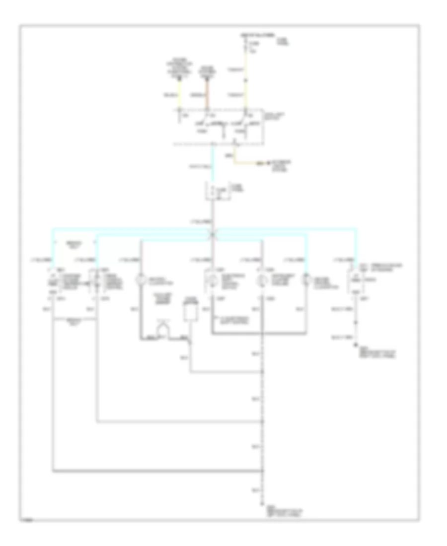
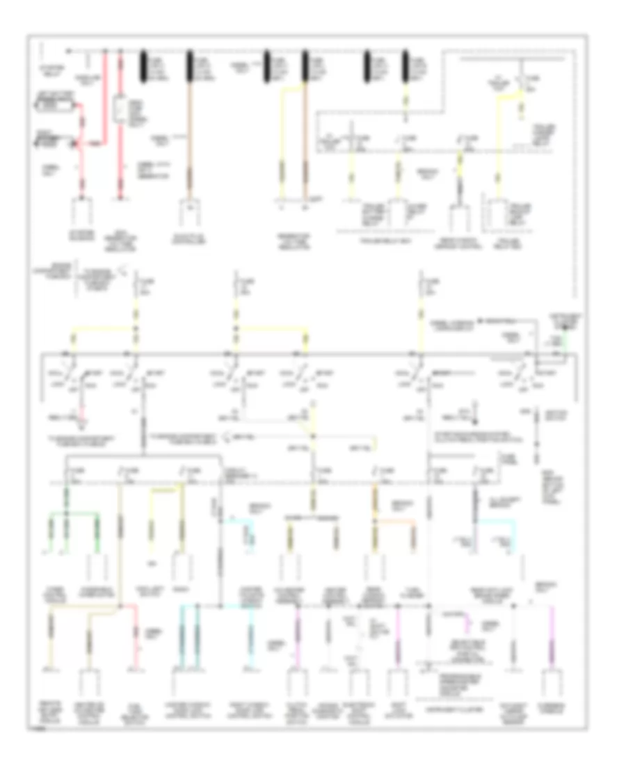
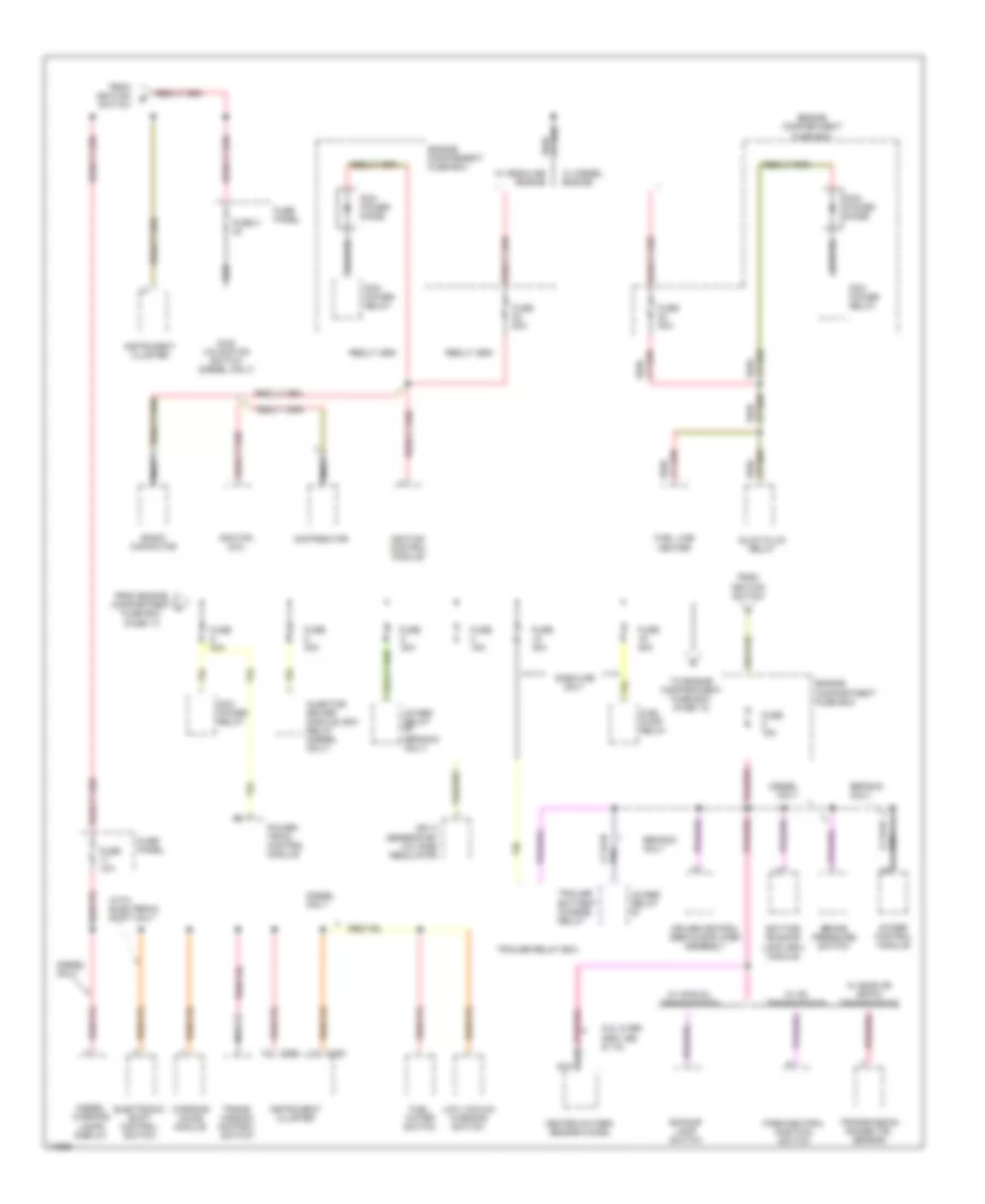
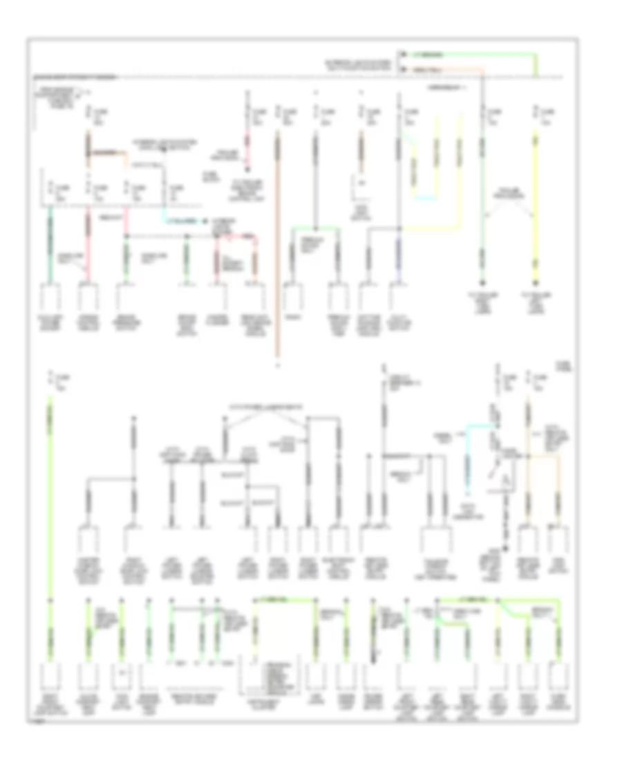
POWER DISTRIBUTION Power Distribution Wiring Diagram (1 of 3) for Ford Bronco 1996 List of elements for Power Distribution Wiring Diagram (1 of 3) for Ford Bronco 1996: 75 (behind bottom of left kick panel) 200a generator/ voltage regulator 4wabs relay #1 A/c-heater control assembly Acc Air bag diagnostic monitor All except bronco Bronco only C153 Circuit breaker 14 20a Clutch pedal position switch Day/night mirror autolamp sensor Diesel only Diesel warning lamps display Diesel with 200 a generator Electronic shift control module Engine compartment fuse box Fuel tank selector switch Fuse 10a Fuse 15a Fuse 20a Fuse 25a Fuse 30a Fuse 50a Fuse panel G200 Gasoline only Generator/ voltage regulator Glow plug controller Gnd Heater control assembly Heater or a/c-heater control module Ign Ignition switch Instrument cluster Instrument cluster system Left battery (diesel only) Lock Main light switch Master tailgate window switch Master window/ door lock control switch Mega fuse 300a (diesel only) Off Overhead console Programmable speedometer/ odometer module Radio Rear anti-lock brake (rabs) module Rear window defrost control Rear window defrost switch Red Remote keyless entry module Right battery Right window/ door lock control switch Run Selectable rpm control (partial connector) Shift lock actuator Sta Start Starter relay Starter solenoid Starting/charging system (clutch pedal position switch) To engine compartment fuse box (fuse 22) To engine compartment fuse box (fuse 5) To engine compartment fuse box (fuse 9) Trailer backup lamp relay Trailer battery charge relay Trailer relay box Trailer/ marker lamps relay Turn flasher W/ a/c W/ shift- on-the fly W/ trailer tow W/o a/c Windshield wiper motor Wiper control module Power Distribution Wiring Diagram (2 of 3) for Ford Bronco 1996 List of elements for Power Distribution Wiring Diagram (2 of 3) for Ford Bronco 1996: 59 (bronco only) 200 a generator/ voltage regulator 4wabs control module 4wabs relay #1 4wabs relay #2 5.8l over 8500 lbs & 7.5l Backup lamp switch Brake pressure switch Bronco only C250 C251 Cruise control servo/amplifier assembly Daytime running lamp (drl) module Diesel only Diesel warning lamps display Distributor Electronic shift control switch Engine comparment fuse box Engine compartment fuse box From engine compartment fuse box (fuse 17) From ignition switch Fuel line heater Fuel pump relay Fuel water switch Fuse 10a Fuse 15a Fuse 20a Fuse 3 3a Fuse 30a Fuse panel Gasoline only Glow plug relay Heated oxygen sensor (ho2s) Idle validation switch (diesel only) Ignition coil Ignition control module Injector driver module (idm) relay (diesel only) Instrument cluster Low vacuum warning switch Nca Park/neutral position switch Pcm power diode Pcm power relay Pnk Power- train control module Radio capacitor Red/ To engine compartment fuse box (fuse 13) Trailer battery charge relay Trailer relay box Trans- mission control switch Transmission range (tr) sensor W/ c6 transmission W/ diesel engine W/ e40d 0r 4r70w transmission W/ gasoline engine W/ manual transmission Warning chime module With electronic shift only Power Distribution Wiring Diagram (3 of 3) for Ford Bronco 1996 List of elements for Power Distribution Wiring Diagram (3 of 3) for Ford Bronco 1996: 77 (behind bottom of left kick panel) Air bag control module All except bronco Auxiliary power socket Brake on/off (boo) switch Brake pressure switch Bronco only C240 C241 Circuit breaker 12 20a Crew cab only Data link connector Daytime running lamp (drl) module Diesel only Electronic shift control module Engine compart- ment lamp Engine compartment fuse box Exterior lights system (multi-function switch) From engine compartment d fuse box (fuse 16) Fuse 10a Fuse 15a Fuse 20a Fuse 25a Fuse 30a Fuse 40a Fuse 4a Fuse 50a Fuse block Fuse panel G200 Gasoline only Glove compart- ment lamp Hazard flasher Horn relay Inside cargo lamp Instrument cluster Interior lights system Interior lights system (main light switch) Left front courtesy lamp switch Left power lumbar switch Left power lumbar/ bolster switch Left rear courtesy lamp switch Left vanity mirror lamp Lighter Main light switch Map lamps Master window/ door lock control switch Multi- function switch Nca Over- head console Power mirror switch Premium sound ampli- fier Premium sound only Program- mable speedo- meter/ odometer module Radio Rear anti- lock brake (rabs) module Red Remote keyless entry module Remote keyless entry module Right front courtesy lamp switch Right power lumbar switch Right rear courtesy lamp switch Right vanity mirror lamp Right window/ door lock control switch Tailgate window switch (key operated) To trailer electronic brake control unit To trailer left turn lamps To trailer right turn lamps Trailer provision Trailer provisions W/o remote keyless entry With captain's chair With cloth bench With power bolster With power lumbar seats With remote keyless entry With remote keyless entry only
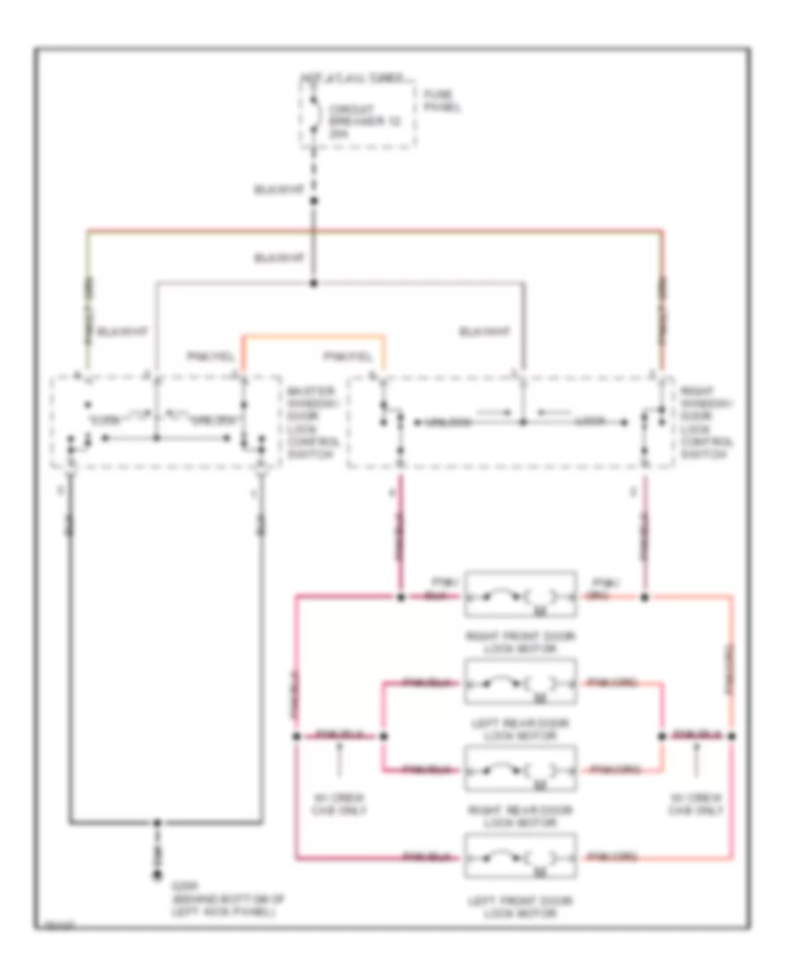
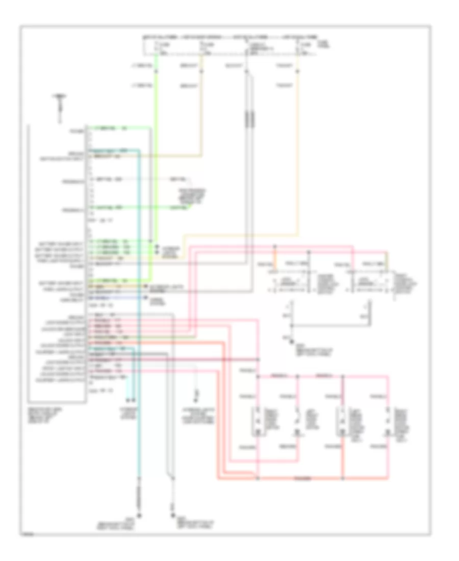
POWER DOOR LOCKS Door Lock Wiring Diagram for Ford Bronco 1996 List of elements for Door Lock Wiring Diagram for Ford Bronco 1996: 14 Circuit breaker 12 20a Fuse panel G200 (behind bottom of left kick panel) Hot at all times Left front door lock motor Left rear door lock motor Lock Master window/ door lock control switch Pnk/ Right front door lock motor Right rear door lock motor Right window/ door lock control switch Unlock W/ crew cab only Keyless Entry Wiring Diagram for Ford Bronco 1996 List of elements for Keyless Entry Wiring Diagram for Ford Bronco 1996: 44 (behind bottom of left cowl panel) (behind bottom of right cowl panel) Antenna Battery saver input Battery saver output C240 C241 C242 Circuit breaker 12 20a Courtesy lamps output Crtsy lamp sw input Exterior lights system Fuse 15a Fuse panel G200 G200 (behind bottom of left cowl panel) G203 Ground Horn relay Horns system Hot at all times Hot in accy or run Ignition switch input Interior lights system Interior lights system (door courtesy lamp switches) Left front door lock motor Left rear door lock motor (crew cab only) Lock doors output Lock input Lock unlock Master window/ door lock control switch Nca Park lamps output Power Program a Program b Remote keyless entry module (behind left side of i/p) Right front door lock motor Right rear door lock motor (crew cab only) Right window/ door lock control switch Rke program connector (behind left side of i/p) Unlock doors output Unlock driver's door Unlock input
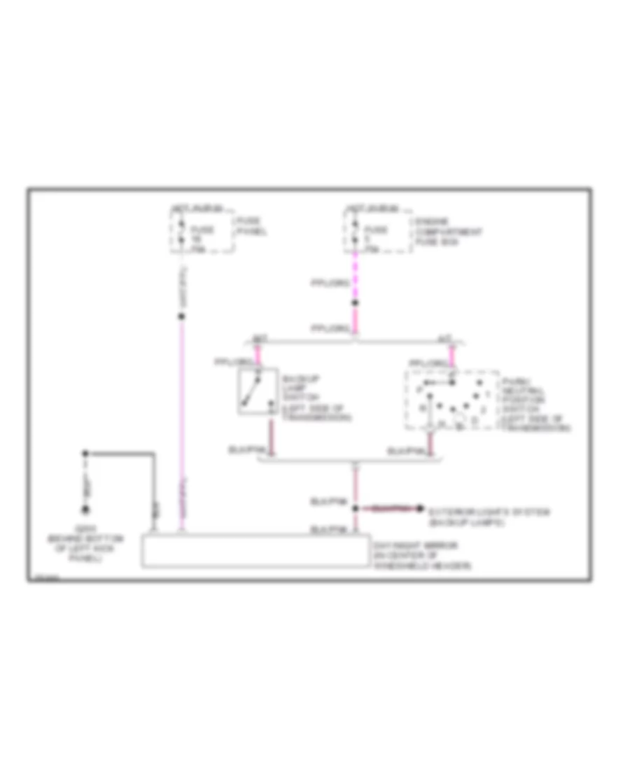
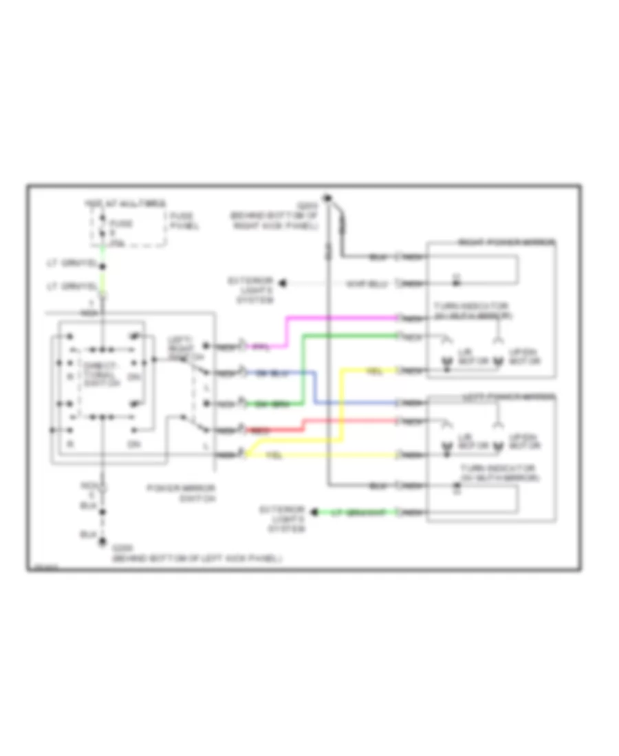
POWER MIRRORS Photochromic Mirror Wiring Diagram for Ford Bronco 1996 List of elements for Photochromic Mirror Wiring Diagram for Ford Bronco 1996: 12 A/t Backup lamp switch (left side of transmission) Day/night mirror (in center of windshield header) Engine compartment fuse box Exterior lights system (backup lamps) Fuse 10a Fuse 15a Fuse panel G200 (behind bottom of left kick panel) Hot in run M/t Park/ neutral position switch (left side of transmission) Power Mirror Wiring Diagram for Ford Bronco 1996 List of elements for Power Mirror Wiring Diagram for Ford Bronco 1996: 16 Direct- tional switch Exterior lights system Fuse 15a Fuse panel G200 (behind bottom of left kick panel) G200 (behind bottom of right kick panel) Hot at all times L/r motor Left power mirror Left/ right switch Nca Power mirror switch Red Right power mirror Turn indicator (w/ muth mirror) Up/dn motor
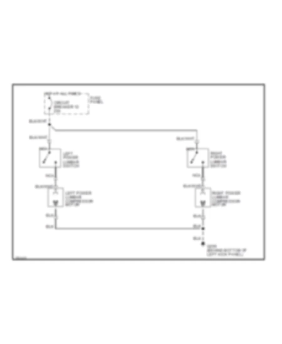
POWER SEATS Lumbar Wiring Diagram for Ford Bronco 1996 List of elements for Lumbar Wiring Diagram for Ford Bronco 1996: 9 Circuit breaker 12 20a Fuse panel G200 (behind bottom of left kick panel) Hot at all times Left power lumbar compressor motor Left power lumbar switch Nca Right power lumbar compressor motor Right power lumbar switch
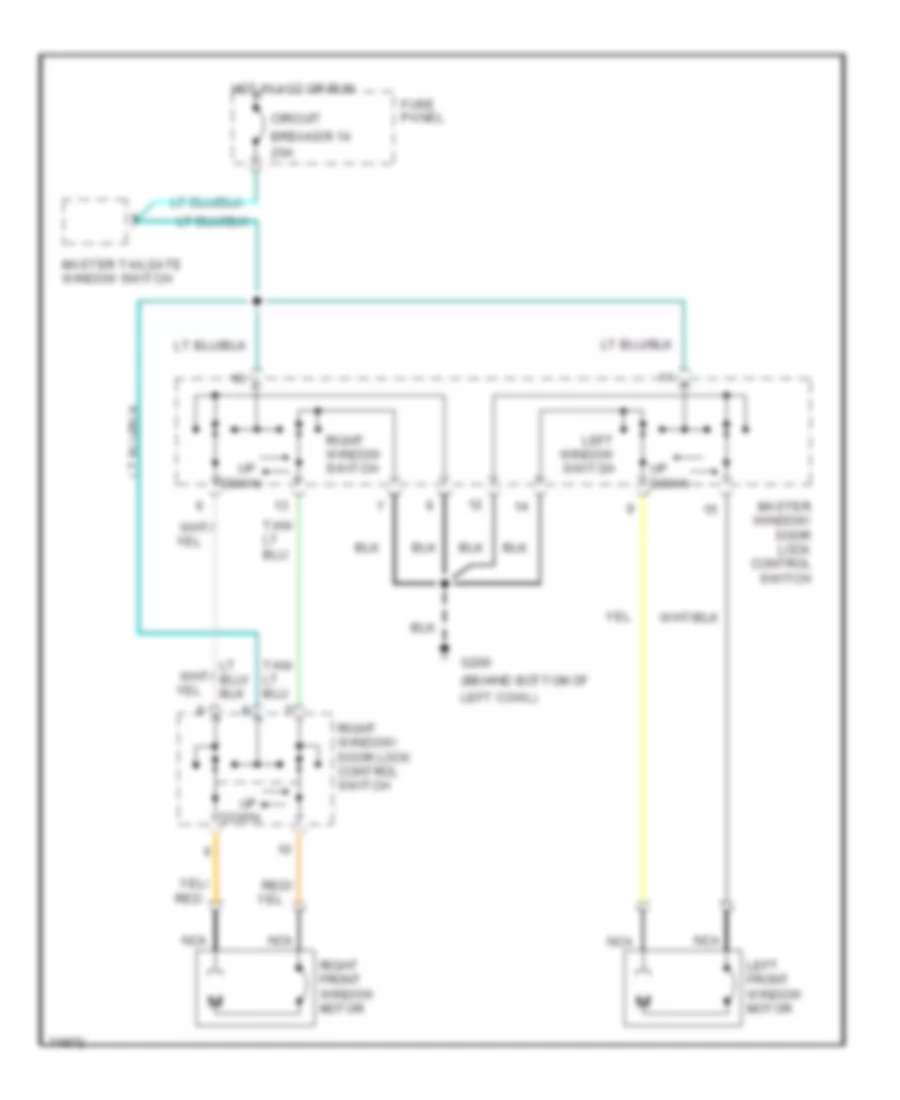
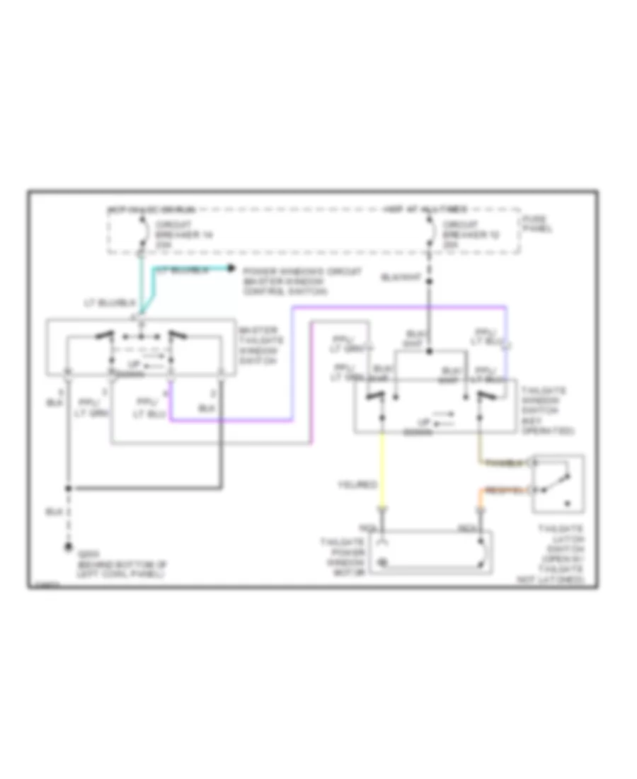
POWER WINDOWS Power Windows Wiring Diagram for Ford Bronco 1996 List of elements for Power Windows Wiring Diagram for Ford Bronco 1996: 20 (behind bottom of 20a Breaker 14 Circuit Down Fuse panel G200 Hot in acc or run Left cowl) Left front window motor Left window switch Master tailgate window switch Master window/ door lock control switch Nca Red Red/ Right front window motor Right window switch Right window/ door lock control switch Up down Tailgate Power Window Wiring Diagram for Ford Bronco 1996 List of elements for Tailgate Power Window Wiring Diagram for Ford Bronco 1996: 13 Circuit breaker 12 20a Circuit breaker 14 20a Down Fuse panel G200 (behind bottom of left cowl panel) Hot at all times Hot in acc or run Master tailgate window switch Nca Power windows circuit (master window control switch) Tailgate latch switch (open w/ tailgate not latched) Tailgate power window motor Tailgate window switch (key operated)
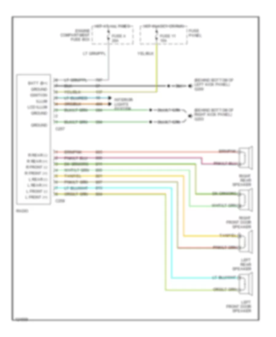
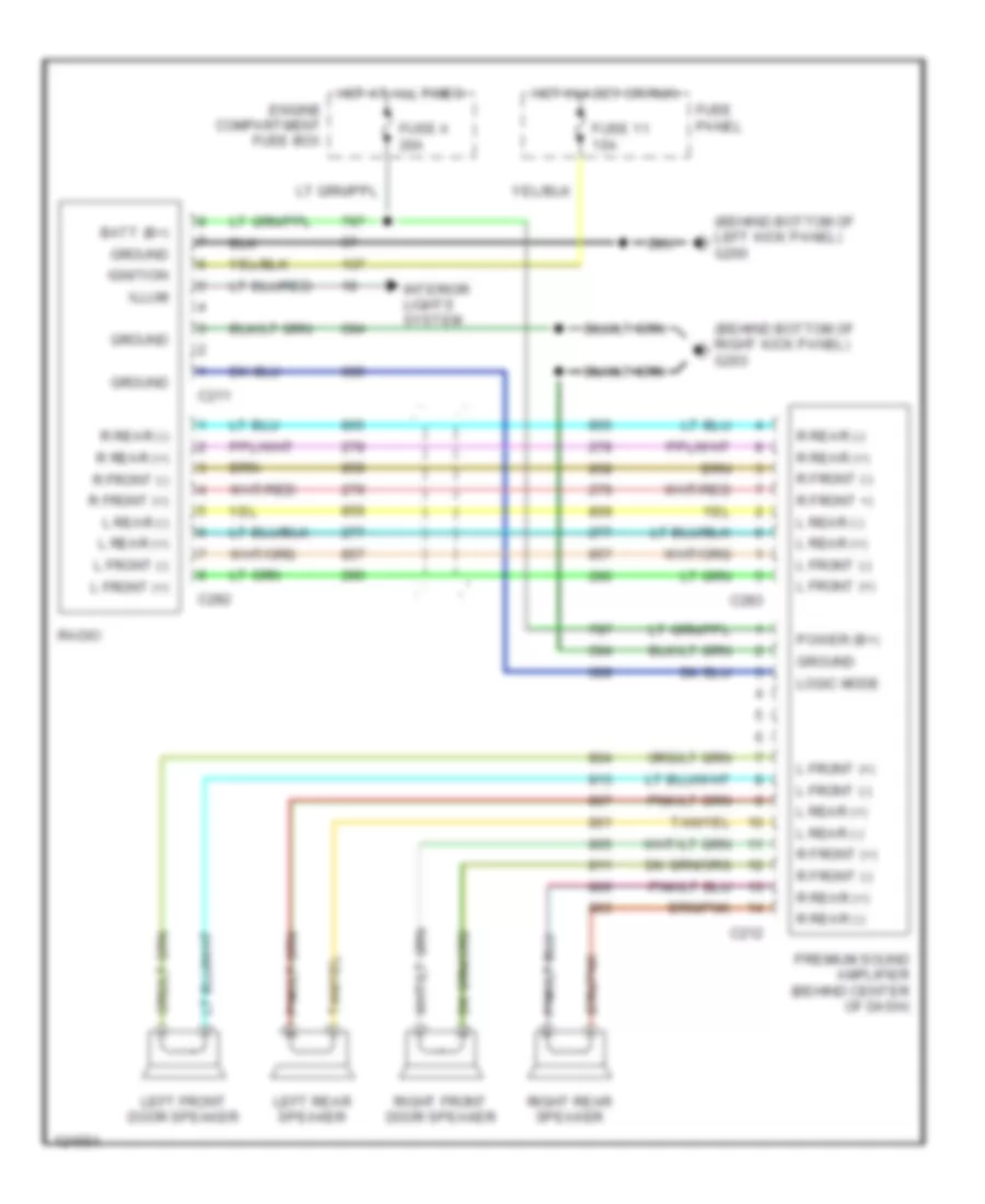
RADIO Base Radio for Ford Bronco 1996 List of elements for Base Radio for Ford Bronco 1996: 29 (behind bottom of left kick panel) g200 (behind bottom of right kick panel) g203 Batt (b+) C257 C258 Engine compartment fuse box Fuse 11 15a Fuse a 20a Fuse panel Ground Hot at all times Hot in accy or run Ignition Illum Interior lights system L front (+) L front (-) L rear (+) L rear (-) Lcd illum Left front door speaker Left rear speaker R front (+) R front (-) R rear (+) R rear (-) Radio Right front door speaker Right rear speaker Premium Sound Radio Wiring Diagram for Ford Bronco 1996 List of elements for Premium Sound Radio Wiring Diagram for Ford Bronco 1996: 34 (behind bottom of left kick panel) g200 (behind bottom of right kick panel) g203 Batt (b+) C211 C212 C282 C283 Engine compartment fuse box Fuse 11 15a Fuse a 20a Fuse panel Ground Hot at all times Hot in accy or run Ignition Illum Interior lights system L front (+) L front (-) L rear (+) L rear (-) Left front door speaker Left rear speaker Logic mode Power (b+) Premium sound amplifier (behind center of dash) R front (+) R front (-) R front +) R rear (+) R rear (-) Radio Right front door speaker Right rear speaker
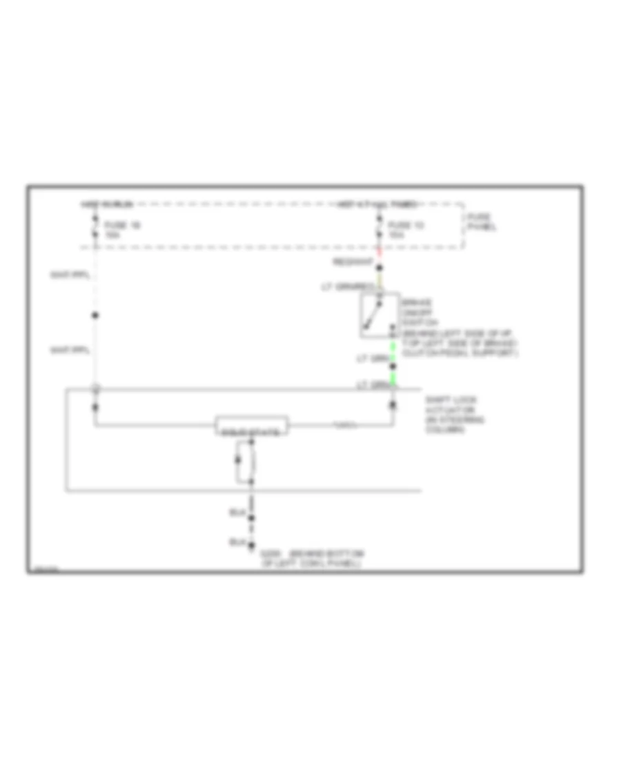
SHIFT INTERLOCKS Shift Interlock Wiring Diagram for Ford Bronco 1996 List of elements for Shift Interlock Wiring Diagram for Ford Bronco 1996: 12 (behind bottom (behind left side of i/p, top left side of brake/ clutch pedal support) Brake on/off switch Fuse 13 15a Fuse 18 10a Fuse panel G200 Hot at all times Hot in run Of left cowl panel) Shift lock actuator (in steering column) Solid state
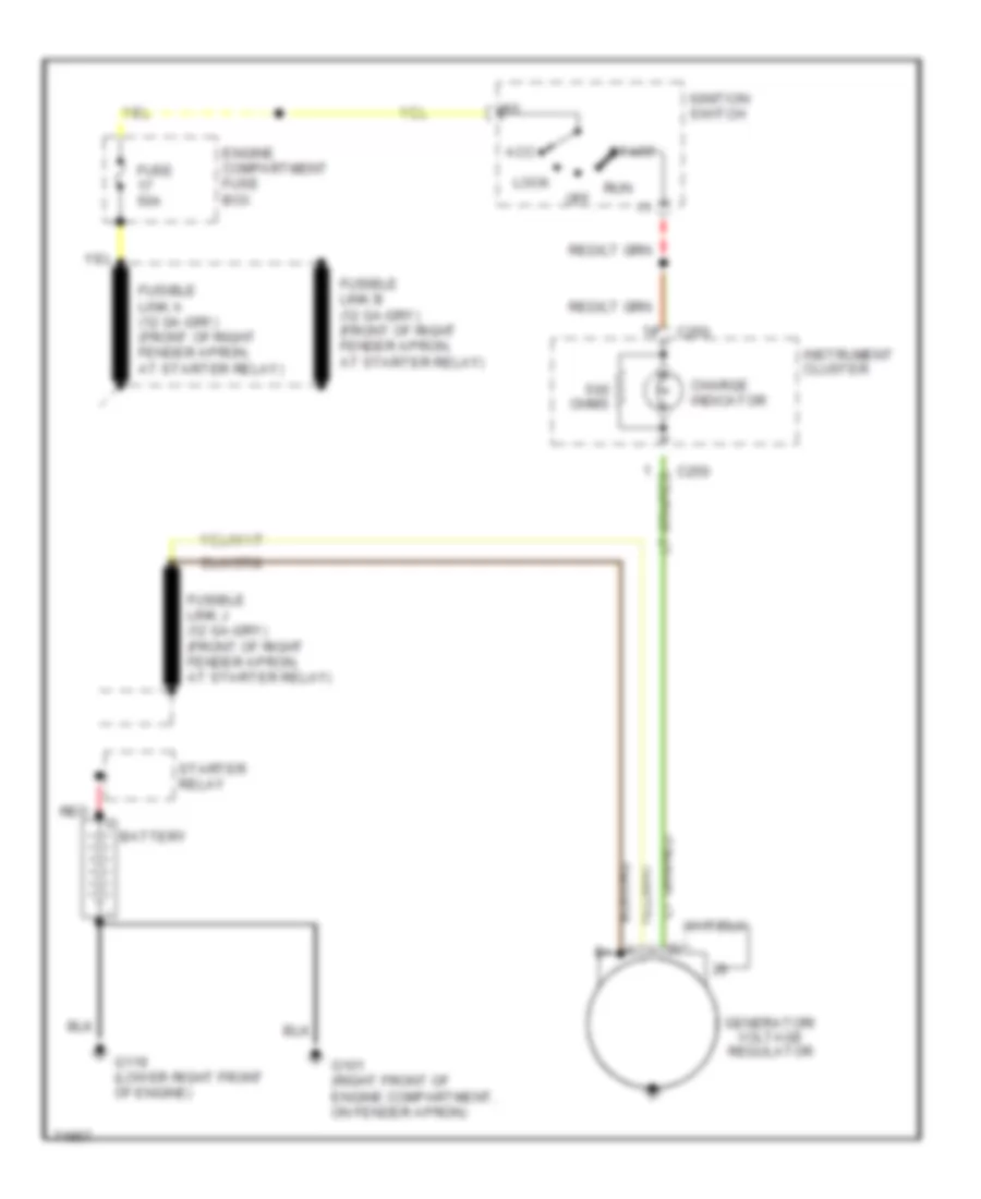
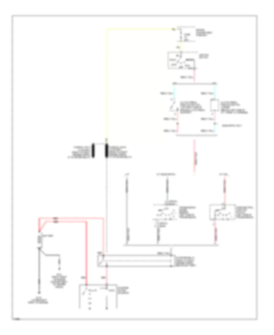
STARTING/CHARGING Charging Wiring Diagram for Ford Bronco 1996 List of elements for Charging Wiring Diagram for Ford Bronco 1996: 18 Acc Battery C250 Charge indicator Engine compartment fuse box Fuse 50a G101 (right front of engine compartment, on fender apron) G119 (lower right front of engine) Generator/ voltage regulator Ignition switch Instrument cluster Lock Off Ohms Red Run Start Starter relay Starting Wiring Diagram for Ford Bronco 1996 List of elements for Starting Wiring Diagram for Ford Bronco 1996: 30 (4r70w) (e40d) (lower right A/t A/t (c6) A/t (e40d/4r70w) Acc Battery Clutch pedal position switch (top right side of brake/clutch pedal support) Clutch pedal positon switch jumper (behind left side of i/p, taped to harness) E40d/4r70w only Engine compartment fuse box Front of engine) Fuse 20a G101 (right front of engine compartment, on fender apron) G119 Hold Ignition switch Lock M/t Off Park/neutral position switch (left side of transmission) Pull-in Red Run Sta Start Starter motor/ solenoid Starter relay (front of right fender apron, behind battery) Transmission range sensor (left side of transmission)
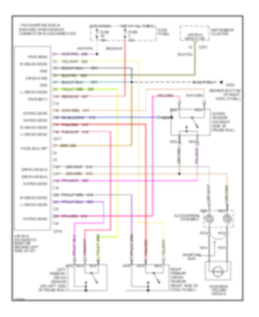
SUPPLEMENTAL RESTRAINTS Supplemental Restraint Wiring Diagram for Ford Bronco 1996 List of elements for Supplemental Restraint Wiring Diagram for Ford Bronco 1996: 31 (behind bottom of right cowl panel) * pin shorting bar is engaged when module connector is disconnected 10* 11* Air bag diagnostic monitor (behind left side of i/p) Air bag ind Air bag indicator C217 C218 C251 Clockspring assembly Drvr air bag Fuse 10a Fuse panel G203 Gnd Hot at all times Hot in run Instrument cluster L crash sens Left primary crash sensor (on left side of frame rail) Nca Pass bag off Pwr (bat) Pwr (run) R crash sens Right primary crash sensor (right side of cowl panel) Safing sens Safing sensor (on right side of frame rail) Shorting bar Steering column air bag
TRANSMISSION
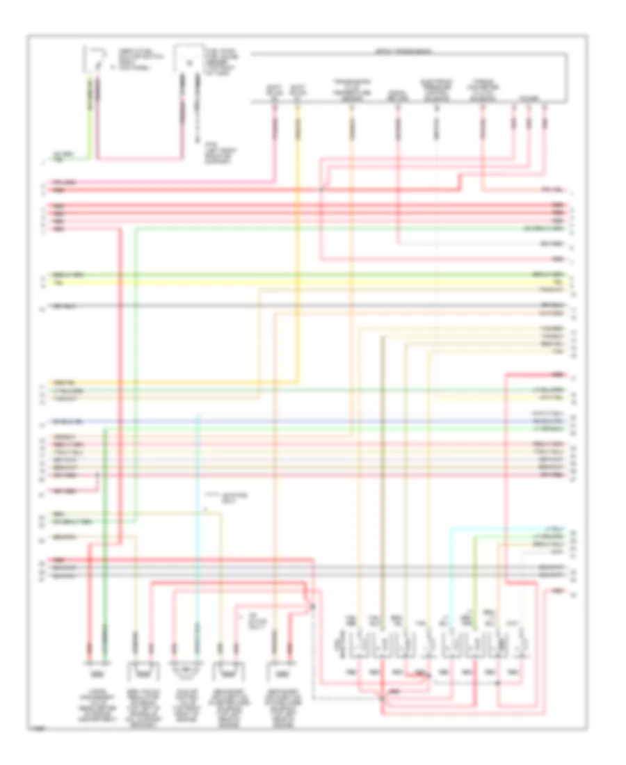
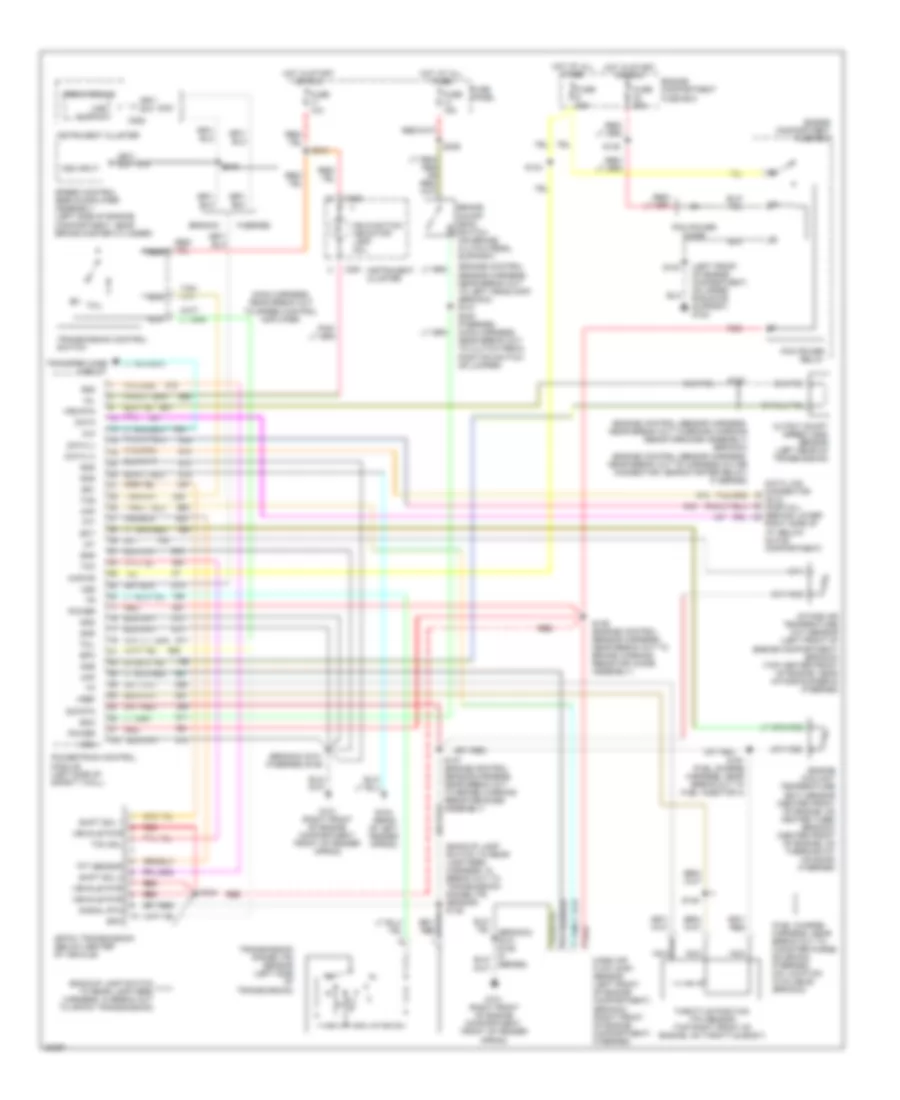
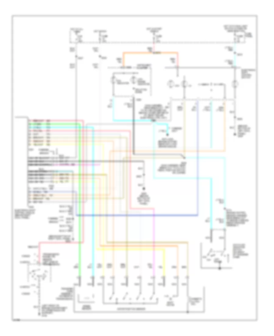
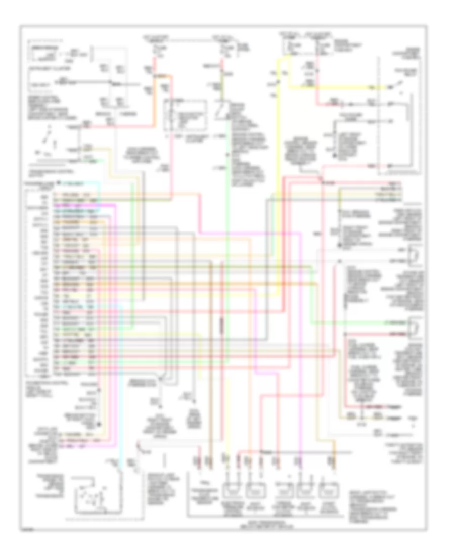
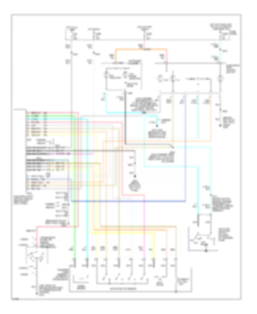
5.0L 5.0L, 4R7OW Transmission Wiring Diagram for Ford Bronco 1996 List of elements for 5.0L, 4R7OW Transmission Wiring Diagram for Ford Bronco 1996: 90 (backup lamp switch to rear lamp feed harness, in break out to 4r70w transmission) (backup lamp switch to rear lamp feed harness, in break out to transmission range (tr) sensor) s146 (bronco) s101 (f-series) s106 (engine control sensor harness, near break out to brake warning resistor/diode assembly) (bronco) (engine control sensor harness, near break out to harness in-line connector, near starter relay) (f series) (engine control sensor harness, near break out to left headlamp) (bronco) s121 (fuel charge harness, near break out to canister purge solenoid) (f-series) (no location available) (bronco) (left front of engine compartment, on upper radiator support) g108 (main harness, near break out to speed control amplifier) 4r70w transmission (below center of vehicle) 4x4 Boo Brake on/off (boo) switch (on brake/ clutch pedal support) Bronco C250 C251 C252 Data Data (+) Data (-) Data link connector (dlc) (partial) (behind lower right side of i/p, below glove compartment) Ect Engine compartment fuse box Engine coolant temperature (ect) sensor (center front of engine, on heater tube) (bronco) (center front of engine, on thermostat housing) (f-series) Epc F-series Fuse 10a Fuse 15a Fuse 20a Fuse 30a Fuse panel G101 (right front of engine compartment, front of fender apron) G104 (rear of left fender apron) Gnd Hot at all times Hot in start or run Iat Instrument cluster Intake air temperature (iat) sensor (left front of engine compartment) (bronco) (top center front of engine, near intake runner 6) (f-series) Kapwr Maf Malfunction indicator lamp (mil) Mass air flow (maf) sensor (left front of engine compartment) (bronco) (right front of engine compartment) (f-series) Mil N d Nca Oss Output shaft speed (oss) sensor (left rear of transmission) Pcm power diode Pcm power relay Power Powertrain control module (left side of safety wall) Psom module Red S102 S104 S124 S127 S135 S136 (engine control sensor harness, near break out to brake warning resistor/ diode assembly) S137 (engine control sensor harness, near break out to brake warning resistor/diode assembly) S148 S161 (fuel charge harness, near break out to fuel injector 4) S215 S236 S240 (f-series) (main harness, near break out to clutch pedal position switch or jumper) S246 Series) Shift sol 1 Shift sol 2 Sig rtn Signal rtn Speed control servo/amplifier assembly (left side of engine compartment, near brake master cylinder) Ss1 Ss2 Tcc Tcc sol Tcil Tcs Tft Tft sensor Throttle position (tp) sensor (top right front of engine, on throttle body) Transfer case circuit Transmission control switch Transmission range (tr) sensor (left side of transmission) Vehicle pwr Vref Vrs rtn Vss Vss input Vss output 5.0L, E4OD Transmission Wiring Diagram for Ford Bronco 1996 List of elements for 5.0L, E4OD Transmission Wiring Diagram for Ford Bronco 1996: 91 (back lamp switch harness, in break out to transmission) (bronco) (transmission harness, near break out to e40d transmission) (f-series) (backup lamp switch to rear lamp feed harness, in break out to transmission range (tr) sensor) (behind bottom of right cowl panel) g203 (bronco) s101 (f-series) s106 (engine control sensor harness, near break out to brake warning resistor/diode assembly) (engine control sensor harness, near break out to left headlamp) (bronco) s121 (fuel charge harness, near break out to canister purge solenoid) (f-series) (no location available) (bronco) (left front of engine compartment, on upper radiator support) g108 (main harness, near break out to speed control amplifier) (right front of engine, compartment, front of fender apron) g101 4x4 Boo Brake on/off (boo) switch (on brake/ clutch pedal support) Bronco C250 C251 C252 Ccs Coast clutch solenoid Data (+) Data (-) Data feps Data link connector (dlc) (partial) (behind lower right side of i/p, below glove compartment) E40d transmission (below center of vehicle) Ect Electronic pressure control solenoid Engine compartment fuse box Engine coolant temperature (ect) sensor (center front of engine, on heater tube) (bronco) (center front of engine, on thermostat housing) (f-series) Epc F-series Fuse 10a Fuse 15a Fuse 20a Fuse 30a Fuse panel G101 (right front of engine compartment, front of fender apron) G104 (rear of left fender apron) Gnd Hot at all times Hot in start or run Iat Instrument cluster Intake air temperature (iat) sensor (left front of engine compartment) (bronco) (top center front of engine, near intake runner 6) (f-series) Kapwr Maf Malfunction indicator lamp (mil) Mass air flow (maf) sensor (left front of engine compartment) (bronco) (right front of engine compartment) (f-series) Mil N d Nca Pcm power diode Pcm power relay Power Powertrain control module (left side of safety wall) Psom module Red S101 (bronco) s106 (f-series) S102 S104 S135 S136 S137 (engine control sensor harness, near break out to brake warning resistor/ diode assembly) S146 S148 S161 (fuel charge harness, near break out to fuel injector 4) S169 S215 S216 S236 S240 (f-series) (main harness, near break out to clutch pedal position switch or jumper) S246 Shift solenoid Sig rtn Speed control servo/amplifier assembly (left side of engine compartment, near brake master cylinder) Ss1 Ss2 Tcc Tcil Tcs Tft Throttle position (tp) sensor (top right front of engine, on throttle body) Torque converter clutch solenoid Transfer case circuit Transmission control switch Transmission fluid temperature sensor Transmission range (tr) sensor (left side of transmission) Vref Vss Vss gnd Vss input Vss output Transfer Case Wiring Diagram for Ford Bronco 1996 List of elements for Transfer Case Wiring Diagram for Ford Bronco 1996: 51 (behiind bottom of left cowl panel) g200 (behind bottom of right cowl panel) g203 (left front of engine compartment, on upper radiator support) g108 (main harness, near break out to clutch pedal position switch or jumper) (main harness, near break out to in-line connector, behind lower center of i/p, near trailer electronic ctrl unit) s244 4x2 4x4 4x4 hi/low indicator switch (on front of transfer case) 4x4 indicator Anti-lock brakes system (rear anti-lock brake module) Bronco C.b. 20a C221 C222 C223 C250 Electronic shift control module (behind right cowl panel) Electronic shift control switch F-series F-series only Fuse 10a Fuse 4a Fuse panel G200 (behind bottom of left cowl panel) Hot at all times Hot in run Hot in start or run Hot with main light switch in park or head position Instrument cluster Isolation diode Low range Low range indicator Magnetic clutch coil Motor position sensor Nca S174 (engine control sensor harness, near break out to brake warning resistor/diode assembly) S202 S203 S210 S215 S218 S237 S242 S245 S258 Shift motor Speed sensor Transfer case assembly (on rear of transmission) Transmission range (tr) sensor (left side of transmission) W/4r70w W/e40d
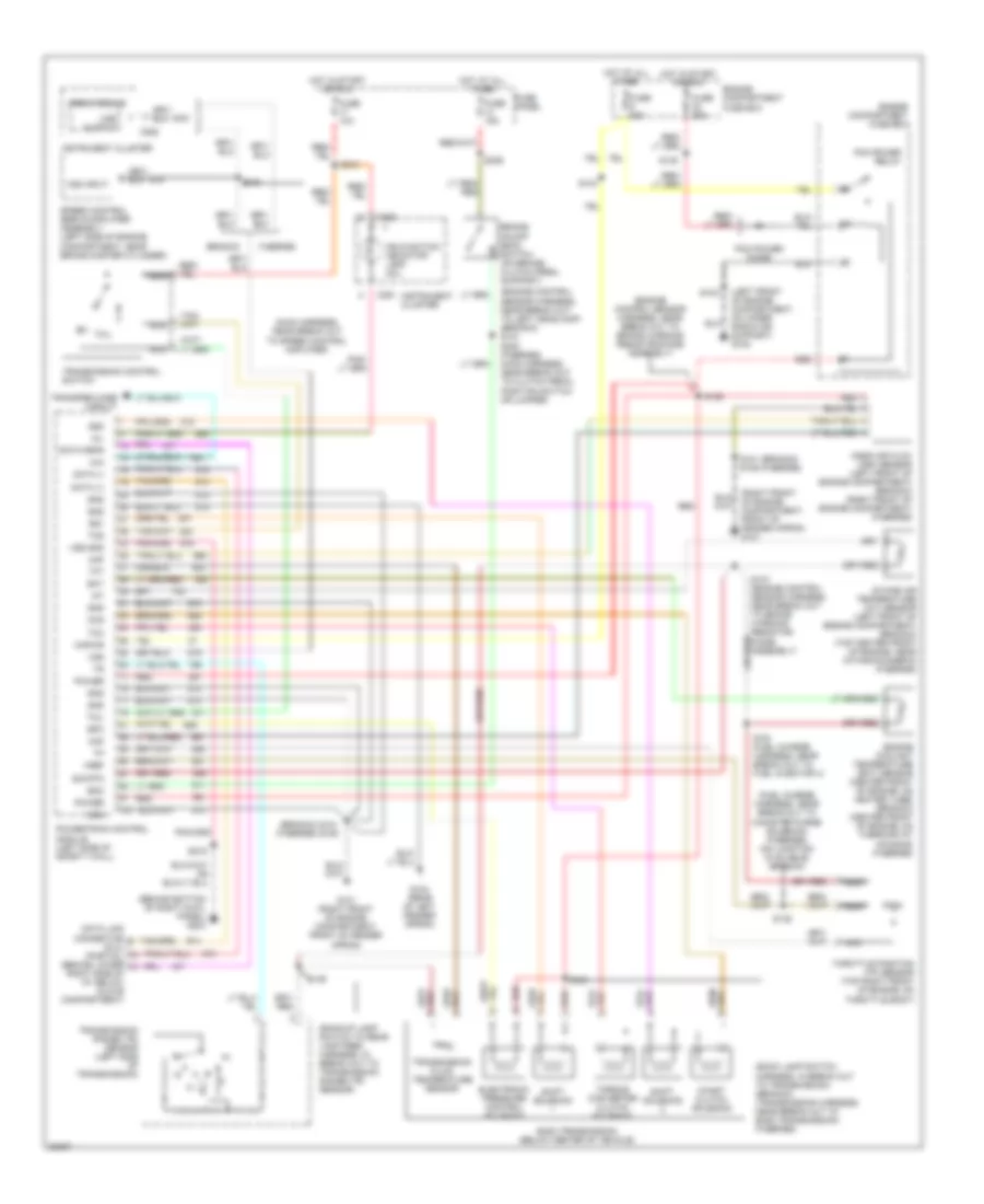
5.8L 5.8L, Transmission Wiring Diagram for Ford Bronco 1996 List of elements for 5.8L, Transmission Wiring Diagram for Ford Bronco 1996: 91 (back lamp switch harness, in break out to transmission) (bronco) (transmission harness, near break out to e40d transmission) (f-series) (backup lamp switch to rear lamp feed harness, in break out to transmission range (tr) sensor) (behind bottom of right cowl panel) g203 (bronco) s101 (f-series) s106 (engine control sensor harness, near break out to brake warning resistor/diode assembly) (engine control sensor harness, near break out to left headlamp) (bronco) s121 (fuel charge harness, near break out to canister purge solenoid) (f-series) (no location available) (bronco) (left front of engine compartment, on upper radiator support) g108 (main harness, near break out to speed control amplifier) (right front of engine, compartment, front of fender apron) g101 4x4 Boo Brake on/off (boo) switch (on brake/ clutch pedal support) Bronco C250 C251 C252 Ccs Coast clutch solenoid Data (+) Data (-) Data feps Data link connector (dlc) (partial) (behind lower right side of i/p, below glove compartment) E40d transmission (below center of vehicle) Ect Electronic pressure control solenoid Engine compartment fuse box Engine coolant temperature (ect) sensor (center front of engine, on heater tube) (bronco) (center front of engine, on thermostat housing) (f-series) Epc F-series Fuse 10a Fuse 15a Fuse 20a Fuse 30a Fuse panel G101 (right front of engine compartment, front of fender apron) G104 (rear of left fender apron) Gnd Hot at all times Hot in start or run Iat Instrument cluster Intake air temperature (iat) sensor (left front of engine compartment) (bronco) (top center front of engine, near intake runner 6) (f-series) Kapwr Maf Malfunction indicator lamp (mil) Mass air flow (maf) sensor (left front of engine compartment) (bronco) (right front of engine compartment) (f-series) Mil N d Nca Pcm power diode Pcm power relay Power Powertrain control module (left side of safety wall) Psom module Red S101 (bronco) s106 (f-series) S102 S104 S135 S136 S137 (engine control sensor harness, near break out to brake warning resistor/ diode assembly) S146 S148 S161 (fuel charge harness, near break out to fuel injector 4) S169 S215 S216 S236 S240 (f-series) (main harness, near break out to clutch pedal position switch or jumper) S246 Shift solenoid Sig rtn Speed control servo/amplifier assembly (left side of engine compartment, near brake master cylinder) Ss1 Ss2 Tcc Tcil Tcs Tft Throttle position (tp) sensor (top right front of engine, on throttle body) Torque converter clutch solenoid Transfer case circuit Transmission control switch Transmission fluid temperature sensor Transmission range (tr) sensor (left side of transmission) Vref Vss Vss gnd Vss input Vss output Transfer Case Wiring Diagram for Ford Bronco 1996 List of elements for Transfer Case Wiring Diagram for Ford Bronco 1996: 51 (behiind bottom of left cowl panel) g200 (behind bottom of right cowl panel) g203 (left front of engine compartment, on upper radiator support) g108 (main harness, near break out to clutch pedal position switch or jumper) (main harness, near break out to in-line connector, behind lower center of i/p, near trailer electronic ctrl unit) s244 4x2 4x4 4x4 hi/low indicator switch (on front of transfer case) 4x4 indicator Anti-lock brakes system (rear anti-lock brake module) Bronco C.b. 20a C221 C222 C223 C250 Electronic shift control module (behind right cowl panel) Electronic shift control switch F-series F-series only Fuse 10a Fuse 4a Fuse panel G200 (behind bottom of left cowl panel) Hot at all times Hot in run Hot in start or run Hot with main light switch in park or head position Instrument cluster Isolation diode Low range Low range indicator Magnetic clutch coil Motor position sensor Nca S174 (engine control sensor harness, near break out to brake warning resistor/diode assembly) S202 S203 S210 S215 S218 S237 S242 S245 S258 Shift motor Speed sensor Transfer case assembly (on rear of transmission) Transmission range (tr) sensor (left side of transmission) W/4r70w W/e40d
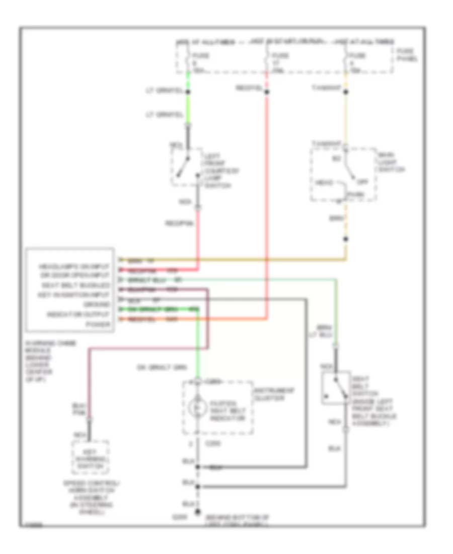
WARNING SYSTEMS Warning System Wiring Diagrams for Ford Bronco 1996 List of elements for Warning System Wiring Diagrams for Ford Bronco 1996: 29 (behind bottom of left cowl panel) (inside left front seat belt buckle assembly) C250 Dr door open input Fasten seat belt indicator Fuse 10a Fuse 15a Fuse panel G200 Ground Head Headlamps on input Hot at all times Hot in start or run Indicator output Instrument cluster Key in ignition input Key warning switch Left front courtesy lamp switch Main light switch Nca Off Park Power Red/pnk Seat belt buckled Seat belt switch Speed control/ horn switch assembly (in steering wheel) Warning chime module (behind lower center of i/p)
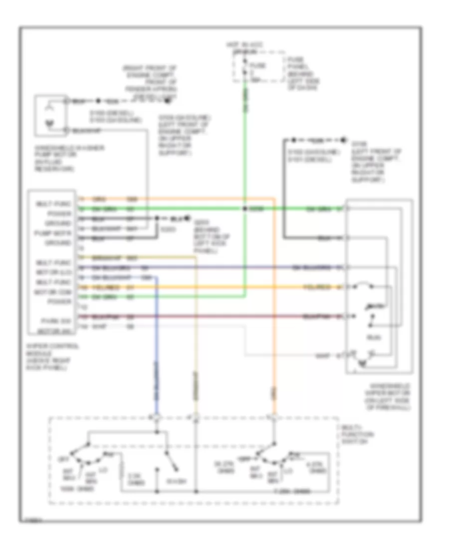
WIPER/WASHER Wiper/Washer Wiring Diagram for Ford Bronco 1996 List of elements for Wiper/Washer Wiring Diagram for Ford Bronco 1996: 35 (right front of engine compt, front of fender apron) (diesel) g101 100k ohms 3.3k ohms 4.07k 7.25k Fuse 30a Fuse panel (behind left side of dash) G108 (gasoline) (left front of engine compt, on upper radiator support) G108 (left front of engine compt, on upper radiator support) G200 (behind bottom of left kick panel) Ground Hot in acc or run Int max Int min Motor (hi) Motor (lo) Motor com Mult-func Multi- function switch Off Off 36.27k ohms Ohms Park Park sw Power Pump motr Run S100 (diesel) s103 (gasoline) S102 (gasoline) s101 (diesel) S203 S238 Wash Windshield washer pump motor (in fluid reservoir) Windshield wiper motor (on left side of firewall) Wiper control module (above right kick panel)