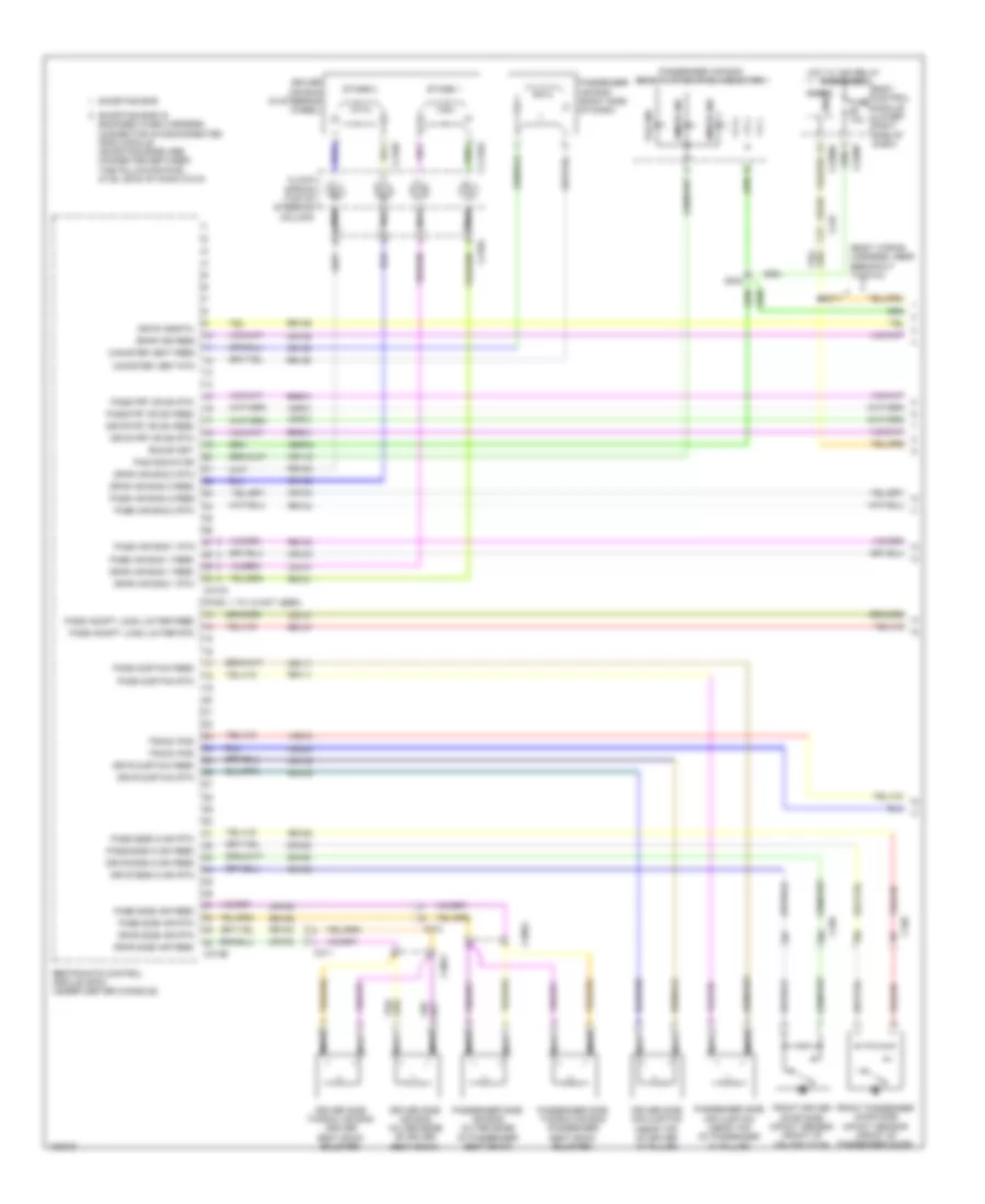
AIR CONDITIONING
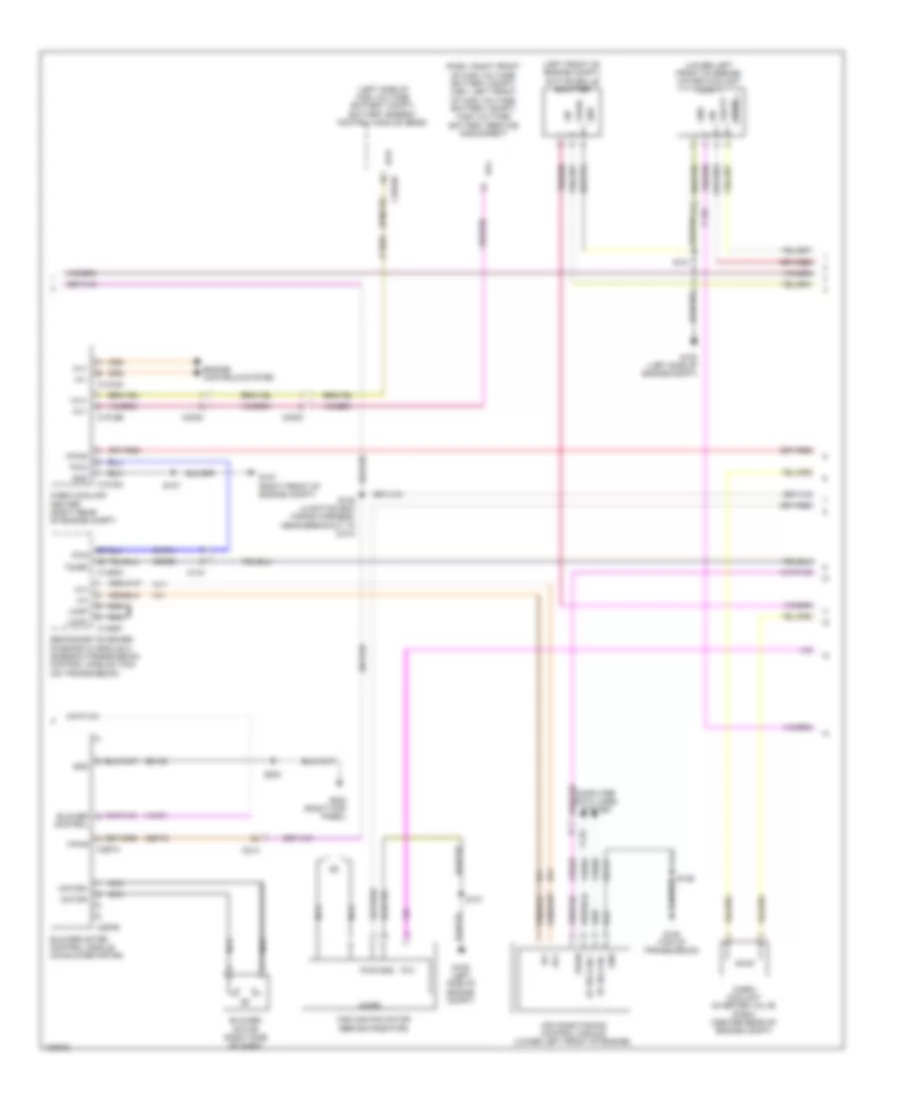
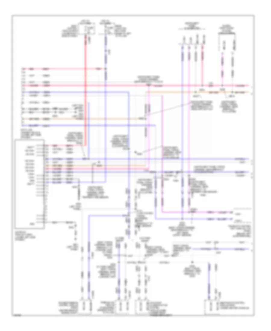
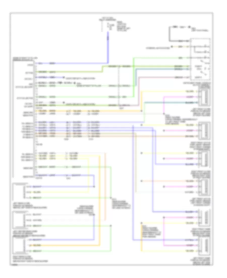
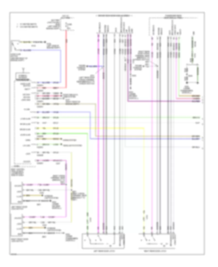
Automatic A/C Wiring Diagram (1 of 3) for Ford C-Max Hybrid SEL 2014

List of elements for Automatic A/C Wiring Diagram (1 of 3) for Ford C-Max Hybrid SEL 2014:
- (right side of hvac unit)
- (top right side of dash) sunload sensor
- Aspirator sens
- Auto lamps sens
- Blower control
- Bmrc
- Body control module (lower right side of dash)
- C213
- C2280a
- C2280c
- C2280f
- C228a
- C228b
- C237
- C238
- Can+ hs
- Can- hs
- Ch123
- Ch201
- Ch202
- Ch203
- Ch204
- Ch205
- Ch206
- Ch207
- Ch208
- Ch209
- Ch210
- Ch211
- Ch212
- Ch213
- Ch214
- Ch215
- Ch227
- Ch228
- Ch229
- Ch230
- Ch231
- Ch237
- Ch238
- Ch239
- Ch240
- Ch241
- Computer data lines system
- Defr a
- Defr b
- Defr c
- Defr d
- Defr pwr
- Defrost/register blend door actuator (right side of hvac unit)
- Disc floor l sens
- Disc floor r sens
- Disc panel l sens
- Disc panel r sens
- Evap temp sens
- Evaporator temperature sensor (under right side of dash)
- Footwell vent/duct blend door actuator (center of hvac unit)
- Fuse 10a
- Fuse 5a
- G201 (left kick panel)
- Gd133
- Gnd
- Heating ventilation & air conditioning (hvac) control module (lower left front of engine)
- Hot at all times
- Humidity sens
- In-car sens
- In-vehicle temperature sensor (behind left side of dash)
- L sunl sens
- L temp a
- L temp b
- L temp c
- L temp d
- L temp power
- Left center register air discharge temperature sensor (top left center of hvac unit)
- Left footwell air discharge temperature sensor (lower left center of dash)
- Left temperature blend door actuator (left side of hvac unit)
- Micro
- Ms can+
- Ms can-
- Pa/fl a
- Pa/fl b
- Pa/fl c
- Pa/fl d
- Pa/fl pwr
- R sunl sens
- R temp a
- R temp b
- R temp c
- R temp d
- R temp power
- Rear junction box (rjb) (base of left "d" pillar)
- Recirc a
- Recirc b
- Recirc c
- Recirc d
- Recirc power
- Recirculation blend door actuator (right side of hvac unit)
- Rh103
- Rh104
- Rh105
- Rh107
- Right center register air discharge temperature sensor (top right center of hvac unit)
- Right footwell air discharge temperature sensor (lower right center of dash)
- Right temperature blend door actuator
- S201
- S246 (instrument panel wiring harness, near breakout to glove box lamp)
- Sbp27
- Sens
- Sens gnd
- Sigrtn
- Vbatt
- Vdb04
- Vdb05
- Vdb06
- Vdb07
- Vh101
- Vh406
- Vh409
- Vh410
- Vh411
- Vh412
- Vh413
- Vh414
- Vh416
- Vh417
- Vpwr
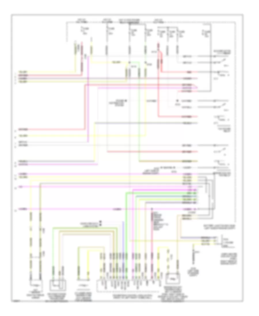
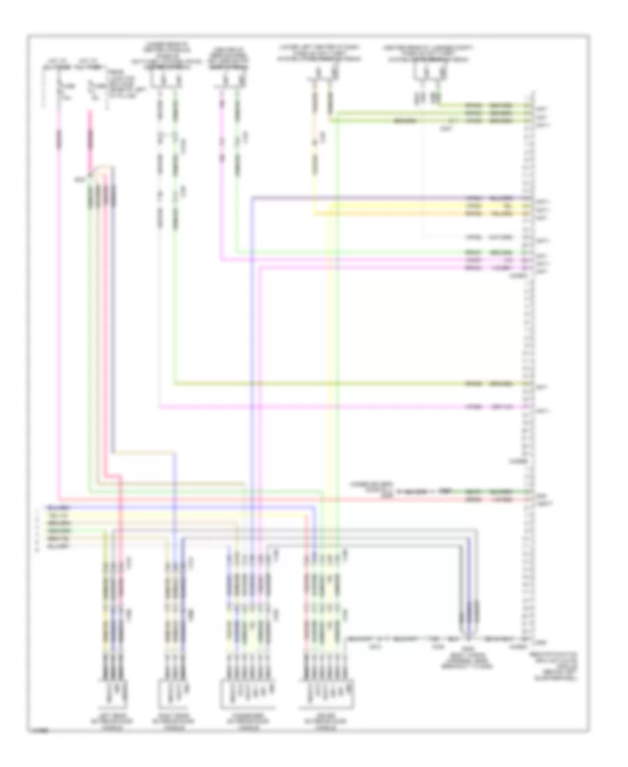
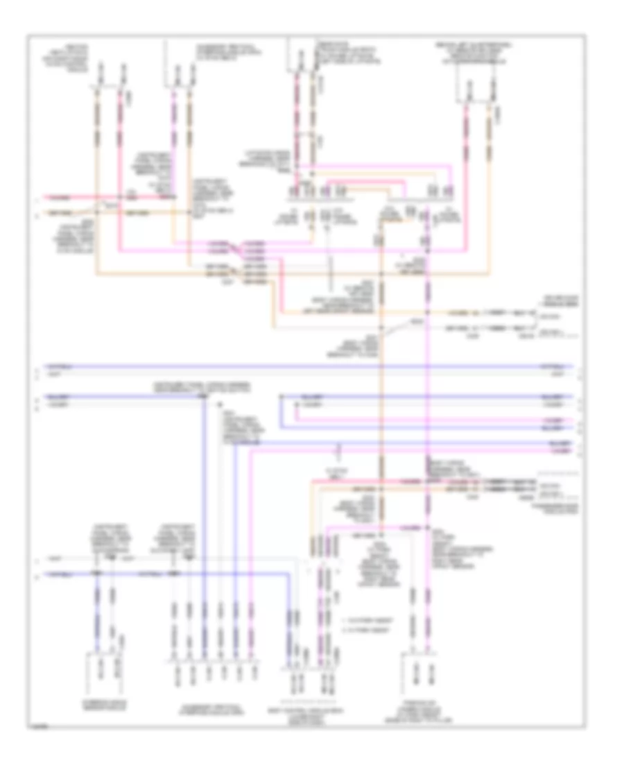
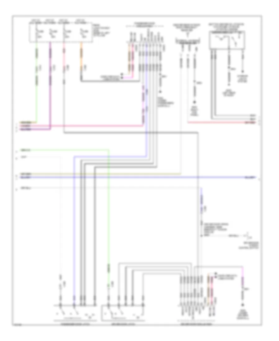
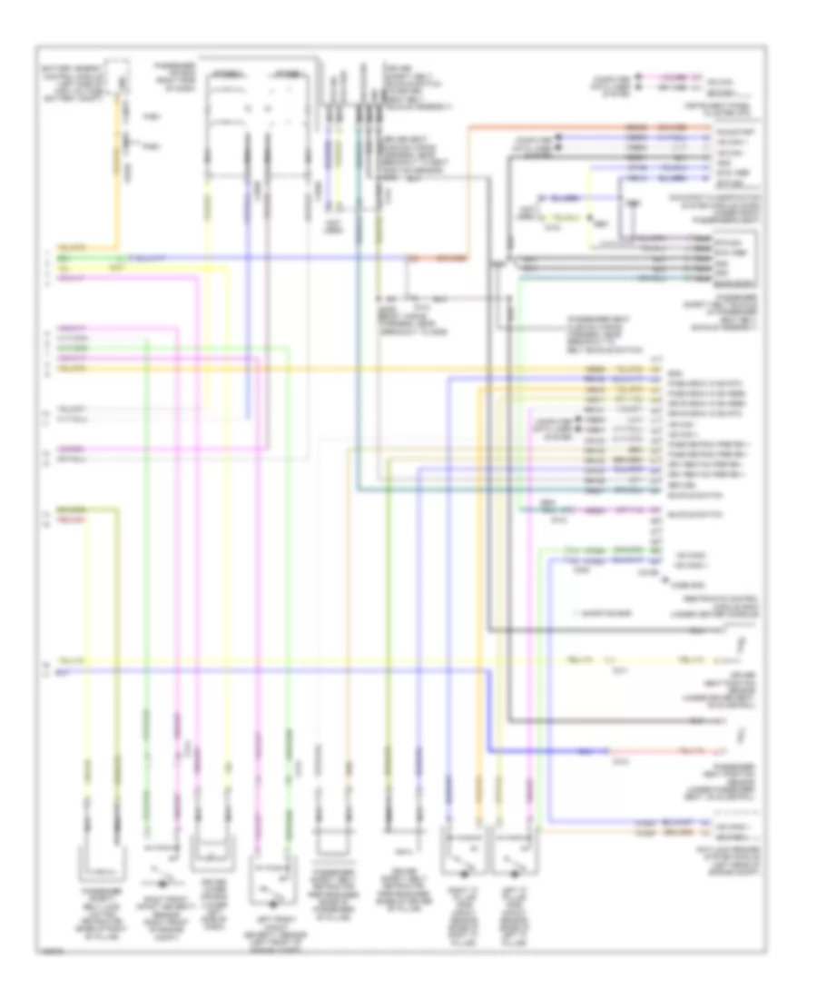
Automatic A/C Wiring Diagram (2 of 3) for Ford C-Max Hybrid SEL 2014
List of elements for Automatic A/C Wiring Diagram (2 of 3) for Ford C-Max Hybrid SEL 2014:
- (left front of engine compt) active grille shutter
- (left side of high voltage battery compt) battery energy control module (becm)
- (lower left front of engine) water coolant pump 1
- (phev: right front of high voltage battery compt) (hev: left front of high voltage battery compt) high voltage battery service disconnect
- Air conditioning control module (lower left front of engine)
- Blower control
- Blower motor (right side of dash)
- Blower motor control module (on blower motor)
- C134
- C140
- C1458a
- C1458f
- C1815a
- C1815b
- C1815c
- C214
- C297a
- C297b
- C4000
- C4002
- C4816b
- Cabin coolant diverter valve (phev) (center rear of engine compt)
- Cabin coolant heater (right rear of engine compt)
- Cbb29
- Cbp18
- Ce302
- Chp01
- Computer data lines system
- Cooling fan motor (behind radiator)
- Cyb03
- Engine controls system
- Ev hs can +
- Ev hs can -
- Fcv
- G105 (left side of engine compt)
- G107 (right front of engine compt)
- G108 (top of transmission)
- G202 (right kick panel)
- Gd131
- Gd138
- Gnd
- Hv+
- Hv-
- Hvi+
- Hvi-
- Lin
- Loop+
- Loop-
- Micro
- Motor+
- Motor-
- Nca
- Pwm
- Pwr
- S101
- S107
- S108 (junction box wiring harness, near breakout to c214)
- S126
- S203
- Secondary on board diagnostic module c (sobdmc)/transmission control module (tcm) (on transmission)
- Tcmrc
- Vbatt
- Vdb04
- Vdb05
- Vh101
- Vpwr
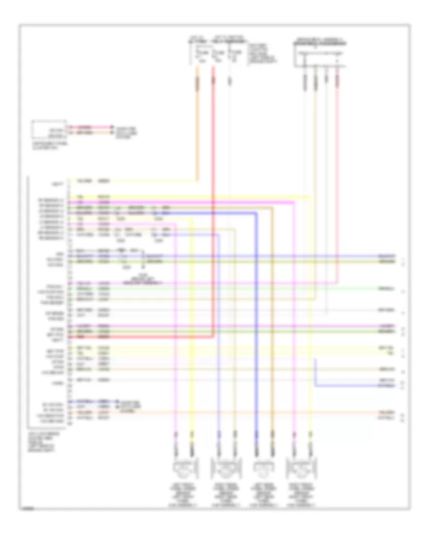
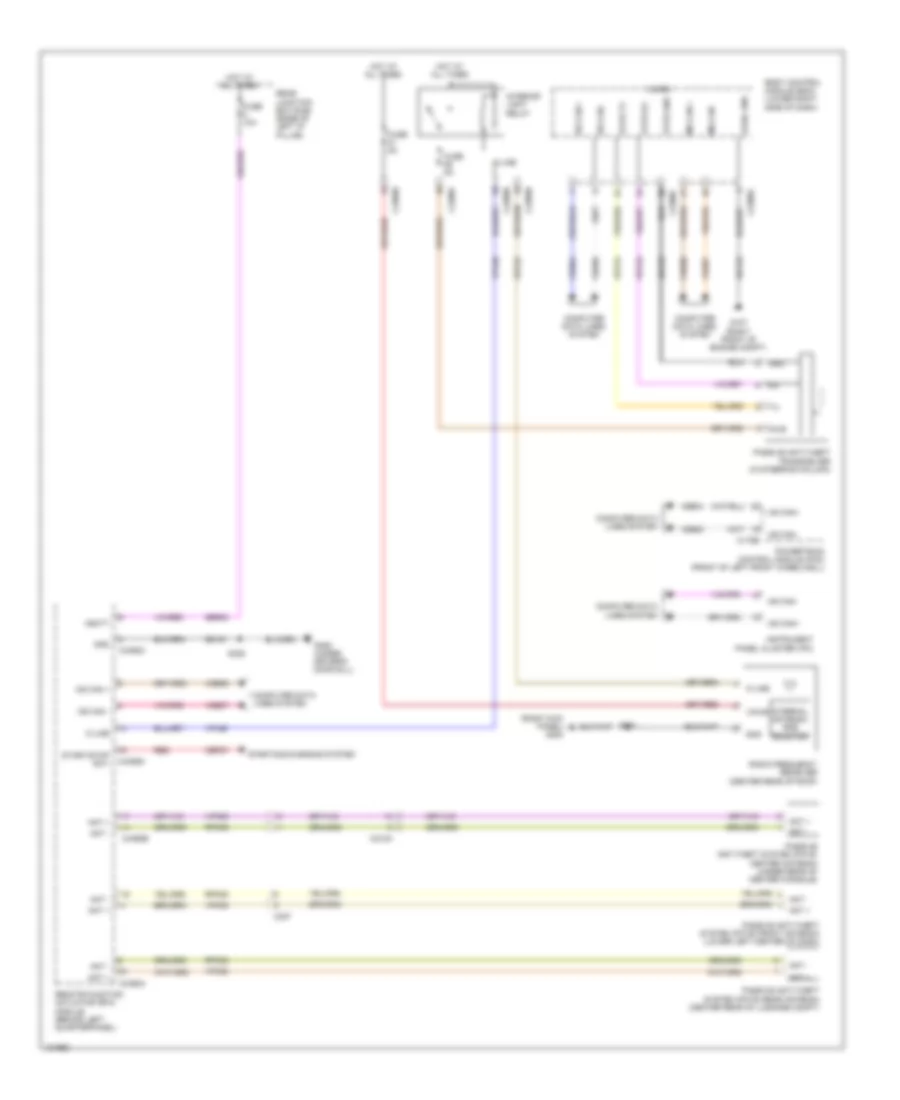
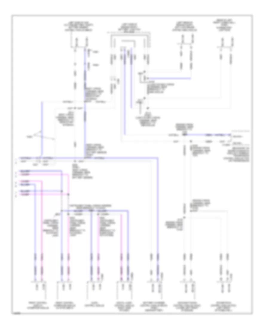
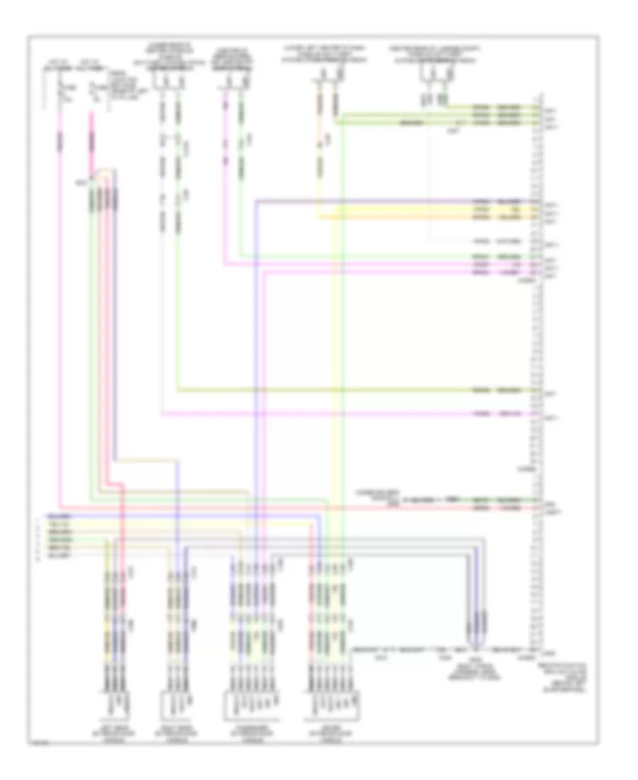
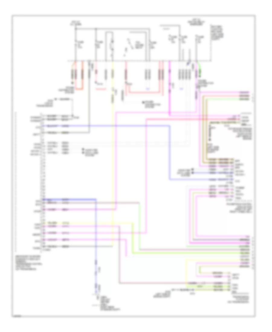
Automatic A/C Wiring Diagram (3 of 3) for Ford C-Max Hybrid SEL 2014
List of elements for Automatic A/C Wiring Diagram (3 of 3) for Ford C-Max Hybrid SEL 2014:
- A10
- Aat
- Aat sensor
- Acpt
- Air conditioning (a/c) pressure transducer (on a/c compressor)
- Battery junction box (bjb) (left side of engine compt)
- Blower motor relay
- Breakout to coolant pump)
- C1035c
- C134
- C140
- C175b
- C175e
- C238
- C340
- Cabin heater coolant pump (phev) (right rear of engine compt)
- Ce104
- Chf01
- Cht
- Computer data lines system
- Cylinder head temperature (cht) sensor (top of engine)
- Ect2
- Engine coolant temperature 2 (ect 2) sensor (phev: right side of engine in coolant tubing) (hev: end of coolant manifold assembly)
- Engine cooling fan relay
- Fcv
- Fuse 10a
- Fuse 20a
- Fuse 25a
- Fuse 40a
- Fuse 50a
- Fuse 5a
- G105 (left side of engine compt)
- Gnd
- Hcso
- Hot at all times
- Hot w/ pcm power relay energized
- Hs can+
- Hs can-
- Lh108
- Lin
- Nca
- Power distribution system
- Powertrain control module (pcm) (front of left front wheelwell)
- Pwm
- Re141
- Red
- Rh107
- Rh108
- Right exterior mirror
- S101
- S102
- S106
- S115
- S119
- S124
- Sig rtn
- Sigrtn
- Tcm power relay
- V power
- Vdb04
- Vdb05
- Vdn08
- Ve203
- Ve716
- Vh407
- Vh442
- Vref
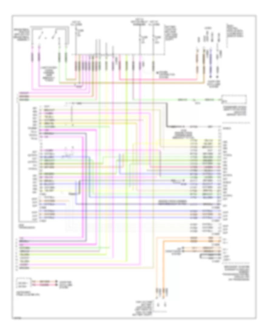
ANTI-LOCK BRAKES
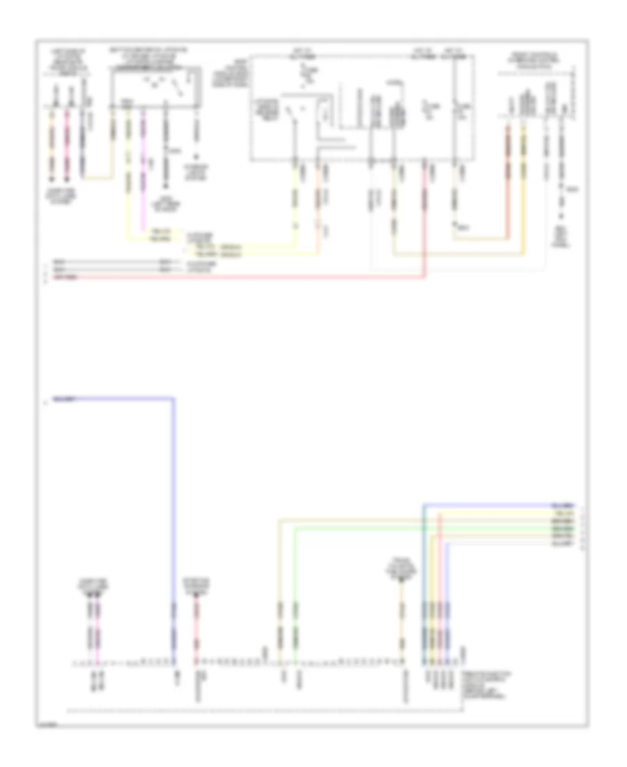
Anti-lock Brakes Wiring Diagram (1 of 2) for Ford C-Max Hybrid SEL 2014
List of elements for Anti-lock Brakes Wiring Diagram (1 of 2) for Ford C-Max Hybrid SEL 2014:
- (brake pedal assembly) brake pedal angle sensor
- Anti-lock brake system (abs) module (left rear of engine compt)
- Battery junction box (bjb) (left side of engine compt)
- Bst pwm
- Bst pwr
- C238
- C405
- C406
- Cbb37
- Cca22
- Ccb30
- Ccb33
- Ccb41
- Ccb42
- Computer data lines system
- Ev hs can+
- Ev hs can-
- Fuse 30a
- Fuse 40a
- Fuse 5a
- G106 (behind left headlamp assembly)
- Gd122
- Gnd
- Hot at all times
- Hot w/ ignition relay energized
- Hs can2+
- Hs can2-
- Instrument panel cluster (ipc)
- Lca27
- Lca37
- Left front wheel speed sensor (left front wheel hub assembly)
- Left rear wheel speed sensor (left rear wheel hub assembly)
- Lf sensor hi
- Lf sensor lo
- Lr sensor hi
- Lr sensor lo
- Mp gnd
- Mp sense
- Mp sig
- Ms can+
- Ms can-
- Nca
- Pas gnd
- Pas sensep
- Pas sig 1
- Pas sig 2
- Rca17
- Rca18
- Rca19
- Rca20
- Rca27
- Rca37
- Rcb33
- Red
- Rf sensor hi
- Rf sensor lo
- Right front wheel speed sensor (right front wheel hub assembly)
- Right rear wheel speed sensor (right rear wheel hub assembly)
- Rr sensor hi
- Rr sensor lo
- S103
- Sbb25
- Sbb26
- Vac pump
- Vac pump mon
- Vac sen gnd
- Vac sen sig
- Vac sens pwr
- Vacrc
- Vbatt
- Vca03
- Vca04
- Vca05
- Vca06
- Vca22
- Vca23
- Vca24
- Vca30
- Vca38
- Vca43
- Vcb34
- Vdb04
- Vdb05
- Vpwr
Anti-lock Brakes Wiring Diagram (2 of 2) for Ford C-Max Hybrid SEL 2014
List of elements for Anti-lock Brakes Wiring Diagram (2 of 2) for Ford C-Max Hybrid SEL 2014:
- (junction box wiring harness, near breakout to bcm)
- (left kick panel) g201
- Battery junction box (bjb) (left side of engine compt)
- Body control module (bcm) (lower right side of dash)
- Bpp
- Bps
- Brake booster solenoid (left rear of engine compt)
- Brake booster travel sensor (brake booster assembly)
- Brake booster vacuum sensor
- Brake pedal position switch (brake pedal assembly)
- Brake vacuum pump (lower left side of engine)
- Brk fluid level sw
- Bst pwm
- Bst pwr
- C1035c
- C140
- C175b
- C226a
- C2280a
- C2280c
- C2280f
- C310b
- Cca29
- Ccb08
- Cmc19
- Cmc25
- Computer data lines system
- Fuse 40a
- Fuse 5a
- Fuse 7.5a
- G104
- G105 (left side of engine compt)
- G107 (right front of engine compt)
- G201 (left kick panel)
- Gd138
- Hot at all times
- Hs can +
- Hs can -
- Hs can+
- Hs can-
- Hs can2+
- Hs can2-
- Low brake fluid warning indicator switch (brake fluid reservoir)
- Micro
- Ms can +
- Ms can -
- Parking brake warning indicator switch (base of parking brake lever assembly) s202
- Powertrain control module (pcm) (left front wheelwell)
- Prk brk sw
- Pwr gnd
- Red
- Restraints control module (rcm) (under center console)
- S101
- S115
- S120
- S202
- Sasm sply
- Sbp07
- Sig rtn
- Steering angle sensor
- Steering angle sensor module (sasm)
- Stp lt sw
- Vacuum pump cut-off relay
- Vacuum pump relay
- Vbatt
- Vca23
- Vca24
- Vdb04
- Vdb05
- Vdb06
- Vdb07
ANTI-THEFT
Forced Entry Wiring Diagram (1 of 4) for Ford C-Max Hybrid SEL 2014
List of elements for Forced Entry Wiring Diagram (1 of 4) for Ford C-Max Hybrid SEL 2014:
- (body wiring harness, near breakout to g301) s310
- (right rear door wiring harness, near breakout to window switch) s801
- A11
- B11
- Battery junction box (bjb) (left side of engine compt)
- Body control module (bcm) (lower right side of dash)
- C2280a
- C2280b
- C2280c
- C2280g
- C2280h
- C237
- C313
- C314
- C339
- C340
- Child lock
- Computer data lines system
- Cpl04
- Cpl08
- Cpl09
- Cpl11
- Cpl25
- Cpl26
- Cpl31
- Cpl36
- Cpl37
- Cpl38
- Cpl39
- Cpl42
- Cpl43
- Cpl53
- Cpl54
- Cpl70
- Crh03
- Dr unlock
- Driver rear door module (drdm)
- Fuse 50a
- G105 (left side of engine compt)
- G107 (right front of engine compt)
- G302 (under passenger's door sill)
- G303 (under driver's door sill)
- Gd123
- Gd134
- Gd140
- Gnd
- Headlights system
- Hood ajar switch
- Hood ajar switch (center front of engine compt)
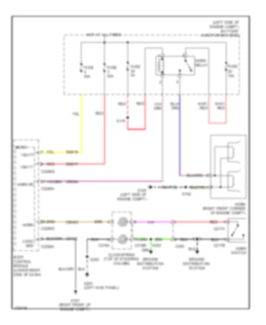
- Horn
- Horns system
- Hot at all times
- Illum
- Interior lights system
- Internal antenna rke receiver
- K-line
- Left front door lock switch
- Left rear door latch
- Lf dr ajar
- Lin
- Lin (lsm)
- Lock
- Lock child lock
- Logic gnd
- Lr dr ajar
- Micro
- Ms can+
- Ms can-
- Mtr double
- Mtr double lck
- Passenger rear door module (prdm)
- Power windows system
- Red
- Return
- Rf dr ajar
- Right front door lock switch
- Right rear door latch
- Rpw49
- Rpw55
- Rr dr ajar
- S102
- S302
- S306
- S501
- S601
- S701 (left rear door wiring harness, near breakout to window switch)
- Sbb17
- Sbr03
- Sbr04
- Unlock
- Vbatt
- Vdb06
- Vdb07
- Vlf25
- Vpl56
- Vpw32
- Vpw33
- Vrt22
- W/ heated seats
- W/o heated seats
Forced Entry Wiring Diagram (2 of 4) for Ford C-Max Hybrid SEL 2014
List of elements for Forced Entry Wiring Diagram (2 of 4) for Ford C-Max Hybrid SEL 2014:
- (bottom center of liftgate) (w/o power liftgate) liftgate/luggage compartment lid latch
- (center rear of roof) radio frequency receiver
- (driver door wiring harness, near breakout to door module) s502
- A14
- A16
- A17
- B17
- C313
- C314
- C339
- C340
- C501a
- C501b
- C652a
- C652b
- Computer data lines system
- Cpl02
- Cpl30
- Cpl35
- Cpl51
- Cpl65
- Cpl66
- Dr unlock
- Driver door latch
- Driver door module (ddm)
- Driver door window control switch
- Fuse 25a
- G202 (right kick panel)
- G302 (under passenger's door sill)
- G303 (under driver's door sill)
- G402 (left rear of roof)
- Gd134
- Gd140
- Gnd
- Hot at all times
- Interior lights system
- Internal antenna rke receiver
- K-line
- Lin
- Lock
- Ms can+
- Ms can-
- Passenger door latch
- Passenger door module (pdm)
- Rear junction box (rjb) (base of left "d" pillar)
- Red
- Return
- Rpl63
- Rpl64
- S404
- S501
- S601
- S902
- Sbr01
- Sbr02
- Unlock
- Vbatt
- Vdb06
- Vdb07
- Vpw32
- Vpw33
- Vpwr
Forced Entry Wiring Diagram (3 of 4) for Ford C-Max Hybrid SEL 2014
List of elements for Forced Entry Wiring Diagram (3 of 4) for Ford C-Max Hybrid SEL 2014:
- (bottom center of liftgate) (w/ power liftgate) liftgate/luggage compartment lid latch
- (left side of liftgate) rear gate trunk module (rgtm)
- Body control module (bcm) (lower right side of dash)
- C2280b
- C2280c
- C2280e
- C2280f
- C2280h
- C411
- C4174b
- C432
- C4392d
- C4392e
- Cbp27
- Cls32
- Computer data lines system
- Cpk19
- Cpk20
- Cpk23
- Cpk24
- Cpk25
- Cpk26
- Cpl44
- Cpl45
- Cplxx
- Cpr89
- Dr lck ctrl sw ind (led)
- Front controls interface control module (fcim)
- Fuse 10a
- Fuse 15a
- Fuse 5a
- G201 (left kick panel)
- G402 (left rear of roof)
- Gd133
- Gnd
- Hazard
- Hazard warning/ sig sw
- Hot at all times
- Interior lights system
- K-line
- Latch sec sig
- Liftgate ajar
- Liftgate sw
- Liftgate/ decklid release relay
- Lock
- Micro
- Ms can +
- Ms can -
- Ms can+
- Ms can-
- Prim sig
- Red
- Remote function actuator (rfa) module (behind left quarterpanel)
- S202
- S243
- S403
- Sbp06
- Start/stop
- Starting/ charging system
- Sw ind (led) dr lck ctrl
- Sw1
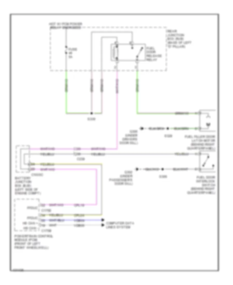
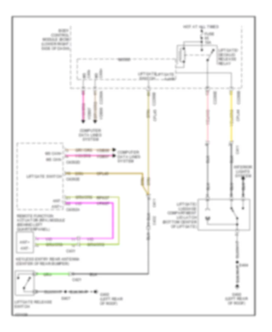
- Trunk, tailgate, fuel doors system
- Unlock
- Vbatt
- Vdb06
- Vdb07
- Vpl56
- W/ power liftgate
- W/o power liftgate
- Warning/ sig sw
Forced Entry Wiring Diagram (4 of 4) for Ford C-Max Hybrid SEL 2014
List of elements for Forced Entry Wiring Diagram (4 of 4) for Ford C-Max Hybrid SEL 2014:
- (center of rear bumper) keyless entry rear antenna
- (center rear of luggage compt) passive anti-theft system (pats) rear antenna
- (lower left center of dash) passive anti-theft system (pats) front antenna
- (under driver's door sill) g306
- (under rear of center console) passive anti-theft system (pats) center antenna
- A12
- Ant +
- Ant -
- C212a
- C237
- C313
- C314
- C339
- C340
- C431
- C4392a
- C4392b
- C4392c
- C510
- C610
- C700
- C800
- Driver exterior door handle
- Fuse 10a
- Fuse 5a
- Gd140
- Gd151
- Gnd
- Hot at all times
- Left rear exterior door handle
- Lock
- Nca
- Passenger exterior door handle
- Rear junction box (rjb) (base of left "d" pillar)
- Remote function (rfa) actuator module (behind left quarterpanel)
- Right rear exterior door handle
- Rpk03
- Rpk04
- Rpk05
- Rpk06
- Rpk07
- Rpk08
- S321
- S328
- S329 (body wiring harness, near breakout to g306)
- Sbr08
- Unlock
- Vbatt
- Vpk03
- Vpk04
- Vpk05
- Vpk06
- Vpk07
- Vpk08
Passive Anti-theft Wiring Diagram for Ford C-Max Hybrid SEL 2014
List of elements for Passive Anti-theft Wiring Diagram for Ford C-Max Hybrid SEL 2014:
- (right kick panel) g202
- Ant +
- Ant -
- Body control module (bcm) (lower right side of dash)
- C175b
- C212a
- C2280a
- C2280b
- C2280c
- C2280f
- C2280h
- C237
- C4392a
- C4392b
- C4392c
- C4392d
- Cbp27
- Computer data lines system
- Fuse 10a
- Fuse 5a
- G107 (right front of engine compt)
- G306 (under driver's door sill)
- Gd123
- Gd133
- Gd151
- Gnd
- Hot at all times
- Hs can +
- Hs can -
- Hs can+
- Hs can-
- Instrument panel cluster (ipc)
- Interior light relay
- Internal antenna rke receiver
- K-line
- Logic gnd
- Micro
- Ms can +
- Ms can -
- Ms can+
- Ms can-
- Passive anti-theft system (pats) center antenna (under rear of center console)
- Passive anti-theft system (pats) front antenna (lower left center of dash)
- Passive anti-theft system (pats) rear antenna (center rear of luggage compt)
- Passive anti-theft transceiver (in steering column)
- Pats gnd
- Pats rx
- Pats tx
- Powertrain control module (pcm) (front of left front wheelwell)
- Pwr
- Radio frequency receiver (center rear of roof)
- Rear junction box (rjb) (base of left "d" pillar)
- Red
- Remote function actuator (rfa) module (behind left quarterpanel)
- Rpk05
- Rpk06
- Rpk08
- S328
- S902
- Sbr08
- Start/stop sw1
- Starting/charging system
- Vbatt
- Vdb04
- Vdb05
- Vdb06
- Vdb07
- Vpk05
- Vpk06
- Vpk08
- Vpl56
- Vpwr
- Vrt22
- Vrt23
- Vrt24
BODY CONTROL MODULES
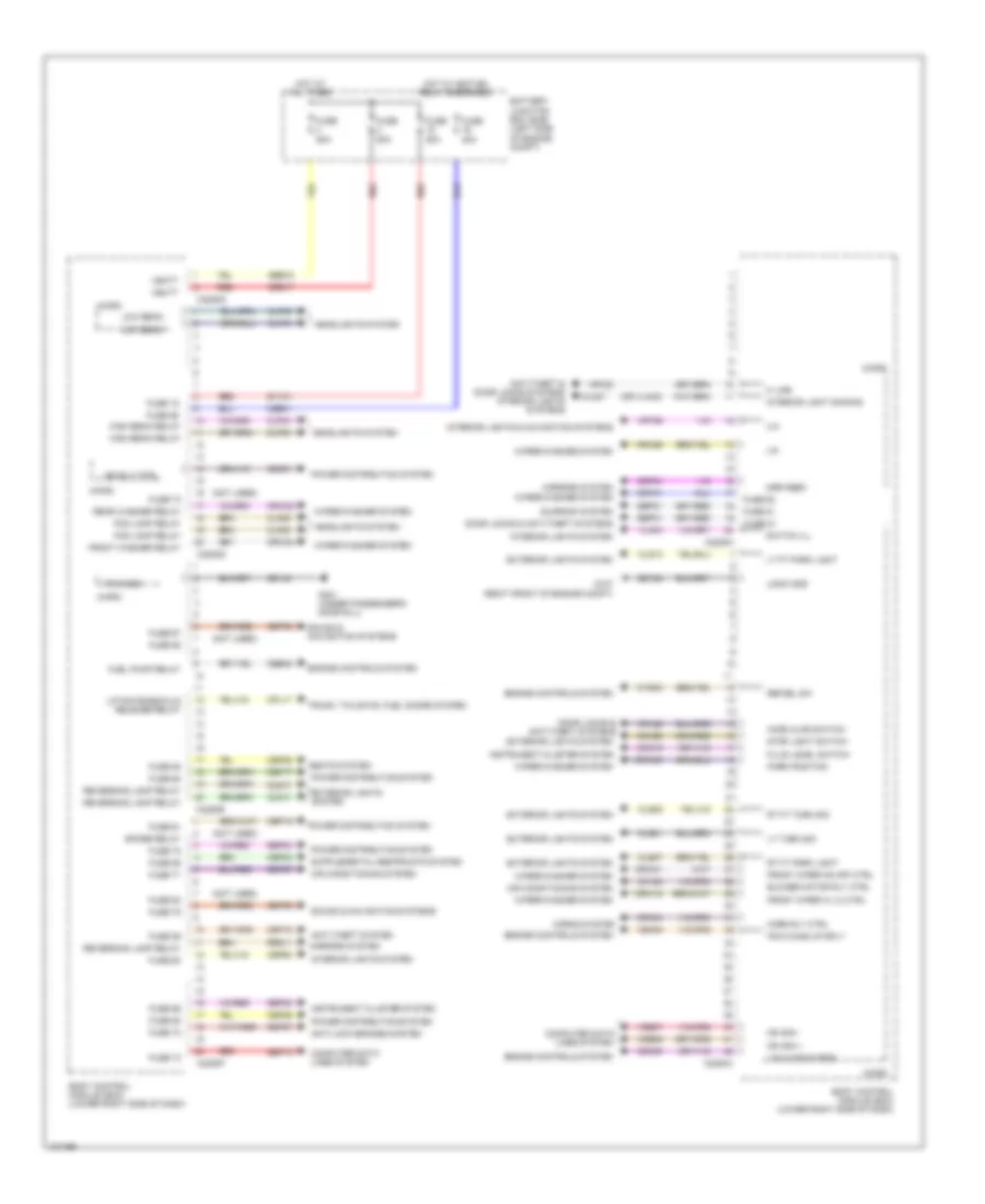
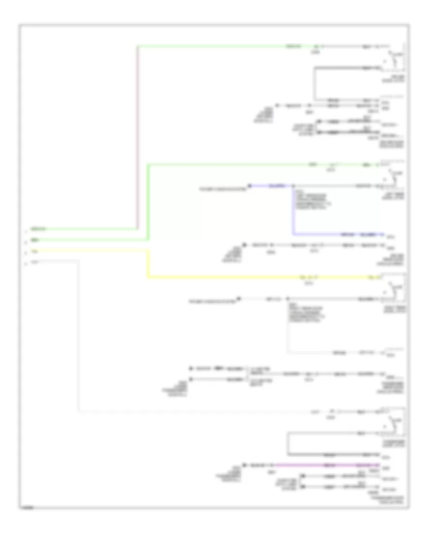
Body Control Modules Wiring Diagram (1 of 2) for Ford C-Max Hybrid SEL 2014
List of elements for Body Control Modules Wiring Diagram (1 of 2) for Ford C-Max Hybrid SEL 2014:
- (not used)
- (or vln40)
- Air conditioning system
- Anti-lock brakes system
- Anti-theft & door locks systems interior lights systems
- Anti-theft system
- Battery junction box (bjb) (left side of engine compt)
- Blower motor rly ctrl
- Body control module (bcm) (lower right side of dash)
- C2280a
- C2280d
- C2280e
- C2280f
- C2280g
- C2280h
- Cbb41
- Cbb48
- Cbp01
- Cbp02
- Cbp04
- Cbp17
- Cbp18
- Cbp19
- Cbp60
- Cbp85
- Cca29
- Cdc01
- Cdc56
- Ce436
- Ch123
- Clf02
- Clf03
- Clf04
- Clf05
- Clf29
- Cln27
- Cls07
- Cls10
- Cls13
- Cls21
- Cls25
- Cmc19
- Computer data lines system
- Cpl17
- Cpl25
- Crh04
- Crw01
- Crw09
- Crw15
- Crw23
- Crw24
- Cyd03
- Door locks & anti-theft systems
- Engine controls system
- Exterior lights system
- Fluid level switch
- Fog lamp relay
- Front washer relay
- Front wiper hi lo ctrl
- Front wiper on off ctrl
- Fuel pump relay
- Fuse 15
- Fuse 20a
- Fuse 50a
- Fuse 58
- Fuse 59
- Fuse 60
- Fuse 61
- Fuse 62
- Fuse 63
- Fuse 67
- Fuse 69
- Fuse 71
- Fuse 72
- Fuse 73
- Fuse 78
- Fuse 79
- Fuse 81
- Fuse 85
- Fuse 86
- G107 (right front of engine compt)
- G301 (under passenger's door sill)
- Gd123
- Gd140
- Headlights system
- High beam relay
- Hood ajar switch
- Horn rly ctrl
- Horns system
- Hot at all times
- Hot w/ ignition relay energized
- Ign rly ctrl
- Instrument cluster system
- Interior light dimming
- Interior lights & navigation systems
- Interior lights system
- K line
- Liftgate/decklid release relay
- Lin
- Lin 8 (wmm & bms)
- Logic gnd
- Low beam
- Lt ft park light
- Lt turn sig
- Micro
- Mirrors system
- Mrr feed
- Ms can +
- Ms can -
- Park position
- Pcm wake up sply
- Power distribution system
- Pwr gnd
- Rear washer relay
- Red
- Refuel sw
- Reversing lamp relay
- Rrd11
- Rt ft park light
- Rt ft turn sig
- Sbb17
- Sbb18
- Sbp06
- Sbp07
- Sbp08
- Sbp21
- Sbp24
- Sbp27
- Sbp73
- Seats system
- Sound & navigation systems
- Spare relay
- Stop light switch
- Sunroof system
- Switch ill
- Syv01
- Trunk, tailgate, fuel doors system
- Vbatt
- Vdb06
- Vdb07
- Vln04
- Vrt22
- Vrt26
- Vrw26
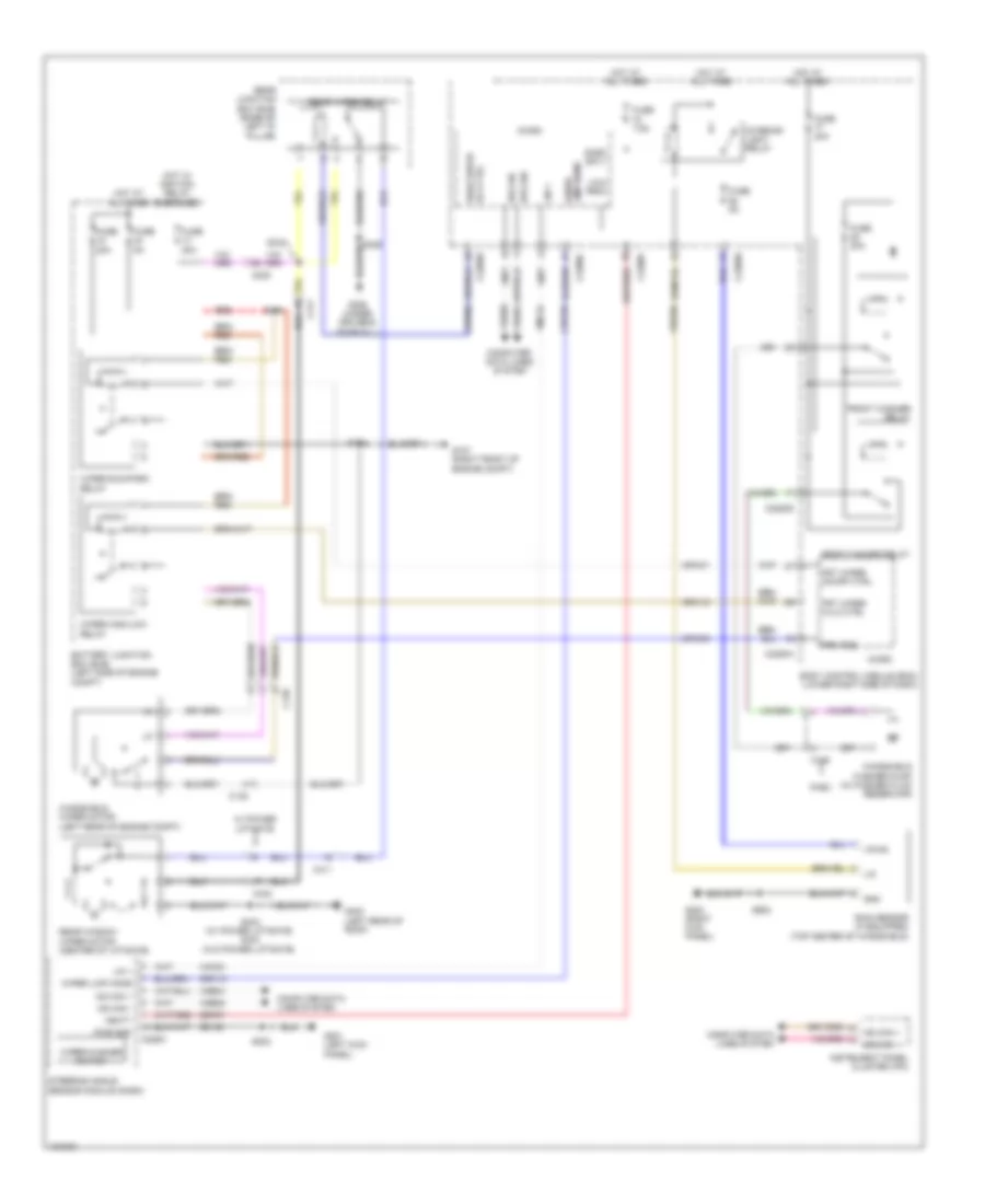
- Wiper/washer system
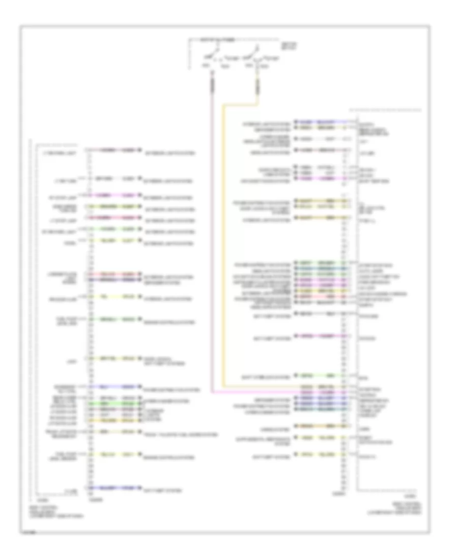
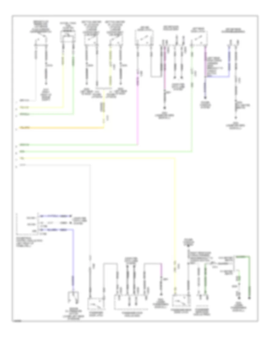
Body Control Modules Wiring Diagram (2 of 2) for Ford C-Max Hybrid SEL 2014
List of elements for Body Control Modules Wiring Diagram (2 of 2) for Ford C-Max Hybrid SEL 2014:
- Acc
- Acc/run
- Accessory rly ctrl
- Air conditioning system
- Anti-theft system
- Audio ant/theft sw
- Auto lamps
- Body control module (bcm) (lower right side of dash)
- Btsi
- C2280b
- C2280c
- Cbp27
- Cdc03
- Cdc30
- Cdc32
- Cdc33
- Cet52
- Chmsl
- Cln17
- Cln38
- Cls04
- Cls08
- Cls09
- Cls17
- Cls23
- Cls27
- Cls32
- Cls44
- Cmc25
- Computer data lines system
- Cpl26
- Cpl31
- Cpl36
- Cpl39
- Cpl42
- Cpl43
- Cpl44
- Cpl45
- Cplxx
- Crd02
- Crd04
- Crd09
- Crh03
- Crw02
- Crw10
- Defogger system
- Defroster sw
- Dim rtn
- Door locks & anti-theft systems
- Engine controls system
- Evap temp sns
- Event notification sig
- Exterior lights system
- Fuel pump level gnd
- Fuel pump level sensor
- Gd133
- Headlights system
- Horn
- Horns system
- Hot at all times
- Hs can +
- Hs can -
- Ignition switch
- Ill dr lock ctrl sw ind
- Instrument cluster system door locks & anti-theft systems exterior lights system
- Interior lights system
- Ip sw ill
- K line
- Key in ign sw
- Lf door ajar
- License plate light rwdrc
- Liftgate ajar
- Lin (lsm)
- Lin 1
- Lock
- Lr door ajar
- Lt rr park light
- Lt rr turn
- Lt stop lamp
- Micro
- Navigation & sound systems
- Off
- Park brake sw
- Pats gnd
- Pats rx
- Pats tx
- Power distribution system
- Power distribution system air conditioning & headlamps systems
- Rear window defroster ind
- Rear wiper relay ctrl
- Red
- Rf door ajar
- Rh107
- Rmc32
- Rr door ajar
- Rt rr park light
- Rt stop lamp
- Run
- Shift interlock system
- Side mirror turn ind
- Sig sw/hazard warning
- Sigrtn
- Start
- Start/run
- Start/stop sw1
- Start/stop sw2
- Trunk liftgate release sw
- Trunk, tailgate, fuel doors system
- Un lock
- Vdb04
- Vdb05
- Ve225
- Vh406
- Vh414
- Vlf25
- Vmc11
- Vmc34
- Vmp19
- Vpl56
- Vrt23
- Vrt24
- Wiper limp home sw
- Wiper/washer system
- Wiper/washer, headlights & exterior lights system
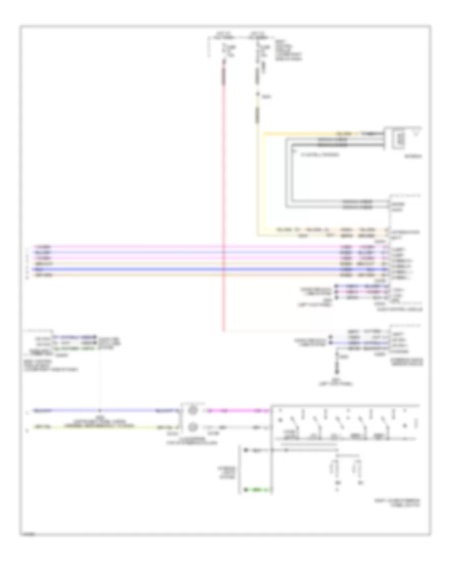
COMPUTER DATA LINES
Computer Data Lines Wiring Diagram (1 of 3) for Ford C-Max Hybrid SEL 2014
List of elements for Computer Data Lines Wiring Diagram (1 of 3) for Ford C-Max Hybrid SEL 2014:
- (body wiring harness, near breakout to g301)
- (body wiring harness, near breakout to g302) s311
- (body wiring harness, near breakout to luggage lamp) (w/ park assist) s320
- (instrument panel wiring harness, near breakout to c213) s210
- (instrument panel wiring harness, near breakout to clockspring)
- (instrument panel wiring harness, near breakout to clockspring) s218
- (instrument panel wiring harness, near breakout to cluster)
- (instrument panel wiring harness, near breakout to gpsm)
- (instrument panel wiring harness, near breakout to headlamp switch)
- (instrument panel wiring harness, near breakout to hvac module)
- (instrument panel wiring harness, near breakout to temperature sensor)
- (left kick panel) g200
- (phev) s335
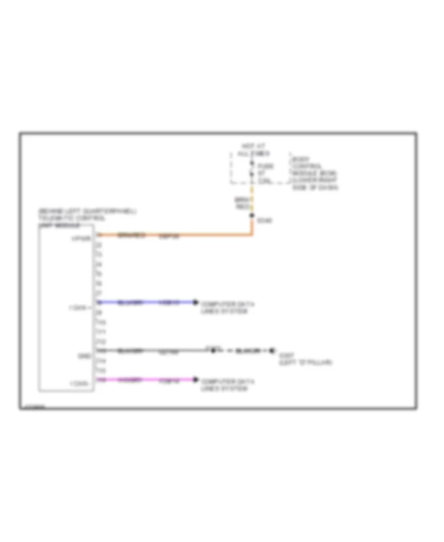
- Body control module (bcm) (lower right side of dash)
- C1046
- C1463b
- C214
- C2280f
- C237
- C310b
- C312
- C4014a
- Cbr21
- Data link connector (dlc) (lower left side of dash)
- Ect sensor) c238
- Fhev
- Fuse 10a
- Fuse 5a
- G200 (left kick panel)
- G201 (left kick panel)
- Gateway module a (gmw) (lower left side of dash)
- Gd133
- Gd135
- Global positioning system module (gpsm)
- Gnd
- Hot at all times
- Hs can +
- Hs can -
- Hs can+
- Hs can-
- I can +
- I can -
- I can+
- I can-
- Instrument panel cluster (ipc)
- Ms can +
- Ms can -
- Ms can+
- Ms can-
- Occupant classification system module (ocsm) (under front passenger's seat)
- Panel wiring harness, near breakout to cluster)
- Parking aid module (if equipped) (base of right "d" pillar)
- Phev
- Power steering control module (pscm) (center rear of engine compt)
- Rear junction box (rjb) (base of left "d" pillar)
- Red
- Restraints control module (rcm) (under center console)
- S114
- S200
- S202
- S204
- S212
- S215
- S216
- S217
- S221
- S222
- S223
- S225
- S235
- S240
- S305 (body wiring harness, near breakout to g302)
- S315
- S316
- S323 (w/ park assist) (body wiring harness, near breakout to luggage lamp)
- S334 (phev) (body wiring harness, near breakout to left rear impact sensor)
- Sbp73
- Telematic control unit module (tcu) (phev) (behind left quarterpanel)
- Vbatt
- Vdb04
- Vdb05
- Vdb06
- Vdb07
- Vdb13
- Vdb14
- W/ park assist
- W/o park assist
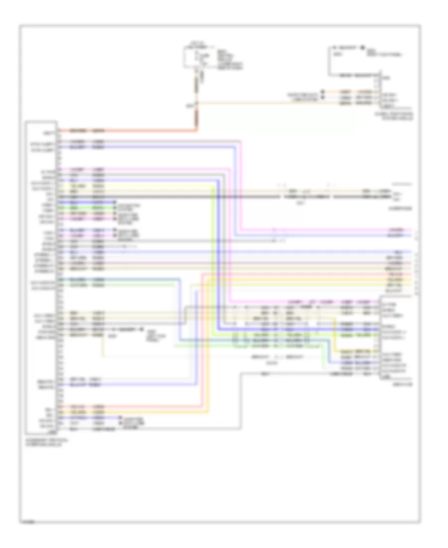
Computer Data Lines Wiring Diagram (2 of 3) for Ford C-Max Hybrid SEL 2014
List of elements for Computer Data Lines Wiring Diagram (2 of 3) for Ford C-Max Hybrid SEL 2014:
- (behind left quarterpanel) (w/ remote keyless) remote function actuator (rfa) module
- (instrument panel wiring harness, near breakout to c210)
- (instrument panel wiring harness, near breakout to c210) (w/ sync gen 2) s207
- (instrument panel wiring harness, near breakout to clockspring) s228
- (instrument panel wiring harness, near breakout to glove box lamp) s205
- (instrument panel wiring harness, near breakout to ignition switch) s213
- (liftgate wiring harness, near breakout to c411) s406
- (w/ sync gen 2) s206
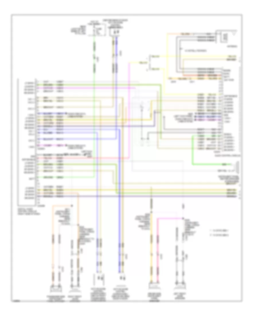
- Accessory protocol interface module (apim)
- Accessory protocol interface module (apim) (w/ sync gen 2)
- Body control module (bcm) (lower right side of dash)
- C226a
- C2280a
- C2280c
- C228b
- C237
- C238
- C339
- C340
- C410
- C4174b
- C432
- C4392d
- C501b
- C652b
- Driver door module (ddm)
- Heating ventilation & air conditioning (hvac) control module
- Hs can +
- Hs can -
- I can +
- I can -
- Ms can +
- Ms can -
- Parking aid camera module (w/ park assist) (base of right "d" pillar)
- Passenger door module (pdm)
- Rear gate trunk module (rgtm) (w/ power liftgate) (left side of liftgate)
- S208 (instrument panel wiring harness, near breakout to hvac module)
- S219
- S234
- S239
- S241 (instrument panel wiring harness, near breakout to hvac module)
- S303 (w/ park assist) (body wiring harness, near breakout to right rear impact sensor)
- S304 (w/ park assist) (body wiring harness, near breakout to right rear impact sensor)
- S330
- S331 (body wiring harness, near breakout to c339)
- S337 (w/ remote keyless) (body wiring harness, near breakout to left rear impact sensor)
- S338 (w/ remote keyless)
- S405
- Steering angle sensor module
- Vdb04
- Vdb05
- Vdb06
- Vdb07
- Vdb13
- Vdb14
- W/ park assist
- W/ power liftgate
- W/ sync gen 1
- W/o park assist
- W/o power liftgate
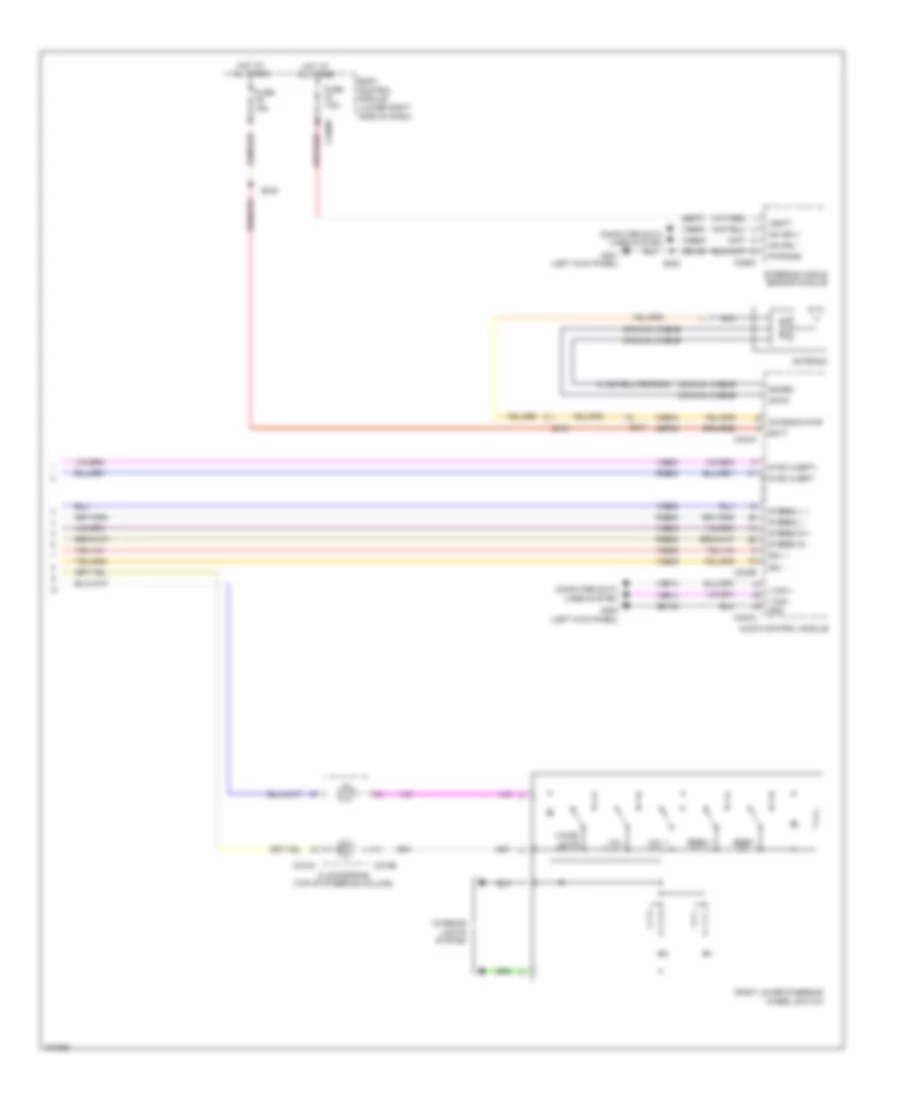
Computer Data Lines Wiring Diagram (3 of 3) for Ford C-Max Hybrid SEL 2014
List of elements for Computer Data Lines Wiring Diagram (3 of 3) for Ford C-Max Hybrid SEL 2014:
- (body wiring harness, near breakout to battery sensor) (phev) s313
- (body wiring harness, near breakout to rear start antenna) s319
- (engine wiring harness, near breakout to g108) s127
- (engine wiring harness, near breakout to tcm)
- (engine wiring harness, near breakout to tcm) s129
- (instrument panel wiring harness, near breakout to dacm) s233
- (instrument panel wiring harness, near breakout to glove box lamp)
- (left rear of engine compt) anti-lock brake system (abs) module
- (left side of engine compt) battery junction box (bjb)
- (left side of high voltage battery compt) battery energy control module (becm)
- (rear of left front wheelwell) (phev) charge port light ring
- Air conditioning control module (accm) (lower left front of engine)
- Audio control module
- Battery charger control module (bccm) (phev) (near battery)
- C1035c
- C1458a
- C175b
- C237
- C238
- C240a
- C2488a
- C4237a
- C4455a
- C4816a
- Digital audio control module (right side of dash)
- Fhev
- Front control interface module (w/ sync gen 2)
- Front control/ display interface module
- Harness, near breakout to abs module)
- Hs can +
- Hs can -
- I can +
- I can -
- Phev
- Powertrain control module (pcm) (left front of wheelwell)
- S110
- S111 (phev)
- S112 (phev) (junction box wiring harness, near breakout to abs module)
- S125 (engine wiring harness, near breakout to g108)
- S220 (instrument panel wiring harness, near breakout to blend door actuators)
- S227
- S230 (instrument panel wiring harness, near breakout to glove box lamp)
- S308 (phev) (body wiring harness, near breakout to battery sensor)
- S314 (body wiring harness, near breakout to rear start antenna)
- Secondary on board diagnostic module c (sobdmc)/ transmission control module (tcm) (on transmission)
- Vdb04
- Vdb05
- Vdb13
- Vdb14
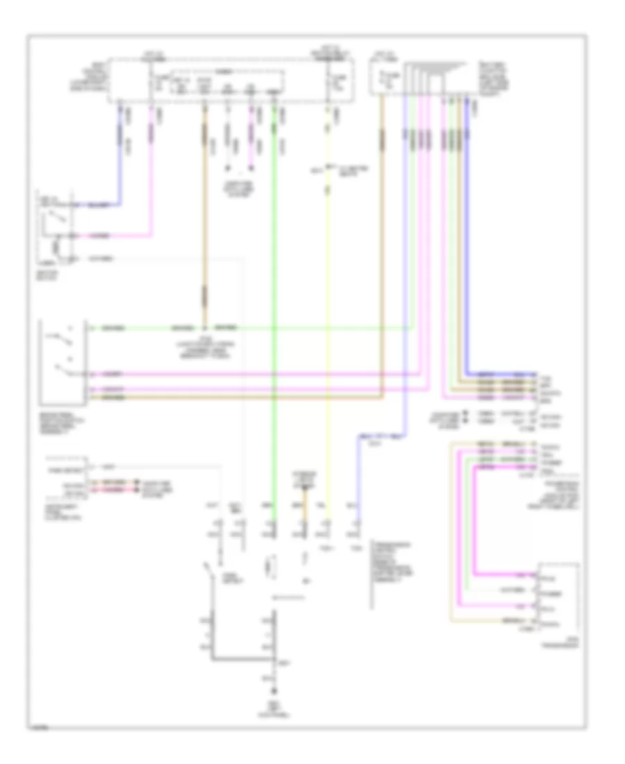
COOLING FAN
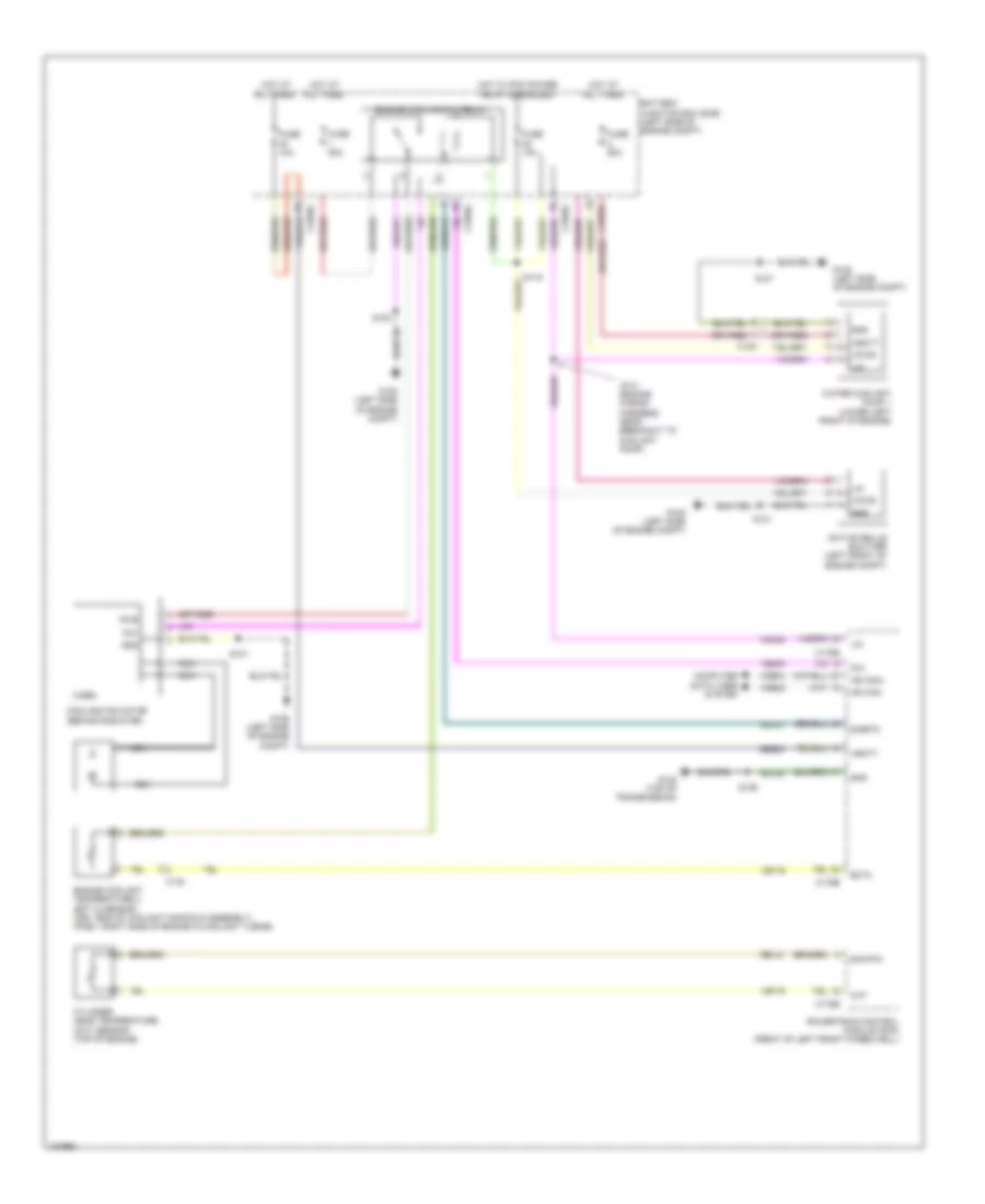
Cooling Fan Wiring Diagram for Ford C-Max Hybrid SEL 2014
List of elements for Cooling Fan Wiring Diagram for Ford C-Max Hybrid SEL 2014:
- (engine wiring harness, near breakout to coolant pump)
- Active grille shutter (left front of engine compt)
- Battery junction box (bjb) (left side of engine compt)
- C1035c
- C134
- C140
- C175b
- C175e
- Cht
- Computer data lines system
- Cooling fan motor (behind radiator)
- Cylinder head temperature (cht) sensor (top of engine)
- Ect2
- Engine coolant temperature 2 (ect 2) sensor (hev: end of coolant manifold assembly) (phev: right side of engine in coolant tubing)
- Engine cooling fan relay
- Fcv
- Fuse 10a
- Fuse 50a
- G105 (left side of engine compt)
- G108 (top of transmission)
- Gd120
- Gnd
- Hot at all times
- Hot w/ pcm power relay energized
- Hs can+
- Hs can-
- Lin
- Micro
- Nca
- Powertrain control module (pcm) (front of left front wheelwell)
- Pwr
- Re141
- Rh107
- S101
- S102
- S119
- S126
- S131
- Sbb30
- Sig rtn
- Sigrtn
- Vbatt
- Vdb04
- Vdb05
- Vdn08
- Ve203
- Ve716
- Vpwr
- Water coolant pump 1 (lower left front of engine)
CRUISE CONTROL
Cruise Control Wiring Diagram for Ford C-Max Hybrid SEL 2014
List of elements for Cruise Control Wiring Diagram for Ford C-Max Hybrid SEL 2014:
- (accelerator pedal assembly) accelerator pedal position sensor
- (junction box wiring harness, near breakout to body control module) s120
- (left side of engine compt) battery junction box (bjb)
- (top of transmission) g108
- Anti-lock brake system module (left rear of engine compt)
- App1
- App2
- Apprtn1
- Apprtn2
- Appvref 1
- Appvref2
- Battery junction box (bjb) (left side of engine compt)
- Body control module (lower right side of dash)
- Bpp
- Bps
- Brake pedal position switch (brake pedal assembly)
- C1035c
- C175b
- C175e
- C218a
- C218b
- C218c
- C218d
- C226a
- C226b
- C226c
- C2280a
- C2280c
- C238
- C405
- C406
- Cbb42
- Cca29
- Ccb08
- Ce412
- Ce426
- Clock spring (top of steering column)
- Computer data lines system
- Cruise gnd
- Cruise sig 1
- Cruise sig 2
- Etcref
- Etcrtn
- Evhs can+
- Evhs can-
- Fuse 5a
- G201 (left kick panel)
- Gd120
- Hot at all times
- Hot w/ ignition relay energized
- Hs can+
- Hs can-
- Interior lights system
- Isp-r
- Le136
- Le137
- Le428
- Left front wheel speed sensor (left front wheel hub assemblies)
- Left lower steering wheel switch
- Left rear wheel speed sensor (left rear wheel hub assemblies)
- Lf sensor hi
- Lf sensor lo
- Lr sensor hi
- Lr sensor lo
- Micro
- Nca
- On/ off
- Powertrain control module (pcm) (front of left front wheelwell)
- Pwr gnd
- Rca17
- Rca18
- Rca19
- Rca20
- Re136
- Re137
- Re427
- Reset/ cancel
- Rf sensor hi
- Rf sensor lo
- Right front wheel speed sensor (right front wheel hub assemblies)
- Right rear wheel speed sensor (right rear wheel hub assemblies)
- Rr sensor hi
- Rr sensor lo
- S126
- S202
- S235
- Set+
- Set-
- Sig rtn
- Steering angle sensor module (sasm)
- Stop light sw
- Tacm+
- Tacm-
- Throttle body (left rear of engine)
- Tp1
- Tp2
- Vca03
- Vca04
- Vca05
- Vca06
- Vdb04
- Vdb05
- Ve701
- Ve702
- Ve818
- Ve819
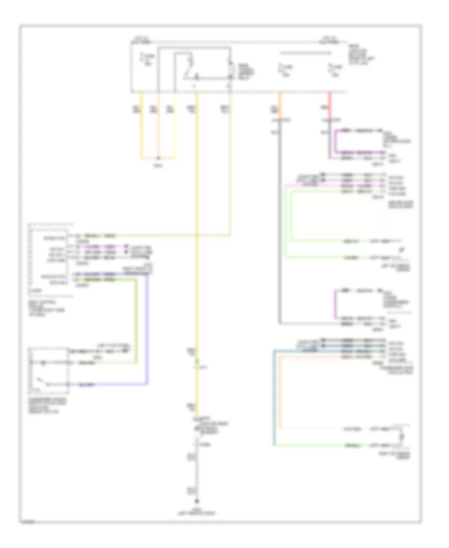
DEFOGGERS
Defoggers Wiring Diagram for Ford C-Max Hybrid SEL 2014
List of elements for Defoggers Wiring Diagram for Ford C-Max Hybrid SEL 2014:
- (left kick panel) g201
- Body control module (lower right side of dash)
- C2280a
- C2280b
- C2280c
- C339 a14
- C340 a14
- C402a
- C402b
- C411
- C501a
- C501b
- C652a
- C652b
- Computer data lines system
- Crd02
- Crd04
- Crd09
- Crd13
- Crd14
- Driver door module (ddm)
- Fuse 25a
- G107 (right front of engine compt)
- G302 (under
- G303 (under driver's door sill)
- G402 (left rear of roof)
- Gd123
- Gd134
- Gd140
- Gnd
- Heated rear window element
- Hot at all times
- Htd mirr
- Left exterior mirror
- Logic gnd
- Micro
- Mirr gnd
- Ms can +
- Ms can -
- Ms can+
- Ms can-
- Nca
- Passenger air bag deactivation (pad) indicator/ derost switch
- Passenger door module (pdm)
- Passenger's door sill)
- Rear junction box (rjb) (base of left "d" pillar)
- Rear window defrost relay
- Red
- Right exterior mirror
- Rpm05
- Rpm08
- Rwd ind
- Rwd switch
- Rwdr ctrl
- S202
- S343
- S501
- S601
- Sbr01
- Sbr02
- Vbatt
- Vdb06
- Vdb07
- Vdbo6
- Vdbo7
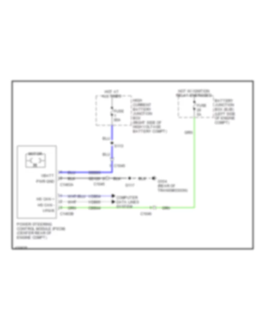
ELECTRONIC POWER STEERING
Electronic Power Steering Wiring Diagram for Ford C-Max Hybrid SEL 2014
List of elements for Electronic Power Steering Wiring Diagram for Ford C-Max Hybrid SEL 2014:
- Battery junction box (bjb) (left side of engine compt)
- C1045
- C1046
- C1463a
- C1463b
- Cbb44
- Computer data lines system
- Fuse 5a
- Fuse 80a
- G104 (rear of transmission)
- Gd120
- High current battery junction box (right side of high voltage battery compt)
- Hot at all times
- Hot w/ ignition relay energized
- Hs can +
- Hs can -
- Motor
- Power steering control module (pscm) (center rear of engine compt)
- Pwr gnd
- S113
- S117
- Sbb03
- Vbatt
- Vdb04
- Vdb05
- Vpwr
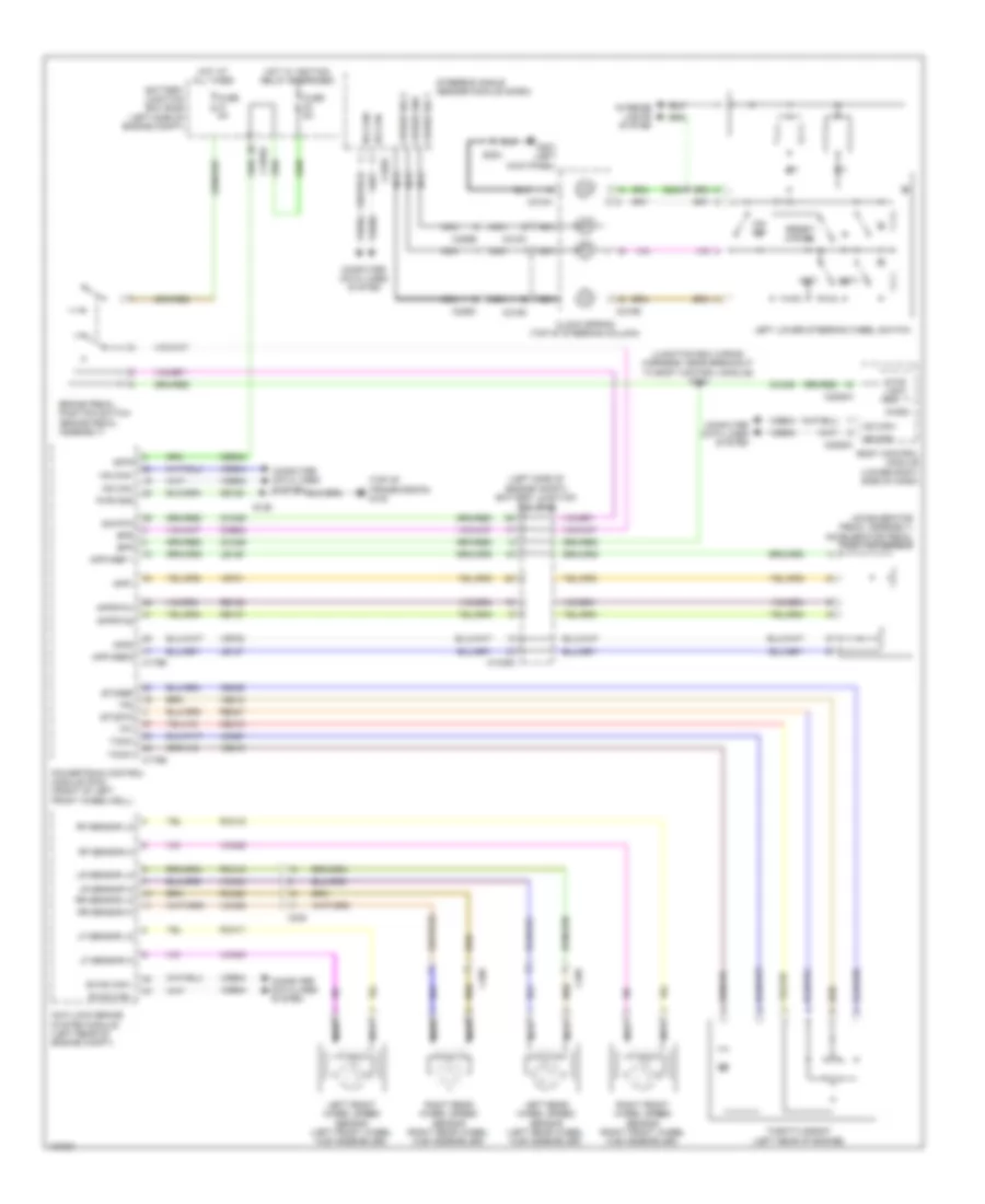
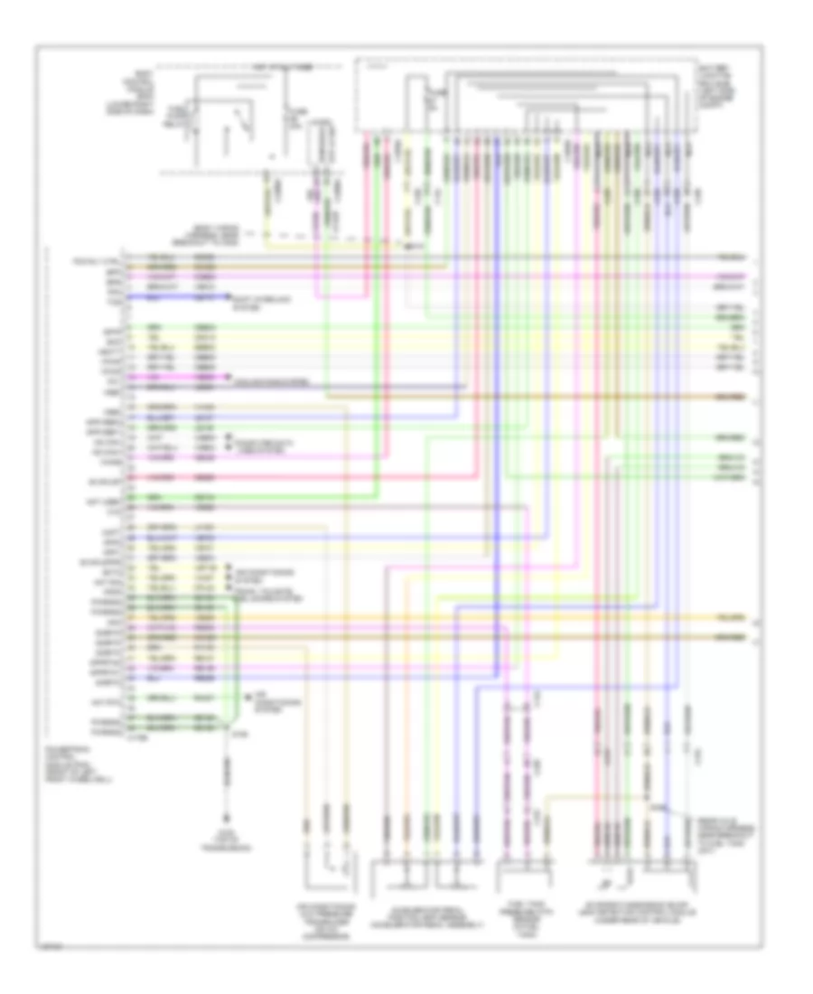
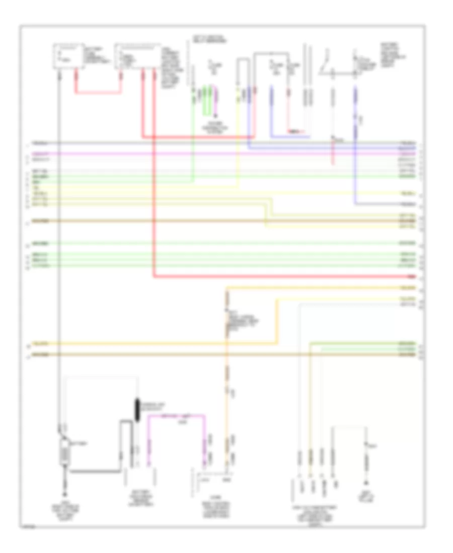
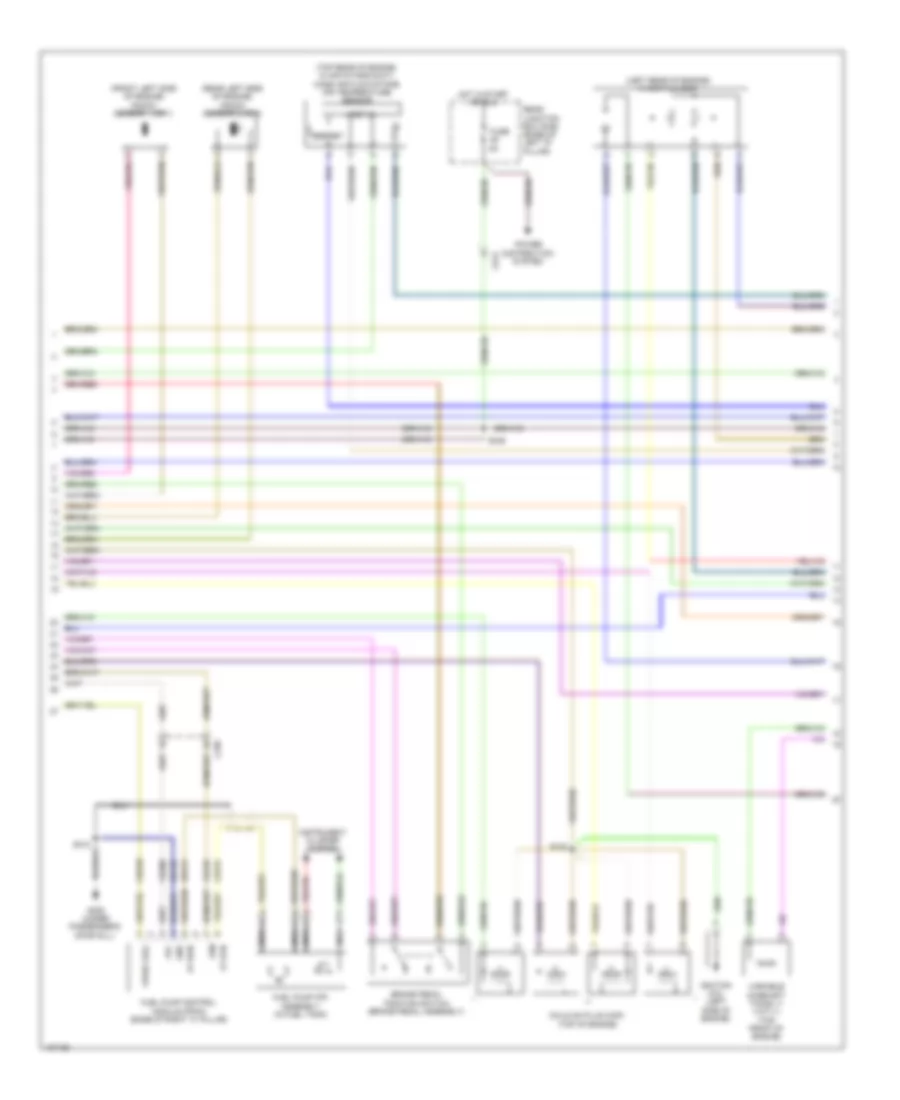
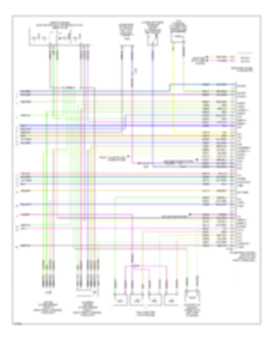
ENGINE PERFORMANCE
2.0L
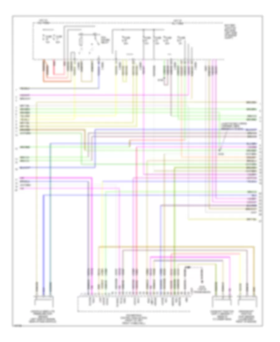
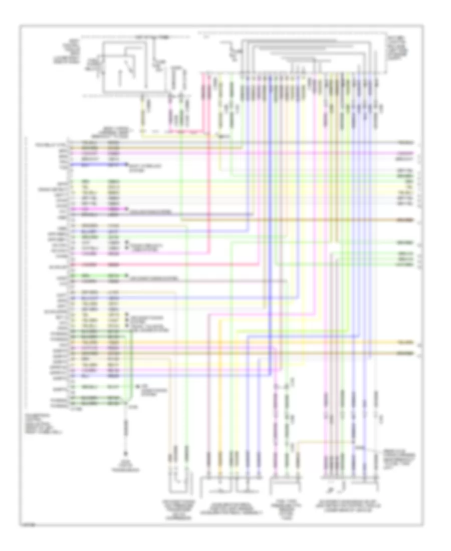
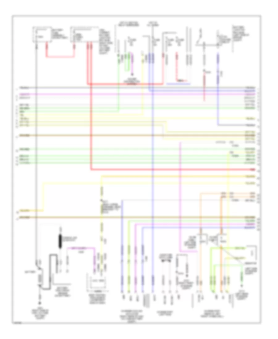
2.0L, Engine Performance Wiring Diagram, FHEV (1 of 8) for Ford C-Max Hybrid SEL 2014
List of elements for 2.0L, Engine Performance Wiring Diagram, FHEV (1 of 8) for Ford C-Max Hybrid SEL 2014:
- (body wiring harness, near breakout to c238)
- (rear axle wiring harness, near breakout to fuel tank unit)
- Aat rtn
- Aat sig
- Accelerator pedal position (app) sensor (accelerator pedal assembly)
- Acpt
- Air conditioning (a/c) pressure transducer (on a/c compressor)
- Air conditioning system
- App1
- App2
- Apprtn1
- Apprtn2
- Appvref1
- Appvref2
- Battery junction box (bjb) (left side of engine compt)
- Body control module (bcm) (lower right side of dash)
- Bpp
- Bps
- C1035c
- C134
- C175b
- C2280a
- C2280e
- C238
- C315
- Cbb08
- Cbb42
- Cca29
- Ccb08
- Cdc12
- Ce104
- Ce229
- Ce302
- Ce436
- Cet47
- Computer data lines system
- Cooling fans system
- Cpl24
- Ecm wake
- Ect2
- Evapldp
- Evapldppr
- Evaporative emission (evap) leak detection control module (under rear of vehicle)
- Fcv
- Ffdp
- Fpc
- Fpm
- Ftp
- Fuel pump relay
- Fuel tank pressure (ftp) sensor (in fuel tank)
- Fuse 20a
- Fuse 5a
- G108 (top of transmission)
- Gd120
- Hot at all times
- Hs can+
- Hs can-
- Isp-r
- Le136
- Le137
- Le230
- Lh108
- Micro
- Nca
- Not used
- Pcm rly ctrl
- Powertrain control module (pcm) (front of left front wheelwell)
- Pwrgnd
- Re136
- Re137
- Re230
- Re259
- Rh108
- Rh407
- S126
- S318
- S345
- Sbb30
- Shift interlock system
- Sigrtn
- Smc
- Stp lp sw
- Tcs
- Trunk, tailgate, fuel doors system
- Vbatt
- Vdb04
- Vdb05
- Ve203
- Ve225
- Ve518
- Ve701
- Ve702
- Ve922
- Ve934
- Vet1b
- Vh407
- Vh442
- Vpwr
- Vref
- Wake
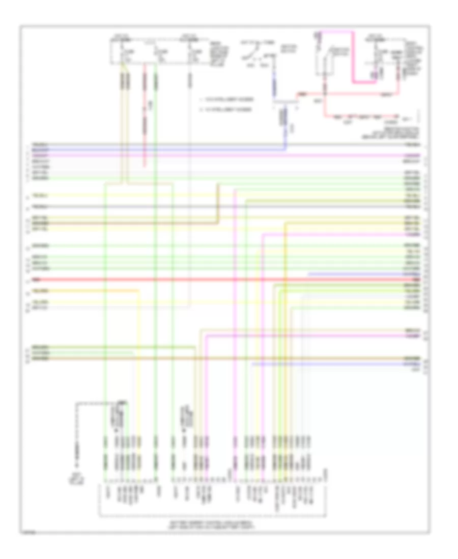
2.0L, Engine Performance Wiring Diagram, FHEV (2 of 8) for Ford C-Max Hybrid SEL 2014
List of elements for 2.0L, Engine Performance Wiring Diagram, FHEV (2 of 8) for Ford C-Max Hybrid SEL 2014:
- 150a
- Battery
- Battery fuse assembly (on battery)
- Battery junction box (bjb) (left side of engine compt)
- Battery monitoring sensor (on battery)
- Body control module (bcm) (lower right side of dash)
- C1035c
- C134
- C2280a
- C2280c
- C237
- C238
- Cdc56
- Ens
- Fan fb
- Fan pwm
- Fuse 25a
- Fuse 5a
- G307 (left "d" pillar)
- G401 (right side of high voltage battery compt)
- Gnd
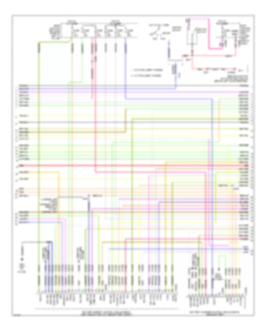
- High current battery junction box (bjb) (right side of high voltage battery compt)
- High voltage battery cooling fan (left side of high voltage battery compt)
- Hot w/ ignition
- Lin 8
- Mega fuse 2 175a
- Micro
- Nca
- Power distribution system
- Red
- Relay energized
- S115
- S124
- S317 (body wiring harness, near breakout to c312)
- S341
- Tcm power relay
- Vbatt
- Ve225
2.0L, Engine Performance Wiring Diagram, FHEV (3 of 8) for Ford C-Max Hybrid SEL 2014
List of elements for 2.0L, Engine Performance Wiring Diagram, FHEV (3 of 8) for Ford C-Max Hybrid SEL 2014:
- Acc
- Battery energy control module (becm) (left side of high voltage battery compt)
- Body control module (bcm) (lower right side of dash)
- C214
- C2280c
- C2280f
- C237
- C238
- C4237a
- C4237b
- C4392d
- Cbp27
- Cbr12
- Cbr17
- Cont pwr en
- Cs aout2
- Cs rtn
- Cs vref
- Cyb03
- Cyb04
- Cyc03
- Cyc04
- Cyc05
- Cyc06
- Cyd14
- Dcdc wkup
- Ens
- Fan fb
- Fan pwm
- Fuse 10a
- Fuse 15a
- Fuse 5a
- G307 (left "d" pillar)
- Gd151
- Hot at all times
- Hs can+
- Hs can-
- Hvi+
- Hvi-
- Ignition switch
- Logic gnd
- Lyc01
- Mc+ ctrl
- Mc- ctrl
- Micro
- Off
- Prc ctrl
- Pwr gnd
- Rear junction box (rjb) (base of left "d" pillar)
- Red
- Remote function actuator (rfa) module (behind left quarterpanel)
- Run
- Ryb18
- Ryc01
- S231
- S327
- Start
- Sw 1
- System data lines computer
- Temp rtn
- Temp sig
- Vbatt
- Vdb04
- Vdb05
- Ve225
- Ve740
- Ve751
- Vpwr
- Vyb18
- Vyc02
- W/ intelligent access
- W/o intelligent access
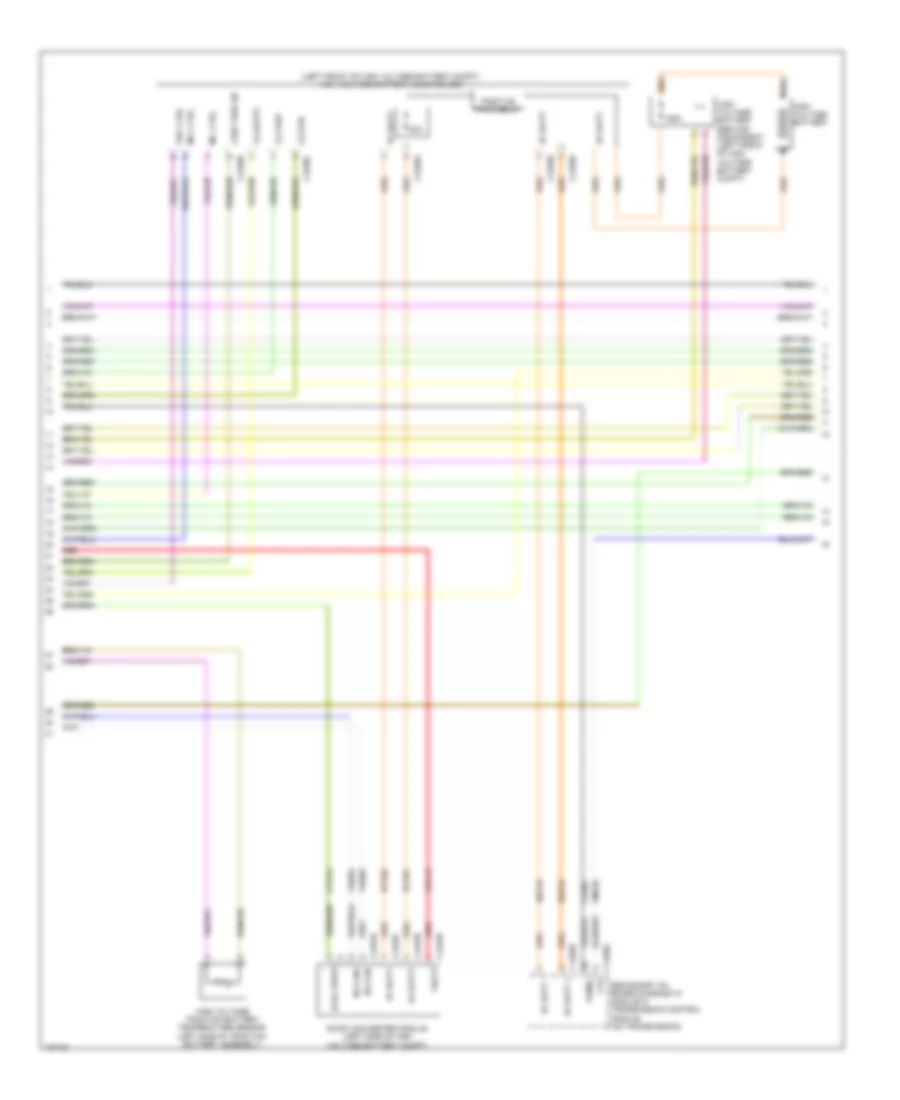
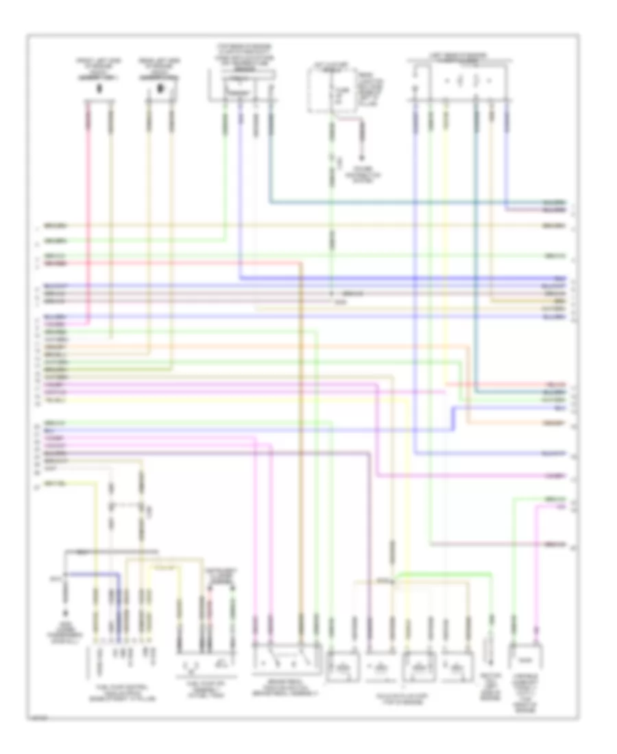
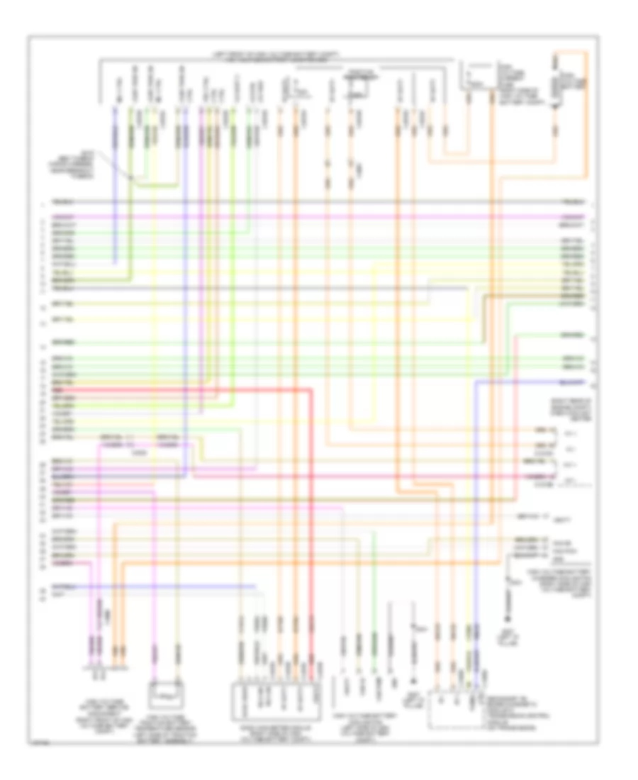
2.0L, Engine Performance Wiring Diagram, FHEV (4 of 8) for Ford C-Max Hybrid SEL 2014
List of elements for 2.0L, Engine Performance Wiring Diagram, FHEV (4 of 8) for Ford C-Max Hybrid SEL 2014:
- (left front of high voltage battery compt) high voltage battery junction box
- 125a
- 30a
- C1458a
- C1458e
- C4236a
- C4236b
- C4236c
- C4236d
- C4236e
- C4453a
- C4453b
- C4453c
- C4453d
- Cdc13
- Ce302
- Cont pwr en
- Cs aout2
- Cs rtn
- Cs vref
- Cto
- Cyd14
- Dc/dc converter module (left side of high voltage battery compt)
- Dcdc wkup
- Hdc52
- Hdc53
- High voltage battery
- High voltage battery service disconnect (left front of high voltage battery compt)
- High voltage traction battery temperature sensor (left side of traction battery assembly)
- Hs can+
- Hs can-
- Hv batt +
- Hv batt -
- Hv batt+
- Hv batt-
- Hyt01
- Hyt02
- Mc+ ctrl
- Mc- ctrl
- Positive pack relay
- Prc ctrl
- Red
- Secondary on board diagnostic module c/ transmission control module (on transmission)
- Tcmrc
- Vbatt
- Vdb04
- Vdb05
- Vmc02
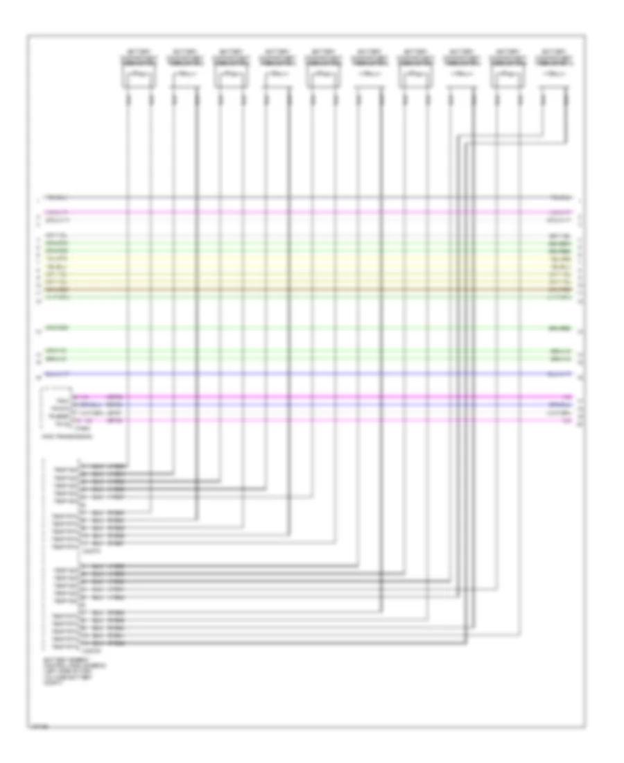
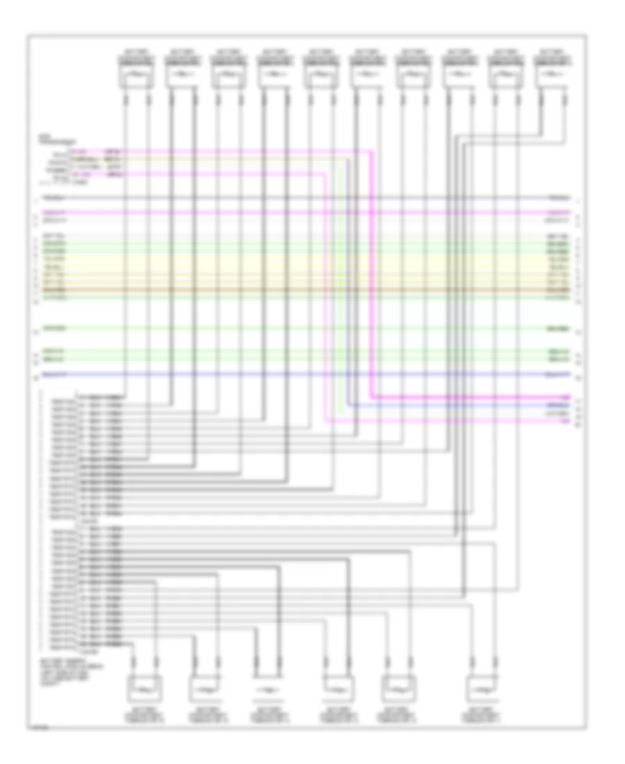
2.0L, Engine Performance Wiring Diagram, FHEV (5 of 8) for Ford C-Max Hybrid SEL 2014
List of elements for 2.0L, Engine Performance Wiring Diagram, FHEV (5 of 8) for Ford C-Max Hybrid SEL 2014:
- Battery compartment thermistor 1
- Battery compartment thermistor 10
- Battery compartment thermistor 2
- Battery compartment thermistor 3
- Battery compartment thermistor 4
- Battery compartment thermistor 5
- Battery compartment thermistor 6
- Battery compartment thermistor 7
- Battery compartment thermistor 8
- Battery compartment thermistor 9
- Battery energy control module (becm) (left side of high voltage battery compt)
- C168c
- C4237c
- C4237d
- Hf35 transmission
- Let57
- Ret24
- Ryb33
- Ryb34
- Ryb35
- Ryb36
- Ryb37
- Ryb38
- Ryb39
- Ryb40
- Ryb41
- Ryb42
- Temp rtn
- Temp sig
- Tr a2
- Tr bref
- Tr rtn
- Tra1
- Vet32
- Vyb33
- Vyb34
- Vyb35
- Vyb36
- Vyb37
- Vyb38
- Vyb39
- Vyb40
- Vyb41
- Vyb42
2.0L, Engine Performance Wiring Diagram, FHEV (6 of 8) for Ford C-Max Hybrid SEL 2014
List of elements for 2.0L, Engine Performance Wiring Diagram, FHEV (6 of 8) for Ford C-Max Hybrid SEL 2014:
- (junction box wiring harness, near breakout to bcm)
- 10a
- 15a
- 20a
- 30a
- Battery junction box (bjb) (left side of engine compt)
- C1035c
- C175t
- Camshaft position (cmp11) sensor 11 (rear of cylinder head)
- Ce303
- Ce304
- Ce305
- Ce306
- Ckp
- Cmp11
- Cop1a
- Cop2d
- Cop3b
- Cop4c
- Crankshaft position (ckp) sensor (lower right front of engine)
- Fuse
- G108 (top of transmission)
- Gd120
- Gnd
- Hot at all times
- Ks1+
- Ks1-
- Ks2+
- Ks2-
- Le143
- Le144
- Let57
- Manifold absolute pressure (map) sensor (left side of engine, near intake manifold)
- Pcm power relay
- Powertrain control module (pcm) (front of left front wheelwell)
- Re143
- Re144
- Re323
- Re324
- Red
- Ret24
- S106
- S120
- S126
- Sigrtn
- Tr a2
- Tr bref
- Tr rtn
- Tra1
- Vbpwr
- Ve706
- Ve707
- Ve801
- Ve802
- Vet32
- Vref
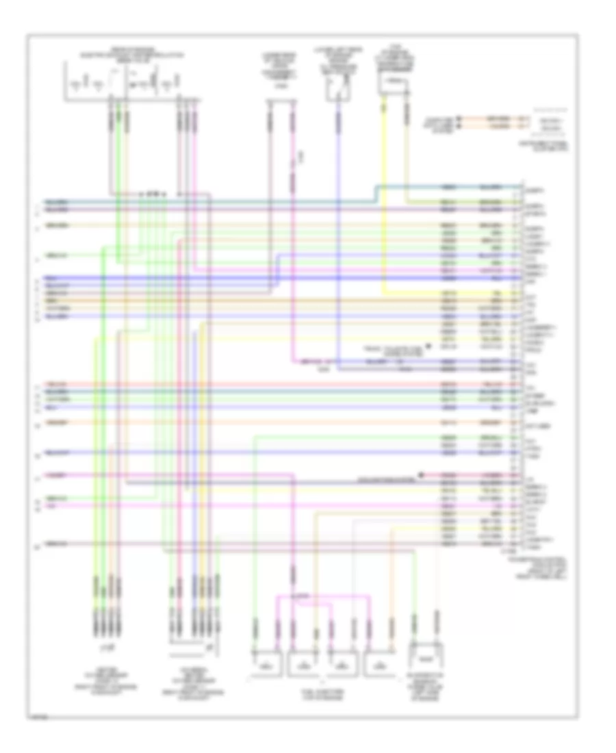
2.0L, Engine Performance Wiring Diagram, FHEV (7 of 8) for Ford C-Max Hybrid SEL 2014
List of elements for 2.0L, Engine Performance Wiring Diagram, FHEV (7 of 8) for Ford C-Max Hybrid SEL 2014:
- (front left side of engine) knock sensor 1 (ks 1)
- (left rear of engine) throttle body
- (rear left side of engine) knock sensor 2 (ks 2)
- (top rear of engine, in air intake duct) mass air flow/intake air temperature sensor
- Brake pedal position switch (brake pedal assembly)
- C238
- C315
- Cbb48
- Ce515
- Coils on plug (cop) (top of engine)
- Digital
- Fp pwr
- Fp rtn
- Fpc
- Fpm
- Fuel pump (fp) assembly (in fuel tank)
- Fuel pump control module (fpcm) (base of right "c" pillar)
- Fuse
- G305 (under passenger's door sill)
- Gd152
- Gnd
- Hot in start or run
- Ignition coil (left side of engine)
- Instrument cluster system
- Nca
- Power distribution system
- Re515
- Rear junction box (rjb) (base of left "d" pillar)
- S132
- S312
- S346
- Variable camshaft timing 11 (vct11) (top front of engine)
- Ve208
- Ve518
- Vpwr fuel
- Vref 5v
2.0L, Engine Performance Wiring Diagram, FHEV (8 of 8) for Ford C-Max Hybrid SEL 2014
List of elements for 2.0L, Engine Performance Wiring Diagram, FHEV (8 of 8) for Ford C-Max Hybrid SEL 2014:
- (lower left rear of engine) engine oil pressure (eop) switch
- (rear of engine) electric exhaust gas recirculation (eegr valve)
- (top of engine) cylinder head temperature (cht) sensor
- (under rear of vehicle) vapor management valve
- C134
- C175e
- C238
- C315
- Cbb06
- Ce101
- Ce102
- Ce103
- Ce104
- Ce113
- Ce173
- Ce205
- Ce206
- Ce207
- Ce208
- Ce227
- Ce233
- Ce412
- Ce421
- Ce426
- Ce908
- Cht
- Coil
- Computer data lines system
- Cooling fans system
- Cpl19
- Cto
- Egrmc 1
- Egrmc 2
- Egrmc 3
- Egrmc 4
- Etcref
- Etcrtn
- Evapcp
- Evapldpsv
- Evaporative emission purge valve (left side of engine)
- Ffduc
- Fuel injectors (top of engine)
- Heated oxygen sensor (ho2s) 12 (right front of engine, in exhaust)
- Ho2s12
- Htr12
- Iat
- Inj1
- Inj2
- Inj3
- Inj4
- Instrument panel cluster (ipc)
- Le329
- Le428
- Le451
- Le452
- Lin
- Maf
- Map
- Ms can +
- Ms can -
- Nca
- Not used
- Ops
- Powertrain control module (pcm) (front of left front wheelwell)
- Re141
- Re242
- Re329
- Re427
- Re803
- S130
- S133
- Sigrtn
- Tacm+
- Tacm-
- Tp1
- Tp2
- Trunk, tailgate, fuel doors system
- Universal heated oxygen sensor (ho2s) 11 (right front of engine, in exhaust)
- Uo2s11
- Uo2sgref11
- Uo2shtr11
- Uo2spc11
- Uo2spct11
- Vct11
- Vdn08
- Ve716
- Ve731
- Ve803
- Ve818
- Ve819
- Ve826
- Ve827
- Vmc02
- Vmv
- Vref
- Za113
2.0L, Engine Performance Wiring Diagram, PHEV (1 of 8) for Ford C-Max Hybrid SEL 2014
List of elements for 2.0L, Engine Performance Wiring Diagram, PHEV (1 of 8) for Ford C-Max Hybrid SEL 2014:
- (body wiring harness, near breakout to c238)
- (rear axle wiring harness, near breakout to fuel tank unit)
- Aat
- Accelerator pedal position (app) sensor (accelerator pedal assembly)
- Acpt
- Air conditioning (a/c) pressure transducer (on a/c compressor)
- Air conditioning system
- Air conditioning system trunk, tailgate, fuel doors system
- App1
- App2
- Apprtn1
- Apprtn2
- Appvref1
- Appvref2
- Battery junction box (bjb) (left side of engine compt)
- Body control module (bcm) (lower right side of dash)
- Bpp
- Bps
- C1035c
- C134
- C175b
- C2280a
- C2280e
- C238
- C315
- Cbb08
- Cbb42
- Cca29
- Ccb08
- Cdc12
- Ce104
- Ce229
- Ce302
- Ce436
- Cet47
- Computer data lines system
- Cooling fans system
- Cpl24
- Crank detect
- Ecm wake
- Ect 2
- Evapldp
- Evapldppr
- Evaporative emission (evap) leak detection control module (under rear of vehicle)
- Fcv
- Ffdp
- Fpc
- Fpm
- Ftp
- Fuel pump relay
- Fuel tank pressure (ftp) sensor (in fuel tank)
- Fuse 20a
- Fuse 5a
- G108 (top of transmission)
- Gd120
- Hcso
- Hot at all times
- Hs can+
- Hs can-
- Isp-r
- Le136
- Le137
- Le230
- Lh108
- Micro
- Nca
- Pcm relay ctrl
- Powertrain control module (pcm) (front of left front wheelwell)
- Pwrgnd
- Re136
- Re137
- Re230
- Re259
- Rh107
- Rh108
- S126
- S318
- S345
- Sbb30
- Shift interlock system
- Sigrtn
- Stp lp sw
- Tcs
- Vbatt
- Vdb04
- Vdb05
- Ve203
- Ve225
- Ve518
- Ve701
- Ve702
- Ve716
- Ve922
- Ve934
- Vh407
- Vh442
- Vpwr
- Vref
- Wake
2.0L, Engine Performance Wiring Diagram, PHEV (2 of 8) for Ford C-Max Hybrid SEL 2014
List of elements for 2.0L, Engine Performance Wiring Diagram, PHEV (2 of 8) for Ford C-Max Hybrid SEL 2014:
- (left side of engine compt)
- 150a
- 40a
- Batt
- Battery
- Battery fuse assembly (on battery)
- Battery junction box (bjb) (left side of engine compt)
- Battery monitoring sensor (on battery)
- Body control module (bcm) (lower right side of dash)
- C1035c
- C134
- C1824
- C2280a
- C2280c
- C237
- C238
- C495
- Cdc56
- Charge port (rear of left front wheelwell)
- Charge port light ring
- Charger cooling actuator (right rear of high voltage battery compt)
- Computer data lines system
- Cp rtn
- Cp sig
- Ens
- Feedback
- Fuse 25a
- Fuse 5a
- G107 (right front of engine compt)
- G113 (left rear of engine compt)
- G401 (right side of high voltage battery compt)
- Gnd
- High current battery junction box (bjb) (right side of high voltage battery compt)
- Hot at all times
- Hot w/ ignition relay energized
- Hs can +
- Hs can -
- Hv +
- Hv -
- Inline fuse 1 (left side of engine compt)
- Inline fuse 2
- Lin 8
- Mega fuse 2 175a
- Micro
- Mtr +
- Mtr -
- Nca
- Power distribution system
- Red
- Resistor
- S104
- S115
- S124
- S317 (body wiring harness, near breakout to c312)
- Tcm power relay
- Ve225
2.0L, Engine Performance Wiring Diagram, PHEV (3 of 8) for Ford C-Max Hybrid SEL 2014
List of elements for 2.0L, Engine Performance Wiring Diagram, PHEV (3 of 8) for Ford C-Max Hybrid SEL 2014:
- (license lamp wiring harness, near breakout to left license lamp)
- Acc
- Battery charger control module (bccm) (near battery)
- Battery energy control module (becm) (left side of high voltage battery compt)
- Body control module (bcm) (lower right side of dash)
- C214
- C2280c
- C2280f
- C237
- C238
- C4000
- C4392d
- C4455a
- C4455b
- C4816a
- C4816b wk up dc/dc
- Cbp27
- Cbr12
- Cbr14
- Cbr17
- Cbr26
- Ce140
- Computer data lines system
- Cont
- Cp rtn
- Cp sig
- Cs aout 2
- Cs rtn
- Cs vref
- Ctrl
- Cyb03
- Cyb04
- Cyb10
- Cyb12
- Cyb13
- Cyb55
- Cyb56
- Cyc03
- Cyc04
- Cyc05
- Cyc06
- Cyc07
- Cyc08
- Cyc09
- Cyd14
- Ens
- Fan fb
- Fan pwm
- Feedback
- Fuse 10a
- Fuse 15a
- Fuse 40a
- Fuse 5a
- G307 (left "d" pillar)
- G404 (near battery)
- Gd145
- Gnd
- Hot at all times
- Hs can+
- Hs can-
- Hv +
- Hv -
- Hvi+
- Hvi-
- Hyb53
- Hyb54
- Ignition switch
- Logic gnd
- Lyc01
- Mc+ ctrl
- Mc-ctrl
- Micro
- Mtr +
- Mtr -
- Off
- Prc ctrl
- Pwr en
- Pwr gnd
- Rear junction box (rjb) (base of left "d" pillar)
- Red
- Remote function actuator (rfa) module (behind left quarterpanel)
- Run
- Ryb10
- Ryb18
- Ryb57
- Ryc01
- S231
- S327
- S407
- Start
- Sw 1
- System data lines computer
- Temp rtn
- Temp sig
- Vbatt
- Vdb04
- Vdb05
- Ve225
- Ve740
- Vpwr
- Vyb18
- Vyc02
- W/ intelligent access
- W/o intelligent access
- Wake
2.0L, Engine Performance Wiring Diagram, PHEV (4 of 8) for Ford C-Max Hybrid SEL 2014
List of elements for 2.0L, Engine Performance Wiring Diagram, PHEV (4 of 8) for Ford C-Max Hybrid SEL 2014:
- (left front of high voltage battery compt) high voltage battery junction box
- (right front of high voltage battery compt)
- (right rear of engine compt) cabin coolant heater
- 200a
- 30a
- C1458a
- C1458e
- C1815a
- C1815b
- C4000
- C4001
- C4002
- C4453a
- C4453b
- C4453c
- C4453d
- C4815a
- C4815b
- C4815c
- C4815d
- C4815e
- C4815f
- C4815g
- C4815h
- Cdc13
- Ce302
- Cont pwr en
- Cs aout 2
- Cs rtn
- Cs vref
- Cto
- Ctrl
- Cyd14
- Dc/dc converter module (right side of high voltage battery compt)
- Dcdc wkup
- Fan fb
- Fan pwm
- G307 (left "d" pillar)
- Gnd
- Hdc52
- Hdc53
- High voltage battery
- High voltage battery charger cooling fan (right side of high voltage battery compt)
- High voltage battery cooling fan (left side of high voltage battery compt)
- High voltage battery service disconnect
- High voltage current fuse (right side of high voltage battery compt)
- High voltage traction battery temperature sensor (left side of traction battery assembly)
- Hs can+
- Hs can-
- Hv +
- Hv -
- Hv batt+
- Hv batt-
- Hvi +
- Hvi -
- Hvi-
- Hyt01
- Hyt02
- Mc+ ctrl
- Mc- ctrl
- Positive pack relay
- Prc ctrl
- Red
- S341
- S415 (bec to becm wiring harness, near breakout to becm)
- Secondary on board diagnostic module c/ transmission control module (on transmission)
- Tcmrc
- Vbatt
- Vdb04
- Vdb05
- Vmc02
2.0L, Engine Performance Wiring Diagram, PHEV (5 of 8) for Ford C-Max Hybrid SEL 2014
List of elements for 2.0L, Engine Performance Wiring Diagram, PHEV (5 of 8) for Ford C-Max Hybrid SEL 2014:
- Battery compartment thermistor 1
- Battery compartment thermistor 10
- Battery compartment thermistor 11
- Battery compartment thermistor 12
- Battery compartment thermistor 13
- Battery compartment thermistor 14
- Battery compartment thermistor 15
- Battery compartment thermistor 16
- Battery compartment thermistor 2
- Battery compartment thermistor 3
- Battery compartment thermistor 4
- Battery compartment thermistor 5
- Battery compartment thermistor 6
- Battery compartment thermistor 7
- Battery compartment thermistor 8
- Battery compartment thermistor 9
- Battery energy control module (becm) (left side of high voltage battery compt)
- C168c
- C4816c
- C4816d
- Hf35 transmission
- Let57
- Ret24
- Ryb41
- Ryb42
- Ryb43
- Ryb44
- Ryb45
- Ryb46
- Ryb47
- Ryb48
- Ryb49
- Ryb50
- Ryb51
- Ryb52
- Ryb53
- Ryb54
- Ryb55
- Ryb56
- Temp rtn
- Temp sig
- Tr a1
- Tr a2
- Tr bref
- Tr rtn
- Vet32
- Vyb41
- Vyb42
- Vyb43
- Vyb44
- Vyb45
- Vyb46
- Vyb47
- Vyb48
- Vyb49
- Vyb50
- Vyb51
- Vyb52
- Vyb53
- Vyb54
- Vyb55
- Vyb56
2.0L, Engine Performance Wiring Diagram, PHEV (6 of 8) for Ford C-Max Hybrid SEL 2014
List of elements for 2.0L, Engine Performance Wiring Diagram, PHEV (6 of 8) for Ford C-Max Hybrid SEL 2014:
- (junction box wiring harness, near breakout to bcm)
- 10a
- 15a
- 20a
- 30a
- Battery junction box (bjb) (left side of engine compt)
- C1035c
- C175t
- Camshaft position (cmp11) sensor 11 (rear of cylinder head)
- Ce303
- Ce304
- Ce305
- Ce306
- Ckp
- Cmp11
- Cop1a
- Cop2d
- Cop3b
- Cop4c
- Crankshaft position (ckp) sensor (lower right front of engine)
- Fuse
- G108 (top of transmission)
- Gd120
- Gnd
- Hot at all times
- Ks1+
- Ks1-
- Ks2+
- Ks2-
- Le143
- Le144
- Let57
- Manifold absolute pressure (map) sensor (left side of engine, near intake manifold)
- Pcm power relay
- Powertrain control module (pcm) (front of left front wheelwell)
- Re143
- Re144
- Re323
- Re324
- Red
- Ret24
- S106
- S120
- S126
- Sigrtn
- Tr a1
- Tr a2
- Tr bref
- Tr rtn
- Vbpwr
- Ve706
- Ve707
- Ve801
- Ve802
- Vet32
- Vref
2.0L, Engine Performance Wiring Diagram, PHEV (7 of 8) for Ford C-Max Hybrid SEL 2014
List of elements for 2.0L, Engine Performance Wiring Diagram, PHEV (7 of 8) for Ford C-Max Hybrid SEL 2014:
- (front left side of engine) knock sensor 1 (ks 1)
- (left rear of engine) throttle body
- (rear left side of engine) knock sensor 2 (ks 2)
- (top rear of engine, in air intake duct) mass air flow/intake air temperature sensor
- Brake pedal position switch (brake pedal assembly)
- C238
- C315
- Cbb48
- Ce515
- Coils on plug (cop) (top of engine)
- Digital
- Fp pwr
- Fp rtn
- Fpc
- Fpm
- Fuel pump (fp) assembly (in fuel tank)
- Fuel pump control module (fpcm) (base of right "c" pillar)
- Fuse
- G305 (under passenger's door sill)
- Gd152
- Gnd
- Hot in start or run
- Ignition coil (left side of engine)
- Instrument cluster system
- Nca
- Power distribution system
- Re515
- Rear junction box (rjb) (base of left "d" pillar)
- S132
- S312
- S346
- Variable camshaft timing 11 (vct11) (top front of engine)
- Ve208
- Ve518
- Vpwr fuel
- Vref 5v
2.0L, Engine Performance Wiring Diagram, PHEV (8 of 8) for Ford C-Max Hybrid SEL 2014
List of elements for 2.0L, Engine Performance Wiring Diagram, PHEV (8 of 8) for Ford C-Max Hybrid SEL 2014:
- (lower left rear of engine) engine oil pressure (eop) switch
- (rear of engine) electric exhaust gas recirculation (eegr valve)
- (top of engine) cylinder head temperature (cht) sensor
- (under rear of vehicle) fuel tank isolation valve
- Air conditioning system
- C134
- C175e
- C238
- C315
- Cbb06
- Ce101
- Ce102
- Ce103
- Ce104
- Ce113
- Ce173
- Ce205
- Ce206
- Ce207
- Ce208
- Ce227
- Ce233
- Ce412
- Ce421
- Ce426
- Ce908
- Chf01
- Cht
- Coil
- Computer data lines system
- Cooling fans system
- Cpl19
- Cto
- Egrmc 1
- Egrmc 2
- Egrmc 3
- Egrmc 4
- Etcref
- Etcrtn
- Evapcp
- Evapldpsv
- Evaporative emission purge valve (left side of engine)
- Ffduc
- Ftiv
- Fuel injectors (top of engine)
- Heated oxygen sensor (ho2s) 12 (right front of engine, in exhaust)
- Ho2s12
- Htr12
- Iat
- Inj1
- Inj2
- Inj3
- Inj4
- Instrument panel cluster (ipc)
- Le329
- Le428
- Le451
- Le452
- Lin
- Maf
- Map
- Ms can +
- Ms can -
- Nca
- Not used
- Ops
- Powertrain control module (pcm) (front of left front wheelwell)
- Pwm
- Re141
- Re242
- Re329
- Re427
- Re803
- S130
- S133
- Sig rtn
- Sigrtn
- Tacm+
- Tacm-
- Tp1
- Tp2
- Trunk, tailgate, fuel doors system
- Universal heated oxygen sensor (ho2s) 11 (right front of engine, in exhaust)
- Uo2s11
- Uo2sgref11
- Uo2shtr11
- Uo2spc11
- Uo2spct11
- Vct11
- Vdn08
- Ve716
- Ve731
- Ve803
- Ve818
- Ve819
- Ve826
- Ve827
- Vmc02
- Vref
- Za113
EXTERIOR LIGHTS
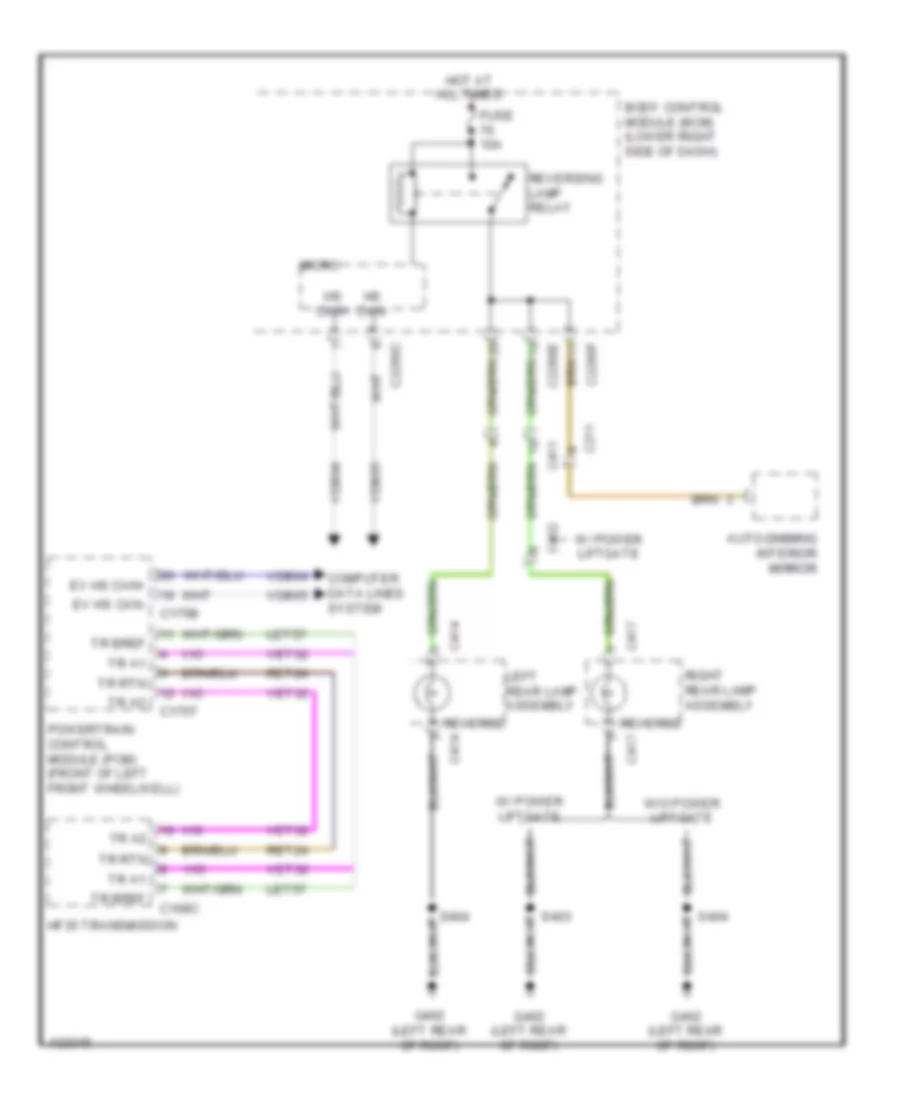
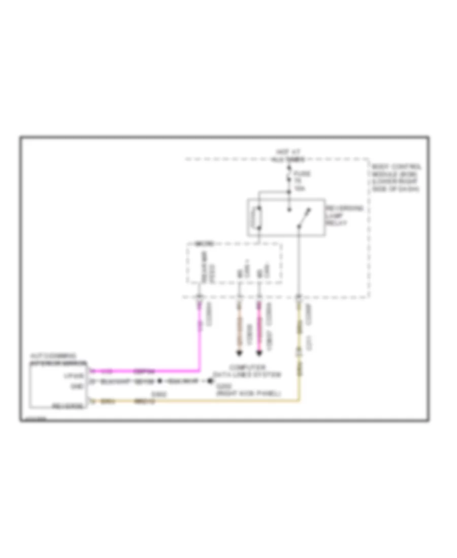
Backup Lamps Wiring Diagram for Ford C-Max Hybrid SEL 2014
List of elements for Backup Lamps Wiring Diagram for Ford C-Max Hybrid SEL 2014:
- Auto-dimming interior mirror
- Body control module (bcm) (lower right side of dash)
- C168c
- C175b
- C175t
- C211
- C2280c
- C2280e
- C2280f
- C411
- C414
- C417
- C432
- Computer data lines system
- Ev hs can+
- Ev hs can-
- Fuse 10a
- G402 (left rear of roof)
- Hf35 transmission
- Hot at all times
- Hs can+
- Hs can-
- Left rear lamp assembly
- Let57
- Micro
- Powertrain control module (pcm) (front of left front wheelwell)
- Ret24
- Reverse
- Reversing lamp relay
- Right rear lamp assembly
- S403
- S404
- Tr a1
- Tr a2
- Tr bref
- Tr rtn
- Vdb04
- Vdb05
- Vet32
- W/ power liftgate
- W/o power liftgate
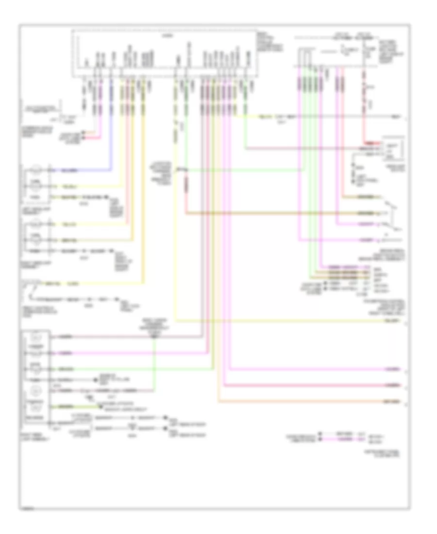
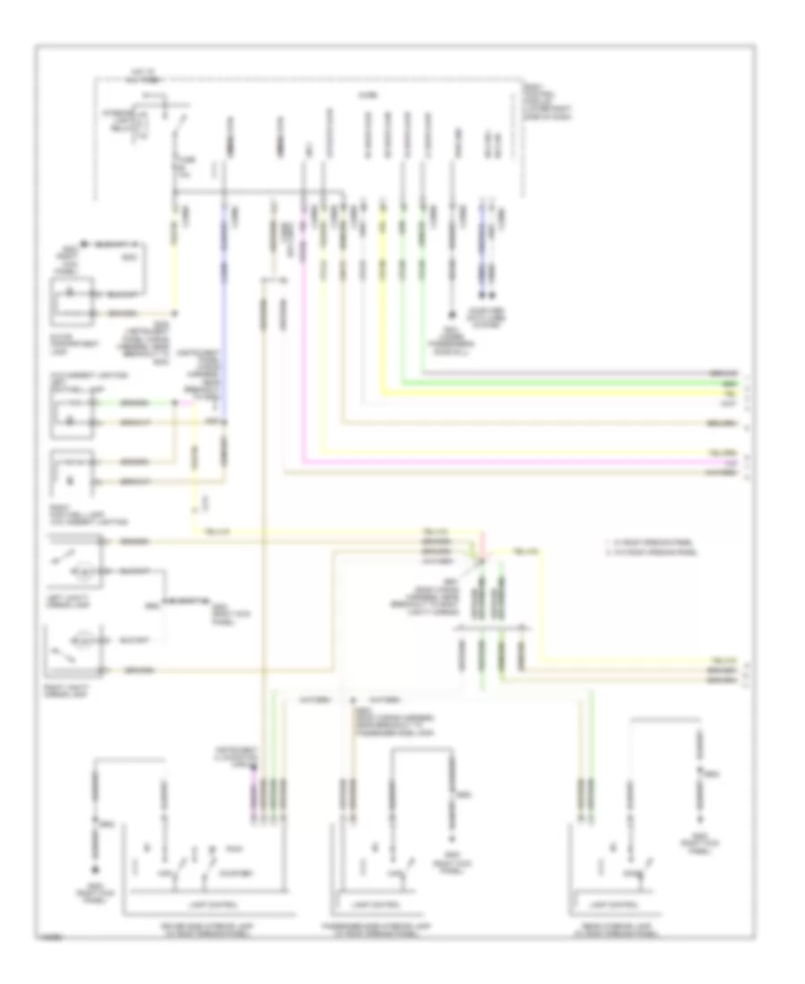
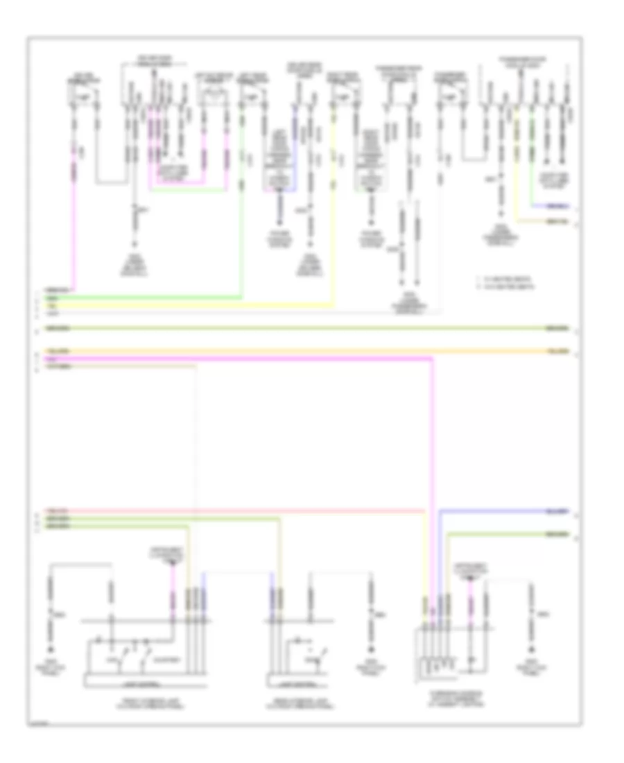
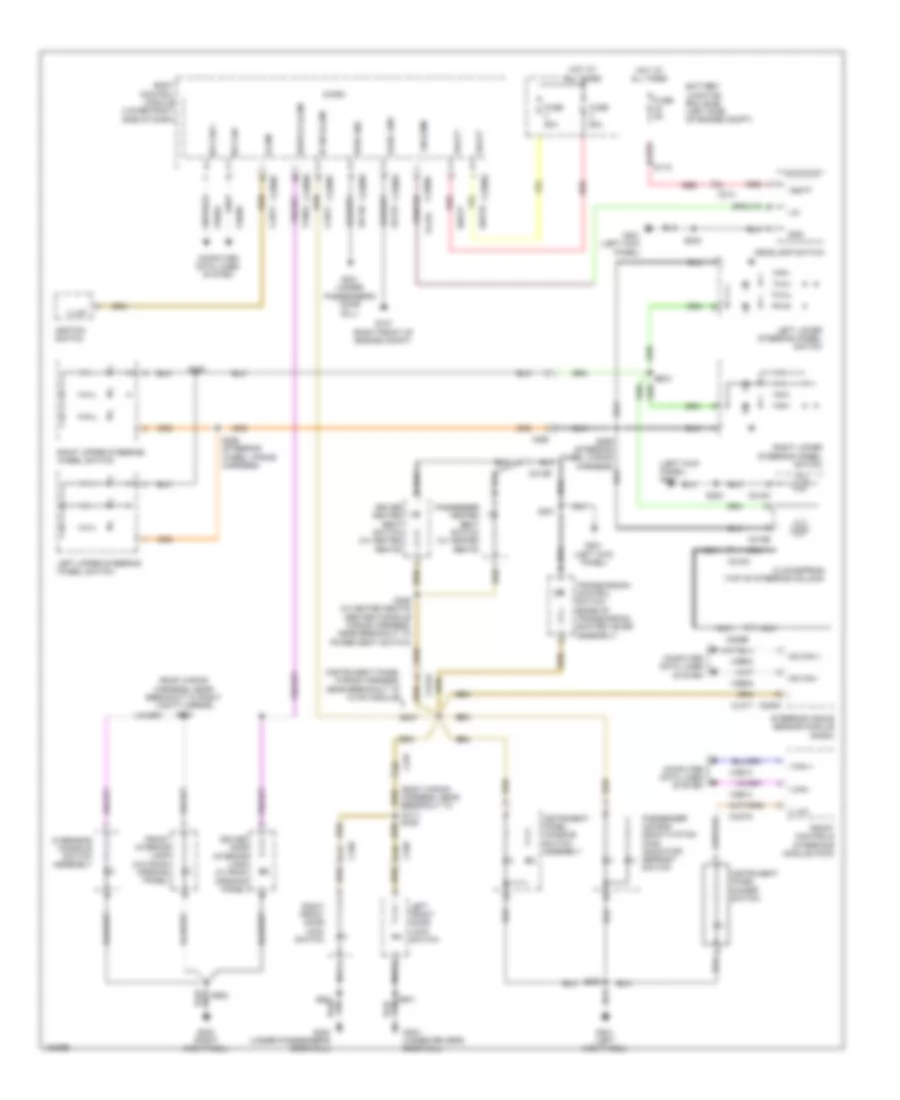
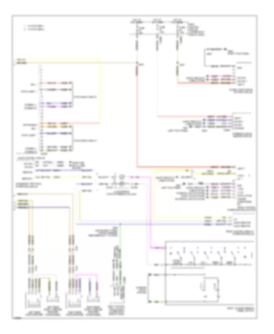
Exterior Lamps Wiring Diagram (1 of 2) for Ford C-Max Hybrid SEL 2014
List of elements for Exterior Lamps Wiring Diagram (1 of 2) for Ford C-Max Hybrid SEL 2014:
- (base of right "d" pillar) g304
- (body wiring harness, near breakout to bcm) s324
- (junction box wiring harness, near breakout to bcm)
- (left kick panel) g201
- Backup lamps circuit
- Battery junction box (bjb) (left side of engine compt)
- Body control module (lower right side of dash)
- Bpp
- Bps
- Brake pedal position switch (brake pedal assembly)
- C1035c
- C175b
- C214
- C226a
- C2280a
- C2280b
- C2280c
- C411
- C415
- C417
- C432
- Cca29
- Ccb08
- Chmsl
- Cls04
- Cls07
- Cls08
- Cls09
- Cls13
- Cls17
- Cls21
- Cls23
- Cls25
- Cls27
- Cls32
- Cls44
- Computer data lines system
- Front controls interface module (fcim)
- Fuse 21 5a
- Fuse 5a
- G105 (left side of engine compt)
- G107 (right front of engine compt)
- G201 (left kick panel)
- G402 (left rear of roof)
- Gd133
- Gnd
- Hazard warning
- Headlamp switch
- Hot at all times
- Hs can +
- Hs can -
- Instrument panel cluster (ipc)
- Left headlamp assembly
- Lf park
- Lf stp
- Lf turn
- License pl
- Lin
- Lin (lsm)
- Lin 1
- Lr park
- Lr turn
- Marker
- Micro
- Ms can +
- Ms can -
- Ms can+
- Ms can-
- Multi-function switch
- Park
- Position
- Powertrain control module (pcm) (front of left front wheelwell)
- Red
- Reverse
- Rf park
- Rh stp
- Right headlamp assembly
- Right rear lamp assembly
- Right turn
- Rr park
- Rr turn
- S102
- S107
- S115
- S120
- S202
- S403
- S404
- Sig sw/
- Sigrtn
- Steering angle sensor module (sasm)
- Stop
- Stop lgt sw
- Turn
- Vbatt
- Vdb04
- Vdb05
- Vdb06
- Vdb07
- Vlf25
- Vmc34
- W/ power liftgate
- W/o power liftgate
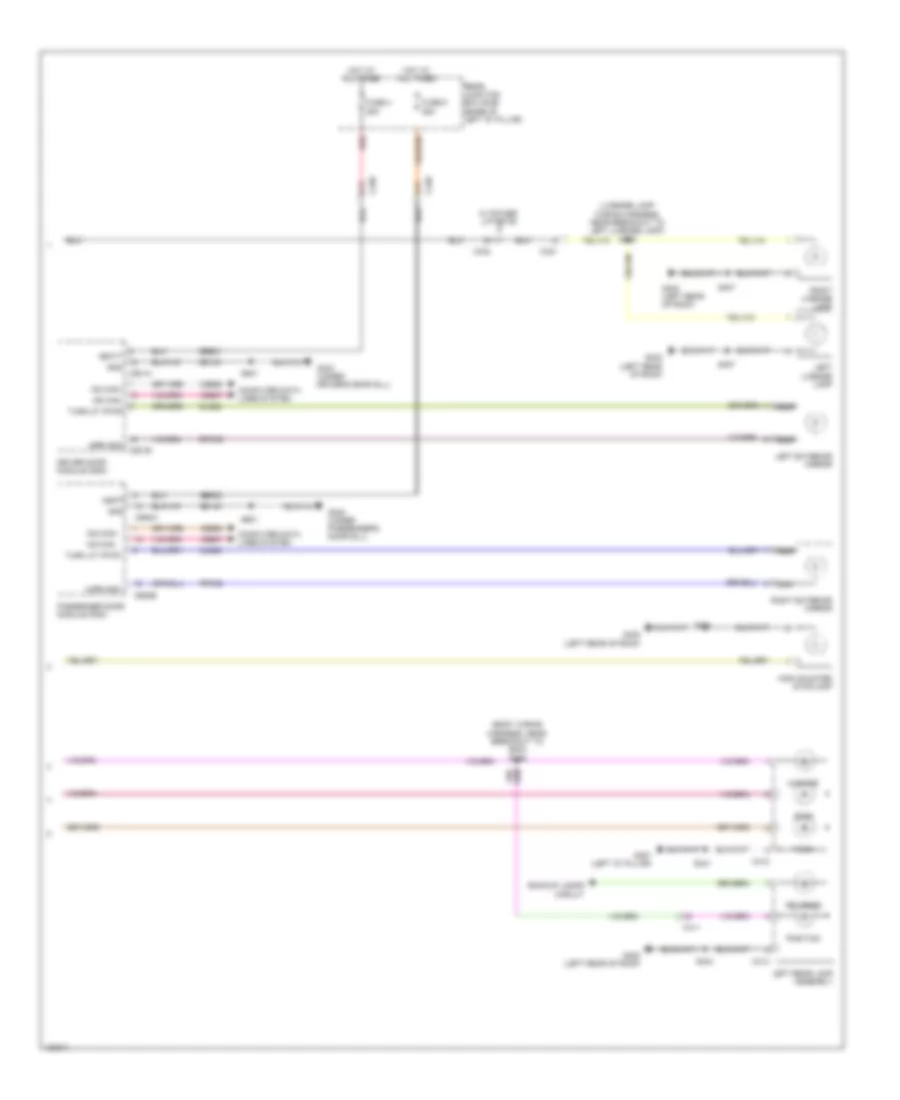
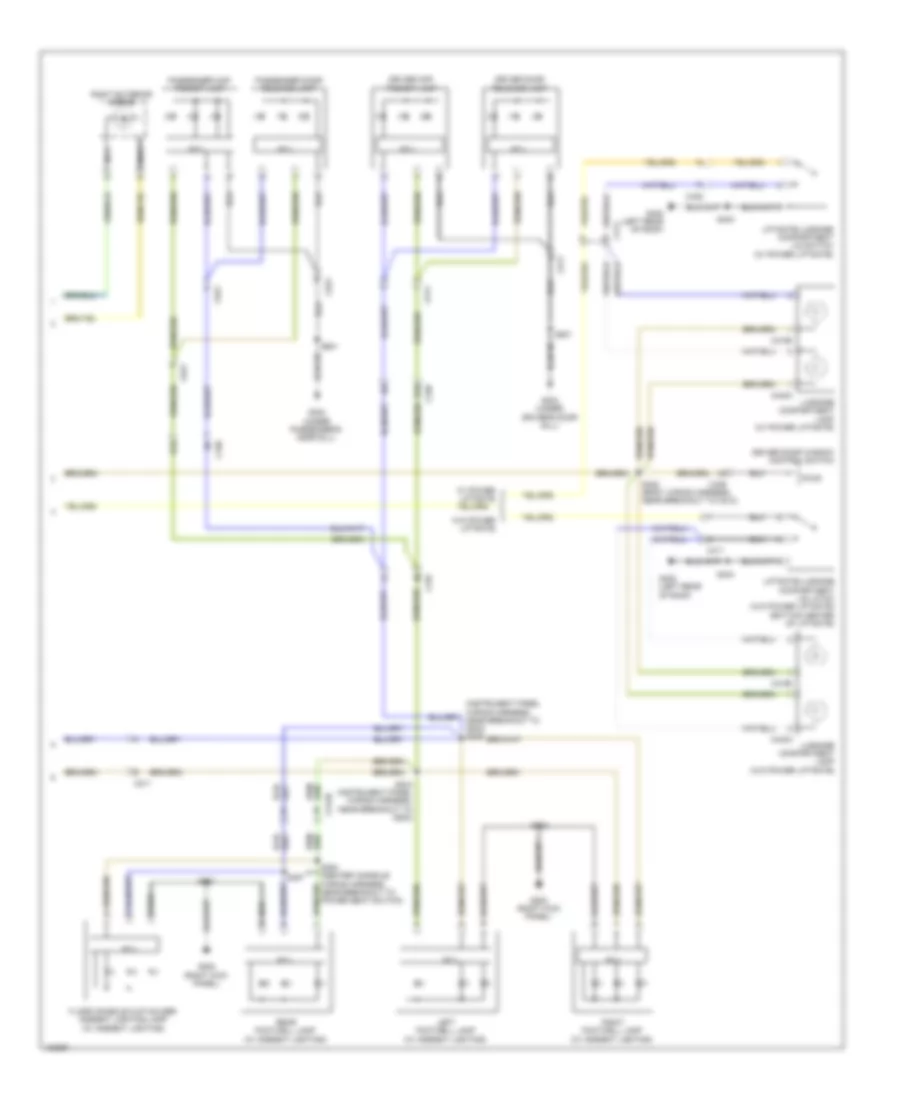
Exterior Lamps Wiring Diagram (2 of 2) for Ford C-Max Hybrid SEL 2014
List of elements for Exterior Lamps Wiring Diagram (2 of 2) for Ford C-Max Hybrid SEL 2014:
- (body wiring harness, near breakout to bcm) s326
- (license lamp wiring harness, near breakout to left license lamp) s408
- A14
- Backup lamps circuit
- C339
- C340
- C411
- C412
- C414
- C421
- C432
- C501a
- C501b
- C652a
- C652b
- Cls22
- Cls26
- Computer data lines system
- Driver door module (ddm)
- Fuse 4 25a
- Fuse 5 25a
- G302 (under passenger's door sill)
- G303 (under driver's door sill)
- G307 (left "d" pillar)
- G402 (left rear of roof)
- Gd134
- Gd140
- Gnd
- High mounted stoplamp
- Hot at all times
- Left exterior mirror
- Left license lamp
- Left rear lamp assembly
- Marker
- Mirr gnd
- Ms can+
- Ms can-
- Nca
- Passenger door module (pdm)
- Position
- Rear junction box (rjb) (base of left "d" pillar)
- Red
- Reverse
- Right exterior mirror
- Right license lamp
- Rpmo5
- Rpmo8
- S341
- S404
- S407
- S501
- S601
- Sbr01
- Sbr02
- Stop
- Turn
- Turn lp vpwr
- Vbatt
- Vdb06
- Vdb07
- W/ power liftgate
GROUND DISTRIBUTION
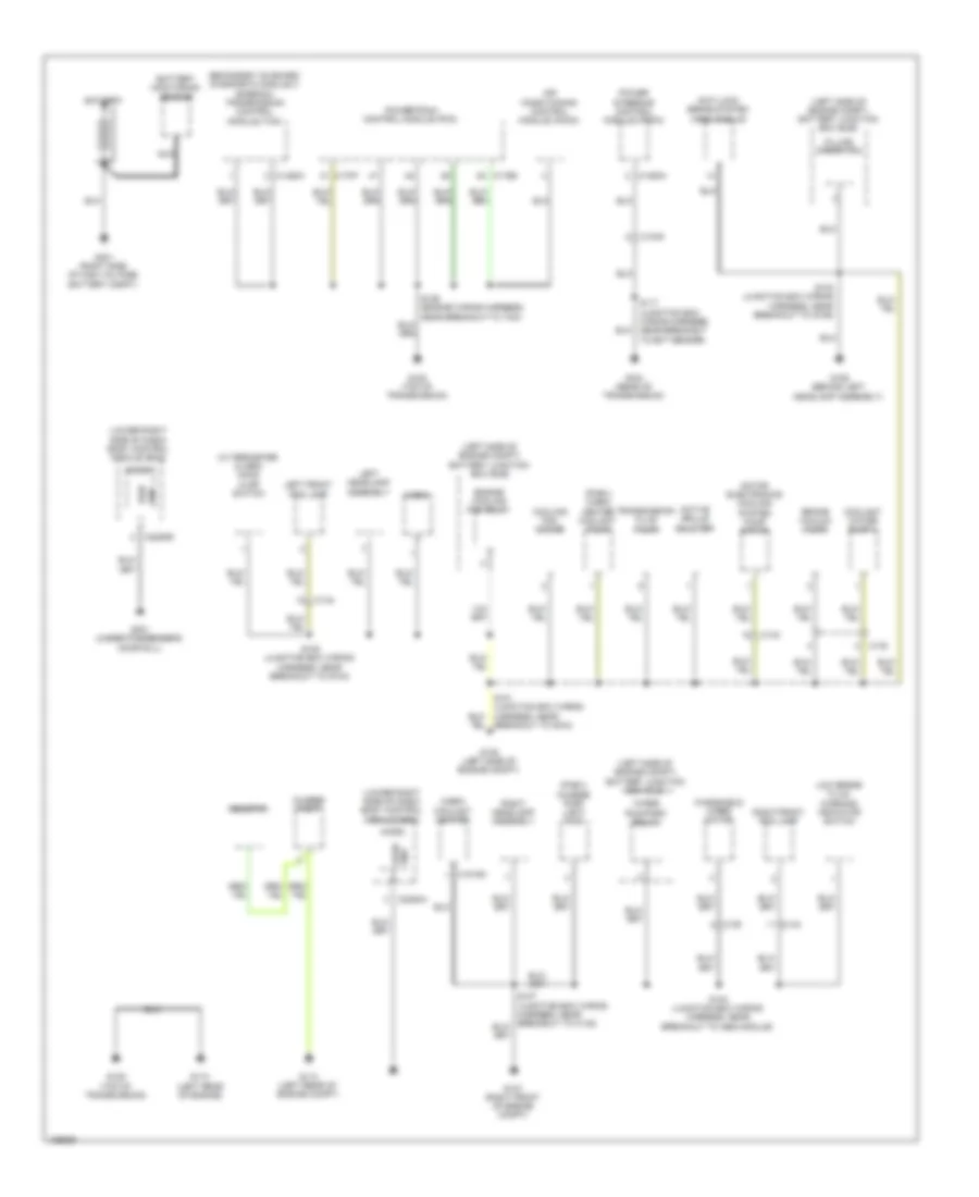
Ground Distribution Wiring Diagram (1 of 4) for Ford C-Max Hybrid SEL 2014
List of elements for Ground Distribution Wiring Diagram (1 of 4) for Ford C-Max Hybrid SEL 2014:
- (left side of engine compt) battery junction box (bjb)
- (lower right side of dash) body control module (bcm)
- (phev) cabin heater coolant pump
- (phev) charge port light ring
- (w/ perimeter alarm) hood ajar switch
- Active grille shutter
- Air conditioning control module (accm)
- Anti-lock brake system (abs) module
- Battery
- Battery monitoring sensor
- Brake vacuum pump
- Breakout to g104)
- C1045
- C134
- C139
- C140
- C144
- C1458a
- C1463a
- C175b
- C175t
- C1815c
- C2280a
- C2280e
- Cabin coolant heater
- Charge port
- Coolant water pump 1
- Cooling fan motor
- Engine cooling fan relay
- Filling operation
- G104 (rear of transmission)
- G105 (left side of engine compt)
- G106 (behind left headlamp assembly)
- G107 (right front of engine compt)
- G108 (top of transmission)
- G109 (top of transmission)
- G110 (left rear of engine)
- G113 (left rear of engine compt)
- G301 (under passenger's door sill)
- G401 (right side of high voltage battery compt)
- Gnd logic
- Horn
- Left front fog lamp
- Left headlamp assembly
- Low brake fluid warning indicator switch
- Micro
- Motor electronics cooling system pump motor
- Nca
- Power steering control module (pscm)
- Powertrain control module (pcm)
- Pwr gnd
- Resistor
- Right front fog lamp
- Right headlamp assembly
- S102 (junction box wiring harness, near breakout to g104)
- S103 (junction box wiring harness, near breakout to g106)
- S104 (junction box wiring harness, near breakout to abs module)
- S117 (junction box wiring harness, near breakout to ect sensor)
- Secondary on board diagnostic module c (sobdmc)/ transmission control module (tcm)
- Transmission fluid pump
- Windshield wiper motor
- Wiper run/park relay
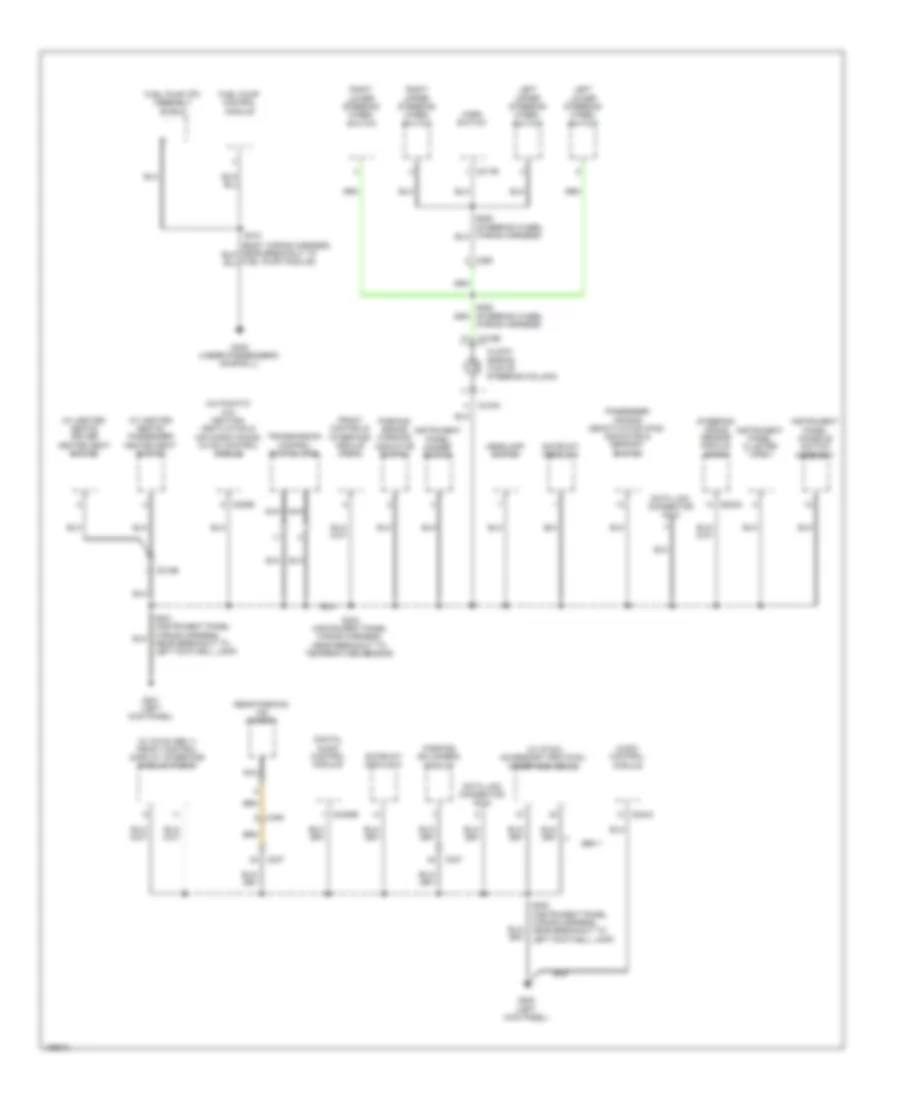
Ground Distribution Wiring Diagram (2 of 4) for Ford C-Max Hybrid SEL 2014
List of elements for Ground Distribution Wiring Diagram (2 of 4) for Ford C-Max Hybrid SEL 2014:
- (automatic a/c) heating, ventilation & air conditioning (hvac) control module
- (w/ heated seats) driver heated seat switch
- (w/ heated seats) passenger heated seat switch
- (w/ sync gen 1) front control display interface module (fcdim)
- (w/ sync) accessory protocol interface module
- Audio control module
- C212b
- C217b
- C218a
- C218b
- C226a
- C228b
- C237
- C240a
- C2488b
- C260
- C494
- Clock- spring (top of steering column)
- Data link connector (dlc)
- Digital audio control module
- Front controls interface module (fcim)
- Fuel pump (fp) assembly shield
- Fuel pump control module
- G200 (left kick panel)
- G201 (left kick panel)
- G305 (under passenger's door sill)
- Gateway module a
- Gen 1
- Headlamp switch
- Horn switch
- Instrument panel cluster (ipc)
- Instrument panel console switch assembly
- Instrument panel dimmer switch
- Left lower steering wheel switch
- Left upper steering wheel switch
- Nca
- Near breakout to left footwell lamp)
- Parking aid camera module
- Parking brake warning indicator switch
- Passenger air bag deactivation (pad) indicator & defrost switch
- Rear parking aid camera
- Right lower steering wheel switch
- Right upper steering wheel switch
- S200 (instrument panel wiring harness, near breakout to left footwell lamp)
- S202 (instrument panel wiring harness, near breakout to temperature sensor)
- S312
- Steering angle sensor module (sasm)
- Transmission control switch (tcs)
- Wiring harness)
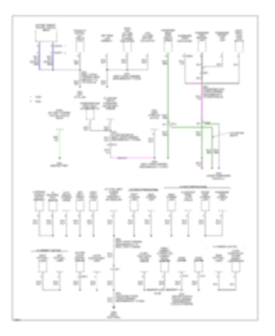
Ground Distribution Wiring Diagram (3 of 4) for Ford C-Max Hybrid SEL 2014
List of elements for Ground Distribution Wiring Diagram (3 of 4) for Ford C-Max Hybrid SEL 2014:
- (if equipped) rain sensor
- (phev) battery charger control module (bccm)
- (phev) high voltage battery charger cooling fan
- (w/ heated seats)
- (w/ intelligent access) radio frequency (rf) receiver
- Auto dimming interior mirror
- B11
- Battery energy control module (becm)
- Blower motor control module
- C211
- C212b
- C297a
- C312
- C314
- C318
- C319
- C340
- C4237a
- C4816a
- C621
- C652a
- Cigar lighter
- Direct current/ alternating current (dc/ac) inverter
- Driver side interior lamp
- Fhev
- Floor console cup holder ambient lighting lamp
- Front interior lamp
- Fuel door interlock switch
- G202 (right kick panel)
- G302 (under passenger's door sill)
- G307 (left "d" pillar)
- G404 (near battery)
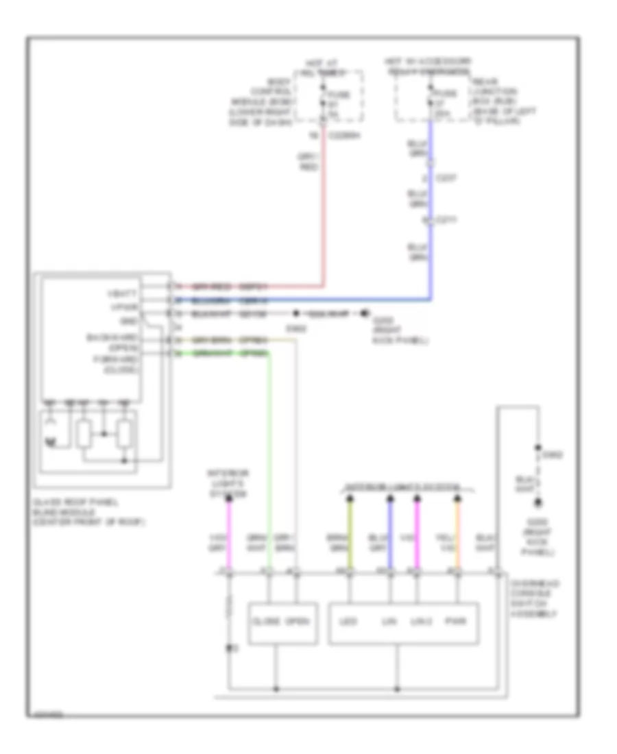
- Glass roof panel blind module
- Global positioning system module
- Glove compartment lamp
- High voltage battery cooling fan
- Left footwell lamp
- Left rear lamp assembly
- Left vanity mirror lamp
- Near breakout to g306)
- Overhead console switch assembly
- Passenger door module (pdm)
- Passenger door release lamp
- Passenger heated seat module
- Passenger pocket map lamp
- Passenger rear door module (prdm)
- Passenger side front seat control switch
- Passenger side interior lamp
- Phev
- Rear footwell lamp
- Rear interior lamp
- Right footwell lamp
- Right front door lock switch
- Right vanity mirror lamp
- S203 (instrument panel wiring harness, near breakout to g202)
- S306 (body wiring harness near breakout to g301)
- S327 (body wiring harness, near breakout to tcu module)
- S341 (body wiring harness, near breakout to rjb)
- S347 (center console wiring harness, near breakout to dc/ac inverter)
- S601 (passenger door wiring harness, near breakout to door module)
- S902 (roof wiring harness, near breakout to right vanity mirror)
- Telematic control unit module (tcu)
- W/ ambient lighting
- W/ roof opening panel
- W/o heated seats
- W/o roof opening panel
Ground Distribution Wiring Diagram (4 of 4) for Ford C-Max Hybrid SEL 2014
List of elements for Ground Distribution Wiring Diagram (4 of 4) for Ford C-Max Hybrid SEL 2014:
- (base of left "d" pillar) rear junction box (rjb)
- (w/ heated seats)
- A11
- B11
- Base
- Breakout to left rear lamp assembly)
- C311
- C313
- C3191a
- C339
- C402b
- C4174a
- C421
- C431
- C432
- C4392c
- C501a
- C511
- Drive side front seat control switch
- Driver door module (ddm)
- Driver door release lamp
- Driver heated seat module
- Driver pocket map lamp
- Driver rear door module (drdm)
- Fuel filler door latch motor
- G303 (under driver's door sill)
- G304 (base of right "d" pillar)
- G306 (under driver's door sill)
- G402 (left rear of roof)
- Hands free liftgate actuator module
- Heated rear window element
- High mounted stop lamp
- Left front door lock switch
- Left license lamp
- Left rear lamp assembly
- Liftgate release switch
- Liftgate/ luggage compartment lid latch
- Luggage compartment power outlet socket
- Near breakout to left rear impact sensor)
- Parking aid module
- Power striker motor
- Premium
- Rear gate trunk module (rgtm)
- Rear power liftgate switch
- Rear window wiper motor
- Rear wiper relay
- Remote function actuator (rfa) module
- Right license lamp
- Right rear lamp assembly
- S349 (w/ heated seats) (driver seat cushion wiring harness, near breakout to power seat switch)
- S403 (liftgate jumper wiring harness, near breakout to left liftgate motor)
- S404 (liftgate wiring harness, near breakout to left rear lamp assembly)
- S407 (license lamp wiring harness, near breakout to left license lamp)
- S501 (driver door wiring harness, near breakout to door module)
- To c311)
- W/ intelligent access
- W/ power liftgate
- W/o heated seats
- W/o power liftgate
HEADLIGHTS
Headlights Wiring Diagram for Ford C-Max Hybrid SEL 2014
List of elements for Headlights Wiring Diagram for Ford C-Max Hybrid SEL 2014:
- (right front of engine compt) g107
- Air conditioning system
- Autolamps sensor
- Battery junction box (bjb) (left side of engine compt)
- Body control module (lower right side of dash)
- C144
- C213
- C214
- C226a
- C2280a
- C2280c
- C2280d
- C228b
- Clf04
- Clf05
- Cmc25
- Computer data lines system
- Fog lamp relay
- Fog lamp relay hi beam relay
- Fuse 15a
- Fuse 5a
- G105 (left side of engine compt)
- G107 (right front of engine compt)
- G201 (left kick panel)
- Gd123
- Gnd
- Headlamp switch
- Heating ventilation & air conditioning (hvac) control module (lower left front of engine)
- High
- High beam relay
- Hot at all times
- Hs can +
- Hs can -
- Instrument panel cluster (ipc)
- L sunl snsr
- Left front fog lamp
- Left headlamp assembly
- Left low beam
- Lin
- Lin (lsm)
- Lin 1
- Logic gnd
- Low
- Micro
- Ms can +
- Ms can -
- Multi-function switch
- Parking brake warning indicator switch (base of parking brake lever assembly)
- Prk brk sw
- R sunl snsr
- Red
- Rh104
- Rh107
- Right front fog lamp
- Right headlamp assembly
- Right low beam
- S102
- S104
- S107
- S115
- S202
- Sigrtn
- Snsr gnd
- Steering angle sensor module (sasm)
- Sunload sensor (top right side of dash)
- V batt
- Vdb04
- Vdb05
- Vdb06
- Vdb07
- Vh414
- Vh416
- Vh417
- Vlf25
- Vmc34
HORN
Horn Wiring Diagram for Ford C-Max Hybrid SEL 2014
List of elements for Horn Wiring Diagram for Ford C-Max Hybrid SEL 2014:
- (left side of engine compt) battery junction box (bjb)
- 15a
- Body control module (lower right side of dash)
- C217a
- C217b
- C218a
- C218b
- C2280a
- C2280c
- C2280g
- C260
- Clockspring (top of steering column)
- Crh03
- Crh04
- Fuse
- Fuse 50a
- Fuse 5a
- G105 (left side of engine compt)
- G107 (right front of engine compt)
- G201 (left kick panel)
- Gd123
- Ground distribution system
- Horn
- Horn (right front corner of engine compt)
- Horn rc
- Horn relay
- Horn switch
- Hot at all times
- Logic gnd
- Micro
- Red
- S102
- S115
- S202
- S252
- S253
- Sbb17
- Sbb18
- Vbatt
INSTRUMENT CLUSTER
Instrument Cluster Wiring Diagram (1 of 2) for Ford C-Max Hybrid SEL 2014
List of elements for Instrument Cluster Wiring Diagram (1 of 2) for Ford C-Max Hybrid SEL 2014:
- (steering wheel wiring harness) s254
- Body control module (lower right side of dash)
- Brake
- C218b
- C218c
- C226a
- C226b
- C2280a
- C2280b
- C2280c
- C2280f
- C260
- Cdc30
- Cdc41
- Clockspring (top of steering column)
- Cmc19
- Cmc25
- Cmc29
- Computer data lines system
- Cpl26
- Cpl31
- Cpl36
- Cpl39
- Cpl44
- Disp signal
- Disp trip gnd
- Down
- Fp lvl gnd
- Fp lvl sensor
- Fuse 5a
- G201 (left kick panel)
- Gd138
- Gnd
- Hot at all times
- Hs can+
- Hs can-
- I can +
- I can -
- Ignition switch (w/o intelligent access)
- Instrument panel cluster (ipc)
- Interior lights system
- Key in ign
- Key in ignition
- Left
- Left upper steering wheel switch
- Lf door ajar
- Liftgate ajar
- Lr door ajar
- Lvl sw brk fluid
- Micro
- Ms can +
- Ms can -
- Ms can+
- Ms can-
- Nca
- Park
- Parking brake switch (base of parking brake lever assembly)
- Prk detect
- Rf door ajar
- Right
- Right upper steering wheel switch (premium audio/ base audio)
- Rmc27
- Rmc32
- Rr door ajar
- S202
- Sbp08
- Shift interlock system
- Steering angle sensor module (sasm)
- Trip sig
- V batt
- Vdb04
- Vdb06
- Vdb07
- Vdb13
- Vdb14
- Vdbo5
- Vdbo7
- Vmc11
- Vmc29
Instrument Cluster Wiring Diagram (2 of 2) for Ford C-Max Hybrid SEL 2014
List of elements for Instrument Cluster Wiring Diagram (2 of 2) for Ford C-Max Hybrid SEL 2014:
- (bottom center of liftgate) liftgate/ luggage compartment lid latch
- (brake fluid reservoir) low brake fluid warning indicator switch
- (in fuel tank) fuel pump (fp) assembly
- (left rear door wiring harness, near breakout to window switch) s701
- (right rear door wiring harness, near breakout to window switch) s801
- A11
- B11
- C175b
- C175e
- C313
- C314
- C339
- C340
- C411
- C432
- C501a
- C501b
- C652a
- C652b ms can -
- Ce908
- Computer data lines system
- Driver door latch
- Driver door module (ddm)
- Driver rear door module (drdm)
- Engine oil pressure switch (lower left rear of engine)
- G107 (right front of engine compt)
- G302 (under passenger's door sill)
- G303 (under driver's door sill)
- G402 (left rear of roof)
- Gd134
- Gd140
- Gnd
- Hs can +
- Hs can -
- Left rear door latch
- Ms can +
- Ms can -
- Nca
- Ops
- Passenger door latch
- Passenger door module (ddm)
- Passenger rear door latch
- Passenger rear door module (prdm)
- Power windows system
- Powertrain control module (pcm) (left front of wheelwell)
- Rpl63
- Rpl64
- Rpw49
- Rpw55
- Rtn
- S104
- S306
- S403
- S404
- S601
- Vdb04
- Vdb05
- Vdb06
- Vdb07
- W/ heated seats
- W/ power liftgate
- W/o heated seats
- W/o power liftgate
INTERIOR LIGHTS
Courtesy Lamps Wiring Diagram (1 of 3) for Ford C-Max Hybrid SEL 2014
List of elements for Courtesy Lamps Wiring Diagram (1 of 3) for Ford C-Max Hybrid SEL 2014:
- (instrument panel wiring harness, near breakout to g202)
- (right kick panel)
- (w/o ambient lighting) left footwell lamp
- Body control module (lower right side of dash)
- C211
- C2280b
- C2280c
- C2280e
- C2280f
- C2280h
- Cbp17
- Cln38
- Computer data lines system
- Courtesy
- Cpl26
- Cpl31
- Cpl36
- Cpl39
- Cpl44
- Dimming rtn
- Dome
- Driver side interior lamp (w/ roof opening panel)
- Fuse 10a
- G202
- G202 (right kick panel)
- G301 (under passenger's door sill)
- Gd140
- Glove compartment lamp
- Hot at all times
- Hs can +
- Hs can -
- Instrument illumination circuit
- Interior light relay
- Lamp control
- Left vanity mirror lamp
- Lf door ajar
- Liftgate ajar
- Lin 2
- Lr door ajar
- Map
- Micro
- Passenger side interior lamp (w/ roof opening panel)
- Pwr gnd
- Rear interior lamp (w/ roof opening panel)
- Rf door ajar
- Right footwell lamp (w/o ambient lighting)
- Right vanity mirror lamp
- Rr door ajar
- S203
- S238 (instrument panel wiring harness, near breakout to bcm)
- S251
- S901 (roof wiring harness, near breakout to right vanity mirror)
- S902
- S903 (roof wiring harness, near breakout to passenger side lamp)
- Vdb04
- Vdb05
- Vln40 (or cln27)
- Vrt26
- W/ roof opening panel
- W/o roof opening panel
Courtesy Lamps Wiring Diagram (2 of 3) for Ford C-Max Hybrid SEL 2014
List of elements for Courtesy Lamps Wiring Diagram (2 of 3) for Ford C-Max Hybrid SEL 2014:
- (left rear door wiring harness, near breakout to window switch) s701
- (right rear door wiring harness, near breakout to window switch) s801
- A11
- Ajar
- B11
- C313
- C314
- C339
- C340
- C501a
- C501b
- C652a
- C652b
- Cln31
- Cln32
- Computer data lines system
- Courtesy
- Dome
- Driver door latch
- Driver door module (ddm)
- Driver rear door module (drdm)
- Front interior lamp (w/o roof opening panel)
- G202 (right kick panel)
- G302 (under passenger's door sill)
- G303 (under driver's door sill)
- Gd134
- Gd140
- Gnd
- Instrument illumination circuit
- Lamp control
- Led
- Left exterior mirror
- Left rear door latch
- Lin
- Lin 2
- Map
- Mirr gnd
- Ms can +
- Ms can -
- Nca
- Overhead console switch assembly (w/ ambient lighting)
- Passenger door latch
- Passenger door module (ddm)
- Passenger rear door module (prdm)
- Power windows system
- Puddle lamp
- Rear interior lamp (w/o roof opening panel)
- Return
- Right rear door latch
- Rpl63
- Rpl64
- Rpm05
- Rpm08
- Rpw49
- Rpw55
- S302
- S601
- S902
- Vdb06
- Vdb07
- Vpwr
- W/ heated seats
- W/o heated seats
Courtesy Lamps Wiring Diagram (3 of 3) for Ford C-Max Hybrid SEL 2014
List of elements for Courtesy Lamps Wiring Diagram (3 of 3) for Ford C-Max Hybrid SEL 2014:
- B10
- C211
- C212b
- C237
- C339
- C340
- C411
- C4198
- C432
- C4403
- C511
- C621
- Driver door release lamp
- Driver door window control switch
- Driver map pocket lamp
- Ecu
- Floor console cup holder ambient lighting lamp (w/ ambient lighting)
- G202 (right kick panel)
- G302 (under passenger's door sill)
- G303 (under driver's door sill)
- G402 (left rear of roof)
- Left footwell lamp (w/ ambient lighting)
- Liftgate/luggage compartment lid latch (w/o power liftgate) (bottom center of liftgate)
- Liftgate/luggage compartment lid switch (w/ power liftgate)
- Luggage compartment lamp (w/ power liftgate)
- Luggage compartment lamp (w/o power liftgate)
- Nca
- Passenger door release lamp
- Passenger map pocket lamp
- Rear footwell lamp (w/ ambient lighting)
- Right exterior mirror
- Right footwell lamp (w/ ambient lighting)
- S203
- S244 (instrument panel wiring harness, near breakout to g202)
- S322 (body wiring harness, near breakout to c212)
- S347
- S354 (center console wiring harness, near breakout to power seat switch)
- S357
- S403
- S404
- S501
- S601
- Vpwr
- W/ power liftgate
- W/o power liftgate
Instrument Illumination Wiring Diagram for Ford C-Max Hybrid SEL 2014
List of elements for Instrument Illumination Wiring Diagram for Ford C-Max Hybrid SEL 2014:
- (body wiring harness, near breakout to c311) s336
- (instrument panel wiring harness, near breakout to hvac module)
- (left kick panel) g201
- (roof wiring harness, near breakout to right vanity mirror) s904
- A10
- A13
- Battery junction box (bjb) (left side of engine compt)
- Body control module (lower right side of dash)
- C212a
- C212b
- C214
- C218a
- C218b
- C218c
- C226a
- C226b
- C2280a
- C2280c
- C2280e
- C2280g
- C2280h
- C237
- C260
- C339
- C340
- Ccd15
- Cln17
- Clockspring (top of steering column)
- Computer data lines system
- Driver heated seat switch (w/ heated seats)
- Driver side interior lamp (w/ roof opening panel)
- Front controls interface module (fcim)
- Front interior lamp (w/o roof opening panel)
- Fuse 50a
- Fuse 5a
- G107 (right front of engine compt)
- G201 (left kick
- G201 (left kick panel)
- G202 (right kick panel)
- G301 (under passenger's door sill)
- G302 (under passenger's door sill)
- G303 (under driver's door sill)
- Gd123
- Gd140
- Gnd
- Headlamp switch
- Hot at all times
- Hs can +
- Hs can -
- I can +
- I can -
- Ignition switch
- Illum
- Instrument panel console switch assembly
- Instrument panel dimmer switch
- Ip sw illum
- Left front door lock switch
- Left lower steering wheel switch
- Left upper steering wheel switch
- Lin
- Lin (lsm)
- Logic gnd
- Micro
- Nca
- Overhead console switch assembly
- Panel)
- Passenger air bag deactivation (pad) indicator/ defrost switch
- Passenger heated seat switch (w/ heated seats)
- Pwr gnd
- Red
- Right front door lock switch
- Right lower steering wheel switch
- Right upper steering wheel switch
- S115
- S201
- S202
- S247
- S252
- S253
- S255 (steering wheel wiring harness)
- S256 (steering wheel wiring harness)
- S355 (w/ heated seats) (center console wiring harness, near breakout to power seat switch)
- S501
- S902
- Sbb17
- Sbb18
- Steering angle sensor module (sasm)
- Switch illum
- Transmission control switch (base of transmission shifter lever assembly)
- Vbatt
- Vdb04
- Vdb05
- Vdb13
- Vdb14
- Vlf25
- Vln04
NAVIGATION
Crew Chief Wiring Diagram for Ford C-Max Hybrid SEL 2014
List of elements for Crew Chief Wiring Diagram for Ford C-Max Hybrid SEL 2014:
- (behind left quarterpanel) telematic control unit module
- Body control module (bcm) (lower right side of dash)
- Computer data lines system
- Fuse 7.5a
- G307 (left "d" pillar)
- Gd149
- Gnd
- Hot at all times
- I can +
- I can -
- S327
- S340
- Sbp06
- Vdb13
- Vdb14
- Vpwr
Navigation Wiring Diagram (1 of 2) for Ford C-Max Hybrid SEL 2014
List of elements for Navigation Wiring Diagram (1 of 2) for Ford C-Max Hybrid SEL 2014:
- (center rear of roof) active noise control microphone-3 mic -
- (left kick panel) g200
- Active noise control microphone-1 (above driver's door in roof)
- Active noise control microphone-2 (above front passenger's door in roof)
- Am/fm
- Amp enable
- Ant pwr
- Antenna
- Audio control module
- Batt
- C211
- C213
- C237
- C240a
- C2488a
- C2488b
- C339
- C340
- C913
- C919
- Cbr22
- Cme27
- Cme44
- Coaxial cable
- Computer data lines system
- Digital audio control module (right side of dash)
- Dme17
- Dmm17
- Driver side instrument panel speaker
- Fuse 10a
- G200 (left kick panel)
- Gd103
- Gd135
- Gnd
- Hot at all times
- I can +
- I can -
- Instrument panel center speaker (9 speakers)
- Ip spkr +
- Ip spkr-
- Left front door speaker
- Lf spkr +
- Lf spkr -
- Lr spkr +
- Lr spkr -
- Mic +
- Mic -
- Mic 1 +
- Mic 1 -
- Mic 2 +
- Mic 2 -
- Mic 3 +
- Mic 3 -
- Nca
- Passenger side instrument panel speaker
- Rear junction box (base of left "d" pillar)
- Rf spkr +
- Rf spkr -
- Right front door speaker
- Rme06
- Rme07
- Rme09
- Rme10
- Rme12
- Rmm13
- Rr spkr +
- Rr spkr -
- S200
- S209 (instrument panel wiring harness, near breakout to c210)
- S211 (instrument panel wiring harness, near breakout to c210)
- S226 (instrument panel wiring harness, near breakout to c210)
- S232 (instrument panel wiring harness, near breakout to glove box lamp)
- Sbp06
- Sdars
- Shield
- Solid state
- Vbd13
- Vbd14
- Vdb13
- Vdb14
- Vme06
- Vme07
- Vme09
- Vme10
- Vme12
- Vmm13
- W/ satellite radio
- W/ sync gen 1
- W/ sync gen 2
Navigation Wiring Diagram (2 of 2) for Ford C-Max Hybrid SEL 2014
List of elements for Navigation Wiring Diagram (2 of 2) for Ford C-Max Hybrid SEL 2014:
- A12
- A13
- Accessory protocol interface module
- Amp enable
- Audio control module
- Audio remote+
- Audio remote-
- B12
- B13
- Body control module (bcm) (lower right side of dash)
- Body control module (lower right side of dash)
- C218a
- C218b
- C226a
- C2280c theft sw audio anti-
- C2280e
- C2280f
- C237
- C240b
- C313
- C314
- Ccd15
- Clockspring (top of steering column)
- Cls32
- Cme27
- Cntr lck sw
- Computer data lines system
- Cplxx
- Door locks system
- Exterior lights system
- Front control interface module (fcim)
- Front control/display interface module
- Fuse 15a
- Fuse 7.5a
- G201 (left kick panel)
- G202 (right kick panel)
- Gd133
- Gd138
- Global positioning system module
- Gnd
- Hazard warning/sig sw
- Hot at all times
- Hs can +
- Hs can -
- Hs can+
- Hs can-
- I can +
- I can -
- Illum
- Interior lights system
- Left rear door speaker
- Left rear door tweeter speaker (9 speakers)
- Lin
- Ms can +
- Ms can -
- Pwr gnd
- Remote +
- Remote -
- Right lower steering wheel switch
- Right rear door speaker
- Right rear door tweeter speaker (9 speakers)
- Rme14
- Rme24
- Rme52
- Rme53
- Rme80
- S202
- S203
- S237
- S243
- S250 (instrument panel wiring harness, near breakout to dacm)
- Sbp06
- Sbp07
- Sdl +
- Sdl -
- Seek +
- Seek -
- Steering angle sensor module
- Stereo l+
- Stereo l-
- Stereo r+
- Stereo r-
- Sync alert +
- Sync alert -
- Sync radio circuit
- System data lines computer
- Vbatt
- Vdb04
- Vdb05
- Vdb06
- Vdb07
- Vdb13 (or vmc29)
- Vdb14
- Vmc29
- Vme14
- Vme52
- Vme53
- Vme58
- Vme59
- Vme80
- Vmp19
- Voice/ mute
- Vol +
- Vol -
- W/ sync gen 1
- W/ sync gen 2
Parking Assistant Wiring Diagram for Ford C-Max Hybrid SEL 2014
List of elements for Parking Assistant Wiring Diagram for Ford C-Max Hybrid SEL 2014:
- (base of right "d" pillar) parking aid module
- (behind right side of rear bumper)
- (rear bumper wiring harness, near breakout to keyless antenna) s414
- C144
- C237
- C238
- C4014a
- C4014b
- C4014c
- C431
- Cbr01
- Cmp02
- Cmp18
- Computer data lines system
- Fil sens in
- Fir sens in
- Fol sens in
- For sens in
- Fuse 5a
- G201 (left kick panel)
- G304 (base of right "d" pillar)
- Gd152
- Gnd
- Hot w/ acc relay energized
- Hs can +
- Hs can -
- Instrument panel console switch assembly (if equipped)
- Interior lights system
- Left center rear inner parking aid sensor (behind center of rear bumper)
- Left front active park assist sensor (left front corner of engine compt)
- Left front inner parking aid sensor (behind left side of front bumper)
- Left front outer parking aid sensor (behind left side of front bumper)
- Left rear outer parking aid sensor (behind left side of rear bumper)
- Lf sens in
- Lmp06
- Lmp07
- Pass
- Rear junction box (rjb) (base of left "d" pillar)
- Rf sens in
- Right front active park assist sensor (right front corner of engine compt)
- Right front inner parking aid sensor (behind right side of front bumper)
- Right front outer parking aid sensor (behind right side of front bumper)
- Right rear outer parking aid sensor
- Ril sens in
- Rmp06
- Rmp07
- Rol sens in
- Ror sens in
- S121 (front bumper wiring harness, near breakout to right front inner park sensor)
- S122 (front bumper wiring harness, near breakout to left front inner park sensor)
- S202
- S325
- S413 (rear bumper wiring harness, near breakout to keyless antenna)
- Sapp
- Sens gnd
- Sens pwr
- Solid state
- Status led pas
- Status led sapp
- Sw pas
- Sw sapp
- Vdb04
- Vdb05
- Vmp10
- Vmp11
- Vmp12
- Vmp13
- Vmp14
- Vmp15
- Vmp17
- Vmp21
- Vpm20
- Vpwr
Rear View Camera Wiring Diagram for Ford C-Max Hybrid SEL 2014
List of elements for Rear View Camera Wiring Diagram for Ford C-Max Hybrid SEL 2014:
- Accessory protocol interface module (apim)
- Body control module (lower right side of dash)
- C211
- C2280h
- C237
- C494
- Cmp10
- Dmp31
- Fuse 5a
- G200 (left kick panel)
- Gm100
- Gnd
- Hot w/ acc relay energized
- Lin
- Micro
- Nca
- Pwr
- Rear junction box (rjb) (base of left "d" pillar)
- Rear parking aid camera (center of liftgate)
- Rmp31
- S200
- S907
- Shield
- Video+
- Video-
- Vmp31
- Vmp35
- Vrt26
POWER DISTRIBUTION
Power Distribution Wiring Diagram (1 of 6) for Ford C-Max Hybrid SEL 2014
List of elements for Power Distribution Wiring Diagram (1 of 6) for Ford C-Max Hybrid SEL 2014:
- (engine wiring harness, near breakout to map sensor) s130
- 150a
- Anti-lock brake system (abs) module
- Battery
- Battery fuse assembly
- Battery junction box (bjb) (left side of engine compt)
- Battery monitoring sensor
- Blower motor relay
- Brake pedal position (bpp)
- C1035c
- C1045
- C140
- C1458a
- C1463a
- C175b
- C4453d
- Charge port light ring
- Coolant water pump 1
- Dc/dc converter module
- Direct current/ alternating current (dc/ac) inverter
- Engine cooling fan relay
- From rear junction box (rjb) (diagram 6 of 6)
- Fuel injector 1
- Fuel injector 2
- Fuel injector 3
- Fuel injector 4
- Fuse 1 80a
- Fuse 10a
- Fuse 15a
- Fuse 2 175a
- Fuse 20a
- Fuse 25a
- Fuse 30a
- Fuse 40a
- Fuse 50a
- Fuse 5a
- G202 (right kick panel)
- G401 (right side of high voltage battery compt)
- High current battery junction box (bjb) (right side of high voltage battery compt)
- Horn relay
- Nca
- Pcm power relay
- Power steering control module (pscm)
- Powertrain control module (pcm)
- Red
- S105 (junction box wiring harness, near breakout to g105)
- S347
- Secondary on board diagnostic module c (sobdmc)/ transmission control module (tcm)
- Switch
- To battery junction box (bjb) (diagram 2 of 6)
- To body control module (bcm) (diagram 4 of 6)
- To body control module (bcm) (diagram 5 of 6)
- To fuse 33 (diagram 3 of 6)
- To splice 115 (diagram 2 of 6)
- To splice s342 (diagram 6 of 6)
- Trans- mission fluid pump
- Vacuum pump cut-off relay
- Wiper run/park relay
Power Distribution Wiring Diagram (2 of 6) for Ford C-Max Hybrid SEL 2014
List of elements for Power Distribution Wiring Diagram (2 of 6) for Ford C-Max Hybrid SEL 2014:
- (junction box wiring harness, near breakout to g105)
- (left side of engine compt) battery junction box (bjb)
- Air conditioning control module (accm)
- Anti-lock brake system (abs) module
- Blower motor relay
- Body control module (bcm) (lower right side of dash)
- C1035c
- C1046
- C134
- C1458a
- C1463b
- C175b
- C1815c
- C214
- C2280d
- C238
- Cabin coolant heater (phev)
- From battery junction box (bjb) (diagram 1 of 6)
- From splice s105 (diagram 1 of 6)
- Fuse 10a
- Fuse 15a
- Fuse 20a
- Fuse 5a
- Headlamp switch
- Horn relay
- Ignition relay
- Ignition relay control
- Micro
- Motor electronics cooling system pump motor
- Power steering control module (pscm)
- Powertrain control module (pcm)
- Red
- S115 (junction box wiring harness, near breakout to g105)
- S116 (junction box wiring harness, near breakout to blower motor diode)
- Secondary on board diagnostic diagnostic module c (sobdmc)/ transmission control module (tcm)
- Secondary on board diagnostic module c (sobdmc)/ transmission control module (tcm)
- Tcm relay
- To body control module (bcm) (diagram 4 of 6)
- To rear junction box (rjb) (diagram 5 of 6)
- To splice 344 (diagram 6 of 6)
- Transmission fluid pump
- Vacuum pump cut-off relay
- Wiper high/ low relay
- Wiper run/ park relay
Power Distribution Wiring Diagram (3 of 6) for Ford C-Max Hybrid SEL 2014
List of elements for Power Distribution Wiring Diagram (3 of 6) for Ford C-Max Hybrid SEL 2014:
- (body wiring harness, near breakout to c212) s322
- (engine wiring harness, near breakout to cmp sensor) s132
- (instrument panel wiring harness, near breakout to bcm) s238
- (left side of engine compt) battery junction box (bjb)
- (lower right side of dash) body control module (bcm)
- (not used)
- (roof wiring harness, near breakout to right vanity mirror) s901
- Active grille shutter
- C1035c
- C211
- C2280e
- C2280f
- C238
- C339
- C4198
- C4403
- Cabin heater coolant diverter valve
- Cabin heater coolant pump
- Coil on plug (cop) 1
- Coil on plug (cop) 2
- Coil on plug (cop) 3
- Coil on plug (cop) 4
- Coolant water pump 1
- Driver door window control switch
- Driver side interior lamp (w/ roof opening panel)
- Electric exhaust gas recirculation (eegr) valve
- Engine cooling fan relay
- Evaporative emission canister purge valve
- From fuse 34 m (diagram 1 of 6)
- From fuse 62 l (diagram 4 of 6)
- Front interior lamp (w/o roof opening panel)
- Fuse 10a
- Fuse 15a
- Fuse 20a
- Fuse 5a
- Glove compart- ment lamp
- Heated oxygen sensor (ho2s) 12
- Ignition coil 1
- Left footwell lamp (w/o ambient lighting)
- Left vanity mirror lamp
- Luggage compart- ment lamp
- Nca
- Overhead console switch assembly
- Passenger side interior lamp (w/ roof opening panel)
- Passive anti-theft system (pats) transceiver
- Rear interior lamp
- Right footwell lamp (w/o ambient lighting)
- Right vanity mirror lamp
- S106 (junction box wiring harness, near breakout to c214)
- S119 (junction box wiring harness, near breakout to g104)
- S133 (engine wiring harness, near breakout to knock sensor 1)
- To rear junction box (rjb) (diagram 5 of 6)
- Universal heated oxygen sensor (ho2s) 11
- Variable camshaft timing 11 (vct11)
Power Distribution Wiring Diagram (4 of 6) for Ford C-Max Hybrid SEL 2014
List of elements for Power Distribution Wiring Diagram (4 of 6) for Ford C-Max Hybrid SEL 2014:
- (body wiring harness, near breakout to g301) s309
- (instrument panel
- (instrument panel wiring harness, near breakout to blend door actuators) s214
- (instrument panel wiring harness, near breakout to glove box lamp) s243
- (lower right side of dash) body control module (bcm)
- (not used)
- Accessory protocol interface module (apim)
- Audio control module (acm)
- C212a
- C212b
- C2280d
- C2280e
- C2280f
- C2280g
- C2280h
- C228b
- C237
- C240a
- C310a
- C311
- C312
- C319
- C3191a
- C3192a
- C380
- Cigar lighter
- Driver heated seat module
- Driver heated seat switch
- From battery junction box (bjb) (diagram 1 of 6)
- From battery junction box (bjb) (diagram 2 of 6)
- Front control/ display interface module (fcdim)
- Front controls interface module (fcim)
- Fuse 10a
- Fuse 15a
- Fuse 20a
- Fuse 5a
- Fuse 7.5a
- G202 (right kick panel)
- Gateway module a (gwm)
- Glass roof panel blind module
- Global positioning system module (gpsm)
- Heating ventilation & air conditioning (hvac) control module
- Instrument panel cluster (ipc)
- Interior light relay
- Liftgate/ decklid release relay
- Micro
- Occupant classification system module (ocsm)
- Passenger air bag deactivation (pad) indicator
- Passenger heated seat module
- Passenger heated seat switch
- Radio frequency (rf) receiver
- Rain sensor
- Red
- Restraints control module (rcm)
- S340 (body wiring harness, near breakout to c311)
- S347
- S356
- Spare relay
- Steering angle sensor module (sasm)
- Telematic control unit module (tcu)
- To c210) s237
- To fuse 60 (diagram 3 of 6)
- Trans- mission control switch (tcs)
- Vpwr
- W/ heated seats
- Wiring harness, near breakout to c210) s236
- Wiring harness, near breakout to g202) s242
Power Distribution Wiring Diagram (5 of 6) for Ford C-Max Hybrid SEL 2014
List of elements for Power Distribution Wiring Diagram (5 of 6) for Ford C-Max Hybrid SEL 2014:
- (base of left "d" pillar) rear junction box (rjb)
- (instrument panel wiring harness, near breakout to blend door actuators) s231
- (lower right side of dash) body control module (bcm)
- Acc
- Acc run
- Acc/ run
- Battery charger control module (bccm) (phev)
- Battery energy control module (becm)
- Battery junction box (bjb) (left side of engine compt) c1035c
- Body control module (bcm) (lower right side of dash)
- C175b
- C214
- C2280c
- C2280f
- C2280g
- C237
- C315
- C4237a
- C4392d
- C4455a
- C4816a
- Evaporative emission (evap) leak detection control module
- Fhev
- Fog lamp relay
- From battery junction box (bjb) (diagram 1 of 6)
- From splice 106 c (diagram 3 of 6)
- From splice 124 h (diagram 2 of 6)
- Front washer relay
- Fuel door release relay
- Fuel pump relay
- Fuel tank isolation valve (phev)
- Fuse 10a
- Fuse 15a
- Fuse 20a
- Fuse 5a
- High beam relay
- Ignition switch
- Illum
- Key in ign sw
- Key in ignition switch
- Lock
- Micro
- Nca
- Off
- Phev
- Powertrain control module (pcm)
- Rear washer relay
- Red
- Remote function actuator (rfa) module
- Reversing lamp relay
- Run
- S339 (body wiring harness, near breakout to rjb)
- S346 (rear axle wiring harness, near breakout to fuel tank unit)
- Start
- Start/ run
- Start/ stop sw 1
- Start/ stop sw 2
- Transmission control switch (tcs)
- Vapor management valve (fhev)
- W/ intelligent access
- W/o intelligent access
Power Distribution Wiring Diagram (6 of 6) for Ford C-Max Hybrid SEL 2014
List of elements for Power Distribution Wiring Diagram (6 of 6) for Ford C-Max Hybrid SEL 2014:
- (base of left "d" pillar) rear junction box (rjb)
- (body wiring harness, near breakout to g306) s321
- (body wiring harness, near breakout to rjb) s342
- (instrument panel wiring harness, near breakout to left footwell lamp)
- A14
- A17
- Accessory relay
- B17
- Battery charger control module (bccm)
- Battery energy control module (becm)
- Body control module (bcm) (lower right side of dash)
- Breakout to left rear lamp)
- C211
- C212a
- C212b
- C2280b
- C237
- C2488b
- C311
- C312
- C313
- C314
- C3191a
- C3192a
- C339
- C340
- C4014a
- C410
- C411
- C4174a
- C4237a
- C431
- C432
- C4392c
- C4455a
- C4816a
- C494
- C501a
- C510
- C610
- C652a
- C700
- C800
- Control relay accessory
- Datalink datalink connector connector (dlc) (dlc)
- Digital audio control module
- Driver door module (ddm)
- Driver exterior door handle
- Driver heated seat module
- Driver rear door module (drdm)
- Driver side front seat control switch
- Fhev
- From battery fuse assembly (diagram 1 of 6)
- From battery junction box (bjb) (diagram 2 of 6)
- Fuse 10a
- Fuse 15a
- Fuse 20a
- Fuse 25a
- Fuse 30a
- Fuse 40a
- Fuse 5a
- G304 (base of right "d" pillar)
- Gateway module a
- Glass roof panel blind module
- Handsfree liftgate actuation module (w/ power liftgate)
- High voltage battery charger cooling fan (phev)
- High voltage battery cooling fan
- Left rear exterior door handle
- Luggage compartment power outlet socket
- Micro
- Nca
- Parking aid module
- Passenger door module (pdm)
- Passenger exterior door handle
- Passenger heated seat module
- Passenger rear door module (prdm)
- Phev
- Rear gate trunk module (rgtm)
- Rear parking aid camera module
- Rear window defrost relay
- Rear window wiper motor
- Rear wiper relay
- Red
- Remote function actuator (rfa) module
- Right rear exterior door handle
- S221
- S325 (w/ intelligent access)
- S343 (body wiring harness, near breakout to rjb)
- To direct current/ alternating current (dc/ac) inverter (diagram 1 of 6)
- W/ power liftgate
POWER DOOR LOCKS
Power Door Locks Wiring Diagram (1 of 4) for Ford C-Max Hybrid SEL 2014
List of elements for Power Door Locks Wiring Diagram (1 of 4) for Ford C-Max Hybrid SEL 2014:
- (body wiring harness, near breakout to g301) s310
- (right rear door wiring harness, near breakout to window switch) s801
- A11
- B11
- Battery junction box (bjb) (left side of engine compt)
- Body control module (bcm) (lower right side of dash)
- C2280a
- C2280b
- C2280c
- C2280g
- C2280h
- C237
- C313
- C314
- C339
- C340
- Child lock
- Computer data lines system
- Cpl04
- Cpl08
- Cpl09
- Cpl11
- Cpl25
- Cpl26
- Cpl31
- Cpl36
- Cpl37
- Cpl38
- Cpl39
- Cpl42
- Cpl43
- Cpl53
- Cpl54
- Cpl70
- Crh03
- Dr unlock
- Driver rear door module (drdm)
- Fuse 50a
- G105 (left side of engine compt)
- G107 (right front of engine compt)
- G302 (under passenger's door sill)
- G303 (under driver's door sill)
- Gd123
- Gd134
- Gd140
- Gnd
- Headlights system
- Hood ajar switch
- Hood ajar switch (center front of engine compt)
- Horn
- Horns system
- Hot at all times
- Illum
- Interior lights system
- Internal antenna rke receiver
- K-line
- Left front door lock switch
- Left rear door latch
- Lf dr ajar
- Lin
- Lin (lsm)
- Lock
- Lock child lock
- Logic gnd
- Lr dr ajar
- Micro
- Ms can+
- Ms can-
- Mtr double
- Mtr double lck
- Passenger rear door module (prdm)
- Power windows system
- Red
- Return
- Rf dr ajar
- Right front door lock switch
- Right rear door latch
- Rpw49
- Rpw55
- Rr dr ajar
- S102
- S302
- S306
- S501
- S601
- S701 (left rear door wiring harness, near breakout to window switch)
- Sbb17
- Sbr03
- Sbr04
- Unlock
- Vbatt
- Vdb06
- Vdb07
- Vlf25
- Vpl56
- Vpw32
- Vpw33
- Vrt22
- W/ heated seats
- W/o heated seats
Power Door Locks Wiring Diagram (2 of 4) for Ford C-Max Hybrid SEL 2014
List of elements for Power Door Locks Wiring Diagram (2 of 4) for Ford C-Max Hybrid SEL 2014:
- (bottom center of liftgate) (w/o power liftgate) liftgate/luggage compartment lid latch
- (center rear of roof) radio frequency receiver
- (driver door wiring harness, near breakout to door module) s502
- A14
- A16
- A17
- B17
- C313
- C314
- C339
- C340
- C501a
- C501b
- C652a
- C652b
- Computer data lines system
- Cpl02
- Cpl30
- Cpl35
- Cpl51
- Cpl65
- Cpl66
- Dr unlock
- Driver door latch
- Driver door module (ddm)
- Driver door window control switch
- Fuse 25a
- G202 (right kick panel)
- G302 (under passenger's door sill)
- G303 (under driver's door sill)
- G402 (left rear of roof)
- Gd134
- Gd140
- Gnd
- Hot at all times
- Interior lights system
- Internal antenna rke receiver
- K-line
- Lin
- Lock
- Ms can+
- Ms can-
- Passenger door latch
- Passenger door module (pdm)
- Rear junction box (rjb) (base of left "d" pillar)
- Red
- Return
- Rpl63
- Rpl64
- S404
- S501
- S601
- S902
- Sbr01
- Sbr02
- Unlock
- Vbatt
- Vdb06
- Vdb07
- Vpw32
- Vpw33
- Vpwr
Power Door Locks Wiring Diagram (3 of 4) for Ford C-Max Hybrid SEL 2014
List of elements for Power Door Locks Wiring Diagram (3 of 4) for Ford C-Max Hybrid SEL 2014:
- (bottom center of liftgate) (w/ power liftgate) liftgate/luggage compartment lid latch
- (left side of liftgate) rear gate trunk module (rgtm)
- Body control module (bcm) (lower right side of dash)
- C2280b
- C2280c
- C2280e
- C2280f
- C2280h
- C411
- C4174b
- C432
- C4392d
- C4392e
- Cbp27
- Cls32
- Computer data lines system
- Cpk19
- Cpk20
- Cpk23
- Cpk24
- Cpk25
- Cpk26
- Cpl44
- Cpl45
- Cplxx
- Cpr89
- Dr lck ctrl sw ind (led)
- Front controls interface control module (fcim)
- Fuse 10a
- Fuse 15a
- Fuse 5a
- G201 (left kick panel)
- G402 (left rear of roof)
- Gd133
- Gnd
- Hazard
- Hazard warning/ sig sw
- Hot at all times
- Interior lights system
- K-line
- Latch sec sig
- Liftgate ajar
- Liftgate sw
- Liftgate/ decklid release relay
- Lock
- Micro
- Ms can +
- Ms can -
- Ms can+
- Ms can-
- Prim sig
- Red
- Remote function actuator (rfa) module (behind left quarterpanel)
- S202
- S243
- S403
- Sbp06
- Start/stop
- Starting/ charging system
- Sw ind (led) dr lck ctrl
- Sw1
- Trunk, tailgate, fuel doors system
- Unlock
- Vbatt
- Vdb06
- Vdb07
- Vpl56
- W/ power liftgate
- W/o power liftgate
- Warning/ sig sw
Power Door Locks Wiring Diagram (4 of 4) for Ford C-Max Hybrid SEL 2014
List of elements for Power Door Locks Wiring Diagram (4 of 4) for Ford C-Max Hybrid SEL 2014:
- (center of rear bumper) keyless entry rear antenna
- (center rear of luggage compt) passive anti-theft system (pats) rear antenna
- (lower left center of dash) passive anti-theft system (pats) front antenna
- (under driver's door sill) g306
- (under rear of center console) passive anti-theft system (pats) center antenna
- A12
- Ant +
- Ant -
- C212a
- C237
- C313
- C314
- C339
- C340
- C431
- C4392a
- C4392b
- C4392c
- C510
- C610
- C700
- C800
- Driver exterior door handle
- Fuse 10a
- Fuse 5a
- Gd140
- Gd151
- Gnd
- Hot at all times
- Left rear exterior door handle
- Lock
- Nca
- Passenger exterior door handle
- Rear junction box (rjb) (base of left "d" pillar)
- Remote function (rfa) actuator module (behind left quarterpanel)
- Right rear exterior door handle
- Rpk03
- Rpk04
- Rpk05
- Rpk06
- Rpk07
- Rpk08
- S321
- S328
- S329 (body wiring harness, near breakout to g306)
- Sbr08
- Unlock
- Vbatt
- Vpk03
- Vpk04
- Vpk05
- Vpk06
- Vpk07
- Vpk08
POWER MIRRORS
Electrochromic Mirror Wiring Diagram for Ford C-Max Hybrid SEL 2014
List of elements for Electrochromic Mirror Wiring Diagram for Ford C-Max Hybrid SEL 2014:
- Auto-dimming interior mirror
- Body control module (bcm) (lower right side of dash)
- C211
- C2280a
- C2280f
- C2280h
- Cbp04
- Computer data lines system
- Feed rear mir
- Fuse 10a
- G202 (right kick panel)
- Gd138
- Gnd
- Hot at all times
- Micro
- Ms can +
- Ms can -
- Reverse
- Reversing lamp relay
- Rrd12
- S902
- Vdb06
- Vdb07
- Vpwr
Power Mirrors Wiring Diagram for Ford C-Max Hybrid SEL 2014
List of elements for Power Mirrors Wiring Diagram for Ford C-Max Hybrid SEL 2014:
- A14
- A16
- Aat sensor
- Air conditioning system
- Body control module (bcm) (lower right side of dash)
- C2280a
- C2280b
- C2280e
- C313
- C339
- C340
- C501a
- C501b
- C652a
- C652b
- Can + ms
- Can - ms
- Cln31
- Cln32
- Cls22
- Cls26
- Computer data lines system
- Cpl26
- Cpl31
- Cpm03
- Cpm06
- Cpm28
- Cpm29
- Cpm33
- Cpm34
- Crd13
- Crd14
- Driver door latch
- Driver door module (ddm)
- Driver door window control switch
- Driver rear door module (drdm)
- Fuse 10a
- Fuse 25a
- G302 (under passenger's door sill)
- G303 (under driver's door sill)
- Gd134
- Gd135
- Gd140
- Gnd
- Hot at all times
- Htd mirr
- Interior light relay
- Left exterior mirror
- Lf door ajar
- Lin
- Micro
- Mirr gnd
- Mirr mtr
- Mirr mtr horz
- Mirr mtr vert
- Ms can +
- Ms can -
- Nca
- Passenger door latch
- Passenger door module (pdm)
- Puddle lamp
- Rear junction box (rjb) (base of left "d" pillar)
- Red
- Return
- Rf door ajar
- Right exterior mirror
- Rpl63
- Rpl64
- Rpm05
- Rpm08
- S322
- S501
- S502 (driver door wiring harness, near breakout to door module)
- S601
- Sbr01
- Sbr02
- Turn lamp
- Vbatt
- Vdb06
- Vdb07
- Vpw32
- Vpwr
POWER SEATS
Driver Power Seat Wiring Diagram for Ford C-Max Hybrid SEL 2014
List of elements for Driver Power Seat Wiring Diagram for Ford C-Max Hybrid SEL 2014:
- (not used)
- Back
- Battery junction box (bjb) (left side of engine compt)
- C3049
- C311
- Down
- Driver seat front height motor
- Driver seat horizontal motor
- Driver seat rear height motor
- Driver side front seat control switch
- Driver's lumbar motor (driver's seat back)
- Driver's recliner motor (driver's seat back)
- Front height
- Fuse 25a
- Fwd
- G303 (under driver's door sill)
- Horizontal
- Hot at all times
- Lumbar
- Rear height
- Recline
- Red
- S349
Heated Seats Wiring Diagram for Ford C-Max Hybrid SEL 2014
List of elements for Heated Seats Wiring Diagram for Ford C-Max Hybrid SEL 2014:
- (under driver's door sill) g303
- (under passenger's door sill) g302
- Body control module (bcm) (lower right side of dash)
- C212a
- C2280e
- C2280f
- C237
- C3049
- C3050
- C311
- C312
- C3191a
- C3191b
- C3192a
- C3192b
- Cbx01
- Chs02
- Chs29
- Driver heated seat module (under front of driver seat)
- Driver heated seat switch
- Drv heater feed
- Drv heater sw
- Drv temp rtn
- Drv temp sense
- Fuse 20a
- Fuse 7.5a
- G201 (left kick panel)
- Gd903
- Gnd
- Heater rtn
- Hot w/ accessory relay energized
- Hot w/ ignition relay energized
- Interior lights system
- Left front seat back heater
- Left front seat cushion heater
- Pass heater feed
- Pass heater rtn
- Pass heater sw
- Pass temp rtn
- Pass temp sense
- Passenger heated seat module (under front of passenger seat)
- Passenger heated seat switch
- Pwr
- Rear junction box (rjb) (base of left "d" pillar)
- Red
- Rhs01
- Rhs05
- Right front seat back heater
- Right front seat cushion heater
- S201
- S214
- S309
- S349
- S353
- S356
- Sbx06
- Vhs26
- Vpwr
Passenger Power Seat Wiring Diagram for Ford C-Max Hybrid SEL 2014
List of elements for Passenger Power Seat Wiring Diagram for Ford C-Max Hybrid SEL 2014:
- (not used)
- Back
- Battery junction box (bjb) (left side of engine compt)
- C3050
- C312
- Down
- Front height
- Fuse 25a
- Fwd
- G302 (under passenger's door sill)
- Horizontal
- Hot at all times
- Lumbar
- Passenger seat front height motor
- Passenger seat horizontal motor
- Passenger seat rear height motor
- Passenger side front seat control switch
- Passenger's lumbar motor (passenger's seat back)
- Passenger's recliner motor (passenger's seat back)
- Rear height
- Recline
- Red
- S353
POWER TOP/SUNROOF
Power Top/Sunroof Wiring Diagram for Ford C-Max Hybrid SEL 2014
List of elements for Power Top/Sunroof Wiring Diagram for Ford C-Max Hybrid SEL 2014:
- Backward (open)
- Body control module (bcm) (lower right side of dash)
- C211
- C2280h
- C237
- Cbr16
- Close
- Cpr85
- Cpr86
- Forward (close)
- Fuse 20a
- Fuse 5a
- G202 (right kick panel)
- Gd138
- Glass roof panel blind module (center front of roof)
- Gnd
- Hot at all times
- Hot w/ accessory relay energized
- Interior lights system
- Led
- Lin
- Lin 2
- Open
- Overhead console switch assembly
- Pwr
- Rear junction box (rjb) (base of left "d" pillar)
- S902
- Sbp21
- Vbatt
- Vpwr
POWER WINDOWS
Power Windows Wiring Diagram (1 of 2) for Ford C-Max Hybrid SEL 2014
List of elements for Power Windows Wiring Diagram (1 of 2) for Ford C-Max Hybrid SEL 2014:
- (under driver's door sill) g303
- A14
- A16
- B11
- B17
- C314
- C339
- C340
- C501a
- C501b
- C652a
- C652b
- Computer data lines system
- Cpl78
- Cpw08
- Cpw12
- Cpw13
- Cpw17
- Cpw18
- Cpw34
- Cpw35
- Cpw40
- Cpw41
- Cpw52
- Cpw53
- Driver door module (ddm)
- Driver door window regulator motor
- Fuse 25a
- G302 (under passenger's door sill)
- Gd134
- Gd135
- Gd140
- Gnd
- Hall sensor
- Hall sensor 1
- Hall sensor 2
- Hot at all times
- Illumination
- Lin
- Lpw36
- Lpw42
- Lpw54
- Ms can+
- Ms can-
- Passenger door module (pdm)
- Passenger door window control switch
- Passenger door window regulator motor
- Passenger rear door module (prdm)
- Rear junction box (rjb) (base of left "d" pillar)
- Red
- Return
- Rpw05
- Rpw37
- Rpw43
- Rpw55
- S306 (w/ heated seats)
- S501
- S601
- Sbr01
- Sbr02
- Sbr04
- Vbatt
- Vdb06
- Vdb07
- Vdbo6
- Vdbo7
- Vpw32
- Vpw33
- Vpw38
- Vpw39
- Vpw44
- Vpw45
- Vpw56
- Vpw57
- Window down
- Window up
Power Windows Wiring Diagram (2 of 2) for Ford C-Max Hybrid SEL 2014
List of elements for Power Windows Wiring Diagram (2 of 2) for Ford C-Max Hybrid SEL 2014:
- A11
- A16
- A17
- Battery junction box (bjb) (left side of engine compt)
- Body control module (bcm) (lower right side of dash)
- C2280e
- C2280g
- C313
- C339
- Cpw06
- Cpw15
- Cpw16
- Cpw46
- Cpw47
- Driver door window control switch
- Driver rear door module (drdm)
- Fuse 10a
- Fuse 50a
- G303 (under driver's door sill)
- Gd134
- Gnd
- Hall sensor 1
- Hall sensor 2
- Hot at all times
- Illumination
- Interior light relay
- Left rear door latch
- Left rear door window control switch
- Left rear door window regulator motor
- Lin
- Lpw48
- Micro
- Red
- Return
- Right rear door latch
- Right rear door window control switch
- Right rear door window regulator motor
- Rpw49
- S302 (w/ heated seats)
- S322
- S701 (left rear door wiring harness, near breakout to window switch)
- S801 (right rear door wiring harness, near breakout to window switch)
- Sbr03
- Vbatt
- Vpw32
- Vpw50
- Vpw51
- Vpwr
- Window down
- Window up
RADIO
Premium Radio Wiring Diagram (1 of 2) for Ford C-Max Hybrid SEL 2014
List of elements for Premium Radio Wiring Diagram (1 of 2) for Ford C-Max Hybrid SEL 2014:
- (center rear of roof) active noise control microphone-3 mic -
- (left kick panel) g200
- Active noise control microphone-1 (above driver's door in roof)
- Active noise control microphone-2 (above front passenger's door in roof)
- Am/fm
- Amp enable
- Ant pwr
- Antenna
- Audio control module
- Batt
- C211
- C213
- C237
- C240a
- C2488a
- C2488b
- C339
- C340
- C913
- C919
- Cbr22
- Cme27
- Cme44
- Coaxial cable
- Computer data lines system
- Digital audio control module (right side of dash)
- Dme17
- Dmm17
- Driver side instrument panel speaker
- Fuse 10a
- G200 (left kick panel)
- Gd103
- Gd135
- Gnd
- Hot at all times
- I can +
- I can -
- Instrument panel center speaker (9 speakers)
- Ip spkr +
- Ip spkr-
- Left front door speaker
- Lf spkr +
- Lf spkr -
- Lr spkr +
- Lr spkr -
- Mic +
- Mic -
- Mic 1 +
- Mic 1 -
- Mic 2 +
- Mic 2 -
- Mic 3 +
- Mic 3 -
- Nca
- Passenger side instrument panel speaker
- Rear junction box (base of left "d" pillar)
- Rf spkr +
- Rf spkr -
- Right front door speaker
- Rme06
- Rme07
- Rme09
- Rme10
- Rme12
- Rmm13
- Rr spkr +
- Rr spkr -
- S200
- S209 (instrument panel wiring harness, near breakout to c210)
- S211 (instrument panel wiring harness, near breakout to c210)
- S226 (instrument panel wiring harness, near breakout to c210)
- S232 (instrument panel wiring harness, near breakout to glove box lamp)
- Sbp06
- Sdars
- Shield
- Solid state
- Vbd13
- Vbd14
- Vdb13
- Vdb14
- Vme06
- Vme07
- Vme09
- Vme10
- Vme12
- Vmm13
- W/ satellite radio
- W/ sync gen 1
- W/ sync gen 2
Premium Radio Wiring Diagram (2 of 2) for Ford C-Max Hybrid SEL 2014
List of elements for Premium Radio Wiring Diagram (2 of 2) for Ford C-Max Hybrid SEL 2014:
- A12
- A13
- Accessory protocol interface module
- Amp enable
- Audio control module
- Audio remote+
- Audio remote-
- B12
- B13
- Body control module (bcm) (lower right side of dash)
- Body control module (lower right side of dash)
- C218a
- C218b
- C226a
- C2280c theft sw audio anti-
- C2280e
- C2280f
- C237
- C240b
- C313
- C314
- Ccd15
- Clockspring (top of steering column)
- Cls32
- Cme27
- Cntr lck sw
- Computer data lines system
- Cplxx
- Door locks system
- Exterior lights system
- Front control interface module (fcim)
- Front control/display interface module
- Fuse 15a
- Fuse 7.5a
- G201 (left kick panel)
- G202 (right kick panel)
- Gd133
- Gd138
- Global positioning system module
- Gnd
- Hazard warning/sig sw
- Hot at all times
- Hs can +
- Hs can -
- Hs can+
- Hs can-
- I can +
- I can -
- Illum
- Interior lights system
- Left rear door speaker
- Left rear door tweeter speaker (9 speakers)
- Lin
- Ms can +
- Ms can -
- Pwr gnd
- Remote +
- Remote -
- Right lower steering wheel switch
- Right rear door speaker
- Right rear door tweeter speaker (9 speakers)
- Rme14
- Rme24
- Rme52
- Rme53
- Rme80
- S202
- S203
- S237
- S243
- S250 (instrument panel wiring harness, near breakout to dacm)
- Sbp06
- Sbp07
- Sdl +
- Sdl -
- Seek +
- Seek -
- Steering angle sensor module
- Stereo l+
- Stereo l-
- Stereo r+
- Stereo r-
- Sync alert +
- Sync alert -
- Sync radio circuit
- System data lines computer
- Vbatt
- Vdb04
- Vdb05
- Vdb06
- Vdb07
- Vdb13 (or vmc29)
- Vdb14
- Vmc29
- Vme14
- Vme52
- Vme53
- Vme58
- Vme59
- Vme80
- Vmp19
- Voice/ mute
- Vol +
- Vol -
- W/ sync gen 1
- W/ sync gen 2
SYNC Radio Wiring Diagram, with SYNC GEN 1 (1 of 2) for Ford C-Max Hybrid SEL 2014
List of elements for SYNC Radio Wiring Diagram, with SYNC GEN 1 (1 of 2) for Ford C-Max Hybrid SEL 2014:
- Accessory protocol interface module
- Alert+
- Alert-
- Audio input socket
- Audio remote+
- Audio remote-
- Aux audio lt
- Aux audio rt
- Aux common
- Body control module (lower right side of dash)
- C211
- C212a
- C2280e
- Computer data lines system
- Dme37
- Dme52
- Dme80
- Dmm13
- Front control/display interface module (fcdim)
- Front controls interface module (fcim)
- Fuse 7.5a
- G200 (left kick panel)
- G202 (right kick panel)
- Gd135
- Gd138
- Global positioning system module
- Gnd
- Hot at all times
- Hs can +
- Hs can -
- I can +
- I can -
- Lin
- Mic+
- Mic-
- Microphone
- Ms can +
- Ms can -
- Nca
- Nca mic + nca mic -
- Pwr gnd
- Rme24
- Rme45
- Rme52
- Rme53
- Rme80
- S200
- S203
- S237
- S905
- S906
- Sbp06
- Shield
- Stereo l +
- Stereo l -
- Stereo r +
- Stereo r -
- Usb
- Usb port
- Vbatt
- Vdb04
- Vdb05
- Vdb06
- Vdb07
- Vdb13
- Vdb14
- Vmc29
- Vme14
- Vme37
- Vme38
- Vme52
- Vme53
- Vme80
- Vmm13
SYNC Radio Wiring Diagram, with SYNC GEN 1 (2 of 2) for Ford C-Max Hybrid SEL 2014
List of elements for SYNC Radio Wiring Diagram, with SYNC GEN 1 (2 of 2) for Ford C-Max Hybrid SEL 2014:
- Alert+
- Alert-
- Am/fm
- Antenna
- Antenna pwr
- Audio anti- theft sw c2280c
- Audio control module
- Batt
- Body control module (bcm) (lower right side of dash)
- Body control module (lower right side of dash)
- C211
- C218a
- C218b
- C226a
- C2280f
- C240a
- C240b
- C919
- Clockspring (top of steering column)
- Cme44
- Coaxial cable
- Computer data lines system
- Fuse 15a
- Fuse 7.5a
- G200 (left kick panel)
- G201 (left kick panel)
- Gd103
- Gd138
- Gnd
- Hot at all times
- Hs can +
- Hs can -
- Hs can+
- Hs can-
- I can +
- I can -
- Interior lights system
- Nca
- Pwr gnd
- Right lower steering wheel switch
- Rme52
- Rme53
- Rme80
- S202
- S243
- S250 (instrument panel wiring harness, near breakout to dacm)
- Sbp06
- Sbp07
- Sdars
- Seek +
- Seek -
- State solid
- Steering angle sensor module
- Stereo l +
- Stereo l -
- Stereo r +
- Stereo r -
- Vbatt
- Vdb04
- Vdb05
- Vdb13
- Vdb14
- Vme52
- Vme53
- Vme80
- Vmp19
- Voice/ mute
- Vol +
- Vol -
- W/ satellite radio
SYNC Radio Wiring Diagram, with SYNC GEN 2 (1 of 2) for Ford C-Max Hybrid SEL 2014
List of elements for SYNC Radio Wiring Diagram, with SYNC GEN 2 (1 of 2) for Ford C-Max Hybrid SEL 2014:
- (left kick panel)
- (usb cable)
- 5v pwr
- Accessory protocol interface module
- Aux audio l+
- Aux audio l-
- Aux audio r+
- Aux audio r-
- Aux video+
- Aux video-
- Body control module (lower right side of dash)
- C211
- C212a
- C212b
- C2280e
- Computer data lines system
- Dme19
- Dme45
- Dme52
- Dme80
- Dmm13
- Fuse 7.5a
- G200
- G202 (right kick panel)
- Gd135
- Gd138
- Global positioning system module
- Gnd
- Hot at all times
- Hs can +
- Hs can -
- I can +
- I can -
- Media gnd
- Media hub
- Mic +
- Mic -
- Microphone
- Ms can +
- Ms can -
- Navigation system
- Nca
- Nca mic + nca mic -
- Pwr gnd
- Remote +
- Remote -
- Rme19
- Rme24
- Rme45
- Rme46
- Rme52
- Rme53
- Rme67
- Rme80
- Rmp31
- S200
- S203
- S237
- Sbp06
- Sdl +
- Sdl -
- Shield
- Stereo l +
- Stereo l -
- Stereo r +
- Stereo r -
- Sync alert+
- Sync alert-
- Usb
- Vbatt
- Vdb04
- Vdb05
- Vdb06
- Vdb07
- Vdb13
- Vdb14
- Video +
- Video -
- Vme14
- Vme19
- Vme45
- Vme46
- Vme52
- Vme53
- Vme58
- Vme59
- Vme67
- Vme80
- Vmm13
- Vmp31
SYNC Radio Wiring Diagram, with SYNC GEN 2 (2 of 2) for Ford C-Max Hybrid SEL 2014
List of elements for SYNC Radio Wiring Diagram, with SYNC GEN 2 (2 of 2) for Ford C-Max Hybrid SEL 2014:
- Am/fm
- Antenna
- Antenna pwr
- Audio control module
- Batt
- Body control module (lower right
- C211
- C218a
- C218b
- C226a
- C2280f
- C240a
- C240b
- C919
- Clockspring (top of steering column)
- Cme44
- Coaxial cable
- Computer data lines system
- Fuse 15a
- Fuse 7.5a
- G200 (left kick panel)
- G201 (left kick panel)
- Gd103
- Gd138
- Gnd
- Hot at all times
- Hs can +
- Hs can -
- I can +
- I can -
- Interior lights system
- Nca
- Pwr gnd
- Right lower steering wheel switch
- Rme52
- Rme53
- Rme80
- S202
- S243
- Sbp06
- Sbp07
- Sdars
- Sdl +
- Sdl -
- Seek +
- Seek -
- Side of dash)
- State solid
- Steering angle sensor module
- Stereo l +
- Stereo l -
- Stereo r +
- Stereo r -
- Sync alert+
- Sync alert-
- Vbatt
- Vdb04
- Vdb05
- Vdb13
- Vdb14
- Vme52
- Vme53
- Vme58
- Vme59
- Vme80
- Voice/ mute
- Vol +
- Vol -
- W/ satellite radio
SHIFT INTERLOCK
Shift Interlock Wiring Diagram for Ford C-Max Hybrid SEL 2014
List of elements for Shift Interlock Wiring Diagram for Ford C-Max Hybrid SEL 2014:
- Battery junction box (bjb) (left side of engine compt)
- Body control module (lower right side of dash)
- Bpp
- Bps
- Brake pedal position switch (brake pedal assembly)
- Btsi
- C1035c
- C168c
- C175b
- C175t
- C214
- C2280a
- C2280c
- C2280f
- Cca29
- Ccb08
- Cdc30
- Cet47
- Cet52
- Computer data lines system
- Fuse 5a
- Fuse 7.5a
- G201 (left kick panel)
- Hf35 transmission
- Hot at all times
- Hot w/ ignition relay energized
- Hs can+
- Hs can-
- Ignition switch
- Instrument panel cluster (ipc)
- Interior lights system
- Key in ign sw
- Key in ignition
- Let57
- Lock
- Micro
- Ms can+
- Ms can-
- Nca
- Park detect
- Powertrain control module (pcm) (front of left front wheelwell)
- Ret24
- S120 (junction box wiring harness, near breakout to bcm)
- S201
- S214
- Sig rtn
- Stop light sw
- Tcs
- Tcs +
- Tcs -
- Tr a1
- Tr a2
- Tr bref
- Tr rtn
- Tra1
- Tra2
- Transmission control switch (base of transmission shifter lever assembly)
- Vdb04
- Vdb05
- Vdb06
- Vdb07
- Vet32
- W/ heated seats
SUPPLEMENTAL RESTRAINTS
Supplemental Restraints Wiring Diagram (1 of 2) for Ford C-Max Hybrid SEL 2014
List of elements for Supplemental Restraints Wiring Diagram (1 of 2) for Ford C-Max Hybrid SEL 2014:
- (body wiring harness, near breakout to c312)
- (pins: 1 to 12 not used)
- Amber ind
- Body control module (lower right side of dash)
- C216a
- C216b
- C218a
- C2280c
- C2280f
- C237
- C3051
- C3052
- C310a
- C310b
- C311
- C312
- C339
- C340
- Canister vent feed
- Canister vent rtn
- Cbp02
- Clock spring (top of steering column)
- Cr101
- Cr102
- Cr103
- Cr104
- Cr105
- Cr106
- Cr109
- Cr111
- Cr116
- Cr139
- Cr147
- Cr152
- Cr153
- Cr234
- Driver air bag (in steering wheel)
- Driver side air bag (outer edge of driver seat back)
- Driver side air curtain (near top of driver "c" pillar)
- Driver side thorax air bag (driver seat back bolster)
- Drvr air bag 1 feed
- Drvr air bag 1 rtn
- Drvr air bag 2 feed
- Drvr air bag 2 rtn
- Drvr curtain feed
- Drvr curtain rtn
- Drvr frt cr sn feed
- Drvr frt cr sn rtn
- Drvr ikb feed
- Drvr ikb rtn
- Drvr side air feed
- Drvr side air rtn
- Drvr side im sn feed
- Drvr side im sn rtn
- Engaged when harness connector is disconnected from module (shorting bars are connected between the following pins: 27-28, 29-30 of conn c310a
- Ens
- Front driver door side impact sensor (front of driver door)
- Front passenger door side impact sensor (front of passenger door)
- Fuse 10a
- Hot w/ ign relay energized
- Micro
- Nca
- Pad ind
- Pad indicator
- Pass adapt load limiter feed
- Pass adapt load limiter rtn
- Pass air bag 1 feed
- Pass air bag 1 rtn
- Pass air bag 2 feed
- Pass air bag 2 rtn
- Pass curtain feed
- Pass curtain rtn
- Pass frt cr sn feed
- Pass frt cr sn rtn
- Pass side air feed
- Pass side air rtn
- Pass side im sn feed
- Pass side im sn rtn
- Passenger air bag (right side of dash)
- Passenger air bag deactivation (pad) indicator
- Passenger side air bag (outer edge of passenger seat back)
- Passenger side air curtain (near top of passenger "c" pillar)
- Passenger side thorax air bag (passenger seat back bolster)
- Restraints control module (rcm) (under center console)
- Rr101
- Rr102
- Rr103
- Rr104
- Rr105
- Rr106
- Rr109
- Rr111
- Rr139
- Rr147
- Rr152
- Rr153
- Rrp01
- Run/start
- S242
- S317
- Shorting bar
- Shorting bar is
- Stage 1
- Stage 2
- Track pos
- Ve225
- Vr215
- Vrp01
Supplemental Restraints Wiring Diagram (2 of 2) for Ford C-Max Hybrid SEL 2014
List of elements for Supplemental Restraints Wiring Diagram (2 of 2) for Ford C-Max Hybrid SEL 2014:
- (not used)
- (passenger seat cushion wiring harness, near breakout to belt buckle switch)
- Anti-lock brakes system module (left rear of engine compt)
- Battery energy control module (left side of high voltage battery compt)
- Btf sig
- Bts sig nca
- Bts vref
- Bts vref nca
- Buckle sw nca
- Buckle switch
- C214
- C237
- C238
- C256a
- C256b
- C310b
- C311
- C312
- C4237a
- C4816a
- Case gnd
- Cbx02
- Computer data lines system
- Cr120
- Cr122
- Cr201
- Cr203
- Driver lower air bag (lower left side of dash)
- Driver safety belt buckle switch (in driver seat belt buckle assembly)
- Driver safety belt retractor pretensioner (base of driver "b" pillar)
- Driver seat position sensor (under driver seat, on slide rail)
- Drv rectac preten +
- Drv rectac preten -
- Drvr 2row im sn feed
- Drvr 2row im sn rtn
- Ens
- Fhev
- Gd901
- Gnd
- Gnd nca
- Hs can +
- Hs can -
- Hs can2 +
- Hs can2 -
- Instrument panel cluster (ipc)
- Left "c" pillar side impact sensor (base of left "c" pillar)
- Left front impact severity sensor (left front of engine compt)
- Lr142
- Ms can+
- Ms can-
- Nca
- Nca bts sig nca bts vref nca gnd nca gnd nca buckle sw
- Occupant classification system module (ocsm) (under front passenger's seat)
- Pass 2row im sn feed
- Pass 2row im sn rtn
- Pass retrac preten +
- Pass retrac preten -
- Passenger air bag (right side of dash)
- Passenger safety belt buckle (in passenger seat belt buckle assembly)
- Passenger safety belt load limiting retractor (base of right "b" pillar)
- Passenger safety belt retractor pretensioner (base of passenger "b" pillar)
- Passenger seat position sensor (under passenger seat, on slide rail)
- Phev
- Restraints control module (rcm) (under center console)
- Return
- Right "c" pillar side impact sensor (base of right "c" pillar)
- Right front impact severity sensor (right front of engine compt)
- Rr120
- Rr122
- Rr131
- Rr132
- Rr155
- Run/start
- S350
- S351
- S352
- Shorting bar
- Stage 1
- Stage 2
- Vca23
- Vca24
- Vdb04
- Vdb05
- Ve225
- Vr210
- Vr217
- Vr218
TRANSMISSION
Transmission Wiring Diagram (1 of 2) for Ford C-Max Hybrid SEL 2014
List of elements for Transmission Wiring Diagram (1 of 2) for Ford C-Max Hybrid SEL 2014:
- Ahc
- Battery junction box (bjb) (left side of engine compt)
- Bpp
- Bps
- C1035c
- C134
- C1458a
- C175b
- C175e
- C175t
- C1815c
- Cabin coolant heater (phev) (right rear of engine compt)
- Cca29
- Ccb08
- Ce302
- Ce322
- Ce341
- Cet70
- Chp01
- Computer data lines system
- Cto
- Cyt14
- Evm
- Fuse 10a
- Fuse 15a
- Fuse 25a
- Fuse 5a
- G105 (left side of engine compt)
- G108 (top of transmission)
- Gd123
- Gnd
- Hot at all times
- Hot w/ ignition relay energized
- Hs can +
- Hs can -
- Let57
- Mecsp
- Mecsp gnd
- Motor electronics cooling system pump motor (left rear of engine)
- Power distribution system
- Power distribution system c134
- Powertrain control module (pcm) (front of left front wheelwell)
- Pwrgnd
- Red
- Ret24
- S101
- S115
- S124
- S126
- Sbb30
- Secondary on board diagnostic module c (sobdmc)/ transmission control module (tcm) (on transmission)
- Sigrtn
- Swu
- Tcm power relay
- Tcmrc
- Topc
- Topm
- Tr bref
- Tr rtn
- Tra1
- Tra2
- Transmission fluid pump (on transmission)
- Vbatt
- Vdb04
- Vdb05
- Vet32
- Vmc02
- Vpwr
- Vyt11
- Vyt12
- Vyt31
Transmission Wiring Diagram (2 of 2) for Ford C-Max Hybrid SEL 2014
List of elements for Transmission Wiring Diagram (2 of 2) for Ford C-Max Hybrid SEL 2014:
- (engine wiring harness, near breakout to tcm)
- (junction box wiring harness, near breakout to bcm)
- Air conditioning system
- Battery junction box (bjb) (left side of engine compt)
- Body control module (bcm) (lower right side of dash)
- Brake pedal position (bpp) switch (brake pedal assembly)
- C1035c
- C1458b
- C1458c
- C1458d
- C1458e
- C1458f
- C168a
- C168b
- C168c
- C214
- C2280a
- C2280c
- C4236d
- C4236e
- Cca29
- Ce436
- Computer data lines system
- Dyt17
- Dyt25
- Evm
- Fuse 20a
- Fuse 5a
- Gc1
- Gc2
- Gct
- Gctrtn
- Gr1
- Gr2
- Gs1
- Gs2
- Gup
- Gvp
- Gwp
- Hdc52
- Hdc53
- Hf35 transmission
- High voltage battery junction box (left front of high voltage battery compt)
- Hot at all times
- Hot w/ ignition relay energized
- Hv +
- Hv -
- Hya04
- Hya05
- Hya06
- Hya07
- Hya08
- Hya09
- Instrument panel cluster (ipc)
- Loop +
- Loop -
- Mc1
- Mc2
- Mct
- Mctrtn
- Micro
- Mr1
- Mr2
- Ms can +
- Ms can -
- Ms1
- Ms2
- Mup
- Mvp
- Mwp
- Nca
- Passenger air bag deactivation (pad) indicator/ defrost switch
- Power distribution system
- Ryt21
- Ryt22
- Ryt29
- S120
- S135
- S136 (engine wiring harness,near breakout to tcm)
- Secondary on board diagnostic module c (sobdmc)/ transmission control module (tcm) (on transmission)
- Shield
- Stop light sw
- Swu
- Tft
- Tftrtn
- Tr a1
- Tr a2
- Tr bref
- Tr rtn
- Vdb04
- Vdb05
- Vty15
- Vyt16
- Vyt17
- Vyt18
- Vyt19
- Vyt20
- Vyt21
- Vyt22
- Vyt23
- Vyt24
- Vyt25
- Vyt26
- Vyt27
- Vyt28
- Vyt29
TRUNK, TAILGATE, FUEL DOOR
Fuel Door Release Wiring Diagram for Ford C-Max Hybrid SEL 2014
List of elements for Fuel Door Release Wiring Diagram for Ford C-Max Hybrid SEL 2014:
- Battery junction box (bjb) (left side of engine compt)
- C1035c
- C175b
- C175e
- C238
- Computer data lines system
- Cpl19
- Cpl24
- Ffduc
- Fuel door interlock switch (behind right quarterpanel)
- Fuel door release relay
- Fuel filler door latch motor (behind right quarterpanel)
- Fuse 5a
- G302 (under passenger's door sill)
- G306 (under driver's door sill)
- Hot w/ pcm power relay energized
- Hs can +
- Hs can -
- Powertrain control module (pcm) (front of left front wheelwell)
- Rear junction box (rjb) (base of left "d" pillar)
- S306
- S328
- S339
- Vdb04
- Vdb05
Liftgate Release Wiring Diagram for Ford C-Max Hybrid SEL 2014
List of elements for Liftgate Release Wiring Diagram for Ford C-Max Hybrid SEL 2014:
- Ant+
- Ant-
- Body control module (bcm) (lower right side of dash)
- C2280a
- C2280b
- C2280e
- C411
- C421
- C431
- C432
- C4392a
- C4392d
- C4392e
- Can+ ms
- Can- ms
- Computer data lines system
- Cpl44
- Cpl45
- Fuse 10a
- G402 (left rear of roof)
- Hot at all times
- Interior lights system
- Keyless entry rear antenna (center of rear bumper)
- Liftgate ajar
- Liftgate release
- Liftgate switch
- Liftgate/ decklid release relay
- Liftgate/ luggage compartment lid latch (bottom center of liftgate)
- Micro
- Ms can+
- Ms can-
- Remote function actuator (rfa) module (behind left quarterpanel)
- Rpk07
- S407
- Switch
- Vdb06
- Vdb07
- Vpk07
Power Liftgate Wiring Diagram for Ford C-Max Hybrid SEL 2014
List of elements for Power Liftgate Wiring Diagram for Ford C-Max Hybrid SEL 2014:
- (base of right "d" pillar) g304
- (bottom center of liftgate) liftgate/ luggage compartment lid latch
- (left kick panel) g201
- (left rear of roof) g402
- (right side of rear bumper) (w/ intelligent access) hands free liftgate actuation module
- 25a
- Body control module (bcm) (lower right side of dash)
- C2280a
- C2280b
- C2280e
- C237
- C342
- C410
- C411
- C4174a
- C4174b
- C421
- C431
- C432
- Can+ ms
- Computer data lines system
- Cpl44
- Cpl45
- Cpr57
- Cpr58
- Cpr63
- Cpr71
- Cpr72
- Cpr74
- Cpr77
- Cpr83
- Cpr89
- Fuse
- Fuse 10a
- G402 (left rear of roof)
- Gd150
- Gd152
- Gnd
- Hands free signal c4392d
- Home position sw
- Hot at all times
- Instrument panel console switch assembly
- Interior lights system
- Latch sec sig
- Left liftgate anti-pinch switch (left outer edge of liftgate)
- Left power liftgate motor (left side of liftgate)
- Liftgate
- Liftgate ajar
- Liftgate release switch
- Liftgate switch
- Liftgate switch c4392e
- Liftgate/ decklid release relay
- Lt pinch strip rtn
- Lt pinch strip sig
- Micro
- Motor (ccw)
- Motor (cw)
- Motor close
- Motor open
- Ms can +
- Ms can -
- Ms can+ ms can- c4392d
- Ms can-
- Nca
- Nca shield
- Open/close sw
- Position sensor
- Power striker motor (bottom center of liftgate)
- Prim sig
- Rear gate/ trunk module (left side of liftgate)
- Rear interior sw
- Rear junction box (rjb) (base of left "d" pillar)
- Rear power liftgate switch
- Red
- Remote function actuator (rfa) module (w/ intelligent access) (behind left quarterpanel)
- Right liftgate anti-pinch switch (right outer edge of liftgate)
- Right power liftgate motor (right side of liftgate)
- Rpr55
- Rpr82
- Rt pinch strip rtn
- Rt pinch strip sig
- S202
- S325
- S403
- S407
- Sbb01
- Sbb03
- Sensor pwr
- Sensor rtn
- Sensor sig 1
- Sensor sig 2
- Shield
- Sig
- Vbatt
- Vdb06
- Vdb07
- Vpr53
- Vpr54
- Vpr55
WARNING SYSTEMS
Warning Systems Wiring Diagram (1 of 2) for Ford C-Max Hybrid SEL 2014
List of elements for Warning Systems Wiring Diagram (1 of 2) for Ford C-Max Hybrid SEL 2014:
- Battery junction box (bjb) (left side of engine compt)
- Body control module (bcm) (lower right side of dash)
- Buckle sw
- C214
- C226a
- C2280a
- C2280b
- C2280c
- C2280e
- C2280f
- C2280g
- C310a
- C310b
- C311
- C411
- C432
- Case gnd
- Cbp02
- Cdc30
- Cmc19
- Cmc25
- Computer data lines system
- Cpl26
- Cpl31
- Cpl36
- Cpl39
- Cpl44
- Cr201
- Driver safety belt buckle switch (in driver seat belt buckle assembly)
- Driver seat position sensor (under driver seat, on slide rail)
- Fuse 10a
- Fuse 50a
- Fuse 5a
- G107 (right front of engine compt)
- G201 (left kick panel)
- G301 (under passenger's door sill)
- G402 (left rear of roof)
- Gd140
- Gnd
- Headlamp switch
- Hot at all times
- Hot w/ ignition relay energized
- Hs can +
- Hs can -
- Hs can+
- Hs can-
- Ignition switch (w/o intelligent access)
- Instrument panel cluster (ipc)
- Interior lights system
- Internal antenna rke receiver
- Key in ign sw
- Key in ignition
- Lf door ajar
- Liftgate ajar
- Liftgate/luggage compartment lid latch (w/ power liftgate) (bottom center of liftgate)
- Liftgate/luggage compartment lid latch (w/o power liftgate) (bottom center of liftgate)
- Lin
- Lin (lsm)
- Low brake fluid warning indicator switch (brake fluid reservoir)
- Lr door ajar
- Lvl sw brk fluid
- Micro
- Ms can +
- Ms can -
- Ms can+
- Ms can-
- Multi- function switch
- Nca
- Nca gnd
- Park brake sw
- Parking brake warning indicator switch (base of parking brake lever assembly)
- Prim sig
- Pwr gnd
- Red
- Restraints control module (under center console)
- Rf door ajar
- Rr door ajar
- Rr155
- Rtn
- Run/start
- S104
- S115
- S202
- S242
- S348 (driver seat cushion wiring harness, near breakout to seat position sensor)
- S353 (body wiring harness, near breakout to g306)
- S403
- S404
- Sbb17
- Steering angle sensor module (sasm)
- Vbatt
- Vdb04
- Vdb05
- Vdb06
- Vdbo5
- Vdbo7
- Vlf25
- W/ power liftgate
- W/o power liftgate
Warning Systems Wiring Diagram (2 of 2) for Ford C-Max Hybrid SEL 2014
List of elements for Warning Systems Wiring Diagram (2 of 2) for Ford C-Max Hybrid SEL 2014:
- A11
- Ajar
- B11
- C313
- C314
- C339
- C340
- C501a
- C501b
- C652b
- Computer data lines system
- Driver door latch
- Driver door module (ddm)
- Driver rear door module (drdm)
- G302 (under passenger's door sill)
- G303 (under driver's door sill)
- Gd134
- Gd140
- Gnd
- Gnd c652a
- Left rear door latch
- Ms can +
- Ms can -
- Passenger door latch
- Passenger door module (pdm)
- Passenger rear door module (prdm)
- Power windows system
- Right rear door latch
- Rpl63
- Rpl64
- Rpw49
- Rpw55
- Rtn
- S302
- S306
- S501
- S601
- S701 (left rear door wiring harness, near breakout to window switch)
- S801 (right rear door wiring harness, near breakout to window switch)
- Vdb06
- Vdb07
- W/ heated seats
- W/o heated seats
WIPER/WASHER
Wiper/Washer Wiring Diagram for Ford C-Max Hybrid SEL 2014
List of elements for Wiper/Washer Wiring Diagram for Ford C-Max Hybrid SEL 2014:
- Battery junction box (bjb) (left side of engine compt)
- Body control module (bcm) (lower right side of dash)
- C139
- C145
- C226a
- C2280a
- C2280b
- C2280c
- C2280d
- C2280f
- C2280h
- C238
- C411
- C432
- Computer data lines system
- Crw01
- Crw02
- Crw09
- Crw10
- Crw15
- Front washer relay
- Frt wiper hi/lo ctrl
- Frt wiper on/off ctrl
- Fuse 20a
- Fuse 5a
- Fuse 7.5a
- G107 (right front of engine compt)
- G201 (left kick panel)
- G202 (right kick panel)
- G306 (under driver's door sill)
- G402 (left rear of roof)
- Gd138
- Gnd
- Hot at all times
- Hot w/ ignition relay energized
- Hs can +
- Hs can -
- Hs can+
- Hs can-
- Instrument panel cluster (ipc)
- Interior light relay
- Lin
- Lin 1
- Lin 8 (rsm)
- Micro
- Ms can +
- Ms can -
- Phev
- Prk pos
- Pwr gnd
- Rain sensor (if equipped) (top center of windshield)
- Rear junction box (rjb) (base of left "d" pillar)
- Rear washer relay
- Rear window wiper motor (center of liftgate)
- Rear wiper relay
- Red
- Rly ctrl rear wiper
- S104
- S115
- S202
- S328
- S344
- S403 (w/ power liftgate) s404 (w/o power liftgate)
- S902
- Sasm sply
- Sbp07
- Steering angle sensor module (sasm)
- Vbatt
- Vdb04
- Vdb05
- Vmc34
- Vpwr
- Vrw26
- W/ power liftgate
- Windshield washer pump (in washer fluid reservoir)
- Windshield wiper motor (left rear of engine compt)
- Wiper high/low relay
- Wiper limp home
- Wiper run/park relay
- Wiper/washer switch