AIR CONDITIONING
4.9L
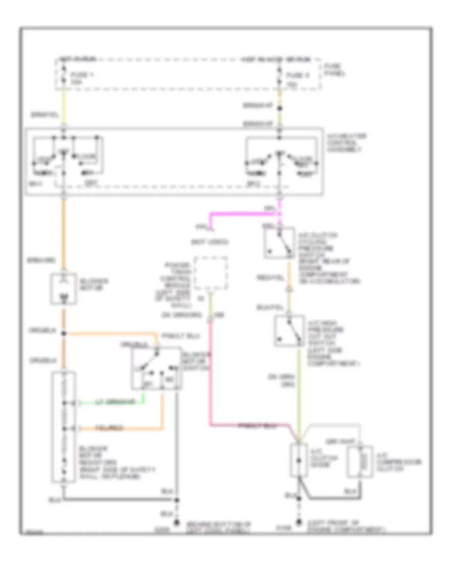
4.9L, A/C Wiring Diagram for Ford Cab & Chassis F350 1996

List of elements for 4.9L, A/C Wiring Diagram for Ford Cab & Chassis F350 1996:
- (behind bottom of left cowl panel)
- (left front of engine compartment)
- (not used)
- 15a
- A/c clutch cycling pressure switch (right rear of engine compartment on accumulator)
- A/c clutch diode
- A/c compressor clutch
- A/c high pressure cut out switch (left side engine compartment)
- A/c-heater control assembly
- Blower motor
- Blower motor resistors (right side of safety wall, on plenum)
- Blower motor switch
- Def
- Floor
- Fuse 1 30a
- Fuse 6
- Fuse panel
- G108
- G200
- Hot in accy or run
- Hot in run
- Max
- Mix
- Norm
- Off
- Pcm power relay
- Power- train control module (left side of safety wall)
- Red
- Vent
- Wac relay (engine compartment fuse box)
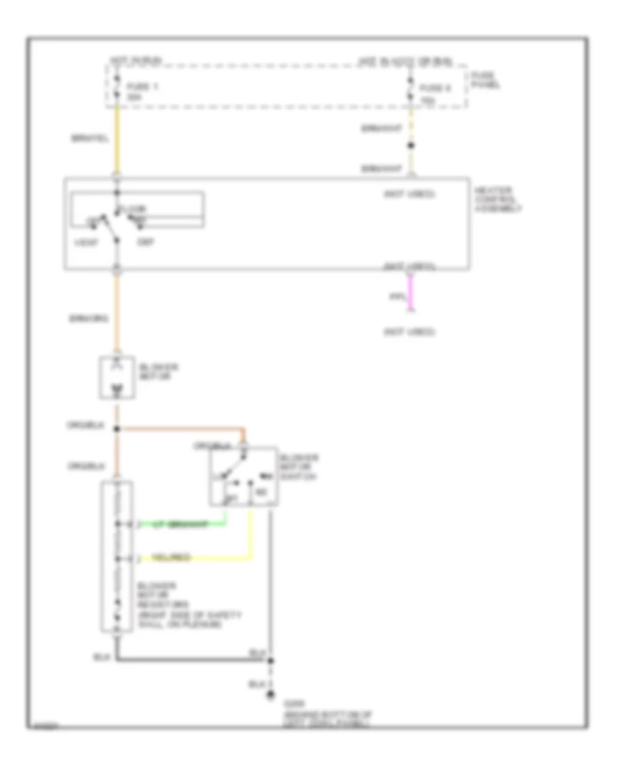
Heater Wiring Diagram for Ford Cab & Chassis F350 1996
List of elements for Heater Wiring Diagram for Ford Cab & Chassis F350 1996:
- (not used)
- 15a
- Blower motor
- Blower motor resistors (right side of safety wall, on plenum)
- Blower motor switch
- Def
- Floor
- Fuse 1 30a
- Fuse 6
- Fuse panel
- G200 (behind bottom of left cowl panel)
- Heater control assembly
- Hot in accy or run
- Hot in run
- Mix
- Off
- Vent
5.8L
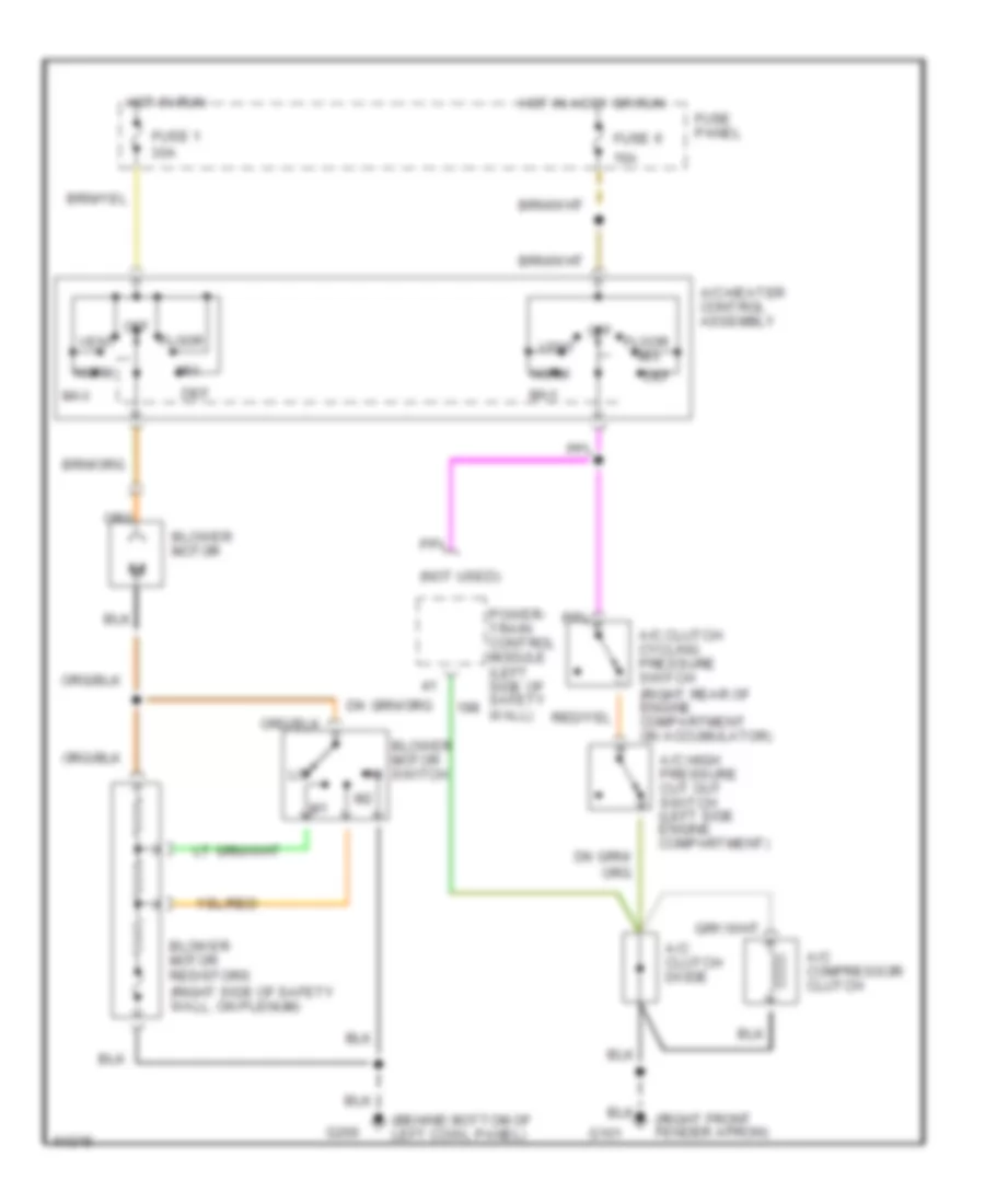
5.8L, A/C Wiring Diagram for Ford Cab & Chassis F350 1996
List of elements for 5.8L, A/C Wiring Diagram for Ford Cab & Chassis F350 1996:
- (behind bottom of left cowl panel)
- (left front of engine compartment)
- (not used)
- 15a
- A/c clutch cycling pressure switch (right rear of engine compartment on accumulator)
- A/c clutch diode
- A/c compressor clutch
- A/c high pressure cut out switch (left side engine compartment)
- A/c-heater control assembly
- Blower motor
- Blower motor resistors (right side of safety wall, on plenum)
- Blower motor switch
- Def
- Floor
- Fuse 1 30a
- Fuse 6
- Fuse panel
- G108
- G200
- Hot in accy or run
- Hot in run
- Max
- Mix
- Norm
- Off
- Power- train control module (left side of safety wall)
- Vent
Heater Wiring Diagram for Ford Cab & Chassis F350 1996
List of elements for Heater Wiring Diagram for Ford Cab & Chassis F350 1996:
- (not used)
- 15a
- Blower motor
- Blower motor resistors (right side of safety wall, on plenum)
- Blower motor switch
- Def
- Floor
- Fuse 1 30a
- Fuse 6
- Fuse panel
- G200 (behind bottom of left cowl panel)
- Heater control assembly
- Hot in accy or run
- Hot in run
- Mix
- Off
- Vent
7.3L
7.3L DI Turbo Diesel, Air Conditioning Wiring Diagrams for Ford Cab & Chassis F350 1996
List of elements for 7.3L DI Turbo Diesel, Air Conditioning Wiring Diagrams for Ford Cab & Chassis F350 1996:
- (behind bottom of left cowl panel)
- (not used)
- (right front fender apron)
- 15a
- A/c clutch cycling pressure switch (right rear of engine compartment on accumulator)
- A/c clutch diode
- A/c compressor clutch
- A/c high pressure cut out switch (left side engine compartment)
- A/c-heater control assembly
- Blower motor
- Blower motor resistors (right side of safety wall, on plenum)
- Blower motor switch
- Def
- Floor
- Fuse 1 30a
- Fuse 6
- Fuse panel
- G101
- G200
- Hot in accy or run
- Hot in run
- Max
- Mix
- Norm
- Off
- Power- train control module (left side of safety wall)
- Vent
Heater Wiring Diagram for Ford Cab & Chassis F350 1996
List of elements for Heater Wiring Diagram for Ford Cab & Chassis F350 1996:
- (not used)
- 15a
- Blower motor
- Blower motor resistors (right side of safety wall, on plenum)
- Blower motor switch
- Def
- Floor
- Fuse 1 30a
- Fuse 6
- Fuse panel
- G200 (behind bottom of left cowl panel)
- Heater control assembly
- Hot in accy or run
- Hot in run
- Mix
- Off
- Vent
7.5L
7.5L, A/C Wiring Diagram for Ford Cab & Chassis F350 1996
List of elements for 7.5L, A/C Wiring Diagram for Ford Cab & Chassis F350 1996:
- (behind bottom of left cowl panel)
- (left front of engine compartment)
- (not used)
- 15a
- A/c clutch cycling pressure switch (right rear of engine compartment on accumulator)
- A/c clutch diode
- A/c compressor clutch
- A/c high pressure cut out switch (left side engine compartment)
- A/c-heater control assembly
- Blower motor
- Blower motor resistors (right side of safety wall, on plenum)
- Blower motor switch
- Def
- Floor
- Fuse 1 30a
- Fuse 6
- Fuse panel
- G108
- G200
- Hot in accy or run
- Hot in run
- Max
- Mix
- Norm
- Off
- Power- train control module (left side of safety wall)
- Vent
Heater Wiring Diagram for Ford Cab & Chassis F350 1996
List of elements for Heater Wiring Diagram for Ford Cab & Chassis F350 1996:
- (not used)
- 15a
- Blower motor
- Blower motor resistors (right side of safety wall, on plenum)
- Blower motor switch
- Def
- Floor
- Fuse 1 30a
- Fuse 6
- Fuse panel
- G200 (behind bottom of left cowl panel)
- Heater control assembly
- Hot in accy or run
- Hot in run
- Mix
- Off
- Vent
ANTI-LOCK BRAKES
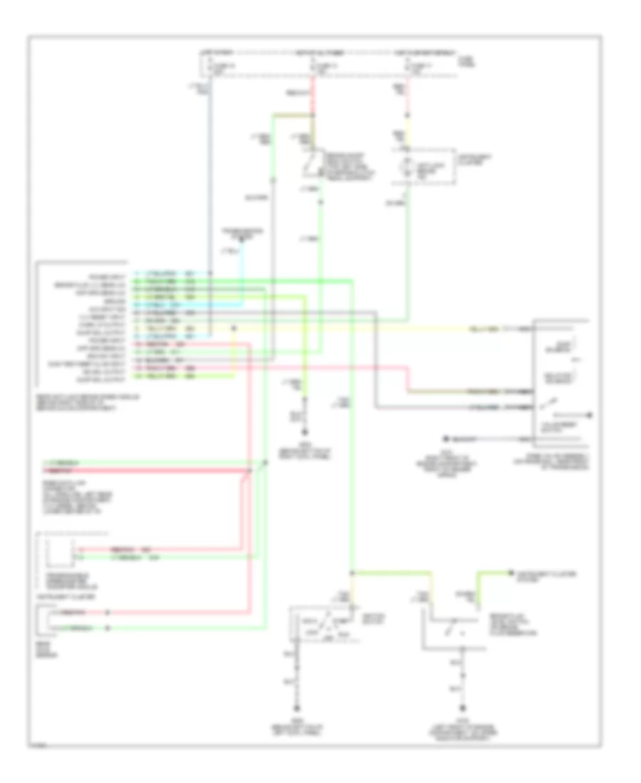
Anti-lock Brake Wiring Diagrams for Ford Cab & Chassis F350 1996
List of elements for Anti-lock Brake Wiring Diagrams for Ford Cab & Chassis F350 1996:
- 4x4 input sig
- Acc
- Anti-lock brake ind
- Boo sw input
- Brake fluid level switch (on brake fluid reservoir)
- Brake fluid lvl sens (lo)
- Brake on/off (boo) switch (top left side of brake/clutch pedal support)
- Diag test/keep alive input
- Diff spd sens (hi)
- Diff spd sens (lo)
- Dump sol output
- Dump solenoid
- Fuse 13 15a
- Fuse 15 20a
- Fuse 17 10a
- Fuse panel
- G101 (right front of engine compartment, front of fender apron)
- G108 (left front of engine compartment, on upper radiator support)
- G200 (behind bottom of left cowl panel)
- G203 (behind bottom of right cowl panel)
- Ground
- Hot at all times
- Hot in run
- Hot in start or run
- Ignition switch
- Instrument cluster
- Instrument cluster system
- Iso sol output
- Isolation solenoid
- Lock
- Nca
- Off
- Power input
- Programmable speedometer/ odometer module
- Rabs data link connector (all gasoline: left rear of engine compartment) (7.3l diesel: behind lower center of i/p)
- Rabs valve assembly (on frame rail, near front of transmission)
- Rear anti-lock brake (rabs) module (behind right side of i/p, behind glove compartment)
- Rear axle sensor
- Red/pnk
- Run
- Start
- Transmissions system
- Valve reset switch
- Vlv reset input
- Warn lp output
COMPUTER DATA LINES
4.9L
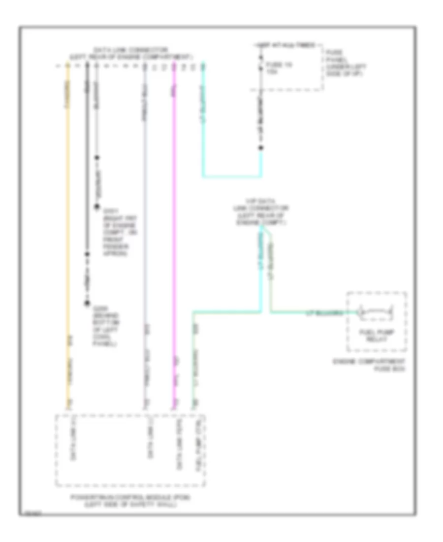
4.9L, Computer Data Lines for Ford Cab & Chassis F350 1996
List of elements for 4.9L, Computer Data Lines for Ford Cab & Chassis F350 1996:
- Data link (+)
- Data link (-)
- Data link connector (left rear of engine compartment)
- Data link feps
- Engine compartment fuse box
- Fuel pump ctrl
- Fuel pump relay
- Fuse 16 15a
- Fuse panel (under left side of i/p)
- G101 (right frt of engine compt, on front fender apron)
- G200 (behind bottom of left cowl panel)
- Hot at all times
- Powertrain control module (pcm) (left side of safety wall)
- Vip data link connector (left rear of engine compt)
5.8L
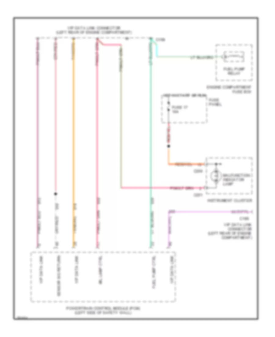
5.8L, Computer Data Lines, Over 8500 GVWR for Ford Cab & Chassis F350 1996
List of elements for 5.8L, Computer Data Lines, Over 8500 GVWR for Ford Cab & Chassis F350 1996:
- C198
- C199
- C250
- C251
- Engine compartment fuse box
- Fuel pump ctrl
- Fuel pump relay
- Fuse 17 10a
- Fuse panel
- Hot in start or run
- Instrument cluster
- Malfunction indicator lamp
- Mil lamp ctrl
- Powertrain control module (pcm) (left side of safety wall)
- Sensor sig return
- Vip data link
- Vip data link connector (left rear of engine compartment)
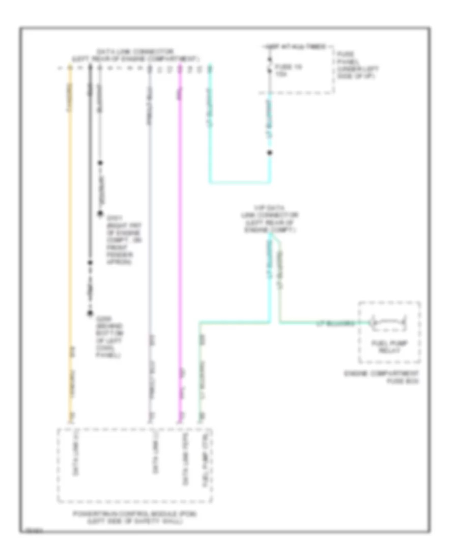
5.8L, Computer Data Lines, Under 8500 GVWR for Ford Cab & Chassis F350 1996
List of elements for 5.8L, Computer Data Lines, Under 8500 GVWR for Ford Cab & Chassis F350 1996:
- Data link (+)
- Data link (-)
- Data link connector (left rear of engine compartment)
- Data link feps
- Engine compartment fuse box
- Fuel pump ctrl
- Fuel pump relay
- Fuse 16 15a
- Fuse panel (under left side of i/p)
- G101 (right frt of engine compt, on front fender apron)
- G200 (behind bottom of left cowl panel)
- Hot at all times
- Powertrain control module (pcm) (left side of safety wall)
- Vip data link connector (left rear of engine compt)
7.3L
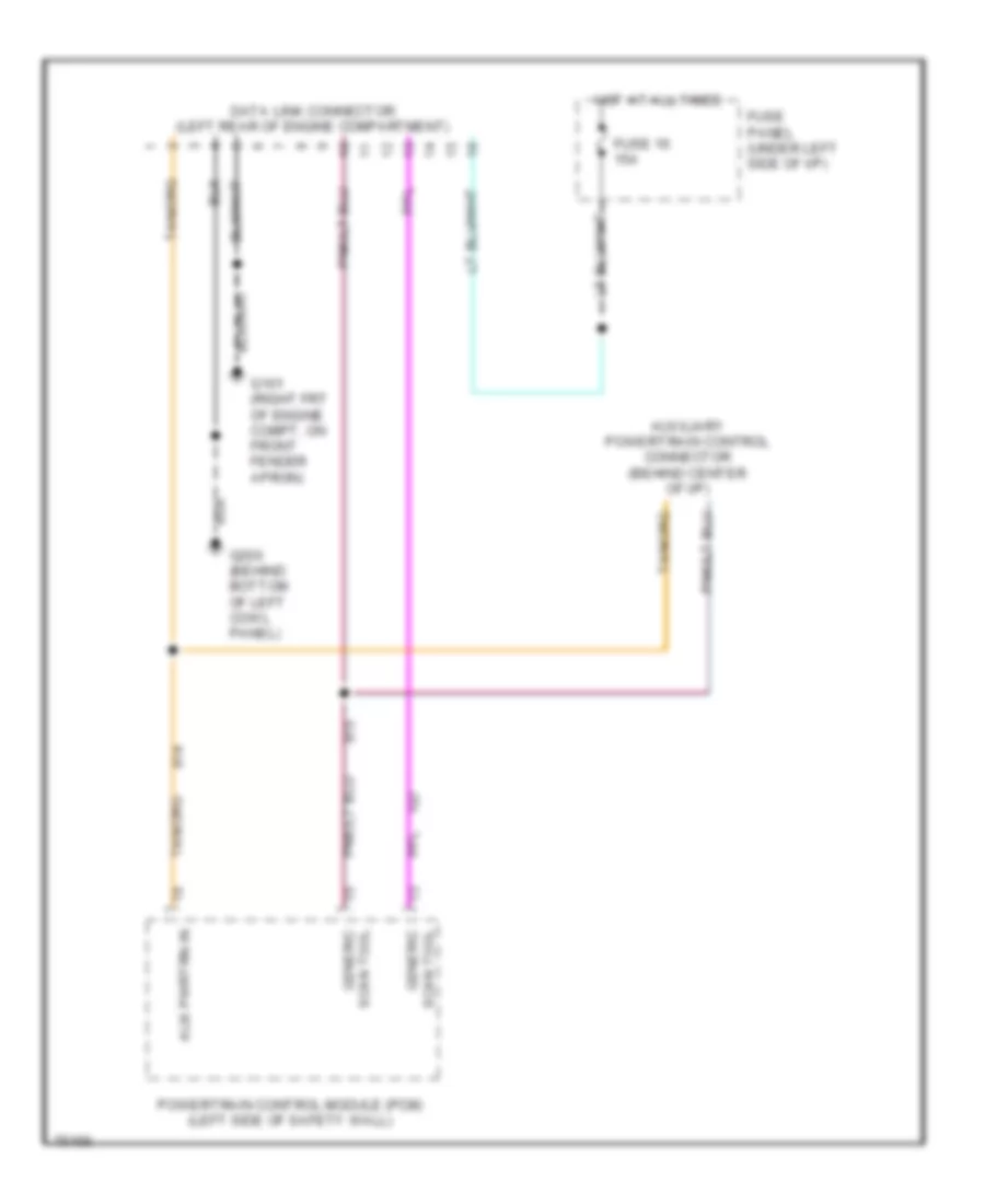
7.3L DI Turbo Diesel, Computer Data Lines for Ford Cab & Chassis F350 1996
List of elements for 7.3L DI Turbo Diesel, Computer Data Lines for Ford Cab & Chassis F350 1996:
- Aux pwrtrn in
- Auxiliary powertrain control connector (behind center of i/p)
- Data link connector (left rear of engine compartment)
- Fuse 16 15a
- Fuse panel (under left side of i/p)
- G101 (right frt of engine compt, on front fender apron)
- G200 (behind bottom of left cowl panel)
- Generic scan tool
- Hot at all times
- Powertrain control module (pcm) (left side of safety wall)
- Scan tool generic
7.5L
7.5L, Computer Data Lines, California for Ford Cab & Chassis F350 1996
List of elements for 7.5L, Computer Data Lines, California for Ford Cab & Chassis F350 1996:
- Data link (+)
- Data link (-)
- Data link connector (left rear of engine compartment)
- Data link feps
- Engine compartment fuse box
- Fuel pump ctrl
- Fuel pump relay
- Fuse 16 15a
- Fuse panel (under left side of i/p)
- G101 (right frt of engine compt, on front fender apron)
- G200 (behind bottom of left cowl panel)
- Hot at all times
- Powertrain control module (pcm) (left side of safety wall)
- Vip data link connector (left rear of engine compt)
7.5L, Computer Data Lines, Federal for Ford Cab & Chassis F350 1996
List of elements for 7.5L, Computer Data Lines, Federal for Ford Cab & Chassis F350 1996:
- C198
- C199
- C250
- C251
- Engine compartment fuse box
- Fuel pump ctrl
- Fuel pump relay
- Fuse 17 10a
- Fuse panel
- Hot in start or run
- Instrument cluster
- Malfunction indicator lamp
- Mil lamp ctrl
- Powertrain control module (pcm) (left side of safety wall)
- Sensor sig return
- Vip data link
- Vip data link connector (left rear of engine compartment)
CRUISE CONTROL
4.9L
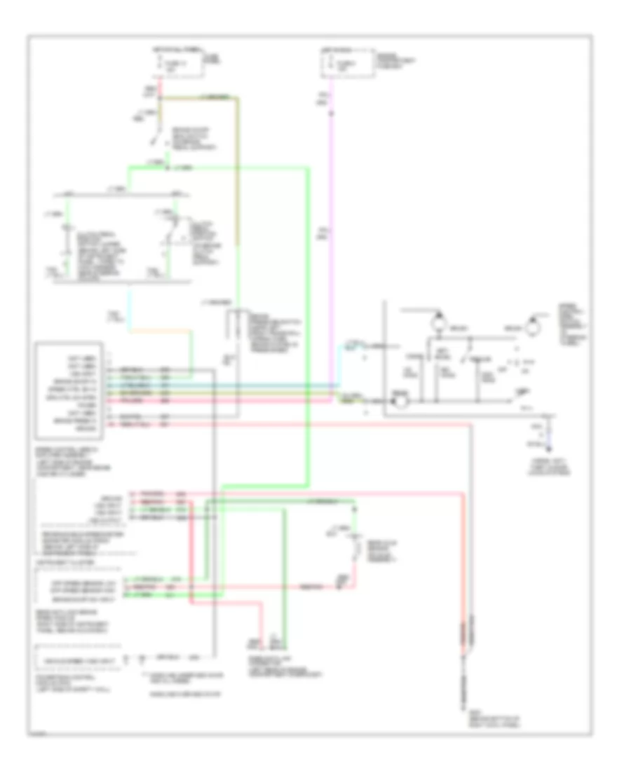
4.9L, Cruise Control Wiring Diagram for Ford Cab & Chassis F350 1996
List of elements for 4.9L, Cruise Control Wiring Diagram for Ford Cab & Chassis F350 1996:
- (behind bottom of right cowl panel)
- (behind left side of instrument panel, taped to main harness near steering column)
- (behind left side of instrument panel)
- (left rear of engine compartment,on bracket)
- (left side of engine compartment, near brake master cylinder)
- (left side of safety wall)
- (not used)
- (on axle assembly)
- (on brake/ clutch
- (right side of instrument panel, behind glove box)
- 15a
- A/t
- Accel
- Brake on/off (boo) switch (on brake pedal support)
- Brake on/off in
- Brake on/off sw input
- Brake press in
- Brake pressure switch (near left front frame rail) (opens when brake system is pressurized)
- Brush
- Clutch pedal position switch
- Clutch pedal position switch jumper
- Coast
- Diff speed sensor high
- Diff speed sensor low
- Engine compartment fuse box
- Fuse 13
- Fuse 5 15a
- Fuse panel
- G203
- Gasoline over 8500 gvwr
- Gasoline under 8500 gvwr and all diesel
- Ground
- Horn
- Horns, anti- theft & door locks systems
- Hot at all times
- Hot in run
- Instrument cluster
- M/t
- Nca
- Off
- Ohms
- Pedal support)
- Pnk
- Power
- Powertrain control module (pcm)
- Programmable speedometer/ odometer module (psom)
- Rabs data link connector
- Rear anti-lock brake (rabs) module
- Rear axle sensor
- Red
- Red/
- Red/ pnk
- Red/pnk
- Resume
- Set/
- Spd ctrl sw rtrn
- Speed control servo/ amplifier assembly
- Speed control/ horn switch assembly (in steering wheel)
- Speed ctrl sw in
- Tan/
- Vehicle speed (vss) input
- Vss input
- Vss output
5.8L
5.8L, Cruise Control Wiring Diagram for Ford Cab & Chassis F350 1996
List of elements for 5.8L, Cruise Control Wiring Diagram for Ford Cab & Chassis F350 1996:
- (behind bottom of right cowl panel)
- (behind left side of instrument panel, taped to main harness near steering column)
- (behind left side of instrument panel)
- (left rear of engine compartment,on bracket)
- (left side of engine compartment, near brake master cylinder)
- (left side of safety wall)
- (not used)
- (on axle assembly)
- (on brake/ clutch
- (right side of instrument panel, behind glove box)
- 15a
- A/t
- Accel
- Brake on/off (boo) switch (on brake pedal support)
- Brake on/off in
- Brake on/off sw input
- Brake press in
- Brake pressure switch (near left front frame rail) (opens when brake system is pressurized)
- Brush
- Clutch pedal position switch
- Clutch pedal position switch jumper
- Coast
- Diff speed sensor high
- Diff speed sensor low
- Engine compartment fuse box
- Fuse 13
- Fuse 5 15a
- Fuse panel
- G203
- Gasoline over 8500 gvwr
- Gasoline under 8500 gvwr and all diesel
- Ground
- Horn
- Horns, anti- theft & door locks systems
- Hot at all times
- Hot in run
- Instrument cluster
- M/t
- Nca
- Off
- Ohms
- Pedal support)
- Pnk
- Power
- Powertrain control module (pcm)
- Programmable speedometer/ odometer module (psom)
- Rabs data link connector
- Rear anti-lock brake (rabs) module
- Rear axle sensor
- Red
- Red/
- Red/ pnk
- Red/pnk
- Resume
- Set/
- Spd ctrl sw rtrn
- Speed control servo/ amplifier assembly
- Speed control/ horn switch assembly (in steering wheel)
- Speed ctrl sw in
- Tan/
- Vehicle speed (vss) input
- Vss input
- Vss output
7.3L
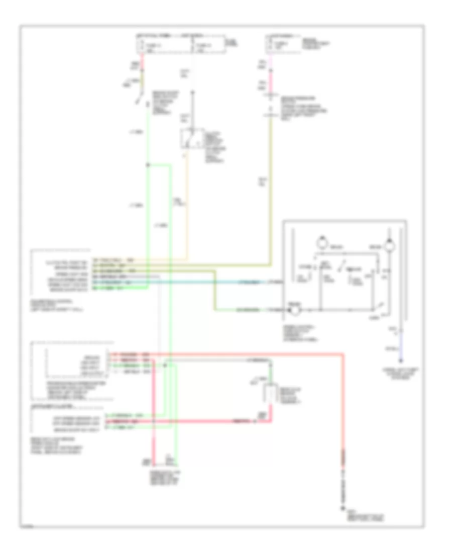
7.3L DI Turbo Diesel, Cruise Control Wiring Diagram for Ford Cab & Chassis F350 1996
List of elements for 7.3L DI Turbo Diesel, Cruise Control Wiring Diagram for Ford Cab & Chassis F350 1996:
- (behind left side of instrument panel)
- (left side of safety wall)
- (on axle assembly)
- (on brake/ clutch
- (on brake/ clutch pedal support)
- (right side of instrument panel, behind glove box)
- 10a
- 15a
- 29
- Accel
- Brake on/off (boo) switch
- Brake on/off sw in
- Brake on/off sw input
- Brake press sw
- Brake pressure switch (opens when brake
- Brush
- Clutch pedal position switch
- Clutch pdl posit sw
- Coast
- Diff speed sensor high
- Diff speed sensor low
- Engine compartment fuse box
- Fuse 13
- Fuse 18
- Fuse 5 15a
- Fuse panel
- G203 (behind bottom of right cowl panel)
- Ground
- Horn
- Horns, anti-theft & door locks systems
- Hot at all times
- Hot in run
- Instrument cluster
- Nca
- Off
- Ohms
- Pedal support)
- Pnk
- Powertrain control module (pcm)
- Programmable speedometer/ odometer module (psom)
- Rabs data link connector (behind lower center of i/p)
- Rear anti-lock brake (rabs) module
- Rear axle sensor
- Red
- Red/
- Red/ pnk
- Red/pnk
- Resume
- Set/
- Speed cont com sig
- Speed cont gnd
- Speed control/ horn switch assembly (steering wheel)
- System has pressure) (near left front rail)
- Tan/
- Vehicle speed sens
- Vss input
- Vss output
7.5L
7.5L, Cruise Control Wiring Diagram for Ford Cab & Chassis F350 1996
List of elements for 7.5L, Cruise Control Wiring Diagram for Ford Cab & Chassis F350 1996:
- (behind bottom of right cowl panel)
- (behind left side of instrument panel, taped to main harness near steering column)
- (behind left side of instrument panel)
- (left rear of engine compartment,on bracket)
- (left side of engine compartment, near brake master cylinder)
- (left side of safety wall)
- (not used)
- (on axle assembly)
- (on brake/ clutch
- (right side of instrument panel, behind glove box)
- 15a
- A/t
- Accel
- Brake on/off (boo) switch (on brake pedal support)
- Brake on/off in
- Brake on/off sw input
- Brake press in
- Brake pressure switch (near left front frame rail) (opens when brake system is pressurized)
- Brush
- Clutch pedal position switch
- Clutch pedal position switch jumper
- Coast
- Diff speed sensor high
- Diff speed sensor low
- Engine compartment fuse box
- Fuse 13
- Fuse 5 15a
- Fuse panel
- G203
- Gasoline over 8500 gvwr
- Gasoline under 8500 gvwr and all diesel
- Ground
- Horn
- Horns, anti- theft & door locks systems
- Hot at all times
- Hot in run
- Instrument cluster
- M/t
- Nca
- Off
- Ohms
- Pedal support)
- Pnk
- Power
- Powertrain control module (pcm)
- Programmable speedometer/ odometer module (psom)
- Rabs data link connector
- Rear anti-lock brake (rabs) module
- Rear axle sensor
- Red
- Red/
- Red/ pnk
- Red/pnk
- Resume
- Set/
- Spd ctrl sw rtrn
- Speed control servo/ amplifier assembly
- Speed control/ horn switch assembly (in steering wheel)
- Speed ctrl sw in
- Tan/
- Vehicle speed (vss) input
- Vss input
- Vss output
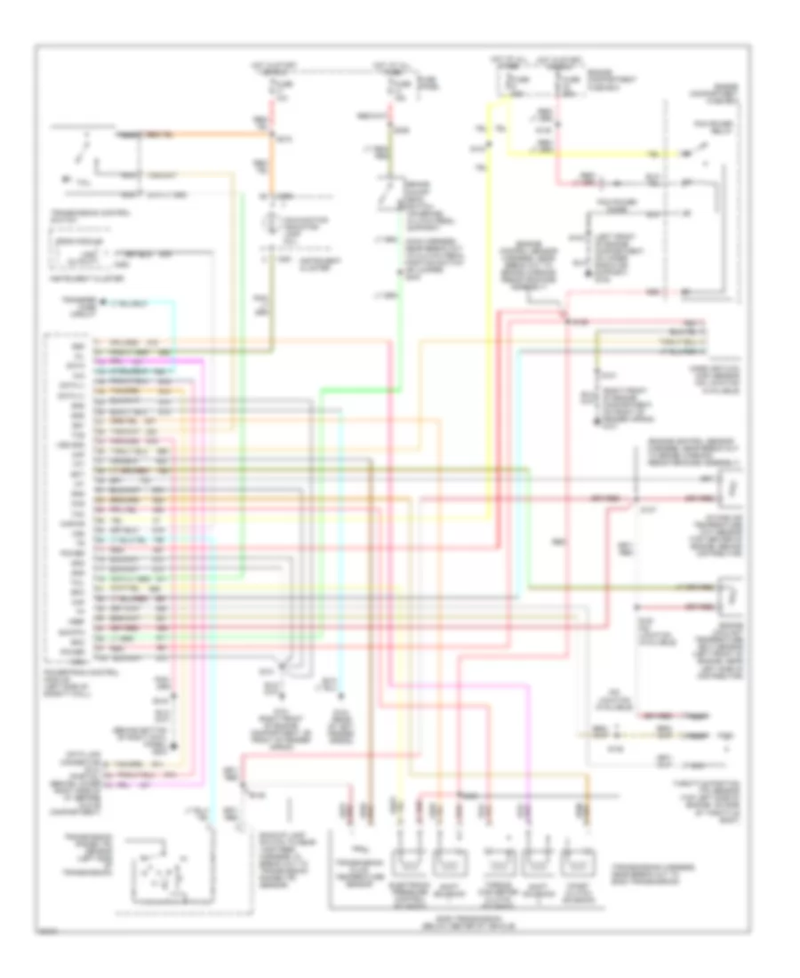
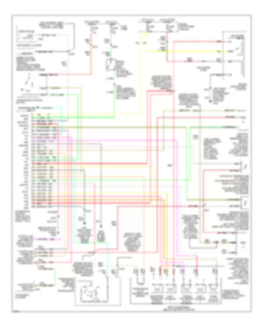
ENGINE PERFORMANCE
4.9L
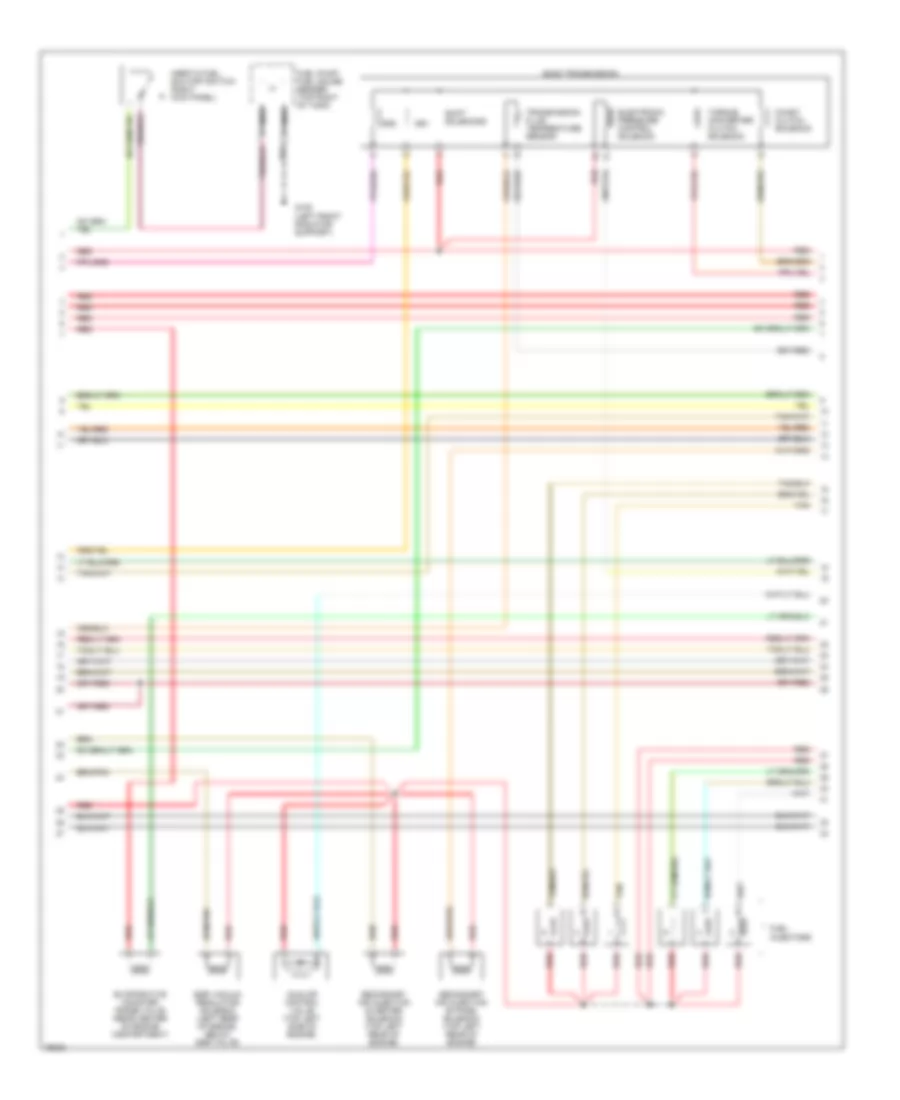
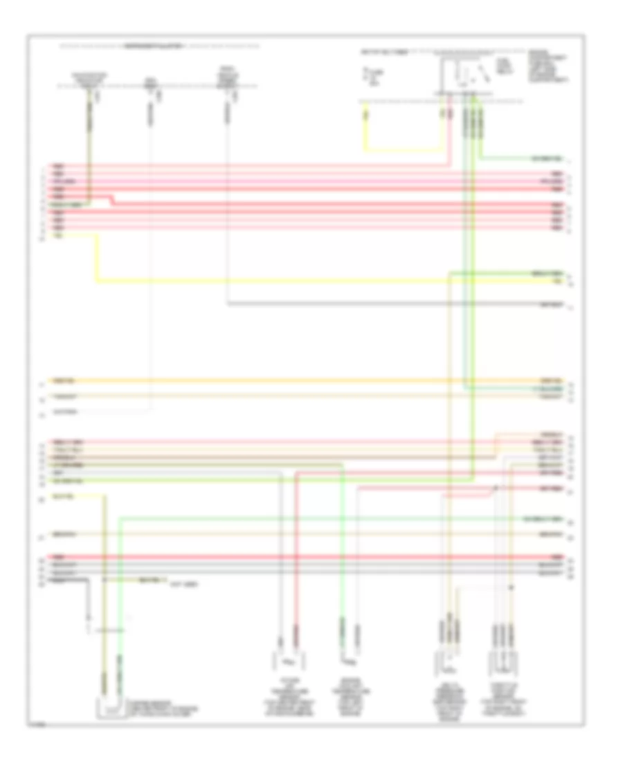
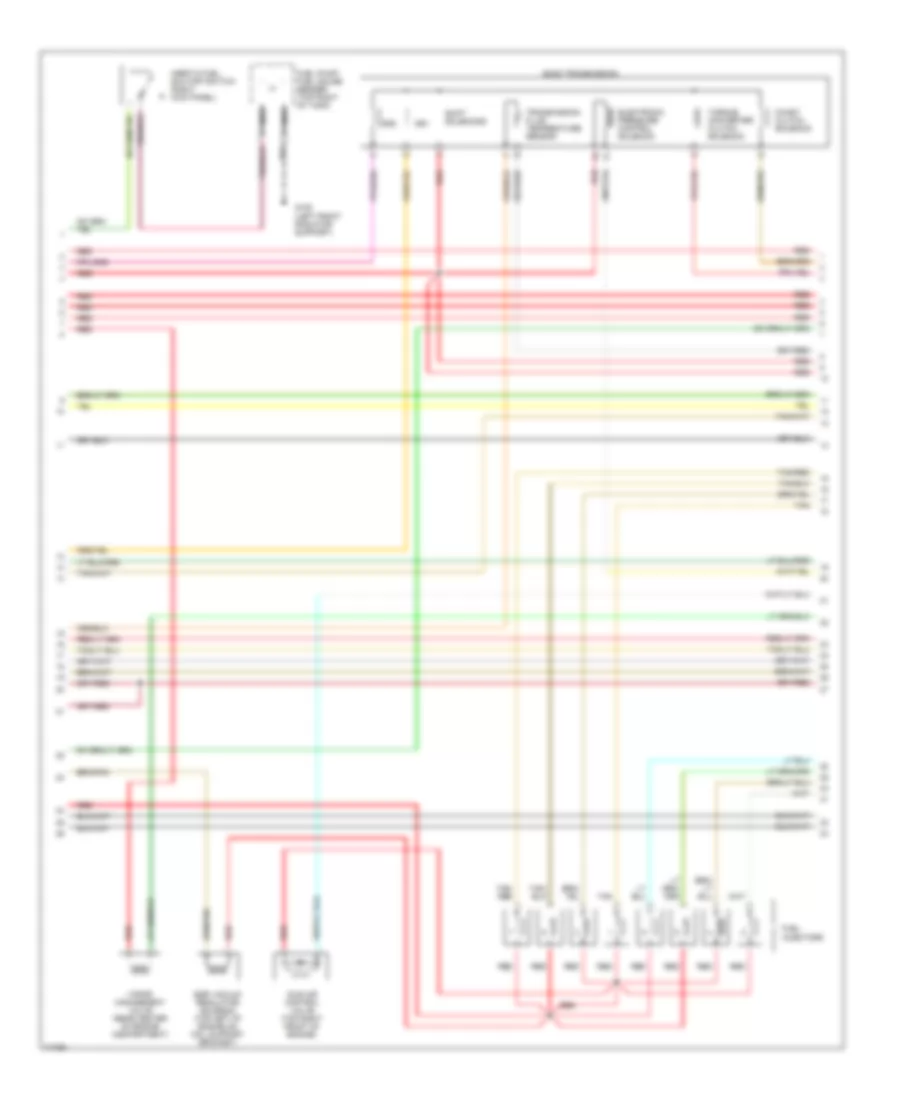
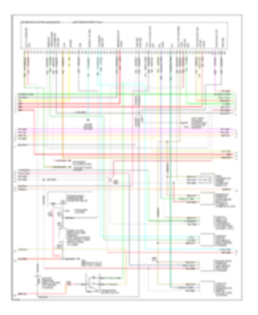
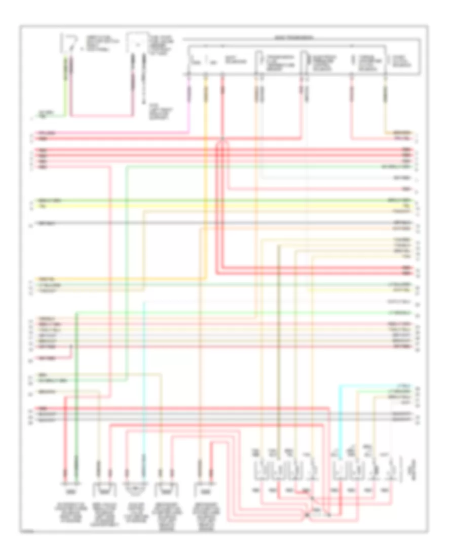
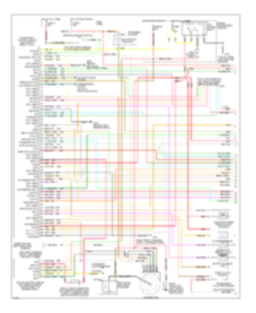
4.9L, Engine Performance Wiring Diagrams (1 of 4) for Ford Cab & Chassis F350 1996
List of elements for 4.9L, Engine Performance Wiring Diagrams (1 of 4) for Ford Cab & Chassis F350 1996:
- (4x4 hi/low indicator switch)
- (not used)
- A/c clutch sig
- Air conditioning system
- Aird solnd
- Case gnd
- Ckp sensor
- Coil
- Data link (+)
- Data link (-)
- Data link connector
- Data link feps
- Distributor (left front of engine)
- Distributor ignition shield
- Ect sens
- Egr solnd ctrl
- Engine compartment fuse box (left side of engine compartment)
- Fuel pump mon
- Fuse 20a
- Fuse 30a
- G104 (rear of left fender apron)
- G108 (left front radiator support)
- G203 (right kick panel)
- Ho2s 12 sig
- Hot at all times
- Hot in start or run
- Iat sens
- Idm
- Idm (fto)
- Ign gnd
- Ignition coil (left front of engine, forward of distributor)
- Ignition control module (left rear side of engine compartment, on fender apron)
- Low rnge 4x4
- Maf sig rtn
- Mil
- Misfire sens
- Nca
- Pcm power diode
- Pcm power relay
- Pip
- Pnk
- Power
- Powertrain control module (top left side of safety wall)
- Pwr gnd
- Pwr grd
- Radio capacitor (left front of engine, near coil)
- Red
- Red/
- Spark output check connector (left rear of engine compartment, near icm)
- Spout
- Trans ctrl sw
- Trans temp
- Trans- missions system
- Tss 1
- Tss 2
- Vss (-)
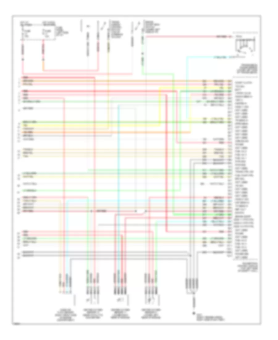
4.9L, Engine Performance Wiring Diagrams (2 of 4) for Ford Cab & Chassis F350 1996
List of elements for 4.9L, Engine Performance Wiring Diagrams (2 of 4) for Ford Cab & Chassis F350 1996:
- C250
- C251
- C252
- Delta pressure feedback egr sensor (left side of engine)
- Engine compartment fuse box (left side of engine compartment)
- Engine coolant temperature sensor (center front of engine, on thermostat housing)
- Fuel pump relay
- Fuse 20a
- Hot at all times
- Instrument cluster
- Intake air temperature sensor (right front of engine, near intake runner #1)
- Knock sensor (left front of engine, near ignition coil)
- Malfunction indicator input
- Misfire sensor (center front of engine, on timing chain cover)
- Nca
- Psom vehicle speed output
- Red
- Rpm input
- Throttle position sensor (top left rear of engine, on throttle body)
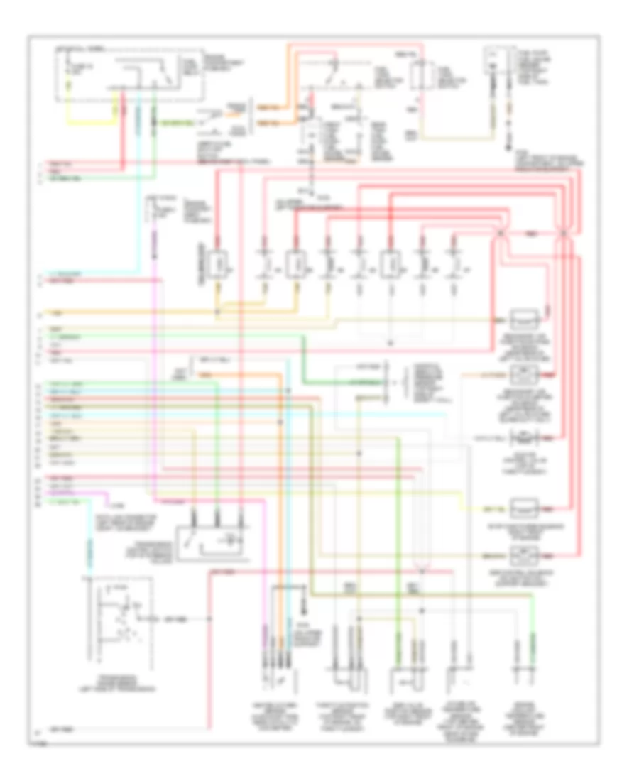
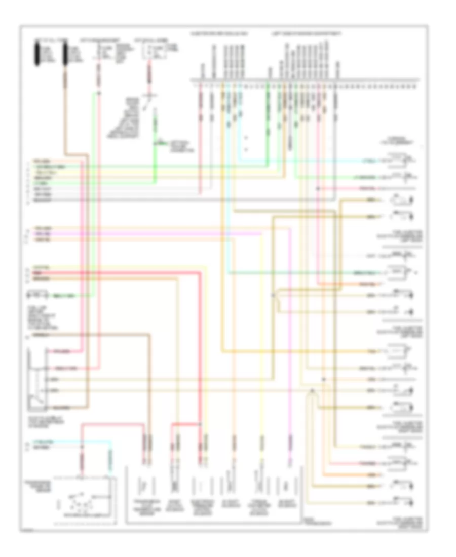
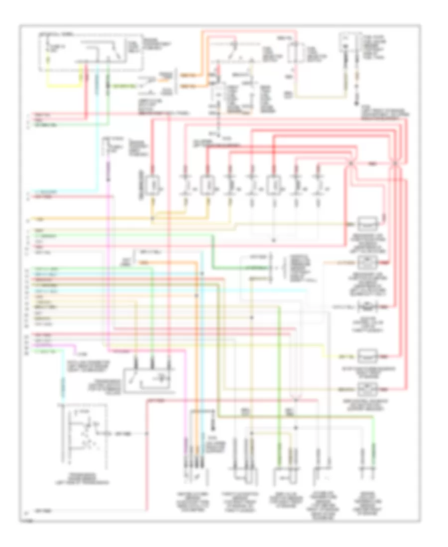
4.9L, Engine Performance Wiring Diagrams (3 of 4) for Ford Cab & Chassis F350 1996
List of elements for 4.9L, Engine Performance Wiring Diagrams (3 of 4) for Ford Cab & Chassis F350 1996:
- Coast clutch solenoid
- E4od transmission
- Egr vacuum regulator solenoid (left rear of engine, below egr valve)
- Electronic pressure control solenoid
- Evaporative canister purge valve (rear center of engine compartment)
- Fuel injectors
- Fuel pump/ fuel gauge sender (top right of tank)
- G108 (left front radiator support)
- Idle air control valve (top left side of engine)
- Inertia fuel shutoff switch (right kick panel)
- Nca
- Red
- Secondary air injection bypass solenoid (top left rear of engine)
- Secondary air injection diverter solenoid (top left rear of engine)
- Shift solenoids
- Ss1
- Ss2
- Tan
- Torque converter clutch solenoid
- Transmission fluid temperature sensor
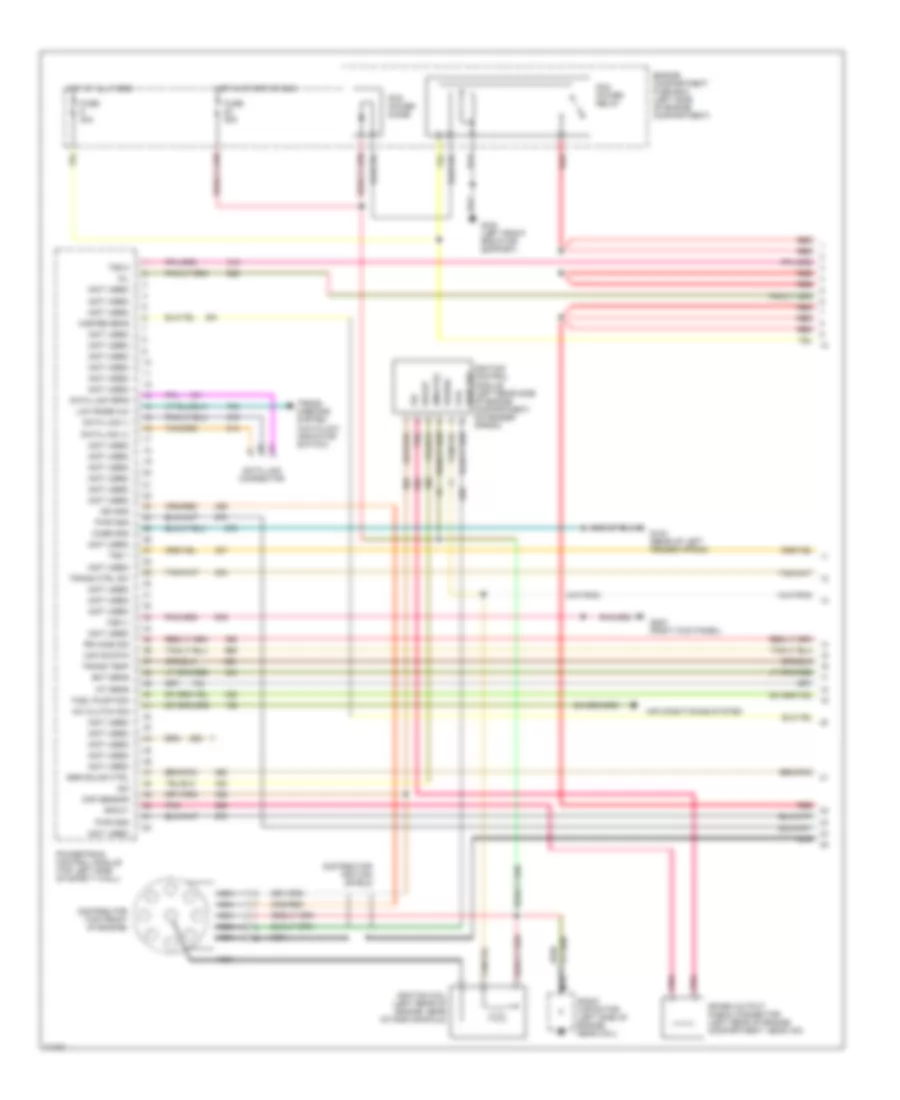
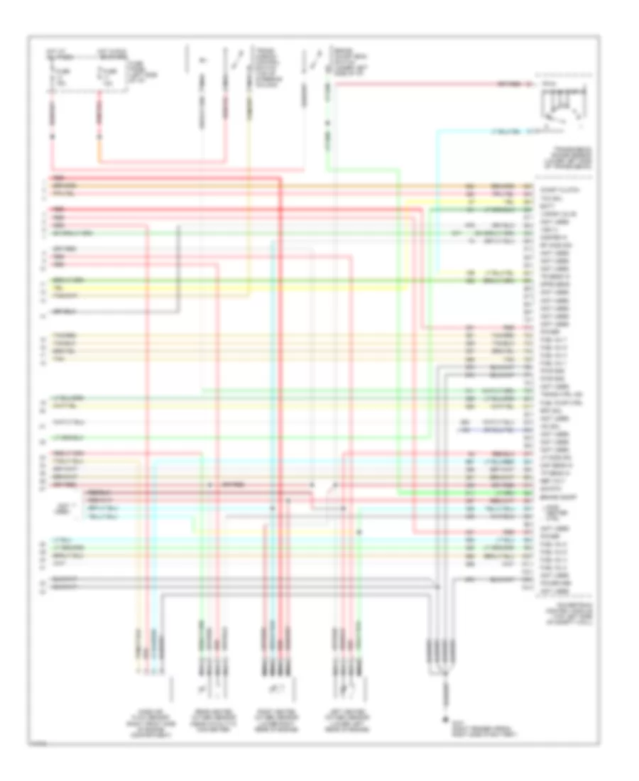
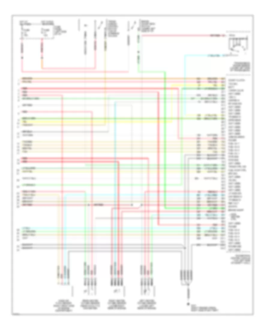
4.9L, Engine Performance Wiring Diagrams (4 of 4) for Ford Cab & Chassis F350 1996
List of elements for 4.9L, Engine Performance Wiring Diagrams (4 of 4) for Ford Cab & Chassis F350 1996:
- (not used)
- Airb solnd
- Batt
- Brake on/off
- Brake on/off (boo) switch (under left side of i/p)
- Coast clutch
- Dpfe sens
- Epc sol
- Fuel inj 1
- Fuel inj 2
- Fuel inj 3
- Fuel inj 4
- Fuel inj 5
- Fuel inj 6
- Fuel pump ctrl
- Fuse 10a
- Fuse 15a
- Fuse panel (left side of i/p)
- G101 (right fender apron, right side of battery)
- H02s 11 htr ctrl
- H02s 12 htr ctrl
- H02s 21 htr ctrl
- Heated oxygen sensor 11 (lower right rear of engine)
- Heated oxygen sensor 12 (near catalytic converter)
- Heated oxygen sensor 21 (lower left rear of engine)
- Ho2s 11 sig
- Ho2s 21 sig
- Hot at all times
- Hot in run or start
- Iac sol
- Knock sens in
- Maf sens in
- Mass air flow sensor (right front side of engine compartment)
- Misfire in
- Nca
- Power
- Power gnd
- Powertrain control module (top left side of safety wall)
- Pwr gnd
- Red
- Ref volt
- Sig rtn
- Tan
- Tcc sol
- Tp sens in
- Tr sens in
- Trans ctrl ind
- Trans- mission control switch (top of steering column)
- Transmission range sensor (lower left side of transmission)
- Vapor valve
- Vss (+)
5.8L
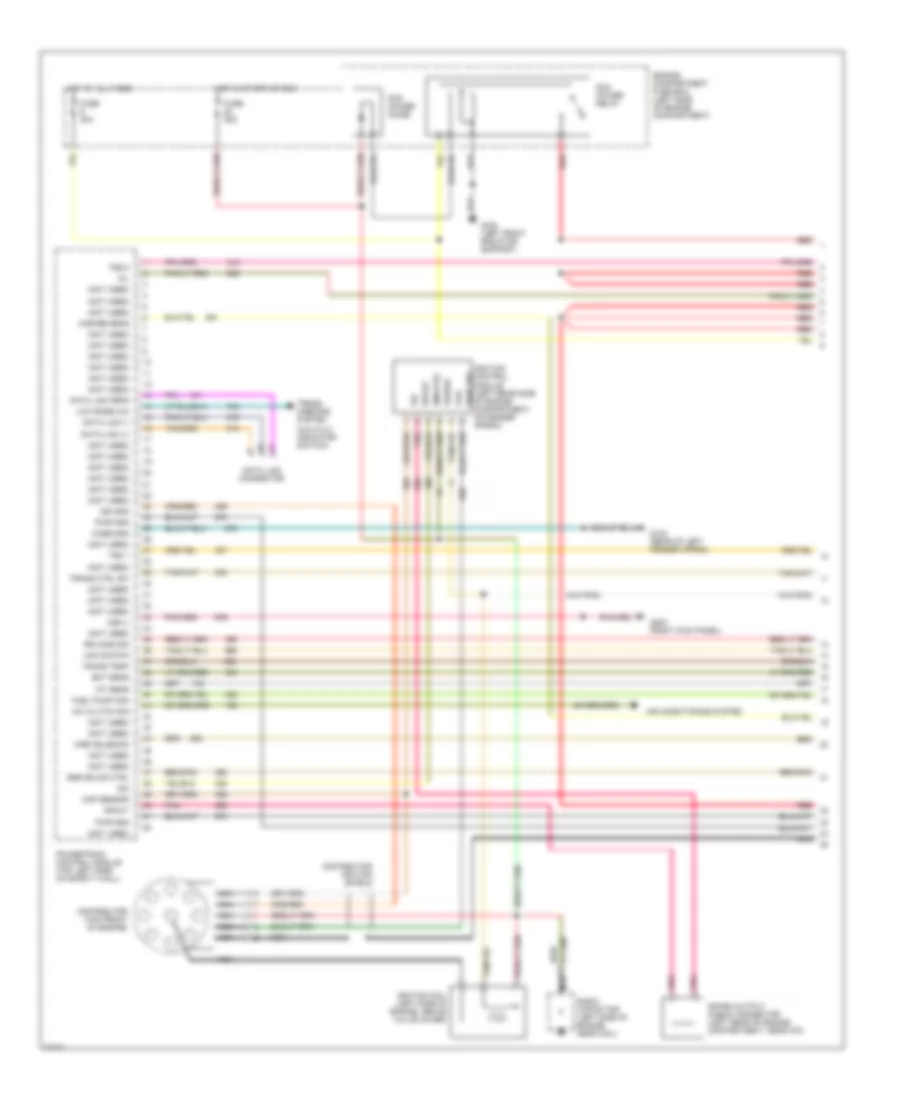
5.8L, Engine Performance Wiring Diagrams, Over 8500 GVWR (1 of 2) for Ford Cab & Chassis F350 1996
List of elements for 5.8L, Engine Performance Wiring Diagrams, Over 8500 GVWR (1 of 2) for Ford Cab & Chassis F350 1996:
- #1 shift solenoid
- #2 shift solenoid
- (4x4 hi/lo indicator switch)
- (left side of engine compt., near brake master cylinder)
- (not used)
- (right front of engine compt, on fender apron)
- (top left side of brake/ clutch pedal support)
- (top of upper left radiator support)
- Accs
- Air conditioning system
- Airb solnd ctrl
- Aird solnd ctrl
- Boo
- Brake on/off (boo) switch
- C198
- C250
- C251
- Ccs
- Ckp sensor
- Coast clutch solenoid
- Coil
- Coil wire
- Cse gnd
- Data link connector (left rear of engine compt, on bracket)
- Distributor
- E40d transmission
- Ect
- Egr cntrl solnd.
- Egr valve pos
- Electronic pres- sure control solenoid
- Engine compartment fuse box
- Epc
- Evap can solnd.
- Fp enable
- Fpm
- Fuse 13 15a
- Fuse 17 10a
- Fuse 20a
- Fuse 22 20a
- Fuse panel
- G101
- G104 (rear of left fender apron)
- G108
- G203 (behind bottom of right cowl panel)
- Gnd
- Ho2s ground
- Ho2s sig input
- Hot at all times
- Hot in start or run
- Iac
- Iat
- Idm
- Idm (fto)
- Ign gnd
- Ignition coil (left rear of engine)
- Ignition control module (left rear of engine compartment, on fender apron)
- Inj 1, 4, 5, 8
- Inj 2, 3, 6, 7
- Instrument cluster
- Instrument cluster system
- Kapwr
- Low rnge 4x4 ind
- Malfunction indicator
- Map sensor input
- Nca
- Pcm power diode
- Pcm power relay
- Pip
- Pnk
- Powertrain control module (left side of safety wall)
- Pwr
- Pwr gnd
- Radio capacitor (left side of engine, near ignition coil)
- Red
- Sig rtn
- Speed control servo/amplifier assembly
- Spout
- Spout check connector (left rear of engine compt, taped to harness, near ignition control module)
- Sto/mil
- Tan
- Tcc
- Tcil
- Tcs
- Tft sensor input
- Torque con- verter clutch solenoid
- Tps input
- Tr sensor input
- Transmission fluid temp sensor
- Transmissions system
- Tss 1
- Tss 2
- Vip dlc
- Vpwr
- Vref
- Vss ground
- Vss signal input
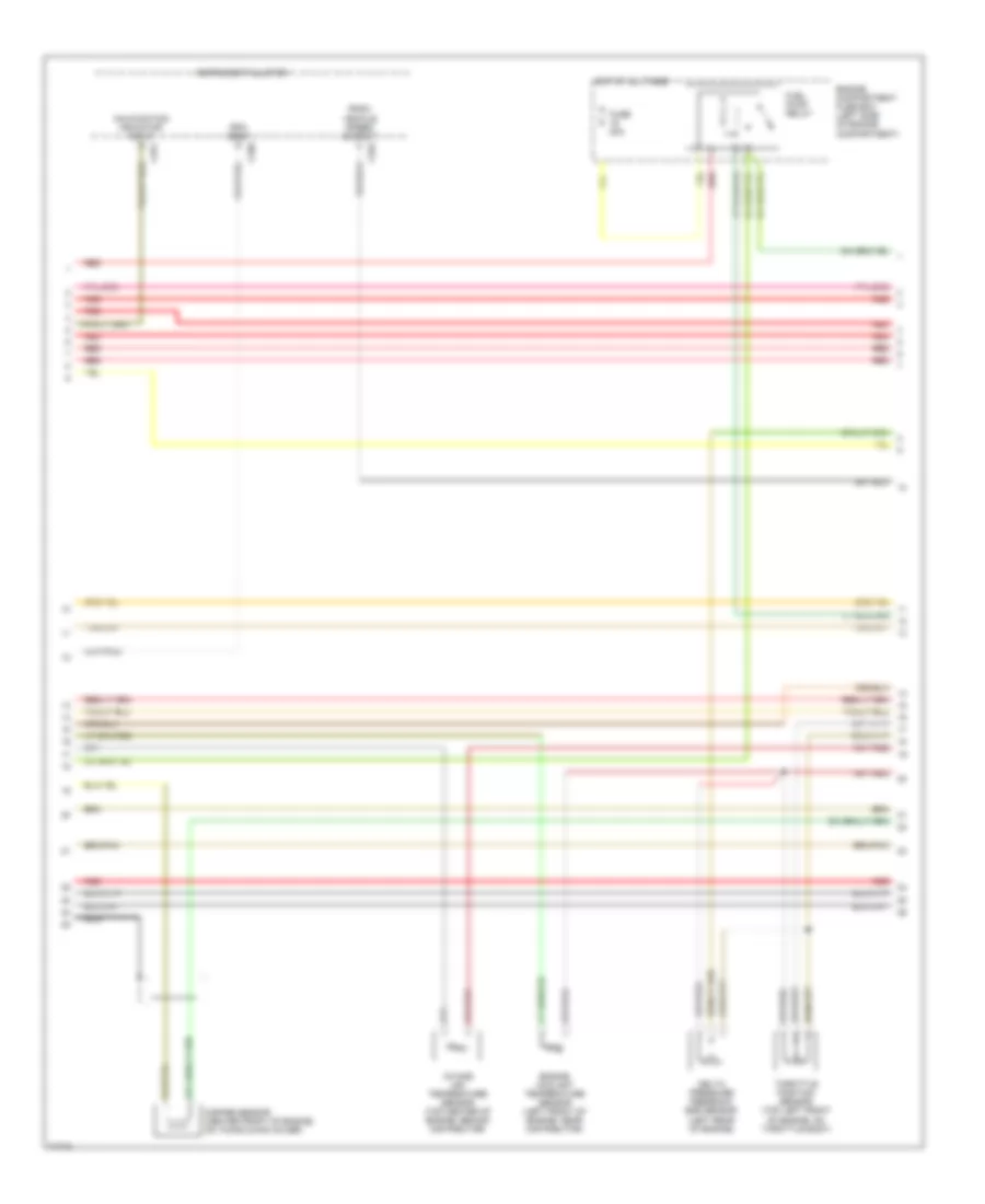
5.8L, Engine Performance Wiring Diagrams, Over 8500 GVWR (2 of 2) for Ford Cab & Chassis F350 1996
List of elements for 5.8L, Engine Performance Wiring Diagrams, Over 8500 GVWR (2 of 2) for Ford Cab & Chassis F350 1996:
- (not used)
- (on upper left radiator support)
- (on upper radiator support)
- C199
- Data link connector (left rear of engine compt, on bracket)
- Dual tanks
- Egr control solenoid (on ignition coil support bracket)
- Egr valve position sensor (top right front of engine)
- Engine compart- ment fuse box
- Engine compartment fuse box
- Engine coolant temperature sensor (center front of engine)
- Evap cann purge solenoid (right front of engine)
- Front tank fuel pump/ fuel gauge sender
- Fuel injectors
- Fuel pump relay
- Fuel pump/ fuel gauge sender (top right side of fuel tank)
- Fuel tank selector switch
- Fuse 16 20a
- Fuse 5 15a
- G108
- G108 (left front of engine compartment, on upper radiator support)
- Heated oxygen sensor (in exhaust pipe, near catalytic converter)
- Hot at all times
- Hot in run
- Idle air control valve (top of throttle body)
- Inertia fuel shut-off switch (behind right cowl panel)
- Intake air temperature sensor (top center front of engine, near intake runner #6)
- Manifold absolute pressure sensor (top right side of safety wall)
- Nca
- Rear tank fuel pump/ fuel gauge sender
- Red
- Secondary air injection bypass solenoid (near rear of left valve cover)
- Secondary air injection diverter solenoid (near rear of left valve cover) (super duty only)
- Single tank
- Tan
- Tcil
- Throttle position sensor (top right front of engine, on throttle body)
- Transmission control switch (top of steering column)
- Transmission range sensor (left side of transmission)
5.8L, Engine Performance Wiring Diagrams, Under 8500 GVWR (1 of 4) for Ford Cab & Chassis F350 1996
List of elements for 5.8L, Engine Performance Wiring Diagrams, Under 8500 GVWR (1 of 4) for Ford Cab & Chassis F350 1996:
- (not used)
- A/c clutch sig
- Air conditioning system
- Case gnd
- Ckp sensor
- Coil
- Data link (+)
- Data link (-)
- Data link connector
- Data link feps
- Distributor (top front of engine)
- Distributor ignition shield
- Ect sens
- Egr solnd ctrl
- Engine compartment fuse box (left side of engine compartment)
- Fuel pump mon
- Fuse 20a
- Fuse 30a
- G104 (rear of left fender apron)
- G108 (left front radiator support)
- G203 (right kick panel)
- Hot at all times
- Hot in start or run
- Iat sens
- Idm
- Idm (fto)
- Ign gnd
- Ignition coil (left rear of engine, near intake manifold)
- Ignition control module (left rear side of engine compartment, on fender apron)
- Low rnge 4x4
- Maf sig rtn
- Mil
- Misfire sens
- Nca
- Pcm power diode
- Pcm power relay
- Pip
- Pnk
- Power
- Powertrain control module (top left side of safety wall)
- Pwr gnd
- Pwr grd
- Radio capacitor (left side of engine, near coil)
- Red
- Red/
- Rr ho2s sig
- Spark output check connector (left rear of engine compartment, near icm)
- Spout
- Trans ctrl sw
- Trans temp
- Trans- missions system (4x4 hi/low indicator switch)
- Tss 1
- Tss 2
- Vss (-)
5.8L, Engine Performance Wiring Diagrams, Under 8500 GVWR (2 of 4) for Ford Cab & Chassis F350 1996
List of elements for 5.8L, Engine Performance Wiring Diagrams, Under 8500 GVWR (2 of 4) for Ford Cab & Chassis F350 1996:
- (not used)
- C250
- C251
- C252
- Delta pressure feedback egr sensor (top right front of engine)
- Engine compartment fuse box (left side of engine compartment)
- Engine coolant temperature sensor (top left front of engine)
- Fuel pump relay
- Fuse 20a
- Hot at all times
- Instrument cluster
- Intake air temperature sensor (top center front of engine, near intake runner #6)
- Malfunction indicator input
- Misfire sensor (center front of engine, on timing chain cover)
- Nca
- Psom vehicle speed output
- Red
- Rpm input
- Throttle position sensor (top right front of engine, on throttle body)
5.8L, Engine Performance Wiring Diagrams, Under 8500 GVWR (3 of 4) for Ford Cab & Chassis F350 1996
List of elements for 5.8L, Engine Performance Wiring Diagrams, Under 8500 GVWR (3 of 4) for Ford Cab & Chassis F350 1996:
- Coast clutch solenoid
- E4od transmission
- Egr vacuum regulator solenoid (top left of engine on coil support bracket)
- Electronic pressure control solenoid
- Fuel injectors
- Fuel pump/ fuel gauge sender (top right of tank)
- G108 (left front radiator support)
- Idle air control valve (top right front of engine)
- Inertia fuel shutoff switch (right kick panel)
- Nca
- Red
- Shift solenoids
- Ss1
- Ss2
- Tan
- Tan/ red
- Tan/red
- Torque converter clutch solenoid
- Transmission fluid temperature sensor
- Vapor management valve (rear center of engine compartment)
5.8L, Engine Performance Wiring Diagrams, Under 8500 GVWR (4 of 4) for Ford Cab & Chassis F350 1996
List of elements for 5.8L, Engine Performance Wiring Diagrams, Under 8500 GVWR (4 of 4) for Ford Cab & Chassis F350 1996:
- (not used)
- Batt
- Brake on/off
- Brake on/off (boo) switch (under left side of i/p)
- Coast clutch
- Dpfe sens
- Epc sol
- Fuel inj 1
- Fuel inj 2
- Fuel inj 3
- Fuel inj 4
- Fuel inj 5
- Fuel inj 6
- Fuel inj 7
- Fuel inj 8
- Fuel pump ctrl
- Fuse 10a
- Fuse 15a
- Fuse panel (left side of i/p)
- G101 (right fender apron, right side of battery)
- H02s heater ctrl
- Hot at all times
- Hot in run or start
- Iac sol
- Left heated oxygen sensor (lower left rear of engine)
- Lf ho2s sig
- Maf sens in
- Mass air flow sensor (right front side of engine compartment)
- Misfire in
- Nca
- Power
- Power gnd
- Powertrain control module (top left side of safety wall)
- Pwr gnd
- Rear heated oxygen sensor (near catalytic converter)
- Red
- Ref volt
- Rf ho2s sig
- Right heated oxygen sensor (lower right rear of engine)
- Sig rtn
- Tan
- Tan/red
- Tcc sol
- Tp sens in
- Tr sens in
- Trans ctrl ind
- Trans- mission control switch (top of steering column)
- Transmission range sensor (lower left side of transmission)
- Vapor valve
- Vss (+)
7.3L
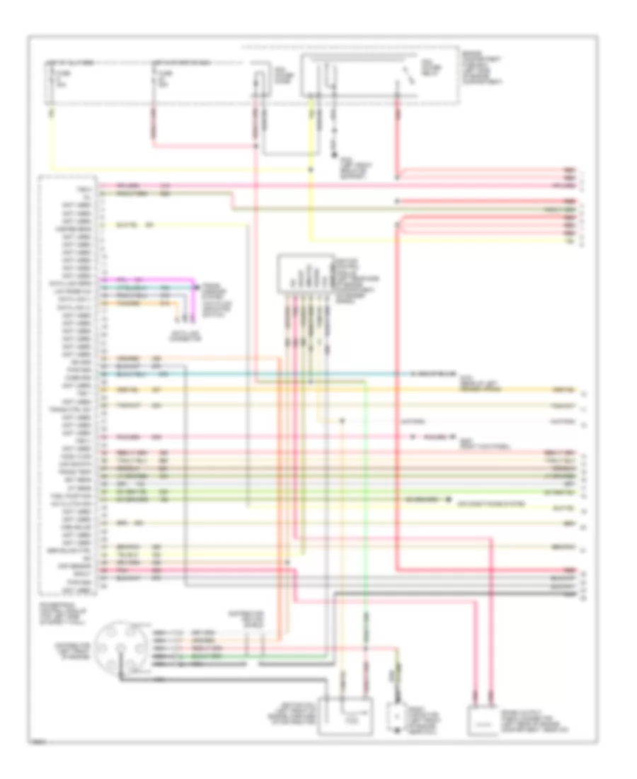
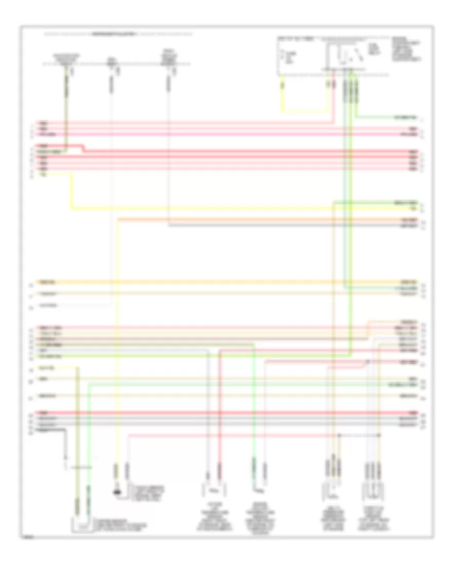
7.3L DI Turbo Diesel, Engine Performance Wiring Diagrams (1 of 3) for Ford Cab & Chassis F350 1996
List of elements for 7.3L DI Turbo Diesel, Engine Performance Wiring Diagrams (1 of 3) for Ford Cab & Chassis F350 1996:
- "wait to start" indicator
- (a/t)
- (left side of safety wall)
- (m/t)
- 4x4 hi/low indicator switch (front of transfer case)
- Acc
- Brake press sw
- Brake warning ind
- C250
- C251
- C264
- Clutch pedal position switch (top right side of brake/clutch pedal support)
- Cruise control system
- Data link connector (behind lower center of i/p)
- Diesel warning lamps display (top left side of i/p, right of instrument cluster)
- Dlc
- Ebp
- Engine compartment fuse box
- Engine oil temperature (eot) sensor (front top of engine)
- Eot
- Fuse 10a
- Fuse 15a
- Fuse 20a
- Fuse 30a
- Fuse 3a
- Fuse panel
- G104 (rear of left fender apron)
- G108 (left front of engine compart- ment, on upper radiator support)
- Hot at all times
- Hot in run
- Hot in run or start
- Iat
- Idle validation sw
- Idle validation switch (closed at idle) (near accele- rator pedal)
- Idm relay
- Ignition switch
- Injection pressure regulator (ipr) (top center of engine)
- Instrument cluster
- Instrument cluster system
- Intake air temper- ature (iat) sensor (top center of engine)
- Lock
- Low range 4x4 sw
- Malfunction indicator lamp (mil)
- Map
- Off
- Pcm dlc
- Pcm power relay
- Power diode
- Powertrain control module (pcm)
- Pwr gnd
- Red
- Rpm ctrl
- Run
- Selectable rpm control (behind center of i/p)
- Speed ctrl gnd
- Ss1
- Ss2
- Start
- Tcc
- Tcs or cpp
- Tft
- Vss gnd
- W/ e4od
- W/o e4od
7.3L DI Turbo Diesel, Engine Performance Wiring Diagrams (2 of 3) for Ford Cab & Chassis F350 1996
List of elements for 7.3L DI Turbo Diesel, Engine Performance Wiring Diagrams (2 of 3) for Ford Cab & Chassis F350 1996:
- (left front of engine compartment, on radiator support)
- (left side of safety wall)
- A/c cyl press sw
- Accl pdl pos sens
- Air conditioning system
- Baro
- Barometric pressure (baro) sensor (below i/p, at base of steering column)
- Boo
- C252
- Cam pos sens
- Camshaft position (cmp) sensor (front center of engine)
- Ccs
- Cid sig
- Cmp rtn
- Cruise control system
- Epc
- Epr
- Exhaust back pressure (ebp) sensor (right side of engine)
- Exhaust pressure regulator (epr) (top center of engine)
- Fuel delivery sig
- G108
- G203 (behind bottom of right cowl panel)
- Glow plug ctrl
- Gnd
- Icp
- Idm enable out
- Idm sig in
- Injection control pressure (icp) sensor (top left side of engine)
- Instrument cluster
- Instrument cluster system
- Ipr
- Kapwr
- Manifold absolute pressure (map) sensor (top right side of safety wall)
- Nca
- Pedal accelerator sensor (under left side of i/p)
- Powertrain control module (pcm)
- Programmable speedometer/ odometer module
- Pwr gnd
- Red
- Sig rtn
- Speed control servo/amplifier assembly (left side of engine compartment, near brake master cylinder)
- Speed ctrl gnd
- Tachometer
- Tcil
- Tcs
- Tr sensor
- Transmission control switch
- Vpwr
- Vref
- Vss
- Vss out
- Wait to start out
7.3L DI Turbo Diesel, Engine Performance Wiring Diagrams (3 of 3) for Ford Cab & Chassis F350 1996
List of elements for 7.3L DI Turbo Diesel, Engine Performance Wiring Diagrams (3 of 3) for Ford Cab & Chassis F350 1996:
- #1 shift solenoid
- #2 shift solenoid
- (left side of engine compartment)
- (optional trailer connector)
- Brake on/off (boo) switch (behind left side of i/p, top left side of brake/clutch pedal support)
- Cid sig in
- Coast clutch solenoid
- E4od transmission
- Electronic pressure control solenoid
- Engine compart- ment fuse box
- Fuel delivery sig
- Fuel inj feed left
- Fuel inj feed right
- Fuel injector #1
- Fuel injector #2
- Fuel injector #3
- Fuel injector #4
- Fuel injector #5
- Fuel injector #6
- Fuel injector #7
- Fuel injector #8 fuel injector #1
- Fuel injector/ glow plug assemblies (left bank)
- Fuel injector/ glow plug assemblies (right bank)
- Fuel line heater (right side of engine, on top of fuel filter/heater)
- Fuse 15a
- Fuse 30a
- Fuse panel
- Glow plug relay (top center rear of engine)
- Hot at all times
- Hot in run or start
- Idm feedback sig
- Inj shield gnd
- Injector driver module (idm)
- Nca
- Pwr gnd
- Red
- Sig rtn
- Tan
- Tan/red
- Torque converter clutch solenoid
- Transmission fluid temperature sensor
- Transmission range (tr) sensor
- Vpwr
- Warning: 115v dc present
7.5L
7.5L, Engine Performance Wiring Diagrams, California (1 of 4) for Ford Cab & Chassis F350 1996
List of elements for 7.5L, Engine Performance Wiring Diagrams, California (1 of 4) for Ford Cab & Chassis F350 1996:
- (4x4 hi/lo indicator switch)
- (not used)
- A/c clutch sig
- Air conditioning system
- Aird solenoid
- Case gnd
- Ckp sensor
- Coil
- Data link (+)
- Data link (-)
- Data link connector
- Data link feps
- Distributor (top front of engine)
- Distributor ignition shield
- Ect sens
- Egr solnd ctrl
- Engine compartment fuse box (left side of engine compartment)
- Fuel pump mon
- Fuse 20a
- Fuse 30a
- G104 (rear of left fender apron)
- G108 (left front radiator support)
- G203 (right kick panel)
- Hot at all times
- Hot in start or run
- Iat sens
- Idm
- Idm (fto)
- Ign gnd
- Ignition coil (left side of engine, above valve cover)
- Ignition control module (left rear side of engine compartment, on fender apron)
- Low rnge 4x4
- Maf sig rtn
- Mil
- Misfire sens
- Nca
- Pcm power diode
- Pcm power relay
- Pip
- Pnk
- Power
- Powertrain control module (top left side of safety wall)
- Pwr gnd
- Pwr grd
- Radio capacitor (left side of engine, near coil)
- Red
- Red/
- Rr ho2s sig
- Spark output check connector (left rear of engine compartment, near icm)
- Spout
- Trans ctrl sw
- Trans temp
- Trans- missions system
- Tss 1
- Tss 2
- Vss (-)
7.5L, Engine Performance Wiring Diagrams, California (2 of 4) for Ford Cab & Chassis F350 1996
List of elements for 7.5L, Engine Performance Wiring Diagrams, California (2 of 4) for Ford Cab & Chassis F350 1996:
- C250
- C251
- C252
- Delta pressure feedback egr sensor (left rear of engine)
- Engine compartment fuse box (left side of engine compartment)
- Engine coolant temperature sensor (left front of engine, near distributor)
- Fuel pump relay
- Fuse 20a
- Hot at all times
- Instrument cluster
- Intake air temperature sensor (top center of engine, behind distributor)
- Malfunction indicator input
- Misfire sensor (center front of engine, on timing chain cover)
- Nca
- Psom vehicle speed output
- Red
- Rpm input
- Throttle position sensor (top left front of engine, on throttle body)
7.5L, Engine Performance Wiring Diagrams, California (3 of 4) for Ford Cab & Chassis F350 1996
List of elements for 7.5L, Engine Performance Wiring Diagrams, California (3 of 4) for Ford Cab & Chassis F350 1996:
- Coast clutch solenoid
- E4od transmission
- Egr vacuum regulator solenoid (left side of engine compartment)
- Electronic pressure control solenoid
- Evaporative canister purge solenoid (right side of engine)
- Fuel pump/ fuel gauge sender (top right of tank)
- G108 (left front radiator support)
- Idle air control valve (top center of engine)
- Inertia fuel shutoff switch (right kick panel)
- Injectors fuel
- Nca
- Red
- Secondary air injection bypass (airb) solenoid (top left rear of engine)
- Secondary air injection diverter (aird) solenoid (top left rear of engine)
- Shift solenoids
- Ss1
- Ss2
- Tan
- Tan/ red
- Tan/red
- Torque converter clutch solenoid
- Transmission fluid temperature sensor
7.5L, Engine Performance Wiring Diagrams, California (4 of 4) for Ford Cab & Chassis F350 1996
List of elements for 7.5L, Engine Performance Wiring Diagrams, California (4 of 4) for Ford Cab & Chassis F350 1996:
- (not used)
- Airb solenoid
- Batt
- Brake on/off
- Brake on/off (boo) switch (under left side of i/p)
- Coast clutch
- Dpfe sens
- Epc sol
- Fuel inj 1
- Fuel inj 2
- Fuel inj 3
- Fuel inj 4
- Fuel inj 5
- Fuel inj 6
- Fuel inj 7
- Fuel inj 8
- Fuel pump ctrl
- Fuse 10a
- Fuse 15a
- Fuse panel (left side of i/p)
- G101 (right fender apron, right side of battery)
- H02s heater ctrl
- Hot at all times
- Hot in run or start
- Iac sol
- Left heated oxygen sensor (lower left rear of engine)
- Lf ho2s sig
- Maf sens in
- Mass air flow sensor (right front side of engine compartment)
- Misfire in
- Nca
- Power
- Power gnd
- Powertrain control module (top left side of safety wall)
- Pwr gnd
- Rear heated oxygen sensor (near catalytic converter)
- Red
- Ref volt
- Rf ho2s sig
- Right heated oxygen sensor (lower right rear of engine)
- Sig rtn
- Tan
- Tan/red
- Tcc sol
- Tp sens in
- Tr sens in
- Trans ctrl ind
- Trans- mission control switch (top of steering column)
- Transmission range sensor (lower left side of transmission)
- Vapor valve
- Vss (+)
7.5L, Engine Performance Wiring Diagrams, Federal (1 of 2) for Ford Cab & Chassis F350 1996
List of elements for 7.5L, Engine Performance Wiring Diagrams, Federal (1 of 2) for Ford Cab & Chassis F350 1996:
- #1 shift solenoid
- #2 shift solenoid
- (4x4 hi/lo indicator switch)
- (left side of engine compt., near brake master cylinder)
- (not used)
- (right front of engine compt, on fender apron)
- (top left side of brake/ clutch pedal support)
- (top of upper left radiator support)
- Accs
- Air conditioning system
- Airb solnd ctrl
- Aird solnd ctrl
- Boo
- Brake on/off (boo) switch
- C198
- C250
- C251
- Ccs
- Ckp sensor
- Coast clutch solenoid
- Coil
- Coil wire
- Cse gnd
- Data link connector (left rear of engine compt, on bracket)
- Distributor
- E40d transmission
- Ect
- Egr cntrl solnd.
- Egr valve pos
- Electronic pres- sure control solenoid
- Engine compartment fuse box
- Epc
- Evap can solnd.
- Fp enable
- Fpm
- Fuse 13 15a
- Fuse 17 10a
- Fuse 20a
- Fuse 22 20a
- Fuse panel
- G101
- G104 (rear of left fender apron)
- G108
- G203 (behind bottom of right cowl panel)
- Gnd
- Ho2s ground
- Ho2s sig input
- Hot at all times
- Hot in start or run
- Iac
- Iat
- Idm
- Idm (fto)
- Ign gnd
- Ignition coil (left rear of engine)
- Ignition control module (left rear of engine compartment, on fender apron)
- Inj 1, 4, 5, 8
- Inj 2, 3, 6, 7
- Instrument cluster
- Instrument cluster system
- Kapwr
- Low rnge 4x4 ind
- Malfunction indicator
- Map sensor input
- Nca
- Pcm power diode
- Pcm power relay
- Pip
- Pnk
- Powertrain control module (left side of safety wall)
- Pwr
- Pwr gnd
- Radio capacitor (left side of engine, near ignition coil)
- Red
- Sig rtn
- Speed control servo/amplifier assembly
- Spout
- Spout check connector (left rear of engine compt, taped to harness, near ignition control module)
- Sto/mil
- Tan
- Tcc
- Tcil
- Tcs
- Tft sensor input
- Torque con- verter clutch solenoid
- Tps input
- Tr sensor input
- Transmission fluid temp sensor
- Transmissions system
- Tss 1
- Tss 2
- Vip dlc
- Vpwr
- Vref
- Vss ground
- Vss signal input
7.5L, Engine Performance Wiring Diagrams, Federal (2 of 2) for Ford Cab & Chassis F350 1996
List of elements for 7.5L, Engine Performance Wiring Diagrams, Federal (2 of 2) for Ford Cab & Chassis F350 1996:
- (not used)
- (on upper left radiator support)
- (on upper radiator support)
- C199
- Data link connector (left rear of engine compt, on bracket)
- Dual tanks
- Egr control solenoid (on ignition coil support bracket)
- Egr valve position sensor (top right front of engine)
- Engine compart- ment fuse box
- Engine compartment fuse box
- Engine coolant temperature sensor (center front of engine)
- Evap cann purge solenoid (right front of engine)
- Front tank fuel pump/ fuel gauge sender
- Fuel injectors
- Fuel pump relay
- Fuel pump/ fuel gauge sender (top right side of fuel tank)
- Fuel tank selector switch
- Fuse 16 20a
- Fuse 5 15a
- G108
- G108 (left front of engine compartment, on upper radiator support)
- Heated oxygen sensor (in exhaust pipe, near catalytic converter)
- Hot at all times
- Hot in run
- Idle air control valve (top of throttle body)
- Inertia fuel shut-off switch (behind right cowl panel)
- Intake air temperature sensor (top center front of engine, near intake runner #6)
- Manifold absolute pressure sensor (top right side of safety wall)
- Nca
- Rear tank fuel pump/ fuel gauge sender
- Red
- Secondary air injection bypass solenoid (near rear of left valve cover)
- Secondary air injection diverter solenoid (near rear of left valve cover) (super duty only)
- Single tank
- Tan
- Tcil
- Throttle position sensor (top right front of engine, on throttle body)
- Transmission control switch (top of steering column)
- Transmission range sensor (left side of transmission)
EXTERIOR LIGHTS
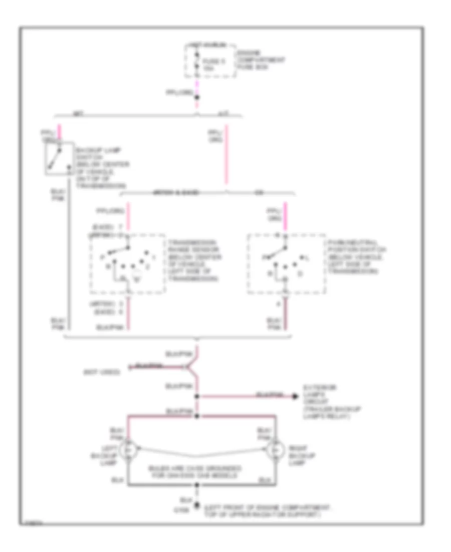
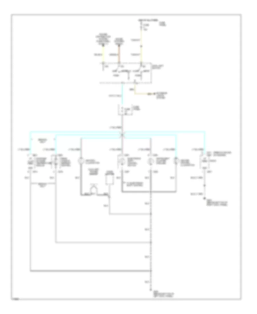
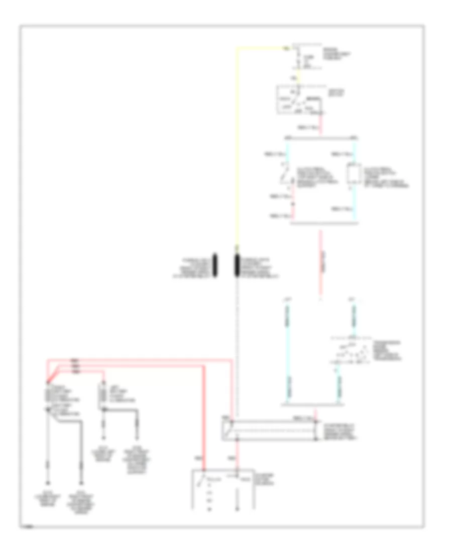
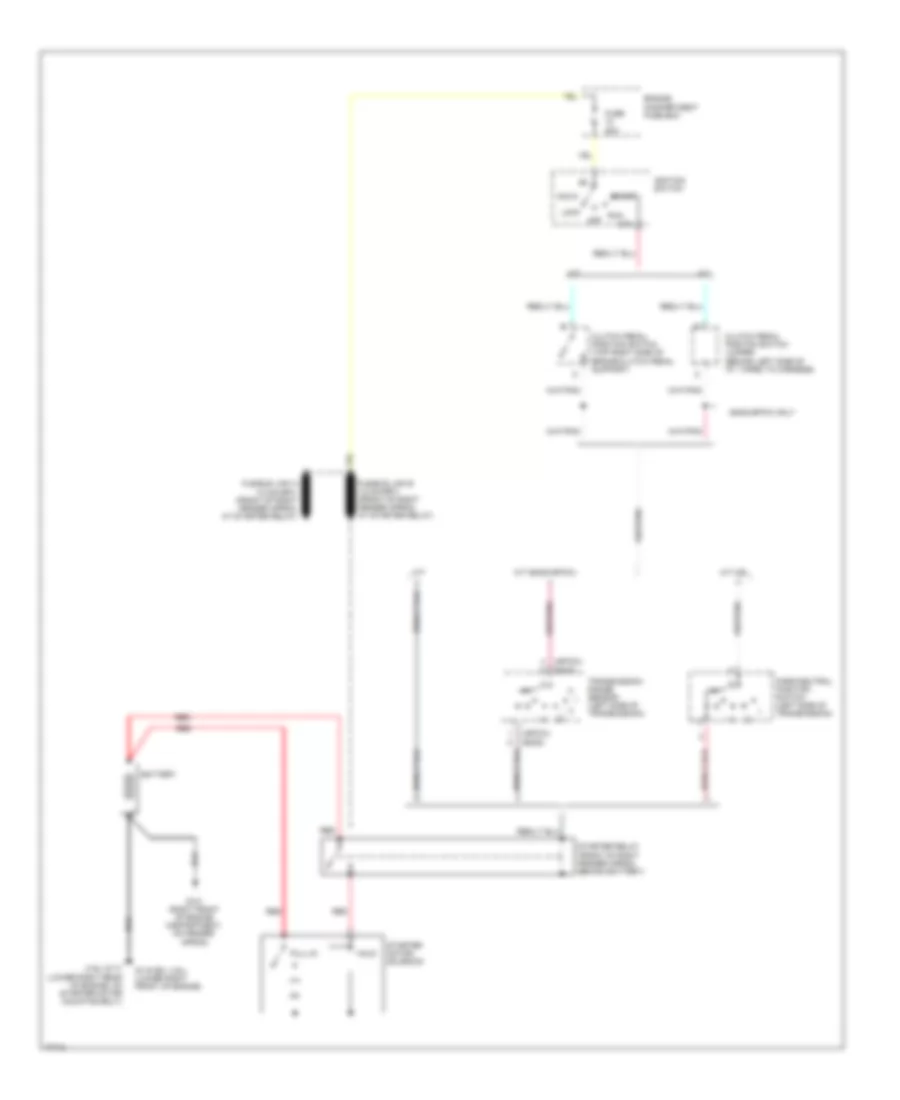
Back-up Lamps Wiring Diagram for Ford Cab & Chassis F350 1996
List of elements for Back-up Lamps Wiring Diagram for Ford Cab & Chassis F350 1996:
- (4r70w)
- (e4od)
- (left front of engine compartment, top of upper radiator support)
- (not used)
- 4r70w & e4od
- A/t
- Backup
- Backup lamp switch (below center of vehicle, on top of transmission)
- Bulbs are case grounded for chassis cab models
- Engine compartment fuse box
- Exterior lamps circuit (trailer backup lamps relay)
- Fuse 5 15a
- G108
- Hot in run
- Lamp
- Left
- M/t
- Park/neutral position switch (below vehicle, left side of transmission)
- Right backup lamp
- Transmission range sensor (below center of vehicle, left side of transmission)
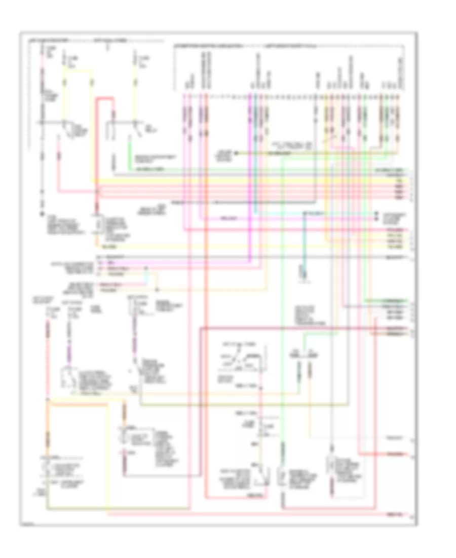
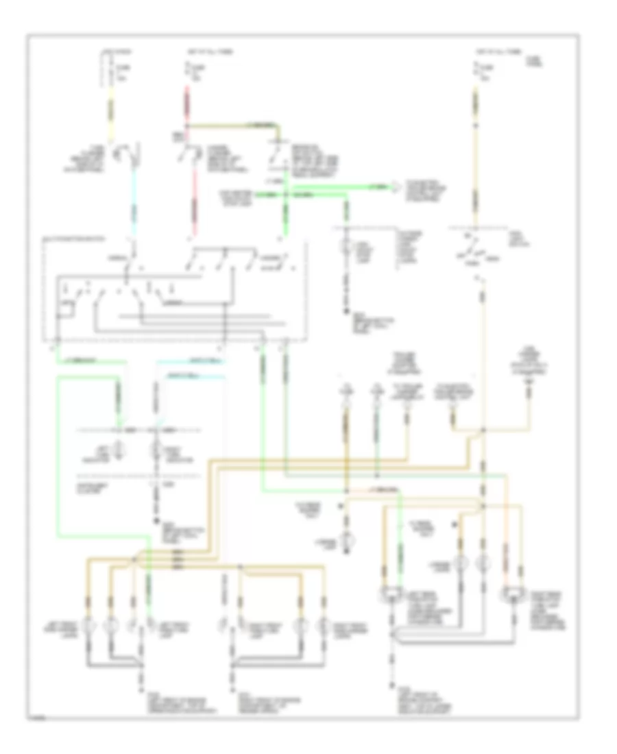
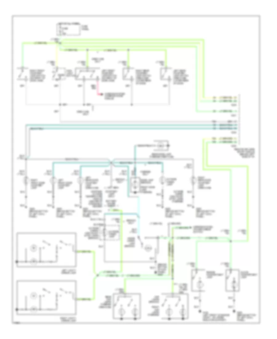
Exterior Lamps Wiring Diagram (1 of 2) for Ford Cab & Chassis F350 1996
List of elements for Exterior Lamps Wiring Diagram (1 of 2) for Ford Cab & Chassis F350 1996:
- (if equipped)
- Brake on/ off switch (behind left side i/p, top left side of brake/clutch pedal support)
- Bumper
- C250
- C251
- Cab marker lamps (pick-up only)
- Cap center high mount stop lamp
- Fuse 15a
- Fuse panel
- G101 (right front of engine compartment, on fender apron)
- G108 (left front of engine compart- ment, top of upper radiator support)
- G108 (left front of engine compartment, top of upper radiator support)
- G200 (behind bottom of left cowl panel)
- Hazard
- Hazard flasher (behind left side of i/p, on fuse panel)
- Head
- High mount stop lamp
- Hot at all times
- Hot in run
- Instrument cluster
- Left
- Left front park/turn lamp
- Left front side marker lamps
- Left rear park/stop/ turn lamp (case grounded for f-series chassis cab)
- Left turn indicator
- License lamp
- License lamps
- Main light switch
- Multi-function switch
- Normal
- Off
- Only
- Outside cargo/ high mount stop lamps
- Park
- Right
- Right front park/turn lamp
- Right front side marker lamps
- Right rear park/stop/ turn lamp (case grounded for f-series chassis cab)
- Right turn indicator
- To electric trailer brake control unit
- To electric trailer brake control unit (if equipped)
- To fuse
- To trailer marker lamps relay
- Trailer/ camper adapter (if equipped)
- Turn flasher (behind left side of i/p, on fuse panel)
- W/ rear
- W/o rear
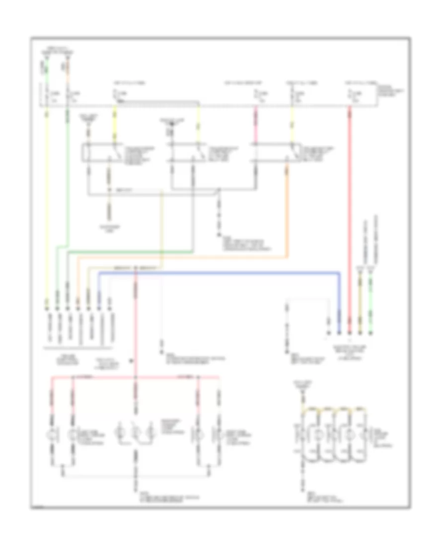
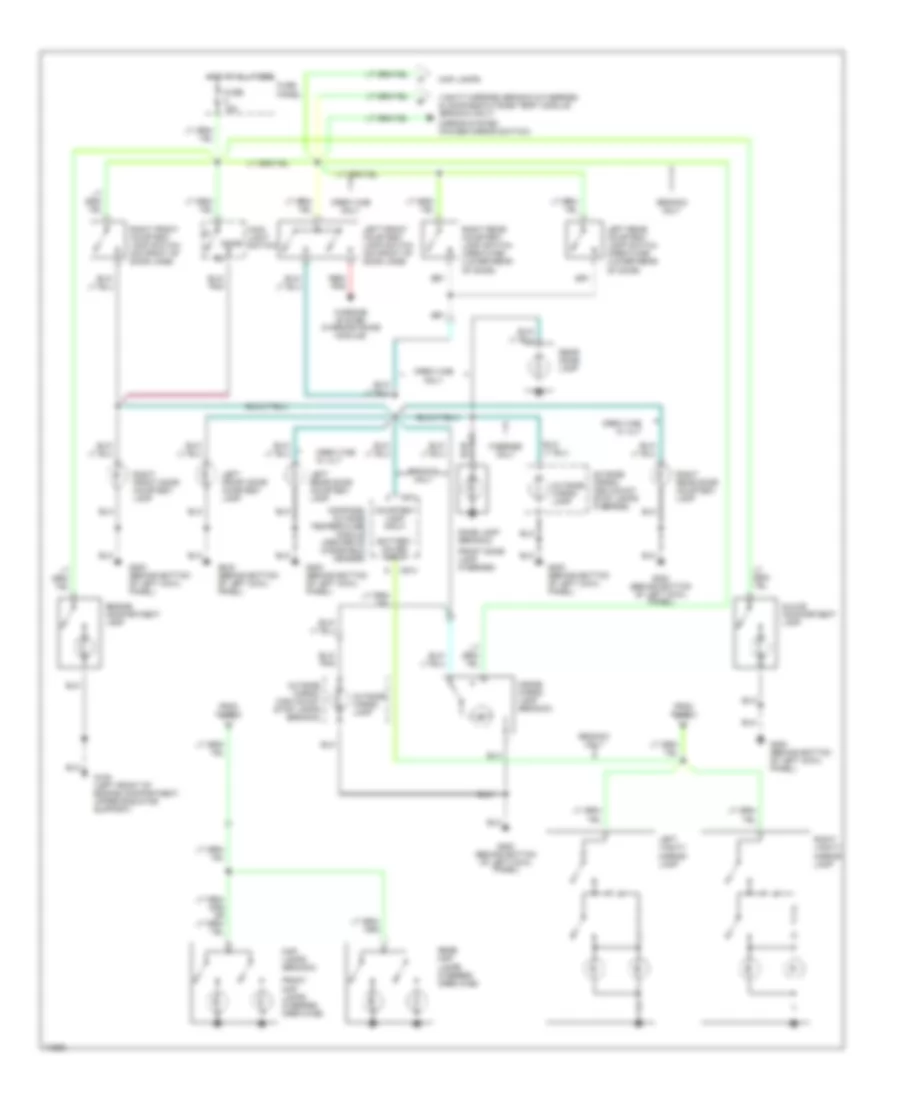
Exterior Lamps Wiring Diagram (2 of 2) for Ford Cab & Chassis F350 1996
List of elements for Exterior Lamps Wiring Diagram (2 of 2) for Ford Cab & Chassis F350 1996:
- (customer use)
- Backup lamp circuit
- Backup lamps
- Battery charge
- Cab marker lamps (if equipped)
- Dual rear
- Electric brakes
- Electric trailer brake control unit (if equipped)
- Engine compartment fuse box
- From brake on/off switch
- From main light switch
- From multi- function switch
- Fuse 10a
- Fuse 15a
- Fuse 25a
- Fuse 30a
- G108 (left front of engine compartment, top of upper radiator support)
- G200 (behind bottom of left kick panel)
- G409 (under center rear of vehicle, on rear crossmember)
- Hot at all times
- Hot in run or start
- Left side body marker lamps (if equipped)
- Left turn lamp
- Main light switch
- Marker lamps
- Nca
- Pick-up w/
- Rear body marker lamps (if equipped)
- Red
- Right side body marker lamps (if equipped)
- Right turn lamp
- Trailer backup lamps relay (in trailer relay box)
- Trailer battery charge relay (in trailer relay box)
- Trailer electrical connector
- Trailer ground
- Trailer marker lamps relay (in engine compartment fuse box)
- Wheels only
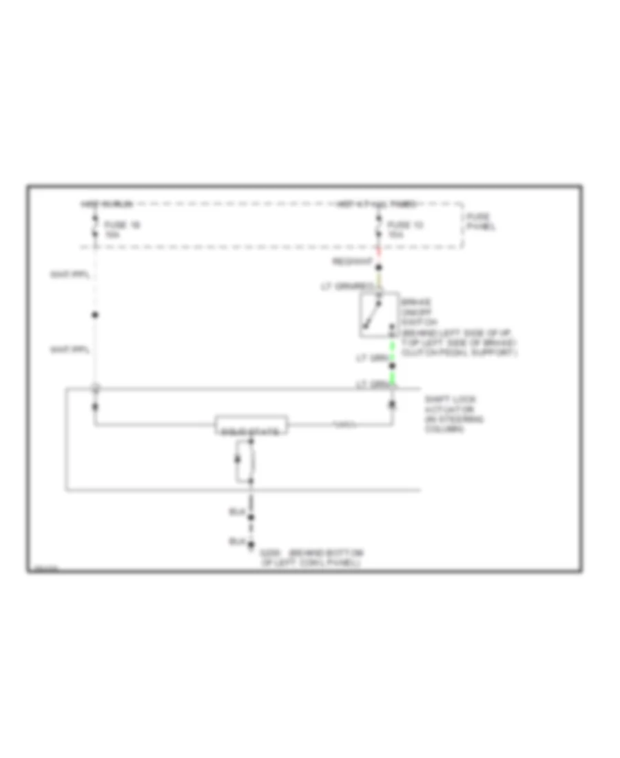
GROUND DISTRIBUTION
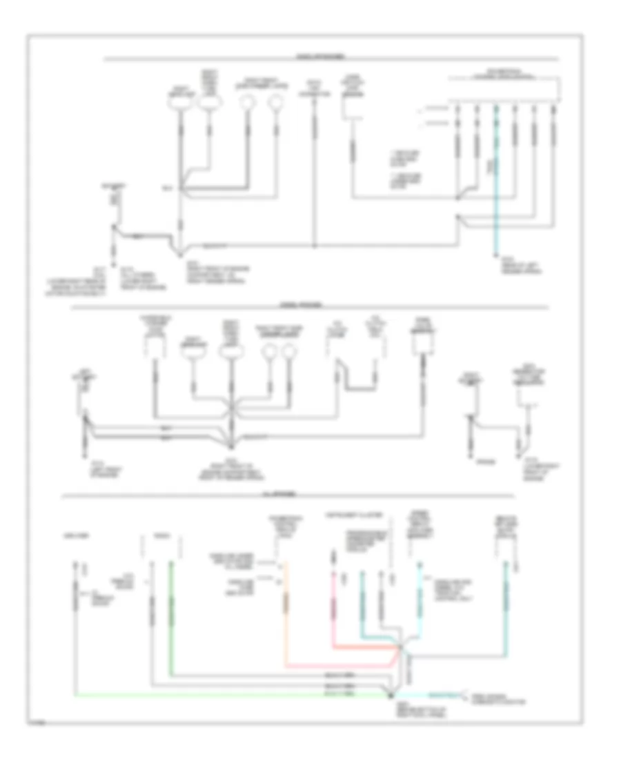
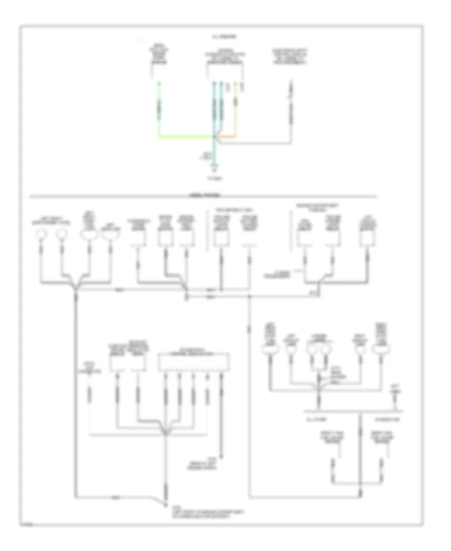
Ground Distribution Wiring Diagram (1 of 4) for Ford Cab & Chassis F350 1996
List of elements for Ground Distribution Wiring Diagram (1 of 4) for Ford Cab & Chassis F350 1996:
- (frame)
- (left front of engine)
- (lower right front of engine)
- (lower right rear of engine, on starter motor mounting bolt)
- * vehicles over 8500 gvwr
- ** vehicles under 8500 gvwr
- 200a generator/ voltage regulator
- A/c clutch diode
- A/c clutch field coil
- All engines
- Amplifier
- Battery
- C212
- C241
- C251
- C252
- Data link connector
- Diesel engines
- From air bag diagnostic monitor
- G101 (right front of engine compartment, front of fender apron)
- G101 (right front of engine compartment, on front fender apron)
- G104 (rear of left fender apron)
- G110
- G117 (4.9l)
- G119
- G119 (all others)
- G203 (behind bottom of right cowl panel)
- Gasoline and diesel w/o traction control only
- Gasoline engines
- Gasoline over 8500 gvwr
- Gasoline under 8500 gvwr and all diesel
- Instrument cluster
- Lamp
- Left battery
- Mass air flow (maf) sensor
- Nca
- Powertrain control module (pcm)
- Programmable speedometer/ odometer module
- Rabs valve assembly
- Radio
- Remote keyless entry module
- Right battery
- Right front park/ turn
- Right front park/ turn lamp
- Right front side marker lamps
- Right headlamp
- Speed control servo/ amplifier assembly
- W/ premium sound
- W/o premium sound
- Windshield washer pump motor
Ground Distribution Wiring Diagram (2 of 4) for Ford Cab & Chassis F350 1996
List of elements for Ground Distribution Wiring Diagram (2 of 4) for Ford Cab & Chassis F350 1996:
- (not
- (rear of left fender apron)
- Air bag diagnostic monitor (ex. diesel w/ traction assist)
- All engines
- All other
- Brake fluid level switch
- Bumper
- C217
- C218
- Chassis cab
- Data link connector
- Diesel engines
- Electronic shift control module (ex. diesel w/ traction assist)
- Engine compart- ment lamp
- Engine compartment fuse box
- Exhaust pressure regulator (epr)
- Front tank fuel gauge sender
- G104
- G108 (left front of engine compartment, on upper radiator support)
- Injector driver module
- Left backup lamp
- Left front park/ turn lamp
- Left front side marker lamps
- Left headlamp
- Left rear park/ stop/ turn lamp
- License lamps
- Low vacuum warning switch
- Nca
- Only
- Pcm power relay
- Powertrain control module (pcm)
- Rear
- Rear anti-lock brake (rabs) module
- Rear tank fuel gauge sender
- Right backup lamp
- Right rear park/ stop/ turn lamp
- To g203
- Trailer backup lamps relay
- Trailer battery charge relay
- Trailer marker lamps relay
- Trailer relay box
- Used)
- W/ e4od transmission
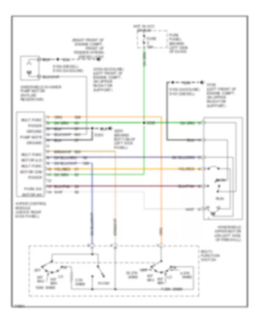
- Windshield wiper motor
- With
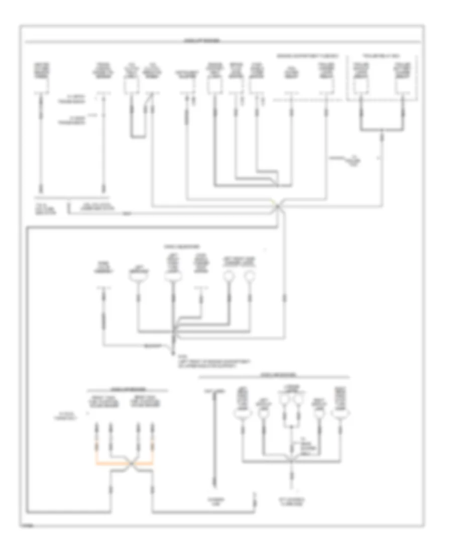
Ground Distribution Wiring Diagram (3 of 4) for Ford Cab & Chassis F350 1996
List of elements for Ground Distribution Wiring Diagram (3 of 4) for Ford Cab & Chassis F350 1996:
- (left front of engine compartment, on upper radiator support)
- (not used)
- 4.9l, 5.0l & 5.8l under 8500 gvwr
- 7.5l & 5.8l over 8500 gvwr
- A/c clutch field coil
- A/c clutch resistor diode
- Brake fluid level switch
- Bumper
- C151
- C170
- C250
- Cab
- Chassis
- Engine compart- ment lamp
- Engine compartment fuse box
- Flare side
- Front tank fuel pump/fuel gauge sender
- G108
- Gasoline engines
- Heated oxygen sensor (ho2s)
- Instrument cluster
- Left backup lamp
- Left front park/ turn lamp
- Left front side marker lamps
- Left headlamp
- Left rear park/ stop/ turn lamp
- License lamps
- Nca
- Only
- Pcm power relay
- Rabs valve assembly
- Rear
- Rear tank fuel pump/fuel gauge sender
- Right backup lamp
- Right rear park/ stop/ turn lamp
- Style side &
- Tanks only
- Tow
- Trailer
- Trailer backup lamps relay
- Trailer battery charge relay
- Trailer relay box
- Trailer/ marker lamps relay
- Trans- mission range (tr) sensor
- Transmission
- W/ 4r70w
- W/ dual
- W/ e4od
- Wind- shield washer pump motor
- Wind- shield wiper motor
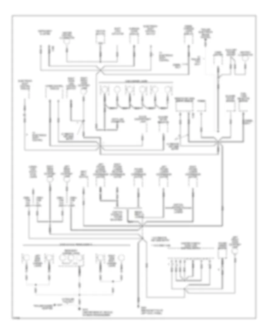
Ground Distribution Wiring Diagram (4 of 4) for Ford Cab & Chassis F350 1996
List of elements for Ground Distribution Wiring Diagram (4 of 4) for Ford Cab & Chassis F350 1996:
- (behind bottom of left cowl panel)
- (center rear of vehicle, on rear crossmember)
- * w/o remote keyless entry
- ** w/o crew cab
- Ashtray illumination
- Auxiliary power socket
- Bench seat w/ lumbar
- Blower motor resistor
- Blower motor switch
- C240
- C250
- Cab marker lamps
- Captain chairs w/ power bolsters
- Captain chairs w/ power lumbar
- Cargo/ high mount stop lamps
- Cigar lighter
- Crew cab w/ xlt
- Crew cab w/o xlt
- Data link connector
- Diesel only
- Diesel warning lamps display
- Electronic shift control module
- Electronic shift control switch
- F-350 w/ dual rear wheels
- Fuel tank selector switch
- G200
- G415
- Glove compartment lamp
- Gnd
- Heater control illumination
- Ignition switch
- Instrument cluster
- Left front door courtesy lamp
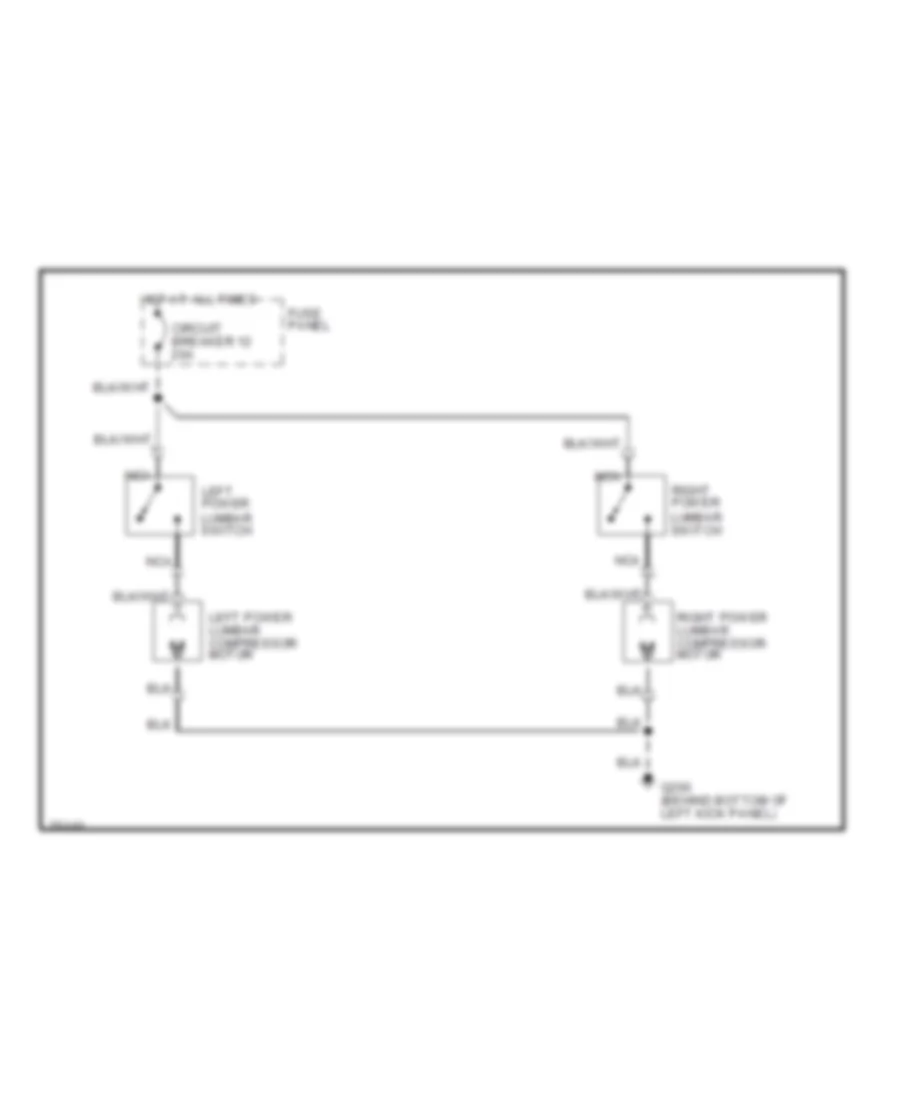
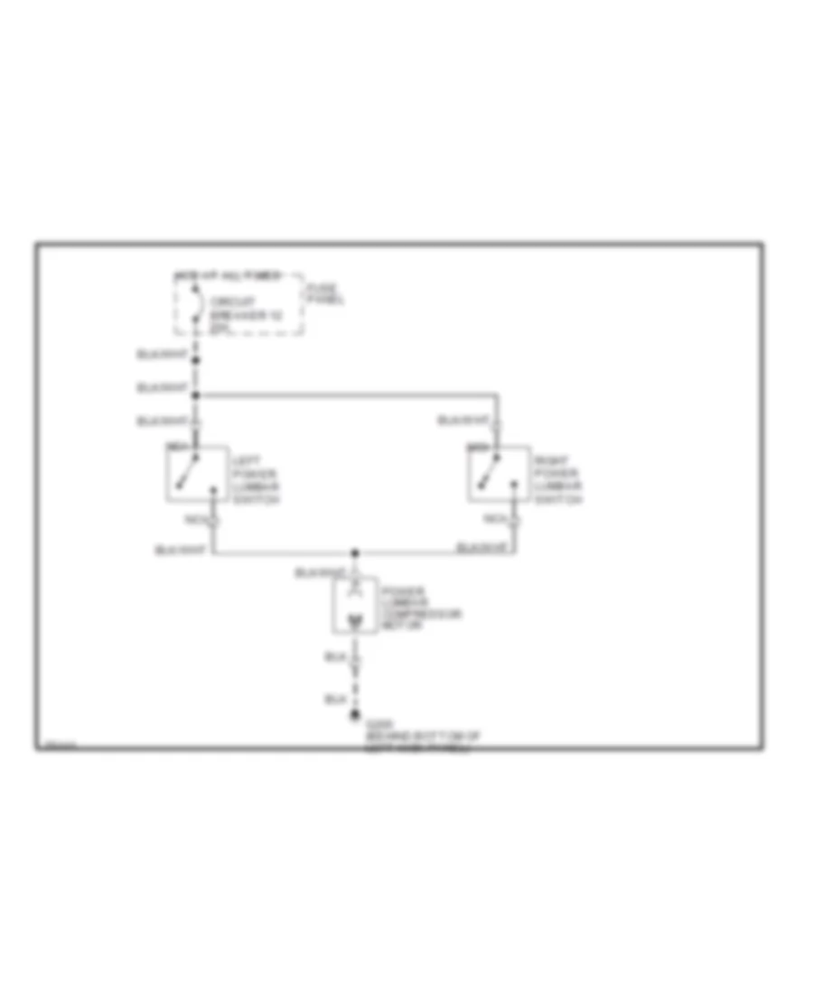
- Left power lumbar compressor motor
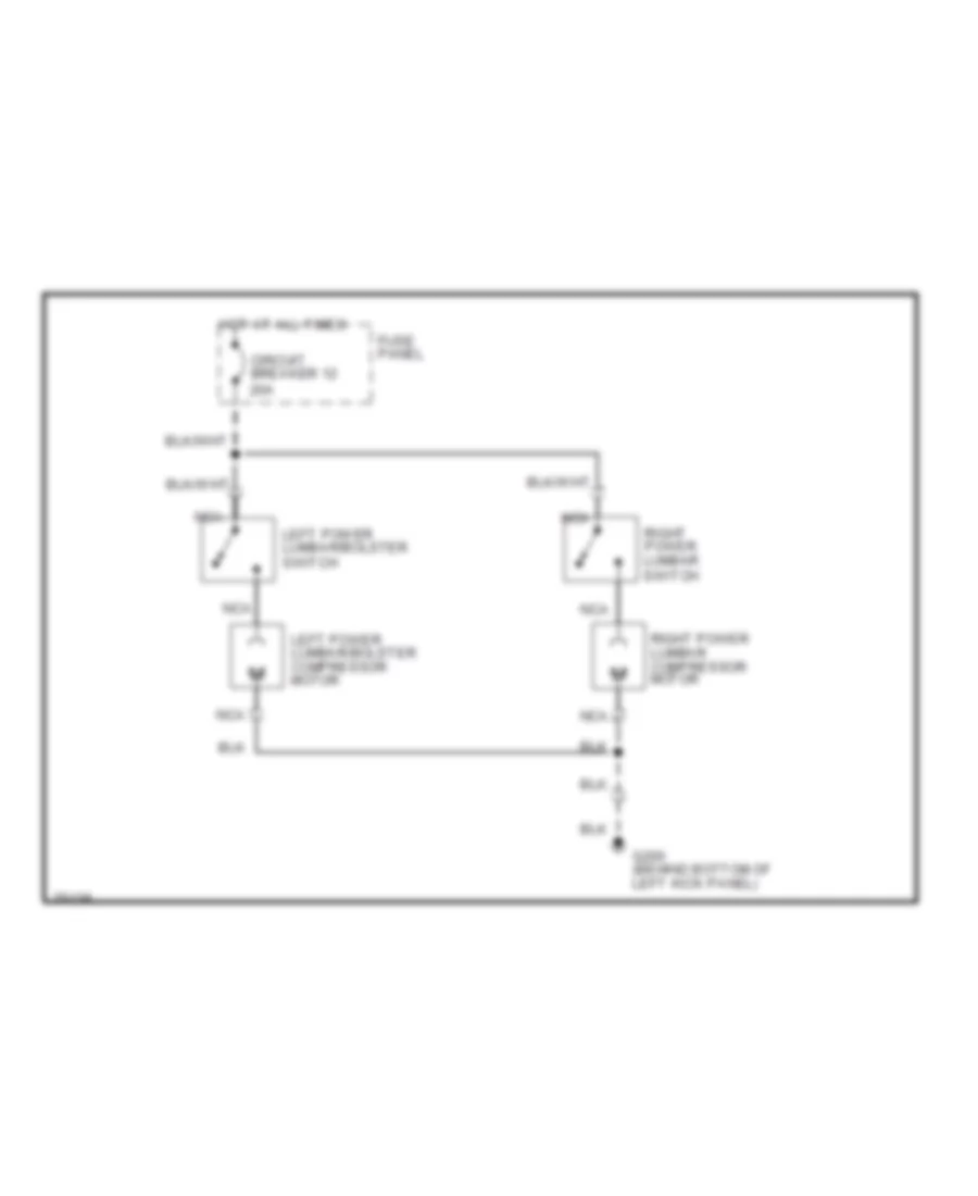
- Left power lumbar/ bolster compressor motor
- Left rear door courtesy lamp
- Left side body marker lamps
- Master window/ door lock control switch
- Nca
- Power lumbar compressor motor
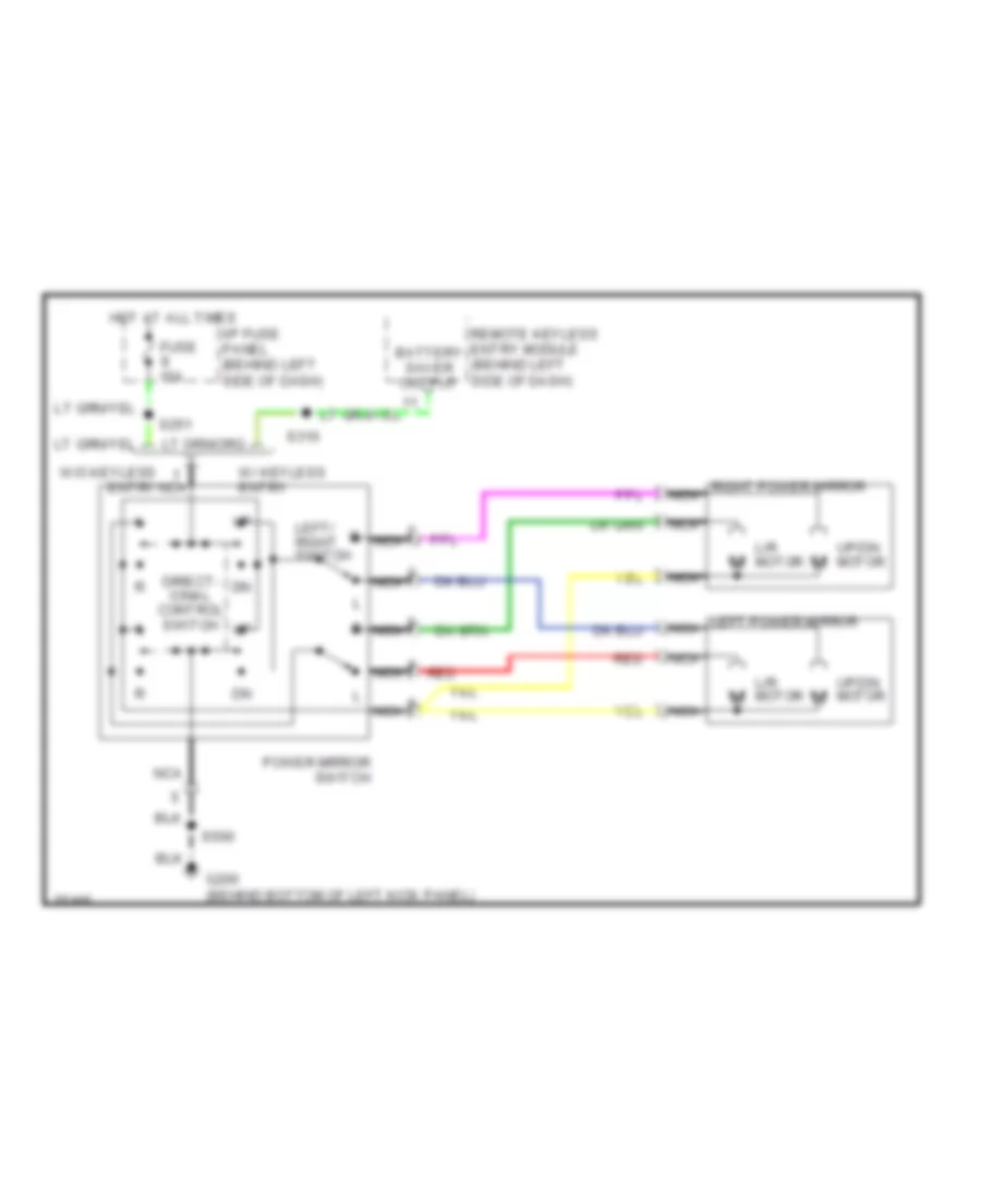
- Power mirror switch
- Radio
- Rear body marker lamps
- Remote keyless entry module
- Right door lock control switch
- Right front door courtesy lamp
- Right power lumbar compressor motor
- Right power lumbar/ bolster compressor motor
- Right rear door courtesy lamp
- Right side body marker lamps
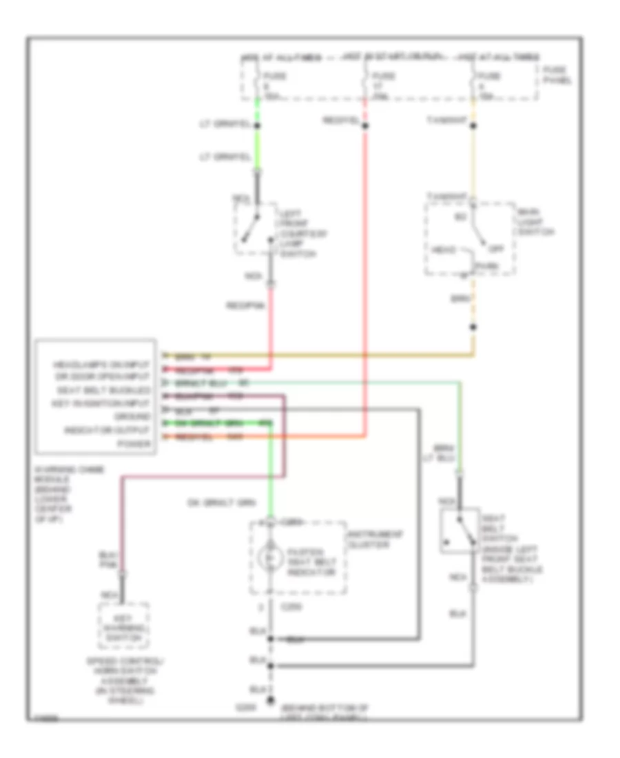
- Seat belt switch
- Shift lock actuator
- Trailer electronic brake control
- Trailer/camper adapter
- W/ electronic shift control
- W/ remote keyless entry
- W/ trailer tow only
- W/trailer tow only
- Warning chime module
- Wiper control module
HEADLIGHTS
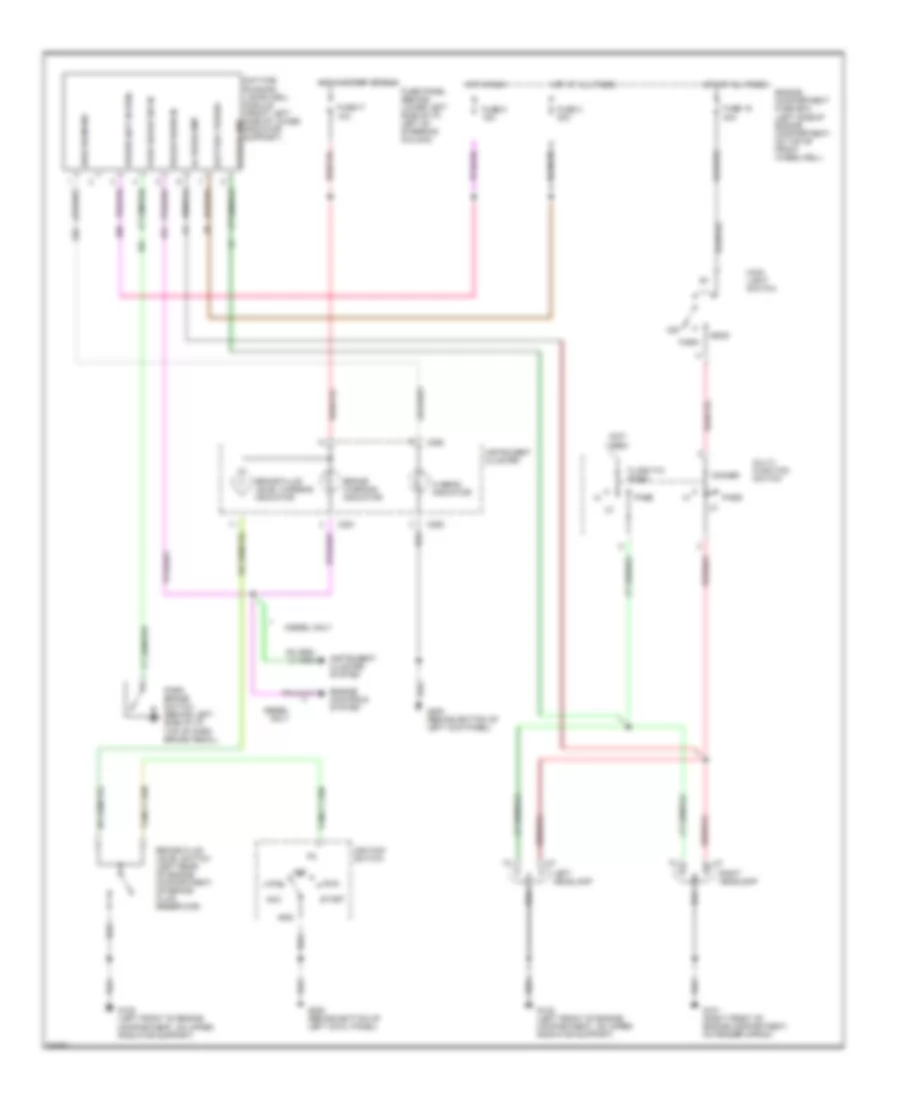
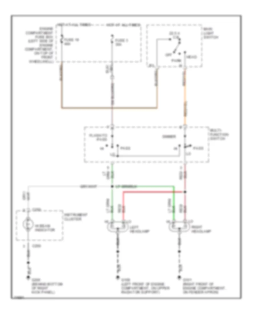
Headlight Wiring Diagram, with DRL for Ford Cab & Chassis F350 1996
List of elements for Headlight Wiring Diagram, with DRL for Ford Cab & Chassis F350 1996:
- (not used)
- 40a
- Acc
- Battery power
- Brake fluid level switch (left rear of engine compartment, on brake fluid reservoir)
- Brake fluid level warning indicator
- Brake warn in
- Brake warning indicator
- C250
- C251
- Daytime running lamps (drl) module (front left side of lower radiator support)
- Diesel only
- Dimmer
- Engine compartment fuse box (left side of engine compartment, on top of front wheelwell)
- Engine controls system
- Flash-to- pass
- Fuse 17 10a
- Fuse 19
- Fuse 3 30a
- Fuse 5 15a
- Fuse panel (behind lower left side of i/p, left of steering column)
- G101 (right front of engine compartment, on fender apron)
- G108 (left front of engine compartment, on upper radiator support)
- G200 (behind bottom of left cowl panel)
- G200 (behind bottom of left kick panel)
- Gnd
- Head
- Hi beam indicator
- Hi headlamp
- High beam ind
- Hot at all times
- Hot in run
- Hot in start or run
- Ignition switch
- Instrument cluster
- Instrument cluster system
- Left headlamp
- Lo headlamp
- Lock
- Main light switch
- Multi- function switch
- Off
- Park
- Park brake sw in
- Park brake switch (behind left side of i/p, top of park brake pedal)
- Pass
- Power (hot in run)
- Right headlamp
- Run
- Start
Headlight Wiring Diagram, without DRL for Ford Cab & Chassis F350 1996
List of elements for Headlight Wiring Diagram, without DRL for Ford Cab & Chassis F350 1996:
- 22.5 a c.b.
- C250
- Dimmer
- Engine compartment fuse box (left side of engine compartment, on top of front wheelwell)
- Flash-to -pass
- Fuse 19 40a
- Fuse 3 30a
- G101 (right front of engine compartment, on fender apron)
- G108 (left front of engine compartment, on upper radiator support)
- G200 (behind bottom of right kick panel)
- Head
- Hi beam indicator
- Hot at all times
- Instrument cluster
- Left headlamp
- Main light switch
- Multi- function switch
- Off
- Park
- Pass
- Right headlamp
HORN
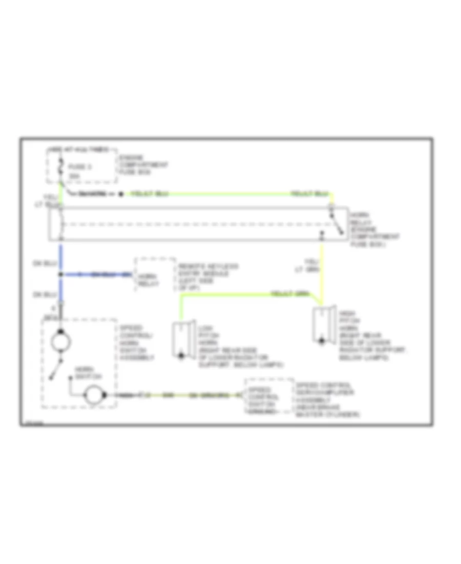
Horn Wiring Diagram for Ford Cab & Chassis F350 1996
List of elements for Horn Wiring Diagram for Ford Cab & Chassis F350 1996:
- 30a
- Engine compartment fuse box
- Fuse 3
- High pitch horn (right rear side of lower radiator support, below lamps)
- Horn relay
- Horn relay (engine compartment fuse box)
- Horn switch
- Hot at all times
- Low pitch horn (right rear side of lower radiator support, below lamps)
- Nca
- Remote keyless entry module (left side of i/p)
- Speed control servo/amplifier assembly (near brake master cylinder)
- Speed control switch ground
- Speed control/ horn switch assembly
INSTRUMENT CLUSTER
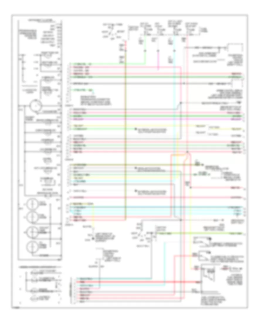
Instrument Cluster Wiring Diagram (1 of 2) for Ford Cab & Chassis F350 1996
List of elements for Instrument Cluster Wiring Diagram (1 of 2) for Ford Cab & Chassis F350 1996:
- (behind bottom of right cowl panel)
- (behind lower center of i/p)
- (behind lower right side of i/p, below glove compt)
- (left front of engine compt, on upper radiator support)
- (left side of safety wall)
- 20 ohms
- 4x4 ind.
- 500 ohms
- A10
- A11
- A12
- A13
- A14
- Acc
- Air bag ind.
- Anti-lock brake ind.
- B10
- B11
- B12
- B13
- Bat
- Brake fluid level
- Brake warning ind.
- Charge ind.
- Check engine ind.
- Chime module
- Conn a
- Conn b
- Conn c
- Control
- Coolant temp. gauge
- Diesel only
- Diesel warning lamps display
- Enable psom programming connector
- Engine warning ind.
- Except diesel
- Exterior lights system (multi-function switch)
- Fasten seat belt ind.
- Fuel gauge
- Fuel water switch (right side of engine, on bottom of fuel filter/heater)
- Fuse 10a
- Fuse 15a
- Fuse 4a
- Fuse panel
- G108
- G200 (behind bottom of left cowl panel)
- G203
- Gas over 8500 gvwr
- Gas under 8500 gvwr and all diesel
- Generator/ voltage regulator
- Gnd
- Headlights system (multi-function switch)
- Hi beam ind.
- Hot at all times
- Hot in run
- Hot in run or start
- Hot w/ light sw in head or park
- Ign (run)
- Ignition switch
- Illumination lamps
- Instrument cluster
- Left turn ind.
- Lock
- Low range ind.
- Mechanical shift only
- Module
- Off
- Oil press. gauge
- Overheat warning switch (left front of engine)
- Plugged fuel filter ind.
- Plugged fuel filter switch (right side of engine, in fuel filter/heater housing)
- Powertrain
- Powertrain control module (left side of safety wall)
- Programmable speedometer/ odometer module
- Red
- Red/pnk
- Right turn ind.
- Run
- Solid state
- Speed control servo/ amplifier assembly (left side of engine compt, near brake master cylinder)
- Start
- Tachometer
- Test
- Volt- meter
- Vss input
- Vss output
- Vss return
- W/ tach
- W/o tach
- Wait-to-start ind.
- Warning
- Water-in- fuel ind.
- Water-in- fuel sensor (right side of engine, near fuel filter)
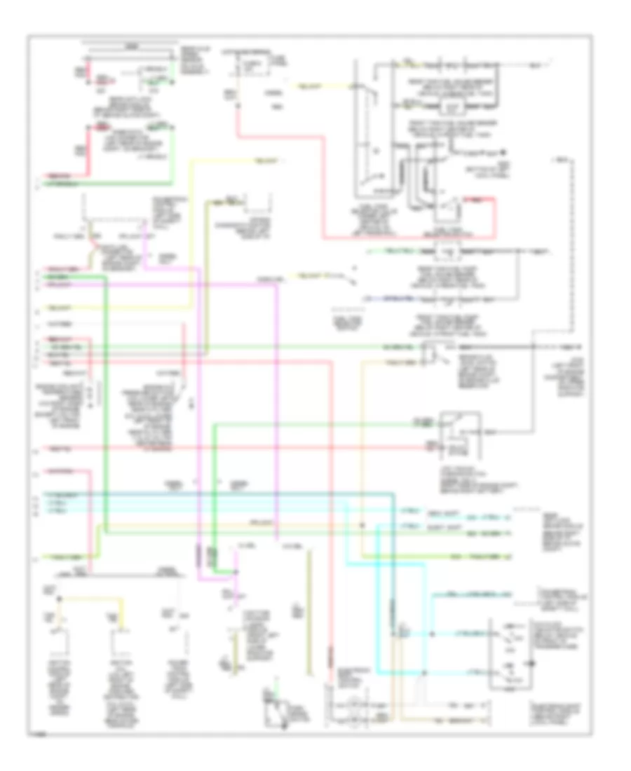
Instrument Cluster Wiring Diagram (2 of 2) for Ford Cab & Chassis F350 1996
List of elements for Instrument Cluster Wiring Diagram (2 of 2) for Ford Cab & Chassis F350 1996:
- (5.0l & 5.8l- (left rear of engine, near intake manifold)
- (5.0l & 5.8l-lower left front of of engine, near oil filter) (7.3l & 7.5l-top center rear of engine)
- (behind right side of i/p, behind glove compt)
- (below right center of
- (below right rear of
- (left rear of engine
- (left rear of engine compt,
- 4x2
- 4x4
- 4x4 hi/low indicator switch (below vehicle, on front of transfer case)
- Air bag diagnostic monitor (behind left side of i/p)
- Brake fluid level switch (left rear of engine compt, on brake fluid reservoir)
- Compt, on bracket)
- Data link connector
- Daytime running lamps module (front left side of lower radiator support)
- Diesel
- Diesel only
- Diesel w/ tach
- Elect. shift
- Electronic shift control module (behind right cowl panel)
- Electronic shift control switch
- Engine coolant temperature sender (4.9l-right side of engine) (except 4.9l-top left front of engine)
- Engine oil pressure switch (4.9l-lower left rear of engine, near oi filter)
- Front
- Front tank fuel gauge sender
- Front tank fuel pump/ fuel gauge sender (below right center of vehicle, in front fuel tank)
- Fuel tank selector switch
- Fuel tank selector valve (under left center of vehicle, on left frame rail)
- Fuse 6 15a
- Fuse panel
- G108 (left front of engine compartment, on upper radiator support)
- G200 (bottom of left cowl panel)
- Gas
- Gasoline
- Hot in acc or run
- Ignition coil (4.9l-left front of engine, forward distributor)
- Ignition control module (left rear of engine compt, on fender apron)
- Link connector
- Low
- Low vacuum warning switch (diesel only) (right side of engine compt., behind right battery)
- Mech. shift
- Nca
- On bracket)
- Only
- Park brake switch
- Power- train control module (left side of safety wall)
- Powertrain control module (left side of safety wall)
- Powertrain control module (left side of safety wall)
- Rabs data
- Rear
- Rear anti-lock brake module
- Rear axle speed sensor (on axle assembly)
- Rear tank fuel gauge sender
- Rear tank fuel pump/ fuel gauge sender (below right rear of vehicle, in rear fuel tank)
- Red
- Red/
- Red/ pnk
- Red/pnk
- Solid state
- Vehicle, in front fuel tank)
- Vehicle, in rear fuel tank)
- W/ drl
- W/o drl
INTERIOR LIGHTS
Courtesy Lamps Wiring Diagram, with Keyless Entry for Ford Cab & Chassis F350 1996
List of elements for Courtesy Lamps Wiring Diagram, with Keyless Entry for Ford Cab & Chassis F350 1996:
- (behind bottom of kick panel) g200
- Battery saver input
- Bronco only
- C240
- C241
- C242
- C914
- Compass/ outside temperature module (center of windshield header)
- Courtesy lamp input
- Crew cab only
- Dome
- Dome lamp (bronco)
- Engine compartment lamp
- F-series only
- Front dome lamp (f-series)
- Front map lamps (f-series)
- Fuse 15a
- Fuse panel
- G108 (left front of engine compt., on upper radiator support)
- G200 (behind bottom of left cowl panel)
- Glove compartment lamp
- Hot at all times
- Inside cargo lamp (bronco)
- Left front courtesy lamp switch (on front of door jamb)
- Left front door courtesy lamp
- Left rear courtesy lamp switch (crew-cab) (lower rear of door)
- Left rear door courtesy lamp (crew-cab)
- Left vanity mirror lamp
- Main light switch
- Map lamps (bronco)
- Mirrors system (power mirror switch)
- Outside cargo lamp
- Outside cargo/ high mount stop lamps (bronco)
- Outside cargo/ high mount stop lamps (f-series)
- Rear dome lamp (f-series crew-cab)
- Rear map lamps (f-series crew-cab)
- Red/ pnk
- Remote keyless entry module (behind left side of i/p)
- Right front courtesy lamp switch (on front of door jamb)
- Right front door courtesy lamp
- Right rear courtesy lamp switch (crew-cab) (lower rear of door)
- Right rear door courtesy lamp (crew-cab)
- Right vanity mirror lamp
- Warning system (warning chime module)
Courtesy Lamps Wiring Diagram, without Keyless Entry for Ford Cab & Chassis F350 1996
List of elements for Courtesy Lamps Wiring Diagram, without Keyless Entry for Ford Cab & Chassis F350 1996:
- Battery saver input
- Bronco only
- C914
- Compass/ outside temperature module (center of windshield header)
- Courtesy lamp input
- Crew cab only
- Crew cab w/ xlt
- Dome
- Dome lamp (bronco)
- Engine compartment lamp
- F-series only
- From fuse 8
- Front dome lamp (f-series)
- Front map lamps (f-series crew-cab)
- Fuse 15a
- Fuse panel
- G108 (left front of engine compartment, upper radiator support)
- G200 (behind bottom of left cowl panel)
- Glove compartment lamp
- Hot at all times
- Inside cargo lamp (bronco)
- Left front courtesy lamp switch (on front of door jamb)
- Left front door courtesy lamp
- Left rear courtesy lamp switch (crew-cab) (lower rear of door)
- Left rear door courtesy lamp
- Left vanity mirror lamp
- Main light switch
- Map lamps
- Map lamps (bronco)
- Mirror system (power mirror switch)
- Outside cargo lamp
- Outside cargo/ high mount stop lamps (bronco)
- Outside cargo/ high mount stop lamps (f-series)
- Rear dome lamp
- Rear map lamps (f-series crew-cab)
- Red/ pnk
- Right front courtesy lamp switch (on front of door jamb)
- Right front door courtesy lamp
- Right rear courtesy lamp switch (crew-cab) (lower rear of door)
- Right rear door courtesy lamp
- Right vanity mirror lamp
- Vanity mirrors (bronco & f-series) & compass/outside temp. module (bronco only)
- Warning system (warning chime module)
Instrument Illumination Wiring Diagram for Ford Cab & Chassis F350 1996
List of elements for Instrument Illumination Wiring Diagram for Ford Cab & Chassis F350 1996:
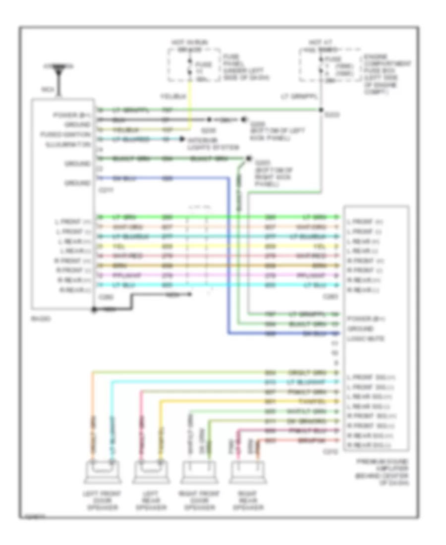
- (premium sound)
- (standard)
- Ashtray illumination
- Auxiliary power socket
- Bronco only
- C211
- C250
- C257
- C267
- C278
- C914
- Cigar lighter
- Compass/ outside temperature module
- Electronic shift control switch
- Exterior lights system
- Fuse 15a
- Fuse 4a
- Fuse panel
- G200 (behind bottom of left cowl panel)
- G203 (behind bottom of right cowl panel)
- Gnd
- Head
- Heater control illumination
- Hot at all times
- I/p feed
- I/p illum feed
- Ign
- Instrument cluster (5 bulbs)
- Main light switch
- Off
- Park
- Power distribution system (fuse panel) (fuse 11)
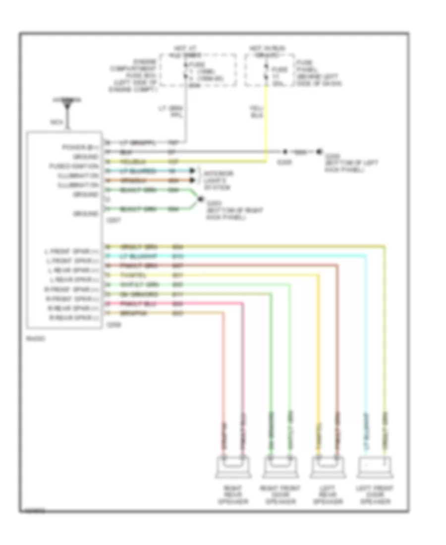
- Radio
- Rear window defrost control
- Sound systems (radio)
- W/ electronic shift control
POWER DISTRIBUTION
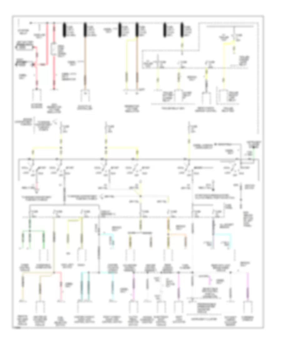
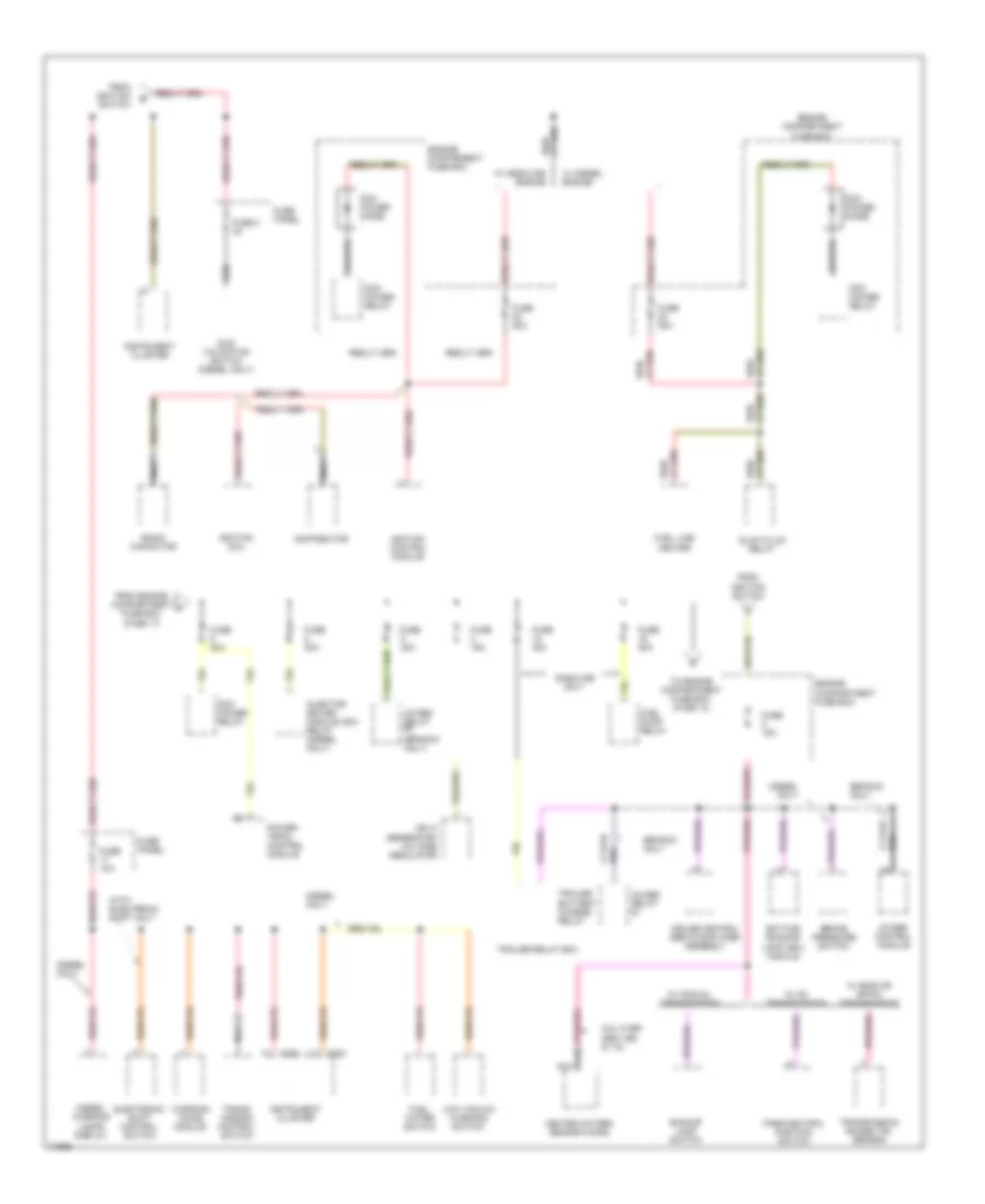
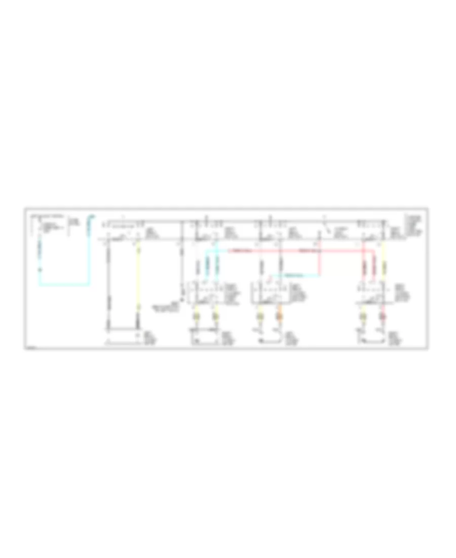
Power Distribution Wiring Diagram (1 of 3) for Ford Cab & Chassis F350 1996
List of elements for Power Distribution Wiring Diagram (1 of 3) for Ford Cab & Chassis F350 1996:
- (behind bottom of left kick panel)
- 200a generator/ voltage regulator
- 4wabs relay #1
- A/c-heater control assembly
- Acc
- Air bag diagnostic monitor
- All except bronco
- Bronco only
- C153
- Circuit breaker 14 20a
- Clutch pedal position switch
- Day/night mirror autolamp sensor
- Diesel only
- Diesel warning lamps display
- Diesel with 200 a generator
- Electronic shift control module
- Engine compartment fuse box
- Fuel tank selector switch
- Fuse 10a
- Fuse 15a
- Fuse 20a
- Fuse 25a
- Fuse 30a
- Fuse 50a
- Fuse panel
- G200
- Gasoline only
- Generator/ voltage regulator
- Glow plug controller
- Gnd
- Heater control assembly
- Heater or a/c-heater control module
- Ign
- Ignition switch
- Instrument cluster
- Instrument cluster system
- Left battery (diesel only)
- Lock
- Main light switch
- Master tailgate window switch
- Master window/ door lock control switch
- Mega fuse 300a (diesel only)
- Off
- Overhead console
- Programmable speedometer/ odometer module
- Radio
- Rear anti-lock brake (rabs) module
- Rear window defrost control
- Rear window defrost switch
- Red
- Remote keyless entry module
- Right battery
- Right window/ door lock control switch
- Run
- Selectable rpm control (partial connector)
- Shift lock actuator
- Sta
- Start
- Starter relay
- Starter solenoid
- Starting/charging system (clutch pedal position switch)
- To engine compartment fuse box (fuse 22)
- To engine compartment fuse box (fuse 5)
- To engine compartment fuse box (fuse 9)
- Trailer backup lamp relay
- Trailer battery charge relay
- Trailer relay box
- Trailer/ marker lamps relay
- Turn flasher
- W/ a/c
- W/ shift- on-the fly
- W/ trailer tow
- W/o a/c
- Windshield wiper motor
- Wiper control module
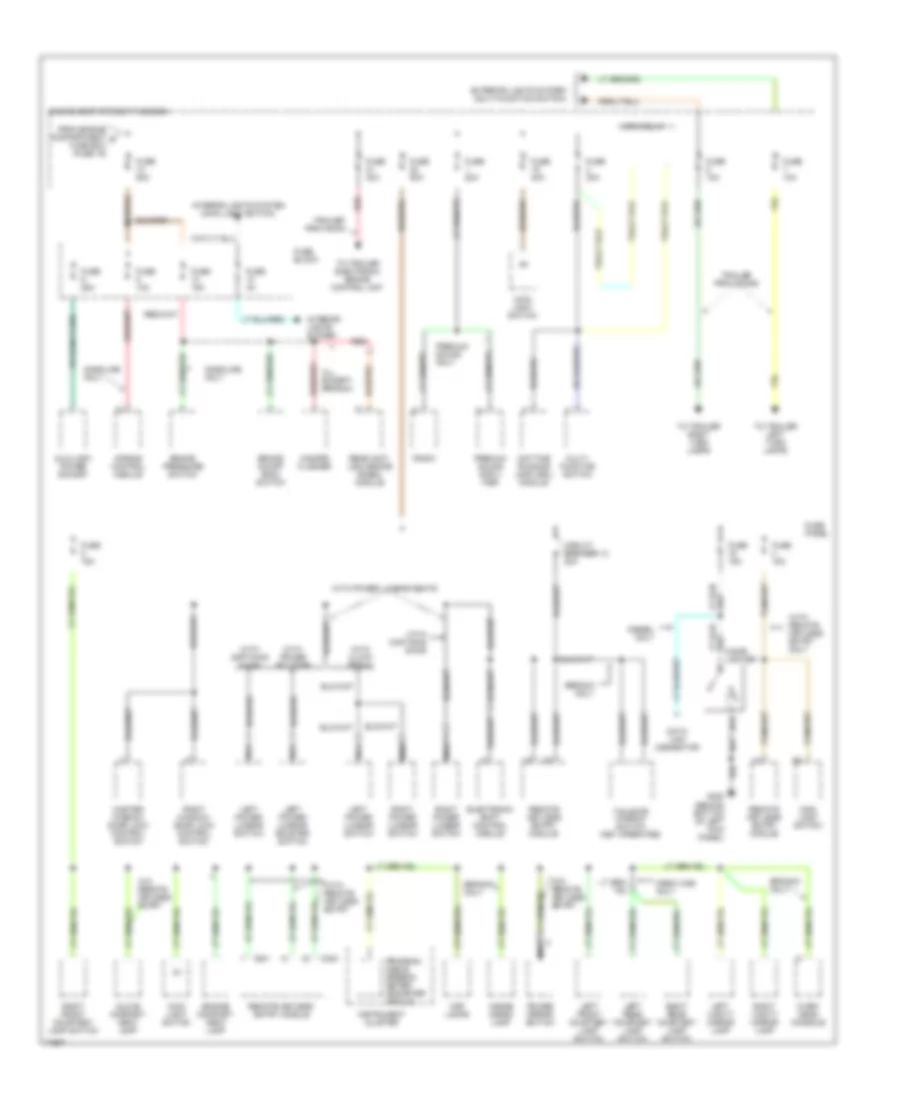
Power Distribution Wiring Diagram (2 of 3) for Ford Cab & Chassis F350 1996
List of elements for Power Distribution Wiring Diagram (2 of 3) for Ford Cab & Chassis F350 1996:
- (bronco only)
- 200 a generator/ voltage regulator
- 4wabs control module
- 4wabs relay #1
- 4wabs relay #2
- 5.8l over 8500 lbs & 7.5l
- Backup lamp switch
- Brake pressure switch
- Bronco only
- C250
- C251
- Cruise control servo/amplifier assembly
- Daytime running lamp (drl) module
- Diesel only
- Diesel warning lamps display
- Distributor
- Electronic shift control switch
- Engine comparment fuse box
- Engine compartment fuse box
- From engine compartment fuse box (fuse 17)
- From ignition switch
- Fuel line heater
- Fuel pump relay
- Fuel water switch
- Fuse 10a
- Fuse 15a
- Fuse 20a
- Fuse 3 3a
- Fuse 30a
- Fuse panel
- Gasoline only
- Glow plug relay
- Heated oxygen sensor (ho2s)
- Idle validation switch (diesel only)
- Ignition coil
- Ignition control module
- Injector driver module (idm) relay (diesel only)
- Instrument cluster
- Low vacuum warning switch
- Nca
- Park/neutral position switch
- Pcm power diode
- Pcm power relay
- Pnk
- Power- train control module
- Radio capacitor
- Red/
- To engine compartment fuse box (fuse 13)
- Trailer battery charge relay
- Trailer relay box
- Trans- mission control switch
- Transmission range (tr) sensor
- W/ c6 transmission
- W/ diesel engine
- W/ e40d 0r 4r70w transmission
- W/ gasoline engine
- W/ manual transmission
- Warning chime module
- With electronic shift only
Power Distribution Wiring Diagram (3 of 3) for Ford Cab & Chassis F350 1996
List of elements for Power Distribution Wiring Diagram (3 of 3) for Ford Cab & Chassis F350 1996:
- (behind bottom of left kick panel)
- Air bag control module
- All except bronco
- Auxiliary power socket
- Brake on/off (boo) switch
- Brake pressure switch
- Bronco only
- C240
- C241
- Circuit breaker 12 20a
- Crew cab only
- Data link connector
- Daytime running lamp (drl) module
- Diesel only
- Electronic shift control module
- Engine compart- ment lamp
- Engine compartment fuse box
- Exterior lights system (multi-function switch)
- From engine compartment d fuse box (fuse 16)
- Fuse 10a
- Fuse 15a
- Fuse 20a
- Fuse 25a
- Fuse 30a
- Fuse 40a
- Fuse 4a
- Fuse 50a
- Fuse block
- Fuse panel
- G200
- Gasoline only
- Glove compart- ment lamp
- Hazard flasher
- Horn relay
- Inside cargo lamp
- Instrument cluster
- Interior lights system
- Interior lights system (main light switch)
- Left front courtesy lamp switch
- Left power lumbar switch
- Left power lumbar/ bolster switch
- Left rear courtesy lamp switch
- Left vanity mirror lamp
- Lighter
- Main light switch
- Map lamps
- Master window/ door lock control switch
- Multi- function switch
- Nca
- Over- head console
- Power mirror switch
- Premium sound ampli- fier
- Premium sound only
- Program- mable speedo- meter/ odometer module
- Radio
- Rear anti- lock brake (rabs) module
- Red
- Remote keyless entry module
- Remote keyless entry module
- Right front courtesy lamp switch
- Right power lumbar switch
- Right rear courtesy lamp switch
- Right vanity mirror lamp
- Right window/ door lock control switch
- Tailgate window switch (key operated)
- To trailer electronic brake control unit
- To trailer left turn lamps
- To trailer right turn lamps
- Trailer provision
- Trailer provisions
- W/o remote keyless entry
- With captain's chair
- With cloth bench
- With power bolster
- With power lumbar seats
- With remote keyless entry
- With remote keyless entry only
POWER DOOR LOCKS
Door Lock Wiring Diagram for Ford Cab & Chassis F350 1996
List of elements for Door Lock Wiring Diagram for Ford Cab & Chassis F350 1996:
- Circuit breaker 12 20a
- Fuse panel
- G200 (behind bottom of left kick panel)
- Hot at all times
- Left front door lock motor
- Left rear door lock motor
- Lock
- Master window/ door lock control switch
- Pnk/
- Right front door lock motor
- Right rear door lock motor
- Right window/ door lock control switch
- Unlock
- W/ crew cab only
Keyless Entry Wiring Diagram for Ford Cab & Chassis F350 1996
List of elements for Keyless Entry Wiring Diagram for Ford Cab & Chassis F350 1996:
- (behind bottom of left cowl panel)
- (behind bottom of right cowl panel)
- Antenna
- Battery saver input
- Battery saver output
- C240
- C241
- C242
- Circuit breaker 12 20a
- Courtesy lamps output
- Crtsy lamp sw input
- Exterior lights system
- Fuse 15a
- Fuse panel
- G200
- G200 (behind bottom of left cowl panel)
- G203
- Ground
- Horn relay
- Horns system
- Hot at all times
- Hot in accy or run
- Ignition switch input
- Interior lights system
- Interior lights system (door courtesy lamp switches)
- Left front door lock motor
- Left rear door lock motor (crew cab only)
- Lock doors output
- Lock input
- Lock unlock
- Master window/ door lock control switch
- Nca
- Park lamps output
- Power
- Program a
- Program b
- Remote keyless entry module (behind left side of i/p)
- Right front door lock motor
- Right rear door lock motor (crew cab only)
- Right window/ door lock control switch
- Rke program connector (behind left side of i/p)
- Unlock doors output
- Unlock driver's door
- Unlock input
POWER MIRRORS
Power Mirror Wiring Diagram for Ford Cab & Chassis F350 1996
List of elements for Power Mirror Wiring Diagram for Ford Cab & Chassis F350 1996:
- Battery saver output
- Direct- ional control switch
- Fuse 15a
- G200 (behind bottom of left kick panel)
- Hot at all times
- I/p fuse panel (behind left side of dash)
- L/r motor
- Left power mirror nca
- Left/ right switch
- Nca
- Nca entry
- Power mirror switch
- Red
- Remote keyless entry module (behind left side of dash)
- Right power mirror nca
- S251
- S316
- S500
- Up/dn motor
- W/ keyless entry
- W/o keyless
POWER SEATS
Lumbar Wiring Diagram, with Captain's Chairs for Ford Cab & Chassis F350 1996
List of elements for Lumbar Wiring Diagram, with Captain's Chairs for Ford Cab & Chassis F350 1996:
- Circuit breaker 12 20a
- Fuse panel
- G200 (behind bottom of left kick panel)
- Hot at all times
- Left power lumbar compressor motor
- Left power lumbar switch
- Nca
- Right power lumbar compressor motor
- Right power lumbar switch
Lumbar Wiring Diagram, with Cloth Bench for Ford Cab & Chassis F350 1996
List of elements for Lumbar Wiring Diagram, with Cloth Bench for Ford Cab & Chassis F350 1996:
- Circuit breaker 12 20a
- Fuse panel
- G200 (behind bottom of left kick panel)
- Hot at all times
- Left power lumbar switch
- Nca
- Power lumbar compressor motor
- Right power lumbar switch
Lumbar/Bolster Wiring Diagram, with Captain's Chairs for Ford Cab & Chassis F350 1996
List of elements for Lumbar/Bolster Wiring Diagram, with Captain's Chairs for Ford Cab & Chassis F350 1996:
- Circuit breaker 12 20a
- Fuse panel
- G200 (behind bottom of left kick panel)
- Hot at all times
- Left power lumbar/bolster compressor motor
- Left power lumbar/bolster switch
- Nca
- Right power lumbar compressor motor
- Right power lumbar switch
POWER WINDOWS
Power Window Wiring Diagram, with Crew Cab for Ford Cab & Chassis F350 1996
List of elements for Power Window Wiring Diagram, with Crew Cab for Ford Cab & Chassis F350 1996:
- Circuit breaker 14 20a
- Down
- Fuse
- G200 (behind bottom of left cowl)
- Hot in accy or run
- Left front switch
- Left front window motor
- Left rear switch
- Left rear window control switch
- Left rear window motor
- Master window/ door lock control switch
- Nca
- Panel
- Right front switch
- Right front window motor
- Right front window/ door lock switch
- Right rear switch
- Right rear window control switch
- Right rear window motor
- Window lock switch
Power Window Wiring Diagram, without Crew Cab for Ford Cab & Chassis F350 1996
List of elements for Power Window Wiring Diagram, without Crew Cab for Ford Cab & Chassis F350 1996:
- (behind bottom of
- 20a
- Breaker 14
- Circuit
- Down
- Fuse panel
- G200
- Hot in acc or run
- Left cowl)
- Left front window motor
- Left window switch
- Master window/ door lock control switch
- Nca
- Red
- Red/
- Right front window motor
- Right window switch
- Right window/ door lock control switch
- Up down
RADIO
Base Radio for Ford Cab & Chassis F350 1996
List of elements for Base Radio for Ford Cab & Chassis F350 1996:
- (1996) (1994-95)
- Antenna
- C257
- C258
- Engine compartment fuse box (left side of engine compt)
- Fuse 15a
- Fuse a 20a
- Fuse panel (behind left side of dash)
- Fused ignition
- G200 (bottom of left kick panel)
- G203 (bottom of right kick panel)
- Ground
- Hot at all times
- Hot in run or acc
- Illuminaton
- Interior lights system
- L front spkr (+)
- L front spkr (-)
- L rear spkr (+)
- L rear spkr (-)
- Left front door speaker
- Left rear speaker
- Nca
- Power (b+)
- R front spkr (+)
- R front spkr (-)
- R rear spkr (+)
- R rear spkr (-)
- Radio
- Right front door speaker
- Right rear speaker
- S205
Premium Sound Radio Wiring Diagram for Ford Cab & Chassis F350 1996
List of elements for Premium Sound Radio Wiring Diagram for Ford Cab & Chassis F350 1996:
- (1996) (1995)
- Antenna
- C211
- C212
- C282
- C283
- Engine compartment fuse box (left side of engine compt)
- Fuse 15a
- Fuse a 20a
- Fuse panel (under left side of dash)
- Fused ignition
- G200 (bottom of left kick panel)
- G203 (bottom of right kick panel)
- Ground
- Hot at all times
- Hot in run or acc
- Illulminaton
- Interior lights system
- L front (+)
- L front (-)
- L front sig (+)
- L front sig (-)
- L rear (+)
- L rear (-)
- L rear sig (+)
- L rear sig (-)
- Left front door speaker
- Left rear speaker
- Logic mute
- Nca
- Power (b+)
- Premium sound amplifier (behind center of dash)
- R front (+)
- R front (-)
- R front sig (+)
- R front sig (-)
- R rear (+)
- R rear (-)
- R rear sig (+)
- R rear sig (-)
- Radio
- Right front door speaker
- Right rear speaker
- S205
- S233
SHIFT INTERLOCKS
Shift Interlock Wiring Diagram for Ford Cab & Chassis F350 1996
List of elements for Shift Interlock Wiring Diagram for Ford Cab & Chassis F350 1996:
- (behind bottom
- (behind left side of i/p, top left side of brake/ clutch pedal support)
- Brake on/off switch
- Fuse 13 15a
- Fuse 18 10a
- Fuse panel
- G200
- Hot at all times
- Hot in run
- Of left cowl panel)
- Shift lock actuator (in steering column)
- Solid state
STARTING/CHARGING
4.9L
4.9L, Charging Wiring Diagram for Ford Cab & Chassis F350 1996
List of elements for 4.9L, Charging Wiring Diagram for Ford Cab & Chassis F350 1996:
- (lower right front of engine) g119 (ex. 4.9l)
- (lower right rear of engine, on starter motor mounting bolt)
- Acc
- Battery
- C250
- Charge indicator
- Engine compartment fuse box
- Fuse 50a
- G101 (right front of engine compartment, on fender apron)
- G117 (4.9l)
- Generator/ voltage regulator
- Ignition switch
- Instrument cluster
- Lock
- Off
- Ohms
- Red
- Run
- Start
- Starter relay
4.9L, Starting Wiring Diagram for Ford Cab & Chassis F350 1996
List of elements for 4.9L, Starting Wiring Diagram for Ford Cab & Chassis F350 1996:
- (4.9l) g117 (lower right rear of engine, on starter motor mounting bolt)
- (4r70w)
- (e40d)
- A/t
- A/t (c6)
- A/t (e40d/4r70w)
- Acc
- Battery
- Clutch pedal position switch (top right side of brake/clutch pedal support)
- Clutch pedal positon switch jumper (behind left side of i/p, taped to harness)
- E40d/4r70w only
- Engine compartment fuse box
- Fuse 20a
- G101 (right front of engine compartment, on fender apron)
- G119 (ex. 4.9l) (lower right front of engine)
- Hold
- Ignition switch
- Lock
- M/t
- Off
- Park/neutral position switch (left side of transmission)
- Pull-in
- Red
- Run
- Sta
- Start
- Starter motor/ solenoid
- Starter relay (front of right fender apron, behind battery)
- Transmission range sensor (left side of transmission)
5.0L
5.0L, Charging Wiring Diagram for Ford Cab & Chassis F350 1996
List of elements for 5.0L, Charging Wiring Diagram for Ford Cab & Chassis F350 1996:
- (lower right front of engine) g119 (ex. 4.9l)
- (lower right rear of engine, on starter motor mounting bolt)
- Acc
- Battery
- C250
- Charge indicator
- Engine compartment fuse box
- Fuse 50a
- G101 (right front of engine compartment, on fender apron)
- G117 (4.9l)
- Generator/ voltage regulator
- Ignition switch
- Instrument cluster
- Lock
- Off
- Ohms
- Red
- Run
- Start
- Starter relay
5.0L, Starting Wiring Diagram for Ford Cab & Chassis F350 1996
List of elements for 5.0L, Starting Wiring Diagram for Ford Cab & Chassis F350 1996:
- (4.9l) g117 (lower right rear of engine, on starter motor mounting bolt)
- (4r70w)
- (e40d)
- A/t
- A/t (c6)
- A/t (e40d/4r70w)
- Acc
- Battery
- Clutch pedal position switch (top right side of brake/clutch pedal support)
- Clutch pedal positon switch jumper (behind left side of i/p, taped to harness)
- E40d/4r70w only
- Engine compartment fuse box
- Fuse 20a
- G101 (right front of engine compartment, on fender apron)
- G119 (ex. 4.9l) (lower right front of engine)
- Hold
- Ignition switch
- Lock
- M/t
- Off
- Park/neutral position switch (left side of transmission)
- Pull-in
- Red
- Run
- Sta
- Start
- Starter motor/ solenoid
- Starter relay (front of right fender apron, behind battery)
- Transmission range sensor (left side of transmission)
5.8L
5.8L, Charging Wiring Diagram for Ford Cab & Chassis F350 1996
List of elements for 5.8L, Charging Wiring Diagram for Ford Cab & Chassis F350 1996:
- (lower right front of engine) g119 (ex. 4.9l)
- (lower right rear of engine, on starter motor mounting bolt)
- Acc
- Battery
- C250
- Charge indicator
- Engine compartment fuse box
- Fuse 50a
- G101 (right front of engine compartment, on fender apron)
- G117 (4.9l)
- Generator/ voltage regulator
- Ignition switch
- Instrument cluster
- Lock
- Off
- Ohms
- Red
- Run
- Start
- Starter relay
5.8L, Starting Wiring Diagram for Ford Cab & Chassis F350 1996
List of elements for 5.8L, Starting Wiring Diagram for Ford Cab & Chassis F350 1996:
- (4.9l) g117 (lower right rear of engine, on starter motor mounting bolt)
- (4r70w)
- (e40d)
- A/t
- A/t (c6)
- A/t (e40d/4r70w)
- Acc
- Battery
- Clutch pedal position switch (top right side of brake/clutch pedal support)
- Clutch pedal positon switch jumper (behind left side of i/p, taped to harness)
- E40d/4r70w only
- Engine compartment fuse box
- Fuse 20a
- G101 (right front of engine compartment, on fender apron)
- G119 (ex. 4.9l) (lower right front of engine)
- Hold
- Ignition switch
- Lock
- M/t
- Off
- Park/neutral position switch (left side of transmission)
- Pull-in
- Red
- Run
- Sta
- Start
- Starter motor/ solenoid
- Starter relay (front of right fender apron, behind battery)
- Transmission range sensor (left side of transmission)
7.3L
7.3L DI Turbo Diesel, Charging Wiring Diagram, with 130 A Alternator for Ford Cab & Chassis F350 1996
List of elements for 7.3L DI Turbo Diesel, Charging Wiring Diagram, with 130 A Alternator for Ford Cab & Chassis F350 1996:
- Acc
- Battery
- C250
- Charge indicator
- Engine compartment fuse box
- Fuse 50a
- G101 (right front of engine compartment, on fender apron)
- G119 (lower right front of engine)
- Generator/ voltage regulator
- Ignition switch
- Instrument cluster
- Lock
- Off
- Ohms
- Red
- Run
- Start
- Starter relay
7.3L DI Turbo Diesel, Charging Wiring Diagram, with 200 A Alternator for Ford Cab & Chassis F350 1996
List of elements for 7.3L DI Turbo Diesel, Charging Wiring Diagram, with 200 A Alternator for Ford Cab & Chassis F350 1996:
- (right front of engine)
- 300a
- Acc
- C250
- Charge indicator
- Engine compartment fuse box
- Fuse 15a
- Fuse 50a
- G101 (right front of engine compartment, on fender apron)
- G109 (right front of engine compartment, on upper radiator support)
- G110 (lower left front of engine)
- G119 (lower right front of engine)
- Generator/ voltage regulator
- Ignition switch
- Instrument cluster
- Left battery
- Lock
- Mega fuse
- Off
- Red
- Right battery
- Run
- Start
- Starter relay
7.3L DI Turbo Diesel, Starting Wiring Diagram for Ford Cab & Chassis F350 1996
List of elements for 7.3L DI Turbo Diesel, Starting Wiring Diagram for Ford Cab & Chassis F350 1996:
- (w/200a alternator)
- A/t
- Acc
- Battery (w/130a alternator)
- Clutch pedal position switch (top right side of brake/clutch pedal support)
- Clutch pedal positon switch jumper (behind left side of i/p, taped to harness)
- Engine compartment fuse box
- Fuse 20a
- G101 (right front of engine compartment, on fender apron)
- G109 (right front of engine compartment, on upper radiator support)
- G110 (lower left front of engine)
- G119 (lower right front of engine)
- Hold
- Ignition switch
- Left battery
- Lock
- M/t
- Off
- Pull-in
- Red
- Right battery (w/200a alternator)
- Run
- Sta
- Start
- Starter motor/ solenoid
- Starter relay (front of right fender apron, behind battery)
- Transmission range sensor (left side of transmission)
7.5L
7.5L, Charging Wiring Diagram for Ford Cab & Chassis F350 1996
List of elements for 7.5L, Charging Wiring Diagram for Ford Cab & Chassis F350 1996:
- (lower right front of engine) g119 (ex. 4.9l)
- (lower right rear of engine, on starter motor mounting bolt)
- Acc
- Battery
- C250
- Charge indicator
- Engine compartment fuse box
- Fuse 50a
- G101 (right front of engine compartment, on fender apron)
- G117 (4.9l)
- Generator/ voltage regulator
- Ignition switch
- Instrument cluster
- Lock
- Off
- Ohms
- Red
- Run
- Start
- Starter relay
7.5L, Starting Wiring Diagram for Ford Cab & Chassis F350 1996
List of elements for 7.5L, Starting Wiring Diagram for Ford Cab & Chassis F350 1996:
- (4.9l) g117 (lower right rear of engine, on starter motor mounting bolt)
- (4r70w)
- (e40d)
- A/t
- A/t (c6)
- A/t (e40d/4r70w)
- Acc
- Battery
- Clutch pedal position switch (top right side of brake/clutch pedal support)
- Clutch pedal positon switch jumper (behind left side of i/p, taped to harness)
- E40d/4r70w only
- Engine compartment fuse box
- Fuse 20a
- G101 (right front of engine compartment, on fender apron)
- G119 (ex. 4.9l) (lower right front of engine)
- Hold
- Ignition switch
- Lock
- M/t
- Off
- Park/neutral position switch (left side of transmission)
- Pull-in
- Red
- Run
- Sta
- Start
- Starter motor/ solenoid
- Starter relay (front of right fender apron, behind battery)
- Transmission range sensor (left side of transmission)
SUPPLEMENTAL RESTRAINTS
Supplemental Restraint Wiring Diagram for Ford Cab & Chassis F350 1996
List of elements for Supplemental Restraint Wiring Diagram for Ford Cab & Chassis F350 1996:
- (behind bottom of right cowl panel)
- * pin shorting bar is engaged when module connector is disconnected
- 10*
- 11*
- Air bag diagnostic monitor (behind left side of i/p)
- Air bag ind
- Air bag indicator
- C217
- C218
- C251
- Clockspring assembly
- Drvr air bag
- Fuse 10a
- Fuse panel
- G203
- Gnd
- Hot at all times
- Hot in run
- Instrument cluster
- L crash sens
- Left primary crash sensor (on left side of frame rail)
- Nca
- Pass bag off
- Pwr (bat)
- Pwr (run)
- R crash sens
- Right primary crash sensor (right side of cowl panel)
- Safing sens
- Safing sensor (on right side of frame rail)
- Shorting bar
- Steering column air bag
TRANSMISSION
5.8L
5.8L, Transmission Wiring Diagram for Ford Cab & Chassis F350 1996
List of elements for 5.8L, Transmission Wiring Diagram for Ford Cab & Chassis F350 1996:
- (backup lamp switch to rear lamp feed harness, in break out to transmission range (tr) sensor)
- (behind bottom of right cowl panel) g203
- (engine control sensor harness, near break out to brake warning resistor/diode assembly)
- (engine control sensor harness, near break out to brake warning resistor/diode assembly) s136
- (fuel charge harness, near break out to canister purge solenoid) (5.8l engine) (no location available) (7.5l engine)
- (fuel charge harness, near break out to fuel injector 4) (5.8l engine) (no location available) (7.5l engine)
- (left front of engine compartment, on upper radiator support) g108
- (transmission harness, near break out to e40d transmission)
- 4x4
- Boo
- Brake on/off (boo) switch (on brake/ clutch pedal support)
- C251
- C252
- Ccs
- Coast clutch solenoid
- Cse gnd
- Data
- E40d transmission (below center of vehicle)
- Ect
- Electronic pressure control solenoid
- Engine compartment fuse box
- Engine control sensor harness, near break out to powertrain control module (pcm))
- Engine coolant temperature (ect) sensor (center front of engine on, thermostat housing) (5.8l engine) (left front of engine, near left side of distributor) (7.5l engine)
- Epc
- Fuse 10a
- Fuse 15a
- Fuse 20a
- Fuse 30a
- Fuse panel
- G101 (right front of engine compartment, front of fender apron)
- G104 (rear of left fender apron)
- Gnd
- Hot at all times
- Hot in start or run
- Iat
- Ign
- Instrument cluster
- Intake air temperature (iat) sensor (top center front of engine near intake runner 6) (5.8l engine) (top center of engine, behind distributor) (7.5l engine)
- Kapwr
- Main harness, near break out to speed control amplifier
- Malfunction indicator lamp (mil)
- Manifold absolute pressure (map) sensor (no location available) (5.8l engine) (top right side of safety wall) (7.5l engine)
- Map
- Mil
- N d
- Nca
- Pcm power diode
- Pcm power relay
- Powertrain control module (pcm) (left side of safety wall)
- Psom module
- Red
- S102
- S106
- S135
- S137
- S146
- S148
- S161
- S163
- S169
- S215
- S216
- S236
- S240 (main harness, near break out to clutch pedal position switch or jumper)
- S246
- Shift solenoid
- Sig rtn
- Speed control servo/amplifier assembly (left side of engine compartment, near brake master cylinder)
- Ss1
- Ss2
- Tcc
- Tcil
- Tcs
- Tft
- Throttle position sensor (tps) (top right front of engine, on throttle body) (5.8l engine) (top left side of engine, on side of throttle body) (7.5l engine)
- Torque converter clutch solenoid
- Transfer case circuit
- Transmission control switch
- Transmission fluid temperature sensor
- Transmission range (tr) sensor (left side of transmission)
- Vip data link connector (left rear of engine compt, on bracket)
- Vip data link connector (partial) (left rear of engine compt, on bracket)
- Vref
- Vss gnd
- Vss input
- Vss output
7.3L
7.3L DI Turbo Diesel, Transmission Wiring Diagram for Ford Cab & Chassis F350 1996
List of elements for 7.3L DI Turbo Diesel, Transmission Wiring Diagram for Ford Cab & Chassis F350 1996:
- (backup lamp switch to rear lamp feed harness, in break out to e40d transmission)
- (backup lamp switch to rear lamp feed harness, in break out to transmission range (tr) sensor)
- (engine control sensor harness, near break out to g108, left front of engine compartment on upper radiator support)
- (engine control sensor harness, near break out to left headlamp)
- (engine control sensor harness, near break out to powertrain control module (pcm)) s157
- (engine control sensor harness, near break out to starter relay) s163
- (left front of engine compartment, on upper radiator support) g108
- (main harness, in break out to throttle position sensor) s239
- (main harness, near break out to, harness in-line connector, behind lower center of i/p)
- (pia harness, in break out to ect sensor)
- 4x4
- Acel pdl
- Amb
- Aux data
- Baro
- Barometric pressure (baro) sensor (at base of steering column)
- Boo
- Brake on/off (boo) switch (on brake/ clutch pedal support)
- C250
- C251
- C252
- Cam
- Cam rtn
- Camshaft position (cmp) sensor (front center of engine)
- Chk eng
- Coast clutch solenoid
- Cpps
- Data link connector (dlc) (partial) (behind lower
- E40d transmission (below center of vehicle)
- Electronic pressure control solenoid
- Eng oil
- Engine compartment fuse box
- Engine oil temperature (eot) sensor (top front of engine)
- Epc
- Fuse 10a
- Fuse 15a
- Fuse 20a
- Fuse 30a
- Fuse panel
- G104 (rear of left fender apron)
- G108 (left front of engine compartment, on upper radiator support)
- G203 (behind bottom of right cowl panel)
- Gen data
- Gnd
- Hot at all times
- Hot in start or run
- Instrument cluster
- Intake air temperature (iat) sensor (top center of engine)
- Kapwr
- Malfunction indicator lamp (mil) "check engine light"
- Manifold absolute pressure (map) sensor (top right side of safety wall)
- Map
- N d
- Nca
- Pcm power diode
- Pcm power relay
- Pedal accelerator sensor (ap) (under left side of i/p)
- Powertrain control (partial) (behind center of i/p)
- Powertrain control module (pcm) (left side of safety wall)
- Psom module
- Pwr in
- Red
- Right side of i/p, before glove compartment)
- S101
- S106
- S114
- S125
- S126
- S129
- S132 (pia harness, in break out to ebp sensor)
- S143
- S146
- S164
- S215
- S216
- S235 (main harness, in break out to throttle position sensor)
- S236
- S240 (main harness, near break out to clutch pedal position switch or jumper)
- S243
- Shift solenoid
- Sig rtn
- Ss1
- Ss2
- Tcc
- Tcil
- Tft
- Torque converter clutch solenoid
- Transfer case circuit
- Transmission control switch
- Transmission fluid temperature sensor
- Transmission range (tr) sensor (left side of transmission)
- Vref
- Vss
- Vss gnd
- Vss output
7.5L
7.5L, Transmission Wiring Diagram, California for Ford Cab & Chassis F350 1996
List of elements for 7.5L, Transmission Wiring Diagram, California for Ford Cab & Chassis F350 1996:
- (behind bottom of right cowl panel) g203
- (engine control sensor harness, near break out to brake warning resistor/diode assembly)
- (left front of engine compartment, on upper radiator support) g108
- (no location available)
- (right front of engine, compartment, on front of fender apron) g101
- (transmission harness, near break out to e40d transmission)
- 4x4
- Backup lamp switch to rear lamp feed harness, in break out to transmission range (tr) sensor)
- Boo
- Brake on/off (boo) switch (on brake/ clutch pedal support)
- C250
- C251
- C252
- Ccs
- Coast clutch solenoid
- Data
- Data (+)
- Data (-)
- Data link connector (dlc) (partial) (behind lower right side of i/p, before glove compartment)
- E40d transmission (below center of vehicle)
- Ect
- Electronic pressure control solenoid
- Engine compartment fuse box
- Engine coolant temperature (ect) sensor (left front of engine, near left side of distributor)
- Epc
- Fuse 10a
- Fuse 15a
- Fuse 20a
- Fuse 30a
- Fuse panel
- G101 (right front of engine compartment, on front of fender apron)
- G104 (rear of left fender apron)
- Gnd
- Hot at all times
- Hot in start or run
- Iat
- Instrument cluster
- Intake air temperature (iat) sensor (top center of engine, behind distributor)
- Kapwr
- Maf
- Malfunction indicator lamp (mil)
- Mass air flow (maf) sensor (no location available)
- Mil
- N d
- Nca
- Pcm power diode
- Pcm power relay
- Power
- Powertrain control module (left side of safety wall)
- Psom module
- Red
- S101
- S102
- S104
- S135
- S136
- S137
- S146
- S148
- S161 (no location available)
- S169
- S215
- S216
- S236
- Shift solenoid
- Sig rtn
- Ss1
- Ss2
- Tcc
- Tcil
- Tcs
- Tft
- Throttle position (tp) sensor (top left side of engine, on side of throttle body)
- Torque converter clutch solenoid
- Transfer case circuit
- Transmission control switch
- Transmission fluid temperature sensor
- Transmission range (tr) sensor (left side of transmission)
- Vref
- Vss
- Vss gnd
- Vss output
7.5L, Transmission Wiring Diagram, Federal for Ford Cab & Chassis F350 1996
List of elements for 7.5L, Transmission Wiring Diagram, Federal for Ford Cab & Chassis F350 1996:
- (backup lamp switch to rear lamp feed harness, in break out to transmission range (tr) sensor)
- (behind bottom of right cowl panel) g203
- (engine control sensor harness, near break out to brake warning resistor/diode assembly)
- (engine control sensor harness, near break out to brake warning resistor/diode assembly) s136
- (fuel charge harness, near break out to canister purge solenoid) (5.8l engine) (no location available) (7.5l engine)
- (fuel charge harness, near break out to fuel injector 4) (5.8l engine) (no location available) (7.5l engine)
- (left front of engine compartment, on upper radiator support) g108
- (transmission harness, near break out to e40d transmission)
- 4x4
- Boo
- Brake on/off (boo) switch (on brake/ clutch pedal support)
- C251
- C252
- Ccs
- Coast clutch solenoid
- Cse gnd
- Data
- E40d transmission (below center of vehicle)
- Ect
- Electronic pressure control solenoid
- Engine compartment fuse box
- Engine control sensor harness, near break out to powertrain control module (pcm))
- Engine coolant temperature (ect) sensor (center front of engine on thermostat housing) (5.8l engine) (left front of engine, near left side of distributor) (7.5l engine)
- Epc
- Fuse 10a
- Fuse 15a
- Fuse 20a
- Fuse 30a
- Fuse panel
- G101 (right front of engine compartment, front of fender apron)
- G104 (rear of left fender apron)
- Gnd
- Hot at all times
- Hot in start or run
- Iat
- Ign
- Instrument cluster
- Intake air temperature (iat) sensor (top center front of engine near intake runner 6) (5.8l engine) (top center of engine, behind distributor) (7.5l engine)
- Kapwr
- Main harness, near break out to speed control amplifier
- Malfunction indicator lamp (mil)
- Manifold absolute pressure (map) sensor (no location available) (5.8l engine) (top right side of safety wall) (7.5l engine)
- Map
- Mil
- N d
- Nca
- Pcm power diode
- Pcm power relay
- Powertrain control module (pcm) (left side of safety wall)
- Psom module
- Red
- S102
- S106
- S135
- S137
- S146
- S148
- S161
- S163
- S169
- S215
- S216
- S236
- S240 (main harness, near break out to clutch pedal position switch or jumper)
- S246
- Shift solenoid
- Sig rtn
- Speed control servo/amplifier assembly (left side of engine compartment, near brake master cylinder)
- Ss1
- Ss2
- Tcc
- Tcil
- Tcs
- Tft
- Throttle position sensor (tps) (top right front of engine, on throttle body) (5.8l engine) (top left side of engine, on side of throttle body) (7.5l engine)
- Torque converter clutch solenoid
- Transfer case circuit
- Transmission control switch
- Transmission fluid temperature sensor
- Transmission range (tr) sensor (left side of transmission)
- Vip data link connector (left rear of engine compt, on bracket)
- Vip data link connector (partial) (left rear of engine compt, on bracket)
- Vref
- Vss gnd
- Vss input
- Vss output
WARNING SYSTEMS
Warning System Wiring Diagrams for Ford Cab & Chassis F350 1996
List of elements for Warning System Wiring Diagrams for Ford Cab & Chassis F350 1996:
- (behind bottom of left cowl panel)
- (inside left front seat belt buckle assembly)
- C250
- Dr door open input
- Fasten seat belt indicator
- Fuse 10a
- Fuse 15a
- Fuse panel
- G200
- Ground
- Head
- Headlamps on input
- Hot at all times
- Hot in start or run
- Indicator output
- Instrument cluster
- Key in ignition input
- Key warning switch
- Left front courtesy lamp switch
- Main light switch
- Nca
- Off
- Park
- Power
- Red/pnk
- Seat belt buckled
- Seat belt switch
- Speed control/ horn switch assembly (in steering wheel)
- Warning chime module (behind lower center of i/p)
WIPER/WASHER
Wiper/Washer Wiring Diagram for Ford Cab & Chassis F350 1996
List of elements for Wiper/Washer Wiring Diagram for Ford Cab & Chassis F350 1996:
- (right front of engine compt, front of fender apron) (diesel) g101
- 100k ohms
- 3.3k ohms
- 4.07k
- 7.25k
- Fuse 30a
- Fuse panel (behind left side of dash)
- G108 (gasoline) (left front of engine compt, on upper radiator support)
- G108 (left front of engine compt, on upper radiator support)
- G200 (behind bottom of left kick panel)
- Ground
- Hot in acc or run
- Int max
- Int min
- Motor (hi)
- Motor (lo)
- Motor com
- Mult-func
- Multi- function switch
- Off
- Off 36.27k ohms
- Ohms
- Park
- Park sw
- Power
- Pump motr
- Run
- S100 (diesel) s103 (gasoline)
- S102 (gasoline) s101 (diesel)
- S203
- S238
- Wash
- Windshield washer pump motor (in fluid reservoir)
- Windshield wiper motor (on left side of firewall)
- Wiper control module (above right kick panel)