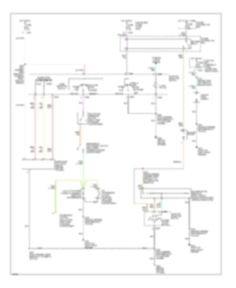
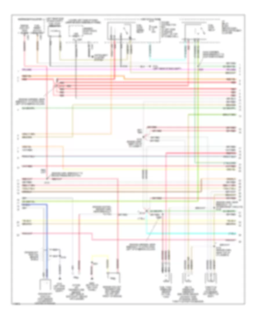
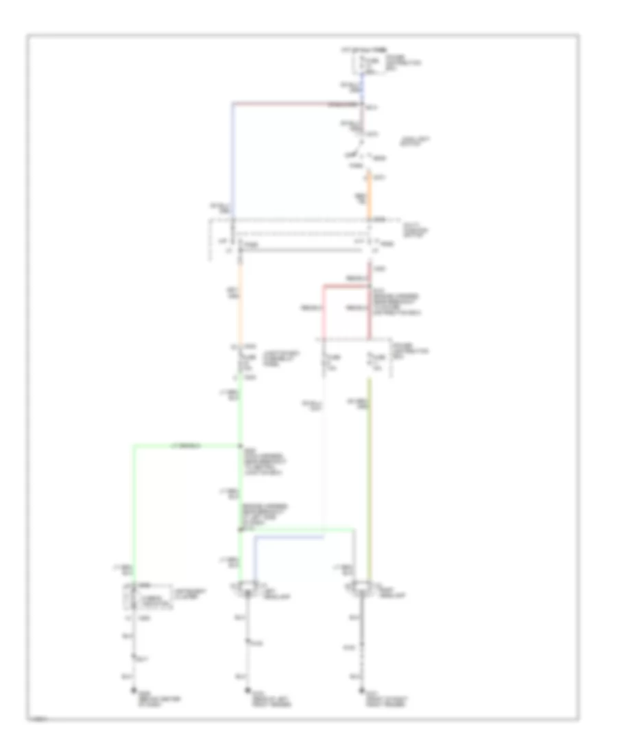
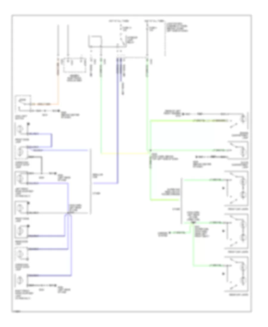
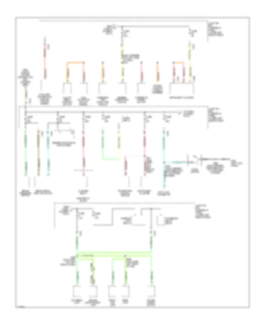
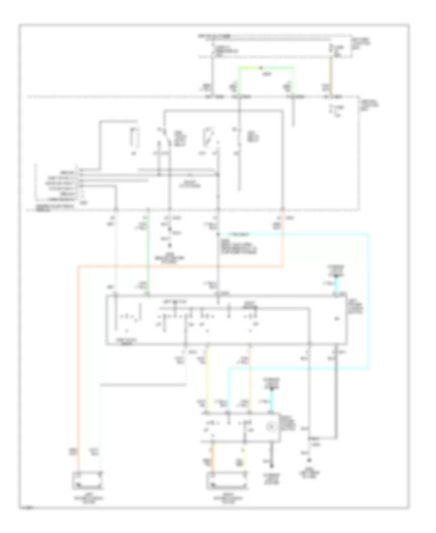
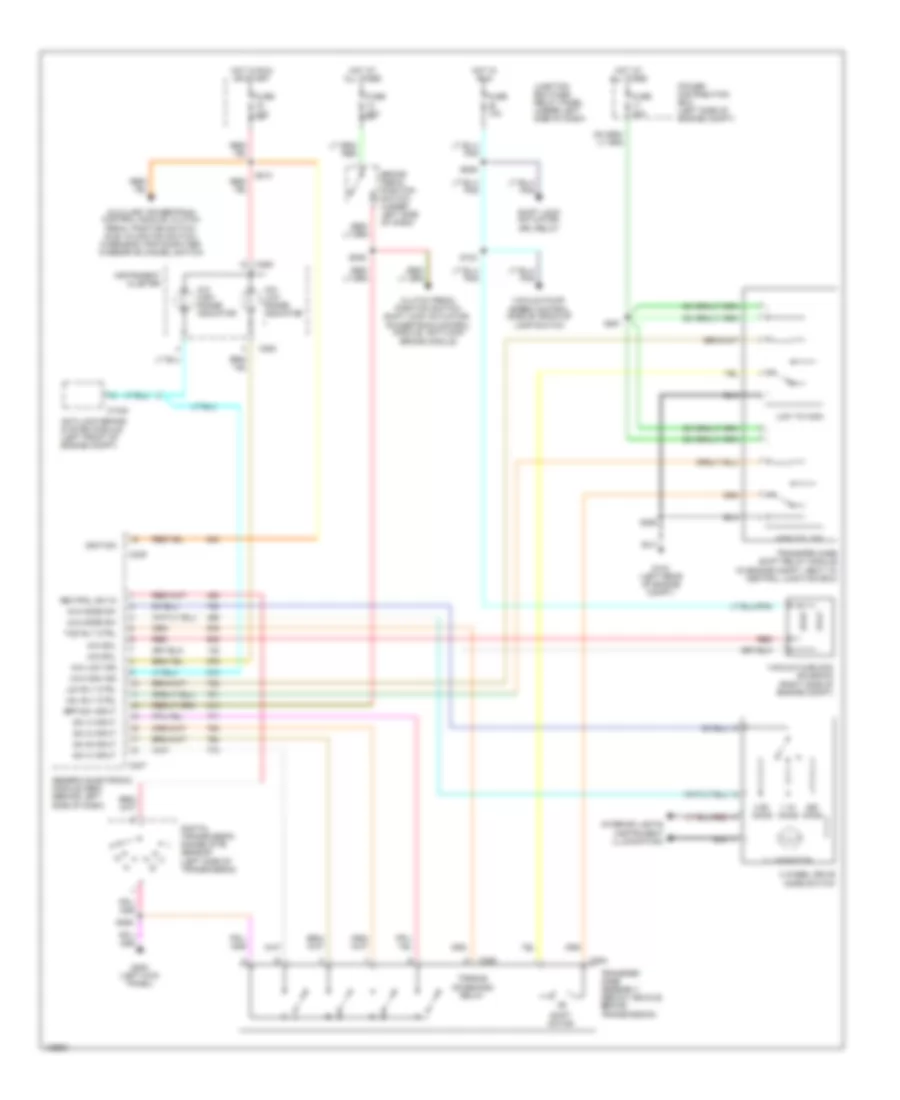
AIR CONDITIONING
Heater Wiring Diagram for Ford Cab & Chassis F350 Super Duty 1999

List of elements for Heater Wiring Diagram for Ford Cab & Chassis F350 Super Duty 1999:
- (engine sensor harness, near breakout to blower motor resistor)
- (right side of engine compartment, near battery) g108
- (under center of dash) g201
- Blend door actuator (behind center of dash)
- Blend door potentiometer
- Blower motor
- Blower motor resistor (right side of engine compartment, near blower motor)
- Blower motor switch
- Blower relay
- C220
- C242
- C243
- C260
- C296
- C298
- Cold
- Def
- Floor
- Flr & def
- Function selector switch
- Fuse 10a
- Fuse 40a
- Hot at all times
- Hot in run
- Illumi- nation
- Instrument panel fuse box
- Interior lights system
- Mode selector switch
- Off
- Panel
- Panel &
- Power distribution box
- S180 (engine harness, near breakout to g108)
- S235 (main harness, near breakout to brake pedal position sensor)
- S257 (main harness, near breakout to inertia switch)
- S290 (main harness, near breakout to customer access)
- Warm
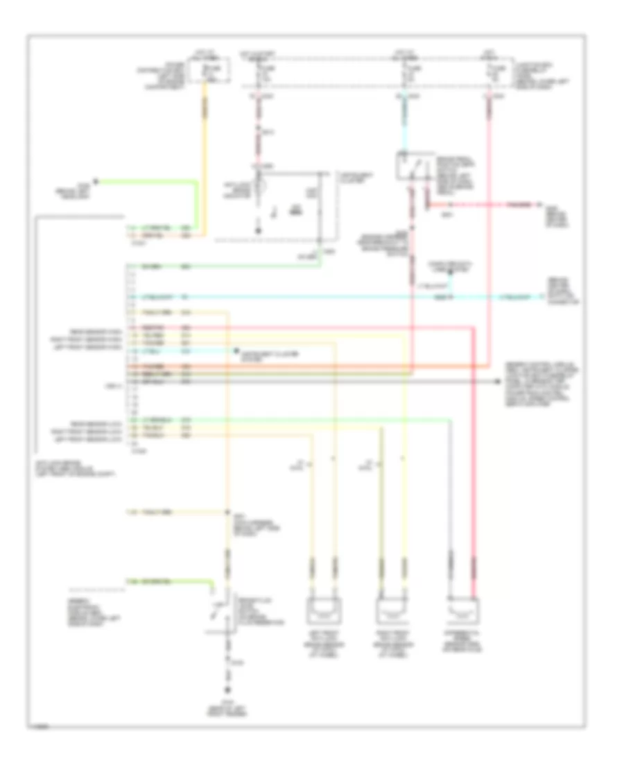
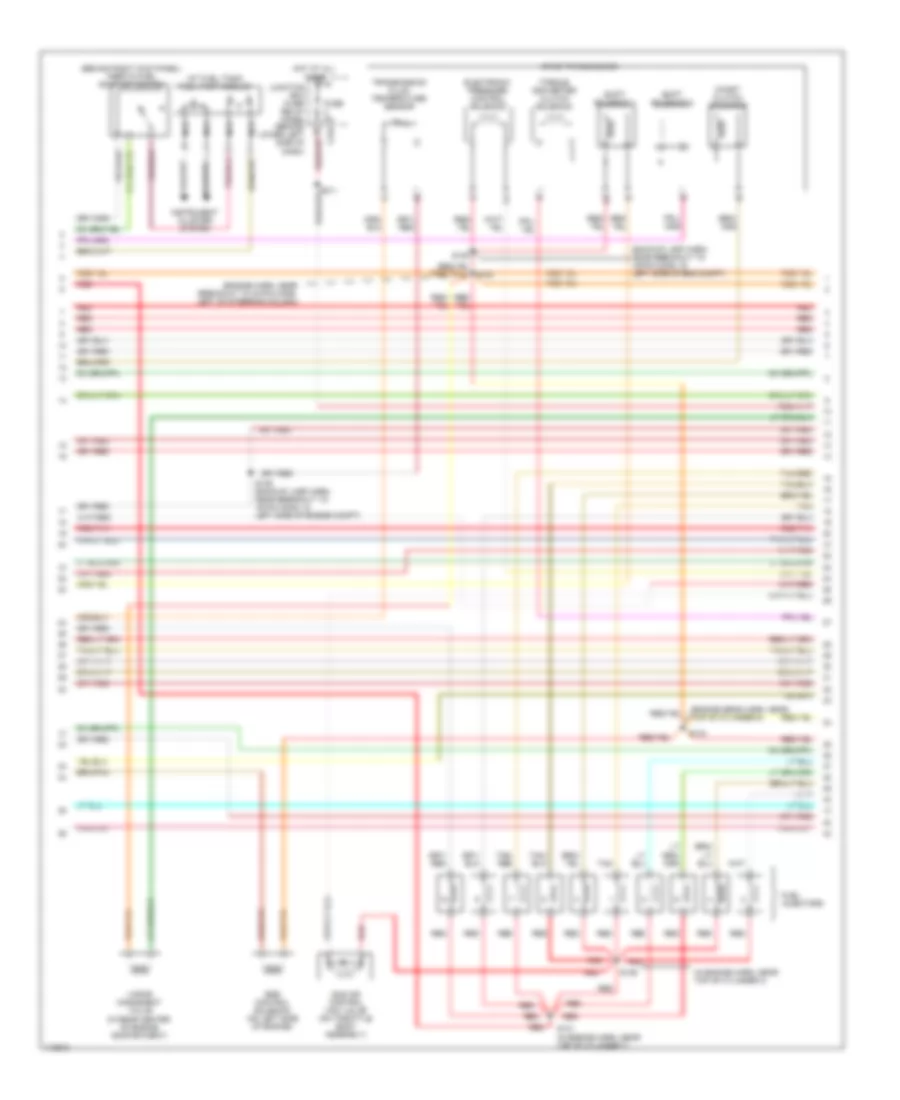
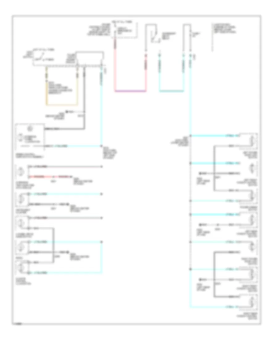
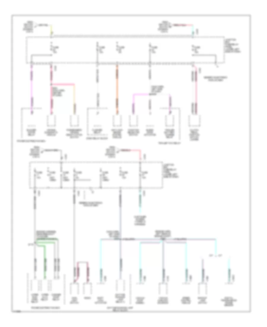
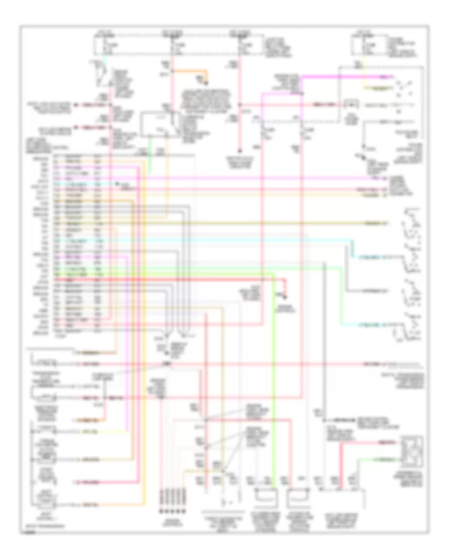
Manual A/C Wiring Diagram for Ford Cab & Chassis F350 Super Duty 1999
List of elements for Manual A/C Wiring Diagram for Ford Cab & Chassis F350 Super Duty 1999:
- A/c
- A/c clutch diode (taped in harness, near a/c compressor)
- A/c compressor clutch solenoid (left side of engine compartment)
- A/c cycling pressure switch (right side of engine compartment)
- Blend door actuator (behind center of dash)
- Blend door potentiometer
- Blower motor
- Blower motor resistor (right side of engine compartment, near blower motor)
- Blower motor switch
- Blower relay
- C225
- C242
- C243
- C260
- C296
- C298
- Cold
- Def
- Defrost
- Floor
- Flr & def
- Flr/def
- Function selector switch
- Fuse 10a
- Fuse 40a
- G101 (front of right front fender)
- G206 (behind center of dash)
- Hot at all times
- Hot in run
- Illumi- nation
- Instrument panel fuse box
- Interior lights system
- Junction box fuse/relay panel (lower left side of dash)
- Max a/c
- Mode selector switch
- Off panel/floor
- Panel
- Panel & off floor
- Power distribution box
- Powertrain control module (pcm) (right side of engine compartment)
- Refrigerant containment switch (right rear corner of engine compartment)
- S152 (engine sensor harness, near breakout to blower motor resistor)
- S180 (engine harness, near breakout to g108)
- S235 (main harness, near breakout to brake pedal position sensor)
- S257 (main harness, near breakout to inertia switch)
- S290 (main harness, near breakout to customer access)
- Vacuum pump (diesel)
- Warm
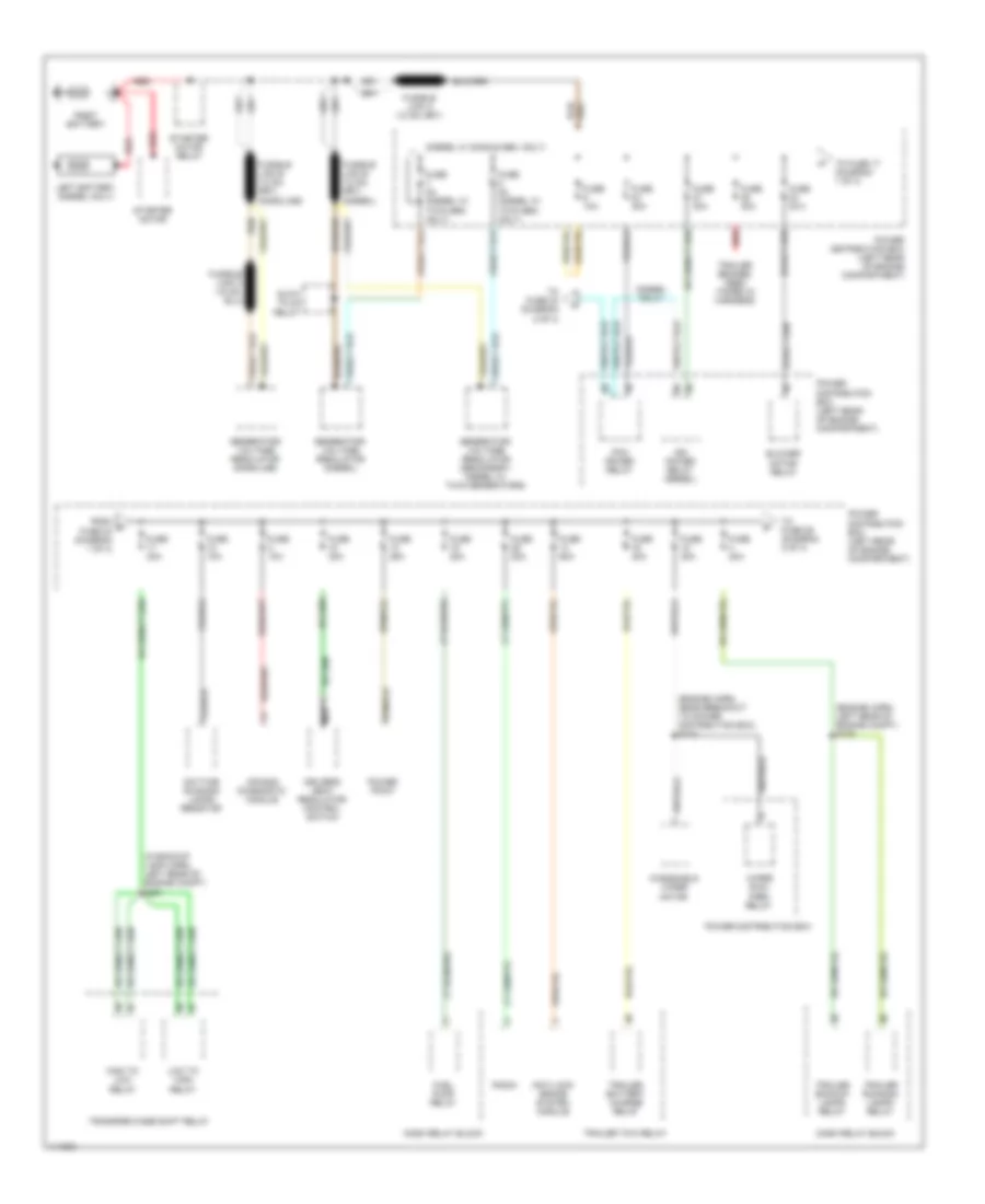
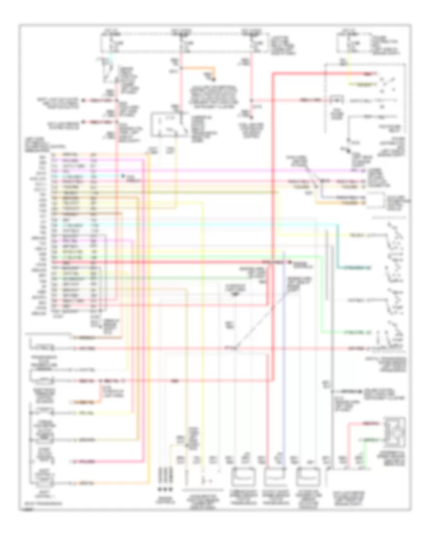
ANTI-LOCK BRAKES
Anti-lock Brakes Wiring Diagram for Ford Cab & Chassis F350 Super Duty 1999
List of elements for Anti-lock Brakes Wiring Diagram for Ford Cab & Chassis F350 Super Duty 1999:
- (behind center of dash) data link connector
- 22k ohm
- 5.6k ohm
- Anti-lock brake indicator
- Anti-lock brake system (abs) module (left front of engine compt)
- Brake fluid level switch (on brake fluid reservoir)
- Brake pedal position (bpp) switch (behind left side of dash, above brake pedal)
- C1040
- C1041
- C243
- C250
- C253
- Computer data lines system
- Differential speed sensor (dss) (on rear axle)
- Fuse 10a
- Fuse 5a
- Fuse 60a
- G104 (rear of left front fender)
- G106 (behind left headlamp)
- G206 (behind center of dash)
- Generic control module (gem), instrument cluster, junction box fuse/relay panel, overhead trip computer (otc) module, powertrain control module, speed control servo amplifier
- Generic electronic module (gem) (behind lower left side of dash)
- Hot at all times
- Hot in run
- Hot in start or run
- Instrument cluster
- Instrument cluster system
- Junction box fuse/relay panel (behind lower left side of dash)
- Left front anti-lock brake sensor (w/ 4wal) (at wheel)
- Left front sensor (high)
- Left front sensor (low)
- Power distribution box (left side of engine compartment)
- Rear sensor (high)
- Rear sensor (low)
- Red/pnk
- Right front anti-lock brake sensor (w/ 4wal) (at wheel)
- Right front sensor (high)
- Right front sensor (low)
- S102
- S108
- S201
- S201 (main harness, behind left side of dash)
- S213
- S225
- Tan/red
- Vss (+)
- W/ 4wal
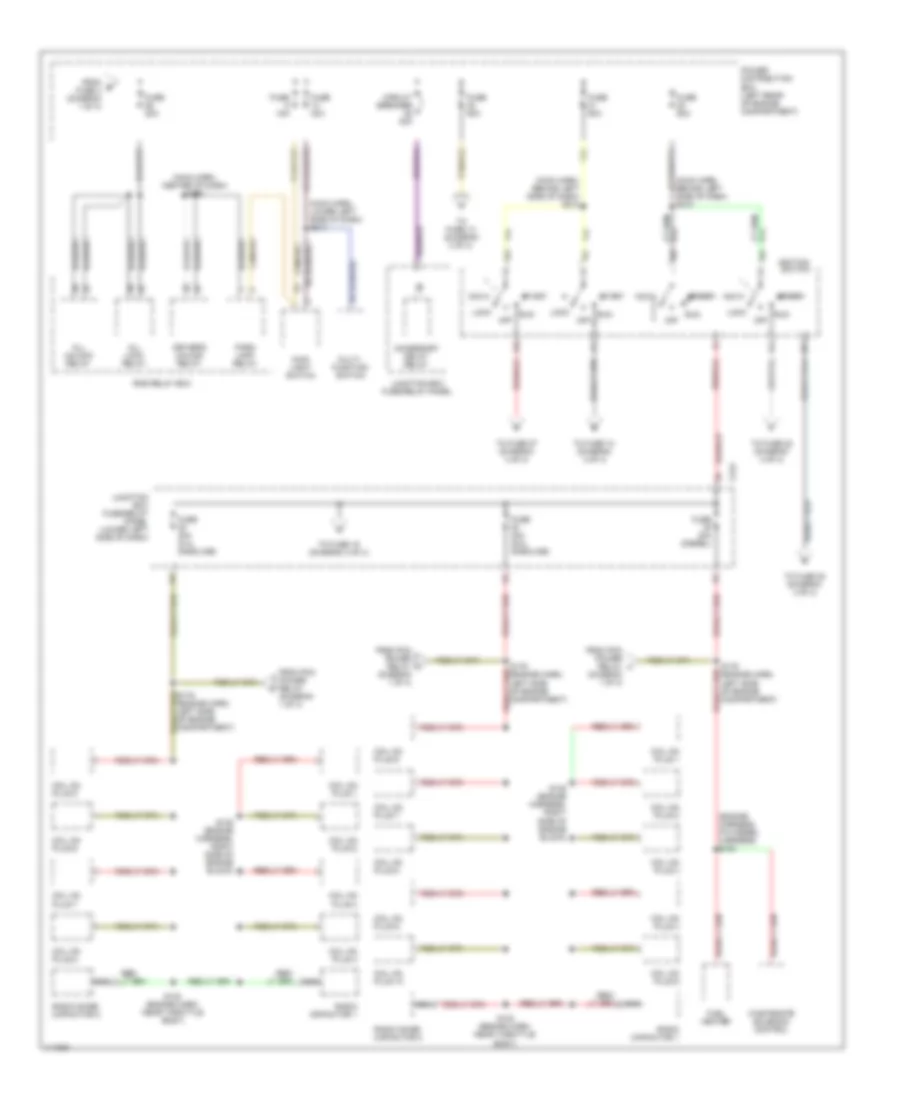
BODY CONTROL MODULES
Body Control Modules Wiring Diagram (1 of 2) for Ford Cab & Chassis F350 Super Duty 1999
List of elements for Body Control Modules Wiring Diagram (1 of 2) for Ford Cab & Chassis F350 Super Duty 1999:
- Accessory delay relay
- Accessory delay relay ctrl
- C241
- C242
- C243
- Circuit breaker 25 30a
- Cruise control system
- Engine controls system
- Fuse 10a
- Fuse 15a
- Fuse 5a
- Fused battery power (b+)
- Fused ignition (acc/run)
- Fused ignition (start)
- G206 (behind center of dash)
- Generic electronic module (gem)
- Head lamp dome switch
- Horn relay
- Horn relay ctrl
- Horns system
- Hot at all times
- Hot in
- Hot in run or acc
- Instrument cluster
- Interior lamp relay
- Interior lamp relay ctrl
- Interior lights system
- Junction box fuse/ relay panel (behind lower left side of dash)
- Lf window motor sense (high)
- Lf window motor sense (low)
- Lf window switch in (down)
- One touch down relay
- One touch down relay ctrl
- One touch down switch in
- Power distribution box (left side of engine compt)
- Power windows system
- S218
- Speed control out
- Start
- Vehicle speed (+)
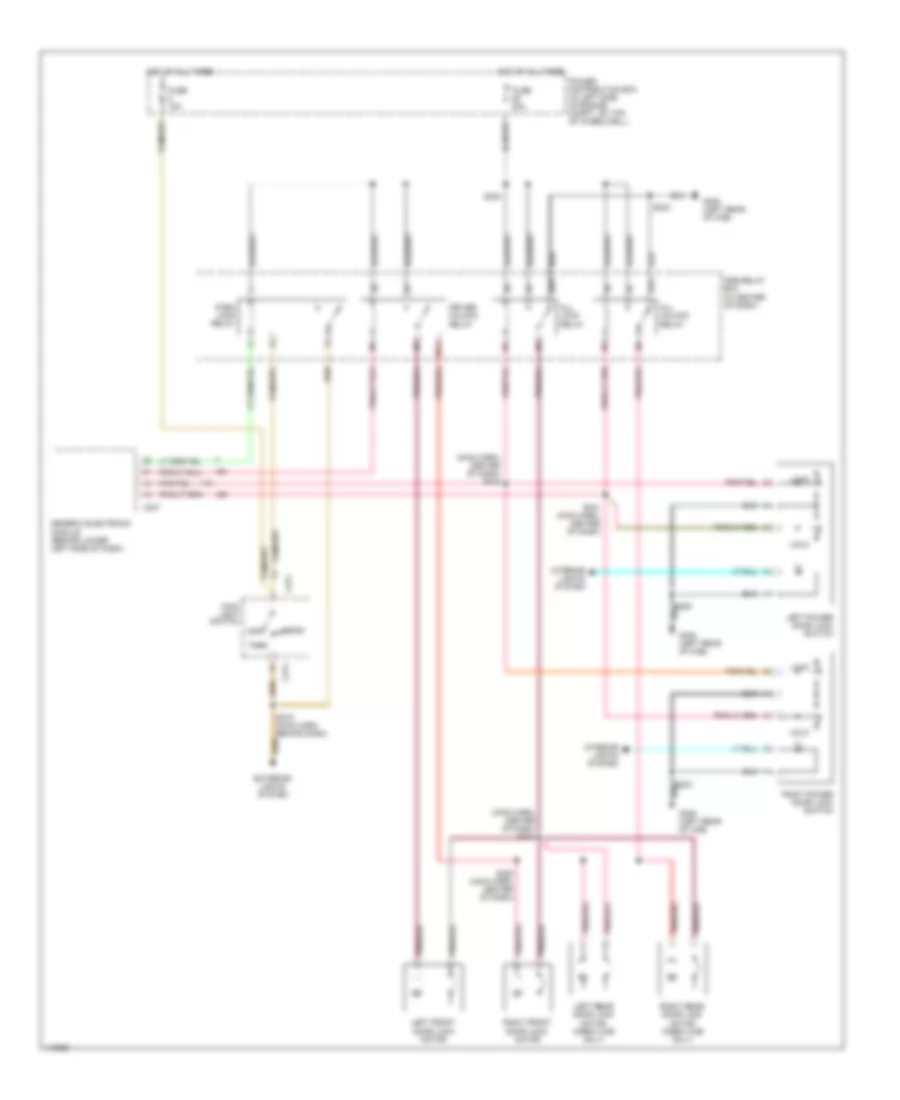
Body Control Modules Wiring Diagram (2 of 2) for Ford Cab & Chassis F350 Super Duty 1999
List of elements for Body Control Modules Wiring Diagram (2 of 2) for Ford Cab & Chassis F350 Super Duty 1999:
- (park/headlamps on) in
- 4 high to 4 low relay ctrl
- 4 low to 4 high relay ctrl
- 4x2 center axle solenoid ctrl
- 4x4 center axle solenoid ctrl
- 4x4 high range ind ctrl
- 4x4 low range ind ctrl
- 4x4 mode switch in
- 4x4 mode switch ref
- Anti-lock brakes sytem (brake fluid level switch)
- Brake fluid level sig
- Brake indicator out
- Brake pedal position switch
- C239
- C243
- C247
- Computer data lines system (datalink pin 7)
- Contact plate a in
- Contact plate b in
- Contact plate c in
- Contact plate p in
- Diagnostic link
- Diesel only
- Door ajar indicator ctrl
- Door locks system (driver unlock relay)
- Door locks system (lock switches)
- Driver unlock relay ctrl
- Exterior lights system (brake pedal position switch)
- Exterior lights system (parklamp relay)
- Fuse 10a
- Fused ignition (run/start)
- G200 (lower left kick panel)
- Generic electronic module (gem) (behind lower left side of dash)
- Ground
- Hot in run or start
- Ignition key warning switch in
- Instrument cluster system
- Interval delay/wash in
- Junction box fuse/relay panel (behind lower left side of dash)
- Lf door ajar switch in
- Lock switch in (lock)
- Lock switch in (unlock)
- Park brake switch (behind left side of dash, on park brake assembly)
- Park brake warning lamp
- Parklamp relay ctrl
- Powertrain control module (left side of firewall)
- Rear door ajar switches in
- Red
- Rf door ajar switch in
- S208
- S213
- S245 (main harn, behind left side of dash)
- Seat belt indicator ctrl
- Seat belt warning switch in
- Signal return
- Tan/red
- Tone request
- Torque on demand relay out
- Trans in neutral in
- Transmission controls system (4 wheel drive mode switch)
- Transmission controls system (4x2 axle disconnect solenoid)
- Transmission controls system (4x4 axle disconnect solenoid)
- Transmission controls system (transfer case assembly)
- Transmission controls system (transfer case shift relays)
- Transmission controls system (transfer case)
- Transmission controls system (transmission range sensor)
- Warning systems (ignition key warning switch)
- Warning systems (lf door ajar switch)
- Warning systems (main light switch)
- Warning systems (rear door ajar switches)
- Warning systems (rf door ajar switch)
- Warning systems (seat belt warning switch)
- Washer pump control
- Wiper hi/lo relay ctrl
- Wiper mode select switch in
- Wiper motor park sense
- Wiper run/park relay ctrl
- Wiper/washer system (hi/lo relay)
- Wiper/washer system (multi-function switch)
- Wiper/washer system (run/park relay)
- Wiper/washer system (washer pump relay)
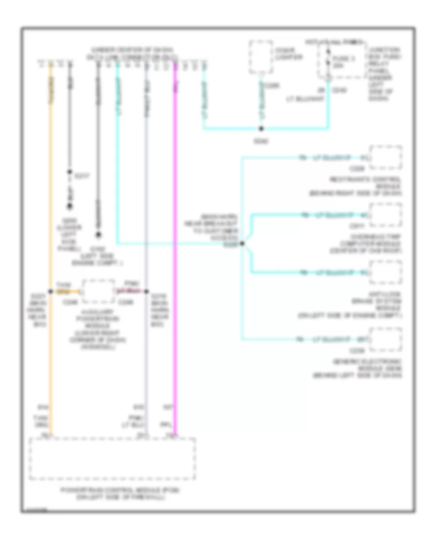
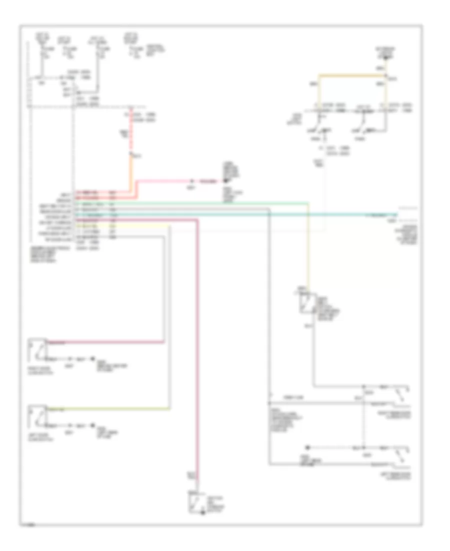
COMPUTER DATA LINES
Computer Data Lines Wiring Diagram for Ford Cab & Chassis F350 Super Duty 1999
List of elements for Computer Data Lines Wiring Diagram for Ford Cab & Chassis F350 Super Duty 1999:
- (main harn, near breakout to customer access) s225
- (under center of dash) data link connector (dlc)
- Anti-lock brake system module (on left side of engine compt)
- Auxiliary powertrain module (lower right corner of dash) (w/diesel)
- C228
- C239
- C242
- C248
- C295
- C911
- Cigar lighter
- Fuse 3 20a
- G102 (left side engine compt.)
- G200 (lower left kick panel)
- Generic electronic module (gem) (behind left side of dash)
- Hot at all times
- Junction box fuse/ relay panel (under left side of dash)
- Overhead trip computer module (center of cab roof)
- Powertrain control module (pcm) (on left side of firewall)
- Restraints control module (behind right side of dash)
- S217
- S219 (main harn. near b/o)
- S221 (main harn. near b/o)
- S242
CRUISE CONTROL
5.4L
5.4L, Cruise Control Wiring Diagram for Ford Cab & Chassis F350 Super Duty 1999
List of elements for 5.4L, Cruise Control Wiring Diagram for Ford Cab & Chassis F350 Super Duty 1999:
- 10a
- 20a
- A/t
- Accel
- Anti-lock brake system (abs) module (in left front of eng compt)
- Brake pedal position (bpp) switch (above brake pedal)
- Brake press in
- Brake pressure switch (on left side of eng compt)
- Brake/clutch sw in
- C242
- C243
- Clock spring
- Clutch pedal position (cpp) switch (above clutch pedal)
- Clutch pedal position (cpp) switch jumper (above clutch pedal)
- Coast
- Differential speed sensor (on center of rear axle)
- Fuse 13
- Fuse 15
- Fuse 28
- G101 (front of right front fender)
- G206 (behind center of dash)
- Generic electronic module (gem)
- Ground
- Horn
- Horn relay
- Hot at all times
- Hot in run
- Junction box fuse/ relay panel
- Junction box fuse/relay panel
- M/t
- Nca
- Off
- Ohms
- Power
- Red/pnk
- Resume
- S115 (engine harn, below brake fluid reservoir)
- S124
- S180
- S201
- S205 (main harness, left of steering column)
- Set/
- Speed control servo/ amplifier assembly (in right side of engine compt)
- Speed control/ horn switch assembly (in steering wheel)
- Speed ctrl sw in
- Speed ctrl sw rtn
- Vss input
- Vss signal
6.8L
6.8L, Cruise Control Wiring Diagram for Ford Cab & Chassis F350 Super Duty 1999
List of elements for 6.8L, Cruise Control Wiring Diagram for Ford Cab & Chassis F350 Super Duty 1999:
- 10a
- 20a
- A/t
- Accel
- Anti-lock brake system (abs) module (in left front of eng compt)
- Brake pedal position (bpp) switch (above brake pedal)
- Brake press in
- Brake pressure switch (on left side of eng compt)
- Brake/clutch sw in
- C242
- C243
- Clock spring
- Clutch pedal position (cpp) switch (above clutch pedal)
- Clutch pedal position (cpp) switch jumper (above clutch pedal)
- Coast
- Differential speed sensor (on center of rear axle)
- Fuse 13
- Fuse 15
- Fuse 28
- G101 (front of right front fender)
- G206 (behind center of dash)
- Generic electronic module (gem)
- Ground
- Horn
- Horn relay
- Hot at all times
- Hot in run
- Junction box fuse/ relay panel
- Junction box fuse/relay panel
- M/t
- Nca
- Off
- Ohms
- Power
- Red/pnk
- Resume
- S115 (engine harn, below brake fluid reservoir)
- S124
- S180
- S201
- S205 (main harness, left of steering column)
- Set/
- Speed control servo/ amplifier assembly (in right side of engine compt)
- Speed control/ horn switch assembly (in steering wheel)
- Speed ctrl sw in
- Speed ctrl sw rtn
- Vss input
- Vss signal
7.3L DI TURBO DIESEL
7.3L DI Turbo Diesel, Cruise Control Wiring Diagram for Ford Cab & Chassis F350 Super Duty 1999
List of elements for 7.3L DI Turbo Diesel, Cruise Control Wiring Diagram for Ford Cab & Chassis F350 Super Duty 1999:
- 10a
- Accel
- Anti-lock brake system (abs) module (in left front of eng compt)
- Brake pedal position (bpp) switch (above brake pedal)
- Brake position in
- Brake press in
- Brake pressure switch (on left side of eng compt)
- C242
- C243
- Clock spring
- Clutch pedal position (cpp) switch (m/t only) (above clutch pedal)
- Clutch position in
- Coast
- Differential speed sensor (on center of rear axle)
- Fuse 15
- Fuse 19
- G206 (behind center of dash)
- Generic electronic module (gem)
- Horn
- Horn relay
- Hot at all times
- Hot in start or run
- Junction box fuse/ relay panel
- Junction box fuse/relay panel
- Nca
- Off
- Ohms
- Pcm power relay
- Power distribution box (left side of engine compt)
- Powertrain control module (on left side of firewall)
- Red
- Red/pnk
- Resume
- S108 (engine harn, near brake pressure switch)
- S115 (engine harn, below brake fluid reservoir)
- S123 (engine harness, left of steering column)
- S201
- S213
- Set/
- Speed control/ horn switch assembly (in steering wheel)
- Speed ctrl sw in
- Speed ctrl sw rtn
- Vss input
- Vss signal
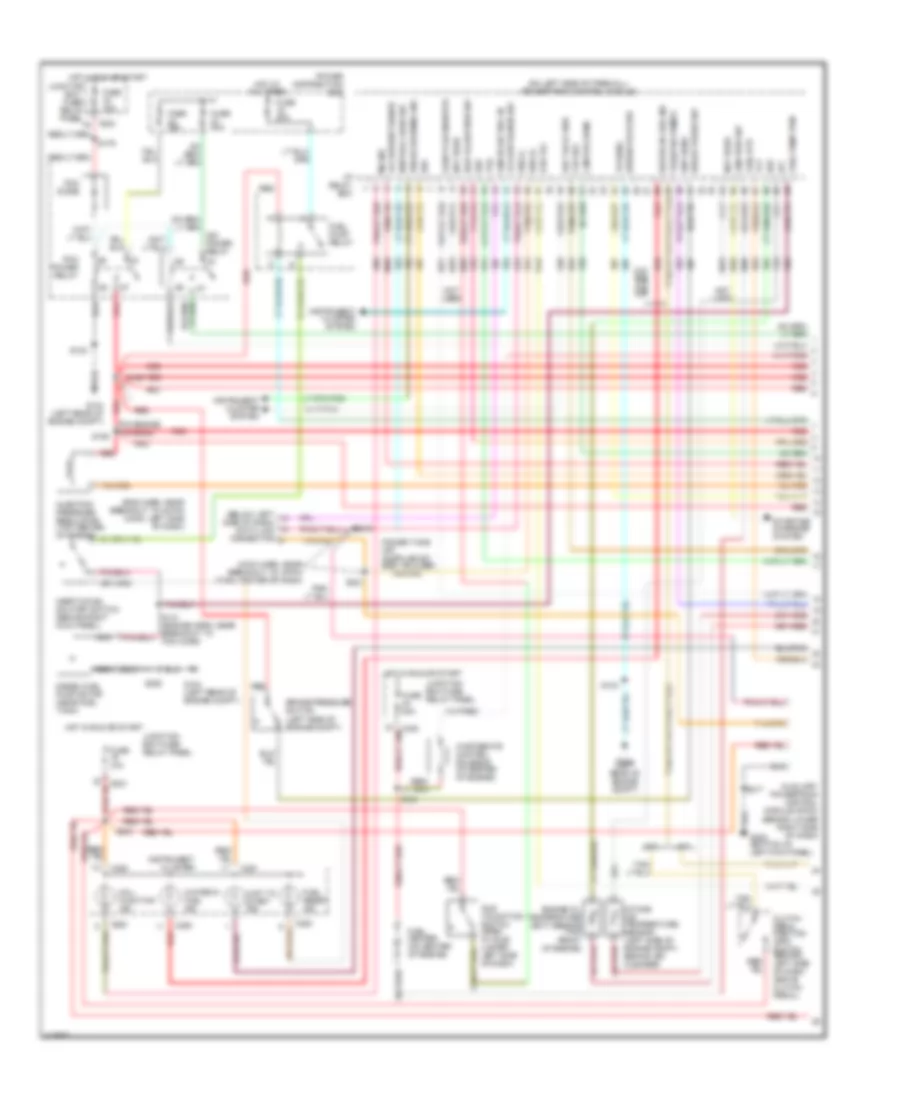
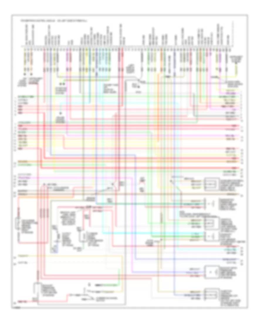
ENGINE PERFORMANCE
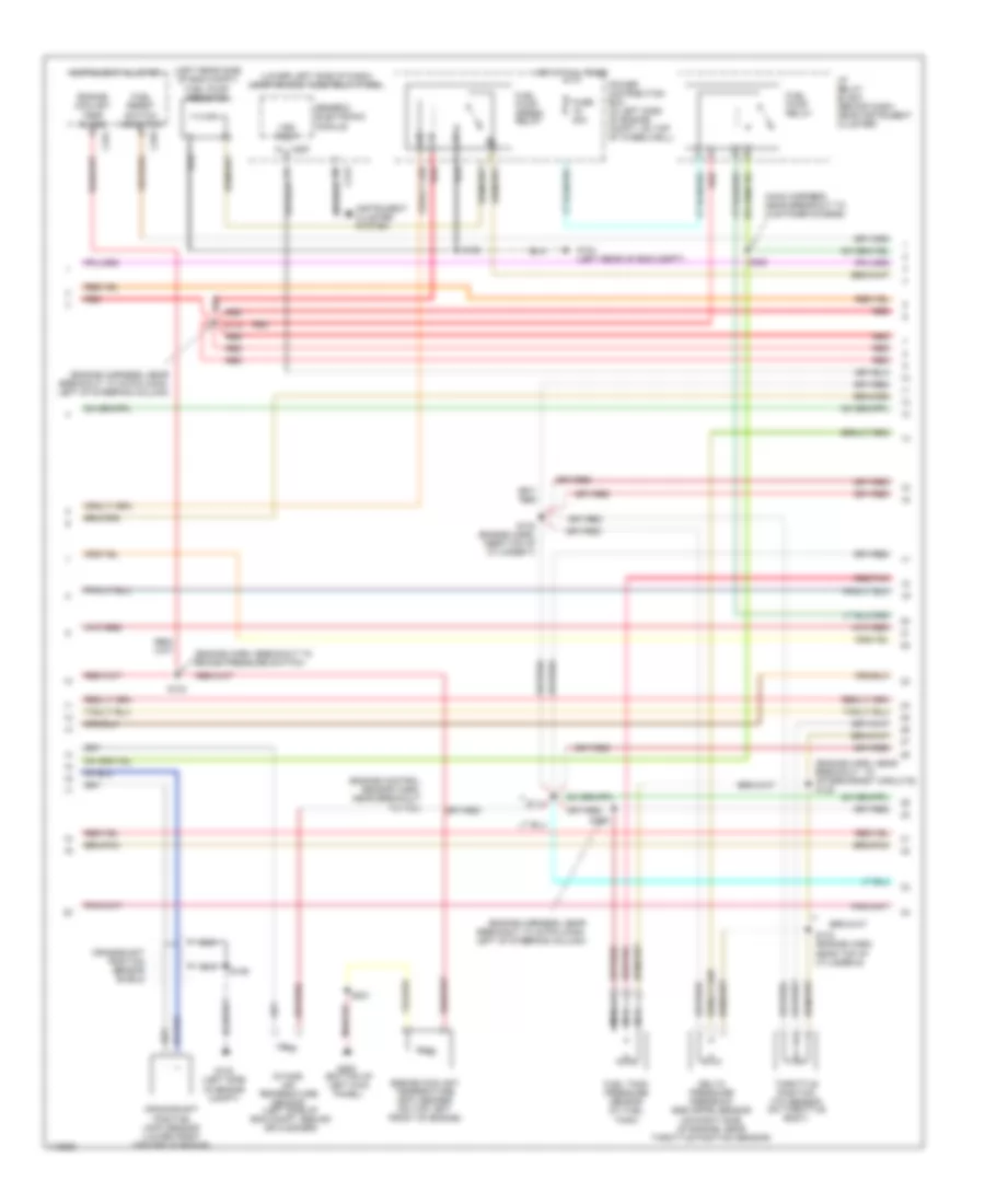
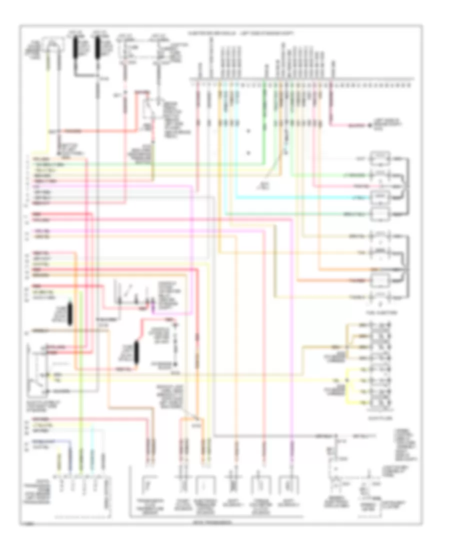
5.4L
5.4L, Engine Performance Wiring Diagram (1 of 4) for Ford Cab & Chassis F350 Super Duty 1999
List of elements for 5.4L, Engine Performance Wiring Diagram (1 of 4) for Ford Cab & Chassis F350 Super Duty 1999:
- (bottom of left kick panel) g200
- (eng sens harn, right side of eng, above cylinder 3)
- (engine harness, near breakout to power distribution box)
- (left rear corner of eng compt) g104
- (left rear corner of engine compt) g104
- (not used)
- (on left side of engine)
- (on right side of engine)
- 4x4 low ind sw
- 820 ohms
- Ac head press sw
- Air conditioning system
- Body computer system
- C243
- C251
- C253
- Ccs
- Ckp(+)
- Ckp(-)
- Data link (+)
- Data link (-)
- Data link connector (dlc) (partial) (behind center of dash)
- Data output
- Diag grd
- Digital transmission range (dtr) sensor (on left side of transmission)
- Egr sol
- Fpsr cntrl
- Fuel gauge in
- Fuel pump mon
- Fuse 10a
- Fuse 20a
- Fuse 30a
- Hego 12
- Hot at all times
- Hot in run or start
- Iat
- Ign coil 1
- Ign coil 3
- Ign coil 5
- Ign coil 6
- Ignition coils
- Instrument cluster
- Instrument cluster system
- Intake manifold
- Intake manifold tunning valve (on top left side of engine)
- Junction box fuse/relay panel (behind lower left side of dash)
- Maf
- Mil ind
- Nca
- Not used
- O/d off
- Overdrive cancel switch (a/t)
- Pcm power diode
- Pcm power relay
- Power distribution box (in left side of engine compt, on top wheelwell)
- Powertrain control module (pcm) (on left side of firewall)
- Pwr gnd
- R n
- Radio noise capacitor
- Radio noise capacitor 2
- Red
- Reprog pwr
- S102
- S103
- S106
- S120
- S130 (engine harn, near breakout to throttle body conn)
- S135
- S201
- S213
- Shift sol 1
- Shift sol 2
- Tach
- Tcs
- Temp output
- Tft
- To dtr sensor (diagram 4 of 4)
- Tr1
- Tr2
- Tr4
- Trans ctrl ind
- Transmission control indicator lamp
- Vss (-)
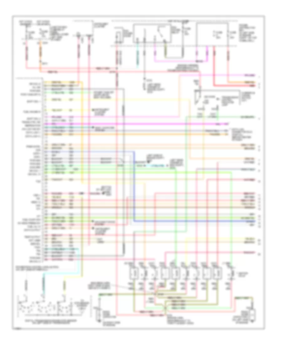
5.4L, Engine Performance Wiring Diagram (2 of 4) for Ford Cab & Chassis F350 Super Duty 1999
List of elements for 5.4L, Engine Performance Wiring Diagram (2 of 4) for Ford Cab & Chassis F350 Super Duty 1999:
- (engine control sensor harn, near breakout to pcm)
- (engine harn, breakout to brake pressure switch)
- (engine harn, near breakout to aftermarket circuits) s128
- (engine harness, near breakout to 40-pin conn, left of steering column)
- (left rear side of eng compt) fuel pump resistor
- (lower left side of dash) junction box fuse/relay panel
- (main harness, near breakout to customer access)
- C251
- C253
- C267
- Crankshaft position (ckp) sensor (lower front center of engine)
- Crankshaft position sensor shield
- Delta pressure feedback egr (dpfe) sensor (on right side of engine, near throttle position sensor)
- Engine coolant temp guage
- Engine coolant temperature (ect) sender (on top left front of engine)
- Fuel pump relay
- Fuel pump speed relay
- Fuel reset switch indicator
- Fuel tank pressure sensor (at fuel tank)
- Fuse 20a
- G102 (left side of engine compt)
- G104 (left rear of eng compt)
- G200 (bottom of left kick panel)
- Generic electronic module
- Hot at all times
- I/p relay block (behind dash, near instrument cluster)
- Instrument cluster
- Instrument cluster system
- Intake air temperature sensor (left side of eng compt, behind air cleaner)
- Nca
- Power distribution box (in left side of engine compt, on top of wheelwell)
- Red
- Red/pnk
- S102
- S104
- S106
- S114
- S123
- S129
- S132 (engine harn, near top of cylinder 7)
- S133 (engine harn, near top of cylinder 6)
- S201
- S226
- Throttle position (tp) sensor (on throttle body)
- Vss input
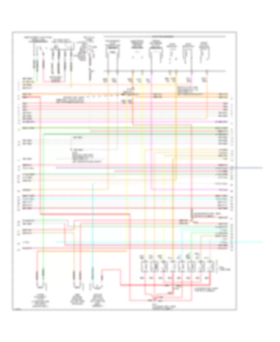
5.4L, Engine Performance Wiring Diagram (3 of 4) for Ford Cab & Chassis F350 Super Duty 1999
List of elements for 5.4L, Engine Performance Wiring Diagram (3 of 4) for Ford Cab & Chassis F350 Super Duty 1999:
- (at fuel tank) fuel pump module
- (backup lamp harn, near breakout to 16-pin conn, in left side of eng compt)
- (behind right kick panel) inertia fuel shut-off switch
- (engine harn, near breakout to 40-pin conn, left of steering column)
- (engine sens harn, near top of cylinder 8)
- (in engine harn, near top of cylinder 3)
- (in rear center of engine compartment)
- 4r100 transmission
- Coast clutch solenoid
- Egr control solenoid (on left side of engine)
- Electronic pressure control solenoid
- Fuel injectors
- Fuse 5a
- Hot at all times
- Idle air control (iac) valve (on throttle body assembly)
- Instrument cluster system
- Junction box fuse/ relay panel (behind lower left side of dash)
- Nca
- Red
- Red/pnk
- S122
- S131 (in engine harn, near top of cylinder 7)
- S134
- S136
- S138
- S139 (backup lamp harn, near breakout to 16-pin conn, in left side of engine compt)
- Shift solenoid 1
- Shift solenoid 2
- Tan
- Tan/ red
- Tan/red
- Torque converter clutch solenoid
- Transmission fluid temperature sensor
- Vapor managment valve
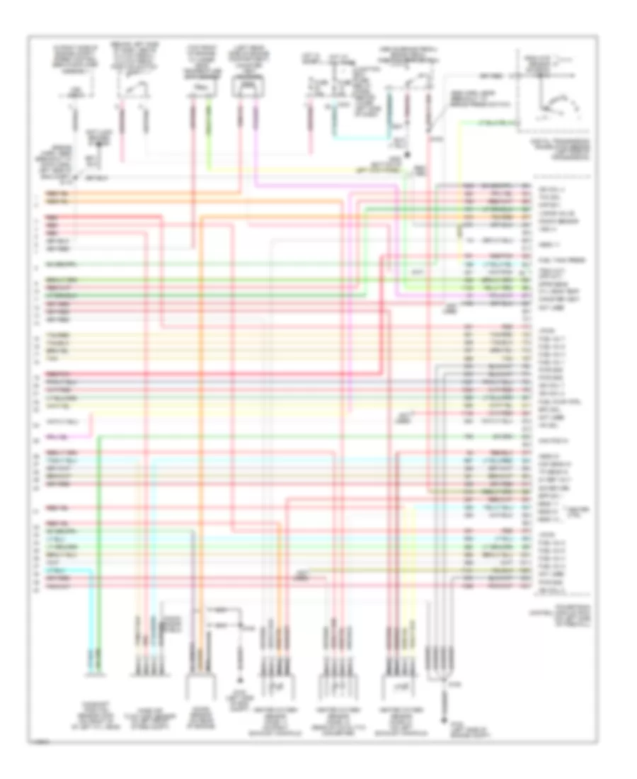
5.4L, Engine Performance Wiring Diagram (4 of 4) for Ford Cab & Chassis F350 Super Duty 1999
List of elements for 5.4L, Engine Performance Wiring Diagram (4 of 4) for Ford Cab & Chassis F350 Super Duty 1999:
- (a/t)
- (above brake pedal) brake pedal position (bpp) switch
- (behind left side of dash, above clutch pedal) clutch pedal position switch (m/t)
- (eng harn, near breakout to brake press switch)
- (engine harn, near breakout to 16-pin conn, left side of eng compt) s115
- (in right side of engine compt) speed control servo/amplifier assembly
- (left rear side of engine compartment) canister vent solenoid
- (m/t)
- (not used)
- (top front of engine) cylinder head temperature (cht) sensor
- 5v ref volt
- Anti-lock brakes system
- Bpp sw
- Cam pos in
- Camshaft position sensor (cmp) (on front of of left cyl head)
- Canister vent
- Cyl head temp
- Digital transmission range (dtr) sensor (left side of transmission)
- Dpfe sens
- Epc sol
- From dtr sensor (diagram 1 of 4)
- Fuel inj 1
- Fuel inj 2
- Fuel inj 3
- Fuel inj 4
- Fuel inj 5
- Fuel inj 6
- Fuel inj 7
- Fuel inj 8
- Fuel pump ctrl
- Fuel tank press
- Fuse 15a
- Fuse 5a
- G102 (left side of eng compt)
- G102 (left side of engine compt)
- G200 (bottom of left kick panel)
- Heated oxygen sensor (ho2s) 11 (on right exhaust manifold)
- Heated oxygen sensor (ho2s) 12 (rear of catalytic converter)
- Heated oxygen sensor (ho2s) 21 (on left exhaust manifold)
- Heater ctrl
- Hego 11
- Hego 12
- Hego 21
- Hot at all times
- Hot in start
- Iac sol
- Ign coil 2
- Ign coil 4
- Ign coil 7
- Ign coil 8
- Junction box fuse/ relay panel (behind lower left side of dash)
- Kap b(+)
- Knock sensor
- Knock sensor (on rear of engine)
- Knock sensor shield
- Maf sens in
- Mass air flow (maf) sensor (in left front of eng compt)
- Nca
- Not used
- Powertrain control module (pcm) (on left side of firewall)
- Pwr gnd
- Red
- Red/pnk
- S106
- S108
- S201
- Sig return
- Tan
- Tan/red
- Tcc sol
- Tp sens in
- Tr3a (a/t) cpp (m/t)
- Vapor valve
- Vpwr
- Vss (+)
- Vss input
6.8L
6.8L, Engine Performance Wiring Diagram (1 of 4) for Ford Cab & Chassis F350 Super Duty 1999
List of elements for 6.8L, Engine Performance Wiring Diagram (1 of 4) for Ford Cab & Chassis F350 Super Duty 1999:
- (bottom of left kick panel) g200
- (eng sens harn, right side of eng, above cylinder 3)
- (engine harness, near breakout to power distribution box)
- (left rear corner of eng compt) g104
- (left rear corner of engine compt) g104
- (not used)
- (on left side of engine)
- (on right side of engine)
- 4x4 low ind sw
- 820 ohms
- Ac head press sw
- Air conditioning system
- Body computer system
- C243
- C251
- C253
- Ccs
- Ckp(+)
- Ckp(-)
- Data link (+)
- Data link (-)
- Data link connector (dlc) (partial) (behind center of dash)
- Data output
- Diag grd
- Digital transmission range (dtr) sensor (on left side of transmission)
- Egr sol
- Fpsr cntrl
- Fuel gauge in
- Fuel inj 10
- Fuel pump mon
- Fuse 10a
- Fuse 20a
- Fuse 30a
- Hego 12
- Hot at all times
- Hot in run or start
- Iat
- Ign coil 1
- Ign coil 10
- Ign coil 5
- Ign coil 6
- Ignition coils
- Instrument cluster
- Instrument cluster system
- Junction box fuse/relay panel (behind lower left side of dash)
- Maf
- Mil ind
- Nca
- Not used
- O/d off
- Overdrive cancel switch (a/t)
- Pcm power diode
- Pcm power relay
- Power distribution box (in left side of engine compt, on top wheelwell)
- Powertrain control module (pcm) (on left side of firewall)
- Pwr gnd
- Pwr take off in
- R n
- Radio noise capacitor
- Radio noise capacitor 2
- Red
- Red/
- Reprog pwr
- S102
- S103
- S106
- S120
- S130 (engine harn, near breakout to throttle body conn)
- S135
- S201
- S213
- Shift sol 1
- Shift sol 2
- Tach
- Tcs
- Temp output
- Tft
- To dtr sensor (diagram 4 of 4)
- Tr1
- Tr2
- Tr4
- Trans ctrl ind
- Transmission control indicator lamp
- Vss (-)
6.8L, Engine Performance Wiring Diagram (2 of 4) for Ford Cab & Chassis F350 Super Duty 1999
List of elements for 6.8L, Engine Performance Wiring Diagram (2 of 4) for Ford Cab & Chassis F350 Super Duty 1999:
- (engine control sensor harn, near breakout to pcm)
- (engine harn, breakout to brake pressure switch)
- (engine harn, near breakout to aftermarket circuits) s128
- (engine harness, near breakout to 40-pin conn, left of steering column)
- (left rear side of eng compt) fuel pump resistor
- (lower left side of dash) junction box fuse/relay panel
- (main harness, near breakout to customer access)
- C251
- C253
- C267
- Crankshaft position (ckp) sensor (lower front center of engine)
- Crankshaft position sensor shield
- Delta pressure feedback egr (dpfe) sensor (on right side of engine, near throttle position sensor)
- Engine coolant temp guage
- Engine coolant temperature (ect) sender (on top left front of engine)
- Fuel pump relay
- Fuel pump speed relay
- Fuel reset switch indicator
- Fuel tank pressure sensor (at fuel tank)
- Fuse 20a
- G102 (left side of engine compt)
- G104 (left rear of eng compt)
- G200 (bottom of left kick panel)
- Generic electronic module
- Hot at all times
- I/p relay block (behind dash, near instrument cluster)
- Instrument cluster
- Instrument cluster system
- Intake air temperature sensor (left side of eng compt, behind air cleaner)
- Nca
- Power distribution box (in left side of engine compt, on top of wheelwell)
- Red
- Red/pnk
- S102
- S104
- S106
- S114
- S123
- S129
- S132 (engine harn, near top of cylinder 7)
- S133 (engine harn, near top of cylinder 6)
- S201
- S226
- Throttle position (tp) sensor (on throttle body)
- Vss input
6.8L, Engine Performance Wiring Diagram (3 of 4) for Ford Cab & Chassis F350 Super Duty 1999
List of elements for 6.8L, Engine Performance Wiring Diagram (3 of 4) for Ford Cab & Chassis F350 Super Duty 1999:
- (at fuel tank) fuel pump module
- (backup lamp harn, near breakout to 16-pin conn, in left side of eng compt)
- (behind right kick panel) inertia fuel shut-off switch
- (engine harn, near breakout to 40-pin conn, left of steering column)
- (engine sens harn, near top of cylinder 8)
- (in engine harn, near top of cylinder 3)
- (in rear center of engine compartment)
- 4r100 transmission
- Coast clutch solenoid
- Egr control solenoid (on left side of engine)
- Electronic pressure control solenoid
- Fuel injectors
- Fuse 5a
- Hot at all times
- Idle air control (iac) valve (on throttle body assembly)
- Instrument cluster system
- Junction box fuse/ relay panel (behind lower left side of dash)
- Nca
- Red
- Red/pnk
- S122
- S131 (in engine harn, near top of cylinder 7)
- S134
- S136
- S138
- S139 (backup lamp harn, near breakout to 16-pin conn, in left side of engine compt)
- Shift solenoid 1
- Shift solenoid 2
- Tan
- Tan/ red
- Tan/red
- Torque converter clutch solenoid
- Transmission fluid temperature sensor
- Vapor managment valve
6.8L, Engine Performance Wiring Diagram (4 of 4) for Ford Cab & Chassis F350 Super Duty 1999
List of elements for 6.8L, Engine Performance Wiring Diagram (4 of 4) for Ford Cab & Chassis F350 Super Duty 1999:
- (a/t)
- (above brake pedal) brake pedal position (bpp) switch
- (behind left side of dash, above clutch pedal) clutch pedal position switch (m/t)
- (eng harn, near breakout to brake press switch)
- (engine harn, near breakout to 16-pin conn, left side of eng compt) s115
- (in right side of engine compt) speed control servo/amplifier assembly
- (left rear side of engine compartment) canister vent solenoid
- (m/t)
- (top front of engine) cylinder head temperature (cht) sensor
- 5v ref volt
- Anti-lock brakes system
- Bpp sw
- Cam pos in
- Camshaft position sensor (cmp) (on front of of left cyl head)
- Canister vent
- Cyl head temp
- Digital transmission range (dtr) sensor (left side of transmission)
- Dpfe sens
- Epc sol
- From dtr sensor (diagram 1 of 4)
- Fuel inj 1
- Fuel inj 2
- Fuel inj 3
- Fuel inj 4
- Fuel inj 5
- Fuel inj 6
- Fuel inj 7
- Fuel inj 8
- Fuel inj 9
- Fuel pump ctrl
- Fuel tank press
- Fuse 15a
- Fuse 5a
- G102 (left side of eng compt)
- G102 (left side of engine compt)
- G200 (bottom of left kick panel)
- Heated oxygen sensor (ho2s) 11 (on right exhaust manifold)
- Heated oxygen sensor (ho2s) 12 (rear of catalytic converter)
- Heated oxygen sensor (ho2s) 21 (on left exhaust manifold)
- Heater ctrl
- Hego 11
- Hego 12
- Hego 21
- Hot at all times
- Hot in start
- Iac sol
- Ign coil 2
- Ign coil 3
- Ign coil 4
- Ign coil 7
- Ign coil 8
- Ign coil 9
- Junction box fuse/ relay panel (behind lower left side of dash)
- Kap b(+)
- Knock sensor
- Knock sensor (on rear of engine)
- Knock sensor shield
- Maf sens in
- Mass air flow (maf) sensor (in left front of eng compt)
- Nca
- Powertrain control module (pcm) (on left side of firewall)
- Pwr gnd
- Red
- Red/pnk
- S106
- S108
- S201
- Sig return
- Tan
- Tan/red
- Tcc sol
- Tp sens in
- Tr3a (a/t) cpp (m/t)
- Vapor valve
- Vpwr
- Vss (+)
- Vss input
7.3L DI TURBO DIESEL
7.3L DI Turbo Diesel, Engine Performance Wiring Diagram (1 of 3) for Ford Cab & Chassis F350 Super Duty 1999
List of elements for 7.3L DI Turbo Diesel, Engine Performance Wiring Diagram (1 of 3) for Ford Cab & Chassis F350 Super Duty 1999:
- (behind lower right side of dash)
- (below left side of dash) data link connector
- (eng harn, near breakout to 40-pin conn, left side of dash)
- (left side of engine compt)
- (main harn, near breakout to 16-pin conn, center of dash)
- (on left side of firewall) powertrain control module
- (pia engine harness)
- 224 (a/t) 306 (m/t)
- 4x4 low range sw
- A/t
- Aux tach feed
- Auxiliary powertrain control module (apcm)
- Brake press sw
- Brake pressure switch
- Brake warning ind
- Bus (+)
- Bus (-)
- C243
- C250
- C251
- C253
- Cam pos sens
- Ccs sol
- Clutch pedal position (cpp) switch (behind left side of dash, above clutch pedal)
- Diesel fuel pump motor (near fuel tank)
- Dtr-tr1
- Ebp sens
- Engine oil temperature (eot) sensor (top front of engine)
- Eot
- Fuel heater (on center of engine)
- Fuel htr
- Fuel pump pwr
- Fuel pump relay
- Fuel reset ind
- Fuse 10a
- Fuse 20a
- Fuse 30a
- G104 (left rear of engine compt)
- G200 (bottom of left kick panel)
- Gen pwr sw
- Gen scan tool in
- Glow plug monitor
- Hot at all times
- Hot in run or start
- I/p relay box
- Iat
- Idle validation sw
- Idle validation switch (open at idle) (lower left side of dash)
- Idm power relay
- Inertia fuel shutoff switch (behind right kick panel)
- Injection pressure regulator (top center of engine)
- Instrument cluster
- Instrument cluster system
- Intake air temperature sensor (left side of engine compt, behind air cleaner)
- Junction box fuse/ relay panel
- Lo current sense
- M/t
- Mal- function ind
- Mil ind
- Nca
- Neutral gear sw
- Not used
- Pcm diode
- Pcm power relay
- Power distribution box
- Red
- Red s123
- S102
- S103
- S141 (engine harn, near breakout to pcm conn)
- S154
- S158
- S179
- S213
- S217
- S219
- S221
- S250
- Speed/tach grd
- Ss1
- Ss2
- Starting/ charging system
- Tcil
- Tcs(a/t)/cpp(m/t)
- Tft
- Tp sens
- Wait to start ind
- Wastegate control solenoid (in center of engine)
- Water in fuel ind
7.3L DI Turbo Diesel, Engine Performance Wiring Diagram (2 of 3) for Ford Cab & Chassis F350 Super Duty 1999
List of elements for 7.3L DI Turbo Diesel, Engine Performance Wiring Diagram (2 of 3) for Ford Cab & Chassis F350 Super Duty 1999:
- (backup lamp harn, near breakout to 16-pin conn, left side of eng compt)
- (eng ctrl harn)
- (engine harness)
- (in pia engine harn)
- (in pia engine harness)
- (left side of engine compt)
- (main harn, near air bag diag mod)
- (on left side of firewall)
- A/c head pres sw
- Accelerator pedal position sensor (under left side of dash, above brake pedal)
- Accl pos sens
- Act sens
- Air charge temperature sensor (center front of engine)
- Air condi- tioning system
- Baro sens
- Barometric pressure (baro) sensor (below left side of dash)
- Bpp sw
- Camshaft position (cmp) sensor (lower front center of engine)
- Charge ind
- Cid sig
- Cmp rtn
- Cruise control system
- Data output link
- Diesel elect drv
- Dtr-tr2
- Dtr-tr3a
- Dtr-tr4
- Epc sol
- Epr
- Exhaust back pressure (ebp) sensor (center rear of engine)
- Exhaust pressure regulator (top center of engine)
- Fuel deliv sig
- Fuel pump rly
- Fuel pump sender
- G102
- Gen pwr
- Glow plug ctrl
- Icp sens
- Idm enable out
- Injection control pressure (icp) sensor (on top left side of engine, right of alternator)
- Instrument cluster system
- Ipr sens
- Manifold absolute pressure (map) sensor (on right side of firewall)
- Map sens
- Nca
- Not used
- Oss sens
- Output shaft speed sensor (on top of trans)
- Overdrive cancel switch
- Pcm to rly
- Power take off (supp by body bldr)
- Powertrain control module
- Pwr
- Pwr gnd
- Pwr in
- Red
- S106
- S114
- S128
- S139
- S151
- S153
- S208
- S222 (main harn, near breakout to 2-pin conn, left side of dash)
- Sig rtn
- Speed ctrl sw
- Starting/ charging system
- Take off pwr in
- Tcc
- Tcil
- Tcs
- Tss sens
- Turbine shaft speed (tss) sensor (on top of trans)
- Vref
- Vss (+)
- Wait to start ind
- Wcs sol
7.3L DI Turbo Diesel, Engine Performance Wiring Diagram (3 of 3) for Ford Cab & Chassis F350 Super Duty 1999
List of elements for 7.3L DI Turbo Diesel, Engine Performance Wiring Diagram (3 of 3) for Ford Cab & Chassis F350 Super Duty 1999:
- (backup lamp harn, near breakout to 16-pin conn left side of eng compt)
- (bottom of left kick panel) g202
- (left side of engine compt)
- (left side of engine compt) g102
- (on engine block)
- (right side of eng compt)
- 4r100 transmission
- Brake pedal position switch (behind left side of dash, above brake pedal)
- C241
- C243
- C253
- Cid sig in
- Coast clutch solenoid
- Digital transmission range (dtr) sensor (left side of transmission)
- Elect feed back sig
- Electronic pressure control solenoid
- Fuel delivery sig
- Fuel gauge sender (at fuel tank)
- Fuel inj feed
- Fuel injector 1
- Fuel injector 2
- Fuel injector 3
- Fuel injector 4
- Fuel injector 5
- Fuel injector 6
- Fuel injector 7
- Fuel injector 8
- Fuel injectors
- Fuse 5a
- G132
- Generic electronic module (gem)
- Glow plug relay (top right side of engine)
- Glow plugs
- Hot at all times
- Inj shield gnd
- Injector driver module
- Instrument cluster
- Junction box fuse/ relay panel
- Junction box fuse/relay panel
- Manifold intake air heater (58 amp)
- Manifold intake air heater relay (center of engine compt)
- Nca
- P, 2, 1
- P, r, 2
- P, r, 2, 1
- P, r, n
- Pwr gnd
- Pwr in
- Red
- S108 (eng harn near brake pressure switch)
- S115
- S138
- S148
- S149
- S155 (pia engine harness)
- S156 (pia engine harness)
- S211
- Shift solenoid 1
- Shift solenoid 2
- Sig rtn
- Signal return
- Speed control servo/ amplifier assembly
- Speedo- meter
- Tan
- Tan/red
- Torque converter clutch solenoid
- Transmission fluid temperature sensor
EXTERIOR LIGHTS
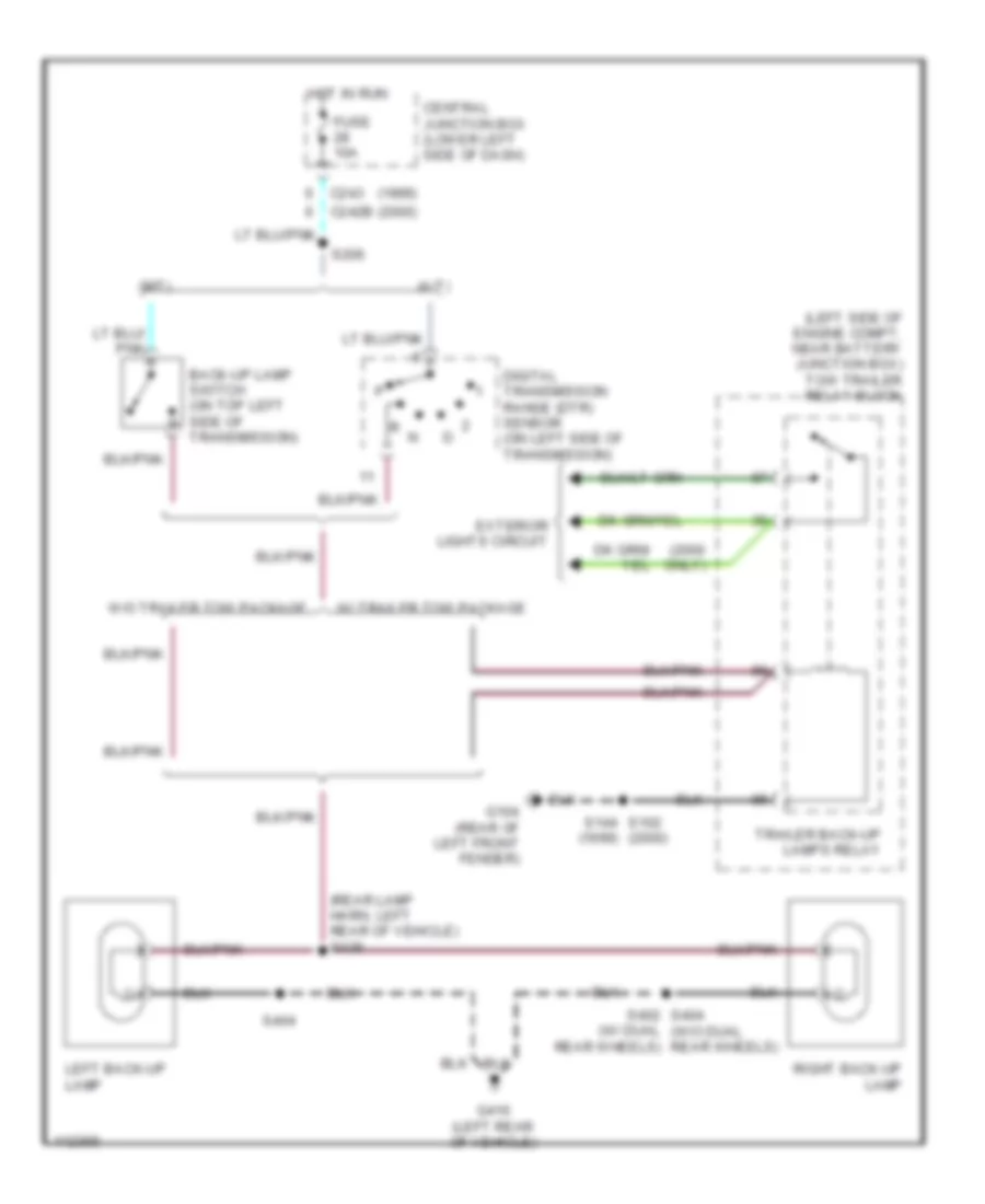
Back-up Lamps Wiring Diagram for Ford Cab & Chassis F350 Super Duty 1999
List of elements for Back-up Lamps Wiring Diagram for Ford Cab & Chassis F350 Super Duty 1999:
- (1999)
- (2000 only)
- (2000)
- (a/t)
- (left side of engine compt, near battery junction box) tow trailer relay block
- (m/t)
- (rear lamp harn, left rear of vehicle) s426
- (w/ dual rear wheels)
- Back-up lamp switch (on top left side of transmission)
- C242b
- C243
- Central junction box (lower left side of dash)
- Digital transmission range (dtr) sensor (on left side of transmission)
- Exterior lights circuit
- Fuse 10a
- G104 (rear of left front fender)
- G416 (left rear of vehicle)
- Hot in run
- Left back-up lamp
- Right back-up lamp
- S144 s102 (2000)
- S206
- S402 s404 (w/o dual rear wheels)
- S404
- Trailer back-up lamps relay
- W/ trailer tow package
- W/o trailer tow package
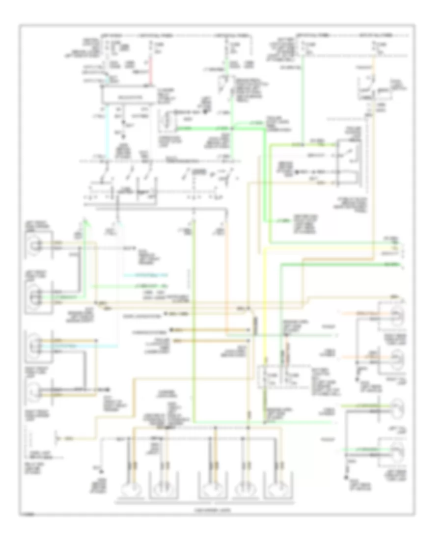
Exterior Lamps & Trailer connector Wiring Diagram (1 of 2) for Ford Cab & Chassis F350 Super Duty 1999
List of elements for Exterior Lamps & Trailer connector Wiring Diagram (1 of 2) for Ford Cab & Chassis F350 Super Duty 1999:
- (1999)
- (1999) (2000)
- (2000 lariat) left side of (center of windshield header) s903
- (2000)
- (behind center of dash) g206
- (engine harn, left side of dash) s110
- (engine harn, left side of dash) s112
- (left rear of cab) g308
- (marker lamp harn)
- 87a
- Battery junction box (in left side of engine compt, on top of wheelwell)
- Brake pedal position switch (behind left side of dash, above brake pedal)
- C242
- C242a
- C242b
- C243
- C250b
- C251
- Cab & chassis
- Cab marker lamps
- Cargo/high mount stop lamp
- Central junction box (behind lower left side of dash)
- Door locks system
- Feed (under dash)
- Flasher relay (i/p relay block)
- Fuse 10a
- Fuse 15a
- Fuse 20a
- Fuse 7.5a
- G101 (front of right front fender)
- G104 (rear of left front fender)
- G206 (behind center of dash)
- G416 (left rear of vehicle)
- Hazard switch
- Head
- Hot at all times
- Hot in run
- I/p relay block (behind dash, near instrument panel)
- Instrument cluster
- Lamp feed (left rear of chassis)
- Left
- Left front park/turn lamp
- Left front side marker lamp
- Left rear park/stop/ turn lamp
- Left tail lamp
- Main light switch
- Multi- function switch
- Off
- Park
- Park lamp relay
- Pickup
- Relay box (center of dash)
- Right
- Right front park/turn lamp
- Right front side marker lamp
- Right rear park/stop/ turn lamp
- Right tail lamp
- S102
- S107 (engine harn, left side of engine compt)
- S109
- S180
- S215 (main harn, behind dash)
- S217
- S217 (2000)
- S240 (main harn, behind left side of dash)
- S300
- S404
- S904
- S920 (2000 lariat)
- Solid state
- Trailer illumination feed (under dash)
- Trailer running lamp relay
- Turn switch
- Warning systems
- Windshield header) s921
Exterior Lamps & Trailer connector Wiring Diagram (2 of 2) for Ford Cab & Chassis F350 Super Duty 1999
List of elements for Exterior Lamps & Trailer connector Wiring Diagram (2 of 2) for Ford Cab & Chassis F350 Super Duty 1999:
- (1999)
- (2000)
- (left rear of chassis) rpo trailer tow adapter (7 wire)
- (left rear of chassis) trailer/camper adapter
- (left side of engine compt, near battery junction box) tow trailer relay block
- (rear lamp harness, center rear of vehicle) s417
- (rear of left frt fender) g104
- (trailer feed harn, under rear of vehicle)
- (trailer feed harn, under rear of vehicle) s432
- Battery junction box (in left side of engine compt, on top of wheelwell)
- C242b
- C243
- Central junction box (behind lower left side of dash)
- Exterior lights system (backup lamps)
- Fuse 10a
- Fuse 30a
- G104 (rear of left frt fender)
- G206 (behind center of dash)
- G416 (left rear of vehicle)
- Hot at all times
- Hot in run
- I/p relay block (near center of dash)
- Left front side marker lamp
- Left license lamp
- Left rear park/stop/ turn lamp
- Left rear side marker lamp
- License lamp
- Nca
- Rear body marker lamps
- Red
- Right front side marker lamp
- Right license lamp
- Right rear park/stop/ turn lamp
- Right rear side marker lamp
- S102
- S235
- S290
- S401
- S402
- S403
- S404
- S417 (rear lamp harness, center rear of vehicle)
- S418 (license lamp harn, center rear of vehicle)
- S430
- S431
- S433
- Trailer backup lamps relay
- Trailer battery charge relay
- Trailer battery feed (under dash)
- Trailer electronic brakes feed (under dash)
- W/ dual rear wheels
- W/ rear bumper
- W/o dual rear wheels
- W/o rear bumper
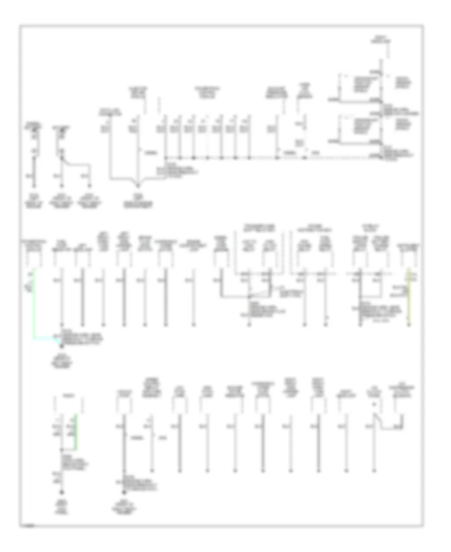
GROUND DISTRIBUTION
Ground Distribution Wiring Diagram (1 of 3) for Ford Cab & Chassis F350 Super Duty 1999
List of elements for Ground Distribution Wiring Diagram (1 of 3) for Ford Cab & Chassis F350 Super Duty 1999:
- (diesel) battery
- 5.4l
- 5.4l, 6.8l
- 6.8l
- 87a
- A/c clutch diode
- A/c compressor clutch solenoid
- Bare
- Battery
- Blower motor resistor
- Brake fluid level switch
- Crankshaft position sensor shield
- Data link connector
- Diesel
- Diesel fuel pump motor
- Engine compartment lamp
- Exhaust pressure regulator
- Fuel pump resistor
- Fuel pump speed relay
- G101 (front of right front fender)
- G102 (left side of engine compartment)
- G104 (rear of left front fender)
- G110 (left front of engine)
- G203 (right kick panel)
- Gas
- High pitch horn
- High to low relay
- I/p relay block
- Injector driver module
- Instrument cluster
- Knock sensor shield
- Left front park/ turn lamp
- Left front side marker lamp
- Left headlamp
- Low pitch horn
- Low to high relay
- Mass air flow sensor
- Nca
- Pcm power relay
- Power distribution box
- Powertrain control module
- Radio
- Right front park/ turn lamp
- Right front side marker lamp
- Right headlamp
- S145 (engine harn, near air cleaner)
- S147 (engine harn, near breakout to pcm)
- S250 (engine harn, near brake fluid reservoir)
- S258 (main harn, behind right kick panel)
- Speed control servo/ amplifier assembly
- Trailer backup lamps relay
- Trailer battery charge relay
- Transfer case shift relay box
- Vacuum pump
- W/ electronic shift ctrl
- Windshield wiper motor
- Windshield wiper pump motor
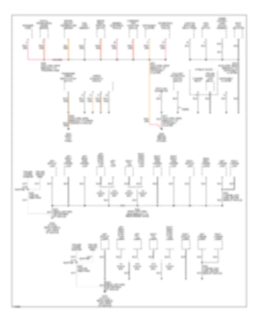
Ground Distribution Wiring Diagram (2 of 3) for Ford Cab & Chassis F350 Super Duty 1999
List of elements for Ground Distribution Wiring Diagram (2 of 3) for Ford Cab & Chassis F350 Super Duty 1999:
- Adapter
- Airbag diagnostic module
- Auxiliary powertrain control module
- Brake pedal position switch
- Data link connector
- Diesel
- Digital transmission range sensor
- Engine coolant temperature sender
- Flasher relay
- Fuel tank assembly
- G203 (right kick panel)
- G206 (behind center of dash)
- G416 (w/ dual rear wheels) (left rear of vehicle)
- G416 (w/o dual rear wheels) (left rear of vehicle)
- Generic electronic module
- I/p relay block
- Instrument cluster
- Junction box fuse/ relay panel
- Left backup lamp
- Left front side marker lamp
- Left license lamp
- Left rear park/ stop/ turn lamp
- Left rear side marker lamp
- Left tail lamp
- Main light switch
- Nca
- Overhead trip computer module
- Passenger airbag deactivation switch
- Powertrain control module
- Rear body marker lamps
- Right backup lamp
- Right front side marker lamp
- Right license lamp
- Right rear park/ stop/ turn lamp
- Right rear side marker lamp
- Right tail lamp
- S201 (main harn, near breakout to instrument cluster)
- S202 (main harn, near breakout to airbag diagnostic module)
- S218 (main harn, near breakout to instrument cluster)
- S255 (main harn, near breakout to transfer case)
- S402 (rear lamp harn, near breakout to rear marker lamps)
- S403 (license lamp harn, center rear of vehicle)
- S432 (trailer feed harn)
- Shift lock actuator
- Speed control/ horn switch assembly
- Trailer ground feed
- Trailer running lamp relay
- Trailer/ camper adapter
- Transfer case
- W/ adapter
- W/ pickup box
- W/o pickup box
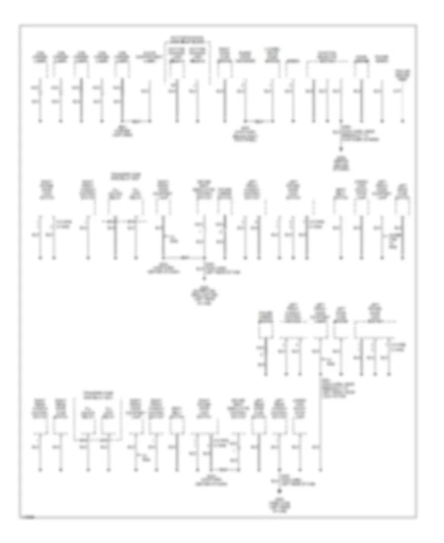
Ground Distribution Wiring Diagram (3 of 3) for Ford Cab & Chassis F350 Super Duty 1999
List of elements for Ground Distribution Wiring Diagram (3 of 3) for Ford Cab & Chassis F350 Super Duty 1999:
- 4 wheel drive mode switch
- 87a
- All lock relay
- All unlock relay
- Blend door actuator
- Cab marker lamp
- Cargo/ high mount stop lamp
- Cigar lighter
- Daytime running lamp relay 1
- Daytime running lamp relay 2
- Daytime running lamp relay block
- Driver seat regulator control switch
- Function selector switch
- G206 (behind center of dash)
- G308 (crew cab) (left rear of cab)
- G308 (super cab, regular cab) (left rear of cab)
- Glove compartment lamp
- Left door ajar switch
- Left front door courtesy lamp
- Left front window control switch
- Left power door lock switch
- Left rear door ajar switch
- Left rear window control switch
- Nca
- Power mirror switch
- Power point
- Radio
- Right door ajar switch
- Right front door courtesy lamp
- Right front window control switch
- Right power door lock switch
- Right rear door ajar switch
- Right rear window control switch
- S233 (main harn center of dash)
- S257 (main harn, behind right kick panel)
- S501 (main harn, near breakout to left front door lock motor)
- S904 (marker lamp harn)
- Seat belt switch
- Super cab w/ rke
- Trailer ground feed
- Transfer case rke relay box
- W/ rke
- W/o rke
HEADLIGHTS
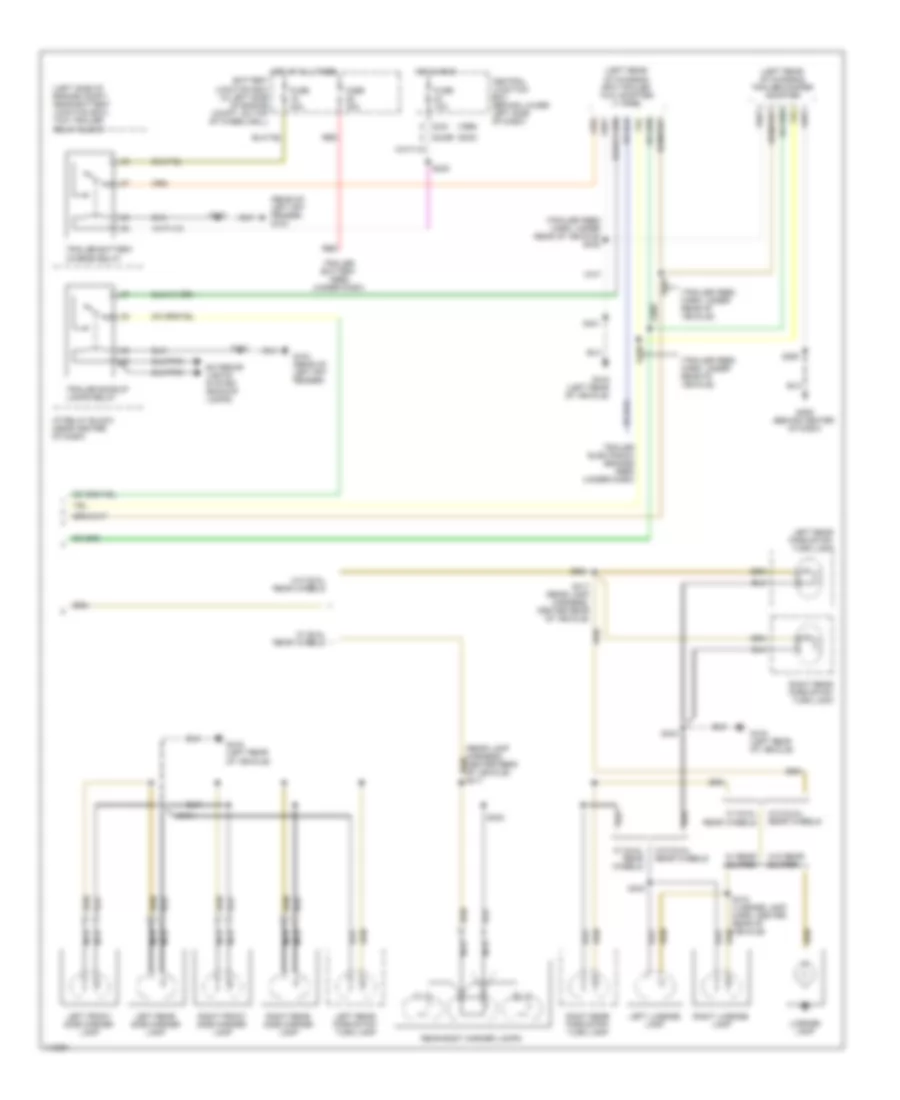
Headlights Wiring Diagram, with DRL for Ford Cab & Chassis F350 Super Duty 1999
List of elements for Headlights Wiring Diagram, with DRL for Ford Cab & Chassis F350 Super Duty 1999:
- 87a
- C230
- C242
- C243
- C253
- C273
- Daytime running lamps relay 1
- Daytime running lamps relay 2
- Daytime running lamps relay block (behind right side of dash)
- Daytime running lamps resistor (on left front side of engine compt)
- Fuse 10a
- Fuse 15a
- Fuse 30a
- G101 (front of right front fender)
- G104 (rear of left front fender)
- G206 (behind center of dash)
- Head
- Hi-beam indicator
- Hot at all times
- Hot in run
- Instrument cluster
- Junction box fuse/relay panel
- Left headlamp
- Main light
- Multi- function switch
- Near center of dash)
- Off
- Park
- Pass
- Power distribution box
- Right headlamp
- S102
- S121 (engine harness, near breakout to power distribution box)
- S180
- S206
- S214
- S217
- S220 (main harness, near breakout to central junction box)
- S257
- Switch
Headlights Wiring Diagram, without DRL for Ford Cab & Chassis F350 Super Duty 1999
List of elements for Headlights Wiring Diagram, without DRL for Ford Cab & Chassis F350 Super Duty 1999:
- (engine harness, near breakout at left side of dash) s113
- C230
- C242
- C253
- C273
- Distribution box)
- Fuse 10a
- Fuse 15a
- Fuse 30a
- G101 (front of right front fender)
- G104 (rear of left front fender)
- G206 (behind center of dash)
- Head
- Hi-beam indicator
- Hot at all times
- Instrument cluster
- Junction box fuse/relay panel
- Left headlamp
- Main light
- Multi- function switch
- Off
- Park
- Pass
- Power distribution box
- Right headlamp
- S102
- S180
- S214
- S217
- S220 (main harness, near breakout to central junction box)
- Switch
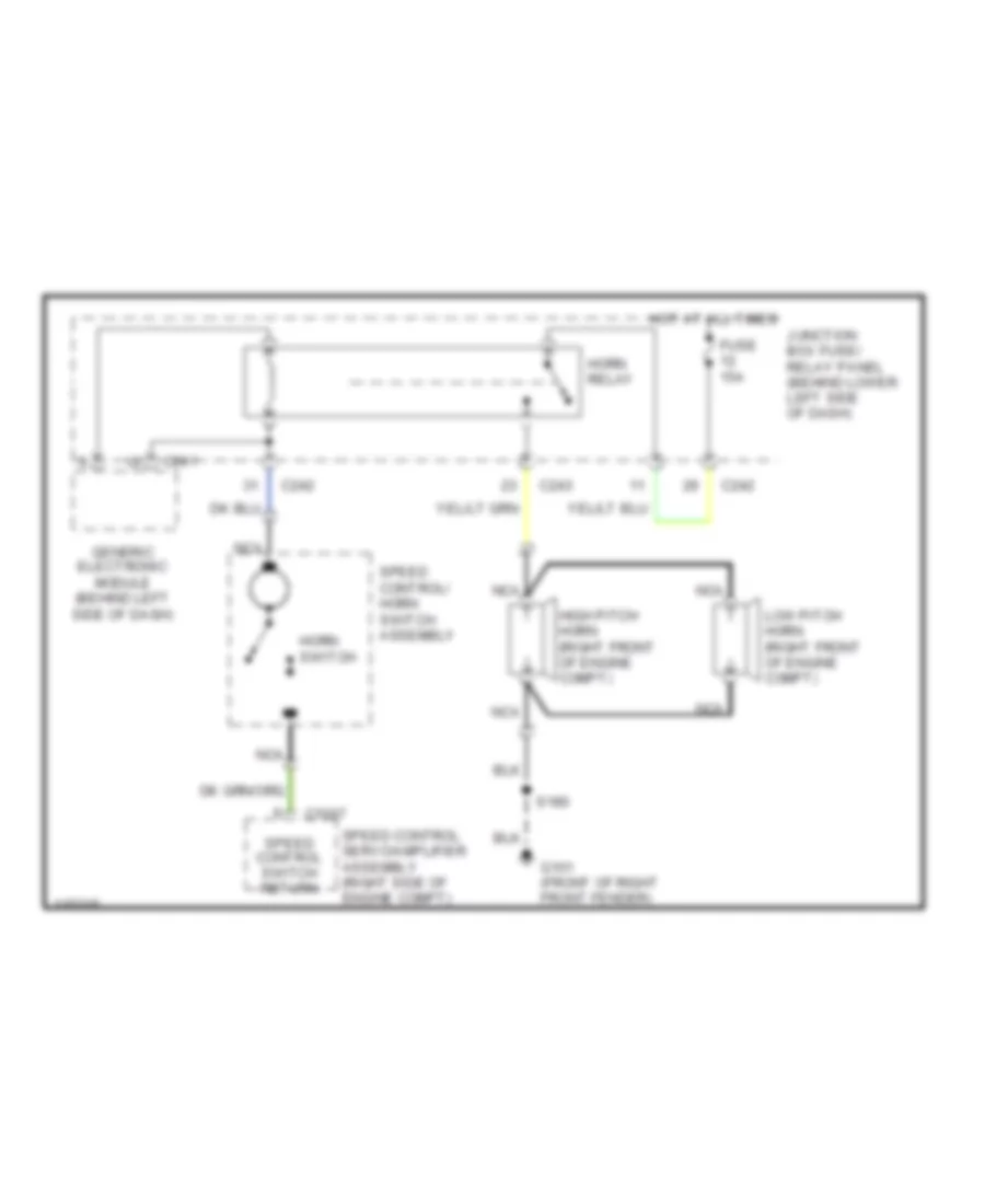
HORN
Horn Wiring Diagram for Ford Cab & Chassis F350 Super Duty 1999
List of elements for Horn Wiring Diagram for Ford Cab & Chassis F350 Super Duty 1999:
- C1067
- C241
- C242
- C243
- Fuse 15a
- G101 (front of right front fender)
- Generic electronic module (behind left side of dash)
- High pitch horn (right front of engine compt)
- Horn relay
- Horn switch
- Hot at all times
- Junction box fuse/ relay panel (behind lower left side of dash)
- Low pitch horn (right front of engine compt)
- Nca
- S180
- Speed control servo/amplifier assembly (right side of engine compt)
- Speed control switch return
- Speed control/ horn switch assembly
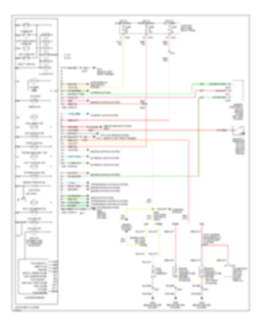
INSTRUMENT CLUSTER
Instrument Cluster Wiring Diagram for Ford Cab & Chassis F350 Super Duty 1999
List of elements for Instrument Cluster Wiring Diagram for Ford Cab & Chassis F350 Super Duty 1999:
- (behind center of dash) g206
- (conn a)
- (conn b)
- (conn c)
- (engine harn, left side of dash) s129
- (main harness, near breakout to instrument cluster) s201
- (rear of left front fender)
- 22k ohms
- 470 ohms
- 4x4 high ind
- 4x4 low ind
- 5.6k ohms
- A 5.4l
- A10
- A11
- Airbag ind
- Anti-lock brake ind
- Anti-lock brake system
- B 6.8l
- B10
- B11
- B12
- B13
- B14
- B16
- Brake warning ind
- C10
- C1027
- C11
- C12
- C239
- C241
- C242
- C243
- C250
- C251
- C253
- Charge ind
- Charging system
- Coolant temperature/ oil pressure indicator
- Daytime running lamps ind
- Diesel
- Door ajar ind
- Eng cool temp gauge
- Eng oil press gauge
- Engine controls system
- Engine coolant temperature sender (on front of engine)
- Engine coolant temperature sender (on top left front of engine)
- Engine oil pressure switch (on top center rear of engine)
- Exterior lights system
- Fasten seat belt ind
- Fuel gauge
- Fuel reset ind
- Fuel tank assembly
- Fuse 10a
- Fuse 5a
- G104
- G104 (rear of left front fender)
- G206 (behind center of dash)
- Gas
- Generic electronic module (behind lower left side of dash)
- Ground
- Headlights system
- Hi beam ind
- Hot at all times
- Hot in start or run
- Illumination
- Instrument cluster
- Interior lights system
- Junction box fuse/ relay panel
- Keep alive
- Left turn ind
- Malfunction ind
- Microprocessor
- Overhead console
- Powertrain control module (on left side of firewall)
- Red
- Right turn ind
- S102
- S201
- S208 (main harn, center of dash)
- S211
- S217
- S289
- Tach select 1
- Tach select 2
- Tachometer
- Transmission controls system
- V power
- Vss+ (speedometer)
- Wait to start ind
- Water in fuel ind
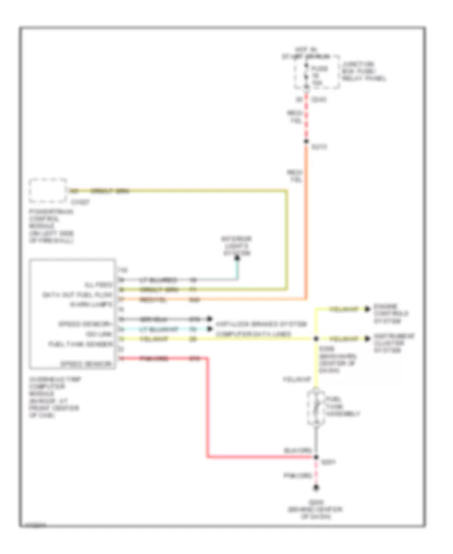
Overhead Console Wiring Diagram for Ford Cab & Chassis F350 Super Duty 1999
List of elements for Overhead Console Wiring Diagram for Ford Cab & Chassis F350 Super Duty 1999:
- Anti-lock brakes system
- C1027
- C243
- Computer data lines
- Data out fuel flow
- Engine controls system
- Fuel tank assembly
- Fuel tank sender
- Fuse 10a
- G206 (behind center of dash)
- Hot in start or run
- Ill feed
- Instrument cluster system
- Interior lights system
- Iso link
- Junction box fuse/ relay panel
- Overhead trip computer module (in roof, at front center of cab)
- Powertrain control module (on left side of firewall)
- S201
- S208 (main harn, center of dash)
- S213
- Speed sensor+
- Speed sensor-
- Warn lamps
INTERIOR LIGHTS
Courtesy Lamps Wiring Diagram for Ford Cab & Chassis F350 Super Duty 1999
List of elements for Courtesy Lamps Wiring Diagram for Ford Cab & Chassis F350 Super Duty 1999:
- (main harn, left rear of cab) (crew cab) s906
- (main harn, left rear of cab) s905
- (not used)
- (rear of left front fender) g104
- C241
- C242
- C243
- Cargo/high mount stop lamp
- Dome
- Engine compartment lamp
- Front dome lamp
- Front map lamps
- Fuse 14 10a
- Fuse 4 10a
- G206 (behind center of dash)
- G308 (left rear of cab)
- Generic electronic module (gem)
- Glove compartment lamp
- Hot at all times
- Interior lamp relay
- Junction box fuse/relay panel (behind lower left side of dash)
- Left front door courtesy lamp (w/ rke only)
- Main light switch
- Mirrors system
- Other
- Rear dome lamp
- Rear map lamps
- Regular cab
- Right front door courtesy lamp (w/ rke only)
- S102
- S218
- S229 (main harn, behind top left side of dash)
- S233
- S257
- S300
- S301 (super cab) (main harn, near left front seat)
- Super and regular w/o power mirrors
Instrument Illumination Wiring Diagram for Ford Cab & Chassis F350 Super Duty 1999
List of elements for Instrument Illumination Wiring Diagram for Ford Cab & Chassis F350 Super Duty 1999:
- 4 wheel drive mode switch
- Accessory delay relay
- C242
- C273
- Circuit breaker 25 30a
- Climate control illumination
- Fuse 7 5a
- G206 (behind center of dash)
- G308 (left rear of cab)
- Head
- Hot at all times
- Instrument cluster
- Junction box fuse/relay panel (behind lower left side of dash)
- Left front window control switch
- Left power door lock switch
- Left rear window control switch
- Main light switch
- Nca
- Off
- Overhead trip computer (otc) module
- Power distribution box (in left side of engine compt, on top of wheelwell)
- Power mirror switch
- Pulse width dimmer module
- Radio
- Right front window control switch
- Right power door lock switch
- Right rear window control switch
- S201
- S215 (main harn, near customer access connector breakout)
- S216 (main harn, behind top left side of dash)
- S218
- S227 (main harn, lower center of dash)
- S233
- S290
- S300
- S501
- Speed control/ horn switch assembly
- Steering wheel illumination
POWER DISTRIBUTION
Power Distribution Wiring Diagram (1 of 4) for Ford Cab & Chassis F350 Super Duty 1999
List of elements for Power Distribution Wiring Diagram (1 of 4) for Ford Cab & Chassis F350 Super Duty 1999:
- (diesel only)
- (diesel w/ single gen. only)
- (engine harn, left rear of engine compt) s109
- (engine harn, near breakout to power distribution box) s118
- (in backup lamp harn, left rear of engine compt) s251
- Air bag diagnostic module
- Anti-lock brake system module
- Blower motor relay
- Dash relay block
- Daytime running lamps resistor
- Driver's seat regulator control switch
- From a fuse 23 (diagram 1 of 4)
- Fuel pump relay
- Fuse 10a
- Fuse 20a
- Fuse 25a
- Fuse 30a
- Fuse 40a
- Fuse 5a (diesel w/ twin gen. only)
- Fuse 60a
- Generator/ voltage regulator (diesel)
- Generator/ voltage regulator (gasoline)
- Generator/ voltage regulator (secondary: diesel w/ twin generators)
- Glow plug relay
- High to low relay
- Idm power relay (diesel)
- Left battery (diesel only)
- Low to high relay
- Nca
- Pcm power relay
- Power distribution box
- Power distribution box (left rear of engine compartment)
- Power point
- Radio
- Red
- Right battery
- Starter motor
- Starter motor relay
- To fuse 17 (diagram 1 of 4)
- To fuse 26 (diagram 2 of 4)
- To fuse 30 (diagram 2 of 4)
- Trailer backup lamps relay
- Trailer battery charge relay
- Trailer brakes feed (taped in harness)
- Trailer running lamps relay
- Trailer tow relay
- Transfer case shift relay
- Windshield wiper motor
- Wiper run/ park relay
Power Distribution Wiring Diagram (2 of 4) for Ford Cab & Chassis F350 Super Duty 1999
List of elements for Power Distribution Wiring Diagram (2 of 4) for Ford Cab & Chassis F350 Super Duty 1999:
- (engine harness, pia diesel harness) s154
- (main harn, behind left side of dash) s210
- (main harn, behind left side of dash) s212
- (main harn, center of dash) s230
- (main harn, lower left side of dash) s214
- Acc
- Accessory delay relay
- All lock relay
- All unlock relay
- C243
- Circuit breaker 30a
- Coil on plug 1
- Coil on plug 10
- Coil on plug 2
- Coil on plug 3
- Coil on plug 4
- Coil on plug 5
- Coil on plug 6
- Coil on plug 7
- Coil on plug 8
- Coil on plug 9
- Driver's unlock relay
- From b fuse 4 (diagram 1 of 4)
- From pcm power relay (diagram 1 of 4)
- Fuel heater
- Fuse 15a
- Fuse 20a
- Fuse 30a
- Fuse 30a (5.4l gasoline)
- Fuse 30a (6.8l gasoline)
- Fuse 30a (diesel)
- Fuse 50a
- Ignition switch
- Junction box fuse/relay panel
- Junction box fuse/relay panel (lower left side of dash)
- Lock
- Main light switch
- Multi- function switch
- Nca
- Off
- Park lamp relay
- Power distribution box (left rear of engine compartment)
- Radio capacitor 1
- Radio noise capacitor 2
- Rke relay box
- Run
- S130 (engine harn, near throttle body)
- S135 (engine harness, right side of engine block)
- S179 (engine harn, left side of engine compartment)
- Start
- To fuse 10 (diagram 4 of 4)
- To fuse 13 (diagram 3 of 4)
- To fuse 19 (diagram 3 of 4)
- To fuse 20 (diagram 4 of 4)
- To fuse 22 (diagram 4 of 4)
- To fuse 27 (diagram 4 of 4)
- Wastegate solenoid control
Power Distribution Wiring Diagram (3 of 4) for Ford Cab & Chassis F350 Super Duty 1999
List of elements for Power Distribution Wiring Diagram (3 of 4) for Ford Cab & Chassis F350 Super Duty 1999:
- (main harness, top left side of dash) s213
- Accessory delay relay
- Auxiliary powertrain control module (diesel)
- Brake pedal position switch
- Brake pressure switch
- C242
- C243
- C250
- C251
- Cigar lighter
- Clutch pedal position switch
- Dash relay block
- Data link connector
- Engine compartment lamp
- Flasher relay
- From fuse 22 (power distribution box) (diagram 2 of 4)
- From fuse 3 k (diagram 3 of 4)
- From h fuse 30 (diagram 2 of 4)
- Front map lamp
- Fuse 10a
- Fuse 15a
- Fuse 20a
- Fuse 5a
- G200 (left kick panel)
- Generic electronic module
- Generic electronic module (gem)
- Glovebox light
- Horn relay
- Idle validation switch (diesel)
- Instrument cluster
- Interior lamp relay
- Junction box fuse/relay panel (lower left side of dash)
- Overdrive cancel switch
- Overhead trip computer module
- Power mirror switch
- Power take-off (taped in harness)
- Powertrain control module
- Rear lamp
- S211 (main harn, top left side of dash)
- S229 (main harn, top left side of dash)
- S242 (main harness, near breakout to customer access)
- S290 (main harness, near breakout to customer access)
- S906 (main harn, left rear of cab)
- To fuse 4 (diagram 3 of 4)
Power Distribution Wiring Diagram (4 of 4) for Ford Cab & Chassis F350 Super Duty 1999
List of elements for Power Distribution Wiring Diagram (4 of 4) for Ford Cab & Chassis F350 Super Duty 1999:
- (engine harn, left rear of engine compt) s124
- (engine harness, near breakout to power distribution box)
- (main harn, left side of dash) s206
- (main harn, left side of dash) s235
- A/t
- Air bag diagnostic module
- Anti-lock brake system module
- Backup lamp switch
- Blend door actuator
- Blower motor relay
- C100
- C1012
- C1067
- C115
- C166
- C236
- C242
- C243
- Clutch pedal position switch jumper
- Customer access (taped in harness)
- Dash relay block
- Daytime running lamp relay 2
- Daytime running lamp relay block
- Digital transmission range sensor
- Flasher relay
- From ignition switch (diagram 2 of 4)
- Function selector switch
- Fuse (not used)
- Fuse 10a
- Fuse 15a
- Fuse 5a
- Generic electronic module (gem)
- Junction box fuse/relay panel (lower left side of dash)
- M/t
- Main light switch
- Passenger's air bag deactivation switch
- Power distribution box
- Radio
- S119
- S203 (main harn, center of dash)
- Shift lock actuator
- Speed control module
- Tan/red
- Trailer battery charge relay
- Trailer tow relay
- Vacuum hublock solenoid
- Vacuum pump (diesel)
- Washer pump relay
- Wiper hi/lo relay
- Wiper run/ park relay
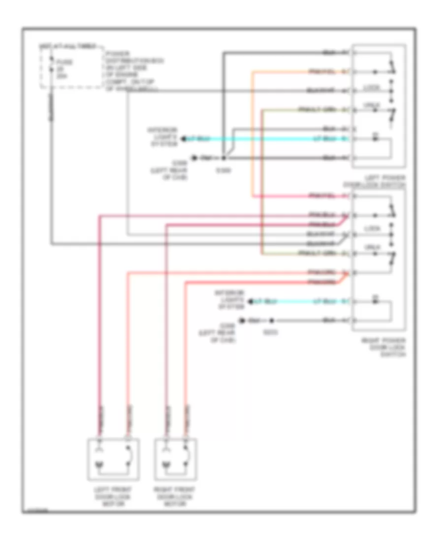
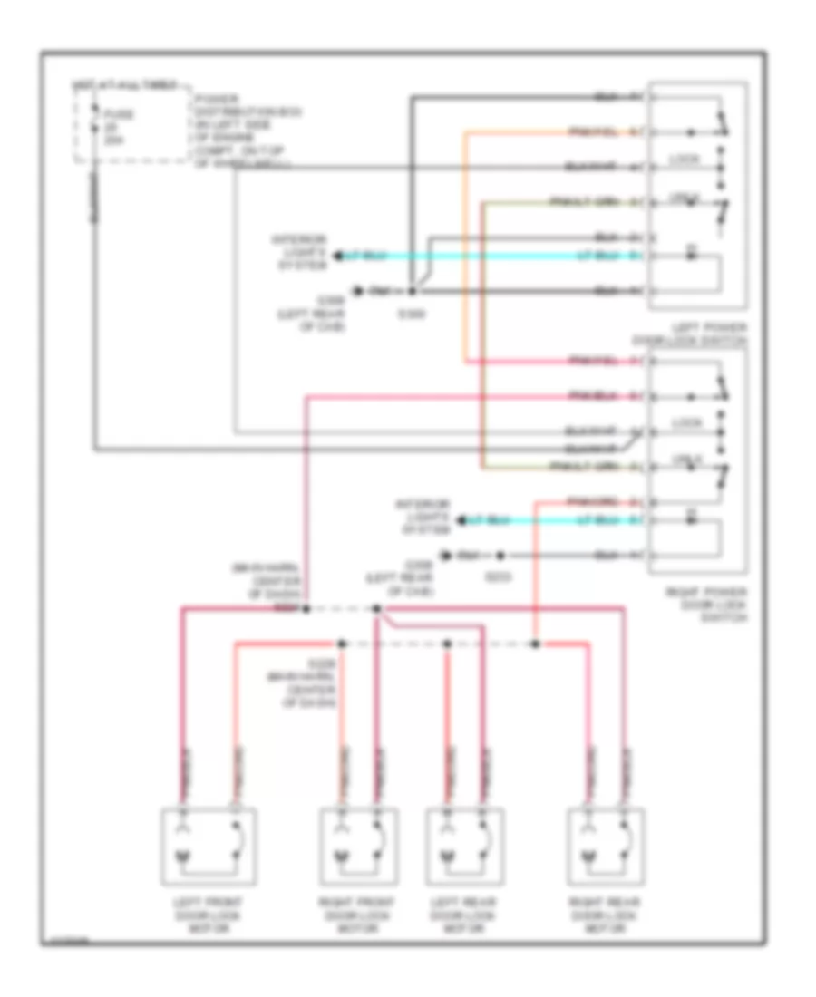
POWER DOOR LOCKS
Power Door Locks Wiring Diagram, with Remote/Keyless Entry for Ford Cab & Chassis F350 Super Duty 1999
List of elements for Power Door Locks Wiring Diagram, with Remote/Keyless Entry for Ford Cab & Chassis F350 Super Duty 1999:
- (main harn, center of dash) s224
- (main harn, center of dash) s232
- 87a
- All lock relay
- All unlock relay
- C247
- C274
- Driver unlock relay
- Exterior lights system
- Fuse 15a
- Fuse 20a
- G308 (left rear of cab)
- Generic electronic module (behind lower left side of dash)
- Head
- Hot at all times
- Interior lights system
- Left front door lock motor
- Left power door lock switch
- Left rear door lock motor (crew cab only)
- Lock
- Main light switch
- Off
- Park
- Park lamp relay
- Power distribution box (in left side of engine compt, on top of wheelwell)
- Right front door lock motor
- Right power door lock switch
- Right rear door lock motor (crew cab only)
- Rke relay box (in center of dash)
- S215 (main harn, behind dash)
- S228 (main harn, center of dash)
- S230
- S231 (main harn, center of dash)
- S233
- S300
- Unlk
Power Door Locks Wiring Diagram, without Remote/Keyless Entry Except Crew Cab for Ford Cab & Chassis F350 Super Duty 1999
List of elements for Power Door Locks Wiring Diagram, without Remote/Keyless Entry Except Crew Cab for Ford Cab & Chassis F350 Super Duty 1999:
- Fuse 20a
- G308 (left rear of cab)
- Hot at all times
- Interior lights system
- Left front door lock motor
- Left power door lock switch
- Lock
- Power distribution box (in left side of engine compt, on top of wheelwell)
- Right front door lock motor
- Right power door lock switch
- S233
- S300
- Unlk
Power Door Locks Wiring Diagram, without Remote/Keyless Entry-Crew Cab for Ford Cab & Chassis F350 Super Duty 1999
List of elements for Power Door Locks Wiring Diagram, without Remote/Keyless Entry-Crew Cab for Ford Cab & Chassis F350 Super Duty 1999:
- (main harn, center of dash) s224
- Fuse 20a
- G308 (left rear of cab)
- Hot at all times
- Interior lights system
- Left front door lock motor
- Left power door lock switch
- Left rear door lock motor
- Lock
- Power distribution box (in left side of engine compt, on top of wheelwell)
- Right front door lock motor
- Right power door lock switch
- Right rear door lock motor
- S228 (main harn, center of dash)
- S233
- S300
- Unlk
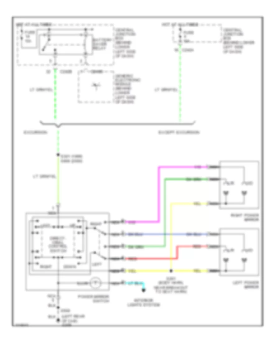
POWER MIRRORS
Power Mirrors Wiring Diagram for Ford Cab & Chassis F350 Super Duty 1999
List of elements for Power Mirrors Wiring Diagram for Ford Cab & Chassis F350 Super Duty 1999:
- (left rear of cab) g308
- Battery saver relay
- C240d
- C242a
- C242b
- Central junction box (behind lower left side of dash)
- Direct- ional control switch
- Down
- Except excursion
- Excursion
- Fuse 10a
- Fuse 15a
- Generic electronic module (behind lower left side of dash)
- Hot at all times
- Illum
- Interior lights system
- L/r
- Left
- Left power mirror
- Nca
- Power mirror switch
- Red
- Right
- Right power mirror
- S261 (body harn, near breakout to seat harn)
- S301 (1999) s906 (2000)
- S500
- U/d
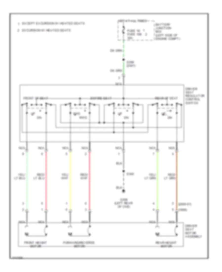
POWER SEATS
6-Way Power Seat Wiring Diagram for Ford Cab & Chassis F350 Super Duty 1999
List of elements for 6-Way Power Seat Wiring Diagram for Ford Cab & Chassis F350 Super Duty 1999:
- (1999)
- (2000-01)
- Battery junction box (left side of engine compt)
- Driver seat motor assembly
- Driver seat regulator control switch
- Entire seat
- Except excursion w/ heated seats
- Excursion w/ heated seats
- Forward/reverse motor
- Front height motor
- Front of seat
- Fuse 18 fuse 108 30a
- Fwd
- G308 (left rear of cab)
- Hot at all times
- Nca
- Rear height motor
- Rear of seat
- Rwd
- S298 (2001)
- S300
POWER WINDOWS
Power Windows Wiring Diagram, Crew Cab for Ford Cab & Chassis F350 Super Duty 1999
List of elements for Power Windows Wiring Diagram, Crew Cab for Ford Cab & Chassis F350 Super Duty 1999:
- 87a
- Acc delay relay
- Battery junction box
- C242
- C243
- C267
- C510
- C511
- Central junction box
- Circuit breaker 25 30a
- Down sw input
- Fuse 10a
- Fuse 50a
- G206 (behind center of dash)
- G308 (left rear of cab)
- Generic electronic module
- Ground
- Hot at all times
- Interior lights system
- Left front power window motor
- Left front power window switch
- Left rear power window motor
- Left rear power window switch
- Left rear switch
- Left switch
- Lock out
- One tch dn hi
- One tch dn lo
- One touch down relay
- Otd sw input
- Otd switch
- Right front power window motor
- Right front power window switch
- Right rear power window motor
- Right rear power window switch
- Right rear switch
- Right switch
- S218
- S229
- S262 (body harn, near breakout under left front seat)
- S501
- Shunt (0.015 ohms)
Power Windows Wiring Diagram, Except Crew Cab for Ford Cab & Chassis F350 Super Duty 1999
List of elements for Power Windows Wiring Diagram, Except Crew Cab for Ford Cab & Chassis F350 Super Duty 1999:
- 87a
- Acc delay relay
- Battery junction box
- C242
- C243
- C267
- C510
- C511
- Central junction box
- Circuit breaker 25 30a
- Down sw input
- Fuse 10a
- Fuse 50a
- G206 (behind center of dash)
- G308 (left rear of cab)
- Generic electronic module
- Ground
- Hot at all times
- Interior lights system
- Left power window motor
- Left power window switch
- Left switch
- One tch dn hi
- One tch dn lo
- One touch down
- One touch down relay
- Otd sw input
- Right power window motor
- Right power window switch
- Right switch
- S218
- S226 (body main harn, near breakout to customer access)
- S229
- S300
- Shunt (0.015 ohms)
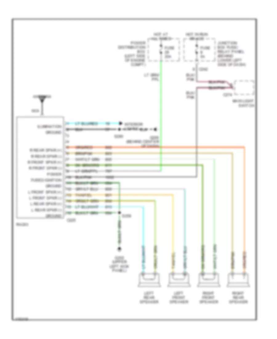
RADIO
Radio Wiring Diagram for Ford Cab & Chassis F350 Super Duty 1999
List of elements for Radio Wiring Diagram for Ford Cab & Chassis F350 Super Duty 1999:
- Antenna
- C225
- C242
- C274
- Fuse 20a
- Fuse 5a
- Fused ignition
- G202 (upper left kick panel)
- G206 (behind center of dash)
- Ground
- Hot at all times
- Hot in run or acc
- Ilumination
- Interior lights
- Junction box fuse/ relay panel (behind lower left side of dash)
- L front spkr (+)
- L front spkr (-)
- L rear spkr (+)
- L rear spkr (-)
- Left front speaker
- Left rear speaker
- Main light switch
- Nca
- Power
- Power distribution box (left side of engine compt)
- R front spkr (+)
- R front spkr (-)
- R rear spkr (+)
- R rear spkr (-)
- Radio
- Right front speaker
- Right rear speaker
- S258
- S290
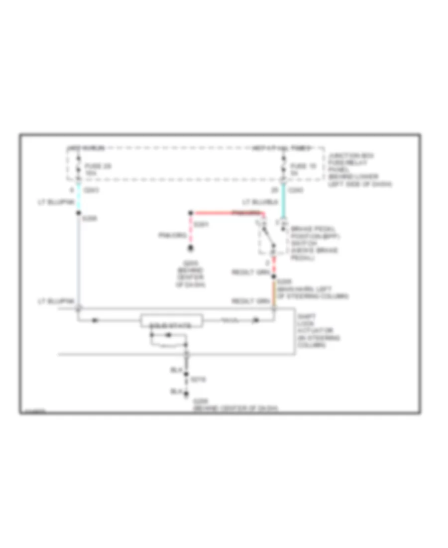
SHIFT INTERLOCK
Shift Interlock Wiring Diagram for Ford Cab & Chassis F350 Super Duty 1999
List of elements for Shift Interlock Wiring Diagram for Ford Cab & Chassis F350 Super Duty 1999:
- Brake pedal position (bpp) switch (above brake pedal)
- C243
- Fuse 15 5a
- Fuse 28 10a
- G206 (behind center of dash)
- Hot at all times
- Hot in run
- Junction box fuse/relay panel (behind lower left side of dash)
- S201
- S205 (main harn, left of steering column)
- S206
- S218
- Shift lock actuator (in steering column)
- Solid state
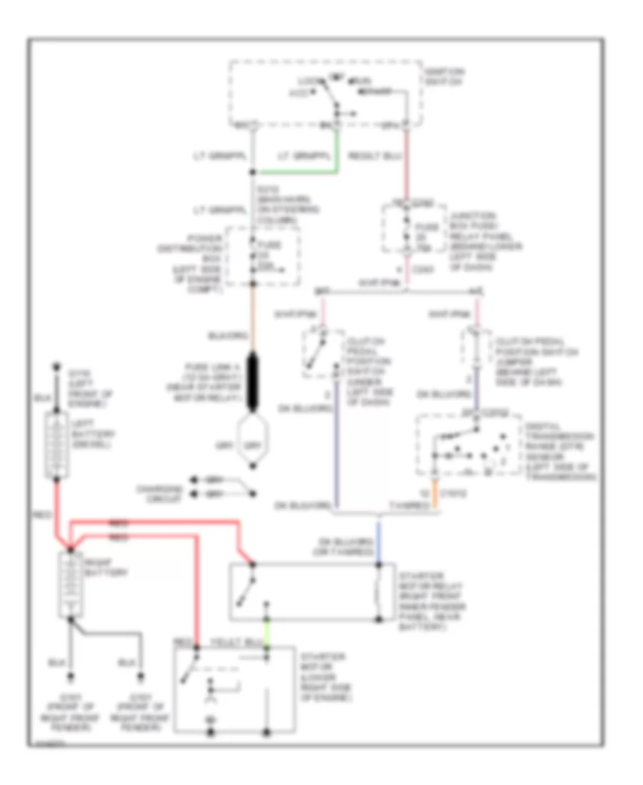
STARTING/CHARGING
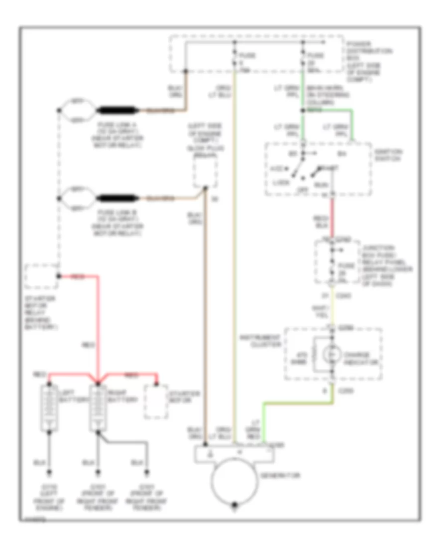
Starting Wiring Diagram for Ford Cab & Chassis F350 Super Duty 1999
List of elements for Starting Wiring Diagram for Ford Cab & Chassis F350 Super Duty 1999:
- A/t
- Acc
- C1012
- C243
- Charging circuit
- Clutch pedal position switch (under left side of dash)
- Clutch pedal position switch jumper (behind left side of dash)
- Column)
- Digital transmission range (dtr) sensor (left side of transmission)
- Fuse 15a
- Fuse 50a
- Fuse link a (12 ga-gray) (near starter motor relay)
- G101 (front of right front fender)
- G110 (left front of engine)
- Ignition switch
- Junction box fuse/ relay panel (behind lower left side of dash)
- Left battery (diesel)
- Lock
- M/t
- Off
- Power distribution box (left side of engine compt)
- Red
- Right battery
- Run
- Sta
- Start
- Starter motor (lower right side of engine)
- Starter motor relay (right front inner fender panel, near battery)
- Tan/red
5.4L
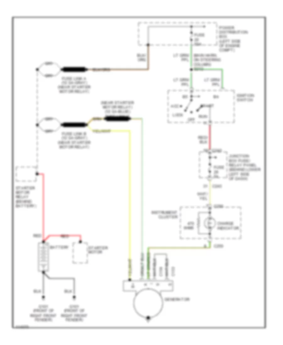
5.4L, Charging Wiring Diagram for Ford Cab & Chassis F350 Super Duty 1999
List of elements for 5.4L, Charging Wiring Diagram for Ford Cab & Chassis F350 Super Duty 1999:
- 0hms
- Acc
- Battery
- C153
- C154
- C243
- C250
- Charge indicator
- Fuse 50a
- Fuse 5a
- Fuse link a (12 ga-gray) (near starter motor relay)
- Fuse link b (12 ga-gray) (near starter motor relay)
- G101 (front of right front fender)
- Generator
- Ignition switch
- Instrument cluster
- Junction box fuse/ relay panel (behind lower left side of dash)
- Lock
- Off
- Power distribution box (left side of engine compt)
- Red
- Run
- Start
- Starter motor
- Starter motor relay (behind battery)
6.8L
6.8L, Charging Wiring Diagram for Ford Cab & Chassis F350 Super Duty 1999
List of elements for 6.8L, Charging Wiring Diagram for Ford Cab & Chassis F350 Super Duty 1999:
- 0hms
- Acc
- Battery
- C153
- C154
- C243
- C250
- Charge indicator
- Fuse 50a
- Fuse 5a
- Fuse link a (12 ga-gray) (near starter motor relay)
- Fuse link b (12 ga-gray) (near starter motor relay)
- G101 (front of right front fender)
- Generator
- Ignition switch
- Instrument cluster
- Junction box fuse/ relay panel (behind lower left side of dash)
- Lock
- Off
- Power distribution box (left side of engine compt)
- Red
- Run
- Start
- Starter motor
- Starter motor relay (behind battery)
7.3L DIESEL
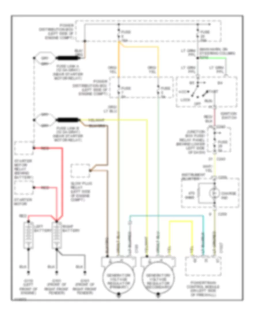
7.3L Diesel, Charging Wiring Diagram, with Dual Generators for Ford Cab & Chassis F350 Super Duty 1999
List of elements for 7.3L Diesel, Charging Wiring Diagram, with Dual Generators for Ford Cab & Chassis F350 Super Duty 1999:
- 0hms
- Acc
- C1027
- C185
- C243
- C250
- Charge ind
- Fuse 10a
- Fuse 50a
- Fuse 5a
- Fuse link a (12 ga-gray) (near starter motor relay)
- Fuse link b (12 ga-gray) (near starter motor relay)
- G101 (front of right front fender)
- G110 (left front of engine)
- Generator/ voltage regulator (primary)
- Generator/ voltage regulator (secondary)
- Glow plug relay (left side of engine compt)
- Ignition switch
- Instrument cluster
- Junction box fuse/ relay panel (behind lower left side of dash)
- Left battery
- Lock
- Off
- Power distribution box (left side of engine compt)
- Powertrain control module (on left side of firewall)
- Red
- Right battery
- Run
- Start
- Starter motor
- Starter motor relay (behind battery)
- Steering column) s212
7.3L Diesel, Charging Wiring Diagram, without Dual Generators for Ford Cab & Chassis F350 Super Duty 1999
List of elements for 7.3L Diesel, Charging Wiring Diagram, without Dual Generators for Ford Cab & Chassis F350 Super Duty 1999:
- (left side of engine compt) glow plug relay
- 0hms
- Acc
- C185
- C243
- C250
- Charge indicator
- Fuse 10a
- Fuse 50a
- Fuse 5a
- Fuse link a (12 ga-gray) (near starter motor relay)
- Fuse link b (12 ga-gray) (near starter motor relay)
- G101 (front of right front fender)
- G110 (left front of engine)
- Generator
- Ignition switch
- Instrument cluster
- Junction box fuse/ relay panel (behind lower left side of dash)
- Left battery
- Lock
- Off
- Power distribution box (left side of engine compt)
- Red
- Right battery
- Run
- Start
- Starter motor
- Starter motor relay (behind battery)
SUPPLEMENTAL RESTRAINTS
Supplemental Restraints Wiring Diagram for Ford Cab & Chassis F350 Super Duty 1999
List of elements for Supplemental Restraints Wiring Diagram for Ford Cab & Chassis F350 Super Duty 1999:
- (behind center of dash)
- Air bag diagnostic module (behind center side of dash)
- Air bag feed
- Air bag indicator
- Air bag return
- C223
- C227
- C239
- C242
- C243
- C250
- Clockspring assembly
- Computer data lines system
- Connector (dlc)
- Data link
- Data link (dlc)
- Deactivation
- Deactivation ind
- Driver air bag
- Fuse 10a
- Fuse 5a
- Fused b(+)
- Fused ignition
- G203 (right kick panel)
- Generic electronic module (gem) (behind center side of dash)
- Ground
- Hot at all times
- Hot in run
- Hot in run or start
- Indicator driver
- Instrument cluster
- Junction box fuse/ relay panel (behind lower left side of dash)
- Nca
- Ohm
- Passenger air bag
- Passenger air bag deactivation switch
- Pin shorting bar is engaged when module connector is disconnected (shorting bar is connected between the following pins: 1-15, 7-21, 8-22, 14-28)
- Power distribution box (left side of engine compt)
- S202
- S203
- S225 (dash harn, near breakout to data link connector)
- Shorting bar
- Tone request
TRANSMISSION
4WD Wiring Diagram for Ford Cab & Chassis F350 Super Duty 1999
List of elements for 4WD Wiring Diagram for Ford Cab & Chassis F350 Super Duty 1999:
- 1.1k ohms
- 3.9k ohms
- 4 wheel drive mode switch
- 4x2 sol
- 4x4 high ind
- 4x4 high range indicator
- 4x4 low ind
- 4x4 low range indicator
- 4x4 mode sw
- 4x4 sol
- Anti-lock brake system module (left front of engine compt)
- Auxiliary powertrain control module, clutch pedal position switch, idle validation switch, overhead trip computer, overdrive cancel switch
- Bpp sw input
- Brake pedal position switch (under left side of dash)
- C1040
- C239
- C247
- C250
- C253
- C284
- C285
- Clutch pedal position switch, shift lock actuator, powertrain control module, anti-lock brake module
- Digital transmission range (dtr) sensor (left side of transmission)
- Fuse 10a
- Fuse 20a
- Fuse 30a
- G104 (left rear of engine compt)
- G200 (left kick panel)
- Generic electronic module (gem) (behind left side of dash)
- H2l rly ctrl
- High to low
- Hot at all times
- Hot in run
- Hot in run or start
- Ignition
- Illumination
- Instrument cluster
- Interior lights (instrument illumination)
- Junction box fuse/ relay panel (under left side of dash)
- L2h rly ctrl
- Low to high
- Neutral sw in
- Ohms
- Power distribution box (left side of engine compt)
- Red
- S124
- S205
- S206
- S213
- S250
- S251
- S255
- Shift lock actuator, drl relay
- Shift motor
- Sw a input
- Sw b input
- Sw c input
- Sw d input
- Tod rly ctrl
- Torque on demand relay
- Transfer case assembly (below vehicle, behind transmission)
- Transfer case shift relay module (in engine compt, next to central junction box)
- Vacuum hublock solenoid (right side of engine compt)
- Vacuum pump, speed control module, back-up lamp switch
5.4L
5.4L, A/T Wiring Diagram for Ford Cab & Chassis F350 Super Duty 1999
List of elements for 5.4L, A/T Wiring Diagram for Ford Cab & Chassis F350 Super Duty 1999:
- (engine ctrl harn, near battery junction box) s120
- (engine harn, left side of dash) s122
- (engine harn, near breakout to fuel injector)
- (engine harn, near breakout to pcm)
- (in back-up lamp harn)
- (left side of firewall) powertrain control module (pcm)
- (rear of engine compt) g123
- (under
- 4r100 transmission
- 4wd circuit
- 4wd low
- Anti-lock brake system module
- Anti-lock brake system module (left front of engine compt)
- Auxiliary powertrain control module, clutch pedal position switch, idle validation switch, overhead trip computer, instrument cluster
- Boo
- Brake pedal position switch (under left side of dash)
- C1027
- Ccs
- Center of dash) data link connector
- Cht
- Coast clutch control
- Cruise control, body computer, instrument cluster
- Cylinder head temperature (cht) sensor (top front of engine)
- Data
- Differential speed sensor (center of rear axle)
- Digital transmission range sensor (left side of transmission)
- Dlc (+)
- Dlc (-)
- Electronic pressure control solenoid
- Engine controls
- Epc
- Fuse 10a
- Fuse 20a
- Fuse 30a
- Fuse 5a
- G104 (left rear of engine compt)
- Ground
- Hot at all times
- Hot in run or start
- Iat
- Ignition coils, radio noise capacitor
- Intake air temperature sensor (on intake manifold)
- Junction box fuse/ relay panel (under left side of dash)
- Of dash)
- Overdrive cancel switch (end of transmission selector lever)
- Pcm power diode
- Pcm power relay
- Power distribution box (left side of engine compt)
- R p
- Red
- Red/ pnk
- Red/pnk
- S102
- S106
- S114
- S115 (engine harn, left side of engine compt)
- S123 (eng harn, left side of dash)
- S132
- S133
- S138
- S139
- S179
- S213
- Shift control 1
- Shift control 2
- Shift lock actuator, gem, clutch pedal position switch
- Side of eng compt)
- Sig rtn
- Ss1
- Ss2
- Tcc
- Tcil
- Tcs
- Tft
- Throttle position (tp) sensor (on throttle body)
- Torque converter clutch solenoid
- Tr1
- Tr2
- Tr3
- Tr4
- Transmission fluid temperature sensor
- Vpwr
- Vref
- Vss in
6.8L
6.8L, A/T Wiring Diagram for Ford Cab & Chassis F350 Super Duty 1999
List of elements for 6.8L, A/T Wiring Diagram for Ford Cab & Chassis F350 Super Duty 1999:
- (engine ctrl harn, near battery junction box) s120
- (engine harn, left side of dash) s122
- (engine harn, near breakout to fuel injector)
- (engine harn, near breakout to pcm)
- (in back-up lamp harn)
- (left side of firewall) powertrain control module (pcm)
- (rear of engine compt) g123
- (under
- 4r100 transmission
- 4wd circuit
- 4wd low
- Anti-lock brake system module
- Anti-lock brake system module (left front of engine compt)
- Auxiliary powertrain control module, clutch pedal position switch, idle validation switch, overhead trip computer, instrument cluster
- Boo
- Brake pedal position switch (under left side of dash)
- C1027
- Ccs
- Center of dash) data link connector
- Cht
- Coast clutch control
- Cruise control, body computer, instrument cluster
- Cylinder head temperature (cht) sensor (top front of engine)
- Data
- Differential speed sensor (center of rear axle)
- Digital transmission range sensor (left side of transmission)
- Dlc (+)
- Dlc (-)
- Electronic pressure control solenoid
- Engine controls
- Epc
- Fuse 10a
- Fuse 20a
- Fuse 30a
- Fuse 5a
- G104 (left rear of engine compt)
- Ground
- Hot at all times
- Hot in run or start
- Iat
- Ignition coils, radio noise capacitor
- Intake air temperature sensor (on intake manifold)
- Junction box fuse/ relay panel (under left side of dash)
- Of dash)
- Overdrive cancel switch (end of transmission selector lever)
- Pcm power diode
- Pcm power relay
- Power distribution box (left side of engine compt)
- R p
- Red
- Red/ pnk
- Red/pnk
- S102
- S106
- S114
- S115 (engine harn, left side of engine compt)
- S123 (eng harn, left side of dash)
- S132
- S133
- S138
- S139
- S179
- S213
- Shift control 1
- Shift control 2
- Shift lock actuator, gem, clutch pedal position switch
- Side of eng compt)
- Sig rtn
- Ss1
- Ss2
- Tcc
- Tcil
- Tcs
- Tft
- Throttle position (tp) sensor (on throttle body)
- Torque converter clutch solenoid
- Tr1
- Tr2
- Tr3
- Tr4
- Transmission fluid temperature sensor
- Vpwr
- Vref
- Vss in
7.3L DIESEL
7.3L Diesel, A/T Wiring Diagram for Ford Cab & Chassis F350 Super Duty 1999
List of elements for 7.3L Diesel, A/T Wiring Diagram for Ford Cab & Chassis F350 Super Duty 1999:
- (engine harn, left side of dash)
- (engine harn, left side of engine compt)
- (in backup lamp harn) s139
- (left side of firewall) powertrain control module (pcm)
- (main harn, center of dash)
- (rear of engine compt) g123
- (under
- 4r100 transmission
- 4wd circuit
- 4wd low
- Accelerator position sensor (under left side of dash)
- Anti-lock brake system module
- Anti-lock brake system module (left front of engine compt)
- Aps
- Auxiliary powertrain control module
- Auxiliary powertrain control module, clutch pedal position switch, idle validation switch, overhead trip computer, instrument cluster
- Boo
- Brake pedal position switch (under left side of dash)
- C1027
- Ccs
- Center of dash) data link connector
- Coast clutch control
- Cruise control, body computer, instrument cluster
- Data
- Differential speed sensor (center of rear axle)
- Digital transmission range sensor (left side of transmission)
- Dlc (+)
- Dlc (-)
- Electronic pressure control solenoid
- Engine controls
- Epc
- Fuel heater, wastegate solenoid control
- Fuse 10a
- Fuse 30a
- Fuse 5a
- G104 (left rear of engine compt)
- Ground
- Hot at all times
- Hot in run or start
- Iat
- Intake air temperature sensor (on intake manifold)
- Junction box fuse/ relay panel (under left side of dash)
- Of dash)
- Oss
- Output shaft speed sensor (top of transmission)
- Overdrive cancel switch (end of transmission selector lever)
- Pcm power diode
- Pcm power relay
- Power distribution box (left side of engine compt)
- R p
- Red
- Red/ pnk
- Red/pnk
- S102
- S106
- S114
- S115 (engine harn, left side of dash)
- S123
- S138 (in back-up lamp harn)
- S179
- S213
- S219
- S221
- Shift control 1
- Shift control 2
- Shift lock actuator, gem, clutch pedal position switch
- Side dash) s222
- Side of eng compt)
- Sig rtn
- Ss1
- Ss2
- Tcc
- Tcil
- Tcs
- Tft
- Torque converter clutch solenoid
- Tr1
- Tr2
- Tr3
- Tr4
- Transmission fluid temperature sensor
- Tss
- Turbine shaft speed sensor (top of transmission)
- Vpwr
- Vref
- Vss in
WARNING SYSTEMS
Warning Systems Wiring Diagram for Ford Cab & Chassis F350 Super Duty 1999
List of elements for Warning Systems Wiring Diagram for Ford Cab & Chassis F350 Super Duty 1999:
- (1999)
- (1999) (behind center of dash) g206
- (2000)
- Air bag diagnostic module (in center of dash)
- Air bag input
- Bat
- C223
- C239
- C240a
- C240d
- C241
- C242b
- C243
- C273a
- C273b
- C274
- Central junction box
- Crew cab
- Exterior lights system
- Fuse 10a
- Fuse 15a
- Fuse 5a
- G200 (left kick panel) (2000)
- G206 (behind center of dash)
- G308 (left rear of cab)
- Generic electronic module (gem)/ (behind left side of dash)
- Ground
- Head
- Hot at all times
- Hot in acc or run
- Hot in run or start
- Hot in start
- Ign
- Ign key warning
- Ignition key warning switch
- Input
- Left door ajar switch
- Left rear door ajar switch
- Lf door ajar
- Main light switch
- Nca
- Off
- Park
- Park/head input
- Rear door ajar
- Rf door ajar
- Right door ajar switch
- Right rear door ajar switch
- S201
- S204 (in main harn, near breakout to air bag diagnostic module)
- S213
- S215
- S233
- S257
- S300
- S501
- Seat belt sw in
- Seat belt switch (in driver's seat belt buckle)
WIPER/WASHER
Wiper/Washer Wiring Diagram for Ford Cab & Chassis F350 Super Duty 1999
List of elements for Wiper/Washer Wiring Diagram for Ford Cab & Chassis F350 Super Duty 1999:
- (engine harness, left side of dash) s116
- (rear of left front fender) g104
- (top of left front wheelwell) power distribution box
- 100k ohms
- 3.3k ohms
- 4.08k
- 7.25k
- Brake/run relay
- C239
- C243
- Fuse 10a
- Fuse 30a
- G101 (front of right front fender)
- Generic electronic module (lower left side of dash)
- Hot at all times
- Hot in acc or run
- Int max
- Int min
- Interval delay/wash
- Junction box fuse/ relay panel (lower left side of dash)
- Multi- function switch
- Off
- Off 38.27k ohms
- Ohms
- Park
- Park sense
- Power distribution box (top of left front wheelwell)
- Red
- Run
- S102
- S118
- S119
- S180
- Signal return
- Tan/ red
- Tan/red
- Washer pump
- Washer pump relay
- Washer switch
- Windshield wiper motor
- Windshield wiper pump motor
- Wiper hi/lo relay
- Wiper mode select
- Wiper run/park relay
- Wiper speed
- Wiper switch