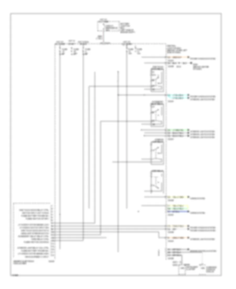
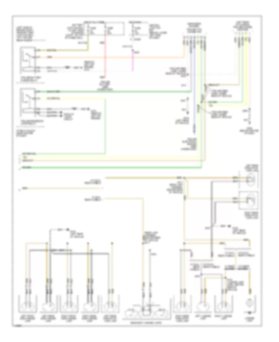
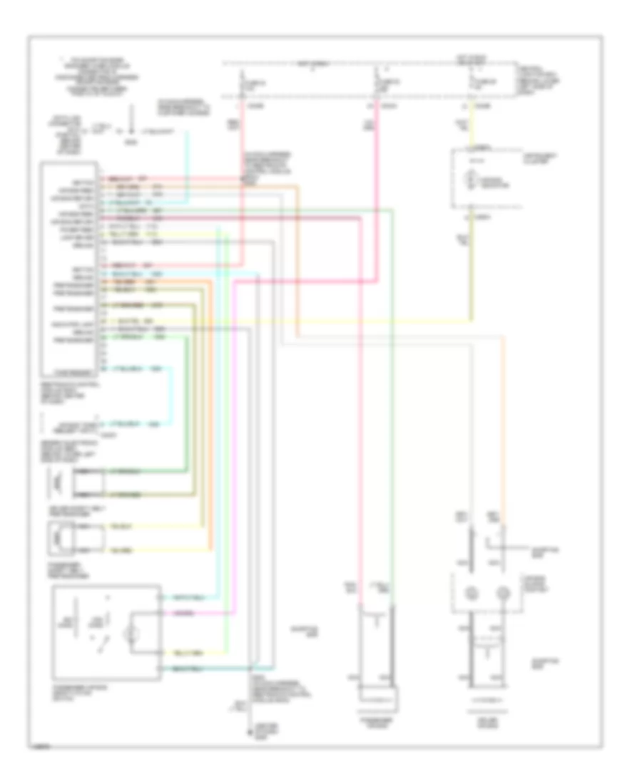
AIR CONDITIONING
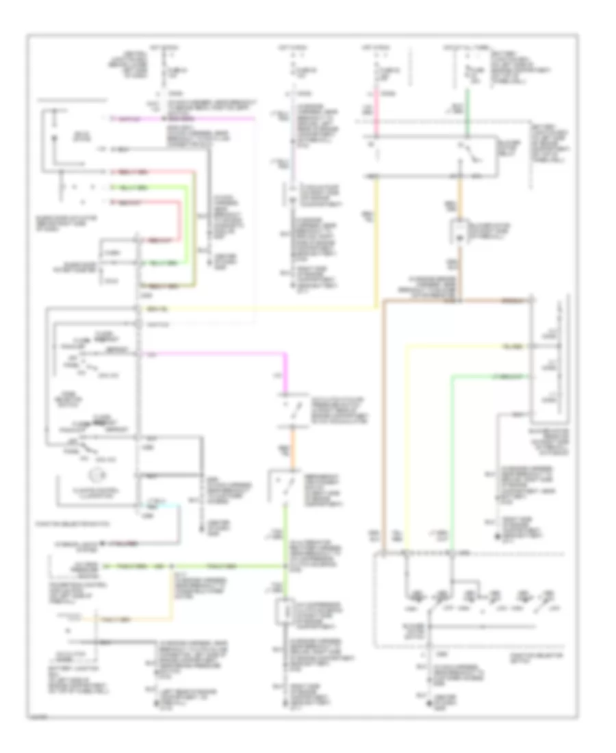
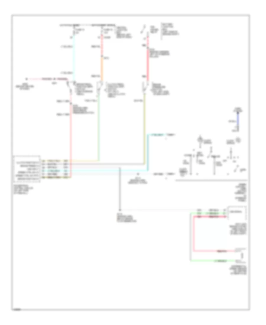
Heater Wiring Diagram for Ford Cab & Chassis F350 Super Duty 2001

List of elements for Heater Wiring Diagram for Ford Cab & Chassis F350 Super Duty 2001:
- (center of dash) g206
- (in engine harness, near breakout to ground, right side of engine compartment, near battery) s180
- (in main harness, near break out to customer access) s290
- (in main harness, near breakout to brake pedal position (bpp) switch) s235 (2000) s235 (2001) (in main harness, near breakout to data link connector (dlc))
- (right side of engine compartment, near battery) g111
- 0.3 ohms
- 0.7 ohms
- 1.7 ohms
- 87a
- Battery junction box (in left side of engine compartment, on top of wheelwell)
- Blend door actuator (behind right side of dash)
- Blend door potentiometer
- Blower motor (on right side of firewall)
- Blower motor relay
- Blower motor resistor (on right side of firewall, on plenum)
- Blower motor switch
- C225
- C242a
- C242b
- C260
- C296
- C298
- Central junction box (behind lower left side of dash)
- Climate control illumination
- Cold
- Defrost
- Floor
- Floor/defrost
- Function selector switch
- Fuse 22 10a
- Fuse 23 40a
- Fuse 24 10a
- High
- Hot at all times
- Hot in run
- Interior lights system
- Low
- Med high
- Med low
- Mode selector switch
- Off
- Panel
- Panel/floor
- Solid state
- To air bag diagnostic module) s257
- Warm
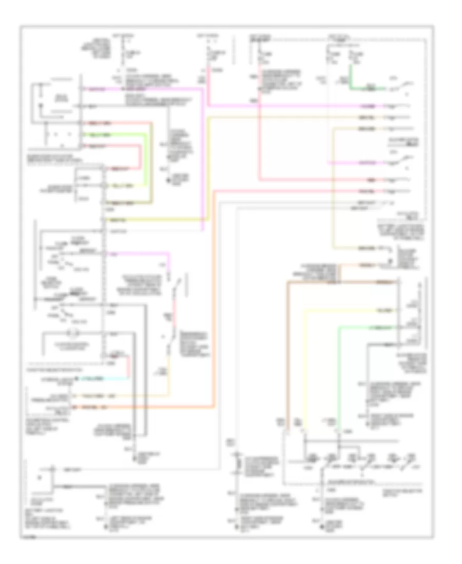
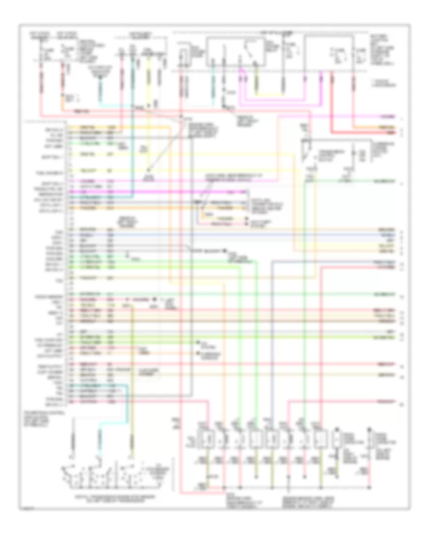
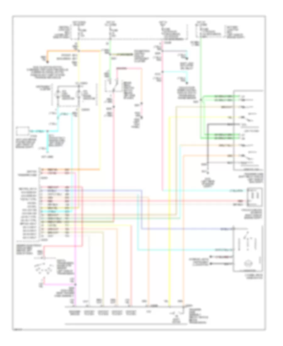
5.4L
5.4L, Manual A/C Wiring Diagram for Ford Cab & Chassis F350 Super Duty 2001
List of elements for 5.4L, Manual A/C Wiring Diagram for Ford Cab & Chassis F350 Super Duty 2001:
- (center of dash) g206
- (in engine harness, near breakout to 8 pin in-line connector, left side of engine compartment, near brake pressure switch) s102
- (in engine harness, near breakout to ground, right side of engine compartment, near battery) s180
- (in engine harness, near breakout to red
- (in engine sensor harness, near breakout to blower motor resistor) s152
- (in main harness, near break out to customer access) s290
- (in main harness, near breakout to customer access) s290
- (left rear of engine compartment, on firewall) g116
- (right side of engine compartment, near battery) g111
- 0.3 ohms
- 0.7 ohms
- 1.7 ohms
- 40 pin in-line connector, left of steering column) s123
- 87a
- A/c
- A/c clutch cycling pressure switch (in right rear of engine compartment, on a/c accumulator)
- A/c clutch diode
- A/c clutch relay
- A/c compressor clutch solenoid (in right side of engine compartment)
- A/c head pressure switch
- Battery junction box (in left side of engine compartment, on top of wheelwell)
- Blend door actuator (behind right side of dash)
- Blend door potentiometer
- Blower motor (on right side of firewall)
- Blower motor relay
- Blower motor resistor (on right side of firewall, on plenum)
- Blower motor switch
- Breakout to brake pedal position (bpp) switch) s235 (2000)
- C225
- C242a
- C242b
- C260
- C296
- C298
- Central junction box (behind lower left side of dash)
- Climate control illumination
- Cold
- Defrost
- Floor
- Floor/ defrost
- Function selector switch
- Fuse 10a
- Fuse 20a
- Fuse 22 10a
- Fuse 24 10a
- Fuse 40a
- High
- Hot at all times
- Hot in run
- Hot in run or start
- Interior lights system
- Low
- Max a/c
- Med high
- Med low
- Mode selector switch
- Off
- Pan/flr
- Panel
- Powertrain control module (pcm) (on left side of firewall)
- Red
- Refrigerant containment switch (in right side of engine compartment)
- S235 (2001) (in main harness, near breakout to data link connector (dlc))
- Solid state
- To air bag diagnostic module) s257
- Warm
6.8L
6.8L, Manual A/C Wiring Diagram for Ford Cab & Chassis F350 Super Duty 2001
List of elements for 6.8L, Manual A/C Wiring Diagram for Ford Cab & Chassis F350 Super Duty 2001:
- (center of dash) g206
- (in engine harness, near breakout to 8 pin in-line connector, left side of engine compartment, near brake pressure switch) s102
- (in engine harness, near breakout to ground, right side of engine compartment, near battery) s180
- (in engine harness, near breakout to red
- (in engine sensor harness, near breakout to blower motor resistor) s152
- (in main harness, near break out to customer access) s290
- (in main harness, near breakout to customer access) s290
- (left rear of engine compartment, on firewall) g116
- (right side of engine compartment, near battery) g111
- 0.3 ohms
- 0.7 ohms
- 1.7 ohms
- 40 pin in-line connector, left of steering column) s123
- 87a
- A/c
- A/c clutch cycling pressure switch (in right rear of engine compartment, on a/c accumulator)
- A/c clutch diode
- A/c clutch relay
- A/c compressor clutch solenoid (in right side of engine compartment)
- A/c head pressure switch
- Battery junction box (in left side of engine compartment, on top of wheelwell)
- Blend door actuator (behind right side of dash)
- Blend door potentiometer
- Blower motor (on right side of firewall)
- Blower motor relay
- Blower motor resistor (on right side of firewall, on plenum)
- Blower motor switch
- Breakout to brake pedal position (bpp) switch) s235 (2000)
- C225
- C242a
- C242b
- C260
- C296
- C298
- Central junction box (behind lower left side of dash)
- Climate control illumination
- Cold
- Defrost
- Floor
- Floor/ defrost
- Function selector switch
- Fuse 10a
- Fuse 20a
- Fuse 22 10a
- Fuse 24 10a
- Fuse 40a
- High
- Hot at all times
- Hot in run
- Hot in run or start
- Interior lights system
- Low
- Max a/c
- Med high
- Med low
- Mode selector switch
- Off
- Pan/flr
- Panel
- Powertrain control module (pcm) (on left side of firewall)
- Red
- Refrigerant containment switch (in right side of engine compartment)
- S235 (2001) (in main harness, near breakout to data link connector (dlc))
- Solid state
- To air bag diagnostic module) s257
- Warm
7.3L DI TURBO DIESEL
7.3L DI Turbo Diesel, Manual A/C Wiring Diagram for Ford Cab & Chassis F350 Super Duty 2001
List of elements for 7.3L DI Turbo Diesel, Manual A/C Wiring Diagram for Ford Cab & Chassis F350 Super Duty 2001:
- (center of dash) g206
- (in alternator rectifier harness, near breakout to a/c compressor clutch solenoid) s125
- (in engine harness, near breakout to ground, left rear of engine compartment, on firewall) s124
- (in engine harness, near breakout to ground, right side of engine compartment, near battery) s180
- (in engine sensor harness, near breakout to blower motor resistor) s152
- (in main harness, near breakout to brake pedal position (bpp) switch) s235 (2000)
- (in main harness, near breakout to customer access) s290
- (right side of engine compartment, near battery) g111
- 0.3 ohms
- 0.7 ohms
- 1.7 ohms
- 87a
- A/c
- A/c clutch cycling pressure switch (in right rear of engine compartment, on a/c accumulator)
- A/c clutch diode
- A/c compressor clutch solenoid (in right side of engine compartment)
- A/c head pressure switch
- Battery junction box (in left side of engine compartment, on top of wheelwell)
- Blend door actuator (behind right side of dash)
- Blend door potentiometer
- Blower motor (on right side of firewall)
- Blower motor relay
- Blower motor resistor (on right side of firewall, on plenum)
- Blower motor switch
- C225
- C242a
- C242b
- C260
- C296
- C298
- Central junction box (behind lower left side of dash)
- Climate control illumination
- Cold
- Defrost
- Floor
- Floor/ defrost
- Function selector switch
- Fuse 22 10a
- Fuse 24 10a
- Fuse 28 10a
- Fuse 40a
- High
- Hot at all times
- Hot in run
- Interior lights system
- Low
- Max a/c
- Med high
- Med low
- Mode selector switch
- Off
- Pan/flr
- Panel
- Powertrain control module (pcm) (on left side of firewall)
- Refrigerant containment switch (in right side of engine compartment)
- S117 (in engine harness, near breakout to windshield wiper motor)
- S235 (2001) (in main harness, near breakout to data link connector (dlc))
- S290 (in main harness, near breakout to customer access)
- Solid state
- To air bag diagnostic module) s257
- Vacuum pump (in right side of engine compartment)
- Warm
ANTI-LOCK BRAKES
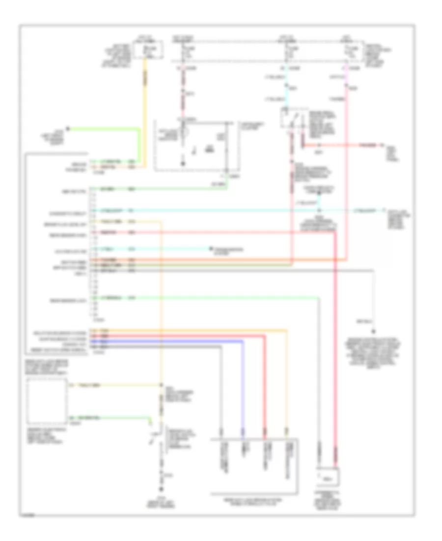
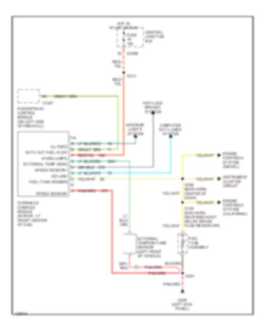
All-Wheel ABS Wiring Diagram for Ford Cab & Chassis F350 Super Duty 2001
List of elements for All-Wheel ABS Wiring Diagram for Ford Cab & Chassis F350 Super Duty 2001:
- 22k ohm
- 4-wheel anti-lock brake system (4wabs) module (in left front of engine compartment)
- 4x4 high/low ind
- 5.6k ohm
- Abs ind ctrl
- Anti-lock brake indicator
- Battery junction box (in left side of engine compt, on top of wheelwell)
- Bpp switch feed
- Brake fluid level sw
- Brake fluid level switch (on brake fluid reservoir)
- Brake pedal position (bpp) switch (behind left side of dash, above brake pedal)
- C104a
- C104b
- C240a
- C242b
- C250a
- C250c
- Central junction box (behind lower left side of dash)
- Computer data lines system
- Data link connector (behind center of dash)
- Diagnostic circuit
- Differential speed sensor (dss) (on center of rear axle)
- Engine controls system (generic electronic module (gem), instrument cluster, central junction box, overhead console module, powertrain control module, speed control servo)
- Fuse 10a
- Fuse 5a
- Fuse 60a
- G100 (left front of engine compt)
- G104 (rear of left front fender)
- G200 (left kick panel)
- Generic electronic module (gem) (behind lower left side of dash)
- Ground
- Hot at all times
- Hot in run
- Hot in run or start
- Ignition feed
- Instrument cluster
- Left front anti-lock brake sensor (at wheel)
- Left front sensor (high)
- Left front sensor (low)
- Nca
- Power (b+)
- Rear sensor (high)
- Rear sensor (low)
- Red/pnk
- Right front anti-lock brake sensor (at wheel)
- Right front sensor (high)
- Right front sensor (low)
- S102
- S108 (engine harness, near breakout to brake pressure switch)
- S201
- S201 (main harness, behind left side of dash)
- S213
- S221
- S225 (main harness, (near breakout to customer access)
- S235
- Tan/red
- Transmissions system
- Vss (+)
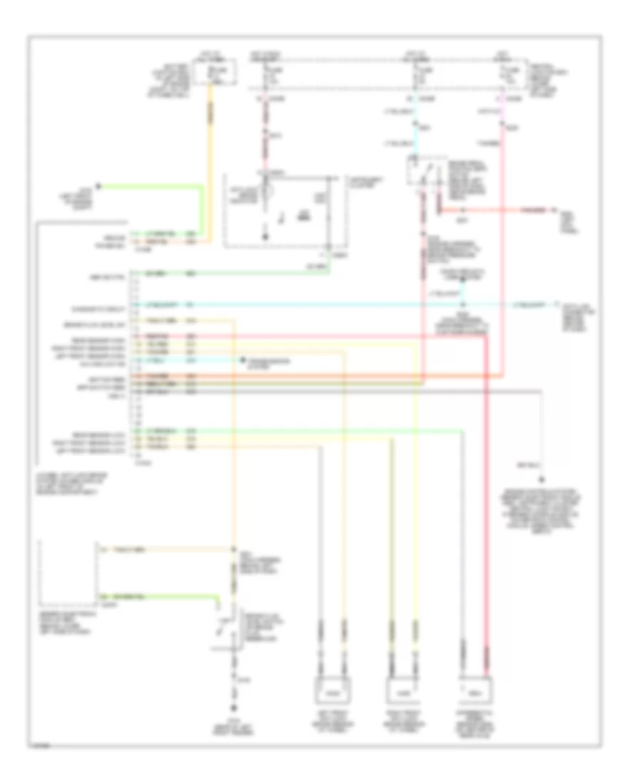
Rear Wheel ABS Wiring Diagram for Ford Cab & Chassis F350 Super Duty 2001
List of elements for Rear Wheel ABS Wiring Diagram for Ford Cab & Chassis F350 Super Duty 2001:
- 22k ohm
- 4x4 high/low ind
- 5.6k ohm
- Abs ind ctrl
- Anti-lock brake indicator
- Battery junction box (in left side of engine compt, on top of wheelwell)
- Bpp switch feed
- Brake fluid level sw
- Brake fluid level switch (on brake fluid reservoir)
- Brake pedal position (bpp) switch (behind left side of dash, above brake pedal)
- C104a
- C104b
- C240a
- C242b
- C250a
- C250c
- Central junction box (behind lower left side of dash)
- Common (12 v)
- Common (12v)
- Computer data lines system
- Data link connector (behind center of dash)
- Diagnostic circuit
- Differential speed sensor (dss) (on center of rear axle)
- Dump solenoid (1-2 ohms)
- Engine controls system (generic electronic module (gem), instrument cluster, central junction box, overhead console module, powertrain control module, speed control servo)
- Fuse 10a
- Fuse 5a
- Fuse 60a
- G100 (left front of engine compt)
- G104 (rear of left front fender)
- G200 (left kick panel)
- Generic electronic module (gem) (behind lower left side of dash)
- Ground
- Hot at all times
- Hot in run
- Hot in run or start
- Ignition feed
- Instrument cluster
- Isolation solenoid (4 ohms)
- Power (b+)
- Rear anti-lock brake system (rabs) hydraulic valve
- Rear anti-lock brake system (rabs) module (in left front of engine compartment)
- Rear sensor (high)
- Rear sensor (low)
- Red
- Red/pnk
- Reset switch (normally open)
- Reset switch (open normal)
- S102
- S108 (engine harness, near breakout to brake pressure switch)
- S201
- S201 (main harness, behind left side of dash)
- S213
- S221
- S225 (main harness, (near breakout to customer access)
- S235
- Tan
- Tan/red
- Transmissions system
- Vss (+)
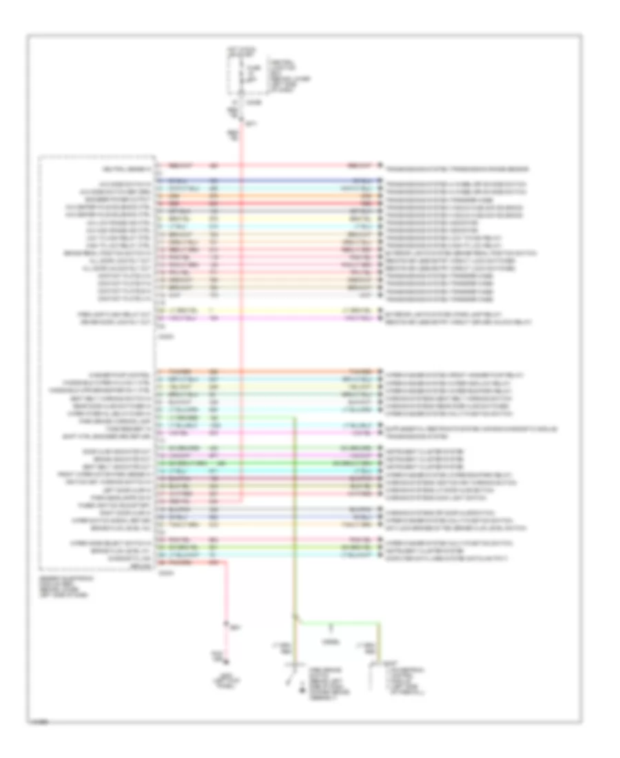
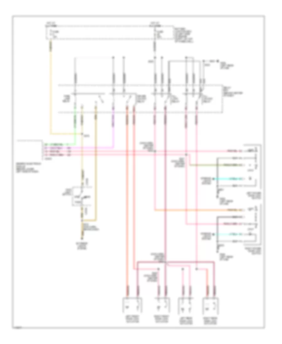
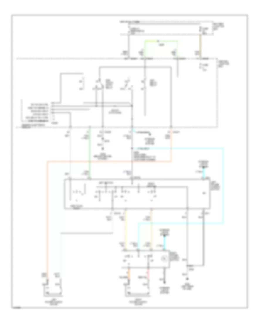
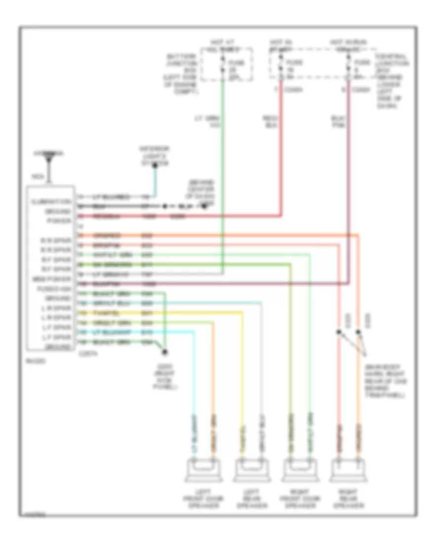
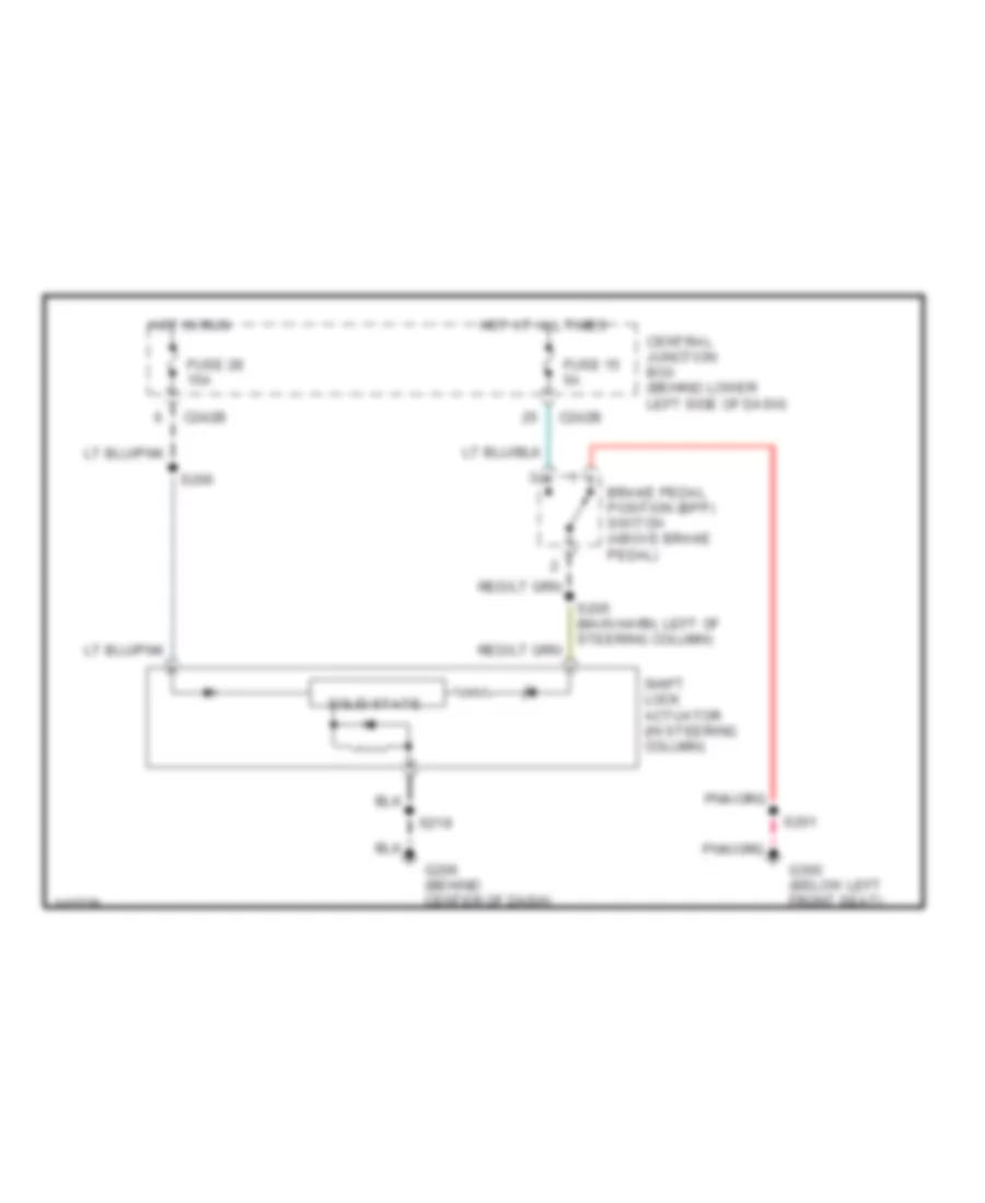
BODY CONTROL MODULES
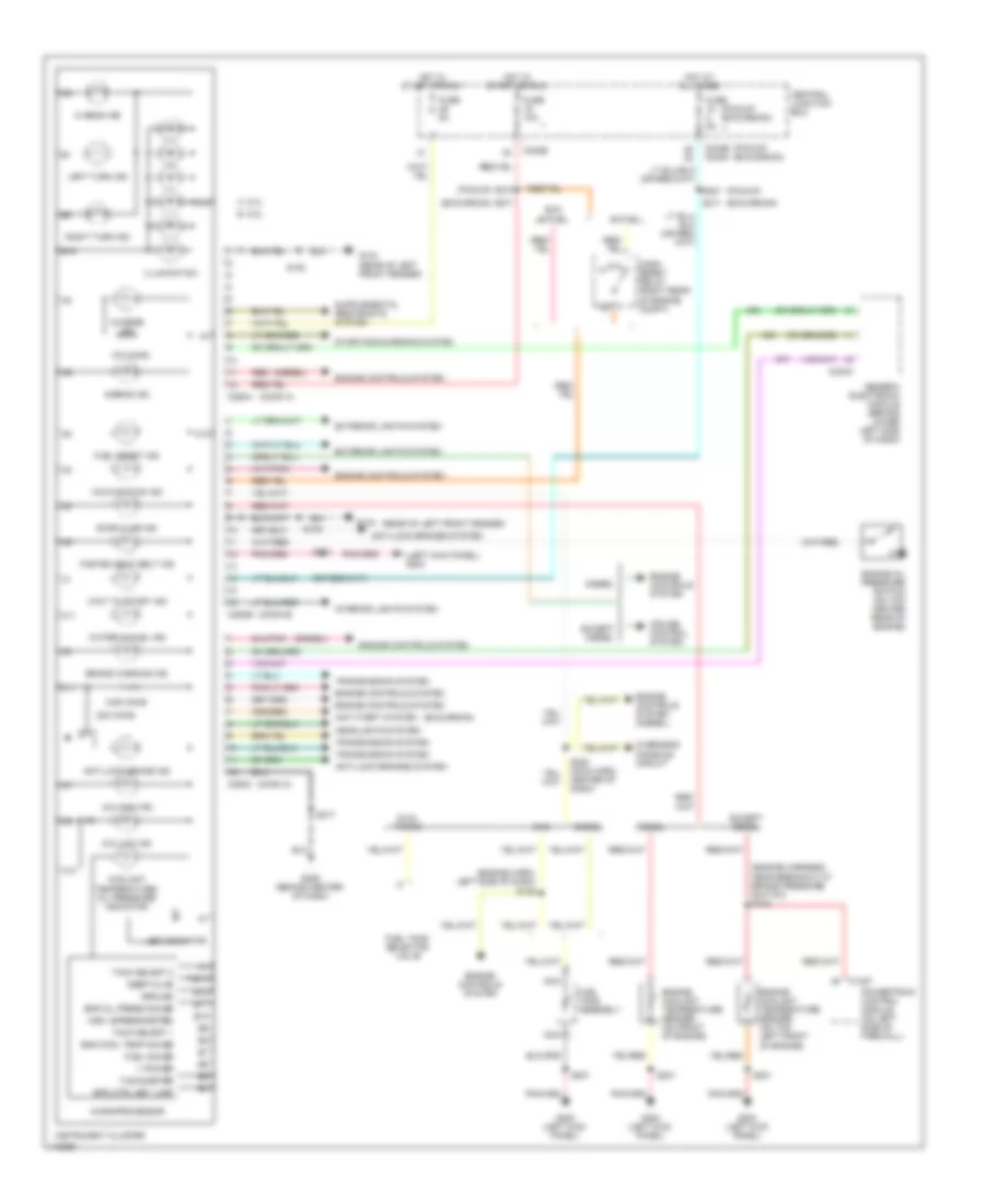
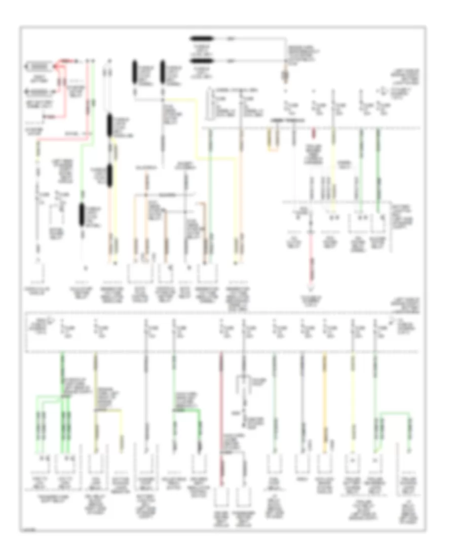
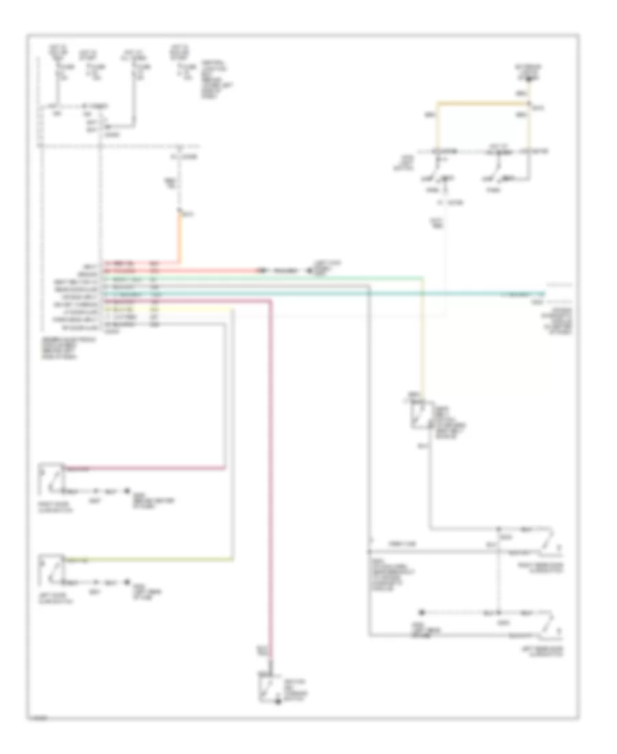
Body Control Modules Wiring Diagram (1 of 2) for Ford Cab & Chassis F350 Super Duty 2001
List of elements for Body Control Modules Wiring Diagram (1 of 2) for Ford Cab & Chassis F350 Super Duty 2001:
- (2000)
- (2001)
- 87a
- Accessory delay relay
- Accessory delay relay ctrl
- Battery junction box (left side of engine compt)
- C240d
- C242a
- C242b
- C250b
- Central junction box (behind lower left side of dash)
- Circuit breaker 25 30a
- Engine controls system
- Fuse 10a
- Fuse 15a
- Fuse 5a
- Fused battery power (b+)
- Fused ignition (acc/run)
- Fused ignition (start)
- G206 (behind center of dash)
- Generic electronic module (gem)
- Headlamp interior switch
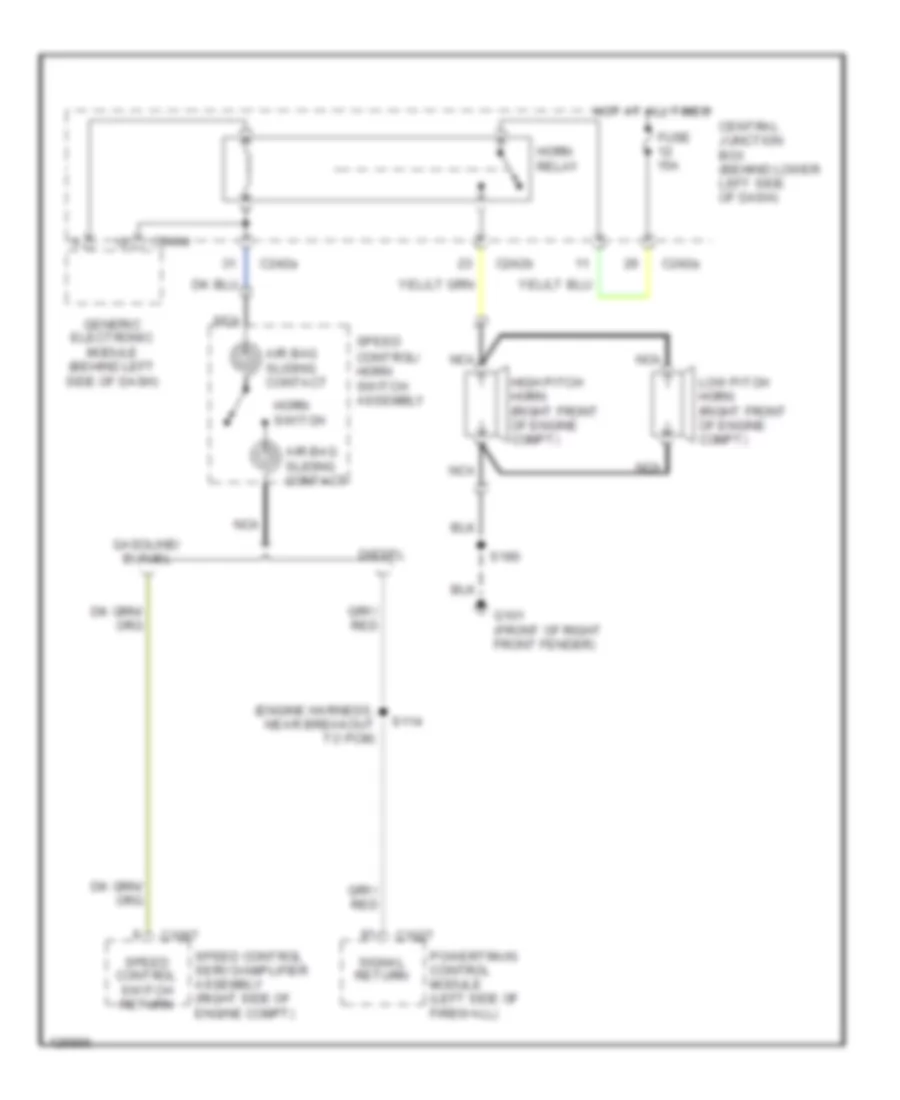
- Horn relay
- Horn relay ctrl
- Horns system
- Hot at all times
- Hot in
- Hot in run or acc
- Ignition input (hot in run)
- Instrument cluster
- Interior lamp relay
- Interior lamp relay coil ctrl
- Interior lights system
- Lf window motor sense (high)
- Lf window motor sense (low)
- Lf window switch input (dn)
- One touch down relay
- One touch down relay ctrl
- One touch down switch in
- Overhead console module
- Power windows system
- S218
- Start
- Vehicle speed (+) input
- Vss
Body Control Modules Wiring Diagram (2 of 2) for Ford Cab & Chassis F350 Super Duty 2001
List of elements for Body Control Modules Wiring Diagram (2 of 2) for Ford Cab & Chassis F350 Super Duty 2001:
- 4x2 center axle solenoid ctrl
- 4x4 center axle solenoid ctrl
- 4x4 high range ind ctrl
- 4x4 low range ind ctrl
- 4x4 mode switch in
- 4x4 mode switch ref (grd)
- All door lock rly out
- All door unlock rly out
- Anti-lock brakes sytem (brake fluid level switch)
- Brake fluid level in 1
- Brake fluid level in 2
- Brake indicator out
- Brake pedal position switch in
- C1027
- C240a
- C240c
- C242b
- Central junction box (behind lower left side of dash)
- Computer data lines system (datalink pin 7)
- Contact plate a in
- Contact plate b in
- Contact plate c in
- Contact plate p in
- Diagnostic link
- Diesel
- Door ajar indicator out
- Driver door lock rly out
- Encoder power output
- Exterior lights system (brake pedal position switch)
- Exterior lights system (park lamp relay)
- Front wiper motor park sense in
- Fuse 10a
- Fused ignition (run/start)
- G200 (left kick panel)
- Generic electronic module (gem) (behind lower left side of dash)
- Ground
- High to low relay ctrl
- Hot in run or start
- Ignition key warning switch in
- Instrument cluster system
- Left door ajar in
- Low to high relay ctrl
- Neutral sense in
- Park brake switch (behind left side of dash, on park brake assembly)
- Park brake warning lamp
- Park/headlamps on in
- Parklamp flash relay out
- Powertrain control module (left side of firewall)
- Rear door ajar switches in
- Red
- Remote keyless entry circuit (driver unlock relay)
- Remote keyless entry circuit (lock switches)
- Right door ajar in
- S201
- S271
- Seat belt indicator out
- Seat belt warning switch in
- Shift ctrl encoder grd return
- Tan/red
- Tone request in
- Transmissions system
- Transmissions system (4 wheel drive mode switch)
- Transmissions system (high to low relay)
- Transmissions system (indicator)
- Transmissions system (low to high relay)
- Transmissions system (transfer case)
- Transmissions system (transmission range sensor)
- Transmissions system (vacuum hublock solenoid)
- Warning systems (ignition key warning switch)
- Warning systems (lf door ajar switch)
- Warning systems (main light switch)
- Warning systems (rear door ajar switches)
- Warning systems (rf door ajar switch)
- Warning systems (seat belt warning switch)
- Washer pump control
- Windshield wiper hi/lo rly ctrl
- Wiper interval delay/wash in
- Wiper mode select switch in
- Wiper switch signal return
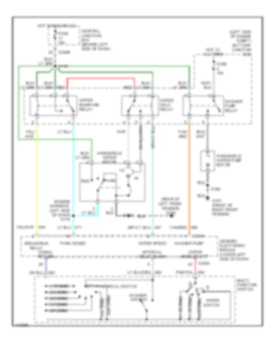
- Wiper/washer system (front washer pump relay)
- Wiper/washer system (multi-function switch)
- Wiper/washer system (wiper high/low relay)
- Wiper/washer system (wiper run/park relay)
- Wndshield wpr brake/park rly ctrl
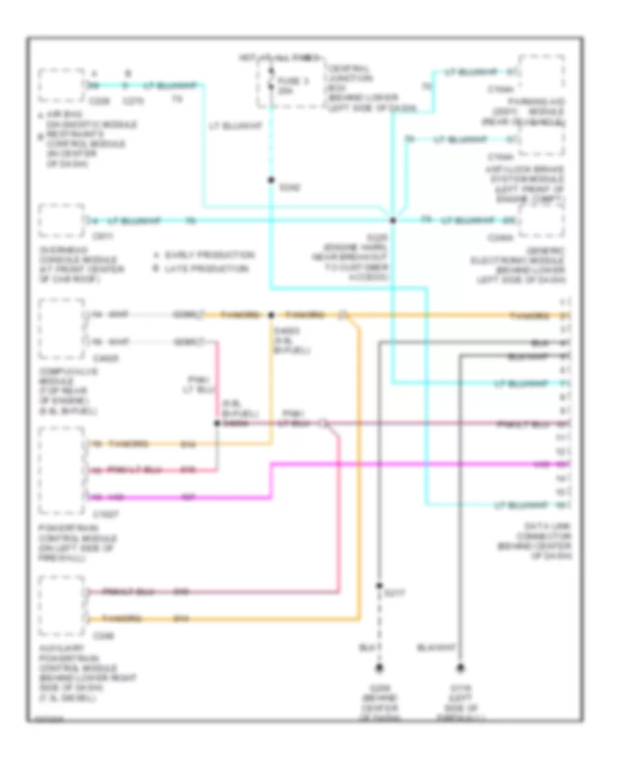
COMPUTER DATA LINES
Computer Data Lines Wiring Diagram for Ford Cab & Chassis F350 Super Duty 2001
List of elements for Computer Data Lines Wiring Diagram for Ford Cab & Chassis F350 Super Duty 2001:
- (2001)
- (6.8l bi-fuel) s4004
- A early production
- Air bag a diagnostic module restraints b control module (in center of dash)
- Anti-lock brake system module (left front of engine compt)
- Auxiliary powertrain control module (behind lower right side of dash) (7.3l diesel)
- B late production
- C1027
- C104a
- C228
- C240a
- C248
- C270
- C4025
- C911
- Central junction box (behind lower left side of dash)
- Compuvalve module (top rear of engine) (6.8l bi-fuel)
- Data link connector (behind center of dash)
- Fuse 3 20a
- G116 (left side of firewall)
- G206 (behind center of dash)
- Generic electronic module (behind lower left side of dash)
- Go85
- Go86
- Hot at all times
- Overhead console module (at front center of cab roof)
- Parking aid module (rear of vehicle)
- Powertrain control module (on left side of firewall)
- S217
- S225 (engine harn, near breakout to customer access)
- S242
- S4003 (6.8l bi-fuel)
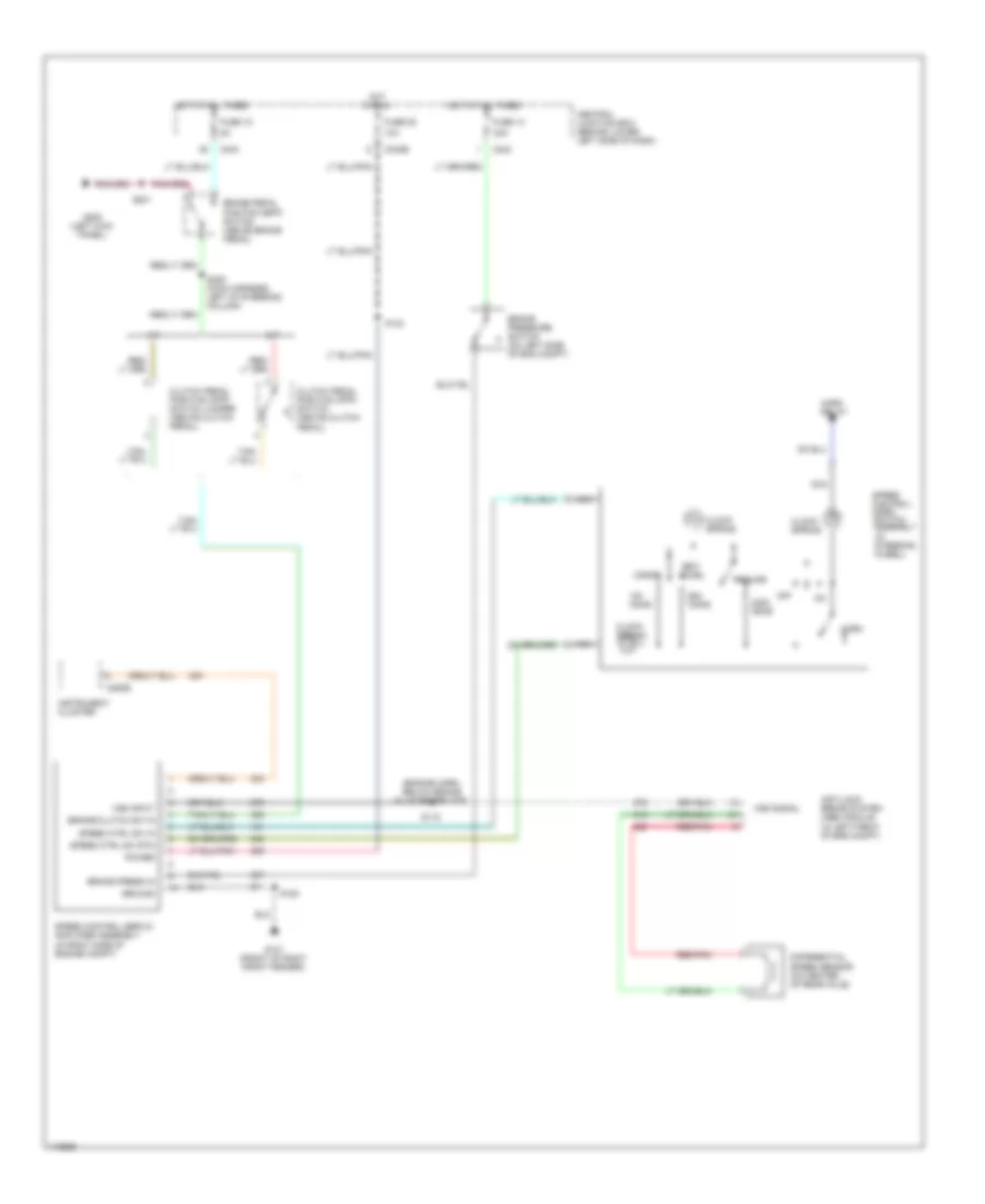
CRUISE CONTROL
5.4L
5.4L, Cruise Control Wiring Diagram for Ford Cab & Chassis F350 Super Duty 2001
List of elements for 5.4L, Cruise Control Wiring Diagram for Ford Cab & Chassis F350 Super Duty 2001:
- (engine harn, below brake fluid reservoir)
- 10a
- 20a
- A/t
- Accel
- Anti-lock brake system (abs) module (in left front of eng compt)
- Brake pedal position (bpp) switch (above brake pedal)
- Brake press in
- Brake pressure switch (on left side of eng compt)
- Brake/clutch sw in
- C242
- C242b
- C243
- C250b
- Central junction box (behind lower left side of dash)
- Clock spring
- Clutch pedal position (cpp) switch (above clutch pedal)
- Clutch pedal position (cpp) switch jumper (above clutch pedal)
- Coast
- Differential speed sensor (on center of rear axle)
- Fuse 13
- Fuse 15
- Fuse 28
- G101 (front of right front fender)
- G200 (left kick panel)
- Ground
- Horn
- Horn relay
- Hot at all times
- Hot in run
- Instrument cluster
- M/t
- Nca
- Off
- Ohms
- Power
- Red/pnk
- Resume
- S115
- S124
- S180
- S201
- S205 (main harness, left of steering column)
- Set/
- Speed control servo/ amplifier assembly (in right side of engine compt)
- Speed control/ horn switch assembly (in steering wheel)
- Speed ctrl sw in
- Speed ctrl sw rtn
- Vss input
- Vss signal
6.8L
6.8L, Cruise Control Wiring Diagram for Ford Cab & Chassis F350 Super Duty 2001
List of elements for 6.8L, Cruise Control Wiring Diagram for Ford Cab & Chassis F350 Super Duty 2001:
- (engine harn, below brake fluid reservoir)
- 10a
- 20a
- A/t
- Accel
- Anti-lock brake system (abs) module (in left front of eng compt)
- Brake pedal position (bpp) switch (above brake pedal)
- Brake press in
- Brake pressure switch (on left side of eng compt)
- Brake/clutch sw in
- C242
- C242b
- C243
- C250b
- Central junction box (behind lower left side of dash)
- Clock spring
- Clutch pedal position (cpp) switch (above clutch pedal)
- Clutch pedal position (cpp) switch jumper (above clutch pedal)
- Coast
- Differential speed sensor (on center of rear axle)
- Fuse 13
- Fuse 15
- Fuse 28
- G101 (front of right front fender)
- G200 (left kick panel)
- Ground
- Horn
- Horn relay
- Hot at all times
- Hot in run
- Instrument cluster
- M/t
- Nca
- Off
- Ohms
- Power
- Red/pnk
- Resume
- S115
- S124
- S180
- S201
- S205 (main harness, left of steering column)
- Set/
- Speed control servo/ amplifier assembly (in right side of engine compt)
- Speed control/ horn switch assembly (in steering wheel)
- Speed ctrl sw in
- Speed ctrl sw rtn
- Vss input
- Vss signal
7.3L DI TURBO DIESEL
7.3L DI Turbo Diesel, Cruise Control Wiring Diagram for Ford Cab & Chassis F350 Super Duty 2001
List of elements for 7.3L DI Turbo Diesel, Cruise Control Wiring Diagram for Ford Cab & Chassis F350 Super Duty 2001:
- 10a
- Accel
- Anti-lock brake system (abs) module (in left front of eng compt)
- Battery junction box (left side of engine compt)
- Brake pedal position (bpp) switch (above brake pedal)
- Brake position in
- Brake press in
- Brake pressure switch (on left side of eng compt)
- C242b
- Central junction box (behind left side of dash)
- Clock spring
- Clutch pedal position (cpp) switch (m/t only) (above clutch pedal)
- Clutch position in
- Coast
- Differential speed sensor (on center of rear axle)
- Fuse 15
- Fuse 19
- G206 (behind center of dash)
- Horn
- Horn system
- Hot at all times
- Hot in start or run
- Nca
- Off
- Ohms
- Pcm power relay
- Powertrain control module (on left side of firewall)
- Red
- Red/pnk
- Resume
- S108 (engine harn, near brake pressure switch)
- S114 (engine harn, near b/o to pcm)
- S115 (engine harn, below brake fluid reservoir)
- S123 (engine harness, left of steering column)
- S201
- S213
- Set/
- Speed control/ horn switch assembly (in steering wheel)
- Speed ctrl sw in
- Speed ctrl sw rtn
- Vss input
- Vss signal
ENGINE PERFORMANCE
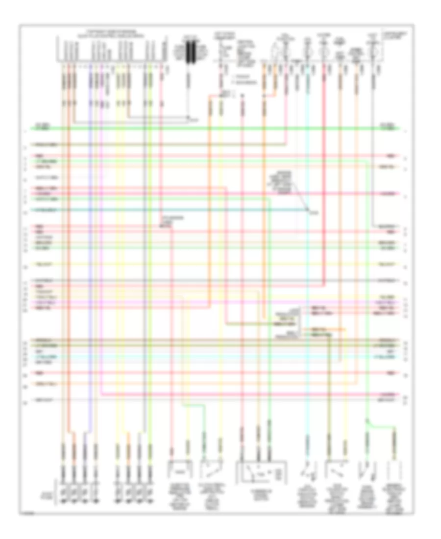
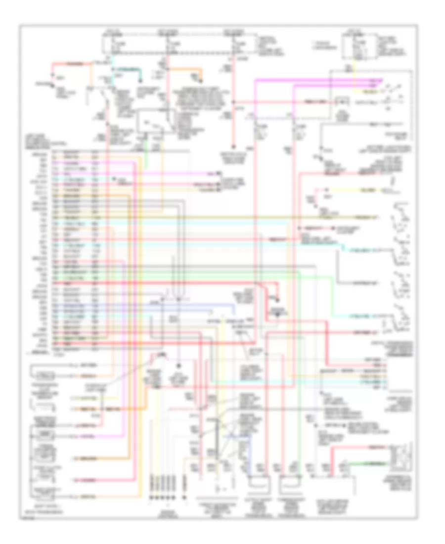
5.4L
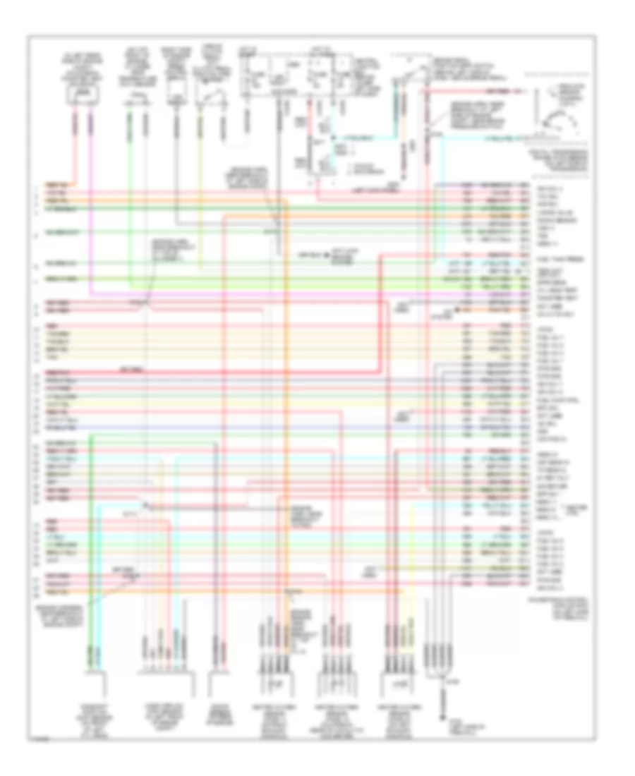
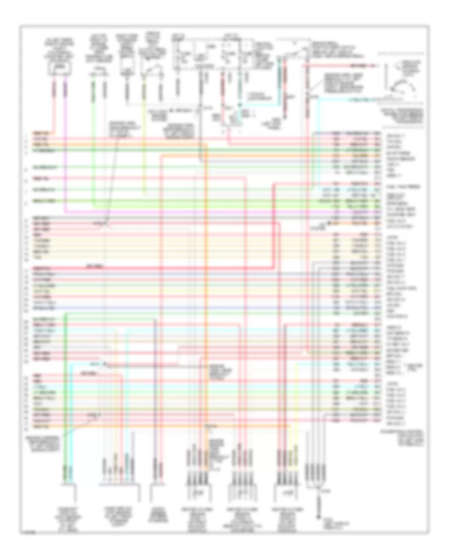
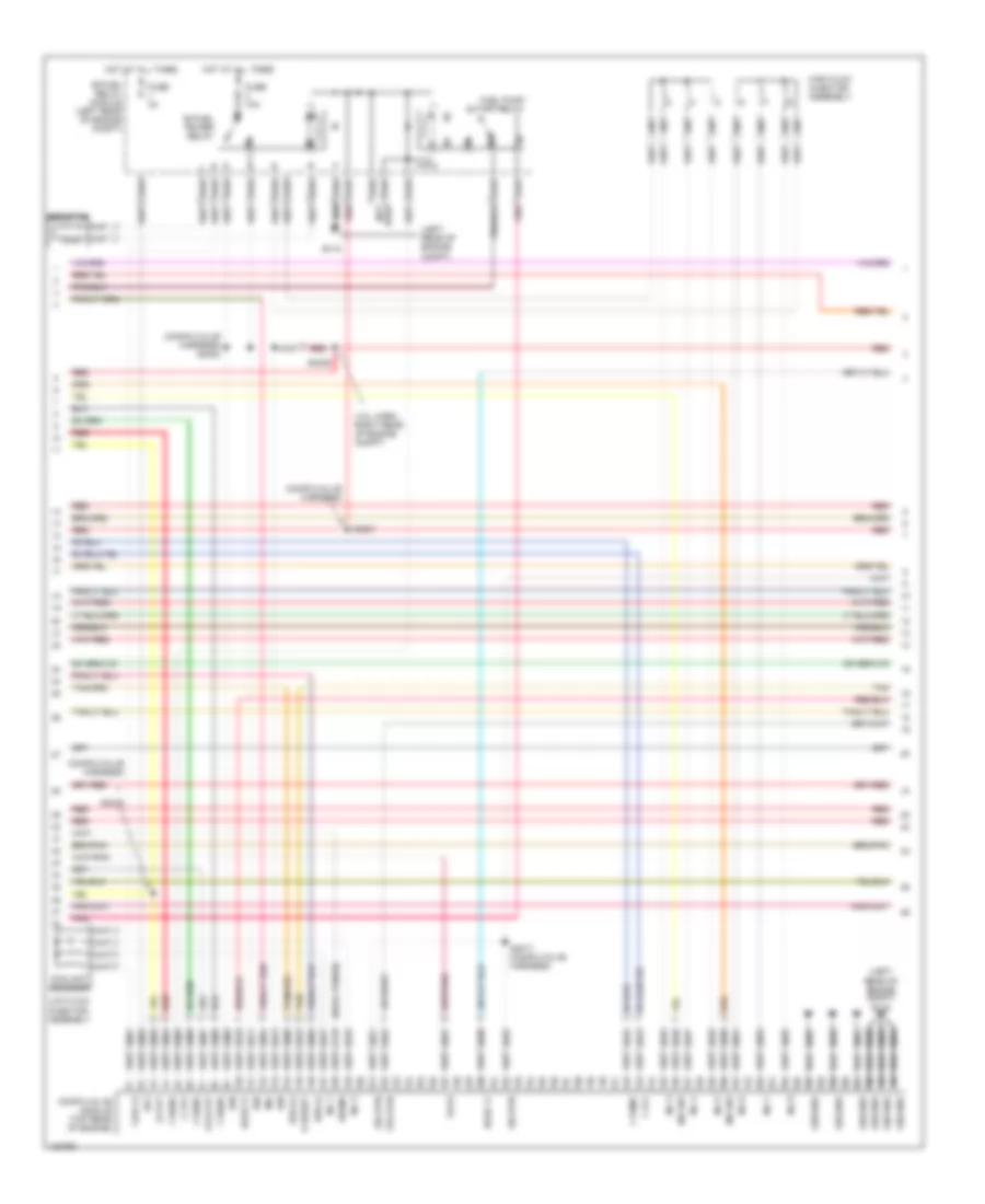
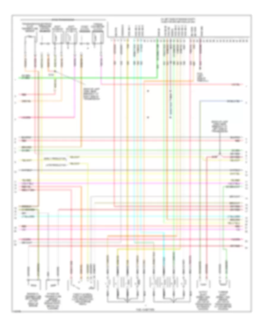
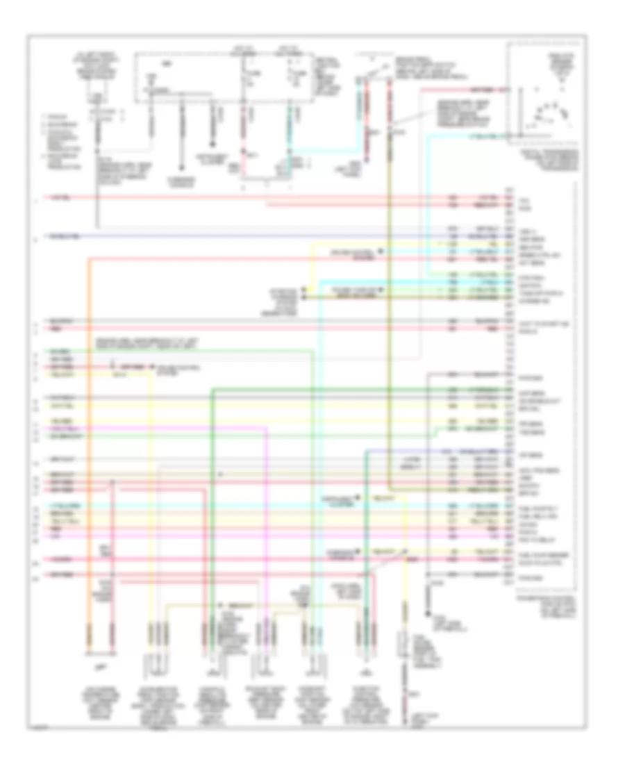
5.4L, Engine Performance Wiring Diagram (1 of 4) for Ford Cab & Chassis F350 Super Duty 2001
List of elements for 5.4L, Engine Performance Wiring Diagram (1 of 4) for Ford Cab & Chassis F350 Super Duty 2001:
- (engine harn, near breakout at left side of engine compt)
- (engine sensor harn, near breakout at right side of engine, above cylinder 3)
- (left kick panel)
- (main harn, near breakout at center of dash, on dlc)
- (not used)
- (pickup)
- (rear of left front fender)
- 4x4 high/low indicator switch
- 4x4 low ind sw
- 4x4 low ind
- A/c press sw
- A/c system
- Anti-theft system
- Battery junction box (in left side of engine compt, on top of wheelwell)
- C242b
- C250b
- C250c
- Ccs
- Central junction box (behind lower left side of dash)
- Ckp(+)
- Ckp(-)
- Coil on plug
- Cust access
- Customer access
- Data link (+)
- Data link (-)
- Data link connector (dlc) (behind center of dash)
- Data output
- Diag grd
- Digital transmission range (dtr) sensor (on left side of transmission)
- Egr sol
- Fuel gauge
- Fuel gauge in
- Fuel pump mon
- Fuse 10a
- Fuse 20a
- Fuse 30a
- G102 (left side of firewall)
- G104
- G200
- Hego 12
- Hot at all times
- Hot in run or start
- Iat
- Ign coil 1
- Ign coil 3
- Ign coil 5
- Ign coil 6
- Instrument cluster
- Knock sensor
- Maf
- Mil ind
- Nca
- Not used
- O/d off ind
- Overdrive cancel switch (a/t)
- Overhead console
- Pcm power diode
- Pcm power relay
- Pickup excursion
- Powertrain control module (pcm) (on left side of firewall)
- Pwr gnd
- R n
- Radio noise capacitor (on left side of engine)
- Radio noise capacitor (on right side of engine)
- Red
- Reprog pwr
- S102
- S105
- S106
- S129 (calif)
- S130 (engine harn, near breakout at throttle body)
- S135
- S179
- S201
- S208
- S213 s271
- S284
- S286
- Shift sol 1
- Shift sol 2
- Tach
- Tcs
- Temp output
- Tft
- To dtr sensor (diagram 4 of 4)
- Tr1
- Tr2
- Tr4
- Trans ctrl ind
- Transmission control switch
- Vss (-)
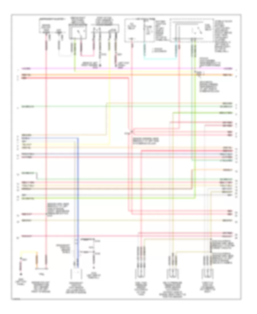
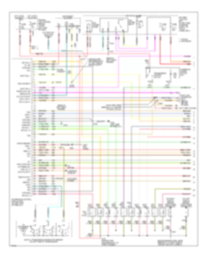
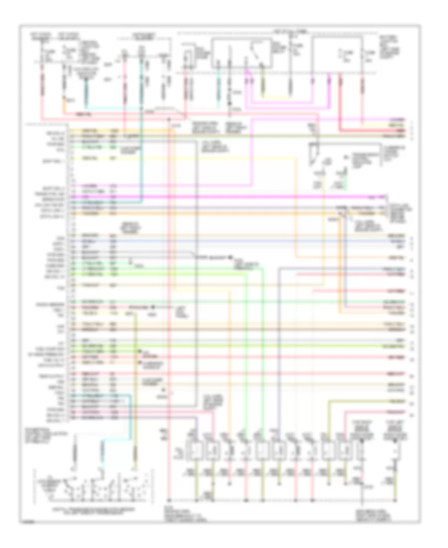
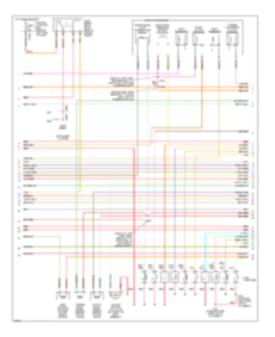
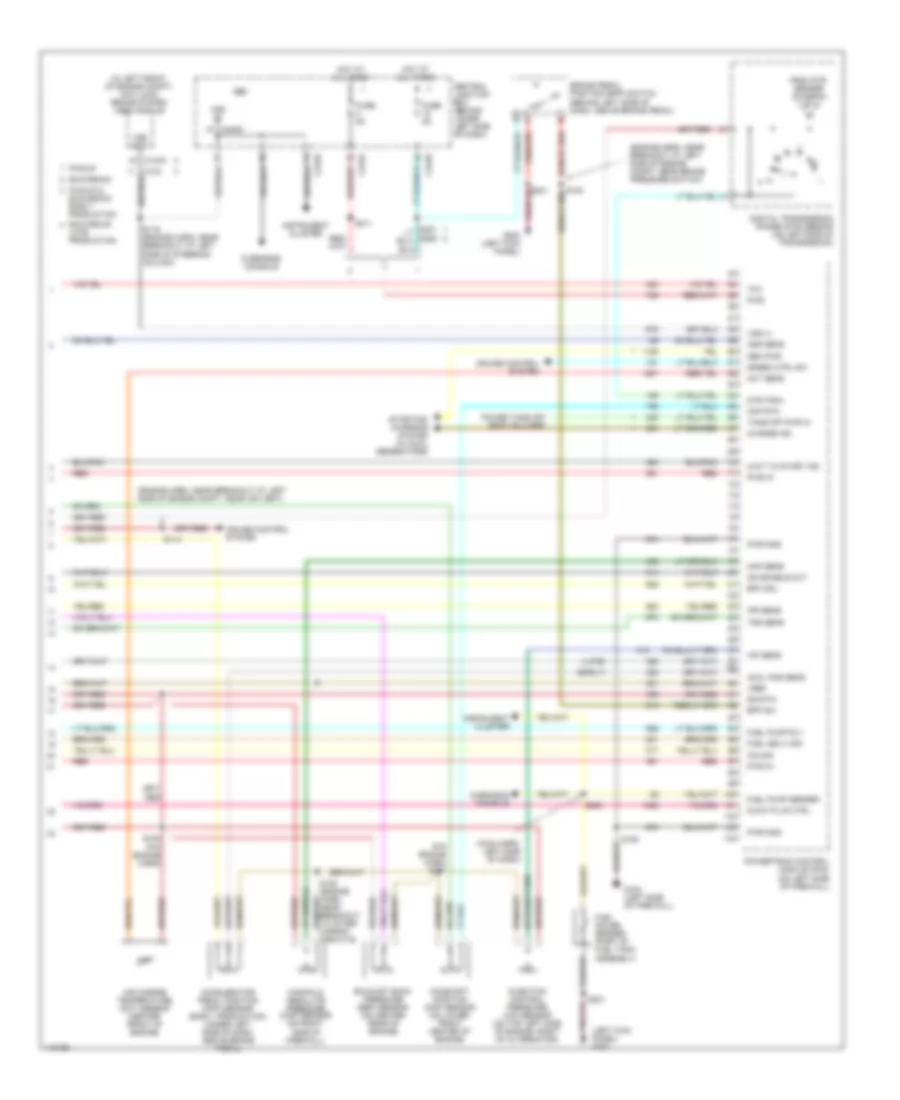
5.4L, Engine Performance Wiring Diagram (2 of 4) for Ford Cab & Chassis F350 Super Duty 2001
List of elements for 5.4L, Engine Performance Wiring Diagram (2 of 4) for Ford Cab & Chassis F350 Super Duty 2001:
- (behind right kick panel) inertia fuel shut-off switch
- (engine harn, near breakout at left side of engine compt, near brake pressure switch) s104
- (engine harness, near breakout at left side of steering column)
- (excursion: engine harness, near breakout at left side of steering column)
- (left kick panel) g200
- (not used)
- (part of fuel tank assembly) fuel pump/fuel gauge sender
- (pickup: main harness, near breakout to customer access)
- (rear of left front fender) g104
- A/c clutch relay
- Battery junction box (in left side of engine compt, on top of wheelwell)
- C250b
- C250c
- Crankshaft position (ckp) sensor (on lower front center of engine)
- Crankshaft position sensor shield
- Delta pressure feedback egr (dpfe) sensor (california) (on right side of engine, near throttle position sensor)
- Engine coolant temp gauge
- Engine coolant temperature (ect) sender (on top left front of engine)
- Fuel pump relay
- Fuel tank pressure sensor (california) (at fuel tank)
- Fuse 20a
- G102 (left side of firewall)
- G200 (left kick panel)
- Hot at all times
- I/p relay block (pickup) battery junction box (excursion) (pickup: behind dash, near instrument cluster) (excursion: in left side of engine compt, on top of wheelwell)
- Instrument cluster
- Nca
- Pickup excursion
- Red
- Red/pnk
- S102
- S106
- S123
- S128 (california) (engine harn, near breakout to after- market circuits)
- S133 (california) (engine harn, near breakout at left side of engine, above cylinder 6)
- S145
- S201
- S226 s164
- Throttle position (tp) sensor (on throttle body)
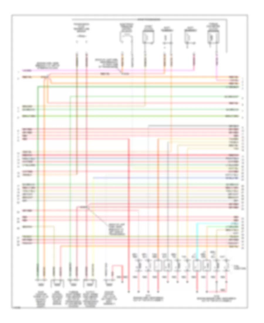
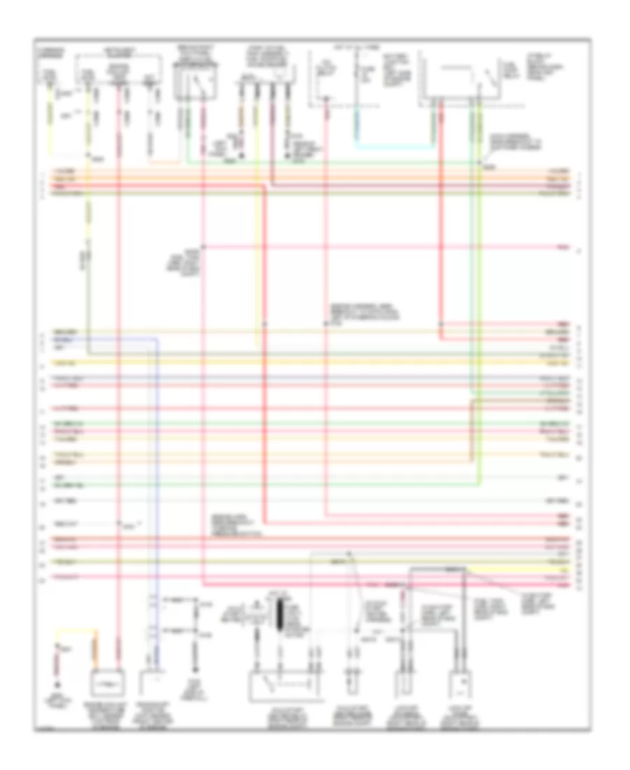
5.4L, Engine Performance Wiring Diagram (3 of 4) for Ford Cab & Chassis F350 Super Duty 2001
List of elements for 5.4L, Engine Performance Wiring Diagram (3 of 4) for Ford Cab & Chassis F350 Super Duty 2001:
- (back-up lamp harn, near break- out at left side of transmission)
- (back-up lamp harn, near breakout at right side of transmission)
- (engine harn, near breakout at left of steering column)
- (engine sensor harn, near breakout at top of cylinder 3)
- (on right rear of engine compt)
- 4r100 transmission
- Coast clutch solenoid
- Egr control solenoid (on left side of engine)
- Electronic pressure control solenoid
- Evap canister purge valve
- Fuel injectors
- Idle air control (iac) valve (on throttle body assembly)
- Output shaft speed (oss) sensor (on top of transmission extension housing)
- Red
- Red/pnk
- S122
- S131 (engine harn, near break- out at top of cylinder 7)
- S136
- S138
- S139
- Shift solenoid 1
- Shift solenoid 2
- Tan
- Tan/ red
- Tan/red
- Torque converter clutch solenoid
- Transmission fluid temperature sensor
- Turbine shaft speed (tss) sensor (on top of transmission, at converter housing)
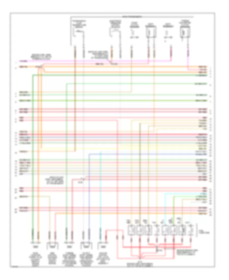
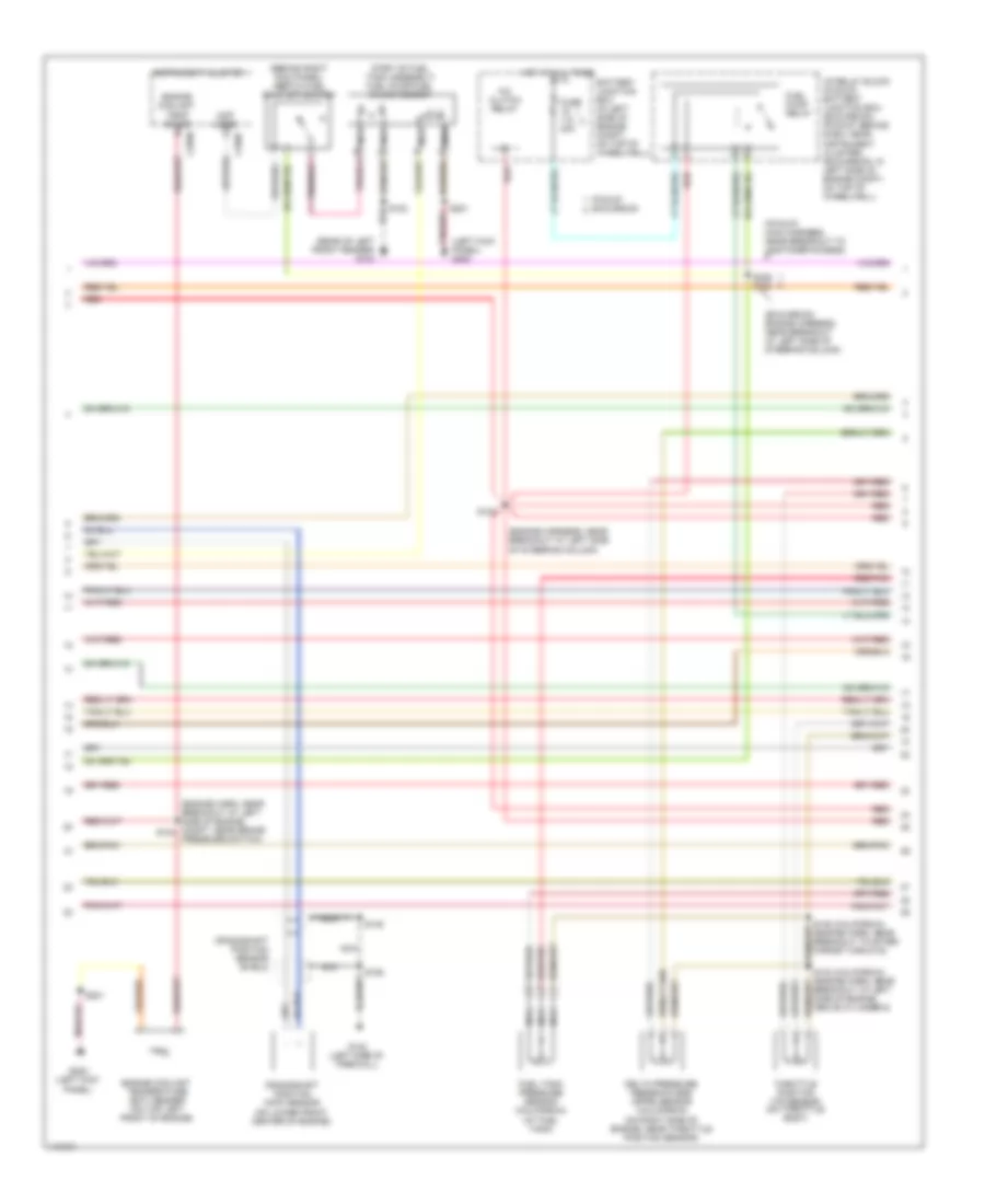
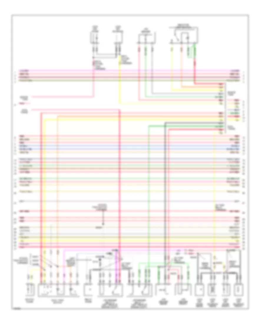
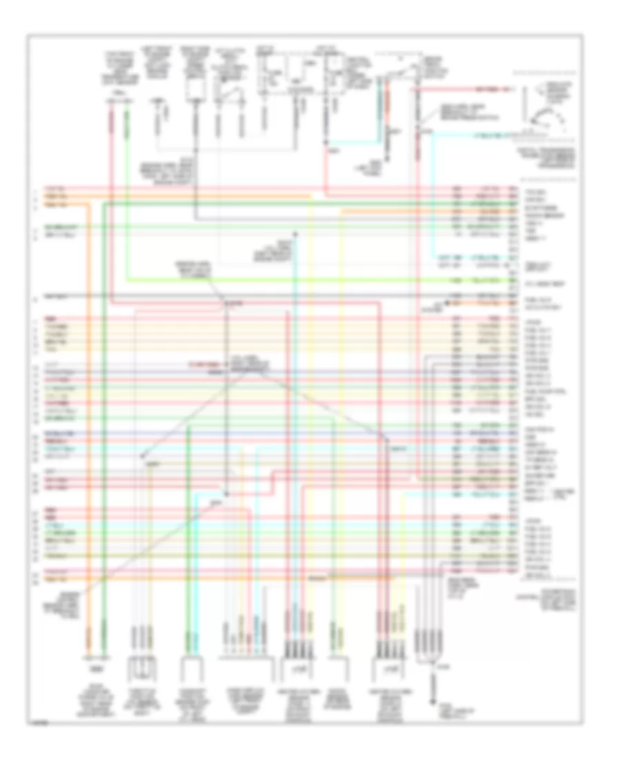
5.4L, Engine Performance Wiring Diagram (4 of 4) for Ford Cab & Chassis F350 Super Duty 2001
List of elements for 5.4L, Engine Performance Wiring Diagram (4 of 4) for Ford Cab & Chassis F350 Super Duty 2001:
- (a/t)
- (above clutch pedal) (m/t) clutch pedal position (cpp) switch
- (calif)
- (engine harn, near breakout at left side of engine compt)
- (engine harn, near breakout at left side of engine compt, near brake pressure switch)
- (engine harn, near breakout at top of cylinder 7)
- (engine harn, near breakout to pcm)
- (engine harness, near breakout at left side of engine compt)
- (in left rear side of engine compt) (california) canister vent solenoid
- (m/t)
- (not used)
- (on top front of engine) cylinder head temperature (cht) sensor
- (right side of engine compt) speed control servo
- 5v ref volt
- A/c cltch rly
- A/c system
- Anti-lock brakes system
- Bpp sw
- Brake pedal position (bpp) switch (behind left side of dash, above brake pedal)
- C240d
- C242a
- C242b
- Cam pos in
- Camshaft position (cmp) sensor (on front of left cyl head)
- Canister vent
- Central junction box (behind lower left side of dash)
- Cyl 8)
- Cyl head temp
- Digital transmission range (dtr) sensor (on left side of transmission)
- Dpfe sens
- Epc sol
- From dtr sensor (diagram 1 of 4)
- Fuel inj 1
- Fuel inj 2
- Fuel inj 3
- Fuel inj 4
- Fuel inj 5
- Fuel inj 6
- Fuel inj 7
- Fuel inj 8
- Fuel pump ctrl
- Fuel tank press
- Fuse 15a
- Fuse 5a
- G102 (left side of firewall)
- G200 (left kick panel)
- Gem
- Heated oxygen sensor (ho2s) 11 (on right exhaust manifold)
- Heated oxygen sensor (ho2s) 12 (california) (rear of catalytic converter)
- Heated oxygen sensor (ho2s) 21 (on left exhaust manifold)
- Heater ctrl
- Hego 11
- Hego 12
- Hego 21
- Hot at all times
- Hot in start
- Iac sol
- Ign coil 2
- Ign coil 4
- Ign coil 7
- Ign coil 8
- Kap b(+)
- Knock sensor
- Knock sensor (on rear of engine)
- Maf sens in
- Mass airflow (maf) sensor (in left front of engine compt)
- Nca
- Not used
- Oss
- Pickup excursion
- Powertrain control module (pcm) (on left side of firewall)
- Pwr gnd
- Red
- Red/pnk
- S106
- S114
- S115
- S129
- S132
- S134
- S211
- S221
- S288
- Sig return
- Tan
- Tan/red
- Tcc sol
- Tp sens in
- Tr3a (a/t) cpp (m/t)
- Tss
- Vapor valve
- Vpwr
- Vss (+)
- Vss input
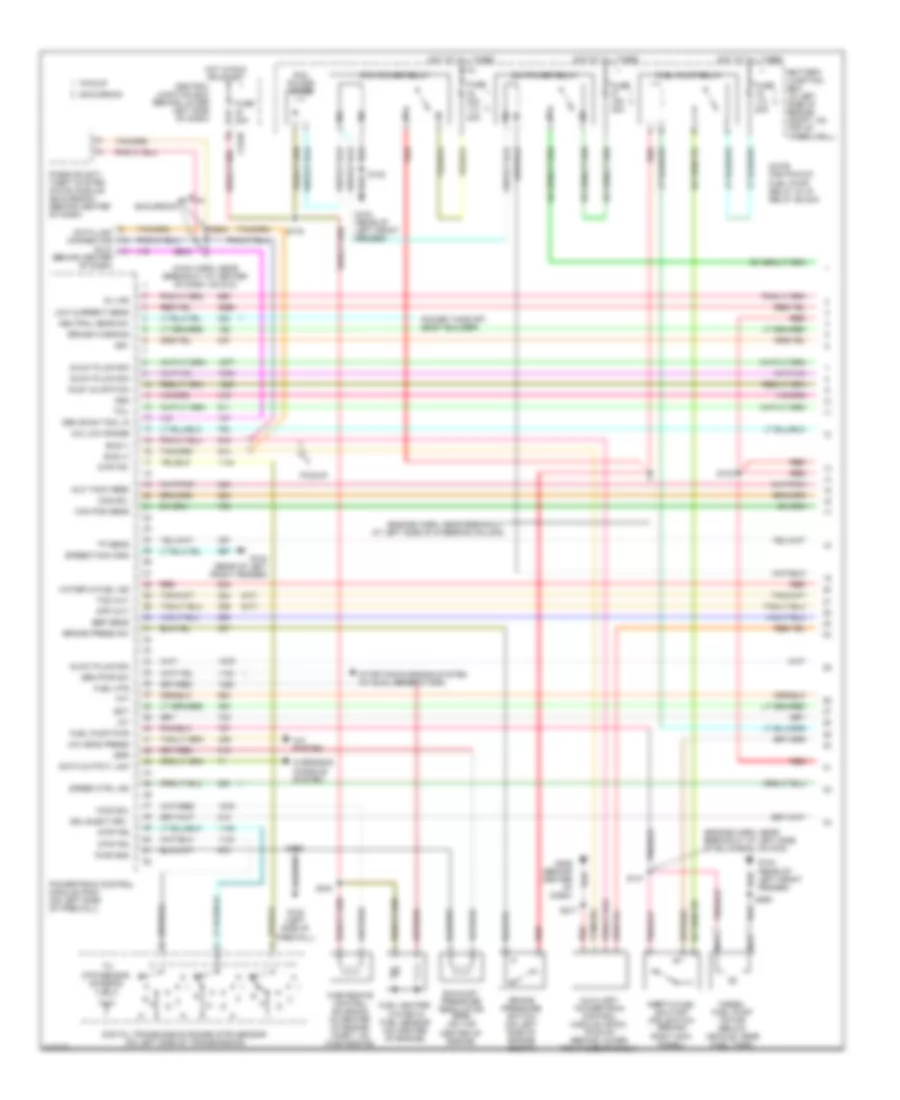
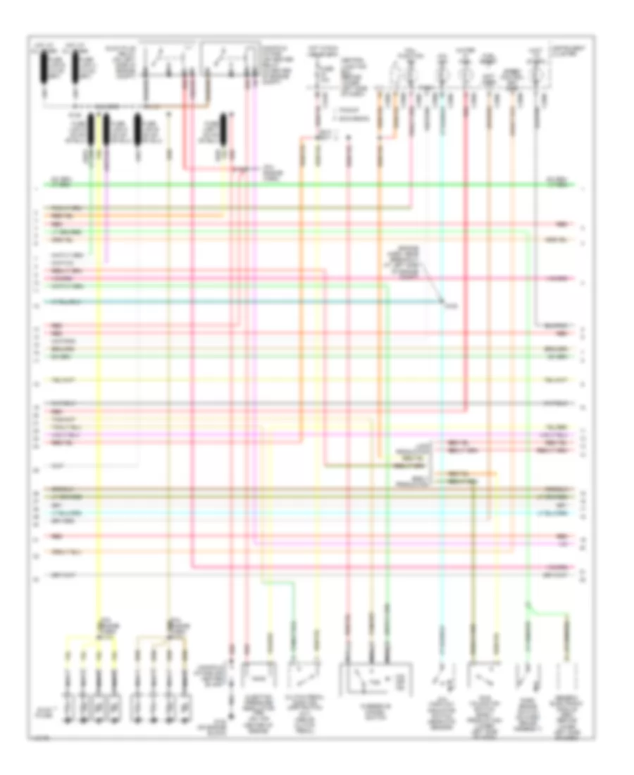
6.8L
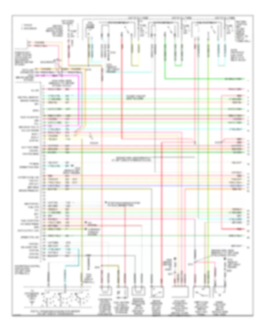
6.8L, Engine Performance Wiring Diagram (1 of 4) for Ford Cab & Chassis F350 Super Duty 2001
List of elements for 6.8L, Engine Performance Wiring Diagram (1 of 4) for Ford Cab & Chassis F350 Super Duty 2001:
- (calif)
- (engine harn, near breakout at left side of engine compt)
- (engine sensor harn, near breakout at right side of engine, above cylinder 3)
- (left kick panel)
- (main harn, near breakout at center of dash, on dlc)
- (on left side of engine) radio noise capacitor 2
- (on right side of engine) radio noise capacitor 1
- (pickup)
- (rear of left front fender)
- 4x4 high/low indicator switch
- 4x4 low ind sw
- 4x4 low ind
- A/c press sw
- A/c system
- Anti-theft system
- Battery junction box (in left side of engine compt, on top of wheelwell)
- C242b
- C250b
- C250c
- Case gnd
- Ccs
- Central junction box (behind lower left side of dash)
- Ckp(+)
- Ckp(-)
- Coil on plug
- Customer access
- Data link (+)
- Data link (-)
- Data link connector (dlc) (behind center of dash)
- Data output
- Digital transmission range (dtr) sensor (on left side of transmission)
- Egr sol
- Eprom pwr
- Fuel gauge
- Fuel gauge in
- Fuel inj 10
- Fuel pump mon
- Fuse 10a
- Fuse 20a
- Fuse 30a
- G102 (left side of firewall)
- G104
- G200
- Hego 12
- Hot at all times
- Hot in run or start
- Iat
- Ign coil 1
- Ign coil 10
- Ign coil 5
- Ign coil 6
- Instrument cluster
- Knock sensor
- Maf
- Mil ind
- Nca
- O/d off ind
- Overdrive cancel switch (a/t)
- Overhead console
- Pcm power diode
- Pcm power relay
- Pickup excursion
- Power take-off
- Powertrain control module (pcm) (on left side of firewall)
- Pto
- Pwr gnd
- R n
- Red
- S102
- S105
- S106
- S129 (calif)
- S130 (engine harn, near breakout at throttle body)
- S135
- S179
- S201
- S208
- S213 s271
- S284
- S286
- Shift sol 1
- Shift sol 2
- Tach
- Tcs
- Temp output
- Tft
- To dtr sensor (diagram 4 of 4)
- Tr1
- Tr2
- Tr4
- Trans ctrl ind
- Transmission control switch
- Vss
- Vss (-)
6.8L, Engine Performance Wiring Diagram (2 of 4) for Ford Cab & Chassis F350 Super Duty 2001
List of elements for 6.8L, Engine Performance Wiring Diagram (2 of 4) for Ford Cab & Chassis F350 Super Duty 2001:
- (behind right kick panel) inertia fuel shut-off switch
- (engine harn, near breakout at left side of engine compt, near brake s104 pressure switch)
- (engine harness, near breakout at left side of steering column)
- (excursion: engine harness, near breakout at left side of steering column)
- (left kick panel) g200
- (not used)
- (part of fuel tank assembly) fuel pump/fuel gauge sender
- (pickup: main harness, near breakout to customer access)
- (rear of left front fender) g104
- A/c clutch relay
- Battery junction box (in left side of engine compt, on top of wheelwell)
- C250b
- C250c
- Crankshaft position (ckp) sensor (on lower front center of engine)
- Crankshaft position sensor shield
- Delta pressure feedback egr (dpfe) sensor (california) (on right side of engine, near throttle position sensor)
- Engine coolant temp gauge
- Engine coolant temperature (ect) sender (on top left front of engine)
- Fuel pump relay
- Fuel tank pressure sensor (california) (at fuel tank)
- Fuse 20a
- G102 (left side of firewall)
- G200 (left kick panel)
- Hot at all times
- I/p relay block (pickup) battery junction box (excursion) (pickup: behind dash, near instrument cluster) (excursion: in left side of engine compt, on top of wheelwell)
- Instrument cluster
- Nca
- Pickup excursion
- Red
- Red/pnk
- S102
- S106
- S123
- S128 (california) (engine harn, near breakout to after- market circuits)
- S133 (california) (engine harn, near breakout at left side of engine, above cylinder 6)
- S145
- S201
- S226 s164
- Throttle position (tp) sensor (on throttle body)
6.8L, Engine Performance Wiring Diagram (3 of 4) for Ford Cab & Chassis F350 Super Duty 2001
List of elements for 6.8L, Engine Performance Wiring Diagram (3 of 4) for Ford Cab & Chassis F350 Super Duty 2001:
- (back-up lamp harn, near breakout at left side of transmission)
- (back-up lamp harn, near breakout at right side of transmission)
- (engine harn, near breakout at left of steering column)
- (on right rear of engine compt)
- 4r100 transmission
- Coast clutch solenoid
- Egr control solenoid (on left side of engine)
- Electronic pressure control solenoid
- Evap canister purge valve
- Fuel injectors
- Idle air control (iac) valve (on throttle body assembly)
- Output shaft speed (oss) sensor (on top of transmission extension housing)
- Red
- Red/pnk
- S122
- S131 (engine harn, near break- out at top of cylinder 7)
- S136 (engine sensor harn, near break- out at top of cylinder 3)
- S138
- S139
- Shift solenoid 1
- Shift solenoid 2
- Tan
- Tan/ red
- Tan/red
- Torque converter clutch solenoid
- Transmission fluid temperature sensor
- Turbine shaft speed (tss) sensor (on top of transmission, at converter housing)
6.8L, Engine Performance Wiring Diagram (4 of 4) for Ford Cab & Chassis F350 Super Duty 2001
List of elements for 6.8L, Engine Performance Wiring Diagram (4 of 4) for Ford Cab & Chassis F350 Super Duty 2001:
- (a/t)
- (above clutch pedal) (m/t) clutch pedal position (cpp) switch
- (calif)
- (engine harn, near breakout at left side of engine compt)
- (engine harn, near breakout at left side of engine compt, near brake pressure switch)
- (engine harn, near breakout at top of cylinder 7)
- (engine harn, near breakout to pcm)
- (engine harness, near breakout at left side of engine compt)
- (in left rear side of engine compt) (california) canister vent solenoid
- (m/t)
- (on top front of engine) cylinder head temperature (cht) sensor
- (right side of engine compt) speed control servo
- 5v ref volt
- A/c cltch rly
- A/c system
- Anti-lock brakes system
- Bpp sw
- Brake pedal position (bpp) switch (behind left side of dash, above brake pedal)
- C240d
- C242a
- C242b
- Cam pos in
- Camshaft position (cmp) sensor (on front of left cyl head)
- Canister vent
- Central junction box (behind lower left side of dash)
- Cyl 8)
- Cyl head temp
- Digital transmission range (dtr) sensor (on left side of transmission)
- Dpfe sens
- Epc sol
- Evap purge
- From dtr sensor (diagram 1 of 4)
- Fuel inj 1
- Fuel inj 2
- Fuel inj 3
- Fuel inj 4
- Fuel inj 5
- Fuel inj 6
- Fuel inj 8
- Fuel inj 9
- Fuel pump ctrl
- Fuel tank press
- Fuse 15a
- Fuse 5a
- G102 (left side of firewall)
- G200 (left kick panel)
- Gem
- Heated oxygen sensor (ho2s) 11 (on right exhaust manifold)
- Heated oxygen sensor (ho2s) 12 (california) (rear of catalytic converter)
- Heated oxygen sensor (ho2s) 21 (on left exhaust manifold)
- Heater ctrl
- Hego 11
- Hego 12
- Hego 21
- Hot at all times
- Hot in start
- Iac sol
- Ign coil 3
- Ign coil 4
- Ign coil 7
- Ign coil 8
- Ign coil 9
- Kap b(+)
- Knock sensor
- Knock sensor (on rear of engine)
- Maf sens in
- Mass airflow (maf) sensor (in left front of engine compt)
- Nca
- Oss
- Pickup excursion
- Powertrain control module (pcm) (on left side of firewall)
- Pwr gnd
- Red
- Red/pnk
- S106
- S114
- S115
- S129
- S132
- S134
- S211
- Sig return
- Tan
- Tan/red
- Tcc sol
- Tp sens in
- Tr3a (a/t) cpp (m/t)
- Tss
- Vpwr
- Vss (+)
- Vss input
6.8L BI-FUEL
6.8L Bi-Fuel, Engine Performance Wiring Diagram (1 of 6) for Ford Cab & Chassis F350 Super Duty 2001
List of elements for 6.8L Bi-Fuel, Engine Performance Wiring Diagram (1 of 6) for Ford Cab & Chassis F350 Super Duty 2001:
- (eng sens harn, right side of eng, above cylinder 3)
- (engine harn, left side of engine compt)
- (left kick panel)
- (rear of left front fender)
- (top left side of engine) radio noise capacitor 2
- (top right side of engine) radio noise capacitor 1
- (vcl harn, left rear of engine compt)
- 4x4 high/low indicator switch
- 4x4 low ind sw
- 4x4 low ind
- A/c system
- Ac head press sw
- Battery junction box (left side of engine compt)
- C242b
- C250b
- C250c
- Case gnd
- Ccs
- Central junction box (behind left side of dash)
- Ckp(+)
- Ckp(-)
- Coil on plug
- Customer access
- Data link (+)
- Data link (-)
- Data link connector (behind center of dash)
- Data output
- Digital transmission range (dtr) sensor (on left side of transmission)
- Egr sol
- Eprom pwr
- Fuel inj 10
- Fuel pump mon
- Fuse 10a
- Fuse 20a
- Fuse 30a
- G102 (left side of firewall)
- G104
- G200
- Hot at all times
- Hot in run or start
- Iat
- Ign coil 1
- Ign coil 10
- Ign coil 5
- Ign coil 6
- Ign coil 7
- Instrument cluster
- Knock sensor
- Maf
- Mil ind
- Nca
- O/d off
- Overdrive cancel switch (a/t)
- Overhead console
- Pcm power diode
- Pcm power relay
- Powertrain control module (pcm) (on left side of firewall)
- Pto
- Pwr gnd
- R n
- Red
- S102
- S105
- S106
- S130 (engine harn, near breakout to throttle body conn)
- S135
- S179
- S201
- S213
- S4002
- S4003
- S4004
- S4022
- Shift sol 1
- Shift sol 2
- Tach
- Tcs
- Temp output
- Tft
- To dtr sensor (diagram 6 of 6)
- Tr1
- Tr2
- Tr4
- Trans ctrl ind
- Transmission control indicator lamp
- Vss
- Vss (-)
6.8L Bi-Fuel, Engine Performance Wiring Diagram (2 of 6) for Ford Cab & Chassis F350 Super Duty 2001
List of elements for 6.8L Bi-Fuel, Engine Performance Wiring Diagram (2 of 6) for Ford Cab & Chassis F350 Super Duty 2001:
- (behind right kick panel) inertia fuel shut-off switch
- (engine harn, near breakout to brake pressure switch)
- (engine harness, near breakout to 40-pin conn, left of steering column) s123
- (fuel tank harn, right rear of eng compt)
- (in cold start heater harness)
- (in shutoff harn, left rear of eng compt)
- (left kick panel)
- (main harness, near breakout to customer access)
- (part of fuel tank assembly) fuel pump/fuel gauge sender
- (rear of left front fender) g104
- A/c clutch relay
- Battery junction box (left side of engine compt)
- C250b
- C250c
- C911
- Cold start heater
- Cold start heater diode (right rear of engine compt)
- Cold start heater relay (right rear of engine compt)
- Crankshaft position (ckp) sensor (front center of engine)
- Engine coolant temp guage
- Engine coolant temperature (ect) sender (top front of engine)
- Fuel level in
- Fuel pump relay
- Fuse 20a
- Fuse link k 12 ga (near starter motor)
- G102 (left side of firewall)
- G200
- G200 (left kick panel)
- Hot at all times
- I/p relay block (behind dash, near inst panel)
- Instrument cluster
- Lock off diode (cold start) (right rear of engine compt)
- Lock off solenoid (cold start) (right rear of engine compt)
- Nca
- Not used
- Overhead console
- Pnk
- Red
- S102
- S104
- S106
- S145
- S201
- S208
- S226
- S4005 (fuel tank harn, right rear of eng compt)
- S4006
- S4013
- S4014
- S4015
- S4016
6.8L Bi-Fuel, Engine Performance Wiring Diagram (3 of 6) for Ford Cab & Chassis F350 Super Duty 2001
List of elements for 6.8L Bi-Fuel, Engine Performance Wiring Diagram (3 of 6) for Ford Cab & Chassis F350 Super Duty 2001:
- (front tank harness)
- (in dual tank switch harness)
- (in tank relay harness)
- (left rear of engine compt)
- (rear tank harness)
- 87a
- Dual tank switch
- Dual tanks
- G116
- Indicator light switch
- Lock off diode
- Lock off diode (front)
- Lock off diode (rear)
- Lock off solenoid
- Lock off solenoid (front)
- Lock off solenoid (rear)
- Lpg sender
- Lpg sender (front)
- Lpg sender (rear)
- Lpg sender relay 1 (left rear of engine compt)
- Lpg sender relay 2 (left rear of engine compt)
- Pnk
- Red
- Relay diode
- S4012 pnk (in fuel tank harness)
- S4024
- S4025
- S4026
- S4027
- S4028
- S4029
- S4030
- S4031
- S4032
- S4033
- S4034
- S4036
- S4037
- S4038
- Single tank
- Switch diode
6.8L Bi-Fuel, Engine Performance Wiring Diagram (4 of 6) for Ford Cab & Chassis F350 Super Duty 2001
List of elements for 6.8L Bi-Fuel, Engine Performance Wiring Diagram (4 of 6) for Ford Cab & Chassis F350 Super Duty 2001:
- (b+)
- (compuvalve harness)
- (compuvalve harness) s4023
- (dual tanks)
- (left
- (left rear of engine compt)
- (vcl harn, right rear of engine compt)
- 1ooo
- 87a
- Bi-fuel power relay
- Bi-fuel relay module (left rear of engine compt)
- Bus (+)
- Bus (-)
- Cold st
- Compuvalve module (top rear of engine)
- Cool s
- Coolant solenoid
- D reset
- Digin6
- F cut
- F lvl
- F pump
- F send
- Fuel pump cutoff relay
- Fuse 10a
- Fuse 3a
- G001
- G002
- G003
- G004
- G005
- G006
- G007
- G008
- G009
- G010
- G011
- G013
- G015
- G017
- G019
- G021
- G022
- G027
- G030
- G032
- G042
- G043
- G045
- G046
- G047
- G049
- G050
- G051
- G053
- G055
- G057
- G059
- G061
- G062
- G063
- G064
- G084
- G085
- G086
- G115
- G116
- Ground
- High flow injector assembly
- Ho2s 11
- Ho2s 21
- Hot at all times
- Ign
- Ind sw
- Inj 1
- Inj 2
- Inj 3
- Inj 4
- Inj 5
- Inj 6
- Inj 7
- Inj 8
- Lk off
- Low flow injector assembly
- Mil
- Pnk
- Rear of engine compt)
- Red
- Resistor
- S4001
- S4010
- S4017 (compuvalve harness)
- S4025
- Sig rtn
- Tach
- Tan
- Tps rtn
- Used not
6.8L Bi-Fuel, Engine Performance Wiring Diagram (5 of 6) for Ford Cab & Chassis F350 Super Duty 2001
List of elements for 6.8L Bi-Fuel, Engine Performance Wiring Diagram (5 of 6) for Ford Cab & Chassis F350 Super Duty 2001:
- (back-up lamp harn, near breakout to 16-pin conn, in left side of engine compt)
- (back-up lamp harn, near breakout to 16-pin conn, left side of engine compt)
- (engine harn, near breakout to 40-pin conn, left of steering column)
- 4r100 transmission
- 87a
- C250b
- Central junction box (behind left side of dash)
- Coast clutch solenoid
- Dash reset
- Dash reset relay (right rear of engine compt)
- Egr control solenoid (on left side of engine)
- Electronic pressure control solenoid
- Fuel injectors
- Fuse 10a
- Hot in run or start
- Idle air control (iac) valve (on throttle body assembly)
- Instrument cluster
- Output shaft speed sensor (top of trans)
- Red
- S122
- S131 (in engine harn, near top of cylinder 7)
- S136 (in engine harn, near top of cylinder 3)
- S138
- S139
- S213
- Shift solenoid 1
- Shift solenoid 2
- Tan
- Tan/ red
- Tan/red
- Torque converter clutch solenoid
- Transmission fluid temperature sensor
- Turbine shaft speed sensor (top of trans)
6.8L Bi-Fuel, Engine Performance Wiring Diagram (6 of 6) for Ford Cab & Chassis F350 Super Duty 2001
List of elements for 6.8L Bi-Fuel, Engine Performance Wiring Diagram (6 of 6) for Ford Cab & Chassis F350 Super Duty 2001:
- (a/t)
- (at clutch pedal) (m/t) clutch pedal position switch
- (eng harn, near breakout to brake press switch)
- (eng sens harn, near top of cyl 8)
- (engine control sensor harn, at breakout to pcm)
- (engine harn, near top of cylinder 7)
- (left front of engine compt) anti-lock brakes module
- (m/t)
- (right rear of engine compartment)
- (right side of engine compt) speed control servo
- (top front of engine) cylinder head temperature (cht) sensor
- (vcl harn, right rear of engine compt)
- 5v ref volt
- A/c cltch rly
- A/c system
- Bpp sw
- Brake pedal position switch
- C240d
- C242b
- Cam pos in
- Camshaft position sensor (cmp) (on front of left cyl head)
- Central junction box (under left side of dash)
- Cyl head temp
- Digital transmission range (dtr) sensor (left side of transmission)
- Epc sol
- Evap canister purge valve
- Evap purge
- From dtr sensor (diagram 1 of 6)
- Fuel inj 1
- Fuel inj 2
- Fuel inj 3
- Fuel inj 4
- Fuel inj 5
- Fuel inj 6
- Fuel inj 7
- Fuel inj 8
- Fuel inj 9
- Fuel pump ctrl
- Fuse 15a
- Fuse 5a
- G102 (left side of firewall)
- G200 (left kick panel)
- Gem
- Heated oxygen sensor (ho2s) 11 (on right exhaust manifold)
- Heated oxygen sensor (ho2s) 21 (on left exhaust manifold)
- Heater ctrl
- Hego 11
- Hego 21
- Hot at all times
- Hot in start
- Iac sol
- Ign coil 2
- Ign coil 3
- Ign coil 4
- Ign coil 8
- Ign coil 9
- Kap b(+)
- Knock sensor
- Knock sensor (on rear of engine)
- Maf sens in
- Mass airflow (maf) sensor (left front of engine compt)
- Nca
- Oss
- Powertrain control module (pcm) (on left side of firewall)
- Pwr gnd
- Red
- S106
- S114
- S115 (engine harn, near breakout to 16-pin conn, left side of engine compt)
- S132
- S134
- S221
- S4018
- S4019 (vcl harn, right rear of engine compt)
- S4020
- S4021
- Sig return
- Tan
- Tan/red
- Tcc sol
- Throttle position (tp) sensor (on throttle body)
- Tp sens in
- Tr3a (a/t) cpp (m/t)
- Tss
- Vpwr
- Vss
- Vss (+)
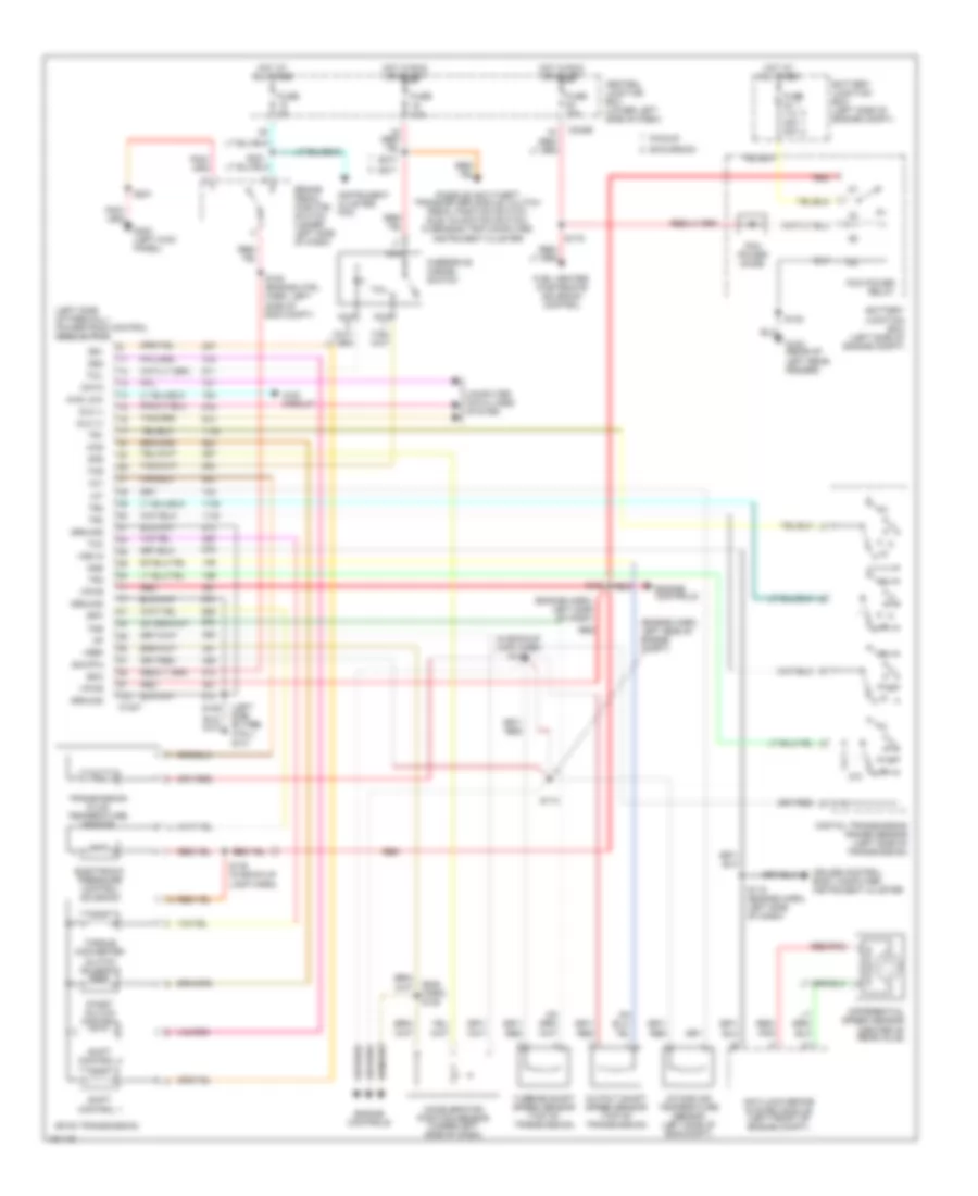
7.3L DI TURBO DIESEL
7.3L DI Turbo Diesel, Engine Performance Wiring Diagram, California (1 of 4) for Ford Cab & Chassis F350 Super Duty 2001
List of elements for 7.3L DI Turbo Diesel, Engine Performance Wiring Diagram, California (1 of 4) for Ford Cab & Chassis F350 Super Duty 2001:
- (a/t)
- (behind center of dash)
- (engine harn, near breakout at left side of bulkhead, on pcm)
- (engine harn, near breakout at left side of steering column)
- (m/t)
- (main harn, near breakout at center of dash, on dlc)
- 4x4 low range
- A/c head press
- A/c system
- Aux tach feed
- Auxiliary powertrain control module (apcm) (pickup) (behind lower right side of dash)
- Battery junction box (in left side of engine compt, on top of wheelwell)
- Brake press sw
- Brake pressure switch (on left side of engine compt)
- Brake warning
- Bus (+)
- Bus (-)
- C242b
- Cam pos sens
- Ccs sol
- Central junction box (behind lower left side of dash)
- Cpp (m/t)
- Dash)
- Data link connector (dlc)
- Data output link
- Diesel fuel pump motor (below vehicle, near fuel tank)
- Digital transmission range (dtr) sensor (on left side of transmission)
- Dsl elect drv
- Dtr-tr1
- Dtr-tr2
- Dtr-tr4
- Ebp sens
- Eot
- Epr
- Excursion
- Exhaust pressure regulator (epr) (on top center of engine)
- Fuel heater/ water in fuel sensor (on center of engine)
- Fuel htr
- Fuel pump pwr
- Fuel pump relay
- Fuse 20a
- Fuse 30a
- Fuse 30a 20a
- G102 (left side of firewall)
- G104 (rear of left front fender)
- Gen pwr sw
- Gen scan tool in
- Gpcm
- Hot at all times
- Hot in run or start
- Iat
- Idle validation
- Idm power relay
- Inertia fuel shutoff (ifs) switch (behind right kick panel)
- Mil ind
- Nca
- Neutral gear sw
- Note: for pickup; fuel pump relay in i/p relay block
- Overhead console system
- Passive anti- theft system (pats) module (excursion) (behind center of dash)
- Pcm power diode
- Pcm power relay
- Pickup
- Power take off (body builder)
- Powertrain control module (pcm) (on left side of firewall)
- Pwr gnd
- R n
- Red
- S106
- S123
- S141
- S154
- S179
- S217
- S250
- S284
- S286
- Speed ctrl ind
- Speed/tach gnd
- Ss1
- Ss2
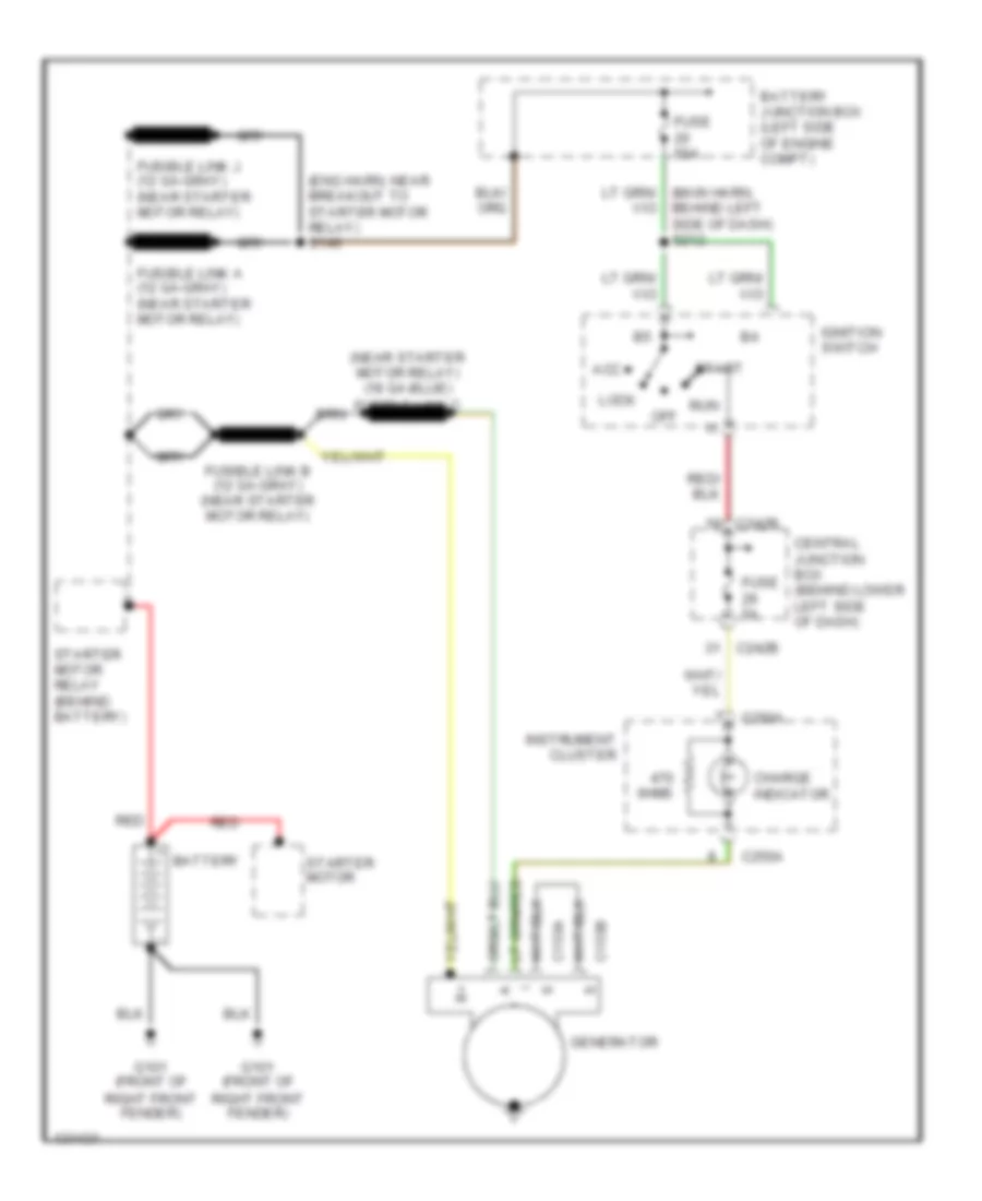
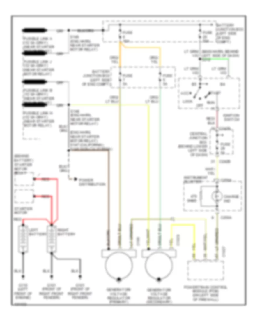
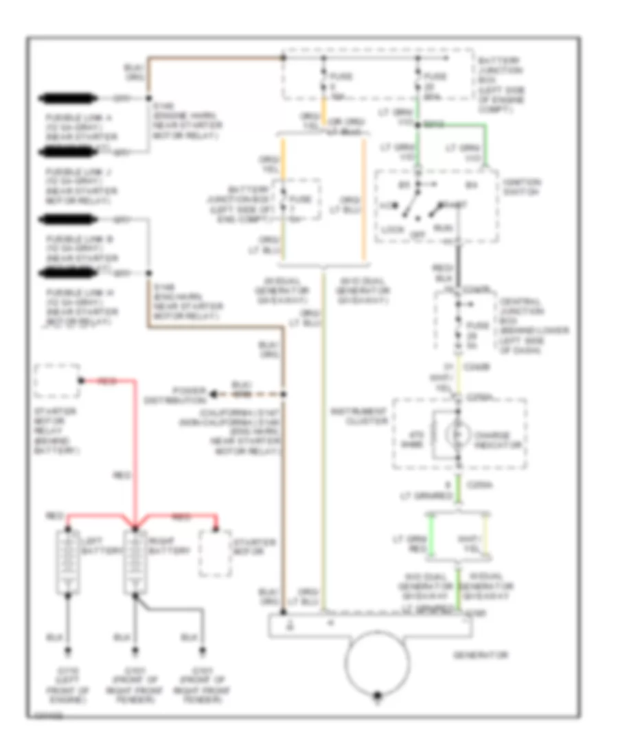
- Starting/charging system (w/ dual generators)
- Tcil
- Tcs (a/t)
- Tft
- To dtr sensor (diagram 4 of 4)
- Tp sens
- Wastegate control solenoid (in center of engine compt, on wastegate)
- Water in fuel ind
- Wcs sol
7.3L DI Turbo Diesel, Engine Performance Wiring Diagram, California (2 of 4) for Ford Cab & Chassis F350 Super Duty 2001
List of elements for 7.3L DI Turbo Diesel, Engine Performance Wiring Diagram, California (2 of 4) for Ford Cab & Chassis F350 Super Duty 2001:
- (engine harn, near breakout at left side of engine compt)
- (not used)
- (pia engine harn) s158
- (top right side of engine) glow plug control module (gpcm)
- 4x4 high/low indicator switch (near dtr sensor)
- 4x4 low
- C152
- C154
- C242b
- C250a
- C250b
- C250c
- Central junction box (behind lower left side of dash)
- Clutch pedal position (cpp) switch (m/t) (above clutch pedal)
- Cntl out
- Early production
- Excursion
- Fuel reset
- Fuse 10a
- Generic electronic module (gem) (behind lower left side of dash)
- Glow plugs
- Glw plg 1
- Glw plg 2
- Glw plg 3
- Glw plg 4
- Glw plg 5
- Glw plg 6
- Glw plg 7
- Glw plg 8
- Gpcm
- Hot at all times
- Hot in run or start
- Idle validation switch (early production) (lower left side of dash)
- Injection pressure regulator (ipr) (on top center of engine)
- Instrument cluster
- Late production
- Mal- function ind
- Nca
- O/d off ind
- Overdrive cancel switch
- Park brake switch (on park brake assembly)
- Pickup
- Power in
- Red
- S105
- S147
- S213 s271
- Speed control set lamp c250b
- Tach c250b
- Tcs
- Wait to start
- Water in fuel
7.3L DI Turbo Diesel, Engine Performance Wiring Diagram, California (3 of 4) for Ford Cab & Chassis F350 Super Duty 2001
List of elements for 7.3L DI Turbo Diesel, Engine Performance Wiring Diagram, California (3 of 4) for Ford Cab & Chassis F350 Super Duty 2001:
- (back-up lamp harn, near breakout at left side of transmission)
- (back-up lamp harn, near breakout at right side of transmission)
- (in left side of engine compt) injector driver module (idm)
- 4r100 transmission
- Cid sig in
- Coast clutch solenoid
- Early production
- Electronic pressure control solenoid
- Engine oil temperature (eot) sensor (on top front of engine)
- Feedback
- Fuel inj 1
- Fuel inj 2
- Fuel inj 3
- Fuel inj 4
- Fuel inj 5
- Fuel inj 6
- Fuel inj 7
- Fuel inj 8
- Fuel injectors
- Fuel sig
- G102 (left side of firewall)
- Inj feed
- Intake air temperature sensor (left side of engine compt, behind air cleaner)
- Late production
- Nca
- Output shaft speed (oss) sensor (on top of transmission extension housing)
- Pwr gnd
- Pwr in
- Red
- S138
- S139
- Shield
- Shift solenoid
- Sig rtn
- Tan
- Tan/red
- Throttle pedal position sensor (late production) (above brake pedal)
- Torque converter clutch solenoid
- Transmission fluid temperature sensor
- Turbine shaft speed (tss) sensor (on top of transmission, at converter housing)
7.3L DI Turbo Diesel, Engine Performance Wiring Diagram, California (4 of 4) for Ford Cab & Chassis F350 Super Duty 2001
List of elements for 7.3L DI Turbo Diesel, Engine Performance Wiring Diagram, California (4 of 4) for Ford Cab & Chassis F350 Super Duty 2001:
- (early)
- (engine harn, near breakout at left side of engine compt, near air vent)
- (engine harn, near breakout at left side of engine compt, near brake pressure switch)
- (in left front of engine compt) anti-lock brake system (abs) module
- (late)
- (left kick panel) g200
- (main harn, left side of dash)
- (pia engine harn) s151
- Accelerator pedal position (app) sensor (early production) (under left side of dash, above brake pedal)
- Accl pos sens
- Act sens
- Air charge temperature (act) sensor (center front of engine)
- Bpp sw
- Brake pedal position (bpp) switch (behind left side of dash, above brake pedal)
- C104a
- C240d
- C242a
- C242b
- Camshaft position (cmp) sensor (on lower front center of engine)
- Central junction box (behind lower left side of dash)
- Charge ind
- Cid sig
- Cmp rtn
- Cruise control system
- Digital transmission range (dtr) sensor (on left side of transmission)
- Dtr-tr3a
- Epc sol
- Excursion
- Excursion late production
- Exhaust back pressure (ebp) sensor (on center rear of engine)
- From dtr sensor (diagram 1 of 4)
- Fuel deliv sig
- Fuel gauge sender (part of fuel tank assembly)
- Fuel pump rly
- Fuel pump sender
- Fuse 5a
- G102 (left side of firewall)
- G200 (left kick panel)
- Gem
- Gen pwr
- Glow plug ctrl
- Hot at all times
- Icp sens
- Idm enable out
- Injection control pressure (icp) sensor (on top left side of engine, right of alternator)
- Instrument cluster
- Ipr sens
- Manifold absolute pressure (map) sensor (on right side of firewall)
- Map sens
- Oss sens
- Overhead console
- Pickup
- Pickup & excursion early production
- Power take off (body builder)
- Powertrain control module (pcm) (on left side of firewall)
- Pwr
- Pwr gnd
- Pwr in
- Red
- S106
- S114
- S115 (engine harn, near breakout at left side of steering column)
- S128 (engine harn, near breakout to after- market circuits)
- S153 (pia engine harn)
- S201
- S208
- S211
- S288
- Sig rtn
- Speed ctrl sw
- Starting/ charging system (w/ dual generators)
- Take off pwr in
- Tcc
- Tss sens
- Vref
- Vss (+)
- Vss in
- Vss out
- Wait to start ind
7.3L DI Turbo Diesel, Engine Performance Wiring Diagram, Federal (1 of 4) for Ford Cab & Chassis F350 Super Duty 2001
List of elements for 7.3L DI Turbo Diesel, Engine Performance Wiring Diagram, Federal (1 of 4) for Ford Cab & Chassis F350 Super Duty 2001:
- (a/t)
- (behind center of dash)
- (engine harn, near breakout at left side of bulkhead, on pcm)
- (engine harn, near breakout at left side of steering column)
- (m/t)
- (main harn, near breakout at center of dash, on dlc)
- 4x4 low range
- A/c head press
- A/c system
- Aux tach feed
- Auxiliary powertrain control module (apcm) (pickup) (behind lower right side of dash)
- Battery junction box (in left side of engine compt, on top of wheelwell)
- Brake press sw
- Brake pressure switch (on left side of engine compt)
- Brake warning
- Bus (+)
- Bus (-)
- C242b
- Cam pos sens
- Ccs sol
- Central junction box (behind lower left side of dash)
- Cpp (m/t)
- Dash)
- Data link connector (dlc)
- Data output link
- Diesel fuel pump motor (below vehicle, near fuel tank)
- Digital transmission range (dtr) sensor (on left side of transmission)
- Dsl elect drv
- Dtr-tr1
- Dtr-tr2
- Dtr-tr4
- Ebp sens
- Eot
- Epr
- Excursion
- Exhaust pressure regulator (epr) (on top center of engine)
- Fuel heater/ water in fuel sensor (on center of engine)
- Fuel htr
- Fuel pump pwr
- Fuel pump relay
- Fuse 20a
- Fuse 30a
- Fuse 30a 20a
- G102 (left side of firewall)
- G104 (rear of left front fender)
- Gen pwr sw
- Gen scan tool in
- Glow plug mon
- Hot at all times
- Hot in run or start
- Iat
- Idle validation
- Idm power relay
- Inertia fuel shutoff (ifs) switch (behind right kick panel)
- Low current sens
- Mil ind
- Nca
- Neutral gear sw
- Note: for pickup; fuel pump relay in i/p relay block
- Overhead console system
- Passive anti- theft system (pats) module (excursion) (behind center of dash)
- Pcm power diode
- Pcm power relay
- Pickup
- Power take off (body builder)
- Powertrain control module (pcm) (on left side of firewall)
- Pwr gnd
- R n
- Red
- S106
- S123
- S141
- S154
- S179
- S217
- S250
- S284
- S286
- Speed ctrl ind
- Speed/tach gnd
- Ss1
- Ss2
- Starting/charging system (w/ dual generators)
- Tcil
- Tcs (a/t)
- Tft
- To dtr sensor (diagram 4 of 4)
- Tp sens
- Wastegate control solenoid (in center of engine compt, on wastegate)
- Water in fuel ind
- Wcs sol
7.3L DI Turbo Diesel, Engine Performance Wiring Diagram, Federal (2 of 4) for Ford Cab & Chassis F350 Super Duty 2001
List of elements for 7.3L DI Turbo Diesel, Engine Performance Wiring Diagram, Federal (2 of 4) for Ford Cab & Chassis F350 Super Duty 2001:
- (engine harn, near breakout at left side of engine compt)
- (not used)
- (pia engine harn)
- 4x4 high/low indicator switch (near dtr sensor)
- 4x4 low
- C242b
- C250a
- C250b
- C250c
- Central junction box (behind lower left side of dash)
- Clutch pedal position (cpp) switch (m/t) (above clutch pedal)
- Early production
- Excursion
- Fuel reset
- Fuse 10a
- G132 (on engine block)
- Generic electronic module (gem) (behind lower left side of dash)
- Glow plug relay (on left side of engine compt)
- Glow plugs
- Hot at all times
- Hot in run or start
- Idle validation switch (early production) (lower left side of dash)
- Injection pressure regulator (ipr) (on top center of engine)
- Instrument cluster
- Late production
- Mal- function ind
- Manifold intake air heater 58 amp
- Manifold intake air heater relay (in center of engine compt)
- Nca
- O/d off ind
- Overdrive cancel switch
- Park brake switch (on park brake assembly)
- Pickup
- Red
- S105
- S148
- S149
- S158
- S213 s271
- Speed control set lamp c250b
- Tach c250b
- Tcs
- Wait to start
- Water in fuel
7.3L DI Turbo Diesel, Engine Performance Wiring Diagram, Federal (3 of 4) for Ford Cab & Chassis F350 Super Duty 2001
List of elements for 7.3L DI Turbo Diesel, Engine Performance Wiring Diagram, Federal (3 of 4) for Ford Cab & Chassis F350 Super Duty 2001:
- (back-up lamp harn, near breakout at left side of transmission)
- (back-up lamp harn, near breakout at right side of transmission)
- (in left side of engine compt) injector driver module (idm)
- 4r100 transmission
- Cid sig in
- Coast clutch solenoid
- Early production
- Electronic pressure control solenoid
- Engine oil temperature (eot) sensor (on top front of engine)
- Feedback
- Fuel inj 1
- Fuel inj 2
- Fuel inj 3
- Fuel inj 4
- Fuel inj 5
- Fuel inj 6
- Fuel inj 7
- Fuel inj 8
- Fuel injectors
- Fuel sig
- G102 (left side of firewall)
- Inj feed
- Intake air temperature sensor (left side of engine compt, behind air cleaner)
- Late production
- Nca
- Output shaft speed (oss) sensor (on top of transmission extension housing)
- Pwr gnd
- Pwr in
- Red
- S138
- S139
- Shield
- Shift solenoid
- Sig rtn
- Tan
- Tan/red
- Throttle pedal position sensor (late production) (above brake pedal)
- Torque converter clutch solenoid
- Transmission fluid temperature sensor
- Turbine shaft speed (tss) sensor (on top of transmission, at converter housing)
7.3L DI Turbo Diesel, Engine Performance Wiring Diagram, Federal (4 of 4) for Ford Cab & Chassis F350 Super Duty 2001
List of elements for 7.3L DI Turbo Diesel, Engine Performance Wiring Diagram, Federal (4 of 4) for Ford Cab & Chassis F350 Super Duty 2001:
- (early)
- (engine harn, near breakout at left side of engine compt, near air vent)
- (engine harn, near breakout at left side of engine compt, near brake pressure switch)
- (in left front of engine compt) anti-lock brake system (abs) module
- (late)
- (left kick panel) g200
- (main harn, left side of dash)
- (pia engine harn) s151
- Accelerator pedal position (app) sensor (early production) (under left side of dash, above brake pedal)
- Accl pos sens
- Act sens
- Air charge temperature (act) sensor (center front of engine)
- Bpp sw
- Brake pedal position (bpp) switch (behind left side of dash, above brake pedal)
- C104a
- C240d
- C242a
- C242b
- Camshaft position (cmp) sensor (on lower front center of engine)
- Central junction box (behind lower left side of dash)
- Charge ind
- Cid sig
- Cmp rtn
- Cruise control system
- Digital transmission range (dtr) sensor (on left side of transmission)
- Dtr-tr3a
- Epc sol
- Excursion
- Excursion late production
- Exhaust back pressure (ebp) sensor (on center rear of engine)
- From dtr sensor (diagram 1 of 4)
- Fuel deliv sig
- Fuel gauge sender (part of fuel tank assembly)
- Fuel pump rly
- Fuel pump sender
- Fuse 5a
- G102 (left side of firewall)
- G200 (left kick panel)
- Gem
- Gen pwr
- Glow plug ctrl
- Hot at all times
- Icp sens
- Idm enable out
- Injection control pressure (icp) sensor (on top left side of engine, right of alternator)
- Instrument cluster
- Ipr sens
- Manifold absolute pressure (map) sensor (on right side of firewall)
- Map sens
- Oss sens
- Overhead console
- Pcm to relay
- Pickup
- Pickup & excursion early production
- Power take off (body builder)
- Powertrain control module (pcm) (on left side of firewall)
- Pwr
- Pwr gnd
- Pwr in
- Red
- S106
- S114
- S115 (engine harn, near breakout at left side of steering column)
- S128 (engine harn, near breakout to after- market circuits)
- S153 (pia engine harn)
- S201
- S208
- S211
- S288
- Sig rtn
- Speed ctrl sw
- Starting/ charging system (w/ dual generators)
- Take off pwr in
- Tcc
- Tss sens
- Vref
- Vss (+)
- Vss in
- Vss out
- Wait to start ind
EXTERIOR LIGHTS
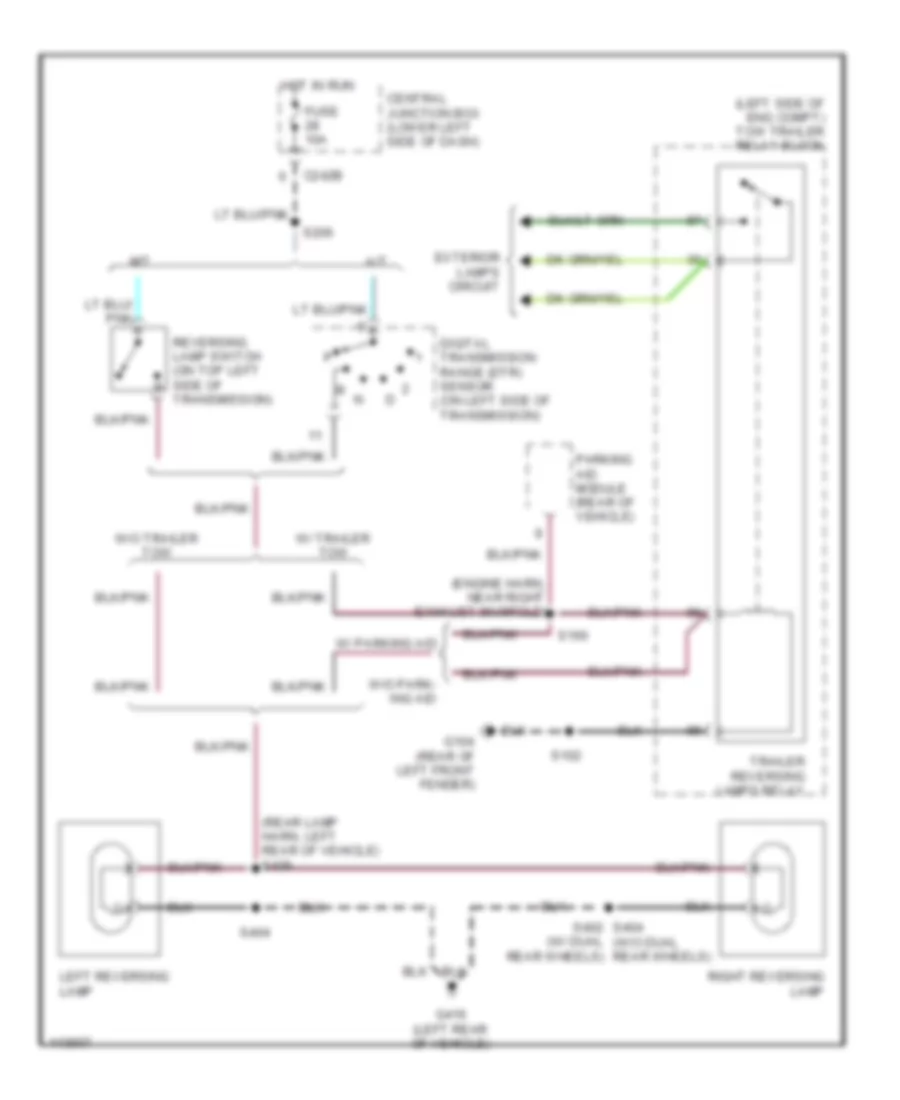
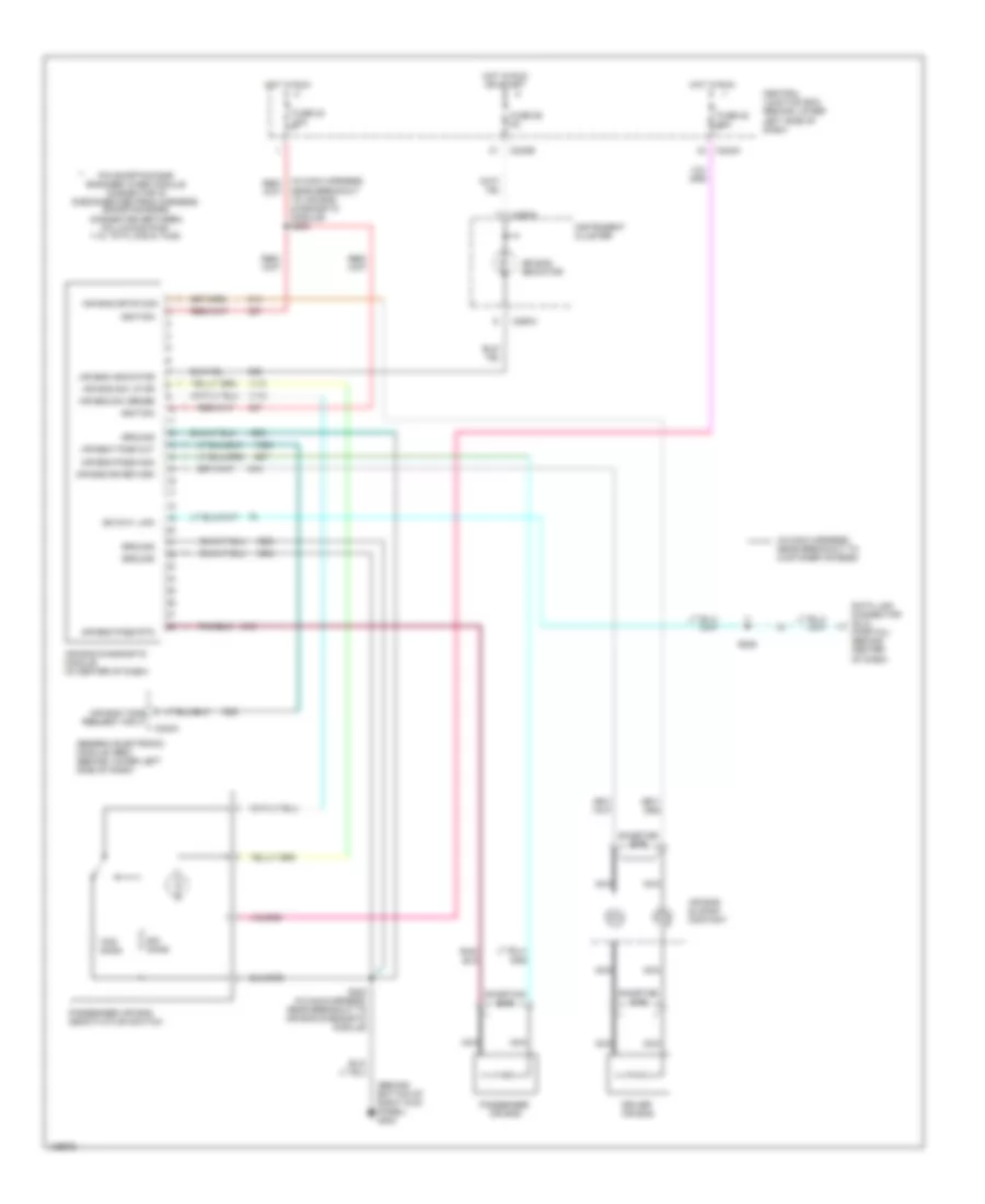
Back-up Lamps Wiring Diagram for Ford Cab & Chassis F350 Super Duty 2001
List of elements for Back-up Lamps Wiring Diagram for Ford Cab & Chassis F350 Super Duty 2001:
- (engine harn, near right exhaust manifold)
- (left side of eng compt) tow trailer relay block
- (rear lamp harn, left rear of vehicle) s426
- (w/ dual rear wheels)
- A/t
- C242b
- Central junction box (lower left side of dash)
- Digital transmission range (dtr) sensor (on left side of transmission)
- Exterior lamps circuit
- Fuse 10a
- G104 (rear of left front fender)
- G416 (left rear of vehicle)
- Hot in run
- Left reversing lamp
- M/t
- Parking aid module (rear of vehicle)
- Reversing lamp switch (on top left side of transmission)
- Right reversing lamp
- S102
- S160
- S206
- S402 s404 (w/o dual rear wheels)
- S404
- Trailer reversing lamps relay
- W/ parking aid
- W/ trailer tow
- W/o park- ing aid
- W/o trailer tow
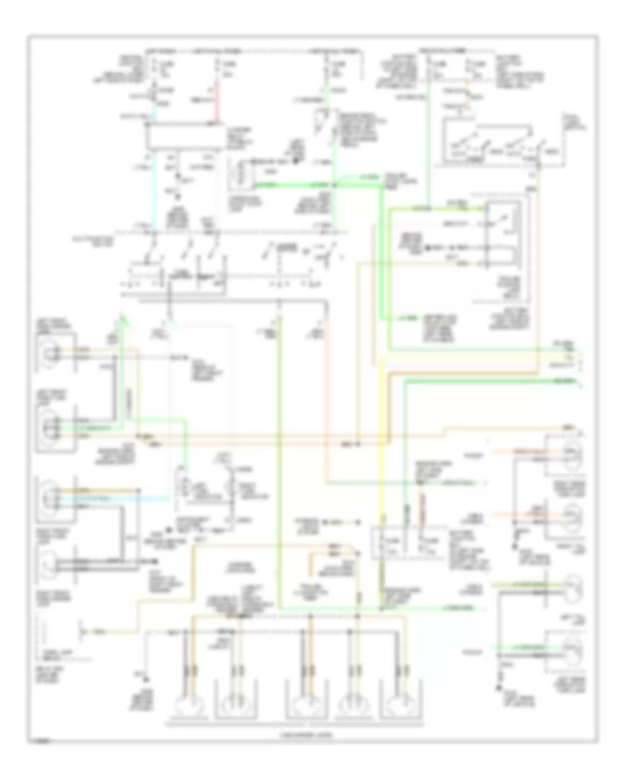
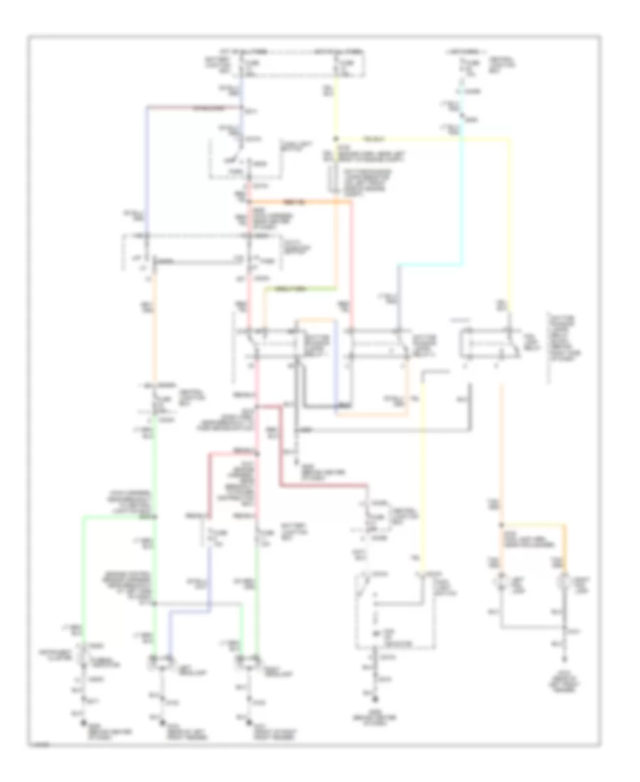
Exterior Lamps Wiring Diagram (1 of 2) for Ford Cab & Chassis F350 Super Duty 2001
List of elements for Exterior Lamps Wiring Diagram (1 of 2) for Ford Cab & Chassis F350 Super Duty 2001:
- (behind center of dash
- (behind center of dash) g206
- (engine harn, left side of dash) s110
- (engine harn, left side of dash) s112
- (lariat) (left side of (center of windshield header) s903
- (left rear of cab) g308
- (marker lamp harn)
- 87a
- Auto
- Battery junction box (in left side of engine compt, on top of wheelwell)
- Battery junction box (left side of eng compt, on top of wheelwell)
- Battery junction box) (left side of engine compt)
- Brake pedal position switch (behind left side of dash, above brake pedal)
- C242a
- C242b
- C250b
- C250c
- Cab & chassis
- Cab marker lamps
- Cargo/high mount stop lamp
- Central junction box (behind lower left side of dash)
- Flasher relay (i/p relay block)
- Fuse 10a
- Fuse 15a
- Fuse 20a
- Fuse 7.5a
- G101 (front of right front fender)
- G104 (rear of left front fender)
- G206
- G206 (behind center of dash)
- G416 (left rear of vehicle)
- Hazard switch
- Head
- Hot at all times
- Hot in run
- Instrument cluster
- Interior lights system
- Left
- Left front park/turn lamp
- Left front side marker lamp
- Left rear park/stop/ turn lamp
- Left tail lamp
- Left turn indicator
- Main light switch
- Mount stop lamp feed (left rear of chassis)
- Multifunction switch
- Off
- Park
- Park lamp relay
- Pickup
- Relay box (center of dash)
- Right
- Right front park/turn lamp
- Right front side marker lamp
- Right rear park/stop/ turn lamp
- Right tail lamp
- Right turn indicator
- S102
- S107 (engine harn, left side of engine compt)
- S109
- S180
- S215 (main harn, behind dash)
- S217
- S235
- S240 (main harn, behind left side of dash)
- S272
- S300
- S404
- S904
- S920 (lariat)
- Stop lamps feed
- Trailer illumination feed
- Trailer running lamp relay
- Turn switch
- Windshield header) s921
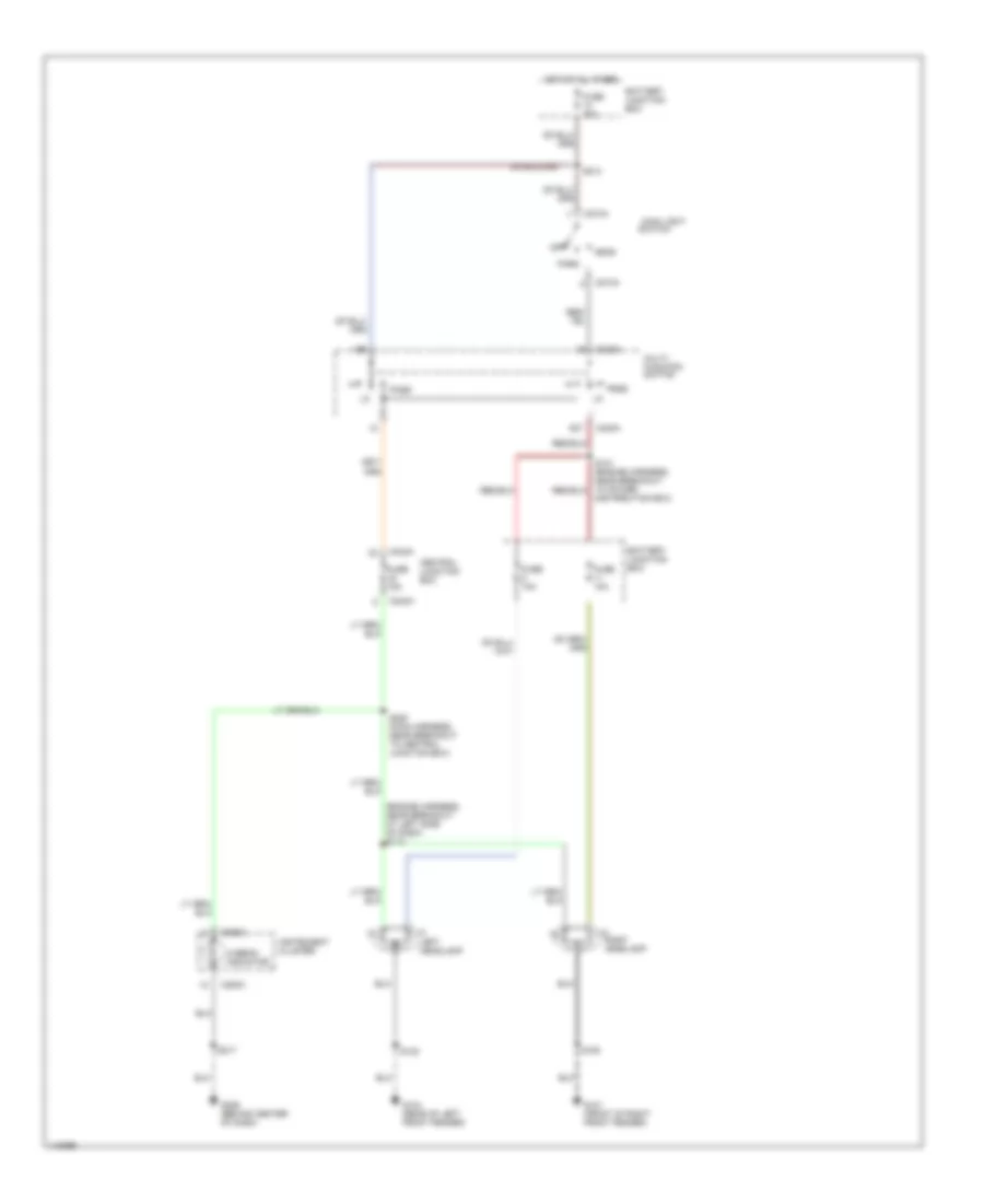
Exterior Lamps Wiring Diagram (2 of 2) for Ford Cab & Chassis F350 Super Duty 2001
List of elements for Exterior Lamps Wiring Diagram (2 of 2) for Ford Cab & Chassis F350 Super Duty 2001:
- (left rear of chassis) trailer/camper adapter
- (left side of engine compt, near battery junction box) tow trailer relay block
- (near rear bumper)
- (rear lamp harness, center rear of vehicle) s417
- (rear of left frt fender) g104
- (trailer feed harn, under rear of vehicle)
- (trailer feed harn, under rear of vehicle) s432
- Back-up lamps circuit
- Battery junction box (in left side of engine compt, on top of wheelwell)
- C242b
- Central junction box (behind lower left side of dash)
- Fuse 10a
- Fuse 30a
- G104 (rear of left frt fender)
- G206 (behind center of dash)
- G416 (left rear of vehicle)
- Hot at all times
- Hot in run
- I/p relay block (near center of dash)
- Left front side marker lamp
- Left license lamp
- Left rear park/stop/ turn lamp
- Left rear side marker lamp
- License lamp
- Nca
- Rear body marker lamps
- Red
- Right front side marker lamp
- Right license lamp
- Right rear park/stop/ turn lamp
- Right rear side marker lamp
- S102
- S235
- S290
- S401
- S402
- S403
- S404
- S417 (rear lamp harness, center rear of vehicle)
- S418 (license lamp harn, center rear of vehicle)
- S430
- S431
- S433
- Trailer battery charge relay
- Trailer battery feed (under dash)
- Trailer electronic brakes feed (under dash)
- Trailer reversing lamps relay
- Trailer tow connector
- W/ dual rear wheels
- W/ rear bumper
- W/o dual rear wheels
- W/o rear bumper
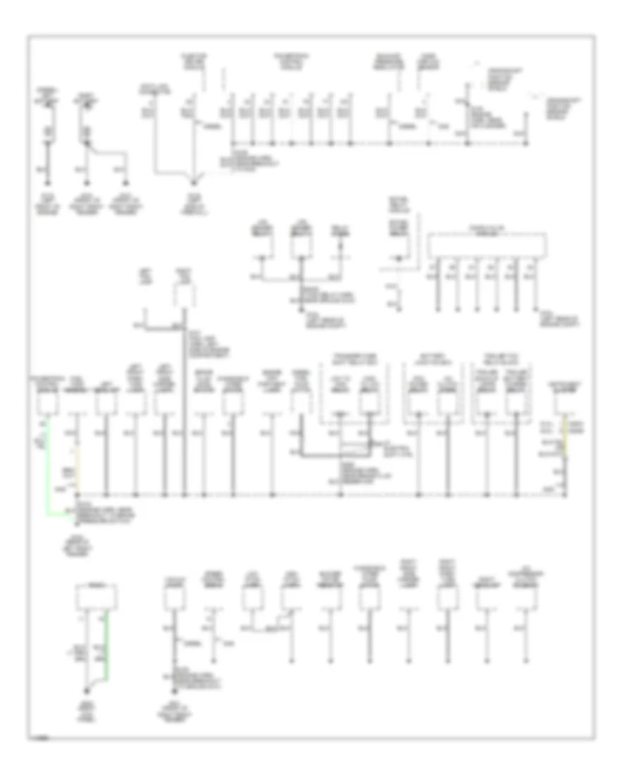
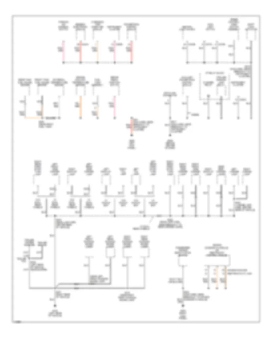
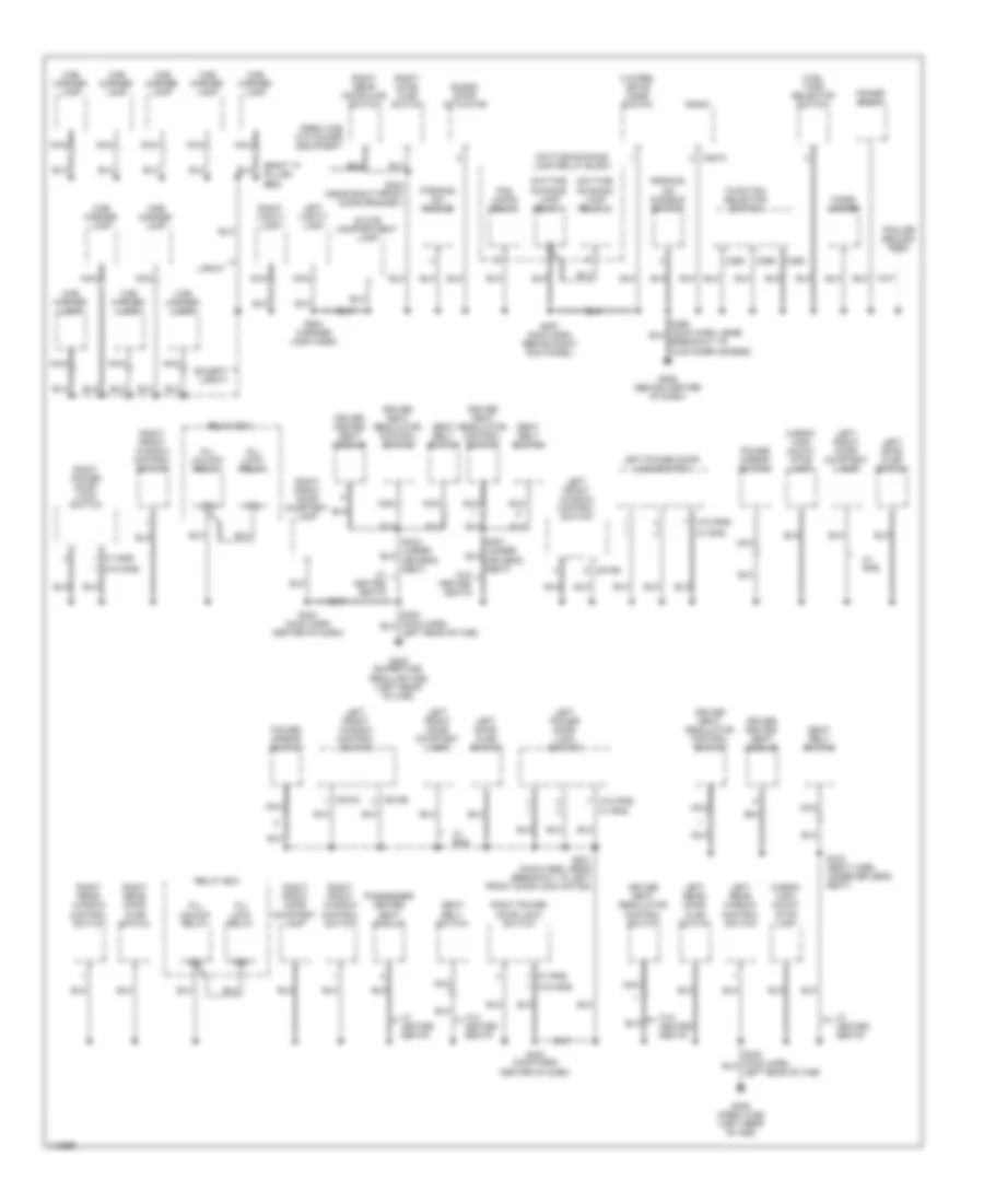
GROUND DISTRIBUTION
Ground Distribution Wiring Diagram (1 of 3) for Ford Cab & Chassis F350 Super Duty 2001
List of elements for Ground Distribution Wiring Diagram (1 of 3) for Ford Cab & Chassis F350 Super Duty 2001:
- (5.4l)
- (6.8l)
- (diesel) left battery
- 87a
- A/c clutch diode
- A/c compressor clutch solenoid
- Battery junction box
- Bi-fuel power relay
- Bi-fuel relay module
- Blower motor resistor
- Brake fluid level switch
- C250a
- C250b
- Compuvalve module
- Crankshaft position sensor shield
- Data link connector
- Diesel
- Diesel fuel pump motor
- Engine com- partment lamp
- Exhaust pressure regulator
- Fuel tank assembly
- G101 (front of right front fender)
- G104 (left rear of engine compt)
- G104 (rear of left front fender)
- G110 (left front of engine)
- G116 (left side of firewall)
- G203 (right kick panel)
- Gas
- High pitch horn
- High to low relay
- Injector driver module
- Instrument cluster
- Left fog lamp
- Left front park/ turn lamp
- Left front side marker lamp
- Left headlamp
- Low pitch horn
- Low to high relay
- Lpg sender relay 1
- Lpg sender relay 2
- Mass airflow sensor
- Nca
- Pcm power relay
- Powertrain control module
- Radio
- Relay diode
- Right battery
- Right fog lamp
- Right front park/ turn lamp
- Right front side marker lamp
- Right headlamp
- S101 (fog lamp harn, left side of engine compartment)
- S145 (engine harn, near air cleaner)
- S250 (engine harn, near brake fluid reservoir)
- Speed control servo
- Trailer back-up lamps relay
- Trailer battery charge relay
- Trailer tow relay block
- Transfer case shift relay box
- Vacuum pump
- W/ electric shift ctrl
- Windshield wiper motor
- Windshield wiper pump motor
Ground Distribution Wiring Diagram (2 of 3) for Ford Cab & Chassis F350 Super Duty 2001
List of elements for Ground Distribution Wiring Diagram (2 of 3) for Ford Cab & Chassis F350 Super Duty 2001:
- (near left front running board lamp) s311
- Air bag diag mod
- Air bag diagnostic module or restraints control module
- Auxiliary powertrain control module
- Brake pedal position switch
- C240a
- C242b
- C250b
- C250c
- C273a
- C273b
- Central junction box
- Data link connector
- Diesel
- Engine coolant temperature sender
- External temperature sender
- Flasher relay
- Front tank fuel gauge sender
- Fuel tank assembly
- G200 (left kick panel)
- G203 (right kick panel)
- G206 (behind center of dash)
- G416 (left rear of vehicle)
- Generic electronic module
- I/p relay block
- Instrument cluster
- Instrument cluster)
- Left back-up lamp
- Left front running board lamp
- Left front side marker lamp
- Left license lamp
- Left rear park/ stop/ turn lamp
- Left rear running board lamp
- Left rear side marker lamp
- Left tail lamp
- Main light switch
- Nca
- Overhead trip computer module
- Parking aid disable switch
- Passenger air bag deactivation switch
- Powertrain control module
- Rear body marker lamps
- Rear tank fuel gauge sender
- Restraints ctl mod
- Right back-up lamp
- Right front running board lamp
- Right front side marker lamp
- Right license lamp
- Right rear park/ stop/ turn lamp
- Right rear running board lamp
- Right rear side marker lamp
- Right tail lamp
- S202 (main harn, near breakout to air bag diagnostic module)
- S218 (main harn, near breakout to instrument cluster)
- S310 (near right front running board lamp)
- S400 (near front fuel tank)
- S401 (right rear of vehicle)
- S402 (rear lamp harn, near breakout to rear marker lamps)
- S403 (license lamp harn, center rear of vehicle)
- S404 (rear lamp harn, center rear of vehicle)
- S432 (left rear of vehicle. near bumper)
- Shift lock actuator
- Speed control/ horn switch assembly
- Trailer ground
- Trailer running lamp relay
- Trailer/ camper adapter
- W/ dual rear wheels
- W/ pickup box
- W/ trailer tow
- W/o dual rear wheels
- W/o pickup box
Ground Distribution Wiring Diagram (3 of 3) for Ford Cab & Chassis F350 Super Duty 2001
List of elements for Ground Distribution Wiring Diagram (3 of 3) for Ford Cab & Chassis F350 Super Duty 2001:
- (right "a" pillar) s920
- 4 wheel drive mode switch
- 87a
- All lock relay
- All unlock relay
- Blend door actuator
- C257a
- C260
- C296
- C298
- C510a
- C510b
- Cab marker lamp
- Cargo/ high mount stop lamp
- Cigar lighter
- Crew cab w/o power equipment
- Daytime running lamp relay 1
- Daytime running lamp relay 2
- Daytime running lamp relay block
- Driver heated seat module
- Driver seat regulator control switch
- Except lariat
- Fog lamps relay
- Fuel tank selector switch
- Function selector switch
- G206 (behind center of dash)
- G308 (crew cab) (left rear of cab)
- G308 (super cab, regular cab) (left rear of cab)
- Glove compartment lamp
- Lariat
- Left door ajar switch
- Left front door courtesy lamp
- Left front window control switch
- Left power door lock switch
- Left rear door ajar switch
- Left rear window control switch
- Left vanity lamp
- Nca
- Parking aid disable switch
- Parking aid module
- Passenger heated seat module
- Power mirror switch
- Power point
- Radio
- Relay box
- Right door ajar switch
- Right front door courtesy lamp
- Right front window control switch
- Right power door lock switch
- Right rear door ajar switch
- Right rear window control switch
- Right vanity lamp
- S203 (near right front door grommet)
- S233 (main harn center of dash)
- S257 (main harn, behind right kick panel)
- S333 (seat harn, under driver's seat)
- S501 (main harn, near breakout to left front door lock motor)
- S904 (marker lamp harn)
- Seat belt switch
- Trailer ground feed
- W/ heated seats
- W/ rke
- W/o heated seats
- W/o rke
HEADLIGHTS
Headlights Wiring Diagram, with DRL for Ford Cab & Chassis F350 Super Duty 2001
List of elements for Headlights Wiring Diagram, with DRL for Ford Cab & Chassis F350 Super Duty 2001:
- (engine control sensor harness, near breakout at left side of dash) s113
- (main harness, near breakout to central junction box) s220
- 87a
- Battery junction box
- C230a
- C242a
- C242b
- C253c
- C273a
- C274a
- Central junction box
- Daytime running lamps relay 1
- Daytime running lamps relay 2
- Daytime running lamps relay block (behind right side of dash)
- Daytime running lamps resistor (on left front side of engine compt)
- Fog lamp relay
- Fog on indicator
- Fuse 10a
- Fuse 15a
- Fuse 30a
- Fuse 5a
- G101 (front of right front fender)
- G104 (rear of left front fender)
- G206 (behind center of dash)
- Head
- Hi-beam indicator
- Hot at all times
- Hot in run
- Instrument cluster
- Left fog lamp
- Left headlamp
- Main light
- Main light switch
- Multi- function switch
- Near center of dash)
- Off
- Park
- Pass
- Right fog lamp
- Right headlamp
- S100 (fog lamp harn, near air cleaner)
- S101
- S102
- S120 (engine harn, near left front of engine compt)
- S121 (engine harness, near breakout to power distribution box)
- S180
- S206
- S214
- S217
- S218
- S219 (dash harn, near breakout to park brake switch)
- S257
- Switch
Headlights Wiring Diagram, without DRL for Ford Cab & Chassis F350 Super Duty 2001
List of elements for Headlights Wiring Diagram, without DRL for Ford Cab & Chassis F350 Super Duty 2001:
- (engine harness, near breakout at left side of dash) s113
- Battery junction box
- C230a
- C242a
- C253c
- C274a
- Central junction box
- Distribution box)
- Fuse 10a
- Fuse 15a
- Fuse 30a
- G101 (front of right front fender)
- G104 (rear of left front fender)
- G206 (behind center of dash)
- Head
- Hi-beam indicator
- Hot at all times
- Instrument cluster
- Left headlamp
- Main light
- Multi- function switch
- Off
- Park
- Pass
- Right headlamp
- S102
- S180
- S214
- S217
- S220 (main harness, near breakout to central junction box)
- Switch
HORN
Horn Wiring Diagram for Ford Cab & Chassis F350 Super Duty 2001
List of elements for Horn Wiring Diagram for Ford Cab & Chassis F350 Super Duty 2001:
- (engine harness, near breakout to pcm)
- Air bag sliding contact
- C1027
- C1067
- C240d
- C242a
- C242b
- Central junction box (behind lower left side of dash)
- Diesel
- Fuse 15a
- G101 (front of right front fender)
- Gasoline/ bi-fuel
- Generic electronic module (behind left side of dash)
- High pitch horn (right front of engine compt)
- Horn relay
- Horn switch
- Hot at all times
- Low pitch horn (right front of engine compt)
- Nca
- Powertrain control module (left side of firewall)
- S114
- S180
- Signal return
- Speed control servo/amplifier assembly (right side of engine compt)
- Speed control switch return
- Speed control/ horn switch assembly
INSTRUMENT CLUSTER
Instrument Cluster Wiring Diagram for Ford Cab & Chassis F350 Super Duty 2001
List of elements for Instrument Cluster Wiring Diagram for Ford Cab & Chassis F350 Super Duty 2001:
- (conn a)
- (conn b)
- (conn c)
- (diesel)
- (engine harn, left side of dash)
- (engine harness, near breakout at brake pressure switch) s104
- (excursion)
- (left kick panel) g200
- (pickup)
- (pickup) (excursion)
- (rear of left front fender)
- 22k ohms
- 470 ohms
- 4x4 high ind
- 4x4 low ind
- 5.6k ohms
- 87a
- A 5.4l
- A11
- A12
- Airbag ind
- Anti-lock brake ind
- Anti-lock brakes system
- Anti-theft system
- B 6.8l
- B10
- B11
- B12
- B14
- B16
- Bi-fuel
- Brake warning ind
- C10
- C1027
- C11
- C12
- C240a
- C242b
- C242b c242a
- C250a
- C250c
- C25ob
- Central junction box
- Charge ind
- Coolant temperature/ oil pressure indicator
- Cruise control system
- Dash reset relay (right rear of engine compt)
- Diesel
- Door ajar ind
- Dual tanks
- Eng cool temp gauge
- Eng oil press gauge
- Engine controls system
- Engine controls system (diesel)
- Engine coolant temperature sender (on front of engine)
- Engine coolant temperature sender (on top left front of engine)
- Engine oil pressure switch (on top center rear of engine)
- Exc bi-fuel
- Except diesel
- Exterior lights system
- Fasten seat belt ind
- Fuel gauge
- Fuel reset ind
- Fuel tank assembly
- Fuel tank selector valve
- Fuse 10a
- Fuse 5a
- G104
- G104 (rear of left front fender)
- G200 (left kick panel)
- G206 (behind center of dash)
- Gas
- Generic electronic module (behind lower left side of dash)
- Ground
- Headlights system
- Hi beam ind
- Hot at all times
- Hot in start or run
- Illumination
- Instrument cluster
- Interior lights system
- Keep alive
- Led indicator
- Left turn ind
- Malfunction ind
- Microprocessor
- Nca
- Overhead console circuit
- Powertrain control module (on left side of firewall)
- Red
- Right turn ind
- S102
- S129
- S201
- S208 (main harn, center of dash)
- S211
- S213
- S217
- S221
- S271
- Spd ctrl set lamp
- Starting/charging system
- Tach select 1
- Tach select 2
- Tachometer
- Transmission system
- V power
- Vss+ (speedometer)
- Wait to start ind
- Water in fuel ind
Overhead Console Wiring Diagram for Ford Cab & Chassis F350 Super Duty 2001
List of elements for Overhead Console Wiring Diagram for Ford Cab & Chassis F350 Super Duty 2001:
- Anti-lock brakes system
- C1027
- C242b
- Central junction box
- Computer data lines system
- Data out fuel flow
- Engine controls system (california)
- Engine controls system (diesel)
- External temp sens
- External temperature sensor (left front of vehicle)
- Fuel tank assembly
- Fuel tank sender
- Fuse 10a
- G200 (left kick panel)
- Hot in start or run
- Ill feed
- Instrument cluster circuit
- Interior lights system
- Iso link
- Overhead console module (in roof, at front center of cab)
- Powertrain control module (on left side of firewall)
- S201
- S208 (main harn, center of dash)
- S213
- Speed sensor+
- Speed sensor-
- Warn lamps
INTERIOR LIGHTS
Courtesy Lamps Wiring Diagram for Ford Cab & Chassis F350 Super Duty 2001
List of elements for Courtesy Lamps Wiring Diagram for Ford Cab & Chassis F350 Super Duty 2001:
- (int lamp harn, near right visor) s937
- (main harn, left rear of cab) s905
- (near brake fluid reservoir) s190
- (near left front running board lamp) s309
- (not used)
- (rear of left front fender) g104
- C240d
- C242a
- C242b
- C273b
- Cargo/high mount stop lamp
- Cargo/high mounted stop lamp
- Central junction box (behind lower left side of dash)
- Engine compartment lamp
- Front interior lamp
- Front map lamps
- Fuse 14 10a
- Fuse 4 10a
- G206 (behind center of dash)
- G308 (left rear of cab)
- G416 (left rear of vehicle)
- Generic electronic module (gem)
- Glove compartment lamp
- Hot at all times
- Interior
- Interior lamp relay
- Left front door courtesy lamp (w/ rke only)
- Left front running board lamp
- Left rear running board lamp
- Left vanity lamp
- Main light switch
- Nca
- Others
- Rear interior lamp
- Rear map lamps
- Regular cab
- Right front door courtesy lamp (w/ rke only)
- Right front running board lamp
- Right rear running board lamp
- Right vanity lamp
- S102
- S218
- S229 (main harn, behind top left side of dash)
- S233
- S257
- S300
- S308 (near right front running board lamp)
- S310
- S311
- S401
- S904
- S906 (main harn, left rear of cab)
- Super & regular w/o power mirrors
- W/ running board lamps
- W/o running board lamps
Instrument Illumination Wiring Diagram for Ford Cab & Chassis F350 Super Duty 2001
List of elements for Instrument Illumination Wiring Diagram for Ford Cab & Chassis F350 Super Duty 2001:
- 4 wheel drive mode switch
- Accessory delay relay
- Adjustable pedal switch
- Battery junction box (in left side of engine compt, on top of wheelwell)
- Bulbs
- C242a
- C250b
- C250c
- C257a
- C273b
- C298
- C510a
- C510b
- Central junction box (behind lower left side of dash)
- Circuit breaker 25 30a
- Climate control illum
- Crew cab
- Except crew cab
- Function selector switch
- Fuse 7 5a
- G200 (left kick panel)
- G206 (behind center of dash)
- G308 (left rear of cab)
- Head
- Hot at all times
- Instrument cluster
- Left front window control switch
- Left power door lock switch
- Left rear window control switch
- Main light switch
- Nca
- Off
- Overhead console module
- Parking aid disable switch
- Power windows system
- Pulse width dimmer module
- Radio
- Right front window control switch
- Right power door lock switch
- Right rear window control switch
- S201
- S215 (main harn, near customer access connector breakout)
- S216 (main harn, behind top left side of dash)
- S217
- S218
- S227 (main harn, lower center of dash)
- S233
- S257
- S290
- S300
- S501 s300
- Speed control/ horn switch assembly
- Steering wheel illumination
POWER DISTRIBUTION
Power Distribution Wiring Diagram (1 of 4) for Ford Cab & Chassis F350 Super Duty 2001
List of elements for Power Distribution Wiring Diagram (1 of 4) for Ford Cab & Chassis F350 Super Duty 2001:
- (center of dash) g206
- (diesel only)
- (diesel w/o dual gen)
- (engine harn, left front of engine compt) s120
- (engne harn, near breakout to starter motor relay) s146
- (in back-up lamp harn, left rear of engine compt) s251
- (left rear of engine compt) bi-fuel relay module
- (left side of engine compt) battery junction box
- (main harn, lower center of dash) s223
- (main harn, near inst cluster breakout) s298
- A/c clutch relay
- Adjustable pedal switch
- Anti-lock brake system module
- Battery junction box (left side of engine compt)
- Bi-fuel
- Bi-fuel power relay
- Blower motor relay
- C104b
- C152
- C154
- C257a
- California
- Cold start heater relay
- Compuvalve module
- Daytime running lamps resistor
- Diesel
- Driver heated seat module
- Driver's seat regulator control switch
- Drl relay block (behind right side of dash)
- Except california
- Fog lamp relay
- From a fuse 23 (diagram 1 of 4)
- Fuel pump relay
- Fuse 10a
- Fuse 15a
- Fuse 20a
- Fuse 30a
- Fuse 3a
- Fuse 40a
- Fuse 5a (diesel w/ dual gen)
- Fuse 60a
- Gasoline
- Generator/ voltage regulator (diesel)
- Generator/ voltage regulator (gasoline)
- Generator/ voltage regulator (secondary: diesel w/ dual gen)
- Glow plug control module
- Glow plug relay
- High to low relay
- I/p relay block (behind left side of dash)
- Idm power relay (diesel)
- Left battery (diesel only)
- Low to high relay
- Manifold intake air heater relay
- Nca
- Passenger heated seat module
- Pcm diode
- Pcm power relay
- Power point
- Radio
- Red
- Right battery
- S147 (near starter motor relay)
- S148 (near starter motor relay)
- S149 (near starter motor relay)
- S290
- Starter motor
- Starter motor relay
- To fuse 17 (diagram 1 of 4)
- To fuse 26 (diagram 2 of 4)
- To fuse 30 (diagram 2 of 4)
- Trailer battery charge relay
- Trailer brakes feed (taped in harness)
- Trailer reversing lamps relay
- Trailer running lamps relay
- Trailer tow relay block (left side of engine compt)
- Transfer case shift relay
- Washer pump relay
Power Distribution Wiring Diagram (2 of 4) for Ford Cab & Chassis F350 Super Duty 2001
List of elements for Power Distribution Wiring Diagram (2 of 4) for Ford Cab & Chassis F350 Super Duty 2001:
- (engine harn, pia diesel harn) s154
- (main harn, behind left side of dash) s210
- (main harn, behind left side of dash) s212
- (main harn, center of dash) s230
- (main harn, lower left side of dash) s214
- Acc
- Accessory delay relay
- All lock relay
- All unlock relay
- Battery junction box (left side of engine compt)
- C242a
- C242b
- Central junction box (lower left side of dash)
- Circuit breaker 30a
- Coil on plug 1
- Coil on plug 10
- Coil on plug 2
- Coil on plug 3
- Coil on plug 4
- Coil on plug 5
- Coil on plug 6
- Coil on plug 7
- Coil on plug 8
- Coil on plug 9
- Driver unlock relay
- From b fuse 4 (diagram 1 of 4)
- From pcm power relay (diagram 1 of 4)
- Fuel heater/ water in fuel sensor
- Fuse 15a
- Fuse 20a
- Fuse 30a
- Fuse 30a (5.4l gasoline)
- Fuse 30a (6.8l gasoline)
- Fuse 30a (diesel)
- Fuse 50a
- Ignition switch
- Left power door lock switch
- Lock
- Main light switch
- Multi- function switch
- Nca
- Off
- Park lamp relay
- Radio capacitor 1
- Radio noise capacitor 2
- Relay box (behind center of dash)
- Right power door lock switch
- Run
- S130 (engine harn, near throttle body)
- S135 (engine harn, right side of engine block)
- S179 (engine harn, left side of engine compartment)
- S272 (main harn, left side of dash)
- Start
- To fuse 10 (diagram 4 of 4)
- To fuse 13 (diagram 3 of 4)
- To fuse 19 (diagram 3 of 4)
- To fuse 20 (diagram 4 of 4)
- To fuse 22 (diagram 4 of 4)
- To fuse 27 (diagram 4 of 4)
- W/ rke
- W/o rke
- Wastegate solenoid control
Power Distribution Wiring Diagram (3 of 4) for Ford Cab & Chassis F350 Super Duty 2001
List of elements for Power Distribution Wiring Diagram (3 of 4) for Ford Cab & Chassis F350 Super Duty 2001:
- (in vanity mirror lamp harn) s937
- (main harn, top left side of dash) s213
- (near brake pedal position switch) s221
- 87a
- Accessory delay relay
- Auxiliary powertrain control module
- Brake pedal position switch
- Brake pressure switch
- C240a
- C242a
- C242b
- C250a
- C250b
- Central junction box (lower left side of dash)
- Cigar lighter
- Clutch pedal position switch
- Dash reset relay
- Data link connector
- Engine compartment lamp
- Flasher relay
- From fuse 22 (power distribution box) (diagram 2 of 4)
- From fuse 3 k (diagram 3 of 4)
- From h fuse 30 (diagram 2 of 4)
- Front map lamp
- Fuse 10a
- Fuse 15a
- Fuse 20a
- Fuse 5a
- G206 (center of dash)
- Generic electronic module
- Generic electronic module (gem)
- Glove compartment lamp
- Horn relay
- I/p relay block
- Idle validation switch
- Instrument cluster
- Interior lamp relay
- Left vanity lamp
- Nca
- Overdrive cancel switch
- Overhead trip computer module
- Power mirror switch
- Powertrain control module
- Rear map lamp
- Right vanity lamp
- S229 (main harn, top left side of dash)
- S242 (main harn, near breakout to customer access)
- S290
- S906 (main harn, left rear of cab)
- To fuse 4 (diagram 3 of 4)
- W/ bi-fuel
- W/o bi-fuel
Power Distribution Wiring Diagram (4 of 4) for Ford Cab & Chassis F350 Super Duty 2001
List of elements for Power Distribution Wiring Diagram (4 of 4) for Ford Cab & Chassis F350 Super Duty 2001:
- (engine harn, left rear of engine compt) s124
- (engine harn, near breakout to power distribution box)
- (main harn, behind center of dash) s238
- (main harn, center of dash) s200
- (main harn, left side of dash) s206
- (main harn, left side of dash) s235
- (main harn, lower left side of dash) s275
- A/t
- Anti-lock brake system module
- Battery junction box
- Battery junction box (left side of engine compt)
- Blend door actuator
- Blower motor relay
- C242a
- C242b
- Central junction box (lower left side of dash)
- Clutch pedal position switch or clutch pedal position switch jumper
- Customer access (taped in harn)
- Daytime running lamp relay 2
- Daytime running lamp relay block
- Digital transmission range sensor
- Driver heated seat module
- Driver heated seat switch
- Flasher relay
- From ignition switch (diagram 2 of 4)
- Fuel tank selector switch
- Function selector switch
- Fuse (not used)
- Fuse 10a
- Fuse 15a
- Fuse 30a
- Fuse 5a
- Generic electronic module (gem)
- I/p relay block (behind dash, near inst panel)
- M/t
- Parking aid module
- Passenger heated seat module
- Passenger heated seat switch
- Passenger's air bag deactivation switch
- Radio
- Red
- Restraints control module
- Reversing lamp switch
- S119
- S334
- S335
- Shift lock actuator
- Speed control module
- Tan/red
- Trailer battery charge relay
- Trailer tow relay block (left side of engine compt)
- Vacuum hublock solenoid
- Vacuum pump
- W/ c/d player
- W/o c/d player
- Washer pump relay
- Windshield wiper motor
- Wiper hi/lo relay
- Wiper run/ park relay
POWER DOOR LOCKS
Power Door Locks Wiring Diagram, with Remote/Keyless Entry Except Crew Cab for Ford Cab & Chassis F350 Super Duty 2001
List of elements for Power Door Locks Wiring Diagram, with Remote/Keyless Entry Except Crew Cab for Ford Cab & Chassis F350 Super Duty 2001:
- (main harn, center of dash) s232
- 87a
- All lock relay
- All unlock relay
- Battery junction box (in left side of engine compt, on top of wheelwell)
- C247
- C273a
- Driver unlock relay
- Exterior lights system
- Fuse 15a
- Fuse 20a
- G308 (left rear of cab)
- Generic electronic module (behind lower left side of dash)
- Head
- Hot at all times
- Interior lights system
- Left door lock actuator
- Left power door lock switch
- Lock
- Main light switch
- Off
- Park
- Park lamp relay
- Relay box (behind center of dash)
- Right door lock actuator
- Right power door lock switch
- S215 (main harn, behind dash)
- S230
- S231 (main harn, center of dash)
- S233
- S272
- S501
- Unlk
Power Door Locks Wiring Diagram, with Remote/Keyless Entry-Crew Cab for Ford Cab & Chassis F350 Super Duty 2001
List of elements for Power Door Locks Wiring Diagram, with Remote/Keyless Entry-Crew Cab for Ford Cab & Chassis F350 Super Duty 2001:
- (main harn, center of dash) s224
- (main harn, center of dash) s232
- 87a
- All lock relay
- All unlock relay
- Battery junction box (in left side of engine compt, on top of wheelwell)
- C240c
- C273a
- Driver unlock relay
- Exterior lights system
- Fuse 15a
- Fuse 20a
- G308 (left rear of cab)
- Generic electronic module (behind lower left side of dash)
- Head
- Hot at all times
- Interior lights system
- Left front door lock actuator
- Left power door lock switch
- Left rear door lock actuator
- Lock
- Main light switch
- Off
- Park
- Park lamp relay
- Relay box (behind center of dash)
- Right front door lock actuator
- Right power door lock switch
- Right rear door lock actuator
- S215 (main harn, behind dash)
- S228 (main harn, center of dash)
- S230
- S231 (main harn, center of dash)
- S233
- S272
- S501
- Unlk
Power Door Locks Wiring Diagram, without Remote/Keyless Entry Except Crew Cab for Ford Cab & Chassis F350 Super Duty 2001
List of elements for Power Door Locks Wiring Diagram, without Remote/Keyless Entry Except Crew Cab for Ford Cab & Chassis F350 Super Duty 2001:
- Battery junction box (in left side of engine compt, on top of wheelwell)
- Fuse 20a
- G308 (left rear of cab)
- Hot at all times
- Interior lights system
- Left front door lock actuator
- Left power door lock switch
- Lock
- Right front door lock actuator
- Right power door lock switch
- S233
- S300
- Unlk
Power Door Locks Wiring Diagram, without Remote/Keyless Entry-Crew Cab for Ford Cab & Chassis F350 Super Duty 2001
List of elements for Power Door Locks Wiring Diagram, without Remote/Keyless Entry-Crew Cab for Ford Cab & Chassis F350 Super Duty 2001:
- (main harn, center of dash) s224
- Battery junction box (in left side of engine compt, on top of wheelwell)
- Fuse 20a
- G308 (left rear of cab)
- Hot at all times
- Interior lights system
- Left front door lock actuator
- Left power door lock switch
- Left rear door lock actuator
- Lock
- Right front door lock actuator
- Right power door lock switch
- Right rear door lock actuator
- S228 (main harn, center of dash)
- S233
- S300
- Unlk
POWER MIRRORS
Power Mirrors Wiring Diagram for Ford Cab & Chassis F350 Super Duty 2001
List of elements for Power Mirrors Wiring Diagram for Ford Cab & Chassis F350 Super Duty 2001:
- (left rear of cab) g308
- Battery saver relay
- C240d
- C242a
- C242b
- Central junction box (behind lower left side of dash)
- Direct- ional control switch
- Down
- Except excursion
- Excursion
- Exterior lights
- Fuse 10a
- Fuse 15a
- G414 (left rear quarter panel)
- Generic electronic module (behind lower left side of dash)
- Hot at all times
- Illum
- Interior lights system
- L/r
- Left
- Left power mirror
- Nca
- Power mirror switch
- Rear window/ mirror defrost
- Red
- Right
- Right power mirror
- S233
- S261 (near breakout to seat harn)
- S301 (1999) s906 (2000, 2001)
- S500
- U/d
POWER SEATS
6-Way Power Seat Wiring Diagram for Ford Cab & Chassis F350 Super Duty 2001
List of elements for 6-Way Power Seat Wiring Diagram for Ford Cab & Chassis F350 Super Duty 2001:
- (1999)
- (2000-01)
- Battery junction box (left side of engine compt)
- Driver seat motor assembly
- Driver seat regulator control switch
- Entire seat
- Except excursion w/ heated seats
- Excursion w/ heated seats
- Forward/reverse motor
- Front height motor
- Front of seat
- Fuse 18 fuse 108 30a
- Fwd
- G308 (left rear of cab)
- Hot at all times
- Nca
- Rear height motor
- Rear of seat
- Rwd
- S298 (2001)
- S300
Adjustable Pedal Wiring Diagram for Ford Cab & Chassis F350 Super Duty 2001
List of elements for Adjustable Pedal Wiring Diagram for Ford Cab & Chassis F350 Super Duty 2001:
- (excursion)
- (pickup)
- (pickup) (excursion)
- Adjustable pedal motor (in driver's footwell)
- Adjustable pedal switch
- Battery junction box (left side of engine compt)
- Fuse 18 fuse 108 30a
- G206 (behind center of dash)
- Hot at all times
- Interior lights system
- Nca
- Red
- S217
- S257
- S298
Heated Seats Wiring Diagram for Ford Cab & Chassis F350 Super Duty 2001
List of elements for Heated Seats Wiring Diagram for Ford Cab & Chassis F350 Super Duty 2001:
- (left rear quater panel)
- (seat harness, near b/o to heated seat switch)
- Battery junction box (left side of engine compt)
- C333
- C334
- C342
- C343
- Central junction box (behind left side of dash)
- Driver's seat back heater
- Driver's heated seat module (under driver's seat)
- Driver's heated seat switch (under driver's seat)
- Driver's seat heater & temp sensor (under driver's seat)
- Fuse 107 (excursion) fuse 15 (pickup) 30a
- Fuse 6 (2000) fuse 28 (2001) 15a
- G414
- Hot at all times
- Hot in run
- Not used
- Pass seat back heater
- Passenger's heated seat module (under passenger's seat)
- Passenger's heated seat switch (under passenger's seat)
- Passenger's seat heater & temp sensor (under passenger's seat)
- Red
- S238
- S281
- S334
- S335
POWER WINDOWS
Power Windows Wiring Diagram, Crew Cab for Ford Cab & Chassis F350 Super Duty 2001
List of elements for Power Windows Wiring Diagram, Crew Cab for Ford Cab & Chassis F350 Super Duty 2001:
- 87a
- Acc delay relay
- Acc delay rly ctrl
- Battery junction box
- C240d
- C242a
- C242b
- C510a
- C510b
- Central junction box
- Circuit breaker 25 30a
- Down sw input
- Fuse 10a
- Fuse 50a
- G206 (behind center of dash)
- G308 (left rear of cab)
- Generic electronic module
- Hot at all times
- Interior lights system
- Left front power window motor
- Left front power window switch
- Left front switch
- Left rear power window motor
- Left rear power window switch
- Left rear switch
- Lock out
- Nca
- One tch dn ctrl
- One tch sense hi
- One tch sense lo
- One touch down relay
- Otd sw input
- Otd switch
- Right front power window motor
- Right front power window switch
- Right front switch
- Right rear power window motor
- Right rear power window switch
- Right rear switch
- S218
- S229
- S262 (harn, near breakout under left front seat)
- S501
- Shunt (0.015 ohms)
Power Windows Wiring Diagram, Except Crew Cab for Ford Cab & Chassis F350 Super Duty 2001
List of elements for Power Windows Wiring Diagram, Except Crew Cab for Ford Cab & Chassis F350 Super Duty 2001:
- 87a
- Acc delay relay
- Acc delay rly ctrl
- Battery junction box
- C240d
- C242a
- C242b
- C510a
- C511
- Central junction box
- Circuit breaker 25 30a
- Down sw input
- Fuse 10a
- Fuse 50a
- G206 (behind center of dash)
- G308 (left rear of cab)
- Generic electronic module
- Hot at all times
- Interior lights system
- Left power window motor
- Left power window switch
- Left switch
- Nca
- On tch dn ctrl
- One tch sense hi
- One tch sense lo
- One touch down
- One touch down relay
- Otd sw input
- Right power window motor
- Right power window switch
- Right switch
- S218
- S226 (main harn, near breakout to customer access)
- S229
- S300
- Shunt (0.015 ohms)
RADIO
Radio Wiring Diagram for Ford Cab & Chassis F350 Super Duty 2001
List of elements for Radio Wiring Diagram for Ford Cab & Chassis F350 Super Duty 2001:
- (behind center of dash) g206
- (main body harn, right rear of cab behind trim panel)
- Antenna
- Battery junction box (left side of engine compt)
- C242a
- C257a
- Central junction box (behind lower left side of dash)
- Fuse 20a
- Fuse 5a
- Fused ign
- G203 (right kick panel)
- Ground
- Hot at all times
- Hot in run or acc
- Hot in start
- Ilumination
- Interior lights system
- L f spkr
- L r spkr
- Left front door speaker
- Left rear speaker
- Mem power
- Nca
- Power
- R f spkr
- R r spkr
- Radio
- Right front door speaker
- Right rear speaker
- S290
- S325
- S326
SHIFT INTERLOCK
Shift Interlock Wiring Diagram for Ford Cab & Chassis F350 Super Duty 2001
List of elements for Shift Interlock Wiring Diagram for Ford Cab & Chassis F350 Super Duty 2001:
- Brake pedal position (bpp) switch (above brake pedal)
- C242b
- Central junction box (behind lower left side of dash)
- Fuse 15 5a
- Fuse 28 15a
- G206 (behind center of dash)
- G300 (below left front seat)
- Hot at all times
- Hot in run
- S201
- S205 (main harn, left of steering column)
- S206
- S218
- Shift lock actuator (in steering column)
- Solid state
STARTING/CHARGING
Starting Wiring Diagram for Ford Cab & Chassis F350 Super Duty 2001
List of elements for Starting Wiring Diagram for Ford Cab & Chassis F350 Super Duty 2001:
- A/t
- Acc
- Battery junction box (left side of engine compt)
- C1012
- C242b
- Central junction box (behind lower left side of dash)
- Clutch pedal position (cpp) switch (behind left side of dash)
- Clutch pedal position (cpp) switch jumper (behind left side of dash)
- Digital transmission range sensor (left side of transmission)
- Fuse 15a
- Fuse 50a
- Fusible link a (12 ga- gray) (near str mtr relay)
- Fusible link j (12 ga- gray) (near str mtr relay)
- G101 (front of right front fender)
- G110 (left front of engine)
- Ignition switch
- Left battery (diesel)
- Lock
- M/t
- Off
- Red
- Right battery
- Run
- S146 (engine harn, near breakout to starter motor relay)
- Side of dash)
- Sta
- Start
- Starter motor
- Starter motor relay (right front inner fender panel, behind battery)
- Tan/red
5.4L
5.4L, Charging Wiring Diagram for Ford Cab & Chassis F350 Super Duty 2001
List of elements for 5.4L, Charging Wiring Diagram for Ford Cab & Chassis F350 Super Duty 2001:
- (eng harn, near breakout to starter motor relay) s146
- 0hms
- Acc
- Battery
- Battery junction box (left side of engine compt)
- C153a
- C153b
- C242b
- C250a
- Central junction box (behind lower left side of dash)
- Charge indicator
- Fuse 50a
- Fuse 5a
- Fusible link a (12 ga-gray) (near starter motor relay)
- Fusible link b (12 ga-gray) (near starter motor relay)
- Fusible link j (12 ga-gray) (near starter motor relay)
- G101 (front of right front fender)
- Generator
- Ignition switch
- Instrument cluster
- Lock
- Off
- Red
- Run
- Start
- Starter motor
- Starter motor relay (behind battery)
6.8L
6.8L, Charging Wiring Diagram for Ford Cab & Chassis F350 Super Duty 2001
List of elements for 6.8L, Charging Wiring Diagram for Ford Cab & Chassis F350 Super Duty 2001:
- (eng harn, near breakout to starter motor relay) s146
- 0hms
- Acc
- Battery
- Battery junction box (left side of engine compt)
- C153a
- C153b
- C242b
- C250a
- Central junction box (behind lower left side of dash)
- Charge indicator
- Fuse 50a
- Fuse 5a
- Fusible link a (12 ga-gray) (near starter motor relay)
- Fusible link b (12 ga-gray) (near starter motor relay)
- Fusible link j (12 ga-gray) (near starter motor relay)
- G101 (front of right front fender)
- Generator
- Ignition switch
- Instrument cluster
- Lock
- Off
- Red
- Run
- Start
- Starter motor
- Starter motor relay (behind battery)
7.3L DIESEL
7.3L Diesel, Charging Wiring Diagram, with Dual Generators for Ford Cab & Chassis F350 Super Duty 2001
List of elements for 7.3L Diesel, Charging Wiring Diagram, with Dual Generators for Ford Cab & Chassis F350 Super Duty 2001:
- (behind battery) starter motor relay
- 0hms
- Acc
- Battery junction box (left side of eng compt)
- C1027
- C1029
- C185
- C242b
- C250a
- Central junction box (behind lower left side of dash)
- Charge ind
- Fuse 10a
- Fuse 50a
- Fuse 5a
- Fusible link a (12 ga-gray) (near starter motor relay)
- Fusible link b (12 ga-gray) (near starter motor relay)
- Fusible link h (12 ga-gray) (near starter motor relay)
- Fusible link j (12 ga-gray) (near starter motor relay)
- G101 (front of right front fender)
- G110 (left front of engine)
- Generator/ voltage regulator (primary)
- Generator/ voltage regulator (secondary)
- Ignition switch
- Instrument cluster
- Left battery
- Left side of dash) s212
- Lock
- Off
- Power distribution
- Powertrain control module (pcm) (on left side of firewall)
- Red
- Right battery
- Run
- S146 (eng harn, near starter motor relay)
- Start
- Starter motor
7.3L Diesel, Charging Wiring Diagram, without Dual Generators for Ford Cab & Chassis F350 Super Duty 2001
List of elements for 7.3L Diesel, Charging Wiring Diagram, without Dual Generators for Ford Cab & Chassis F350 Super Duty 2001:
- (california) s147 (non-california) s149 (eng harn, near starter motor relay)
- (w/dual generator giveaway)
- (w/o dual generator giveaway)
- 0hms
- Acc
- Battery junction box (left side of eng compt)
- Battery junction box (left side of engine compt)
- C185
- C242b
- C250a
- Central junction box (behind lower left side of dash)
- Charge indicator
- Fuse 10a
- Fuse 50a
- Fuse 5a
- Fusible link a (12 ga-gray) (near starter motor relay)
- Fusible link b (12 ga-gray) (near starter motor relay)
- Fusible link h (12 ga-gray) (near starter motor relay)
- Fusible link j (12 ga-gray) (near starter motor relay)
- G101 (front of right front fender)
- G110 (left front of engine)
- Generator
- Ignition switch
- Instrument cluster
- Left battery
- Lock
- Off
- Power distribution
- Red
- Right battery
- Run
- S146 (engine harn, near starter motor relay)
- S148 (eng harn, near starter motor relay)
- Start
- Starter motor
- Starter motor relay (behind battery)
- W/dual generator giveaway
- W/o dual generator giveaway
SUPPLEMENTAL RESTRAINTS
Supplemental Restraints Wiring Diagram, Early Production for Ford Cab & Chassis F350 Super Duty 2001
List of elements for Supplemental Restraints Wiring Diagram, Early Production for Ford Cab & Chassis F350 Super Duty 2001:
- (behind bottom of right kick panel) g203
- (in main harness, near breakout to air bag diagnostic module) s200
- (in main harness, near breakout to customer access)
- Air bag diagnostic module (in center of dash)
- Air bag dr fd mon
- Air bag dr return
- Air bag indicator
- Air bag pass mon
- Air bag pass rtn
- Air bag sliding contact
- Air bag sw lp dr
- Air bag sw sense
- Air bag tone out
- Air bag tone request input
- C240a
- C242a
- C242b
- C250a
- Central junction box (behind lower left side of dash)
- Data link connector (dlc) (partial) (behind center of dash)
- Driver air bag
- Fuse 22 10a
- Fuse 23 10a
- Fuse 29 5a
- Generic electronic module (gem) (behind lower left side of dash)
- Ground
- Hot in run
- Hot in run or start
- Ignition
- Instrument cluster
- Iso 9141 link
- Nca
- Ohms
- Passenger air bag
- Passenger air bag deactivation switch
- Pin shorting bar engaged when module connector is disconnected from harness: (shorting bars connected between following pins: 1-15, 10-13, 8-22 & 14-28)
- S202 (in main harness, near breakout to air bag diagnostic module)
- S225
- Shorting bar
Supplemental Restraints Wiring Diagram, Late Production for Ford Cab & Chassis F350 Super Duty 2001
List of elements for Supplemental Restraints Wiring Diagram, Late Production for Ford Cab & Chassis F350 Super Duty 2001:
- (center of dash) g206
- (in main harness, near breakout to customer access)
- (in main harness, near breakout to restraints control module (rcm)) s200
- Air bag feed
- Air bag indicator
- Air bag return
- Air bag sliding contact
- Air bag tone request input
- C240a
- C242a
- C242b
- C250a
- Central junction box (behind lower left side of dash)
- Data
- Data link connector (dlc) (partial) (behind center of dash)
- Driver air bag
- Driver safety belt pretensioner
- Fuse 22 10a
- Fuse 23 10a
- Fuse 29 5a
- Generic electronic module (gem) (behind lower left side of dash)
- Ground
- Hot in run
- Hot in run or start
- Ignition
- Indicator lamp
- Instrument cluster
- Lamp driver
- Nca
- Ohms
- Passenger air bag
- Passenger air bag deactivation switch
- Passenger safety belt pretensioner
- Pin shorting bars engaged when module connector is disconnected from harness: (shorting bars connected between pins 3-4, 6-7 & 20-21)
- Power feed
- Pretensioner
- Restraints control module (rcm) (behind center of dash)
- S202 (in main harness, near breakout to restraints control module (rcm))
- S225
- Shorting bar
- Tone request
TRANSMISSION
4WD Wiring Diagram for Ford Cab & Chassis F350 Super Duty 2001
List of elements for 4WD Wiring Diagram for Ford Cab & Chassis F350 Super Duty 2001:
- (excursion)
- (pickup)
- 4 wheel drive mode switch
- 4x2 sol
- 4x4 high ind
- 4x4 high range indicator
- 4x4 low ind
- 4x4 low range indicator
- 4x4 mode sw
- 4x4 sol
- 87a
- Anti-lock brake system module (left front of engine compt)
- Battery junction box (left side of engine compt)
- Bpp sw input
- Brake pedal position switch (behind left side of dash)
- C1040
- C240a
- C240c
- C242b
- C250a
- C2530c
- C285a
- C285b
- Central junction box (lower left side of dash)
- Contact plate a
- Contact plate b
- Contact plate c
- Contact plate p
- Digital transmission range (dtr) sensor (left side of transmission)
- Encoder ground
- Fuse 10a
- Fuse 17 (pickup) 104 (excursion) 30a
- Fuse 20a
- Fuse 28 (pickup) 6 (excursion) 10a (pickup) 15a (excursion)
- G100 (left rear of engine compt)
- G300 (left kick panel)
- Generic electronic module (gem) (behind left side of dash)
- H2l rly ctrl
- High to low
- Hot at all times
- Hot in run
- Hot in run or start
- Idle validation switch, overhead trip computer module, overdrive cancel switch, passive anti-theft system transceiver module
- Ignition
- Illumination
- Instrument cluster
- Interior lights (instrument illumination)
- L2h rly ctrl
- Low to high
- Neutral sw in
- Not used
- Powertrain control module, instrument cluster
- Red
- S111 (pickup only) (engine harn, left side of eng compt)
- S124
- S201
- S205
- S206
- S213
- S221
- S250
- S251
- S255 (main harn, near transer case assembly)
- S271
- Shift lock actuator, drl relay
- Shift motor
- Sw a input
- Sw b input
- Sw c input
- Sw d input
- Tod rly ctrl
- Transfer case
- Transfer case assembly (below vehicle, behind transmission)
- Transfer case shift relay module (left side of eng compt)
- Vacuum hublock solenoid (right side of engine compt)
- Vacuum pump, speed control module, digital transmission range sensor
- Vcc
5.4L
5.4L, A/T Wiring Diagram for Ford Cab & Chassis F350 Super Duty 2001
List of elements for 5.4L, A/T Wiring Diagram for Ford Cab & Chassis F350 Super Duty 2001:
- (bi-fuel only)
- (engine harn, left side of dash) s122
- (engine harn, left side of eng compt)
- (engine harn, near aftermarket circuits breakout)
- (engine harn, near breakout to fuel injector 6 or 7)
- (in back-up lamp harn)
- (left side of firewall) powertrain control module (pcm)
- (top left front of eng) engine coolant temperature sender
- (vcl/sens harn, right rear of eng compt)
- 4r100 transmission
- 4wd circuit
- 4wd low
- Anti-lock brake system module (left front of engine compt)
- Battery junction box (left side of engine compt)
- Bi-fuel
- Boo
- Brake pedal position switch (under left side of dash)
- C1027
- C242b
- Calif only w/o bi- fuel
- Ccs
- Central junction box (lower left side of dash)
- Coast clutch control
- Computer data lines system
- Cruise control, body computer, instrument cluster
- Data
- Differential speed sensor (center of rear axle)
- Digital transmission range sensor (left side of transmission)
- Dlc (+)
- Dlc (-)
- Ect
- Electronic pressure cntrl sol
- Engine controls
- Epc
- Fuse 10a
- Fuse 20a
- Fuse 30a
- Fuse 30a 20a
- Fuse 5a
- G100 (rear of left front fender)
- G101 (left side of fire- wall)
- G101 (left side of firewall)
- G300 (left kick panel)
- Gasoline
- Ground
- Hot at all times
- Hot in run or start
- Iat
- Ignition coils, radio noise capacitor
- Instrument cluster
- Instrument cluster, pcm
- Maf
- Mass airlow sensor (left front of eng compt)
- Nca
- Oss
- Output shaft speed sensor (top of transmission)
- Overdrive cancel switch (end of transmission selector lever)
- Passive anti-theft transciever module, clutch pedal position switch, idle validation switch, overhead trip computer, instrument cluster
- Pcm power diode
- Pcm power relay
- Pickup excursion
- R p
- Red
- Red/ pnk
- Red/pnk
- S102
- S104 (eng harn, left side of eng compt)
- S106
- S114
- S115 (engine harn, left side of dash)
- S123 (eng harn, left side of dash)
- S128
- S132
- S133
- S138
- S139
- S179
- S201
- S213
- S271
- S4021
- Shift cntrl 1
- Shift cntrl 2
- Side of eng compt)
- Sig rtn
- Ss1
- Ss2
- Tcc
- Tcil
- Tcs
- Tft
- Throttle position (tp) sensor (on throttle body)
- Torque converter clutch sol
- Tr1
- Tr2
- Tr3
- Tr4
- Transmission fluid temperature sensor
- Tss
- Turbine shaft speed sensor (top of transmission)
- Vpwr
- Vref
- Vss in
6.8L
6.8L, A/T Wiring Diagram for Ford Cab & Chassis F350 Super Duty 2001
List of elements for 6.8L, A/T Wiring Diagram for Ford Cab & Chassis F350 Super Duty 2001:
- (bi-fuel only)
- (engine harn, left side of dash) s122
- (engine harn, left side of eng compt)
- (engine harn, near aftermarket circuits breakout)
- (engine harn, near breakout to fuel injector 6 or 7)
- (in back-up lamp harn)
- (left side of firewall) powertrain control module (pcm)
- (top left front of eng) engine coolant temperature sender
- (vcl/sens harn, right rear of eng compt)
- 4r100 transmission
- 4wd circuit
- 4wd low
- Anti-lock brake system module (left front of engine compt)
- Battery junction box (left side of engine compt)
- Bi-fuel
- Boo
- Brake pedal position switch (under left side of dash)
- C1027
- C242b
- Calif only w/o bi- fuel
- Ccs
- Central junction box (lower left side of dash)
- Coast clutch control
- Computer data lines system
- Cruise control, body computer, instrument cluster
- Data
- Differential speed sensor (center of rear axle)
- Digital transmission range sensor (left side of transmission)
- Dlc (+)
- Dlc (-)
- Ect
- Electronic pressure cntrl sol
- Engine controls
- Epc
- Fuse 10a
- Fuse 20a
- Fuse 30a
- Fuse 30a 20a
- Fuse 5a
- G100 (rear of left front fender)
- G101 (left side of fire- wall)
- G101 (left side of firewall)
- G300 (left kick panel)
- Gasoline
- Ground
- Hot at all times
- Hot in run or start
- Iat
- Ignition coils, radio noise capacitor
- Instrument cluster
- Instrument cluster, pcm
- Maf
- Mass airlow sensor (left front of eng compt)
- Nca
- Oss
- Output shaft speed sensor (top of transmission)
- Overdrive cancel switch (end of transmission selector lever)
- Passive anti-theft transciever module, clutch pedal position switch, idle validation switch, overhead trip computer, instrument cluster
- Pcm power diode
- Pcm power relay
- Pickup excursion
- R p
- Red
- Red/ pnk
- Red/pnk
- S102
- S104 (eng harn, left side of eng compt)
- S106
- S114
- S115 (engine harn, left side of dash)
- S123 (eng harn, left side of dash)
- S128
- S132
- S133
- S138
- S139
- S179
- S201
- S213
- S271
- S4021
- Shift cntrl 1
- Shift cntrl 2
- Side of eng compt)
- Sig rtn
- Ss1
- Ss2
- Tcc
- Tcil
- Tcs
- Tft
- Throttle position (tp) sensor (on throttle body)
- Torque converter clutch sol
- Tr1
- Tr2
- Tr3
- Tr4
- Transmission fluid temperature sensor
- Tss
- Turbine shaft speed sensor (top of transmission)
- Vpwr
- Vref
- Vss in
6.8L BI-FUEL
6.8L Bi-Fuel, A/T Wiring Diagram for Ford Cab & Chassis F350 Super Duty 2001
List of elements for 6.8L Bi-Fuel, A/T Wiring Diagram for Ford Cab & Chassis F350 Super Duty 2001:
- (bi-fuel only)
- (engine harn, left side of dash) s122
- (engine harn, left side of eng compt)
- (engine harn, near aftermarket circuits breakout)
- (engine harn, near breakout to fuel injector 6 or 7)
- (in back-up lamp harn)
- (left side of firewall) powertrain control module (pcm)
- (top left front of eng) engine coolant temperature sender
- (vcl/sens harn, right rear of eng compt)
- 4r100 transmission
- 4wd circuit
- 4wd low
- Anti-lock brake system module (left front of engine compt)
- Battery junction box (left side of engine compt)
- Bi-fuel
- Boo
- Brake pedal position switch (under left side of dash)
- C1027
- C242b
- Calif only w/o bi- fuel
- Ccs
- Central junction box (lower left side of dash)
- Coast clutch control
- Computer data lines system
- Cruise control, body computer, instrument cluster
- Data
- Differential speed sensor (center of rear axle)
- Digital transmission range sensor (left side of transmission)
- Dlc (+)
- Dlc (-)
- Ect
- Electronic pressure cntrl sol
- Engine controls
- Epc
- Fuse 10a
- Fuse 20a
- Fuse 30a
- Fuse 30a 20a
- Fuse 5a
- G100 (rear of left front fender)
- G101 (left side of fire- wall)
- G101 (left side of firewall)
- G300 (left kick panel)
- Gasoline
- Ground
- Hot at all times
- Hot in run or start
- Iat
- Ignition coils, radio noise capacitor
- Instrument cluster
- Instrument cluster, pcm
- Maf
- Mass airlow sensor (left front of eng compt)
- Nca
- Oss
- Output shaft speed sensor (top of transmission)
- Overdrive cancel switch (end of transmission selector lever)
- Passive anti-theft transciever module, clutch pedal position switch, idle validation switch, overhead trip computer, instrument cluster
- Pcm power diode
- Pcm power relay
- Pickup excursion
- R p
- Red
- Red/ pnk
- Red/pnk
- S102
- S104 (eng harn, left side of eng compt)
- S106
- S114
- S115 (engine harn, left side of dash)
- S123 (eng harn, left side of dash)
- S128
- S132
- S133
- S138
- S139
- S179
- S201
- S213
- S271
- S4021
- Shift cntrl 1
- Shift cntrl 2
- Side of eng compt)
- Sig rtn
- Ss1
- Ss2
- Tcc
- Tcil
- Tcs
- Tft
- Throttle position (tp) sensor (on throttle body)
- Torque converter clutch sol
- Tr1
- Tr2
- Tr3
- Tr4
- Transmission fluid temperature sensor
- Tss
- Turbine shaft speed sensor (top of transmission)
- Vpwr
- Vref
- Vss in
7.3L DIESEL
7.3L Diesel, A/T Wiring Diagram for Ford Cab & Chassis F350 Super Duty 2001
List of elements for 7.3L Diesel, A/T Wiring Diagram for Ford Cab & Chassis F350 Super Duty 2001:
- (eng harn) s128
- (engine harn, left side of dash)
- (engine harn, left side of engine compt)
- (in backup lamp harn) s139
- (left side of fire- wall) g101
- (left side of firewall) powertrain control module (pcm)
- 4r100 transmission
- 4wd circuit
- 4wd low
- Accelerator position sensor (under left side of dash)
- Anti-lock brake system module (left front of engine compt)
- Aps
- Battery junction box (left side of engine compt)
- Boo
- Brake pedal position switch (under left side of dash)
- C1027
- C242b
- Ccs
- Central junction box (lower left side of dash)
- Coast clutch control
- Computer data lines system
- Cruise control, body computer, instrument cluster
- Data
- Differential speed sensor (center of rear axle)
- Digital transmission range sensor (left side of transmission)
- Dlc (+)
- Dlc (-)
- Electronic pressure control solenoid
- Engine controls
- Epc
- Excursion
- Fuel heater, wastegate solenoid control
- Fuse 10a
- Fuse 30a
- Fuse 30a 20a
- Fuse 5a
- G100 (rear of left rear fender)
- G300 (left kick panel)
- Ground
- Hot at all times
- Hot in run or start
- Iat
- Instrument cluster, pcm
- Intake air temperature sensor (left side of eng compt)
- Nca
- Oss
- Output shaft speed sensor (top of transmission)
- Overdrive cancel switch
- Passive anti-theft transceiver module, clutch pedal position switch, idle validation switch, overhead trip computer, instrument cluster
- Pcm power diode
- Pcm power relay
- Pickup
- R p
- Red
- Red/ pnk
- Red/pnk
- S102
- S106
- S108 (engine ctrl harn, left side of eng compt)
- S114
- S115 (engine harn, left side of dash)
- S123
- S138 (in back-up lamp harn)
- S179
- S201
- S213
- S221
- S271
- Shift control 1
- Shift control 2
- Sig rtn
- Ss1
- Ss2
- Tcc
- Tcil
- Tcs
- Tft
- Torque converter clutch solenoid
- Tr1
- Tr2
- Tr3
- Tr4
- Transmission fluid temperature sensor
- Tss
- Turbine shaft speed sensor (top of transmission)
- Vpwr
- Vref
- Vss in
WARNING SYSTEMS
Warning Systems Wiring Diagram for Ford Cab & Chassis F350 Super Duty 2001
List of elements for Warning Systems Wiring Diagram for Ford Cab & Chassis F350 Super Duty 2001:
- (left kick panel) g200
- Air bag diagnostic module (in center of dash)
- Air bag input
- Bat
- C223
- C240a
- C240d
- C242b
- C273b
- Central junction box (behind lower left side of dash)
- Crew cab
- Exterior lights system
- Fuse 10a
- Fuse 15a
- Fuse 5a
- G206 (behind center of dash)
- G308 (left rear of cab)
- Generic electronic module (gem)/ (behind left side of dash)
- Ground
- Head
- Hot at all times
- Hot in acc or run
- Hot in run or start
- Hot in start
- Ign
- Ign key warning
- Ignition key warning switch
- Input
- Left door ajar switch
- Left rear door ajar switch
- Lf door ajar
- Main light switch
- Nca
- Off
- Park
- Park/head input
- Rear door ajar
- Rf door ajar
- Right door ajar switch
- Right rear door ajar switch
- S201
- S204 (in main harn, near breakout to air bag diagnostic module)
- S213
- S215
- S233
- S257
- S300
- S501
- Seat belt sw in
- Seat belt switch (in driver's seat belt buckle)
WIPER/WASHER
Wiper/Washer Wiring Diagram for Ford Cab & Chassis F350 Super Duty 2001
List of elements for Wiper/Washer Wiring Diagram for Ford Cab & Chassis F350 Super Duty 2001:
- (engine harness, left side of dash) s116
- (left side of engine compt) battery junction box
- (rear of left front fender) g104
- 11.2k ohms
- 20k ohms
- 3.3k ohms
- 36k ohms
- 4080 ohms
- 47.5k ohms
- 51k ohms
- 68k ohms
- 700k ohms
- 82k ohms
- Brake/run relay
- C240a
- C242b
- Central junction box (behind left side of dash)
- Fuse 10a
- Fuse 30a
- G101 (front of right front fender)
- Generic electronic module (lower left side of dash)
- Hot at all times
- Hot in run or acc
- Int
- Interval delay/wash
- Interval switch
- Multi- function switch
- Off
- Park
- Park sense
- Red
- Run
- S102
- S119
- S180
- Signal return
- Tan/ red
- Tan/red
- Washer pump
- Washer pump relay
- Washer switch
- Windshield wiper motor
- Windshield wiper pump motor
- Wiper hi/lo relay
- Wiper mode select
- Wiper run/park relay
- Wiper speed
- Wiper switch