AIR CONDITIONING
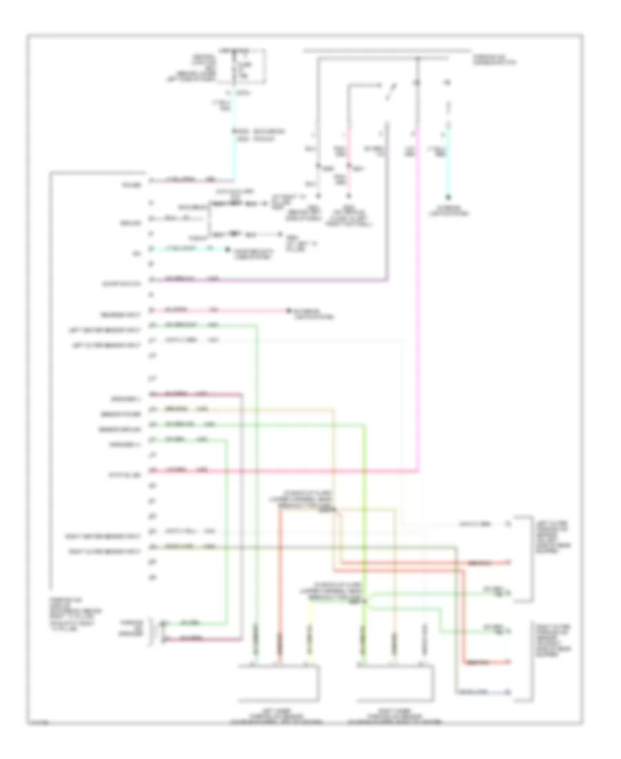
Automatic A/C Wiring Diagram (1 of 2) for Ford Cab & Chassis F350 Super Duty 2003

List of elements for Automatic A/C Wiring Diagram (1 of 2) for Ford Cab & Chassis F350 Super Duty 2003:
- (in main harness, near breakout for instrument cluster) s228
- (on vehicle floor, in left front footwell) g300
- A/c demand sig
- Air bag sliding contact
- Ambient air temperature sensor (on left front of engine compt)
- Ambient temp
- Batt
- Blend door actuator
- Blend door monitor
- Blend door sense +
- Blend door signal -
- Blow motor rly control
- Blower motor high
- Blower speed control signal return
- C228a
- C228b
- C270a
- Central junction box (cjb) (behind lower left side of dash)
- Diesel
- Electronic automatic temperature control (eatc) module (behind center of dash)
- Fan speed (+)
- Fan speed (-)
- Fuse 10a
- Gasoline
- Hot at all times
- Hot in run
- Ign
- Illumination
- In car temp sensor
- In-vehicle temperature sensor (behind left side of dash)
- Interior lights system
- Logic gnd
- Nca
- Powertrain control module (pcm) (on left side of firewall)
- Remote solenoid assembly
- Rest
- S114 (in engine control harness, near breakout for g101)
- Sensor return
- Sig rtn
- Solenoid assembly
- Speed control servo (in right side of engine compt)
- Speed controller
- Steering wheel contrlos
- Steering wheel radio switch
- Sunload sensor sig
- Temp (+)
- Temp (-)
- Temperature blend door actuator (behind right side of dash)
- Ubp diag
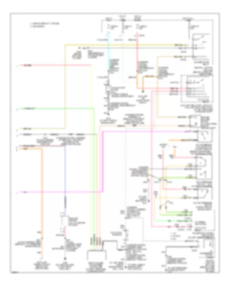
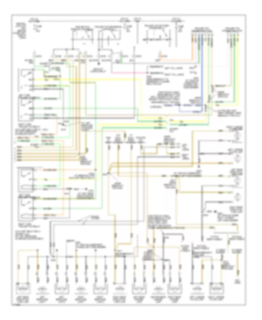
Automatic A/C Wiring Diagram (2 of 2) for Ford Cab & Chassis F350 Super Duty 2003
List of elements for Automatic A/C Wiring Diagram (2 of 2) for Ford Cab & Chassis F350 Super Duty 2003:
- (6.0l)
- (at left rear side of engine compt) g100
- (at left side of eng compt) g101
- (at right side of engine compt) g108
- (exc 6.0l)
- (exc 6.0l) (6.0l)
- (excursion)
- (ford super duty trucks)
- (in engine control harness, at breakout for auxiliary relay box 5) s171
- (in engine control harness, at breakout for front blower motor speed controller)
- (in engine control harness, at breakout for front blower motor speed controller) s158
- (in engine control harness, near breakout for g100) s122
- (in engine control harness, near breakout for g100) s124
- (in engine control harness, near breakout for g100) s173
- (in engine control harness, near breakout for g108) s180 s102 (in engine control harness, near breakout for g101)
- (in engine control harness, near breakout for powertrain control module)
- (on top center of dash)
- 5.4l/6.8l
- 6.0l
- 7.3l
- A/c clutch relay
- A/c clutch solenoid
- A/c compressor clutch diode
- A/c compressor cycling switch (in right rear of engine compartment, on a/c accumulator)
- A/c high pressure switch (in right side of engine compt)
- A/c press switch sig
- Auxiliary air conditioning circuit
- Auxiliary relay box 4 (exc 6.0l) auxiliary relay box 5 (6.0l) (at left rear side of engine compt)
- Blower motor relay
- C1381a
- C175
- C270a
- C270f
- C270g
- C270h
- Central junction box (cjb) (behind lower left side of dash)
- Data link connector (dlc) (behind left side of dash)
- Dual pressure (6.0l) (at front of engine)
- Exc 6.0l
- Except 6.0l
- For g108) s180
- Front blower motor speed controller (at right rear side of engine compt)
- Fuse 10 10a
- Fuse 107 40a
- Fuse 23 20a
- Fuse 27 15a
- G108 (at right side of engine compt)
- G202 (behind left side of dash)
- G300 (on vehicle floor, in left front footwell)
- Heater blower motor (at right rear side of engine compt)
- Hot at all times
- Hot in run
- Hot in start or run
- Instrument cluster)
- Nca
- Powertrain control module (pcm) (on left side of firewall)
- S106
- S116
- S119
- S157
- S162 (in engine control harness, near breakout for g100)
- S191 (in main harness, near breakout for c146)
- S218 (near breakout for instrument cluster)
- S247 (in main harness, near breakout to passenger air bag module)
- Sunload sensor
- Switch
- Vacuum pump motor (6.0l) (in right side of engine compartment)
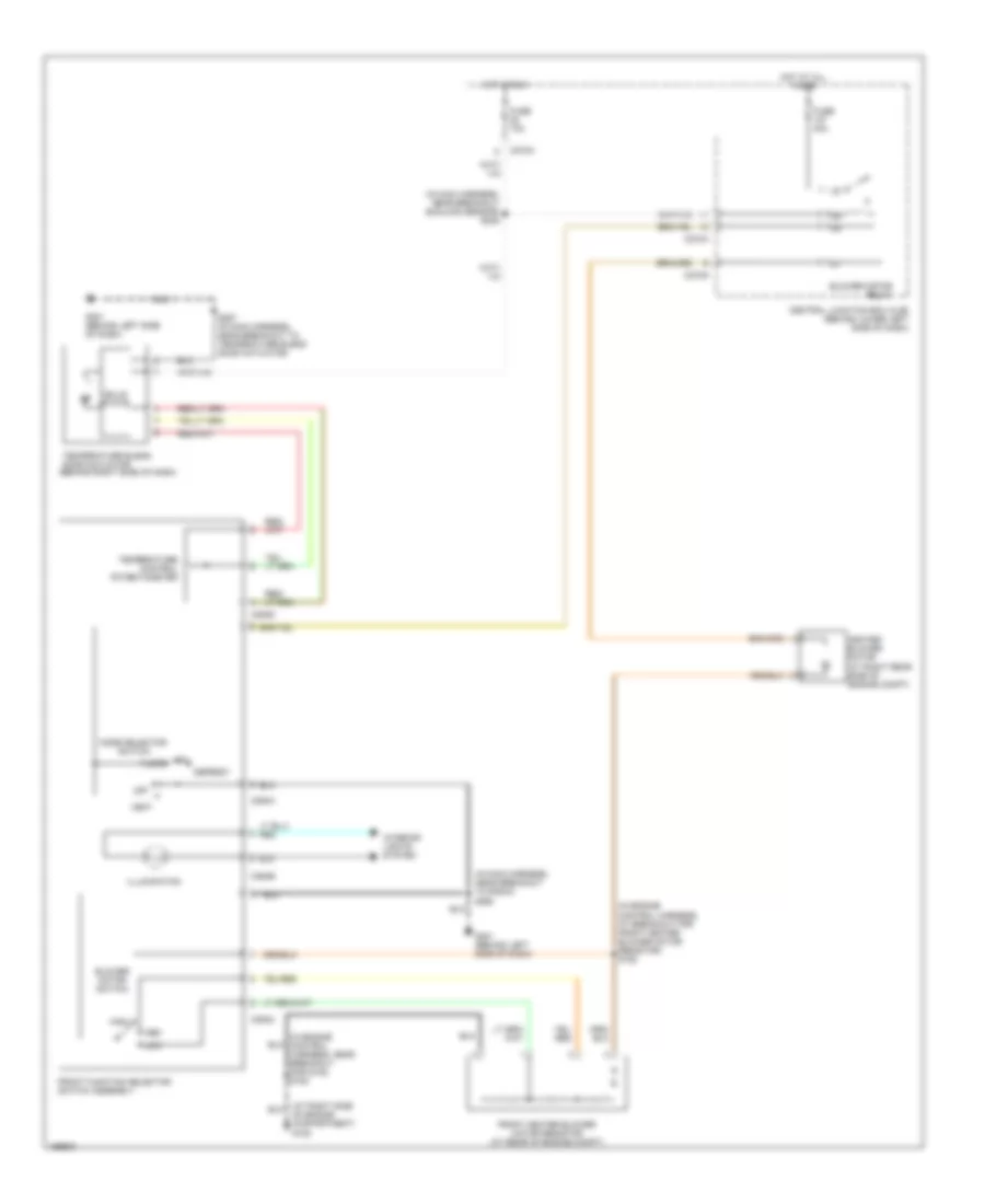
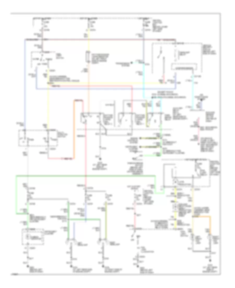
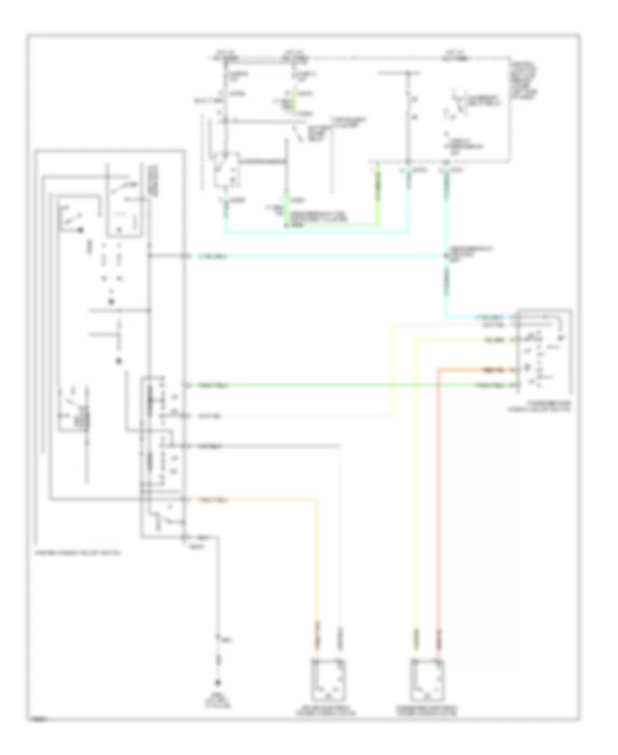
Heater Wiring Diagram for Ford Cab & Chassis F350 Super Duty 2003
List of elements for Heater Wiring Diagram for Ford Cab & Chassis F350 Super Duty 2003:
- (in engine control harness, at breakout for front heater blower motor resistor) s152
- (in engine control harness, near breakout for g108) s180
- (in main harness, near breakout sunload sensor) s235
- (in main harness, near breakout to radio) s290
- Blower motor relay
- Blower motor switch
- C270a
- C270g
- C294a
- C294b
- C294c
- C294d
- Central junction box (cjb) (behind lower left side of dash)
- Defrost
- Floor
- Front function selector switch assembly
- Front heater blower motor resistor (at rear of engine compt)
- Fuse 10a
- Fuse 40a
- G201 (behind left side of dash)
- Heater blower motor (at right rear side of engine compt)
- High
- Hot at all times
- Hot in run
- Illumination
- Interior lights system
- Low
- Med
- Mix
- Mode selector switch
- Of engine compartment) g108
- Off
- S257 (in main harness, near breakout to temperature blend door actuator)
- Solid state
- Temperature blend door actuator (behind right side of dash)
- Temperature control potentiometer
- Vent
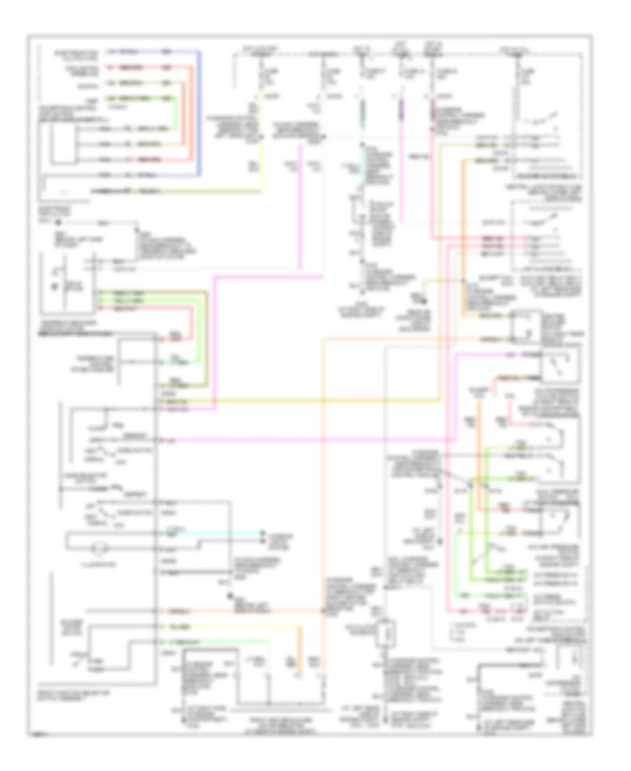
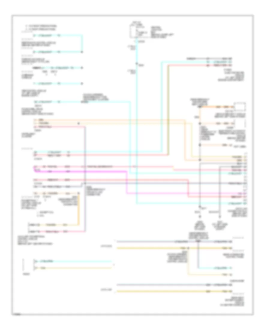
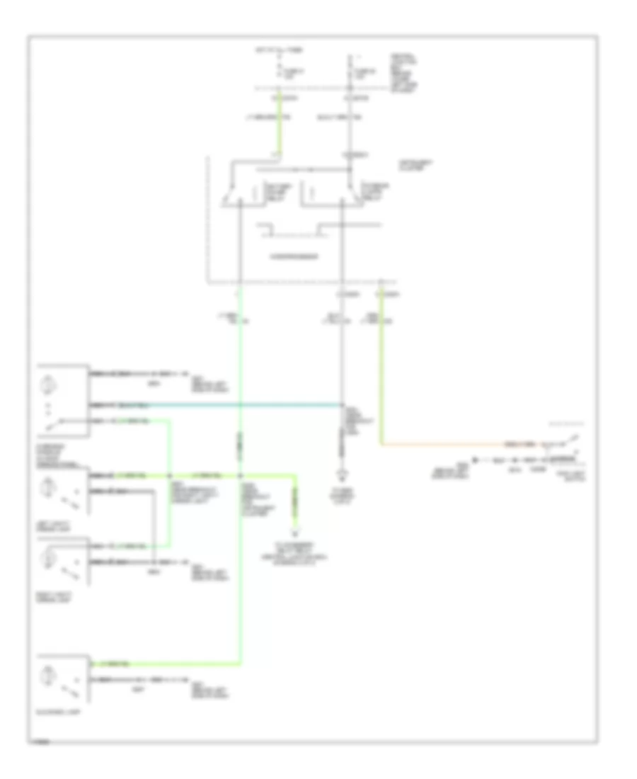
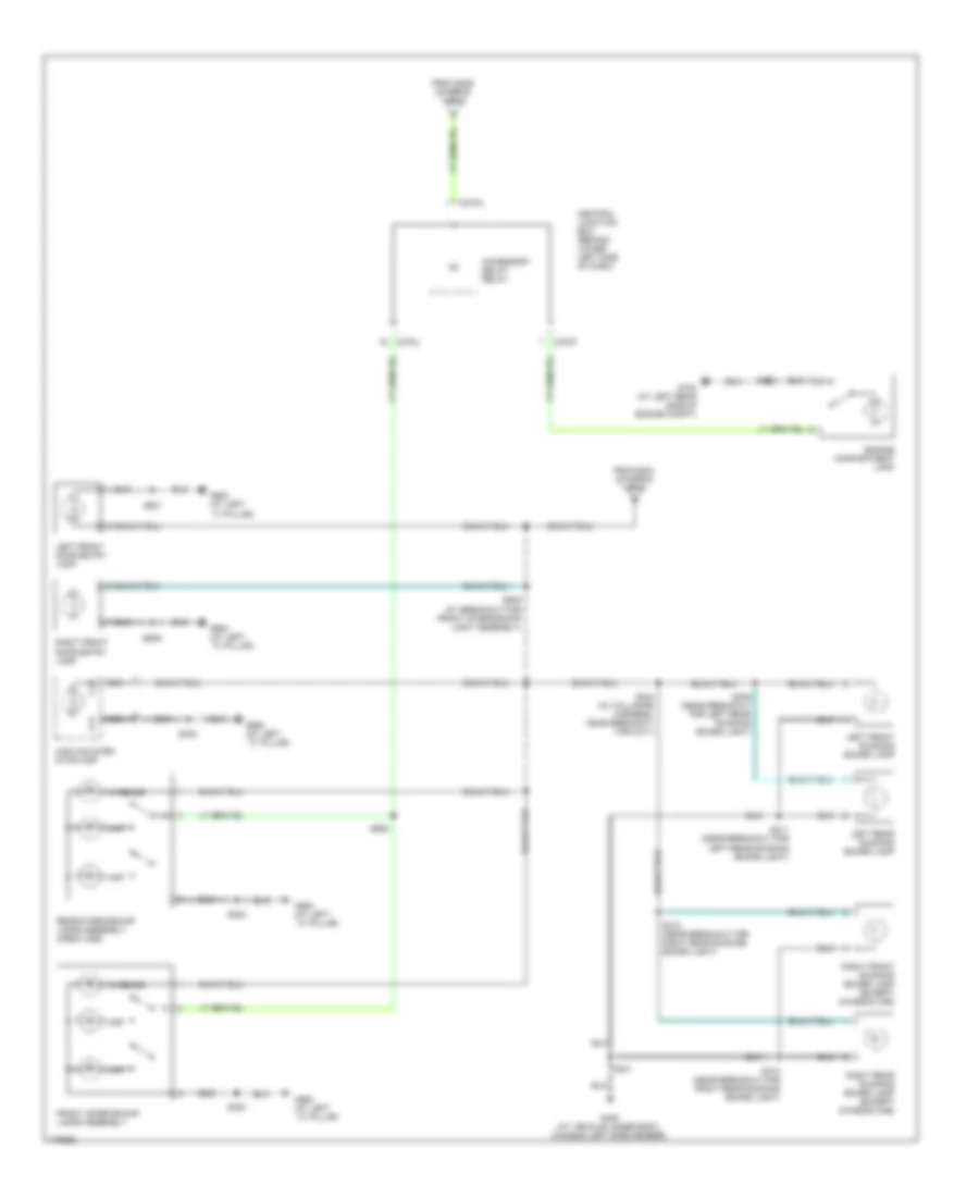
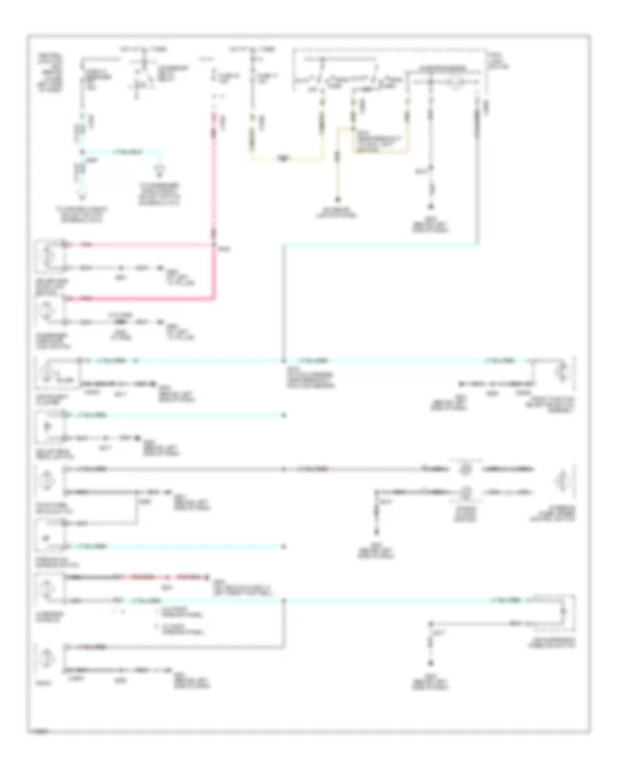
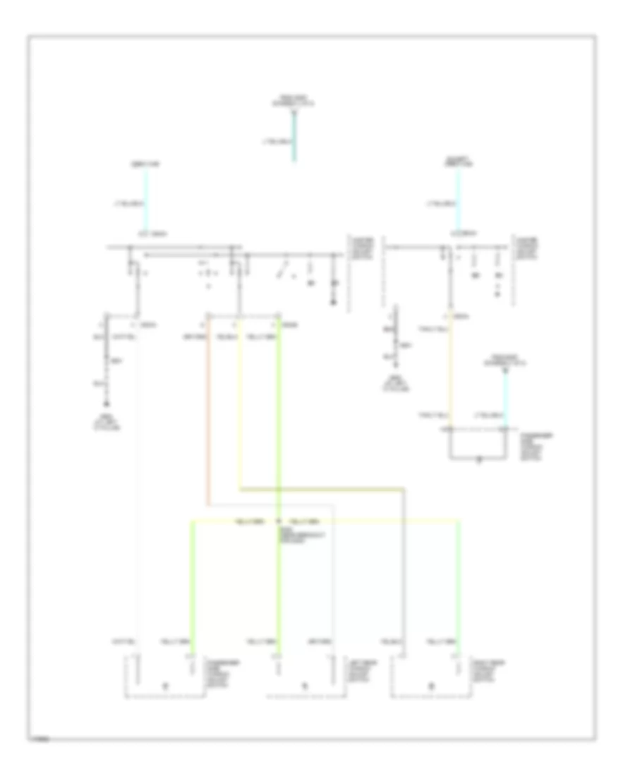
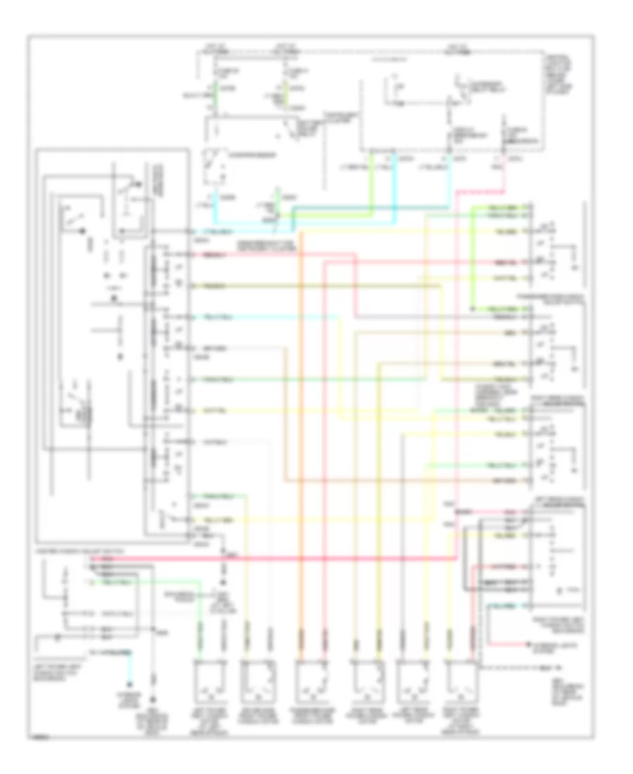
Manual A/C Wiring Diagram for Ford Cab & Chassis F350 Super Duty 2003
List of elements for Manual A/C Wiring Diagram for Ford Cab & Chassis F350 Super Duty 2003:
- (6.0l)
- (6.0l: in engine control harness, at breakout for auxiliary relay box 5) s171
- (at left rear side of engine compt) g100
- (at left side of eng compt) g101
- (at right side of engine compt) g108
- (exc 6.0l)
- (exc 6.0l) (6.0l)
- (except 6.0l) (6.0l)
- (in engine control harness, at breakout for front heater blower motor resistor) s152
- (in engine control harness, near breakout for g100) s122
- (in engine control harness, near breakout for g108) s180
- (in engine control harness, near breakout for left headlight) s109
- (in engine control harness, near breakout for powertrain control module)
- (in main harness, near breakout sunload sensor) s235
- (in main harness, near breakout to radio) s290
- 5.4l/6.8l
- 6.0l
- 7.3l
- A/c clutch relay
- A/c clutch solenoid
- A/c compressor clutch diode
- A/c compressor cycling switch (in right rear of engine compartment, on a/c accumulator)
- A/c high pressure switch (in right side of engine compt)
- A/c press sw in
- A/c press switch sig rtn
- Auxiliary relay box 4 auxiliary relay box 5 (at left rear side of engine compt)
- Blower motor relay
- Blower motor switch
- Breakout for g101)
- C1381a
- C1381c
- C175
- C270a
- C270f
- C270g
- C270h
- C294a
- C294b
- C294c
- C294d
- Central junction box (cjb) (behind lower left side of dash)
- Cooling fan speed sig
- Defrost
- Dual pressure (6.0l) (at front of engine)
- Electronic fan clutch (6.0l)
- Electronic fan clutch ctrl
- Exc 6.0l
- Except 6.0l
- Floor
- Front function selector switch assembly
- Front heater blower motor resistor (at rear of engine compt)
- Fuse 10 10a
- Fuse 10a
- Fuse 23 20a
- Fuse 27 15a
- Fuse 40a
- G108 (at right side of engine compt)
- G201 (behind left side of dash)
- Heater blower motor (at right rear side of engine compt)
- High
- Hot at all times
- Hot in run
- Hot in start or run
- Illumination
- Interior lights system
- Low
- Max
- Med
- Mix
- Mode selector switch
- Mode switch
- Nca
- Near breakout for g100)
- Normal
- Normal max
- Of engine compartment) g108
- Off
- Powertrain control module (pcm) (on left side of firewall)
- Rear air conditioning circuit (excursion)
- S106
- S116
- S119
- S162 (in engine control harness, near breakout for g100)
- S173 (in engine control harness, near breakout for g100)
- S180 (in engine control harness, near breakout for g108)
- S257 (in main harness, near breakout to temperature blend door actuator)
- Sig rtn
- Solid state
- Switch
- Temperature blend door actuator (behind right side of dash)
- Temperature control potentiometer
- Vacuum pump motor (diesel) (in right side of engine compt)
- Vent
- Vref
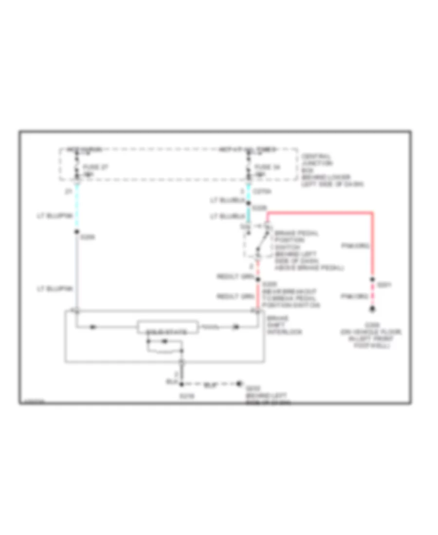
ANTI-LOCK BRAKES
Anti-lock Brakes Wiring Diagram for Ford Cab & Chassis F350 Super Duty 2003
List of elements for Anti-lock Brakes Wiring Diagram for Ford Cab & Chassis F350 Super Duty 2003:
- (in engine control harness, near breakout for c144)
- (in engine control harness, near breakout for left headlight) s159
- (in main harness, near breakout to brake pedal position switch)
- 4x4 high/low indicator switch (near digital transmission range sensor)
- 6.0l
- Abs control module (at left side of engine compt)
- Brake fluid level switch (on brake fluid reservoir)
- Brake pedal position (bpp) switch (behind left side of dash, above brake pedal)
- C220b
- C220c
- C270a
- C270f
- C270m
- C281b
- Central junction box (cjb) (behind lower left side of dash)
- Computer data lines system
- Cooling fans system
- Engine controls, wiper/washer, instrument cluster, cruise control, sound, transmissions systems
- Four-wheel drive control module (behind right side of dash)
- Fuse 10a
- Fuse 60a
- G100 (at left rear side of engine compt)
- G105 (at left front side of engine compt)
- G300 (on vehicle floor, in left front footwell)
- Ground
- Hot at all times
- Hot in run
- Instrument cluster
- Iso
- Left front wheel speed sensor (at left front wheel)
- Nca
- Rear axle speed sensor (on differential)
- Red/pnk
- Right front wheel speed sensor (at right front wheel)
- S102
- S109
- S111
- S163
- S178 (in engine control harness, near breakout for g101)
- S201
- S228
- S259
- Vbatt
- Vpwr
- With electronic shift on the fly
- With mechanical shift on the fly
ANTI-THEFT
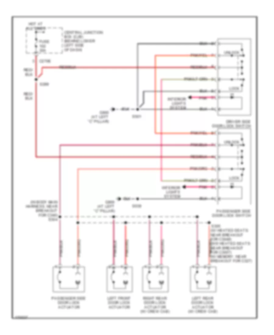
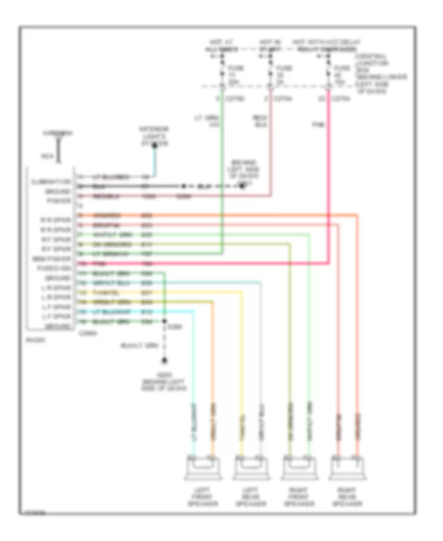
Power Door Locks Wiring Diagram, with Keyless Entry for Ford Cab & Chassis F350 Super Duty 2003
List of elements for Power Door Locks Wiring Diagram, with Keyless Entry for Ford Cab & Chassis F350 Super Duty 2003:
- (behind
- (in body main harness, near breakout for c340)
- (w/ heated seats: near breakout for c3049) (w/0 heated seats: near breakout for c3007) (w/ memory: near breakout for c327)
- Air conditioning system
- Autolamps on
- C2113a
- C2113b
- C2113c
- C270a
- C270b
- C270e
- Central junction box (cjb) (behind lower left side of dash)
- Diagnostic
- Door ajar sw
- Door lock
- Door lock out
- Door unlock
- Dr door relay
- Driver side door lock switch
- Driver side front door ajar switch
- Driver side rear door ajar switch
- Ext lamp pwr
- Exterior lights system
- Fuse 15a
- Fuse 30a
- Fuse 5a
- G201 (behind left side of dash)
- G900 (at left ``c" pillar)
- Ground
- Headlights system
- Headlmp relay
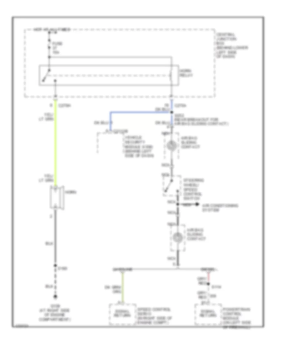
- Horn relay
- Horns system
- Hot at all times
- Interior lights system
- Left front door lock actuator
- Left rear door lock actuator
- Left side of dash) data link connector (dlc)
- Lock
- Pass- enger side door lock switch
- Passenger side door lock actuator
- Passenger side front door ajar switch
- Passenger side rear door ajar switch
- Pnk
- Right rear door lock actuator
- S214
- S233
- S272
- S290
- S300
- S304
- S305
- S307 (in body main harness, near breakout for driver's seat module)
- S318 (in body main harness, near breakout for g300)
- S329 (in body main harness, near breakout for g300)
- S501
- S639
- Sunload sens
- Sunload sensor (on top center of dash)
- Unlock
- Vbatt
- Vehicle security module (vsm) (behind left side of dash)
COMPUTER DATA LINES
Computer Data Lines Wiring Diagram for Ford Cab & Chassis F350 Super Duty 2003
List of elements for Computer Data Lines Wiring Diagram for Ford Cab & Chassis F350 Super Duty 2003:
- (in main harness, near breakout for instrument cluster) s225
- (near breakout for driver's seat module) s307
- (near breakout for restraints control module)
- (not used)
- 6.0l
- Abs control module (at left side of engine compt)
- Auxiliary powertrain control module (6.0l/7.3l) (behind left center of dash)
- C1318a
- C1381a
- C1381c
- C1388c
- C175
- C2113c
- C220a
- C228b
- C270d
- C281a
- C9013
- C930
- Central junction box (behind lower left side of dash)
- Data link connector (dlc) (behind left side of dash)
- Dvd player
- Electronic automatic temperature control module (behind center of dash)
- Except 6.0l
- Four-wheel drive control module (behind right side of dash)
- Fuse 12 20a
- G101 (at left side of engine compt)
- G202 (behind left side of dash)
- Hot at all times
- Injector driver module (at left side of engine compartment)
- Instrument cluster
- Nca
- Overhead console
- Parking aid module (behind right "c" pillar)
- Powertrain control module (on left side of firewall)
- Radio
- Rear integrated control panel
- Rear seat entertainment module (in center console)
- Restraints control module (behind center of dash)
- S217
- S242
- S245 (in main harness, near breakout for restraints control module)
- S246
- S247 (near breakout to passenger air bag module)
- S284 (near breakout for data link connector)
- S286 (near breakout for data link connector)
- Shield
- Tan
- Vehicle security module (behind left side of dash)
- W/ roof opening panel
- W/0 roof opening panel
- With dvd
- With vcp
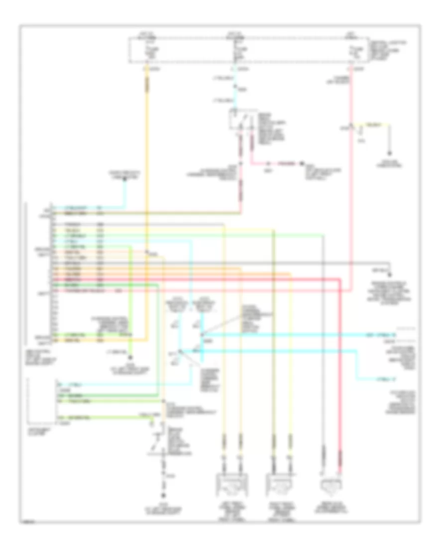
COOLING FAN
6.0L
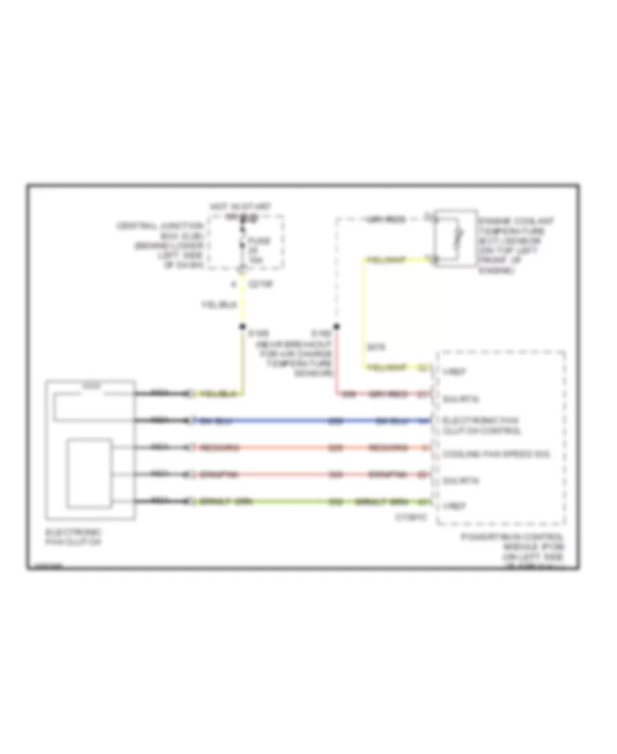
6.0L, Cooling Fan Wiring Diagram for Ford Cab & Chassis F350 Super Duty 2003
List of elements for 6.0L, Cooling Fan Wiring Diagram for Ford Cab & Chassis F350 Super Duty 2003:
- C1381c
- C270f
- Central junction box (cjb) (behind lower left side of dash)
- Cooling fan speed sig
- Electronic fan clutch
- Electronic fan clutch control
- Engine coolant temperature (ect) sensor (on top left front of engine)
- Fuse 10a
- Hot in start or run
- Nca
- Powertrain control module (pcm) (on left side of firewall)
- S109
- S192 (near breakout for air charge temperature sensor)
- Sig rtn
- Vref
CRUISE CONTROL
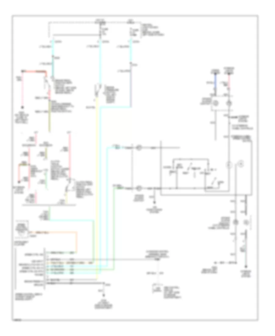
5.4L
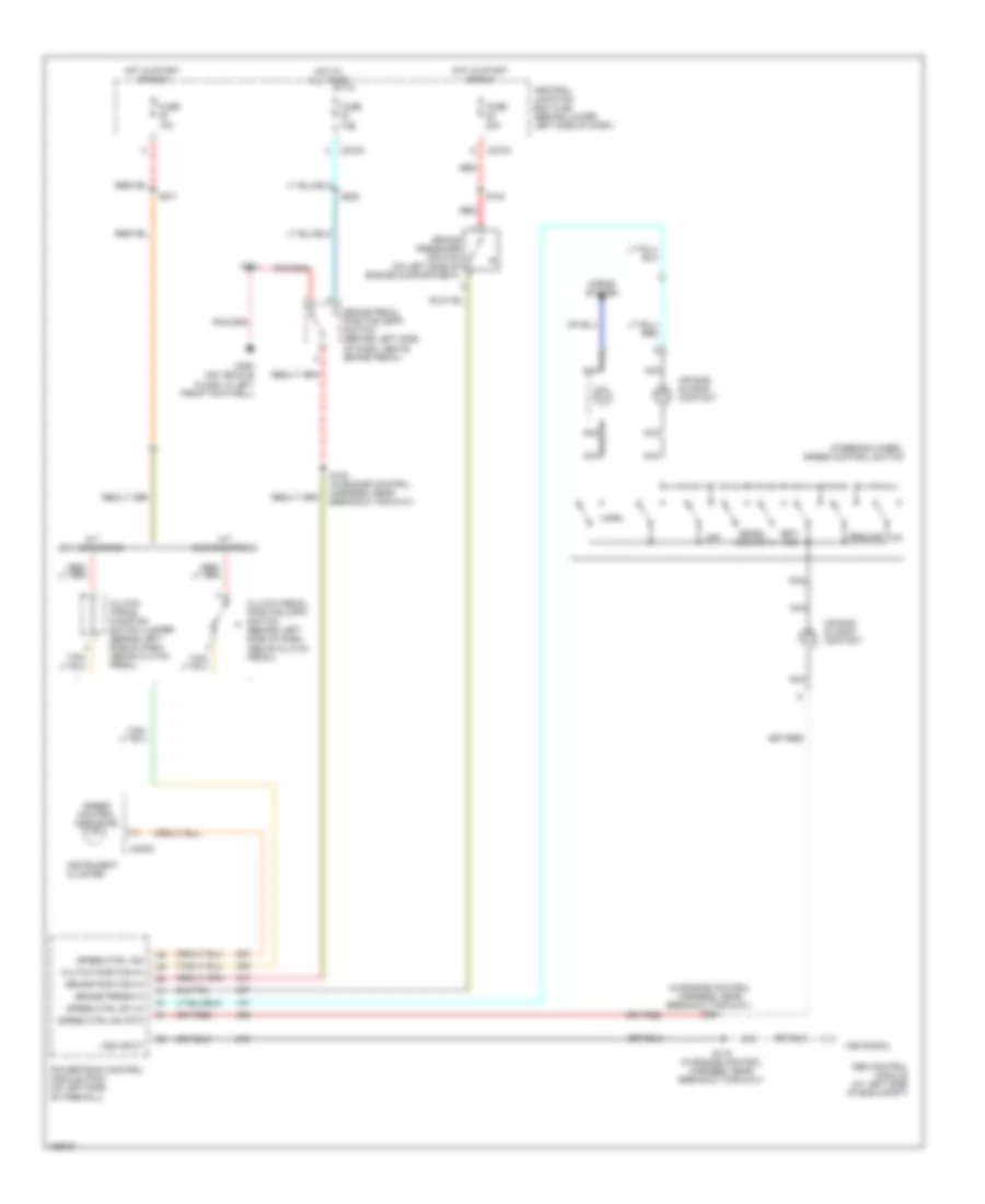
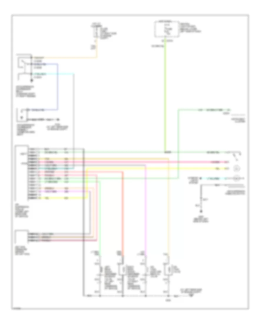
5.4L, Cruise Control Wiring Diagram for Ford Cab & Chassis F350 Super Duty 2003
List of elements for 5.4L, Cruise Control Wiring Diagram for Ford Cab & Chassis F350 Super Duty 2003:
- (in engine control harness, near breakout for g101) s115
- (w/ steering wheel controls)
- A/t
- Abs control module (at left side of engine compartment)
- Accel
- Air bag sliding contact
- Air bag sliding contact (w/o steering wheel controls)
- Air conditioning system
- Brake pedal position (bpp) switch (behind left side of dash, above brake pedal)
- Brake press in
- Brake pressure switch (on left side of engine compt)
- Brake/clutch sw in
- C220c
- C270a
- C270g
- C270h
- Central junction box (cjb) (behind lower left side of dash)
- Clutch pedal position (cpp) switch (behind left side of dash, above clutch pedal)
- Clutch triple function switch jumper (behind left side of dash, above clutch pedal)
- Coast
- Exc excursion
- Excursion
- Exterior lights system
- Fuse 10a
- Fuse 15a
- G108 (at right side of engine compartment)
- G202 (behind left side of dash)
- G300 (on vehicle floor, in left front footwell)
- Ground
- Horn
- Horns system
- Hot at all times
- Hot in run
- Instrument cluster
- Interior lights system
- M/t
- Nca
- Off
- Power
- Rest
- Resume
- S108 (near breakout for g101)
- S124
- S180
- S201
- S205 (in main harness, near breakout to brake pedal position switch)
- S218
- S228
- Set/
- Speed control indicator
- Speed control servo (in right side of engine compt)
- Speed ctrl ind
- Speed ctrl sw in
- Speed ctrl sw rtn
- Steering wheel/ speed control switch
- Vss input
- Vss signal
6.0L DIESEL
6.0L Diesel, Cruise Control Wiring Diagram for Ford Cab & Chassis F350 Super Duty 2003
List of elements for 6.0L Diesel, Cruise Control Wiring Diagram for Ford Cab & Chassis F350 Super Duty 2003:
- Abs control module (at left side of eng compt)
- Air bag sliding contact
- Brake pedal position (bpp) switch (behind left side of dash, above brake pedal)
- Brake position in
- Brake press in
- Brake pressure switch (on left side of engine compartment)
- C1381a
- C220c
- C270a
- C270h
- Central junction box (cjb) (behind lower left side of dash)
- Clutch pedal position (cpp) switch (behind left side of dash, above clutch pedal)
- Coast
- Fuse 10a
- Fuse 20a
- G300 (on vehicle floor, in left front footwell)
- Horn
- Hot at all times
- Hot in start or run
- Instrument cluster
- Interior lights system
- M/t
- Nca
- Off
- Powertrain control module (pcm) (on left side of firewall)
- Red
- Rest
- Resume
- S108 (in engine control harness, near breakout for g101)
- S112 (in engine control harness, near breakout for powertrain control module)
- S115 (in engine control harness, near breakout for g101)
- S123
- S201
- S228
- S271
- Set/ accelerate
- Speed control indicator
- Speed ctrl ind
- Speed ctrl sw in
- Speed ctrl sw rtn
- Steering wheel/ speed control switch
- Vpwr
- Vss input
- Vss signal
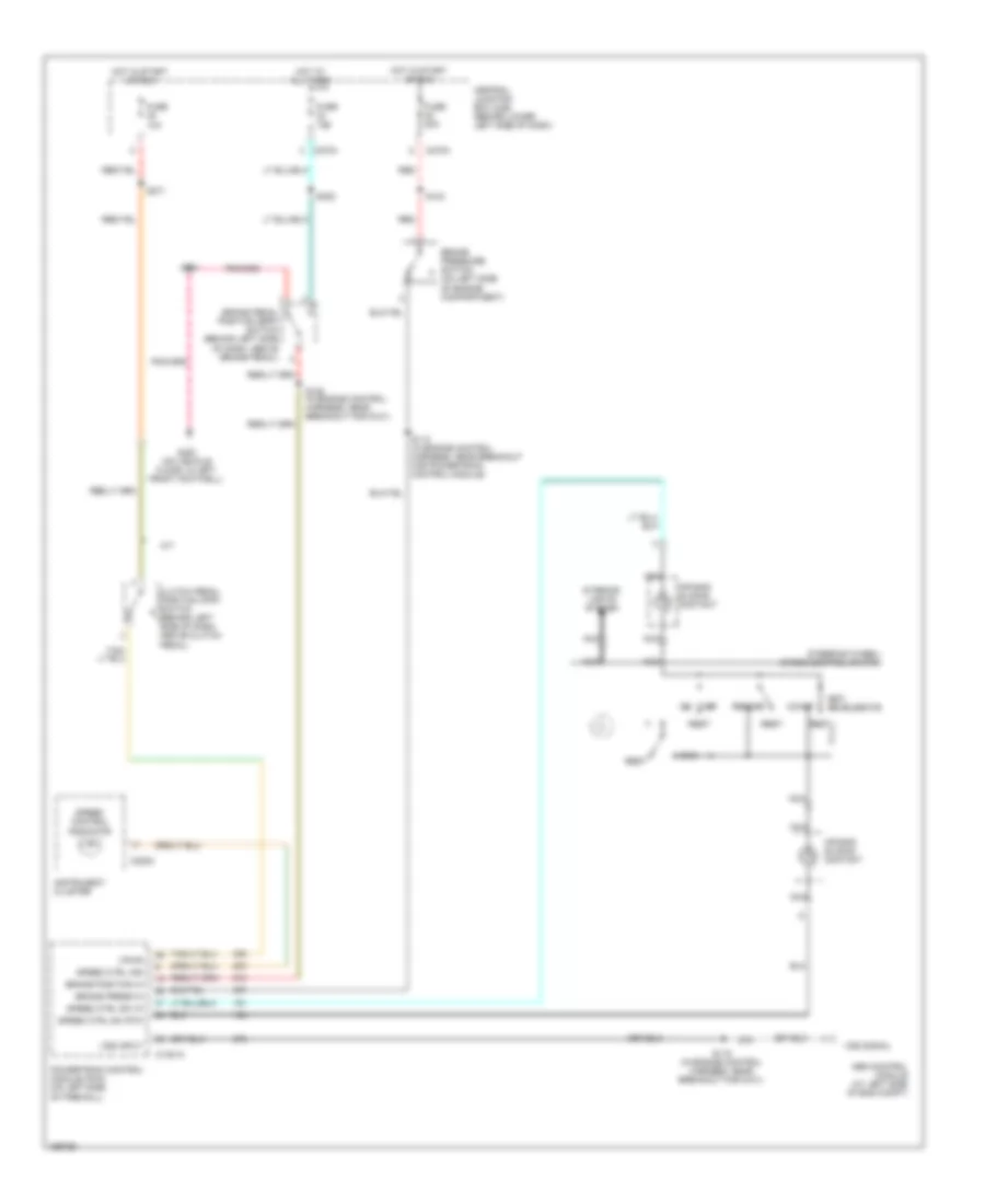
6.8L
6.8L, Cruise Control Wiring Diagram for Ford Cab & Chassis F350 Super Duty 2003
List of elements for 6.8L, Cruise Control Wiring Diagram for Ford Cab & Chassis F350 Super Duty 2003:
- (in engine control harness, near breakout for g101) s115
- (w/ steering wheel controls)
- A/t
- Abs control module (at left side of engine compartment)
- Accel
- Air bag sliding contact
- Air bag sliding contact (w/o steering wheel controls)
- Air conditioning system
- Brake pedal position (bpp) switch (behind left side of dash, above brake pedal)
- Brake press in
- Brake pressure switch (on left side of engine compt)
- Brake/clutch sw in
- C220c
- C270a
- C270g
- C270h
- Central junction box (cjb) (behind lower left side of dash)
- Clutch pedal position (cpp) switch (behind left side of dash, above clutch pedal)
- Clutch triple function switch jumper (behind left side of dash, above clutch pedal)
- Coast
- Exc excursion
- Excursion
- Exterior lights system
- Fuse 10a
- Fuse 15a
- G108 (at right side of engine compartment)
- G202 (behind left side of dash)
- G300 (on vehicle floor, in left front footwell)
- Ground
- Horn
- Horns system
- Hot at all times
- Hot in run
- Instrument cluster
- Interior lights system
- M/t
- Nca
- Off
- Power
- Rest
- Resume
- S108 (near breakout for g101)
- S124
- S180
- S201
- S205 (in main harness, near breakout to brake pedal position switch)
- S218
- S228
- Set/
- Speed control indicator
- Speed control servo (in right side of engine compt)
- Speed ctrl ind
- Speed ctrl sw in
- Speed ctrl sw rtn
- Steering wheel/ speed control switch
- Vss input
- Vss signal
7.3L DI TURBO DIESEL
7.3L DI Turbo Diesel, Cruise Control Wiring Diagram for Ford Cab & Chassis F350 Super Duty 2003
List of elements for 7.3L DI Turbo Diesel, Cruise Control Wiring Diagram for Ford Cab & Chassis F350 Super Duty 2003:
- (in engine control harness, near breakout for g101) s114
- A/t exc excursion
- Abs control module (at left side of eng compt)
- Air bag sliding contact
- Brake pedal position (bpp) switch (behind left side of dash, above brake pedal)
- Brake position in
- Brake press in
- Brake pressure switch (on left side of engine compartment)
- C220c
- C270a
- C270h
- Central junction box (cjb) (behind lower left side of dash)
- Clutch pedal position (cpp) switch (behind left side of dash, above clutch pedal)
- Clutch position in
- Clutch triple function switch jumper (behind left side of dash, above clutch pedal)
- Decel- erate
- Fuse 10a
- Fuse 20a
- G300 (on vehicle floor, in left front footwell)
- Horn
- Horns system
- Hot at all times
- Hot in start or run
- Instrument cluster
- M/t exc excursion
- Nca
- Off
- Powertrain control module (pcm) (on left side of firewall)
- Red
- Resume
- S108 (in engine control harness, near breakout for g101)
- S115 (in engine control harness, near breakout for g101)
- S123
- S201
- S228
- S271
- Set/ acc
- Speed control indicator
- Speed ctrl ind
- Speed ctrl sw in
- Speed ctrl sw rtn
- Steering wheel/ speed control switch
- Vss input
- Vss signal
ELECTRONIC SUSPENSION
Electronic Suspension Wiring Diagram for Ford Cab & Chassis F350 Super Duty 2003
List of elements for Electronic Suspension Wiring Diagram for Ford Cab & Chassis F350 Super Duty 2003:
- (at left rear side of engine compt) g100
- Air suspension compressor assembly (under driver's seat)
- Air suspension compressor relay (in engine compt, at right fender)
- Air suspension kneeling switch
- Air suspension module (under left rear side of vehicle)
- Air tank moisture removal valve
- Air tank pressure sensor (on air tank)
- Air tank valve
- C1300a
- C1300b
- C220a
- C270a
- Central junction box (behind lower left side of dash)
- Fuse 15a
- G100 (at left rear side of engine compt)
- G202 (behind left side of dash)
- Hot at all times
- Hot in run
- In-line fuse 1 (at right side of engine compt)
- Instrument cluster
- Interior lights system
- Left rear shock absorber solenoid valve (at left rear underside of vehicle)
- Nca
- Right rear shock absorber solenoid valve (at right rear underside of vehicle)
- S102
- S217
- S296
- S380
- Tan
- Vbatt
- Vpwr
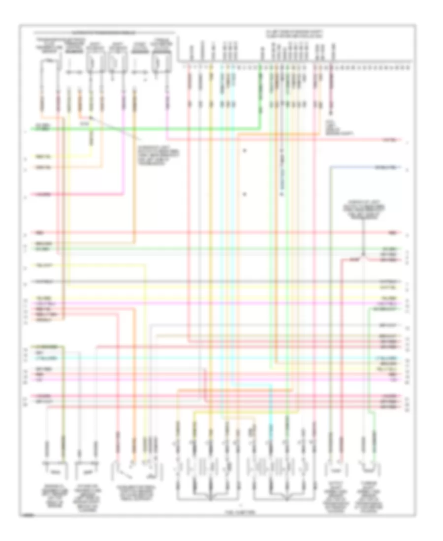
ENGINE PERFORMANCE
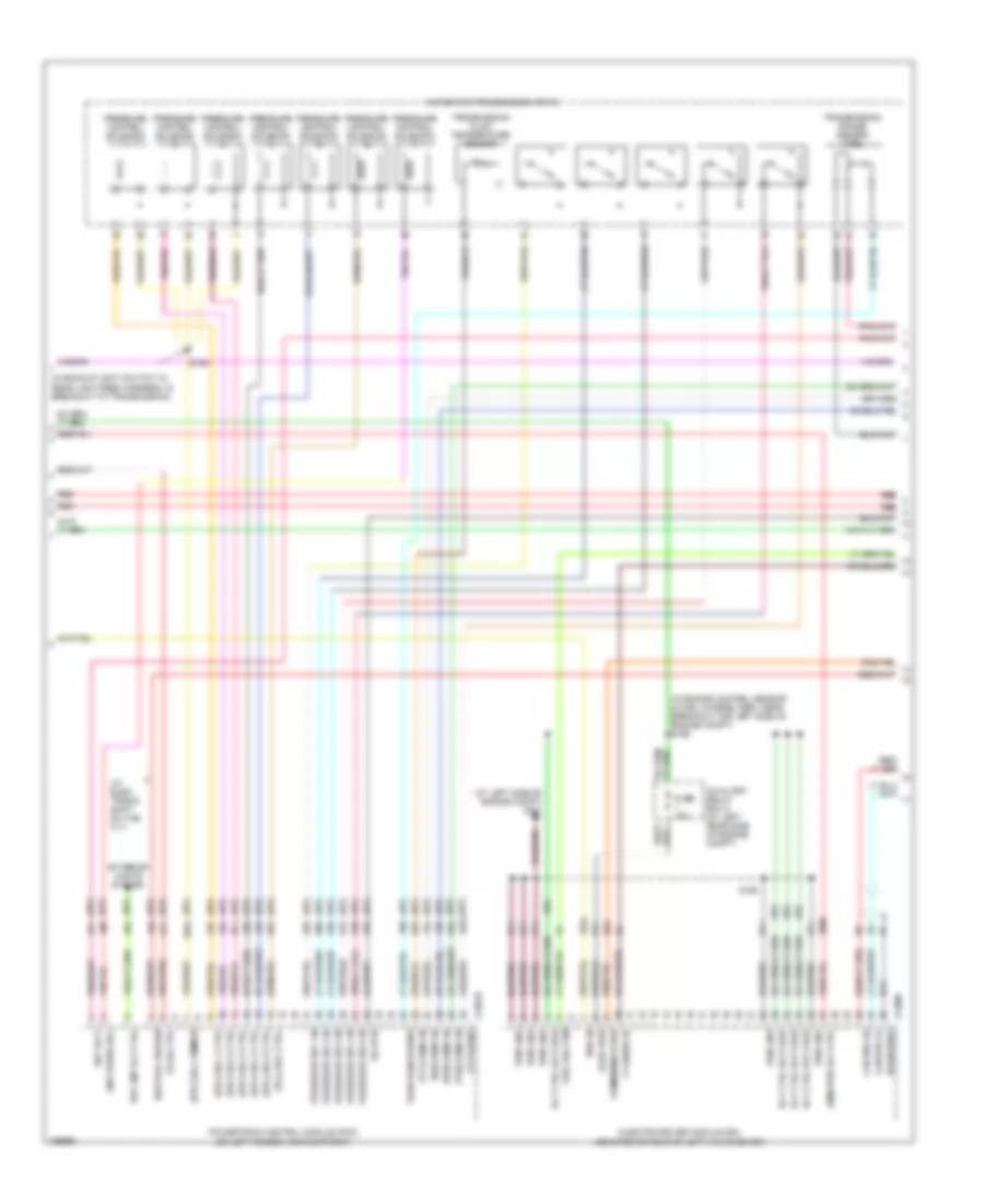
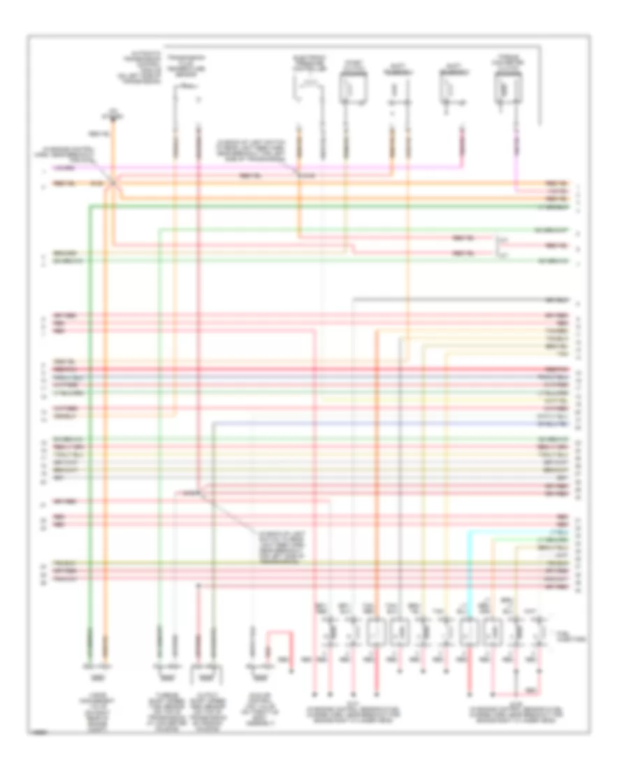
5.4L
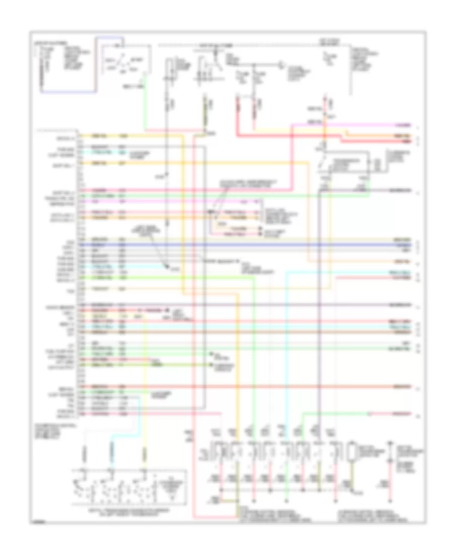
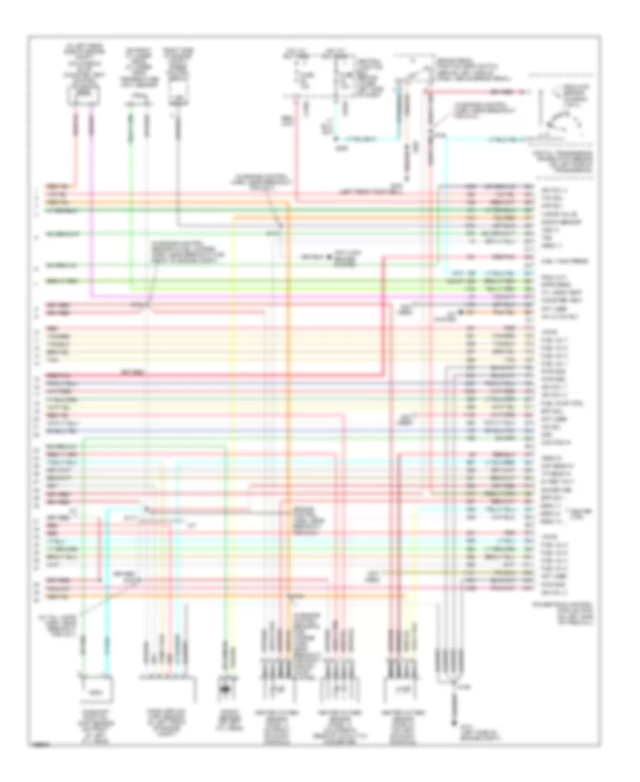
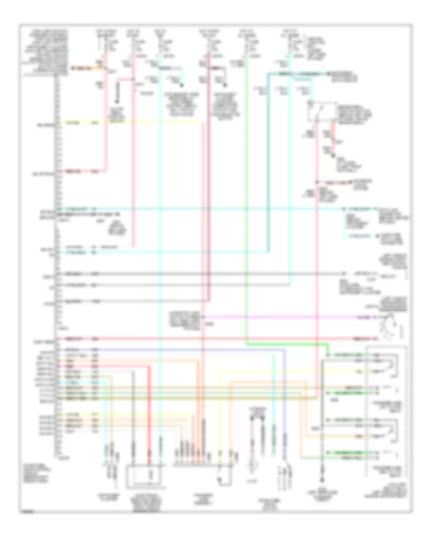
5.4L, Engine Performance Wiring Diagram (1 of 4) for Ford Cab & Chassis F350 Super Duty 2003
List of elements for 5.4L, Engine Performance Wiring Diagram (1 of 4) for Ford Cab & Chassis F350 Super Duty 2003:
- (in engine control sensor & fuel charge harn, near break- out for engine left cylinder head)
- (in main harn, near breakout for data link connector)
- (left front g300 footwell)
- (left rear side of engine compt)
- (not used)
- A/c press sw
- A/c system
- Acc
- Anti-theft system
- C270a
- Ccs
- Central junction box (behind lower left side of dash)
- Ckp(+)
- Ckp(-)
- Coil on plug
- Cust access
- Customer access
- Data link (+)
- Data link (-)
- Data link connector (dlc) (behind left side of dash)
- Data output
- Diag grd
- Digital transmission range (dtr) sensor (on left side of transmission)
- Egr sol
- Fuel pump mon
- Fuse 10a
- Fuse 20a
- Fuse 30a
- G100
- G101 (left side of engine compt)
- Hego 12
- Hot at all times
- Hot in run or start
- Iat
- Ign coil 1
- Ign coil 3
- Ign coil 5
- Ign coil 6
- Ignition transformer capacitor
- Ignition transformer capacitor (on rear of right cyl head)
- Knock sensor
- Lock
- Maf
- Nca
- Not used
- O/d off ind
- Off
- Overdrive cancel switch
- Overhead console
- Pcm power diode
- Pcm power relay
- Powertrain control module (pcm) (on left side of firewall)
- Pwr gnd
- R n
- Red
- Reprog pwr
- Run
- S106
- S130 (in engine control sensor & fuel charge harn, near break- out for engine right cylinder head)
- S135
- S162
- S201
- S258
- S271
- S284
- S286
- Shift sol 1
- Shift sol 2
- Start
- Tcs
- Tft
- To dtr sensor (diagram 4 of 4)
- To fuel pump relay (diagram 2 of 4)
- Tr1
- Tr2
- Tr4
- Trans ctrl ind
- Transmission control switch
- Vss (-)
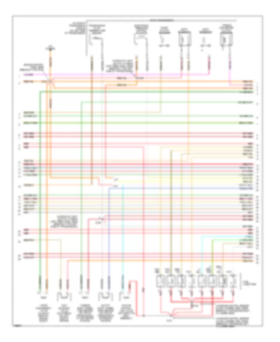
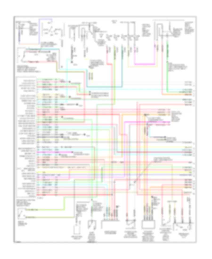
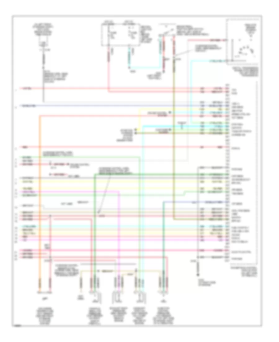
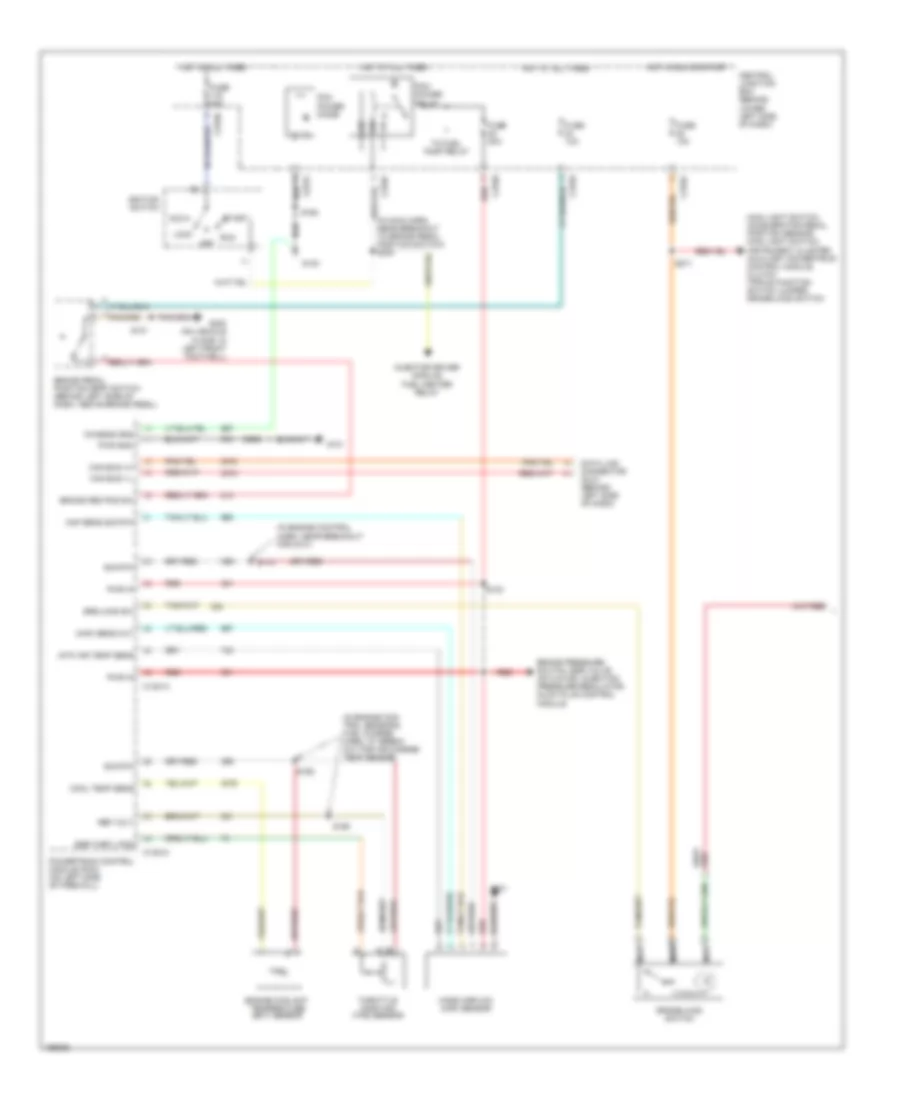
5.4L, Engine Performance Wiring Diagram (2 of 4) for Ford Cab & Chassis F350 Super Duty 2003
List of elements for 5.4L, Engine Performance Wiring Diagram (2 of 4) for Ford Cab & Chassis F350 Super Duty 2003:
- (behind right side of dash) inertia fuel shut-off switch
- (engine harness, near breakout for left side of engine compt)
- (part of fuel tank assembly) fuel tank unit
- C2207
- C270a
- C270f
- C270h
- C282
- C4033
- C433
- California
- Central junction box (behind lower left side of dash)
- Crankshaft position (ckp) sensor (on lower front center of engine)
- Crankshaft position sensor shield
- Differential pressure feedback egr (dpfe) sensor (california) (at top of engine)
- Except pickup
- Federal
- From pcm power relay (diagram 1 of 4)
- Fuel pump relay
- Fuel tank unit (california) (at fuel tank)
- Fuse 20a
- G101 (left side of engine compt)
- Hot at all times
- Instrument cluster system
- Nca
- Pickup
- Red
- Red/pnk
- S123
- S133 (california) (in engine control sensor & fuel charge harn, near breakout for engine right cylinder head)
- S145
- S161
- S167
- S401
- Throttle position (tp) sensor (on throttle body)
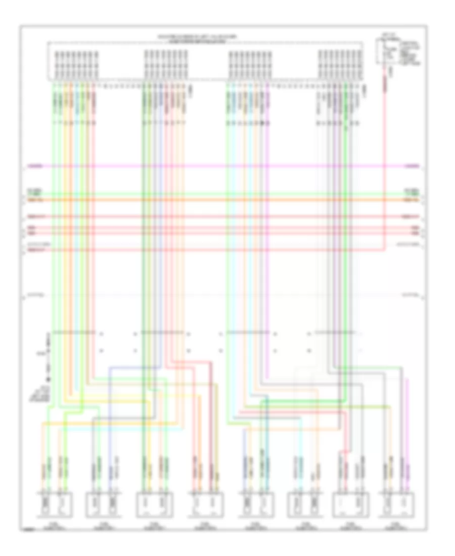
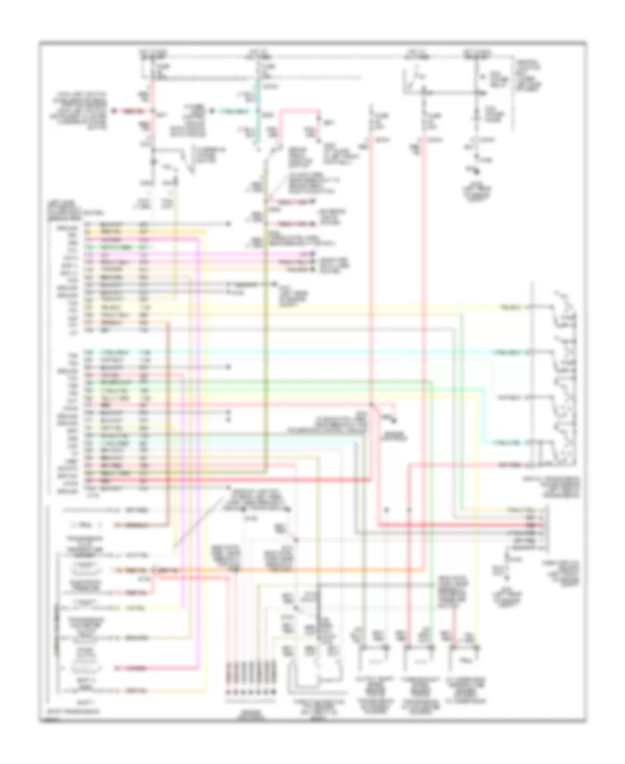
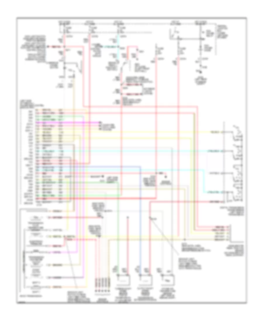
5.4L, Engine Performance Wiring Diagram (3 of 4) for Ford Cab & Chassis F350 Super Duty 2003
List of elements for 5.4L, Engine Performance Wiring Diagram (3 of 4) for Ford Cab & Chassis F350 Super Duty 2003:
- (engine control harn, near breakout for g100)
- (in back-up light switch to rear light feed harn, near breakout for left side of transmission)
- (in engine control sensor & fuel charge harn, near breakout for engine left cylinder head)
- (in engine control sensor & fuel charge harn, near breakout for engine right cylinder head)
- (on right rear of engine compt)
- 4r100 transmission
- A/c system
- A/t
- Automatic transmission module (on left side of transmission)
- Coast clutch solenoid
- Electronic pressure control solenoid
- Evr solenoid valve (california) (on left side of engine)
- Fuel injectors
- Idle air control (iac) valve (on throttle body assembly)
- M/t
- Output shaft speed (oss) sensor (on top of transmission extension housing)
- Red
- Red/pnk
- S122
- S131
- S136
- S138
- S139
- Shift solenoid 1
- Shift solenoid 2
- Tan
- Tan/ red
- Tan/red
- Torque converter clutch solenoid
- Transmission fluid temperature sensor
- Turbine shaft speed (tss) sensor (on top of transmission, at converter housing)
- Vapor management valve
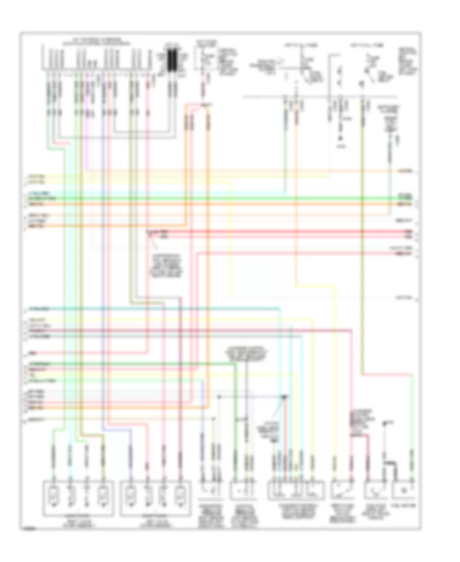
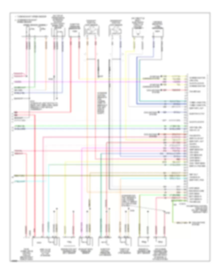
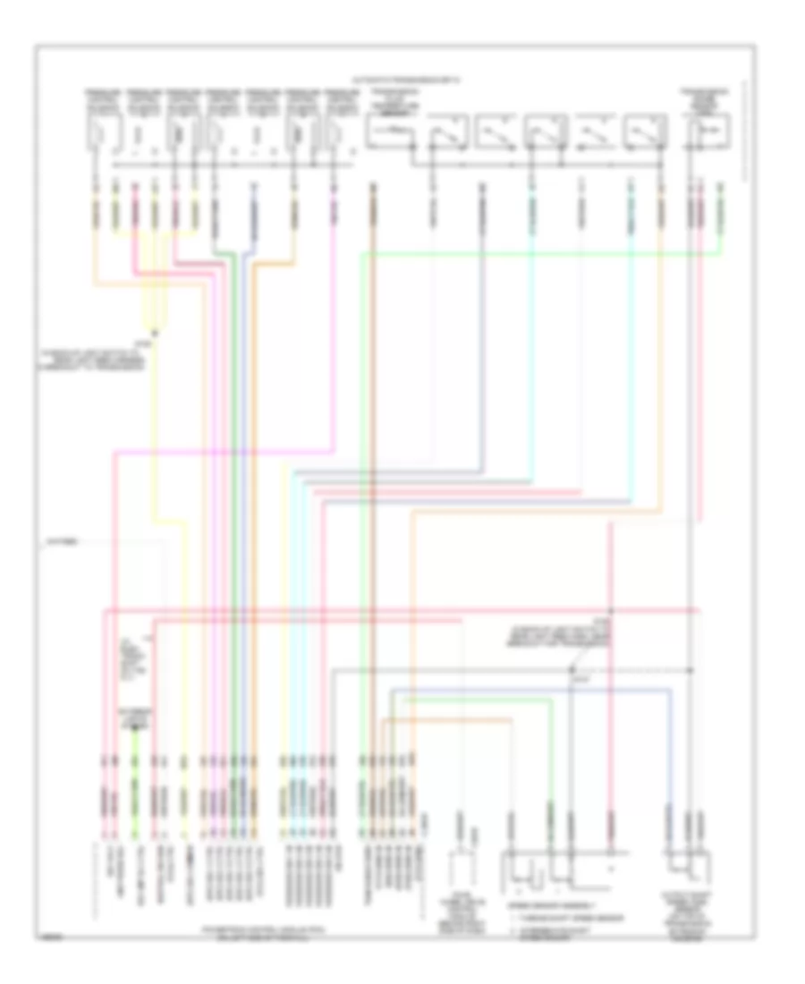
5.4L, Engine Performance Wiring Diagram (4 of 4) for Ford Cab & Chassis F350 Super Duty 2003
List of elements for 5.4L, Engine Performance Wiring Diagram (4 of 4) for Ford Cab & Chassis F350 Super Duty 2003:
- (a/t)
- (calif)
- (engine control harn, near breakout for g101)
- (in engine control harn, near breakout for g101)
- (in engine control sensor & fuel charge harn, near breakout for front of engine compt)
- (in engine control sensor & fuel charge harn, near breakout for right side ex- haust system)
- (in left rear side of engine compt) (california) evap canister vent control solenoid
- (in tail lamps harn, near breakout for c311)
- (not used)
- (on right cylinder head) cylinder head temperature (cht) sensor
- (right side of engine compt) speed control servo
- 5v ref volt
- A/c cltch rly
- A/c system
- A/t
- Anti-lock brakes system
- Bpp sw
- Brake pedal position (bpp) switch (behind left side of dash, above brake pedal)
- C270a
- C270g
- Cam pos in
- Camshaft position (cmp) sensor (on front of left cyl head)
- Canister vent
- Central junction box (behind lower left side of dash)
- Cyl head temp
- Digital transmission range (dtr) sensor (on left side of transmission)
- Dpfe sens
- Epc sol
- From dtr sensor (diagram 1 of 4)
- Fuel inj 1
- Fuel inj 2
- Fuel inj 3
- Fuel inj 4
- Fuel inj 5
- Fuel inj 6
- Fuel inj 7
- Fuel inj 8
- Fuel pump ctrl
- Fuel tank press
- Fuse 10a
- G101 (left side of engine compt)
- G300 (left front footwell)
- Heated oxygen sensor (ho2s) 11 (on right exhaust manifold)
- Heated oxygen sensor (ho2s) 12 (california) (rear of catalytic converter)
- Heated oxygen sensor (ho2s) 21 (on left exhaust manifold)
- Heater ctrl
- Hego 11
- Hego 12
- Hego 21
- Hot at all times
- Iac sol
- Ign coil 2
- Ign coil 4
- Ign coil 7
- Ign coil 8
- Kap b(+)
- Knock sensor
- Knock sensor (on left cyl head)
- M/t
- Maf sens in
- Mass airflow (maf) sensor (in left front of engine compt)
- Nca
- Not used
- Oss
- Powertrain control module (pcm) (on left side of firewall)
- Pwr gnd
- Red
- Red/pnk
- S106
- S114
- S115
- S132
- S134
- S228
- S343
- Sig return
- Tan
- Tan/red
- Tcc sol
- Tp sens in
- Tr3a (a/t)
- Tss
- Vapor valve
- Vpwr
- Vss (+)
- Vss input
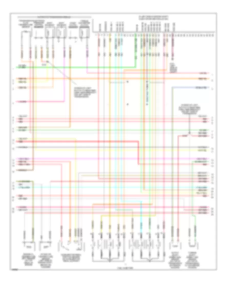
6.0L DIESEL
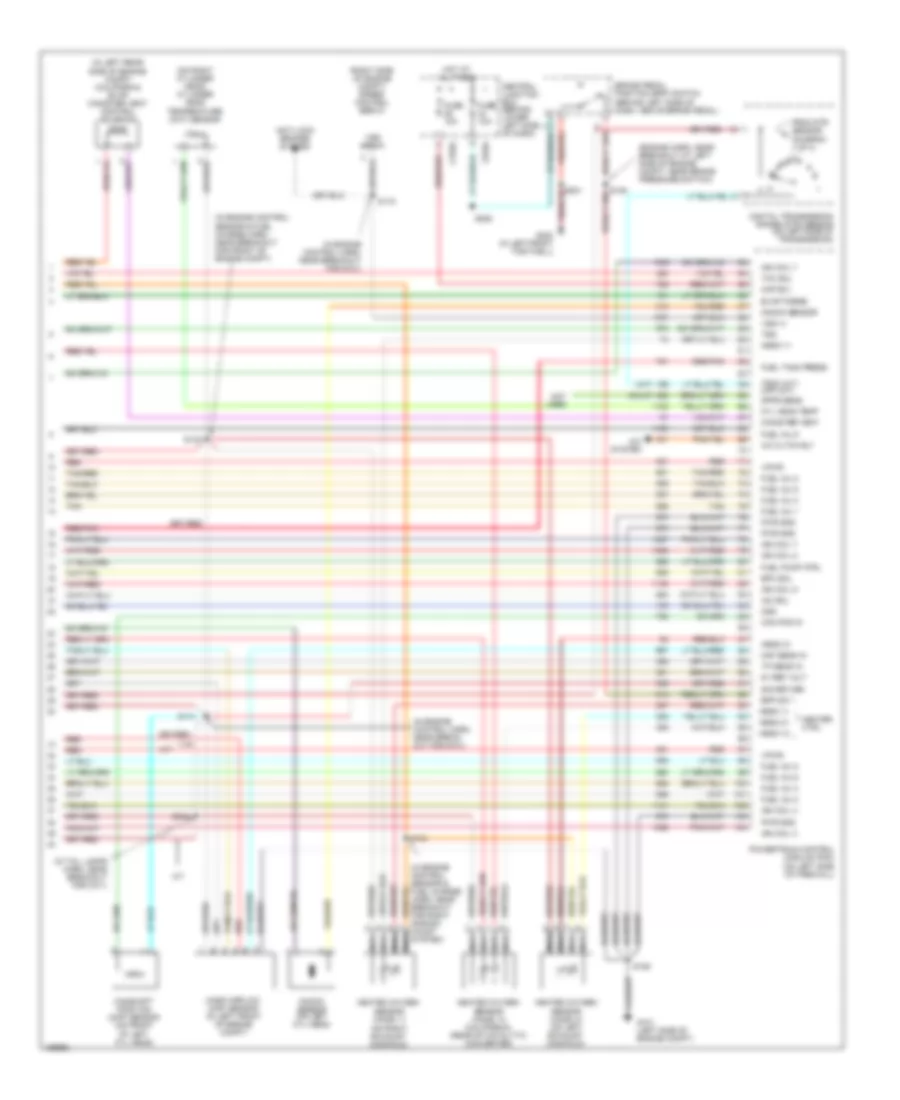
6.0L Diesel, Engine Performance Wiring Diagram (1 of 5) for Ford Cab & Chassis F350 Super Duty 2003
List of elements for 6.0L Diesel, Engine Performance Wiring Diagram (1 of 5) for Ford Cab & Chassis F350 Super Duty 2003:
- (a/t)
- (bap) sens mon
- (in engine control harn, near breakout for c1047)
- (in engine control harn, near breakout for g101)
- (in fog jumper harn, near break- out for c1045)
- (in main harn, near breakout for dlc)
- (in main harn, near breakout to brake pedal support) s224
- (m/t)
- (maf) sens out
- (map) sens mon
- (not used)
- (scp) data -
- (scp) data+
- A/c clutch input
- A/c clutch rly
- A/c system
- A/t
- Abs control module
- Acc
- Apps monitor 1
- Apps monitor 2
- Apps monitor 3
- Apps ref volt 2
- Apps sig rtn 2
- Auxiliary powertrain control module (apcm) (behind left side of dash)
- Auxiliary relay box 5 (at left rear side of engine compt)
- Brake ped pos sw
- Brake pedal position (bpp) switch (behind left side of dash, above brake pedal)
- Brake press sw in
- Brake pressure switch
- C135
- C1381a
- C270h red
- Can bus 1h
- Can bus 1l
- Central junction box (behind lower left side of dash)
- Chassis gnd
- Clutch pedal position (cpp) switch (m/t) (above clutch pedal)
- Computer data lines system
- Cruise control system
- Cust acc tp sig
- Cust acc vss out
- Data link connector (dlc) (behind left side of dash)
- Data output link
- Fuel pmp rly
- Fuel pump monitor
- Fuse 10a
- Fuse 20a
- Fuse 2a
- Fuse 30a
- Fuse 50a
- G100
- G101
- G300 (on vehicle floor, in left front footwell)
- Gen/bat ind
- Grade/load switch (a/t)
- Grd/load sw (cpp) sw
- Hot at all times
- Hot in run
- Injector driver module power relay
- Intk air temp sens
- Lock
- M/t
- Maf sens sig rtn
- Mass airflow (maf) sensor
- Mod prog sig
- Nca
- Off
- Overhead console
- Park brake switch (on park brake assembly)
- Park brk sw input
- Pcm power diode
- Pcm power relay
- Powertrain control module (pcm) (on left fender, near battery)
- Pto ctrl
- Pwr
- Pwr gnd
- Pwr in
- Red
- Ref volt
- Run
- S101
- S106
- S114
- S120 (in engine control harn, near breakout for auxiliary relay box 5)
- S123
- S174
- S217
- S284
- S286
- Sig rtn
- Sig rtn spd ctrl
- Speed ctrl ind
- Speed ctrl sw in
- Start
- Start rly ctrl
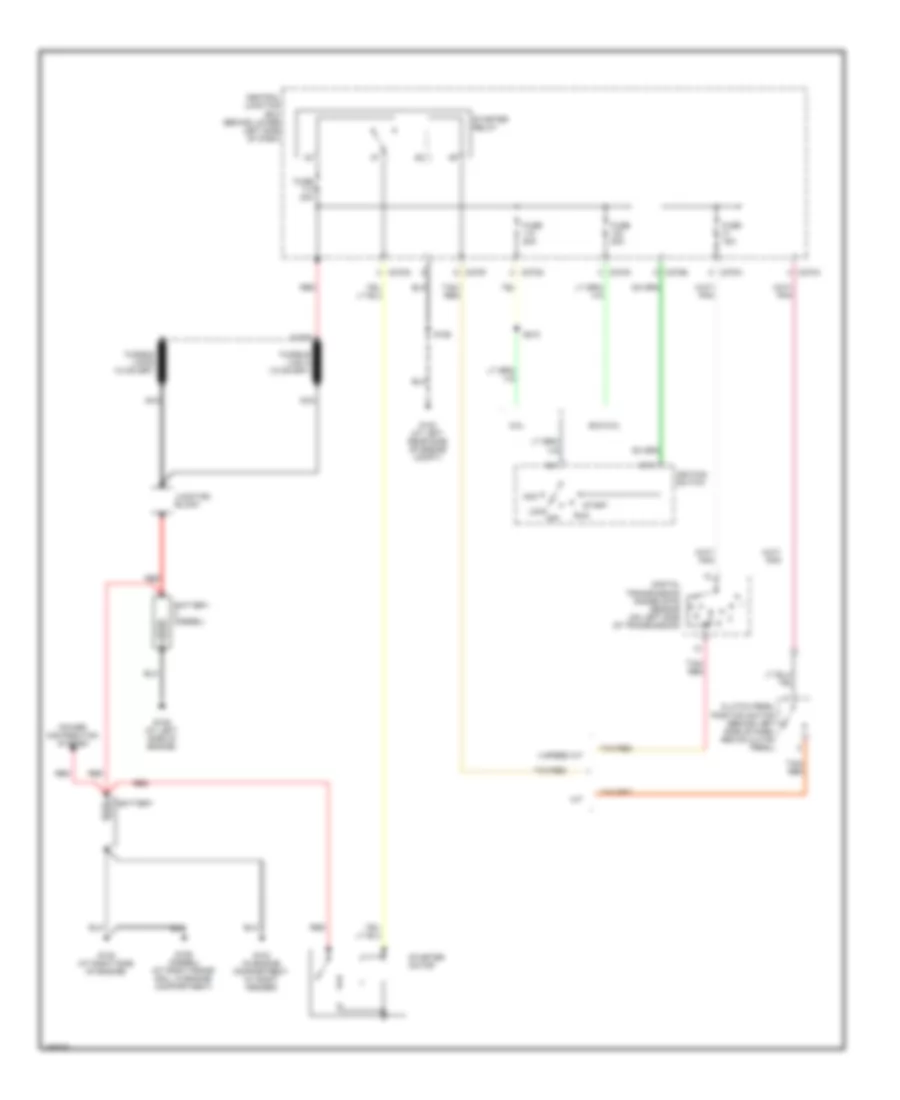
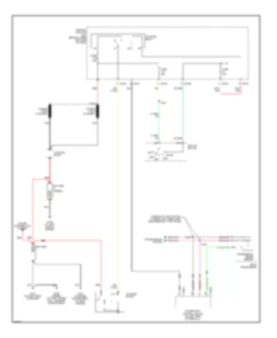
- Starting/ charging system
- Starting/charging system
- Tach output
- To fuel pump relay (diagram 2 of 4)
- Vss input
- Water in fuel sens
- Water in fuel sensor (at top right side of engine)
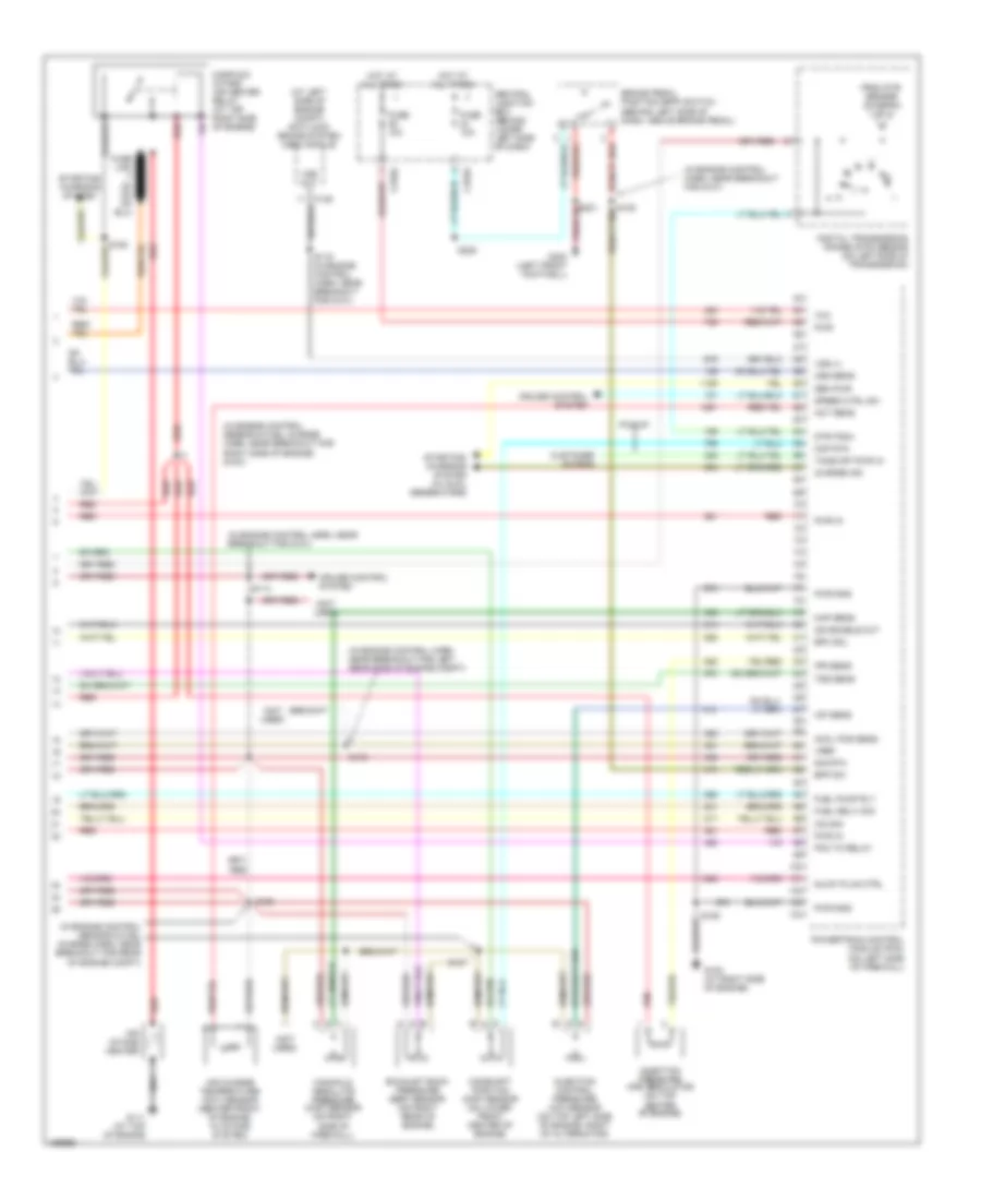
6.0L Diesel, Engine Performance Wiring Diagram (2 of 5) for Ford Cab & Chassis F350 Super Duty 2003
List of elements for 6.0L Diesel, Engine Performance Wiring Diagram (2 of 5) for Ford Cab & Chassis F350 Super Duty 2003:
- (at top front of engine) glow plug control module (gpcm)
- (in engine con-
- (in engine control harn, near breakout for left rear side of engine compt)
- (in main harn, near breakout
- Accelerator pedal position sensor (on accelerator pedal support)
- Barometric absolute pressure (bap) sensor (behind left side of dash)
- C1273a
- C1273b
- C220c
- C270a
- C270f
- Central junction box (behind lower left side of dash)
- Ctrl set lamp
- For c212) s223
- From pcm a power relay (diagram 1 of 4)
- Fuel heater
- Fuel heater relay
- Fuel pump (near left side of trans- mission)
- Fuel pump relay
- Fuse 10a
- Fuse 20a
- Fuse 30a
- G100
- Glow plugs
- Glw plg 1
- Glw plg 2
- Glw plg 3
- Glw plg 4
- Glw plg 5
- Glw plg 6
- Glw plg 7
- Glw plg 8
- Hot at all times
- Hot in run or start
- Inertia fuel shut off switch (behind right side of dash)
- Instrument cluster
- Left valve cover assembly
- Manifold absolute pressure (map) sensor (at right side of firewall)
- Nca
- Pcm
- Power in
- Red
- Right valve cover assembly
- S147
- S162
- S170
- S193
- S213
- S250
- S271
- Speed
- Trol sensor & fuel charge harn, at break- out for top left side of engine)
6.0L Diesel, Engine Performance Wiring Diagram (3 of 5) for Ford Cab & Chassis F350 Super Duty 2003
List of elements for 6.0L Diesel, Engine Performance Wiring Diagram (3 of 5) for Ford Cab & Chassis F350 Super Duty 2003:
- (mounted on rear of left valve cover) injector driver module (idm)
- C1388a
- C1388b
- C270g
- Central junction box (behind lower left side
- Fuel inj 1 gnd
- Fuel inj 1 pwr
- Fuel inj 2 gnd
- Fuel inj 2 pwr
- Fuel inj 3 gnd
- Fuel inj 3 pwr
- Fuel inj 4 gnd
- Fuel inj 4 pwr
- Fuel inj 5 gnd
- Fuel inj 5 pwr
- Fuel inj 6 gnd
- Fuel inj 6 pwr
- Fuel inj 7 gnd
- Fuel inj 7 pwr
- Fuel inj 8 gnd
- Fuel inj 8 pwr
- Fuel injector 1
- Fuel injector 2
- Fuel injector 3
- Fuel injector 4
- Fuel injector 5
- Fuel injector 6
- Fuel injector 7
- Fuel injector 8
- Fuse 10a
- G110 (at top left side of engine)
- Hot at all times
- Nca
- Red red
- S194
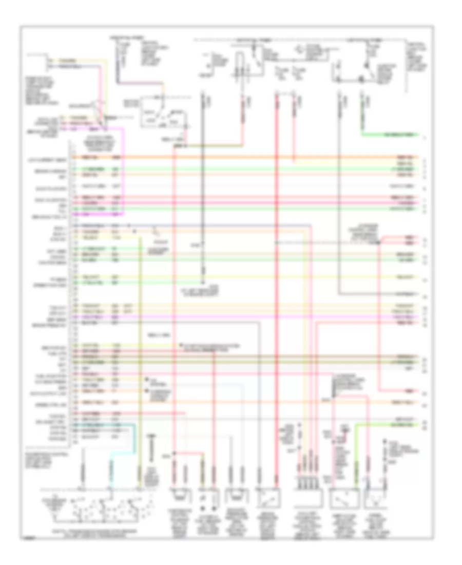
6.0L Diesel, Engine Performance Wiring Diagram (4 of 5) for Ford Cab & Chassis F350 Super Duty 2003
List of elements for 6.0L Diesel, Engine Performance Wiring Diagram (4 of 5) for Ford Cab & Chassis F350 Super Duty 2003:
- (a/t)
- (at left side of engine compt) g101
- (epc) sol 1 ctrl
- (epc) sol 2 ctrl
- (epc) sol 3 ctrl
- (epc) sol 4 ctrl
- (epc) sol 5 ctrl
- (epc) sol common
- (idm) pwr rly ctrl
- (in backup light switch to rear light feed harness, in breakout to transmission)
- (in engine control sensor & fuel charge harn, near breakout for left side of engine compt) s196
- (iss) sens in
- (on left fender, near battery)
- (oss) sens in
- (tcc) sol ctrl
- (tcil) ctrl
- (tft) sens
- (tft) sens in
- (tss) sens in
- (w/ elec- tronic shift on the fly)
- Automatic transmission 5r110
- Auxiliary relay box 5 (at left rear side of engine compt)
- C1381b
- C1388c
- Can bus 2h
- Can bus 2l
- Commumincation
- Cylinder id
- Drain wire
- Exterior lights system
- Fuel del com
- Fuse 15a
- Injector driver module (idm) (mounted on rear of left valve cover)
- Line press sol
- Logic pwr
- Neutral sw sen
- Powertrain control module (pcm)
- Pressure control solenoid
- Pressure sw 1 in
- Pressure sw 2 in
- Pressure sw 3 in
- Pressure sw 4 in
- Pressure sw 5 in
- Pwr gnd
- Pwr in
- Red
- Red red
- Ref volt
- Rev lmp rly ctrl
- Rly ctrl bat feed
- S129
- S195
- Sig rtn
- Tran range sens
- Transmission fluid temperature sensor
- Transmission range sensor (trs)
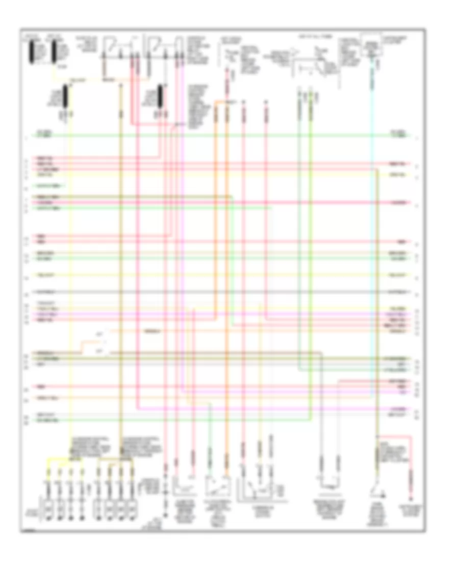
6.0L Diesel, Engine Performance Wiring Diagram (5 of 5) for Ford Cab & Chassis F350 Super Duty 2003
List of elements for 6.0L Diesel, Engine Performance Wiring Diagram (5 of 5) for Ford Cab & Chassis F350 Super Duty 2003:
- (act) sens in
- (ckp) sens +
- (ckp) sens -
- (cmp) sens +
- (cmp) sens -
- (ebp) sens sig
- (eot) sens in
- (icp) sens sig
- (idm) comm
- (idm) cyl id
- (idm) fuel del
- (in engine con- trol sensor & fuel charge harn, at break- out for intake system)
- (in engine control sensor & fuel charge harn, at breakout for left side of engine compt)
- (ipr) ctrl
- (on throttle body) electronic throttle control motor
- (on top of transmission extension housing) output shaft speed (oss) sensor
- Air charge temperature (act) sensor (center front of engine, in intake system)
- C1381c
- C281b
- Camshaft position (cmp) sensor
- Can bus 2h
- Can bus 2l
- Charge monitor
- Cool temp sens
- Cooling fans system
- Crankshaft position (ckp) sensor
- Egr thrtl act
- Egr thrtl pos
- Egr val pos sen
- Egr valve act
- Egr valve actuator (at top of engine)
- Elec fan cltch
- Engine coolant temperature (ect) sensor
- Engine oil temperature (eot) sensor
- Exhaust back pressure sensor
- Fan sig rtn
- Fan spd sig
- Four- wheel drive control module (behind right side of dash)
- Glow plug sys
- Gnd drain wire
- Injection control pressure (icp) sensor
- Injection pressure regulator
- Intermediate shaft
- Nca
- Powertrain control module (pcm) (on left fender, near battery)
- Red
- Ref volt
- S127 (in back-up light switch to rear light feed harn, near breakout for vehicle underbody)
- S128
- S190
- S192
- S197
- Sig rtn
- Speed sensor
- Speed sensor assembly
- Starting/ charging system
- Throttle position (tps) sensor
- Turbine shaft speed sensor
- Turbo vane ctrl
- Variable geometric turbo actuator
6.8L
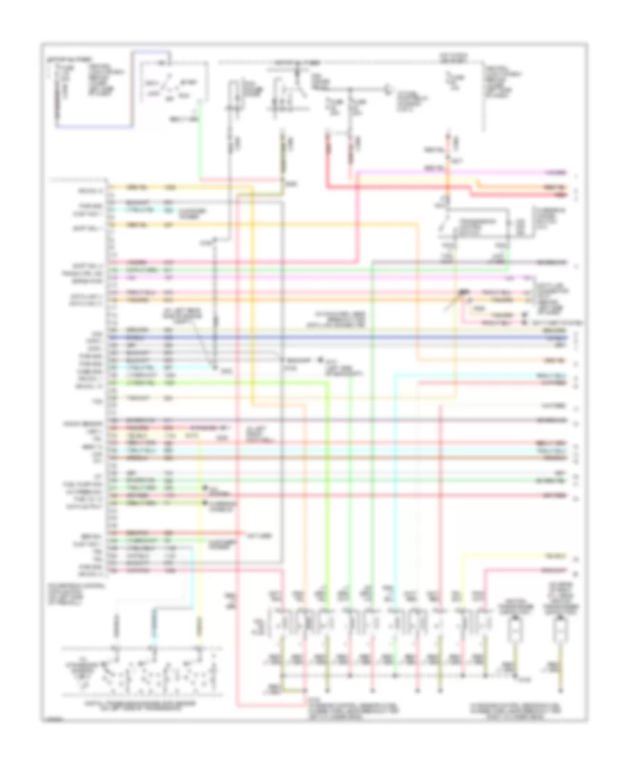
6.8L, Engine Performance Wiring Diagram (1 of 4) for Ford Cab & Chassis F350 Super Duty 2003
List of elements for 6.8L, Engine Performance Wiring Diagram (1 of 4) for Ford Cab & Chassis F350 Super Duty 2003:
- (at left rear side of engine compt)
- (in engine control sensor & fuel charge harn, near breakout for right cylinder head)
- (in left front footwell)
- (in main harn, near breakout for data link connector)
- (on rear of right cyl head) ignition transformer capacitor 2
- A/c press sw
- A/c system
- Acc
- Anti-theft system
- C270a
- Case gnd
- Ccs
- Central junction box (behind lower left side of dash)
- Ckp(+)
- Ckp(-)
- Coil on plug
- Cust acc 1
- Customer access
- Data link (+)
- Data link (-)
- Data link connector (dlc) (behind left side of dash)
- Data output
- Digital transmission range (dtr) sensor (on left side of transmission)
- Egr sol
- Eprom pwr
- Fuel inj 10
- Fuel pump mon
- Fuse 10a
- Fuse 20a
- Fuse 30a
- G100
- G101 (left side of eng compt)
- G300
- Hego 12
- Hot at all times
- Hot in run or start
- Iat
- Ign coil 1
- Ign coil 10
- Ign coil 5
- Ign coil 6
- Ignition transformer capacitor 1
- Knock sensor
- Lock
- Maf
- Nca
- Not used
- O/d off ind
- Off
- Overdrive cancel switch (a/t)
- Overhead console
- Pcm power diode
- Pcm power relay
- Powertrain control module (pcm) (on left side of firewall)
- Pwr gnd
- R n
- Red
- Run
- S106
- S130 (in engine control sensor & fuel charge harn, near breakout for left cylinder head)
- S135
- S162
- S172
- S258
- S271
- S284
- S286
- Shift sol 1
- Shift sol 2
- Start
- Tcs
- Tft
- To dtr sensor (diagram 4 of 4)
- To fuel pump relay (diagram 2 of 4)
- Tr1
- Tr2
- Tr4
- Trans ctrl ind
- Transmission control switch
- Vss (-)
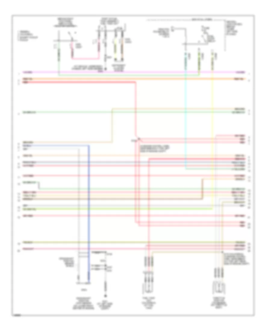
6.8L, Engine Performance Wiring Diagram (2 of 4) for Ford Cab & Chassis F350 Super Duty 2003
List of elements for 6.8L, Engine Performance Wiring Diagram (2 of 4) for Ford Cab & Chassis F350 Super Duty 2003:
- (at vehicle under body, chassis left side member) g400
- (behind right kick panel) inertia fuel shut-off switch
- (in engine control harn, near breakout for left side of engine compt)
- (part of fuel tank assembly) fuel tank unit
- C2207
- C270a
- C270f
- C270h
- C282
- C4033
- C433
- California
- Central junction box (behind lower left side of dash)
- Crankshaft position (ckp) sensor (on lower front center of engine)
- Crankshaft position sensor shield
- Except pickup
- Federal
- From pcm power relay (diagram 1 of 4)
- Fuel pump relay
- Fuel tank unit (california) (at fuel tank)
- Fuse 20a
- G101 (at left side of engine compt)
- Hot at all times
- Instrument cluster system
- Nca
- Pickup
- Red
- Red/pnk
- S123
- S145
- S161
- S167
- S170 (california) (in engine control harn, near break- out for left rear side of engine compt)
- S401
- Throttle position (tp) sensor (on throttle body)
6.8L, Engine Performance Wiring Diagram (3 of 4) for Ford Cab & Chassis F350 Super Duty 2003
List of elements for 6.8L, Engine Performance Wiring Diagram (3 of 4) for Ford Cab & Chassis F350 Super Duty 2003:
- (in back-up light switch to rear light feed harn, near breakout for left side of transmission)
- (in engine control harn, near breakout for g100)
- (on right rear of engine compt)
- A/c system
- A/t
- Automatic transmission control module (on left side of transmission)
- Coast clutch solenoid
- Electronic pressure controller
- Fuel injectors
- Idle air control (iac) valve (on throttle body assembly)
- M/t
- Output shaft speed (oss) sensor (on top of transmission extension housing)
- Red
- Red/pnk
- S122
- S131 (in engine control sensor & fuel charge harn, near breakout for engine right cylinder head)
- S136 (in engine control sensor & fuel charge harn, near breakout for engine right cylinder head)
- S138
- S139
- Shift solenoid 1
- Shift solenoid 2
- Tan
- Tan/ red
- Tan/red
- Torque converter clutch solenoid
- Transmission fluid temperature sensor
- Turbine shaft speed (tss) sensor (on top of transmission, at converter housing)
- Vapor management valve
6.8L, Engine Performance Wiring Diagram (4 of 4) for Ford Cab & Chassis F350 Super Duty 2003
List of elements for 6.8L, Engine Performance Wiring Diagram (4 of 4) for Ford Cab & Chassis F350 Super Duty 2003:
- (a/t)
- (calif)
- (engine harn, near breakout at left side of engine compt, near brake pressure switch)
- (in engine control harn, near break- out for g101)
- (in engine control harn, near breakout for g101)
- (in engine control sensor & fuel charge harn, near breakout for front of engine compt)
- (in left rear side of engine compt) (california) evap canister vent control solenoid
- (in tail lamps harn, near breakout for c311)
- (on right cylinder head) cylinder head temperature (cht) sensor
- (on right exhaust manifold)
- (right side of engine compt) speed control servo
- 5v ref volt
- A/c cltch rly
- A/c system
- A/t
- Anti-lock brakes system
- Bpp sw
- Brake pedal position (bpp) switch (behind left side of dash, above brake pedal)
- C270a
- C270g
- Cam pos in
- Camshaft position (cmp) sensor (on front of left cyl head)
- Canister vent
- Central junction box (behind lower left side of dash)
- Cyl head temp
- Digital transmission range (dtr) sensor (on left side of transmission)
- Dpfe sens
- Epc sol
- Evap purge
- From dtr sensor (diagram 1 of 4)
- Fuel inj 1
- Fuel inj 2
- Fuel inj 3
- Fuel inj 4
- Fuel inj 5
- Fuel inj 6
- Fuel inj 8
- Fuel inj 9
- Fuel pump ctrl
- Fuel tank press
- Fuse 10a
- G101 (left side of engine compt)
- G300 (in left front footwell)
- Heated oxygen sensor (ho2s) 11
- Heated oxygen sensor (ho2s) 12 (california) (rear of catalytic converter)
- Heated oxygen sensor (ho2s) 21 (on left exhaust manifold)
- Heater ctrl
- Hego 11
- Hego 12
- Hego 21
- Hot at all times
- Iac sol
- Ign coil 3
- Ign coil 4
- Ign coil 7
- Ign coil 8
- Ign coil 9
- Kap b(+)
- Knock sensor
- Knock sensor (on left cyl head)
- M/t
- Maf sens in
- Mass airflow (maf) sensor (in left front of engine compt)
- Nca
- Not used
- Oss
- Powertrain control module (pcm) (on left side of firewall)
- Pwr gnd
- Red
- Red/pnk
- S106
- S114
- S115
- S132
- S134
- S228
- S343
- Side ex- haust system)
- Sig return
- Tan
- Tan/red
- Tcc sol
- Tp sens in
- Tr3a (a/t) cpp (m/t)
- Tss
- Vpwr
- Vss (+)
- Vss input
7.3L DI TURBO DIESEL
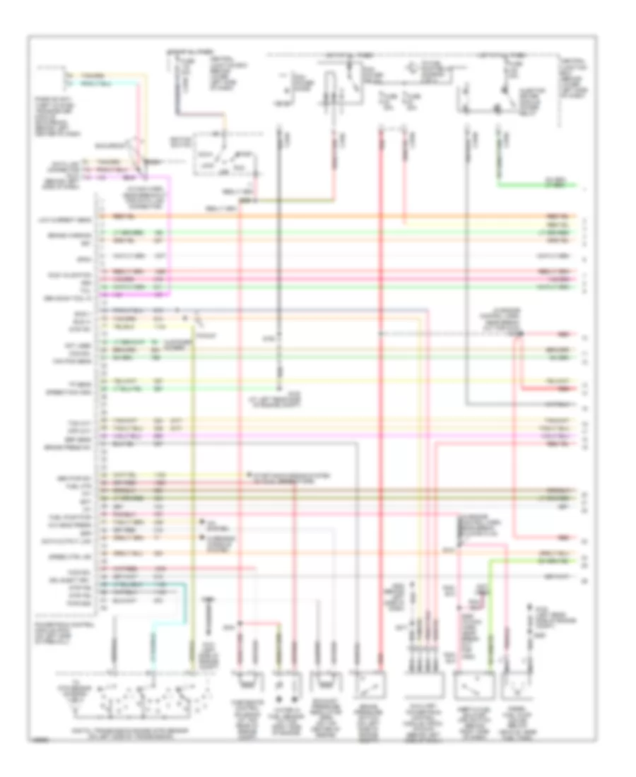
7.3L DI Turbo Diesel, Engine Performance Wiring Diagram, California (1 of 4) for Ford Cab & Chassis F350 Super Duty 2003
List of elements for 7.3L DI Turbo Diesel, Engine Performance Wiring Diagram, California (1 of 4) for Ford Cab & Chassis F350 Super Duty 2003:
- (a/t)
- (behind left side of dash)
- (in engine control harn, near break- out for c144)
- (in engine control harn, near break- out for g100) s123
- (in main harn, near breakout for data link connector)
- (m/t)
- (not used)
- A/c head press
- A/c system
- Acc
- Auxiliary powertrain control module (apcm) (pickup) (behind left side of dash)
- Brake press sw
- Brake pressure switch (on left side of engine compt)
- Brake warning
- Bus (+)
- Bus (-)
- Cam pos sens
- Ccs sol
- Central junction box (behind lower left side of dash)
- Cpp (m/t)
- Customer access
- Dash)
- Data link connector (dlc)
- Data output link
- Diesel fuel pump motor (below vehicle, near fuel tank)
- Digital transmission range (dtr) sensor (on left side of transmission)
- Dsl elect drv
- Dtr-tr1
- Dtr-tr2
- Dtr-tr4
- Ebp sens
- Eot
- Epr
- Excursion
- Exhaust pressure regulator (epr) (on top center of engine)
- Fuel htr
- Fuel pump pwr
- Fuse 20a
- Fuse 30a
- G100 (at left rear side of engine compt)
- G100 (left rear side of engine compt)
- G101 (left side of engine compt)
- Gen pwr sw
- Gen scan tool in
- Gpcm
- Hot at all times
- Iat
- Idle validation
- Ignition switch
- Inertia fuel shutoff (ifs) switch (behind right side of dash)
- Injector driver module power relay
- Lock
- Low current sens
- Nca
- Not used
- Off
- Overhead console system
- Passive anti- theft system transceiver module (excursion) (behind left center of dash)
- Pcm power diode
- Pcm power relay
- Pickup
- Powertrain control module (pcm) (on left side of firewall)
- Pwr gnd
- R n
- Red
- Run
- S106
- S141
- S154
- S162
- S217
- S250
- S258
- S260 (in main harn, near break- out for c264)
- S284
- S286
- Speed ctrl ind
- Speed/tach gnd
- Ss1
- Ss2
- Start
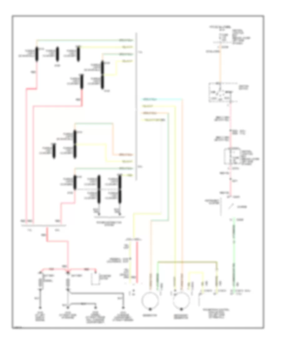
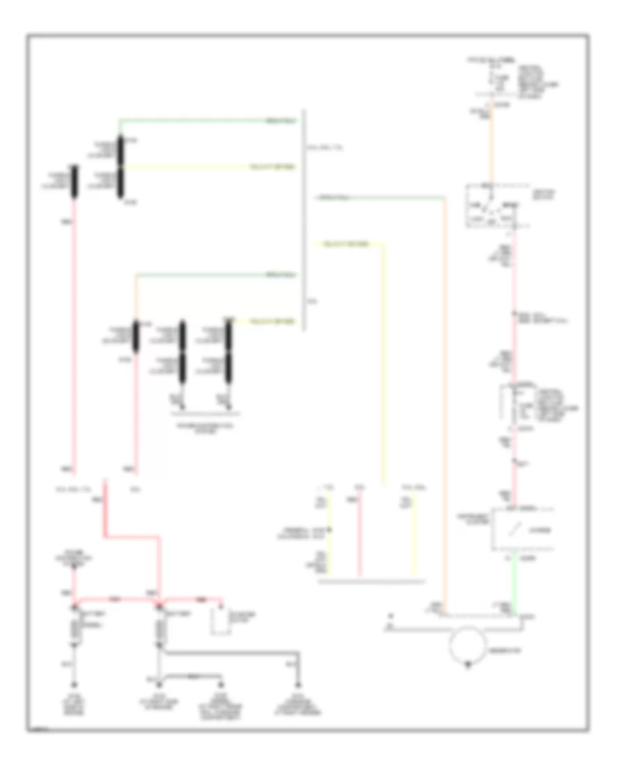
- Starting/charging system (w/ dual generators)
- Tcil
- Tcs (a/t)
- Tft
- To dtr sensor (diagram 4 of 4)
- To fuel pump relay (diagram 2 of 4)
- Tp sens
- Wastegate control solenoid (at top rear of engine compt)
- Water in fuel sensor (at top right side of engine)
- Wcs sol
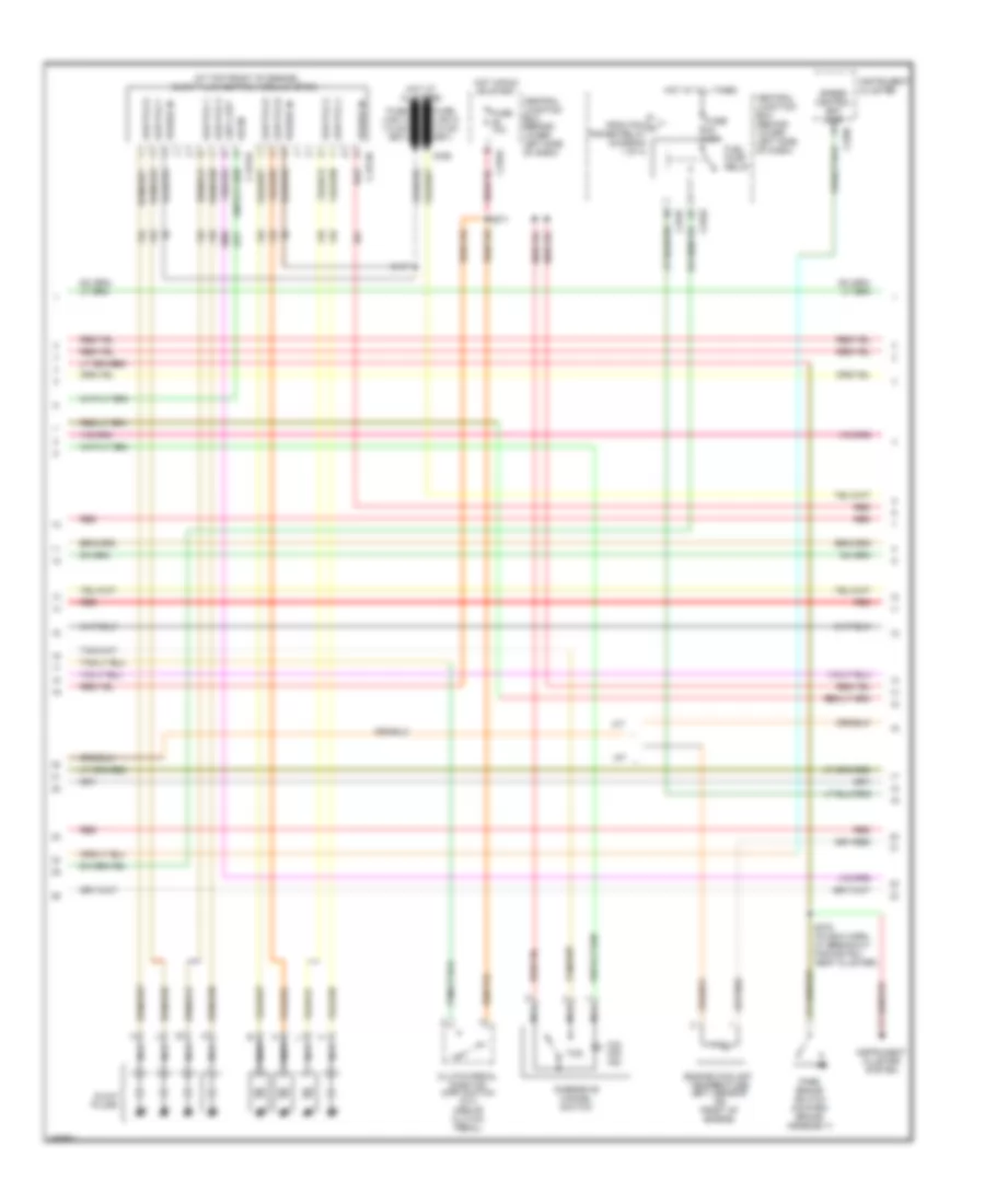
7.3L DI Turbo Diesel, Engine Performance Wiring Diagram, California (2 of 4) for Ford Cab & Chassis F350 Super Duty 2003
List of elements for 7.3L DI Turbo Diesel, Engine Performance Wiring Diagram, California (2 of 4) for Ford Cab & Chassis F350 Super Duty 2003:
- (at top front of engine) glow plug control module (gpcm)
- A/t
- C1273a
- C1273b
- C270a
- C270f
- Central junction box (behind lower left side of dash)
- Clutch pedal position (cpp) switch (m/t) (above clutch pedal)
- Cntl out
- Engine coolant temperature (ect) sensor (on front of engine)
- From pcm a power relay (diagram 1 of 4)
- Fuel pump relay
- Fuse 10a
- Fuse 20a
- Glow plugs
- Glw plg 1
- Glw plg 2
- Glw plg 3
- Glw plg 4
- Glw plg 5
- Glw plg 6
- Glw plg 7
- Glw plg 8
- Gpcm
- Hot at all times
- Hot in run or start
- Instrument cluster
- Instrument cluster system
- M/t
- Nca
- O/d off ind
- Overdrive cancel switch
- Park brake switch (on park brake assembly)
- Power in
- Red
- S126
- S147
- S271
- S278 (in main harn, at breakout for instru- ment cluster)
- Speed control set lamp c220c
- Tcs
7.3L DI Turbo Diesel, Engine Performance Wiring Diagram, California (3 of 4) for Ford Cab & Chassis F350 Super Duty 2003
List of elements for 7.3L DI Turbo Diesel, Engine Performance Wiring Diagram, California (3 of 4) for Ford Cab & Chassis F350 Super Duty 2003:
- (in back-up light switch to rear feed harn, near breakout for left side of transmission)
- (in left side of engine compt) injector driver module (idm)
- Accelerator pedal position sensor (on accelerator pedal support)
- Automatic transmission module
- Cid sig in
- Coast clutch solenoid
- Electronic pressure control solenoid
- Engine oil temperature (eot) sensor (on top front of engine)
- Feedback
- Fuel inj 1
- Fuel inj 2
- Fuel inj 3
- Fuel inj 4
- Fuel inj 5
- Fuel inj 6
- Fuel inj 7
- Fuel inj 8
- Fuel injectors
- Fuel sig
- G101 (left side of engine compt)
- Inj feed
- Intake air temperature sensor (left side of engine compt, behind air cleaner)
- Nca
- Output shaft speed (oss) sensor (on top of transmission extension housing)
- Pwr gnd
- Pwr in
- Red
- S138
- S139
- Shield
- Shift solenoid
- Sig rtn
- Tan
- Tan/red
- Torque converter clutch solenoid
- Transmission fluid temperature sensor
- Turbine shaft speed (tss) sensor (on top of transmission, at converter housing)
7.3L DI Turbo Diesel, Engine Performance Wiring Diagram, California (4 of 4) for Ford Cab & Chassis F350 Super Duty 2003
List of elements for 7.3L DI Turbo Diesel, Engine Performance Wiring Diagram, California (4 of 4) for Ford Cab & Chassis F350 Super Duty 2003:
- (at left side of engine compt) anti-lock brake system (abs) module
- (in engine control harn, near breakout for g101)
- (in engine control harn, near breakout for left rear side of engine compt)
- (in engine control sensor & fuel charge harn, near breakout for rear of engine compt)
- (in engine control sensor & fuel charge harn, near breakout for right side of engine) s1001
- (not used)
- Accl pos sens
- Act sens
- Air charge temperature (act) sensor (center front of engine, in intake system)
- Air intake heater
- Bpp sw
- Brake pedal position (bpp) switch (behind left side of dash, above brake pedal)
- C270a
- C270g
- Camshaft position (cmp) sensor (on lower front center of engine)
- Central junction box (behind lower left side of dash)
- Charge ind
- Cid sig
- Cmp rtn
- Cruise control system
- Customer access
- Digital transmission range (dtr) sensor (on left side of transmission)
- Dtr-tr3a
- Epc sol
- Exhaust back pressure (ebp) sensor (on right rear of engine)
- From dtr sensor (diagram 1 of 4)
- Fuel deliv sig
- Fuel pump rly
- Fuse 10a
- G102 (at right side of engine)
- G111 (at top of engine
- G300 (left front footwell)
- Gen pwr
- Glow plug ctrl
- Hot at all times
- Icp sens
- Idm enable out
- Injection control pressure (icp) sensor (on top left side of engine, right of alternator)
- Injection pressure (ipr) regulator (on top center of engine)
- Ipr sens
- Manifold absolute pressure (map) sensor (on right side of firewall)
- Manifold intake air heater relay (at top right side of engine)
- Map sens
- Oss sens
- Pcm to relay
- Pickup
- Powertrain control module (pcm) (on left side of firewall)
- Pwr
- Pwr gnd
- Pwr in
- Red
- S106
- S114
- S115 (in engine control harn, near breakout for g101)
- S151
- S153
- S170
- S228
- Sig rtn
- Speed ctrl sw
- Starting/ charging system
- Starting/ charging system (w/ dual generators)
- Take off pwr in
- Tcc
- Tss sens
- Vref
- Vss (+)
- Vss out
7.3L DI Turbo Diesel, Engine Performance Wiring Diagram, Federal (1 of 4) for Ford Cab & Chassis F350 Super Duty 2003
List of elements for 7.3L DI Turbo Diesel, Engine Performance Wiring Diagram, Federal (1 of 4) for Ford Cab & Chassis F350 Super Duty 2003:
- (a/t)
- (behind center of dash)
- (in engine control harn, near break- out for c144)
- (in engine control harn, near break- out for g100) s123
- (in main harn, near breakout for data link connector)
- (m/t)
- A/c head press
- A/c system
- Acc
- Auxiliary powertrain control module (apcm) (pickup) (behind left side of dash)
- Brake press sw
- Brake pressure switch (on left side of engine compt)
- Brake warning
- Bus (+)
- Bus (-)
- Cam pos sens
- Ccs sol
- Central junction box (behind lower left side of dash)
- Cpp (m/t)
- Customer access
- Dash)
- Data link connector (dlc)
- Data output link
- Diesel fuel pump motor (below vehicle, near fuel tank)
- Digital transmission range (dtr) sensor (on left side of transmission)
- Dsl elect drv
- Dtr-tr1
- Dtr-tr2
- Dtr-tr4
- Ebp sens
- Eot
- Epr
- Excursion
- Exhaust pressure regulator (epr) (on top center of engine)
- Fuel htr
- Fuel pump pwr
- Fuse 20a
- Fuse 30a
- G100 (at left rear side of engine compt)
- G100 (left rear side of engine compt)
- G101 (left side of engine compt)
- Gen pwr sw
- Gen scan tool in
- Glow plug mon
- Hot at all times
- Iat
- Idle validation
- Ignition switch
- Inertia fuel shutoff (ifs) switch (behind right side of dash)
- Injector driver module power relay
- Lock
- Low current sens
- Nca
- Not used
- Off
- Overhead console system
- Passive anti- theft system transceiver module (excursion) (behind left center of dash)
- Pcm power diode
- Pcm power relay
- Pickup
- Powertrain control module (pcm) (on left side of firewall)
- Pwr gnd
- R n
- Red
- Run
- S106
- S141
- S154
- S162
- S217
- S250
- S258
- S284
- S286
- Speed ctrl ind
- Speed/tach gnd
- Ss1
- Ss2
- Start
- Starting/charging system (w/ dual generators)
- Tcil
- Tcs (a/t)
- Tft
- To dtr sensor (diagram 4 of 4)
- To fuel pump relay (diagram 2 of 4)
- Tp sens
- Wastegate control solenoid (at top rear of engine compt)
- Water in fuel sensor (at top right side of engine)
- Wcs sol
7.3L DI Turbo Diesel, Engine Performance Wiring Diagram, Federal (2 of 4) for Ford Cab & Chassis F350 Super Duty 2003
List of elements for 7.3L DI Turbo Diesel, Engine Performance Wiring Diagram, Federal (2 of 4) for Ford Cab & Chassis F350 Super Duty 2003:
- (in engine control sensor & fuel charge harn, near breakout for right side of engine) s1001
- A/t
- C1279
- C1280
- C270a
- C270f
- Central junction box (behind lower left side of dash)
- Clutch pedal position (cpp) switch (m/t) (above clutch pedal)
- Engine coolant temperature (ect) sensor (on front of engine)
- From pcm a power relay (diagram 1 of 4)
- Fuel pump relay
- Fuse 10a
- Fuse 20a
- G111 (at top of engine)
- Glow plug relay (at top of engine)
- Glow plugs
- Hot at all times
- Hot in run or start
- Injector pressure sensor (on top center of engine)
- Instrument cluster
- Instrument cluster system
- M/t
- Manifold intake air heater 58 amp
- Manifold intake air heater relay (at top right side of engine)
- Nca
- O/d off ind
- Overdrive cancel switch
- Park brake switch (on park brake assembly)
- Red
- S126
- S150
- S271
- S278 (in main harn, at breakout for instru- ment cluster)
- Speed control set lamp c270c
- Tcs
7.3L DI Turbo Diesel, Engine Performance Wiring Diagram, Federal (3 of 4) for Ford Cab & Chassis F350 Super Duty 2003
List of elements for 7.3L DI Turbo Diesel, Engine Performance Wiring Diagram, Federal (3 of 4) for Ford Cab & Chassis F350 Super Duty 2003:
- (in back-up light switch to rear feed harn, near breakout for left side of transmission)
- (in left side of engine compt) injector driver module (idm)
- Accelerator pedal position sensor (on accelerator pedal support)
- Automatic transmission module
- Cid sig in
- Coast clutch solenoid
- Electronic pressure control solenoid
- Engine oil temperature (eot) sensor (on top front of engine)
- Feedback
- Fuel inj 1
- Fuel inj 2
- Fuel inj 3
- Fuel inj 4
- Fuel inj 5
- Fuel inj 6
- Fuel inj 7
- Fuel inj 8
- Fuel injectors
- Fuel sig
- G101 (left side of engine compt)
- Inj feed
- Intake air temperature sensor (left side of engine compt, behind air cleaner)
- Nca
- Output shaft speed (oss) sensor (on top of transmission extension housing)
- Pwr gnd
- Pwr in
- Red
- S138
- S139
- Shield
- Shift solenoid
- Sig rtn
- Tan
- Tan/red
- Torque converter clutch solenoid
- Transmission fluid temperature sensor
- Turbine shaft speed (tss) sensor (on top of transmission, at converter housing)
7.3L DI Turbo Diesel, Engine Performance Wiring Diagram, Federal (4 of 4) for Ford Cab & Chassis F350 Super Duty 2003
List of elements for 7.3L DI Turbo Diesel, Engine Performance Wiring Diagram, Federal (4 of 4) for Ford Cab & Chassis F350 Super Duty 2003:
- (in engine control harn, near breakout for g101)
- (in engine control harn, near breakout for left rear side of engine compt)
- (in engine control sensor & fuel charge harn, near breakout for rear of engine compt)
- (in left front of engine compt) anti-lock brake system (abs) module
- (not used)
- Accl pos sens
- Act sens
- Air charge temperature (act) sensor (center front of engine, in intake system)
- Bpp sw
- Brake pedal position (bpp) switch (behind left side of dash, above brake pedal)
- C135
- C270a
- C270g
- Camshaft position (cmp) sensor (on lower front center of engine)
- Central junction box (behind lower left side of dash)
- Charge ind
- Cid sig
- Cmp rtn
- Cruise control system
- Customer access
- Digital transmission range (dtr) sensor (on left side of transmission)
- Dtr-tr3a
- Epc sol
- Exhaust back pressure (ebp) sensor (on right rear of engine)
- From dtr sensor (diagram 1 of 4)
- Fuel deliv sig
- Fuel pump rly
- Fuse 10a
- G102 (at right side of engine)
- G300 (left front footwell)
- Gen pwr
- Glow plug ctrl
- Hot at all times
- Icp sens
- Idm enable out
- Injection control pressure (icp) sensor (on top left side of engine, right of alternator)
- Ipr sens
- Manifold absolute pressure (map) sensor (on right side of firewall)
- Map sens
- Not used
- Oss sens
- Pcm to relay
- Pickup
- Powertrain control module (pcm) (on left side of firewall)
- Pwr
- Pwr gnd
- Pwr in
- Red
- S106
- S114
- S115 (engine harn, near breakout at left side of steering column)
- S151
- S153
- S170
- S228
- Sig rtn
- Speed ctrl sw
- Starting/ charging system (w/ dual generators)
- Take off pwr in
- Tcc
- Tss sens
- Vref
- Vss (+)
- Vss out
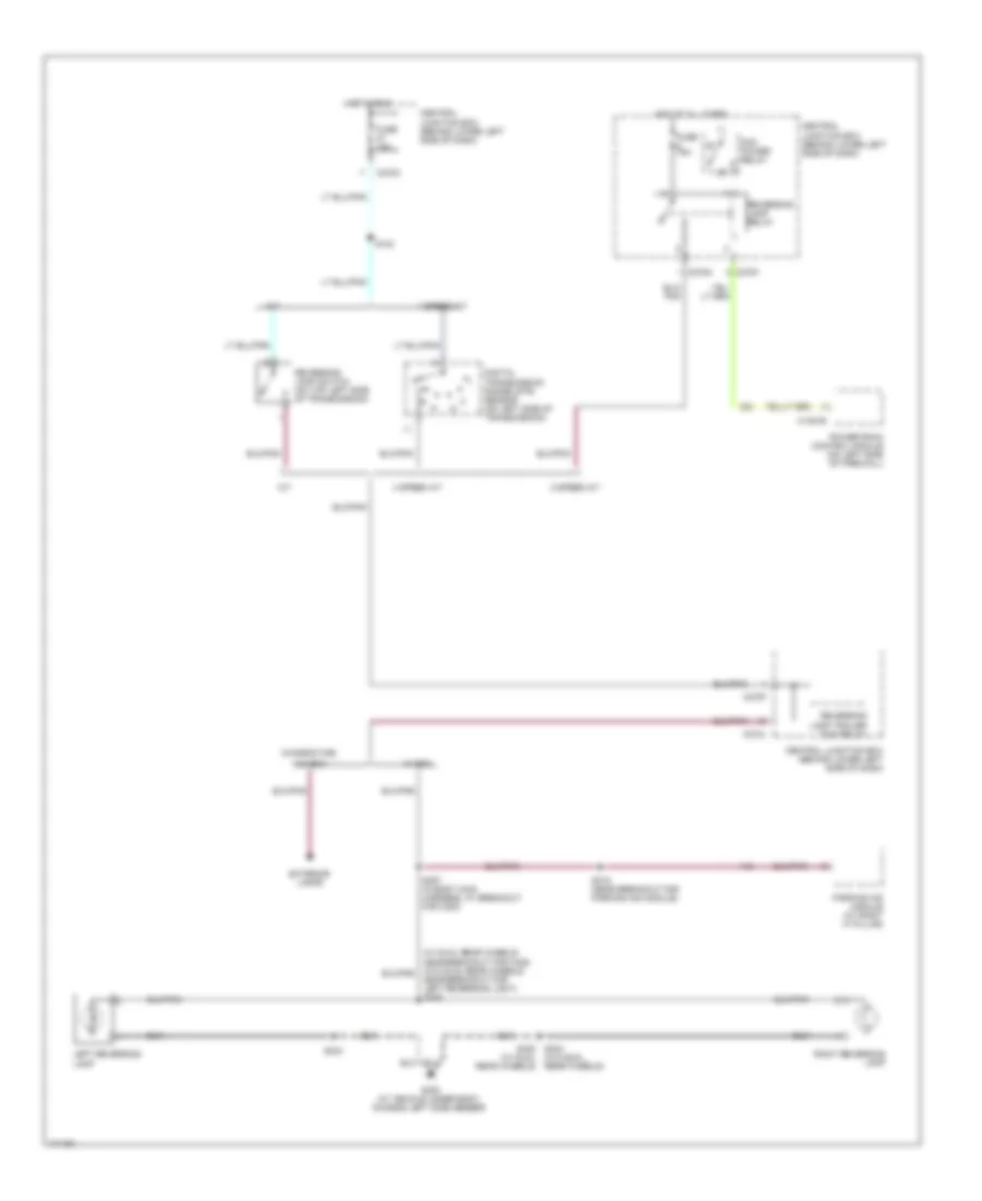
EXTERIOR LIGHTS
Back-up Lamps Wiring Diagram for Ford Cab & Chassis F350 Super Duty 2003
List of elements for Back-up Lamps Wiring Diagram for Ford Cab & Chassis F350 Super Duty 2003:
- (w/o dual rear wheels)
- 4 speed a/t
- 5 speed a/t
- C1381b
- C270f
- C270g
- C270h
- C270j
- Central junction box (behind lower left side of dash)
- Chassis cab,
- Digital transmission range (dtr) sensor (on left side of transmission)
- Exterior lamps
- Fuse 15a
- G400 (at vehicle under body, chassis left side member)
- Hot at all times
- Hot in run
- Left reversing lamp
- M/t
- Near breakout for left reversing light) s426
- Parking aid module (at right ``a" pillar)
- Pcm power relay
- Powertrain control module (on left side of firewall)
- Reversing lamp relay
- Reversing lamp switch (on top left side of transmission)
- Reversing lamp trailer tow relay
- Right reversing lamp
- S124
- S319 (near breakout for parking aid module)
- S357 (in body main harness, at breakout for c300)
- S404
- S404 s402 (w/ dual rear wheels)
- W/ box
- W/o box
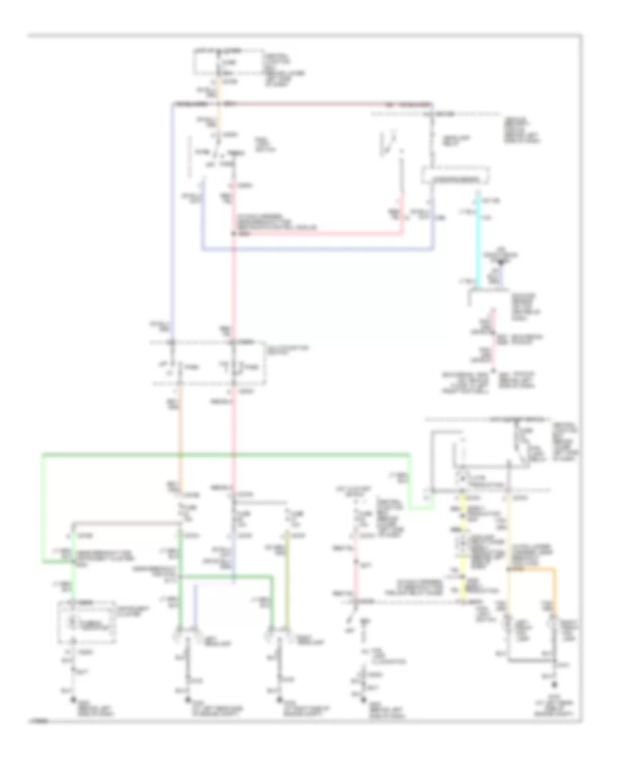
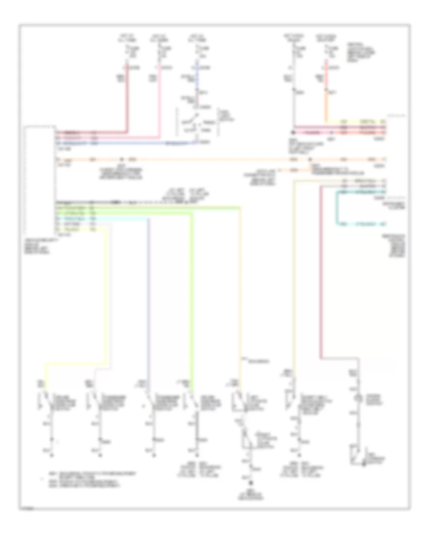
Exterior Lamps Wiring Diagram (1 of 2) for Ford Cab & Chassis F350 Super Duty 2003
List of elements for Exterior Lamps Wiring Diagram (1 of 2) for Ford Cab & Chassis F350 Super Duty 2003:
- (6.0l:in main harness near breakout to ignition switch) (except 6.0l: in main harness, near breakout to brake pedal position switch)
- (at left "c" pillar) g900
- (at left rear side of engine compartment) g100
- (crew cab)
- (except 6.0l: near breakout to brake pedal position switch) (6.0l:near breakout to ignition switch)
- (except crew cab)
- (except lariat) s904
- (in roof marker lamp jumper harness, near breakout for center roof marker light) s921
- (near breakout to brake pedal position switch) s240
- (near breakout to ignition switch)
- (not used)
- Auto
- Auxiliary relay box 1 (behind dash panel, to left of glove box near center of dash)
- Brake pedal position (bpp) switch (behind left side of dash, above brake pedal)
- C202a
- C202b
- C205a
- C2113b
- C220a
- C220c
- C270a
- C270b
- Center
- Central junction box (behind lower left side of dash)
- Driver side exterior rear view mirror
- Except lariat
- Fuse 15a
- Fuse 20a
- Fuse 30a
- G108 (at right side of engine compt)
- G201 (behind left side of dash)
- G202 (behind left side of dash)
- G400 (at vehicle under body, chassis left side member)
- G900 (at left "c" pillar)
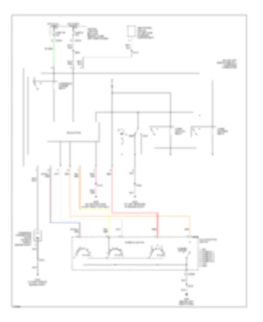
- Hazard switch
- Head
- High mounted stoplamp
- Hot at all times
- Hot in run
- Indicator flasher relay 87a
- Instrument cluster
- Interior lights system
- Lariat
- Late production
- Left
- Left center
- Left front park/turn lamp
- Left front side lamp
- Left rear park/stop/ turn lamp
- Left tail lamps
- Left turn indicator
- Main light switch
- Microprocessor
- Multifunction switch
- Nca
- Off
- Park
- Park lamp relay
- Passenger side exterior rear view mirror
- Right
- Right center
- Right front park/turn lamp
- Right front side lamp
- Right rear park/stop/ turn lamp
- Right tail lamps
- Right turn indicator
- Roof marker lamps
- S102
- S104 (in engine control control harness, near breakout for c192)
- S105 (near breakout for c144)
- S107 (near breakout for c192)
- S180
- S206
- S207
- S211
- S212
- S214
- S215 (near breakout to main light switch)
- S217
- S249
- S272
- S300
- S402
- S404
- S501
- S639
- S920 (lariat)
- Switch)
- Turn switch
- Vehicle security module (behind left side of dash)
- W/ box
- W/o box
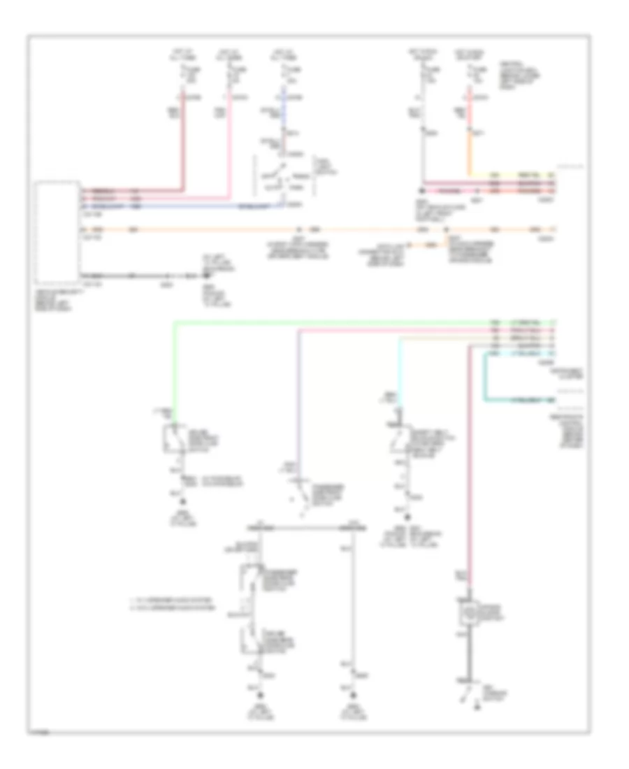
Exterior Lamps Wiring Diagram (2 of 2) for Ford Cab & Chassis F350 Super Duty 2003
List of elements for Exterior Lamps Wiring Diagram (2 of 2) for Ford Cab & Chassis F350 Super Duty 2003:
- (6.0l)
- (at left rear side of engine compartment)
- (at left rear side of engine compt)
- (f450 pickup w/box: near breakout for left license plate light) (except f450 pickup w/box:
- (f450 pickup w/box: near breakout for right rear park/ stop/turn light) (except f450 pickup w/box: near breakout for c438)
- (in trailer lamp feed harness, near breakout for c410)
- (near breakout for c408)
- (near breakout for c410)
- (near breakout for c410) s434
- (near breakout for c465)
- (not used)
- (wire end)
- 6.0l
- Auxiliary relay box 4 (except 6.0l) (at left rear side of engine compartment)
- Auxiliary relay box 5 (at left rear side of engine compt)
- Back-up lamps circuit
- C270b
- C270f
- C270h
- C270j
- C270k
- Center rear marker lamp
- Central junction box (behind lower left side of dash)
- Except 6.0l
- F450 w/ box
- Fuse 20a
- G100
- G400 (at vehicle under body, chassis left side member)
- Hot at all times
- Hot in run
- Left license plate lamp
- Left rear marker lamp
- Left rear park/stop/ turn lamp
- Left rear side lamp 1
- Left rear side lamp 2
- Left tail lamps
- Left turn trailer tow relay
- Nca
- Near breakout for g400) s406
- Pickup w/o box
- Pickups w/o box
- Right license plate lamp
- Right rear marker lamp
- Right rear park/stop/ turn lamp
- Right rear side lamp 1
- Right rear side lamp 2
- Right tail lamps
- Right turn trailer tow relay
- S103
- S103 (at breakout for auxiliary relay box 4)
- S162
- S265 (near breakout for g300)
- S401
- S402
- S404
- S407
- S417
- S417 (near breakout for c408)
- S418 (near breakout for c465)
- S426 (near breakout to emergency flasher relay block)
- S430
- S431
- S432
- S433
- S460 (in rear window defrost harness)
- S461
- S463
- Trailer tow battery charge relay
- Trailer tow connector (4 pin)
- Trailer tow connector (7 pin)
- Trailer tow parking lamp relay
- Trailer tow reversing lamp relay
- W/ dual rear wheels
- W/ rear bumper
- W/o dual rear wheels
- W/o rear bumper
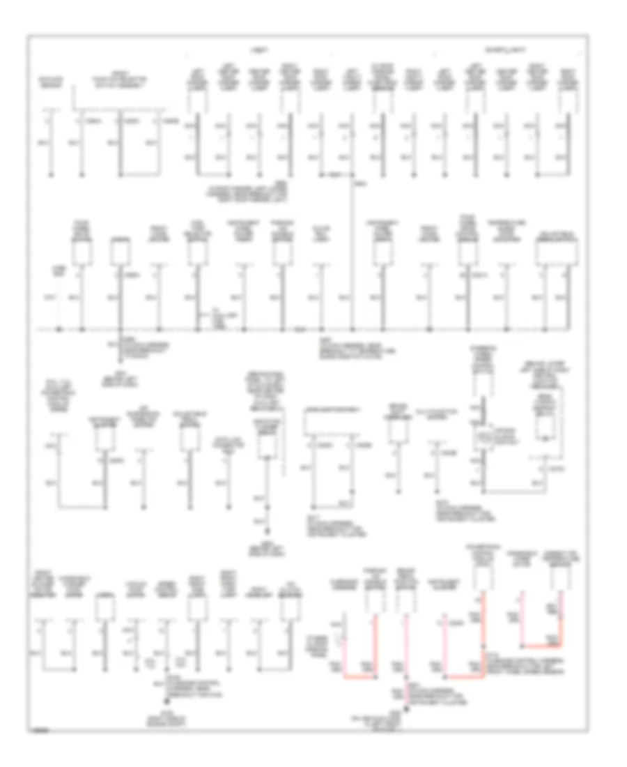
GROUND DISTRIBUTION
Ground Distribution Wiring Diagram (1 of 4) for Ford Cab & Chassis F350 Super Duty 2003
List of elements for Ground Distribution Wiring Diagram (1 of 4) for Ford Cab & Chassis F350 Super Duty 2003:
- (6.0l)
- (6.0l) a/c clutch solenoid
- (6.0l) dual pressure switch
- (6.0l) fuel heater
- (6.0l) fuel heater relay
- (6.0l) injector driver module (idm)
- (6.0l) powertrain control module (pcm)
- (7.3l) injector driver module (idm)
- (a/t: at breakout for c1010)
- (behind lower left side of dash) central junction box (cjb)
- (diesel) exhaust pressure regulator (epr)
- (exc 6.0l)
- (exc 6.0l) powertrain control module (pcm)
- (exc 7.3l) mass air flow (maf) sensor
- (left rear side of engine compartment) auxiliary relay box 2
- (left rear side of engine compartment) auxiliary relay box 3
- (left rear side of engine compt) (6.0l) auxiliary relay box 5
- (left rear side of engine compt) (except 6.0l) auxiliary relay box 4
- (m/t: at breakout for left auxiliary relay box no.3)
- (near breakout for injector driver module)
- 5.4l, 6.8l
- 5.4l, 6.8l, 7.3l
- 6.0l
- 7.3l
- 87a
- A/c compressor clutch diode
- Abs control module
- Air filter sensor
- Air suspension compressor assembly
- Air suspension module
- Air tank moisture removal valve
- Air tank valve
- Battery
- Battery 2
- Battery charge trailer tow relay
- Brake fluid level switch
- C1381a
- C1388c
- C270f
- C270h
- C290a
- Control harness, near breakout for left headlight)
- Crankshaft position shield
- Data link connector (dlc)
- Daytime running lamps (drl) relay 1
- Daytime running lamps (drl) relay 2
- Engine compartment lamp
- Fuel pump
- G100 (left rear side of engine compt)
- G101 (left side of eng compt)
- G102 (right side of engine)
- G104 (in engine compt, at right fender)
- G105 (left front side of engine compt)
- G106 (right frame rail, in engine compt)
- G109 (left side of engine)
- G200 (behind left side of dash)
- Left front fog lamp
- Left front park/ turn lamp
- Left front side lamp
- Left headlamp
- Left rear shock absorber solenoid valve
- Left turn trailer tow relay
- Nca
- Near breakout for g100)
- Parking lamp trailer tow relay
- Pcm power diode
- Pcm power relay
- Powertrain control module (pcm)
- Radio
- Reversing lamp trailer tow relay
- Right front fog lamp
- Right rear shock absorber solenoid valve
- Right turn trailer tow relay
- S102 (in engine control harness, near breakout for g101)
- S106 (in engine control harness, near breakout for powertrain control module)
- S145 (near breakout for c110)
- S161 (near breakout for c110)
- S167
- S195
- S250
- S380 (in air suspension pressure indicator switch harness, near breakout for air tank moisture removal valve)
- Starter relay
- Transfer case high to low
- Transfer case low to high
- Windshield wiper motor
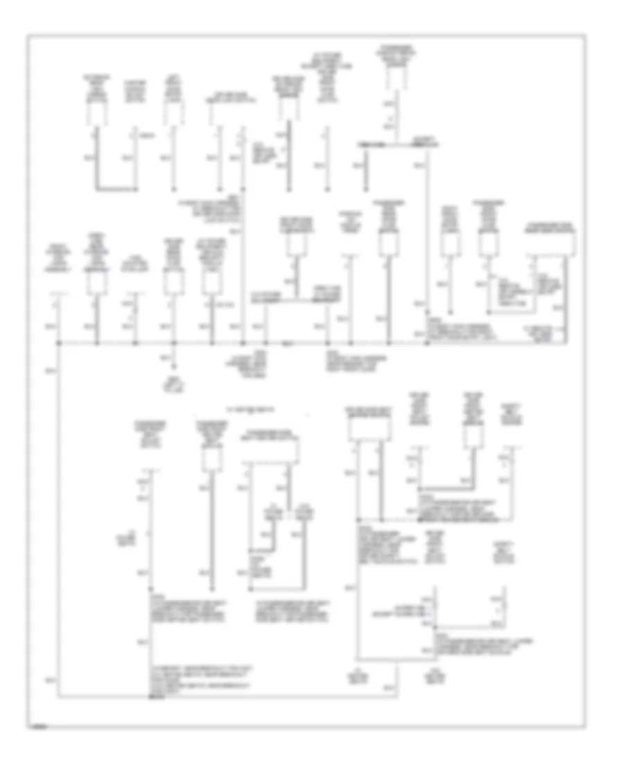
Ground Distribution Wiring Diagram (2 of 4) for Ford Cab & Chassis F350 Super Duty 2003
List of elements for Ground Distribution Wiring Diagram (2 of 4) for Ford Cab & Chassis F350 Super Duty 2003:
- (6.0l, 7.3l) auxiliary powertrain control module (apcm)
- (behind dash panel, to left of glove box near center of dash) auxiliary relay box 1
- (behind lower left side of dash) central junction box (cjb)
- (w/ roof opening panel) over head console
- 5.4l, 6.8l
- 6.0l, 7.3l
- A/c clutch solenoid
- Adjustable pedal switch
- Air bag sliding contact
- Air suspension kneeling switch
- Ambient air temperature sensor
- Brake pedal position switch
- Brake shift interlock
- C202b
- C205a
- C205b
- C220c
- C270a
- C281a
- C290a
- C294a
- C294b
- C294c
- Center roof marker lamp
- Data link connector (dlc)
- Except lariat
- Four- wheel drive control module
- Four- wheel drive switch
- Front cigar lighter
- Front function selector switch assembly
- Front heater blower motor resistor
- Fuel tank selector switch
- G108 (right side of engine compt)
- G201 (behind left side of dash)
- G202 (behind left side of dash)
- G300 (on vehicle floor, in left front footwell)
- Glove box lamp
- Harness, near breakout for g108)
- Horn
- Indicator flasher relay
- Instrument cluster
- Instrument panel power point
- Lariat
- Left center roof marker lamp
- Left roof marker lamp
- Left vanity mirror lamp
- Main light switch
- Multi-function switch
- Nca
- Near breakout for instrument cluster)
- Others w/ roof opening panel
- Overhead console
- Parking aid disable switch
- Powertrain control module (pcm)
- Radio
- Rear window defrost relay
- Right center roof marker lamp
- Right front park/ turn lamp
- Right front side lamp
- Right headlamp
- Right roof marker lamp
- Right vanity mirror lamp
- S172 (in engine control harness, near breakout for left front wheel speed sensor)
- S217 (in main harness, near breakout for instrument cluster)
- S218 (in main harness, near breakout for instrument cluster)
- S257 (in main harness, near breakout to temperature blend door actuator)
- S290 (in main harness, near breakout to radio)
- S904
- S920 (in roof marker lamp jumper harness, near breakout for right roof marker light)
- Speed control servo
- Steering wheel/ speed control switch
- Sunload sensor
- Temperature blend door actuator
- Vacuum pump motor
- W/ auxiliary fuel tank
- Windshield washer pump motor
- Windshield wiper motor
- Wire end
Ground Distribution Wiring Diagram (3 of 4) for Ford Cab & Chassis F350 Super Duty 2003
List of elements for Ground Distribution Wiring Diagram (3 of 4) for Ford Cab & Chassis F350 Super Duty 2003:
- (california)
- (federal)
- (in air suspension pressure indicator switch harness, near breakout for air tank moisture removal valve) s380
- (in rear lamp connector harness, near breakout for c408) s404
- (not used)
- (vehicle under body, chassis left side member) g400
- 4-pin trailer tow connector
- 7-pin trailer tow connector
- Center rear marker lamp
- Chassis cab
- Connector harness, near breakout for c408)
- Defrost harness)
- Except chassis cab
- F450 pickup w/ box
- Fuel tank unit
- G203 (uner right side of dash)
- G400 (vehicle under body, chassis left side member)
- Harness, near breakout for c410)
- Left front running board lamp
- Left license plate lamp
- Left rear marker lamp
- Left rear park/ stop/ turn lamp
- Left rear park/stop turn lamp
- Left rear park/stop/ turn lamp
- Left rear running board lamp
- Left rear side lamp 1
- Left rear side lamp 2
- Left reversing lamp
- Left tail lamps
- Nca
- Passenger air bag deactivation (pad) switch
- Pickups w/ box
- Pickups w/o box
- Restraints control module
- Right front running board lamp
- Right license plate lamp
- Right rear marker lamp
- Right rear park/ stop/ turn lamp
- Right rear park/stop turn lamp
- Right rear park/stop/ turn lamp
- Right rear running board lamp
- Right rear side lamp 1
- Right rear side lamp 2
- Right reversing lamp
- Right tail lamps
- S402 (in rear lamp connector harness, near breakout for right rear park/ stop/turn light)
- S461 (in rear window defrost harness)
- S463 (in rear license plate lamp harness, near breakout for c465)
- S463 (near breakout for c465)
- Trailer tow connector truck bed
- W/ dual rear wheels
- W/ rear bumper
- W/o dual rear wheels
- W/o rear bumper
Ground Distribution Wiring Diagram (4 of 4) for Ford Cab & Chassis F350 Super Duty 2003
List of elements for Ground Distribution Wiring Diagram (4 of 4) for Ford Cab & Chassis F350 Super Duty 2003:
- (crew cab) rear interior/ map lamps assembly
- (except super cab)
- (in passenger-driver seat jumper harness, near breakout for passenger side seat heater switch)
- (super cab)
- (w/ power equipment) vehicle security module (vsm)
- (w/ power equipment, except crew cab) driver side front door ajar switch
- (w/memory: near breakout for c327) (w/ heated seats: near breakout for c3049) (w/o heated seats: near breakout for c3007) s306
- C2113a
- C504a
- Crew cab
- Driver side door lock switch
- Driver side exterior rear view mirror
- Driver side front door ajar switch
- Driver side front heated seat module
- Driver side front seat adjust switch
- Driver side rear door ajar switch
- Driver side seat heater switch
- Except crew cab
- Exterior rear view mirror switch
- Front interior/ map lamps assembly
- G900 (left "c" pillar)
- High mounted stoplamp
- Left front door entry lamp
- Master window adjust switch
- Nca
- Parking aid module (pam)
- Passenger side door lock switch
- Passenger side exterior rear view mirror
- Passenger side front door ajar switch
- Passenger side front heated seat module
- Passenger side front seat adjust switch
- Passenger side rear door ajar switch
- Passenger side seat heater switch
- Right front door entry lamp
- S233 (in body main harness, near grommet for right front door)
- S300 (in body main harness, near breakout for g900)
- S332 (in passenger- driver seat jumper harness, near breakout for driver safety belt buckle switch)
- S335 (in passenger-driver seat jumper harness, near breakout for passenger side heated seat switch)
- S501 (in body main harness, at breakout for driver side door lock switch)
- Safety belt buckle switch
- W/ heated seats
- W/ power equipment
- W/ power seats
- W/ remote keyless entry
- W/o heated seats
- W/o power equipment
- W/o power seats
- W/o remote keyless entry
- W/o remote keyless entry, crew cab
HEADLIGHTS
Headlights Wiring Diagram, with DRL for Ford Cab & Chassis F350 Super Duty 2003
List of elements for Headlights Wiring Diagram, with DRL for Ford Cab & Chassis F350 Super Duty 2003:
- (early production) s221
- (except pickup & diesel excursion)
- (excursion) (pickup)
- (in fog jumper harness, near breakout for c1045) s100
- (in main harness, at breakout for foglamp relay diode)
- (in main harness, near breakout for restraints control module) s244
- (late
- (near breakout for g100)
- (on vehicle floor, in left front footwell) g300 g201 (behind left side of dash)
- (pickup & diesel excursion)
- 87a
- Air conditioning system
- Auto
- Auxiliary relay box 2 (at left rear side of engine compt)
- C202a
- C205a
- C2113b
- C220c
- C270a
- C270b
- C270f
- C270g
- C270h
- Central junction box (behind lower left side of dash)
- Central junction box (behind lower left side of dash)
- Daytime running lamps (drl) relay 1
- Daytime running lamps (drl) relay 2
- Daytime running lamps resistor (on left front side of engine compt)
- Diesel
- Engine controls system
- Fog
- Fog lamp illumination
- Fog lamp relay
- Foglamp relay diode (early production) (behind left side of dash)
- For c1047)
- Fuse 10a
- Fuse 15a
- Fuse 30a
- G100 (at left rear side of engine compt)
- G108 (at right side of engine compt)
- G202 (behind left side of dash)
- Head
- Headlamp relay
- Hi-beam indicator
- Hot at all times
- Hot in run
- Hot in start or run
- Hot in start or run
- Instrument cluster
- Instrument cluster system
- Left front fog lamp
- Left headlamp
- Main light switch
- Microprocessor
- Multi- function switch
- Off
- Park
- Park brake relay
- Parking brake switch (behind left side of dash, (on park brake assembly)
- Pass
- Production)
- Right front fog lamp
- Right headlamp
- S101
- S102
- S113
- S124
- S180
- S198
- S201 s290
- S203 (near breakout for instrument cluster)
- S214
- S217
- S220 (early production)
- S271
- Sunload sensor (on top center of dash)
- Tan/
- Transmission system
- Vehicle security module (behind left side of dash)
Headlights Wiring Diagram, without DRL for Ford Cab & Chassis F350 Super Duty 2003
List of elements for Headlights Wiring Diagram, without DRL for Ford Cab & Chassis F350 Super Duty 2003:
- (early production) s221
- (excursion)
- (excursion) (pickup)
- (in fog jumper harness, near breakout for c1045) s100
- (in main harness, at breakout for foglamp relay diode)
- (in main harness, near breakout for restraints control module)
- (late
- (near breakout for g100)
- (pickup)
- Air conditioning system
- Auto
- C202a
- C205a
- C2113b
- C220c
- C270a
- C270b
- C270f
- C270g
- C270h
- Central junction box (behind lower left side of dash)
- Central junction box (behind lower left side of dash)
- Fog
- Fog lamp illumination
- Fog lamp relay
- Foglamp relay diode (early production) (behind left side of dash)
- Fuse 10a
- Fuse 15a
- Fuse 30a
- G100 (at left rear side of engine compt)
- G108 (at right side of engine compt)
- G201 (behind left side of dash)
- G202 (behind left side of dash)
- G300 (on vehicle floor, in left front footwell)
- Head
- Headlamp relay
- Hi-beam indicator
- Hot at all times
- Hot in start or run
- Instrument cluster
- Left front fog lamp
- Left headlamp
- Main light switch
- Microprocessor
- Multi-function switch
- Off
- Park
- Pass
- Production)
- Right front fog lamp
- Right headlamp
- S101
- S102
- S113
- S180
- S201 s290
- S214
- S217
- S220 (early production)
- S244
- S271
- Sunload sensor (on top center of dash)
- Tan/
- Vehicle security module (behind left side of dash)
HORN
Horn Wiring Diagram for Ford Cab & Chassis F350 Super Duty 2003
List of elements for Horn Wiring Diagram for Ford Cab & Chassis F350 Super Duty 2003:
- Air bag sliding contact
- Air conditioning system
- C2113b
- C270a
- C270h
- Central junction box (behind lower left side of dash)
- Diesel
- Fuse 15a
- G108 (at right side of engine compartment)
- Gasoline
- Horn
- Horn relay
- Hot at all times
- Nca
- Powertrain control module (on left side of firewall)
- S114
- S180
- S252 (near breakout for air bag sliding contact)
- Signal return
- Speed control servo (in right side of engine compt)
- Steering wheel/ speed control switch
- Vehicle security module (vsm) (behind left side of dash)
INSTRUMENT CLUSTER
Instrument Cluster Wiring Diagram for Ford Cab & Chassis F350 Super Duty 2003
List of elements for Instrument Cluster Wiring Diagram for Ford Cab & Chassis F350 Super Duty 2003:
- (behind left side of dash, on park brake assembly) parking brake switch
- (in taillamps harness, near breakout for fuel tank selector valve) s400
- (on left side of firewall) powertrain control module (pcm)
- 6.0l except 6.0l
- Air filter sensor (diesel) (on left side of engine compartment)
- Anti-lock brake system
- Anti-theft system
- Battery saver relay
- Brake fluid level switch (on brake fluid reservoir)
- C1381a
- C175
- C205b
- C220a
- C220b
- C220c
- C270a
- C270b
- California
- Central junction box (cjb) (behind lower left side of dash)
- Computer data lines
- Computer data lines system
- Coolant temperature sensor 2 (diesel) (at top of engine, on water pump)
- Defogger system
- Diesel
- Electronic suspension system
- Except california
- Excursion
- Exterior lights system
- Fuel tank selector switch
- Fuel tank selector valve
- Fuel tank unit
- Fuse 10a
- Fuse 15a
- G100 (at left rear side of engine compartment)
- G202 (behind left side of dash)
- G300 (on vehicle floor, in left front footwell)
- Gasoline
- Headlights system
- Hot at all times
- Hot in run or acc
- Hot in start or run
- Illumination (6 bulbs)
- Instrument cluster
- Interior lamps relay
- Interior lights system
- Interior lights, power windows system
- Keyless entry
- Main light switch
- Microprocessor
- Nca
- Oil pressure switch (5.4l, 6.8l: on left front of engine) (7.3l: on top center rear of engine)
- Overhead console
- Pickup
- Powertrain control module (pcm) (on left side of firewall)
- Primary fuel sender (on fuel tank)
- S102
- S201
- S208 (in main harness, near breakout for c264)
- S217
- S254
- S271
- S278 (in main harness, at breakout for instrument cluster)
- S298 (in main harness, at breakout for instrument cluster)
- Secondary fuel sender (on fuel tank)
- Speed control servo (in right side of engine compt)
- Starting/charging system
- Transmissions system
- Trip computer module (on front center of roof)
- W/ auxiliary fuel tank
- W/ roof opening panel
- W/o auxiliary fuel tank
- W/o remote
- W/o roof opening panel
- Warning system
Overhead Console Wiring Diagram, with Roof Opening Panel for Ford Cab & Chassis F350 Super Duty 2003
List of elements for Overhead Console Wiring Diagram, with Roof Opening Panel for Ford Cab & Chassis F350 Super Duty 2003:
- (in main harness, at breakout for instrument cluster) s253
- (not
- (on vehicle floor, in left front footwell) g300
- 6.0l
- Abs control module (at left side of engine compartment)
- Ambient air temperature sensor (on left front of engine compt)
- C1381a
- C175
- C270a
- California
- Central junction box (cjb) (behind lower left side of dash)
- Computer data lines system
- Except 6.0l
- Except california
- Fuel tank selector valve
- Fuel tank unit
- Fuse 15a
- Hot in run
- Interior lights system
- Nca
- Overhead console
- Powertrain control module (pcm) (on left side of firewall)
- S172
- S201
- S206
- S208 (in main harness, near breakout for c264)
- Used)
- W/ auxiliary fuel tank
- W/o auxiliary fuel tank
Overhead Console Wiring Diagram, without Roof Opening Panel for Ford Cab & Chassis F350 Super Duty 2003
List of elements for Overhead Console Wiring Diagram, without Roof Opening Panel for Ford Cab & Chassis F350 Super Duty 2003:
- (in main harness, at breakout for instrument cluster) s253
- (not
- (on vehicle floor, in left front footwell) g300
- 6.0l
- Abs control module (at left side of engine compartment)
- Ambient air temperature sensor (on left front of engine compt)
- C1381a
- C175
- C270a
- California
- Central junction box (cjb) (behind lower left side of dash)
- Computer data lines system
- Except 6.0l
- Except california
- Fuel tank selector valve
- Fuel tank unit
- Fuse 15a
- Hot in run
- Interior lights system
- Nca
- Overhead console
- Powertrain control module (pcm) (on left side of firewall)
- S172
- S201
- S206
- S208 (in main harness, near breakout for c264)
- Used)
- W/ auxiliary fuel tank
- W/o auxiliary fuel tank
INTERIOR LIGHTS
Courtesy Lamps Wiring Diagram (1 of 2) for Ford Cab & Chassis F350 Super Duty 2003
List of elements for Courtesy Lamps Wiring Diagram (1 of 2) for Ford Cab & Chassis F350 Super Duty 2003:
- Battery saver relay
- C205b
- C220a
- C220c
- C270a
- C270b
- Central junction box (behind lower left side of dash)
- Fuse 35 10a
- Fuse 41 10a
- G201 (behind left side of dash)
- G202 (behind left side of dash)
- Glove box lamp
- Hot at all times
- Instrument cluster
- Interior
- Interior lamps relay
- Left vanity mirror lamp
- Main light switch
- Microprocessor
- Nca
- Overhead console (w/ roof opening panel)
- Right vanity mirror lamp
- S204 (near breakout for c264)
- S218
- S229 (near breakout for instrument cluster)
- S257
- S904
- S937 (near breakout for right vanity mirror light)
- To accessory delay relay (central junction box) (diagram 2 of 2)
- To s905 (diagram 2 of 2)
Courtesy Lamps Wiring Diagram (2 of 2) for Ford Cab & Chassis F350 Super Duty 2003
List of elements for Courtesy Lamps Wiring Diagram (2 of 2) for Ford Cab & Chassis F350 Super Duty 2003:
- Accessory delay relay
- C270a
- C270f
- C270j
- Central junction box (behind lower left side of dash)
- Engine compartment lamp
- From s204 (diagram 1 of 2)
- From s229 (diagram 1 of 2)
- Front interior/map lamps assembly
- G100 (at left rear side of engine compt)
- G400 (at vehicle under body, chassis left side member)
- G900 (at left ``c" pillar)
- High mounted stoplamp
- Interior
- Left front door entry lamp
- Left front running board lamp
- Left rear running board lamp
- Map
- Nca
- Rear interior/map lamps assembly (crew cab)
- Right front door entry lamp
- Right front running board lamp (except chassis cab)
- Right rear running board lamp (except chassis cab)
- S162
- S300
- S309 (near breakout for left rear running board light)
- S310 (near breakout for right rear running board light)
- S311 (near breakout for left rear running board light)
- S312 (near breakout for right rear running board light)
- S344 (in taillamps harness, near breakout for c311)
- S401
- S501
- S639
- S905 (at breakout for front interior/map light assembly)
- S906
Instrument Illumination Wiring Diagram (1 of 2) for Ford Cab & Chassis F350 Super Duty 2003
List of elements for Instrument Illumination Wiring Diagram (1 of 2) for Ford Cab & Chassis F350 Super Duty 2003:
- (w/ roof opening panel)
- (w/o rke) s639
- (w/o roof
- Accessory delay relay
- Adjustable pedal switch
- Air bag sliding contact
- Air suspension kneeling switch
- Auto
- Bulbs
- C205a
- C205b
- C220c
- C270b
- C270i
- C270j
- C290a
- C294b
- Central junction box (behind lower left side of dash)
- Circuit breaker 30a
- Driver side door lock switch
- Exterior lights system
- Four-wheel drive switch
- Front function selector switch assembly
- Fuse 17 15a
- Fuse 42 15a
- G201 (behind left side of dash)
- G202 (behind left side of dash)
- G300 (on vehicle floor, in left front footwell)
- G900 (at left ``c" pillar)
- Head
- Hot at all times
- Instrument cluster
- Main light switch
- Microprocessor
- Nca
- Off
- Opening panel)
- Overhead console
- Park
- Parking aid disable switch
- Passenger side door lock switch
- Pnk
- Radio
- S201
- S215 (near breakout to main light switch)
- S216 (in main harness, near breakout sunload sensor)
- S217
- S218
- S233 (w/ rke)
- S272
- S290
- S297
- S302
- S501
- Steering wheel/speed control switch
- To master window adjust switch (diagram 2 of 2)
- To passenger side window adjust switch (diagram 2 of 2)
Instrument Illumination Wiring Diagram (2 of 2) for Ford Cab & Chassis F350 Super Duty 2003
List of elements for Instrument Illumination Wiring Diagram (2 of 2) for Ford Cab & Chassis F350 Super Duty 2003:
- C504a
- C504b
- Crew cab
- Except crew cab
- From s297 (diagram 1 of 2)
- G900 (at left ``c" pillar)
- Left rear window adjust switch
- Master window adjust switch
- Passenger side window adjust switch
- Right rear window adjust switch
- S328 (near breakout for g300)
- S501
NAVIGATION
Navigation Wiring Diagram for Ford Cab & Chassis F350 Super Duty 2003
List of elements for Navigation Wiring Diagram for Ford Cab & Chassis F350 Super Duty 2003:
- (at right ``d" pillar) g403
- (behind left side of dash)
- (excursion)
- (in back-up alarm jumper harness, near breakout for c406)
- (pickup)
- (pickup:at right ``a" pillar)
- (w/o auxiliary a/c) s323
- C270j
- Central junction box (behind lower left side of dash)
- Compuer data lines system
- Excursion
- Exterior lights system
- Fuse 15a
- G201
- G300 (on vehicle floor, in left front footwell)
- G900 (at left ``c" pillar)
- Ground
- Hot in run
- Interior lights system
- Iso
- Left center sensor input
- Left inner parking aid sensor (on rear bumper, left of center)
- Left outer parking aid sensor (on left side of rear bumper)
- Left outer sensor input
- On/off switch
- Parking aid disable switch
- Parking aid module (excursion: behind right ``c" pillar)
- Parking aid speaker
- Pickup
- Power
- Reverse input
- Right center sensor input
- Right inner parking aid sensor (on rear bumper, right of center)
- Right outer parking aid sensor (on right side of rear bumper)
- Right outer sensor input
- S201
- S233
- S290
- S303
- S320
- S450
- S451
- Sensor ground
- Sensor power
- Speaker (+)
- Speaker (-)
- Status led
POWER DISTRIBUTION
Power Distribution Wiring Diagram (1 of 4) for Ford Cab & Chassis F350 Super Duty 2003
List of elements for Power Distribution Wiring Diagram (1 of 4) for Ford Cab & Chassis F350 Super Duty 2003:
- (6.0l) (except 6.0l)
- (behind left side of dash) g201
- (breakout for auxiliary relay box 4) s103
- (except 6.0l) (6.0l)
- (in back-up light switch to rear light feed harness, at breakout for auxiliary relay box 3) s199
- (in engine control harness, near breakout for abs control module) s163
- (near breakout for auxiliary relay box 1) s249
- (near breakout for data link connector) s242
- (near breakout for instrument cluster) s228
- (near breakout for instrument cluster) s275
- (near breakout to brake pedal position switch) s214
- (near breakout to main light switch) s272
- 5 speed a/t
- 6.0l
- A/c clutch relay
- Abs control module
- Adjustable pedal switch
- Auxiliary relay box 1 (behind dash panel, to left of glove box near center of dash)
- Auxiliary relay box 3 (left rear side of engine compt)
- Auxiliary relay box 4 (except 6.0l) auxiliary relay box 5 (6.0l) (left rear side of engine compt)
- Auxiliary relay box 4 (or 5) (left rear side of engine compt)
- Auxiliary relay box 5 (left rear side of engine compt)
- Battery
- Battery ii (6.0l/7.3l)
- Brake pedal position switch
- Brake pressure switch (5.4l/6.8l)
- C202a
- C205a
- C2113b
- C270a
- C270b
- C270d
- C270e
- C270f
- C270g
- C270h
- C270i
- C270j
- C270k
- C270m
- C270p
- C281c
- C290a
- Central junction box (cjb) (behind lower left side of dash)
- Clutch pedal position switch
- Data link connector (dlc)
- Daytime running lamps resistor
- Digital transmission range (dtr) sensor
- Except 5 speed a/t
- Except 6.0l
- Exterior rear view mirror switch
- Four- wheel drive control module
- Four-wheel drive control module (w/ electronic shift on the fly)
- From a fuse 602 (diagram 1 of 4)
- From b fuse 13 (diagram 1 of 4)
- From ignition switch (diagram 3 of 4)
- Front cigar lighter
- Fuse 1 15a
- Fuse 10 10a
- Fuse 11 20a
- Fuse 111 30a
- Fuse 114 30a
- Fuse 12 20a
- Fuse 13 10a
- Fuse 14 15a
- Fuse 17 15a
- Fuse 18 20a
- Fuse 19 5a
- Fuse 20 10a
- Fuse 31 15a
- Fuse 34 10a
- Fuse 4 20a
- Fuse 5a
- Fuse 6 20a
- Fuse 602 60a
- Fuse 7 30a
- Indicator flasher relay
- Injector driver module power relay
- Instrument panel power point
- Junction block
- Left turn trailer tow relay
- Main light switch
- Multi- function switch
- Nca
- Passenger side front seat adjust switch
- Radio
- Red
- Right turn trailer tow relay
- S1000 (in battery output harness, at breakout for junction block on left fender)
- S1002 (in battery output harness, near grommet on firewall)
- S257 s290
- S290 s257
- Starter relay
- To fuse (diagram 1 of 4)
- To fuse 35 (diagram 2 of 4)
- Transfer case high to low relay
- Transfer case low to high relay
- Vehicle security module (vsm)
Power Distribution Wiring Diagram (2 of 4) for Ford Cab & Chassis F350 Super Duty 2003
List of elements for Power Distribution Wiring Diagram (2 of 4) for Ford Cab & Chassis F350 Super Duty 2003:
- (6.0l)
- (in body main harness, near breakout for g300) s289
- (in body main harness, near grommet on left side of vehicle floor) s315
- (in main harness, at breakout for instrument cluster) s254
- (w/ super cab)
- Battery charge trailer tow relay
- C175
- C2113b
- C220c
- C270a
- C270b
- C270c
- C270e
- C270g
- C270i
- C270k
- C270m
- C281c
- C3181a
- Central junction box (cjb) (behind lower left side of dash)
- Driver side door lock switch
- Driver side front heated seat module
- Driver side front seat adjust switch
- Four-wheel drive control module
- From c fuse 111 (diagram 1 of 4)
- From d fuse 112 (diagram 2 of 4)
- From ignition switch (diagram 3 of 4)
- Fuel heater relay (6.0l)
- Fuel pump relay
- Fuel tank selector switch
- Fuse 101 30a
- Fuse 102 30a
- Fuse 104 40a
- Fuse 105 30a
- Fuse 106 30a
- Fuse 109 30a
- Fuse 112 30a
- Fuse 113 30a
- Fuse 115 20a
- Fuse 33 15a
- Fuse 35 10a
- Fuse 36 10a
- Fuse 37 15a
- Fuse 40 20a
- Fuse 41 10a
- Horn relay
- Injector driver module (idm) power relay (7.3l)
- Instrument cluster
- Nca
- Not used
- Passenger side door lock switch
- Passenger side front heated seat module
- Pcm power relay
- Powertrain control module (pcm)
- Rear window defrost relay
- Red
- Starter relay
- To fuse (diagram 2 of 4)
- To fuse (diagram 3 of 4)
- Vehicle security module (vsm)
- W/ remote keyless entry
- W/o remote keyless entry
- Windshield wiper motor
Power Distribution Wiring Diagram (3 of 4) for Ford Cab & Chassis F350 Super Duty 2003
List of elements for Power Distribution Wiring Diagram (3 of 4) for Ford Cab & Chassis F350 Super Duty 2003:
- (5.4l: near breakout for fuel injector 3) (6.8l: near breakout for fuel injector 5) s135
- (5.4l: near breakout for fuel injector 6) (6.8l: near breakout for fuel injector 9) s130
- (6.0l/7.3l)
- (a/t)
- (in engine control harness, near breakout for left headlight) (6.0l) s109
- (in engine control sensor & fuel charge harness, near breakout for waste gate solenoid) s154
- (in main harness, near breakout for instrument cluster) s271
- (in main harness, near breakout for restraints control module) s202
- (in main harness, near breakout to ignition switch) s210
- (not used)
- (or
- 4 speed a/t
- 5 speed a/t
- 5.4l
- 5.4l/6.8l
- 6.0l
- 6.0l/7.3l
- 6.8l
- Abs control module
- Acc
- Accelerator pedal position sensor
- Auxiliary powertrain control module (apcm) (6.0l/7.3l)
- Auxiliary relay box 5 (left rear side of engine compt)
- Blower motor relay
- C1388c
- C220c
- C270a
- C270c
- C270e
- C270f
- C281a
- Central junction box (cjb) (behind lower left side of dash)
- Clutch triple function switch jumper clutch pedal position switch (m/t)
- Coil on plug (cop) 1
- Coil on plug (cop) 10
- Coil on plug (cop) 2
- Coil on plug (cop) 3
- Coil on plug (cop) 4
- Coil on plug (cop) 5
- Coil on plug (cop) 6
- Coil on plug (cop) 7
- Coil on plug (cop) 8
- Coil on plug (cop) 9 (6.8l)
- Electronic fan clutch (6.0l)
- Except 6.0l
- Fog lamp relay
- Four- wheel drive control module
- From e fuse 115 (diagram 2 of 4)
- Fuel heater
- Fuel heater relay
- Fuse 103 50a
- Fuse 107 40a
- Fuse 10a
- Fuse 110 50a
- Fuse 116 30a
- Fuse 25 10a
- Fuse 26 10a
- Fuse 38 20a
- Fuse 45 10a
- Fuse 8 15a
- Grade/ load switch
- Ignition switch
- Ignition transformer capacitor 1
- Ignition transformer capacitor 2
- Injector driver module (idm)
- Injector driver module (idm) power relay
- Instrument cluster
- Lock
- Main light switch (w/ fog lamps)
- Nca
- Off
- Overdrive cancel switch
- Parking lamp trailer tow relay
- Passenger air bag deactivation (pad) switch
- Pcm power relay
- Restraints control module
- Reversing lamp trailer tow relay
- Reversing lamps relay
- Run
- S224 (in main harness, near breakout to brake pedal position switch)
- S258 (in main harness, near breakout to brake pedal position switch)
- Sta
- Start
- Tan/red
- To fuse 27 (diagram 4 of 4)
- To fuse 31 (diagram 1 of 4)
- To fuse 33 (diagram 2 of 4)
- Waste gate solenoid
Power Distribution Wiring Diagram (4 of 4) for Ford Cab & Chassis F350 Super Duty 2003
List of elements for Power Distribution Wiring Diagram (4 of 4) for Ford Cab & Chassis F350 Super Duty 2003:
- (in body main harness, near breakout for c340) s303
- (in daytime running light kit harness, near breakout for c1047) s198
- (in engine control harness, near breakout for g100) s124
- (in main harness, near breakout sunload sensor) s206
- (in main harness, near breakout sunload sensor) s235
- (in main harness, near breakout to air suspension kneeling switch) s296
- (not used)
- 5.4l/6.8l
- 6.0l/7.3l
- A/t
- Air suspension kneeling switch
- Air suspension module
- Auxiliary relay box 1 (behind dash panel, to left of glove box near center of dash)
- Auxiliary relay box 2 (left rear side of engine compartment)
- Battery charge trailer tow relay
- Blower motor relay
- Brake shift interlock
- C270a
- C270c
- C270h
- C294a
- Central junction box (cjb) (behind lower left side of dash)
- Digital transmission range (dtr) sensor
- Driver side front heated seat module
- Electronic shift on the fly (esof) solenoid
- From fuse 25 (diagram 3 of 4)
- From ignition switch (diagram 3 of 4)
- Front function selector switch assembly
- Fuse 10a
- Fuse 15a
- Fuse 27 15a
- Indicator flasher relay
- M/t
- Nca
- Overhead console
- Park brake relay
- Parking aid module (pam)
- Passenter side front heated seat module
- Rear window defrost relay
- Reversing lamps switch
- Speed control servo
- Temperature blend door actuator
- Vaccum pump motor
- W/ roof opening panel
POWER DOOR LOCKS
Power Door Locks Wiring Diagram, without Keyless Entry for Ford Cab & Chassis F350 Super Duty 2003
List of elements for Power Door Locks Wiring Diagram, without Keyless Entry for Ford Cab & Chassis F350 Super Duty 2003:
- (in body main harness, near breakout for c340) s304
- C270e
- Central junction box (cjb) (behind lower left side of dash)
- Driver side door lock switch
- Fuse 30a
- G900 (at left ``c" pillar)
- Hot at all times
- Interior lights system
- Left front door lock actuator
- Left rear door lock actuator (w/ crew cab)
- Lock
- Passenger side door lock actuator
- Passenger side door lock switch
- Pnk
- Right rear door lock actuator (w/ crew cab)
- S289
- S501
- S639
- Unlock
POWER MIRRORS
Power Mirrors Wiring Diagram for Ford Cab & Chassis F350 Super Duty 2003
List of elements for Power Mirrors Wiring Diagram for Ford Cab & Chassis F350 Super Duty 2003:
- (at left "c" pillar) g900
- (crew cab)
- (except crew cab)
- (near breakout for g300) s279
- C270d
- C270j
- Central junction box (cjb) (behind lower left side of dash)
- Down
- Driver side exterior rear view mirror
- Exterior lights system
- Exterior rear view mirror switch
- Fuse 10a
- Fuse 20a
- Fuse 40a
- G301 (at left "c" pillar)
- Hot at all times
- Left
- Left mirror select
- Nca
- Passenger side exterior rear view mirror
- Rear window defrost relay
- Red
- Right
- Right mirror select
- S317 (near grommet on left side of vehicle floor)
- S501
- S639
POWER SEATS
Adjustable Pedal Wiring Diagram for Ford Cab & Chassis F350 Super Duty 2003
List of elements for Adjustable Pedal Wiring Diagram for Ford Cab & Chassis F350 Super Duty 2003:
- 270d
- Adjustable pedal motor (in driver's footwell)
- Adjustable pedal switch
- Central junction box (behind lower left side of dash)
- Fuse 15a
- Fwd
- G201 (behind left side of dash)
- Hot at all times
- Interior lights system
- Nca
- Rwd
- S257
Driver Power Seat Wiring Diagram for Ford Cab & Chassis F350 Super Duty 2003
List of elements for Driver Power Seat Wiring Diagram for Ford Cab & Chassis F350 Super Duty 2003:
- (at left "c" pillar) g301
- (excursion)
- (excursion) (pickup)
- (on vehicle floor, in left front footwell) g300
- (pickup)
- (pickup) (excursion)
- C270i
- Central junction box (behind lower left side of dash)
- Driver side front seat adjust switch
- Except super cab
- Forward/rearward
- Front up/down
- Fuse 30a
- Fwd
- G900 (at left "c" pillar)
- Hot at all times
- Left power seat motor assembly
- Nca
- Rear up/down
- Rwd
- S332 s301
- St dn
- St up
- Super cab
- W/ heated seats
- W/o heated seats
Heated Seats Wiring Diagram for Ford Cab & Chassis F350 Super Duty 2003
List of elements for Heated Seats Wiring Diagram for Ford Cab & Chassis F350 Super Duty 2003:
- (at left "c" pillar) g900
- Bat
- C270j
- C270k
- Central junction box (behind lower left side of dash)
- Driver side front heated seat module
- Driver side seat heater switch
- Fuse 15a
- Fuse 30a
- Gnd
- Heater feed
- Heater ret
- Hot at all times
- Hot in run
- Ind
- Left front seat back heater
- Left front seat cushion heater
- Passenger side front heated seat module
- Passenger side seat heater switch
- Right front seat back heater
- Right front seat cushion heater
- S303
- S315
- S332
- S333
- S335
- S355
- Sens feed
- Sens ret
- Sw input
- Voltage
- W/ pwr seats
- W/o pwr seats
Passenger Power Seat Wiring Diagram for Ford Cab & Chassis F350 Super Duty 2003
List of elements for Passenger Power Seat Wiring Diagram for Ford Cab & Chassis F350 Super Duty 2003:
- (at left "c" pillar) g900
- (excursion)
- (pickup)
- C270i
- Central junction box (behind lower left side of dash)
- Forward/rearward
- Front up/down
- Fuse 30a
- Fwd
- G301 (at left "c" pillar)
- Hot at all times
- Nca
- Passenger side front seat adjust switch
- Rear up/down
- Right power seat motor assembly
- Rwd
- S335
- St dn
- St up
POWER TOP/SUNROOF
Power Top/Sunroof Wiring Diagram for Ford Cab & Chassis F350 Super Duty 2003
List of elements for Power Top/Sunroof Wiring Diagram for Ford Cab & Chassis F350 Super Duty 2003:
- (behind left side of dash) g201
- (near breakout for
- Accessory delay relay
- Battery saver relay
- C220b
- C220c
- C270a
- C270b
- C270d
- Central junction box (behind lower left side of dash)
- Circuit breaker 30a
- Fuse 10a
- Hot at all times
- Instrument cluster
- Instrument cluster) s229
- Interior lights system
- Microprocessor
- Nca
- Overhead console
- Roof opening panel module (at rear of roof)
- Roof opening panel motor assembly (at rear of roof)
- S904
- Tan/red
POWER WINDOWS
Power Windows Wiring Diagram, Crew Cab for Ford Cab & Chassis F350 Super Duty 2003
List of elements for Power Windows Wiring Diagram, Crew Cab for Ford Cab & Chassis F350 Super Duty 2003:
- (in body main harness, near breakout for g300) s328
- (near breakout for instrument cluster)
- Accessory delay relay
- Battery saver relay
- C220b
- C220c
- C270a
- C270b
- C270i
- C270j
- C504a
- C504b
- Central junction box (cjb) (behind lower left side of dash)
- Circuit breaker 601 30a
- Driver
- Driver side front power window motor
- Excursion pickup
- Fuse 35 10a
- Fuse 41 10a
- Fuse 42 15a (excursion)
- G301 g900 (at left ``c" pillar)
- G901 (excursion) (at rear of of vehicle roof)
- G901 (excursion) (at rear of vehicle roof)
- Hot at all times
- Instrument cluster
- Interior lights system
- Left power vent window motor (at left rear of roof)
- Left power vent window switch (excursion)
- Left rear
- Left rear power window motor
- Left rear window adjust switch
- Lock
- Master window adjust switch
- Microprocessor
- One- touch down
- One-touch down relay
- Passenger
- Passenger side front power window motor
- Passenger side window adjust switch
- Pnk
- Right power vent window motor (at right rear of roof)
- Right power vent window switch (excursion)
- Right rear
- Right rear power window motor
- Right rear window adjust switch
- S229
- S501
- S935
- S939
- Vpwr
Power Windows Wiring Diagram, Except Crew Cab for Ford Cab & Chassis F350 Super Duty 2003
List of elements for Power Windows Wiring Diagram, Except Crew Cab for Ford Cab & Chassis F350 Super Duty 2003:
- (near breakout for g300) s297
- Accessory delay relay
- Battery saver relay
- C220b
- C220c
- C270a
- C270b
- C270i
- C504a
- Central junction box (cjb) (behind lower left side of dash)
- Circuit breaker 601 30a
- Driver
- Driver side front power window motor
- Fuse 35 10a
- Fuse 41 10a
- G900 (at left ``c" pillar)
- Hot at all times
- Instrument cluster
- Lock
- Master window adjust switch
- Microprocessor
- One- touch down
- One-touch down relay
- Passenger
- Passenger side front power window motor
- Passenger side window adjust switch
- S229
- S501
- Vpwr
RADIO
Radio Wiring Diagram for Ford Cab & Chassis F350 Super Duty 2003
List of elements for Radio Wiring Diagram for Ford Cab & Chassis F350 Super Duty 2003:
- (behind left side of dash) g201
- Antenna
- C270a
- C270d
- C290a
- Central junction box (behind lower left side of dash)
- Fuse 15a
- Fuse 20a
- Fuse 5a
- Fused ign
- G200 (behind left side of dash)
- Ground
- Hot at all times
- Hot in start
- Hot with acc delay relay energized
- Ilumination
- Interior lights system
- L f spkr
- L r spkr
- Left front speaker
- Left rear speaker
- Mem power
- Nca
- Pnk
- Power
- R f spkr
- R r spkr
- Radio
- Right front speaker
- Right rear speaker
- S285
- S290
SHIFT INTERLOCK
Shift Interlock Wiring Diagram for Ford Cab & Chassis F350 Super Duty 2003
List of elements for Shift Interlock Wiring Diagram for Ford Cab & Chassis F350 Super Duty 2003:
- Brake pedal position switch (behind left side of dash, above brake pedal)
- Brake shift interlock
- C270a
- Central junction box (behind lower left side of dash)
- Fuse 27 15a
- Fuse 34 10a
- G202 (behind left side of dash)
- G300 (on vehicle floor, in left front footwell)
- Hot at all times
- Hot in run
- S201
- S205 (near breakout to break pedal position switch)
- S206
- S218
- S228
- Solid state
STARTING/CHARGING
Starting Wiring Diagram, 4 Speed A/T, M/T & 4 Speed A/T for Ford Cab & Chassis F350 Super Duty 2003
List of elements for Starting Wiring Diagram, 4 Speed A/T, M/T & 4 Speed A/T for Ford Cab & Chassis F350 Super Duty 2003:
- 4 speed a/t
- 6.0l
- Acc
- Battery
- Battery (diesel)
- C270a
- C270b
- C270c
- C270f
- C270g
- C270h
- Central junction box (behind lower left side of dash)
- Clutch pedal position switch (behind left side of dash, above clutch pedal)
- Digital transmission range (dtr) sensor (on left side of transmission)
- Exc 6.0l
- Fuse 15a
- Fuse 30a
- Fuse 50a
- G100 (at left rear side of engine compt)
- G102 (at right side of engine)
- G104 (in engine compartment, at right fender)
- G106 (diesel) (at right frame rail, in engine compartment)
- G109 (at left side of engine)
- Ignition switch
- Junction block
- Lock
- M/t
- Nca
- Off
- Power distribution system
- Red
- Run
- S1000
- S162
- S210
- Sta
- Start
- Starter motor
- Starter relay
- Tan/ red
- Tan/red
Starting Wiring Diagram, 5 Speed A/T for Ford Cab & Chassis F350 Super Duty 2003
List of elements for Starting Wiring Diagram, 5 Speed A/T for Ford Cab & Chassis F350 Super Duty 2003:
- (in back-up light switch to rear light feed harn, near breakout for trans)
- 5r100 transmission
- Acc
- Battery
- Battery (diesel)
- C1381a
- C1381b
- C270b
- C270f
- C270g
- C270h
- Central junction box (behind lower left side of dash)
- Fuse 15a
- Fuse 30a
- Fuse 50a
- G102 (at right side of engine)
- G104 (in engine compartment, at right fender)
- G106 (diesel) (at right frame rail, in engine compartment)
- G109 (at left side of engine)
- Ignition switch
- Junction block
- Lock
- Nca
- Off
- Power distribution system
- Powertrain control module (on left side of firewall)
- Red
- Run
- S1000
- S127
- S128
- S210
- Sta
- Start
- Starter motor
- Starter relay
- Transmission range sensor
- Transmissions system
5.4L
5.4L, Charging Wiring Diagram, without Dual Generators for Ford Cab & Chassis F350 Super Duty 2003
List of elements for 5.4L, Charging Wiring Diagram, without Dual Generators for Ford Cab & Chassis F350 Super Duty 2003:
- (6.0l) (except 6.0l)
- (federal) (california)
- 5.4l, 6.8l
- 5.4l, 6.8l, 7.3l
- 6.0l
- 7.3l
- Acc
- Battery
- Battery (diesel)
- C102a
- C220b
- C220c
- C270a
- C270c
- C270e
- Central junction box (cjb) (behind lower left side of dash)
- Charge
- Fuse 10a
- Fuse 30a
- G102 (at right side of engine)
- G104 (in engine compartment, at right fender)
- G106 (diesel) (at right frame rail, in engine compartment)
- G109 (at left side of engine)
- Generator
- Hot at all times
- Ignition switch
- Instrument cluster
- Lock
- Off
- Power distribution system
- Red
- Run
- S125
- S126
- S149
- S150 s147
- S224 s258
- S271
- Start
- Starter motor
6.0L DIESEL
6.0L Diesel, Charging Wiring Diagram, without Dual Generators for Ford Cab & Chassis F350 Super Duty 2003
List of elements for 6.0L Diesel, Charging Wiring Diagram, without Dual Generators for Ford Cab & Chassis F350 Super Duty 2003:
- (6.0l) (except 6.0l)
- (federal) (california)
- 5.4l, 6.8l
- 5.4l, 6.8l, 7.3l
- 6.0l
- 7.3l
- Acc
- Battery
- Battery (diesel)
- C102a
- C220b
- C220c
- C270a
- C270c
- C270e
- Central junction box (cjb) (behind lower left side of dash)
- Charge
- Fuse 10a
- Fuse 30a
- G102 (at right side of engine)
- G104 (in engine compartment, at right fender)
- G106 (diesel) (at right frame rail, in engine compartment)
- G109 (at left side of engine)
- Generator
- Hot at all times
- Ignition switch
- Instrument cluster
- Lock
- Off
- Power distribution system
- Red
- Run
- S125
- S126
- S149
- S150 s147
- S224 s258
- S271
- Start
- Starter motor
6.0L Diesel, Charging Wiring Diagram, with Dual Generators for Ford Cab & Chassis F350 Super Duty 2003
List of elements for 6.0L Diesel, Charging Wiring Diagram, with Dual Generators for Ford Cab & Chassis F350 Super Duty 2003:
- (6.0l)
- (6.0l) (7.3l)
- (7.3l)
- (federal) (california)
- 6.0l
- 7.3l
- Acc
- Battery
- Battery (diesel)
- C102a
- C1251a
- C1381a
- C1381c
- C220b
- C220c
- C270a
- C270c
- C270e
- Central junction box (behind lower left side of dash)
- Charge
- Fuse 10a
- Fuse 30a
- G102 (at right side of engine)
- G104 (in engine compartment, at right fender)
- G106 (diesel) (at right frame rail, in engine compartment)
- G109 (at left side of engine)
- Generator
- Hot at all times
- Ignition switch
- Instrument cluster
- Lock
- Off
- Power distribution system
- Powertrain control module (pcm) (on left side of firewall)
- Red
- Run
- S125
- S126
- S143
- S149
- S150 s147
- S165
- S166
- S224 s258
- S271
- Secondary generator
- Start
- Starter motor
6.8L
6.8L, Charging Wiring Diagram, without Dual Generators for Ford Cab & Chassis F350 Super Duty 2003
List of elements for 6.8L, Charging Wiring Diagram, without Dual Generators for Ford Cab & Chassis F350 Super Duty 2003:
- (6.0l) (except 6.0l)
- (federal) (california)
- 5.4l, 6.8l
- 5.4l, 6.8l, 7.3l
- 6.0l
- 7.3l
- Acc
- Battery
- Battery (diesel)
- C102a
- C220b
- C220c
- C270a
- C270c
- C270e
- Central junction box (cjb) (behind lower left side of dash)
- Charge
- Fuse 10a
- Fuse 30a
- G102 (at right side of engine)
- G104 (in engine compartment, at right fender)
- G106 (diesel) (at right frame rail, in engine compartment)
- G109 (at left side of engine)
- Generator
- Hot at all times
- Ignition switch
- Instrument cluster
- Lock
- Off
- Power distribution system
- Red
- Run
- S125
- S126
- S149
- S150 s147
- S224 s258
- S271
- Start
- Starter motor
7.3L DI TURBO DIESEL
7.3L DI Turbo Diesel, Charging Wiring Diagram, without Dual Generators for Ford Cab & Chassis F350 Super Duty 2003
List of elements for 7.3L DI Turbo Diesel, Charging Wiring Diagram, without Dual Generators for Ford Cab & Chassis F350 Super Duty 2003:
- (6.0l) (except 6.0l)
- (federal) (california)
- 5.4l, 6.8l
- 5.4l, 6.8l, 7.3l
- 6.0l
- 7.3l
- Acc
- Battery
- Battery (diesel)
- C102a
- C220b
- C220c
- C270a
- C270c
- C270e
- Central junction box (cjb) (behind lower left side of dash)
- Charge
- Fuse 10a
- Fuse 30a
- G102 (at right side of engine)
- G104 (in engine compartment, at right fender)
- G106 (diesel) (at right frame rail, in engine compartment)
- G109 (at left side of engine)
- Generator
- Hot at all times
- Ignition switch
- Instrument cluster
- Lock
- Off
- Power distribution system
- Red
- Run
- S125
- S126
- S149
- S150 s147
- S224 s258
- S271
- Start
- Starter motor
7.3L DI Turbo Diesel, Charging Wiring Diagram, with Dual Generators for Ford Cab & Chassis F350 Super Duty 2003
List of elements for 7.3L DI Turbo Diesel, Charging Wiring Diagram, with Dual Generators for Ford Cab & Chassis F350 Super Duty 2003:
- (6.0l)
- (6.0l) (7.3l)
- (7.3l)
- (federal) (california)
- 6.0l
- 7.3l
- Acc
- Battery
- Battery (diesel)
- C102a
- C1251a
- C1381a
- C1381c
- C220b
- C220c
- C270a
- C270c
- C270e
- Central junction box (behind lower left side of dash)
- Charge
- Fuse 10a
- Fuse 30a
- G102 (at right side of engine)
- G104 (in engine compartment, at right fender)
- G106 (diesel) (at right frame rail, in engine compartment)
- G109 (at left side of engine)
- Generator
- Hot at all times
- Ignition switch
- Instrument cluster
- Lock
- Off
- Power distribution system
- Powertrain control module (pcm) (on left side of firewall)
- Red
- Run
- S125
- S126
- S143
- S149
- S150 s147
- S165
- S166
- S224 s258
- S271
- Secondary generator
- Start
- Starter motor
SUPPLEMENTAL RESTRAINTS
Supplemental Restraints Wiring Diagram for Ford Cab & Chassis F350 Super Duty 2003
List of elements for Supplemental Restraints Wiring Diagram for Ford Cab & Chassis F350 Super Duty 2003:
- (under right side dash panel) g203
- 500,000 (or 500) ohms
- Air bag feed
- Air bag indicator
- Air bag return
- Air bag sliding contact
- C220a
- C220b
- C220c
- C270a
- C270c
- Central junction box (behind lower left side of dash)
- Data link connector (dlc) (partial) (behind center of dash)
- Driver air bag unit
- Driver safety belt retractor pretensioner
- Fuse f2.26 10a
- Fuse f2.33 15a
- Fuse f2.45 10a
- Ground
- Hot in acc or run
- Hot in run
- Hot in run or start
- Ignition
- Indicator ctrl
- Instrument cluster
- Iso bus
- Nca
- Ohms
- Pad ind ctrl
- Pad input
- Passenger air bag deactivation (pad) switch (on right side of dash)
- Passenger air bag module
- Passenger safety belt retractor pretensioner
- Pin shorting bars engaged when module connector is disconnected from harness: (shorting bars connected between pins 3-4, 6-7 & 20-21)
- Preten feed
- Preten return
- Restraints control module (rcm) (behind center of dash)
- S202
- S225 (in main harn, near breakout for instrument cluster)
- S254
- S271
- S299
- Shorting bar
- Tone driver
TRANSMISSION
4WD Wiring Diagram for Ford Cab & Chassis F350 Super Duty 2003
List of elements for 4WD Wiring Diagram for Ford Cab & Chassis F350 Super Duty 2003:
- (in backup light switch to rear light feed harn, near breakout to c1220)
- (left side of engine compt) abs control module
- (left side of transmission) digital transmission range sensor
- (pick-up)
- 4wd hi
- 4wd hi ind
- 4wd lo
- 4wd lo ind
- 4wd sw
- 87a
- Auxiliary relay box 3 (left rear side of engine compartment)
- Bpp sw
- Brake pedal position switch (behind left side of dash, above brake pedal)
- C135
- C220b
- C270a
- C270h
- C270m
- C281a
- C281b
- C281c
- C350a
- C350b
- Central junction box (lower left side of dash)
- Clutch pedal position switch
- Computer data lines connector
- Data link connector (behind center of dash)
- Dtr sensor, park brake relay, gas: speed control servo, dsl: vacuum pump motor
- Electronic shift-on-the-fly (esof) solenoid (right side of engine compt)
- Esof sol
- Excursion: pats module, eatc module
- Exterior lights system
- Four-wheel drive control module (behind right side of dash)
- Four-wheel drive switch
- Fuse 10a
- Fuse 15a
- Fuse 30a
- G100 (left rear side of engine compt)
- G201 (behind left side of dash)
- G300 (at floor, in left front footwell)
- Ground
- Hi to lo
- Hot at all times
- Hot in run
- Hot in run or acc
- Hot in run or start
- Hot in start
- Ign (st)
- Ign (st/run)
- Illum
- Instrument cluster
- Instrument cluster, windshield wiper motor, pickup: fuel tank selector switch
- Interior lights system
- Iso bus
- Lo to hi
- Main light switch, accelerator pedal position sensor, main light switch, instrument cluster, auxiliary powertrain control module, grade/load switch, clutch triple function switch jumper, overdrive cancel switch
- Motor 2
- Motor 3
- Motor 4
- Motor 5
- Nuet sens
- Off
- Pickup
- Red
- Ref volt
- Reverse
- S124
- S199
- S201
- S205 (behind left side of dash)
- S225 (behind instrument cluster)
- S228
- S250
- S253 (main harn, at breakout for instrument cluster)
- S254
- S255
- S257
- S271
- S275
- Shift sol
- Transfer case assembly
- Transfer case high to low relay
- Transfer case low to high relay
- Vpwr
- Vss in
- Vss out
5.4L
5.4L, A/T Wiring Diagram for Ford Cab & Chassis F350 Super Duty 2003
List of elements for 5.4L, A/T Wiring Diagram for Ford Cab & Chassis F350 Super Duty 2003:
- (5.4l calif) s133
- (backup light sw to rear light feed harn, near breakout for auto trans module)
- (eng cntrl harn, near breakout for brake pressure switch)
- (eng cntrl harn, near breakout for g100 s122
- (in main harn, near breakout to brake pedal position switch)
- (left side of firewall) powertrain control module (pcm)
- 4-wheel drive control module, pats module, eatc module
- 4r100 transmission
- Bpp sw
- Brake pedal position switch
- C175
- C270a
- C270f
- C270h
- Ccs
- Central junction box (lower left side of dash)
- Cht
- Coast clutch
- Computer data lines system
- Control solenoids
- Cylinder head temperature sender (on right cylinder head)
- Data
- Digital transmission range sensor (left side of transmission)
- Electronic pressure
- Engine controls
- Epc
- Exterior lights system
- Fuse 10a
- Fuse 20a
- G100 (left rear of engine compt)
- G101 (left rear of engine compt)
- G300 (at floor, in left front footwell)
- Ground
- Hot at all times
- Hot in run or start
- Iat
- Maf
- Main light switch, accelerator pedal position sensor, main light switch, instrument cluster, overdrive cancel switch
- Mass airflow sensor (left front of engine compt)
- Nca
- Near breakout for g101)
- Oss
- Output shaft speed sensor (top of transmission extension housing)
- Overdrive cancel switch
- Pcm power diode
- Pcm power relay
- R p
- Red
- S106
- S114 (eng cntrl narn near breakout for g101)
- S123 (in eng cntrl harn, near breakout for powertrain control module)
- S132
- S138
- S139
- S162
- S170 (calif)
- S201
- S205
- S228
- S271
- Scp (+)
- Scp (-)
- Shift 1
- Shift 2
- Sig rtn
- Ss1
- Ss2
- Tcc
- Tcil
- Tcs
- Tft
- Throttle position (tp) sensor (on throttle body)
- Tr1
- Tr2
- Tr3
- Tr4
- Transmission converter clutch
- Transmission fluid temperature sensor
- Tss
- Turbine shaft speed sensor (top of transmission at converter housing)
- Vpwr
- Vref
6.0L DIESEL
6.0L Diesel, A/T Wiring Diagram (1 of 2) for Ford Cab & Chassis F350 Super Duty 2003
List of elements for 6.0L Diesel, A/T Wiring Diagram (1 of 2) for Ford Cab & Chassis F350 Super Duty 2003:
- (in engine con- trol sensor & fuel charge harn, at break- out for air charge temp sensor)
- (in engine control harn, near breakout for g101)
- (in main harn, near breakout to brake pedal position switch) s224
- (maf) sens out
- Acc
- Brake ped pos sw
- Brake pedal position (bpp) switch (behind left side of dash, above brake pedal)
- Brake pressure switch, egr valve actuator, injection pressure regulator, glow plug control module
- C1381a
- C1381c
- C270a
- C270h red
- Can bus 1h
- Can bus 1l
- Central junction box (behind lower left side of dash)
- Chassis gnd
- Cool temp sens
- Data link connector (dlc) (behind left side of dash)
- Egr thrtl pos
- Engine coolant temperature (ect) sensor
- Fuse 10a
- Fuse 20a
- Fuse 30a
- G100
- G101
- G300 (on vehicle floor, in left front footwell)
- Grade/load switch
- Grd/load sw
- Hot at all times
- Hot in run or start
- Ignition switch
- Injector driver module, fuel heater relay
- Intk air temp sens
- Lock
- Maf sens sig rtn
- Main light switch, accelerator pedal position sensor, main light switch, instrument cluster, auxiliary powertrain control module, clutch triple function switch jumper, grade/load switch
- Mass airflow (maf) sensor
- Nca
- Off
- Pcm power diode
- Pcm power relay
- Powertrain control module (pcm) (on left side of firewall)
- Pwr gnd
- Pwr in
- Red
- Ref volt
- Run
- S101
- S106
- S114
- S123
- S162
- S190
- S192
- S271
- Sig rtn
- Start
- Throttle position (tps) sensor
- To fuel pump relay
6.0L Diesel, A/T Wiring Diagram (2 of 2) for Ford Cab & Chassis F350 Super Duty 2003
List of elements for 6.0L Diesel, A/T Wiring Diagram (2 of 2) for Ford Cab & Chassis F350 Super Duty 2003:
- (epc) sol 1 ctrl
- (epc) sol 2 ctrl
- (epc) sol 3 ctrl
- (epc) sol 4 ctrl
- (epc) sol 5 ctrl
- (epc) sol common
- (in back-up light switch to
- (iss) sens in
- (on left side of firewall)
- (oss) sens in
- (tcc) sol ctrl
- (tcil) ctrl
- (tft) sens
- (tft) sens in
- (tss) sens in
- (w/ elec- tronic shift on the fly)
- Automatic transmission 5r110
- C1381b
- C281b
- Exterior lights system
- Four- wheel drive control module (behind right side of dash)
- In breakout to transmission)
- Intermediate shaft
- Line press sol
- Neutral sw sen
- Output shaft speed (oss) sensor (on top of transmission extension housing)
- Powertrain control module (pcm)
- Pressure control solenoid
- Pressure sw 1 in
- Pressure sw 2 in
- Pressure sw 3 in
- Pressure sw 4 in
- Pressure sw 5 in
- Rear light feed harness,
- Ref volt
- Rev lmp rly ctrl
- S127
- S128 (in back-up light switch to rear light feed harn, near breakout for transmission)
- S129
- Sig rtn
- Speed sensor
- Speed sensor assembly
- Tran range sens
- Transmission fluid temperature sensor
- Transmission range sensor (trs)
- Turbine shaft speed sensor
6.8L
6.8L, A/T Wiring Diagram for Ford Cab & Chassis F350 Super Duty 2003
List of elements for 6.8L, A/T Wiring Diagram for Ford Cab & Chassis F350 Super Duty 2003:
- (5.4l calif) s133
- (backup light sw to rear light feed harn, near breakout for auto trans module)
- (eng cntrl harn, near breakout for brake pressure switch)
- (eng cntrl harn, near breakout for g100 s122
- (in main harn, near breakout to brake pedal position switch)
- (left side of firewall) powertrain control module (pcm)
- 4-wheel drive control module, pats module, eatc module
- 4r100 transmission
- Bpp sw
- Brake pedal position switch
- C175
- C270a
- C270f
- C270h
- Ccs
- Central junction box (lower left side of dash)
- Cht
- Coast clutch
- Computer data lines system
- Control solenoids
- Cylinder head temperature sender (on right cylinder head)
- Data
- Digital transmission range sensor (left side of transmission)
- Electronic pressure
- Engine controls
- Epc
- Exterior lights system
- Fuse 10a
- Fuse 20a
- G100 (left rear of engine compt)
- G101 (left rear of engine compt)
- G300 (at floor, in left front footwell)
- Ground
- Hot at all times
- Hot in run or start
- Iat
- Maf
- Main light switch, accelerator pedal position sensor, main light switch, instrument cluster, overdrive cancel switch
- Mass airflow sensor (left front of engine compt)
- Nca
- Near breakout for g101)
- Oss
- Output shaft speed sensor (top of transmission extension housing)
- Overdrive cancel switch
- Pcm power diode
- Pcm power relay
- R p
- Red
- S106
- S114 (eng cntrl narn near breakout for g101)
- S123 (in eng cntrl harn, near breakout for powertrain control module)
- S132
- S138
- S139
- S162
- S170 (calif)
- S201
- S205
- S228
- S271
- Scp (+)
- Scp (-)
- Shift 1
- Shift 2
- Sig rtn
- Ss1
- Ss2
- Tcc
- Tcil
- Tcs
- Tft
- Throttle position (tp) sensor (on throttle body)
- Tr1
- Tr2
- Tr3
- Tr4
- Transmission converter clutch
- Transmission fluid temperature sensor
- Tss
- Turbine shaft speed sensor (top of transmission at converter housing)
- Vpwr
- Vref
7.3L DIESEL
7.3L Diesel, A/T Wiring Diagram for Ford Cab & Chassis F350 Super Duty 2003
List of elements for 7.3L Diesel, A/T Wiring Diagram for Ford Cab & Chassis F350 Super Duty 2003:
- (backup light switch to rear light feed harn, near breakout for auto trans module)
- (eng cntrl harn, near breakout for g100) s122
- (eng cntrl harn, near breakout for g101)
- (left side of engine compt)
- (left side of firewall) powertrain control module (pcm)
- (main harn, near breakout to brake pedal position switch)
- 4-wheel drive control, pats & eatc module
- 4r100 transmission
- Accelerator pedal position sensor (on accelerator pedal support)
- App
- Bpp sw
- Brake pedal position switch
- C175
- C270a
- C270f
- C270g
- C270h
- Ccs
- Central junction box (lower left side of dash)
- Coast clutch
- Computer data lines system
- Control solenoids
- Data
- Digital transmission range sensor (left side of transmission)
- Electronic pressure
- Engine controls
- Epc
- Exterior lights system
- Fuse 10a
- Fuse 20a
- G100 (left rear of engine compt)
- G101
- G300 (at floor, in left front footwell)
- Ground
- Hot at all times
- Hot in run or start
- Iat
- Intake air temperature sensor (left side of engine compt)
- Main light switch, accelerator pedal position sensor, main light switch, instrument cluster, auxiliary powertrain control module, clutch triple function switch jumper, overdrive cancel switch
- Nca
- Near breakout for g101)
- Oss
- Output shaft speed sensor (top of transmission extension housing)
- Overdrive cancel switch
- Pcm power diode
- Pcm power relay
- R p
- Red
- S106
- S114
- S123 (eng cntrl harn, near breakout for g100)
- S138
- S139
- S162
- S170 (eng cntrl harn, near breakout for brake pressure switch)
- S201
- S205
- S228
- S271
- Scp (+)
- Scp (-)
- Shift 1
- Shift 2
- Sig rtn
- Ss1
- Ss2
- Tcc
- Tcil
- Tcs
- Tft
- Tr1
- Tr2
- Tr3
- Tr4
- Transmission converter clutch
- Transmission fluid temperature sensor
- Tss
- Turbine shaft speed sensor (top of transmission, at converter housing)
- Vbatt
- Vpwr
- Vref
WARNING SYSTEMS
Warning Systems Wiring Diagram, with Remote/Keyless Entry for Ford Cab & Chassis F350 Super Duty 2003
List of elements for Warning Systems Wiring Diagram, with Remote/Keyless Entry for Ford Cab & Chassis F350 Super Duty 2003:
- (at left ``c" pillar)
- (at left ``c'' pillar)
- (behind left side of dash)
- (excursion)
- (excursion) g301
- (excursion, pickup w/ power equipment except crew cab) (pickup w/o power equipment) (crewcab w/ power equipment)
- (pickup) (at left ``c" pillar)
- (pickup) g900
- Air bag sliding contact
- Auto
- C205a
- C2113a
- C2113b
- C2113c
- C220a
- C220b
- C220c
- C270a
- C270b
- C270e
- Central junction box (behind lower left side of dash)
- Data link connector (dlc)
- Driver side front door ajar switch
- Driver side rear door ajar switch
- Excursion
- Fuse 10a
- Fuse 15a
- Fuse 30a
- Fuse 5a
- G300 (on vehicle floor, in left front footwell)
- G301 g900 (pickup) (at left (at left ``c" pillar)
- G900 g301 (excursion) (at left ``c" pillar)
- G901 (at rear of vehicle roof)
- Head
- Hot at all times
- Hot in run or acc
- Hot in run or start
- Instrument cluster
- Key warning switch
- Left liftgate ajar switch
- Main light switch
- Nca
- Off
- Park
- Passenger side front door ajar switch
- Passenger side rear door ajar switch
- Restraints control module (behind center of dash)
- Right liftgate ajar switch
- S201
- S214
- S233
- S247 (near breakout to passenger air bag module)
- S254
- S271
- S300
- S307 (in body main harness, near breakout for driver's seat module)
- S332
- S440
- S501
- S639
- Safety belt buckle switch (in driver's seat belt buckle)
- Vehicle security module (behind left side of dash)
- ``c" pillar)
Warning Systems Wiring Diagram, without Remote/Keyless Entry for Ford Cab & Chassis F350 Super Duty 2003
List of elements for Warning Systems Wiring Diagram, without Remote/Keyless Entry for Ford Cab & Chassis F350 Super Duty 2003:
- (at left ``c" pillar) (excursion) g301
- (excursion)
- (w/ pwr equip) w/o pwr equip)
- Air bag sliding contact
- Auto
- C205a
- C2113a
- C2113b
- C2113c
- C220a
- C220b
- C220c
- C270a
- C270b
- C270e
- Central junction box (behind lower left side of dash)
- Data link connector (dlc) (behind left side of dash)
- Driver side front door ajar switch
- Driver side rear door ajar switch
- Fuse 10a
- Fuse 15a
- Fuse 30a
- Fuse 5a
- G300 (on vehicle floor, in left front footwell)
- G301 g900 (pickup) (at left (at left ``c" pillar)
- G900 (at left ``c" pillar)
- G900 (pickup) (at left ``c" pillar)
- Head
- Hot at all times
- Hot in run or acc
- Hot in run or start
- Instrument cluster
- Key warning switch
- Main light switch
- Nca
- Off
- Park
- Passenger side front door ajar switch
- Passenger side rear door ajar switch
- Restraints control module (behind center of dash)
- S201
- S214
- S247 (in main harness, near breakout to passenger air bag module)
- S254
- S271
- S300
- S307 (in body main harness, near breakout for driver's seat module)
- S332
- S501 s300
- S639
- Safety belt buckle switch (in driver's seat belt buckle)
- Vehicle security module (behind left side of dash)
- W/ 4 speaker audio system
- W/ crew cab
- W/o 4 speaker audio system
- W/o crew cab
- ``c" pillar)
WIPER/WASHER
Wiper/Washer Wiring Diagram for Ford Cab & Chassis F350 Super Duty 2003
List of elements for Wiper/Washer Wiring Diagram for Ford Cab & Chassis F350 Super Duty 2003:
- (on top left side of firewall) windshield wiper motor
- 1. off 2. interval 1 3. interval 2 4. interval 3 5. interval 4 6. interval 5 7. low 8. high
- Abs control module (at left side of engine compartment)
- C202b
- C270a
- C270m
- Central junction box (cjb) (behind lower left side of dash)
- Fuse 106 30a
- Fuse 33 15a
- G100 (at left rear side of engine compt)
- G108 (at right side of engine compt)
- G202 (behind left side of dash)
- G300 (on vehicle floor, in left front footwell)
- Hot at all times
- Hot in run or acc
- Interval switch
- Multi-function switch
- Red
- Rest
- Run
- S115
- S162
- S172
- S180
- S218
- S254
- Solid state
- Washer switch
- Windshield washer pump motor (on right side of engine compt)
- Windshield washer relay
- Wiper high/low relay
- Wiper run/park relay