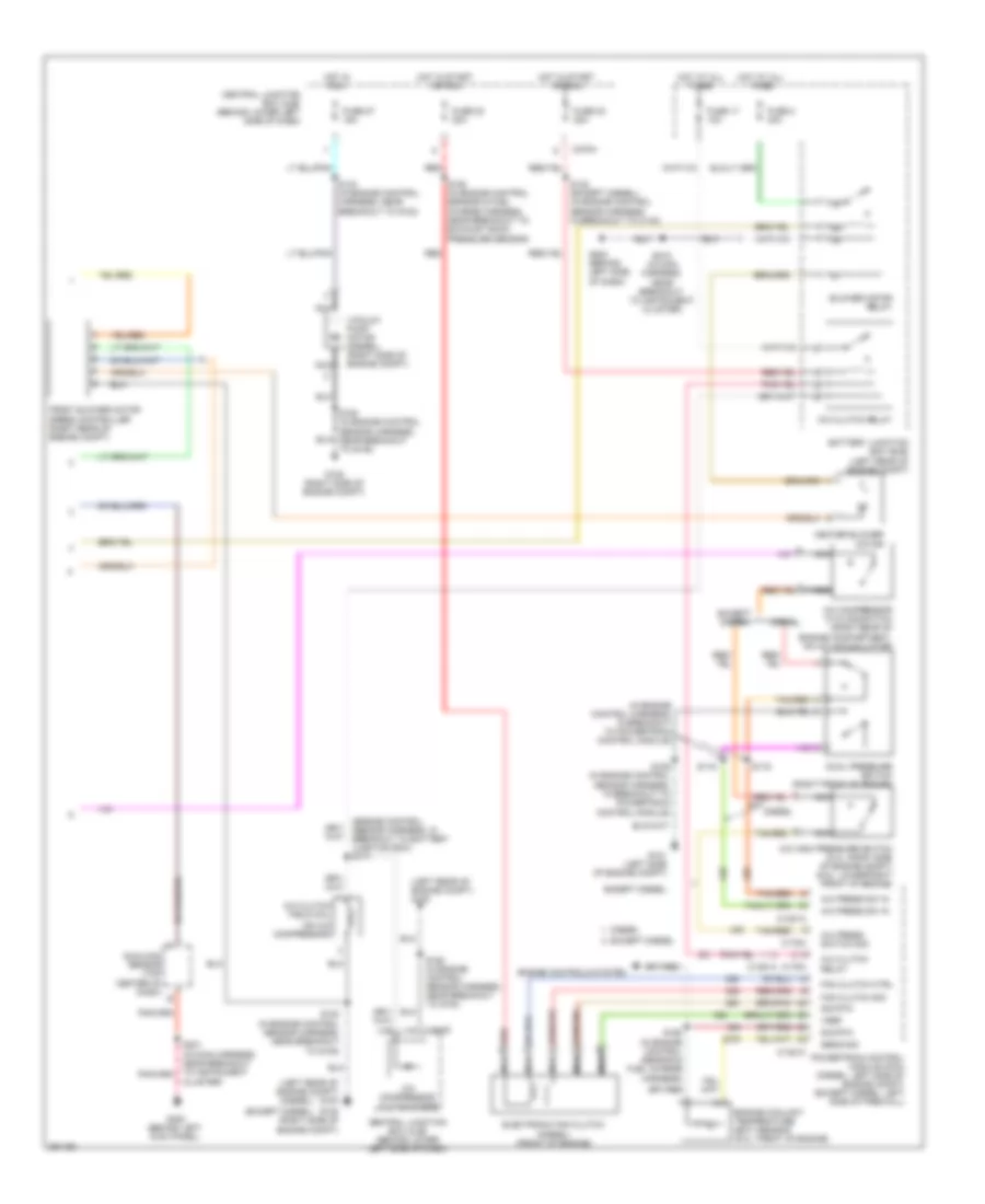
AIR CONDITIONING
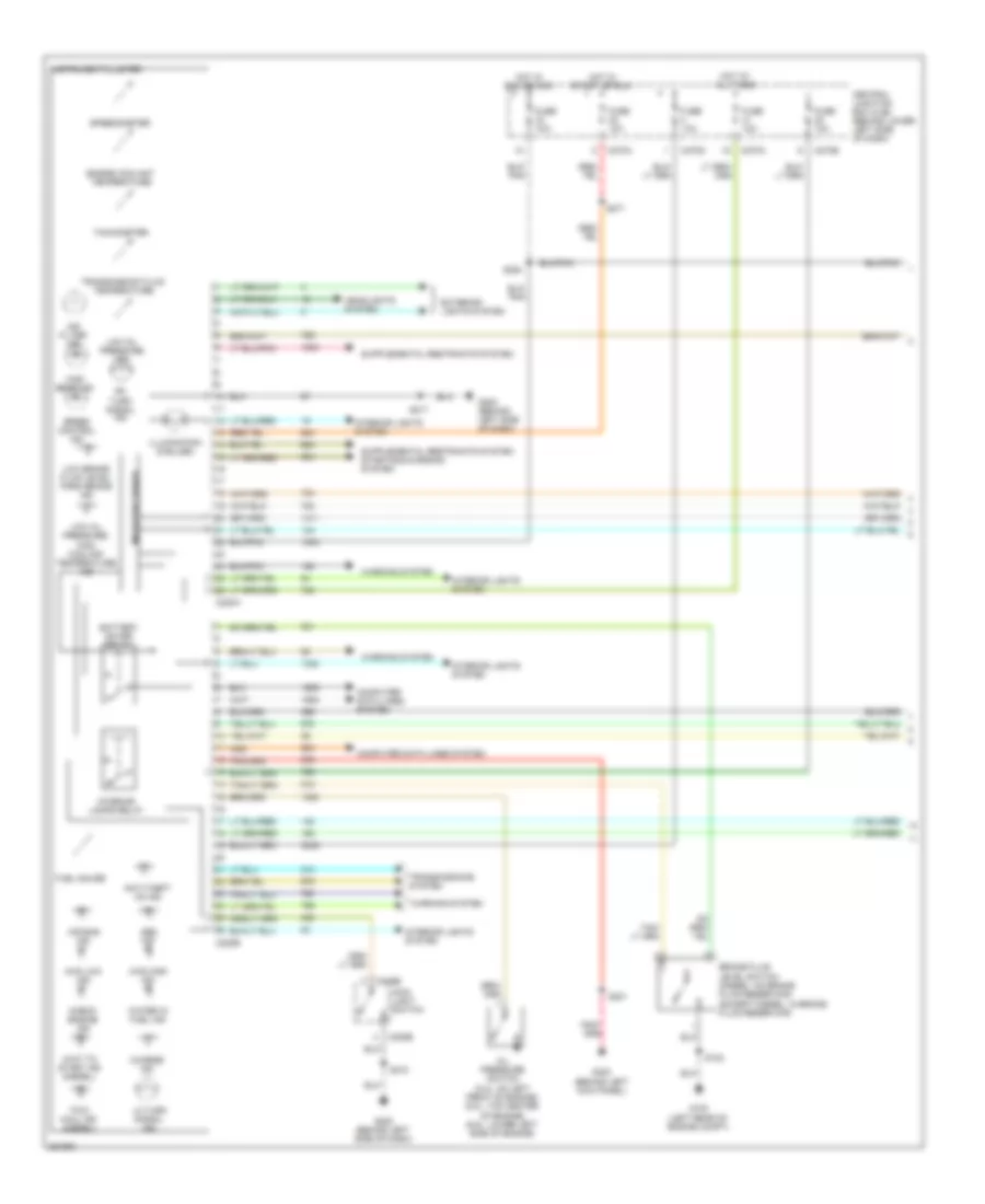
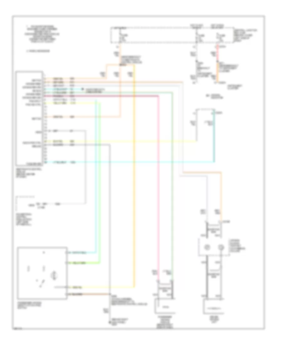
Automatic A/C Wiring Diagram (1 of 2) for Ford Cab & Chassis F350 Super Duty 2007

List of elements for Automatic A/C Wiring Diagram (1 of 2) for Ford Cab & Chassis F350 Super Duty 2007:
- A/c demand sig
- Air bag sliding contact (in steering column)
- Air temp dr sense +
- Air temp dr signal -
- Ambient air temperature sensor (except diesel: left front of engine compt)
- Ambient temp
- Blend door actuator +
- Blend door actuator -
- Blend door monitor
- Blower motor high
- Blower mtr rly ctrl
- Blower speed control signal return
- C228a
- C228b
- C270a
- Central junction box (cjb) (behind lower left side of dash)
- Computer data lines system
- Electronic automatic temperature control (eatc) module (behind center of dash)
- Fan speed (+)
- Fan speed (-)
- Fuse 10a
- Fuse 15a
- G202 (behind left side of dash)
- G300 (behind left kick panel)
- Harness, near breakout to instrument cluster)
- Hot at all times
- Hot in run
- Illumination
- In veh temp sensor
- In-vehicle temperature sensor (behind left side of dash)
- Interior lights system
- Logic gnd
- Nca
- Remote solenoid assembly (behind center of dash)
- Rest
- S148 (in main harness, near breakout to brake pressure transducer)
- S208 (in main harness, near breakout to instrument cluster)
- S218 (in main harness, near breakout to instrument cluster)
- S235 (in main harness, near breakout to auxiliary relay box 1)
- Sig return
- Solenoid 1 ctrl
- Solenoid 2 ctrl
- Solenoid 3 ctrl
- Solenoid 4 ctrl
- Solenoid 5 ctrl
- Solenoid assembly
- Speed controller
- Steering wheel controls
- Steering wheel radio switch
- Sunload sensor sig
- Temp (+)
- Temp (-)
- Temperature blend door actuator (behind right side of dash)
- Ubp diag
- Vpwr
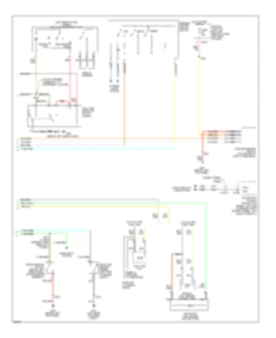
Automatic A/C Wiring Diagram (2 of 2) for Ford Cab & Chassis F350 Super Duty 2007
List of elements for Automatic A/C Wiring Diagram (2 of 2) for Ford Cab & Chassis F350 Super Duty 2007:
- (diesel)
- (engine control sensor harness, in breakout to battery junction box) s171
- (except diesel)
- (in engine control harness, in breakout to powertrain control module)
- (left rear of engine compt) g100
- (on a/c compressor)
- A/c clutch field coil
- A/c clutch relay
- A/c compressor clutch diode
- A/c compressor cycling switch (right rear of engine compartment, on a/c accumulator)
- A/c high pressure switch (5.4l: right side of engine compt) (6.8l: lower right front of engine)
- A/c press sw in
- A/c press switch sig
- Battery junction box (bjb) (left rear of engine compt)
- Blower motor relay
- C1381a
- C1381c
- C175a
- C270f
- C270h
- Central junction box (cjb) (behind lower left side of dash)
- Cluster)
- Diesel
- Dual pressure switch (right front of engine)
- Electronic fan clutch (diesel) (front of engine)
- Engine controls system
- Engine coolant temperature (ect) sensor (6.0l: front of engine)
- Except diesel
- Fan clutch ctrl
- Fan clutch sig
- Front blower motor speed controller (right rear of engine compt)
- Fuse 17 10a
- Fuse 2 40a
- Fuse 22 20a
- Fuse 23 20a
- Fuse 27 15a
- G101 (left side of engine compt)
- G108 (right side of engine compt)
- G202 (behind left side of dash)
- G300 (behind left kick panel)
- Heater blower motor
- Hot at all times
- Hot in run
- Hot in start or run
- Nca
- Powertrain control module (pcm) (diesel: left side of engine compt) (except diesel: left side of firewall)
- Red
- S106 (in engine control sensor harness, in breakout to powertrain control module)
- S116
- S119
- S122 (except diesel) (in engine control sensor harness, in breakout to c140)
- S124 (in engine control harness, near breakout to g100)
- S162 (in engine control sensor harness, near breakout to g100)
- S180 (in engine control sensor harness, near breakout to g108)
- S192 (in engine control sensor & fuel charge harness)
- S193 (in engine control sensor & fuel charge harness, near breakout to exhaust back pressure sensor)
- S218 (in main harness, near breakout to instrument cluster)
- Sens sig
- Sig rtn
- Sunload sensor (top center of dash)
- Tan/red
- Vacuum pump motor (diesel) (right side of engine compt)
- Vref
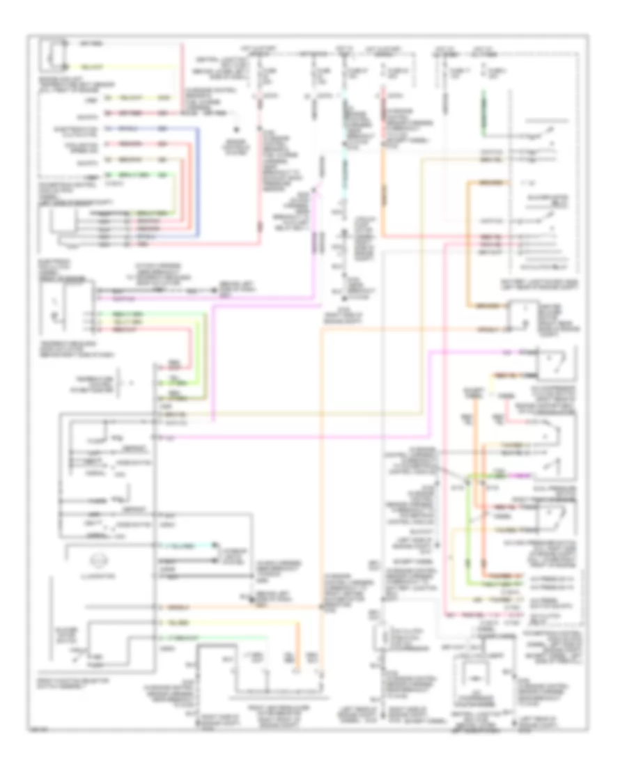
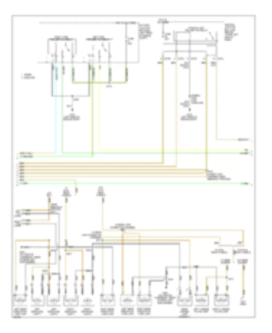
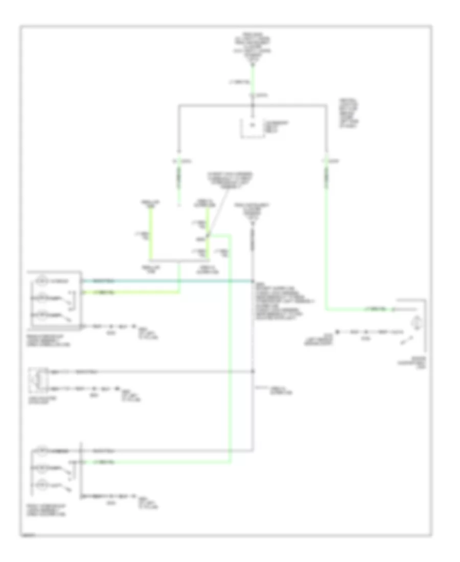
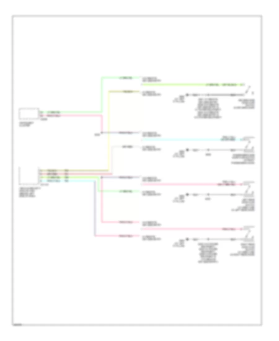
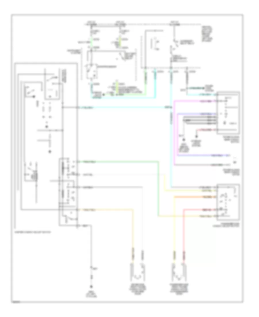
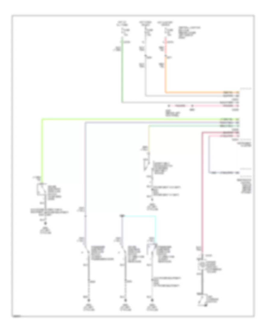
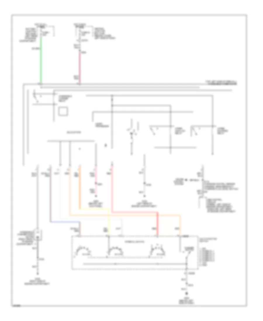
Manual A/C Wiring Diagram for Ford Cab & Chassis F350 Super Duty 2007
List of elements for Manual A/C Wiring Diagram for Ford Cab & Chassis F350 Super Duty 2007:
- (behind left side of dash) g201
- (diesel)
- (except diesel)
- (in engine control harness, in breakout to front heater blower motor resistor) s152
- (in engine control harness, in breakout to powertrain control module)
- (in engine control harness, near breakout to g100) s124
- (in engine control sensor & fuel charge harness) s192
- (in engine control sensor harness, in breakout to c140) (except diesel) s122
- (in main harness, near breakout to radio) s290
- (in main harness, near breakout to temperature blend door actuator) s257
- (left rear of engine compt) g100
- (left side of engine compt) g101
- (right side of engine compt) g108
- A/c clutch field coil (on a/c compressor)
- A/c clutch relay
- A/c compressor clutch diode
- A/c compressor cycling switch (right rear of engine compartment, on a/c accumulator)
- A/c high pressure switch (5.4l: right side of engine compt) (6.8l: lower right front of engine)
- A/c press sw in
- A/c press switch sig rtn
- Battery junction box (bjb) (left rear of engine compt)
- Blower motor relay
- Blower motor switch
- C1381a
- C1381c
- C175a
- C270a
- C270f
- C270h
- C289
- C294a
- C294b
- C294c
- Central junction box (cjb) (behind lower left side of dash)
- Cooling fan speed sig
- Defrost
- Diesel
- Dual pressure switch (right front of engine)
- Electronic fan clutch (diesel) (front of engine)
- Electronic fan clutch ctrl
- Engine controls system
- Engine coolant temperature (ect) sensor (6.0l: front of engine)
- Except diesel
- Floor
- Front function selector switch assembly
- Front heater blower motor resistor (right front of engine compt)
- Fuse 15a
- Fuse 17 10a
- Fuse 2 40a
- Fuse 20a
- Fuse 23 20a
- Fuse 27 15a
- G108 (right side of engine compt)
- Heater blower motor (right rear side of engine compt)
- High
- Hot at all times
- Hot in run
- Hot in start or run
- Illumination
- Interior lights system
- Low
- Max
- Med
- Mix
- Mode switch
- Nca
- Normal
- Off
- Powertrain control module (pcm) (diesel) (left side of engine compt)
- Powertrain control module (pcm) (diesel: left side of engine compt) (except diesel: left side of firewall)
- Red
- S106 (in engine control sensor harness, in breakout to powertrain control module)
- S116
- S119
- S162 (in engine control sensor harness, near breakout to g100)
- S180 (in engine control sensor harness, near breakout to g108)
- S193 (in engine control sensor & fuel charge harness, near breakout to exhaust back pressure sensor)
- S235 (in main harness, near breakout to auxiliary relay box 1)
- Sig rtn
- Tan/red
- Temperature blend door actuator (behind right side of dash)
- Temperature control potentiometer
- To g108)
- Vacuum pump motor (diesel) (right side of engine compt)
- Vent
- Vref
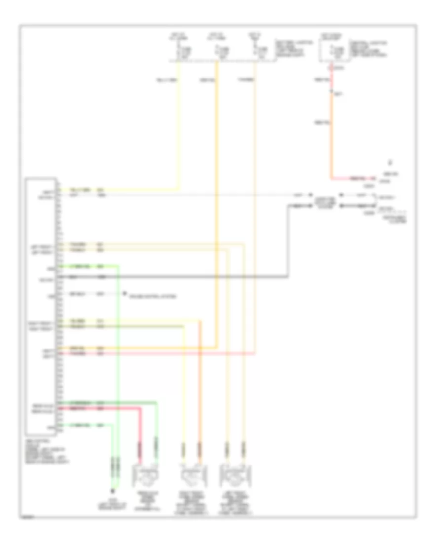
ANTI-LOCK BRAKES
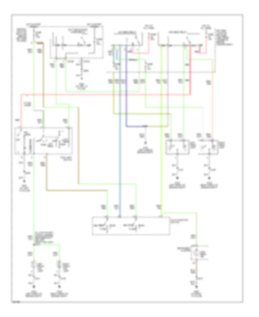
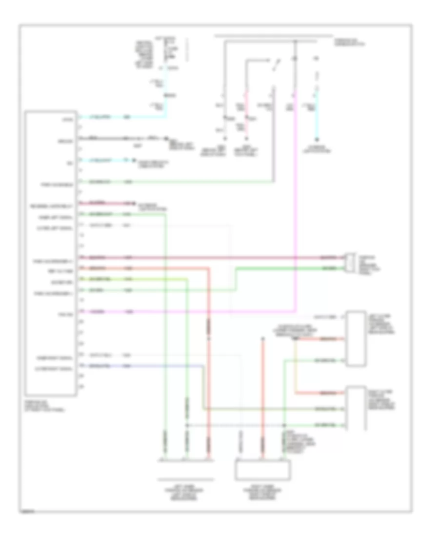
Anti-lock Brakes Wiring Diagram for Ford Cab & Chassis F350 Super Duty 2007
List of elements for Anti-lock Brakes Wiring Diagram for Ford Cab & Chassis F350 Super Duty 2007:
- Abs control module (diesel: left side of engine compt) (except diesel: left rear of engine compt)
- Abs ind
- Battery junction box (bjb) (left rear of engine compt)
- C220a
- C220b
- C270a
- Central junction box (cjb) (behind lower left side of dash)
- Computer data lines system
- Cruise control system
- Fuse f1.11 10a
- Fuse f1.22 60a
- Fuse f1.23 60a
- Fuse f2.45 10a
- G105 (left front of engine compt)
- Gnd
- Hot at all times
- Hot in run
- Hot in run or start
- Hs can +
- Hs can -
- Instrument cluster
- Left front +
- Left front -
- Left front wheel speed sensor (except diesel: at left front wheel assembly)
- Rear axle +
- Rear axle -
- Rear axle speed sensor (on differential)
- Red/pnk
- Right front +
- Right front -
- Right front wheel speed sensor (except diesel: at right front wheel assembly)
- S271
- Tan/red
- Vbatt
- Vpwr
- Vss
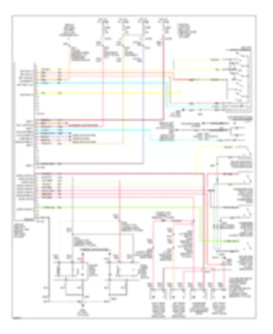
ANTI-THEFT
Anti-theft Wiring Diagram for Ford Cab & Chassis F350 Super Duty 2007
List of elements for Anti-theft Wiring Diagram for Ford Cab & Chassis F350 Super Duty 2007:
- (behind
- (behind left kick panel) (automatic a/c) g300 g201 (manual a/c) (behind left side of dash)
- (in body main harness, in breakout to c855) s316
- (manual a/c)
- (top center of dash) sunload sensor
- (w/o heated seats: near breakout to right rear speaker) (w/ heated seats: in body main harness, near breakout to c340)
- 1/2
- 3/4
- 5/6
- 7/8
- 9/0
- Air conditioning system
- Autolamps on
- C2113a
- C2113b
- C2113c
- C270a
- C270b
- C270e
- Central junction box (cjb) (behind lower left side of dash)
- Diagnostic
- Door ajar sw
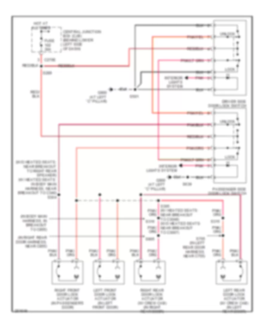
- Door lock
- Door lock out
- Door unlock
- Dr door relay
- Driver side door lock switch
- Driver side front door ajar switch (in driver's door)
- Driver side rear door ajar switch (crew cab) (in left rear door)
- Equipment)
- Ext lamp pwr
- Exterior lights system
- Fuse 10a
- Fuse 15a
- Fuse 30a
- G900 (at left "c" pillar)
- G900 (at left ``c" pillar)
- Ground
- Headlights system
- Headlmp relay
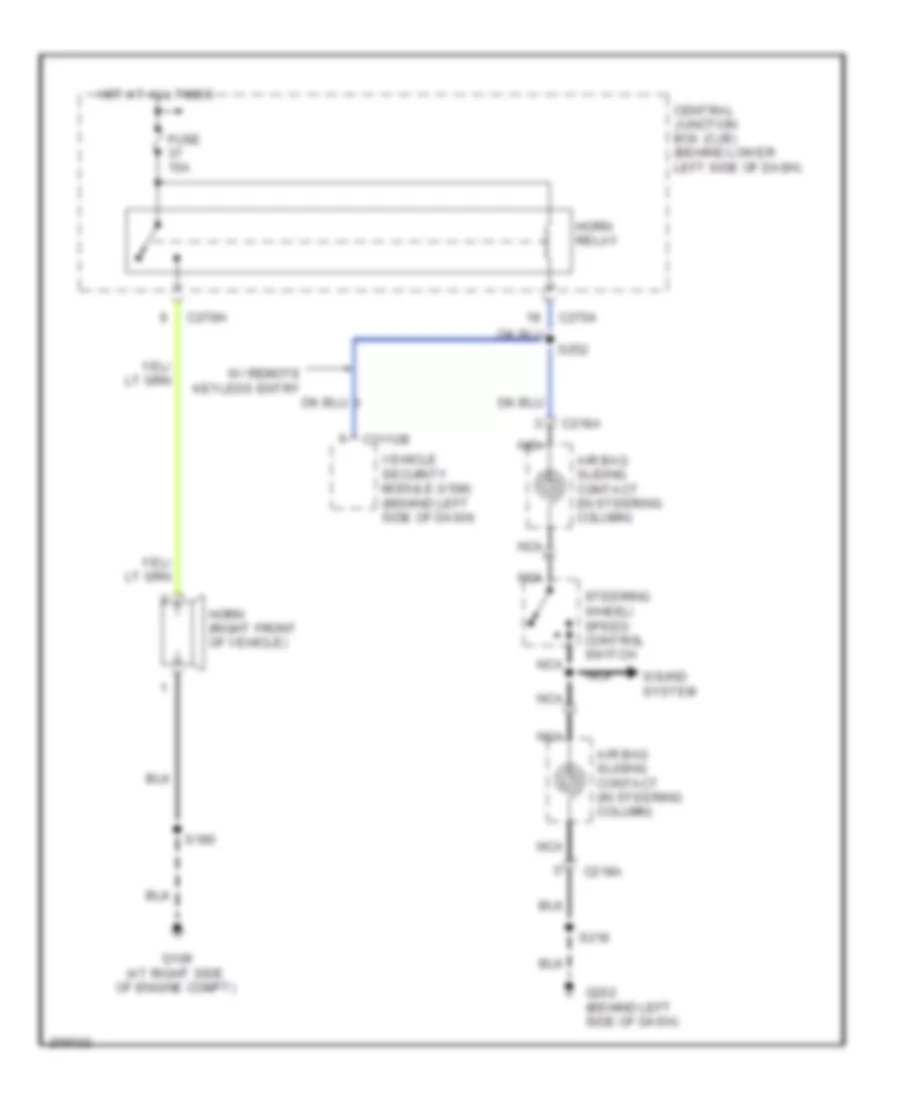
- Horn relay
- Horns system
- Hot at all times
- Interior lights system
- Key pad 1/2
- Key pad 3/4
- Key pad 7/8
- Key pad com
- Key pad illum
- Key pad switch assembly
- Left front door lock actuator (in left front door)
- Left rear door lock actuator (crew cab) (in left rear door)
- Left side of dash) data link connector (dlc)
- Lock
- Pass- enger side door lock switch
- Passenger side door lock actuator (in passenger's door)
- Passenger side front door ajar switch (in front passenger's door)
- Passenger side rear door ajar switch (crew cab) (in right rear door)
- Pnk
- Red
- Right rear door lock actuator (crew cab) (in right rear door)
- S214
- S230 (w/ electronic shift on the fly)
- S247 (in main harness, near breakout to passenger air bag module)
- S272 (w/ power equipment)
- S290 s201 (automatic a/c)
- S300
- S304
- S305 (w/ heated seats: near breakout to c3049) (w/o heated seats: near breakout to c3007)
- S306
- S315
- S318 (in body main harness, near breakout to g300)
- S329 (in body main harness, near breakout to g300)
- S501
- S639
- S705 (in left rear door harness, near c755)
- S805 (in right rear door harness, near c855)
- Sunload sens
- Unlock
- Vbatt
- Vehicle security module (vsm) (behind left side of dash)
COMPUTER DATA LINES
Computer Data Lines Wiring Diagram for Ford Cab & Chassis F350 Super Duty 2007
List of elements for Computer Data Lines Wiring Diagram for Ford Cab & Chassis F350 Super Duty 2007:
- (except diesel)
- (except diesel) s109
- (in engine control sensor harness, in breakout to abs control module)
- (in main harness, in breakout to data link connector)
- (in main harness, near breakout to instrument cluster) s225
- Abs control module (except diesel: left rear of engine compt) (diesel: left side of engine compt)
- C1381a
- C175b
- C2113c
- C2142b
- C220b
- C228b
- C270d
- C281b
- Can h
- Can l
- Central junction box (cjb) (behind lower left side of dash)
- Data link connector (dlc) (behind left side of dash)
- Diesel
- Electronic automatic temperature control (eatc) module (behind center of dash)
- Except diesel
- Feps
- Four wheel drive control module (behind right side of dash)
- Fuse 12 20a
- G101 (except diesel: left rear of engine compt) (diesel: left side of engine compt)
- G202 (behind left side of dash)
- Hot at all times
- Hs can+
- Hs can-
- Instrument cluster
- Iso
- Parking aid module (pam) (right kick panel)
- Powertrain control module (pcm) (except diesel: left side of firewall) (diesel: left side of engine compt)
- Restraints control module (behind center of dash)
- S140 (diesel)
- S142 (diesel)
- S146
- S213
- S217
- S220
- S242
- S247 (in main harness, near breakout to passenger air bag module)
- Trailer brake control module (behind center of dash)
- Ubp
- Vehicle security module (vsm) (behind left side of dash)
- W/ eatc
- W/ electronic shift on the fly
- W/ parking aid
- W/ remote keyless entry
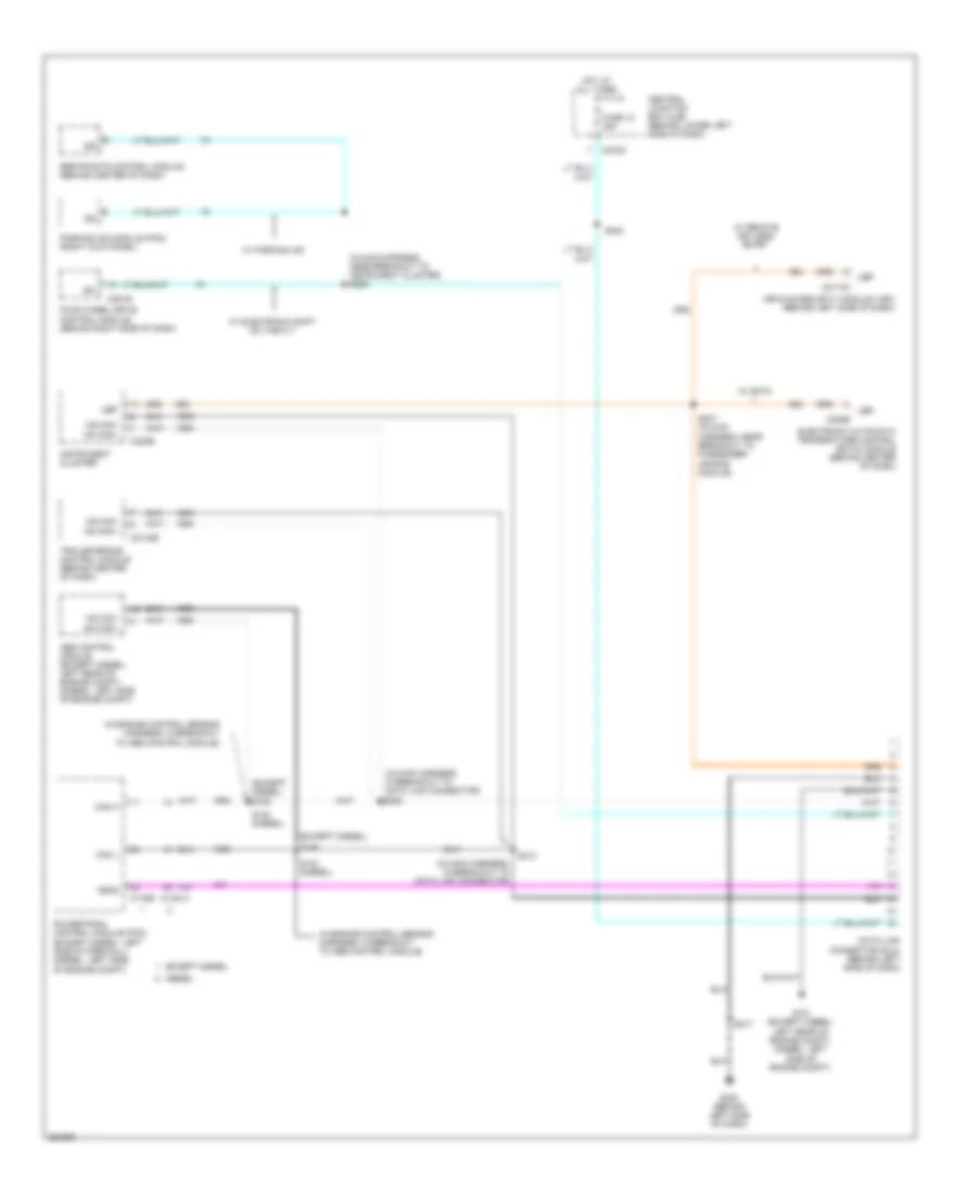
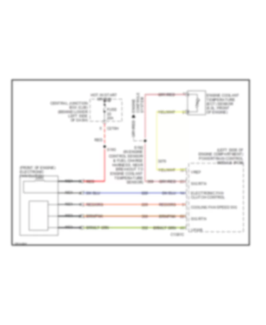
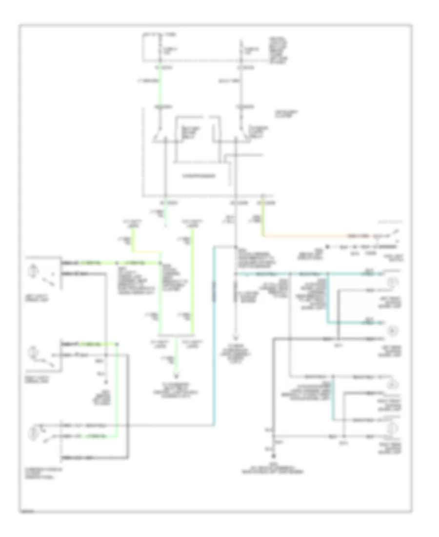
COOLING FAN
6.0L DIESEL
6.0L Diesel, Cooling Fan Wiring Diagram for Ford Cab & Chassis F350 Super Duty 2007
List of elements for 6.0L Diesel, Cooling Fan Wiring Diagram for Ford Cab & Chassis F350 Super Duty 2007:
- (front of engine) electronic fan clutch
- (left side of engine compartment) powertrain control module (pcm)
- C1381c
- C270h
- Central junction box (cjb) (behind lower left side of dash)
- Cooling fan speed sig
- Electronic fan clutch control
- Engine controls system
- Engine coolant temperature (ect) sensor (6.0l: front of engine)
- Fuse 20a
- Hot in start or run
- Nca
- Red
- S192 (in engine control sensor & fuel charge harness, near breakout to engine coolant temperature sensor)
- S193
- Sig rtn
- Vpwr
- Vref
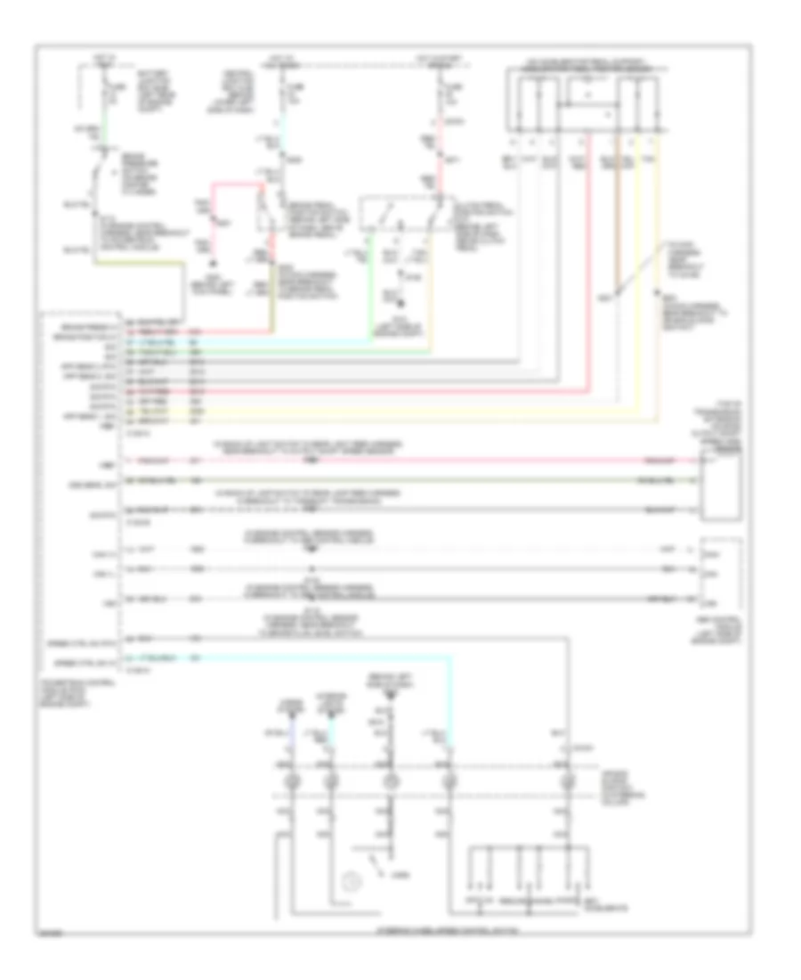
CRUISE CONTROL
5.4L
5.4L, Cruise Control Wiring Diagram for Ford Cab & Chassis F350 Super Duty 2007
List of elements for 5.4L, Cruise Control Wiring Diagram for Ford Cab & Chassis F350 Super Duty 2007:
- (behind left side of dash) g202
- (in engine control sensor harness, in breakout to abs control module) s109
- (in main harness, near breakout to c2186) s221
- (not used)
- (on accelerator pedal support) accelerator pedal position sensor
- (on throttle body) throttle position sensor (tps)
- Abs control module (left rear of engine compt)
- Air bag sliding contact (in steering column)
- App sens 1, sig
- App sens 2, sig
- App sens 3, pwr
- App sens 3, rtn
- App sens 3, sig
- Battery junction box (bjb) (left rear of engine compartment)
- Brake pedal position switch (behind left side of dash, above brake pedal)
- Brake position in
- Brake press in
- Brake pressure switch (bottom of master cylinder)
- C175a
- C175b
- C218a
- C270a
- Can+
- Can-
- Cancel
- Central junction box (cjb) (behind lower left side of dash)
- Clutch pedal position switch (behind left side of dash, above clutch pedal)
- Coast
- Fuse 10a
- Fuse 2a
- G300 (behind left kick panel)
- Horn
- Horns system
- Hot at all times
- Hot in run
- Interior lights system
- M/t
- Nca
- Off
- Powertrain control module (pcm) (left side of firewall)
- Resume
- S115 (in engine control sensor harness, near breakout to brake fluid level switch)
- S146 (in engine control sensor harness, in breakout to abs control module)
- S201
- S205 (in main harness, near breakout to brake pedal position switch)
- S208
- S218
- S223 (in main harness, near breakout to air bag sliding contact)
- Scp+
- Scp-
- Set/ accelerate
- Sig rtn
- Speed ctrl sw in
- Speed ctrl sw rtn
- Steering wheel/speed control switch
- Tan
- Tps sig 1
- Tps sig 2
- Volt ref
- Vss
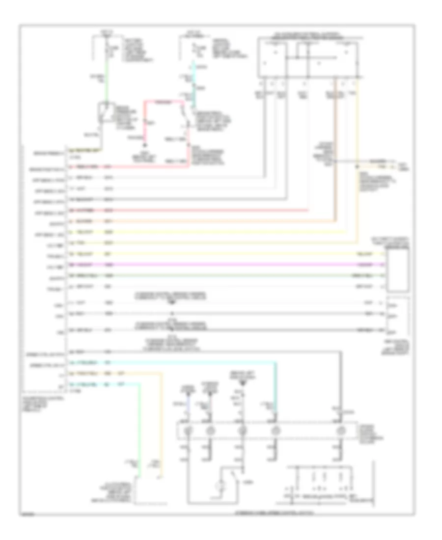
6.0L DIESEL
6.0L Diesel, Cruise Control Wiring Diagram for Ford Cab & Chassis F350 Super Duty 2007
List of elements for 6.0L Diesel, Cruise Control Wiring Diagram for Ford Cab & Chassis F350 Super Duty 2007:
- (behind left side of dash) g202
- (in back-up lamp switch to rear lamp feed harness, in breakout to torqshift transmission) s127
- (in back-up light switch to rear light feed harness, near breakout to output shaft speed sensor) s128
- (in engine control sensor harness, in breakout to abs control module) s140
- (in main harness, near breakout to c2186)
- (on accelerator pedal support) accelerator pedal position sensor
- (top of transmission extension housing) output shaft speed (oss) sensor
- Abs control module (left side of engine compt)
- Air bag sliding contact (in steering column)
- App sens 1, sig
- App sens 2, rtn
- App sens 2, sig
- Battery junction box (bjb) (left rear of engine compt)
- Brake pedal position switch (behind left side of dash, above brake pedal)
- Brake position in
- Brake press in
- Brake pressure switch (on brake master cylinder)
- C1381a
- C1381b
- C218a
- C270a
- Can 1h
- Can 1l
- Can+
- Can-
- Cancel
- Central junction box (cjb) (behind lower left side of dash)
- Clutch pedal position switch (m/t) (behind left side of dash, above clutch pedal)
- Coast
- Fuse 10a
- Fuse 2a
- G101 (left side of engine compt)
- G300 (behind left kick panel)
- Horn
- Horns system
- Hot at all times
- Hot in run
- Hot in start or run
- Interior lights system
- Nca
- Off
- Oss sens, sig
- Powertrain control module (pcm) (left side of engine compt)
- Resume
- S106
- S112 (in engine control harness, near breakout to powertrain control module)
- S115 (in engine control sensor harness, near breakout to brake fluid level switch)
- S142 (in engine control sensor harness, in breakout to abs control module)
- S201
- S205 (in main harness, near breakout to brake pedal position switch)
- S208
- S218
- S221
- S223 (in main harness, near breakout to air bag sliding contact)
- S271
- Set/ accelerate
- Sig
- Sig rtn
- Speed ctrl sw in
- Speed ctrl sw rtn
- Steering wheel/speed control switch
- Tan
- Vref
- Vss
6.8L
6.8L, Cruise Control Wiring Diagram for Ford Cab & Chassis F350 Super Duty 2007
List of elements for 6.8L, Cruise Control Wiring Diagram for Ford Cab & Chassis F350 Super Duty 2007:
- (behind left side of dash) g202
- (in engine control sensor harness, in breakout to abs control module) s109
- (in main harness, near breakout to c2186) s221
- (not used)
- (on accelerator pedal support) accelerator pedal position sensor
- (on throttle body) throttle position sensor (tps)
- Abs control module (left rear of engine compt)
- Air bag sliding contact (in steering column)
- App sens 1, sig
- App sens 2, sig
- App sens 3, pwr
- App sens 3, rtn
- App sens 3, sig
- Battery junction box (bjb) (left rear of engine compartment)
- Brake pedal position switch (behind left side of dash, above brake pedal)
- Brake position in
- Brake press in
- Brake pressure switch (bottom of master cylinder)
- C175a
- C175b
- C218a
- C270a
- Can+
- Can-
- Cancel
- Central junction box (cjb) (behind lower left side of dash)
- Clutch pedal position switch (behind left side of dash, above clutch pedal)
- Coast
- Fuse 10a
- Fuse 2a
- G300 (behind left kick panel)
- Horn
- Horns system
- Hot at all times
- Hot in run
- Interior lights system
- M/t
- Nca
- Off
- Powertrain control module (pcm) (left side of firewall)
- Resume
- S115 (in engine control sensor harness, near breakout to brake fluid level switch)
- S146 (in engine control sensor harness, in breakout to abs control module)
- S201
- S205 (in main harness, near breakout to brake pedal position switch)
- S208
- S218
- S223 (in main harness, near breakout to air bag sliding contact)
- Scp+
- Scp-
- Set/ accelerate
- Sig rtn
- Speed ctrl sw in
- Speed ctrl sw rtn
- Steering wheel/speed control switch
- Tan
- Tps sig 1
- Tps sig 2
- Volt ref
- Vss
DEFOGGERS
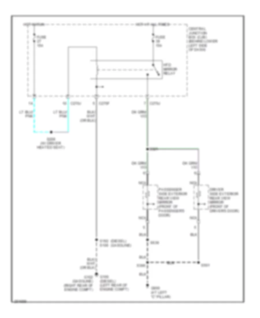
Defoggers Wiring Diagram for Ford Cab & Chassis F350 Super Duty 2007
List of elements for Defoggers Wiring Diagram for Ford Cab & Chassis F350 Super Duty 2007:
- (diesel)
- (gasoline)
- C270f
- C270j
- Central junction box (cjb) (behind lower left side of dash)
- Driver side exterior rear view mirror (front of driver's door)
- Fuse 15a
- G100 (diesel) (left rear of engine compt)
- G102 (gasoline) (right rear of engine compt)
- G900 (at left "c" pillar)
- Hot at all times
- Hot in run
- Htd mirror relay
- Nca
- Passenger side exterior rear view mirror (front of passenger's door)
- S106
- S162
- S209 (w/ driver heated seat)
- S306
- S321
- S501
- S639
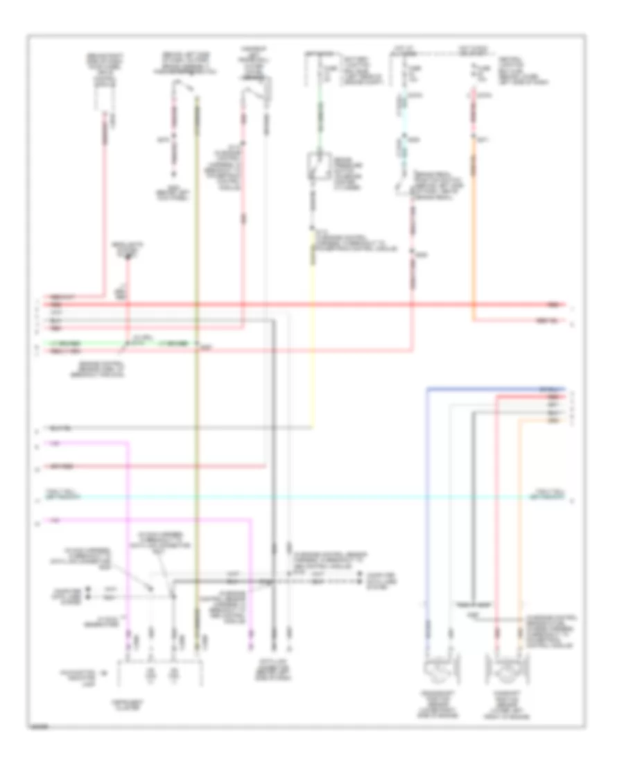
ENGINE PERFORMANCE
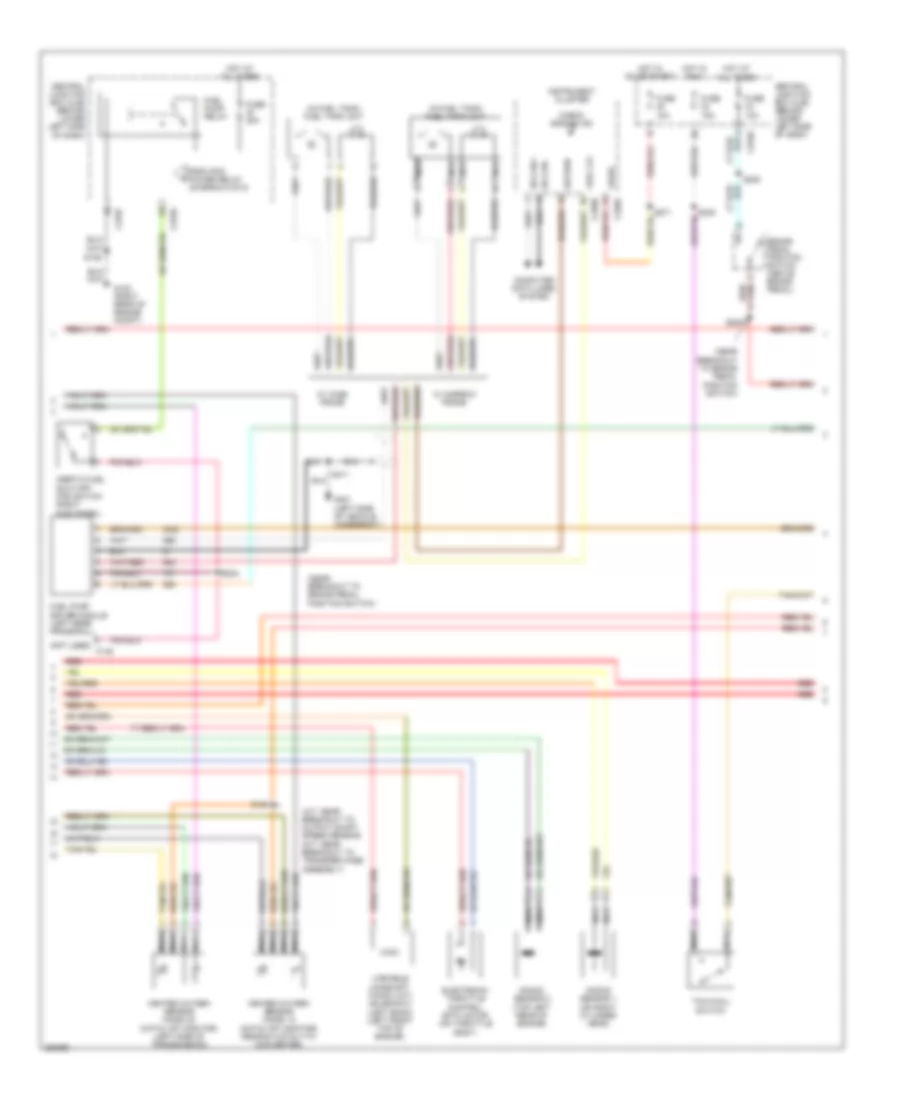
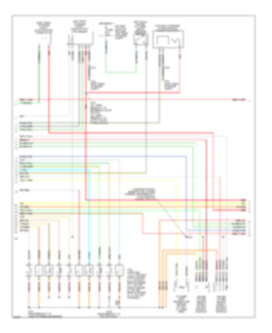
5.4L
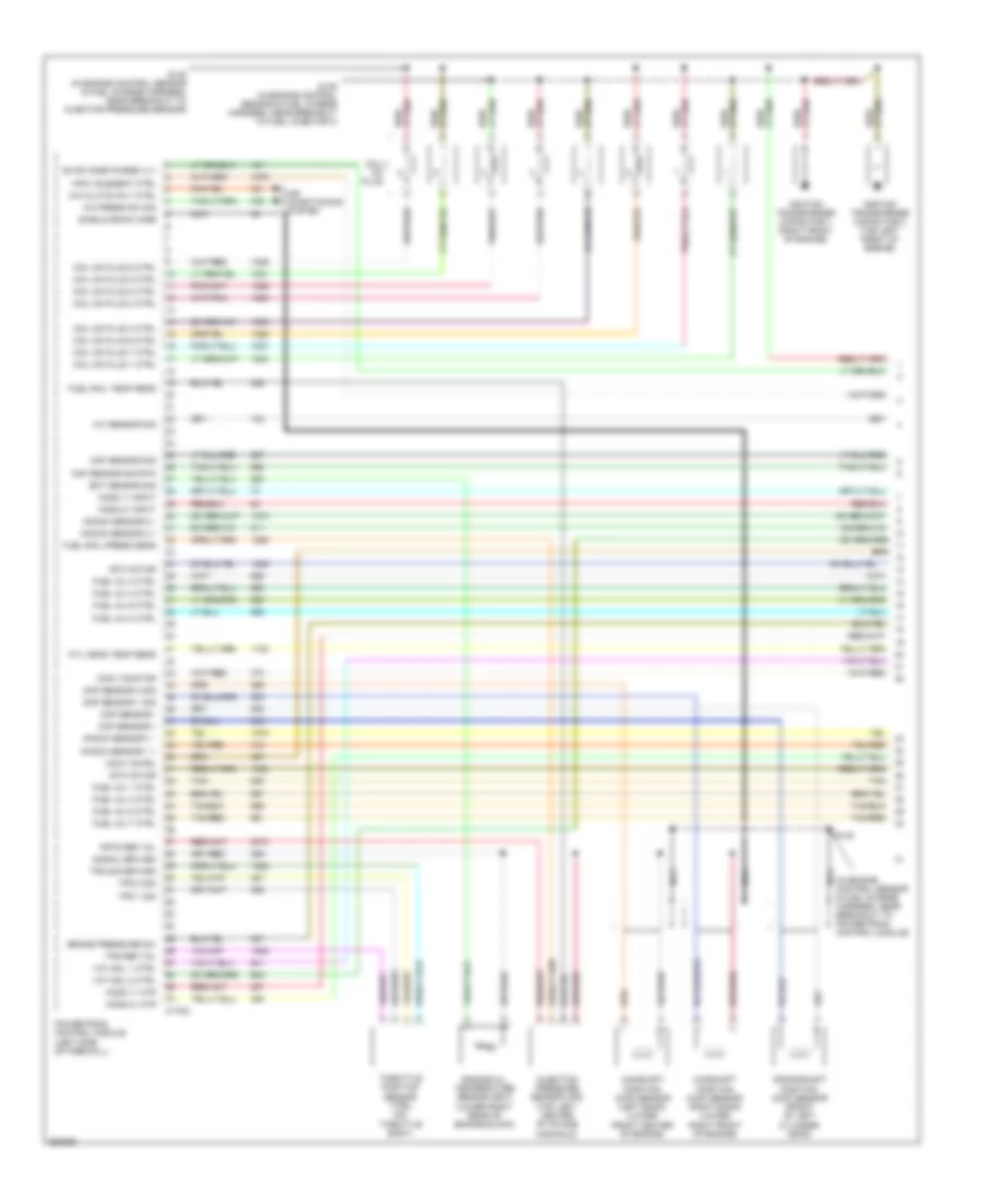
5.4L, Engine Performance Wiring Diagram (1 of 5) for Ford Cab & Chassis F350 Super Duty 2007
List of elements for 5.4L, Engine Performance Wiring Diagram (1 of 5) for Ford Cab & Chassis F350 Super Duty 2007:
- (in engine control sensor & fuel charge harness, near breakout to powertrain control module)
- A/c clutch rly ctrl
- A/c press sw sig
- Air conditioning system
- Brake pressure sw
- C175a
- Camshaft position (ckp) sensor (left bank) (lower front center of engine)
- Camshaft position (ckp) sensor (right bank) (lower right front of engine)
- Ckp sensor +
- Ckp sensor -
- Cmcv cntrl
- Cmcv monitor
- Cmp sensor 1 sig
- Cmp sensor 2 sig
- Coil on plug
- Coil on plug 1 ctrl
- Coil on plug 2 ctrl
- Coil on plug 3 ctrl
- Coil on plug 4 ctrl
- Coil on plug 5 ctrl
- Coil on plug 6 ctrl
- Coil on plug 7 ctrl
- Coil on plug 8 ctrl
- Crankshaft position (cmp) sensor (front of left cylinder head)
- Cyl head temp sens
- Engine oil temperature sensor (eot) (lower right rear of engine block)
- Eot sensor sig
- Etc motor
- Evap cnsr purge vlv
- Frts ref vol
- Fuel inj 1 ctrl
- Fuel inj 2 ctrl
- Fuel inj 3 ctrl
- Fuel inj 4 ctrl
- Fuel inj 5 ctrl
- Fuel inj 6 ctrl
- Fuel inj 7 ctrl
- Fuel inj 8 ctrl
- Fuel rail press sens
- Fuel rail temp sens
- Ho2s 11 htr
- Ho2s 11 input
- Ho2s 21 htr
- Ho2s 21 input
- Hpcv element ctrl
- Iat sensor sig
- Ignition transformer capacitor 1 (right front of engine)
- Ignition transformer capacitor 2 (top left front of engine)
- Injection pressure sensor (ips) (top left center of intake manifold)
- Knock sensor 1 +
- Knock sensor 1 -
- Knock sensor 2 +
- Knock sensor 2 -
- Maf sensor sig
- Maf sensor sig rtn
- Nca
- Powertrain control module (left side of firewall)
- S130 (in engine control sensor & fuel charge harness, near breakout to injector pressure sensor)
- S135 (in engine control sensor & fuel charge harness, near breakout to fuel injector 3)
- S145
- Shield drain wire
- Signal return
- Tan
- Tan/red
- Throttle position sensor (tps) (on throttle body)
- Tps 1 sig
- Tps 2 sig
- Tps ref vol
- Tps sig return
- Vct sol 1 ctrl
- Vct sol 2 ctrl
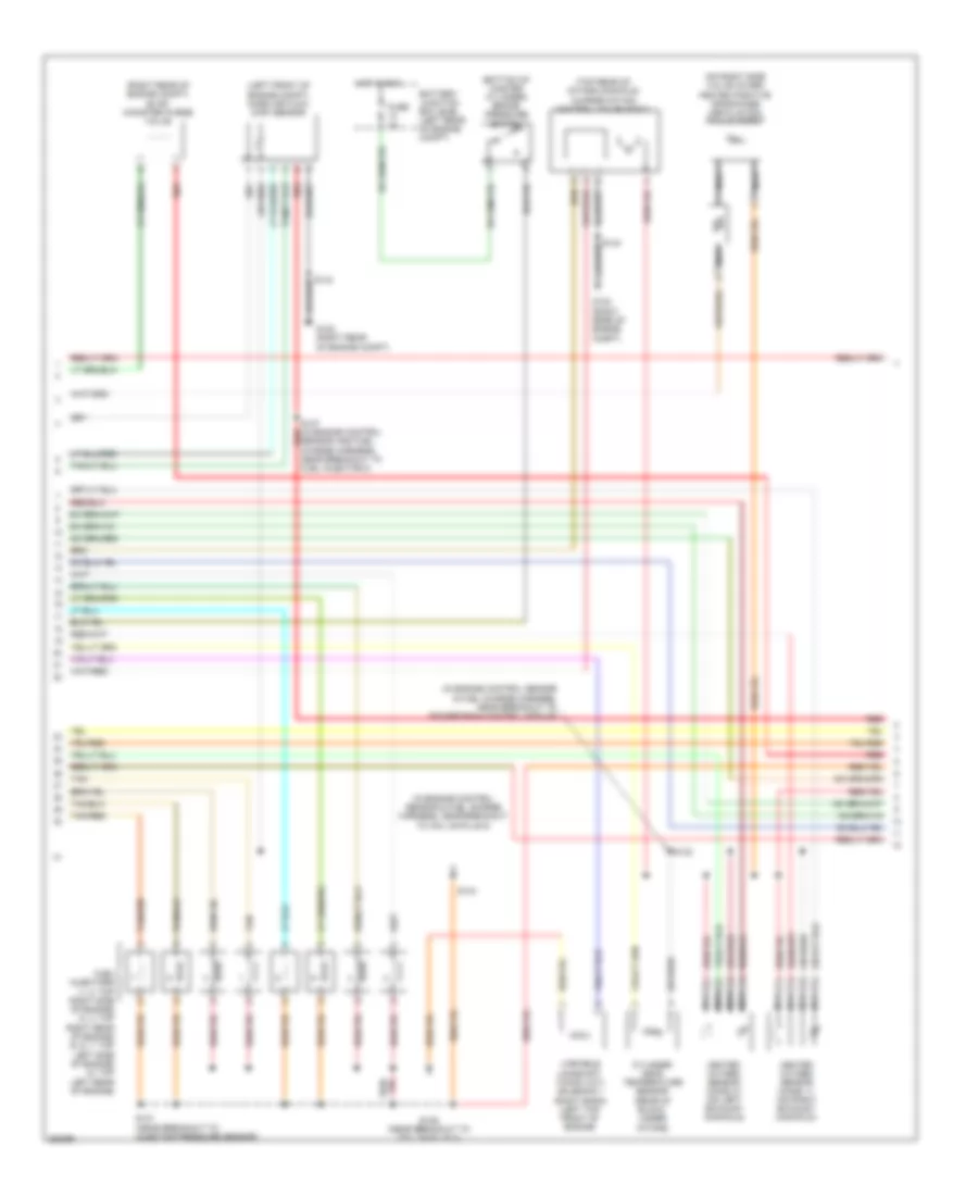
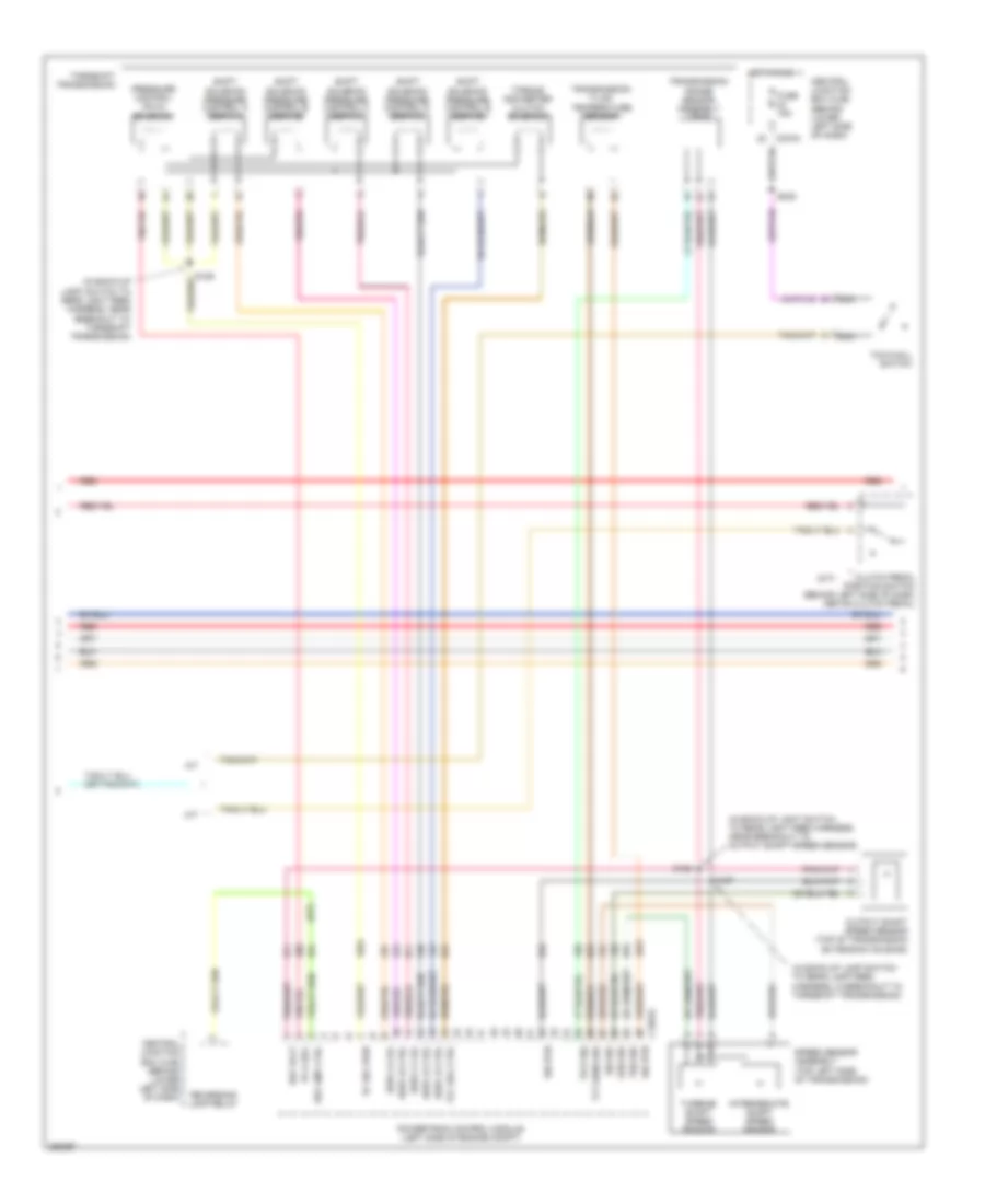
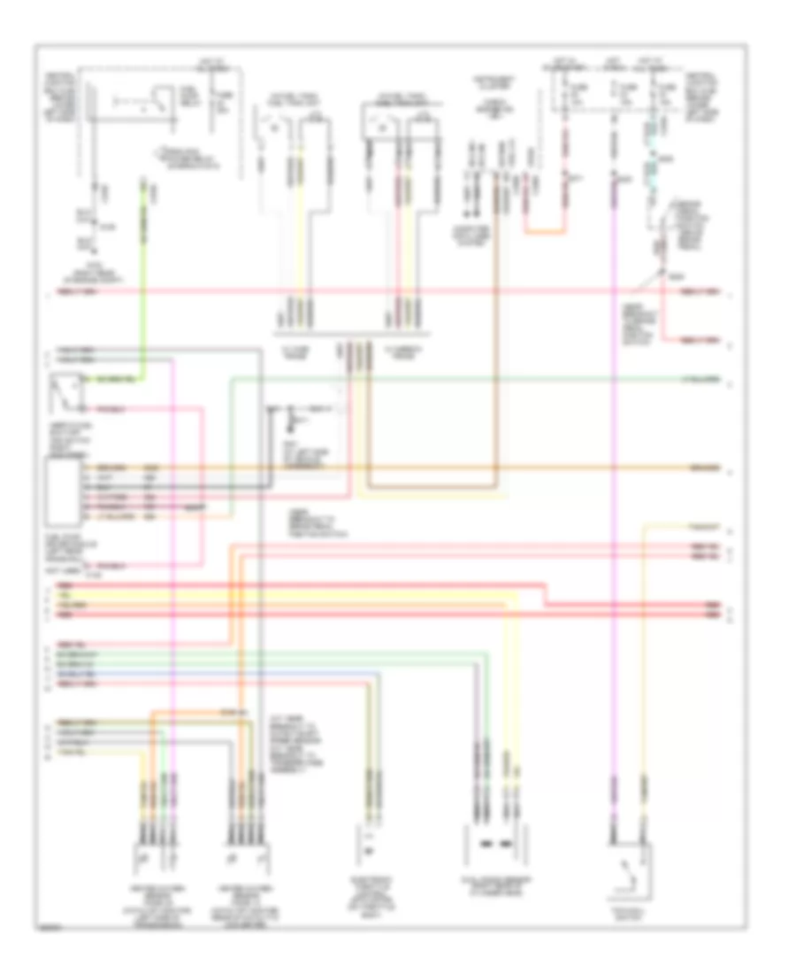
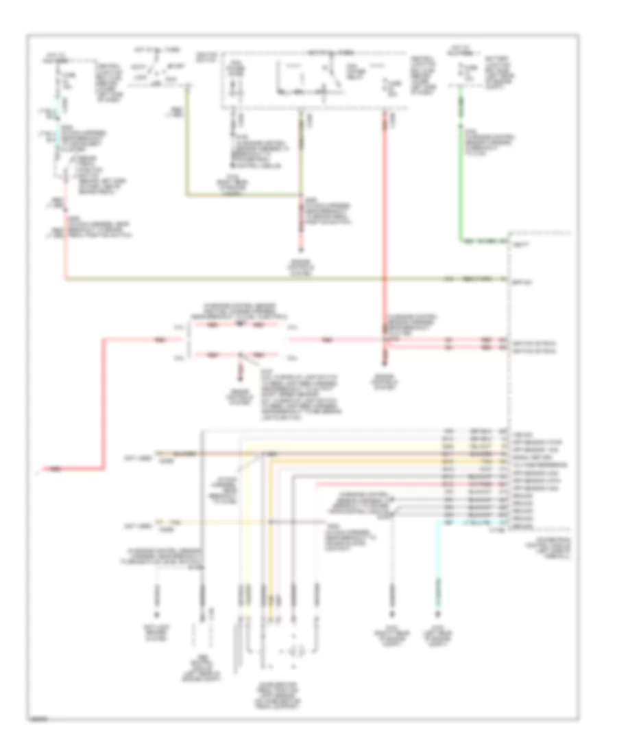
5.4L, Engine Performance Wiring Diagram (2 of 5) for Ford Cab & Chassis F350 Super Duty 2007
List of elements for 5.4L, Engine Performance Wiring Diagram (2 of 5) for Ford Cab & Chassis F350 Super Duty 2007:
- (bottom of master cylinder) brake pressure switch
- (in engine control sensor & fuel charge harness, near breakout to coil on plug 8)
- (in engine control sensor & fuel charge harness, near breakout to powertrain control module)
- (left front of engine compt) mass air flow (maf) sensor
- (on right side valve cover) heated positive crankcase ventilation (pcv) element
- (right rear of engine compt) evap canister purge valve
- (top rear of intake manifold) charge motion control valve (cmcv)
- Battery junction box (bjb) (left rear of engine compt)
- Cylinder head temperature sensor (rear of block, under intake)
- Fuel injectors (1, 2: top right side of engine) (3, 4: top right rear of engine) (5, 6, 7: top left side of engine) (8: top left rear of engine)
- Fuse 2a
- G102 (right rear of engine compt)
- Heated oxygen sensor (ho2s) 11 (on right exhaust manifold)
- Heated oxygen sensor (ho2s) 21 (on left exhaust manifold)
- Hot in run
- Nca
- Red
- S131 (near breakout to injector pressure sensor)
- S132
- S134
- S136 (near breakout to coil on plug 3)
- S137 (in engine control red
- Sensor and fuel charge harness, near breakout to fuel injector 8)
- Tan
- Tan/red
- Variable camshaft timing (vct) solenoid 1 (right bank) (left top front of engine)
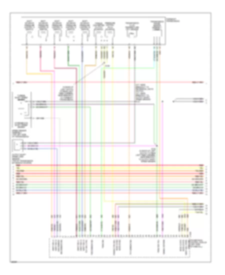
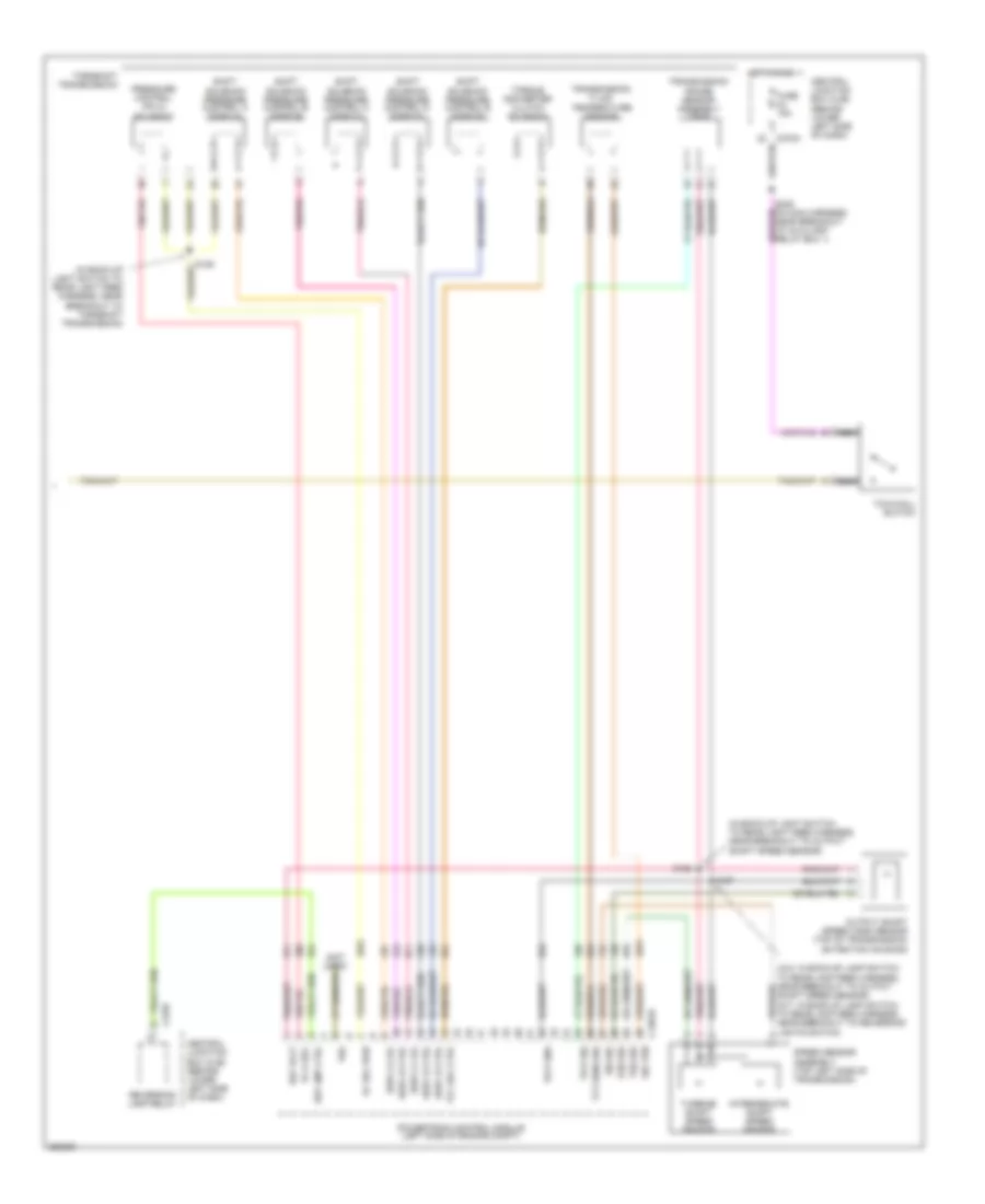
5.4L, Engine Performance Wiring Diagram (3 of 5) for Ford Cab & Chassis F350 Super Duty 2007
List of elements for 5.4L, Engine Performance Wiring Diagram (3 of 5) for Ford Cab & Chassis F350 Super Duty 2007:
- (in back-up light switch to rear light feed harness, near breakout to torqshift transmission)
- (m/t: near breakout to reversing lights switch) (a/t: near breakout to output shaft speed sensor) s127
- C175c
- Ho2s 12 htr
- Ho2s 12 sig
- Ho2s 22 htr
- Ho2s 22 sig
- Intermediate shaft speed sensor
- Iss sensor sig
- Oss sensor
- Output shaft speed (oss) sensor (top of transmission extension housing)
- Powertrain control module (left side of firewall)
- Press ctrl sol
- Pressure control (pc-a) solenoid
- Red
- S128 (in back-up light switch to rear light feed harness, near breakout to output shaft speed sensor)
- S129
- Shift sol a
- Shift sol b
- Shift sol c
- Shift sol d
- Shift sol e
- Shift sol vpwr
- Shift solenoid pressure control a (sspc-a)
- Shift solenoid pressure control b (sspc-b)
- Shift solenoid pressure control c (sspc-c)
- Shift solenoid pressure control d (sspc-d)
- Shift solenoid pressure control e (sspc-e)
- Signal return
- Speed sensor assembly (top left side of transmission)
- Tcc sol ctrl
- Tft sensor sig
- Torqshift transmission
- Torque converter clutch solenoid
- Transmission fluid temperature (tft) sensor
- Transmission range sensor assembly (tr-p)
- Trsa gnd
- Trsa ref vol
- Trsa sig
- Tss sensor sig
- Turbine shaft speed sensor
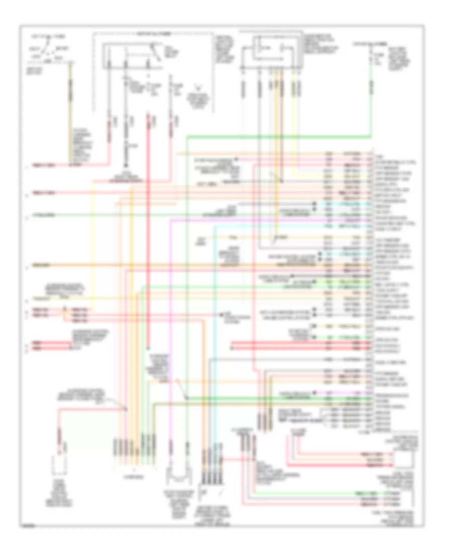
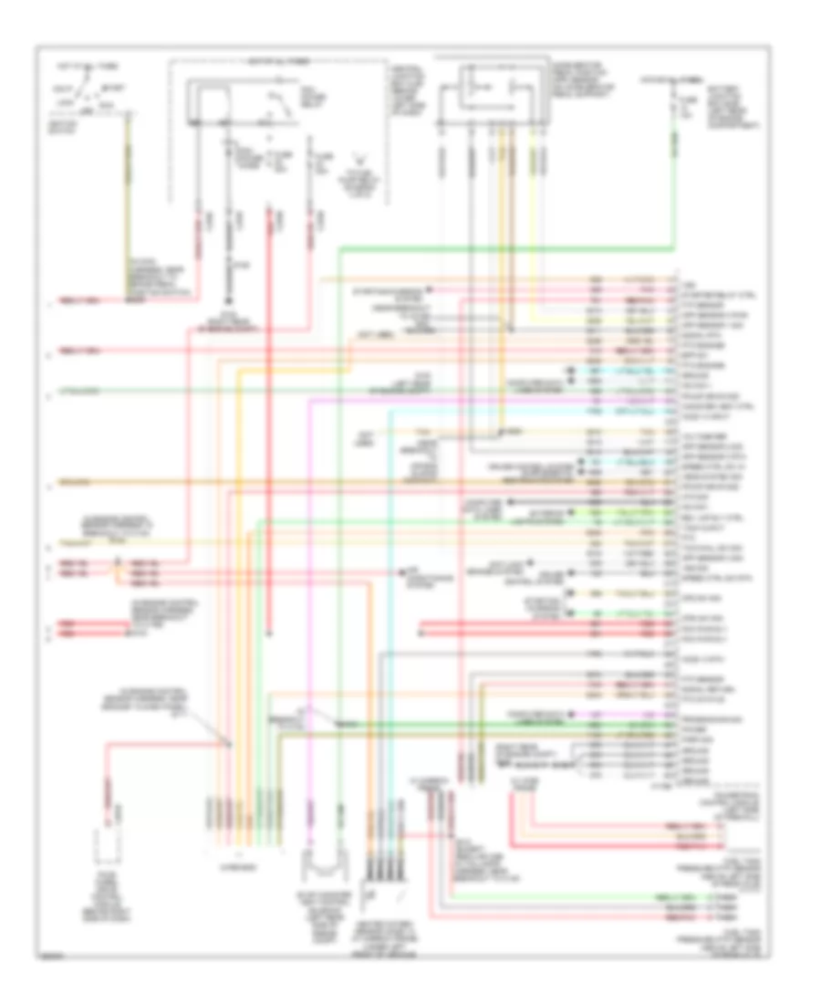
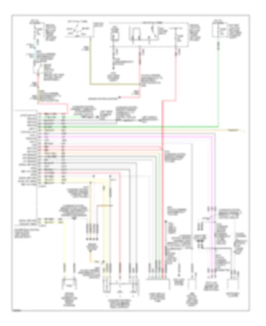
5.4L, Engine Performance Wiring Diagram (4 of 5) for Ford Cab & Chassis F350 Super Duty 2007
List of elements for 5.4L, Engine Performance Wiring Diagram (4 of 5) for Ford Cab & Chassis F350 Super Duty 2007:
- (a/t: near breakout to output shaft speed sensor) (m/t: near breakout to transfer case assembly)
- (in fuel tank) fuel tank unit
- (near breakout to brake pedal position switch)
- (not used) c145
- Brake pedal position switch (above brake pedal)
- C270a
- C270f
- Central junction box (cjb) (behind lower left side of dash)
- Check engine ind
- Computer data lines system
- Electronic throttle control (etc) motor (on throttle body)
- From pcm power relay (diagram 5 of 5)
- Fuel pump driver module (left rear frame rail)
- Fuel pump relay
- Fuse 10a
- Fuse 15a
- Fuse 20a
- G102 (right rear of engine compt)
- G401 (left side of vehicle underbody)
- Heated oxygen sensor (ho2s) 12 (catalyst monitor) (rear of catalytic converter)
- Heated oxygen sensor (ho2s) 22 (catalyst monitor) (left side of transmission)
- Hot at all times
- Hot in on or start
- Hot in run
- Hs can +
- Hs can -
- Inertia fuel shut-off (ifs) switch (right kick panel)
- Instrument cluster
- Knock sensor 1 (on right cylinder head)
- Knock sensor 2 (top left rear of engine)
- Nca
- Red
- Red/
- Return
- S106
- S138
- S205
- S208
- S234
- S411
- Tow/haul switch
- Variable camshaft timing (vct) solenoid 2 (left bank) (left front top of engine)
- W/ narrow frame
- W/ wide frame
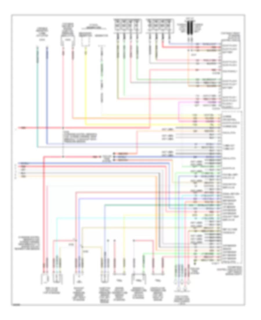
5.4L, Engine Performance Wiring Diagram (5 of 5) for Ford Cab & Chassis F350 Super Duty 2007
List of elements for 5.4L, Engine Performance Wiring Diagram (5 of 5) for Ford Cab & Chassis F350 Super Duty 2007:
- (in engine control sensor harness, in breakout to c140) s122
- (in engine control sensor harness, in breakout to c140) s164
- (in engine control sensor harness, near breakout to c1756) s123
- (in engine control sensor harness, near grommet in dash panel) s111
- (in main harness, near breakout to brake pedal position switch)
- (in main harness, near breakout to c2186) s221
- (near breakout to air bag sliding contact)
- (not used)
- (right rear of engine compt) g102
- (wire end)
- 20a
- Acc
- Accelerator pedal position sensor (on accelerator pedal support)
- Air conditioning system
- Anti-lock brakes system
- App sensor 1 sig
- App sensor 2 sig
- App sensor 3 pwr
- App sensor 3 rtn
- App sensor 3 sig
- Atn sig
- Battery junction box (bjb) (left rear of engine compt)
- Bpp sw input
- C175b
- C270c
- C270f
- C270h
- C281b
- Canister vent ctrl
- Central junction box (cjb) (behind lower left side of dash)
- Computer data lines system
- Cpda sw sig
- Cpsi sw sig
- Cruise control system
- Evap canister vent control solenoid (left rear side of engine compt)
- Exterior lights system
- Four- wheel drive control module (behind right side of dash)
- Fpump drvr mod
- Fpump dvr mod rtn
- From fuel pump relay (diagram 4 of 5)
- Ftp sensor
- Fuel tank pressure (ftp) sensor (above left side of rear axle)
- Fuel tank pressure sensor (above left side of rear axle)
- Fuse
- Fuse 10a
- Fuse 20a
- G100 (left rear of engine compt)
- G102 (right rear of engine compt)
- Ground
- Heated oxygen sensor (ho2s) 13 (w/ narrow frame) (under left front of vehicle)
- Ho2s 13 input
- Ho2s 13 return
- Hot at all times
- Hs can +
- Hs can -
- Ignition switch
- Lock
- Nca
- Off
- Pcm power diode
- Pcm power relay
- Pcm pwr rly
- Pnk
- Power
- Power take off
- Powertrain control module (left side of firewall)
- Programming sig
- Pto engage sig
- Pto rpm ctrl sig
- Red
- Red/pnk
- Rev lmp rly ctrl
- Run
- S106
- S223
- S258
- S412 (except regular cab) (in taillamps harness, near breakout to c140)
- Signal return
- Signal rtn
- Speed ctrl rtn sw
- Speed ctrl sw in
- Start
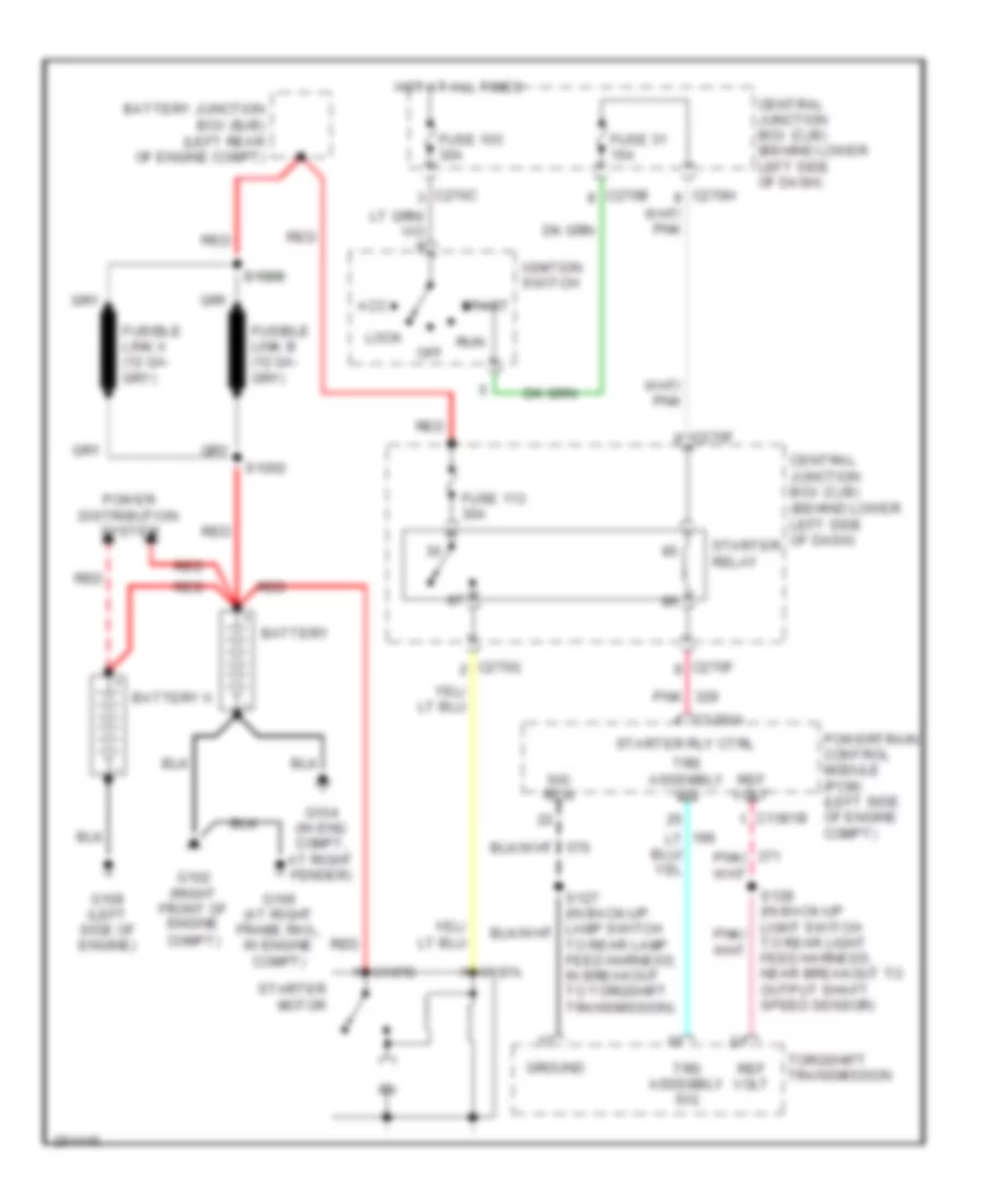
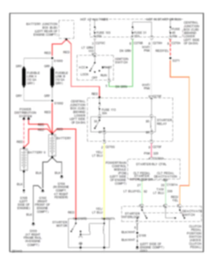
- Starter relay ctrl
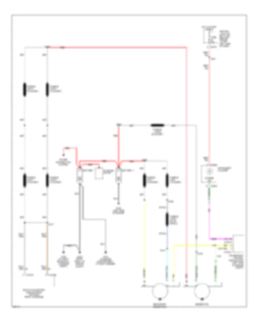
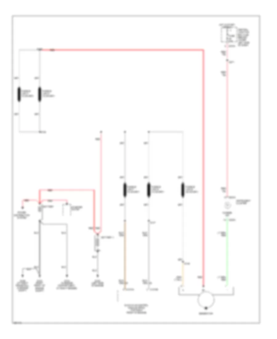
- Starting/ charging system
- Starting/charging system
- Tach ouput
- Tan
- Tow/haul sw sig
- Tr park signal
- Vems aa sig
- Voltage ref
- Vss
- Vss sig
- W/ narrow frame red/pnk
- W/ wide frame
6.0L DIESEL
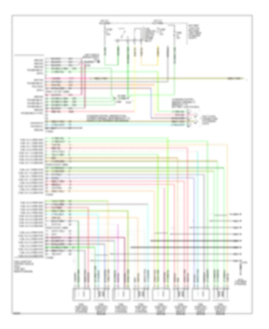
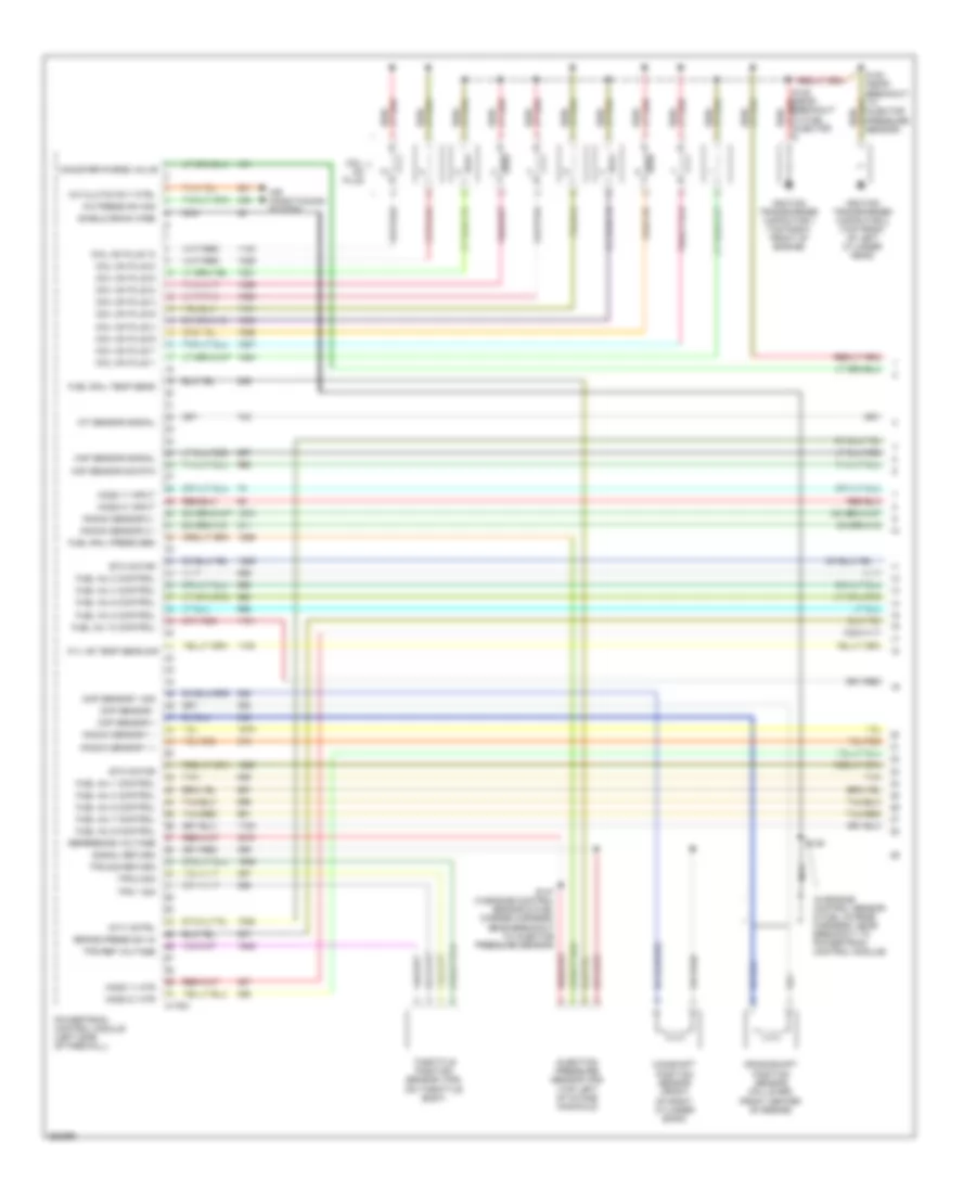
6.0L Diesel, Engine Performance Wiring Diagram (1 of 5) for Ford Cab & Chassis F350 Super Duty 2007
List of elements for 6.0L Diesel, Engine Performance Wiring Diagram (1 of 5) for Ford Cab & Chassis F350 Super Duty 2007:
- (in engine control sensor & fuel charge harness, near breakout to manifold air temperature sensor)
- (in engine control sensor harness, in breakout to battery junction box)
- (left side of engine compt) g101
- (pins 11-21 not used)
- (pins 9-16 not used)
- Battery junction box (bjb) (left rear of engine compt)
- C1388a
- C1388b
- C1388c
- Can bus 2h
- Can bus 2l
- Ckp-o
- Cmp-o
- Ficm to pcm connections (to diagram 5 of 5)
- Fuel inj 1 close gnd
- Fuel inj 1 close pwr
- Fuel inj 1 open gnd
- Fuel inj 1 open pwr
- Fuel inj 2 close gnd
- Fuel inj 2 close pwr
- Fuel inj 2 open gnd
- Fuel inj 2 open pwr
- Fuel inj 3 close gnd
- Fuel inj 3 close pwr
- Fuel inj 3 open gnd
- Fuel inj 3 open pwr
- Fuel inj 4 close gnd
- Fuel inj 4 close pwr
- Fuel inj 4 open gnd
- Fuel inj 4 open pwr
- Fuel inj 5 close gnd
- Fuel inj 5 close pwr
- Fuel inj 5 open gnd
- Fuel inj 5 open pwr
- Fuel inj 6 close gnd
- Fuel inj 6 close pwr
- Fuel inj 6 open gnd
- Fuel inj 6 open pwr
- Fuel inj 7 close gnd
- Fuel inj 7 close pwr
- Fuel inj 7 open gnd
- Fuel inj 7 open pwr
- Fuel inj 8 close gnd
- Fuel inj 8 close pwr
- Fuel inj 8 open gnd
- Fuel inj 8 open pwr
- Fuel injection control module (ficm) (top left rear of engine)
- Fuel injector 1 (top right side of engine)
- Fuel injector 2 (top left of engine)
- Fuel injector 3 (top right of engine)
- Fuel injector 4 (top left side of engine)
- Fuel injector 5 (top right rear of engine)
- Fuel injector 6 (top left rear of engine)
- Fuel injector 7 (top right rear of engine)
- Fuel injector 8 (left rear of engine)
- Fuel injector control module power relay
- Fuse 10a
- Fuse 15a
- Fuse 50a
- G110 (top rear of engine)
- Ground
- Hot at all times
- Ignition
- Nca
- Pcm comm
- Power relay
- Power relay ctrl
- S120
- S194
- S195
- S196
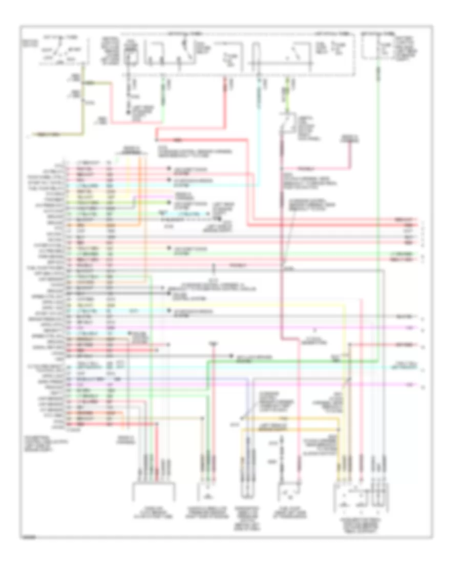
6.0L Diesel, Engine Performance Wiring Diagram (2 of 5) for Ford Cab & Chassis F350 Super Duty 2007
List of elements for 6.0L Diesel, Engine Performance Wiring Diagram (2 of 5) for Ford Cab & Chassis F350 Super Duty 2007:
- (ends in harness)
- (in engine control sensor harness, near breakout to g100)
- (in engine control sensor harness, under battery junction box)
- (left rear of engine compt)
- (left rear of engine compt) g100
- (m/t)
- (m/t) (a/t)
- A/c pre sen
- A/c press sw
- A/c relay
- Acc
- Accelerator pedal position sensor (on accelerator pedal support)
- Air conditioning system
- Anti-lock brakes system
- App sen 3 rtn
- Apps 1 sig
- Apps 2 rtn
- Apps 2 sig
- Apps 3 sig
- Auto chg
- Baro press
- Barometric absolute pressure switch (behind left side of dash)
- Battery junction box (bjb) (left rear of engine compt)
- Bpp sw
- Brake press sw
- C1381b
- C270a
- C270c
- C270f
- C270h
- Central junction box (cjb) (behind lower left side of dash)
- Cltch ped deact
- Cruise control system
- Cto
- Four wheel ctrl
- Fuel pump (near left side of transmission)
- Fuel pump power
- Fuel pump relay
- Fuse 10a
- Fuse 20a
- G100
- G101 (left side of engine compt)
- Gen/batt
- Ground
- Hot at all times
- Hs can+
- Hs can-
- Iat sensor
- Ignition switch
- Inertia fuel shutoff switch (right kick panel)
- Lock
- Maf sensor
- Manifold absolute pressure sensor (right side of engine)
- Map sensor
- Mass air- flow sensor (in air intake tube)
- Nca
- Off
- Park brake
- Pcm power diode
- Pcm power relay
- Pnk
- Powertrain control module (pcm) (left side of engine compt)
- Prog sig
- Pto
- Pto rpm
- Pto vref
- Pwr
- Red
- Run
- S106
- S114
- S117
- S118 (in engine control harness, in breakout to powertrain control module)
- S123 (in engine control sensor harness, near breakout to c1298)
- S139
- S162
- S170
- S182
- S221 in main harness, near breakout to c2186)
- S223 (in main harness, near breakout to air bag sliding contact)
- S234 (in main harness, near breakout to brake pedal position switch)
- S250
- S258
- Signal return
- Speed ctrl sw
- Start
- Start intlck
- Start rly cntrl
- Starting/charging system
- Tan
- Tow/haul sw
- Tps-feed
- Vbatt
- Vpwr
- Vs sig
- Vss
- W/ dual generators
- Water in fuel
6.0L Diesel, Engine Performance Wiring Diagram (3 of 5) for Ford Cab & Chassis F350 Super Duty 2007
List of elements for 6.0L Diesel, Engine Performance Wiring Diagram (3 of 5) for Ford Cab & Chassis F350 Super Duty 2007:
- (behind left side of dash, on park brake assembly) parking brake switch
- (behind right side of dash) four wheel drive control module
- (engine control sensor harn, at breakout for g100)
- (in engine control sensor & fuel charge harness, in breakout to powertrain control module)
- (in engine control sensor harness, in breakout to abs control module)
- (in main harness, in breakout to data link connector) s213
- (in main harness, in breakout to data link connector) s220
- (inside of left frame rail) water- in-fuel sensor
- (w/ drl)
- Battery junction box (bjb) (left rear of engine compt)
- Brake pedal position switch (behind left side of dash, above brake pedal)
- Brake pressure switch (on brake master cylinder)
- C220a
- C220b
- C270a
- C281b
- Camshaft position sensor (lower left front of engine)
- Central junction box (cjb) (behind lower left side of dash)
- Computer data lines system
- Crankshaft position sensor (lower right side of engine)
- Data link connector (behind left side of dash)
- Fuse 10a
- Fuse 2a
- G300 (behind left kick panel)
- Harness, in breakout to abs control module) s140
- Headlights system (w/ drl)
- Hot at all times
- Hot in run
- Hot in run or start
- Hs can (+)
- Hs can (-)
- Instrument cluster
- Malfunction indicator lamp
- Nca
- Red
- S110 (in engine control harness, in breakout to powertrain control module)
- S112 (in engine control harness, in breakout to powertrain control module)
- S142
- S174
- S197
- S205
- S208
- S271
- S287
- W/ dual generators
6.0L Diesel, Engine Performance Wiring Diagram (4 of 5) for Ford Cab & Chassis F350 Super Duty 2007
List of elements for 6.0L Diesel, Engine Performance Wiring Diagram (4 of 5) for Ford Cab & Chassis F350 Super Duty 2007:
- (a/t)
- (in back-up lamp switch to rear lamp feed harness, in breakout to torqshift transmission)
- (in back-up light switch to rear light feed harness, near breakout to output shaft speed sensor)
- (in back-up light switch to rear light feed harness, near breakout to torqshift transmission)
- (m/t)
- A/t
- C1381e
- C270a
- Central junction box (cjb) (behind lower left side of dash)
- Clutch pedal position switch (behind left side of dash, above clutch pedal)
- Fuse 15a
- Hot in run
- Intermediate shaft speed sensor
- Iss sig
- M/t
- Nca
- Oss sig
- Output shaft speed sensor (top of transmission extension housing)
- Pc sol pwr
- Pc-a sol
- Powertrain control module (left side of engine compt)
- Pressure control (pc-a) solenoid
- Red
- Ref volt
- Rev lmp ctrl
- Reversing lamp relay
- S127
- S128
- S129
- S235
- Shift solenoid pressure control a (sspc-a)
- Shift solenoid pressure control b (sspc-b)
- Shift solenoid pressure control c (sspc-c)
- Shift solenoid pressure control d (sspc-d)
- Shift solenoid pressure control e (sspc-e)
- Sig rtn
- Speed sensor assembly (top left side of transmission)
- Sspc-a crl
- Sspc-b ctrl
- Sspc-c crl
- Sspc-d ctrl
- Sspc-e ctrl
- Tcc sol ctrl
- Tft sens sig
- Torqshift transmission
- Torque converter clutch solenoid
- Tow/haul switch
- Tr-p sig
- Transmission fluid temperature sensor
- Transmission range sensor assembly (tr-p)
- Tss sig
- Turbine shaft speed sensor
6.0L Diesel, Engine Performance Wiring Diagram (5 of 5) for Ford Cab & Chassis F350 Super Duty 2007
List of elements for 6.0L Diesel, Engine Performance Wiring Diagram (5 of 5) for Ford Cab & Chassis F350 Super Duty 2007:
- (in engine control sensor & fuel charge harness, near breakout to engine coolant temperature sensor)
- (not used)
- (top rear center of engine) injection pressure regulator
- (top right front of engine) glow plug control module
- Battery
- C1273a
- C1273b
- C1381t
- Can bus 2h
- Can bus 2l
- Charge
- Charge (2nd)
- Ckp sensor
- Cmp sensor
- Coolant temp
- Cooling fan
- Cooling fans system
- Ebp sensor
- Egr valve
- Egr valve actuator (top of engine)
- Engine coolant temperature sensor (front of engine)
- Engine oil temperature sensor (top right of engine)
- Eot sensor
- Exhaust back pressure sensor (left front of engine)
- Fan clutch
- Ficm comm
- Ficm cyl id
- Ficm delivery
- Ficm to pcm connections (from diagram 1 of 5)
- Generator
- Glow plug
- Glow plug 1
- Glow plug 2
- Glow plug 3
- Glow plug 4
- Glow plug 5
- Glow plug 6
- Glow plug 7
- Glow plug 8
- Glow plug sys
- Ground
- Hot at all times
- Icp sensor
- Injection control pressure sensor (top left rear of engine)
- Ipr control
- Left glow plug bank
- Manifold air temperature sensor (top left front of engine)
- Mat sensor
- Nca
- Pcm pwr rly
- Plug rly
- Powertrain control module (pcm) (left side of engine compt)
- Red
- Ref voltage
- Right glow plug bank
- S147
- S190
- S192
- S193 (in engine control sensor & fuel charge harness, near breakout to exhaust back pressure sensor)
- Secondary generator
- Signal return
- Turbo act
- Variable geometric turbo actuator
- W/ dual generators
6.8L
6.8L, Engine Performance Wiring Diagram (1 of 5) for Ford Cab & Chassis F350 Super Duty 2007
List of elements for 6.8L, Engine Performance Wiring Diagram (1 of 5) for Ford Cab & Chassis F350 Super Duty 2007:
- (in engine control sensor & fuel charge harness, near breakout to powertrain control module)
- A/c clutch rly ctrl
- A/c press sw sig
- Air conditioning system
- Brake press sw in
- C175a
- Camshaft position sensor (front of right cylinder bank)
- Canister purge valve
- Ckp sensor +
- Ckp sensor -
- Cmp sensor 1 sig
- Coil on plug
- Coil on plug 1
- Coil on plug 10
- Coil on plug 2
- Coil on plug 3
- Coil on plug 4
- Coil on plug 5
- Coil on plug 6
- Coil on plug 7
- Coil on plug 8
- Coil on plug 9
- Crankshaft position sensor (on lower front center of engine)
- Cyl hd temp sens sig
- Etc motor
- Fuel inj 1 control
- Fuel inj 10 control
- Fuel inj 2 control
- Fuel inj 3 control
- Fuel inj 4 control
- Fuel inj 5 control
- Fuel inj 6 control
- Fuel inj 7 control
- Fuel inj 8 control
- Fuel inj 9 control
- Fuel rail press sen
- Fuel rail temp sens
- Ho2s 11 htr
- Ho2s 11 input
- Ho2s 21 htr
- Ho2s 21 input
- Iat sensor signal
- Ignition transformer capacitor 1 (top right front of engine)
- Ignition transformer capacitor 2 (top front of left cylinder head)
- Imtv cntrl
- Injection pressure sensor (ips) (top left of intake manifold)
- Knock sensor 1 +
- Knock sensor 1 -
- Knock sensor 2 +
- Knock sensor 2 -
- Maf sensor sig rtn
- Maf sensor signal
- Nca
- Powertrain control module (left side of firewall)
- Red/
- Reference voltage
- S145
- S147 (in engine control sensor & fuel charge harness, near breakout to injector pressure sensor)
- Shield drain wire
- Signal return
- Tan
- Tan/red
- Throttle position sensor (tps) (on throttle body)
- Tps 1 sig
- Tps 2 sig
- Tps ref voltage
- Tps sig return
6.8L, Engine Performance Wiring Diagram (2 of 5) for Ford Cab & Chassis F350 Super Duty 2007
List of elements for 6.8L, Engine Performance Wiring Diagram (2 of 5) for Ford Cab & Chassis F350 Super Duty 2007:
- (bottom of master cylinder) brake pressure switch
- (in engine control sensor & fuel charge harness, near breakout to powertrain control module)
- (left front of engine compt) mass air flow (maf) sensor
- (right rear of engine compt) evap canister purge valve
- (top right of engine) intake manifold tuning valve (imtv)
- Battery junction box (bjb) (left rear of engine compt)
- Cylinder head temperature sensor (on left cylinder head)
- Fuel injectors (1, 2, 5: top right side of engine) (3, 4: top right rear of engine) (6, 7: top left side of engine) (8: top left rear of engine) (9, 10: top left of engine)
- Fuse 2a
- G102 (right rear of engine compt)
- Heated oxygen sensor (ho2s) 11 (on right exhaust manifold)
- Heated oxygen sensor (ho2s) 21 (on left exhaust manifold)
- Hot in run
- Nca
- Red
- S127 (m/t: near breakout to reversing lights switch) (a/t: near breakout to output shaft speed sensor)
- S131 (near breakout to injector pressure sensor)
- S132
- S136 (near breakout to coil on plug 3)
- Tan
- Tan/red
6.8L, Engine Performance Wiring Diagram (3 of 5) for Ford Cab & Chassis F350 Super Duty 2007
List of elements for 6.8L, Engine Performance Wiring Diagram (3 of 5) for Ford Cab & Chassis F350 Super Duty 2007:
- (in back-up light switch to rear light feed harness, near breakout to torqshift transmission)
- (m/t: near breakout to reversing lights switch) (a/t: near breakout to output shaft speed sensor) s127
- C175c
- Ho2s 12 htr
- Ho2s 12 sig
- Ho2s 22 htr
- Ho2s 22 sig
- Intermediate shaft speed sensor
- Iss sensor sig
- Oss sensor sig
- Output shaft speed sensor (top of transmission extension housing)
- Powertrain control module (left side of firewall)
- Pr ctrl sol
- Pressure control (pc-a) solenoid
- Red
- S128 (in back-up light switch to rear light feed harness, near breakout to output shaft speed sensor)
- S129
- Shift sol a
- Shift sol b
- Shift sol c
- Shift sol d
- Shift sol e
- Shift sol vpwr
- Shift solenoid pressure control a (sspc-a)
- Shift solenoid pressure control b (sspc-b)
- Shift solenoid pressure control c (sspc-c)
- Shift solenoid pressure control d (sspc-d)
- Shift solenoid pressure control e (sspc-e)
- Sig rtn
- Speed sensor assembly (top left side of transmission)
- Tcc sol ctrl
- Tft sensor sig
- Torqshift transmission
- Torque converter clutch (tcc) solenoid
- Tr sens sig
- Transmission fluid temperature sensor
- Transmission range sensor assembly (tr-p)
- Trs ground
- Trs ref voltage
- Tss sensor sig
- Turbine shaft speed sensor
6.8L, Engine Performance Wiring Diagram (4 of 5) for Ford Cab & Chassis F350 Super Duty 2007
List of elements for 6.8L, Engine Performance Wiring Diagram (4 of 5) for Ford Cab & Chassis F350 Super Duty 2007:
- (a/t: near breakout to output shaft speed sensor) (m/t: near breakout to transfer case assembly)
- (in fuel tank) fuel tank unit
- (near breakout to brake pedal position switch)
- (not used) c145
- Brake pedal position switch (above brake pedal)
- C270a
- C270f
- Central junction box (cjb) (behind lower left side of dash)
- Check engine ind
- Computer data lines system
- Dual knock sensor (right rear of cylinder head)
- Electronic throttle control (etc) motor (on throttle body)
- From pcm power relay (diagram 5 of 5)
- Fuel pump driver module (left rear frame rail)
- Fuel pump relay
- Fuse 10a
- Fuse 15a
- Fuse 20a
- G102 (right rear of engine compt)
- G401 (at left side of vehicle underbody)
- Heated oxygen sensor (ho2s) 12 (catalyst monitor) (rear of catalytic converter)
- Heated oxygen sensor (ho2s) 22 (catalyst monitor) (left side of transmission)
- Hot at all times
- Hot in on or start
- Hot in run
- Hs can +
- Hs can -
- Inertia fuel shut-off (ifs) switch (right kick panel)
- Instrument cluster
- Nca
- Red
- Red/
- Return
- S106
- S138
- S205
- S208
- S234
- Tow/haul switch
- W/ narrow frame
- W/ wide frame
6.8L, Engine Performance Wiring Diagram (5 of 5) for Ford Cab & Chassis F350 Super Duty 2007
List of elements for 6.8L, Engine Performance Wiring Diagram (5 of 5) for Ford Cab & Chassis F350 Super Duty 2007:
- (in breakout to c140)
- (in engine control sensor harness, in breakout to c140) s122
- (in engine control sensor harness, near breakout to c1756) s123
- (in engine control sensor harness, near grommet in dash panel) s111
- (in main harness, near breakout to brake pedal position switch) s258
- (near breakout to air bag sliding contact)
- (near breakout to c2186) s221
- (not used)
- (right rear of engine compt) g102
- (wire end)
- Acc
- Accelerator pedal position (app) sensor (on accelerator pedal support)
- Air conditioning system
- Anti-lock brakes system
- App sensor 1 sig
- App sensor 2 sig
- App sensor 3 pwr
- App sensor 3 rtn
- App sensor 3 sig
- Atn sig
- Battery junction box (bjb) (left rear of engine compartment)
- Bpp sw
- C175b
- C270c
- C270f
- C270h
- C281b
- Canister vent ctrl
- Central junction box (cjb) (behind lower left side of dash)
- Computer data lines system
- Cpd sw sig
- Cpsi sw sig
- Cruise control system
- Evap canister vent control solenoid (left rear side of engine compt)
- Exterior lights system
- Four- wheel drive control module (behind right side of dash)
- Fpump drvr mod
- Ftp sensor
- Fuel tank pressure (ftp) sensor (above left side of rear axle)
- Fuse 10a
- Fuse 20a
- G100 (left rear of engine compt)
- G102 (right rear of engine compt)
- Ground
- Heated oxygen sensor (ho2s) 13 (w/ narrow frame) (under left front of vehicle)
- Ho2s 13 input
- Ho2s 13 rtn
- Hot at all times
- Hs can +
- Hs can -
- Ignition switch
- Lock
- Nca
- Off
- Park sig
- Pcm power diode
- Pcm power relay
- Pcm pwr rly
- Pnk
- Power
- Powertrain control module (left side of firewall)
- Programming sig
- Pto
- Pto engage
- Pto status
- Red
- Red/pnk
- Rev lmp rly ctrl
- Run
- S106
- S164
- S223
- S412 (except regular cab) (in taillamps harness, near breakout to c140)
- Signal return
- Signal rtn
- Speed ctrl sw in
- Speed ctrl sw rtn
- Start
- Starter relay ctrl
- Starting/ charging system
- Starting/charging system
- Tach ouput
- Tan
- To fuel pump relay (diagram 4 of 5)
- Tow/haul sw sig
- Vems system sig
- Voltage ref
- Vss
- Vss sig
- W/ narrow frame red/pnk
- W/ wide frame
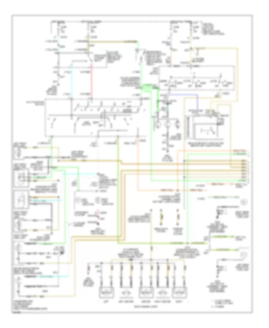
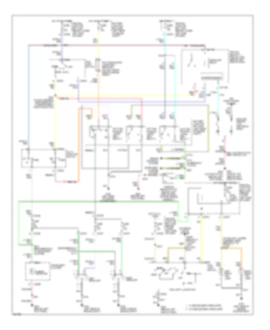
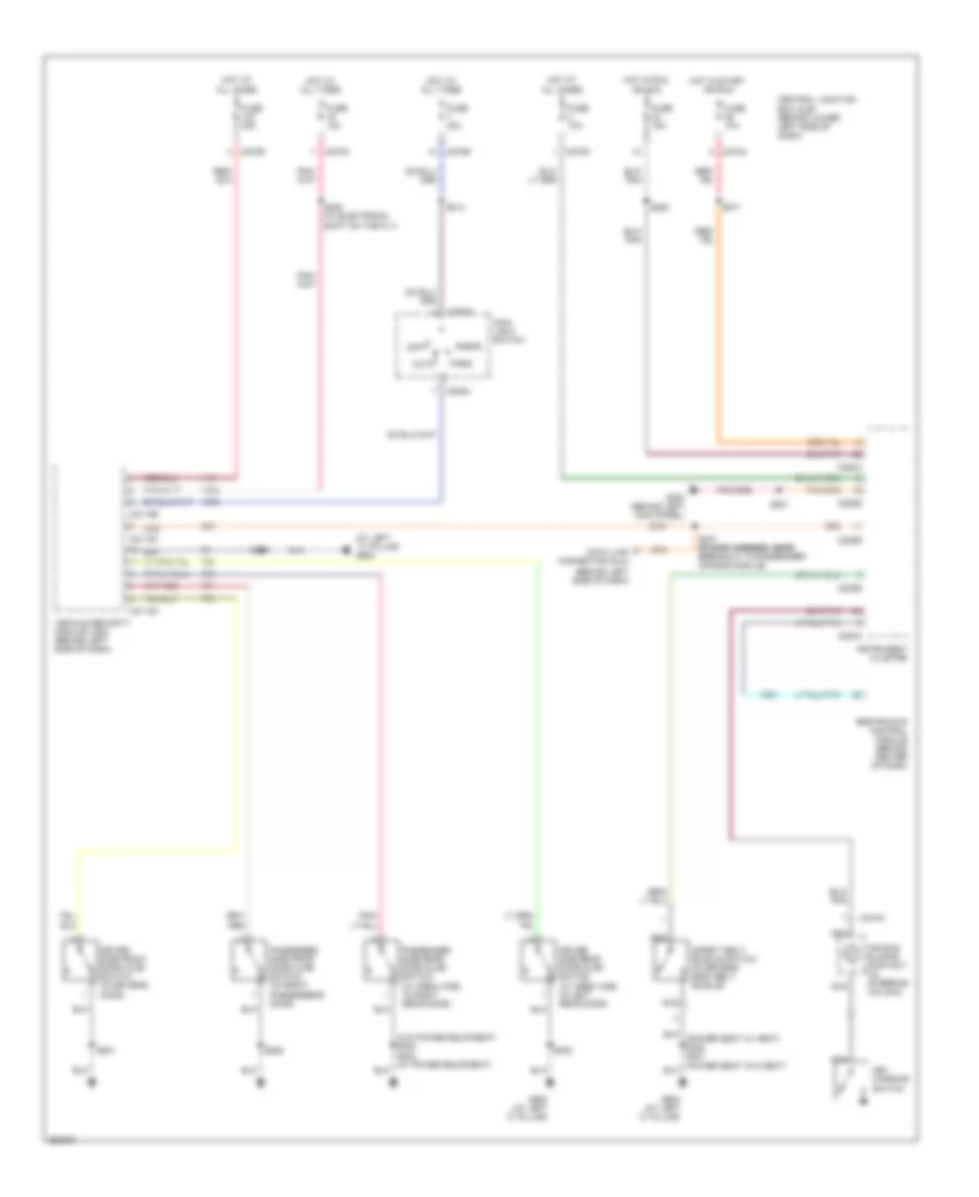
EXTERIOR LIGHTS
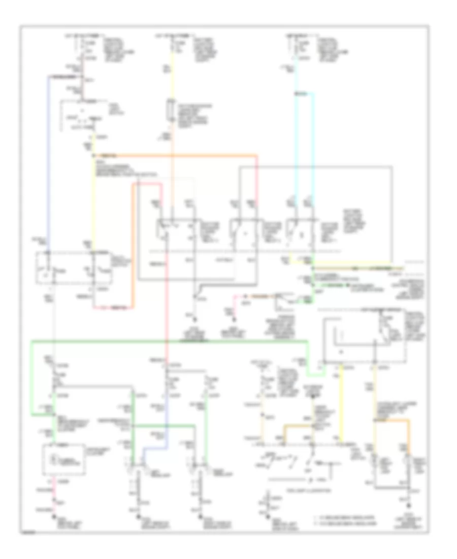
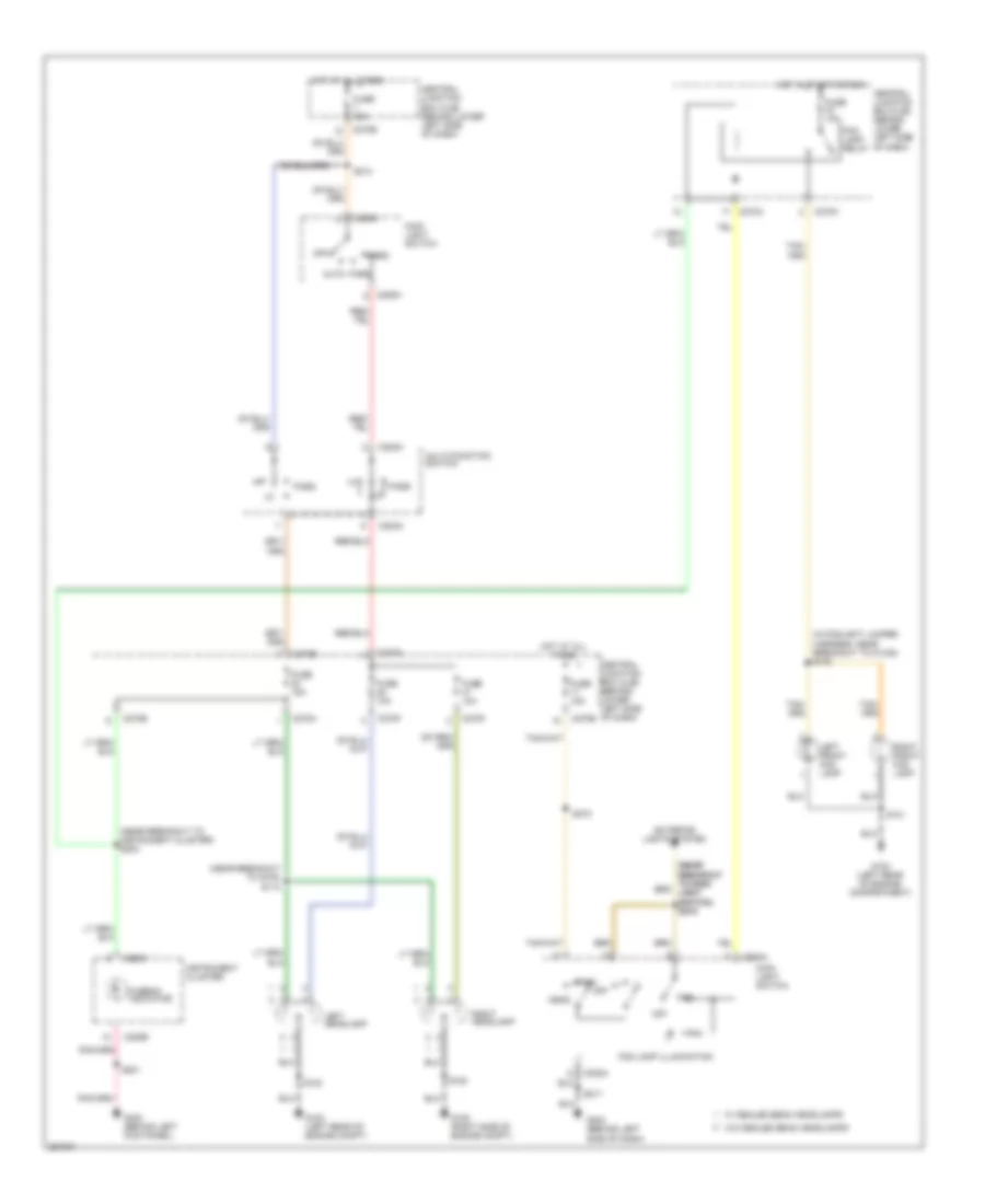
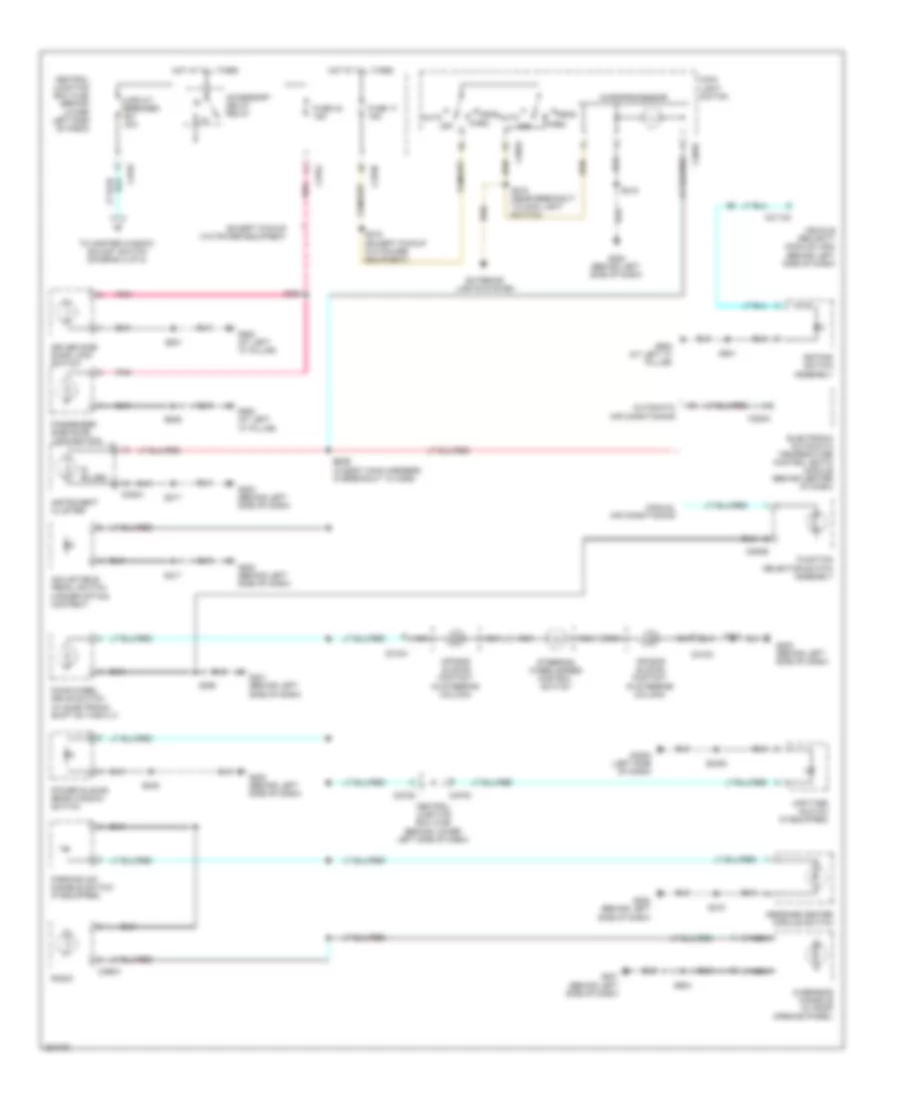
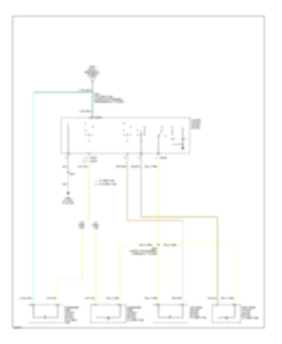
Exterior Lamps & Trailer Connector Wiring Diagram (1 of 3) for Ford Cab & Chassis F350 Super Duty 2007
List of elements for Exterior Lamps & Trailer Connector Wiring Diagram (1 of 3) for Ford Cab & Chassis F350 Super Duty 2007:
- (at left "c" pillar) g900
- (in main harness, near breakout to brake pedal position switch) s240
- (in overhead console, near breakout to center roof marker light) s921
- (left rear of engine compartment) g100
- (near breakout to ignition switch)
- Auto
- Auxiliary relay box 1 (behind left center of dash)
- Brake pedal position switch (behind left side of dash, above brake pedal)
- C202a
- C202b
- C205a
- C2113b
- C220a
- C220b
- C270a
- C270b
- Center
- Central junction box (cjb) (behind lower left side of dash)
- Driver side exterior rear view mirror (front of driver's door)
- Fuse 15a
- Fuse 20a
- Fuse 30a
- G108 (right side of engine compt)
- G201 (behind left side of dash)
- G202 (behind left side of dash)
- G300 (behind left kick panel)
- G400 (on vehicle underbody, rear chassis left side member)
- G900 (at left "c" pillar)
- Hazard switch
- Head
- Headlights system
- High mounted stoplamp
- Hot at all times
- Hot in run
- Indicator flasher relay
- Instrument cluster
- Interior lights system
- Left
- Left center
- Left front park/turn lamp
- Left front side lamp
- Left rear park/stop/ turn lamp
- Left tail lamps
- Left turn indicator
- Main light switch
- Microprocessor
- Multi-function switch
- Nca
- Off
- Others
- Park
- Park lamp relay
- Passenger side exterior rear view mirror (front of passenger's door)
- Right
- Right center
- Right front park/turn lamp
- Right front side lamp
- Right rear park/stop/ turn lamp
- Right tail lamps
- Right turn indicator
- Roof marker lamps
- S102
- S104 (in engine control sensor harness, in breakout to battery junction box)
- S105 (in engine control harness, under battery junction box)
- S107 (in engine control sensor harness, near breakout to g100)
- S180
- S201
- S206
- S207
- S214
- S215 (in main harness, near breakout to main light switch)
- S217
- S249
- S272
- S300
- S402
- S404
- S501
- S639
- S904
- Switch)
- Turn switch
- Vehicle security module (vsm) (behind left side of dash)
- W/ box
- W/ dual rear wheel & w/ box
- W/ power equipment
- W/ power mirrors
- W/o box
Exterior Lamps & Trailer Connector Wiring Diagram (2 of 3) for Ford Cab & Chassis F350 Super Duty 2007
List of elements for Exterior Lamps & Trailer Connector Wiring Diagram (2 of 3) for Ford Cab & Chassis F350 Super Duty 2007:
- (diesel) s162 s106 (gasoline)
- (in rear lamp connector harness) s417
- (not used)
- Battery junction box (bjb) (left rear of engine compt)
- C270b
- C270f
- C270h
- C270j
- Central junction box (cjb) (behind lower left side of dash)
- Diesel
- Fuse 20a
- G100 (left rear of engine compt)
- G400 (on vehicle underbody, rear chassis left side member)
- Gasoline
- Hot at all times
- Left license plate lamp
- Left rear park/stop/ turn lamp
- Left rear side lamp 1
- Left rear side lamp 2
- Left tail lamps
- Left turn trailer tow relay
- Nca
- Parking lamp trailer tow relay
- Rear marker lamp assembly
- Right license plate lamp
- Right rear park/stop/ turn lamp
- Right rear side lamp 1
- Right rear side lamp 2
- Right tail lamps
- Right turn trailer tow relay
- S103
- S162
- S319 (in body main harness, near breakout for g300)
- S402
- S404
- S407
- S408
- S409
- S410
- S418
- S463
- W/ dual rear wheels
- W/ rear bumper
- W/o box
- W/o dual rear wheels
- W/o rear bumper
Exterior Lamps & Trailer Connector Wiring Diagram (3 of 3) for Ford Cab & Chassis F350 Super Duty 2007
List of elements for Exterior Lamps & Trailer Connector Wiring Diagram (3 of 3) for Ford Cab & Chassis F350 Super Duty 2007:
- (in trailer lamp feed harness, near breakout to 7-pin trailer tow connector)
- (left side of rear bumper) trailer tow connector (4 pin)
- (left side of rear bumper) trailer tow connector (7 pin)
- (not used)
- 1792
- Battery charge trailer tow relay
- Battery junction box (bjb) (left rear of engine compt)
- Brake pressure transducer
- C1381b
- C175b
- C2142a
- C2142b
- C270a
- C270b
- C270e
- C270f
- C270g
- Central junction box (cjb) (behind lower left side of dash)
- Chassis cab
- Computer data lines system
- Diesel
- Except chassis cab
- Fuse 10a
- Fuse 15a
- Fuse 20a
- Fuse 30a
- G100 (diesel) (left rear of engine compt)
- G102 (gasoline) (right rear of engine compt)
- G201 (behind left side of dash)
- G202 (behind left side of dash)
- G400 (on vehicle underbody, rear chassis left side member)
- Gasoline
- Hi can -
- Hi can+
- Hot at all times
- Hot in run
- Hot in run or start
- Pcm power diode
- Pcm power relay
- Pnk
- Powertrain control module (gasoline: on left side of firewall) (diesel: left side of engine compt)
- Red
- S106 (gasoline)
- S121 (in main harness, in breakout to c211)
- S160 (in engine control harness, under battery junction box)
- S162 (diesel)
- S218
- S290
- S413 (in taillamps harness, near breakout to c140)
- S430
- S431
- S432
- S433 (in trailer lamp feed harness, near to breakout 7-pin trailer tow connector)
- Sig rtn
- Trailer brake control (tbc) connector
- Trailer brake control (tbc) module (behind center of dash)
- Trailer tow reversing lamp relay
- Vbatt
- Vpwr
- W/ brake control module
- W/o brake control module
5.4L
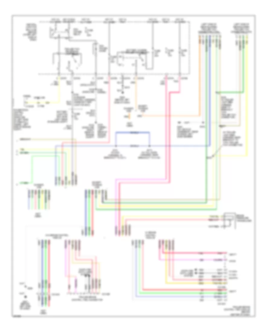
5.4L, Back-up Lamps Wiring Diagram for Ford Cab & Chassis F350 Super Duty 2007
List of elements for 5.4L, Back-up Lamps Wiring Diagram for Ford Cab & Chassis F350 Super Duty 2007:
- (not used)
- (others) s404
- A/t
- Battery junction box (bjb) (left rear of engine compt)
- C145
- C175b
- C270f
- C270g
- C4099
- Central junction box (cjb) (behind lower left side of dash)
- Chassis cab
- Electrochromatic inside mirror unit
- Except chassis cab
- Fuse 10a
- Fuse 15a
- G100 (left rear of engine compt)
- G102 (right rear of engine compt)
- G400 (on vehicle underbody, rear chassis left side member)
- Hot at all times
- Hot in run or start
- If equipped
- Left reversing lamp
- M/t
- Nca
- Others
- Parking aid
- Parking aid module (pam) (right kick panel)
- Pcm power diode
- Pcm power relay
- Powertrain control module (pcm) (left side of firewall)
- Reversing lamp relay
- Reversing lamps switch (on top left side of trans- mission)
- Right reversing lamp
- S106
- S133 (in engine control sensor harness, under battery junction box)
- S211 (in main harn, near breakout to c264)
- S250
- S402
- S426 (in rear lamp connector harness)
- S426 (in tail lamps harness, near breakout to c423)
- To left tail lamps
- To right tail lamps
- Trailer tow connector (7 pin) (left side of rear bumper)
- W/ electrochromatic mirror
6.0L DIESEL
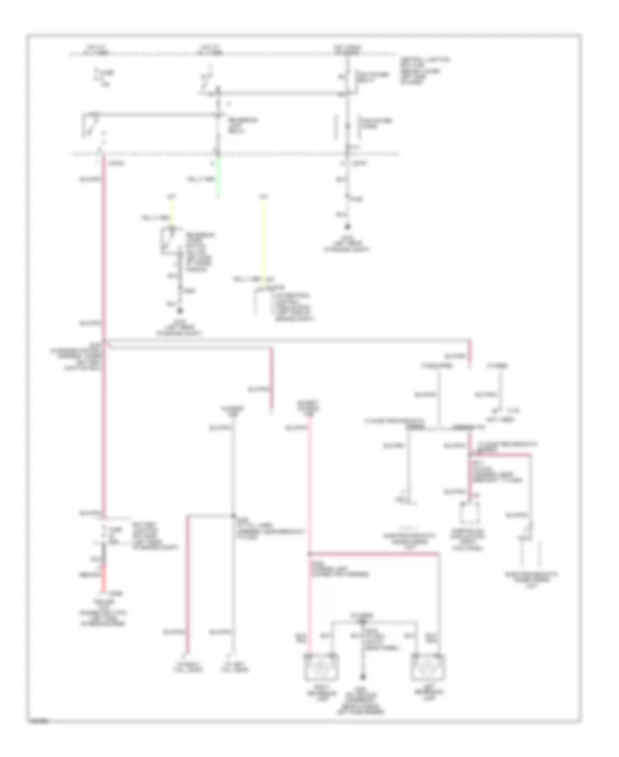
6.0L Diesel, Back-up Lamps Wiring Diagram for Ford Cab & Chassis F350 Super Duty 2007
List of elements for 6.0L Diesel, Back-up Lamps Wiring Diagram for Ford Cab & Chassis F350 Super Duty 2007:
- (not used)
- (others) s404
- A/t
- Battery junction box (bjb) (left rear of engine compt)
- C1381b
- C145
- C270f
- C270g
- C4099
- Central junction box (cjb) (behind lower left side of dash)
- Chassis cab
- Electrochromatic inside mirror unit
- Except chassis cab
- Fuse 10a
- Fuse 15a
- G100 (left rear of engine compt)
- G400 (on vehicle underbody, rear chassis left side member)
- Hot at all times
- Hot in run or start
- If equipped
- Left reversing lamp
- M/t
- Nca
- Others
- Parking aid
- Parking aid module (pam) (right kick panel)
- Pcm power diode
- Pcm power relay
- Powertrain control module (pcm) (left side of engine compt)
- Red/pnk
- Reversing lamp relay
- Reversing lamps switch (on top left side of trans- mission)
- Right reversing lamp
- S160 (in engine control harness, under battery junction box)
- S162
- S211 (in main harness, near breakout to c264)
- S250
- S402 (w/ box & dual rear wheel)
- S426 (in rear lamp connector harness)
- S426 (in tail lamps harness, near breakout to c423)
- To left tail lamps
- To right tail lamps
- Trailer tow connector (7 pin) (left side of rear bumper)
- W/ electrochromatic mirror
6.8L
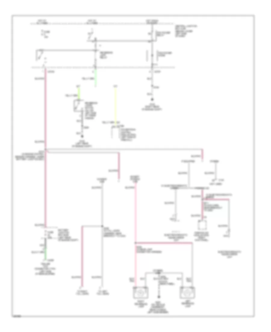
6.8L, Back-up Lamps Wiring Diagram for Ford Cab & Chassis F350 Super Duty 2007
List of elements for 6.8L, Back-up Lamps Wiring Diagram for Ford Cab & Chassis F350 Super Duty 2007:
- (not used)
- (others) s404
- A/t
- Battery junction box (bjb) (left rear of engine compt)
- C145
- C175b
- C270f
- C270g
- C4099
- Central junction box (cjb) (behind lower left side of dash)
- Chassis cab
- Electrochromatic inside mirror unit
- Except chassis cab
- Fuse 10a
- Fuse 15a
- G100 (left rear of engine compt)
- G102 (right rear of engine compt)
- G400 (on vehicle underbody, rear chassis left side member)
- Hot at all times
- Hot in run or start
- If equipped
- Left reversing lamp
- M/t
- Nca
- Others
- Parking aid
- Parking aid module (pam) (right kick panel)
- Pcm power diode
- Pcm power relay
- Powertrain control module (pcm) (left side of firewall)
- Reversing lamp relay
- Reversing lamps switch (on top left side of trans- mission)
- Right reversing lamp
- S106
- S133 (in engine control sensor harness, under battery junction box)
- S211 (in main harn, near breakout to c264)
- S250
- S402
- S426 (in rear lamp connector harness)
- S426 (in tail lamps harness, near breakout to c423)
- To left tail lamps
- To right tail lamps
- Trailer tow connector (7 pin) (left side of rear bumper)
- W/ electrochromatic mirror
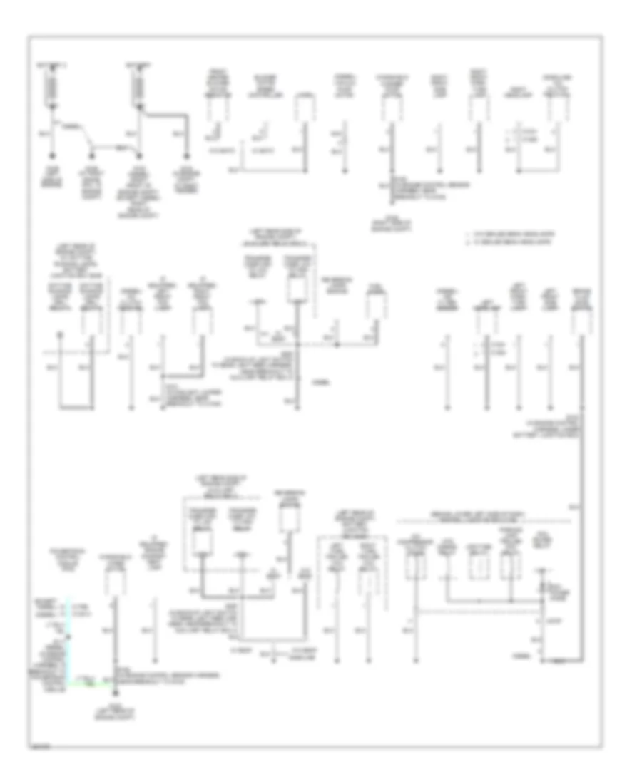
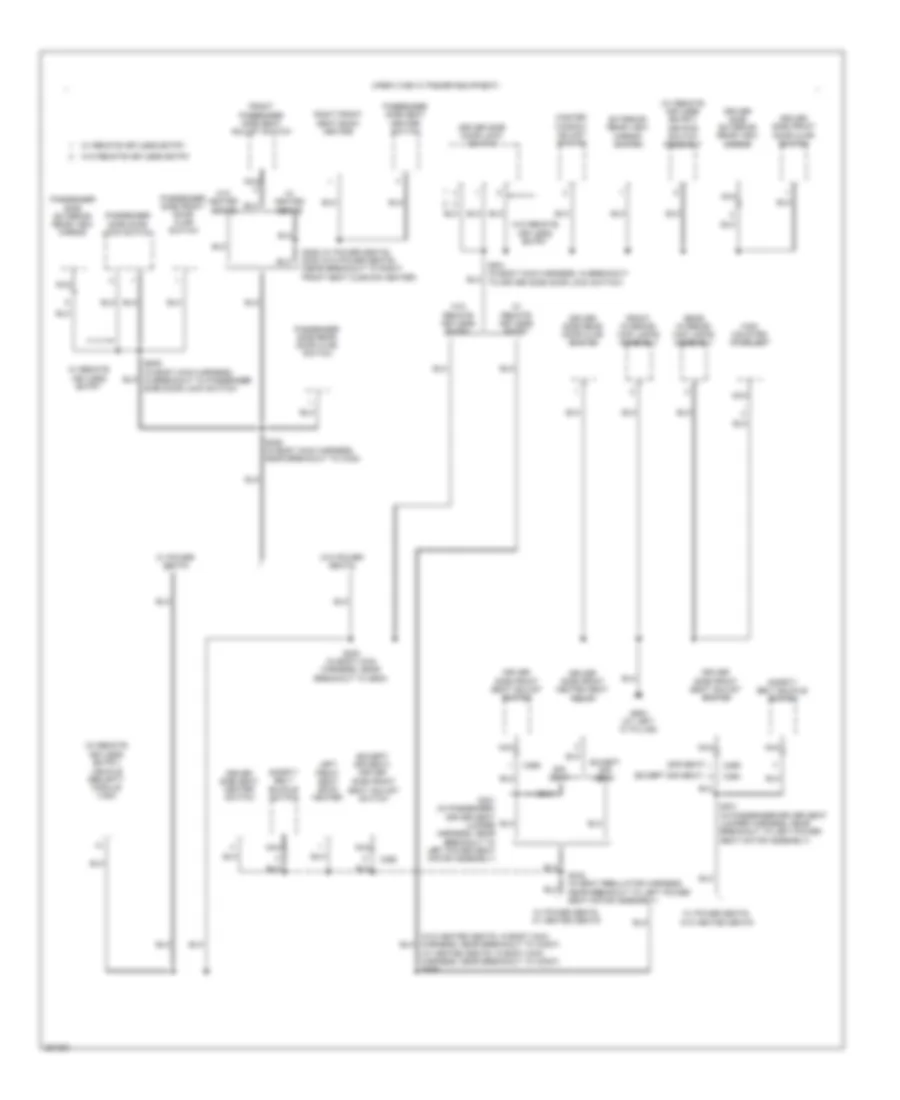
GROUND DISTRIBUTION
Ground Distribution Wiring Diagram (1 of 7) for Ford Cab & Chassis F350 Super Duty 2007
List of elements for Ground Distribution Wiring Diagram (1 of 7) for Ford Cab & Chassis F350 Super Duty 2007:
- (behind lower left side of dash) central junction box (cjb)
- (diesel)
- (diesel) a/c clutch field coil
- (diesel) air filter sensor
- (except diesel)
- (gasoline) a/c clutch field coil
- (if equipped) engine compart- ment lamp
- (if equipped) left front fog lamp
- (if equipped) right front fog lamp
- (left rear of engine compt) (w/ daytime running lamps) battery junction box (bjb)
- (left rear of engine compt) battery junction box (bjb)
- (left rear side of engine compt) auxiliary relay box 3
- 87a
- A/c compressor clutch diode
- Battery
- Battery 2
- Blower motor speed controller
- Brake fluid level switch
- C1021
- C1041
- C1284
- C1285
- C1381a
- C175b
- C270f
- Daytime running lamps (drl) relay 2
- Daytime running lamps (drl) relay 3
- Diesel
- Front heater blower motor resistor
- Fuel pump
- G100 (left rear of engine compt)
- G102 (diesel) (right front of engine compt) (except diesel) (right rear of engine compt)
- G104 (in engine compt, at right fender)
- G106 (at right frame rail, in engine compt)
- G108 (right side of engine compt)
- G109 (left side of engine)
- Gasoline
- Harness, near breakout to g108)
- Horn
- Htd mirror relay
- Left front park/ turn lamp
- Left front side lamp
- Left headlamp
- Left turn trailer tow relay
- Nca
- Parking lamp trailer tow relay
- Pcm power diode
- Pcm power relay
- Powertrain control module (pcm)
- Reversing lamps switch
- Right front park/ turn lamp
- Right front side lamp
- Right headlamp
- Right turn trailer tow relay
- S101 (in foglight jumper harness, near breakout to c1045)
- S102 (in engine control harness, under battery junction box)
- S117 (diesel) (in engine control harness, in breakout to powertrain control module)
- S250 (in back-up light switch to rear light feed har- ness, near breakout to auxiliary relay box 3)
- S250 (in back-up light switch to rear light feed harness, near breakout to auxiliary relay box 3)
- Transfer case high to low relay
- Transfer case low to high relay
- Upfitter relay
- Vacuum pump motor
- W/ eatc
- W/ esof
- W/ sealed beam headlamps
- W/o eatc
- W/o esof
- W/o sealed beam headlamps
- Windshield washer pump motor
- Windshield wiper motor
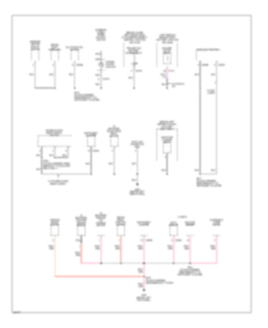
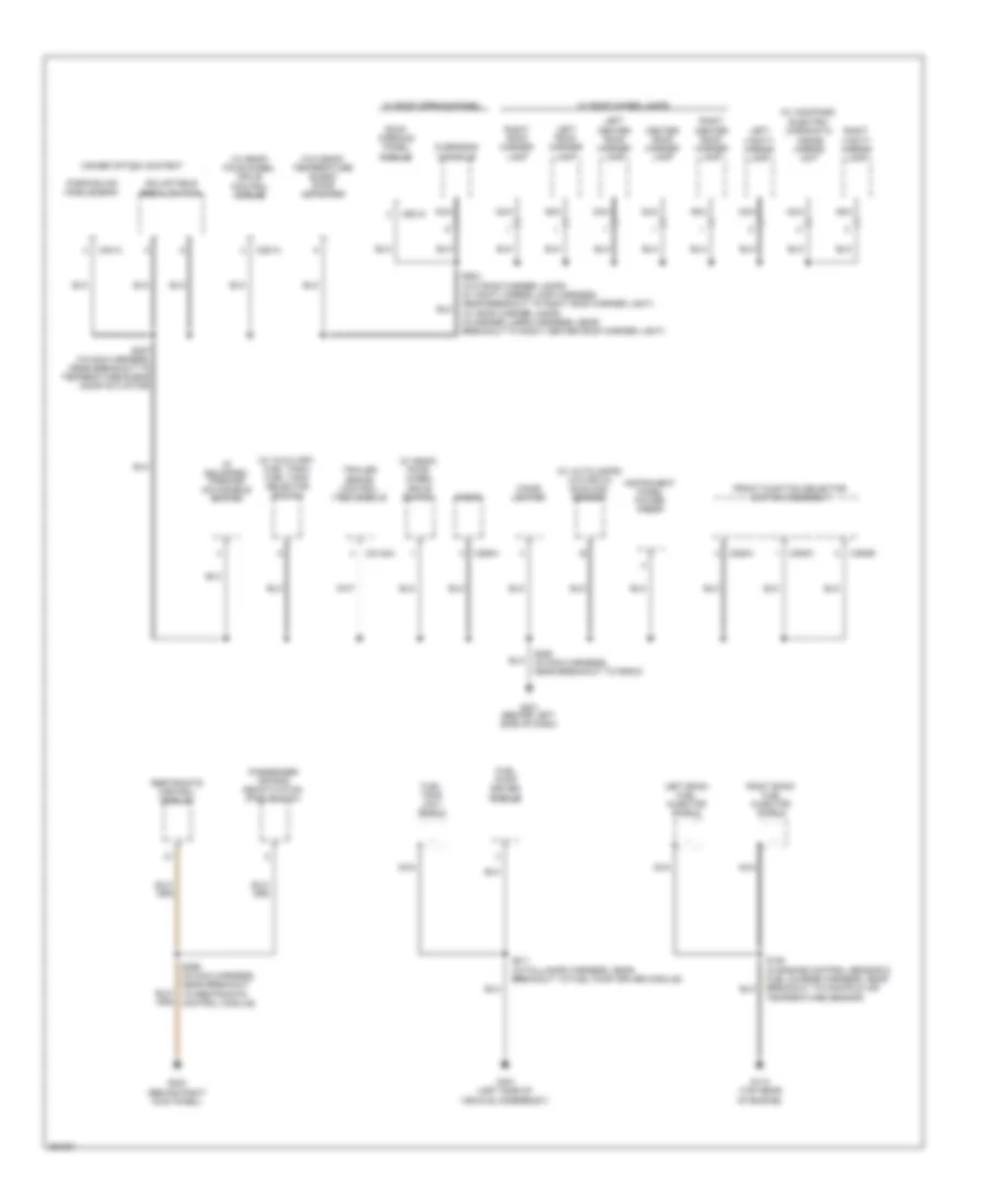
Ground Distribution Wiring Diagram (2 of 7) for Ford Cab & Chassis F350 Super Duty 2007
List of elements for Ground Distribution Wiring Diagram (2 of 7) for Ford Cab & Chassis F350 Super Duty 2007:
- (behind left center of dash) auxiliary relay box 1
- (behind lower left side of dash) (w/ power equipment) central junction box (cjb)
- (if equipped) adjustable pedal switch
- (if equipped) compass sensor module
- (if equipped) parking aid disable switch
- (left rear of engine compt) battery junction box (bjb)
- Air bag sliding contact
- Automatic a/c
- Blower motor relay
- Brake pedal position switch
- Brake shift interlock
- C1011
- C202b
- C205a
- C205b
- C218a
- C220a
- C220b
- C228a
- C270a
- Data link connector (dlc)
- Eatc module
- G202 (behind left side of dash)
- G300 (behind left kick panel)
- Indicator flasher relay
- Instrument cluster
- Main light switch
- Message center module switch
- Multifunction switch
- Nca
- Parking brake switch
- Power sliding rear window switch
- S201 (in main harness, near breakout to instrument cluster)
- S217 (in main harness, near breakout to instrument cluster)
- S218 (in main harness, near breakout to instrument cluster)
- S232 (in main harness, near breakout to auxiliary relay box 1)
- S278 (in main harness, near breakout to c291)
- Steering wheel/ speed control switch
- Sunload sensor
- Trailer tow battery charge relay
- W/ eatc
- W/ fog lamps
- W/ power sliding rear window
- Windshield wiper motor
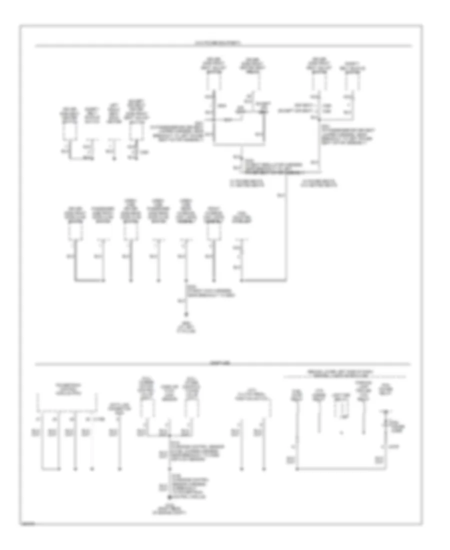
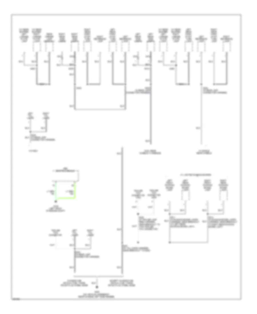
Ground Distribution Wiring Diagram (3 of 7) for Ford Cab & Chassis F350 Super Duty 2007
List of elements for Ground Distribution Wiring Diagram (3 of 7) for Ford Cab & Chassis F350 Super Duty 2007:
- (5.4l) charge motion control valve (cmcv)
- (6.8l) intake manifold tuning valve (imtv)
- (behind lower left side of dash) central junction box (cjb)
- (crew cab) driver side rear door ajar switch
- (crew cab) passenger side rear door ajar switch
- (crew cab) rear interior/ map lamps assembly
- (except sir seat)
- (except sir seat) driver side front seat adjust switch
- (gasoline)
- (m/t) clutch pedal position switch
- (sir seat)
- (w/o power equipment)
- C175b
- C270f
- C360
- C369
- Data link connector (dlc)
- Driver side front door ajar switch
- Driver side front heated seat relay
- Driver side front seat adjust switch
- Driver side seat heater switch
- Except sir seat
- Front interior/ map lamps assembly
- Fuel pump relay
- G102 (right rear of engine compt)
- G900 (at left "c" pillar)
- High mounted stoplamp
- Htd mirror relay
- Left front seat back heater
- Mass air flow (maf) sensor
- Nca
- Parking lamp trailer tow relay
- Passenger side front door ajar switch
- Pcm power diode
- Pcm power relay
- Powertrain control module (pcm)
- S106 (in engine control sensor harness, in breakout to powertrain control module)
- S300 (in body main harness, near breakout to g900)
- S301 (in passenger-driver seat jumper harness, near breakout to left power seat motor assembly)
- S332 (in seat regulator harness, near breakout to left power seat motor assembly)
- Safety belt buckle switch
- Sir seat
- Upfitter relay
- W/ power seats, w/ heated seats
- W/ power seats, w/o heated seats
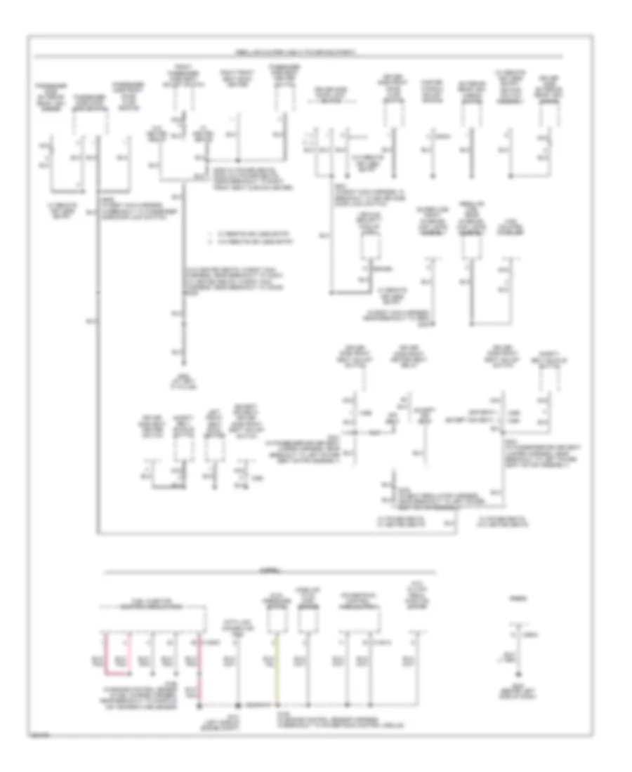
Ground Distribution Wiring Diagram (4 of 7) for Ford Cab & Chassis F350 Super Duty 2007
List of elements for Ground Distribution Wiring Diagram (4 of 7) for Ford Cab & Chassis F350 Super Duty 2007:
- (diesel)
- (except sir seat)
- (except sir seat) driver side front seat adjust switch
- (in body main harness, near breakout to g900) s300
- (m/t) clutch pedal position switch
- (regular & super cab w/ power equipment)
- (regular cab) rear interior/ map lamps assembly
- (sir seat)
- (super cab) front interior/ map lamps assembly
- (w/ remote keyless entry) keypad switch assembly
- (w/o heated seats: in body main harness, near breakout to c3007) (w/ heated seats: in body main harness, near breakout to c3049) s306
- C1381a
- C1388c
- C2113a
- C290a
- C360
- C369
- C504a
- Data link connector (dlc)
- Driver side door lock switch
- Driver side exterior rear view mirror
- Driver side front door ajar switch
- Driver side front heated seat relay
- Driver side front seat adjust switch
- Driver side seat heater switch
- Dual pressure switch
- Except sir seat
- Exterior rear view mirror switch
- Front passenger side seat adjust switch
- Fuel injector control module (ficm)
- G101 (left side of engine compt)
- G200 (behind left side of dash)
- G900 (at left "c" pillar)
- High mounted stoplamp
- Left front seat back heater
- Mass air flow (maf) sensor
- Master window adjust switch
- Nca
- Passenger side door lock switch
- Passenger side exterior rear view mirror
- Passenger side front door ajar switch
- Passenger side seat heater switch
- Powertrain control module (pcm)
- Radio
- Right front seat back heater
- S106 (in engine control sensor harness, in breakout to powertrain control module)
- S195 (in engine control sensor & fuel charge harness, near breakout to manifold air temperature sensor)
- S301 (in passenger-driver seat jumper harness, near breakout to left power seat motor assembly)
- S332 (in seat regulator harness, near breakout to left power seat motor assembly)
- S355 (w/ power seats) s335 (w/o power seats) (near breakout to right front seat cushion heater)
- S501 (in body main harness, in breakout to driver side door lock switch)
- Safety belt buckle switch
- Side door lock switch)
- Sir seat
- Vehicle security module (vsm)
- W/ heated seats
- W/ power seats, w/ heated seats
- W/ power seats, w/o heated seats
- W/ remote keyless entry
- W/o heated seats
- W/o remote keyless entry
Ground Distribution Wiring Diagram (5 of 7) for Ford Cab & Chassis F350 Super Duty 2007
List of elements for Ground Distribution Wiring Diagram (5 of 7) for Ford Cab & Chassis F350 Super Duty 2007:
- (crew cab w/ power equipment)
- (except sir seat)
- (except sir seat) driver side front seat adjust switch
- (sir seat)
- (w/ heated seats: in body main harness, near breakout to c3007) s306
- (w/ remote
- (w/ remote keyless entry) keypad switch assembly
- C360
- C369
- Driver side door lock switch
- Driver side exterior rear view mirror
- Driver side front door ajar switch
- Driver side front heated seat relay
- Driver side front seat adjust switch
- Driver side rear door ajar switch
- Driver side seat heater switch
- Except sir seat
- Exterior rear view mirror switch
- Front interior/ map lamps assembly
- Front passenger side seat adjust switch
- G900 (at left "c" pillar)
- High mounted stoplamp
- Keyless entry)
- Left front seat back heater
- Master window adjust switch
- Nca
- Passenger side door lock switch
- Passenger side exterior rear view mirror
- Passenger side front door ajar switch
- Passenger side rear door ajar switch
- Passenger side seat heater switch
- Rear interior/ map lamps assembly
- Right front seat back heater
- S300 (in body main harness, near breakout to g900)
- S301 (in passenger- driver seat jumper harness, near breakout to left power seat motor assembly)
- S301 (in passenger-driver seat jumper harness, near breakout to left power seat motor assembly)
- S326 (in body main harness, near breakout to c340)
- S332 (in seat regulator harness, near breakout to left power seat motor assembly)
- S355 (w/ power seats) s335 (w/o power seats) (near breakout to right front seat cushion heater)
- S501 (in body main harness, in breakout to driver side door lock switch)
- S639 (in body main harness, in breakout to passenger side door lock switch)
- Safety belt buckle switch
- Sir seat
- Vehicle security module (vsm)
- W/ heated seats
- W/ power seats
- W/ power seats, w/ heated seats
- W/ power seats, w/o heated seats
- W/ remote keyless entry
- W/o heated seats
- W/o power seats
- W/o remote keyless entry
Ground Distribution Wiring Diagram (6 of 7) for Ford Cab & Chassis F350 Super Duty 2007
List of elements for Ground Distribution Wiring Diagram (6 of 7) for Ford Cab & Chassis F350 Super Duty 2007:
- (if equipped) parking aid disable switch
- (w/ autolamps) (w/o eatc) sunload sensor
- (w/ auxiliary fuel tank) fuel tank selector switch
- (w/ compass) electro- chromatic inside mirror unit
- (w/ esof) four- wheel drive switch
- (w/ esof) four-wheel drive control module
- (w/o esof) temperature blend door actuator
- Adjustable pedal switch
- C2142a
- C281a
- C290a
- C294a
- C294b
- C294c
- C4014
- C921a
- Center roof marker lamp
- Cigar lighter
- Front function selector switch assembly
- Fuel pump driver module
- Fuel tank unit shield
- G110 (top rear of engine)
- G201 (behind left side of dash)
- G203 (behind right kick panel)
- G401 (left side of vehicle underbody)
- Higher option content
- Instrument panel power point
- Left bank fuel injector shield
- Left center roof marker lamp
- Left roof marker lamp
- Left vanity mirror lamp
- Nca
- Overhead console
- Parking aid module (pam)
- Passenger air bag deactivation (pad) switch
- Radio
- Restraints control module
- Right bank fuel injector shield
- Right center roof marker lamp
- Right roof marker lamp
- Right vanity mirror lamp
- Roof opening panel module
- S194 (in engine control sensor & fuel charge harness, near breakout to manifold air temperature sensor)
- S257 (in main harness, near breakout to temperature blend door actuator)
- S290 (in main harness, near breakout to radio)
- S299 (in main harness, near breakout to restraints control module)
- S411 (in taillamps harness, near breakout to fuel pump driver module)
- S904 (w/o roof marker lamps: in vanity mirror lamp harness, near breakout to right roof marker light) (w/ roof marker lamps: in marker lamps harness, near breakout to right center roof marker light)
- Trailer brake control (tbc) module
- W/ roof maker lamps
- W/ roof opening panel
Ground Distribution Wiring Diagram (7 of 7) for Ford Cab & Chassis F350 Super Duty 2007
List of elements for Ground Distribution Wiring Diagram (7 of 7) for Ford Cab & Chassis F350 Super Duty 2007:
- (w/ rear bumper) left license plate lamp
- (w/ rear bumper) right license plate lamp
- Abs control module
- Chassis cab or dual fuel tanks or 200 plus wheel base
- Connector harness)
- Dual rear wheels, flareside
- Except chassis cab or dual fuel tanks or 200 plus wheel base
- G105 (left front of engine compt)
- G400 (on vehicle underbody, rear chassis left side member)
- Left front running board lamp
- Left rear park/ stop/ turn lamp
- Left rear running board lamp
- Left rear side lamp 1
- Left rear side lamp 2
- Left reversing lamp
- Left tail lamps
- Nca
- Rear marker lamp assembly
- Right front running board lamp
- Right rear park/ stop/ turn lamp
- Right rear running board lamp
- Right rear side lamp 1
- Right rear side lamp 2
- Right reversing lamp
- Right tail lamps
- S313 (in running board lamps harness, near breakout to right rear running board light)
- S401 (in taillamps harness, near breakout to g400)
- S402
- S404 (in rear lamp connector harness)
- S409
- S410
- S432 (in trailer lamp feed harness, near breakout to 7-pin trailer tow connector )
- S463
- Trailer tow connector
- Trailer tow connector 4-pin
- Trailer tow connector 7-pin
- W/ lighted running boards
- W/ single rear wheels
- W/o box
HEADLIGHTS
Autolamps Wiring Diagram, with DRL for Ford Cab & Chassis F350 Super Duty 2007
List of elements for Autolamps Wiring Diagram, with DRL for Ford Cab & Chassis F350 Super Duty 2007:
- (automatic a/c) (manual a/c)
- (in foglight jumper harness, near breakout to c1045) s100
- (near breakout to g100)
- 6.0l
- 87a
- Air conditioning system
- Auto
- Battery junction box (bjb) (left rear of engine compt)
- C202a
- C205a
- C2113b
- C220a
- C220b
- C270a
- C270b
- C270f
- C270g
- C270h
- Central junction box (cjb) (behind lower left side of dash)
- Central junction box (cjb) (behind lower left side of dash)
- Daytime running lamps (drl) relay 1
- Daytime running lamps (drl) relay 2
- Daytime running lamps (drl) relay 3
- Daytime running lamps (drl) resistor (on left front side of engine compt)
- Engine controls system
- Exterior lights system
- Fog
- Fog lamp illumination
- Fog lamp relay
- Fuse 10a
- Fuse 15a
- Fuse 30a
- G100 (left rear of engine compartment)
- G100 (left rear of engine compt)
- G108 (right side of engine compt)
- G201 (manual a/c) (behind left side of dash)
- G202 (behind left side of dash)
- G300 (automatic a/c) (behind left kick panel)
- G300 (behind left kick panel)
- Head
- Headlamp relay
- Hi-beam indicator
- Hot at all times
- Hot in run
- Hot in start or run
- Instrument cluster
- Instrument cluster system
- Left front fog lamp
- Left headlamp
- Main light switch
- Microprocessor
- Multi- function switch
- Off
- Park
- Parking brake switch (behind left side of dash, on park brake assembly)
- Pass
- Right front fog lamp
- Right headlamp
- S101
- S102
- S113
- S124
- S180
- S201
- S201 s290
- S203 (near breakout to instrument cluster)
- S214
- S217
- S244 (in main harness, near breakout to brake pedal position switch)
- S272
- S278
- S287
- Sunload sensor (top center of dash)
- To g100)
- Vehicle security module (vsm) (behind left side of dash)
- W/ sealed beam headlamps
- W/o sealed beam headlamps
Autolamps Wiring Diagram, without DRL for Ford Cab & Chassis F350 Super Duty 2007
List of elements for Autolamps Wiring Diagram, without DRL for Ford Cab & Chassis F350 Super Duty 2007:
- (in junction box wiring harness, near breakout for left front fog light) s110
- 87a
- Battery junction box (bjb) (left rear corner of engine compartment)
- C270b
- C270c
- C270e
- Central junction box (cjb) (behind left side of dash)
- Daytime running lamps relay
- Flash
- Fog lamps
- Fuse 10a
- Fuse 15a
- Fuse 20a
- Fuse 7.5a
- G100 (left front of engine compt)
- G102 (right front of engine compt)
- G103 (left side of engine compt)
- G203 (at right ``a" pillar)
- G204 (at left "a" pillar)
- G204 (at left ``a" pillar)
- High
- High beam ind
- High beam relay
- Hot at all times
- Hot in start or run
- Illumination
- Instrument cluster
- Left front fog lamp
- Left head- lamp
- Low beam
- Low beam relay
- Main light switch
- Multi-function switch
- Neutral
- Off
- Park
- Red
- Right front fog lamp
- Right head- lamp
- S109
- S118
- S121
- S206
- S212
- W/ fog lamps
Headlamps Wiring Diagram, with DRL for Ford Cab & Chassis F350 Super Duty 2007
List of elements for Headlamps Wiring Diagram, with DRL for Ford Cab & Chassis F350 Super Duty 2007:
- (in foglight jumper harness, near breakout to c1045) s100
- (near breakout to g100)
- 87a
- Auto
- Battery junction box (bjb) (left rear of engine compt)
- C1381a
- C202a
- C205a
- C220a
- C220b
- C270a
- C270b
- C270f
- C270g
- C270h
- Central junction box (cjb) (behind lower left side of dash)
- Central junction box (cjb) (behind lower left side of dash)
- Daytime running lamps (drl) relay 1
- Daytime running lamps (drl) relay 2
- Daytime running lamps (drl) relay 3
- Daytime running lamps (drl) resistor (on left front side of engine compt)
- Exterior lights system
- Fog
- Fog lamp illumination
- Fog lamp relay
- Fuse 10a
- Fuse 15a
- Fuse 30a
- G100 (left rear of engine compartment)
- G100 (left rear of engine compt)
- G108 (right side of engine compt)
- G202 (behind left side of dash)
- G300 (behind left kick panel)
- Head
- Hi-beam indicator
- Hot at all times
- Hot in run
- Hot in start or run
- Instrument cluster
- Instrument cluster system
- Left front fog lamp
- Left headlamp
- Main light switch
- Multi- function switch
- Off
- Park
- Parking brake switch (behind left side of dash, on park brake assembly)
- Pass
- Powertrain control module (diesel) (left side of engine compt)
- Right front fog lamp
- Right headlamp
- S101
- S102
- S113
- S124
- S180
- S201
- S203 (near breakout to instrument cluster)
- S214
- S217
- S244 (in main harness, near breakout to brake pedal position switch)
- S272
- S278
- S287
- W/ sealed beam headlamps
- W/o sealed beam headlamps
Headlamps Wiring Diagram, without DRL for Ford Cab & Chassis F350 Super Duty 2007
List of elements for Headlamps Wiring Diagram, without DRL for Ford Cab & Chassis F350 Super Duty 2007:
- (in foglight jumper harness, near breakout to c1045) s100
- (near breakout to g100)
- (near breakout to instrument cluster) s203
- Auto
- C202a
- C205a
- C220a
- C220b
- C270a
- C270b
- C270f
- C270g
- C270h
- Central junction box (cjb) (behind lower left side of dash)
- Central junction box (cjb) (behind lower left side of dash)
- Exterior lights system
- Fog
- Fog lamp illumination
- Fog lamp relay
- Fuse 10a
- Fuse 15a
- Fuse 30a
- G100 (left rear of engine compartment)
- G100 (left rear of engine compt)
- G108 (right side of engine compt)
- G202 (behind left side of dash)
- G300 (behind left kick panel)
- Head
- Hi-beam indicator
- Hot at all times
- Hot in start or run
- Instrument cluster
- Left front fog lamp
- Left headlamp
- Main light switch
- Multi-function switch
- Off
- Park
- Pass
- Right front fog lamp
- Right headlamp
- S101
- S102
- S113
- S180
- S201
- S214
- S217
- S272
- W/ sealed beam headlamps
- W/o sealed beam headlamps
HORN
Horn Wiring Diagram for Ford Cab & Chassis F350 Super Duty 2007
List of elements for Horn Wiring Diagram for Ford Cab & Chassis F350 Super Duty 2007:
- Air bag sliding contact (in steering column)
- C2113b
- C218a
- C270a
- C270h
- Central junction box (cjb) (behind lower left side of dash)
- Fuse 15a
- G108 (at right side of engine compt)
- G202 (behind left side of dash)
- Horn (right front of vehicle)
- Horn relay
- Hot at all times
- Nca
- S180
- S218
- S252
- Sound system
- Steering wheel/ speed control switch
- Vehicle security module (vsm) (behind left side of dash)
- W/ remote keyless entry
INSTRUMENT CLUSTER
Instrument Cluster Wiring Diagram (1 of 2) for Ford Cab & Chassis F350 Super Duty 2007
List of elements for Instrument Cluster Wiring Diagram (1 of 2) for Ford Cab & Chassis F350 Super Duty 2007:
- 4wd high ind
- 4wd low ind
- Abs ind
- Air bag ind
- Air filter ind
- Anti-theft on ind
- Battery saver relay
- Brake fluid level switch (diesel: on brake fluid reservoir) (except diesel: in brake fluid reservoir)
- C205b
- C220a
- C220b
- C270a
- C270b
- C270d
- Central junction box (cjb) (behind lower left side of dash)
- Charge ind
- Check engine ind
- Computer data lines system
- Engine coolant temperature
- Exterior lights system
- Fuel gauge
- Fuse 10a
- Fuse 15a
- G100 (left rear of engine compt)
- G202 (behind left side of dash)
- G300 (behind left kick panel)
- Headlights system
- High beam ind
- Hot at all times
- Hot in run or acc
- Hot in start or run
- Illumination (6 bulbs)
- Instrument cluster
- Interior lamps relay
- Interior lights system
- Lh turn signal ind
- Low brake fluid level/ park brake ind
- Low oil pressure ind
- Low oil pressure/ high coolant temperature ind
- Main light switch
- Microprocessor
- Oil pressure switch (5.4l: on left front of engine) (6.0l: top center of engine) (6.8l: lower left side of engine)
- Rh turn signal ind
- S102
- S201
- S217
- S218
- S254
- S271
- Speed control ind
- Speedometer
- Tachometer
- Tow/ haul ind (diesel)
- Transmission fluid temperature
- Transmissions system
- Wait to start ind (diesel)
- Warning system
- Water in fuel ind
Instrument Cluster Wiring Diagram (2 of 2) for Ford Cab & Chassis F350 Super Duty 2007
List of elements for Instrument Cluster Wiring Diagram (2 of 2) for Ford Cab & Chassis F350 Super Duty 2007:
- (behind left side of dash)
- (in main harness, in breakout to instrument cluster)
- (left rear of cab) (diesel) fuel tank selector valve
- Air filter sensor (diesel) (left side of engine compt)
- C1381a
- C175b
- C270a
- Can +
- Can -
- Central junction box (cjb) (behind lower left side of dash)
- Compass sensor module (top center of front windshield)
- Computer data lines system
- Diesel
- Diesel & gasoline w/ wide frame
- Ends in harness
- Except diesel
- Fuel tank selector switch (diesel)
- Fuel tank unit
- Fuse 10a
- G100 (left rear of engine compt)
- G201
- G300 (behind left kick panel)
- Gasoline w/ narrow frame
- Headlights system
- Hot in start or run
- Info
- Interior lights system
- Message center module switch
- Nca
- Parking brake switch (behind left side of dash, on park brake assembly)
- Powertrain control module (pcm) (diesel: left side of engine compt) (except diesel: left side of firewall)
- Primary fuel sender (on fuel tank)
- Primary tank
- Red
- Reset
- S102
- S201
- S278
- S278 (in main harness, near breakout to c291)
- S290
- S298
- S400
- S901
- Secondary fuel sender (on fuel tank)
- Secondary tank
- Setup
- W/ auxiliary fuel tank
- W/o auxiliary fuel tank
Overhead Console Wiring Diagram for Ford Cab & Chassis F350 Super Duty 2007
List of elements for Overhead Console Wiring Diagram for Ford Cab & Chassis F350 Super Duty 2007:
- (behind left side of dash) g201
- C220a
- C220b
- C921a
- Close/tilt up
- G201 (behind left side of dash)
- Ground
- Hot at all times
- Instrument cluster
- Interior lamp relay
- Interior lights system
- Micro- processor
- Nca
- Open/tilt dn
- Overhead console
- Roof opening panel module (rear of roof)
- Roof opening panel, close circuit
- Roof opening panel, common
- Roof opening panel, open circuit
- S904
- S937 (in vanity mirror lamp harness, near breakout to electrochromatic inside mirror unit)
- Tan/red
INTERIOR LIGHTS
Courtesy Lamps Wiring Diagram (1 of 3) for Ford Cab & Chassis F350 Super Duty 2007
List of elements for Courtesy Lamps Wiring Diagram (1 of 3) for Ford Cab & Chassis F350 Super Duty 2007:
- Battery saver relay
- C205b
- C220a
- C220b
- C270a
- C270b
- Central junction box (cjb) (behind lower left side of dash)
- Fuse 35 10a
- Fuse 41 10a
- G201 (behind left side of dash)
- G202 (behind left side of dash)
- G400 (on vehicle underbody, rear chassis left side member)
- Hot at all times
- Instrument cluster
- Interior
- Interior lamps relay
- Left front running board lamp
- Left rear running board lamp
- Left vanity mirror lamp
- Main light switch
- Microprocessor
- Nca
- Overhead console (w/ roof opening panel)
- Right front running board lamp
- Right rear running board lamp
- Right vanity mirror lamp
- S204 (in main harness, near breakout to accelerator pedal position sensor)
- S218
- S229 (in main harness, near breakout to instrument cluster)
- S309 (in running board lamps harness, near breakout to left front running board light)
- S311
- S312 (in running board lamps harness, near breakout to right front running board light)
- S313
- S344 (in taillamps harness, near breakout to c494)
- S401
- S904
- S937 (in vanity mirror lamp harness, near breakout to electrochromatic inside mirror unit)
- To accessory delay relay (central junction box) (diagram 2 of 3)
- To rear interior/map lamps assembly (diagram 2 of 3)
- W/ lighted running boards
- W/ vanity lamps
- W/o vanity lamps
Courtesy Lamps Wiring Diagram (2 of 3) for Ford Cab & Chassis F350 Super Duty 2007
List of elements for Courtesy Lamps Wiring Diagram (2 of 3) for Ford Cab & Chassis F350 Super Duty 2007:
- (in body main harness, in breakout to front interior/map light assembly)
- Accessory delay relay
- C270a
- C270f
- C270j
- Central junction box (cjb) (behind lower left side of dash)
- Crew & super cab
- Engine compartment lamp
- From instrument cluster (diagram 1 of 3)
- From s229 (w/ vanity lamps) from instrument cluster (w/o vanity lamps) (diagram 1 of 3)
- Front interior/map lamps assembly (crew & super cab)
- G100 (left rear of engine compt)
- G900 (at left "c" pillar)
- High mounted stoplamp
- Interior
- Map
- Nca
- Rear interior/map lamps assembly (crew & regular cab)
- Regular cab
- S162
- S300
- S905 (except super cab: in body main harness, near breakout to rear interior/map light assembly) (super cab: in body main harness, near breakout to high mounted stoplight)
- S906
Courtesy Lamps Wiring Diagram (3 of 3) for Ford Cab & Chassis F350 Super Duty 2007
List of elements for Courtesy Lamps Wiring Diagram (3 of 3) for Ford Cab & Chassis F350 Super Duty 2007:
- C2113a
- C220b
- Driver's side door ajar switch (in driver's door)
- G900 (at left "c" pillar)
- Instrument cluster
- Left rear door ajar switch (w/ crew cab) (in left rear door)
- Passenger's side door ajar switch (in front passenger's door)
- Right rear door ajar switch (w/ crew cab) (in right rear door)
- S236
- S300
- S300 (w/o power equipment) s233 (w/ power equipment) s326 (w/power equipment & w/o remote keyless entry))
- S501 (w/ remote keyless entry) s326 (w/o remote keyless entry & w/ power equipment) s300 (w/o remote keyless entry & w/o power equipment)
- S639
- Vehicle security module (vsm) (behind left side of dash)
- W/ remote keyless entry
- W/o remote keyless entry
Instrument Illumination Wiring Diagram (1 of 2) for Ford Cab & Chassis F350 Super Duty 2007
List of elements for Instrument Illumination Wiring Diagram (1 of 2) for Ford Cab & Chassis F350 Super Duty 2007:
- (6 bulbs)
- Accessory delay relay
- Adjustable pedal switch (higher option content)
- Air bag sliding contact (in steering column)
- Auto
- Automatic air conditioning
- C205a
- C205b
- C2113c
- C218a
- C220a
- C228a
- C270b
- C270d
- C270i
- C270j
- C270k
- C290a
- C294b
- Central junction box (cjb) (behind lower left side of dash)
- Circuit breaker 30a
- Driver side door lock switch
- Electronic automatic temperature control (eatc) module (behind center of dash)
- Except pickup w/0 power equipment
- Exterior lights system
- Four-wheel drive switch (w/ electronic shift on the fly)
- Function selector switch assembly
- Fuse 17 15a
- Fuse 42 15a
- G201 (behind left side of dash)
- G202 (behind left side of dash)
- G2300 (left side of dash)
- G900 (at left "c" pillar)
- Head
- Hot at all times
- Instrument cluster
- Keypad switch assembly
- Main light switch
- Manual air conditioning
- Message center module switch
- Microprocessor
- Nca
- Off
- Overhead console (w/ roof opening panel)
- Park
- Parking aid disable switch (if equipped)
- Passenger side door lock switch
- Pnk
- Power sliding rear window switch
- Radio
- S215 (near breakout to main light switch)
- S216 s216 (in body main harness, in breakout to c855)
- S217
- S218
- S2300
- S232
- S272 (except pickup w/o power equipment)
- S290
- S320
- S501
- S639
- S904
- Steering wheel/speed control switch
- To master window adjust switch (diagram 2 of 2)
- Upfitter switch (if equipped)
- Vehicle security module (vsm) (behind left side of dash)
Instrument Illumination Wiring Diagram (2 of 2) for Ford Cab & Chassis F350 Super Duty 2007
List of elements for Instrument Illumination Wiring Diagram (2 of 2) for Ford Cab & Chassis F350 Super Duty 2007:
- C504a
- C504b
- From circuit breaker 601 (diagram 1 of 2)
- G900 (at left "c" pillar)
- Left rear window adjust switch (w/ crew cab)
- Master window adjust switch
- Passenger side window adjust switch (w/ crew cab)
- Passenger side window adjust switch (w/o crew cab)
- Right rear window adjust switch (w/ crew cab)
- S297 (w/o crew cab) (in body main harness, near breakout to g300)
- S328 (in body main harness, in breakout to c855)
- S501
- W/ crew cab
- W/o crew cab
NAVIGATION
Parking Assistant Wiring Diagram for Ford Cab & Chassis F350 Super Duty 2007
List of elements for Parking Assistant Wiring Diagram for Ford Cab & Chassis F350 Super Duty 2007:
- (in back-up alarm jumper harness, near breakout to c4001) s450
- C270a
- Central junction box (cjb) (behind lower left side of dash)
- Computer data lines system
- Exterior lights system
- Fuse 15a
- G201 (behind left side of dash)
- G300 (behind left kick panel.)
- Ground
- Hot in run
- Inner left signal
- Inner right signal
- Interior lights system
- Iso
- Left inner parking aid sensor (left side of rear bumper)
- Left outer parking aid sensor (left side of rear bumper)
- Outer left signal
- Outer right signal
- Pam ind
- Park aid enable
- Park aid speaker (+)
- Park aid speaker (-)
- Parking aid disable switch
- Parking aid module (pam) (at right kick panel)
- Parking aid speaker (right kick panel)
- Ref voltage
- Reverse lamps relay
- Right inner parking aid sensor (right side of rear bumper)
- Right outer parking aid sensor (right side of rear bumper)
- S201
- S206
- S257
- S290
- S451 (in back-up alarm jumper harness, near breakout to c4001)
- Sig return
- Vpwr
POWER DISTRIBUTION
Power Distribution Wiring Diagram (1 of 5) for Ford Cab & Chassis F350 Super Duty 2007
List of elements for Power Distribution Wiring Diagram (1 of 5) for Ford Cab & Chassis F350 Super Duty 2007:
- (behind lower left side of dash) central junction box (cjb)
- (in main harness, in breakout to central junction box) s249
- (in main harness, near breakout for data link connector) s242
- (in main harness, near breakout to brake pedal position switch) s214
- (in main harness, near breakout to instrument cluster) (w/ eatc) s208
- (in main harness, near breakout to restraints control module) (w/ electronic shift on the fly) s230
- (not used)
- 2 of 5)
- 30a
- Adjustable pedal switch (w/o memory)
- Auxiliary relay box 1 (behind left center of dash)
- Battery
- Battery ii (diesel)
- Brake pedal position switch
- C197b
- C202a
- C205a
- C2113b
- C2142b
- C220b
- C228b
- C270a
- C270b
- C270d
- C270e
- C270g
- C270h
- C270i
- C270j
- C270k
- C281a
- C290a
- Central junction box (cjb) (behind lower left side of dash)
- Data link connector (dlc)
- Driver side front heated seat relay
- Electronic automatic temperature control (eatc) module
- Exterior rear view mirror switch
- Four-wheel drive control module (w/ electronic shift on the fly)
- From a fuse 10 (diagram 1 of 5)
- From b fuse 16 (diagram 1 of 5)
- Front cigar lighter
- Fuse
- Fuse (not used)
- Fuse 1 15a
- Fuse 11 20a
- Fuse 111 (not used)
- Fuse 12 20a
- Fuse 13 5a
- Fuse 17 15a
- Fuse 18 20a
- Fuse 19 10a
- Fuse 2 10a
- Fuse 20 15a
- Fuse 21 20a
- Fuse 34 10a
- Fuse 4 20a
- Fuse 6
- Fuse 7 30a
- G201 (behind left side of dash)
- Indicator flasher relay
- Instru- ment panel power point
- Instrument cluster
- Main light switch
- Multi- function switch
- Nca
- Passenger side front seat adjust switch
- Pnk
- Radio
- Red
- S1000 (in engine control sensor harness, near battery) red
- S1002 (in engine control sensor harness, near battery)
- S290
- Starter motor
- To fuse (diagram 2 of 5)
- To fuse 1 (diagram 5 of 5)
- To fuse 108 (diagram 1 of 5)
- To fuse 12 (diagram 1 of 5)
- To fusible links (diagram
- To fusible links (diagram 2 of 5)
- Trailer brake control module
- Vehicle security module (vsm)
- W/ power equipment
- W/ remote keyless entry
Power Distribution Wiring Diagram (2 of 5) for Ford Cab & Chassis F350 Super Duty 2007
List of elements for Power Distribution Wiring Diagram (2 of 5) for Ford Cab & Chassis F350 Super Duty 2007:
- (behind lower left side of dash) central junction box (cjb)
- (in alternator rectifier system harness, near breakout to battery) s165
- (in alternator rectifier system harness, near breakout to secondary generator)
- (in alternator rectifier system harness, near positive battery cable)
- (in body main harness, near breakout to g300) s289
- (in engine control sensor harness, near breakout to glow plug control module) red s125
- (in main harness, in breakout to instrument cluster) s254
- (not used)
- (w/o sir seat) (w/ sir seat)
- C102a
- C1251a
- C1273a
- C1273b
- C2113b
- C2142a
- C220a
- C270a
- C270b
- C270c
- C270d
- C270e
- C270f
- C270g
- C270h
- C270i
- C270j
- C270k
- C281a
- C290a
- Central junction box (cjb) (behind lower left side of dash)
- Diesel
- Driver side door lock switch
- Driver side front seat adjust switch
- Except diesel
- Four-wheel drive control module (w/ electronic shift on the fly)
- From battery (diagram 1 of 5)
- From d fuse 112 (diagram 2 of 5)
- From fuse 111 (diagram 1 of 5)
- From ignition switch (diagram 3 of 5)
- Fuel pump relay
- Fuel tank selector switch (w/ auxiliary fuel tank, diesel only)
- Fuse
- Fuse (not used)
- Fuse (not used)
- Fuse 101 30a
- Fuse 102 30a
- Fuse 10a
- Fuse 112 30a
- Fuse 15a
- Fuse 20a
- Fuse 30a
- Fuse 33 15a
- Fuse 5a
- Fusible link e
- Fusible link h
- Generator
- Glow plug control module (gpcm)
- Horn relay
- Instrument cluster
- Nca
- Passenger side door lock switch
- Pcm power relay
- Radio
- Red
- S125 (in engine control sensor harness, near breakout to glow plug control module)
- S126 (in engine control sensor harness, near breakout to glow plug control module)
- S144
- S147 (in engine control sensor & fuel charge harness, near breakout to glow plug control module )
- S149
- S149 (in engine control sensor & fuel charge harness, near breakout to glow plug control module)
- S166 (in alternator rectifier system harness, near breakout to battery)
- Secondary generator (w/ dual generators)
- Starter relay
- To fuse (diagram 3 of 5)
- To fuse 104 (diagram 2 of 5)
- To instrument cluster (diagram 4 of 5)
- Trailer brake control module
- Upfitter relay
- Upfitter relay 1
- Upfitter relay 2
- Upfitter relay 3
- Upfitter relay 4
- Upfitter relay box (right side of dash)
- Vehicle security module (vsm)
- W/ remote keyless entry
- W/o remote keyless entry
- Windshield wiper motor
Power Distribution Wiring Diagram (3 of 5) for Ford Cab & Chassis F350 Super Duty 2007
List of elements for Power Distribution Wiring Diagram (3 of 5) for Ford Cab & Chassis F350 Super Duty 2007:
- (in engine control harness, near breakout for g100) s182
- (in engine control sensor & fuel charge harness, near breakout to fuel injector 3) s135
- (in engine control sensor harness, under battery junction box)
- (in main harness, near breakout to brake pedal position switch) s260
- (in main harness, near breakout to ignition switch) s210
- (in main harness, near breakout to instrument cluster) s271
- (in main harness, near breakout to restraints control module) s202
- (not used)
- 5.4l
- 6.8l
- Abs control module
- Acc
- Battery charge trailer tow relay
- Battery junction box (bjb) (left rear of engine compt)
- Brake pressure switch
- C1388c
- C220a
- C270a
- C270b
- C270c
- C270e
- C270f
- C281a
- Central junction box (cjb) (behind lower left side of dash)
- Clutch pedal position switch (m/t, diesel)
- Coil on plug (cop) 1
- Coil on plug (cop) 10
- Coil on plug (cop) 2
- Coil on plug (cop) 3
- Coil on plug (cop) 4
- Coil on plug (cop) 5
- Coil on plug (cop) 6
- Coil on plug (cop) 7
- Coil on plug (cop) 8
- Coil on plug (cop) 9 (6.8l)
- Compass sensor module
- Diesel
- Electro- chromatic inside mirror unit
- Fog lamp relay
- Four wheel drive control module (w/ electronic shift on the fly)
- From e fuse 115 (diagram 2 of 5)
- Fuel injector driver module (ficm)
- Fuse
- Fuse 103 30a
- Fuse 107 20a
- Fuse 10a
- Fuse 110 30a
- Fuse 116 30a
- Fuse 25
- Fuse 26 10a
- Fuse 2a
- Fuse 38 20a
- Fuse 39 15a
- Fuse 45 10a
- Fuse 8 20a
- Gasoline
- Htd mirror relay
- Ignition switch
- Ignition transformer capacitor 1
- Ignition transformer capacitor 2
- Instrument cluster
- Lock
- Nca
- Off
- Parking lamp trailer tow relay
- Passenger air bag deactivation (pad) switch
- Pcm power relay
- Red/
- Restraints control module
- Reversing lamps relay
- Run
- S108
- S130 (in engine control sensor & fuel charge harness, near breakout to injector pressure sensor)
- S258 (in main harness, near breakout to brake pedal position switch)
- Start
- Tan/ red
- To accessory delay relay (diagram 4 of 5)
- To fuse 27 (diagram 4 of 5)
- To fuse 31 (diagram 2 of 5)
- To fuse 48 (diagram 2 of 5)
Power Distribution Wiring Diagram (4 of 5) for Ford Cab & Chassis F350 Super Duty 2007
List of elements for Power Distribution Wiring Diagram (4 of 5) for Ford Cab & Chassis F350 Super Duty 2007:
- (in body main harness, in breakout to central junction box) s209
- (in body main harness, in breakout to front interior/map light assembly)
- (in body main harness, near breakout to g300) (w/o crew cab) s297
- (in engine control harness, near breakout for g100) s124
- (in main harness, near breakout to air bag sliding contact) s206
- (in main harness, near breakout to auxiliary relay box 1)
- (in main harness, near breakout to sunload sensor) (w/ power sliding rear window) s219
- (not used)
- Accessory delay relay
- All others
- Auxiliary relay box 1 (behind left center of dash)
- Battery charge trailer tow relay
- Battery junction box (bjb) (left rear of engine compt)
- Battery saver relay
- Blower motor relay
- Brake shift interlock
- C2142b
- C220a
- C220b
- C228b
- C270a
- C270c
- C270d
- C270f
- C270h
- C270i
- C270j
- C290a
- C294a
- C359
- Central junction box (cjb) (behind lower left side of dash)
- Daytime running lamps (drl) relay
- Diesel w/o electronic shift on the fly or drl
- Driver side door lock switch
- Driver side front heated seat module
- Electronic automatic temperature control (eatc) module
- Electronic shift on the fly (esof) solenoid
- Engine compartment lamp
- From central junction box (diagram 3 of 5)
- From fuse 35 (diagram 2 of 5)
- From fuse 41 (diagram 3 of 5)
- From ignition switch (diagram 3 of 5)
- From j fuse 25 (diagram 3 of 5)
- Front interior/ map lamps assembly (w/ crew & super cab)
- Function selector switch assembly
- Fuse 10a
- Fuse 15a
- Fuse 30a
- Gas w/ a/t & electronic shift on the fly w/o drl
- Gas w/ m/t & electronic shift on the fly w/o drl
- Htd mirror relay
- Indicator flasher relay
- Instrument cluster
- Interior lamps relay
- Left vanity mirror lamp
- Master window adjust switch
- Micro- processor
- Nca
- Overhead console (w/ roof opening panel)
- Parking aid module (pam)
- Passenger side door lock switch
- Passenger side window adjust switch (w/o crew cab)
- Pnk
- Power sliding rear window switch (if equipped)
- Radio
- Rear interior/ map lamps assembly
- Right vanity mirror lamp
- Roof opening panel module
- S229 (w/ vanity lamps) (in main harness, near breakout to instrument cluster)
- S235
- S320
- S906 (w/ crew & super cab)
- S937 (in vanity mirror lamp harness, near breakout to electro -chromatic inside mirror unit)
- Temperature blend door actuator (w/o eatc)
- Tow/ haul switch (w/ a/t)
- Trailer brake control module
- Vacuum pump motor
- Vacuum pump motor (diesel)
- W/ overhead console
- W/ power equipment
Power Distribution Wiring Diagram (5 of 5) for Ford Cab & Chassis F350 Super Duty 2007
List of elements for Power Distribution Wiring Diagram (5 of 5) for Ford Cab & Chassis F350 Super Duty 2007:
- (diesel)
- (in back up lamp switch harness, near breakout to auxiliary relay box 3) s163
- (in engine control sensor harness, in breakout for battery junction box) s103
- (in engine control sensor harness, left rear engine compartment)
- A/c clutch relay
- Abs control module
- Auxiliary relay box 3 (except diesel: left side of engine compt)
- Battery junction box (bjb) (left rear of engine compt)
- Blower motor relay
- C1381a
- C175b
- Daytime running lamps resistor
- Diesel
- Evap canister vent control solenoid
- From fusible link b (diagram 1 of 5)
- Fuel injector control module (ficm) relay
- Fuse (not used)
- Fuse 10a
- Fuse 15a
- Fuse 20a
- Fuse 30a
- Fuse 40a
- Fuse 50a
- Fuse 60a
- Fuse shunt
- Gasoline
- Left turn trailer tow relay
- Powertrain control module (pcm)
- Red
- Right turn trailer tow relay
- S164
- Transfer case high to low relay
- Transfer case low to high relay
- W/ electronic shift on the fly
- Windshield wiper motor
POWER DOOR LOCKS
Power Door Locks Wiring Diagram, with Keyless Entry for Ford Cab & Chassis F350 Super Duty 2007
List of elements for Power Door Locks Wiring Diagram, with Keyless Entry for Ford Cab & Chassis F350 Super Duty 2007:
- (behind
- (behind left kick panel) (automatic a/c) g300 g201 (manual a/c) (behind left side of dash)
- (in body main harness, in breakout to c855) s316
- (manual a/c)
- (top center of dash) sunload sensor
- (w/o heated seats: near breakout to right rear speaker) (w/ heated seats: in body main harness, near breakout to c340)
- 1/2
- 3/4
- 5/6
- 7/8
- 9/0
- Air conditioning system
- Autolamps on
- C2113a
- C2113b
- C2113c
- C270a
- C270b
- C270e
- Central junction box (cjb) (behind lower left side of dash)
- Diagnostic
- Door ajar sw
- Door lock
- Door lock out
- Door unlock
- Dr door relay
- Driver side door lock switch
- Driver side front door ajar switch (in driver's door)
- Driver side rear door ajar switch (crew cab) (in left rear door)
- Equipment)
- Ext lamp pwr
- Exterior lights system
- Fuse 10a
- Fuse 15a
- Fuse 30a
- G900 (at left "c" pillar)
- G900 (at left ``c" pillar)
- Ground
- Headlights system
- Headlmp relay
- Horn relay
- Horns system
- Hot at all times
- Interior lights system
- Key pad 1/2
- Key pad 3/4
- Key pad 7/8
- Key pad com
- Key pad illum
- Key pad switch assembly
- Left front door lock actuator (in left front door)
- Left rear door lock actuator (crew cab) (in left rear door)
- Left side of dash) data link connector (dlc)
- Lock
- Pass- enger side door lock switch
- Passenger side door lock actuator (in passenger's door)
- Passenger side front door ajar switch (in front passenger's door)
- Passenger side rear door ajar switch (crew cab) (in right rear door)
- Pnk
- Red
- Right rear door lock actuator (crew cab) (in right rear door)
- S214
- S230 (w/ electronic shift on the fly)
- S247 (in main harness, near breakout to passenger air bag module)
- S272 (w/ power equipment)
- S290 s201 (automatic a/c)
- S300
- S304
- S305 (w/ heated seats: near breakout to c3049) (w/o heated seats: near breakout to c3007)
- S306
- S315
- S318 (in body main harness, near breakout to g300)
- S329 (in body main harness, near breakout to g300)
- S501
- S639
- S705 (in left rear door harness, near c755)
- S805 (in right rear door harness, near c855)
- Sunload sens
- Unlock
- Vbatt
- Vehicle security module (vsm) (behind left side of dash)
Power Door Locks Wiring Diagram, without Keyless Entry for Ford Cab & Chassis F350 Super Duty 2007
List of elements for Power Door Locks Wiring Diagram, without Keyless Entry for Ford Cab & Chassis F350 Super Duty 2007:
- (in body main harness, in breakout to c855)
- (in right rear door harness, near c855)
- (w/o heated seats: near breakout to right rear speaker) (w/ heated seats: in body main harness, near breakout to c340) s304
- C270e
- Central junction box (cjb) (behind lower left side of dash)
- Driver side door lock switch
- Fuse 30a
- G900 (at left ``c" pillar)
- Hot at all times
- Interior lights system
- Left front door lock actuator (in left front door)
- Left rear door lock actuator (w/ crew cab) (in left rear door)
- Lock
- Passenger side door lock switch
- Pnk
- Right front door lock actuator (in passenger's door)
- Right rear door lock actuator (w/ crew cab) (in right rear door)
- S289
- S315
- S316
- S501
- S639
- S705 (in left rear door harness, near c755)
- S805
- Unlock
POWER MIRRORS
Electronic Day/Night Mirror Wiring Diagram for Ford Cab & Chassis F350 Super Duty 2007
List of elements for Electronic Day/Night Mirror Wiring Diagram for Ford Cab & Chassis F350 Super Duty 2007:
- (diesel)
- (diesel: left side of engine compt) (gasoline: left side of firewall)
- (gasoline)
- Acc
- C1381b
- C175b
- C270a
- C270c
- C270e
- C270f
- C270g
- Central junction box (cjb) (behind lower left side of dash)
- Compass sensor module (top center of front windshield)
- Electrochromatic inside mirror unit (center of front windshield)
- Fuse 10a
- Fuse 15a
- Fuse 30a
- G100 (diesel) (at left rear of engine compartment)
- G102 (gasoline) (at right rear of engine compartment)
- G201 (behind left side of dash)
- Ground
- Hot at all times
- Hot in start or run
- Ignition switch
- Lock
- Module voltage
- Nca
- Off
- Parking aid module (pam) (right kick panel)
- Pcm power diode
- Pcm power relay
- Powertrain control module (pcm)
- Red/
- Ref voltage
- Reversing lamp relay
- Run
- S106
- S162
- S258
- S901
- S904
- Start
- To c264)
Power Mirrors Wiring Diagram for Ford Cab & Chassis F350 Super Duty 2007
List of elements for Power Mirrors Wiring Diagram for Ford Cab & Chassis F350 Super Duty 2007:
- (at left "c" pillar) g900
- C270j
- Central junction box (cjb) (behind lower left side of dash)
- Defogger system
- Down
- Driver side exterior rear view mirror (front of driver's door)
- Exterior lights system
- Exterior rear view mirror switch
- Fuse 5a
- Hot at all times
- Left
- Mirror select switch
- Nca
- Passenger side exterior rear view mirror (front of passenger's door)
- Red
- Right
- S501
- S542
- S639
POWER SEATS
Adjustable Pedal Wiring Diagram for Ford Cab & Chassis F350 Super Duty 2007
List of elements for Adjustable Pedal Wiring Diagram for Ford Cab & Chassis F350 Super Duty 2007:
- 270d
- Adjustable pedal motor (in driver's footwell)
- Adjustable pedal switch
- Central junction box (cjb) (behind lower left side of dash)
- Fuse 15a
- Fwd
- G201 (behind left side of dash)
- Hot at all times
- Interior lights system
- Nca
- Rwd
- S257
Climate Control Seats Wiring Diagram for Ford Cab & Chassis F350 Super Duty 2007
List of elements for Climate Control Seats Wiring Diagram for Ford Cab & Chassis F350 Super Duty 2007:
- C270i
- C270j
- Central junction box (cjb) (behind lower left side of dash)
- Driver side front heated seat relay (in driver's seat cushion)
- Driver side seat heater switch
- Fuse 15a
- Fuse 20a
- G900 (at left "c" pillar)
- Hot at all times
- Hot in run
- Integrated restraints) s301 s332 (w/o seat integrated restraints)
- Left front seat back heater (in driver's seat back)
- Left front seat cushion heater (in driver's seat)
- Passenger side seat heater switch
- Right front seat back heater (in front passenger's seat back)
- Right front seat cushion heater (in front passenger's seat cushion)
- S209
- S327 (w/ heated seats: in seat regulator harness, near breakout to driver side seat heater switch) (w/o heated seats: in seat regulator harness, near breakout to left power seat motor assembly)
- S335
Driver Power Seat Wiring Diagram for Ford Cab & Chassis F350 Super Duty 2007
List of elements for Driver Power Seat Wiring Diagram for Ford Cab & Chassis F350 Super Duty 2007:
- (w/ seat integrated restraints) s301 s332 (w/o seat integrated restraints)
- C270i
- Central junction box (cjb) (behind lower left side of dash)
- Driver side front seat adjust switch
- Forward/rearward
- Front up/down
- Fuse 30a
- Fwd
- G900 (at left "c" pillar)
- Hot at all times
- Left power seat motor assembly (in driver's seat bottom)
- Nca
- Rear up/down
- Rwd
- St dn
- St up
- W/ sir seat
- W/o sir seat
Passenger Power Seat Wiring Diagram for Ford Cab & Chassis F350 Super Duty 2007
List of elements for Passenger Power Seat Wiring Diagram for Ford Cab & Chassis F350 Super Duty 2007:
- (at left "c" pillar)
- (crew cab)
- C270i
- Central junction box (cjb) (behind lower left side of dash)
- Forward/rearward
- Front up/down
- Fuse 30a
- Fwd
- G900
- G900 (at left "c" pillar)
- Hot at all times
- Nca
- Passenger side front seat adjust switch
- Rear up/down
- Right power seat motor assembly (in bottom of passenger's seat)
- Rwd
- S355
- St dn
- St up
- W/ heated seats
- W/o heated seats
POWER TOP/SUNROOF
Power Top/Sunroof Wiring Diagram for Ford Cab & Chassis F350 Super Duty 2007
List of elements for Power Top/Sunroof Wiring Diagram for Ford Cab & Chassis F350 Super Duty 2007:
- (behind left side of dash) g201
- Accessory delay relay
- Battery saver relay
- C220a
- C220b
- C270a
- C270d
- C921a
- Central junction box (cjb) (behind lower left side of dash)
- Circuit breaker 30a
- Close/tilt up
- Fuse 10a
- Gnd
- Hot at all times
- Instrument cluster
- Interior lights system
- Microprocessor
- Nca
- Open/tilt dn
- Overhead console
- Power windows system
- Pwr
- Red
- Roof opening panel module (rear of roof)
- Roof opening panel motor assembly
- S219
- S229 (in main harness, near breakout to instrument cluster)
- S904
- Sig rtn
- Tan/red
- Vpwr
- Vref
POWER WINDOWS
Power Windows Wiring Diagram, Crew Cab (1 of 2) for Ford Cab & Chassis F350 Super Duty 2007
List of elements for Power Windows Wiring Diagram, Crew Cab (1 of 2) for Ford Cab & Chassis F350 Super Duty 2007:
- (near breakout to instrument cluster)
- Accessory delay relay
- Battery saver relay
- C220a
- C220b
- C270a
- C270d
- C270i
- C504a
- C504b
- Central junction box (cjb) (behind lower left side of dash)
- Circuit breaker 601 30a
- Driver
- Driver side front power window motor (in driver's door)
- Fuse 2 10a
- Fuse 41 10a
- G900 (at left ``c" pillar)
- Hot at all times
- Instrument cluster
- Interior lights system
- Left rear
- Lock
- Master window adjust switch
- Microprocessor
- One- touch down
- One-touch down relay
- Passenger
- Power tops system
- Right rear
- S219
- S229
- S501
- Vpwr
Power Windows Wiring Diagram, Crew Cab (2 of 2) for Ford Cab & Chassis F350 Super Duty 2007
List of elements for Power Windows Wiring Diagram, Crew Cab (2 of 2) for Ford Cab & Chassis F350 Super Duty 2007:
- G202 (behind left side of dash)
- Interior lights system
- Left rear power window motor (in left rear door)
- Left rear window adjust switch
- Passenger side front power window motor (in passenger's door)
- Passenger side window adjust switch
- Power sliding rear window motor (center rear of cab)
- Power sliding rear window switch
- Right rear power window motor (in right rear door)
- Right rear window adjust switch
- S232
- S328 (in body main harness, in breakout to c855)
Power Windows Wiring Diagram, Except Crew Cab for Ford Cab & Chassis F350 Super Duty 2007
List of elements for Power Windows Wiring Diagram, Except Crew Cab for Ford Cab & Chassis F350 Super Duty 2007:
- Accessory delay relay
- Battery saver relay
- C220a
- C220b
- C270a
- C270d
- C270i
- Central junction box (cjb) (behind lower left side of dash)
- Circuit breaker 601 30a
- Driver
- Driver side front power window motor (in driver's door)
- Fuse 2 10a
- Fuse 41 10a
- G202 (behind left side of dash)
- G900 (at left ``c" pillar)
- Hot at all times
- Instrument cluster
- Interior lights system
- Lock
- Master window adjust switch
- Microprocessor
- One- touch down
- One-touch down relay
- Passenger
- Passenger side front power window motor (in passenger's door)
- Passenger side window adjust switch
- Power sliding rear window motor
- Power sliding rear window switch
- Power tops system
- S219
- S229
- S232
- S297
- S501
- Vpwr
RADIO
Radio Wiring Diagram for Ford Cab & Chassis F350 Super Duty 2007
List of elements for Radio Wiring Diagram for Ford Cab & Chassis F350 Super Duty 2007:
- (behind left side of dash) g202
- Air bag sliding contact (in steering column)
- Anti-lock brakes system
- C218a
- C270a
- C270d
- Central junction box (cjb) (behind lower left side of dash)
- Fuse 15a
- Fuse 20a
- Fuse 5a
- G200 (behind left side of dash)
- G201 (behind left side of dash)
- Gnd
- Hot at all times
- Hot in start
- Hot w/ acc delay relay energized
- Illum input
- Interior lights system
- Left front speaker
- Left rear speaker
- Lf speaker (+)
- Lf speaker (-)
- Lr speaker (+)
- Lr speaker (-)
- Mode
- Nca
- Next
- Pnk
- Radio
- Rf speaker (+)
- Rf speaker (-)
- Right front speaker
- Right rear speaker
- Rr speaker (+)
- Rr speaker (-)
- S218
- S290
- Sig
- Steering wheel radio switch
- Vbatt
- Vol +
- Vol -
- Vpwr
- Vref
- W/ steering wheel controls
SHIFT INTERLOCK
Shift Interlock Wiring Diagram for Ford Cab & Chassis F350 Super Duty 2007
List of elements for Shift Interlock Wiring Diagram for Ford Cab & Chassis F350 Super Duty 2007:
- Brake pedal position switch (behind left side of dash, above brake pedal)
- Brake shift interlock (on steering column)
- C270a
- Central junction box (cjb) (behind lower left side of dash)
- Fuse 27 15a
- Fuse 34 10a
- G202 (behind left side of dash)
- G300 (behind left kick panel)
- Hot at all times
- Hot in run
- S201
- S205 (near breakout to brake pedal position switch)
- S206
- S208 (w/ eatc)
- S218
STARTING/CHARGING
5.4L
5.4L, Charging Wiring Diagram for Ford Cab & Chassis F350 Super Duty 2007
List of elements for 5.4L, Charging Wiring Diagram for Ford Cab & Chassis F350 Super Duty 2007:
- Battery
- C102a
- C102b
- C220a
- C270a
- Central junction box (cjb) (behind lower left side of dash)
- Charge ind
- Fuse 45 10a
- G102 (right rear of engine compt)
- G104 (in engine compt, at right fender)
- Generator
- Hot in start or run
- Instrument cluster
- Power distribution system
- Red
- S125
- S126
- S149
- S271
- Starter motor
5.4L, Starting Wiring Diagram for Ford Cab & Chassis F350 Super Duty 2007
List of elements for 5.4L, Starting Wiring Diagram for Ford Cab & Chassis F350 Super Duty 2007:
- (right rear of engine compt)
- Acc
- Battery
- Battery junction box (bjb) (left rear of eng compt)
- C175b
- C197a
- C197b
- C270b
- C270c
- C270f
- C270g
- C270h
- Central junction box (cjb) (behind lower left side of dash)
- Charging circuit
- Clutch pedal position switch (above clutch pedal)
- Fuse 103 30a
- Fuse 113 30a
- Fuse 31 15a
- G102
- G102 (right rear of engine compt)
- G104 (in engine compt, at right fender)
- Hot at all times
- Ignition switch
- Lock
- M/t
- Off
- Pnk
- Powertrain control module (pcm) (left side of firewall)
- Red
- Run
- S1000
- S1002
- S106
- Start
- Starter motor
- Starter relay
6.0L DIESEL
6.0L Diesel, Charging Wiring Diagram, with Dual Generators for Ford Cab & Chassis F350 Super Duty 2007
List of elements for 6.0L Diesel, Charging Wiring Diagram, with Dual Generators for Ford Cab & Chassis F350 Super Duty 2007:
- Battery
- Battery ii
- C1273a
- C1273b
- C1381a
- C1381c
- C220a
- C270a
- Central junction box (cjb) (behind lower left side of dash)
- Charge ind
- Fuse 10a
- G102 (right front of engine compt)
- G104 (in engine compartment, at right fender)
- G106 (at right frame rail, in engine compt)
- G109 (left side of engine)
- Generator
- Glow plug control module (gpcm) (top right front of engine)
- Hot in start or run
- Instrument cluster
- Power distribution system
- Powertrain control module (pcm) (left side of engine compt)
- Red
- S125
- S126
- S144
- S147
- S149
- S165
- S166
- S271
- Secondary generator
- Starter motor
6.0L Diesel, Charging Wiring Diagram, without Dual Generators for Ford Cab & Chassis F350 Super Duty 2007
List of elements for 6.0L Diesel, Charging Wiring Diagram, without Dual Generators for Ford Cab & Chassis F350 Super Duty 2007:
- Battery
- Battery ii
- C1273a
- C1273b
- C220a
- C270a
- Central junction box (cjb) (behind lower left side of dash)
- Charge ind
- Fuse 10a
- G102 (right front of engine compt)
- G104 (in engine compartment, at right fender)
- G106 (at right frame rail, in engine compt)
- G109 (left side of engine)
- Generator
- Glow plug control module (gpcm) (top right front of engine)
- Hot in start or run
- Instrument cluster
- Power distribution system
- Red
- S125
- S126
- S147
- S149
- S271
- Starter motor
6.0L Diesel, Starting Wiring Diagram, A/T for Ford Cab & Chassis F350 Super Duty 2007
List of elements for 6.0L Diesel, Starting Wiring Diagram, A/T for Ford Cab & Chassis F350 Super Duty 2007:
- Acc
- Battery
- Battery ii
- Battery junction box (bjb) (left rear of engine compt)
- C1381a
- C1381b
- C197a
- C197b
- C270b
- C270c
- C270f
- C270g
- Central junction box (cjb) (behind lower left side of dash)
- Fuse 103 30a
- Fuse 113 30a
- Fuse 31 15a
- G102 (right front of engine compt)
- G104 (in eng compt, at right fender)
- G106 (at right frame rail, in engine compt)
- G109 (left side of engine)
- Ground
- Hot at all times
- Ignition switch
- Lock
- Off
- Pnk
- Power distribution system
- Powertrain control module (pcm) (left side of engine compt)
- Red
- Ref volt
- Run
- S1000 s1000
- S1002
- Sig rtn
- Start
- Starter motor
- Starter relay
- Starter rly ctrl
- Torqshift transmission
- Trs assembly sig
6.0L Diesel, Starting Wiring Diagram, M/T for Ford Cab & Chassis F350 Super Duty 2007
List of elements for 6.0L Diesel, Starting Wiring Diagram, M/T for Ford Cab & Chassis F350 Super Duty 2007:
- (left side of engine compt) g101
- Acc
- Battery
- Battery ii
- Battery junction box (bjb) (left rear of engine compt)
- C1381a
- C197a
- C197b
- C270a
- C270b
- C270c
- C270f
- C270g
- Central junction box (cjb) (behind lower left side of dash)
- Clt pedal deactivation sw
- Clt pedal starter interlock sw
- Clutch pedal position switch (above clutch pedal)
- Deactivate switch
- Fuse 103 30a
- Fuse 10a
- Fuse 113 30a
- Fuse 31 15a
- G102 (right front of engine compt)
- G104 (in engine compt, at right fender)
- G106 (at right frame rail, in engine compt)
- G109 (left side of engine)
- Hot at all times
- Hot in start or run
- Ignition switch
- Lock
- Off
- Pnk
- Power distribution system
- Powertrain control module (pcm) (left side of engine compt)
- Red
- Run
- S1000
- S1002
- S106
- S271
- Start
- Starter interlock
- Starter motor
- Starter relay
- Starter rly ctrl
6.8L
6.8L, Charging Wiring Diagram for Ford Cab & Chassis F350 Super Duty 2007
List of elements for 6.8L, Charging Wiring Diagram for Ford Cab & Chassis F350 Super Duty 2007:
- Battery
- C102a
- C102b
- C220a
- C270a
- Central junction box (cjb) (behind lower left side of dash)
- Charge ind
- Fuse 45 10a
- G102 (right rear of engine compt)
- G104 (in engine compt, at right fender)
- Generator
- Hot in start or run
- Instrument cluster
- Power distribution system
- Red
- S125
- S126
- S149
- S271
- Starter motor
6.8L, Starting Wiring Diagram for Ford Cab & Chassis F350 Super Duty 2007
List of elements for 6.8L, Starting Wiring Diagram for Ford Cab & Chassis F350 Super Duty 2007:
- (right rear of engine compt)
- Acc
- Battery
- Battery junction box (bjb) (left rear of eng compt)
- C175b
- C197a
- C197b
- C270b
- C270c
- C270f
- C270g
- C270h
- Central junction box (cjb) (behind lower left side of dash)
- Charging circuit
- Clutch pedal position switch (above clutch pedal)
- Fuse 103 30a
- Fuse 113 30a
- Fuse 31 15a
- G102
- G102 (right rear of engine compt)
- G104 (in engine compt, at right fender)
- Hot at all times
- Ignition switch
- Lock
- M/t
- Off
- Pnk
- Powertrain control module (pcm) (left side of firewall)
- Red
- Run
- S1000
- S1002
- S106
- Start
- Starter motor
- Starter relay
SUPPLEMENTAL RESTRAINTS
Supplemental Restraints Wiring Diagram for Ford Cab & Chassis F350 Super Duty 2007
List of elements for Supplemental Restraints Wiring Diagram for Ford Cab & Chassis F350 Super Duty 2007:
- (behind right kick panel) g203
- (in steering column)
- Air bag feed
- Air bag indicator
- Air bag return
- Air bag sliding contact
- C175b
- C218b
- C220a
- C270a
- Central junction box (cjb) (behind lower left side of dash)
- Computer data lines system
- Driver air bag unit
- Fuse 10a
- Fuse 15a
- Gasoline engine
- Ground
- Hot in acc or run
- Hot in run
- Hot in run or start
- Ignition
- Indicator ctrl
- Instrument cluster
- Iso bus
- Nca
- Pad ind ctrl
- Pad input
- Passenger air bag deactivation (pad) switch
- Passenger air bag module (behind right side of dash)
- Pin shorting bars engaged when harness connector is disconnected from module: (shorting bars connected between pins 3-4, 6-7 & 20-21)
- Powertrain control module (pcm) (left side of firewall)
- Restraints control module (behind center of dash)
- S271 (near breakout to instrument cluster)
- S299 (in main harness, near breakout to restraints control module)
- Shorting bar
- Tone driver
- Vems
TRANSMISSION
4WD Wiring Diagram for Ford Cab & Chassis F350 Super Duty 2007
List of elements for 4WD Wiring Diagram for Ford Cab & Chassis F350 Super Duty 2007:
- (in engine control harness, near breakout to g100) s124
- (in main harness, in breakout to instrument cluster)
- (in main harness, in breakout to instrument cluster) s254
- (in main harness, near breakout to brake pedal position switch)
- (in main harness, near breakout to brake pedal position switch) s205
- (in main harness, near breakout to instrument cluster) s271
- (in main harness, near breakout to restraints control module) s230
- (left side of engine compt) powertrain control module
- (not used)
- 4wd hi
- 4wd hi ind
- 4wd lo
- 4wd lo ind
- 4wd sw
- 87a
- Anti-lock brakes system
- Auxiliary relay box 3 (gasoline: left rear side of engine compt)
- Battery
- Battery junction box (bjb) (left rear of engine compt)
- Bpp sw
- Brake pedal position switch (behind left side of dash, above brake pedal)
- C1381a
- C175b
- C220b
- C270a
- C270h
- C281a
- C281b
- C350a
- C350b
- Central junction box (cjb) (behind lower left side of dash)
- Computer data lines system
- Data link connector (behind left side of dash)
- Diesel
- Electronic shift on the fly (esof) solenoid (right side of engine compt)
- Enc gnd rtn
- Esof sol
- Exterior lights system
- Four-wheel drive control module (behind right side of dash)
- Four-wheel drive switch
- Fuse 10a
- Fuse 15a
- Fuse 30a
- G100 (left rear of engine compt)
- G201 (behind left side of dash)
- G300 (behind left kick panel)
- Gasoline
- Ground
- Hi to lo
- Hot at all times
- Hot in run
- Hot in run or acc
- Hot in run or start
- Illum
- Instrument cluster
- Interior lights system
- Iso bus
- Lo to hi
- Mtr pos 2
- Mtr pos 3
- Mtr pos 4
- Mtr pos 5
- Neut sens
- Off
- Powertrain control module (left side of firewall)
- Pwr to enc
- Red
- Run/acc
- S111 (in engine control sensor harness, near grommet in dash panel)
- S163 (in back up lamp switch harness, near breakout to auxiliary relay box 3)
- S201 (in main harness, near breakout to instrument cluster)
- S208 (in main harness, near breakout to instrument cluster)
- S225 (in main harness, near breakout to instrument cluster)
- S250 (in back-up light switch to rear light feed harness, near breakout to auxiliary relay box 3)
- S257 (in main harness, near breakout to temperature blend door actuator)
- S259
- S268
- Sig rtn
- Transfer case assembly
- Transfer case high to low relay
- Transfer case low to high relay
- Vpwr
- Vss
5.4L
5.4L, A/T Wiring Diagram (1 of 2) for Ford Cab & Chassis F350 Super Duty 2007
List of elements for 5.4L, A/T Wiring Diagram (1 of 2) for Ford Cab & Chassis F350 Super Duty 2007:
- (4x4: in back-up lamp switch to rear lamp feed harness, near breakout to output shaft speed sensor) (m/t: in back-up lamp switch to rear lamp feed harness, near breakout to reversing lights switch)
- (6.8l: top center of engine)
- (in back-up light switch to rear light feed harness, near breakout to torqshift transmission)
- (in main harness, in breakout to data link connector)
- (top of transmission extension housing) output shaft speed (oss) sensor
- C175a
- C175b
- C175c
- C220b
- Computer data lines system
- Control module)
- Cyl head temp
- Cylinder head temperature sensor (6.8l: on left cylinder head) (5.4l: rear of block, under intake)
- Data link connector (behind left side of dash)
- Electronic throttle control motor (on throttle body)
- Engine controls system
- Etc cntrl
- Etc return
- G102 (right rear of engine compt)
- Hs can +
- Hs can -
- Iat sensor
- Instrument cluster
- Intermediate shaft speed sensor
- Iss sensor
- Maf sensor
- Mass air flow (maf) sensor (left front of engine compt)
- Oss sensor
- Pc sol
- Powertrain control module (left side of firewall)
- Pressure control (pc-a) solenoid
- Prog sig
- Red
- Ref voltage
- S109 (in engine control sensor harness, in breakout to abs control module)
- S127
- S128 (in back-up light switch to rear light feed harness, near breakout to output shaft speed sensor)
- S129
- S143 (in engine control sensor and fuel charge harness, near breakout to mass air flow sensor)
- S146
- S213 (in main harness, in breakout to data link connector)
- S220
- Shift sol
- Shift sol a
- Shift sol b
- Shift sol c
- Shift sol d
- Shift sol e
- Shift solenoid pressure control a (sspc-a)
- Shift solenoid pressure control b (sspc-b)
- Shift solenoid pressure control c (sspc-c)
- Shift solenoid pressure control d (sspc-d)
- Shift solenoid pressure control e (sspc-e)
- Signal return
- Speed sensor assembly (top left side of transmission)
- Tcc sol
- Tft sensor
- Throttle position sensor (5.4l: on throttle body)
- Torqshift transmission
- Torque converter clutch solenoid
- Tps 2 sig
- Tps output
- Tps sig
- Tps sig return
- Transmission fluid temperature sensor
- Transmission range sensor assembly (tr-p)
- Trs assembly
- Trs sensor
- Tss sensor
- Turbine shaft speed sensor
5.4L, A/T Wiring Diagram (2 of 2) for Ford Cab & Chassis F350 Super Duty 2007
List of elements for 5.4L, A/T Wiring Diagram (2 of 2) for Ford Cab & Chassis F350 Super Duty 2007:
- (in engine control sensor and fuel charge harness, near breakout to fuel injector 8) s137
- (in engine control sensor harness, in breakout to power- train control module) s106
- (in engine control sensor harness, near breakout to brake fluid level switch) s115
- (in engine control sensor harness, near breakout to c1756) s123
- (in main harness, near breakout to air bag sliding contact)
- (in main harness, near breakout to c2186)
- (not used)
- 5.4l
- 6.8l
- Abs control module (left rear of engine compt)
- Acc
- Accelerator pedal position (app) sensor (on accelerator pedal support)
- Anti-lock brakes system
- App sensor 1 sig
- App sensor 2 sig
- App sensor 3 pwr
- App sensor 3 rtn
- App sensor 3 sig
- Battery junction box (bjb) (left rear of engine compt)
- Bpp sw
- Brake pedal position switch (behind left side of dash, above brake pedal)
- C135
- C175b
- C2256
- C270a
- C270c
- C270f
- C270h
- Central junction box (cjb) (behind lower left side of dash)
- Engine controls system
- Fuse 10a
- Fuse 15a
- Fuse 20a
- G100 (left rear of engine compt)
- G102 (right rear of engine compt)
- G102 (rightt rear of engine compt)
- Ground
- Hot at all times
- Ignition (st/run)
- Ignition switch
- Lock
- Near breakout to brake pedal position switch)
- Near breakout to instrument cluster)
- Off
- Pcm power diode
- Pcm power relay
- Pedal position switch)
- Powertrain control module (left side of firewall)
- Red
- Run
- S106 (in engine control sensor harness, in breakout to powertrain control module)
- S127 (4x4: in back-up lamp switch to rear lamp feed harness, near breakout to output shaft speed sensor) (m/t: in back-up lamp switch to rear lamp feed harness, near breakout to reversing lights switch)
- S164 (in engine control sensor harness, in breakout to c140)
- S221
- S223
- Signal return
- Start
- Tan
- Vbatt
- Voltage reference
- Vss sig
6.0L DIESEL
6.0L Diesel, A/T Wiring Diagram (1 of 2) for Ford Cab & Chassis F350 Super Duty 2007
List of elements for 6.0L Diesel, A/T Wiring Diagram (1 of 2) for Ford Cab & Chassis F350 Super Duty 2007:
- (in engine control harness, in breakout to powertrain control module) s117
- (in engine control sensor & fuel charge harness, near breakout to engine coolant temperature sensor) s192
- (in engine control sensor harness, in breakout to abs control module)
- (in engine control sensor harness, in breakout to powertrain control module) s106
- (in engine control sensor harness, near breakout to brake fluid level switch) s115
- (in main harness, near breakout to brake pedal position switch) s258
- (left rear of engine compt)
- (left rear of engine compt) g100
- (left side of engine compt) g101
- Abs control module (left side of engine compt)
- Acc
- Accel pdl sens
- Accelerator pedal position sensor (on accelerator pedal support)
- Anti-lock brakes system
- Aps2
- Aps3
- Battery junction box (bjb) (left rear of engine compt)
- Brake pedal position switch (behind left side of dash, above brake pedal)
- Brake pedal position switch)
- C135
- C1381a
- C1381c
- C220a
- C270a
- C270c
- C270f
- C270h
- Can h
- Can l
- Central junction box (cjb) (behind lower left side of dash)
- Computer data lines system
- Control module) s106
- Coolant temp
- Data link connector (behind left side of dash)
- Engine controls system
- Engine coolant temperature sensor (front of engine)
- Fuse 10a
- Fuse 15a
- Fuse 20a
- G100
- G101 (left side of engine compt)
- Ground
- Hot at all times
- Iat sensor
- Ignition
- Ignition switch
- Instrument cluster
- Lock
- Maf sensor
- Mass airflow (maf) sensor (in air intake tube)
- Near breakout to instrument cluster)
- Off
- Pcm power diode
- Pcm power relay
- Powertrain control module (pcm) (left side of engine compt)
- Prog sig
- Red
- Ref voltage
- Run
- S114
- S123 (in engine control sensor harness, near breakout to c1298)
- S140
- S142 (in engine control sensor harness, in breakout to abs control module)
- S170 (in engine control sensor harness, under battery junction box)
- S213 (in main harness, in breakout to data link connector)
- S221 (in main harness, near breakout to c2186)
- S223 (in main harness, near breakout to air bag sliding contact)
- Signal return
- Start
- Stoplamp sw
- Tan
- Tow/haul sw
- Vbatt
- Vss
6.0L Diesel, A/T Wiring Diagram (2 of 2) for Ford Cab & Chassis F350 Super Duty 2007
List of elements for 6.0L Diesel, A/T Wiring Diagram (2 of 2) for Ford Cab & Chassis F350 Super Duty 2007:
- (in back-up light switch to rear light feed harness, near breakout to output shaft speed sensor)
- (in back-up light switch to rear light feed harness, near breakout to torqshift transmission)
- (not used)
- C1381b
- C270a
- C270f
- Central junction box (cjb) (behind lower left side of dash)
- Fuse 15a
- Hot in run
- Intermediate shaft speed sensor
- Iss sig
- Lights switch)
- Nca
- Oss sig
- Output shaft speed (oss) sensor (top of transmission) extention housing)
- Pc sol pwr
- Pc-a sol
- Powertrain control module (left side of engine compt)
- Pressure control (pc-a) solenoid
- Ref volt
- Rev lmp ctrl
- Reversing lamp relay
- S127
- S128
- S129
- S235 (in main harness, near breakout to auxiliary relay box 1)
- Shift solenoid pressure control a (sspc-a)
- Shift solenoid pressure control b (sspc-b)
- Shift solenoid pressure control c (sspc-c)
- Shift solenoid pressure control d (sspc-d)
- Shift solenoid pressure control e (sspc-e)
- Sig trn
- Speed sensor assembly (top left side of transmission)
- Sspc-a crl
- Sspc-b ctrl
- Sspc-c crl
- Sspc-d ctrl
- Sspc-e ctrl
- Tcc sol ctrl
- Tft sens sig
- Torqshift transmission
- Torque converter clutch solenoid
- Tow/haul switch
- Tr-p gnd
- Tr-p sig
- Transmission fluid temperature sensor
- Transmission range sensor assembly (tr-p)
- Tro
- Tss sig
- Turbine shaft speed sensor
6.8L
6.8L, A/T Wiring Diagram (1 of 2) for Ford Cab & Chassis F350 Super Duty 2007
List of elements for 6.8L, A/T Wiring Diagram (1 of 2) for Ford Cab & Chassis F350 Super Duty 2007:
- (4x4: in back-up lamp switch to rear lamp feed harness, near breakout to output shaft speed sensor) (m/t: in back-up lamp switch to rear lamp feed harness, near breakout to reversing lights switch)
- (6.8l: top center of engine)
- (in back-up light switch to rear light feed harness, near breakout to torqshift transmission)
- (in main harness, in breakout to data link connector)
- (top of transmission extension housing) output shaft speed (oss) sensor
- C175a
- C175b
- C175c
- C220b
- Computer data lines system
- Control module)
- Cyl head temp
- Cylinder head temperature sensor (6.8l: on left cylinder head) (5.4l: rear of block, under intake)
- Data link connector (behind left side of dash)
- Electronic throttle control motor (on throttle body)
- Engine controls system
- Etc cntrl
- Etc return
- G102 (right rear of engine compt)
- Hs can +
- Hs can -
- Iat sensor
- Instrument cluster
- Intermediate shaft speed sensor
- Iss sensor
- Maf sensor
- Mass air flow (maf) sensor (left front of engine compt)
- Oss sensor
- Pc sol
- Powertrain control module (left side of firewall)
- Pressure control (pc-a) solenoid
- Prog sig
- Red
- Ref voltage
- S109 (in engine control sensor harness, in breakout to abs control module)
- S127
- S128 (in back-up light switch to rear light feed harness, near breakout to output shaft speed sensor)
- S129
- S143 (in engine control sensor and fuel charge harness, near breakout to mass air flow sensor)
- S146
- S213 (in main harness, in breakout to data link connector)
- S220
- Shift sol
- Shift sol a
- Shift sol b
- Shift sol c
- Shift sol d
- Shift sol e
- Shift solenoid pressure control a (sspc-a)
- Shift solenoid pressure control b (sspc-b)
- Shift solenoid pressure control c (sspc-c)
- Shift solenoid pressure control d (sspc-d)
- Shift solenoid pressure control e (sspc-e)
- Signal return
- Speed sensor assembly (top left side of transmission)
- Tcc sol
- Tft sensor
- Throttle position sensor (5.4l: on throttle body)
- Torqshift transmission
- Torque converter clutch solenoid
- Tps 2 sig
- Tps output
- Tps sig
- Tps sig return
- Transmission fluid temperature sensor
- Transmission range sensor assembly (tr-p)
- Trs assembly
- Trs sensor
- Tss sensor
- Turbine shaft speed sensor
6.8L, A/T Wiring Diagram (2 of 2) for Ford Cab & Chassis F350 Super Duty 2007
List of elements for 6.8L, A/T Wiring Diagram (2 of 2) for Ford Cab & Chassis F350 Super Duty 2007:
- (in engine control sensor and fuel charge harness, near breakout to fuel injector 8) s137
- (in engine control sensor harness, in breakout to power- train control module) s106
- (in engine control sensor harness, near breakout to brake fluid level switch) s115
- (in engine control sensor harness, near breakout to c1756) s123
- (in main harness, near breakout to air bag sliding contact)
- (in main harness, near breakout to c2186)
- (not used)
- 5.4l
- 6.8l
- Abs control module (left rear of engine compt)
- Acc
- Accelerator pedal position (app) sensor (on accelerator pedal support)
- Anti-lock brakes system
- App sensor 1 sig
- App sensor 2 sig
- App sensor 3 pwr
- App sensor 3 rtn
- App sensor 3 sig
- Battery junction box (bjb) (left rear of engine compt)
- Bpp sw
- Brake pedal position switch (behind left side of dash, above brake pedal)
- C135
- C175b
- C2256
- C270a
- C270c
- C270f
- C270h
- Central junction box (cjb) (behind lower left side of dash)
- Engine controls system
- Fuse 10a
- Fuse 15a
- Fuse 20a
- G100 (left rear of engine compt)
- G102 (right rear of engine compt)
- G102 (rightt rear of engine compt)
- Ground
- Hot at all times
- Ignition (st/run)
- Ignition switch
- Lock
- Near breakout to brake pedal position switch)
- Near breakout to instrument cluster)
- Off
- Pcm power diode
- Pcm power relay
- Pedal position switch)
- Powertrain control module (left side of firewall)
- Red
- Run
- S106 (in engine control sensor harness, in breakout to powertrain control module)
- S127 (4x4: in back-up lamp switch to rear lamp feed harness, near breakout to output shaft speed sensor) (m/t: in back-up lamp switch to rear lamp feed harness, near breakout to reversing lights switch)
- S164 (in engine control sensor harness, in breakout to c140)
- S221
- S223
- Signal return
- Start
- Tan
- Vbatt
- Voltage reference
- Vss sig
WARNING SYSTEMS
Warning Systems Wiring Diagram, with Remote/Keyless Entry for Ford Cab & Chassis F350 Super Duty 2007
List of elements for Warning Systems Wiring Diagram, with Remote/Keyless Entry for Ford Cab & Chassis F350 Super Duty 2007:
- (at left ``c" pillar) g900
- (behind left side of dash)
- (w/o power equipment) s300
- Air bag sliding contact (in steering column)
- Auto
- C205a
- C2113a
- C2113b
- C2113c
- C218a
- C220a
- C220b
- C270a
- C270b
- C270d
- C270e
- Central junction box (cjb) (behind lower left side of dash)
- Data link connector (dlc)
- Driver side front door ajar switch (in driver's door)
- Driver side rear door ajar switch (w/ crew cab) (in left rear door)
- Fuse 10a
- Fuse 15a
- Fuse 30a
- G300 (behind left kick panel)
- G900 (at left ``c" pillar)
- Head
- Hot at all times
- Hot in run or acc
- Hot in start or run
- Instrument cluster
- Key warning switch
- Main light switch
- Nca
- Off
- Park
- Passenger side front door ajar switch (in front passenger's door)
- Passenger side rear door ajar switch (w/ crew cab) (in right rear door)
- Restraints control module (behind center of dash)
- S201
- S214
- S230 (w/ electronic shift on the fly)
- S247 (in main harness, near (in main harness, near breakout to passenger air bag module)
- S254
- S271
- S300
- S306
- S501
- S639
- Safety belt buckle switch (in driver's seat belt buckle)
- Vehicle security module (vsm) (behind left side of dash)
Warning Systems Wiring Diagram, without Remote/Keyless Entry for Ford Cab & Chassis F350 Super Duty 2007
List of elements for Warning Systems Wiring Diagram, without Remote/Keyless Entry for Ford Cab & Chassis F350 Super Duty 2007:
- (crew cab w/ power equipment) s501
- (w/o power equipment) s300
- Air bag sliding contact (in steering column)
- C218a
- C220a
- C220b
- C270a
- C270d
- Central junction box (cjb) (behind lower left side of dash)
- Driver side front door ajar switch (in driver's door)
- Driver side rear door ajar switch (w/ crew cab) (in left rear door)
- Fuse 10a
- Fuse 15a
- G300 (behind left kick panel)
- G900 (at left ``c" pillar)
- Hot at all times
- Hot in run or acc
- Hot in start or run
- Instrument cluster
- Key warning switch
- Nca
- Passenger side front door ajar switch (in front passenger's door)
- Passenger side rear door ajar switch (w/ crew cab) (in right rear door)
- Restraints control module (behind center of dash)
- S201 s201
- S236
- S254
- S271
- S300
- S326 (w/ power equipment)
- S639
- Safety belt buckle switch (in driver's seat belt buckle)
WIPER/WASHER
Wiper/Washer Wiring Diagram for Ford Cab & Chassis F350 Super Duty 2007
List of elements for Wiper/Washer Wiring Diagram for Ford Cab & Chassis F350 Super Duty 2007:
- (left rear
- (top left side of firewall) windshield wiper motor
- 1. off 2. interval 1 3. interval 2 4. interval 3 5. interval 4 6. interval 5 7. low 8. high
- Abs control module (diesel: left side of engine compartment) (gasoline: left rear of engine compartment)
- Battery junction box (bjb)
- C202b
- C270a
- Central junction box (cjb) (behind lower left side of dash)
- Cruise control system
- Fuse 1 30a
- Fuse 33 15a
- G100 (left rear of engine compartment)
- G108 (right side of engine compartment)
- G202 (behind left side of dash)
- G300 (behind left kick panel)
- Hot at all times
- Hot in run or acc
- Interval switch
- Micro- processor
- Multi-function switch
- Of engine compartment)
- Red
- S115 (in engine control sensor harness, near breakout to brake fluid level switch)
- S162
- S180
- S201
- S218
- S254
- Solid state
- Washer switch
- Windshield washer pump motor (right front of engine compartment)
- Windshield washer relay
- Wiper high/low relay
- Wiper run/park relay