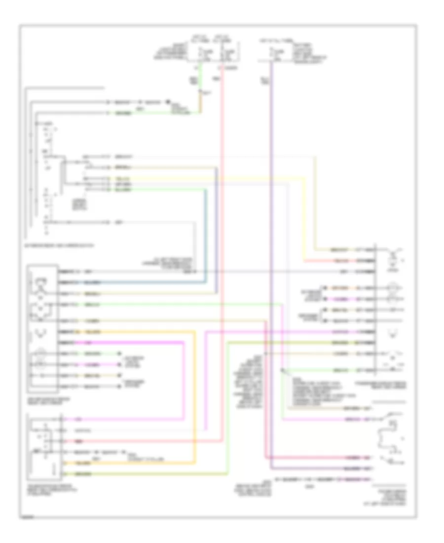
AIR CONDITIONING
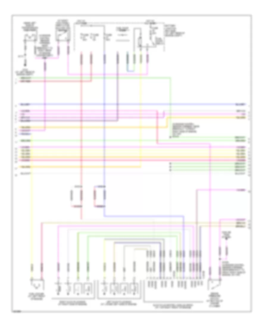
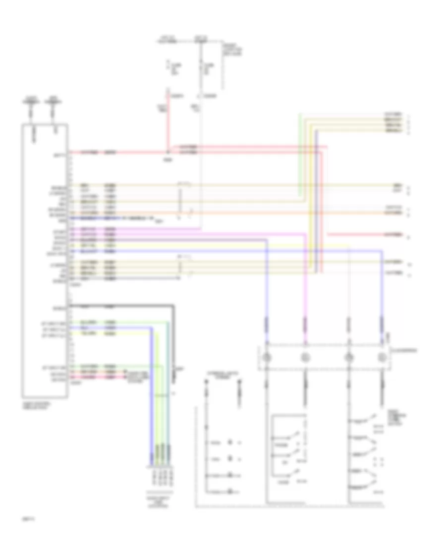
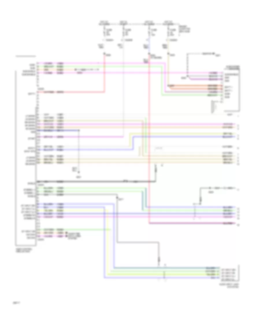
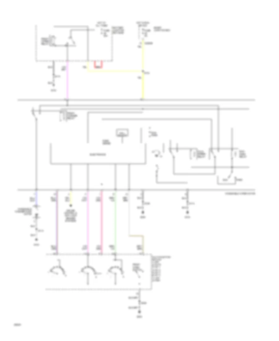
Automatic A/C Wiring Diagram (1 of 3) for Ford Cab & Chassis F350 Super Duty 2009

List of elements for Automatic A/C Wiring Diagram (1 of 3) for Ford Cab & Chassis F350 Super Duty 2009:
- 150a
- Ambient
- Auxiliary heater control module
- Battery
- Battery junction box (bjb)
- Blower command
- Blower motor relay
- C2280a
- C2280b
- C2280e
- C228a
- C2357b
- C2463a
- C2463b
- C2463c
- Cable pro
- Cbp37
- Ch122
- Ch123
- Ch207
- Ch208
- Ch211
- Ch213
- Ch228
- Ch229
- Ch237
- Ch239
- Chs29
- Chs30
- Computer data lines system
- Defrost/panel/floor mode actuator
- Driver temperature blend door actuator
- Drv htd seat sw
- Drv sun load
- Drv temp a+
- Drv temp b+
- Drv temp feedback
- Front blower rly
- Fuse 10a
- Fuse 40a
- Fuse 5a
- G300
- Gd133
- Gnd
- Heated mirror relay
- Hot at all times
- Hot in run or acc
- Hot in run or start
- Hscan+
- Hscan-
- Hvac-datc
- Incar temp sn
- Lh111
- Mode actr a+
- Mode actr b+
- Mode actr feedback
- Mscan+
- Mscan-
- Nca
- Pass htd seat sw
- Pass sun load
- Pass temp a+
- Pass temp b+
- Pass temp feedback
- Passenger temperature blend door actuator
- Rear def htd mirror
- Recirc door a+
- Recirc door b+
- Recirculation door actuator
- Red
- Rh111
- S104
- S143
- S144
- S145
- S206
- S224
- S250
- S251
- Sbp15
- Smart junction box
- Vbat
- Vdb06
- Vdb07
- Vh101
- Vh407
- Vh414
- Vh416
- Vh417
- Vh436
- Vh440
- Vh441
- Vign
- Vref actr
- Vref rtn
- W/ electric heater
- W/o electric heater
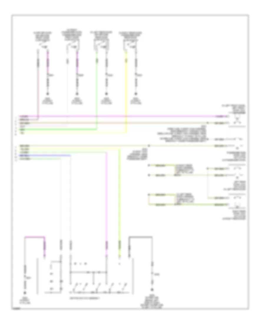
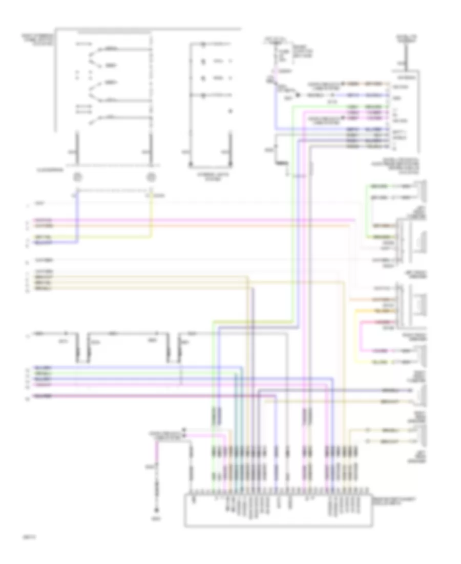
Automatic A/C Wiring Diagram (2 of 3) for Ford Cab & Chassis F350 Super Duty 2009
List of elements for Automatic A/C Wiring Diagram (2 of 3) for Ford Cab & Chassis F350 Super Duty 2009:
- (at right side of hvac assembly) blower motor control module
- (behind center of dash) autolamp/sunload sensor
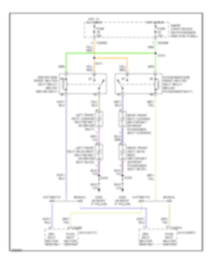
- (below driver seat) driver side front heated seat relay
- (below passenger seat) passenger side front heated seat relay
- (in extension
- Assembly-a/c blower motor feed harness, at right side of hvac case)
- Blower motor
- Ch218
- Ch402
- G203 (behind center of dash, behind audio control module)
- G300 (crew cab & regular cab: in left "a" pillar) (super cab: behind left side of dash)
- Gd115
- Headlights system
- In vehicle temperature sensor (behind left side of dash)
- Outside air temperature sensor (at right front of engine compt)
- S210 (in main harness, near breakout behind audio control module)
- S225
- S257
- Solid state control
- Vh101
Automatic A/C Wiring Diagram (3 of 3) for Ford Cab & Chassis F350 Super Duty 2009
List of elements for Automatic A/C Wiring Diagram (3 of 3) for Ford Cab & Chassis F350 Super Duty 2009:
- (at front of engine) (diesel) engine coolant temperature (ect) sensor
- (diesel)
- (diesel) (gas)
- (gas)
- (in engine control sensor & fuel charge harness, near breakout to front right side of engine, on top) s133
- (in engine control sensor harness, near breakout to front center of engine compt)
- (in engine control sensor harness, near breakout to front right side of engine, on top) s1013
- A/c clutch diode
- A/c clutch relay
- A/c compressor field coil
- A/c cycling switch
- A/c cycling switch (gas)
- A/c high pressure switch (at right side of engine compt)
- Accr
- Accs
- Acpsw
- Battery junction box (bjb) (at left rear of engine compt)
- Brake pressure switch (at bottom of master cylinder)
- C1232b
- C1232e
- C175b
- C175e
- Ce237
- Cec11
- Ch302
- Ch421
- Ch425
- Cht
- Control
- Cylinder head temperature sensor (6.8l: on right cylinder head) (5.4l: at rear of block, under intake)
- Diesel
- Dual pressure switch (diesel) (at right front of engine)
- Ect
- Electric fan clutch (at front of engine)
- Engine controls system
- Fuse 10a
- Fuse 20a
- Fuse 50 (gas) 30a fuse 39 (diesel) 50a
- G103 (at right rear of engine compt)
- G108 (at left rear of engine compt)
- Gas
- Gd119
- Gnd
- Hot at all times
- Kapwr
- Mpr (pcm-rc)
- Nca control
- Nca gnd
- Nca sig
- Nca vbpwr
- Nca vpwr
- Near breakout to left front of frame)
- Pcm power relay
- Powertrain control module (pcm) (at left side of firewall)
- Re405
- S1008 (in engine control sensor harness, near breakout to right rear of engine compt)
- S1009 (in engine control sensor harness, near breakout to front right side of engine, on top)
- S1010 (in engine control sensor harness, near breakout to front right side of engine, on top)
- S114
- S115
- S117 (diesel)
- S120
- S128
- S154 (gas)
- S158 (gas)
- Sbb36
- Sig
- Sig rtn
- Vbpwr
- Ve712
- Ve716
- Vec03
- Vec10
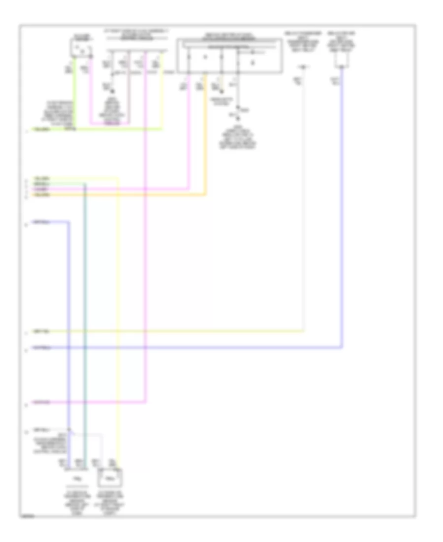
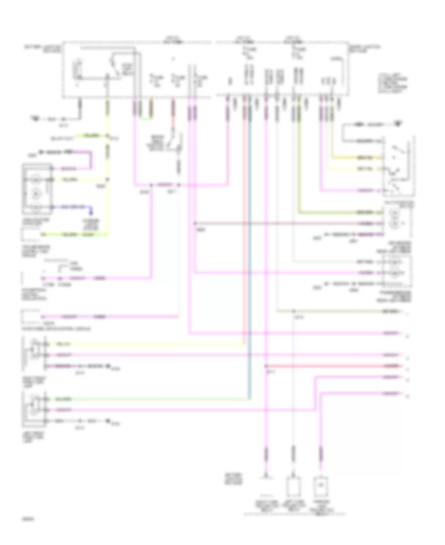
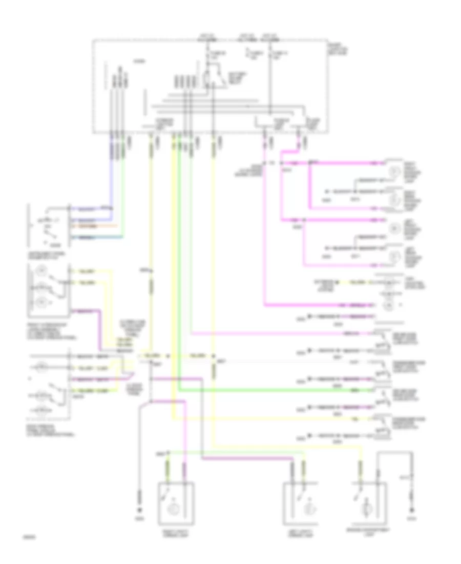
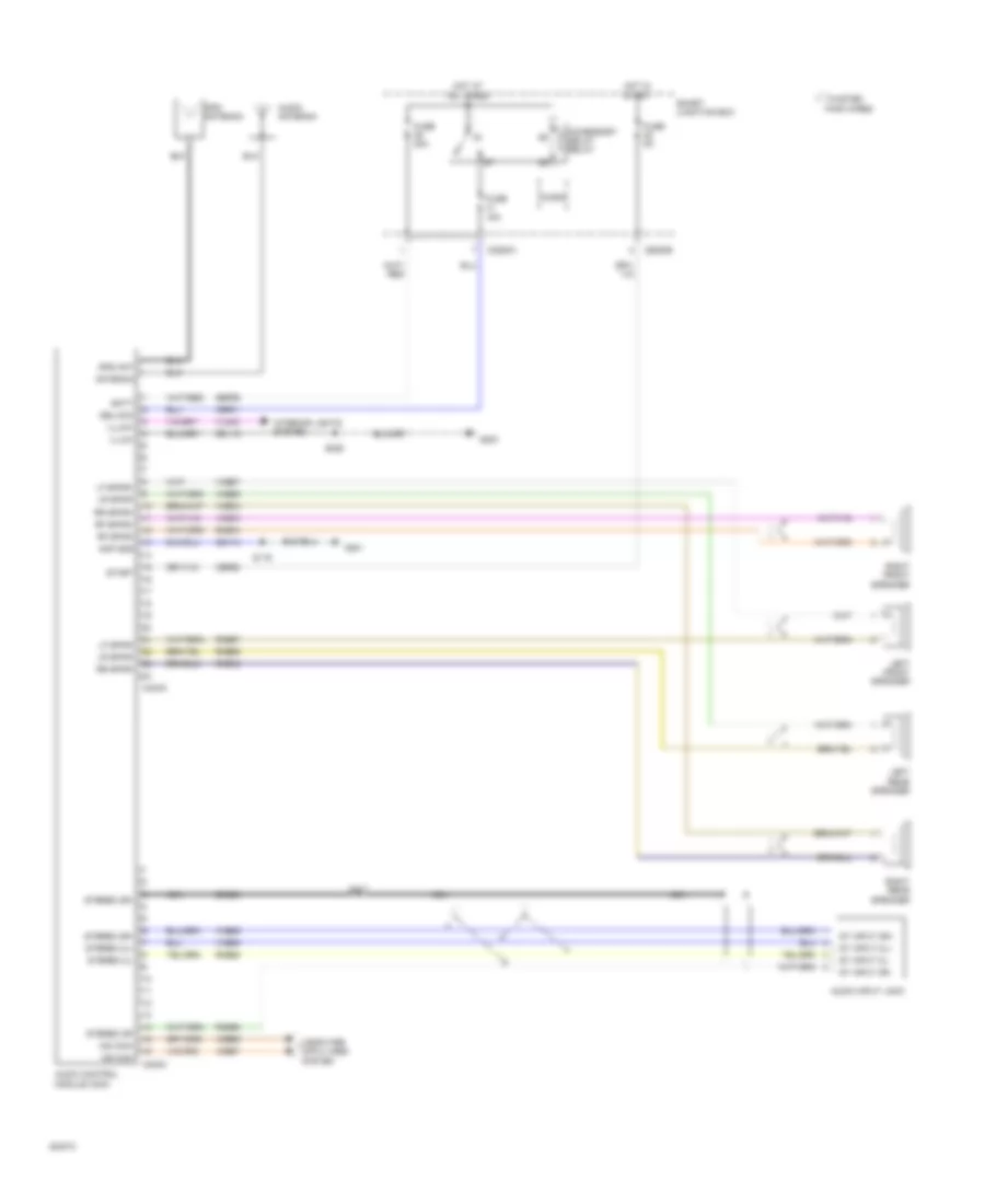
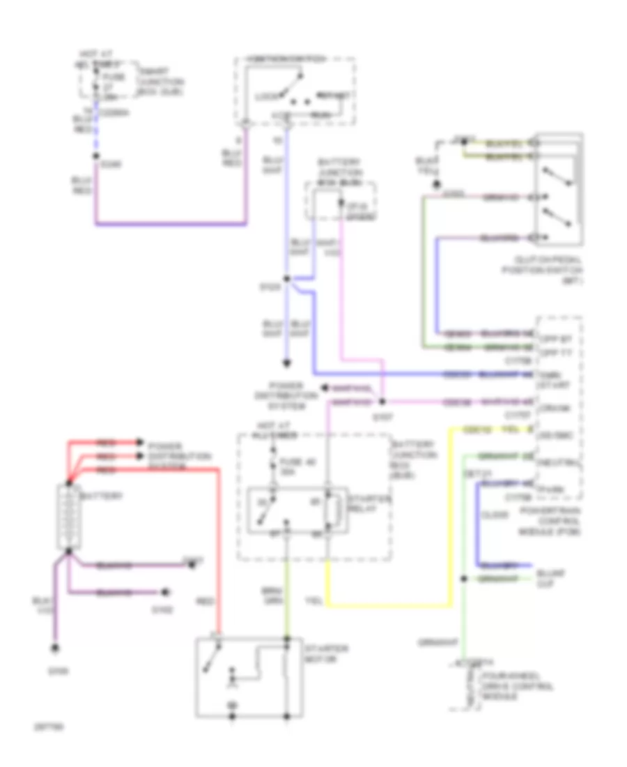
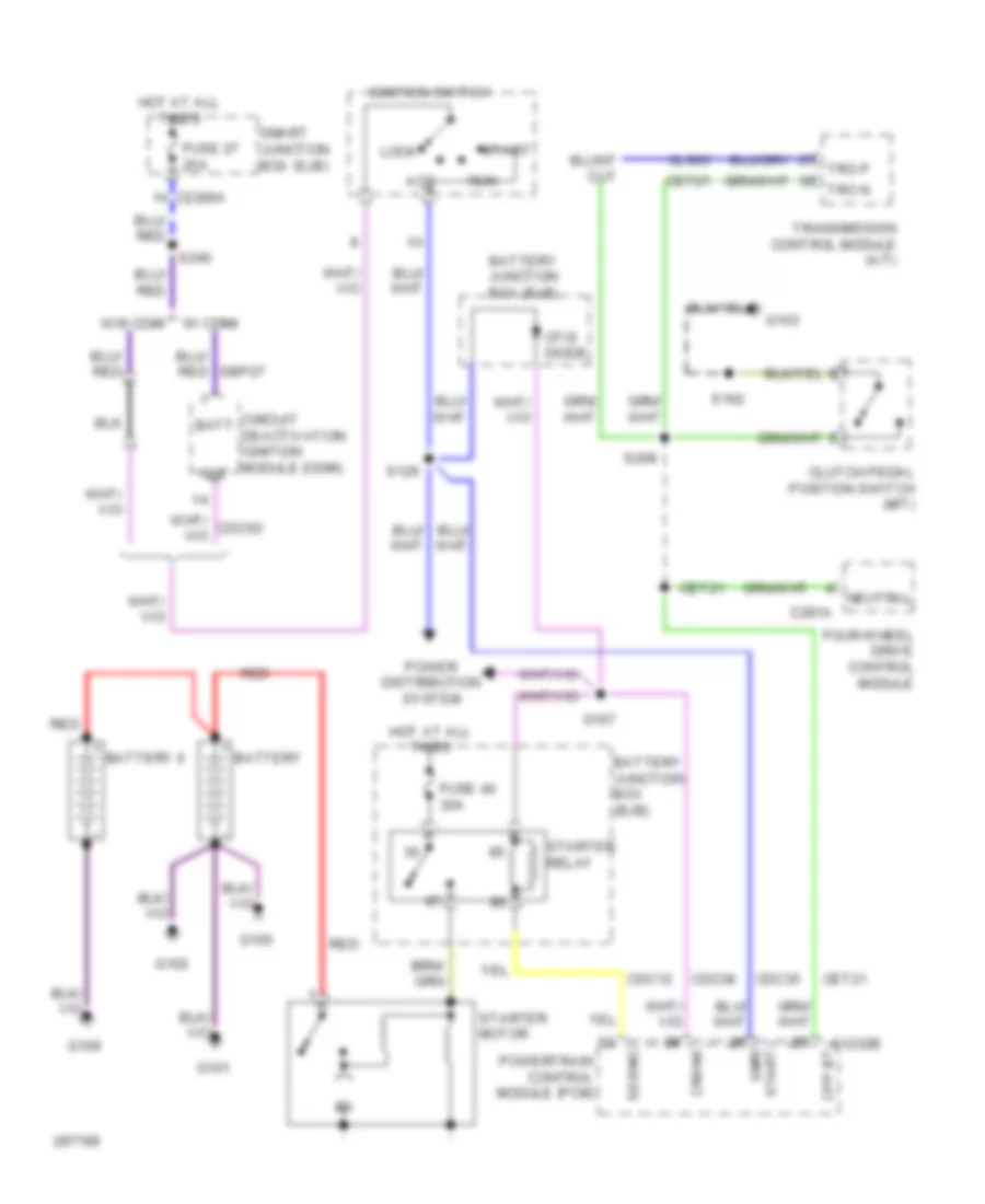
Manual A/C Wiring Diagram (1 of 2) for Ford Cab & Chassis F350 Super Duty 2009
List of elements for Manual A/C Wiring Diagram (1 of 2) for Ford Cab & Chassis F350 Super Duty 2009:
- 150a
- Auxiliary heater control module
- Battery
- Battery junction box (bjb)
- Blower motor
- Blower motor relay
- C2280a
- C2280b
- C2280e
- C2357a
- C2357b
- C2463a
- C2463b
- C2463c
- Cable pro
- Cbp37
- Ch122
- Ch123
- Ch202
- Ch203
- Ch207
- Ch208
- Ch233
- Ch234
- Ch428
- Ch429
- Ch430
- Chs29
- Chs30
- Computer data lines system
- Defrost/panel/flo mode actuator
- Driver side front heated seat relay
- Drv htd seat sw
- Drv temp a+
- Drv temp b+
- Drv temp feedback
- Front blower motor resistor assembly
- Front blower rly
- Fuse 10a
- Fuse 40a
- Fuse 5a
- G203
- G300
- Gd115
- Gd133
- Gnd
- Heated mirror relay
- Hot at all times
- Hot in run or acc
- Hot in run or start
- Hscan+
- Hscan-
- Hvac-emtc
- Lh111
- Med hi
- Med lo
- Mode actr a+
- Mode actr b-
- Mscan+
- Mscan-
- Nca
- Panel/defrost feedback
- Pass htd seat sw
- Passenger side front heated seat relay
- Rear def htd mirror
- Recirc door a+
- Recirc door b+
- Red
- Rh111
- S104
- S143
- S144
- S145
- S206
- S224
- S225
- S250
- S251
- S256
- Sbp15
- Smart junction box
- Temperature blend door actuator
- Vbat
- Vdb06
- Vdb07
- Vh437
- Vh439
- Vign
- Vref actr
- Vref return
- W/ electric heater
- W/o electric heater
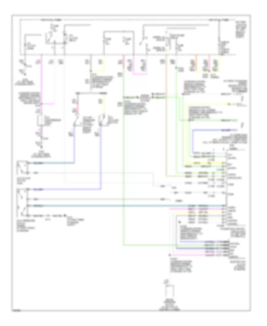
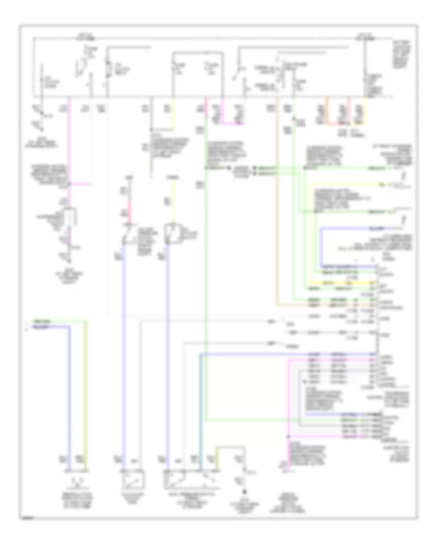
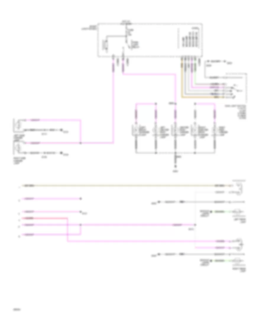
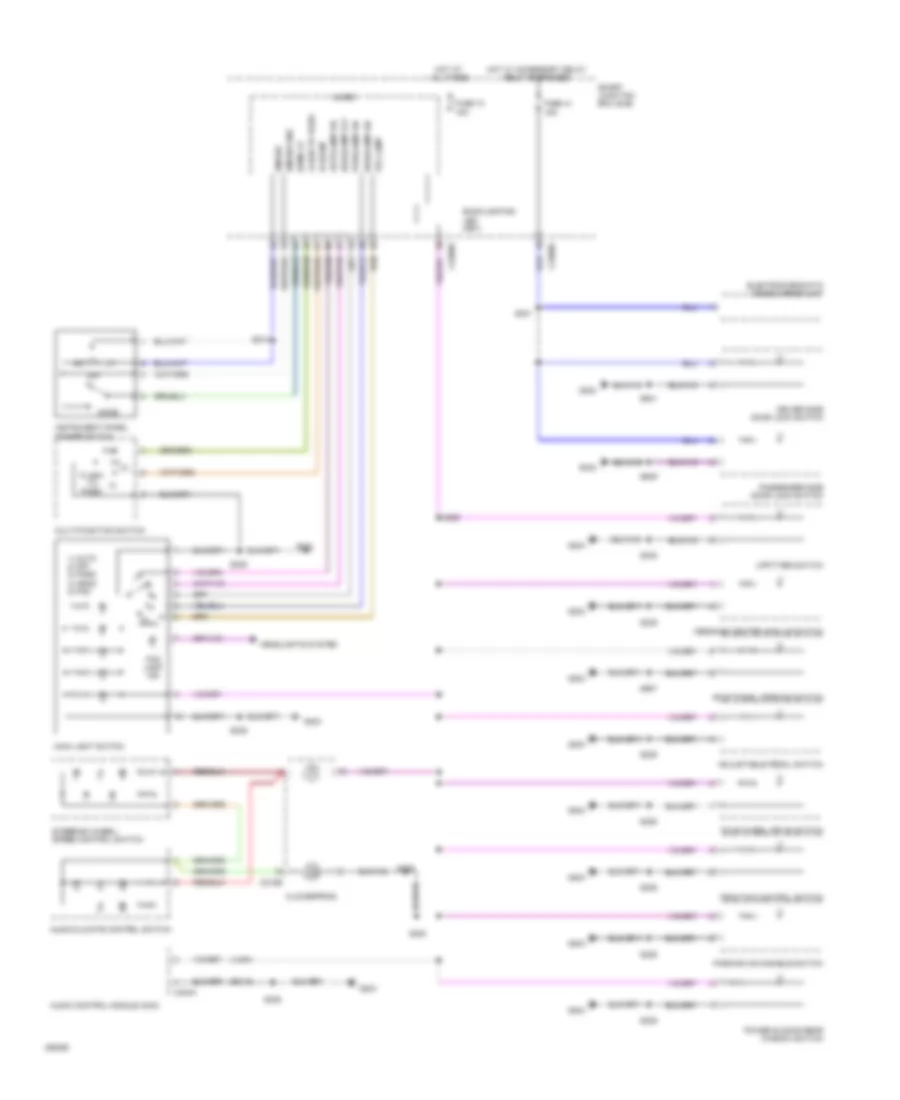
Manual A/C Wiring Diagram (2 of 2) for Ford Cab & Chassis F350 Super Duty 2009
List of elements for Manual A/C Wiring Diagram (2 of 2) for Ford Cab & Chassis F350 Super Duty 2009:
- (at front of engine) (diesel) engine coolant temperature (ect) sensor
- (diesel)
- (diesel) (gas)
- (gas)
- (in engine control sensor & fuel charge harness, near breakout to front right side of engine, on top) s133
- (in engine control sensor harness, near breakout to front center of engine compt)
- (in engine control sensor harness, near breakout to front right side of engine, on top) s1013
- A/c clutch diode
- A/c clutch relay
- A/c compressor clutch field coil
- A/c cycling switch
- A/c cycling switch (gas)
- A/c high pressure switch (at right side of engine compt)
- Accr
- Accs
- Acpsw
- Battery junction box (bjb) (at left rear of engine compt)
- Brake pressure switch (at bottom of master cylinder)
- C1232b
- C1232e
- C175b
- C175e
- Ce237
- Cec11
- Ch302
- Ch421
- Ch425
- Cht
- Control
- Cylinder head temperature sensor (6.8l: on right cylinder head) (5.4l: at rear of block, under intake)
- Diesel
- Dual pressure switch (diesel) (at right front of engine)
- Ect
- Electric fan clutch (at front of engine)
- Engine controls system
- Fuse 10a
- Fuse 20a
- Fuse 50 (gas) 30a fuse 39 (diesel) 50a
- G103 (at right rear of engine compt)
- G108 (at left rear of engine compt)
- Gas
- Gd119
- Gnd
- Hot at all times
- Kapwr
- Mpr (pcm-rc)
- Nca control
- Nca gnd
- Nca sig
- Nca vbpwr
- Nca vpwr
- Near breakout to left front of frame)
- Pcm power relay
- Powertrain control module (pcm) (at left side of firewall)
- Re405
- Recirculation door actuator (at right side of hvac case)
- S1008 (in engine control sensor harness, near breakout to right rear of engine compt)
- S114
- S115
- S120
- S128
- S154 s117 (diesel)
- S158 (gas)
- Sbb36
- Sig
- Sig rtn
- Vbpwr
- Ve712
- Ve716
- Vec03
- Vec10
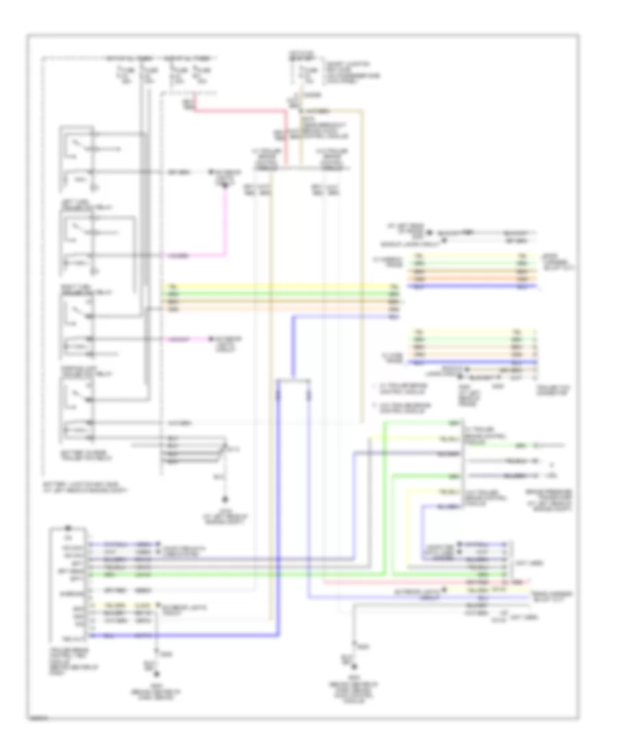
ANTI-LOCK BRAKES
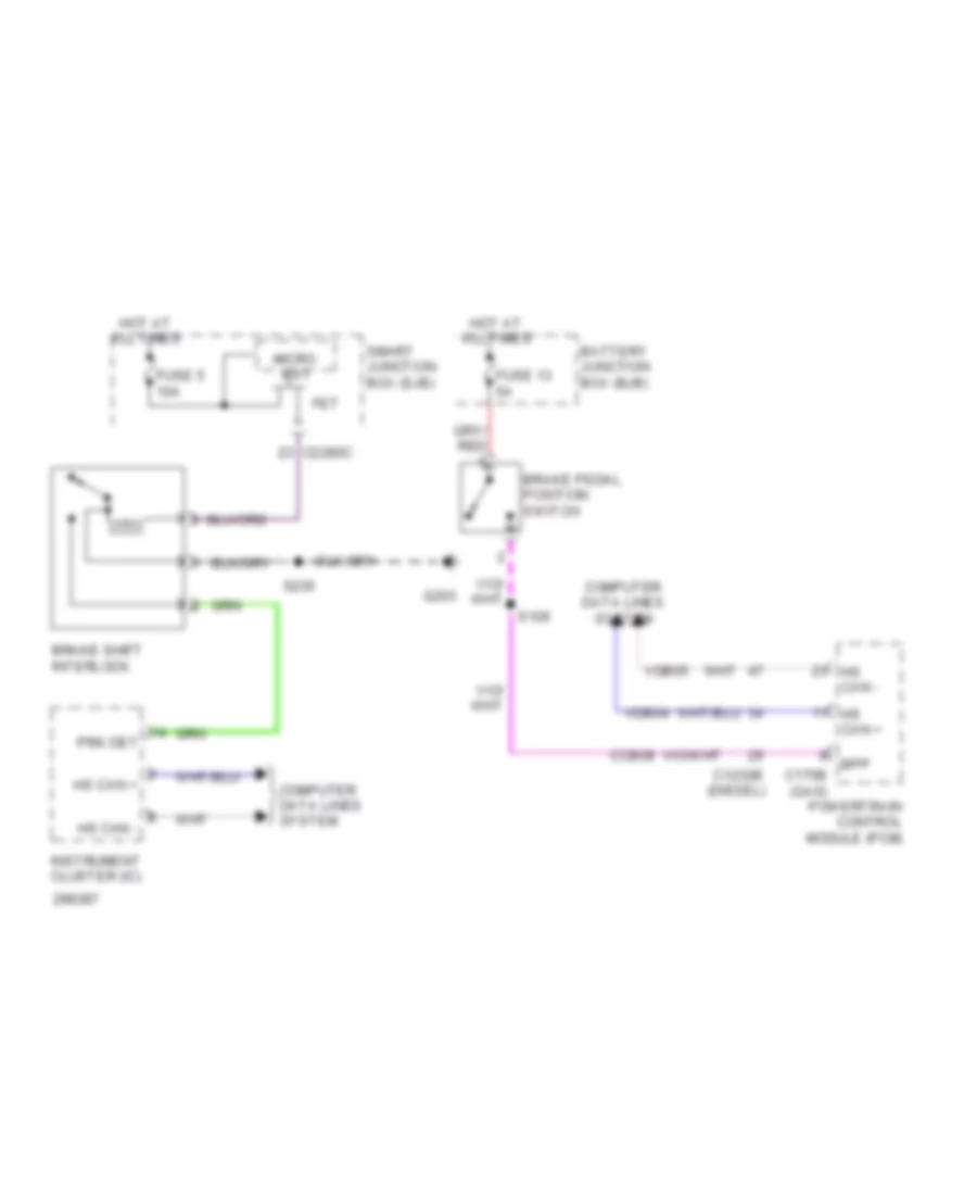
Anti-lock Brakes Wiring Diagram for Ford Cab & Chassis F350 Super Duty 2009
List of elements for Anti-lock Brakes Wiring Diagram for Ford Cab & Chassis F350 Super Duty 2009:
- (at left front of frame) g135
- (in engine control sensor harness, near breakout to left front of frame) s106
- (or le111)
- Abs control module (diesel: at left side of engine compt) (except diesel: at left rear of engine compt)
- Battery junction box (bjb) (at left rear of engine compt)
- Bpp
- Bps
- Brake pedal position switch (behind left side of dash, above brake pedal)
- Brake pressure switch (at bottom of master cylinder)
- C1232b
- C1232e
- C175b
- C175e
- C175t
- C2280b
- Cbb77
- Cca10
- Cca15
- Ccb08
- Cec11
- Ces09
- Computer data lines system
- Cooling fans & transmissions systems
- Diesel
- Diff sen+
- Diff sen-
- Exterior lights system
- Fl gnd
- Fr gnd
- Fuse 10a
- Fuse 40a
- Fuse 5a
- G135 (at left front of frame)
- Gas
- Gd163
- Gnd
- Hot at all times
- Hot in run or start
- Hs can +
- Hs can -
- Ign
- Interior lights system
- Kl30 p
- Kl30 v
- Left front wheel speed sensor (at left front wheel assembly)
- Lf whl spd+
- Powertrain control module (pcm) (at left side of firewall)
- Rca17
- Rca19
- Rca21
- Rear axle speed sensor (on differential)
- Red
- Rf whl spd+
- Right front wheel speed sensor (at right front wheel assembly)
- S1009 (diesel) s196 (gas) (diesel: in engine control sensor harness, near breakout to front right side of engine, on top) (gas: in backup lamp switch to rear lamp feed harness, near breakout to front left side of transmission, near top)
- S130 (in engine control sensor harness, near breakout to master cylinder)
- S211 (in main harness, near breakout behind audio control module)
- S227
- S404 (in tail lamps harness, in breakout to left rear of frame)
- S405 (in tail lamps harness, in breakout to left rear of frame)
- Sbb06
- Sbb09
- Smart junction box (on passenger side kick panel)
- Tracs
- Tracsil
- Traction control switch
- Vbpwrt (or vbpwr)
- Vca03
- Vca05
- Vca07
- Vdb04
- Vdb05
- Ve822
- Vss
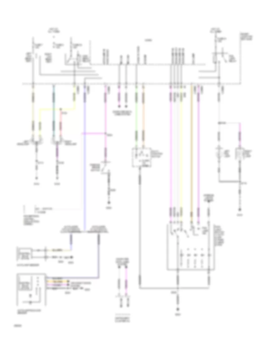
- Wiper/ washer system
ANTI-THEFT
Forced Entry Wiring Diagram (1 of 2) for Ford Cab & Chassis F350 Super Duty 2009
List of elements for Forced Entry Wiring Diagram (1 of 2) for Ford Cab & Chassis F350 Super Duty 2009:
- (crew cab: in body main harness, near breakout to right "a" pillar) (regular cab: in body main harness, near breakout to right "b" pillar) (super cab: in body main harness, near breakout under passenger seat)
- (super cab: in body main harness, near breakout under passenger seat) (except super cab: in body main harness, near breakout to right "b" pillar)
- All lock relay
- Antenna
- C2280c
- C2280d
- Control
- Driver side door lock switch
- Driver unlock relay
- Fuse 15a
- Fuse 20a
- G302 (in right "a" pillar)
- Hot at all times
- Hot w/ accessory delay relay energized
- Hsd
- Lock
- Logic
- Passenger side door lock switch
- Rke receiver internal antenna
- S301
- S305
- S306
- S308
- S501
- S639
- Sense
- Smart junction box (sjb) (on passenger side kick panel)
- Un lock
Forced Entry Wiring Diagram (2 of 2) for Ford Cab & Chassis F350 Super Duty 2009
List of elements for Forced Entry Wiring Diagram (2 of 2) for Ford Cab & Chassis F350 Super Duty 2009:
- (in driver door) driver side front door ajar switch
- (in front passenger door) passenger side front door ajar switch
- (in left front door) left front door lock actuator
- (in left rear door harness, in breakout to left "b" pillar) s800
- (in left rear door) driver side rear door ajar switch
- (in right rear door harness, in breakout to left "b" pillar) s700
- (in right rear door) passenger side rear door ajar switch
- 1/2
- 3/4
- 5/6
- 7/8
- 9/0
- Ajar
- G300 (super cab: behind left side of dash) (except super cab: in left "a" pillar)
- G302 (in right "a" pillar)
- Keypad switch assembly
- Left rear door lock actuator (in left rear door)
- Passenger side door lock actuator (in passenger door)
- Right rear door lock actuator (in right rear door)
- S302 (crew cab: in body main harness, near breakout across floor) (regular cab: in body main harness, near breakout to right "b" pillar) (super cab: in body main harness, near breakout under passenger seat)
- S308
- S323
- S326
- S333 (in body main harness, near breakout under passenger seat)
- S501
- S639
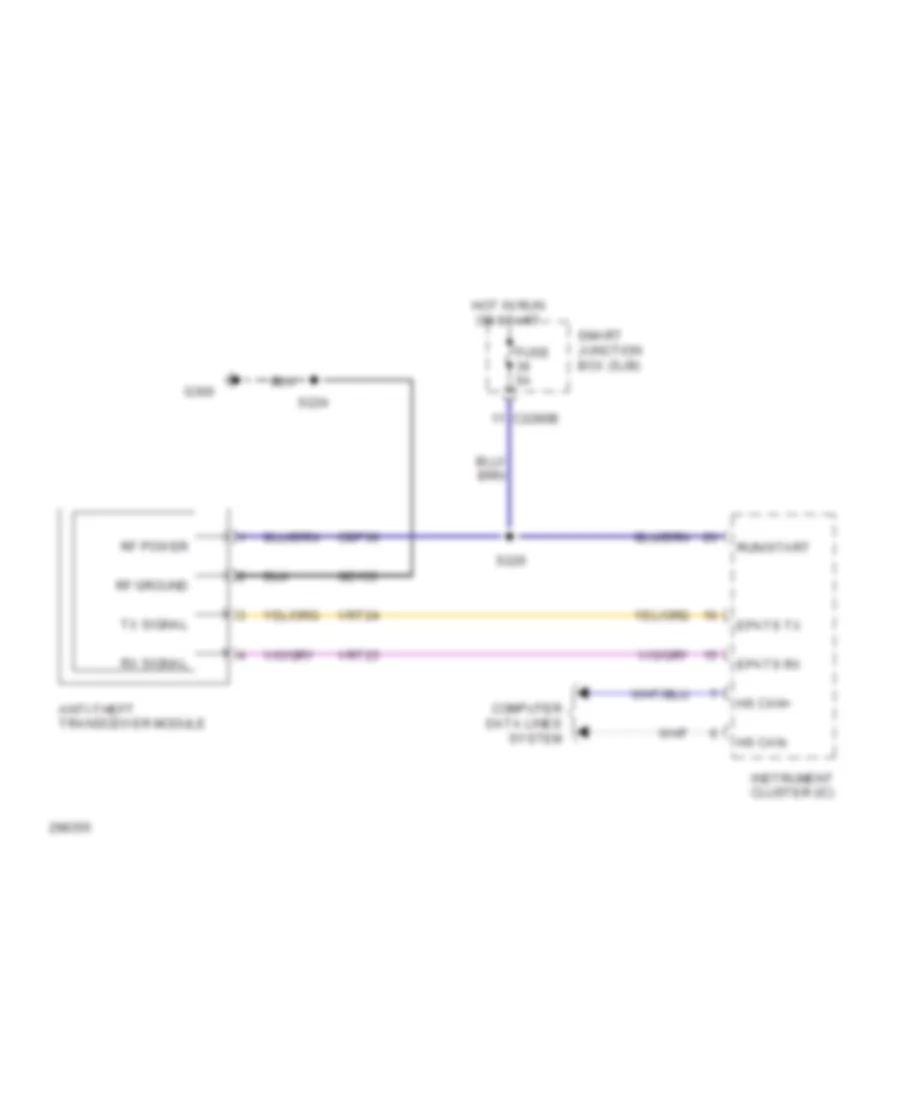
Passive Anti-theft Wiring Diagram for Ford Cab & Chassis F350 Super Duty 2009
List of elements for Passive Anti-theft Wiring Diagram for Ford Cab & Chassis F350 Super Duty 2009:
- Anti-theft transceiver module
- C2280b
- Cbp36
- Computer data lines system
- Epats rx
- Epats tx
- Fuse 5a
- G300
- Gd133
- Hot in run or start
- Hs can+
- Hs can-
- Instrument cluster (ic)
- Rf ground
- Rf power
- Run/start
- Rx signal
- S224
- S226
- Smart junction box (sjb)
- Tx signal
- Vrt23
- Vrt24
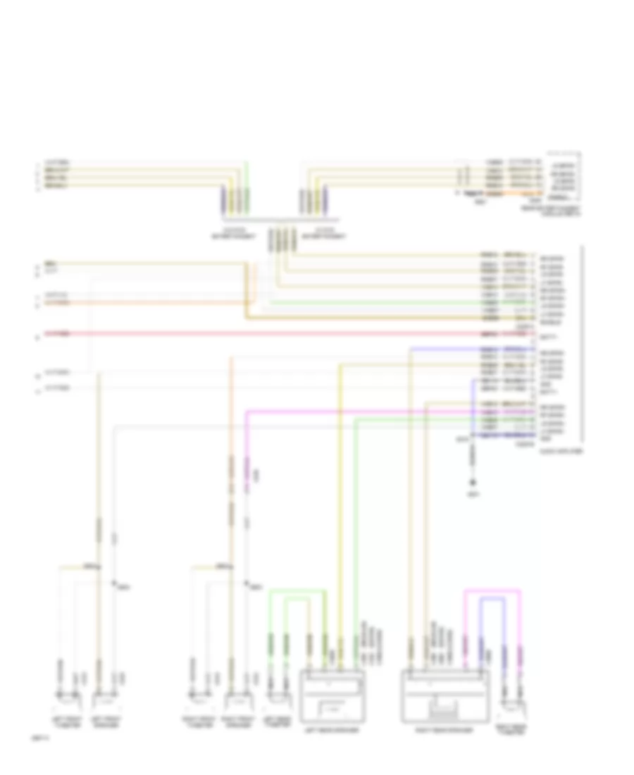
COMPUTER DATA LINES
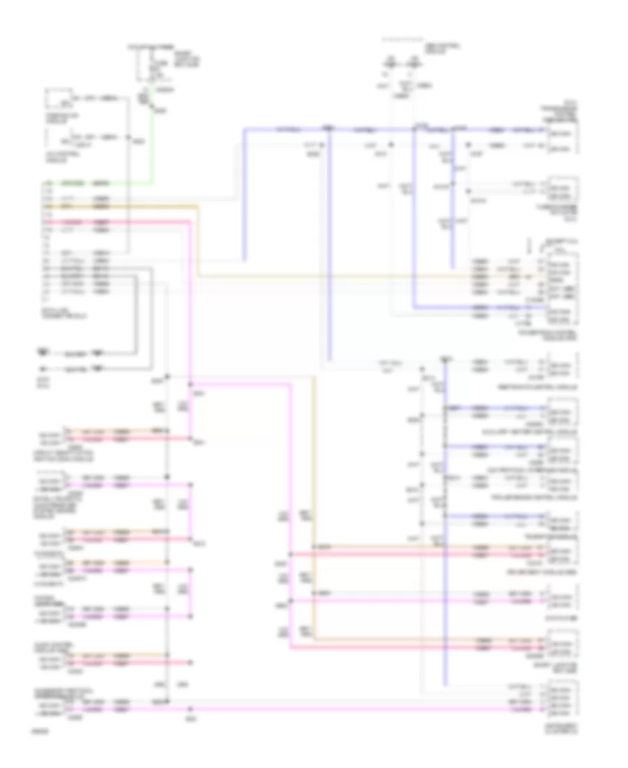
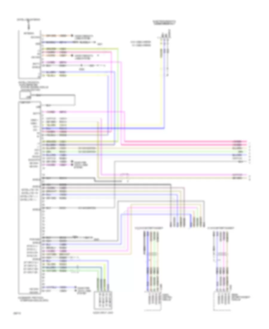
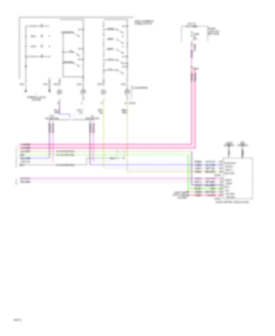
Computer Data Lines Wiring Diagram for Ford Cab & Chassis F350 Super Duty 2009
List of elements for Computer Data Lines Wiring Diagram for Ford Cab & Chassis F350 Super Duty 2009:
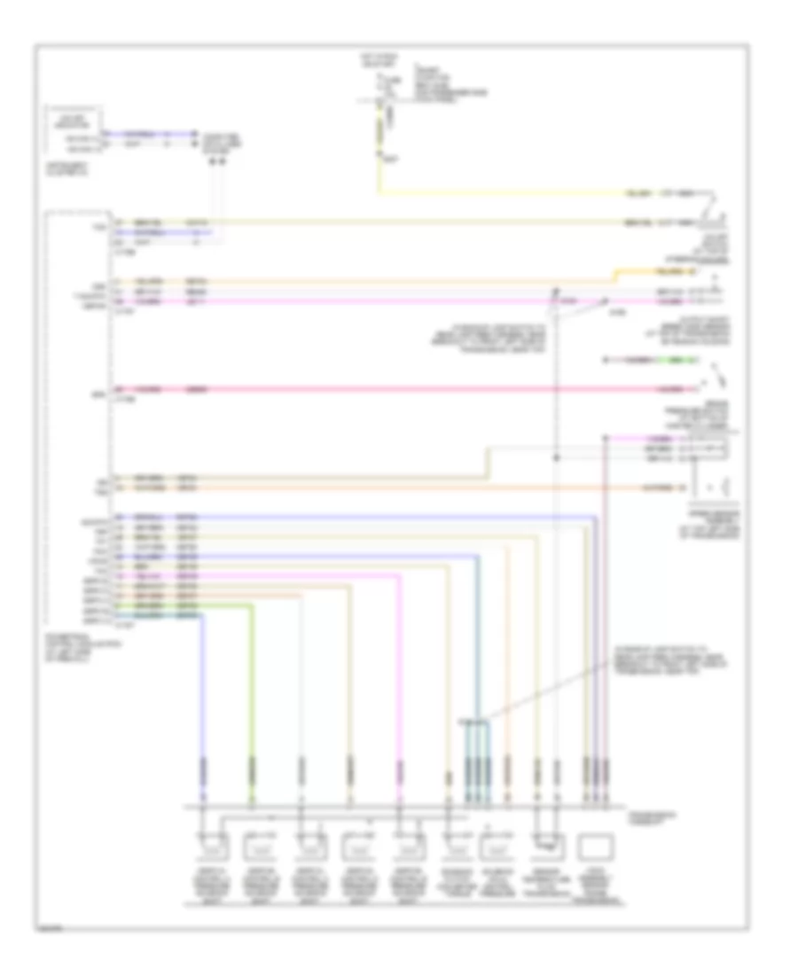
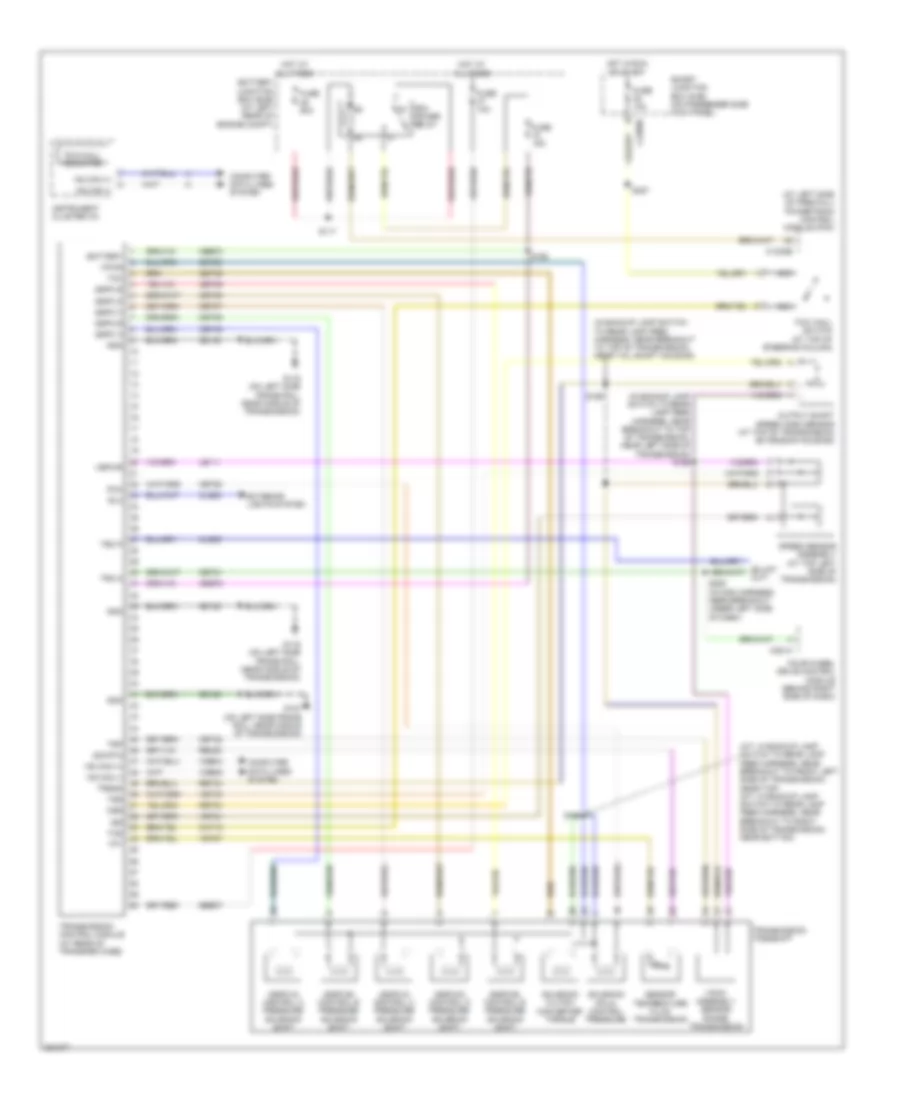
- (6.4l) transmission control module (tcm)
- 4x4 control module
- 6.4l
- Abs control module
- Acc protocol interface module
- Accessory protocol interface module
- Audio control module (acm)
- Auxiliary heater control module
- C1232b
- C175b
- C2280a
- C2280b
- C228a
- C2298
- C2357a
- C2408b
- C240c
- C240d
- C2463c
- C2500
- C281a
- C310b
- C341d
- Cdb08
- Circuit deactivation ignition (cdim) module
- Data link connector (dlc)
- Driver seat module (dsm)
- Dvd player
- Except 6.4l
- Feps
- Fuse 15a
- G103 (6.4l)
- G203
- Gd113
- Gd115
- Hot at all times
- Hs can+
- Hs can-
- Hvac-eatc
- Hvac-emtc
- In-dash computer
- Instrument cluster (ic)
- Iso
- Ms can+
- Ms can-
- Not used
- Parking aid module
- Powertrain control module (pcm)
- Restraints control module
- S1018
- S1019
- S129
- S131
- S162
- S193
- S197
- S207
- S208
- S212
- S214
- S215
- S218
- S221
- S222
- S223
- S228
- S230
- S231
- S234
- S235
- S236
- S238
- S241
- S312
- S313
- S319
- S320
- S902
- S903
- Satellite digital audio receiver system (sdars) module
- Sbp20
- Smart junction box (sjb)
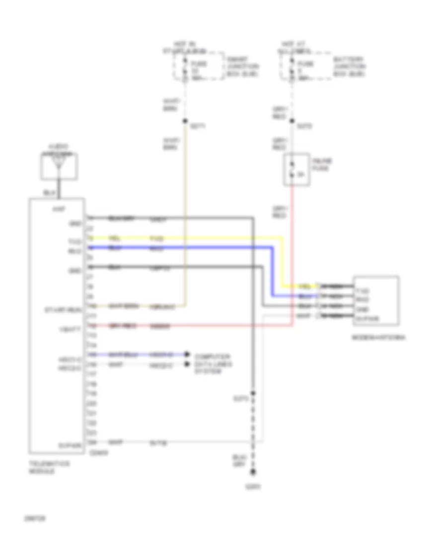
- Telematics module
- Trailer brake control module
- Turbocharger actuator (6.4l)
- Vdb04
- Vdb05
- Vdb06
- Vdb07
- Vdb10
COOLING FAN
Cooling Fan Wiring Diagram for Ford Cab & Chassis F350 Super Duty 2009
List of elements for Cooling Fan Wiring Diagram for Ford Cab & Chassis F350 Super Duty 2009:
- (diesel)
- (diesel) (gas)
- (gas)
- (in engine control sensor & fuel charge harness, near breakout to front right side of engine, on top) s133
- (in engine control sensor harness, near breakout to front right side of engine, on top)
- (in engine control sensor harness, near breakout to right rear of engine compt) s1008
- Battery junction box (bjb) (at left rear of engine compt)
- Brake pressure switch (at bottom of master cylinder)
- C1232b
- C1232e
- C175b
- C175e
- Ce237
- Cec11
- Cht
- Control
- Cylinder head temperature sensor (6.8l: on right cylinder head) (5.4l: at rear of block, under intake)
- Diesel
- Electric fan clutch (at front of engine)
- Engine controls system
- Engine coolant temperature (ect) sensor (diesel) (at front of engine)
- Fuse 10a
- Fuse 20a
- Fuse 50 (gas) 30a fuse 39 (diesel) 50a
- Gas
- Gd119
- Gnd
- Hot at all times
- Kapwr
- Mpr (pcm-rc)
- Nca
- Pcm power relay
- Powertrain control module (pcm) (at left side of firewall)
- Re405
- S1009 (in engine control sensor harness, near breakout to front right side of engine, on top)
- S1013 (in engine control sensor harness, near breakout to front right side of engine, on top)
- S154 s117 (diesel)
- S158 (gas)
- Sbb36
- Sig
- Sig rtn
- Vbpwr
- Ve712
- Ve716
- Vec03
- Vec10
- Vpwr
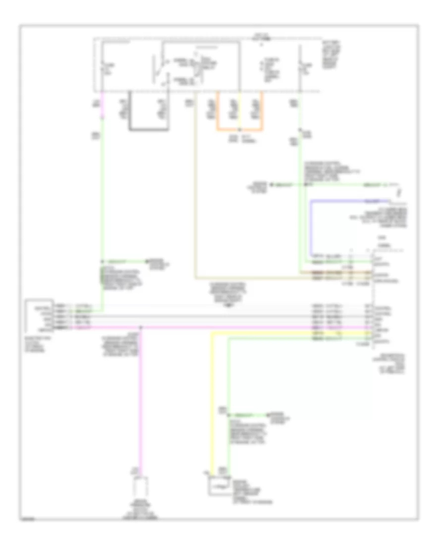
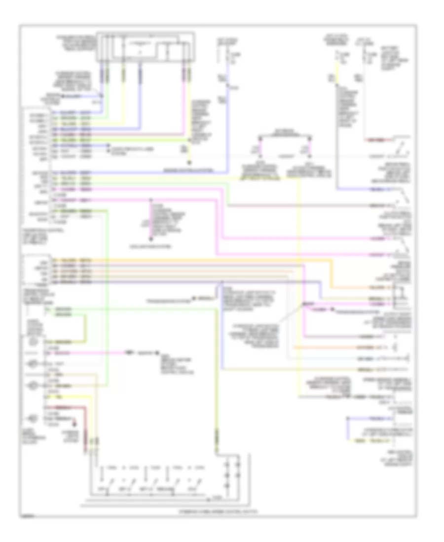
CRUISE CONTROL
5.4L
5.4L, Cruise Control Wiring Diagram for Ford Cab & Chassis F350 Super Duty 2009
List of elements for 5.4L, Cruise Control Wiring Diagram for Ford Cab & Chassis F350 Super Duty 2009:
- (at bottom of master cylinder) brake pressure switch
- (at top of transmission extension housing) output shaft speed (oss) sensor
- (in backup lamp switch to rear lamp feed harness, near breakout to front left side of transmission, near top)
- (in engine control sensor harness, near breakout to master cylinder) s130
- 4x4 control module
- Abs control module (at left rear of engine compt)
- Accelerator pedal position sensor (on accelerator pedal support)
- App1
- App2
- App3
- Audio/ climate control switch
- Battery junction box (bjb) (at left rear of engine compt)
- Bpp
- Bps
- Brake pedal position switch (behind left side of dash, above brake pedal)
- C175b
- C175e
- C175t
- C218a
- C218b
- C281a
- Cbb71
- Ccb08
- Ce412
- Ce426
- Ce904
- Ces09
- Clock spring (in steering column)
- Clutch pedal position switch (m/t) (behind left side of dash, above clutch pedal)
- Computer data lines system
- Cpp tt
- Electronic throttle control (etc) motor (on throttle body)
- Etcref
- Etcref1
- Etcrtn
- Etcrtn1
- Exterior lights system
- Fuse 5a
- G103 (at right rear of engine compt)
- G202 (behind center of dash, behind audio control module)
- Hot at all times
- Hot in run or start
- Hs can+
- Hs can-
- Interior lights system
- Isp r
- Iss
- Le111
- Le136
- Le137
- Le428
- Off
- Oss
- Powertrain control module (pcm) (at left side of firewall)
- Re136
- Re137
- Re406
- Re427
- Res08
- Resume
- Ret04
- S106 (in engine control sensor harness, near breakout to left front of frame)
- S123
- S162
- S183
- S196 (in backup lamp switch to rear lamp feed harness, near breakout to front left side of transmission, near top)
- S211 (in main harness, near breakout behind audio control module)
- S239
- Sccs
- Sccs rtn
- Set+
- Set-
- Solid state
- Speed sensor assembly (at top left side of transmission)
- Steering wheel/speed control switch
- T sigrtn
- Tacm n
- Tacm p
- Throttle position sensor (tps) (5.4l: on throttle body) (6.8l: at top center of engine)
- Tp1 ns
- Tp2 ps
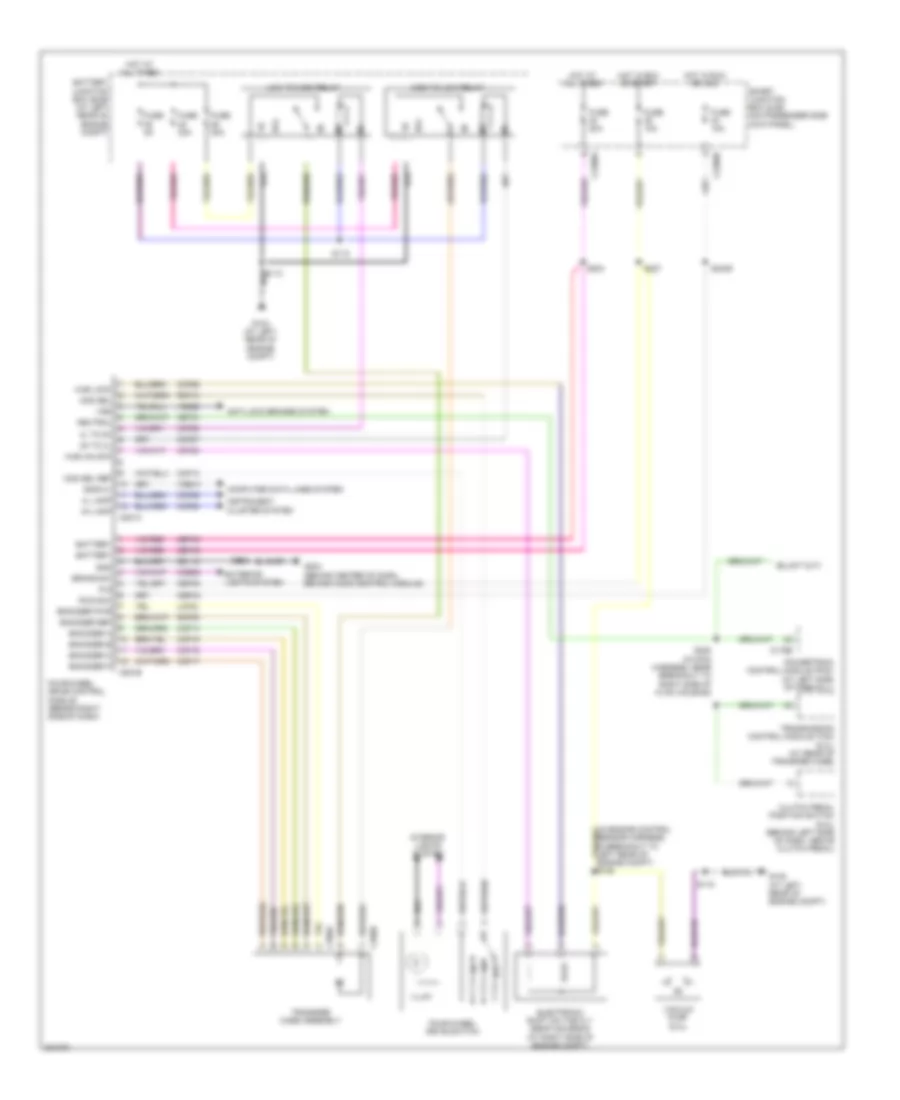
- Transmissions system
- Tss
- Vbpwr
- Vdb04
- Vdb05
- Ve701
- Ve702
- Ve703
- Ve744
- Ve818
- Ve819
- Ve822
- Ves10
- Vet33
- Vss
- Windshield wiper motor (at left side of firewall)
6.4L DIESEL
6.4L Diesel, Cruise Control Wiring Diagram for Ford Cab & Chassis F350 Super Duty 2009
List of elements for 6.4L Diesel, Cruise Control Wiring Diagram for Ford Cab & Chassis F350 Super Duty 2009:
- (in backup lamp switch to rear lamp feed harness, near breakout to top of transmission, near left side of transmission)
- (in engine control sensor harness, near breakout to front right side of engine, on top)
- (in engine control sensor harness, near breakout to left front corner of vehicle) s116
- (in engine control sensor harness, near breakout to master cylinder) s130
- 4x4 control module
- Abs control module (at left rear of engine compt)
- Accelerator pedal position sensor (on accelerator pedal support)
- App1
- App2
- Audio/ climate control switch
- Battery junction box (bjb) (at left rear of engine compt)
- Bpp
- Bps
- Brake pedal position switch (behind left side of dash, above brake pedal)
- Brake pressure switch (at bottom of master cylinder)
- C1232b
- C1232e
- C218a
- C218b
- C281a
- Cbb71
- Ccb08
- Ce904
- Cec11
- Ces09
- Clock spring (in steering column)
- Clutch pedal position switch (m/t) (behind left side of dash, above clutch pedal)
- Computer data lines system
- Cooling fans system
- Cpp tt
- Engine controls system
- Etcref 2
- Etcref 3
- Etcrtn 2
- Etcrtn 3
- Exterior lights system
- Fuse 10a
- Fuse 5a
- G202 (behind center of dash, behind audio control module)
- Hot at all times
- Hot in run or start
- Hot w/ pcm power relay energized
- Hs acn-
- Hs can+
- Interior lights system
- Iss
- Keypwr (r/s) vss
- Le111
- Le136
- Le137
- Off
- Oss
- Output shaft speed (oss) sensor (at top of transmission extension housing)
- Powertrain control module (pcm) (at left side of firewall)
- Re136
- Re137
- Res08
- Resume
- Ret04
- Ret24
- S1009 (in engine control sensor harness, near breakout to front right side of engine, on top)
- S101 (in engine control sensor harness, near breakout to left front of frame)
- S106 (in engine control sensor harness, near breakout to left front of frame)
- S114
- S123
- S196
- S198 (in backup lamp switch to rear lamp feed harness, near breakout to top of transmission, near tail shaft housing)
- S211 (in main harness, near breakout behind audio control module)
- S239
- Sccs
- Sccs rtn
- Set+
- Set-
- Speed sensor assembly (at top left side of transmission)
- Steering wheel/speed control switch
- Transmission control module (at rear of transfer case)
- Transmissions system
- Trgnd
- Tss
- Vbpwr
- Vdb04
- Vdb05
- Ve701
- Ve702
- Ve744
- Ve822
- Ves10
- Vet33
- Windshield wiper motor (at left side of firewall)
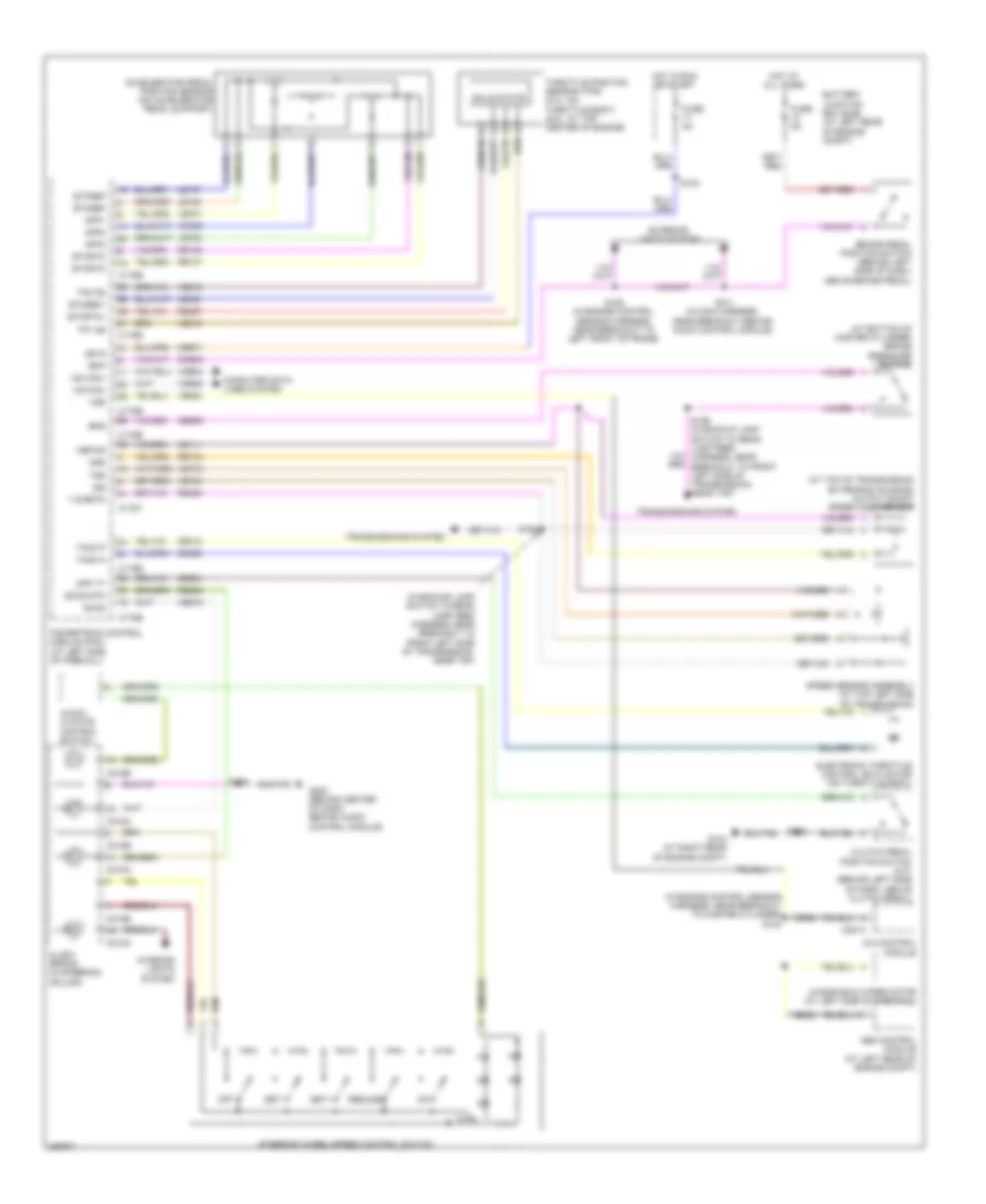
6.8L
6.8L, Cruise Control Wiring Diagram for Ford Cab & Chassis F350 Super Duty 2009
List of elements for 6.8L, Cruise Control Wiring Diagram for Ford Cab & Chassis F350 Super Duty 2009:
- (at bottom of master cylinder) brake pressure switch
- (at top of transmission extension housing) output shaft speed (oss) sensor
- (in backup lamp switch to rear lamp feed harness, near breakout to front left side of transmission, near top)
- (in engine control sensor harness, near breakout to master cylinder) s130
- 4x4 control module
- Abs control module (at left rear of engine compt)
- Accelerator pedal position sensor (on accelerator pedal support)
- App1
- App2
- App3
- Audio/ climate control switch
- Battery junction box (bjb) (at left rear of engine compt)
- Bpp
- Bps
- Brake pedal position switch (behind left side of dash, above brake pedal)
- C175b
- C175e
- C175t
- C218a
- C218b
- C281a
- Cbb71
- Ccb08
- Ce412
- Ce426
- Ce904
- Ces09
- Clock spring (in steering column)
- Clutch pedal position switch (m/t) (behind left side of dash, above clutch pedal)
- Computer data lines system
- Cpp tt
- Electronic throttle control (etc) motor (on throttle body)
- Etcref
- Etcref1
- Etcrtn
- Etcrtn1
- Exterior lights system
- Fuse 5a
- G103 (at right rear of engine compt)
- G202 (behind center of dash, behind audio control module)
- Hot at all times
- Hot in run or start
- Hs can+
- Hs can-
- Interior lights system
- Isp r
- Iss
- Le111
- Le136
- Le137
- Le428
- Off
- Oss
- Powertrain control module (pcm) (at left side of firewall)
- Re136
- Re137
- Re406
- Re427
- Res08
- Resume
- Ret04
- S106 (in engine control sensor harness, near breakout to left front of frame)
- S123
- S162
- S183
- S196 (in backup lamp switch to rear lamp feed harness, near breakout to front left side of transmission, near top)
- S211 (in main harness, near breakout behind audio control module)
- S239
- Sccs
- Sccs rtn
- Set+
- Set-
- Solid state
- Speed sensor assembly (at top left side of transmission)
- Steering wheel/speed control switch
- T sigrtn
- Tacm n
- Tacm p
- Throttle position sensor (tps) (5.4l: on throttle body) (6.8l: at top center of engine)
- Tp1 ns
- Tp2 ps
- Transmissions system
- Tss
- Vbpwr
- Vdb04
- Vdb05
- Ve701
- Ve702
- Ve703
- Ve744
- Ve818
- Ve819
- Ve822
- Ves10
- Vet33
- Vss
- Windshield wiper motor (at left side of firewall)
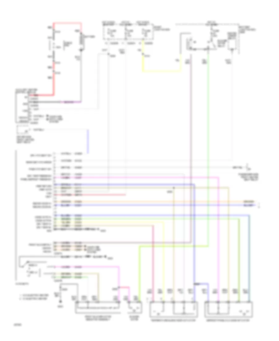
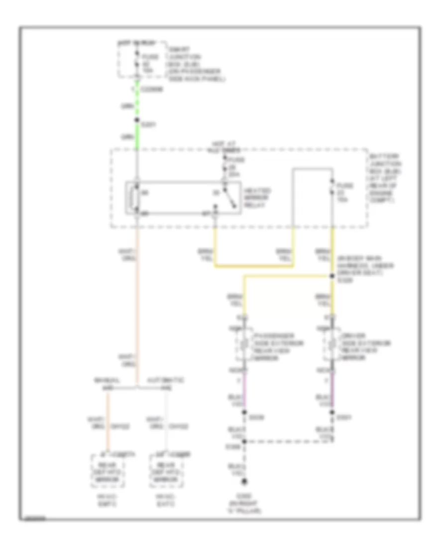
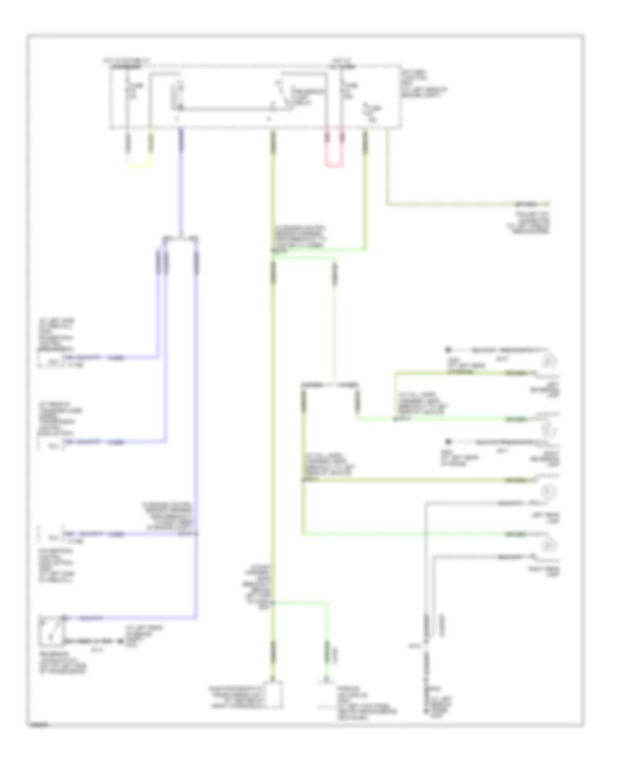
DEFOGGERS
Defoggers Wiring Diagram for Ford Cab & Chassis F350 Super Duty 2009
List of elements for Defoggers Wiring Diagram for Ford Cab & Chassis F350 Super Duty 2009:
- (in body main harness, under driver seat) s329
- Automatic a/c
- Battery junction box (bjb) (at left rear of engine compt)
- C2280b
- C228b
- C2357a
- Driver side exterior rear view mirror
- Fuse 10a
- Fuse 15a
- Fuse 20a
- G302 (in right "a" pillar)
- Heated mirror relay
- Hot at all times
- Hot in run
- Hvac- eatc
- Hvac- emtc
- Manual a/c
- Nca
- Passenger side exterior rear view mirror
- Rear def htd mirror
- S201
- S308
- S501
- S639
- Smart junction box (sjb) (on passenger side kick panel)
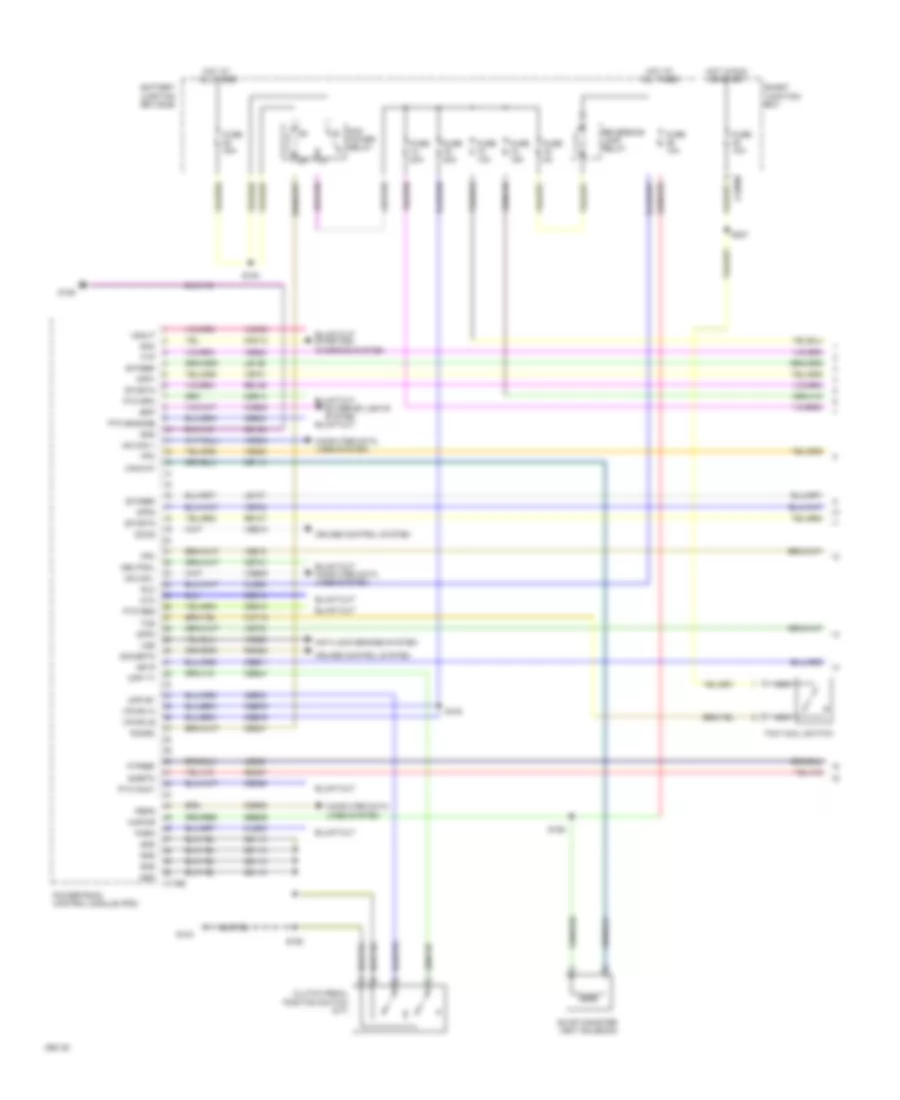
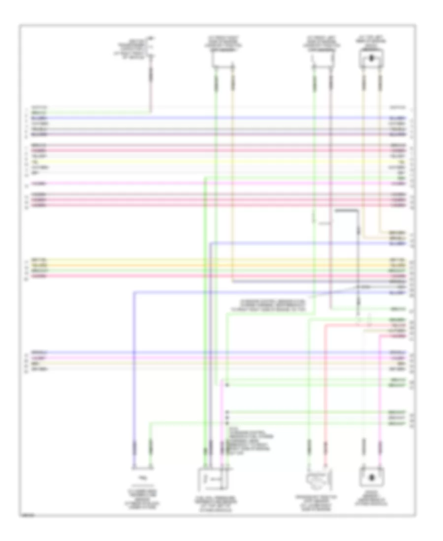
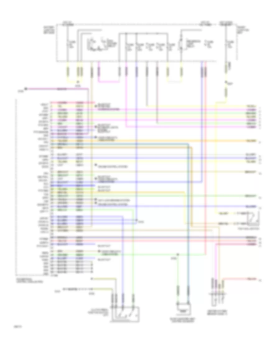
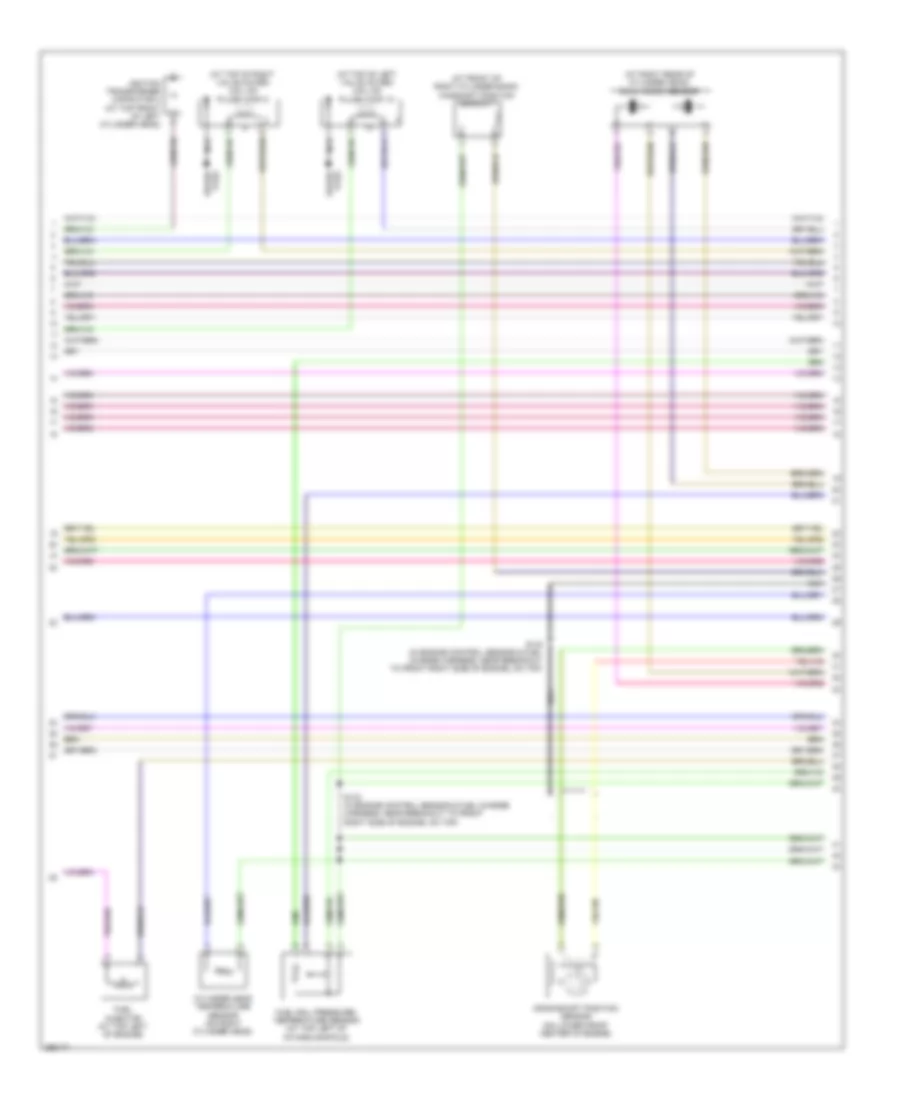
ENGINE PERFORMANCE
5.4L
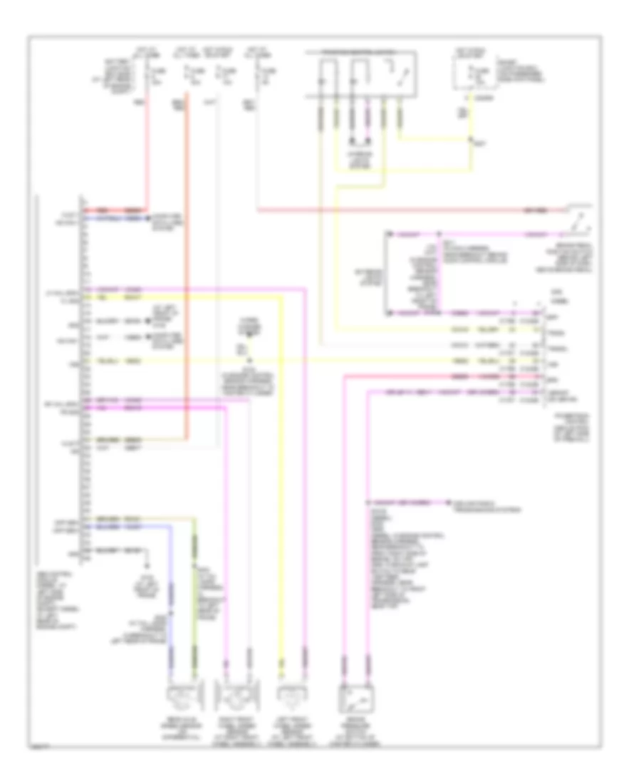
5.4L, Engine Performance Wiring Diagram (1 of 6) for Ford Cab & Chassis F350 Super Duty 2009
List of elements for 5.4L, Engine Performance Wiring Diagram (1 of 6) for Ford Cab & Chassis F350 Super Duty 2009:
- Anti-lock brakes system
- App1
- App2
- App3
- Battery junction box (bjb)
- Bpp
- C175b
- C2280b
- Canvnt
- Cat15
- Cbb71
- Cbb76
- Ccb08
- Cdb08
- Cdc12
- Ce114
- Ce237
- Ce326
- Ce903
- Ce904
- Ce912
- Ce913
- Ce914
- Ce924
- Cet21
- Cls05
- Cls28
- Clutch pedal position switch (m/t)
- Computer data lines system
- Cpp bt
- Cpp tt
- Cruise control system
- Cto
- Etcref
- Etcrtn
- Evap canister vent solenoid
- Exterior lights system
- Fpc
- Fpm
- Ftp
- Ftpref
- Fuse 10a
- Fuse 15a
- Fuse 20a
- Fuse 30a
- Fuse 5a
- G103
- G106
- Gd113
- Gd164
- Gnd
- Hot at all times
- Hot in run or start
- Hs can +
- Hs can -
- Isp r
- Kapwr
- Le136
- Le137
- Le230
- Nca
- Neutral
- Park
- Pcm power relay
- Pcmrc
- Peps
- Powertrain control module (pcm)
- Pto engage
- Pto okay
- Pto req
- Pto rpm
- Re136
- Re137
- Re407
- Res08
- Reversing lamp relay
- Rlc
- S102
- S154
- S158
- S162
- S227
- Sbb36
- Sccs
- Sccsrtn
- Sigrtn
- Smart junction box
- Smc
- Tcs
- Tow haul switch
- Vdb04
- Vdb05
- Ve225
- Ve518
- Ve701
- Ve702
- Ve703
- Ve822
- Ve922
- Ves10
- Vmc05
- Vpwr1-a
- Vpwr1-b
- Vsout
- Vss
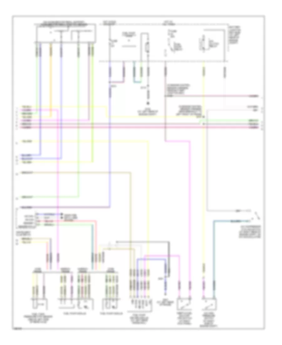
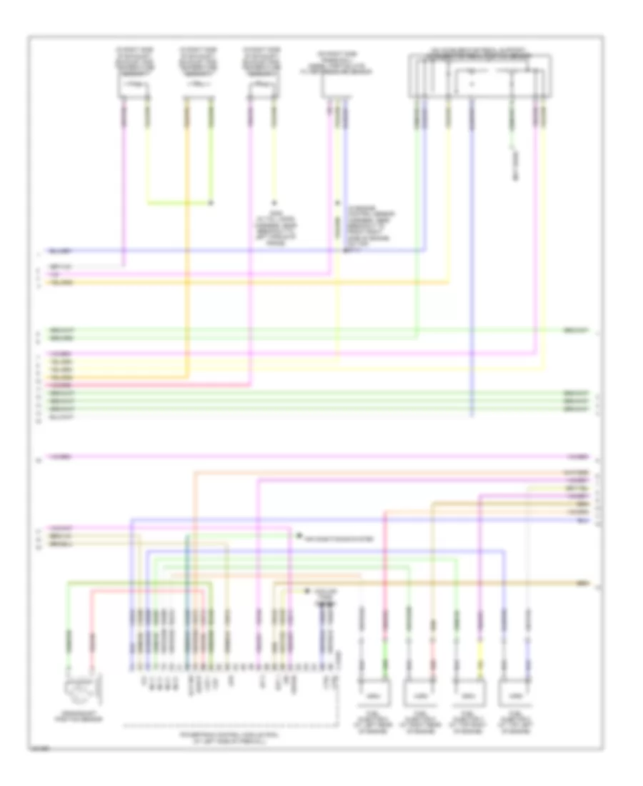
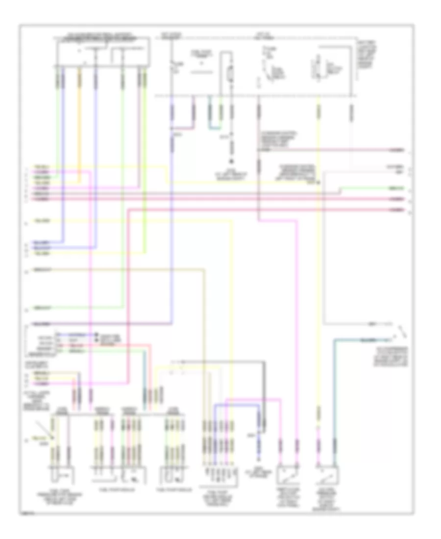
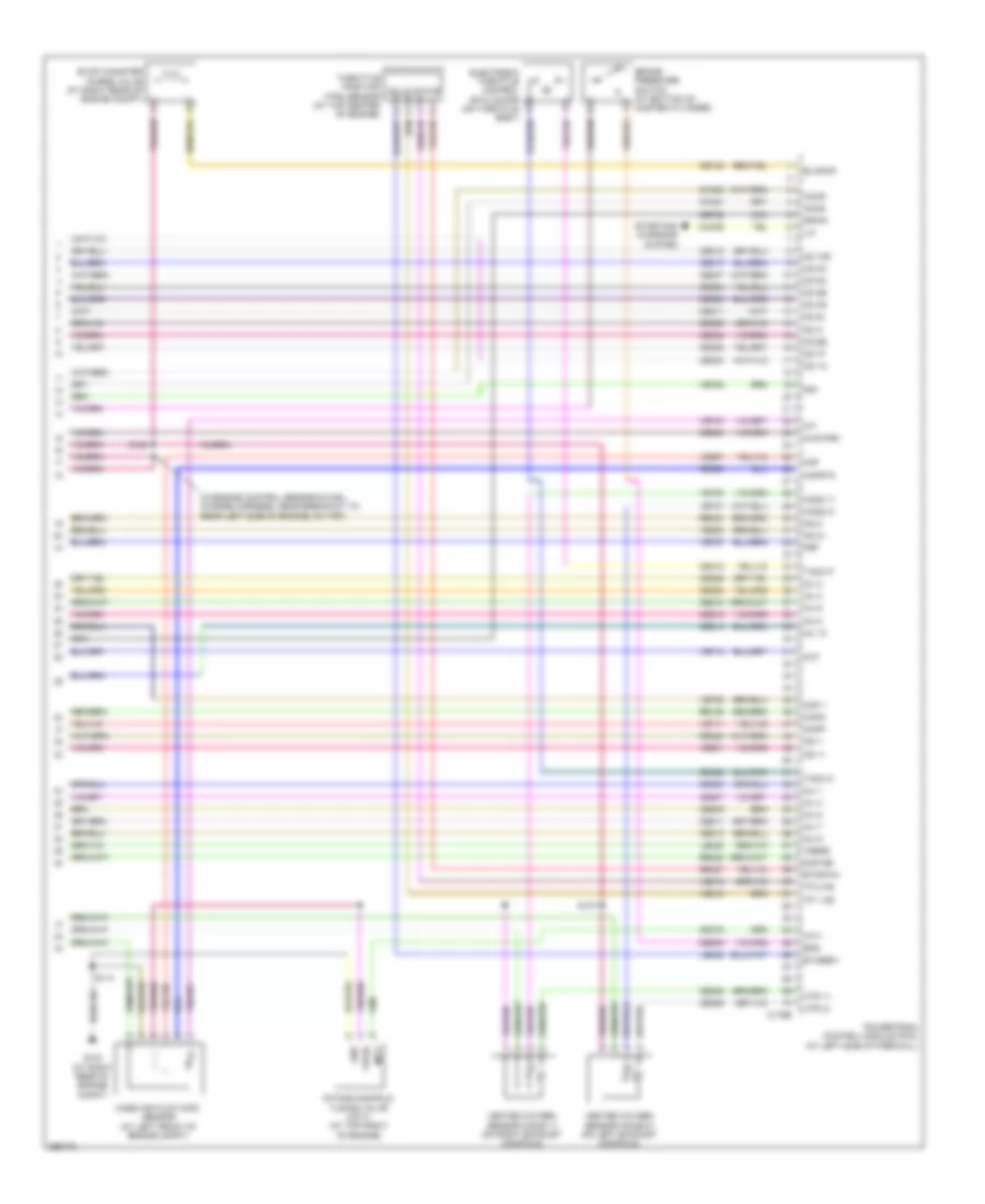
5.4L, Engine Performance Wiring Diagram (2 of 6) for Ford Cab & Chassis F350 Super Duty 2009
List of elements for 5.4L, Engine Performance Wiring Diagram (2 of 6) for Ford Cab & Chassis F350 Super Duty 2009:
- (in engine control sensor harness, near battery junction box) s156
- (in engine control sensor harness, near breakout to left front of frame) s101
- (on accelerator pedal support) accelerator pedal position sensor
- A/c clutch relay
- A/c compressor cycling switch (at right rear of engine compt, on a/c accumulator)
- A/c high pressure switch (at right side of engine compt)
- Batt
- Battery junction box (bjb) (at left rear of engine compt)
- Ce515
- Ce911
- Computer data lines system
- Fp pwr
- Fp rtn
- Fpc
- Fpm
- Fuel pump diode
- Fuel pump driver module (at left rear frame rail)
- Fuel pump module
- Fuel pump relay
- Fuel tank pressure (ftp) sensor (above left side of rear axle)
- Fuse 20a
- Fuse 5a
- G108 (at left rear of engine compt)
- G401 (at left rear of frame)
- Gd117
- Hot at all times
- Hot in run or start
- Hs can +
- Hs can -
- Inertia fuel shutoff (ifs) switch (at right kick panel)
- Instrument cluster (ic)
- Le230
- Md grd
- Narrow frame
- Nca
- Re407
- Re515
- Rmc32
- S115
- S123
- S401
- Sender 1
- Sender rtn 2
- Ve225
- Ve518
- Ve922
- Vmc11
- Wide frame
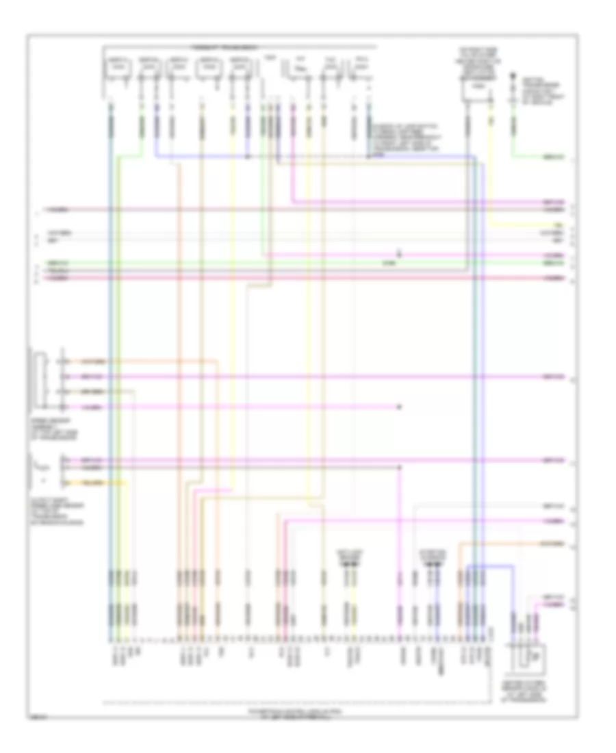
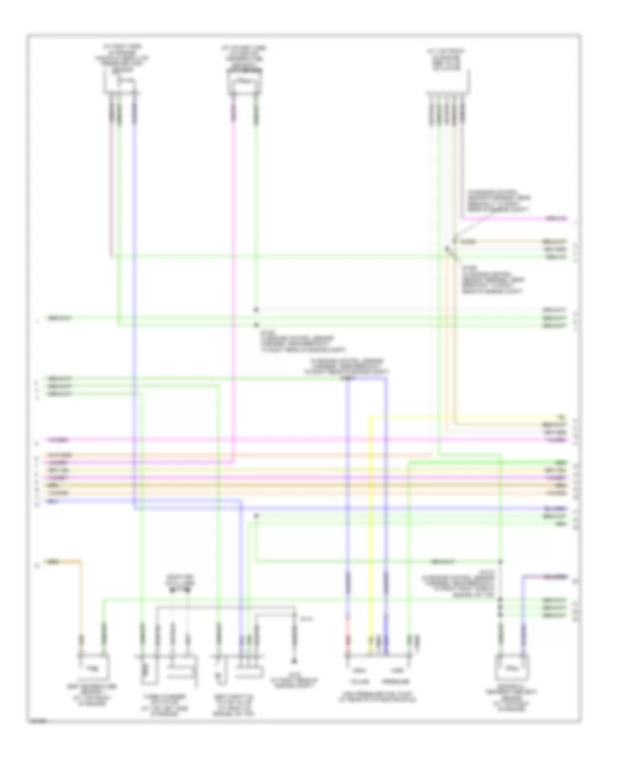
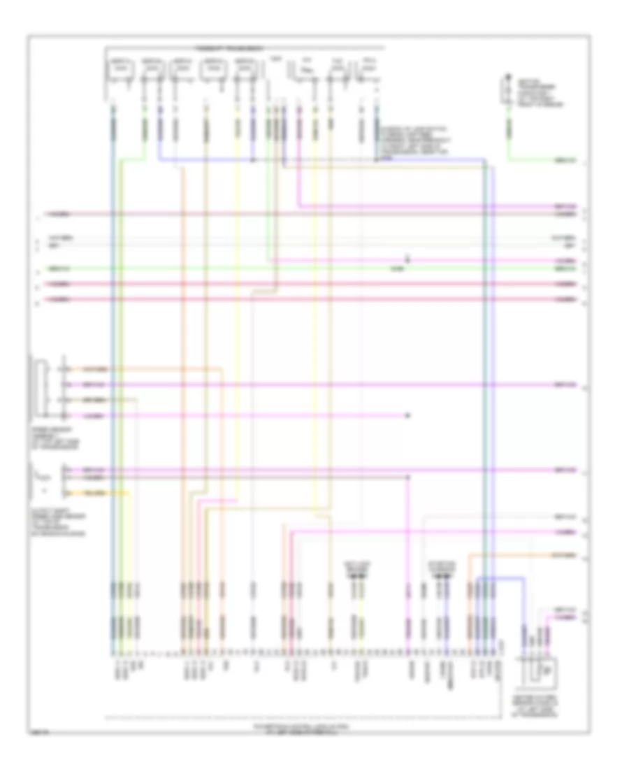
5.4L, Engine Performance Wiring Diagram (3 of 6) for Ford Cab & Chassis F350 Super Duty 2009
List of elements for 5.4L, Engine Performance Wiring Diagram (3 of 6) for Ford Cab & Chassis F350 Super Duty 2009:
- (in back up lamp switch to rear lamp feed harness, near breakout to front left side of transmission, near top) s194
- (on right side valve cover) heated positive crankcase ventilation (pcv) element
- Anti-lock brakes system
- C175t
- Cca10
- Cca15
- Cdc35
- Cdc38
- Ce233
- Ce234
- Cet05
- Cet06
- Cet07
- Cet08
- Cet09
- Cet22
- Cet25
- Cet49
- Cet50
- Crank
- Heated oxygen sensor (ho2s) 22 (at left side of transmission)
- Ho2s 12
- Ho2s 22
- Htr 12
- Htr 22
- Ignition transformer capacitor 1 (at right front of vehicle)
- Iss
- Le111
- Oss
- Output shaft speed (oss) sensor (at top of transmission extension housing)
- Pc-a
- Pca
- Powertrain control module (pcm) (at left side of firewall)
- Re406
- Ret04
- Ret24
- S196
- Sig rtn
- Sigrtn
- Smr/start
- Speed sensor assembly (at top left side of transmission)
- Sspc a
- Sspc b
- Sspc c
- Sspc d
- Sspc e
- Sspc-a
- Sspc-b
- Sspc-c
- Sspc-d
- Sspc-e
- Starting/ charging system
- Tcc
- Tft
- Torqshift transmission
- Tr p
- Tr-p
- Tracs
- Tracsil
- Tss
- Vbpwr
- Ve730
- Ve733
- Ve744
- Vet27
- Vet33
- Vpwr
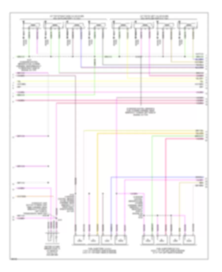
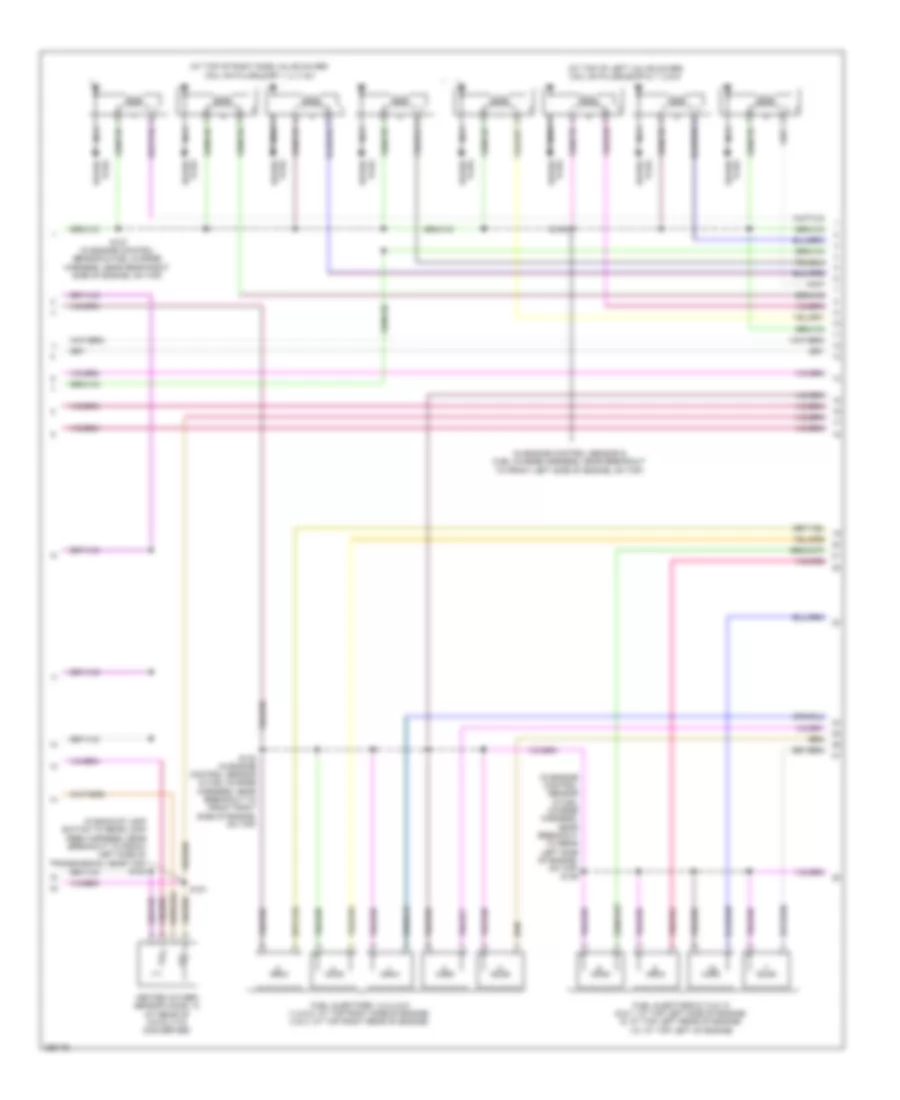
5.4L, Engine Performance Wiring Diagram (4 of 6) for Ford Cab & Chassis F350 Super Duty 2009
List of elements for 5.4L, Engine Performance Wiring Diagram (4 of 6) for Ford Cab & Chassis F350 Super Duty 2009:
- (at top of left valve cover) coil on plugs (cop) 5, 6, 7 & 8
- (at top of right side valve cover) coil on plugs (cop) 1, 2, 3 & 4
- (in backup lamp switch to rear lamp feed harness, near breakout to front left side of transmission, near top) s183
- (in engine control sensor & fuel charge harness, near breakout to rear left side of engine, on top)
- (in engine control sensor & fuel charge harness, near breakout to rear right side of engine, on top) s108
- Fuel injectors 1,2,3 & 4 (1 & 2: at top right side of engine) (3 & 4: at top right rear of engine)
- Fuel injectors 5,6,7 & 8 (5,6 & 7: at top left side of engine) (8: at top left rear of engine)
- Heated oxygen sensor (ho2s) 12 (at rear of catalytic converter)
- Nca
- Plug spark
- S127 (in engine control sensor & fuel charge harness, near breakout to rear right side of engine, on top)
- S132 (in engine control sensor & fuel charge harness, near breakout to front right side of engine, on top)
- S135
- S181
- Spark plug
5.4L, Engine Performance Wiring Diagram (5 of 6) for Ford Cab & Chassis F350 Super Duty 2009
List of elements for 5.4L, Engine Performance Wiring Diagram (5 of 6) for Ford Cab & Chassis F350 Super Duty 2009:
- (at front left side of engine) camshaft position (ckp) sensor 2
- (at front right side of engine) camshaft position (ckp) sensor 1
- (at top left rear of engine) knock sensor 2
- (in engine control sensor & fuel charge harness, near breakout to front right side of engine, on top)
- Crankshaft position (cmp) sensor (at lower right side of engine)
- Cylinder head temperature sensor (at rear of block, under intake)
- Fuel rail pressure/ temperature sensor (at top left of intake manifold)
- Ignition transformer capacitor 2 (at right front of vehicle)
- Knock sensor 1 (near rear of intake manifold)
- Nca
- S133 (in engine control sensor & fuel charge harness, near breakout to front right side of engine, on top)
- S134
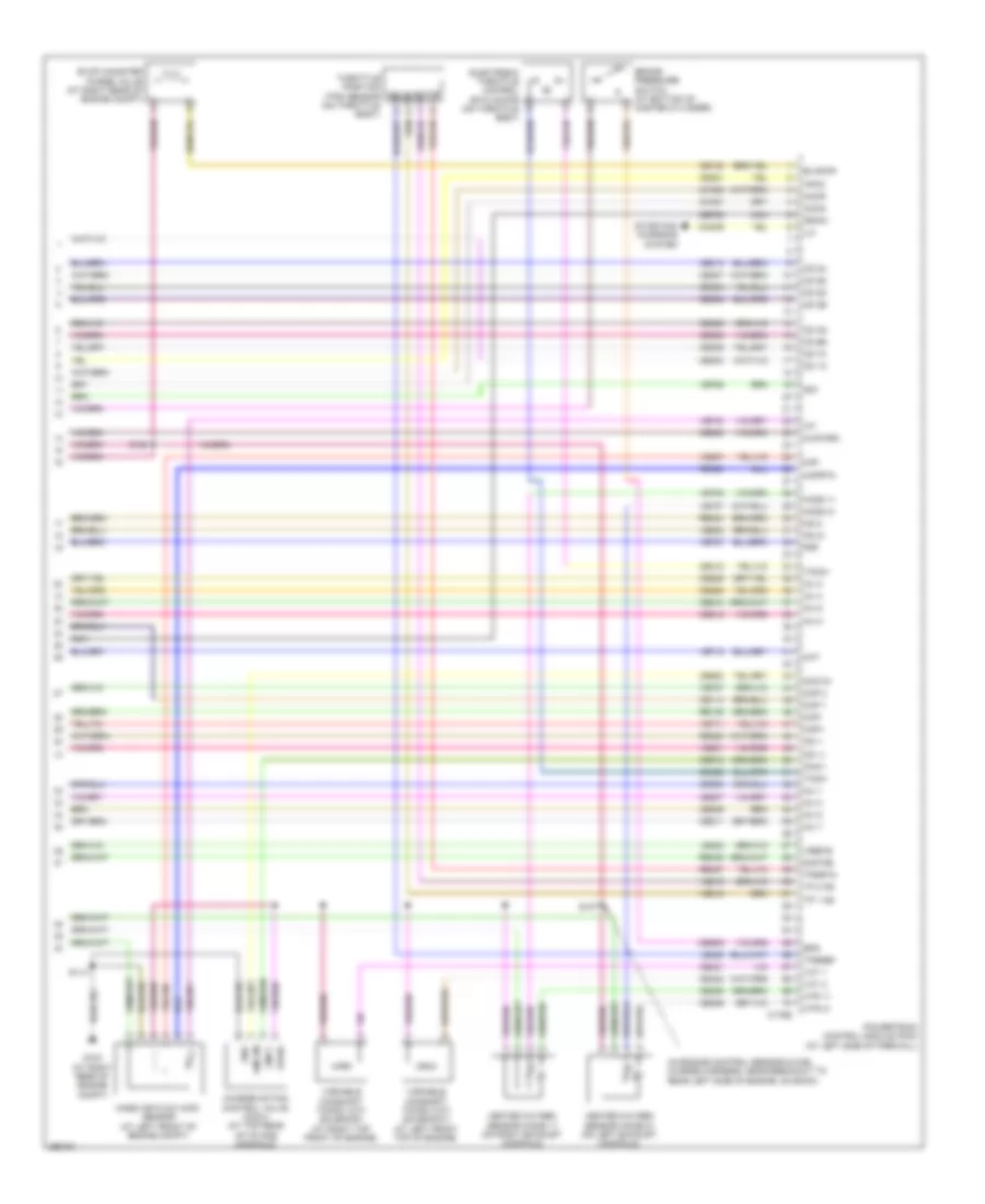
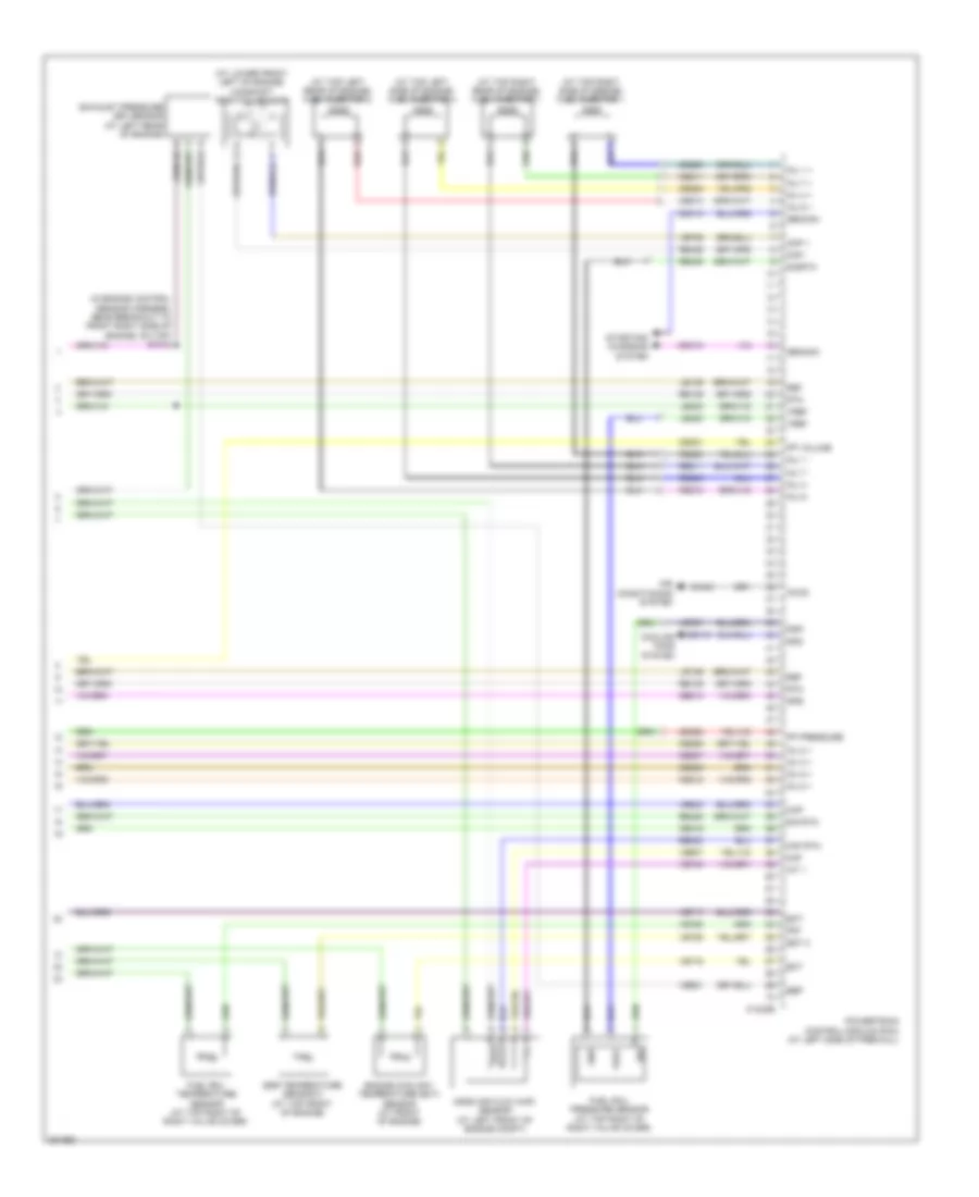
5.4L, Engine Performance Wiring Diagram (6 of 6) for Ford Cab & Chassis F350 Super Duty 2009
List of elements for 5.4L, Engine Performance Wiring Diagram (6 of 6) for Ford Cab & Chassis F350 Super Duty 2009:
- (in engine control sensor & fuel charge harness, near breakout to rear left side of engine, on back)
- Accr
- Accs
- Bps
- Brake pressure switch (at bottom of master cylinder)
- C175e
- Cac09
- Cd 1a
- Cd 2d
- Cd 3b
- Cd 4g
- Cd 5d
- Cd 6e
- Cd 7c
- Cd 8h
- Ce114
- Ce132
- Ce205
- Ce206
- Ce207
- Ce208
- Ce209
- Ce210
- Ce211
- Ce212
- Ce235
- Ce236
- Ce303
- Ce304
- Ce305
- Ce306
- Ce307
- Ce308
- Ce309
- Ce310
- Ce321
- Ce412
- Ce421
- Ce422
- Ce426
- Ce608
- Ce918
- Ce923
- Ces09
- Ch302
- Ch421
- Charge motion control valve (cmcv) (at top rear of intake manifold)
- Cht
- Ckp+
- Ckp-
- Cmcv
- Cmcvm
- Cmp 1
- Cmp 2
- De706
- Drain
- Evap canister purge valve (at right rear of engine compt)
- Evapcp
- Frp
- Frt
- G103 (at right rear of engine compt)
- Gnd
- Heated oxygen sensor (ho2s) 11 (on right exhaust manifold)
- Heated oxygen sensor (ho2s) 21 (on left exhaust manifold)
- Ho2s 11
- Ho2s 21
- Hpcc
- Htr 11
- Htr 21
- Iat
- Ilc
- Inj 1
- Inj 2
- Inj 3
- Inj 4
- Inj 5
- Inj 6
- Inj 7
- Inj 8
- Injpwrm
- Ks 1+
- Ks 1-
- Ks 2+
- Ks 2-
- Le423
- Le428
- Maf
- Mafrtn
- Mass air flow (maf) sensor (at left front of engine compt)
- Nca
- Powertrain control module (pcm) (at left side of firewall)
- Re135
- Re320
- Re323
- Re324
- Re405
- Re427
- S107
- S114
- S155
- Sigtne
- Solid state
- Starting/ charging system
- Tacm+
- Tacm-
- Throttle position (tps) sensor (on throttle body)
- Tp 1 ns
- Tp 2 ps
- Tpsref
- Tpsrtn
- Variable camshaft timing (vct) solenoid 2 (at left front top of engine)
- Variable camshaft timing (vct) solenoid1 (at right top front of engine)
- Vct 1
- Vct 2
- Ve707
- Ve711
- Ve712
- Ve727
- Ve728
- Ve735
- Ve737
- Ve740
- Ve801
- Ve802
- Ve807
- Ve818
- Ve819
- Vpwr
- Vref-e
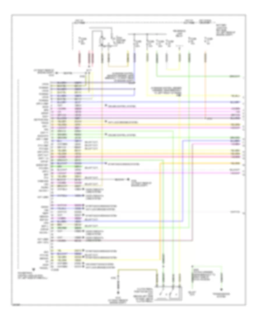
6.4L DIESEL
6.4L Diesel, Engine Performance Wiring Diagram (1 of 6) for Ford Cab & Chassis F350 Super Duty 2009
List of elements for 6.4L Diesel, Engine Performance Wiring Diagram (1 of 6) for Ford Cab & Chassis F350 Super Duty 2009:
- (at right rear of engine compt) g103
- (in engine control sensor harness, near breakout to left front of frame) s101
- (in engine control sensor harness, near breakout to right rear of engine compt) s102
- Accr
- Air conditioning system
- Anti-lock brakes system
- App 1
- App 1 rtn
- App 1 vref
- App 2
- App 2 rtn
- App 2 vref
- Battery junction box (bjb) (at left rear of engine compt)
- Bcp il
- Bcp sw
- Bpp
- Bps
- C1232b
- Case gnd
- Cbb71
- Cbb76
- Cca10
- Cca15
- Ccb06
- Cdc12
- Cdc35
- Cdc38
- Cdc46
- Cdc47
- Ce140
- Ce237
- Ce326
- Ce904
- Ce911
- Ce912
- Ce913
- Ce914
- Ce925
- Ces09
- Cet21
- Ch302
- Clutch pedal position switch (m/t) (behind left side of dash, above clutch pedal)
- Cmc25
- Computer data lines system
- Cpp bt
- Cpp tt
- Crank
- Cruise control system
- Cto
- Doct
- Dpfdp
- Dpft 1 in
- Dpft out
- Fpm
- Fuse 10a
- Fuse 20a
- Fuse 50a
- Fuse 5a
- G103 (at right rear of engine compt)
- G106 (at right rear of engine compt)
- Gd113
- Gd164
- Gencom
- Genmon
- Hot at all times
- Hot in run or start
- Hs can +
- Hs can -
- Kapwr
- Keypwr (r/s)
- Le136
- Le137
- Le434
- Not used
- Pbpp
- Pcm power relay
- Pcmrc
- Powertrain control module (pcm) (at left side of firewall)
- Pto
- Pto gnd
- Pto ind
- Pto rpm
- Pto vref
- Pwrgnd
- Re136
- Re137
- Re327
- Res08
- Reversing lamp relay
- S117
- S123
- S162
- S208 (in main harness, near breakout to right side of hvac housing)
- Sbb36
- Sccs
- Sccs rtn
- Smc
- Smr/start
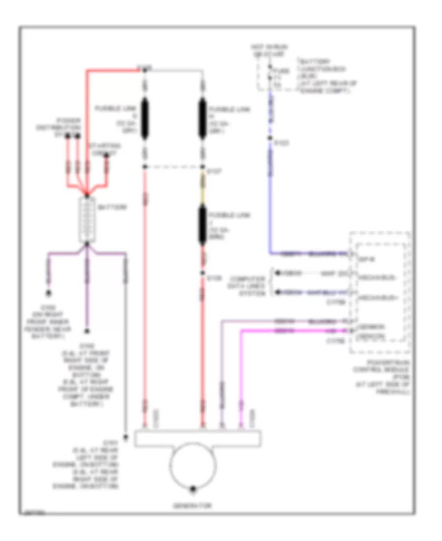
- Starting/charging system
- Tracs
- Tracsil
- Transmissions system
- Vdb04
- Vdb05
- Ve225
- Ve701
- Ve702
- Ve746
- Ve747
- Ve748
- Ve749
- Ve822
- Ve823
- Ves10
- Vmv05
- Vpwr
- Vso
- Vss
- Wfs
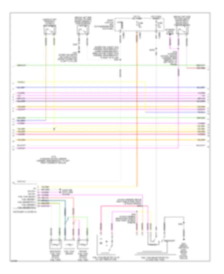
6.4L Diesel, Engine Performance Wiring Diagram (2 of 6) for Ford Cab & Chassis F350 Super Duty 2009
List of elements for 6.4L Diesel, Engine Performance Wiring Diagram (2 of 6) for Ford Cab & Chassis F350 Super Duty 2009:
- (behind left side of dash, above brake pedal) brake pedal position switch
- (behind left side of dash, on park brake assembly) parking brake switch
- (in main harness, behind right side of dash, right of radio opening)
- (inside of left frame rail) water in fuel sensor
- (super cab: in body main harness, near breakout under passenger seat) (regular cab: in body main harness, near breakout to right "b" pillar) s304
- C2280a
- C2280b
- C2280c
- Computer data lines system
- Exterior lights system
- Fuel sender 1
- Fuel sender 2
- Fuel sender rtn 2
- Fuel tank select
- Fuel tank selector switch (w/ duel fuel tank)
- Fuel tank selector valve (at left rear of cab)
- Fuel tank sensor
- Fuse 10a
- G203 (behind center of dash, behind audio control module)
- G300 (super cab: behind left side of dash) (except super cab: in left "a" pillar)
- Hot at all times
- Hot in run or acc
- Instrument cluster (ic)
- Micro
- Ms can +
- Ms can -
- Primary
- Primary fuel tank sensor (w/ dual fuel tank)
- S106 (in engine control sensor harness, near breakout to left front of frame)
- S116 (in engine control sensor harness, near breakout to left front corner of vehicle)
- S225
- S2439
- S245
- S246 (in main harness, behind right side of dash, right of radio opening)
- S326
- Secondary
- Secondary fuel tank sensor (w/ dual fuel tank)
- Sense
- Smart junction box (on passenger side kick panel)
6.4L Diesel, Engine Performance Wiring Diagram (3 of 6) for Ford Cab & Chassis F350 Super Duty 2009
List of elements for 6.4L Diesel, Engine Performance Wiring Diagram (3 of 6) for Ford Cab & Chassis F350 Super Duty 2009:
- (at right kick panel) inertia fuel shutoff (ifs) switch
- (in engine control sensor harness, near breakout to front right side of engine, on top) s1010
- (in engine control sensor harness, near breakout to right rear of engine compartment) s107
- (near left side of transmission) fuel pump
- Battery junction box (bjb) (at left rear of engine compt)
- Brake pressure switch (at bottom of master cylinder)
- C1273a
- C1273b
- Cbb12
- Ce243
- Ce244
- Ce245
- Ce246
- Ce247
- Ce248
- Ce251
- Ce252
- Ce513
- Ce514
- Cooling fans system
- Fuel cooler (at left front of engine)
- Fuel pump diode
- Fuel pump relay
- Fuse 20a
- Fuse 50a
- Fuse 5a
- G104 (at left rear of engine compt)
- Glow plug control module (gpcm) (at top right front of engine)
- Gpd
- Gpe
- Hot at all times
- Kapwr
- Left glow plug bank (at lower left side of engine)
- Right glow plug bank (at right side of engine)
- S1000
- S1003
- S1009 (in engine control sensor harness, near breakout to front right side of engine, on top)
- S103
- S113
- S124
- Sbb27
- Sbb47
- Vpwr
6.4L Diesel, Engine Performance Wiring Diagram (4 of 6) for Ford Cab & Chassis F350 Super Duty 2009
List of elements for 6.4L Diesel, Engine Performance Wiring Diagram (4 of 6) for Ford Cab & Chassis F350 Super Duty 2009:
- (in engine control sensor harness, near breakout to front right side of engine, on top) s114
- (in right side of exhaust) exhaust gas temperature sensor 1
- (in right side of exhaust) exhaust gas temperature sensor 2
- (in right side of exhaust) exhaust gas temperature sensor 3
- (not used)
- (on accelerator pedal support) accelerator pedal position sensor
- (on right side frame rail) diesel particulate filter pressure sensor
- Acp sw
- Air conditioning system
- C1232e
- Ce250
- Ce315
- Ce514
- Cec11
- Ch425
- Ckp +
- Ckp -
- Cooling fans system
- Crankshaft position sensor
- Ctrl
- Egrvp
- Egt 1
- Fcc
- Fuel injector 2 (at top left of engine)
- Fuel injector 3 (at top right of engine)
- Fuel injector 5 (at right rear of engine)
- Fuel injector 8 (at left rear of engine)
- Gpd
- Iat 2
- Inj 2 -
- Inj 3 -
- Inj 5 -
- Inj 8 -
- Powertrain control module (pcm) (at left side of firewall)
- Re135
- Re206
- Re207
- Re209
- Re212
- Red
- S408 (in tail lamps harness, near breakout to left middle of frame)
- Sig
- Vbpwr
- Ve711
- Ve721
- Ve722
- Ve740
- Vec03
- Vec10
6.4L Diesel, Engine Performance Wiring Diagram (5 of 6) for Ford Cab & Chassis F350 Super Duty 2009
List of elements for 6.4L Diesel, Engine Performance Wiring Diagram (5 of 6) for Ford Cab & Chassis F350 Super Duty 2009:
- (at intake tube) intake air temperature sensor 2 (iat2) sensor
- (at right side of engine) manifold absolute pressure (map) sensor
- (at top front of engine) egr valve actuator
- (in engine control sensor harness, near breakout to right rear of engine compt)
- (in engine control sensor harness, near breakout to right rear of engine compt) s1007
- C1906a
- C1906b
- Computer data lines system
- Egr temperature sensor 1 (at top front of engine)
- Egr throttle plate valve (at front of engine, on top)
- Engine oil temperature (eot) sensor (at top right of engine)
- G103 (at right rear of engine compt)
- High pressure fuel pump (at rear of intake manifold)
- Pressure
- Red
- S1002 (in engine control sensor harness, near breakout to right rear of engine compt)
- S1005
- S1006 (in engine control sensor harness, near breakout to right rear of engine compt)
- S1013 (in engine control sensor harness, near breakout to front right side of engine, on top)
- S114
- Turbo charger actuator (at top left side of engine)
- Volume
6.4L Diesel, Engine Performance Wiring Diagram (6 of 6) for Ford Cab & Chassis F350 Super Duty 2009
List of elements for 6.4L Diesel, Engine Performance Wiring Diagram (6 of 6) for Ford Cab & Chassis F350 Super Duty 2009:
- (at lower front left of engine) camshaft position sensor
- (at top left rear of engine) fuel injector 6
- (at top left side of engine) fuel injector 4
- (at top right rear of engine) fuel injector 7
- (at top right side of engine) fuel injector 1
- (in engine control sensor harness, near breakout to front right side of engine, on top) s1012
- Accs
- Air conditioning system
- C1232e
- Cdc10
- Cdc15
- Ce205
- Ce206
- Ce207
- Ce208
- Ce209
- Ce210
- Ce211
- Ce212
- Ce316
- Ce321
- Ce328
- Ch421
- Cmp +
- Cmp -
- Cooling fans system
- Ebp
- Ect
- Egr temperature sensor 2 (at top front of engine)
- Egt 2
- Engine coolant temperature (ect) sensor (at front of engine)
- Eot
- Exhaust pressure (ep) sensor (at left rear of engine)
- Frpi
- Frt
- Fuel rail pressure sensor (at top right of right valve cover)
- Fuel rail temperature sensor (at top right of right valve cover)
- Gd119
- Ge513
- Gencom
- Genmon
- Gnd
- Gpe
- Iat 1
- Inj 1 +
- Inj 1 -
- Inj 2 +
- Inj 3 +
- Inj 4 +
- Inj 4 -
- Inj 5 +
- Inj 6 +
- Inj 6 -
- Inj 7 +
- Inj 7 -
- Inj 8 +
- Le139
- Le423
- Lr139
- Maf
- Maf rtn
- Map
- Mass air flow (maf) sensor (at left front of engine compt)
- Powertrain control module (pcm) (at left side of firewall)
- Pp pressure
- Pp volume
- Re139
- Re205
- Re208
- Re210
- Re211
- Re230
- Re405
- Re406
- Re429
- Red
- Ref
- Rtn
- Sig
- Sig rtn
- Sigrtn
- Starting/ charging system
- Ve607
- Ve706
- Ve716
- Ve717
- Ve726
- Ve727
- Ve728
- Ve740
- Ve803
- Ve921
- Vref
6.8L
6.8L, Engine Performance Wiring Diagram (1 of 6) for Ford Cab & Chassis F350 Super Duty 2009
List of elements for 6.8L, Engine Performance Wiring Diagram (1 of 6) for Ford Cab & Chassis F350 Super Duty 2009:
- Anti-lock brakes system
- App1
- App2
- App3
- Battery junction box (bjb)
- Bpp
- C175b
- C2280b
- Canvnt
- Cat15
- Cbb71
- Cbb76
- Ccb08
- Cdb08
- Cdc12
- Ce114
- Ce237
- Ce239
- Ce326
- Ce903
- Ce904
- Ce912
- Ce913
- Ce914
- Ce924
- Cet21
- Cls05
- Cls28
- Clutch pedal position switch (m/t)
- Computer data lines system
- Cpp bt
- Cpp tt
- Cruise control system
- Cto
- Etcref
- Etcrtn
- Evap canister vent control solenoid
- Fpc
- Fpm
- Ftpref
- Ftpt
- Fuse 10a
- Fuse 15a
- Fuse 20a
- Fuse 30a
- Fuse 5a
- G103
- G106
- Gd113
- Gd164
- Gnd
- Heated oxygen sensor (ho2s) 13
- Ho2s 13
- Hot at all times
- Hot in run or start
- Hs can +
- Hs can -
- Htr 13
- Isp r
- Kapwr
- Le136
- Le137
- Le230
- Nca
- Neutral
- Park
- Pcm power relay
- Pcmrc
- Peps
- Powertrain control module (pcm)
- Pto engage
- Pto okay
- Pto req
- Pto rpm
- Re136
- Re137
- Re407
- Res08
- Reversing lamp relay
- Rlc
- S102
- S154
- S158
- S162
- S227
- Sbb36
- Sccs
- Sccsrtn
- Sigrtn
- Smart junction box
- Smc
- Tcs
- Tow haul switch
- Vdb04
- Vdb05
- Ve225
- Ve518
- Ve701
- Ve702
- Ve703
- Ve745
- Ve822
- Ve922
- Ves10
- Vmc05
- Vpwr1-a
- Vpwr1-b
- Vsout
- Vss
6.8L, Engine Performance Wiring Diagram (2 of 6) for Ford Cab & Chassis F350 Super Duty 2009
List of elements for 6.8L, Engine Performance Wiring Diagram (2 of 6) for Ford Cab & Chassis F350 Super Duty 2009:
- (in engine control sensor harness, near battery junction box) s156
- (in engine control sensor harness, near breakout to left front of frame) s101
- (in tail lamps harness, near breakout to cross brace)
- (on accelerator pedal support) accelerator pedal position sensor
- A/c clutch relay
- A/c compressor cycling switch (at right rear of engine compt, on a/c accumulator)
- A/c high pressure switch (at right side of engine compt)
- Batt
- Battery junction box (bjb) (at left rear of engine compt)
- Ce515
- Ce911
- Computer data lines system
- Fp pwr
- Fp rtn
- Fpc
- Fpm
- Fuel pump diode
- Fuel pump driver module (at left rear frame rail)
- Fuel pump module
- Fuel pump relay
- Fuel tank pressure (ftp) sensor (above left side of rear axle)
- Fuse 20a
- Fuse 5a
- G108 (at left rear of engine compt)
- G400 (at left rear of frame)
- Gd117
- Hot at all times
- Hot in run or start
- Hs can +
- Hs can -
- Inertia fuel shutoff (ifs) switch (at right kick panel)
- Instrument cluster (ic)
- Le230
- Md grd
- Narrow frame
- Nca
- Re407
- Re515
- Rmc32
- S115
- S123
- S401
- S406
- Sender 1
- Sender rtn 2
- Ve225
- Ve518
- Ve922
- Vmc11
- Wide frame
6.8L, Engine Performance Wiring Diagram (3 of 6) for Ford Cab & Chassis F350 Super Duty 2009
List of elements for 6.8L, Engine Performance Wiring Diagram (3 of 6) for Ford Cab & Chassis F350 Super Duty 2009:
- (in back up lamp switch to rear lamp feed harness, near breakout to front left side of transmission, near top) s194
- Anti-lock brakes system
- C175t
- Cca10
- Cca15
- Cdc35
- Cdc38
- Ce233
- Ce234
- Cet05
- Cet06
- Cet07
- Cet08
- Cet09
- Cet22
- Cet25
- Cet49
- Cet50
- Crank
- Heated oxygen sensor (ho2s) 22 (at left side of transmission)
- Ho2s 12
- Ho2s 22
- Htr 12
- Htr 22
- Ignition transformer capacitor 1 (at top right front of engine)
- Iss
- Le111
- Oss
- Output shaft speed (oss) sensor (at top of transmission extension housing)
- Pc-a
- Pca
- Powertrain control module (pcm) (at left side of firewall)
- Re406
- Ret04
- Ret24
- S196
- Sig rtn
- Sigrtnt
- Smr/start
- Speed sensor assembly (at top left side of transmission)
- Sspc a
- Sspc b
- Sspc c
- Sspc d
- Sspc e
- Sspc-a
- Sspc-b
- Sspc-c
- Sspc-d
- Sspc-e
- Starting/ charging system
- Tcc
- Tft
- Torqshift transmission
- Tr p
- Tr-p
- Tracs
- Tracsil
- Tss
- Vbpwr
- Ve730
- Ve733
- Ve744
- Vet27
- Vet33
- Vpwr
6.8L, Engine Performance Wiring Diagram (4 of 6) for Ford Cab & Chassis F350 Super Duty 2009
List of elements for 6.8L, Engine Performance Wiring Diagram (4 of 6) for Ford Cab & Chassis F350 Super Duty 2009:
- (at top of left valve cover) coil on plugs (cop) 6, 7, 8 & 9
- (at top of right side valve cover) coil on plugs (cop) 1, 2, 3 & 4
- (in backup lamp switch to rear lamp feed harness, near breakout to front left side of transmission, near top) s183
- (in engine control sensor & fuel charge harness, near breakout to front left side of engine, on top)
- (in engine control sensor & fuel charge harness, near breakout to rear left side of engine, on top) s136
- Fuel injectors 1,2,3,4 & 5 (1,2 & 5: at top right side of engine) (3 & 4: at top right rear of engine)
- Fuel injectors 6,7,8 & 10 (6 & 7: at top left side of engine) (8: at top left rear of engine) (10: at top left of engine)
- Heated oxygen sensor (ho2s) 12 (at rear of catalytic converter)
- Nca
- Plug spark
- S127 (in engine control sensor & fuel charge harness, near rear right side of engine, on top)
- S132 (in engine control sensor & fuel charge harness, near breakout to front right side of engine, on top)
- S135
- S181
- Spark plug
6.8L, Engine Performance Wiring Diagram (5 of 6) for Ford Cab & Chassis F350 Super Duty 2009
List of elements for 6.8L, Engine Performance Wiring Diagram (5 of 6) for Ford Cab & Chassis F350 Super Duty 2009:
- (at front of right cylinder bank) camshaft position sensor 1
- (at right rear of cylinder head) dual knock sensor
- (at top of left valve cover) coil on plugs (cop) 10
- (at top of right valve cover) coil on plugs (cop) 5
- Crankshaft position sensor (on lower front center of engine)
- Cylinder head temperature sensor (on right cylinder head)
- Fuel injector (at top left of engine)
- Fuel rail pressure/ temperature sensor (at top left of intake manifold)
- Ignition transformer capacitor 2 (at top front of left cylinder head)
- Nca
- S133 (in engine control sensor & fuel charge harness, near breakout to front right side of engine, on top)
- S134 (in engine control sensor & fuel charge harness, near breakout to front right side of engine, on top)
- Spark plug
6.8L, Engine Performance Wiring Diagram (6 of 6) for Ford Cab & Chassis F350 Super Duty 2009
List of elements for 6.8L, Engine Performance Wiring Diagram (6 of 6) for Ford Cab & Chassis F350 Super Duty 2009:
- (in engine control sensor & fuel charge harness, near breakout to rear left side of engine, on top)
- Accr
- Accs
- Bps
- Brake pressure switch (at bottom of master cylinder)
- C175e
- Cac09
- Cd 10d
- Cd 1a
- Cd 2e
- Cd 3g
- Cd 4i
- Cd 5o
- Cd 6b
- Cd 7f
- Cd 8h
- Cd 9j
- Ce132
- Ce205
- Ce206
- Ce207
- Ce208
- Ce209
- Ce210
- Ce211
- Ce212
- Ce213
- Ce214
- Ce235
- Ce236
- Ce303
- Ce304
- Ce305
- Ce306
- Ce307
- Ce308
- Ce309
- Ce310
- Ce311
- Ce312
- Ce316
- Ce412
- Ce426
- Ce608
- Ces09
- Ch302
- Ch421
- Cht
- Ckpn
- Ckpp
- Cmp 1
- De706
- Drain
- Etcref1
- Etcrtn1
- Evap canister purge valve (at right rear of engine compt)
- Evapcp
- Frp
- Frt
- G103 (at right rear of engine compt)
- Gnd
- Heated oxygen sensor (ho2s) 11 (on right exhaust manifold)
- Heated oxygen sensor (ho2s) 21 (on left exhaust manifold)
- Ho2s 11
- Ho2s 21
- Htr 11
- Htr 21
- Iat
- Ilc
- Imtv
- Inj 1
- Inj 10
- Inj 2
- Inj 3
- Inj 4
- Inj 5
- Inj 6
- Inj 7
- Inj 8
- Inj 9
- Injpwrm
- Intake manifold tuning valve (imtv) (at top right of engine)
- Ks 1+
- Ks 1-
- Ks 2+
- Ks 2-
- Le423
- Le428
- Maf
- Mafrtn
- Mass air flow (maf) sensor (at left front of engine compt)
- Nca
- Powertrain control module (pcm) (at left side of firewall)
- Re135
- Re320
- Re323
- Re324
- Re405
- Re427
- S107
- S114
- S155
- Sigtne
- Solid state
- Starting/ charging system
- Tacm n
- Tacm p
- Throttle position (tps) sensor (at top center of engine)
- Tp 1 ns
- Tp 2 ps
- Ve706
- Ve711
- Ve712
- Ve727
- Ve728
- Ve735
- Ve737
- Ve740
- Ve801
- Ve802
- Ve807
- Ve818
- Ve819
- Vpwr
- Vrefe
EXTERIOR LIGHTS
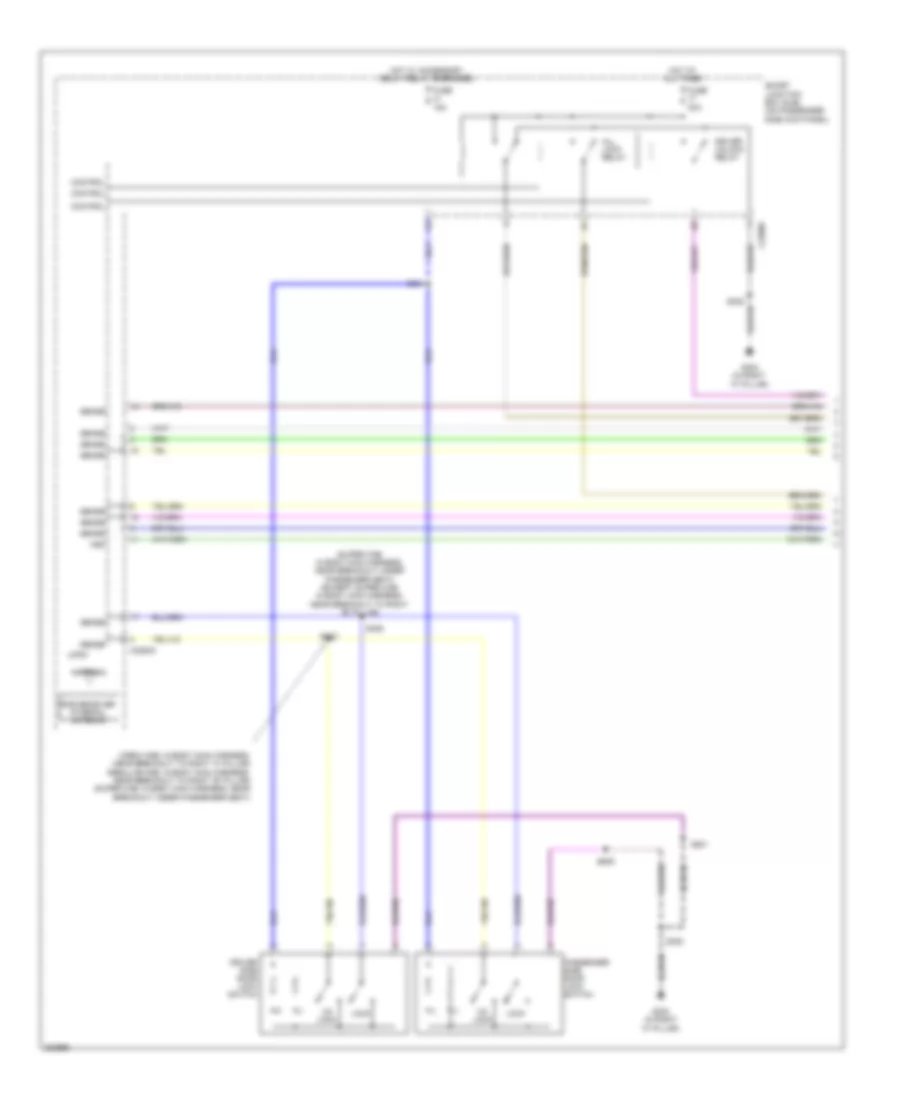
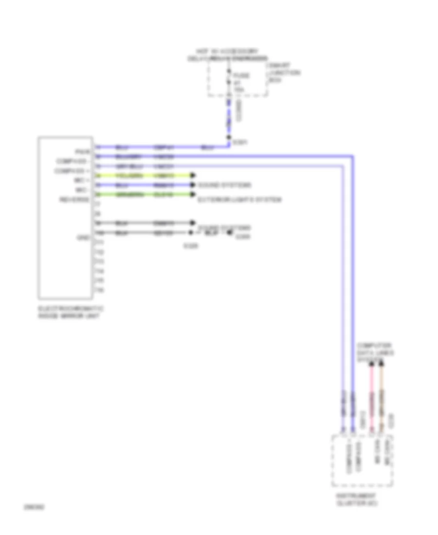
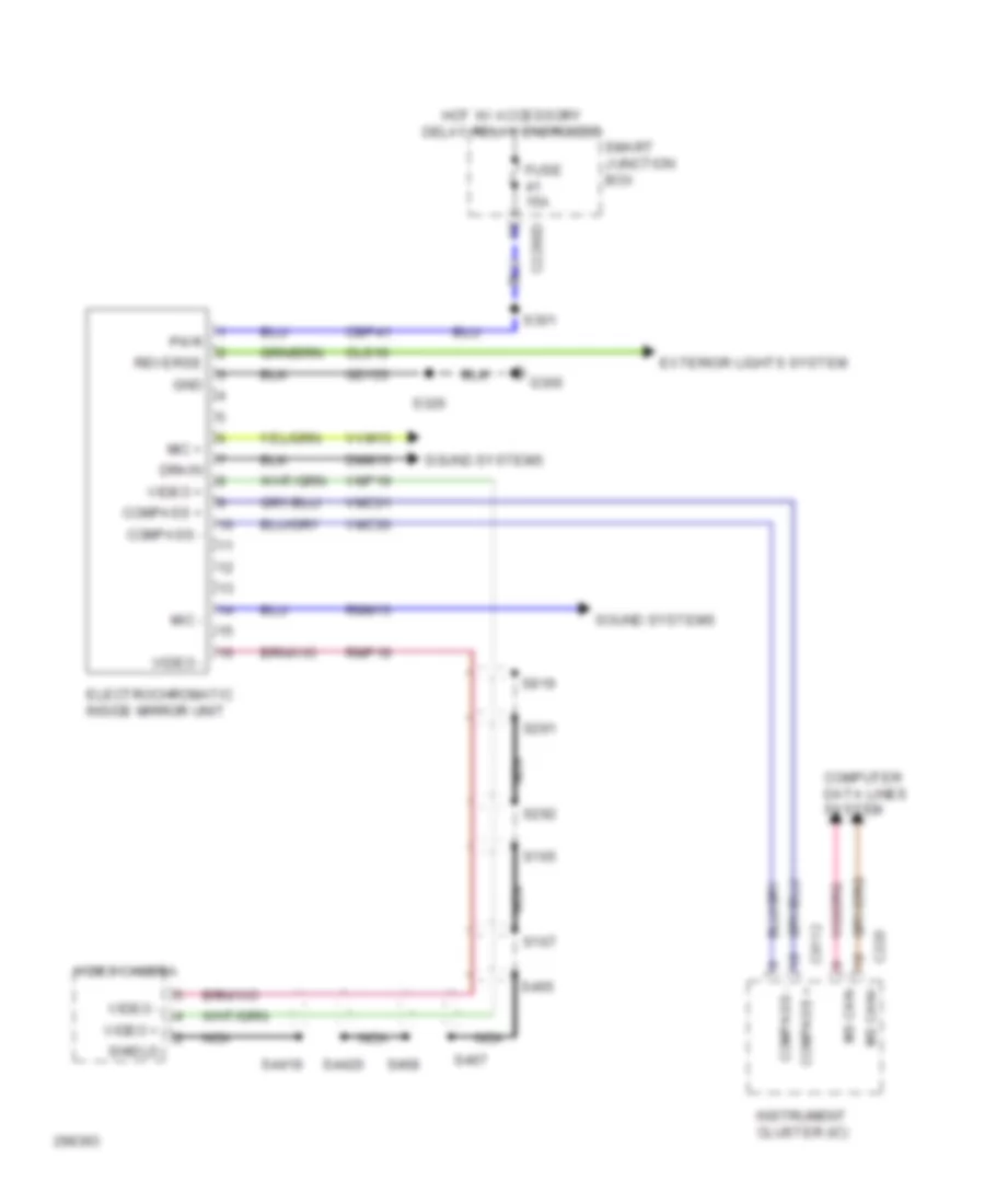
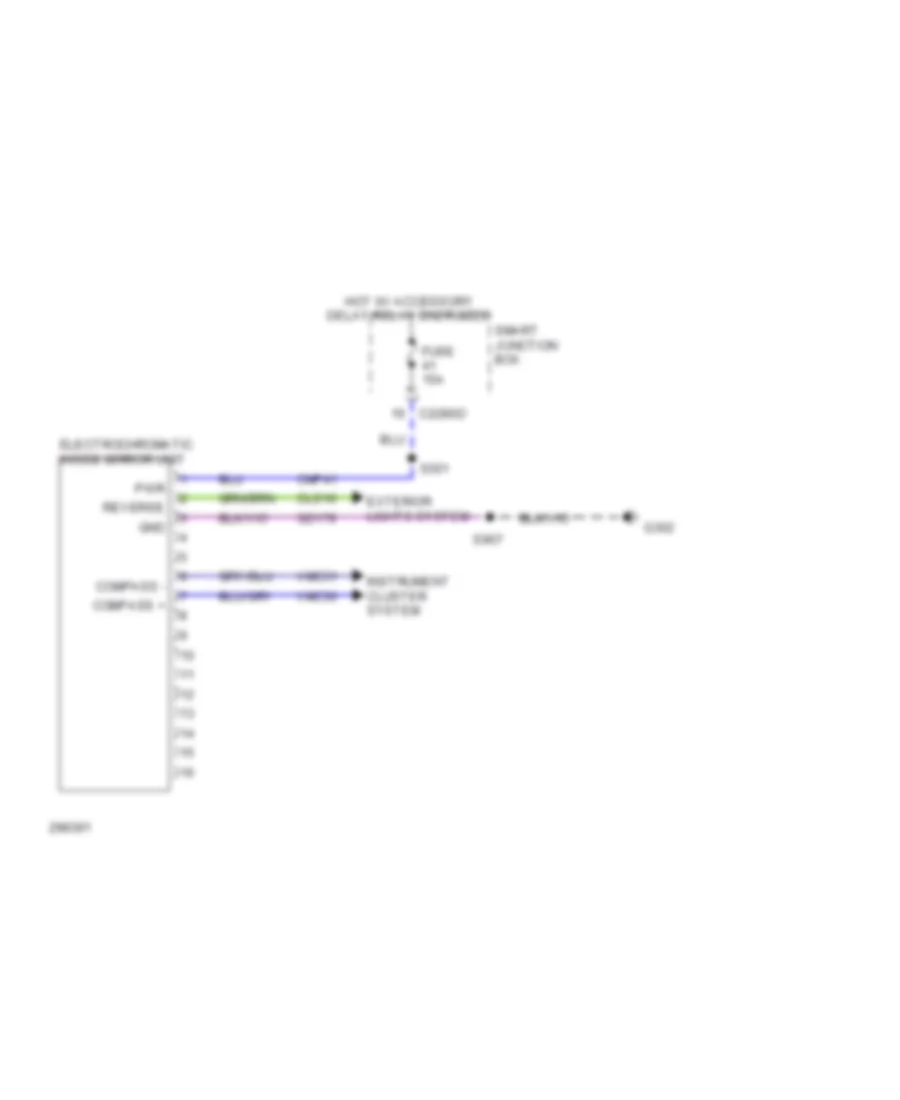
Backup Lamps Wiring Diagram for Ford Cab & Chassis F350 Super Duty 2009
List of elements for Backup Lamps Wiring Diagram for Ford Cab & Chassis F350 Super Duty 2009:
- (at left rear of engine compt) g104
- (at left rear of frame) g400
- (at left side of firewall) (gas) powertrain control module (pcm)
- (at rear of transfer case) (diesel) transmisson control module (tcm)
- (in engine control sensor harness, near breakout to master cylinder) s109
- (in engine control sensor harness, near breakout to right rear of engine compt) s1777
- (in main harness, near breakout behind left side of dash) s237
- (in tail lamps harness, near breakout to left rear of vehicle) s414
- A/t
- Battery junction box (at left rear of engine compt)
- C175b
- Cls10
- Cls28
- Electrochromatic inside mirror unit (at center of front windshield)
- Fuse 15a
- Fuse 20a
- Fuse 5a
- G400 (at left rear of frame)
- Hot at all times
- Hot w/ pcm relay energized
- Left rear lamp
- Left reversing lamp
- M/t
- Parking aid module (pam) (at left kick panel, above parking brake mechanism)
- Powertrain control module (pcm) (gas) (at left side of firewall)
- Red
- Reversing lamp relay
- Reversing lamps switch (on top left side of transmission)
- Right rear lamp
- Right reversing lamp
- Rlc
- S113
- S400
- S411
- S413
- Trailer tow connector (at left side of rear bumper)
- W/ box
- W/o box
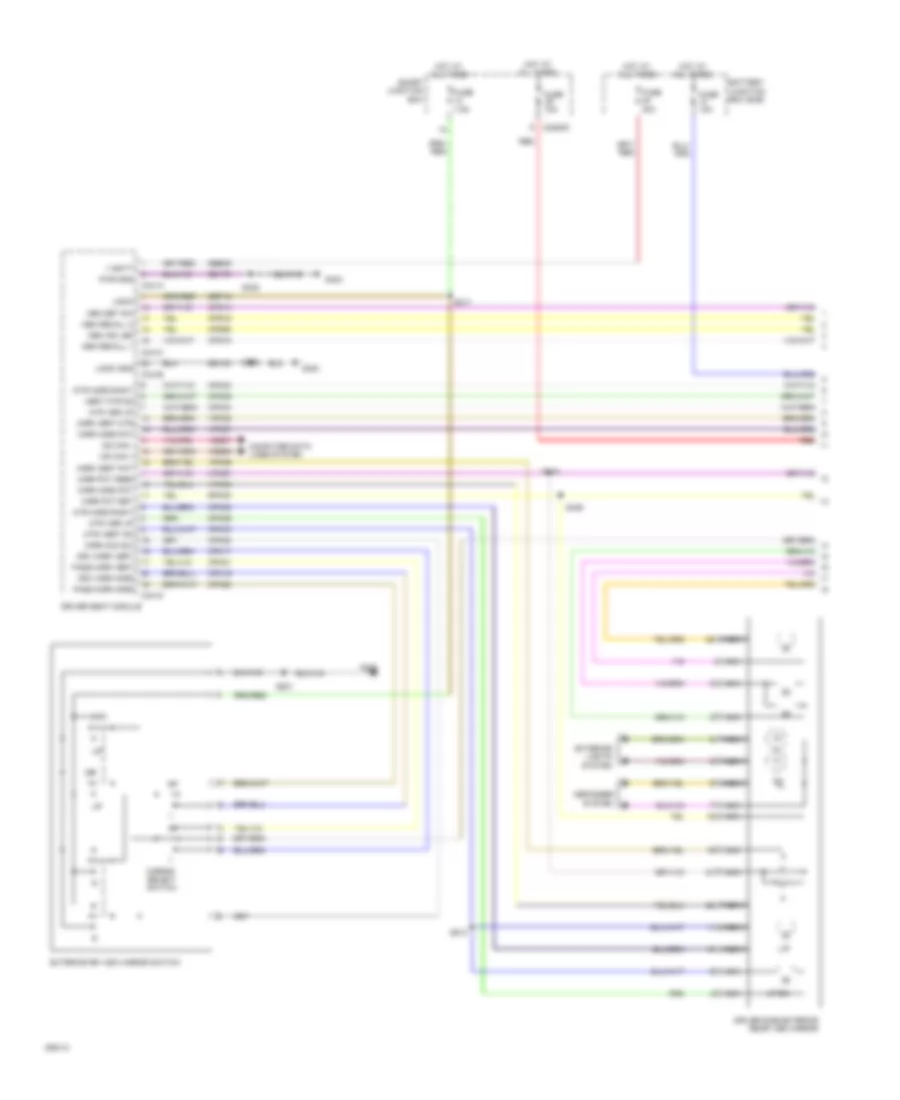
Exterior Lamps Wiring Diagram, with Box (1 of 2) for Ford Cab & Chassis F350 Super Duty 2009
List of elements for Exterior Lamps Wiring Diagram, with Box (1 of 2) for Ford Cab & Chassis F350 Super Duty 2009:
- (at left rear of engine compt) g104
- (behind center of dash, behind audio control module) g203
- 1) full left 2) lane change 3) neutral 4) lane change 5) full right
- Battery junction box (bjb) (at left rear of engine compt)
- Boo
- Brake pedal position switch (behind left side of dash, above brake pedal)
- C1232b
- C175b
- C2280b
- C2280d
- C2280f
- C281b
- Ccb08
- Cls43
- Diesel
- Driver side exterior rear view mirror
- Four-wheel drive control module (behind right side of dash)
- Fuse 15a
- Fuse 20a
- Fuse 5a
- G104 (at left rear of engine compt)
- G108 (at left rear of engine compt)
- G302 (in right "a" pillar)
- Gas
- Haz
- Hazard
- High mounted stoplamp
- Hot at all times
- Interior lights system
- Left front park/turn lamp
- Left turn trailer tow relay
- Lf turn lp
- Lp/lh mir
- Lp/rh mir
- Lr stop turn lp
- Lts
- Micro
- Multi-function switch
- Parking lamp trailer tow relay
- Passenger side exterior rear view mirror
- Powertrain control module (pcm) (at left side of firewall)
- Rf turn lp
- Right front park/turn lamp
- Right turn trailer tow relay
- Rr stop turn lp
- Rts
- S106 (in engine control sensor harness, near breakout to left front of frame)
- S110 (in engine control sensor harness, near breakout to left front corner of vehicle)
- S111 (in engine control sensor harness, near breakout to left front corner of vehicle)
- S112 (in engine control sensor harness, near breakout to master cylinder)
- S113
- S115
- S211 (in main harness, near breakout behind audio control module)
- S229 (in main harness, near breakout behind audio control module)
- S235
- S323
- S329 (in body main harness, under driver seat)
- S501
- S639
- Smart junction box (sjb) (behind passenger side kick panel)
- Stop lamp relay
- Trailer brake control (tbc) module (behind center of dash)
- Turn signal
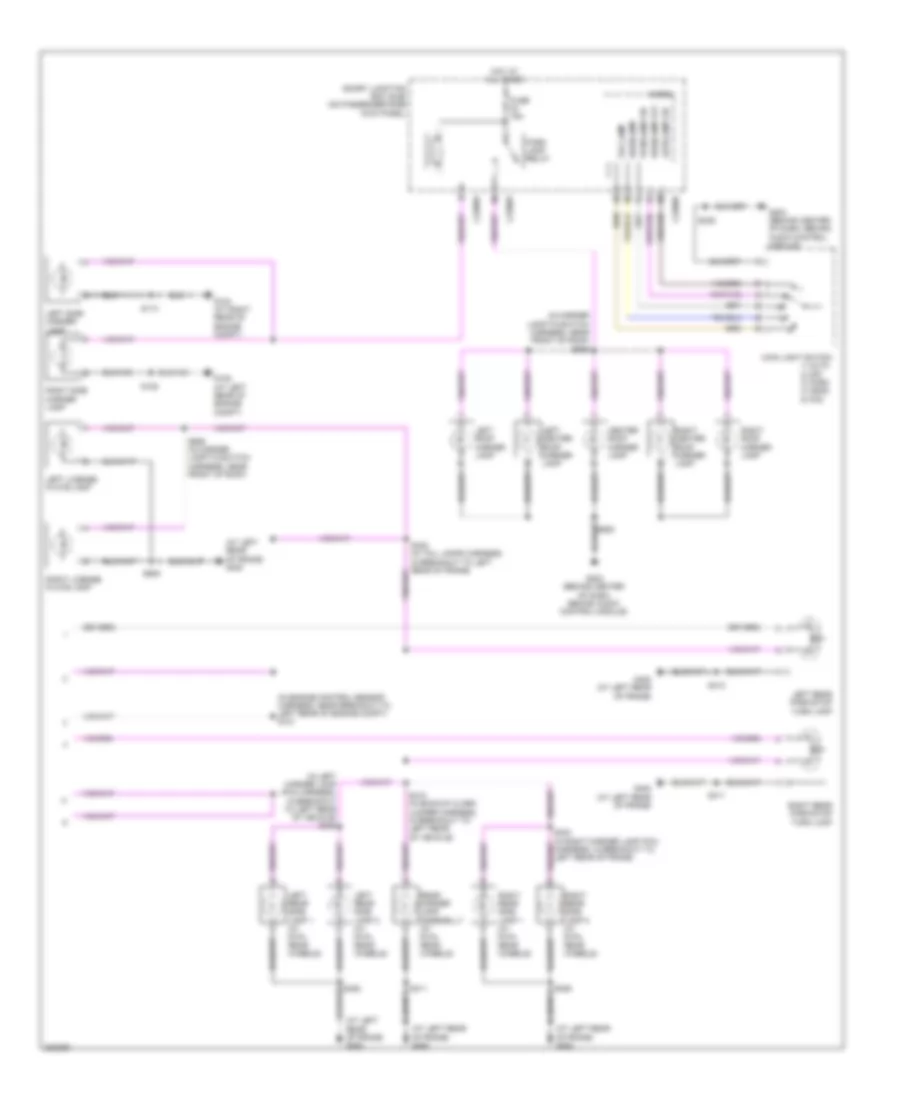
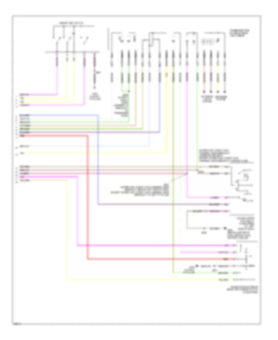
Exterior Lamps Wiring Diagram, with Box (2 of 2) for Ford Cab & Chassis F350 Super Duty 2009
List of elements for Exterior Lamps Wiring Diagram, with Box (2 of 2) for Ford Cab & Chassis F350 Super Duty 2009:
- (at left rear of frame) g400
- (in engine control sensor harness, near breakout to left rear of engine compt) s121
- (in left marker lamp (pia) harness, in breakout to left rear of vehicle) s423
- (in marker lamp-to-switch harness, near front of roof) s906
- 1) auto 2) off 3) park 4) head 5) fog
- Autolamp on
- C2280b
- C2280d
- C2280e
- Center roof marker lamp
- Fog lamp
- Fuse 15a
- G104 (at right rear of engine compt)
- G108 (at left rear of engine compt)
- G203 (behind center of dash, behind audio control module)
- G400 (at left rear of frame)
- Headlamp
- Headlamp off
- Hot at all times
- Left center roof marker lamp
- Left license plate lamp
- Left rear park/stop turn lamp
- Left rear side lamp 1 (w/ dual rear wheels)
- Left rear side lamp 2 (w/ dual rear wheels)
- Left roof marker lamp
- Left side marker lamp
- Main light switch
- Micro
- Park lamp relay
- Parklamp on
- Rear marker lamp assemblly (w/ dual rear wheels)
- Right center roof marker lamp
- Right license plate lamp
- Right rear park/stop turn lamp
- Right rear side lamp 1 (w/ dual rear wheels)
- Right rear side lamp 2 (w/ dual rear wheels)
- Right roof marker lamp
- Right side marker lamp
- S113
- S128
- S235
- S402 (in tail lamps harness, in breakout to left rear of frame)
- S411
- S412 (in backup alarm jumper harness, in breakout to left rear of vehicle)
- S413
- S424 (in right marker lamp (pia) harness, in breakout to left rear of frame)
- S426
- S905
- S906 (in marker lamp-to-switch harness, near front of roof)
- Smart junction box (sjb) (on passenger side kick panel)
Exterior Lamps Wiring Diagram, without Box (1 of 2) for Ford Cab & Chassis F350 Super Duty 2009
List of elements for Exterior Lamps Wiring Diagram, without Box (1 of 2) for Ford Cab & Chassis F350 Super Duty 2009:
- 1) full left 2) lane change 3) neutral 4) lane change 5) full right
- Battery junction box (bjb)
- Boo
- Brake pedal position switch
- C1232b
- C175b
- C2280b
- C2280d
- C2280f
- C281b
- Ccb08
- Cls43
- Diesel
- Driver side exterior rear view mirror
- Four-wheel drive control module
- Fuse 15a
- Fuse 20a
- Fuse 5a
- G104
- G108
- G203
- G302
- Gas
- Haz
- High mounted stoplamp
- Hot at all times
- Interior lights system
- Left front park/turn lamp
- Left turn trailer tow relay
- Lf turn lp
- Lp/lh mir
- Lp/rh mir
- Lr stop turn lp
- Lts
- Micro
- Multi-function switch
- Parking lamp trailer tow relay
- Passenger side exterior rear view mirror
- Powertrain control module (pcm)
- Rf turn lp
- Right front park/turn lamp
- Right turn trailer tow relay
- Rr stop turn lp
- Rts
- S106
- S110
- S111
- S112
- S113
- S115
- S211
- S229
- S235
- S323
- S329
- S501
- S639
- Smart junction box (sjb)
- Stop lamp relay
- Trailer brake control (tbc) module
Exterior Lamps Wiring Diagram, without Box (2 of 2) for Ford Cab & Chassis F350 Super Duty 2009
List of elements for Exterior Lamps Wiring Diagram, without Box (2 of 2) for Ford Cab & Chassis F350 Super Duty 2009:
- Autolamp on
- Backup lamps circuit
- C2280b
- C2280d
- C2280e
- Center roof marker lamp
- Fog lamp
- Fuse 15a
- G104
- G108
- G203
- G400
- Headlamp
- Headlamp off
- Hot at all times
- Left center roof marker lamp
- Left rear lamp
- Left roof marker lamp
- Left side marker lamp
- Main light switch 1) auto 2) off 3) park 4) head 5) fog
- Micro
- Park lamp relay
- Parklamp on
- Right center roof marker lamp
- Right rear lamp
- Right roof marker lamp
- Right side marker lamp
- S113
- S121
- S128
- S235
- S412
- S413
- S906
- Smart junction box
Trailer/Camper Adapter Wiring Diagram for Ford Cab & Chassis F350 Super Duty 2009
List of elements for Trailer/Camper Adapter Wiring Diagram for Ford Cab & Chassis F350 Super Duty 2009:
- (at left rear of frame) g400
- (behind center of dash, behind audio control module)
- (not used)
- (not used) c2142
- B+brake
- Backup lamps circuit
- Battery charge trailer tow relay
- Battery junction box (bjb) (at left rear of engine compt)
- Boo
- Bpt sens
- Bpt+
- Bpt-
- Brake control module
- Brake pressure transducer (at left rear of engine compt)
- C2142
- C2280b
- Cat19
- Cbp33
- Cls43
- Computer data lines system
- Control module
- Exterior lights circuit
- Fuse 10a
- Fuse 25a
- Fuse 30a
- G104 (at left rear of engine compt)
- G203
- G400 (at left rear of frame)
- Gd115
- Gnd
- Hot at all times
- Hot in on or start
- Hs can+
- Hs can-
- Lca16
- Left turn trailer tow relay
- Parking lamp trailer tow relay
- R/s
- Rca16
- Red
- Right turn trailer tow relay
- S113
- S203 (behind center of dash, behind
- S225
- S400
- Sbb05
- Smart junction box (sjb) (on passenger side kick panel)
- Tbc out
- Trailer brake control (tbc) module (behind center of dash)
- Trailer tow connector
- Vca13
- Vdb04
- Vdb05
- W/ narrow frame
- W/ trailer
- W/ trailer brake
- W/ trailer brake control module
- W/ wide frame
- W/o trailer brake control module
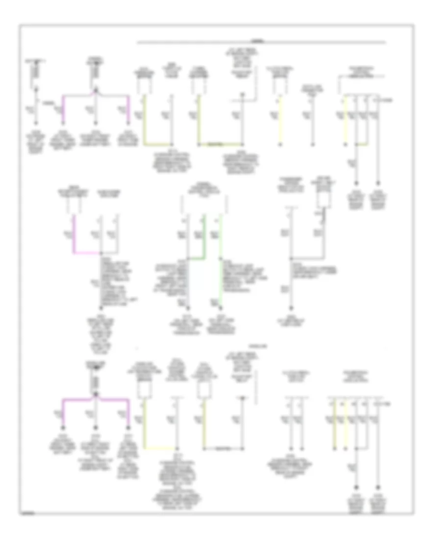
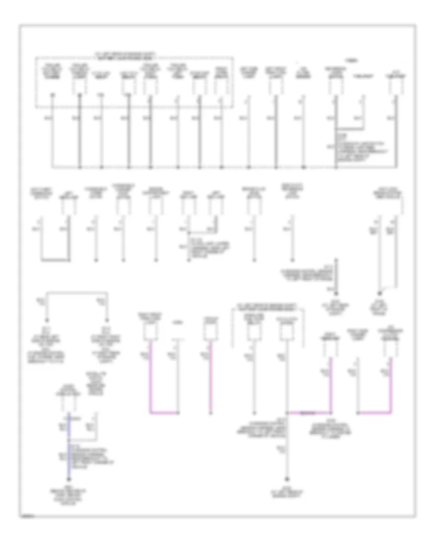
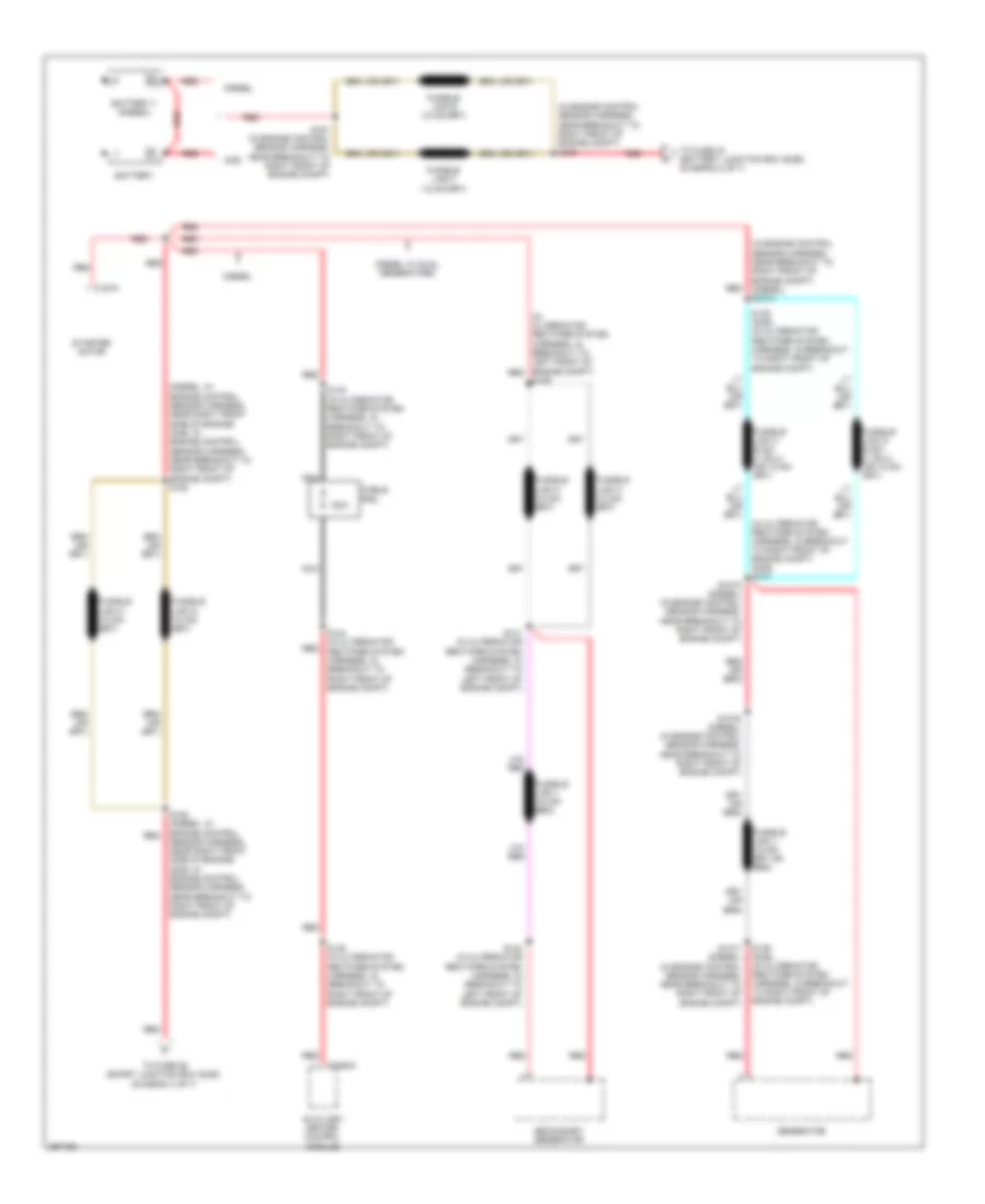
GROUND DISTRIBUTION
Ground Distribution Wiring Diagram (1 of 5) for Ford Cab & Chassis F350 Super Duty 2009
List of elements for Ground Distribution Wiring Diagram (1 of 5) for Ford Cab & Chassis F350 Super Duty 2009:
- (5.4l) intake manifold runner control valve (imrc)
- (6.8l) intake manifold tuning valve (imtv)
- (at left rear of engine compt) battery junction box (bjb)
- (diesel) battery
- (diesel) transmission control module (tcm)
- (gasoline) battery
- Battery ii
- C1232b
- C175b
- Clutch pedal position switch
- Data link connector (dlc)
- Diesel
- Driver safety belt buckle switch
- Dual pressure switch
- Egr throttle plate valve
- G100 (at right front inner fender, near battery)
- G100 (on right front inner fender, near battery)
- G101 (5.4l: at rear left side of engine, on bottom) (6.8l: at rear right side of engine, on bottom)
- G101 (on right front side of engine)
- G102 (5.4l: at front right side of engine, on bottom) (6.8l: at right front of engine compt, under battery)
- G102 (on right front inner fender, under battery)
- G103 (at right rear of engine compt)
- G106 (at right rear of engine compt)
- G107 (on left side frame rail, near middle of transmission)
- G109 (on frame, at left front of engine compt)
- G116 (on left side frame rail, near middle of transmission)
- G301 (regular cab: in left rear "b" pillar) (super cab: in left "b" pillar) (crew cab: in left "c" pillar)
- G303 (at center of cab floor)
- Gasoline
- Mass air flow/intake air temperature (maf/iat) sensor
- Nca
- Passenger air bag deactivation (pad) switch
- Powertrain control module (pcm)
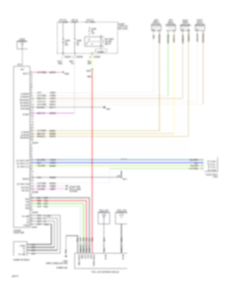
- Rear entertainment module (retm)
- Run/start relay
- S114 (5.4l: in engine control sensor & fuel charge harness, near breakout to rear right side of engine, on top) (6.8l: in engine control sensor & fuel charge harness, near breakout to rear left side of engine, on top)
- S114 (in engine control sensor harness, near breakout to front right side of engine, on top)
- S162 (in engine control sensor harness, near breakout to right rear of engine compt)
- S190 (in backup lamp switch to rear lamp feed harness, near breakout to left side frame rail, near middle of transmission)
- S191 (in backup lamp switch to rear lamp feed harness, near breakout to front left side of transmission, near top)
- S316 (in body main harness, near breakout under driver seat)
- Subwoofer amplifier
- Turbo charger actuator
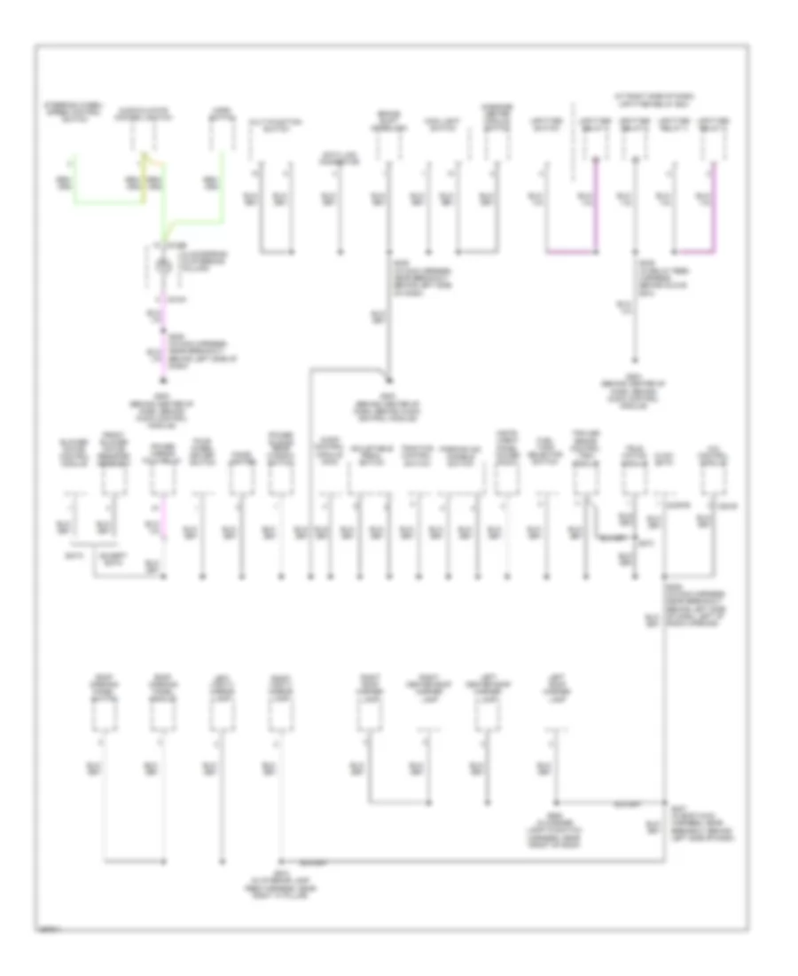
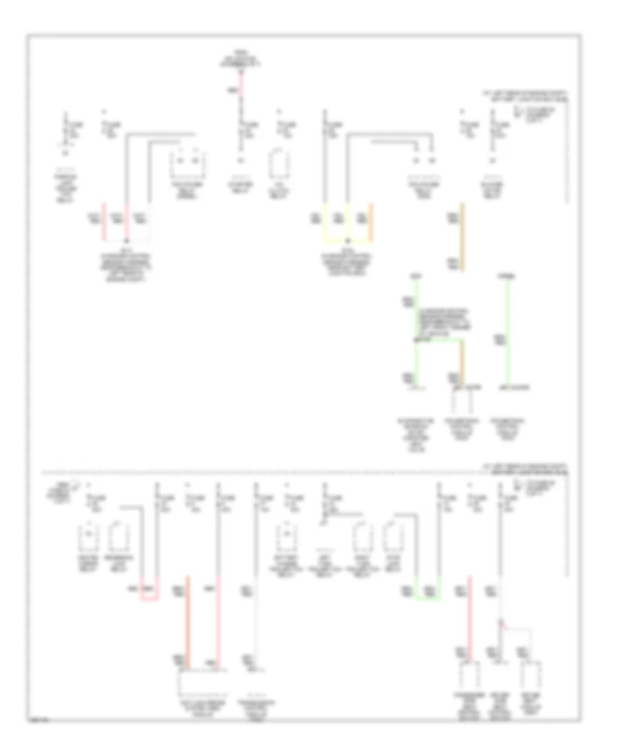
Ground Distribution Wiring Diagram (2 of 5) for Ford Cab & Chassis F350 Super Duty 2009
List of elements for Ground Distribution Wiring Diagram (2 of 5) for Ford Cab & Chassis F350 Super Duty 2009:
- (a/t) fuel pump
- (at left rear of engine compt) battery junction box (bjb)
- (gas w/ m/t) reversing lamp switch
- (gasoline) fuel pump relay
- 87a
- A/c clutch diode
- A/c compressor clutch field coil
- Air filter sensor
- Anti-lock brake system (abs) module
- Anti-theft underhood switch
- Audio control module (acm)
- Brake fluid level switch
- C240a
- Diesel
- Engine compartment lamp
- Front wiper relay
- Fuel pump
- G104 (at left rear of engine compt)
- G108 (at left rear of engine compt)
- G111 (5.4l: at rear left side of engine, on top) (6.8l: at engine control fuel charge, near breakout to c115)
- G112 (5.4l: at front right side of engine, on top) (6.8l: at right rear of engine compt)
- G135 (at left front of frame)
- G201 (behind center of dash, behind audio control module)
- Hi to low relay
- Horn
- Left fog lamp
- Left front park/turn lamp
- Left headlamp
- Left side marker lamp
- Low to hi relay
- Reversing lamps switch
- Right fog lamp
- Right front park/turn lamp
- Right headlamp
- Right side marker lamp
- S1119 (in fog lamp jumper harness, near left front corner of vehicle)
- S113 (in engine control sensor harness, near breakout to left front of frame)
- S115 (in engine control sensor harness, near breakout to left front corner of vehicle)
- S119 (in engine control sensor harness, near breakout to left front corner of vehicle)
- S128 (in engine control sensor harness, in breakout to master cylinder)
- S199 (m/t) (in backup lamp switch to rear lamp feed harness, near breakout to left rear of engine compt)
- Satellite digital audio receiver (sdars) module
- Stoplamp relay
- Trailer tow relay battery charge
- Trailer tow relay left turn
- Trailer tow relay parking lamp
- Trailer tow relay right turn
- Vacuum pump
- Windshield washer pump motor
- Windshield wiper motor
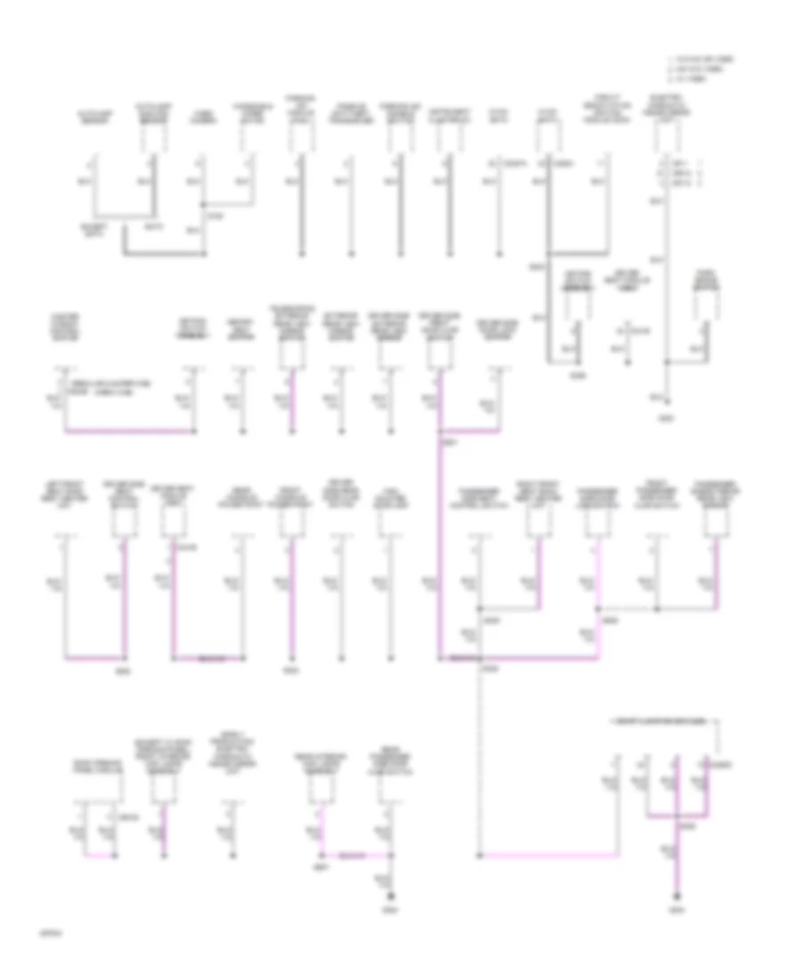
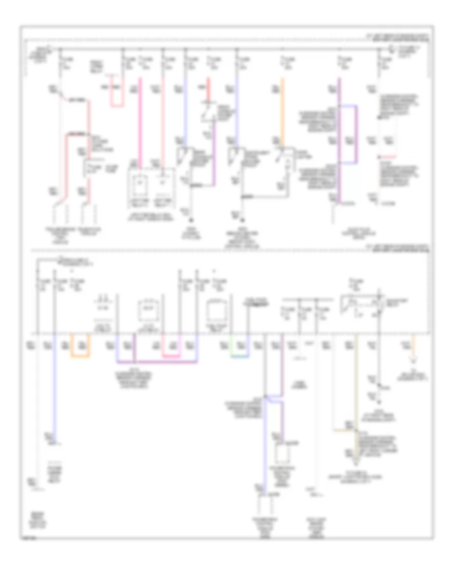
Ground Distribution Wiring Diagram (3 of 5) for Ford Cab & Chassis F350 Super Duty 2009
List of elements for Ground Distribution Wiring Diagram (3 of 5) for Ford Cab & Chassis F350 Super Duty 2009:
- (at right side of dash) upfitter relay box
- 4x4 control module
- Adjustable pedal switch
- Audio control module (acm)
- Audio/climate control switch
- Behind left side of dash)
- Blower motor control module
- Brake shift interlock
- C218a
- C218b
- C2357b
- C281b
- Cigar lighter
- Clockspring (in steering column)
- Data link connector
- Eatc
- Except eatc
- Four- wheel driver switch
- Front blower motor resister assembly
- Fuel tank selector switch
- G202 (behind center of dash, behind audio control module)
- G203 (behind center of dash, behind audio control module)
- G204 (behind center of dash, behind audio control module)
- Horn switch
- Hvac- emtc
- Instr- ument panel power point
- Left center roof marker lamp
- Left roof marker lamp
- Left vanity mirror lamp
- Main light switch
- Massage center module switch
- Multi-function switch
- Parking aid disable switch
- Power mirror fold relay
- Power sliding rear window switch
- Radio opening)
- Right center roof marker lamp
- Right roof marker lamp
- Right vanity mirror lamp
- Roof opening panel module
- Roof opening panel switch
- S235 (in main harness, near breakout behind left side of dash)
- S247 (in body main harness, near breakout behind left side of dash)
- S249 (in relay feed harness, behind glove box)
- S273
- S905 (in marker lamp-to-switch harness, near front of roof)
- S910 (in interior lamp feed harness, near right "a" pillar)
- Steering wheel/ speed control switch
- Tele- matics module
- Traction control switch
- Trailer brake control (tbc) module
- Upfitter relay 1
- Upfitter relay 2
- Upfitter relay 3
- Upfitter relay 4
- Upfitter switch
Ground Distribution Wiring Diagram (4 of 5) for Ford Cab & Chassis F350 Super Duty 2009
List of elements for Ground Distribution Wiring Diagram (4 of 5) for Ford Cab & Chassis F350 Super Duty 2009:
- (crew cab)
- (early production) electro- chromatic inside mirror unit
- (except w/ roof opening panel) front interior/ map lamps assembly
- (regular & super cab)
- Autolamp sensor
- Autolamp/ sunload sensor
- C2280d
- C228a
- C2357a
- C341b
- C9012
- C911
- C9112
- C921b
- Circuit deactivation ignition module (cdim)
- Driver seat module (dsm)
- Driver side door lock switch
- Driver side exterior rear view mirror
- Driver side front door ajar switch
- Driver side rear door ajar switch
- Driver side seat control switch
- Eatc
- Electro- chromatic inside mirror unit
- Except eatc
- Exterior rear view mirror switch
- Front console power point
- Front passenger side door ajar switch
- G300
- G302
- G304
- High mounted stoplamp
- Hvac- eatc
- Hvac- emtc
- Instrument cluster (ic)
- Keypad switch assembly
- Left front seat back rest heater mat
- Master window control switch
- Memory seat switch
- Mic w/o video
- Park brake switch
- Parking aid disable switch
- Parking aid module (pam)
- Passenger side door lock switch
- Passenger side exterior rear view mirror
- Passenger side seat control switch
- Passive anti-theft transceiver
- Rear console power point
- Rear interior/ map lamps assembly
- Rear passenger side door ajar switch
- Right front seat back rest heater mat
- Roof opening panel module
- S185
- S224
- S308
- S309
- S323
- S326
- S338
- S339
- S501
- S639
- S907
- Smart junction box (sjb)
- Telescoping exterior rear view mirror switch
- Video camera
- W/ video
- W/o mic or video
- Windshield wiper motor
Ground Distribution Wiring Diagram (5 of 5) for Ford Cab & Chassis F350 Super Duty 2009
List of elements for Ground Distribution Wiring Diagram (5 of 5) for Ford Cab & Chassis F350 Super Duty 2009:
- Breakout to left rear of frame)
- Breakout under center console) (regular cab: in body main harness, near breakout to center of cab floor, near rear of cab)
- Driver fuel pump module
- G400 (at left rear of frame)
- G401 (at left rear of frame)
- Gasoline
- Left front running board lamp
- Left license plate lamp
- Left rear lamp
- Left rear running board lamp
- Left rear side lamp 1
- Left rear side lamp 2
- Left reversing lamp
- Nca
- Rear marker lamp assembly
- Right front running board lamp
- Right license plate lamp
- Right rear lamp
- Right rear park/stop/ turn lamp
- Right rear running board lamp
- Right rear side lamp 1
- Right rear side lamp 2
- Right reversing lamp
- S400 (in tail lamps harness, in breakout to left rear of fram)
- S411 (in tail lamps harness, in breakout to rear of vehicle)
- S413 (in tail lamps harness, in breakout to left rear of vehicle)
- S905 (in marker lamp-to-switch harness, near front of roof)
- Shield
- Trailer tow connector
- W/ box
- W/ dual rear wheels
- W/ running board light
- W/o box
HEADLIGHTS
Headlights Wiring Diagram for Ford Cab & Chassis F350 Super Duty 2009
List of elements for Headlights Wiring Diagram for Ford Cab & Chassis F350 Super Duty 2009:
- Air conditioning system
- Autolamp in
- Autolamp on
- Autolamp sensor
- Autolamp/sunload sensor
- Autolamps w/ automatic climate control
- Autolamps w/o automatic climate control
- C1232b
- C2280a
- C2280b
- C2280c
- C2280e
- Computer data lines system
- Control solid state
- Flash to pass
- Fog lamp
- Fog lamp ind
- Fog lamp relay
- Ftp
- Fuse 21 15a
- Fuse 23 15a
- Fuse 7 10a
- Fuse 8 10a
- G104
- G108
- G203
- G300
- Headlamp off
- Headlamp on
- Hi beam
- High beam relay
- Hot at all times
- Instrument cluster (ic)
- Interior lights system
- Left fog lamp
- Left headlamp
- Left low beam (fet)
- Main light switch 1) auto 2) off 3) park 4) head 5) fog
- Micro
- Ms can+
- Ms can-
- Multi- function switch
- Park brake
- Parking brake switch
- Parklamp on
- Powertrain control module (pcm) (diesel)
- Right fog lamp
- Right headlamp
- Right low beam (fet)
- S113
- S119
- S122
- S128
- S142
- S224
- S235
- S304
- S326
- Smart junction box (sjb)
HORN
Horn Wiring Diagram for Ford Cab & Chassis F350 Super Duty 2009
List of elements for Horn Wiring Diagram for Ford Cab & Chassis F350 Super Duty 2009:
- (behind center of dash, behind audio control module) g202
- C218a
- C218b
- C2280b
- C2280e
- Clockspring (on steering column)
- Fuse 20a
- G108 (at left rear of engine compt)
- Ground distribution system
- Horn (at right front of vehicle)
- Horn relay
- Horn switch
- Hot at all times
- Micro
- S115
- S239
- Smart junction box (on passenger side kick panel)
INSTRUMENT CLUSTER
Instrument Cluster Wiring Diagram (1 of 2) for Ford Cab & Chassis F350 Super Duty 2009
List of elements for Instrument Cluster Wiring Diagram (1 of 2) for Ford Cab & Chassis F350 Super Duty 2009:
- 4x4 high
- 4x4 low
- Air filter minder sw
- Anti-theft system
- C218a
- C2280a
- C2280b
- Compass mod +
- Compass mod -
- Compass sensor module (early production)
- Computer data lines system
- Electrochromatic inside mirror unit (late production)
- Engine controls system
- Epats rx
- Epats tx
- Fuel sender 1
- Fuel sender 2
- Fuel sender rtn 1
- Fuel sender rtn 2
- Fuel tank select
- Fuel tank selector switch (diesel w/ dual fuel tank)
- Fuse 10a
- Fuse 5a
- G203
- G300
- Hot at all times
- Hot in run or start
- Hs can +
- Hs can -
- Info
- Instrument cluster (ic)
- Interior lights system
- Logic gnd
- Message center module switch
- Ms can +
- Ms can -
- Msg ctr +
- Msg ctr -
- Ops
- Park detect
- R/s
- Reset
- S223
- S224
- S235
- S245
- Secondary fuel tank sensor (diesel w/ dual fuel tank)
- Setup
- Shift interlock system
- Smart junction box
- Vmc30
- Vmc31
- W/ video camera
- W/o video camera
Instrument Cluster Wiring Diagram (2 of 2) for Ford Cab & Chassis F350 Super Duty 2009
List of elements for Instrument Cluster Wiring Diagram (2 of 2) for Ford Cab & Chassis F350 Super Duty 2009:
- 4h lamp
- 4l lmap
- Air filter sensor (diesel)
- Ajar
- Brake fluid level switch
- C1232b
- C2280b
- C2280c
- C2280f
- C281a
- Ccf06
- Ccf22
- Cmc25
- Diesel
- Driver side front door ajar switch
- Driver side rear door ajar switch
- Four-by-four high/low indicator switch
- Four-wheel drive control module
- Fuel pump module
- Fuel tank sensor
- G104
- G300
- G302
- Gas
- Med can
- Micro
- Narrow frame
- Nca
- Oil pressure switch
- Parking brake switch
- Passenger side front door ajar switch
- Passenger side rear door ajar switch
- Pbpp
- Powertrain control module (pcm) (diesel)
- Primary fuel tank sensor (dual fuel tank)
- S113
- S205
- S209
- S304
- S308
- S323
- S326
- S501
- S639
- Sense
- Smart junction box (sjb)
- W/ esof
- W/o esof
- Wide frame
INTERIOR LIGHTS
Courtesy Lamps Wiring Diagram for Ford Cab & Chassis F350 Super Duty 2009
List of elements for Courtesy Lamps Wiring Diagram for Ford Cab & Chassis F350 Super Duty 2009:
- Ajar
- Battery saver relay
- C2280a
- C2280b
- C2280c
- C2280d
- C921b
- Cln03
- Cln09
- Dim
- Dim sw
- Dim sw gnd
- Dome
- Dome lp
- Driver side front door ajar switch
- Driver side rear door ajar switch
- Engine compartment lamp
- Exterior lights system
- Floor lamp (fet)
- Front interior/map lamps assembly (w/ crew cab or w/o roof opening panel)
- Fuse 10 15a
- Fuse 25 10a
- Fuse 9 15a
- G104
- G302
- G400
- Gd179
- High mounted stoplamp
- Hot at all times
- Instrument panel dimmer switch
- Interior lighting (fet)
- Left front running board lamp
- Left rear running board lamp
- Left vanity mirror lamp
- Micro
- Passenger side front door ajar switch
- Passenger side rear door ajar switch
- Puddle lamp (fet)
- Right front running board lamp
- Right rear running board lamp
- Right vanity mirror lamp
- Roof opening panel module (w/ roof opening panel)
- S113
- S214
- S307
- S308
- S311
- S312
- S313
- S323
- S328
- S3325 (w/ running board lamps)
- S410
- S501
- S639
- S907
- S908
- S909
- Sense
- Smart junction box (sjb)
- W/ crew cab or w/o roof opening panel)
- W/ roof opening panel
Instrument Illumination Wiring Diagram for Ford Cab & Chassis F350 Super Duty 2009
List of elements for Instrument Illumination Wiring Diagram for Ford Cab & Chassis F350 Super Duty 2009:
- 1) auto 2) off 3) park 4) head 5) fog
- Adjustable pedal switch
- Audio control module (acm)
- Audio/climate control switch
- Autolamp on
- Backlighting led (fet)
- C218b
- C2280b
- C2280d
- C240a
- Clockspring
- Dim
- Dim sw
- Dim sw gnd
- Dome
- Dome lp
- Driver side door lock switch
- Electrochromatic inside mirror unit
- Flash to pass
- Fog lamp
- Fog lamp ind
- Four wheel drive switch
- Ftp
- Fuse 10 15a
- Fuse 41 15a
- G202
- G203
- G204
- G302
- Gd115
- Headlamp off
- Headlamp on
- Headlights system
- Hi beam
- Hot at all times
- Hot w/ accessory delay relay energized
- Instrument panel dimmer switch
- Main light switch
- Message center module switch
- Micro
- Multi-function switch
- Parking aid disable switch
- Parklamp on
- Passenger side door lock switch
- Power sliding rear window switch
- Roof panel opening switch
- S214
- S220
- S225
- S235
- S239
- S301
- S501
- S639
- S907
- Smart junction box (sjb)
- Steering wheel/ speed control switch
- Traction control switch
- Upfitter switch
- Vln04
MEMORY SYSTEMS
Adjustable Pedal Wiring Diagram for Ford Cab & Chassis F350 Super Duty 2009
List of elements for Adjustable Pedal Wiring Diagram for Ford Cab & Chassis F350 Super Duty 2009:
- Adjustable pedal assembly
- Adjustable pedal switch
- C2280a
- C341c
- Cpp01
- Cpp02
- Cpp09
- Cpp10
- Cps14
- Cps15
- Cps16
- Cps55
- Driver seat module
- Eff feed
- Far
- Forward sw
- Fuse 15a
- G203
- G302
- Hot at all times
- Interior lights system
- Mem ind led
- Mem recall 1
- Mem recall 2
- Mem set sw
- Memory set switch
- Mtr forward
- Near
- Pedal mtr aft
- Rearward sw
- Rpp06
- S228
- S501
- Smart junction box
- Sns ret
- Vpp16
Driver"s Memory Seat Wiring Diagram for Ford Cab & Chassis F350 Super Duty 2009
List of elements for Driver"s Memory Seat Wiring Diagram for Ford Cab & Chassis F350 Super Duty 2009:
- Adjustable pedal circuit
- Battery junction box (bjb)
- C2280d
- C341a
- C341b
- C341c
- C341d
- C357
- C372
- C373
- C383
- Computer data lines system
- Cpm03
- Cpm06
- Cpm16
- Cpm17
- Cpm20
- Cpm21
- Cpm23
- Cpm28
- Cpm29
- Cpm33
- Cpm34
- Cpp01
- Cpp02
- Cpp09
- Cpp10
- Cps01
- Cps02
- Cps03
- Cps04
- Cps05
- Cps06
- Cps14
- Cps15
- Cps16
- Cps23
- Cps24
- Cps25
- Cps26
- Cps27
- Cps28
- Cps55
- Driver seat module
- Driver side seat control switch
- Drv mirr horz
- Drv mirr vert
- Eff sns ret
- Forward sw
- Front up/ down
- Front up/down
- Frt tilt dn sw
- Frt tilt eff
- Frt tilt mtr dn
- Frt tilt mtr up
- Frt tilt up sw
- Fuse 30a
- Fuse 7.5a
- Fwd/ back
- G300
- G302
- Gd133
- Gd179
- Hall eff feed
- Horz base aft
- Horz base eff
- Horz base fore
- Horz fwd/ rwd
- Hot at all times
- Left power seat motor assembly
- Logic
- Logic gnd
- Lpm30
- Mem ind led
- Mem recall 1
- Mem recall 2
- Mem set sw
- Memory mirrors circuit
- Memory set switch
- Mirr com sw
- Mirr horz pot
- Mirr pot feed
- Mirr pot ret
- Mirr vert pot
- Ms can +
- Ms can -
- Mtr forward
- Mtr horz right
- Mtr ver up
- Mtr vert dn
- Pass mirr horz
- Pass mirr vert
- Pedal mtr aft
- Pwr gnd
- Rear tilt eff
- Rear tilt mtr up
- Rear up/ down
- Rear up/down
- Rearward sw
- Rpm30
- Rpp06
- Rps13
- Rr tilt dn sw
- Rr tilt mtr dn
- Rr tilt up sw
- S317
- S326
- S334
- S338
- S501
- Sbb45
- Sbp12
- Seat hall eff
- Smart junction box
- V batt
- Vdb06
- Vdb07
- Vpm35
- Vpm36
- Vpm37
- Vpm38
- Vpp16
- Vps09
- Vps10
- Vps11
Memory Mirrors Wiring Diagram (1 of 2) for Ford Cab & Chassis F350 Super Duty 2009
List of elements for Memory Mirrors Wiring Diagram (1 of 2) for Ford Cab & Chassis F350 Super Duty 2009:
- Battery junction box (bjb)
- C2280d
- C341a
- C341b
- C341c
- C341d
- Computer data lines system
- Cpm03
- Cpm06
- Cpm16
- Cpm17
- Cpm20
- Cpm21
- Cpm23
- Cpm28
- Cpm29
- Cpm33
- Cpm34
- Cps14
- Cps15
- Cps16
- Cps55
- Defogger system
- Driver seat module
- Driver side exterior rear view mirror
- Drv mirr horz
- Drv mirr vert
- Exterior lights system
- Exterior rr view mirror switch
- Fuse 10a
- Fuse 15a
- Fuse 30a
- Fuse 7.5a
- G300
- G302
- Gd133
- Gd179
- Hot at all times
- L/r
- Logic
- Logic gnd
- Lpm30
- Mem ind led
- Mem recall 1
- Mem recall 2
- Mem set sw
- Mirr com sw
- Mirr horz pot
- Mirr pot feed
- Mirr pot ret
- Mirr vert mtr
- Mirr vert pot
- Mirror select switch
- Ms can +
- Ms can -
- Mtr horz right
- Mtr ver up
- Mtr vert dn
- Nca
- Pass mirr horz
- Pass mirr vert
- Pwr gnd
- Red
- Rpm30
- S317
- S318
- S326
- S336
- S338
- S501
- S513
- Sbb45
- Sbp12
- Smart junction box
- Up/dn
- V batt
- Vdb06
- Vdb07
- Vert mtr dn
- Vpm35
- Vpm36
- Vpm37
- Vpm38
Memory Mirrors Wiring Diagram (2 of 2) for Ford Cab & Chassis F350 Super Duty 2009
List of elements for Memory Mirrors Wiring Diagram (2 of 2) for Ford Cab & Chassis F350 Super Duty 2009:
- (super cab: in body main harness, near breakout under driver seat) (except super cab: in body main harness, near breakout across floor)
- Defogger system
- Dn/up
- Exterior lights system
- G203 (behind center of dash, behind audio control module)
- G302 (in right "a" pillar)
- L/r
- Memory set switch
- Nca
- Out
- Passenger side exterior rear view mirror
- Power mirror fold relay (if equipped) (at left side of dash)
- Red
- S225
- S325
- S327 (super cab: in body main harness, near breakout behind left side of dash) (except super cab: in body main harness, near breakout to left "a" pillar)
- S501
- S609 (in right front door harness, in breakout to passenger door)
- Telescoping exterior rear view mirror switch (if equipped)
NAVIGATION
Crew Chief Wiring Diagram for Ford Cab & Chassis F350 Super Duty 2009
List of elements for Crew Chief Wiring Diagram for Ford Cab & Chassis F350 Super Duty 2009:
- 5vpwr
- 5vtb
- Ant
- Audio antenna
- Battery junction box (bjb)
- C2409
- Cbp33
- Computer data lines system
- Fuse 10a
- Fuse 30a
- G203
- Gnd
- Gnd1
- Hot at all times
- Hot in start & run
- Hsc1-c
- Hsc2-c
- Igrun-c
- Inline fuse
- Modem-antenna
- Nca
- Rxd
- S271
- S272
- S273
- Sbb05
- Smart junction box (sjb)
- Start/run
- Telematics module
- Txd
- Vbatt
In Dash Computer Wiring Diagram for Ford Cab & Chassis F350 Super Duty 2009
List of elements for In Dash Computer Wiring Diagram for Ford Cab & Chassis F350 Super Duty 2009:
- 5v usb
- Ant
- Audio antenna
- Audio input jack
- Batt+
- Battery
- C gnd
- C2280a
- C2280b
- C2280d
- C2408a
- C2408b
- C2408c
- C2409
- Cbp28
- Cgnd
- Computer data lines system
- Dme45
- Dtr
- Fuse 10a
- Fuse 20a
- Fuse 5a
- G201
- G300 crew & regular cab:
- Gd114
- Gnd
- Gnd cable
- Hot at all times
- Hot in start
- In-dash computer
- Left front speaker
- Left rear speaker
- Lf spkr+
- Lf spkr-
- Lr spkr+
- Lr spkr-
- Micro
- Modem-antenna
- Ms can+
- Ms can-
- Nca
- Pwr cable
- Pwr gnd
- Red
- Relay
- Rf in
- Rf spkr+
- Rf spkr-
- Right front speaker
- Right rear speaker
- Rme07
- Rme09
- Rme10
- Rme12
- Rme45
- Rme46
- Rr spkr+
- Rr spkr-
- Rxd
- S217
- S265
- S350
- Saver
- Sbp39
- Shield
- Smart junction box (sjb)
- St in 2l +
- St in 2l -
- St in 2r +
- St in 2r -
- St input 2l+
- St input 2l-
- St input 2r+
- St input 2r-
- Start
- Super cab:
- Tool link antenna 1
- Tool link antenna 2
- Tool link antenna module
- Txd
- Vdb06
- Vdb07
- Vme07
- Vme09
- Vme10
- Vme12
- Vme45
- Vme46
Navigation Wiring Diagram (1 of 2) for Ford Cab & Chassis F350 Super Duty 2009
List of elements for Navigation Wiring Diagram (1 of 2) for Ford Cab & Chassis F350 Super Duty 2009:
- Antenna
- Audio antenna
- Audio control module (acm)
- Audio input jack (w/o sync)
- Batt+
- C218a
- C2280a
- C2280b
- C240a
- C240c
- Cbp28
- Clockspring
- Computer data lines system
- Dme07
- Dme09
- Enable
- Fuse 20a
- Fuse 5a
- G201
- Gd114
- Gnd
- Gps
- Gps antenna
- Hot at all times
- Hot in start
- Interior lights system
- Lf spkr+
- Lf spkr-
- Lr+
- Lr-
- Media
- Ms can+
- Ms can-
- Nca
- Phone
- Rf spkr+
- Rf spkr-
- Right steering wheel switch
- Rme07
- Rme09
- Rme10
- Rme12
- Rme24
- Rme45
- Rme46
- Rme54
- Rr+
- Rr-
- S265
- S267
- Sbp39
- Seek+
- Seek-
- Shield
- Smart junction box (sjb)
- Sme56
- St in 2l +
- St in 2l -
- St in 2r +
- St in 2r -
- St input 2l+
- St input 2l-
- St input 2r+
- St input 2r-
- Start
- Swc1 +
- Swc1 rtn
- Swc2+
- Swc2-
- Vdb06
- Vdb07
- Vme07
- Vme09
- Vme10
- Vme12
- Vme14
- Vme45
- Vme46
- Vme54
- Voice
- Vol+
- Vol-
Navigation Wiring Diagram (2 of 2) for Ford Cab & Chassis F350 Super Duty 2009
List of elements for Navigation Wiring Diagram (2 of 2) for Ford Cab & Chassis F350 Super Duty 2009:
- (crew)
- (regular)
- (super)
- Audio amplifier
- Batt+
- C2291a
- C2291b
- C395
- C395a
- C395b
- C396
- C396a
- C396b
- C513
- C523
- C610
- C612
- C702
- C802
- C949
- Dme09
- Enable
- G201
- Gd114
- Gnd
- Left front speaker
- Left front tweeter
- Left rear speaker
- Left rear tweeter
- Lf spkr+
- Lf spkr-
- Lr spkr+
- Lr spkr-
- Nca
- Rear entertainment module (retm)
- Rf spkr+
- Rf spkr-
- Right front speaker
- Right front tweeter
- Right rear speaker
- Right rear tweeter
- Rme07
- Rme09
- Rme10
- Rme12
- Rr spkr+
- Rr spkr-
- S219
- S502
- S503
- S602
- S603
- S921
- Sbp40
- Shield
- Sme56
- Vme07
- Vme09
- Vme10
- Vme12
- W/ dvd entertainment
- W/o dvd entertainment
POWER DISTRIBUTION
Power Distribution Wiring Diagram (1 of 7) for Ford Cab & Chassis F350 Super Duty 2009
List of elements for Power Distribution Wiring Diagram (1 of 7) for Ford Cab & Chassis F350 Super Duty 2009:
- (diesel: in engine control sensor harness, near right front side of engine) (gas: in engine control sensor harness, near breakout to right front of engine compt) s153
- (in alternator rectifier system harness, in breakout to left front of engine compt) red
- (in alternator rectifier system harness, in breakout to right front of engine compt) (gas) s137
- (in engine control sensor harness, near breakout to right front of engine compt) (diesel) s1014
- (in engine control sensor harness, near breakout to right front of engine compt) s160
- 150a
- Auxiliary heater control module
- Battery
- Battery ii (diesel)
- C197a
- C2463a
- Cable pro
- Diesel
- Diesel w/ dual generators
- Gas
- Generator
- Nca
- Red
- S1015 (diesel) (in engine control sensor harness, near breakout to right front of engine compt)
- S1016 (diesel) (in engine control sensor harness, near breakout to right front of engine compt)
- S1017 (diesel) (in engine control sensor harness, near breakout to right front of engine compt)
- S138 (gas) (in alternator rectifier system harness, in breakout to right front of engine compt)
- S139
- S139 (gas) (in alternator rectifier system harness, in breakout to right front of engine compt)
- S140 (in alternator rectifier system harness, in breakout to left front of engine compt)
- S141 (in alternator rectifier system harness, in breakout to left front of engine compt)
- S143 (in alternator rectifier system harness, in breakout to right front of engine compt)
- S144 (in alternator rectifier system harness, in breakout to right front of engine compt)
- S145 (in alternator rectifier system harness, in breakout to right front of engine compt)
- S152 (diesel: in engine control sensor harness, near right front side of engine) (gas: in engine control sensor harness, near breakout to right front of engine compt)
- S161 (in engine control sensor harness, near breakout to right front of engine compt)
- Secondary generator
- Starter motor
- To fuse 26 (smart junction box (sjb)) (diagram 4 of 7)
- To fuse 40 (battery junction box (bjb)) (diagram 2 of 7)
Power Distribution Wiring Diagram (2 of 7) for Ford Cab & Chassis F350 Super Duty 2009
List of elements for Power Distribution Wiring Diagram (2 of 7) for Ford Cab & Chassis F350 Super Duty 2009:
- (at left rear of engine compt) battery junction box (bjb)
- (in engine control sensor harness, near breakout to left front corner of vehicle) s158
- A/c clutch relay
- Anti-lock brake system (abs) module
- Battery charge trailer tow relay
- Blower motor relay
- C1232b
- Diesel
- Driver seat module (dsm)
- Driver side seat control switch
- Evaporative emission (evap) canister vent valve
- From c fuse 24 (diagram 2 of 7)
- From splice s160 (diagram 1 of 7)
- Fuse 10a
- Fuse 15a
- Fuse 20a
- Fuse 25a
- Fuse 30a
- Fuse 40a
- Fuse 50a
- Gas
- Heated mirror relay
- Left turn trailer tow relay
- Parking lamp trailer tow relay
- Passenger side seat control switch
- Pcm power relay (diesel)
- Pcm power relay (gas)
- Powertrain control module (pcm)
- Red
- Reversing lamp relay
- Right turn trailer tow relay
- S117 (in engine control sensor harness, near breakout to left rear of engine compt)
- S154 (in engine control sensor harness, near battery junction box)
- Starter relay
- Stop lamp relay
- To fuse 28 (diagram 2 of 7)
- To fuse 49 (diagram 3 of 7)
- Transmission control module (tcm)
Power Distribution Wiring Diagram (3 of 7) for Ford Cab & Chassis F350 Super Duty 2009
List of elements for Power Distribution Wiring Diagram (3 of 7) for Ford Cab & Chassis F350 Super Duty 2009:
- (at left rear of engine compt) battery junction box (bjb)
- (in engine control sensor harness, near breakout to right rear of engine compt) s103
- Anti-lock brake system (abs) module
- Brake pedal position switch
- C1232b
- C1273a
- C1273b
- C175b
- Cigar lighter
- From d fuse 45 (diagram 2 of 7)
- From fuse 47 (diagram 3 of 7)
- Front console power point
- Front wiper relay
- Fuel pump motor diode
- Fuel pump relay
- Fuse 10a
- Fuse 15a
- Fuse 20a
- Fuse 2a
- Fuse 30a
- Fuse 3a
- Fuse 40a
- Fuse 50a
- Fuse 5a
- G103 (at right rear of engine compt)
- G203 (behind center of dash, behind audio control module)
- G302 (in right "a" pillar)
- Glow plug control module (gpcm)
- Hi to low relay
- Inline fuse
- Instrument panel power point
- Low to hi relay
- Power mirror fold relay
- Powertrain control module (pcm) (diesel)
- Powertrain control module (pcm) (gas)
- Rear console power point
- Red
- Run/start relay
- S1000 (in engine control sensor harness, near breakout to right rear of engine compt)
- S1003 (in engine control sensor harness, near breakout to right rear of engine compt)
- S118 (in engine control sensor harness, near battery junction box)
- S119 (in engine control sensor harness, near breakout to left front corner of vehicle)
- S123 (in engine control sensor harness, near battery junction box)
- S124 (in engine control sensor harness, near breakout to right rear of engine compt)
- S162
- S225
- S272 (w/ ford work solutions)
- S323
- Telematics module
- To fuse 13 (diagram 3 of 7)
- To fuse 33 (smart junction box (sjb)) (diagram 4 of 7)
- To splice s233 (diagram 4 of 7)
- Trailer brake control (tbc) module
- Upfitter relay 1
- Upfitter relay 2
- Upfitter relay box (at right side of dash)
- Video camera
Power Distribution Wiring Diagram (4 of 7) for Ford Cab & Chassis F350 Super Duty 2009
List of elements for Power Distribution Wiring Diagram (4 of 7) for Ford Cab & Chassis F350 Super Duty 2009:
- (not used)
- (w/crew chief) s271
- 4x4 control module
- Acc
- Battery charge trailer tow relay
- Battery junction box (bjb)
- C2280a
- C2280b
- C2280d
- C2280e
- C2280h
- C2357a
- C2463c
- C281b
- Compass sensor module (early production)
- Electric heater
- Electronic shift on the fly (esof) solenoid
- From h fuse 35 (diagram 4 of 7)
- From run/start relay (diagram 3 of 7)
- From splice s119 (diagram 3 of 7)
- From splice s152 (diagram 1 of 7)
- Fuse 10a
- Fuse 20a
- Fuse 5a
- Fuse 7.5a
- Hvac eatc
- Hvac emtc
- Ignition switch
- Instrument cluster (ic)
- Key in switch
- Logic
- Off
- Parking aid module (pam)
- Passenger air bag deactivation (pad) switch
- Passive anti-theft transceiver
- Red
- Restraints control module (rcm)
- Run
- S105
- S206
- S216
- S223
- S227
- S233
- S240
- S314
- Smart junction box (sjb)
- Start
- Tele- matics module (w/crew chief)
- To circuit deactivation ignition module (cdim) (diagram 5 of 7)
- To fuse 36 (diagram 4 of 7)
- To fuse 38 (diagram 5 of 7)
- To fuse 43 (smart junction box (sjb)) (diagram 5 of 7)
- To fuse 44 (smart junction box (sjb)) (diagram 5 of 7)
- To splice s126 (diagram 5 of 7)
- Towl haul switch
- Traction control switch
- Trailer brake control (tbc) module (w/o crew chief)
- Vacuum pump
- W/ cdim
- W/o cdim
Power Distribution Wiring Diagram (5 of 7) for Ford Cab & Chassis F350 Super Duty 2009
List of elements for Power Distribution Wiring Diagram (5 of 7) for Ford Cab & Chassis F350 Super Duty 2009:
- (diesel)
- (gas)
- (not used)
- 4x4 control module
- Audio amplifier
- Audio control module (acm)
- Batt
- Battery junction box (bjb)
- Battery junction box (bjb) (diesel early production)
- Battery junction box (bjb) (gas & late production diesel)
- Blower motor relay
- C1232b
- C175t
- C2280a
- C2280b
- C2280d
- C2280e
- C2291b
- C240a
- C281b
- Circuit deactivation ignition module (cdim)
- Computer data lines system
- Diesel early production
- Driver side front heated seat relay
- From fuse 27 (diagram 4 of 7)
- From ignition switch (diagram 4 of 7)
- From splice s240 (diagram 4 of 7)
- Front wiper relay
- Fuel tank selector switch
- Fuse 10a
- Fuse 20a
- Fuse 5a
- G300
- Gnd
- Heated mirror relay
- Logic
- Ms can+
- Ms can-
- Otis diode
- Passenger side front heated seat relay
- Powertrain control module (pcm) (gas & late production diesel)
- Run in
- S104
- S126
- S157
- S201
- S224
- S2439
- S265
- S310
- S321
- Smart junction box (sjb)
- Starter relay
- Subwoofer amplifier
- To fuse 2 (diagram 6 of 7)
- Upfitter switch
- W/ cdim
- W/o cdim
- Windshield wiper motor
Power Distribution Wiring Diagram (6 of 7) for Ford Cab & Chassis F350 Super Duty 2009
List of elements for Power Distribution Wiring Diagram (6 of 7) for Ford Cab & Chassis F350 Super Duty 2009:
- (not used)
- 4x4 control module
- Accessory protocol interface module (apim)
- All lock/ unlock relay
- Backlighting led (fet)
- Battery saver relay
- Bs1 (fet)
- C2280a
- C2280d
- Driver unlock relay
- Fog lamp relay
- From fuse 25 r (diagram 6 of 7)
- From fuse 39 (diagram 5 of 7)
- From fuse 6 (diagram 6 of 7)
- Fuse 10a
- Fuse 15a
- Fuse 20a
- High beam relay
- Interior lighting (fet)
- Keypad illum (fet)
- Left low beam (fet)
- Lf turn lamp (fet)
- Lh corner (fet)
- Lift gate (fet)
- Lift glass release relay
- Logic
- Lr stop/ turn lamp (fet)
- Nca
- Park lamp relay
- Puddle lamp (fet)
- Rear entertainment module (retm)
- Red
- Rf turn lamp (fet)
- Rh corner (fet)
- Right low beam (fet)
- Rr stop/ turn lamp (fet)
- S204
- Satellite digital audio receiver system (sdars) module
- Smart junction box (sjb)
- Telescoping exterior rear view mirror switch
- To fuse 10 (diagram 6 of 7)
- To fuse 11 (diagram 7 of 7)
- To fuse 17 (diagram 6 of 7)
Power Distribution Wiring Diagram (7 of 7) for Ford Cab & Chassis F350 Super Duty 2009
List of elements for Power Distribution Wiring Diagram (7 of 7) for Ford Cab & Chassis F350 Super Duty 2009:
- (not used)
- Accessory delay relay
- Adjustable pedal switch
- Audio control module (acm)
- C2280a
- C2280b
- C2280d
- C228a
- C2357a
- C240a
- C341b
- C921a
- Circuit breaker 30a
- Crew cab
- Data link connector (dlc)
- Driver seat module (dsm)
- Driver side door lock switch
- Driver side front heated seat relay
- Driver side seat control switch
- Electrochromatic inside mirror unit
- Exterior rear view mirror switch
- From fuse 20 t (diagram 7 of 7)
- From fuse 22 s (diagram 6 of 7)
- Fuse 10a
- Fuse 15a
- Fuse 20a
- Fuse 25a
- Fuse 7.5a
- Horn relay
- Hvac eatc
- Hvac emtc
- Logic
- Master window control switch
- Passenger side door lock switch
- Passenger side front heated seat relay
- Passenger side window control switch (regular & super cab)
- Power sliding rear window switch
- Regular & super cab
- Roof opening panel module
- S228
- S301
- S303
- S311
- S315
- S317
- Smart junction box (sjb)
- To fuse 24 (diagram 7 of 7)
- Upfitter relay 3
- Upfitter relay 4
- Upfitter relay box
POWER DOOR LOCKS
Power Door Locks Wiring Diagram (1 of 2) for Ford Cab & Chassis F350 Super Duty 2009
List of elements for Power Door Locks Wiring Diagram (1 of 2) for Ford Cab & Chassis F350 Super Duty 2009:
- (crew cab: in body main harness, near breakout to right "a" pillar) (regular cab: in body main harness, near breakout to right "b" pillar) (super cab: in body main harness, near breakout under passenger seat)
- (super cab: in body main harness, near breakout under passenger seat) (except super cab: in body main harness, near breakout to right "b" pillar)
- All lock relay
- Antenna
- C2280c
- C2280d
- Control
- Driver side door lock switch
- Driver unlock relay
- Fuse 15a
- Fuse 20a
- G302 (in right "a" pillar)
- Hot at all times
- Hot w/ accessory delay relay energized
- Hsd
- Lock
- Logic
- Passenger side door lock switch
- Rke receiver internal antenna
- S301
- S305
- S306
- S308
- S501
- S639
- Sense
- Smart junction box (sjb) (on passenger side kick panel)
- Un lock
Power Door Locks Wiring Diagram (2 of 2) for Ford Cab & Chassis F350 Super Duty 2009
List of elements for Power Door Locks Wiring Diagram (2 of 2) for Ford Cab & Chassis F350 Super Duty 2009:
- (in driver door) driver side front door ajar switch
- (in front passenger door) passenger side front door ajar switch
- (in left front door) left front door lock actuator
- (in left rear door harness, in breakout to left "b" pillar) s800
- (in left rear door) driver side rear door ajar switch
- (in right rear door harness, in breakout to left "b" pillar) s700
- (in right rear door) passenger side rear door ajar switch
- 1/2
- 3/4
- 5/6
- 7/8
- 9/0
- Ajar
- G300 (super cab: behind left side of dash) (except super cab: in left "a" pillar)
- G302 (in right "a" pillar)
- Keypad switch assembly
- Left rear door lock actuator (in left rear door)
- Passenger side door lock actuator (in passenger door)
- Right rear door lock actuator (in right rear door)
- S302 (crew cab: in body main harness, near breakout across floor) (regular cab: in body main harness, near breakout to right "b" pillar) (super cab: in body main harness, near breakout under passenger seat)
- S308
- S323
- S326
- S333 (in body main harness, near breakout under passenger seat)
- S501
- S639
POWER MIRRORS
Electrochromic Mirror Wiring Diagram, with Microphone without Video for Ford Cab & Chassis F350 Super Duty 2009
List of elements for Electrochromic Mirror Wiring Diagram, with Microphone without Video for Ford Cab & Chassis F350 Super Duty 2009:
- C220
- C2280d
- C9012
- Cbp41
- Cls10
- Compass +
- Compass -
- Computer data lines system
- Dmm13
- Electrochromatic inside mirror unit
- Exterior lights system
- Fuse 15a
- G300
- Gd133
- Gnd
- Hot w/ accessory delay relay energized
- Instrument cluster (ic)
- Mic +
- Mic -
- Ms can+
- Ms can-
- Pwr
- Reverse
- Rmm13
- S301
- S326
- Smart junction box
- Sound systems
- Vmc30
- Vmc31
- Vmm13
Electrochromic Mirror Wiring Diagram, with Video for Ford Cab & Chassis F350 Super Duty 2009
List of elements for Electrochromic Mirror Wiring Diagram, with Video for Ford Cab & Chassis F350 Super Duty 2009:
- C220
- C2280d
- C9112
- Cbp41
- Cls10
- Compass +
- Compass -
- Computer data lines system
- Dmm13
- Drain
- Electrochromatic inside mirror unit
- Exterior lights system
- Fuse 15a
- G300
- Gd133
- Gnd
- Hot w/ accessory delay relay energized
- Instrument cluster (ic)
- Mic +
- Mic -
- Ms can+
- Ms can-
- Nca
- Pwr
- Reverse
- Rmm13
- Rmp19
- S165
- S167
- S291
- S292
- S301
- S326
- S4419
- S4420
- S465
- S467
- S468
- S919
- Shield
- Smart junction box
- Sound systems
- Video +
- Video -
- Video camera
- Vmc30
- Vmc31
- Vmp19
- Vvm13
Electrochromic Mirror Wiring Diagram, without Microphone without Video for Ford Cab & Chassis F350 Super Duty 2009
List of elements for Electrochromic Mirror Wiring Diagram, without Microphone without Video for Ford Cab & Chassis F350 Super Duty 2009:
- C2280d
- Cls10
- Cmp41
- Compass +
- Compass -
- Electrochromatic inside mirror unit
- Exterior lights system
- Fuse 15a
- G302
- Gd179
- Gnd
- Hot w/ accessory delay relay energized
- Instrument cluster system
- Pwr
- Reverse
- S301
- S907
- Smart junction box
- Vmc30
- Vmc31
Power Mirrors Wiring Diagram for Ford Cab & Chassis F350 Super Duty 2009
List of elements for Power Mirrors Wiring Diagram for Ford Cab & Chassis F350 Super Duty 2009:
- (in left front door harness, near breakout to driver door) s500
- Battery junction box (bjb) (at left rear of engine compt)
- C2280d
- Defogger
- Defogger system
- Driver side exterior rear view mirror
- Exterior
- Exterior lights system
- Exterior rear view mirror switch
- Fuse 10a
- Fuse 15a
- Fuse 7.5a
- G203 (behind center of dash, behind audio control module)
- G302 (in right "a" pillar)
- Hot at all times
- L/r
- Lights system
- Mirror select switch
- Nca
- Out
- Passenger side exterior rear view mirror
- Power mirror fold relay (if equipped) (at left side of dash)
- Red
- S225
- S317
- S325 (super cab: in body main harness, near breakout under driver seat) (except super cab: in body main harness, near breakout across floor)
- S327 (except super cab: in body main harness, near breakout to left "a" pillar) (super cab: in body main harness, near breakout behind left side of dash)
- S501
- Smart junction box (on passenger side kick panel)
- System
- Telescoping exterior rear view mirror switch (if equipped)
- Up/dn
POWER SEATS
Adjustable Pedal Wiring Diagram for Ford Cab & Chassis F350 Super Duty 2009
List of elements for Adjustable Pedal Wiring Diagram for Ford Cab & Chassis F350 Super Duty 2009:
- Adjustable pedal assembly (in driver footwell)
- Adjustable pedal switch
- C2280a
- Far
- Fuse 15a
- G203 (behind center of dash, behind audio control module)
- Hot at all times
- Interior lights system
- Near
- S228
- Smart junction box (on passenger side kick panel)
Driver Power Seat Wiring Diagram for Ford Cab & Chassis F350 Super Duty 2009
List of elements for Driver Power Seat Wiring Diagram for Ford Cab & Chassis F350 Super Duty 2009:
- Battery junction box (bjb) (at left rear of engine compt)
- Driver side seat control switch
- Front up/down
- Fuse 30a
- Fwd/ back
- Fwd/back
- G302 (in right "a" pillar)
- Hot at all times
- Left power seat motor assembly (in driver seat bottom)
- Rear up/down
- S338
Heated Seats Wiring Diagram for Ford Cab & Chassis F350 Super Duty 2009
List of elements for Heated Seats Wiring Diagram for Ford Cab & Chassis F350 Super Duty 2009:
- Automatic a/c
- C2280b
- C2280d
- C228b
- C2357a
- Driver side front heated seat relay (below driver seat)
- Drv seat heater switch
- Fuse 10a
- Fuse 20a
- G302 (in right "a" pillar)
- Hot at all times
- Hot in run
- Hvac-eatc
- Hvac-emtc
- Left front seat back rest heater mat (in driver seat back)
- Left front seat cushion heater mat (in driver seat)
- Manual a/c
- Pass seat heater switch
- Passenger side front heated seat relay (below passenger seat)
- Right front seat back rest heater mat (in front passenger seat back)
- Right front seat cushion heater mat (in front passenger seat cushion)
- S310
- S311
- S338
- S339
- Smart junction box (on passenger side kick panel)
Passenger Power Seat Wiring Diagram for Ford Cab & Chassis F350 Super Duty 2009
List of elements for Passenger Power Seat Wiring Diagram for Ford Cab & Chassis F350 Super Duty 2009:
- Battery junction box (bjb) (at left rear of engine compt)
- Front up/down
- Fuse 30a
- Fwd/ back
- Fwd/back
- G302 (in right "a" pillar)
- Hot at all times
- Passenger seat control switch
- Rear up/down
- Right power seat motor assembly (in bottom of passenger seat)
- S339
POWER WINDOWS
Power Windows Wiring Diagram, Crew Cab (1 of 2) for Ford Cab & Chassis F350 Super Duty 2009
List of elements for Power Windows Wiring Diagram, Crew Cab (1 of 2) for Ford Cab & Chassis F350 Super Duty 2009:
- C2280d
- C504a
- C504b
- Circuit breaker 30a
- Control
- Driver rear
- Driver side front power window motor (in driver door)
- G302 (in right "a" pillar)
- Hot at all times
- Lock out
- Master window control switch
- One touch elect
- Passenger front
- Passenger rear
- S303
- S501
- Smart junction box (sjb) (on passenger side kick panel)
Power Windows Wiring Diagram, Crew Cab (2 of 2) for Ford Cab & Chassis F350 Super Duty 2009
List of elements for Power Windows Wiring Diagram, Crew Cab (2 of 2) for Ford Cab & Chassis F350 Super Duty 2009:
- (in body main harness, near breakout under driver seat) s335
- G203 (behind center of dash, behind audio control module)
- Interior lights system
- Left rear power window motor (in left rear door)
- Left rear window control switch
- Passenger side front power window motor (in passenger door)
- Passenger side window control switch
- Power sliding rear window motor (at center rear of cab)
- Power sliding rear window switch
- Right rear power window motor (in right rear door)
- Right rear window control switch
- S225
Power Windows Wiring Diagram, Except Crew Cab for Ford Cab & Chassis F350 Super Duty 2009
List of elements for Power Windows Wiring Diagram, Except Crew Cab for Ford Cab & Chassis F350 Super Duty 2009:
- Ain
- Amp
- Auto down sw
- C2280d
- Circuit breaker 30a
- Control
- Down
- Driver side front power window motor (in driver door)
- Drv sw
- G203 (behind center of dash, behind audio control module)
- G302 (in right "a" pillar)
- Gnd
- Hot at all times
- Interior lights system
- Master window control switch
- Micro
- Out
- Pass sw
- Passenger side front power window motor (in passenger door)
- Passenger side window control switch
- Power sliding rear window motor (at center rear of cab)
- Power sliding rear window switch
- Relay contact
- Rly coil
- S225
- S303
- S501
- Smart junction box (sjb) (on passenger side kick panel)
- Vdd
- Xin
- Xout
RADIO
Audiophile Sound Radio Wiring Diagram (1 of 2) for Ford Cab & Chassis F350 Super Duty 2009
List of elements for Audiophile Sound Radio Wiring Diagram (1 of 2) for Ford Cab & Chassis F350 Super Duty 2009:
- Audio control module (acm)
- Audio input jack (w/o sync)
- Batt +
- Batt+
- C2280a
- C2280b
- C2280d
- C240a
- C240c
- C240d
- Cbp28
- Computer data lines system
- Dme09
- Dme22
- Dme45
- Fuse 15a
- Fuse 20a
- Fuse 5a
- G201
- G301
- Gd114
- Gnd
- Hot at all times
- Hot in start
- Lf spkr+
- Lf spkr-
- Lr spkr+
- Lr spkr-
- Ms can+
- Ms can-
- Nca
- Rf spkr+
- Rf spkr-
- Rme07
- Rme09
- Rme10
- Rme12
- Rme22
- Rme24
- Rme45
- Rme46
- Rmr29
- Rmr30
- Rr spkr+
- Rr spkr-
- S202
- S214
- S217
- S232
- S265
- S321
- S322
- S382 (w/ sdars)
- S400
- Sbp39
- Shield
- Smart junction box (sjb)
- Sme23
- St input 2l+
- St input 2l-
- St input 2r+
- St input 2r-
- Start
- Stereo l+
- Stereo l-
- Stereo r+
- Stereo r-
- Sub enable
- Sub shield
- Sub+
- Sub-
- Subwoofer amplifier
- Swc1 rtn
- Swc1+
- Vdb06
- Vdb07
- Vme07
- Vme09
- Vme10
- Vme12
- Vme14
- Vme22
- Vme45
- Vme46
- Vmr29
- Vmv30
Audiophile Sound Radio Wiring Diagram (2 of 2) for Ford Cab & Chassis F350 Super Duty 2009
List of elements for Audiophile Sound Radio Wiring Diagram (2 of 2) for Ford Cab & Chassis F350 Super Duty 2009:
- Antenna
- Batt +
- Batt+
- C218a
- C2280a
- C523a
- C523b
- C612a
- C612b
- Clockspring
- Computer data lines system
- Dme14
- Dme41
- Fuse 20a
- G201
- G202
- Gd114
- Gd143
- Gnd
- Hot at all times
- Interior lights system
- Left front speaker
- Left front tweeter
- Left rear speaker
- Lr spkr+
- Lr spkr-
- Media
- Ms can+
- Ms can-
- Nca
- Rear entertainment module (retm)
- Rear spkr+
- Rear spkr-
- Right front speaker
- Right front tweeter
- Right rear speaker
- Right steering wheel switch (w/o sync)
- Rme09
- Rme12
- Rme41
- Rme42
- Rme52
- Rme53
- Rmr29
- Rmr30
- Rr spkr+
- Rr spkr-
- S119
- S204 (w/ retm)
- S313
- S322
- S334
- S352
- S900
- S901
- Satellite antenna
- Satellite digital audio receiver system (sdars) module (w/o sync)
- Sbp03
- Sbp40
- Seek+
- Seek-
- Shield
- Smart junction box (sjb)
- Stereo l+
- Stereo l-
- Stereo r+
- Stereo r-
- Vdb06
- Vdb07
- Vme09
- Vme12
- Vme41
- Vme42
- Vme52
- Vme53
- Vmr29
- Vmr30
- Vol+
- Vol-
Base Radio Wiring Diagram for Ford Cab & Chassis F350 Super Duty 2009
List of elements for Base Radio Wiring Diagram for Ford Cab & Chassis F350 Super Duty 2009:
- Accessory delay relay
- Amp gnd
- Antenna
- Audio antenna
- Audio control module (acm)
- Audio input jack
- Batt
- C2280a
- C2280b
- C240a
- C240c
- Cbp28
- Cbp41
- Computer data lines system
- Del/acc
- Dme45
- Fuse 15a
- Fuse 20a
- Fuse 5a
- G201
- G203
- Gd114
- Gd115
- Gps ant
- Gps antenna
- Hot at all times
- Hot in start
- Illum+
- Illum-
- Interior lights system
- Left front speaker
- Left rear speaker
- Lf spkr+
- Lf spkr-
- Lr spkr-
- Micro
- Ms can+
- Ms can-
- Nca
- Pair wires
- Rf spkr+
- Rf spkr-
- Right front speaker
- Right rear speaker
- Rme07
- Rme09
- Rme10
- Rme12
- Rme45
- Rme46
- Rr spkr+
- Rr spkr-
- S119
- S217
- S225
- Sbp39
- Smart junction box
- St input 2l+
- St input 2l-
- St input 2r+
- St input 2r-
- Start
- Stereo 2l+
- Stereo 2l-
- Stereo 2r+
- Stereo 2r-
- Twisted
- Vdb06
- Vdb07
- Vln04
- Vme07
- Vme09
- Vme10
- Vme12
- Vme45
- Vme46
Premium Radio Wiring Diagram (1 of 2) for Ford Cab & Chassis F350 Super Duty 2009
List of elements for Premium Radio Wiring Diagram (1 of 2) for Ford Cab & Chassis F350 Super Duty 2009:
- Antenna
- Audio antenna
- Audio control module (acm)
- Audio input jack (w/o sync)
- Batt+
- C218a
- C2280a
- C2280b
- C240a
- C240c
- Cbp28
- Clockspring
- Computer data lines system
- Dme07
- Dme09
- Enable
- Fuse 20a
- Fuse 5a
- G201
- Gd114
- Gnd
- Gps
- Gps antenna
- Hot at all times
- Hot in start
- Interior lights system
- Lf spkr+
- Lf spkr-
- Lr+
- Lr-
- Media
- Ms can+
- Ms can-
- Nca
- Phone
- Rf spkr+
- Rf spkr-
- Right steering wheel switch
- Rme07
- Rme09
- Rme10
- Rme12
- Rme24
- Rme45
- Rme46
- Rme54
- Rr+
- Rr-
- S265
- S267
- Sbp39
- Seek+
- Seek-
- Shield
- Smart junction box (sjb)
- Sme56
- St in 2l +
- St in 2l -
- St in 2r +
- St in 2r -
- St input 2l+
- St input 2l-
- St input 2r+
- St input 2r-
- Start
- Swc1 +
- Swc1 rtn
- Swc2+
- Swc2-
- Vdb06
- Vdb07
- Vme07
- Vme09
- Vme10
- Vme12
- Vme14
- Vme45
- Vme46
- Vme54
- Voice
- Vol+
- Vol-
Premium Radio Wiring Diagram (2 of 2) for Ford Cab & Chassis F350 Super Duty 2009
List of elements for Premium Radio Wiring Diagram (2 of 2) for Ford Cab & Chassis F350 Super Duty 2009:
- (crew)
- (regular)
- (super)
- Audio amplifier
- Batt+
- C2291a
- C2291b
- C395
- C395a
- C395b
- C396
- C396a
- C396b
- C513
- C523
- C610
- C612
- C702
- C802
- C949
- Dme09
- Enable
- G201
- Gd114
- Gnd
- Left front speaker
- Left front tweeter
- Left rear speaker
- Left rear tweeter
- Lf spkr+
- Lf spkr-
- Lr spkr+
- Lr spkr-
- Nca
- Rear entertainment module (retm)
- Rf spkr+
- Rf spkr-
- Right front speaker
- Right front tweeter
- Right rear speaker
- Right rear tweeter
- Rme07
- Rme09
- Rme10
- Rme12
- Rr spkr+
- Rr spkr-
- S219
- S502
- S503
- S602
- S603
- S921
- Sbp40
- Shield
- Sme56
- Vme07
- Vme09
- Vme10
- Vme12
- W/ dvd entertainment
- W/o dvd entertainment
SYNC Radio Wiring Diagram (1 of 2) for Ford Cab & Chassis F350 Super Duty 2009
List of elements for SYNC Radio Wiring Diagram (1 of 2) for Ford Cab & Chassis F350 Super Duty 2009:
- (w/ navigation)
- (w/o navigation)
- Accessory protocol
- Antenna
- Audio control module
- Audio input jack
- Audio receiver
- Batt+
- C240c
- C949
- Computer
- Computer data lines system
- Data lines
- Dme41
- Dme45
- Dme52
- Dme58
- Dmn01
- Dmn14
- Electrochromatic inside mirror unit
- G201
- G300
- Gd114
- Gd133
- Gnd
- Hs can+
- Hs can-
- Interface module (apim)
- Mic +
- Mic -
- Mic+
- Mic-
- Mono +
- Mono -
- Ms can+
- Ms can-
- Nca
- Pwr gnd
- Rear entertainment module
- Rme41
- Rme42
- Rme45
- Rme46
- Rme52
- Rme53
- Rme54
- Rme58
- Rmm13
- Rmn01
- Rmn14
- S119
- S224
- S352
- Satellite 1 l +
- Satellite 1 l -
- Satellite 1 r+
- Satellite 1 r-
- Satellite antenna
- Satellite digital
- Sbp40
- Shield
- St input 2l+
- St input 2l-
- St input 2r+
- St input 2r-
- Stereo l+
- Stereo l-
- Stereo r+
- Stereo r-
- Swc2 rtn
- Swc2+
- Sync 2 l+
- Sync 2 l-
- Sync 2 r+
- Sync 2 r-
- System
- System (sdars) module
- Usb
- Usb port
- Vdb04
- Vdb05
- Vdb06
- Vdb07
- Vme41
- Vme42
- Vme45
- Vme46
- Vme52
- Vme53
- Vme54
- Vme58
- Vme59
- Vmm13
- Vmn01
- Vmn14
- W/ dvd entertainment
- W/ video mirror
- W/o dvd entertainment
- W/o video mirror
SYNC Radio Wiring Diagram (2 of 2) for Ford Cab & Chassis F350 Super Duty 2009
List of elements for SYNC Radio Wiring Diagram (2 of 2) for Ford Cab & Chassis F350 Super Duty 2009:
- (w/ navigation)
- Audio antenna
- Audio control module (acm)
- C218a
- C2280a
- C240a
- C240c
- Clockspring
- Computer
- Data lines
- Fuse 20a
- Gps antenna
- Hot at all times
- Interior lights system
- Media
- Mic+
- Mic-
- Mono+
- Mono-
- Ms can+
- Ms can-
- Nca
- Phone
- Right steering
- Rme24
- Rme54
- Rmn01
- Rmn14
- S204
- Seek+
- Seek-
- Smart junction box (sjb)
- Swc rtn
- Swc1 +
- Swc2 +
- Swc2 rtn
- System
- Vdb06
- Vdb07
- Vme14
- Vme54
- Vmn01
- Vmn14
- Voice/pitt
- Vol+
- Vol-
- W/ navigation
- W/o navigation
- Wheel switch
SHIFT INTERLOCK
Shift Interlock Wiring Diagram for Ford Cab & Chassis F350 Super Duty 2009
List of elements for Shift Interlock Wiring Diagram for Ford Cab & Chassis F350 Super Duty 2009:
- Battery junction box (bjb)
- Bpp
- Brake pedal position switch
- Brake shift interlock
- C1232b (diesel)
- C175b (gas)
- C2280c
- Ccb08
- Computer data lines system
- Fet
- Fuse 13 5a
- Fuse 5 10a
- G203
- Hot at all times
- Hs can +
- Hs can -
- Instrument cluster (ic)
- Micro bs1
- Powertrain control module (pcm)
- Prk det
- S106
- S235
- Smart junction box (sjb)
- Vdb04
- Vdb05
STARTING/CHARGING
5.4L
5.4L, Charging Wiring Diagram for Ford Cab & Chassis F350 Super Duty 2009
List of elements for 5.4L, Charging Wiring Diagram for Ford Cab & Chassis F350 Super Duty 2009:
- Battery
- Battery junction box (bjb) (at left rear of engine compt)
- C102a
- C102c
- C175b
- C175e
- Cbb71
- Cdc10
- Cdc15
- Computer data lines system
- Fuse 5a
- G100 (on right front inner fender, near battery)
- G101 (5.4l: at rear left side of engine, on bottom) (6.8l: at rear right side of engine, on bottom)
- G102 (5.4l: at front right side of engine, on bottom) (6.8l: at right front of engine compt, under battery)
- Gencon
- Generator
- Genmon
- Hot in run or start
- Hscan bus+
- Hscan bus-
- Isp-r
- Power distribution system
- Powertrain control module (pcm) (at left side of firewall)
- Red
- S123
- S137
- S138
- S139
- Starting circuit
- Vdbo4
- Vdbo5
5.4L, Starting Wiring Diagram for Ford Cab & Chassis F350 Super Duty 2009
List of elements for 5.4L, Starting Wiring Diagram for Ford Cab & Chassis F350 Super Duty 2009:
- Acc
- Battery
- Battery junction box (bjb)
- C175b
- C175t
- C281a
- Cdc12
- Cdc35
- Cdc38
- Ce903
- Ce904
- Cet21
- Cls05
- Clutch pedal position switch (m/t)
- Cpp bt
- Cpp tt
- Crank
- Four-wheel drive control module
- Fuse 20a
- Fuse 40 30a
- G100
- G101
- G102
- G103
- Hot at all times
- Ignition switch
- Lock
- Neutral
- Otis diode
- Park
- Power distribution system
- Powertrain control module (pcm)
- Red
- Run
- S126
- S157
- S162
- S240
- Se/smc
- Smart junction box (sjb)
- Smr/ start
- Start
- Starter motor
- Starter relay
6.4L DIESEL
6.4L Diesel, Charging Wiring Diagram for Ford Cab & Chassis F350 Super Duty 2009
List of elements for 6.4L Diesel, Charging Wiring Diagram for Ford Cab & Chassis F350 Super Duty 2009:
- Battery
- Battery ii
- Battery junction box (bjb) (at left rear of engine compt)
- C1104a
- C1232b
- C1232e
- C1251a
- Cbb71
- Cdc10
- Cdc15
- Cdc47
- Cdc48
- Charging indicator
- Computer data lines system
- Fuse 5a
- G100 (at right front inner fender, near battery)
- G101 (on right front side of engine)
- G102 (on right front inner fender, under battery)
- G109 (on frame, at left front of engine compt)
- Gencon
- Generator
- Genmon
- Hot in start or run
- Hscan +
- Hscan+
- Hscan-
- Keypwr
- Power distribution system
- Powertrain control module (pcm) (at left side of firewall)
- Red
- S1014
- S1015
- S1016
- S1017
- S123
- S139
- S140
- S141
- Secondary generator
- Starting circuit
- Vdb04
- Vdb05
- W/ dual generators
6.4L Diesel, Starting Wiring Diagram for Ford Cab & Chassis F350 Super Duty 2009
List of elements for 6.4L Diesel, Starting Wiring Diagram for Ford Cab & Chassis F350 Super Duty 2009:
- Acc
- Batt
- Battery
- Battery ii
- Battery junction box (bjb)
- C1232b
- C2280a
- C281a
- Cdc12
- Cdc35
- Cdc38
- Cet21
- Circuit deactivation ignition module (cdim)
- Cls05
- Clutch pedal position switch (m/t)
- Cpp bt
- Crank
- Four-wheel drive control module
- Fuse 27 20a
- Fuse 40 30a
- G100
- G101
- G102
- G103
- G109
- Hot at all times
- Ignition switch
- Lock
- Neutral
- Otis diode
- Out
- Power distribution system
- Powertrain control module (pcm)
- Red
- Run
- S126
- S157
- S162
- S208
- S240
- Se/smc
- Smart junction box (sjb)
- Smr/ start
- Start
- Starter motor
- Starter relay
- Transmission control module (a/t)
- Tro n
- Tro p
- W/ cdim
- W/o cdim
6.8L
6.8L, Charging Wiring Diagram for Ford Cab & Chassis F350 Super Duty 2009
List of elements for 6.8L, Charging Wiring Diagram for Ford Cab & Chassis F350 Super Duty 2009:
- Battery
- Battery junction box (bjb) (at left rear of engine compt)
- C102a
- C102c
- C175b
- C175e
- Cbb71
- Cdc10
- Cdc15
- Computer data lines system
- Fuse 5a
- G100 (on right front inner fender, near battery)
- G101 (5.4l: at rear left side of engine, on bottom) (6.8l: at rear right side of engine, on bottom)
- G102 (5.4l: at front right side of engine, on bottom) (6.8l: at right front of engine compt, under battery)
- Gencon
- Generator
- Genmon
- Hot in run or start
- Hscan bus+
- Hscan bus-
- Isp-r
- Power distribution system
- Powertrain control module (pcm) (at left side of firewall)
- Red
- S123
- S137
- S138
- S139
- Starting circuit
- Vdbo4
- Vdbo5
6.8L, Starting Wiring Diagram for Ford Cab & Chassis F350 Super Duty 2009
List of elements for 6.8L, Starting Wiring Diagram for Ford Cab & Chassis F350 Super Duty 2009:
- Acc
- Battery
- Battery junction box (bjb)
- C175b
- C175t
- C281a
- Cdc12
- Cdc35
- Cdc38
- Ce903
- Ce904
- Cet21
- Cls05
- Clutch pedal position switch (m/t)
- Cpp bt
- Cpp tt
- Crank
- Four-wheel drive control module
- Fuse 20a
- Fuse 40 30a
- G100
- G101
- G102
- G103
- Hot at all times
- Ignition switch
- Lock
- Neutral
- Otis diode
- Park
- Power distribution system
- Powertrain control module (pcm)
- Red
- Run
- S126
- S157
- S162
- S240
- Se/smc
- Smart junction box (sjb)
- Smr/ start
- Start
- Starter motor
- Starter relay
SUPPLEMENTAL RESTRAINTS
Supplemental Restraints Wiring Diagram for Ford Cab & Chassis F350 Super Duty 2009
List of elements for Supplemental Restraints Wiring Diagram for Ford Cab & Chassis F350 Super Duty 2009:
- (behind right side of dash) passenger air bag igniter
- (in steering wheel) driver air bag
- C218a
- C2280d
- C310a
- C310b
- Cbp32
- Clock- spring (in steering column)
- Computer data lines system
- Cr101
- Cr103
- Cr120
- Cr122
- Cr139
- Cr201
- Cr224
- Cutoff sw
- Dr ab feed1
- Dr ab rtn1
- Dr buckle
- Dr pret feed
- Dr pret rtn
- Driver safety belt buckle switch
- Driver safety belt retractor pretensioner (at left "b" pillar)
- Engaged when harness connector is disconnected from module
- Fr crsh sns
- Front impact severity sensor (at right front of vehicle)
- Fuse 10a
- G303 (at center of cab floor)
- Hot in run or start
- Hs can +
- Hs can -
- Pad ind
- Passenger air bag deactivation (pad) switch
- Passenger safety belt retractor pretensioner (at right "b" pillar)
- Pin shorting bars
- Ps ab feed1
- Ps ab rtn1
- Ps pret feed
- Ps pret rtn
- Red
- Restraints control module (under center of front seat)
- Rr101
- Rr103
- Rr116
- Rr120
- Rr122
- Rr139
- Run/strt
- S316
- Shorting bar
- Smart junction box (sjb) (on passenger side kick panel)
- Vdb04
- Vdb05
TRANSMISSION
4WD Wiring Diagram for Ford Cab & Chassis F350 Super Duty 2009
List of elements for 4WD Wiring Diagram for Ford Cab & Chassis F350 Super Duty 2009:
- (in engine control sensor harness, in breakout to left rear of engine compt) s105
- 2h to 4l
- 4h lamp
- 4l lamp
- 4l to 2h
- 87a
- Anti-lock brakes system
- Battery
- Battery junction box (bjb) (at left rear of engine compt)
- Brake sw
- C175b
- C2280a
- C2280b
- C281a
- C281b
- C350a
- C350b
- Cbp35
- Cbp43
- Ccb08
- Ccf06
- Ccf13
- Ccf14
- Ccf15
- Ccf16
- Ccf17
- Ccf22
- Ccf25
- Ccf26
- Ccf27
- Ccf28
- Cet21
- Clutch pedal position switch (6.4l) (behind left side of dash, above clutch pedal)
- Computer data lines system
- Electronic shift on the fly (esof) solenoid (at right side of engine compt)
- Encoder a
- Encoder b
- Encoder c
- Encoder p
- Encoder pwr
- Encoder ref
- Exterior lights system
- Four-wheel drive control module (behind right side of dash)
- Four-wheel drive switch
- Fuse 10a
- Fuse 20a
- Fuse 30a
- Fuse 5a
- G104 (at left rear of engine compt)
- G108 (at left rear of engine compt)
- G203 (behind center of dash, behind audio control module)
- Gd115
- Gnd
- High to low relay
- Hot at all times
- Hot in run or acc
- Hot in run or start
- Hub lock
- Hub unlock
- Illum
- Instrument cluster system
- Interior lights system
- Iso9141
- Lcf24
- Low to high relay
- Mod sel
- Mod sel ref
- Neutral
- Off
- Powertrain control module (pcm) (at left side of firewall)
- R s
- Rcf09
- Rcf13
- Run/acc
- S115
- S118
- S204
- S208 (in main harness, near breakout to right side of hvac housing)
- S225
- S227
- S2439
- Sbp40
- Smart junction box (sjb) (on passenger side kick panel)
- Transfer case assembly
- Transmission control module (tcm) (6.4l) (at rear of transfer case)
- Vacuum pump (6.4l)
- Vdb10
- Ve822
- Vss
5.4L
5.4L, A/T Wiring Diagram for Ford Cab & Chassis F350 Super Duty 2009
List of elements for 5.4L, A/T Wiring Diagram for Ford Cab & Chassis F350 Super Duty 2009:
- (in backup lamp switch to rear lamp feed harness, near breakout to front left side of transmission, near top)
- (sspc-a) control a pressure solenoid shift
- (sspc-b) control b pressure solenoid shift
- (sspc-c) control c pressure solenoid shift
- (sspc-d) control d pressure solenoid shift
- (sspc-e) control e pressure solenoid shift
- (tr-p) assembly sensor range transmission
- Bps
- Brake pressure switch (at bottom of master cylinder)
- C175b
- C175e
- C175t
- C2280b
- Cat15
- Ces09
- Cet05
- Cet06
- Cet07
- Cet08
- Cet09
- Cet22
- Cet25
- Cet49
- Cet50
- Computer data lines system
- Fuse 10a
- Hot in run or start
- Hs can (+)
- Hs can (-)
- Instrument cluster (ic)
- Iss
- Le111
- Nca
- O/d off indicator
- O/d off switch (at top of steering column)
- Oss
- Output shaft speed (oss) sensor (at top of transmission extension housing)
- Pca
- Powertrain control module (pcm) (at left side of firewall)
- Re406
- Ret04
- Ret24
- S183
- S194
- S196
- S227
- Sensor temperature fluid transmission
- Sig rtn
- Smart junction box (sjb) (on passenger side kick panel)
- Solenoid (pc-a) control pressure
- Solenoid clutch converter torque
- Speed sensor assembly (at top left side of transmission)
- Sspc a
- Sspc b
- Sspc c
- Sspc d
- Sspc e
- T sig rtn
- Tcc
- Tcs
- Tft
- Transmission torqshift
- Trp
- Tss
- Vbpwr
- Ve733
- Ve744
- Vet27
- Vpwr
6.4L DIESEL
6.4L Diesel, A/T Wiring Diagram for Ford Cab & Chassis F350 Super Duty 2009
List of elements for 6.4L Diesel, A/T Wiring Diagram for Ford Cab & Chassis F350 Super Duty 2009:
- (a/t: in backup lamp switch to rear lamp feed harness, near breakout to front left side of transmission, near top) (m/t: in backup lamp switch to rear lamp feed harness, near breakout to right side of transmission, near bottom)
- (at left side of firewall) powertrain control module (pcm)
- (in backup lamp switch to rear lamp feed harness, near breakout to top of transmission, near left side of transmission) s196
- (in backup lamp switch to rear lamp feed harness, near breakout to top of transmission, near tail shaft housing)
- (sspc-a) control a pressure solenoid shift
- (sspc-b) control b pressure solenoid shift
- (sspc-c) control c pressure solenoid shift
- (sspc-d) control d pressure solenoid shift
- (sspc-e) control e pressure solenoid shift
- (tr-p) assembly sensor range transmission
- Battery
- Battery junction box (bjb) (at left rear of engine compt)
- C1232b
- C2280b
- C281a
- Cat15
- Cbb72
- Cet05
- Cet06
- Cet07
- Cet09
- Cet21
- Cet22
- Cet25
- Cet49
- Cet50
- Cls05
- Cls28
- Computer data lines system
- Exterior lights system
- Four-wheel drive control module (behind right side of dash)
- Fuse 10a
- Fuse 15a
- Fuse 50a
- G107 (on left side frame rail, near middle of transmission)
- G116 (on left side frame rail, near middle of transmission)
- Gd120
- Gnd
- Hot at all times
- Hot in run or start
- Hs can (+)
- Hs can (-)
- Instrument cluster (ic)
- Iss
- Le111
- Nca
- Oss
- Output shaft speed (oss) sensor (at top of transmission extension housing)
- Pca
- Pcm power relay
- Re406
- Ret04
- Ret24
- Rlc
- S117
- S192
- S194
- S198
- S208 (in main harness, near breakout under left side of dash)
- S227
- Sbb37
- Sensor temperature fluid transmission
- Sig rtn
- Smart junction box (sjb) (on passenger side kick panel)
- Solenoid (pc-a) control pressure
- Solenoid clutch converter torque
- Speed sensor assembly (at top left side of transmission)
- Sspc a
- Sspc b
- Sspc c
- Sspc d
- Sspc e
- Tcc
- Tcs
- Tft
- Tow haul switch (at top of steering column)
- Tow/haul indicator
- Transmission control module (at rear of transfer case)
- Transmission torqshift
- Trgnd
- Tro n
- Tro p
- Trp
- Tss
- Vbpwr
- Vdb04
- Vdb05
- Ve744
- Vet27
- Vet33
- Vpwr
6.8L
6.8L, A/T Wiring Diagram for Ford Cab & Chassis F350 Super Duty 2009
List of elements for 6.8L, A/T Wiring Diagram for Ford Cab & Chassis F350 Super Duty 2009:
- (in backup lamp switch to rear lamp feed harness, near breakout to front left side of transmission, near top)
- (sspc-a) control a pressure solenoid shift
- (sspc-b) control b pressure solenoid shift
- (sspc-c) control c pressure solenoid shift
- (sspc-d) control d pressure solenoid shift
- (sspc-e) control e pressure solenoid shift
- (tr-p) assembly sensor range transmission
- Bps
- Brake pressure switch (at bottom of master cylinder)
- C175b
- C175e
- C175t
- C2280b
- Cat15
- Ces09
- Cet05
- Cet06
- Cet07
- Cet08
- Cet09
- Cet22
- Cet25
- Cet49
- Cet50
- Computer data lines system
- Fuse 10a
- Hot in run or start
- Hs can (+)
- Hs can (-)
- Instrument cluster (ic)
- Iss
- Le111
- Nca
- O/d off indicator
- O/d off switch (at top of steering column)
- Oss
- Output shaft speed (oss) sensor (at top of transmission extension housing)
- Pca
- Powertrain control module (pcm) (at left side of firewall)
- Re406
- Ret04
- Ret24
- S183
- S194
- S196
- S227
- Sensor temperature fluid transmission
- Sig rtn
- Smart junction box (sjb) (on passenger side kick panel)
- Solenoid (pc-a) control pressure
- Solenoid clutch converter torque
- Speed sensor assembly (at top left side of transmission)
- Sspc a
- Sspc b
- Sspc c
- Sspc d
- Sspc e
- T sig rtn
- Tcc
- Tcs
- Tft
- Transmission torqshift
- Trp
- Tss
- Vbpwr
- Ve733
- Ve744
- Vet27
- Vpwr
WARNING SYSTEMS
Warning Systems Wiring Diagram for Ford Cab & Chassis F350 Super Duty 2009
List of elements for Warning Systems Wiring Diagram for Ford Cab & Chassis F350 Super Duty 2009:
- Auto lp
- Autolp on
- Brake fluid level switch
- C1232b
- C2280a
- C2280b
- C2280c
- C2280d
- C2280f
- C310a
- C310b
- Cbp32
- Cmc25
- Computer data lines system
- Cr201
- Driver safety belt buckle switch
- Driver side front door ajar switch
- Driver side rear door ajar switch
- Fog lp
- Fuse 10a
- Fuse 20a
- G104
- G203
- G300
- G302
- G303
- Gnd
- Hdlp off
- Hdlp on
- Headlamp switch
- Hot at all times
- Hot in run or start
- Hs can +
- Hs can -
- Ignition switch
- Input
- Instrument cluster (ic)
- Key in ignition switch
- Left turn
- Lh turn
- Med can
- Micro
- Ms can +
- Ms can -
- Multifunction switch
- Nca
- Park brk sw
- Park lp
- Park lp on
- Parking brake switch
- Passenger side front door ajar switch
- Passenger side rear door ajar switch
- Powertrain control module (pcm) (diesel)
- Restraints control module (rcm)
- Rh turn
- Right turn
- Run/start
- S113
- S235
- S240
- S304
- S308
- S314
- S316
- S323
- S326
- S501
- S639
- Sense
- Smart junction box (sjb)
- Vdb04
- Vdb05
WIPER/WASHER
Wiper/Washer Wiring Diagram for Ford Cab & Chassis F350 Super Duty 2009
List of elements for Wiper/Washer Wiring Diagram for Ford Cab & Chassis F350 Super Duty 2009:
- 4) int 2 5) int 3 6) int 4 7) low 8) high
- Battery junction box (bjb)
- C2280e
- Cruise control & anti-lock brakes systems
- Electronics
- Front wash switch
- Front washer relay
- Front wiper relay
- Fuse 30a
- Fuse 5a
- G104
- G203
- G300
- Hall sensor
- Hi/lo speed relay
- Hot at all times
- Hot in run or acc
- Multi-function switch 1) off 2) auto 3) int 1
- Park
- Park sense
- Red
- Run
- Run/ park
- Run/ park relay
- S104
- S113
- S185
- S235
- Smart junction box
- Windshield washer pump motor
- Windshield wiper motor