Diagram sections — 23 (70 total)
ANTI-LOCK BRAKES ANTI-THEFT COMPUTER DATA LINES CRUISE CONTROL ENGINE PERFORMANCE EXTERIOR LIGHTS GROUND DISTRIBUTION HEADLIGHTS HORN INSTRUMENT CLUSTER INTERIOR LIGHTS POWER DISTRIBUTION POWER DOOR LOCKS POWER MIRRORS POWER SEATS POWER WINDOWS RADIO SHIFT INTERLOCKS STARTING/CHARGING SUPPLEMENTAL RESTRAINTS TRANSMISSION WARNING SYSTEMS WIPER/WASHER
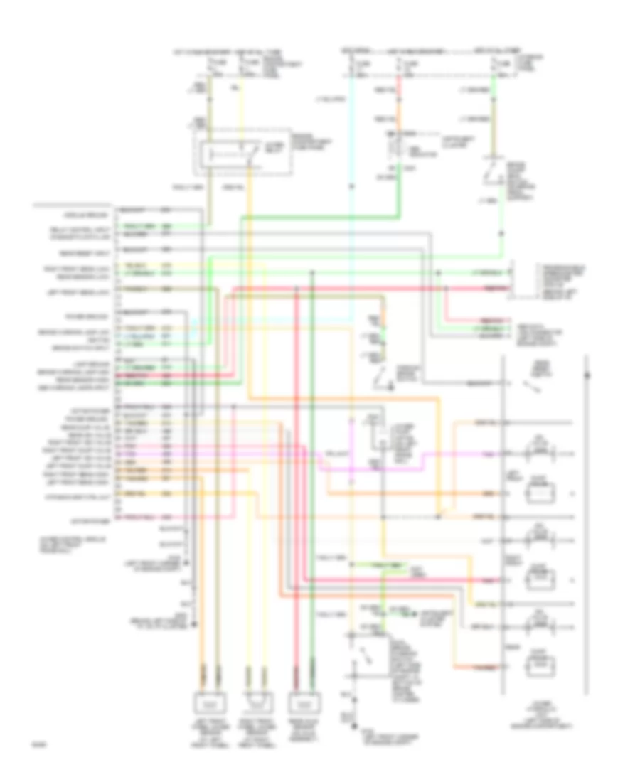
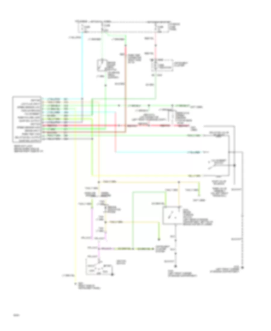
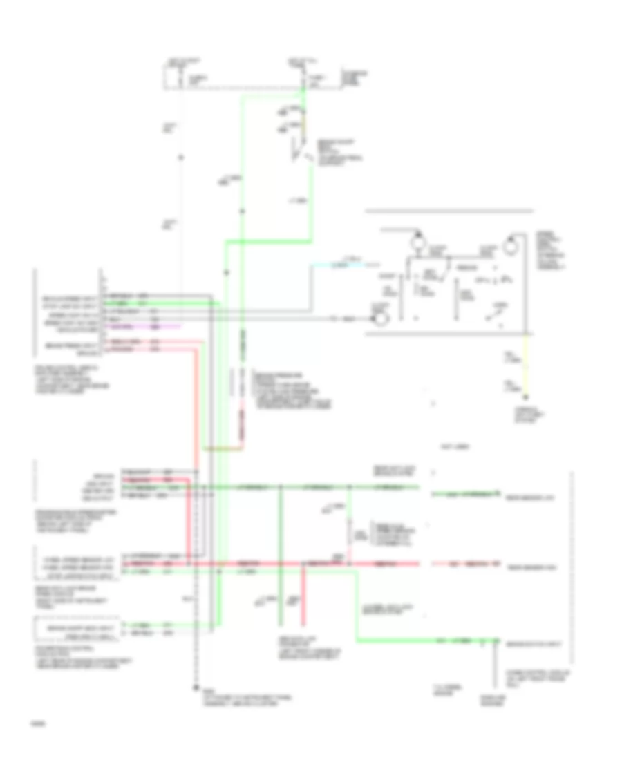
ANTI-LOCK BRAKES Anti Lock Brake Wiring Diagram, 4 Wheel ABS for Ford Club Wagon E150 1994 List of elements for Anti Lock Brake Wiring Diagram, 4 Wheel ABS for Ford Club Wagon E150 1994: 66 (at left front wheel) (at right front wheel) (behind left side of i/p) (left front corner (not used) 13b 4wabs control module (on left front frame rail) 4wabs hydraulic unit (left side of engine compartment) 4wabs pump motor (on left front frame rail) 4wabs relay Abs data link connector (left side of engine compt) Abs indicator Abs warning lamps input Brake on/off (boo) switch (on brake pedal support) Brake switch input Brake warning lamp high Brake warning lamp low C233 Diagnostic data link Dual brake warning switch (left side of engine compt, in bottom of brake master cylinder) Dump valve Engine compartment fuse panel Fuse 15a Fuse 20a Fuse u 30a Fuse v 60a G100 G100 (left front corner of engine compt) G202 (behind left side of i/p, on i/p cluster) Hot at all times Hot in run Hot in run or start Ignition Instrument cluster Instrument cluster system Interior fuse panel Iso valve Lamp ground Left front Left front sens (high) Left front sens (low) Left front wheel 4wabs sensor Module ground Motor power Mtr back emf ctrl out Of engine compt) Parking brake switch Pnk Power ground Programmable speedometer/ odometer module Rear Rear axle sensor (on axle assembly) Rear dump valve Rear iso valve right front iso valve right front dump valve left front iso valve left front dump valve Rear reset input Rear reset switch Rear sensor (high) Rear sensor (low) Red/pnk Relay control input Right front Right front sens (high) Right front sens (low) Right front wheel 4wabs sensor Tan Tan/red Anti Lock Brake Wiring Diagram, Rear Wheel ABS for Ford Club Wagon E150 1994 List of elements for Anti Lock Brake Wiring Diagram, Rear Wheel ABS for Ford Club Wagon E150 1994: 49 (not used) (on brake pedal support) (top of rear axle) 13b Abs data link connector (left front of engine compt) Abs indicator Acc Brake indicator diode Brake input Brake on/off (boo) switch C233 Diesel engines Dual brake warning switch (left rear of engine compartment, bottom of brake master cylinder) Dump sol output Dump valve solenoid Fuse 15a Fuse 20a G100 (left front corner of engine compartment) G201 (right side of instrument panel) Gasoline engines Hot at all times Hot in run Hot in run or start Ignition Ignition switch Instrument cluster Instrument cluster system Interior fuse panel Isolation sol output Isolation valve solenoid Lock Low fluid input Module ground Off Rabs failure lamp Rabs test connector (right side of i/p) Rabs test kam Rabs valve assembly (on left front frame rail) Rear anti-lock brake (rabs) module (behind right side of i/p) Rear axle speed sensor Red Red/pnk Run Speed sensor high Speed sensor low Start Tan/ Valve reset Valve reset switch
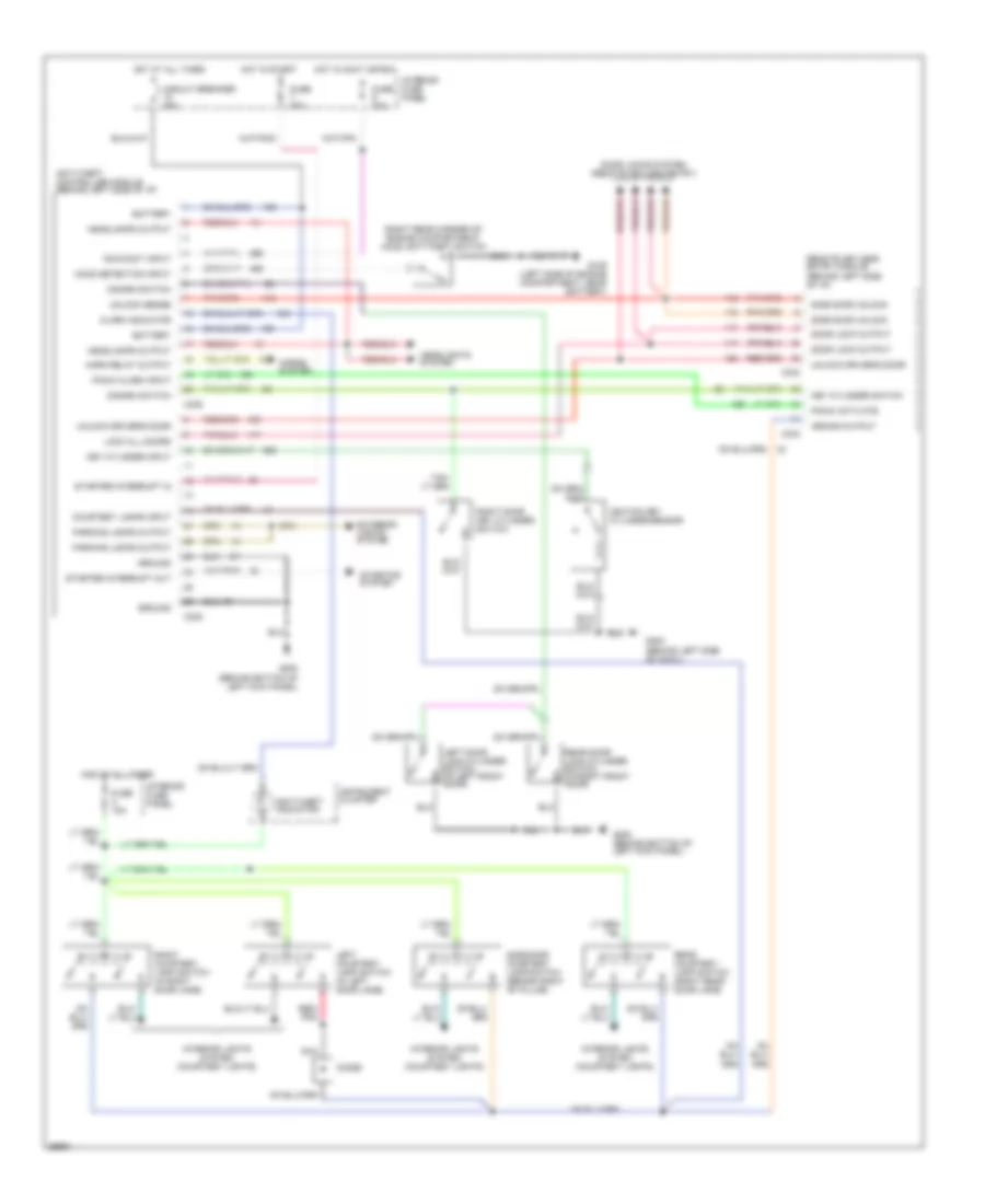
ANTI-THEFT Anti-theft Wiring Diagram for Ford Club Wagon E150 1994 List of elements for Anti-theft Wiring Diagram for Ford Club Wagon E150 1994: 59 (right rear corner of engine compartment) hood anti-theft switch Alarm indicator Anti-theft controller module (behind left side of i/p) Anti-theft indicator Arming output Battery C238 C333 C334 C335 Circuit breaker 20a Courtesy lamps input Diode Disarm switch Door lock output Door locks system (remote keyless entry) Exterior lights system Fuse 15a Fuse 20a Fuse 30a G106 (left side of engine compartment, near battery) G200 (behind bottom of left kick panel) G200 (behind left side of cowl) Ground Headlamps output Headlights system Hood detection input Horn relay output Horns system Hot at all times Hot in accy or run Hot in start Ignition key cylinder sensor Instrument cluster Interior fuse panel Interior lights system (courtesy lights) Key cylinder input Key cylinder switch Left courtesy lamp switch (in left door jamb) Left door lock cylinder switch (in left front door) Lock all doors Nca Panic activate Panic alarm input Parking lamps output Rear courtesy lamp switch (right rear door jamb) Rear door lock cylinder switch (in right front door) Red/ pnk Remote keyless entry module (behind left side of i/p) Right courtesy lamp switch (in right door jamb) Right door key cylinder switch Run/accy input Side door courtesy lamp switch (behind right "b" pillar) Side door unlock Starter interrupt in Starter interrupt out Starting system Unlock driver's door Unlock sense
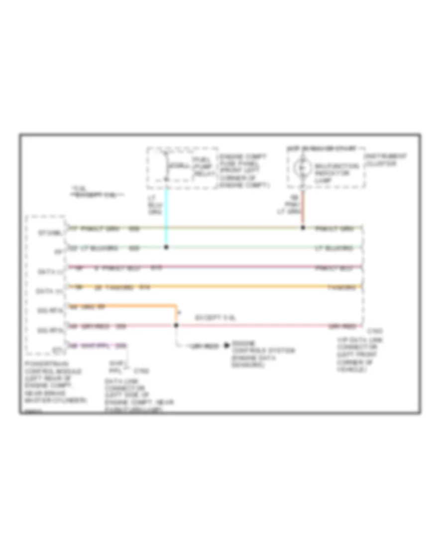
COMPUTER DATA LINES Data Link Connector Wiring Diagram for Ford Club Wagon E150 1994 List of elements for Data Link Connector Wiring Diagram for Ford Club Wagon E150 1994: 21 *5.0l **except 5.0l (coil) * ** C162 C163 Data (+) Data (-) Data link connector (left side of engine compt, near park/turn lamp) Engine compt fuse panel (front left corner of engine compt) Engine controls system (engine data sensors) Except 5.0l Fuel pump relay Hot in run or start Instrument cluster Malfunction indicator lamp Pnk/ Powertrain control module (left rear of engine compt, near brake master cylinder) Sig rtn Sti Sto/mil Vip data link connector (left front corner of vehicle)
CRUISE CONTROL
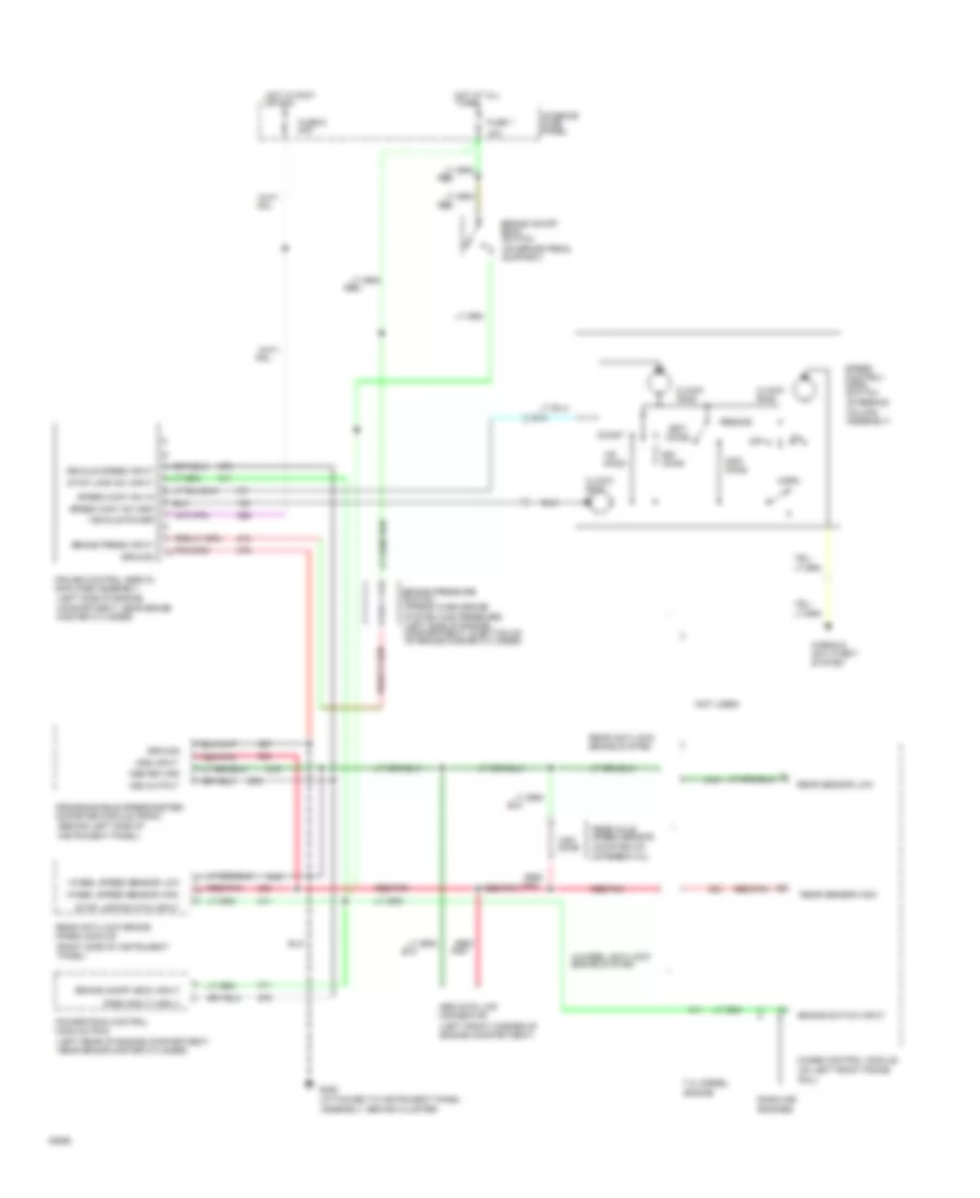
4.9L 4.9L, Cruise Control Wiring Diagram for Ford Club Wagon E150 1994 List of elements for 4.9L, Cruise Control Wiring Diagram for Ford Club Wagon E150 1994: 65 (attached to instrument panel assembly, behind cluster) (behind left side of instrument panel) (left front corner of engine compartment) (left rear of engine compartment, near brake master cylinder) (left side of engine compartment, near brake master cylinder) (mounted on differential) (not used) (on brake pedal support) (right side of instrument panel) (steering column assembly) 15a 4-wheel anti-lock brake system 4wabs control module (on left front frame 7.3l diesel engine Abs data link connector Accel Brake on/off (boo) input Brake on/off (boo) switch Brake press input Brake pressure switch (opens when brake Brake switch input Clock- ring Coast Cruise control servo/ amplifier assembly Dss input Dss return Fuse 1 Fuse 6 20a G206 Gasoline engines Ground Horn Horns & anti-theft system Hot at all times Hot in accy or run Interior fuse panel Off Ohms Pnk Powertrain control module (pcm) Programmable speedometer/ odometer module (psom) Psom input (vss +) Rail) Rear anti-lock brake (rabs) module Rear anti-lock brake system Rear axle speed sensor Rear sensor high Rear sensor low Red Red/ Red/ pnk Red/pnk Resume Set/ Speed cont sw gnd Speed cont sw in Speed control/ horn switch Stop lamp sw input Stop lamp switch input System has pressure) (left side of engine compartment, in bottom of of brake master cylinder) Vehicle power Vehicle speed input Vss output Wheel speed sensor high Wheel speed sensor low
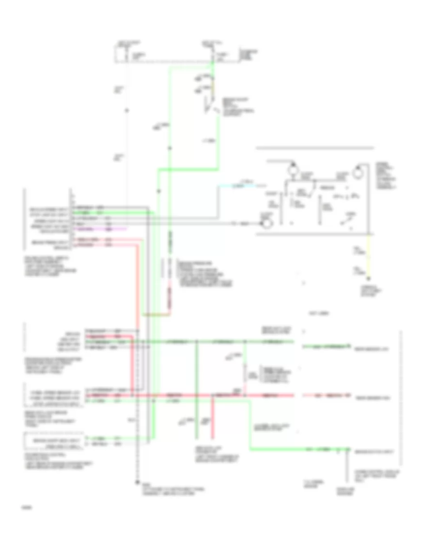
5.0L 5.0L, Cruise Control Wiring Diagram for Ford Club Wagon E150 1994 List of elements for 5.0L, Cruise Control Wiring Diagram for Ford Club Wagon E150 1994: 65 (attached to instrument panel assembly, behind cluster) (behind left side of instrument panel) (left front corner of engine compartment) (left rear of engine compartment, near brake master cylinder) (left side of engine compartment, near brake master cylinder) (mounted on differential) (not used) (on brake pedal support) (right side of instrument panel) (steering column assembly) 15a 4-wheel anti-lock brake system 4wabs control module (on left front frame 7.3l diesel engine Abs data link connector Accel Brake on/off (boo) input Brake on/off (boo) switch Brake press input Brake pressure switch (opens when brake Brake switch input Clock- ring Coast Cruise control servo/ amplifier assembly Dss input Dss return Fuse 1 Fuse 6 20a G206 Gasoline engines Ground Horn Horns & anti-theft system Hot at all times Hot in accy or run Interior fuse panel Off Ohms Pnk Powertrain control module (pcm) Programmable speedometer/ odometer module (psom) Psom input (vss +) Rail) Rear anti-lock brake (rabs) module Rear anti-lock brake system Rear axle speed sensor Rear sensor high Rear sensor low Red Red/ Red/ pnk Red/pnk Resume Set/ Speed cont sw gnd Speed cont sw in Speed control/ horn switch Stop lamp sw input Stop lamp switch input System has pressure) (left side of engine compartment, in bottom of of brake master cylinder) Vehicle power Vehicle speed input Vss output Wheel speed sensor high Wheel speed sensor low
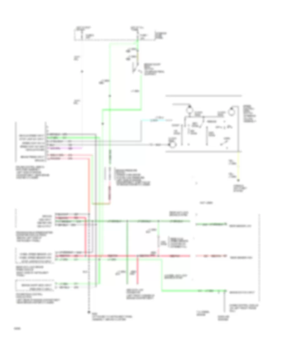
5.8L 5.8L, Cruise Control Wiring Diagram for Ford Club Wagon E150 1994 List of elements for 5.8L, Cruise Control Wiring Diagram for Ford Club Wagon E150 1994: 65 (attached to instrument panel assembly, behind cluster) (behind left side of instrument panel) (left front corner of engine compartment) (left rear of engine compartment, near brake master cylinder) (left side of engine compartment, near brake master cylinder) (mounted on differential) (not used) (on brake pedal support) (right side of instrument panel) (steering column assembly) 15a 4-wheel anti-lock brake system 4wabs control module (on left front frame 7.3l diesel engine Abs data link connector Accel Brake on/off (boo) input Brake on/off (boo) switch Brake press input Brake pressure switch (opens when brake Brake switch input Clock- ring Coast Cruise control servo/ amplifier assembly Dss input Dss return Fuse 1 Fuse 6 20a G206 Gasoline engines Ground Horn Horns & anti-theft system Hot at all times Hot in accy or run Interior fuse panel Off Ohms Pnk Powertrain control module (pcm) Programmable speedometer/ odometer module (psom) Psom input (vss +) Rail) Rear anti-lock brake (rabs) module Rear anti-lock brake system Rear axle speed sensor Rear sensor high Rear sensor low Red Red/ Red/ pnk Red/pnk Resume Set/ Speed cont sw gnd Speed cont sw in Speed control/ horn switch Stop lamp sw input Stop lamp switch input System has pressure) (left side of engine compartment, in bottom of of brake master cylinder) Vehicle power Vehicle speed input Vss output Wheel speed sensor high Wheel speed sensor low
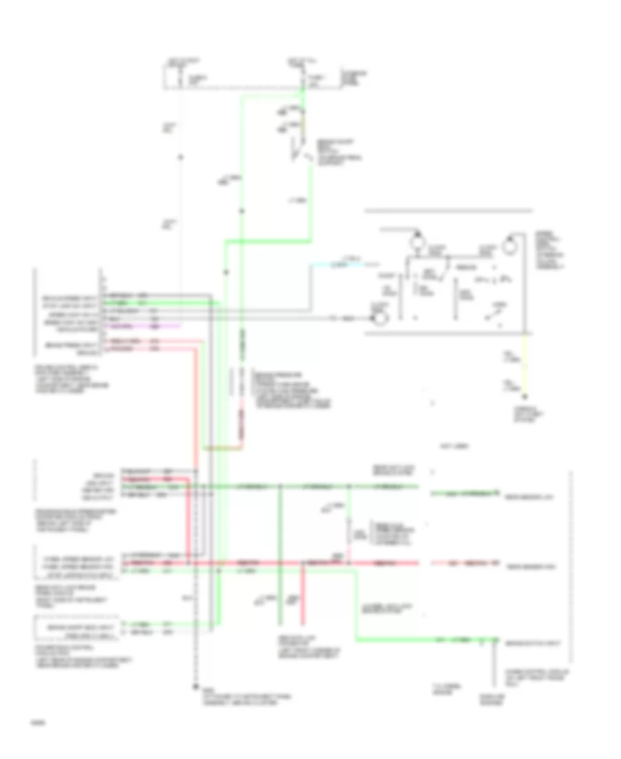
7.3L 7.3L Diesel, Cruise Control Wiring Diagram for Ford Club Wagon E150 1994 List of elements for 7.3L Diesel, Cruise Control Wiring Diagram for Ford Club Wagon E150 1994: 65 (attached to instrument panel assembly, behind cluster) (behind left side of instrument panel) (left front corner of engine compartment) (left rear of engine compartment, near brake master cylinder) (left side of engine compartment, near brake master cylinder) (mounted on differential) (not used) (on brake pedal support) (right side of instrument panel) (steering column assembly) 15a 4-wheel anti-lock brake system 4wabs control module (on left front frame 7.3l diesel engine Abs data link connector Accel Brake on/off (boo) input Brake on/off (boo) switch Brake press input Brake pressure switch (opens when brake Brake switch input Clock- ring Coast Cruise control servo/ amplifier assembly Dss input Dss return Fuse 1 Fuse 6 20a G206 Gasoline engines Ground Horn Horns & anti-theft system Hot at all times Hot in accy or run Interior fuse panel Off Ohms Pnk Powertrain control module (pcm) Programmable speedometer/ odometer module (psom) Psom input (vss +) Rail) Rear anti-lock brake (rabs) module Rear anti-lock brake system Rear axle speed sensor Rear sensor high Rear sensor low Red Red/ Red/ pnk Red/pnk Resume Set/ Speed cont sw gnd Speed cont sw in Speed control/ horn switch Stop lamp sw input Stop lamp switch input System has pressure) (left side of engine compartment, in bottom of of brake master cylinder) Vehicle power Vehicle speed input Vss output Wheel speed sensor high Wheel speed sensor low
7.5L 7.5L, Cruise Control Wiring Diagram for Ford Club Wagon E150 1994 List of elements for 7.5L, Cruise Control Wiring Diagram for Ford Club Wagon E150 1994: 65 (attached to instrument panel assembly, behind cluster) (behind left side of instrument panel) (left front corner of engine compartment) (left rear of engine compartment, near brake master cylinder) (left side of engine compartment, near brake master cylinder) (mounted on differential) (not used) (on brake pedal support) (right side of instrument panel) (steering column assembly) 15a 4-wheel anti-lock brake system 4wabs control module (on left front frame 7.3l diesel engine Abs data link connector Accel Brake on/off (boo) input Brake on/off (boo) switch Brake press input Brake pressure switch (opens when brake Brake switch input Clock- ring Coast Cruise control servo/ amplifier assembly Dss input Dss return Fuse 1 Fuse 6 20a G206 Gasoline engines Ground Horn Horns & anti-theft system Hot at all times Hot in accy or run Interior fuse panel Off Ohms Pnk Powertrain control module (pcm) Programmable speedometer/ odometer module (psom) Psom input (vss +) Rail) Rear anti-lock brake (rabs) module Rear anti-lock brake system Rear axle speed sensor Rear sensor high Rear sensor low Red Red/ Red/ pnk Red/pnk Resume Set/ Speed cont sw gnd Speed cont sw in Speed control/ horn switch Stop lamp sw input Stop lamp switch input System has pressure) (left side of engine compartment, in bottom of of brake master cylinder) Vehicle power Vehicle speed input Vss output Wheel speed sensor high Wheel speed sensor low
ENGINE PERFORMANCE
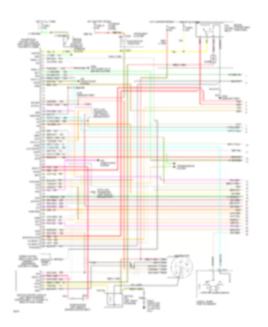
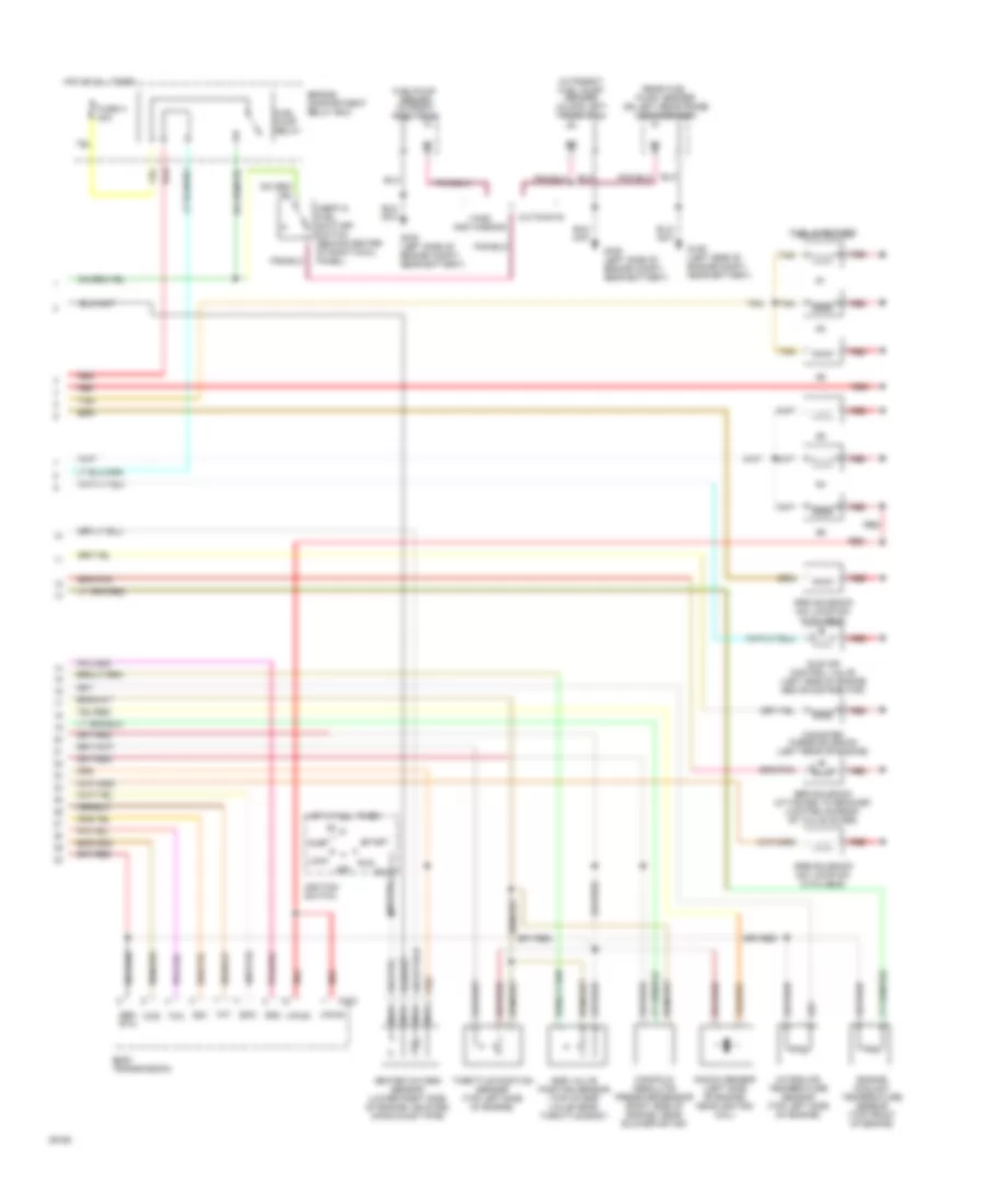
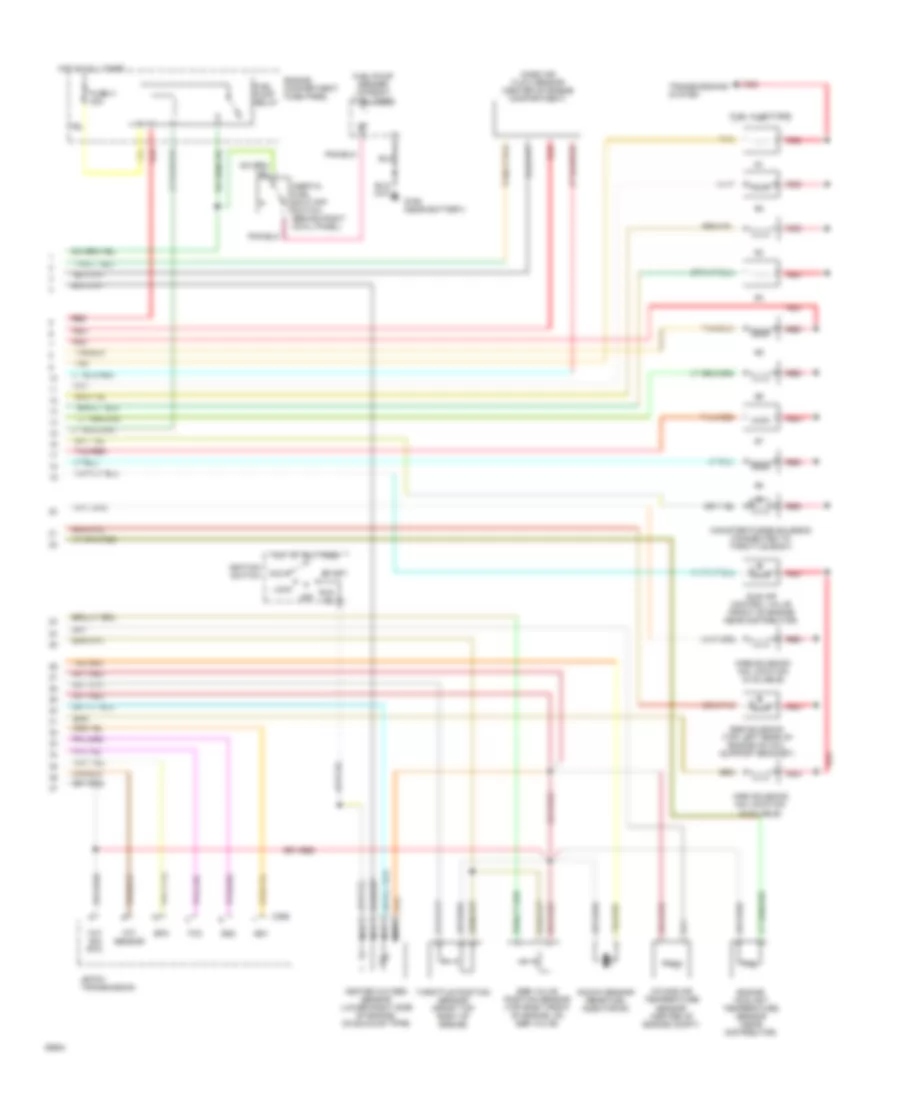
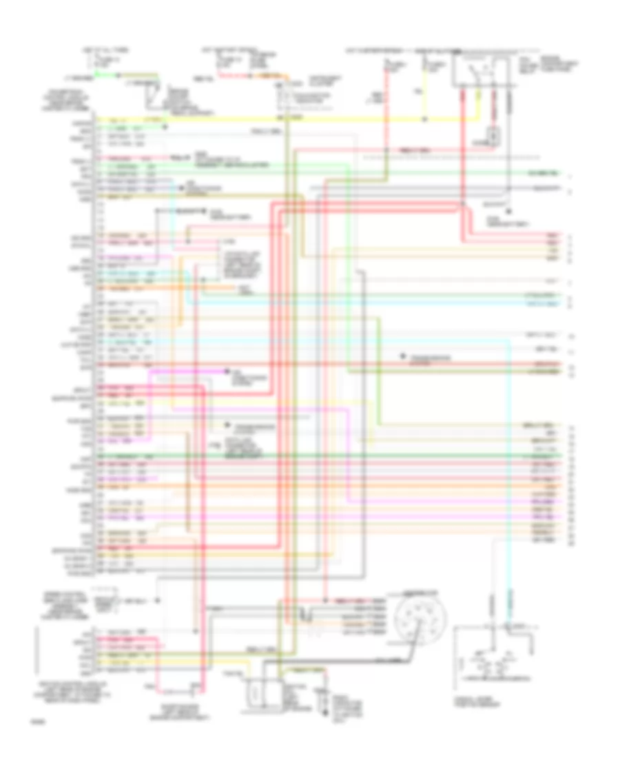
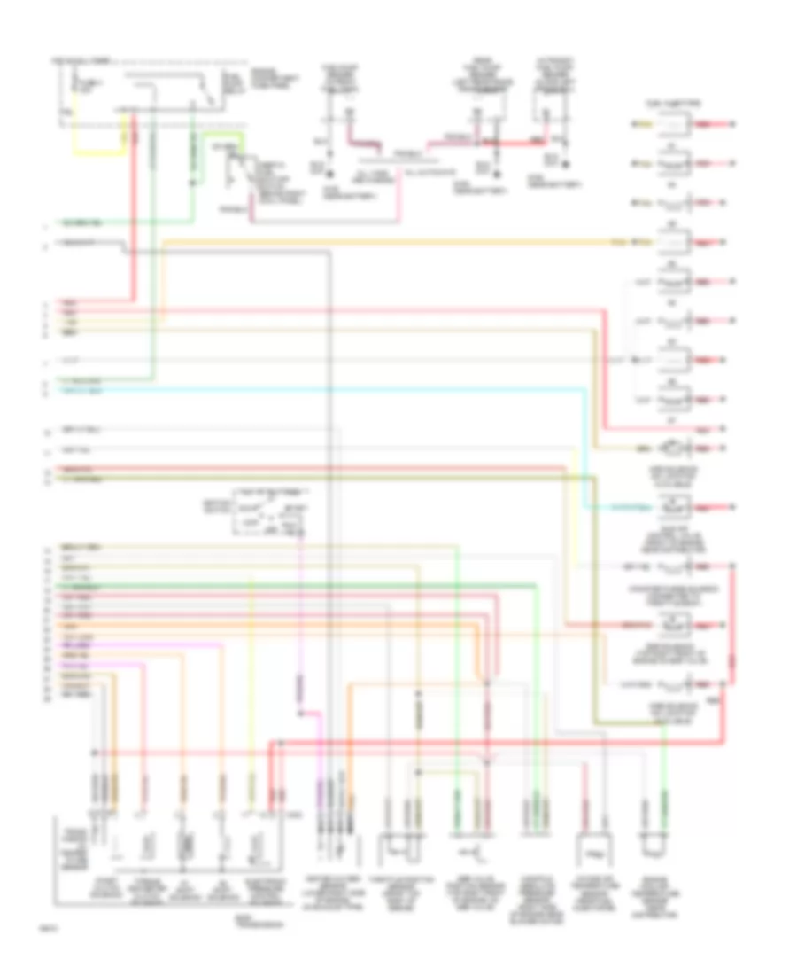
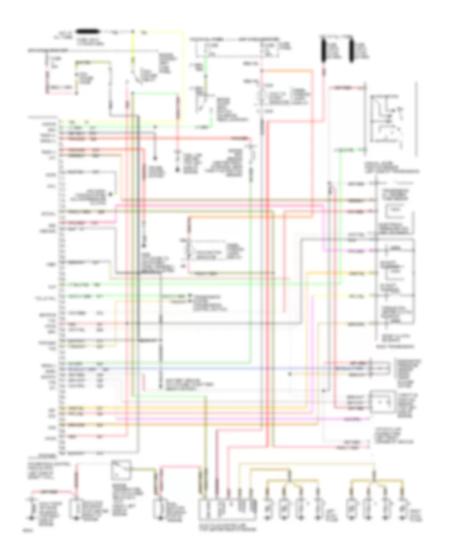
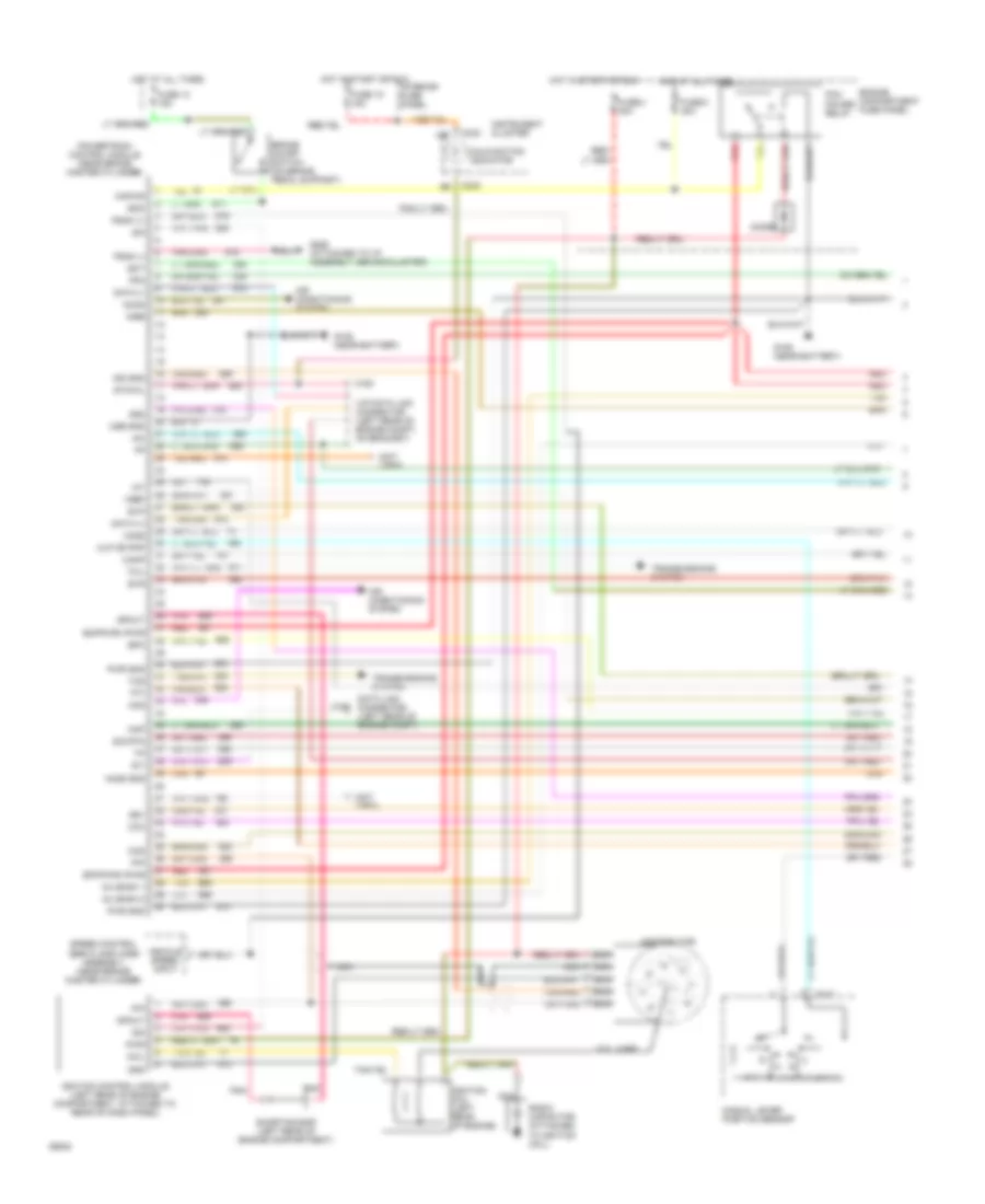
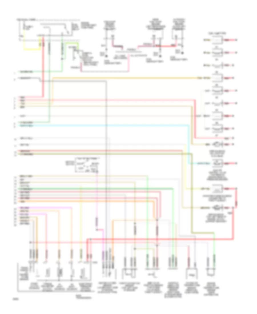
4.9L 4.9L, Engine Performance Wiring Diagrams (1 of 2) for Ford Club Wagon E150 1994 List of elements for 4.9L, Engine Performance Wiring Diagrams (1 of 2) for Ford Club Wagon E150 1994: 83 13b Accs Acd Air conditioning system Airb Aird Boo Brake on/off switch (behind steering column) C162 C198 C233 C317 Canp Ccs Coil Coil wire Cse gnd Data (+) Data (-) Data link connector (left side of engine compt) Diode Distributor Ect Engine compartment fuse panel Epc Epcpwr/vpwr Evp Evr Fpm Fuse 1 15a Fuse 18 15a Fuse c 30a Fuse u 30a G106 (near battery) G206 (attached to i/p, behind cluster) Gnd Ho2s Ho2s gnd Hot at all times Hot in start or run Iac Iat Idm Ign gnd Ignition coil (left front of engine) Ignition control module (left rear of engine compartment, attached to rear of dash panel) Inj bank 1 Inj bank 2 Instrument cluster Interior fuse panel Kapwr Malfunction indicator Manual lever position sensor Map Mlp or pnp Nca Pcm power relay Pip Pnk Powertrain control module (left side of brake master cylinder) Psom (+) Psom (-) Pwr Pwr gnd Radio capacitor (attached to ignition coil) Red Shorting bar (left rear of engine compartment) Sig rtn Speed control servo amplifier assembly (near brake master cylinder) Spout Ss1 Ss2 Sti Sto/mil Tan Tcc Tcil Tcs Tft Transmissions system Vehicle speed input Vpwr Vref 4.9L, Engine Performance Wiring Diagrams (2 of 2) for Ford Club Wagon E150 1994 List of elements for 4.9L, Engine Performance Wiring Diagrams (2 of 2) for Ford Club Wagon E150 1994: 43 Acc Airb solenoid (no location available) Aird solenoid (no location available) C303 Canister purge solenoid (left rear of engine) Ccs Cutaways E40d transmission Egr solenoid (attached to bracket located on rear of valve cover) Egr valve position sensor (top of egr valve near throttle body) Engine compartment relay box Engine coolant temperature sensor (top front of engine) Epc Fuel injectors Fuel pump relay Fuel/pump sender (in front fuel tank) Fuse h 30a G106 (left side of engine compt, near battery) Heated oxygen sensor (lower right side of engine, mounted on exhaust pipe) Hot at all times Idle air control valve (left side of engine above distributor) Ignition switch In-transit fuel pump/ sender (along left frame rail) Inertia fuel shut-off switch (behind center of right cowl panel) Intake air temperature sensor (top left side of engine) Knock sensor (left side of engine, near ignition coil) Lock Manifold absolute pressure sensor (right side of engine, near blower motor) Nca Off Rear fuel pump/ sender (on left rear frame crossmember) Red Run Sen rtn Ss1 Ss2 Start Tan Tcc Tft Throttle position sensor (top left side of engine) Vans and wagons Vpwr
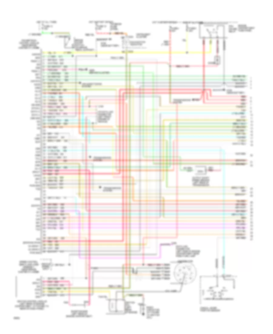
5.0L 5.0L, Engine Performance Wiring Diagrams (1 of 2) for Ford Club Wagon E150 1994 List of elements for 5.0L, Engine Performance Wiring Diagrams (1 of 2) for Ford Club Wagon E150 1994: 90 13b Accs Air conditioning system Airb Aird Boo Brake on/off switch (on brake pedal support) C162 C163 C233 C317 Coil Coil wire Cse gnd Data (+) Data (-) Data link connector (left side of engine compartment near park/turn lamp) Diode Distributor Ect Engine compartment fuse panel Epc Epcpwr/vpwr Evp Evr Fpm Fuse 13 15a Fuse 18 15a Fuse c 30a Fuse u 30a G106 (near battery) G206 (behind cluster) Gnd Ho2s Hot at all times Hot in start or run Iac Iat Idm Ign gnd Ignition coil (left rear of engine) Ignition control module (left rear of engine compartment, attached to rear of dash panel) Inj 3 Inj 4 Inj 5 Inj 6 Inj 7 Inj 8 Inj bank 1 Inj bank 2 Instrument cluster Interior fuse panel Kapwr Maf Maf rtn Malfunction indicator Manual lever position sensor Mlp Nca Oss Output shaft speed sensor (left rear of transmission) Pcm power relay Pip Pnk Powertrain control module (near brake master cylinder) Psom (+) Psom (-) Pwr Pwr gnd Radio capacitor (attached to ignition coil) Red Shorting bar (left rear of engine compartment) Sig rtn Speed control servo amplifier assembly (near brake master cylinder) Spout Ss1 Ss2 Sti Sto/mil Tan Tan/red Tcc Tcil Tcs Tft Transmissions system Vehicle speed input Vip data link connector (left front corner of vehicle) Vpwr Vref 5.0L, Engine Performance Wiring Diagrams (2 of 2) for Ford Club Wagon E150 1994 List of elements for 5.0L, Engine Performance Wiring Diagrams (2 of 2) for Ford Club Wagon E150 1994: 39 4r70w transmission Acc Airb soleniod (no location available) Aird soleniod (no location available) C356 Canister purge solenoid (connected to throttle body) Egr solenoid (top left rear of engine on coil support bracket) Egr valve position sensor (top right front of engine, on egr valve) Engine compartment fuse panel Engine coolant temperature sensor (near distributor) Epc Fuel injectors Fuel pump relay Fuel/pump sender (in front fuel tank) Fuse h 30a G106 (near battery) Heated oxygen sensor (lower right side of engine, on exhaust pipe) Hot at all times Idle air control valve (front of engine near distributor) Ignition switch Inertia fuel shut-off switch (behind right cowl panel) Intake air temperature sensor (center of engine compt) Knock sensor (near fuel injector #4) Lock Mass air flow sensor (center of engine compartment) Nca Off Red Run Ss1 Ss2 Start Tan Tan/red Tcc Tft sensor Throttle position sensor (front top right of engine) Tot sig rtn Transmissions system
5.8L 5.8L, Engine Performance Wiring Diagrams (1 of 2) for Ford Club Wagon E150 1994 List of elements for 5.8L, Engine Performance Wiring Diagrams (1 of 2) for Ford Club Wagon E150 1994: 85 (not used) 13b Accs Acd Air conditioning system Airb Aird Boo Brake on/off switch (on brake pedal support) C162 C163 C233 C317 Canp Ccc Ccs Coil Coil wire Cse gnd Data (+) Data (-) Data link connector (left rear of engine compt) Diode Distributor Ecppwr/vpwr Ect Engine compartment fuse panel Epc Epcpwr/vpwr Evp Evr Fpm Fuse 13 15a Fuse 18 15a Fuse c 30a Fuse u 30a G106 (near battery) G206 (attached to i/p assembly, behind cluster) Gnd Ho2s Ho2s gnd Hot at all times Hot in start or run Iac Iat Idm Ign gnd Ignition coil (left rear of engine) Ignition control module (left rear of engine compartment, attached to rear of dash panel) Inj bank 1 Inj bank 2 Instrument cluster Interior fuse panel Kapwr Malfunction indicator Manual lever position sensor Map Mlp or pnp Nca Pcm power relay Pip Pnk Powertrain control module (near brake master cylinder) Psom (+) Psom (-) Pwr Pwr gnd Radio capacitor (attached to ignition coil) Red Shorting bar (left rear of engine compartment) Sig rtn Speed control servo amplifier assembly (near brake master cylinder) Spout Ss1 Ss2 Sti Sto/mil Tan Tcil Tcs Tft Transmissions system Vehicle speed input Vip data link connector (left rear of engine compt, on bracket) Vref 5.8L, Engine Performance Wiring Diagrams (2 of 2) for Ford Club Wagon E150 1994 List of elements for 5.8L, Engine Performance Wiring Diagrams (2 of 2) for Ford Club Wagon E150 1994: 40 #1 shift solenoid #2 shift solenoid Acc Airb soleniod (no location available) Aird soleniod (no location available) All cutaways All vans and wagons C303 Canister purge solenoid (connected to throttle body) Coast clutch solenoid E40d transmission Egr solenoid (top right front of engine on egr valve) Egr valve position sensor (top right front of engine, on egr valve) Electronic pressure control solenoid Engine compartment fuse panel Engine coolant temperature sensor (near distributor) Fuel injectors Fuel pump relay Fuel/pump sender (in front fuel tank) Fuse h 30a G106 (near battery) Heated oxygen sensor (lower right side of engine, on exhaust pipe) Hot at all times Idle air control valve (front of engine near distributor) Ignition switch In-transit fuel pump/ sender (along left frame rail) Inertia fuel shut-off switch (behind right cowl panel) Intake air temperature sensor (near fuel injector #6) Lock Manifold absolute pressure sensor (right side of engine near blower motor) Nca Off Rear fuel pump/ sender (left rear frame crossmember) Red Run Start Tan Throttle position sensor (front top right of engine) Torque converter clutch solenoid Trans- mission oil temper- ature sensor
7.3L 7.3L Diesel, Engine Performance Wiring Diagrams for Ford Club Wagon E150 1994 List of elements for 7.3L Diesel, Engine Performance Wiring Diagrams for Ford Club Wagon E150 1994: 77 "wait to start" indicator #1 shift solenoid #2 shift solenoid (closed (front left side of engine) (left side of safety wall, 13b 4x4l Accs Air condi- tioning system (a/c compressure clutch) Baro Barometric pressure sensor (baro) (near blower motor) Boo Brake on/off (boo) switch (on brake pedal support) C240 Ccc Ccs Coast clutch solenoid Cold idle solenoid (top center front of engine) Cold timimg advance solenoid (top right side of engine) Cruise control system Cse gnd Diesel warning lamps display E4od transmission Electronic pressure con- trol solenoid Engine compart- ment fuse Engine rpm sensor (center front of engine, near throttle position sensor) Engine temperature switch below 62 c, 144 f) Epc Epcpwr Fuel line heater (top left side of engine) Fuel shutoff solenoid (top of engine) Fuse 15a Fuse panel Fuse u 30a G206 (attached to instrument panel assembly, behind cluster) Glow plug controller (top center rear of engine) Glow plugs Hot at all times Hot in run or start Ign feed Kapwr Left glow plugs Malfunction indicator Manual lever position sensor (left side of transmission) Mlp Nca Panel Pcm power diode Pcm power relay Plugs glow Powertrain control module (pcm) Psom (+) Psom (-) Pwr gnd Red Right glow plugs Rpms (+) Rpms (-) Sig rtn Ss1 Ss2 Sti Sto/mil Tac Tcil & tmil Tcs Tft Throttle position sensor (top left side of engine) Torque con- verter clutch solenoid Tps Transmission oil tempera- ture sensor Transmission system (transmission control switch) Vip data link connectors (left front corner of vehicle) Vpwr Vref Wait to start
7.5L 7.5L, Engine Performance Wiring Diagrams (1 of 2) for Ford Club Wagon E150 1994 List of elements for 7.5L, Engine Performance Wiring Diagrams (1 of 2) for Ford Club Wagon E150 1994: 84 (not used) 13b Accs Acd Air conditioning system Airb Boo Brake on/off switch (on brake pedal support) C162 C163 C233 C317 Canp Ccc Ccs Coil Coil wire Cse gnd Data (+) Data (-) Data link connector (left rear of engine compt) Diode Distributor Ecppwr/vpwr Ect Engine compartment fuse panel Epc Epcpwr/vpwr Evp Evr Fpm Fuse 13 15a Fuse 18 15a Fuse c 30a Fuse u 30a G106 (near battery) G206 (attached to i/p assembly, behind cluster) Gnd Ho2s Ho2s gnd Hot at all times Hot in start or run Iac Iat Idm Ign gnd Ignition coil (left rear of engine) Ignition control module (left rear of engine compartment, attached to rear of dash panel) Inj bank 1 Inj bank 2 Instrument cluster Interior fuse panel Kapwr Malfunction indicator Manual lever position sensor Map Mlp or pnp Nca Pcm power relay Pip Pnk Powertrain control module (near brake master cylinder) Psom (+) Psom (-) Pwr Pwr gnd Radio capacitor (attached to ignition coil) Red Shorting bar (left rear of engine compartment) Sig rtn Speed control servo amplifier assembly (near brake master cylinder) Spout Ss1 Ss2 Sti Sto/mil Tan Tcil Tcs Tft Transmissions system Vehicle speed input Vip data link connector (left rear of engine compt, on bracket) Vref 7.5L, Engine Performance Wiring Diagrams (2 of 2) for Ford Club Wagon E150 1994 List of elements for 7.5L, Engine Performance Wiring Diagrams (2 of 2) for Ford Club Wagon E150 1994: 39 #1 shift solenoid #2 shift solenoid Acc Airb soleniod (no location available) All cutaways All vans and wagons C303 Canister purge solenoid (connected to throttle body) Coast clutch solenoid E40d transmission Egr solenoid (top left rear of engine, on coil support bracket) Egr valve position sensor (top of egr valve near throttle body) Electronic pressure control solenoid Engine compartment fuse panel Engine coolant temperature sensor (near distributor) Fuel injectors Fuel pump relay Fuel/pump sender (in front fuel tank) Fuse h 30a G106 (near battery) Heated oxygen sensor (lower right side of engine, on exhaust pipe) Hot at all times Idle air control valve (top rear of engine near oil pressure sender) Ignition switch In-transit fuel pump/ sender (along left frame rail) Inertia fuel shut-off switch (behind right cowl panel) Intake air temperature sensor (near fuel injector #6) Lock Manifold absolute pressure sensor (right side of engine near blower motor) Nca Off Rear fuel pump/ sender (left rear frame crossmember) Red Run Start Tan Throttle position sensor (top left side of engine) Torque converter clutch solenoid Trans- mission oil temper- ature sensor
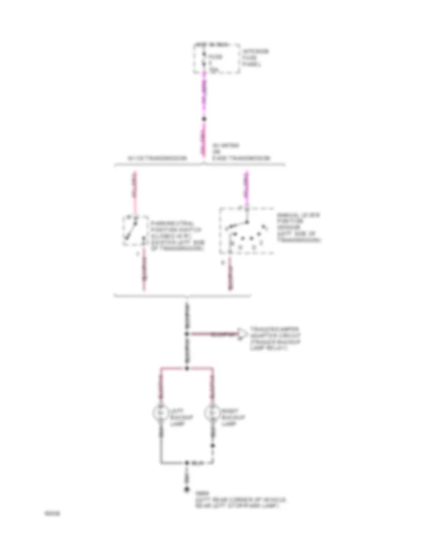
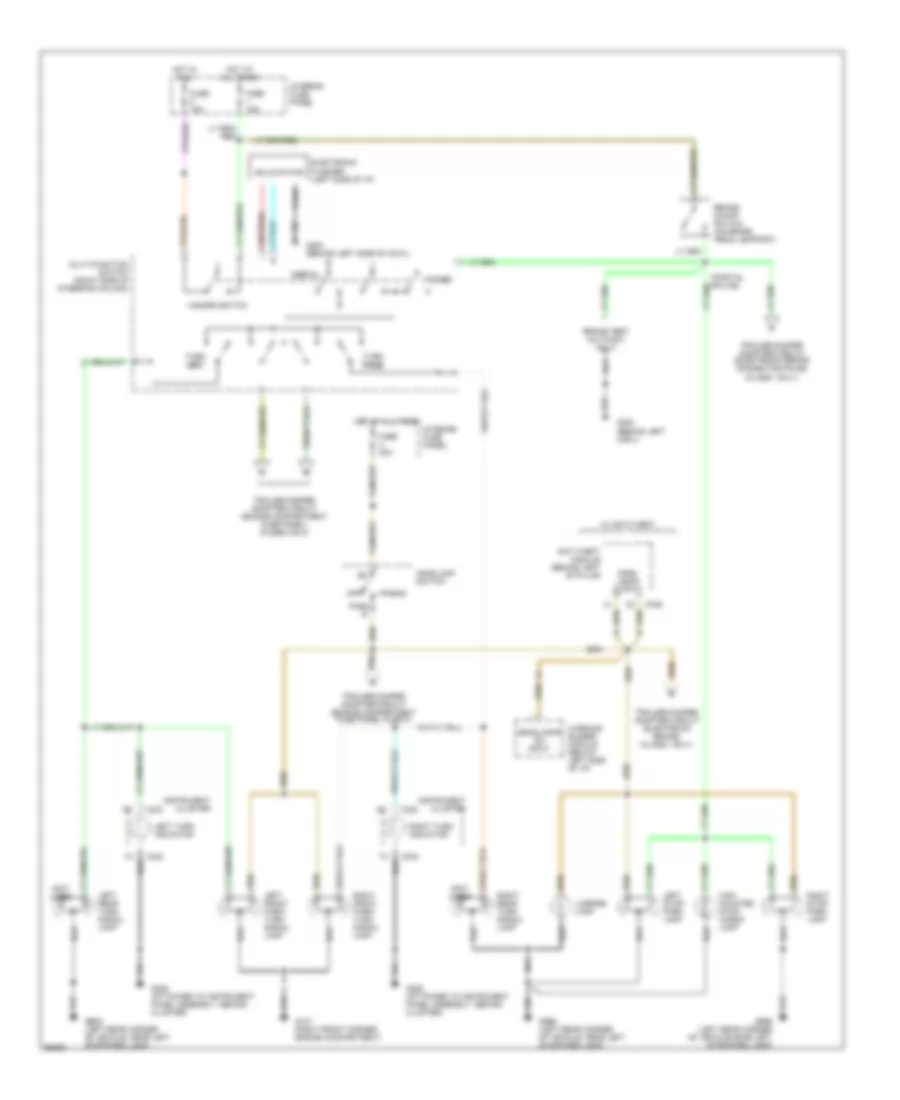
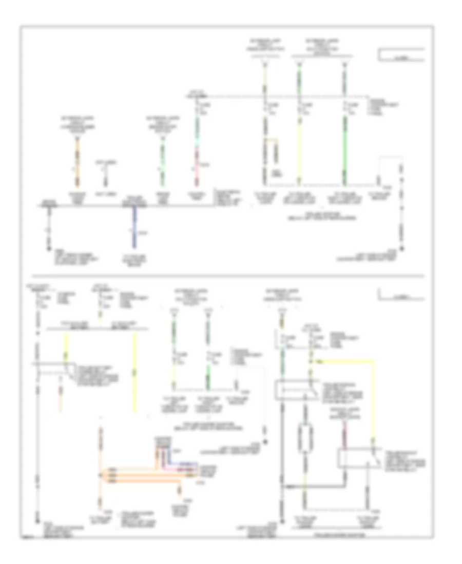
EXTERIOR LIGHTS Backup Lamps Wiring Diagram for Ford Club Wagon E150 1994 List of elements for Backup Lamps Wiring Diagram for Ford Club Wagon E150 1994: 11 Fuse 15a G999 (left rear corner of vehicle, near left stop/park lamp) Hot in run Interior fuse panel Left backup lamp Manual lever position sensor (left side of transmission) Park/neutral position switch (closed in 'r') (center left side of transmission) Right backup lamp Trailer/camper adapter circuit (trailer backup lamp relay) W/ 4r70w or e4od transmission W/ c6 transmission Exterior Lamps Wiring Diagram for Ford Club Wagon E150 1994 List of elements for Exterior Lamps Wiring Diagram for Ford Club Wagon E150 1994: 49 (not used) Anti-theft module (behind left 'b' pillar Brake on/off switch (on brake pedal support) Brake test (cutaway only) C232 C233 C336 Electronic flasher (left side of i/p) Fuse 15a Fuse 20a G107 (right front corner engine compartment) G200 (behind left cowl) G200 (behind left side of cowl) G206 (attached to instrument panel assembly, behind cluster) G999 (left rear corner of vehicle, near left stop/park lamp) G999 (left rear corner of vehicle,near left stop/park lamp) Hazard Hazard switch Head Headlamp switch Headlamps on input High mounted stop/ cargo lamp Hot at all times Hot in run Instrument cluster Interior fuse panel Left front park/ turn signal lamp Left rear turn signal lamp Left stop/ park lamp Left turn indicator License lamp Multi-function switch (right side of steering column) Normal Off Park lamps output Park r Right front park/ turn signal lamp Right rear turn signal lamp Right stop/ park lamp Right turn indicator Solid state Trailer/camper adapter circuit (electronic brake connector pin #5) (class i only) Trailer/camper adapter circuit (electronic brake) (class i only) Trailer/camper adapter circuit (engine compartment fuse panel fuse p) Trailer/camper adapter circuit (engine compartment fuse panel) (fuses n & m) Turn left Turn right W/ anti-theft Warning buzzer module (below left side of i/p) Trailer/Camper Adapter Wiring Diagram for Ford Club Wagon E150 1994 List of elements for Trailer/Camper Adapter Wiring Diagram for Ford Club Wagon E150 1994: 50 (not used) Backup lamps circuit (backup lamps) Brake lamp feed C184 C216 C231 C330 C422 Class i Class ii Control feed Electronic brake (below left side of i/p) Engine compartment fuse panel Exterior lamp circuit (headlamp switch) Exterior lamps circuit (brake on/off switch) Exterior lamps circuit (headlamp switch) Exterior lamps circuit (multi-function switch) Exterior lamps circuit (warning buzzer module) Fuse 20a Fuse d 20a Fuse j 40a Fuse m 10a Fuse n 10a Fuse p 10a Fuse p 30a G106 (left side of engine compartment, near battery G106 (left side of engine compartment, near battery) G999 (left rear corner of vehicle, near left stop/park lamp) Hot at all times Hot in accy or run Interior fuse panel Modified vehicle power Nca Red Running lamps feed To trailer backup lamps To trailer battery To trailer electronic brake To trailer ground To trailer left turn/stop or hazard lamp To trailer right turn/stop or hazard lamp To trailer running lamps Trailer adapter (below left side of rear bumper) Trailer backup lamp relay (left side of engine compartment, near starter relay) Trailer battery charge relay (left side of engine compartment, near starter relay) Trailer running lamp relay (left side of engine compartment, near starter relay) Trailer/camper adapter Trailer/camper adapter (below left side of rear bumper) W/ auxiliary battery W/o auxiliary battery
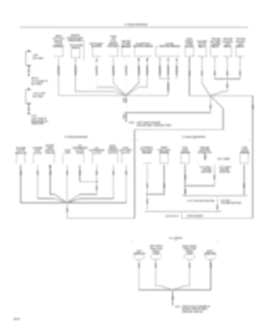
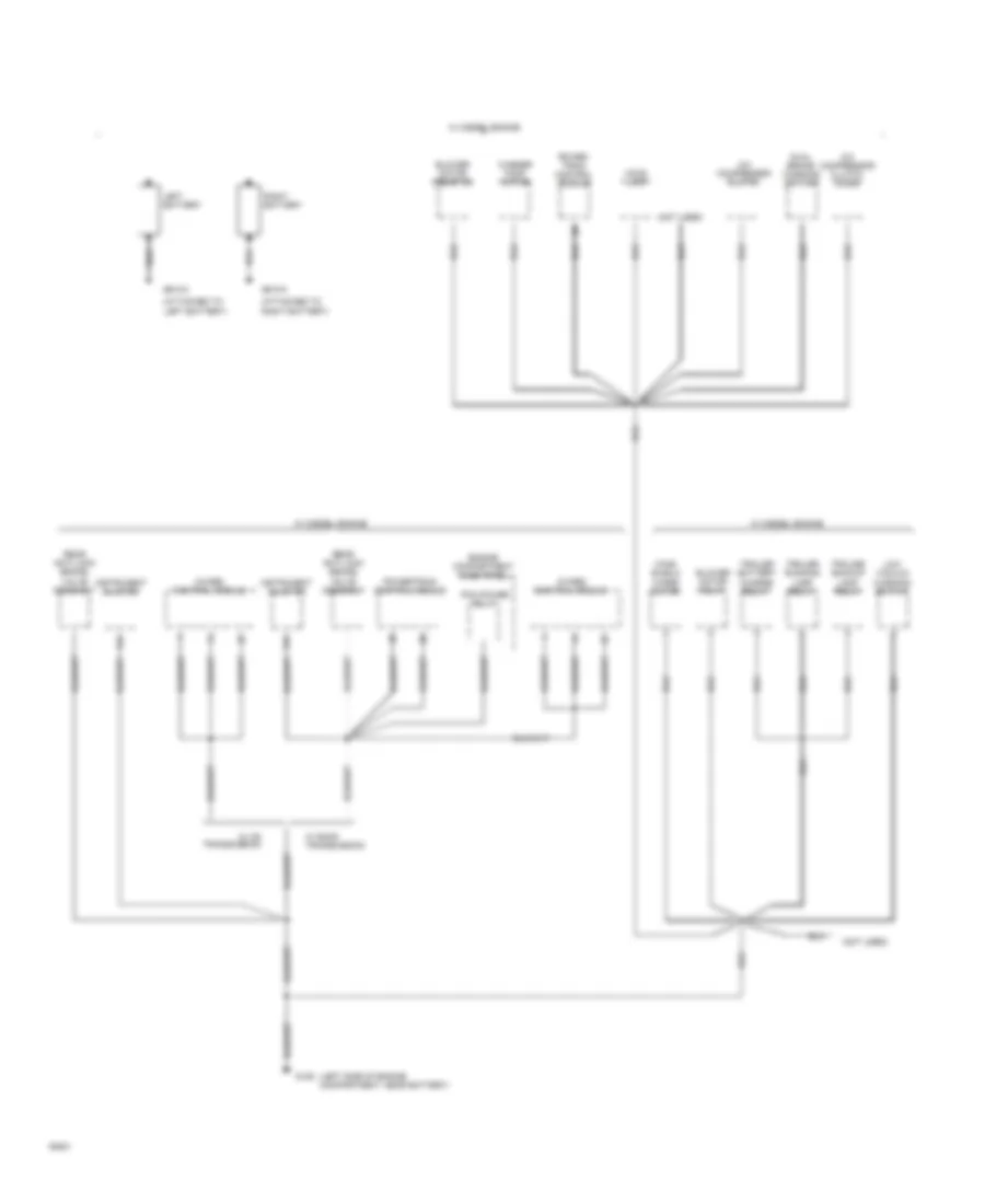
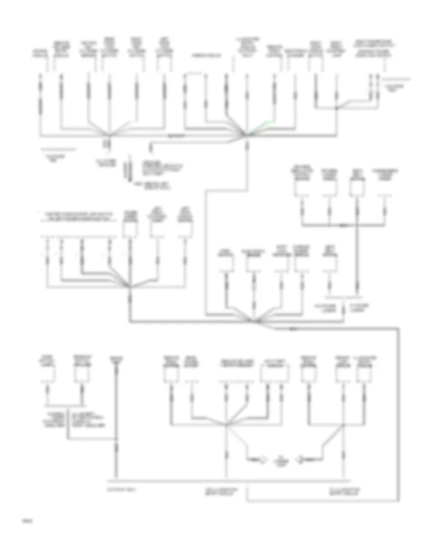
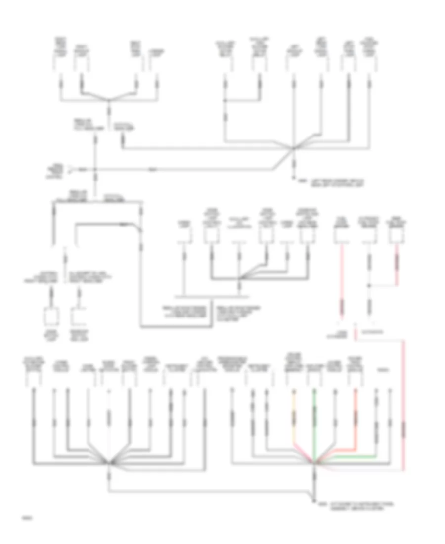
GROUND DISTRIBUTION Ground Distribution Wiring Diagram (1 of 4) for Ford Club Wagon E150 1994 List of elements for Ground Distribution Wiring Diagram (1 of 4) for Ford Club Wagon E150 1994: 50 (attached to battery) (front right corner of engine compartment, near drl module) (left side of engine below headlamp) (left side of engine compartment, near battery) (not used) 14a 4wabs control module A/c compressor clutch A/c compressor clutch diode All models Auxilliary Battery Blower motor relay Blower motor resistor Cutaways Dual brake warning switch Engine compartment fuse panel Fuel pump/ sender G# n/a G106 G107 G110 Heated oxygen sensor Hood anti-theft switch Hood lamp In-transit fuel pump/ sender Instrument cluster Left Left front park/turn signal lamp Left headlamp Mass air flow sensor (5.ol only) Pcm power relay Power- train control module Powertrain control module Rear anti-lock brake valve assembly Rear fuel pump/ sender Right front park/turn signal lamp Right headlamp Trailer adapter connector Trailer backup lamp relay Trailer battery charge relay Trailer running lamp relay Vans/wagons W/ class i trailer adapter W/ class ii trailer adapter W/ gasoline engine Washer pump motor Wind- shield wiper motor With trailer adapter Without trailer adapter Ground Distribution Wiring Diagram (2 of 4) for Ford Club Wagon E150 1994 List of elements for Ground Distribution Wiring Diagram (2 of 4) for Ford Club Wagon E150 1994: 31 (attached to left battery) (attached to right battery) (left side of engine compartment, near battery) (not used) 14a 4wabs control module A/c compressor clutch A/c compressor clutch diode Blower motor relay Blower motor resistor Dual brake warning switch Engine compartment fuse panel G# n/a G106 Hood lamp Instrument cluster Left battery Low vacuum warning switch Pcm power relay Power- train control module Powertrain control module Rear anti-lock brake valve assembly Right battery Trailer backup lamp relay Trailer battery charge relay Trailer running lamp relay W/ c6 transmission W/ diesel engine W/ e4od transmission Washer pump motor Wind- shield wiper motor Ground Distribution Wiring Diagram (3 of 4) for Ford Club Wagon E150 1994 List of elements for Ground Distribution Wiring Diagram (3 of 4) for Ford Club Wagon E150 1994: 52 (behind left side of cowl) * w/o door Air bag module Airbag module All except rv and chateau wagon w/ front headliner All other vehicles Anti-theft module Brake test C208 C209 Chateau wagon with front headliner Cutaway only Dome switch/ lamp Dome/map switch and lamp Driver's regulator control switch Drivers lumbar pump Electronic brake Electronic flasher G200 Horn switch Ignition key cylinder sensor Illuminated entry module Illuminated entry module (cutaway only) Left door handle switch Left door lock cylinder switch Left front courtesy lamp Lumbar Master window/door lock switch Memory lock module Nca Or left power window switch Or right power door lock switch Passenger's lumbar pump Power mirror switch Rear door lock cylinder switch Rear power outlet Remote keyless entry module Remote radio control Right door handle switch Right door key cylinder switch Right front courtesy lamp Right power door lock/window switch Seat belt switch Shift lock actuator To license lamp Trim Vehicles over 8500 lbs gvw & cutaways without anti-theft W/ illumination entry module W/ power W/o illumination entry module W/o power Warning buzzer module Ground Distribution Wiring Diagram (4 of 4) for Ford Club Wagon E150 1994 List of elements for Ground Distribution Wiring Diagram (4 of 4) for Ford Club Wagon E150 1994: 50 (attached to instrument panel assembly, behind cluster) (chateau only) (left rear corner vehicle, near left stop/park lamp) (w/o rear headliner) 12a 4wabs control module A/c- heater control illumination All except rv and chateau wagon with front headliner Amplifier (radio) Auxiliary a/c-heater blower switch Auxillary a/c illumination Auxillary blower motor relay Auxillary high blower motor relay Blend door actuator C224 C232 C233 Cargo lamp Chateau wagon with front headliner Cigar lighter Cruise control servo/ amplifier assembly Cutaways Diesel warning lamp module Dome switch/ lamp Dome/map switch and lamp From remote radio control Front blower switch Fuel pump/ sender G206 G999 High mounted stop/ cargo lamp In-transit fuel pump/ sender Instrument cluster Left backup lamp Left rear turn signal lamp Left stop/ park lamp License lamp Power- train control module Programmable speedometer odometer module Radio Rear fuel pump/ sender Regular or extended vans,and wagons with auxilliary a/c-heater Regular or extended vans,and wagons with rear headliner Regular vans w/o full headliner Right backup lamp Right rear turn signal lamp Right stop/ park lamp Vans & wagons Wiper control module With full headliner
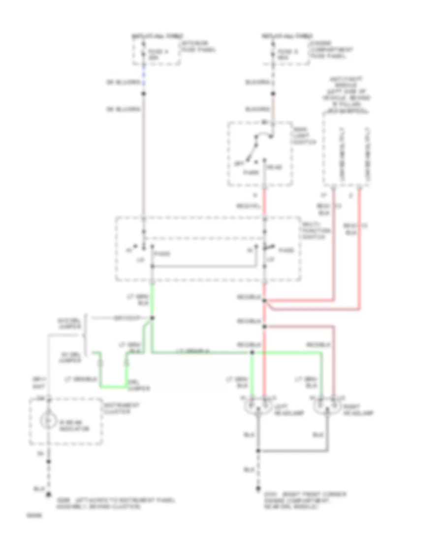
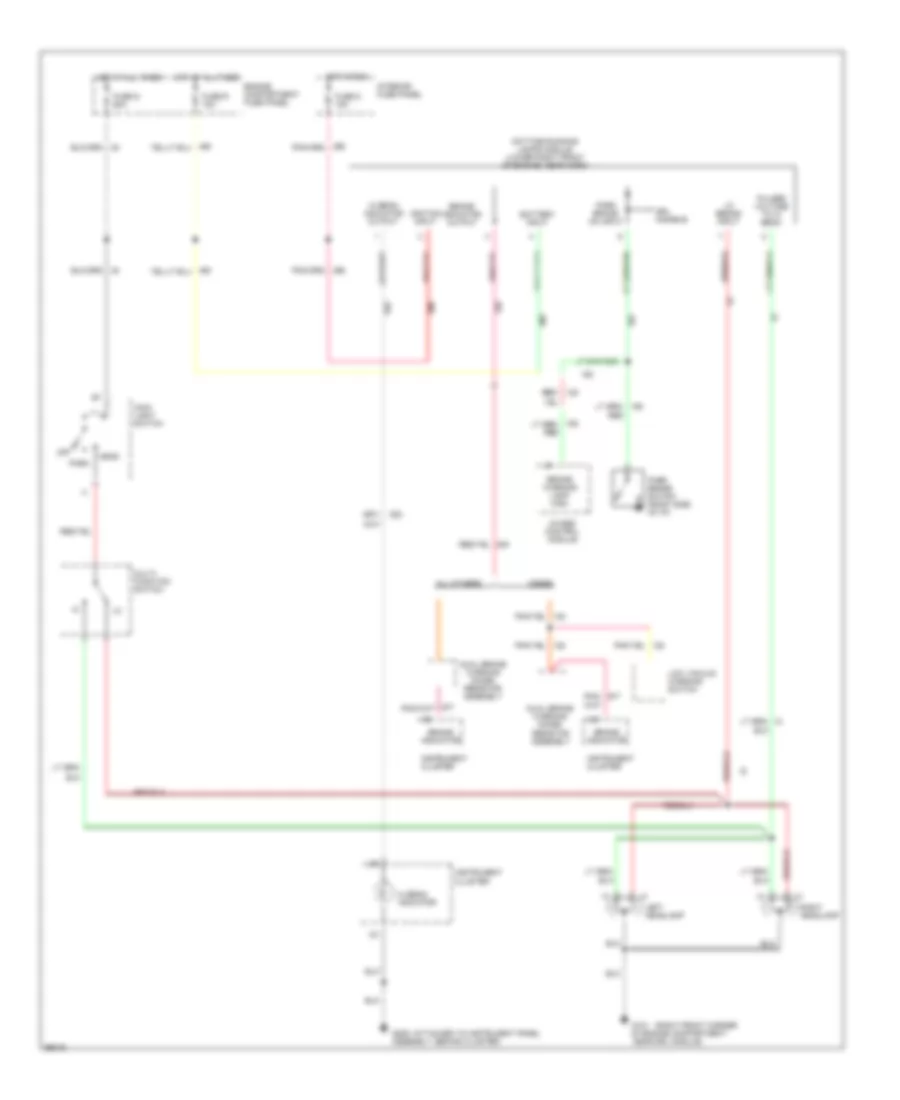
HEADLIGHTS Headlamps Wiring Diagram for Ford Club Wagon E150 1994 List of elements for Headlamps Wiring Diagram for Ford Club Wagon E150 1994: 25 (attached to instrument panel g206 Anti-theft module (left side of vehicle, behind 'b' pillar) (if equipped) Assembly, behind cluster) Drl Engine compartment fuse panel Engine compartment, near drl module) Fuse 4 20a Fuse s 60a G101 (right front corner Head Hi beam indicator Hot at all times Instrument cluster Interior fuse panel Jumper Left headlamp Low beam output Main light switch Multi- function switch Off Park Pass Right headlamp W/ drl jumper W/o drl jumper Headlamps Wiring Diagram, with DRL for Ford Club Wagon E150 1994 List of elements for Headlamps Wiring Diagram, with DRL for Ford Club Wagon E150 1994: 39 (attached to instrument panel g206 (right front corner g101 4wabs control module All others Assembly, behind cluster) Battery input Brake indicator Brake indicator output Brake warning lamp high Daytime running lamps module (lower right front of engine, near horn) Diesel Drl disable Dual brake warning diode/ resistor assembly Engine compartment fuse panel Fuse 5 15a Fuse r 15a Fuse s 60a Head Hi beam indicator Hi beam indicator output Hot at all times Hot in run Ignition input Instrument cluster Interior fuse panel Left headlamp Lo beams input Low vacuum warning switch Main light switch Multi- function switch Of engine compartment, near drl module) Off Park Park brake on input Park brake switch (right side of i/p) Pulsed voltage to hi beam Red Red/ Right headlamp
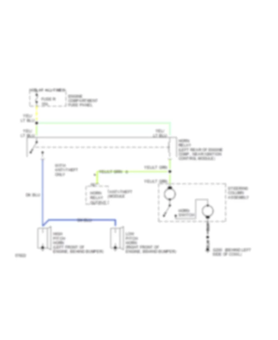
HORN Horn Wiring Diagram for Ford Club Wagon E150 1994 List of elements for Horn Wiring Diagram for Ford Club Wagon E150 1994: 15 (behind left 15a Anti-theft module Engine compartment fuse panel Fuse r G200 side of cowl) High pitch horn (left front of engine, behind bumper) Horn relay Horn relay (left rear of engine comp., near ignition control module) Horn switch Hot at all times Low pitch horn (right front of engine, behind bumper) Output Steering column assembly With anti-theft only
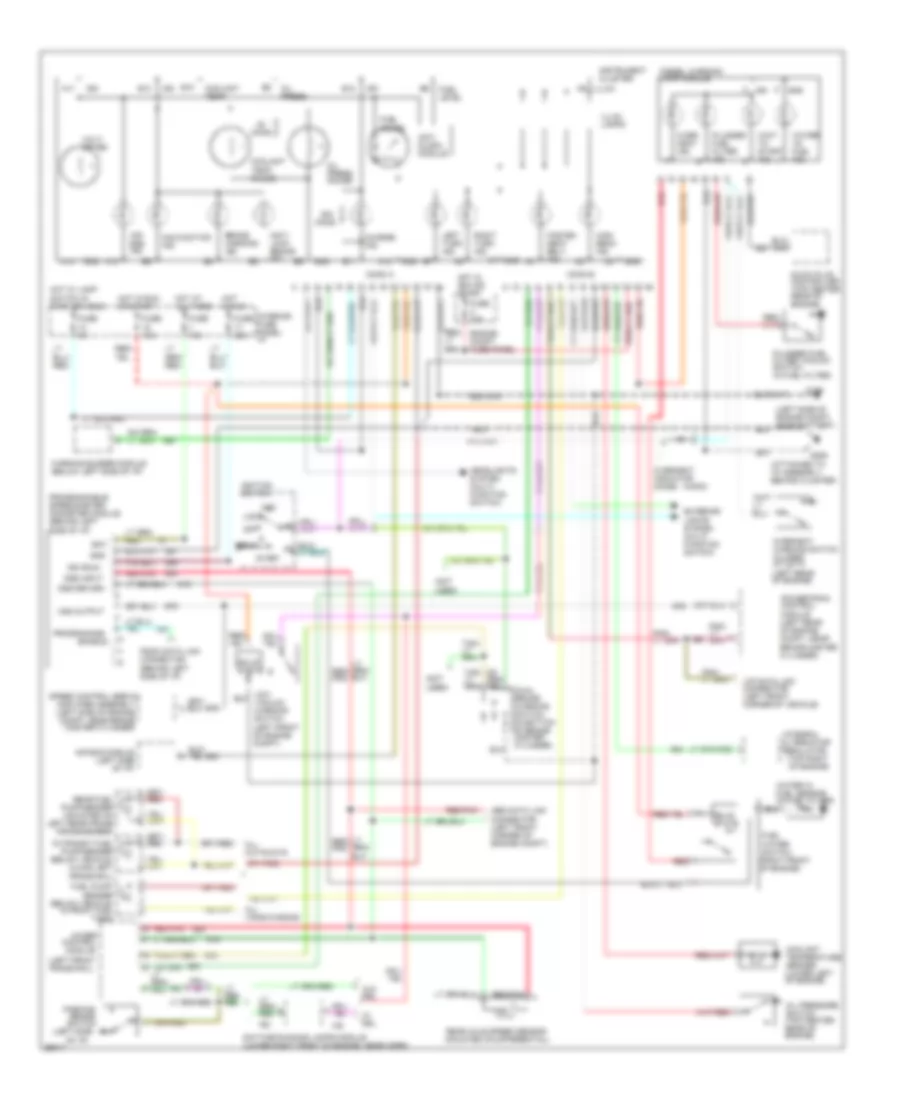
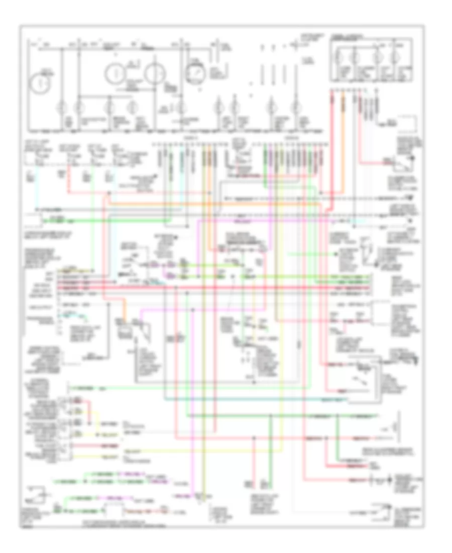
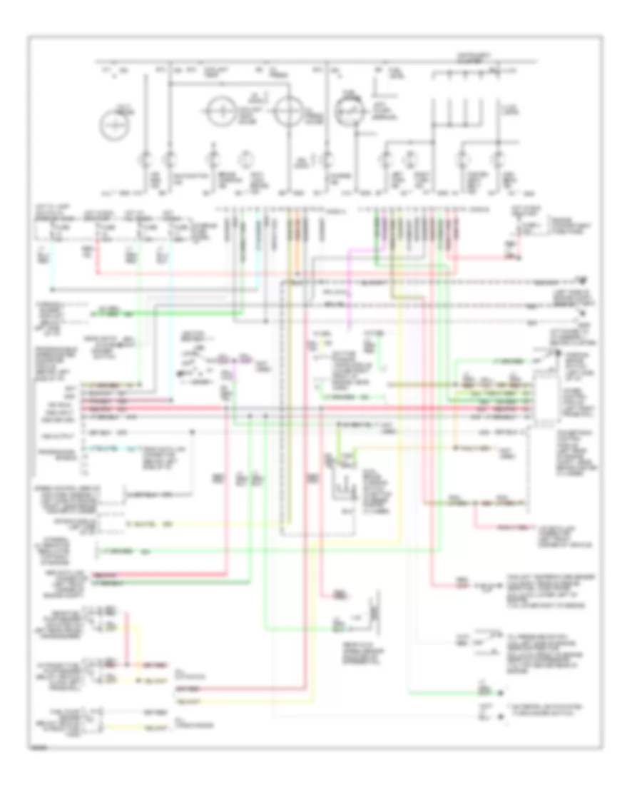
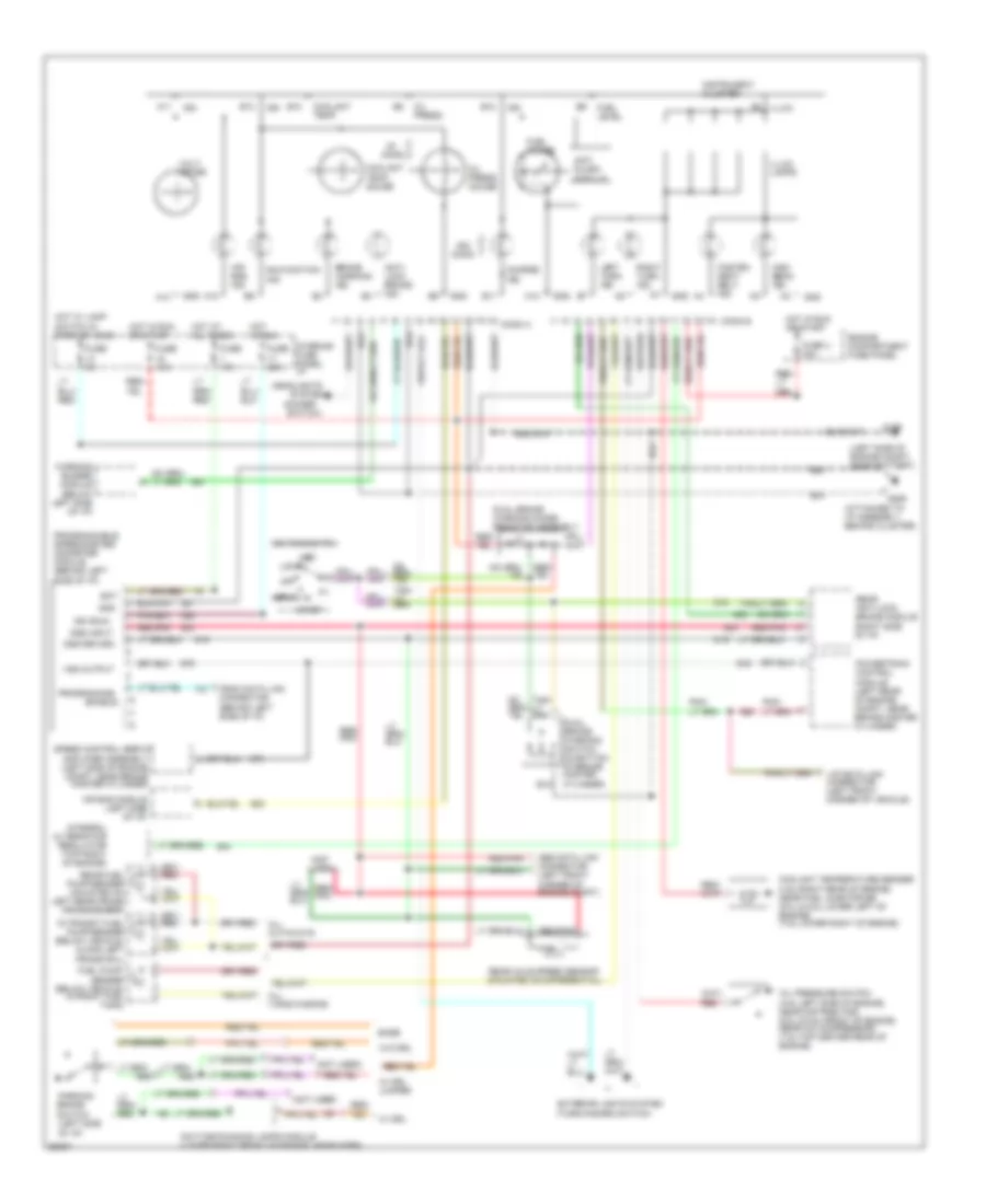
INSTRUMENT CLUSTER Gas Engine Wiring Diagram, with 4 Wheel ABS for Ford Club Wagon E150 1994 List of elements for Gas Engine Wiring Diagram, with 4 Wheel ABS for Ford Club Wagon E150 1994: 98 (attached to i/p assembly, behind cluster) (below left side of i/p) (dimmer (left front (left front frame rail) (left side of engine compt, near battery) (not used) 1.4k 4wabs control module A10 A11 A12 A14 Abs data link Acc Air bag ind. Air bag module (left side of i/p) All cutaways All vans/wagons Anti slosh module Anti- lock brake ind. B10 B11 B12 B13 Bat Brake warning ind. Charge ind. Conn a Conn b Connector Coolant temp. Coolant temp. gauge Coolant temperature sender (4.9l-right rear of engine, near fuel injector #6) (5.0l & 5.8l-lower left of engine) (7.5l-lower right of engine) Corner of Daytime running lamps module (lower right front of engine, near horn) Dss input Dss return Dual brake warning switch (in bottom of brake master cylinder) Enable Engine compartment fuse panel Engine compt) Exterior lights system (turn/hazard switch) Fasten seat belt ind. Fuel gauge Fuel level Fuel pump/ sender (below vehicle, in front fuel tank) Fuse 15a Fuse 20a Fuse 5a Fuse u 30a G106 G206 Gnd Headlights High beam ind. Hot at all times Hot in run Hot in run or start Hot w/ lamp switch in park or head Ign Ign (run) Ignition switch Illum. Illum. lamps In-transit fuel pump/sender (below vehicle, along left frame rail) Instrument cluster Integral alternator regulator (top right of engine) Interior fuse panel: i/p Left turn ind. Lock Malfunction ind. Off Ohms Oil press. Oil press. gauge Oil pressure switch (4.9l-left side of engine, near distributor) (5.0l & 5.8l-front of engine, near a/c compressor) (7.5l-top center rear of engine) Parking brake switch (left side of i/p) Powertrain control module (left rear of engine compt, near brake master cylinder) Programmable speedometer/ odometer module (behind left side of i/p) Programming Psom data link connector (behind left side of i/p) Rear axle speed sensor (mounted on differential) Rear fuel pump/sender (mounted on left rear frame crossmember) Red/ pnk Red/pnk Right turn ind. Run Speed control servo/ amplifier assembly (left side of engine compt, near brake master cylinder) Start Switch) System Vip data link connector (left front corner of vehicle) Volt- meter Vss output W/ drl W/o drl Warning buzzer module Gas Engine Wiring Diagram, with Rear Wheel ABS for Ford Club Wagon E150 1994 List of elements for Gas Engine Wiring Diagram, with Rear Wheel ABS for Ford Club Wagon E150 1994: 99 (attached to i/p assembly, behind cluster) (below left side of i/p) (dimmer (left side of engine compt, near battery) (not used) (right side of i/p) 1.4k A10 A11 A12 A14 Abs data link connector (left front corner of engine compt) Acc Air bag ind. Air bag module (left side of i/p) All cutaways All vans/wagons Amplifier assembly (left side of engine compt, near brake master cylinder) Anti slosh module Anti- lock brake ind. B10 B11 B12 B13 Base Bat Brake warning ind. Charge ind. Conn a Conn b Coolant temp. Coolant temp. gauge Coolant temperature sender (4.9l-right rear of engine, near fuel injector #6) (5.0l & 5.8l-lower left of engine) (7.5l-lower right of engine) Daytime running lamps module (lower right front of engine, near horn) Dss input Dss return Dual brake warning diode/ resistor assembly Dual brake warning switch (in bottom of brake master cylinder) Enable Engine compartment fuse panel Exterior lights system (turn/hazard switch) Fasten seat belt ind. Fuel gauge Fuel level Fuel pump/ sender (below vehicle, in front fuel tank) Fuse 15a Fuse 20a Fuse 5a Fuse u 30a G106 G206 Gnd Headlights High beam ind. Hot at all times Hot in run Hot in run or start Hot w/ lamp switch in park or head Ign Ign (run) Ignition switch Illum. Illum. lamps In-transit fuel pump/sender (below vehicle, along left frame rail) Instrument cluster Integral alternator regulator (top right of engine) Interior fuse panel: i/p Left turn ind. Lock Malfunction ind. Off Ohms Oil press. Oil press. gauge Oil pressure switch (4.9l-left side of engine, near distributor) (5.0l & 5.8l-front of engine, near a/c compressor) (7.5l-top center rear of engine) Parking brake switch (left side of i/p) Powertrain control module (left rear of engine compt, near brake master cylinder) Programmable speedometer/ odometer module (behind left side of i/p) Programming Psom data link connector (behind left side of i/p) Rear anti-lock brake module Rear axle speed sensor (mounted on differential) Rear fuel pump/sender (mounted on left rear frame crossmember) Red Red/ pnk Red/pnk Right turn ind. Run Speed control servo/ Start Switch) System Vip data link connector (left front corner of vehicle) Volt- meter Vss output W/ drl W/ drl jumper W/o drl Warning buzzer module
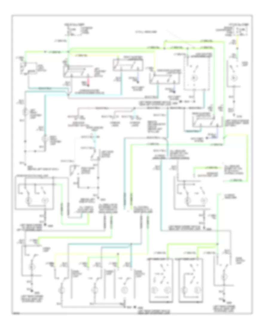
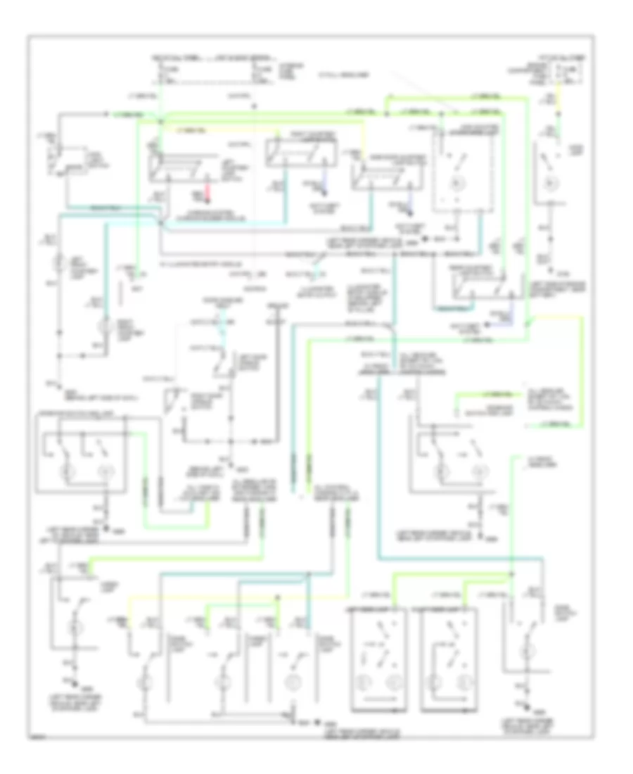
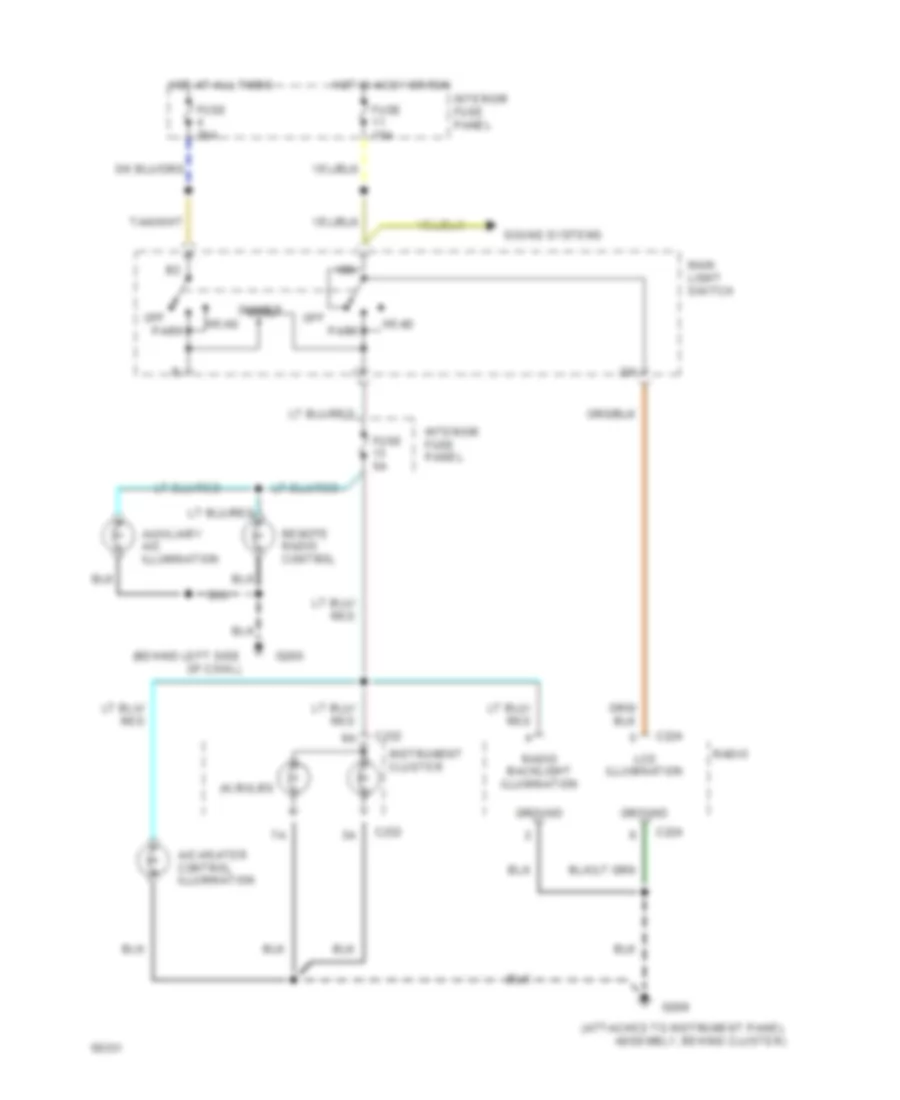
INTERIOR LIGHTS Courtesy Lamp Wiring Diagram, with Keyless Entry for Ford Club Wagon E150 1994 List of elements for Courtesy Lamp Wiring Diagram, with Keyless Entry for Ford Club Wagon E150 1994: 43 (behind left side of cowl) (left rear corner of vehicle, near left stop/park lamp) (left rear corner vehicle, near left stop/park lamp) (left side of engine compartment, near battery) All chateau wagons w/ p.i.a. rear headliner All regular or extended vans, and wagons w/ rear headliner All vans w/ auxiliary air w/o headliner All vehicles except rv van, rv cutaway, chateau wagon Anti-theft system Cargo lamp Dome Dome switch/ lamp Dome/map switch and lamp Door handles input Engine compartment fuse panel Fuse 15a Fuse r 15a G106 G200 G200 (behind left side of cowl) G999 High mounted stop/cargo lamp Hood lamp Hot at all times Interior fuse panel Interior lamps Left courtesy lamp switch Left door handle switch Left front courtesy lamp Left visor lamp Main light switch Rear courtesy lamp switch Red/ pnk Remote keyless entry module (behind left "b" pillar) Right courtesy lamp switch Right door handle switch Right front courtesy lamp Right visor lamp Side door courtesy lamp switch Side door courtesy switch W/ front headliner W/ full headliner Warning system (warning buzzer module) Courtesy Lamp Wiring Diagram, without Keyless Entry for Ford Club Wagon E150 1994 List of elements for Courtesy Lamp Wiring Diagram, without Keyless Entry for Ford Club Wagon E150 1994: 48 (behind left side of cowl) (left rear corner of vehicle, near left stop/park lamp) (left rear corner vehicle, near left stop/park lamp) (left side of engine compartment, near battery) Acc/run All chateau wagons w/ p.i.a. rear headliner All regular or extended vans, and wagons w/ rear headliner All vans w/ auxiliary air w/o headliner All vehicles except rv van, rv cutaway, chateau wagon Anti-theft system Bat Cargo lamp Dome Dome switch/ lamp Dome/map switch and lamp Door handles input Engine compartment fuse panel Fuse 15a Fuse 20a Fuse r 15a G106 G200 G200 (behind left side of cowl) G999 Ground High mounted stop/cargo lamp Hood lamp Hot at all times Hot in accy or run Illuminated entry module (if equipped) (behind left "b" pillar) Illuminated entry output Interior fuse panel Left courtesy lamp switch Left door handle switch Left front courtesy lamp Left visor lamp Main light switch Rear courtesy lamp switch Red/ pnk Right courtesy lamp switch Right door handle switch Right front courtesy lamp Right visor lamp Side door courtesy lamp switch W/ front headliner W/ full headliner W/ illuminated entry module Warning system (warning buzzer module) Instrument Illumination Wiring Diagram for Ford Club Wagon E150 1994 List of elements for Instrument Illumination Wiring Diagram for Ford Club Wagon E150 1994: 28 (4) bulbs (attached to instrument panel assembly, behind cluster) (behind left side of cowl) A/c-heater control illumination Auxiliary a/c illumination C224 C232 Dimmer Fuse 15a Fuse 20a Fuse 5a G200 G206 Ground Head Hot at all times Hot in accy or run Ign Instrument cluster Interior fuse panel Lcd illumination Main light switch Off Park Radio Radio backlight illumination Remote radio control Sound systems
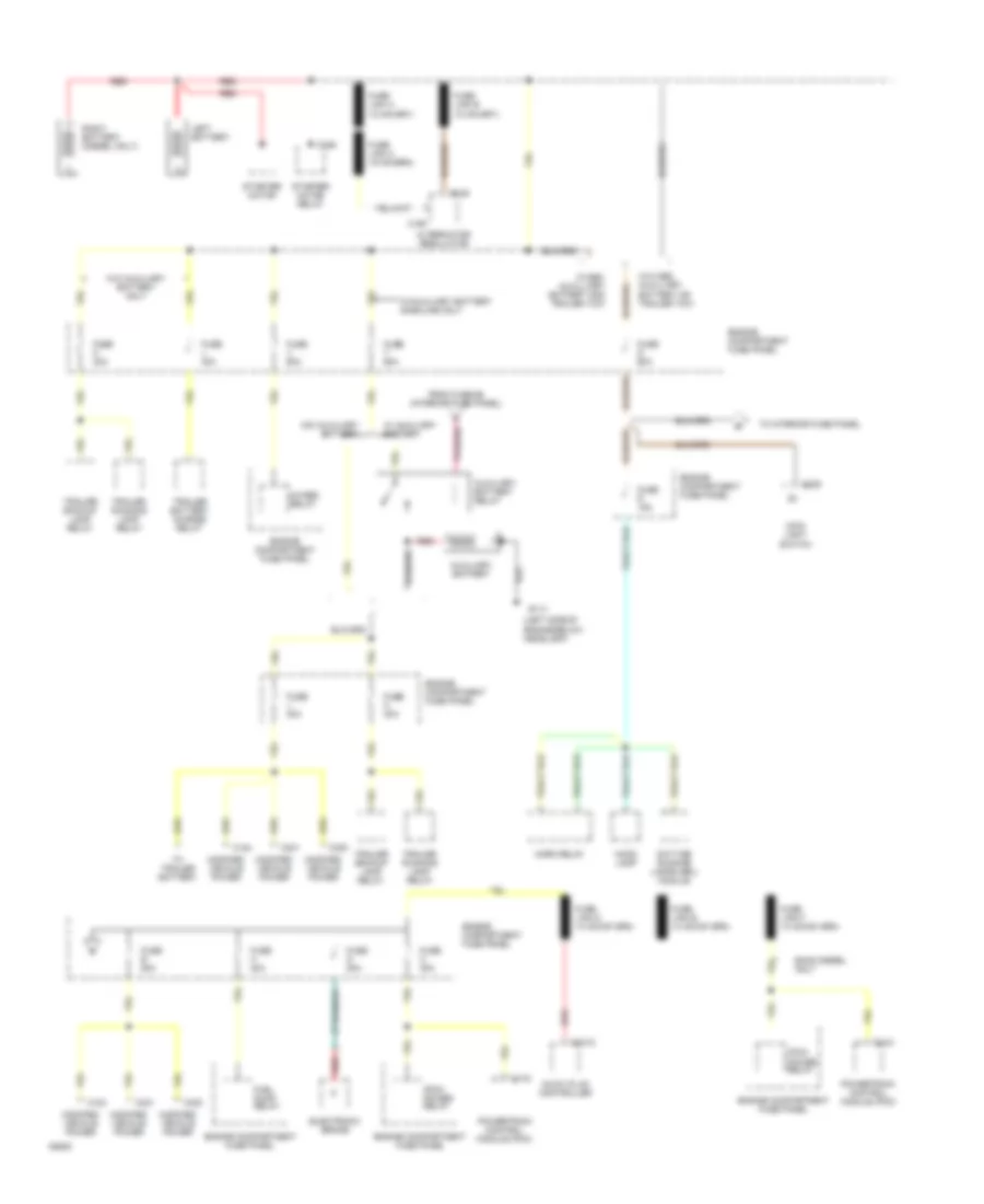
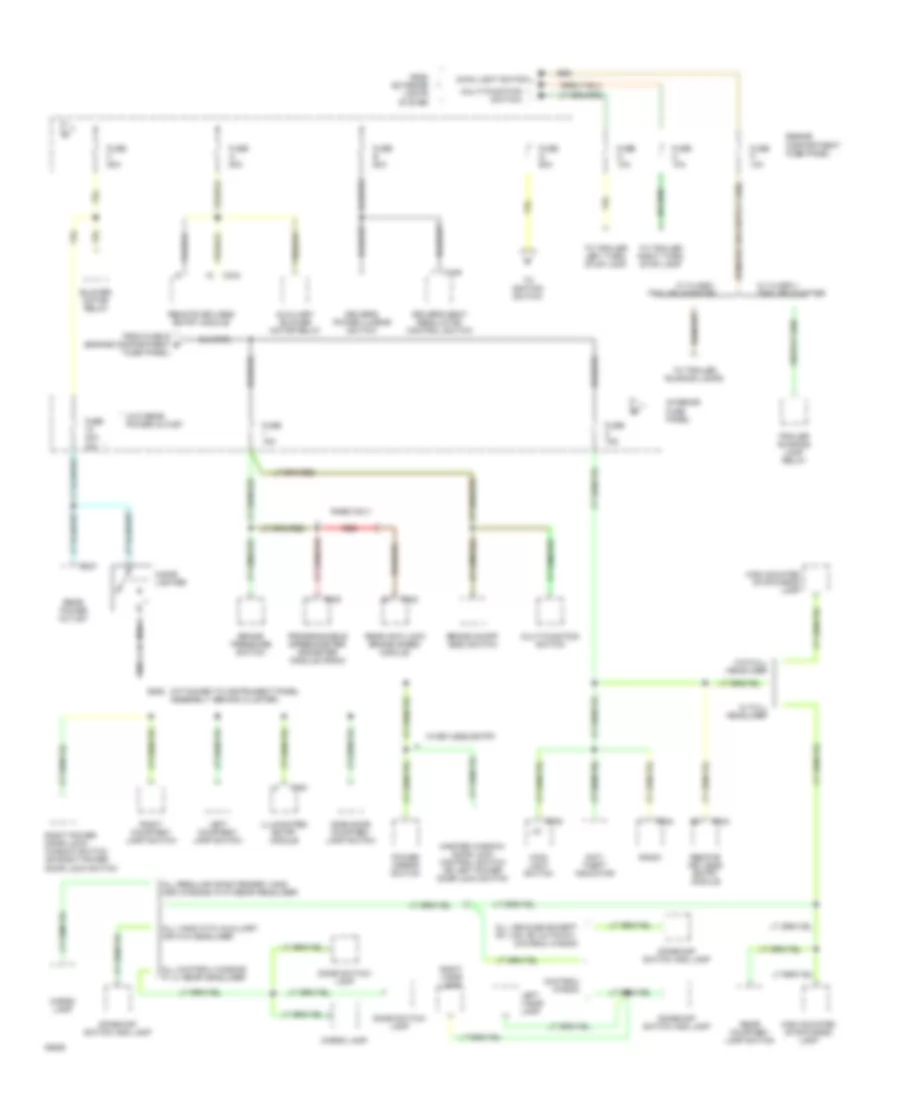
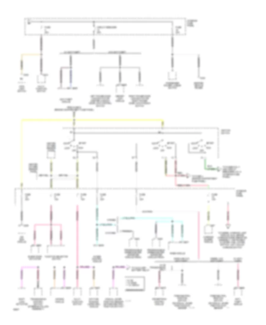
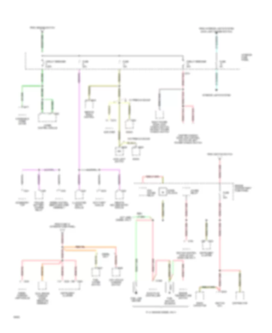
POWER DISTRIBUTION Power Distribution Wiring Diagram (1 of 4) for Ford Club Wagon E150 1994 List of elements for Power Distribution Wiring Diagram (1 of 4) for Ford Club Wagon E150 1994: 55 (left side of engine below headlamp) (pcm) power relay 4wabs relay Alternator/ regulator Auxiliary battery Auxiliary battery relay C1010 C143 C175 C184 C186 C188 C190 C231 C235 C330 Daytime running lamps (drl) module E4od diesel only Electronic brake Engine compartment fuse panel From fuse #5 (interior fuse panel) Fuel pump relay Fuse b 50a Fuse c 30a Fuse d 20a Fuse h 30a Fuse j 40a Fuse k 30a Fuse r 15a Fuse s 60a Fuse t 60a Fuse v 60a G110 Glow plug controller Hood lamp Horn relay Left battery Main light switch Modified vehicle power Powertrain control module (pcm) Red Right battery (diesel only) Starter motor Starter motor relay To interior fuse panel To trailer battery Trailer backup lamp relay Trailer battery charge relay Trailer running lamp relay W/ auxiliary battery W/abs, auxilliary battery and trailer tow W/auxiliary battery gasoline only W/o abs, auxillary battery or trailer tow W/o auxiliary battery W/o auxiliary battery only Power Distribution Wiring Diagram (2 of 4) for Ford Club Wagon E150 1994 List of elements for Power Distribution Wiring Diagram (2 of 4) for Ford Club Wagon E150 1994: 73 (attached to instrument panel assembly, behind cluster) (main light switch) (multi-function switch) * (w/o rear power outlet All chateau wagons p.i.a. rear headliner All regular or extended vans and wagons with rear headliner All vans with auxiliary air w/o headliner All vehicles except rv van, rv cutaway, chateau wagon Anti- theft indicator Auxiliary blower motor relay Blower motor relay Brake on/off (boo) switch Brake pressure switch C223 C224 C230 C235 C333 C334 C337 C340 C349 Cargo lamp Chateau wagon Cigar lighter Dome switch/ lamp Dome/map switch and lamp Driver's power lumbar switch Driver's seat regulator control switch Engine compartment fuse panel From exterior lights system From fuse s (engine compartment fuse panel) Fuse 15a Fuse 20a 15a Fuse a 50a Fuse e 50a Fuse f 50a Fuse g 60a Fuse m 10a Fuse n 10a Fuse p 10a G206 High mounted stop/cargo lamp Illuminated entry module Interior fuse panel Left courtesy lamp switch Left visor lamp Main light switch Master window/ door lock control switch or left power door lock switch Multi-function switch Power mirror switch Programmable speedometer/ odometer module (psom) Rabs only Radio Rear anti-lock brake (rabs) module Rear courtesy lamp switch Rear power outlet Red Remote keyless entry module Right courtesy lamp switch Right power door lock/ window switch or right power door lock switch Right visor lamp Side door courtesy lamp switch To ignition switch To trailer left turn/ stop lamp To trailer right turn/ stop lamp To trailer running lamps Trailer running lamp relay W/ class i trailer adapter W/ class ii trailer adapter W/ full headliner W/keyless entry W/o full headliner Power Distribution Wiring Diagram (3 of 4) for Ford Club Wagon E150 1994 List of elements for Power Distribution Wiring Diagram (3 of 4) for Ford Club Wagon E150 1994: 67 * w/ c6 ** w/ e40d *** w/ 4r70w **, *** 4wabs control module Acc Air bag module Anti- theft module Anti-theft module Blend door actuator C151 C175 C199 C200 C207 C209 C218 C230 C231 C235 C330 C335 C336 C339 Circuit breaker 20a Daytime running lamps (drl) module Diesel w/o anti-theft From fuse g (engine compartment fuse panel) Function selector switch Fuse 15a Fuse 20a Fuse 30a Fuse panel) Gasoline w/o anti-theft Heated oxygen sensor (ho2s) Ignition switch Interior fuse panel Left power door lock switch or master window/ door lock control switch Lock Main light switch Manual lever position sensor or park/neutral position switch Memory lock module Modified vehicle power Multi- function switch Nca Off Park/neutral position switch or manual lever position (mlp) sensor Passenger power lumbar switch Powertrain control module Programmable speedometer/ odometer module (psom) Rabs module Red/ Right power door lock switch or right power door lock/window switch Run Shift lock actuator Start To auxiliary battery relay To diesel warning lamp module, dual brake warning diode/ resistor assembly, instrument cluster, fuel water switch, low vacuum warning switch To fuse u (engine compartment To fuses 6 & 11 and circuit breakers 2 & 14 (interior fuse panel) Transmission control switch (steering column assembly) Transmissions W/ anti- theft W/ anti-theft W/ c6 transmission only W/4wabs W/o anti-theft W/rabs Warning buzzer module Power Distribution Wiring Diagram (4 of 4) for Ford Club Wagon E150 1994 List of elements for Power Distribution Wiring Diagram (4 of 4) for Ford Club Wagon E150 1994: 74 (main light dimmer switch) 11a 12b 13b 4wabs relay Accessory tap Amplifier Anti-theft module C1009 C124 C137 C159 C164 C171 C180 C185 C213 C214 C222 C224 C232 C233 C235 C240 C241 C319 C333 C335 C340 Circuit breaker 20a Circuit breaker 8.25a Diesel only Diesel warning lamp module Diode (plug-in) Distributor Dual brake warning diode/ resistor assembly Engine compartment fuse panel Engine temperature switch From fuse 18 (interior fuse panel) From ignition switch From interior lights system Fuel line heater Fuel shutoff solenoid Fuel water switch Fuse 15a Fuse 20a Fuse 5a Fuse u 30a Glow plug controller Ign Ignition coil Ignition control module (icm) (gasoline only) Illuminated entry module Instrument cluster Interior fuse panel Interior lights system Low vacuum warning switch Main light switch Master window/ door lock control switch or left power window switch Not used (diesel only) P.i.a. engine (diesel only) Pcm power relay Radio Radio capacitor Red/ Remote keyless entry module Remote radio control Right power door lock/ window switch or right power window switch Speed control servo/amplifier assembly Trailer battery charge relay W/ premium sound W/o premium sound Windshield wiper motor Wiper control module
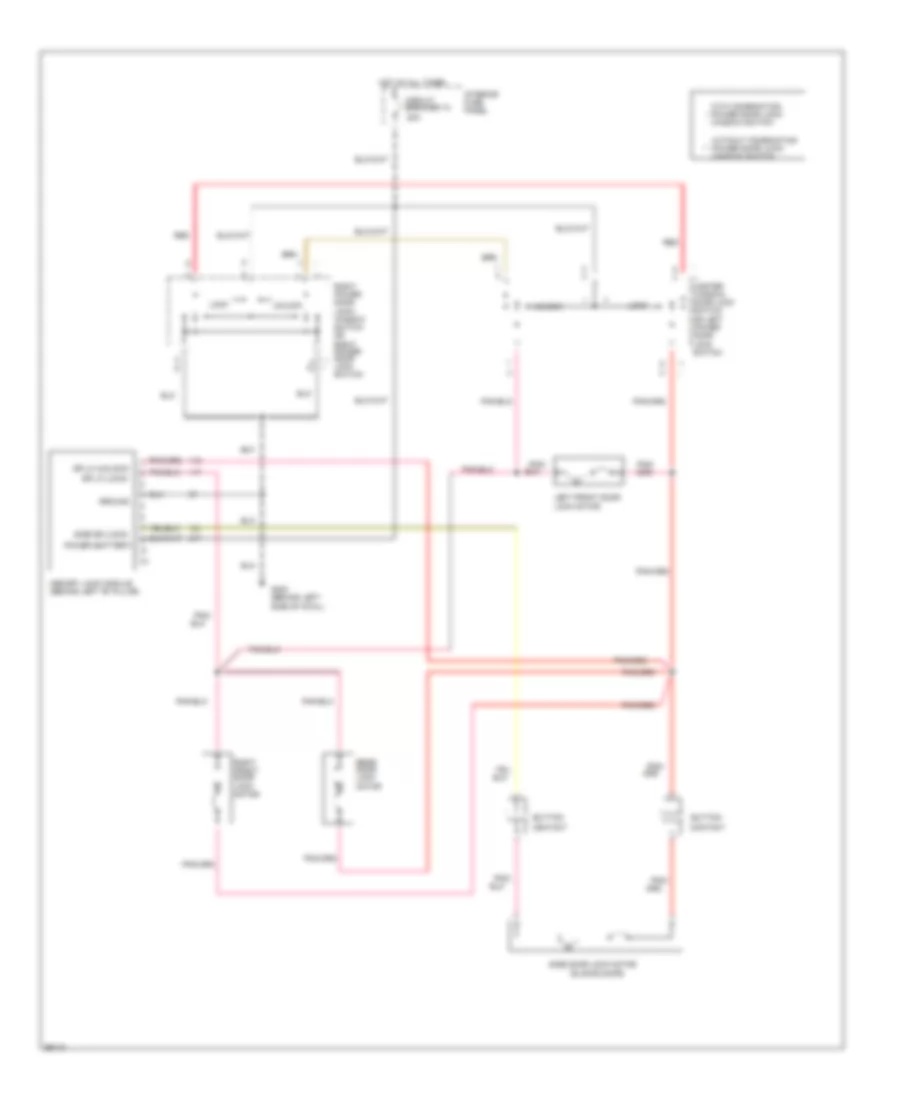
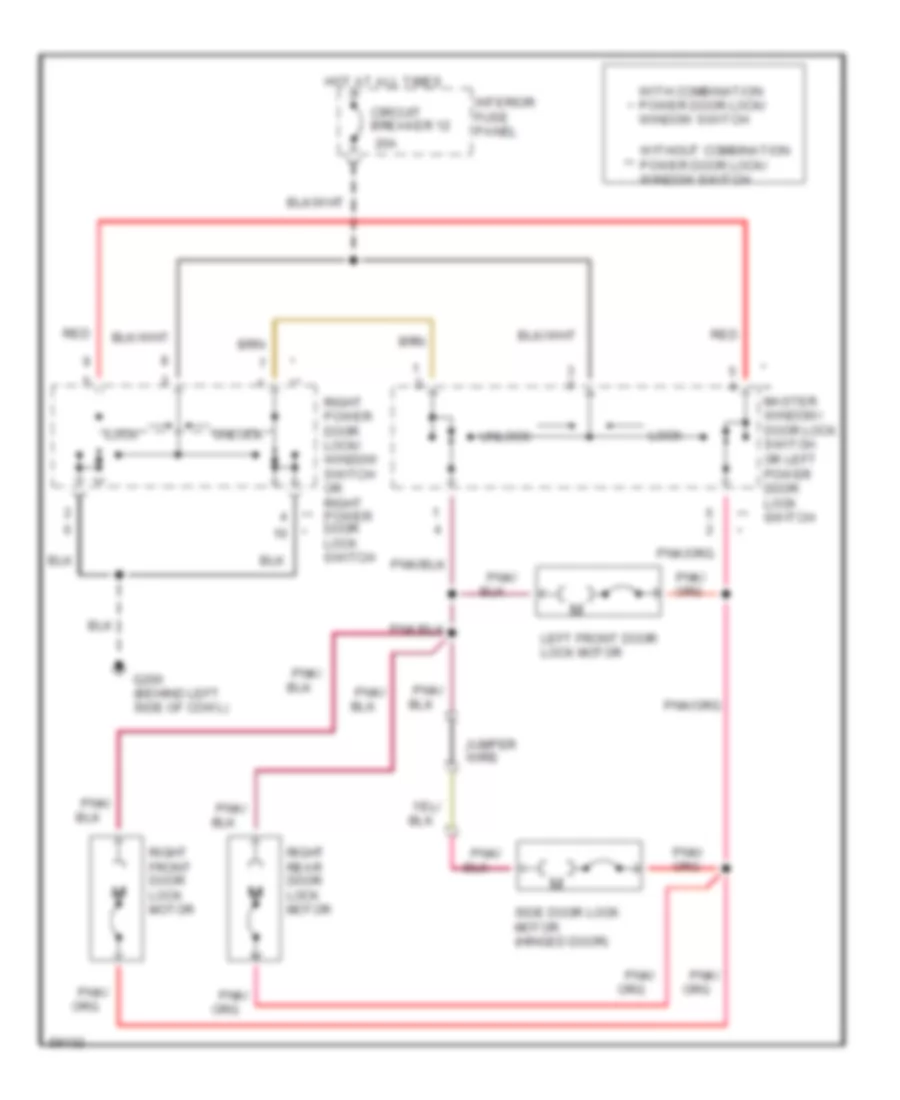
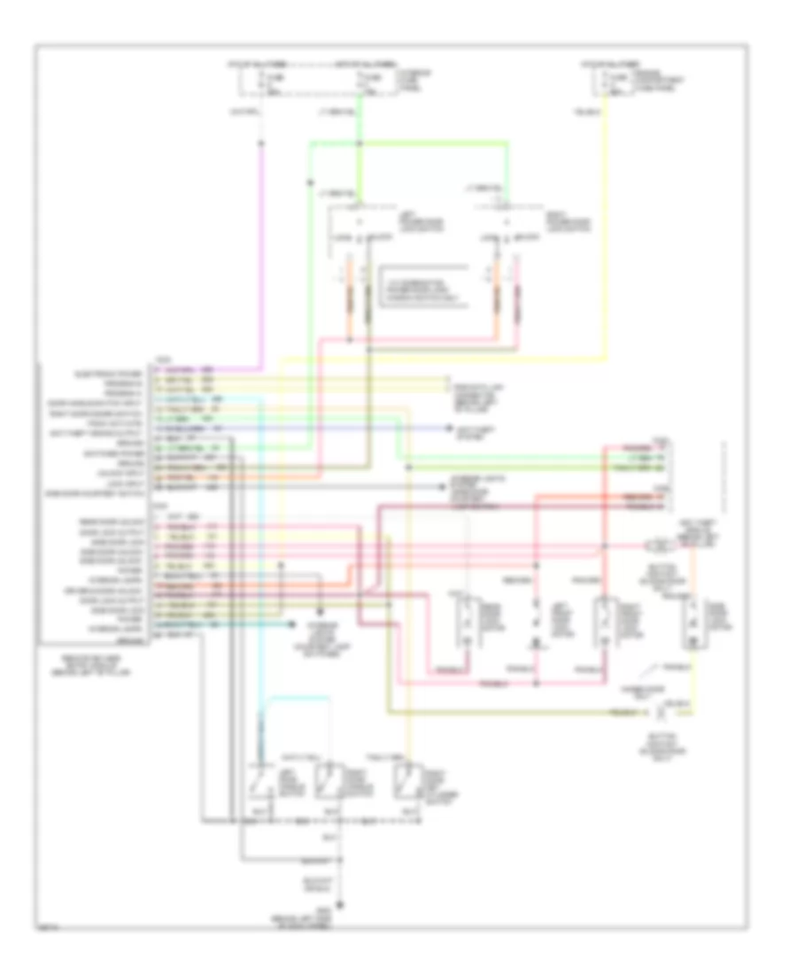
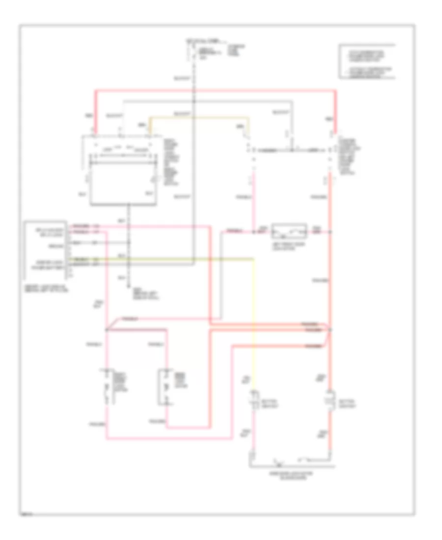
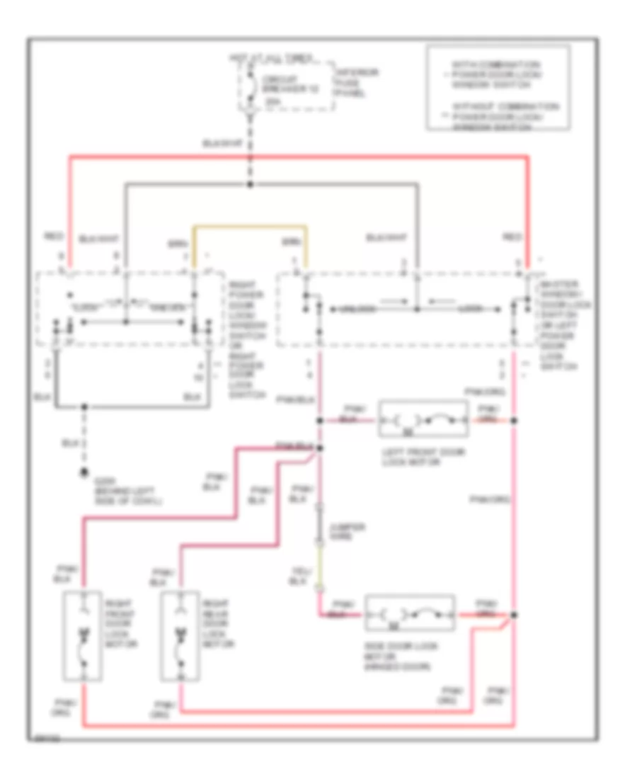
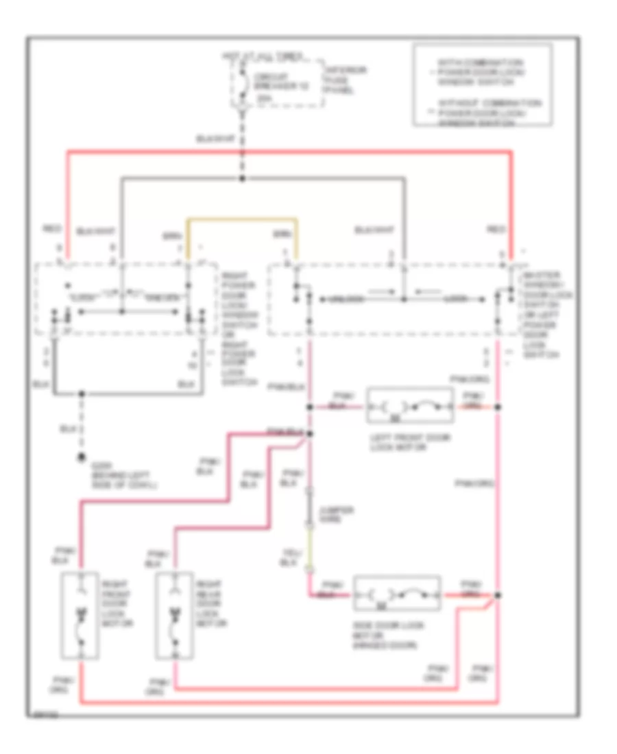
POWER DOOR LOCKS Door Lock Wiring Diagram, with Memory Lock for Ford Club Wagon E150 1994 List of elements for Door Lock Wiring Diagram, with Memory Lock for Ford Club Wagon E150 1994: 28 (sliding door) ** * ** master window/ door lock switch or left power door lock switch 20a Button Circuit breaker 12 Contact Dr lk (lock) Dr lk (unlock) G200 (behind left side of cowl) Ground Hot at all times Interior fuse panel Left front door Lock Lock motor Memory lock module (behind left "b" pillar) Pnk/ Power (battery) Rear door lock motor Red Right front door lock motor Right power door lock/ window switch or right power door lock switch Side door lock motor Side dr (lock) Unlock With combination power door lock/ * window switch Without combination ** power door lock/ window switch Door Lock Wiring Diagram, without Memory Lock for Ford Club Wagon E150 1994 List of elements for Door Lock Wiring Diagram, without Memory Lock for Ford Club Wagon E150 1994: 18 ** master window/ door lock switch or left power door lock switch 20a Circuit breaker 12 G200 (behind left side of cowl) Hot at all times Interior fuse panel Jumper wire Left front door lock motor Lock Pnk/ Red Right front door lock motor Right power door lock/ window switch or right power door lock switch Right rear door lock motor Side door lock motor (hinged door) Unlock With combination power door lock/ * window switch Without combination ** power door lock/ window switch Keyless Entry Wiring Diagram for Ford Club Wagon E150 1994 List of elements for Keyless Entry Wiring Diagram for Ford Club Wagon E150 1994: 53 (side door courtesy * w/ combination power door lock/ window switch only Anti theft module (behind left "b" pillar) Anti-theft arming output Anti-theft system Button contact (sliding door only) C333 C334 C335 C336 Door handle switch input Door lock output Driver,s door unlock Electronic power Engine compartment fuse panel Fuse 15a Fuse 20a Fuse a 50a G200 (behind left side of cowl panel) Ground Hinged door only Hot at all times Interior fuse panel Interior lamps Interior lights Interior lights system (courtesy lamp switches) Lamp switch) Left door handle switch Left front door lock motor Left power door lock switch Lock Lock input Panic activate Power Program a Program b Rear door lock motor Rear door unlock Remote keyless entry module (behind left "b" pillar) Right door disarm switch Right door handle switch Right door key cylinder switch Right front door lock motor Right power door lock switch Rke data link connector (behind left "b" pillar) Side door courtesy switch Side door lock Side door lock motor Side door unlock Switched power System Unlock Unlock input Power Door Locks Wiring Diagram, with Memory Lock for Ford Club Wagon E150 1994 List of elements for Power Door Locks Wiring Diagram, with Memory Lock for Ford Club Wagon E150 1994: 28 (sliding door) ** * ** master window/ door lock switch or left power door lock switch 20a Button Circuit breaker 12 Contact Dr lk (lock) Dr lk (unlock) G200 (behind left side of cowl) Ground Hot at all times Interior fuse panel Left front door Lock Lock motor Memory lock module (behind left "b" pillar) Pnk/ Power (battery) Rear door lock motor Red Right front door lock motor Right power door lock/ window switch or right power door lock switch Side door lock motor Side dr (lock) Unlock With combination power door lock/ * window switch Without combination ** power door lock/ window switch Power Door Locks Wiring Diagram, without Keyless Entry for Ford Club Wagon E150 1994 List of elements for Power Door Locks Wiring Diagram, without Keyless Entry for Ford Club Wagon E150 1994: 18 ** master window/ door lock switch or left power door lock switch 20a Circuit breaker 12 G200 (behind left side of cowl) Hot at all times Interior fuse panel Jumper wire Left front door lock motor Lock Pnk/ Red Right front door lock motor Right power door lock/ window switch or right power door lock switch Right rear door lock motor Side door lock motor (hinged door) Unlock With combination power door lock/ * window switch Without combination ** power door lock/ window switch Power Door Locks Wiring Diagram, without Memory Lock for Ford Club Wagon E150 1994 List of elements for Power Door Locks Wiring Diagram, without Memory Lock for Ford Club Wagon E150 1994: 18 ** master window/ door lock switch or left power door lock switch 20a Circuit breaker 12 G200 (behind left side of cowl) Hot at all times Interior fuse panel Jumper wire Left front door lock motor Lock Pnk/ Red Right front door lock motor Right power door lock/ window switch or right power door lock switch Right rear door lock motor Side door lock motor (hinged door) Unlock With combination power door lock/ * window switch Without combination ** power door lock/ window switch
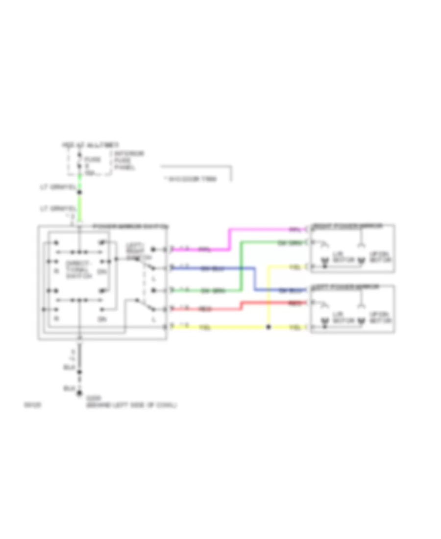
POWER MIRRORS Power Mirror Wiring Diagram for Ford Club Wagon E150 1994 List of elements for Power Mirror Wiring Diagram for Ford Club Wagon E150 1994: 13 * w/o door trim Direct- tional switch Fuse 15a G200 (behind left side of cowl) Hot at all times Interior fuse panel L/r motor Left power mirror Left/ right switch Power mirror switch Red Right power mirror Up/dn motor
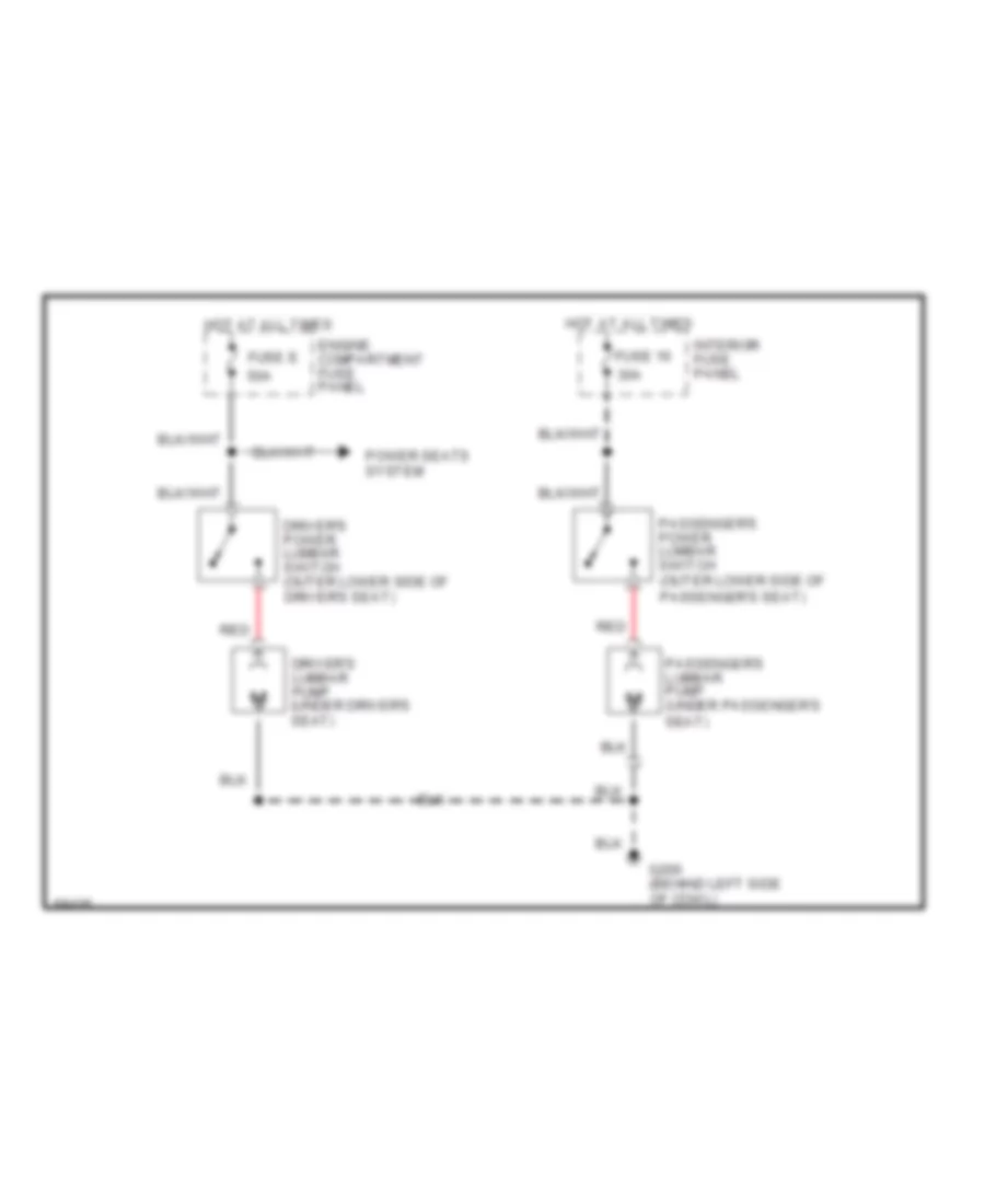
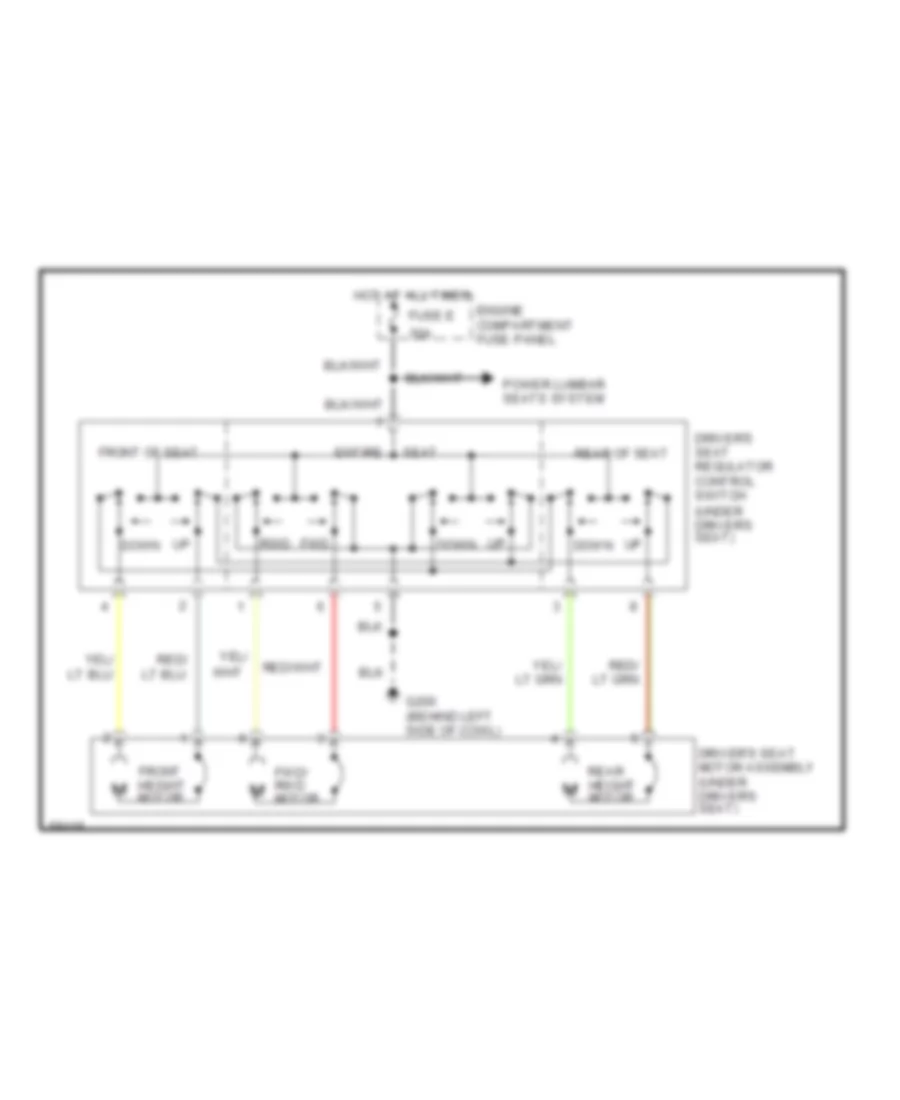
POWER SEATS Lumbar Wiring Diagram for Ford Club Wagon E150 1994 List of elements for Lumbar Wiring Diagram for Ford Club Wagon E150 1994: 14 30a 50a Driver's lumbar pump (under driver's seat) Driver's power lumbar switch (outer lower side of driver's seat) Engine compartment fuse panel Fuse 16 Fuse e G200 (behind left side of cowl) Hot at all times Interior fuse panel Passenger's lumbar pump (under passenger's seat) Passenger's power lumbar switch (outer lower side of passenger's seat) Power seats system Red Power Seat Wiring Diagram for Ford Club Wagon E150 1994 List of elements for Power Seat Wiring Diagram for Ford Club Wagon E150 1994: 17 (under driver's seat) Driver's seat motor assembly (under driver's seat) Driver's seat regulator control switch Engine compartment fuse panel Entire Front height motor Front of seat Fuse e 50a Fwd rwd Fwd/ rwd motor G200 (behind left side of cowl) Hot at all times Power lumbar seats system Rear height motor Rear of seat Seat Up down
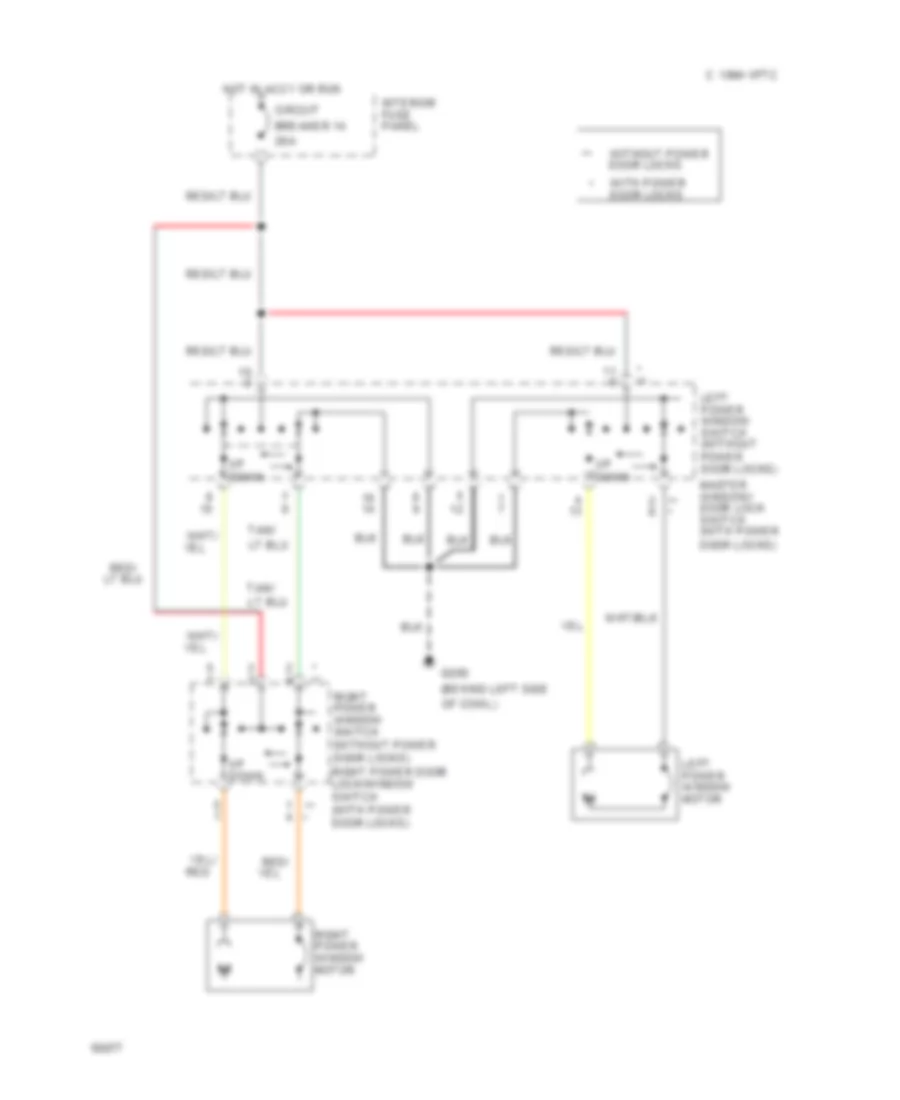
POWER WINDOWS Power Window Wiring Diagram for Ford Club Wagon E150 1994 List of elements for Power Window Wiring Diagram for Ford Club Wagon E150 1994: 21 (behind left side * ** ** * 1994 vftc c 20a Breaker 14 Circuit G200 Hot in accy or run Interior fuse panel Left power window motor Left power window switch (without power door locks) Master window/ door lock switch (with power door locks) Of cowl) Red/ Right power window motor Right power window switch (without power door locks) right power door lock/window switch (with power door locks) Tan/ Up down With power door locks Without power door locks
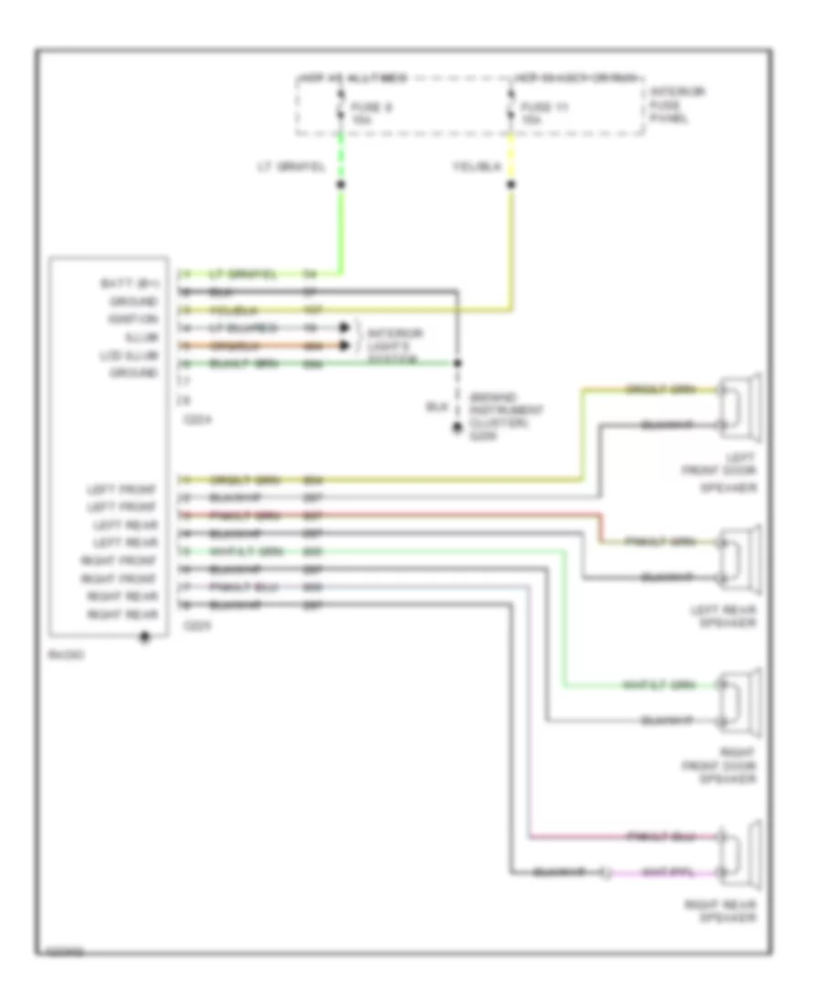
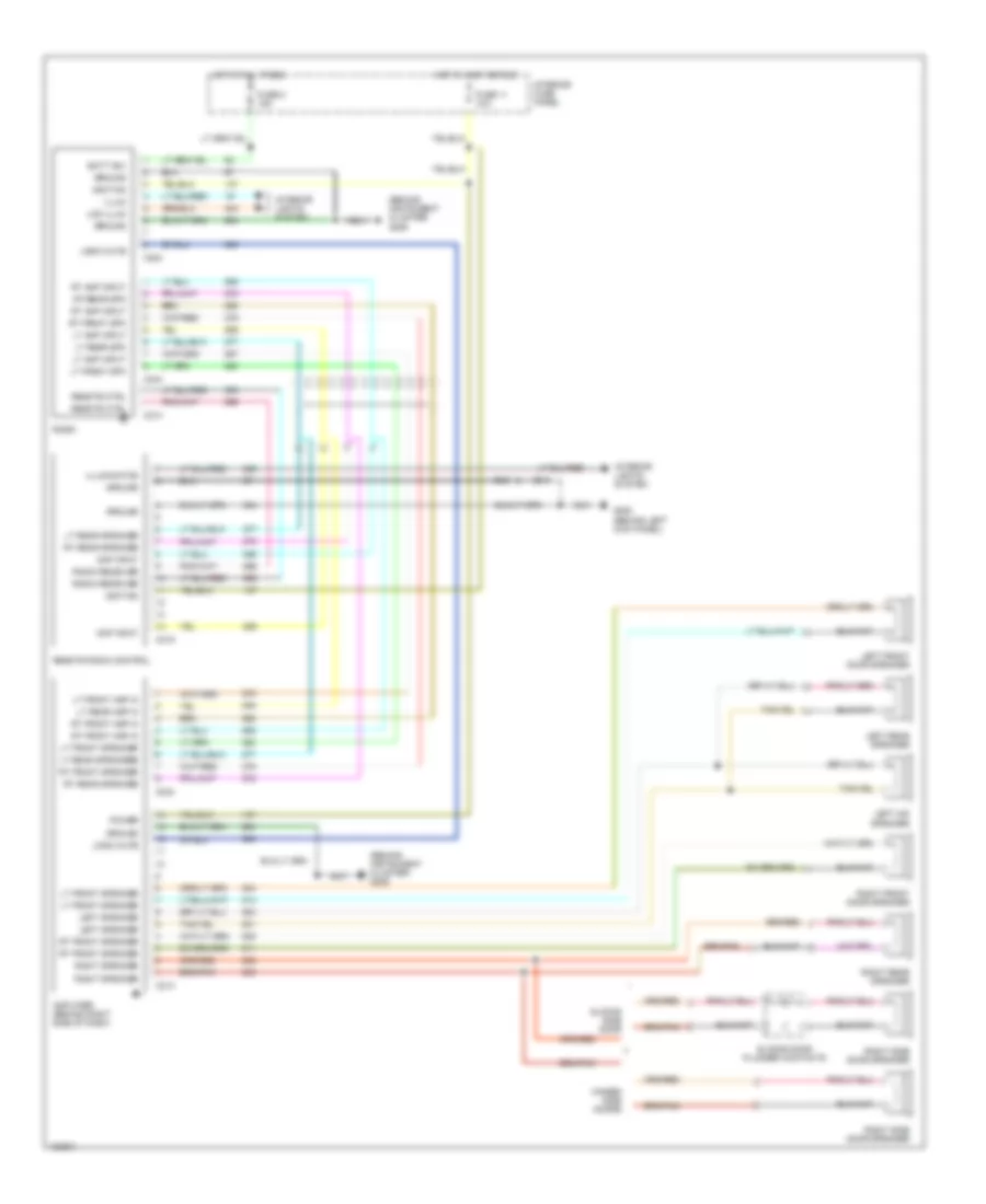
RADIO Base Radio for Ford Club Wagon E150 1994 List of elements for Base Radio for Ford Club Wagon E150 1994: 24 (benind instrument cluster) g206 Batt (b+) C224 C225 Fuse 11 15a Fuse 8 15a Ground Hot at all times Hot in accy or run Ignition Illum Interior fuse panel Interior lights system Lcd illum Left front Left front door Left rear Left rear speaker Radio Right front Right front door speaker Right rear Right rear speaker Speaker Premium Sound Radio Wiring Diagram for Ford Club Wagon E150 1994 List of elements for Premium Sound Radio Wiring Diagram for Ford Club Wagon E150 1994: 53 (behind instrument cluster) g206 Amp input Amplifier (behind right side of dash) Batt (b+) C213 C214 C224 C234 C244 C319 Fuse 11 15a Fuse 8 15a G200 (behind left kick panel) Ground Hinged side doors Hot at all times Hot in accy or run Ignition Illum Illumination Interior fuse panel Interior lights system Lcd illum Left front door speaker Left mid speaker Left rear speaker Left speaker Logic mute Lt amp input Lt front amp in Lt front speaker Lt front spk Lt rear amp in Lt rear speaker Lt rear speakere Lt rear spk Power Radio Radio receiver Remote ctrl Remote radio control Right front door speaker Right rear speaker Right side door speaker Right speaker Rt amp input Rt front amp in Rt front speaker Rt front spk Rt rear speaker Rt/rear spk Sliding door plunger contacts Sliding side door
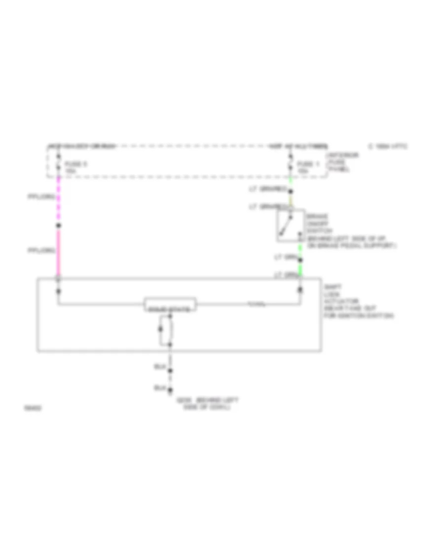
SHIFT INTERLOCKS Shift Interlock Wiring Diagram for Ford Club Wagon E150 1994 List of elements for Shift Interlock Wiring Diagram for Ford Club Wagon E150 1994: 13 (behind left (behind left side of i/p, on brake pedal support) 1994 vftc c Brake on/off switch Fuse 1 15a Fuse 5 15a G200 Hot at all times Hot in accy or run Interior fuse panel Shift lock actuator (near take out for ignition switch) Side of cowl) Solid state
STARTING/CHARGING
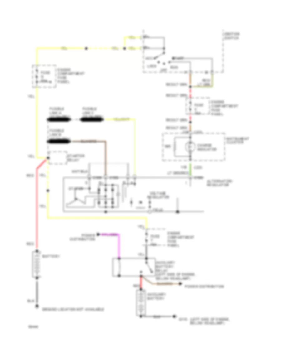
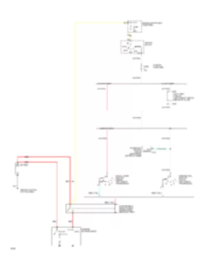
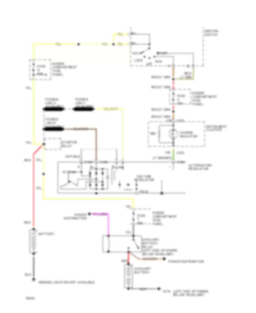
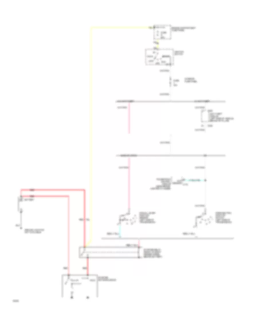
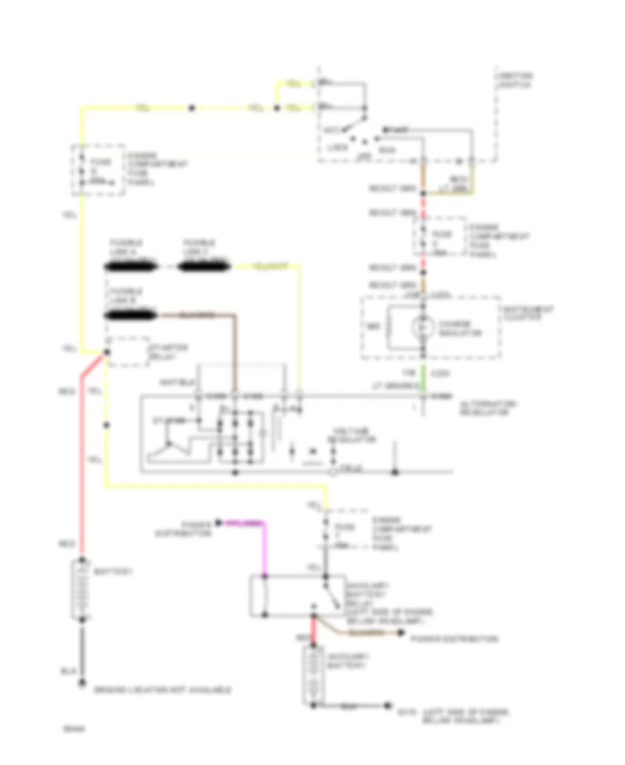
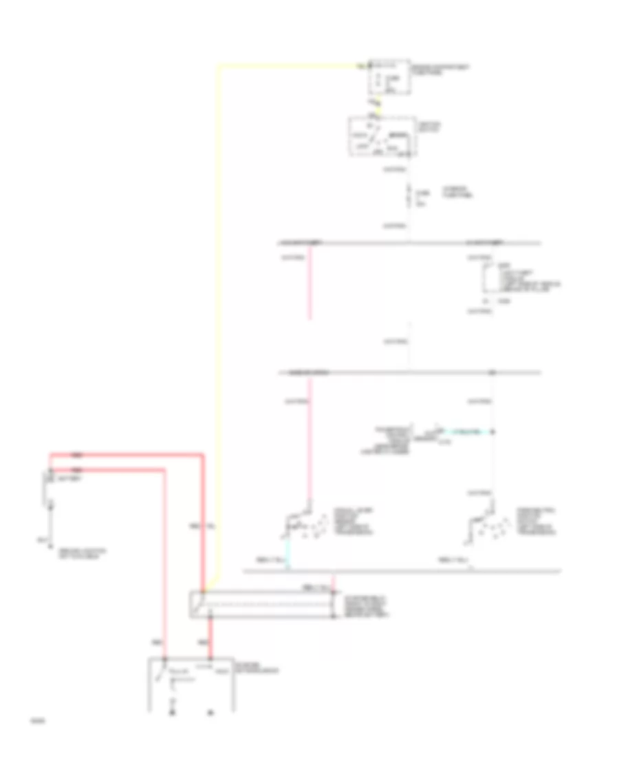
4.9L 4.9L, Charging Wiring Diagram for Ford Club Wagon E150 1994 List of elements for 4.9L, Charging Wiring Diagram for Ford Club Wagon E150 1994: 31 (left side of engine, below headlamp) 11b 12b Acc Alternator/ regulator Auxiliary battery Auxiliary battery relay (left side of engine, below headlamp) Battery C188 C189 C190 C233 Charge indicator Engine compartment fuse panel Field Fuse g 60a Fuse t 60a Fuse u 30a G110 Ground location not available Ignition switch Instrument cluster Lock Off Power distribution Red Run Start Starter relay Stator Voltage regulator 4.9L, Starting Wiring Diagram for Ford Club Wagon E150 1994 List of elements for 4.9L, Starting Wiring Diagram for Ford Club Wagon E150 1994: 27 (left side of transmission) Acc Anti-theft module (left side of vehicle, behind "b" pillar) Battery C336 E4od or 4r70w Engine compartment fuse panel Fuse 30a Fuse g 60a Ground location not available Hold Ignition switch Interior fuse panel Lock Manual lever position sensor Mlp sensor c175 Off Park/neutral position switch (left side of transmission) Powertrain control module (near brake master cylinder) Pull-in Red Run Start Starter motor/solenoid Starter relay (front of right fender apron, behind battery) W/ anti-theft W/o anti-theft
5.0L 5.0L, Charging Wiring Diagram for Ford Club Wagon E150 1994 List of elements for 5.0L, Charging Wiring Diagram for Ford Club Wagon E150 1994: 31 (left side of engine, below headlamp) 11b 12b Acc Alternator/ regulator Auxiliary battery Auxiliary battery relay (left side of engine, below headlamp) Battery C188 C189 C190 C233 Charge indicator Engine compartment fuse panel Field Fuse g 60a Fuse t 60a Fuse u 30a G110 Ground location not available Ignition switch Instrument cluster Lock Off Power distribution Red Run Start Starter relay Stator Voltage regulator 5.0L, Starting Wiring Diagram for Ford Club Wagon E150 1994 List of elements for 5.0L, Starting Wiring Diagram for Ford Club Wagon E150 1994: 27 (left side of transmission) Acc Anti-theft module (left side of vehicle, behind "b" pillar) Battery C336 E4od or 4r70w Engine compartment fuse panel Fuse 30a Fuse g 60a Ground location not available Hold Ignition switch Interior fuse panel Lock Manual lever position sensor Mlp sensor c175 Off Park/neutral position switch (left side of transmission) Powertrain control module (near brake master cylinder) Pull-in Red Run Start Starter motor/solenoid Starter relay (front of right fender apron, behind battery) W/ anti-theft W/o anti-theft
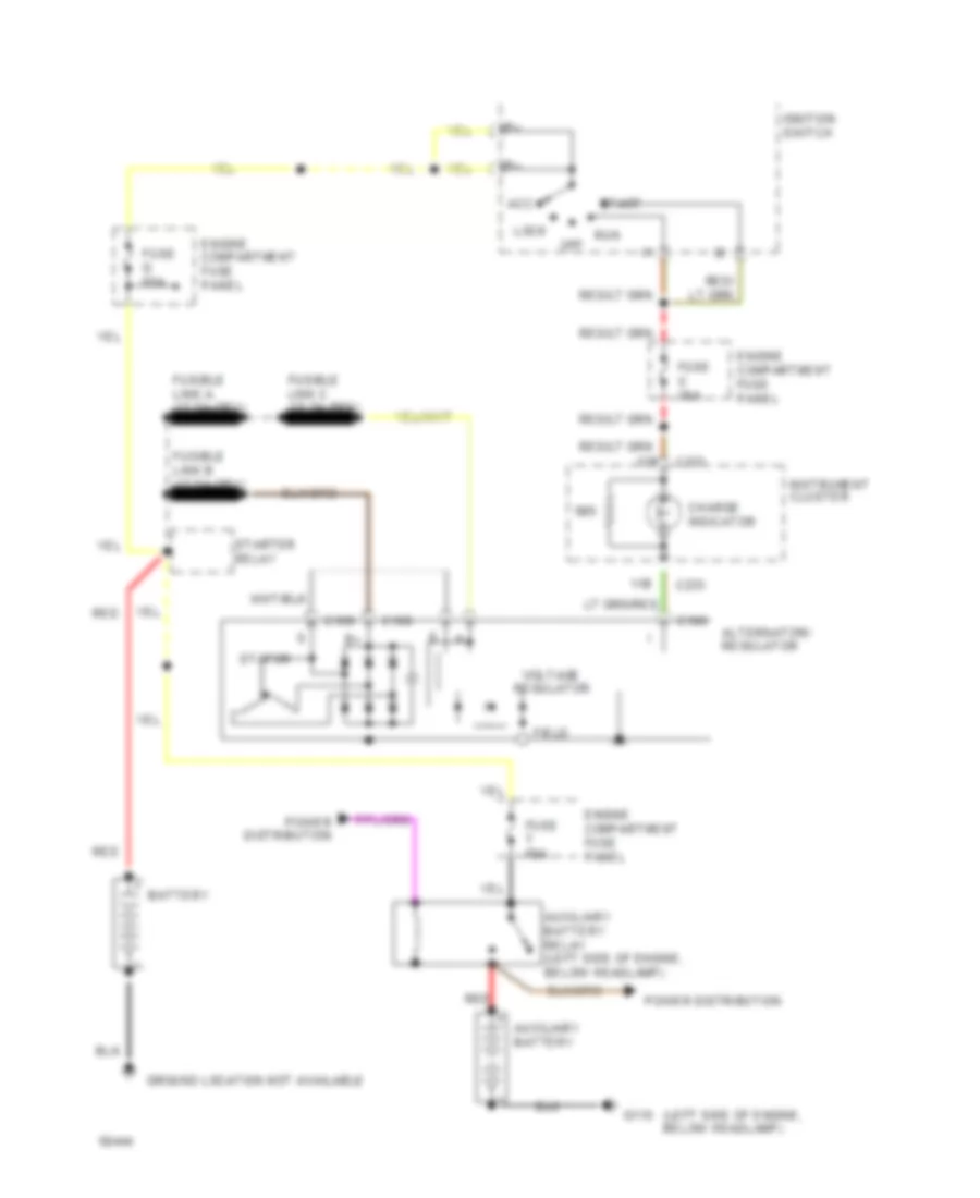
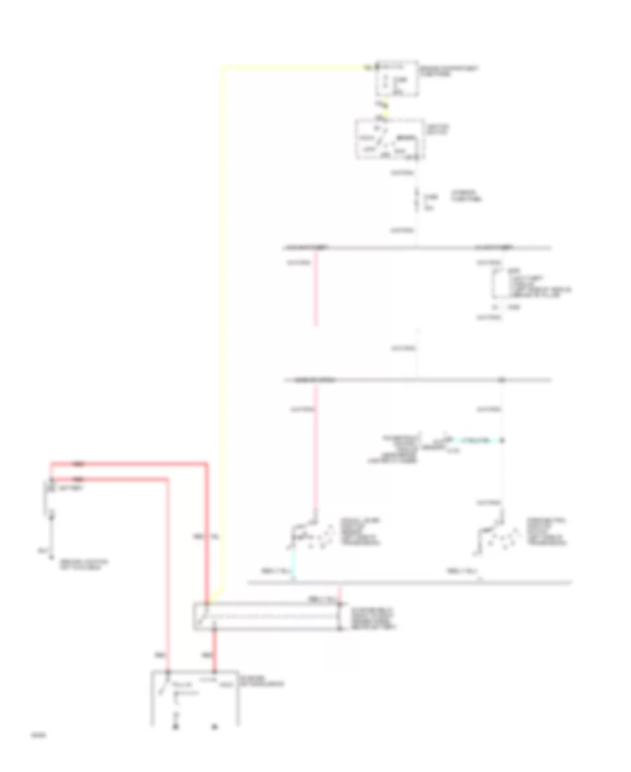
5.8L 5.8L, Charging Wiring Diagram for Ford Club Wagon E150 1994 List of elements for 5.8L, Charging Wiring Diagram for Ford Club Wagon E150 1994: 31 (left side of engine, below headlamp) 11b 12b Acc Alternator/ regulator Auxiliary battery Auxiliary battery relay (left side of engine, below headlamp) Battery C188 C189 C190 C233 Charge indicator Engine compartment fuse panel Field Fuse g 60a Fuse t 60a Fuse u 30a G110 Ground location not available Ignition switch Instrument cluster Lock Off Power distribution Red Run Start Starter relay Stator Voltage regulator 5.8L, Starting Wiring Diagram for Ford Club Wagon E150 1994 List of elements for 5.8L, Starting Wiring Diagram for Ford Club Wagon E150 1994: 27 (left side of transmission) Acc Anti-theft module (left side of vehicle, behind "b" pillar) Battery C336 E4od or 4r70w Engine compartment fuse panel Fuse 30a Fuse g 60a Ground location not available Hold Ignition switch Interior fuse panel Lock Manual lever position sensor Mlp sensor c175 Off Park/neutral position switch (left side of transmission) Powertrain control module (near brake master cylinder) Pull-in Red Run Start Starter motor/solenoid Starter relay (front of right fender apron, behind battery) W/ anti-theft W/o anti-theft
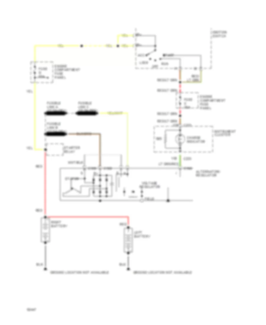
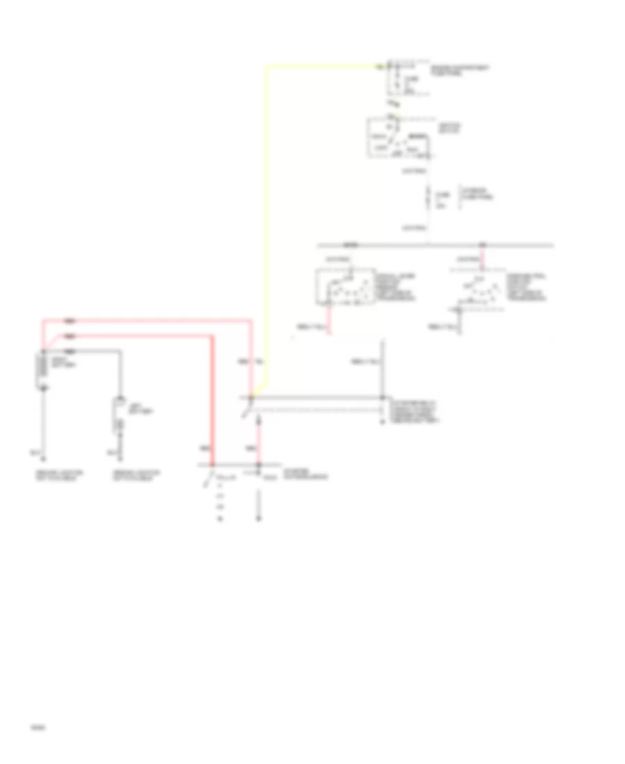
7.3L 7.3L Diesel, Charging Wiring Diagram for Ford Club Wagon E150 1994 List of elements for 7.3L Diesel, Charging Wiring Diagram for Ford Club Wagon E150 1994: 26 11b 12b Acc Alternator/ regulator C188 C189 C190 C233 Charge indicator Engine compartment fuse panel Field Fuse g 60a Fuse u 30a Ground location not available Ignition switch Instrument cluster Left battery Lock Off Red Right battery Run Start Starter relay Stator Voltage regulator 7.3L Diesel, Starting Wiring Diagram for Ford Club Wagon E150 1994 List of elements for 7.3L Diesel, Starting Wiring Diagram for Ford Club Wagon E150 1994: 22 (left side of transmission) Acc E4od Engine compartment fuse panel Fuse 30a Fuse g 60a Ground location not available Hold Ignition switch Interior fuse panel Left battery Lock Manual lever position sensor Off Park/neutral position switch (left side of transmission) Pull-in Red Right battery Run Start Starter motor/solenoid Starter relay (front of right fender apron, behind battery)
7.5L 7.5L, Charging Wiring Diagram for Ford Club Wagon E150 1994 List of elements for 7.5L, Charging Wiring Diagram for Ford Club Wagon E150 1994: 31 (left side of engine, below headlamp) 11b 12b Acc Alternator/ regulator Auxiliary battery Auxiliary battery relay (left side of engine, below headlamp) Battery C188 C189 C190 C233 Charge indicator Engine compartment fuse panel Field Fuse g 60a Fuse t 60a Fuse u 30a G110 Ground location not available Ignition switch Instrument cluster Lock Off Power distribution Red Run Start Starter relay Stator Voltage regulator 7.5L, Starting Wiring Diagram for Ford Club Wagon E150 1994 List of elements for 7.5L, Starting Wiring Diagram for Ford Club Wagon E150 1994: 27 (left side of transmission) Acc Anti-theft module (left side of vehicle, behind "b" pillar) Battery C336 E4od or 4r70w Engine compartment fuse panel Fuse 30a Fuse g 60a Ground location not available Hold Ignition switch Interior fuse panel Lock Manual lever position sensor Mlp sensor c175 Off Park/neutral position switch (left side of transmission) Powertrain control module (near brake master cylinder) Pull-in Red Run Start Starter motor/solenoid Starter relay (front of right fender apron, behind battery) W/ anti-theft W/o anti-theft
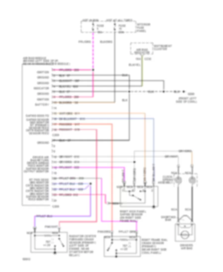
SUPPLEMENTAL RESTRAINTS Supplemental Restraint Wiring Diagram for Ford Club Wagon E150 1994 List of elements for Supplemental Restraint Wiring Diagram for Ford Club Wagon E150 1994: 30 (front left side of cowl) +/- 20 10a Air bag indicator Air bag module (behind left side of i/p, near warning buzzer module) Battery C208 C209 C232 Clock- spring assembly Driver air bag return driver airbag feed monitor safing sensor output monitor Driver's air bag Fuse 15a Fuse 20a G200 Ground Hot at all times Hot in run Ignition Indicator Instrument cluster Interior fuse panel Nca Radiator center forward crash sensor (primary) (left side of engine, near starter motor relay) Right frame rail crash sensor (primary) (near right side cowl panel) Right kick panel safing sensor (on right side frame rail) Rt fwd sens grd monitor cntr radiator grd monitor cntr radiator grd monitor safing sensor feed monitor Safing sens fd Safing sensor gnd monitor rt (primary) sensor feed cntr radiator sensor feed Shorting bar
TRANSMISSION
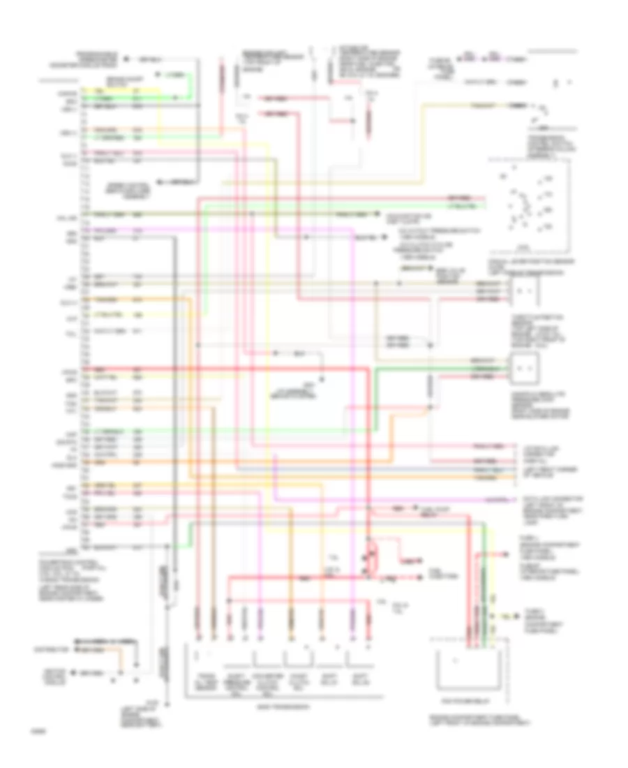
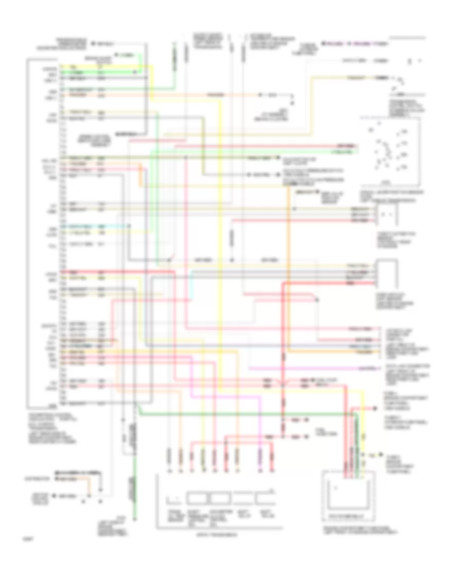
4.9L 4.9L, Transmission Wiring Diagram for Ford Club Wagon E150 1994 List of elements for 4.9L, Transmission Wiring Diagram for Ford Club Wagon E150 1994: 93 dlc (+) gnd (1993 models) (1994 models) (4.9 & 7.5l) (5.8l) (engine (engine compartment (i/p assembly (interior (left front corner of vehicle) (left front of engine compartment, near park/turn lamp) (left rear side of engine compartment, near master cylinder) (left side of engine compartment near battery) (partial) (partial) 4.9l 4.9l & 5.8l 5.8l & 5.8l & 7.5l 7.5l A/c clutch cycling A/c cutout pressure switch Accs Assembly) Behind cluster) Boo Brake on/off switch Ccs Coast clutch sol Compartment Converter clutch control sol Data link connector Distributor Dlc Dlc (-) E40d transmission Egr valve position sensor Elect pressure control sol Engine compartment fuse panel (left front of engine compartment) Engine coolant temperature sensor (top front of Engine) Epc Fuel injectors Fuel pump relay Fuse Fuse #5 Fuse #7 (interior fuse panel) Fuse c Fuse panel) Fuse u G100 G201 Gnd Ho2s gnd Iat Icm Ignition control module Intake air temperature sensor (right side of engine near fuel injector; #1 (4.9l engine) #6 (5.8l & 7.5l engines) Kapwr Mal ind Malfunction ind (inst clstr) Manifold absolute pressure (map) sensor (right side of engine near blower motor) Manual lever position sensor (mlps) (left side of transmission) Map Mlp Nca Off Or, Panel) Pcm power relay Powertrain control module (pcm) (4.9l, 5.8l, & 7.5l w/e4od transmission) Pressure switch Programmable speedometer odometer module (psom) Red Shift sol #1 Shift sol #2 Sig rtn Speed control servo/amplifier assembly Ss1 Ss2 Tccs Tcil Tcsi Tfti Throttle position sensor (top left side of engine) (top right front of engine) Trans oil temp sensor Transmission control switch (steering column Vip data link connector Vpwr Vref Vss (+) Vss (-)
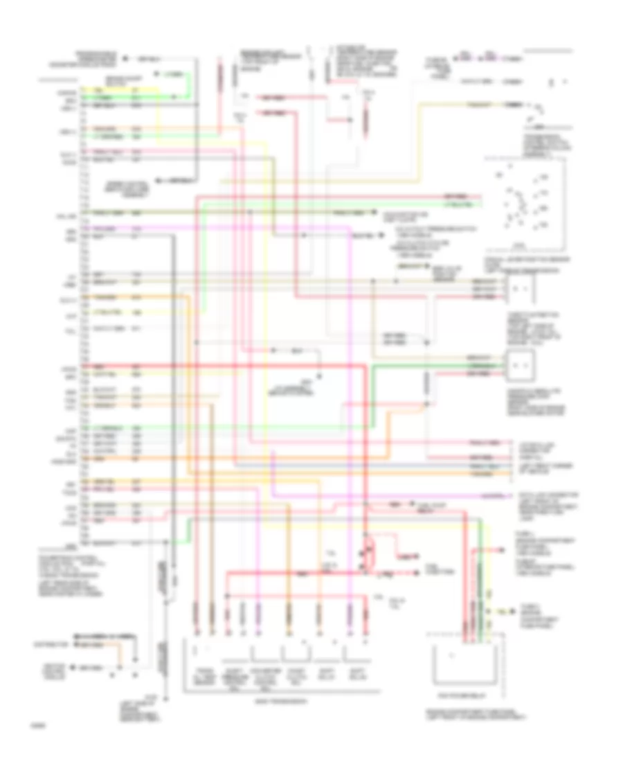
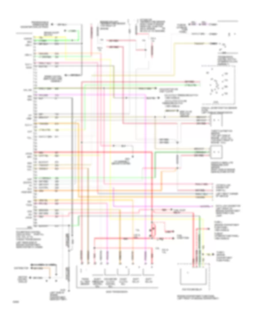
5.0L 5.0L, Transmission Wiring Diagram for Ford Club Wagon E150 1994 List of elements for 5.0L, Transmission Wiring Diagram for Ford Club Wagon E150 1994: 84 (1993 models) (1993 models) (1994 models) (5.0l w/4r70w transmission) (center of engine compartment) (center of engine compartment) (engine (engine compartment (left front of engine compartment, near park/turn lamp) (left rear side of engine compartment, near master cylinder) (left side of engine compartment near battery) (partial) (steering column assembly) 4r70w transmission A/c clutch cycling pressure switch A/c cutout pressure switch (1994 models) Accs Boo Brake on/off switch Clutch control Compartment Converter Data link connector Distributor Dlc Dlc (+) Dlc (-) Egr valve position sensor Elect Engine compartment fuse panel (left front of engine compartment) Epc Fuel injectors Fuel pump relay Fuse # 7 (interior fuse panel) Fuse #5 (interior Fuse c Fuse panel) Fuse u G100 G201 (i/p assembly behind cluster) Gnd Iat Icm Ignition control module Intake air temperature sensor Kapwr Maf Mafs Mal ind Malfunction ind (inst clstr) Manual lever position sensor (mlps) (left side of transmission) Mass air flow (maf) sensor Mlps Nca Off Oil temp sensor Oss Output shaft speed sensor (left rear of Pcm power relay Powertrain control module (pcm) Pressure control Programmable speedometer odometer module (psom) Red Shift Sig rtn Sol Sol #1 Sol #2 Speed control servo/amplifier assembly Ss1 Ss2 Tcc Tcil Tcs Tfti Throttle position sensor (top right front of engine) Trans Transmission control switch Transmission) Vip data link connector Vpwr Vref Vss (+) Vss (-)
5.8L 5.8L, Transmission Wiring Diagram for Ford Club Wagon E150 1994 List of elements for 5.8L, Transmission Wiring Diagram for Ford Club Wagon E150 1994: 93 dlc (+) gnd (1993 models) (1994 models) (4.9 & 7.5l) (5.8l) (engine (engine compartment (i/p assembly (interior (left front corner of vehicle) (left front of engine compartment, near park/turn lamp) (left rear side of engine compartment, near master cylinder) (left side of engine compartment near battery) (partial) (partial) 4.9l 4.9l & 5.8l 5.8l & 5.8l & 7.5l 7.5l A/c clutch cycling A/c cutout pressure switch Accs Assembly) Behind cluster) Boo Brake on/off switch Ccs Coast clutch sol Compartment Converter clutch control sol Data link connector Distributor Dlc Dlc (-) E40d transmission Egr valve position sensor Elect pressure control sol Engine compartment fuse panel (left front of engine compartment) Engine coolant temperature sensor (top front of Engine) Epc Fuel injectors Fuel pump relay Fuse Fuse #5 Fuse #7 (interior fuse panel) Fuse c Fuse panel) Fuse u G100 G201 Gnd Ho2s gnd Iat Icm Ignition control module Intake air temperature sensor (right side of engine near fuel injector; #1 (4.9l engine) #6 (5.8l & 7.5l engines) Kapwr Mal ind Malfunction ind (inst clstr) Manifold absolute pressure (map) sensor (right side of engine near blower motor) Manual lever position sensor (mlps) (left side of transmission) Map Mlp Nca Off Or, Panel) Pcm power relay Powertrain control module (pcm) (4.9l, 5.8l, & 7.5l w/e4od transmission) Pressure switch Programmable speedometer odometer module (psom) Red Shift sol #1 Shift sol #2 Sig rtn Speed control servo/amplifier assembly Ss1 Ss2 Tccs Tcil Tcsi Tfti Throttle position sensor (top left side of engine) (top right front of engine) Trans oil temp sensor Transmission control switch (steering column Vip data link connector Vpwr Vref Vss (+) Vss (-)
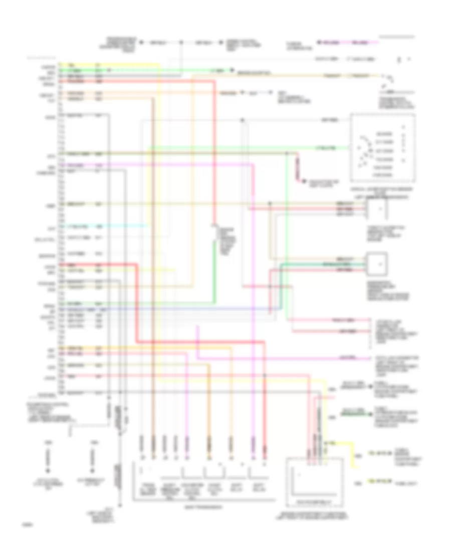
7.3L 7.3L Diesel, Transmission Wiring Diagram for Ford Club Wagon E150 1994 List of elements for 7.3L Diesel, Transmission Wiring Diagram for Ford Club Wagon E150 1994: 83 (engine (engine compartment (left front of engine compartment, near park/turn lamp) (left front of engine compartment) (left rear of engine compt near master cyl) (left side of (left side of transmission) (mlps) (psom) 1448 ohms 1993 1994 211 ohms 401 ohms 4189 ohms 733 ohms 86 ohms A/c clutch A/c press cut Accs Barometric pressure (bp) sensor (right side of engine near blower motor) Behind cluster) Boo Brake on/off sw Case gnd Ccc Ccs Coast clutch sol Compartment Converter clutch control sol Cycling press Data link connector E40d transmission Elect pressure control sol Eng compt near batt) Engine compartment fuse panel Engine rpm sensor (ctr frt of eng near tps) Epc Epcpwr Fipl Fuse #5 (interior f/b) Fuse 7 (interior fuse block) Fuse c Fuse link f Fuse panel) Fuse u (via power diode) G111 G201 (i/p assembly Kapwr Malfuction ind (inst clstr) Manual lever position sensor Mlp Module (pcm) (7.3l diesel) Ocil & tmil Ocs Odometer module Off Out sw Pcm power relay Powertrain control Programmable speedometer/ Pwr gnd Red Rpms+ Rpms- Shift sol #1 Shift sol #2 Sig rtn Speed control servo / amplifier assy Ss1 Ss2 Sti Sto Throttle position sensor (tps) (top left side of engine) Tot Trans oil temp sensor Transmission control switch (steering column) Via power diode (engine compartment fuse block) Vip data link connector (left front of engine compartment, near park/turn lamp) Vpwr Vref Vss dif + Vss dif -
7.5L 7.5L, Transmission Wiring Diagram for Ford Club Wagon E150 1994 List of elements for 7.5L, Transmission Wiring Diagram for Ford Club Wagon E150 1994: 93 dlc (+) gnd (1993 models) (1994 models) (4.9 & 7.5l) (5.8l) (engine (engine compartment (i/p assembly (interior (left front corner of vehicle) (left front of engine compartment, near park/turn lamp) (left rear side of engine compartment, near master cylinder) (left side of engine compartment near battery) (partial) (partial) 4.9l 4.9l & 5.8l 5.8l & 5.8l & 7.5l 7.5l A/c clutch cycling A/c cutout pressure switch Accs Assembly) Behind cluster) Boo Brake on/off switch Ccs Coast clutch sol Compartment Converter clutch control sol Data link connector Distributor Dlc Dlc (-) E40d transmission Egr valve position sensor Elect pressure control sol Engine compartment fuse panel (left front of engine compartment) Engine coolant temperature sensor (top front of Engine) Epc Fuel injectors Fuel pump relay Fuse Fuse #5 Fuse #7 (interior fuse panel) Fuse c Fuse panel) Fuse u G100 G201 Gnd Ho2s gnd Iat Icm Ignition control module Intake air temperature sensor (right side of engine near fuel injector; #1 (4.9l engine) #6 (5.8l & 7.5l engines) Kapwr Mal ind Malfunction ind (inst clstr) Manifold absolute pressure (map) sensor (right side of engine near blower motor) Manual lever position sensor (mlps) (left side of transmission) Map Mlp Nca Off Or, Panel) Pcm power relay Powertrain control module (pcm) (4.9l, 5.8l, & 7.5l w/e4od transmission) Pressure switch Programmable speedometer odometer module (psom) Red Shift sol #1 Shift sol #2 Sig rtn Speed control servo/amplifier assembly Ss1 Ss2 Tccs Tcil Tcsi Tfti Throttle position sensor (top left side of engine) (top right front of engine) Trans oil temp sensor Transmission control switch (steering column Vip data link connector Vpwr Vref Vss (+) Vss (-)
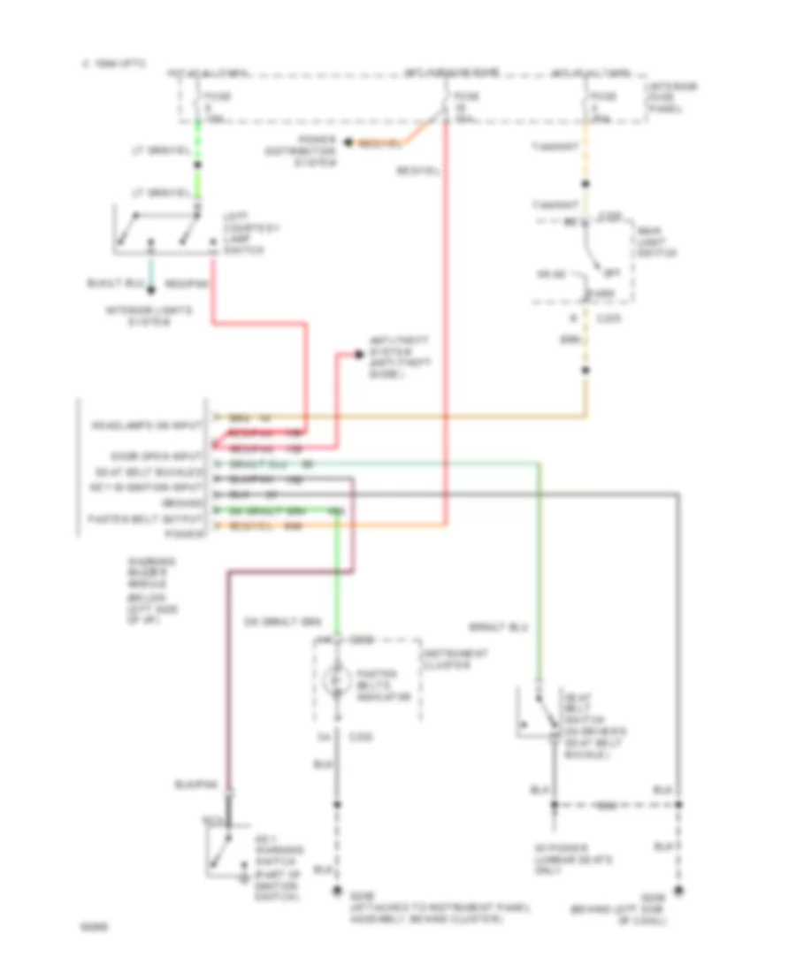
WARNING SYSTEMS Warning System Wiring Diagrams for Ford Club Wagon E150 1994 List of elements for Warning System Wiring Diagrams for Ford Club Wagon E150 1994: 35 (below left side of i/p) (part of ignition switch) 1994 vftc c Anti-theft system (anti-theft diode) C232 C235 Door open input Fasten belt output Fasten belts indicator Fuse 15a Fuse 20a G200 (behind left side of cowl) G206 (attached to instrument panel assembly, behind cluster) Ground Head Headlamps on input Hot at all times Hot in run or start Instrument cluster Interior fuse panel Interior lights system Key in ignition input Key warning switch Left courtesy lamp switch Main light switch Nca Off Park Power Power distribution system Red/pnk Seat belt buckled Seat belt switch (in driver's seat belt buckle) W/ power lumbar seats only Warning buzzer module
WIPER/WASHER Wiper/Washer Wiring Diagram for Ford Club Wagon E150 1994 List of elements for Wiper/Washer Wiring Diagram for Ford Club Wagon E150 1994: 37 (behind cluster) (left side of engine compartment, near battery) 100k ohms 1994 vftc c 3.3k ohms 4.08k 7.25k Circuit breaker 8.5a G106 G206 Gnd Ground Hot in accy or run Ignition Input Int max Int min Interior fuse panel Multi- function switch Off Off 36.27k Ohms Park Park switch Pump motor control Red Run Washer switch Windshield washer pump motor (near washer reservoir) Windshield wiper motor Wiper control module (behind right side of i/p) Wiper motor Wiper motor (common) Wiper motor (hi) Wiper motor (lo) Wiper motor position input Wiper/washer switch