AIR CONDITIONING
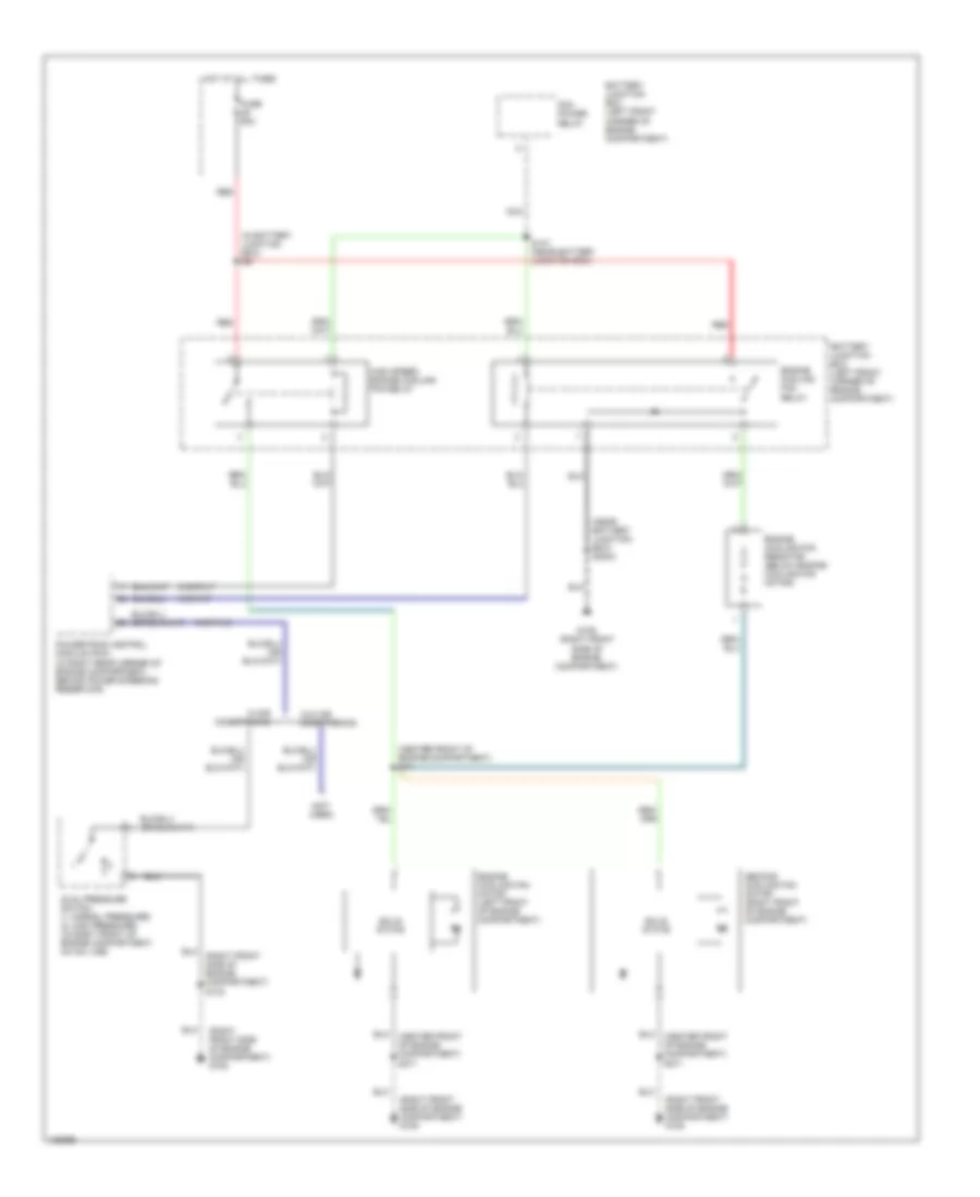
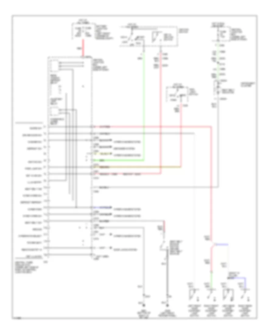
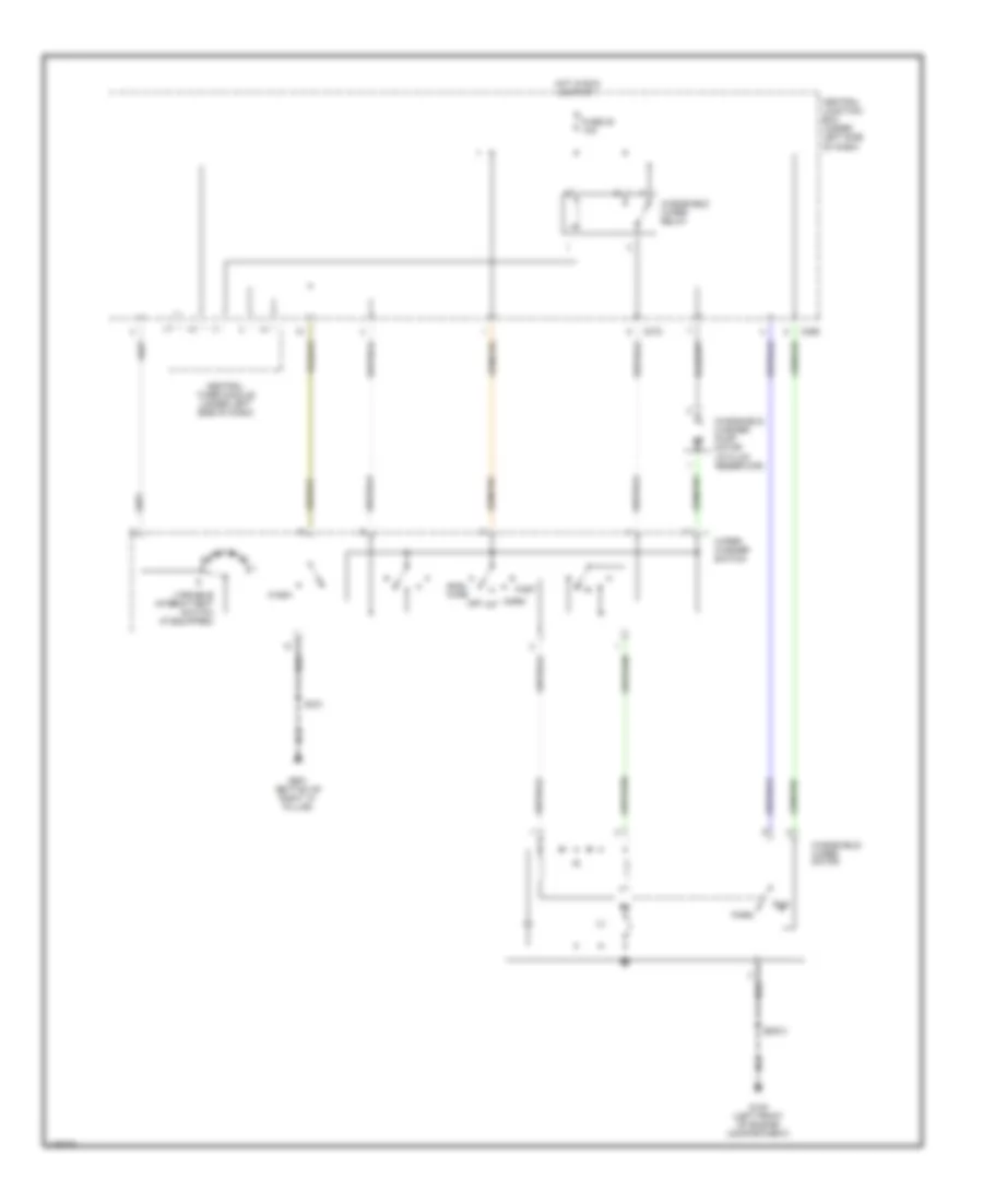
Heater Wiring Diagram for Ford Contour SE 2000

List of elements for Heater Wiring Diagram for Ford Contour SE 2000:
- (behind center dash panel) s274
- (bottom of right "a" pillar) g901
- Air temperature actuator (behind center of dash)
- C360
- C361
- Central junction box (under left side of dash)
- Def/flr
- Defrost
- Floor
- Fuse 23 15a
- Fuse 30a
- Heater blower motor (under right side of dash, behind glove box)
- Heater blower relay
- Heater blower series resistor (under right side of dash, near blower motor)
- Heater blower switch
- Heater mode switch
- High
- Hot at all times
- Hot in run or start
- Low
- Nca
- Off
- Pan/flr
- Panel
- S331 (near steering column)
- Side dash panel) s104
- Temperature door variable resistor (behind center of dash)
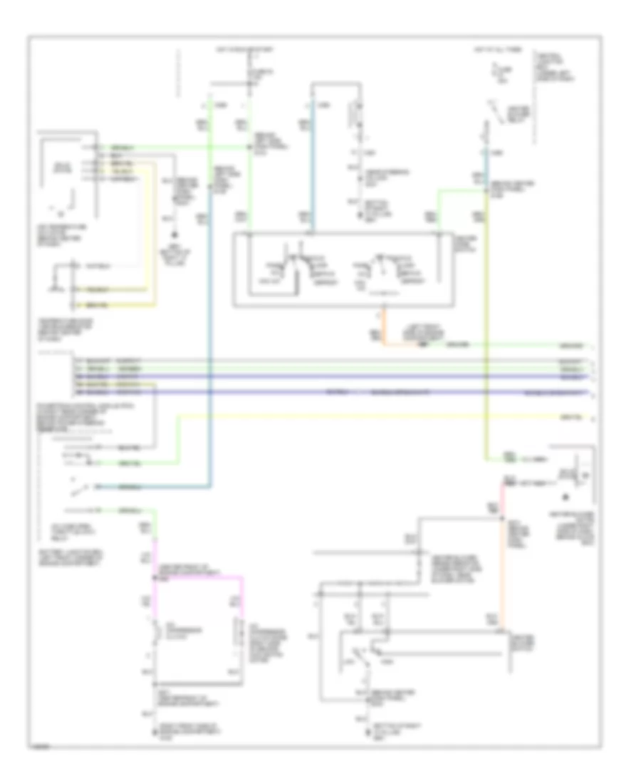
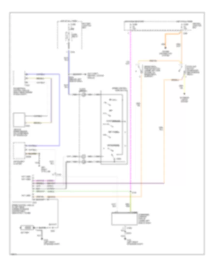
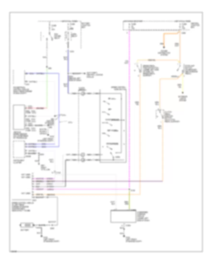
Manual A/C Wiring Diagram (1 of 2) for Ford Contour SE 2000
List of elements for Manual A/C Wiring Diagram (1 of 2) for Ford Contour SE 2000:
- (behind center dash panel) s166
- (behind left side dash panel) s104
- (behind left side dash panel) s136
- (bottom of right "a" pillar) g901
- (center front of engine compartment) s46
- (left front side of engine compartment) s167
- (near steering column) s331
- (right front side of engine compartment) g109
- 15s-re9a
- 91s-fa11
- 91s-pa13
- 91s-pa17
- 91s-pa7
- A/c
- A/c compressor clutch
- A/c compressor clutch diode (right side of second cooling fan motor)
- A/c wide open throttle (wot) relay
- Air temperature actuator (behind center of dash)
- Battery junction box (left front corner of engine compartment)
- C360
- C361
- C369
- Center dash panel) s244
- Central junction box (under left side of dash)
- Def/flr
- Defrost
- Floor
- Fuse 23 15a
- Fuse 30a
- G901 (bottom of right "a" pillar)
- Heater blower motor (under right side of dash, behind glove box)
- Heater blower relay
- Heater blower series resistor (under right side of dash, near blower motor)
- Heater blower switch
- Heater mode switch
- High
- Hot at all times
- Hot in run or start
- Low
- Max a/c
- Nca
- Off
- Pan/flr
- Panel
- Powertrain control module (pcm) (in right rear corner of engine compartment, behind power steering reservoir)
- S271 (center front of engine compartment)
- S274 (behind center dash panel)
- Solid state
- Temperature door variable resistor (behind center of dash)
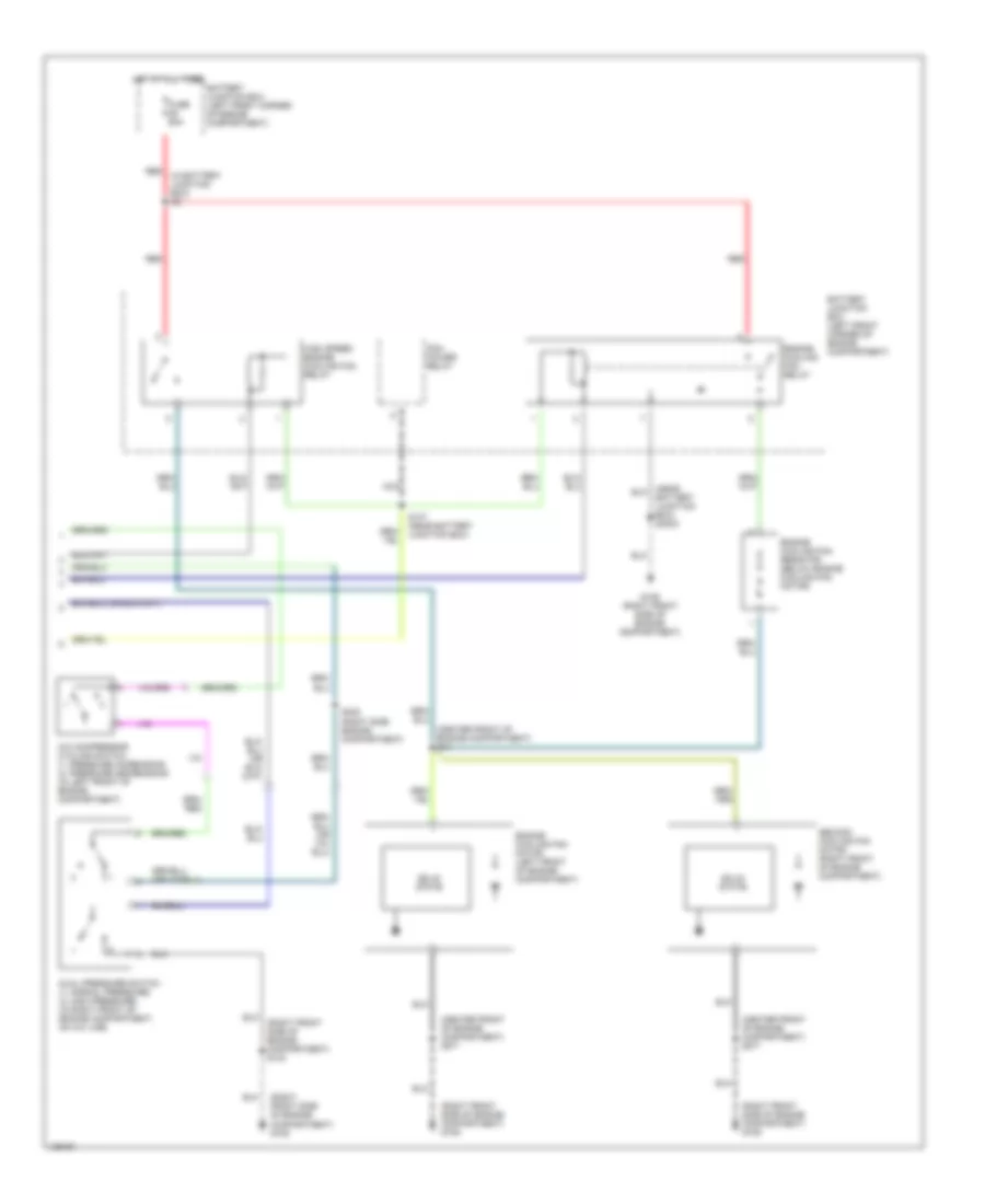
Manual A/C Wiring Diagram (2 of 2) for Ford Contour SE 2000
List of elements for Manual A/C Wiring Diagram (2 of 2) for Ford Contour SE 2000:
- (center front of engine compartment) s271
- (center front of engine compartment) s44
- (in battery junction box) s9
- (right front side of engine compartment) g109
- (right front side of engine compartment) s133
- A/c compressor cycling switch (1: pressure increasing) (2: pressure decreasing) (in left front of engine compartment)
- Battery junction box (left front corner of engine compartment)
- Battery junction box) s3003
- Dual pressure switch (1: normal pressure) (2: high pressure) (in right front of engine compartment, on a/c line)
- Engine cooling fan motor (left front of engine compartment)
- Engine cooling fan relay
- Engine cooling fan resistor (below engine cooling fan motor)
- Fuse 60a
- G109 (right front side of engine compartment)
- High speed engine cooling fan relay
- Hot at all times
- Nca
- Pcm power relay
- Red
- S147 (near battery junction box)
- S408 (right side engine compartment)
- Second cooling fan motor (right front of engine compartment)
- Solid state
ANTI-LOCK BRAKES
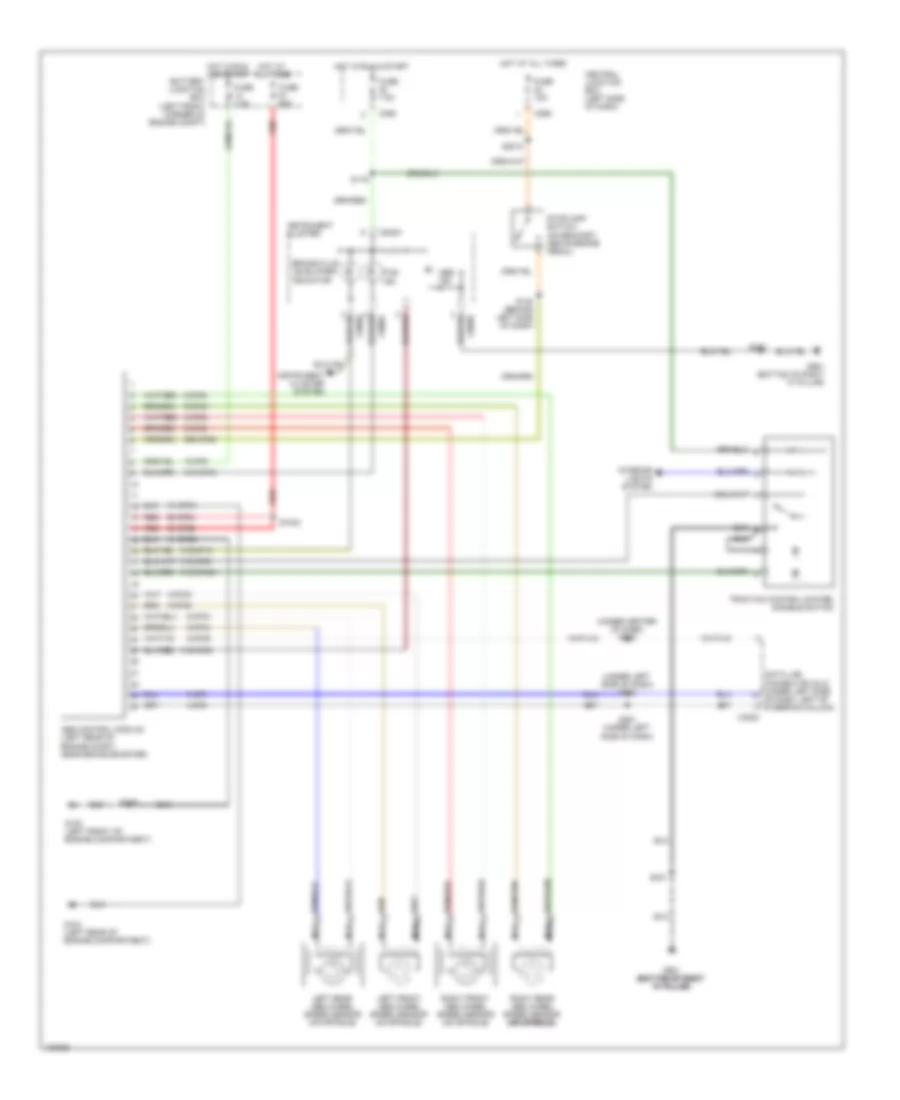
Anti-lock Brake Wiring Diagrams, with Traction Control for Ford Contour SE 2000
List of elements for Anti-lock Brake Wiring Diagrams, with Traction Control for Ford Contour SE 2000:
- (under center of dash) s283
- (under left side of dash) s282
- 15-cf6
- 29s-cf58
- 31-cf6a
- 31-cf6b
- 31s-cf12
- 31s-cf28
- 31s-cf45
- 31s-cf45a
- 31s-cf54
- 4-cf6
- 5-cf6
- 8-cf29
- 8-cf32
- 8-cf34
- 8-cf38
- 8-cf40
- 9-cf32
- 9-cf34
- 9-cf38
- 9-cf40
- 90-cf6a
- 90-cf6b
- Abs control module (left rear of engine compt, near brake booster)
- Abs ind
- Battery junction box (left front corner of engine compt)
- Brake fluid level/park indicator
- C3000
- C362
- C369
- C808a
- C808b
- Central junction box (left side of dash)
- Data link connector (dlc) (under left side of dash, left of steering column)
- Fuse 15a
- Fuse 60a
- Fuse 7.5a
- G100 (left front of engine compartment)
- G104 (left rear of engine compartment)
- G901 (bottom of right "a" pillar)
- G901 (bottom of right (bottom of right (bottom of right "a" pillar) "a" pillar) "a" pillar)
- Hot at all times
- Hot in run & start
- Hot in run and start
- Instrument cluster
- Instrument cluster system
- Interior lights system
- Left front abs wheel speed sensor (on spindle)
- Left rear abs wheel speed sensor (on spindle)
- Nca
- Red
- Right front abs wheel speed sensor (on spindle)
- Right rear abs wheel speed sensor (on spindle) (on spindle) (on spindle)
- S1002
- S116
- S130 (behind left side of dash)
- S249
- S281 (under left side of dash)
- S300
- S3010
- S331
- Stoplamp switch (on bracket, above brake pedal)
- Tcs ind
- Traction control system disable switch
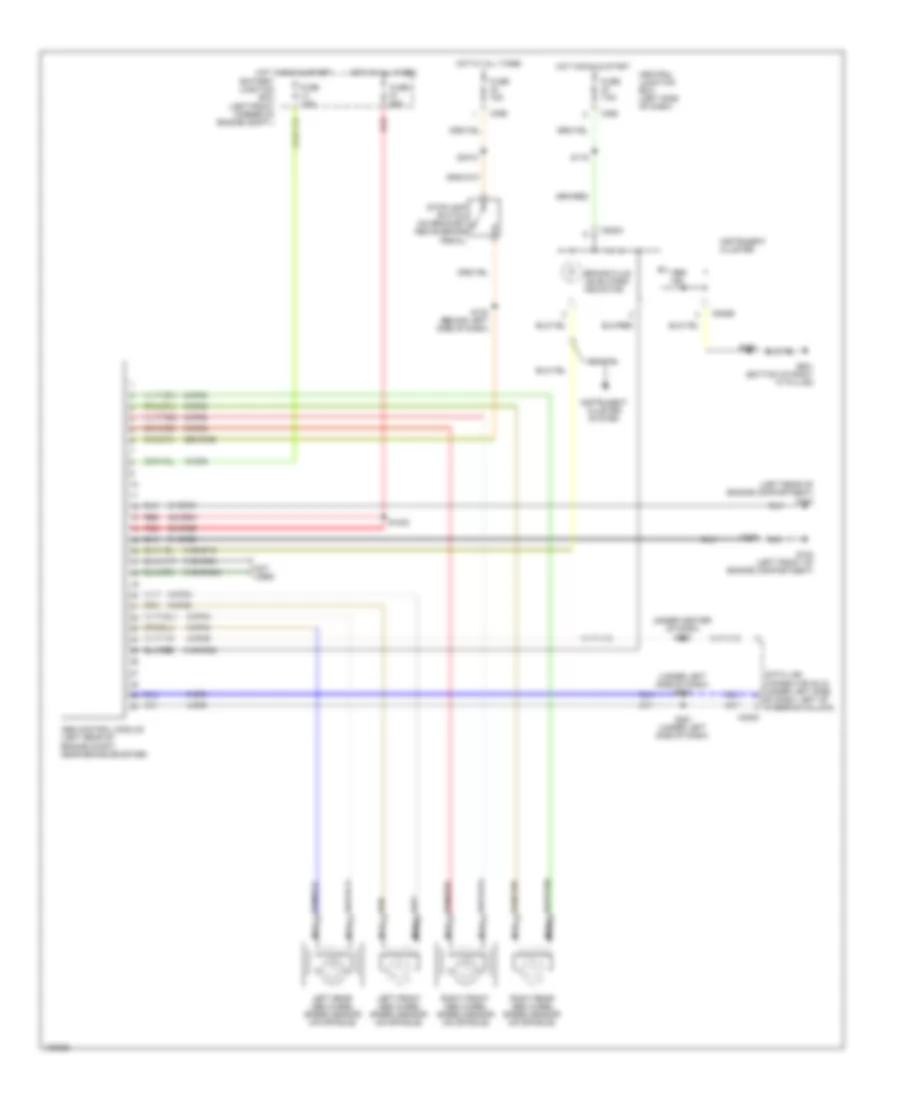
Anti-lock Brake Wiring Diagrams, without Traction Control for Ford Contour SE 2000
List of elements for Anti-lock Brake Wiring Diagrams, without Traction Control for Ford Contour SE 2000:
- (left rear of engine compartment) g104
- (under center of dash) s283
- (under left side of dash) s282
- 15-cf6
- 29s-cf58
- 30-cf6a
- 30-cf6b
- 31-cf6a
- 31-cf6b
- 31s-cf12
- 31s-cf28
- 31s-cf45a
- 31s-cf54
- 4-cf6
- 5-cf6
- 8-cf29
- 8-cf32
- 8-cf34
- 8-cf38
- 8-cf40
- 9-cf32
- 9-cf34
- 9-cf38
- 9-cf40
- Abs control module (left rear of engine compt, near brake booster)
- Abs ind
- Battery junction box (left front corner of engine compt.)
- Brake fluid level/park indicator
- C3000
- C362
- C369
- C808a
- C808b
- Central junction box (left side of dash)
- Data link connector (dlc) (under left side of dash, left of steering column)
- Fuse 15a
- Fuse 60a
- Fuse 7.5a
- G100 (left front of engine compartment)
- G901 (bottom of right "a" pillar)
- Hot at all times
- Hot in run & start
- Instrument cluster
- Instrument cluster system
- Left front abs wheel speed sensor (on spindle)
- Left rear abs wheel speed sensor (on spindle)
- Nca
- Not used
- Red
- Right front abs wheel speed sensor (on spindle)
- Right rear abs wheel speed sensor (on spindle)
- S1002
- S116
- S130 (behind left side of dash)
- S249
- S281 (under left side of dash)
- S300
- S3010
- Stoplamp switch (on bracket above brake pedal)
ANTI-THEFT
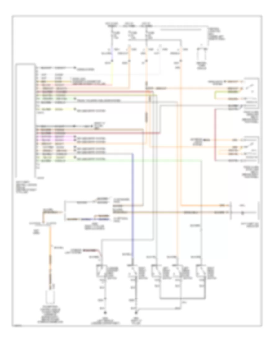
Forced Entry Wiring Diagram for Ford Contour SE 2000
List of elements for Forced Entry Wiring Diagram for Ford Contour SE 2000:
- (bi-fuel)
- (not used)
- (right "a" pillar) g901
- 29-aa17
- 29-aa17a
- 29s-aa28
- 29s-aa32
- 31-aa17
- 31s-aa17
- 31s-gl12
- 31s-gl16
- 31s-gl19
- 31s-gl39
- 31s-gl6
- 31s-gl9
- 31s-mb20
- 32-aa17
- 32-aa4
- 33-aa11
- 33-aa17
- 33-aa4
- 75-aa17
- 8-aa36
- 8-aa6
- 9-aa6
- Anti-theft 'on' indicator
- Anti-theft/ central locking module (center of right "a" pillar)
- C23
- C360
- C364
- C365
- C366
- C421
- C451a
- C451b
- Central junction box (under left side of dash)
- Central timer module
- Door lock diagnostic connector (center of right 'a" pillar)
- Exterior lights system
- Fuse 20a
- Fuse 7.5a
- G404 (left rear of luggage compartment)
- G901 (right "a" pillar)
- Headlights system
- Horns system
- Hot at all times
- Hot in acc or run
- Interior light system
- Keyless entry system
- Left front door ajar switch
- Left rear door ajar switch
- Luggage compart- ment lamp switch
- Nca
- Panic alarm headlamp relay (behind right kick panel)
- Panic alarm stop lamp relay (behind right kick panel)
- Powertrain control module (in right rear corner of engine compt, behind power steering reservoir)
- Right front door ajar switch
- Right rear door ajar switch
- S14
- S258
- S299 (right "a" pillar, near glove box)
- S304
- S318
- S319
- S320
- S321
- Trunk, tailgate, fuel door system
- W/ optional pats
- W/ pats
- W/ standard pats
- W/o pats
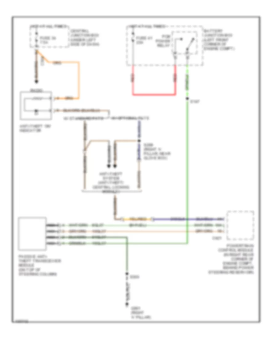
Passive Anti-theft Wiring Diagram for Ford Contour SE 2000
List of elements for Passive Anti-theft Wiring Diagram for Ford Contour SE 2000:
- (bi-fuel)
- 10gl37
- 15gl37
- 31sgl6
- 8gl37
- 91gl37
- Anti-theft 'on' indicator
- Anti-theft system (anti-theft/ central locking module)
- Battery junction box (left front corner of engine compt)
- C364
- C421
- Central junction box (under left side of dash)
- Fuse 34 7.5a
- Fuse 41 20a
- G901 (right 'a' pillar)
- Hot at all times
- Nca
- Passive anti- theft transceiver module (on top of steering column)
- Pcm power relay
- Powertrain control module (in right rear corner of engine compt, behind power steering reservoir)
- Radio
- Red
- S147
- S299 (right 'a' pillar, near glove box)
- S300
- W/ optional pats
- W/ standard pats
COMPUTER DATA LINES
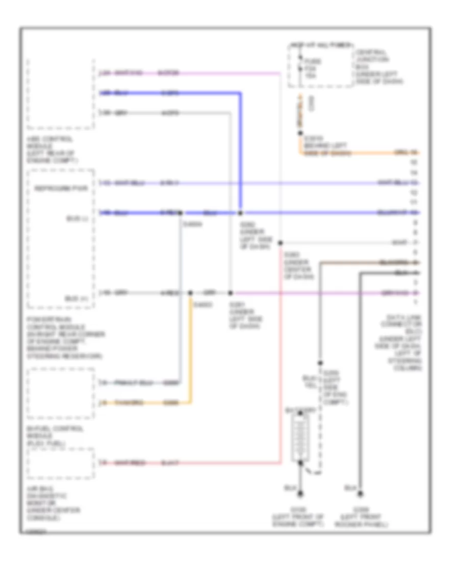
Computer Data Lines, with ABS for Ford Contour SE 2000
List of elements for Computer Data Lines, with ABS for Ford Contour SE 2000:
- 4-cf6
- 4-re8
- 5-cf6
- 5-re8
- 8-cf29
- 8-ja7
- 8-ra1
- Abs control module (left rear of engine compt)
- Air bag diagnostic monitor (under center console)
- Battery
- Bi-fuel control module (flex fuel)
- Bus (+)
- Bus (-)
- C369
- Central junction box (under left side of dash)
- Data link connector (dlc) (under left side of dash, left of steering column)
- Fuse f24 15a
- G085
- G086
- G100 (left front of engine compt)
- G309 (left front rocker panel)
- Hot at all times
- Powertrain control module (in right rear corner of engine compt, behind power steering reservoir)
- Reprogrm pwr
- S281 (under left side of dash)
- S282 (under left side of dash)
- S283 (under center of dash)
- S3010 (behind left side of dash)
- S4003
- S4004
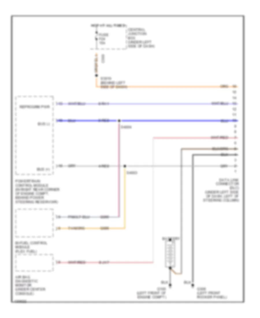
Computer Data Lines, without ABS for Ford Contour SE 2000
List of elements for Computer Data Lines, without ABS for Ford Contour SE 2000:
- 4-re8
- 5-re8
- 8-ja7
- 8-ra1
- Air bag diagnostic monitor (under center console)
- Battery
- Bi-fuel control module (flex fuel)
- Bus (+)
- Bus (-)
- C369
- Central junction box (under left side of dash)
- Data link connector (dlc) (under left side of dash, left of steering column)
- Fuse f24 15a
- G085
- G086
- G100 (left front of engine compt)
- G309 (left front rocker panel)
- Hot at all times
- Powertrain control module (in right rear corner of engine compt, behind power steering reservoir)
- Reprogrm pwr
- S3010 (behind left side of dash)
- S4003
- S4004
COOLING FAN
Cooling Fan Wiring Diagram for Ford Contour SE 2000
List of elements for Cooling Fan Wiring Diagram for Ford Contour SE 2000:
- (center front of engine compartment) s271
- (center front of engine compartment) s44
- (in battery junction box) s9
- (near battery junction box) s3003
- (not used)
- (right front side of engine compartment) g109
- (right front side of engine compartment) s133
- 91s-pa13
- 91s-pa17
- 91s-pa7
- Battery junction box (left front corner of engine compartment)
- Dual pressure switch (1: normal pressure) (2: high pressure) (in right front of engine compartment, on a/c line)
- Engine cooling fan motor (left front of engine compartment)
- Engine cooling fan relay
- Engine cooling fan resistor (below engine cooling fan motor)
- Fuse 60a
- G109 (right front side of engine compartment)
- High speed engine cooling fan relay
- Hot at all times
- Nca
- Pcm power relay
- Powertrain control module (pcm) (in right rear corner of engine compartment, behind power steering reservoir)
- Red
- S147 (near battery junction box)
- Second cooling fan motor (right front of engine compartment)
- Solid state
- W/air conditioning
- W/o air conditioning
CRUISE CONTROL
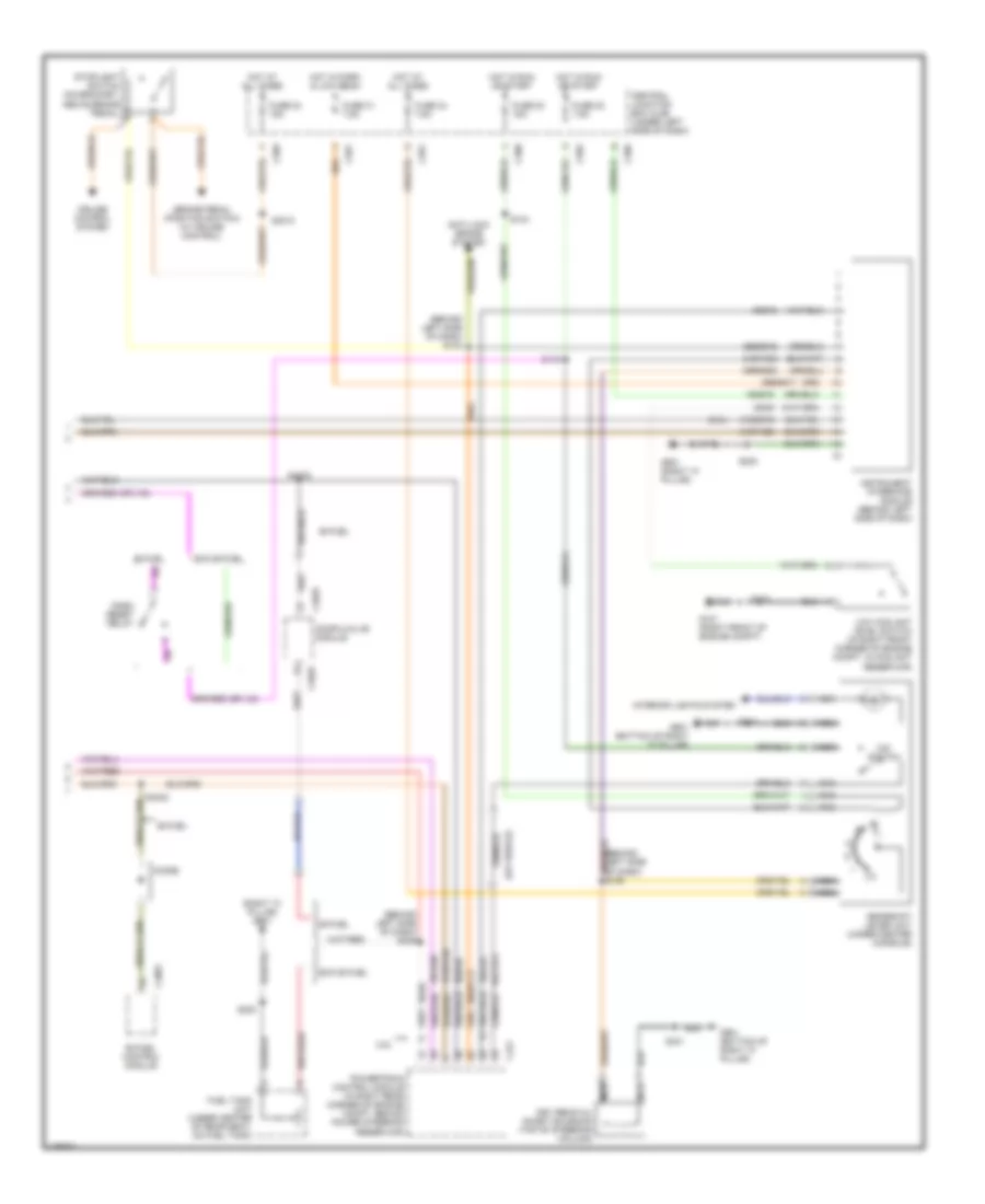
Cruise Control Wiring Diagram, A/T for Ford Contour SE 2000
List of elements for Cruise Control Wiring Diagram, A/T for Ford Contour SE 2000:
- 14-pg12
- 29s-pg16
- 29s-pg17
- 31-pg13
- 8-pg12
- 8-pg13
- Anti-theft/ central locking module
- Battery
- Battery junction box
- Brake pedal position switch (under left side of dash, on brake pedal support)
- C102
- C1908
- C333
- C369
- C421
- C808b
- C822
- C833
- Central junction box
- Clock- spring
- Coast/resume
- Decelerate
- Exterior lights system
- Fuse 15a
- Fuse 20a
- G100 (left front of engine compt)
- G901 (right "a" pillar)
- Horn
- Horn relay
- Hot at all times
- Hot in run or start
- Instrument cluster
- Nca
- Not used
- Off
- Overspeed warning module (under left
- Power distribution system
- Powertrain control module (right rear corner of eng compt)
- S136
- S250
- S3003
- S404 (behind left side of dash)
- Set/accel
- Side of dash)
- Speed control module (in left rear corner of engine compartment, near strut tower)
- Speed control/ horn switch
- Stoplamp switch (on bracket, above brake pedal)
- Vehicle speed sensor (on lower rear of transaxle)
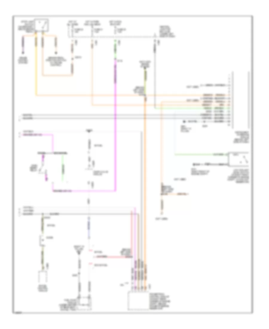
Cruise Control Wiring Diagram, M/T for Ford Contour SE 2000
List of elements for Cruise Control Wiring Diagram, M/T for Ford Contour SE 2000:
- (2.0l)
- (2.5l)
- (2.5l) (2.0l)
- (left front of engine compt)
- 14-pg12
- 29s-pg16
- 29s-pg17
- 31-pg13
- 8-pg12
- 8-pg13
- Anti-theft/ central locking module
- Battery
- Battery junction box
- Brake pedal position switch (under left side of dash, on brake pedal support)
- C102
- C1908
- C333
- C369
- C421
- C808b
- C823 c1899
- C833
- Central junction box
- Clock- spring
- Clutch pedal position switch (on clutch pedal support)
- Coast/resume
- Decelerate
- Exterior lights system
- Fuse 15a
- Fuse 20a
- G100
- G100 (left front of engine compt)
- G901 (right "a" pillar)
- Horn
- Horn relay
- Hot at all times
- Hot in run or start
- Instrument cluster
- Nca
- Not used
- Off
- Overspeed warning module (under left
- Pcm power relay
- Power distribution system
- Powertrain control module (right rear corner of eng compt)
- S136
- S250
- S300
- S404 (behind left side of dash)
- S59
- S60 (center of engine compt)
- S62
- Set/accel
- Side of dash)
- Speed control module (in left rear corner of engine compartment, near strut tower)
- Speed control/ horn switch
- Stoplamp switch (on bracket, above brake pedal)
- Vehicle speed sensor (on lower rear of transaxle)
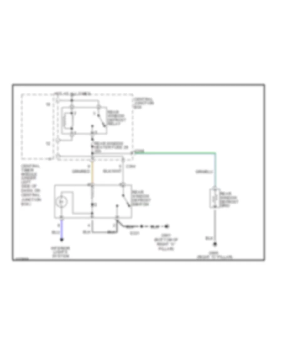
DEFOGGERS
Defogger Wiring Diagram for Ford Contour SE 2000
List of elements for Defogger Wiring Diagram for Ford Contour SE 2000:
- (right "c" pillar)
- C364
- C368
- Central junction box
- Central timer module (under left side of dash, on central junction box)
- G901 (bottom of right "a" pillar)
- G905
- Hot at all times
- Interior lights system
- Rear window defrost grid
- Rear window defrost relay
- Rear window defrost switch switch
- Rear window heater fuse 29 30a
- S331
ENGINE PERFORMANCE
2.0L
2.0L Flex Fuel, Engine Performance Wiring Diagrams (1 of 4) for Ford Contour SE 2000
List of elements for 2.0L Flex Fuel, Engine Performance Wiring Diagrams (1 of 4) for Ford Contour SE 2000:
- (a/t)
- (bottom of right "a" pillar)
- (left center of engine compt)
- (left front of engine compt)
- (left side of luggage compt)
- (near cylinder head) s414
- (right front of engine compt)
- (under left side of dash) central junction box
- (under left side of dash, left of steering column)
- 10-gl37
- 15s-re16
- 15s-re9a
- 15s-ta21
- 4-re8
- 5-re8
- 8-ce6
- 8-ga6
- 8-gb10
- 8-gg18
- 8-ra1
- 8-rj17
- 8-rj25
- 8-rj29b
- 8-rj4
- 8-rj6
- 8-ta26
- 8-ta27
- 9-rj22
- 9-rj29
- 9-rj4
- 9-rr1
- 9-rr2
- 91-re21
- 91-re8c
- 91-re8e
- 91s-pa17
- 91s-rd7
- 91s-rl27
- 91s-ta24
- Acc
- Air charge temperature sensor
- Air conditioning (dual press sw)
- Anti-lock brake system
- Battery junction box (left front corner of engine compt)
- Bi-fuel indicator light switch
- C361
- C370
- C371
- C372
- C440
- Check engine ind
- Cooling fans (high speed relay)
- Cps return
- Cps signal
- Crankshaft position sensor (lower left rear of engine)
- Cta ctrl
- Data link conn +
- Data link conn -
- Data link power
- Datalink connector
- Fuel level sen
- Fuel pump module
- Fuel pump module (left front of luggage compt, near fenderwell)
- Fuel pump relay
- Fuel tank unit (on fuel tank)
- Fuse 15a
- Fuse 20a
- Fuse 60a
- G100
- G100 (left front of engine compt)
- G101
- G400
- G901
- G901 (bottom of right "a" pillar)
- Gearshift lever unit (a/t only) (at center console)
- Ground
- Hi press cutoff
- High speed fan
- Ho2s 12
- Hot at all times
- Ignition coil
- Ignition relay
- Ignition relay diode
- Ignition switch
- Ignition transformer (on rear of cylinder head)
- Ignition transformer capacitor (rear of cylinder head)
- Inertia fuel shut-off switch (behind left kick panel)
- Inst interface
- Instrument interface module (a/t only) (behind left side of dash)
- Intake air temp
- Lock
- Low flow injector assembly
- Maf return
- Mass air- flow sensor (on rear of air cleaner assembly)
- Nca
- Off
- P/s press sw
- Pats module
- Pcm power relay
- Plugs
- Powertrain control module (pcm) (right rear of engine compt, behind power steering reservoir)
- Red
- Run
- S300
- S3003
- S303
- S331
- S4003
- S4004
- S62
- Shift sol 2
- Start
- Tachometer
- Temp sens
- To spark
- Trans cntrl sw
- Trans temp
- Tss return
- Vss return
- Vss signal
2.0L Flex Fuel, Engine Performance Wiring Diagrams (2 of 4) for Ford Contour SE 2000
List of elements for 2.0L Flex Fuel, Engine Performance Wiring Diagrams (2 of 4) for Ford Contour SE 2000:
- (left front of eng compt)
- 10a
- 1ooo
- Bi-fuel control module
- Bi-fuel power relay
- Bi-fuel relay module
- Bi-fuel tank pressure transducer sensor
- Bi-fuel tank temperature sensor
- C4019
- C4026
- C4035
- Compuvalve module
- Fuel pump cutoff relay
- Fuse
- G001
- G002
- G003
- G004
- G005
- G006
- G007
- G008
- G009
- G010
- G011
- G013
- G015
- G017
- G019
- G021
- G022
- G026
- G027
- G030
- G033
- G042
- G043
- G045
- G046
- G047
- G049
- G050
- G051
- G052
- G054
- G055
- G056
- G057
- G058
- G059
- G060
- G061
- G062
- G063
- G064
- G082
- G084
- G085
- G086
- G087
- G088
- G089
- G090
- G091
- G100
- Hot at all times
- Nca
- Not used
- Pnk
- Red
- Resistor
- S4000
- S4005
- S4007
- S4017
- S4022
- S409 (behind left side of dash)
- Tan
- Tank valve
- Used not
2.0L Flex Fuel, Engine Performance Wiring Diagrams (3 of 4) for Ford Contour SE 2000
List of elements for 2.0L Flex Fuel, Engine Performance Wiring Diagrams (3 of 4) for Ford Contour SE 2000:
- (left front corner of engine compt) battery junction box
- (on right side of engine)
- (right side of engine)
- (top of engine)
- (top of steering column)
- (top of trans)
- C362
- Central junction box (under left side of dash)
- Check engine
- Dash reset
- Dash reset relay
- Diode
- Electric pressure control solenoid
- Engine coolant temperature sensor (upper left rear of engine)
- Fuel gauge
- Fuel rail pressure transducer sensor (left front of engine)
- Fuel tank pressure transducer sensor (on fuel tank)
- Fuse 20a
- Fuse 7.5a
- Heated oxygen
- High flow injector assembly
- Hot in run or start
- Instrument cluster
- Knock sensor
- Modulated lockup solenoid
- Nca
- Passive anti-theft transceiver module
- Power steering pressure switch (on left front of engine)
- S3005 (left rear side of engine)
- S4021
- S4023
- S4024
- S4025
- S425
- S48
- S53 (rear of engine)
- S54
- Sensor (ho2s) (front 11) (on left side of engine, in exhaust manifold)
- Sensor (ho2s) (rear 12) (on left side of engine, in exhaust, behind converter)
- Shift solenoid no 1
- Shift solenoid no 2
- Shift solenoid no 3
- Tachometer c808a
- Throttle position sensor (on throttle body)
- Transmission hardware unit
- Transmission oil temperature sensor
- Vss signal c808b
2.0L Flex Fuel, Engine Performance Wiring Diagrams (4 of 4) for Ford Contour SE 2000
List of elements for 2.0L Flex Fuel, Engine Performance Wiring Diagrams (4 of 4) for Ford Contour SE 2000:
- (at cylinder head) s47
- (center of engine compt)
- (left front of engine compt) g100
- (on bracket, above clutch pedal) clutch pedal position switch
- (on fuel tank)
- (on transmission, rear of engine)
- (right rear of engine compt) evap canister purge valve
- 15-re8
- 15-re8a
- 15s-re13
- 29s-re13
- 30-re8
- 31s-bb12
- 31s-ta9
- 33-xl65
- 7-re8
- 8-ba9
- 8-bb6
- 8-gl37
- 8-re8a
- 8-rj11
- 8-rj13
- 8-rj14
- 8-rj18
- 8-rj22
- 8-rj28
- 8-rj29
- 8-rj3
- 8-ta9
- 9-re8
- 9-rj18
- 9-rj3
- 91-re8b
- 91-re8d
- 91s-fa11
- 91s-pa13
- 91s-re31
- 91s-rj14
- 91s-rj25
- 91s-rl10
- 91s-rl11
- 91s-rl12
- 91s-rl13
- 91s-rl2
- 91s-rl3
- 91s-rl9
- 91s-ta17
- 91s-ta20
- 91s-ta23
- 91s-ta25
- A/t
- Air conditioning
- Air conditioning (a/c wide open throttle relay)
- Battery junction box (left front of engine compt)
- Camshaft position sensor (on cylinder head, upper left rear of engine)
- Camshaft timing actuator (on top side, front of engine)
- Canister purge
- Cmp return
- Cmp sens sig
- Cooling fans (fan relay)
- Cooling fans, anti-theft, air conditioning
- Cp sw (m/t)
- Dual press sw
- Elect press
- Ends in harness
- Evap valve
- Evaporative emission canister vent valve
- Exterior lights system
- Fan relay
- Fuel inj 1
- Fuel inj 2
- Fuel inj 3
- Fuel inj 4
- Fuel injectors
- Fuel line press
- Fuel pump mod
- Fuel tank press
- Fuse 15a
- Fuse 3a
- G100 (left front of engine compt)
- Generator
- Ground
- Ho2s 11
- Ho2s 12
- Hot at all times
- Iac valve
- Idle speed control valve (on upper right side of engine)
- Ignition power
- Keep alive pwr
- Knock sensor
- Ks return
- M/t
- Maf sensor sig
- Not used
- Pats module
- Powertrain control module (right rear of engine compt, behind power steering reservoir)
- Red
- Ref voltage
- S130 (behind left side of dash)
- S147
- S285 (a/t) (right side of engine)
- S3010
- S62
- Shft sol 3
- Shift sol 1
- Signal control
- Start sig
- Starting system
- Stop lamp
- Stop lamp switch (on bracket, above brake pedal)
- Tcc sol
- Tp sig signal
- Tr sens (a/t)
- Transmission range sensor
- Turbine shaft speed sensor (a/t) (lower left rear of engine compt)
- Vehicle speed sensor (a/t) (lower rear of transaxle)
- Vehicle speed sensor (m/t) (lower rear of transaxle)
- Vss signal
- Wot a/c relay
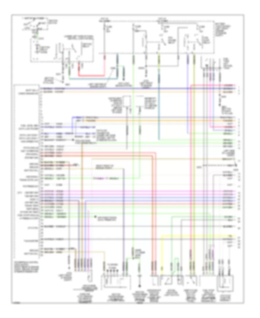
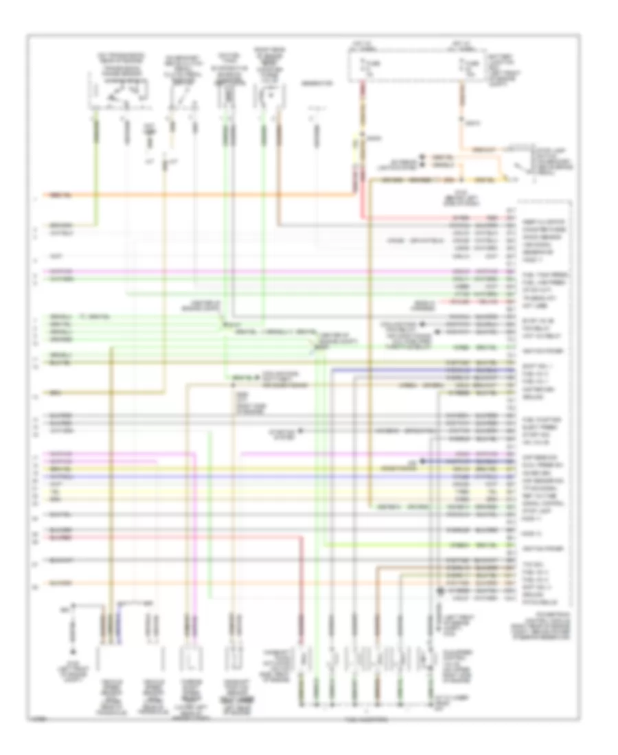
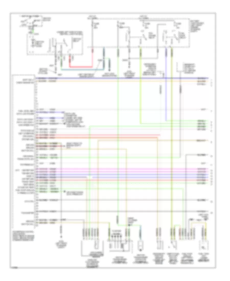
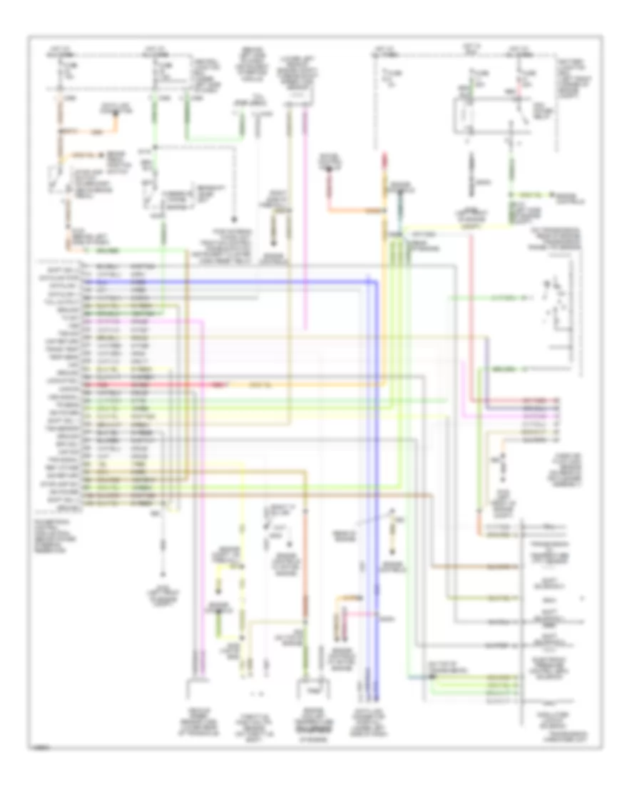
2.0L, Engine Performance Wiring Diagrams (1 of 3) for Ford Contour SE 2000
List of elements for 2.0L, Engine Performance Wiring Diagrams (1 of 3) for Ford Contour SE 2000:
- (a/t)
- (bottom of right "a" pillar)
- (left center of engine compt)
- (left kick panel) g200
- (near cylinder head) s414
- (right front of engine compt) g101
- (under left side of dash) central junction box
- 10-gl37
- 15s-re16
- 15s-re9a
- 15s-ta21
- 4-re8
- 5-re8
- 8-ce6
- 8-ga6
- 8-gb10
- 8-gg18
- 8-ra1
- 8-rj17
- 8-rj25
- 8-rj29b
- 8-rj4
- 8-rj6
- 8-ta26
- 8-ta27
- 9-rj22
- 9-rj29
- 9-rj4
- 9-rr1
- 9-rr2
- 91-re21
- 91-re8c
- 91-re8e
- 91s-pa17
- 91s-rd7
- 91s-rl27
- 91s-ta24
- Acc
- Air charge temperature sensor
- Air conditioning (dual press sw)
- Anti-lock brake system
- Battery junction box (left front corner of engine compt)
- C361
- C370
- C371
- C372
- C440
- Check engine ind
- Cooling fans (high speed relay)
- Cps return
- Cps signal
- Crankshaft position sensor (lower left rear of engine)
- Cta ctrl
- Data link conn +
- Data link conn -
- Data link connector (under left side
- Data link power
- Fuel level sen
- Fuel pump module
- Fuel pump module (left front of luggage compt, near fenderwell)
- Fuel pump relay
- Fuel tank unit (under center of rear seat)
- Fuse 15a
- Fuse 20a
- Fuse 60a
- G100 (left front of engine compt)
- G901
- Gearshift lever unit (a/t only) (at center console)
- Ground
- Hi press cutoff
- High speed fan
- Ho2s 12
- Hot at all times
- Ignition coil
- Ignition relay
- Ignition relay diode
- Ignition switch
- Ignition transformer (on rear of cylinder head)
- Ignition transformer capacitor (on rear of cylinder head)
- Inertia fuel shut-off switch (behind left kick panel)
- Inst interface
- Instrument interface module (a/t only) (behind left side of dash)
- Intake air temp
- Lock
- Maf return
- Mass air- flow sensor (on rear of air cleaner assembly)
- Of dash, left of steering column)
- Off
- P/s press sw
- Pats module
- Pcm power relay
- Plugs
- Powertrain control module (pcm) (right rear of engine compt, behind power steering reservoir)
- Red
- Run
- S3003
- S301
- S331
- S62
- Shift sol 2
- Start
- Tachometer
- Temp sens
- To spark
- Trans cntrl sw
- Trans temp
- Tss return
- Vss return
- Vss signal
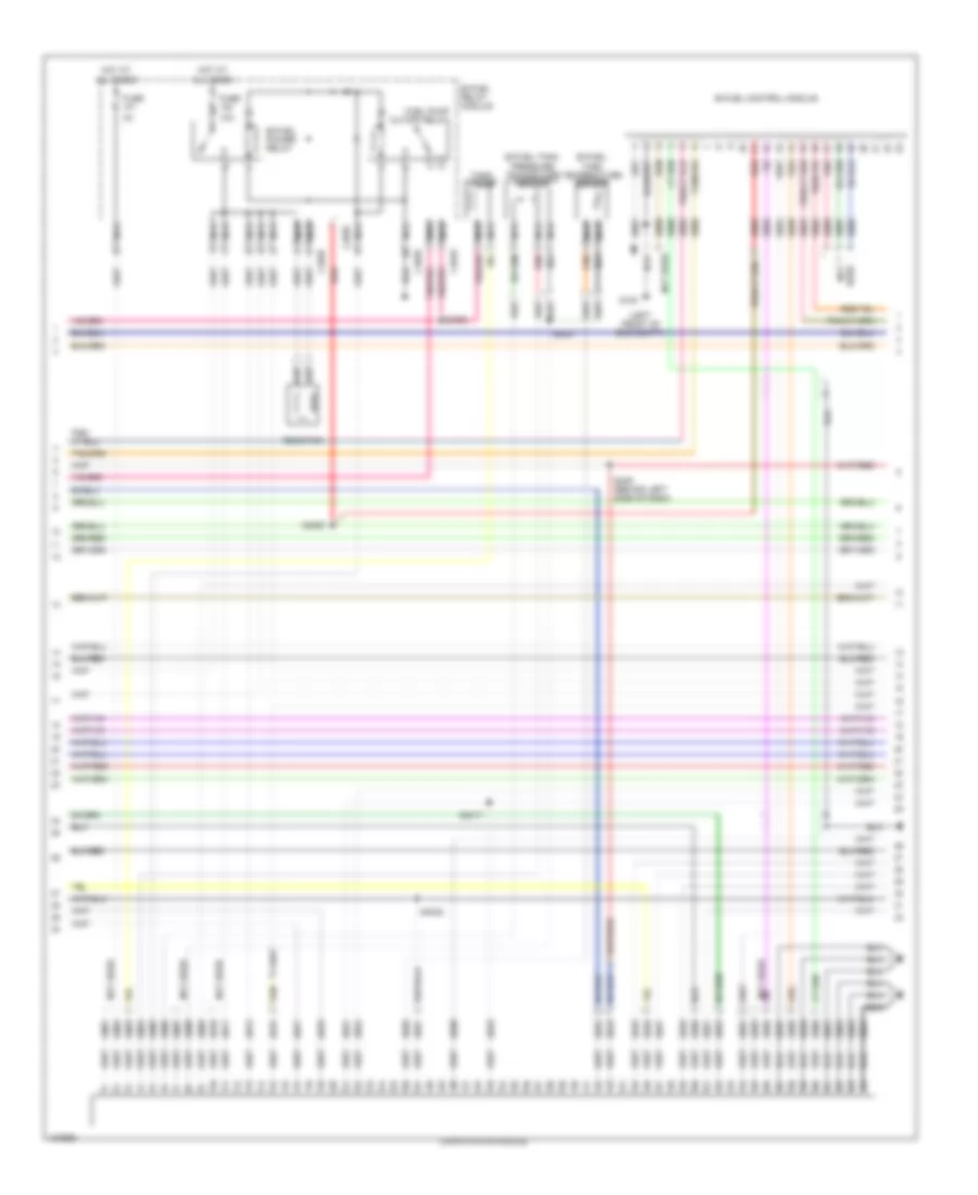
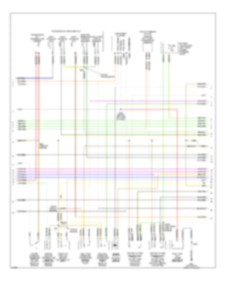
2.0L, Engine Performance Wiring Diagrams (2 of 3) for Ford Contour SE 2000
List of elements for 2.0L, Engine Performance Wiring Diagrams (2 of 3) for Ford Contour SE 2000:
- (on right side of engine)
- (right side of engine)
- (top of engine)
- (top of steering column)
- (top of transmission)
- Battery junction box (left front corner of engine compt)
- C808a
- Check engine
- Electric pressure control solenoid
- Engine coolant temperature sensor (upper left rear of engine)
- Fuel gauge c808b
- Fuel rail pressure transducer sensor (left front of engine)
- Fuel tank pressure transducer sensor (on fuel tank)
- Fuel tank unit (under center of rear seat)
- Fuse 20a
- G901 (bottom of right "a" pillar)
- Heated oxygen
- Instrument cluster
- Knock sensor
- Modulated lockup solenoid
- Nca
- Passive anti-theft transceiver module
- Power steering pressure switch (on left front of engine)
- S300
- S3005 (left rear side of engine)
- S409 (behind left side of dash)
- S425
- S48
- S53 (rear of engine)
- S54
- Sensor (ho2s) (front 11) (on left side of engine, in exhaust manifold)
- Sensor (ho2s) (rear 12) (on left side of engine, in exhaust, behind converter)
- Shift solenoid no 1
- Shift solenoid no 2
- Shift solenoid no 3
- Tachometer
- Throttle position sensor (on throttle body)
- Transmission hardware unit
- Transmission oil temperature sensor
- Vss signal
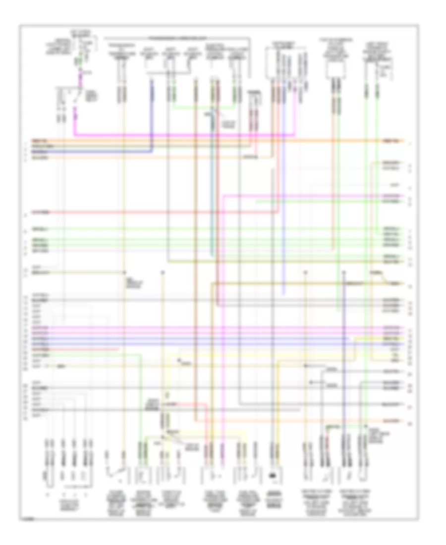
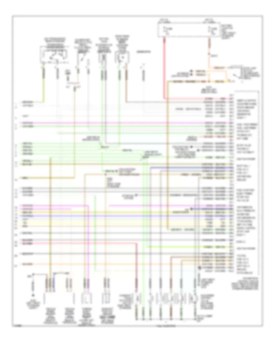
2.0L, Engine Performance Wiring Diagrams (3 of 3) for Ford Contour SE 2000
List of elements for 2.0L, Engine Performance Wiring Diagrams (3 of 3) for Ford Contour SE 2000:
- (at cylinder head) s47
- (center of engine compt)
- (center of engine compt) s59
- (left front of engine compt) g100
- (on bracket, above clutch pedal) clutch pedal position switch
- (on fuel tank)
- (on transmission, rear of engine)
- (right rear of engine compt) evap canister purge valve
- 15-re8
- 15-re8a
- 15s-re13
- 29s-re13
- 30-re8
- 31s-bb12
- 31s-ta9
- 33-xl65
- 7-re8
- 8-ba9
- 8-bb6
- 8-gl37
- 8-re8a
- 8-rj11
- 8-rj13
- 8-rj14
- 8-rj18
- 8-rj22
- 8-rj28
- 8-rj29
- 8-rj3
- 8-ta9
- 9-re8
- 9-rj18
- 9-rj3
- 91-re8b
- 91-re8d
- 91s-fa11
- 91s-pa13
- 91s-re31
- 91s-rj14
- 91s-rj25
- 91s-rl10
- 91s-rl11
- 91s-rl12
- 91s-rl13
- 91s-rl2
- 91s-rl3
- 91s-rl9
- 91s-ta17
- 91s-ta20
- 91s-ta23
- 91s-ta25
- A/t
- Air conditioning
- Air conditioning (a/c wide open throttle relay)
- Battery junction box (left front of engine compt)
- Camshaft position sensor (on cylinder head, upper left rear of engine)
- Camshaft timing actuator (on top side, front of engine)
- Canister purge
- Cmp return
- Cmp sens sig
- Cooling fans (fan relay)
- Cooling fans, anti-theft, air conditioning
- Cp sw (m/t)
- Dual press sw
- Elect press
- Ends in harness
- Evap valve
- Evaporative emission canister vent valve
- Exterior lights system
- Fan relay
- Fuel inj 1
- Fuel inj 2
- Fuel inj 3
- Fuel inj 4
- Fuel injectors
- Fuel line press
- Fuel pump mod
- Fuel tank press
- Fuse 15a
- Fuse 3a
- G100 (left front of engine compt)
- Generator
- Ground
- Ho2s 11
- Ho2s 12
- Hot at all times
- Iac valve
- Idle speed control valve (on upper right side of engine)
- Ignition power
- Keep alive pwr
- Knock sensor
- Ks return
- M/t
- Maf sensor sig
- Not used
- Pats module
- Powertrain control module (right rear of engine compt, behind power steering reservoir)
- Red
- Ref voltage
- S130 (behind left side of dash)
- S147
- S285 (a/t) (right side of engine)
- S3010
- S62
- Shft sol 3
- Shift sol 1
- Signal control
- Start sig
- Starting system
- Stop lamp
- Stop lamp switch (on bracket, above brake pedal)
- Tcc sol
- Tp sig signal
- Tr sens (a/t)
- Transmission range sensor
- Turbine shaft speed sensor (a/t) (lower left rear of engine compt)
- Vehicle speed sensor (a/t) (lower rear of transaxle)
- Vehicle speed sensor (m/t) (lower rear of transaxle)
- Vss signal
- Wot a/c relay
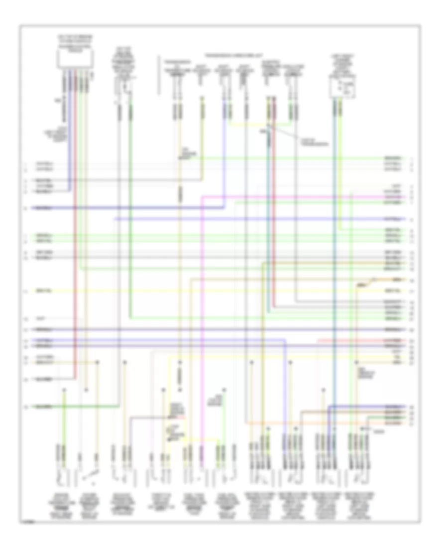
2.5L
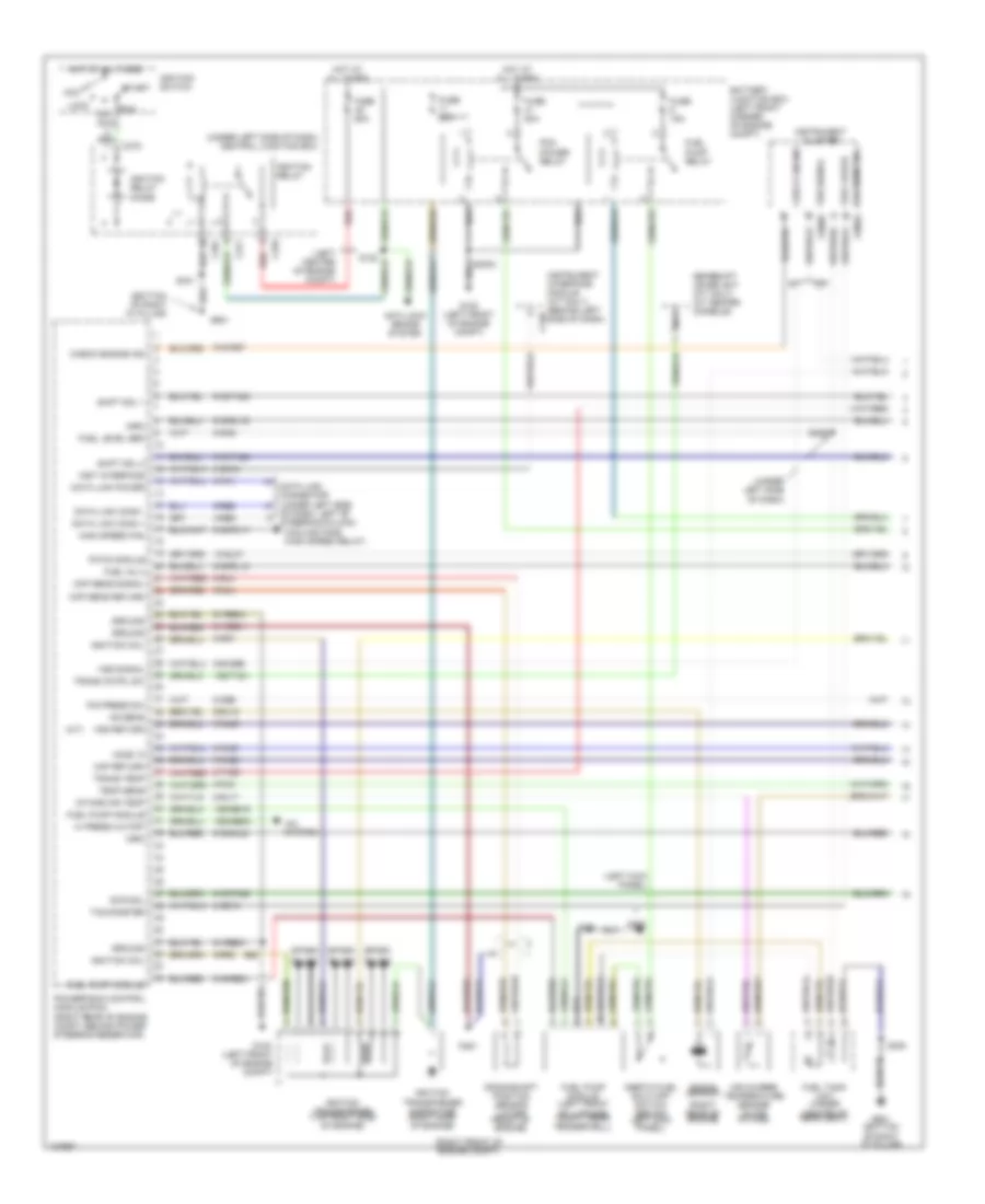
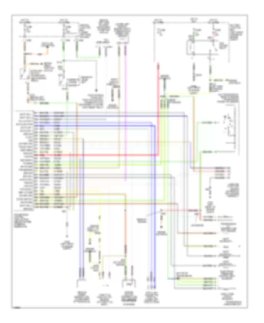
2.5L, Engine Performance Wiring Diagrams (1 of 3) for Ford Contour SE 2000
List of elements for 2.5L, Engine Performance Wiring Diagrams (1 of 3) for Ford Contour SE 2000:
- (a/t)
- (bottom of right "a" pillar)
- (left center of engine compt)
- (left kick panel)
- (right front of engine compt)
- (right rear of engine)
- (under left side of dash)
- (under left side of dash) central junction box
- 10-gl37
- 15s-re16
- 15s-re9a
- 15s-ta21
- 4-re8
- 5-re8
- 8-ce6
- 8-ga6
- 8-gb10
- 8-gg18
- 8-ra1
- 8-rj17
- 8-rj25
- 8-rj29b
- 8-rj4
- 8-rj6
- 8-ta26
- 9-rj18
- 9-rj22
- 9-rj29
- 9-rj4
- 9-rr1
- 9-rr2
- 91-re21
- 91-re8a
- 91-re8c
- 91s-pa17
- 91s-pa25
- 91s-rd7
- 91s-re31
- 91s-rj16
- 91s-rl12
- 91s-rl20
- 91s-ta23
- 91s-ta24
- A/c system
- A/t
- Acc
- Air charge temperature sensor (in air intake)
- Anti-lock brake system
- Battery junction box (left front corner of engine compt)
- C361
- C370
- C371
- C372
- C440
- C808b
- Center of rear seat)
- Check engine
- Check engine ind
- Ckp sens return
- Ckp sens signal
- Cooling fans (high speed relay)
- Crankshaft position sensor (lower front of engine)
- Data link conn +
- Data link conn -
- Data link connector (under left side
- Data link power
- Evr sol
- Fuel gauge
- Fuel inj 3
- Fuel level sen
- Fuel pump module
- Fuel pump module (left front of luggage compt, near fenderwell)
- Fuel pump relay
- Fuel tank unit (under
- Fuse 15a
- Fuse 20a
- Fuse 60a
- G100 (left front of engine compt)
- G101
- G200
- G901
- G901 (bottom of right "a" pillar)
- Gearshift lever unit (a/t only) (at center console)
- Ground
- Hi press cutoff
- High speed fan
- Ho2s 12
- Hot at all times
- Ignition coil
- Ignition relay
- Ignition relay diode
- Ignition switch
- Ignition transformer (top right side of engine)
- Ignition transformer capacitor (right side of engine)
- Imrc
- Inertia fuel shut-off switch (behind left kick panel)
- Inst interface
- Instrument cluster
- Instrument interface module (a/t only) (behind left side of dash)
- Intake air temp
- Knock sensor
- Ks sens
- Lock
- M/t
- Maf return
- Nca
- Of dash, left of steering column)
- Off
- P/s press sw
- Pats module
- Pcm power relay
- Plugs
- Powertrain control module (pcm) (right rear of engine compt, behind power steering reservoir)
- Red
- Run
- S300
- S3003
- S301
- S331
- S409
- S62
- Shift sol 1
- Shift sol 2
- Spark
- Start
- Tachometer
- Tachometer c808a
- Temp sens
- Trans cntrl sw
- Trans temp
- Vss return
- Vss signal
2.5L, Engine Performance Wiring Diagrams (2 of 3) for Ford Contour SE 2000
List of elements for 2.5L, Engine Performance Wiring Diagrams (2 of 3) for Ford Contour SE 2000:
- (left front corner of engine compt) battery junction box
- (on engine) s407
- (on top center of engine) electronic vacuum regulator solenoid valve
- (on top of engine) intake manifold
- (right side of engine) s54
- (top of transmission)
- C104
- Electric pressure control solenoid
- Engine coolant temperature sensor (upper right rear of engine)
- Exhaust pressure transducer sensor (right rear of engine)
- Fuel rail pressure transducer sensor (left front of engine)
- Fuel tank pressure transducer sensor (on fuel tank)
- Fuse 20a
- G100 (left front of engine compt)
- Heated oxygen sensor (ho2s) (front 11) (right side of engine, in exhaust manifold)
- Heated oxygen sensor (ho2s) (front 21) (left side of engine, in exhaust manifold)
- Heated oxygen sensor (ho2s) (rear 12) (right side of engine, behind converter)
- Heated oxygen sensor (ho2s) (rear 22) (left side of engine, behind converter)
- Modulated lockup solenoid
- Nca
- Power steering pressure switch (right front of engine)
- Runner control module
- S3005
- S425
- S48 (top of engine)
- S53 (rear of engine)
- S62
- Shift solenoid no 1
- Shift solenoid no 2
- Shift solenoid no 3
- Throttle position sensor (on throttle body)
- Transmission hardware unit
- Transmission oil temperature sensor
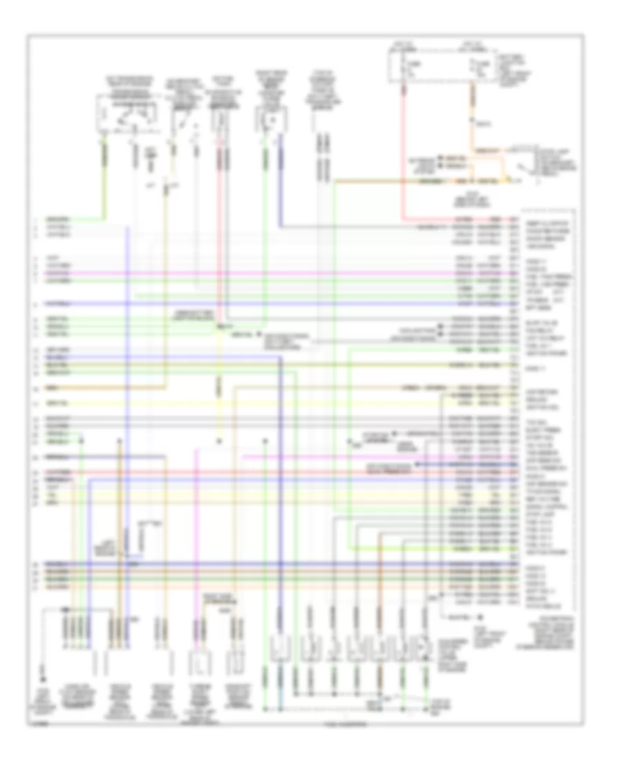
2.5L, Engine Performance Wiring Diagrams (3 of 3) for Ford Contour SE 2000
List of elements for 2.5L, Engine Performance Wiring Diagrams (3 of 3) for Ford Contour SE 2000:
- (a/t)
- (left rear of engine)
- (m/t)
- (near battery junction block)
- (near engine)
- (on bracket, above clutch pedal) clutch pedal position switch
- (on fuel tank)
- (on transmission, rear of engine)
- (right rear of engine compt) evap canister purge valve
- (right side of engine)
- (top of engine) s50
- (top of steering column)
- 15-re8
- 15-re8a
- 15s-re13
- 30-re8
- 31s-ta9
- 7-re8
- 8-bb6
- 8-gl37
- 8-re8a
- 8-rj11
- 8-rj13
- 8-rj14
- 8-rj15
- 8-rj18
- 8-rj22
- 8-rj26
- 8-rj28
- 8-rj29a
- 8-rj3
- 8-rj7
- 8-ta27
- 8-ta9
- 9-re8
- 9-rj3
- 9-rr3
- 91-re8
- 91-re8b
- 91s-fa11
- 91s-pa13
- 91s-pa7
- 91s-rj14
- 91s-rj15
- 91s-rj25
- 91s-rj26
- 91s-rl10
- 91s-rl11
- 91s-rl13
- 91s-rl14
- 91s-rl15
- 91s-rl2
- 91s-rl3
- 91s-rl9
- 91s-ta17
- 91s-ta20
- 91s-ta25
- A/t
- Air conditioning
- Air conditioning (dual press sw)
- Air conditioning, anti-theft, cooling fans
- Battery junction box (left front of engine compt)
- Camshaft position sensor (front of engine)
- Canister purge
- Cmp return
- Cmp sens sig
- Cooling fans
- Cp sw
- Dual press sw
- Elect press
- Ept sens
- Evap valve
- Evaporative emission canister vent valve
- Exterior lights system
- Fan relay
- Fuel inj 1
- Fuel inj 2
- Fuel inj 4
- Fuel inj 5
- Fuel inj 6
- Fuel injectors
- Fuel line press
- Fuel tank press
- Fuse 15a
- Fuse 3a
- G100 (left front of engine compt)
- Ground
- Ho2s 11
- Ho2s 12
- Ho2s 21
- Ho2s 22
- Hot at all times
- Iac valve
- Idle speed control valve (upper right side of engine)
- Ignition coil
- Ignition power
- Keep alive pwr
- Knock sensor
- M/t
- Maf sensor sig
- Mass air- flow sensor (on rear of air cleaner assembly)
- Nca
- Not used
- Passive anti-theft transceiver module
- Pats module
- Powertrain control module (right rear of engine compt, behind power steering reservoir)
- Red
- Ref voltage
- S130 (behind left side of dash)
- S147
- S285
- S3010
- S51
- S59
- S60
- S62
- Shft sol 3
- Signal control
- Start sig
- Starting system
- Stop lamp
- Stop lamp switch (on bracket, above brake pedal)
- Tcc sol
- Tp sig signal
- Tr sens
- Transmission range sensor
- Tss sensor
- Turbine shaft speed sensor (a/t) (lower left rear of engine compt)
- Vehicle speed sensor (a/t) (lower rear of transaxle)
- Vehicle speed sensor (m/t) (lower rear of transaxle)
- Vss signal
- Wot a/c relay
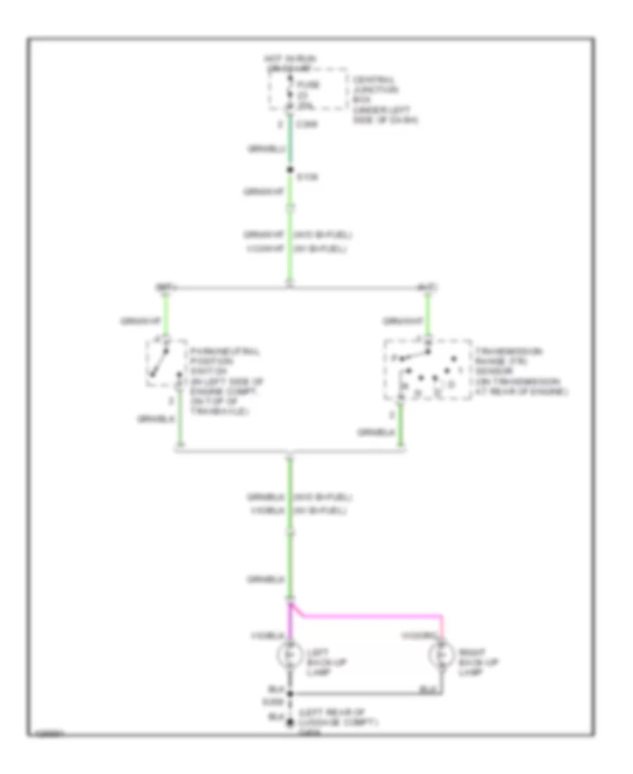
EXTERIOR LIGHTS
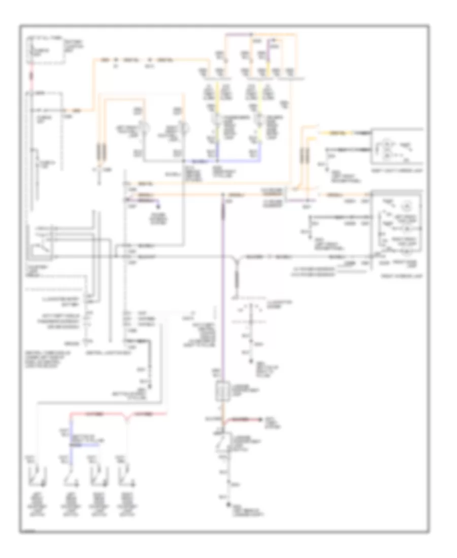
Back-up Lamps Wiring Diagram for Ford Contour SE 2000
List of elements for Back-up Lamps Wiring Diagram for Ford Contour SE 2000:
- (a/t)
- (left rear of luggage compt) g404
- (m/t)
- C369
- Central junction box (under left side of dash)
- Fuse 15a
- Hot in run or start
- Left back-up lamp
- Park/neutral position switch (in left side of engine compt, on top of transaxle)
- Right back-up lamp
- S136
- S268
- Transmission range (tr) sensor (on transmission at rear of engine)
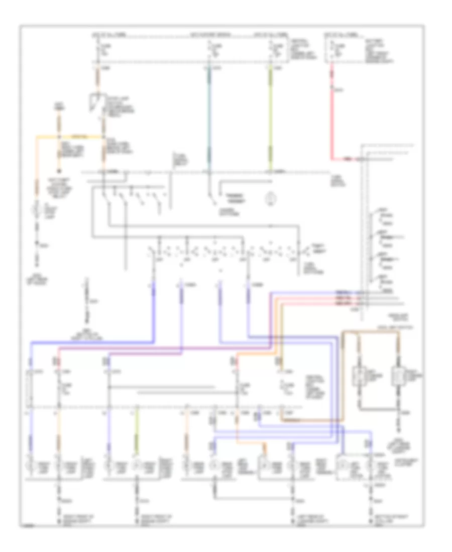
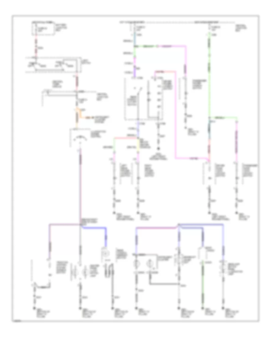
Exterior Lamps Wiring Diagram for Ford Contour SE 2000
List of elements for Exterior Lamps Wiring Diagram for Ford Contour SE 2000:
- (bottom of right 'a' pillar) g901
- (left rear of luggage compt) g404
- (not used)
- (right front of engine compt) g101
- Anti-theft system (panic alarm stop lamp relay)
- Battery junction box (left front corner of engine compt)
- C320
- C361
- C362
- C367
- C369
- C372
- C459a
- C459b
- C808a
- Central junction box (under left side of dash)
- Front park lamp
- Front turn lamp
- Fuse 15a
- Fuse 20a
- Fuse 7.5a
- G404 (left rear of luggage compt)
- G404 (left rear of trunk)
- G901 (bottom of right "a" pillar)
- Hazard
- Hazard switches
- Head
- Headlamp switch
- Hi mount stop lamp
- Hot at all times
- Hot in start or run
- Instrument cluster
- Left
- Left front park/ turn lamp
- Left license lamp
- Left rear lamp assembly
- Left turn indi- cator
- Main light switch
- Nca
- Normal
- Off
- Park
- Rear park lamp
- Rear seat)
- Rear turn/ stop lamp
- Red
- Right
- Right front park/ turn lamp
- Right license lamp
- Right rear lamp assembly
- Right turn indi- cator
- S130 (dash harn, behind left side of dash)
- S133
- S244
- S268
- S3003
- S304
- S310
- S331
- Stop lamp switch (on bracket, above brake pedal)
- Turn signal relay
- Turn signal switch
- Turn signal switches
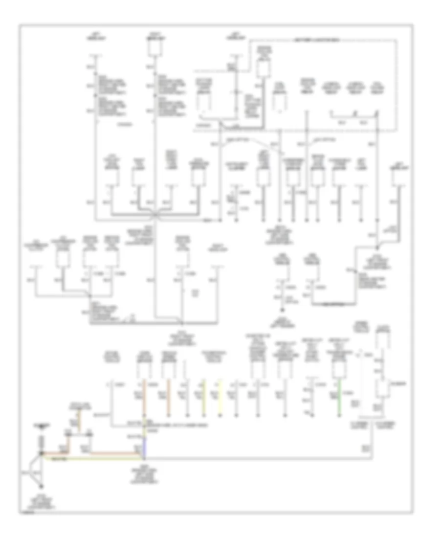
GROUND DISTRIBUTION
Ground Distribution Wiring Diagram (1 of 3) for Ford Contour SE 2000
List of elements for Ground Distribution Wiring Diagram (1 of 3) for Ford Contour SE 2000:
- (duratec-ve only) intake manifold runner control module
- (engine harn, left side of engine compartment)
- (zetec-vct only) (a/t) transmission range switch
- (zetec-vct only) (m/t) start inhibit switch
- (zetec-vct only) coolant temperature sensor
- A/c compressor clutch
- A/c compressor clutch diode
- Abs control module
- Battery
- Battery junction box
- Bi-fuel control module
- Brake fluid level switch
- Busbar
- C102
- C104
- C1856
- C1858
- C1908
- C1919
- C1942
- C3002
- C4001
- C421
- C808b
- C833
- Canada
- Clock spring
- Compartment)
- Data link connector
- Daytime running lamps relay
- Dual pressure switch
- Engine cooling fan motor
- Engine cooling fan relay
- Fuel pump relay
- G100 (left front of engine compartment)
- G101 (right front of engine compartment)
- G104 (rear of left fender)
- Hi-beam headlamp relay
- High option
- Instrument cluster
- Left fog lamp
- Left front park/ turn lamp
- Left headlamp
- Lo-beam headlamp relay
- Low coolant level switch
- Low option
- Mass airflow sensor
- Non- daytime running lamps relay jumper
- Overspeed warning module
- Pcm power relay
- Powertrain control module
- Right fog lamp
- Right front park/ turn lamp
- Right headlamp
- S133 (engine harn, right front of engine compartment)
- S249 (rear center of engine compartment)
- S250 (engine harn, left side of engine compartment)
- S3003
- S323 (engine harn, front center of engine compartment)
- S324 (engine harn, front center of engine compartment)
- S325 (engine harn, front center of engine compartment)
- S4026
- Second cooling fan motor
- Speed control module
- U.s.
- Vehicle speed sensor
- W/ a/c
- W/ abs
- W/ speed control
- W/o a/c
- W/o abs
- W/o speed control
- Windshield wiper motor
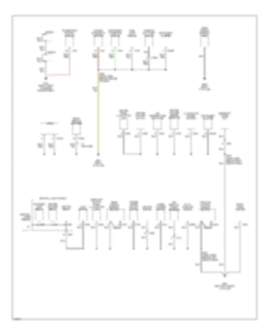
Ground Distribution Wiring Diagram (2 of 3) for Ford Contour SE 2000
List of elements for Ground Distribution Wiring Diagram (2 of 3) for Ford Contour SE 2000:
- Air bag diagnostic monitor
- Air temperature actuator
- C1943
- C1945
- C20
- C2001
- C320
- C361
- C400
- C406
- C421
- C437
- C440
- C441
- C443a
- C456
- C459a
- C469
- C470
- C493
- C57
- C59
- C711
- C732
- C740
- C808a
- C808b
- C81
- C846
- C912
- C931
- Central junction box
- Central timer module
- Courtesy lamp relay
- Front cigar lighter
- Front remote amplifier
- Fuel pump module
- G101 (right front of engine compartment)
- G901 (bottom of right "a" pillar)
- G901 (right "a" pillar)
- G905 (right "c" pillar)
- Gearshift lever unit
- Headlight switch panel illumination lamp
- Heater blower relay
- Heater blower series resistor
- Heater blower switch
- Heater panel illumination lamp
- Ignition relay
- Ignition switch
- Illumination dimmer control
- Instrument cluster
- Instrument interface module
- Key removal inhibit solenoid
- Light switch
- Multi- function switch
- Passive anti-theft module
- Power mirror adjust switch
- Powertrain control module
- Radio
- Rear window defrost grid
- Rear window defrost switch
- S244 (dash harn, behind right side of dash)
- S300 (dash harn, behind center of dash)
- S331 (dash harn, behind left side of dash)
- Shield
- Traction control disable switch
- W/ amplifier
- Wiper/ washer switch
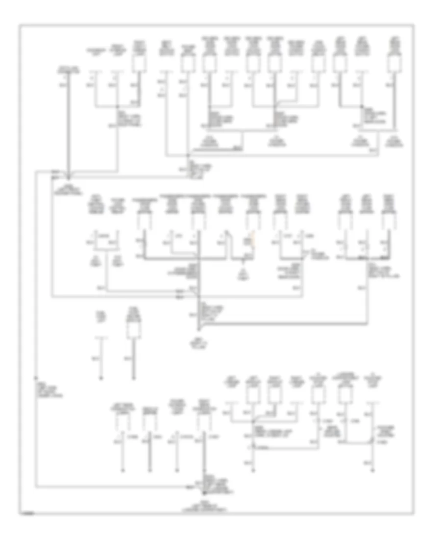
Ground Distribution Wiring Diagram (3 of 3) for Ford Contour SE 2000
List of elements for Ground Distribution Wiring Diagram (3 of 3) for Ford Contour SE 2000:
- Anti- theft central locking module
- C107
- C1913a
- C1914
- C1920
- C1921
- C1946
- C1947
- C451b
- C490
- C78
- C798
- C844
- Data link connector
- Decklid motor
- Driver's door lock/ unlock switch
- Driver's power window switch
- Driver's side door lock motor
- Front interior lamp
- Fuel pump driver module
- Fuel tank unit
- G309 (left front rocker panel)
- G404 (left rear of luggage compartment)
- G901 (right "a" pillar)
- Hi mounted stop lamp
- Left backup lamp
- Left front door ajar switch
- Left license lamp
- Left rear combination lamp
- Left rear door ajar switch
- Left rear door lock motor
- Left rear power window switch
- Luggage compartment lamp switch
- Moonroof unit
- One touch window relay
- Package shelf mounted
- Passenger's door ajar switch
- Passenger's door lock/ unlock switch
- Passenger's side door lock motor
- Passenger's side door lock switch
- Passenger's side power window switch
- Power antenna timing unit
- Power lock control relay
- Power seat switch
- Rear spoiler mounted
- Right backup lamp
- Right license lamp
- Right rear combination lamp
- Right rear door ajar switch
- Right rear door lock motor
- Right rear power window switch
- Right vanity mirror lamp
- S14 (body harn, bottom of right "b" pillar)
- S258 (door harn, in passenger's door)
- S259 (door harn, in right rear door)
- S269 (door harn, in left rear door)
- S303 (left side of trunk, under lining)
- S4 (body harn, bottom of right "a" pillar)
- S8 (body harn, bottom of left "a" pillar)
- Seat belt buckle switch
- W/ anti- theft
- W/ power windows
- W/o anti- theft
- W/o power windows
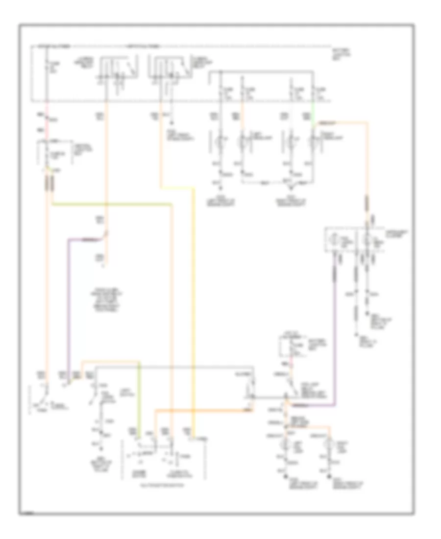
HEADLIGHTS
Headlight Wiring Diagram, Base for Ford Contour SE 2000
List of elements for Headlight Wiring Diagram, Base for Ford Contour SE 2000:
- (behind left side of dash)
- Battery junction box
- C320
- C361
- C459a
- C808a
- C808b
- Central junction box
- Dimmer switch
- Flash-to- pass switch
- Fog lamp relay (behind left side of dash)
- Fog lamps ind
- Fog lamps switch
- Fuse 20a
- Fuse 26 7.5a
- Fuse 7.5a
- G100 (left front of eng compt)
- G100 (left front of engine compt)
- G101 (right front of engine compt)
- G101 (right front of engine compt)
- G901 (bottom of right "a" pillar)
- G901 (right "a" pillar)
- Head
- Hi beam headlamp relay
- Hi beam ind
- Hot at all times
- Instrument cluster
- Left fog lamp
- Left headlamp
- Light switch
- Lo beam headlamp relay
- Multifunction switch
- Off
- Panic alarm headlamp relay (w/ active anti-theft) (behind right kick panel)
- Park
- Pass
- Red
- Right fog lamp
- Right headlamp
- S133
- S231
- S232
- S244
- S300
- S3003
- S323
- S325
- S331
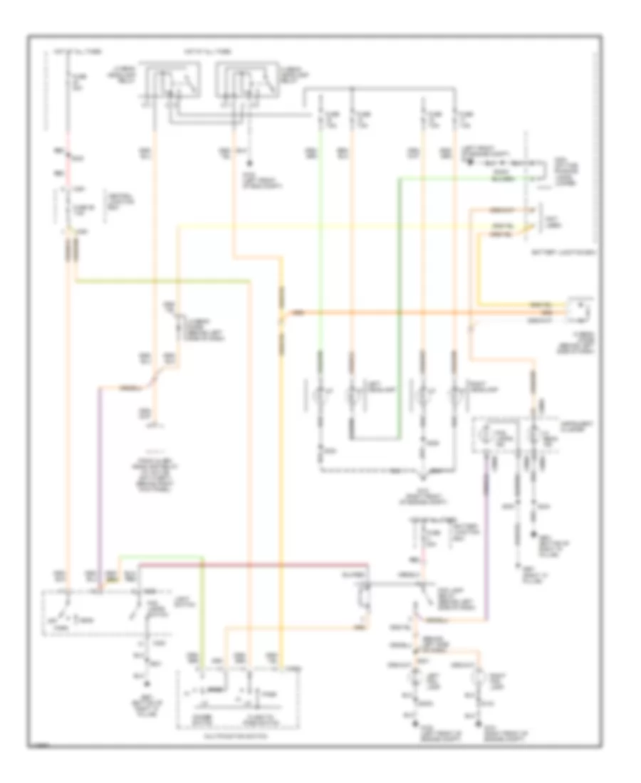
Headlight Wiring Diagram, High Level for Ford Contour SE 2000
List of elements for Headlight Wiring Diagram, High Level for Ford Contour SE 2000:
- (behind left side of dash)
- (left front of engine compt) g100
- (not used)
- Battery junction box
- C320
- C361
- C459a
- C808a
- C808b
- Central junction box
- Dimmer switch
- Flash-to- pass switch
- Fog lamp relay (behind left side of dash)
- Fog lamps ind
- Fog lamps switch
- Fuse 20a
- Fuse 26 7.5a
- Fuse 7.5a
- G100 (left front of eng compt)
- G100 (left front of engine compt)
- G101 (right front of engine compt)
- G901 (bottom of right "a" pillar)
- G901 (right "a" pillar)
- Head
- Hi beam diode (behind left side of dash)
- Hi beam headlamp relay
- Hi beam ind
- Hot at all times
- Instrument cluster
- Left fog lamp
- Left headlamp
- Light switch
- Lo beam diode (behind left side of dash)
- Lo beam headlamp relay
- Multifunction switch
- Non- daytime running lamps jumper
- Off
- Panic alarm headlamp relay (w/ active anti-theft) (behind right kick panel)
- Park
- Pass
- Red
- Right fog lamp
- Right headlamp
- S133
- S231
- S232
- S244
- S300
- S3003
- S323
- S325
- S331
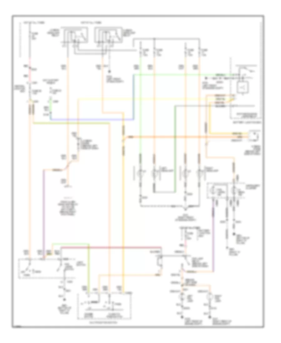
Headlight Wiring Diagram, with DRL for Ford Contour SE 2000
List of elements for Headlight Wiring Diagram, with DRL for Ford Contour SE 2000:
- (behind left side of dash)
- Battery junction box
- C320
- C361
- C369
- C459a
- C808a
- C808b
- Central junction box
- Daytime running lamps relay
- Dimmer switch
- Flash-to- pass switch
- Fog lamp relay (behind left side of dash)
- Fog lamps ind
- Fog lamps switch
- Fuse 20a
- Fuse 23 15a
- Fuse 26 7.5a
- Fuse 7.5a
- G100 (left front of eng compt)
- G100 (left front of engine compt)
- G101 (right front of engine compt)
- G901 (bottom of right "a" pillar)
- G901 (right "a" pillar)
- Head
- Hi beam diode (behind left side of dash)
- Hi beam headlamp relay
- Hi beam ind
- Hot at all times
- Hot in start or run
- Instrument cluster
- Left fog lamp
- Left headlamp
- Light switch
- Lo beam diode (behind left side of dash)
- Lo beam headlamp relay
- Multifunction switch
- Off
- Panic alarm headlamp relay (w/ active anti-theft) (behind right kick panel)
- Park
- Pass
- Red
- Right fog lamp
- Right headlamp
- S133
- S136
- S231
- S232
- S244
- S300
- S3003
- S323
- S325
- S331
HORN
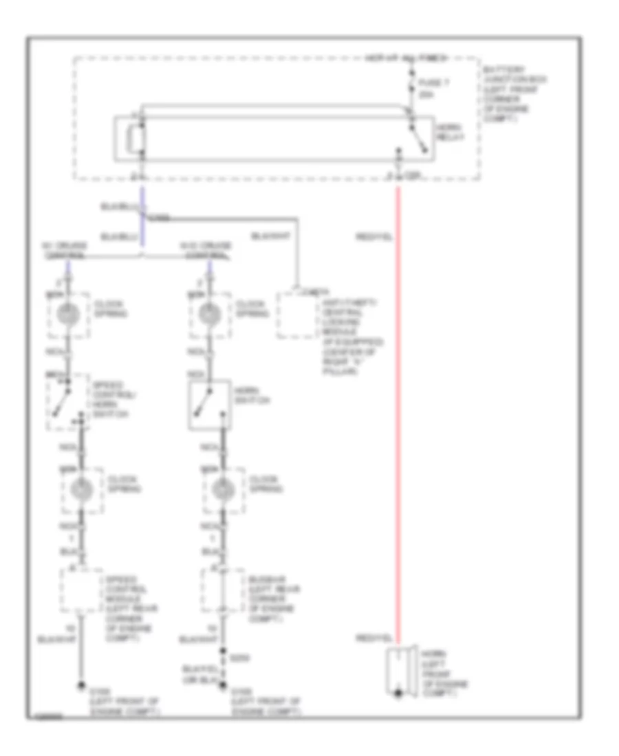
Horn Wiring Diagram for Ford Contour SE 2000
List of elements for Horn Wiring Diagram for Ford Contour SE 2000:
- 20a
- Anti-theft/ central locking module (if equipped) (center of right "a" pillar)
- Battery junction box (left front corner of engine compt)
- Busbar (left rear corner of engine compt)
- C102
- C451a
- C69
- Clock spring
- Fuse 7
- G100 (left front of engine compt)
- Horn (left front of engine compt)
- Horn relay
- Horn switch
- Hot at all times
- Nca
- S250
- Speed control module (left rear corner of engine compt)
- Speed control/ horn switch
- W/ cruise control
- W/o cruise control
INSTRUMENT CLUSTER
Instrument Cluster Wiring Diagram, A/T (1 of 2) for Ford Contour SE 2000
List of elements for Instrument Cluster Wiring Diagram, A/T (1 of 2) for Ford Contour SE 2000:
- (2.5l)
- (not used)
- 2.0l
- 2.5l
- A10
- A11
- A12
- A13
- A14
- A15
- A16
- Abs ind
- Acc
- Airbag ind
- Anti-lock brakes system
- B10
- Brake fluid level switch (in left rear of engine compt)
- Brake ind
- C808a (conn a)
- C808b (conn b)
- Charge ind
- Check engine ind
- Coolant temperature gauge
- Coolant temperature sensor (on left rear of engine)
- Coolant temperature sensor (on right rear of engine)
- Cruise control, warning systems
- Exterior lights system
- Fog lamps ind
- Fuel gauge
- G100 (left front of engine compt)
- G101 (right front of engine compt)
- G901 (bottom of right "a" pillar)
- G901 (right "a" pillar)
- Headlights system
- Hi beam ind
- Ignition switch
- Instrument cluster
- Instrument illumination
- Interior lights system
- Left turn ind
- Low coolant level ind
- Low fuel ind
- Low oil pressure ind
- Nca
- O/d off
- Off
- Oil pressure switch (2.0l: on right side of engine) (2.5l: on left side of engine)
- Park brake switch (at base of parking brake brake lever)
- Right turn ind
- Run
- S244
- S300
- S3003
- S331
- S62
- Seat belt ind
- Secondary airbag ind
- Speedometer
- Start
- Starting/charging system
- Tachometer
- Traction control ind
- W/abs
- W/o abs
- Warning systems
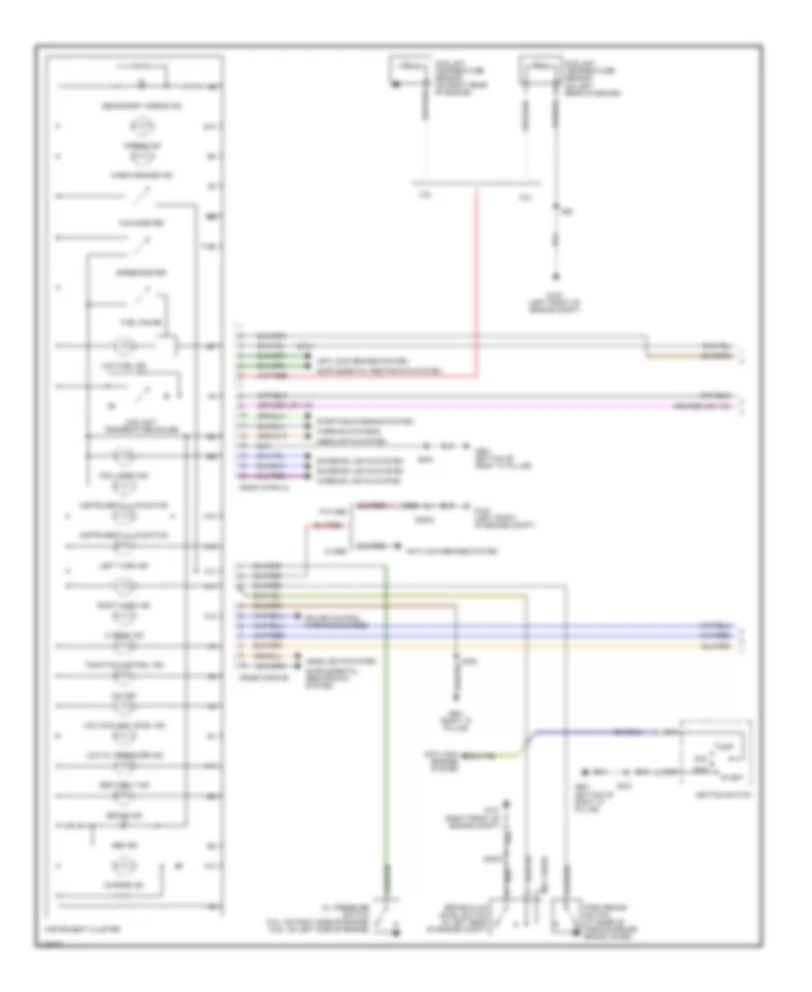
Instrument Cluster Wiring Diagram, A/T (2 of 2) for Ford Contour SE 2000
List of elements for Instrument Cluster Wiring Diagram, A/T (2 of 2) for Ford Contour SE 2000:
- (2.5l)
- (behind left side of dash) s106
- (behind left side of dash) s130
- (behind left side of dash) s409
- (brake pedal (position switch) (w/ cruise control)
- (right "a" pillar) g901
- 15gg15
- 15sta21
- 2.5l
- 29sgg15
- 29sgg17
- 29sgg20
- 29spc73
- 31sgc12
- 31sta28
- 31sta33
- 8ga6
- 8gb10
- 8gc9
- 8gg18
- 8rj29b
- 91spc85
- Anti-lock brake system
- Bi-fuel
- Bi-fuel control module
- C360
- C361
- C362
- C366
- C369
- C4001
- C4025
- C421
- Central junction box (cjb) (under left side of dash)
- Compuvalve module
- Cruise control system
- Dash reset relay
- Diode
- Exc bi-fuel
- Fuel tank unit (under center of rear seat, on fuel tank)
- Fuse 23 15a
- Fuse 24 15a
- Fuse 30 7.5a
- Fuse 31 7.5a
- Fuse 34 7.5a
- G101 (right front of engine compt)
- G901 (bottom of right "a" pillar)
- G901 (right "a" pillar)
- Gearshift lever unit (under center console)
- Hot at all times
- Hot in park & low beam
- Hot in run or start
- Instrument interface module (behind left side of dash)
- Interior lights system
- Low coolant level switch (in right front corner of engine compt, in coolant reservoir)
- Nca
- Nca key removal inhibit solenoid (top of steering column)
- O/d switch
- Powertrain control module (in right rear corner of engine compt, behind power steering reservoir)
- S104
- S116
- S133
- S244
- S300
- S3010
- S331
- S4022
- S4023
- Stoplight switch (on bracket, above brake pedal)
Instrument Cluster Wiring Diagram, M/T (1 of 2) for Ford Contour SE 2000
List of elements for Instrument Cluster Wiring Diagram, M/T (1 of 2) for Ford Contour SE 2000:
- (2.5l)
- (not used)
- 2.0l
- 2.5l
- A10
- A11
- A12
- A13
- A14
- A15
- A16
- Abs ind
- Acc
- Airbag ind
- Anti-lock brakes system
- B10
- Brake fluid level switch (in left rear of engine compt)
- Brake ind
- C808a (conn a)
- C808b (conn b)
- Charge ind
- Check engine ind
- Coolant temperature gauge
- Coolant temperature sensor (on left rear of engine)
- Coolant temperature sensor (on right rear of engine)
- Cruise control, warning systems
- Exterior lights system
- Fog lamps ind
- Fuel gauge
- G100 (left front of engine compt)
- G101 (right front of engine compt)
- G901 (bottom of right "a" pillar)
- G901 (right "a" pillar)
- Headlights system
- Hi beam ind
- Ignition switch
- Instrument cluster
- Instrument illumination
- Interior lights system
- Left turn ind
- Low coolant level ind
- Low fuel ind
- Low oil pressure ind
- Nca
- O/d off
- Off
- Oil pressure switch (2.0l: on right side of engine) (2.5l: on left side of engine)
- Park brake switch (at base of parking brake brake lever)
- Right turn ind
- Run
- S244
- S300
- S3003
- S331
- S62
- Seat belt ind
- Secondary airbag ind
- Speedometer
- Start
- Starting/charging system
- Tachometer
- Traction control ind
- W/abs
- W/o abs
- Warning systems
Instrument Cluster Wiring Diagram, M/T (2 of 2) for Ford Contour SE 2000
List of elements for Instrument Cluster Wiring Diagram, M/T (2 of 2) for Ford Contour SE 2000:
- (behind left side of dash) s106
- (behind left side of dash) s130
- (behind left side of dash) s409
- (brake pedal (position switch) (w/ cruise control)
- (not used)
- (right "a" pillar) g901
- 15gg15
- 2.5l
- 29sgg15
- 29sgg17
- 29sgg20
- 29spc73
- 31ssgc12
- 31sta28
- 31sta33
- 8ga6
- 8gb10
- 8gc9
- 8gg18
- 8rj29b
- 91spc85
- Anti-lock brake system
- Bi-fuel
- Bi-fuel control module
- C361
- C362
- C366
- C369
- C4001
- C4025
- C421
- Central junction box (cjb) (under left side of dash)
- Compuvalve module
- Cruise control system
- Dash reset relay
- Diode
- Exc bi-fuel
- Fuel pump module (under center of rear seat, on fuel tank)
- Fuse 24 15a
- Fuse 30 7.5a
- Fuse 31 7.5a
- G101 (right front of engine compt)
- G901 (right "a" pillar)
- Hot at all times
- Hot in park and low beam
- Hot in run or start
- Instrument interface module (behind left side of dash)
- Low coolant level switch (in right front corner of engine compt, in coolant reservoir)
- Powertrain control module (in right rear corner of engine compt, behind power steering reservoir)
- S116
- S133
- S300
- S3010
- S4022
- S4023
- Stop lamp switch (on bracket, above brake pedal)
INTERIOR LIGHTS
Courtesy Lamp Wiring Diagram for Ford Contour SE 2000
List of elements for Courtesy Lamp Wiring Diagram for Ford Contour SE 2000:
- (w/ power moonroof)
- (w/o power moonroof)
- Anti- theft system
- Anti-theft module
- Anti-theft/ central locking module (in center of right "a" pillar)
- Battery
- Battery junction box
- C360
- C361
- C365
- C366
- C367
- C370
- C451a
- C890a
- C890b
- C891
- Central junction box
- Central timer module (under left side of
- Courtesy lamp relay
- Dash, on central junction block)
- Door
- Driver door sw
- Driver's side front door entry lamp
- Front dome lamp
- Front interior lamp
- Fuse 25 20a
- Fuse 34 7.5a
- Fuse 52 60a
- G304 (left front rocker panel)
- G404 (left rear of luggage compt)
- G901 (bottom of right "a" pillar)
- G901 (bottom of right "a) pillar)
- Ground
- Hot at all times
- Illuminated entry
- Illumination dimmer
- Left front door courtesy lamp switch
- Left front footwell lamp
- Left front map lamp
- Left rear door courtesy lamp switch
- Luggage compartment lamp
- Luggage compartment lamp switch
- Nca
- Off
- Pass/rear doors sw
- Passenger's side front door entry lamp
- Power antenna system
- Red
- Right front door courtesy lamp switch
- Right front footwell lamp
- Right front map lamp
- Right rear door courtesy lamp switch
- Right vanity mirror lamp
- S113 (behind center of dash)
- S241
- S244
- S304
- S320
- S329 (near right "a" pillar)
- S331
- S34
- S36
- S413
- W/ anti- theft alarm
- W/ power moonroof
- W/o anti- theft alarm
- W/o power moonroof
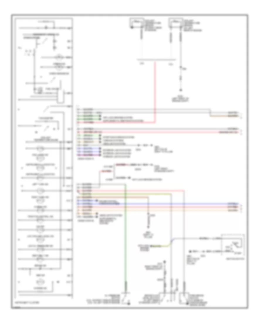
Instrument Illumination Wiring Diagram for Ford Contour SE 2000
List of elements for Instrument Illumination Wiring Diagram for Ford Contour SE 2000:
- (4)
- (behind right side of dash) s333
- Battery junction box
- C282
- C360
- C361
- C363
- C443a
- C75a
- C75b
- C808a
- C808b
- Central junction box
- Central timer module
- Driver door lock/ unlock switch
- Driver power window switch
- Fuse 21 40a
- Fuse 23 15a
- Fuse 31 7.5a
- Fuse 40 20a
- G304 (left front rocker panel)
- G901 (bottom of right "a" pillar)
- G901 (right "a" pillar)
- Gearshift lever unit
- Head
- Headlamp switch panel illumination lamp
- Heater panel illumi- nation lamp
- Hot at all times
- Hot in run or start
- Illumination dimmer control
- Instrument cluster
- Instrument cluster system
- Left rear power window switch
- Light switch
- Nca
- Off
- Park
- Passenger door lock/ unlock switch
- Passenger power window switch
- Radio
- Rear window cut-off switch
- Rear window defrost switch
- Red
- Right rear power window switch
- S20 (below center console)
- S232 red
- S244
- S257
- S258
- S259
- S269
- S300
- S314
- S331
- S86
- Traction control system disable switch
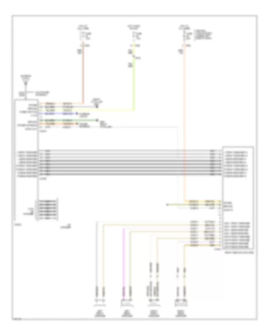
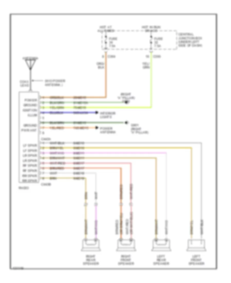
POWER ANTENNA
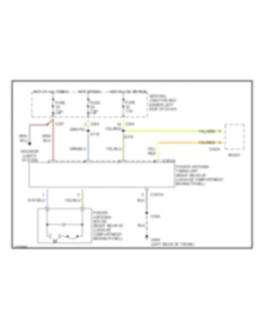
Power Antenna Wiring Diagram for Ford Contour SE 2000
List of elements for Power Antenna Wiring Diagram for Ford Contour SE 2000:
- C1913a
- C362
- C364
- C367
- C443a
- Central junction box (under left side of dash)
- Fuse 7.5a
- G404 (left rear of trunk)
- Hot at all times
- Hot in acc or run
- Hot in run
- Interior lights system
- Power antenna motor (right rear of luggage compartment, behind panel)
- Power antenna timing unit (right rear of luggage compartment, behind panel)
- Radio
- S116
- S304
- S319
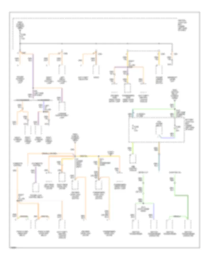
POWER DISTRIBUTION
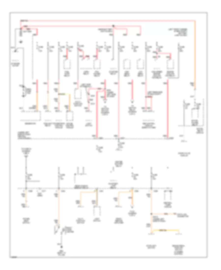
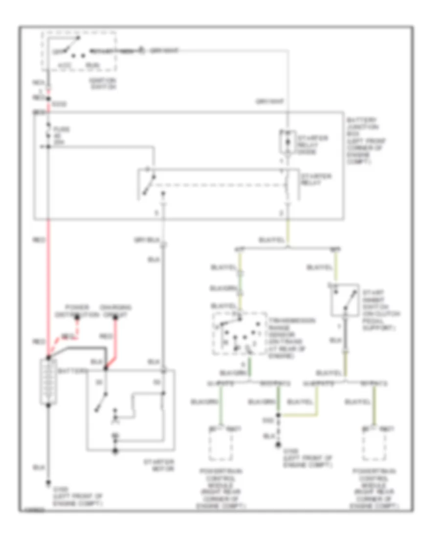
Power Distribution Wiring Diagram (1 of 4) for Ford Contour SE 2000
List of elements for Power Distribution Wiring Diagram (1 of 4) for Ford Contour SE 2000:
- (left front corner of eng compt) battery junction box
- (left rear side of eng compt)
- (left side of firewall)
- (near battery jnction box)
- (not used)
- (under left side of dash) central junction box
- Abs control module (bosch 5.3 abs)
- Battery
- Bi-fuel control module
- Bi-fuel power relay
- Bi-fuel relay module
- Brake pedal position switch (w speed control)
- C23
- C360
- C361
- C363
- C366
- C369
- C370
- C371
- Central timer module
- Compuvalve module
- Courtesy lamp relay
- Data link connector
- Engine cooling fan relay
- Foglight relay
- Front cigar lighter
- Front remote amplifier
- Fuel pump relay
- Fuse 10a
- Fuse 15a
- Fuse 20a
- Fuse 30a
- Fuse 3a
- Fuse 40a
- Fuse 60a
- Fuse 7.5a
- G901 (right "a" pillar)
- Generator
- Heater blower relay
- High beam relay
- High speed engine cooling fan relay
- Horn relay
- Light switch
- Low beam relay
- Mega fuse 175a
- Multi- function switch
- Pcm power relay
- Power seat switch
- Powertrain control module
- Rear window defrost relay
- Red
- S1002
- S232 (under left side of dash)
- S233
- S3010 (under left side of dash)
- S310
- S4002
- Starter motor
- Starter relay
- Stoplight switch
- To fuse 34 (diagram 3 of 4)
- To ignition relay (diagram 2 of 4)
- To ignition switch (diagram 2 of 4)
- To s1 (diagram 3 of 4)
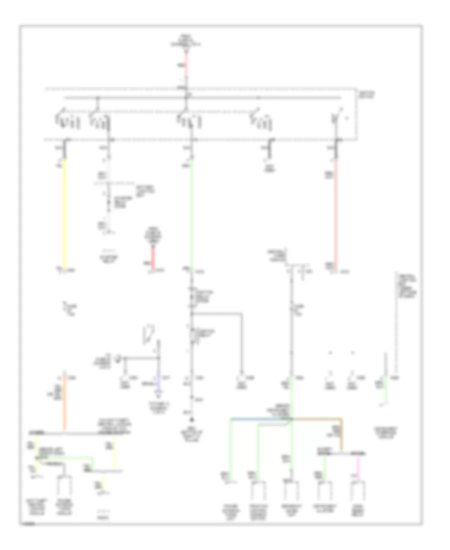
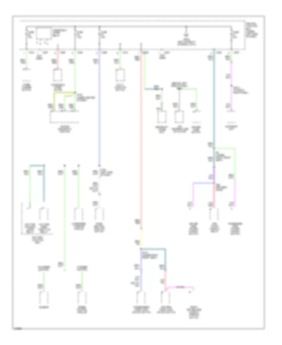
Power Distribution Wiring Diagram (2 of 4) for Ford Contour SE 2000
List of elements for Power Distribution Wiring Diagram (2 of 4) for Ford Contour SE 2000:
- (behind instrument cluster) s116
- (behind left side of dash) s319
- (not used
- (not used)
- Acc
- Anti-theft central locking module
- Battery junction box
- Bi-fuel
- C23
- C361
- C362
- C363
- C364
- C365
- C366
- C369
- C370
- C371
- C372
- Central junction box (under left side of dash)
- Central timer module
- Dash reset relay
- Except bi-fuel
- From fuse 40 (diagram 1 of 4)
- From fuse 45 (diagram 1 of 4)
- Fuse 7.5a
- G901 (bottom of right "a" pillar)
- Gearshift lever unit
- Ignition relay
- Ignition relay diode
- Ignition switch
- Instrument cluster
- Instrument interface module
- Lock
- Nca
- Off
- Others
- Power antenna timing module
- Power antenna timing unit
- Radio
- Red
- Run
- S331
- Start
- Starter relay
- Starter relay diode
- To fuse 14 (diagram 3 of 4)
- To fuse 20 (diagram 4 of 4)
- Traction control disable switch
- W/o anti-theft/ central locking module, w/o power antenna
Power Distribution Wiring Diagram (3 of 4) for Ford Contour SE 2000
List of elements for Power Distribution Wiring Diagram (3 of 4) for Ford Contour SE 2000:
- (left "a" pillar) s241
- (right "a" pillar) s318
- (right "a" pillar) s320
- Abs control module
- Anti-theft indicator
- Anti-theft/ central locking module
- Battery junction box (under left side of dash)
- C361
- C364
- C365
- C366
- C367
- Central junction box (under left side of dash)
- Driver's door lock motor
- Driver's door lock/ unlock switch
- Driver's side front door entry lamp
- Duratec-ve
- From fuse 25 (diagram 1 of 4)
- From fuse 28 (diagram 1 of 4)
- From ignition relay diagram (2 of 4)
- Front interior lamp
- Fuse 20a
- Fuse 7.5a
- Gearshift lever unit
- Ignition transformer
- Ignition transformer capacitor
- Left front footwell lamp
- Left rear door lock motor
- Luggage compartment lamp
- Nca
- Panic alarm headlamp relay
- Panic alarm stoplamp relay
- Passenger's door lock motor
- Passenger's door lock/ unlock switch
- Passenger's front door entry lamp
- Passenger's side front door entry lamp
- Pcm power relay
- Power antenna timing unit
- Power lock control relay
- Power mirror adjust switch
- Radio
- Right front footwell lamp
- Right rear door lock motor
- Right vanity mirror lamp
- S1 (under right front seat)
- S127 (left side of engine compt)
- S36 (left side of dash)
- S413 (in passenger door)
- S414 (on cylinder head)
- W/ bosch 5.3 abs
- W/ moonroof
- W/anti- theft
- W/o moonroof
- W/o remote control
- W/remote control
- Zetec-vct
Power Distribution Wiring Diagram (4 of 4) for Ford Contour SE 2000
List of elements for Power Distribution Wiring Diagram (4 of 4) for Ford Contour SE 2000:
- (behind left side of dash) s104
- (not used)
- (under center of dash)
- A/c wide open throttle relay
- Air bag diagnostic monitor
- Air temperature actuator
- Battery junction box
- Busbar
- C360
- C363
- C364
- C367
- C369
- C372
- Central junction box (under left side of dash)
- Daytime running lamps relay
- Driver side power window switch
- Driver's door lock/ unlock switch
- From ignition relay (diagram 2 of 4)
- Front driver side window opening switch
- Fuse 10a
- Fuse 15a
- Fuse 40a
- Fuse 7.5a
- Gearshift lever unit
- Heater mode switch
- Moonroof unit
- Multi- function switch
- Nca
- One touch window relay
- Overspeed warning module
- Park/ neutral position switch
- Passenger side power window switch
- Passenger's door lock/ unlock switch
- S109
- S136 (left side of dash)
- S3011 (in front roof panel)
- S314 (under right front seat)
- S86 (driver's door)
- Seat)
- Speed control module
- W/o speed control
- W/speed control
- Windshield wiper motor
- Windshield wiper relay
- Wiper/ washer switch
POWER DOOR LOCKS
Door Lock Wiring Diagram for Ford Contour SE 2000
List of elements for Door Lock Wiring Diagram for Ford Contour SE 2000:
- (under right front seat) s6
- (under right front seat) s7
- C360
- Central junction box (under left side of dash)
- Driver side door lock motor
- Driver's door lock/unlock switch
- Fuse 20a
- G304 (left front rocker panel)
- G901 (right "a" pillar)
- Hot at all times
- Interior lights system
- Left rear door lock motor
- Lock
- Passenger side door lock motor
- Passenger side lock/unlock switch
- Power lock control relay (behind top of right kick panel)
- Right rear door lock motor
- S257
- S258
- S259
- S269
- Solid state
- Unlock
Keyless Entry Wiring Diagram for Ford Contour SE 2000
List of elements for Keyless Entry Wiring Diagram for Ford Contour SE 2000:
- (center of right "a" pillar) door lock diagnostic connector
- (not used)
- (under left side of rear seat, on central junction box)
- (under right front seat)
- (under right front seat) s6
- 29-aa17
- 29-aa17a
- 29s-aa28
- 29s-aa32
- 31-aa17
- 31s-aa17
- 31s-gl39
- 32-aa17
- 32-aa4
- 33-aa11
- 33-aa17
- 33-aa4
- 75-aa17
- 8-aa36
- 8-aa6
- 9-aa6
- Anti-theft system (panic alarm headlamp relay)
- Anti-theft/ central locking module (on center of right "a" pillar)
- C23
- C360
- C364
- C365
- C366
- C451a
- C451b
- Central junction box (under left side of dash)
- Central timer module
- Decklid motor (in center rear of luggage compt)
- Driver side door lock motor
- Driver side door lock switch
- Driver's door lock/unlock switch
- Fuse 20a
- Fuse 7.5a
- G304 (left front rocker panel)
- G404 (left rear of luggage compt)
- G901 (right "a" pillar)
- Horns system
- Hot at all times
- Hot in acc or run
- Interior lights system
- Left rear door lock motor
- Lock
- Off
- Passenger door lock motor
- Passenger side door lock switch
- Passenger side door lock/unlock switch
- Reset
- Right rear door lock motor
- S257
- S258
- S259
- S269
- S304
- S318
- S319
- S320
- S402 (in right "a" pillar)
- S403 (in right "a" pillar)
- Set
- Unlck
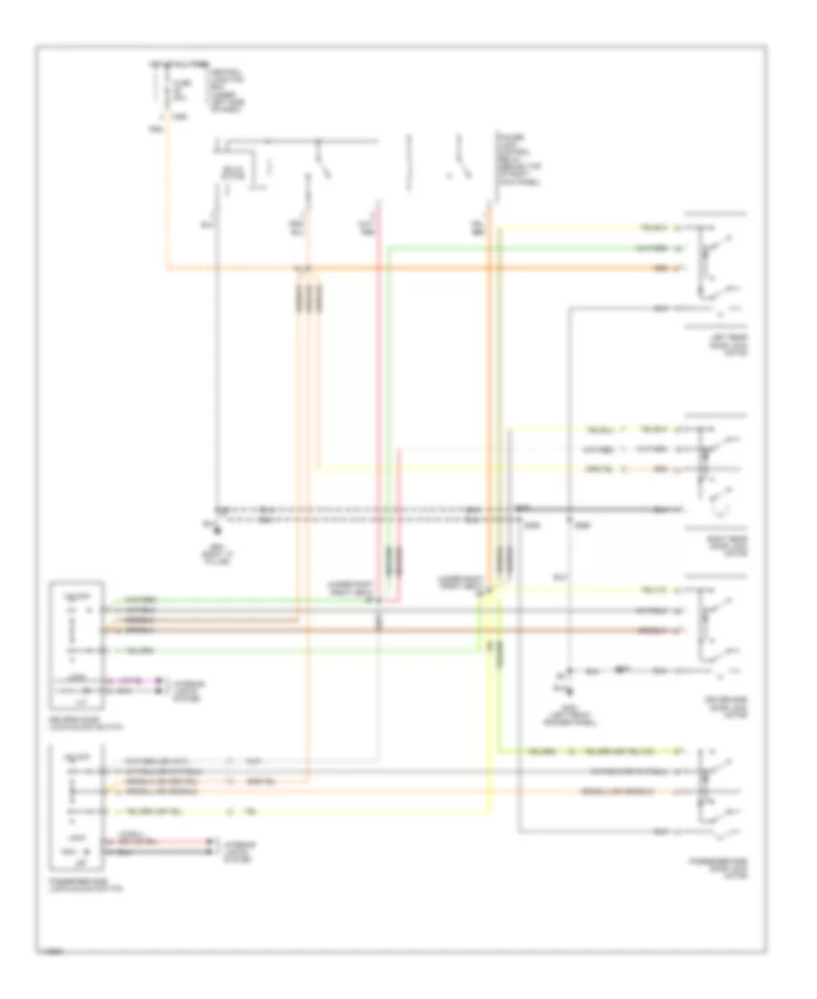
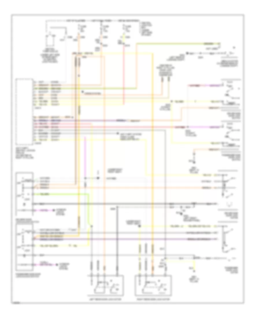
POWER MIRRORS
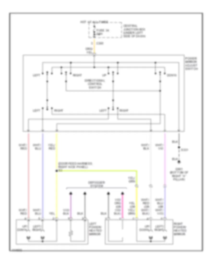
Power Mirror Wiring Diagram for Ford Contour SE 2000
List of elements for Power Mirror Wiring Diagram for Ford Contour SE 2000:
- (door feed harness, right kick panel) s3
- C365
- Central junction box (under left side of dash)
- Defogger system
- Directional control switch
- Down
- Fuse 34 7.5a
- G901 (bottom of right "a" pillar)
- Hot at all times
- Left
- Left power/ heated mirror
- Left/ right
- Power mirror adjust switch
- Right
- Right power/ heated mirror
- S331
- Up/ down
POWER SEATS
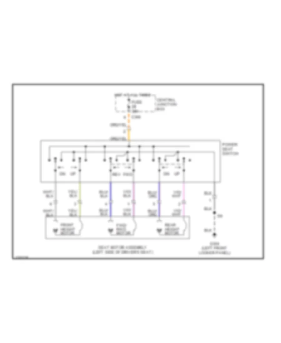
6-Way Power Seat Wiring Diagram for Ford Contour SE 2000
List of elements for 6-Way Power Seat Wiring Diagram for Ford Contour SE 2000:
- C366
- Central junction box
- Front height motor
- Fuse 30a
- Fwd
- Fwd/ rwd motor
- G304 (left front locker panel)
- Hot at all times
- Power seat switch
- Rear height motor
- Rev
- Seat motor assembly (left side of driver's seat)
POWER TOP/SUNROOF
Power Top/Sunroof Wiring Diagrams for Ford Contour SE 2000
List of elements for Power Top/Sunroof Wiring Diagrams for Ford Contour SE 2000:
- C3009
- C367
- C748a
- C748b
- Central junction box (dash left side of dash)
- Circuit breaker
- Down/open
- Fuse 40a
- G304 (left front rocker panel)
- Hot in start or run
- Moon roof adjust switch
- Moon roof motor (at center of windshield header)
- Moon roof unit (at center of of windshield header)
- Nca
- S3011
- S34
- Up/close
POWER WINDOWS
Power Window Wiring Diagram for Ford Contour SE 2000
List of elements for Power Window Wiring Diagram for Ford Contour SE 2000:
- (center console) s20
- C146
- C148
- C149
- C150
- C360
- C363
- C74b
- C75a
- C75b
- Central junction box (under left side of dash)
- Driver power window switch
- Driver's door lock/unlock switch
- Front driver side power window motor
- Front passenger side power window motor
- Fuse 21 40a
- Fuse 23 15a
- G304 (left front rocker panel)
- G901 (right "a" pillar)
- Hot in run or start
- Left rear power window motor
- Left rear power window switch
- One touch dn
- One- touch window relay (front of left front door)
- Passenger side power window switch
- Right rear power window motor
- Right rear power window switch
- S257
- S258
- S259
- S269
- S314
- S86
- Solid state
- Window operating isolator switch
RADIO
Radio Wiring Diagrams, High Option Content for Ford Contour SE 2000
List of elements for Radio Wiring Diagrams, High Option Content for Ford Contour SE 2000:
- (right "a" pillar) g901
- (w/o power antenna,)
- 29-md12
- 29-md15
- 64s-lk34
- 74s-md13
- 75-md15
- 8-md10
- 8-md11
- 8-md12
- 8-md17
- 8-md18
- 9-md10
- 9-md11
- 9-md17
- 9-md18
- 91-md12
- 91-md15
- 91-md15a
- Amp l front speaker
- Amp l rear speaker
- Amp r front speaker
- Amp r rear speaker
- Antenna
- Audio in
- Audio out
- C1943
- C360
- C364
- C443a
- C443b
- Cd changer
- Central junction box (under left side of dash)
- Coax lead
- Front remote amplifier
- Fuse 20a
- Fuse 7.5a
- Fused ignition
- G901 (right "a" pillar)
- Ground
- Hot at all times
- Hot in run or acc
- Illum
- Interior lights
- L front speaker
- L front speaker in
- L rear speaker
- L rear speaker in
- Left front speaker
- Left rear speaker
- Nca
- Power
- Power antenna
- R front speaker
- R front speaker in
- R rear speaker
- R rear speaker in
- Radio
- Right front speaker
- Right rear speaker
- S319
- With cd changer
Radio Wiring Diagrams, Low Option Content for Ford Contour SE 2000
List of elements for Radio Wiring Diagrams, Low Option Content for Ford Contour SE 2000:
- (right "a" pillar) g901
- (w/o power antenna,)
- 29-md15
- 64s-lk34
- 74s-md13
- 75-md15
- 8-md10
- 8-md11
- 8-md17
- 8-md18
- 9-md10
- 9-md11
- 9-md17
- 9-md18
- 91-md15
- 91-md15a
- Antenna
- C360
- C364
- C443a
- C443b
- Central junction box (under left side of dash)
- Coax lead
- Fuse 7.5a
- G901 (right "a" pillar)
- Ground
- Hot at all times
- Hot in run or acc
- Ignition
- Illum
- Interior lights
- Left front speaker
- Left rear speaker
- Lf spkr
- Lr spkr
- Power
- Power antenna
- Pwr ant
- Radio
- Rf spkr
- Right front speaker
- Right rear speaker
- Rr spkr
SHIFT INTERLOCKS
Shift Interlock Wiring Diagram for Ford Contour SE 2000
List of elements for Shift Interlock Wiring Diagram for Ford Contour SE 2000:
- (bottom of right "a" pillar)
- 15-gg15
- 15s-ta21
- C360
- C361
- C362
- C366
- C369
- C421
- Central junction box (cjb) (under left side of dash)
- Cruise control system
- Fuse 15a
- Fuse 7.5a
- G901
- G901 (bottom of right "a" pillar)
- G901 (right "a" pillar)
- Gear- shift lever unit (below center console)
- Hot at all times
- Hot in run
- Illum. lamp
- Instrument interface module (behind left side of dash)
- Interior lights system
- Key removal inhibit solenoid (on top of steering column)
- Nca
- Or start
- Over- drive cancel switch
- Park lock sol.
- Powertrain control module (behind power steering reservoir)
- S104
- S106 (behind left side of dash panel)
- S116
- S130 (behind left side of dash)
- S244
- S300
- S3010
- S331
- Stoplamp switch (on bracket, above brake pedal)
STARTING/CHARGING
Charging Wiring Diagram for Ford Contour SE 2000
List of elements for Charging Wiring Diagram for Ford Contour SE 2000:
- 2.0l
- 2.5l
- Battery
- Battery junction box (left front corner of eng compt)
- C1885a
- C1885b
- C1885c
- C362
- C421
- C448
- C808a
- Central junction box (under left side of dash)
- Charge indicator
- Fuse 7.5a
- G100 (left front of engine compt)
- Generator
- Hot at all times
- Hot in run or start
- Instrument cluster
- Mega fuse 175a
- Pcm (right rear of engine compt)
- Power distribution system
- Red
- S116
- Starter motor
Starting Wiring Diagram for Ford Contour SE 2000
List of elements for Starting Wiring Diagram for Ford Contour SE 2000:
- A/t
- Acc
- Battery
- Battery junction box (left front corner of engine compt)
- C421
- Charging circuit
- Fuse 20a
- G100 (left front of engine compt)
- Ignition switch
- M/t
- Nca
- Off
- Power distribution
- Powertrain control module (right rear corner of engine compt)
- Red
- Run
- S232
- S62
- Start
- Start inhibit switch (on clutch pedal support)
- Starter motor
- Starter relay
- Starter relay diode
- Transmission range sensor (on trans at rear of engine)
- W/ pats
- W/o pats
SUPPLEMENTAL RESTRAINTS
Supplemental Restraint Wiring Diagram for Ford Contour SE 2000
List of elements for Supplemental Restraint Wiring Diagram for Ford Contour SE 2000:
- (behind center dash panel) s300
- (behind instrument cluster) s116
- (bottom of right "a" pillar) g901
- (under center dash panel)
- 15-ja10a
- 15-ja10b
- 15-ja10c
- 15s-ja11
- 15s-ja8
- 8-da1
- 8-ja7
- 91-ja10
- 91s-ja11
- 91s-ja14
- 91s-ja14a
- 91s-ja8
- Air bag diagnostic monitor (under center console)
- Air bag indicator
- C362
- C364
- C808a
- C808b
- Central junction box (under left side of dash)
- Clockspring
- Data link connector (dlc) (partial) (under left side of dash, left of steering column)
- Driver air bag module
- Fuse 30 7.5a
- Fuse 38 7.5a
- Hot in run or start
- Instrument cluster
- Nca
- Passenger air bag module
- S283 (w/abs)
- Secondary air bag indicator
TRANSMISSION
2.0L
2.0L, A/T Wiring Diagram for Ford Contour SE 2000
List of elements for 2.0L, A/T Wiring Diagram for Ford Contour SE 2000:
- (behind left side of dash) instrument interface module
- (engine compt, on firewall) s54
- (lower left rear of engine compt) turbine shaft speed (tss) sensor
- (on top of transmission) s66
- (on transmission, rear of engine) transmission range (tr) sensor
- (rear of engine)
- 15-re8
- 15-re8a
- 15s-re13
- 15s-ta21
- 30-re8
- 4-re8
- 5-re8
- 7-re8
- 8-gg18
- 8-ra1
- 8-rj17
- 8-rj22
- 8-rj28
- 8-rj29
- 8-rj6
- 8-ta26
- 8-ta27
- 8-ta9
- 9-re8
- 9-re8a
- 9-rj22
- 9-rj29
- 91-re8a
- 91-re8b
- 91-re8c
- 91-re8d
- 91s-re31
- 91s-ta17
- 91s-ta23
- 91s-ta24
- 91s-ta25
- Battery junction box (left front corner of engine compt)
- Bi-fuel control module
- Brake pedal position switch
- C362
- C366
- Central junction box (under left side of dash)
- Compt)
- Data link connector
- Data link connector (partial) (under left side of dash)
- Datalink +
- Datalink -
- Datalink pwr
- Electronic pressure control (epc) solenoid
- Engine controls
- Engine controls (w/ bi-fuel engine)
- Engine coolant temperature (ect) sensor (upper rear
- Epc sol
- Fuse 15a
- Fuse 20a
- Fuse 3a
- Fuse 7.5a
- G100 (left front of engine
- G100 (left front of engine compt)
- Gearshift lever unit
- Ground
- Hot at all times
- Hot in run
- Ign power
- Kapwr
- Lockup sol
- Maf
- Maf return
- Maf sig
- Mass air- flow (maf) sensor (on rear of air cleaner assembly)
- Modulated lockup solenoid
- Nca
- Of engine)
- Overdrive cancel
- Pcm power relay
- Pillar)
- Powertrain control module (pcm) (behind power steering reservoir)
- Pwr
- Pwr antenna timing unit, traction control disable switch, instrument cluster, dash reset relay
- Red
- Ref votage
- S116
- S130 (behind left side of dash)
- S3010
- S4002
- S4003
- S4004
- S53
- S59
- S62
- Shift sol 1
- Shift sol 2
- Shift sol 3
- Shift solenoid 1
- Shift solenoid 2
- Shift solenoid 3
- Sig return
- Stoplamp sw
- Stoplamp switch (on bracket, above brake pedal)
- Switch
- Tc sw
- Tcil input
- Tcil output
- Temp sens
- Throttle position (tp) sensor (on throttle body)
- Tps signal
- Tr sens
- Trans temp
- Transmission hardware unit
- Transmission oil temperature (tft) sensor
- Tss sensor
- Tss sig
- Vehicle speed sensor (vss) (lower rear of transaxle)
- Vss
- Vss signal
2.5L
2.5L, A/T Wiring Diagram for Ford Contour SE 2000
List of elements for 2.5L, A/T Wiring Diagram for Ford Contour SE 2000:
- (behind left side of dash) instrument interface module
- (engine compt, on firewall) s54
- (lower left rear of engine compt) turbine shaft speed (tss) sensor
- (on engine)
- (on top of transmission) s66
- (on transmission, rear of engine) transmission range (tr) sensor
- (rear of engine)
- 15-re8
- 15-re8a
- 15s-re13
- 15s-ta21
- 30-re8
- 4-re8
- 5-re8
- 7-re8
- 8-gg18
- 8-ra1
- 8-rj22
- 8-rj28
- 8-rj29
- 8-rj6
- 8-ta26
- 8-ta27
- 8-ta9
- 9-re8
- 9-re8a
- 9-rj22
- 9-rj29
- 91-re8a
- 91-re8b
- 91-re8c
- 91-re8d
- 91s-re31
- 91s-ta17
- 91s-ta23
- 91s-ta25
- Battery junction box (left front corner of engine compt)
- Brake pedal position switch
- C362
- C366
- Central junction box (under left side of dash)
- Compt)
- Data link connector
- Data link connector (partial) (under left side of dash)
- Datalink +
- Datalink -
- Datalink pwr
- Electronic pressure control (epc) solenoid
- Engine controls
- Engine coolant temperature (ect) sensor (upper rear
- Epc sol
- Fuse 15a
- Fuse 20a
- Fuse 3a
- Fuse 7.5a
- G100 (left front of engine
- G100 (left front of engine compt)
- Gearshift lever unit
- Ground
- Hot at all times
- Hot in run
- Ign power
- Kapwr
- Lockup sol
- Maf return
- Maf sig
- Mass air- flow (maf) sensor (on rear of air cleaner assembly)
- Modulated lockup solenoid
- Nca
- Of engine)
- Overdrive cancel
- Pcm power relay
- Powertrain control module (pcm) (behind power steering reservoir)
- Pwr
- Pwr antenna timing unit, traction control disable switch, instrument cluster, dash reset relay
- Red
- Ref votage
- S116
- S130 (behind left side of dash)
- S3010
- S407
- S59
- S62
- Shift sol 1
- Shift sol 2
- Shift sol 3
- Shift solenoid 1
- Shift solenoid 2
- Shift solenoid 3
- Sig return
- Stoplamp sw
- Stoplamp switch (on bracket, above brake pedal)
- Switch
- Tc sw
- Tcil input
- Tcil output
- Temp sens
- Throttle position (tp) sensor (on throttle body)
- Tps signal
- Tr sens
- Trans temp
- Transmission hardware unit
- Transmission oil temperature (tft) sensor
- Tss sensor
- Tss sig
- Vehicle speed sensor (vss) (lower rear of transaxle)
- Vss
- Vss signal
WARNING SYSTEMS
Warning System Wiring Diagrams for Ford Contour SE 2000
List of elements for Warning System Wiring Diagrams for Ford Contour SE 2000:
- (1999)
- (2000)
- (not used)
- (right "a" pillar) s330
- Acc
- Battery junction box (left front corner of engine compt)
- C23
- C320
- C361
- C362
- C364
- C366
- C369
- C370
- C372
- C456
- C808a
- Central junction box (under left side of dash)
- Central timer module (ctm) (under left side of dash, on central junction box)
- Courtesy lamp relay
- Defogger system
- Defrost refrost
- Defrost sw
- Door locks system
- Doors sw
- Driver door sw
- Fuse 60a (2000)
- Fuse 7.5a
- Fuse 80a (1999)
- G309 (left front rocker panel)
- G901 (bottom of right "a" pillar)
- Ground
- Head
- Hot at all times
- Hot in run or start
- Ignition sw
- Ignition switch
- Illum entry
- Instrument cluster
- Inter wiper sw
- Key illum sw
- Key in ign sw
- Key in ignition switch
- Left front door courtesy lamp switch
- Left rear door courtesy lamp switch
- Lock
- Main light switch
- Off
- Park
- Park lamp sw
- Power (bat)
- Rear window defrost relay
- Red
- Remote entry in
- Right front door courtesy lamp switch
- Right rear door courtesy lamp switch
- Run
- S116
- S331
- Seat belt buckle switch (driver seat belt buckle)
- Seat belt ind
- Seat belt indicator
- Seat belt sw
- Start
- Washer sw
- Windshield wiper relay
- Wiper park
- Wiper/rate select
- Wiper/washer system
WIPER/WASHER
Wiper/Washer Wiring Diagram for Ford Contour SE 2000
List of elements for Wiper/Washer Wiring Diagram for Ford Contour SE 2000:
- C369
- C372
- Central junction box (under left side of dash)
- Central timer module (under left side of dash)
- Fast
- Fuse 20 10a
- G100 (left front of engine compartment)
- G901 (bottom of right "a" pillar)
- Hot in run & start
- Int
- Norm
- Off
- Park
- Run
- S3003
- S331
- Sngl wipe
- Variable intermittent switch (if equipped)
- Wash
- Windshield washer pump motor (in fluid reservoir)
- Windshield wiper motor
- Windshield wiper relay
- Wiper/ washer switch