AIR CONDITIONING
A/C Wiring Diagram, Auto A/C for Ford Crown Victoria S 1997

List of elements for A/C Wiring Diagram, Auto A/C for Ford Crown Victoria S 1997:
- (engine harn, left rear of eng compt) s110
- (engine harn, near right front fender)
- (i/p harn, behind center of i/p)
- (i/p harn, behind right side of i/p) s200
- (i/p harn, behind top left side of i/p)
- (i/p harn, near data link conn (dlc) breakout)
- (i/p harn, near glove box lamp breakout)
- (not used)
- (top of engine, near fuel injector 1)
- A/c compressor clutch
- A/c clutch cycling pressure switch (right rear of engine compartment)
- A/c clutch diode
- A/c clutch out
- A/c cutout relay (in relay center)
- A/c high pressure cut out switch (right side of engine compartment)
- A/c plenum)
- Ambient temp input
- Ambient temperature sensor (center front of vehicle, on upper radiator support)
- Battery
- Blend door act
- Blend door actuator (behind right side of i/p, top of
- Blend door pot
- Blend door ref
- Blower motor
- Blower motor speed
- Blower motor speed controller (top right center of safety wall)
- Blower spped fback
- C227
- C228
- Cooling fan
- Cooling fan fuse 50a
- Cooling fan relay (engine compartment fuse box)
- Data link (+)
- Data link (-)
- Data link connector (dlc) (behind left side of i/p)
- Electronic automatic temperature control (eatc) module (center of i/p)
- Eng/met conv
- Engine compartment fuse box
- Fuse 15a
- Fuse 30a
- G101 (front of right front fender apron)
- G134
- Ground
- Hot at all times
- Hot in run
- I/p fuse panel
- Ignition
- Illumination
- In car temp sens
- In-car temperature sensor (behind top center of i/p)
- Instrument cluster (digital)
- Interior lights system
- Pcm power relay
- Powertrain control module (pcm) (behind left side of i/p)
- Red
- Relay signal
- S113
- S117
- S118
- S206
- S226
- S227 (i/p harness, behind left side of i/p)
- S251
- Sensor ground
- Sun load sensor (top right side of i/p, above glove box)
- Sunload sens input
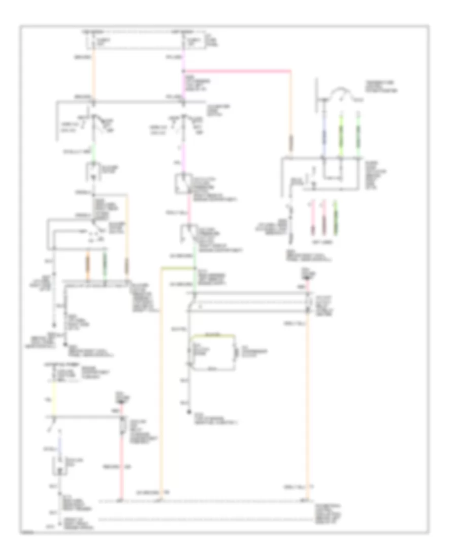
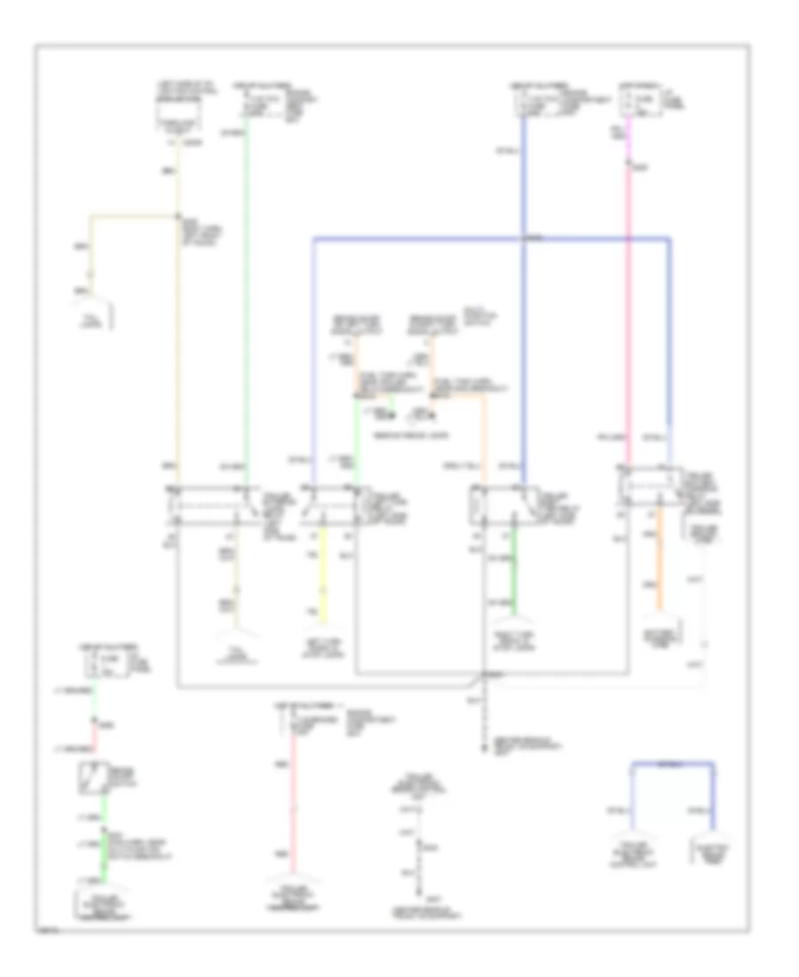
A/C Wiring Diagram, Manual A/C for Ford Crown Victoria S 1997
List of elements for A/C Wiring Diagram, Manual A/C for Ford Crown Victoria S 1997:
- (front of right front fender apron)
- (not used)
- A/c clutch cycling pressure switch (right rear of engine compartment)
- A/c clutch diode
- A/c compressor clutch
- A/c high pressure cut out switch (right side of engine compartment)
- A/c wot cutout relay (in relay center)
- A/c-heater mode switch
- Blend door actuator (behind right side of i/p)
- Blower motor
- Blower motor resistor assembly (top right center of safety wall)
- Blower motor switch
- Cold
- Cooling fan
- Cooling fan fuse 50a
- Cooling fan relay (in engine compartment fuse box)
- Def
- Engine compartment fuse box
- Floor
- Fuse 5 15a
- Fuse 9 30a
- G101
- G134 (top of engine near fuel injector 1)
- G200 (behind left cowl panel, near door sill)
- G203 (behind right cowl panel, near door sill)
- Hot at all times
- Hot in run
- I/p fuse panel
- Max a/c
- Mix
- Norm a/c
- Off
- Pcm power relay
- Pnk
- Powertrain control module (pcm) (behind left side of i/p)
- Red
- S110 (eng harness, left rear of engine compt)
- S113 (eng harn, near right front fender)
- S200 (i/p harn, right side of i/p)
- S206 (i/p harn, near glove box lamp breakout)
- S207 (i/p harn, right side of i/p)
- S226 (i/p harness, top left side of i/p)
- S239 (eng harn, right rear of eng compt)
- Solid state
- Temperature control potentiometer
- Vent
- Warm
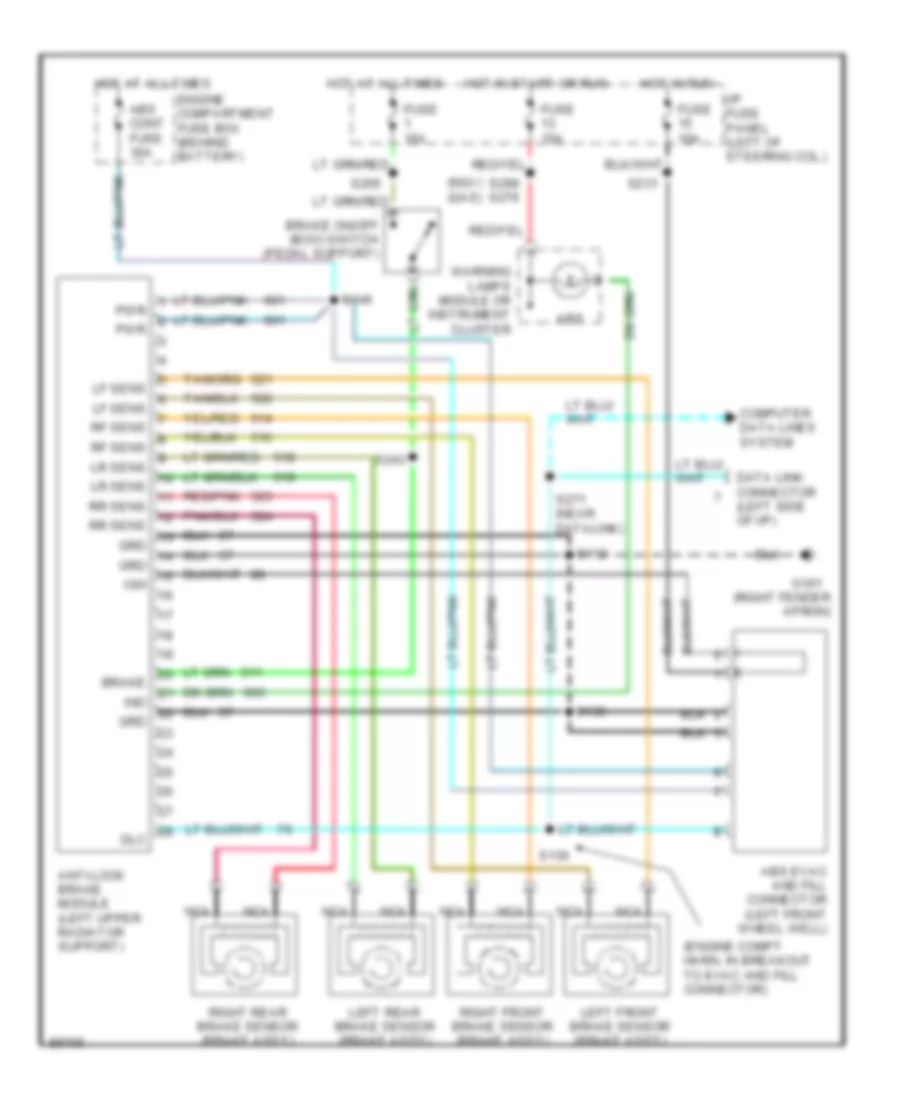
ANTI-LOCK BRAKES
Anti-lock Brake Wiring Diagrams for Ford Crown Victoria S 1997
List of elements for Anti-lock Brake Wiring Diagrams for Ford Crown Victoria S 1997:
- (engine compt harn, in breakout to evac and fill connector)
- (ngv) (gas)
- (right fender apron)
- Abs
- Abs cont fuse 30a
- Abs evac and fill connector (left front wheel well)
- Anti-lock brake module (left upper radiator support)
- Brake
- Brake on/off (boo) switch (pedal support)
- Computer data lines system
- Data link connector (left side of i/p)
- Dlc
- Engine compartment fuse box (behind battery)
- Fuse 10a
- Fuse 15a
- G101
- Grd
- Hot at all times
- Hot in run
- Hot in start or run
- I/p fuse panel (left of steering col.)
- Ign
- Ind
- Left front brake sensor (brake ass'y)
- Left rear brake sensor (brake ass'y)
- Lf sens
- Lr sens
- Nca
- Pwr
- Red/pnk
- Rf sens
- Right front brake sensor (brake ass'y)
- Right rear brake sensor (brake ass'y)
- Rr sens
- S112
- S136
- S146
- S231
- S243
- S265
- S271 (near datalink)
- S299 s276
- Warning lamps module or instrument cluster
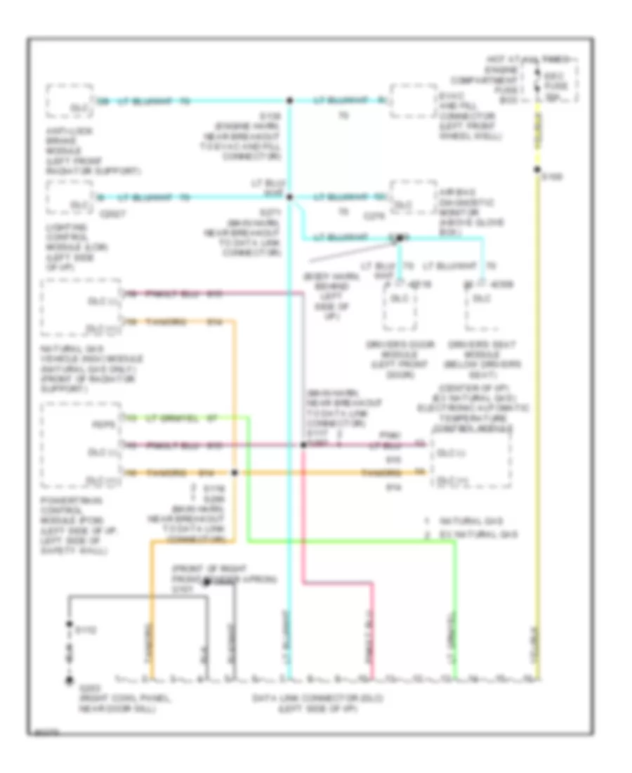
COMPUTER DATA LINES
Computer Data Lines for Ford Crown Victoria S 1997
List of elements for Computer Data Lines for Ford Crown Victoria S 1997:
- (body harn, behind left side of i/p)
- (center of i/p) (ex natural gas) electronic automatic temperature control module
- (front of right front fender apron) g101
- (main harn, near breakout to data link connector) s117 s297
- Air bag diagnostic monitor (above glove box)
- Anti-lock brake module (left front radiator support)
- C2027
- C276
- C308
- C518
- Data link connector (dlc) (left side of i/p)
- Dlc
- Dlc (+)
- Dlc (-)
- Driver's door module (left front door)
- Driver's seat module (below driver's seat)
- Eec fuse 30a
- Engine compartment fuse box
- Evac and fill connector (left front wheel well)
- Ex natural gas
- Feps
- G203 (right cowl panel, near door sill)
- Hot at all times
- Lighting control module (lcm) (left side of i/p)
- Natural gas
- Natural gas vehicle (ngv) module (natural gas only) (front of radiator support)
- Powertrain control module (pcm) (left side of i/p, left side of safety wall)
- S100
- S112
- S118 s296 (main harn, near breakout to data link connector)
- S136 (engine harn, near breakout to evac and fill connector)
- S271 (main harn, near breakout to data link connector)
- S286
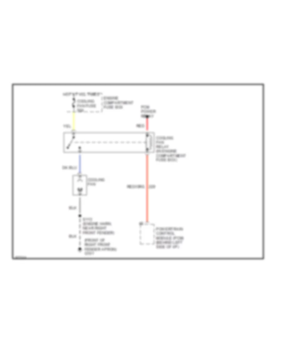
COOLING FAN
Cooling Fan Wiring Diagram for Ford Crown Victoria S 1997
List of elements for Cooling Fan Wiring Diagram for Ford Crown Victoria S 1997:
- (front of right front fender apron) g101
- Cooling fan
- Cooling fan fuse 50a
- Cooling fan relay (in engine compartment fuse box)
- Engine compartment fuse box
- Hot at all times
- Pcm power relay
- Powertrain control module (pcm) (behind left side of i/p)
- Red
- S113 (engine harn, near right front fender)
CRUISE CONTROL
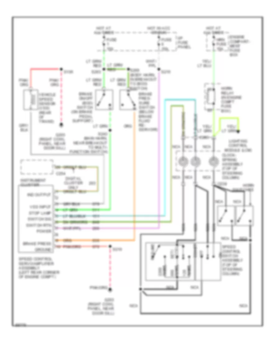
Cruise Control Wiring Diagram for Ford Crown Victoria S 1997
List of elements for Cruise Control Wiring Diagram for Ford Crown Victoria S 1997:
- Brake on/off (boo) switch (on brake pedal support)
- Brake pres- sure switch (below brake fluid re- servoir)
- Brake press
- C238
- C254
- C283
- Clock- spring assembly (top of steering column)
- Coast
- Digital cluster only
- Engine compart- ment fuse box
- Fuse 15a
- G203 (right cowl panel, near door sill)
- Ground
- Horn relay (in engine compt fuse box)
- Horn switches
- Hot at all times
- Hot in acc or run
- Hrn fuse 15a
- I/p fuse panel
- Ind output
- Instrument cluster
- Lighting control module (lcm)
- Nca
- Off
- Ohms
- Power
- Resume
- S105
- S210
- S215
- S243 (main harn, near breakout to multi- function switch)
- S263
- Set/ accel
- Speed control servo/amplifier assembly (left rear corner of engine compt)
- Speed control switch assembly (top of steering column)
- Stop lamp
- Switch rtn
- Switch sig
- To (boo) switch)
- Vehicle speed sensor (vss) (rear of trans)
- Vss input
DEFOGGERS
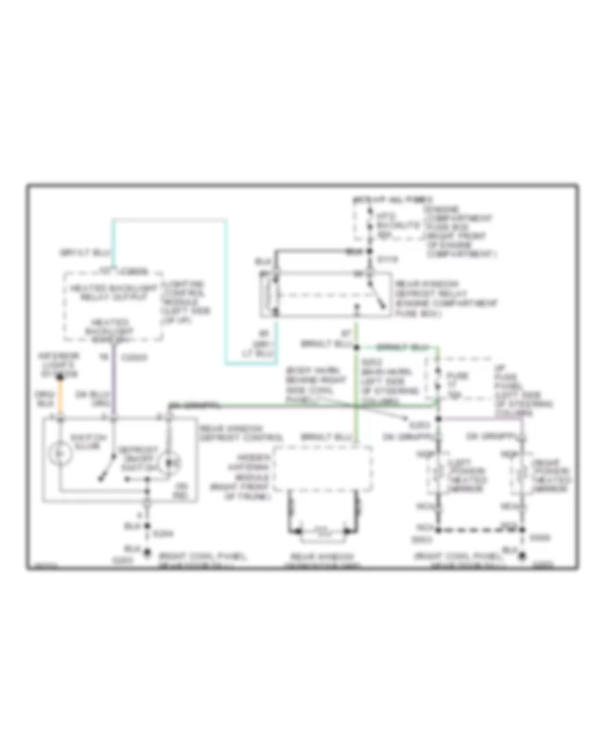
Defogger Wiring Diagram for Ford Crown Victoria S 1997
List of elements for Defogger Wiring Diagram for Ford Crown Victoria S 1997:
- (body harn, behind right side cowl panel)
- (right cowl panel, near door sill)
- C2026
- Defrost on/off switch
- Engine compartment fuse box (right front of engine compartment)
- Fuse 10a
- G203
- Heated backlight relay output
- Heated backlight switch
- Hidden antenna module (right front of trunk)
- Hot at all times
- Htd backlite 40a
- I/p fuse panel (left side of steering column)
- Interior lights system
- Left power/ heated mirror
- Lighting control module (left side of i/p)
- Nca
- On ind.
- Rear window defrost control
- Rear window defrost relay (engine compartment fuse box)
- Rear window defroster grid
- Right power/ heated mirror
- S119
- S204
- S252 (main harn, left side of steering column)
- S253
- S503
- S600
- Switch illum.
ELECTRONIC POWER STEERING
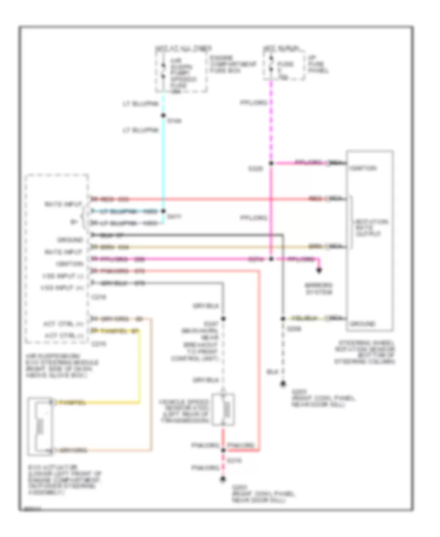
Electronic Power Steering Wiring Diagram, with Air Suspension for Ford Crown Victoria S 1997
List of elements for Electronic Power Steering Wiring Diagram, with Air Suspension for Ford Crown Victoria S 1997:
- Act ctrl (+)
- Act ctrl (-)
- Air suspension/ evo steering module (right side of dash, above glove box)
- Air suspn pump/ speedo fuse 30a
- C215
- C216
- Engine compartment fuse box
- Evo actuator (lower left front of engine compartment, on power steering assembly)
- Fuse 15a
- G203 (right cowl panel, near door sill)
- Ground
- Hot at all times
- Hot in run
- I/p fuse panel
- Ignition
- Mirrors system
- Nca
- Rate input
- Red
- Rotation rate output
- S144
- S208
- S210
- S226
- S247 (main harn, near breakout to front control unit)
- S274
- S411
- Steering wheel rotation sensor (bottom of steering column)
- Vehicle speed sensor (vss) (left rear of transmission)
- Vss input (+)
- Vss input (-)
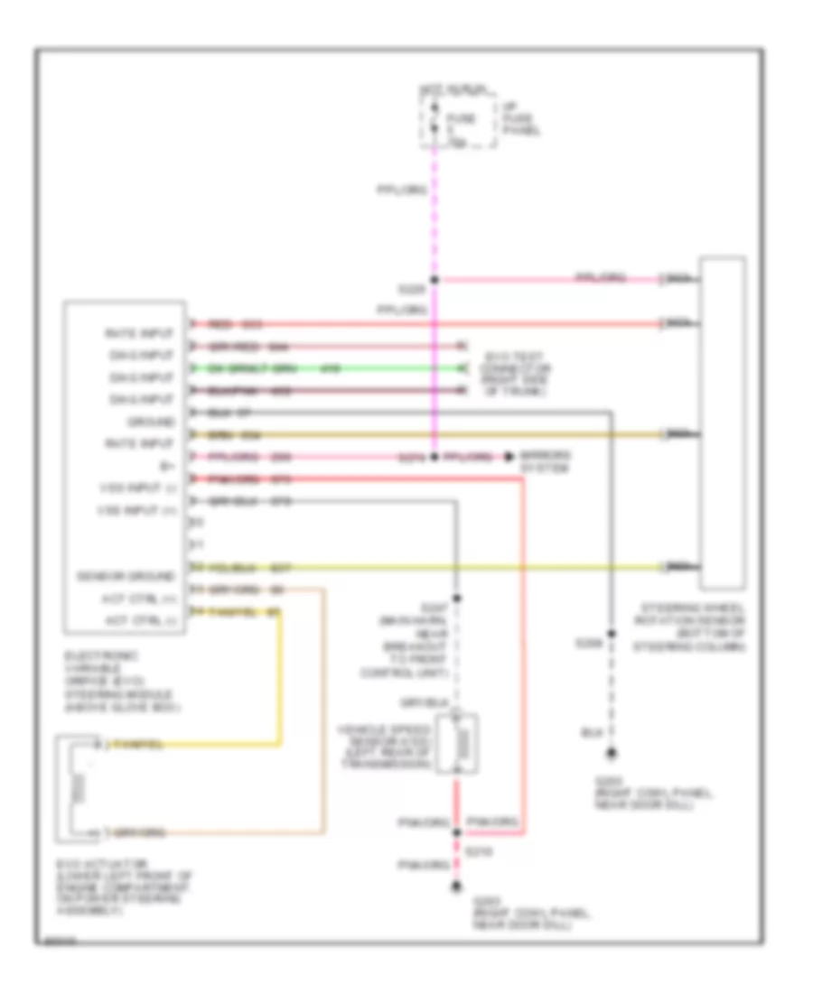
Electronic Power Steering Wiring Diagram, without Air Suspension for Ford Crown Victoria S 1997
List of elements for Electronic Power Steering Wiring Diagram, without Air Suspension for Ford Crown Victoria S 1997:
- Act ctrl (+)
- Act ctrl (-)
- Diag input
- Electronic variable orifice (evo) steering module (above glove box)
- Evo actuator (lower left front of engine compartment, on power steering assembly)
- Evo test connector (right side of trunk)
- Fuse 15a
- G203 (right cowl panel, near door sill)
- Ground
- Hot in run
- I/p fuse panel
- Mirrors system
- Nca
- Rate input
- Red
- S208
- S210
- S226
- S247 (main harn, near breakout to front control unit)
- S274
- Sensor ground
- Steering wheel rotation sensor (bottom of steering column)
- Vehicle speed sensor (vss) (left rear of transmission)
- Vss input (+)
- Vss input (-)
ELECTRONIC SUSPENSION
Electronic Suspension Wiring Diagram for Ford Crown Victoria S 1997
List of elements for Electronic Suspension Wiring Diagram for Ford Crown Victoria S 1997:
- (above glove box)
- (below air cleaner assembly)
- (body harn, near
- (bottom of steering column)
- (engine compartment fuse box)
- (left rear upper control arm)
- (luggage compt harn,
- (main harn, near
- (on power steering assembly)
- (rear of transmission)
- (right cowl panel,
- (right side
- (right side of trunk)
- 15a
- 30a
- 87a
- Air
- Air spring
- Air suspension
- Air suspension compressor
- Air suspension/evo steering module
- Air suspn
- Airbag diagnostic
- All times
- Analog
- Battery pwr
- Breakout to
- C215
- C216
- C251
- C255
- C256
- Check air
- Cluster
- Comp relay ctrl
- Compartment
- Compressor relay
- Connector)
- Diagnostic input
- Digital
- Door open input
- Engine
- Evo actuator
- Evo actuator ctrl +
- Evo actuator ctrl -
- Frt ctrl unit)
- Fuse
- Fuse box
- G101
- G203
- Ground
- Hgt sensor ground
- Hgt sensor input
- Hgt sensor pwr
- Hot at
- Hot in run
- I/p
- Ign
- Ignition on input
- Indicator
- Instrument
- Interior
- L rear spring sol
- Left rear
- Lights
- Linear height sensor
- Motor and vent solenoid
- Near breakout to
- Near door sill)
- Panel
- Pnk
- Pnk 421
- Pump/
- Red
- Red 633
- Right rear
- Right rear speaker)
- Rt rear spring sol
- S112
- S144
- S208
- S210
- S247
- S269
- S274
- S300
- S403
- S411
- S431
- Service input
- Solenoid
- Speedo
- Steering rotate rate
- Steering wheel rotation sensor
- Suspension
- Switch
- System
- Test connector
- Vehicle spd input +
- Vehicle spd input -
- Vehicle speed sensor
- Vent sol ctrl
- Warning lt output
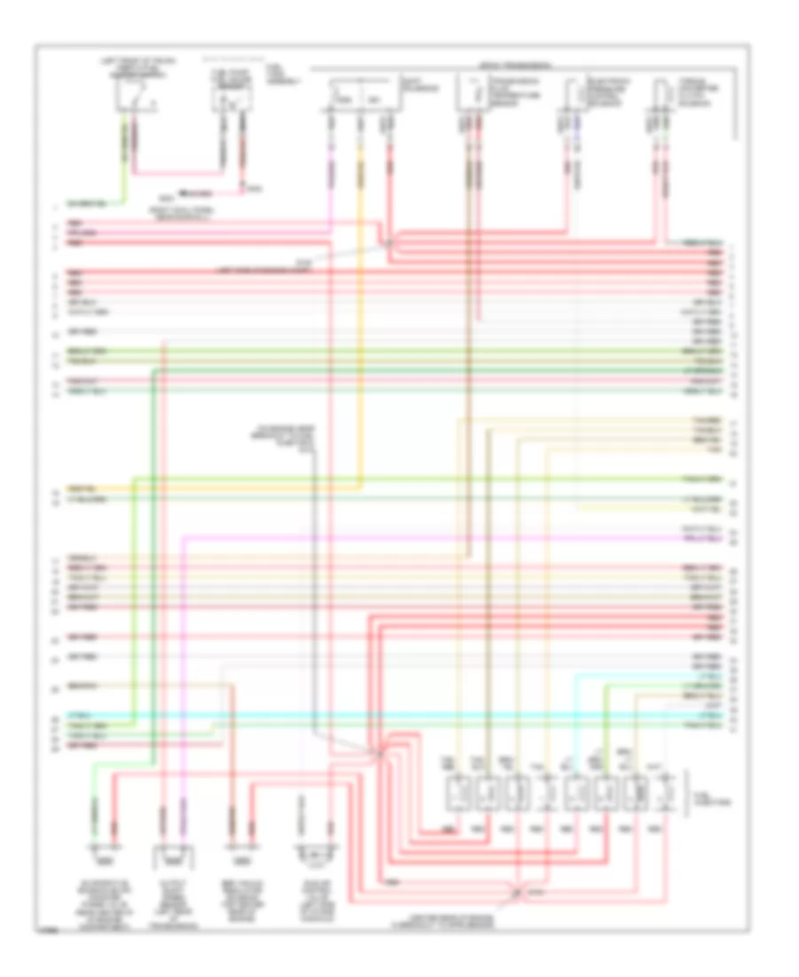
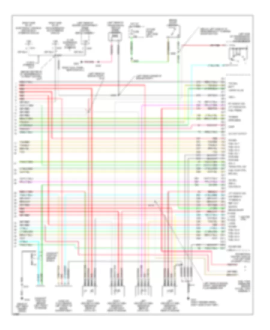
ENGINE PERFORMANCE
4.6L
4.6L CNG, Engine Performance Wiring Diagrams (1 of 5) for Ford Crown Victoria S 1997
List of elements for 4.6L CNG, Engine Performance Wiring Diagrams (1 of 5) for Ford Crown Victoria S 1997:
- (front of right fender apron) g101
- (front of engine compt, near breakout to ngv module)
- (front of right fender apron)
- (left front of engine, in breakout to camshaft position sensor)
- (left rear corner of eng compt)
- (left side of i/p, near breakout to dlc)
- (rear of left fender apron)
- (rear of left front fender apron)
- (right cowl panel, near door sill)
- (top right front of engine, in breakout to right ignition coil)
- A/c clutch sig
- C2021
- Case gnd
- Ckp (+)
- Ckp (-)
- Coil
- Coil 1
- Coil 2
- Cool fan ctrl
- Cooling fans system (cooling fan relay)
- Crankshaft position (ckp) sensor (lower right front of engine)
- Crankshaft position sensor shield
- Data link (+)
- Data link (-)
- Data link connector (left side of i/p)
- Ect sens
- Eec fuse 30a
- Egr vac reg
- Engine compartment fuse box (right front of engine compartment)
- Feps (eprom)
- Fuel pump mon
- Fuel rail sens
- Fuse 15a
- Fuse 25a
- G101
- G104
- G203
- Hot at all times
- Hot in run or start
- I/p fuse panel (below left side of i/p)
- Iat sens
- Left ignition coil
- Left radio noise capacitor
- Maf sig rtn
- Mil
- Nca
- Octane adjust
- Pcm power diode
- Pcm power relay
- Powertrain control module (top left side of safety wall)
- Pwr gnd
- Red
- Relay center (left side of engine compartment)
- Right ignition coil
- Right radio noise capacitor
- S100
- S101
- S102
- S103
- S105
- S114
- S117
- S118
- S129
- S151
- S197
- S276
- Shift sol 1
- Shift sol 2
- To spark plugs 1 & 6
- To spark plugs 2 & 8
- To spark plugs 3 & 5
- To spark plugs 4 & 7
- Trans ctrl sw
- Trans temp
- Transmission control switch
- Vss (-)
4.6L CNG, Engine Performance Wiring Diagrams (2 of 5) for Ford Crown Victoria S 1997
List of elements for 4.6L CNG, Engine Performance Wiring Diagrams (2 of 5) for Ford Crown Victoria S 1997:
- (a/c high pressure cut out switch) air conditioning system
- (left rear of engine compt)
- (left side of engine compt)
- (left side of i/p, near breakout to cluster)
- (lower right rear of engine, near breakout to right heated oxygen sensor 1)
- A/c wot cutout relay
- Differential pressure feedback egr sensor (near right side of intake manifold)
- Engine compartment fuse box (right front of engine compartment)
- Engine coolant temperature sensor (top left front of engine)
- Fuel level input
- Fuel pmp fuse 20a
- Fuel rail pressure sensor (top of engine)
- Fuel rail temperature sensor #1 (top of engine)
- Fuel valve relay
- Ground
- Hot at all times
- Instrument cluster
- Intake air temperature sensor (rear of air cleaner assembly)
- Malfunction indicator lamp
- Octane adjust plug (left side of engine compartment)
- Power
- Red
- Red/pnk
- Relay center (left side of engine compartment)
- S110
- S125
- S126
- S130
- S147 (left side of engine compt)
- S299
- Throttle position sensor (left side of throttle body)
- Transmission control indicator input
- Vss (+)
4.6L CNG, Engine Performance Wiring Diagrams (3 of 5) for Ford Crown Victoria S 1997
List of elements for 4.6L CNG, Engine Performance Wiring Diagrams (3 of 5) for Ford Crown Victoria S 1997:
- (center rear of engine, in breakout to dpfe sensor)
- (on engine near breakout to fuel injector 8) s131
- 4r70w transmission
- Egr vacuum regulator solenoid (top center rear of engine)
- Electronic pressure control solenoid
- Fuel injectors
- Idle air control valve (left side of intake manifold)
- Output shaft speed sensor (left rear of transmission)
- Red
- Red/pnk
- S143
- S148 (left side of engine compt)
- Shift solenoids
- Ss1
- Ss2
- Tan
- Tan/ red
- Tan/red
- Torque converter clutch solenoid
- Transmission fluid temperature sensor
4.6L CNG, Engine Performance Wiring Diagrams (4 of 5) for Ford Crown Victoria S 1997
List of elements for 4.6L CNG, Engine Performance Wiring Diagrams (4 of 5) for Ford Crown Victoria S 1997:
- (behind left cowl panel)
- (center rear of trunk, on support)
- (fuel tank assembly) fuel tank assembly temperature sensor #1
- (fuel tank assembly) fuel tank assembly temperature sensor #2
- (fuel tank assembly) fuel tank pressure sensor
- (fuel tank assembly) fuel tank solenoid valve #1
- (fuel tank assembly) fuel tank solenoid valve #2
- (fuel tank assembly) fuel tank solenoid valve #3
- (fuel tank assembly) fuel tank solenoid valve #4
- (in fuel tank assy, near breakout to fuel tank solenoid valve 4)
- (left side of trunk)
- (left side of trunk) inertia fuel shut-off switch
- (near #1 fuel injector)
- (right front fender apron, right side of battery)
- (top of engine) fuel rail cutoff solenoid
- (top of engine) fuel rail temperature sensor #2
- Data (+)
- Data (-)
- G101
- G101 (right front fender apron, right side of battery)
- G134
- G407
- Ground
- I/p
- Ignition
- Injector #1 input
- Injector #1 out
- Injector #2 input
- Injector #2 out
- Injector #3 input
- Injector #3 out
- Injector #4 input
- Injector #4 out
- Injector #5 input
- Injector #5 out
- Injector #6 input
- Injector #6 out
- Injector #7 input
- Injector #7 out
- Injector #8 input
- Injector #8 out
- Natural gas vehicle (ngv) module (front of engine compartment)
- Power
- Red
- Red/pnk
- Ref voltage
- S112
- S141
- S298
- S405
- S427
- S429
- S430
- Tan
- Tan/red
- Temp sens #1
- Temp sens #2
- Transducer input
- Transducer ret
4.6L CNG, Engine Performance Wiring Diagrams (5 of 5) for Ford Crown Victoria S 1997
List of elements for 4.6L CNG, Engine Performance Wiring Diagrams (5 of 5) for Ford Crown Victoria S 1997:
- (behind center of i/p, near breakout to front control unit)
- (below left side of i/p, near breakout to brake on/off switch)
- (left rear corner of engine compt)
- (left rear of engine compartment) speed control servo assembly
- (left rear of engine compt)
- (left rear of transmission) vehicle speed sensor
- (left side of transmission) transmission range sensor
- (rear of left front fender apron)
- (right cowl panel, near door sill)
- (right side of i/p) air suspension/ evo steering module
- (right side of i/p) electronic variable orifice (evo) steering module
- A/c wot cutout
- Batt
- Brake on/off
- Brake on/off switch
- C214
- C216
- C234
- Cam pos in
- Camshaft position sensor (left front of engine)
- Camshaft position sensor shield
- Coil 3
- Coil 4
- Dpfe sens
- Epc sol
- Fuel inj 1
- Fuel inj 2
- Fuel inj 3
- Fuel inj 4
- Fuel inj 5
- Fuel inj 6
- Fuel inj 7
- Fuel inj 8
- Fuel pump ctrl
- Fuel rail press
- Fuel rail temp
- Fuse 15a
- G101 (right fender apron, right side of battery)
- G104
- G203
- Heater ctrl
- Hot at all times
- I/p fuse panel (left side of i/p)
- Iac sol
- L ho2s
- Left heated oxygen sensor #1 (lower left rear of engine)
- Lft ho2s #1 sig
- Maf sens in
- Mass air flow sensor (left front of engine compartment)
- Nca
- Oss (+)
- Power
- Power gnd
- Powertrain control module (top left side of safety wall)
- Pwr gnd
- R ho2s
- Red
- Red/pnk
- Ref volt
- Right heated oxygen sensor #1 (lower right rear of engine)
- Rt ho2s #1 sig
- S101
- S105
- S106
- S109
- S114
- S147
- S247
- S258
- S263
- Sig rtn
- Tan
- Tan/red
- Tcc sol
- Tp sens in
- Tr sens
- Trans ctrl ind
- Vss (+)
- Vss (-)
- W/ air suspension and evo steering
- W/ evo steering only
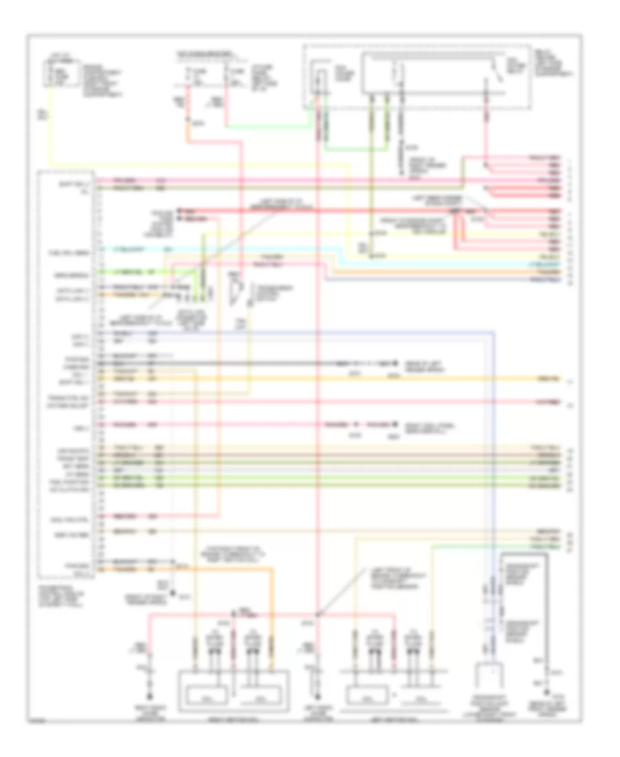
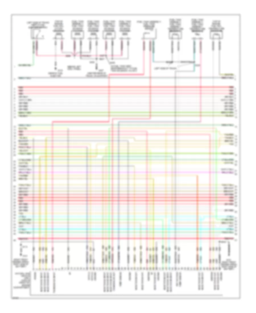
4.6L, Engine Performance Wiring Diagrams (1 of 4) for Ford Crown Victoria S 1997
List of elements for 4.6L, Engine Performance Wiring Diagrams (1 of 4) for Ford Crown Victoria S 1997:
- (front of right fender apron) g101
- (front of right fender apron)
- (inside front of right front fender)
- (left front of engine in breakout to cam- shaft position sensor)
- (left rear corner of engine compt)
- (left side of i/p, near breakout to dlc)
- (rear of left fender apron)
- (right cowl panel, near door sill)
- (top right front of engine, in breakout to right ignition coil)
- A/c clutch sig
- C2021
- Canister vent solenoid (right front of engine compt, lower side of eng compt fuse box)
- Case gnd
- Ckp (+)
- Ckp (-)
- Coil
- Coil 1
- Coil 2
- Cool fan ctrl
- Cooling fans system (cooling fan relay)
- Data link (+)
- Data link (-)
- Data link connector (left side of i/p)
- Ect sens
- Eec fuse 30a
- Egr vac reg
- Engine compartment fuse box (right front of engine compartment)
- Feps (eprom)
- Fuel flow rate
- Fuel level
- Fuel pump mon
- Fuse 15a
- Fuse 25a
- G101
- G104
- G203
- Hot at all times
- Hot in run or start
- I/p fuse panel (below left side of i/p)
- Iat sens
- Instrument cluster system (fuel gauge)
- Left ignition coil
- Left radio noise capacitor
- Maf sig rtn
- Mil
- Nca
- Octane adjust
- Pcm power diode
- Pcm power relay
- Powertrain control module (top left side of safety wall)
- Pwr gnd
- Red
- Relay center (left side of engine compartment)
- Right ignition coil
- Right radio noise capacitor
- Rt ho2s #2 sig
- S100
- S101
- S102
- S103
- S105
- S106
- S116
- S117
- S118
- S129
- S276
- Shift sol 1
- Shift sol 2
- To spark plugs 1 & 6
- To spark plugs 2 & 8
- To spark plugs 3 & 5
- To spark plugs 4 & 7
- Trans ctrl sw
- Trans temp
- Transmission control switch
- Vss (-)
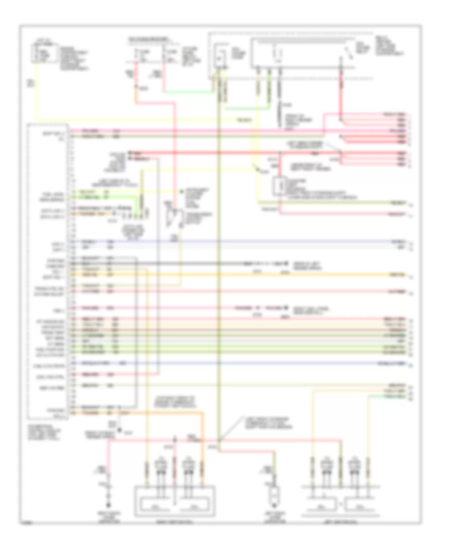
4.6L, Engine Performance Wiring Diagrams (2 of 4) for Ford Crown Victoria S 1997
List of elements for 4.6L, Engine Performance Wiring Diagrams (2 of 4) for Ford Crown Victoria S 1997:
- (a/c high pressure cut out switch) air conditioning system
- (left rear of engine compt)
- (left side of engine compt)
- (left side of engine compt, near breakout to fuel pump prime connector)
- (speedometer/ odometer) vehicle speed input
- C255
- Crankshaft position (ckp) sensor (lower right front of engine)
- Crankshaft position sensor shield
- Differential pressure feedback egr sensor (near right side of intake manifold)
- Digital only
- Engine compartment fuse box (right front of engine compartment)
- Engine coolant temperature sensor (top left front of engine)
- Fuel flow rate input
- Fuel pmp fuse 20a
- Fuel pump prime connector (left side of engine compartment)
- Fuel pump relay
- G104 (rear of left front fender apron)
- Hot at all times
- Instrument cluster
- Intake air temperature sensor (rear of air cleaner assembly)
- Malfunction indicator input
- Octane adjust plug (left side of engine compartment)
- Red
- Relay center (left side of engine compartment)
- S101
- S110
- S124
- S125
- S126 (lower right rear of engine, near breakout to right heated oxygen sensor 1)
- S130
- S147
- Throttle position sensor (left side of throttle body)
- Transmission control indicator input
- Wot cutout relay
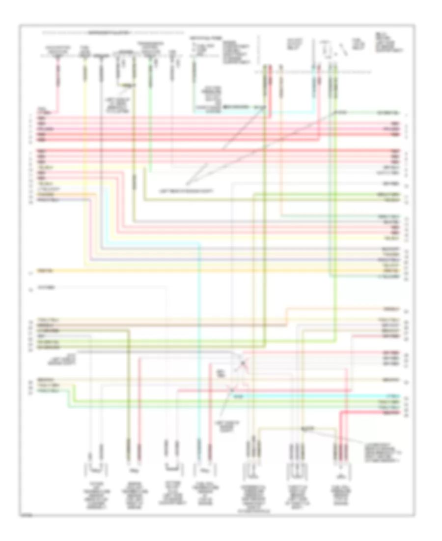
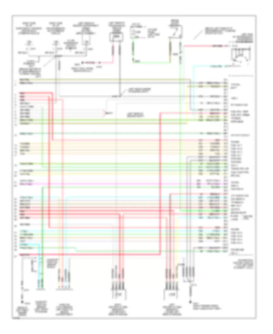
4.6L, Engine Performance Wiring Diagrams (3 of 4) for Ford Crown Victoria S 1997
List of elements for 4.6L, Engine Performance Wiring Diagrams (3 of 4) for Ford Crown Victoria S 1997:
- (center rear of engine, in breakout to dpfe sensor)
- (left front of trunk) inertia fuel shutoff switch
- (on engine, near breakout to fuel injector 8) s131
- (rear center of of engine) compartment)
- (right cowl panel, near door sill)
- 4r70w transmission
- Egr vacuum regulator solenoid (top center rear of engine)
- Electronic pressure control solenoid
- Evaporative emission (evap) canister purge valve
- Fuel injectors
- Fuel pump/ fuel gauge sender
- Fuel tank assembly
- G203
- Idle air control valve (left side of intake manifold)
- Nca
- Output shaft speed sensor (left rear of transmission)
- Red
- S143
- S148 (left side of engine compt)
- S402
- Shift solenoids
- Ss1
- Ss2
- Tan
- Tan/ red
- Tan/red
- Torque converter clutch solenoid
- Transmission fluid temperature sensor
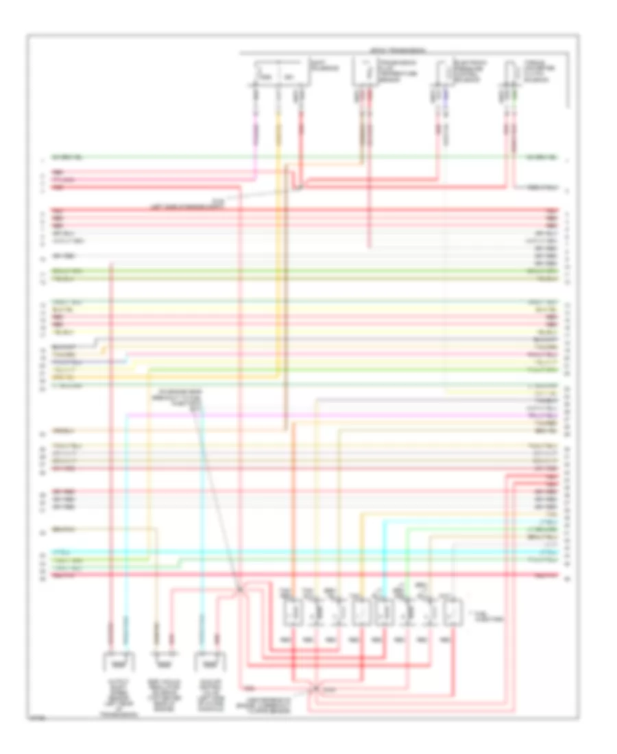
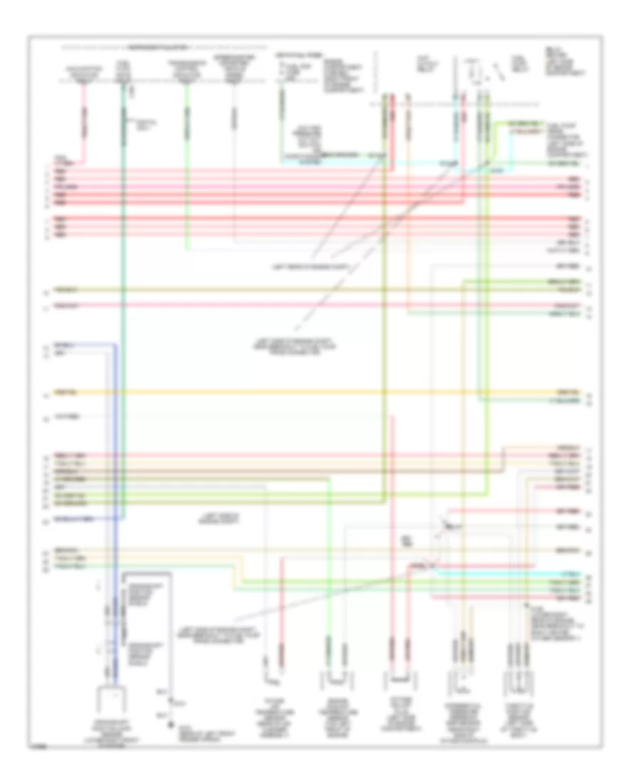
4.6L, Engine Performance Wiring Diagrams (4 of 4) for Ford Crown Victoria S 1997
List of elements for 4.6L, Engine Performance Wiring Diagrams (4 of 4) for Ford Crown Victoria S 1997:
- (behind center of i/p, near breakout to front control unit)
- (below left side of i/p, near breakout to brake on/off switch)
- (left rear corner of engine compt)
- (left rear of engine compartment) speed control servo assembly
- (left rear of engine compt) s147
- (left rear of engine compt, near brake fluid reservoir)
- (left rear of transmission) vehicle speed sensor
- (left side of transmission) transmission range sensor
- (rear of left front fender apron)
- (right cowl panel, near door sill)
- (right side of i/p) air suspension/ evo steering module
- (right side of i/p) electronic variable orifice (evo) steering module
- A/c wot cutout
- Batt
- Brake on/off
- Brake on/off switch
- C214
- C216
- C234
- Cam pos in
- Camshaft position sensor (left front of engine)
- Camshaft position sensor shield
- Canp
- Coil 3
- Coil 4
- Dpfe sens
- Epc sol
- Fuel inj 1
- Fuel inj 2
- Fuel inj 3
- Fuel inj 4
- Fuel inj 5
- Fuel inj 6
- Fuel inj 7
- Fuel inj 8
- Fuel press
- Fuel pump ctrl
- Fuel tank pressure sensor (in fuel tank assembly)
- Fuse 15a
- G101 (right fender apron, right side of battery)
- G104
- G203
- Heater ctrl
- Hot at all times
- I/p fuse panel (left side of i/p)
- Iac sol
- L ho2s
- Left heated oxygen sensor #1 (lower left rear of engine)
- Left heated oxygen sensor #2 (rear of catalyst)
- Lft ho2s #1 sig
- Lft ho2s #2 sig
- Maf sens in
- Mass air flow sensor (left front of engine compartment)
- Nca
- Oss (+)
- Power
- Power gnd
- Powertrain control module (top left side of safety wall)
- Pwr gnd
- R ho2s
- Red
- Red/pnk
- Ref volt
- Right heated oxygen sensor #1 (lower right rear of engine)
- Right heated oxygen sensor #2 (rear of catalyst)
- Rt ho2s #1 sig
- S101
- S105
- S106
- S109
- S114
- S115
- S247
- S258
- S263
- Sig rtn
- Tan
- Tan/red
- Tcc sol
- Tp sens in
- Tr sens
- Trans ctrl ind
- Vapor valve
- Vss (+)
- Vss (-)
- W/ air suspension and evo steering
- W/ evo steering only
EXTERIOR LIGHTS
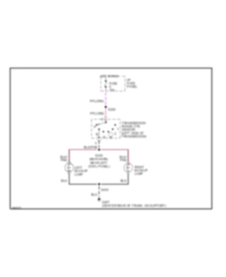
Back-up Lamps Wiring Diagram for Ford Crown Victoria S 1997
List of elements for Back-up Lamps Wiring Diagram for Ford Crown Victoria S 1997:
- Fuse 15a
- G407 (center rear of trunk, on support)
- Hot in run
- I/p fuse panel
- Left backup lamp
- Right backup lamp
- S226
- S230 (main harn, near left cowl panel)
- S403
- Transmission range (tr) sensor (left side of transmission)
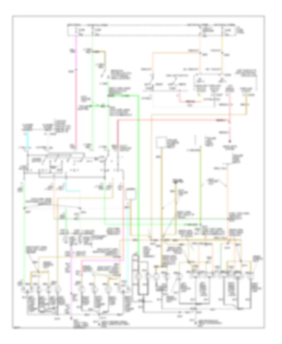
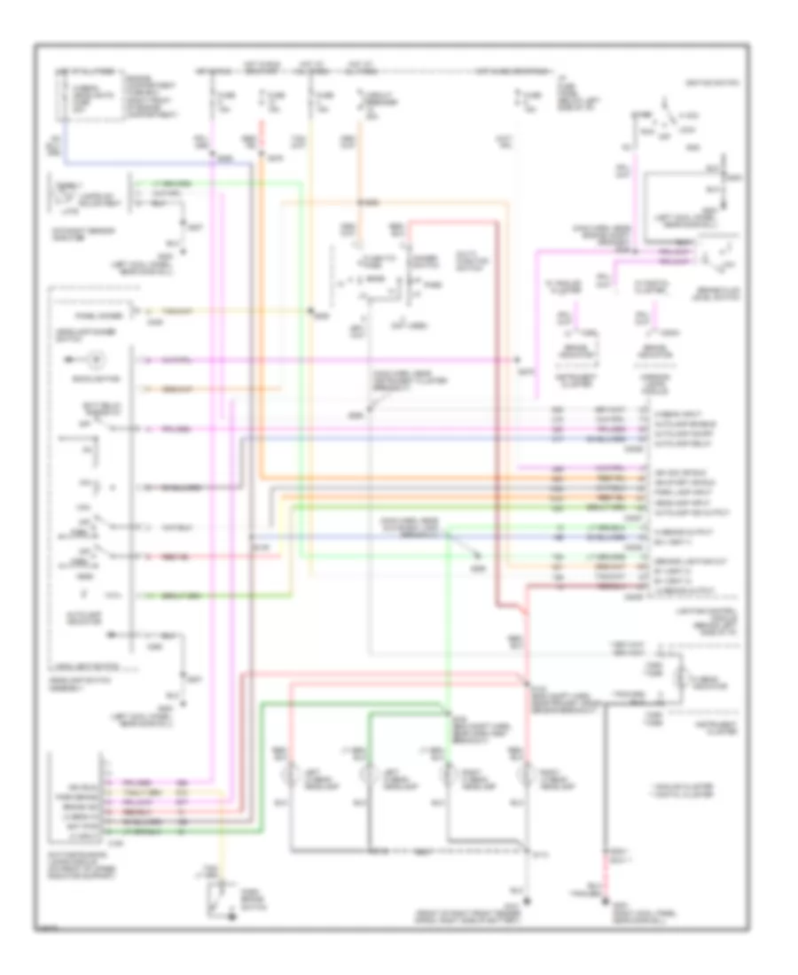
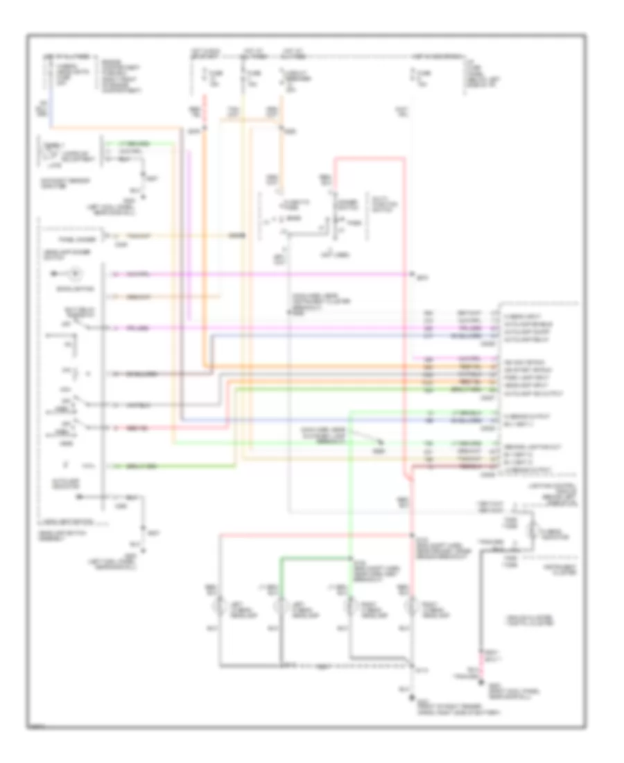
Exterior Lamps Wiring Diagram for Ford Crown Victoria S 1997
List of elements for Exterior Lamps Wiring Diagram for Ford Crown Victoria S 1997:
- (analog) (digital)
- (body harn, left front of trunk)
- (body harn, near brake switch breakout) s258
- (center rear of trunk, on support) g407
- (eng compt harn, near horn assembly breakout) s120
- (eng compt harn, near left front fender)
- (eng compt harn, near right front fender)
- (fuel tank harn, near g407 breakout) s419
- (left side of i/p) lighting control module (lcm)
- (main harn, near clock breakout)
- (main harn, near instrument cluster breakout)
- (rear harn, left rear of trunk)
- (rear harn, near trunk lid switch breakout) s412
- (rear harn, right rear of trunk)
- (right fender apron, right side of battery) g102
- B+ vbat 2
- B+ vbat 3
- Brake on/ off (boo) switch (top of brake pedal support)
- C2027
- C2029
- C250
- C250 c256
- C251 c256
- C256
- Circuit breaker 20a
- Clock
- Flasher power input
- Flasher power output
- Fuse 15a
- G201 (right cowl panel, near door sill)
- Grand marquis only
- Hazard switch
- Head
- Headlamp switch output
- Headlights system
- High mount stop lamp assembly
- Hot at all times
- Hot in run
- I/p fuse panel
- Instrument cluster
- Left
- Left corn- ering lamp
- Left front park lamp
- Left front side marker lamp
- Left rear park/ stop/ turn lamps
- Left turn indi- cator
- License lamps
- Lighting control module (lcm) (behind left side of i/p)
- Low beams output
- Main light switch
- Multi- function switch
- Nca
- Near trailer tow relays breakout)
- Off
- Park
- Parklamp output
- Parklamp switch input
- Right
- Right corn- ering lamp
- Right front park lamp
- Right front park/ turn/ side marker lamp
- Right front side marker lamp
- Right rear park/ stop/ turn lamps
- Right rear running lamp
- Right turn indi- cator
- S108
- S113
- S121
- S122
- S226
- S242
- S243 (main harn, near multi-function switch breakout)
- S257
- S257 or s210
- S262
- S263
- S285
- S301
- S400
- S401
- S402
- S403
- S409
- S413
- S414
- S416
- Trailer adapter
- Trailer exterior lamps relay
- Trailer left turn relay
- Trailer right turn relay
- Turn switch
- With trailer tow
Trailer/Camper Adapter Wiring Diagram for Ford Crown Victoria S 1997
List of elements for Trailer/Camper Adapter Wiring Diagram for Ford Crown Victoria S 1997:
- (center rear of trunk, on support)
- (center rear of trunk, on support) g407
- (fuel tank harn, near g400 breakout) s419
- (fuel tank harn, near trailer relays breakout) s418
- (left side of i/p) lighting control module (lcm)
- Battery charging wire
- Brake on/off & right turn signal output
- Brake on/off or left turn signal output
- Brake on/off switch
- C2029
- Electric brake feed
- Engine compart- ment fuse box
- Engine compartment fuse box
- Fuse 15a
- G407
- Hot at all times
- Hot in run
- I/p fuse panel
- Left turn signal & stop lamps
- Multi- function switch
- Multi-function switch breakout)
- Parklamp output
- Rear exterior lamps
- Red
- Right turn signal & stop lamps
- S226
- S265
- S402
- S404
- S409 (body harn, left front of trunk)
- S425
- Tail lamps
- Tlr brakes fuse 30a
- Tlr tow fuse 20a
- Tlr tow fuse 40a
- Trailer battery charging relay (left side of trunk)
- Trailer electronic brake control unit
- Trailer exterior lamps relay (left side of trunk)
- Trailer ground wire
- Trailer left turn relay (left side of trunk)
- Trailer right turn relay (left side of trunk)
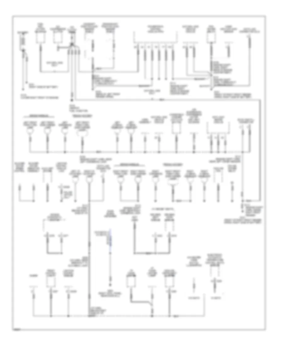
GROUND DISTRIBUTION
Ground Distribution Wiring Diagram (1 of 3) for Ford Crown Victoria S 1997
List of elements for Ground Distribution Wiring Diagram (1 of 3) for Ford Crown Victoria S 1997:
- (analog) instrument cluster
- (engine compt harn, inside right front fender)
- (i/p harn, behind right side of i/p) s204
- (not used)
- A/c clutch diode
- A/c compressor clutch
- A/c-heater mode switch illumination
- Air bag diagnostic monitor
- Air suspension compressor motor and vent solenoid
- Anti-lock brake module
- Auxiliary power
- Battery
- Blower motor resistor assembly
- Blower motor speed control
- C2026
- C2029
- C228
- C250
- C257
- C276
- C277
- C303
- C519
- Camshaft position (cmp) sensor shield
- Clock
- Cooling fan
- Crankshaft position (ckp) sensor shield
- Crown victoria
- Data link connector (dlc)
- Door blend actuator
- Driver's door module
- Driver's seat module
- Electronic automatic temperature control (eatc) module
- Evac and fill connector
- Front control unit
- Fuel rail cutoff solenoid
- G101 (front of right front fender apron, right side of battery)
- G101 (right side of battery)
- G104 (rear of left front fender apron)
- G119 (lower right front of engine)
- G134 (near #1 fuel injector)
- G203 (right cowl panel, near door sill)
- Grand marquis
- Horn assembly
- I/p cigar lighter
- I/p cigar lighter lamp
- Left cornering lamp
- Left front park/turn lamp
- Left front park/turn/ side marker lamp
- Left front side marker lamp
- Left hi beam headlamp
- Left i/p courtesy lamp
- Left lo beam headlamp
- Lighting control module
- Lighting control module (lcm)
- Mass air flow (maf) sensor
- Natural gas only
- Natural gas vehicle module
- Pcm power relay
- Police option only
- Police power relay
- Powertrain control module (pcm)
- Right cornering lamp
- Right front park/turn lamp
- Right front park/turn/ side marker lamp
- Right front side marker lamp
- Right hi beam headlamp
- Right i/p courtesy lamp
- Right lo beam headlamp
- S108 (engine compt harn, near left cornering lamp)
- S112 (engine compt harn, near left crash sensor)
- S112 (engine compt harn, near right cornering lamp)
- S112 (i/p harn, behind right side of i/p)
- S113
- S114 (engine compt harn, right rear of engine compartment)
- S141 (engine compt harn, in breakout to ground g101)
- S206 (i/p harn, near breakout to glovebox lamp)
- W/ eatc
- W/ memory seats
- W/o eatc
- Windshield washer low fluid switch
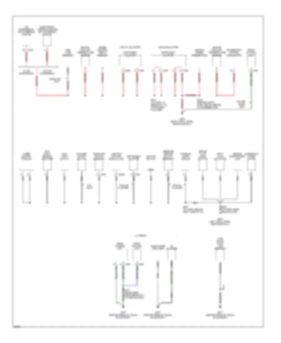
Ground Distribution Wiring Diagram (2 of 3) for Ford Crown Victoria S 1997
List of elements for Ground Distribution Wiring Diagram (2 of 3) for Ford Crown Victoria S 1997:
- 48 (bare)
- Air suspension/ evo steering module
- Analog cluster
- Blower motor switch
- Brake fluid level switch
- C2029
- C216
- C249
- C250
- C251
- C255
- C256
- C257
- C452
- Cd changer
- Day/ night sensor/ amplifier
- Digital cluster
- Electronic variable orifice (evo) steering module
- Engine compartment lamp
- Engine coolant temperature sensor
- Front control unit
- Fuel tank assembly
- G200 (left cowl panel, near door sill)
- G203 (right cowl panel, near door sill)
- G407 (center rear of trunk, on support)
- Gasoline only
- Gnd
- Headlamp switch assembly
- High mount stop lamp assembly
- Ignition switch
- Instrument cluster
- Lighting control module (lcm)
- Lux radio
- Main light switch
- Message center switch assembly
- Midline radio only
- Nca
- Powertrain control module (pcm)
- Rear chassis unit
- S105 (engine compt harn, below brake fluid reservoir)
- S207 (i/p harn, behind right side of i/p)
- S210 (i/p harn, in breakout to instrument cluster)
- Shift lock actuator
- Speed control servo assembly
- Subwoofer amplifier
- Vehicle speed sensor (vss)
- W/ air suspension
- W/o air suspension
- W/o eatc
- Warning lamps module
- Windshield wiper motor
- Wiper control module
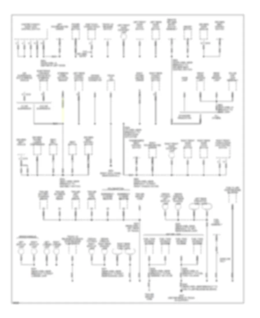
Ground Distribution Wiring Diagram (3 of 3) for Ford Crown Victoria S 1997
List of elements for Ground Distribution Wiring Diagram (3 of 3) for Ford Crown Victoria S 1997:
- (crown victoria) left back-up lamp
- (crown victoria) right back-up lamp
- (grand marquis) left rear running lamp
- (grand marquis) right rear running lamp
- Air bag diagnostic connector
- Air suspension evo steering module
- All others
- C216
- C319
- C519
- Dome lamp
- Driver's door module
- Driver's power lumbar compressor
- Driver's seat control switch
- Driver's seat module
- Electronic variable orifice (evo) steering module
- Emergency flasher relay #1
- Emergency flasher relay #2
- Front dome/ reading lamp
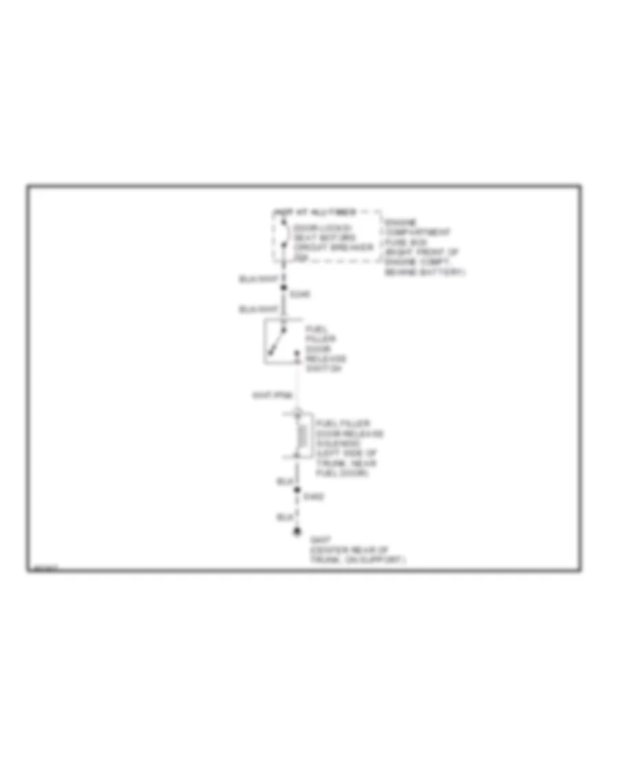
- Fuel filler door release solenoid
- Fuel filler release solenoid)
- Fuel tank assembly
- Fuel tank solenoid valve #1
- Fuel tank solenoid valve #2
- Fuel tank solenoid valve #3
- Fuel tank solenoid valve #4
- G203 (right cowl panel, near door sill)
- G407 (center rear of trunk, on support)
- Gasoline only
- Grand marquis
- Left back-up lamp
- Left front door courtesy lamp
- Left front door latch switch
- Left license lamp
- Left power/heated mirror
- Left rear door latch switch
- Left rear park/stop/ turn lamps
- Left rear window control switch
- Master window/ door lock control switch
- Memory switch
- Natural gas
- Nca
- One touch window down module
- Passenger's seat control switch
- Police map lamp assembly
- Police option
- Power mirror switch
- Rear dome/ reading lamp
- Remote keyless entry switch assembly
- Right back-up lamp
- Right front door courtesy lamp
- Right front door latch switch
- Right front window/door lock control switch
- Right license lamp
- Right power/ heated mirror
- Right power/heated mirror
- Right rear door latch switch
- Right rear park/stop/ turn lamps
- Right rear window control switch
- S208 (i/p harn, near breakout to blend door actuator)
- S304 (body harn, near breakout to seatbelt switch)
- S400 (rear harn, near breakout to left rear running lamp)
- S401 (rear harn, near breakout to right rear running lamp)
- S403 (rear harn, near breakout to right license lamp)
- S404 (rear harn, left rear of trunk)
- S405 (rear harn, in breakout to fuel tank valve #4)
- S428 (rear harn, near breakout to fuel assembly #2 valve)
- S500 (door harn, near breakout to driver's seat control switch)
- S503 (door harn, in center of left door)
- S600 (door harn, near breakout to right front window motor)
- Seat belt switch
- Seat switch
- Standard production
- Steering wheel rotation sensor
- Trailer battery charging relay
- Trailer exterior lamps relay
- Trailer ground wire
- Trailer left turn relay
- Trailer right turn relay
- Trunk lid lamp
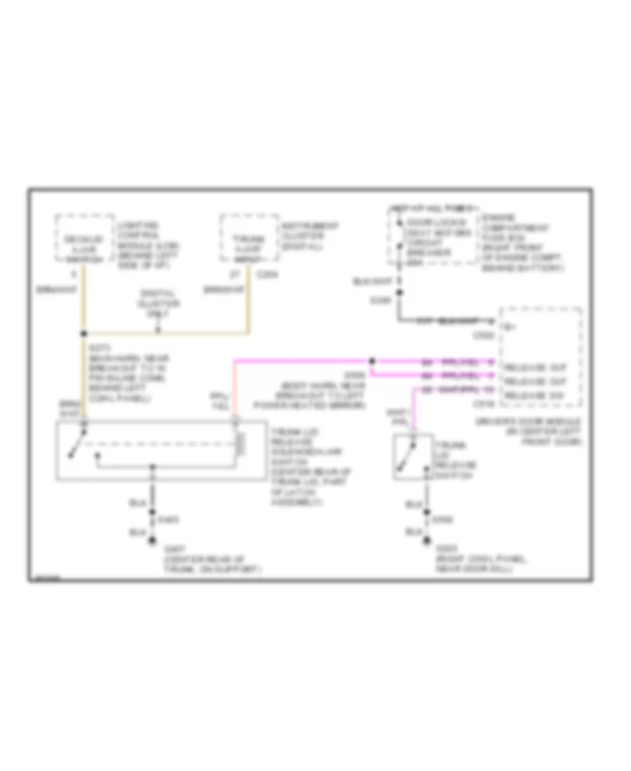
- Trunk lid release solenoid/ door release ajar switch
- Trunk lid release switch
- W/ air suspension
- W/o air suspension
- W/o keyless entry
HEADLIGHTS
Headlamps Wiring Diagram, with DRL for Ford Crown Victoria S 1997
List of elements for Headlamps Wiring Diagram, with DRL for Ford Crown Victoria S 1997:
- "lamps on" adjustment
- (main harn, near engine compt grommet) s248
- (main harn, near glove box lamp breakout)
- (main harn, near instrument cluster breakout)
- (not used)
- * analog cluster
- ** digital cluster
- **c256
- *c250
- Acc
- Aut0lamp enable
- Autolamp delay
- Autolamp ind output
- Autolamp indicator
- Autolamp on/off
- B(+) vbat 4
- B+ (vbat 2)
- B+ (vbat 3)
- Backlighting
- Bat pwr
- Brake fluid level switch
- Brake ind
- Brake indicator
- C180
- C2004
- C2026
- C2027
- C2028
- C2029
- C249
- C250
- C262
- Circuit breaker 20a
- Day/night sensor amplifier
- Daytime running lamps module (on front of upper radiator support)
- Demand lighting out
- Dimmer switch
- Early
- Engine compartment fuse box (right front of engine compartment)
- Exit delay rheostat
- Flash-to- pass
- Fuse 15a
- G101 (front of right front fender apron, right side of battery)
- G200 (left cowl panel, near door sill)
- G203 (right cowl panel, near door sill)
- Gnd
- Head
- Headlamp dimmer switch
- Headlamp input
- Headlamp switch assembly
- Hi beam indicator
- Hi beams output
- Hi input
- Hi-beam headlights fuse 20a
- Hi-beam input
- Hot at all times
- Hot in acc or or run
- Hot in run
- Hot in run or start
- I/p fuse panel (below left side of i/p)
- Ign (run)
- Ign acc or run
- Ign start or run
- Ignition switch
- Instrument cluster
- Late
- Left hi beam headlamp
- Left lo beam headlamp
- Lighting control module (behind left side of i/p)
- Lo beam in
- Lo beams output
- Lock
- Low
- Main light switch
- Max
- Min
- Multi- function switch
- Off
- Panel dimmer
- Park
- Park brake
- Park brake switch
- Park lamp input
- Pass
- Right hi beam headlamp
- Right lo beam headlamp
- Run
- S112
- S113
- S138 (eng compt harn, near horn assy breakout)
- S140 (eng compt harn, near primary crash sensor breakout)
- S149
- S203
- S204 *
- S207
- S210 **
- S226
- S262
- S276
- S278
- S280
- S285
- S290
- Start
- W/ analog cluster
- W/ digital cluster
- Warning lamps module
Headlamps Wiring Diagram, without DRL for Ford Crown Victoria S 1997
List of elements for Headlamps Wiring Diagram, without DRL for Ford Crown Victoria S 1997:
- "lamps on" adjustment
- (main harn, near glove box lamp breakout)
- (main harn, near instrument cluster breakout) s280
- (not used)
- * analog cluster ** digital cluster
- **c256
- *c250
- Aut0lamp enable
- Autolamp delay
- Autolamp ind output
- Autolamp indicator
- Autolamp on/off
- B(+) vbat 4
- B+ (vbat 2)
- B+ (vbat 3)
- Backlighting
- C2026
- C2027
- C2028
- C2029
- C249
- C262
- Circuit breaker 20a
- Day/night sensor amplifier
- Demand lighting out
- Dimmer switch
- Early
- Engine compartment fuse box (right front of engine compartment)
- Exit delay rheostat
- Flash-to- pass
- Fuse 15a
- G101 (front of right fender apron, right side of battery)
- G200 (left cowl panel, near door sill)
- G203 (right cowl panel, near door sill)
- Head
- Headlamp dimmer switch
- Headlamp input
- Headlamp switch assembly
- Hi beam indicator
- Hi beam input
- Hi beams output
- Hi-beam headlights fuse 20a
- Hot at all times
- Hot in acc or run
- Hot in run or start
- I/p fuse panel (below left side of i/p)
- Ign acc or run
- Ign start or run
- Instrument cluster
- Late
- Left hi beam headlamp
- Left lo beam headlamp
- Lighting control module (behind left side of i/p)
- Lo beams output
- Main light switch
- Max
- Min
- Multi- function switch
- Off
- Panel dimmer
- Park
- Park lamp input
- Pass
- Right hi beam headlamp
- Right lo beam headlamp
- S112
- S113
- S138 (eng compt harn, near horn assy breakout)
- S140 (eng compt harn, near primary crash sensor breakout)
- S204 *
- S207
- S210 **
- S262
- S276
- S278
- S285
- S290
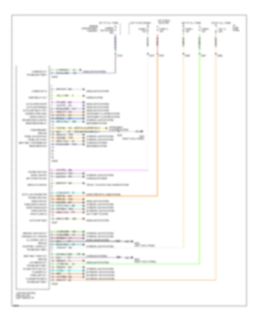
Lighting Control Module Wiring Diagram for Ford Crown Victoria S 1997
List of elements for Lighting Control Module Wiring Diagram for Ford Crown Victoria S 1997:
- (digital cluster only)
- (police package only)
- All doors lock in
- Anti-theft system
- Autolamp delay pot
- Autolamp enable
- Autolamp indic
- Autolamps on/off
- C.b. 12 20a
- C2026
- C2027
- C2028
- C2029
- Computer data lines system
- Courtesy lamps out
- Data link connector
- Decklid ajar sw
- Defogger system
- Demand lighting out
- Dome lamp sw
- Door ajar out
- Door handle sws
- Door locks system
- Driver door ajar sw
- Engine compartment fuse box
- Exterior lights system
- Flasher out
- Flasher power in
- Fuse 13 15a
- Fuse 4 15a
- Fuse 6 15a
- Fuse 8 15a
- G200 (left cowl panel)
- G203 (right cowl panel)
- Ground
- Hazard warn indic
- Headlamp sw
- Headlights system
- Hi beam sw in
- Hi beams out
- Hi-beam hdlts fuse 20a
- Horn relay out
- Horns system
- Hot at all times
- Hot in acc or run
- Hot in run or start
- I/p fuse panel
- Instrument cluster system
- Interior lights system
- Key-in-ignition sw
- Lighting control module (lcm) (left side of i/p)
- Low beams out
- Panel dim down sw
- Panel dim up sw
- Panic alarm in
- Parklamp out
- Parklamp sw
- Pass door ajar sw
- Power (battery)
- Power (ignition)
- Pulse width dim out
- Rear defog relay
- Rear defog sw
- S149
- S200
- S204
- S207
- S227
- S262
- S276
- S278
- S285
- Seat belt fastened sw
- Seat belt indic out
- Tone request
- Trunk, tailgate, fuel doors system
- Variable volt dimming
- Warning systems
HORN
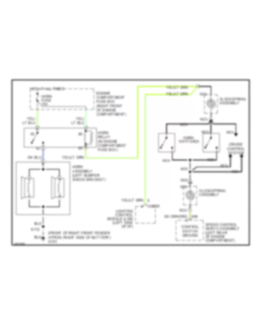
Horn Wiring Diagram for Ford Crown Victoria S 1997
List of elements for Horn Wiring Diagram for Ford Crown Victoria S 1997:
-
- (front of right front fender apron, right side of battery) g101
- C2026
- Clockspring assembly
- Control switch ground
- Cruise control system
- Engine compartment fuse box (right front of engine compartment)
- Horn
- Horn assembly (left bumper shock bracket)
- Horn fuse 15a
- Horn relay (in engine compartment fuse box)
- Hot at all times
- Lighting control module (lcm) (left side of i/p)
- Nca
- S112
- Speed control servo assembly (left rear of engine compartment)
- Switches
INSTRUMENT CLUSTER
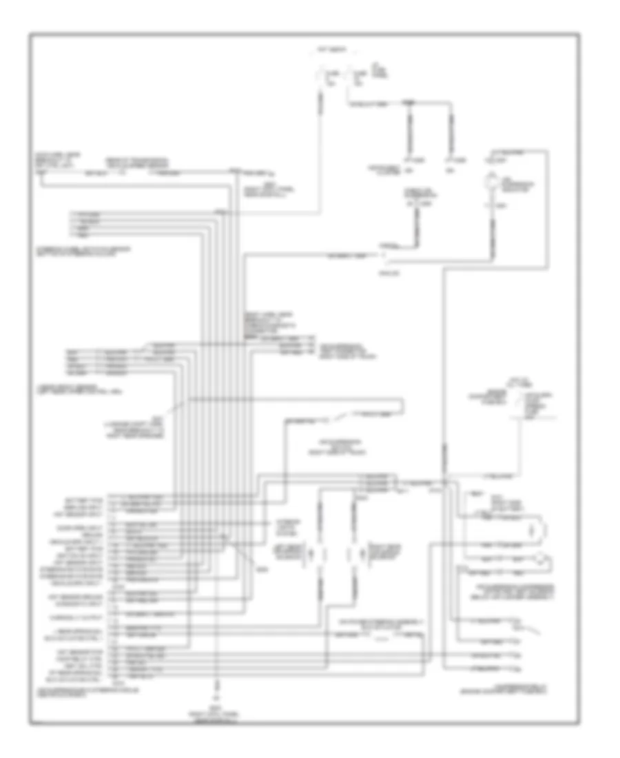
Analog Cluster Wiring Diagram for Ford Crown Victoria S 1997
List of elements for Analog Cluster Wiring Diagram for Ford Crown Victoria S 1997:
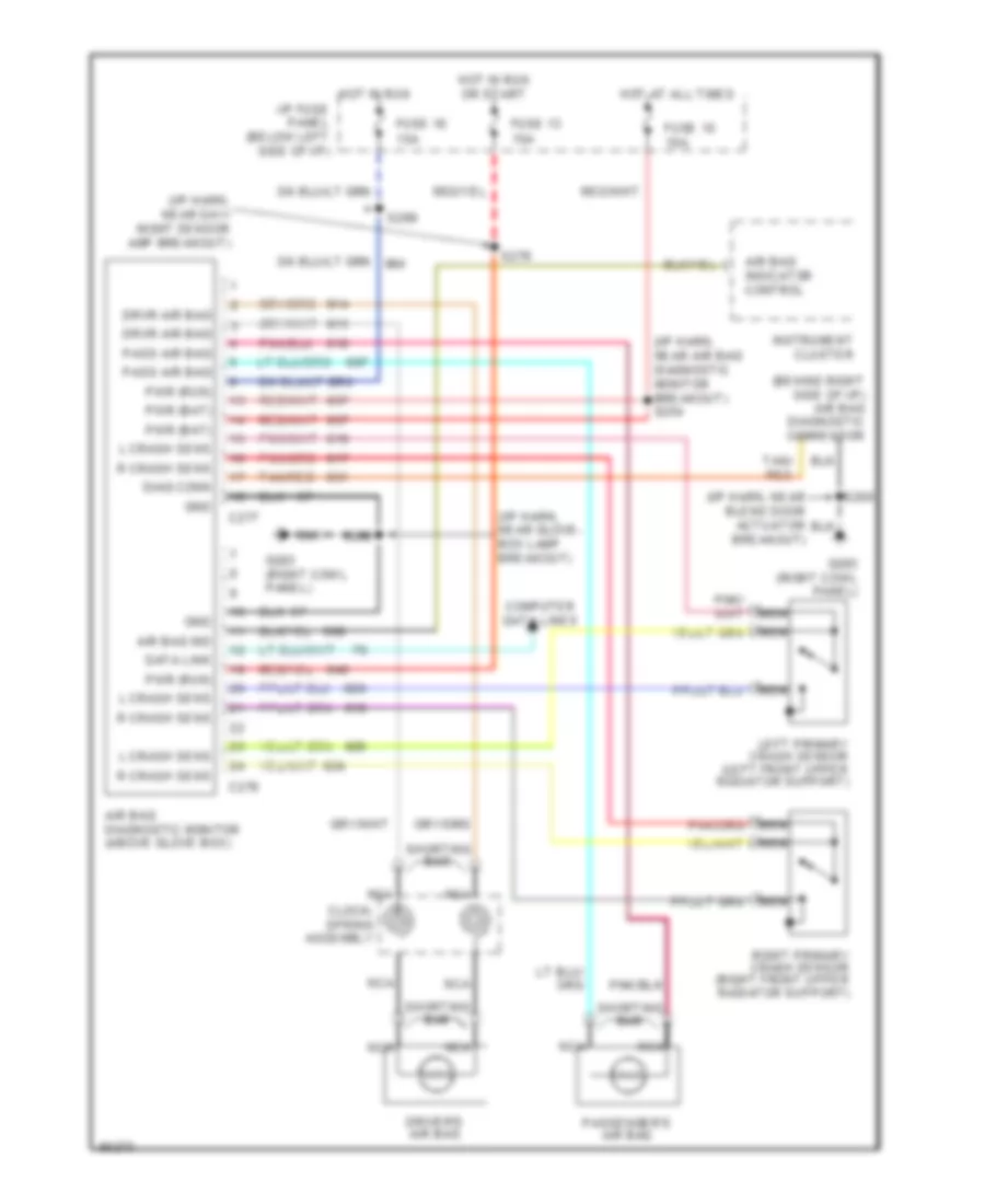
- "air bag"
- "anti-lock"
- (above glove box)
- (above oil
- (behind left cowl
- (brake fluid
- (check engine)
- (front center of upper
- (left front upper
- (left rear of
- (left side
- (left side of i/p)
- (left side of instrument
- (main harn,
- (main harn, near
- (multi-function switch)
- (qty. 6)
- (rear of
- (right cowl panel,
- (right front of
- (right side of
- (top of park
- (top right front
- 10a
- 15a
- 30a
- Acc
- Air
- Air suspension
- Air suspension/evo steering
- Airbag diagnostic monitor
- Airbag indicator
- Anti-lock brake module
- Anti-slosh
- Assembly
- At all
- Belts indicator
- Brake
- Brake assembly)
- Brake fluid
- Breakout to airbag
- C2029
- C215
- C250
- C251
- C276
- C459
- Charge
- Compartment
- Control
- Coolant
- Daytime running
- Diag conn)
- Dimming output
- Drl
- Drl disable
- Electronic
- Engine
- Engine compartment)
- Engine coolant
- Engine oil
- Engine oil pressure
- Exterior lights system
- Fasten
- Filter)
- Fuel
- Fuel tank)
- Fuse
- Fuse box
- G200
- G203
- Gauge
- Generator/
- Gnd
- Guage
- Headlights system
- Hi beam
- Hot
- Hot in
- I/p
- Ignition switch
- Illumination lamps
- In run
- Indicator
- Indicator control
- Indicator output
- Instrument cluster
- Lamp (tcil)
- Lamps (drl) module
- Left turn
- Level switch
- Lighting control module
- Lock
- Low
- Low fuel
- Malfunction
- Mil output
- Module
- Near door sill)
- Near grommet
- Normal
- Odometer
- Of engine)
- Of i/p)
- Off
- Ohms
- Or run
- Panel
- Panel, near door sill)
- Panel, on left
- Park
- Powertrain control module (pcm)
- Pressure
- Pump/
- Radiator support)
- Regulator
- Reservoir)
- Right turn
- Run
- S105
- S144
- S203
- S204
- S210
- S231
- S248
- S276
- S300
- Sender
- Sensor
- Side of safety wall)
- Speed
- Speedo
- Speedometer/
- Start
- Suspension
- Suspn
- Switch
- Tank
- Tcil
- Temperature
- Test connector
- Times
- To eng compt)
- Transmission
- Transmission)
- Trunk)
- Vehicle
- Voltage
- Voltmeter
- W/o
Analog Cluster Wiring Diagram, with Natural Gas for Ford Crown Victoria S 1997
List of elements for Analog Cluster Wiring Diagram, with Natural Gas for Ford Crown Victoria S 1997:
- "air bag"
- "anti-lock"
- (above glove box)
- (above oil
- (behind left cowl
- (body harn, near
- (brake fluid
- (check engine)
- (front center of upper
- (front of
- (left front upper
- (left rear of
- (left side
- (left side of i/p)
- (left side of instrument
- (main harn,
- (main harn, near
- (multi-function switch)
- (qty. 6)
- (right cowl panel,
- (right front of
- (right side of
- (top of park
- (top right front
- 10a
- 30a
- Acc
- Air
- Air suspension
- Air suspension/evo steering
- Airbag diagnostic monitor
- Airbag indicator
- Anti-lock brake module
- Anti-slosh
- Belts indicator
- Brake
- Brake assembly)
- Brake fluid
- Breakout to
- Breakout to airbag
- C2029
- C215
- C250
- C251
- C276
- C459
- Charge
- Cluster
- Compartment
- Compartment)
- Control
- Coolant
- Daytime running
- Diag conn)
- Dimming output
- Drl
- Drl disable
- Electronic
- Engine
- Engine compartment)
- Engine coolant
- Engine oil
- Engine oil pressure
- Exterior lights system
- Fasten
- Filter)
- Fuel
- Fuse
- Fuse box
- G200
- G203
- Gas vehicle
- Gauge
- Generator/
- Gnd
- Ground
- Guage
- Headlights system
- Hi beam
- Hot at all times
- Hot in run
- I/p
- Ignition switch
- Illumination lamps
- Indicator
- Indicator control
- Indicator output
- Inst cluster)
- Instrument cluster
- Lamp (tcil)
- Lamps (drl) module
- Left turn
- Level switch
- Lighting control module
- Lock
- Low
- Low fuel
- Malfunction
- Mil output
- Module
- Natural
- Near door sill)
- Near grommet
- Normal
- Odometer
- Of engine)
- Of i/p)
- Off
- Ohms
- Panel
- Panel, near door sill)
- Panel, on left
- Park
- Power
- Powertrain control module (pcm)
- Pressure
- Pump/
- Radiator support)
- Regulator
- Reservoir)
- Right turn
- Run
- S105
- S144
- S203
- S204
- S210
- S231
- S248
- S299
- S300
- Sender
- Sensor
- Side of safety wall)
- Signal
- Speed
- Speedo
- Speedometer/
- Start
- Suspension
- Suspn
- Switch
- Tcil
- Temperature
- Test connector
- To eng compt)
- Transmission
- Transmission)
- Trunk)
- Vehicle
- Voltage
- Voltmeter
- W/o
Electronic Cluster Wiring Diagram (1 of 2) for Ford Crown Victoria S 1997
List of elements for Electronic Cluster Wiring Diagram (1 of 2) for Ford Crown Victoria S 1997:
- (above oil filter)
- (behind right
- (body harn, near
- (front of right front fender
- (in fluid reservoir)
- (left rear
- (left rear of
- (left side of safety wall)
- (main harn, near
- (rear of
- (right front cowl
- (right side of trunk)
- (top right
- 15a
- 17400 ohm
- 2670 ohm
- 7320 ohm
- Air bag
- Air susp in
- Air suspension
- Air suspension/
- Airbag diagnostic
- Airbag ind in
- All times
- Apron, right side of battery)
- Assembly
- Automatic
- Battery power
- Breakout to
- C215
- C227
- C254
- C255
- C256
- C276
- Charge ind in
- Cluster)
- Connector)
- Control (eatc)
- Coolant temp sens in
- Deck lid open
- Diagnostic
- Dim display in
- Door ajar in
- Door sill)
- E/m
- Electronic
- Engine compartment)
- Engine coolant temperature
- Engine oil
- English/metric
- Evo steering module
- Exterior lights system
- Fasten belts in
- Front of engine)
- Fuel
- Fuel flow rate in
- Fuel level in
- Fuel tank)
- Fuse
- G101
- G203
- Headlights system
- Hi beam in
- Hot at
- Hot in run
- I/p
- Ind
- Instrument cluster
- Interior
- Interior lights system
- Left turn signal
- Lights
- Low fluid switch
- Low washer fluid in
- Malfunction ind
- Message center switch assembly
- Module
- Monitor
- Of transmission)
- Oil pres ind in
- Out
- Output
- Panel
- Panel, near
- Power ground
- Powertrain control module
- Pressure switch
- Prndl illum
- Red 506
- Reset
- Right turn signal
- S105
- S109
- S112
- S202
- S210
- S227
- S269
- S300
- Select
- Sens ground
- Sensor
- Servo assembly
- Side of i/p)
- Sound tone output
- Speed control
- Speed control in
- Switch assembly in
- Switched power
- Tank
- Temperature
- Test connector
- Trans ctrl ind lt
- Vehicle speed
- Vehicle speed in +
- Windshield washer
Electronic Cluster Wiring Diagram (2 of 2) for Ford Crown Victoria S 1997
List of elements for Electronic Cluster Wiring Diagram (2 of 2) for Ford Crown Victoria S 1997:
- (above glove box)
- (behind right
- (body harn, at
- (body harn, near
- (center rear
- (left front door)
- (left side of i/p)
- (main harn,
- (main harn, near
- (part of
- (right cowl panel,
- 10a
- A pillar)
- Air suspension
- Airbag diagnostic
- Ajar
- Ajar lamp output
- Behind left
- Breakout to
- C2026
- C2027
- C2029
- C216
- C518
- Center of right
- Closed
- Connector)
- Cowl panel,
- Decklid jar
- Door
- Door ajar
- Driver's ajar switch
- Driver's door
- Evo steering module
- Front
- Fuse
- G203
- G407
- Generator/voltage regulator
- Hot
- I/p
- In run
- Input
- Kick panel)
- Latch
- Latch assembly)
- Left
- Lid
- Lighting control module
- Lighting ctrl
- Module
- Module)
- Near door sill)
- Of trunk
- On support)
- Panel
- Pass. ajar switch
- Rear
- Right
- S231
- S257
- S268
- S273
- S277
- S304
- S403
- S500
- S600
- Seat belt
- Seatbelt ind out
- Seatbelt switch
- Solenoid ajar switch
- Switch
- Tone request
- Trunk lid release
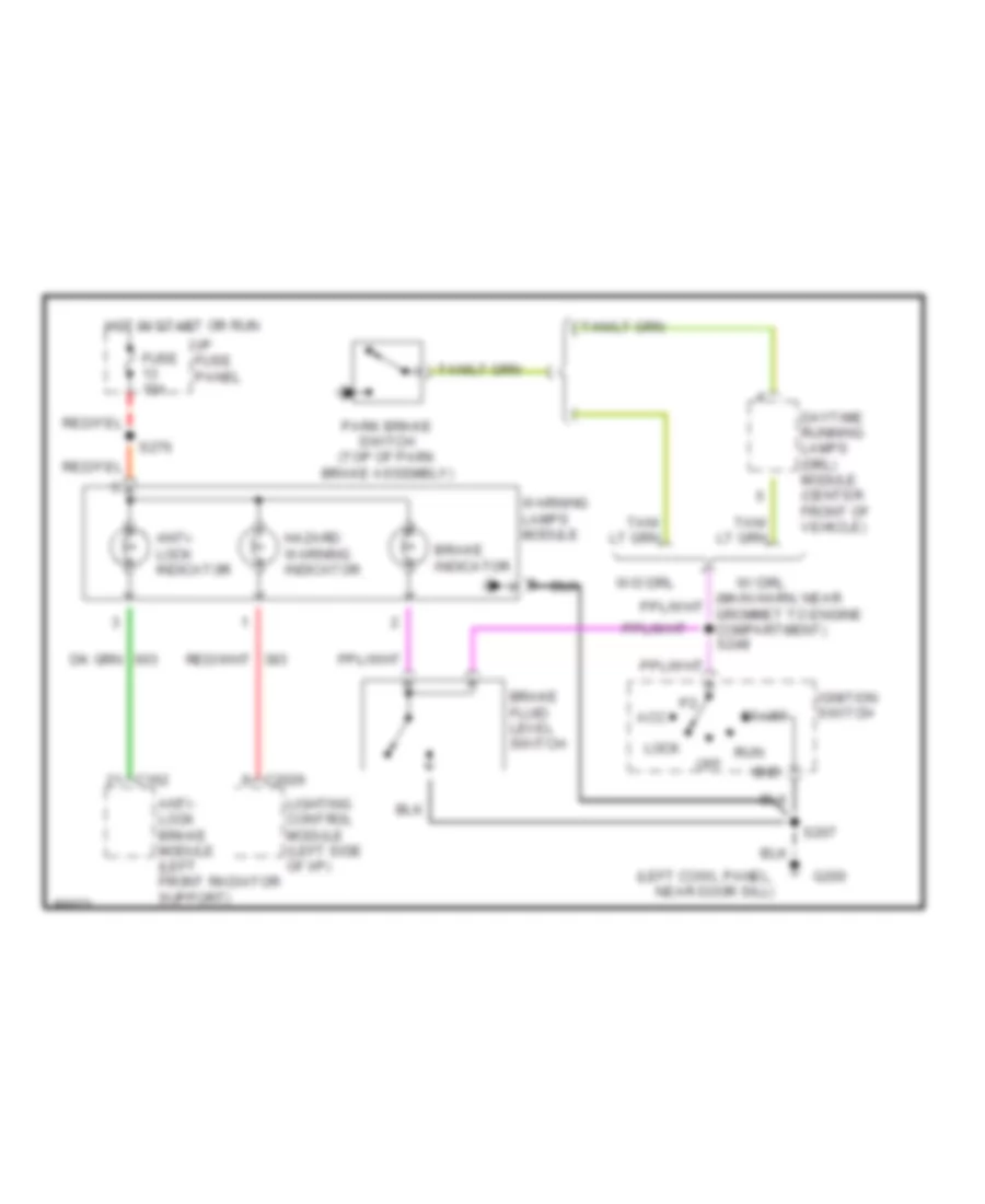
Warning Lights Wiring Diagram for Ford Crown Victoria S 1997
List of elements for Warning Lights Wiring Diagram for Ford Crown Victoria S 1997:
- (left cowl panel, near door sill)
- Acc
- Anti- lock brake module (left front radiator support)
- Anti- lock indicator
- Brake fluid level switch
- Brake indicator
- C162
- C2026
- Daytime running lamps (drl) module (center front of vehicle)
- Fuse 15a
- G200
- Gnd
- Hazard warning indicator
- Hot in start or run
- I/p fuse panel
- Ignition switch
- Lighting control module (left side of i/p)
- Lock
- Off
- Park brake switch (top of park brake assembly)
- Run
- S207
- S276
- Start
- W/ drl
- W/o drl
- Warning lamps module
INTERIOR LIGHTS
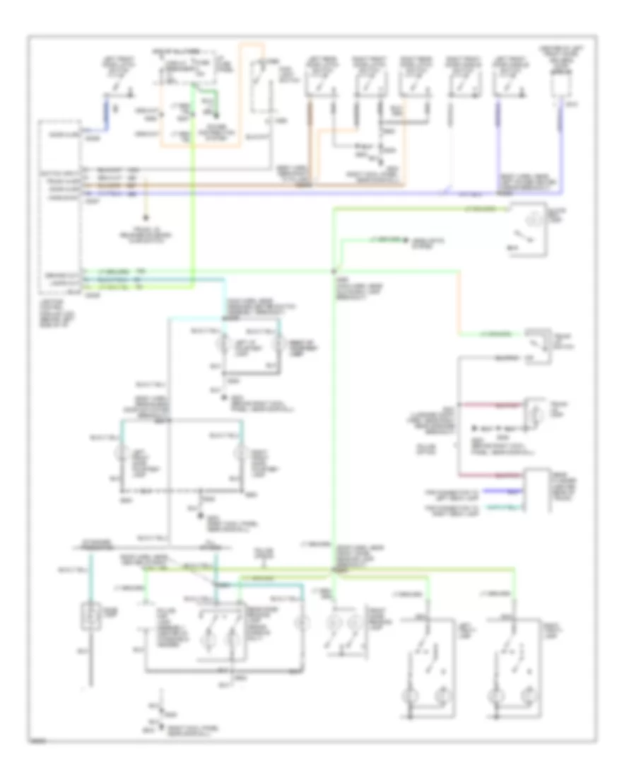
Courtesy Lamps Wiring Diagram for Ford Crown Victoria S 1997
List of elements for Courtesy Lamps Wiring Diagram for Ford Crown Victoria S 1997:
- (body harn, near blend door actuator breakout) s237
- (body harn, near left power heated mirror breakout) s505
- (body harn, near right "a" pillar) s259
- (center of left front door) driver's door module
- (main harn, near message center switch assembly breakout) s236
- (right cowl panel, near door sill)
- (roof harn, near center of right "a" pillar)
- (roof harn, near front dome/ reading lamp breakout) s900
- All others
- B (+)
- C2026
- C2027
- C2029
- C262
- C518
- Circuit breaker 20a
- Demand out
- Dome lamp
- Door ajar
- For connection to left deck lamp
- For connection to right deck lamp
- Front dome/ reading lamp
- Fuse 15a
- G203
- G203 (behind right cowl panel, near door sill)
- G203 (right cowl panel, near door sill)
- Glove box lamp
- Handle sw
- Headlights system
- Hot at all times
- I/p fuse panel
- Lamps out
- Left front door courtesy lamp
- Left front door handle switch
- Left front door latch switch
- Left i/p courtesy lamp
- Left rear door latch switch
- Left vanity lamp
- Lighting control module (lcm) (behind left side of i/p)
- Main light switch
- Nca
- Police map lamp assembly (center of windshield header)
- Police option
- Power distribution system
- Rear dome/ reading lamp (grand marquis only)
- Rear flasher (center rear of trunk)
- Right front door courtesy lamp
- Right front door handle switch
- Right front door latch switch
- Right i/p right i/p courtesy courtesy lamp lamp
- Right rear door latch switch
- Right vanity lamp
- S200
- S208
- S227
- S262
- S290 (main harn, near glove box lamp breakout)
- S431 (luggage compt harn, near right rear speaker breakout)
- S500
- S600
- S901
- S902
- Standard production
- Switch input
- Trunk ajar
- Trunk lid lamp
- Trunk lid release solenoid/ ajar switch
- Trunk lid switch
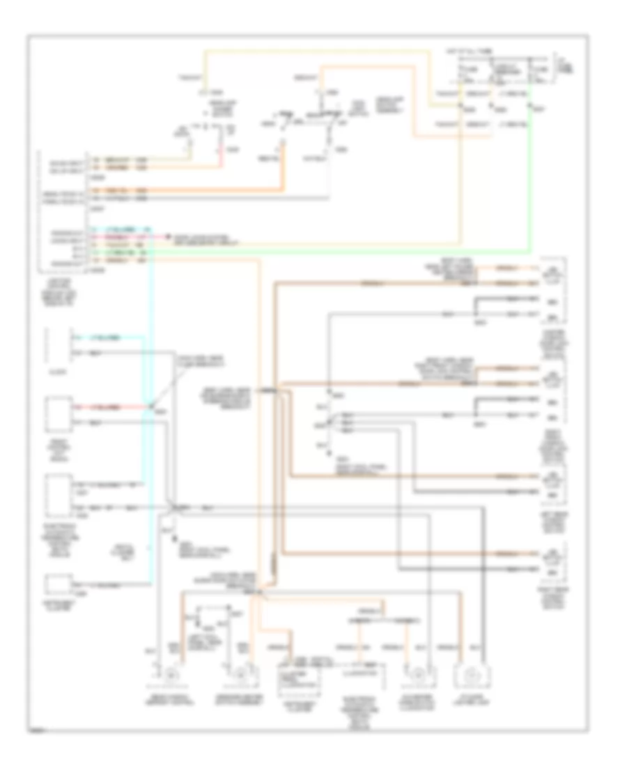
Instrument Illumination Wiring Diagram for Ford Crown Victoria S 1997
List of elements for Instrument Illumination Wiring Diagram for Ford Crown Victoria S 1997:
- (body harn, near air supension/evo steering module breakout)
- (body harn, near left power heated mirror breakout) s507
- (body harn, near right front window/ door lock control switch breakout) s289
- (digital) (analog)
- (left cowl panel, near door sill)
- (main harn, near blend door actuator breakout) s287
- (main harn, near clock breakout)
- (right cowl panel, near door sill)
- A/c-heater mode switch illumination
- B (+)
- C2026
- C2027
- C2029
- C227
- C228
- C249
- C255
- C256 c250
- C262
- Circuit breaker 20a
- Clock
- Cluster/ prndl illumination
- Digital cluster only
- Dim dn input
- Dim down
- Dim up
- Dim up input
- Dimming out
- Door locks system keyless entry circuit
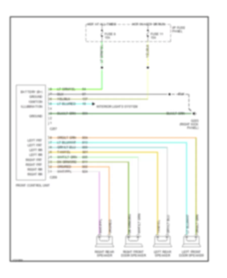
- Electronic automatic temperature control (eatc) module
- Front control unit (radio)
- Fuse 15a
- G200
- G203
- Grd
- Head
- Headlamp dimmer switch
- Headlamp switch assembly
- Headlite sw in
- Hot at all times
- I/p cigar lighter lamp
- I/p fuse panel
- Illumination
- Instrument cluster
- Led switch illum
- Left rear window control switch
- Lighting control module (lcm) (behind left side of i/p)
- Locks input
- Main light switch
- Master window/ door lock control switch
- Message center switch assembly
- Off
- Park
- Parklite sw in
- Rear window defrost control
- Right front window/ door lock control switch
- Right rear window control switch
- S204
- S207
- S208
- S227
- S262
- S285
- S288
- S500
- S503
- S523
- S600
- W/ eatc
- W/o eatc
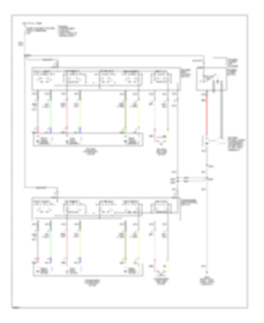
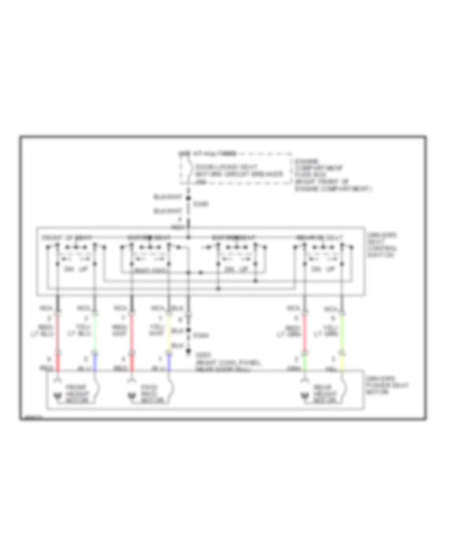
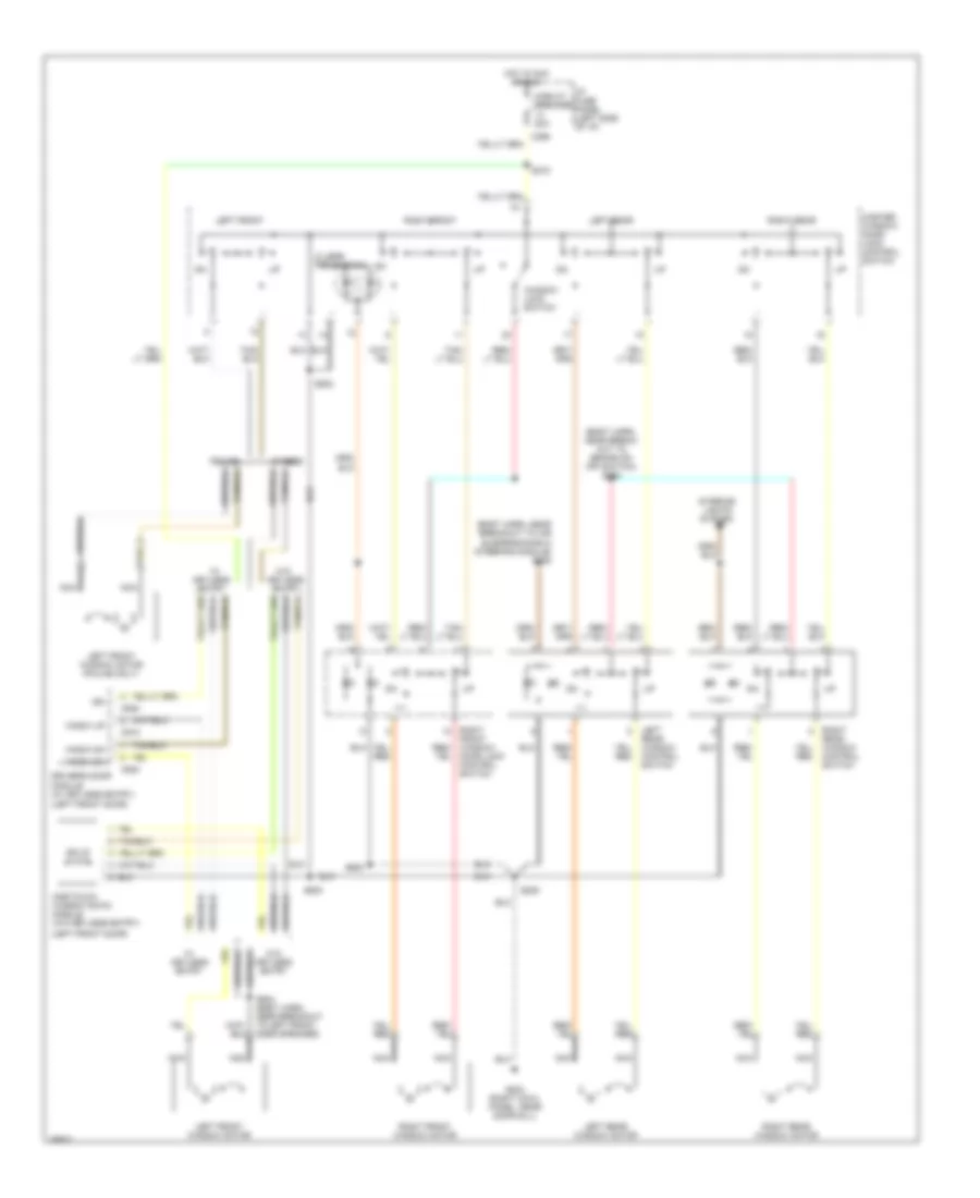
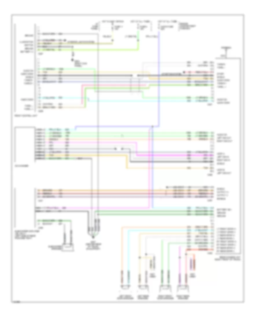
MEMORY SYSTEMS
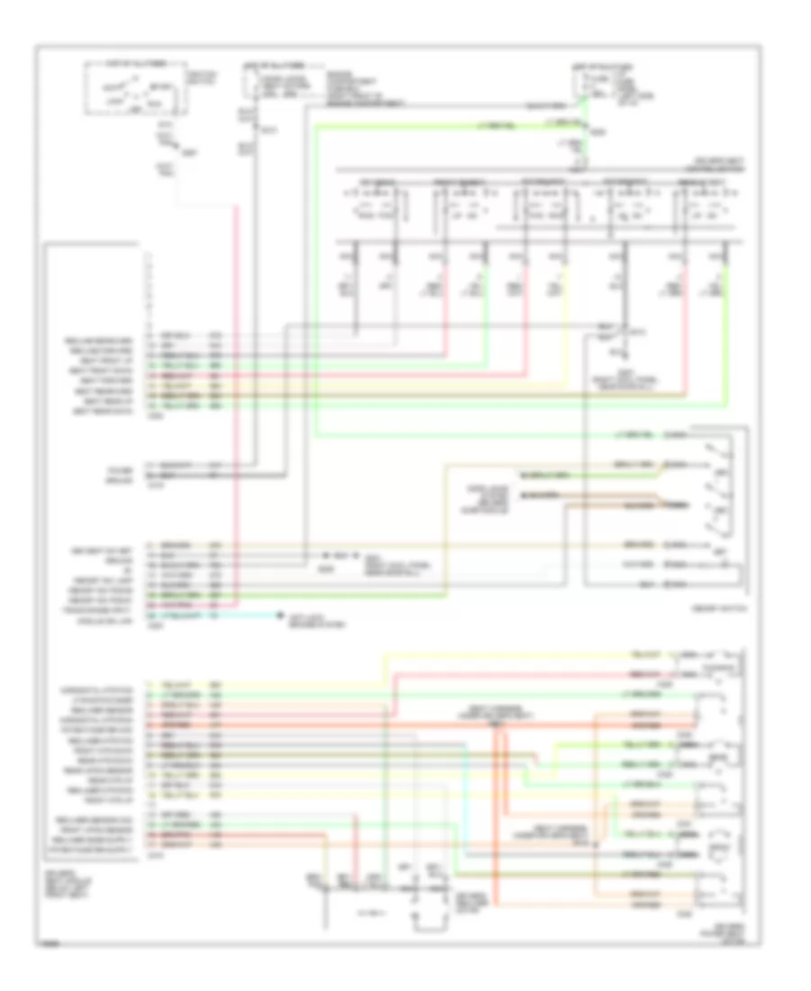
Memory System Wiring Diagrams for Ford Crown Victoria S 1997
List of elements for Memory System Wiring Diagrams for Ford Crown Victoria S 1997:
- (seat harness, under driver's seat) s314
- (seat harness, under driver's seat) s315
- 20a
- Acc
- Anti-lock brakes system
- C302
- C303
- C318
- C319
- C320
- C321
- C322
- C325
- Door locks system (driver's door module)
- Door locks/ seat motors c.b.
- Driver's power seat motor
- Driver's recliner motor
- Driver's seat control switch
- Driver's seat module (below left front seat)
- Engine compartment fuse box (right front of engine compartment)
- Entire seat
- Front
- Front mtr down
- Front mtr up
- Front of seat
- Front up/dn sensor
- Fuse 15a
- Fwd
- Fwd/rwd
- G203 (right cowl panel, near door sill)
- Ground
- Horizontal mtr fwd
- Horizontal mtr rwd
- Hot at all times
- I/p fuse panel (left side of i/p)
- Ignition switch
- Lf rwd/fwd snsr
- Lock
- Mem
- Mem seat sw set
- Memory sw lamp
- Memory sw pos #1
- Memory sw pos #2
- Memory switch
- Module iso link
- Nca
- Off
- Potentiometer com
- Power
- Rear
- Rear mtr down
- Rear mtr up
- Rear of seat
- Rear up/dn sensor
- Recline forward
- Recline rearward
- Recliner mtr fwd
- Recliner mtr rwd
- Recliner sensor
- Recliner sensor com
- Run
- Rwd
- S228
- S229
- S267
- S310
- S312
- Seat forward
- Seat front down
- Seat front up
- Seat rear down
- Seat rear up
- Seat rearward
- Seatback
- Set
- Sta
- Start
- Trans range input
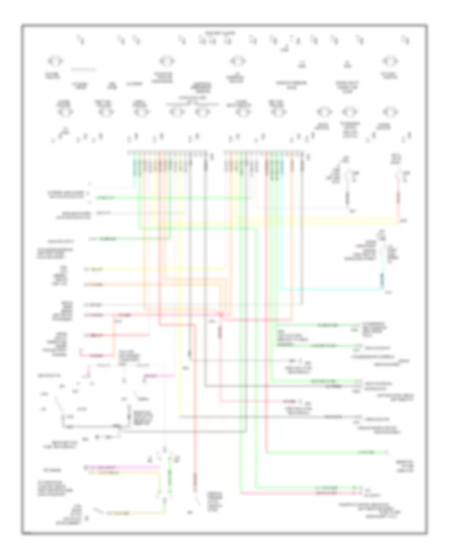
POWER DISTRIBUTION
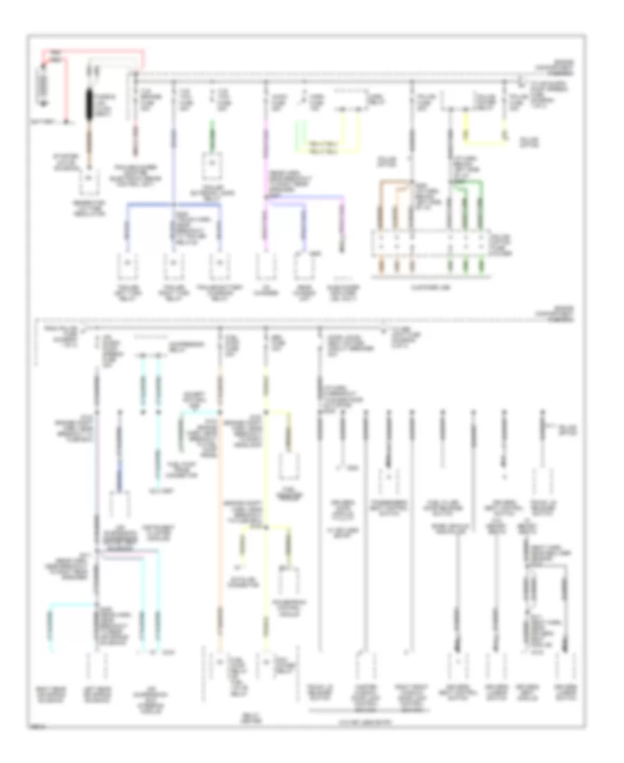
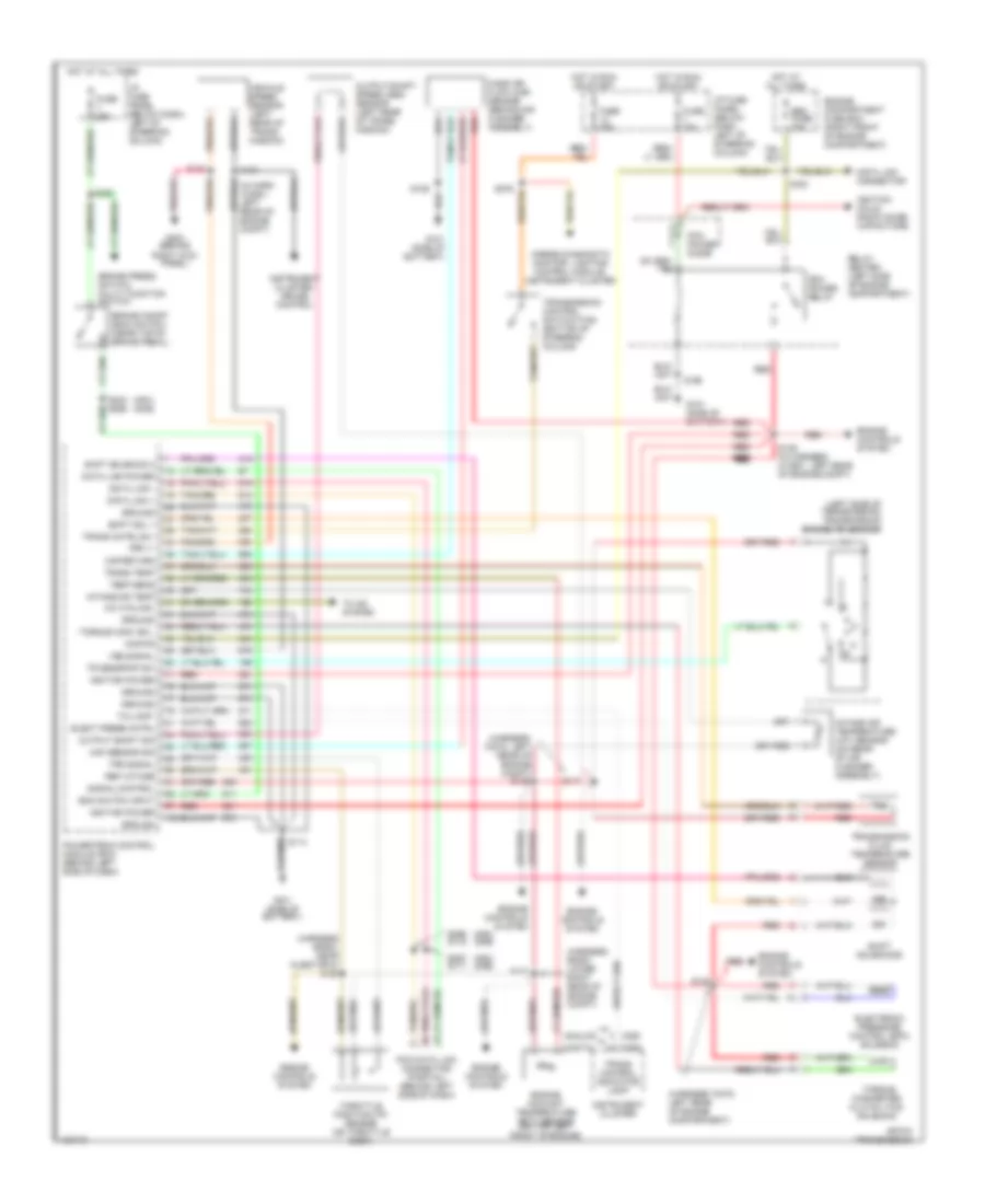
Power Distribution Wiring Diagram (1 of 4) for Ford Crown Victoria S 1997
List of elements for Power Distribution Wiring Diagram (1 of 4) for Ford Crown Victoria S 1997:
- (engine compt harn, near breakout to fuse box) s100
- (i/p harn, behind left side of i/p) s283
- (i/p harn, in breakout to blend door actuator) s245
- (rear harn, near breakout to right rear speaker)
- (rear harn, near breakout to right rear speaker) s407
- (seat harn, near recliner sensor) s310
- Air suspension compressor motor/ vent solenoid
- Air suspension/ evo steering module
- Air suspn pump/ speedo fuse 30a
- Audio fuse 25a
- Base vehicle and police
- Battery
- C216
- C251
- C319
- C452
- C520
- Cd changer
- Compressor relay
- Customer use
- Datalink connector
- Door locks/ seat motors circuit breaker 20a
- Driver's door module
- Driver's lumbar switch
- Driver's seat control switch
- Driver's seat module
- Eec fuse 30a
- Engine compartment fuse box
- Except natural gas
- From police a fuse (diagram 1 of 4)
- Fuel filler door release switch
- Fuel indicator module
- Fuel pump fuse 20a
- Fuel pump prime connector
- Fuel pump relay or fuel valve relay
- Fusible link (12 ga) (gray)
- Generator/ voltage regulator
- Horn fuse 15a
- Horn relay
- Instrument cluster (analog)
- Left rear air spring solenoid
- Master window/ door lock control switch
- Nca
- Passenger's seat control switch
- Pcm power relay
- Police fuse 30a
- Police fuse 50a
- Police option
- Police option fuse holder
- Police power relay
- Powertrain control module
- Rear chassis unit
- Red
- Relay center
- Right front window/ door lock control switch
- Right rear air spring solenoid
- S124 (engine harn, near breakout to fuel pump prime)
- S144 (engine compt harn, near breakout to fuse box)
- S151 (engine compt harn, near breakout to right headlamp)
- S282 (i/p harn, behind left side of i/p)
- S311 (seat harn, near driver's seat module)
- S406 (rear harn, near breakout to rear air spring solenoid)
- S411
- S425 (trunk harn, near breakout to trailer relays)
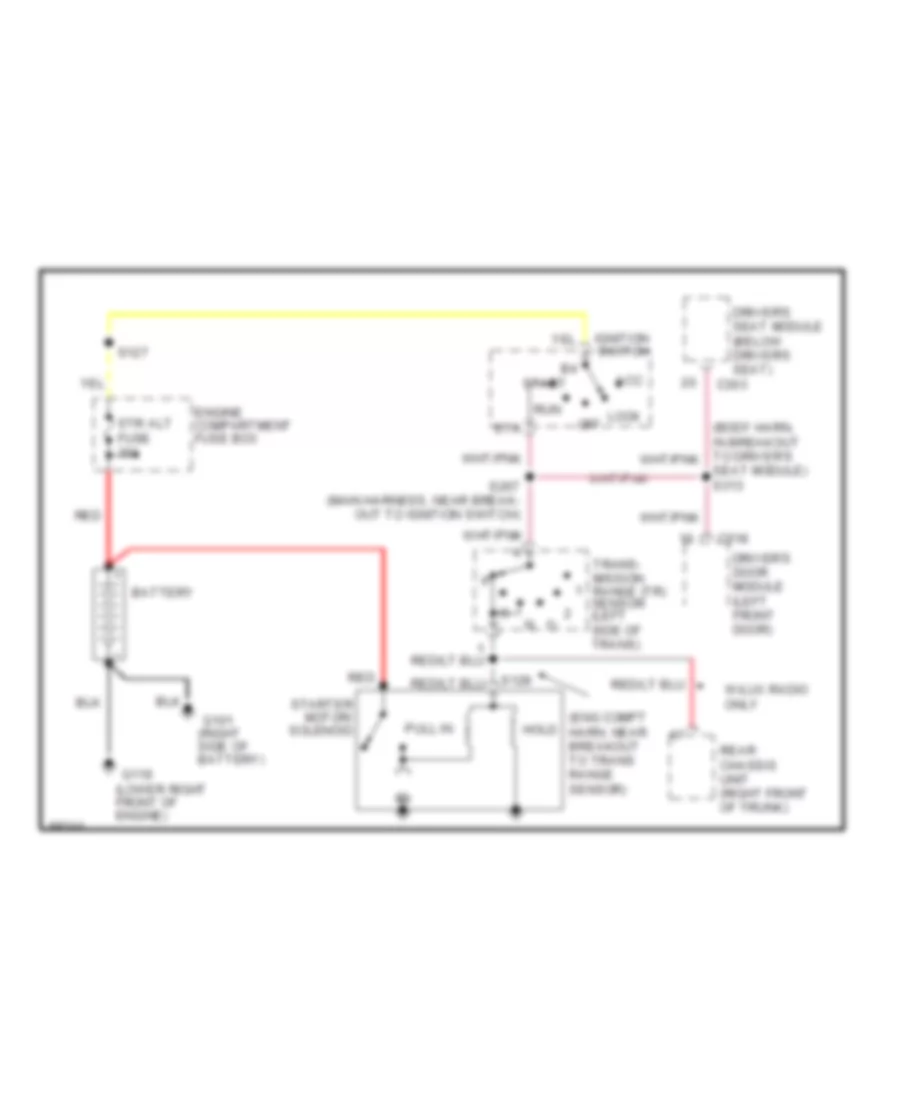
- Starter/ motor solenoid
- Subwoofer amplifier (jbl only)
- Tlr brakes fuse 30a
- Tlr tow fuse 20a
- Tlr tow fuse 40a
- To abs cont fuse (diagram 2 of 4)
- To air suspn pump/ speedo fuse (diagram 1 of 4)
- Trailer battery charging relay
- Trailer exterior lamps relay
- Trailer left turn relay
- Trailer right turn relay
- Trailer/camper adapter (electronic brake control unit)
- Trunk lid release switch
- W/ keyless entry
- W/ memory seats
- W/o keyless entry
- W/o memory seats
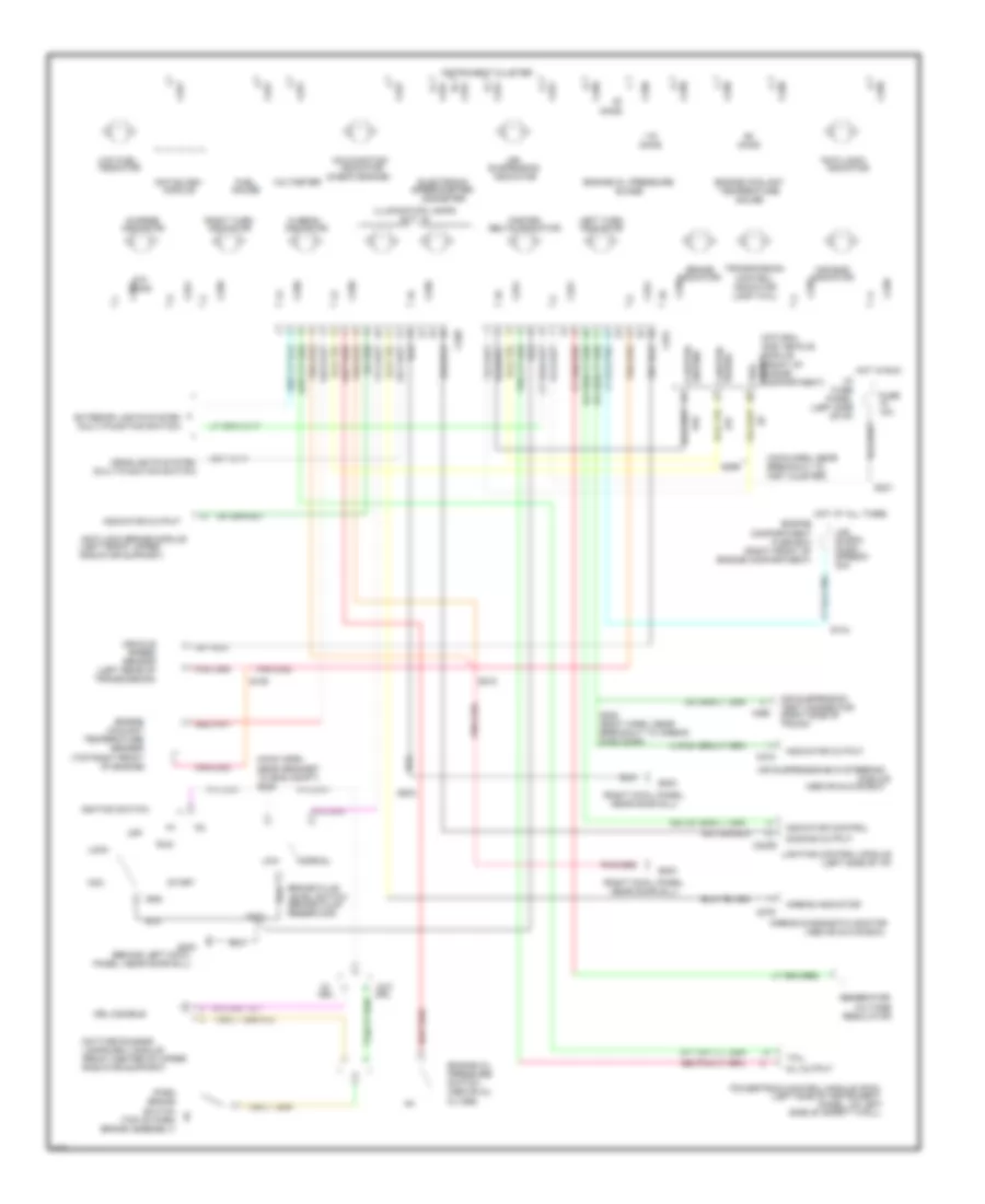
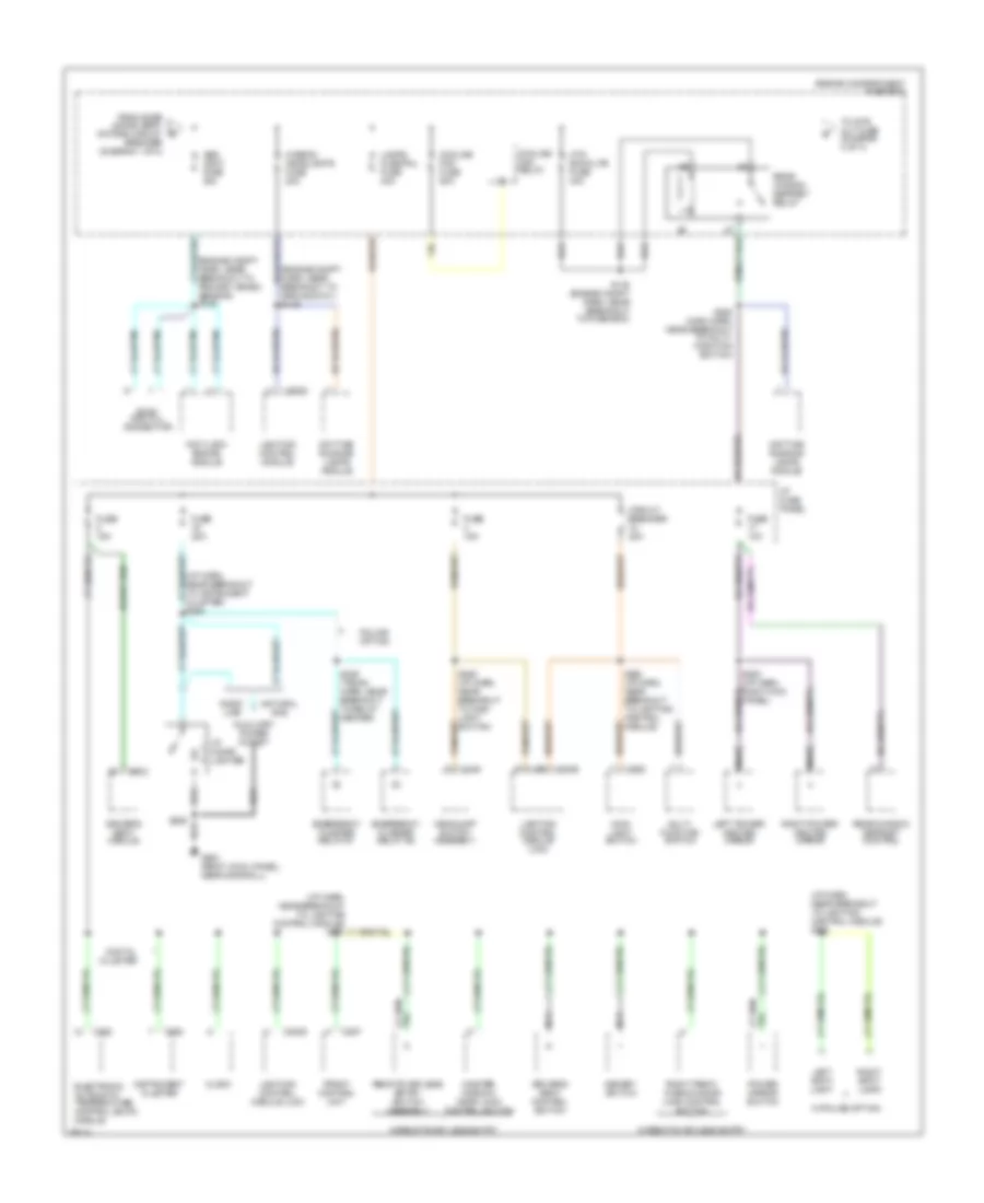
Power Distribution Wiring Diagram (2 of 4) for Ford Crown Victoria S 1997
List of elements for Power Distribution Wiring Diagram (2 of 4) for Ford Crown Victoria S 1997:
- (engine compt harn, near breakout to ground g101) s149
- (engine compt harn, near breakout to primary crash sensor) s146
- (i/p harn, near breakout to instrument cluster) s294
- (i/p harn, near breakout to lighting control module) s228
- Abs cont fuse 30a
- Anti-lock brake module
- Auxiliary power outlet
- C2028
- C2029
- C228
- C249
- C255
- C257
- C262
- C303
- Circuit breaker 20a
- Clock
- Cooling fan fuse 50a
- Cooling fan relay
- Daytime running lamps module
- Digital cluster
- Driver's seat control switch
- Driver's seat module
- Electronic automatic temperature control (eatc) module
- Emergency flasher relay #1
- Emergency flasher relay #2
- Engine compartment fuse box
- Evac and fill connector
- From door locks/ seat motors circuit breaker (diagram 1 of 4)
- Front control unit
- Fuse 10a
- Fuse 15a
- Fuse 20a
- G203 (right cowl panel, near door sill)
- Gaso- line
- Headlamp switch assembly
- Hi-beam headlights fuse 20a
- Htd backlite fuse 40a
- I/p cigar lighter
- I/p fuse panel
- Instrument cluster
- Lamps fuse pnl fuse 40a
- Left power/ heated mirror
- Left spot light
- Lighting control module
- Lighting control module (lcm)
- Main light switch
- Master window/ door lock control switch
- Memory switch
- Multi- function switch
- Natural gas
- Nca
- Police option
- Power mirror switch
- Rear window defrost control
- Rear window defrost relay
- Remote keyless entry switch assembly
- Right front window/door lock control switch
- Right power/ heated mirror
- Right spot light
- S119 (engine compt harn, near breakout to fuse box)
- S206
- S252 (main harn, near breakout to multi- function switch)
- S253 (i/p harn, right kick panel)
- S262 (i/p harn, near breakout to lighting control module)
- S285 (i/p harn, near breakout to main light switch)
- S426 (trunk harn, near breakout to relay center)
- To str alt fuse (diagram 3 of 4)
- W/police option
- W/remote keyless entry
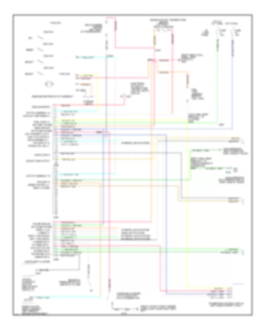
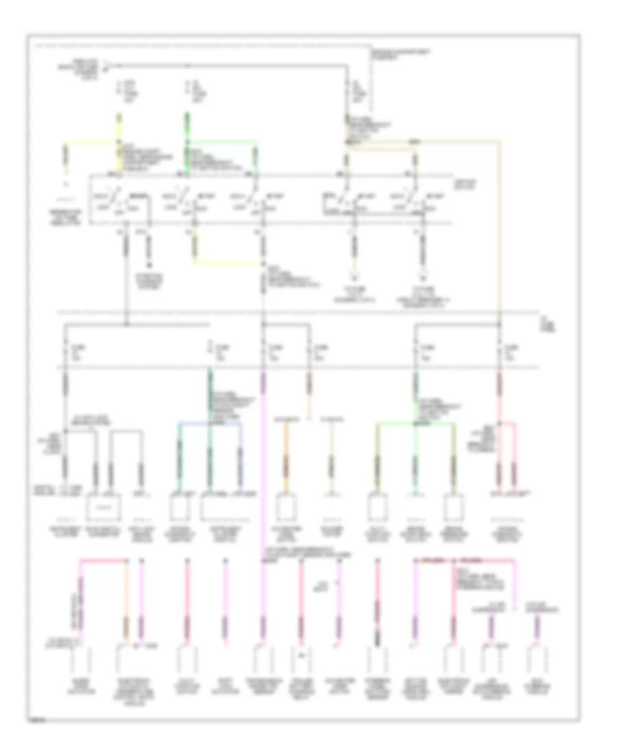
Power Distribution Wiring Diagram (3 of 4) for Ford Crown Victoria S 1997
List of elements for Power Distribution Wiring Diagram (3 of 4) for Ford Crown Victoria S 1997:
- (digital) (analog)
- (i/p harn, near breakout to day/night sensor amplifier) s226
- (i/p harn, near breakout to day/night/ sensor amplifier) s269
- (i/p harn, near breakout to ignition switch) s263
- (w/ eatc)
- (w/ eatc) (w/o eatc)
- (w/o eatc)
- A/c-heater mode switch
- Acc
- Air bag diagnostic monitor
- Air suspension/ evo steering module
- Anti-lock brake module
- Blend door actuator
- Blower motor
- Brake on/off (boo) switch
- Brake pressure switch
- C216
- C228
- C255
- C256
- C256 c251
- C277
- Daytime running lamps (drl) module
- Electronic automatic temperature control (eatc) module
- Electronic day/night mirror
- Engine compartment fuse box
- Evac and fill connector
- Evo steering module
- From htd backlite fuse (diagram 2 of 4)
- Fuse 10a
- Fuse 15a
- Fuse 30a
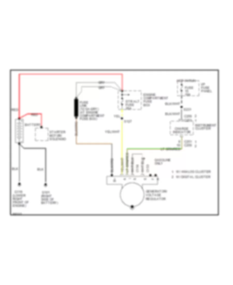
- Generator/ voltage regulator
- I/p fuse panel
- Ig sw fuse 50a
- Ignition switch
- Instrument cluster
- Instrument cluster (digital)
- Lock
- Multi- function switch
- Nca
- Near breakout to ignition switch)
- Off
- Run
- S231 (i/p harn, near clock)
- S254 (i/p harn, near breakout to airbag)
- S272 (i/p harn, near breakout to ignition switch)
- S274 (i/p harn, near breakout to evo steering module)
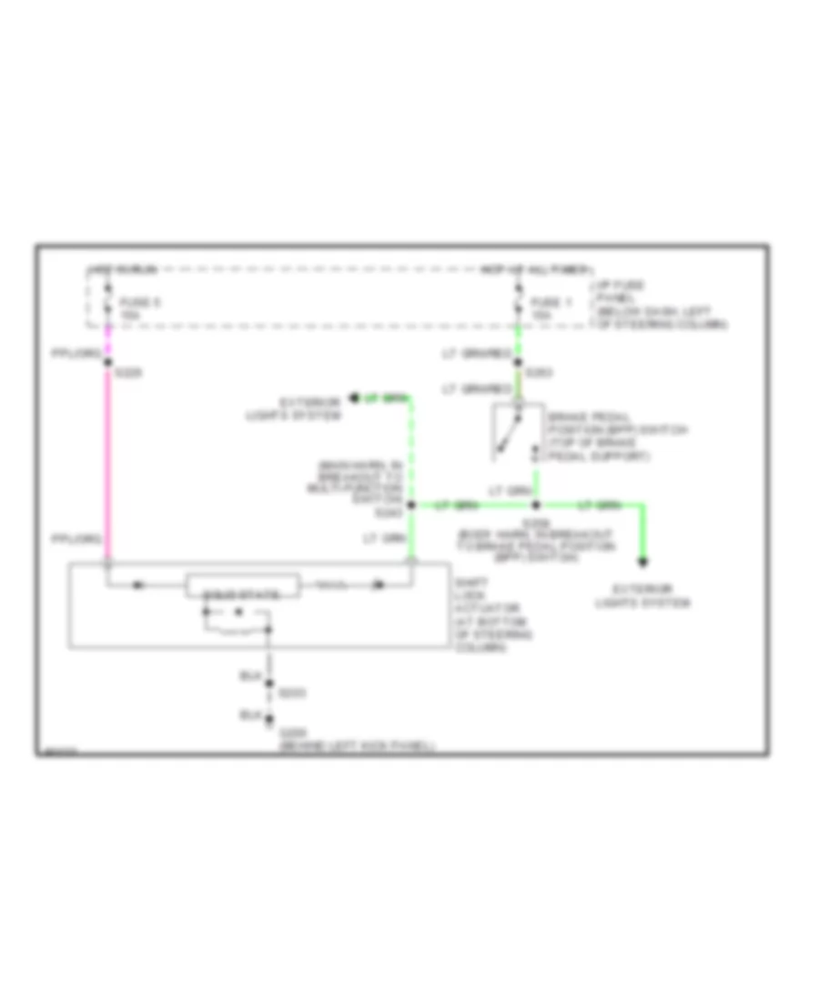
- Shift lock actuator
- Start
- Starting/ charging system
- Steering wheel rotation sensor
- Str alt fuse 30a
- To fuse 2, 6, 11 & circuit breaker 14 (diagram 4 of 4)
- To fuse 7 & 13 (diagram 4 of 4)
- Trailer battery charging relay
- Transmission range (tr) sensor
- W/ air suspension
- W/ anti-lock brake system
- W/ eatc
- W/o air suspension
- W/o eatc
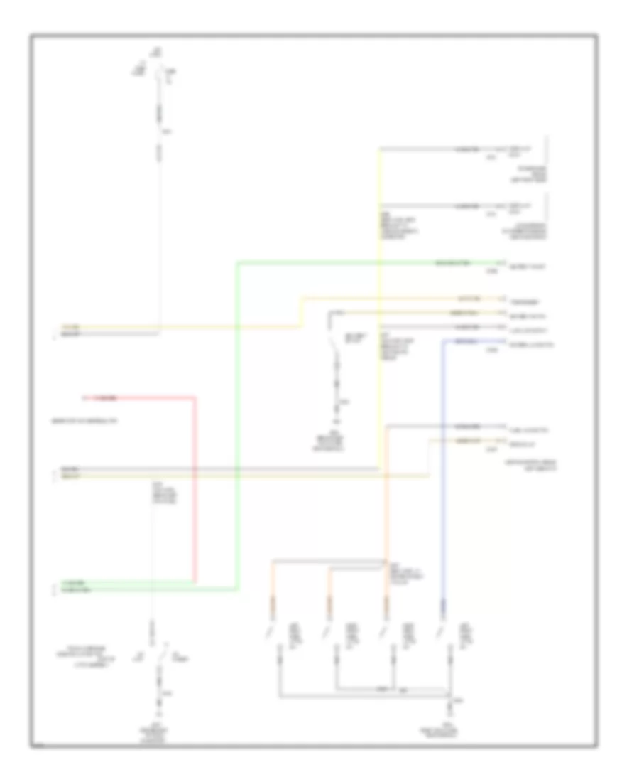
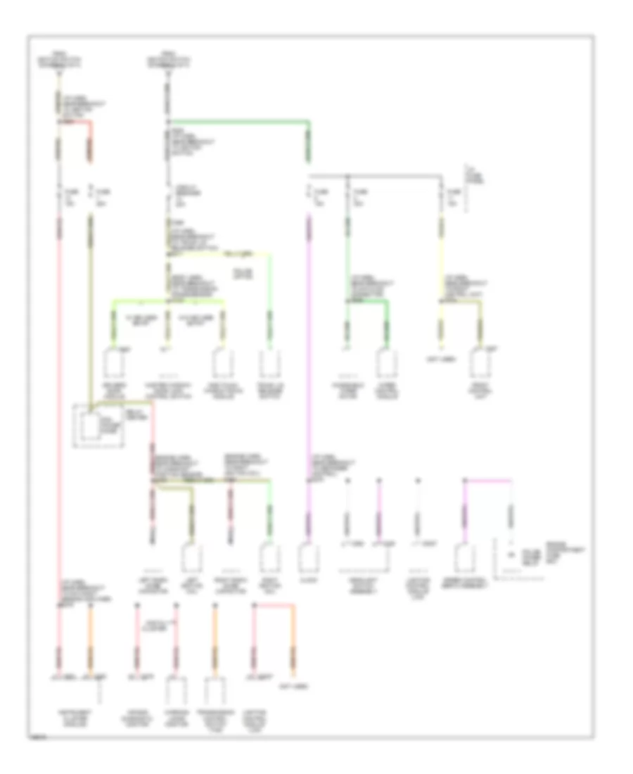
Power Distribution Wiring Diagram (4 of 4) for Ford Crown Victoria S 1997
List of elements for Power Distribution Wiring Diagram (4 of 4) for Ford Crown Victoria S 1997:
- (body harn, near breakout to transmission range sensor) s128
- (engine harn, near breakout to right ignition coil) s102
- (i/p harn, near breakout to datalink connector) s266
- (i/p harn, near breakout to day/night sensor amplifier) s276
- (i/p harn, near breakout to defogger control) s278
- (i/p harn, near breakout to front control unit) s224
- (i/p harn, near breakout to ignition switch) s221
- (i/p harn, near breakout to trunk lid release switch) s211
- (not used)
- Air bag diagnostic monitor
- C2027
- C249
- C250
- C251
- C257
- C262
- C276
- C520
- Circuit breaker 20a
- Clock
- Digital cluster
- Driver's door module
- Engine compartment fuse box
- From ignition switch (diagram 3 of 4)
- Front control unit
- Fuse 15a
- Fuse 25a
- Fuse 30a
- Headlight switch assembly
- I/p fuse panel
- Instrument cluster (analog)
- Left ignition coil
- Left radio noise capacitor
- Lighting control module (lcm)
- Master window/ door lock control switch
- Nca
- One touch window down module
- Pcm power diode
- Police option
- Police power relay
- Relay center
- Right ignition coil
- Right radio noise capacitor
- S103
- S225 (i/p harn, near breakout to ignition switch)
- Speed control servo assembly
- Transmission control switch (tcs)
- Trunk lid release switch
- W/ keyless entry
- W/o keyless entry
- Warning lamps monitor
- Windshield wiper motor
- Wiper control module
POWER DOOR LOCKS
Door Lock Wiring Diagram for Ford Crown Victoria S 1997
List of elements for Door Lock Wiring Diagram for Ford Crown Victoria S 1997:
- (body harn, near breakout to 16 pin conn, behin left cowl panel) s260
- (body harn, near breakout to boo switch) s261
- (main harn, near breakout to right rear door grommet) s291
- C2029
- Door lock in
- Door locks/ seat motors circuit breaker 20a
- Engine compartment fuse box (right front of engine compt)
- G203 (right cowl panel, near door sill)
- Hot at all times
- Interior lights system
- Left front door lock motor
- Left rear door lock motor
- Lighting control module (behind left side of i/p)
- Lock
- Master window/door lock control switch
- Right front door lock motor
- Right front window/door lock control switch
- Right rear door lock motor
- S208
- S245
- S288 (body harn, near breakout to air suspsn/ evo strng mod)
- S503
- S600
- Unlock
Keyless Entry Wiring Diagram for Ford Crown Victoria S 1997
List of elements for Keyless Entry Wiring Diagram for Ford Crown Victoria S 1997:
- (body harn, near breakout to boo switch)
- (body harn, near breakout to left power heated mirror) s506
- (body harn, near breakout to left pwr htd mirror) s506
- 1/2
- 3/4
- 5/6
- 7/8
- 9/0
- C2026
- C2027
- C2029
- C518
- C519
- C520
- Door ajar
- Door handle
- Door hndl sw
- Door lock
- Door locks/ seat motors circuit breaker 20a
- Door unlock
- Driver's door module (left front door)
- Engine compartment fuse box (right front of engine compt)
- Fuse 8 15a
- G203 (right cowl panel, near door sill)
- G407 (center rear of trunk, on support)
- Hot at all times
- I/p fuse panel (left side of i/p)
- Interior lights system
- Keypad illum
- Keypad lamp
- Left front door handle switch
- Left front door lock motor
- Left rear door lock motor
- Lf door unlck
- Lighting control module (behind left side of i/p)
- Lock
- Master window/ door lock control switch
- Mem 1
- Mem 2
- Memory systems
- Nca
- Panic
- Panic out
- Power distribution system
- Red
- Remote keyless entry switch assembly
- Right front door handle switch
- Right front door lock motor
- Right front window/door lock control switch
- Right rear door lock motor
- S208
- S228
- S245
- S260 (body harn, near breakout to 16 pin conn, behind left cowl panel)
- S261 (body harn, near breakout to park boo switch)
- S288 (body harn, near breakout to air suspsn/ evo strg mod)
- S291 (main harn, near breakout to right rear door grommet)
- S304
- S403
- S500
- S503
- S510 (body harn, near breakout to left front door)
- S511
- S600
- Seat
- Seat switch
- Start input
- Starting/charging system
- Trunk
- Trunk lid
- Trunk lid release solenoid/ ajar switch
- Trunk lid release switch
- Trunk, tailgate, fuel doors system
- Unlock
POWER MIRRORS
Photochromic Mirror Wiring Diagram for Ford Crown Victoria S 1997
List of elements for Photochromic Mirror Wiring Diagram for Ford Crown Victoria S 1997:
- Electronic day/night mirror
- Exterior lights system
- Fuse 15a
- G203 (right cowl panel, near door sill)
- Ground
- Hot in run
- I/p fuse panel
- Ignition
- Reverse
- S226
- S230 (main harness, left cowl panel)
- S500
- Transmission range (tr) sensor (left side of transmission)
Power Mirror Wiring Diagram for Ford Crown Victoria S 1997
List of elements for Power Mirror Wiring Diagram for Ford Crown Victoria S 1997:
- Defogger system
- Direct- tional switch
- Fuse 15a
- G203 (behind right cowl panel near door sill)
- Hot at all times
- I/p fuse panel
- L/r motor
- Left power/ heated mirror
- Left/ right switch
- Nca
- Power mirror switch
- Red
- Right power/ heated mirror
- S228
- S500
- Up/dn motor
POWER SEATS
6-Way, Recliner & Lumbar Power Seat Wiring Diagram for Ford Crown Victoria S 1997
List of elements for 6-Way, Recliner & Lumbar Power Seat Wiring Diagram for Ford Crown Victoria S 1997:
- nca
- Door lock/seat motors circuit breaker 20a
- Driver's lumbar air bladder
- Driver's lumbar switch
- Driver's power lumbar compressor (under front of left seat assembly)
- Driver's power seat motor
- Driver's recliner motor
- Driver's seat control switch
- Engine compartment fuse box (right front of engine compt)
- Entire seat
- Front height motor
- Front of seat
- Fwd
- Fwd/ rwd motor
- G203 (right cowl panel, near door sill)
- Hot at all times
- Inflate
- Nca
- Passenger's power seat motor
- Passenger's recliner motor
- Passenger's seat control switch
- Rear height motor
- Rear of seat
- Red
- Red
- Rwd
- S208
- S245
- S304
- S500
- S600
- Seat back
- Vent
Driver Power Seat Wiring Diagram for Ford Crown Victoria S 1997
List of elements for Driver Power Seat Wiring Diagram for Ford Crown Victoria S 1997:
- Door locks/ seat motors circuit breaker 20a
- Driver's power seat motor
- Driver's seat control switch
- Engine compartment fuse box (right front of engine compartment)
- Entire seat
- Front height motor
- Front of seat
- Fwd
- Fwd/ rwd motor
- G203 (right cowl panel, near door sill)
- Hot at all times
- Nca
- Rear height motor
- Rear of seat
- Red
- Rwd
- S245
- S304
POWER WINDOWS
Power Window Wiring Diagram for Ford Crown Victoria S 1997
List of elements for Power Window Wiring Diagram for Ford Crown Victoria S 1997:
- (2 led's per switch)
- (body harn, near break- out to brake on/ off switch) s264
- (body harn, near breakout to air suspension/evo steering module) s288
- (left front door)
- C298
- C518
- C520
- Circuit breaker 20a
- Door lock control switch
- Driver's door module (w/ keyless entry)
- Entry
- G203 (right cowl panel, near door sill)
- Hot in acc or run
- I/p fuse panel (left side of i/p)
- Ign
- Interior lights system
- Keyless
- Left
- Left front
- Left front window motor
- Left front window motor (police only)
- Left rear
- Left rear window motor
- Master window/ door lock control switch
- Nca
- One touch window down module (w/o keyless entry)
- Others
- Police
- Rear window control switch
- Right
- Right front
- Right front window motor
- Right rear
- Right rear window motor
- S208
- S218
- S500
- S503
- S504 (body harn, near breakout to left front door speaker)
- S600
- Solid state
- W/ keyless entry
- W/o
- W/o keyless entry
- Window lock switch
- Wndw dn
- Wndw up
RADIO
Base Radio for Ford Crown Victoria S 1997
List of elements for Base Radio for Ford Crown Victoria S 1997:
- Battery (b+)
- C257
- C258
- Front control unit
- Fuse 11 15a
- Fuse 8 15a
- G203 (right kick panel)
- Ground
- Hot at all times
- Hot in accy or run
- I/p fuse panel
- Ignition
- Illumination
- Interior lights system
- Left front door speaker
- Left frt
- Left rear speaker
- Left rr
- Right front door speaker
- Right frt
- Right rear speaker
- Right rr
Premium Sound Radio Wiring Diagram for Ford Crown Victoria S 1997
List of elements for Premium Sound Radio Wiring Diagram for Ford Crown Victoria S 1997:
- (acp) a
- (acp) b
- (jbl only)
- (not used)
- Antenna
- Audio comm
- Audio fuse 25a
- Audio on
- Battery (+)
- Battery (b+)
- C257
- C259
- C401
- C451
- C452
- C490
- C497
- C498
- Cd changer
- Enable
- Engine compartment fuse box
- Front control unit
- Fuse 11 15a
- Fuse 8 15a
- G203 (right kick panel)
- G407 (center rear of trunk, on support)
- Ground
- Hot at all times
- Hot in accy or run
- I/p fuse panel
- Ignition
- Illumination
- Interior lights system
- Left front door speaker
- Left rear speaker
- Left sig in
- Left sig out
- Lt front spkr (+)
- Lt front spkr (-)
- Lt rear spkr (+)
- Lt rear spkr (-)
- Nca
- Output (+)
- Output (-)
- Rear chassis unit (right front of trunk)
- Right front door speaker
- Right rear speaker
- Right sig in
- Right sig out
- Rt front spkr (+)
- Rt front spkr (-)
- Rt rear spkr (+)
- Rt rear spkr (-)
- Shield
- Start
- Starting system
- Subwoofer amplifier (jbl only) (left side of rear package tray)
- Subwoofer speaker
- Tan
- Tape l +
- Tape l -
- Tape r +
- Tape r -
SHIFT INTERLOCKS
Shift Interlock Wiring Diagram for Ford Crown Victoria S 1997
List of elements for Shift Interlock Wiring Diagram for Ford Crown Victoria S 1997:
- (main harn, in breakout to multi-function switch) s243
- Brake pedal position (bpp) switch (top of brake pedal support)
- Exterior lights system
- Fuse 1 15a
- Fuse 5 15a
- G200 (behind left kick panel)
- Hot at all times
- Hot in run
- I/p fuse panel (below dash, left of steering column)
- S203
- S226
- S258 (body harn, in breakout to brake pedal position (bpp) switch)
- S263
- Shift lock actuator (at bottom of steering column)
- Solid state
STARTING/CHARGING
Charging Wiring Diagram for Ford Crown Victoria S 1997
List of elements for Charging Wiring Diagram for Ford Crown Victoria S 1997:
- Battery
- C153
- C154
- C251
- C251 c256
- C256
- Charge indicator
- Engine compartment fuse box
- Fuse 10a
- G101 (right side of battery)
- G119 (lower right front of engine)
- Gasoline only
- Generator/ voltage regulator
- Hot in run
- I/p fuse panel
- Instrument cluster
- Red
- S127
- S231
- Starter motor/ solenoid
- Str alt fuse 30a
- W/ analog cluster
- W/ digital cluster
Starting Wiring Diagram for Ford Crown Victoria S 1997
List of elements for Starting Wiring Diagram for Ford Crown Victoria S 1997:
- (eng compt harn, near breakout to trans range sensor)
- (lower right front of engine)
- Acc
- Battery
- C303
- C518
- Driver's door module (left front door)
- Driver's seat module (below driver's seat)
- Engine compartment fuse box
- G101 (right side of battery)
- G119
- Hold
- Ignition switch
- Lock
- Off
- Pull in
- Rear chassis unit (right front of trunk)
- Red
- Run
- S127
- S128
- S267 (main harness, near break- out to ignition switch)
- Seat module) s313
- Sta
- Start
- Starter motor/ solenoid
- Str alt fuse 30a
- Trans- mission range (tr) sensor (left side of trans)
- W/lux radio only
SUPPLEMENTAL RESTRAINTS
Supplemental Restraint Wiring Diagram for Ford Crown Victoria S 1997
List of elements for Supplemental Restraint Wiring Diagram for Ford Crown Victoria S 1997:
- (behind right side of i/p) air bag diagnostic connector
- (i/p harn, near air bag diagnostic monitor breakout) s254
- (i/p harn, near blend door actuator breakout)
- (i/p harn, near day/ night sensor amp breakout)
- (i/p harn, near glove- box lamp breakout)
- Air bag diagnostic monitor (above glove box)
- Air bag ind
- Air bag indicator control
- C276
- C277
- Clock- spring assembly
- Computer data lines
- Data link
- Diag conn
- Driver's air bag
- Drvr air bag
- Fuse 10 10a
- Fuse 13 15a
- Fuse 18 15a
- G203 (right cowl panel)
- Gnd
- Hot at all times
- Hot in run
- Hot in run or start
- I/p fuse panel (below left side of i/p)
- Instrument cluster
- L crash sens
- Left primary crash sensor (left front upper radiator support)
- Nca
- Pass air bag
- Passenger's air bag
- Pwr (bat)
- Pwr (run)
- R crash sens
- Right primary crash sensor (right front upper radiator support)
- S206
- S208
- S269
- S276
- Shorting bar
- Tan/ red
- Tan/red
TRANSMISSION
Transmission Wiring Diagram for Ford Crown Victoria S 1997
List of elements for Transmission Wiring Diagram for Ford Crown Victoria S 1997:
- (harness 7c078, left rear of engine compartment)
- (harness 7c078, left rear of engine compt) s125
- (harness 9d930, lower right rear of engine compt)
- (harness 9d930, near injector 8) s126
- (in harn 12a581, left rear of engine compt)
- (left side of transmission) transmission range (tr) sensor
- (ngv) (gas)
- 4r70w transmission
- A/c cycling
- Airbag diagnostic monitor, lighting control module, instrument cluster
- Analog
- Boo switch input
- Brake on/off (boo) switch (near top of brake pedal)
- Brake press switch, multi- function switch
- C250
- C255
- Data link +
- Data link -
- Data link connector
- Data link power
- Digital
- Eec fuse 30a
- Elect press cntrl
- Electronic pressure control (epc) solenoid
- Engine compartment fuse box (right front of engine compartment)
- Engine controls system
- Engine coolant temperature (ect) sensor (on top left front of engine)
- Fuse 25a
- G101 (side of battery)
- G203 (behind
- Ground
- Hot at all times
- Hot in run or start
- I/p fuse panel (below dash, left of steering column)
- I/p fuse panel (below dash, left of steering column)
- Ignition coils, radio noise capacitors
- Ignition power
- Instrument cluster
- Instrument cluster, cruise control
- Intake air temp
- Intake air temperature (iat) sensor (on rear of air cleaner assembly)
- Kapwr
- Maf return
- Maf sensor sig
- Mass air flow (maf) sensor (behind air cleaner assembly)
- Output shaft sig
- Output shaft speed (oss) sensor (left rear of trans- mission)
- Pcm data link connector (partial) (behind left side of dash)
- Pcm power diode
- Pcm power relay
- Powertrain control module (pcm) (behind left side of dash)
- Red
- Red red
- Ref votage
- Relay center (left side of engine compartment)
- Right kick panel)
- S100
- S105
- S106
- S109
- S114
- S123
- S129 (in harness 21a581, left rear of engine compt)
- S147
- S148
- S243 s295
- S263
- S276
- S296 s118
- S297 s117
- Shift sol 1
- Shift solenoid 2
- Shift solenoids
- Signal control
- Ss1
- Ss2
- Tci lamp
- Temp sens
- Throttle position (tp) sensor (on throttle body)
- To a/c system
- Torque conv sol
- Torque converter clutch (tcc) solenoid
- Tps signal
- Tr sens/pnp sw
- Trans cntrl sw
- Trans control indicator lamp
- Trans temp
- Transmission control switch (tcs) (bottom of steering column)
- Transmission fluid temperature sensor
- Vehicle speed sensor (left rear of trans- mission)
- Vss (-)
- Vss signal
TRUNK, TAILGATE, FUEL DOOR
Fuel Door Release Wiring Diagram for Ford Crown Victoria S 1997
List of elements for Fuel Door Release Wiring Diagram for Ford Crown Victoria S 1997:
- Door locks/ seat motors circuit breaker 20a
- Engine compartment fuse box (right front of engine compt, behind battery)
- Fuel filler door release solenoid (left side of trunk, near fuel door)
- Fuel filler door release switch
- G407 (center rear of trunk, on support)
- Hot at all times
- S245
- S402
Trunk Release Wiring Diagram, with Keyless Entry for Ford Crown Victoria S 1997
List of elements for Trunk Release Wiring Diagram, with Keyless Entry for Ford Crown Victoria S 1997:
- "trunk ajar" input
- C254
- C519
- C520
- Decklid ajar switch
- Digital cluster only
- Door locks/ seat motors circuit breaker 20a
- Driver's door module (in center left front door)
- Engine compartment fuse box (right front of engine compt, behind battery)
- G203 (right cowl panel, near door sill)
- G407 (center rear of trunk, on support)
- Hot at all times
- Instrument cluster (digital)
- Lighting control module (lcm) (behind left side of i/p)
- Release out
- Release sw
- S245
- S403
- S500
- S506 (body harn, near breakout to left power heated mirror)
- Trunk lid release solenoid/ajar switch (center rear of trunk lid, part of latch assembly)
- Trunk lid release switch
Trunk Release Wiring Diagram, without Keyless Entry for Ford Crown Victoria S 1997
List of elements for Trunk Release Wiring Diagram, without Keyless Entry for Ford Crown Victoria S 1997:
- "trunk ajar" input
- (police only)
- C254
- C298
- Circuit breaker 20a
- Decklid ajar switch
- Digital cluster only
- Door locks/ seat motors circuit breaker 20a
- Engine compartment fuse box (right front of engine compt, behind battery)
- G407 (center rear of trunk, on support)
- Hot at all times
- Hot in acc or run
- I/p fuse panel (left side of i/p)
- Instru- ment cluster (digital)
- Lighting control module (lcm) (behind left side of i/p)
- Police only
- S205 (main harn, near breakout to 3 pin in-line conn, behind left side of i/p)
- S211
- S245
- S273 (main harn, near breakout to 16 pin in-line conn, behind left cowl panel)
- S403
- Trunk lid release solenoid/ajar switch (center rear of trunk lid, part of latch assembly)
- Trunk lid release switch
WARNING SYSTEMS
Warning System Wiring Diagrams for Ford Crown Victoria S 1997
List of elements for Warning System Wiring Diagrams for Ford Crown Victoria S 1997:
- (bady harn, near right "a" pillar)
- (left cowl panel, near door sill)
- (police)
- (right cowl panel, near door sill)
- *10 **11
- *analog **digital
- Ajar lamp output
- Autolamp delay
- Autolamp enable
- Autolamp ind
- Autolamp on/off
- B(+) vbat 4
- B+ to module
- C2026
- C2027
- C2028
- C2029
- C255
- C262
- Circuit breaker 20a
- Computer data lines system
- Courtesy lps out
- Decklid ajar
- Defogger system
- Demand lt out
- Dimming out
- Dimming output
- Dlc
- Dome lamp sw
- Door handle sw
- Door locks input
- Door locks system
- Driver's ajar sw
- Except police
- Exterior lights system
- Fasten belts input *c251 **c256
- Flasher output
- Flasher pwr in
- Fuse 15a
- G200
- G203
- G203 (right cowl panel, near door sill)
- Ground
- Hazard ind
- Head
- Headlamp sw
- Headlamp switch assembly
- Headlights system
- Heated backlt sw
- Hi beam sw input
- Hi beams out
- Horn relay output
- Horns system
- Hot at all times
- Hot in accy or run
- Hot in start or run
- I/p fuse panel (left side of i/p)
- Ignition
- Instrument cluster
- Instrument cluster system
- Interior lights system
- Key in
- Key warning switch
- Left front door latch switch
- Left rear door latch switch
- Lighting control module (lcm) (left side of i/p)
- Low beams out
- Nca
- Off
- Panel dim down
- Panel dim up
- Panic alarm
- Park
- Parklamp output
- Parklamp sw
- Pass. ajar sw
- Police
- Relay output
- Right front door latch switch
- Right rear door latch switch
- S200
- S204
- S207
- S208
- S227
- S259
- S262
- S275
- S276
- S285
- S304
- S500
- Seat belt switch
- Seatbelt ind
- Seatbelt sw
- Sound tone output (digital only)
- Tone req or grd
- Trunk, tailgate, fuel doors system
WIPER/WASHER
Wiper/Washer Wiring Diagram for Ford Crown Victoria S 1997
List of elements for Wiper/Washer Wiring Diagram for Ford Crown Victoria S 1997:
- (1996-97)
- (1998)
- (behind left kick panel) g200
- 100k ohms
- 3.3k ohms
- 4.08k
- 7.25k
- Fuse 30a
- G101 (front of right fender)
- Hot in acc or run
- I/p fuse panel (below dash, left of steering column)
- Int max
- Int min
- Multi- function switch
- Off
- Off 36.27k ohms
- Ohms
- Parked
- Parking
- Red
- Run
- S112
- S207
- S266
- Wash
- Windshield washer pump (in fluid reservoir)
- Windshield wiper motor (top center of firewall)
- Wiper control module (behind center of of dash, above warning lamp module)