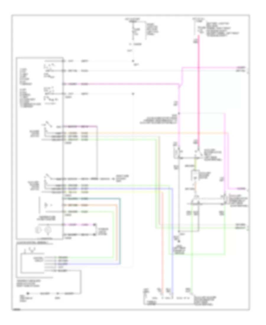
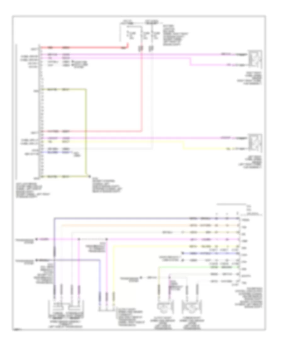
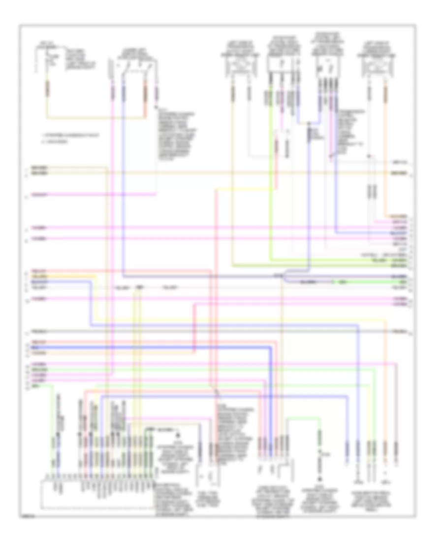
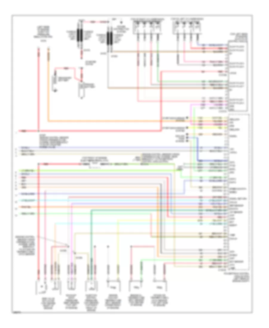
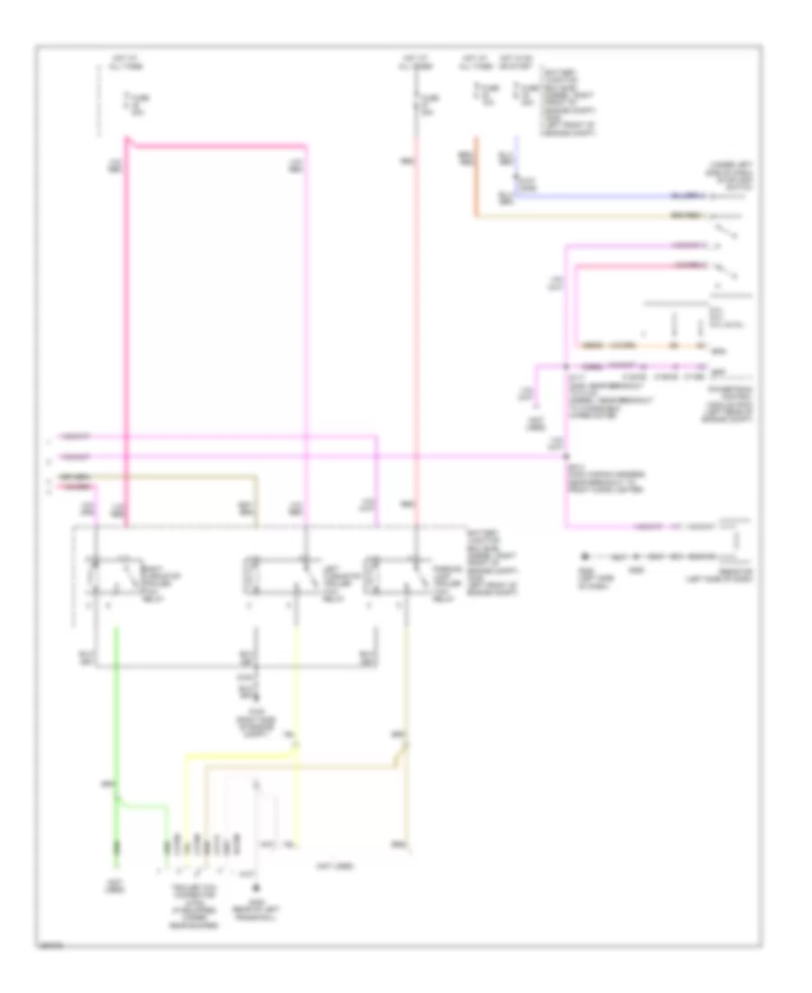
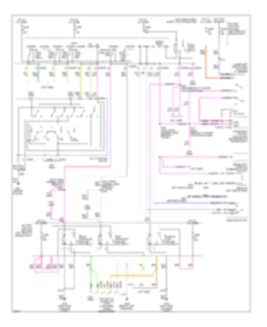
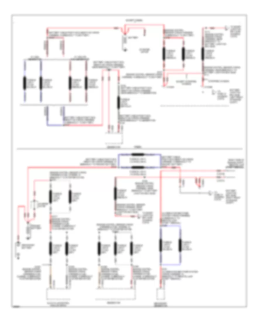
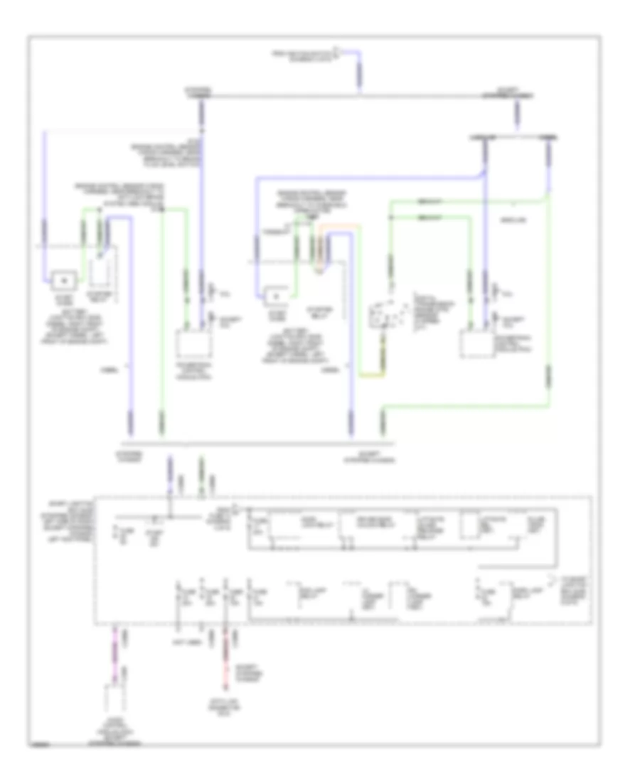
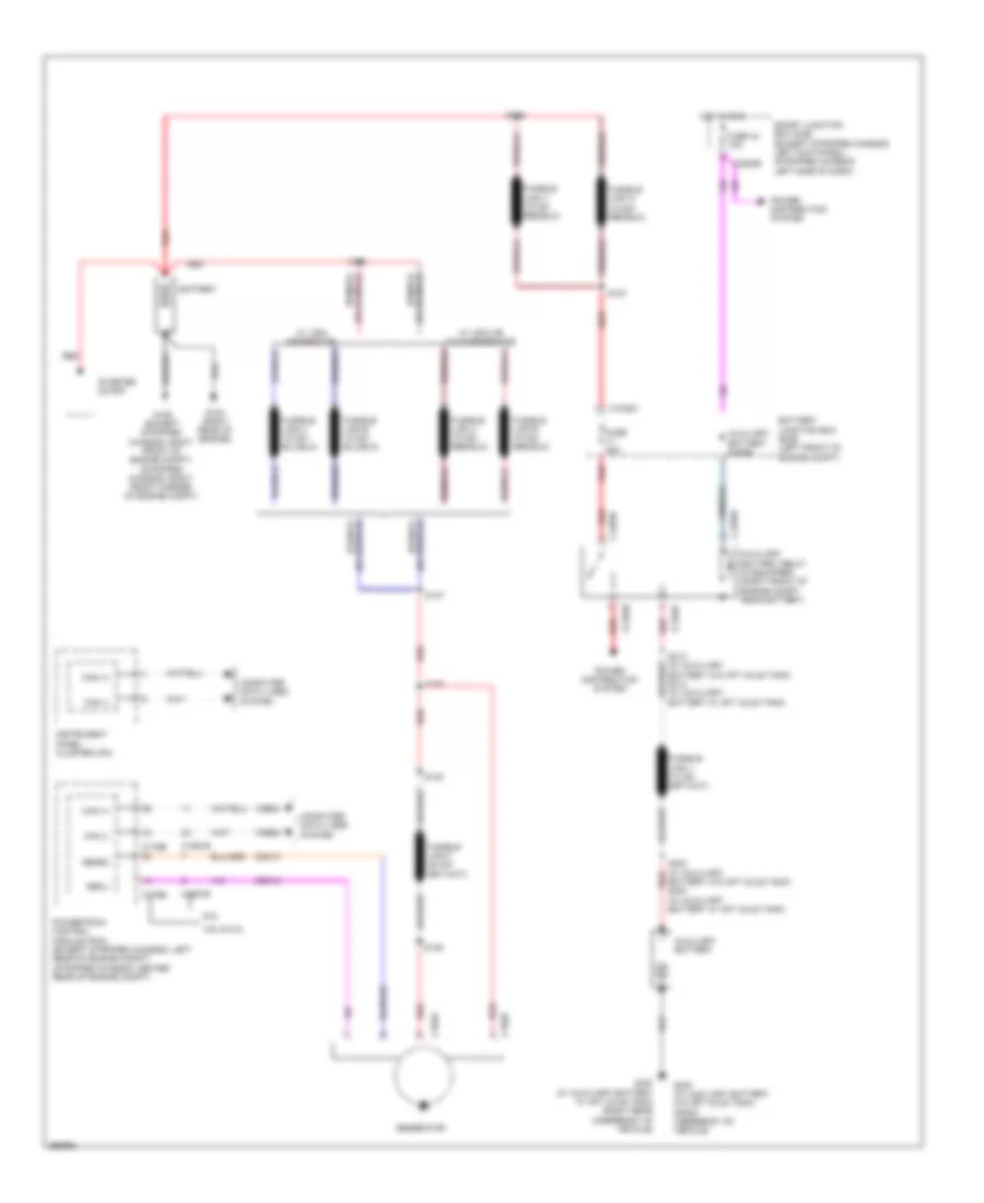
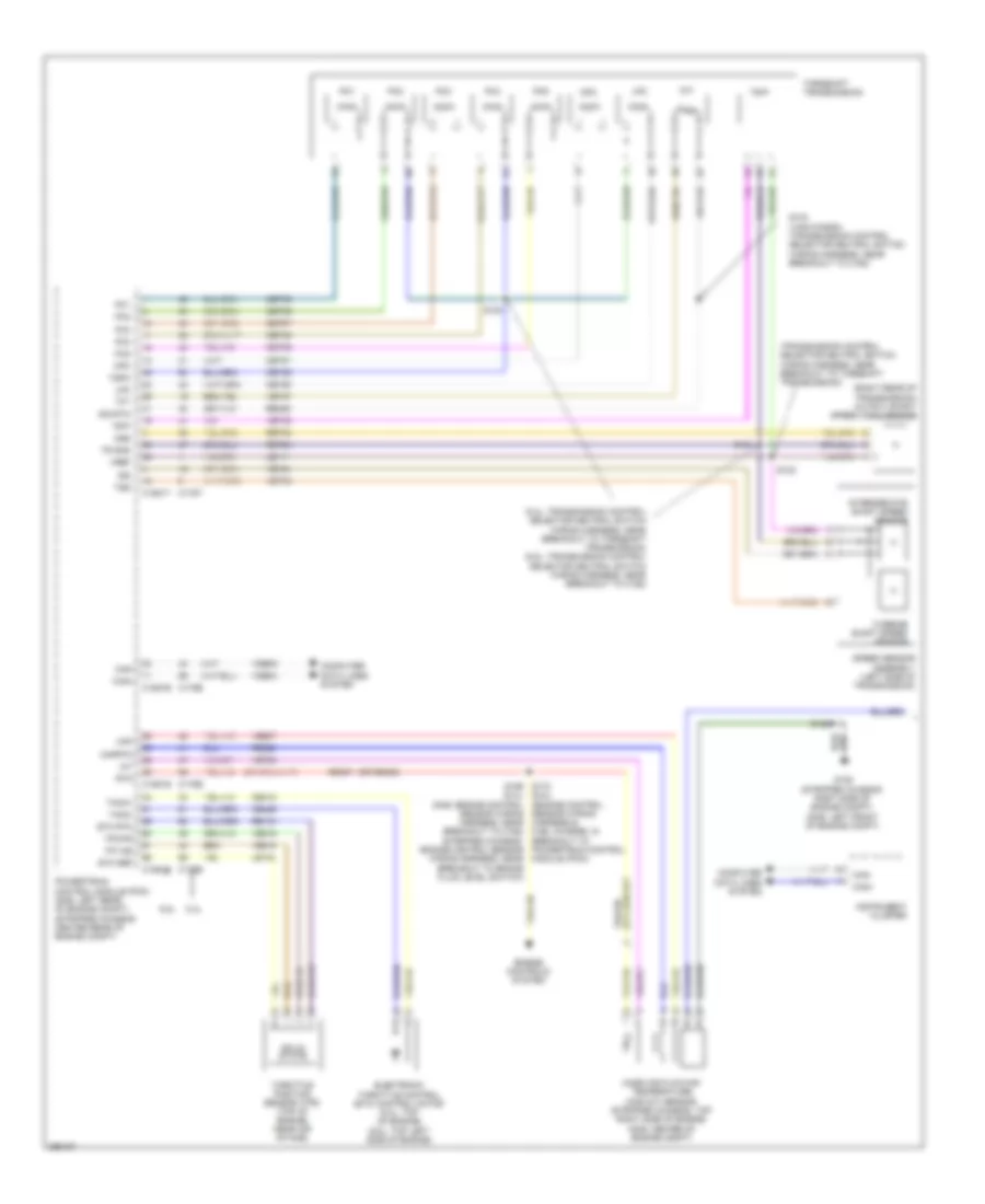
AIR CONDITIONING
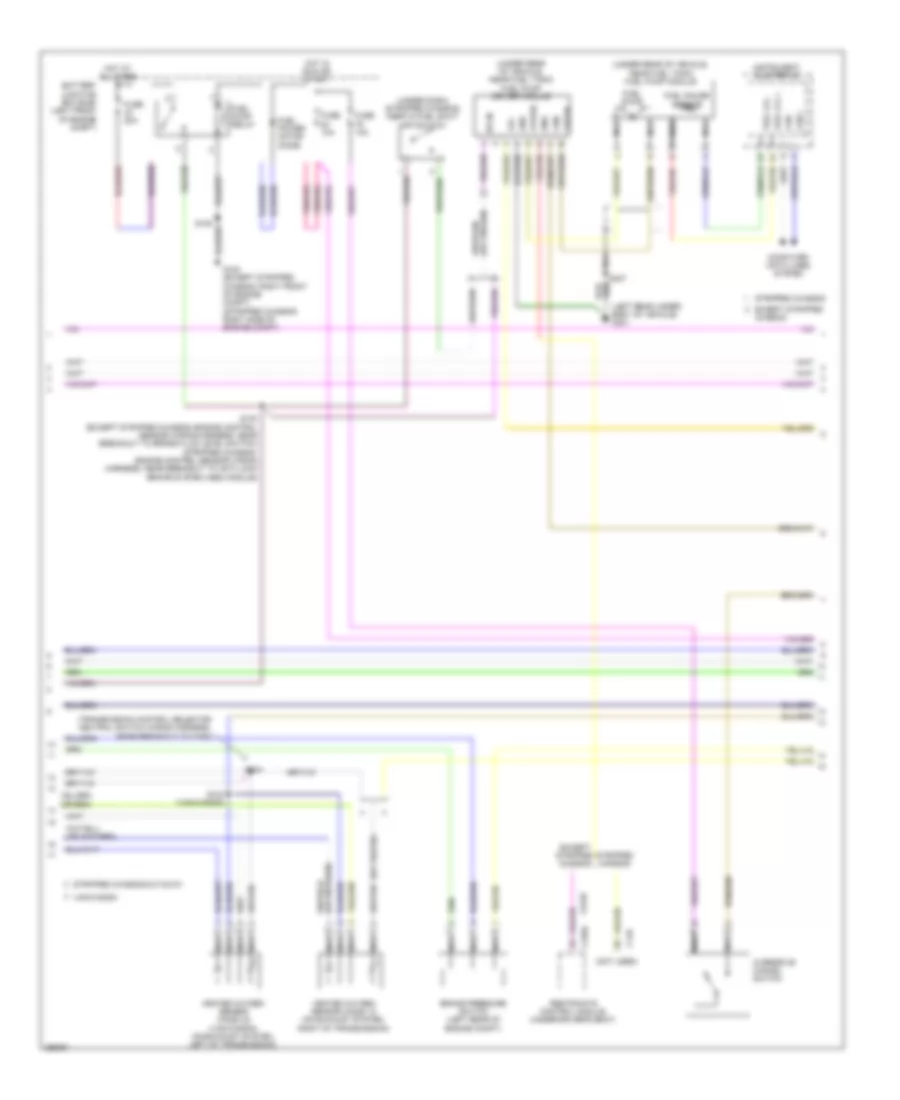
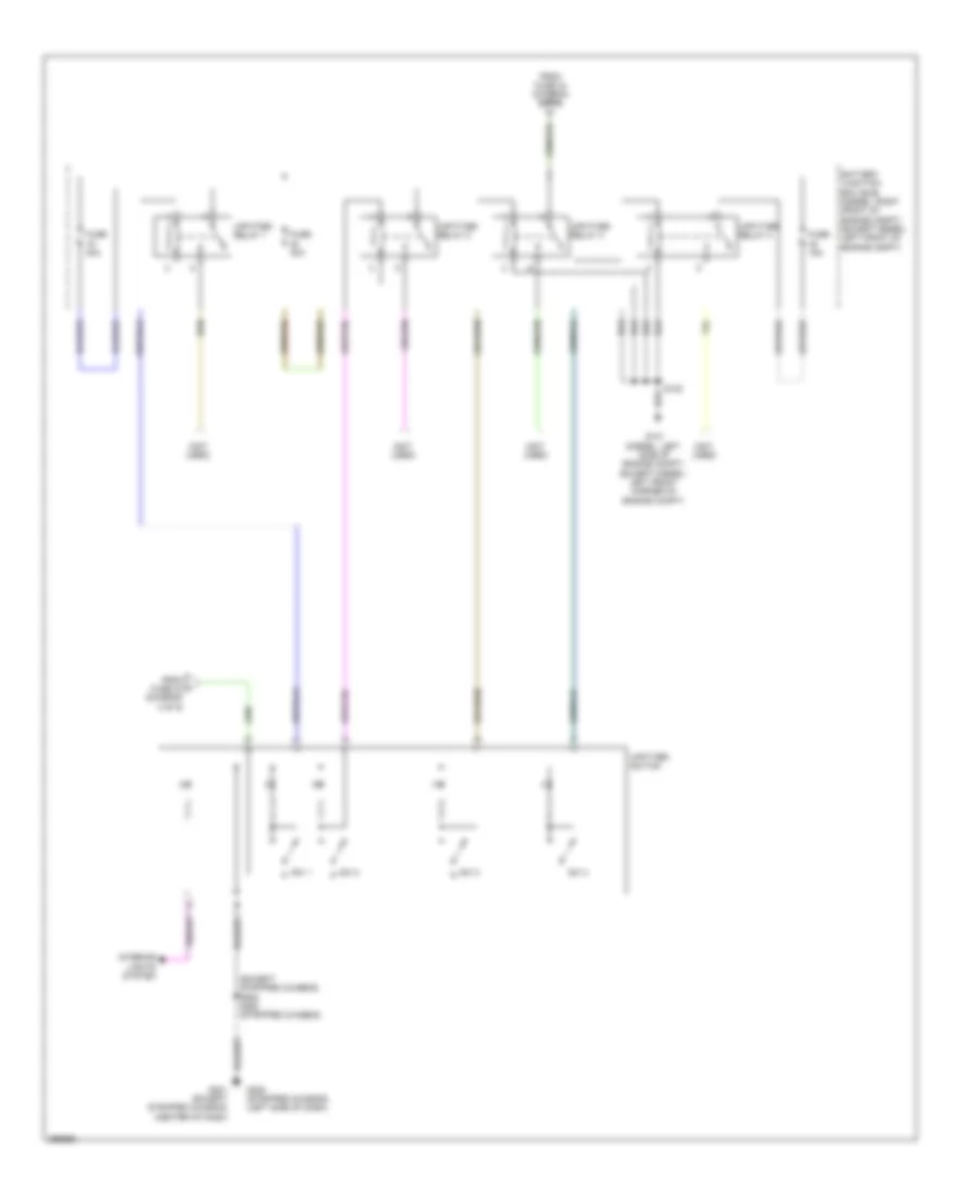
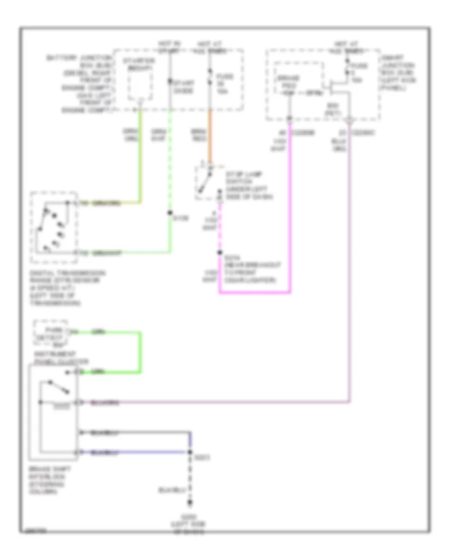
Manual A/C Wiring Diagram, with Stripped Chassis for Ford Cutaway E350 Super Duty 2009

List of elements for Manual A/C Wiring Diagram, with Stripped Chassis for Ford Cutaway E350 Super Duty 2009:
- (4.6l: engine control sensor wiring harness & fuel charge, near breakout to evap canister purge valve) (6.8l: engine control sensor wiring harness & fuel charge, in breakout to powertrain control module (pcm)) s172
- (not used)
- 4.6l & 5.4l
- 6.8l
- A/c clutch relay
- A/c compressor clutch field coil (lower right front of engine)
- Accr
- Accs
- Battery junction box (bjb) (left front of engine compt)
- Blower motor relay
- C1551e
- C175b
- C175e
- C2280b
- Ch302
- Ch421
- Cht
- Customer access connector (right front of engine compt)
- Cylinder head temperature sensor (front of left cylinder head)
- Engine controls system
- Except 5.4l
- Fuse 10a
- Fuse 50a
- G100 (right side of engine compt)
- G101 (left front corner of engine compt)
- Hot at all times
- Hot in start or run
- Hot w/ pcm power relay energized
- Powertrain control module (pcm) (center rear of engine compt)
- Re405
- S108
- S123
- S124
- Sigrtn
- Smart junction box (sjb) (left side of dash)
- Ve712
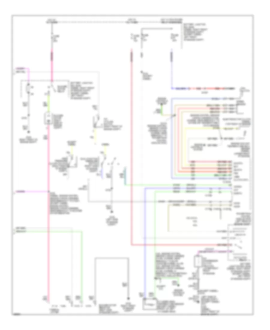
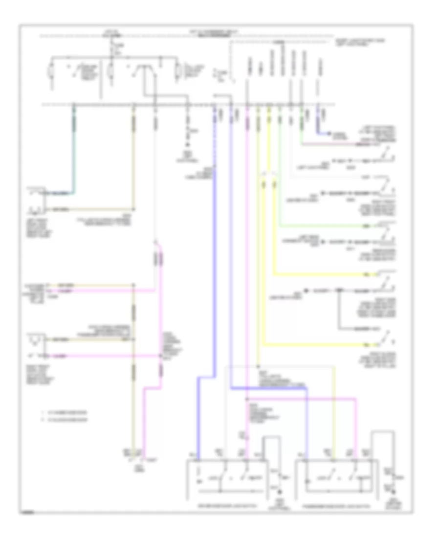
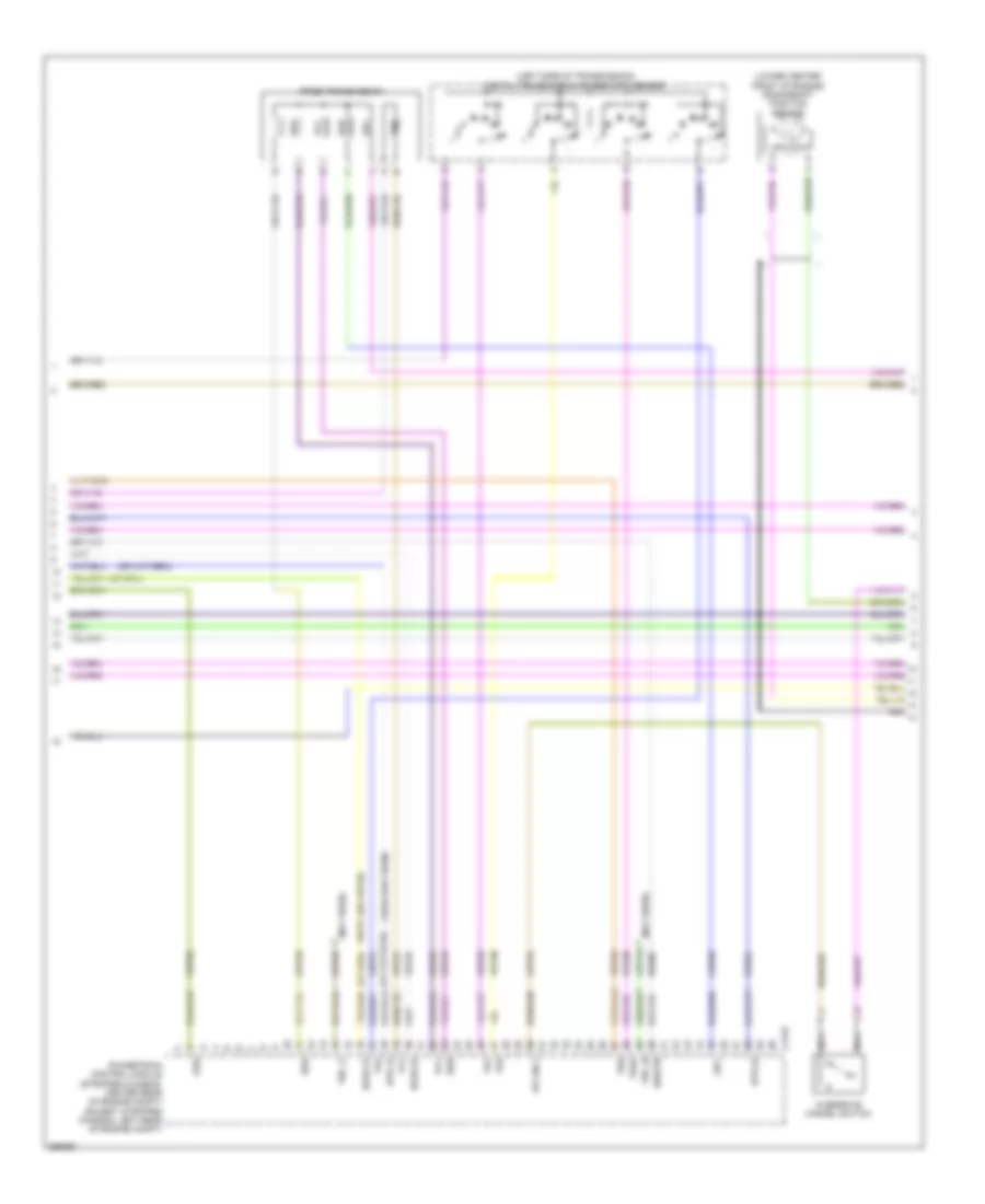
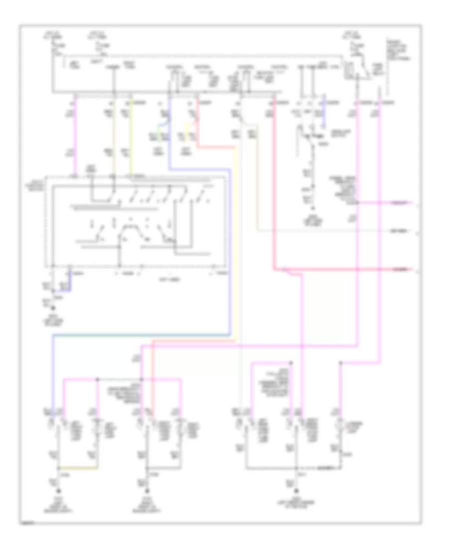
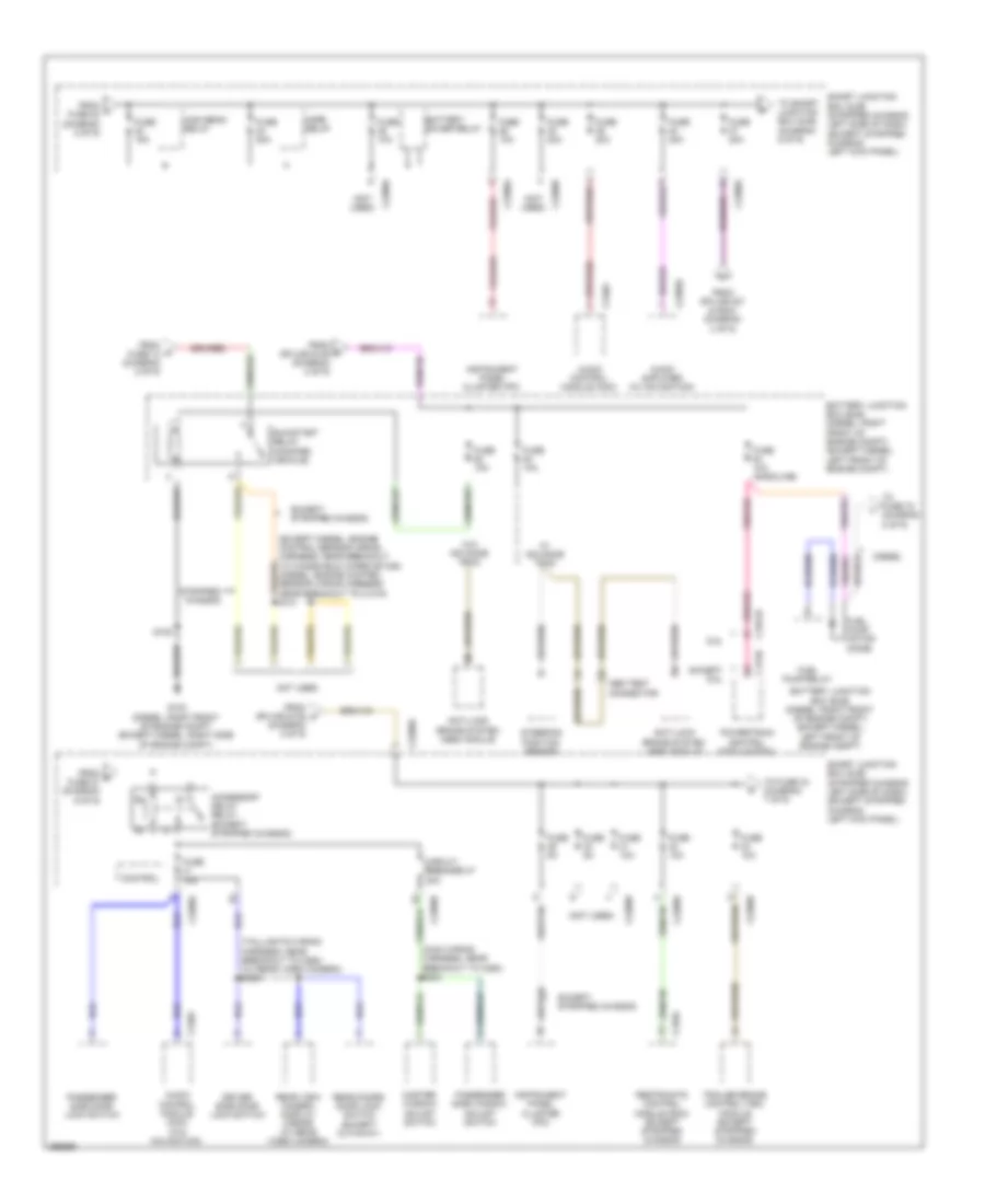
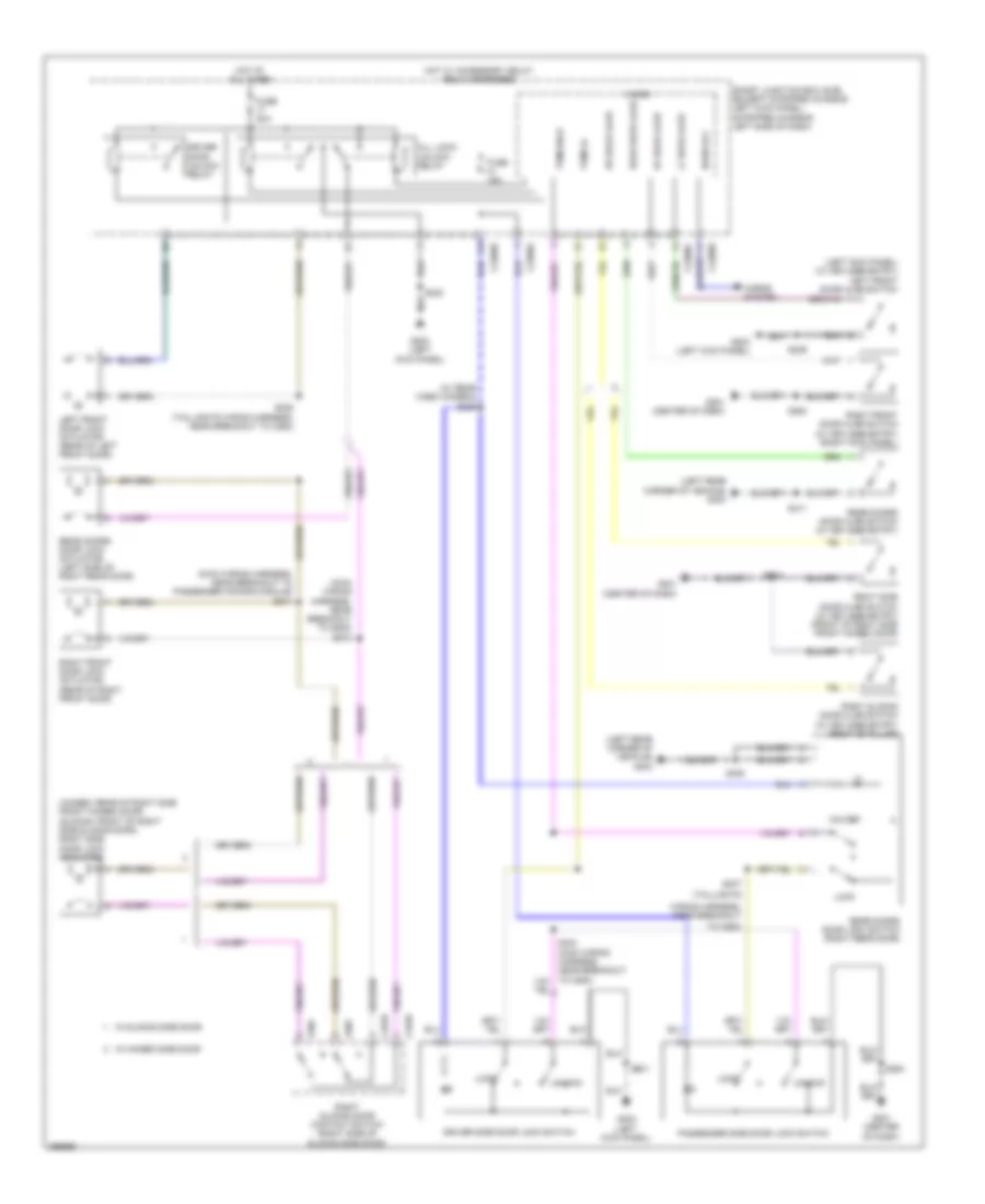
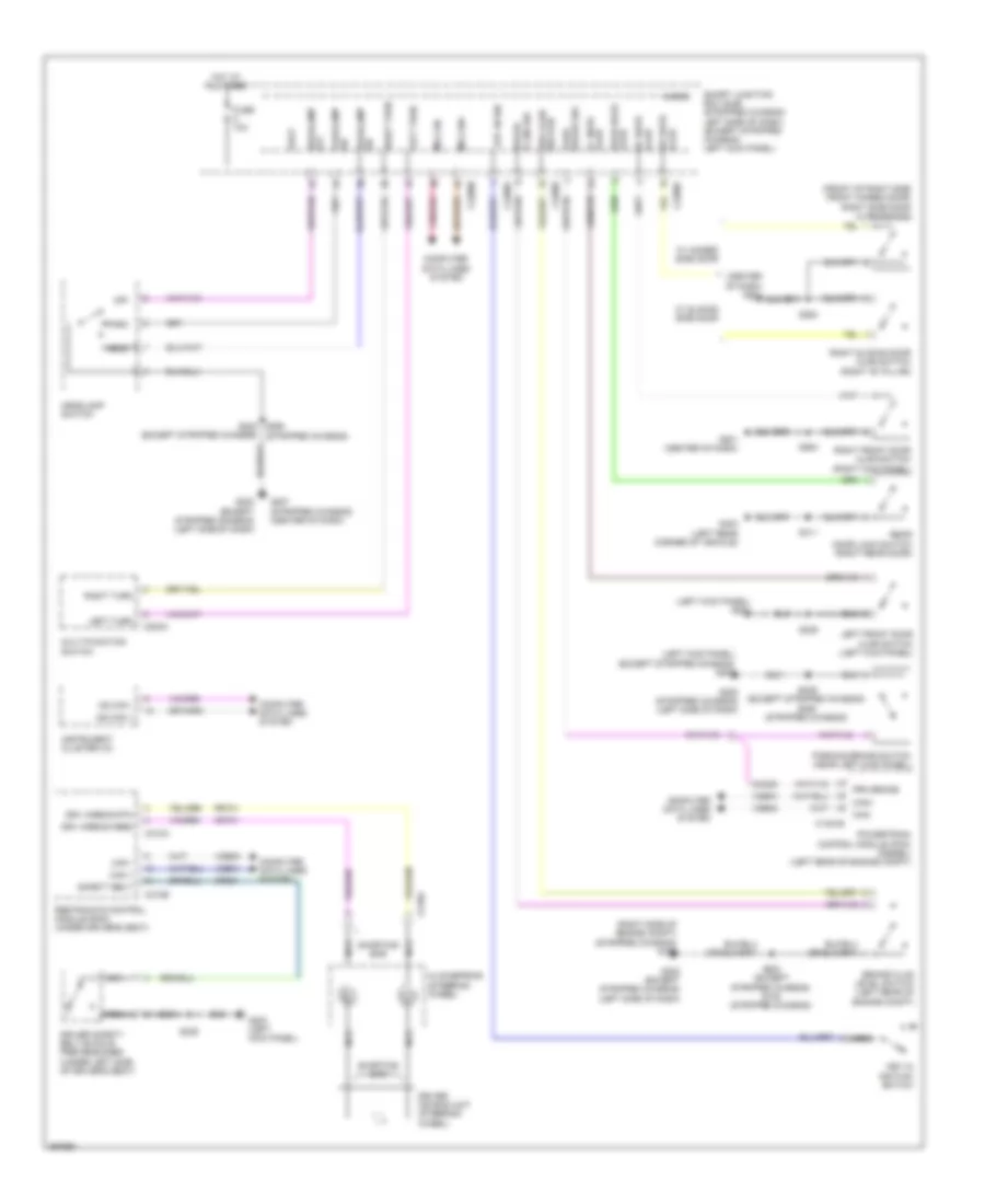
Manual A/C Wiring Diagram, without Stripped Chassis (1 of 2) for Ford Cutaway E350 Super Duty 2009
List of elements for Manual A/C Wiring Diagram, without Stripped Chassis (1 of 2) for Ford Cutaway E350 Super Duty 2009:
- (not used)
- (right side of dash) g200
- 0) off 5) max 6) normal 7) vent 8) floor/vent 9) floor 10) defrost/floor 11) defrost
- 1) max 2) a/c 3) vent 4) off 5) floor 6) mix 7) defrost
- 87a
- Auxiliary blower motor
- Auxiliary blower motor relay (left rear quarterpanel)
- Auxiliary blower motor resistor (left rear quarterpanel)
- Auxiliary blower motor speed relay (left rear quarterpanel)
- Auxiliary blower motor switch
- Battery junction box (bjb) (diesel: right front of engine compt) (except diesel: left front of engine compt)
- Blower motor switch
- C2280b
- C294a
- C294b
- C294c
- C294d
- C294e
- Cbp37
- Ch202
- Ch203
- Ch204
- Ch428
- Ch429
- Ch430
- Ch434
- Ch435
- Cha06
- Cha07
- Cha08
- Circuit
- Climate control assembly
- Control
- Fuse 10a
- Fuse 50a
- G201 (center of dash)
- G403 (left rear corner of vehicle)
- Gd115
- Gd116
- Gnd
- High
- Hot at all times
- Hot in start or run
- Illumination
- Interior lights system
- Mid high
- Mid low
- S217
- S264
- S265
- S400 (a/c blower motor wiring harness, near breakout to auxiliary blower motor relay)
- S401
- Smart junction box (sjb) (left kick panel)
- Temperature blend door actuator (right side of dash)
- Temperature potentiometer
- Thermal limiter
- Vlno4
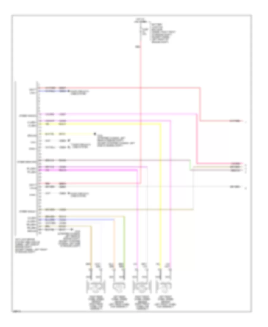
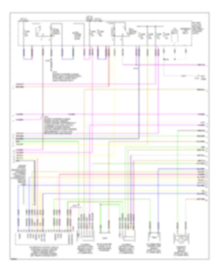
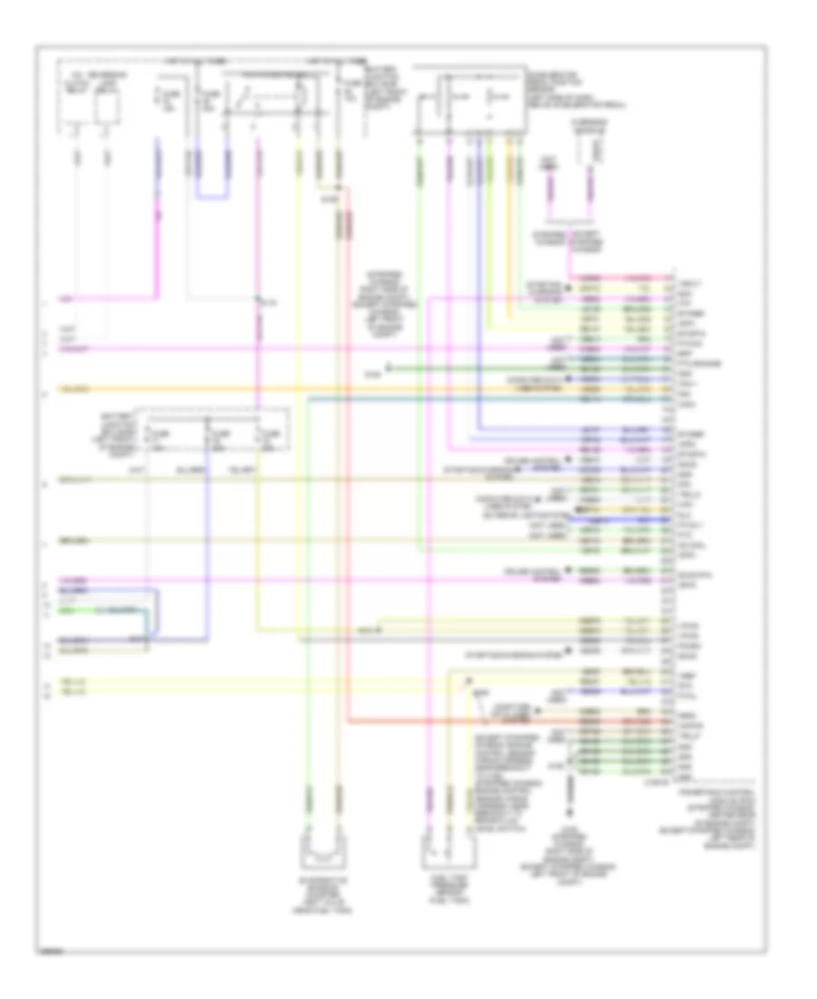
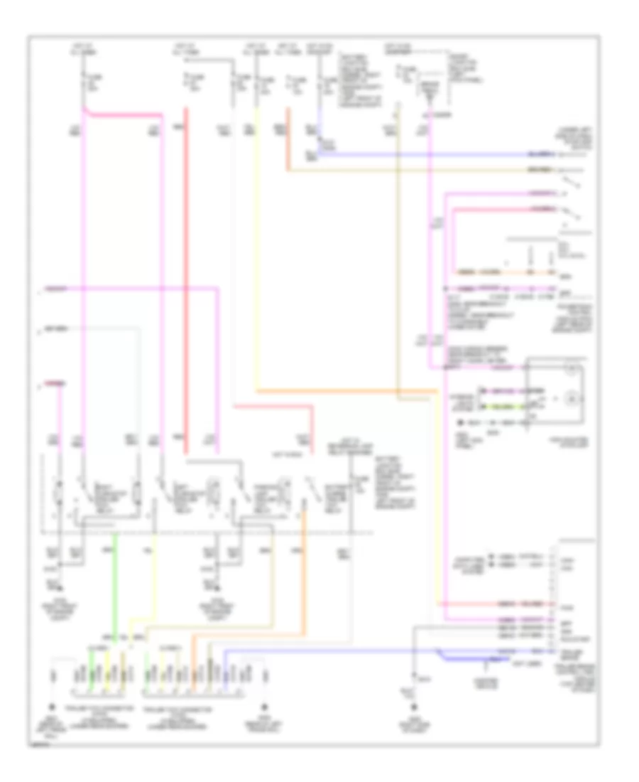
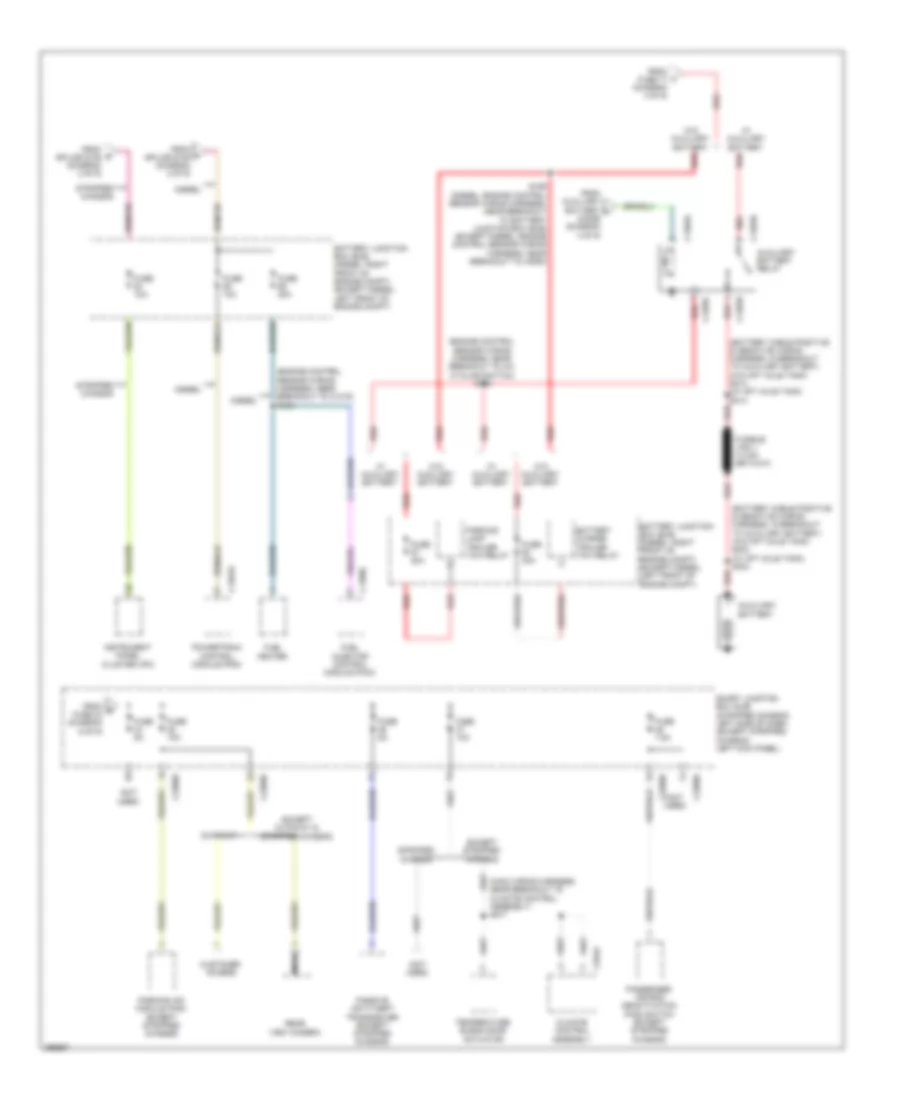
Manual A/C Wiring Diagram, without Stripped Chassis (2 of 2) for Ford Cutaway E350 Super Duty 2009
List of elements for Manual A/C Wiring Diagram, without Stripped Chassis (2 of 2) for Ford Cutaway E350 Super Duty 2009:
- (4.6l: engine control sensor wiring harness & fuel charge, near breakout to evap canister purge valve) (6.8l: engine control sensor wiring harness & fuel charge, in breakout to powertrain control module (pcm)) s172
- (engine control sensor wiring harness & fuel charge, near breakout to intake air temperature 2 (iat2) sensor) s1059
- (except diesel) s123
- (left side of engine compt) (except diesel) g101 g106 (diesel) (right front of engine compt)
- (or ch419)
- 4.6l & 5.4l
- 6.0l
- 6.8l
- A/c clutch relay
- A/c compressor clutch field coil (lower right front of engine)
- A/c cycling switch (right front of engine compt)
- Accr
- Accs
- Acpsw
- Battery junction box (bjb) (diesel: right front of engine compt) (except diesel: left front
- Blower motor (right side of engine compt)
- Blower motor relay
- Blower motor resistor (right side of engine compt)
- C1381b
- C1381e
- C1551e
- C175b
- C175e
- Ch302
- Ch421
- Ch425
- Cht
- Clutch cntl
- Cylinder head temperature sensor (except diesel) (front of left cylinder head)
- Diesel
- Dual function pressure switch (right side of engine compt)
- Ect
- Electronic fan clutch (diesel) (top front of engine)
- Engine controls system
- Engine coolant temperature (ect) sender (diesel) (upper front of engine)
- Except 5.4l
- Except diesel
- Fan clutch
- Fss
- Fuse 10a
- Fuse 20a
- Fuse 50a
- G100 (right front of engine compt)
- G105 (left side of engine compt)
- High pressure cutoff switch (right front of engine compt)
- Hot at all times
- Hot w/ pcm power relay energized
- Nca
- Of engine compt)
- Powertrain control module (pcm) (left rear of engine compt)
- Re405
- Red
- S1010 (engine control sensor wiring harness & fuel charge, near breakout to powertrain control module (pcm))
- S105 (diesel: engine control sensor wiring harness, near breakout to c1221) (except diesel: engine control sensor wiring harness, near breakout to blower motor resistor)
- S1057
- S108
- S124 (except diesel)
- S125
- Sig rtn
- Sigrtn
- Speed sensor
- Ss rtn
- Thermal limiter
- Ve712
- Vref
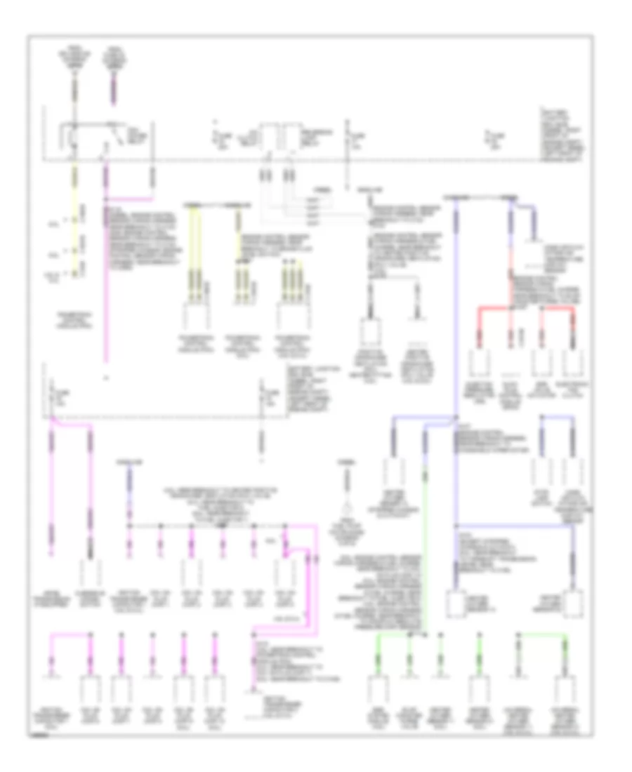
ANTI-LOCK BRAKES
Anti-lock Brakes Wiring Diagram, with Stability Assist (1 of 2) for Ford Cutaway E350 Super Duty 2009
List of elements for Anti-lock Brakes Wiring Diagram, with Stability Assist (1 of 2) for Ford Cutaway E350 Super Duty 2009:
- Anti-lock brake system (abs) module (diesel: left side of engine compt) (except diesel: left front of engine compt)
- Battery junction box (bjb) (diesel: right front of engine compt) (except diesel: left front of engine compt)
- Can +
- Can -
- Can2 +
- Can2 -
- Cbb53
- Computer data lines system
- Fuse 40a
- G102 (stripped chassis: left rear of engine compt) (except stripped chassis: left side of engine compt)
- Gd121
- Ground
- Hot at all times
- Left front wheel speed sensor (left front wheel hub assembly)
- Left rear wheel speed sensor (left rear wheel hub assembly)
- Lf_sen+
- Lf_sen-
- Lr_sen+
- Lr_sen-
- Nca
- Rca09
- Rca17
- Rca18
- Rca19
- Rca20
- Red
- Rf_sen+
- Rf_sen-
- Right front wheel speed sensor (right front wheel hub assembly)
- Right rear wheel speed sensor (right rear wheel hub assembly)
- Rr_sen+
- Rr_sen-
- Sbb33
- Sbb47
- Steer angle 1
- Steer angle 2
- Steer sens gnd
- Vbatt
- Vca03
- Vca04
- Vca05
- Vca06
- Vcs06
- Vcs07
- Vdb04
- Vdb05
- Vpwr
Anti-lock Brakes Wiring Diagram, with Stability Assist (2 of 2) for Ford Cutaway E350 Super Duty 2009
List of elements for Anti-lock Brakes Wiring Diagram, with Stability Assist (2 of 2) for Ford Cutaway E350 Super Duty 2009:
- (left side of dash) (stripped chassis) g205
- (not used)
- (stripped chassis) s250
- 4.6l & 5.4l
- 6.0l
- 6.8l
- Abs test connector (gas: left front corner of engine compt)
- Battery junction box (bjb) (diesel: right front of engine compt) (except diesel: left front of engine compt)
- C1381b
- C1381t
- C1551b
- C1551t
- C175b
- C175t
- Can+
- Can-
- Cbb53
- Computer data lines system
- Fuse 10a
- Fuse 40a
- G103 (gas: left side of engine compt)
- G201 (except stripped chassis) (center of dash)
- Gd121
- Hot at all times
- Hot in run or start
- Instrument cluster (ic)
- Interior lights system
- Intermediate shaft speed sensor
- Iss
- Le111
- Oss
- Output shaft speed (oss) sensor (4r75e) (left side of transmission)
- Output shaft speed (oss) sensor (torqshift) (gas: right rear of transmission) (diesel: right side of transmission)
- Powertrain control module (pcm) (stripped chassis: center rear of engine compt) (except stripped chassis: left rear of engine compt)
- Re406
- Ret04
- Ret24
- S101 (6.8l: near breakout to c192) (except 6.8l: near breakout to torqshift transmission)
- S102 (near breakout to torqshift transmission)
- S104 (near breakout to c192)
- S264 (except stripped chassis)
- Sbb47
- Sig rtn
- Speed sensor assembly (torqshift) (left side of transmission)
- Steering position sensor (bottom of steering column)
- Tc on/off
- Traction control switch
- Transmissions system
- Trgnd
- Tss
- Turbine shaft speed (tss) sensor (4r75e) (left side of transmission)
- Turbine shaft speed sensor
- Vdb04
- Vdb05
- Ve744
- Vet26
- Vet33
- Vref
Anti-lock Brakes Wiring Diagram, without Stability Assist for Ford Cutaway E350 Super Duty 2009
List of elements for Anti-lock Brakes Wiring Diagram, without Stability Assist for Ford Cutaway E350 Super Duty 2009:
- (not used)
- 4.6l & 5.4l
- 6.0l
- 6.8l
- Abs active
- Anti-lock brake system (abs) module (diesel: left side of engine compt) (except diesel: left front of engine compt)
- Battery junction box (bjb) (diesel: right front of engine compt) (except diesel: left front of engine compt)
- C1381b
- C1381t
- C1551b
- C1551t
- C175b
- C175t
- Can+
- Can-
- Cbb53
- Cca01
- Computer data lines system
- Fuse 10a
- Fuse 40a
- G102 (except stripped chassis: left side of engine compt) (stripped chassis: left rear of engine compt)
- Gd121
- Gnd
- Hot at all times
- Hot in run or start
- Hs can +
- Hs can -
- Intermediate shaft speed sensor
- Iss
- Le111
- Left front wheel speed sensor (left front wheel hub assembly)
- Nca
- Oss
- Output shaft speed (oss) sensor (4r75e) (left side of transmission)
- Output shaft speed (oss) sensor (torqshift) (gas: right rear of transmission) (diesel: right side of transmission)
- Powertrain control module (pcm) (stripped chassis: center rear of engine compt) (except stripped chassis: left rear of engine compt)
- Rca17
- Rca19
- Re406
- Red
- Ret04
- Ret24
- Right front wheel speed sensor (right front wheel hub assembly)
- S101 (6.8l: near breakout to c192) (except 6.8l: near breakout to torqshift transmission)
- S102 (near breakout to torqshift transmission)
- S104 (near breakout to c192)
- Sbb33
- Sbb47
- Sig rtn
- Speed sensor assembly (torqshift) (left side of transmission)
- Transmissions system
- Trgnd
- Tss
- Turbine shaft speed (tss) sensor (4r75e) (left side of transmission)
- Turbine shaft speed sensor
- Vbatt
- Vca03
- Vdb04
- Vdb05
- Ve744
- Vet26
- Vet33
- Vpwr
- Vref
- Wheel spd lf+
- Wheel spd lf-
- Wheel spd rf+
- Wheel spd rf-
ANTI-THEFT
Forced Entry Wiring Diagram, with Cutaway for Ford Cutaway E350 Super Duty 2009
List of elements for Forced Entry Wiring Diagram, with Cutaway for Ford Cutaway E350 Super Duty 2009:
- (left kick panel) (w/ keyless entry) left front door ajar switch
- (left rear corner of vehicle) g403
- (main wiring harness, near breakout to g200) s210
- (main wiring harness, near breakout to passenger air bag module) s211
- (not used)
- All lock/ unlock relay
- C2280a
- C2280b
- C2280c
- C2280d
- C3007
- Connector c3359 (left "b" pillar)
- Customer access
- Driver door unlock relay
- Driver side door lock switch
- Fuse 15a
- Fuse 20a
- G201 (center of dash)
- G203 (left kick panel)
- Horn rly
- Horns system
- Hot at all times
- Hot w/ accessory delay relay energized
- Left front door lock actuator (rear of left front door)
- Lf door ajar
- Lock
- Micro
- Passenger side door lock switch
- Rear door ajar
- Rear doors door ajar switch (w/ keyless entry)
- Rf door ajar
- Right front door ajar switch (w/ keyless entry) (right kick panel)
- Right front door lock actuator (rear of right front door)
- Right side door ajar switch (w/ keyless entry) (front of right side front hinged door)
- Right sliding door ajar switch (w/ keyless entry) (right "b" pillar)
- Rr door ajar
- S233 (main wiring harness, near breakout to c264)
- S236 (w/ rear video camera)
- S237 (taillights wiring harness, near breakout to c263)
- S238 (taillights wiring harness, near breakout to c263)
- S239
- S240
- S264
- S411
- S501
- Smart junction box (sjb) (left kick panel)
- Trim lk
- Trim unlk
- Unlock
- W/ hinged side door
- W/ sliding side door
Forced Entry Wiring Diagram, without Cutaway for Ford Cutaway E350 Super Duty 2009
List of elements for Forced Entry Wiring Diagram, without Cutaway for Ford Cutaway E350 Super Duty 2009:
- (hinged: rear of right side front hinged door) (sliding: front of right side sliding door) right side door lock actuator
- (left kick panel) (w/ keyless entry) left front door ajar switch
- (left rear corner of vehicle) g403
- (main wiring harness, near breakout to g200) s210
- (main wiring harness, near breakout to passenger air bag module) s211
- (taillights
- (w/ rear video camera) s236
- All lock/ unlock relay
- C2280a
- C2280b
- C2280c
- C2280d
- C3235
- C807
- Driver door unlock relay
- Driver side door lock switch
- Fuse 15a
- Fuse 20a
- G201 (center of dash)
- G203 (left kick panel)
- Horn rly
- Horns system
- Hot at all times
- Hot w/ accessory delay relay energized
- Left front door lock actuator (rear of left front door)
- Lf door ajar
- Lock
- Micro
- Passenger side door lock switch
- Rear door ajar
- Rear doors door ajar switch (w/ keyless entry)
- Rear doors door lock actuator (left side of right rear door)
- Rear doors door lock switch (right rear door)
- Rf door ajar
- Right front door ajar switch (w/ keyless entry) (right kick panel)
- Right front door lock actuator (rear of right front door)
- Right side door ajar switch (w/ keyless entry) (front of right side front hinged door)
- Right sliding door ajar switch (w/ keyless entry) (right "b" pillar)
- Right sliding door contact switch (right side of sliding side door)
- Rr door ajar
- S237
- S238 (taillights wiring harness, near breakout to c263)
- S239
- S240
- S264
- S405
- S411
- S501
- Smart junction box (sjb) (except stripped chassis: left kick panel) (stripped chassis: left side of dash)
- To c263)
- Trim lk
- Trim unlk
- Unlock
- W/ hinged side door
- W/ sliding side door
- Wiring harness, near breakout
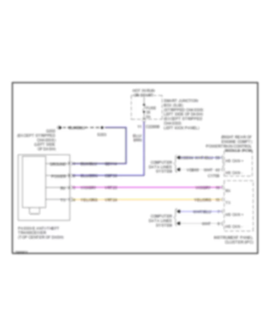
Passive Anti-theft Wiring Diagram for Ford Cutaway E350 Super Duty 2009
List of elements for Passive Anti-theft Wiring Diagram for Ford Cutaway E350 Super Duty 2009:
- (right rear of engine compt) powertrain control module (pcm)
- C175b
- C2280b
- Cbp36
- Computer data lines system
- Fuse 5a
- G202 (except stripped chassis) (left side of dash)
- Gd114
- Ground
- Hot in run or start
- Hs can +
- Hs can -
- Instrument panel cluster (ipc)
- Passive anti-theft transceiver (top center of dash)
- Power
- S263
- Smart junction box (sjb) (stripped chassis: left side of dash) (except stripped chassis: left kick panel)
- Vdb04
- Vdb05
- Vrt23
- Vrt24
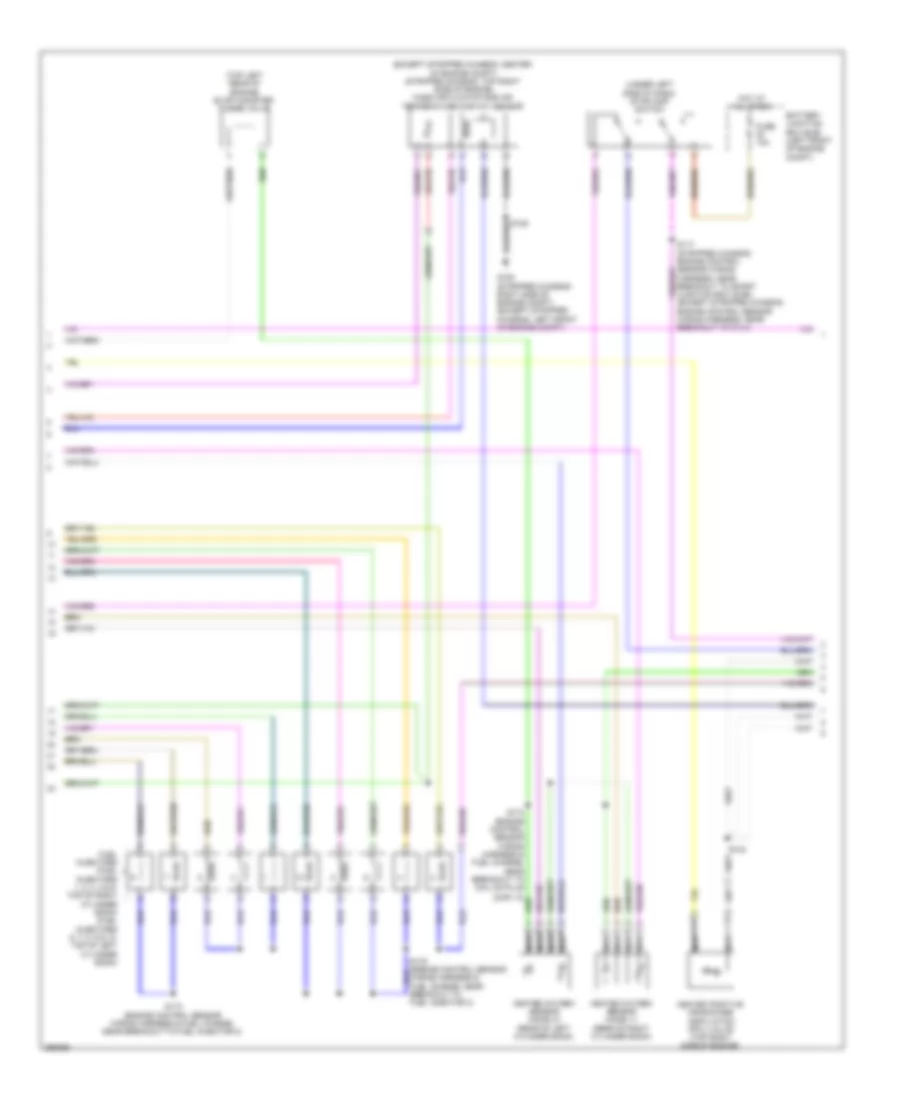
BODY CONTROL MODULES
Body Control Modules Wiring Diagram (1 of 3) for Ford Cutaway E350 Super Duty 2009
List of elements for Body Control Modules Wiring Diagram (1 of 3) for Ford Cutaway E350 Super Duty 2009:
- (not used)
- Acc
- Air conditioning system
- Anti-theft system
- Back lighting led (fet)
- Battery junction box (bjb) (left front of engine compt)
- Brk pedal sw
- C2280a
- C2280b
- Cbp28
- Cbp29
- Cbp33
- Cbp35
- Cbp36
- Cbp37
- Cbp41
- Cbp42
- Cbp46
- Ccb08
- Cdc32
- Cdc33
- Cdc34
- Ce336
- Clf17
- Clf18
- Clf23
- Clf27
- Cln28
- Cls32
- Cls34
- Cls39
- Cls41
- Computer data lines system
- Crh02
- Diesel
- Dim sw gnd
- Dimmer sw
- Dome lp
- Door locks & sound systems
- Exterior lights system
- Flash to pass
- Floor lamp (fet)
- Fog lamp relay
- Fuse 14, 10a
- Fuse 15, 10a
- Fuse 16, 15a
- Fuse 20, 15a
- Fuse 26, 10a
- Fuse 27, 20a
- Fuse 28, 5a
- Fuse 29, 5a
- Fuse 30, 5a
- Fuse 31, 10a
- Fuse 33, 10a
- Fuse 34, 5a
- Fuse 35, 10a
- Fuse 36, 5a
- Fuse 37, 10a
- Fuse 39, 20a
- Fuse 40, 20a
- Fuse 41, 15a
- Fuse 42, 10a
- Fuse 43, 10a
- Fuse 46, 7.5a
- Gasoline
- Gasoline except stripped chassis
- Gasoline stripped chassis
- Hazard
- Headlamp off
- Headlamp on
- Headlights system
- High beam
- Horn sw
- Horns system
- Hot at all times
- Hot in run
- Hot in run or acc
- Hot in start
- Ignition switch
- Instrument cluster system
- Interior lighting (fet)
- Interior lights system
- Lock
- Ms can+
- Ms can-
- Navigation system
- Off
- Parklamp on
- Power distribution system
- Rln29
- Run
- Run/start ign sw
- S132
- S139
- Sbp20
- Sbp26
- Sbp27
- Sbp39
- Sbp40
- Smart junction box (sjb) (stripped chassis: left side of dash) (except stripped chassis: left kick panel)
- Sound systems
- Start
- Start diode
- Turn left
- Turn right
- Vdb06
- Vdb07
- Vln04
- Vln18
- Vln33
- White light (fet)
Body Control Modules Wiring Diagram (2 of 3) for Ford Cutaway E350 Super Duty 2009
List of elements for Body Control Modules Wiring Diagram (2 of 3) for Ford Cutaway E350 Super Duty 2009:
- (except cutway) s240
- (left kick panel) (except stripped chassis) g203
- (not used)
- 3rd row seat enable (fet)
- Battery saver relay
- Bsi (fet)
- C2280c
- C2280d
- Cbp32
- Cbp35
- Cbp41
- Cbp43
- Cbp47
- Cdc30
- Cet53
- Cln09
- Cls18
- Cls19
- Cls23
- Cls27
- Cls30
- Cmc25
- Cpl11
- Cpl26
- Cpl31
- Cpl36
- Cpl39
- Cpl42
- Cpl43
- Cpl51
- Cpl52
- Door lock relay
- Door locks & navigation systems
- Door locks system
- Driver door unlock relay
- Exterior lights system
- Fuse 1, 30a
- Fuse 10a
- Fuse 11, 10a
- Fuse 12, 7.5a
- Fuse 13, 5a
- Fuse 14, 10a
- Fuse 18, 20a
- Fuse 19, 25a
- Fuse 2, 15a
- Fuse 3, 15a
- Fuse 32, 10a
- Fuse 35, 10a
- Fuse 38, 20a
- Fuse 4, 30a
- Fuse 41, 15a
- Fuse 43, 10a
- Fuse 46, 7.5a
- Fuse 47, 30a
- G203 (except stripped chassis) (left kick panel)
- Gd126
- Gd133
- Headlights system
- Hot at all times
- Instrument cluster system
- Interior lights system
- Key in ignition
- Keypad illum (fet)
- Lf door ajar
- Liftgate glass release relay
- Liftgate rel (fet)
- Logic gnd
- Lr stop/turn lamp (fet)
- Lr turn lamp (fet)
- Mirrors system
- Navigation system
- Park brake
- Park lamp relay
- Power gnd
- Power windows system
- Puddle lamp (fet)
- Pulse train (fet)
- Rear door ajar
- Rf door ajar
- Rr door ajar
- Rr stop/turn lamp (fet)
- Rr turn lamp (fet)
- S239
- S317 (cutway)
- Sbp13
- Shift interlock system
- Smart junction box (sjb) (stripped chassis: left side of dash) (except stripped chassis: left kick panel)
- Trim lock
- Trim unlock
- Vbatt
Body Control Modules Wiring Diagram (3 of 3) for Ford Cutaway E350 Super Duty 2009
List of elements for Body Control Modules Wiring Diagram (3 of 3) for Ford Cutaway E350 Super Duty 2009:
- (not used)
- Accessory delay relay
- Battery saver relay
- Brake fluid sw
- Brake fluid sw rtn
- C2280e
- C2280f
- C2280g
- Cbp44
- Cbp45
- Cdc35
- Cdc55
- Clf04
- Clf05
- Clf08
- Cls21
- Cls25
- Cls30
- Cmc19
- Door lock relay
- Driver door unlock relay
- Exterior lights system
- Fog lamp relay
- Fuse 44, 10a
- Fuse 45, 5a
- Fusible link b
- Headlights system
- High beam relay
- Horn relay
- Horns system
- Instrument cluster system
- Left low beam
- Lf turn lamp (fet)
- Lh corner lamp (fet)
- Liftgate glass release relay
- Park lamp relay
- Power distribution system
- Red
- Rf turn lamp (fet)
- Rh corner lamp (fet)
- Right low beam
- Rmc19
- Run/start relay
- Sdc02
- Smart junction box (sjb) (stripped chassis: left side of dash) (except stripped chassis: left kick panel)
- Srh01
- Start ign sw
- Starting/charging system
- Tpms 1 (fet)
- Tpms 2 (fet)
- Tpms 3 (fet)
- Wiper/washer system
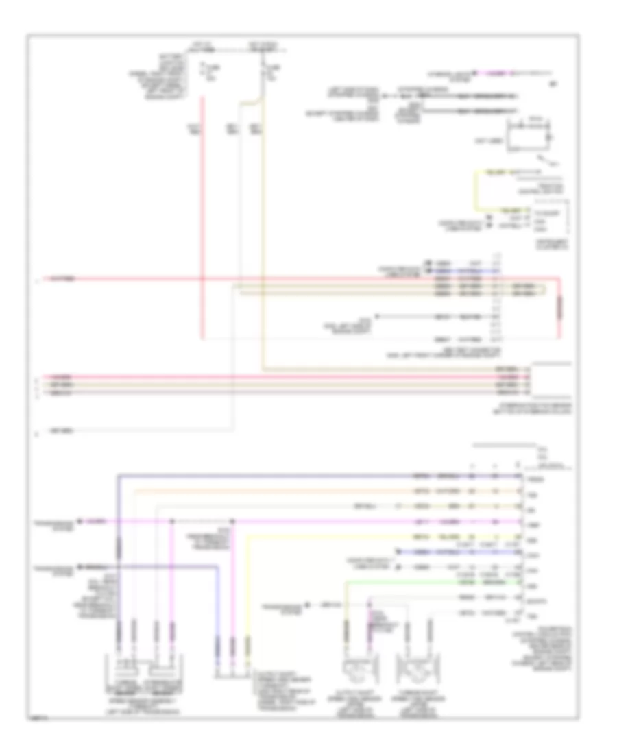
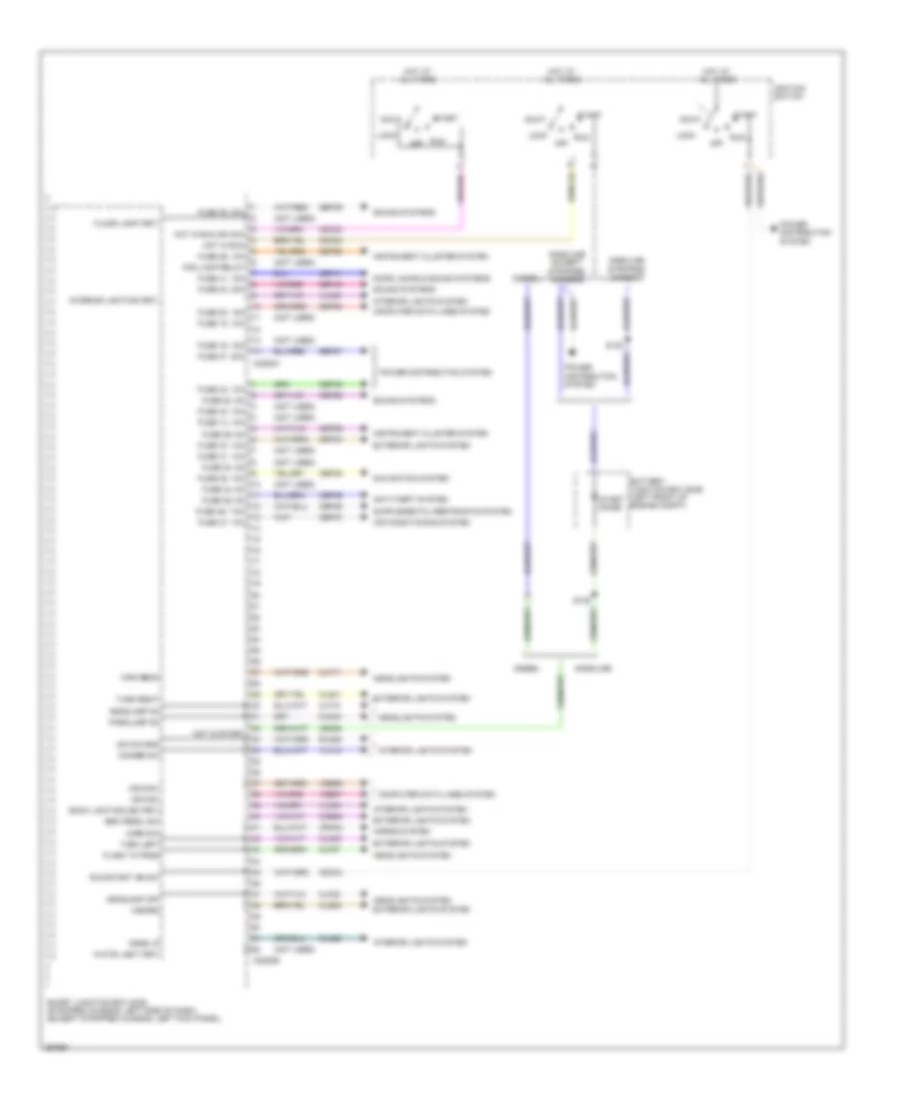
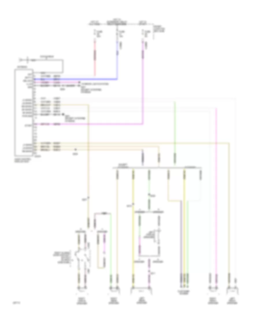
COMPUTER DATA LINES
Computer Data Lines Wiring Diagram, with Stripped Chassis for Ford Cutaway E350 Super Duty 2009
List of elements for Computer Data Lines Wiring Diagram, with Stripped Chassis for Ford Cutaway E350 Super Duty 2009:
- (engine control sensor wiring harness, near breakout to c110) s111
- (left front of engine compt) anti-lock brake system (abs) module
- (main wiring harness, near breakout to traction control switch) s258
- 6.8l
- Battery junction box (bjb) (left front of engine compt)
- C1551b
- C175b
- C2280b
- Can +
- Can -
- Can+
- Can-
- Cdb08
- Data link connector (dlc) (left side of dash)
- Except 6.8l
- Feps
- Fuse 15a
- G205 (left side of dash)
- G207 (center of dash)
- Gd114
- Gd133
- Hot at all times
- Instrument panel cluster (ipc)
- Ms can+
- Ms can-
- Powertrain control module (pcm) (center rear of engine compt)
- S250
- S255 (main wiring harness, near breakout to traction control switch)
- S256
- S257 (main wiring harness, near breakout to traction control switch)
- Sbb42
- Smart junction box (left side of dash)
- Vdb04
- Vdb05
- Vdb06
- Vdb07
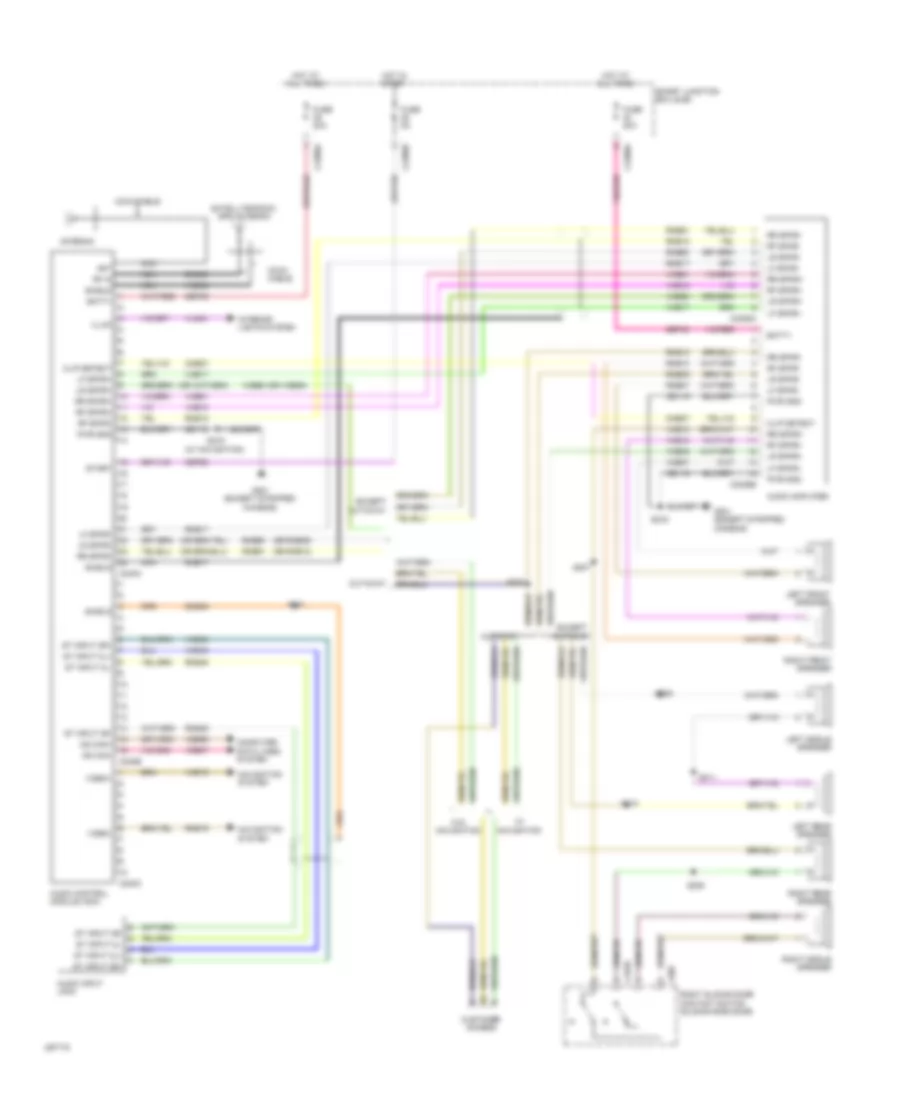
Computer Data Lines Wiring Diagram, without Stripped Chassis for Ford Cutaway E350 Super Duty 2009
List of elements for Computer Data Lines Wiring Diagram, without Stripped Chassis for Ford Cutaway E350 Super Duty 2009:
- (engine control sensor wiring harness, near breakout to c192) s126
- (engine control sensor wiring harness, near breakout to c192) s127
- (main wiring harness, in breakout to instrument panel cluster (ipc)) s224
- (main wiring harness, in breakout to instrument panel cluster (ipc)) s225
- (main wiring harness, near breakout to c210) (w/ parking aid) s232
- 4.6l & 5.4l
- 6.8l
- Abs test connector (w/ advance trac) (gas: left front corner of engine comp)
- Anti-lock brake system (abs) module (diesel: left side of engine compt) (gas: left front of engine compt)
- Audio control module (acm)
- C1381b
- C1551b
- C175b
- C2280a
- C2280b
- C240b
- C310b
- Can +
- Can -
- Can+
- Can-
- Cdb08
- Data link connector (dlc) (below left side of dash)
- Diesel
- Feps
- Fuse 15a
- G201 (center of dash)
- G202 (left side of dash)
- Gd114
- Gd115
- Hot at all times
- Instrument panel cluster (ipc)
- Ms can+
- Ms can-
- Parking aid module (pam) (if equipped) (under left side of dash)
- Powertrain control module (pcm) (left rear of engine compt)
- Restraints control module (rcm) (under driver's seat)
- S111 (w/ advance trac) (diesel: engine control sensor wiring harness, near breakout to windshield wiper motor) (gas: engine control sensor wiring harness, near breakout to g105)
- S112 (w/ advance trac) (diesel: engine control sensor wiring harness, near breakout to windshield wiper motor) (gas: engine control sensor wiring harness, near breakout to g105)
- S221 (main wiring harness, near breakout to trailer brake control (tbc) module)
- S222 (main wiring harness, near breakout to trailer brake control (tbc) module)
- S229 (main wiring harness, near breakout to overdrive cancel switch)
- S231 (w/ parking aid) (main wiring harness, near breakout to g202)
- S263
- S264
- S301 (taillights wiring harness, near breakout to g203)
- S302 (taillights wiring harness, near breakout to g203)
- Sbp20
- Smart junction box (sjb) (left kick panel)
- Trailer brake control (tbc) module (top center of dash)
- Vdb04
- Vdb05
- Vdb06
- Vdb07
- W/ advance trac
- W/o advance trac
COOLING FAN
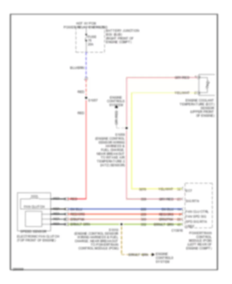
Cooling Fan Wiring Diagram for Ford Cutaway E350 Super Duty 2009
List of elements for Cooling Fan Wiring Diagram for Ford Cutaway E350 Super Duty 2009:
- Battery junction box (bjb) (right front of engine compt)
- C1381e
- Ect
- Electronic fan clutch (top front of engine)
- Engine controls system
- Engine coolant temperature (ect) sensor (upper front of engine)
- Fan clu ctrl
- Fan clutch
- Fan spd sig
- Fuse 20a
- Hot w/ pcm power relay energized
- Nca
- Powertrain control module (pcm) (left rear of engine compt)
- Red
- S1010 (engine control sensor wiring harness & fuel charge, near breakout to powertrain control module (pcm))
- S1057
- S1059 (engine control sensor wiring harness & fuel charge, near breakout to intake air temperature 2 (iat2) sensor)
- Sig rtn
- Spd sig rtn
- Speed sensor
- Vref
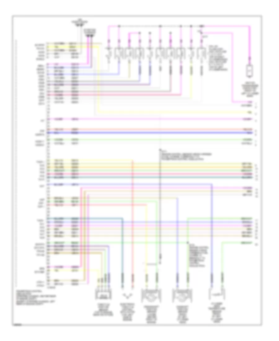
CRUISE CONTROL
5.4L
5.4L, Cruise Control Wiring Diagram for Ford Cutaway E350 Super Duty 2009
List of elements for 5.4L, Cruise Control Wiring Diagram for Ford Cutaway E350 Super Duty 2009:
- (5.4l: transmission control selector neutral switch wiring harness, near breakout to torqshift transmission) (6.8l: transmission control selector neutral switch wiring harness, near breakout to c192) s101
- (left rear of engine compt) (5.4l & 6.8l) brake pressure switch
- (left side of dash, above accelerator pedal) accelerator pedal position sensor
- (or etcref2)
- (or etcref3)
- (or etcrtn2)
- (or etcrtn3)
- (right rear of transmission) (torqshift) output shaft speed (oss) sensor
- (stripped chassis: near breakout to brake fluid level switch) (except stripped chassis: near breakout to c192 s156
- 4.6l
- 5.4l
- 5.4l & 4.6l
- 5.4l & 6.8l
- 6.8l
- App1
- App2
- App3
- Battery junction box (bjb) (left front of engine compt)
- Bfp
- Bpp
- C1551b
- C1551e
- C1551t
- C175b
- C175e
- C175t
- C218b
- Ccb08
- Ce412
- Ce426
- Clockspring (steering wheel)
- Coast
- Electronic throttle control (etc) control motor (5.4l: top of engine) (6.8l: top left side of engine)
- Electronic throttle control (etc) control motor (top of engine)
- Etc ref
- Etc rtn
- Etcref
- Etcrtn
- Fuse 10a
- G105 (except stripped chassis: left front of engine compt) (stripped chassis: right side of engine compt)
- G202 (left side of dash)
- Gd120
- Ground
- Horn switch
- Horns system
- Hot at all times
- Interior lights system
- Kapwr
- Lca16
- Le111
- Le134
- Le136
- Le137
- Left steering wheel switch
- Nca
- Off
- Oss
- Output shaft speed (oss) sensor (4 speed a/t) (left side of transmission)
- Powertrain control module (pcm) (except stripped chassis: left rear of engine compt) (stripped chassis: center rear of engine compt)
- Rca16
- Re134
- Re136
- Re137
- Re406
- Re407
- Res
- Res08
- Ret04
- Ret24
- Right steering wheel switch
- Rtn
- S102 (transmission control selector neutral switch wiring harness, near breakout to torqshift transmission)
- S104 (transmission control selector neutral switch wiring harness, near breakout to c192)
- S117 (except stripped chassis: (gas: engine control sensor wiring harness, near breakout to c144) (stripped chassis: engine control sensor wiring harness, near breakout to smart junction box (sjb))
- S129
- S223
- Sbb46
- Sccs
- Sccsrtn
- Set/accel
- Sig rtn
- Solid state
- Stoplamp switch (under left side of dash)
- Tacm +
- Tacm -
- Throttle position sensor (tps) (top of engine, near air intake)
- Tp1-ns
- Tp2-ps
- Tr gnd
- Ve701
- Ve702
- Ve703
- Ve818
- Ve819
- Ves10
- Vref
- Vt126
6.0L DIESEL
6.0L Diesel, Cruise Control Wiring Diagram for Ford Cutaway E350 Super Duty 2009
List of elements for 6.0L Diesel, Cruise Control Wiring Diagram for Ford Cutaway E350 Super Duty 2009:
- (left side of engine compt) g105
- (transmission control selector neutral switch wiring harness, near breakout to torqshift transmission) s101
- Accelerator pedal position sensor (left side of dash, above accelerator pedal)
- App1 sig
- App2 sig
- App3 sig
- Battery junction box (bjb) (right front of engine compt)
- Bpp
- Brake press sw
- Brake pressure switch (left rear of engine compt)
- C1381b
- C1381e
- C1381t
- C218b
- Ccb08
- Clockspring (steering wheel)
- Cmc22
- Coast
- Electronic fan clutch (top front of engine)
- Fuse 10a
- G202 (left side of dash)
- Gd120
- Ground
- Horn switch
- Horns system
- Hot at all times
- Interior lights system
- Kapwr
- Le111
- Le136
- Le423
- Left steering wheel switch
- Nca
- Off
- Oss
- Output shaft speed (oss) sensor (right side of transmission)
- Power distribution system
- Powertrain control module (pcm) (left rear of engine compt)
- Re136
- Re407
- Res
- Res08
- Ret04
- Ret24
- Right steering wheel switch
- S1010 (engine control sensor wiring harness & fuel charge, near breakout to powertrain control module (pcm))
- S102 (transmission control selector neutral switch wiring harness, near breakout to torqshift transmission)
- S117 (engine control sensor wiring harness, near breakout to windshield wiper motor)
- S155 (engine control sensor wiring harness, near breakout to c140)
- S156 (engine control sensor wiring harness, near breakout to brake fluid level switch)
- S223
- Sbb46
- Sccs
- Sccsrtn
- Set/accel
- Sig rtn
- Sig rtn cowl
- Stoplamp switch (under left side of dash)
- Tr gnd
- Ve701
- Ve702
- Ve703
- Ves10
- Vref
6.8L
6.8L, Cruise Control Wiring Diagram for Ford Cutaway E350 Super Duty 2009
List of elements for 6.8L, Cruise Control Wiring Diagram for Ford Cutaway E350 Super Duty 2009:
- (5.4l: transmission control selector neutral switch wiring harness, near breakout to torqshift transmission) (6.8l: transmission control selector neutral switch wiring harness, near breakout to c192) s101
- (left rear of engine compt) (5.4l & 6.8l) brake pressure switch
- (left side of dash, above accelerator pedal) accelerator pedal position sensor
- (or etcref2)
- (or etcref3)
- (or etcrtn2)
- (or etcrtn3)
- (right rear of transmission) (torqshift) output shaft speed (oss) sensor
- (stripped chassis: near breakout to brake fluid level switch) (except stripped chassis: near breakout to c192 s156
- 4.6l
- 5.4l
- 5.4l & 4.6l
- 5.4l & 6.8l
- 6.8l
- App1
- App2
- App3
- Battery junction box (bjb) (left front of engine compt)
- Bfp
- Bpp
- C1551b
- C1551e
- C1551t
- C175b
- C175e
- C175t
- C218b
- Ccb08
- Ce412
- Ce426
- Clockspring (steering wheel)
- Coast
- Electronic throttle control (etc) control motor (5.4l: top of engine) (6.8l: top left side of engine)
- Electronic throttle control (etc) control motor (top of engine)
- Etc ref
- Etc rtn
- Etcref
- Etcrtn
- Fuse 10a
- G105 (except stripped chassis: left front of engine compt) (stripped chassis: right side of engine compt)
- G202 (left side of dash)
- Gd120
- Ground
- Horn switch
- Horns system
- Hot at all times
- Interior lights system
- Kapwr
- Lca16
- Le111
- Le134
- Le136
- Le137
- Left steering wheel switch
- Nca
- Off
- Oss
- Output shaft speed (oss) sensor (4 speed a/t) (left side of transmission)
- Powertrain control module (pcm) (except stripped chassis: left rear of engine compt) (stripped chassis: center rear of engine compt)
- Rca16
- Re134
- Re136
- Re137
- Re406
- Re407
- Res
- Res08
- Ret04
- Ret24
- Right steering wheel switch
- Rtn
- S102 (transmission control selector neutral switch wiring harness, near breakout to torqshift transmission)
- S104 (transmission control selector neutral switch wiring harness, near breakout to c192)
- S117 (except stripped chassis: (gas: engine control sensor wiring harness, near breakout to c144) (stripped chassis: engine control sensor wiring harness, near breakout to smart junction box (sjb))
- S129
- S223
- Sbb46
- Sccs
- Sccsrtn
- Set/accel
- Sig rtn
- Solid state
- Stoplamp switch (under left side of dash)
- Tacm +
- Tacm -
- Throttle position sensor (tps) (top of engine, near air intake)
- Tp1-ns
- Tp2-ps
- Tr gnd
- Ve701
- Ve702
- Ve703
- Ve818
- Ve819
- Ves10
- Vref
- Vt126
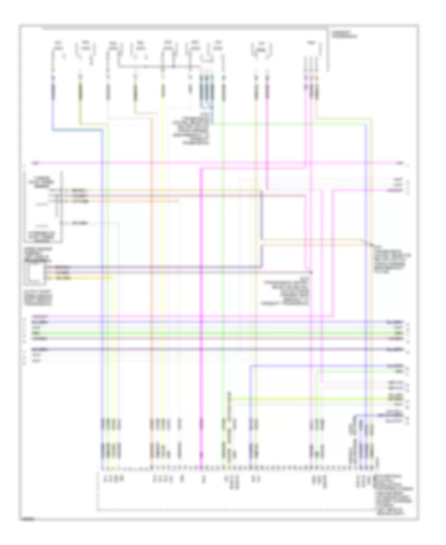
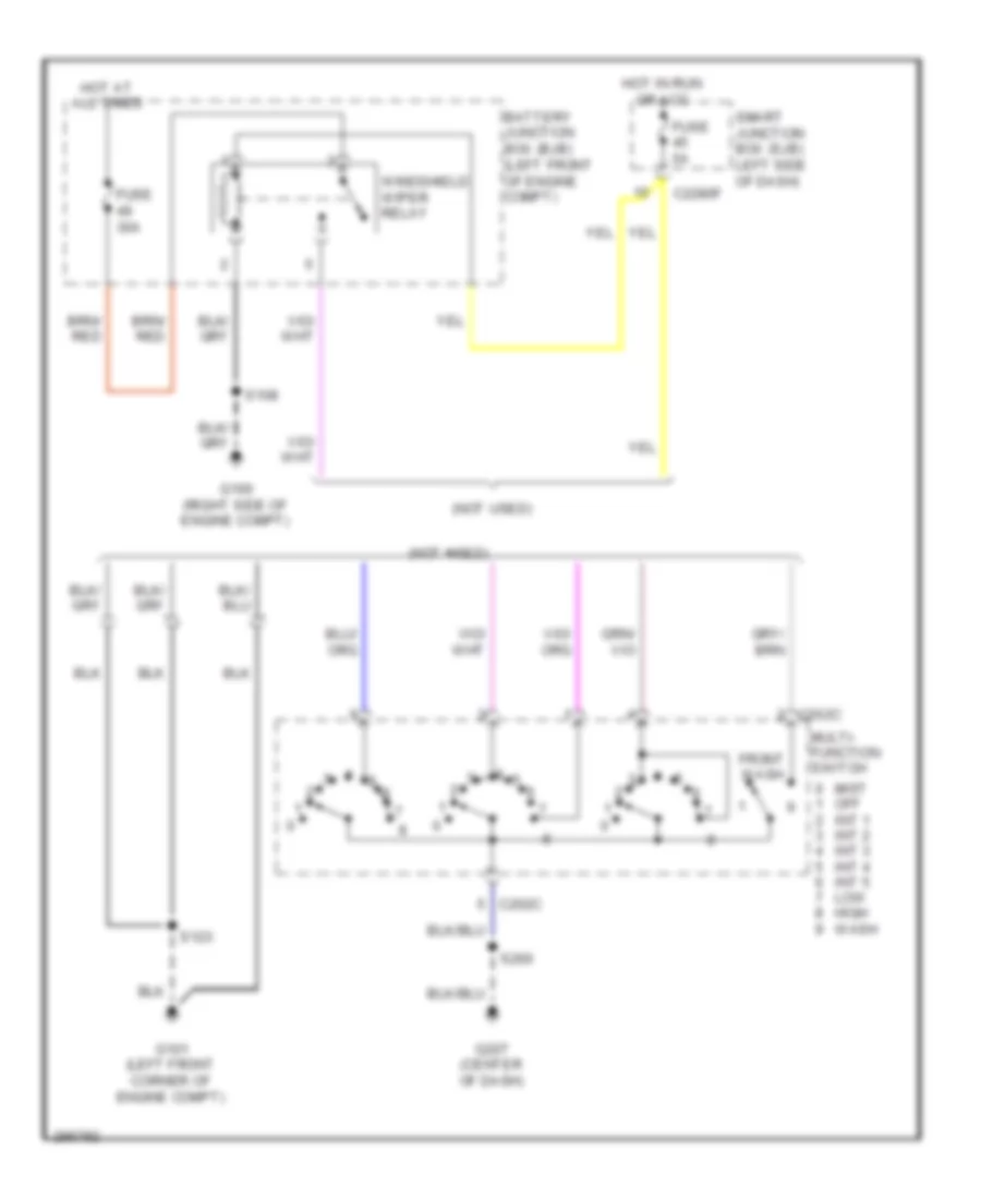
ENGINE PERFORMANCE
5.4L
5.4L, Engine Performance Wiring Diagram, with Torqshift (1 of 5) for Ford Cutaway E350 Super Duty 2009
List of elements for 5.4L, Engine Performance Wiring Diagram, with Torqshift (1 of 5) for Ford Cutaway E350 Super Duty 2009:
- (left rear of engine compt) brake pressure switch
- (near fuel tank) evaporative emission (evap) canister vent valve
- (not used)
- Accr
- Air conditioning system
- App1
- App2
- Battery junction box (bjb) (left front of engine compt)
- Bfp
- Bpp
- Bps
- C110
- C175b
- C310a
- Can+
- Can-
- Canv
- Cbb54
- Cbb75
- Ccb08
- Cdc12
- Cdc15
- Cdc35
- Ce114
- Ce302
- Ce326
- Ce336
- Ce515
- Ce608
- Ce912
- Ce913
- Ce914
- Ce924
- Ces09
- Ch302
- Computer data lines system
- Cr167
- Cruise control system
- Ens
- Etcref2
- Etcrtn2
- Except stripped chassis
- Fpc
- Fpm
- Fppwr
- Fprtn
- Fuel pump driver module (under rear of vehicle, near fuel tank)
- Fuel pump module (under rear of vehicle, near fuel tank)
- Fuel sndr 1
- Fuel sndr rtn
- Fuse 10a
- G105 (stripped chassis: right side of engine compt) (except stripped chassis: left front of engine compt)
- G401 (left rear underbody of vehicle)
- Gd120
- Gd128
- Genli
- Gnd
- Hot at all times
- Iat
- Inertia fuel shutoff (ifs) switch (under dash)
- Inj pwrm
- Instrument cluster (ic)
- Isp-r
- Le136
- Maf
- Mafrtn
- Nca
- Overhead console
- Pcmrc
- Powertrain control module (stripped chassis: center rear of engine compt) (except stripped chassis: left rear of engine compt)
- Ptioc 1
- Pto
- Ptoengage
- Ptoic 2
- Ptoil
- Rca16
- Re136
- Re320
- Re515
- Res08
- Restraints control module (rcm) (under driver's seat)
- S125
- S129
- S407
- Sccsrtn
- Smc
- Smcs
- Smr
- Starting/charging system
- Stripped chassis
- Vdb05
- Ve225
- Ve518
- Ve701
- Ve702
- Ve740
- Ve807
- Vmc05
- Vpwr
- Vs out
- Vssout
5.4L, Engine Performance Wiring Diagram, with Torqshift (2 of 5) for Ford Cutaway E350 Super Duty 2009
List of elements for 5.4L, Engine Performance Wiring Diagram, with Torqshift (2 of 5) for Ford Cutaway E350 Super Duty 2009:
- (except stripped
- (on exhaust system, left of transmission) (van/wagon) heated oxygen sensor (ho2s) 22
- (on exhaust system, right of transmission) heated oxygen sensor (ho2s) 12
- (transmission control selector neutral switch wiring harness, near breakout to c192) s104
- (under left side of dash) stoplamp switch
- Accelerator pedal position sensor (left side of dash, above accelerator pedal)
- Accs
- Anti-lock brakes system
- Battery junction box (bjb) (left front of engine compt)
- C175b
- C192)
- Can+
- Cbb75
- Cdb08
- Cdc10
- Ch421
- Etcref3
- Etcrtn3
- Feps
- Fuel tank pressure (ftp) sensor (fuel tank)
- Fuse 10a
- G105 (stripped chassis: right side of engine compt) (except stripped chassis: left front of engine compt)
- Gd120
- Genrc
- Gnd
- Hot at all times
- Kapwr
- Lca16
- Le137
- Le230
- Lines system computer data
- Mass air flow/ air temperature (maf/iat) sensor (stripped chasis: top right side of engine) (except stripped chassis: center of engine compt)
- Nca
- Powertrain control module (stripped chassis: center rear of engine compt) (except stripped chassis: left rear of engine compt)
- Re137
- Re407
- Rtn
- S117 (stripped chassis: engine control sensor wiring harness, near breakout to smart junction box (sjb)) (except stripped chassis: engine control sensor wiring harness, near breakout to c144)
- S125
- S131
- S137
- S156 (stripped chassis: engine control sensor wiring harness, near breakout to brake fluid level switch)
- Sbb46
- Sccs
- Stripped chassis/cutaway
- System air conditioning
- System starting/charging
- Van/wagon
- Vdb04
- Ve922
- Ves10
- Vpwr
- Vref
5.4L, Engine Performance Wiring Diagram, with Torqshift (3 of 5) for Ford Cutaway E350 Super Duty 2009
List of elements for 5.4L, Engine Performance Wiring Diagram, with Torqshift (3 of 5) for Ford Cutaway E350 Super Duty 2009:
- (left side of transmission) speed sensor assembly
- (lower center front of engine) crankshaft position sensor
- (near breakout to torqshift transmission) s101
- (not used)
- (or ce239)
- (or ve745)
- (right rear of transmission) output shaft speed sensor (oss)
- (stripped chassis: center rear of engine compt) (except stripped chassis: left rear of engine compt)
- (transmission control selector neutral switch wiring harness, near breakout to torqshift transmission)
- C175t
- Ce223
- Ce234
- Cet05
- Cet06
- Cet07
- Cet08
- Cet09
- Cet21
- Cet22
- Cet25
- Cet34
- Cet50
- Cet51
- Cpc
- Cutaway
- Ho2s-12
- Ho2s-22
- Htr-12
- Htr-22
- Intermediate shaft speed sensor
- Iss
- Le111
- Lpc
- Nca
- Od cncl
- Oss
- Overdrive cancel switch
- Pc1
- Pc2
- Pc3
- Pc4
- Pc5
- Powertrain control module
- Re406
- Ret04
- Ret24
- S100
- S102
- Sigrtn
- Stripped chassis/
- Tft
- Torqshift transmission
- Tr gnd
- Tr-p
- Tro_n
- Tro_p
- Tspc
- Tss
- Turbine shaft speed sensor
- Van/wagon
- Ve731
- Ve733
- Ve744
- Vet27
- Vet32
- Vet33
- Vref
5.4L, Engine Performance Wiring Diagram, with Torqshift (4 of 5) for Ford Cutaway E350 Super Duty 2009
List of elements for 5.4L, Engine Performance Wiring Diagram, with Torqshift (4 of 5) for Ford Cutaway E350 Super Duty 2009:
- (engine control sensor wiring harness & fuel charge, in breakout to crankshaft position sensor) s178
- (not used)
- A/c clutch relay
- Battery junction box (bjb) (left front of engine compt)
- C134
- C175e
- Camshaft position sensor (front of left cylinder head)
- Cd1a
- Cd2d
- Cd3b
- Cd6e
- Cd7c
- Ce235
- Ce236
- Ce303
- Ce304
- Ce305
- Ce308
- Ce309
- Ce426
- Ckp+
- Cylinder head temperature sensor (front of left cylinder head)
- De135
- Etc ref
- Etc rtn
- Evap canister purge valve (center rear of engine)
- Fuel power motor diode
- Fuel pump relay
- Fuse 10a
- Fuse 20a
- Fuse 40a
- G100 (stripped chassis: right side of of engine compt) (except stripped chassis: right front of engine compt)
- Hot at all times
- Hot in run or start
- Hot in start or run
- Le134
- Nca
- Pcm power relay
- Powertrain control module (stripped chassis: center rear of engine compt) (except stripped chassis: left rear of engine compt)
- Re134
- Re405
- Red
- Reversing lamp relay
- S116
- S124
- S130 (stripped chassis: engine control sensor wiring harness, near breakout to anti-lock brake system (abs) module) (except stripped chassis: engine control sensor wiring harness, near breakout to brake fluid level switch)
- S174
- Shield
- Sigrtn
- Tacm-
- Universal heated oxygen sensor (ho2s) 11 (rear of right cylinder bank)
- Universal heated oxygen sensor (ho2s) 21 (rear of left cylinder bank)
- Uo2shtr11
- Uo2shtr21
- Ve711
5.4L, Engine Performance Wiring Diagram, with Torqshift (5 of 5) for Ford Cutaway E350 Super Duty 2009
List of elements for 5.4L, Engine Performance Wiring Diagram, with Torqshift (5 of 5) for Ford Cutaway E350 Super Duty 2009:
- (engine control sensor wiring harness & fuel charge, near breakout to coil on
- (engine control sensor wiring harness & fuel charge, near breakout to fuel injector 1)
- (fuel injectors 1, 2, 3 & 4: top of right cylinder bank) (fuel injectors 5, 6, 7 & 8: top of left cylinder bank) fuel injectors
- (top of left cylinder bank)
- (top of right cylinder bank)
- Battery junction box (bjb) (left front of engine compt)
- C175e
- Cd4g
- Cd5f
- Cd8h
- Ce113
- Ce205
- Ce206
- Ce207
- Ce208
- Ce209
- Ce210
- Ce211
- Ce212
- Ce306
- Ce307
- Ce310
- Ce412
- Cht
- Ckp-
- Cmp
- Coil on plug (cop) 1
- Coil on plug (cop) 2
- Coil on plug (cop) 3
- Coil on plug (cop) 4
- Coil on plug (cop) 5
- Coil on plug (cop) 6
- Coil on plug (cop) 7
- Coil on plug (cop) 8
- Electronic throttle control (etc) motor (top of engine)
- Evapcp
- Fuse 15a
- Ignition trans- former capacitor 1 (top right front of engine)
- Ignition trans- former capacitor 2 (left front of engine)
- Inj1
- Inj2
- Inj3
- Inj4
- Inj5
- Inj6
- Inj7
- Inj8
- Knock sensor (top rear of engine)
- Ks1+
- Ks1-
- Le448
- Le449
- Le450
- Le451
- Le452
- Le453
- Nca
- Plug (cop) 7)
- Powertrain control module (pcm) (stripped chassis: center rear of engine compt) (except stripped chassis: left rear of engine compt)
- Re135
- Re323
- Re429
- S170
- S173
- S175
- S177
- Sigrtn
- Solid state
- Tacm+
- Throttle position sensor (top of engine, near air intake)
- Tp1-ns
- Tp2-ps
- Uo2s11
- Uo2s21
- Uo2sgref11
- Uo2sgref21
- Uo2spc11
- Uo2spct11
- Uo2spct21
- Uo2sps21
- Ve707
- Ve712
- Ve801
- Ve818
- Ve819
- Ve826
- Ve827
5.4L, Engine Performance Wiring Diagram, without Torqshift (1 of 5) for Ford Cutaway E350 Super Duty 2009
List of elements for 5.4L, Engine Performance Wiring Diagram, without Torqshift (1 of 5) for Ford Cutaway E350 Super Duty 2009:
- (left rear of engine compt) brake pressure switch
- (near fuel tank) evaporative emission (evap) canister vent valve
- (not used)
- Accr
- Air conditioning system
- App1
- App2
- Battery junction box (bjb) (left front of engine compt)
- Bfp
- Bpp
- Bps
- C110
- C175b
- C310a
- Can+
- Can-
- Canv
- Cbb54
- Cbb75
- Ccb08
- Cdc12
- Cdc15
- Cdc35
- Ce114
- Ce302
- Ce326
- Ce336
- Ce515
- Ce608
- Ce912
- Ce913
- Ce914
- Ce924
- Ces09
- Ch302
- Computer data lines system
- Cr167
- Cruise control system
- Ens
- Etcref2
- Etcrtn2
- Except stripped chassis
- Fpc
- Fpm
- Fppwr
- Fprtn
- Fuel pump driver module (under rear of vehicle, near fuel tank)
- Fuel pump module (under rear of vehicle, near fuel tank)
- Fuel sndr rtn
- Fuel sndr sig
- Fuse 10a
- G105 (stripped chassis: right side of engine compt) (except stripped chassis: left front of engine compt)
- G401 (left rear underbody of vehicle)
- Gd120
- Gd128
- Genli
- Gnd
- Hot at all times
- Iat
- Inertia fuel shutoff (ifs) switch (under dash)
- Inj pwrm
- Instrument cluster (ic)
- Isp-r
- Le136
- Maf
- Mafrtn
- Nca
- Overhead console
- Pcmrc
- Powertrain control module (stripped chassis: center rear of engine compt) (except stripped chassis: left rear of engine compt)
- Ptioc 1
- Pto
- Ptoengage
- Ptoic 2
- Ptoil
- Rca16
- Re136
- Re320
- Re515
- Res08
- Restraints control module (rcm) (under driver's seat)
- S125
- S129
- S407
- Sccsrtn
- Smc
- Smcs
- Smr
- Starting/charging system
- Stripped chassis
- Vdb05
- Ve225
- Ve518
- Ve701
- Ve702
- Ve740
- Ve807
- Vmc05
- Vpwr
- Vs out
- Vsout
5.4L, Engine Performance Wiring Diagram, without Torqshift (2 of 5) for Ford Cutaway E350 Super Duty 2009
List of elements for 5.4L, Engine Performance Wiring Diagram, without Torqshift (2 of 5) for Ford Cutaway E350 Super Duty 2009:
- (except stripped
- (left side of transmission) output shaft speed sensor (oss)
- (left side of transmission) turbine shaft speed sensor (oss)
- (on exhaust system, left of transmission) (van/wagon) heated oxygen sensor (ho2s) 22
- (on exhaust system, right of transmission) heated oxygen sensor (ho2s) 12
- (stripped chassis: right side of engine compt) (except stripped chassis: left front of engine compt)
- (transmission control selector neutral switch wiring harness, near breakout to c192) s104
- (under left side of dash) stoplamp switch
- Accelerator pedal position sensor (left side of dash, above accelerator pedal)
- Accs
- Anti-lock brakes system
- Battery junction box (bjb) (left front of engine compt)
- C175b
- Can+
- Cbb75
- Cdb08
- Cdc10
- Ch421
- Chassis: engine engine control sensor wiring harness, near breakout to c192)
- Etcref3
- Etcrtn3
- Feps
- Ftpt
- Fuel tank pressure (ftp) sensor (fuel tank)
- Fuse 10a
- G105
- G105 (stripped chassis: right side of engine compt) (except stripped chassis: left front of engine compt)
- Gd120
- Genrc
- Gnd
- Gnd powertrain control module (stripped chassis: center rear of engine compt) (except stripped chassis: left rear of engine compt)
- Hot at all times
- Kapwr
- Lca16
- Le137
- Le230
- Lines system computer data
- Mass air flow/ air temperature (maf/iat) sensor (stripped chasis: top right side of engine) (except stripped chassis: center of engine compt)
- Nca
- Re137
- Re407
- Rtn
- S117 (stripped chassis: engine control sensor wiring harness, near breakout to smart junction box (sjb)) (except stripped chassis: engine control sensor wiring harness, near breakout to c144)
- S125
- S131
- S137
- S156 (stripped chassis: engine control sensor wiring harness, near breakout to brake fluid level switch)
- Sbb46
- Sccs
- Stripped chassis/cutaway
- System air conditioning
- System starting/charging
- Van/wagon
- Vdb04
- Ve922
- Ves10
- Vpwr
- Vref
5.4L, Engine Performance Wiring Diagram, without Torqshift (3 of 5) for Ford Cutaway E350 Super Duty 2009
List of elements for 5.4L, Engine Performance Wiring Diagram, without Torqshift (3 of 5) for Ford Cutaway E350 Super Duty 2009:
- (left side of transmission) digital transmission range (dtr) sensor
- (lower center front of engine) crankshaft position sensor
- (not used)
- (or ce239)
- (or ve745)
- (stripped chassis: center rear of engine compt) (except stripped chassis: left rear of engine compt)
- 4r75e transmission
- C175t
- Ce223
- Ce234
- Ce418
- Cet05
- Cet121
- Cet18
- Cet19
- Cet22
- Cet34
- Epc
- Ho2s-12
- Ho2s-22
- Htr-12
- Htr-22
- N r
- Nca
- Od cncl
- Oss
- Overdrive cancel switch
- Powertrain control module
- Re406
- Sigrtn
- Ssa
- Ssb
- Tcc
- Tft
- Tr1
- Tr2
- Tr3a
- Tr4
- Tro_n
- Tro_p
- Tss
- Ve731
- Ve733
- Vet26
- Vet27
- Vet28
- Vet29
- Vet30
- Vet31
- Vet33
5.4L, Engine Performance Wiring Diagram, without Torqshift (4 of 5) for Ford Cutaway E350 Super Duty 2009
List of elements for 5.4L, Engine Performance Wiring Diagram, without Torqshift (4 of 5) for Ford Cutaway E350 Super Duty 2009:
- (engine control sensor wiring harness & fuel charge, in breakout to crankshaft position sensor) s178
- (not
- A/c clutch relay
- Battery junction box (bjb) (left front of engine compt)
- C134 used)
- C175e
- Camshaft position sensor (front of left cylinder head)
- Cd1a
- Cd2d
- Cd3b
- Cd6e
- Cd7c
- Ce235
- Ce236
- Ce303
- Ce304
- Ce305
- Ce308
- Ce309
- Ce426
- Ckp+
- Cylinder head temperature sensor (front of left cylinder head)
- De135
- Etc ref
- Etc rtn
- Evap canister purge valve (center rear of engine)
- Fuel power motor diode
- Fuel pump relay
- Fuse 10a
- Fuse 20a
- Fuse 40a
- G100 (except stripped chassis: right front of engine compt) (stripped chassis: right side of engine compt)
- Hot at all times
- Hot in run or start
- Le134
- Nca
- Pcm power relay
- Powertrain control module (stripped chassis: center rear of engine compt) (except stripped chassis: left rear of engine compt)
- Re134
- Re405
- Red
- Reversing lamp relay
- S116
- S124
- S130 (except stripped chassis: engine control sensor wiring harness, near breakout to brake fluid level switch) (stripped chassis: engine control sensor wiring harness, near breakout to anti-lock brake system (abs) module)
- S174
- Shield
- Sigrtn
- Tacm-
- Universal heated oxygen sensor (ho2s) 11 (rear of right cylinder bank)
- Universal heated oxygen sensor (ho2s) 21 (rear of left cylinder bank)
- Uo2shtr11
- Uo2shtr21
- Ve711
5.4L, Engine Performance Wiring Diagram, without Torqshift (5 of 5) for Ford Cutaway E350 Super Duty 2009
List of elements for 5.4L, Engine Performance Wiring Diagram, without Torqshift (5 of 5) for Ford Cutaway E350 Super Duty 2009:
- (engine control sensor wiring harness & fuel charge, near breakout to coil on
- (engine control sensor wiring harness & fuel charge, near breakout to fuel injector 1)
- (fuel injectors 1, 2, 3 & 4: top of right cylinder bank) (fuel injectors 5, 6, 7 & 8: top of left cylinder bank) fuel injectors
- (top of left cylinder bank)
- (top of right cylinder bank)
- Battery junction box (bjb) (left front of engine compt)
- C175e
- Cd4g
- Cd5f
- Cd8h
- Ce113
- Ce205
- Ce206
- Ce207
- Ce208
- Ce209
- Ce210
- Ce211
- Ce212
- Ce306
- Ce307
- Ce310
- Ce412
- Cht
- Ckp-
- Cmp
- Coil on plug (cop) 1
- Coil on plug (cop) 2
- Coil on plug (cop) 3
- Coil on plug (cop) 4
- Coil on plug (cop) 5
- Coil on plug (cop) 6
- Coil on plug (cop) 7
- Coil on plug (cop) 8
- Electronic throttle control (etc) motor (top of engine)
- Evapcp
- Fuse 15a
- Ignition trans- former capacitor 1 (top right front of engine)
- Ignition trans- former capacitor 2 (left front of engine)
- Inj1
- Inj2
- Inj3
- Inj4
- Inj5
- Inj6
- Inj7
- Inj8
- Knock sensor (top rear of engine)
- Ks1+
- Ks1-
- Le448
- Le449
- Le450
- Le451
- Le452
- Le453
- Nca
- Plug (cop) 7)
- Powertrain control module (pcm) (stripped chassis: center rear of engine compt) (except stripped chassis: left rear of engine compt)
- Re135
- Re323
- Re429
- S170
- S173
- S175
- S177
- Sigrtn
- Solid state
- Tacm+
- Throttle position sensor (top of engine, near air intake)
- Tp1-ns
- Tp2-ps
- Uo2s11
- Uo2s21
- Uo2sgref11
- Uo2sgref21
- Uo2spc11
- Uo2spc21
- Uo2spct11
- Uo2spct21
- Ve707
- Ve712
- Ve801
- Ve818
- Ve819
- Ve826
- Ve827
6.0L DIESEL
6.0L Diesel, Engine Performance Wiring Diagram (1 of 5) for Ford Cutaway E350 Super Duty 2009
List of elements for 6.0L Diesel, Engine Performance Wiring Diagram (1 of 5) for Ford Cutaway E350 Super Duty 2009:
- (engine control sensor wiring harness, near breakout to c1019)
- (pins 11-21 not used)
- (pins 9-16 not used)
- (right front of engine compt) g106
- (top of left cylinder bank)
- (top of right cylinder bank)
- Battery junction box (bjb) (right front of engine compt)
- C1388a
- C1388b
- C1388c
- Can 2h
- Ckp-o
- Cmp-o
- Fuel injector 1
- Fuel injector 2
- Fuel injector 3
- Fuel injector 4
- Fuel injector 5
- Fuel injector 6
- Fuel injector 7
- Fuel injector 8 (top of left cylinder bank)
- Fuel injector control module (ficm) (left rear of engine compt)
- Fuel injector control module power relay
- Fuse
- Fuse 10a
- Fuse 15a
- Fuse 50a
- G110 (lower left rear of engine)
- Ground
- Ground pcm rly
- Hot at all times
- Inj +
- Inj -
- Inj ctrl
- Nca
- Pcm rly
- S1060 (engine control sensor wiring harness & fuel charge, near breakout to g108)
- S1061
- S1062
- S1063
- Shield
6.0L Diesel, Engine Performance Wiring Diagram (2 of 5) for Ford Cutaway E350 Super Duty 2009
List of elements for 6.0L Diesel, Engine Performance Wiring Diagram (2 of 5) for Ford Cutaway E350 Super Duty 2009:
- (engine control sensor wiring harness, near breakout to brake fluid level switch) s156
- (engine control sensor wiring harness, near breakout to windshield wiper motor)
- (left frame rail) fuel heater
- (not used)
- Accr
- Accs
- Acpsw
- Air conditioning system
- App1
- App2
- App3
- Baro
- Barometric absolute pressure (baro) sensor (left end of dash)
- Battery junction box (bjb) (right front of engine compt)
- Bcpsw
- Bpp
- Brk press sw
- C1381b
- Can+
- Can-
- Cbb55
- Cbb75
- Ccb08
- Cdb08
- Cdc09
- Cdc12
- Ce302
- Ce912
- Ce913
- Ce914
- Ce926
- Cet22
- Cet34
- Ch302
- Ch419
- Ch425
- Charging ind
- Cmc22
- Cmc25
- Computer data lines system
- Cruise control system
- Feps
- Fpc
- Fpm
- Fuse 10a
- Fuse 15a
- Fuse 20a
- Fuse 40a
- G105 (left side of engine compt)
- G401 (left rear underbody of vehicle)
- Gd120
- Gnd
- Hot at all times
- Hot in start or run
- Iat
- Isp-r
- Kapwr
- Le136
- Le329
- Le423
- Le434
- Maf
- Mafrtn
- Manifold absolute pressure (map) sensor (right side of engine compt)
- Map
- Mass air flow/intake air temperature (maf/iat) sensor (left rear of engine compt)
- Nca
- Od cncl
- Overdrive cancel switch
- Park brake
- Pcm power relay
- Pcmrc
- Powertrain control module (pcm) (left rear of engine compt)
- Pto
- Pto ground
- Pto vref
- Ptoic 1
- Ptoic 2
- Re136
- Re320
- Re327
- Re407
- Red
- Res08
- S116
- S117
- S125
- S154
- Sbb46
- Sccs
- Sccs rtn
- Sig rtn
- Sig trn cowl
- Smr
- Starting/charging system
- Starting/charging system cruise control system
- Tr0-p
- Vdb04
- Vdb05
- Ve225
- Ve518
- Ve701
- Ve702
- Ve703
- Ve705
- Ve740
- Ve807
- Ve823
- Ves10
- Vmc05
- Vpwra
- Vpwrb
- Vref
- Vsout
- Water in fuel sensor (left frame rail)
- Wif
6.0L Diesel, Engine Performance Wiring Diagram (3 of 5) for Ford Cutaway E350 Super Duty 2009
List of elements for 6.0L Diesel, Engine Performance Wiring Diagram (3 of 5) for Ford Cutaway E350 Super Duty 2009:
- (engine control sensor wiring harness, near breakout to windshield wiper motor) s160
- (near left kick panel) parking brake switch
- Accelerator pedal position sensor (left side of dash, above accelerator pedal)
- Battery junction box (bjb) (right front of engine compt)
- Brake pressure switch (left rear of engine compt)
- Camshaft position sensor (lower left front of engine)
- Crankshaft position sensor (lower center front of engine)
- Fuel pump (left frame rail)
- Fuel pump motor diode
- Fuel pump relay
- Fuse 10a
- Fuse 20a
- G203 (left kick panel)
- G401 (left rear underbody of vehicle)
- Hot at all times
- Inertia fuel shutoff switch (right kick panel)
- Instrument cluster system
- Nca
- Red
- S1064 (engine control sensor wiring harness & fuel charge, near breakout to powertrain control module (pcm))
- S239
- Stoplamp switch (under left side of dash)
6.0L Diesel, Engine Performance Wiring Diagram (4 of 5) for Ford Cutaway E350 Super Duty 2009
List of elements for 6.0L Diesel, Engine Performance Wiring Diagram (4 of 5) for Ford Cutaway E350 Super Duty 2009:
- (not used)
- (top center of engine) variable geometric turbo actuator
- (transmission control selector neutral switch wiring harness, in breakout to torqshift transmission)
- (transmission control selector neutral switch wiring harness, near breakout to torqshift transmission)
- C1047
- C1381t
- Cet05
- Cet20
- Cet25
- Cet41
- Cet50
- Cet51
- Ceto6
- Ceto7
- Ceto8
- Ceto9
- Cpc
- Exterior lights system
- Intermediate shaft speed sensor
- Iss sig
- Le111
- Lpc
- Oss sig
- Output shaft speed sensor (right side of transmission)
- Pc-1
- Pc-2
- Pc-3
- Pc-4
- Pc-5
- Pc1
- Pc2
- Pc3
- Pc4
- Pc5
- Powertrain control module (pcm) (left rear of engine compartment)
- Re406
- Red
- Ret04
- Ret24
- Rlc
- S100
- S101
- S102
- Sig rtn
- Sig trn
- Speed sensor assembly (left side of transmission)
- Tcil
- Tft
- Tft sens sig
- Torqshift transmission
- Tr-p
- Tspc
- Tss sig
- Turbine shaft speed sensor
- Ve744
- Vet27
- Vet32
- Vet33
- Vref
6.0L Diesel, Engine Performance Wiring Diagram (5 of 5) for Ford Cutaway E350 Super Duty 2009
List of elements for 6.0L Diesel, Engine Performance Wiring Diagram (5 of 5) for Ford Cutaway E350 Super Duty 2009:
- (engine control sensor wiring harness & fuel charge, near breakout to intake air temperature 2 (iat2) sensor)
- (left rear of engine) injection pressure regulator (ipr)
- (not used)
- (top front of engine) electronic fan clutch
- (top left rear of engine) glow plug control module
- (top of left cylinder bank) left glow plug bank
- (top of right cylinder bank) right glow plug bank
- Bcpil
- C1273a
- C1273b
- C1381e
- Can 2h
- Ckp -
- Ckp-
- Ckp-o
- Cmp -
- Cmp+
- Cmp-o
- Cntl
- Cooling fans system
- Ebp sensor
- Ect
- Egr valve actuator (top center front of engine)
- Egrdc
- Egrvp
- Engine coolant temperature (ect) sensor (upper front of engine)
- Engine oil temperature (eot) sensor (top center of engine)
- Eot sensor
- Exhaust back pressure (ebp) sensor (top left of engine)
- Gen_mon
- Glow plug 1
- Glow plug 2
- Glow plug 3
- Glow plug 4
- Glow plug 5
- Glow plug 6
- Glow plug 7
- Glow plug 8
- Gpd
- Gpe
- Iat2
- Icp sensor
- Injection control pressure (icp) sensor (top right front of engine)
- Intake air temperature 2 (iat2) sensor (top left side of engine)
- Ipr
- Nca
- Power distribution system
- Powertrain control module (pcm) (left rear of engine compt)
- Primary battery
- Ptoc
- Red
- S1051
- S1052
- S1054
- S1057 (engine control sensor wiring harness & fuel charge, near breakout to evap canister purge valve)
- S1058
- S1059
- S1071
- S1072
- Secondary battery
- Shield
- Sig rtn
- Signal
- Signal return
- Speed sig rtn
- Starter motor
- Starting/charging system
- Vgt
- Vgtch
- Vpwr
- Vref
6.8L
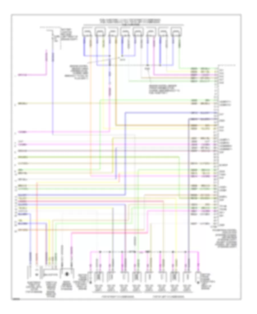
6.8L, Engine Performance Wiring Diagram (1 of 5) for Ford Cutaway E350 Super Duty 2009
List of elements for 6.8L, Engine Performance Wiring Diagram (1 of 5) for Ford Cutaway E350 Super Duty 2009:
- Accr
- Accs
- Air conditioning system
- Bps
- C1551e
- Camshaft position sensor (front of left cylinder head)
- Cd10d
- Cd1a
- Cd2e
- Cd3g
- Cd4i
- Cd5c
- Cd6b
- Cd7f
- Cd8h
- Cd9j
- Cdc10
- Cdc15
- Ce113
- Ce205
- Ce206
- Ce207
- Ce208
- Ce209
- Ce210
- Ce211
- Ce212
- Ce213
- Ce214
- Ce235
- Ce236
- Ce303
- Ce304
- Ce305
- Ce306
- Ce307
- Ce308
- Ce309
- Ce310
- Ce311
- Ce312
- Ce321
- Ce412
- Ce426
- Ces09
- Ch302
- Cht
- Ckp +
- Ckp -
- Cmp
- Coil on plugs (cop) (coil on plugs 1, 2, 3, 4 & 5: top of right cylinder bank) (coil on plugs 6, 7, 8, 9 & 10: top of left cylinder bank)
- Crankshaft position sensor (lower center front of engine)
- Cylinder head temperature sensor (front of left cylinder head)
- De135
- Electronic throttle control (etc) motor (top left side of engine)
- Etc ref
- Etc rtn
- Evapcp
- Genli
- Genrc
- Ho2s-11
- Ho2s-21
- Htr-11
- Htr-21
- Iat
- Ignition transformer capacitor 1 (front of left cylinder bank)
- Inj1
- Inj10
- Inj2
- Inj3
- Inj4
- Inj5
- Inj6
- Inj7
- Inj8
- Inj9
- Le134
- Maf
- Mafrtn
- Nca
- Pcvhc
- Powertrain control module (pcm) (stripped chassis: center rear of engine compt) (except stripped chassis: left rear of engine compt)
- Re134
- Re135
- Re320
- Re405
- S170
- S171 (engine control sensor wiring harness & fuel charge, in breakout to powertrain control module (pcm)
- S172 (engine control sensor wiring harness & fuel charge, in breakout to powertrain control module (pcm))
- S177
- Shield
- Sig rtn
- Solid state
- Starting/ charging system
- Tacm +
- Tacm -
- Throttle position sensor (top of engine, near air intake)
- Tp1-ns
- Tp2-ns
- Ve706
- Ve711
- Ve712
- Ve735
- Ve737
- Ve740
- Ve807
- Ve818
- Ve819
6.8L, Engine Performance Wiring Diagram (2 of 5) for Ford Cutaway E350 Super Duty 2009
List of elements for 6.8L, Engine Performance Wiring Diagram (2 of 5) for Ford Cutaway E350 Super Duty 2009:
- (cop) 10)
- (except stripped chassis: center of engine compt) (stripped chassis: top right side of engine) mass air flow/intake air temperature (maf/iat) sensor
- (top left rear of engine) evap canister purge valve
- (under left side of dash) stoplamp switch
- Battery junction box (bjb) (left front of engine compt)
- Fuel injectors (fuel injectors 1, 2, 3 ,4 & 5: top of right cylinder bank) (fuel injectors 6, 7, 8, 9 & 10: top of left cylinder bank)
- Fuse 10a
- G105 (stripped chassis: right side of engine compt) (except stripped chassis: left front of engine compt)
- Harness, near breakout to smart junction box (sjb)) (except stripped chassis: engine control sensor wiring harness, near breakout to c144)
- Heated oxygen sensor (ho2s) 11 (rear of right cylinder bank)
- Heated oxygen sensor (ho2s) 21 (rear of left cylinder bank)
- Heated positive crankcase ventilation (pcv) valve (top right side of engine)
- Hot at all times
- Nca
- S124
- S173 (engine control sensor wiring harness & fuel charge, near breakout to fuel injector 8)
- S174 (engine control sensor wiring harness & fuel charge, near breakout to coil on plug
6.8L, Engine Performance Wiring Diagram (3 of 5) for Ford Cutaway E350 Super Duty 2009
List of elements for 6.8L, Engine Performance Wiring Diagram (3 of 5) for Ford Cutaway E350 Super Duty 2009:
- (or ce239) ce233
- (or ve745)
- Bfp
- C1551t
- Ce234
- Cet05
- Cet06
- Cet07
- Cet08
- Cet09
- Cet25
- Cet50
- Cet51
- Control module (pcm) (stripped chassis: center rear of engine compt) (except stripped chassis: left rear of engine compt)
- Cpc
- Ho2s-12
- Ho2s-22
- Htr-12
- Htr-22
- Intermediate shaft speed sensor
- Iss
- Lca16
- Le111
- Lpc
- Oss
- Output shaft speed sensor (right rear of transmission)
- Pc1
- Pc2
- Pc3
- Pc4
- Pc5
- Powertrain tr gnd
- Rca16
- Re406
- Ret04
- Ret24
- S100 (transmission control selector neutral switch wiring harness, near breakout to torqshift transmission)
- S101 (transmission control selector neutral switch wiring harness, near breakout to c192)
- S102 (transmission control selector neutral switch wiring harness, near breakout to torqshift transmission)
- Sigrtn
- Speed sensor assembly (left side of transmission)
- Tft
- Torqshift transmission
- Tr-p
- Tspc
- Tss
- Turbine shaft speed sensor
- Ve731
- Ve733
- Ve744
- Vet27
- Vet32
- Vet33
- Vref
6.8L, Engine Performance Wiring Diagram (4 of 5) for Ford Cutaway E350 Super Duty 2009
List of elements for 6.8L, Engine Performance Wiring Diagram (4 of 5) for Ford Cutaway E350 Super Duty 2009:
- (left rear under- body of vehicle) g401
- (not used)
- (transmission control selector neutral switch wiring harness, near breakout to c192)
- (under dash) (stripped chassis) inertia fuel shut- off switch
- (under rear of vehicle, near fuel tank) fuel pump driver module
- (under rear of vehicle, near fuel tank) fuel pump module
- Battery junction box (bjb) (left front of engine compt)
- Brake pressure switch (left rear of engine compt)
- C110
- C310a
- Can +
- Can -
- Chassis
- Computer data lines system
- Cr167
- Ens
- Except stripped
- Except stripped chassis
- Fpc
- Fpm
- Fppwr
- Fprtn
- Fuel gauge sensor
- Fuel lvl +
- Fuel lvl -
- Fuel power motor diode
- Fuel pump
- Fuel pump relay
- Fuse 10a
- Fuse 20a
- G100 (except stripped chassis: right front of engine compt) (stripped chassis: right side of engine compt)
- Gnd
- Heated oxygen sensor (ho2s) 12 (on exhaust system, right of transmission)
- Heated oxygen sensor (ho2s) 22 (van/wagon) (on exhaust system, left of transmission)
- Hot at all times
- Hot in run or start
- Ifs in
- Instrument cluster (ic)
- Nca
- Overdrive cancel switch
- Restraints control module (under driver's seat)
- S103 (van/wagon)
- S104
- S130 (except stripped chassis: engine control sensor wiring harness, near breakout to brake fluid level switch) (stripped chassis: engine control sensor wiring harness, near breakout to anti-lock brake system (abs) module)
- S407
- Stripped chassis
- Stripped chassis/cutaway
- Van/wagon
6.8L, Engine Performance Wiring Diagram (5 of 5) for Ford Cutaway E350 Super Duty 2009
List of elements for 6.8L, Engine Performance Wiring Diagram (5 of 5) for Ford Cutaway E350 Super Duty 2009:
- (except stripped chassis: engine control sensor wiring harness, near breakout to c192) (stripped chassis: engine control sensor wiring harness, near breakout to brake fluid level switch)
- (not used)
- (stripped chassis: right side of engine compt) (except stripped chassis: left front of engine compt)
- A/c clutch relay
- Accelerator pedal position sensor (left side of dash, above accelerator pedal)
- App1
- App2
- App3
- Battery junction box (bjb) (left front of engine compt)
- Bpp
- C1551b
- Can +
- Can -
- Canv
- Cbb54
- Cbb75
- Ccb08
- Cdb08
- Cdc12
- Cdc35
- Ce114
- Ce302
- Ce326
- Ce336
- Ce912
- Ce913
- Ce914
- Ce924
- Cet21
- Cet22
- Cet34
- Cet41
- Computer data lines system
- Cruise control system
- Etcref
- Etcrtn
- Evaporative emission canister vent valve (near fuel tank)
- Except stripped chassis
- Exterior lights system
- Feps
- Fpc
- Fpm
- Ftp
- Fuel tank pressure sensor (fuel tank)
- Fuse 10a
- Fuse 15a
- Fuse 20a
- Fuse 40a
- G105
- G105 (stripped chassis: right side of engine compt) (except stripped chassis: left front of engine compt)
- Gd120
- Gnd
- Hot at all times
- Isp-r
- Kapwr
- Le136
- Le137
- Le230
- Od cncl
- Overhead console
- Pcm power relay
- Pcmrc
- Powertrain control module (pcm) (stripped chassis: center rear of engine compt) (except stripped chassis: left rear of engine compt)
- Pto
- Pto engage
- Ptoic 1
- Ptoic2
- Ptoil
- Re136
- Re137
- Re407
- Res08
- Reversing lamp relay
- Rlc
- Rtn
- S116
- S125
- S129
- S131
- S137
- S156
- Sbb46
- Sccs
- Sccs rtn
- Smc
- Smcs
- Smr
- Starting/ charging system
- Starting/charging system
- Stripped chassis
- Tro_n
- Tro_p
- Vdb04
- Vdb05
- Ve225
- Ve518
- Ve701
- Ve702
- Ve703
- Ve922
- Ves10
- Vmc05
- Vpwr
- Vref
- Vsout
EXTERIOR LIGHTS
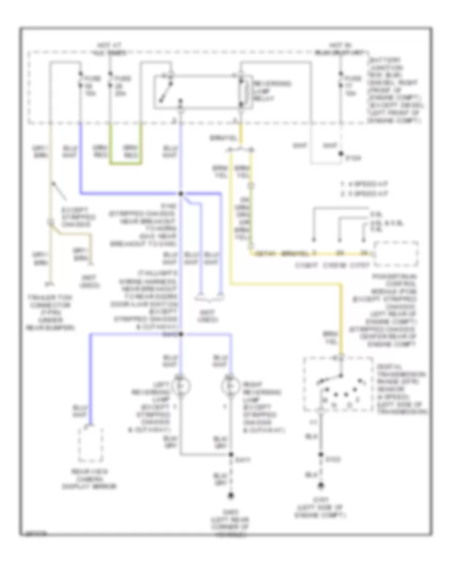
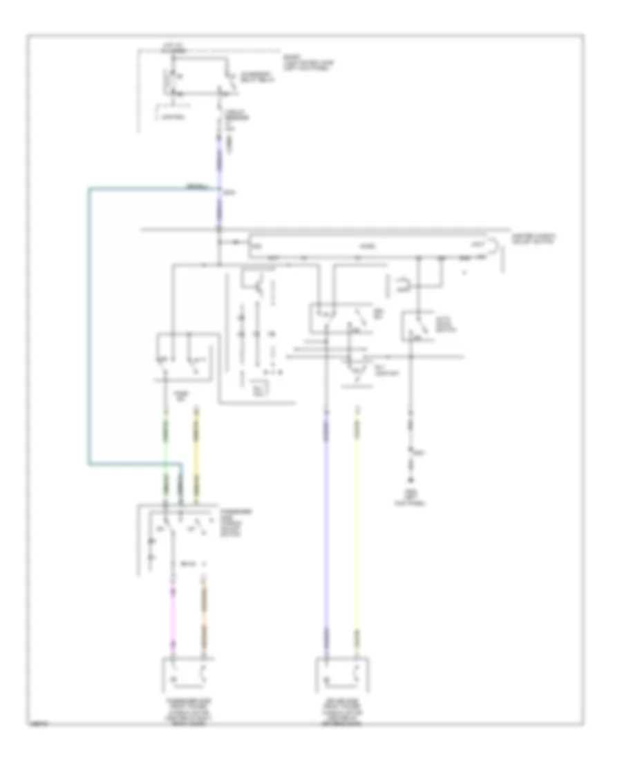
Backup Lamps Wiring Diagram for Ford Cutaway E350 Super Duty 2009
List of elements for Backup Lamps Wiring Diagram for Ford Cutaway E350 Super Duty 2009:
- (not used)
- (taillights
- 4 speed a/t
- 4.6l & 6.8l 5.4l
- 5 speed a/t
- 6.0l
- Battery junction box (bjb) (diesel: right front of engine compt) (except diesel: left front of engine compt)
- C1381t
- C1551b
- C175t
- Cet41
- Digital transmission range (dtr) sensor (4 speed) (left side of transmission)
- Except stripped chassis
- Fuse 10a
- Fuse 15a
- Fuse 20a
- G101 (left side of engine compt)
- G403 (left rear corner of vehicle)
- Hot at all times
- Hot in run or start
- Left reversing lamp (except stripped chassis & cutaway)
- Powertrain control module (pcm) (except stripped chassis: left rear of engine compt) (stripped chassis: center rear of engine compt
- Rear view camera display mirror
- Reversing lamp relay
- Right reversing lamp (except stripped chassis & cutaway)
- S123
- S124
- S142 (stripped chassis: near breakout to horn) (gas: near breakout to g105)
- S411
- Trailer tow connector (7-pin) (under rear bumper)
- Wiring harness, near breakout to rear doors door ajar switch) (except stripped chassis & cutaway) s412
Exterior Lamps Wiring Diagram, Cutaway (1 of 2) for Ford Cutaway E350 Super Duty 2009
List of elements for Exterior Lamps Wiring Diagram, Cutaway (1 of 2) for Ford Cutaway E350 Super Duty 2009:
- (not used)
- Brake pedal sw
- Breakout to c263) (gas: in breakout to c110) s120
- C202a
- C202b
- C2280b
- C2280d
- C2280e
- C2280f
- Control
- Ctrl
- Fuse 10a
- Fuse 15a
- Fuse 20a
- G107 (left front of engine compt)
- G108 (right front of engine compt)
- G202 (left side of dash)
- Hazard
- Head
- Headlamp switch
- Hot at all times
- Left front park/ turn lamp
- Left front side lamp
- Left turn
- Lf turn lamp (fet)
- Low beam
- Lr stop/ turn lamp (fet)
- Multi- function switch
- Off
- Park
- Park lamp relay
- Rf turn lamp (fet)
- Right front park/ turn lamp
- Right front side lamp
- Right turn
- Rr stop/ turn lamp (fet)
- S162
- S164 (near breakout to left frontal restraints sensor)
- S165
- S223
- Smart junction box (sjb) (left kick panel)
- Vbatt
Exterior Lamps Wiring Diagram, Cutaway (2 of 2) for Ford Cutaway E350 Super Duty 2009
List of elements for Exterior Lamps Wiring Diagram, Cutaway (2 of 2) for Ford Cutaway E350 Super Duty 2009:
- (not used)
- (under left side of dash) stoplamp switch
- 6.0l 6.8l 5.4l & 4.6l
- Battery junction box (bjb) (diesel: right front of engine compt) (gas: left front of engine compt)
- Bpp
- Bps
- C1381b
- C1551b
- C175b
- Cat06
- Cat09
- Cat17
- Ccb08
- Ces09
- Fuse 10a
- Fuse 20a
- G100 (right side of engine compt)
- G205 (left side of dash)
- G402 (rear of left frame rail)
- Hot at all times
- Hot in on or start
- Left turn/stop trailer tow relay
- Parking lamp trailer tow relay
- Powertrain control module (pcm) (left rear of engine compt)
- Rat08
- Red
- Resistor (left side of dash)
- Right turn/stop trailer tow relay
- S108
- S117 (gas: near breakout to c144) (diesel: near breakout to windshield wiper motor)
- S137 (gas)
- S214 (main wiring harness, near breakout to front cigar lighter)
- S250
- Trailer tow connector (4-pin) (if equipped) (under rear bumper)
Exterior Lamps Wiring Diagram, Except Cutaway & Stripped Chassis (1 of 2) for Ford Cutaway E350 Super Duty 2009
List of elements for Exterior Lamps Wiring Diagram, Except Cutaway & Stripped Chassis (1 of 2) for Ford Cutaway E350 Super Duty 2009:
- (diesel: near breakout to c263) (gas: in breakout to c110) s120
- (not used)
- C202a
- C202b
- C2280b
- C2280d
- C2280e
- C2280f
- Control
- Ctrl
- Fuse 10a
- Fuse 15a
- Fuse 20a
- G107 (left front of engine compt)
- G108 (right front of engine compt)
- G202 (left side of dash)
- G403 (left rear corner of vehicle)
- Hazard
- Head
- Headlamp switch
- Hot at all times
- Left front park/ turn lamp
- Left front side lamp
- Left rear park/ stop/ turn lamp
- Left turn
- Lf turn lamp (fet)
- License plate lamp
- Low beam
- Lr stop/ turn lamp (fet)
- Multi- function switch
- Off
- Park
- Park lamp relay
- Rf turn lamp (fet)
- Right front park/ turn lamp
- Right front side lamp
- Right rear park/ stop/ turn lamp
- Right turn
- Rr stop/ turn lamp (fet)
- S162
- S164 (near breakout to left frontal restraints sensor)
- S165
- S223
- S405
- S410 (taillights wiring harness, near breakout to high mounted stoplight)
- S411
- Smart junction box (sjb) (left kick panel)
- Vbatt
Exterior Lamps Wiring Diagram, Except Cutaway & Stripped Chassis (2 of 2) for Ford Cutaway E350 Super Duty 2009
List of elements for Exterior Lamps Wiring Diagram, Except Cutaway & Stripped Chassis (2 of 2) for Ford Cutaway E350 Super Duty 2009:
- (main wiring harness, near breakout to front cigar lighter) s214
- (not used)
- (under left side of dash) stoplamp switch
- 6.0l 6.8l 5.4l & 4.6l
- Battery charge trailer tow relay
- Battery junction box (bjb) (diesel: right front of engine compt) (gas: left front of engine compt)
- Bpp
- Bps
- Brake pedal sw
- C1381b
- C1551b
- C175b
- C2280b
- Can+
- Can-
- Cat03
- Cat06
- Cat09
- Cat14
- Cat17
- Cat19
- Cbp33
- Ccb08
- Ces09
- Class i
- Class ii
- Computer data lines system
- Ctsy
- Fuse 10a
- Fuse 15a
- Fuse 20a
- Fuse 30a
- G100 (right front of engine compt)
- G200 (right side of dash)
- G203 (left kick panel)
- G402 (rear of left frame rail)
- Gd116
- Gnd
- High mounted stoplamp
- Hot at all times
- Hot in on or start
- Hot in run
- Hot w/ reversing lamp relay engaged
- Interior lights system
- Left turn/stop trailer tow relay
- Modified vehicle
- Off
- Parking lamp trailer tow relay
- Powertrain control module (pcm) (left rear of engine compt)
- Pwr
- Rat08
- Red
- Right turn/stop trailer tow relay
- Run start
- S108
- S117 (gas: near breakout to c144) (diesel: near breakout to windshield wiper motor)
- S137 (gas)
- S218
- S240
- Sbb18
- Smart junction box (sjb) (left kick panel)
- Trailer brake
- Trailer brake control (tbc) module (top center of dash)
- Trailer tow connector (4-pin) (if equipped) (under rear bumper)
- Trailer tow connector (7-pin) (if equipped) (under rear bumper)
- Vdb04
- Vdb05
Exterior Lamps Wiring Diagram, Stripped Chassis for Ford Cutaway E350 Super Duty 2009
List of elements for Exterior Lamps Wiring Diagram, Stripped Chassis for Ford Cutaway E350 Super Duty 2009:
- (left side of dash) smart junction box (sjb)
- (main wiring harness, near breakout to g207) s242
- (not used)
- (under left side of dash) stoplamp switch
- 6.8l 5.4l & 4.6l
- Battery junction box (bjb) (left front of engine compt)
- Bpp
- Bps
- Brake pedal sw
- Brake shift interlock (steering column)
- C1551b
- C175b
- C202a
- C202b
- C2280b
- C2280c
- C2280d
- C2280e
- C2280f
- Cat06
- Cat09
- Cat17
- Ccb08
- Ces09
- Control
- Ctrl
- Fuse 10a
- Fuse 15a
- Fuse 20a
- G100 (right side of engine compt)
- G205 (left side of dash)
- G207 (center of dash)
- G402 (rear of left frame rail)
- Hazard
- Head
- Headlamp switch
- Hot at all times
- Hot in on or start
- Left turn/stop trailer tow relay
- Lf turn lamp (fet)
- Lh turn
- Lr stop/ turn lamp (fet)
- Lr turn lamp (fet)
- Multi-function switch
- Off
- Park
- Park lamp relay
- Parking lamp trailer tow relay
- Powertrain control module (pcm) (center rear of engine compt)
- Rat08
- Red
- Resistor (left side of dash)
- Rf turn lamp (fet)
- Rh turn
- Right turn/stop trailer tow relay
- Rr stop/ turn lamp (fet)
- Rr turn lamp (fet)
- S108
- S117 (near breakout to smart junction box (sjb))
- S120 (near breakout to smart junction box (sjb))
- S137
- S245 (main wiring harness, near breakout to g207)
- S250
- S260
- Trailer tow connector (4-pin) (if equipped) (under rear bumper)
- Vbatt
GROUND DISTRIBUTION
Ground Distribution Wiring Diagram (1 of 5) for Ford Cutaway E350 Super Duty 2009
List of elements for Ground Distribution Wiring Diagram (1 of 5) for Ford Cutaway E350 Super Duty 2009:
- (diesel: right front of engine compt) (gas: left front of engine compt) battery junction box (bjb)
- (diesel: right front of engine compt) (stripped chassis & gas: left front of engine compt) battery junction box (bjb)
- (except stripped chassis) windshield wiper motor
- (gas & 4 speed a/t) digital transmission range (dtr) sensor
- (gas & diesel) windshield washer pump motor
- (gas & stripped chassis) a/c compressor clutch field coil
- (gas) fuel pump relay
- (modified vehicle) run/start relay
- Auxiliary battery (auxiliary battery w/ aft axle tank)
- Auxiliary battery (auxiliary battery w/ midship tank)
- Battery
- Battery charge trailer tow relay
- Blower motor relay
- Blower motor resistor
- Body builder ground
- Brake fluid level switch
- Breakout to a/c cycling switch) (diesel: engine control sensor wiring harness, near breakout to manifold absolute pressure (map) sensor)
- Diesel
- G100 (gas & diesel) (right front of engine compt)
- G101 (gas & diesel: left side of engine compt) (stripped chassis: left front corner of engine compt)
- G109 (4.6l & 5.4l) (gas: right front of engine compt) (stripped chassis: right front corner of engine compt)
- G109 (6.8l) (gas: right front of engine compt) (stripped chassis: right front corner of engine compt)
- G111 (right side of engine compt)
- G117 (right side of engine compt)
- G118 (lower right front of engine compt)
- G119 (lower right front of engine)
- G120 (4.6l & 5.4l) (right rear of engine)
- G120 (6.8l) (right rear of engine)
- G300 (right underbody of vehicle)
- G301 (diesel) (near secondary battery)
- G400 (right rear underbody of vehicle)
- Gas & stripped chassis
- Harness, near breakout to c140) (stripped chassis: engine control sensor wiring harness, near breakout to horn)
- Horn
- Left turn/stop trailer tow relay
- Parking lamp trailer tow relay
- Primary battery
- Right turn/stop trailer tow relay
- Run/ start relay
- Secondary battery
- Stripped chassis
- Upfitter relay 1
- Upfitter relay 2
- Upfitter relay 3
- Windshield wiper relay
Ground Distribution Wiring Diagram (2 of 5) for Ford Cutaway E350 Super Duty 2009
List of elements for Ground Distribution Wiring Diagram (2 of 5) for Ford Cutaway E350 Super Duty 2009:
- (not used)
- 4-pin trailer tow connector
- 7-pin trailer tow connector
- Abs test connector
- Anti-lock brake system (abs) module
- Brake fluid level switch
- Brake shift interlock
- C202a
- C202b
- C202c
- C218b
- C3358
- Clock- spring
- Customer access
- Cutaway
- Data link connector (dlc)
- G102 (gas & diesel: left side of engine compt) (stripped chassis: left rear of engine compt)
- G103 (left side of engine compt)
- G202 (except stripped chassis) (left side of dash)
- G207 (stripped chassis) (center of dash)
- G208 (left kick panel)
- G402 (rear of left frame rail)
- Headlamp switch
- Instrument panel cluster (ipc)
- Left steering wheel switch
- Multi-function switch
- Nca
- Parking aid module (pam)
- Passive anti-theft transceiver
- Right steering wheel switch
- S223 (main wiring harness, near breakout to c210)
- S260 (main wiring harness, near breakout to g207)
- S263 (main wiring harness, near breakout to c219)
- W/ advance trac
- W/o advance trac
Ground Distribution Wiring Diagram (3 of 5) for Ford Cutaway E350 Super Duty 2009
List of elements for Ground Distribution Wiring Diagram (3 of 5) for Ford Cutaway E350 Super Duty 2009:
- (except cutaway) overhead console
- (left kick panel) smart junction box (sjb)
- 6.8l
- Auxiliary cargo lamp
- C1381b
- C1551b
- C175b
- C2280d
- Cargo lamp
- Cutaway
- Driver safety belt buckle pretensioner
- Driver side door lock switch
- Driver side front seat adjust switch
- Driver side front seat control switch
- Dual function pressure switch
- Except 6.8l
- Except cutaway
- Exterior rear view mirror switch
- Front interior/ map lamps assembly
- G105 (diesel) (left side of engine compt)
- G105 (gas) (left front of engine compt)
- G203 (except stripped chassis) (left kick panel)
- High mounted stoplamp
- Left front door ajar
- Mass air flow/intake air temperature (maf/iat) sensor
- Master window adjust switch
- Nca
- Parking brake switch
- Powertrain control module (pcm)
- Rear power point
- Rear view camera display mirror
- Resistor
- S239 (taillights wiring harness, near breakout to c263)
- S240 (taillights wiring harness, near breakout to g203)
- S317 (taillights wiring harness, near breakout to g203)
- S501 (left front door window regulator wiring harness, near breakout to driver side front power window motor)
- S901 (interior illumination wiring harness, in breakout to c315)
- Second row cargo lamp
- Second row interior lamp
- Third row cargo lamp
- Third row interior lamp
- To a/c cycling switch)
- Wiring harness, near breakout to c192)
Ground Distribution Wiring Diagram (4 of 5) for Ford Cutaway E350 Super Duty 2009
List of elements for Ground Distribution Wiring Diagram (4 of 5) for Ford Cutaway E350 Super Duty 2009:
- (diesel: engine control sensor wiring harness, near breakout to g108)
- Auxiliary blower motor relay
- Auxiliary blower motor speed relay
- Breakout to c405)
- Fuel heater
- Fuel pump
- Fuel pump driver module
- G108 (except stripped chassis) (right front of engine compt)
- G110 (diesel) (lower left rear of engine)
- G401 (diesel) (left rear underbody of vehicle)
- G401 (gasoline) (left rear underbody of vehicle)
- G403 (except stripped chassis) (left rear corner of vehicle)
- Left rear park/stop/ turn lamp
- Left reversing lamp
- License plate lamp
- Mounted stoplight)
- Nca
- Near breakout to g108)
- Rear doors ajar switch
- Rear doors lock switch
- Rear view camera
- Right front park/turn lamp
- Right front side lamp
- Right headlamp
- Right rear park/stop/ turn lamp
- Right reversing lamp
- S1062 (engine control sensor wiring harness & fuel charge,
- S401 (a/c blower motor wiring harness, in
- S405 (rear license plate lamp wiring harness, near breakout
- S411 (taillights wiring harness, near breakout to high
- Shield
- To right rear speaker)
- W/ aero headlamps
- W/o aero headlamps
Ground Distribution Wiring Diagram (5 of 5) for Ford Cutaway E350 Super Duty 2009
List of elements for Ground Distribution Wiring Diagram (5 of 5) for Ford Cutaway E350 Super Duty 2009:
- (left side of dash) smart junction box (sjb)
- (w/ aero headlamps)
- (w/ hinged side door) right side door ajar switch
- (w/ navigation) audio amplifier
- (w/ navigation) audio control module (acm)
- (w/ sliding door) right sliding door ajar switch
- (w/o aero headlamps)
- (w/o navigation) audio control module (acm)
- A/c compressor clutch field coil
- Base audio
- C1388c
- C2280d
- C2385b
- C240a
- C294b
- C294c
- C294e
- Climate control assembly
- Data link connector (dlc)
- Front cigar lighter
- Fuel injector control module (ficm)
- G106 (diesel) (right front of engine compt)
- G107 (except stripped chassis) (left front of engine compt)
- G200 (except stripped chassis) (right side of dash)
- G201 (except stripped chassis) (center of dash)
- G205 (stripped chassis) (left side of dash)
- Horn
- Instrument panel power point 1
- Instrument panel power point 2
- Left front park/turn lamp
- Left front side lamp
- Left headlamp
- Parking brake switch
- Passenger air bag deactivation (pad) switch
- Passenger slide door lock switch
- Resistor
- Right front door ajar switch
- S216 (main wiring harness, near breakout to front cigar lighter)
- S218 (main wiring harness, near breakout to g200)
- S250 (main wiring harness, near breakout to g207)
- S264 (main wiring harness, near breakout to audio control module (acm))
- S265 (main wiring harness, near breakout to audio control module (acm))
- Temperature blend door actuator
- Traction control switch
- Trailer brake control (tbc) module
- Upfitter switch
HEADLIGHTS
Headlights Wiring Diagram for Ford Cutaway E350 Super Duty 2009
List of elements for Headlights Wiring Diagram for Ford Cutaway E350 Super Duty 2009:
- (dash panel to headlamp junction wiring harness, near breakout to left frontal restraints sensor) s163
- (except (stripped chassis) s223
- (not used)
- C202b
- C2280b
- C2280e
- Can +
- Can -
- Computer data lines system
- Control
- Except stripped chassis
- Ftp
- Fuse 10a
- Fuse 15a
- G107 (left front of engine compt)
- G108 (right front of engine compt)
- G202 (except stripped chassis) (left side of dash)
- G207 (stripped chassis) (center of dash)
- Head
- Headlamp off
- Headlamp switch
- High
- High beam
- High beam relay
- Hot at all times
- Instrument panel cluster (ipc)
- Interior lights system
- Left headlamp
- Left low beam (fet)
- Low
- Ms can +
- Ms can -
- Multi-function switch
- Off
- On headlamp
- On parklamp
- Park
- Pass flash to
- Right headlamp
- Right low beam (fet)
- S162
- S165
- S260 (stripped chassis)
- Smart junction box (sjb) (except stripped chassis: left kick panel) (stripped chassis: left side of dash)
- Stripped chassis
- W/ aero headlamps
- W/o aero headlamps
HORN
Horn Wiring Diagram, with Stripped Chassis for Ford Cutaway E350 Super Duty 2009
List of elements for Horn Wiring Diagram, with Stripped Chassis for Ford Cutaway E350 Super Duty 2009:
- 20a
- Battery junction box (bjb) (left front of engine compt)
- C218b
- Clockspring (steering wheel)
- Fuse 34
- G101 (left front corner of engine compt)
- G207 (center of dash)
- Horn (right front of engine compt)
- Horn relay
- Horn switch
- Hot at all times
- Left steering wheel switch
- Nca
- S123
- S260
Horn Wiring Diagram, without Stripped Chassis for Ford Cutaway E350 Super Duty 2009
List of elements for Horn Wiring Diagram, without Stripped Chassis for Ford Cutaway E350 Super Duty 2009:
- 20a
- C218b
- C2280b
- C2280e
- Clockspring (steering wheel)
- Control
- Fuse 24
- G107 (left front of engine compt)
- G202 (left side of dash)
- Horn (right front of engine compt)
- Horn relay
- Horn switch
- Hot at all times
- Left steering wheel switch
- Nca
- S162
- S223
- Smart junction box (sjb) (left kick panel)
INSTRUMENT CLUSTER
Instrument Cluster Wiring Diagram for Ford Cutaway E350 Super Duty 2009
List of elements for Instrument Cluster Wiring Diagram for Ford Cutaway E350 Super Duty 2009:
- (except stripped chassis) s108 (stripped chassis)
- (except stripped chassis) s260 (stripped chassis)
- (front of right side front hinged door) right side door ajar switch
- (left kick panel) (except stripped chassis) g203
- (left kick panel) g203
- (left side of dash) (except stripped chassis) g205
- (or cbb80)
- (or sbb31)
- (stripped chassis) s260 s223 (except stripped chassis)
- 6.0l
- Anti-theft system
- Battery junction box (bjb) (left front of engine compt)
- Brake fluid level switch (left rear of engine compt)
- Brake shift interlock (steering column)
- Brk fluid sw rtn
- C1381b
- C218b
- C2280a
- C2280b
- C2280c
- C2280f
- Can +
- Can -
- Can+
- Can-
- Cbp29
- Cca15
- Cdc09
- Cet52
- Cmc24
- Cmc25
- Computer data lines system
- Except 6.0l
- Except stripped chassis
- Fluid sw brake
- Fuel level sensor (fuel tank)
- Fuel pump module (under rear of vehicle, near fuel tank)
- Fuse 10a
- Fuse 5a
- G100 (stripped chassis) (right side of engine compt)
- G201 (center of dash)
- G201 (stripped chassis) (center of dash)
- G202 (except stripped chassis) (left side of dash)
- G205 (stripped chassis) (left side of dash)
- G207 (stripped chassis) (center of dash)
- G403 (left rear corner of vehicle)
- Gd114
- Hot at all times
- Hot in start or run
- Ilc
- Instrument panel cluster (ipc)
- Key in ign
- Key in ignition switch
- Left front door ajar switch (left kick panel)
- Lf door ajar
- Micro
- Ms can +
- Ms can -
- Nca
- Oil pressure switch (6.0l: top center of engine) (except 6.0l: lower left front of engine)
- Oil sw
- Park brake sw
- Park sw
- Parking brake switch (near left kick panel)
- Powertrain control module (pcm) (left rear of engine compt)
- Prk brake
- Pwr gnd
- Re407
- Rear door ajar
- Rear doors door ajar switch
- Rf door ajar
- Right front door ajar switch (right kick panel)
- Right sliding door ajar switch (right "b" pillar)
- Rmc32
- Rr door ajar
- Run/start
- S156 (engine control sensor wiring harness, near breakout to brake fluid level switch)
- S239
- S239 (except stripped chassis) s250 (stripped chassis)
- S264
- S264 (except stripped chassis) s250 (stripped chassis)
- S411
- Sbp26
- Sender 1
- Sender rtn
- Sig rtn coil
- Smart junction box (sjb) (stripped chassis: left side of dash) (except stripped chassis: left kick panel)
- Starting/ charging system
- Stripped chassis
- Tc on/off
- Traction control switch
- Vbatt
- Vdb04
- Vdb05
- Vdb06
- Vdb07
- Ve823
- Vmc11
- Vrt23
- Vrt24
- W/ hinged side door
- W/ sliding side door
- Water in fuel sensor (left frame rail)
- Wif
Overhead Console Wiring Diagram for Ford Cutaway E350 Super Duty 2009
List of elements for Overhead Console Wiring Diagram for Ford Cutaway E350 Super Duty 2009:
- (not used)
- (stripped chassis: main wiring harness, near breakout to g205) s219 (except stripped chassis: main wiring harness, near breakout to g201)
- 4.6l & 5.4l
- 6.0l
- 6.8l
- Ambient air temperature sensor (left front of engine compt)
- Back lighting led (fet)
- C1381b
- C1551b
- C175b
- C2280b
- C2280d
- Control
- Except stripped chassis
- Fuse 10a
- Fuse 15a
- G203 (left kick panel)
- Gnd
- Hot at all times
- Hot in run or acc
- Illum
- Interior lights system
- Nca
- Overhead console
- Powertrain control module (pcm) (except stripped chassis: left rear of engine compt) (stripped chassis: center rear of engine compt)
- S239
- Sig rtn
- Smart junction box (sjb) (stripped chassis: left side of dash) (except stripped chassis: left kick panel)
- Stripped chassis
- Vpwr
- Vref
- Vsout
INTERIOR LIGHTS
Courtesy Lamps Wiring Diagram for Ford Cutaway E350 Super Duty 2009
List of elements for Courtesy Lamps Wiring Diagram for Ford Cutaway E350 Super Duty 2009:
- (interior illumination wiring harness, near breakout to c315) s900
- (interior lights wiring harness, near breakout to second row interior lamp) s904
- (main wiring harness, near breakout to headlight switch) s230
- (not used)
- (taillights wiring harness, near breakout to second row cargo lamp) s312
- Auxiliary cargo lamp (except cutaway & full headliner)
- Battery saver relay
- C2280a
- C2280b
- C2280c
- C2280d
- Cargo lamp (w/ full headliner)
- Ctsy
- Customer access (cutaway) (left "b" pillar)
- Dim sw gnd
- Dimmer sw
- Dome lp
- Except stripped chassis
- Exterior lights system
- Front interior/map lamps assembly
- Fuse 10a
- Fuse 15a
- G201 (center of dash)
- G203 (left kick panel)
- G403 (left rear corner of vehicle)
- High mounted stop lamp
- Hot at all times
- Illumination dimmer
- Interior lighting (fet)
- Left front door ajar switch (left kick panel)
- Left vanity mirror lamp (if equipped)
- Lf dr ajar
- Micro
- Off
- Rear door ajar
- Rear doors door ajar switch (right rear door)
- Rf dr ajar
- Right front door ajar switch (right kick panel)
- Right side door ajar switch (front of right side front hinged door)
- Right sliding door ajar switch (right "b" pillar)
- Right vanity mirror lamp (if equipped)
- Rr door ajar
- S239
- S240
- S264
- S304 (taillights wiring harness, near breakout to c3135)
- S411
- S901
- S902
- S903 (interior lights wiring harness, near breakout to second row interior lamp)
- Second row cargo lamp (except cutaway & full headliner)
- Second row interior lamp (w/ full headliner)
- Smart junction box (sjb) (except stripped chassis: left kick panel) (stripped chassis: left side of dash)
- Stripped chassis
- Third row cargo lamp (except cutaway & full headliner)
- Third row interior lamp (w/ full headliner)
- W/ hinged side door
- W/ sliding side door
Instrument Illumination Wiring Diagram for Ford Cutaway E350 Super Duty 2009
List of elements for Instrument Illumination Wiring Diagram for Ford Cutaway E350 Super Duty 2009:
- (center of dash)
- (except stripped chassis: main wiring harness, breakout near to g201) (stripped chassis: main wiring harness, breakout near to g205) s219
- (left side of dash) (except stripped chassis) g202
- (main wiring harness, near breakout to headlight switch) s230
- (not used)
- Audio control assembly (w/o navigation)
- Backlighting led (fet)
- C218b
- C2280b
- C240a
- C294e
- Climate control assembly
- Clockspring (steering wheel)
- Dim sw gnd
- Dimmer sw
- Dome lp
- Fuse 15a
- G201 (center of dash)
- G202 (left side of dash)
- G203 (left kick panel)
- G207 (stripped chassis)
- Gnd
- Hdlp off
- Hdlp on
- Head
- Headlamp switch
- Hot at all times
- Illum
- Illumination dimmer
- Left steering wheel switch
- Micro
- Nca
- Off
- Overhead console
- Park
- Park lamp on
- Right steering wheel switch
- S223
- S223 (except stripped chassis) s260 (stripped chassis)
- S239
- S264
- Smart junction box (sjb) (except stripped chassis: left kick panel) (stripped chassis: left side of dash)
- Traction control switch
- Upfitter switch
- White led (fet)
NAVIGATION
Navigation Wiring Diagram for Ford Cutaway E350 Super Duty 2009
List of elements for Navigation Wiring Diagram for Ford Cutaway E350 Super Duty 2009:
- (main wiring harness, in breakout to audio input jack) s241
- (main wiring harness, near breakout to g200) s207
- (main wiring harness, near breakout to g200) s208
- (or rme12)
- (taillights wiring harness, near breakout to c3135) s309
- (taillights wiring harness, near breakout to c3135) s310
- (taillights wiring harness, near breakout to c3135) s311
- Ant
- Antenna
- Audio amplifier
- Audio control module (acm)
- Audio input jack
- Batt+
- C2280a
- C2280b
- C2385a
- C2385b
- C240a
- C240b
- C240c
- C3235
- C807
- Cbp28
- Clip detect
- Cme27
- Coax cable
- Computer data lines system
- Customer access (left "b" pillar)
- Cutaway
- Dme17
- Dme43
- Dme45
- Except cutaway
- Fuse 20a
- Fuse 5a
- G201 (except stripped chassis) (center of dash)
- Gd115
- Hot at all times
- Hot in start
- Illum
- Interior lights system
- Left front speaker
- Left middle speaker
- Left rear speaker
- Lf spkr+
- Lf spkr-
- Lr spkr+
- Lr spkr-
- Ms can+
- Ms can-
- Navigation system
- Nca
- Pwr gnd
- Rf in
- Rf spkr+
- Rf spkr-
- Right front speaker
- Right middle speaker
- Right rear speaker
- Right sliding door contact switch (sliding side door) (right side of sliding side door)
- Rme07
- Rme09
- Rme10
- Rme12
- Rme17
- Rme18
- Rme19
- Rme45
- Rme46
- Rme60
- Rme61
- Rr spkr+
- Rr spkr-
- S209 (main wiring harness,near breakout to g200)
- S216
- S216 (w/ navigation)
- Satellite radio/ gps antenna
- Sbp39
- Sbp40
- Shield
- Smart junction box (sjb) (stripped chassis: left side of dash) (except stripped chassis: left kick panel)
- St input 2l+
- St input 2l-
- St input 2r+
- St input 2r-
- Start
- Vdb06
- Vdb07
- Video+
- Video-
- Vln04
- Vme07
- Vme09
- Vme10
- Vme12
- Vme17
- Vme18
- Vme19
- Vme43
- Vme45
- Vme46
- Vme60
- Vme61
Parking Assistant Wiring Diagram for Ford Cutaway E350 Super Duty 2009
List of elements for Parking Assistant Wiring Diagram for Ford Cutaway E350 Super Duty 2009:
- (taillight jumper wiring harness, near breakout to c410) s402
- (taillight jumper wiring harness, near breakout to c410) s408
- (under left side of dash) parking aid speaker
- C2280b
- Cbp35
- Cmp09
- Computer data lines system
- Fuse 10a
- G202 (except stripped chassis) (left side of dash)
- Gd114
- Gnd
- Hot in start or run
- Inner left parking aid sensor (left side of rear bumper)
- Inner right parking aid sensor (right side of rear bumper)
- Lmp07
- Ms can+
- Ms can-
- Outer left parking aid sensor (left side of rear bumper)
- Outer right parking aid sensor (right side of rear bumper)
- Parking aid module (pam) (under left side of dash)
- Rear sounder +
- Rear sounder -
- Ril sensor in
- Rir sensor in
- Rmp07
- Rmp09
- Rol sensor in
- Ror sensor in
- S263
- Sensor gnd
- Sensor pwr
- Smart junction box (sjb) (stripped chassis: left side of dash) (except stripped chassis: left kick panel)
- Solid state
- Vdb06
- Vdb07
- Vmp14
- Vmp15
- Vmp16
- Vmp17
- Vpwr
Rear Camera Wiring Diagram, Customer Access for Ford Cutaway E350 Super Duty 2009
List of elements for Rear Camera Wiring Diagram, Customer Access for Ford Cutaway E350 Super Duty 2009:
- (not
- (rear license plate lamp wiring harness, in breakout to rear view camera) s404
- (taillights wiring harness, near breakout to c3135) s314
- Audio control module (acm)
- C2280d
- C240c
- Cbp35
- Cbp41
- Cls28
- Customer access connector (left "b" pillar)
- Dme19
- Exterior lights system
- Fuse 15a
- G203 (left kick panel)
- Gd133
- Gd149
- Gnd
- Hot w/ accessory delay relay energized
- Nca
- Rear view camera (center of right rear door)
- Rear view camera display mirror (cutway w/ navigation & rear camera display mirror)
- Reverse
- Rme19
- S236
- S315 (taillights wiring harness, near breakout to c3135)
- S316 (taillights wiring harness, near breakout to c3135)
- S901
- Smart junction box (sjb) (stripped chassis: left side of dash) (except stripped chassis: left kick panel)
- Used)
- Video +
- Video -
- Video shld
- Vme19
- Vpwr
Rear Camera Wiring Diagram, Except Customer Access for Ford Cutaway E350 Super Duty 2009
List of elements for Rear Camera Wiring Diagram, Except Customer Access for Ford Cutaway E350 Super Duty 2009:
- (left rear corner of vehicle) (except stripped chassis) g403
- (taillights wiring harness, near breakout to c3135) s314
- Audio control module (acm)
- C2280d
- C240c
- Cbp35
- Cbp41
- Cls28
- Dme19
- Exterior lights system
- Fuse 10a
- Fuse 15a
- G203 (left kick panel)
- Gd133
- Gd149
- Gnd
- Hot in start or run
- Hot w/ accessory delay relay energized
- Nca
- Rear view camera (center of right rear door)
- Rear view camera display mirror
- Reverse
- Rme19
- S236
- S315 (taillights wiring harness, near breakout to c3135)
- S316 (taillights wiring harness, near breakout to c3135)
- S404 (rear license plate lamp wiring harness, in breakout to rear view camera)
- S414 (rear license plate lamp wiring harness, in breakout to rear view camera)
- S415 (rear license plate lamp wiring harness, in breakout to rear view camera)
- S901
- Smart junction box (sjb) (stripped chassis: left side of dash) (except stripped chassis: left kick panel)
- Video +
- Video -
- Video shld
- Vme19
- Vpwr
- W/ navigation
- W/o navigation
POWER DISTRIBUTION
Power Distribution Wiring Diagram (1 of 9) for Ford Cutaway E350 Super Duty 2009
List of elements for Power Distribution Wiring Diagram (1 of 9) for Ford Cutaway E350 Super Duty 2009:
- (alternator rectifier system wiring harness, in breakout to remote jump start terminal) red
- (engine control red
- (engine control sensor wiring harness & fuel charge, in breakout to starter motor) s1052
- (engine control sensor wiring harness & fuel charge, in breakout to starter motor) s1072
- (engine control sensor wiring harness, near breakout to battery junction box (bjb) s153
- (right side of engine compt) remote jump start terminal
- Battery
- Battery junction box (bjb) (left front of engine compt)
- Battery junction box (bjb) (right front of engine compt)
- C102a
- C102b
- C1035a
- C1035b
- C1035c
- C1104a
- C1104c
- C1251b
- C1273a
- C1273b
- C1577a
- C1577b
- Charge, in breakout to starter motor)
- Diesel
- Except diesel
- Except stripped chassis
- Generator
- Glow plug control module (gpcm)
- Primary battery
- Red
- S1051 (engine control sensor wiring harness & fuel charge, in breakout to starter motor)
- S1054 (engine control sensor wiring harness & fuel charge, in breakout to starter motor)
- S1055 (engine control sensor wiring harness & fuel charge, in breakout to starter motor)
- S1056 (engine control sensor wiring harness & fuel charge, in breakout to starter motor)
- S107 (engine control sensor wiring harness, in breakout to battery)
- S1071 (engine control sensor wiring harness & fuel red
- S113
- S114 (engine control sensor wiring harness, near breakout to battery junction box (bjb)
- S152 (engine control sensor wiring harness, near breakout to battery junction box (bjb))
- S166
- S167 (alternator rectifier system wiring harness, in breakout to remote jump start terminal)
- Secondary battery
- Secondary generator
- Sensor wiring harness, in breakout to battery) s106
- Starter motor
- Stripped chassis
- To fuse 15 (diagram 2 of 9)
- To smart junction box (sjb) (diagram 3 of 9)
- W/ 125a generator
- W/ 150a or 215a generator
Power Distribution Wiring Diagram (2 of 9) for Ford Cutaway E350 Super Duty 2009
List of elements for Power Distribution Wiring Diagram (2 of 9) for Ford Cutaway E350 Super Duty 2009:
- (diesel: near breakout to c1019) (gas: near breakout to windshield wiper motor) (stripped chassis: near breakout to anti-lock brake system (abs) module) s136
- (not used)
- 6.8l
- A/c clutch relay
- Abs test connector (w/ advance trac)
- Anti-lock brake system (abs) module
- Auxiliary blower motor relay
- Battery junction box (bjb) (diesel: right front of engine compt) (except diesel: left front of engine compt)
- Blower motor relay
- C1251a
- C1381b
- C1551b
- C175b
- Customer access
- Cutaway
- Diesel
- Evaporative emission (evap) canister vent valve
- Except 6.8l
- Except cutaway
- Except stripped chassis
- From a battery junction box (bjb) (diagram 1 of 9)
- From c fuse 41 (diagram 2 of 9)
- Fuel injector control module (ficm) power relay (diesel)
- Fuel pump relay
- Fuse 10a
- Fuse 20a
- Fuse 30a
- Fuse 40a
- Fuse 50a
- G100 (diesel: right front of engine compt (except diesel: right side of engine compt)
- Gasoline
- Horn relay (stripped chassis)
- Instrument panel cluster (ipc) (stripped chassis)
- Left turn/stop trailer tow relay
- Powertrain control module (pcm)
- Red
- Reversing lamp relay
- Right turn/stop trailer tow relay
- Run/start relay
- S108
- S129 (engine control sensor wiring harness, near breakout to brake fluid level switch)
- Secondary generator (diesel)
- Stripped chassis
- To fuse 29 (diagram 6 of 9)
- To fuse 31 (diagram 2 of 9)
- To fuse 33 (diagram 3 of 9)
- To fuse 52 (diagram 6 of 9)
- To fuse 55 (diagram 7 of 9)
- To fuse 80 (diagram 7 of 9)
- To ignition switch (diagram 4 of 9)
- To pcm power relay (diagram 8 of 9)
- To run/start relay (modified vehicle) (diagram 6 of 9)
- To upfitter relay 3 (diagram 9 of 9)
- Windshield wiper relay
Power Distribution Wiring Diagram (3 of 9) for Ford Cutaway E350 Super Duty 2009
List of elements for Power Distribution Wiring Diagram (3 of 9) for Ford Cutaway E350 Super Duty 2009:
- (not used)
- 3rd row seat enable (fet)
- Anti-lock brake system (abs) module
- Back lighting led (fet)
- Battery junction box (bjb) (diesel: right front of engine compt) (except diesel: left front of engine compt)
- Bsi (fet)
- C2280a
- C2280b
- C2280d
- C2280g
- Customer access
- Cutaway
- Cutaway & stripped chassis
- Except cutaway
- Except cutaway & stripped chassis
- Except stripped chassis
- Exterior rear view mirror switch
- Floor lamp (fet)
- From d fuse 16 (diagram 2 of 9)
- From smart f junction box (sjb) (diagram 3 of 9)
- From smart g junction box (sjb) (diagram 3 of 9)
- From splice s114 & s153 (diagram 1 of 9)
- Front cigar lighter
- Fuse 10a
- Fuse 15a
- Fuse 20a
- Fuse 30a
- Fuse 40a
- Fuse 50a
- Fuse 5a
- Fuse 7.5a
- G200 (right side of dash)
- G203 (left kick panel)
- Instrument panel power point 1
- Instrument panel power point 2
- Interior lighting (fet)
- Keypad illmu (fet)
- Left low beam (fet)
- Lf turn lamp (fet)
- Lr stop/ turn lamp (fet)
- Lr turn lamp (fet)
- Not used
- Puddle lamp (fet)
- Rear power point
- Red
- Rf turn lamp (fet)
- Right low beam (fet)
- Rr stop/ turn lamp (fet)
- Rr turn lamp (fet)
- S218
- S240
- Smart junction box (sjb) (stripped chassis: left side of dash) (except stripped chassis: left kick panel)
- Stop lamp switch
- To auxiliary battery relay (diagram 7 of 9)
- To fuse 42 (diagram 4 of 9)
- To smart junction box (sjb) (diagram 3 of 9)
- To smart junction box (sjb) (diagram 5 of 9)
- Tpms (fet)
- Trailer brake control (tbc) module
- Vbatt
- W/ advance trac
- W/o advance trac
- White light (fet)
Power Distribution Wiring Diagram (4 of 9) for Ford Cutaway E350 Super Duty 2009
List of elements for Power Distribution Wiring Diagram (4 of 9) for Ford Cutaway E350 Super Duty 2009:
- (diesel: engine control sensor wiring harness, near breakout to manifold absolute pressure (map) sensor) (gas: engine control sensor wiring harness, near breakout to windshield wiper motor) s143
- (main wiring harness, near breakout to g202) (except stripped chassis) s227
- (main wiring harness, near breakout to ignition switch) (stripped chassis) s244
- (not used)
- Acc
- Auxiliary battery diode
- Battery charge trailer tow relay
- Battery junction box (bjb) (diesel: right front of engine compt) (except diesel: left front of engine compt)
- C2280a
- C2280b
- C2280d
- C2280e
- Data link connector (dlc)
- Driver side front seat control switch
- Except cutaway & stripped chassis
- Except stripped chassis
- From e fuse 65 (diagram 3 of 9)
- From run/start relay (diagram 2 of 9)
- Fuse 10a
- Fuse 15a
- Fuse 20a
- Fuse 30a
- Fuse 50a
- Fuse 5a
- Ignition switch
- Lock
- Nca
- Not used
- Off
- Overhead console
- Run
- Run/ acc ign sw
- Run/start ign sw
- Smart junction box (sjb) (stripped chassis: left side of dash) (except stripped chassis: left kick panel)
- Start
- Starter relay
- Stripped chassis
- To auxiliary battery relay (diagram 7 of 9)
- To fuse 27 (diagram 6 of 9)
- To splice 132 (diagram 5 of 9)
- To upfitter switch (diagram 9 of 9)
- Windshield wiper motor
- Windshield wiper relay
Power Distribution Wiring Diagram (5 of 9) for Ford Cutaway E350 Super Duty 2009
List of elements for Power Distribution Wiring Diagram (5 of 9) for Ford Cutaway E350 Super Duty 2009:
- (engine control sensor wiring harness, near breakout to anti-lock brake system (abs) module) s139
- (engine control sensor wiring harness, near breakout to windshield wiper motor) s139
- (not used)
- 6.8l
- Audio control module (acm) (except stripped chassis)
- Battery junction box (bjb) (diesel: right front of engine compt) (except diesel: left front of engine compt)
- C1551b
- C175b
- C2280a
- C2280b
- C2280d
- C2280e
- C240a
- Data link connector (dlc)
- Diesel
- Digital transmission range (dtr) sensor (4 speed a/t)
- Door lock relay
- Driver door unlock relay
- Except 6.8l
- Except stripped chassis
- Fog lamp relay
- From h fuse 14 (diagram 3 of 9)
- From ignition switch l (diagram 4 of 9)
- Fuse 15a
- Fuse 20a
- Fuse 25a
- Fuse 5a
- Gasoline
- Lh corner lamp (fet)
- Liftgate glass release relay
- Liftgate rel (fet)
- Park lamp relay
- Powertrain control module (pcm)
- Pulse train (fet)
- Rh corner lamp (fet)
- S132 (engine control sensor wiring harness, near breakout to brake fluid level switch)
- Smart junction box (sjb) (stripped chassis: left side of dash) (except stripped chassis: left kick panel)
- Start diode
- Start ign sw
- Starter relay
- Stripped chassis
- To smart junction box (sjb) (diagram 6 of 9)
- W/ torqshift
Power Distribution Wiring Diagram (6 of 9) for Ford Cutaway E350 Super Duty 2009
List of elements for Power Distribution Wiring Diagram (6 of 9) for Ford Cutaway E350 Super Duty 2009:
- (diagram 2 of 9)
- (except diesel: engine control sensor wiring harness, near breakout to windshield wiper motor) (diesel: engine control sensor wiring harness, near breakout to c1019) s141
- (main wiring harness, near breakout to c264) s234
- (not used)
- (taillights wiring harness, near breakout to c263) (w/ rear video camera) s236
- 6.8l
- Abs test connector
- Accessory delay relay (except stripped chassis)
- Anti-lock brake system (abs) module
- Audio amplifier (w/ navigation)
- Audio control module (acm)
- Audio control module (acm) (w/o navigation)
- Battery junction box (bjb) (diesel: right front of engine compt) (except diesel: left front of engine compt)
- Battery saver relay
- C1551b
- C175b
- C2280a
- C2280b
- C2280d
- C2280e
- C2385b
- C240a
- C310a
- Circuit breaker 47 30a
- Control
- Diesel
- Driver side door lock switch
- Except 6.8l
- Except stripped chassis
- From fuse 27 (diagram 6 of 9)
- From j fuse 22 (diagram 5 of 9)
- From n fuse 12 (diagram 2 of 9)
- From r splice s136 (diagram 2 of 9)
- From splice 227 & s244 (diagram 4 of 9)
- From splice s136 p
- Fuel pump motor diode
- Fuel pump relay
- Fuse 10a
- Fuse 10a (gasoline)
- Fuse 15a
- Fuse 20a
- Fuse 5a
- G100 (diesel: right front of engine compt (except diesel: right side of engine compt)
- High beam relay
- Horn relay
- Instrument panel cluster (ipc)
- Master window adjust switch
- Not used
- Passenger side door lock switch
- Passenger side window adjust switch
- Powertrain control module (pcm)
- Rear doors door lock switch (except cutaway)
- Rear view camera display mirror (w/ rear video camera)
- Restraints control module (rcm) (except stripped chassis)
- Run/start relay (modified vehicle)
- S108
- Smart junction box (sjb) (stripped chassis: left side of dash) (except stripped chassis: left kick panel)
- Steering position sensor
- Stripped chassis
- To fuse 34 (diagram 7 of 9)
- To fuse 78 (diagram 8 of 9)
- To smart junction box (sjb) (diagram 6 of 9)
- Trailer brake control (tbc) module (except stripped chassis)
- W/ advance trac
- W/o advance trac
Power Distribution Wiring Diagram (7 of 9) for Ford Cutaway E350 Super Duty 2009
List of elements for Power Distribution Wiring Diagram (7 of 9) for Ford Cutaway E350 Super Duty 2009:
- (engine control sensor wiring harness, near breakout to a/c cycling switch) s109
- (engine control sensor wiring harness, near breakout to c1019) s154
- (main wiring harness, near breakout to climate control assembly) s217
- (not used)
- Auxiliary battery
- Auxiliary battery relay
- Battery charge trailer tow relay
- Battery junction box (bjb) (diesel: right front of engine compt) (except diesel: left front of engine compt)
- C1283a
- C1283b
- C1283c
- C1283d
- C1381b
- C1388c
- C2280b
- C2280d
- C294a
- Climate control assembly
- Customer access
- Cutaway
- Diesel
- Except cutaway & stripped chassis
- Except stripped chassis
- From auxiliary battery v diode (diagram 4 of 9)
- From q fuse 33 (diagram 6 of 9)
- From s splice s136 (diagram 2 of 9)
- From t splice s136 (diagram 2 of 9)
- From u fuse 17 (diagram 3 of 9)
- Fuel heater
- Fuel injector control module (ficm)
- Fuse 10a
- Fuse 20a
- Fuse 30a
- Fuse 5a
- Fuse 7.5a
- Instrument panel cluster (ipc)
- Nca
- Parking aid module (pam) (except stripped chassis)
- Parking lamp trailer tow relay
- Passenger air bag deactivation (pad) switch (except stripped chassis)
- Passive anti-theft transceiver (except stripped chassis)
- Powertrain control module (pcm)
- Rear view camera
- Red
- S159 (diesel: engine control sensor wiring harness, near breakout to battery junction box (bjb) (except diesel: engine control sensor wiring harness, near breakout to horn)
- Smart junction box (sjb) (stripped chassis: left side of dash) (except stripped chassis: left kick panel)
- Stripped chassis
- Temperature blend door actuator
- W/ auxiliary battery
- W/o auxiliary battery
Power Distribution Wiring Diagram (8 of 9) for Ford Cutaway E350 Super Duty 2009
List of elements for Power Distribution Wiring Diagram (8 of 9) for Ford Cutaway E350 Super Duty 2009:
- (4.6l: near breakout to heated positive crankcase ventilation (pcv) valve) (5.4l: near breakout to fuel injector 2) (6.8l: near breakout to fuel injector 1) s177
- (6.8l: engine control sensor wiring harness & fuel charge, near breakout to coil on plug (cop) 10) (5.4l: engine control sensor wiring harness & fuel charge, near breakout to fuel injector 8) (4.6l: engine control sensor wiring harness & fuel charge, near breakout to manifold absolute pressure (map) sensor) s174
- (engine control red sensor wiring harness & fuel charge, near breakout to evap canister purge valve6) s1057
- (engine control sensor wiring harness & fuel charge, near breakout to heated positive crankcase ventilation (pcv) valve) (4.6l) s179
- (engine control sensor wiring harness, near breakout to brake fluid level switch) s131
- (engine control sensor wiring harness, near breakout to c134) s124
- 4.6l & 5.4l
- 4r75e transmission (if equipped)
- 6.0l
- 6.8l
- A/c clutch relay
- Battery junction box (bjb) (diesel: right front of engine compt) (except diesel: left front of engine compt)
- C1273b
- C1381b
- C1551b
- C175b
- Coil on plug (cop) 1
- Coil on plug (cop) 10 (6.8l)
- Coil on plug (cop) 2
- Coil on plug (cop) 3
- Coil on plug (cop) 4
- Coil on plug (cop) 5
- Coil on plug (cop) 6
- Coil on plug (cop) 7
- Coil on plug (cop) 7) (6.8l: near breakout to c1046)
- Coil on plug (cop) 8
- Coil on plug (cop) 9 (6.8l)
- Diesel
- Egr system module (4.6l)
- Egr valve actuator
- Electronic fan clutch
- Evap canister purge valve
- From fuel pump motor diode (diagram 6 of 9)
- From fuse 35 (diagram 2 of 9)
- From splice s129 (diagram 2 of 9)
- Fuse 10a
- Fuse 15a
- Fuse 20a
- Gasoline
- Glow plug control module (gpcm)
- Heated oxygen sensor 11 (6.8l)
- Heated oxygen sensor 12
- Heated oxygen sensor 12 (stripped chassis & cutaway)
- Heated oxygen sensor 21 (6.8l)
- Heated oxygen sensor 22
- Heated positive crankcase ventilation (pcv) valve (4.6l & 6.8l)
- Ignition transformer capacitor 1 (4.6l & 5.4l)
- Ignition transformer capacitor 1 (6.8l)
- Ignition transformer capacitor 2 (4.6l & 5.4l)
- Injection pressure regulator (ipr)
- Mass air flow intake air temperature (maf/iat) sensor
- Nca
- Overdrive cancel switch
- Pcm power relay
- Positive crankcase ventilation (pcv) heater fitting (4.6l)
- Powertrain control module (pcm)
- Powertrain control module (pcm) (4.6l & 5.4l)
- Powertrain control module (pcm) (6.8l)
- Red
- Red a
- Red e
- Reversing lamp relay
- S103 (except stripped chassis & cutaway) (6.8l: near breakout to torqshift transmission) (4r75e: near breakout to c192)
- S137 (engine control sensor wiring harness, near breakout to windshield wiper motor)
- Stop lamp switch
- Universal heated oxygen sensor 11 (4.6l & 5.4l)
- Universal heated oxygen sensor 21 (4.6l & 5.4l)
Power Distribution Wiring Diagram (9 of 9) for Ford Cutaway E350 Super Duty 2009
List of elements for Power Distribution Wiring Diagram (9 of 9) for Ford Cutaway E350 Super Duty 2009:
- (except stripped chassis) s264 s250 (stripped chassis)
- (not used)
- Battery junction box (bjb) (diesel: right front of engine compt) (except diesel: left front of engine compt)
- From fuse 44 (diagram 2 of 9)
- From i fuse 42 (diagram 4 of 9)
- Fuse 15a
- Fuse 30a
- G101 (diesel: left side of engine compt) (except diesel: left front corner of engine compt)
- G201 (except stripped chassis) (center of dash)
- G205 (stripped chassis) (left side of dash)
- Interior lights system
- S123
- Sw 1
- Sw 2
- Sw 3
- Sw 4
- Upfitter relay 1
- Upfitter relay 2
- Upfitter relay 3
- Upfitter relay 4
- Upfitter switch
POWER DOOR LOCKS
Power Door Locks Wiring Diagram, with Cutaway for Ford Cutaway E350 Super Duty 2009
List of elements for Power Door Locks Wiring Diagram, with Cutaway for Ford Cutaway E350 Super Duty 2009:
- (left kick panel) (w/ keyless entry) left front door ajar switch
- (left rear corner of vehicle) g403
- (main wiring harness, near breakout to g200) s210
- (main wiring harness, near breakout to passenger air bag module) s211
- (not used)
- All lock/ unlock relay
- C2280a
- C2280b
- C2280c
- C2280d
- C3007
- Connector c3359 (left "b" pillar)
- Customer access
- Driver door unlock relay
- Driver side door lock switch
- Fuse 15a
- Fuse 20a
- G201 (center of dash)
- G203 (left kick panel)
- Horn rly
- Horns system
- Hot at all times
- Hot w/ accessory delay relay energized
- Left front door lock actuator (rear of left front door)
- Lf door ajar
- Lock
- Micro
- Passenger side door lock switch
- Rear door ajar
- Rear doors door ajar switch (w/ keyless entry)
- Rf door ajar
- Right front door ajar switch (w/ keyless entry) (right kick panel)
- Right front door lock actuator (rear of right front door)
- Right side door ajar switch (w/ keyless entry) (front of right side front hinged door)
- Right sliding door ajar switch (w/ keyless entry) (right "b" pillar)
- Rr door ajar
- S233 (main wiring harness, near breakout to c264)
- S236 (w/ rear video camera)
- S237 (taillights wiring harness, near breakout to c263)
- S238 (taillights wiring harness, near breakout to c263)
- S239
- S240
- S264
- S411
- S501
- Smart junction box (sjb) (left kick panel)
- Trim lk
- Trim unlk
- Unlock
- W/ hinged side door
- W/ sliding side door
Power Door Locks Wiring Diagram, without Cutaway for Ford Cutaway E350 Super Duty 2009
List of elements for Power Door Locks Wiring Diagram, without Cutaway for Ford Cutaway E350 Super Duty 2009:
- (hinged: rear of right side front hinged door) (sliding: front of right side sliding door) right side door lock actuator
- (left kick panel) (w/ keyless entry) left front door ajar switch
- (left rear corner of vehicle) g403
- (main wiring harness, near breakout to g200) s210
- (main wiring harness, near breakout to passenger air bag module) s211
- (taillights
- (w/ rear video camera) s236
- All lock/ unlock relay
- C2280a
- C2280b
- C2280c
- C2280d
- C3235
- C807
- Driver door unlock relay
- Driver side door lock switch
- Fuse 15a
- Fuse 20a
- G201 (center of dash)
- G203 (left kick panel)
- Horn rly
- Horns system
- Hot at all times
- Hot w/ accessory delay relay energized
- Left front door lock actuator (rear of left front door)
- Lf door ajar
- Lock
- Micro
- Passenger side door lock switch
- Rear door ajar
- Rear doors door ajar switch (w/ keyless entry)
- Rear doors door lock actuator (left side of right rear door)
- Rear doors door lock switch (right rear door)
- Rf door ajar
- Right front door ajar switch (w/ keyless entry) (right kick panel)
- Right front door lock actuator (rear of right front door)
- Right side door ajar switch (w/ keyless entry) (front of right side front hinged door)
- Right sliding door ajar switch (w/ keyless entry) (right "b" pillar)
- Right sliding door contact switch (right side of sliding side door)
- Rr door ajar
- S237
- S238 (taillights wiring harness, near breakout to c263)
- S239
- S240
- S264
- S405
- S411
- S501
- Smart junction box (sjb) (except stripped chassis: left kick panel) (stripped chassis: left side of dash)
- To c263)
- Trim lk
- Trim unlk
- Unlock
- W/ hinged side door
- W/ sliding side door
- Wiring harness, near breakout
POWER MIRRORS
Power Mirrors Wiring Diagram for Ford Cutaway E350 Super Duty 2009
List of elements for Power Mirrors Wiring Diagram for Ford Cutaway E350 Super Duty 2009:
- C2280d
- Down
- Driver side exterior rear view mirror
- Exterior rear view mirror switch
- Fuse 5a
- G203 (left kick panel)
- Horizontal
- Hot at all times
- Left
- Mirror select
- Passenger side exterior rear view mirror
- Right
- S500
- S501
- Smart junction box (sjb) (stripped chassis: left side of dash) (except stripped chassis: left kick panel)
- Vertical
POWER SEATS
Power Seats Wiring Diagram for Ford Cutaway E350 Super Duty 2009
List of elements for Power Seats Wiring Diagram for Ford Cutaway E350 Super Duty 2009:
- Aft
- Battery junction box (bjb) (diesel: right front of engine compt) (except diesel: left front of engine compt)
- Down
- Driver seat front height motor (under driver's seat)
- Driver seat horizontal motor (under driver's seat)
- Driver seat rear height motor (under driver's seat)
- Driver side front seat control switch
- Fore
- Front up/down
- Fuse 30a
- Fwd/back
- G203 (left kick panel)
- Hot at all times
- Nca
- Rear up/down
- S240 (except cutaway) s317 (cutaway)
- Tilt down
- Tilt up
- Up/down
POWER WINDOWS
Power Windows Wiring Diagram for Ford Cutaway E350 Super Duty 2009
List of elements for Power Windows Wiring Diagram for Ford Cutaway E350 Super Duty 2009:
- Accessory delay relay
- Ain
- Amp
- Auto down switch
- C2280d
- Circuit breaker 30a
- Control
- Driver side front power window motor (center of driver's door)
- Drv sw
- G203 (left kick panel)
- Gnd
- Hot at all times
- Master window adjust switch
- Micro
- Out
- Pass sw
- Passenger side front power window motor (center of right front door)
- Passenger side window adjust switch
- Rly coil
- Rly contact
- S234
- S501
- Smart junction box (sjb) (left kick panel)
- Vdd
- Xin
- Xout
RADIO
Base Radio Wiring Diagram for Ford Cutaway E350 Super Duty 2009
List of elements for Base Radio Wiring Diagram for Ford Cutaway E350 Super Duty 2009:
- Ant
- Antenna
- Audio control module (acm)
- Batt+
- C2280a
- C2280b
- C240a
- C3235
- C807
- Cbp28
- Cbp41
- Coax cable
- Customer access
- Cutaway
- Del/acc
- Except cutaway
- Fuse 15a
- Fuse 20a
- Fuse 5a
- G201 (except stripped chassis)
- Gd115
- Gnd
- Hot at all times
- Hot in start
- Hot w/ accessory delay relay energized
- Illum
- Interior lights system
- Left front speaker
- Left middle speaker
- Left rear speaker
- Lf spkr+
- Lf spkr-
- Lr spkr+
- Lr spkr-
- Nca
- Pwr gnd
- Rf spkr+
- Rf spkr-
- Right front speaker
- Right middle speaker
- Right rear speaker
- Right sliding door contact switch (sliding side door)
- Rme07
- Rme09
- Rme10
- Rme12
- Rr spkr+
- Rr spkr-
- S207
- S208
- S209
- S264
- S309
- S310
- S311
- Sbp39
- Smart junction box (sjb)
- Speaker
- Start
- Vln04
- Vme07
- Vme09
- Vme10
- Vme12
Premium Radio Wiring Diagram for Ford Cutaway E350 Super Duty 2009
List of elements for Premium Radio Wiring Diagram for Ford Cutaway E350 Super Duty 2009:
- (or rme09)
- (or rme12)
- (or vme09)
- Ant
- Antenna
- Audio amplifier
- Audio control module (acm)
- Audio input jack
- Batt+
- C2280a
- C2280b
- C2385a
- C2385b
- C240a
- C240b
- C240c
- C3235
- C807
- Cbp28
- Clip detect
- Cme27
- Coax cable
- Computer data lines system
- Customer access
- Cutaway
- Dme17
- Dme43
- Dme45
- Except cutaway
- Fuse 20a
- Fuse 5a
- G201 (except stripped chassis)
- Gd115
- Hot at all times
- Hot in start
- Illum
- Interior lights system
- Left front speaker
- Left middle speaker
- Left rear speaker
- Lf spkr+
- Lf spkr-
- Lr spkr+
- Lr spkr-
- Ms can+
- Ms can-
- Navigation system
- Nca
- Pwr gnd
- Rf in
- Rf spkr+
- Rf spkr-
- Right front speaker
- Right middle speaker
- Right rear speaker
- Right sliding door contact switch (sliding side door)
- Rme07
- Rme09
- Rme10
- Rme12
- Rme17
- Rme18
- Rme19
- Rme45
- Rme46
- Rme60
- Rme61
- Rr spkr+
- Rr spkr-
- S207
- S208
- S209
- S216
- S216 (w/ navigation)
- S241
- S309
- S310
- S311
- Satellite radio/ gps antenna
- Sbp39
- Sbp40
- Shield
- Smart junction box (sjb)
- St input 2l+
- St input 2l-
- St input 2r+
- St input 2r-
- Start
- Vdb06
- Vdb07
- Video+
- Video-
- Vln04
- Vme07
- Vme09
- Vme10
- Vme12
- Vme17
- Vme18
- Vme19
- Vme43
- Vme45
- Vme46
- Vme60
- Vme61
- W/ navigation
- W/o navigation
SHIFT INTERLOCK
Shift Interlock Wiring Diagram, with Stripped Chassis for Ford Cutaway E350 Super Duty 2009
List of elements for Shift Interlock Wiring Diagram, with Stripped Chassis for Ford Cutaway E350 Super Duty 2009:
- Battery junction box (bjb) (left front of engine compt)
- Brake shift interlock (steering column)
- Detect sw
- Fuse 10a
- G207 (center of dash)
- Hot at all times
- Instrument panel cluster
- Park
- S245 (near breakout to g207)
- S260
- Stop lamp switch (under left side of dash)
Shift Interlock Wiring Diagram, without Stripped Chassis for Ford Cutaway E350 Super Duty 2009
List of elements for Shift Interlock Wiring Diagram, without Stripped Chassis for Ford Cutaway E350 Super Duty 2009:
- Battery junction box (bjb) (diesel: right front of engine compt) (gas: left front of engine compt)
- Brake ped sw
- Brake shift interlock (steering column)
- Bsi (fet)
- C2280b
- C2280c
- Ctrl
- Detect sw
- Digital transmission range (dtr) sensor (4 speed a/t) (left side of transmission)
- Fuse 10a
- G202 (left side of dash)
- Hot at all times
- Hot in start
- Instrument panel cluster
- P r
- Park
- S139
- S223
- Smart junction box (sjb) (left kick panel)
- Start diode
- Starter relay
- Stop lamp switch (under left side of dash)
STARTING/CHARGING
5.4L
5.4L, Charging Wiring Diagram for Ford Cutaway E350 Super Duty 2009
List of elements for 5.4L, Charging Wiring Diagram for Ford Cutaway E350 Super Duty 2009:
- 4.6l & 5.4l
- 6.8l
- Auxiliary battery
- Auxiliary battery diode
- Auxiliary battery relay (if equipped) (right front of engine compt, near battery)
- Battery
- Battery junction box (bjb) (left front of engine compt)
- C102a
- C102b
- C1035a
- C1283a
- C1283b
- C1283c
- C1283d
- C1551b
- C1551e
- C175b
- C2280e
- Can (+)
- Can (-)
- Cdc10
- Cdc15
- Computer data lines system
- Fuse 44 10a
- Fuse 50a
- G109 (except stripped chassis: right front of engine compt) (stripped chassis: right front corner of engine compt)
- G120 (right rear of engine)
- G300 (w/ auxiliary battery w/o aft axle tank) (right underbody of vehicle)
- G400 (w/ auxiliary battery w/ aft axle tank) (right rear underbody of vehicle)
- Generator
- Genli
- Genrc
- Hot in run
- Instrument panel cluster (ipc)
- Power distribution system
- Powertrain control module (pcm) (except stripped chassis: left rear of engine compt) (stripped chassis: center rear of engine compt)
- Red
- S106
- S107
- S146
- S147
- S148
- S149
- S150
- S303 (w/ auxiliary battery w/o aft axle tank) s403 (w/ auxiliary battery w/ aft axle tank)
- S313 (w/ auxiliary battery w/o aft axle tank) s413 (w/ auxiliary battery w/ aft axle tank)
- Smart junction box (sjb) (except stripped chassis: left kick panel) (stripped chassis: left side of dash)
- Starter motor
- Vdb04
- Vdb05
- W/ 125a generator
- W/ 150a or 215a generator
5.4L, Starting Wiring Diagram for Ford Cutaway E350 Super Duty 2009
List of elements for 5.4L, Starting Wiring Diagram for Ford Cutaway E350 Super Duty 2009:
- (except stripped chassis: engine control sensor wiring harness, near breakout to windshield wiper motor) (stripped chassis: engine control sensor wiring harness, near breakout to anti-lock brake system (abs) module) s139
- 4 speed a/t
- 4.6l & 5.4l
- 6.8l
- Acc
- Battery
- Battery junction box (bjb) (left front of engine compt)
- C1551b
- C175b
- C2280a
- Cdc12
- Cdc35
- Ce336
- Charging system
- Digital transmission range sensor (left side of transmission)
- Except stripped chassis
- Fuse 20a
- Fuse 30a
- G109 (except stripped chassis: right front of engine compt) (stripped chassis: right front corner of engine compt)
- G120 (right rear of engine)
- Hot at all times
- Ignition switch
- Lock
- Off
- Power distribution system
- Powertrain control module (pcm) (except stripped chassis: left rear of engine compt) (stripped chassis: center rear of engine compt)
- Red
- Run
- S132
- S227
- S244
- Smart junction box (sjb) (left kick panel)
- Smc
- Smcs
- Smr
- Start
- Start diode
- Starter motor
- Starter relay
- Stripped chassis
- Torqshift transmission
6.0L
6.0L, Charging Wiring Diagram, with Dual Generators for Ford Cutaway E350 Super Duty 2009
List of elements for 6.0L, Charging Wiring Diagram, with Dual Generators for Ford Cutaway E350 Super Duty 2009:
- Battery junction box (bjb) (right front of engine compt)
- C1035b
- C1035c
- C1381b
- C1381e
- C1577a
- C1577b
- Can +
- Can-
- Cdc09
- Charging ind
- Computer data lines system
- Fuse 10a
- G301 (near secondary battery)
- Generator
- Gen_mon
- Hot at all times
- Ilc
- Instrument panel cluster (ipc)
- Power distribution system
- Powertrain control module (pcm) (left rear of engine compt)
- Primary battery
- Red
- Remote jump start terminal (right side of engine compt)
- S1052
- S1055
- S1056
- S1071
- S1072
- S166
- S167
- S318
- S319
- Secondary battery
- Secondary generator
- Starter motor
6.0L, Charging Wiring Diagram, without Dual Generators for Ford Cutaway E350 Super Duty 2009
List of elements for 6.0L, Charging Wiring Diagram, without Dual Generators for Ford Cutaway E350 Super Duty 2009:
- Can +
- Can-
- Computer data lines system
- G301 (near secondary battery)
- Generator
- Ilc
- Instrument panel cluster (ipc)
- Power distribution system
- Primary battery
- Red
- S1055
- S1056
- S1071
- S1072
- Secondary battery
- Starter motor
6.0L, Starting Wiring Diagram for Ford Cutaway E350 Super Duty 2009
List of elements for 6.0L, Starting Wiring Diagram for Ford Cutaway E350 Super Duty 2009:
- Acc
- Battery junction box (bjb) (right front of engine compt)
- C1381b
- C2280b
- C2280e
- Cdc12
- Charging system
- Fuse 30a
- G301 (near secondary battery)
- Hot at all times
- Ignition switch
- Lock
- Off
- Power distribution system
- Powertrain control module (pcm) (left rear of engine compt)
- Primary battery
- Red
- Run
- Secondary battery
- Smart junction box (sjb) (except stripped chassis: left kick panel) (stripped chassis: left side of dash)
- Smc
- Start
- Starter motor
- Starter relay
6.8L
6.8L, Charging Wiring Diagram for Ford Cutaway E350 Super Duty 2009
List of elements for 6.8L, Charging Wiring Diagram for Ford Cutaway E350 Super Duty 2009:
- 4.6l & 5.4l
- 6.8l
- Auxiliary battery
- Auxiliary battery diode
- Auxiliary battery relay (if equipped) (right front of engine compt, near battery)
- Battery
- Battery junction box (bjb) (left front of engine compt)
- C102a
- C102b
- C1035a
- C1283a
- C1283b
- C1283c
- C1283d
- C1551b
- C1551e
- C175b
- C2280e
- Can (+)
- Can (-)
- Cdc10
- Cdc15
- Computer data lines system
- Fuse 44 10a
- Fuse 50a
- G109 (except stripped chassis: right front of engine compt) (stripped chassis: right front corner of engine compt)
- G120 (right rear of engine)
- G300 (w/ auxiliary battery w/o aft axle tank) (right underbody of vehicle)
- G400 (w/ auxiliary battery w/ aft axle tank) (right rear underbody of vehicle)
- Generator
- Genli
- Genrc
- Hot in run
- Instrument panel cluster (ipc)
- Power distribution system
- Powertrain control module (pcm) (except stripped chassis: left rear of engine compt) (stripped chassis: center rear of engine compt)
- Red
- S106
- S107
- S146
- S147
- S148
- S149
- S150
- S303 (w/ auxiliary battery w/o aft axle tank) s403 (w/ auxiliary battery w/ aft axle tank)
- S313 (w/ auxiliary battery w/o aft axle tank) s413 (w/ auxiliary battery w/ aft axle tank)
- Smart junction box (sjb) (except stripped chassis: left kick panel) (stripped chassis: left side of dash)
- Starter motor
- Vdb04
- Vdb05
- W/ 125a generator
- W/ 150a or 215a generator
6.8L, Starting Wiring Diagram for Ford Cutaway E350 Super Duty 2009
List of elements for 6.8L, Starting Wiring Diagram for Ford Cutaway E350 Super Duty 2009:
- (except stripped chassis: engine control sensor wiring harness, near breakout to windshield wiper motor) (stripped chassis: engine control sensor wiring harness, near breakout to anti-lock brake system (abs) module) s139
- 4 speed a/t
- 4.6l & 5.4l
- 6.8l
- Acc
- Battery
- Battery junction box (bjb) (left front of engine compt)
- C1551b
- C175b
- C2280a
- Cdc12
- Cdc35
- Ce336
- Charging system
- Digital transmission range sensor (left side of transmission)
- Except stripped chassis
- Fuse 20a
- Fuse 30a
- G109 (except stripped chassis: right front of engine compt) (stripped chassis: right front corner of engine compt)
- G120 (right rear of engine)
- Hot at all times
- Ignition switch
- Lock
- Off
- Power distribution system
- Powertrain control module (pcm) (except stripped chassis: left rear of engine compt) (stripped chassis: center rear of engine compt)
- Red
- Run
- S132
- S227
- S244
- Smart junction box (sjb) (left kick panel)
- Smc
- Smcs
- Smr
- Start
- Start diode
- Starter motor
- Starter relay
- Stripped chassis
- Torqshift transmission
SUPPLEMENTAL RESTRAINTS
Supplemental Restraints Wiring Diagram for Ford Cutaway E350 Super Duty 2009
List of elements for Supplemental Restraints Wiring Diagram for Ford Cutaway E350 Super Duty 2009:
- (under right side of front passenger seat) passenger safety belt buckle pretensioner
- Anti-lock brake system (abs) module (left side of engine compt)
- C218a
- C2280b
- C2280d
- C310a
- C310b
- Can +
- Can -
- Can2 +
- Can2 -
- Case grounded
- Cbp32
- Clockspring (steering wheel)
- Computer data lines system
- Cr101
- Cr103
- Cr116
- Cr120
- Cr122
- Cr167
- Cr201
- Cr225
- Cutoff sw
- Dr ab fd 1
- Dr ab rtn 1
- Driver air bag unit (steering wheel)
- Driver safety belt buckle pretensioner (under left side of driver's seat)
- Engine controls system
- Ens
- Feed
- Feed return
- Fuse 10a
- Fuse 7.5a
- G201 (center of dash)
- G203 (left kick panel)
- Hot in run or start
- Hs can+
- Hs can-
- Instrument cluster (ic)
- Left frontal restraints sensor (front center of engine compt)
- Nca
- Pad ind
- Passenger air bag deactivation (pad) switch
- Passenger air bag module (right side of dash)
- Ps ab fd 1
- Ps ab ret 1
- Restraints control module (rcm) (under driver's seat)
- Return
- Rr101
- Rr103
- Rr120
- Rr122
- Rr129
- Run/start
- S239
- S264
- Safety belt
- Shorting bar
- Shorting bar is engaged when harness connector is disconnected from module (shorting bars are connected between the following pins: 1-2, 3-4 of conn c310a & 3-4, 13-14 of conn c310b)
- Smart junction box (sjb) (except stripped chassis: left kick panel) (stripped chassis: left side of dash)
- Vdb04
- Vdb05
- Vr213
- Vref sigrtn
TRANSMISSION
5.4L
5.4L, Transmission Wiring Diagram, with Torqshift (1 of 2) for Ford Cutaway E350 Super Duty 2009
List of elements for 5.4L, Transmission Wiring Diagram, with Torqshift (1 of 2) for Ford Cutaway E350 Super Duty 2009:
- (5.4l: transmission control selector neutral switch wiring harness, near breakout to torqshift transmission) (6.8l: transmission control selector neutral switch wiring harness, near breakout to c192)
- (or re405)
- (right rear of transmission) output shaft speed (oss) sensor
- (transmission control selector neutral switch wiring harness, near breakout to torqshift transmission)
- 5.4l
- 6.8l
- C1551b
- C1551e
- C1551t
- C175b
- C175e
- C175t
- Can+
- Can-
- Ce412
- Ce426
- Cet05
- Cet06
- Cet07
- Cet08
- Cet09
- Cet25
- Cet50
- Cet51
- Computer data lines system
- Cpc
- Electronic throttle control (etc) control motor (5.4l: top of engine) (6.8l: top left side of engine)
- Engine controls system
- Etc ref
- Etc rtn
- G105 (stripped chassis: right side of engine compt) (gas: left front of engine compt)
- Iat
- Instrument cluster
- Intermediate shaft speed sensor
- Iss
- Le111
- Le134
- Lpc
- Maf
- Mafrtn
- Mass air flow/air temperature (maf/iat) sensor (stripped chassis: top right side of engine) (gas: center of engine compt)
- Oss
- Pc1
- Pc2
- Pc3
- Pc4
- Pc5
- Powertrain control module (pcm) (gas: left rear of engine compt) (stripped chassis: center rear of engine compt)
- Re134
- Re320
- Re406
- Re407
- Ret04
- Ret24
- Rtn
- S100
- S101
- S102
- S104 (van/wagon) (transmission control selector neutral switch wiring harness, near breakout to c192)
- S125
- S172 s156 (5.4l) (6.8l) (engine control (gas: engine control sensor wiring harness, near breakout to c192) (stripped chassis: engine control sensor wiring harness, near breakout to brake fluid level switch)
- Sensor wiring harness & fuel charge, in breakout to powertrain control module (pcm))
- Sig rtn
- Solid state
- Speed sensor assembly (left side of transmission)
- Tacm+
- Tacm-
- Tft
- Throttle position sensor (tps) (top of engine, near air intake)
- Torqshift transmission
- Tp1-ns
- Tp2-ps
- Tr gnd
- Tr-p
- Tspc
- Tss
- Turbine shaft speed sensor
- Vdb04
- Vdb05
- Ve740
- Ve744
- Ve807
- Ve818
- Ve819
- Vet27
- Vet32
- Vet33
- Vref
5.4L, Transmission Wiring Diagram, with Torqshift (2 of 2) for Ford Cutaway E350 Super Duty 2009
List of elements for 5.4L, Transmission Wiring Diagram, with Torqshift (2 of 2) for Ford Cutaway E350 Super Duty 2009:
- 5.4l
- 6.8l
- Accelerator pedal position sensor (left side of dash, above accelerator pedal)
- App1
- App2
- App3
- Battery junction box (bjb) (left front of engine compt)
- C1551b
- C175b
- C175t
- Cbb75
- Ce302
- Cet34
- Cet41
- Controls system
- Engine
- Etcref (or etcref2)
- Etcref (or etcref3)
- Etcrtn (or etcrtn2)
- Etcrtn (or etcrtn3)
- Fuse 10a
- Fuse 20a
- Fuse 40a
- G105 (gas: left front of engine compt) (stripped chassis: right side of engine compt)
- Gd120
- Gnd
- Hot at all times
- Hot in start or run
- Kapwr
- Le136
- Le137
- Nca
- O/d off
- Od cancel sw
- Overdrive cancel switch
- Overhead console
- Pcm power relay
- Pcmrc
- Powertrain control module (pcm) (gas: left rear of engine compt) (stripped chassis: center rear of engine compt)
- Re136
- Re137
- Reversing lamp relay
- Rlc
- S116
- S125
- S129
- S131
- S137
- Sbb46
- Ve701
- Ve702
- Ve703
- Vmc05
- Vpwr
- Vsout
5.4L, Transmission Wiring Diagram, without Torqshift (1 of 2) for Ford Cutaway E350 Super Duty 2009
List of elements for 5.4L, Transmission Wiring Diagram, without Torqshift (1 of 2) for Ford Cutaway E350 Super Duty 2009:
- (left side of transmission) digital transmission range (dtr) sensor
- (left side of transmission) output shaft speed (oss) sensor
- (transmission control selector neutral switch wiring harness, near breakout to c192) s104
- 4.6l
- 4r75e transmission
- 5.4l
- C175b
- C175e
- C175t
- Can+
- Can-
- Ce412
- Ce418
- Ce426
- Cet05
- Cet18
- Cet19
- Computer data lines system
- Electronic throttle control (etc) control motor (top of engine)
- Engine controls system
- Epc
- Etc ref
- Etc rtn
- Exterior lights system
- G105 (stripped chassis: right side of engine compt) (gas: left front of engine compt)
- Harness, near breakout to brake fluid level switch)
- Iat
- Instrument cluster
- Le134
- Maf
- Mafrtn
- Mass air flow/air temperature (maf/iat) sensor (stripped chassis: top right side of engine) (gas: center of engine compt)
- Oss
- Powertrain control module (pcm) (gas: left rear of engine compt) (stripped chassis: center rear of engine compt)
- Re134
- Re320
- Re406
- Re407
- Rtn
- S125
- Sig rtn
- Solid state
- Ssa
- Ssb
- Starting/ charging system
- Tacm+
- Tacm-
- Tcc
- Tft
- Throttle position sensor (tps) (top of engine, near air intake)
- Tp1-ns
- Tp2-ps
- Tr1
- Tr2
- Tr3a
- Tr4
- Tss
- Turbine shaft speed (tss) sensor (left side of transmission)
- Vdb04
- Vdb05
- Ve740
- Ve807
- Ve818
- Ve819
- Vet26
- Vet27
- Vet28
- Vet29
- Vet30
- Vet31
- Vet33
5.4L, Transmission Wiring Diagram, without Torqshift (2 of 2) for Ford Cutaway E350 Super Duty 2009
List of elements for 5.4L, Transmission Wiring Diagram, without Torqshift (2 of 2) for Ford Cutaway E350 Super Duty 2009:
- 4.6l
- 5.4l
- Accelerator pedal position sensor (left side of dash, above accelerator pedal)
- App1
- App2
- Battery junction box (bjb) (left front of engine compt)
- C175b
- C175t
- Cbb75
- Ce302
- Cet34
- Cet41
- Controls system
- Engine
- Etcref2
- Etcref3
- Etcrtn2
- Etcrtn3
- Fuse 10a
- Fuse 20a
- Fuse 40a
- G105 (gas: left front of engine compt) (stripped chassis: right side of engine compt)
- Gd120
- Gnd
- Hot at all times
- Kapwr
- Le136
- Le137
- Nca
- O/d off
- Od cancel sw
- Overdrive cancel switch
- Overhead console
- Pcm power relay
- Pcmrc
- Powertrain control module (pcm) (gas: left rear of engine compt) (stripped chassis: center rear of engine compt)
- Re136
- Re137
- Reversing lamp relay
- Rlc
- S116
- S125
- S129
- S131
- S137
- Sbb46
- Ve701
- Ve702
- Vmc05
- Vpwr
- Vsout
6.0L DIESEL
6.0L Diesel, Transmission Wiring Diagram (1 of 2) for Ford Cutaway E350 Super Duty 2009
List of elements for 6.0L Diesel, Transmission Wiring Diagram (1 of 2) for Ford Cutaway E350 Super Duty 2009:
- (right side of transmission) output shaft speed (oss) sensor
- (transmission control selector neutral switch wiring harness, near breakout to torqshift transmission)
- Accelerator pedal position sensor (left side of dash, above accelerator pedal)
- App1
- App2
- App3
- C1381b
- C1381t
- Cet05
- Cet06
- Cet07
- Cet08
- Cet09
- Cet25
- Cet50
- Cet51
- Cpc
- Engine controls system
- G105 (left side of engine compt)
- Iat
- Intermediate shaft speed sensor
- Iss
- Le111
- Le136
- Le423
- Lpc
- Maf
- Mafrtn
- Mass air flow/air temperature (maf/iat) sensor (left rear of engine compt)
- Oss
- Pc1
- Pc2
- Pc3
- Pc4
- Pc5
- Powertrain control module (pcm) (left rear of engine compt)
- Re136
- Re320
- Re406
- Re407
- Ret04
- Ret24
- S100 (transmission control selector neutral switch wiring harness, in breakout to torqshift transmission)
- S101
- S102
- S125
- S155 (engine control sensor wiring harness, near breakout to c140)
- S156 (engine control sensor wiring harness, near breakout to brake fluid level switch)
- Sig rtn
- Sig rtn cowl
- Speed sensor assembly (left side of transmission)
- Tft
- Torqshift transmission
- Tr gnd
- Tr-p
- Tspc
- Tss
- Turbine shaft speed sensor
- Ve701
- Ve702
- Ve703
- Ve740
- Ve744
- Ve807
- Vet27
- Vet32
- Vet33
- Vref
6.0L Diesel, Transmission Wiring Diagram (2 of 2) for Ford Cutaway E350 Super Duty 2009
List of elements for 6.0L Diesel, Transmission Wiring Diagram (2 of 2) for Ford Cutaway E350 Super Duty 2009:
- Battery junction box (bjb) (right front of engine compt)
- C1381b
- C1381t
- Can+
- Can-
- Cbb75
- Ce302
- Cet34
- Cet41
- Computer data lines system
- Controls system
- Engine
- Engine controls system
- Fuse 10a
- Fuse 20a
- Fuse 40a
- G105 (left side of engine compt)
- Gd120
- Gnd
- Hot at all times
- Hot in start or run
- Instrument cluster
- Kapwr
- Nca
- O/d off
- Od cancel sw
- Overdrive cancel switch
- Overhead console
- Pcm power relay
- Pcmrc
- Powertrain control module (pcm) (left rear of engine compt)
- Reversing lamp relay
- Rlc
- S116
- S125
- Sbb46
- Vdb04
- Vdb05
- Vmc05
- Vpwra
- Vpwrb
- Vsout
6.8L
6.8L, Transmission Wiring Diagram (1 of 2) for Ford Cutaway E350 Super Duty 2009
List of elements for 6.8L, Transmission Wiring Diagram (1 of 2) for Ford Cutaway E350 Super Duty 2009:
- (5.4l: transmission control selector neutral switch wiring harness, near breakout to torqshift transmission) (6.8l: transmission control selector neutral switch wiring harness, near breakout to c192)
- (or re405)
- (right rear of transmission) output shaft speed (oss) sensor
- (transmission control selector neutral switch wiring harness, near breakout to torqshift transmission)
- 5.4l
- 6.8l
- C1551b
- C1551e
- C1551t
- C175b
- C175e
- C175t
- Can+
- Can-
- Ce412
- Ce426
- Cet05
- Cet06
- Cet07
- Cet08
- Cet09
- Cet25
- Cet50
- Cet51
- Computer data lines system
- Cpc
- Electronic throttle control (etc) control motor (5.4l: top of engine) (6.8l: top left side of engine)
- Engine controls system
- Etc ref
- Etc rtn
- G105 (stripped chassis: right side of engine compt) (gas: left front of engine compt)
- Iat
- Instrument cluster
- Intermediate shaft speed sensor
- Iss
- Le111
- Le134
- Lpc
- Maf
- Mafrtn
- Mass air flow/air temperature (maf/iat) sensor (stripped chassis: top right side of engine) (gas: center of engine compt)
- Oss
- Pc1
- Pc2
- Pc3
- Pc4
- Pc5
- Powertrain control module (pcm) (gas: left rear of engine compt) (stripped chassis: center rear of engine compt)
- Re134
- Re320
- Re406
- Re407
- Ret04
- Ret24
- Rtn
- S100
- S101
- S102
- S104 (van/wagon) (transmission control selector neutral switch wiring harness, near breakout to c192)
- S125
- S172 s156 (5.4l) (6.8l) (engine control (gas: engine control sensor wiring harness, near breakout to c192) (stripped chassis: engine control sensor wiring harness, near breakout to brake fluid level switch)
- Sensor wiring harness & fuel charge, in breakout to powertrain control module (pcm))
- Sig rtn
- Solid state
- Speed sensor assembly (left side of transmission)
- Tacm+
- Tacm-
- Tft
- Throttle position sensor (tps) (top of engine, near air intake)
- Torqshift transmission
- Tp1-ns
- Tp2-ps
- Tr gnd
- Tr-p
- Tspc
- Tss
- Turbine shaft speed sensor
- Vdb04
- Vdb05
- Ve740
- Ve744
- Ve807
- Ve818
- Ve819
- Vet27
- Vet32
- Vet33
- Vref
6.8L, Transmission Wiring Diagram (2 of 2) for Ford Cutaway E350 Super Duty 2009
List of elements for 6.8L, Transmission Wiring Diagram (2 of 2) for Ford Cutaway E350 Super Duty 2009:
- 5.4l
- 6.8l
- Accelerator pedal position sensor (left side of dash, above accelerator pedal)
- App1
- App2
- App3
- Battery junction box (bjb) (left front of engine compt)
- C1551b
- C175b
- C175t
- Cbb75
- Ce302
- Cet34
- Cet41
- Controls system
- Engine
- Etcref (or etcref2)
- Etcref (or etcref3)
- Etcrtn (or etcrtn2)
- Etcrtn (or etcrtn3)
- Fuse 10a
- Fuse 20a
- Fuse 40a
- G105 (gas: left front of engine compt) (stripped chassis: right side of engine compt)
- Gd120
- Gnd
- Hot at all times
- Hot in start or run
- Kapwr
- Le136
- Le137
- Nca
- O/d off
- Od cancel sw
- Overdrive cancel switch
- Overhead console
- Pcm power relay
- Pcmrc
- Powertrain control module (pcm) (gas: left rear of engine compt) (stripped chassis: center rear of engine compt)
- Re136
- Re137
- Reversing lamp relay
- Rlc
- S116
- S125
- S129
- S131
- S137
- Sbb46
- Ve701
- Ve702
- Ve703
- Vmc05
- Vpwr
- Vsout
WARNING SYSTEMS
Chime Wiring Diagram for Ford Cutaway E350 Super Duty 2009
List of elements for Chime Wiring Diagram for Ford Cutaway E350 Super Duty 2009:
- (center of dash) g201
- (except stripped chassis)
- (front of right side front hinged door) right side door ajar switch
- (left kick panel) (except stripped chassis) g203
- (left kick panel) g203
- (right side of engine compt) (stripped chassis) g100
- Brake fluid level switch (left rear of engine compt)
- Brk fluid sw rtn
- C1381b
- C202a
- C218a
- C2280b
- C2280c
- C2280f
- C310a
- C310b
- Can +
- Can -
- Can+
- Can-
- Clockspring (steering wheel)
- Cmc25
- Computer data lines system
- Cr101
- Cr201
- Driver air bag unit (steering wheel)
- Driver safety belt buckle pretensioner (under left side of driver's seat)
- Drv airbag feed
- Drv airbag rtn
- Fluid sw brake
- Fuse 10a
- G201 (center of dash)
- G202 (except stripped chassis) (left side of dash)
- G203 (left kick panel)
- G205 (stripped chassis) (left side of dash)
- G207 (stripped chassis) (center of dash)
- G403 (left rear corner of vehicle)
- Head
- Headlamp on
- Headlamp switch
- Hot at all times
- Instrument cluster (ic)
- Key in ign
- Key in ignition switch
- Left front door ajar switch (left kick panel)
- Left turn
- Lf door ajar
- Micro
- Ms can +
- Ms can -
- Ms can+
- Ms can-
- Multi-function switch
- Nca
- Off
- Off headlamp
- On parklamp
- Park
- Park brake sw
- Parking brake switch (near left kick panel)
- Powertrain control module (pcm) (diesel) (left rear of engine compt)
- Prk brake
- Rear door ajar
- Rear door lock switch (right rear door)
- Restraints control module (rcm) (under driver's seat)
- Rf door ajar
- Right front door ajar switch (right kick panel)
- Right sliding door ajar switch (right "b" pillar)
- Right turn
- Rr door ajar
- Rr101
- S223 (except stripped chassis) s108 (stripped chassis)
- S223 s260 (stripped chassis)
- S239
- S239 (except stripped chassis) s250 (stripped chassis)
- S264
- S411
- Safety belt
- Shorting bar
- Smart junction box (sjb) (stripped chassis: left side of dash) (except stripped chassis: left kick panel)
- Vbat
- Vdb04
- Vdb05
- W/ hinged side door
- W/ sliding side door
Tire Pressure Monitoring Wiring Diagram for Ford Cutaway E350 Super Duty 2009
List of elements for Tire Pressure Monitoring Wiring Diagram for Ford Cutaway E350 Super Duty 2009:
- (left kick panel) (except stripped chassis) g203
- (left side of dash) (stripped chassis) g205
- C2280b
- C2280d
- Computer data lines system
- Fuse 10a
- Gnd
- Hot at all times
- Instrument cluster (ic)
- Internal tpms/ rke antenna
- Left front tire pressure sensor
- Left rear tire pressure sensor
- Ms can+
- Ms can-
- Right front tire pressure sensor
- Right rear tire pressure sensor
- S239 (except stripped chassis)
- S250 (stripped chassis)
- Smart junction box (sjb) (except stripped chassis: left kick panel) (stripped chassis: left side of dash)
- Tpms receiver
- Vbatt
WIPER/WASHER
Wiper/Washer Wiring Diagram, with Stripped Chassis for Ford Cutaway E350 Super Duty 2009
List of elements for Wiper/Washer Wiring Diagram, with Stripped Chassis for Ford Cutaway E350 Super Duty 2009:
- (not used)
- Battery junction box (bjb) (left front of engine compt)
- C202c
- C2280f
- Front wash
- Fuse 30a
- Fuse 5a
- G100 (right side of engine compt)
- G101 (left front corner of engine compt)
- G207 (center of dash)
- Hot at all times
- Hot in run or acc
- Mist off int 1 int 2 int 3 int 4 int 5 low high wash
- Multi- function switch
- S108
- S123
- S260
- Smart junction box (sjb) left side of dash)
- Windshield wiper relay
Wiper/Washer Wiring Diagram, without Stripped Chassis for Ford Cutaway E350 Super Duty 2009
List of elements for Wiper/Washer Wiring Diagram, without Stripped Chassis for Ford Cutaway E350 Super Duty 2009:
- Battery junction box (bjb) (diesel: right front of engine compt) (gas: left front of engine compt)
- C202c
- C2280e
- Electronics
- Front wash
- Front washer pump relay
- Fuse 30a
- Fuse 5a
- G100 (diesel: right front of engine compt) (gas: right side of engine compt)
- G101 (left side of engine compt)
- G202 (left side of dash)
- Hall sensor
- Hot at all times
- Hot in run or acc
- Mist off int 1 int 2 int 3 int 4 int 5 low high wash
- Multifunction switch
- S108
- S123
- S223
- Smart junction box (sjb) left kick pane)
- Windshield washer pump motor (gas: washer fluid reservoir)
- Windshield wiper motor (left rear of engine compt)
- Windshield wiper relay
- Wiper high/low relay
- Wiper run/ park relay