AIR CONDITIONING
Manual A/C Wiring Diagram, with Stripped Chassis for Ford E-350 Super Duty XL 2013

List of elements for Manual A/C Wiring Diagram, with Stripped Chassis for Ford E-350 Super Duty XL 2013:
- (engine control sensor wiring harness & fuel charge, near breakout to evap canister purge valve) s172
- (not used)
- 4.6l & 5.4l
- 6.8l
- A/c clutch relay
- A/c compressor clutch field coil (lower right front of engine)
- Accr
- Accs
- Battery junction box (bjb) (left front of engine compt)
- Blower motor relay
- C1046
- C134
- C1551b
- C1551e
- C175b
- C175e
- C2095
- C291
- Ce302
- Ch302
- Ch421
- Cht
- Customer access (right front of engine compt)
- Cylinder head temperature sensor (front of left cylinder head)
- Engine controls system
- Except 5.4l
- Fuse 10a
- Fuse 40a
- Fuse 50a
- G100 (right side of engine compt)
- G101 (left front corner of engine compt)
- Hot at all times
- Pcm power relay
- Pcmrc
- Powertrain control module (pcm) (center rear of engine compt)
- Re405
- S108
- S116
- S123
- S124
- S129
- Sigrtn
- Ve712
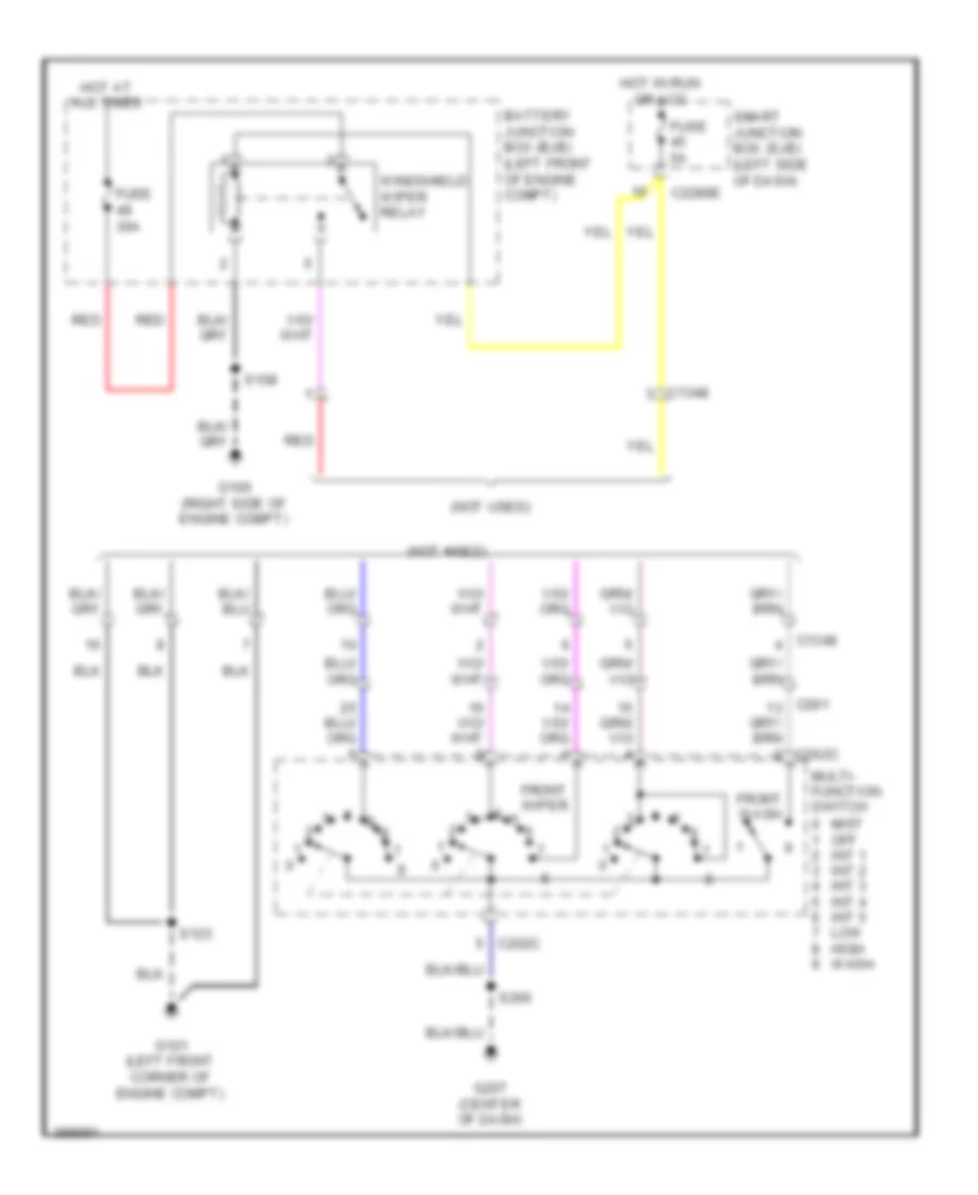
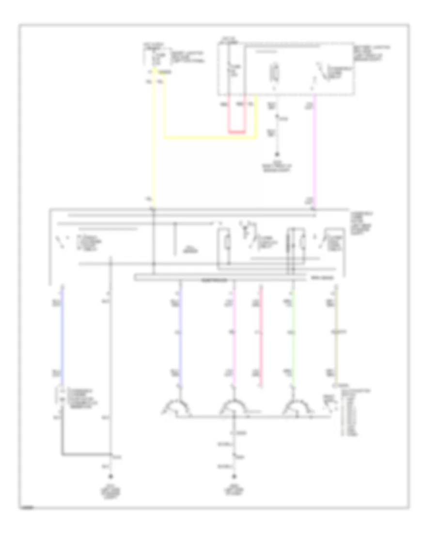
Manual A/C Wiring Diagram, without Stripped Chassis (1 of 2) for Ford E-350 Super Duty XL 2013
List of elements for Manual A/C Wiring Diagram, without Stripped Chassis (1 of 2) for Ford E-350 Super Duty XL 2013:
- (not used)
- (right side of dash) g200
- 0) off 5) max 6) normal 7) vent 8) floor/vent 9) floor 10) defrost/floor 11) defrost
- 1) max 2) a/c 3) vent 4) off 5) floor 6) mix 7) defrost
- 1) off 2) mid low 3) mid high 4) high
- 87a
- Auxiliary blower motor (left rear quarterpanel)
- Auxiliary blower motor relay (left rear quarterpanel)
- Auxiliary blower motor resistor (left rear quarterpanel)
- Auxiliary blower motor speed relay (left rear quarterpanel)
- Battery junction box (bjb) (left front of engine compt)
- C210
- C214
- C219
- C2280b
- C264
- C294a
- C294b
- C294c
- C294d
- C294e
- C405
- Cbp37
- Ch202
- Ch203
- Ch204
- Ch428
- Ch429
- Ch430
- Ch434
- Ch435
- Cha06
- Cha07
- Cha08
- Climate control assembly
- Control circuit
- Fuse 10a
- Fuse 50a
- G201 (center of dash)
- G403 (left rear corner of vehicle)
- Gd115
- Gd116
- Gnd
- High
- Hot at all times
- Hot in start or run
- Illumination
- Interior lights system
- Mid high
- Mid low
- S217
- S264
- S265
- S400 (a/c blower motor wiring harness, near breakout to auxiliary blower motor relay)
- S401
- Smart junction box (sjb) (left kick panel)
- Temperature blend door actuator (right side of dash)
- Temperature potentiometer
- Thermal limiter
- Vlno4
Manual A/C Wiring Diagram, without Stripped Chassis (2 of 2) for Ford E-350 Super Duty XL 2013
List of elements for Manual A/C Wiring Diagram, without Stripped Chassis (2 of 2) for Ford E-350 Super Duty XL 2013:
- (engine control sensor wiring harness & fuel charge, near breakout to evap canister purge valve) s172
- (engine control sensor wiring harness, near breakout to blower motor resistor)
- (right front of engine compt)
- 1) normal pressure 2) high pressure
- 1) normal pressure 2) low pressure
- 4.6l & 5.4l
- 6.8l
- A/c clutch relay
- A/c compressor clutch field coil (lower right front of engine)
- A/c cycling switch
- Accr
- Accs
- Battery junction box (bjb) (left front
- Battery junction box (bjb) (left front of engine compt)
- Blower motor (right side of engine compt)
- Blower motor relay
- Blower motor resistor (right side of engine compt)
- C1046
- C134
- C1551b
- C175b
- C175e
- Ce302
- Ch302
- Ch421
- Cht
- Compt)
- Cylinder head temperature sensor (front of left cylinder head)
- Engine controls system
- Except 5.4l
- Fuse 10a
- Fuse 40a
- Fuse 50a
- G100 (right front of engine compt)
- G101 (left side of engine compt)
- High pressure cutoff
- Hot at all times
- Of engine
- Pcm power relay
- Pcmrc
- Powertrain control module (pcm) (left rear of engine compt)
- Re405
- S105
- S108
- S116
- S123
- S124
- S129
- Sigrtn
- Switch (right front of engine compt)
- Thermal limiter
- Ve712
ANTI-LOCK BRAKES
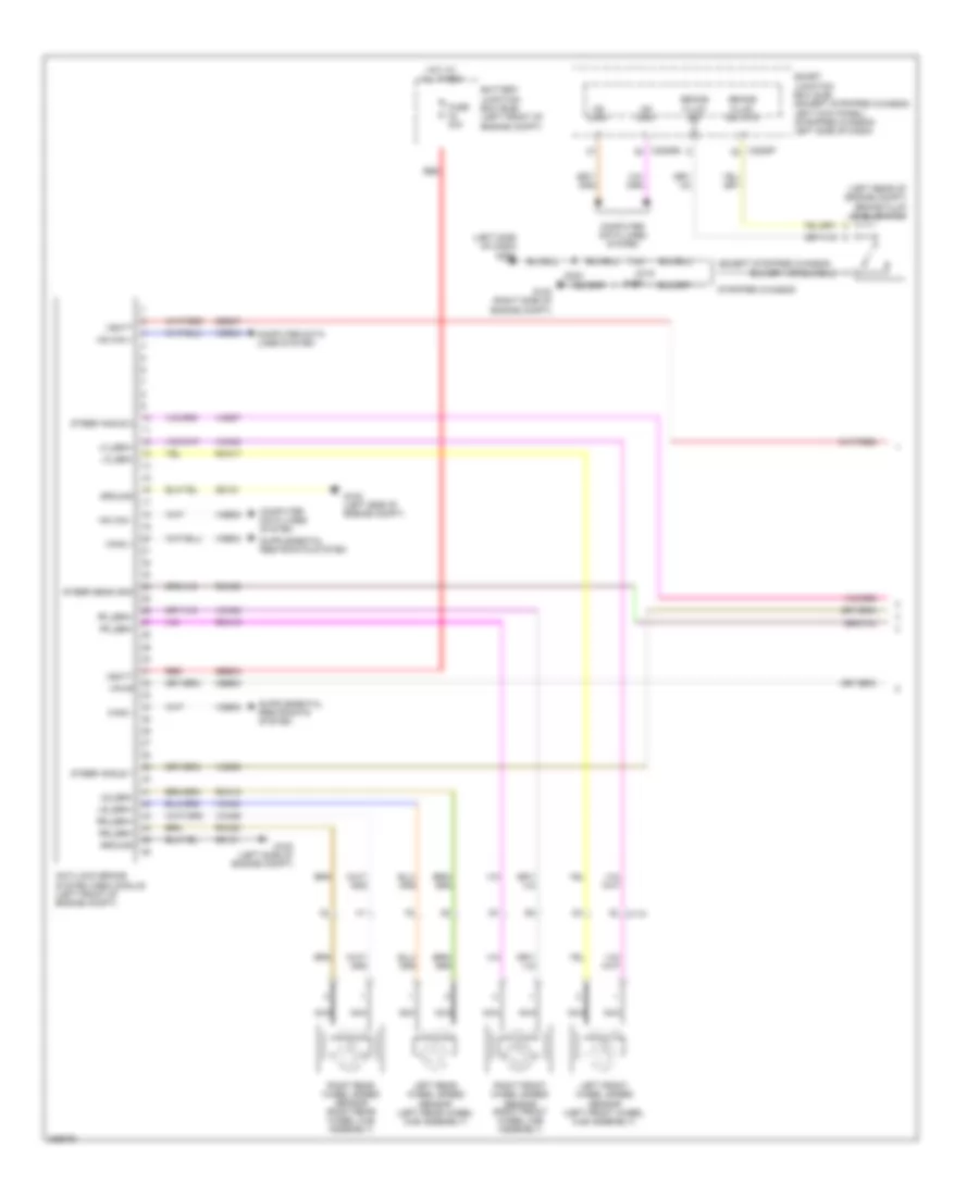
Anti-lock Brakes Wiring Diagram, with Stability Assist (1 of 2) for Ford E-350 Super Duty XL 2013
List of elements for Anti-lock Brakes Wiring Diagram, with Stability Assist (1 of 2) for Ford E-350 Super Duty XL 2013:
- (left rear of engine compt) brake fluid level switch
- (left side of dash)
- Anti-lock brake system (abs) module (left front of engine compt)
- Battery junction box (bjb) (left front of engine compt)
- Brake fluid sw
- Brake fluid sw rtn
- C110
- C219
- C2280b
- C2280f
- Can2 +
- Can2 -
- Cbb53
- Computer data lines system
- Except stripped chassis
- Fuse 40a
- G100 (right side of engine compt)
- G102 (left side of engine compt)
- G202
- Gd121
- Ground
- Hot at all times
- Hs can +
- Hs can -
- Left front wheel speed sensor (left front wheel hub assembly)
- Left rear wheel speed sensor (left rear wheel hub assembly)
- Lf_sen+
- Lf_sen-
- Lr_sen+
- Lr_sen-
- Ms can+
- Ms can-
- Nca
- Rca09
- Rca17
- Rca18
- Rca19
- Rca20
- Red
- Rf_sen+
- Rf_sen-
- Right front wheel speed sensor (right front wheel hub assembly)
- Right rear wheel speed sensor (right rear wheel hub assembly)
- Rr_sen+
- Rr_sen-
- S108
- S223
- Sbb33
- Sbb47
- Smart junction box (sjb) (except stripped chassis: left kick panel) (stripped chassis: left side of dash)
- Steer angle 1
- Steer angle 2
- Steer sens gnd
- Stripped chassis
- Vbatt
- Vca03
- Vca04
- Vca05
- Vca06
- Vcs06
- Vcs07
- Vdb04
- Vdb05
- Vpwr
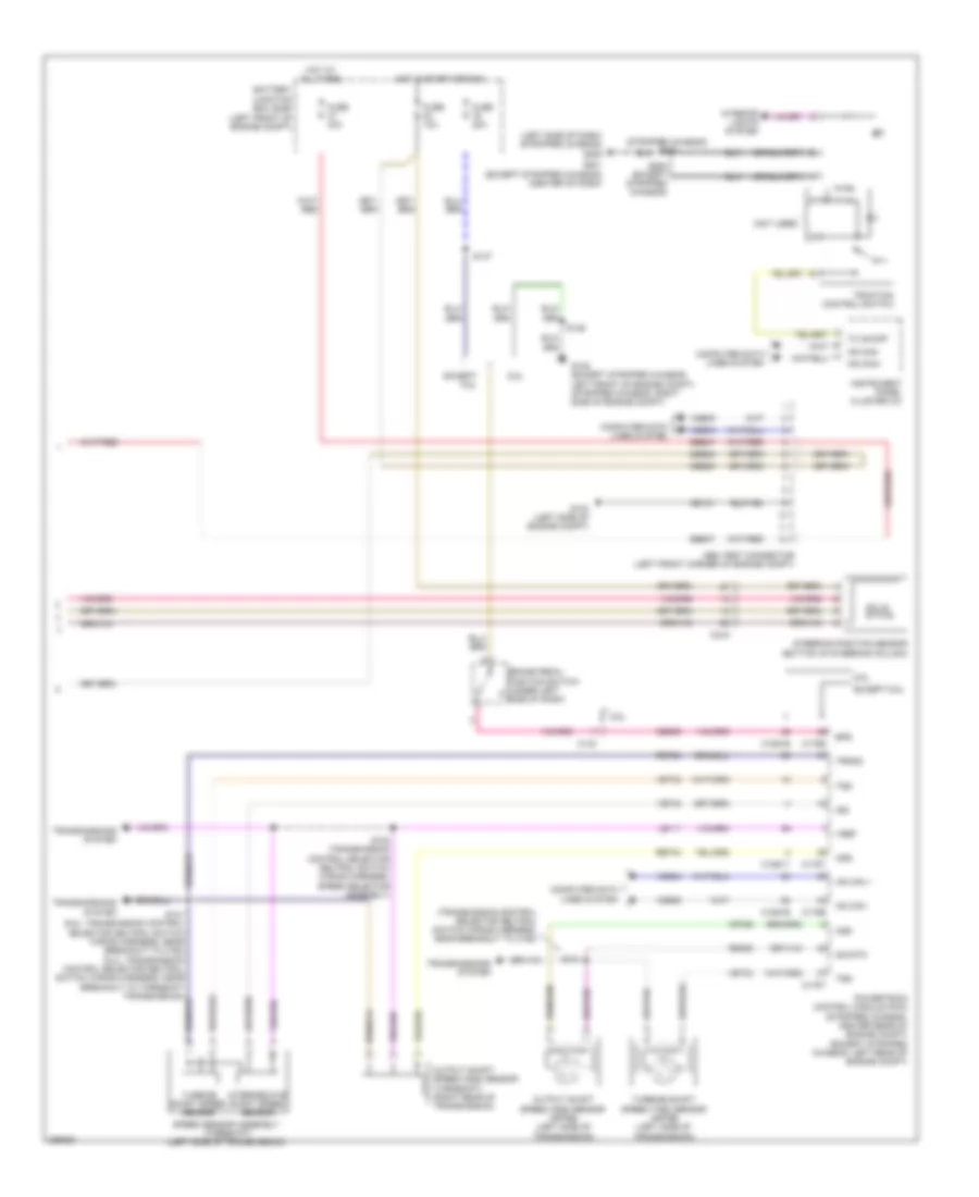
Anti-lock Brakes Wiring Diagram, with Stability Assist (2 of 2) for Ford E-350 Super Duty XL 2013
List of elements for Anti-lock Brakes Wiring Diagram, with Stability Assist (2 of 2) for Ford E-350 Super Duty XL 2013:
- (left front of engine compt)
- (left side of dash) (stripped chassis) g205
- (not used)
- (stripped chassis) s250
- (transmission control selector neutral switch wiring harness, near breakout to c192)
- 6.8l
- Abs test connector (left front corner of engine compt)
- Battery junction box (bjb)
- Bps
- Brake pedal position switch (under left side of dash)
- C134
- C1551b
- C1551t
- C175b
- C175t
- C219
- Cbb53
- Ces09
- Computer data lines system
- Except 6.8l
- Fuse 10a
- Fuse 20a
- Fuse 40a
- G103 (left side of engine compt)
- G105 (except stripped chassis: left front of engine compt) (stripped chassis: right side of engine compt)
- G201 (except stripped chassis) (center of dash)
- Gd121
- Hot at all times
- Hot in start or run
- Hs can +
- Hs can -
- Hs can+
- Hs can-
- Instrument panel cluster (ic)
- Interior lights system
- Intermediate shaft speed sensor
- Iss
- Le111
- Oss
- Output shaft speed (oss) sensor (4r75e) (left side of transmission)
- Output shaft speed (oss) sensor (torqshift) (right rear of transmission)
- Powertrain control module (pcm) (stripped chassis: center rear of engine compt) (except stripped chassis: left rear of engine compt)
- Re406
- Ret04
- Ret24
- S101 (6.8l: transmission control selector neutral switch wiring harness, near breakout to c192) (5.4l: transmission control selector neutral switch wiring harness, near breakout to torqshift transmission)
- S102 (transmission control selector neutral switch wiring harness, speed selector assembly)
- S104
- S125
- S137
- S264 (except stripped chassis)
- Sbb47
- Sig rtn
- Solid state
- Speed sensor assembly (torqshift) (left side of transmission)
- Steering position sensor (bottom of steering column)
- Tc on/off
- Traction control switch
- Transmissions system
- Trgnd
- Tss
- Turbine shaft speed (tss) sensor (4r75e) (left side of transmission)
- Turbine shaft speed sensor
- Vdb04
- Vdb05
- Ve744
- Vet26
- Vet33
- Vref
Anti-lock Brakes Wiring Diagram, without Stability Assist for Ford E-350 Super Duty XL 2013
List of elements for Anti-lock Brakes Wiring Diagram, without Stability Assist for Ford E-350 Super Duty XL 2013:
- (left rear of engine compt) brake fluid level switch
- (left side of dash)
- (not used)
- (transmission control selector neutral switch wiring harness,
- 6.8l
- Abs active
- Anti-lock brake system (abs) module (left front of engine compt)
- Battery junction box (bjb) (left front of engine compt)
- Bps
- Brake fluid sw
- Brake fluid sw rtn
- Brake pedal position switch (under left side of dash)
- C110
- C134
- C1551b
- C1551t
- C175b
- C175t
- C219
- C2280b
- C2280f
- Cbb53
- Cca01
- Ces09
- Computer data lines system
- Except 6.8l
- Except stripped chassis
- Fuse 10a
- Fuse 20a
- Fuse 40a
- G100 (right side of engine compt)
- G102 (left side of engine compt)
- G105 (except stripped chassis: left front of engine compt) (stripped chassis: right side of engine compt)
- G202
- Gd121
- Gnd
- Hot at all times
- Hot in start or run
- Hs can +
- Hs can -
- Intermediate shaft speed sensor
- Iss
- Le111
- Left front wheel speed sensor (left front wheel hub assembly)
- Ms can+
- Ms can-
- Nca
- Near breakout to c192)
- Oss
- Output shaft speed (oss) sensor (4r75e) (left side of transmission)
- Output shaft speed (oss) sensor (torqshift) (right rear of transmission)
- Powertrain control module (pcm) (stripped chassis: center rear of engine compt) (except stripped chassis: left rear of engine compt)
- Rca17
- Rca19
- Re406
- Red
- Ret04
- Ret24
- Right front wheel speed sensor (right front wheel hub assembly)
- S101 (6.8l: transmission control selector neutral switch wiring harness, near breakout to c192) (5.4l: transmission control selector neutral switch wiring harness, near breakout to torqshift transmission)
- S102 (transmission control selector neutral switch wiring harness, near breakout to speed selector assembly)
- S104
- S108
- S125
- S137
- S223
- Sbb33
- Sbb47
- Sig rtn
- Smart junction box (sjb) (except stripped chassis: left kick panel) (stripped chassis: left side of dash)
- Speed sensor assembly (torqshift) (left side of transmission)
- Stripped chassis
- Transmissions system
- Trgnd
- Tss
- Turbine shaft speed (tss) sensor (4r75e) (left side of transmission)
- Turbine shaft speed sensor
- Vbatt
- Vca03
- Vca05
- Vdb04
- Vdb05
- Ve744
- Vet26
- Vet33
- Vpwr
- Vref
- Wheel spd lf+
- Wheel spd lf-
- Wheel spd rf+
- Wheel spd rf-
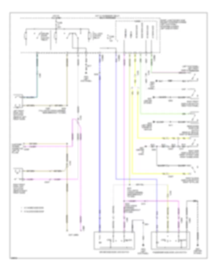
ANTI-THEFT
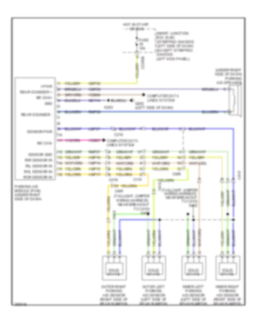
Forced Entry Wiring Diagram, with Cutaway for Ford E-350 Super Duty XL 2013
List of elements for Forced Entry Wiring Diagram, with Cutaway for Ford E-350 Super Duty XL 2013:
- (left kick panel) left front door ajar switch
- (not used)
- All lock/ unlock relay
- C210
- C2280a
- C2280c
- C2280d
- C265
- C268
- C3007
- C3047
- C3049
- C314
- C3359
- Customer access connector (left "b" pillar)
- Driver door unlock relay
- Driver side door lock switch
- Fuse 15a
- Fuse 20a
- G201 (center of dash)
- G203 (left kick panel)
- G403 (left rear corner of vehicle)
- Hot at all times
- Hot w/ accessory delay relay energized
- Left front door lock actuator (rear of left front door)
- Lf door ajar
- Lock
- Micro
- Passenger side door lock switch
- Rear door ajar
- Rear doors door ajar switch (rear of vehicle, right of rear door)
- Rf door ajar
- Right front door ajar switch (right kick panel)
- Right front door lock actuator (rear of right front door)
- Right side door ajar switch (front of right side front hinged door)
- Right sliding door ajar switch (right "b" pillar)
- Rr door ajar
- S233 (main wiring harness, near breakout to c264)
- S236
- S237 (taillights wiring harness, near breakout to c263)
- S238 (taillights wiring harness, near breakout to c263)
- S239
- S264
- S317
- S411
- S501
- Smart junction box (sjb) (except stripped chassis: left kick panel) (stripped chassis: left side of dash)
- Trim lk
- Trim unlk
- Unlock
- W/ hinged side door
- W/ sliding side door
Forced Entry Wiring Diagram, without Cutaway for Ford E-350 Super Duty XL 2013
List of elements for Forced Entry Wiring Diagram, without Cutaway for Ford E-350 Super Duty XL 2013:
- (hinged: rear of right side front hinged door) (sliding: front of right side sliding door) right side door lock actuator
- (left kick panel) g203
- (left kick panel) left front door ajar switch
- All lock/ unlock relay
- C210
- C2280a
- C2280c
- C2280d
- C265
- C268
- C3007
- C3047
- C3049
- C313
- C314
- C3235
- C406
- C807
- Driver door unlock relay
- Driver side door lock switch
- Fuse 15a
- Fuse 20a
- G201 (center of dash)
- G203 (left kick panel)
- G403 (left rear corner of vehicle)
- Hot at all times
- Hot w/ accessory delay relay energized
- Left front door lock actuator (rear of left front door)
- Lf door ajar
- Lock
- Micro
- Passenger side door lock switch
- Rear door ajar
- Rear doors door ajar switch (rear of vehicle, right of rear door)
- Rear doors door lock actuator (left side of right rear door)
- Rear doors door lock switch (right rear door)
- Rf door ajar
- Right front door ajar switch (right kick panel)
- Right front door lock actuator (rear of right front door)
- Right side door ajar switch (front of right side front hinged door)
- Right sliding door ajar switch (right "b" pillar)
- Right sliding door contact switch (right side of sliding side door)
- Rr door ajar
- S233 (main wiring harness, near breakout to c264)
- S236
- S237 (taillights wiring harness, near breakout to c263)
- S238 (taillights wiring harness, near breakout to c263)
- S239
- S240
- S264
- S405
- S411
- S501
- Smart junction box (sjb) (except stripped chassis: left kick panel) (stripped chassis: left side of dash)
- Trim lk
- Trim unlk
- Unlock
- W/ hinged side door
- W/ sliding side door
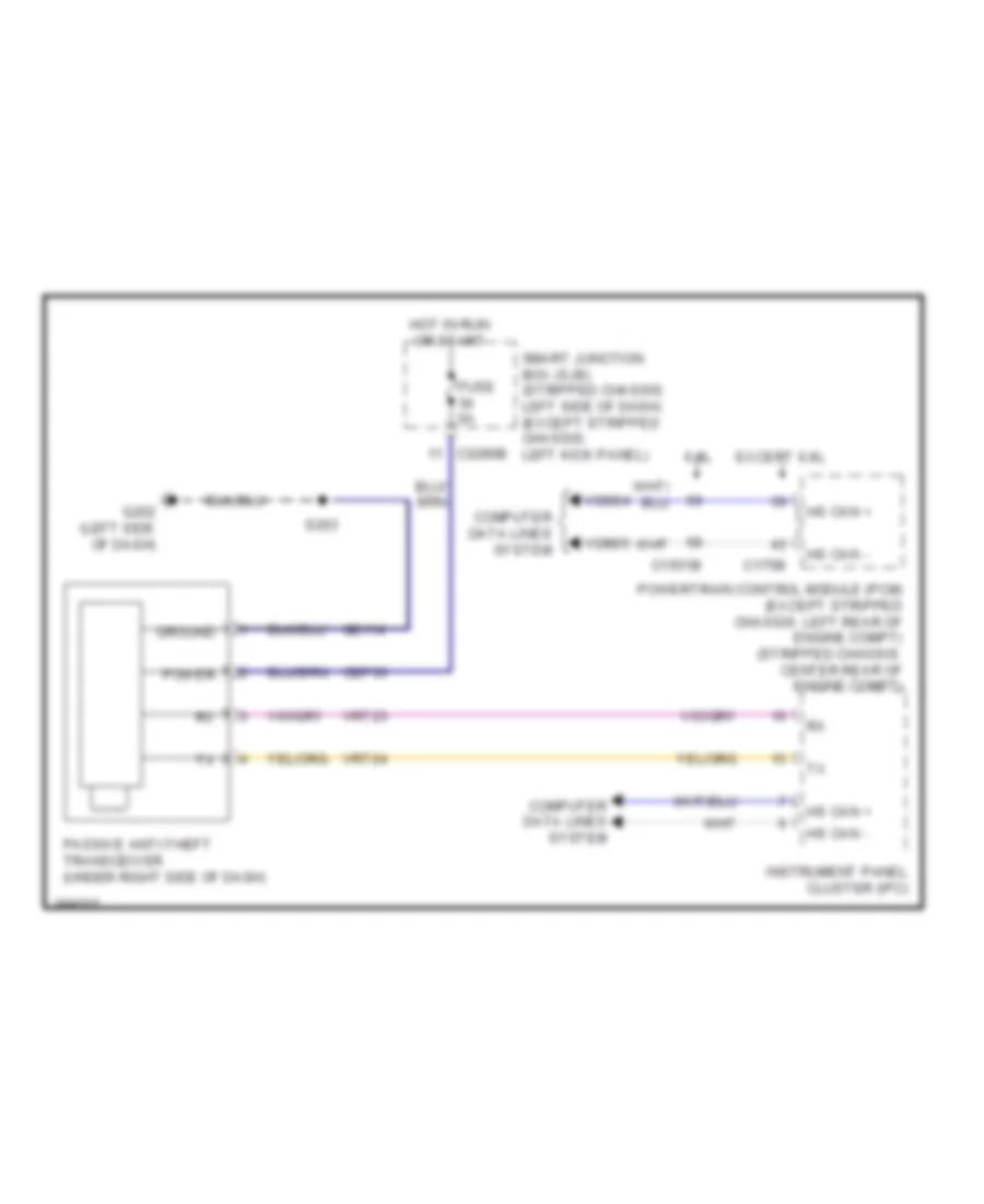
Passive Anti-theft Wiring Diagram for Ford E-350 Super Duty XL 2013
List of elements for Passive Anti-theft Wiring Diagram for Ford E-350 Super Duty XL 2013:
- 6.8l
- C1551b
- C175b
- C2280b
- Cbp36
- Computer data lines system
- Except 6.8l
- Fuse 5a
- G202 (left side of dash)
- Gd114
- Ground
- Hot in run or start
- Hs can +
- Hs can -
- Instrument panel cluster (ipc)
- Passive anti-theft transceiver (under right side of dash)
- Power
- Powertrain control module (pcm) (except stripped chassis: left rear of engine compt) (stripped chassis: center rear of engine compt)
- S263
- Smart junction box (sjb) (stripped chassis: left side of dash) (except stripped chassis: left kick panel)
- Vdb04
- Vdb05
- Vrt23
- Vrt24
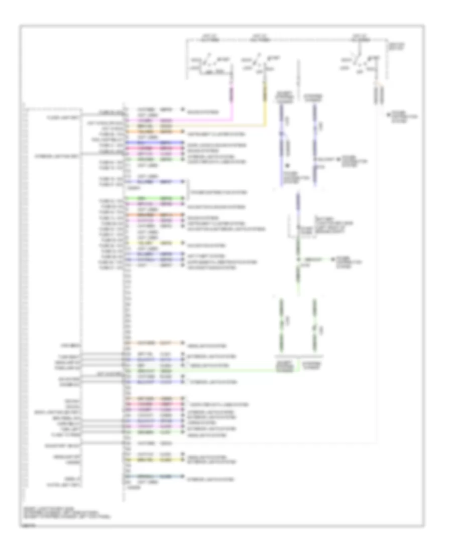
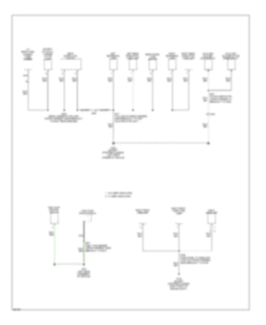
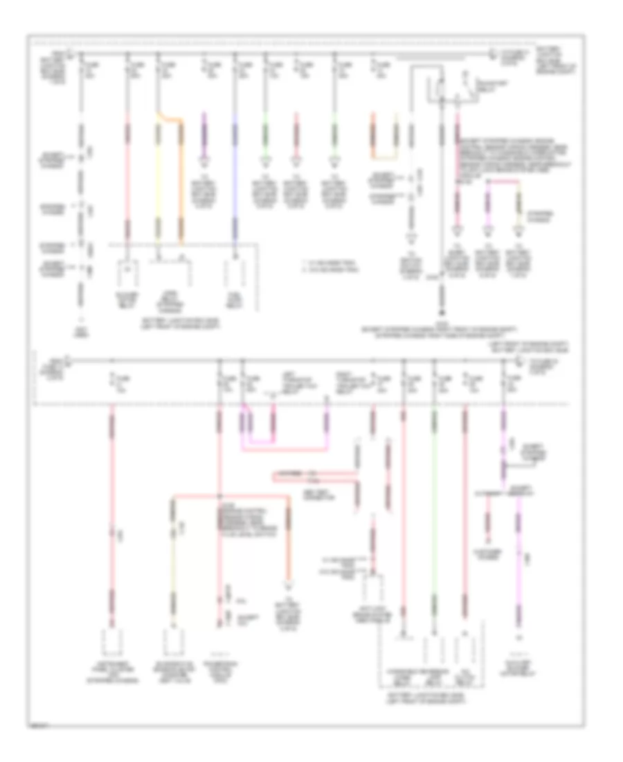
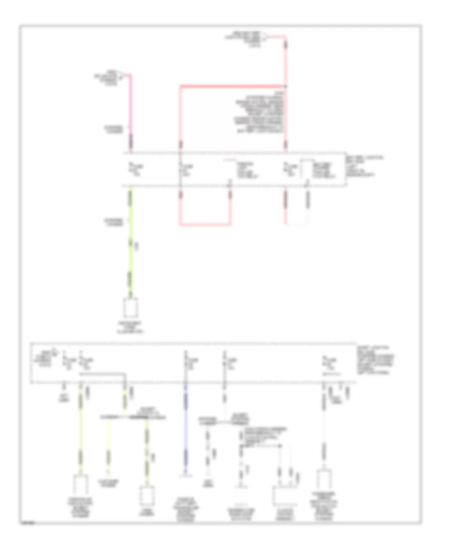
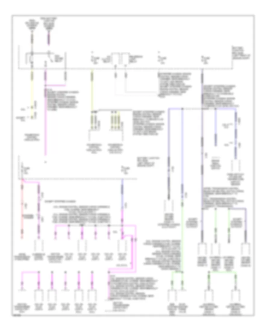
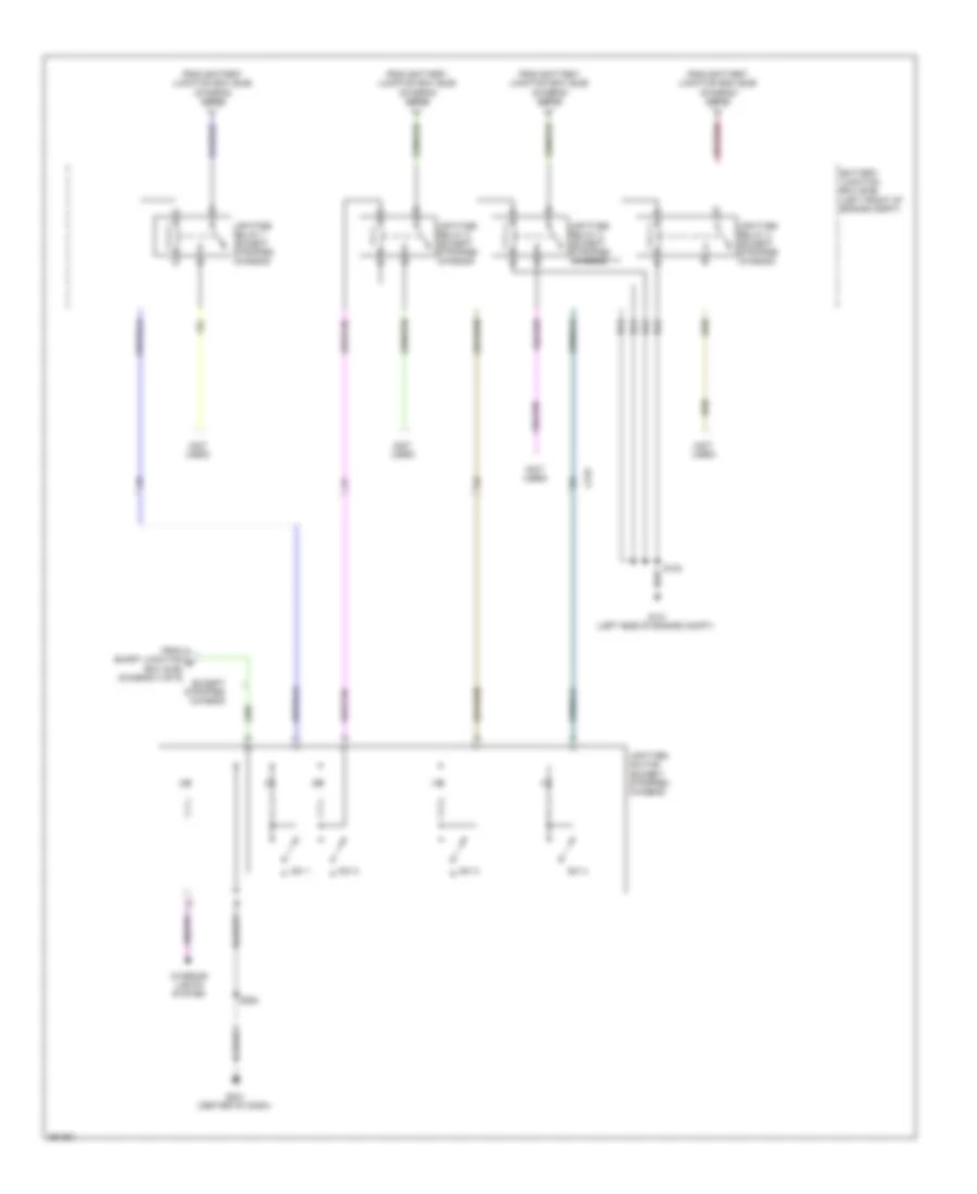
BODY CONTROL MODULES
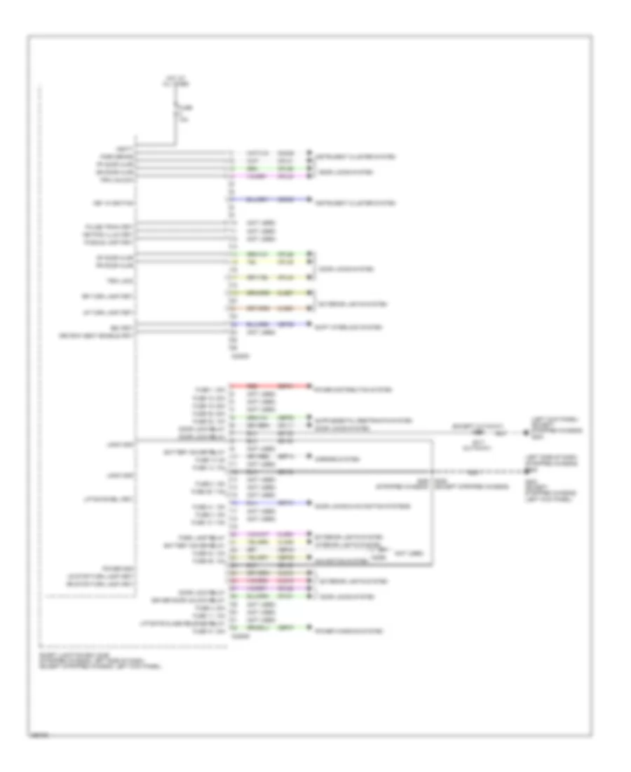
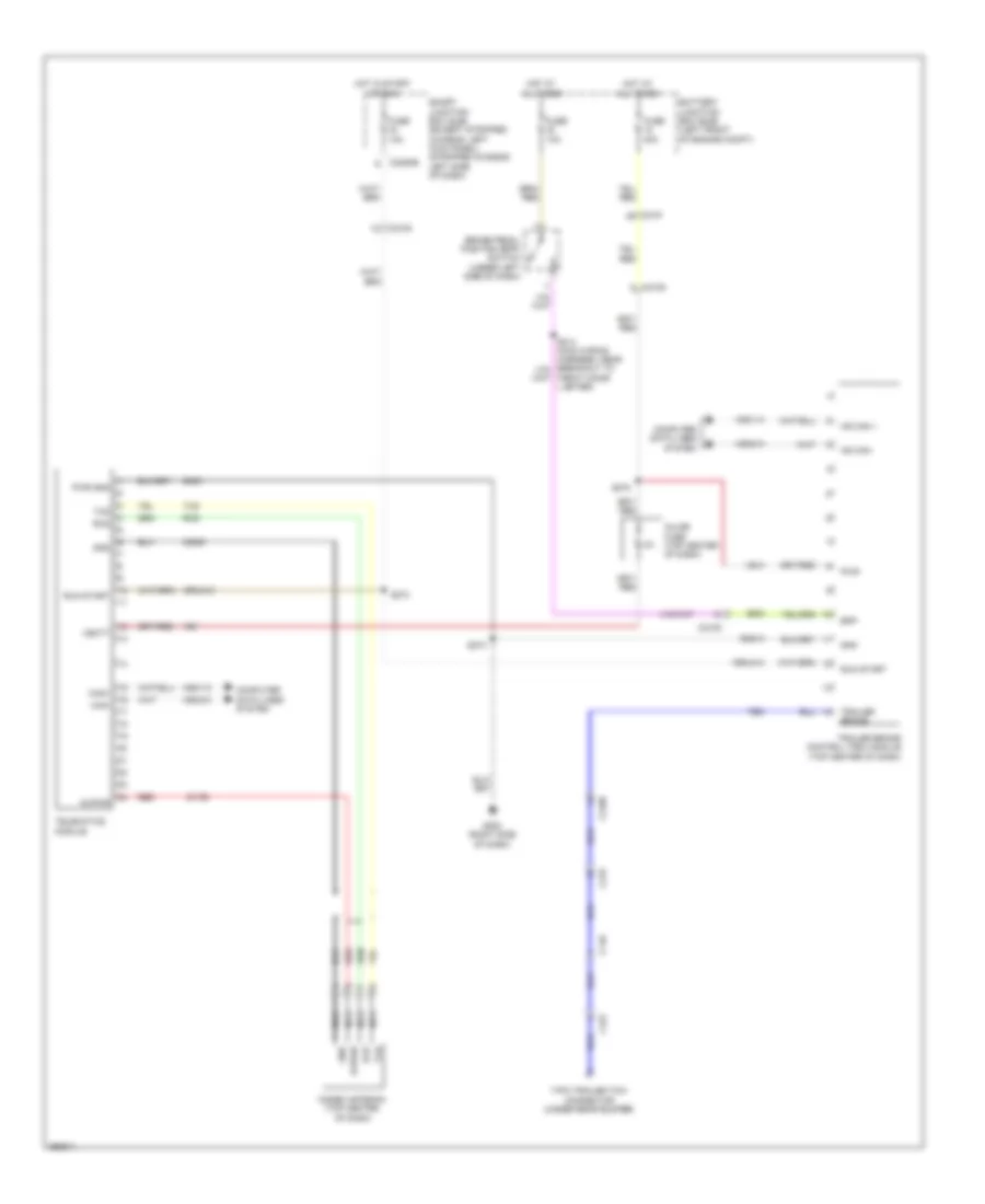
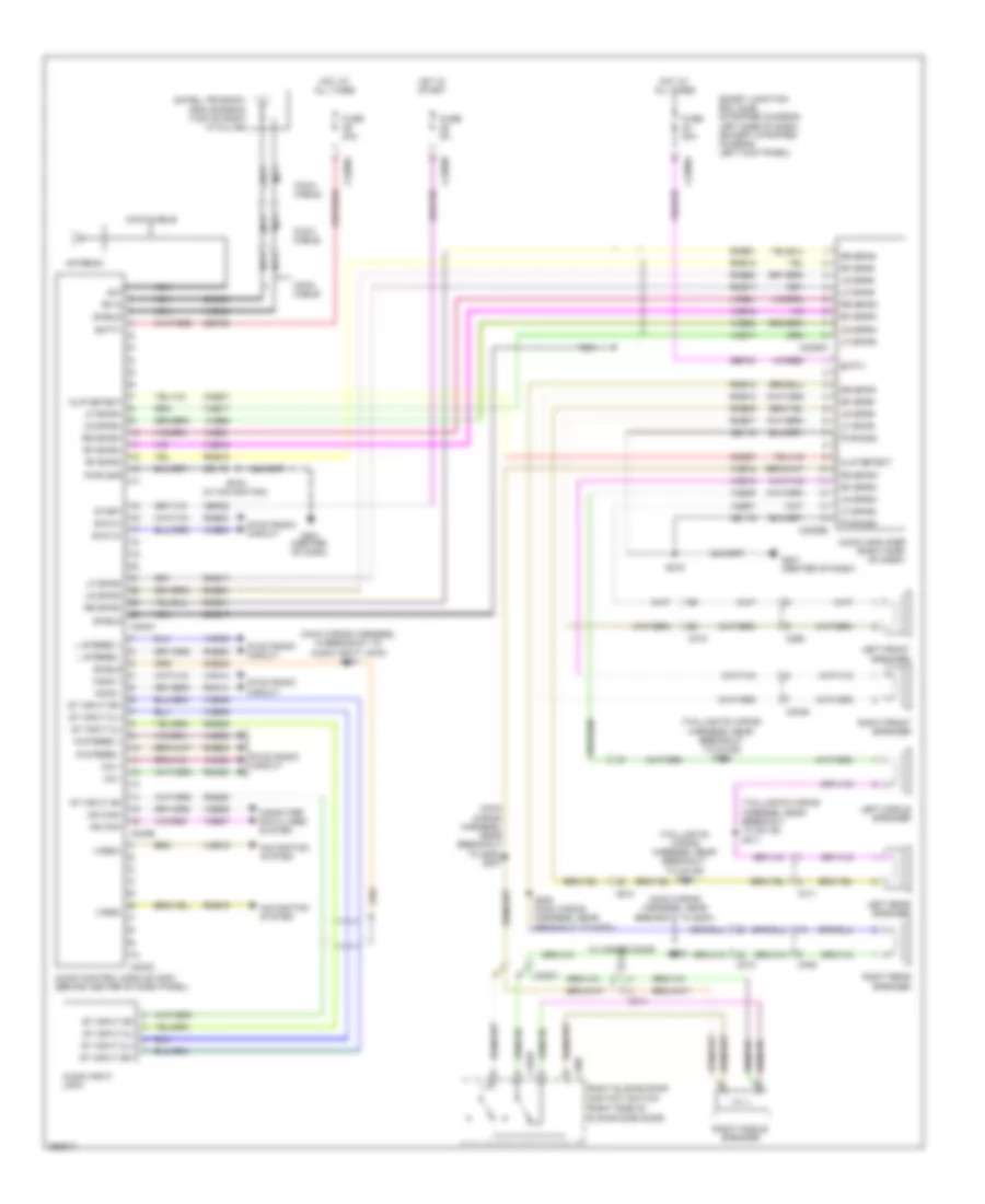
Body Control Modules Wiring Diagram (1 of 3) for Ford E-350 Super Duty XL 2013
List of elements for Body Control Modules Wiring Diagram (1 of 3) for Ford E-350 Super Duty XL 2013:
- (not used)
- Acc
- Air conditioning system
- Anti-theft system
- Back lighting led (fet)
- Battery junction box (bjb) (left front of engine compt)
- Brk pedal sw
- C219
- C2280a
- C2280b
- C291
- Cbp28
- Cbp29
- Cbp33
- Cbp35
- Cbp36
- Cbp37
- Cbp41
- Cbp42
- Cbp46
- Ccb08
- Cdc32
- Cdc33
- Cdc34
- Ce336
- Clf17
- Clf18
- Clf23
- Clf27
- Cln28
- Cls32
- Cls34
- Cls39
- Cls41
- Computer data lines system
- Crh02
- Dim sw gnd
- Dimmer sw
- Dome lp
- Door locks & sound systems
- Except stripped chassis
- Exterior lights system
- Flash to pass
- Floor lamp (fet)
- Fog lamp relay
- Fuse 14, 10a
- Fuse 15, 10a
- Fuse 16, 15a
- Fuse 20, 15a
- Fuse 26, 10a
- Fuse 27, 20a
- Fuse 28, 5a
- Fuse 29, 5a
- Fuse 30, 5a
- Fuse 31, 10a
- Fuse 33, 10a
- Fuse 34, 5a
- Fuse 35, 10a
- Fuse 36, 5a
- Fuse 37, 10a
- Fuse 39, 20a
- Fuse 40, 20a
- Fuse 41, 15a
- Fuse 42, 10a
- Fuse 43, 10a
- Fuse 46, 7.5a
- Hazard
- Headlamp off
- Headlamp on
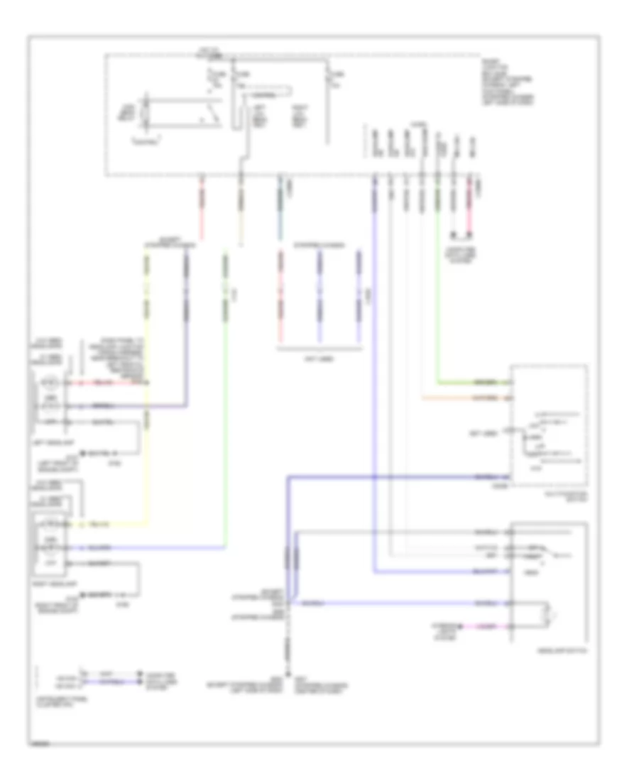
- Headlights system
- High beam
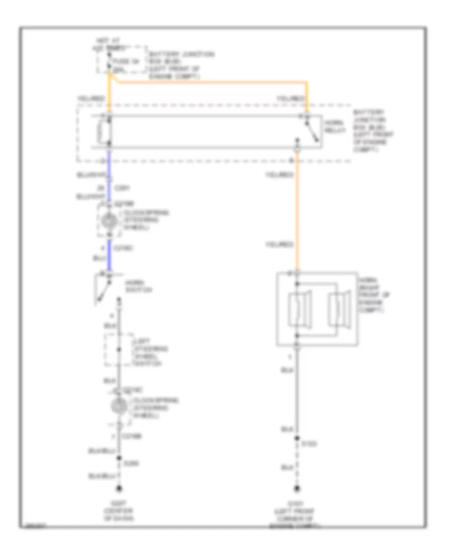
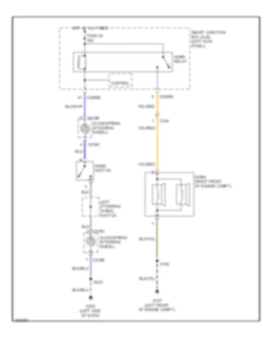
- Horn relay
- Horns system
- Hot at all times
- Hot in run
- Hot in run or acc
- Hot in start
- Ignition switch
- Instrument cluster system
- Interior lighting (fet)
- Interior lights system
- Lock
- Ms can+
- Ms can-
- Navigation & exterior lights systems
- Navigation & sound systems
- Navigation system
- Off
- Parklamp on
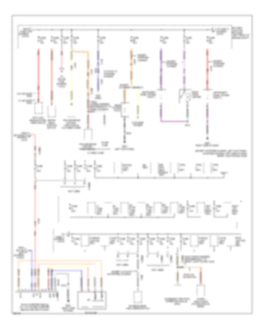
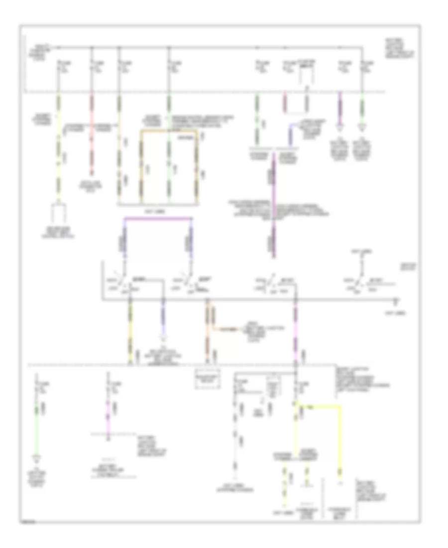
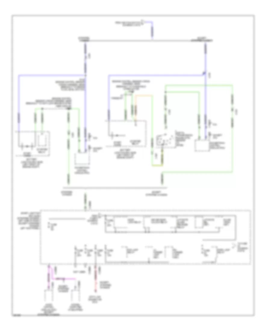
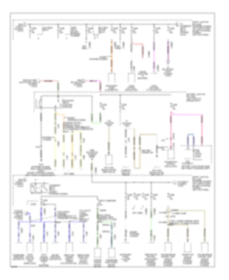
- Power distribution system
- Rln29
- Run
- Run/start ign sw
- S139
- Sbp14
- Sbp20
- Sbp26
- Sbp27
- Sbp39
- Sbp40
- Smart junction box (sjb) (stripped chassis: left side of dash) (except stripped chassis: left kick panel)
- Sound systems
- Start
- Start diode
- Stripped chassis
- Turn left
- Turn right
- Vdb06
- Vdb07
- Vln04
- Vln18
- Vln33
- White light (fet)
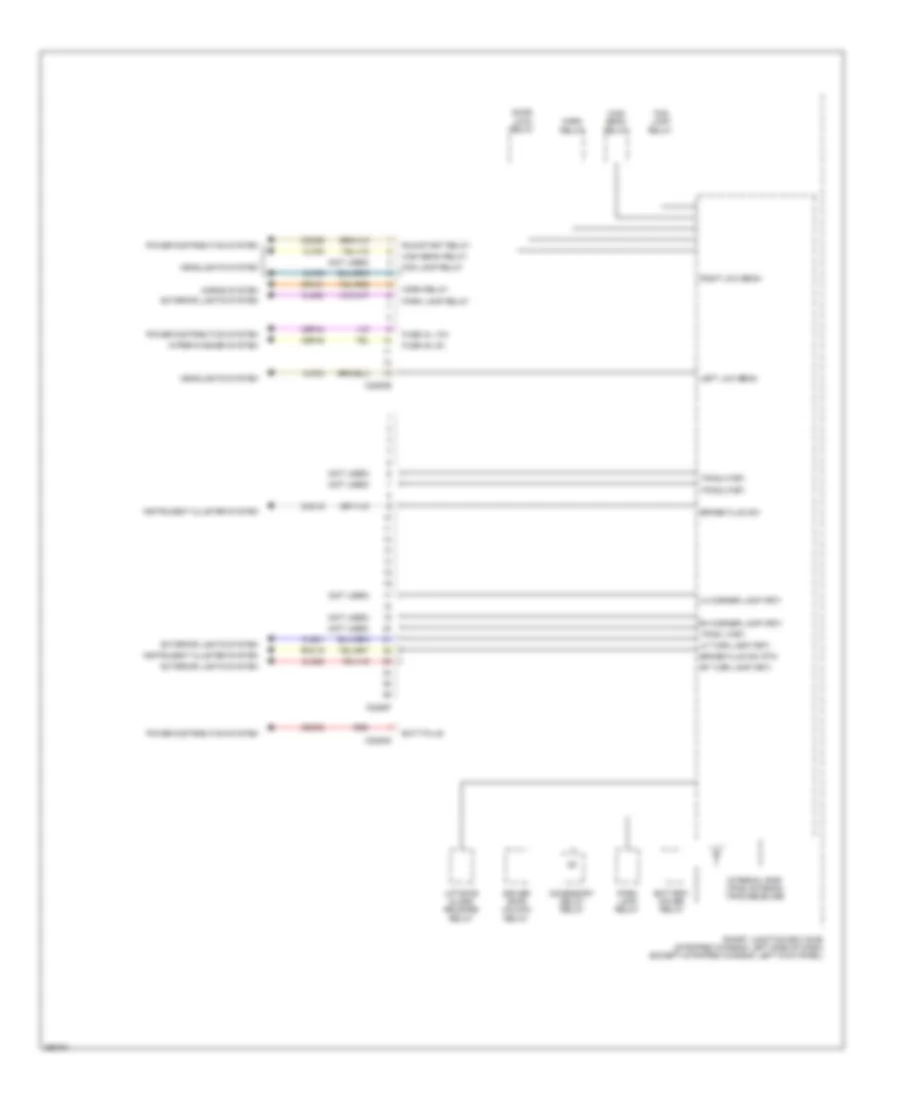
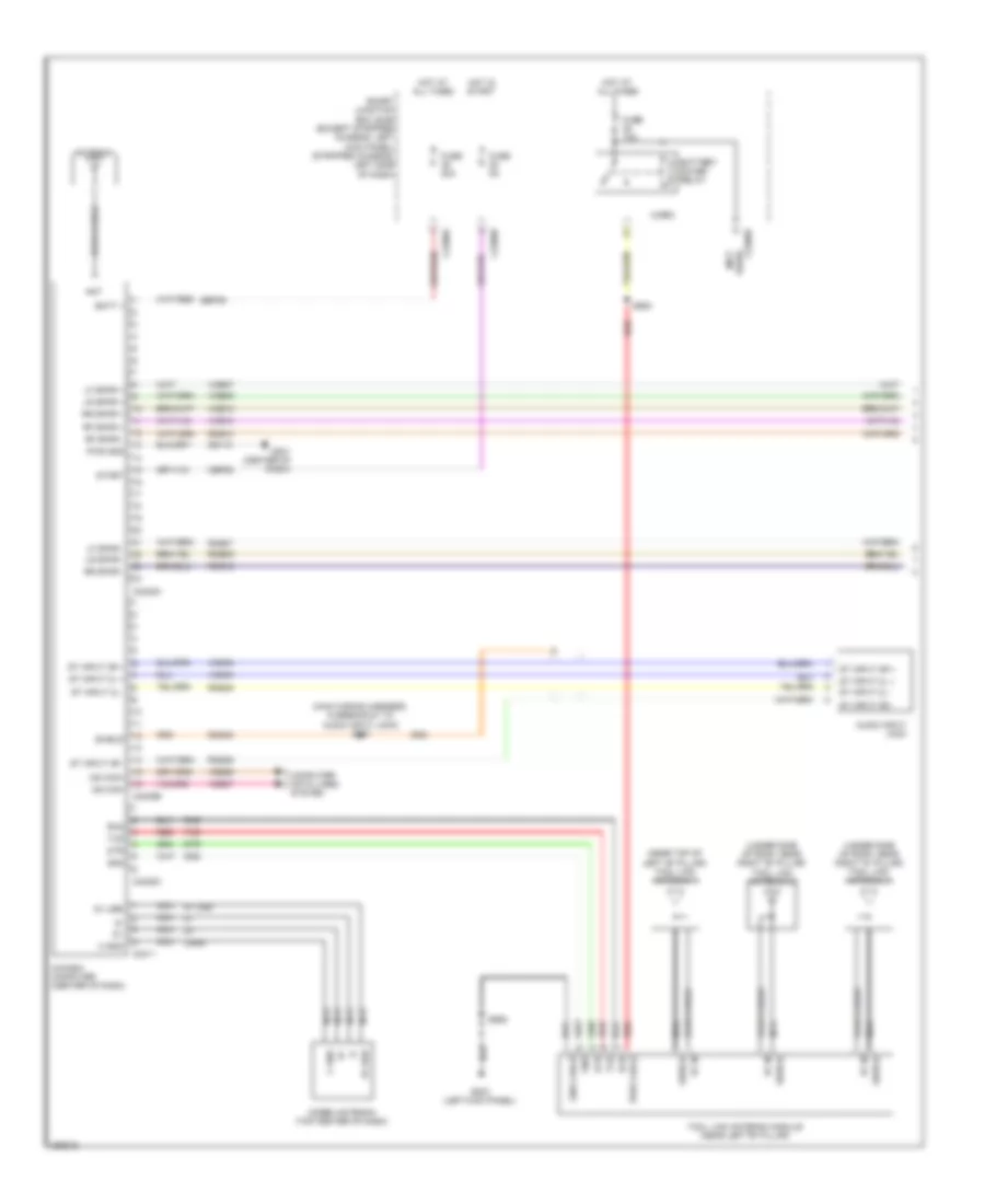
Body Control Modules Wiring Diagram (2 of 3) for Ford E-350 Super Duty XL 2013
List of elements for Body Control Modules Wiring Diagram (2 of 3) for Ford E-350 Super Duty XL 2013:
- (except cutaway) s240
- (except stripped chassis)
- (left kick panel) (except stripped chassis) g203
- (left side of dash)
- (not used)
- (stripped chassis)
- (stripped chassis) g205
- 3rd row seat enable (fet)
- Battery saver relay
- Bsi (fet)
- C2095
- C2280c
- C2280d
- Cbp32
- Cbp35
- Cbp41
- Cbp43
- Cbp47
- Cdc30
- Cet53
- Cln09
- Cls18
- Cls19
- Cls23
- Cls27
- Cls30
- Cmc25
- Cpl11
- Cpl26
- Cpl31
- Cpl36
- Cpl39
- Cpl42
- Cpl43
- Cpl51
- Cpl52
- Df door ajar
- Door lock relay
- Door locks & navigation systems
- Door locks system
- Dr door ajar
- Driver door unlock relay
- Exterior lights system
- Fuse 1, 30a
- Fuse 10a
- Fuse 11, 10a
- Fuse 12, 7.5a
- Fuse 13, 5a
- Fuse 14, 10a
- Fuse 18, 20a
- Fuse 19, 25a
- Fuse 2, 15a
- Fuse 3, 15a
- Fuse 32, 10a
- Fuse 35, 10a
- Fuse 38, 20a
- Fuse 4, 30a
- Fuse 41, 15a
- Fuse 43, 10a
- Fuse 46, 7.5a
- Fuse 47, 30a
- G203 (except stripped chassis) (left kick panel)
- Gd133
- Hot at all times
- Instrument cluster system
- Interior lights system
- Key in ignition
- Keypad illum (fet)
- Liftgate glass release relay
- Liftgate rel (fet)
- Logic gnd
- Lr stop/turn lamp (fet)
- Lr turn lamp (fet)
- Mirrors system
- Navigation system
- Park brake
- Park lamp relay
- Pf door ajar
- Power distribution system
- Power gnd
- Power windows system
- Pr door ajar
- Puddle lamp (fet)
- Pulse train (fet)
- Red
- Rr stop/turn lamp (fet)
- Rr turn lamp (fet)
- S239
- S250
- S317 (cutaway)
- Sbp01
- Sbp13
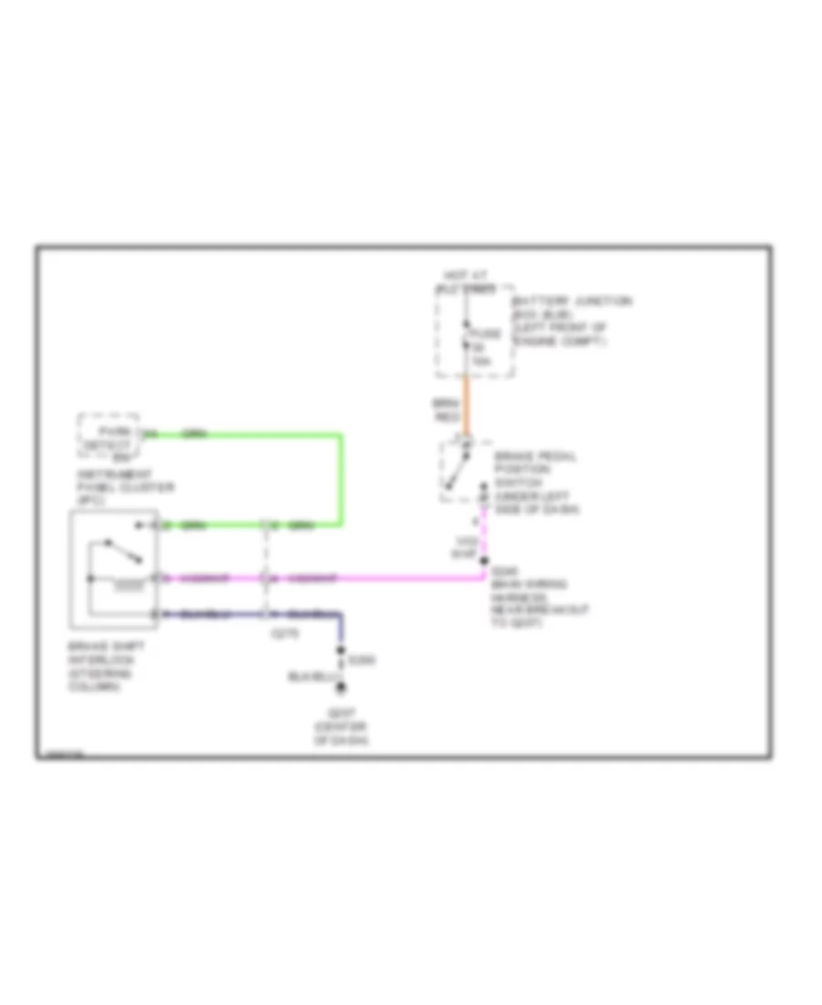
- Shift interlock system
- Smart junction box (sjb) (stripped chassis: left side of dash) (except stripped chassis: left kick panel)
- Trim lock
- Trim unlock
- Vbatt
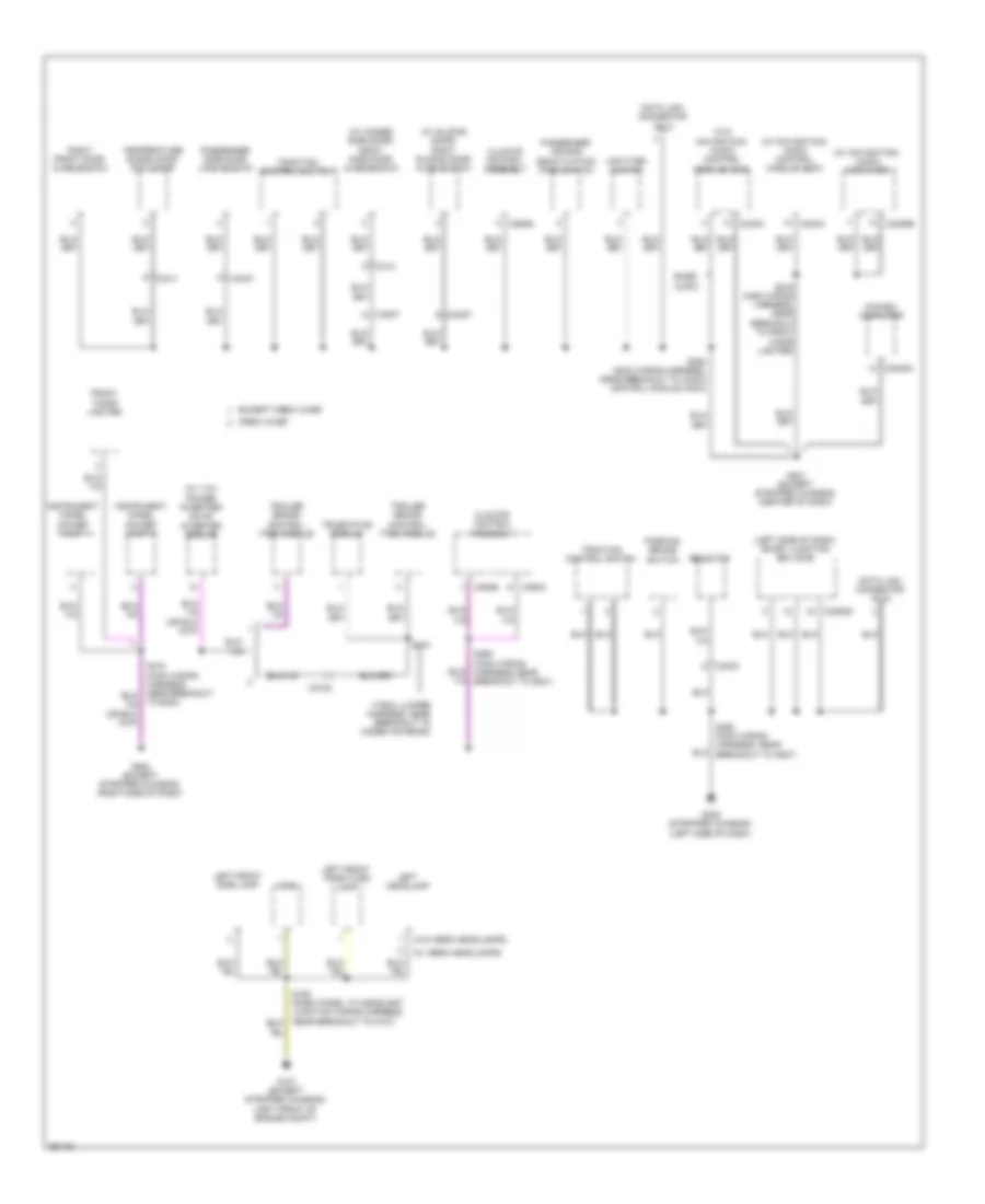
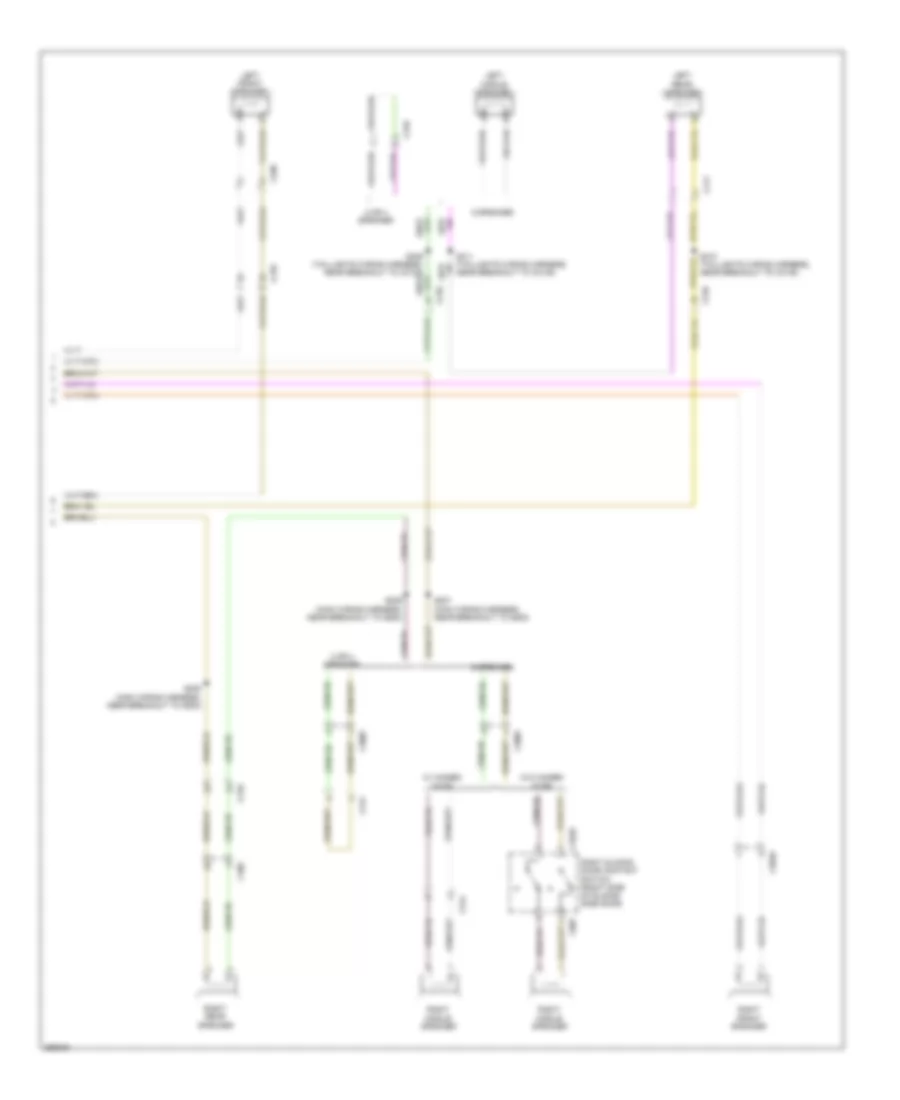
Body Control Modules Wiring Diagram (3 of 3) for Ford E-350 Super Duty XL 2013
List of elements for Body Control Modules Wiring Diagram (3 of 3) for Ford E-350 Super Duty XL 2013:
- (not used)
- Accessory delay relay
- Batt-plus
- Battery saver relay
- Brake fluid sw
- Brake fluid sw rtn
- C2280e
- C2280f
- C2280g
- Cbp44
- Cbp45
- Cdc55
- Clf04
- Clf05
- Clf08
- Cls21
- Cls25
- Cls30
- Cmc19
- Door lock relay
- Driver door unlock relay
- Exterior lights system
- Fog lamp relay
- Fuse 44, 10a
- Fuse 45, 5a
- Headlights system
- High beam relay
- Horn relay
- Horns system
- Instrument cluster system
- Internal rke/ tpms antenna tpms receiver
- Left low beam
- Lf turn lamp (fet)
- Lh corner lamp (fet)
- Liftgate glass release relay
- Park lamp relay
- Power distribution system
- Red
- Rf turn lamp (fet)
- Rh corner lamp (fet)
- Right low beam
- Rmc19
- Run/start relay
- Sdc02
- Smart junction box (sjb) (stripped chassis: left side of dash) (except stripped chassis: left kick panel)
- Srh01
- Tpms 1 (fet)
- Tpms 2 (fet)
- Tpms 3 (fet)
- Wiper/washer system
COMPUTER DATA LINES
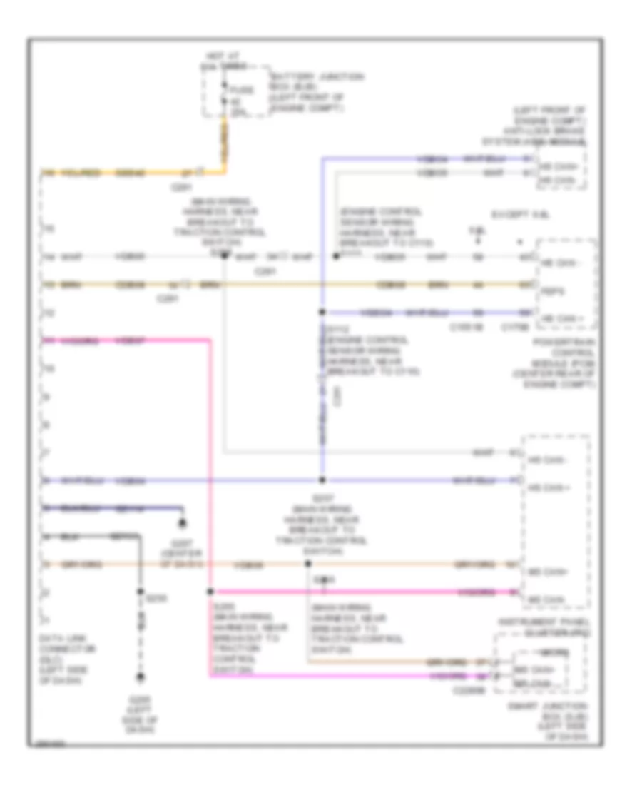
Computer Data Lines Wiring Diagram, with Stripped Chassis for Ford E-350 Super Duty XL 2013
List of elements for Computer Data Lines Wiring Diagram, with Stripped Chassis for Ford E-350 Super Duty XL 2013:
- (engine control sensor wiring harness, near breakout to c110)
- (engine control sensor wiring harness, near breakout to c110) s111
- (left front of engine compt) anti-lock brake system (abs) module
- (main wiring harness, near breakout to traction control switch)
- (main wiring harness, near breakout to traction control switch) s258
- 6.8l
- Battery junction box (bjb) (left front of engine compt)
- C1551b
- C175b
- C2280b
- C291
- Cdb08
- Data link connector (dlc) (left side of dash)
- Except 6.8l
- Feps
- Fuse 15a
- G205 (left side of dash)
- G207 (center of dash)
- Gd114
- Gd133
- Hot at all times
- Hs can +
- Hs can -
- Hs can+
- Hs can-
- Instrument panel cluster (ipc)
- Micro
- Ms can+
- Ms can-
- Powertrain control module (pcm) (center rear of engine compt)
- S250
- S255 (main wiring harness, near breakout to traction control switch)
- S256
- S257 (main wiring harness, near breakout to traction control switch)
- Sbb42
- Smart junction box (sjb) (left side of dash)
- Vdb04
- Vdb05
- Vdb06
- Vdb07
- Vdbo4
- Vdbo5
Computer Data Lines Wiring Diagram, without Stripped Chassis with Navigation (1 of 2) for Ford E-350 Super Duty XL 2013
List of elements for Computer Data Lines Wiring Diagram, without Stripped Chassis with Navigation (1 of 2) for Ford E-350 Super Duty XL 2013:
- (main wiring harness, in breakout to accessory protocol interface module (apim)) s266
- (main wiring harness, in breakout to accessory protocol interface module (apim)) s267
- (main wiring harness, in breakout to instrument panel cluster (ipc)) s224
- (main wiring harness, in breakout to instrument panel cluster (ipc)) s225
- (main wiring harness, near breakout to overdrive cancel switch)
- Accessory protocol interface module (apim) (w/ sync) (behind left side of dash)
- Audio control module (acm) (behind center of dash panel)
- C219
- C2280a
- C2280b
- C240b
- Cdb08
- Data link connector (dlc) (below left side of dash)
- Fuse 15a
- G201 (center of dash)
- G202 (left side
- Gd114
- Gd115
- Hot at all times
- Hs can +
- Hs can -
- Instrument panel cluster (ipc)
- Micro
- Ms can +
- Ms can -
- Of dash)
- Parking aid module (pam) (under right side of dash)
- S228
- S229 (main wiring harness, near breakout to overdrive cancel switch)
- S263
- S264
- Sbp20
- Smart junction box (sjb) (left kick panel)
- Vdb04
- Vdb05
- Vdb06
- Vdb07
Computer Data Lines Wiring Diagram, without Stripped Chassis with Navigation (2 of 2) for Ford E-350 Super Duty XL 2013
List of elements for Computer Data Lines Wiring Diagram, without Stripped Chassis with Navigation (2 of 2) for Ford E-350 Super Duty XL 2013:
- (engine control sensor wiring harness, near breakout to c192)
- (engine control sensor wiring harness, near breakout to c192) s126
- (engine control sensor wiring harness, near breakout to g105)
- (left front corner
- (main wiring harness, near breakout to trailer brake control (tbc) module)
- (t-box jumper harness, near breakout to modem antenna) s270
- (w/ advance trac)
- 6.8l
- Abs test connector (w/ advance trac)
- Anti-lock brake system (abs) module (left front of engine compt)
- C1551b
- C175b
- C210
- C2108
- C219
- C310b
- Cdb08
- Except 6.8l
- Feps
- Harness, near breakout to modem antenna)
- Hs can +
- Hs can -
- Hsc1-a
- Hsc1-c
- Hsc2-c
- Of engine compt)
- Powertrain control module (pcm) (left rear of engine compt)
- Restraints control module (rcm) (under driver's seat)
- S111 (w/ advance trac) (engine control sensor wiring harness, near breakout to g105)
- S112
- S127
- S221
- S222 (main wiring harness, near breakout to trailer brake control (tbc) module)
- S271 (t-box jumper hsc2-a
- S301 (taillights wiring harness, near breakout to g203)
- S302
- Telematics module (crew chief)
- Trailer brake control (tbc) module (crew chief) (top center of dash)
- Trailer brake control (tbc) module (except crew chief) (top center of dash)
- Vdb04
- Vdb05
- W/ advance trac
- W/o advance trac
Computer Data Lines Wiring Diagram, without Stripped Chassis without Navigation (1 of 2) for Ford E-350 Super Duty XL 2013
List of elements for Computer Data Lines Wiring Diagram, without Stripped Chassis without Navigation (1 of 2) for Ford E-350 Super Duty XL 2013:
- (center of dash)
- (main wiring harness, in breakout accessory protocol interface module (apim)) s266
- (main wiring harness, in breakout to instrument panel cluster (ipc)) s224
- (main wiring harness, in breakout to instrument panel cluster (ipc)) s225
- (main wiring harness, near breakout to overdrive cancel switch)
- (under right
- Accessory protocol interface module (apim) (w/ sync) (behind left side of dash)
- Audio control module (acm) (behind center of dash panel)
- C219
- C2280a
- C2280b
- C2408b
- C240b
- Cdb08
- Data link connector (dlc) (below left side of dash)
- Fuse 15a
- G201 (center of dash)
- G202 (left side
- Gd114
- Gd115
- Global positioning system module (gpsm) (w/ sync) (behind left side of dash)
- Hot at all times
- Hs can +
- Hs can -
- In dash computer
- Instrument panel cluster (ipc)
- Micro
- Ms can +
- Ms can -
- Of dash)
- Parking aid module (pam)
- S228
- S229 (main wiring harness, near breakout to overdrive cancel switch)
- S263
- S264
- S267 (main wiring harness, in breakout accessory protocol interface module (apim))
- Sbp20
- Side of dash)
- Smart junction box (sjb) (left kick panel)
- Vdb04
- Vdb05
- Vdb06
- Vdb07
Computer Data Lines Wiring Diagram, without Stripped Chassis without Navigation (2 of 2) for Ford E-350 Super Duty XL 2013
List of elements for Computer Data Lines Wiring Diagram, without Stripped Chassis without Navigation (2 of 2) for Ford E-350 Super Duty XL 2013:
- (engine control sensor wiring harness, near breakout to c192)
- (engine control sensor wiring harness, near breakout to c192) s126
- (engine control sensor wiring harness, near breakout to g105)
- (left front corner
- (main wiring harness, near breakout to trailer brake control (tbc) module)
- (t-box jumper harness, near breakout to modem antenna)
- (w/ advance trac)
- 6.8l
- Abs test connector (w/ advance trac)
- Anti-lock brake system (abs) module (left front of engine compt)
- C1551b
- C175b
- C210
- C2108
- C219
- C310b
- Cdb08
- Except 6.8l
- Feps
- Harness, near breakout to modem antenna)
- Hs can +
- Hs can -
- Hsc1-a
- Hsc1-c
- Hsc2-c
- Of engine compt)
- Powertrain control module (pcm) (left rear of engine compt)
- Restraints control module (rcm) (under driver's seat)
- S111 (w/ advance trac)
- S112
- S127
- S221
- S222 (main wiring harness, near breakout to trailer brake control (tbc) module)
- S270
- S271 (t-box jumper hsc2-a
- S301 (taillights wiring harness, near breakout to g203)
- S302
- Telematics module (crew chief)
- Trailer brake control (tbc) module (crew chief) (top center of dash)
- Trailer brake control (tbc) module (except crew chief) (top center of dash)
- Vdb04
- Vdb05
- W/ advance trac
- W/o advance trac
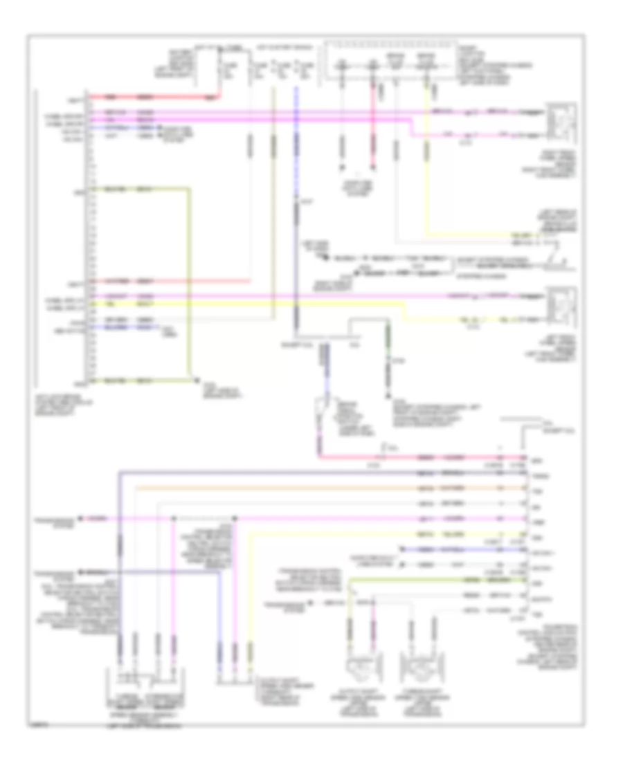
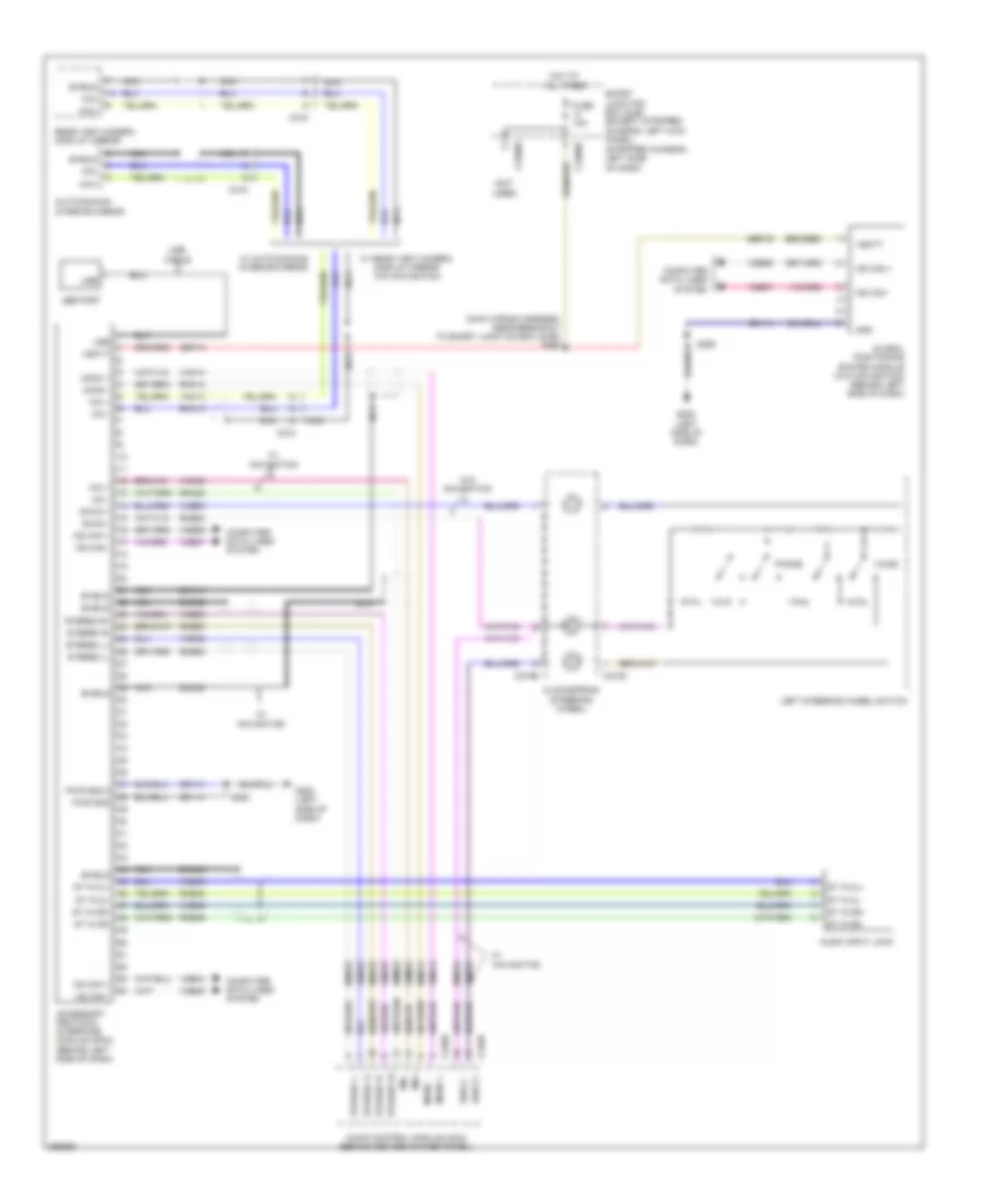
CRUISE CONTROL
5.4L
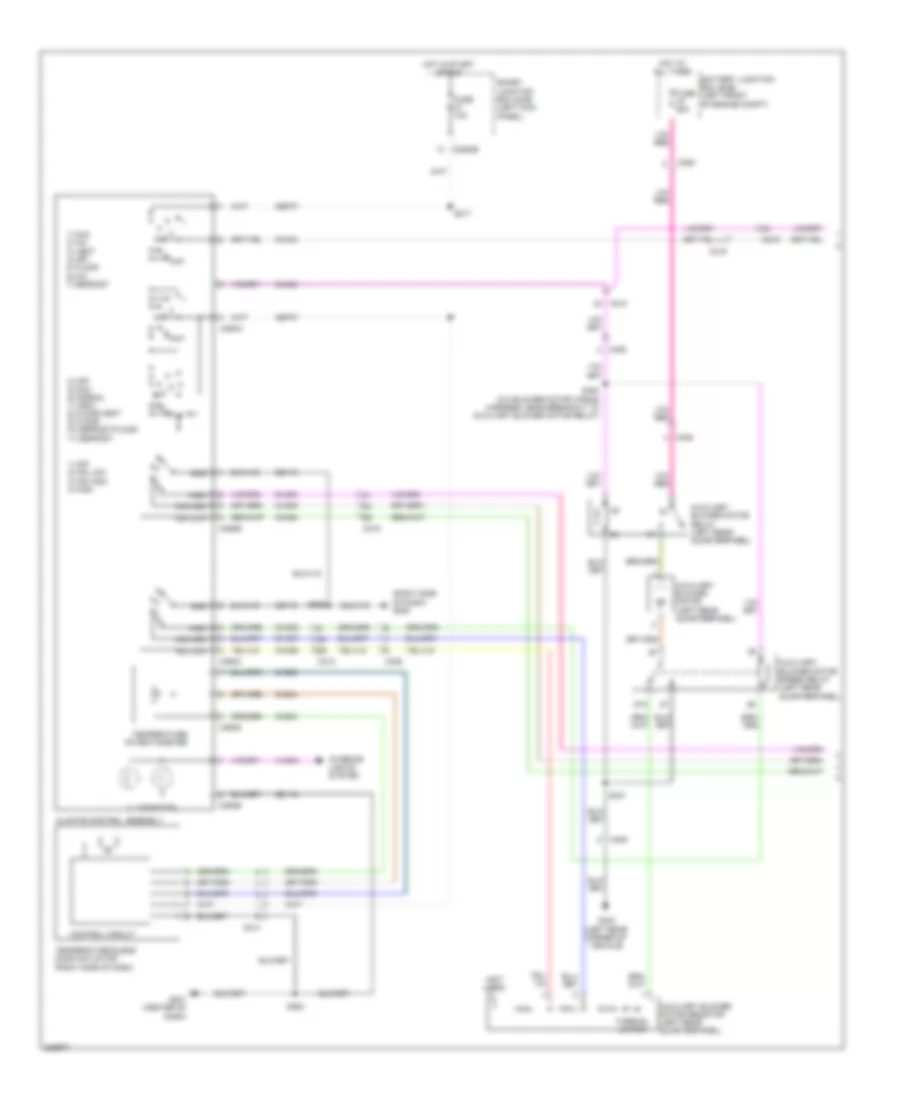
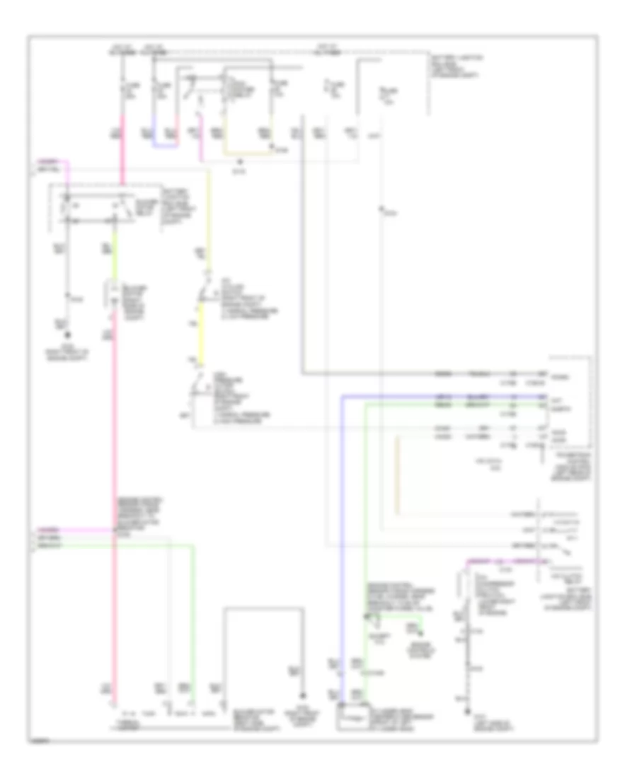
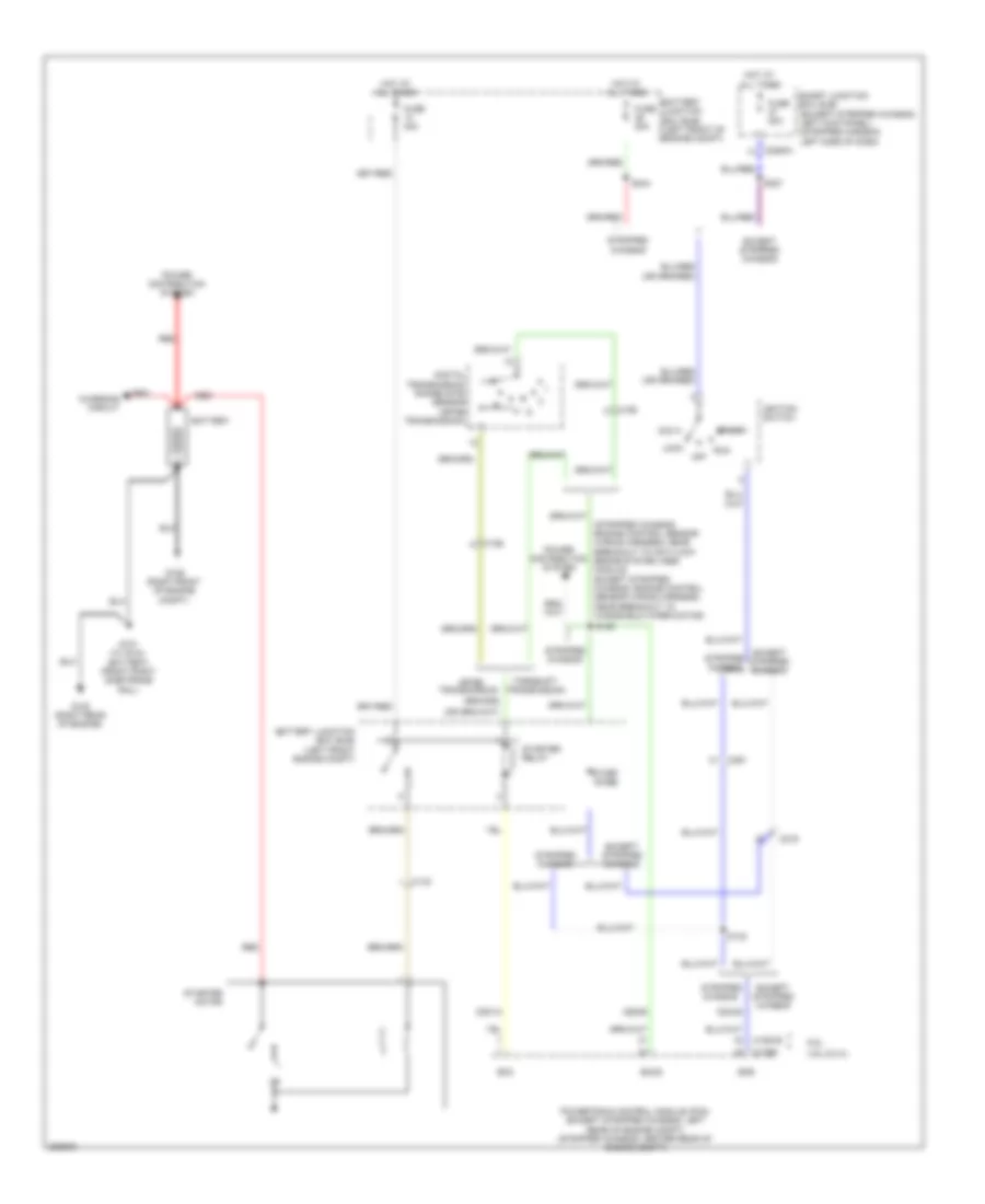
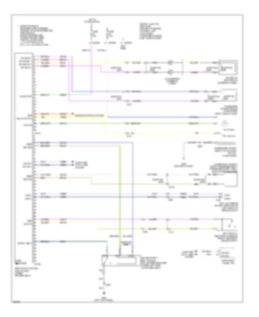
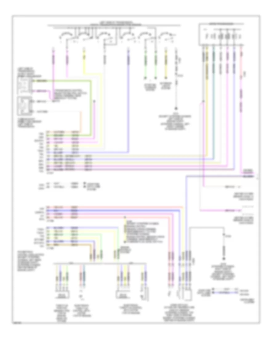
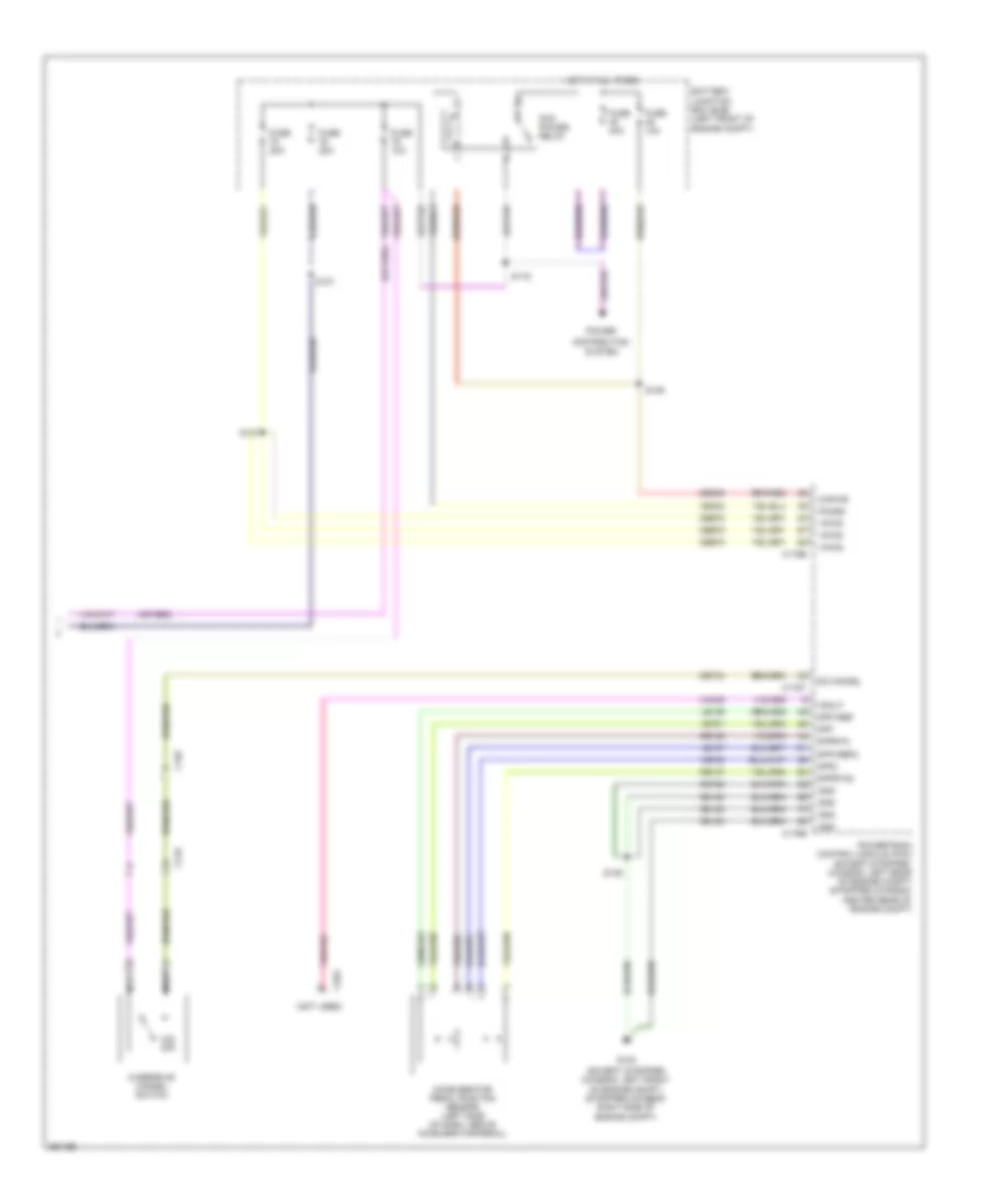
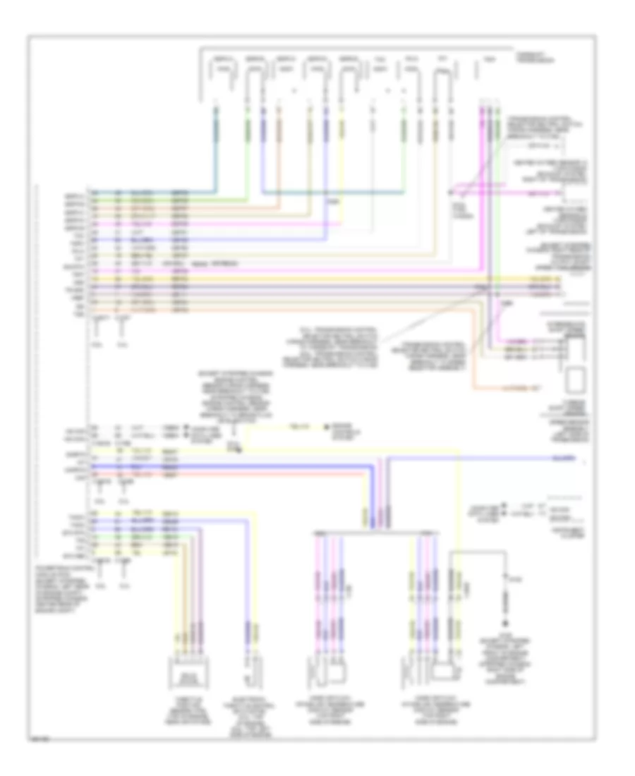
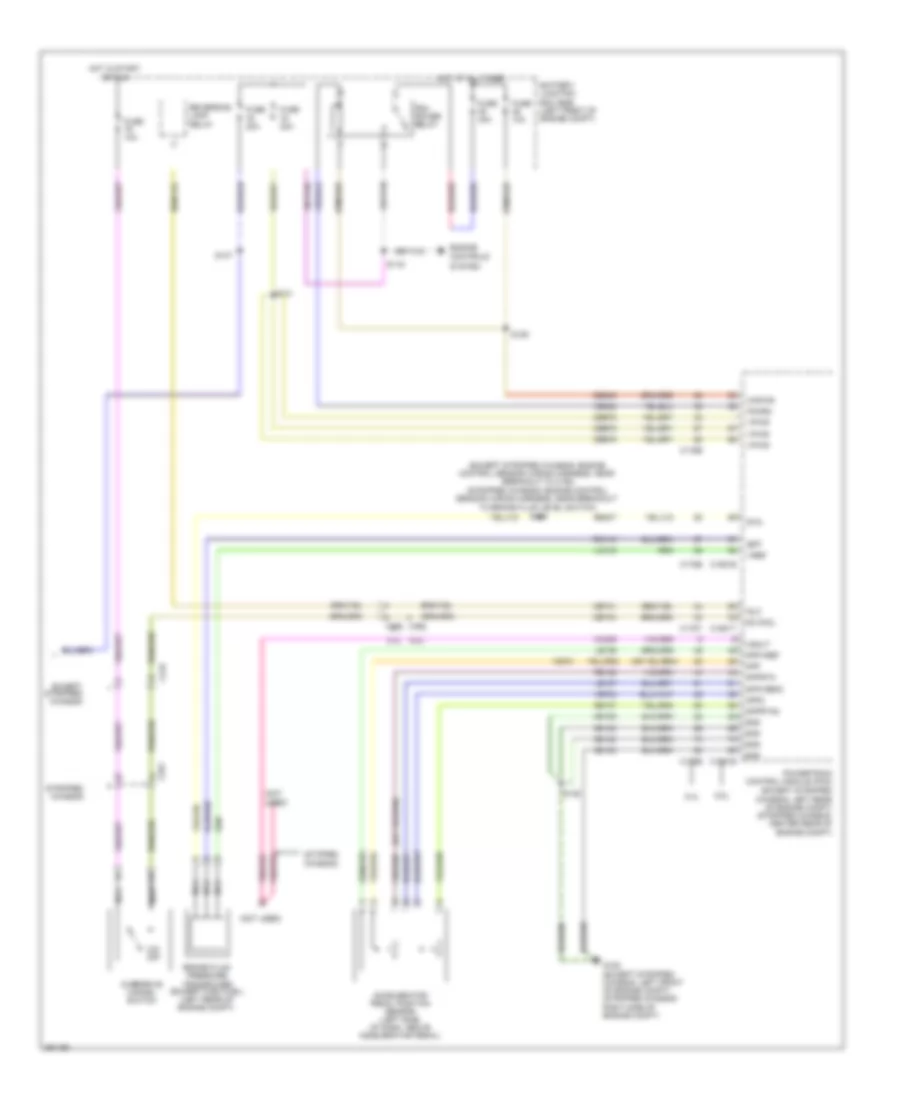
5.4L, Cruise Control Wiring Diagram for Ford E-350 Super Duty XL 2013
List of elements for 5.4L, Cruise Control Wiring Diagram for Ford E-350 Super Duty XL 2013:
- (5.4l: transmission control selector neutral switch wiring harness, near breakout to torqshift transmission) (6.8l: transmission control selector neutral switch wiring harness, near breakout to c192) s101
- (6.8l: top left side of engine)
- (except stripped chassis)
- (except stripped chassis: left front of engine compt) (stripped chassis: right side of engine compt)
- (left side of dash, above accelerator pedal) accelerator pedal position sensor
- (right rear of transmission) (torqshift) output shaft speed (oss) sensor
- (stripped stripped: engine control sensor wiring harness, near breakout to brake fluid level switch) (except stripped chassis: engine control sensor wiring harness, near breakout to c192)
- (transmission control selector neutral switch wiring harness, near breakout to speed selector assembly)
- 4.6l
- 5.4l
- 5.4l & 6.8l
- 6.8l
- App1
- App2
- Apprtn
- Apprtn2
- Appvref
- Appvref2
- Battery junction box (bjb) (left front of engine compt)
- Bfp
- Bpp
- Bps
- Brake pedal position switch (under left side of dash)
- Brake pressure transducer (5.4l & 6.8l) (left side of engine compt)
- C1551b
- C1551e
- C1551t
- C155t
- C175b
- C175e
- C175t
- C218b
- C218c
- C219
- C291
- Ccb08
- Ce412
- Ce426
- Ces09
- Clockspring (steering wheel)
- Coast
- Electronic throttle control (etc) motor (5.4l: top of engine)
- Electronic throttle control (etc) motor (top of engine)
- Engine controls system
- Etc ref
- Etc rtn
- Except stripped chassis
- Exterior lights system
- Fuse 10a
- Fuse 20a
- G105
- G202 (left side of dash)
- G207 (center of dash)
- Gd120
- Horn switch
- Horns system
- Hot at all times
- Hot in start or run
- Interior lights system
- Kapwr
- Lca16
- Le111
- Le134
- Le136
- Le137
- Left steering wheel switch
- Nca
- Off
- Oss
- Output shaft speed (oss) sensor (4r75e) (left side of transmission)
- Power gnd
- Powertrain control module (pcm) (except stripped chassis: left rear of engine compt) (stripped chassis: center rear of engine compt)
- Rca16
- Re134
- Re136
- Re137
- Re406
- Re407
- Res
- Res08
- Ret04
- Ret24
- Right steering wheel switch
- Rtn
- S102
- S104 (transmission control selector neutral switch wiring harness, near breakout to c192)
- S129
- S137
- S156
- S223 (except stripped chassis)
- S260 (stripped chassis)
- Sbb46
- Sccs
- Sccsrtn
- Set/accel
- Sig rtn
- Smart junction box (sjb))
- Solid state
- Sound systems
- Stripped chassis
- Tacm +
- Tacm -
- Throttle position sensor (tps) (top of engine, near air intake)
- Tp1
- Tp2
- Tr gnd
- Trans- missions system
- Transmissions system
- Ve701
- Ve702
- Ve818
- Ve819
- Ves10
- Vet26
- Vref
6.8L
6.8L, Cruise Control Wiring Diagram for Ford E-350 Super Duty XL 2013
List of elements for 6.8L, Cruise Control Wiring Diagram for Ford E-350 Super Duty XL 2013:
- (5.4l: transmission control selector neutral switch wiring harness, near breakout to torqshift transmission) (6.8l: transmission control selector neutral switch wiring harness, near breakout to c192) s101
- (6.8l: top left side of engine)
- (except stripped chassis)
- (except stripped chassis: left front of engine compt) (stripped chassis: right side of engine compt)
- (left side of dash, above accelerator pedal) accelerator pedal position sensor
- (right rear of transmission) (torqshift) output shaft speed (oss) sensor
- (stripped stripped: engine control sensor wiring harness, near breakout to brake fluid level switch) (except stripped chassis: engine control sensor wiring harness, near breakout to c192)
- (transmission control selector neutral switch wiring harness, near breakout to speed selector assembly)
- 4.6l
- 5.4l
- 5.4l & 6.8l
- 6.8l
- App1
- App2
- Apprtn
- Apprtn2
- Appvref
- Appvref2
- Battery junction box (bjb) (left front of engine compt)
- Bfp
- Bpp
- Bps
- Brake pedal position switch (under left side of dash)
- Brake pressure transducer (5.4l & 6.8l) (left side of engine compt)
- C1551b
- C1551e
- C1551t
- C155t
- C175b
- C175e
- C175t
- C218b
- C218c
- C219
- C291
- Ccb08
- Ce412
- Ce426
- Ces09
- Clockspring (steering wheel)
- Coast
- Electronic throttle control (etc) motor (5.4l: top of engine)
- Electronic throttle control (etc) motor (top of engine)
- Engine controls system
- Etc ref
- Etc rtn
- Except stripped chassis
- Exterior lights system
- Fuse 10a
- Fuse 20a
- G105
- G202 (left side of dash)
- G207 (center of dash)
- Gd120
- Horn switch
- Horns system
- Hot at all times
- Hot in start or run
- Interior lights system
- Kapwr
- Lca16
- Le111
- Le134
- Le136
- Le137
- Left steering wheel switch
- Nca
- Off
- Oss
- Output shaft speed (oss) sensor (4r75e) (left side of transmission)
- Power gnd
- Powertrain control module (pcm) (except stripped chassis: left rear of engine compt) (stripped chassis: center rear of engine compt)
- Rca16
- Re134
- Re136
- Re137
- Re406
- Re407
- Res
- Res08
- Ret04
- Ret24
- Right steering wheel switch
- Rtn
- S102
- S104 (transmission control selector neutral switch wiring harness, near breakout to c192)
- S129
- S137
- S156
- S223 (except stripped chassis)
- S260 (stripped chassis)
- Sbb46
- Sccs
- Sccsrtn
- Set/accel
- Sig rtn
- Smart junction box (sjb))
- Solid state
- Sound systems
- Stripped chassis
- Tacm +
- Tacm -
- Throttle position sensor (tps) (top of engine, near air intake)
- Tp1
- Tp2
- Tr gnd
- Trans- missions system
- Transmissions system
- Ve701
- Ve702
- Ve818
- Ve819
- Ves10
- Vet26
- Vref
ENGINE PERFORMANCE
5.4L
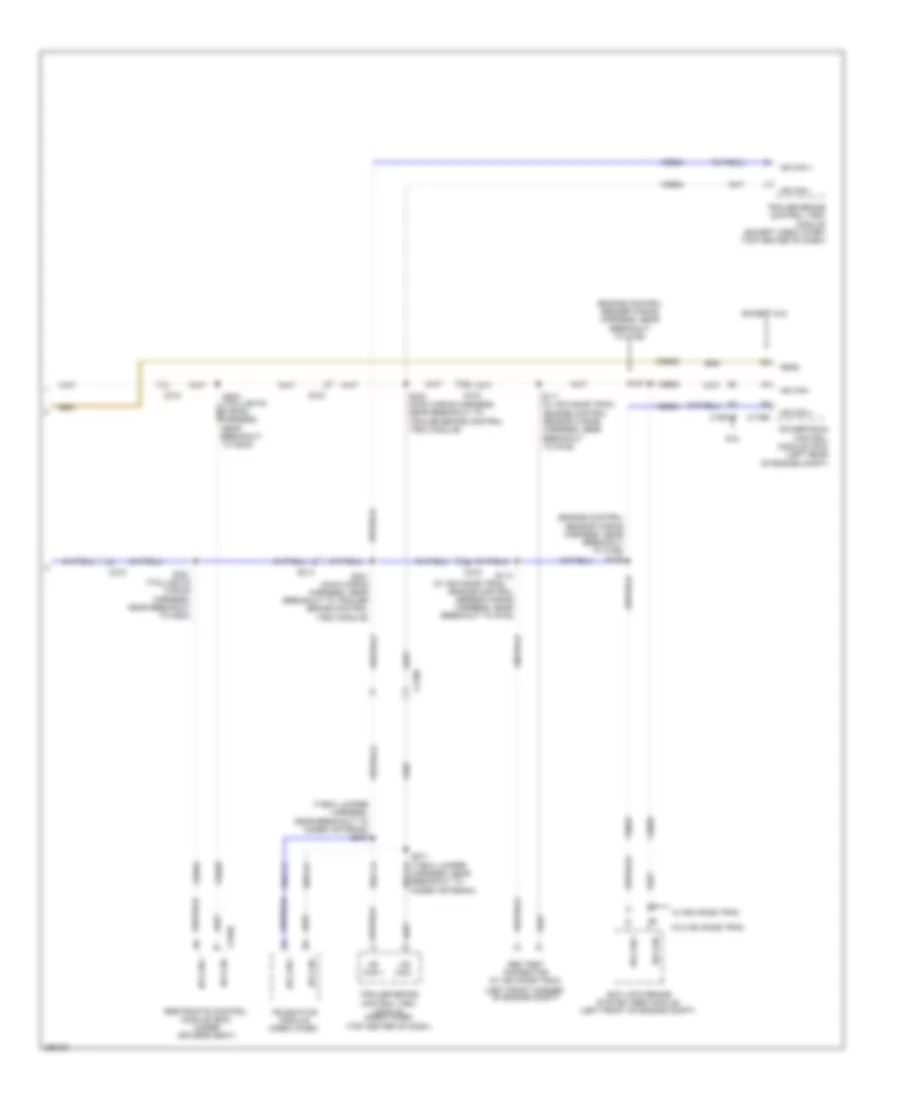
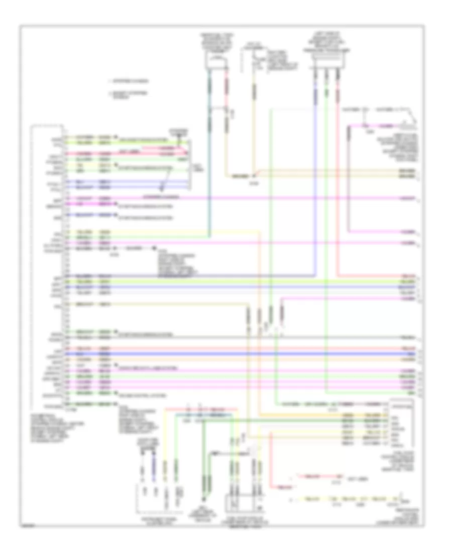
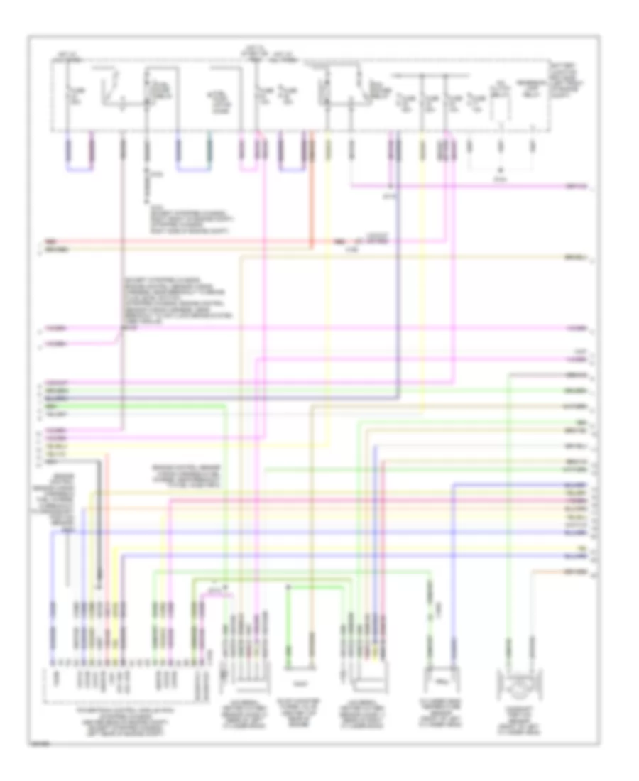
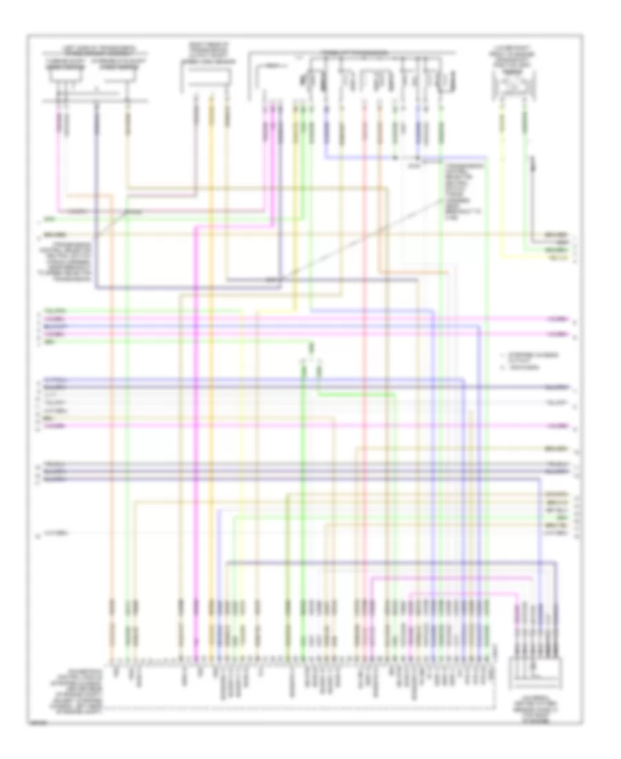
5.4L, Engine Performance Wiring Diagram, with Torqshift (1 of 5) for Ford E-350 Super Duty XL 2013
List of elements for 5.4L, Engine Performance Wiring Diagram, with Torqshift (1 of 5) for Ford E-350 Super Duty XL 2013:
- (left side of engine compt) (except flex fuel) brake fluid pressure transducer
- (near fuel tank) evaporative emission (evap) canister vent valve
- (not used)
- Accr
- Air conditioning system
- App1
- App2
- Apprtn1
- Appvref1
- Battery junction box (bjb) (left front of engine compt)
- Bfp
- Bpp
- Bps
- C110
- C175b
- C219
- C263
- C291
- C310a
- Can+
- Can-
- Canv
- Cbb54
- Cbb75
- Ccb08
- Cdc12
- Cdc15
- Cdc35
- Ce114
- Ce302
- Ce326
- Ce336
- Ce515
- Ce608
- Ce912
- Ce913
- Ce914
- Ce924
- Ces09
- Ch302
- Computer data lines system
- Cr167
- Cruise control system
- Ens
- Except stripped chassis
- Fpc
- Fpm
- Fppwr
- Fprtn
- Fuel pump control module (under rear of vehicle, near fuel tank)
- Fuel pump module (under rear of vehicle, near fuel tank)
- Fuel sndr 1
- Fuel sndr rtn 1
- Fuse 10a
- G105 (stripped chassis: right side of engine compt) (except stripped chassis: left front of engine compt)
- G401 (left rear underbody of vehicle)
- Gd120
- Gd128
- Genmon
- Gnd
- Hot at all times
- Hs can-
- Iat
- Inertia fuel shutoff (ifs) switch (stripped chassis: under dash) (except stripped chassis: right kick panel)
- Inj pwrm
- Instrument panel cluster (ipc)
- Isp-r
- Le136
- Maf
- Mafrtn
- Nca
- Pcmrc
- Powertrain control module (stripped chassis: center rear of engine compt) (except stripped chassis: left rear of engine compt)
- Ptioc 1
- Pto
- Ptoeng
- Ptoil
- Ptorpm
- Pwr gnd
- Rca16
- Re136
- Re320
- Re515
- Res08
- Restraints control module (rcm) (under driver's seat)
- S125
- S129
- S407
- Sccs rtn
- Smc
- Smcs
- Smr
- Starting/charging system
- Stripped chassis
- Vdb05
- Ve225
- Ve518
- Ve701
- Ve702
- Ve740
- Ve807
- Vmc05
- Vpwr
- Vpwr fuel
- Vsout
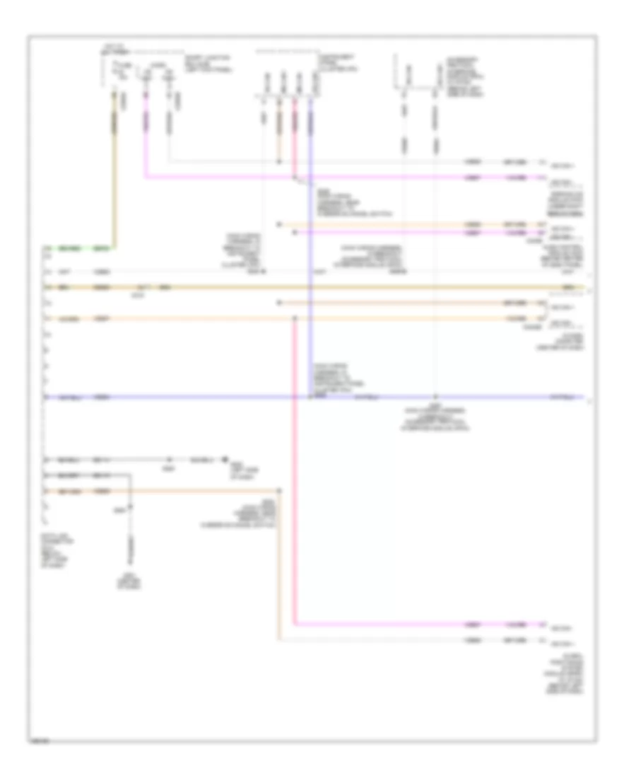
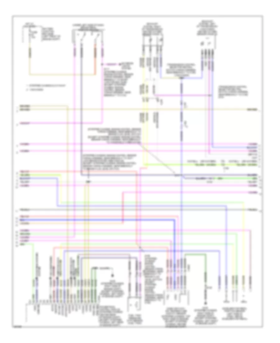
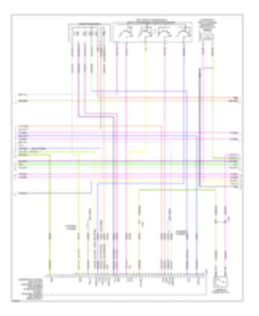
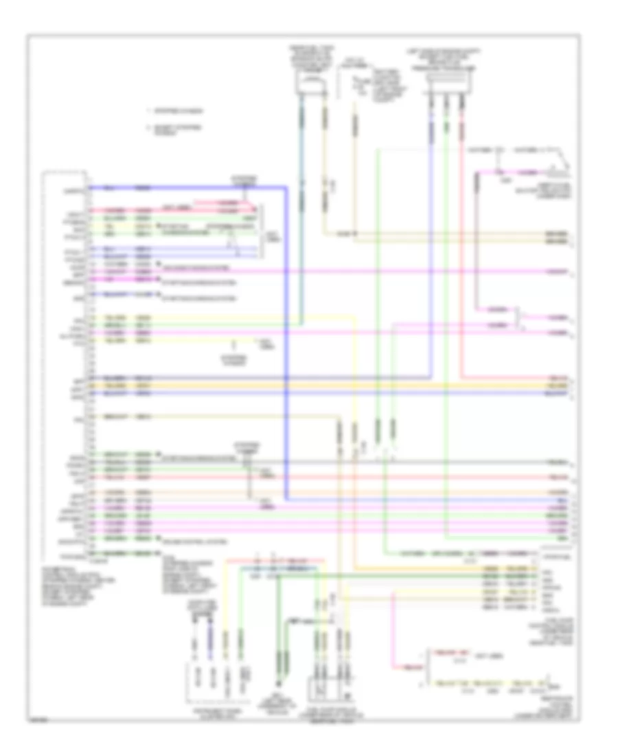
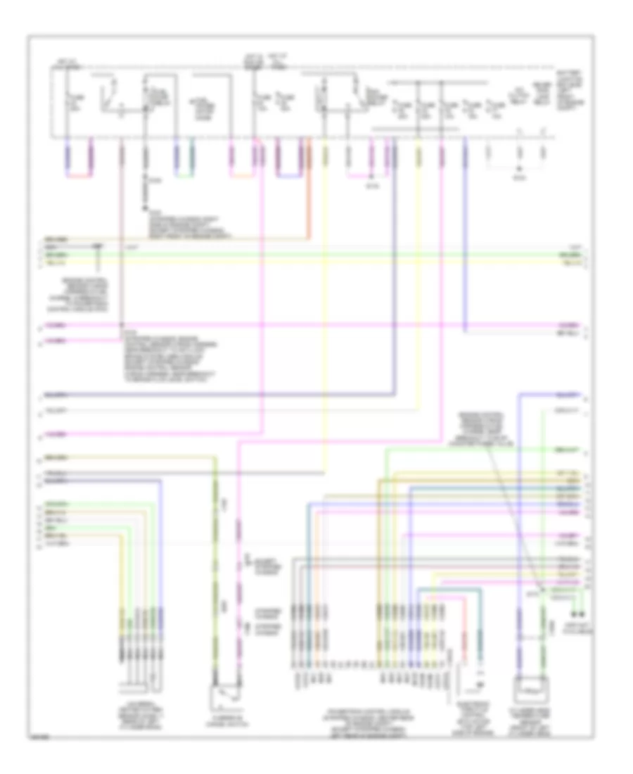
5.4L, Engine Performance Wiring Diagram, with Torqshift (2 of 5) for Ford E-350 Super Duty XL 2013
List of elements for 5.4L, Engine Performance Wiring Diagram, with Torqshift (2 of 5) for Ford E-350 Super Duty XL 2013:
- (exhaust system, left of transmission) (van/wagon) heated oxygen sensor (ho2s) 22
- (exhaust system, right of transmission) heated oxygen sensor (ho2s) 12
- (stripped chassis: engine control sensor wiring harness, near breakout to anti- lock brake system (abs) module) (except stripped chassis: engine control
- (stripped chassis: engine control sensor wiring harness, near breakout to brake fluid level switch) (except stripped chassis: engine control
- (transmission control selector neutral switch wiring harness, near breakout to c192)
- (transmission control selector neutral switch wiring harness, near breakout to c192) s104
- (under left side of dash) brake pedal position switch
- (van/wagon) s103
- Accelerator pedal position sensor (left side of dash, above accelerator pedal)
- Accs
- Apprtn2
- Appvref2
- Battery junction box (bjb) (left front of engine compt)
- C1033
- C110
- C134
- C175b
- C192
- Cbb75
- Cdb08
- Cdc10
- Ch421
- Cruise control system
- Exterior lights system
- Feps
- Ftp
- Ftpref
- Fuel tank pressure (ftp) sensor (fuel tank)
- Fuse 10a
- G105 (stripped chassis: right side of engine compt) (except stripped chassis: left front of engine compt)
- Gd120
- Gencom
- Hot at all times
- Hs can+
- Kapwr
- Lca16
- Le137
- Le230
- Level switch) (except stripped chassis: engine control sensor wiring harness, near breakout to c192)
- Lines system computer data
- Mass air flow/ air temperature (maf/iat) sensor (stripped chassis: top right side of engine) (except stripped chassis: center of engine compt)
- Nca
- Powertrain control module (stripped chassis: center rear of engine compt) (except stripped chassis: left rear of engine compt)
- Pwr gnd
- Re137
- Re407
- S117 (stripped chassis: engine control sensor wiring harness, near breakout to smart junction box (sjb)) (except stripped chassis: engine control sensor wiring harness, near breakout to c144)
- S125
- S131
- S137
- S156 (stripped chassis: engine control sensor wiring harness, near breakout to brake fluid
- Sbb46
- Sccs
- Sensor wiring harness, near breakout to brake fluid level switch)
- Sensor wiring harness, near breakout to windshield wiper motor)
- Sigrtn
- Stripped chassis & cutaway
- System air conditioning
- System starting/charging
- Van/wagon
- Vdb04
- Ve922
- Ves10
- Vpwr
- Vref
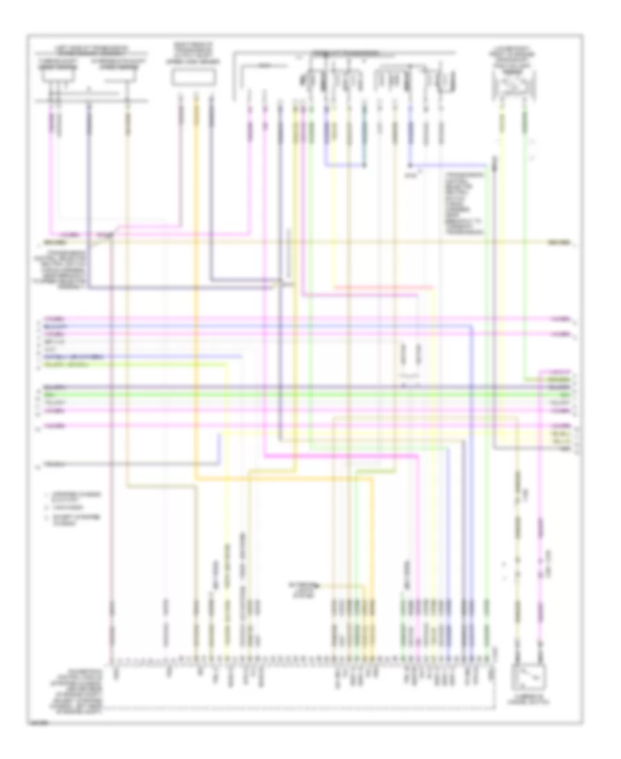
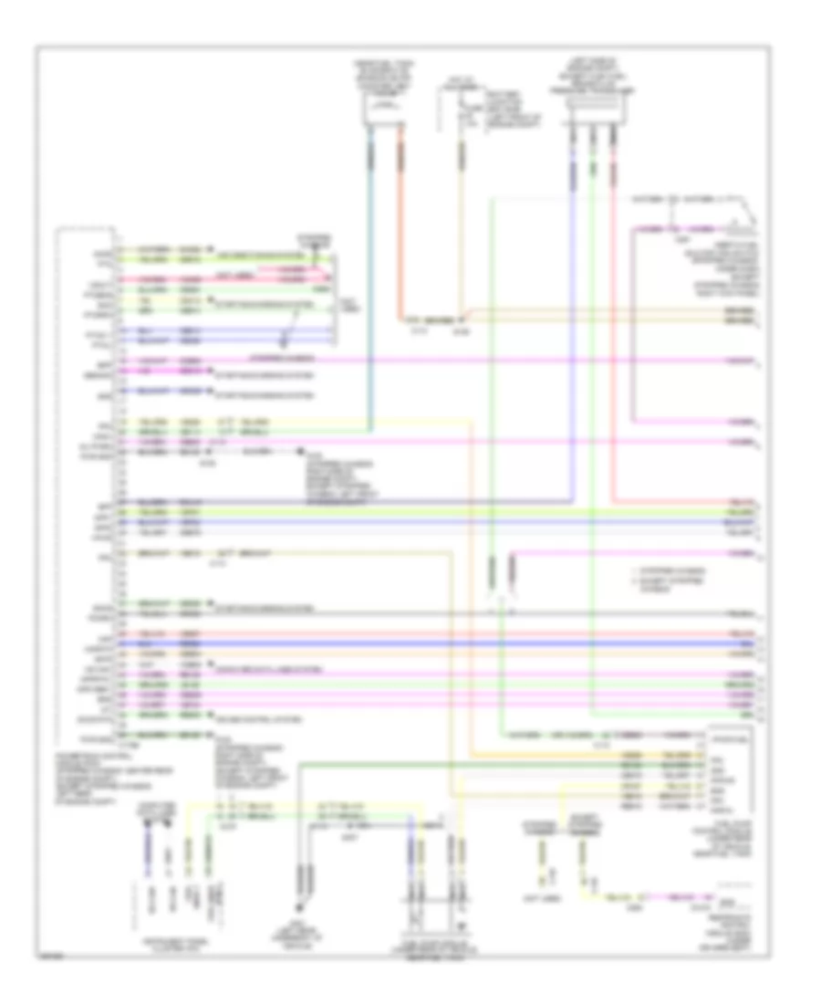
5.4L, Engine Performance Wiring Diagram, with Torqshift (3 of 5) for Ford E-350 Super Duty XL 2013
List of elements for 5.4L, Engine Performance Wiring Diagram, with Torqshift (3 of 5) for Ford E-350 Super Duty XL 2013:
- & cutway
- (left side of transmission) speed sensor assembly
- (lower right front of engine) crankshaft position (ckp) sensor
- (not used)
- (or ce239)
- (or ve745)
- (right rear of transmission) output shaft speed (oss) sensor
- (stripped chassis: center rear of engine compt) (except stripped chassis: left rear of engine compt)
- (transmission control selector neutral switch wiring harness, near breakout to speed selector assembly)
- (transmission control selector neutral switch wiring harness, near breakout to torqshift transmission)
- C175t
- C192
- C219
- C291
- Ce223
- Ce234
- Cet05
- Cet06
- Cet07
- Cet08
- Cet09
- Cet21
- Cet22
- Cet25
- Cet34
- Cet41
- Cet50
- Cet51
- Except stripped chassis
- Exterior
- Ho2s-12
- Ho2s-22
- Htr-12
- Htr-22
- Intermediate shaft speed sensor
- Iss
- Le111
- Lights system
- Nca
- Od cncl
- Oss
- Overdrive cancel switch
- Pc-a
- Powertrain control module
- Re406
- Ret04
- Ret24
- Rlc
- S100
- S101
- S102
- Sigrtn
- Sspc a
- Sspc b
- Sspc c
- Sspc d
- Sspc e
- Sspc-a
- Sspc-b
- Sspc-c
- Sspc-d
- Sspc-e
- Stripped chassis
- Tcc
- Tft
- Torqshift transmission
- Tr gnd
- Tr-p
- Tro_n
- Tro_p
- Tspc
- Tss
- Turbine shaft speed sensor
- Van/wagon
- Ve731
- Ve733
- Ve744
- Vet27
- Vet32
- Vet33
- Vref
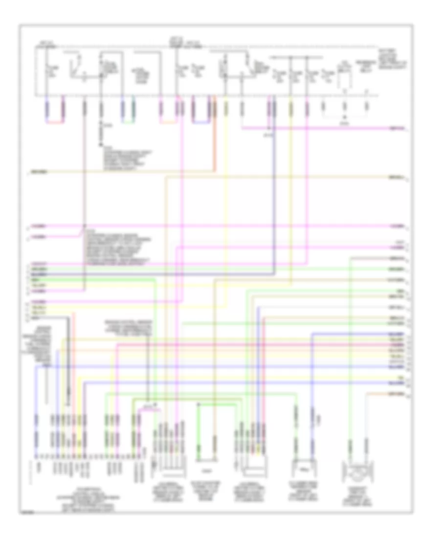
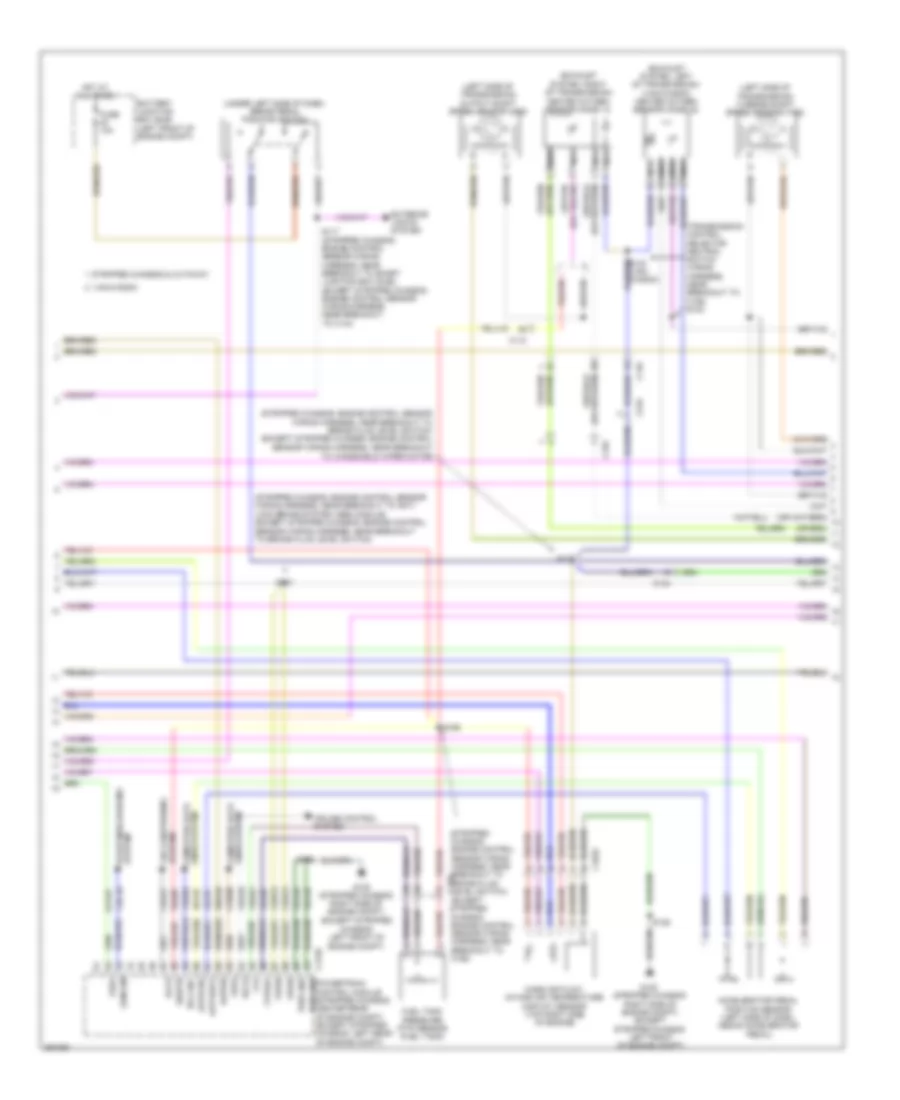
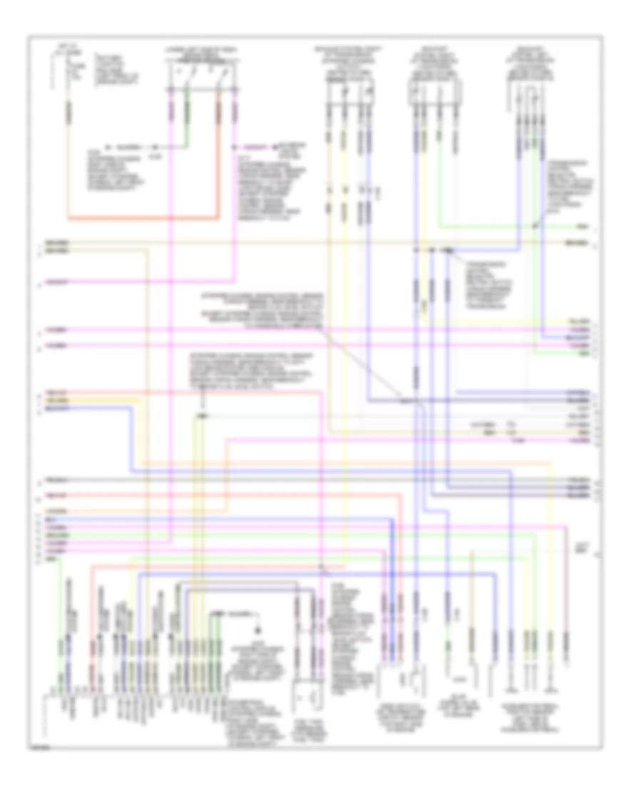
5.4L, Engine Performance Wiring Diagram, with Torqshift (4 of 5) for Ford E-350 Super Duty XL 2013
List of elements for 5.4L, Engine Performance Wiring Diagram, with Torqshift (4 of 5) for Ford E-350 Super Duty XL 2013:
- (engine control sensor wiring harness & fuel charge, in breakout to crankshaft position sensor) s178
- (engine control sensor wiring harness & fuel charge, near breakout to fuel injector 8)
- A/c clutch relay
- Battery junction box (bjb) (left front of engine compt)
- C1046
- C175e
- Camshaft position sensor 11 (front of left cylinder head)
- Ce235
- Ce236
- Ce303
- Ce304
- Ce305
- Ce308
- Ce309
- Ce426
- Ckp+
- Cop1a
- Cop2d
- Cop3b
- Cop6e
- Cop7c
- Cylinder head temperature sensor (front of left cylinder head)
- De135
- Etc ref
- Etc rtn
- Evap canister purge valve (center top rear of engine)
- Fuel power motor diode
- Fuel pump relay
- Fuse 10a
- Fuse 20a
- Fuse 40a
- G100 (stripped chassis: right side of engine compt) (except stripped chassis: right front of engine compt)
- Hot at all times
- Hot in run or start
- Le134
- Nca
- Pcm power relay
- Powertrain control module (stripped chassis: center rear of engine compt) (except stripped chassis: left rear of engine compt)
- Re134
- Re405
- Red
- Reversing lamp relay
- S108
- S116
- S124
- S130 (stripped chassis: engine control sensor wiring harness, near breakout to anti-lock brake system (abs) module) (except stripped chassis: engine control sensor wiring harness, near breakout to brake fluid level switch)
- S174
- Shdrtn
- Sigrtn
- Tacm-
- Universal heated oxygen sensor (ho2s) 11 (rear of right cylinder bank)
- Universal heated oxygen sensor (ho2s) 21 (rear of left cylinder bank)
- Uo2shtr11
- Uo2shtr21
- Ve711
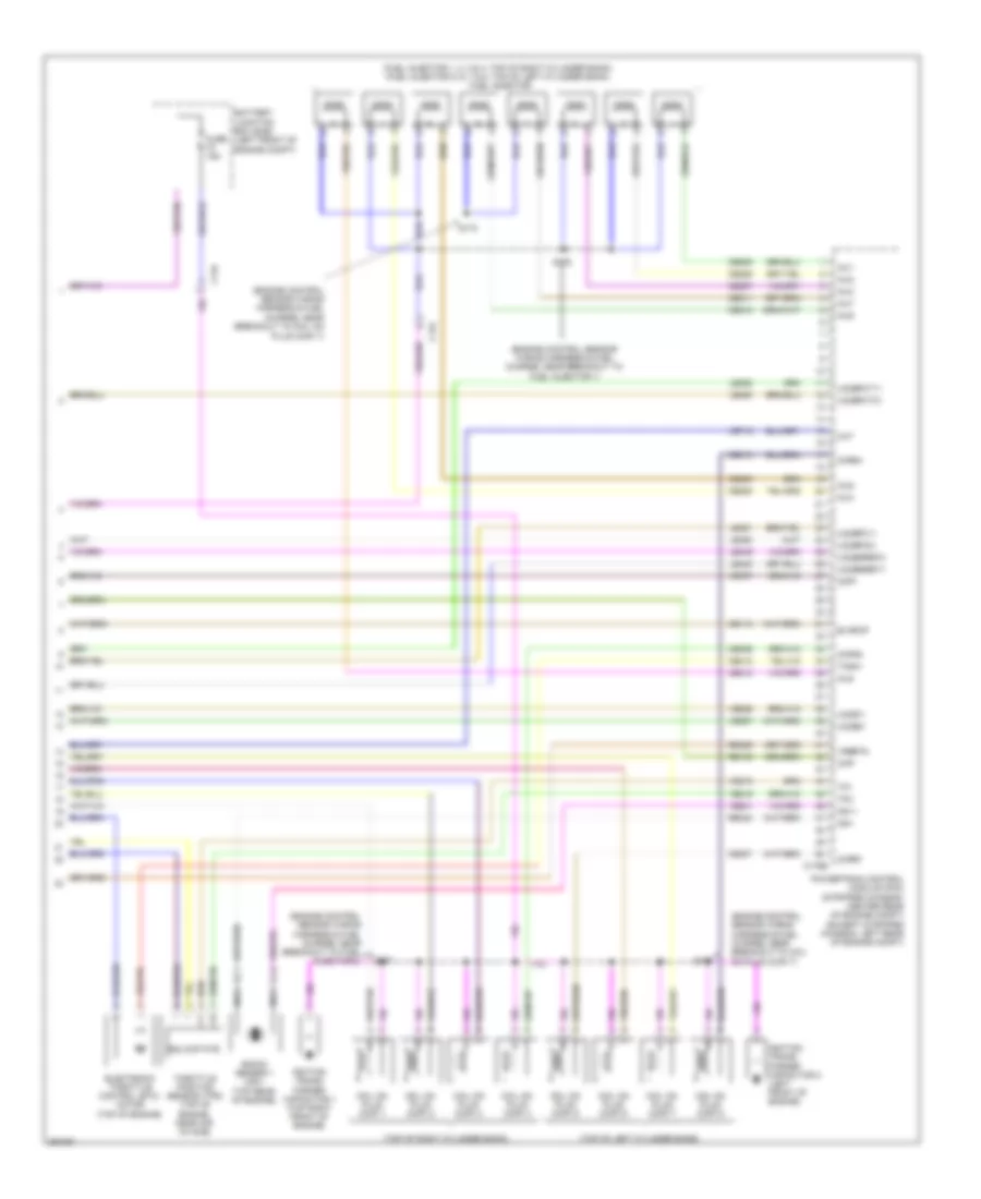
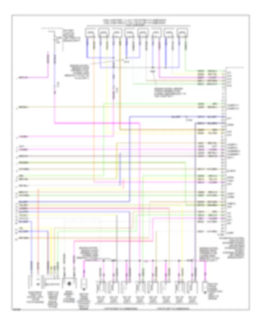
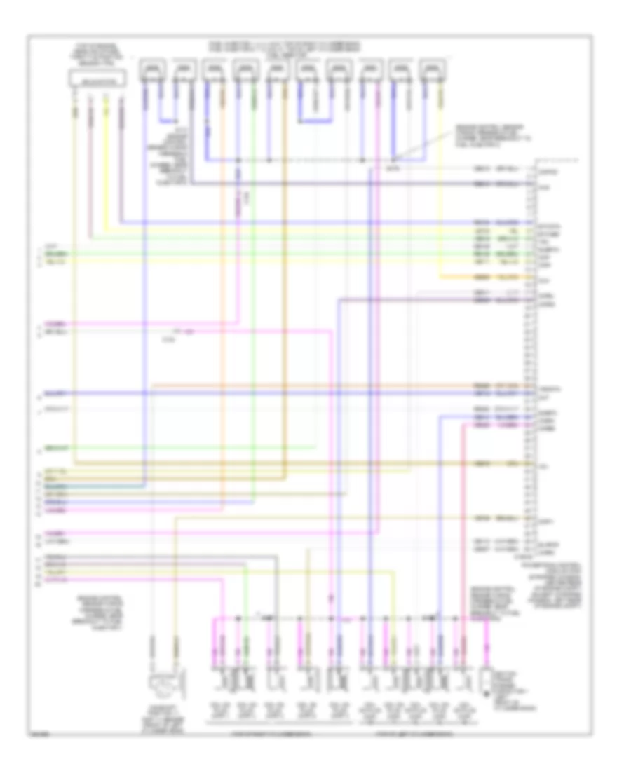
5.4L, Engine Performance Wiring Diagram, with Torqshift (5 of 5) for Ford E-350 Super Duty XL 2013
List of elements for 5.4L, Engine Performance Wiring Diagram, with Torqshift (5 of 5) for Ford E-350 Super Duty XL 2013:
- (engine control sensor wiring harness & fuel charge, near breakout to coil on
- (engine control sensor wiring harness & fuel charge, near breakout to coil on plug (cop) 7)
- (engine control sensor wiring harness & fuel charge, near breakout to fuel injector 1)
- (engine control sensor wiring harness & fuel charge, near breakout to fuel injector 2)
- (fuel injector 1, 2, 3 & 4: top of right cylinder bank) (fuel injector 5, 6, 7 & 8: top of left cylinder bank) fuel injector
- (top of left cylinder bank)
- (top of right cylinder bank)
- Battery junction box (bjb) (left front of engine compt)
- C134
- C175e
- Ce113
- Ce205
- Ce206
- Ce207
- Ce208
- Ce209
- Ce210
- Ce211
- Ce212
- Ce306
- Ce307
- Ce310
- Ce412
- Cht
- Ckp-
- Cmp1
- Coil on plug (cop) 1
- Coil on plug (cop) 2
- Coil on plug (cop) 3
- Coil on plug (cop) 4
- Coil on plug (cop) 5
- Coil on plug (cop) 6
- Coil on plug (cop) 7
- Coil on plug (cop) 8
- Cop4g
- Cop5f
- Cop8h
- Electronic throttle control (etc) motor (top of engine)
- Evapcp
- Fuse 15a
- Ignition trans- former capacitor 1 (top right front of engine)
- Ignition trans- former capacitor 2 (left front of engine)
- Inj1
- Inj2
- Inj3
- Inj4
- Inj5
- Inj6
- Inj7
- Inj8
- Knock sensor 1 (ks1) (top rear of engine)
- Ks1+
- Ks1-
- Le448
- Le449
- Le450
- Le451
- Le452
- Le453
- Nca
- Plug (cop) 7)
- Powertrain control module (pcm) (stripped chassis: center rear of engine compt) (except stripped chassis: left rear of engine compt)
- Re135
- Re323
- Re429
- S170
- S173
- S175
- S177
- Solid state
- Tacm+
- Throttle position sensor (tps) (top of engine, near air intake)
- Tp1
- Tp2
- Uo2s11
- Uo2s21
- Uo2sgref11
- Uo2sgref21
- Uo2spc11
- Uo2spc21
- Uo2spct11
- Uo2spct21
- Ve707
- Ve712
- Ve801
- Ve818
- Ve819
- Ve826
- Ve827
- Vrsrtn
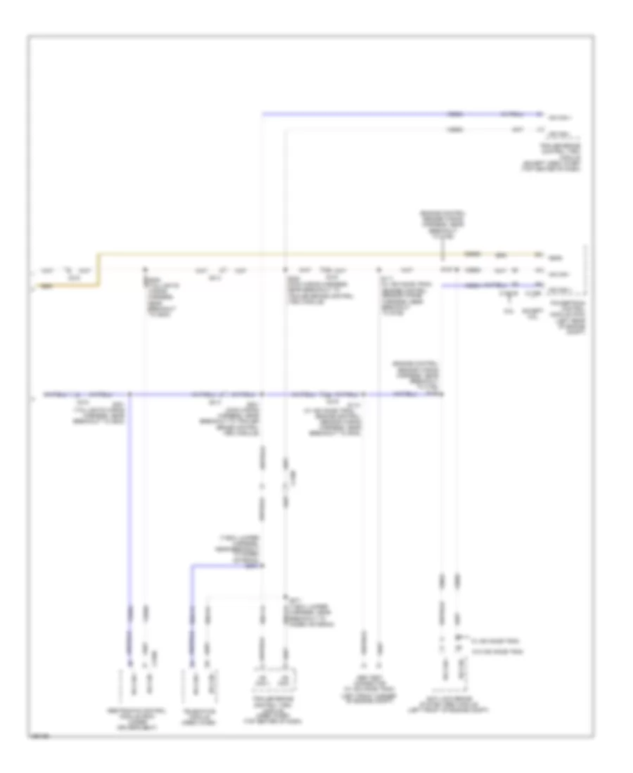
5.4L, Engine Performance Wiring Diagram, without Torqshift (1 of 5) for Ford E-350 Super Duty XL 2013
List of elements for 5.4L, Engine Performance Wiring Diagram, without Torqshift (1 of 5) for Ford E-350 Super Duty XL 2013:
- (left side of engine compt) (except flex fuel) brake fluid pressure transducer
- (near fuel tank) evaporative emission (evap) canister vent valve
- (not used)
- Accr
- Air conditioning system
- App1
- App2
- Apprtn1
- Appvref1
- Battery junction box (bjb) (left front of engine compt)
- Bfp
- Bpp
- Bps
- C110
- C175b
- C219
- C263
- C291
- C310a
- Canv
- Cbb54
- Cbb75
- Ccb08
- Cdc12
- Cdc15
- Cdc35
- Ce114
- Ce302
- Ce326
- Ce336
- Ce515
- Ce608
- Ce912
- Ce913
- Ce914
- Ce924
- Ces09
- Ch302
- Chassis: left front of engine compt)
- Computer data lines system
- Cr167
- Cruise control system
- Ens
- Except stripped chassis
- Fpc
- Fpm
- Fppwr
- Fprtn
- Fuel
- Fuel pump control module (under rear of vehicle, near fuel tank)
- Fuel pump module (under rear of vehicle, near fuel tank)
- Fuel sndr rtn 1
- Fuse 10a
- G105 (stripped chassis: right side of engine compt) (except stripped
- G105 (stripped chassis: right side of engine compt) (except stripped chassis: left front of engine compt)
- G401 (left rear underbody of vehicle)
- Gd120
- Gd128
- Genmon
- Gnd
- Hot at all times
- Hs can+
- Hs can-
- Iat
- Inertia fuel shutoff (ifs) switch (stripped chassis:
- Inj pwrm
- Instrument panel cluster (ipc)
- Isp-r
- Le136
- Maf
- Mafrtn
- Nca
- Pcmrc
- Powertrain control module (pcm) (stripped chassis: center rear of engine compt) (except stripped chassis: left rear of engine compt)
- Ptioc 1
- Pto
- Ptoeng
- Ptoil
- Ptorpm
- Pwr gnd
- Rca16
- Re136
- Re320
- Re515
- Res08
- Restraints control module (rcm) (under driver's seat)
- Right kick panel)
- S125
- S129
- S407
- Sccs rtn
- Smc
- Smcs
- Smr
- Sndr 1
- Starting/charging system
- Stripped chassis
- Stripped chassis:
- Under dash) (except
- Vdb05
- Ve225
- Ve518
- Ve701
- Ve702
- Ve740
- Ve807
- Vmc05
- Vpwr
- Vpwr fuel
- Vsout
5.4L, Engine Performance Wiring Diagram, without Torqshift (2 of 5) for Ford E-350 Super Duty XL 2013
List of elements for 5.4L, Engine Performance Wiring Diagram, without Torqshift (2 of 5) for Ford E-350 Super Duty XL 2013:
- (exhaust system, left of transmission) (van/wagon) heated oxygen sensor (ho2s) 22
- (exhaust system, right of transmission)
- (left side of transmission) output shaft speed sensor (oss)
- (left side of transmission) turbine shaft speed sensor (tss)
- (stripped chassis: engine control sensor wiring harness, near breakout to anti- lock brake system (abs) module) (except stripped chassis: engine control
- (stripped chassis: engine control sensor wiring harness, near breakout to brake fluid level switch) (except stripped chassis: engine control
- (stripped chassis: engine control sensor wiring harness, near breakout to brake fluid level switch) c110 (except stripped chassis: engine control sensor wiring harness, near breakout to c192)
- (stripped chassis: right side of engine compt) (except stripped
- (transmission control selector neutral switch wiring harness, near breakout to c192) s104
- (under left side of dash) brake pedal position switch
- Accelerator pedal position sensor (left side of dash, above accelerator pedal)
- Accs
- Apprtn2
- Appvref2
- Battery junction box (bjb) (left front of engine compt)
- C1033
- C110
- C134
- C175b
- C192
- Cbb75
- Cdb08
- Cdc10
- Ch421
- Chassis: left front of engine compt)
- Chassis: left rear of engine compt)
- Cruise control system
- Exterior lights system
- Feps
- Ftp
- Ftpref
- Fuel tank pressure (ftp) sensor (fuel tank)
- Fuse 10a
- G105
- G105 (stripped chassis: right side of engine compt) (except stripped chassis: left front of engine compt)
- Gd120
- Gencom
- Heated oxygen sensor (ho2s) 12
- Hot at all times
- Hs can+
- Kapwr
- Lca16
- Le137
- Le230
- Lines system computer data
- Mass air flow/ intake air temperature (maf/iat) sensor (top right side of engine)
- Nca
- Pwr gnd
- Pwr gnd powertrain control module (stripped chassis: center rear of engine compt) (except stripped
- Re137
- Re407
- S117 (stripped chassis: engine control sensor wiring harness, near breakout to smart junction box (sjb)) (except stripped chassis: engine control sensor wiring harness, near breakout to c144)
- S125
- S131
- S137
- S156
- Sbb46
- Sccs
- Sensor wiring harness, near breakout to brake fluid level switch)
- Sensor wiring harness, near breakout to windshield wiper motor)
- Sigrtn
- Stripped chassis & cutaway
- System air conditioning
- System starting/charging
- Van/wagon
- Vdb04
- Ve922
- Ves10
- Vpwr
- Vref
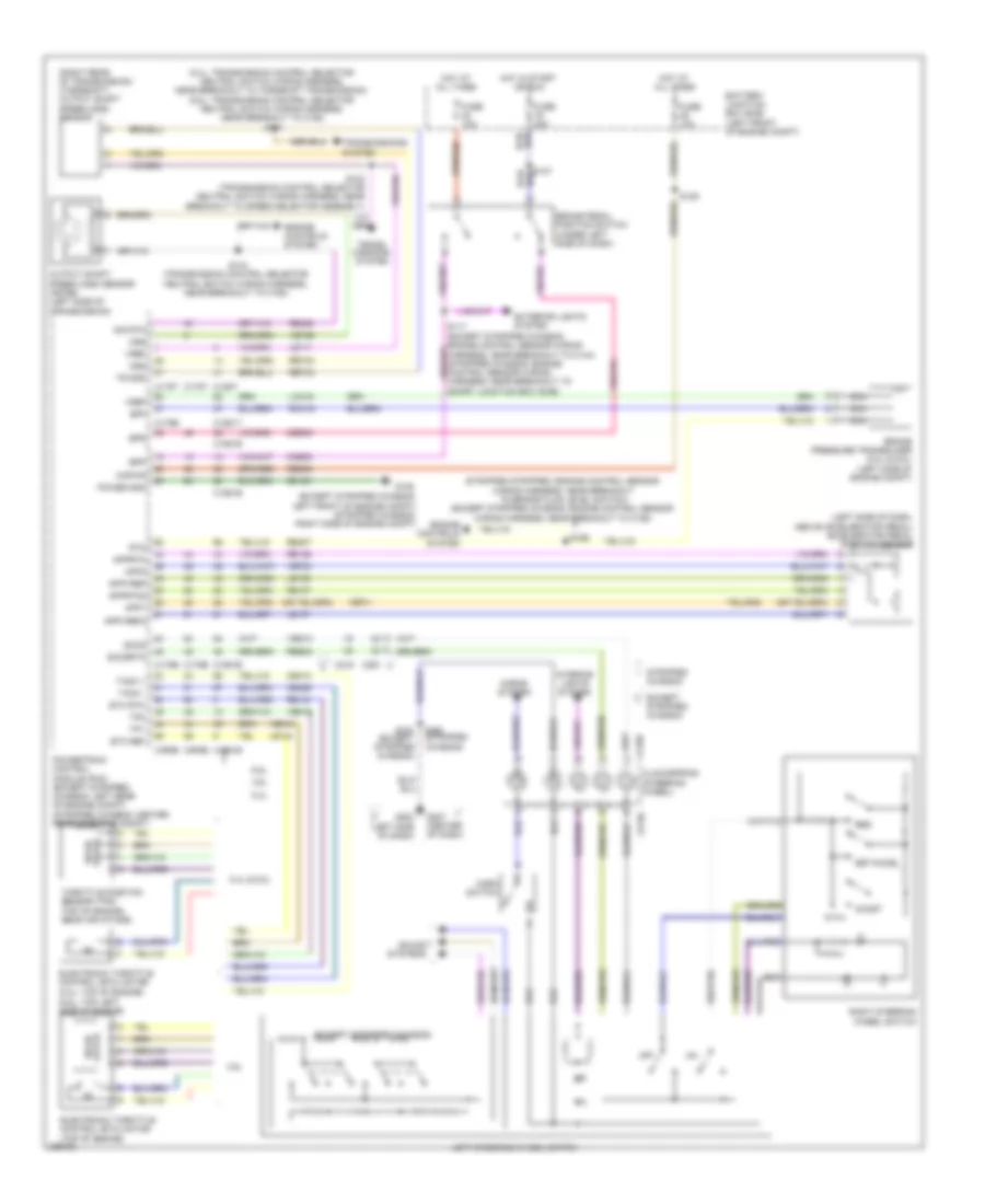
5.4L, Engine Performance Wiring Diagram, without Torqshift (3 of 5) for Ford E-350 Super Duty XL 2013
List of elements for 5.4L, Engine Performance Wiring Diagram, without Torqshift (3 of 5) for Ford E-350 Super Duty XL 2013:
- (left side of transmission) digital transmission range (dtr) sensor
- (lower right front of engine) crankshaft position (ckp) sensor
- (not used)
- (or ce239)
- (or ve745)
- (stripped chassis: center rear of engine compt) (except stripped chassis: left rear of engine compt)
- 4r75e transmission
- C175t
- C192
- C219
- Ce223
- Ce234
- Ce418
- Cet05
- Cet18
- Cet19
- Cet21
- Cet22
- Cet34
- Epc
- Ho2s-12
- Ho2s-22
- Htr-12
- Htr-22
- N r
- Nca
- Od cncl
- Oss
- Overdrive cancel switch
- Powertrain control module (pcm)
- Re406
- Red
- Sigrtn
- Ssa
- Ssb
- Stripped chassis
- Tcc
- Tft
- Tr1
- Tr2
- Tr3a
- Tr4
- Tro_n
- Tro_p
- Tss
- Ve731
- Ve733
- Vet26
- Vet27
- Vet28
- Vet29
- Vet30
- Vet31
- Vet33
5.4L, Engine Performance Wiring Diagram, without Torqshift (4 of 5) for Ford E-350 Super Duty XL 2013
List of elements for 5.4L, Engine Performance Wiring Diagram, without Torqshift (4 of 5) for Ford E-350 Super Duty XL 2013:
- (engine control sensor wiring harness & fuel charge, in breakout to crankshaft position sensor) s178
- (engine control sensor wiring harness & fuel charge, near breakout to fuel injector 8)
- (except stripped chassis: engine control sensor wiring harness, near breakout to brake fluid level switch) (stripped chassis: engine control sensor wiring harness, near breakout to anti-lock brake system (abs) module) s130
- A/c clutch relay
- Battery junction box (bjb) (left front of engine compt)
- C1046
- C175e
- C192
- Camshaft position sensor (front of left cylinder head)
- Ce235
- Ce236
- Ce303
- Ce304
- Ce305
- Ce308
- Ce309
- Ce426
- Ckp+
- Cop1a
- Cop2d
- Cop3b
- Cop6e
- Cop7c
- Cylinder head temperature sensor (front of left cylinder head)
- De135
- Etc ref
- Etc rtn
- Evap canister purge valve (center top rear of engine)
- Fuel pump motor diode
- Fuel pump relay
- Fuse 10a
- Fuse 20a
- Fuse 40a
- G100 (except stripped chassis: right front of engine compt) (stripped chassis: right side of engine compt)
- Hot at all times
- Hot in start or run
- Le134
- Nca
- Pcm power relay
- Powertrain control module (pcm) (stripped chassis: center rear of engine compt) (except stripped chassis: left rear of engine compt)
- Re134
- Re405
- Red
- Reversing lamp relay
- S108
- S116
- S124
- S174
- Shdrtn
- Sigrtn
- Tacm-
- Universal heated oxygen sensor (ho2s) 11 (rear of right cylinder bank)
- Universal heated oxygen sensor (ho2s) 21 (rear of left cylinder bank)
- Uo2shtr11
- Uo2shtr21
- Ve711
5.4L, Engine Performance Wiring Diagram, without Torqshift (5 of 5) for Ford E-350 Super Duty XL 2013
List of elements for 5.4L, Engine Performance Wiring Diagram, without Torqshift (5 of 5) for Ford E-350 Super Duty XL 2013:
- (engine control sensor wiring harness & fuel charge, near breakout to coil on
- (engine control sensor wiring harness & fuel charge, near breakout to coil on plug (cop) 7)
- (engine control sensor wiring harness & fuel charge, near breakout to fuel injector 1)
- (engine control sensor wiring harness & fuel charge, near breakout to fuel injector 2)
- (fuel injectors 1, 2, 3 & 4: top of right cylinder bank) (fuel injectors 5, 6, 7 & 8: top of left cylinder bank) fuel injectors
- (top of left cylinder bank)
- (top of right cylinder bank)
- Battery junction box (bjb) (left front of engine compt)
- C1046
- C134
- C175e
- Ce113
- Ce205
- Ce206
- Ce207
- Ce208
- Ce209
- Ce210
- Ce211
- Ce212
- Ce306
- Ce307
- Ce310
- Ce412
- Cht
- Ckp-
- Cmp 11
- Coil on plug (cop) 1
- Coil on plug (cop) 2
- Coil on plug (cop) 3
- Coil on plug (cop) 4
- Coil on plug (cop) 5
- Coil on plug (cop) 6
- Coil on plug (cop) 7
- Coil on plug (cop) 8
- Cop4g
- Cop5f
- Cop8h
- Electronic throttle control (etc) motor (top of engine)
- Evapcp
- Fuse 15a
- Ignition trans- former capacitor 1 (top right front of engine)
- Ignition trans- former capacitor 2 (left front of engine)
- Inj1
- Inj2
- Inj3
- Inj4
- Inj5
- Inj6
- Inj7
- Inj8
- Knock sensor 1 (ks1) (top rear of engine)
- Ks1+
- Ks1-
- Le448
- Le449
- Le450
- Le451
- Le452
- Le453
- Nca
- Plug (cop) 7)
- Powertrain control module (pcm) (stripped chassis: center rear of engine compt) (except stripped chassis: left rear of engine compt)
- Re135
- Re323
- Re429
- S170
- S173
- S175
- S177
- Solid state
- Tacm+
- Throttle position sensor (top of engine, near air intake)
- Tp1
- Tp2
- Uo2s11
- Uo2s21
- Uo2sgref11
- Uo2sgref21
- Uo2spc11
- Uo2spc21
- Uo2spct11
- Uo2spct21
- Ve707
- Ve712
- Ve801
- Ve818
- Ve819
- Ve826
- Ve827
- Vrsrtn
6.8L
6.8L, Engine Performance Wiring Diagram (1 of 5) for Ford E-350 Super Duty XL 2013
List of elements for 6.8L, Engine Performance Wiring Diagram (1 of 5) for Ford E-350 Super Duty XL 2013:
- (left side of engine compt) (except flex fuel) brake fluid pressure transducer
- (near fuel tank) evaporative emission (evap) canister vent valve
- (not used)
- Accr
- Air conditioning system
- App1
- App2
- Apprtn1
- Appvref1
- Battery junction box (bjb) (left front of engine compt)
- Bfp
- Bpp
- Bps
- C110
- C1551b
- C219
- C263
- C291
- C310a
- Canv
- Cbb54
- Ccb08
- Cdc12
- Cdc15
- Cdc35
- Ce114
- Ce302
- Ce326
- Ce336
- Ce515
- Ce608
- Ce912
- Ce913
- Ce914
- Ce924
- Ces09
- Cet21
- Cet22
- Ch302
- Chassis
- Computer data lines system
- Cr167
- Cruise control system
- Ens
- Except stripped
- Fpc
- Fpm
- Fppwr
- Fprtn
- Fuel pump control module (under rear of vehicle, near fuel tank)
- Fuel pump module (under rear of vehicle, near fuel tank)
- Fuel sndr 1
- Fuel sndr rtn 1
- Fuse 10a
- G105 (stripped chassis: right side of engine compt) (except stripped chassis: left front of engine compt)
- G401 (left rear underbody of vehicle)
- Gd120
- Gd128
- Genmon
- Gnd
- Hot at all times
- Hs can+
- Hs can-
- Iat
- Inertia fuel shutoff (ifs) switch (under dash)
- Inj pwrm
- Instrument panel cluster (ipc)
- Isp-r
- Le136
- Maf
- Mafrtn
- Nca
- Pcmrc
- Powertrain control module (pcm) (stripped chassis: center rear of engine compt) (except stripped chassis: left rear of engine compt)
- Pto
- Ptoeng
- Ptoic 1
- Ptoic 2
- Ptoind
- Pwr gnd
- Rca16
- Re136
- Re320
- Re515
- Res08
- Restraints control module (rcm) (under driver's seat)
- S129
- S407
- Sccs rtn
- Smc
- Smcs
- Smr
- Starting/ charging system
- Starting/charging system
- Stripped chassis
- Tro n
- Tro p
- Ve225
- Ve518
- Ve701
- Ve702
- Ve740
- Ve807
- Vmc05
- Vpwr fuel
- Vsout
6.8L, Engine Performance Wiring Diagram (2 of 5) for Ford E-350 Super Duty XL 2013
List of elements for 6.8L, Engine Performance Wiring Diagram (2 of 5) for Ford E-350 Super Duty XL 2013:
- (exhaust system, left of transmission) (van/wagon) heated oxygen sensor (ho2s) 22
- (exhaust system, right of transmission) (stripped chassis/ cutway) heated oxygen sensor (ho2s) 12
- (exhaust system, right of transmission) (van/wagon) heated oxygen sensor (ho2s) 12
- (stripped chassis: engine control sensor wiring harness, near breakout to anti- lock brake system (abs) module) (except stripped chassis: engine control
- (stripped chassis: engine control sensor wiring harness, near breakout to brake fluid level switch) (except stripped chassis: engine control
- (transmission control selector neutral switch wiring harness, near breakout to c192) (van/wagon) s104
- (transmission control selector neutral switch wiring harness, near breakout to torqshift transmission)
- (under left side of dash) brake pedal position switch
- Accelerator pedal position sensor (left side of dash, above accelerator pedal)
- Accs
- Apprtn2
- Appvref2
- Battery junction box (bjb) (left front of engine compt)
- C110
- C134
- C139
- C1551b
- C192
- Cbb75
- Cdc10
- Cet41
- Ch421
- Cruise control system
- Evap purge valve (top left rear of engine)
- Exterior lights system
- Ftp
- Fuel tank pressure (ftp) sensor (fuel tank)
- Fuse 10a
- G105 (stripped chassis: right side of engine compt) (except stripped chassis: left front of engine compt)
- Gd120
- Gencom
- Hot at all times
- Hs can+
- Hs can-
- Kapwr
- Lca16
- Le137
- Le230
- Level switch) (except stripped chassis: engine control sensor wiring harness, near breakout to c192)
- Lights system exterior
- Mass air flow/ air temperature (maf/iat) sensor (top right side of engine)
- Nca
- Powertrain control module (stripped chassis: right side of engine compt) (except stripped chassis: left front of engine compt)
- Pwr gnd
- Re137
- Re407
- Rlc
- S103
- S117 (stripped chassis: engine control sensor wiring harness, near breakout to smart junction box (sjb)) (except stripped chassis: engine control sensor wiring harness, near breakout to c144)
- S125
- S131
- S137
- S156 (stripped chassis: engine control sensor wiring harness, near breakout to brake fluid
- Sbb46
- Sccs
- Sensor wiring harness, near breakout to brake fluid level switch)
- Sensor wiring harness, near breakout to windshield wiper motor)
- Sigrtn
- System air conditioning
- System data lines computer
- System starting/charging
- Vdb04
- Vdb05
- Ve922
- Ves10
- Vpwr
- Vref
6.8L, Engine Performance Wiring Diagram (3 of 5) for Ford E-350 Super Duty XL 2013
List of elements for 6.8L, Engine Performance Wiring Diagram (3 of 5) for Ford E-350 Super Duty XL 2013:
- (left side of transmission) speed sensor assembly
- (lower right front of engine) crankshaft position (ckp) sensor
- (right rear of transmission) output shaft speed (oss) sensor
- (stripped chassis: center rear of engine compt) (except stripped chassis: left rear of engine compt)
- (transmission control selector neutral switch wiring harness, near breakout to c192)
- (transmission control selector neutral switch wiring harness, near breakout to speed selector transmission)
- C1551t
- Ce233
- Ce234
- Ce235
- Ce236
- Ce239
- Cet05
- Cet06
- Cet07
- Cet08
- Cet09
- Cet25
- Cet34
- Cet50
- Cet51
- Cutway
- Ho2s-12
- Ho2s-22
- Htr-12
- Htr-22
- Intermediate shaft speed sensor
- Iss
- Le111
- Le448
- Le449
- Le450
- Le451
- Le452
- Le453
- Nca
- Od cncl
- Oss
- Pc a
- Pc-a
- Powertrain control module
- Re242
- Ret04
- Ret24
- S100
- S101
- S102
- Sig rtn
- Sspc a
- Sspc b
- Sspc c
- Sspc e
- Sspc-a
- Sspc-b
- Sspc-c
- Sspc-d
- Sspc-e
- Stripped chassis/
- Tcc
- Tft
- Torqshift transmission
- Tr gnd
- Tr-p
- Tspc
- Tss
- Turbine shaft speed sensor
- Universal heated oxygen sensor (ho2s) 21 (top right of engine)
- Uo2s-11
- Uo2s-21
- Uo2sgref-11
- Uo2sgref-21
- Uo2shtr-11
- Uo2shtr-21
- Uo2spc-11
- Uo2spc-21
- Uo2spct-11
- Uo2spct-21
- Van/wagon
- Ve731
- Ve733
- Ve744
- Ve745
- Ve826
- Ve827
- Vet27
- Vet32
- Vet33
- Vref
6.8L, Engine Performance Wiring Diagram (4 of 5) for Ford E-350 Super Duty XL 2013
List of elements for 6.8L, Engine Performance Wiring Diagram (4 of 5) for Ford E-350 Super Duty XL 2013:
- (engine control sensor wiring harness & fuel charge, in breakout to powertrain control module (pcm)
- (engine control sensor wiring harness & fuel charge, near breakout to evap canister purge valve)
- (info not available)
- A/c clutch relay
- Battery junction box (bjb) (left front of engine compt)
- C1046
- C1551e
- C192
- C219
- C291
- Ce205
- Ce206
- Ce207
- Ce209
- Ce210
- Ce211
- Ce212
- Ce214
- Ce303
- Ce304
- Ce306
- Ce309
- Ce412
- Ce426
- Cop1a
- Cop2e
- Cop4i
- Cop7f
- Cylinder head temperature sensor (front of left cylinder head)
- Electronic throttle control (etc) motor (top left side of engine)
- Except stripped chassis
- Fuel power motor diode
- Fuel pump relay
- Fuse 10a
- Fuse 15a
- Fuse 20a
- Fuse 40a
- G100 (stripped chassis: right side of engine compt) (except stripped chassis: right front of engine compt)
- Hot at all times
- Hot in run or start
- Inj1
- Inj10
- Inj2
- Inj3
- Inj5
- Inj6
- Inj7
- Inj8
- Nca
- Overdrive cancel switch
- Pcm power relay
- Powertrain control module (stripped chassis: center rear of engine compt) (except stripped chassis: left rear of engine compt)
- Rever- sing lamp relay
- S108
- S116
- S124
- S130 (stripped chassis: engine control sensor wiring harness, near breakout to anti-lock brake system (abs) module) (except stripped chassis: engine control sensor wiring harness, near breakout to brake fluid level switch)
- S171
- S172
- Stripped chassis
- Tacm+
- Tacm-
- Universal heated oxygen sensor (ho2s) 11 (rear of left cylinder bank)
6.8L, Engine Performance Wiring Diagram (5 of 5) for Ford E-350 Super Duty XL 2013
List of elements for 6.8L, Engine Performance Wiring Diagram (5 of 5) for Ford E-350 Super Duty XL 2013:
- (engine control sensor wiring harness & fuel charge, near breakout to fuel injector 1)
- (engine control sensor wiring harness & fuel charge, near breakout to fuel injector 3)
- (engine control sensor wiring harness & fuel charge, near breakout to fuel injector 6)
- (fuel injector 1, 2, 3, 4 & 5: top of right cylinder bank) (fuel injector 6, 7, 8, 9 & 10: top of left cylinder bank) fuel injector
- (top of engine, near air intake) throttle position sensor (tps)
- (top of left cylinder bank)
- (top of right cylinder bank)
- C134
- C1551e
- Camshaft position 11 (cmp 11) sensor (front of left cylinder head)
- Ce113
- Ce208
- Ce213
- Ce305
- Ce307
- Ce308
- Ce310
- Ce311
- Ce312
- Cht
- Ckp+
- Ckp-
- Cmp11
- Coil on plug (cop)
- Coil on plug (cop) 1
- Coil on plug (cop) 2
- Coil on plug (cop) 3
- Coil on plug (cop) 4
- Coil on plug (cop) 5
- Cop10d
- Cop3g
- Cop5c
- Cop6b
- Cop8h
- Cop9j
- De135
- Etc ref
- Etc rtn
- Evapcp
- Ignition trans- former capacitor 1 (left front of cylinder bank)
- Inj4
- Inj9
- Le134
- Powertrain control module (pcm) (stripped chassis: center rear of engine compt) (except stripped chassis: left rear of engine compt)
- Re134
- Re135
- Re405
- Re429
- S170
- S173 (engine control sensor wiring harness & fuel charge, near breakout to fuel injector 8)
- S175
- S177
- Shdrtn
- Sigrtn
- Solid state
- Tp1
- Tp2
- Ve706
- Ve711
- Ve712
- Ve818
- Ve819
- Vrs rtn
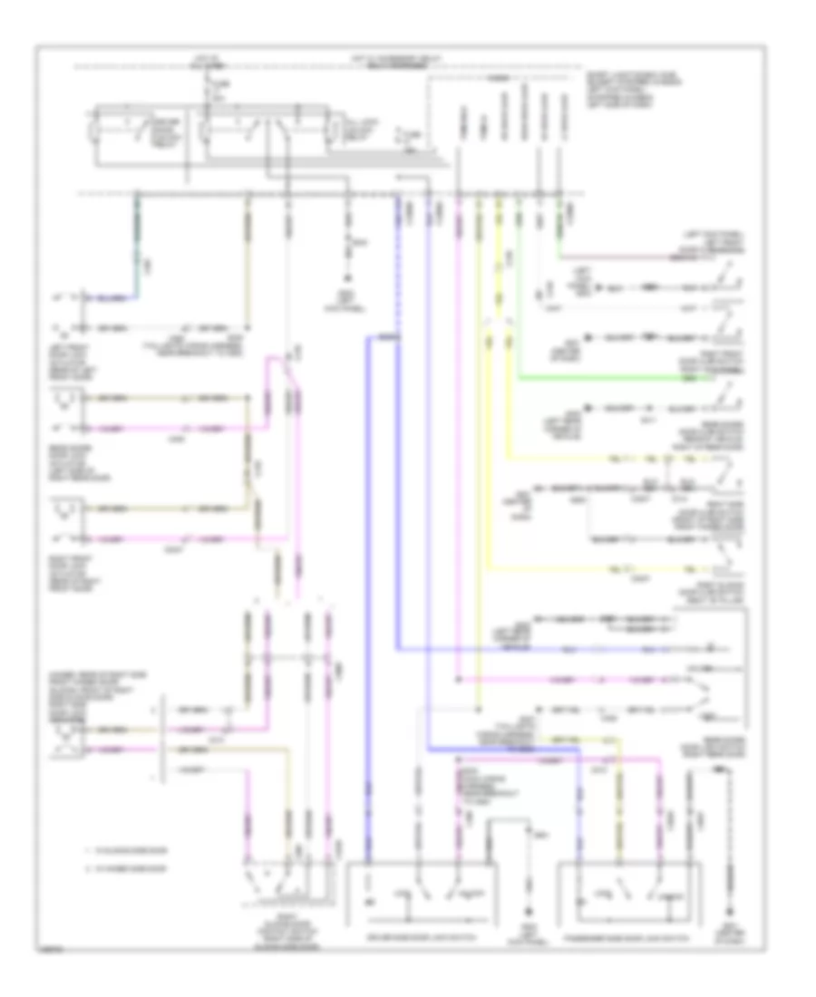
EXTERIOR LIGHTS
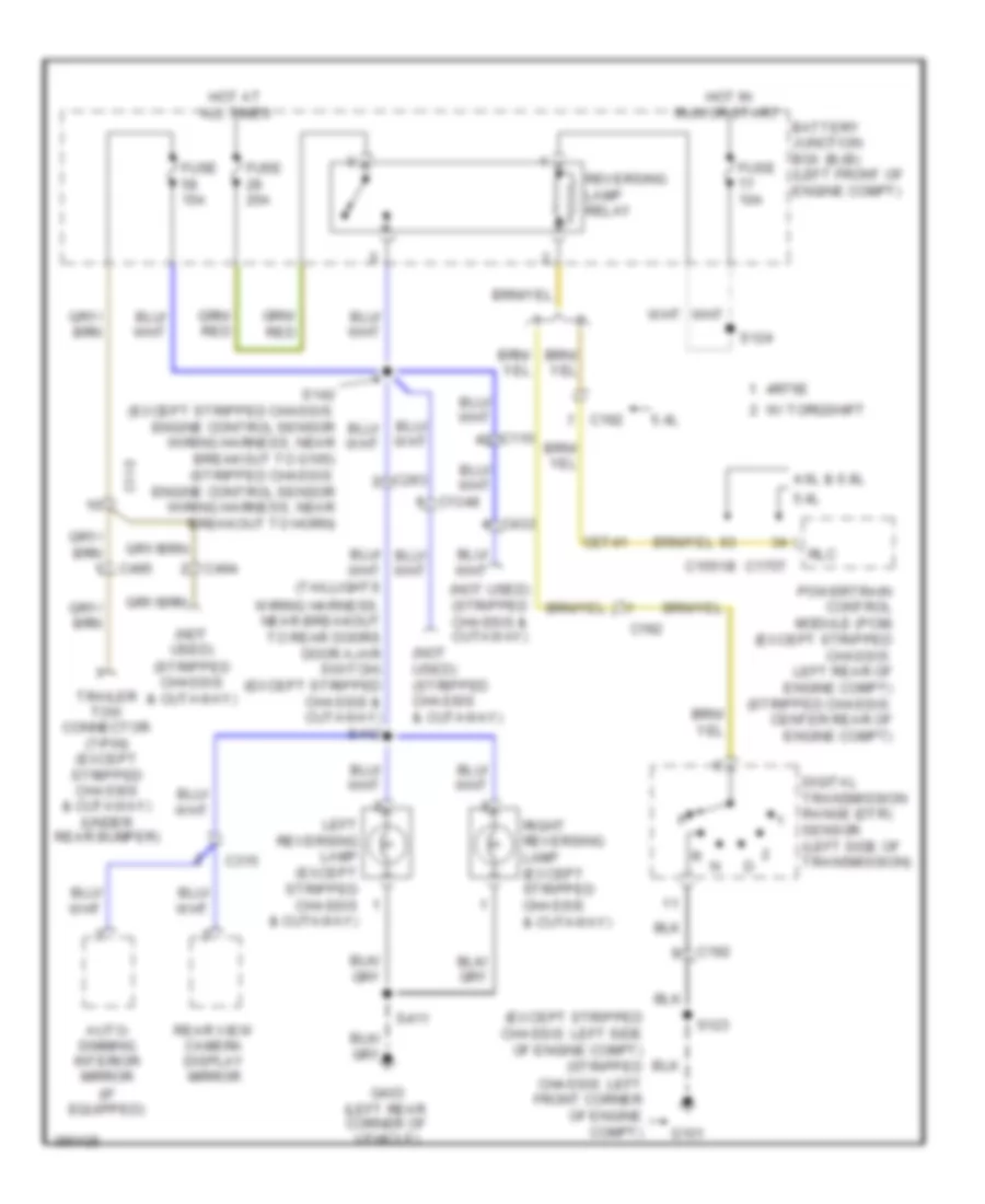
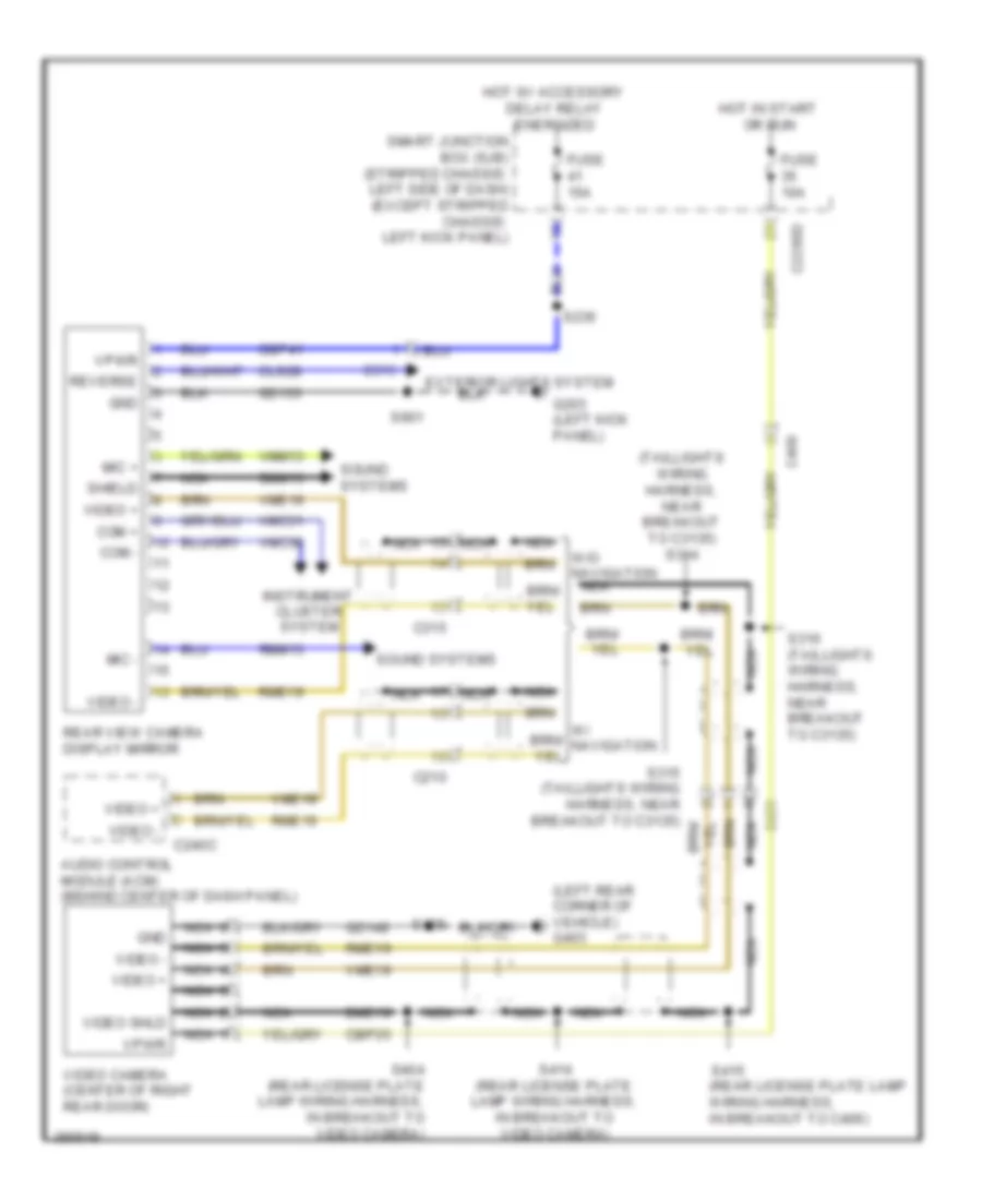
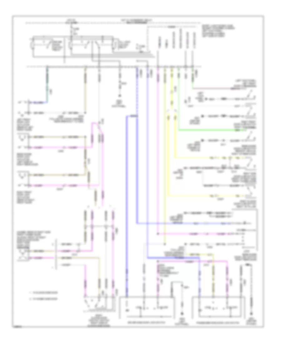
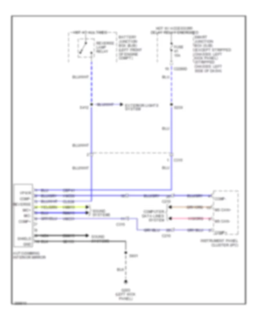
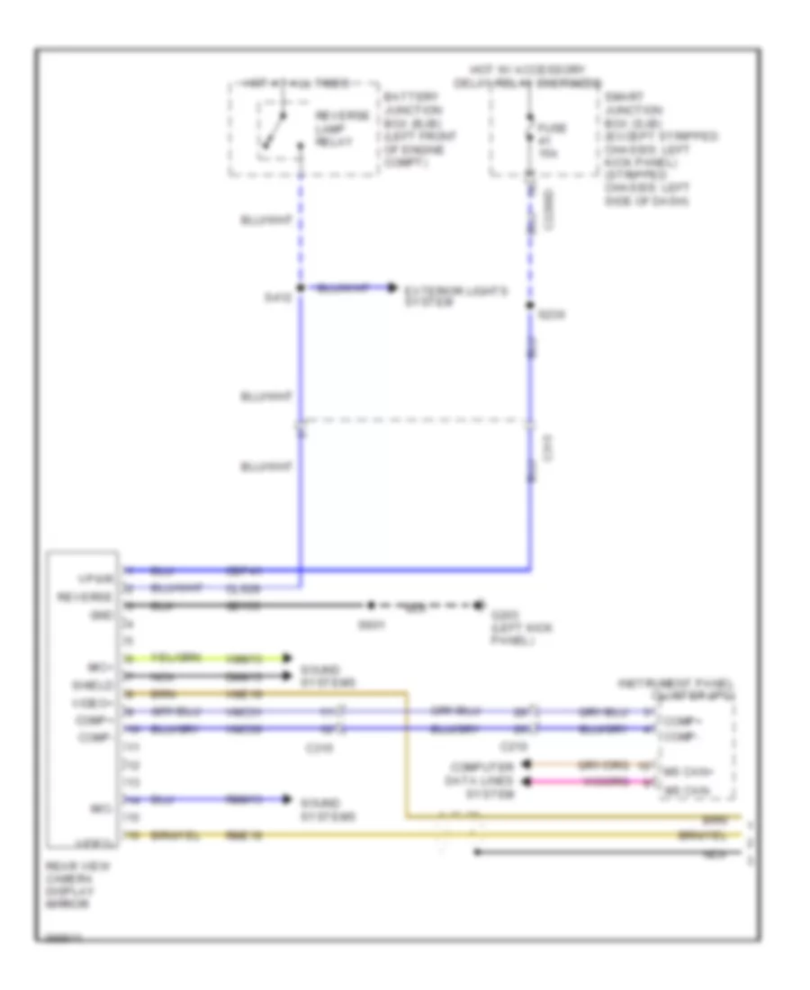
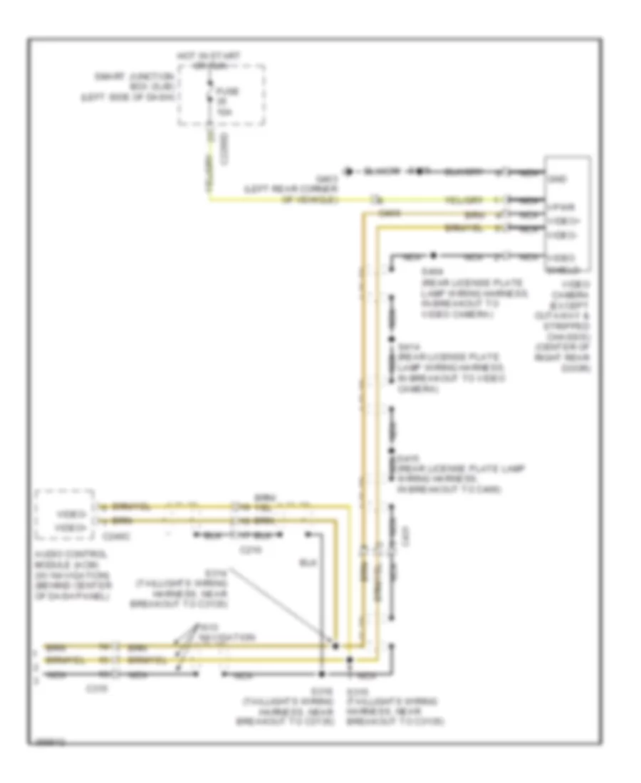
Backup Lamps Wiring Diagram for Ford E-350 Super Duty XL 2013
List of elements for Backup Lamps Wiring Diagram for Ford E-350 Super Duty XL 2013:
- (except stripped chassis: left side of engine compt) (stripped
- (not used)
- (not used) (stripped chassis & cutaway)
- (stripped chassis & cutaway)
- 4.6l & 6.8l
- 4r75e
- 5.4l
- Auto- dimming interior mirror (if equipped)
- Battery junction box (bjb) (left front of engine compt)
- C110
- C1348
- C1551b
- C175t
- C192
- C263
- C315
- C432
- C494
- C495
- Cet41
- Chassis: left front corner of engine compt)
- Digital transmission range (dtr) sensor (left side of transmission)
- Fuse 10a
- Fuse 15a
- Fuse 20a
- G101
- G403 (left rear corner of vehicle)
- Hot at all times
- Hot in run or start
- Left reversing lamp (except stripped chassis & cutaway)
- Powertrain control module (pcm) (except stripped chassis: left rear of engine compt) (stripped chassis: center rear of engine compt)
- Rear view camera display mirror
- Reversing lamp relay
- Right reversing lamp (except stripped chassis & cutaway)
- Rlc
- S123
- S124
- S142 (except stripped chassis: engine control sensor wiring harness, near breakout to g105) (stripped chassis: engine control sensor wiring harness, near breakout to horn)
- S411
- Trailer tow connector (7-pin) (except stripped chassis & cutaway) (under rear bumper)
- W/ torqshift
- Wiring harness, near breakout to rear doors door ajar switch) (except stripped chassis & cutaway) s412
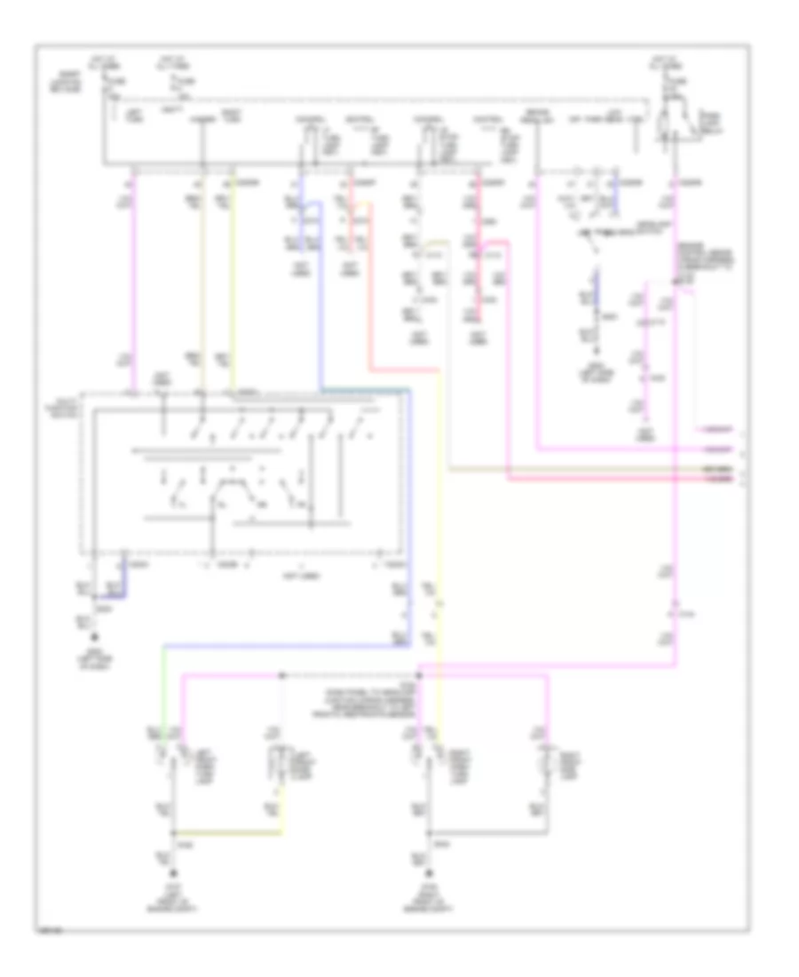
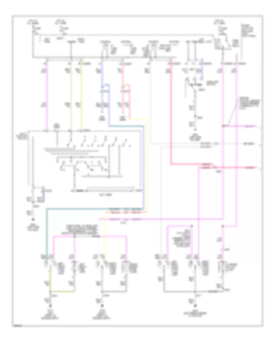
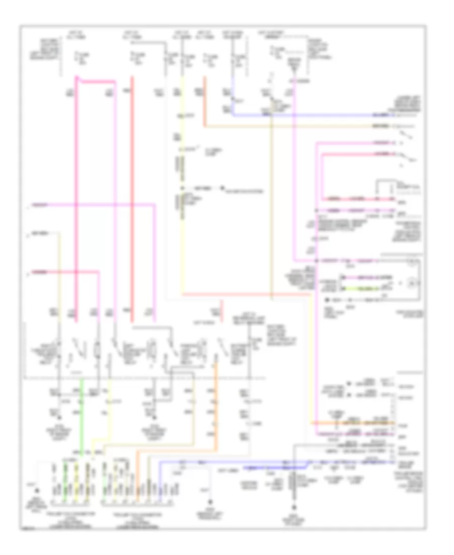
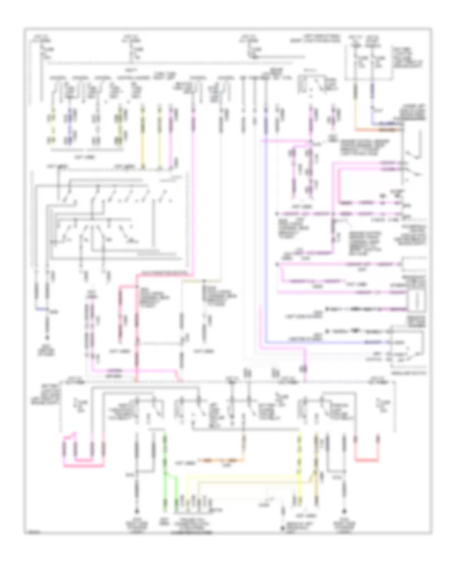
Exterior Lamps Wiring Diagram, Cutaway (1 of 2) for Ford E-350 Super Duty XL 2013
List of elements for Exterior Lamps Wiring Diagram, Cutaway (1 of 2) for Ford E-350 Super Duty XL 2013:
- (engine control senor wiring harness, in breakout to c110) s120
- (not used)
- Brake pedal sw
- C110
- C144
- C202a
- C202b
- C215
- C2280b
- C2280d
- C2280e
- C2280f
- C263
- C432
- Control
- Ctrl
- Fuse 10a
- Fuse 15a
- Fuse 20a
- G107 (left front of engine compt)
- G108 (right front of engine compt)
- G202 (left side of dash)
- Hazard
- Head
- Headlamp switch
- Hot at all times
- Left front park/ turn lamp
- Left front side lamp
- Left turn
- Lf turn lamp (fet)
- Low beam
- Lr stop/ turn lamp (fet)
- Multi- function switch
- Off
- Park
- Park lamp relay
- Rf turn lamp (fet)
- Right front park/ turn lamp
- Right front side lamp
- Right turn
- Rr stop/ turn lamp (fet)
- S162
- S164 (dash panel to headlamp junction wiring harness, near breakout to left frontal restraints sensor)
- S165
- S223
- Smart junction box (sjb)
- Vbatt
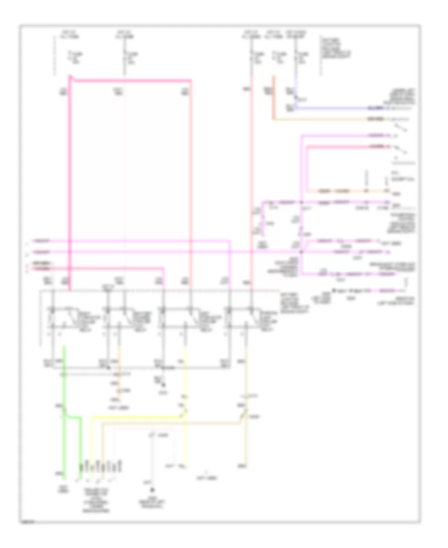
Exterior Lamps Wiring Diagram, Cutaway (2 of 2) for Ford E-350 Super Duty XL 2013
List of elements for Exterior Lamps Wiring Diagram, Cutaway (2 of 2) for Ford E-350 Super Duty XL 2013:
- (left side of dash)
- (not used)
- (under left side of dash) brake pedal position switch
- 6.8l
- Battery charge trailer tow relay
- Battery junction box (bjb) (left front of engine compt)
- Bpp
- Bps
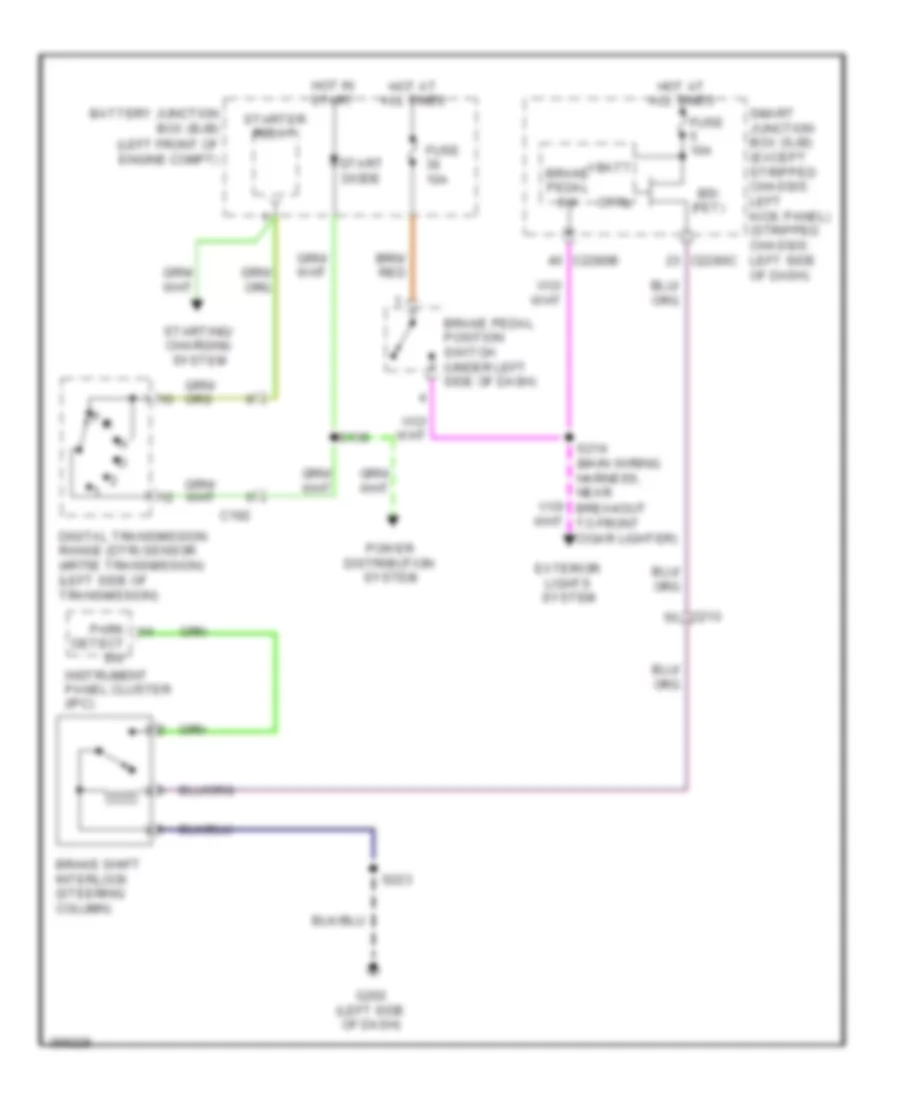
- Brake shift interlock (steering column)
- C110
- C1551b
- C175b
- C2026
- C210
- C275
- C291
- C4000
- C432
- C494
- Cat06
- Cat09
- Cat17
- Ccb08
- Ces09
- Except 6.8l
- Fuse 10a
- Fuse 20a
- Fuse 30a
- G100
- G205
- G402 (rear of left frame rail)
- Hot at all times
- Hot in run
- Hot in run or start
- Left turn/stop trailer tow relay
- Parking lamp trailer tow relay
- Powertrain control module (pcm) (left rear of engine compt)
- Rat08
- Red
- Resistor (left side of dash)
- Right turn/stop trailer tow relay
- S108
- S117
- S137
- S245 (main wiring harness, near breakout to g207)
- S250
- Trailer tow connector (4-pin) (if equipped) (under rear bumper)
Exterior Lamps Wiring Diagram, Except Cutaway & Stripped Chassis (1 of 2) for Ford E-350 Super Duty XL 2013
List of elements for Exterior Lamps Wiring Diagram, Except Cutaway & Stripped Chassis (1 of 2) for Ford E-350 Super Duty XL 2013:
- (dash panel to headlamp junction wiring harness, near breakout to left frontal restraints sensor) s164
- (engine control sensor wiring harness, in breakout to c110)
- (not used)
- C144
- C202a
- C202b
- C215
- C2280b
- C2280d
- C2280e
- C2280f
- C263
- C406
- Control
- Ctrl
- Fuse 10a
- Fuse 15a
- Fuse 20a
- G107 (left front of engine compt)
- G108 (right front of engine compt)
- G202 (left side of dash)
- G403 (left rear corner of vehicle)
- Hazard
- Head
- Headlamp switch
- Hot at all times
- Left front park/ turn lamp
- Left front side lamp
- Left rear park/ stop/ turn lamp
- Left turn
- Lf turn lamp (fet)
- License plate lamp
- Low beam
- Lr stop/ turn lamp (fet)
- Multi- function switch
- Off
- Park
- Park lamp relay
- Rf turn lamp (fet)
- Right front park/ turn lamp
- Right front side lamp
- Right rear park/ stop/ turn lamp
- Right turn
- Rr stop/ turn lamp (fet)
- S120
- S162
- S165
- S223
- S405
- S410 (taillights wiring harness, near breakout to high mounted stoplight)
- S411
- Smart junction box (sjb) (left kick panel)
- Vbatt
Exterior Lamps Wiring Diagram, Except Cutaway & Stripped Chassis (2 of 2) for Ford E-350 Super Duty XL 2013
List of elements for Exterior Lamps Wiring Diagram, Except Cutaway & Stripped Chassis (2 of 2) for Ford E-350 Super Duty XL 2013:
- (main wiring harness, near breakout to front cigar lighter)
- (not used)
- (or igrun-a)
- (under left side of dash) brake pedal position switch
- (w/ crew chief)
- (w/o crew chief)
- 6.8l except 6.8l
- Battery charge trailer tow relay
- Battery junction box (bjb) (left front of engine compt)
- Bpp
- Bps
- Brake pedal sw
- C110
- C1551b
- C175b
- C210
- C2108
- C219
- C2280b
- C422
- C494
- C495
- Cat03
- Cat06
- Cat09
- Cat14
- Cat17
- Cat19
- Cat19 (or tbo)
- Cbp33
- Ccb08
- Ccb08 (or boo)
- Ces09
- Class i
- Class ii
- Computer data lines system
- Ctsy
- Fuse 10a
- Fuse 15a
- Fuse 20a
- Fuse 30a
- G100 (right front of engine compt)
- G200 (right side of dash)
- G203 (left kick panel)
- G402 (rear of left frame rail)
- Gd116 (or gnd-a)
- Gnd
- High mounted stoplamp
- Hot at all times
- Hot in run
- Hot in run or start
- Hot in start or run
- Hot w/ reversing lamp relay engaged
- Hs can+
- Hs can-
- Interior lights system
- Left turn/stop trailer tow relay
- Modified vehicle
- Navigation system
- Off
- Parking lamp trailer tow relay
- Powertrain control module (pcm) (left rear of engine compt)
- Pwr
- Rat08
- Red
- Right turn/stop trailer tow relay
- Run start
- S108
- S137
- S214
- S240
- S273 (w/ crew chief)
- S274 (w/ crew chief)
- Sbb18 (or vb-a)
- Smart junction box (sjb) (left kick panel)
- Trailer brake
- Trailer brake control (tbc) module (top center of dash)
- Trailer tow connector (4-pin) (if equipped) (under rear bumper)
- Trailer tow connector (7-pin) (if equipped) (under rear bumper)
- Vdb04 (or hscip)
- Vdb05 (or hsc2a)
- W/ crew chief
- W/o crew chief
- Wiring harness, near breakout to c144)
Exterior Lamps Wiring Diagram, Stripped Chassis for Ford E-350 Super Duty XL 2013
List of elements for Exterior Lamps Wiring Diagram, Stripped Chassis for Ford E-350 Super Duty XL 2013:
- (engine control sensor wiring harness, near breakout to smart junction box (sjb))
- (left side of dash) smart junction box (sjb)
- (main wiring harness, near breakout to g207)
- (not used)
- (rear of left frame rail) g402
- (under left side of dash) brake pedal position switch
- 6.8l
- All times
- Battery charge trailer tow relay
- Battery junction box (bjb) (left front of engine compt)
- Bpp
- Bps
- Brake pedal sw
- Brake shift interlock (steering column)
- C1010
- C110
- C1551b
- C175b
- C2026
- C202a
- C202b
- C2280b
- C2280c
- C2280d
- C2280e
- C2280f
- C275
- C291
- C4000
- C432
- C494
- Cat06
- Cat09
- Cat17
- Ccb08
- Ces09
- Control
- Ctrl
- Except 6.8l
- Fuse 10a
- Fuse 15a
- Fuse 20a
- Fuse 30a
- G100 (right side of engine compt)
- G205 (left side of dash)
- G207 (center of dash)
- Hazard
- Head
- Headlamp switch
- Hot at
- Hot at all times
- Hot in run
- Hot in start and run
- Left turn/ stop trailer tow relay
- Lf turn lamp (fet)
- Low beam
- Lr stop/ turn lamp (fet)
- Lr turn lamp (fet)
- Multi-function switch
- Off
- Park
- Park lamp relay
- Parking lamp trailer tow relay
- Powertrain control module (pcm) (center rear of engine compt)
- Red
- Resistor (left side of dash)
- Rf turn lamp (fet)
- Right turn/stop trailer tow relay
- Rr stop/ turn lamp (fet)
- Rr turn lamp (fet)
- S108
- S120
- S137
- S242
- S245 (main wiring harness, near breakout to g207)
- S249 (main wiring harness, near breakout to c2026)
- S250
- S260
- Trailer tow connector (4-pin) (if equipped) (under rear bumper)
- Turn left
- Turn right
- Vbatt
GROUND DISTRIBUTION
Ground Distribution Wiring Diagram (1 of 5) for Ford E-350 Super Duty XL 2013
List of elements for Ground Distribution Wiring Diagram (1 of 5) for Ford E-350 Super Duty XL 2013:
- (4r75e transmission) digital transmission range (dtr) sensor
- (except stripped chassis) windshield washer pump motor
- (except stripped chassis) windshield wiper motor
- (except stripped chassis: left side of engine compt) (stripped chassis: left front corner of engine compt)
- (except stripped chassis: right front of engine compt) (stripped chassis: right side
- (left front of engine compt) (except stripped chassis) battery junction box (bjb)
- (left front of engine compt) battery junction box (bjb)
- (not used)
- (stripped chassis) (not used)
- (stripped chassis) horn
- A/c compressor clutch field coil
- Battery
- Battery charge trailer tow relay
- Battery secondary (dual battery w/ aft axle tank)
- Battery secondary (dual battery w/ midship tank)
- Blower motor relay
- Blower motor resistor
- Body builder ground
- Brake fluid level switch
- C1010
- C134
- C1348
- C192
- Fuel pump relay
- G100
- G101
- G109 (4.6l & 5.4l) (right front of engine compt)
- G109 (6.8l) (right front of engine compt)
- G120 (4.6l & 5.4l) (right rear of engine)
- G120 (6.8l) (right rear of engine)
- G121 (4.6l & 5.4l) (w/ dual battery) (front right side frame rail)
- G121 (6.8l) (w/ dual battery) (front right side frame rail)
- G300 (right underbody of vehicle)
- G400 (right rear underbody of vehicle)
- Left turn/stop trailer tow relay
- Of engine compt)
- Parking lamp trailer tow relay
- Right turn/stop trailer tow relay
- Run/ start relay
- Run/start relay
- S123 (except stripped chassis: engine control sensor wiring harness, near breakout to c144)
- Sensor wiring harness, near breakout to horn)
- Stripped chassis
- Upfitter relay 1
- Upfitter relay 2
- Upfitter relay 3
- Upfitter relay 4
- W/o dual battery
- Windshield wiper relay
- Wiring harness, near breakout to a/c cycling switch) (stripped chassis: engine control sensor wiring harness, near breakout to brake fluid level switch)
Ground Distribution Wiring Diagram (2 of 5) for Ford E-350 Super Duty XL 2013
List of elements for Ground Distribution Wiring Diagram (2 of 5) for Ford E-350 Super Duty XL 2013:
- & cutaway
- (not used)
- 4-pin trailer tow connector
- 7-pin trailer tow connector
- Abs test connector
- Accessory protocol interface module (apim)
- Anti-lock brake system (abs) module
- Brake fluid level switch
- Brake shift interlock
- C202a
- C202b
- C202c
- C218b
- C218c
- C219
- C275
- C300
- C4000
- C422
- C432
- C495
- Clock- spring (steering wheel)
- Customer access
- Cutaway
- Data link connector (dlc)
- Except stripped chassis
- G102 (except stripped chassis: left side of engine compt) (stripped chassis: left rear of engine compt)
- G103 (left side of engine compt)
- G202 (except stripped chassis) (left side of dash)
- G207 (stripped chassis) (center of dash)
- G208 (left kick panel)
- G402 (rear of left frame rail)
- Global positioning system module (gpsm)
- Headlamp switch
- Instrument panel cluster (ipc)
- Left steering wheel switch
- Multi-function switch
- Parking aid module (pam)
- Passive anti-theft transceiver
- S223 (main wiring harness, near breakout to c210)
- S260 (main wiring harness, near breakout to g207)
- S263 (main wiring harness, near breakout to c219)
- Stripped chassis
- W/ advance trac
- W/o advance trac
- Wagon/van
Ground Distribution Wiring Diagram (3 of 5) for Ford E-350 Super Duty XL 2013
List of elements for Ground Distribution Wiring Diagram (3 of 5) for Ford E-350 Super Duty XL 2013:
- (6.8l) brake pedal position switch
- (except 6.8l) mass air flow/intake air temperature (maf/iat) sensor
- (interior lights wiring harness, near breakout to c315)
- (left kick panel) smart junction box (sjb)
- (not used)
- (stripped chassis: right side of engine compt)
- (w/ auto- dimming interior mirror) auto- dimming interior mirror
- (w/ rear view camera display mirror w/o navigation) rear view camera display mirror
- 6.8l
- Auxiliary cargo lamp
- C1033
- C1551b
- C175b
- C2280d
- C2403
- C265
- C300
- C3133
- C315
- C925
- Cargo lamp
- Cutaway
- Driver safety belt buckle switch/ pretensioner
- Driver side door lock switch
- Driver side front seat control switch
- Except 6.8l
- Except cutaway
- Except cutaway & full headliner
- Exterior rear view mirror switch
- Front interior/ map lamps assembly
- G105 (except stripped chassis: left front of engine compt)
- G203 (except stripped chassis) (left kick panel)
- G204 (except stripped chassis) (left kick panel)
- Gnd cable
- High mounted stoplamp
- Left front door ajar switch
- Master window adjust switch
- Nca
- Parking brake switch
- Powertrain control module (pcm)
- Rear power point
- Resistor
- S239 (taillights wiring harness, near breakout to c263)
- S240 (taillights wiring harness, near breakout to g203)
- S317 (taillights wiring harness, near breakout to g203)
- S501 (left front door window regulator wiring harness, near breakout to driver side front power window motor)
- S906
- Second row cargo lamp
- Second row interior lamp
- Third row cargo lamp
- Third row interior lamp
- Tool link antenna module
- W/ full headliner
- Wiring harness, near breakout to c192) (stripped chassis: engine control sensor wiring harness, near breakout to g105)
Ground Distribution Wiring Diagram (4 of 5) for Ford E-350 Super Duty XL 2013
List of elements for Ground Distribution Wiring Diagram (4 of 5) for Ford E-350 Super Duty XL 2013:
- (except cutaway) license plate lamp
- (w/ rear video camera) video camera
- Auxiliary blower motor relay
- Auxiliary blower motor speed relay
- Breakout to g401)
- C405
- C406
- Fuel pump control module
- Fuel pump module shield
- G108 (except stripped chassis) (right front of engine compt)
- G401 (left rear underbody of vehicle)
- G403 (except stripped chassis) (left rear corner of vehicle)
- Left rear park/stop/ turn lamp
- Left reversing lamp
- Mounted stoplight)
- Nca
- Rear doors ajar switch
- Rear doors lock switch
- Right front park/turn lamp
- Right front side lamp
- Right headlamp
- Right rear park/stop/ turn lamp
- Right reversing lamp
- S405 (rear license plate lamp wiring harness, near breakout
- S411 (taillights wiring harness, near breakout to high
- To right rear speaker)
- W/ aero headlamps
- W/o aero headlamps
Ground Distribution Wiring Diagram (5 of 5) for Ford E-350 Super Duty XL 2013
List of elements for Ground Distribution Wiring Diagram (5 of 5) for Ford E-350 Super Duty XL 2013:
- (left side of dash) smart junction box (sjb)
- (t-box jumper harness, near breakout to modem antenna)
- (w/ 110v power inverter) dc/ac inverter module
- (w/ aero headlamps)
- (w/ hinged side door) right side door ajar switch
- (w/ navigation) audio amplifier
- (w/ navigation) audio control module (acm)
- (w/ sliding door) right sliding door ajar switch
- (w/o aero headlamps)
- (w/o navigation) audio control module (acm)
- Base audio
- C2108
- C214
- C2280d
- C2385b
- C2403
- C2408a
- C240a
- C294b
- C294c
- C294e
- C3007
- C3047
- C314
- Cigar lighter)
- Climate control assembly
- Crew chief
- Data link connector (dlc)
- Except crew chief
- Front cigar lighter
- G107 (except stripped chassis) (left front of engine compt)
- G200 (except stripped chassis) (right side of dash)
- G201 (except stripped chassis) (center of dash)
- G205 (stripped chassis) (left side of dash)
- Horn
- In-dash computer
- Instrument panel power point 1
- Instrument panel power point 2
- Left front park/turn lamp
- Left front side lamp
- Left headlamp
- Parking brake switch
- Passenger air bag deactivation (pad) switch
- Passenger side door lock switch
- Resistor
- Right front door ajar switch
- S216 (main wiring harness, near breakout to front
- S250 (main wiring harness, near breakout to g207)
- S264 (main wiring harness, near breakout to audio control module (acm))
- S265 (main wiring harness, near breakout to g201)
- S273
- Telematics module
- Temperature blend door actuator
- To g200)
- Traction control switch
- Trailer brake control (tbc) module
- Upfitter switch
HEADLIGHTS
Headlights Wiring Diagram for Ford E-350 Super Duty XL 2013
List of elements for Headlights Wiring Diagram for Ford E-350 Super Duty XL 2013:
- (dash panel to headlamp junction wiring harness, near breakout to left frontal restraints sensor) s163
- (except stripped chassis) s223
- (not used)
- C1010
- C144
- C202b
- C2280b
- C2280e
- Computer data lines system
- Control
- Except stripped chassis
- Ftp
- Fuse 10a
- Fuse 15a
- G107 (left front of engine compt)
- G108 (right front of engine compt)
- G202 (except stripped chassis) (left side of dash)
- G207 (stripped chassis) (center of dash)
- Head
- Headlamp off
- Headlamp switch
- High
- High beam
- High beam relay
- Hot at all times
- Hs can +
- Hs can -
- Instrument panel cluster (ipc)
- Interior lights system
- Left headlamp
- Left low beam (fet)
- Low
- Micro
- Ms can +
- Ms can -
- Multi-function switch
- Off
- On headlamp
- On parklamp
- Park
- Pass flash to
- Right headlamp
- Right low beam (fet)
- S162
- S165
- S260 (stripped chassis)
- Smart junction box (sjb) (except stripped chassis: left kick panel) (stripped chassis: left side of dash)
- Stripped chassis
- W/ aero headlamps
- W/o aero headlamps
HORN
Horn Wiring Diagram, with Stripped Chassis for Ford E-350 Super Duty XL 2013
List of elements for Horn Wiring Diagram, with Stripped Chassis for Ford E-350 Super Duty XL 2013:
- 20a
- Battery junction box (bjb) (left front of engine compt)
- C218b
- C218c
- C291
- Clockspring (steering wheel)
- Fuse 34
- G101 (left front corner of engine compt)
- G207 (center of dash)
- Horn (right front of engine compt)
- Horn relay
- Horn switch
- Hot at all times
- Left steering wheel switch
- S123
- S260
Horn Wiring Diagram, without Stripped Chassis for Ford E-350 Super Duty XL 2013
List of elements for Horn Wiring Diagram, without Stripped Chassis for Ford E-350 Super Duty XL 2013:
- C144
- C218b
- C218c
- C2280b
- C2280e
- Clockspring (steering wheel)
- Control
- Fuse 24 20a
- G107 (left front of engine compt)
- G202 (left side of dash)
- Horn (right front of engine compt)
- Horn relay
- Horn switch
- Hot at all times
- Left steering wheel switch
- S162
- S223
- Smart junction box (sjb) (left kick panel)
INSTRUMENT CLUSTER
Instrument Cluster Wiring Diagram for Ford E-350 Super Duty XL 2013
List of elements for Instrument Cluster Wiring Diagram for Ford E-350 Super Duty XL 2013:
- (center of dash)
- (except stripped chassis) s239
- (except stripped chassis) s263 s260 (stripped
- (except stripped chassis) s264 s250 (stripped chassis)
- (except stripped chassis: left kick panel)
- (left kick panel) (except stripped chassis) g203
- (left rear corner of vehicle) g403
- (left side of dash) (stripped chassis) g205
- (or cbb80)
- (stripped chassis)
- (stripped chassis) s260
- 6.8l
- Auto-dimming interior mirror
- Battery junction box (bjb) (left front of engine compt)
- Brake fluid level switch (left rear of engine compt)
- Brake shift interlock (steering column)
- Brk fluid sw rtn
- C110
- C134
- C210
- C219
- C2280a
- C2280b
- C2280c
- C2280f
- C275
- C291
- C3007
- C314
- C315
- Cbp29
- Cca15
- Cdc30
- Cet52
- Chassis)
- Cmc19
- Cmc24
- Cmc25
- Compass +
- Compass -
- Compass+
- Compass-
- Computer data lines system
- Cpl26
- Cpl31
- Cpl36
- Cpl39
- Display
- Except 6.8l
- Except stripped chassis
- Fluid sw brake
- Fuel gauge sensor
- Fuel pump module (under rear of vehicle, near fuel tank)
- Fuse 10a
- Fuse 5a
- G100 (stripped chassis) (right side of engine compt)
- G201
- G201 (center of dash)
- G201 (except stripped chassis) (center of dash)
- G202 (except stripped chassis) (left side of dash)
- G203 (left kick panel)
- G205 (stripped chassis) (left side of dash)
- G207 (stripped chassis) (center of dash)
- Gd114
- Hot at all times
- Hot in start or run
- Hs can +
- Hs can -
- Instrument panel cluster (ipc)
- Key in ign
- Key in ignition switch
- Left front door ajar switch (left kick panel)
- Lf door ajar
- Micro
- Mirror
- Mirror w/o navi- gation
- Ms can +
- Ms can -
- Nca
- Oil pressure switch (lower left front of engine)
- Oil sw
- Park brake
- Park sw
- Parking brake switch (near left kick panel)
- Passive anti-theft transceiver (under right side of dash)
- Pwr gnd
- Rear door ajar
- Rear doors door ajar switch
- Rear view camera display mirror
- Rf door ajar
- Right front door ajar switch (right kick panel)
- Right side door ajar switch (front of right side front hinged door)
- Right sliding door ajar switch (right "b" pillar)
- Rmc19
- Rmc32
- Rr door ajar
- Run/start
- S223 (except stripped chassis)
- S239
- S250 (stripped chassis)
- S264
- S411
- Sbp26 (or sbb31)
- Sender 1
- Sender rtn 1
- Smart junction box (sjb) (stripped chassis: left side of dash)
- Stripped chassis
- Tc on/off
- Traction control switch
- Vbatt
- Vdb04
- Vdb05
- Vdb06
- Vdb07
- Vmc11
- Vmc30
- Vmc31
- Vrt23
- Vrt24
- W/ auto- dimming interior
- W/ hinged side door
- W/ rear view camera
- W/ sliding side door
INTERIOR LIGHTS
Courtesy Lamps Wiring Diagram for Ford E-350 Super Duty XL 2013
List of elements for Courtesy Lamps Wiring Diagram for Ford E-350 Super Duty XL 2013:
- (interior lights wiring harness, near breakout to second row interior lamp) s904
- (left rear corner of vehicle)
- (main wiring harness, near breakout to headlight switch)
- (not used)
- (not used) (cutaway)
- (taillights wiring harness, near breakout to second row cargo lamp) s312
- Auxiliary cargo lamp (except cutaway & full headliner)
- Battery saver relay
- C110
- C2095
- C210
- C2280a
- C2280b
- C2280c
- C2280d
- C264
- C291
- C3007
- C314
- C315
- C432
- C925
- Cargo lamp (w/ full headliner)
- Ctsy
- Customer access connector (cutaway) (left "b" pillar)
- Dim sw gnd
- Dimmer sw
- Dome lp
- Except stripped chassis
- Exterior lights system
- Front interior/map lamps assembly
- Fuse 10a
- Fuse 15a
- G201 (center of dash)
- G203 (left kick panel)
- G403
- High mounted stop lamp
- Hot at all times
- Illumination dimmer
- Interior lighting (fet)
- Left front door ajar switch (left kick panel)
- Left vanity mirror lamp (w/ vanity mirror lamps)
- Lf dr ajar
- Micro
- Off
- Rear door ajar
- Rear doors door ajar switch (rear of vehicle, right of rear door)
- Rf dr ajar
- Right front door ajar switch (right kick panel)
- Right side door ajar switch (front of right side front hinged door)
- Right sliding door ajar switch (right "b" pillar)
- Right vanity mirror lamp (w/ vanity mirror lamps)
- Rr door ajar
- S230
- S239
- S240
- S264
- S304 (taillights wiring harness, near breakout to c3135)
- S411
- S901
- S902
- S903 (interior lights wiring harness, near breakout to second row interior lamp)
- S905 (interior lights wiring harness, near breakout to c315)
- Second row cargo lamp (except cutaway & full headliner)
- Second row interior lamp (w/ full headliner)
- Smart junction box (sjb) (except stripped chassis: left kick panel) (stripped chassis: left side of dash)
- Stripped chassis
- Third row cargo lamp (except cutaway & full headliner)
- Third row interior lamp (w/ full headliner)
- W/ hinged side door
- W/ sliding side door
Instrument Illumination Wiring Diagram for Ford E-350 Super Duty XL 2013
List of elements for Instrument Illumination Wiring Diagram for Ford E-350 Super Duty XL 2013:
- (behind center of dash panel) (base audio) audio control module
- (center of dash)
- (except stripped chassis)
- (except stripped chassis) s223 s260 (stripped chassis)
- (except stripped chassis: main wiring harness, near breakout to g201) (stripped chassis: main wiring harness, near breakout to g205) s219
- (left side of dash) (except stripped chassis) g202
- (main wiring harness, near breakout to headlight switch) s230
- (not used)
- (stripped chassis)
- Backlighting led (fet)
- C218b
- C218c
- C2280b
- C240a
- C294e
- Chassis)
- Climate control assembly
- Clockspring (steering wheel)
- Dim sw gnd
- Dimmer sw
- Dome lp
- Fuse 15a
- G201 (except stripped chassis) (center of dash)
- G205 (stripped chassis) (left side of dash)
- G207 (stripped chassis)
- Gnd
- Head
- Head- lamp off
- Head- lamp on
- Headlamp switch
- Hot at all times
- Illum
- Illumination dimmer
- Left steering wheel switch
- Micro
- Off
- Park
- Park- lamp on
- Right steering wheel switch
- S223 s260 (stripped
- S250
- S264 (except stripped chassis)
- Smart junction box (sjb) (except stripped chassis: left kick panel) (stripped chassis: left side of dash)
- Stripped chassis)
- Traction control switch
- Upfitter switch (except
- White led (fet)
NAVIGATION
Crew Chief Wiring Diagram for Ford E-350 Super Duty XL 2013
List of elements for Crew Chief Wiring Diagram for Ford E-350 Super Duty XL 2013:
- 5vpwr
- 5vtb
- 7-pin trailer tow connector (under rear bumper)
- Battery junction box (bjb) (left front of engine compt)
- Boo
- Bpp
- Brake
- Brake pedal position (bpp) switch (under left side of dash)
- C110
- C2108
- C219
- C2280b
- C422
- Can+
- Can-
- Cgnd
- Computer data lines system
- Front cigar lighter)
- Fuse 10a
- Fuse 30a
- G200 (right side of dash)
- Gnd
- Gnd-a
- Gnd1
- Hot at all times
- Hot in start or run
- Hs can +
- Hs can -
- Hsc1-a
- Hsc1-c
- Hsc2-a
- Hsc2-c
- Igrun-a
- Igrun-c
- Inline fuse (top center of dash)
- Modem antenna (top center of dash)
- Nca
- Pwr
- Pwr gnd
- Red
- Run start
- Rxd
- S272
- S273
- S274
- Smart junction box (sjb) (except stripped chassis: left kick panel) (stripped chassis: left side of dash)
- Tbo
- Telematics module
- Trailer
- Trailer brake control (tbc) module (top center of dash)
- Txd
- Vb-a
- Vb1
- Vbatt
In Dash Computer Wiring Diagram (1 of 2) for Ford E-350 Super Duty XL 2013
List of elements for In Dash Computer Wiring Diagram (1 of 2) for Ford E-350 Super Duty XL 2013:
- (main wiring harness, in breakout to audio input jack) s241
- (near top of left "b" pillar) tool link antenna 1
- (under side of roof, near right "b" pillar) tool link antenna 2
- (under side of roof, near right "d" pillar) tool link antenna 3
- 5v usb
- Ant
- Antenna
- Audio input jack
- Batt +
- Battery saver relay
- C gnd
- C2280a
- C2280b
- C2280d
- C2408a
- C2408b
- C2408c
- C2411
- Cbp28
- Cgnd
- Coax cable
- Computer data lines system
- Dme45
- Dtr
- Fuse 10a
- Fuse 20a
- Fuse 5a
- G201 (center of dash)
- G203 (left kick panel)
- Gd115
- Gnd
- Gnd cable
- Hot at all times
- Hot in start
- In-dash computer (center of dash)
- Lf spkr +
- Lf spkr -
- Lr spkr +
- Lr spkr -
- Micro
- Modem antenna (top center of dash)
- Ms can+
- Ms can-
- Nca
- Pwr cable
- Pwr gnd
- Red
- Rf in
- Rf spkr +
- Rf spkr -
- Rme07
- Rme09
- Rme10
- Rme12
- Rme45
- Rme46
- Rr spkr +
- Rr spkr -
- Rxd
- S905
- S906
- Sbp39
- Shield
- Smart junction box (sjb) (except stripped chassis: left kick panel) (stripped chassis: left side of dash)
- St input 2l +
- St input 2l -
- St input 2r +
- St input 2r -
- Start
- Tool link antenna module (near left "b" pillar)
- Txd
- Used) (not
- Vdb06
- Vdb07
- Vme07
- Vme09
- Vme10
- Vme12
- Vme45
- Vme46
In Dash Computer Wiring Diagram (2 of 2) for Ford E-350 Super Duty XL 2013
List of elements for In Dash Computer Wiring Diagram (2 of 2) for Ford E-350 Super Duty XL 2013:
- 2 or 4 speaker
- 6 speaker
- C210
- C268
- C3007
- C3049
- C314
- C316
- C3235
- C406
- C411
- C807
- Left front speaker
- Left middle speaker
- Left rear speaker
- Right front speaker
- Right middle speaker
- Right rear speaker
- Right sliding door contact switch (right side of sliding side door)
- S207 (main wiring harness, near breakout to g200)
- S208 (main wiring harness, near breakout to g200)
- S209 (main wiring harness, near breakout to g200)
- S310 (taillights wiring harness, near breakout to c3135)
- S311 (taillights wiring harness, near breakout to c3135)
- W/ hinged door
- W/o hinged door
Navigation Wiring Diagram for Ford E-350 Super Duty XL 2013
List of elements for Navigation Wiring Diagram for Ford E-350 Super Duty XL 2013:
- (main wiring harness, in breakout to audio input jack) s241
- (main wiring harness, near breakout to g200)
- (main wiring harness, near breakout to g200) s207
- (right side of sliding side door)
- (taillights wiring harness, near breakout to c3135)
- (taillights wiring harness, near breakout to c3135) s311
- Ant
- Antenna
- Audio amplifier (right side of dash)
- Audio control module (acm) (behind center of dash panel)
- Audio input jack
- Batt+
- C210
- C2280a
- C2280b
- C2385a
- C2385b
- C240a
- C240b
- C240c
- C268
- C3007
- C3049
- C314
- C3235
- C406
- C411
- C807
- Cbp28
- Clip detect
- Cme27
- Coax cable
- Computer data lines system
- Dme17
- Dme43
- Dme45
- Fuse 20a
- Fuse 5a
- G201 (center of dash)
- Gd115
- Hot at all times
- Hot in start
- L stereo +
- L stereo -
- Left front speaker
- Left middle speaker
- Left rear speaker
- Lf spkr+
- Lf spkr-
- Lr spkr+
- Lr spkr-
- Mic +
- Mic -
- Mono +
- Mono -
- Ms can+
- Ms can-
- Navigation system
- Nca
- Pwr gnd
- R stereo +
- R stereo -
- Rf in
- Rf spkr+
- Rf spkr-
- Right front speaker
- Right middle speaker
- Right rear speaker
- Right sliding door contact switch
- Rme07
- Rme09
- Rme10
- Rme12
- Rme17
- Rme18
- Rme19
- Rme45
- Rme46
- Rme52
- Rme53
- Rme54
- Rme60
- Rme61
- Rmm23
- Rmn14
- Rr spkr+
- Rr spkr-
- S208 (main wiring harness, near breakout to g200)
- S209
- S216
- S216 (w/ navigation)
- S309
- Satellite radio/ gps antenna (top of right "a" pillar)
- Sbp39
- Sbp40
- Shield
- Smart junction box (sjb) (stripped chassis: left side of dash) (except stripped chassis: left kick panel)
- St input 2l+
- St input 2l-
- St input 2r+
- St input 2r-
- Start
- Swc 2+
- Swc 2-
- Sync radio circuit
- Vdb06
- Vdb07
- Video+
- Video-
- Vme07
- Vme09
- Vme10
- Vme12
- Vme17
- Vme18
- Vme19
- Vme43
- Vme45
- Vme46
- Vme52
- Vme53
- Vme54
- Vme60
- Vme61
- Vmm23
- Vmn14
- W/ hinged door
Parking Assistant Wiring Diagram for Ford E-350 Super Duty XL 2013
List of elements for Parking Assistant Wiring Diagram for Ford E-350 Super Duty XL 2013:
- (taillight jumper wiring harness, near breakout to c410) s402
- (taillight jumper wiring harness, near breakout to c410) s408
- (under right side of dash) parking aid speaker
- C110
- C219
- C2280b
- C410
- C495
- Cbp35
- Cmp09
- Computer data lines system
- Fuse 10a
- G202 (left side of dash)
- Gd114
- Gnd
- Hot in start or run
- Inner left parking aid sensor (left side of rear bumper)
- Inner right parking aid sensor (right side of rear bumper)
- Lmp07
- Ms can+
- Ms can-
- Outer left parking aid sensor (left side of rear bumper)
- Outer right parking aid sensor (right side of rear bumper)
- Parking aid module (pam) (under right side of dash)
- Rear sounder +
- Rear sounder -
- Ril sensor in
- Rir sensor in
- Rmp07
- Rmp09
- Rol sensor in
- Ror sensor in
- S263
- Sensor gnd
- Sensor pwr
- Smart junction box (sjb) (stripped chassis: left side of dash) (except stripped chassis: left kick panel)
- Solid state
- Vdb06
- Vdb07
- Vmp14
- Vmp15
- Vmp16
- Vmp17
- Vpwr
Rear Camera Wiring Diagram for Ford E-350 Super Duty XL 2013
List of elements for Rear Camera Wiring Diagram for Ford E-350 Super Duty XL 2013:
- (left rear corner of vehicle) g403
- (rear license plate lamp wiring harness, in breakout to c406)
- (taillights wiring harness, near breakout to c3135) s314
- Audio control module (acm) (behind center of dash panel)
- C210
- C2280d
- C240c
- C315
- C406
- C431
- Cbp35
- Cbp41
- Cls28
- Com +
- Com -
- Dme19
- Dmm13
- Exterior lights system
- Fuse 10a
- Fuse 15a
- G203 (left kick panel)
- Gd133
- Gd149
- Gnd
- Hot in start or run
- Hot w/ accessory delay relay energized
- Instrument cluster system
- Mic +
- Mic -
- Nca
- Rear view camera display mirror
- Reverse
- Rme19
- Rmm13
- S236
- S316 (taillights wiring harness, near breakout to c3135)
- S404 (rear license plate lamp wiring harness, in breakout to video camera)
- S414 (rear license plate lamp wiring harness, in breakout to video camera)
- S415
- S901
- Shield
- Smart junction box (sjb) (stripped chassis: left side of dash) (except stripped chassis: left kick panel)
- Sound systems
- Video +
- Video -
- Video camera (center of right rear door)
- Video shld
- Vmc30
- Vmc31
- Vme19
- Vmm13
- Vpwr
- W/o navigation nca
POWER DISTRIBUTION
Power Distribution Wiring Diagram (1 of 9) for Ford E-350 Super Duty XL 2013
List of elements for Power Distribution Wiring Diagram (1 of 9) for Ford E-350 Super Duty XL 2013:
- (engine control red
- (engine control sensor wiring harness, in breakout to battery)
- (engine control sensor wiring harness, near breakout to battery junction box (bjb))
- (left front of engine compt)
- (right rear of engine)
- Battery
- Battery junction box (bjb)
- Battery secondary
- C1035a
- C1035b
- Except stripped chassis
- Fusible link j (8 ga- red)
- G109 (right front of engine compt)
- G120
- G121 (w/ dual battery) (front right side frame rail)
- G300 (w/o aft axle tank) (right underbody of vehicle)
- G400 (w/ aft axle tank) (right rear underbody of vehicle)
- Generator
- Red
- S106
- S107
- S113
- S114 (engine control sensor wiring harness, near breakout to battery junction box (bjb))
- S303
- S313 (w/o aft axle tank) s413 (w/ aft axle tank)
- Sensor wiring harness, in breakout to battery)
- Starter motor
- Stripped chassis
- To fuse 15 (diagram 2 of 9)
- To smart junction box (sjb) (diagram 3 of 9)
- W/ dual battery
Power Distribution Wiring Diagram (2 of 9) for Ford E-350 Super Duty XL 2013
List of elements for Power Distribution Wiring Diagram (2 of 9) for Ford E-350 Super Duty XL 2013:
- (except stripped chassis: engine control sensor wiring harness, near breakout to windshield wiper motor) (stripped chassis: engine control sensor wiring harness, near breakout to anti-lock brake system (abs) module) s136
- (except stripped chassis: right front of engine compt) (stripped chassis: right side of engine compt)
- (left front of engine compt) battery junction box (bjb)
- (not used)
- 6.8l
- A/c clutch relay
- Abs test connector
- Anti-lock brake system (abs) module
- Auxiliary blower motor relay
- Battery junction box (bjb) (left front of engine compt)
- Blower motor relay
- C110
- C1551b
- C175b
- C2026
- C219
- C264
- C291
- C300
- C405
- Customer access
- Cutaway
- Evaporative emission (evap) canister vent valve
- Except
- Except 6.8l
- Except cutaway
- Except stripped chassis
- From a battery junction box (bjb) (diagram 1 of 9)
- From c fuse 14 (diagram 2 of 9)
- Fuel pump relay
- Fuse 10a
- Fuse 15a
- Fuse 20a
- Fuse 30a
- Fuse 40a
- Fuse 50a
- G100
- Horn relay (stripped chassis)
- Instrument panel cluster (ipc) (stripped chassis)
- Left turn/stop trailer tow relay
- Powertrain control module (pcm)
- Red
- Reversing lamp relay
- Right turn/stop trailer tow relay
- Run/start relay
- S108
- S129 (engine control sensor wiring harness, near breakout to brake fluid level switch)
- Stripped chassis
- To battery junction box (bjb) (diagram 6 of 9)
- To battery junction box (bjb) (diagram 7 of 9)
- To battery junction box (bjb) (diagram 8 of 9)
- To battery junction box (bjb) (diagram 9 of 9)
- To fuse 31 (diagram 2 of 9)
- To fuse 33 (diagram 3 of 9)
- To ignition switch (diagram 4 of 9)
- To smart junction box (sjb) (diagram 6 of 9)
- W/ advance trac
- W/ advance trac w/o advance trac
- W/o advance trac
- Windshield wiper relay
Power Distribution Wiring Diagram (3 of 9) for Ford E-350 Super Duty XL 2013
List of elements for Power Distribution Wiring Diagram (3 of 9) for Ford E-350 Super Duty XL 2013:
- & stripped chassis
- (apim)
- (except stripped chassis: left kick panel) (stripped chassis: left side of dash) smart junction box (sjb)
- (gpsm)
- (main wiring harness, near breakout to smart junction box (sjb)
- (not used)
- (t-box jumper harness, near breakout to modem antenna) s272
- 3rd row seat enable (fet)
- Ac outlet
- Ac-a
- Ac-b
- Acc
- Accessory protocol
- Anti-lock brake system (abs) module
- Back lighting led (fet)
- Battery junction box (bjb) (left front of engine compt)
- Brake pedal position switch
- Bsi (fet)
- C110
- C210
- C2108
- C219
- C2280a
- C2280b
- C2280d
- C2280g
- C263
- C268
- C432
- Cbp41
- Customer access
- Cutaway
- Cutaway & stripped chassis
- Dc/ac inverter module (w/ 110v power inverter) (behind center of dash)
- Except cutaway
- Except stripped chassis
- Exterior rear view mirror switch
- Floor lamp (fet)
- From d fuse 16 (diagram 2 of 9)
- From splice f s200 (diagram 6 of 9)
- From splice s114 b (diagram 1 of 9)
- Front cigar lighter
- Fuse 10a
- Fuse 15a
- Fuse 20a
- Fuse 30a
- Fuse 40a
- Fuse 50a
- Fuse 5a
- Fuse 7.5a
- G200 (right side of dash)
- G203 (left kick panel)
- Gd116
- Global
- Gnd
- Hot
- Hya01
- Hya02
- Inline fuse
- Instrument panel power point 1
- Instrument panel power point 2
- Interface module
- Interior lighting (fet)
- Keypad illmu (fet)
- Led+
- Led-
- Left low beam (fet)
- Lf turn lamp (fet)
- Lr stop/ turn lamp (fet)
- Lr turn lamp (fet)
- Lya03
- Neut
- Positioning
- Puddle lamp (fet)
- Rear power point
- Red
- Rf turn lamp (fet)
- Right low beam (fet)
- Rr stop/ turn lamp (fet)
- Rr turn lamp (fet)
- Rya03
- S218
- S240
- S268
- Sbp01
- Sync w/o navigation
- System module
- To fuse 17 (diagram 5 of 9)
- To fuse 74 (diagram 4 of 9)
- To splice s159 (diagram 7 of 9)
- Tpms (fet)
- Trailer brake control (tbc) module
- Trailer brake control (tbc) module (w/o crew chief)
- Vbatt
- W/ advance trac
- W/ crew chief
- W/o advance trac
- White light (fet)
Power Distribution Wiring Diagram (4 of 9) for Ford E-350 Super Duty XL 2013
List of elements for Power Distribution Wiring Diagram (4 of 9) for Ford E-350 Super Duty XL 2013:
- (engine control sensor wiring harness, near breakout to windshield wiper motor) s143
- (main wiring harness, near breakout to g202) (except stripped chassis) s227
- (main wiring harness, near breakout to ignition switch) (stripped chassis) s244
- (not used)
- (stripped chassis)
- Acc
- Battery charge trailer tow relay
- Battery junction box (bjb) (left front of engine compt)
- C1348
- C140
- C2095
- C215
- C2280a
- C2280b
- C2280d
- C2280e
- C264
- C291
- C300
- C3133
- Data link connector (dlc)
- Driver side front seat control switch
- Except stripped chassis
- From battery junction box (bjb) (diagram 2 of 9)
- From e fuse 65 (diagram 3 of 9)
- From smart junction box (sjb) (diagram 6 of 9)
- Fuse 10a
- Fuse 15a
- Fuse 20a
- Fuse 30a
- Fuse 50a
- Fuse 5a
- Ignition switch
- Lock
- Off
- Run
- Run/ acc ign sw
- Run/start ign sw
- Smart junction box (sjb) (stripped chassis: left side of dash) (except stripped chassis: left kick panel)
- Start
- Starter relay
- Stripped chassis
- To battery junction box (bjb) (diagram 9 of 9)
- To splice s132 & battery junction box (bjb) (diagram 5 of 9)
- To upfitter switch (diagram 9 of 9)
- Windshield wiper motor
- Windshield wiper relay
Power Distribution Wiring Diagram (5 of 9) for Ford E-350 Super Duty XL 2013
List of elements for Power Distribution Wiring Diagram (5 of 9) for Ford E-350 Super Duty XL 2013:
- (engine control sensor wiring harness, near breakout to anti-lock brake system (abs) module) s139
- (engine control sensor wiring harness, near breakout to windshield wiper motor) s139
- (not used)
- 6.8l
- Audio control module (acm) (except stripped chassis)
- Battery junction box (bjb) (left front of engine compt)
- C1551b
- C175b
- C192
- C219
- C2280a
- C2280b
- C2280d
- C2408a
- C240a
- C291
- Data link connector (dlc)
- Digital transmission range (dtr) sensor (w/ 4r75e)
- Door lock relay
- Driver door unlock relay
- Except 6.8l
- Except stripped chassis
- Fog lamp relay
- From h fuse 9 (diagram 3 of 9)
- From ignition switch l (diagram 4 of 9)
- Fuse 15a
- Fuse 20a
- Fuse 25a
- Fuse 5a
- In-dash computer (if equipped)
- Lh corner lamp (fet)
- Liftgate glass release relay
- Liftgate rel (fet)
- Park lamp relay
- Powertrain control module (pcm)
- Pulse train (fet)
- Rh corner lamp (fet)
- S132 (engine control sensor wiring harness, near breakout to brake fluid level switch)
- Smart junction box (sjb) (stripped chassis: left side of dash) (except stripped chassis: left kick panel)
- Start diode
- Starter relay
- Stripped chassis
- To fuse (diagram 6 of 9)
- W/ torqshift
Power Distribution Wiring Diagram (6 of 9) for Ford E-350 Super Duty XL 2013
List of elements for Power Distribution Wiring Diagram (6 of 9) for Ford E-350 Super Duty XL 2013:
- (engine control sensor wiring harness, near breakout to windshield wiper motor)
- (except stripped chassis)
- (main wiring harness, near breakout to c264) s234
- (main wiring harness, near breakout to passenger air bag)
- (not used)
- (t-box jumper harness, near breakout to modem antenna) s274
- (taillights wiring harness, near breakout to c263)
- 6.8l
- Abs test connector
- Accessory delay relay (except stripped chassis)
- Anti-lock brake system (abs) module
- Audio amplifier (w/ navigation)
- Audio control module (acm)
- Audio control module (acm) (base audio)
- Auto- dimming interior mirror (if equipped)
- Battery junction box (bjb) (left front of engine compt)
- Battery saver relay
- C140
- C1551b
- C175b
- C2026
- C210
- C2108
- C215
- C219
- C2280a
- C2280b
- C2280d
- C2280e
- C2385b
- C2408a
- C240a
- C264
- C265
- C268
- C291
- C300
- C3047
- C3049
- C310a
- C315
- C406
- Circuit breaker 30a
- Driver side door lock switch
- Except 6.8l
- Except stripped chassis
- From battery n junction box (bjb) (diagram 2 of 9)
- From fuse 27 (diagram 6 of 9)
- From j fuse 22 (diagram 5 of 9)
- From r splice s136 (diagram 2 of 9)
- From splice s136 (diagram 2 of 9)
- Fuel pump motor diode
- Fuel pump relay
- Fuse 10a
- Fuse 15a
- Fuse 20a
- Fuse 5a
- G100 (stripped chassis: right side of engine compt) (except stripped chassis: right front of engine compt)
- High beam relay
- Horn relay
- In-dash computer (if equipped)
- Instrument panel cluster (ipc)
- Master window adjust switch
- Micro
- Passenger side door lock switch
- Passenger side window adjust switch
- Powertrain control module (pcm)
- Rear doors door lock switch (except cutaway)
- Rear view camera display mirror (w/o navigation)
- Restraints control module (rcm) (except stripped chassis)
- Run/start relay (modified vehicle)
- S108
- S200
- S236
- Smart junction box (sjb) (stripped chassis: left side of dash) (except stripped chassis: left kick panel)
- Steering position sensor
- Stripped chassis
- Telematics module (except stripped chassis)
- To accessory delay relay (diagram 6 of 9)
- To dc/ac inverter module (diagram 3 of 9)
- To fuse 34 (diagram 7 of 9)
- To splice s227 & s244 (diagram 4 of 9)
- Trailer brake control (tbc) module (except stripped chassis)
- W/ advance trac
- W/ crew chief
- W/o advance trac
Power Distribution Wiring Diagram (7 of 9) for Ford E-350 Super Duty XL 2013
List of elements for Power Distribution Wiring Diagram (7 of 9) for Ford E-350 Super Duty XL 2013:
- (left
- (main wiring harness, near breakout to climate control assembly) s217
- (not used)
- Battery charge trailer tow relay
- Battery junction box (bjb)
- C2095
- C214
- C2280b
- C2280d
- C291
- C294a
- C406
- Climate control assembly
- Customer access
- Cutaway
- Except cutaway & stripped chassis
- Except stripped chassis
- From battery junction box (bjb) u (diagram 3 of 9)
- From q fuse 33 (diagram 6 of 9)
- From splice s136 s (diagram 2 of 9)
- Front of engine compt)
- Fuse 10a
- Fuse 20a
- Fuse 30a
- Fuse 5a
- Fuse 7.5a
- Instrument panel cluster (ipc)
- Parking aid module (pam) (except stripped chassis)
- Parking lamp trailer tow relay
- Passenger airbag deactivation (pad) switch (except stripped chassis)
- Passive anti-theft transceiver (except stripped chassis)
- Red
- S159 (stripped chassis: engine control sensor wiring harness, near breakout to horn) (except stripped chassis: engine control sensor wiring harness, near breakout to battery junction box)
- Smart junction box (sjb) (stripped chassis: left side of dash) (except stripped chassis: left kick panel)
- Stripped chassis
- Temperature blend door actuator
- Video camera
Power Distribution Wiring Diagram (8 of 9) for Ford E-350 Super Duty XL 2013
List of elements for Power Distribution Wiring Diagram (8 of 9) for Ford E-350 Super Duty XL 2013:
- (4.6l: engine control sensor wiring harness & fuel charge, near breakout to coil on plug (cop) 1) (5.4l: engine control sensor wiring harness & fuel charge, near breakout to fuel injector 2) (6.8l: engine control sensor wiring harness & fuel charge, near breakout to fuel injector 1) s177
- (4r75e: transmission control selector neutral switch wiring harness, near breakout to c192) (6.8l: transmission control selector neutral switch wiring harness, near breakout to torqshift transmission) s103
- (6.8l: engine control sensor wiring harness & fuel charge, near breakout to coil on plug (cop) 10) (5.4l: engine control sensor wiring harness & fuel charge, near breakout to fuel injector 8) (4.6l: engine control sensor wiring harness & fuel charge, near breakout to knock sensor 1) s174
- (except stripped chassis: engine control sensor wiring harness, near breakout to brake fluid level switch) (stripped chassis: engine control sensor wiring harness, near breakout to anti-lock brake system (abs) module)
- (ho2s) 12 (stripped chassis & cutaway)
- (ho2s) 22
- 4.6l & 5.4l
- 4r75e transmission (if equipped)
- 6.8l
- A/c clutch relay
- Battery junction box (bjb) (left front of engine compt)
- Brake pedal position switch
- C1033
- C110
- C134
- C139
- C1551b
- C175b
- C192
- C219
- C291
- C314
- Coil on plug (cop) 1
- Coil on plug (cop) 10 (6.8l)
- Coil on plug (cop) 2
- Coil on plug (cop) 3
- Coil on plug (cop) 4
- Coil on plug (cop) 5
- Coil on plug (cop) 6
- Coil on plug (cop) 7
- Coil on plug (cop) 8
- Coil on plug (cop) 9 (6.8l)
- Control sensor wiring harness, near breakout to anti-lock brake system (abs) module) (except stripped chassis:
- Egr system module (esm) (4.6l)
- Engine control sensor wiring harness, near breakout to c134) s124
- Evap canister purge valve
- Except 6.8l
- Except stripped chassis
- Except stripped chassis & cutaway
- From battery junction box (bjb) (diagram 2 of 9)
- From splice s129 (diagram 2 of 9)
- Fuse 10a
- Fuse 15a
- Fuse 20a
- Harness & fuel charge, near breakout to coil on plug (cop) 7) (6.8l: engine control sensor wiring harness & fuel charge, near breakout to fuel injector 6)
- Heated oxygen sensor
- Heated oxygen sensor (ho2s) 12
- Ignition transformer capacitor 1 (4.6l & 5.4l)
- Ignition transformer capacitor 1 (6.8l)
- Ignition transformer capacitor 2 (4.6l & 5.4l)
- Mass air flow intake air temperature (maf/iat) sensor
- Nca
- Overdrive cancel switch
- Pcm power relay
- Powertrain control module (pcm)
- Powertrain control module (pcm) (4.6l & 5.4l)
- Powertrain control module (pcm) (6.8l)
- Red
- Reversing lamp relay
- S131
- Stripped chassis
- To brake fluid level switch) s137
- Universal heated oxygen sensor (ho2s) 11 (4.6l & 5.4l)
- Universal heated oxygen sensor (ho2s) 11 (6.8l)
- Universal heated oxygen sensor (ho2s) 21 (4.6l & 5.4l)
- Universal heated oxygen sensor (ho2s) 21 (6.8l)
Power Distribution Wiring Diagram (9 of 9) for Ford E-350 Super Duty XL 2013
List of elements for Power Distribution Wiring Diagram (9 of 9) for Ford E-350 Super Duty XL 2013:
- (not used)
- Battery junction box (bjb) (left front of engine compt)
- C219
- Except stripped chassis
- From battery junction box (bjb) (diagram 2 of 9)
- From battery junction box (bjb) (diagram 4 of 9)
- From smart junction g box (sjb) (diagram 4 of 9)
- G101 (left side of engine compt)
- G201 (center of dash)
- Interior lights system
- S123
- S264
- Sw 1
- Sw 2
- Sw 3
- Sw 4
- Upfitter relay 1 (except stripped chassis)
- Upfitter relay 2 (except stripped chassis)
- Upfitter relay 3 (except stripped chassis)
- Upfitter relay 4 (except stripped chassis)
- Upfitter switch (except stripped chassis)
POWER DOOR LOCKS
Power Door Locks Wiring Diagram, with Cutaway for Ford E-350 Super Duty XL 2013
List of elements for Power Door Locks Wiring Diagram, with Cutaway for Ford E-350 Super Duty XL 2013:
- (left kick panel) left front door ajar switch
- (not used)
- All lock/ unlock relay
- C210
- C2280a
- C2280c
- C2280d
- C265
- C268
- C3007
- C3047
- C3049
- C314
- C3359
- Customer access connector (left "b" pillar)
- Driver door unlock relay
- Driver side door lock switch
- Fuse 15a
- Fuse 20a
- G201 (center of dash)
- G203 (left kick panel)
- G403 (left rear corner of vehicle)
- Hot at all times
- Hot w/ accessory delay relay energized
- Left front door lock actuator (rear of left front door)
- Lf door ajar
- Lock
- Micro
- Passenger side door lock switch
- Rear door ajar
- Rear doors door ajar switch (rear of vehicle, right of rear door)
- Rf door ajar
- Right front door ajar switch (right kick panel)
- Right front door lock actuator (rear of right front door)
- Right side door ajar switch (front of right side front hinged door)
- Right sliding door ajar switch (right "b" pillar)
- Rr door ajar
- S233 (main wiring harness, near breakout to c264)
- S236
- S237 (taillights wiring harness, near breakout to c263)
- S238 (taillights wiring harness, near breakout to c263)
- S239
- S264
- S317
- S411
- S501
- Smart junction box (sjb) (except stripped chassis: left kick panel) (stripped chassis: left side of dash)
- Trim lk
- Trim unlk
- Unlock
- W/ hinged side door
- W/ sliding side door
Power Door Locks Wiring Diagram, without Cutaway for Ford E-350 Super Duty XL 2013
List of elements for Power Door Locks Wiring Diagram, without Cutaway for Ford E-350 Super Duty XL 2013:
- (hinged: rear of right side front hinged door) (sliding: front of right side sliding door) right side door lock actuator
- (left kick panel) g203
- (left kick panel) left front door ajar switch
- All lock/ unlock relay
- C210
- C2280a
- C2280c
- C2280d
- C265
- C268
- C3007
- C3047
- C3049
- C313
- C314
- C3235
- C406
- C807
- Driver door unlock relay
- Driver side door lock switch
- Fuse 15a
- Fuse 20a
- G201 (center of dash)
- G203 (left kick panel)
- G403 (left rear corner of vehicle)
- Hot at all times
- Hot w/ accessory delay relay energized
- Left front door lock actuator (rear of left front door)
- Lf door ajar
- Lock
- Micro
- Passenger side door lock switch
- Rear door ajar
- Rear doors door ajar switch (rear of vehicle, right of rear door)
- Rear doors door lock actuator (left side of right rear door)
- Rear doors door lock switch (right rear door)
- Rf door ajar
- Right front door ajar switch (right kick panel)
- Right front door lock actuator (rear of right front door)
- Right side door ajar switch (front of right side front hinged door)
- Right sliding door ajar switch (right "b" pillar)
- Right sliding door contact switch (right side of sliding side door)
- Rr door ajar
- S233 (main wiring harness, near breakout to c264)
- S236
- S237 (taillights wiring harness, near breakout to c263)
- S238 (taillights wiring harness, near breakout to c263)
- S239
- S240
- S264
- S405
- S411
- S501
- Smart junction box (sjb) (except stripped chassis: left kick panel) (stripped chassis: left side of dash)
- Trim lk
- Trim unlk
- Unlock
- W/ hinged side door
- W/ sliding side door
POWER MIRRORS
Electrochromic Mirror Wiring Diagram, with Auto Dimming Inside Mirror for Ford E-350 Super Duty XL 2013
List of elements for Electrochromic Mirror Wiring Diagram, with Auto Dimming Inside Mirror for Ford E-350 Super Duty XL 2013:
- Auto-dimming interior mirror
- Battery junction box (bjb) (left front of engine compt)
- C210
- C2280d
- C315
- Cbp41
- Cls28
- Comp+
- Comp-
- Computer data lines system
- Dmm13
- Exterior lights system
- Fuse 15a
- G203 (left kick panel)
- Gd133
- Gnd
- Hot at all times
- Hot w/ accessory delay relay energized
- Instrument panel cluster (ipc)
- Mic+
- Mic-
- Ms can+
- Ms can-
- Nca
- Reverse
- Reverse lamp relay
- Rmm13
- S236
- S412
- S901
- Shield
- Smart junction box (sjb) (except stripped chassis: left kick panel) (stripped chassis: left side of dash)
- Sound systems
- Vmc30
- Vmc31
- Vmm13
- Vpwr
Electrochromic Mirror Wiring Diagram, with Rear View Camera (1 of 2) for Ford E-350 Super Duty XL 2013
List of elements for Electrochromic Mirror Wiring Diagram, with Rear View Camera (1 of 2) for Ford E-350 Super Duty XL 2013:
- Battery junction box (bjb) (left front of engine compt)
- C210
- C2280d
- C315
- Cbp41
- Cls28
- Comp+
- Comp-
- Computer data lines system
- Dmm13
- Exterior lights system
- Fuse 15a
- G203 (left kick panel)
- Gd133
- Gnd
- Hot at all times
- Hot w/ accessory delay relay energized
- Instrument panel cluster (ipc)
- Mic+
- Mic-
- Ms can+
- Ms can-
- Nca
- Rear view camera display mirror
- Reverse
- Reverse lamp relay
- Rme19
- Rmm13
- S236
- S412
- S901
- Shield
- Smart junction box (sjb) (except stripped chassis: left kick panel) (stripped chassis: left side of dash)
- Sound systems
- Video+
- Video-
- Vmc30
- Vmc31
- Vme19
- Vmm13
- Vpwr
Electrochromic Mirror Wiring Diagram, with Rear View Camera (2 of 2) for Ford E-350 Super Duty XL 2013
List of elements for Electrochromic Mirror Wiring Diagram, with Rear View Camera (2 of 2) for Ford E-350 Super Duty XL 2013:
- (rear license plate lamp wiring harness, in breakout to video camera)
- Audio control module (acm) (w/ navigation) (behind center of dash panel)
- C210
- C2280d
- C240c
- C315
- C406
- C431
- Fuse 10a
- G403 (left rear corner of vehicle)
- Hot in start or run
- Nca
- Nca gnd
- Nca video
- Nca video+
- Nca video-
- Nca vpwr
- S314 (taillights wiring harness, near breakout to c3135)
- S315 (taillights wiring harness, near breakout to c3135)
- S316 (taillights wiring harness, near breakout to c3135)
- S404
- S405
- S414 (rear license plate lamp wiring harness, in breakout to video camera)
- S415 (rear license plate lamp wiring harness, in breakout to c406)
- Shield
- Smart junction box (sjb) (left side of dash)
- Video camera (except cutaway & stripped chassis) (center of right rear door)
- Video+
- Video-
- W/o navigation
Power Mirrors Wiring Diagram for Ford E-350 Super Duty XL 2013
List of elements for Power Mirrors Wiring Diagram for Ford E-350 Super Duty XL 2013:
- C210
- C2280d
- C268
- C3049
- Down
- Except stripped chassis & cut away
- Exterior rear view mirror switch
- Fuse 5a
- G203 (left kick panel)
- Horizontal
- Hot at all times
- Left
- Left exterior rear view mirror (at mirror)
- Mirror select
- Right
- Right exterior rear view mirror (at mirror)
- S500
- S501
- Smart junction box (sjb) (left kick panel)
- Vertical
POWER SEATS
Power Seats Wiring Diagram for Ford E-350 Super Duty XL 2013
List of elements for Power Seats Wiring Diagram for Ford E-350 Super Duty XL 2013:
- (cutaway)
- Aft
- Battery junction box (bjb) (left front of engine compt)
- C264
- C3133
- C339
- Cutaway)
- Down
- Driver seat front height motor (under driver's seat)
- Driver seat horizontal motor (under driver's seat)
- Driver seat rear height motor (under driver's seat)
- Driver side front seat control switch
- Except stripped chassis
- Fore
- Front up/down
- Fuse 30a
- Fwd/back
- G203 (left kick panel)
- Hot at all times
- Nca
- Rear up/down
- Up/down
POWER WINDOWS
Power Windows Wiring Diagram for Ford E-350 Super Duty XL 2013
List of elements for Power Windows Wiring Diagram for Ford E-350 Super Duty XL 2013:
- Accessory delay relay
- Ain
- Amp
- Auto down switch
- C210
- C2280d
- C265
- C3047
- Circuit breaker 30a
- Control
- Driver side front power window motor (center of driver's door)
- Drv sw
- G203 (left kick panel)
- Gnd
- Hot at all times
- Master window adjust switch
- Micro
- Out
- Pass sw
- Passenger side front power window motor (center of right front door)
- Passenger side window adjust switch
- Rly coil
- Rly contact
- S501
- Smart junction box (sjb) (except stripped chassis: left kick panel) (stripped chassis: left side of dash)
- Vdd
- Xin
- Xout
RADIO
Base Radio Wiring Diagram for Ford E-350 Super Duty XL 2013
List of elements for Base Radio Wiring Diagram for Ford E-350 Super Duty XL 2013:
- (main wiring harness, near breakout to g200) s207
- (main wiring harness, near breakout to g200) s209
- (taillights wiring harness, near breakout to c3135) s310
- 2 or 4 speaker
- Ant
- Antenna
- Audio control module (acm) (behind center of dash panel)
- Audio input jack
- Batt+
- C210
- C2280a
- C2280b
- C240a
- C268
- C3007
- C3049
- C314
- C316
- C3235
- C406
- C411
- C807
- Cbp28
- Cbp41
- Coax cable
- Del/acc
- Dme45
- Fuse 15a
- Fuse 20a
- Fuse 5a
- G201 (center of dash)
- Gd115
- Gnd
- Hot at all times
- Hot in start
- Hot w/ accessory delay relay energized
- Illum
- Interior lights system
- Left front speaker
- Left middle speaker
- Left rear speaker
- Lf spkr+
- Lf spkr-
- Lr spkr+
- Lr spkr-
- Nca
- Pwr gnd
- Rf spkr+
- Rf spkr-
- Right front speaker
- Right middle speaker
- Right rear speaker
- Right sliding door contact switch (right side of sliding side door)
- Rme07
- Rme09
- Rme10
- Rme12
- Rme45
- Rme46
- Rr spkr+
- Rr spkr-
- S208 (main wiring harness, near breakout to g200)
- S241 (main wiring harness, in breakout to audio input jack)
- S264
- S311 (taillights wiring harness, near breakout to c3135)
- Satellite radio/gps antenna (w/o navigation) (top of right "a" pillar)
- Sbp39
- Shield
- Smart junction box (sjb) (stripped chassis: left side of dash) (except stripped chassis: left kick panel)
- Speaker
- St input 2l+
- St input 2l-
- St input 2r+
- St input 2r-
- Start
- Vln04
- Vme07
- Vme09
- Vme10
- Vme12
- Vme45
- Vme46
- W/ hinged door
Premium Radio Wiring Diagram for Ford E-350 Super Duty XL 2013
List of elements for Premium Radio Wiring Diagram for Ford E-350 Super Duty XL 2013:
- (main wiring harness, in breakout to audio input jack) s241
- (main wiring harness, near breakout to g200)
- (main wiring harness, near breakout to g200) s207
- (right side of sliding side door)
- (taillights wiring harness, near breakout to c3135)
- (taillights wiring harness, near breakout to c3135) s311
- Ant
- Antenna
- Audio amplifier (right side of dash)
- Audio control module (acm) (behind center of dash panel)
- Audio input jack
- Batt+
- C210
- C2280a
- C2280b
- C2385a
- C2385b
- C240a
- C240b
- C240c
- C268
- C3007
- C3049
- C314
- C3235
- C406
- C411
- C807
- Cbp28
- Clip detect
- Cme27
- Coax cable
- Computer data lines system
- Dme17
- Dme43
- Dme45
- Fuse 20a
- Fuse 5a
- G201 (center of dash)
- Gd115
- Hot at all times
- Hot in start
- L stereo +
- L stereo -
- Left front speaker
- Left middle speaker
- Left rear speaker
- Lf spkr+
- Lf spkr-
- Lr spkr+
- Lr spkr-
- Mic +
- Mic -
- Mono +
- Mono -
- Ms can+
- Ms can-
- Navigation system
- Nca
- Pwr gnd
- R stereo +
- R stereo -
- Rf in
- Rf spkr+
- Rf spkr-
- Right front speaker
- Right middle speaker
- Right rear speaker
- Right sliding door contact switch
- Rme07
- Rme09
- Rme10
- Rme12
- Rme17
- Rme18
- Rme19
- Rme45
- Rme46
- Rme52
- Rme53
- Rme54
- Rme60
- Rme61
- Rmm23
- Rmn14
- Rr spkr+
- Rr spkr-
- S208 (main wiring harness, near breakout to g200)
- S209
- S216
- S216 (w/ navigation)
- S309
- Satellite radio/ gps antenna (top of right "a" pillar)
- Sbp39
- Sbp40
- Shield
- Smart junction box (sjb) (stripped chassis: left side of dash) (except stripped chassis: left kick panel)
- St input 2l+
- St input 2l-
- St input 2r+
- St input 2r-
- Start
- Swc 2+
- Swc 2-
- Sync radio circuit
- Vdb06
- Vdb07
- Video+
- Video-
- Vme07
- Vme09
- Vme10
- Vme12
- Vme17
- Vme18
- Vme19
- Vme43
- Vme45
- Vme46
- Vme52
- Vme53
- Vme54
- Vme60
- Vme61
- Vmm23
- Vmn14
- W/ hinged door
SYNC Radio Wiring Diagram for Ford E-350 Super Duty XL 2013
List of elements for SYNC Radio Wiring Diagram for Ford E-350 Super Duty XL 2013:
- (main wiring harness, near breakout to smart junction box (sjb)) s268
- (not used)
- (stripped chassis: left side of dash)
- Accessory protocol interface module (apim) (behind left side of dash)
- Audio control module (acm) (behind center of dash panel)
- Audio input jack
- Auto-dimming interior mirror
- C210
- C218b
- C218c
- C2280b
- C2280d
- C240a
- C240b
- C315
- Clockspring (steering wheel)
- Computer data lines system
- Dme45
- Dme52
- Dmm23
- Dmn14
- Fuse 10a
- G202 (left side of dash)
- Gd114
- Global positioning system module (w/o navigation) (behind left side of dash)
- Gnd
- Hot at all times
- Hs can +
- Hs can -
- Left steering wheel switch
- Mic +
- Mic -
- Mic+
- Mic-
- Mono +
- Mono -
- Ms can +
- Ms can -
- Nca
- Phone
- Pwr gnd
- Pwr gnd 2
- Rear view camera display mirror
- Rme45
- Rme46
- Rme52
- Rme53
- Rme54
- Rmm13
- Rmm23
- Rmn14
- S263
- Sbp14
- Sbp19
- Shield
- Smart junction box (sjb) (except stripped chassis: left kick panel)
- St in 2l+
- St in 2l-
- St in 2r+
- St in 2r-
- Stereo l+
- Stereo l-
- Stereo r+
- Stereo r-
- Swc2 +
- Swc2 -
- Usb
- Usb cable
- Usb port
- Vbatt
- Vdb04
- Vdb05
- Vdb06
- Vdb07
- Vme45
- Vme46
- Vme52
- Vme53
- Vme54
- Vmm13
- Vmm23
- Vmn14
- Voice
- W/ auto-dimming interior mirror
- W/ navigation
- W/ rear view camera display mirror w/o navigation
- W/o navigation
SHIFT INTERLOCK
Shift Interlock Wiring Diagram, with Stripped Chassis for Ford E-350 Super Duty XL 2013
List of elements for Shift Interlock Wiring Diagram, with Stripped Chassis for Ford E-350 Super Duty XL 2013:
- Battery junction box (bjb) (left front of engine compt)
- Brake pedal position switch (under left side of dash)
- Brake shift interlock (steering column)
- C275
- Detect sw
- Fuse 10a
- G207 (center of dash)
- Hot at all times
- Instrument panel cluster (ipc)
- Park
- S245 (main wiring harness, near breakout to g207)
- S260
Shift Interlock Wiring Diagram, without Stripped Chassis for Ford E-350 Super Duty XL 2013
List of elements for Shift Interlock Wiring Diagram, without Stripped Chassis for Ford E-350 Super Duty XL 2013:
- (left front of engine compt)
- Battery junction box (bjb)
- Brake pedal position switch (under left side of dash)
- Brake pedal sw
- Brake shift interlock (steering column)
- Bsi (fet)
- C192
- C210
- C2280b
- C2280c
- Ctrl
- Detect sw
- Digital transmission range (dtr) sensor (4r75e transmission) (left side of transmission)
- Exterior lights system
- Fuse 10a
- G202 (left side of dash)
- Hot at all times
- Hot in start
- Instrument panel cluster (ipc)
- P r
- Park
- Power distribution system
- S139
- S214 (main wiring harness, near breakout to front cigar lighter)
- S223
- Smart junction box (sjb) (except stripped chassis: left kick panel) (stripped chassis: left side of dash)
- Start diode
- Starter relay
- Starting/ charging system
- Vbatt
STARTING/CHARGING
Charging Wiring Diagram for Ford E-350 Super Duty XL 2013
List of elements for Charging Wiring Diagram for Ford E-350 Super Duty XL 2013:
- (w/ 125a generator)
- 4.6l & 5.4l
- 6.8l
- Battery
- C133
- C1551b
- C1551e
- C175b
- Cdc10
- Cdc15
- Computer data lines system
- Fusible link j (8 ga- red)
- G109 (lower right rear of engine)
- G120 (right rear of engine)
- G121 (w/ dual battery) (front right side frame rail)
- G300 (w/ dual battery w/o aft axle tank) (right underbody of vehicle)
- G400 (w/ dual battery w/ aft axle tank) (right rear underbody of vehicle)
- Gencom
- Generator
- Genmon
- Hs can (+)
- Hs can (-)
- Instrument panel cluster (ipc)
- Power distribution system
- Powertrain control module (pcm) (except stripped chassis: left rear of engine compt) (stripped chassis: center rear of engine compt)
- Red
- S146
- S147
- S148
- S149
- S150
- S151
- S152
- S303 (w/ dual battery w/o aft axle tank) s403 (w/ dual battery w/ aft axle tank)
- S313 (w/ dual battery w/o aft axle tank)
- S413 (w/ dual battery w/ aft axle tank)
- Secondary battery
- Starter motor
- Vdb04
- Vdb05
Starting Wiring Diagram for Ford E-350 Super Duty XL 2013
List of elements for Starting Wiring Diagram for Ford E-350 Super Duty XL 2013:
- (stripped chassis: engine control sensor wiring harness, near breakout to anti-lock brake system (abs) module except stripped chassis: engine control sensor wiring harness, near breakout to windshield wiper motor)
- 4.6l & 5.4l
- 4r75e transmission
- 6.8l
- Acc
- Battery
- Battery junction box (bjb) (left front engine compt)
- Battery junction box (bjb) (left front of engine compt)
- C133
- C1551b
- C175b
- C192
- C219
- C2280a
- C291
- Cdc12
- Cdc35
- Ce336
- Charging circuit
- Digital transmission range (dtr) sensor (4r75e transmission)
- Except stripped chassis
- Fuse 20a
- Fuse 30a
- G109 (right front of engine compt)
- G120 (right rear of engine)
- G121 (w/ dual battery) (front right side frame rail)
- Hot at all times
- Ignition switch
- Lock
- Off
- Power distribution system
- Powertrain control module (pcm) (except stripped chassis: left rear of engine compt) (stripped chassis: center rear of engine compt)
- Red
- Run
- S132
- S139
- S227
- S244
- Smart junction box (sjb) (except stripped chassis: left kick panel) (stripped chassis: left side of dash)
- Smc
- Smcs
- Smr
- Start
- Start diode
- Starter motor
- Starter relay
- Stripped chassis
- Torqshift transmission
SUPPLEMENTAL RESTRAINTS
Supplemental Restraints Wiring Diagram for Ford E-350 Super Duty XL 2013
List of elements for Supplemental Restraints Wiring Diagram for Ford E-350 Super Duty XL 2013:
- (not used)
- (under right side of front passenger seat) passenger safety belt buckle pretensioner
- Ab cutoff sw
- Anti-lock brake system (abs) module (left front of engine compt)
- C144
- C155
- C210
- C2280b
- C2280d
- C263
- C310a
- C310b
- C3135
- Can2 +
- Can2 -
- Case grounded
- Cbp32
- Clockspring (steering wheel)
- Computer data lines system
- Cr101
- Cr103
- Cr116
- Cr120
- Cr122
- Cr167
- Cr201
- Cr225
- Dr ab fd 1
- Dr ab rtn 1
- Driver air bag module (steering wheel)
- Driver safety belt buckle switch/pretensioner (under left side of driver's seat)
- Engine controls system
- Ens
- Feed
- Feed return
- Fuse 10a
- Fuse 7.5a
- G201 (center of dash)
- G203 (left kick panel)
- Hot in start or run
- Hs can +
- Hs can -
- Hs can+
- Hs can-
- Instrument panel (ipc)
- Left frontal restraints sensor (front center of engine compt)
- Nca
- Pad ind
- Passenger air bag deactivation (pad) switch (if equipped)
- Passenger air bag module (if equipped) (right side of dash)
- Ps ab fd 1
- Ps ab ret 1
- Restraints control module (rcm) (under driver's seat)
- Return
- Rr101
- Rr103
- Rr120
- Rr122
- Rr129
- Run/start
- S239
- S264
- Safety belt
- Shorting bar
- Shorting bar is engaged when harness connector is disconnected from module (shorting bars are connected between the following pins: 1-2, 3-4 of conn c310a & 3-4, 13-14 of conn c310b)
- Smart junction box (sjb) (except stripped chassis: left kick panel) (stripped chassis: left side of dash)
- Vdb04
- Vdb05
- Vr213
- Vref sig rtn
TRANSMISSION
5.4L
5.4L, Transmission Wiring Diagram, with Torqshift (1 of 2) for Ford E-350 Super Duty XL 2013
List of elements for 5.4L, Transmission Wiring Diagram, with Torqshift (1 of 2) for Ford E-350 Super Duty XL 2013:
- (5.4l) s156
- (5.4l: transmission control selector neutral switch wiring harness, near breakout to torqshift transmission) (6.8l: transmission control selector neutral switch wiring harness, near breakout to c192)
- (except stripped chassis: engine control sensor wiring harness, near breakout to c192) (stripped chassis: engine control sensor wiring harness, near breakout to brake fluid level switch)
- (except stripped chassis: left rear of engine compt) (stripped chassis: center rear of engine compt)
- (except stripped chassis: right rear of transmission) output shaft speed (oss) sensor
- (or re242)
- (transmission control selector neutral switch wiring harness, near breakout to c192)
- (transmission control selector neutral switch wiring harness, near breakout to speed selector assembly)
- 5.4l
- 6.8l
- C1033
- C139
- C1551b
- C1551e
- C1551t
- C175b
- C175e
- C175t
- Ce412
- Ce426
- Cet05
- Cet06
- Cet07
- Cet08
- Cet09
- Cet25
- Cet50
- Cet51
- Computer data lines system
- Electronic throttle control (etc) motor (5.4l: top of engine) (6.8l: top left side of engine)
- Engine controls system
- Etc ref
- Etc rtn
- G105 (except stripped chassis: left front of engine compartment) (stripped chassis: right side of engine compartment)
- Heated oxygen sensor 12 (van/wagon) (exhaust system, right of transmission)
- Heated oxygen sensor 22 (van/wagon) (exhaust system, left of transmission)
- Hs can+
- Hs can-
- Iat
- Instrument cluster
- Intermediate shaft speed sensor
- Iss
- Le111
- Le134
- Maf
- Mafrtn
- Mass air flow/ intake air temperature (maf/iat) sensor (top right side of engine)
- Oss
- Pc-a
- Powertrain control module (pcm)
- Re134
- Re320
- Re406
- Re407
- Ret04
- Ret24
- S100
- S101
- S102
- S104 (van/ wagon)
- S125
- Sig rtn
- Sigrtn
- Solid state
- Speed sensor assembly (left side of transmission)
- Sspc-a
- Sspc-b
- Sspc-c
- Sspc-d
- Sspc-e
- Tacm+
- Tacm-
- Tcc
- Tft
- Throttle position sensor (tps) (top of engine, near air intake)
- Torqshift transmission
- Tp1
- Tp2
- Tr gnd
- Tr-p
- Tspc
- Tss
- Turbine shaft speed sensor
- Vdb04
- Vdb05
- Ve740
- Ve744
- Ve807
- Ve818
- Ve819
- Vet27
- Vet32
- Vet33
- Vref
5.4L, Transmission Wiring Diagram, with Torqshift (2 of 2) for Ford E-350 Super Duty XL 2013
List of elements for 5.4L, Transmission Wiring Diagram, with Torqshift (2 of 2) for Ford E-350 Super Duty XL 2013:
- (except flex fuel)
- (except stripped chassis: engine control sensor wiring harness, near breakout to c192) (stripped chassis: engine control sensor wiring harness, near breakout to brake fluid level switch)
- (except stripped chassis: left rear of engine compt) (stripped chassis: center rear of engine compt)
- (left rear of engine compt)
- (not used)
- (stipped chassis)
- 5.4l
- 6.8l
- Accelerator pedal position sensor (left side of dash, above accelerator pedal)
- App
- App2
- Apprtn
- Apprtn2
- Appvref
- Appvref2
- Battery junction box (bjb) (left front of engine compt)
- Bfp
- Brake fluid pressure transducer
- C1551b
- C1551t
- C175b
- C175t
- C192
- C219
- C291
- Cbb75
- Ce302
- Cet34
- Cet41
- Controls
- Engine
- Except stripped chassis
- Fuse 10a
- Fuse 20a
- Fuse 40a
- G105 (except stripped chassis: left front of engine compt) (stripped chassis: right side of engine compt)
- Gd120
- Gnd
- Hot at all times
- Hot in start or run
- Kapwr
- Lca16
- Le136
- Le137
- Nca
- O/d off
- Od cncl
- Overdrive cancel switch
- Pcm power relay
- Pcmrc
- Powertrain control module (pcm)
- Rca16
- Re136
- Re137
- Re407
- Reversing lamp relay
- Rlc
- Rtn
- S116
- S125
- S129
- S131
- S137
- S156
- Sbb46
- Stripped chassis
- System
- Ve701
- Ve702
- Vmc05
- Vpwr
- Vref
- Vsout
5.4L, Transmission Wiring Diagram, without Torqshift (1 of 2) for Ford E-350 Super Duty XL 2013
List of elements for 5.4L, Transmission Wiring Diagram, without Torqshift (1 of 2) for Ford E-350 Super Duty XL 2013:
- (except stripped chassis: left side of engine compt) (stripped chassis: left front conner of engine compt)
- (left side of transmission) digital transmission range (dtr) sensor
- (left side of transmission) output shaft speed (oss) sensor
- (or red)
- (transmission control selector neutral switch wiring harness, near breakout to c192) s104
- (van/wagon)
- 4.6l
- 4r75e transmission
- 5.4l
- C1033
- C175b
- C175e
- C175t
- C192
- Can+
- Can-
- Ce412
- Ce418
- Ce426
- Cet05
- Cet18
- Cet19
- Computer data lines system
- Electronic throttle control (etc) motor (top of engine)
- Engine control sensor wiring harness, near breakout to brake fluid level switch)
- Engine controls system
- Epc
- Etc ref
- Etc rtn
- Exterior lights system
- G101
- G105 (stripped chassis: right side of engine compt) (except stripped chassis: left front of engine compt)
- Heated oxygen sensor (ho2s) 12
- Heated oxygen sensor (ho2s) 22
- Hs can+
- Hs can-
- Iat
- Instrument cluster
- Le134
- Maf
- Mafrtn
- Mass air flow intake air temperature (maf/iat) sensor (stripped chassis: top right side of engine) (except stripped chassis: center of engine compt)
- Oss
- Powertrain control module (pcm) (except stripped chassis: left rear of engine compt) (stripped chassis: center rear of engine compt)
- Re134
- Re320
- Re406
- Re407
- Red
- Rtn
- S123
- S125
- S156 (except stripped chassis:
- Sig rtn
- Solid state
- Ssa
- Ssb
- Starting/ charging system
- Tacm+
- Tacm-
- Tcc
- Tft
- Throttle position sensor (tps) (top of engine, near air intake)
- Tp1
- Tp2
- Tr1
- Tr2
- Tr3a
- Tr4
- Tss
- Turbine shaft speed (tss) sensor (left side of transmission)
- Vdb04
- Vdb05
- Ve740
- Ve807
- Ve818
- Ve819
- Vet26
- Vet27
- Vet28
- Vet29
- Vet30
- Vet31
- Vet33
5.4L, Transmission Wiring Diagram, without Torqshift (2 of 2) for Ford E-350 Super Duty XL 2013
List of elements for 5.4L, Transmission Wiring Diagram, without Torqshift (2 of 2) for Ford E-350 Super Duty XL 2013:
- (except stripped chassis: left front of engine compt) (stripped chassis: right side of engine compt)
- (not used)
- (or red)
- Accelerator pedal position sensor (left side of dash, above accelerator pedal)
- App
- App2
- Apprtn
- Apprtn2
- Appvref
- Appvref2
- Battery junction box (bjb) (left front of engine compt)
- C175b
- C175t
- C192
- C219
- C263
- Cbb75
- Ce302
- Cet34
- Distribution
- Fuse 10a
- Fuse 20a
- Fuse 40a
- G105
- Gd120
- Gnd
- Hot at all times
- Kapwr
- Le136
- Le137
- Nca
- O/d off
- Od cancel
- Overdrive cancel switch
- Pcm power relay
- Pcmrc
- Power
- Powertrain control module (pcm) (except stripped chassis: left rear of engine compt) (stripped chassis: center rear of engine compt)
- Re136
- Re137
- S116
- S125
- S129
- S131
- S137
- Sbb46
- System
- Ve701
- Ve702
- Vmc05
- Vpwr
- Vsout
6.8L
6.8L, Transmission Wiring Diagram (1 of 2) for Ford E-350 Super Duty XL 2013
List of elements for 6.8L, Transmission Wiring Diagram (1 of 2) for Ford E-350 Super Duty XL 2013:
- (5.4l) s156
- (5.4l: transmission control selector neutral switch wiring harness, near breakout to torqshift transmission) (6.8l: transmission control selector neutral switch wiring harness, near breakout to c192)
- (except stripped chassis: engine control sensor wiring harness, near breakout to c192) (stripped chassis: engine control sensor wiring harness, near breakout to brake fluid level switch)
- (except stripped chassis: left rear of engine compt) (stripped chassis: center rear of engine compt)
- (except stripped chassis: right rear of transmission) output shaft speed (oss) sensor
- (or re242)
- (transmission control selector neutral switch wiring harness, near breakout to c192)
- (transmission control selector neutral switch wiring harness, near breakout to speed selector assembly)
- 5.4l
- 6.8l
- C1033
- C139
- C1551b
- C1551e
- C1551t
- C175b
- C175e
- C175t
- Ce412
- Ce426
- Cet05
- Cet06
- Cet07
- Cet08
- Cet09
- Cet25
- Cet50
- Cet51
- Computer data lines system
- Electronic throttle control (etc) motor (5.4l: top of engine) (6.8l: top left side of engine)
- Engine controls system
- Etc ref
- Etc rtn
- G105 (except stripped chassis: left front of engine compartment) (stripped chassis: right side of engine compartment)
- Heated oxygen sensor 12 (van/wagon) (exhaust system, right of transmission)
- Heated oxygen sensor 22 (van/wagon) (exhaust system, left of transmission)
- Hs can+
- Hs can-
- Iat
- Instrument cluster
- Intermediate shaft speed sensor
- Iss
- Le111
- Le134
- Maf
- Mafrtn
- Mass air flow/ intake air temperature (maf/iat) sensor (top right side of engine)
- Oss
- Pc-a
- Powertrain control module (pcm)
- Re134
- Re320
- Re406
- Re407
- Ret04
- Ret24
- S100
- S101
- S102
- S104 (van/ wagon)
- S125
- Sig rtn
- Sigrtn
- Solid state
- Speed sensor assembly (left side of transmission)
- Sspc-a
- Sspc-b
- Sspc-c
- Sspc-d
- Sspc-e
- Tacm+
- Tacm-
- Tcc
- Tft
- Throttle position sensor (tps) (top of engine, near air intake)
- Torqshift transmission
- Tp1
- Tp2
- Tr gnd
- Tr-p
- Tspc
- Tss
- Turbine shaft speed sensor
- Vdb04
- Vdb05
- Ve740
- Ve744
- Ve807
- Ve818
- Ve819
- Vet27
- Vet32
- Vet33
- Vref
6.8L, Transmission Wiring Diagram (2 of 2) for Ford E-350 Super Duty XL 2013
List of elements for 6.8L, Transmission Wiring Diagram (2 of 2) for Ford E-350 Super Duty XL 2013:
- (except flex fuel)
- (except stripped chassis: engine control sensor wiring harness, near breakout to c192) (stripped chassis: engine control sensor wiring harness, near breakout to brake fluid level switch)
- (except stripped chassis: left rear of engine compt) (stripped chassis: center rear of engine compt)
- (left rear of engine compt)
- (not used)
- (stipped chassis)
- 5.4l
- 6.8l
- Accelerator pedal position sensor (left side of dash, above accelerator pedal)
- App
- App2
- Apprtn
- Apprtn2
- Appvref
- Appvref2
- Battery junction box (bjb) (left front of engine compt)
- Bfp
- Brake fluid pressure transducer
- C1551b
- C1551t
- C175b
- C175t
- C192
- C219
- C291
- Cbb75
- Ce302
- Cet34
- Cet41
- Controls
- Engine
- Except stripped chassis
- Fuse 10a
- Fuse 20a
- Fuse 40a
- G105 (except stripped chassis: left front of engine compt) (stripped chassis: right side of engine compt)
- Gd120
- Gnd
- Hot at all times
- Hot in start or run
- Kapwr
- Lca16
- Le136
- Le137
- Nca
- O/d off
- Od cncl
- Overdrive cancel switch
- Pcm power relay
- Pcmrc
- Powertrain control module (pcm)
- Rca16
- Re136
- Re137
- Re407
- Reversing lamp relay
- Rlc
- Rtn
- S116
- S125
- S129
- S131
- S137
- S156
- Sbb46
- Stripped chassis
- System
- Ve701
- Ve702
- Vmc05
- Vpwr
- Vref
- Vsout
WARNING SYSTEMS
Chime Wiring Diagram for Ford E-350 Super Duty XL 2013
List of elements for Chime Wiring Diagram for Ford E-350 Super Duty XL 2013:
- (except stripped chassis) s239
- (left kick panel) (except stripped chassis) g203
- (left kick panel) g203
- (near left kick panel)
- Brake fluid level switch (left rear of engine compt)
- Brk fluid sw rtn
- C202a
- C210
- C219
- C2280b
- C2280c
- C2280f
- C3007
- C310b
- C314
- Chassis
- Computer data lines system
- Cr201
- Driver safety belt buckle switch/ pretensioner (under left side of driver's seat)
- Except
- Fluid sw brake
- Fuse 10a
- G100 (right side of engine compt)
- G201 (center of dash)
- G202 (except stripped chassis) (left side of dash)
- G202 (left side of dash)
- G203 (left kick panel)
- G205 (stripped chassis) (left side of dash)
- G207 (stripped chassis) (center of dash)
- G403 (left rear corner of vehicle)
- Head
- Headlamp on
- Headlamp switch
- Hot at all times
- Hs can +
- Hs can -
- Instrument panel cluster (ipc)
- Key in ign
- Key-in ignition switch (steering column)
- Left front door ajar switch (left kick panel)
- Left turn
- Lf door ajar
- Micro
- Ms can +
- Ms can -
- Ms can+
- Ms can-
- Multi-function switch
- Nca
- Off
- Off headlamp
- On parklamp
- Park
- Park brake sw
- Parking brake switch
- Rear door ajar
- Rear doors door ajar switch (rear of vehicle, right of rear door)
- Restraints control module (rcm) (under driver's seat)
- Rf door ajar
- Right front door ajar switch (right kick panel)
- Right side door ajar switch (front of right side front hinged door)
- Right sliding door ajar switch (right "b" pillar)
- Right turn
- Rr door ajar
- S108
- S223
- S223 (except stripped chassis)
- S239
- S250 (stripped chassis)
- S260 (stripped chassis)
- S264
- S411
- Safety belt
- Smart junction box (sjb) (stripped chassis: left side of dash) (except stripped chassis: left kick panel)
- Stripped
- Vbat
- Vdb04
- Vdb05
- W/ hinged side door
- W/ sliding side door
Tire Pressure Monitoring Wiring Diagram for Ford E-350 Super Duty XL 2013
List of elements for Tire Pressure Monitoring Wiring Diagram for Ford E-350 Super Duty XL 2013:
- (left kick panel) (except stripped chassis) g203
- (left side of dash) (stripped chassis) g205
- (not used)
- C2280b
- C2280d
- C2280f
- Computer data lines system
- Ctrk
- Ctrl
- Fuse 10a
- Hot at all times
- Instrument panel cluster (ipc)
- Internal tpms/ rke antenna
- Left front tire pressure sensor
- Left rear tire pressure sensor
- Micro
- Ms can+
- Ms can-
- Power gnd
- Right front tire pressure sensor
- Right rear tire pressure sensor
- S239 (except stripped chassis)
- S250 (stripped chassis)
- Smart junction box (sjb) (except stripped chassis: left kick panel) (stripped chassis: left side of dash)
- Tpms (fet)
- Tpms receiver
- Vbatt
WIPER/WASHER
Wiper/Washer Wiring Diagram, with Stripped Chassis for Ford E-350 Super Duty XL 2013
List of elements for Wiper/Washer Wiring Diagram, with Stripped Chassis for Ford E-350 Super Duty XL 2013:
- (not used)
- Battery junction box (bjb) (left front of engine compt)
- C1348
- C202c
- C2280e
- Front wash
- Front wiper
- Fuse 30a
- Fuse 5a
- G100 (right side of engine compt)
- G101 (left front corner of engine compt)
- G207 (center of dash)
- Hot at all times
- Hot in run or acc
- Mist off int 1 int 2 int 3 int 4 int 5 low high wash
- Multi- function switch
- Red
- S108
- S123
- S260
- Smart junction box (sjb) (left side of dash)
- Windshield wiper relay
Wiper/Washer Wiring Diagram, without Stripped Chassis for Ford E-350 Super Duty XL 2013
List of elements for Wiper/Washer Wiring Diagram, without Stripped Chassis for Ford E-350 Super Duty XL 2013:
- Battery junction box (bjb) (left front of engine compt)
- C202c
- C219
- C2280e
- Electronics
- Front wash
- Front washer pump relay
- Fuse 30a
- Fuse 5a
- G100 (right front of engine compt)
- G101 (left side of engine compt)
- G202 (left side of dash)
- Hall sensor
- Hot at all times
- Hot in run or acc
- Mist off int 1 int 2 int 3 int 4 int 5 low high wash
- Multi-function switch
- Prrk sense
- Red
- Run/park
- S108
- S123
- S223
- Smart junction box (sjb) (left kick panel)
- Windshield washer pump motor (washer fluid reservoir)
- Windshield wiper motor (left rear of engine compt)
- Windshield wiper relay
- Wiper high/low relay
- Wiper run/ park relay