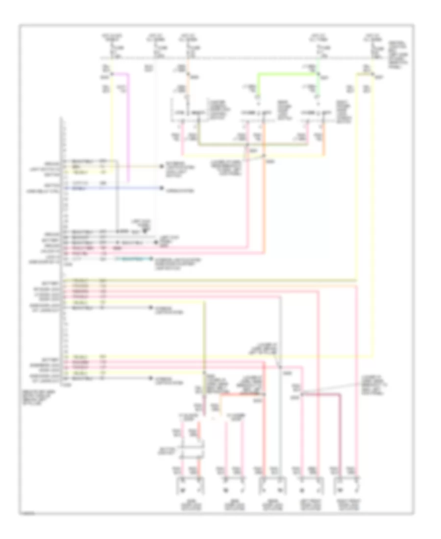
AIR CONDITIONING
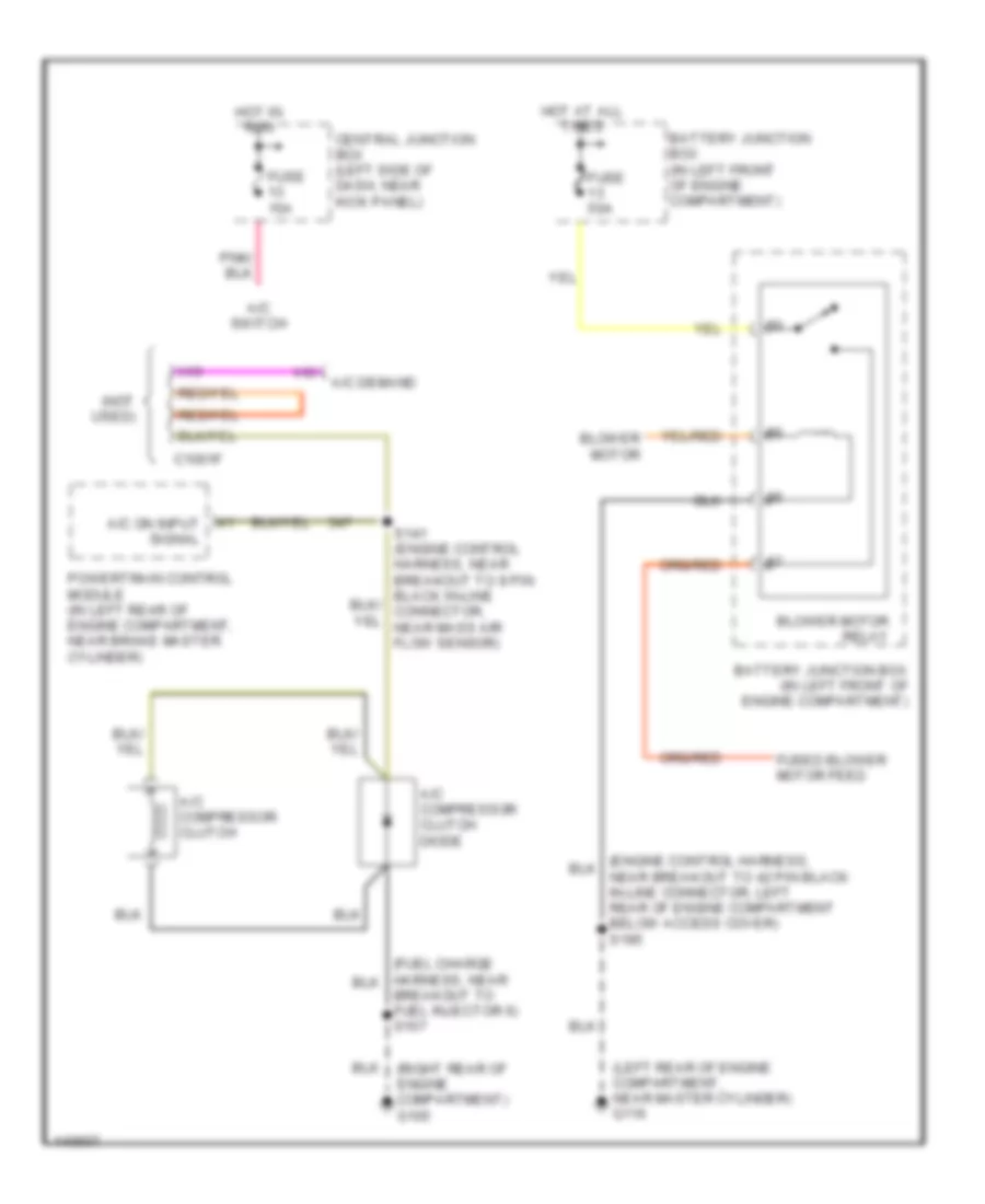
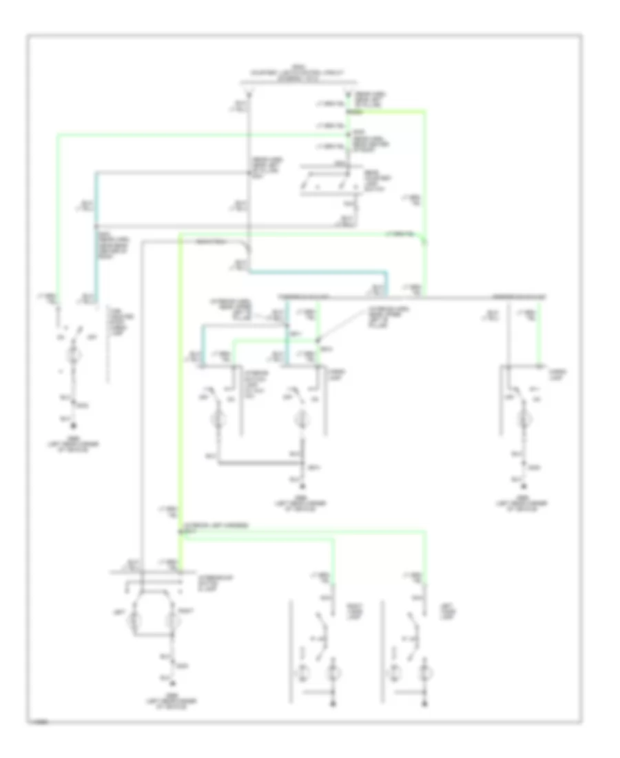
Heater Wiring Diagram, with Stripped Chassis for Ford E450 Super Duty 2001

List of elements for Heater Wiring Diagram, with Stripped Chassis for Ford E450 Super Duty 2001:
- (engine control harness, near breakout to 42 pin in-line connector, left rear of engine compartment below access cover) s195
- (left rear of engine compartment, near master cylinder) g116
- Battery junction box (in left front of engine compartment)
- Blower motor
- Blower motor relay
- Fuse 50a
- Fused blower motor feed
- Hot at all times
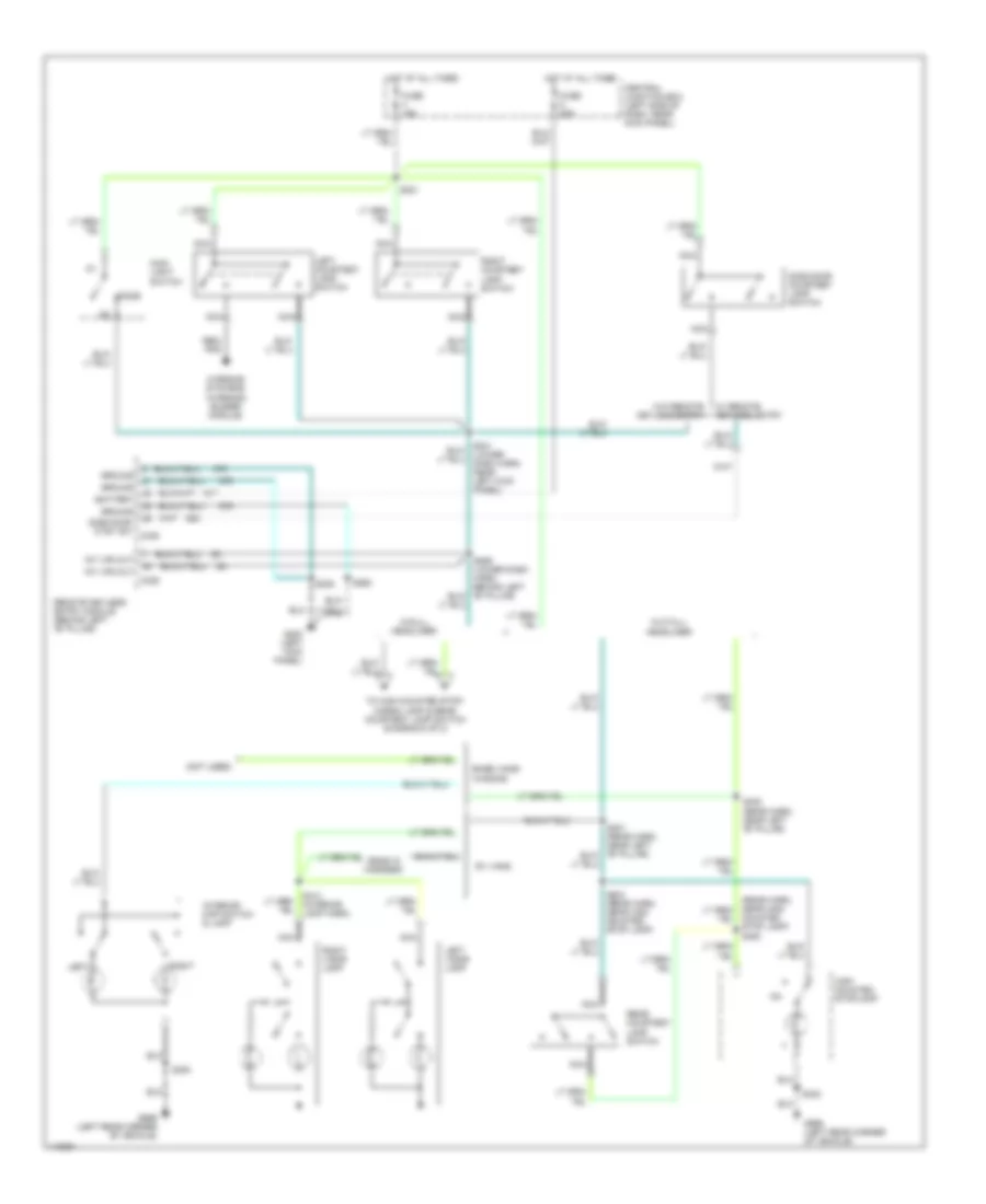
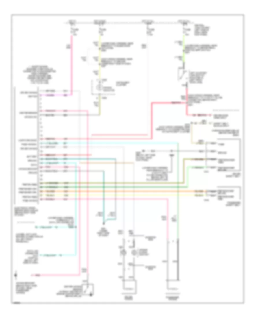
Heater Wiring Diagram, without Stripped Chassis for Ford E450 Super Duty 2001
List of elements for Heater Wiring Diagram, without Stripped Chassis for Ford E450 Super Duty 2001:
- (auxiliary blower motor harness, in breakout to 12-pin in-line connector left rear cargo area) s401
- (behind upper left side of dash, near kick panel) g202
- (below left side of dash, near kick panel) g202
- (engine control harness, near breakout to 76 pin in-line connector, left rear of engine compartment, on firewall) s122
- (left rear corner of vehicle, near left rear door) g999
- (main harness near breakout to radio) s202
- (not used)
- (rear harness, near breakout to 12 pin gray in-line connector, along left "b" pillar near roof)
- .25 ohms +/- 10%
- .8 ohms +/- 10%
- 2.7 ohms +/- 10%
- 87a
- Auxiliary blower motor (above left rear wheelwell)
- Auxiliary blower motor relay (in left rear corner of vehicle, above wheelwell)
- Auxiliary blower resistor (above left rear wheelwell)
- Auxiliary heater blower switch note: (w/o rear contrl: low position) (with rear control: rear control)
- Auxiliary heater blower switch off
- Auxiliary high blower motor relay (in left rear corner of vehicle, above wheelwell)
- Battery junction box (in left front of engine compartment)
- Blend door actuator (behind right side of dash, on a/c-heater plenum)
- Blower motor (on right side of engine compartment)
- Blower motor relay
- Blower motor resistor (in right rear of engine compartment)
- Central junction box left side of dash, near kick panel)
- Cutaways
- Cutout switch)
- Def/flr
- Defrost
- Floor
- Front blower switch
- Function selector switch
- Fuse 13 15a
- Fuse 13 50a
- Fuse 16 50a
- G108 (left front of engine compartment, at left upper radiator support)
- G109 (right front of engine compartment, at right upper radiator support)
- G202 (behind upper left side of dash, near kick panel)
- High
- Hot at all times
- Hot in run
- Low
- Off
- Pnk/ (main harness, near breakout to radio) s203
- Rear auxiliary blower switch
- S111 (engine control harness, near breakout to battery junction box)
- S143 (engine control harness, near breakout to a/c pressure cut-out switch)
- S202 (main harness, near breakout to radio)
- S303
- S304
- S305
- S323
- S400 (window regulator relay switch harness, near breakout for 2 pin connector behind left "b" pillar)
- See note below
- Temper- ature control switch
- Thermal limiter
- Vans & wagons
- Vent
- W/ rear control
- W/auxiliary heat
- W/o rear con- trol
6.8L
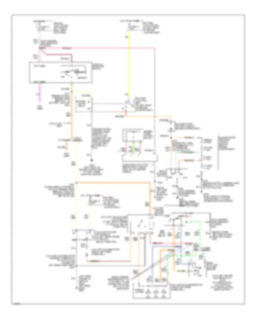
6.8L, Manual A/C Wiring Diagram, with Stripped Chassis for Ford E450 Super Duty 2001
List of elements for 6.8L, Manual A/C Wiring Diagram, with Stripped Chassis for Ford E450 Super Duty 2001:
- (left rear of engine compartment, near master cylinder) g116
- (not used)
- (right rear of engine compartment) g105
- A/c compressor clutch
- A/c compressor clutch diode
- A/c demand
- A/c on input signal
- A/c switch
- Battery junction box (in left front of engine compartment)
- Blower motor
- Blower motor relay
- Breakout to fuel injector 6) s107
- C1001f
- Central junction box (left side of dash, near kick panel)
- Fuse 15a
- Fuse 50a
- Fused blower motor feed
- Hot at all times
- Hot in run
- Powertrain control module (in left rear of engine compartment, near brake master cylinder)
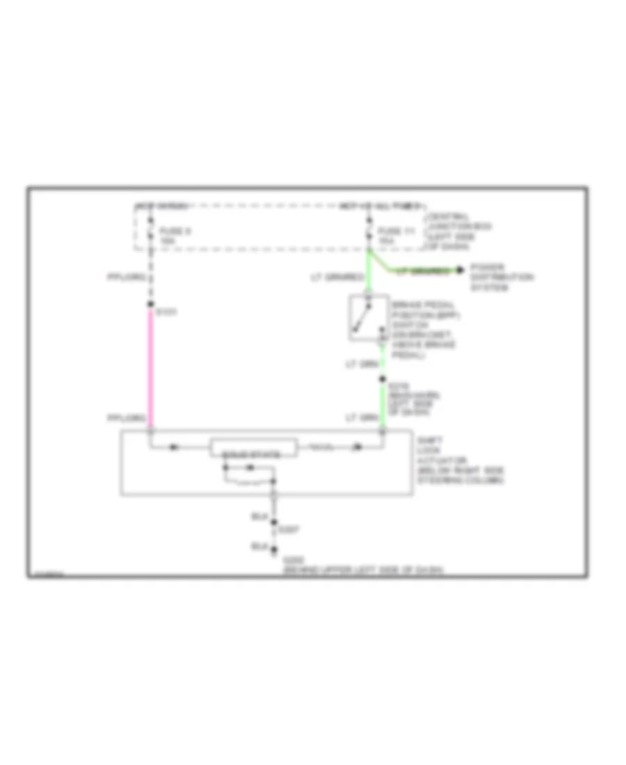
ANTI-LOCK BRAKES
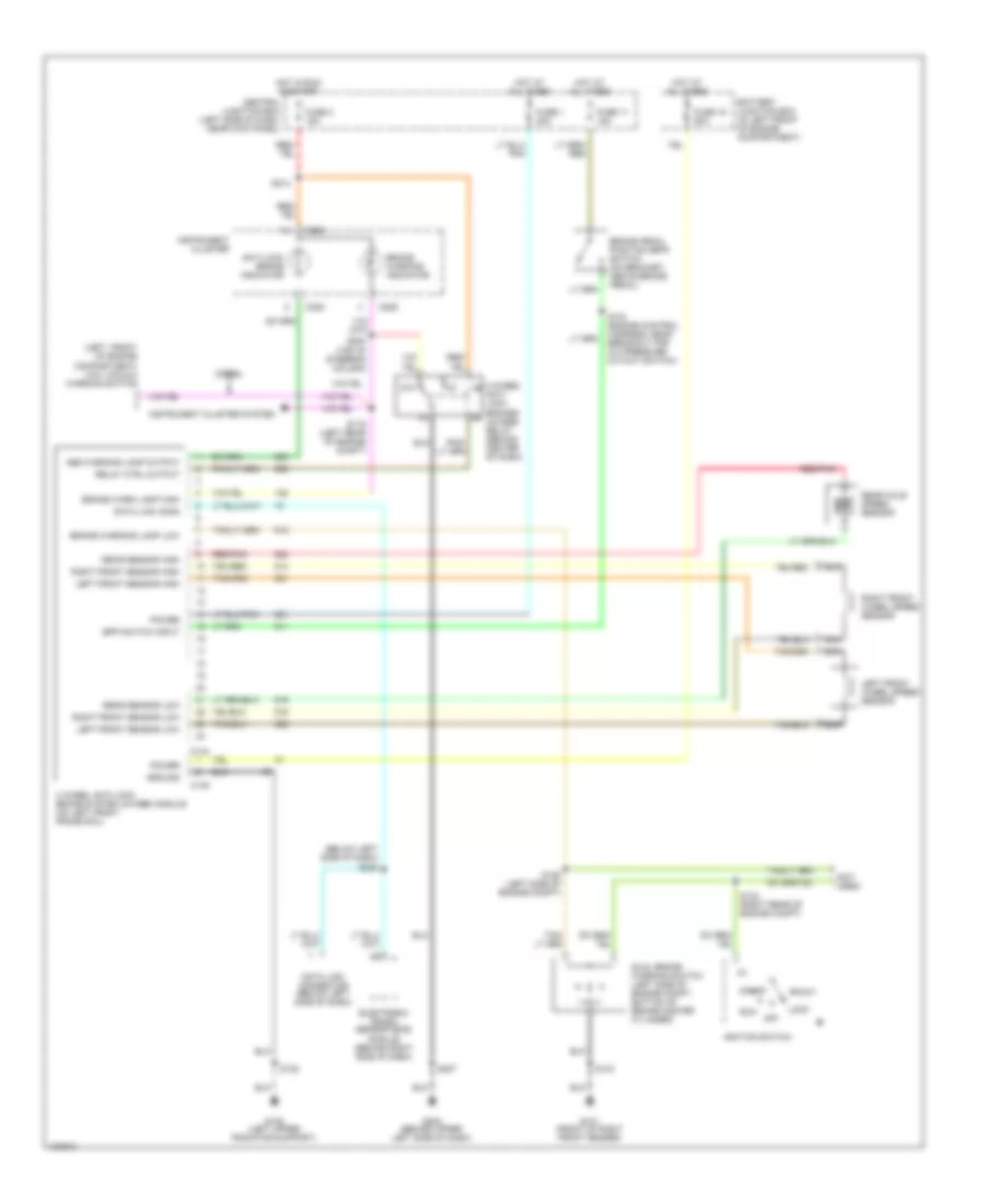
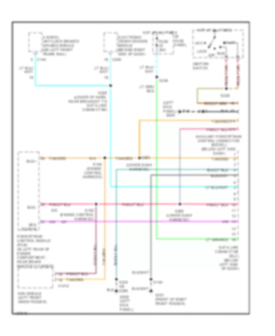
Anti-lock Brakes Wiring Diagram for Ford E450 Super Duty 2001
List of elements for Anti-lock Brakes Wiring Diagram for Ford E450 Super Duty 2001:
- (below left side of dash)
- (left front of engine compartment) low vacuum warning switch
- (not used)
- 4 wheel anti-lock brake system (4wabs) module (on left front frame rail)
- 4-wheel anti- lock brakes (4wabs) relay (behind center of dash)
- 87a
- Abs warning lamp output
- Accy
- Anti-lock brake indicator
- Battery junction box (in left front of engine compartment)
- Bpp switch input
- Brake pedal position (bpp) switch (on bracket, above brake pedal)
- Brake warn lamp high
- Brake warning indicator
- Brake warning lamp low
- C144
- C145
- C225
- C226
- Central junction box (left side of dash, near kick panel)
- Data link conn
- Data link connector (below left side of dash)
- Diesel
- Dual brake warning switch (left side of engine compt, bottom of brake master cylinder)
- Electronic crash sensor (ecs) module (behind right side of dash)
- Fuse 1 20a
- Fuse 11 15a
- Fuse 19 60a
- Fuse 2 15a
- G101 (front of right front fender)
- G108 (left upper radiator support)
- G202 (behind upper left side of dash)
- Ground
- Hot at all times
- Hot in run or start
- Ignition switch
- Instrument cluster
- Instrument cluster system
- Left front sensor high
- Left front sensor low
- Left front wheel speed sensor
- Lock
- Nca
- Off
- Ohm
- Power
- Rear axle speed sensor
- Rear sensor high
- Rear sensor low
- Red/pnk
- Relay ctrl output
- Right front sensor high
- Right front sensor low
- Right front wheel speed sensor
- Run
- S119 (left rear of engine compt)
- S122
- S125 (left side of engine compt)
- S132 (right rear of engine compt)
- S134 (engine control harness, near breakout for a/c pressure cutout switch)
- S143
- S207
- S213
- S220 (top of steering column)
- S228
- Start
COMPUTER DATA LINES
Computer Data Lines Wiring Diagram for Ford E450 Super Duty 2001
List of elements for Computer Data Lines Wiring Diagram for Ford E450 Super Duty 2001:
- (left kick panel)
- (lower dash harness)
- 4 wheel anti-lock brakes (4wabs) module (on left front frame rail)
- Acc
- Auxiliary powertrain control connector (diesel) (below left side dash)
- Bus+
- Bus-
- C1012
- C144
- C200
- Data link connector (dlc) (below left side of dash)
- Electronic crash sensor module (behind right side of dash)
- Fuse 20a
- G101 (front of right front fender)
- G200
- G200 (left kick panel)
- Gen scan in
- Hot at all times
- I/p fuse panel
- Ignition switch
- Lock
- Ngv module (left front inner fender)
- Off
- Powertrain control module (pcm) (in left rear of engine compartment, near brake master cylinder)
- Run
- S140
- S182 (engine control harness)
- S184 (engine control harness)
- S223
- S228 (lower i/p harn, near breakout to data link connector)
- S229
- S230
- S235 or s260
- S262 (lower dash harness)
- S263
- Start
CRUISE CONTROL
6.8L
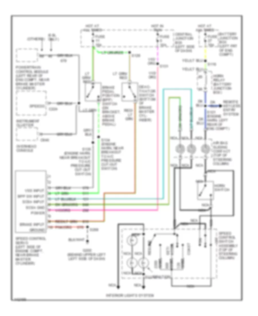
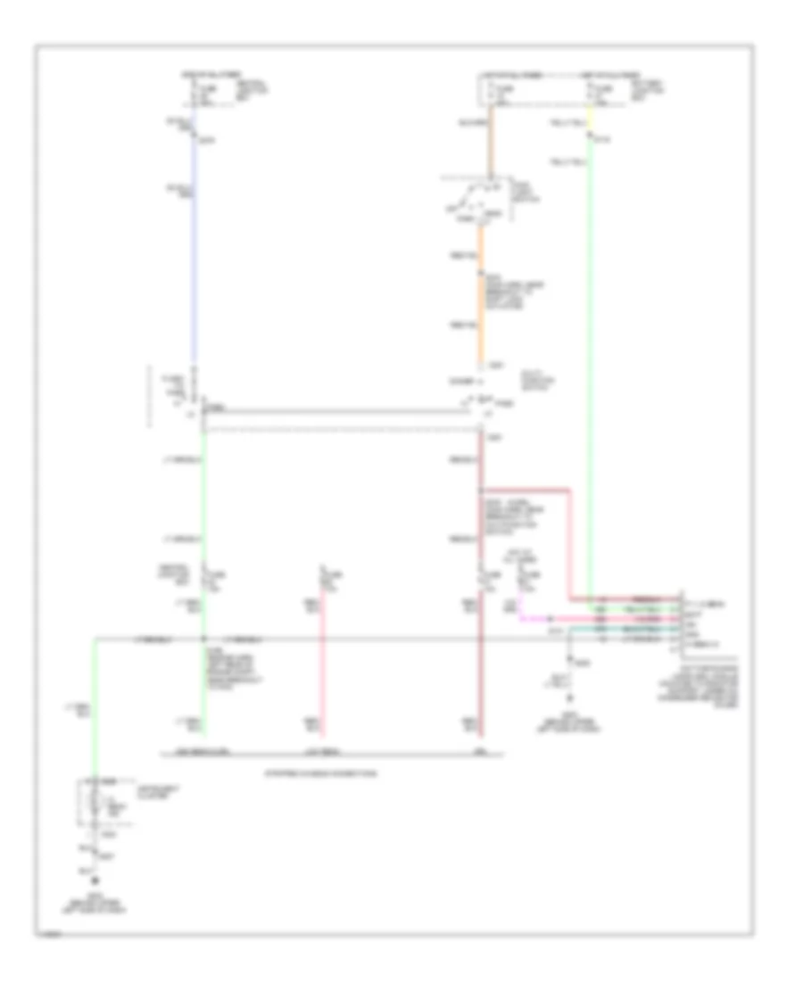
6.8L, Cruise Control Wiring Diagram for Ford E450 Super Duty 2001
List of elements for 6.8L, Cruise Control Wiring Diagram for Ford E450 Super Duty 2001:
- (6.8l only)
- (others)
- Accel set/
- Air bag sliding contact (top of steering column)
- Battery junction box (left frt of eng compt)
- Bpp sw input
- Brake input
- Brake pedal position (bpp) switch (on bracket, above brake pedal)
- C224
- C940
- Central junction box (left side of dash)
- Coast
- Deac- tivator switch (bottom of brake master cyl- inder)
- Fuse 10a
- Fuse 15a
- G202 (behind upper left left side of dash)
- Ground
- Horn relay (battery junction box)
- Horn switch
- Hot at all times
- Hot at all times
- Hot in run
- Illumination
- Instrument cluster
- Interior lights system
- Nca
- Off
- Ohms
- Overhead console
- Power
- Powertrain control module (left rear of eng compt, near brake master cylinder)
- Remote keyless entry system
- Resume
- S116
- S129
- S131
- S134 (engine harn, near breakout to a/c pressure cut-out switch)
- S135 (engine harn, near breakout to a/c pressure cut-out switch)
- S268
- Scsa gnd
- Scsa input
- Speed control servo (left side of engine compt, near brake master cylinder)
- Speed control switch assembly (top of steering column)
- Speedo
- Vss input
7.3L DI TURBO DIESEL
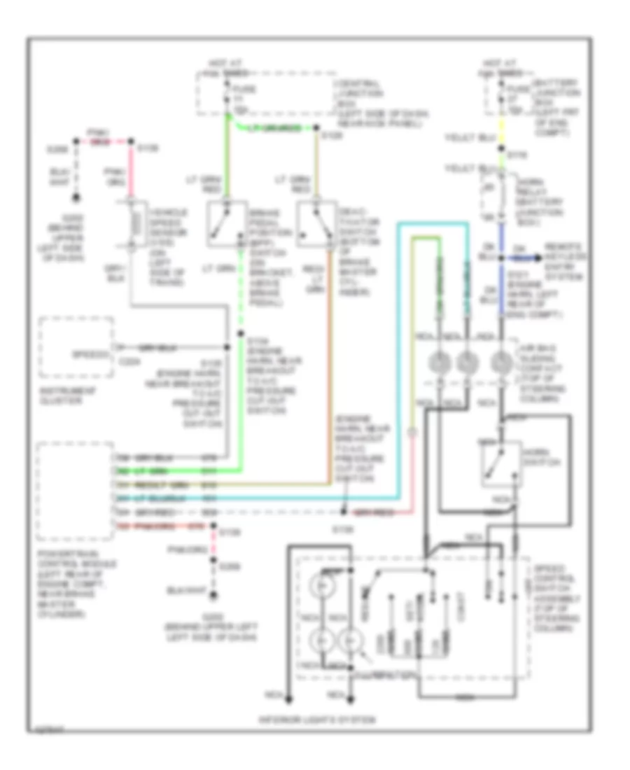
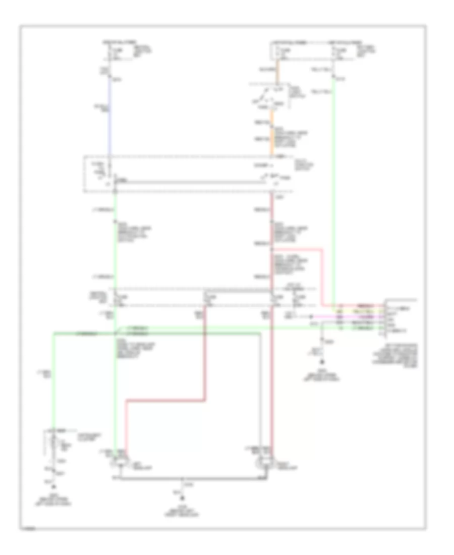
7.3L DI Turbo Diesel, Cruise Control Wiring Diagram for Ford E450 Super Duty 2001
List of elements for 7.3L DI Turbo Diesel, Cruise Control Wiring Diagram for Ford E450 Super Duty 2001:
- (engine harn, near breakout to a/c pressure cut-out switch)
- Accel set/
- Air bag sliding contact (top of steering column)
- Battery junction box (left frt of eng compt)
- Brake pedal position (bpp) switch (on bracket, above brake pedal)
- C224
- Central junction box (left side of dash, near kick panel)
- Coast
- Deac- tivator switch (bottom of brake master cyl- inder)
- Fuse 15a
- G202 (behind upper left left side of dash)
- G202 (behind upper left side of dash)
- Horn relay (battery junction box)
- Horn switch
- Hot at all times
- Hot at all times
- Illumination
- Instrument cluster
- Interior lights system
- Nca
- Off
- Ohms
- Powertrain control module (left rear of engine compt, near brake master cylinder)
- Remote keyless entry system
- Resume
- S116
- S121 (engine harn, left rear of eng compt)
- S129
- S134 (engine harn, near breakout to a/c pressure cut-out switch)
- S135 (engine harn, near breakout to a/c pressure cut-out switch)
- S136
- S139
- S268
- Speed control switch assembly (top of steering column)
- Speedo
- Vehicle speed sensor (vss) (on left side of trans)
ENGINE PERFORMANCE
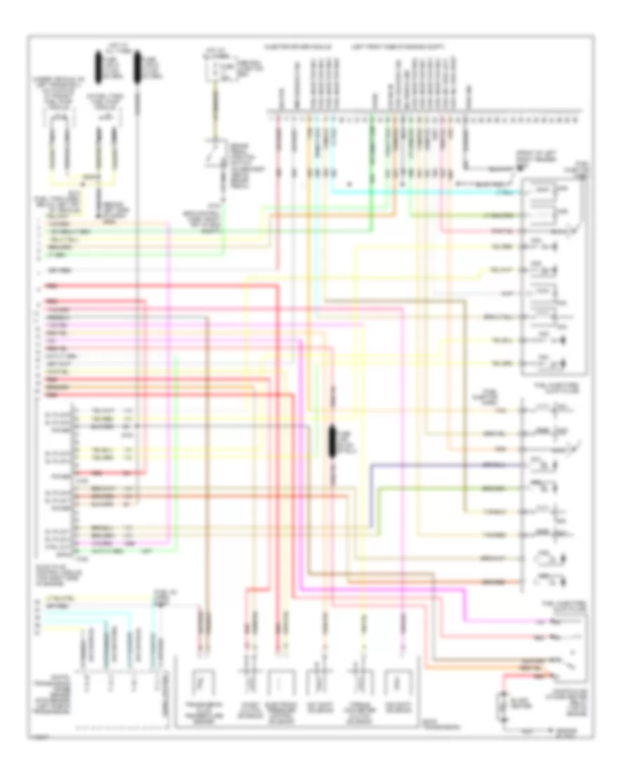
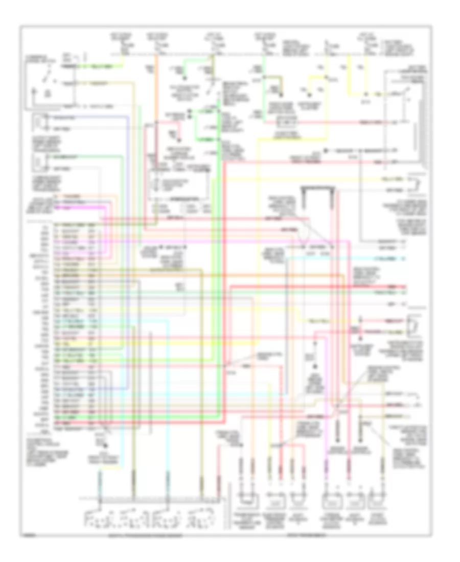
6.8L
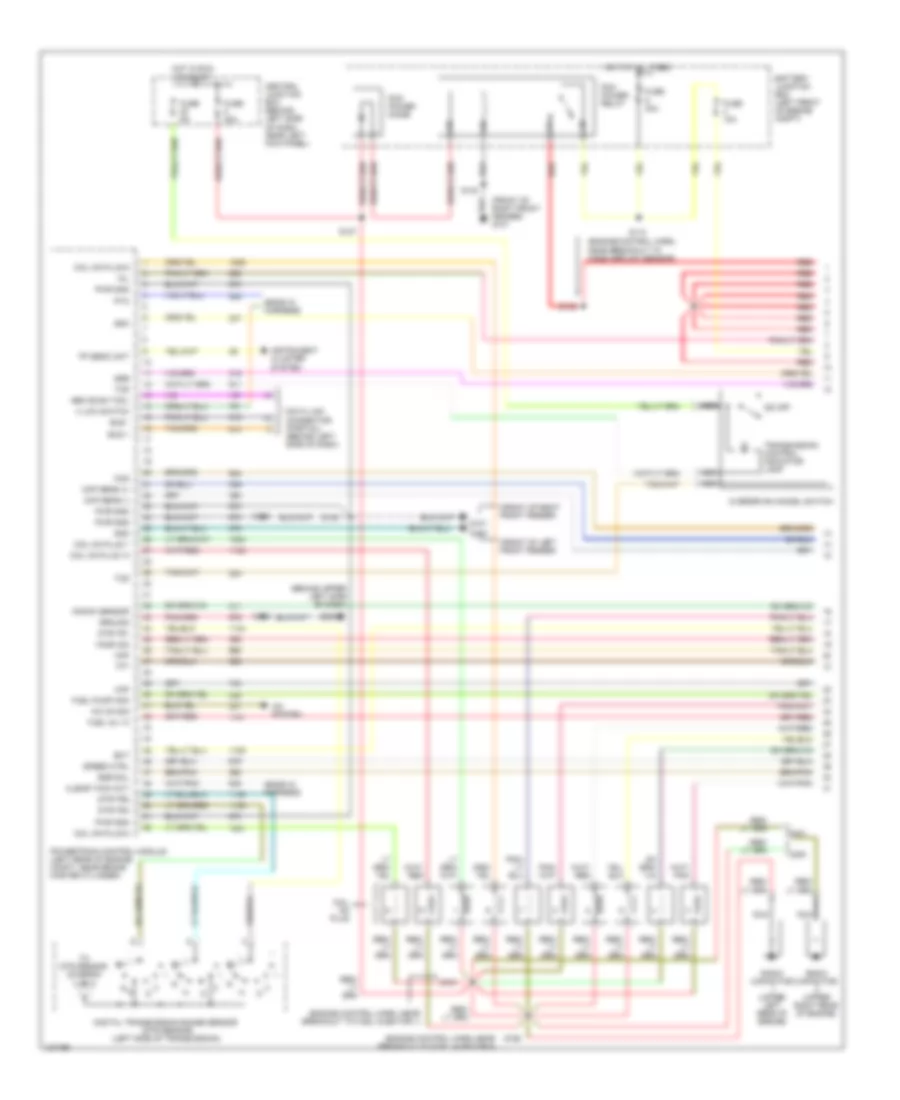
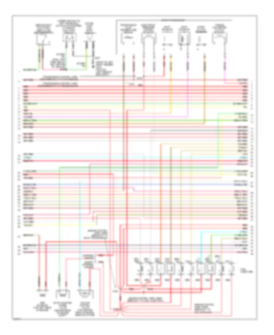
6.8L, Engine Performance Wiring Diagram (1 of 4) for Ford E450 Super Duty 2001
List of elements for 6.8L, Engine Performance Wiring Diagram (1 of 4) for Ford E450 Super Duty 2001:
- (behind upper left side of dash)
- (ends in harness)
- (engine control harn, near breakout to fuel injector 1)
- (engine control harn, near breakout to fuel injector 6)
- (engine control harn, near breakout to mass airflow sensor)
- (front of left front fender)
- (front of right front fender)
- (front of right front fender) g101
- 4 low switch
- A/c on sig
- A/c system
- Battery junction box (left front of engine compt)
- Bus +
- Bus -
- Ccs
- Central junction box (behind left side of dash, near left kick panel)
- Ckp sens (+)
- Ckp sens (-)
- Clear tach out
- Coil on plug
- Coil on plug 1
- Coil on plug 10
- Coil on plug 5
- Coil on plug 6
- Data link connector (partial) (behind left side of dash)
- Digital transmission range sensor (dtr sensor) (left side of transmission)
- Dtr-tr1
- Dtr-tr2
- Dtr-tr4
- Ect
- Egr sol
- Fp send unit
- Fuel inj 10
- Fuel pump mon
- Fuse 10a
- Fuse 30a
- Fuse 5a
- G100
- G101
- G202
- Gen scan tool
- Gnd
- Ground
- Ho2s (22)
- Hot at all times
- Hot in run or start
- Instrument cluster system
- Knock sensor
- Maf
- Mil
- Nca
- O/d off
- Overdrive cancel switch
- Pcm power diode
- Pcm power relay
- Powertrain control module (left rear of engine compt, near brake master cylinder)
- Pto
- Pwr gnd
- R n
- Radio capacitor (upper left rear of engine)
- Radio capacitor (upper right rear of engine)
- Red
- S110
- S127
- S140
- S142
- S161
- S162
- S169
- S198
- Speed ctrl
- Ssa
- Ssb
- Tcs
- Tft
- To dtr sensor (diagram 4 of 4)
- Transmission control indicator lamp
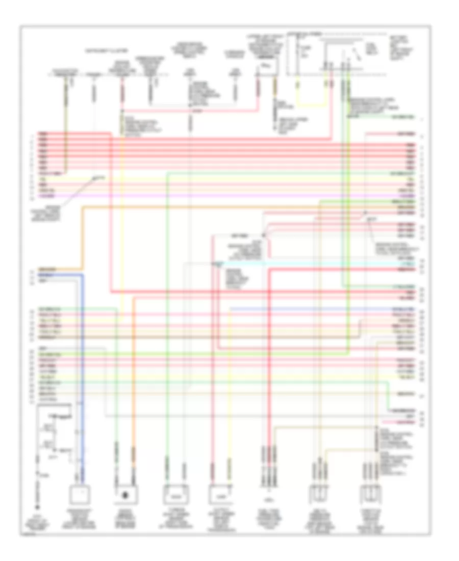
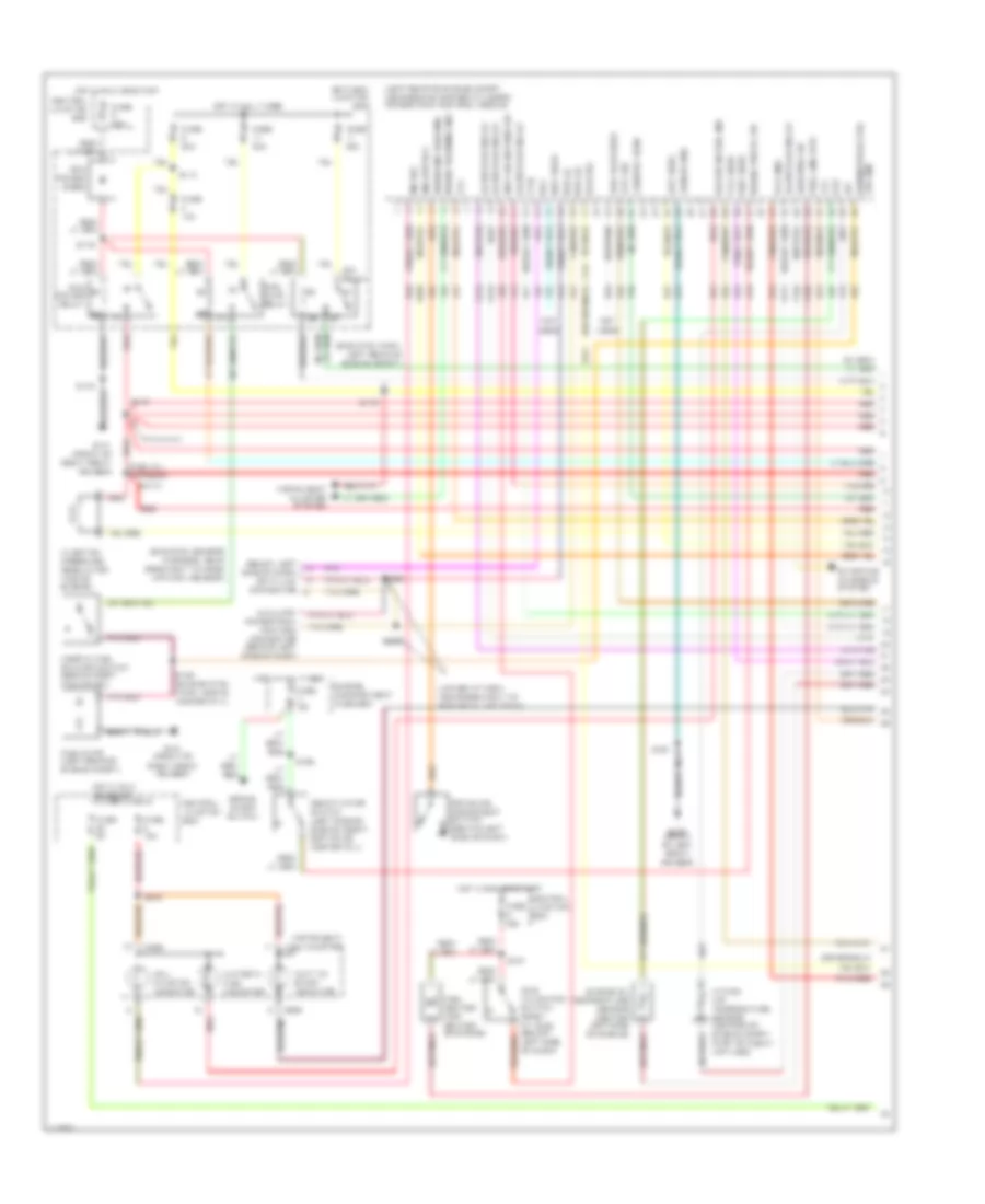
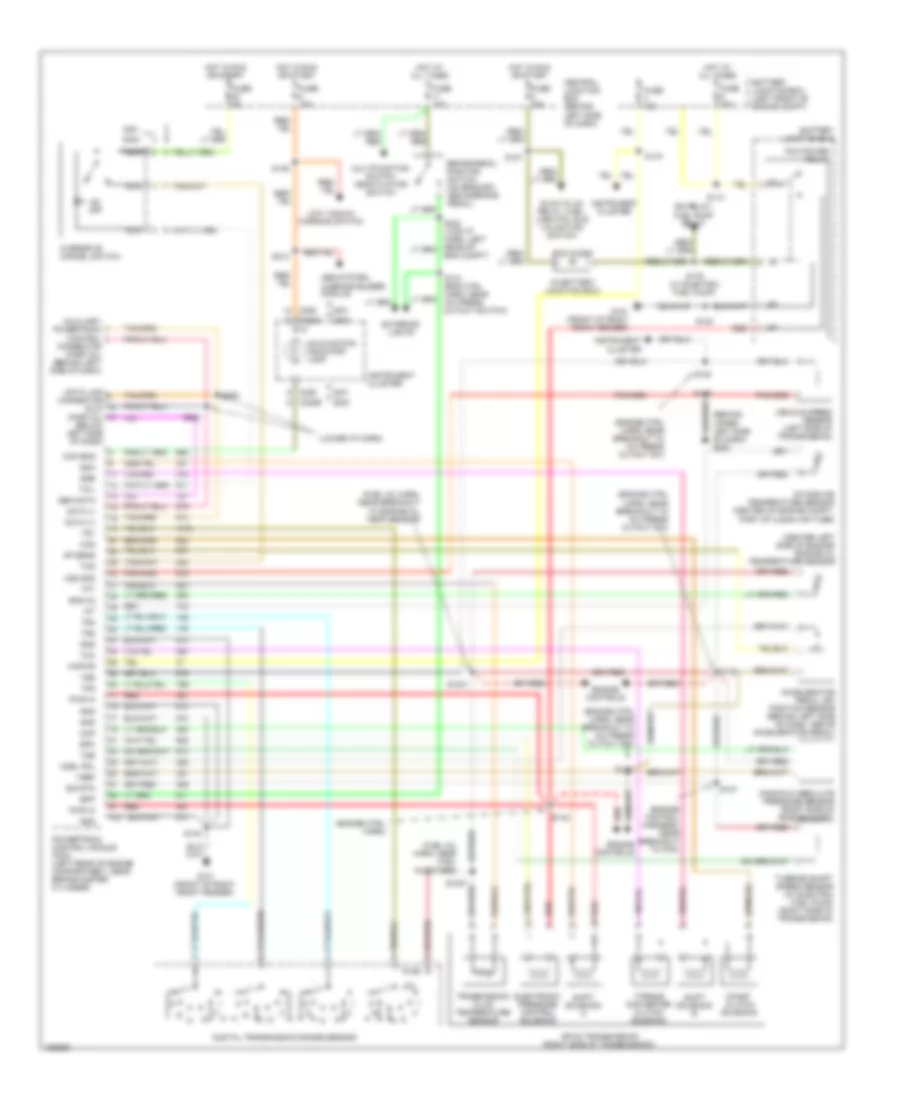
6.8L, Engine Performance Wiring Diagram (2 of 4) for Ford E450 Super Duty 2001
List of elements for 6.8L, Engine Performance Wiring Diagram (2 of 4) for Ford E450 Super Duty 2001:
- (behind upper left side of dash) g202
- (engine control harn, left rear of engine compt)
- (engine control harn, near breakout to 76-pin conn in left rear of engine compt) s126
- (engine control harn, near breakout to coil on plug 9)
- (engine control harn, near breakout to pcm)
- (near brake master cylinder) speed control servo
- (speedometer/ odometer) vehicle speed input
- (upper left front of engine) instrumentation engine coolant temperature sensor
- Battery junction box (left front of engine compt)
- Crankshaft position sensor (lower center front of engine)
- Delta pressure feedback egr sensor (top left rear of engine)
- Engine coolant temperature gauge
- Fuel pump relay
- Fuel tank pressure transducer (near fuel tank)
- Fuse 30a
- G101 (front of right front fender)
- Hot at all times
- Instrument cluster
- Knock sensor (top right rear side of engine)
- Malfunction indicator
- Nca
- Output shaft speed sensor (on left side of transmission)
- Overhead console
- Power
- Red
- Red/pnk
- S133 (engine control harn, near a/c pressure cutout switch)
- S135
- S136 (engine control harn, near a/c pressure cutout switch)
- S137
- S138 (engine control harn, near a/c pressure cutout switch)
- S157
- S158 (engine control harn, near breakout to radio capacitor 1)
- S169
- S170
- S171
- S175
- Throttle position sensor (top of engine, near air intake)
- Turbine shaft speed sensor (right side of transmission)
- Vss input
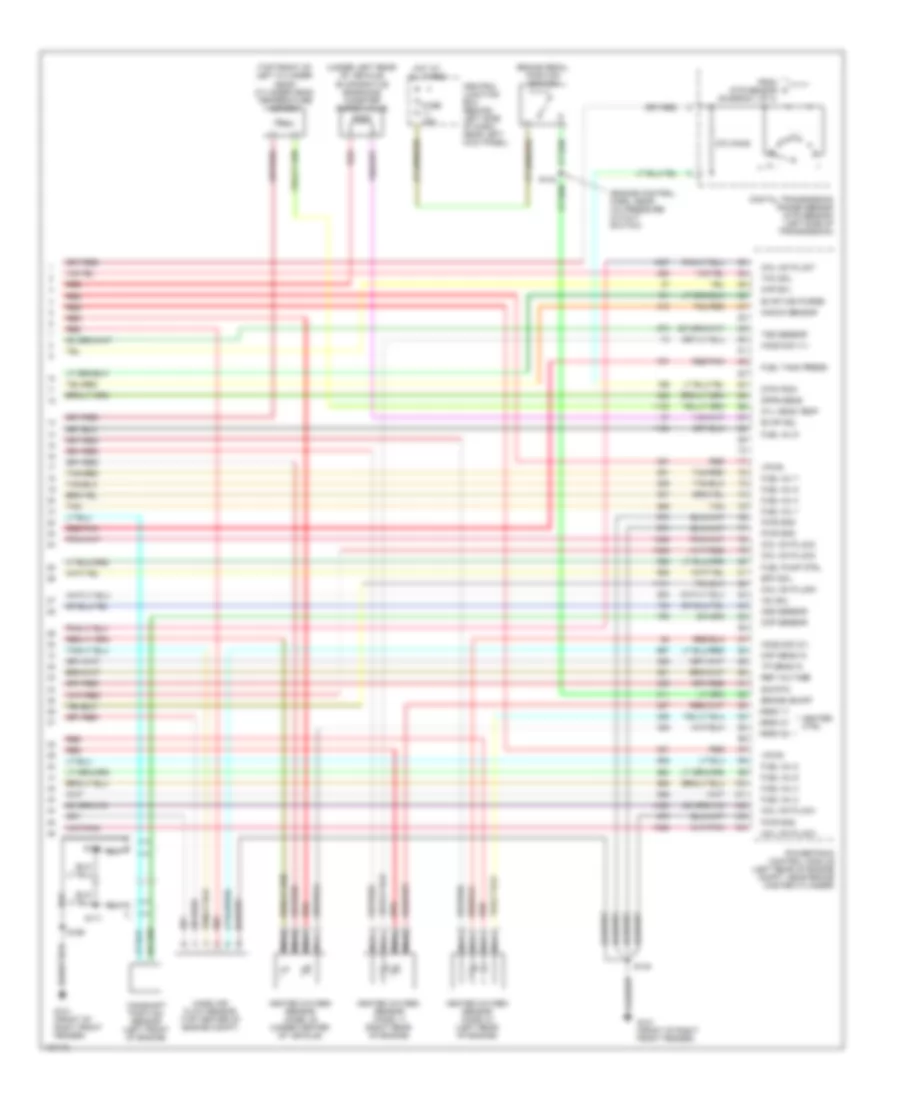
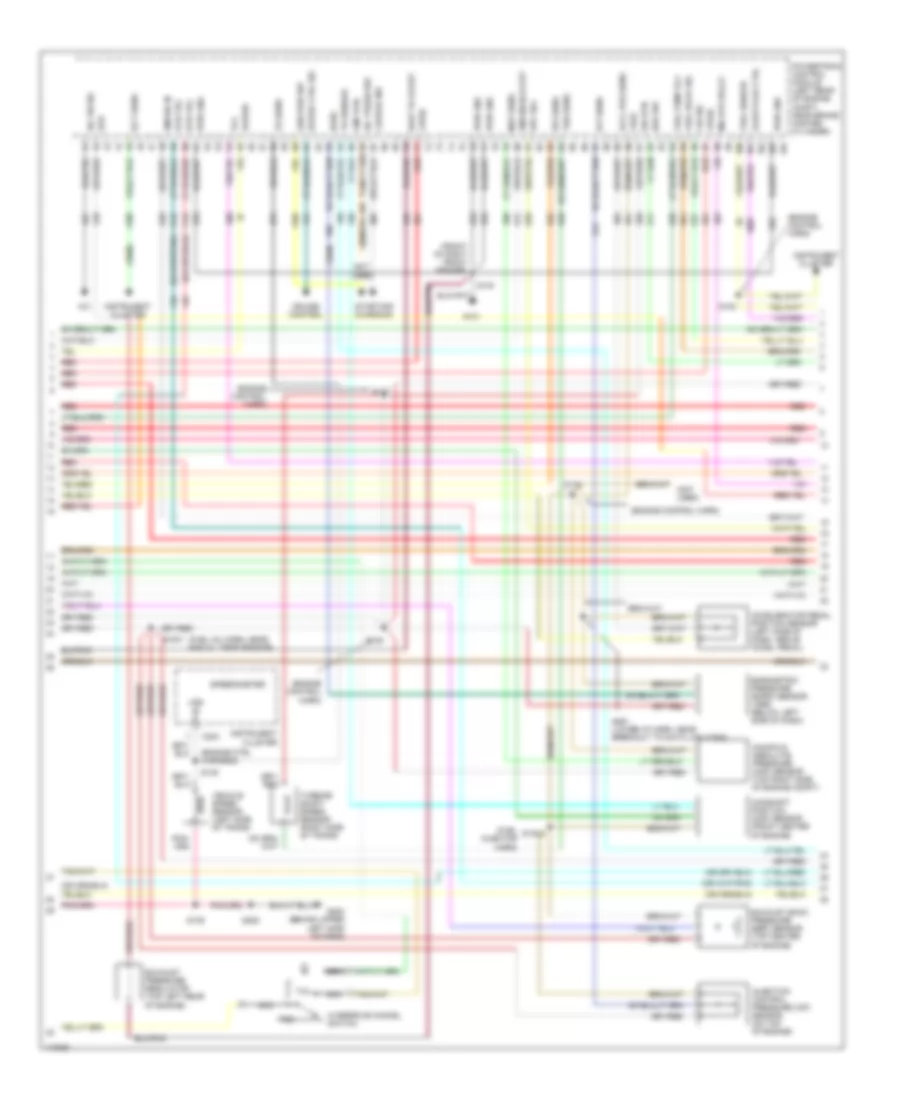
6.8L, Engine Performance Wiring Diagram (3 of 4) for Ford E450 Super Duty 2001
List of elements for 6.8L, Engine Performance Wiring Diagram (3 of 4) for Ford E450 Super Duty 2001:
- (behind right kick panel) inertia fuel shut-off switch
- (center rear of engine compt)
- (engine control harn, near breakout to 4r100 transmission)
- (engine control harn, near breakout to coil on plug 2)
- (engine control harn, near breakout to fuel injector 6)
- (front of left front fender) g100 (or g104) (left rear of eng compt)
- (fuel tank harn, below left center of vehicle) s309
- (in fuel tank) fuel pump module
- (transmission control harn, near breakout to dtr sensor)
- (transmission control harn, near breakout to transmission)
- (under vehicle, on left frame rail) (cutaways/stripped) in transit fuel pump module
- 4r100 transmission
- Coast clutch solenoid
- Egr solenoid (top left rear of engine)
- Electronic pressure control solenoid
- Evap canister purge valve
- Except stripped chassis
- Fuel injectors
- Idle air control valve (top center rear of engine, near air intake)
- Nca
- Red
- Red/pnk
- S100
- S102
- S155
- S159
- S160
- S307
- Shift solenoid
- Stripped chassis
- Tan
- Tan/ red
- Tan/red
- Torque converter clutch solenoid
- Transmission fluid temperature sensor
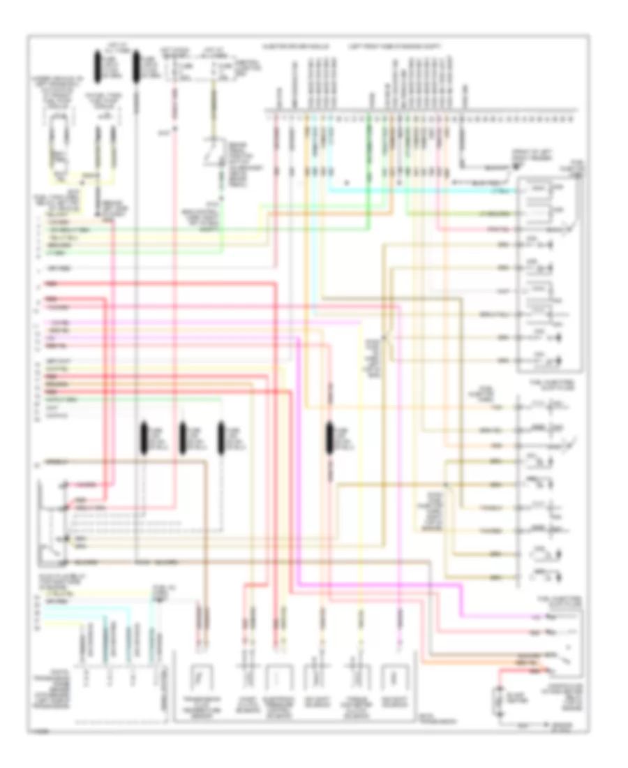
6.8L, Engine Performance Wiring Diagram (4 of 4) for Ford E450 Super Duty 2001
List of elements for 6.8L, Engine Performance Wiring Diagram (4 of 4) for Ford E450 Super Duty 2001:
- (engine control harn, near a/c pressure cutout switch)
- (top front of left cylinder head) cylinder head temperature sensor
- (under left rear of vehicle) evaporative emissions canister purge valve
- 270 ohms
- Brake on/off
- Brake pedal position switch
- Camshaft position sensor (left front of engine)
- Central junction box (behind left side of dash, near left kick panel)
- Cmp sensor
- Coil on plug 2
- Coil on plug 3
- Coil on plug 4
- Coil on plug 7
- Coil on plug 8
- Coil on plug 9
- Cyl head temp
- Digital transmission range sensor (dtr sensor) (left side of transmission)
- Dpfe sens
- Dtr-tr3a
- Epc sol
- Evap can purge
- Evap sol
- From dtr sensor (diagram 1 of 4)
- Fuel inj 1
- Fuel inj 2
- Fuel inj 3
- Fuel inj 4
- Fuel inj 5
- Fuel inj 6
- Fuel inj 7
- Fuel inj 8
- Fuel inj 9
- Fuel pump ctrl
- Fuel tank press
- Fuse 15a
- G101 (front of right front fender)
- Heated oxygen sensor (hos2) 11 (right rear of engine)
- Heated oxygen sensor (hos2) 21 (left rear of engine)
- Heated oxygen sensor (hos2) 22 (under center of vehicle)
- Heater ctrl
- Hego 11
- Hego 21
- Hego 22
- Ho2s sig (11)
- Ho2s sig (21)
- Hot at all times
- Iac sol
- Kap b(+)
- Knock sensor
- Maf sens in
- Mass air- flow sensor (top center of engine compt)
- Nca
- Oss sensor
- Powertrain control module (left rear of engine compt, near brake master cylinder)
- Pwr gnd
- Red
- Red/pnk
- Ref voltage
- S140
- S169
- S170
- S171
- Sig rtn
- Tan
- Tan/red
- Tcc sol
- Tp sens in
- Tss sensor
- Vpwr
7.3L DI TURBO DIESEL
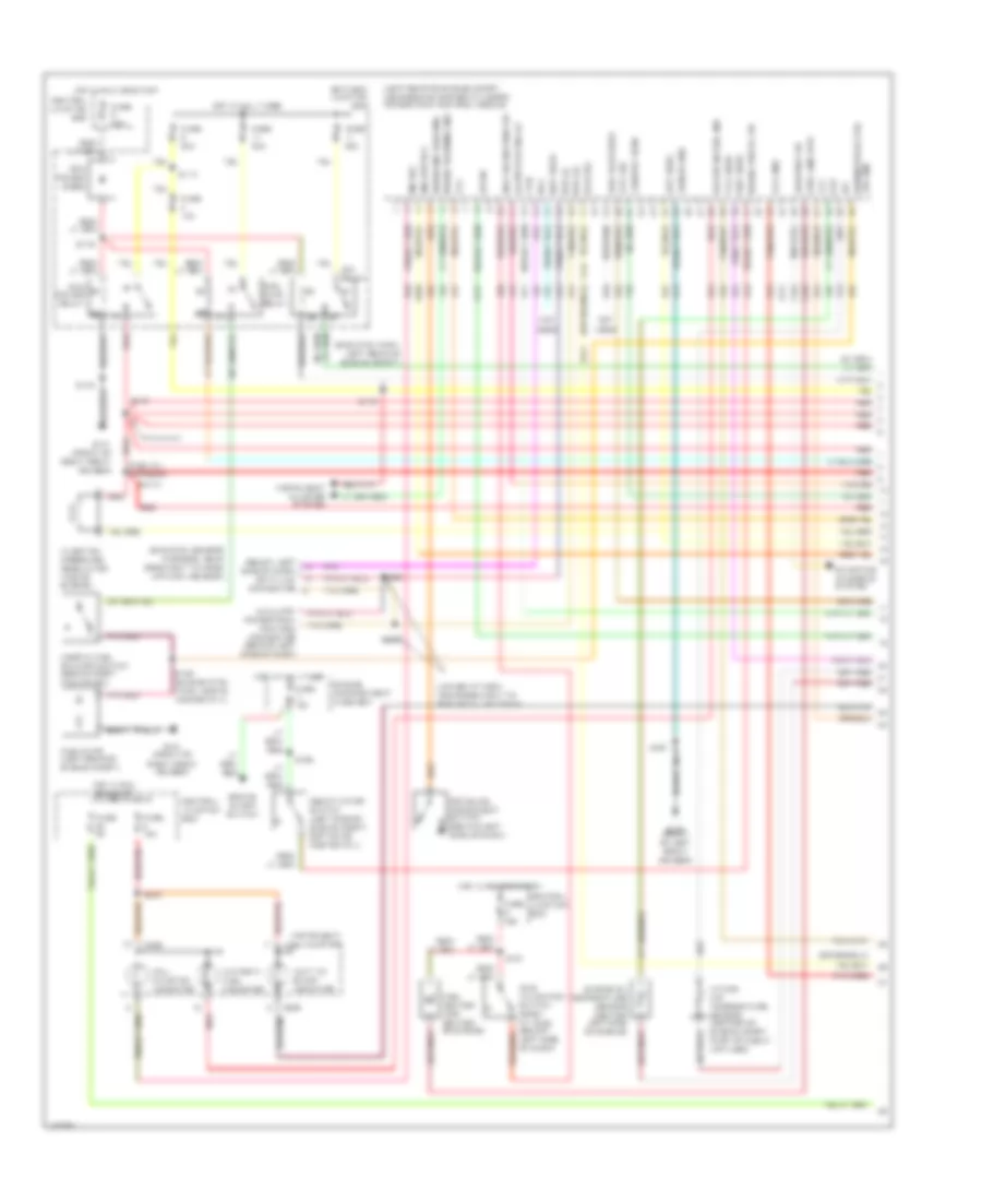
7.3L DI Turbo Diesel, Engine Performance Wiring Diagram, California (1 of 3) for Ford E450 Super Duty 2001
List of elements for 7.3L DI Turbo Diesel, Engine Performance Wiring Diagram, California (1 of 3) for Ford E450 Super Duty 2001:
- (below left side of dash) data link connector
- (eng ctrl harn, left rear of engine compt)
- (eng ctrl sensor harness, near breakout to mass air flow sensor)
- (fuel inj harness)
- (left rear of engine compt, near brake master cylinder) powertrain control module
- (left side of engine compt, bottom of master cyl)
- (lower i/p harn, near breakout to rke data link conn)
- App sens
- Aux tach feed
- Auxiliary powertrain control connector (behind left side of dash)
- Battery junction box
- Brake on/off switch
- Brake press sw
- Brake warning ind
- Bus (+)
- Bus (-)
- C224
- C225
- C226
- Cam pos sens
- Ccs sol
- Central junction box
- Deactivator switch
- Dlc
- Driveline disconn
- Driveline disconnect switch (behind left side of dash)
- Dtr-tr1
- Ebp sens
- Engine compartment fuse box
- Engine oil temperature sensor (center left side of engine)
- Eot
- Fuel heater (top center of engine)
- Fuel line htr
- Fuel pump (left rear of engine compt)
- Fuel pump relay
- Fuse 10a
- Fuse 15a
- Fuse 30a
- Fuse 5a
- G100 (front of left front fender)
- G101 (front of right front fender)
- Gen pwr sw
- Glow plug relay
- Gpcm
- Horn/speed ctrl sw gnd
- Hot at all times
- Hot in run or start
- Iat
- Idle validation sw
- Idle validation switch (open at idle) (below left side of dash)
- Idm relay
- Inertia fuel shutoff switch (behind right kick panel)
- Injection pressure regulator (top of engine)
- Instrument cluster
- Instrument cluster system
- Intake air temperature sensor (center of engine compt, part of clean air tube)
- Mal- function indicator
- Mia htr rly
- Mil dlc
- Not used
- Pcm power diode
- Pcm power relay
- Red
- S1013
- S110
- S127
- S129
- S140
- S142
- S167
- S175
- S176
- S180 (engine ctrl harn, above master cyl)
- S213
- S262
- S263
- Shield gnd
- Ss1
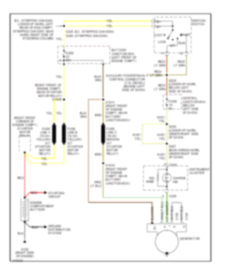
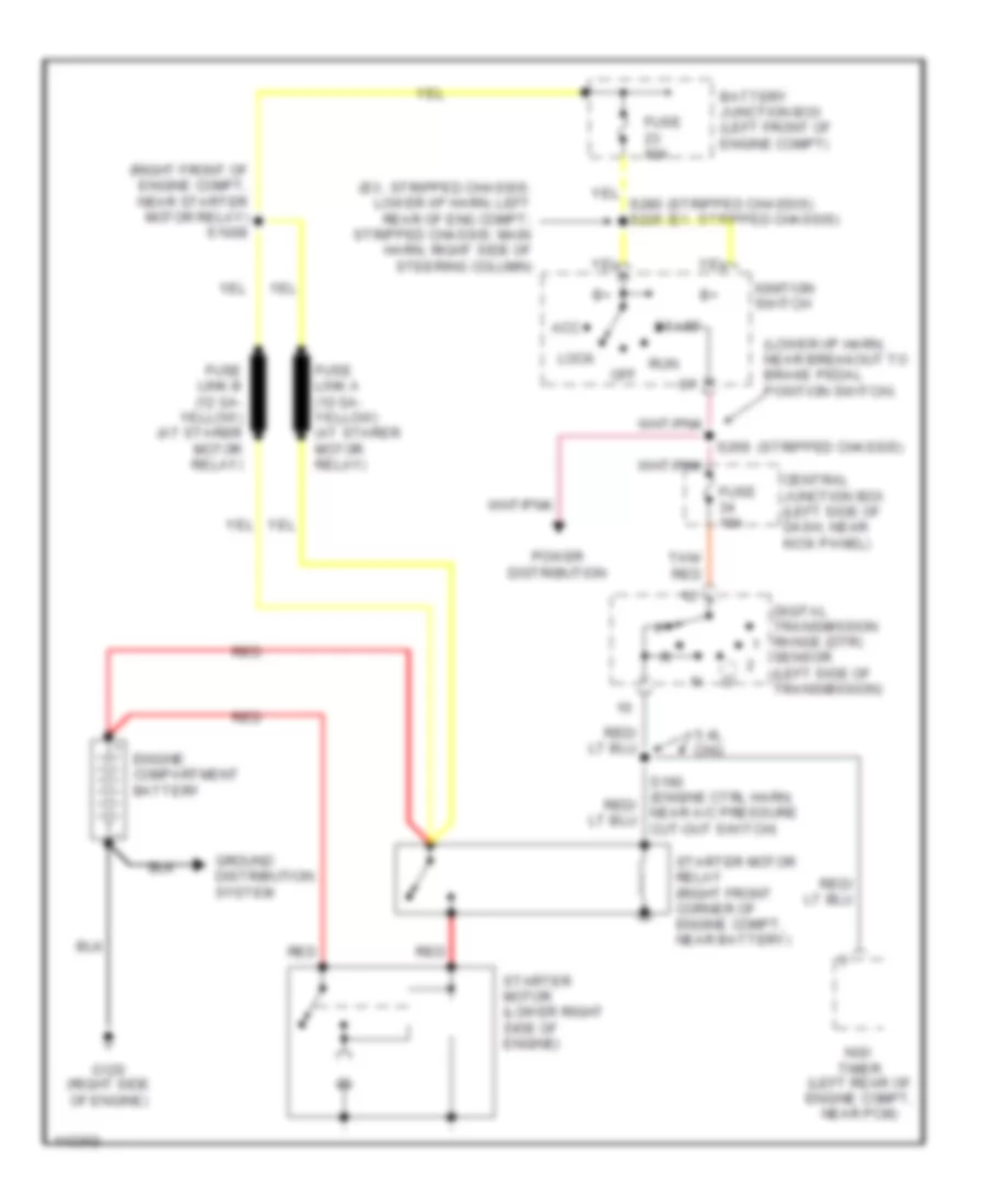
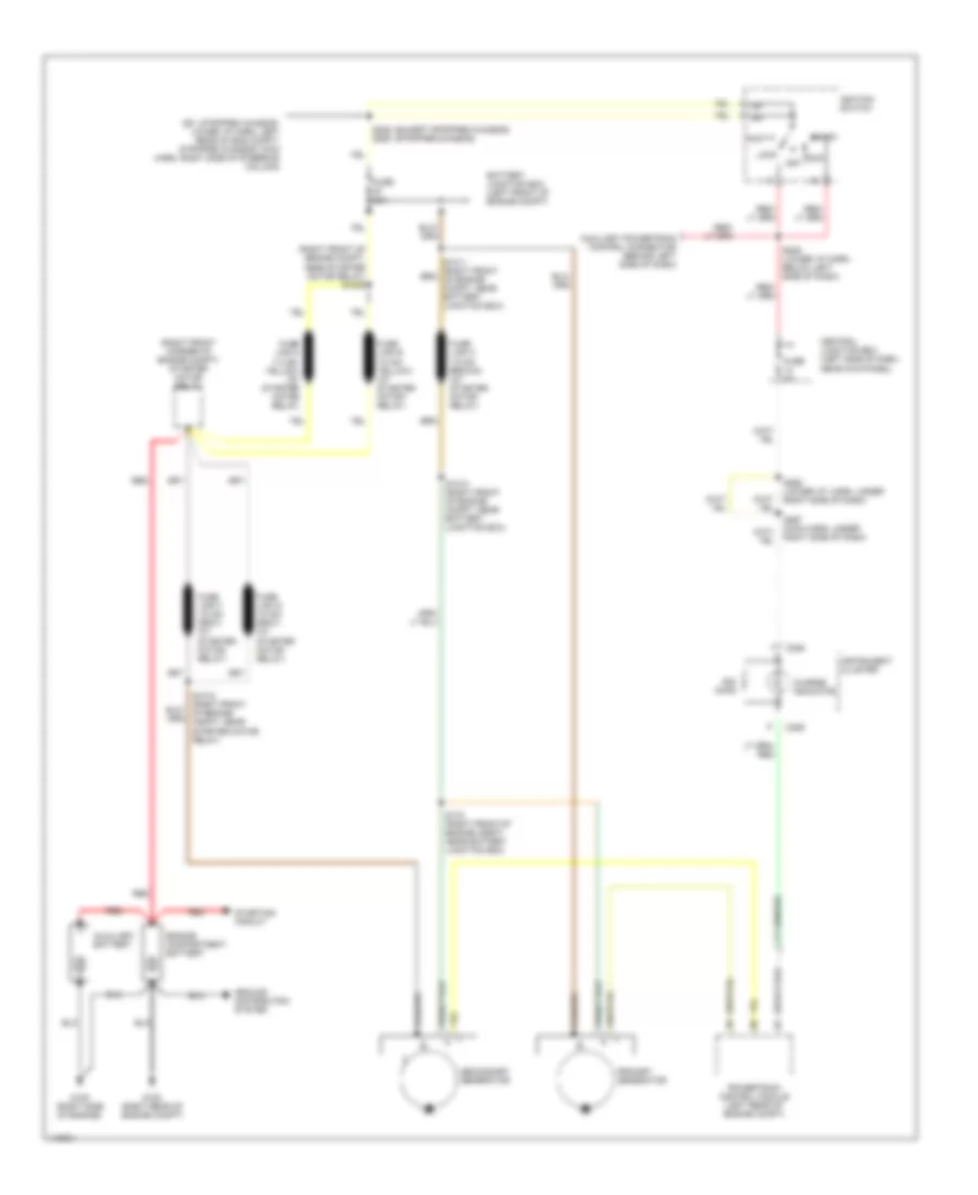
- Starting/ charging system
- Tcil
- Tcs sens
- Tft
- Vss gnd
- Wait to start indicator
- Water in fuel ind
- Water in fuel indicator
7.3L DI Turbo Diesel, Engine Performance Wiring Diagram, California (2 of 3) for Ford E450 Super Duty 2001
List of elements for 7.3L DI Turbo Diesel, Engine Performance Wiring Diagram, California (2 of 3) for Ford E450 Super Duty 2001:
- (engine control harn)
- (engine ctrl harness)
- (front of right front fender)
- (fuel inj harn, near eng oil temp sensor)
- (fuel injector harn)
- (not used)
- A/c
- A/c on sig
- A/c press sw
- Accelerator pedal position sensor (left side of dash, above accel pedal)
- Accl pos sens
- Boo sw
- C224
- Camshaft position (cmp) sensor (front center of engine)
- Charge ind
- Cid sig
- Cmp rtn
- Cruise control
- Dtr-tr2
- Dtr-tr4
- Epc sol
- Epr
- Exhaust back pressure (ebp) sensor (top center of engine)
- Exhaust pressure regulator (top left rear of engine)
- Fuel deliv sig
- Fuel pump rly
- Fuel sender
- G101
- G202 (behind upper left side of dash)
- Gen pwr sw
- Glow plug ctrl
- Icp sens
- Idm enable out
- Idm sig in
- Injection control pressure (icp) sensor (on top of engine)
- Instrument cluster
- Ipr sens
- Kapwr
- Manifold absolute pressure (map) sensor (top right side of engine compt)
- Map sens
- Mia htr relay
- Nca
- Not used
- Overdrive cancel switch
- Powertrain control module (left rear of engine compt, near brake master cylinder)
- Pwr gnd
- Red
- S1001
- S1002
- S120
- S135
- S136
- S137
- S138
- S139
- S140
- S205
- S261 (lower i/p harn, near breakout to data link conn)
- Sig rtn
- Speed ctrl sig
- Speedometer
- Starting/ charging
- Tcc
- Tcil
- Tcs
- Tr sensor
- Tss sens
- Turbine shaft speed sensor (right side of trans)
- Vehicle speed sensor (left side of trans)
- Vpwr
- Vref
- Vs sens
- Vss in
- Wait to start
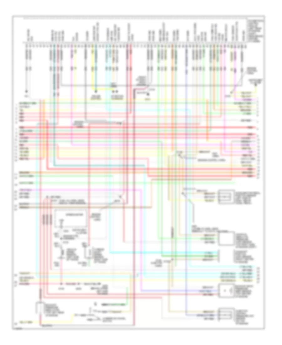
7.3L DI Turbo Diesel, Engine Performance Wiring Diagram, California (3 of 3) for Ford E450 Super Duty 2001
List of elements for 7.3L DI Turbo Diesel, Engine Performance Wiring Diagram, California (3 of 3) for Ford E450 Super Duty 2001:
- (behind left side of dash) g202
- (eng control harn, right frt of eng compt)
- (engine block)
- (fuel inj harn) s1007
- (fuel injector harn)
- (in fuel tank) fuel pump module
- (left front side of engine compt)
- (under vehicle, on left frame rail) (cutaways) in transit fuel pump module
- 4r100 transmission
- 58 amp heater
- Brake pedal position switch (on bracket, above brake pedal)
- C152
- C153
- Central junction box
- Cid sig in
- Coast clutch solenoid
- Ctrl out
- Digital transmission range sensor (dtr sensor) (left side of transmission)
- Electronic pressure control solenoid
- Fuel delivery sig
- Fuel inj feed left
- Fuel inj feed right
- Fuel injector no1
- Fuel injector no2
- Fuel injector no3
- Fuel injector no4
- Fuel injector no5
- Fuel injector no6
- Fuel injector no7
- Fuel injector no8
- Fuel injectors/ glow plugs
- Fuse 15a
- Gl plug 1
- Gl plug 2
- Gl plug 3
- Gl plug 4
- Gl plug 5
- Gl plug 6
- Gl plug 7
- Gl plug 8
- Glow plug control module (top right side of engine)
- Gpcm
- Hot at all times
- Idm feedback sig
- Inj shield gnd
- Injector driver module
- Manifold air intake heater relay (top of engine)
- Nca
- No1
- No1 shift solenoid
- No2
- No2 shift solenoid
- No3
- No4
- No5
- No6
- No7
- No8
- P, 2, 1
- P, n, 1
- P, r, 2
- P, r, n
- Power
- Pwr gnd
- Red
- S1007
- S1014
- S134
- S191
- S308
- S310 (fuel tank harn, below left frt of vehicle)
- Sig rtn
- Signal return
- Tan
- Tan/red
- Torque converter clutch solenoid
- Transmission fluid temperature sensor
- Vpwr
7.3L DI Turbo Diesel, Engine Performance Wiring Diagram, Except California (1 of 3) for Ford E450 Super Duty 2001
List of elements for 7.3L DI Turbo Diesel, Engine Performance Wiring Diagram, Except California (1 of 3) for Ford E450 Super Duty 2001:
- (below left side of dash) data link connector
- (eng ctrl harn, left rear of engine compt)
- (eng ctrl sensor harness, near breakout to mass air flow sensor)
- (fuel inj harness)
- (left rear of engine compt, near brake master cylinder) powertrain control module
- (left side of engine compt, bottom of master cyl)
- (lower i/p harn, near breakout to rke data link conn)
- App sens
- Aux tach feed
- Auxiliary powertrain control connector (behind left side of dash)
- Battery junction box
- Brake on/off switch
- Brake press sw
- Brake warning ind
- Bus (+)
- Bus (-)
- C224
- C225
- C226
- Cam pos sens
- Ccs sol
- Central junction box
- Deactivator switch
- Dlc
- Driveline disconn
- Driveline disconnect switch (behind left side of dash)
- Dtr-tr1
- Ebp sens
- Engine compartment fuse box
- Engine oil temperature sensor (center left side of engine)
- Eot
- Fuel heater (top center of engine)
- Fuel line htr
- Fuel pump (left rear of engine compt)
- Fuel pump relay
- Fuse 10a
- Fuse 15a
- Fuse 30a
- Fuse 5a
- G100 (front of left front fender)
- G101 (front of right front fender)
- Gen pwr sw
- Glow plug relay
- Horn/speed ctrl sw gnd
- Hot at all times
- Hot in run or start
- Iat
- Idle validation sw
- Idle validation switch (open at idle) (below left side of dash)
- Idm relay
- Inertia fuel shutoff switch (behind right kick panel)
- Injection pressure regulator (top of engine)
- Instrument cluster
- Instrument cluster system
- Intake air temperature sensor (center of engine compt, part of clean air tube)
- Mal- function indicator
- Mia htr rly
- Mil dlc
- Not used
- Pcm power diode
- Pcm power relay
- Red
- S1013
- S110
- S127
- S129
- S140
- S142
- S167
- S175
- S176
- S180 (engine ctrl harn, above master cyl)
- S213
- S262
- S263
- Shield gnd
- Ss1
- Starting/ charging system
- Tcil
- Tcs sens
- Tft
- Vss gnd
- Wait to start indicator
- Water in fuel ind
- Water in fuel indicator
7.3L DI Turbo Diesel, Engine Performance Wiring Diagram, Except California (2 of 3) for Ford E450 Super Duty 2001
List of elements for 7.3L DI Turbo Diesel, Engine Performance Wiring Diagram, Except California (2 of 3) for Ford E450 Super Duty 2001:
- (1999)
- (2000-01)
- (engine control harn)
- (engine ctrl harness)
- (front of right front fender)
- (fuel inj harn, near eng oil temp sensor)
- (fuel injector harn)
- (not used)
- A/c
- A/c on sig
- A/c press sw
- Accelerator pedal position sensor (left side of dash, above accel pedal)
- Accl pos sens
- Baro
- Barometric pressure (baro) sensor (1999) (below left side of dash)
- Boo sw
- C224
- Camshaft position (cmp) sensor (front center of engine)
- Charge ind
- Cid sig
- Cmp rtn
- Cruise control
- Dtr-tr2
- Dtr-tr4
- Ect sens
- Epc sol
- Epr
- Exhaust back pressure (ebp) sensor (top center of engine)
- Exhaust pressure regulator (top left rear of engine)
- Fuel deliv sig
- Fuel pump rly
- Fuel sender
- G101
- G202 (behind upper left side of dash)
- Gen pwr sw
- Glow plug ctrl
- Icp sens
- Idm enable out
- Idm sig in
- Injection control pressure (icp) sensor (on top of engine)
- Instrument cluster
- Ipr sens
- Kapwr
- Manifold absolute pressure (map) sensor (top right side of engine compt)
- Map sens
- Mia htr relay
- Nca
- Not used
- Overdrive cancel switch
- Powertrain control module (left rear of engine compt, near brake master cylinder)
- Pwr gnd
- Red
- S1001
- S1002
- S120
- S135
- S136
- S137
- S138
- S139
- S140
- S205
- S261 (lower i/p harn, near breakout to data link conn)
- Sig rtn
- Speed ctrl sig
- Speedometer
- Starting/ charging
- Tcc
- Tcil
- Tcs
- Tr sensor
- Tss sens
- Turbine shaft speed sensor (right side of trans)
- Vehicle speed sensor (left side of trans)
- Vpwr
- Vref
- Vs sens
- Vss in
- Wait to start
7.3L DI Turbo Diesel, Engine Performance Wiring Diagram, Except California (3 of 3) for Ford E450 Super Duty 2001
List of elements for 7.3L DI Turbo Diesel, Engine Performance Wiring Diagram, Except California (3 of 3) for Ford E450 Super Duty 2001:
- (behind left side of dash) g202
- (eng control harn, right frt of eng compt)
- (engine block)
- (fuel inj harn) s1007
- (fuel injector harn)
- (in fuel tank) fuel pump module
- (left front side of engine compt)
- (under vehicle, on left frame rail) (cutaways) in transit fuel pump module
- 4r100 transmission
- 58 amp heater
- Brake pedal position switch (on bracket, above brake pedal)
- Central junction box
- Cid sig in
- Coast clutch solenoid
- Digital transmission range sensor (dtr sensor) (left side of transmission)
- Electronic pressure control solenoid
- Fuel delivery sig
- Fuel inj feed left
- Fuel inj feed right
- Fuel injector no1
- Fuel injector no2
- Fuel injector no3
- Fuel injector no4
- Fuel injector no5
- Fuel injector no6
- Fuel injector no7
- Fuel injector no8
- Fuel injectors/ glow plugs
- Fuse 15a
- Fuse 30a
- Glow plug relay (top right side of engine)
- Hot at all times
- Hot in run or start
- Idm feedback sig
- Inj shield gnd
- Injector driver module
- Manifold air intake heater relay (top of engine)
- Nca
- No1
- No1 shift solenoid
- No2
- No2 shift solenoid
- No3
- No4
- No5
- No6
- No7
- No8
- P, 2, 1
- P, n, 1
- P, r, 2
- P, r, n
- Pwr gnd
- Red
- S1003 (fuel injector harn, right top of engine)
- S1004 (fuel inj harn, left top of eng)
- S1007
- S1014
- S127
- S134
- S191
- S308
- S310 (fuel tank harn, below left frt of vehicle)
- Sig rtn
- Signal return
- Tan
- Tan/red
- Torque converter clutch solenoid
- Transmission fluid temperature sensor
- Vpwr
EXTERIOR LIGHTS
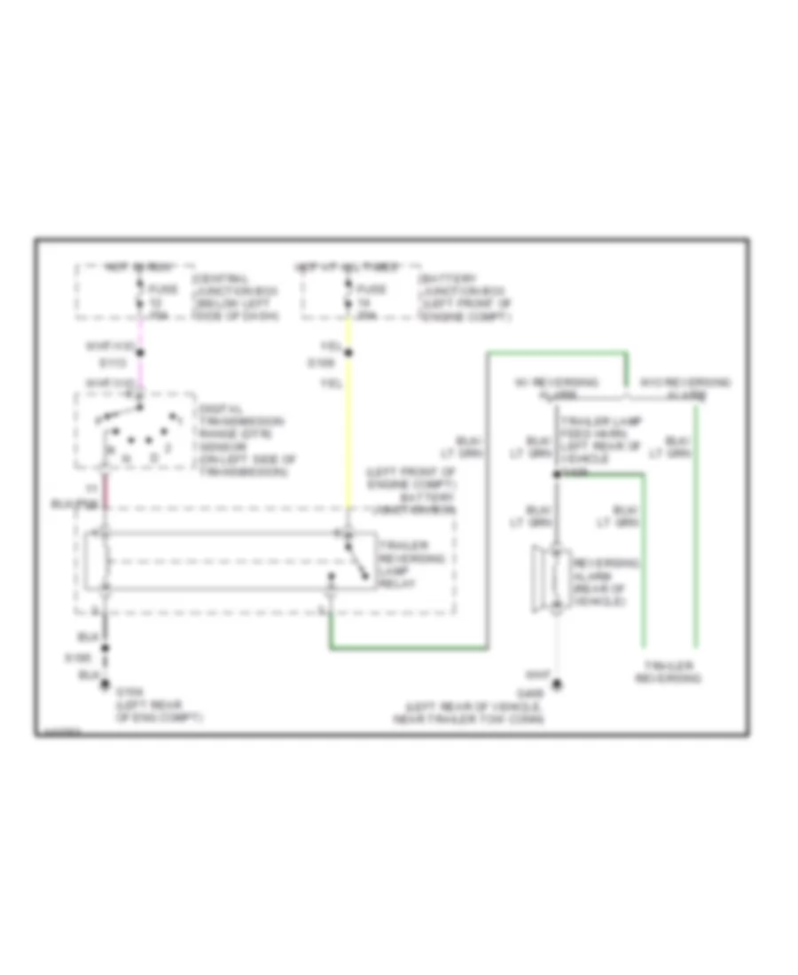
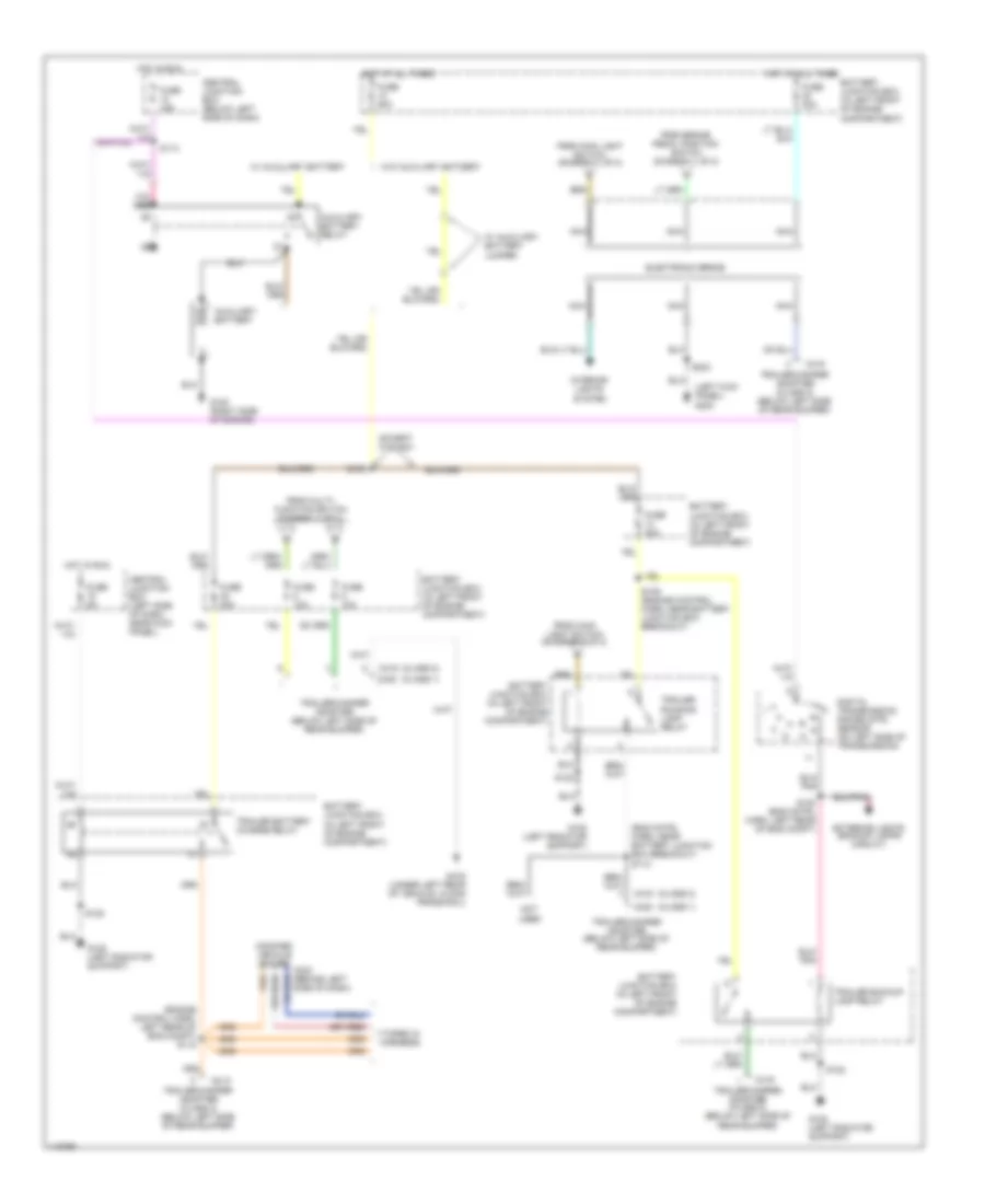
Back-up Lamps Wiring Diagram, with Stripped Chassis for Ford E450 Super Duty 2001
List of elements for Back-up Lamps Wiring Diagram, with Stripped Chassis for Ford E450 Super Duty 2001:
- (left front of engine compt) battery junction box
- Battery junction box (left front of engine compt)
- Central junction box (below left side of dash)
- Digital transmission range (dtr) sensor (on left side of transmission)
- Fuse 15a
- Fuse 30a
- G104 (left rear of eng compt)
- G409 (left rear of vehicle, near trailer tow conn)
- Hot at all times
- Hot in run
- Reversing alarm (rear of vehicle)
- S109
- S113
- S195
- Trailer reversing
- Trailer reversing lamp relay
- W/ reversing alarm
- W/o reversing alarm
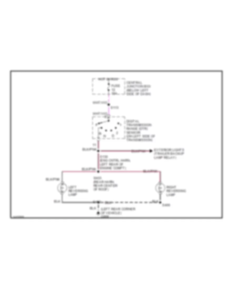
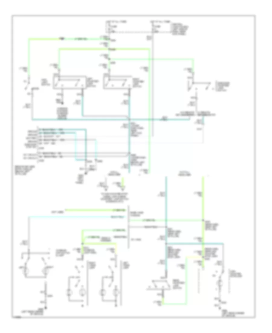
Back-up Lamps Wiring Diagram, without Stripped Chassis for Ford E450 Super Duty 2001
List of elements for Back-up Lamps Wiring Diagram, without Stripped Chassis for Ford E450 Super Duty 2001:
- (left rear corner of vehicle) g999
- Central junction box (below left side of dash)
- Digital transmission range (dtr) sensor (on left side of transmission)
- Exterior lights (trailer backup lamp relay)
- Fuse 15a
- Hot in run
- Left reversing lamp
- Right reversing lamp
- S113
- S402
- S403 (rear harn, rear center of roof)
- S406
Exterior Lamps Wiring Diagram, with Stripped Chassis for Ford E450 Super Duty 2001
List of elements for Exterior Lamps Wiring Diagram, with Stripped Chassis for Ford E450 Super Duty 2001:
- (eng cntrl harn, near powertrain control module) s283
- (engine cntrl harn, left rear of engine compt) s194
- (left front of engine compartment) battery junction box
- (main harn, under left side of dash) s283
- 4 wheel anti-lock brake system module
- Aux battery relay
- Auxiliary battery
- Batt
- Battery
- Battery junction box
- Battery junction box (left front of engine compt)
- Brake pedal position (bpp) switch (on bracket, above brake pedal)
- Brake switch relay
- C144
- C154
- C224
- C250
- Central junction box (below left side of dash)
- Electronic flasher (behind left side of dash)
- Fuse 10a
- Fuse 15a
- Fuse 25a
- Fuse 30a
- Fuse 5a
- Fuse 60a
- G104 (left rear of engine compt)
- G120 (right side of engine)
- G200 (behind left side of dash, near kick panel)
- G200 (left kick panel)
- G416 (left rear of vehicle, on frame rail)
- Ground
- Hazard
- Hazard switch
- Head
- Hot at all times
- Hot in run
- Ign
- Instrument cluster
- Left hand turn
- Left turn indicator
- Main light switch
- Multi- function switch
- Normal
- Not used
- Off
- Park
- Power distribution system
- Powertrain control module (left rear of engine compt)
- Relay control battery feed
- Right hand turn
- Right turn indicator
- Running lamps
- S108
- S109
- S113
- S114 (eng cntrl harn, above master clyinder)
- S148
- S195 (engine cntrl harn, left rear of engine compt)
- S215 (main harn, on multi- function switch)
- S217 (main harn, on instrument cluster)
- S276
- S284
- S286
- Shift lock actuator (below right side of steering column)
- Side marker
- Solid state
- Stop lamps
- Trailer battery charge relay
- Trailer brakes
- Trailer running lamp relay
- Turn left
- Turn right
- W/auxiliary battery
- W/auxiliary battery jumper only
- W/o aux battery
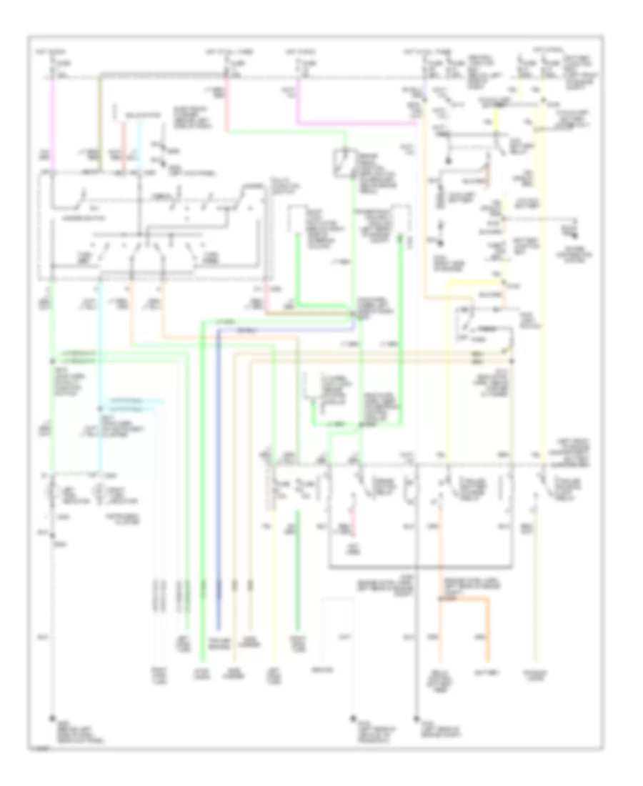
Exterior Lamps Wiring Diagram, without Stripped Chassis (1 of 2) for Ford E450 Super Duty 2001
List of elements for Exterior Lamps Wiring Diagram, without Stripped Chassis (1 of 2) for Ford E450 Super Duty 2001:
- (dash to headlamp harn, right front corner of eng compt) s165
- (engine cntrl harn, near a/c pressure cut- out switch) s134
- (lower i/p harn, near left kick panel) s232
- (lower i/p harn, near left rear of engine compt)
- (not used)
- (wires terminate in harness) (cutaway models)
- All others
- Anti- lock brakes systems
- Batt
- Battery junction box (left front of engine compt)
- Battery junction box breakout)
- Brake pedal position (bpp) switch (on bracket, above brake pedal)
- Brake switch relay
- C224
- C250
- Central junction box (below left side of dash)
- Cruise control systems
- Cut- aways
- Electronic flasher (behind left side of dash)
- Engine controls systems
- Fuse 10a
- Fuse 15a
- Fuse 20a
- G107 (behind right front headlamp)
- G108 (upper left radiator support)
- G200 (left kick panel)
- G202 (behind upper left side of dash)
- G999 (left rear corner of vehicle)
- Hazard
- Hazard switch
- Head
- High mounted stop lamp
- Hot at all times
- Hot in run
- Ign
- Instrument cluster
- Left front park/ turn lamp
- Left stop/ park/
- Left turn indicator
- License lamp
- Main light switch
- Multi- function switch
- Normal
- Off
- Overhead console
- Park r
- Remote keyless entry module (behind left "b" pillar)
- Right front park/ turn lamp
- Right stop/ park/
- Right turn indicator
- S122
- S129
- S163
- S207
- S217 (main harn, behind left side of dash)
- S218
- S223
- S224 (lower i/p harn, left rear of eng compt)
- S226
- S234 (lower i/p harn, near left seat belt retractor)
- S306 (rear harn, left rear of cargo area)
- S402
- S406
- Shift inter- lock systems
- Solid state
- To battery junction box (fuses 5 & 6) (digram 2 of 2)
- To battery junction box (trailer running lamp relay) (diagram 2 of 2)
- To electronic brake wiring (diagram 2 of 2)
- Turn lamp
- Turn left
- Turn right
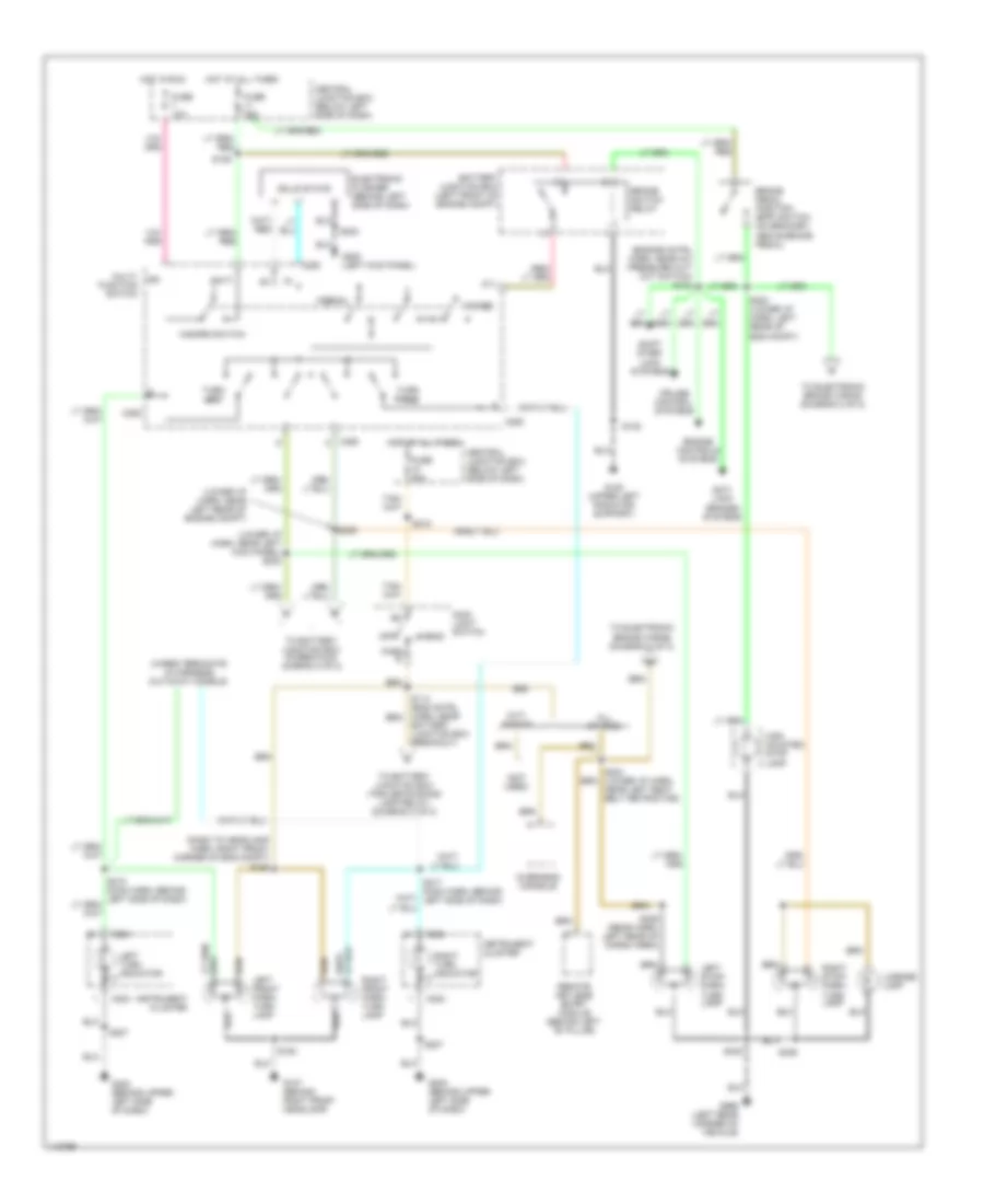
Exterior Lamps Wiring Diagram, without Stripped Chassis (2 of 2) for Ford E450 Super Duty 2001
List of elements for Exterior Lamps Wiring Diagram, without Stripped Chassis (2 of 2) for Ford E450 Super Duty 2001:
- (class 1)
- (class 2)
- (eng cntrl harn, near battery junction box breakout) s112
- (engine control harn, left rear of eng compt) s118
- (left kick panel) g200
- (taped in harness)
- Auxiliary battery
- Auxiliary battery relay
- Battery junction box (in left front of engine compartment)
- C233 (behind left side of dash)
- C419
- C422
- Central junction box (below left side of dash)
- Central junction box (left side of dash, near kick panel)
- Digital transmission range (dtr) sensor (on left side of transmission)
- Electronic brake
- Except 5.4l ngv
- Exterior lights (backup lamps circuit)
- From brake pedal position switch (diagram 1 of 2)
- From main light switch (diagram 1 of 2)
- From multi- function switch (diagram 1 of 2)
- Fuse 10a
- Fuse 15a
- Fuse 20a
- Fuse 30a
- Fuse 40a
- Fuse 5a
- Fuse 60a
- G108 (left radiator support)
- G120 (right side of engine)
- G416 (under left rear of vehicle, along frame rail)
- Hot at all times
- Hot in run
- Interior lights system
- Modified vehicle power
- Nca
- Not used
- S108
- S109 (engine control harn, near battery junction box breakout)
- S113
- S122
- S130 (eng cntrl harn, left rear of eng compt)
- S223
- Trailer backup lamp relay
- Trailer battery charge relay
- Trailer running lamp relay
- Trailer/camper adapter (below left side of rear bumper)
- Trailer/camper adapter (class 2) (below left side of rear bumper)
- Trailer/camper adapter (class 2) (below left side of rear bumper)
- W/ auxiliary battery
- W/ auxiliary battery jumper
- W/o auxiliary battery
GROUND DISTRIBUTION
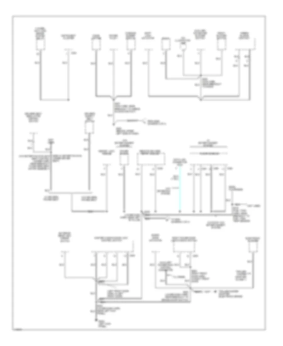
Ground Distribution Wiring Diagram, with Stripped Chassis for Ford E450 Super Duty 2001
List of elements for Ground Distribution Wiring Diagram, with Stripped Chassis for Ford E450 Super Duty 2001:
- (w. 138 in, 158 in, & 178 in wheel base)
- 4 wheel anti-lock brake system module
- 4 wheel anti-lock brake system relay
- A/c compressor clutch
- A/c compressor clutch diode
- Air bag sliding contact
- Battery junction box
- Blower motor relay
- Brake switch relay
- C224
- Daytime running lamps module
- Dual brake warning switch
- Electric intake manifold runner control
- Electronic flasher
- Fuel pump module
- G104 (left rear of engine compartment)
- G105 (right rear of engine compt)
- G200 (behind left side of dash, near kick panel)
- Ground
- In-transit fuel pump module
- Instrument cluster
- Instrumentation engine coolant temperature sending unit
- Powertrain control module
- S107 (fuel charge harn, near breakout to fuel injector 6)
- S195 (engine control harness, left rear of engine compartment)
- S197 (engine control harness, near breakout to mass airflow sensor)
- S198 (6.8l) (engine control harness, near left rear of eng compt)
- S199 (engine control harness, near breakout to pcm)
- S284 (main harn, near breakout to brake pedal position switch)
- S285 (main harness, near breakout to g200)
- S286 (main harness, right side of dash, near intertia fuel shutoff breakout)
- S287 (main harn, left side of dash, near i/p breakout)
- S307 (fuel tank harn, near breakout to fuel pump module)
- S308 (fuel tank harn, under left center of vehicle)
- Shift lock actuator
- Trailer battery charge relay
- Trailer reversing lamp relay
- Trailer running lamp relay
- Wiper control module
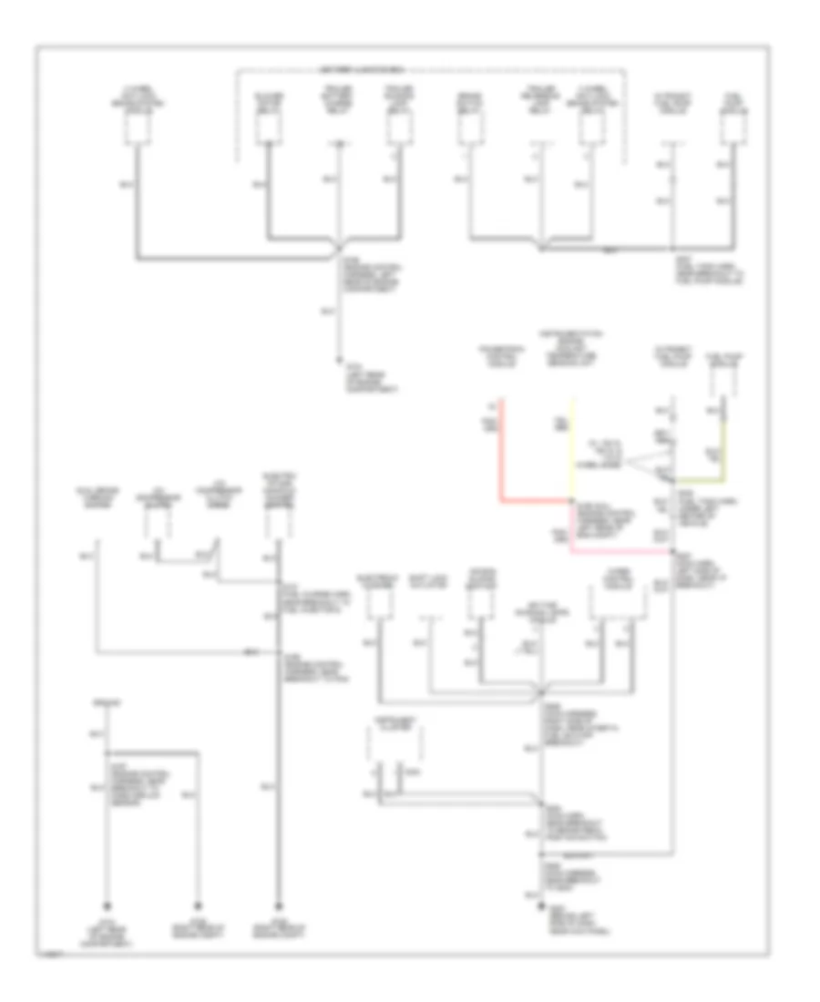
Ground Distribution Wiring Diagram, without Stripped Chassis (1 of 4) for Ford E450 Super Duty 2001
List of elements for Ground Distribution Wiring Diagram, without Stripped Chassis (1 of 4) for Ford E450 Super Duty 2001:
- (4.2l - eng ctrl harn, left rear of eng compt) (exc. 4.2l - eng ctrl harn, near breakout to pcm)
- (4.2l) (exc. 4.2l)
- (eng control harn, near breakout to a/c pressure cut-out switch)
- 4.2l
- 4.2l only
- 4.6l
- 5.4l ngv only
- 5.4l, 6.8l
- 6.8l
- A/c compressor clutch
- A/c compressor clutch diode
- Auxiliary battery
- Battery junction box
- Blower motor resistor
- C154
- Camshaft position sensor
- Crankshaft position sensor shield
- Data link connector
- Data link connector (dlc)
- Diesel
- Diesel models
- Dual brake warning switch
- Electric intake manifold runner control
- Engine compartment battery
- Exc. 4.2l
- Exhaust pressure regulator (epr)
- Fuel rail cut- off valve
- G101 (front of right front fender)
- G105 (right rear of engine compt)
- G120 (right side of engine)
- Gasoline models
- Mass airflow sensor
- Ngv timer
- Pcm power relay
- Powertrain control module (pcm)
- S107 (fuel charge harn, near breakout to fuel injector 6)
- S140 (eng control harn, near breakout to a/c pressure cutout switch)
- S143
- S167 s169
- S189 (eng control harn, near breakout to injection pressure sensor)
- Washer pump
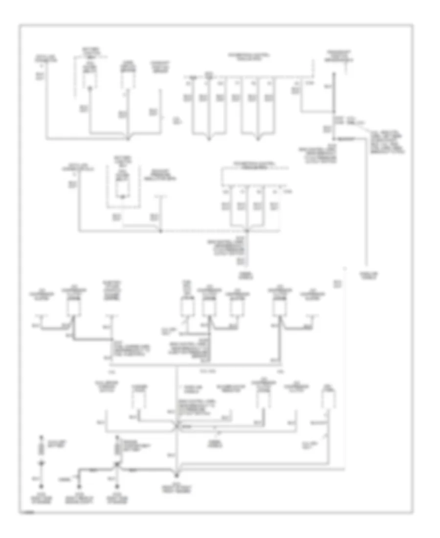
Ground Distribution Wiring Diagram, without Stripped Chassis (2 of 4) for Ford E450 Super Duty 2001
List of elements for Ground Distribution Wiring Diagram, without Stripped Chassis (2 of 4) for Ford E450 Super Duty 2001:
- (engine control harn, left rear of engine compt)
- (fuel tank sender harn, under left rear of vehicle) s320
- (main harness, near breakout to airbag assembly)
- 4 wheel anti-lock brake system module
- 5.4l ngv
- 5.4l ngv only
- 7.3l diesel
- Battery junction box
- Blower motor relay
- Brake switch relay
- C224
- C226
- Cutaway
- Daytime running lights module
- Diesel
- Engine coolant temperature sender
- Except 5.4l ngv
- Extended range fuel tank valve
- Forward aft- axle fuel tank valve
- Fuel pump
- Fuel pump module
- Fuel tank sender
- G106 (behind left front headlamp)
- G107 (behind right front headlamp)
- G108 (left upper radiator support)
- G202 (behind upper left side of dash)
- Gas
- In-transit fuel pump module
- Injector driver module
- Instrument cluster
- Instrumentation engine coolant temperature sensor
- Left front park/turn lamp
- Left headlamp
- Low vacuum warning switch
- Midship fuel tank valve
- Nca
- Ngv module
- Ngv timer
- Powertrain control module
- Rear aft- axle fuel tank valve
- Right front park/turn lamp
- Right headlamp
- S122
- S139 (engine cntrl harn, near breakout to a/c pressure cutout switch)
- S163 (dash to headlamp harn, near breakout to left front park/ turn signal lamp)
- S205
- S268 (main harn, left rear of engine compartment)
- S307 (fuel tank harn, near breakout to fuel pump module)
- S308 (fuel tank harn, below left center of vehicle)
- S317 (fuel tank harn, near breakout to fuel tank sender)
- Speed control servo
- To g202 (diagram 3 of 4)
- Trailer battery charge relay
- Trailer reversing lamp relay
- Trailer running lamp relay
- Vehicle speed sensor
- Wiper control module
Ground Distribution Wiring Diagram, without Stripped Chassis (3 of 4) for Ford E450 Super Duty 2001
List of elements for Ground Distribution Wiring Diagram, without Stripped Chassis (3 of 4) for Ford E450 Super Duty 2001:
- (left front door harn, in left front door)
- (lower dash harn, near left "b" pillar)
- (not used)
- (w/o entertain sys) s315 (seat control jumper harn, near breakout to driver's seat motor assembly)
- 4 wheel anti-lock brake system relay
- 7.3l diesel
- A/c illumination lamp
- Airbag sliding contact
- Auxiliary a/c-heater blower switch
- Auxiliary powertrain control connector
- Blend door actuator
- C224
- C335
- C360
- C361
- C362
- C500
- C600
- Cigar lighter
- Cutaway w/o entertainment system
- Data link connector (dlc)
- Driver's safety belt switch
- Driver's seat regulator control switch
- Electronic flasher
- Ends in harness
- Exterior rear view mirror switch
- Floor console
- From s268 (diagram 2 of 4)
- Front blower switch
- G202 (behind upper left side of dash)
- G2oo (left kick panel)
- Instrument cluster
- Master window/door lock control switch
- Memory lock module
- Panel)
- Power plug 1
- Power plug 2
- Radio
- Remote keyless entry module
- Right power door lock/window switch
- S202 (main harn, near breakout to radio)
- S207 (main harn, near breakout to airbag sliding contact)
- S223 (lower dash harn, near breakout to brake on/off switch)
- S235
- S299 (w/ entertain sys) (under driver seat)
- S316 (fuel tank harn, near breakout to fuel tank temp sensor)
- S500
- S600 (right front door harn, in right front door)
- Shift lock actuator
- To s300 (diagram 4 of 4)
- Trailer/ camper adapter (class 1)
- Trailer/camper adapter (electronic brake)
- W/ driver's power seat
- W/ entertainment system
- W/o driver's power seat
- W/o entertain system
- W/o entertainment system
- Warning buzzer module
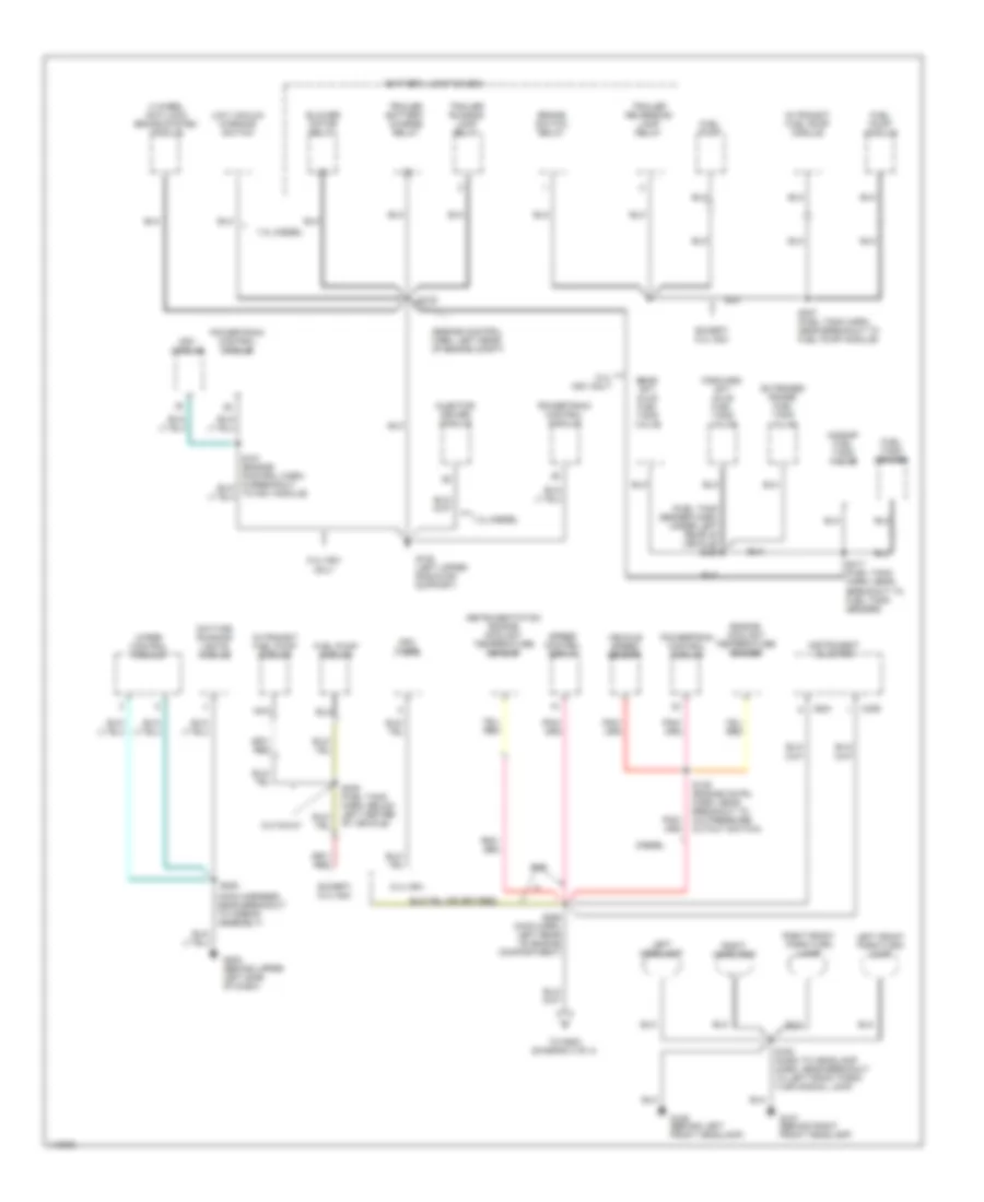
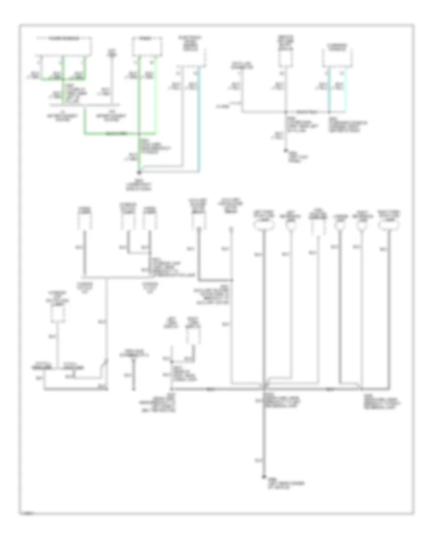
Ground Distribution Wiring Diagram, without Stripped Chassis (4 of 4) for Ford E450 Super Duty 2001
List of elements for Ground Distribution Wiring Diagram, without Stripped Chassis (4 of 4) for Ford E450 Super Duty 2001:
- Auxiliary blower motor relay
- Auxiliary high blower motor relay
- Cargo lamp
- Data link connector
- Electronic crash sensor module
- Floor console
- From s235 (diagram 3 of 4)
- G200 (left kick panel)
- G203 (under right side of dash)
- G999 (left rear corner of vehicle)
- High mounted stoplamp
- Interior switch/ lamp
- Interior/ map switch and lamp
- Left park/ stop/turn lamp
- Left reversing lamp
- Left video display
- License lamp
- Not used
- Overhead console
- Radio
- Remote keyless entry module
- Right park/ stop/turn lamp
- Right reversing lamp
- Right video display
- S204 (main harn, near breakout to radio)
- S260 (lower dash harn, near left "b" pillar)
- S297 (lower i/p harn, near left "b" pillar)
- S300 (rear harn, near breakout to left safety belt retractor)
- S401 (auxiliary blower motor harn, in breakout to auxiliary motor)
- S406 (rear harn, near breakout to right reversing lamp)
- S913 (interior lamp harn, near breakout to interior switch/lamp)
- S915 (rear of roof, near cargo lamp)
- S930 (overhead console harness, front center of roof)
- W/ entertainment system
- W/ full headliner
- W/ rke
- W/o entertainment system
- W/o full headliner
- Wagons w/ aux a/c
- Wagons w/o aux a/c
HEADLIGHTS
Headlights Wiring Diagram, with Stripped Chassis for Ford E450 Super Duty 2001
List of elements for Headlights Wiring Diagram, with Stripped Chassis for Ford E450 Super Duty 2001:
- (w/drl)
- Batt
- Battery junction box
- C224
- C225
- C251
- Central junction box
- Daytime runnng lamps (drl) module (mounted to radiator support, under a/c condenser deflector cover)
- Dimmer
- Drl
- Flash- to- pass
- Fuse 10a
- Fuse 15a
- Fuse 25a
- Fuse 40a
- G202 (behind upper left side of dash)
- Gnd
- Head
- Hi beam in
- Hi beam ind
- High beam & drl
- Hot at all times
- Ign
- Instrument cluster
- Low beam
- Main light switch
- Multi- function switch
- Off
- P v lo beam
- Park
- Pass
- S116
- S131
- S196 (engine harn, left rear of engine compt, near breakout to pcm)
- S205
- S207
- S276
- S278 (main harn, near breakout to shift lock actuator)
- S279 (main harn, near breakout to multifunction switch)
- Stripped chassis connections
Headlights Wiring Diagram, without Stripped Chassis for Ford E450 Super Duty 2001
List of elements for Headlights Wiring Diagram, without Stripped Chassis for Ford E450 Super Duty 2001:
- (w/drl)
- Batt
- Battery junction box
- C224
- C225
- C251
- Central junction box
- Daytime runnng lamps (drl) module (mounted to radiator support, under a/c condenser deflector cover)
- Dimmer
- Flash- to- pass
- Fuse 10a
- Fuse 15a
- Fuse 20a
- Fuse 40a
- G106 (behind left front headlamp)
- G202 (behind upper left side of dash)
- Gnd
- Head
- Hi beam in
- Hi beam ind
- Hot at all times
- Ign
- Instrument cluster
- Left headlamp
- Main light switch
- Multi- function switch
- Off
- P v lo beam
- Park
- Pass
- Right headlamp
- S116
- S131
- S163
- S164 (dash to headlamp panel harn, near drl module breakout)
- S205
- S207
- S218
- S270 (main harn, near breakout to air bag sliding contact)
- S276 (main harn, near breakout to multifunction switch)
- S278 (main harn, near breakout to shift lock actuator)
HORN
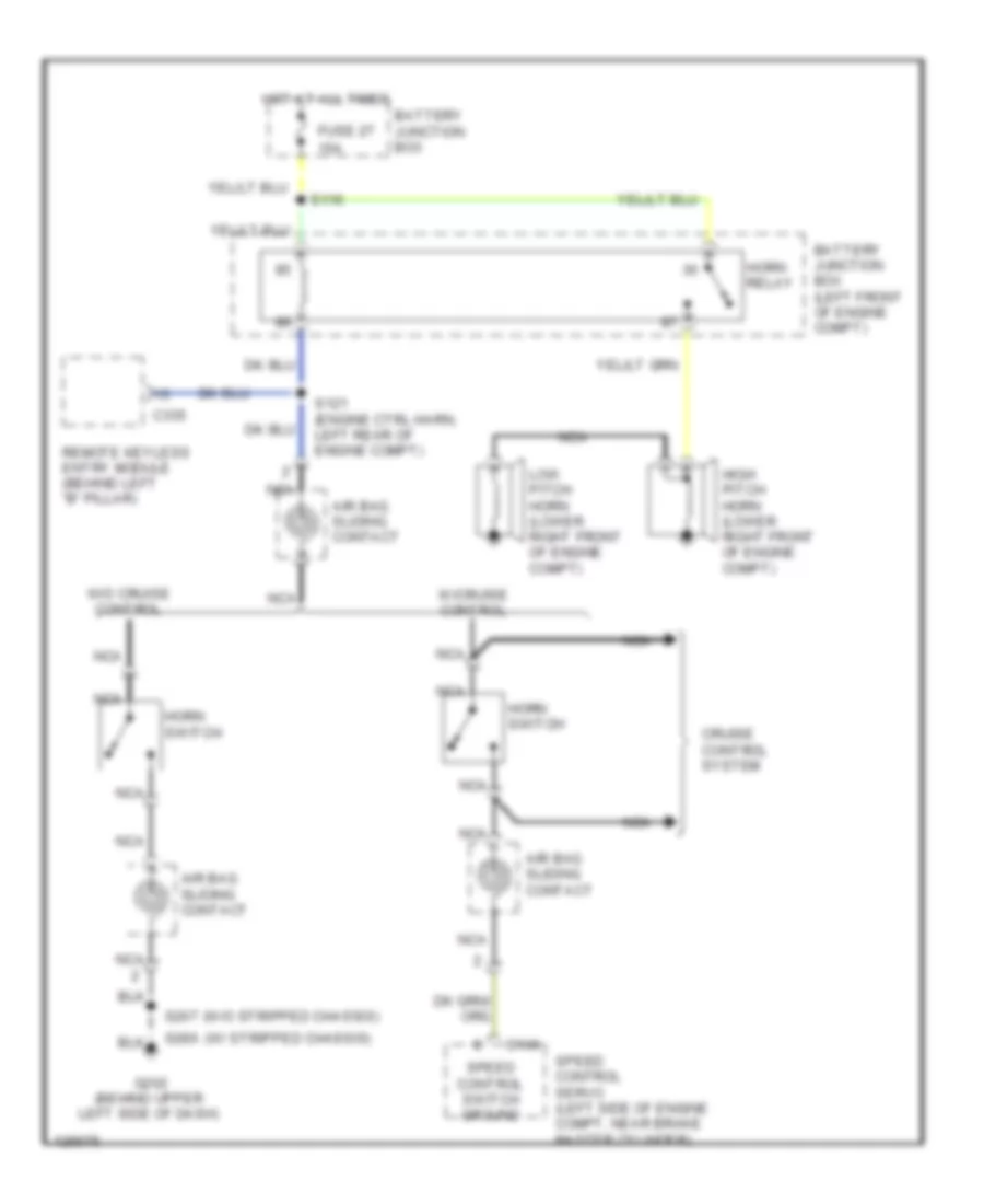
Horn Wiring Diagram for Ford E450 Super Duty 2001
List of elements for Horn Wiring Diagram for Ford E450 Super Duty 2001:
- (w/ stripped chassis)
- (w/o stripped chassis)
- 15a
- Air bag sliding contact
- Battery junction box
- Battery junction box (left front of engine compt)
- C146
- C335
- Cruise control system
- Fuse 27
- G202 (behind upper left side of dash)
- High pitch horn (lower right front of engine compt)
- Horn relay
- Horn switch
- Hot at all times
- Low pitch horn (lower right front of engine compt)
- Nca
- Remote keyless entry module (behind left "b" pillar)
- S116
- S121 (engine ctrl harn, left rear of engine compt)
- S207
- S286
- Speed control servo (left side of engine compt, near brake master cylinder)
- Speed control switch ground
- W/cruise control
- W/o cruise control
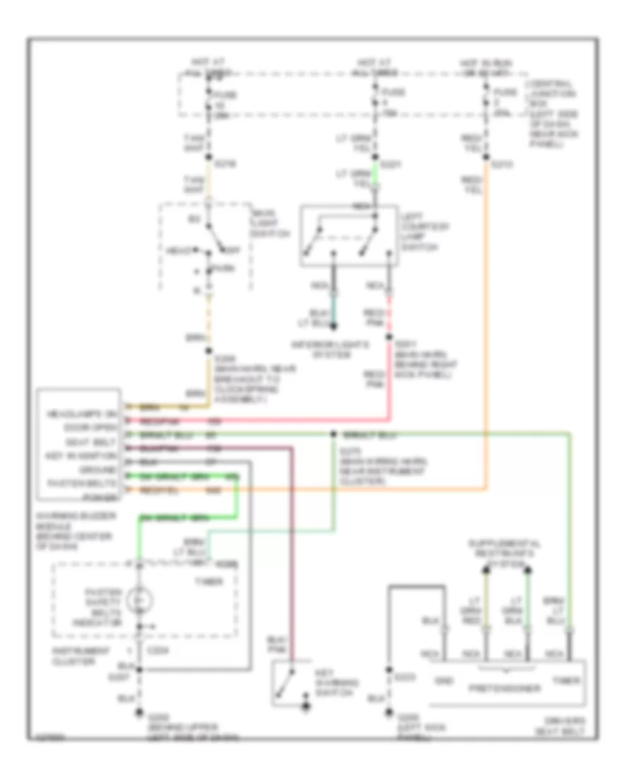
INSTRUMENT CLUSTER
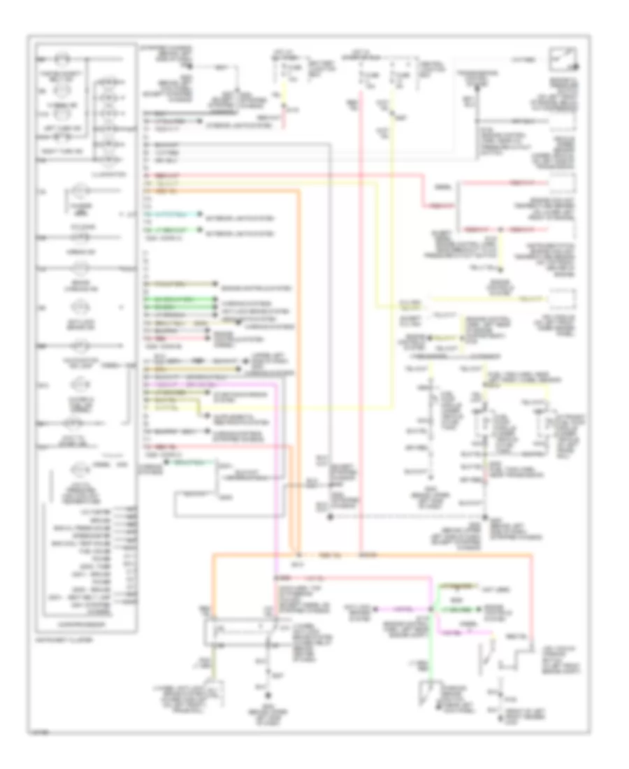
Instrument Cluster Wiring Diagram for Ford E450 Super Duty 2001
List of elements for Instrument Cluster Wiring Diagram for Ford E450 Super Duty 2001:
- (2000)
- (2001 stripped chassis)
- (2001)
- (conn a)
- (conn b)
- (conn c)
- (engine control harn, left rear of engine compartemnt) s120
- (except stripped chassis)
- (front of left front fender) g100
- (fuel tank harn, near left front wheel sensor) s310
- (main harn, top of steering column) (except diesel or stripped chassis)
- (not used)
- (stripped chassis) (behind left side of dash) g202
- (upper left side of dash) g202
- 4 wheel anti-lock brake system (4wabs) module (on left front frame rail)
- 4 wheel anti-lock brake system (4wabs) relay (behind center of dash)
- 510 ohms
- 87a
- A10
- A11
- A14
- A16
- Airbag ind
- Anti-lock brake ind
- Anti-lock brake system
- Anti-lock brakes system
- B10
- B11
- B12
- Battery junction box
- Brake warning ind
- C10
- C12
- C224
- C225
- C226
- Central junction box
- Charge ind
- Cutaways
- Diesel
- E250
- Eng cool temp gauge
- Eng oil press gauge
- Engine controls system
- Engine controls system (diesel)
- Engine coolant temperature sender (on lower left front of engine)
- Engine oil pressure switch (on left front of engine, below a/c compressor)
- Except 5.4l ngv
- Except diesel
- Exterior lights system
- Fasten safety belt ind
- Fuel gauge
- Fuel pump module (under vehicle, in fuel tank)
- Fuse 10a
- Fuse 15a
- Fuse 5a
- G200 (behind left kick panel) (except stripped chassis)
- G200 (behind left side of dash) (stripped chassis)
- G202 (behind upper left side of dash)
- G202 (behind upper left side of dash) (except stripped chassis)
- Gas
- Ground
- Headlights system
- Hi beam ind
- Hot at all times
- Hot in start or run
- Illumination
- In-transit fuel pump module (under vehicle, on left frame rail)
- Instrument cluster
- Instrumentation engine coolant temperature sensor (on top front center of engine)
- Interior lights system
- Left turn ind
- Low oil pressure/ high coolant temperature
- Low vacuum warning switch (in left front engine compt)
- Malfunction ind lamp
- Microprocessor
- Nca
- Ngv module (on left front inner fender panel)
- Parking brake switch (near left kick panel)
- Power
- Red
- Right turn ind
- Rly ctrl
- S119 (engine control harn, left rear engine compt)
- S122
- S133 (engine control harn, near breakout to a/c pressure cutout switch)
- S135 (engine control harn, near a/c pressure cutout switch)
- S146
- S175
- S207
- S207 s284 (stripped chassis)
- S213
- S220
- S267
- S268
- S308 (fuel tank harn, near transmission)
- Seat belt lamp
- Speedometer
- Starting/charging system
- Timer
- Transmissions control system
- Vans/wagons
- Vehicle speed sensor (under vehicle, on left side of transmission)
- Voltmeter
- Wait to start ind
- Warning systems
- Warning systems (stripped chassis)
- Water in fuel ind (diesel)
INTERIOR LIGHTS
Courtesy Lamps Wiring Diagram, Cutaway Chassis for Ford E450 Super Duty 2001
List of elements for Courtesy Lamps Wiring Diagram, Cutaway Chassis for Ford E450 Super Duty 2001:
- (lower dash harn, near left kick panel)
- Central junction box (left side of dash, near kick panel)
- Dome
- Exterior lights (electronic brake)
- Fuse 15a
- Hot at all times
- Left courtesy lamp switch
- Main light switch
- Nca
- Red/ pnk
- Right courtesy lamp switch
- S221
- Warning systems (warning buzzer module)
- Wire ends in harness
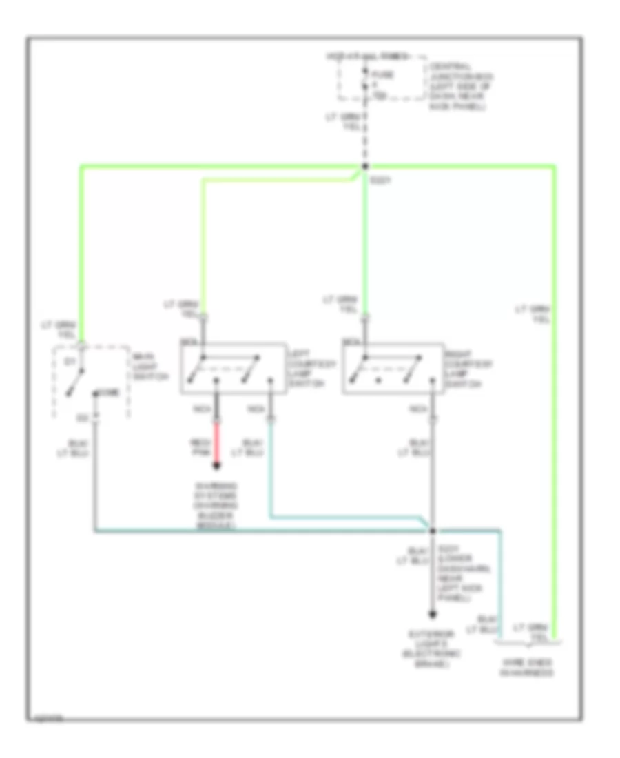
Courtesy Lamps Wiring Diagram, Except Cutaway with Entertainment System (1 of 2) for Ford E450 Super Duty 2001
List of elements for Courtesy Lamps Wiring Diagram, Except Cutaway with Entertainment System (1 of 2) for Ford E450 Super Duty 2001:
- (not used)
- Base vans/ wagons
- Battery
- C335
- C336
- Central junction box (left side of dash, near kick panel)
- Dome
- Ends in harness
- Fuse 15a
- Fuse 20a
- G200 (left kick panel)
- G999 (left rear corner of vehicle)
- Ground
- High mounted stoplamp
- Hot at all times
- Int lps out
- Interior map switch & lamp
- Left
- Left courtesy lamp switch
- Left visor lamp
- Main light switch
- Mounted stop lamp) s405
- Nca
- Rear courtesy lamp switch
- Red/ pnk
- Remote keyless entry module (behind left "b" pillar)
- Right
- Right courtesy lamp switch
- Right visor lamp
- Rv vans
- S231 (lower dash harn, near left kick panel)
- S235
- S259 (lower dash harn, behind left "b" pillar)
- S260
- S290
- S292
- S296
- S300
- S302 (rear harn, near left "b" pillar)
- S314 (interior lamp harn)
- S402
- S404 (rear harn, near high mounted stop lamp)
- Side door courtesy lamp switch
- Side door ctsy sw
- To high mounted stop/ cargo lamp & rear courtesy lamp switch (diagram 2 of 2)
- W/ remote keyless entry
- W/full headliner
- W/o full headliner
- W/o remote keyless entry
- Warning systems (warning buzzer module)
Courtesy Lamps Wiring Diagram, Except Cutaway with Entertainment System (2 of 2) for Ford E450 Super Duty 2001
List of elements for Courtesy Lamps Wiring Diagram, Except Cutaway with Entertainment System (2 of 2) for Ford E450 Super Duty 2001:
- (interior harn, near upper left "b' pillar)
- (interior lamp harness) s314
- (rear harn, near left "b" pillar)
- (rear harn, near left "b" pillar) s301
- (rear harn, rear center of roof)
- Cargo lamp
- From courtesy lights control circuit (diagram 1 of 2)
- G999 (left rear corner of vehicle)
- High mounted stop/ cargo lamp
- Interior switch/ lamp (w/ aux a/c)
- Interior/map switch & lamp
- Left
- Left visor lamp
- Nca
- Off
- Rear courtesy lamp switch
- Right
- Right visor lamp
- S300
- S302
- S402
- S404 (rear harn, near rear center of roof)
- S405
- S911
- S912
- S913
- Wagons w/ aux a/c
- Wagons w/o aux a/c
Courtesy Lamps Wiring Diagram, Except Cutaway without Entertainment System (1 of 2) for Ford E450 Super Duty 2001
List of elements for Courtesy Lamps Wiring Diagram, Except Cutaway without Entertainment System (1 of 2) for Ford E450 Super Duty 2001:
- (not used)
- Base vans/ wagons
- Battery
- C335
- C336
- Central junction box (left side of dash, near kick panel)
- Dome
- Ends in harness
- Fuse 15a
- Fuse 20a
- G200 (left kick panel)
- G999 (left rear corner of vehicle)
- Ground
- High mounted stoplamp
- Hot at all times
- Int lps out
- Interior map switch & lamp
- Left
- Left courtesy lamp switch
- Left visor lamp
- Main light switch
- Mounted stop lamp) s405
- Nca
- Rear courtesy lamp switch
- Red/ pnk
- Remote keyless entry module (behind left "b" pillar)
- Right
- Right courtesy lamp switch
- Right visor lamp
- Rv vans
- S221
- S231 (lower dash harn, near left kick panel)
- S235
- S259 (lower dash harn, behind left "b" pillar)
- S260
- S300
- S302 (rear harn, near left "b" pillar)
- S314 (interior lamp harn)
- S402
- S404 (rear harn, near high mounted stop lamp)
- Side door courtesy lamp switch
- Side door ctsy sw
- To high mounted stop/ cargo lamp & rear courtesy lamp switch (diagram 2 of 2)
- W/ remote keyless entry
- W/full headliner
- W/o full headliner
- W/o remote keyless entry
- Warning systems (warning buzzer module)
Courtesy Lamps Wiring Diagram, Except Cutaway without Entertainment System (2 of 2) for Ford E450 Super Duty 2001
List of elements for Courtesy Lamps Wiring Diagram, Except Cutaway without Entertainment System (2 of 2) for Ford E450 Super Duty 2001:
- (interior harn, near upper left "b' pillar)
- (interior lamp harness) s314
- (rear harn, near left "b" pillar)
- (rear harn, near left "b" pillar) s301
- (rear harn, rear center of roof)
- Cargo lamp
- From courtesy lights control circuit (diagram 1 of 2)
- G999 (left rear corner of vehicle)
- High mounted stop/ cargo lamp
- Interior switch/ lamp (w/ aux a/c)
- Interior/map switch & lamp
- Left
- Left visor lamp
- Nca
- Off
- Rear courtesy lamp switch
- Right
- Right visor lamp
- S300
- S302
- S402
- S404 (rear harn, near rear center of roof)
- S405
- S911
- S912
- S913
- Wagons w/ aux a/c
- Wagons w/o aux a/c
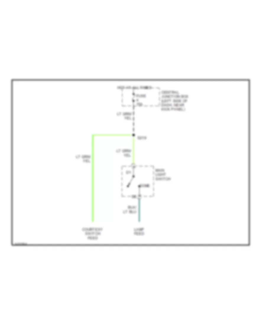
Courtesy Lamps Wiring Diagram, with Stripped Chassis for Ford E450 Super Duty 2001
List of elements for Courtesy Lamps Wiring Diagram, with Stripped Chassis for Ford E450 Super Duty 2001:
- Central junction box (left side of dash, near kick panel)
- Courtesy switch feed
- Dome
- Fuse 15a
- Hot at all times
- Lamp feed
- Main light switch
- S219
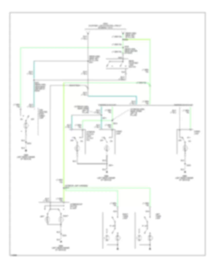
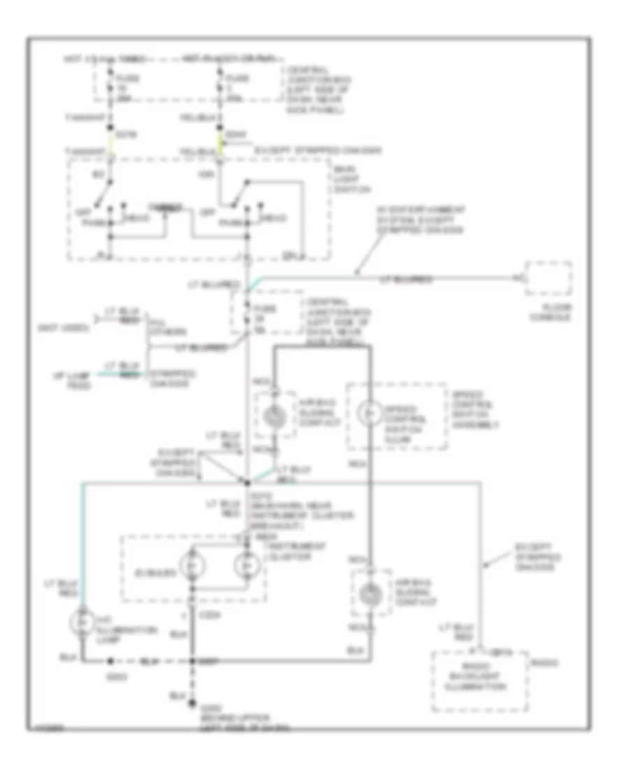
Instrument Illumination Wiring Diagram for Ford E450 Super Duty 2001
List of elements for Instrument Illumination Wiring Diagram for Ford E450 Super Duty 2001:
- (5) bulbs
- (not used)
- A/c illumination lamp
- Air bag sliding contact
- All others
- C213
- C224
- Central junction box (left side of dash, near kick panel)
- Dimmer
- Except stripped chassis
- Floor console
- Fuse 15a
- Fuse 20a
- Fuse 5a
- G202 (behind upper left side of dash)
- Head
- Hot at all times
- Hot in accy or run
- I/p lamp feed
- Ign
- Instrument cluster
- Main light switch
- Nca
- Off
- Park
- Radio
- Radio backlight illumination
- S202
- S207
- S212 (main harn, near instrument cluster breakout)
- S218
- S245
- Speed control switch assembly
- Speed control switch illum
- Stripped chassis
- W/ entertainment system, except stripped chassis
POWER DISTRIBUTION
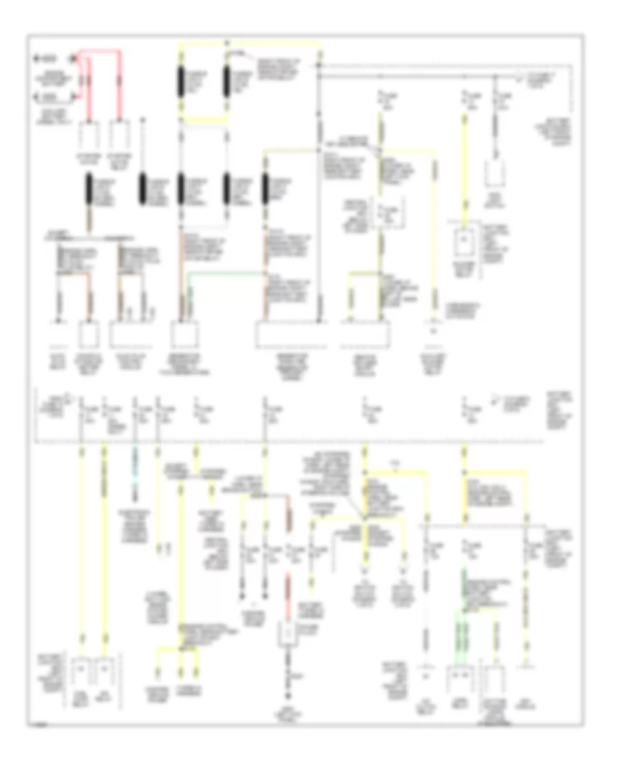
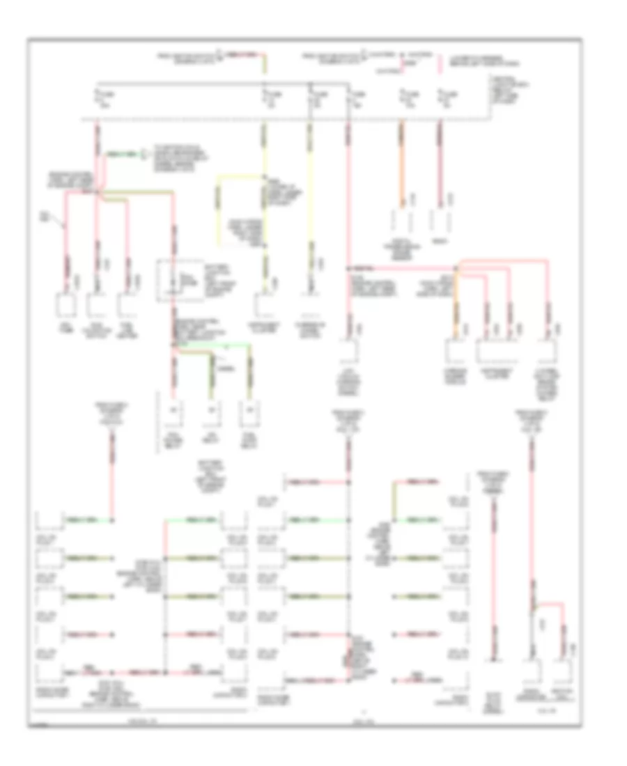
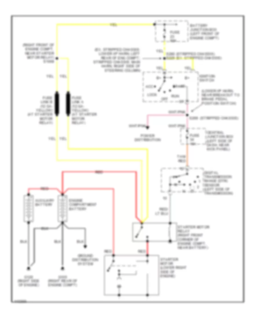
Power Distribution Wiring Diagram (1 of 5) for Ford E450 Super Duty 2001
List of elements for Power Distribution Wiring Diagram (1 of 5) for Ford E450 Super Duty 2001:
- (5.4l ngv only)
- (diesel only)
- (engine control harn, near battery junction box breakout) s115
- (engine control harn, near battery junction box breakout) s116
- (engine harn, at breakout to glow plug module) s192
- (engine harn, at breakout to glow plug relay) s191
- (ex stripped chasis: lower i/p harn, left rear of engine compt) (stripped chasis: main harn, right side of steering column)
- (lower i/p harn, near brake switch) s266
- (right front of engine compt, near starter motor relay)
- (taped in harness)
- 4 wheel anti-lock brake system (4wabs) module
- 4.2l
- A/c clutch relay
- Auxiliary battery (diesel only)
- Auxiliary blower motor relay
- Battery (taped in harness)
- Battery feed (taped in harness)
- Battery junction box (left front of engine compt)
- Blower motor relay
- C145
- C152
- C153
- California
- Central junction box (below left side of dash)
- Daytime running lamps module (if equipped)
- Electronic trailer brakes harness (taped in harness)
- Engine compartment battery
- Except california
- Except stripped chasis
- From a fuse 15 (diagram 1 of 5)
- Fuel pump relay
- Fuse
- Fuse 10a
- Fuse 15a
- Fuse 20a
- Fuse 30a
- Fuse 30a (diesel only)
- Fuse 40a
- Fuse 50a
- Fuse 60a
- G200 (left kick panel)
- Generator (gasoline) generator (primary) (diesel)
- Generator (secondary: diesel w/ twin generators)
- Glow plug control module
- Glow plug relay
- Horn relay
- Idm relay
- Main light switch
- Manifold intake air heater relay
- Modified vehicle power
- Nca
- Ngv module
- Power plug 2
- Red
- Remote keyless entry module
- S1008
- S101 (engine control harn, near battery junction box breakout)
- S1010 (right front of engine compt, near battery junction box)
- S1011 (right front of engine compt, near battery junction box)
- S1012 (right front of engine compt, near starter motor relay)
- S178 (right front of engine compt, near battery junction box)
- S183 (5.4l ngv only) (engine control harn, left rear of engine compt)
- S225 (except stripped chasis)
- S235
- S254 (lower i/p harn, near left kick panel)
- S257 (lower i/p harn, behind left 'b' pillar, near floor)
- S280 (stripped chasis)
- Starter motor
- Starter motor relay
- Stripped chasis
- To fuse 17 (diagram 1 of 5)
- To fuse 9 (diagram 2 of 5)
- To ignition switch (diagram 3 of 5)
- W/ remote keyless entry
- Wire ends in harness in cutaways
Power Distribution Wiring Diagram (2 of 5) for Ford E450 Super Duty 2001
List of elements for Power Distribution Wiring Diagram (2 of 5) for Ford E450 Super Duty 2001:
- (door harn, inside left front door) (w/ rke only) s506
- (engine compt harn, left rear of engine compt) s129
- (engine ctrl harn, near battery junction box breakout)
- (lower i/p harn, behind left side of dash)
- (lower i/p harn, below left side of dash) s230
- (lower i/p harn, below right side of dash)
- (lower i/p harn, left rear of engine compt) s227
- (main harn, left side of dash)
- (main wiring harn, base of steering column) s218
- Auxiliary battery
- Auxiliary battery relay
- Battery junction box (left front of engine compt)
- Brake pedal position (bpp) switch
- C151
- C154
- C200
- C213
- C218
- C224
- C227
- C238
- C241
- C250
- C251
- C330
- C335
- C337
- C425
- C500
- C600
- Central junction box (below left side of dash)
- Cigar lighter
- Data link connector (dlc)
- Deactivator switch
- Driver seat regulator control switch
- Electronic crash sensor module
- Except stripped chasis
- Exterior rear view mirror switch
- Floor console
- From b fuse 12 (diagram 1 of 5)
- Fuse 10a
- Fuse 15a
- Fuse 20a
- Fuse 25a
- Fuse 30a
- Fuse 40a
- Fuse 5a
- Fuse 60a
- G202 (behind upper left side of dash)
- Instrument cluster
- Main light switch
- Master window/ door lock control switch
- Memory lock module
- Multi- function switch
- Nca
- Overhead console
- Pcm power relay
- Power plug 1
- Power- train control module
- Radio
- Rear power door lock switch
- Red
- Remote keyless entry nodule
- Right power door lock/ window switch
- S108
- S109 (engine control harn, near battery junction box breakout)
- S110 (engine control harn, near battery junction box breakout)
- S148
- S175 (engine control harn, left rear of engine compt)
- S207
- S237
- S276
- S291
- Stripped chasis
- To fuse 4 (diagram 5 of 5)
- Trailer battery charge relay
- Trailer reversing lamp relay
- Trailer running lamp relay
- W/ aux battery
- W/ entertainment system
- W/ power seats
- W/ remote keyless
- W/ rke only
- W/o aux battery
- W/o entertainment system
- W/o remote keyless
Power Distribution Wiring Diagram (3 of 5) for Ford E450 Super Duty 2001
List of elements for Power Distribution Wiring Diagram (3 of 5) for Ford E450 Super Duty 2001:
- (engine control harn, left rear of engine compt) (except cutaways) s131
- (engine control harn, near battery junction box breakout) s113
- (interior lamp harn) s314
- (main wiring harn, center of dash) s203
- (main wiring harn, left side of dash) (cutaways) s282
- 4 wheel anti-lock brake system (4wabs) module
- A/c switch (taped in harness)
- Acc
- Auxiliary battery relay
- Auxiliary powertrain control connector (diesel)
- Base vans & wagons, cutaways
- Batt
- Blend door actuator
- C115
- C144
- C146
- C193
- C200
- C204
- C221
- C237
- C249
- C250
- Cargo lamp
- Central junction box (below left side of dash)
- Daytime running lamps (drl) module
- Digital transmission range (dtr) sensor
- Electronic crash sensor (ecs) module
- Except stripped chasis
- From fuse 23 c (diagram 1 of 5)
- From fuse 23 d (diagram 1 of 5)
- From fuse 4 j (diagram 5 of 5)
- Function selector switch
- Fuse 10a
- Fuse 15a
- Fuse 20a
- Gasoline only
- High mounted stoplamp
- Ignition switch
- Interior switch/ lamp
- Interior/ map switch & lamp
- Left visor lamp
- Lock
- Multi- function switch
- Nca
- Not used
- Off
- Rear courtesy lamp switch
- Right visor lamp
- Run
- S229 (lower i/p harn, below left side of dash)
- S912 (interior harn, left "b" pillar)
- Shift lock actuator
- Speed control servo (except stripped chasis)
- Start
- Stripped chasis
- To fuse 14 (diagram 4 of 5)
- To fuse 34 (diagram 4 of 5)
- To fuse 9 (diagram 5 of 5)
- W/ auxiliary battery
- W/ full headliner
- W/o full headliner
- Wagons w/ auxiliary a/c
- Wagons w/o auxiliary a/c
- Wagons, rv vans
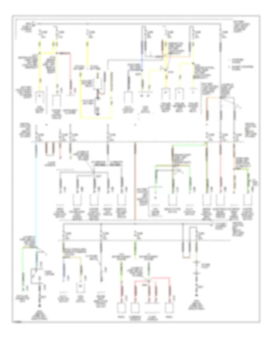
Power Distribution Wiring Diagram (4 of 5) for Ford E450 Super Duty 2001
List of elements for Power Distribution Wiring Diagram (4 of 5) for Ford E450 Super Duty 2001:
- (engine control harn, left rear of engine compt) s127
- (lower i/p harness, behind left side of dash)
- (main wiring harn, under right side of dash) s267
- 4 wheel anti-lock brake system (4wabs) relay
- 4.2l v6
- 4.6l/5.4l v8
- 5.4l ngv
- 6.8l v10
- Battery junction box (left front of engine compt)
- C1013
- C1018
- C115
- C130
- C131
- C164
- C213
- C214
- C222
- C224
- C226
- C232
- C247
- Central junction box (below left side of dash)
- Coil on plug 1
- Coil on plug 10
- Coil on plug 2
- Coil on plug 3
- Coil on plug 4
- Coil on plug 5
- Coil on plug 6
- Coil on plug 7
- Coil on plug 8
- Coil on plug 9
- Diesel
- Digital transmission range sensor
- From fuse 8 (diagram 4 of 5) (4.2l v6)
- From fuse 8 (diagram 4 of 5) (4.6l/5.4l)
- From fuse 8 (diagram 4 of 5) (6.8l v10)
- From fuse 8 (diagram 4 of 5) (diesel)
- From ignition switch f (diagram 3 of 5)
- From ignition switch g (diagram 3 of 5)
- Fuel line heater
- Fuel pump relay
- Fuse 10a
- Fuse 15a
- Fuse 30a
- Fuse 5a
- Glow plug relay (diesel)
- Idle validation switch
- Idm relay
- Ignition coil
- Instrument cluster
- Low vacuum warning switch (diesel)
- Nca
- Ngv timer
- Overdrive cancel switch
- Pcm diode
- Pcm power relay
- Radio
- Radio capacitor
- Radio capacitor 2
- Radio noise capacitor 1
- S146 (engine control harn, left rear of engine compt)
- S156 (5.4l) s193 (4.6l) (engine control harn, above left cylinder bank)
- S161 (5.4l) s150 (4.6l) (engine control harn, above right cylinder bank)
- S161 (engine control harn, above right cylinder bank)
- S162 (engine control harn, above left cylinder bank)
- S213 (main wiring harn, left side of dash)
- S265 (lower i/p harn, under right side of dash)
- S269
- Tan/red
- To ignition coils (gasoline engines) or glow plug relay (diesel engine) (diagram 4 of 5)
- Warning buzzer module
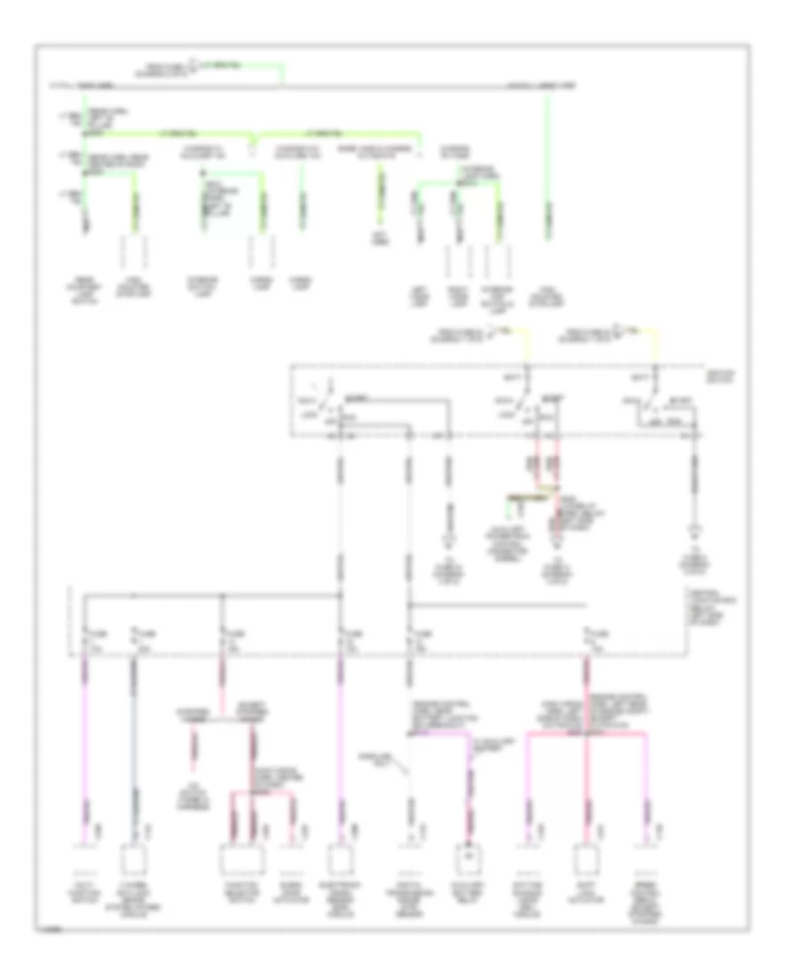
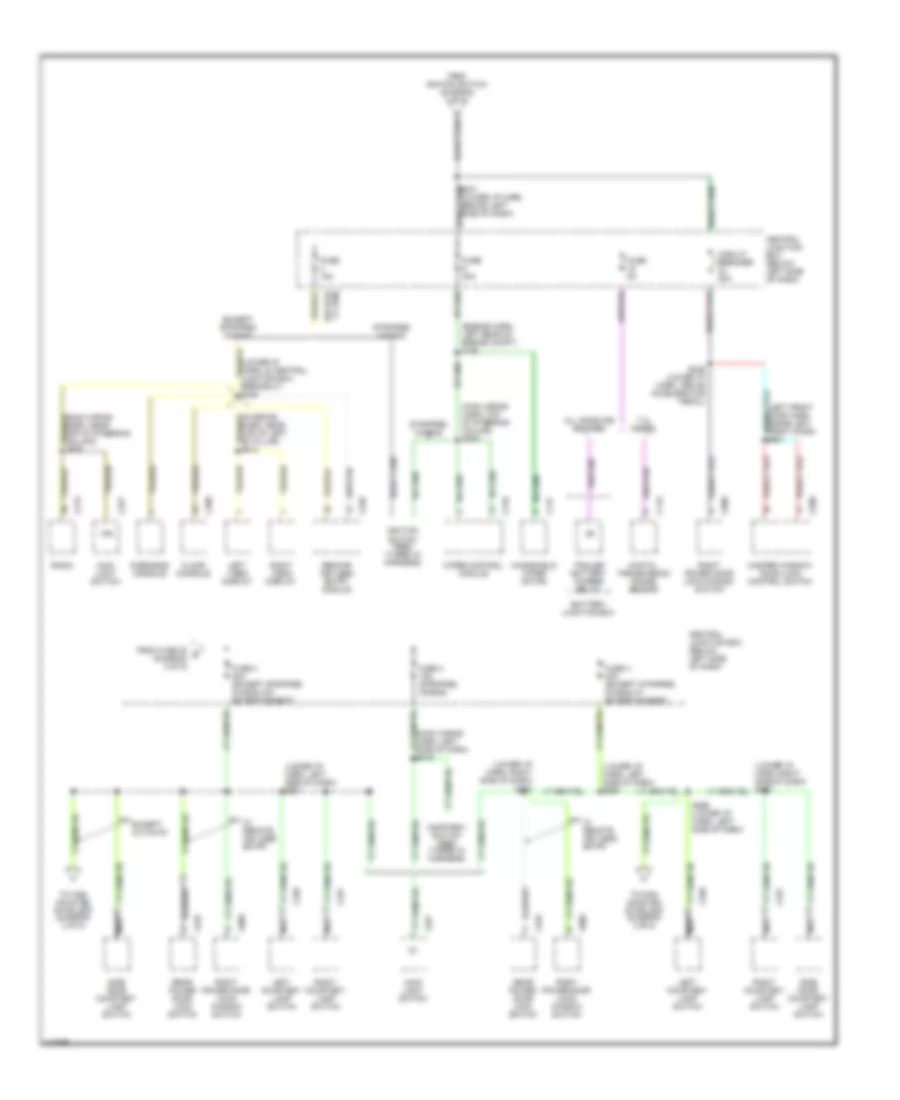
Power Distribution Wiring Diagram (5 of 5) for Ford E450 Super Duty 2001
List of elements for Power Distribution Wiring Diagram (5 of 5) for Ford E450 Super Duty 2001:
- (engine harn, left rear of engine compt) s128
- (left front door harn, inside left front door) s501
- (lower i/p harn, left side of dash) s221
- (lower i/p harn, left side of dash) s294
- (lower i/p harn, right side of dash) s292
- (main wiring harn, left side of dash) s219
- (main wiring harn, top of steering column) s208
- 7.3l diesel
- All gasoline engines
- Battery junction box
- C115
- C147
- C213
- C216
- C227
- C327
- C328
- C335
- C360
- C425
- C500
- C600
- Central junction box (below left side of dash)
- Circuit breaker 20a
- Courtesy switch feed (taped in harness)
- Digital transmission range sensor
- Except cutaway
- Except stripped chasis
- Floor console
- From fuse 28 e (diagram 2 of 5)
- From ignition switch (diagram 3 of 5)
- Fuse 15a
- Fuse 30a
- Fuse 4 15a (stripped chasis)
- Fuse 4 30a (except stripped chasis w/ entertainment)
- Fuse 4 30a (except stripped chasis w/o entertainment)
- Fuse 5a
- Ign
- Ignition switch feed (taped in harness)
- Left courtesy lamp switch
- Left video display
- Main light switch
- Master window/ door lock control switch
- Nca
- Overhead console
- Radio
- Rear power door lock switch
- Remote keyless entry module
- Right courtesy lamp switch
- Right power door lock/ window switch
- Right power door lock/window switch
- Right video display
- S236 (lower i/p harn, above accelerator pedal)
- S271 (lower i/p harn, behind left side of dash)
- S296 (lower i/p harn, left side of dash)
- Side door courtesy lamp switch
- Stripped chasis
- To high mounted stoplamp (diagram 3 of 5)
- Trailer battery charge relay
- W/ remote keyless entry
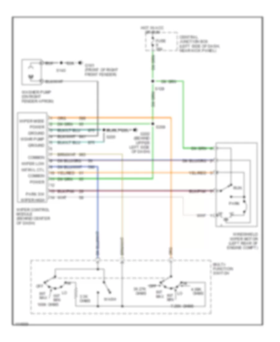
- Windshield wiper motor
- Wiper control module
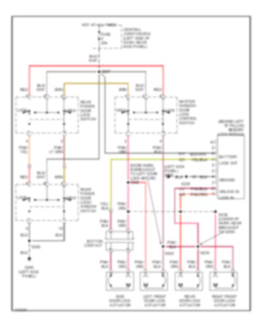
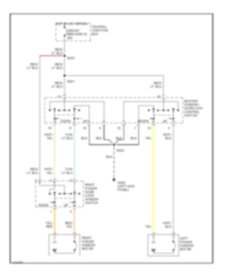
POWER DOOR LOCKS
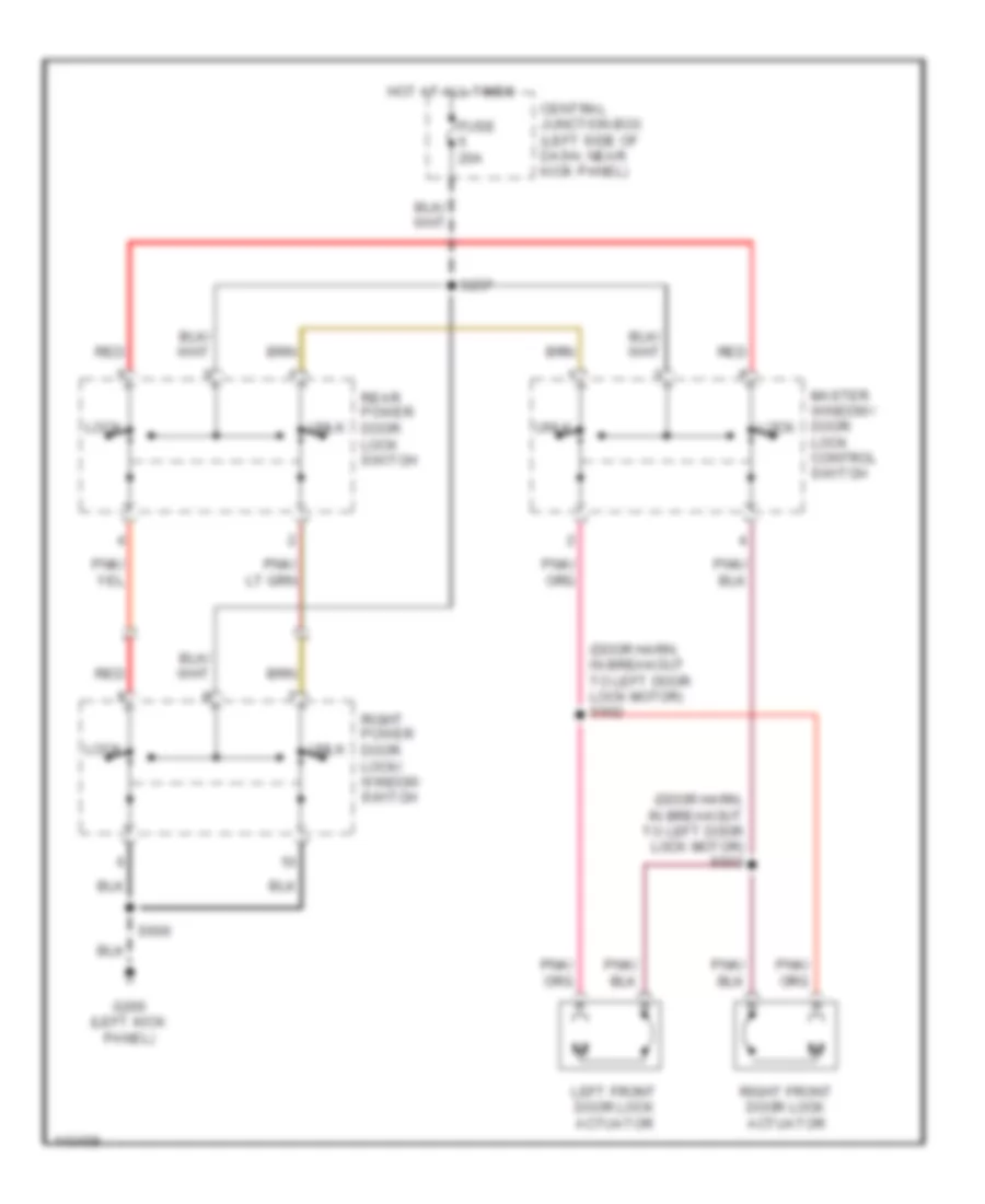
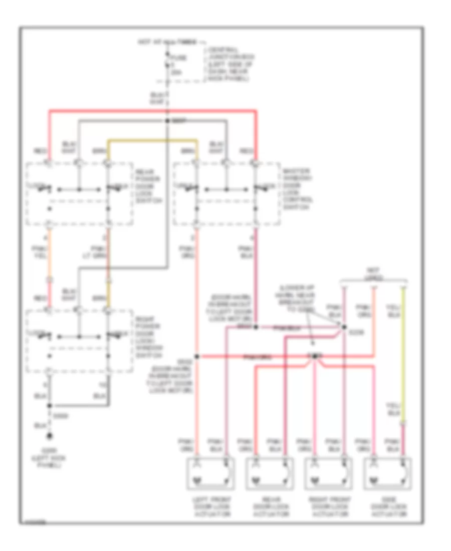
Door Lock Wiring Diagram, Cutaway Chassis for Ford E450 Super Duty 2001
List of elements for Door Lock Wiring Diagram, Cutaway Chassis for Ford E450 Super Duty 2001:
- (door harn, in breakout to left door lock motor) s502
- (door harn, in breakout to left door lock motor) s503
- Central junction box (left side of dash, near kick panel)
- Fuse 20a
- G200 (left kick panel)
- Hot at all times
- Left front door lock actuator
- Lock
- Master window/ door lock control switch
- Rear power door lock switch
- Red
- Right front door lock actuator
- Right power door lock/ window switch
- S237
- S600
- Unlk
Door Lock Wiring Diagram, with Hinged Side Door for Ford E450 Super Duty 2001
List of elements for Door Lock Wiring Diagram, with Hinged Side Door for Ford E450 Super Duty 2001:
- (door harn, in breakout to left door lock motor) s503
- (lower i/p harn, near breakout to g200)
- Central junction box (left side of dash, near kick panel)
- Fuse 20a
- G200 (left kick panel)
- Hot at all times
- Left front door lock actuator
- Lock
- Master window/ door lock control switch
- Not used
- Rear door lock actuator
- Rear power door lock switch
- Red
- Right front door lock actuator
- Right power door lock/ window switch
- S237
- S238
- S239
- S502 (door harn, in breakout to left door lock motor)
- S600
- Side door lock actuator
- Unlk
Door Lock Wiring Diagram, with Sliding Side Door for Ford E450 Super Duty 2001
List of elements for Door Lock Wiring Diagram, with Sliding Side Door for Ford E450 Super Duty 2001:
- (behind left "b" pillar) memory lock module
- (door harn, in breakout to left door lock motor) s502
- (left kick panel) g200
- Battery
- Button contact
- Central junction box (left side of dash, near kick panel)
- Fuse 20a
- G200 (left kick panel)
- Ground
- Hot at all times
- Left front door lock actuator
- Lock
- Lock in
- Lock out
- Master window/ door lock control switch
- Rear door lock actuator
- Rear power door lock switch
- Red
- Right front door lock actuator
- Right power door lock/ window switch
- S235
- S237
- S238 (lower i/p harn, near breakout to g200)
- S239
- S503
- S600
- Side door lock actuator
- Unlk
- Unlock in
Keyless Entry Wiring Diagram for Ford E450 Super Duty 2001
List of elements for Keyless Entry Wiring Diagram for Ford E450 Super Duty 2001:
- (left kick panel) g200
- (lower i/p harn, behind left "b" pillar)
- (lower i/p harn, near breakout to g200, left kick panel)
- Battery
- Button contact
- C335
- C336
- Central junction box (left side of dash, near kick panel)
- Door lock
- Exterior lights system (main light switch)
- Fuse 15a
- Fuse 20a
- Fuse 30a
- Fuse 5a
- Ground
- Horn relay ctrl
- Horns system
- Hot at all times
- Hot in acc or run
- Ignition
- Int lamps out
- Interior lights system
- Interior lights system (side door courtesy lamp switch)
- Left front door lock actuator
- Lf door lock
- Light switch in
- Lock
- Lock in
- Master window/ door lock control switch
- Rear door lock actuator
- Rear power door lock switch
- Remote keyless entry module (behind left "b" pillar)
- Retractor)
- Rf door lock
- Right front door lock actuator
- Right power door lock/ window switch
- S221
- S235
- S238
- S239
- S245
- S251
- S252
- S255
- S257
- S260
- S506
- Side door lock
- Side door lock actuator
- Side door sw in
- Side/rear lock
- Unlock
- Unlock in
- W/ hinged door
- W/ sliding door
POWER MIRRORS
Power Mirrors Wiring Diagram for Ford E450 Super Duty 2001
List of elements for Power Mirrors Wiring Diagram for Ford E450 Super Duty 2001:
- Central junction box (left side of dash, near kick panel)
- Direc- tional control switch
- Exterior rear view mirror switch
- Fuse 32 5a
- G200 (left kick panel)
- Hot at all times
- L/r motor
- Left exterior rear view mirror
- Left/ right switch
- Nca
- Red
- Right exterior rear view mirror
- S500
- S504 (body harness, front of left front door)
- S506
- Up/dn motor
POWER SEATS
Power Seats Wiring Diagram for Ford E450 Super Duty 2001
List of elements for Power Seats Wiring Diagram for Ford E450 Super Duty 2001:
- Central junction box (left side of dash, near kick panel)
- Driver seat motor assembly
- Driver seat regulator control switch
- Entire seat
- Front height motor
- Front of seat
- Fuse 16 30a
- Fwd
- Fwd/ rwd motor
- G200 (left kick panel)
- Hot at all times
- Nca
- Rear height motor
- Rear of seat
- Rwd
- S315
POWER WINDOWS
Power Windows Wiring Diagram for Ford E450 Super Duty 2001
List of elements for Power Windows Wiring Diagram for Ford E450 Super Duty 2001:
- Central junction box
- Circuit breaker 43 20a
- Down
- G200 (left kick panel)
- Hot in acc or run
- Left power window motor
- Master window/ door lock control switch
- Right power door lock/ window switch
- Right power window motor
- S236
- S500
- S501
RADIO
Radio Wiring Diagram, with Rear Entertainment (1 of 2) for Ford E450 Super Duty 2001
List of elements for Radio Wiring Diagram, with Rear Entertainment (1 of 2) for Ford E450 Super Duty 2001:
- (behind upper left side of dash) g202
- Antenna
- C212
- C213
- Central junction box (left side of dash, near kick panel)
- Fuse 15a
- Fuse 5a
- G203 (under right side of dash)
- Ground
- Hot at all times
- Hot in park or head
- Hot in run or acc
- Hot in start
- Illumination
- L front speaker
- L rear speaker
- Left front door speaker
- Memory power
- Nca
- Noise reduction
- Power
- R front speaker
- R rear speaker
- Radio
- Red
- Right front speaker
- S202
- S204
- S209
- S212
- S245
- S291
- Shield
- Signal
- Tan
Radio Wiring Diagram, with Rear Entertainment (2 of 2) for Ford E450 Super Duty 2001
List of elements for Radio Wiring Diagram, with Rear Entertainment (2 of 2) for Ford E450 Super Duty 2001:
- (interior harn, near breakout to video displays)
- (left kick panel)
- (left rear corner of vehicle) g999
- (lower dash harn, near breakout to safety belt retractor)
- (rear of roof, near cargo lamp) s914
- (under right side of dash) g203
- Button contact
- C360
- C362
- C364
- C365
- Floor console
- G200
- Ground
- Illumination
- Interior lights system
- Left mid speaker
- Left rear speaker
- Left video display
- Lr spkr in
- Lr spkr/mid in
- Lr spkr/mid out
- Nca
- Power
- Rear seat entertainment module
- Red
- Right rear speaker
- Right side door speaker
- Right video display
- Rr spkr in
- Rr spkr out
- Rr spkrs in
- S235
- S243
- S288 (lower dash harn, near breakout to remote radio controls)
- S297
- S915
- S920
- S921
- Shield
- Signal
- Tan
- Video cassette player
Radio Wiring Diagram, without Rear Entertainment for Ford E450 Super Duty 2001
List of elements for Radio Wiring Diagram, without Rear Entertainment for Ford E450 Super Duty 2001:
- (behind upper left side of dash) g202
- (lower dash harn, near breakout to blend door actuator) s240
- (lower dash harn, near breakout to safety belt retractor) s244
- Antenna
- Button contact
- C213
- Central junction box (left side of dash, near kick panel)
- Cutaways
- Fuse 15a
- Fuse 5a
- G203 (under right side if dash)
- Ground
- Hinged door
- Hot at all times
- Hot in park or head
- Hot in run or acc
- Hot in start
- Illumination
- L front speaker
- L rear speaker
- Left front door speaker
- Left mid speaker (w/ 6 speakers)
- Left rear speaker
- Memory power
- Nca
- Noise reduction
- Not used
- Power
- R front speaker
- R rear speaker
- Radio
- Right front speaker
- Right mid speaker (w/ 6 speakers)
- Right rear speaker
- S202
- S204
- S209
- S212
- S241
- S243
- Sliding door
- Vans/ wagons
SHIFT INTERLOCK
Shift Interlock Wiring Diagram for Ford E450 Super Duty 2001
List of elements for Shift Interlock Wiring Diagram for Ford E450 Super Duty 2001:
- Brake pedal position (bpp) switch (on bracket, above brake pedal)
- Central junction box (left side of dash)
- Fuse 11 15a
- Fuse 6 10a
- G202 (behind upper left side of dash)
- Hot at all times
- Hot in run
- Power distribution system
- S131
- S207
- S216 (main harn, left side of dash)
- Shift lock actuator (below right side steering column)
- Solid state
STARTING/CHARGING
6.8L
6.8L, Charging Wiring Diagram, without Dual Generators for Ford E450 Super Duty 2001
List of elements for 6.8L, Charging Wiring Diagram, without Dual Generators for Ford E450 Super Duty 2001:
- (ex. stripped chassis)
- (ex. stripped chassis: lower i/p harn, left rear of eng compt; stripped chassis: main harn, right side of steering column)
- (right front corner of engine compt) starter motor relay
- (right front of engine compt, near starter motor relay) s1008
- (stripped chassis)
- 0hms
- Accy
- Auxiliary powertrain control connector (7.3l diesel) (behind left side of dash)
- Battery junction box (left front of engine compt)
- Below left side of dash)
- C198
- C199
- C226
- Central junction box (below left side of dash)
- Charge ind
- Engine compartment battery
- Fuse 5a
- Fuse 60a
- Fuse link c (18 ga- brown) (at starter motor relay)
- G120 (right side of engine)
- Generator
- Ground distribution system
- Ignition switch
- Instrument cluster
- Lock
- Of dash)
- Off
- Red
- Run
- S1010 (right front of engine compt, near battery junction box)
- S1011 (right front of engine compt, near battery junction box)
- S225
- S280
- Start
- Starting circuit
6.8L, Starting Wiring Diagram for Ford E450 Super Duty 2001
List of elements for 6.8L, Starting Wiring Diagram for Ford E450 Super Duty 2001:
- (ex. stripped chassis: lower i/p harn, left rear of eng compt; stripped chassis: main harn, right side of steering column)
- (lower i/p harn, near breakout to brake pedal position switch)
- (right front of engine compt, near starter motor relay) s1008
- (stripped chassis)
- (stripped chassis) (ex. stripped chassis)
- 5.4l cng
- Acc
- Battery junction box (left front of engine compt)
- Central junction box (left side of dash, near kick panel)
- Digital transmission range (dtr)
- Engine compartment battery
- Fuse 10a
- Fuse 60a
- G120 (right side of engine)
- Ground distribution system
- Ignition switch
- Lock
- Ngv timer (left rear of engine compt, near pcm)
- Off
- Power distribution
- Red
- Run
- S269
- Sensor (left side of transmission)
- Start
- Starter motor (lower right side of engine)
- Starter motor relay (right front corner of engine compt, near battery)
- Tan/ red
7.3L DIESEL
7.3L Diesel, Charging Wiring Diagram, with Dual Generators for Ford E450 Super Duty 2001
List of elements for 7.3L Diesel, Charging Wiring Diagram, with Dual Generators for Ford E450 Super Duty 2001:
- (ex. stripped chassis: lower i/p harn, left rear of eng compt; stripped chassis: main harn, right side of steering column)
- (except stripped chassis) (stripped chassis)
- (right front corner of engine compt) starter motor relay
- (right front of engine compt, near starter motor relay) s1008
- 0hms
- Accy
- Auxiliary battery
- Auxiliary powertrain control connector (behind left side of dash)
- Battery junction box (left front of engine compt)
- C226
- Central junction box (left side of dash, near kick panel)
- Charge indicator
- Engine compartment battery
- Fuse 5a
- Fuse 60a
- Fuse link c (18 ga- brown) (at starter motor relay)
- Fuse link f (12 ga- gray) (at starter motor relay)
- Fuse link g (12 ga- gray) (at starter motor relay)
- G105 (right rear of engine compt)
- G120 (right side of engine)
- Ground distribution system
- Ignition switch
- Instrument cluster
- Lock
- Off
- Powertrain control module (left rear of engine compt)
- Primary generator
- Red
- Run
- S1010 (right front of engine compt, near battery junction box)
- S178 (right front of engine compt, near battery junction box)
- S225 s280
- S229 (lower i/p harn, below left side of dash)
- S265 (lower i/p harn, under right side of dash)
- S267 (main harn, under right side of dash)
- Secondary generator
- Start
- Starting circuit
7.3L Diesel, Charging Wiring Diagram, without Dual Generators for Ford E450 Super Duty 2001
List of elements for 7.3L Diesel, Charging Wiring Diagram, without Dual Generators for Ford E450 Super Duty 2001:
- (ex. stripped chassis)
- (ex. stripped chassis: lower i/p harn, left rear of eng compt; stripped chassis: main harn, right side of steering column)
- (right front corner of engine compt) starter motor relay
- (right front of engine compt, near starter motor relay) s1008
- (stripped chassis)
- 0hms
- Accy
- Auxiliary powertrain control connector (7.3l diesel) (behind left side of dash)
- Battery junction box (left front of engine compt)
- Below left side of dash)
- C198
- C199
- C226
- Central junction box (below left side of dash)
- Charge ind
- Engine compartment battery
- Fuse 5a
- Fuse 60a
- Fuse link c (18 ga- brown) (at starter motor relay)
- G120 (right side of engine)
- Generator
- Ground distribution system
- Ignition switch
- Instrument cluster
- Lock
- Of dash)
- Off
- Red
- Run
- S1010 (right front of engine compt, near battery junction box)
- S1011 (right front of engine compt, near battery junction box)
- S225
- S280
- Start
- Starting circuit
7.3L Diesel, Starting Wiring Diagram for Ford E450 Super Duty 2001
List of elements for 7.3L Diesel, Starting Wiring Diagram for Ford E450 Super Duty 2001:
- (ex. stripped chassis: lower i/p harn, left rear of eng compt; stripped chassis: main harn, right side of steering column)
- (lower i/p harn, near breakout to brake pedal position switch)
- (right front of engine compt, near starter motor relay) s1008
- (stripped chassis)
- (stripped chassis) (ex. stripped chassis)
- Acc
- Auxiliary battery
- Battery junction box (left front of engine compt)
- Central junction box (left side of dash, near kick panel)
- Digital transmission range (dtr)
- Engine compartment battery
- Fuse 10a
- Fuse 60a
- G105 (right rear of engine compt)
- G120 (right side of engine)
- Ground distribution system
- Ignition switch
- Lock
- Off
- Power distribution
- Red
- Run
- S269
- Sensor (left side of transmission)
- Start
- Starter motor (lower right side of engine)
- Starter motor relay (right front corner of engine compt, near battery)
- Tan/ red
SUPPLEMENTAL RESTRAINTS
Supplemental Restraints Wiring Diagram for Ford E450 Super Duty 2001
List of elements for Supplemental Restraints Wiring Diagram for Ford E450 Super Duty 2001:
- (lower dash harness, in breakout to data link connector (dlc)) s228
- (lower dash harness, near breakout to 8 cavity gray in-line connector, behind left "b" pillar near floor)
- (lower dash harness, near breakout to blend door actuator) s265
- (lower dash harness, near breakout to brake pedal position (bpp) switch) s221
- (main wiring harness, near breakout to 14 cavity in-line connector, behind right kick panel) s201
- (main wiring harness, near breakout to ground under right side of dash) s267
- 4-wheel anti-lock brakes (4wabs) module (on left front frame rail)
- Air bag bracket
- Air bag bracket (behind right side of dash, near passenger air bag)
- Air bag ind
- Air bag indicator
- Air bag sliding contact
- Battery
- C226
- C341
- C342
- Center air bag sensor (in front center of engine compartment, behind grille)
- Center sensor
- Central junction box (left side of dash, near kick panel)
- Data
- Data link connector (dlc) (partial) (below left side of dash)
- Driver air bag
- Driver door open input
- Driver safety belt
- Electronic crash sensor (ecs) module (behind right side of dash)
- Fuse 10a
- Fuse 15a
- Fuse 5a
- G201 (under right side of dash)
- G202 (below left side of dash, near kick panel)
- Ground
- Hot at all times
- Hot in run
- Hot in run or start
- Ignition
- Instrument cluster
- Lamp/warn buzz
- Left courtesy lamp switch (mounted in left front door jamb)
- Nca
- Pass air bag
- Passenger air bag
- Passenger safety belt
- Pnk
- Preten feed
- Preten return
- Pretensioner feed
- Pretensioner nca
- Pretensioner return
- Red/ pnk
- Red/pnk
- Return
- S235
- S275 (main wiring harness, near breakout to connector c225 on instrument cluster)
- Safety belt buckle input
- Shorting bar
- Shorting bar engaged when module connector is disconnected from harness (shorting bars are connected between following pins: 1-15, 7-21 & 14-28)
- Timer
- Warning buzzer module (behind center of dash)
TRANSMISSION
6.8L
6.8L, A/T Wiring Diagram, 4R100 for Ford E450 Super Duty 2001
List of elements for 6.8L, A/T Wiring Diagram, 4R100 for Ford E450 Super Duty 2001:
- (eng control harn, near breakout to a/c cutout switch)
- (eng control harn, near breakout to a/c pressure cutout switch)
- (eng ctrl harn, near breakout to pcm)
- (engine control harn, above left bank of engine)
- (engine ctrl harn)
- (in battery junction box)
- (top center of engine compt) mass airflow (maf) sensor
- (trans ctrl harn, near breakout to dtr sensor)
- (trans ctrl harn, near trans) s102
- 4r100 transmission
- Abs system, warning buzzer module
- Battery junction box
- Battery junction box (left front of engine compt)
- Bpp
- Brake pedal position switch (on bracket, above brake pedal)
- C220a
- C220b
- C220c
- C224
- C225
- C226
- Cc sol
- Central junction box (behind left side of dash)
- Cht
- Coast clutch solenoid
- Cruise control system
- Cylinder head temperature sensor (top front of left cylinder head)
- Data (+)
- Data (-)
- Data link connector (below left side of dash)
- Digital transmission range sensor
- Electronic pressure control solenoid
- Eng compt)
- Engine controls
- Epc
- Exterior lights
- Fuse 10a
- Fuse 15a
- Fuse 30a
- Fuse 5a
- G101 (front of right front fender)
- G203 (behind upper left side of dash)
- Gen data
- Gnd
- Hot at all times
- Hot in run or start
- Iat
- Instrument cluster
- Instrument cluster system
- Instrumentation engine coolant temperature sensor (upper left front of engine)
- Kapwr
- Maf
- Malfunction indicator lamp
- Mil
- Multifunction switch, deactivator switch
- Nca
- Od off
- Oss
- Output shaft speed sensor (left side of transmission)
- Overdrive cancel switch
- Pcm diode
- Pcm power relay
- Powertrain control module (pcm) (left rear of engine compartment, near brake master cylinder)
- Pwr in
- Radio noise capacitors, ignition coils
- Red
- S100
- S110
- S127
- S134 (eng ctrl harn, near a/c press cutout sw)
- S135 (eng cntrl harn, near a/c press cutout switch)
- S136
- S137
- S138
- S140
- S142
- S157
- S175
- S213
- Shift solenoid a
- Shift solenoid b
- Sig rtn
- Speedometer
- Ssa
- Tcc
- Tcil
- Tcs
- Tft
- Throttle position sensor (tps) (on top of engine, near air intake)
- Torque converter clutch solenoid
- Tps
- Tr1
- Tr2
- Tr3
- Tr4
- Transmission fluid temperature sensor
- Tss
- Turbine shaft speed sensor (left side of transmission)
- Vref
- Vss
- Vss gnd
7.3L DI TURBO DIESEL
7.3L DI Turbo Diesel, A/T Wiring Diagram, 4R100 for Ford E450 Super Duty 2001
List of elements for 7.3L DI Turbo Diesel, A/T Wiring Diagram, 4R100 for Ford E450 Super Duty 2001:
- (behind upper left side of dash) g203
- (center left side of engine) engine oil temperature sensor
- (engine control harness, near breakout to pcm)
- (engine ctrl harn)
- (engine ctrl harn, near breakout to a/c press cutout sw)
- (fuel inj harn, near breakout to engine oil temp sensor)
- (fuel inj harn, near fuel injectors)
- (in battery junction box)
- (lower i/p harn)
- 4r100 transmission (right side of transmission)
- Abs system, warning buzzer module
- Accelerator pedal (ap) position sensor (behind left side of dash, above accelerator pedal)
- Acel pdl
- Ap sens
- Auxiliary powertrain control connector (partial) (behind left side of dash)
- Battery junction box
- Battery junction box (left front of engine compt)
- Bpp
- Brake pedal position switch (on bracket, above brake pedal)
- C220b
- C220c
- C225
- C226
- Ccs
- Central junction box (behind left side of dash)
- Chk eng
- Coast clutch solenoid
- Data (+)
- Data (-)
- Data link connector (dlc) (partial) (below left side of dash)
- Digital transmission range sensor
- Electronic pressure control solenoid
- Eng compt)
- Eng oil
- Engine controls
- Epc
- Exterior lights
- Fuse 10a
- Fuse 15a
- Fuse 30a
- Fuse 5a
- G101 (front of right front fender)
- Gen data
- Glow plug relay, fuel line htr, idle validation switch
- Gnd
- Hot at all times
- Hot in run or start
- Iat
- Idm relay, fuel pump relay
- Instrument cluster
- Intake air temperature sensor (center of engine compt, part of clean air tube)
- Kapwr
- Low vacuum warning switch
- Malfunction indicator lamp
- Manifold absolute pressure sensor (right side of engine compt)
- Map
- Multifunction switch deactivator switch
- Nca
- Od off
- Overdrive cancel switch
- Pcm diode
- Pcm power relay
- Powertrain control module (pcm) (left rear of engine compartment, near brake master cylinder)
- Pwr in
- Red
- S1001
- S1007
- S110
- S127
- S134 (eng ctrl harn, near a/c press cutout switch)
- S135
- S136
- S137
- S138
- S139
- S140
- S142
- S146
- S175
- S176 (w/ electric fuel pump)
- S213
- S262
- S263
- Shift solenoid a
- Shift solenoid b
- Sig rtn
- Ssa
- Ssb
- Tcc
- Tcil
- Tcs
- Tft
- Torque converter clutch solenoid
- Tr1
- Tr2
- Tr3
- Tr4
- Transmission fluid temperature sensor
- Tss
- Turbine shaft speed sensor (w/ electric fuel pump) (right side of transmission)
- Vehicle speed sensor (left side of transmission)
- Vref
- Vss
- Vss gnd
WARNING SYSTEMS
Warning Systems Wiring Diagram for Ford E450 Super Duty 2001
List of elements for Warning Systems Wiring Diagram for Ford E450 Super Duty 2001:
- Assembly)
- C224
- C225
- Central junction box (left side of dash, near kick panel)
- Door open
- Driver's seat belt
- Fasten belts
- Fasten safety belts indicator
- Fuse 15a
- Fuse 20a
- G200 (left kick panel)
- G202 (behind upper left side of dash)
- Gnd
- Ground
- Head
- Headlamps on
- Hot at all times
- Hot in run or start
- Instrument cluster
- Interior lights system
- Key in ignition
- Key warning switch
- Left courtesy lamp switch
- Main light switch
- Nca
- Off
- Park
- Power
- Pretensioner
- Red/ pnk
- Red/pnk
- S201 (main harn, behind right kick panel)
- S207
- S213
- S218
- S221
- S233
- S275 (main wiring harn, near instrument cluster)
- Seat belt
- Timer
- Warning buzzer module (behind center of dash)
WIPER/WASHER
Wiper/Washer Wiring Diagram for Ford E450 Super Duty 2001
List of elements for Wiper/Washer Wiring Diagram for Ford E450 Super Duty 2001:
- 100k ohms
- 3.3k ohms
- 4.08k
- 7.25k
- Central junction box (left side of dash, near kick panel)
- Common
- Fuse 30a
- G101 (front of right front fender)
- G202 (behind upper left side of dash)
- Ground
- Hot in acc or run
- Int max
- Int min
- Intrvl ctl
- Multi- function switch
- Off
- Off 36.27k ohms
- Ohms
- Park
- Park sw
- Power
- Run
- S143
- S205
- S208
- Wash
- Washer pump (on right fender apron)
- Windshield wiper motor (left rear of engine compt)
- Wiper control module (behind center of dash)
- Wiper high
- Wiper low
- Wiper mode
- Wshr pump