AIR CONDITIONING
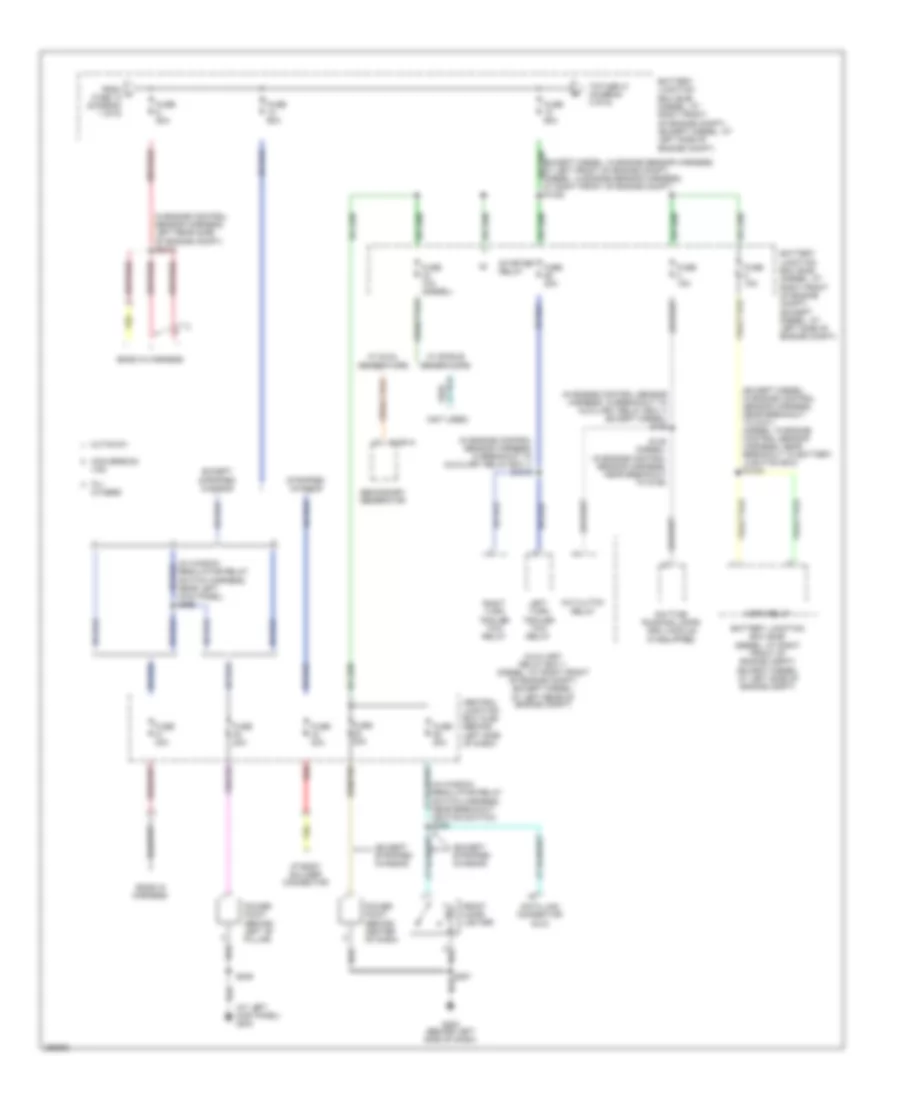
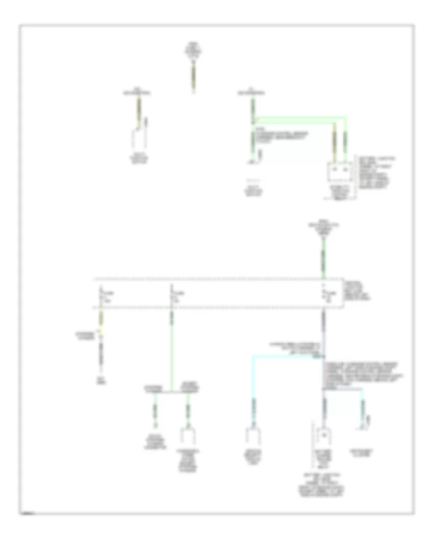
Manual A/C Wiring Diagram, with Stripped Chassis for Ford E450 Super Duty 2007

List of elements for Manual A/C Wiring Diagram, with Stripped Chassis for Ford E450 Super Duty 2007:
- (customer access)
- A/c demand signal
- A/c on input signal
- Battery junction box (bjb) (left side of engine compt)
- Blower motor relay
- C1026
- C175e
- Central junction box (cjb) (behind left side of dash)
- Fuse 15a
- Fuse 50a
- G114 (left rear of engine compt)
- Hot at all times
- Hot in run
- Powertrain control module (pcm) (left rear of engine compt)
- S195
- To body builder connector
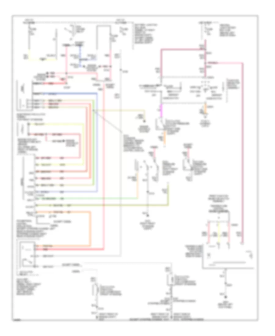
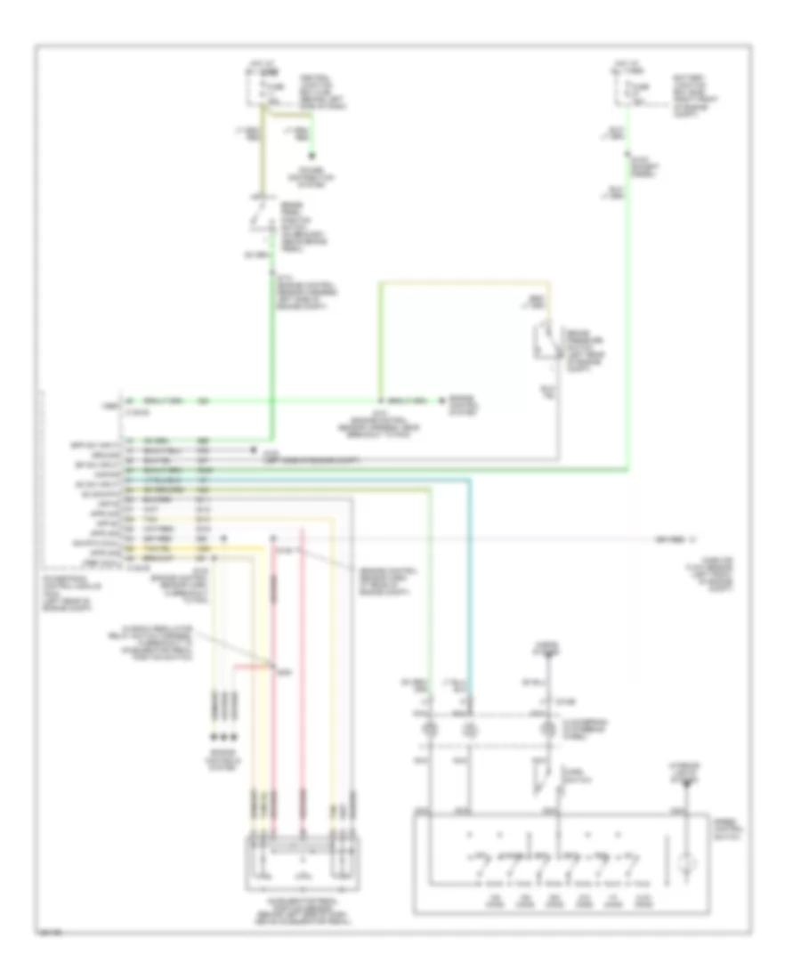
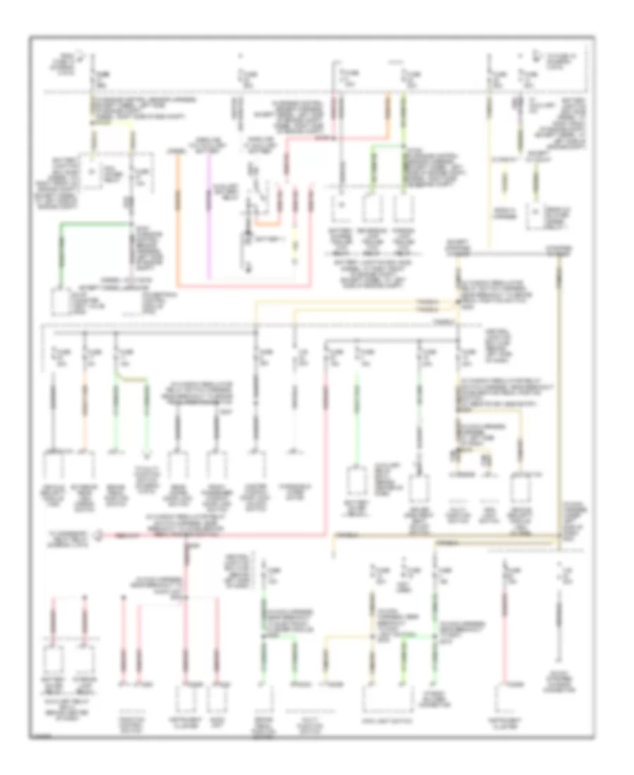
Manual A/C Wiring Diagram, without Stripped Chassis (1 of 2) for Ford E450 Super Duty 2007
List of elements for Manual A/C Wiring Diagram, without Stripped Chassis (1 of 2) for Ford E450 Super Duty 2007:
- (except stripped chassis)
- (right front of engine compt) g107
- (right side of engine compt) g115
- (stripped chassis)
- A/c clutch cycling pressure switch (right side of engine compt)
- A/c clutch field coil (on lower right front of engine)
- A/c clutch relay
- A/c high pressure switch (right side of engine compt)
- A/c sw
- Auxiliary relay box 1 (diesel: right front of engine compt) (except diesel: left rear of engine compt)
- Battery junction box (bjb) (diesel: at right front of engine compt) (except diesel: at left side of engine compt)
- C1381b
- C175e
- C294a
- C294d
- Central junction box box (cjb) (behind left side of dash)
- Clutch ctrl c1381e
- Defrost
- Diesel
- Dual pressure switch (right front of engine compt)
- Electronic fan clutch (diesel) (top front of engine)
- Engine controls system
- Engine coolant temperature (ect) sensor (on upper left front of engine) (diesel)
- Except diesel
- Floor
- Front function selector switch assembly
- Fss
- Function selector switch assembly
- Fuse 15a
- Fuse 20a
- Fuse 30a
- G107 (right front of engine compt)
- G204 (behind left kick panel)
- Gnd
- Hot at all times
- Hot in run
- Input
- Max a/c
- Mix
- Mode switch
- Nca
- Norm a/c
- Off
- Pcm power relay
- Powertrain control module (pcm) (except stripped chassis: left rear of engine compt) (stripped chassis: right rear of engine compt)
- Red
- Relay ctrl
- S101 (in engine control sensor harness, near breakout to to powertrain control module)
- S1033
- S1057
- S142
- S143
- S143 (except stripped chassis)
- S186
- S197 (stripped chassis)
- S203
- S223
- S242
- Temperature blend door actuator (behind right side of dash)
- Temperature control potentiometer
- To s111 (diagram 2 of 2)
- Vent
- Vent norm a/c
- Vpwr
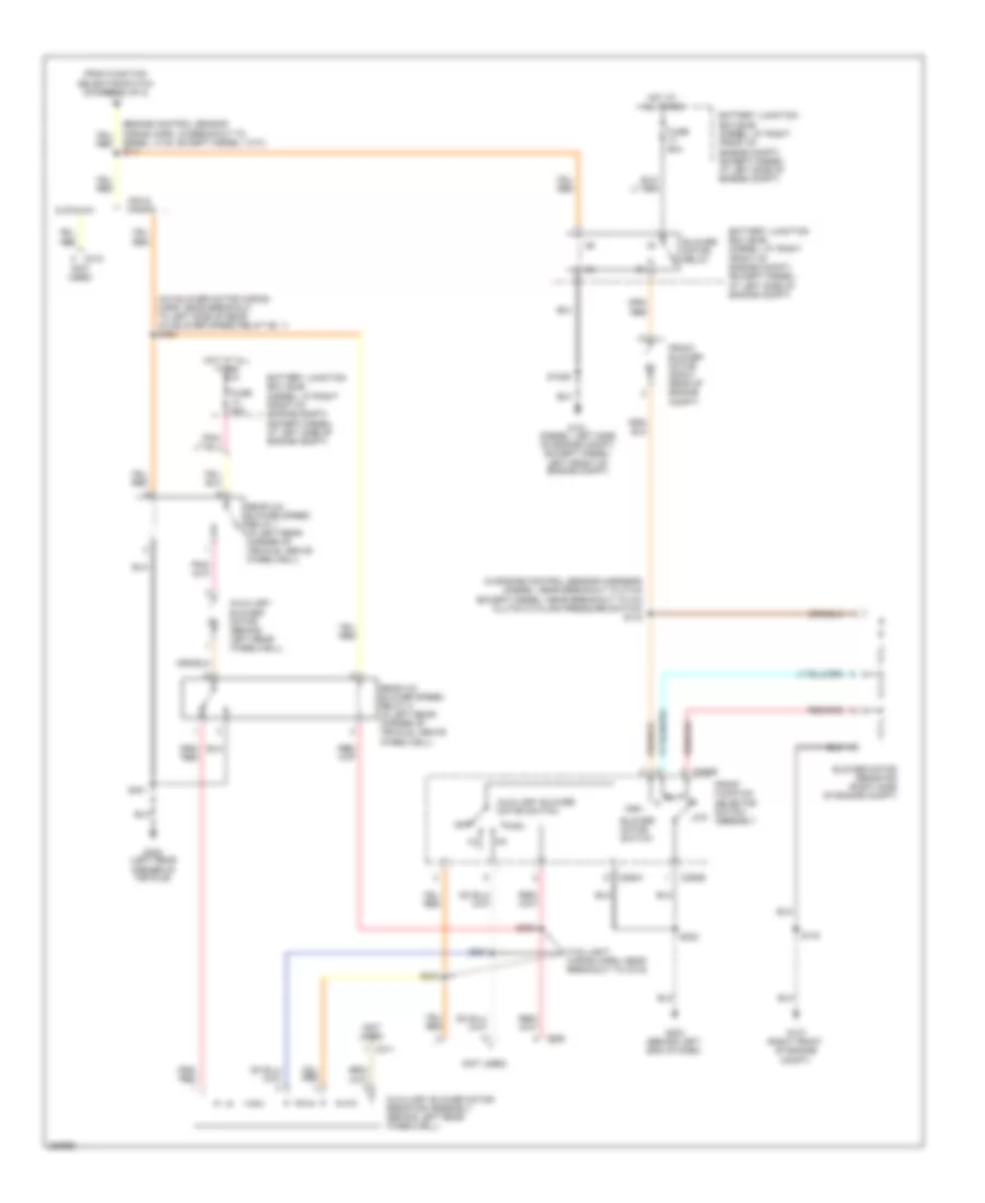
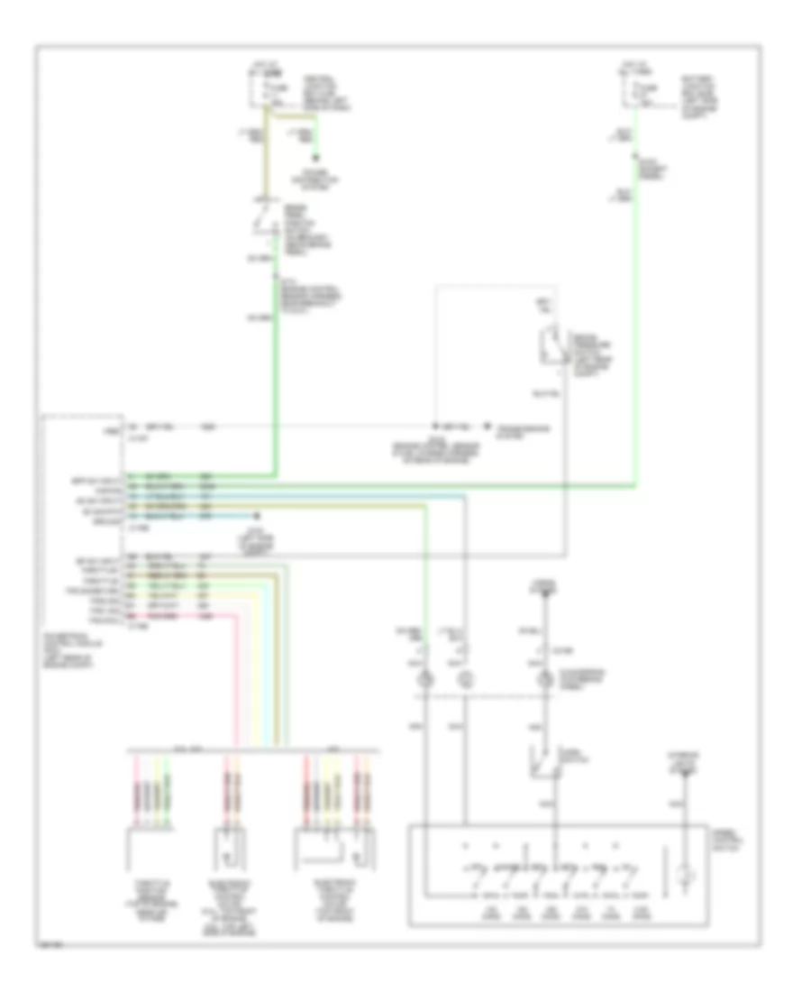
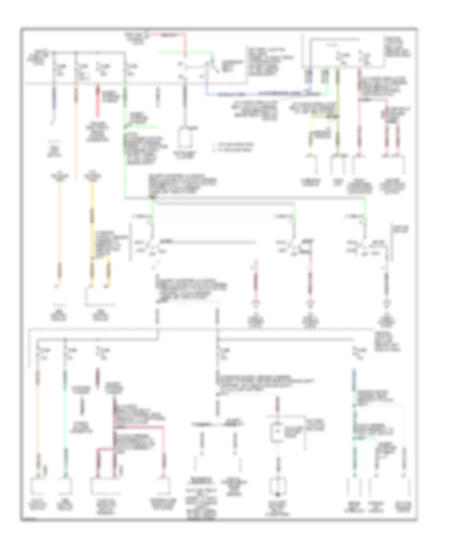
Manual A/C Wiring Diagram, without Stripped Chassis (2 of 2) for Ford E450 Super Duty 2007
List of elements for Manual A/C Wiring Diagram, without Stripped Chassis (2 of 2) for Ford E450 Super Duty 2007:
- (a/c blower motor wiring harn, near breakout to left side of rear a/c blower speed relay no. 1) s400
- (in engine control sensor harness) (diesel: near breakout to c144) (except diesel: near breakout to a/c clutch cycling pressure switch) s144
- (not used)
- (taillight wiring harn, near breakout to c315)
- Auxiliary blower motor (behind left rear wheelwell)
- Auxiliary blower motor resistor assembly (behind left rear wheelwell)
- Auxiliary blower motor switch
- Battery junction box (bjb) (diesel: at right front of engine compt) (except diesel: at left side of engine compt)
- Blower motor relay
- Blower motor resistor (right side of engine compt)
- Blower motor switch
- C294b
- C294c
- C311
- C312
- C925
- Cutaway
- Diesel: c140, except diesel: c101) s111
- From function selector switch (diagram 1 of 2)
- Front blower motor (right rear of engine compt)
- Front function selector switch assembly
- Fuse 50a
- G101 (diesel: left side of engine compt) (except diesel: left front of engine compt)
- G107 (right front of engine compt)
- G203 (behind left end of dash)
- G400 (left rear corner of vehicle)
- High
- Hot at all times
- Low
- Off
- Rear a/c blower speed relay 1 (in left rear corner of vehicle, above wheelwell)
- Rear a/c blower speed relay 2 (in left rear corner of vehicle, above wheelwell)
- S1029
- S143
- S202
- S303
- S304
- S305
- S401
- Van & wagon
ANTI-LOCK BRAKES
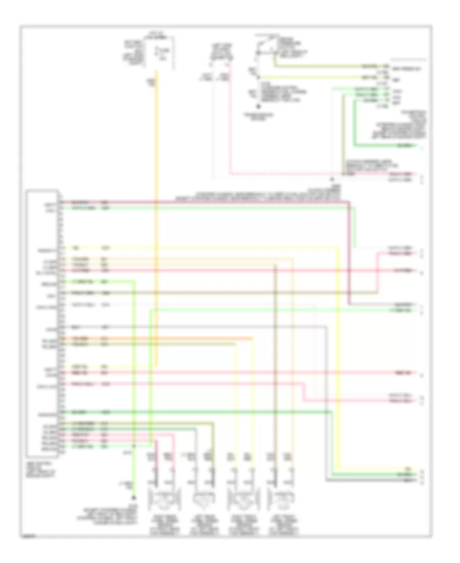
Anti-lock Brakes Wiring Diagram, with Stability Assist (1 of 2) for Ford E450 Super Duty 2007
List of elements for Anti-lock Brakes Wiring Diagram, with Stability Assist (1 of 2) for Ford E450 Super Duty 2007:
- (in main harness, near breakout to inertia fuel shutoff (ifs) switch s228
- (left side of dash) data link connector
- Abs control module (left front of engine compt)
- Angle a/1
- Angle b/2
- Battery junction box (left side of engine compt)
- Bpp
- Brake pressure switch (left rear of eng compt)
- Brk press sw
- C175b
- C175e
- C175t
- Can +
- Can -
- Can 2 high
- Can 2 low
- Can+
- Can-
- Fuse 40a
- G105 (except stripped chassis: left front of eng compt, stripped chassis: left front corner of eng compt)
- Ground
- Hot at all times
- Left front wheel speed sensor (at left front hub assembly)
- Left rear wheel speed sensor (at left rear hub assembly)
- Lf_gnd
- Lf_sen
- Lr_gnd
- Lr_sen
- Nca
- Powertrain control module (stripped chassis: right rear of engine compt, except stripped chassis: left rear of engine compt)
- Red/ pnk
- Red/pnk
- Ref
- Rf_gnd
- Rf_sen
- Right front wheel speed sensor (at right front hub assembly)
- Right rear wheel speed sensor (at right rear hub assembly)
- Rly cntrl
- Rr_gnd
- Rr_sen
- S139 (in engine control sensor & fuel charge harness, near breakout for c192)
- S147
- S269 (in main harness stripped chassis: near breakout to inertia fuel shutoff (ifs) switch except stripped chassis: near breakout to brake pedal position (bpp) switch)
- Transmissions system
- Vbatt
- Vpwr
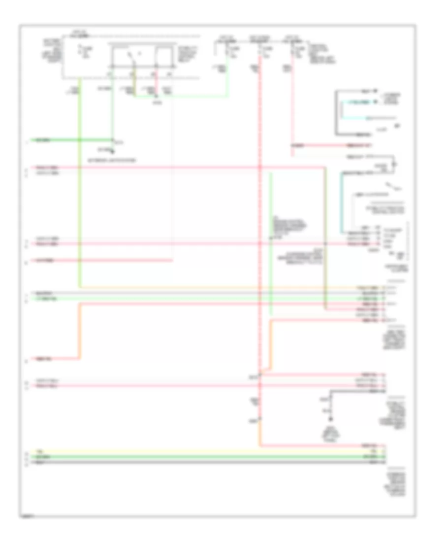
Anti-lock Brakes Wiring Diagram, with Stability Assist (2 of 2) for Ford E450 Super Duty 2007
List of elements for Anti-lock Brakes Wiring Diagram, with Stability Assist (2 of 2) for Ford E450 Super Duty 2007:
- (in engine control sensor harness, near breakout to c110) s146
- Abs ind
- Abs test connector (left front corner of eng compt)
- Battery junction box (left side of engine compt)
- C220a
- Can+
- Can-
- Central junction box (behind left side of dash)
- Exterior lights system
- Fuse 10a
- Fuse 15a
- Fuse 40a
- G204 (behind left kick panel)
- Hot at all times
- Hot in run or start
- Illum
- Instrument cluster
- Interior lights system
- On/off ind
- S105
- S148 (in engine control sensor harness, near breakout to c110)
- S174
- S205
- S216
- S235
- S260
- Stability control sensor cluster (under front passenger's seat)
- Stability/ traction control relay
- Stability/traction control switch
- Steering position sensor (bottom of steering column)
- Tc ind
- Tc on/off
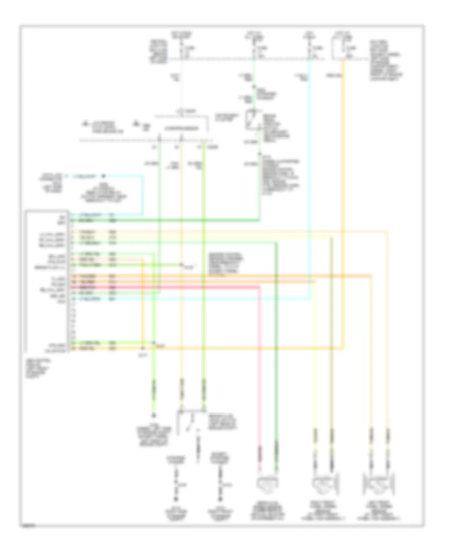
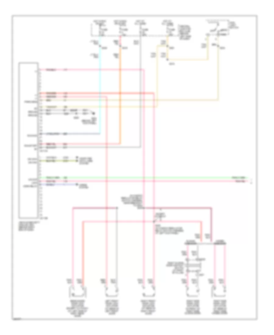
Anti-lock Brakes Wiring Diagram, without Stability Assist for Ford E450 Super Duty 2007
List of elements for Anti-lock Brakes Wiring Diagram, without Stability Assist for Ford E450 Super Duty 2007:
- (engine control sensor harness, near breakout diesel: to c110 except diesel: to c219)
- Abs control module (left front of engine compt)
- Abs ind
- Abs led
- Battery junction box (bjb) (except diesel: left side of engine compartment) (diesel: right front of engine compartment)
- Bpp
- Brake fluid level switch (left rear of engine compt)
- Brake fluid lvl
- Brake pedal position switch (on bracket, above brake pedal)
- C220a
- C220b
- Central junction box (cjb) (behind left side of dash)
- Data link connector (dlc) (left side of dash)
- Ecu_gnd
- Except stripped chassis
- Fl_gnd
- Fr_gnd
- Fuse 15a
- Fuse 5a
- Fuse 60a
- G105 (diesel: left side of engine compt) (except diesel: left front of engine compt)
- G107 (right front of engine compt)
- G115 (right side of engine compt)
- Hot at all times
- Hot in run
- Hot in run or start
- Instrument cluster
- Iso
- Left front wheel speed sensor (at left front wheel hub assembly)
- Lf_whl_spd+
- Low brake fluid level/ park brake ind
- Microprocessor
- Mtr_gnd
- Mtr_pwr
- Nca
- Rear axle speed sensor (under rear of vehicle, mounted on differential)
- Red/pnk
- Rf_whl_spd+
- Right front wheel speed sensor (at right front wheel hub assembly)
- Rr_whl_spd+
- Rr_whl_spd-
- Run
- S143
- S147
- S149
- S174 (diesel & stripped chassis: engine control sensor harn, in breakout to c219, gas: engine ctrl sensor harn, in breakout to c110)
- S177
- S197
- S226 (in window regulator relay switch harness, near breakout to c237
- S282 (stripped chassis)
- Stripped chassis
- Valve pwr
ANTI-THEFT
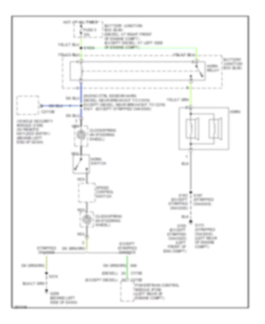
Anti-theft Wiring Diagram (1 of 2) for Ford E450 Super Duty 2007
List of elements for Anti-theft Wiring Diagram (1 of 2) for Ford E450 Super Duty 2007:
- (in window regulator relay switch harness, near breakout to g204) s239
- +/-
- C2113a
- C2113b
- C3235
- C807
- Central junction box (cjb) (behind left side of dash)
- Computer data lines system
- Except cutaway
- Fuse 10a
- Fuse 20a
- Fuse 5a
- G204 (behind left kick panel)
- Ground
- Head
- Hinged side door
- Horn relay
- Horns system
- Hot at all times
- Hot in run or acc
- Hot in run or start
- Left front door lock actuator (at rear of left front door)
- Lock
- Main light switch
- Ms can+
- Ms can-
- Off
- Park
- Park/head
- Rear doors door lock actuator (except cutaway) (at left side of right rear door)
- Right front door lock actuator (at rear of right front door)
- Right side door lock actuator (at rear of right side hinged door)
- Right side door lock actuator (in front of right side sliding door)
- Right sliding door contact switch (at right "b" pillar)
- Run/acc
- Run/start
- S216
- S218
- S233
- S234
- S238 (in window regulator relay switch harness, at left kick panel)
- S246
- S250
- S261
- Sliding side door
- Unlock
- Vehicle security module (vsm) (behind right end of dash)
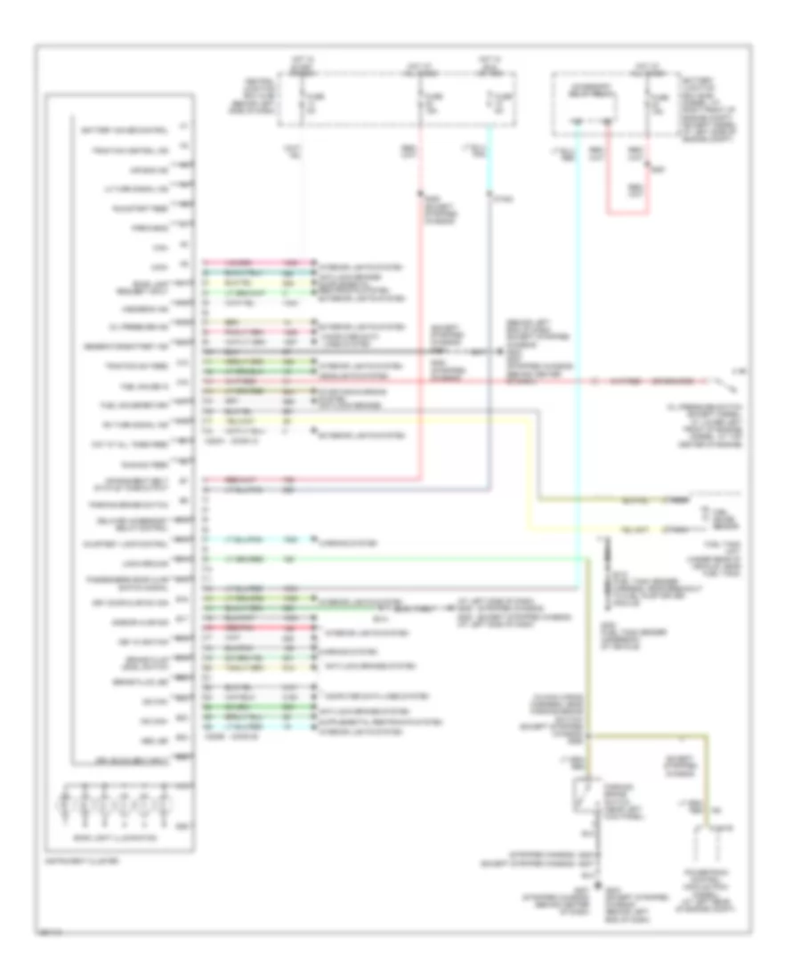
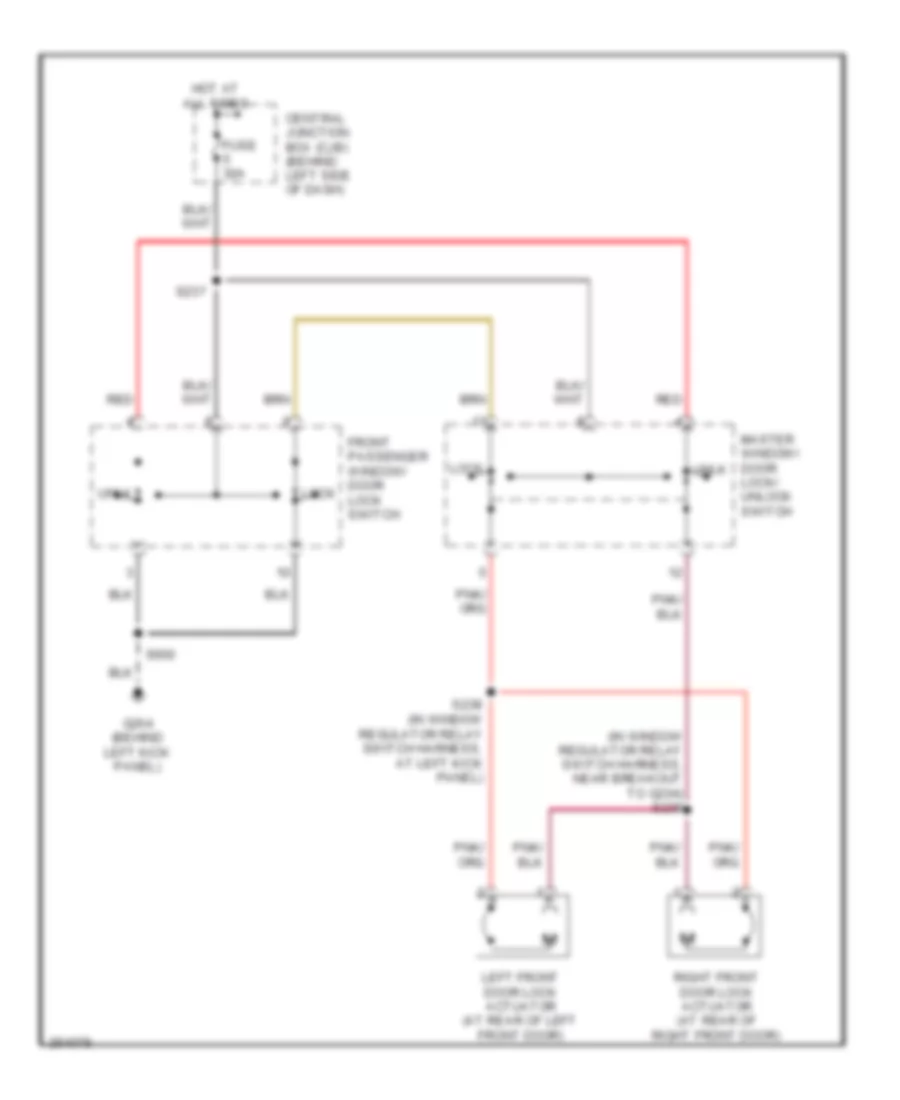
Anti-theft Wiring Diagram (2 of 2) for Ford E450 Super Duty 2007
List of elements for Anti-theft Wiring Diagram (2 of 2) for Ford E450 Super Duty 2007:
- (except cutaway)
- C220a
- C220b
- Central junction box (cjb) (behind left side of dash)
- Computer data lines system
- Corner of vehicle)
- Doors ajar
- Driver door ajar
- Front passenger window/door lock switch
- Fuse 15a
- Fuse 5a
- G202 (behind left side of dash)
- G203 (behind left end of dash)
- G204 (behind left kick panel)
- G400 (left rear
- G400 (left rear corner of vehicle)
- Hot at all times
- Hot in run or start
- Instrument cluster
- Left front door ajar switch (at left kick panel)
- Lock
- Logic ground
- Master window/ door lock/unlock switch
- Ms can+
- Ms can-
- Nca
- Pwr ground
- Rear doors door ajar switch (except cutaway)
- Rear doors door lock switch
- Red/ pnk
- Red/pnk
- Right front door ajar switch (at right kick panel)
- Right side door ajar switch (in front of right side door)
- Right sliding door ajar switch (at right "b" pillar)
- Run/start
- S205
- S207
- S214
- S223
- S233
- S251 (in window regulator relay switch harness, near breakout to g204)
- S252 (in window regulator relay switch harness, near breakout to g204)
- S253 (window regulator relay switch harness, near breakout to vehicle security module)
- S402
- S414
- S500
- S600
- Sliding door ajar
- Unlock
- W/ hinged cargo door
- W/ sliding cargo door
COMPUTER DATA LINES
Computer Data Lines Wiring Diagram, with Stripped Chassis for Ford E450 Super Duty 2007
List of elements for Computer Data Lines Wiring Diagram, with Stripped Chassis for Ford E450 Super Duty 2007:
- (in main harn, near breakout to inertia fuel shutoff (ifs) switch) s228
- Abs control module (left front of engine compt)
- C135
- C175b
- C220a
- C220b
- Can +
- Can -
- Central junction box (cjb) (behind left side of dash)
- Data link connector (dlc) (behind left side of dash)
- Feps
- Fuse 20a
- G104 (right side of engine compt)
- G208 (behind left side of dash)
- Hot at all times
- Instrument cluster
- Iso
- Ms can +
- Ms can -
- Powertrain control module (right rear of engine compt)
- S172
- S269 (in main harn, near breakout to inertia fuel shutoff (ifs) switch)
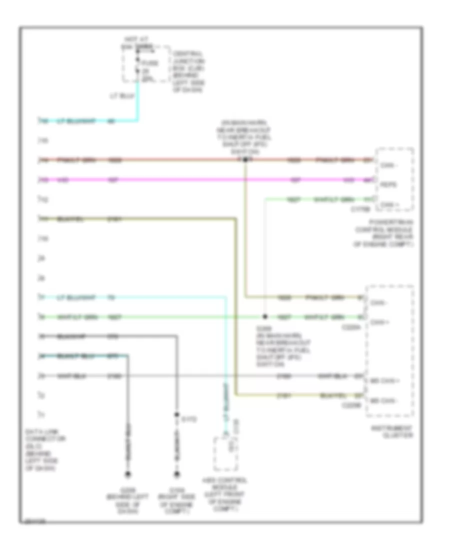
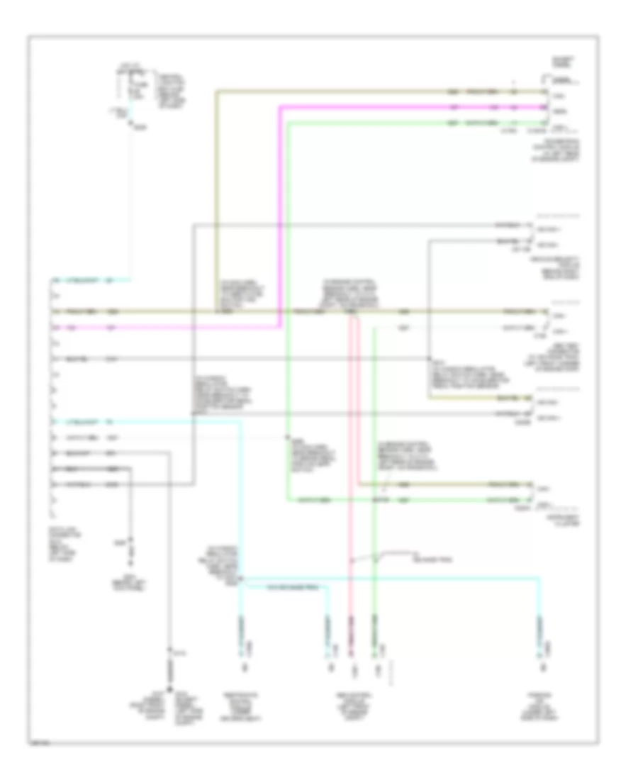
Computer Data Lines Wiring Diagram, without Stripped Chassis for Ford E450 Super Duty 2007
List of elements for Computer Data Lines Wiring Diagram, without Stripped Chassis for Ford E450 Super Duty 2007:
- (in engine control sensor harn, near breakout to c110, left rear of engine compt, on frame rail)
- (in engine control sensor harn, near breakout to c110, left rear of engine compt, on frame rail) s148
- (in main harn, near breakout to inertia fuel shutoff (ifs) switch) s228
- (in window regulator relay switch harn, near breakout to accelerator pedal position sensor. s211
- (in window regulator relay switch harn, near breakout to c237) s226
- Abs control module (left front of engine compt)
- Abs test connector (w/ advance trac) (left front corner of engine comp)
- C126
- C135
- C1381b
- C155
- C175a
- C2033
- C2113b
- C220a
- C220b
- C310a
- Can +
- Can -
- Central junction box (cjb) (behind left side of dash)
- Data link connector (dlc) (below left side of dash)
- Diesel
- Except diesel
- Feps
- Fuse 20a
- G104 (except diesel) (left side of engine compt)
- G107 (diesel) (right front of engine compt)
- G204 (behind left kick panel)
- Hot at all times
- Instrument cluster
- Iso
- Ms can +
- Ms can -
- Parking aid module (under left side of dash)
- Powertrain control module (in left rear of engine compt)
- Restraints control module (under driver's seat)
- S146
- S172
- S210 (in window regulator relay switch harn, near breakout to accelerator pedal position sensor)
- S229
- S250
- S269 (in main harn, near breakout to brake pedal position (bpp) switch)
- Vehicle security module (behind right eng of dash)
- W/ advance trac
- W/o advance trac
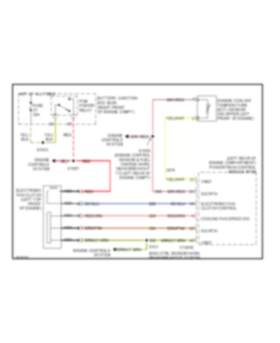
COOLING FAN
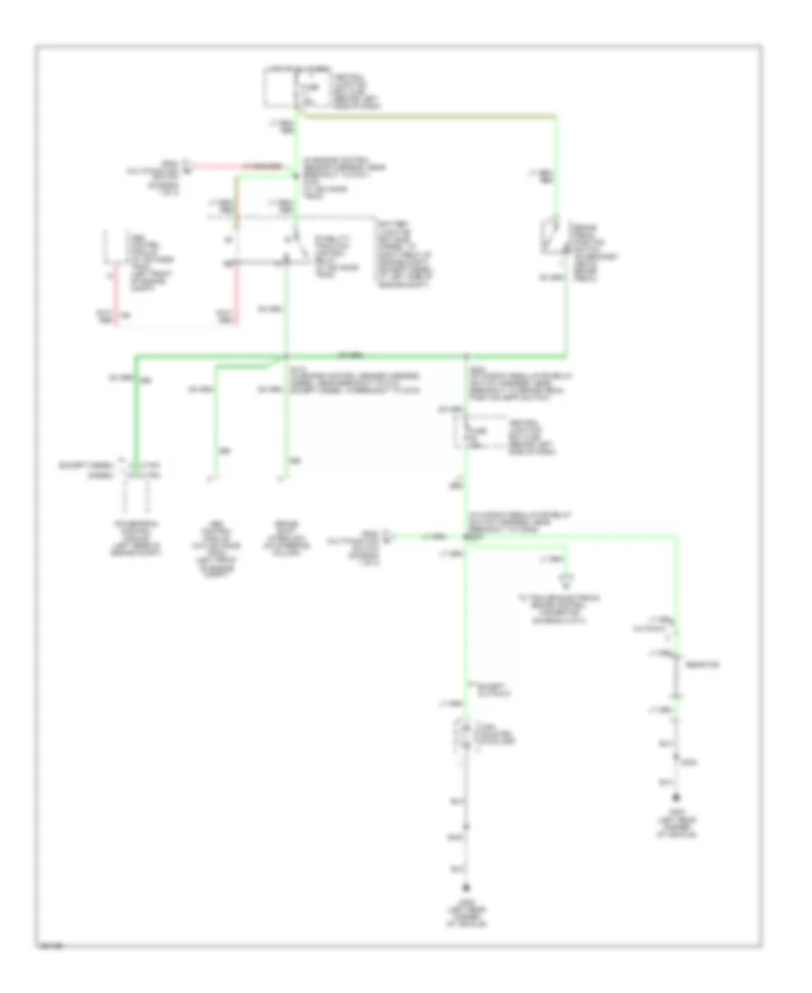
Cooling Fan Wiring Diagram for Ford E450 Super Duty 2007
List of elements for Cooling Fan Wiring Diagram for Ford E450 Super Duty 2007:
- (eng ctrl sensor harn, near breakout to pcm)
- (left rear of engine compartment) powertrain control module (pcm)
- Battery junction box (bjb) (right front of engine compt)
- C1381e
- Cooling fan speed sig
- Electronic fan clutch (left top front of engine)
- Electronic fan clutch control
- Engine controls system
- Engine coolant temperature (ect) sensor (on upper left front of engine)
- Fuse 30a
- Hot at all times
- Nca
- Pcm power relay
- Red
- S101
- S1033
- S1057
- S1059 (engine control sensor & fuel charge harn, near breakout to left rear of engine compt)
- Sig rtn
- Vref
CRUISE CONTROL
5.4L
5.4L, Cruise Control Wiring Diagram for Ford E450 Super Duty 2007
List of elements for 5.4L, Cruise Control Wiring Diagram for Ford E450 Super Duty 2007:
- 1k ohms
- 2.2k ohms
- 4.6l
- 5.4l, 6.8l
- Battery junction box (bjb) (left side of engine compt)
- Bp sw input
- Bpp sw input
- Brake pedal position switch (on bracket, above brake pedal)
- Brake pressure switch (left rear of engine compt)
- C175b
- C175e
- C175t
- C218b
- Cancel
- Central junction box (cjb) (behind left side of dash)
- Clockspring (in steering wheel)
- Electronic throttle control motor (5.4l: top front of engine, 6.8l: top left side of engine)
- Electronic throttle control motor (top front of engine)
- Fuse 10a
- Fuse 15a
- G100 (left side of engine compt)
- Ground
- Horn switch
- Horns system
- Hot at all times
- Hot at all times
- Interior lights system
- Kapwr
- Nca
- Off
- Ohms
- Power distribution system
- Powertrain control module (pcm) (left rear of engine compt)
- Rsm
- S1021 (except diesel)
- S139 (engine control sensor & fuel charge harness, on rear of engine)
- S174 (engine control sensor harness, near breakout to g101)
- Sc sig rtn
- Sc sw input
- Set+
- Set-
- Speed control switch
- Throttle position sensor (top of engine, near air intake)
- Throttle+
- Throttle-
- Tps pow
- Tps sig return
- Tps1 sig
- Tps2 sig
- Transmissions system
- Vref
6.0L DIESEL
6.0L Diesel, Cruise Control Wiring Diagram, Diesel for Ford E450 Super Duty 2007
List of elements for 6.0L Diesel, Cruise Control Wiring Diagram, Diesel for Ford E450 Super Duty 2007:
- (engine control sensor harn, at rear of engine compt)
- (window regulator relay switch harness, in breakout to accelerator pedal position switch)
- 1k ohms
- 2.2k ohms
- Accelerator pedal position sensor (behind left side of dash, above accelerator pedal)
- App b+
- App b-
- App2 sig
- App3 sig
- Battery junction box (bjb) (right front of engine compt)
- Bp sw input
- Bpp sw input
- Brake pedal position switch (on bracket, above brake pedal)
- Brake pressure switch (left rear of engine compt)
- C1381b
- C1381e
- C218b
- Cancel
- Central junction box (cjb) (behind left side of dash)
- Clockspring (in steering wheel)
- Engine control system
- Engine controls system
- Fuse 10a
- Fuse 15a
- G100 (left side of engine compt)
- Ground
- Horn switch
- Horns system
- Hot at all times
- Hot at all times
- Interior lights system
- Kapwr
- Mass air flow sensor (left front of engine compt)
- Nca
- Off
- Ohms
- Power distribution system
- Powertrain control module (pcm) (left rear of engine compt)
- Rsm
- S101 (engine control sensor harness, near breakout to pcm)
- S1021 (except diesel)
- S136
- S138 (engine control sensor harn, in breakout to pcm)
- S174 (engine control sensor harness, left side of engine compt)
- S200
- Sc sig rtn
- Sc sw input
- Set+
- Set-
- Sig rtn cowl
- Speed control switch
- Tan
- Vref
- Vref cowl
6.8L
6.8L, Cruise Control Wiring Diagram for Ford E450 Super Duty 2007
List of elements for 6.8L, Cruise Control Wiring Diagram for Ford E450 Super Duty 2007:
- 1k ohms
- 2.2k ohms
- 4.6l
- 5.4l, 6.8l
- Battery junction box (bjb) (left side of engine compt)
- Bp sw input
- Bpp sw input
- Brake pedal position switch (on bracket, above brake pedal)
- Brake pressure switch (left rear of engine compt)
- C175b
- C175e
- C175t
- C218b
- Cancel
- Central junction box (cjb) (behind left side of dash)
- Clockspring (in steering wheel)
- Electronic throttle control motor (5.4l: top front of engine, 6.8l: top left side of engine)
- Electronic throttle control motor (top front of engine)
- Fuse 10a
- Fuse 15a
- G100 (left side of engine compt)
- Ground
- Horn switch
- Horns system
- Hot at all times
- Hot at all times
- Interior lights system
- Kapwr
- Nca
- Off
- Ohms
- Power distribution system
- Powertrain control module (pcm) (left rear of engine compt)
- Rsm
- S1021 (except diesel)
- S139 (engine control sensor & fuel charge harness, on rear of engine)
- S174 (engine control sensor harness, near breakout to g101)
- Sc sig rtn
- Sc sw input
- Set+
- Set-
- Speed control switch
- Throttle position sensor (top of engine, near air intake)
- Throttle+
- Throttle-
- Tps pow
- Tps sig return
- Tps1 sig
- Tps2 sig
- Transmissions system
- Vref
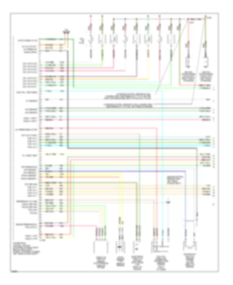
ENGINE PERFORMANCE
5.4L
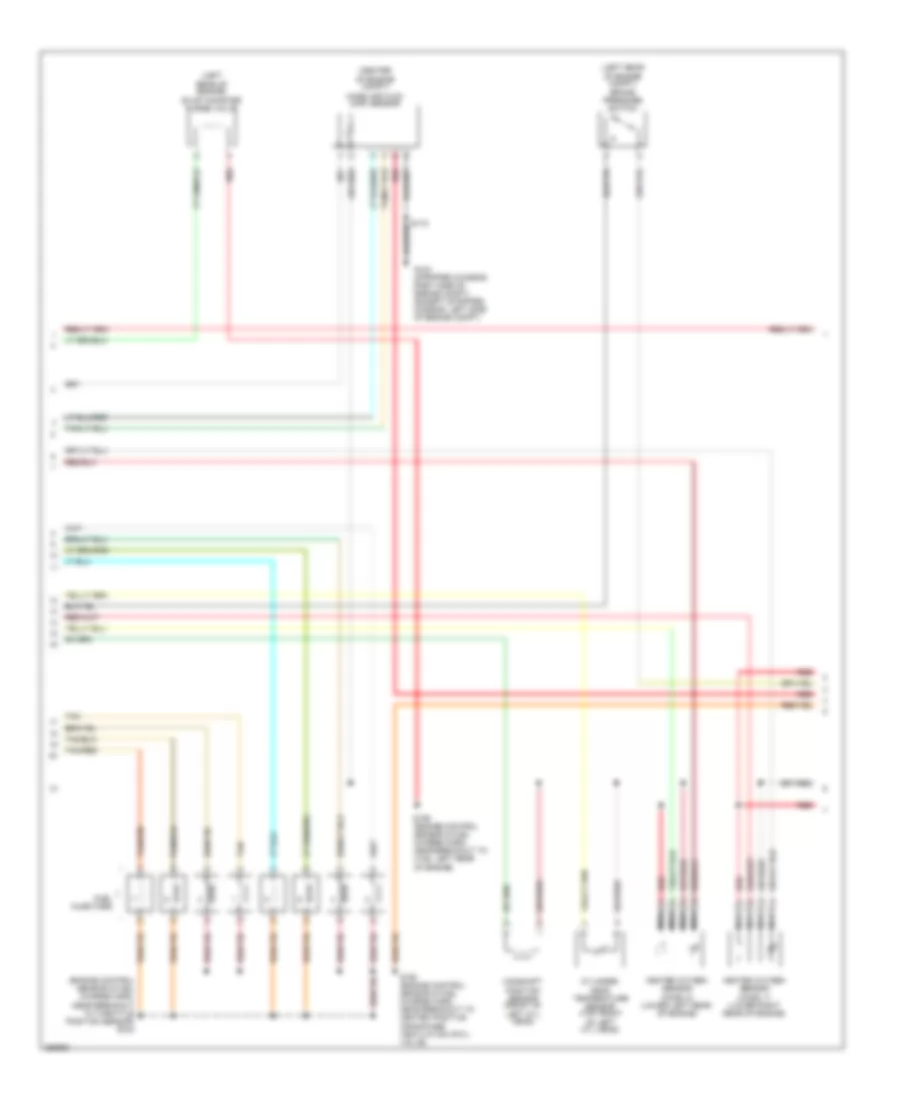
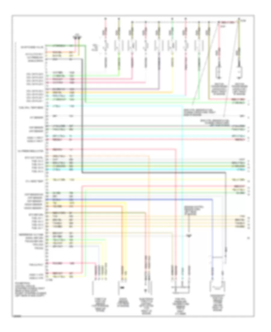
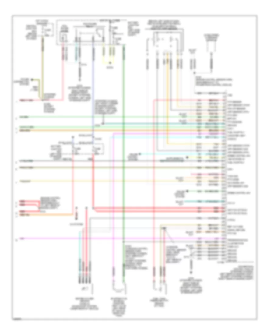
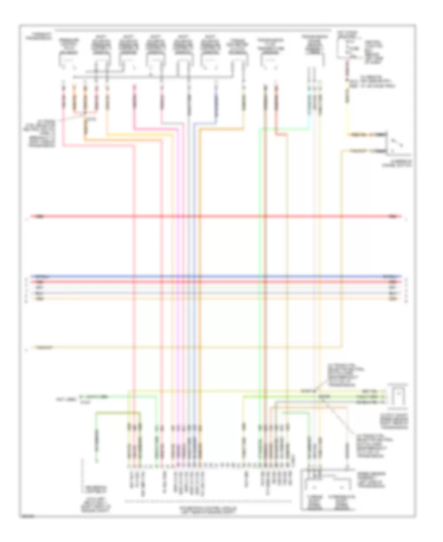
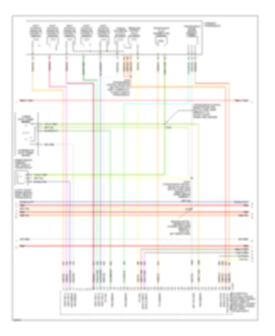
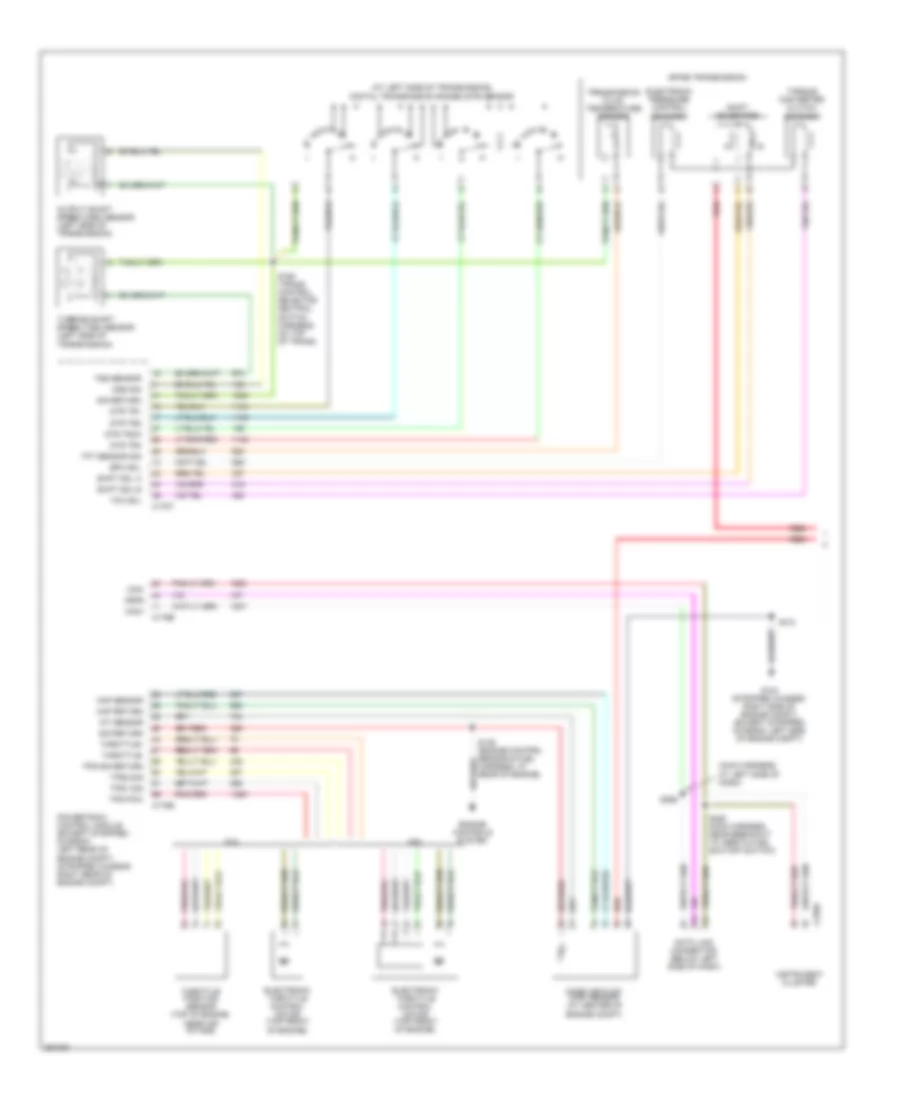
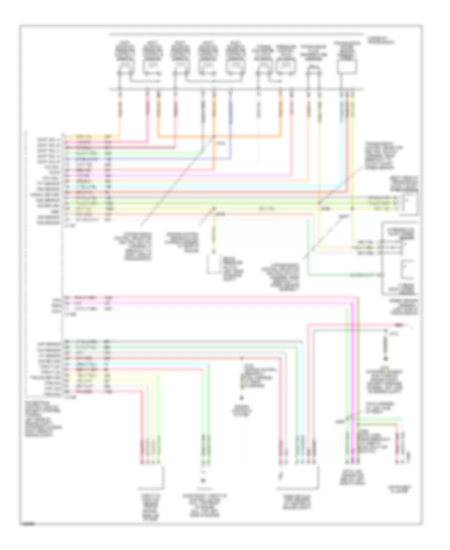
5.4L, Engine Performance Wiring Diagram, with Torqshift (1 of 5) for Ford E450 Super Duty 2007
List of elements for 5.4L, Engine Performance Wiring Diagram, with Torqshift (1 of 5) for Ford E450 Super Duty 2007:
- (engine control sensor harn, left rear of eng compt)
- (in engine control sensor & fuel charge harn, near breakout to c192, left rear of engine)
- (in engine control sensor & fuel charge harn, near breakout to to heated positive crankcase ventilation (pcv) valve)
- A/c clutch rly
- A/c press sw
- A/c system
- Brake pressure sw
- C175e
- Ckp sensor +
- Ckp sensor -
- Cmp sensor sig
- Coil on plug
- Coil on plug 1
- Coil on plug 2
- Coil on plug 3
- Coil on plug 4
- Coil on plug 5
- Coil on plug 6
- Coil on plug 7
- Coil on plug 8
- Crankshaft position sensor (lower center front of engine)
- Cyl head temp
- Electronic throttle control (etc) motor (top front of engine)
- Etc return
- Etc wot cntrl
- Evap purge valve
- Fuel inj 1
- Fuel inj 2
- Fuel inj 3
- Fuel inj 4
- Fuel inj 5
- Fuel inj 6
- Fuel inj 7
- Fuel inj 8
- Fuel rail pressure/ temperature sensor (top of right cylinder
- Fuel rail temp sens
- Ho2s 11 htr
- Ho2s 11 input
- Ho2s 21 htr
- Ho2s 21 input
- Iat sensor
- Ignition transformer capacitor 1 (left front of engine)
- Ignition transformer capacitor 2 (right front of engine)
- Inj press regulator
- Knock sensor (top rear of engine)
- Knock sensor +
- Knock sensor -
- Maf sensor
- Nca
- Powertrain control module (stripped chassis: right rear of eng compt, except stripped chassis: left rear of eng compt)
- Red/pnk
- Reference voltage
- S136
- S156
- S161
- Shield drain
- Signal return
- Tan
- Tan/red
- Throttle position sensor (top of engine, near air intake)
- Tps 2 sig
- Tps output
- Tps sig
- Tps sig return
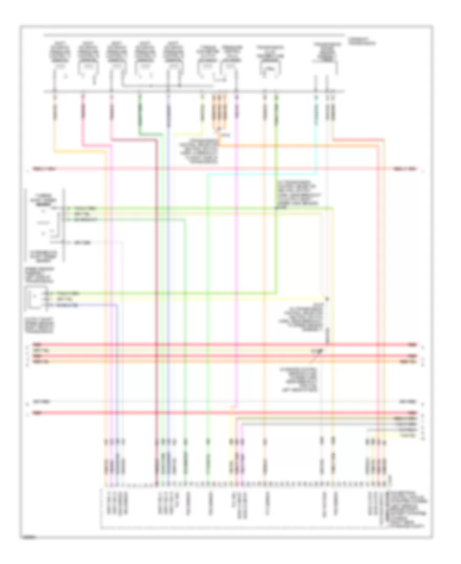
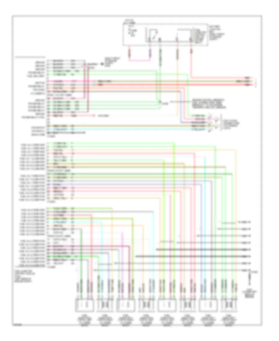
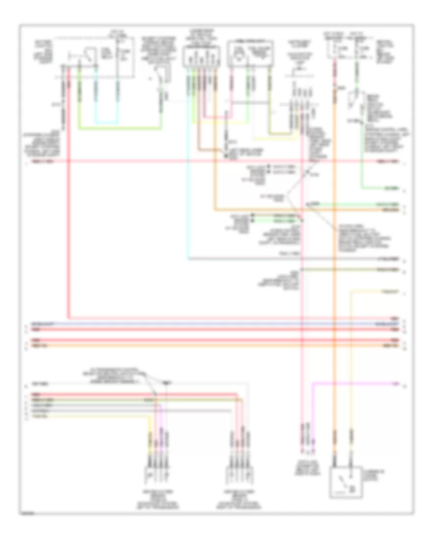
5.4L, Engine Performance Wiring Diagram, with Torqshift (2 of 5) for Ford E450 Super Duty 2007
List of elements for 5.4L, Engine Performance Wiring Diagram, with Torqshift (2 of 5) for Ford E450 Super Duty 2007:
- (center
- (engine control sensor & fuel charge harn, near breakout to throttle position sensor) s155
- (left rear of engine compt) brake pressure switch
- (left rear of engine) evap canister purge valve
- Camshaft position sensor (front of left cyl head)
- Cylinder- head temperature sensor (top front of left cyl head)
- Fuel injectors
- G104 (stripped chassis: right side of engine compt) (except stripped chassis: left side of engine compt)
- Heated oxygen sensor (ho2s) 11 (lower right rear of engine)
- Heated oxygen sensor (ho2s) 21 (lower left rear of engine)
- Mass air flow (maf) sensor
- Nca
- Of engine compt)
- Red
- S159 (engine control sensor & fuel charge harn, near breakout to c192, left rear of engine)
- S160 (engine control sensor & fuel charge harn, near breakout to heated positive crankcase ventilation (pcv) valve)
- Tan
- Tan/red
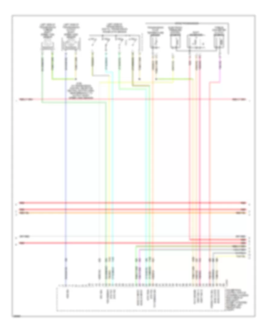
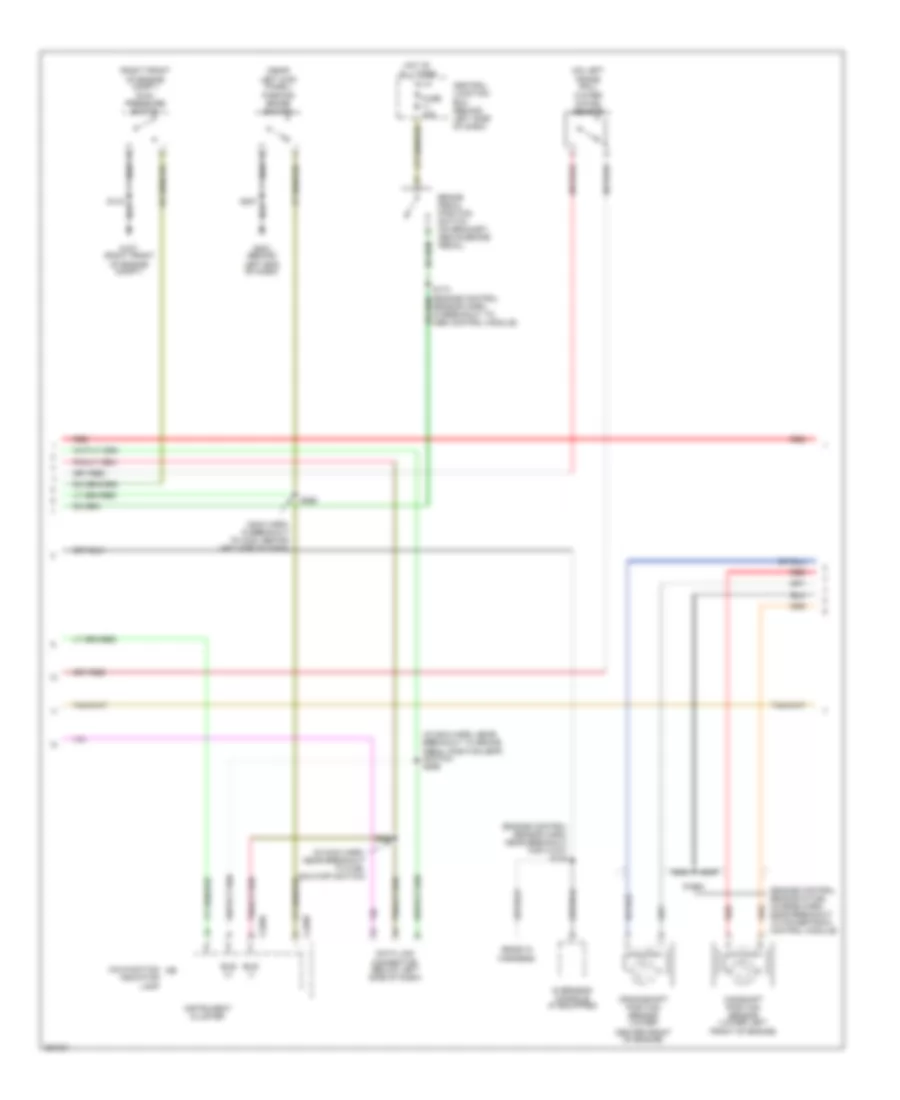
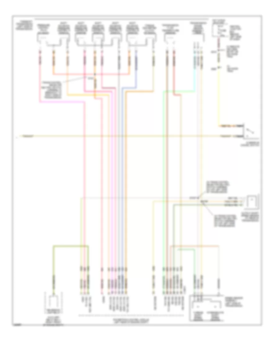
5.4L, Engine Performance Wiring Diagram, with Torqshift (3 of 5) for Ford E450 Super Duty 2007
List of elements for 5.4L, Engine Performance Wiring Diagram, with Torqshift (3 of 5) for Ford E450 Super Duty 2007:
- (in engine control sensor & fuel charge harn, near breakout for c192, left rear of eng)
- (in transmission control selector neutral switch harn, near breakout to output shaft speed (oss) sensor) s198
- (transmission control selector neutral switch harn, in breakout to right side of transmission)
- C175t
- Ho2s 12 htr
- Ho2s 12 input
- Ho2s 22 htr
- Ho2s 22 input
- Intermediate shaft speed sensor
- Iss sensor
- Oss sensor
- Output shaft speed sensor (right rear of transmission)
- Powertrain control module (stripped chassis: (left rear of engine compt) (except stripped chassis: (right rear of engine compt)
- Pressure control (pc-a) solenoid
- Red
- Ref voltage
- S1037 (in transmission control selector neutral switch harn, near breakout to speed sensor assembly)
- S123
- S139
- Shift sol a
- Shift sol b
- Shift sol c
- Shift sol d
- Shift sol e
- Shift solenoid pressure control a (sspc-a)
- Shift solenoid pressure control b (sspc-b)
- Shift solenoid pressure control c (sspc-c)
- Shift solenoid pressure control d (sspc-d)
- Shift solenoid pressure control e (sspc-e)
- Signal return
- Speed sensor assembly (left side of transmission)
- Tcc sol
- Tft sensor
- Torqshift transmission
- Torque converter clutch solenoid
- Transmission fluid temperature sensor
- Transmission range sensor assembly (tr-p)
- Trs sensor
- Tss sensor
- Turbine shaft speed sensor
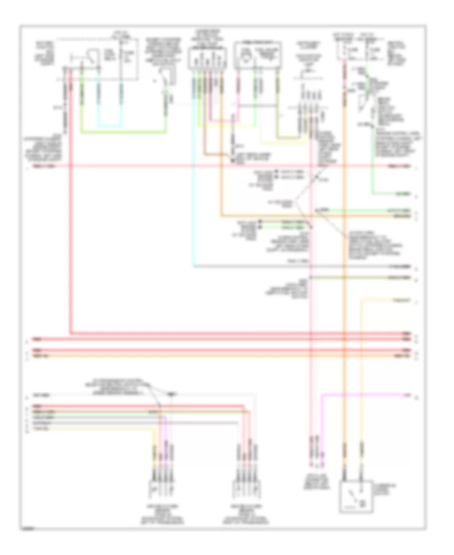
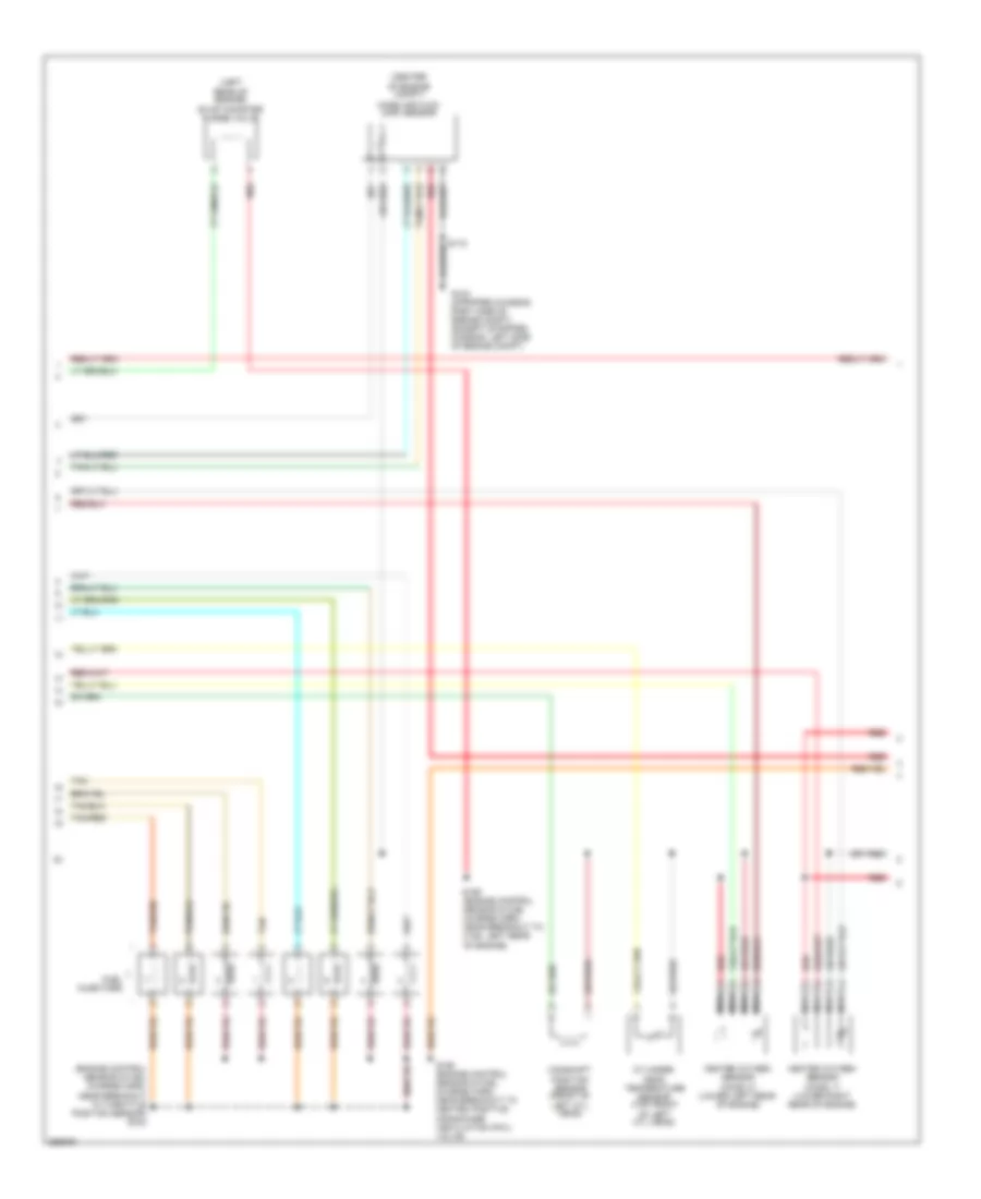
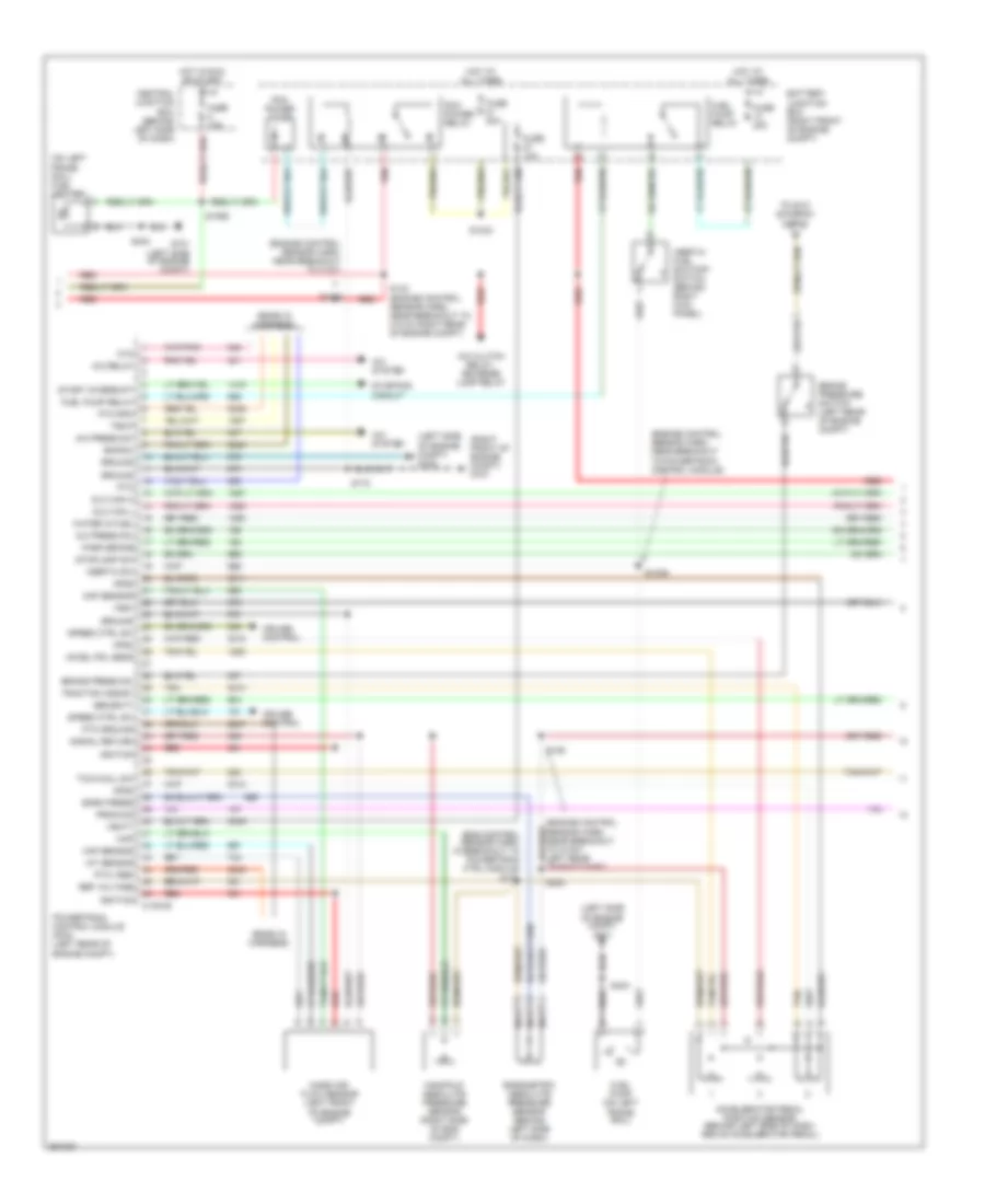
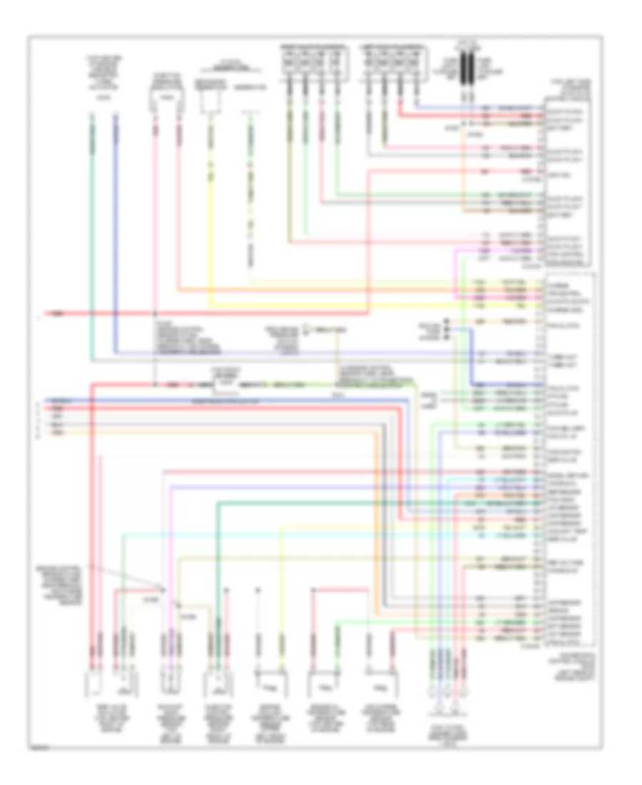
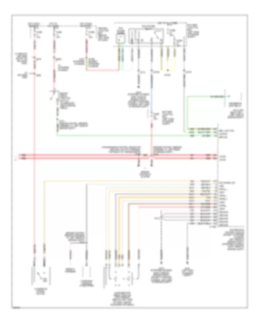
5.4L, Engine Performance Wiring Diagram, with Torqshift (4 of 5) for Ford E450 Super Duty 2007
List of elements for 5.4L, Engine Performance Wiring Diagram, with Torqshift (4 of 5) for Ford E450 Super Duty 2007:
- (except stripped chassis: behind right kick panel) (stripped chassis: under dash) inertia fuel shut- off switch
- (in eng control sensor harn, near left rear of eng compt, on frame rail)
- (in main harn, near breakout to: inertia fuel shutoff switch (stripped chassis), brake pedal position switch (except stripped chassis))
- (in transmission control selector neutral switch harn, near breakout to speed sensor assembly)
- (left rear under- body of vehicle) g300
- (under rear of vehicle, near fuel tank) fuel pump driver module
- (w/ advance trac)
- Anti-lock brakes system (w/ advance trac)
- Battery junction box (left side of engine compt)
- Brake pedal position switch (on bracket above brake pedal)
- Bus +
- Bus -
- Central junction box (behind left side of dash)
- Chassis only)
- Data link connector (below left side of dash)
- Fp pwr
- Fp rtn
- Fpm
- Fuel gauge sensor
- Fuel lvl
- Fuel pump
- Fuel pump relay
- Fuel tank unit
- Fuse 10a
- Fuse 15a
- Fuse 20a
- G104 (stripped chassis: right side of engine compt) (except stripped chassis: left side of engine compt)
- Gnd
- Heated oxygen sensor (ho2s) 12 (on exhaust system, right of transmission)
- Heated oxygen sensor (ho2s) 22 (on exhaust system, left of transmission)
- Hot at all times
- Hot in run or start
- Ifs in
- Instrument cluster
- Malfunction indicator lamp
- Nca
- O/d off
- Overdrive cancel switch
- Red
- S100
- S102
- S146
- S148 (in eng control sensor harn, near left rear of eng compt, on frame rail)
- S172
- S174 (engine control harn,
- S228 (main harn, near breakout to inertia fuel shutoff switch)
- S260
- S269
- S312
- Stripped chassis: left rear of eng compt except stripped chassis: left front of engine compt)
- Vref
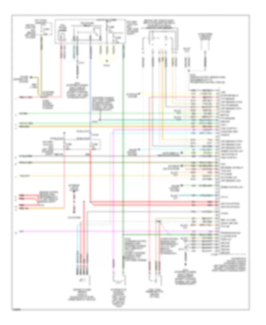
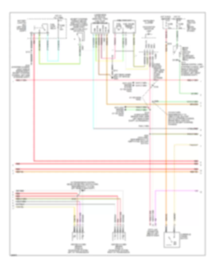
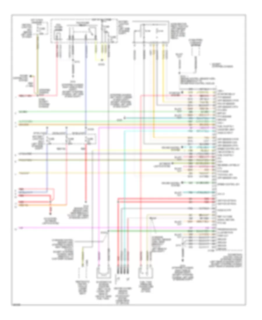
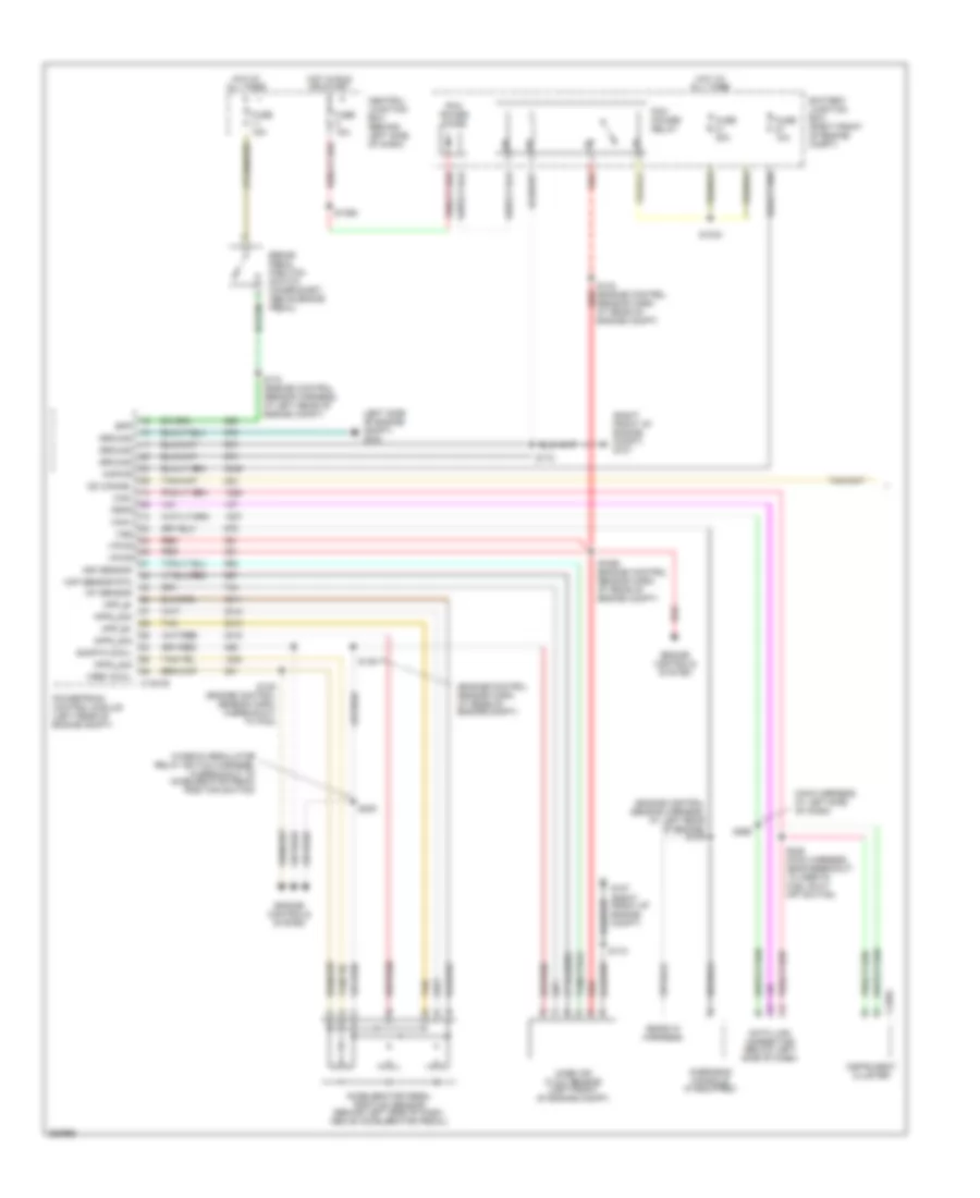
5.4L, Engine Performance Wiring Diagram, with Torqshift (5 of 5) for Ford E450 Super Duty 2007
List of elements for 5.4L, Engine Performance Wiring Diagram, with Torqshift (5 of 5) for Ford E450 Super Duty 2007:
- (behind left side of dash, above accelerator pedal) accelerator pedal position (app) sensor
- (engine control sensor harn, near breakout to left rear of engine compt)
- (if equipped) overhead console
- (in eng control sensor harn, near breakout to c110, left rear of eng compt on frame rail)
- (stripped chassis) s127
- (stripped chassis: left front corner of engine compt) (except stripped chassis: left side of engine compt)
- 4x4 lo
- A/c system
- App sensor 2 pwr
- App sensor 2 rtn
- App sensor 2 sig
- App sensor 3 pwr
- App sensor 3 rtn
- App sensor 3 sig
- Battery junction box (left side of engine compt)
- Bpp sw
- C175b
- Can +
- Can -
- Canister vent
- Central junction box (behind left side of dash)
- Cluster pwr
- Cruise control system
- Evaporative emission canister vent valve (left rear of vehicle, near fuel tank)
- Exterior lights system
- Ftp sensor
- Fuel pump rly
- Fuel tank pressure (ftp) sensor (in tank)
- Fuse 10a
- Fuse 15a
- Fuse 20a
- Fuse 30a
- G100
- G104 (stripped chassis: right side of engine compt) (except stripped chassis: left side of engine compt)
- Ground
- Heated oxygen sensor (ho2s) 23 (on exhaust system, under rear of vehicle)
- Ho2s-23
- Hot at all times
- Hot in run or start
- Htr-23
- Ignition (st/run)
- Nca
- Od cancel sw
- Park out
- Pcm ap sensor
- Pcm power diode
- Pcm power relay
- Power distribution system
- Powertrain control module (stripped chassis: (left rear of engine compt) (except stripped chassis: (right rear of engine compt)
- Programming sig
- Pto engage
- Pto ind
- Pto mode
- Pto rpm
- Red
- Red/pnk
- Ref voltage
- Reverse lmp relay
- S1021 (in engine control sensor harn, stripped chassis: neat breakout to g101) except stripped chassis: near breakout to customer access)
- S1033
- S1035
- S1065 (except stripped chassis)
- S135 (engine control sensor harn, near breakout to powertrain control module)
- S142
- S157
- S172
- Signal return
- Speed control sw
- Starter relay
- Starting system
- Tach sig
- Tan
- Vem system in
- Vss
5.4L, Engine Performance Wiring Diagram, without Torqshift (1 of 5) for Ford E450 Super Duty 2007
List of elements for 5.4L, Engine Performance Wiring Diagram, without Torqshift (1 of 5) for Ford E450 Super Duty 2007:
- (eng ctrl sensor & fuel charge wiring harn, left side of eng)
- (eng ctrl sensor & fuel charge wiring harn, right side of engine)
- (engine control sensor harn, left rear of engine)
- A/c clutch rly
- A/c press sw
- A/c system
- C175e
- Ckp sensor +
- Ckp sensor -
- Cmp sensor sig
- Coil on plug
- Coil on plug 1
- Coil on plug 2
- Coil on plug 3
- Coil on plug 4
- Coil on plug 5
- Coil on plug 6
- Coil on plug 7
- Coil on plug 8
- Crankshaft position sensor (lower center front of engine)
- Cyl head temp
- Electronic throttle control (etc) motor (top front of engine)
- Etc return
- Etc wot cntrl
- Evap purge valve
- Fuel inj 1
- Fuel inj 2
- Fuel inj 3
- Fuel inj 4
- Fuel inj 5
- Fuel inj 6
- Fuel inj 7
- Fuel inj 8
- Fuel rail pressure/ temperature sensor (top of right cylinder
- Fuel rail temp sens
- Ho2s 11 htr
- Ho2s 11 input
- Ho2s 21 htr
- Ho2s 21 input
- Iat sensor
- Ignition transformer capacitor 1 (left front of engine)
- Ignition transformer capacitor 2 (right front of engine)
- Inj press regulator
- Knock sensor (top rear of engine)
- Knock sensor +
- Knock sensor -
- Maf sensor
- Nca
- Powertrain control module (stripped chassis: right rear of eng compt, except stripped chassis: left rear of eng compt)
- Red/pnk
- Reference voltage
- S136
- S156
- S161
- Shield drain
- Signal return
- Tan
- Tan/red
- Throttle position sensor (top of engine, near air intake)
- Tps 2 sig
- Tps output
- Tps sig
- Tps sig return
5.4L, Engine Performance Wiring Diagram, without Torqshift (2 of 5) for Ford E450 Super Duty 2007
List of elements for 5.4L, Engine Performance Wiring Diagram, without Torqshift (2 of 5) for Ford E450 Super Duty 2007:
- (center
- (engine control sensor & fuel charge harn, near breakout to throttle position sensor) s155
- (left rear of engine) evap canister purge valve
- Camshaft position sensor (front of left cyl head)
- Cylinder- head temperature sensor (top front of left cyl head)
- Fuel injectors
- G104 (stripped chassis: right side of engine compt) (except stripped chassis: left side of engine compt)
- Heated oxygen sensor (ho2s) 11 (lower right rear of engine)
- Heated oxygen sensor (ho2s) 21 (lower left rear of engine)
- Mass air flow (maf) sensor
- Nca
- Of engine compt)
- Red
- S159 (engine control sensor & fuel charge harn, near breakout to c192, left rear of engine)
- S160 (engine control sensor & fuel charge harn, near breakout to heated positive crankcase ventilation (pcv) valve)
- Tan
- Tan/red
5.4L, Engine Performance Wiring Diagram, without Torqshift (3 of 5) for Ford E450 Super Duty 2007
List of elements for 5.4L, Engine Performance Wiring Diagram, without Torqshift (3 of 5) for Ford E450 Super Duty 2007:
- (in transmission control selector neutral switch harn, near breakout to output shaft speed (oss) sensor)
- (left side of transmission) digital transmission range (dtr) sensor
- (left side of transmission) output shaft speed (oss) sensor
- (left side of transmission) turbine shaft speed (tss) sensor
- 4r75e transmission
- C175t
- Dtr tr1
- Dtr tr2
- Dtr tr3a
- Dtr tr4
- Electronic pressure control solenoid
- Epc sol
- Ho2s 12 htr
- Ho2s 12 input
- Ho2s 22 htr
- Ho2s 22 input
- Oss sig
- Powertrain control module (stripped chassis: right rear of eng compt, except stripped chassis: left rear of eng compt)
- Press ctrl sol
- Red
- S198
- Shift sol a
- Shift sol b
- Shift solenoids
- Tft sensor sig
- Torque converter clutch solenoid
- Tr-p ground
- Tr1
- Tr2
- Tr3
- Tr4
- Transmission fluid temperature sensor
- Tss sensor
5.4L, Engine Performance Wiring Diagram, without Torqshift (4 of 5) for Ford E450 Super Duty 2007
List of elements for 5.4L, Engine Performance Wiring Diagram, without Torqshift (4 of 5) for Ford E450 Super Duty 2007:
- (except stripped chassis: behind right kick panel) (stripped chassis: under dash) inertia fuel shut- off switch
- (in eng control sensor harn, near left rear of eng compt, on frame rail)
- (in main harn, near breakout to: inertia fuel shutoff switch (stripped chassis), brake pedal position switch (except stripped chassis))
- (in transmission control selector neutral switch harn, near breakout to c192, left rear of eng compt) s102
- (left rear under- body of vehicle) g300
- (under rear of vehicle, near fuel tank) fuel pump driver module
- (w/ advance trac)
- Anti-lock brakes system (w/ advance trac)
- Battery junction box (left side of engine compt)
- Brake pedal position switch (on bracket above brake pedal)
- Bus +
- Bus -
- Central junction box (behind left side of dash)
- Data link connector (below left side of dash)
- Fp pwr
- Fp rtn
- Fpm
- Fuel gauge sensor
- Fuel lvl
- Fuel pump
- Fuel pump relay
- Fuel tank unit
- Fuse 10a
- Fuse 15a
- Fuse 20a
- G104 (stripped chassis: right side of engine compt) (except stripped chassis: left side of engine compt)
- Gnd
- Heated oxygen sensor (ho2s) 12 (on exhaust system, right of transmission)
- Heated oxygen sensor (ho2s) 22 (on exhaust system, left of transmission)
- Hot at all times
- Hot in run or start
- Ifs in
- Instrument cluster
- Malfunction indicator lamp
- Nca
- O/d off
- Overdrive cancel switch
- Red
- S100
- S146
- S148 (in eng control sensor harn, near left rear of eng compt, on frame rail)
- S172
- S174 (engine control harn,
- S216
- S228 (main harn, near breakout to inertia fuel shutoff switch)
- S269
- S312
- Stripped chassis: left rear of eng compt except stripped chassis: left front of engine compt)
- Vref
5.4L, Engine Performance Wiring Diagram, without Torqshift (5 of 5) for Ford E450 Super Duty 2007
List of elements for 5.4L, Engine Performance Wiring Diagram, without Torqshift (5 of 5) for Ford E450 Super Duty 2007:
- (behind left side of dash, above accelerator pedal) accelerator pedal position (app) sensor
- (engine control sensor harn, near breakout to left rear of engine compt)
- (if equipped) overhead console
- (in engine control sensor harn, near breakout to c110, left rear of eng compt)
- (stripped chassis) s127
- (stripped chassis: left front corner of engine compt) (except stripped chassis: left side of engine compt)
- 4x4 lo
- A/c system
- App sensor 2 pwr
- App sensor 2 rtn
- App sensor 2 sig
- App sensor 3 pwr
- App sensor 3 rtn
- App sensor 3 sig
- Battery junction box (left side of engine compt)
- Bpp sw
- C175b
- Can +
- Can -
- Canister vent
- Central junction box (behind left side of dash)
- Cluster pwr
- Cruise control system
- Evaporative emission canister vent valve (left rear of vehicle, near fuel tank)
- Ftp sensor
- Fuel pump rly
- Fuel tank pressure (ftp) sensor (in tank)
- Fuse 10a
- Fuse 15a
- Fuse 20a
- Fuse 30a
- G100
- G104 (stripped chassis: right side of engine compt) (except stripped chassis: left side of engine compt)
- Ground
- Heated oxygen sensor (ho2s) 23 (on exhaust system, under rear of vehicle)
- Ho2s-23
- Hot at all times
- Hot in run or start
- Htr-23
- Ignition (st/run)
- Nca
- Od cancel sw
- Park out
- Pcm ap sensor
- Pcm power diode
- Pcm power relay
- Power distribution system
- Powertrain control module (stripped chassis: (left rear of engine compt) (except stripped chassis: (right rear of engine compt)
- Programming sig
- Pto engage
- Pto ind
- Pto mode
- Pto rpm
- Red
- Red/pnk
- Ref voltage
- S1021 (in engine control sensor harn, stripped chassis: neat breakout to g101) except stripped chassis: near breakout to customer access)
- S1033
- S1035
- S1065 (except stripped chassis)
- S135 (engine control sensor harn, near breakout to powertrain control module)
- S142
- S157
- S172
- Signal return
- Speed control sw
- Tach sig
- Tan
- Vem system in
- Vss
6.0L DIESEL
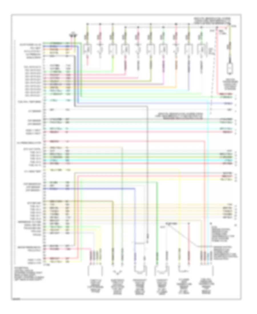
6.0L Diesel, Engine Performance Wiring Diagram (1 of 5) for Ford E450 Super Duty 2007
List of elements for 6.0L Diesel, Engine Performance Wiring Diagram (1 of 5) for Ford E450 Super Duty 2007:
- (engine control sensor & fuel charge harn, near breakout to air charge temperature (act) sensor)
- (pins 11-21 not used)
- (pins 9-16 not used)
- (right front of engine compt) g106
- Battery junction box (right front of engine compt)
- C1388a
- C1388b
- C1388c
- Can bus 2h
- Can bus 2l
- Cylinder id
- Drain wire
- Ficm to pcm connections (to diagram 5 of 5)
- Fuel delivery
- Fuel inj 1 close gnd
- Fuel inj 1 close pwr
- Fuel inj 1 open gnd
- Fuel inj 1 open pwr
- Fuel inj 2 close gnd
- Fuel inj 2 close pwr
- Fuel inj 2 open gnd
- Fuel inj 2 open pwr
- Fuel inj 3 close gnd
- Fuel inj 3 close pwr
- Fuel inj 3 open gnd
- Fuel inj 3 open pwr
- Fuel inj 4 close gnd
- Fuel inj 4 close pwr
- Fuel inj 4 open gnd
- Fuel inj 4 open pwr
- Fuel inj 5 close gnd
- Fuel inj 5 close pwr
- Fuel inj 5 open gnd
- Fuel inj 5 open pwr
- Fuel inj 6 close gnd
- Fuel inj 6 close pwr
- Fuel inj 6 open gnd
- Fuel inj 6 open pwr
- Fuel inj 7 close gnd
- Fuel inj 7 close pwr
- Fuel inj 7 open gnd
- Fuel inj 7 open pwr
- Fuel inj 8 close gnd
- Fuel inj 8 close pwr
- Fuel inj 8 open gnd
- Fuel inj 8 open pwr
- Fuel injector 1 (top of right cylinder bank)
- Fuel injector 2 (top of left cylinder bank)
- Fuel injector 3 (top of right cylinder bank)
- Fuel injector 4 (top of left cylinder bank)
- Fuel injector 5 (top of right cylinder bank)
- Fuel injector 6 (top of left cylinder bank)
- Fuel injector 7 (top of right cylinder bank)
- Fuel injector 8 (top of left cylinder bank)
- Fuel injector control module (ficm) (left rear of engine compt)
- Fuel injector control module power relay
- Fuse 50a
- G108 (lower left rear of engine)
- Ground
- Hot at all times
- Ignition
- Nca
- Pcm comm
- Power relay
- Power relay ctrl
- Red
- S1060
- S1061
- S1062
6.0L Diesel, Engine Performance Wiring Diagram (2 of 5) for Ford E450 Super Duty 2007
List of elements for 6.0L Diesel, Engine Performance Wiring Diagram (2 of 5) for Ford E450 Super Duty 2007:
- (ends in harness)
- (eng control sensor harn, in breakout to powertrain ctrl module) s138
- (engine control sensor harn, near breakout to c1047, left rear of eng compt)
- (engine control sensor harn, near breakout to c127)
- (engine control sensor harn, near breakout to powertrain control module)
- (left side of engine compt) g100
- (left side of engine compt) g101
- (on left frame rail) fuel heater
- (right front of engine compt) g107
- A/c clutch relay, reverse lamp relay
- A/c press sw
- A/c relay
- A/c system
- Accel pdl sens
- Accelerator pedal position sensor (behind left side of dash, above accelerator pedal)
- Aps2
- Aps3
- Baro press
- Barometric absolute pressure sensor (behind left side of dash)
- Battery junction box (right front of engine compt)
- Bcpsw
- Brake press sw
- Brake pressure switch (left rear of engine compt)
- C1381b
- Central junction box (behind left side of dash)
- Cruise control
- Cto
- Dlc can h
- Dlc can l
- Fuel pump (on left frame rail)
- Fuel pump relay
- Fuse 10a
- Fuse 15a
- Fuse 20a
- Fuse 30a
- G101 (left side of engine compt)
- Gen/batt
- Ground
- Hot at all times
- Hot in run or start
- Iat sensor
- Ignition
- Inertia fuel shutoff switch (behind right kick panel)
- Inertia sw
- Maf sensor
- Manifold absolute pressure sensor (right side of eng compt)
- Map
- Mass air- flow sensor (left front of engine compt)
- Nca
- Park brake
- Pcm power diode
- Pcm power relay
- Powertrain control module (pcm) (left rear of engine compt)
- Prog sig
- Pto
- Pto ground
- Pto rpm
- Pto vref
- Red
- Ref voltage
- S1033
- S1049
- S1065
- S1068
- S136
- S142 (engine control sensor harn, near breakout to c1019, right rear of engine compt)
- S172
- S200
- S404
- Signal return
- Speed ctrl sw
- Start interrupt
- Starting circuit
- Stoplamp sw
- Tan
- To s101 (diagram 5 of 5)
- Tow/haul sw
- Tr0-p
- Traction assist
- Vbatt
- Vss+
- Water in fuel
6.0L Diesel, Engine Performance Wiring Diagram (3 of 5) for Ford E450 Super Duty 2007
List of elements for 6.0L Diesel, Engine Performance Wiring Diagram (3 of 5) for Ford E450 Super Duty 2007:
- (ends in harness)
- (engine control sensor & fuel charge harn, near breakout to powertrain control module)
- (engine control sensor harn, near breakout for c1047) s135
- (in main harn, near breakout to brake pedal position (bpp) switch) s269
- (in main harn, near breakout to fuel shutoff switch)
- (main harn, in breakout to c238, behind left side of dash)
- (near left kick panel) parking brake switch
- (on left frame rail) water- in-fuel sensor
- (right front of engine compt) dual pressure switch
- Brake pedal position switch (on bracket, above brake pedal)
- Bus (+)
- Bus (-)
- C220a
- C220b
- Camshaft position sensor (lower left front of engine)
- Center front of engine)
- Central junction box (behind left side of dash)
- Crankshaft position sensor (lower
- Data link connector (below left side of dash)
- Fuse 15a
- G107 (right front of engine compt)
- G203 (behind left end of dash)
- Hot at all times
- Instrument cluster
- Malfunction indicator lamp
- Nca
- Overhead console (if equipped)
- Red
- S1064
- S228
- S268
- Sensor harn, in breakout to abs control module)
6.0L Diesel, Engine Performance Wiring Diagram (4 of 5) for Ford E450 Super Duty 2007
List of elements for 6.0L Diesel, Engine Performance Wiring Diagram (4 of 5) for Ford E450 Super Duty 2007:
- (in trans ctrl selector neutral switch harn, in breakout to right side of transmission)
- (in trans ctrl selector neutral switch harn, near breakout to c1148, at transmission)
- (not used)
- (w/ advance trac)
- (w/ remote keyless entry)
- Auxiliary relay box 1 (right front of engine compt)
- C1047
- C1381t
- Central junction box (behind left side of dash)
- Fuse 10a
- Hot in run or start
- Intermediate shaft speed sensor
- Iss sig
- Nca
- Oss sig
- Output shaft speed sensor (right rear of transmission)
- Overdrive cancel switch
- Pc sol pwr
- Pc-a sol
- Powertrain control module (left rear of engine compt)
- Pressure control (pc-a) solenoid
- Red
- Ref volt
- Rev lmp ctrl
- Reversing lamp relay
- S1037
- S123
- S198
- S215
- S260
- Shift solenoid pressure control a (sspc-a)
- Shift solenoid pressure control b (sspc-b)
- Shift solenoid pressure control c (sspc-c)
- Shift solenoid pressure control d (sspc-d)
- Shift solenoid pressure control e (sspc-e)
- Sig trn
- Speed sensor assembly (left side of transmission)
- Sspc-a crl
- Sspc-b ctrl
- Sspc-c crl
- Sspc-d ctrl
- Sspc-e ctrl
- Tcc sol ctrl
- Tft sens sig
- Torqshift transmission
- Torque converter clutch solenoid
- Tr-p gnd
- Tr-p sig
- Transmission fluid temperature sensor
- Transmission range sensor assembly (tr-p)
- Tss sig
- Turbine shaft speed sensor
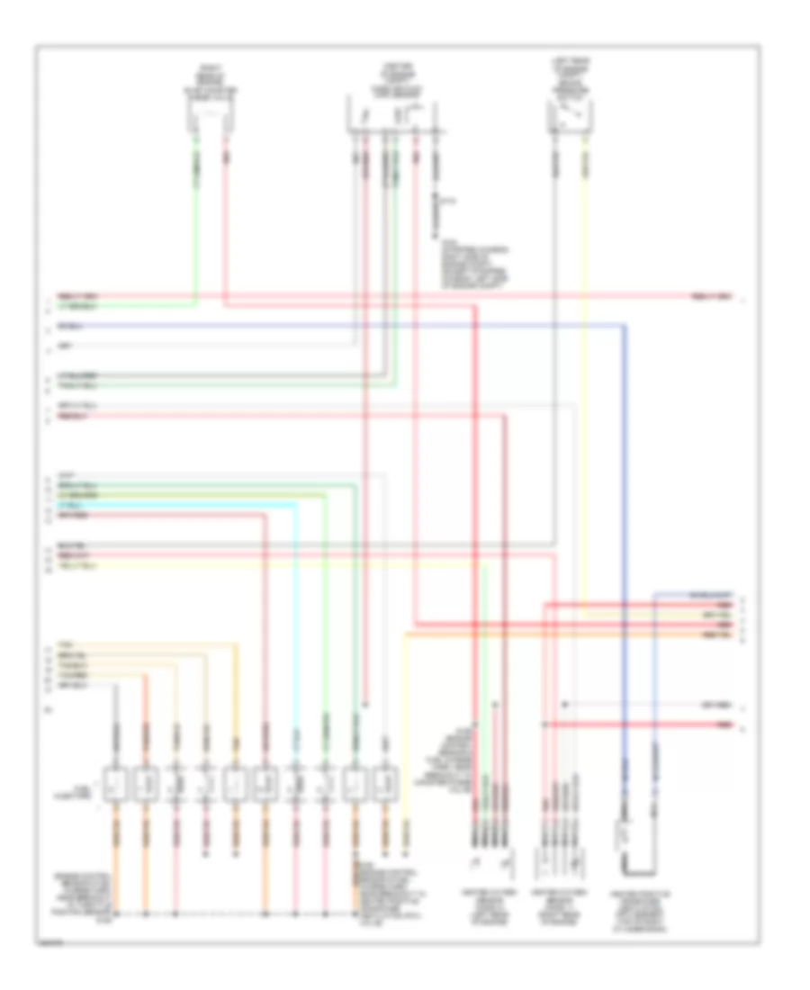
6.0L Diesel, Engine Performance Wiring Diagram (5 of 5) for Ford E450 Super Duty 2007
List of elements for 6.0L Diesel, Engine Performance Wiring Diagram (5 of 5) for Ford E450 Super Duty 2007:
- (ends in harn)
- (engine control sensor & fuel charge harn, near breakou air charge temperature sensor)
- (in engine control sensor harn, near breakout to powertrain control module (pcm))
- (top center of engine) variable geometric turbo actuator
- (top front of eng)
- (top left side of engine) glow plug control module
- Act sensor
- Air charge temperature sensor (top rear of engine)
- Battery
- C1273a
- C1273b
- C1381e
- Can bus 2h
- Can bus 2l
- Charge
- Charge (2nd)
- Ckp sensor
- Cmp sensor
- Coolant temp
- Cooling fan
- Cooling fans system
- Ebp sensor
- Egr valve
- Egr valve actuator (top center front of engine)
- Electronic fan clutch
- Engine coolant temperature sensor (upper
- Engine oil temperature sensor (top center of engine)
- Eot sensor
- Exhaust back pressure sensor (top left of engine)
- Fan clutch
- Ficm comm
- Ficm cyl id
- Ficm delivery
- Ficm to pcm connections (from diagram 1 of 5)
- From brake pressure switch (diagram 2 of 5)
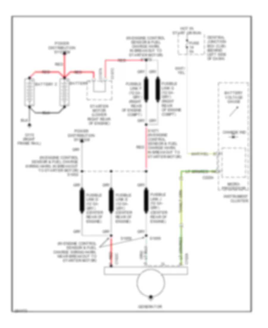
- Generator
- Glow plug
- Glow plug 1
- Glow plug 2
- Glow plug 3
- Glow plug 4
- Glow plug 5
- Glow plug 6
- Glow plug 7
- Glow plug 8
- Glow plug sys
- Ground
- Hot at all times
- Icp sensor
- Ignition
- Injection control pressure sensor (right front of engine)
- Injection pressure regulator
- Ipr control
- Left front of engine)
- Left glow plug bank
- Nca
- Pcm control
- Pcm monitor
- Powertrain control module (pcm) (left rear of engine compt)
- Pto ind
- Red
- Ref voltage
- Right glow plug bank
- S101
- S1051
- S1054
- S1057 (engine control sensor & fuel charge harn, near breakout air charge temperature sensor)
- S1058
- S1059
- Secondary generator
- Signal return
- Turbo act
- W/ dual generators
6.8L
6.8L, Engine Performance Wiring Diagram (1 of 5) for Ford E450 Super Duty 2007
List of elements for 6.8L, Engine Performance Wiring Diagram (1 of 5) for Ford E450 Super Duty 2007:
- (eng ctrl sensor & fuel charge wiring harn, near breakout to heated positive rankcase ventilation (pcv) valve)
- (eng ctrl sensor & fuel charge wiring harn, near breakout to throttle position sensor (tps))
- (engine control sensor & fuel charge harn, near breakout for powertrain control module (pcm))
- A/c clutch rly
- A/c press sw
- A/c system
- Brake pressure sw
- C175e
- Camshaft position sensor (front of left cylinder head)
- Ckp sensor +
- Ckp sensor -
- Cmp sensor sig
- Coil on plug
- Coil on plug 1
- Coil on plug 10
- Coil on plug 2
- Coil on plug 3
- Coil on plug 4
- Coil on plug 5
- Coil on plug 6
- Coil on plug 7
- Coil on plug 8
- Coil on plug 9
- Crankshaft position sensor (lower center front of engine)
- Cyl head temp
- Cylinder head temperature sensor (front of left cyl head)
- Electronic throttle control (etc) motor (top left side of engine)
- Etc return
- Etc wot cntrl
- Evap purge valve
- Fuel inj 1
- Fuel inj 10
- Fuel inj 2
- Fuel inj 3
- Fuel inj 4
- Fuel inj 5
- Fuel inj 6
- Fuel inj 7
- Fuel inj 8
- Fuel inj 9
- Fuel rail pressure/ temperature sensor (top rear of engine)
- Fuel rail temp sens
- Ho2s 11 htr
- Ho2s 11 input
- Ho2s 21 htr
- Ho2s 21 input
- Iat sensor
- Ignition transformer capacitor 1 (top front of engine)
- Inj press regulator
- Maf sensor
- Nca
- Pcv heat
- Powertrain control module (stripped chassis: right rear of eng compt, except stripped chassis: left rear of eng compt)
- Red/pnk
- Reference voltage
- S136 (engine control sensor & fuel charge harn, near breakout for evap canister purge valve)
- S137
- S161
- S162
- Shield drain
- Signal return
- Tan
- Tan/red
- Throttle position sensor (top of engine, near air intake)
- Tps 2 sig
- Tps output
- Tps sig
- Tps sig return
6.8L, Engine Performance Wiring Diagram (2 of 5) for Ford E450 Super Duty 2007
List of elements for 6.8L, Engine Performance Wiring Diagram (2 of 5) for Ford E450 Super Duty 2007:
- (center of engine compt) mass air flow (maf) sensor
- (engine control sensor & fuel charge harn, near breakout to throttle position sensor) s155
- (left rear of engine compt) brake pressure switch
- (right rear of engine) evap canister purge valve
- Fuel injectors
- G104 (stripped chassis: right side of engine compt) (except stripped chassis: left side of engine compt)
- Heated oxygen sensor (ho2s) 11 (right rear of engine)
- Heated oxygen sensor (ho2s) 21 (left rear of engine)
- Heated positive crankcase ventilation (pcv) element (top of right cylinder bank)
- Nca
- Red
- S159 (engine control sensor & fuel charge harn, near breakout to canister purge valve)
- Tan
- Tan/red
6.8L, Engine Performance Wiring Diagram (3 of 5) for Ford E450 Super Duty 2007
List of elements for 6.8L, Engine Performance Wiring Diagram (3 of 5) for Ford E450 Super Duty 2007:
- (engine control sensor & fuel charge harn, near breakout for c192, left rear of eng)
- (transmission control selector neutral switch harn, near breakout to output shaft speed (oss) sensor)
- C175t
- Ho2s 12 htr
- Ho2s 12 input
- Ho2s 22 htr
- Ho2s 22 input
- Intermediate shaft speed sensor
- Iss sensor
- Oss sensor
- Output shaft speed sensor (right rear of transmission)
- Powertrain control module (stripped chassis: right rear of eng compt, except stripped chassis: left rear of eng compt)
- Pressure control (pc-a) solenoid
- Red
- Ref voltage
- S1037 (transmission control selector neutral switch harn, near breakout to speed sensor assembly)
- S123 (transmission control selector neutral switch harn, in breakout to right side of transmission)
- S139
- S198
- Shift sol a
- Shift sol b
- Shift sol c
- Shift sol d
- Shift sol e
- Shift solenoid pressure control a (sspc-a)
- Shift solenoid pressure control b (sspc-b)
- Shift solenoid pressure control c (sspc-c)
- Shift solenoid pressure control d (sspc-d)
- Shift solenoid pressure control e (sspc-e)
- Signal return
- Speed sensor assembly (left side of transmission)
- Tcc sol
- Tft sensor
- Torqshift transmission
- Torque converter clutch solenoid
- Transmission fluid temperature sensor
- Transmission range sensor assembly (tr-p)
- Trs sensor
- Tss sensor
- Turbine shaft speed sensor
6.8L, Engine Performance Wiring Diagram (4 of 5) for Ford E450 Super Duty 2007
List of elements for 6.8L, Engine Performance Wiring Diagram (4 of 5) for Ford E450 Super Duty 2007:
- (except stripped chassis: behind right kick panel) (stripped chassis: under dash) inertia fuel shut- off switch
- (in eng control sensor harn, near left rear of eng compt, on frame rail)
- (in main harn, near breakout to: inertia fuel shutoff switch (stripped chassis), brake pedal position switch (except stripped chassis))
- (in transmission control selector neutral switch harn, near breakout to speed sensor assembly)
- (left rear under- body of vehicle) g300
- (under rear of vehicle, near fuel tank) fuel pump driver module
- (w/ advance trac)
- Anti-lock brakes system (w/ advance trac)
- Battery junction box (left side of engine compt)
- Brake pedal position switch (on bracket above brake pedal)
- Bus +
- Bus -
- Central junction box (behind left side of dash)
- Data link connector (below left side of dash)
- Fp pwr
- Fp rtn
- Fpm
- Fuel gauge sensor
- Fuel lvl
- Fuel pump
- Fuel pump relay
- Fuel tank unit
- Fuse 10a
- Fuse 15a
- Fuse 20a
- G104 (stripped chassis: right side of engine compt) (except stripped chassis: left side of engine compt)
- Gnd
- Heated oxygen sensor (ho2s) 12 (on exhaust system, right of transmission)
- Heated oxygen sensor (ho2s) 22 (on exhaust system, left of transmission)
- Hot at all times
- Hot in run or start
- Ifs in
- Instrument cluster
- Malfunction indicator lamp
- Nca
- O/d off
- Overdrive cancel switch
- Red
- S100
- S102
- S146
- S148 (in eng control sensor harn, near left rear of eng compt, on frame rail)
- S172
- S174 (engine control harn,
- S228 (main harn, near breakout to inertia fuel shutoff switch)
- S260
- S269
- S312
- Stripped chassis: left rear of eng compt except stripped chassis: left front of engine compt)
- Vref
6.8L, Engine Performance Wiring Diagram (5 of 5) for Ford E450 Super Duty 2007
List of elements for 6.8L, Engine Performance Wiring Diagram (5 of 5) for Ford E450 Super Duty 2007:
- (if equipped) overhead console
- (in engine control sensor harn, near breakout to c110, left rear of eng compt)
- (in engine control sensor harn, stripped chassis: neat breakout to g101) except stripped chassis: near breakout to customer access)
- (on exhaust system, under rear of vehicle)
- (stripped chassis) s127
- (stripped chassis: left front corner of eng compt) (except stripped chassis: left side of eng compt)
- (stripped chassis: right side of eng compt) (except stripped chassis: left side of eng compt)
- 4x4 lo
- A/c system, exterior lights system
- Accelerator pedal position (app) sensor (behind left side of dash, above accel pedal)
- App sensor 2 pwr
- App sensor 2 rtn
- App sensor 2 sig
- App sensor 3 pwr
- App sensor 3 rtn
- App sensor 3 sig
- Battery junction box (left side of engine compt)
- Bpp sw
- C175b
- C310a
- Can +
- Can -
- Canister vent
- Central junction box (behind left side of dash)
- Cluster pwr
- Cruise control system
- Cto
- Evaporative emission canister vent valve (under left rear of vehicle, near fuel tank)
- Except
- Exterior lights system
- Ftp sensor
- Fuel pump rly
- Fuel tank pressure transducer sensor (in tank)
- Fuse 10a
- Fuse 15a
- Fuse 20a
- Fuse 30a
- Fuse 5a
- G100
- G104
- G104 (stripped chassis: right side of engine compt) (except stripped chassis: left side of engine compt)
- Ground
- Heated oxygen sensor (ho2s) 23
- Ho2s 23 htr
- Ho2s 23 input
- Hot at all times
- Hot in run or start
- Ignition (st/run)
- Nca
- P/n
- Park out
- Pcm ap sensor
- Pcm power diode
- Pcm power relay
- Power distribution system
- Powertrain control module (stripped chassis: (left rear of engine compt) (except stripped chassis: (right rear of engine compt)
- Programming sig
- Pto engage
- Pto ind
- Pto mode
- Pto rpm
- Red
- Red/pnk
- Ref voltage
- Restraints control module (under driver seat)
- Reverse lmp relay
- S1021
- S1033
- S1035
- S1065 (except stripped chassis)
- S135 (engine control sensor harn, near breakout to powertrain control module)
- S142 (engine ctrl sensor harn, near breakout to c219, left rear of engine compt)
- S157
- S172
- Signal return
- Speed control sw
- Starter relay
- Starting system
- Stripped chassis
- Tan
- Tow/haul sw
- Vem system in
- Vss +
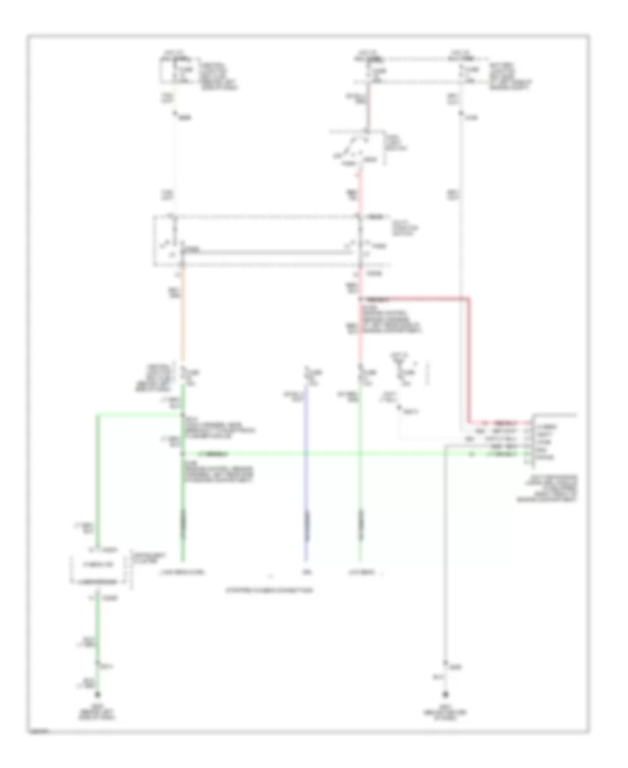
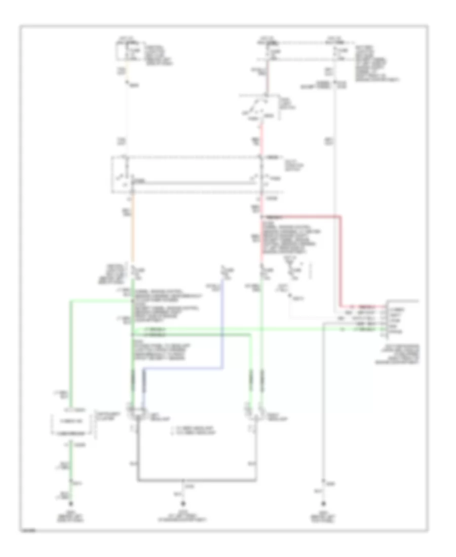
EXTERIOR LIGHTS
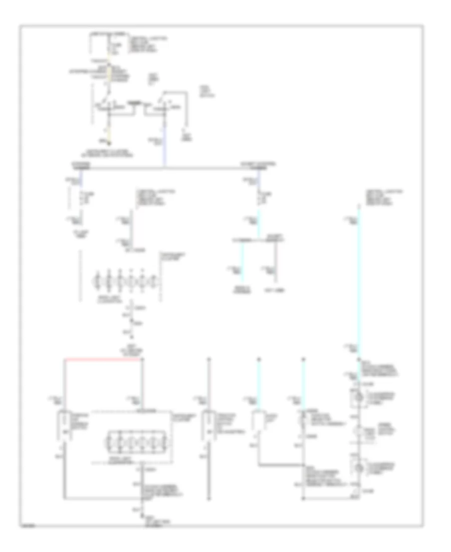
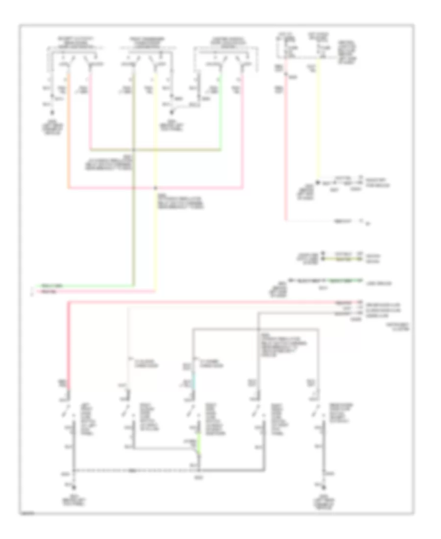
Backup Lamps Wiring Diagram for Ford E450 Super Duty 2007
List of elements for Backup Lamps Wiring Diagram for Ford E450 Super Duty 2007:
- (in engine control sensor harness, (stripped chassis: near breakout to customer access) diesel: near breakout to c140 gas: near breakout to c237) s130
- (in taillight harness, near breakout to high mounted stoplight) s403
- At left side of engine compt)
- Auxiliary relay box 1 (diesel: right front of engine compt) (except diesel: left rear of engine compt)
- Battery junction box (bjb) (diesel: at right
- Battery junction box (bjb) (diesel: at right front of engine compt) (except diesel: at left side of engine compt)
- Battery junction box (bjb) (left side of eng compt)
- C1381t
- C175b
- Central junction box box (cjb) (behind left side of dash)
- Cutaway
- Diesel
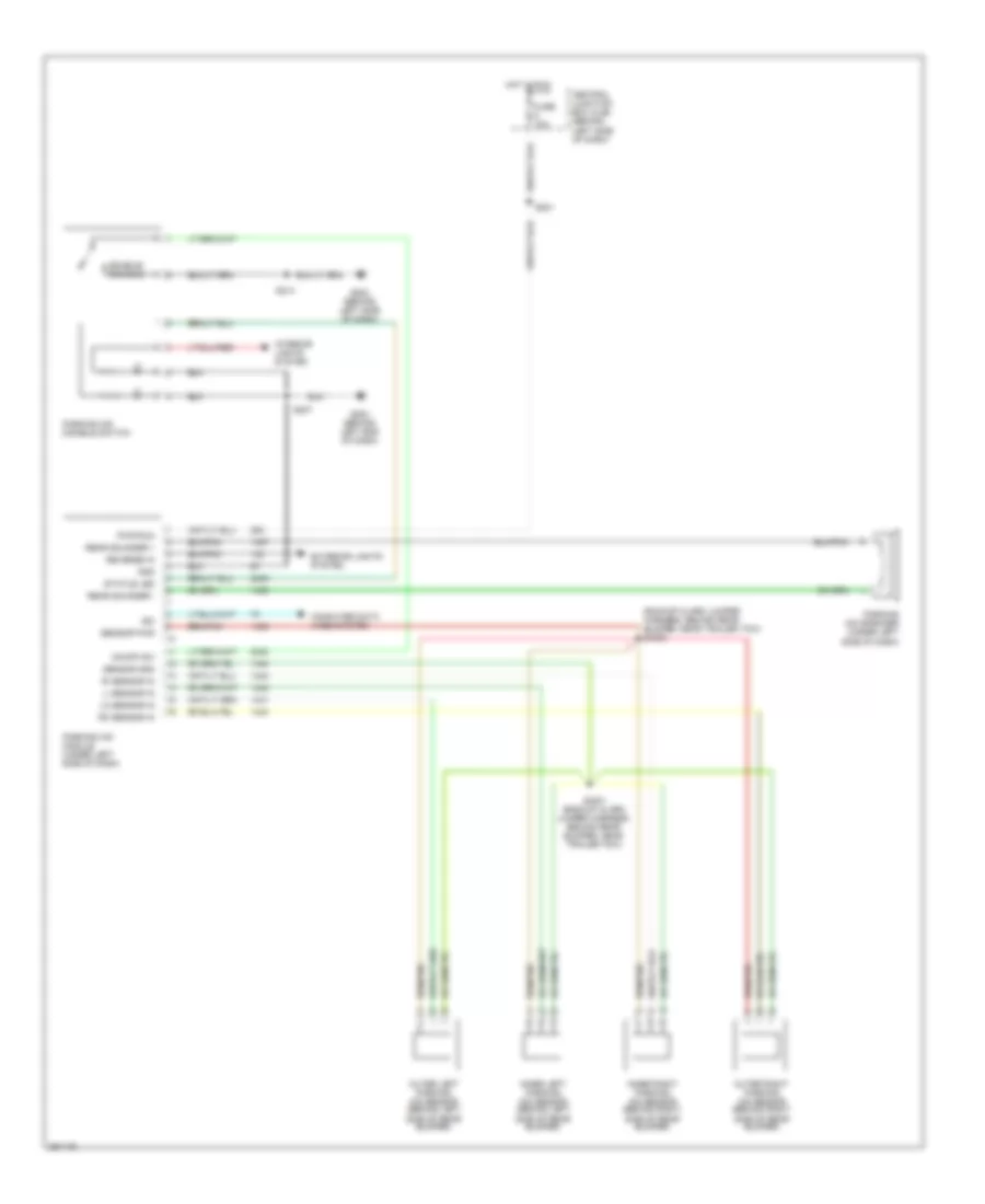
- Digital transmission range (dtr) sensor (left side of transmission)
- Ends in harness
- Engine controls system, air conditioning system
- Except cutaway, except stripped chassis
- Except diesel
- Except torqshift
- Front of engine compt) (except diesel:
- Fuse 15a
- Fuse 20a
- Fuse 30a
- G101 (diesel: left side of engine compt) (except diesel: left front of engine compt)
- G400 (left rear corner of vehicle)
- Gasoline
- Hot at all times
- Hot in run
- Left rear lamp assembly
- Left reversing lamp
- Nca
- Parking aid module (under left side of dash)
- Pcm power relay
- Pnk
- Power distribution system
- Powertrain control module (except stripped chassis: left rear of engine compt stripped chassis: right rear of engine compt)
- Red
- Reversing lamp relay
- Reversing lamp trailer tow relay
- Right rear lamp assembly
- Right reversing lamp
- S1033
- S1035
- S142 (engine control sensor harn, near breakout to diesel: c1019 gas: c140 stripped chassis: c219)
- S402
- S406
- S432
- Stripped chassis
- Torqshift
- W/ torqshift
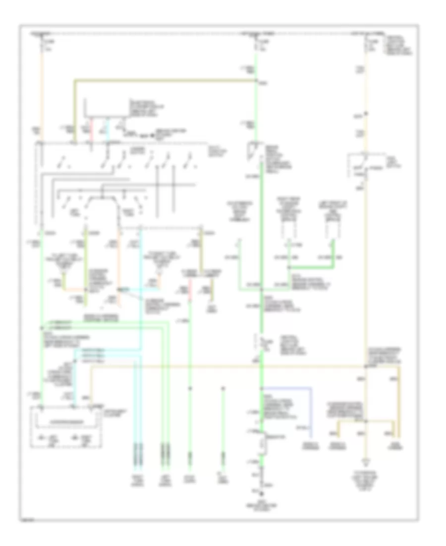
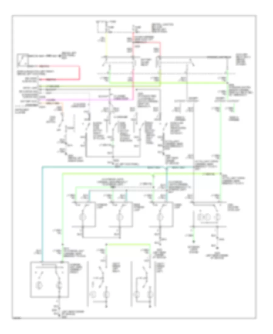
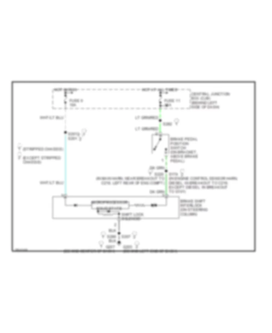
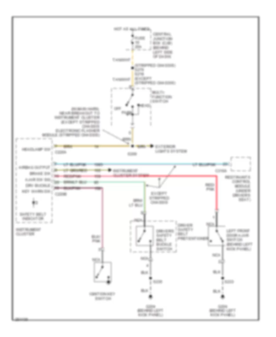
Exterior Lamps Wiring Diagram, with Stripped Chassis (1 of 2) for Ford E450 Super Duty 2007
List of elements for Exterior Lamps Wiring Diagram, with Stripped Chassis (1 of 2) for Ford E450 Super Duty 2007:
- (behind center of dash) g207
- (ends in harness) (modified vehicle)
- (in engine control harness, in breakout to c110)
- (in engine control harness, in breakout to c110) g2010
- (in engine control sensor harness, near breakout to customer access) s114
- (in main harness, near breakout to electronic flasher module) s206
- (left front of engine compt) abs control module
- (not used)
- (on steering column) brake shift interlock
- (right rear of engine compt) powertrain control module
- Brake pedal position switch (on bracket, above brake pedal)
- Breakout to c219)
- C175b
- C202a
- C202b
- C220a
- Central junction box (cjb) (behind left side of dash)
- Electronic flasher module (behind left side of dash)
- Ends in harness
- Fuse 10a
- Fuse 15a
- Fuse 20a
- G207 (behind center of dash)
- Hazard switch
- Head
- Hot at all times
- Hot in run
- Instrument cluster
- Left turn
- Left turn ind
- Left turn signal
- Main light switch
- Microprocessor
- Multi- function switch
- Off
- Park
- Resistor
- Right turn
- Right turn ind
- Right turn signal
- S132
- S215 (in main wiring harness, near breakout to left side of dash)
- S217 (in main wiring harn, in breakout to instrument cluster)
- S220 (in main wiring harness, near breakout to c219)
- S276
- S282
- S283 (in main wiring harness, near breakout to brake pedal position switch)
- S284
- S286
- Side marker
- Stop lamps
- To left turn trailer tow relay (diagram 2 of 2)
- To parking lamp trailer tow relay (diagram 2 of 2)
- To right turn trailer tow relay (diagram 2 of 2)
- W/ rear lights
- W/o rear lights
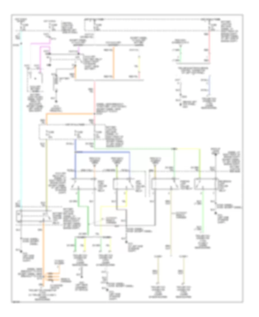
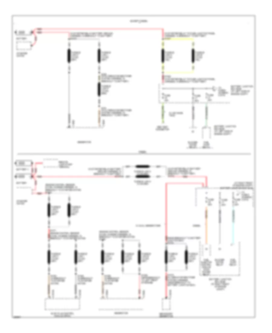
Exterior Lamps Wiring Diagram, with Stripped Chassis (2 of 2) for Ford E450 Super Duty 2007
List of elements for Exterior Lamps Wiring Diagram, with Stripped Chassis (2 of 2) for Ford E450 Super Duty 2007:
- (in engine control sensor harness, in breakout to c110) s194
- (left front of engine compt)
- (near breakout to starter relay) s1027
- (to body builder)
- Auxiliary battery diode
- Auxiliary battery relay (right front of engine compt, near battery)
- Auxiliary relay box 1 (at left side of engine compt)
- Back-up lamps circuit
- Battery 2
- Battery charge trailer tow relay
- Battery junction box (bjb)
- Battery junction box (bjb) (at left front of engine compt)
- Battery junction box (left front front of of eng compt)
- Central junction box (cjb) (behind left side of dash)
- Ends in harness
- Except diesel w/ auxiliary battery
- Except diesel, w/ auxiliary battery jumper
- From s114 (diagram 1 of 2)
- From s132 (diagram 1 of 2)
- From s2010 (diagram 1 of 2)
- Fuse 15a
- Fuse 20a
- Fuse 40a
- Fuse 5a
- Fuse 60a
- G110 (right frame rail)
- G116 (right side of engine compt)
- Hot at all times
- Hot in run
- Hot in run or acc
- Left turn trailer tow relay
- Parking lamp trailer tow relay
- Reversing lamp trailer tow relay
- Right turn trailer tow relay
- S1019
- S1022
- S1032
- S113
- S195
- S199
- Trailer tow connector (7 pin) (class ii) (at right side of rear bumper)
- Trailer tow connector (7 pin) (class ii) (right side of rear bumper)
- W/o auxiliary battery
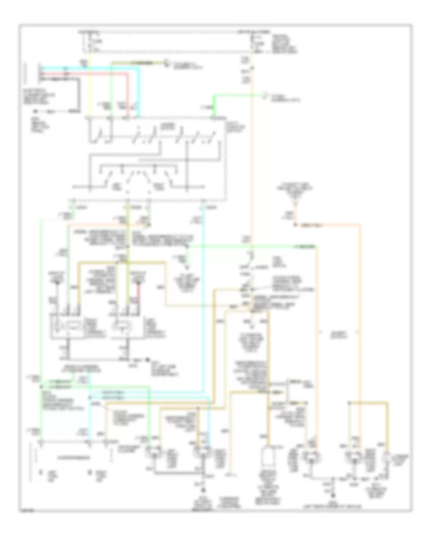
Exterior Lamps Wiring Diagram, without Stripped Chassis (1 of 3) for Ford E450 Super Duty 2007
List of elements for Exterior Lamps Wiring Diagram, without Stripped Chassis (1 of 3) for Ford E450 Super Duty 2007:
- (diesel: near breakout to customer access) (except diesel: near breakout to c125) s2010
- (ends in harness) (w/ modified vehicle)
- (in main wiring harness, in breakout to c238)
- (in main wiring harness, near breakout to instrument cluster)
- (near breakout to restraints control module) (w/ remote keyless entry or overhead console) s234
- (not used)
- Back-up lamps circuit
- C202a
- C202b
- C2113a
- C220a
- Central junction box (cjb) (behind left side of dash)
- Cutaway
- Electronic flasher module (behind left side of dash)
- Except cutaway
- Fuse 10a
- Fuse 20a
- G101 (at left side of engine compartment)
- G103 (at right front of eng compt)
- G204 (behind left kick panel)
- G400 (left rear corner of vehicle)
- Hazard switch
- Head
- Hot at all times
- Hot in run
- Instrument cluster
- Left front park/ turn lamp
- Left rear lamp assembly (cutaway)
- Left rear park/ stop/ turn lamp
- Left turn
- Left turn ind
- License plate lamp
- Main light switch
- Microprocessor
- Multi- function switch
- Nca
- Off
- Overhead console (if equipped)
- Park
- Right front park/ turn lamp
- Right rear lamp assembly (cutaway)
- Right rear park/ stop/ turn lamp
- Right turn
- Right turn ind
- S132 (diesel: near breakout to c140) (except diesel: near breakout to windshield wiper motor)
- S163
- S165 (near breakout to right front park/turn light)
- S206 (diesel: near breakout to c1019) (except diesel: near breakout to c140) s114
- S215 (in main wiring harness, near breakout to main light switch)
- S217
- S218
- S223
- S306 (in taillight harness, near breakout to c405)
- S402
- S406
- S414 (w/ remote keyless entry)
- S430 (in rear light connector harness, near breakout to left rear light assembly)
- S432
- To fuse f11 (diagram 3 of 3)
- To left turn trailer tow relay (diagram 2 of 3)
- To parking lamp trailer tow relay (diagram 2 of 3)
- To right turn trailer tow relay (diagram 2 of 3)
- To s231 (diagram 3 of 3)
- Vehicle security module (vsm) (w/ remote keyless entry) (behind right end of dash)
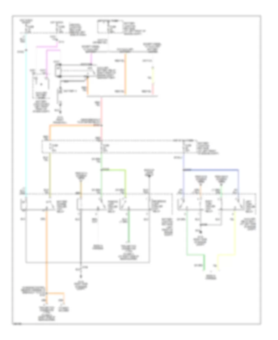
Exterior Lamps Wiring Diagram, without Stripped Chassis (2 of 3) for Ford E450 Super Duty 2007
List of elements for Exterior Lamps Wiring Diagram, without Stripped Chassis (2 of 3) for Ford E450 Super Duty 2007:
- (behind left kick panel) g204
- (diesel) (except diesel)
- (diesel: at right front of engine compt) (except diesel: at left side of engine compt) battery junction box (bjb)
- (diesel: near breakout to battery junction box) (except diesel: near breakout to g101) s1027
- (diesel: near breakout to c219) (except diesel: near breakout to c125) s118
- (ends in harness)
- (to body builder)
- Auxiliary battery diode
- Auxiliary battery relay (right front of engine compt, near battery)
- Auxiliary relay box 1 (diesel: at right front of engine compt) (except diesel: at left rear of engine compt)
- Back-up lamps circuit
- Battery
- Battery charge trailer tow relay
- Battery junction box (bjb) (diesel: at right front of engine compt) (except diesel: at left side of engine compt)
- Battery junction box (diesel: right front of eng compt) (except diesel: left side of eng compt)
- Central junction box (cjb) (behind left side of dash)
- Class i
- Class ii
- Cutaway: ends in harness
- Except diesel, w/ auxiliary battery
- Except diesel, w/ auxiliary battery jumper
- From s114 (diagram 1 of 3)
- From s132 (diagram 1 of 3)
- From s2010 (diagram 1 of 3)
- From s231 (diagram 3 of 3)
- Fuse 15a
- Fuse 20a
- Fuse 30a
- Fuse 40a
- Fuse 5a
- Fuse 60a
- G101 (at left side of engine compt)
- G101 (left side of engine compt)
- G110 (on right frame rail)
- G401 (left rear underbody of vehicle)
- Hot at all times
- Hot in run
- Hot in run or acc
- Left turn trailer tow relay
- Parking lamp trailer tow relay
- Red
- Reversing lamp trailer tow relay
- Right turn trailer tow relay
- S1019
- S1022
- S1025 s1005
- S1029 s1005
- S1032
- S113
- S223
- Trailer electronic brake control connector (at left kick panel)
- Trailer tow connector (4-pin) (under of rear bumper)
- Trailer tow connector (7 pin) (class ii) (under rear bumper)
- Trailer tow connector (7 pin) (under rear bumper)
- Trailer tow connector (7 pin) (w/ trailer tow class ii) (under rear bumper)
- Trailer tow connector (7-pin) (under rear bumper)
- W/ modified vehicle
- W/o auxiliary battery
Exterior Lamps Wiring Diagram, without Stripped Chassis (3 of 3) for Ford E450 Super Duty 2007
List of elements for Exterior Lamps Wiring Diagram, without Stripped Chassis (3 of 3) for Ford E450 Super Duty 2007:
- (diesel)
- (except diesel)
- (in engine control sensor harness, near breakout to g101) s105 (w/ advance trac)
- (in window regulator relay switch harness, near breakout to c3052) s231
- Abs control module (w/ advance trac) (left front of engine compt)
- Abs control module (w/o advance trac) (left front of engine compt)
- Battery junction box (bjb) (diesel: at right front of engine compt) (except diesel: at left side of engine compt)
- Brake pedal position switch (on bracket, above brake pedal)
- Brake shift interlock (on steering column)
- C175a
- C176a
- Central junction box (cjb) (behind left side of dash)
- Cutaway
- Except cutaway
- From multifunction e
- From multifunction f
- Fuse 10a
- Fuse 15a
- G400 (left rear corner of vehicle)
- High mounted stoplamp
- Hot at all times
- Powertrain control module (left rear of engine compt)
- Resistor
- S174 (in engine control sensor harness, diesel: near breakout to g101 except diesel: in breakout to c219)
- S224 (in window regulator relay switch harness, near breakout to brake pedal position (bpp) switch)
- S235
- S402
- Stability/ traction control relay (w/ advance trac)
- Switch (diagram 1 of 3)
- To trailer electronic brake control connector (diagram 2 of 3)
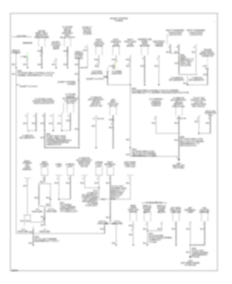
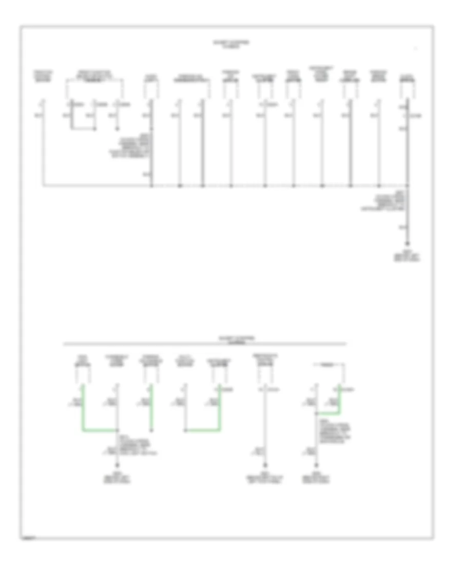
GROUND DISTRIBUTION
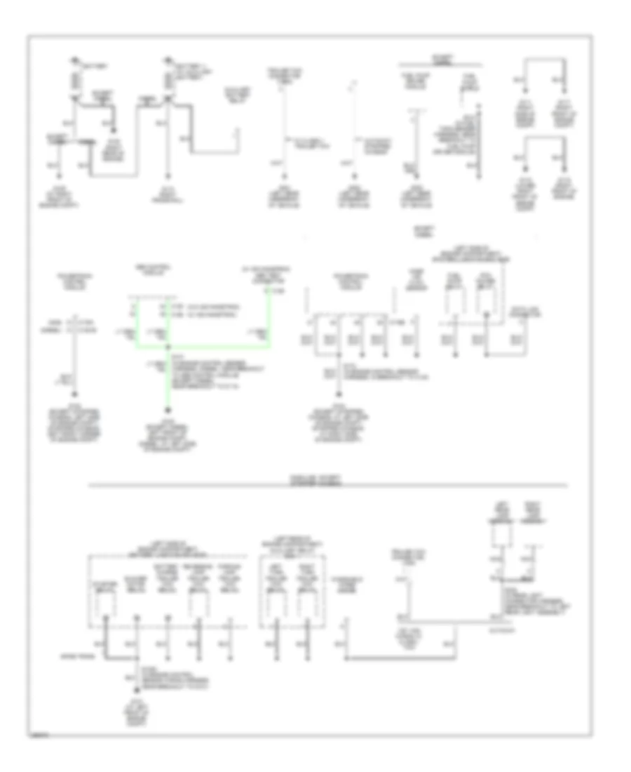
Ground Distribution Wiring Diagram (1 of 5) for Ford E450 Super Duty 2007
List of elements for Ground Distribution Wiring Diagram (1 of 5) for Ford E450 Super Duty 2007:
- (diesel)
- (gas)
- (left rear of engine compartment) auxiliary relay box 1
- (left side of engine compartment) battery junction box (bjb)
- (w/ advancetrac)
- (w/o advancetrac)
- 138" van/ wagon w/ class i tow
- 4r75e trans
- Abs control module
- Abs test connector
- Auxiliary battery relay
- Battery
- Battery charge trailer tow relay
- Battery ii (w/ auxiliary battery)
- Blower motor relay
- C126
- C135
- C1381b
- C155
- C175a
- C175b
- Cutaway
- Cutaway/ stripped chassis
- Data link connector
- Diesel
- Except diesel
- Fuel pump driver module
- Fuel pump relay
- Fuel pump shield
- G100 (except stripped chassis: left side of engine compt) (stripped chassis: left front corner of engine compt)
- G101 (at left front of engine compt)
- G104 (except stripped chassis: at left side of engine compt) (stripped chassis: at right side of engine compt)
- G105 (except diesel: left front of engine compt) (diesel: at left side of engine compt)
- G109 (at right front of engine compt)
- G110 (right frame rail)
- G111 (right side of engine compt)
- G117 (right front of engine compt)
- G118 (lower right front of engine compt)
- G119 (right front of engine)
- G120 (right rear of engine)
- G300 (left rear underbody of vehicle)
- G401 (left rear underbody of vehicle)
- G402 (left rear underbody of vehicle)
- Gasoline - except stripped chassis
- Harness, (diesel: near breakout to abs control module) (except diesel: near breakout to c110)
- Left rear lamp assembly
- Left turn trailer tow relay
- Mass air flow sensor
- Nca
- Parking lamp trailer tow relay
- Pcm power relay
- Powertrain control module
- Reversing lamp trailer tow relay
- Right rear lamp assembly
- Right turn trailer tow relay
- S1005 (in engine control sensor wiring harness, near breakout to g101)
- S172 (in engine control sensor harness, in breakout to c140)
- S312 (in fuel tank sender harness, near breakout to fuel pump driver module)
- Starter relay
- Trailer tow connector (7-pin)
- Trailer tow connector, 4-pin
- W/ class ii trailer tow
- Windshield wiper motor
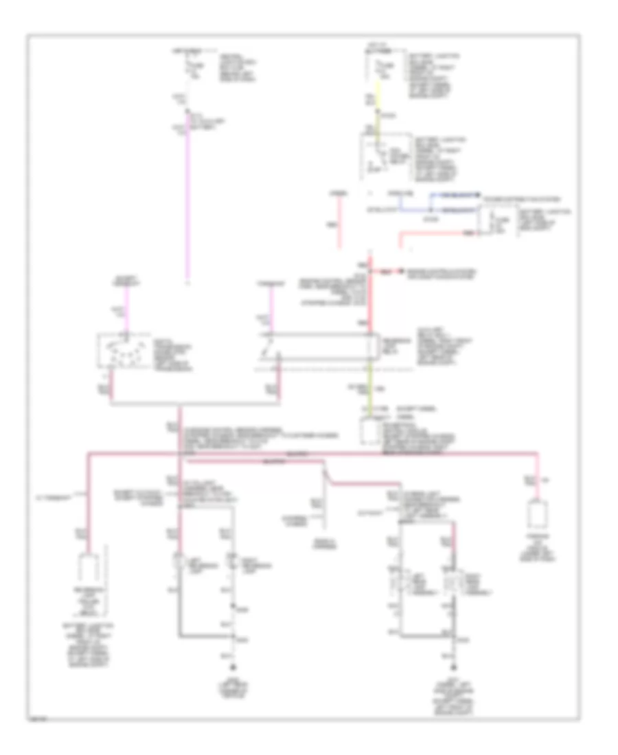
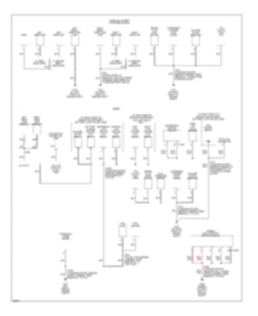
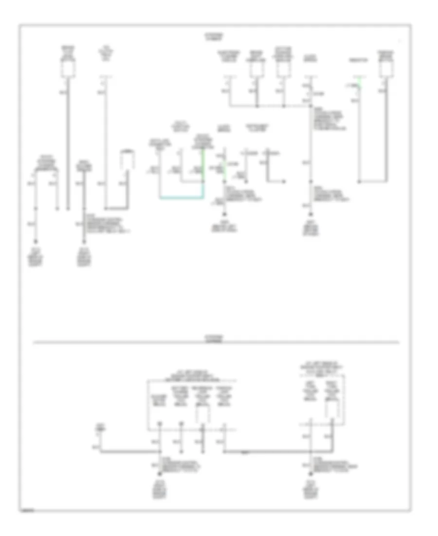
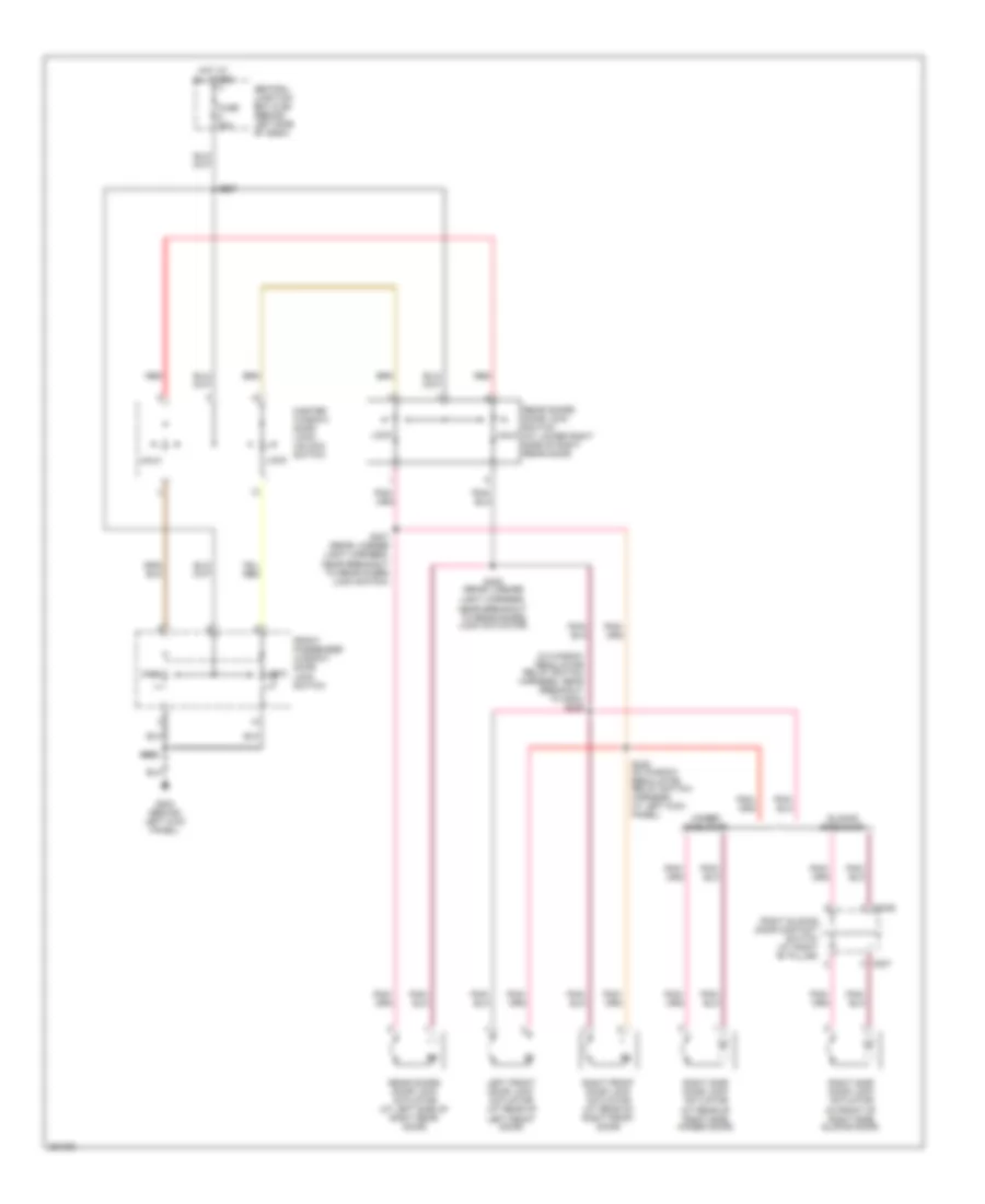
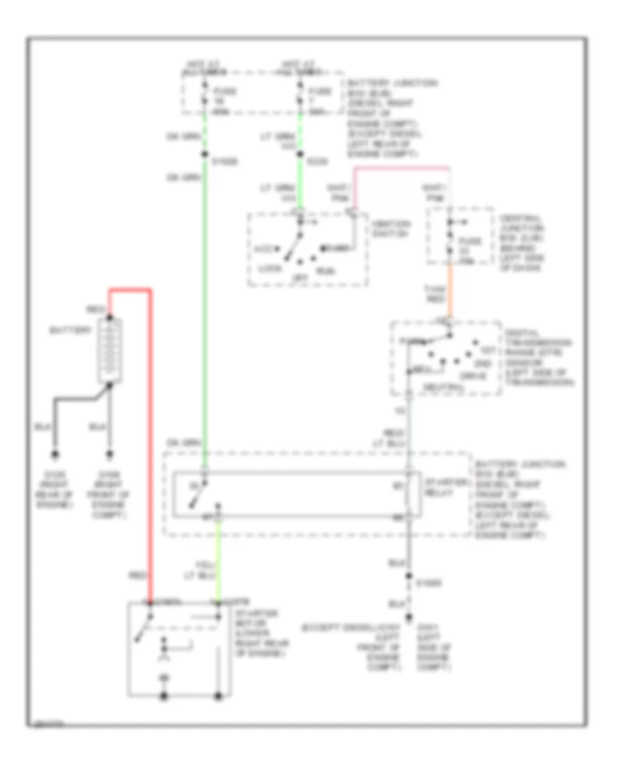
Ground Distribution Wiring Diagram (2 of 5) for Ford E450 Super Duty 2007
List of elements for Ground Distribution Wiring Diagram (2 of 5) for Ford E450 Super Duty 2007:
- (at right front of engine compartment) battery junction box (bjb)
- (at right rear of engine compartment) auxiliary relay box 1
- (diesel) fuel injector control module
- 138" van/ wagon w/ class i tow
- A/c clutch field coil
- Battery charge trailer tow relay
- Blower motor relay
- Blower motor resistor
- Brake fluid level switch
- C1388c
- C176a
- Cutaway
- Data link connector
- Diesel
- Dual pressure switch
- Fuel heater
- Fuel pump
- G101 (left side of engine compt)
- G102 (at left front of engine compt)
- G103 (at right front of engine compt)
- G106 (diesel) (at right ront of engine compt)
- G107 (at right front of engine compt)
- Gasoline - except stripped chassis
- Harness, near breakout to center front grille)
- Horn
- Left front park/turn lamp
- Left headlamp
- Left rear lamp assembly
- Left turn trailer tow relay
- Mass air flow sensor
- Nca
- Parking lamp trailer tow relay
- Pcm power relay
- Powertrain control module
- Reversing lamp trailer tow relay
- Right front park/turn lamp
- Right headlamp
- Right rear lamp assembly
- Right turn trailer tow relay
- S1005 (in engine control sensor wiring harness, near breakout to c110)
- S1029 (in engine control sensor harness, near breakout to c133)
- S143 (in engine control sensor harness, near breakout to c144)
- S143 (in engine control sensor harness, near breakout to right side of engine compt)
- S172 (in engine control sensor harness, at near breakout to windshield wiper motor)
- S404 (in fuel tank sender harness, near breakout to fuel pump)
- S432
- Trailer tow connector, 4-pin
- W/ aero headlamps
- W/ sealed beam headlamps
- Windshield washer pump motor
- Windshield wiper motor
Ground Distribution Wiring Diagram (3 of 5) for Ford E450 Super Duty 2007
List of elements for Ground Distribution Wiring Diagram (3 of 5) for Ford E450 Super Duty 2007:
- (at left rear of engine compartment) auxiliary relay box 1
- (at left side of engine compartment) battery junction box (bjb)
- (not used)
- 16-way stripped chassis connector
- A/c clutch field coil
- Battery charge trailer tow relay
- Blower motor relay
- Body builder ground
- Brake fluid level switch
- Brake shift interlock
- C218b
- C220a
- C220b
- Clock spring
- Data link connector (dlc)
- Daytime running lamps (drl) module
- Electronic flasher module
- G113 (left rear of engine compt)
- G114 (left rear of engine compt)
- G115 (right side of engine compt)
- G116 (right side of engine compt)
- G207 (behind center of dash)
- G208 (behind left side of dash)
- Horn
- Instrument cluster
- Left turn trailer tow relay
- Multi- function switch
- Nca
- Near breakout to auxiliary relay box 1)
- Parking brake switch
- Parking lamp trailer tow relay
- Resistor
- Reversing lamp trailer tow relay
- Right turn trailer tow relay
- S195 (in engine control sensor harness, in breakout to c110)
- S199 (in engine control sensor harness, near breakout to c219)
- S284 (in main wiring harness, near breakout to g207)
- S286 (in main wiring harness, near breakout to electronic flasher module)
- Stripped chassis
Ground Distribution Wiring Diagram (4 of 5) for Ford E450 Super Duty 2007
List of elements for Ground Distribution Wiring Diagram (4 of 5) for Ford E450 Super Duty 2007:
- (except cutaway) power point
- (in taillight harness, near breakout to rear doors door ajar switch) s406
- (w/ daytime running lamps) daytime running lamps (drl) module
- (w/ overhead console) overhead console
- (w/ power locks) master window/door lock/unlock switch
- (w/ power mirrors) exterior rear view mirror switch
- (w/ power seats) driver side front seat adjust switch
- (w/ remote keyless entry) rear doors door lock switch
- (w/ remote keyless entry) vehicle security module (vsm)
- C2113a
- Cargo lamp
- Cutaway
- Data link connector (dlc)
- Driver safety belt retractor pretensioner
- Electronic flasher module
- Ends in harness
- Ends in harness (w/ con- version)
- Except cutaway
- Except stripped chassis
- Front interior/ map lamps assembly
- Front passenger window/door lock switch
- G204 (behind left kick panel)
- G400 (left rear corner of vehicle)
- High mounted stoplamp
- Interior lamp
- Left front door ajar switch
- Left rear park/stop/ turn lamp
- Left reversing lamp
- License plate lamp
- Nca
- Rear a/c blower speed relay 1
- Rear a/c blower speed relay 2
- Rear doors door ajar switch
- Rear interior lamp
- Resistor
- Right front door ajar switch
- Right rear park/stop/ turn lamp
- Right reversing lamp
- Right side door ajar switch
- Right sliding door ajar switch
- S223 (in window regulator relay switch harness, near breakout to temperature blend door actuator)
- S233 in window regulator relay switch harness, near breakout to g204)
- S300 (in taillight harness, near breakout to c311)
- S402 (in taillight wiring harness, near breakout to g402)
- S414 (w/ remote keyless entry) (in rear license light harness, near breakout to license plate light)
- S500 (in left front door window regulator harness, near breakout to exterior rearview mirror switch)
- S600 (near breakout to right front door lock actuator)
- S913 (in interior lamps harness, near breakout to interior light)
- Stability control sensor cluster
- Temperature blend door actuator
- Trailer electronic brake control connector
- W/ auxiliary a/c
- W/ full headliner
- W/ headliner
- W/ hinged side door
- W/ remote keyless entry
- W/ sliding cargo door
- W/o full headliner
- W/o headliner
- W/o remote keyless entry
Ground Distribution Wiring Diagram (5 of 5) for Ford E450 Super Duty 2007
List of elements for Ground Distribution Wiring Diagram (5 of 5) for Ford E450 Super Duty 2007:
- Audio unit
- Brake shift interlock
- C2188a
- C218b
- C220a
- C220b
- C294b
- C294c
- C294e
- C310a
- Clock spring
- Except stripped chassis
- Front cigar lighter
- Front function selector switch assembly
- G200 (behind right side of dash)
- G201 (behind bottom of left kick panel)
- G202 (behind left side of dash)
- G203 (behind left end of dash)
- Instrument cluster
- Instrument panel power point
- Main light switch
- Multi- function switch
- Nca
- Parking aid disable switch
- Parking aid module
- Parking brake switch
- Radio
- Restraints control module
- S202 (in main wiring harness, near breakout to function selector switch assembly)
- S204 (in main wiring harness, near breakout to passenger air bag module)
- S207 (in main wiring harness, near breakout to instrument cluster)
- S214 (in main wiring harness, near breakout to main light switch)
- Traction control switch
- Windshield wiper motor
HEADLIGHTS
Headlights Wiring Diagram, with Stripped Chassis for Ford E450 Super Duty 2007
List of elements for Headlights Wiring Diagram, with Stripped Chassis for Ford E450 Super Duty 2007:
- Battery junction box (bjb) at left side of engine compt)
- C202b
- C220a
- C220b
- Central junction box (cjb) (behind left side of dash)
- Daytime running lamps (drl) module (if equipped) (right front of engine compartment)
- Drl
- Engine compartment)
- Fppwr
- Fuse 10a
- Fuse 15a
- Fuse 20a
- Fuse 30a
- G207 (behind center of dash)
- G208 (behind left side of dash)
- Gnd
- Head
- Hi beam ind
- High beam & drl
- Hot at all times
- Hot in run
- Instrument cluster
- Lo beam
- Logic ground
- Low beam
- Main light switch
- Multi- function switch
- Off
- Park
- Pass
- S186
- S196 (engine control sensor harness, left rear side of engine compartment)
- S2013
- S214
- S218 s276
- S286
- Stripped chassis connections
- Vbatt
- Vpwr
Headlights Wiring Diagram, without Stripped Chassis for Ford E450 Super Duty 2007
List of elements for Headlights Wiring Diagram, without Stripped Chassis for Ford E450 Super Duty 2007:
- (diesel) (except diesel)
- (except diesel: engine control sensor harness, at left rear side of engine compartment)
- Battery junction box (bjb) (except diesel: at left side of engine compt) (diesel: at right front of engine compartment)
- C202b
- C220a
- C220b
- Central junction box (cjb) (behind left side of dash)
- Daytime running lamps (drl) module (if equipped) (right front of engine compartment)
- Fppwr
- Fuse 10a
- Fuse 15a
- Fuse 20a
- Fuse 30a
- G102 (at left front of engine compartment)
- G202 (behind left side of dash)
- G204 (behind left kick panel)
- Gnd
- Head
- Hi beam ind
- Hot at all times
- Hot in run
- Instrument cluster
- Left headlamp
- Lo beam
- Logic ground
- Main light switch
- Multi- function switch
- Off
- Park
- Pass
- Right headlamp
- S145 s186
- S163
- S164 (in dash panel to headlamp junction wiring harness, near breakout to front impact severity sensor)
- S2013
- S214
- S218 s218
- S250
- Vbatt
- Vpwr
- W/ aero headlamp
- W/o aero headlamp
HORN
Horn Wiring Diagram for Ford E450 Super Duty 2007
List of elements for Horn Wiring Diagram for Ford E450 Super Duty 2007:
- (diesel)
- (except diesel)
- (except stripped chassis)
- 15a
- Battery junction box (bjb)
- Battery junction box (bjb) (diesel: at right front of engine compt) (except diesel: at left side of engine compt)
- C175b
- C2113b
- Clockspring (in steering wheel)
- Except stripped chassis
- Fuse 5
- G102 (except stripped chassis) (left front of eng compt)
- G113 (stripped chassis) (left rear of engine compt)
- G208 (behind left side of dash)
- Horn
- Horn relay
- Horn switch
- Hot at all times
- Nca
- Powertrain control module (pcm) (left rear of engine compt)
- S1034
- S163 (except stripped chassis)
- S197 (stripped chassis)
- S214
- Speed control switch
- Stripped chassis
- Vehicle security module (vsm) (w/ remote keyless entry) (behind left end of dash)
INSTRUMENT CLUSTER
Instrument Cluster Wiring Diagram for Ford E450 Super Duty 2007
List of elements for Instrument Cluster Wiring Diagram for Ford E450 Super Duty 2007:
- (at left side of dash) g208
- (behind left end of dash) (except stripped chassis) g203 g207 (stripped chassis) (behind center of dash)
- (conn a)
- (conn b)
- (except stripped chassis)
- (except stripped chassis) s207
- (in main wiring harness, near parking brake switch) (except stripped chassis) s268
- (stripped chassis)
- A10
- A11
- A12
- A13
- A14
- A15
- A16
- A17
- A18
- Abs led
- Accessory delay relay
- Air bag ind
- Air bag/seat belt status tone output
- Anti-lock brakes system
- B12
- B13
- B14
- B15
- B16
- B17
- B18
- B19
- B20
- B22
- B23
- B24
- B25
- B26
- Back light illumination
- Battery junction box (bjb) (diesel: at right front of engine compt) (except diesel: at left side of engine compt)
- Battery saver control
- Brake fluid led
- Brake fluid level switch
- C1381b
- C220a
- C220b
- Can+
- Can-
- Central junction box (cjb) (behind left side of dash)
- Computer data lines system
- Courtesy lamp control
- Delayed accessory relay control
- Dome lamp request input
- Drv bucklesw input
- Drv door ajar sw sig
- Except stripped chassis
- Exterior lights system
- Fuel gauge in
- Fuel gauge return
- Fuel gauge sensor
- Fuel tank unit (under rear of vehicle, near fuel tank)
- Fuse 15a
- Fuse 5a
- G202 (at left side of dash)
- G203 (except stripped chassis) (behind left end of dash)
- G207 (stripped chassis) (behind center of dash)
- G300 (fuel tank sender underbody of vehicle)
- Generator/battery ind
- Headlights system
- Hieg beam ind
- Hot at all times
- Hot at all times feed
- Hot in run or acc
- Hot in start or run
- Instrument cluster
- Interior lights system
- Key in ignition
- Lh turn signal ind
- Logic ground
- Ms can+
- Ms can-
- Nca
- Oil pressure ind
- Oil pressure switch (except diesel: at lower left front of engine) (diesel: at top center of engine)
- Park/head
- Parking brake switch
- Parking brake switch (near left kick panel)
- Passengers door ajar switch signal
- Powertrain control module (pcm) (diesel) (at left rear of engine compt)
- Red/pnk
- Rh turn signal ind
- Run/acc feed
- Run/start feed
- S1022
- S205 (except stripped chassis)
- S207
- S214
- S284
- S284 (stripped chassis)
- S291
- S312 (fuel tank sender harness, near breakout to fuel pump driver module)
- Side dr ajar sig
- Starting/charging system anti-lock brakes
- Traction control ind
- Traction sw feed
- Warning system
Overhead Console Wiring Diagram for Ford E450 Super Duty 2007
List of elements for Overhead Console Wiring Diagram for Ford E450 Super Duty 2007:
- (not
- Ambient air temperature sensor (left front of engine compt)
- Central junction box (cjb) (behind left side of dash)
- Fuse 15a
- G204 (behind left kick panel)
- Gnd
- Head
- Hot at all times
- Hot in run or acc
- Main light switch
- Nca
- Off
- Overhead console
- Park
- Park/head
- S234
- S245
- S250
- Sig rtn
- Transmissions system
- Used)
- Vpwr
- Vref
- Vss
INTERIOR LIGHTS
Courtesy Lamps Wiring Diagram, with Stripped Chassis for Ford E450 Super Duty 2007
List of elements for Courtesy Lamps Wiring Diagram, with Stripped Chassis for Ford E450 Super Duty 2007:
- Central junction box (cjb) (behind left side of dash)
- Fuse 15a
- Hot at all times
- Interior switch
- Main light switch
- S219 (in main harness, near g207 breakout)
- To i/p body builder connector
Courtesy Lamps Wiring Diagram, without Stripped Chassis for Ford E450 Super Duty 2007
List of elements for Courtesy Lamps Wiring Diagram, without Stripped Chassis for Ford E450 Super Duty 2007:
- (at left kick panel) g204
- (behind left kick panel) g204
- (except cutaway)
- (in interior lights harness, near breakout to interior light) s911
- (in interior lights harness, near breakout to interior light) s912
- (in main harness, near audio unit breakout)
- (in taillight harness, near g402 breakout) s402
- (in taillight wiring harness, near breakout to c311) s301
- (left rear corner of vehicle) g400
- (right) (at right "b" pillar)
- Auxiliary relay box 2 (behind center of dash)
- Battery saver relay
- Battery svr
- C220a
- Cargo lamp
- Central junction box (cjb) (behind left side of dash)
- Crtsy lamp dr ajar sw sig sliding door ajar sw sig c220b
- Cutaway
- Dome
- Dome req
- Door ajar switch (left front) (behind left kick panel)
- Door ajar switch (rear doors)
- Drv door ajar sw sig
- Ends in harness
- Except cutaway
- Exterior lights system
- Front door ajar switch (right) (behind right kick panel)
- Fuse 15a
- G202 (behind left side of dash)
- G400 (left rear corner of vehicle)
- High mounted stoplamp
- Hot at all times
- Instrument cluster
- Interior lamp
- Interior lamp relay
- Interior/ map lamps assembly (front)
- Main light switch
- Nca
- Off
- Rear interior lamp
- Red/pnk
- S205
- S209 (in engine control sensor harness, near aux relay box no.1 breakout)
- S214
- S223
- S233
- S253 (in window reg- ulator relay switch harness, near vsm breakout)
- S300
- S302 (in taillight wiring harness, near breakout to c311)
- S314 (in interior light harness, near breakout to c315)
- S402
- S913
- Side door ajar switch (right) (in front of right side door)
- Sliding door ajar switch
- Vanity mirror lamp (left)
- Vanity mirror lamp (right)
- W/ hinged cargo door
- W/ sliding cargo door
- W/ speaker
Instrument Illumination Wiring Diagram for Ford E450 Super Duty 2007
List of elements for Instrument Illumination Wiring Diagram for Ford E450 Super Duty 2007:
- (not used)
- Audio unit
- Back light illum
- Back light illumination
- C218b
- C220a
- C220b
- C294e
- Central junction box (cjb) (behind left side of dash)
- Chassis)
- Clockspring (in steering wheel)
- Cutaway
- Dimmer
- Ends in harness
- Except cutaway
- Except stripped chassis
- Function selector switch assembly
- Fuse 20a
- Fuse 5a
- G203 (at left end of dash)
- G207 (at center of dash)
- Head
- Hot at all times
- I/p lamp feed
- Instrument cluster
- Instrument cluster, exterior lights systems
- Main light switch
- Nca
- Off
- Park
- Parking aid disable switch
- S212 (in main harness, near front cigar lighter breakout)
- S276 (stripped chassis)
- S284
- Speed control switch
- Stripped chassis
- Traction control switch (w/ advancetrac)
NAVIGATION
Parking Assistant Wiring Diagram for Ford E450 Super Duty 2007
List of elements for Parking Assistant Wiring Diagram for Ford E450 Super Duty 2007:
- (backup alarm jumper harness, behind rear bumper, near trailer tow) s4000
- Central junction box (cjb) (behind left side of dash)
- Computer data lines system
- Enable/ disable
- Exterior lights system
- Fuse 10a
- G202 (behind left side of dash)
- G203 (behind left end of dash)
- Gnd
- Hot in run
- Inner left parking aid sensor (behind left side of rear bumper)
- Inner right parking aid sensor (behind right side of rear bumper)
- Interior lights system
- Iso
- Li sensor in
- Lo sensor in
- On/off sw
- Outer left parking aid sensor (behind left side of rear bumper)
- Outer right parking aid sensor (behind right side of rear bumper)
- Parking aid disable switch
- Parking aid module (under left side of dash)
- Parking aid speaker (under left side of dash)
- Pwr run
- Rear sounder +
- Rear sounder -
- Reverse in
- Ri sensor in
- Ro sensor in
- S201
- S207
- S214
- S4001 (backup alarm jumper harness, behind rear bumper, near trailer tow)
- Sensor gnd
- Sensor pwr
- Status led
POWER DISTRIBUTION
Power Distribution Wiring Diagram (1 of 6) for Ford E450 Super Duty 2007
List of elements for Power Distribution Wiring Diagram (1 of 6) for Ford E450 Super Duty 2007:
- (at right front of engine compt) battery junction box (bjb)
- (engine control sensor & fuel charge harness, in breakout to starter motor)
- (engine control sensor & fuel charge harness, in breakout to starter motor) s1052
- (engine control sensor & fuel charge harness, in breakout to starter motor) s1072
- (in starter relay to fuse junction panel harness, in breakout to battery) s1007
- (in starter relay/battery ground harness, in breakout to battery) s1073
- (in starter relay/battery ground harness, in breakout to battery) s1074
- (in starter relay/battery ground harness, in breakout to battery) s1076
- (near breakout to battery junction box) red s1075
- Abs test connector
- Battery
- Battery ii
- Battery junction box (bjb) (at left side of engine compt)
- Battery junction box (bjb) (at right front of engine compt)
- Blower motor relay
- C102a
- C102c
- C1104a
- C1104c
- C1251b
- C1273a
- C1273b
- Diesel
- Except diesel
- Fuel injector control module (ficm) power relay
- Fuel pump relay
- Fuse 20a
- Fuse 40a
- Fuse 50a
- Generator
- Glow plug control module (gpcm)
- Red
- Remote jump start terminal
- S1008 (in starter relay to fuse junction panel harness, in breakout to battery)
- S1051 (in breakout to starter motor)
- S1054 (in breakout to starter motor)
- S1055 (near breakout to left front of engine)
- S1056 (in breakout to starter motor)
- S1071
- S1073 (alternator rectifier system harness, red (near breakout to battery junction box)
- S191 (in alternator rectifier system harness, in breakout to battery)
- S192 (in alternator rectifier system harness, in breakout to battery)
- Secondary generator
- Starter motor
- To fuse 9 (diagram 2 of 6)
- W/ advance trac
- W/ dual generators
Power Distribution Wiring Diagram (2 of 6) for Ford E450 Super Duty 2007
List of elements for Power Distribution Wiring Diagram (2 of 6) for Ford E450 Super Duty 2007:
- (at left kick panel) g204
- (except diesel: in engine control sensor harness, near breakout to g101) (diesel: in engine control sensor harness, near breakout to battery junction box) s1034
- (except diesel: in engine sensor harness, at left front of engine compt) (diesel: in engine sensor harness, at right front of engine compt) s1028
- (except stripped chassis)
- (in engine control sensor harness, in breakout to auxiliary relay box 1) (except diesel) s186
- (in engine control sensor harness, in breakout to auxiliary relay box 1) s1019
- (in window regulator relay switch harness, near breakout ignition switch) s229
- (in window regulator relay switch harness, near left kick panel) s266
- (not used)
- A/c clutch relay
- All
- Auxiliary relay box 1 (diesel: at right front of engine compt) (except diesel: at left rear of engine compt)
- Battery junction box (bjb) (diesel: at right front of engine compt) (except diesel: at left side of engine compt)
- C1251a
- Central junction box (cjb) (behind left side of dash)
- Conversion
- Cutaway
- Data link connector (dlc)
- Daytime running lamps (drl) module (if equipped)
- Ends in harness
- Except stripped chassis
- From a fuse 13 (diagram 1 of 6)
- Front cigar lighter
- Fuse 10a (diesel)
- Fuse 15a
- Fuse 20a
- Fuse 30a
- Fuse 50a
- Fuse 60a
- G202 (behind left side of dash)
- Horn relay
- I/p body builder connector
- In engine control sensor harness, left rear side of engine compt) s2012
- Left turn trailer tow relay
- Others
- Power point (behind center of dash)
- Power point (behind left "b" pillar)
- Red
- Right turn trailer tow relay
- S145 (diesel) (in engine control sensor harness, near breakout to g106)
- S207
- S235
- Secondary generator
- Starter relay
- Stripped chassis
- To fuse 21 (diagram 3 of 6)
- Van
- W/ dual generators
- W/ single generators
Power Distribution Wiring Diagram (3 of 6) for Ford E450 Super Duty 2007
List of elements for Power Distribution Wiring Diagram (3 of 6) for Ford E450 Super Duty 2007:
- (diesel)
- (except diesel)
- (in engine control sensor harness, except diesel: left side of engine compt, diesel: right side of eng compt) s1033
- (in main harness, harness, at left side of dash)
- (in main harness, near breakout to audio unit s205
- (in main harness, near breakout to electronic flasher module) s282
- (in main harness, near breakout to g207) s219
- (in main harness, near breakout to main light switch) s276
- (in main harness, under left side of dash) s221
- (in window regulator relay switch harness, near breakout accelerator pedal postion switch) (w/ remote keyless entry) s261
- (in window regulator relay switch harness, near breakout to accelerator pedal position switch)
- (in window regulator relay switch harness, near breakout to brake pedal position switch)
- (not used)
- 16-way stripped chassis connector
- Audio unit
- Auxiliary battery relay
- Auxiliary relay box 2 (behind center of dash)
- Battery charge trailer tow relay
- Battery ii
- Battery junction box (bjb) (diesel: at right front of engine compt) (except diesel: at left side of engine compt)
- Battery saver relay
- Brake pedal position switch
- C.b. 20a
- C1381b
- C175b
- C202a
- C202b
- C2113a
- C220b
- C240
- C280
- Central junction box (cjb) (behind left side of dash)
- Cutaway
- Diesel
- Driver side front seat adjust switch
- Ends in harness
- Evap canister vent valve (gas)
- Except cutaway
- Except stripped chassis
- Exterior rear view mirror switch
- From b fuse 18 (diagram 2 of 6)
- Front passenger window/ door lock switch
- Fuse
- Fuse 10a
- Fuse 15a
- Fuse 20a
- Fuse 30a
- Fuse 40a
- Fuse 50a
- Fuse 5a
- Fuse 60a
- Fuse fuse 30a 30a
- Gasoline w/ auxiliary battery
- Gasoline w/o auxiliary battery
- I/p body builder connector
- Instrument cluster
- Interior lamp relay
- Main light switch
- Master window/ door lock/ unlock switch
- Multi- function switch
- Nca
- Parking lamp trailer tow relay
- Pcm power relay
- Powertrain control module (pcm)
- Rear a/c blower speed relay 1
- Rear doors door lock switch
- Reversing lamp trailer tow relay
- S1021 (in engine control sensor harness, (left side of engine compt)
- S1027
- S1032 (in engine control sensor harness, except diesel: left side of engine compt, diesel: right side of engine compt)
- S218
- S225
- S237
- S291
- Stripped chassis
- To accessory delay relay (diagram 4 of 6)
- To fuse 15 (diagram 4 of 6)
- To multi- function switch (diagram 6 of 6)
- Traction control switch
- Vehicle security module (vsm)
- Vehicle security module (vsm) (w/ rke)
- W/ auxiliary a/c
- Windshield wiper motor
Power Distribution Wiring Diagram (4 of 6) for Ford E450 Super Duty 2007
List of elements for Power Distribution Wiring Diagram (4 of 6) for Ford E450 Super Duty 2007:
- (center of driver's door) s501
- (engine control harness, near breakout to c219) s2013
- (except stripped: in window regulator relay switch harness, near breakout to igniton switch, stripped: in main harness, under left end of dash) s230
- (except stripped: in window regulator relay switch harness, near breakout to igniton switch, stripped: in main harness, under left end of dash) s280
- (in engine control sensor harness, except stripped: center rear of engine compt, stripped: left side of engine compt) (w/ auxiliary battery) s113
- (in engine control sensor harness, in breakout to abs control module) s177
- (in main harness, near breakout to function selector switch assembly) s203
- (in window regulator relay switch harness, (at left end of dash) s245
- (in window regulator relay switch harness, (near breakout to accelerator pedal postion switch)
- (in window regulator relay switch harness, near breakout to brake pedal position switch)
- (in window regulator relay switch harness, near breakout to temp blend door actuator) s242
- (main harness, near breakout to main light switch) s201
- 40a
- Abs control module
- Acc
- Accessory delay relay
- At left side of engine compt)
- Audio unit
- Auxiliary battery diode
- Auxiliary battery relay (if equipped)
- Auxiliary relay box 1 (diesel: at right front of engine compt) (except diesel: at left side of engine compt)
- Battery junction box (bjb)
- Battery junction box (bjb) (diesel: at right front of engine compt) (except diesel: at left side of engine compt)
- Brake shift interlock
- C.b. 20a
- C202a
- C220b
- C240
- C294a
- Central junction box (cjb) (behind left side of dash)
- Daytime running lights
- Digital transmission range (dtr) sensor
- Except stripped chassis
- Except torqshift
- From e fuse 14 (diagram 3 of 6)
- From s291 f (diagram 3 of 6)
- Front passenger window/door lock switch
- Function selector switch assembly
- Fuse 10a
- Fuse 15a
- Fuse 30a
- Fuse 5a
- Fuse 60a
- I/p body builder connector
- Ignition switch
- Instrument cluster
- Lock
- Main light switch
- Master window/door lock/unlock switch
- Multi- function switch
- Off
- Overhead console
- Parking aid module
- Red
- Reversing lamp relay
- Run
- S227
- S236
- Start
- Stripped chassis
- Temperature blend door actuator
- To fuse 14 (diagram 5 of 6)
- To fuse 33 (diagram 5 of 6)
- To fuse 9 (diagram 6 of 6)
- Torqshift
- Trailer electronic brake control connector
- W/ advance trac
- W/ overhead console
- W/ power door locks
- W/o advance trac
Power Distribution Wiring Diagram (5 of 6) for Ford E450 Super Duty 2007
List of elements for Power Distribution Wiring Diagram (5 of 6) for Ford E450 Super Duty 2007:
- (6.8l)
- (diesel: at right front of engine compt) (except diesel: at left side of engine compt)
- (except 6.8l)
- (in engine control sensor & fuel charge harness, in breakout to heated positive crankcase ventilation valve s161
- (in engine control sensor wiring harness, at left rear of engine compt) s127 (stripped chassis) s1065 (except stripped chassis)
- (in main harness, in breakout to cigar ligher) s260
- (in window regulator relay switch harness, near breakout to accelerator pedal position switch) s216
- Abs
- Audio unit
- Battery junction box (bjb)
- Battery junction box (bjb) (diesel: at right front of engine compt) (except diesel: at left side of engine compt)
- C126
- C1388c
- C155
- C203b
- C220a
- C240
- C310a
- Cancel switch
- Central junction box (cjb) (behind left side of dash)
- Coil on plug (cop) 1
- Coil on plug (cop) 10 (6.8l)
- Coil on plug (cop) 2
- Coil on plug (cop) 3
- Coil on plug (cop) 4
- Coil on plug (cop) 5
- Coil on plug (cop) 6
- Coil on plug (cop) 7
- Coil on plug (cop) 8
- Coil on plug (cop) 9 (6.8l)
- Control module
- Control sensor cluster
- Diesel
- Digital transmission range (dtr) sensor
- Except diesel
- Except stripped chassis
- Except torqshift
- From ignition switch k (diagram 4 of 6)
- From ignition switch l (diagram 4 of 6)
- Fuel heater
- Fuel injector control module (ficm)
- Fuse 10a
- Fuse 15a
- Fuse 5a
- Ignition transformer capacitor 1
- Ignition transformer capacitor 2
- Instrument cluster
- Nca
- Overdrive
- Pcm power diode
- Pcm power relay
- Position sensor
- Restraints control module
- S156
- S162 (in engine control sensor & fuel charge harness, near breakout to throttle position sensor)
- Security module (vsm)
- Stability
- Starter relay
- Steering
- Tan/red
- Test connector
- Torqshift
- Vehicle
- W/ advance trac
- W/ remote keyless entry
Power Distribution Wiring Diagram (6 of 6) for Ford E450 Super Duty 2007
List of elements for Power Distribution Wiring Diagram (6 of 6) for Ford E450 Super Duty 2007:
- (gasoline: in engine control sensor harness, left side of engine compt, diesel: in engine control sensor harness, center rear of engine compt, stripped: main harness, behind left side of dash) s1022
- (window regulator relay switch harness, at left kick panel) s246
- 16-way stripped chassis connector
- Battery charge trailer tow relay
- Battery junction box (bjb) (diesel: at right front of engine compt) (except diesel: at left side of engine compt)
- C202a
- C220b
- Central junction box (cjb) (behind left side of dash)
- Except stripped chassis
- From fuse 11 (diagram 3 of 6)
- From ignition switch (diagram 4 of 6)
- Fuse 15a
- Fuse 5a
- Instrument cluster
- Multi- function switch
- Not used
- S105 (in engine control sensor harness, near breakout to g101)
- Stability/ traction control relay
- Stripped chassis
- Vehicle security module (vsm)
- W/ advancetrac
- W/o advancetrac
- Windshield wiper motor (except stripped chassis)
POWER DOOR LOCKS
Power Door Locks Wiring Diagram, with Cutaway Chassis without Keyless Entry for Ford E450 Super Duty 2007
List of elements for Power Door Locks Wiring Diagram, with Cutaway Chassis without Keyless Entry for Ford E450 Super Duty 2007:
- (in window regulator relay switch harness, near breakout to g204) s239
- Central junction box (cjb) (behind left side of dash)
- Front passenger window/ door lock switch
- Fuse 30a
- G204 (behind left kick panel)
- Hot at all times
- Left front door lock actuator (at rear of left front door)
- Lock
- Master window/ door lock/ unlock switch
- Red
- Right front door lock actuator (at rear of right front door)
- S237
- S238 (in window regulator relay switch harness, at left kick panel)
- S600
- Unlk
Power Door Locks Wiring Diagram, with Keyless Entry (1 of 2) for Ford E450 Super Duty 2007
List of elements for Power Door Locks Wiring Diagram, with Keyless Entry (1 of 2) for Ford E450 Super Duty 2007:
- (in window regulator relay switch harness, near breakout to g204) s239
- +/-
- C2113a
- C2113b
- C3235
- C807
- Central junction box (cjb) (behind left side of dash)
- Computer data lines system
- Except cutaway
- Fuse 10a
- Fuse 20a
- Fuse 5a
- G204 (behind left kick panel)
- Ground
- Head
- Hinged side door
- Horn relay
- Horns system
- Hot at all times
- Hot in run or acc
- Hot in run or start
- Left front door lock actuator (at rear of left front door)
- Lock
- Main light switch
- Ms can+
- Ms can-
- Off
- Park
- Park/head
- Rear doors door lock actuator (except cutaway) (at left side of right rear door)
- Right front door lock actuator (at rear of right front door)
- Right side door lock actuator (at rear of right side hinged door)
- Right side door lock actuator (in front of right side sliding door)
- Right sliding door contact switch (at right "b" pillar)
- Run/acc
- Run/start
- S216
- S218
- S233
- S234
- S238 (in window regulator relay switch harness, at left kick panel)
- S246
- S250
- S261
- Sliding side door
- Unlock
- Vehicle security module (vsm) (behind right end of dash)
Power Door Locks Wiring Diagram, with Keyless Entry (2 of 2) for Ford E450 Super Duty 2007
List of elements for Power Door Locks Wiring Diagram, with Keyless Entry (2 of 2) for Ford E450 Super Duty 2007:
- (except cutaway)
- C220a
- C220b
- Central junction box (cjb) (behind left side of dash)
- Computer data lines system
- Corner of vehicle)
- Doors ajar
- Driver door ajar
- Front passenger window/door lock switch
- Fuse 15a
- Fuse 5a
- G202 (behind left side of dash)
- G203 (behind left end of dash)
- G204 (behind left kick panel)
- G400 (left rear
- G400 (left rear corner of vehicle)
- Hot at all times
- Hot in run or start
- Instrument cluster
- Left front door ajar switch (at left kick panel)
- Lock
- Logic ground
- Master window/ door lock/unlock switch
- Ms can+
- Ms can-
- Nca
- Pwr ground
- Rear doors door ajar switch (except cutaway)
- Rear doors door lock switch
- Red/ pnk
- Red/pnk
- Right front door ajar switch (at right kick panel)
- Right side door ajar switch (in front of right side door)
- Right sliding door ajar switch (at right "b" pillar)
- Run/start
- S205
- S207
- S214
- S223
- S233
- S251 (in window regulator relay switch harness, near breakout to g204)
- S252 (in window regulator relay switch harness, near breakout to g204)
- S253 (window regulator relay switch harness, near breakout to vehicle security module)
- S402
- S414
- S500
- S600
- Sliding door ajar
- Unlock
- W/ hinged cargo door
- W/ sliding cargo door
Power Door Locks Wiring Diagram, without Cutaway Chassis without Keyless Entry for Ford E450 Super Duty 2007
List of elements for Power Door Locks Wiring Diagram, without Cutaway Chassis without Keyless Entry for Ford E450 Super Duty 2007:
- (in window regulator relay switch harness, near breakout to g204) s239
- C3235
- C807
- Central junction box (cjb) (behind left side of dash)
- Front passenger window/ door lock switch
- Fuse 30a
- G204 (behind left kick panel)
- Hinged side door
- Hot at all times
- Left front door lock actuator (at rear of left front door)
- Lock
- Master window/ door lock/ unlock switch
- Rear doors door lock actuator (at left side of right rear door)
- Rear doors door lock switch (at lower right side of right rear door)
- Red
- Right front door lock actuator (at rear of right front door)
- Right side door lock actuator (at rear of right side hinged door)
- Right side door lock actuator (in front of right side sliding door)
- Right sliding door contact switch (at right "b" pillar)
- S237 s237
- S238 (in window regulator relay switch harness, at left kick panel)
- S407 (rear license light harness, near breakout to rear doors lock switch)
- S408 (rear license light harness, near breakout to rear doors lock actuator)
- S600 s600
- Sliding side door
- Unlk
POWER MIRRORS
Power Mirrors Wiring Diagram for Ford E450 Super Duty 2007
List of elements for Power Mirrors Wiring Diagram for Ford E450 Super Duty 2007:
- Central junction box (cjb) (behind left side of dash)
- Down
- Driver side exterior rear view mirror
- Exterior rear view mirror switch
- Fuse 5a
- G204 (behind left kick panel)
- Horizontal
- Hot at all times
- Left
- Left/ right
- Left/ right m
- Mirror select
- Nca
- Passenger side exterior rear view mirror
- Red
- Right
- S500
- S504 (in left front door window regulator harness, near breakout to left front speaker)
- Up/ down m
- Vertical
POWER SEATS
Power Seats Wiring Diagram for Ford E450 Super Duty 2007
List of elements for Power Seats Wiring Diagram for Ford E450 Super Duty 2007:
- Central junction box (cjb) (behind left side of dash)
- Driver seat front height motor (under driver seat)
- Driver seat horizontal motor (under driver seat)
- Driver seat rear height motor (under driver seat)
- Entire seat
- Front driver side seat adjust switch
- Front of seat
- Fuse 30a
- Fwd
- G204 (behind left kick panel)
- Hot at all times
- Nca
- Rear of seat
- Rwd
- S235
POWER WINDOWS
Power Windows Wiring Diagram for Ford E450 Super Duty 2007
List of elements for Power Windows Wiring Diagram for Ford E450 Super Duty 2007:
- Central junction box (cjb) (behind left side of dash)
- Circuit breaker f42 20a
- Driver side front power window motor (center of left front door)
- Front passenger window/ door lock switch
- G204 (at left kick panel)
- Hot in run or acc
- Master window/ door lock/ unlock switch
- Nca
- Passenger side front power window motor (center) of right front door)
- S236
- S500
- S501
RADIO
Radio Wiring Diagram for Ford E450 Super Duty 2007
List of elements for Radio Wiring Diagram for Ford E450 Super Duty 2007:
- (behind left end of dash) g203
- (in window regulator relay switch harn, near breakout to c3138, bottom of left "b" pillar)
- (in window regulator relay switch harn, near breakout to power point) s244
- (in window regulator relay switch harness, near breakout to temperature blend door actuator) s241
- (not used)
- Antenna
- C240
- C312
- C3235
- C807
- Central junction box (cjb) (behind left side of dash)
- Cutaway
- Fuse 15a
- Fuse 5a
- G200 (behind right side of dash)
- Ground
- Hinged side door
- Hot at all times
- Hot in park or head
- Hot in run or acc
- Hot in start
- Illum, feed
- L front speaker (+)
- L rear speaker (+)
- L rear speaker (-)
- Left front speaker
- Left middle speaker (w/ 6 speakers)
- Left rear speaker
- Nca
- R front speaker (+)
- R front speaker (-)
- R rear speaker (+)
- R rear speaker (-)
- Radio
- Right front speaker
- Right middle speaker (w/ 6 speakers)
- Right rear speaker
- Right sliding door contact switch
- S202
- S204
- S205
- S212
- S240
- S243
- S245 (w/ overhead console)
- Sliding side door
- Twisted pair
- Van, wagon
- Vbatt
- Vpwr
SHIFT INTERLOCK
Shift Interlock Wiring Diagram for Ford E450 Super Duty 2007
List of elements for Shift Interlock Wiring Diagram for Ford E450 Super Duty 2007:
- (except stripped chassis)
- (stripped chassis)
- Brake pedal position switch (on bracket, above brake pedal)
- Brake shift interlock (on steering column)
- Central junction box (cjb) (behind left side of dash)
- Fuse 11 15a
- Fuse 6 10a
- G203 (behind left end of dash)
- G207 (behind center of dash)
- Hot at all times
- Hot in run
- Microprocessor
- S2013 s201
- S207
- S220 (in main harn, near breakout to c219, left rear of eng compt)
- S282
- Shift lock solenoid
- Solid state
STARTING/CHARGING
5.4L
5.4L, Charging Wiring Diagram for Ford E450 Super Duty 2007
List of elements for 5.4L, Charging Wiring Diagram for Ford E450 Super Duty 2007:
- (3g)
- (6g)
- (in alternator rectifier system wiring harn, in breakout battery) s1073
- Battery
- Battery voltage gauge
- C102a
- C102b
- C102c
- C1558c
- C220a
- C220b
- Central junction box (cjb) (behind left side of dash)
- Charge ind
- Fuse 5a
- G109 (right front of engine compt)
- G120 (right rear of engine)
- G202 (except stripped chassis) (behind left side of dash)
- G208 (stripped chassis) (behind left side of dash)
- Generator
- Hot in run or start
- Instrument cluster
- Micro- processor
- Red
- S191 (in alternator rectifier system wiring harn, near breakout to c146, right side of engine compt)
- S192 (in alternator rectifier system wiring harn, in breakout to battery)
- S214
- Starter motor (lower right rear of engine)
- W/ 3g
5.4L, Starting Wiring Diagram, with 4R75E for Ford E450 Super Duty 2007
List of elements for 5.4L, Starting Wiring Diagram, with 4R75E for Ford E450 Super Duty 2007:
- (except diesel)
- 1st
- 2nd
- Acc
- Battery
- Battery junction box (bjb) (diesel: right front of engine compt) (except diesel: left rear of engine compt)
- C197a
- C197b
- Central junction box (cjb) (behind left side of dash)
- Digital transmission range (dtr) sensor (left side of transmission)
- Drive
- Fuse 10a
- Fuse 60a
- G101 (left front of engine compt)
- G101 (left side of engine compt)
- G109 (right front of engine compt)
- G120 (right rear of engine)
- Hot at all times
- Ignition switch
- Lock
- Neutral
- Off
- Park
- Red
- Rev
- Run
- S1005
- S1028
- S230
- Start
- Starter motor (lower right rear of engine)
- Starter relay
- Tan/ red
5.4L, Starting Wiring Diagram, with Torqshift for Ford E450 Super Duty 2007
List of elements for 5.4L, Starting Wiring Diagram, with Torqshift for Ford E450 Super Duty 2007:
- (diesel)
- (except diesel)
- (except stripped chassis)
- (stripped chassis)
- Acc
- Battery
- Battery 2
- Battery junction box (bjb) (diesel: right front of engine compt) (except diesel: left rear of engine compt)
- C1381b
- C175b
- C197a
- C197b
- Central junction box (cjb) (behind left side of dash)
- Diesel
- Fuse 10a
- Fuse 60a
- G109 (right front of engine compt)
- G110 (on right frame rail)
- G120 (right rear of engine)
- Gas
- Hot at all times
- Ignition switch
- Lock
- Off
- Power distribution system
- Powertrain control module (pcm) (stripped chassis: right rear of engine compt, except stripped chassis: left rear of engine compt)
- Red
- Run
- S1028
- S230 s1030
- Start
- Starter motor (lower right rear of engine)
- Starter relay
- Tan/ red
6.0L DIESEL
6.0L Diesel, Charging Wiring Diagram, with Dual Generators for Ford E450 Super Duty 2007
List of elements for 6.0L Diesel, Charging Wiring Diagram, with Dual Generators for Ford E450 Super Duty 2007:
- (center rear of engine)
- (in alternator rectifier system harn, near breakout to battery junction box (bjb)) s1075
- (in engine control ensor & fuel charge harn, in breakout to starter motor) s1072
- (in engine control sensor & fuel charge wiring harn, in breakout to starter motor) s1052
- (in engine control sensor & fuel charge wiring harn, near breakout to stareter motor)
- (in starter relay & battery ground harn, in breakout to battery) s1076
- (under front passenger's seat)
- Battery
- Battery ii
- Battery junction box (bjb) (at right front of engine compt)
- Battery voltage gauge
- C102a
- C102c
- C1035a
- C1035b
- C1251a
- C1251b
- C1381b
- C1381e
- C197a
- C197c
- C220a
- Central junction box (cjb) (behind left side of dash)
- Charge harn, in breakout to starter motor)
- Charge ind
- Fuse 10a
- Fuse 5a
- G110 (on right frame rail)
- Generator
- Hot at all times
- Hot in start or run
- Instrument cluster
- Micro- processor
- Power distribution system
- Powertrain control module (pcm) (left rear of engine compt)
- Red
- S1055
- S1056
- S1071 (in engine control ensor & fuel red
- S1073 (in alternator rectifier system wiring harness, near breakout to battery junction box (bjb))
- S1074 (in starter relay & battery ground harn, in breakout to battery)
- Secondary generator
- Starter motor (lower right rear of engine)
6.0L Diesel, Charging Wiring Diagram, without Dual Generators for Ford E450 Super Duty 2007
List of elements for 6.0L Diesel, Charging Wiring Diagram, without Dual Generators for Ford E450 Super Duty 2007:
- (center rear of engine)
- (in engine control sensor & fuel charge harn, in breakout to starter motor) s1072
- (in engine control sensor & fuel charge wiring harn, in breakout to starter motor) s1052
- (in engine control sensor & fuel charge wiring harn, near breakout to starter motor)
- Battery
- Battery 2
- Battery voltage gauge
- C102a
- C102c
- C197a
- C197c
- C220a
- Central junction box (cjb) (behind left side of dash)
- Charge ind
- Fuse 5a
- G110 (right frame rail)
- Generator
- Hot in start or run
- Instrument cluster
- Micro- processor
- Power distribution system
- Red
- S1055
- S1056
- S1071 (in engine control sensor & fuel charge harn, in breakout to starter motor)
- Starter motor (lower right rear of engine)
6.0L Diesel, Starting Wiring Diagram, with Torqshift for Ford E450 Super Duty 2007
List of elements for 6.0L Diesel, Starting Wiring Diagram, with Torqshift for Ford E450 Super Duty 2007:
- (diesel)
- (except diesel)
- (except stripped chassis)
- (stripped chassis)
- Acc
- Battery
- Battery 2
- Battery junction box (bjb) (diesel: right front of engine compt) (except diesel: left rear of engine compt)
- C1381b
- C175b
- C197a
- C197b
- Central junction box (cjb) (behind left side of dash)
- Diesel
- Fuse 10a
- Fuse 60a
- G109 (right front of engine compt)
- G110 (on right frame rail)
- G120 (right rear of engine)
- Gas
- Hot at all times
- Ignition switch
- Lock
- Off
- Power distribution system
- Powertrain control module (pcm) (stripped chassis: right rear of engine compt, except stripped chassis: left rear of engine compt)
- Red
- Run
- S1028
- S230 s1030
- Start
- Starter motor (lower right rear of engine)
- Starter relay
- Tan/ red
6.8L
6.8L, Charging Wiring Diagram for Ford E450 Super Duty 2007
List of elements for 6.8L, Charging Wiring Diagram for Ford E450 Super Duty 2007:
- (3g)
- (6g)
- (in alternator rectifier system wiring harn, in breakout battery) s1073
- Battery
- Battery voltage gauge
- C102a
- C102b
- C102c
- C1558c
- C220a
- C220b
- Central junction box (cjb) (behind left side of dash)
- Charge ind
- Fuse 5a
- G109 (right front of engine compt)
- G120 (right rear of engine)
- G202 (except stripped chassis) (behind left side of dash)
- G208 (stripped chassis) (behind left side of dash)
- Generator
- Hot in run or start
- Instrument cluster
- Micro- processor
- Red
- S191 (in alternator rectifier system wiring harn, near breakout to c146, right side of engine compt)
- S192 (in alternator rectifier system wiring harn, in breakout to battery)
- S214
- Starter motor (lower right rear of engine)
- W/ 3g
6.8L, Starting Wiring Diagram, with Torqshift for Ford E450 Super Duty 2007
List of elements for 6.8L, Starting Wiring Diagram, with Torqshift for Ford E450 Super Duty 2007:
- (diesel)
- (except diesel)
- (except stripped chassis)
- (stripped chassis)
- Acc
- Battery
- Battery 2
- Battery junction box (bjb) (diesel: right front of engine compt) (except diesel: left rear of engine compt)
- C1381b
- C175b
- C197a
- C197b
- Central junction box (cjb) (behind left side of dash)
- Diesel
- Fuse 10a
- Fuse 60a
- G109 (right front of engine compt)
- G110 (on right frame rail)
- G120 (right rear of engine)
- Gas
- Hot at all times
- Ignition switch
- Lock
- Off
- Power distribution system
- Powertrain control module (pcm) (stripped chassis: right rear of engine compt, except stripped chassis: left rear of engine compt)
- Red
- Run
- S1028
- S230 s1030
- Start
- Starter motor (lower right rear of engine)
- Starter relay
- Tan/ red
SUPPLEMENTAL RESTRAINTS
Supplemental Restraints Wiring Diagram for Ford E450 Super Duty 2007
List of elements for Supplemental Restraints Wiring Diagram for Ford E450 Super Duty 2007:
- (behind
- (in steering wheel) clockspring
- Air bag ind ground vems
- Air bag indicator
- Bottom of left kick panel)
- C175b
- C218a
- C220a
- C220b
- C310a
- C310b
- Central junction box (cjb) (behind left side of dash)
- Computer data lines system
- Driver air bag unit
- Driver's safety belt buckle pretensioner (under driver's seat)
- Drvr airbag feed 1
- Drvr airbag rtn 1
- Feed
- Front impact severity sensor (front center of engine compt)
- Fuse 10a
- Fuse 5a
- G201
- G204 (behind left kick panel)
- Hot in run or start
- Instrument cluster
- Iso run/start
- Microprocessor
- Nca
- Pass airbag feed 1
- Pass airbag rtn 1
- Passenger air bag module (behind right side of dash)
- Passenger's safety belt buckle pretensioner (under passenger's seat)
- Powertrain control module (except stripped chassis: left rear of engine compt) (stripped chassis: right rear of engine compt)
- Restraints control module (under driver's seat)
- Return
- S235
- Safety belt indicator
- Shorting bar
- Shorting bar is engaged when harness connector is disconnected from module (shorting bars are connected between the following pins: 1-2, 3-4 & 15-16 of conn c310a)
- Sig rtn
- Tone req
- Vref
TRANSMISSION
5.4L
5.4L, A/T Wiring Diagram, with Torqshift (1 of 2) for Ford E450 Super Duty 2007
List of elements for 5.4L, A/T Wiring Diagram, with Torqshift (1 of 2) for Ford E450 Super Duty 2007:
- (engine control sensor & fuel charge harness, at rear of engine)
- (main harness, at left side of dash)
- (right rear of transmission) output shaft speed sensor
- (transmission control selector neutral switch harness, in breakout to right side of transmission)
- (transmission control selector neutral switch harness, near breakout to output shaft speed sensor
- (transmission control selector neutral switch harness, near breakout to speed sensor assembly)
- Brake pressure switch (left rear of engine compt)
- C175b
- C175e
- C175t
- C220a
- Can+
- Can-
- Data link connector (below left side of dash)
- Electronic throttle control motor (5.4l: top front of engine) (6.8l: top left side of engine)
- Engine controls system
- Feps
- G104 (stripped chassis: right side of engine compt) (except stripped chassis: left side of engine compt)
- Iat sensor
- Instrument cluster
- Intermediate shaft speed sensor
- Iss sensor
- Maf sensor
- Mass air flow (maf) sensor (at center of engine compt)
- Oss sensor
- Pc-a sol
- Powertrain control module (except stripped chassis: left rear of engine compt) (stripped chassis: right rear of engine compt)
- Pressure control (pc-a) solenoid
- Red
- S1037
- S123
- S136 (engine control sensor & fuel harness, at rear of engine)
- S139
- S172
- S198
- S228 (main harn, near breakout to inertia fuel shut off switch)
- S269
- Shift sol a
- Shift sol b
- Shift sol c
- Shift sol d
- Shift sol e
- Shift solenoid pressure control a (sspc-a)
- Shift solenoid pressure control b (sspc-b)
- Shift solenoid pressure control c (sspc-c)
- Shift solenoid pressure control d (sspc-d)
- Shift solenoid pressure control e (sspc-e)
- Sig return
- Signal return
- Speed sensor assembly (left side of transmission)
- Tcc sol
- Tft sensor
- Throttle position sensor (top of engine, near air intake)
- Throttle+
- Throttle-
- Torqshift transmission
- Torque converter clutch solenoid
- Tps pow
- Tps sig return
- Tps1 sig
- Tps2 sig
- Transmission fluid temperature sensor
- Transmission range sensor assembly (tr-p)
- Trs sensor
- Tss sensor
- Turbine shaft speed sensor
- Vpwr
- Vref
5.4L, A/T Wiring Diagram, with Torqshift (2 of 2) for Ford E450 Super Duty 2007
List of elements for 5.4L, A/T Wiring Diagram, with Torqshift (2 of 2) for Ford E450 Super Duty 2007:
- (ends in harness)
- (engine control sensor harness, at left rear of engine compt) s135
- (engine control sensor harness, at left rear of engine compt) s142
- Accelerator pedal position (app) sensor (behind left side of dash, above accelerator pedal)
- App1
- App2
- App3
- Appa_+
- Appa_-
- Appb_+
- Appb_-
- Auxiliary relay box 1 (left side of engine compt)
- Battery junction box (left side of engine compt)
- Bpp sw
- Brake pedal position switch (on bracket, above brake pedal)
- C175b
- Central junction box (behind left side of dash)
- Engine controls system
- Fuse 10a
- Fuse 15a
- Fuse 20a
- Fuse 30a
- G100 (left side of engine compt)
- G104 (stripped chassis: right side of engine compt) (except stripped chassis: left side of engine compt)
- Ground
- Hot at all times
- Hot in run or start
- Kapwr
- Nca
- O/d off
- Od cancel sw
- Overdrive cancel switch
- Overhead console (if equipped)
- Pcm power diode
- Pcm power relay
- Powertrain control module (except stripped chassis: left rear of engine compt) (stripped chassis: right rear of engine compt)
- Red
- Rev lmp ctrl
- Reversing lamp relay
- S1021
- S1033
- S1035
- S1065 (except stripped chassis)
- S127 (stripped chassis)
- S172
- S174 (engine control sensor harness, at left side of engine compt)
- S216
- S260
- S282
- Tan
- Vpwr
- Vss
- W/ advance trac
- W/ remote keyless entry or advance trac
- W/ stripped chassis
5.4L, A/T Wiring Diagram, without Torqshift (1 of 2) for Ford E450 Super Duty 2007
List of elements for 5.4L, A/T Wiring Diagram, without Torqshift (1 of 2) for Ford E450 Super Duty 2007:
- (at left side of transmission) digital transmission range (dtr) sensor
- (main harness, at left side of dash)
- 4.6l
- 4r75e transmission
- 5.4l
- C175b
- C175e
- C175t
- C220a
- Can+
- Can-
- Data link connector (below left side of dash)
- Dtr tr1
- Dtr tr2
- Dtr tr3a
- Dtr tr4
- Electronic pressure control solenoid
- Electronic throttle control motor (top front of engine)
- Engine controls system
- Epc sol
- Feps
- G104 (stripped chassis: right side of engine compt) (except stripped chassis: left side of engine compt)
- Iat sensor
- Instrument cluster
- Maf return
- Maf sensor
- Mass air flow (maf) sensor (at center of engine compt)
- Oss sig
- Output shaft speed (oss) sensor (left side of transmission)
- Powertrain control module (except stripped chassis: left rear of engine compt) (stripped chassis: right rear of engine compt)
- Red
- S136 (engine control sensor & fuel harness, at rear of engine)
- S172
- S198 (trans control selector neutral switch harness, on top of trans)
- S228 (main harness, near breakout to inertia fuel shutoff switch)
- S269
- Shift sol a
- Shift sol b
- Shift solenoids
- Sig return
- Tcc sol
- Tft sensor sig
- Throttle position sensor (top of engine, near air intake)
- Throttle+
- Throttle-
- Torque converter clutch solenoid
- Tps pow
- Tps sig return
- Tps1 sig
- Tps2 sig
- Transmission fluid temperature sensor
- Tss sensor
- Turbine shaft speed (tss) sensor (left side of transmission)
5.4L, A/T Wiring Diagram, without Torqshift (2 of 2) for Ford E450 Super Duty 2007
List of elements for 5.4L, A/T Wiring Diagram, without Torqshift (2 of 2) for Ford E450 Super Duty 2007:
- (ends in harness)
- (engine control sensor harness, at left rear of engine compt) s135
- (engine control sensor harness, at left rear of engine compt) s142
- (transmission control selector neutral switch harness, top front of transmission) s100
- Accelerator pedal position (app) sensor (behind left side of dash, above accelerator pedal)
- App1
- App2
- App3
- Appa_+
- Appa_-
- Appb_+
- Appb_-
- Auxiliary relay box 1 (left side of engine compt)
- Battery junction box (left side of engine compt)
- Bpp sw
- Brake pedal position switch (on bracket, above brake pedal)
- C175b
- Central junction box (behind left side of dash)
- Engine controls system
- Fuse 10a
- Fuse 15a
- Fuse 20a
- Fuse 30a
- G100 (left side of engine compt)
- G104 (stripped chassis: right side of engine compt) (except stripped chassis: left side of engine compt)
- Ground
- Hot at all times
- Hot in run or start
- Kapwr
- Nca
- O/d off
- Od cancel sw
- Overdrive cancel switch
- Overhead console (if equipped)
- Pcm power diode
- Pcm power relay
- Powertrain control module (except stripped chassis: left rear of engine compt) (stripped chassis: right rear of engine compt)
- Red
- Rev lmp ctrl
- Reversing lamp relay
- S1021
- S1033
- S1035
- S1065 (except stripped chassis)
- S127 (stripped chassis)
- S172
- S174 (engine control sensor harness, at left side of engine compt)
- S216
- S260
- S282
- Tan
- Vpwr
- Vss
- W/ advance trac
- W/ remote keyless entry or advance trac
- W/ stripped chassis
6.0L DIESEL
6.0L Diesel, A/T Wiring Diagram (1 of 2) for Ford E450 Super Duty 2007
List of elements for 6.0L Diesel, A/T Wiring Diagram (1 of 2) for Ford E450 Super Duty 2007:
- (ends in harness)
- (engine control sensor harn, at rear of engine compt)
- (engine control sensor harness, at left rear of engine) s135
- (left side of engine compt) g100
- (main harness, at left side of dash)
- (right front of engine compt) g107
- (window regulator relay switch harness, in breakout to accelerator pedal position switch)
- Accelerator pedal position sensor (behind left side of dash, above accelerator pedal)
- App2_sig
- App3_sig
- App_b+
- App_b-
- Battery junction box (right front of engine compt)
- Bpp
- Brake pedal position switch (on bracket, above brake pedal)
- C1381b
- C220a
- Can+
- Can-
- Central junction box (behind left side of dash)
- Data link connector (below left side of dash)
- Engine controls system
- Feps
- Fuse 10a
- Fuse 15a
- Fuse 30a
- G107 (right front of engine compt)
- Ground
- Hot at all times
- Hot in run or start
- Iat sensor
- Instrument cluster
- Kapwr
- Maf sensor
- Maf sensor rtn
- Mass air flow sensor (left front of engine compt)
- Od cancel
- Overhead console (if equipped)
- Pcm power diode
- Pcm power relay
- Powertrain control module (left rear of engine compt)
- Red
- S1033
- S1065
- S1068 (engine control sensor harn, at rear of engine compt)
- S136
- S138 (engine control sensor harn, in breakout to pcm)
- S142 (engine control red
- S172
- S174 (engine control sensor harness, at left rear of engine compt)
- S200
- S228 (main harness, near breakout to inertia fuel shut off switch)
- S269
- Sensor harn, at rear of engine compt)
- Sig rtn cowl
- Tan
- Vpwr
- Vref cowl
- Vss
6.0L Diesel, A/T Wiring Diagram (2 of 2) for Ford E450 Super Duty 2007
List of elements for 6.0L Diesel, A/T Wiring Diagram (2 of 2) for Ford E450 Super Duty 2007:
- (in trans control selector neutral switch harness, on top left side of transmission)
- (trans control selector neutral switch harness, in breakout to right side of transmission)
- Auxiliary relay box 1 (right front of engine compt)
- C1381t
- Central junction box (behind left side of dash)
- Fuse 10a
- Hot in run or start
- Intermediate shaft speed sensor
- Iss sig
- Nca
- Oss sig
- Output shaft speed sensor (at rear of transmission)
- Overdrive cancel switch
- Pc-a sol
- Powertrain control module (left rear of engine compt)
- Pressure control (pc-a) solenoid
- Rev lmp ctrl
- Reversing lamp relay
- S1037
- S198
- S215
- S260
- Shift solenoid pressure control a (sspc-a)
- Shift solenoid pressure control b (sspc-b)
- Shift solenoid pressure control c (sspc-c)
- Shift solenoid pressure control d (sspc-d)
- Shift solenoid pressure control e (sspc-e)
- Sig return
- Speed sensor assembly (left side of transmission)
- Sspc-a crl
- Sspc-b ctrl
- Sspc-c crl
- Sspc-d ctrl
- Sspc-e ctrl
- Tcc sol ctrl
- Tft sens sig
- Torqshift transmission (left side of transmission)
- Torque converter clutch solenoid
- Tr-p sig
- Transmission fluid temperature sensor
- Transmission range sensor assembly (tr-p)
- Tss sig
- Turbine shaft speed sensor
- Vpwr
- Vref
- W/ advance trac
- W/ remote keyless entry or advance trac
6.8L
6.8L, A/T Wiring Diagram, with Torqshift (1 of 2) for Ford E450 Super Duty 2007
List of elements for 6.8L, A/T Wiring Diagram, with Torqshift (1 of 2) for Ford E450 Super Duty 2007:
- (engine control sensor & fuel charge harness, at rear of engine)
- (main harness, at left side of dash)
- (right rear of transmission) output shaft speed sensor
- (transmission control selector neutral switch harness, in breakout to right side of transmission)
- (transmission control selector neutral switch harness, near breakout to output shaft speed sensor
- (transmission control selector neutral switch harness, near breakout to speed sensor assembly)
- Brake pressure switch (left rear of engine compt)
- C175b
- C175e
- C175t
- C220a
- Can+
- Can-
- Data link connector (below left side of dash)
- Electronic throttle control motor (5.4l: top front of engine) (6.8l: top left side of engine)
- Engine controls system
- Feps
- G104 (stripped chassis: right side of engine compt) (except stripped chassis: left side of engine compt)
- Iat sensor
- Instrument cluster
- Intermediate shaft speed sensor
- Iss sensor
- Maf sensor
- Mass air flow (maf) sensor (at center of engine compt)
- Oss sensor
- Pc-a sol
- Powertrain control module (except stripped chassis: left rear of engine compt) (stripped chassis: right rear of engine compt)
- Pressure control (pc-a) solenoid
- Red
- S1037
- S123
- S136 (engine control sensor & fuel harness, at rear of engine)
- S139
- S172
- S198
- S228 (main harn, near breakout to inertia fuel shut off switch)
- S269
- Shift sol a
- Shift sol b
- Shift sol c
- Shift sol d
- Shift sol e
- Shift solenoid pressure control a (sspc-a)
- Shift solenoid pressure control b (sspc-b)
- Shift solenoid pressure control c (sspc-c)
- Shift solenoid pressure control d (sspc-d)
- Shift solenoid pressure control e (sspc-e)
- Sig return
- Signal return
- Speed sensor assembly (left side of transmission)
- Tcc sol
- Tft sensor
- Throttle position sensor (top of engine, near air intake)
- Throttle+
- Throttle-
- Torqshift transmission
- Torque converter clutch solenoid
- Tps pow
- Tps sig return
- Tps1 sig
- Tps2 sig
- Transmission fluid temperature sensor
- Transmission range sensor assembly (tr-p)
- Trs sensor
- Tss sensor
- Turbine shaft speed sensor
- Vpwr
- Vref
6.8L, A/T Wiring Diagram, with Torqshift (2 of 2) for Ford E450 Super Duty 2007
List of elements for 6.8L, A/T Wiring Diagram, with Torqshift (2 of 2) for Ford E450 Super Duty 2007:
- (ends in harness)
- (engine control sensor harness, at left rear of engine compt) s135
- (engine control sensor harness, at left rear of engine compt) s142
- Accelerator pedal position (app) sensor (behind left side of dash, above accelerator pedal)
- App1
- App2
- App3
- Appa_+
- Appa_-
- Appb_+
- Appb_-
- Auxiliary relay box 1 (left side of engine compt)
- Battery junction box (left side of engine compt)
- Bpp sw
- Brake pedal position switch (on bracket, above brake pedal)
- C175b
- Central junction box (behind left side of dash)
- Engine controls system
- Fuse 10a
- Fuse 15a
- Fuse 20a
- Fuse 30a
- G100 (left side of engine compt)
- G104 (stripped chassis: right side of engine compt) (except stripped chassis: left side of engine compt)
- Ground
- Hot at all times
- Hot in run or start
- Kapwr
- Nca
- O/d off
- Od cancel sw
- Overdrive cancel switch
- Overhead console (if equipped)
- Pcm power diode
- Pcm power relay
- Powertrain control module (except stripped chassis: left rear of engine compt) (stripped chassis: right rear of engine compt)
- Red
- Rev lmp ctrl
- Reversing lamp relay
- S1021
- S1033
- S1035
- S1065 (except stripped chassis)
- S127 (stripped chassis)
- S172
- S174 (engine control sensor harness, at left side of engine compt)
- S216
- S260
- S282
- Tan
- Vpwr
- Vss
- W/ advance trac
- W/ remote keyless entry or advance trac
- W/ stripped chassis
WARNING SYSTEMS
Warning Systems Wiring Diagram for Ford E450 Super Duty 2007
List of elements for Warning Systems Wiring Diagram for Ford E450 Super Duty 2007:
- (in main harn, near breakout to instrument cluster (except stripped chassis electronic flasher module (stripped chassis)
- (stripped chassis)
- Airbag output
- Ajar sw sig
- Brake sw
- C220a
- C220b
- C310a
- Central junction box (cjb) (behind left side of dash)
- Driver safety belt pretentioner
- Driver's safety belt buckle switch
- Drv buckle
- Except stripped chassis
- Exterior lights system
- Fuse 20a
- G204 (behind left kick panel)
- Head
- Headlamp sw
- Hot at all times
- Ignition key switch
- Instrument cluster
- Instrument cluster system
- Key warn sw
- Left front door ajar switch (behind left kick panel)
- Multi- function switch
- Nca
- Off
- Park
- Red/ pnk
- Red/pnk
- Restraints control module (under driver's seat)
- S206
- S233
- S235
- Safety belt indicator
WIPER/WASHER
Wiper/Washer Wiring Diagram, with Stripped Chassis for Ford E450 Super Duty 2007
List of elements for Wiper/Washer Wiring Diagram, with Stripped Chassis for Ford E450 Super Duty 2007:
- 16-way stripped chassis connector
- C125
- C202c
- Central junction box (cjb) (behind left side of dash)
- Circuit breaker 44 20a
- Fuse 5a
- G115 (right side of engine compt)
- G208 (behind left side of dash)
- Hot at all times
- Hot in run or acc
- Multi- function switch
- Off int 1 int 2 int 3 int 4 int 5 low high wash
- Red
- S197
- S214
- Wash
Wiper/Washer Wiring Diagram, without Stripped Chassis for Ford E450 Super Duty 2007
List of elements for Wiper/Washer Wiring Diagram, without Stripped Chassis for Ford E450 Super Duty 2007:
- C202c
- Central junction box (cjb) (behind left side of dash)
- Circuit breaker 44 20a
- Electronics
- Front washer pump relay
- Fuse 5a
- G101 (left side of engine compt)
- G107 (right front of engine compt)
- G202 (behind left side of dash)
- Hall sensor
- Hot at all times
- Hot in run or acc
- Multi- function switch
- Off int 1 int 2 int 3 int 4 int 5 low high wash
- Red
- S1005
- S143
- S214
- Wash
- Windshield washer pump motor (attached to washer fluid reservoir)
- Windshield wiper motor (left rear of engine compt)
- Wiper high/ low relay
- Wiper run/ park relay