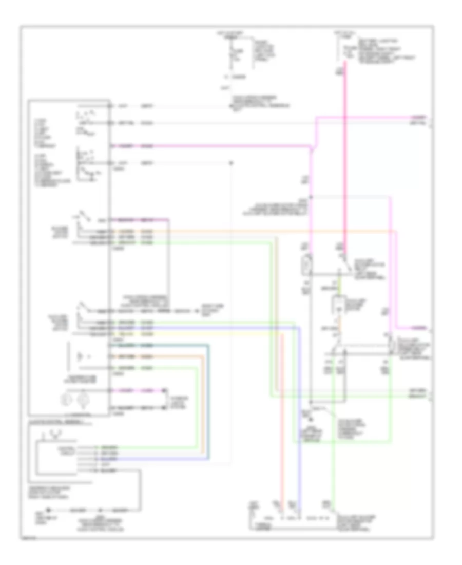
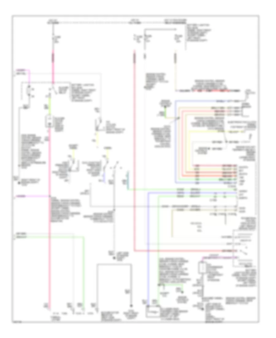
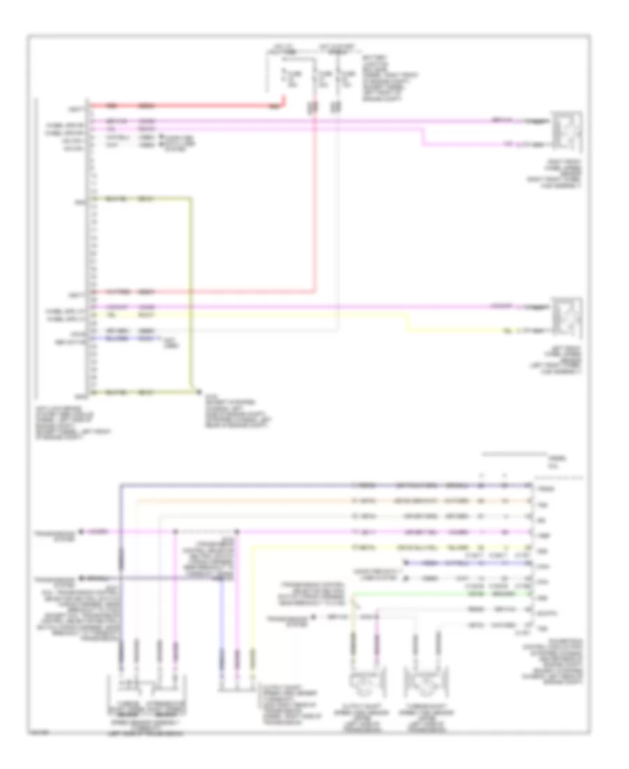
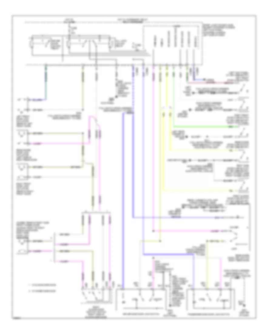
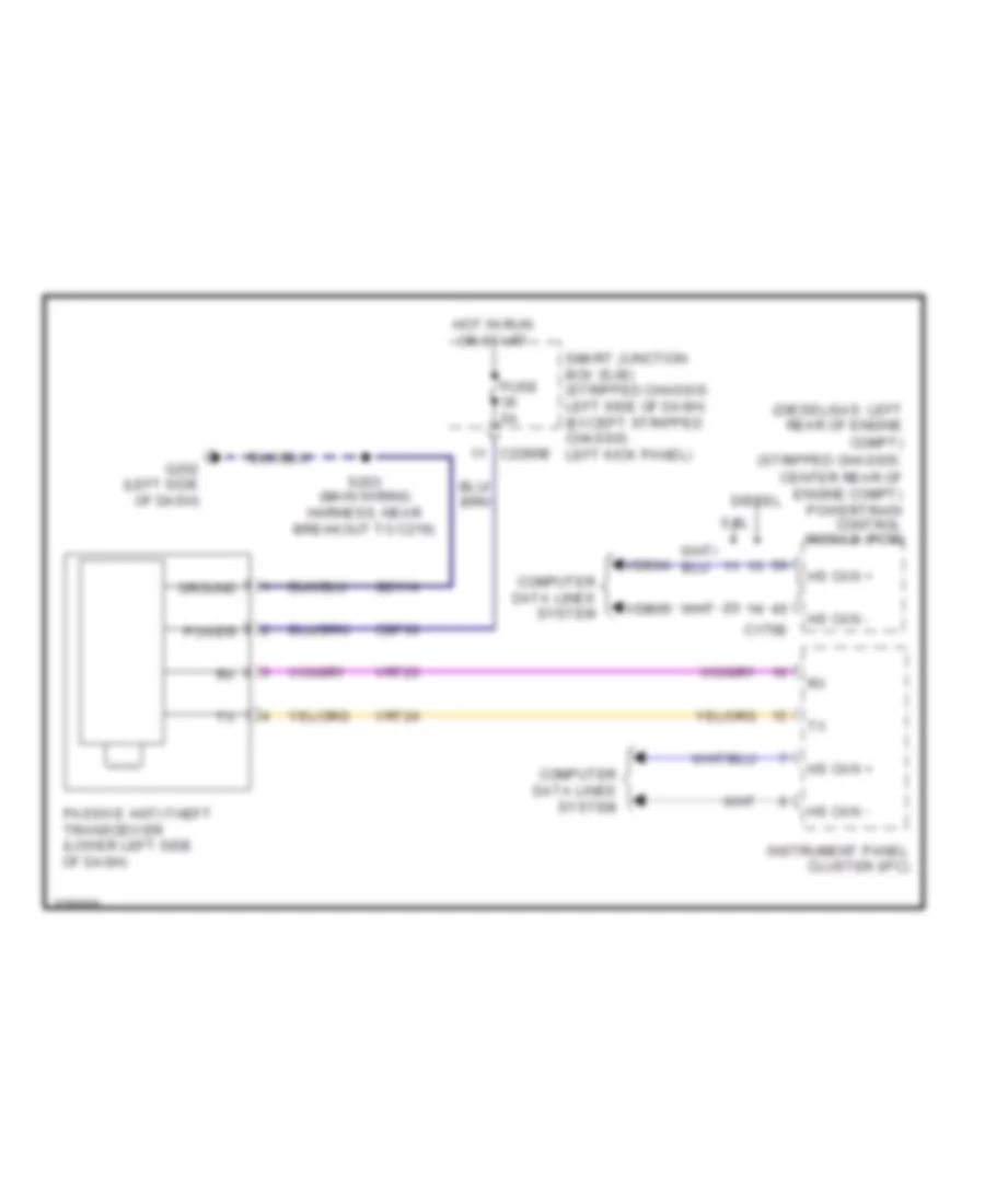
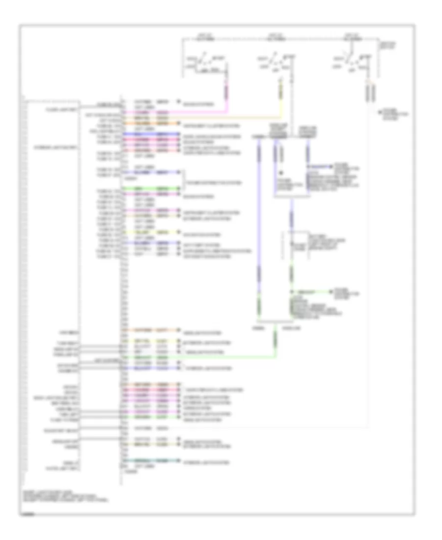
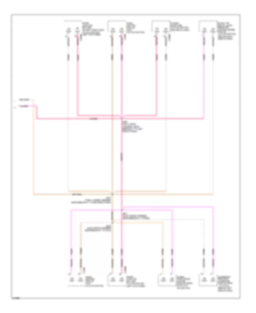
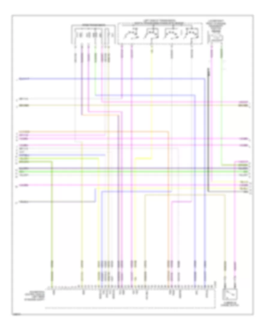
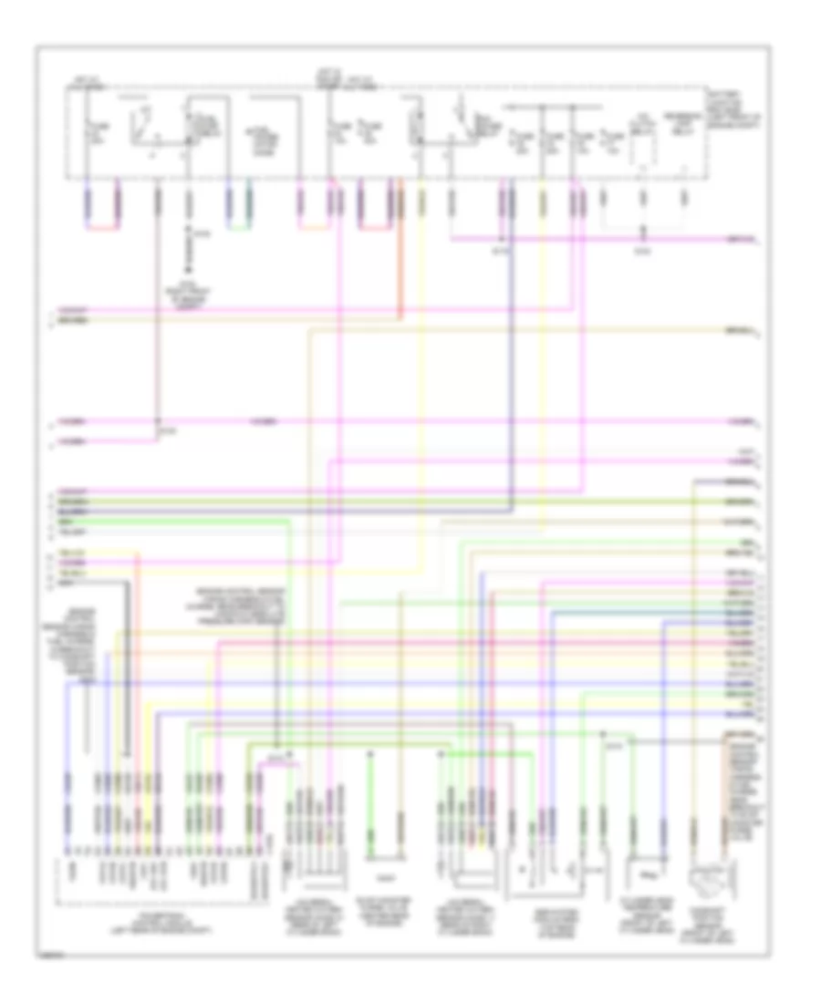
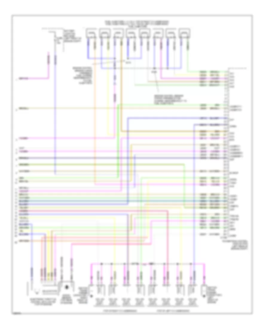
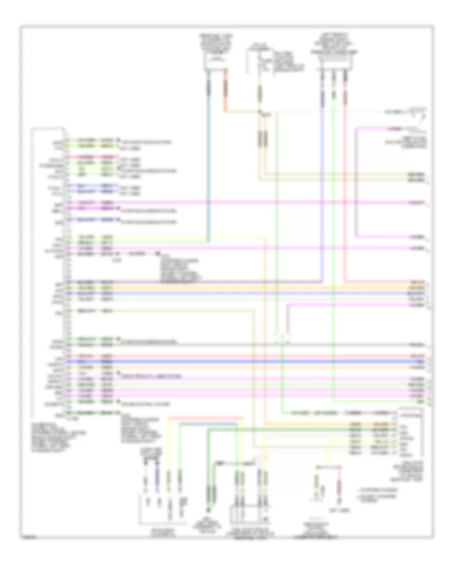
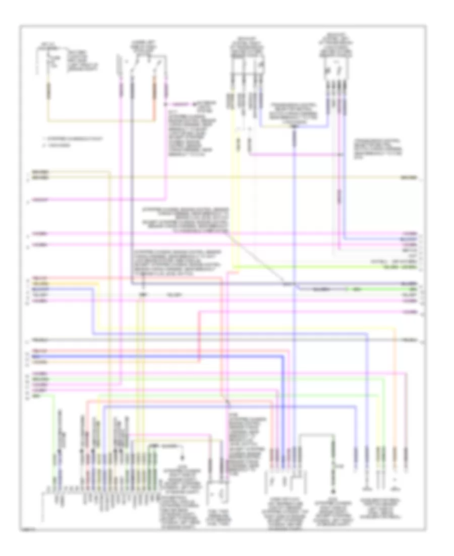
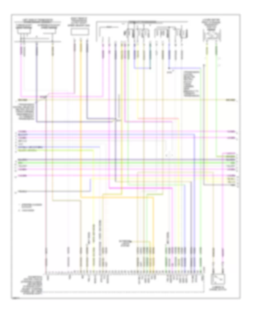
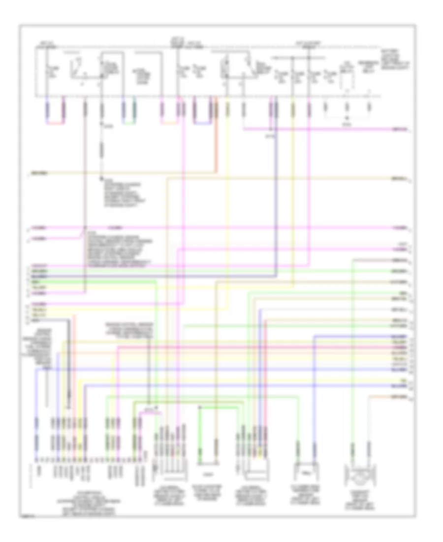
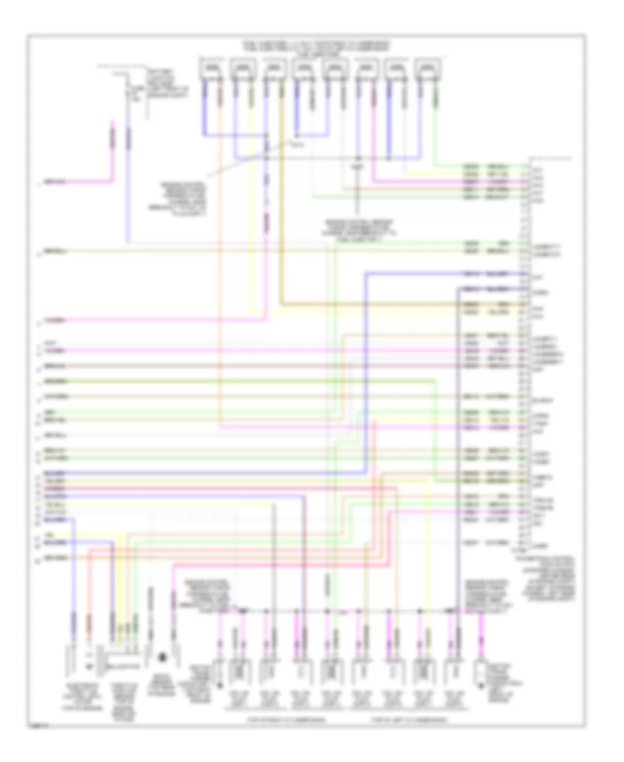
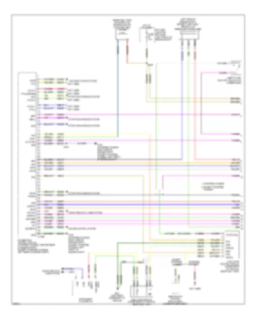
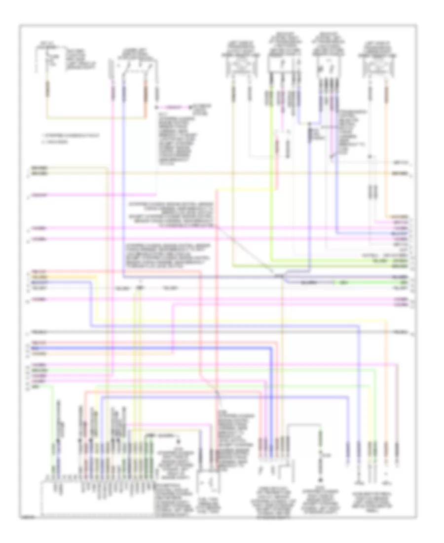
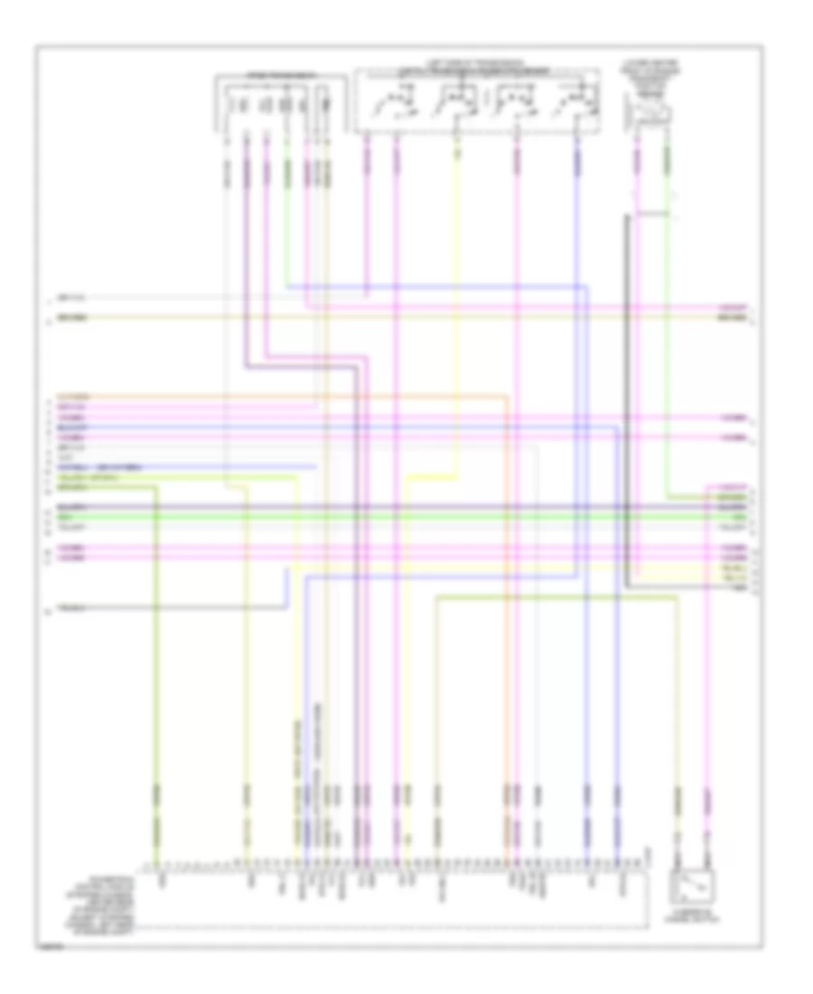
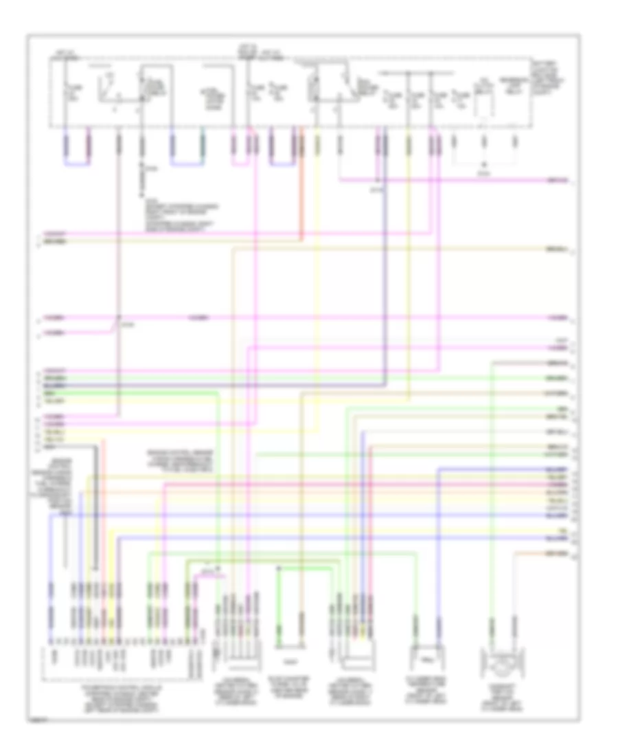
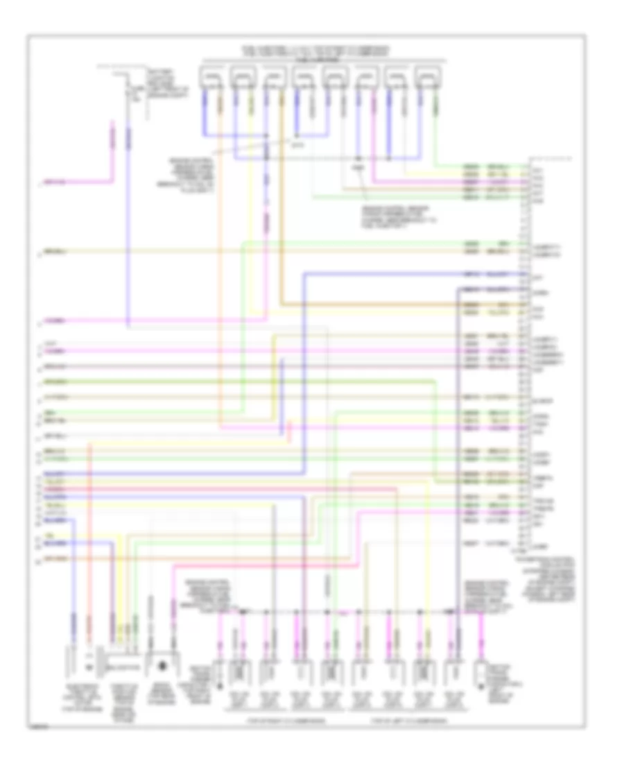
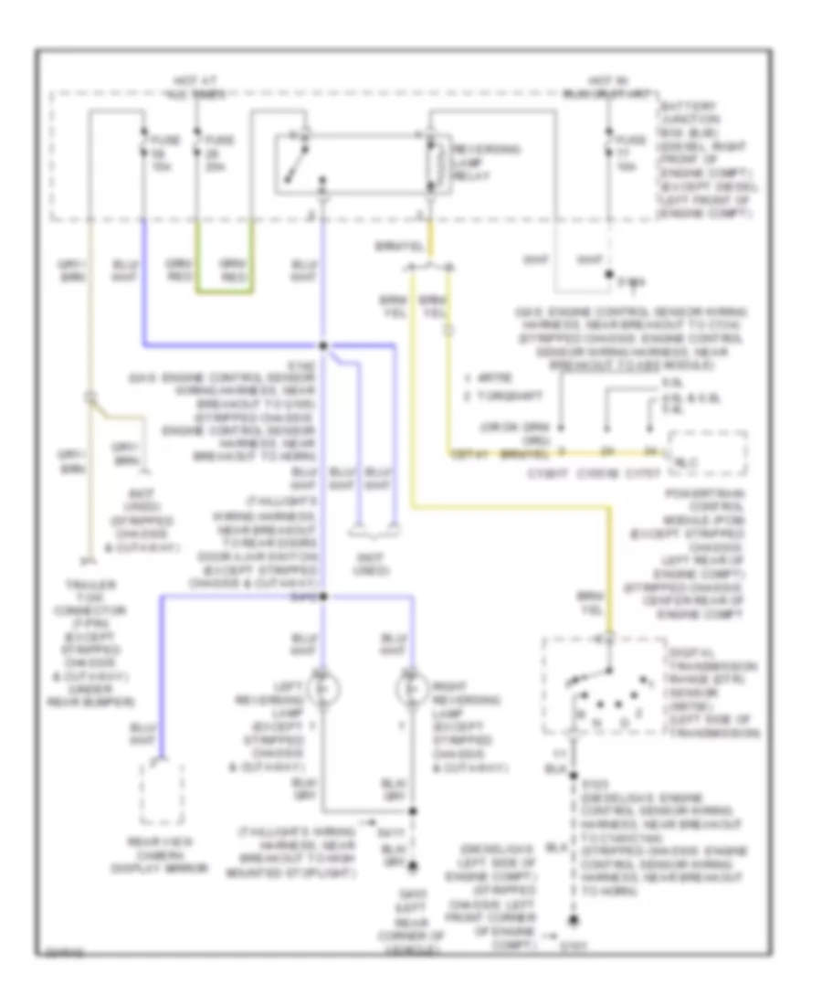
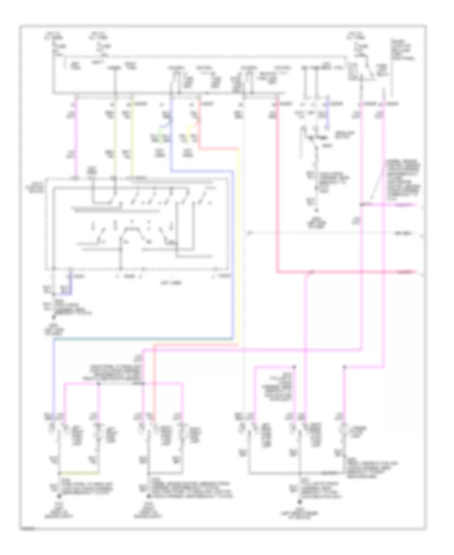
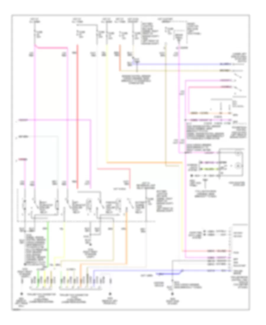
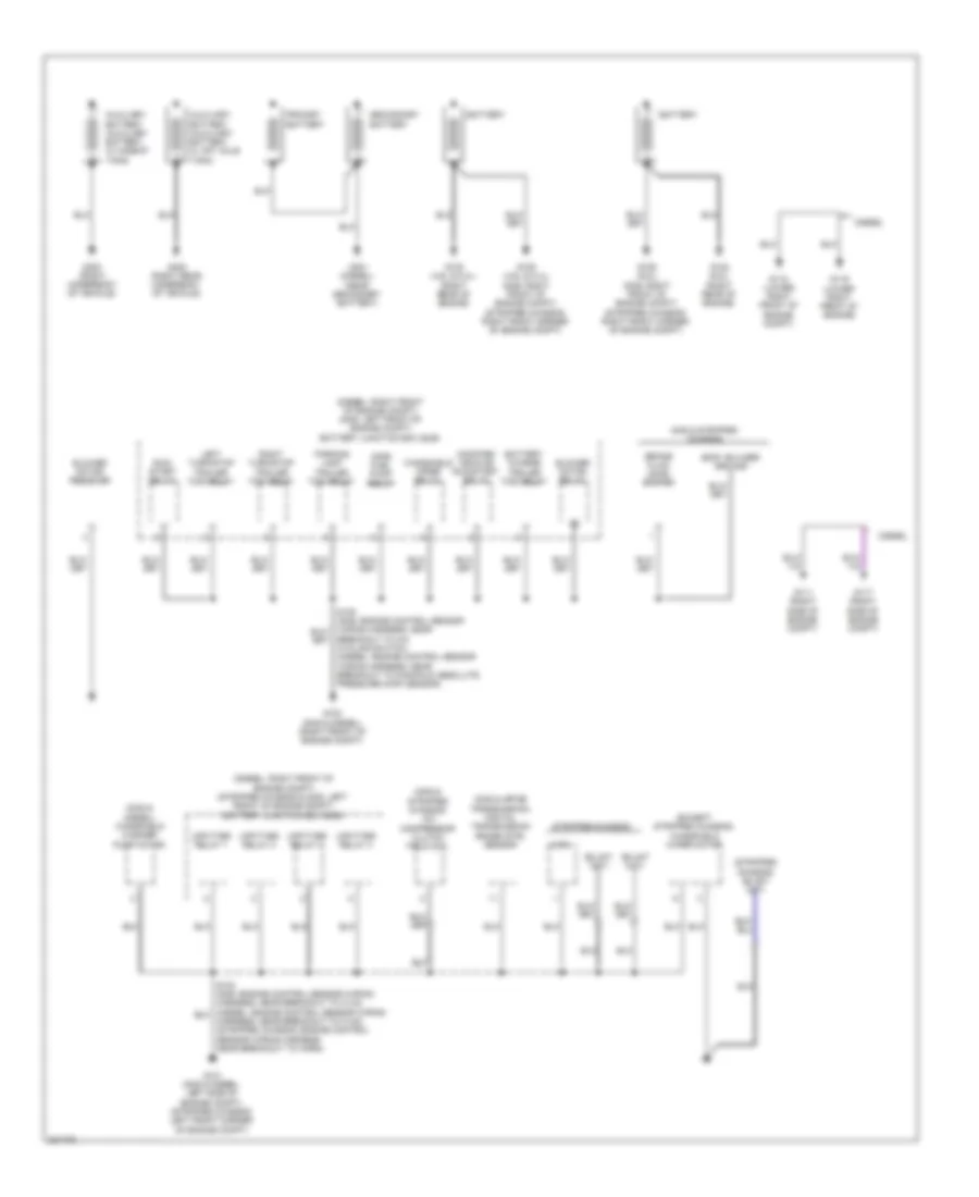
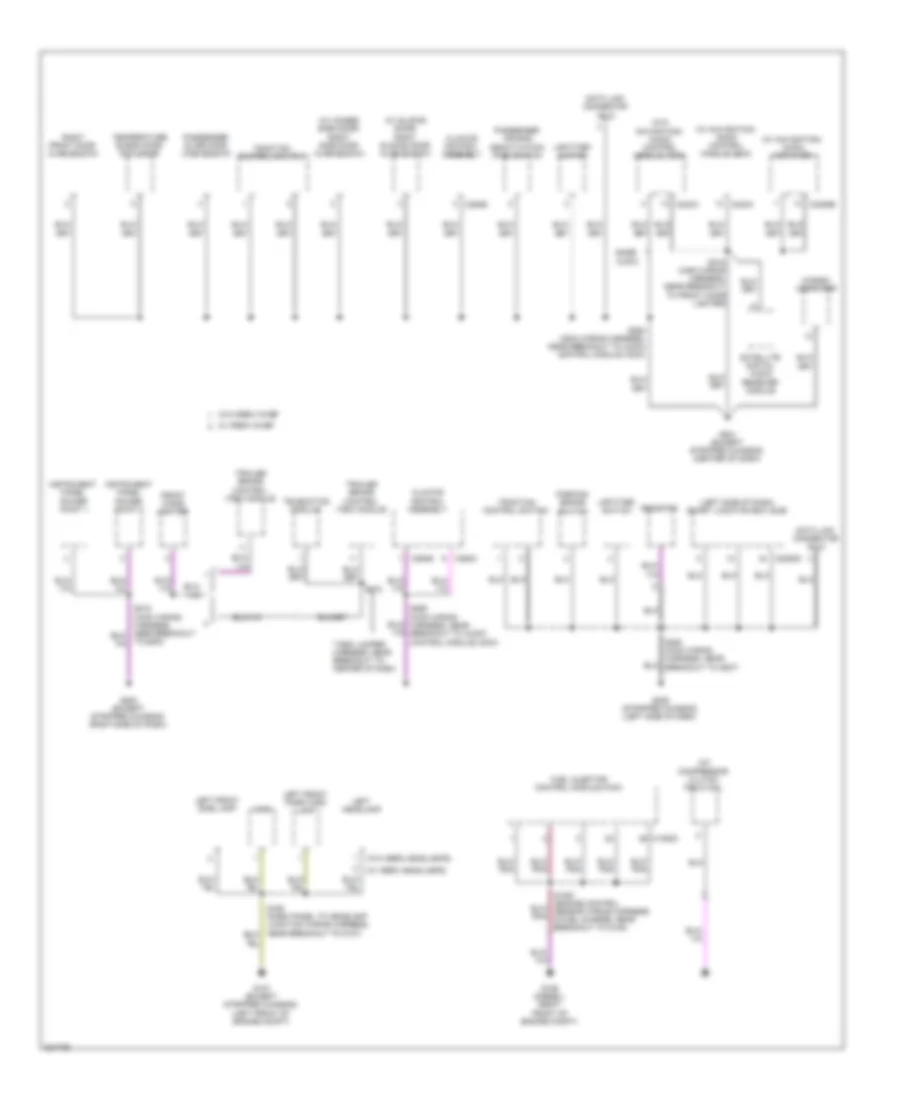
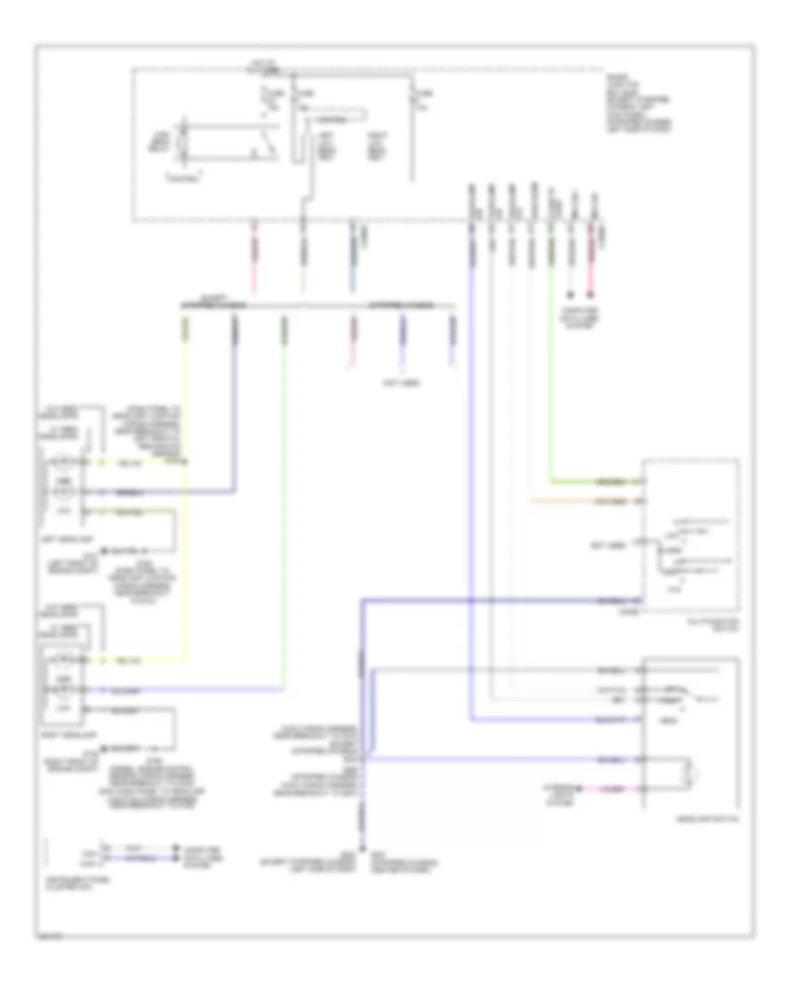
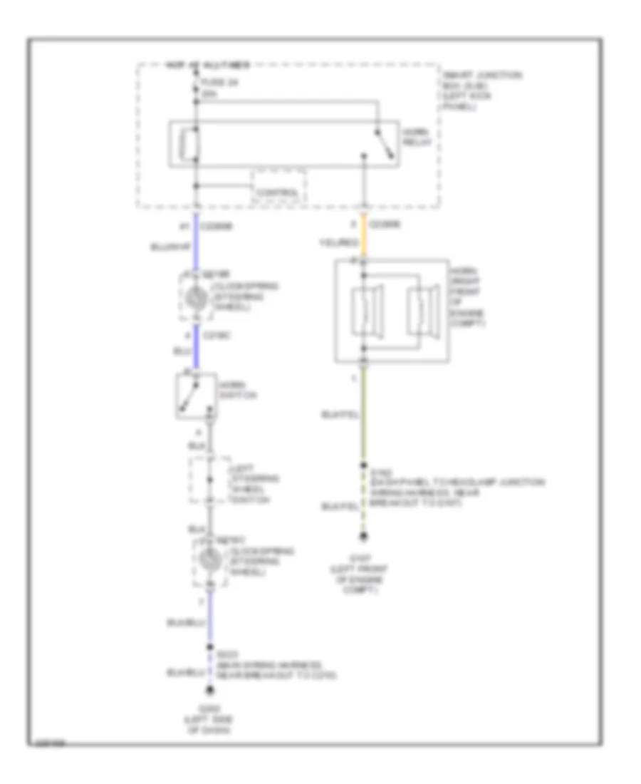
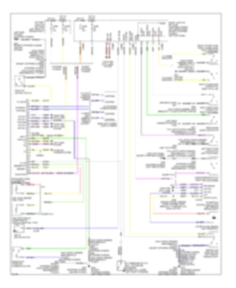
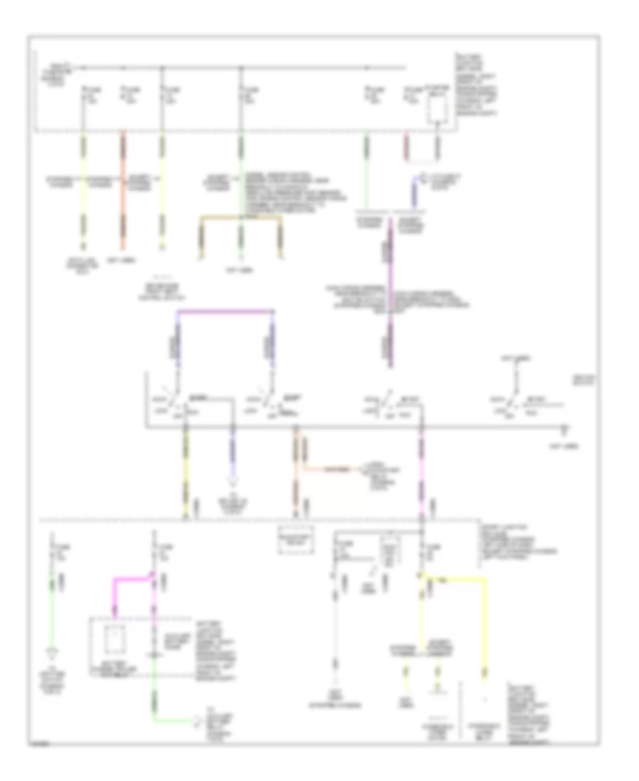
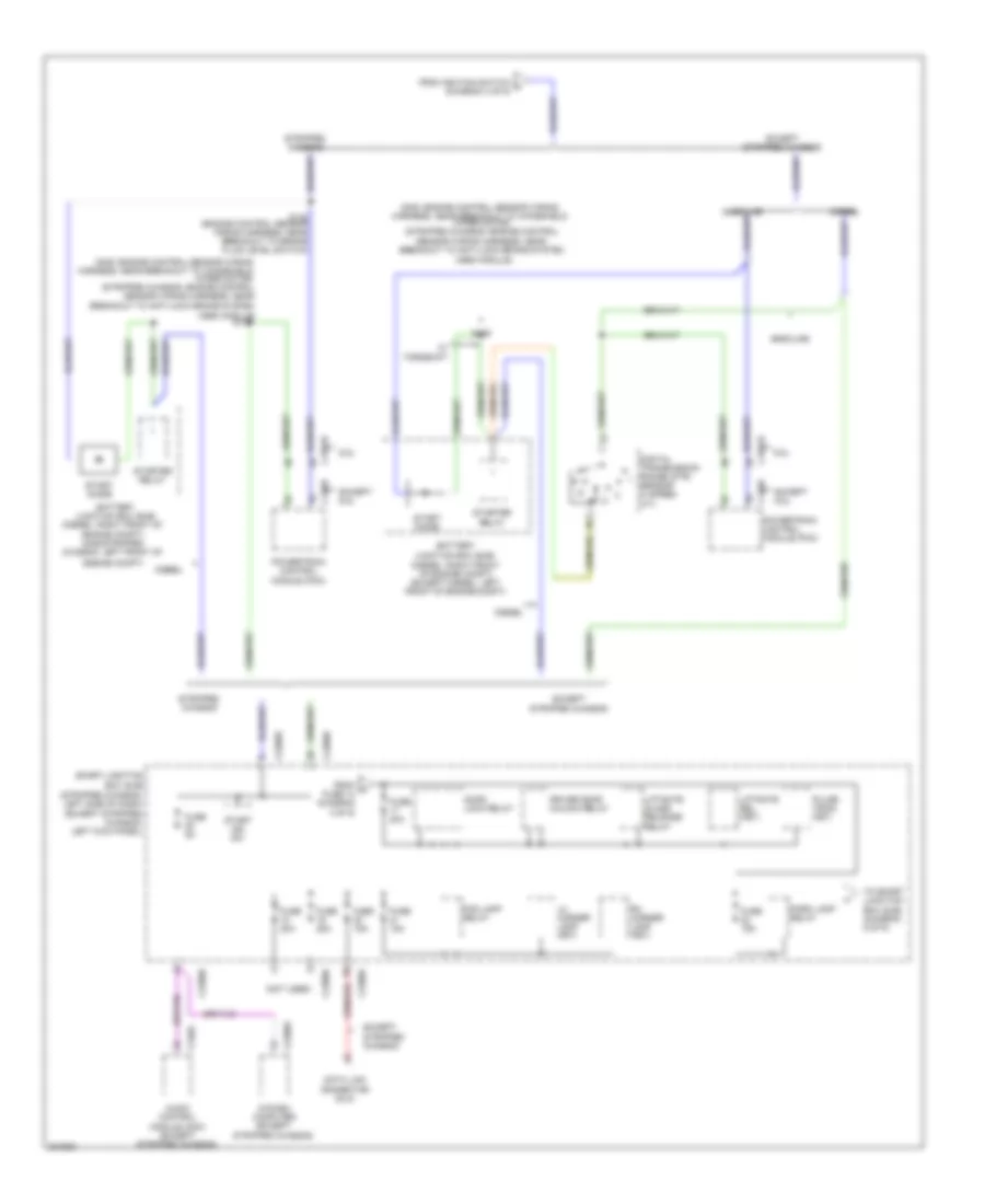
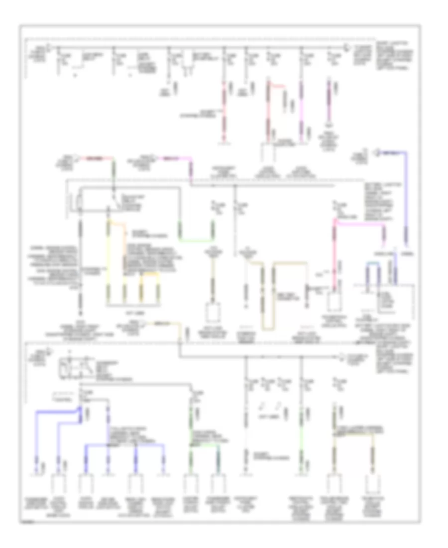
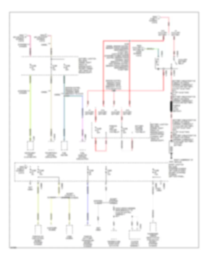
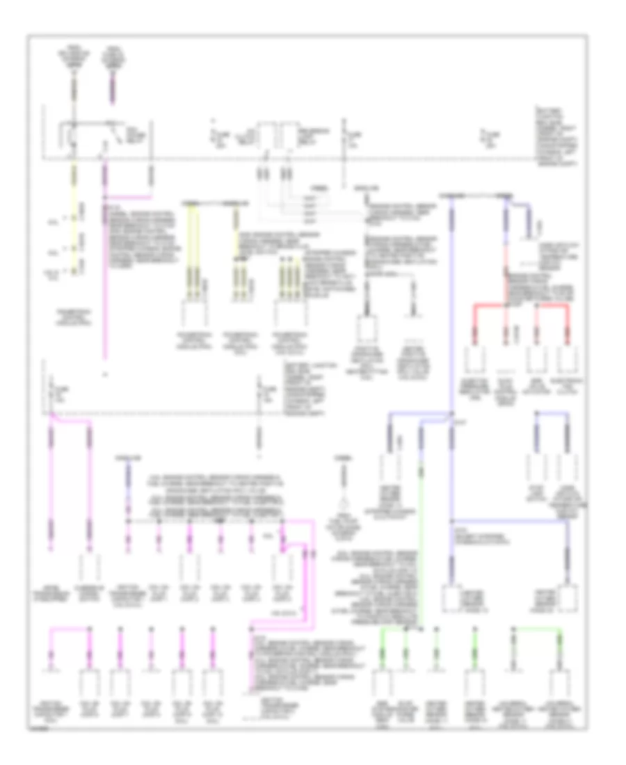
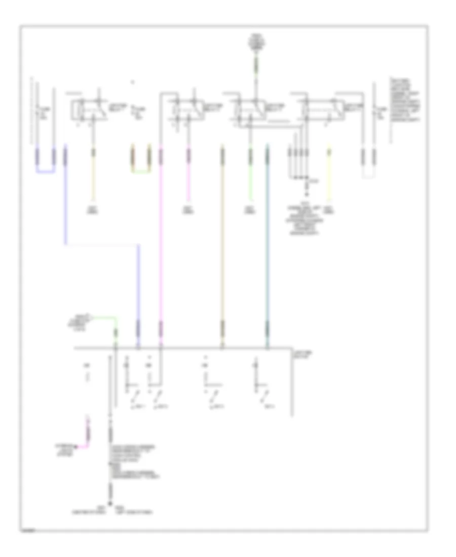
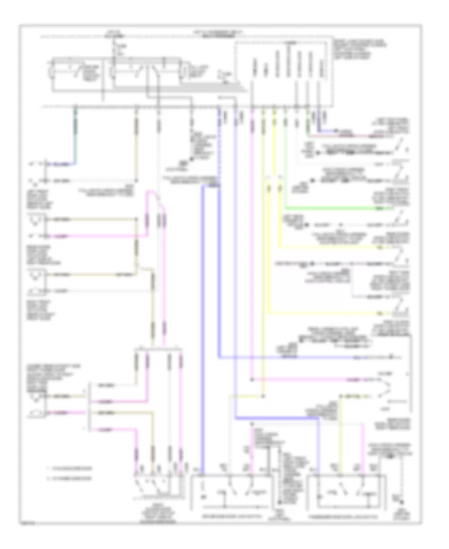
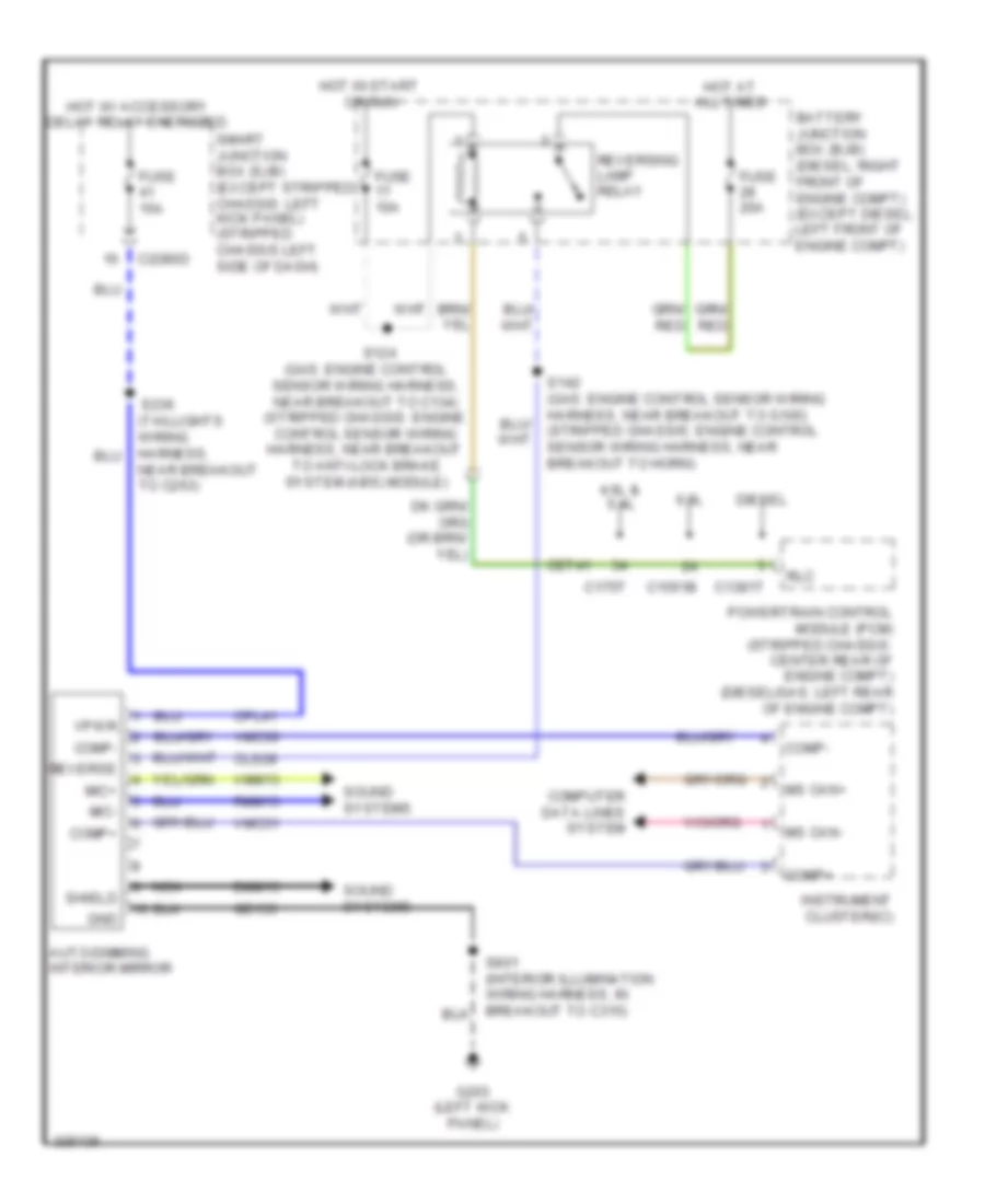
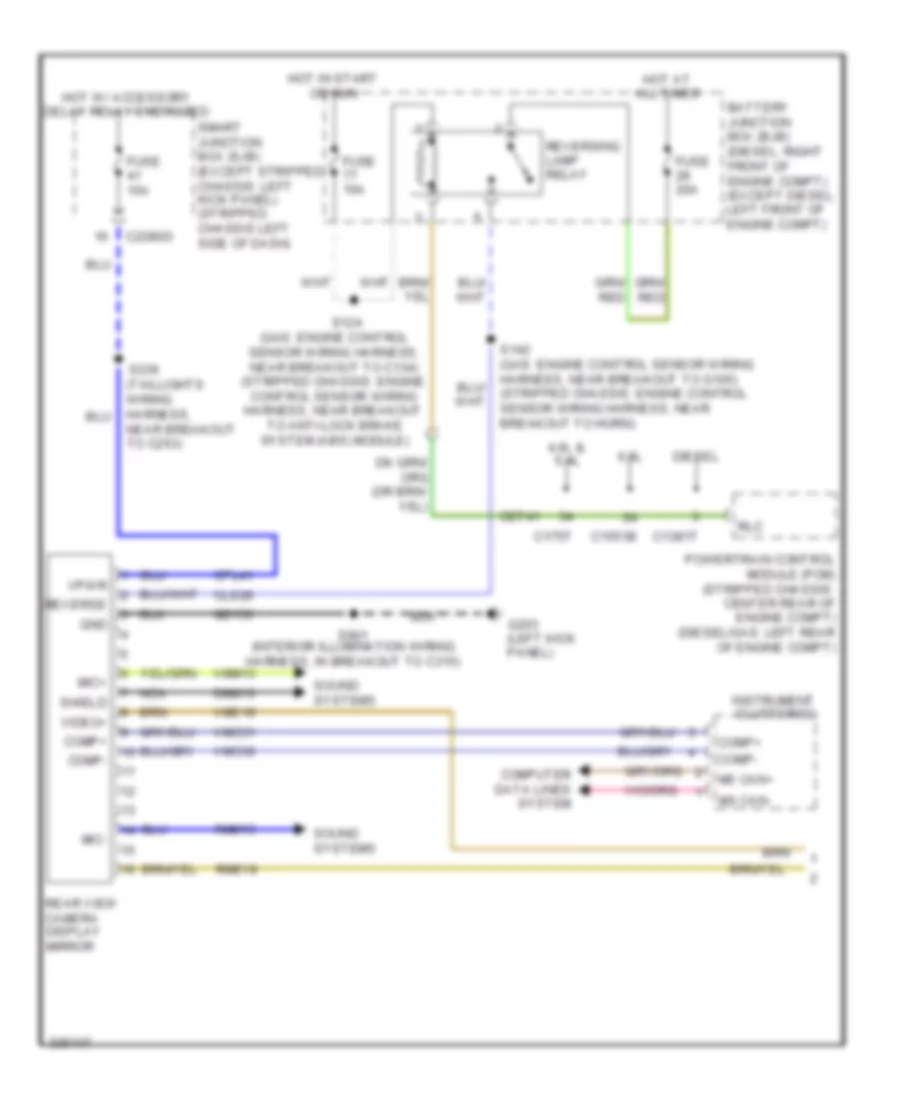
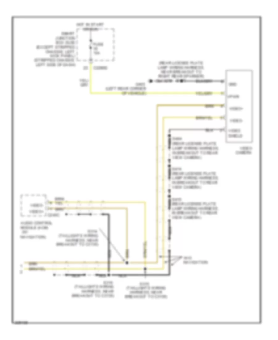
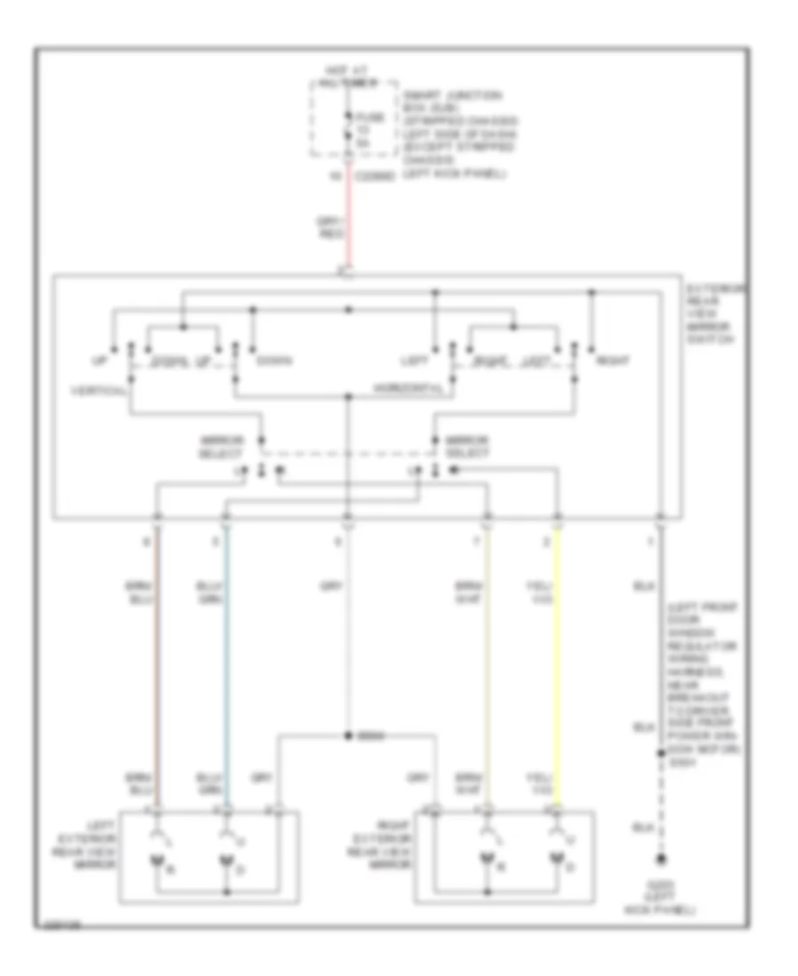
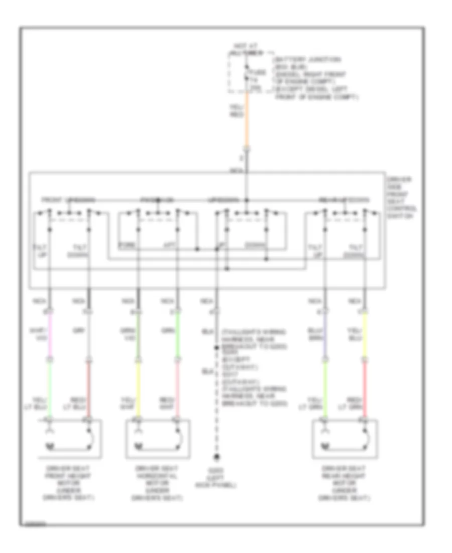
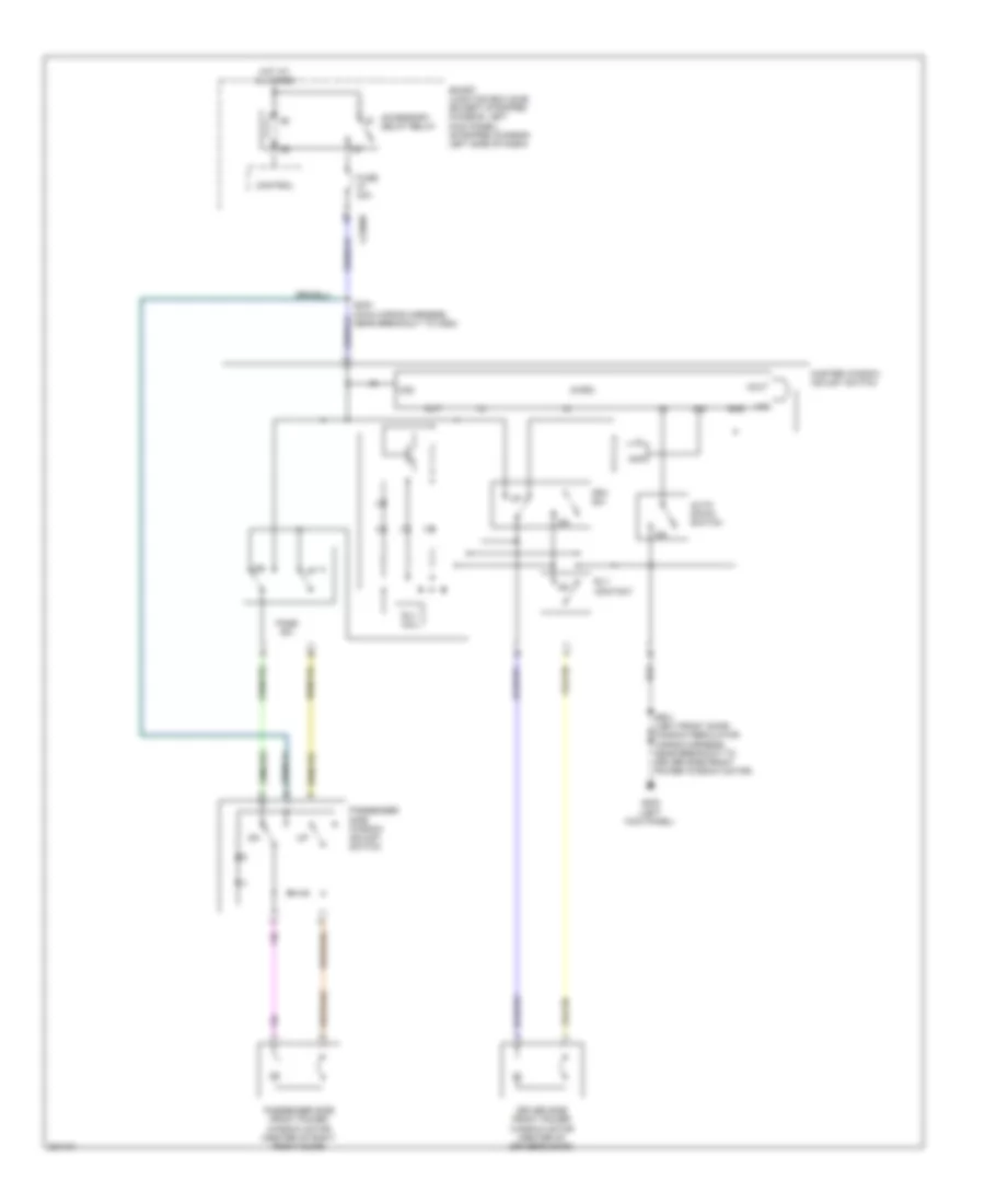
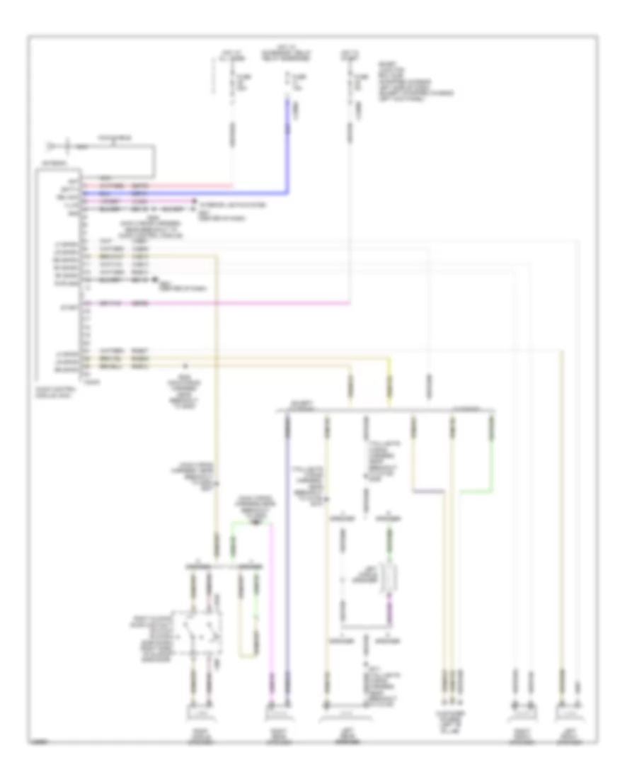
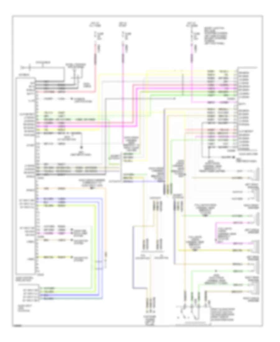
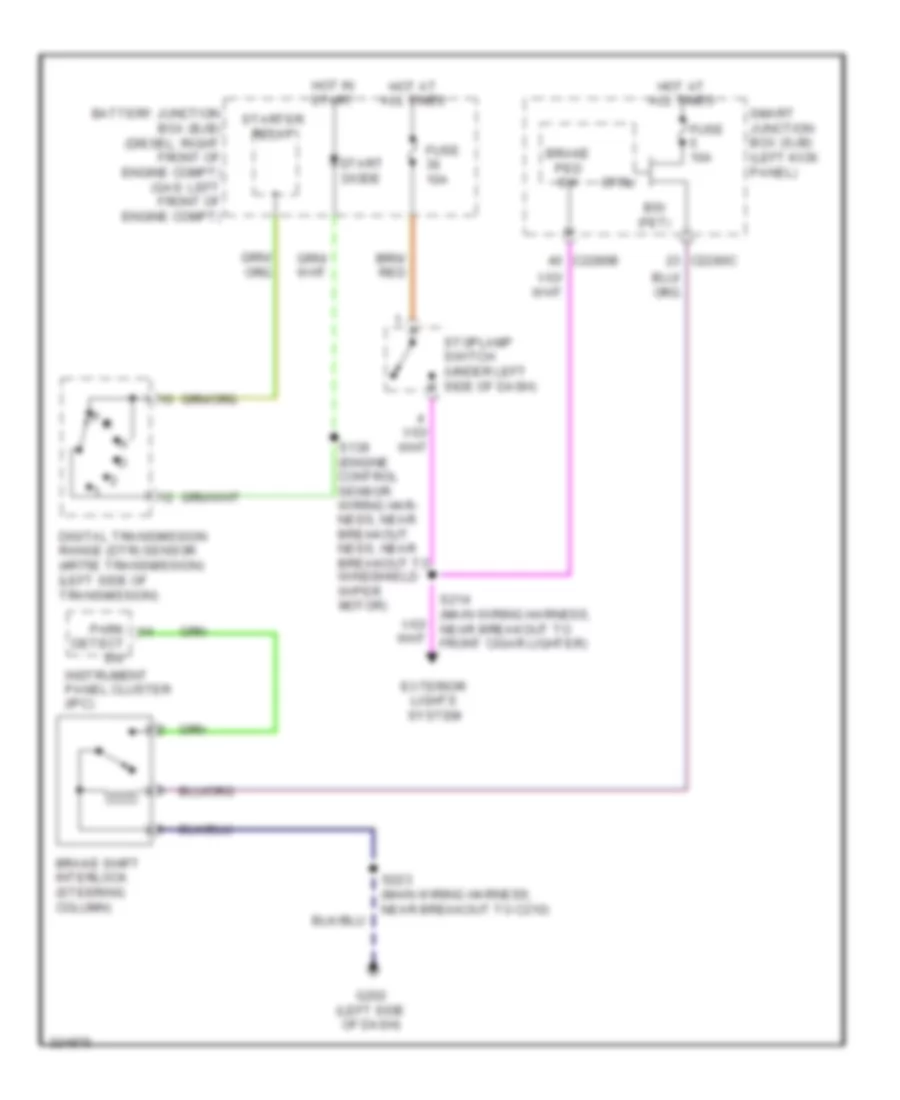
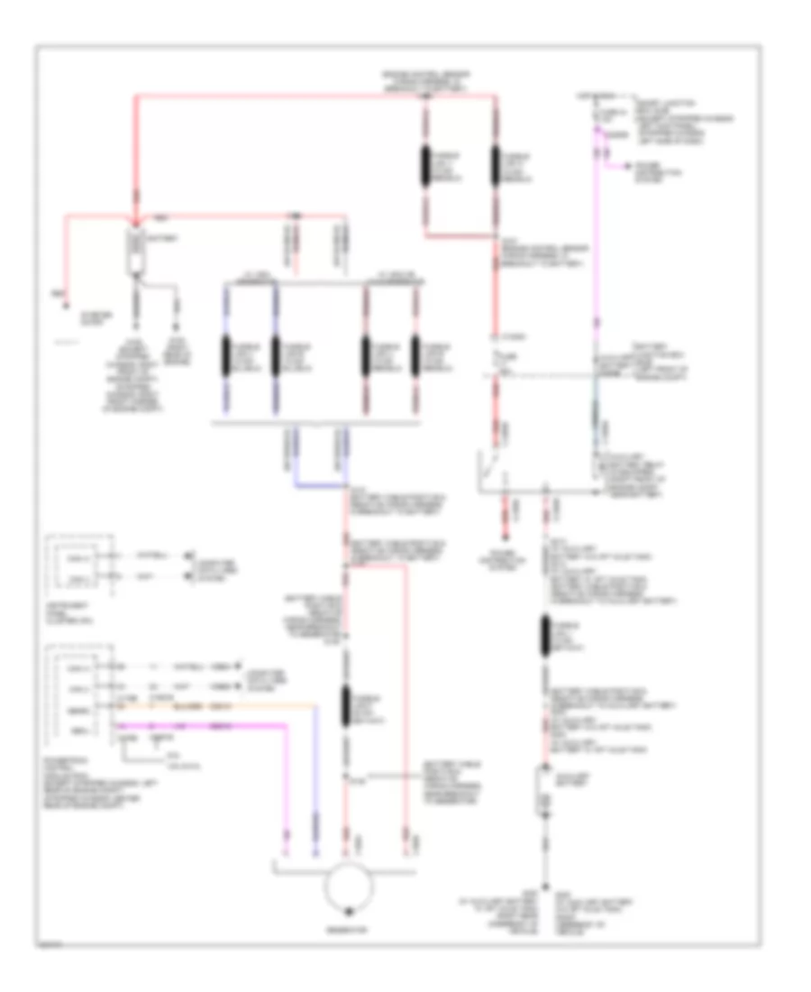
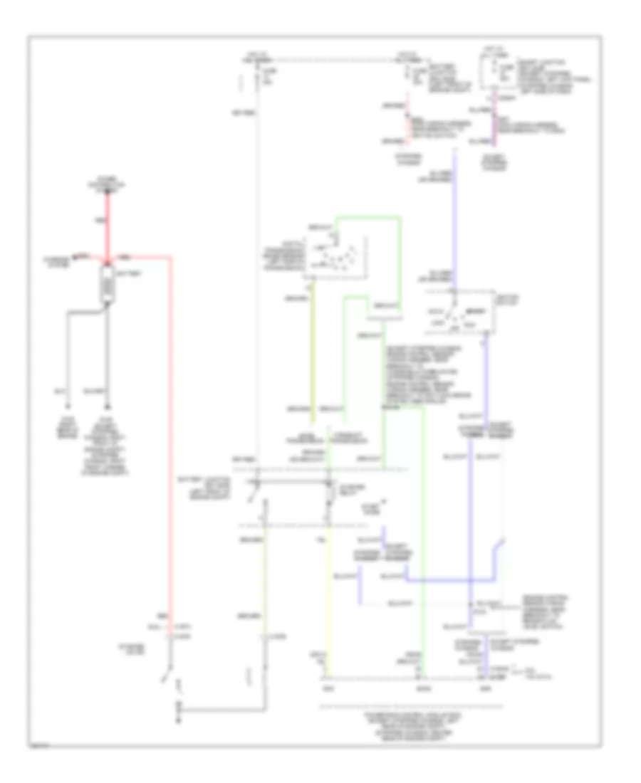
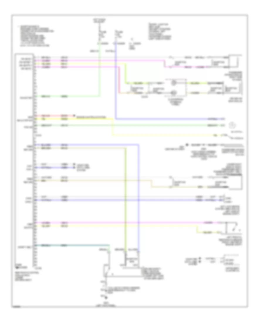
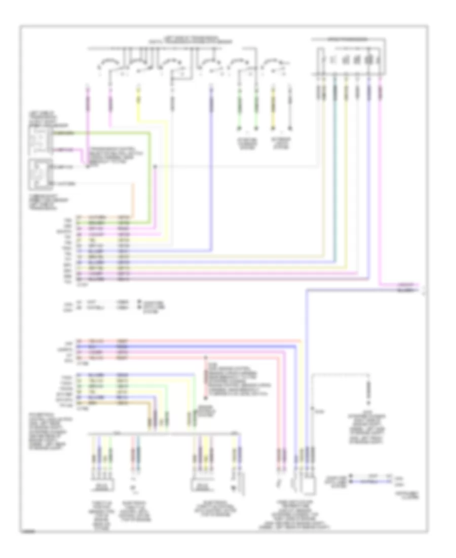
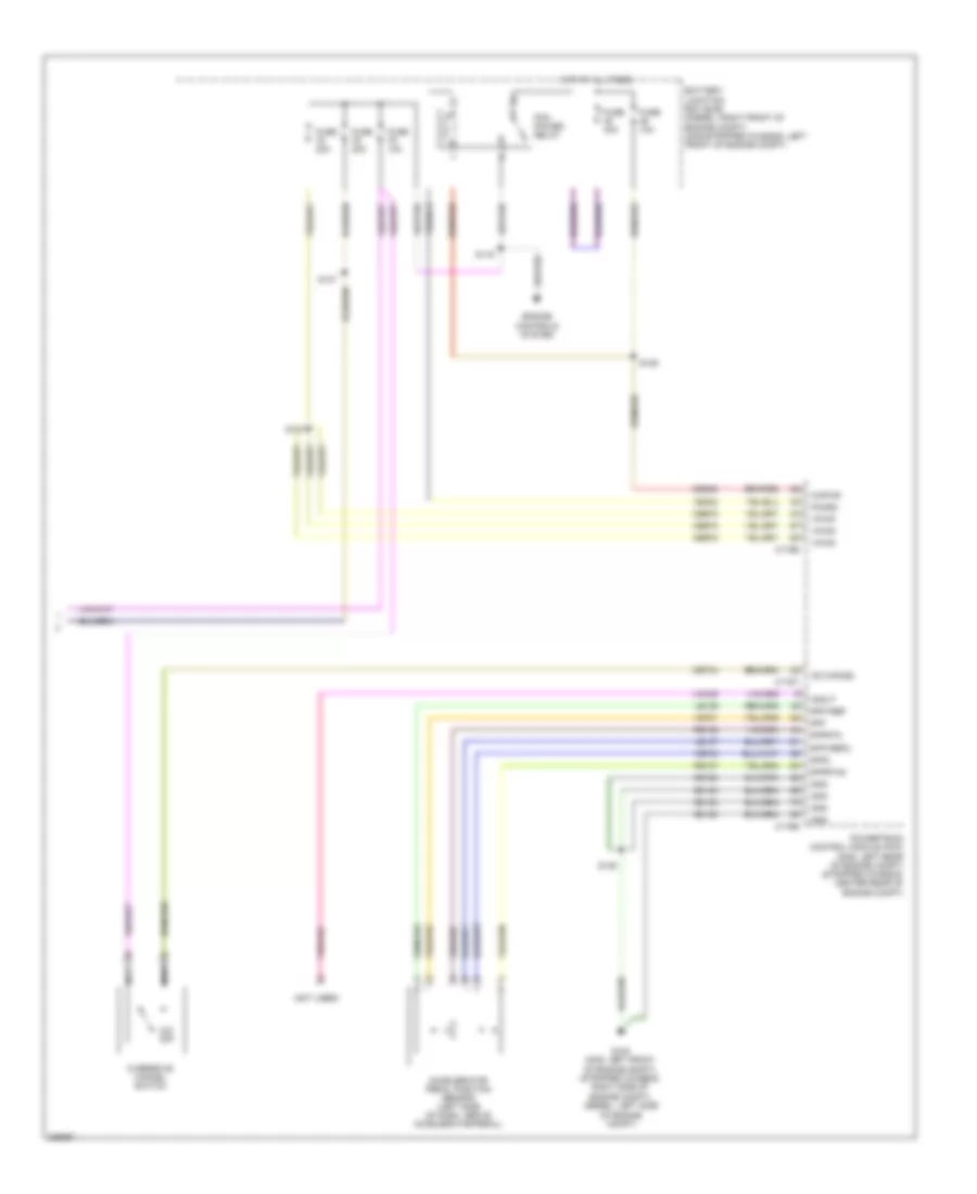
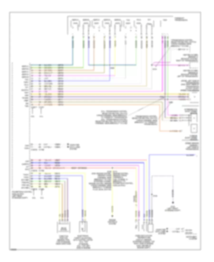
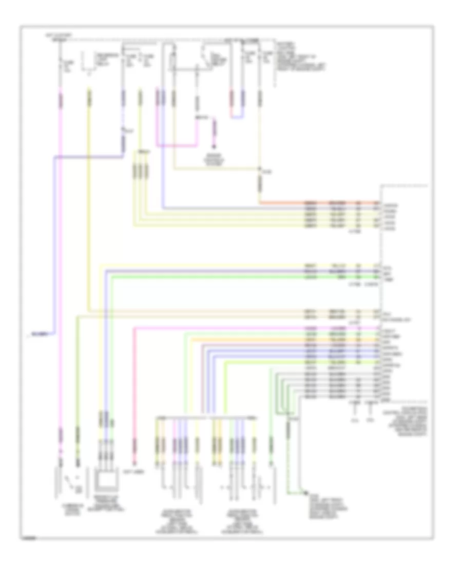
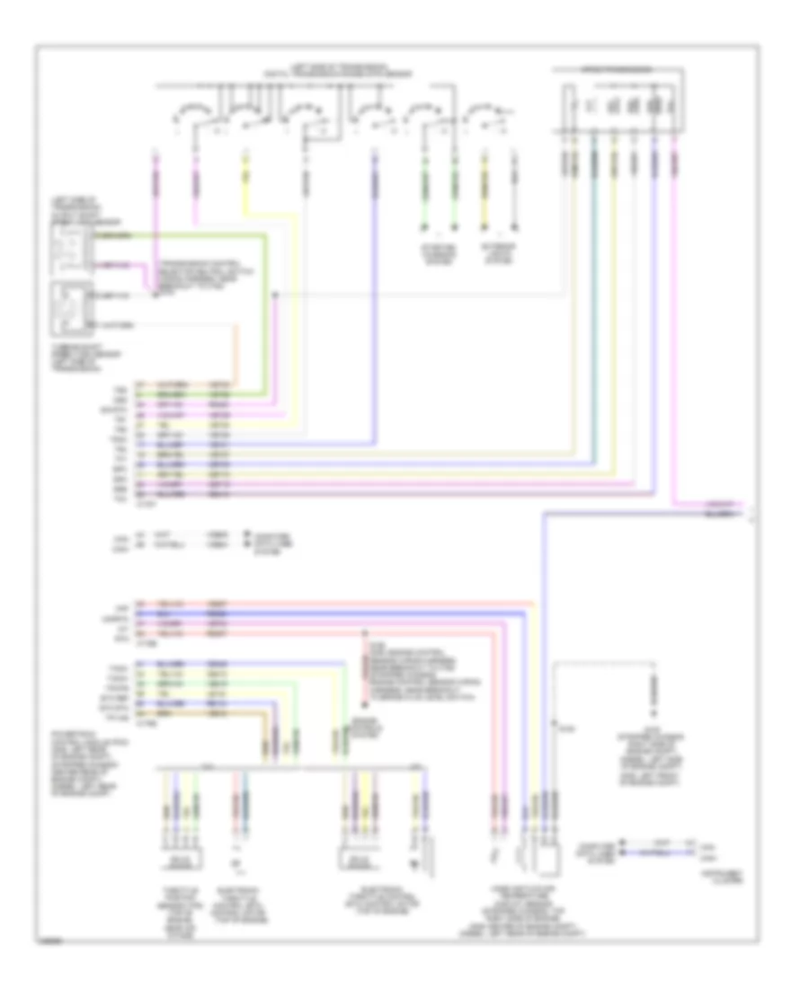
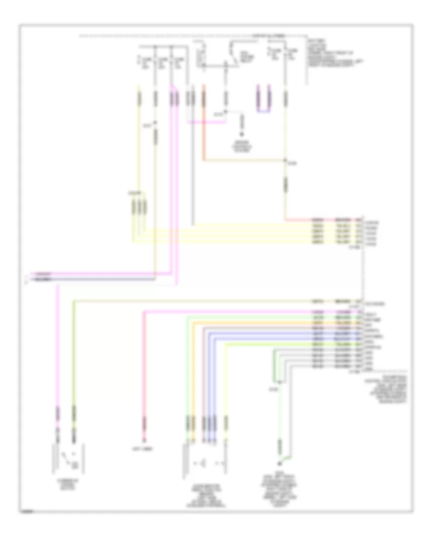
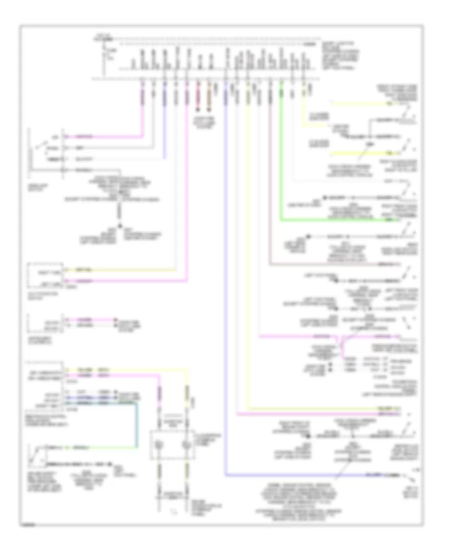
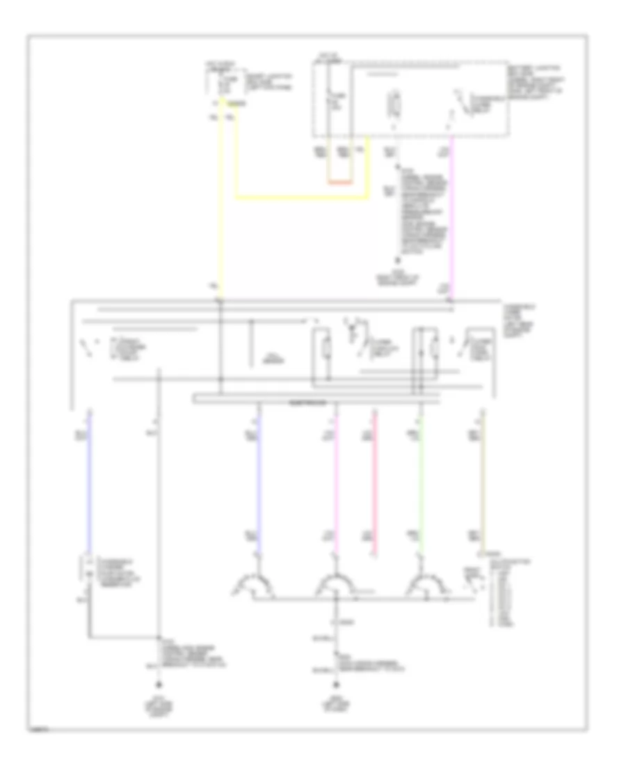
List of elements for Manual A/C Wiring Diagram (2 of 2) for Ford Econoline E250 2010:
71
(4.6l: engine control sensor wiring harness & fuel charge, near breakout to evap canister purge valve) (6.8l: engine control sensor wiring harness & fuel charge, in breakout to powertrain control module (pcm)) s172
(engine control sensor wiring harness, near breakout to c134) (except diesel) s124
(engine control sensor wiring harness & fuel charge, near breakout to evap canister purge valve6) s1057
(engine control sensor wiring harness & fuel charge, near breakout to intake air temperature 2 (iat2) sensor) s1059
(engine control sensor wiring harness, near breakout to c144)
(except diesel) s123
(gas: engine control sensor wiring harness, near breakout to a/c cycling switch) (diesel: engine control sensor wiring harness, near breakout to manifold absolute pressure sensor)
(left side of engine compt)
(left side of engine compt) (except diesel) g101 g106 (diesel) (right front of engine compt)
(or ch419)
(right front of engine compt)
4.6l & 5.4l
6.0l
6.8l
A/c clutch relay
A/c compressor clutch field coil (lower right front of engine)
A/c cycling switch (right front of engine compt)
Accr
Accs
Acpsw
Battery junction box (bjb) (diesel: right front of engine compt) (except diesel: left front
Battery junction box (bjb) (diesel: right front of engine compt) (except diesel: left front of engine compt)
Blower motor (right side of engine compt)
Blower motor relay
Blower motor resistor (right side of engine compt)
C1381b
C1381e
C1551e
C175b
C175e
Ch302
Ch421
Ch425
Cht
Cylinder head temperature sensor (except diesel) (front of left cylinder head)
Diesel
Dual function pressure switch (right side of engine compt)
Ect
Electronic fan clutch (diesel) (top front of engine)
Engine controls system
Engine coolant temperature (ect) sender (diesel) (upper front of engine)
Except 5.4l
Except diesel
Fan clutch
Fuse 10a
Fuse 20a
Fuse 50a
G100
G100 (right front of engine compt)
G105
High pressure cutoff switch (right front of engine compt)
Hot at all times
Hot w/ pcm power relay energized
Nca
Of engine compt)
Powertrain control module (pcm) (left rear of engine compt)
Re405
Red
S1010 (engine control sensor wiring harness & fuel charge, near breakout to powertrain control module (pcm))
S105 (diesel: engine control sensor wiring harness, near breakout to c1221) (except diesel: engine control sensor wiring harness, near breakout to blower motor resistor)
S108
S125 (engine control sensor wiring harness, in breakout to a/c cycling switch)
Sig rtn
Sigrtn
Speed sensor
Ss rtn
Thermal limiter
Vdf
Ve712
Vref
Vss
ANTI-LOCK BRAKES
Anti-lock Brakes Wiring Diagram, with Stability Assist (1 of 2) for Ford Econoline E250 2010
List of elements for Anti-lock Brakes Wiring Diagram, with Stability Assist (2 of 2) for Ford Econoline E250 2010:
60
(left side of dash) (stripped chassis) g205
(main wiring harness, near breakout to audio control module (acm))
(main wiring harness, near breakout to g207) (stripped chassis) s250
(not used)
(transmission control selector neutral switch wiring harness,
6.8l
Abs test connector (gas: left front corner of engine compt)
Battery junction box (bjb) (diesel: right front of engine compt) (except diesel: left front of engine compt)
C1381b
C1381t
C1551b
C1551t
C175b
C175t
Can+
Can-
Cbb53
Computer data lines system
Diesel
Fuse 10a
Fuse 40a
G103 (gas: left side of engine compt)
G201 (except stripped chassis) (center of dash)
Gd121
Hot at all times
Hot in start or run
Instrument panel cluster (ic)
Interior lights system
Intermediate shaft speed sensor
Iss
Le111
Near breakout to c192)
Oss
Output shaft speed (oss) sensor (4r75e) (left side of transmission)
Output shaft speed (oss) sensor (torqshift) (gas: right rear of transmission) (diesel: right side of transmission)
Powertrain control module (pcm) (stripped chassis: center rear of engine compt) (except stripped chassis: left rear of engine compt)
Re406
Ret04
Ret24
S101 (6.8l: transmission control selector neutral switch wiring harness, near breakout to c192) (except 6.8l: transmission control selector neutral switch wiring harness, near breakout to torqshift transmission)
S102 (transmission control selector neutral switch wiring harness, near breakout to torqshift trans- mission)
S104
S264 (except stripped chassis)
Sbb47
Sig rtn
Speed sensor assembly (torqshift) (left side of transmission)
Steering position sensor (bottom of steering column)
Tc on/off
Traction control switch
Transmissions system
Trgnd
Tss
Turbine shaft speed (tss) sensor (4r75e) (left side of transmission)
Turbine shaft speed sensor
Vdb04
Vdb05
Ve744
Vet26
Vet33
Vref
Anti-lock Brakes Wiring Diagram, without Stability Assist for Ford Econoline E250 2010
List of elements for Anti-lock Brakes Wiring Diagram, without Stability Assist for Ford Econoline E250 2010:
70
(not used)
(transmission control selector neutral switch wiring harness,
6.8l
Abs active
Anti-lock brake system (abs) module (diesel: left side of engine compt) (except diesel: left front of engine compt)
Battery junction box (bjb) (diesel: right front of engine compt) (except diesel: left front of engine compt)
C1381b
C1381t
C1551b
C1551t
C175b
C175t
Can+
Can-
Cbb53
Cca01
Computer data lines system
Diesel
Fuse 10a
Fuse 40a
G102 (except stripped chassis: left side of engine compt) (stripped chassis: left rear of engine compt)
Gd121
Gnd
Hot at all times
Hot in start or run
Hs can +
Hs can -
Intermediate shaft speed sensor
Iss
Le111
Left front wheel speed sensor (left front wheel hub assembly)
Nca
Near breakout to c192)
Oss
Output shaft speed (oss) sensor (4r75e) (left side of transmission)
Output shaft speed (oss) sensor (torqshift) (gas: right rear of transmission) (diesel: right side of transmission)
Powertrain control module (pcm) (stripped chassis: center rear of engine compt) (except stripped chassis: left rear of engine compt)
Rca17
Rca19
Re406
Red
Ret04
Ret24
Right front wheel speed sensor (right front wheel hub assembly)
S101 (6.8l: transmission control selector neutral switch wiring harness, near breakout to c192) (except 6.8l: transmission control selector neutral switch wiring harness, near breakout to torqshift transmission)
S102 (transmission control selector neutral switch wiring harness, near breakout to torqshift trans- mission)
S104
Sbb33
Sbb47
Sig rtn
Speed sensor assembly (torqshift) (left side of transmission)
Transmissions system
Trgnd
Tss
Turbine shaft speed (tss) sensor (4r75e) (left side of transmission)
Turbine shaft speed sensor
Vbatt
Vca03
Vca05
Vdb04
Vdb05
Ve744
Vet26
Vet33
Vpwr
Vref
Wheel spd lf+
Wheel spd lf-
Wheel spd rf+
Wheel spd rf-
ANTI-THEFT
Forced Entry Wiring Diagram for Ford Econoline E250 2010
List of elements for Computer Data Lines Wiring Diagram, without Stripped Chassis (1 of 2) for Ford Econoline E250 2010:
68
(engine control sensor wiring harness, near breakout to c192)
(engine control sensor wiring harness, near breakout to c192) s127
(main wiring harness, in breakout to c2383)
(main wiring harness, in breakout to instrument panel cluster (ipc)) s224
(main wiring harness, in breakout to instrument panel cluster (ipc)) s225
(main wiring harness, near breakout to c219)
(main wiring harness, near breakout to overdrive cancel switch) s228
(main wiring harness, near breakout to trailer brake control (tbc) module)
(taillights wiring harness, near breakout to g203) s302
(under left side of dash)
(w/ crew chief)
4.6l & 5.4l
6.8l
Abs test connector (w/ advancetrac) (gas: left front corner of engine compt)
Accessory protocol interface module(apim) (behind left side of dash)
Anti-lock brake system (abs) module (diesel: left side of engine compt) (gas: left front of engine compt)
Base audio
C1381b
C1551b
C175b
C2280a
C2280b
C310b hs can -
Can +
Can -
Cdb08
Data link connector (dlc) (below left side of dash)
Diesel
Feps
Fuse 15a
G201 (center of dash)
G202 (left side of dash)
Gd114
Gd115
Hot at all times
Hs can +
Hs can -
Hs can+
Hs can-
Instrument panel cluster (ipc)
Ms can+
Ms can-
Parking aid module (pam)
Powertrain control module (pcm) (left rear of engine compt)
Restraints control module (rcm) (under driver's seat)
S111 (w/ advancetrac) (diesel: engine control sensor wiring harness, near breakout to windshield wiper motor) (gas: engine control sensor wiring harness, near breakout to g105)
S112 (w/ advancetrac) (diesel: engine control sensor wiring harness, near breakout to windshield wiper motor) (gas: engine control sensor wiring harness, near breakout to g105)
S126
S221 (main wiring harness, near breakout to trailer brake control (tbc) module)
S222
S229 (main wiring harness, near breakout to overdrive cancel switch)
S263
S264 (main wiring harness, near breakout to audio control module)
S266
S267 (main wiring harness, in breakout to c2383)
S270
S271 (t-box jumper harness, near breakout to center of dash)
S301 (taillights wiring harness, near breakout to g203)
Sbp20
Smart junction box (sjb) (left kick panel)
Telematics module
Trailer brake control (tbc) module (w/ crew chief) (top center of dash)
Vdb04
Vdb05
Vdb06
Vdb07
W/ advancetrac
W/o advancetrac
Computer Data Lines Wiring Diagram, without Stripped Chassis (2 of 2) for Ford Econoline E250 2010
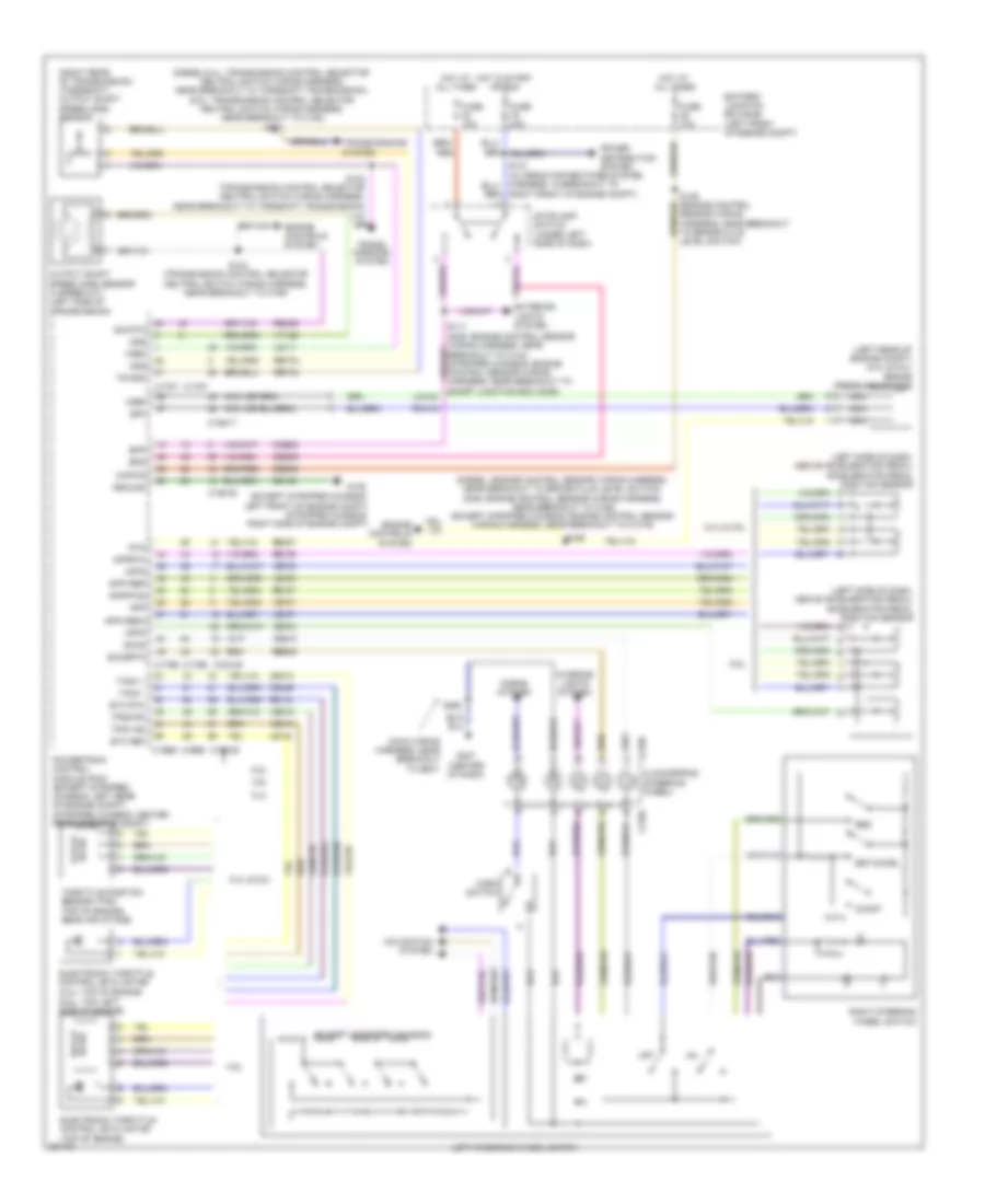
List of elements for Cruise Control Wiring Diagram for Ford Econoline E250 2010:
113
(6.8l: top left side of engine)
(diesel/5.4l: transmission control selector neutral switch wiring harness, near breakout to torqshift transmission) (6.8l: transmission control selector neutral switch wiring harness, near breakout to c192) s101
(diesel: engine control sensor wiring harness, near breakout to brake fluid level switch) (gas: engine control sensor wiring harness, near breakout to c192) (except stripped chassis: engine control sensor wiring harness, near breakout to c1019)
(except stripped chassis)
(except stripped chassis: left front of engine compt) (stripped chassis: right side of engine compt)
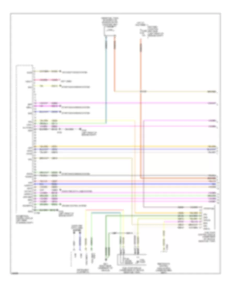
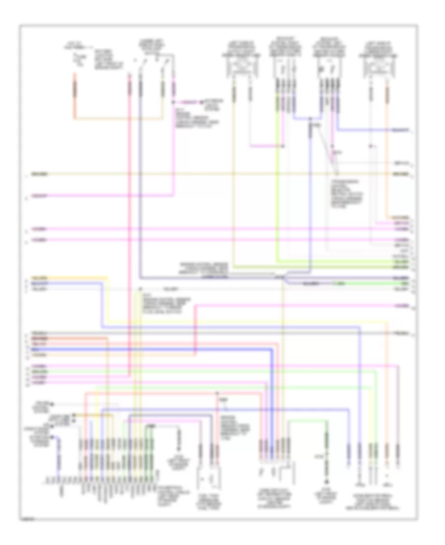
List of elements for 5.4L, Engine Performance Wiring Diagram, with Torqshift (2 of 5) for Ford Econoline E250 2010:
61
(except stripped
(exhaust system, left of transmission) (van/wagon) heated oxygen sensor (ho2s) 22
(exhaust system, right of transmission) heated oxygen sensor (ho2s) 12
(stripped chassis: engine control sensor wiring harness, near breakout to anti- lock brake system (abs) module) (except stripped chassis: engine control
(stripped chassis: engine control sensor wiring harness, near breakout to brake fluid level switch) (except stripped chassis: engine control
(transmission control selector neutral switch wiring harness, near breakout to c192)
(transmission control selector neutral switch wiring harness, near breakout to c192) s104
(under left side of dash) stoplamp switch
(van/wagon) s103
Accelerator pedal position sensor (left side of dash, above accelerator pedal)
Accs
Anti-lock brakes system
Battery junction box (bjb) (left front of engine compt)
C175b
Can+
Cbb75
Cdb08
Cdc10
Ch421
Etcref3
Etcrtn3
Exterior lights system
Feps
Ftp
Ftpref
Fuel tank pressure (ftp) sensor (fuel tank)
Fuse 10a
G105 (stripped chassis: right side of engine compt) (except stripped chassis: left front of engine compt)
Gd120
Genrc
Gnd
Hot at all times
Kapwr
Lca16
Le137
Le230
Lines system computer data
Mass air flow/ air temperature (maf/iat) sensor (stripped chassis: top right side of engine) (except stripped chassis: center of engine compt)
Nca
Powertrain control module (stripped chassis: center rear of engine compt) (except stripped chassis: left rear of engine compt)
Re137
Re407
Rtn
S117 (stripped chassis: engine control sensor wiring harness, near breakout to smart junction box (sjb)) (except stripped chassis: engine control sensor wiring harness, near breakout to c144)
S125
S131
S137
S156 (stripped chassis: engine control sensor wiring harness, near breakout to brake fluid level switch)
Sbb46
Sccs
Sensor wiring harness, near breakout to brake fluid level switch)
Sensor wiring harness, near breakout to windshield wiper motor)
Stripped chassis/cutaway
System air conditioning
System starting/charging
Van/wagon
Vdb04
Ve922
Ves10
Vpwr
Vref
5.4L, Engine Performance Wiring Diagram, with Torqshift (3 of 5) for Ford Econoline E250 2010
List of elements for 5.4L, Engine Performance Wiring Diagram, with Torqshift (4 of 5) for Ford Econoline E250 2010:
55
(engine control sensor wiring harness & fuel charge, in breakout to crankshaft position sensor) s178
(engine control sensor wiring harness & fuel charge, near breakout to fuel injector 8)
A/c clutch relay
Battery junction box (bjb) (left front of engine compt)
C175e
Camshaft position sensor (front of left cylinder head)
Ce235
Ce236
Ce303
Ce304
Ce305
Ce308
Ce309
Ce426
Ckp+
Cop1a
Cop2d
Cop3b
Cop6e
Cop7c
Cylinder head temperature sensor (front of left cylinder head)
De135
Etc ref
Etc rtn
Evap canister purge valve (center rear of engine)
Fuel power motor diode
Fuel pump relay
Fuse 10a
Fuse 20a
Fuse 40a
G100 (stripped chassis: right side of of engine compt) (except stripped chassis: right front of engine compt)
Hot at all times
Hot in run or start
Hot in start or run
Le134
Nca
Pcm power relay
Powertrain control module (stripped chassis: center rear of engine compt) (except stripped chassis: left rear of engine compt)
Re134
Re405
Red
Reversing lamp relay
S108
S116
S124
S130 (stripped chassis: engine control sensor wiring harness, near breakout to anti-lock brake system (abs) module) (except stripped chassis: engine control sensor wiring harness, near breakout to brake fluid level switch)
S174
Shdrtn
Sigrtn
Tacm-
Universal heated oxygen sensor (ho2s) 11 (rear of right cylinder bank)
Universal heated oxygen sensor (ho2s) 21 (rear of left cylinder bank)
Uo2shtr11
Uo2shtr21
Ve711
5.4L, Engine Performance Wiring Diagram, with Torqshift (5 of 5) for Ford Econoline E250 2010
List of elements for 5.4L, Engine Performance Wiring Diagram, without Torqshift (2 of 5) for Ford Econoline E250 2010:
65
(except stripped
(exhaust system, left of transmission) (van/wagon) heated oxygen sensor (ho2s) 22
(exhaust system, right of transmission) (van/wagon)
(left side of transmission) output shaft speed sensor (oss)
(left side of transmission) turbine shaft speed sensor (oss)
(stripped chassis: engine control sensor wiring harness, near breakout to anti- lock brake system (abs) module) (except stripped chassis: engine control
(stripped chassis: engine control sensor wiring harness, near breakout to brake fluid level switch) (except stripped chassis: engine control
(stripped chassis: right side of engine compt) (except stripped chassis: left front of engine compt)
(transmission control selector neutral switch wiring harness, near breakout to c192) s104
(under left side of dash) stoplamp switch
Accelerator pedal position sensor (left side of dash, above accelerator pedal)
Accs
Anti-lock brakes system
Battery junction box (bjb) (left front of engine compt)
C175b
Can+
Cbb75
Cdb08
Cdc10
Ch421
Chassis: engine engine control sensor wiring harness, near breakout to c192)
Etcref3
Etcrtn3
Exterior lights system
Feps
Ftp
Ftpref
Fuel tank pressure (ftp) sensor (fuel tank)
Fuse 10a
G105
G105 (stripped chassis: right side of engine compt) (except stripped chassis: left front of engine compt)
Gd120
Genrc
Gnd
Gnd powertrain control module (stripped chassis: center rear of engine compt) (except stripped chassis: left rear of engine compt)
Heated oxygen sensor (ho2s) 12
Hot at all times
Kapwr
Lca16
Le137
Le230
Lines system computer data
Mass air flow/ air temperature (maf/iat) sensor (stripped chassis: top right side of engine) (except stripped chassis: center of engine compt)
Nca
Re137
Re407
Rtn
S117 (stripped chassis: engine control sensor wiring harness, near breakout to smart junction box (sjb)) (except stripped chassis: engine control sensor wiring harness, near breakout to c144)
S125
S131
S137
S156 (stripped chassis: engine control sensor wiring harness, near breakout to brake fluid level switch)
Sbb46
Sccs
Sensor wiring harness, near breakout to brake fluid level switch)
Sensor wiring harness, near breakout to windshield wiper motor)
Stripped chassis/cutaway
System air conditioning
System starting/charging
Van/wagon
Vdb04
Ve922
Ves10
Vpwr
Vref
5.4L, Engine Performance Wiring Diagram, without Torqshift (3 of 5) for Ford Econoline E250 2010
List of elements for Backup Lamps Wiring Diagram for Ford Econoline E250 2010:
37
(diesel/gas: left side of engine compt) (stripped
(gas: engine control sensor wiring harness, near breakout to c134) (stripped chassis: engine control sensor wiring harness, near breakout to abs module)
(not used)
(stripped chassis & cutaway)
(taillights
(taillights wiring harness, near breakout to high mounted stoplight)
4.6l & 6.8l 5.4l
4r75e
6.0l
Battery junction box (bjb) (diesel: right front of engine compt) (except diesel: left front of engine compt)
C1381t
C1551b
C175t
Cet41
Chassis: left front corner of engine compt)
Digital transmission range (dtr) sensor (5r75e) (left side of transmission)
Fuse 10a
Fuse 15a
Fuse 20a
G101
G403 (left
Hot at all times
Hot in run or start
Left reversing lamp (except stripped chassis & cutaway)
Powertrain control module (pcm) (except stripped chassis: left rear of engine compt) (stripped chassis: center rear of engine compt
Rear corner of vehicle)
Rear view camera display mirror
Reversing lamp relay
Right reversing lamp (except stripped chassis & cutaway)
Rlc
S123 (diesel/gas: engine control sensor wiring harness, near breakout to c140/c144) (stripped chassis: engine control sensor wiring harness, near breakout to horn)
S124
S142 (gas: engine control sensor wiring harness, near breakout to g105) (stripped chassis: engine control sensor harness, near breakout to horn)
List of elements for Exterior Lamps Wiring Diagram (1 of 2) for Ford Econoline E250 2010:
50
(dash panel to headlamp junction wiring harness, near breakout to left frontal restraints sensor) s164
(diesel: engine control sensor wiring harness, near breakout to c263) (gas: engine control sensor wiring harness, in breakout to c110)
(not used)
C202a
C202b
C2280b
C2280d
C2280e
C2280f
Control
Ctrl
Fuse 10a
Fuse 15a
Fuse 20a
G107 (left front of engine compt)
G108 (right front of engine compt)
G202 (left side of dash)
G403 (left rear corner of vehicle)
Hazard
Head
Headlamp switch
Hot at all times
Junction wiring harness, near breakout to g107)
Left front park/ turn lamp
Left front side lamp
Left rear park/ stop/ turn lamp
Left turn
Lf turn lamp (fet)
License plate lamp
Low beam
Lr stop/ turn lamp (fet)
Multi- function switch
Off
Park
Park lamp relay
Rf turn lamp (fet)
Right front park/ turn lamp
Right front side lamp
Right rear park/ stop/ turn lamp
Right turn
Rr stop/ turn lamp (fet)
S120
S165 (diesel: engine control sensor wiring harness, near breakout to g108) (gas: dash panel to headlamp junction wiring harness, near breakout to g108)
S223
S223 (main wiring harness, near breakout to c210)
S405 (rear license plate lamp wiring harness, near breakout to right rear speaker)
S410 (taillights wiring harness, near breakout to high mounted stoplight)
S411 (taillights wiring harness, near breakout to high mounted stoplight)
Smart junction box (sjb) (left kick panel)
Vbatt
Exterior Lamps Wiring Diagram (2 of 2) for Ford Econoline E250 2010
List of elements for Exterior Lamps Wiring Diagram (2 of 2) for Ford Econoline E250 2010:
72
(engine control sensor wiring harness, near breakout to windshield wiper motor)
(gas: engine control sensor harness, near breakout to a/c cycling switch)
(main wiring harness, near breakout to front cigar lighter) s214
(not used)
(taillights wiring harness, near breakout to g203)
(under left side of dash) stoplamp switch
6.0l 6.8l 5.4l & 4.6l
Battery charge trailer tow relay
Battery junction box (bjb) (diesel: right front of engine compt) (gas: left front of engine compt)
Bpp
Bps
Brake pedal sw
C1381b
C1551b
C1551e
C175b
C2280b
Cat03
Cat06
Cat09
Cat14
Cat17
Cat19
Cbp33
Ccb08
Ces09
Class i
Class ii
Computer data lines system
Ctsy
Fuse 10a
Fuse 15a
Fuse 20a
Fuse 30a
G100 (right front of engine compt)
G200 (right side of dash)
G203 (left kick panel)
G402 (rear of left frame rail)
Gd116
Gnd
High mounted stoplamp
Hot at all times
Hot in on or start
Hot in run
Hot in start or run
Hot w/ reversing lamp relay engaged
Hs can+
Hs can-
Interior lights system
Left turn/stop trailer tow relay
Modified vehicle
Off
Parking lamp trailer tow relay
Powertrain control module (pcm) (left rear of engine compt)
Pwr
Rat08
Red
Right turn/stop trailer tow relay
Run start
S108
S117 (gas: engine control sensor wiring harness, near breakout to c144) (diesel: engine control sensor wiring harness, near breakout to windshield wiper motor)
S218 (main wiring harness, near breakout to g200)
S240
Sbb18
Smart junction box (sjb) (left kick panel)
Trailer brake
Trailer brake control (tbc) module (top center of dash)
Trailer tow connector (4-pin) (if equipped) (under rear bumper)
Trailer tow connector (7-pin) (if equipped) (under rear bumper)
Vdb04
Vdb05
Wiring harness, near breakout to manifold ab- solute pressure (map) sensor)
GROUND DISTRIBUTION
Ground Distribution Wiring Diagram (1 of 5) for Ford Econoline E250 2010
List of elements for Headlights Wiring Diagram for Ford Econoline E250 2010:
47
(dash panel to headlamp junction wiring harness, near breakout to left frontal restraints sensor) s163
(main wiring harness, near breakout to c210) (except (stripped chassis) s223
(not used)
C202b
C2280b
C2280e
Can +
Can -
Computer data lines system
Control
Except stripped chassis
Ftp
Fuse 10a
Fuse 15a
G107 (left front of engine compt)
G108 (right front of engine compt)
G202 (except stripped chassis) (left side of dash)
G207 (stripped chassis) (center of dash)
Head
Headlamp off
Headlamp switch
High
High beam
High beam relay
Hot at all times
Instrument panel cluster (ipc)
Interior lights system
Left headlamp
Left low beam (fet)
Low
Ms can +
Ms can -
Multifunction switch
Off
On headlamp
On parklamp
Park
Pass flash to
Right headlamp
Right low beam (fet)
S162 (dash panel to headlamp junction wiring harness, near breakout to g107)
S165 (diesel: engine control sensor wiring harness, near breakout to g108) (gas: dash panel to headlamp junction wiring harness, near breakout to g108)
S260 (stripped chassis) (main wiring harness, near breakout to g207)
Smart junction box (sjb) (except stripped chassis: left kick panel) (stripped chassis: left side of dash)
List of elements for Power Distribution Wiring Diagram (4 of 9) for Ford Econoline E250 2010:
45
(diesel: engine control sensor wiring harness, near breakout to manifold absolute pressure (map) sensor) (gas: engine control sensor wiring harness, near breakout to windshield wiper motor) s143
(diesel: right front of engine compt) (gas/stripped
(main wiring harness, near breakout to g202) (except stripped chassis) s227
(main wiring harness, near breakout to ignition switch) (stripped chassis) s244
(not used)
(stripped chassis)
Acc
Auxiliary battery diode
Battery charge trailer tow relay
Battery junction box (bjb)
Battery junction box (bjb) (diesel: right front of engine compt) (gas/stripped
C2280a
C2280b
C2280d
C2280e
Chassis: left
Data link connector (dlc)
Driver side front seat control switch
Except stripped chassis
From e fuse 65 (diagram 3 of 9)
From run/start relay (diagram 2 of 9)
Front of engine compt)
Fuse 10a
Fuse 15a
Fuse 20a
Fuse 30a
Fuse 50a
Fuse 5a
Ignition switch
Lock
Not used
Off
Run
Run/ acc ign sw
Run/start ign sw
Smart junction box (sjb) (stripped chassis: left side of dash) (except stripped chassis: left kick panel)
Start
Starter relay
Stripped chassis
To auxiliary battery relay (diagram 7 of 9)
To fuse 27 (diagram 6 of 9)
To splice 132 (diagram 5 of 9)
To upfitter switch (diagram 9 of 9)
Windshield wiper motor
Windshield wiper relay
Power Distribution Wiring Diagram (5 of 9) for Ford Econoline E250 2010
List of elements for Power Distribution Wiring Diagram (5 of 9) for Ford Econoline E250 2010:
51
(abs) module)
(abs) module) s139
(diesel: right front of engine compt) (except diesel: left front of engine compt)
(gas: engine control sensor wiring harness, near breakout to wingshield wiper motor) (stripped chassis: engine control sensor wiring harness, near breakout to anti-lock brake system
(not used)
(stripped chassis: left side of dash) (except stripped chassis: left kick panel)
6.8l
Audio control module (acm) (except stripped chassis)
Battery junction box (bjb)
Battery junction box (bjb) (diesel: right front of engine compt) (gas/stripped chassis: left front of
C1551b
C175b
C2280a
C2280b
C2280d
C2280e
C2408a
C240a
Data link connector (dlc)
Diesel
Digital transmission range (dtr) sensor (4 speed a/t)
Door lock relay
Driver door unlock relay
Engine compt)
Except 6.8l
Except stripped chassis
Fog lamp relay
From h fuse 14 (diagram 3 of 9)
From ignition switch l (diagram 4 of 9)
Fuse 15a
Fuse 20a
Fuse 25a
Fuse 5a
Gasoline
In-dash computer (except stripped chassis)
Lh corner lamp (fet)
Liftgate glass release relay
Liftgate rel (fet)
Park lamp relay
Powertrain control module (pcm)
Pulse train (fet)
Rh corner lamp (fet)
S132 (engine control sensor wiring harness, near breakout to brake fluid level switch)
S139
Smart junction box (sjb)
Start diode
Start ign sw
Starter relay
Stripped chassis
To smart junction box (sjb) (diagram 6 of 9)
W/ torqshift
Power Distribution Wiring Diagram (6 of 9) for Ford Econoline E250 2010
List of elements for Power Distribution Wiring Diagram (6 of 9) for Ford Econoline E250 2010:
79
(diagram 2 of 9)
(diesel: engine control sensor wiring harness, near breakout to manifold absolute
(diesel: right front of engine compt) (gas/stripped
(except stripped chassis)
(gas: engine control sensor wiring harness, near breakout to a/c cycling switch)
(gas: engine control sensor wiring harness, near breakout to windshield wiper motor) (diesel: engine control sensor wiring harness, near breakout to c1019) s141
(main wiring harness, near breakout to c264) s234
(not used)
(t-box jumper harness, near breakout to g203) s274
(taillights wiring harness, near breakout to c263) (w/ rear video camera) s236
6.8l
Abs test connector
Accessory delay relay (except stripped chassis)
Anti-lock brake system (abs) module
Audio amplifier (w/ navigation)
Audio control module (acm)
Audio control module (acm) (base audio)
Audio- dimming module
Battery junction box (bjb)
Battery junction box (bjb) (diesel: right front of engine compt) (gas/stripped chassis: left front of engine compt)
Battery saver relay
C1551b
C175b
C2280a
C2280b
C2280d
C2280e
C2385b
C2408a
C240a
C310a
Chassis: left
Control
Diesel
Driver side door lock switch
Except 6.8l
Except stripped chassis
From fuse 27 (diagram 6 of 9)
From j fuse 22 (diagram 5 of 9)
From n fuse 12 (diagram 2 of 9)
From r splice s136 (diagram 2 of 9)
From splice 227 & s244 (diagram 4 of 9)
From splice s136 p
Front of engine compt)
Fuel pump motor diode
Fuel pump relay
Fuse 10a
Fuse 10a (gasoline)
Fuse 15a
Fuse 20a
Fuse 30a
Fuse 5a
G100 (diesel: right front of engine compt (gas/stripped chassis : right side of engine compt)
Gasoliine
High beam relay
Horn relay
In-dash computer
Instrument panel cluster (ipc)
Master window adjust switch
Not used
Passenger side door lock switch
Passenger side window adjust switch
Powertrain control module (pcm)
Pressure (map) sensor)
Rear doors door lock switch (except cutaway)
Rear view camera display mirror (w/o navigation)
Restraints control module (rcm) (except stripped chassis)
Run/start relay (modified vehicle)
S108
Smart junction box (sjb) (stripped chassis: left side of dash) (except stripped chassis: left kick panel)
Steering position sensor
Stripped chassis
Telematics module (except stripped chassis)
To fuse 34 (diagram 7 of 9)
To fuse 78 (diagram 8 of 9)
To smart junction box (sjb) (diagram 6 of 9)
Trailer brake control (tbc) module (except stripped chassis)
W/ advance trac
W/o advance trac
Power Distribution Wiring Diagram (7 of 9) for Ford Econoline E250 2010
S159 (diesel: engine control sensor wiring harness, near breakout to battery junction box (bjb) (stripped chassis: engine control sensor wiring harness, near breakout to horn) (gas: engine control sensor wiring harness, near breakout to battery
Smart junction box (sjb) (stripped chassis: left side of dash) (except stripped chassis: left kick panel)
Stripped chassis
Temperature blend door actuator
Video camera
W/ auxiliary battery
W/o auxiliary battery
Power Distribution Wiring Diagram (8 of 9) for Ford Econoline E250 2010
List of elements for Power Distribution Wiring Diagram (8 of 9) for Ford Econoline E250 2010:
85
engine control
(4.6l)
(4.6l: engine control sensor wiring harness &
(5.4l: engine control sensor wiring harness & fuel charge, near breakout to fuel injector 1) s177
(5.4l: engine control sensor wiring harness & fuel charge, near breakout to fuel injector 2)
(6.8l)
(6.8l: engine control sensor wiring harness & fuel charge, near breakout to coil on plug (cop) 10) (5.4l: engine control sensor wiring harness & fuel charge, near breakout to fuel injector 8) (4.6l: engine control sensor wiring harness & fuel charge, near breakout to manifold absolute pressure (map) sensor) s174
(diesel: engine control sensor wiring harness, near breakout to c140) (gas: engine control sensor wiring harness, near breakout to c144) (stripped chassis: engine control sensor wiring harness, near breakout to horn)
(engine control red sensor wiring harness & fuel charge, near breakout to evap canister purge valve6) s1057
(engine control sensor wiring harness, near breakout to c134) s124
(gas: engine control sensor wiring harness, near breakout to brake fluid level switch) s131
(ho2s) 11
(ho2s) 11 (4.6l & 5.4l)
(ho2s) 12
(ho2s) 12 (stripped chassis & cutaway)
(ho2s) 21 (4.6l & 5.4l)
(ho2s) 22
(stripped chassis:
4.6l & 5.4l
4r75e transmission (if equipped)
6.0l
6.8l
A/c clutch relay
Battery junction box (bjb) (diesel: right front of engine compt) (gas/stripped
C1273b
C1381b
C1454
C1551b
C175b
C4354
Chassis: left
Coil on plug (cop) 1
Coil on plug (cop) 10 (6.8l)
Coil on plug (cop) 2
Coil on plug (cop) 3
Coil on plug (cop) 4
Coil on plug (cop) 5
Coil on plug (cop) 6
Coil on plug (cop) 7
Coil on plug (cop) 8
Coil on plug (cop) 9 (6.8l)
Crankcase ventilation (pcv) valve)
Diesel
Egr system module (esm) (4.6l)
Egr valve actuator
Electronic fan clutch
Evap canister purge valve
From fuel pump motor diode (diagram 6 of 9)
From fuse 35 (diagram 2 of 9)
From splice s129 (diagram 2 of 9)
Front of engine compt)
Fuel charge, near breakout to heated positive
Fuse 10a
Fuse 15a
Fuse 20a
Gasoline
Glow plug control module (gpcm)
Harness & fuel charge, near breakout to coil on plug (cop) 7) (6.8l: engine control sensor wiring harness & fuel charge, near breakout to c1046)
List of elements for Electrochromic Mirror Wiring Diagram, with Auto Dimming Inside Mirror for Ford Econoline E250 2010:
49
(gas: engine control sensor wiring harness, near breakout to c134) (stripped chassis: engine control sensor wiring harness, near breakout to anti-lock brake system (abs) module)
4.6l & 5.4l
6.8l
Auto-dimming interior mirror
Battery junction box (bjb) (diesel: right front of engine compt) (except diesel: left front of engine compt)
C1381t
C1551b
C175t
C2280d
Cet41
Cls28
Comp+
Comp-
Computer data lines system
Cpl41
Diesel
Dmm13
Fuse 10a
Fuse 15a
Fuse 20a
G203 (left kick panel)
Gd133
Gnd
Hot at all times
Hot in start or run
Hot w/ accessory delay relay energized
Instrument cluster(ic)
Mic+
Mic-
Ms can+
Ms can-
Nca
Near breakout to c263)
Powertrain control module (pcm) (stripped chassis: center rear of engine compt) (diesel/gas: left rear of engine compt)
Reverse
Reversing lamp relay
Rlc
Rmm13
S124
S142 (gas: engine control sensor wiring harness, near breakout to g105) (stripped chassis: engine control sensor wiring harness, near breakout to horn)
S236
S901 (interior illumination wiring harness, in breakout to c315)
Shield
Smart junction box (sjb) (except stripped chassis: left kick panel) (stripped chassis left side of dash)
Sound systems
Vmc30
Vmc31
Vmm13
Vpwr
Electrochromic Mirror Wiring Diagram, with Rear View Camera (1 of 2) for Ford Econoline E250 2010
List of elements for Electrochromic Mirror Wiring Diagram, with Rear View Camera (1 of 2) for Ford Econoline E250 2010:
54
(gas: engine control sensor wiring harness, near breakout to c134) (stripped chassis: engine control sensor wiring harness, near breakout to anti-lock brake system (abs) module)
(interior illumination wiring harness, in breakout to c315)
(left kick panel)
4.6l & 5.4l
6.8l
Battery junction box (bjb) (diesel: right front of engine compt) (except diesel: left front of engine compt)
C1381t
C1551b
C175t
C2280d
Cet41
Cls28
Comp+
Comp-
Computer data lines system
Cpl41
Diesel
Dmm13
Fuse 10a
Fuse 15a
Fuse 20a
G203
Gd133
Gnd
Hot at all times
Hot in start or run
Hot w/ accessory delay relay energized
Instrument cluster(ic)
Mic+
Mic-
Ms can+
Ms can-
Nca
Near breakout to c263)
Powertrain control module (pcm) (stripped chassis: center rear of engine compt) (diesel/gas: left rear of engine compt)
Rear view camera display mirror
Reverse
Reversing lamp relay
Rlc
Rme19
Rmm13
S124
S142 (gas: engine control sensor wiring harness, near breakout to g105) (stripped chassis: engine control sensor wiring harness, near breakout to horn)
S236
S901
Shield
Smart junction box (sjb) (except stripped chassis: left kick panel) (stripped chassis left side of dash)
Sound systems
Video+
Vmc30
Vmc31
Vme19
Vmm13
Vpwr
Electrochromic Mirror Wiring Diagram, with Rear View Camera (2 of 2) for Ford Econoline E250 2010
List of elements for Starting Wiring Diagram for Ford Econoline E250 2010:
46
(6.8l)
(engine control sensor wiring harness, near breakout to brake fluid level switch)
(except stripped chassis: engine control sensor wiring harness, near breakout to windshield wiper motor) (stripped chassis: engine control sensor wiring harness, near breakout to anti-lock brake system (abs) module) s139
4.6l & 5.4l
4r75e transmission
6.8l
Acc
Battery
Battery junction box (bjb) (left front of engine compt)
C1551b
C175b
C197a
C197b
C197d
C2280a
Cdc12
Cdc35
Ce336
Charging system
Digital transmission range sensor (left side of transmission)
Except stripped chassis
Fuse 20a
Fuse 30a
G109 (except stripped chassis: right front of engine compt) (stripped chassis: right front corner of engine compt)
G120 (right rear of engine)
Hot at all times
Ignition switch
Lock
Off
Power distribution system
Powertrain control module (pcm) (except stripped chassis: left rear of engine compt) (stripped chassis: center rear of engine compt)
Red
Run
S132
S227 (main wiring harness, near breakout to g202)
S244 (main wiring harness, near breakout to ignition switch)
Smart junction box (sjb) (except stripped chassis: left kick panel) (stripped chassis: left side of dash)
Smc
Smcs
Smr
Start
Start diode
Starter motor
Starter relay
Stripped chassis
Torqshift transmission
SUPPLEMENTAL RESTRAINTS
Supplemental Restraints Wiring Diagram for Ford Econoline E250 2010
List of elements for Supplemental Restraints Wiring Diagram for Ford Econoline E250 2010:
67
(main wiring harness, near breakout to audio control module (acm))
(not used)
(taillights wiring harness, near breakout to c263) s239
(under right side of front passenger seat) passenger safety belt buckle pretensioner
Ab cutoff sw
Anti-lock brake system (abs) module (left side of engine compt)
C218a
C2280b
C2280d
C310a
C310b
Can +
Can -
Can2 +
Can2 -
Case grounded
Cbp32
Clockspring (steering wheel)
Computer data lines system
Cr101
Cr103
Cr116
Cr120
Cr122
Cr167
Cr201
Cr225
Dr ab fd 1
Dr ab rtn 1
Driver air bag module
Driver safety belt buckle pretensioner (under left side of driver's seat)
Engine controls system
Ens
Feed
Feed return
Fuse 10a
Fuse 7.5a
G201 (center of dash)
G203 (left kick panel)
Hot in run or start
Hs can+
Hs can-
Instrument cluster (ic)
Left frontal restraints sensor (front center of engine compt)
Nca
Pad ind
Passenger air bag deactivation (pad) switch
Passenger air bag module (right side of dash)
Ps ab fd 1
Ps ab ret 1
Restraints control module (rcm) (under driver's seat)
Return
Rr101
Rr103
Rr120
Rr122
Rr129
Run/start
S264
Safety belt
Shorting bar
Shorting bar is engaged when harness connector is disconnected from module (shorting bars are connected between the following pins: 1-2, 3-4 of conn c310a & 3-4, 13-14 of conn c310b)
Smart junction box (sjb) (except stripped chassis: left kick panel) (stripped chassis: left side of dash)
Vdb04
Vdb05
Vr213
Vref sig rtn
TRANSMISSION
4.6L
4.6L, Transmission Wiring Diagram (1 of 2) for Ford Econoline E250 2010
List of elements for 4.6L, Transmission Wiring Diagram (1 of 2) for Ford Econoline E250 2010:
72
(gas: left front of engine compt)
(left side of transmission) digital transmission range (dtr) sensor
(left side of transmission) output shaft speed (oss) sensor
(transmission control selector neutral switch wiring harness, near breakout to c192) s104
4.6
4r75e transmission
5.4l
C175b
C175e
C175t
Can+
Can-
Ce412
Ce418
Ce426
Cet05
Cet18
Cet19
Computer data lines system
Electronic throttle control (etc) control motor (top of engine)
Engine controls system
Epc
Etc ref
Etc rtn
Exterior lights system
G105 (stripped chassis: right side of engine compt) (diesel: left side of engine compt)
Harness, near breakout to brake fluid level switch)
Iat
Instrument cluster
Le134
Maf
Mafrtn
Mass air flow/air temperature (maf/iat) sensor (stripped chassis: top right side of engine) (gas: center of engine compt) (diesel: left rear of engine compt)
Oss
Powertrain control module (pcm) (gas: left rear of engine compt) (stripped chassis: center rear of engine compt) (diesel: left rear of engine compt)
Re134
Re320
Re406
Re407
Rtn
S125
Sig rtn
Solid state
Ssa
Ssb
Starting/ charging system
Tacm+
Tacm-
Tcc
Tft
Throttle position sensor (tps) (top of engine, near air intake)
Tp1-ns
Tp2-ps
Tr1
Tr2
Tr3a
Tr4
Tss
Turbine shaft speed (tss) sensor (left side of transmission)
Vdb04
Vdb05
Ve740
Ve807
Ve818
Ve819
Vet26
Vet27
Vet28
Vet29
Vet30
Vet31
Vet33
4.6L, Transmission Wiring Diagram (2 of 2) for Ford Econoline E250 2010
List of elements for 5.4L, Transmission Wiring Diagram, with Torqshift (1 of 2) for Ford Econoline E250 2010:
92
(4r75e: left side of transmission) (gas: right rear of transmission) output shaft speed (oss) sensor
(5.4l: transmission control selector neutral switch wiring harness, near breakout to torqshift transmission) (6.8l: transmission control selector neutral switch wiring harness, near breakout to c192)
(engine control sensor wiring harness & fuel charge, in breakout to powertrain control module (pcm))
(or re405)
(transmission control selector neutral switch wiring harness near breakout to c192)
(transmission control selector neutral switch wiring harness, near breakout to torqshift transmission)
5.4l
6.8l
C1551b
C1551e
C1551t
C175b
C175e
C175t
Can+
Can-
Ce412
Ce426
Cet05
Cet06
Cet07
Cet08
Cet09
Cet25
Cet50
Cet51
Computer data lines system
Electronic throttle control (etc) control motor (5.4l: top of engine) (6.8l: top left side of engine)
Engine controls system
Etc ref
G105 (left front of engine compt)
Heated oxygen sensor 12 (exhaust system, right of transmission)
Heated oxygen sensor 22 (exhaust system, left of transmission)
Hs can+
Hs can-
Iat
Instrument cluster
Intermediate shaft speed sensor
Iss
Le111
Le134
Maf
Mafrtn
Mass air flow/air temperature (maf/iat) sensor (stripped chassis: top right side of engine) (gas: center of engine compt)
Oss
Pc-a
Powertrain control module (pcm) (left rear of engine compt)
Re134
Re320
Re406
Re407
Ret04
Ret24
Rtn
S100
S101
S102
S104
S125
S172 s156 (gas: engine control sensor wiring harness, near breakout to c192) (stripped chassis: engine control sensor wiring harness, near breakout to brake fluid level switch)
Sig rtn
Solid state
Speed sensor assembly (left side of transmission)
Sspc-a
Sspc-b
Sspc-c
Sspc-d
Sspc-e
Tacm+
Tacm-
Tcc
Tft
Throttle position sensor (tps) (top of engine, near airintake)
Torqshift transmission
Tps1-ns
Tps2-ps
Tr gnd
Tr-p
Tspc
Tss
Turbine shaft speed sensor
Vdb04
Vdb05
Ve740
Ve744
Ve807
Ve818
Ve819
Vet27
Vet32
Vet33
Vref
5.4L, Transmission Wiring Diagram, with Torqshift (2 of 2) for Ford Econoline E250 2010
List of elements for 5.4L, Transmission Wiring Diagram, without Torqshift (1 of 2) for Ford Econoline E250 2010:
72
(gas: left front of engine compt)
(left side of transmission) digital transmission range (dtr) sensor
(left side of transmission) output shaft speed (oss) sensor
(transmission control selector neutral switch wiring harness, near breakout to c192) s104
4.6
4r75e transmission
5.4l
C175b
C175e
C175t
Can+
Can-
Ce412
Ce418
Ce426
Cet05
Cet18
Cet19
Computer data lines system
Electronic throttle control (etc) control motor (top of engine)
Engine controls system
Epc
Etc ref
Etc rtn
Exterior lights system
G105 (stripped chassis: right side of engine compt) (diesel: left side of engine compt)
Harness, near breakout to brake fluid level switch)
Iat
Instrument cluster
Le134
Maf
Mafrtn
Mass air flow/air temperature (maf/iat) sensor (stripped chassis: top right side of engine) (gas: center of engine compt) (diesel: left rear of engine compt)
Oss
Powertrain control module (pcm) (gas: left rear of engine compt) (stripped chassis: center rear of engine compt) (diesel: left rear of engine compt)
Re134
Re320
Re406
Re407
Rtn
S125
Sig rtn
Solid state
Ssa
Ssb
Starting/ charging system
Tacm+
Tacm-
Tcc
Tft
Throttle position sensor (tps) (top of engine, near air intake)
Tp1-ns
Tp2-ps
Tr1
Tr2
Tr3a
Tr4
Tss
Turbine shaft speed (tss) sensor (left side of transmission)
Vdb04
Vdb05
Ve740
Ve807
Ve818
Ve819
Vet26
Vet27
Vet28
Vet29
Vet30
Vet31
Vet33
5.4L, Transmission Wiring Diagram, without Torqshift (2 of 2) for Ford Econoline E250 2010
List of elements for Chime Wiring Diagram for Ford Econoline E250 2010:
97
(center of dash) g201
(diesel: engine control sensor wiring harness, near breakout to manifold absolute pressure sensor) (gas: engine control sensor wiring harness, near breakout to a/c
(except stripped chassis)
(front of right side front hinged door) right side door ajar switch
(left kick panel) (except stripped chassis) g203
(left kick panel) g203
(main wiring (main wiring harness, near harness, near breakout to g207)
(main wiring harness,
(main wiring harness, near breakout to audio control module)
(main wiring harness, near breakout to g207)
(right front of engine compt) (stripped chassis) g100
Brake fluid level switch (left rear of engine compt)
Breakout to c210)
Breakout to c263)
Breakout to high mounted stoplight)
Brk fluid sw rtn
C1381b
C202a
C218a
C2280b
C2280c
C2280f
C310a
C310b
Clockspring (steering wheel)
Cmc25
Computer data lines system
Cr101
Cr201
Cycling switch) (stripped chassis: engine control sensor wiring harness, near breakout to brake fluid level switch)
Driver air bag module (steering wheel)
Driver safety belt buckle pretensioner (under left side of driver's seat)
Drv airbag feed
Drv airbag rtn
Fluid sw brake
Fuse 10a
G201 (center of dash)
G202 (except stripped chassis) (left side of dash)
G203 (left kick panel)
G205 (stripped chassis) (left side of dash)
G207 (stripped chassis) (center of dash)
G403 (left rear corner of vehicle)
Head
Headlamp on
Headlamp switch
Hot at all times
Hs can +
Hs can -
Hs can+
Hs can-
Instrument cluster (ic)
Key in ign
Key in ignition switch
Left front door ajar switch (left kick panel)
Left turn
Lf door ajar
Micro
Ms can +
Ms can -
Ms can+
Ms can-
Multi-function switch
Nca
Near breakout
Off
Off headlamp
On parklamp
Park
Park brake sw
Parking brake switch (near left kick panel)
Powertrain control module (pcm) (diesel) (left rear of engine compt)
Prk brake
Rear door ajar
Rear door lock switch (right rear door)
Restraints control module (rcm) (under driver's seat)
We use cookies to enhance your browsing experience, serve
personalized ads or content, and analyze our traffic. By clicking "Accept All",
you consent to our use of cookies. Privacy Policy