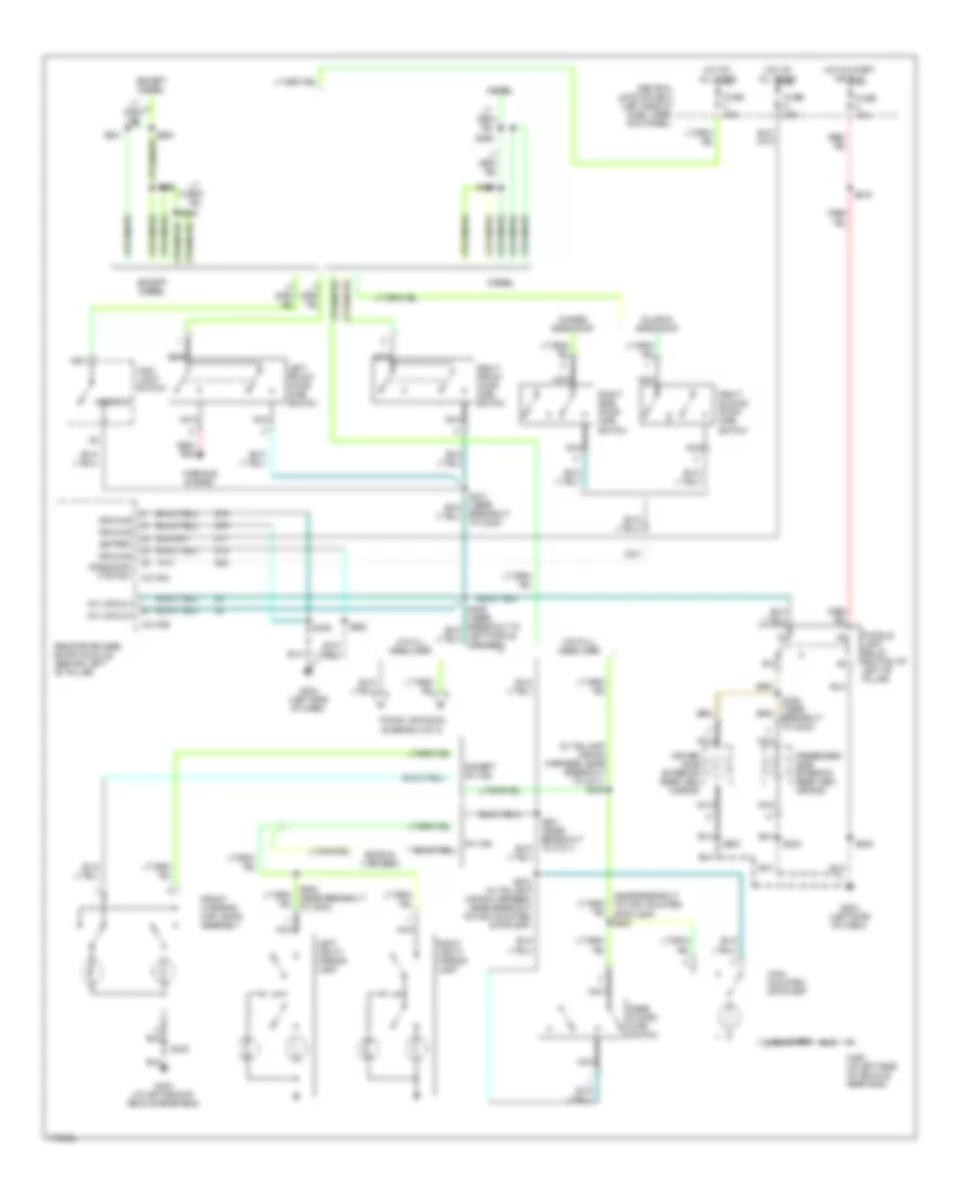
AIR CONDITIONING
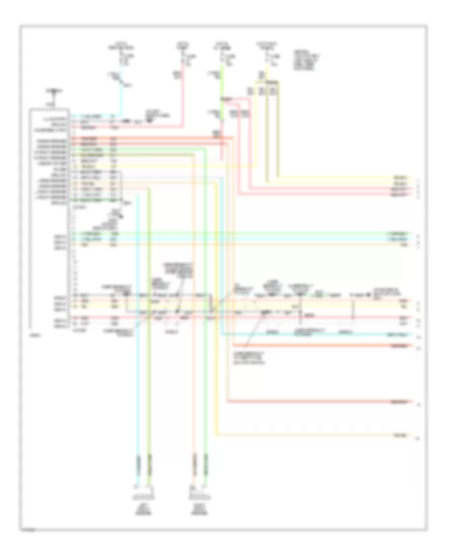
4.2L
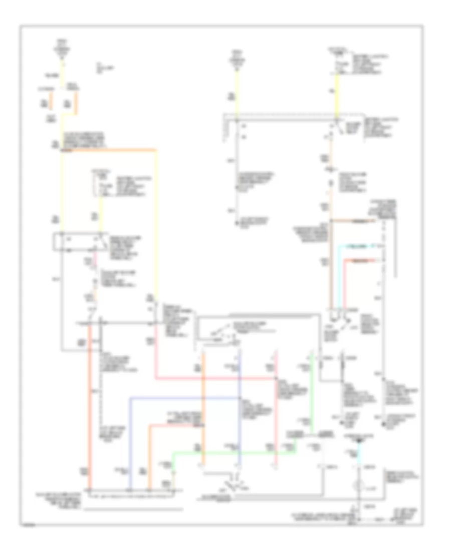
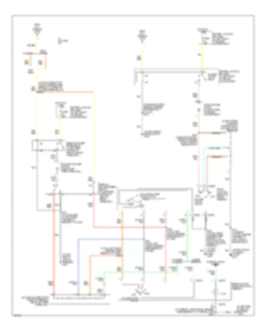
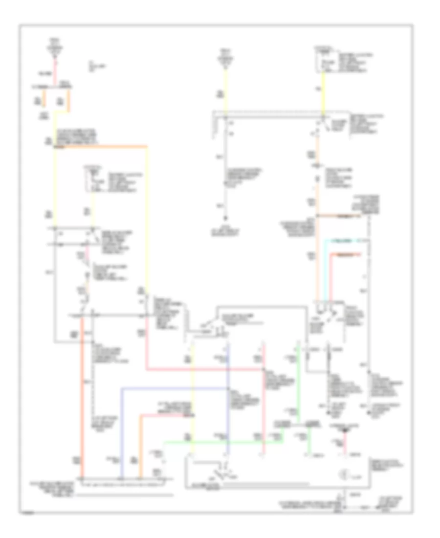
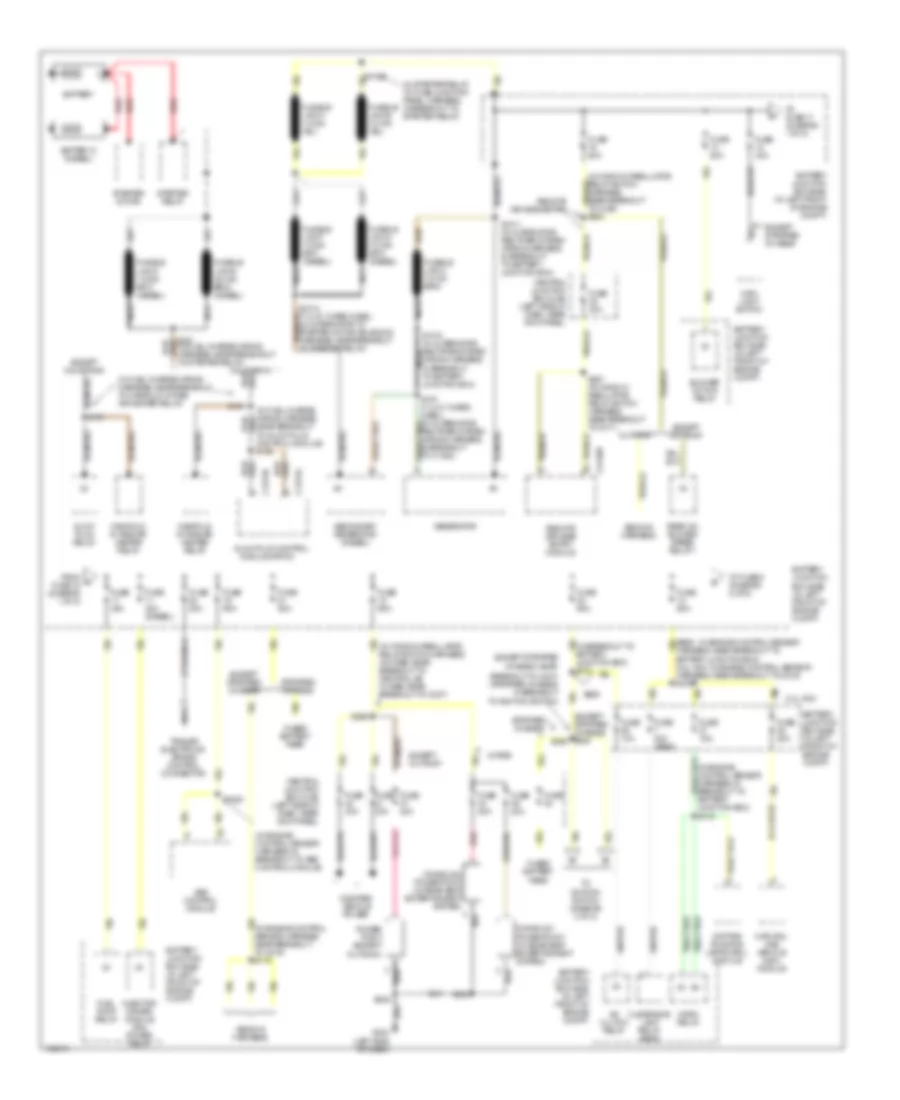
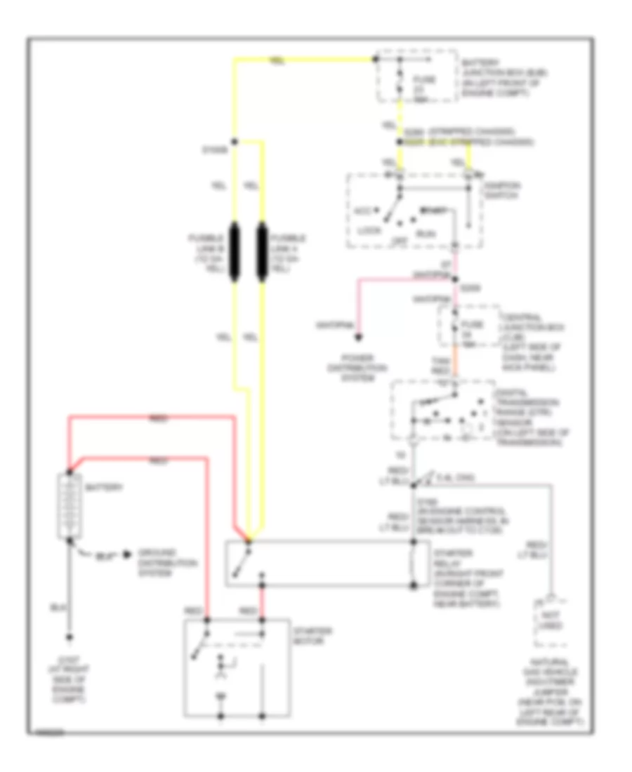
4.2L, Manual A/C Wiring Diagram, without Stripped Chassis (1 of 2) for Ford Econoline E350 Super Duty 2003

List of elements for 4.2L, Manual A/C Wiring Diagram, without Stripped Chassis (1 of 2) for Ford Econoline E350 Super Duty 2003:
- (1: temperature control potentiometer)
- (at right front of engine compt)
- (at right front of engine compt) g101
- (in engine control sensor harness, in breakout to battery junction box) s110
- (in engine control sensor harness, in breakout to battery junction box) s176
- (in fuel charge wiring harness, near breakout to intake manifold runner control module) s107
- (in window regulator relay switch harness, near breakout to ignition switch) s223
- (left side of dash) g204
- A/c clutch cycling pressure switch (in right front of engine compartment)
- A/c clutch relay
- A/c clutch solenoid (on left front of engine)
- A/c compressor clutch diode (near front of engine)
- A/c high pressure switch (in right front of engine compartment)
- A/c on input signal
- A/c relay control
- Battery junction box (bjb) (in left front of engine compartment)
- C294a
- C294d
- Central junction box (cjb) (left side of dash, near kick panel)
- Defrost
- Floor
- Front function selector switch assembly
- Fuse 10a
- Fuse 15a
- Fuse 30a
- G101
- Hot at all times
- Hot in run
- Hot in start or run
- Max a/c
- Mix
- Mode switch
- Norm a/c
- Of engine compt)
- Off
- Pcm power relay
- Pnk/ (in main wiring harness, near breakout to front function selector switch assembly) s203
- Powertrain control module (pcm) (in left rear of engine compartment, near brake master cylinder)
- Red
- S142 (in engine control sensor harness, at center rear red
- Temperature blend door actuator (behind right side of dash, on a/c heater plenum)
- To blower motor relay (diagram 2 of 2)
- To s400 (diagram 2 of 2)
- Vent
- Vent norm a/c
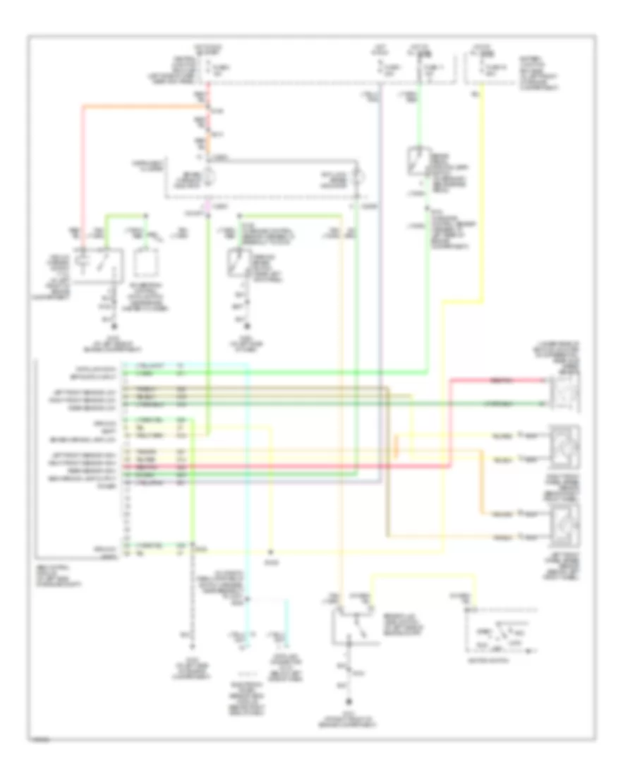
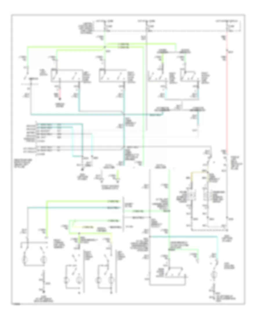
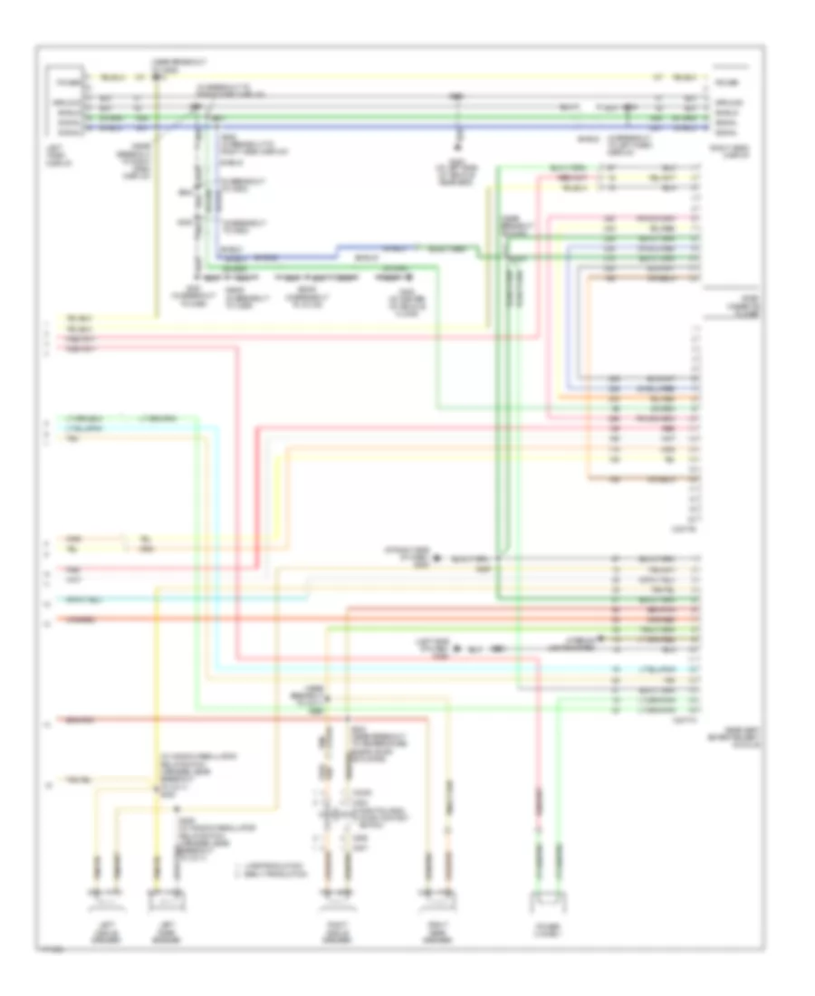
4.2L, Manual A/C Wiring Diagram, without Stripped Chassis (2 of 2) for Ford Econoline E350 Super Duty 2003
List of elements for 4.2L, Manual A/C Wiring Diagram, without Stripped Chassis (2 of 2) for Ford Econoline E350 Super Duty 2003:
- (at left side of dash) g203
- (at left side of engine compt) g100
- (at left side of vehicle rear end)
- (at left side of vehicle rear end) g400
- (at right front of engine compt) g101
- (in a/c blower motor wiring harness, near breakout to rear a/c blower speed relay 1) s400
- (in engine control sensor harness, near breakout to c219) s122
- (in interior lamps wiring harness, near breakout to interior lamp) s913
- (in right rear of engine compartment) blower motor resistor
- (in taillamp wiring harness, near breakout to c925) s303
- (not used)
- 87a
- Auxiliary blower motor (above left rear wheelwell)
- Auxiliary blower motor resistor assembly (above left rear wheelwell)
- Auxiliary blower motor switch
- Battery junction box (bjb) (in left front of engine compartment)
- Blower motor relay
- Blower motor switch
- C294b
- C294c
- C951a
- C951b
- Cutaway
- From s111 (diagram 1 of 2)
- Front blower motor (on right side of engine compartment)
- Front function selector switch assembly
- Fuse 50a
- G400
- High
- Hot at all times
- Illum
- Interior lights system
- Low
- Off
- Rear a/c blower speed relay 1 (in left rear corner of vehicle, above wheelwell)
- Rear a/c blower speed relay 2 (in left rear corner of vehicle, above wheelwell)
- Rear function selector switch assembly
- S143 (in engine control sensor harness, at right side of engine compt)
- S144 (in engine control sensor harness, at right side of engine compt)
- S202 (near breakout to front function selector switch assembly)
- S304 (in taillamp wiring harness, near breakout to c925)
- S305 (in taillamp wiring harness, near breakout to c925)
- S401 (in a/c blower motor wiring harness, in breakout to c405)
- Van & wagon
- W/ auxiliary a/c
- W/ rear control
- W/o rear control
4.6L
4.6L, Manual A/C Wiring Diagram (1 of 2) for Ford Econoline E350 Super Duty 2003
List of elements for 4.6L, Manual A/C Wiring Diagram (1 of 2) for Ford Econoline E350 Super Duty 2003:
- (1: temperature control potentiometer)
- (at right front of engine compt)
- (in engine control sensor harness, in breakout to battery junction box) s110
- (in engine control sensor harness, in breakout to battery junction box) s176
- (in window regulator relay switch harness, near breakout to ignition switch) s223
- (left side of dash) g204
- 87a
- A/c clutch cycling pressure switch (in right front of engine compartment)
- A/c clutch relay
- A/c clutch solenoid (on lower right front of engine)
- A/c compressor clutch diode (near front of engine)
- A/c high pressure switch (in right front of engine compartment)
- A/c on input sig
- A/c relay ctrl
- Battery junction box (bjb) (in left front of engine compartment)
- C294a
- C294d
- Central junction box (cjb) (left side of dash, near kick panel)
- Defrost
- Engine compartment)
- Floor
- Front function selector switch assembly
- Fuse 15a
- Fuse 30a
- G101
- G101 (at right front of engine compt)
- Hot at all times
- Hot in run
- Hot in start or run
- Max a/c
- Mix
- Mode switch
- Norm a/c
- Off
- Pcm power relay
- Pnk/ (in main wiring harness, near breakout to front function selector switch assembly) s203
- Powertrain control module (pcm) (in left rear of engine compartment, near brake master cylinder)
- Red
- S142 (in engine control sensor harness, at center rear of engine compartment)
- S166 (in engine control sensor harness, near breakout to c139)
- Temperature blend door actuator (behind right side of dash, on a/c heater plenum)
- To blower motor relay (diagram 2 of 2)
- To s400 (diagram 2 of 2)
- Vent
- Vent norm a/c
4.6L, Manual A/C Wiring Diagram (2 of 2) for Ford Econoline E350 Super Duty 2003
List of elements for 4.6L, Manual A/C Wiring Diagram (2 of 2) for Ford Econoline E350 Super Duty 2003:
- (at left side of dash) g203
- (at left side of engine compt) g100
- (at left side of vehicle rear end)
- (at left side of vehicle rear end) g400
- (at right front of engine compt) g101
- (in a/c blower motor wiring harness, near breakout to rear a/c blower speed relay 1) s400
- (in engine control sensor harness, near breakout to c219) s122
- (in interior lamps wiring harness, near breakout to interior lamp) s913
- (in right rear of engine compartment) blower motor resistor
- (in taillamp wiring harness, near breakout to c925) s303
- (not used)
- 87a
- Auxiliary blower motor (above left rear wheelwell)
- Auxiliary blower motor resistor assembly (above left rear wheelwell)
- Auxiliary blower motor switch
- Battery junction box (bjb) (in left front of engine compartment)
- Blower motor relay
- Blower motor switch
- C294b
- C294c
- C951a
- C951b
- Cutaway
- From s111 (diagram 1 of 2)
- Front blower motor (on right side of engine compartment)
- Front function selector switch assembly
- Fuse 50a
- G400
- High
- Hot at all times
- Illum
- Interior lights system
- Low
- Off
- Rear a/c blower speed relay 1 (in left rear corner of vehicle, above wheelwell)
- Rear a/c blower speed relay 2 (in left rear corner of vehicle, above wheelwell)
- Rear function selector switch assembly
- S143 (in engine control sensor harness, at right side of engine compt)
- S144 (in engine control sensor harness, at right side of engine compt)
- S202 (in main wiring harness, near breakout to front function selector switch assembly)
- S304 (in taillamp wiring harness, near breakout to c925)
- S305 (in taillamp wiring harness, near breakout to c925)
- S401 (in a/c blower motor wiring harness, in breakout to c405)
- Van & wagon
- W/ auxiliary a/c
- W/ rear control
- W/o rear control
5.4L
5.4L, Manual A/C Wiring Diagram, without Stripped Chassis (1 of 2) for Ford Econoline E350 Super Duty 2003
List of elements for 5.4L, Manual A/C Wiring Diagram, without Stripped Chassis (1 of 2) for Ford Econoline E350 Super Duty 2003:
- (at right front of engine compt) g101
- (in engine control sensor & fuel charge wiring harness, near breakout to a/c clutch solenoid) s189
- (in window regulator relay switch harness, near breakout to ignition switch) s223
- (left side of dash) g204
- (temperature control potentiometer)
- 5.4l, 5.4l cng & 6.8l
- 7.3l di turbo diesel
- A/c clutch cycling pressure switch (in right front of engine compartment)
- A/c clutch solenoid (on lower right front of engine)
- A/c clutch solenoid (on top left front of engine)
- A/c compressor clutch diode (near front of engine)
- A/c high pressure switch (in right front of engine compartment)
- A/c on input signal
- C294a
- C294d
- Central junction box box (cjb) (left side of dash, near kick panel)
- Defrost
- Floor
- Front function selector switch assembly
- Front function selector switch assembly front12
- Fuse 15a
- Hot in run
- Max a/c
- Mix
- Mode switch
- Norm a/c
- Off
- Pnk/ (in main wiring harness, near breakout to front function selector switch assembly) s203
- Powertrain control module (pcm) (in left rear of engine compartment, near brake master cylinder)
- S111 (in engine control sensor harness, in breakout to battery junction box)
- S141 (in engine control sensor harness, near breakout to c139) (7.3l: in engine control sensor harness, near breakout to c1168)
- S143 (in engine control sensor harness, at right side of engine compartment)
- Temperature blend door actuator (behind right side of dash, on a/c heater plenum)
- To blower motor relay (diagram 2 of 2)
- To s400 (diagram 2 of 2)
- Vent
- Vent norm a/c
5.4L, Manual A/C Wiring Diagram, without Stripped Chassis (2 of 2) for Ford Econoline E350 Super Duty 2003
List of elements for 5.4L, Manual A/C Wiring Diagram, without Stripped Chassis (2 of 2) for Ford Econoline E350 Super Duty 2003:
- (at left side of dash) g203
- (at left side of vehicle rear end)
- (at left side of vehicle rear end) g400
- (at right front of engine compt) g101
- (in a/c blower motor wiring harness, near breakout to rear a/c blower speed relay 1) s400
- (in engine control sensor harness, near breakout to c219) s122
- (in interior lamps wiring harness, near breakout to interior lamp) s913
- (in right rear of engine compartment) blower motor resistor
- (in taillamp wiring harness, near breakout to c925) s303
- (not used)
- 87a
- Auxiliary blower motor (above left rear wheelwell)
- Auxiliary blower motor resistor assembly (above left rear wheelwell)
- Auxiliary blower motor switch
- Battery junction box (bjb) (in left front of engine compartment)
- Blower motor relay
- Blower motor switch
- C294b
- C294c
- C951a
- C951b
- Cutaway
- From s111 (diagram 1 of 2)
- Front blower motor (on right side of engine compartment)
- Front function selector switch assembly
- Fuse 50a
- G100 (at left side of engine compt)
- G400
- High
- Hot at all times
- Illum
- Interior lights system
- Low
- Off
- Rear a/c blower speed relay 1 (in left rear corner of vehicle, above wheelwell)
- Rear a/c blower speed relay 2 (in left rear corner of vehicle, above wheelwell)
- Rear function selector switch assembly
- S143 (in engine control sensor harness, at right side of engine compt)
- S144 (in engine control sensor harness, at right side of engine compt)
- S202 (near breakout to front function selector switch assembly)
- S304 (in taillamp wiring harness, near breakout to c925)
- S305 (in taillamp wiring harness, near breakout to c925)
- S401 (in a/c blower motor wiring harness, in breakout to c405)
- Van & wagon
- W/ auxiliary a/c
- W/ rear control
- W/o rear control
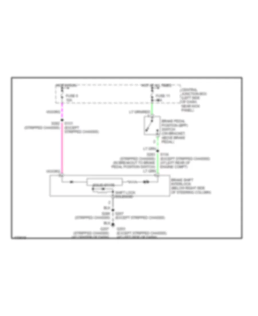
ANTI-LOCK BRAKES
Anti-lock Brakes Wiring Diagram, without Stripped Chassis for Ford Econoline E350 Super Duty 2003
List of elements for Anti-lock Brakes Wiring Diagram, without Stripped Chassis for Ford Econoline E350 Super Duty 2003:
- (in window regulator relay
- (near brake master cylinder)
- (under rear of vehicle, mounted on differential) rear axle speed sensor
- 7.3l
- Abs control module (at left side of engine compt)
- Abs warning lamp output
- Acc
- Anti-lock brake indicator
- Battery junction box (bjb) (in left front of engine compartment)
- Bpp switch input
- Brake fluid level switch (at left side of engine compt)
- Brake pedal position (bpp) switch (on bracket, above brake pedal)
- Brake warning indicator
- Brake warning lamp low
- C220b
- C220c
- Central junction box (cjb) (left side of dash, near kick panel)
- Data link conn
- Data link connector (dlc) (below left side of dash)
- Electronic crash sensor (ecs) module (behind right side of dash)
- Fuse 1 20a
- Fuse 11 15a
- Fuse 19 60a
- Fuse 2 15a
- G100 (at left side of engine compartment)
- G101 (at right front of engine compartment)
- G203 (at left side of dash)
- Ground
- Hot at all times
- Hot in run
- Hot in run or start
- Ignition switch
- Instrument cluster
- Left front sensor high
- Left front sensor low
- Left front wheel speed sensor (behind left front wheel)
- Lock
- Nca
- Off
- Parking brake switch (near left kick panel)
- Power
- Powertrain control module (pcm)
- Rear sensor high
- Rear sensor low
- Red/pnk
- Right front sensor high
- Right front sensor low
- Right front wheel speed sensor (behind right front wheel)
- Run
- S1020
- S122
- S125 (in engine control sensor harness, in breakout to c219)
- S134 (in engine control sensor harness, at left rear of engine compartment)
- S143
- S146
- S207
- S213
- S228
- Start
- Switch harness, near breakout to c237)
- Vacuum warning switch (7.3l) (in left front of engine compartment)
- Vbatt
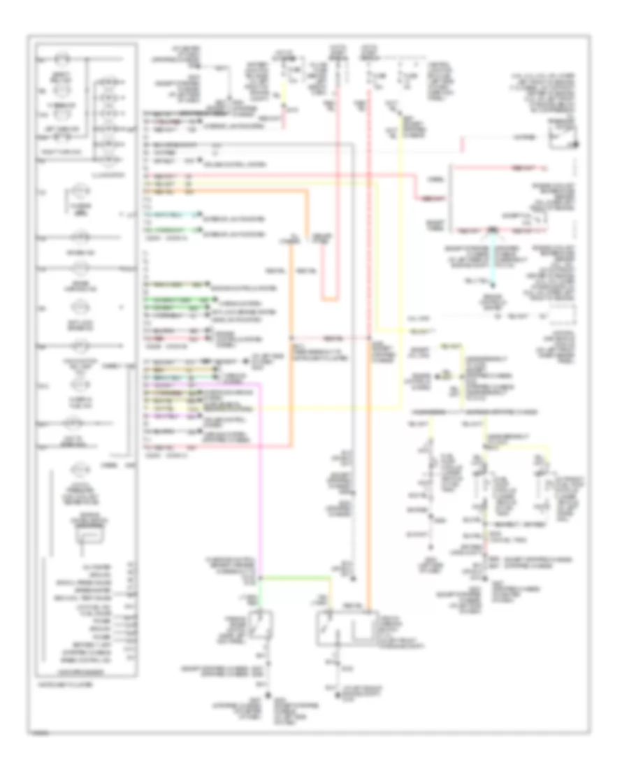
COMPUTER DATA LINES
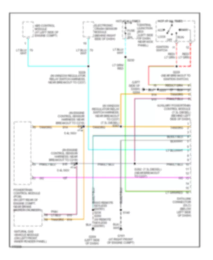
Computer Data Lines Wiring Diagram, without Stripped Chassis for Ford Econoline E350 Super Duty 2003
List of elements for Computer Data Lines Wiring Diagram, without Stripped Chassis for Ford Econoline E350 Super Duty 2003:
- (7.3l diesel)
- (in engine control sensor harness, near breakout to c219) s182
- (in engine control sensor harness, near breakout to c219) s184
- (in window regulator relay switch harness, near breakout to c237) (7.3l diesel) s263
- (left side of dash) g204
- 5.4l ngv
- Abs control module (at left side of engine compt)
- Acc
- Auxiliary powertrain control module (7.3l diesel) (behind left side of dash)
- Central junction box (left side of dash, near kick panel)
- Data link connector (dlc) (below left side of dash)
- Electronic crash sensor module (behind right side of dash)
- Fuse 20a
- G101 (at right front of engine compt)
- G204 (left side of dash)
- Hot at all times
- Ignition switch
- Lock
- Natural gas vehicle module (on left front inner fender panel)
- Off
- Powertrain control module (pcm) (in left rear of engine compt, near brake master cylinder)
- Run
- S140
- S223
- S228 (in window regulator relay switch harness, near breakout to c237)
- S229 (near breakout to ignition switch)
- S230
- S262 (near breakout to c237)
- Start
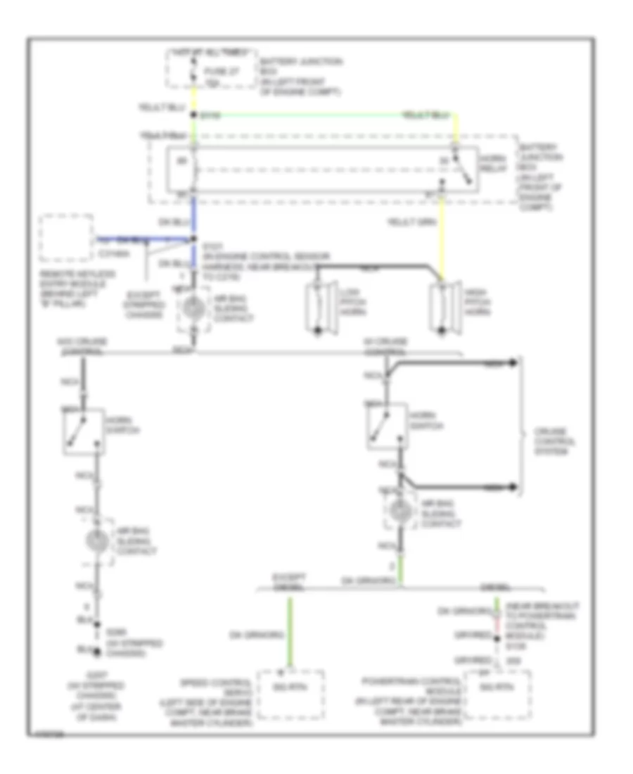
CRUISE CONTROL
4.2L
4.2L, Cruise Control Wiring Diagram for Ford Econoline E350 Super Duty 2003
List of elements for 4.2L, Cruise Control Wiring Diagram for Ford Econoline E350 Super Duty 2003:
- Accel set/
- Air bag sliding contact
- Battery junction box (bjb) (in left front of engine compartment)
- Bpp sw input
- Brake input
- Brake pedal position (bpp) switch (on bracket, above brake pedal)
- Brake pressure switch (at left side of engine compartment)
- C220a
- C3140a
- Central junction box (cjb) (left side of dash, near kick panel)
- Coast
- Except stripped chassis
- Fuse 10a
- Fuse 15a
- G203 (at left side of dash)
- Ground
- Horn relay
- Horn switch
- Hot at all times
- Hot at all times
- Hot in run
- Instrument cluster
- Microprocessor
- Nca
- Off
- On indicator
- Overhead console
- Power
- Powertrain control module (pcm) (in left rear of engine compt, near brake master cylinder)
- Remote keyless entry module (behind left ``b" pillar)
- Resume
- S116
- S121 (in engine control sensor harness, near breakout to c219)
- S129
- S131
- S134 (in engine control sensor harness, at left rear of engine compartment)
- S135 (in engine control sensor harness, near breakout to powertrain control module)
- S268
- Scsa gnd
- Scsa input
- Speed control indicator c220c
- Speed control servo (left side of engine compt, near brake master cylinder)
- Speed control switch
- Vss input
4.6L
4.6L, Cruise Control Wiring Diagram for Ford Econoline E350 Super Duty 2003
List of elements for 4.6L, Cruise Control Wiring Diagram for Ford Econoline E350 Super Duty 2003:
- Accel set/
- Air bag sliding contact
- Battery junction box (bjb) (in left front of engine compartment)
- Bpp sw input
- Brake input
- Brake pedal position (bpp) switch (on bracket, above brake pedal)
- Brake pressure switch (at left side of engine compartment)
- C220a
- C3140a
- Central junction box (cjb) (left side of dash, near kick panel)
- Coast
- Except stripped chassis
- Fuse 10a
- Fuse 15a
- G203 (at left side of dash)
- Ground
- Horn relay
- Horn switch
- Hot at all times
- Hot at all times
- Hot in run
- Instrument cluster
- Microprocessor
- Nca
- Off
- On indicator
- Overhead console
- Power
- Powertrain control module (pcm) (in left rear of engine compt, near brake master cylinder)
- Remote keyless entry module (behind left ``b" pillar)
- Resume
- S116
- S121 (in engine control sensor harness, near breakout to c219)
- S129
- S131
- S134 (in engine control sensor harness, at left rear of engine compartment)
- S135 (in engine control sensor harness, near breakout to powertrain control module)
- S268
- Scsa gnd
- Scsa input
- Speed control indicator c220c
- Speed control servo (left side of engine compt, near brake master cylinder)
- Speed control switch
- Vss input
5.4L
5.4L, Cruise Control Wiring Diagram for Ford Econoline E350 Super Duty 2003
List of elements for 5.4L, Cruise Control Wiring Diagram for Ford Econoline E350 Super Duty 2003:
- Accel set/
- Air bag sliding contact
- Battery junction box (bjb) (in left front of engine compartment)
- Bpp sw input
- Brake input
- Brake pedal position (bpp) switch (on bracket, above brake pedal)
- Brake pressure switch (at left side of engine compartment)
- C220a
- C3140a
- Central junction box (cjb) (left side of dash, near kick panel)
- Coast
- Except stripped chassis
- Fuse 10a
- Fuse 15a
- G203 (at left side of dash)
- Ground
- Horn relay
- Horn switch
- Hot at all times
- Hot at all times
- Hot in run
- Instrument cluster
- Microprocessor
- Nca
- Off
- On indicator
- Overhead console
- Power
- Powertrain control module (pcm) (in left rear of engine compt, near brake master cylinder)
- Remote keyless entry module (behind left ``b" pillar)
- Resume
- S116
- S121 (in engine control sensor harness, near breakout to c219)
- S129
- S131
- S134 (in engine control sensor harness, at left rear of engine compartment)
- S135 (in engine control sensor harness, near breakout to powertrain control module)
- S268
- Scsa gnd
- Scsa input
- Speed control indicator c220c
- Speed control servo (left side of engine compt, near brake master cylinder)
- Speed control switch
- Vss input
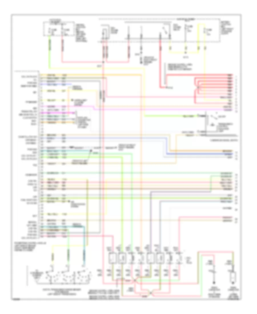
ENGINE PERFORMANCE
4.2L
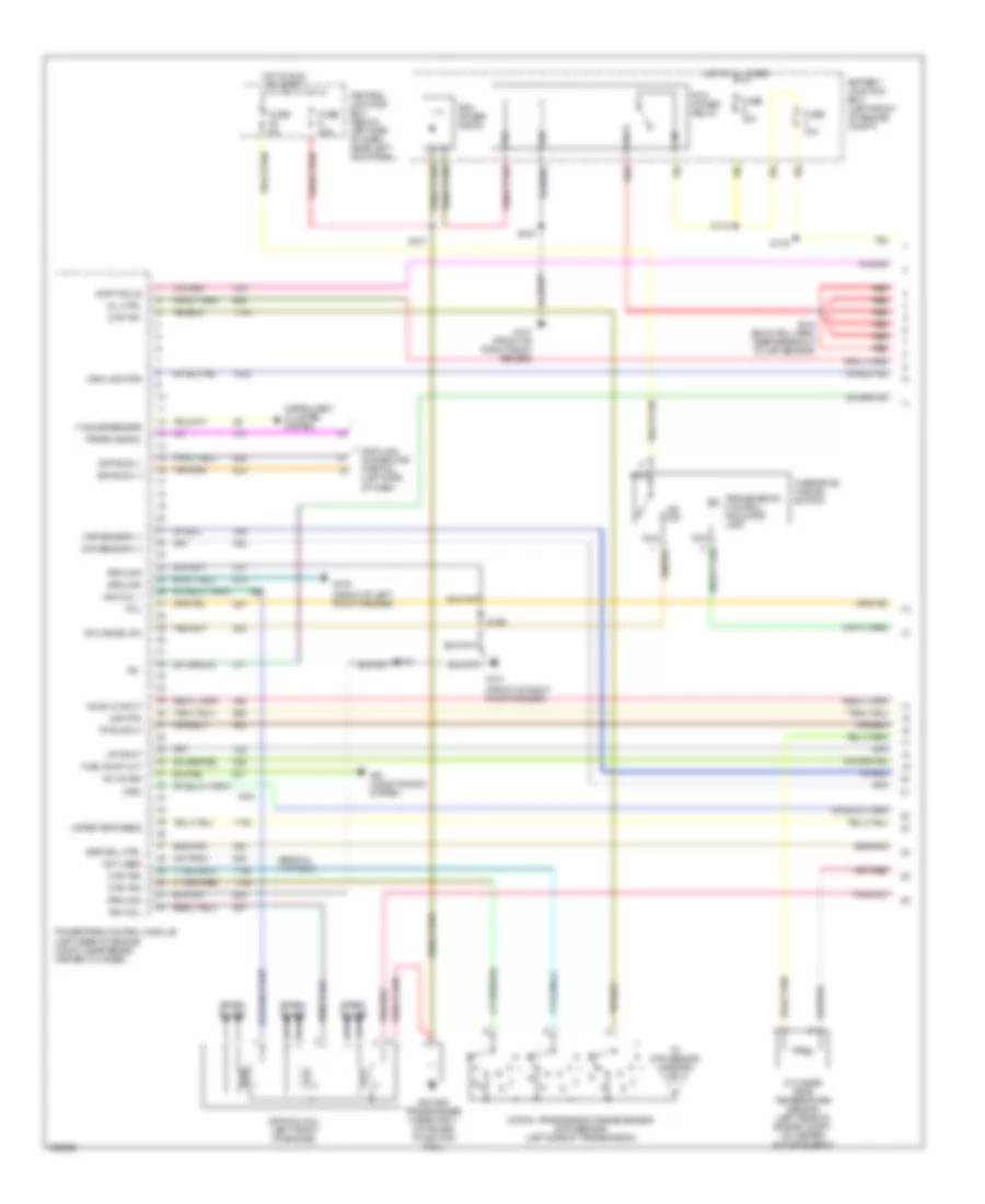
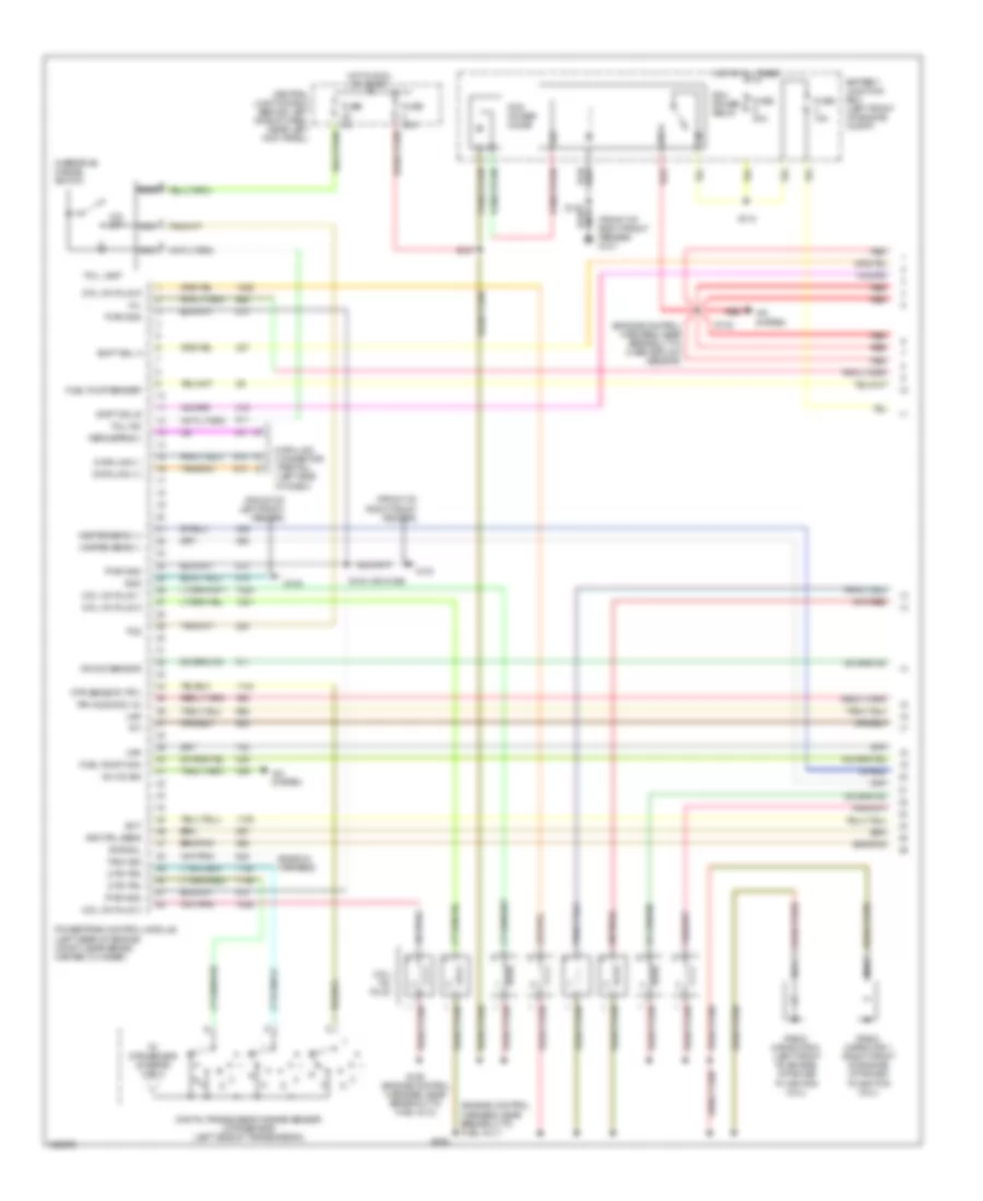
4.2L, Engine Performance Wiring Diagram (1 of 4) for Ford Econoline E350 Super Duty 2003
List of elements for 4.2L, Engine Performance Wiring Diagram (1 of 4) for Ford Econoline E350 Super Duty 2003:
- (ends in harness)
- (front of left front fender)
- (front of right front fender)
- A/c on sig
- Air conditioning system
- Battery junction box (left front of engine compt)
- Central junction box (below left side of dash, near left kick panel)
- Ckp sensor (+)
- Ckp sensor (-)
- Cylinder head temperature sensor (left rear of engine compt, on heater outlet elbow)
- Data link connector (partial) (left side of dash)
- Digital transmission range sensor (dtr sensor) (left side of transmission)
- Dtr-tr1
- Dtr-tr2
- Dtr-tr4
- Egr sol ctrl
- F gauge sender
- Fuel pump out
- Fuse 10a
- Fuse 30a
- Fuse 5a
- G100
- G101
- G101 (front of right front fender)
- Ground
- Ho2s 12 input
- Hot at all times
- Hot in run or start
- Iat input
- Ign coil
- Ign coil 1
- Ignition coil (left front of engine)
- Ignition transformer capacitor 1 (attached to ignition coil)
- Imrc
- Imrc monitor
- Instrument cluster system
- Ks -
- Maf rtn
- Mil ctrl
- Nca
- Not used
- O/d off
- Od cancel sw
- Overdrive cancel switch
- Pcm power diode
- Pcm power relay
- Powertrain control module (left rear of engine compt, near brake master cylinder)
- Prgrm signal
- R n
- Red
- S110
- S127
- S140
- S142 (eng ctrl harn, near breakout to maf sensor)
- S169
- S175
- Scp bus (+)
- Scp bus (-)
- Shift sol b
- Spark plugs
- Tcil
- Tfts input
- To dtr sensor (diagram 4 of 4)
- Transmission control indicator lamp
- Water temp sens
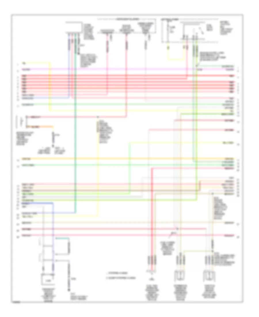
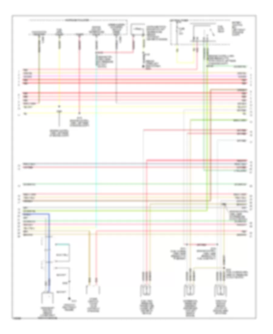
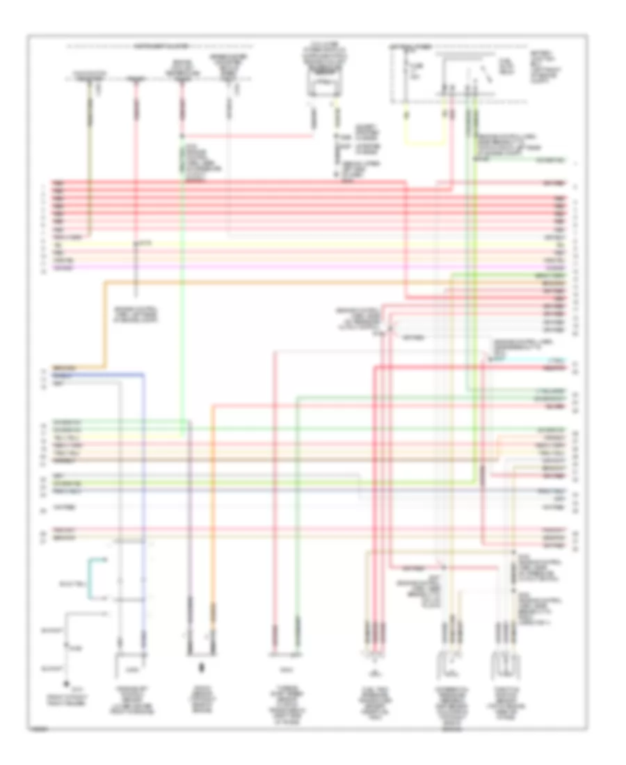
4.2L, Engine Performance Wiring Diagram (2 of 4) for Ford Econoline E350 Super Duty 2003
List of elements for 4.2L, Engine Performance Wiring Diagram (2 of 4) for Ford Econoline E350 Super Duty 2003:
- (engine control harn, near breakout to 76-pin conn in left rear of engine compt)
- (front of right front fender)
- (fuel charge harn, near breakout to throttle position sensor)
- (left side of dash)
- (speedometer/ odometer) vehicle speed input
- Battery junction box (left front of engine compt)
- C220a
- C220b
- Crankshaft position sensor (lower right front of engine)
- Differential pressure feedback egr sensor (top right front of engine)
- Engine coolant temperature gauge
- Engine coolant temperature sender (top front center of engine)
- Except stripped chassis
- Fuel pump relay
- Fuel tank pressure transducer sensor (under left center of vehicle)
- Fuse 30a
- G101
- G101 (or g114) (front of right front fender or right rear of engine compt)
- G203
- G207 (center of dash panel)
- Hot at all times
- Instrument cluster
- Intake manifold runner control module (on rear of intake)
- Malfunction indicator
- Red
- Red/pnk
- S103
- S107
- S126
- S133 (engine control harn, near breakout to 16-pin conn near a/c pressure cut out switch)
- S138 (engine control harn, near breakout to 16-pin conn near a/c pressure cut out switch)
- S169
- Stripped chassis
- Throttle position sensor (on top of engine, near air intake)
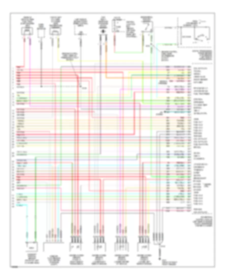
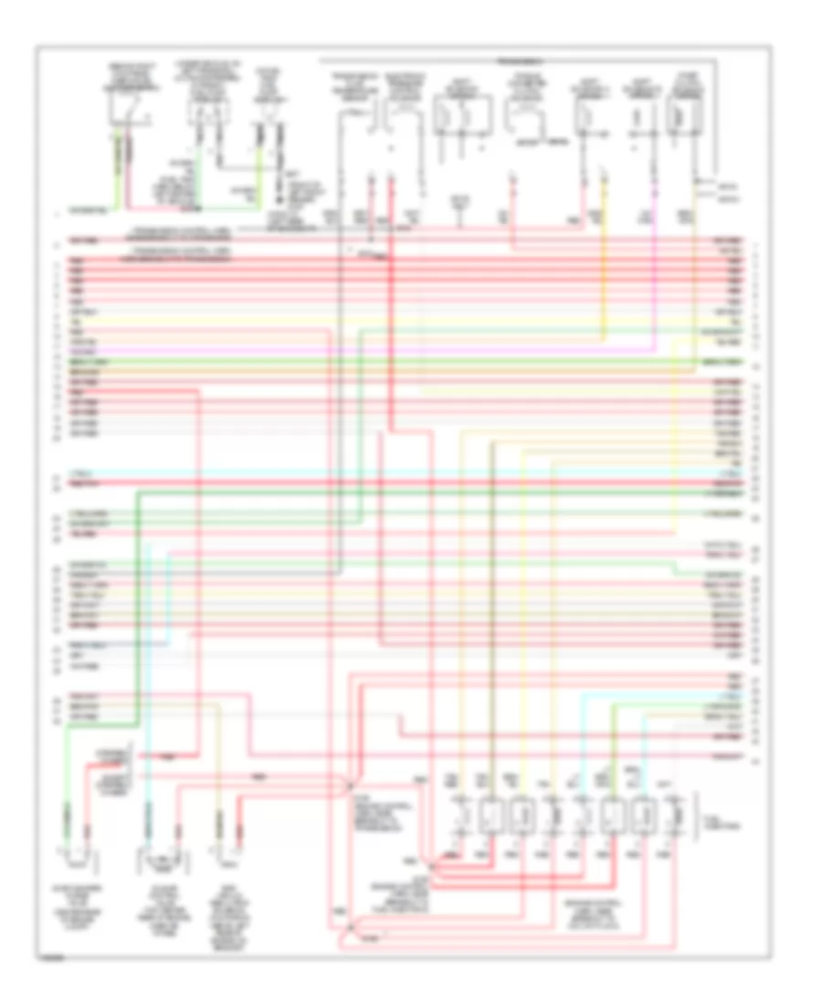
4.2L, Engine Performance Wiring Diagram (3 of 4) for Ford Econoline E350 Super Duty 2003
List of elements for 4.2L, Engine Performance Wiring Diagram (3 of 4) for Ford Econoline E350 Super Duty 2003:
- (behind right kick panel) inertia fuel shut-off switch
- (engine control harn, near a/c pressure cut out switch)
- (fuel charge harn, near breakout to fuel injector 2)
- (in center rear of engine compt)
- (in fuel tank) fuel pump module
- (on left frame rail) (cutaways/ stripped chassis) in transit fuel pump module
- (trans cntrl harn, near breakout to dtr sensor)
- (transmission control harn, near breakout to transmission)
- 4r70w transmission
- Chassis
- Egr vacuum regulator solenoid (above center of right valve cover)
- Electronic pressure control solenoid
- Evap canister purge valve
- Except stripped chassis
- Fuel injectors
- G100 (front of left front fender)
- G113 (left rear of engine compt)
- Idle air control valve (right side of engine, near ignition coil)
- Nca
- Output shaft speed sensor (left side of transmission)
- Red
- Red/pnk
- S100
- S102
- S105 (fuel charge harn, near breakout to fuel injector 3)
- S106
- S136
- S137 (sensor ctrl harn, in breakout to pcm)
- S307
- S309 (fuel tank harn, below left center of vehicle)
- Shift solenoids
- Stripped
- Stripped chassis
- Tan
- Torque converter clutch solenoid
- Transmission fluid temperature sensor
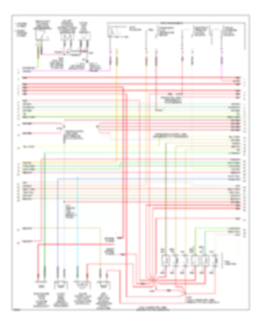
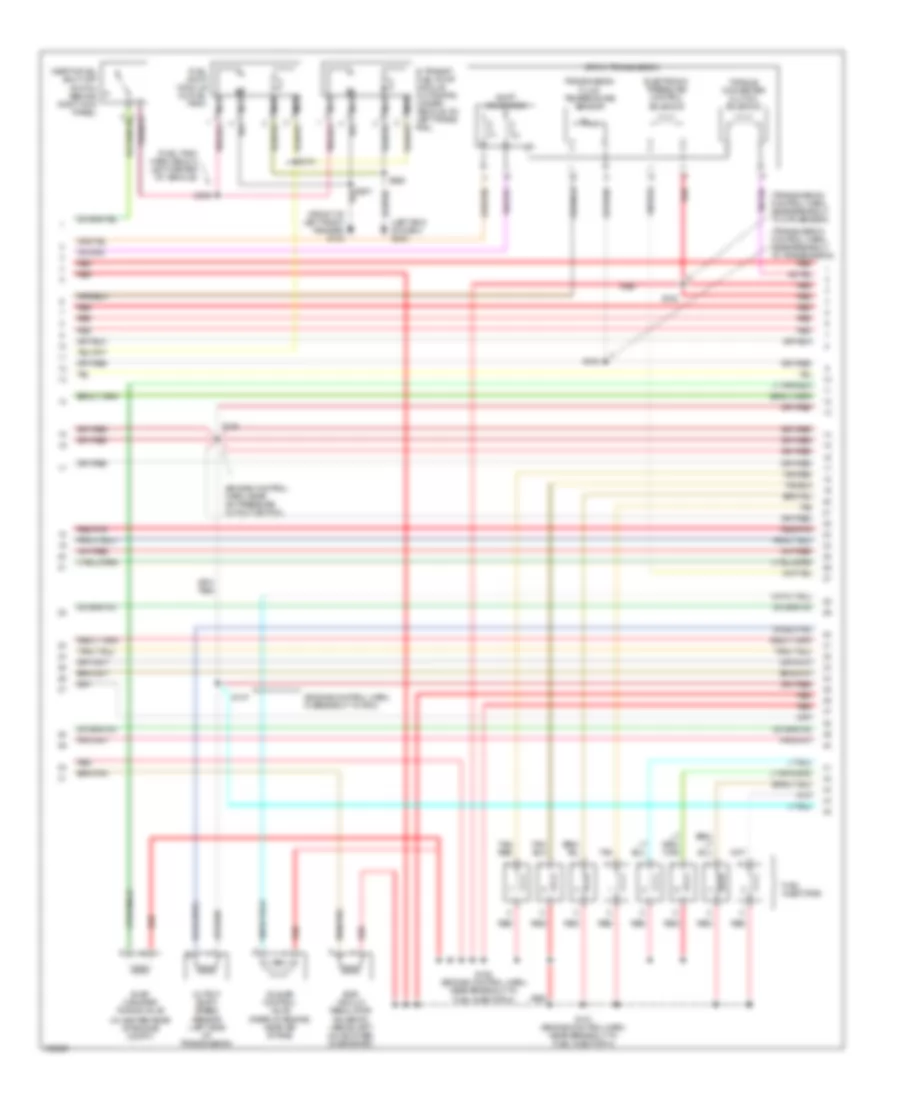
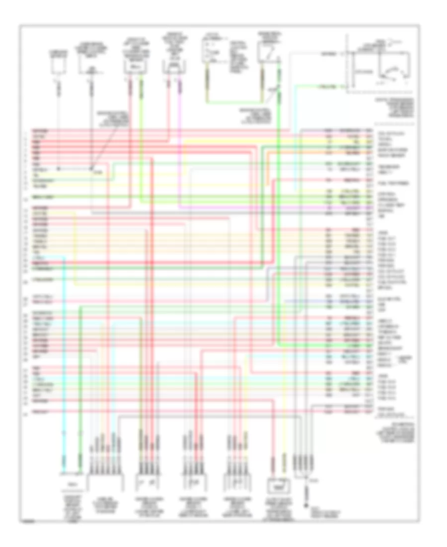
4.2L, Engine Performance Wiring Diagram (4 of 4) for Ford Econoline E350 Super Duty 2003
List of elements for 4.2L, Engine Performance Wiring Diagram (4 of 4) for Ford Econoline E350 Super Duty 2003:
- (engine control harn, near a/c pressure cut out switch) s135
- (near brake master cylinder) speed control servo
- (right rear side of engine) knock sensor
- 240 ohms
- A/c rly cntrl
- A/c system
- Brake on/off
- Brake pedal position switch
- Camshaft position sensor (on front center of engine)
- Canister vent
- Central junction box (below left side of dash, near left kick panel)
- Cht input
- Cmp sensor
- Digital transmission range (dtr) sensor (left side of transmission)
- Dpfe input
- Dtr-tr3a
- Epc sol
- Evap valve
- Evaporative emissions canister vent solenoid (rear of vehicle, near fuel tank)
- From dtr sensor (diagram 1 of 4)
- Fuel pump ctrl
- Fuel tank press
- Fuse 15a
- G101 (front of right front fender)
- Gnd
- Ground
- Heated oxygen sensor 11 (ho2s) (lower right rear of engine)
- Heated oxygen sensor 12 (ho2s) (right side of transmission)
- Heated oxygen sensor 21 (ho2s) (left rear of engine)
- Heated oxygen sensor 22 (ho2s) (under center of vehicle)
- Heater ctrl
- Ho2s 11
- Ho2s 11 input
- Ho2s 12
- Ho2s 21
- Ho2s 21 input
- Ho2s 22
- Ho2s 22 input
- Hot at all times
- Iac ctrl
- Ign coil
- Inj 1 ctrl
- Inj 2 ctrl
- Inj 3 ctrl
- Inj 4 ctrl
- Inj 5 ctrl
- Inj 6 ctrl
- Kap b(+)
- Knock sensor
- Maf sens out
- Mass air flow sensor (on top center of engine compt)
- Nca
- Oss (-)
- Over- head console
- Powertrain control module (left rear of engine compt, near master cylinder)
- Red
- Red/pnk
- Ref output volt
- S134 (engine control harn, near a/c pressure cut out switch)
- S140
- Sig rtn
- Tan
- Tcc sol
- Tcil
- Tp sens in
- Vpwr
- Vss (+)
- Vss input
4.6L
4.6L, Engine Performance Wiring Diagram (1 of 4) for Ford Econoline E350 Super Duty 2003
List of elements for 4.6L, Engine Performance Wiring Diagram (1 of 4) for Ford Econoline E350 Super Duty 2003:
- (ends in harness)
- (engine control harness, near breakout to fuel inj 7)
- (engine control harness, near breakout to mass airflow sensor)
- (front of left front fender)
- (front of right front fender)
- (front of right front fender) g101
- A/c on sig
- A/c system
- Air ctrl sens
- Battery junction box (left front of engine compt)
- Central junction box (behind left side of dash, near left kick panel)
- Coil on plug
- Coil on plug 1
- Coil on plug 3
- Coil on plug 5
- Coil on plug 6
- Data link (+)
- Data link (-)
- Data link connector (partial) (left side of dash)
- Digital transmission range sensor (dtr sensor) (left side of transmission)
- Dtr sensor (tr1)
- Dtr-tr2
- Dtr-tr4
- Ect
- Evr sol
- Feps (eprom)
- Fuel pump mon
- Fuel pump sender
- Fuse 10a
- Fuse 30a
- Fuse 5a
- G100
- G101
- Gnd
- Hot at all times
- Hot in run or start
- Knock sensor
- Maf
- Mil
- Misfire sens (+)
- Misfire sens (-)
- Nca
- O/d off
- Overdrive cancel switch
- Pcm power diode
- Pcm power relay
- Powertrain control module (left rear of engine compt, near brake master cylinder)
- Pwr gnd
- R n
- Radio capacitor 1 (right front of engine, attached to ignition coil)
- Radio capacitor 2 (left front of engine, attached to ignition coil)
- Red
- Rr ho2s sig (12)
- S110
- S127
- S140 (or s169)
- S142
- S150 (engine control harness, near breakout to fuel inj 2)
- S193
- Shift sol a
- Shift sol b
- Tach sig
- Tcil ind
- Tcil lamp
- Tcs
- Tft
- To dtr sensor (diagram 4 of 4)
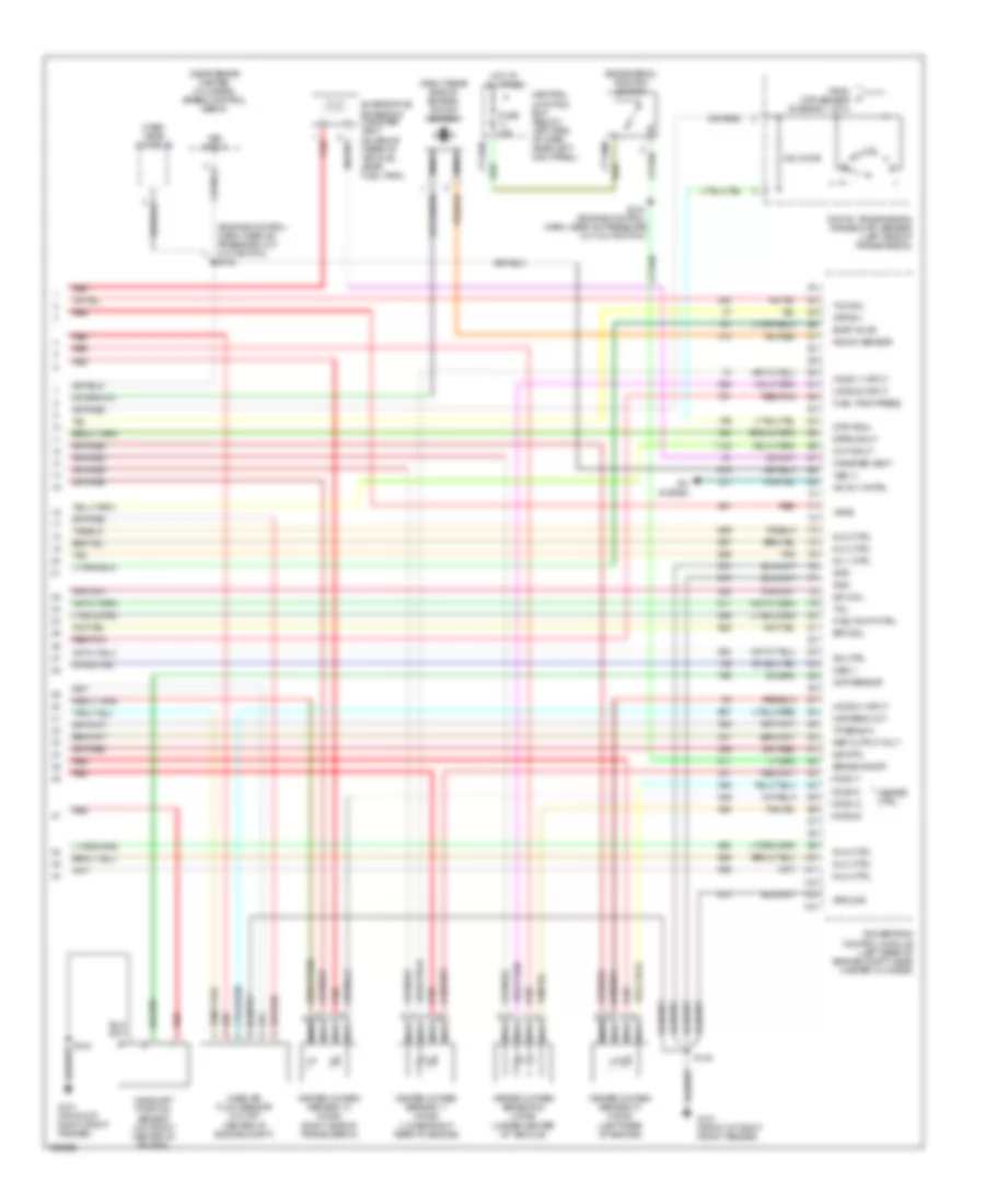
4.6L, Engine Performance Wiring Diagram (2 of 4) for Ford Econoline E350 Super Duty 2003
List of elements for 4.6L, Engine Performance Wiring Diagram (2 of 4) for Ford Econoline E350 Super Duty 2003:
- (behind upper left side of dash) g203
- (engine control harn, left rear of engine compt)
- (engine control harn, near a/c pressure cutout switch)
- (engine control harn, near breakout to 76-pin conn in left rear of engine compt) s126
- (front of right front fender)
- (speedometer/ odometer) vehicle speed input
- Battery junction box (left front of engine compt)
- Crankshaft position sensor (lower right front of engine)
- Differential pressure feedback egr sensor (top left rear of engine)
- Engine coolant temperature gauge
- Fuel level gauge
- Fuel pump relay
- Fuel tank pressure transducer (under left center of vehicle)
- Fuse 30a
- G101
- Hot at all times
- Instrument cluster
- Instrumentation engine coolant temperature sensor (top front center of engine)
- Intake manifold tuning valve (top front of engine)
- Malfunction indicator
- Power
- Red
- Red/pnk
- S103 (fuel charge harn, near breakout to tp sensor)
- S120
- S133
- S138
- S153 (fuel charge harn, near a/c pressure cutout switch)
- S154 (engine control harn, near breakout to fuel injector 7)
- S169
- S175 (engine control harn, left rear of engine compt)
- Throttle position sensor (on top of engine, near air intake)
4.6L, Engine Performance Wiring Diagram (3 of 4) for Ford Econoline E350 Super Duty 2003
List of elements for 4.6L, Engine Performance Wiring Diagram (3 of 4) for Ford Econoline E350 Super Duty 2003:
- (engine control harn, in breakout to pcm)
- (engine control harn, near a/c pressure cutout switch)
- (front of left front fender) g100
- (fuel tank harn, below left center of vehicle)
- (in center rear of engine compt)
- (left end of dash) g203
- (transmission control harn, near breakout to dtr sensor)
- (transmission control harn, near breakout to transmission)
- 4r70w transmission
- Egr vacuum regulator solenoid (above left valve cover, on bracket)
- Electronic pressure control solenoid
- Evap canister purge valve
- Fuel injectors
- Fuel pump module (in fuel tank)
- Idle air control valve (rear of engine, near air intake)
- In transit fuel pump module (cutaways) (under vehicle, on left frame rail)
- Inertia fuel shut-off switch (behind right kick panel)
- Nca
- Output shaft speed sensor (left side of transmission)
- Red
- Red/pnk
- S100
- S102
- S136
- S137
- S151 (engine control harn, near breakout to fuel injector 4)
- S152 (engine control harn, near breakout to fuel injector 8)
- S268
- S309
- S310
- Shift solenoids
- Tan
- Tan/ red
- Tan/red
- Torque converter clutch solenoid
- Transmission fluid temperature sensor
4.6L, Engine Performance Wiring Diagram (4 of 4) for Ford Econoline E350 Super Duty 2003
List of elements for 4.6L, Engine Performance Wiring Diagram (4 of 4) for Ford Econoline E350 Super Duty 2003:
- (ends in harness)
- (engine control harn, near a/c pressure cutout switch)
- (left side of engine compt) speed control servo
- (rear of vehicle, near fuel tank) evap canister vent valve
- (top of left cyl head) cylinder head temperature sensor
- (top right rear side of engine) knock sensor
- 240 ohms
- 5v ref
- A/c relay ctrl
- A/c system
- Brake on/off
- Brake pedal position switch
- Camshaft position sensor (front of left cylinder head)
- Central junction box (behind left side of dash, near left kick panel)
- Coil on plug 2
- Coil on plug 4
- Coil on plug 7
- Coil on plug 8
- Cyl head temp
- Cylinder id
- Digital transmission range sensor (dtr sensor) (left side of transmission)
- Dpfe sens
- Dtr-tr3a
- Epc sol
- Evap sol
- From dtr sensor (diagram 1 of 4)
- Fuel inj 1
- Fuel inj 2
- Fuel inj 3
- Fuel inj 4
- Fuel inj 5
- Fuel inj 6
- Fuel inj 7
- Fuel inj 8
- Fuel pump ctrl
- Fuel tank press
- Fuse 15a
- G101 (front of right front fender)
- Heated oxygen sensor (ho2s) 11 (lower right rear of engine)
- Heated oxygen sensor (ho2s) 12 (right side of transmission)
- Heated oxygen sensor (ho2s) 21 (lower left rear of engine)
- Heated oxygen sensor (ho2s) 22 (under center of vehicle)
- Heater ctrl
- Hot at all times
- Iac sol
- Kap b(+)
- Knock sensor
- Lf ho2s
- Lf ho2s sig (21)
- Lr ho2s
- Lr ho2s sig (22)
- Maf sens in
- Mass air- flow sensor (top center of engine compt)
- Nca
- Not used
- Oss (+)
- Over- head console
- Powertrain control module (left rear of engine compt, near brake master cylinder)
- Pwr gnd
- Red
- Red/pnk
- Rf ho2s
- Rf ho2s sig (11)
- Rr ho2s
- S135
- S140
- Sig rtn
- Tan
- Tan/red
- Tcc sol
- Tp sens in
- Vapor valve
- Vpwr
- Vss (+)
- Vss input
5.4L
5.4L, Engine Performance Wiring Diagram (1 of 4) for Ford Econoline E350 Super Duty 2003
List of elements for 5.4L, Engine Performance Wiring Diagram (1 of 4) for Ford Econoline E350 Super Duty 2003:
- (ends in harness)
- (engine control harn, near breakout to coil on plug 6)
- (engine control harn, near breakout to fuel injector 1)
- (engine control harn, near breakout to mass air flow sensor)
- (front of left front fender)
- (front of right front fender) g101
- 4 low switch
- A/c on sig
- Air conditioning system
- Battery junction box (left front of engine compt)
- Bus +
- Bus -
- Central junction box (behind left side of dash, near left kick panel)
- Ckp sens +
- Ckp sens -
- Coast clutch sw
- Coil on plug
- Coil on plug 1
- Coil on plug 3
- Coil on plug 5
- Coil on plug 6
- Data link connector (partial) (left side of dash)
- Digital transmission range sensor (dtr sensor) (left side of transmission)
- Dtr-tr1
- Dtr-tr2
- Dtr-tr4
- Ect
- Egr sol
- Fp sender
- Fuel pump mon
- Fuse 10a
- Fuse 30a
- Fuse 5a
- G100
- Gen scan tool in
- Gnd
- Ho2s (12)
- Hot at all times
- Hot in run or start
- Instrument cluster system
- Ks sensor
- Maf
- Mil
- Nca
- Not used
- O/d off
- Overdrive cancel switch
- Pcm power diode
- Pcm power relay
- Powertrain control module (left side of engine compt, near brake master cylinder)
- Pwr gnd
- R n
- Radio capacitor (right rear of engine)
- Radio capacitor (upper left rear of engine)
- Rear pwr feed
- Red
- S110
- S127
- S140
- S142
- S156
- S161
- S169
- Ss1
- Ss2
- Tcs
- Tft
- To dtr sensor (diagram 4 of 4)
- Trans ctrl sw
- Transmission control indicator lamp
5.4L, Engine Performance Wiring Diagram (2 of 4) for Ford Econoline E350 Super Duty 2003
List of elements for 5.4L, Engine Performance Wiring Diagram (2 of 4) for Ford Econoline E350 Super Duty 2003:
- (behind upper left side of dash) g202
- (engine control harn, left rear of engine compt)
- (engine control harn, near a/c pressure cutout switch)
- (engine control harn, near breakout to 76-pin conn in left rear of engine compt) s126
- (engine control harn, near breakout to pcm) s137
- (except stripped chassis)
- (front of right front fender)
- (on lower intake manifold) instrumentation engine coolant temperature sensor
- (speedometer/ odometer) vehicle speed input
- (stripped chassis)
- Battery junction box (left front of engine compt)
- C224
- C225
- Crankshaft position sensor (lower center front of engine)
- Differential pressure feedback egr sensor (california) (top right side of engine)
- Engine coolant temperature gauge
- Fuel pump relay
- Fuel tank pressure transducer sensor (near fuel tank)
- Fuse 30a
- G101
- Hot at all times
- Instrument cluster
- Knock sensor (top right rear of engine)
- Malfunction indicator
- Nca
- Power
- Red
- Red/pnk
- S136
- S138 (engine control harn, near a/c pressure cutout switch)
- S157 (engine control harn, near breakout to coil on plug 9)
- S158 (engine control harn, near breakout to radio capacitor 1)
- S169
- S175
- S268
- Throttle position sensor (top of engine, near air intake)
- Turbine shaft speed sensor (w 4r100 transmission) (right side of trans)
5.4L, Engine Performance Wiring Diagram (3 of 4) for Ford Econoline E350 Super Duty 2003
List of elements for 5.4L, Engine Performance Wiring Diagram (3 of 4) for Ford Econoline E350 Super Duty 2003:
- (behind right kick panel) inertia fuel shut-off switch
- (center rear of engine compt)
- (engine control harn, near breakout to coil on plug 2)
- (front of left front fender) g100
- (fuel tank harn, below left center of vehicle) s309
- (in fuel tank) fuel pump module
- (or g113) (left rear of eng compt)
- (transmission control harn, near breakout to dtr sensor)
- (transmission control harn, near breakout to transmission)
- (under vehicle, on left frame rail) (cutaway/stripped) in transit fuel pump module
- 4r100
- 4r100 only
- 4r70w
- Coast clutch solenoid (4r100)
- Egr vacuum regulator solenoid (california) (above left rear of engine, on bracket)
- Electronic pressure control solenoid
- Evap canister purge valve
- Except stripped chassis
- Fuel injectors
- Idle air control valve (top center rear of engine, near air intake)
- Nca
- Red
- Red/pnk
- S100
- S102
- S155 (engine control harn, near breakout to fuel injector 6)
- S159 (engine control, harn, near breakout to transmission)
- S160
- S307
- Shift solenoid (4r70w)
- Shift solenoid a (4r100)
- Shift solenoid b (4r100)
- Stripped chassis
- Tan
- Tan/ red
- Tan/red
- Torque converter clutch solenoid
- Transmission
- Transmission fluid temperature sensor
5.4L, Engine Performance Wiring Diagram (4 of 4) for Ford Econoline E350 Super Duty 2003
List of elements for 5.4L, Engine Performance Wiring Diagram (4 of 4) for Ford Econoline E350 Super Duty 2003:
- (engine control harn, near a/c pressure cutout switch)
- (front of left cylinder head) cylinder head temperature sensor
- (near brake master cylinder) speed control servo
- (rear of vehicle, near fuel tank) evap canister vent valve
- 270 ohms
- Brake on/off
- Brake pedal position switch
- Camshaft position sensor (on front of left cylinder head)
- Central junction box (behind left side of dash, near kick panel)
- Cmp
- Coil on plug 2
- Coil on plug 4
- Coil on plug 7
- Coil on plug 8
- Cyl head temp
- Digital transmission range sensor (dtr sensor) (left side of transmission)
- Dpfe sens
- Dtr-tr3a
- Epc sol
- Evap can purge
- Evap sol
- From dtr sensor (diagram 1 of 4)
- Fuel inj 1
- Fuel inj 2
- Fuel inj 3
- Fuel inj 4
- Fuel inj 5
- Fuel inj 6
- Fuel inj 7
- Fuel inj 8
- Fuel pump ctrl
- Fuel tank press
- Fuse 15a
- G101 (front of right front fender)
- Heated oxygen sensor (ho2s) 11 (lower right rear of engine)
- Heated oxygen sensor (ho2s) 21 (lower left rear of engine)
- Heated oxygen sensor (ho2s) 22 (under center of vehicle)
- Heater ctrl
- Hego 11
- Hego 21
- Hego 22
- Hot at all times
- Idle air ctrl
- Kap b(+)
- Knock sensor
- Maf sens in
- Mass air- flow sensor (top center of engine)
- Nca
- Oss
- Output shaft speed sensor (w/ 4r70w transmission) (on left side of transmission)
- Overhead console
- Powertrain control module (left rear of engine compt, near brake master cylinder)
- Pwr gnd
- Red
- Red/pnk
- Ref voltage
- S135
- S140
- Sig rtn
- Tan
- Tan/red
- Tcc sol
- Tp sens in
- Tss sensor
- Vpwr
- Vss
- Vss input
EXTERIOR LIGHTS
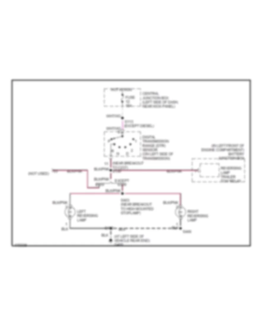
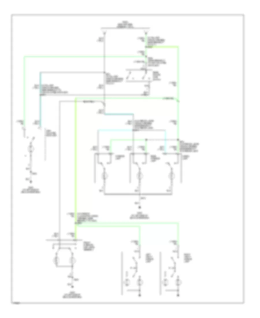
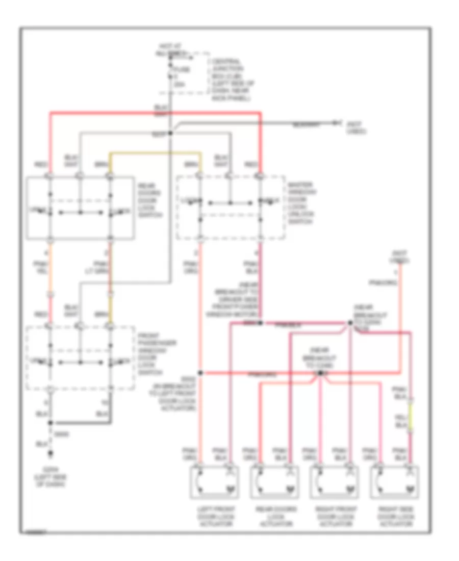
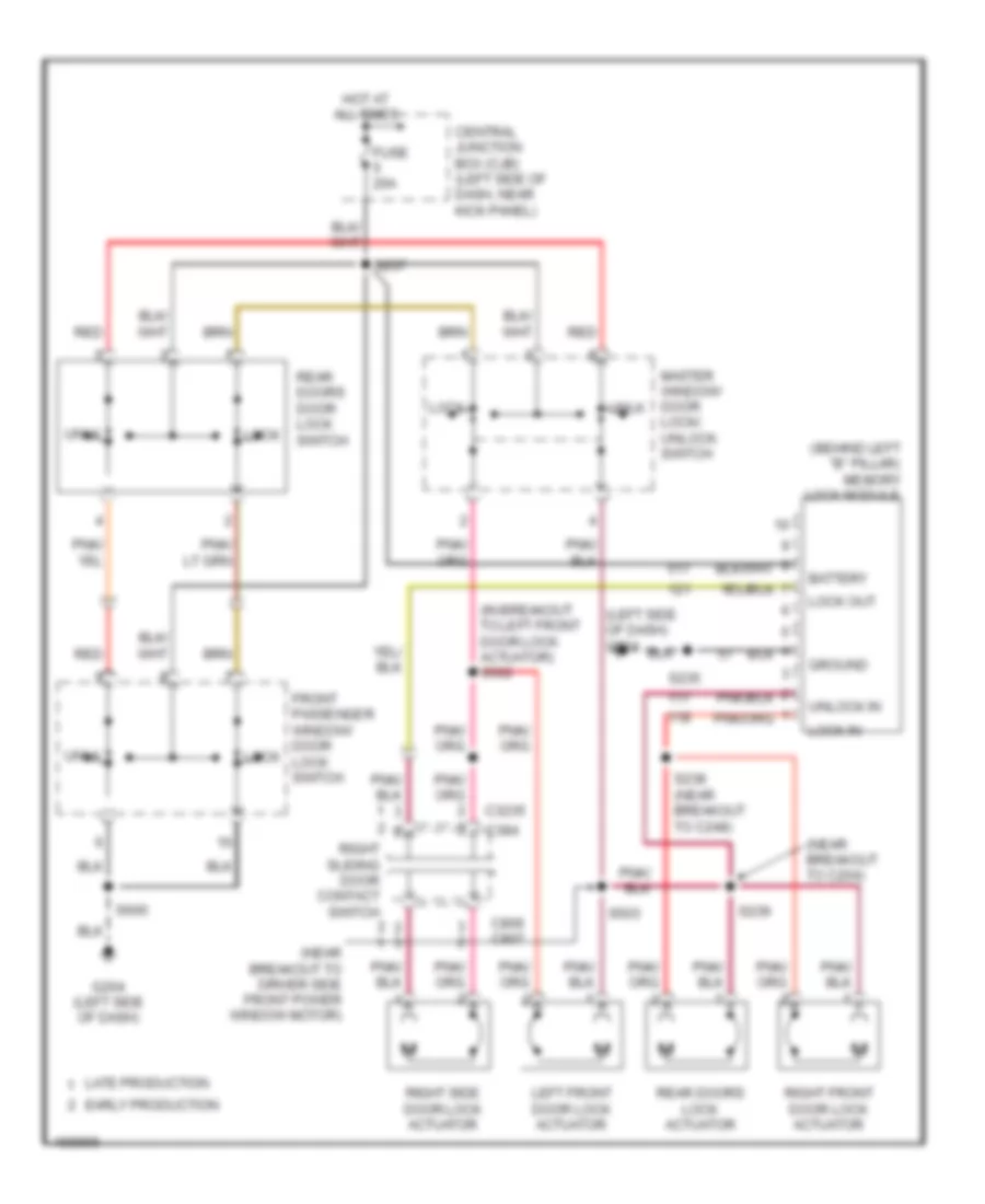
Backup Lamps Wiring Diagram, without Stripped Chassis for Ford Econoline E350 Super Duty 2003
List of elements for Backup Lamps Wiring Diagram, without Stripped Chassis for Ford Econoline E350 Super Duty 2003:
- (at left side of vehicle rear end) g400
- (in left front of engine compartment) battery junction box
- (near breakout
- (not used)
- Central junction box (left side of dash, near kick panel)
- Digital transmission range (dtr) sensor (on left side of transmission)
- E550
- Except e550
- Fuse 15a
- Hot in run
- Left reversing lamp
- Reversing lamp trailer tow relay
- Right reversing lamp
- S402
- S403 (near breakout to high mounted stoplamp)
- S406
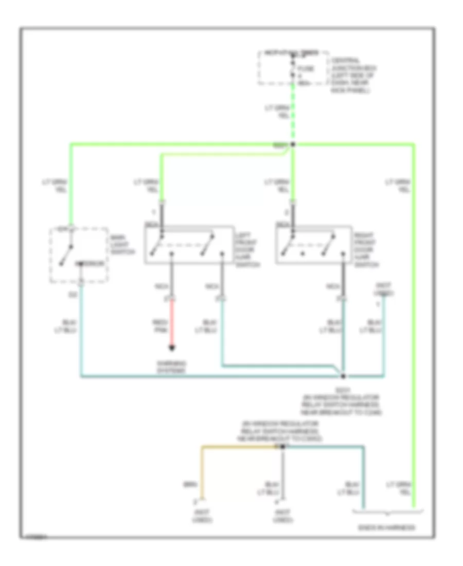
Exterior Lamps Wiring Diagram, without Stripped Chassis (1 of 2) for Ford Econoline E350 Super Duty 2003
List of elements for Exterior Lamps Wiring Diagram, without Stripped Chassis (1 of 2) for Ford Econoline E350 Super Duty 2003:
- (at left rear of engine compt) s134
- (ends in harness) (cutaway)
- (in dash panel to headlamp junction wiring harness, near breakout to g103) s165
- (near breakout to c237)
- (near breakout to c248) s232
- (not used)
- Anti- lock brakes system
- Batt
- Battery junction box (in left front of engine compt)
- Beacon lamp (dealer- fitted)
- Brake pedal position switch (on bracket, above brake pedal)
- C202a
- C220a
- C3140a
- Central junction box (left side of dash, near kick panel)
- Central junction box (left side of dash, near kick panel)
- Compartment)
- Cruise control system
- Cutaway
- E550
- E550, cutaway
- Electronic flasher module or grote flasher module (behind left side of dash)
- Engine controls system
- Except e550
- Except e550, cutaway
- Fuse 10a
- Fuse 15a
- Fuse 20a
- G100 (at left side of engine compt)
- G102 (at left front of vehicle)
- G203 (at left side of dash)
- G204 (left side of dash)
- G400 (at left side of vehicle rear end)
- Hazard
- Hazard switch
- Head
- High mounted stop lamp
- Hot at all times
- Hot in run
- Ign
- Instrument cluster
- Left front park/ turn lamp
- Left rear park/ stop/ turn lamp
- Left turn indicator
- License plate lamp
- Main light switch
- Multi- function switch
- Nca
- Normal
- Off
- Overhead console
- Park
- Red
- Remote keyless entry module (behind left "b" pillar)
- Resistor
- Right front park/ turn lamp
- Right rear park/ stop/ turn lamp
- Right turn indicator
- S122
- S129
- S163
- S207
- S217 (left side of dash)
- S218
- S223
- S226
- S234 (near breakout to c311)
- S235
- S306 (near breakout to high mounted stoplamp)
- S340
- S402
- S406
- Shift inter- lock system
- Solid state
- Stop lamp relay
- To battery junction box (fuses 5 & 6) (digram 2 of 2)
- To c311)
- To clearance lamp relay (diagram 2 of 2)
- To electronic brake control connector (diagram 2 of 2)
- To parking lamp trailer tow relay (diagram 2 of 2)
- Turn left
- Turn right
Exterior Lamps Wiring Diagram, without Stripped Chassis (2 of 2) for Ford Econoline E350 Super Duty 2003
List of elements for Exterior Lamps Wiring Diagram, without Stripped Chassis (2 of 2) for Ford Econoline E350 Super Duty 2003:
- (at left side of engine compt) g100
- (class 1)
- (class 2)
- (class 2) (class 1)
- (ends in harness)
- (in breakout to c110)
- (in left front of engine compt) battery junction box
- (in marker lamp to switch harness, near breakout to center roof marker lamp) s950
- (left rear of engine compt) modified vehicle power
- (left side of dash) g204
- (near breakout to c237) s118
- (not used)
- Auxiliary battery relay
- Backup lamps circuit
- Battery charge trailer tow relay
- Battery ii
- Battery junction box (in left front of engine compartment)
- Center roof marker lamp
- Central junction box (left side of dash, near kick panel)
- Clearance lamp relay
- Digital transmission range (dtr) sensor (on left side of transmission)
- E550
- Except 5.4l ngv
- Except 7.3l
- Except e550
- From brake pedal position switch (diagram 1 of 2)
- From main light switch (diagram 1 of 2)
- From multi- function switch (diagram 1 of 2)
- Fuse 10a
- Fuse 15a
- Fuse 20a
- Fuse 30a
- Fuse 40a
- Fuse 5a
- Fuse 60a
- G100 (at left side of engine compartment)
- G100 (at left side of engine compt)
- G110 (on right frame rail)
- G204 (left side of dash)
- G401 g100 (except 7.3l) (at left side of (at left side of engine compt)
- Hot at all times
- Hot in run
- Hot in run or acc
- Interior lights system
- Left
- Left rear lamp assembly
- Left roof marker lamp
- Nca
- Parking lamp trailer tow relay
- Reversing lamp trailer tow relay
- Right
- Right rear lamp assembly
- Right roof marker lamp
- S108
- S109
- S112
- S113 (except diesel)
- S122
- S130 (in engine control sensor harness, near breakout to c237)
- S223
- S324
- S430
- S431 (near breakout to c421)
- S432
- S951
- Trailer electronic brake control connector
- Trailer tow connector (7 pin) (class 2) (at center of vehicle rear end)
- Trailer tow connector (at center of vehicle rear end)
- Vehicle rear end)
- W/ auxiliary battery
- W/ auxiliary battery jumper
- W/o auxiliary battery
GROUND DISTRIBUTION
Ground Distribution Wiring Diagram, without Stripped Chassis (1 of 4) for Ford Econoline E350 Super Duty 2003
List of elements for Ground Distribution Wiring Diagram, without Stripped Chassis (1 of 4) for Ford Econoline E350 Super Duty 2003:
- (in engine control sensor harness, at right side of engine compartment)
- (in engine control sensor harness, in breakout to c134)
- (in left front of engine compartment) battery junction box (bjb)
- 4.2l
- 4.6l
- 5.4l cng
- 5.4l, 6.8l
- 6.8l
- 7.3l
- 7.3l diesel
- A/c clutch solenoid
- A/c compressor clutch diode
- Battery
- Battery ii
- Blower motor resistor
- Brake fluid level switch
- Camshaft position sensor
- Crankshaft position sensor shield
- Data link connector (dlc)
- Electronic crash sensor (ecs) module
- Except 4.2l
- Except 7.3l diesel
- Exhaust pressure regulator (epr)
- Fuel rail cut- off valve
- G101 (right front of engine compt)
- G107 (right side of engine compt)
- G110 (on right frame rail)
- G199 (right side of engine compt)
- G206 (right side of dash)
- G300 (center of vehicle floor)
- Gasoline models
- Intake manifold runner control (imrc) module
- Left video display
- Mass air flow (maf) sensor
- Natural gas vehicle (ngv) timer jumper
- Nca
- Pcm power relay
- Powertrain control module (pcm)
- Right video display
- Right video display)
- S140 (engine control sensor harn, near breakout to powertrain control module)
- S140 (in engine control sensor harness, near breakout to powertrain control module)
- S143
- S169 (in engine control sensor harness, in breakout to powertrain control module)
- S170
- S171
- S189 (in engine control sensor & fuel charge wiring harness, near breakout
- S2005 (in breakout to c3138)
- S2009 (in breakout to 299)
- S380 (in breakout to c983)
- S381 (in breakout to 299)
- S916 (near breakout to left video display)
- Shield
- To intake manifold runner control module)
- Windshield washer pump motor
Ground Distribution Wiring Diagram, without Stripped Chassis (2 of 4) for Ford Econoline E350 Super Duty 2003
List of elements for Ground Distribution Wiring Diagram, without Stripped Chassis (2 of 4) for Ford Econoline E350 Super Duty 2003:
- (7.3l) (not used)
- (aero)
- (dealer- fitted) (not used)
- (except 7.3l) speed control servo
- (in fuel tank sender extension harness, in breakout to rear aft-axle fuel tank valve) s320
- (in fuel tank sender wiring harness, near breakout to c1279)
- (in left front of engine compartment) battery junction box (bjb)
- (not used)
- (sealed beam)
- 5.4l cng
- 7.3l
- 7.3l diesel
- Anti-lock brake system control module
- Blower motor relay
- C220a
- C220c
- Clearance lamp relay
- Cutaway
- Cutaway, stripped chassis, e550
- Daytime running lamps (drl) module
- E550
- Engine coolant temperature (ect) sender
- Except 5.4l cng
- Except 7.3l
- Except cutaway
- Extended range fuel tank valve 1
- Extended range fuel tank valve 2
- Front aft- axle fuel tank valve
- Fuel pump
- Fuel pump module
- Fuel sender
- G100 (left side of engine compartment)
- G102 (left front of vehicle)
- G103 (right front of vehicle)
- G202 (left side of dash)
- Gas
- Gasoline models
- In-transit fuel pump module
- Injector driver module (idm)
- Instrument cluster
- Left front park/turn lamp
- Left headlamp
- Left rear lamp assembly
- Midship fuel tank valve
- Natural gas vehicle (ngv) module
- Natural gas vehicle (ngv) timer jumper
- Nca
- Others
- Powertrain control module (pcm)
- Rear aft- axle fuel tank valve
- Right front park/turn lamp
- Right headlamp
- Right rear lamp assembly
- S122 (in engine control sensor harness, near breakout to c219)
- S139 (in engine control sensor harness, near breakout to powertrain control module)
- S163 (in dash panel to headlamp junction wiring harness, near breakout to forward crash sensor)
- S205 (in main wiring harness, near breakout to radio)
- S268 (in main wiring harness, in breakout to c219)
- S307 (in fuel tank sender wiring harness, near breakout to fuel pump module)
- S308 (in fuel tank sender wiring harness, on fuel tank)
- S317 (in fuel tank sender wiring harness, near breakout to fuel sender)
- S322 (in fuel tank sender extension harness, near breakout to c3149)
- S324
- S432 (near breakout to c421)
- Stop lamp relay
- To g203 (diagram 3 of 4)
- Trailer tow battery charge relay
- Trailer tow connector, 4-pin
- Trailer tow parking lamp relay
- Trailer tow reversing lamp relay
- Vacuum warning switch
- Vehicle speed sensor (vss)
- W/ extended range tank
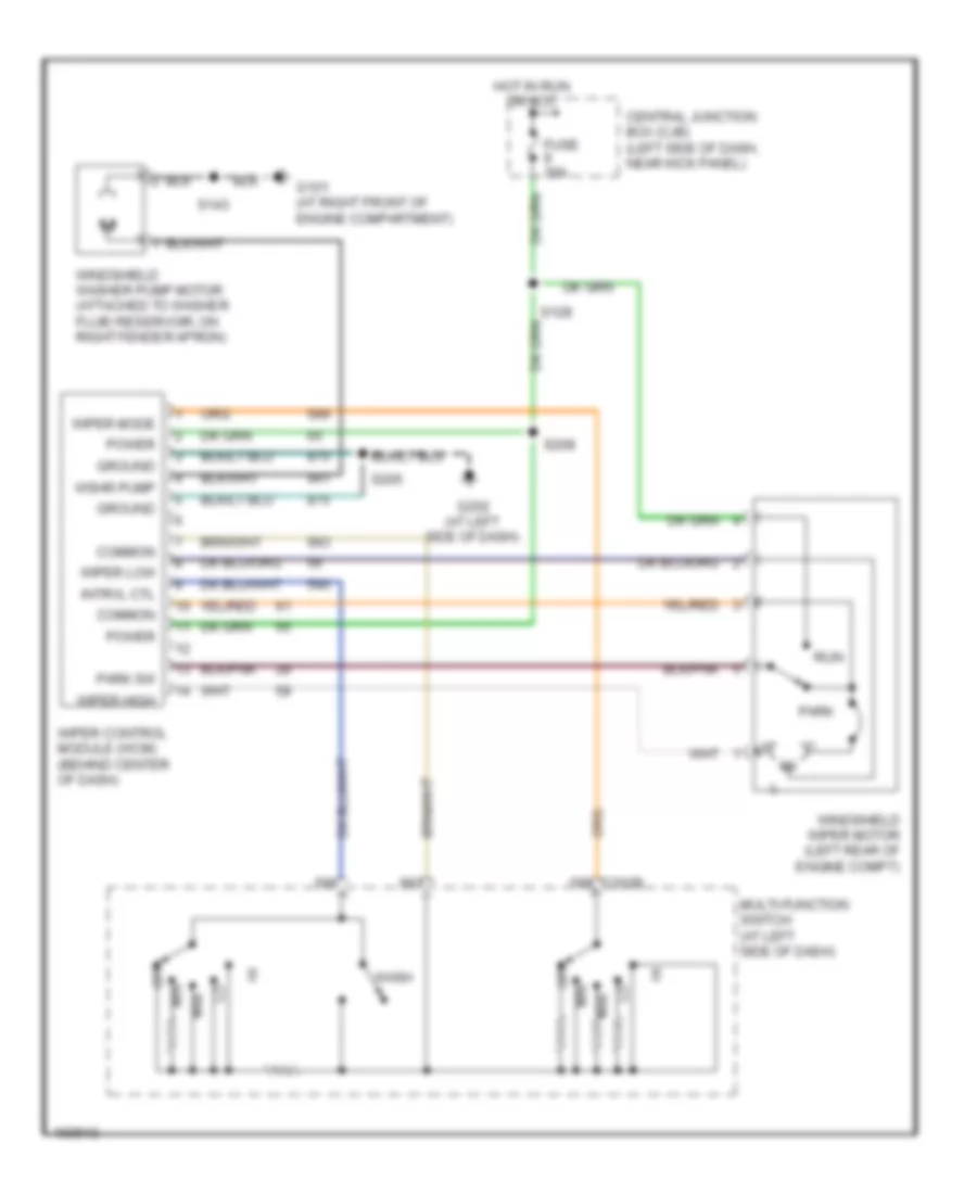
- Wiper control module (wcm)
Ground Distribution Wiring Diagram, without Stripped Chassis (3 of 4) for Ford Econoline E350 Super Duty 2003
List of elements for Ground Distribution Wiring Diagram, without Stripped Chassis (3 of 4) for Ford Econoline E350 Super Duty 2003:
- (dealer- fitted) (not used)
- (dealer- fitted) beacon lamp
- (diagram 2 of 4)
- (in left front door window regulator harness, near breakout to master window/
- (not used)
- (not used) (dealer- fitted)
- (w/ hinged side door)
- (w/ rear seat entertainment system) power point
- (w/ rse)
- (w/ sliding side door) memory lock module
- (w/o remote keyless entry) data link connector (dlc)
- (w/o rse)
- 7.3l diesel
- Air bag sliding contact
- Auxiliary powertrain control module (apcm)
- Brake shift interlock
- C2188a
- C220a
- C294b
- C294c
- C294e
- C3077a
- C3140a
- Center roof marker lamp
- Class i
- Console 1 power point
- Console 2 power point
- Cutaway, w/o rear entertainment system
- Door lock/unlock switch)
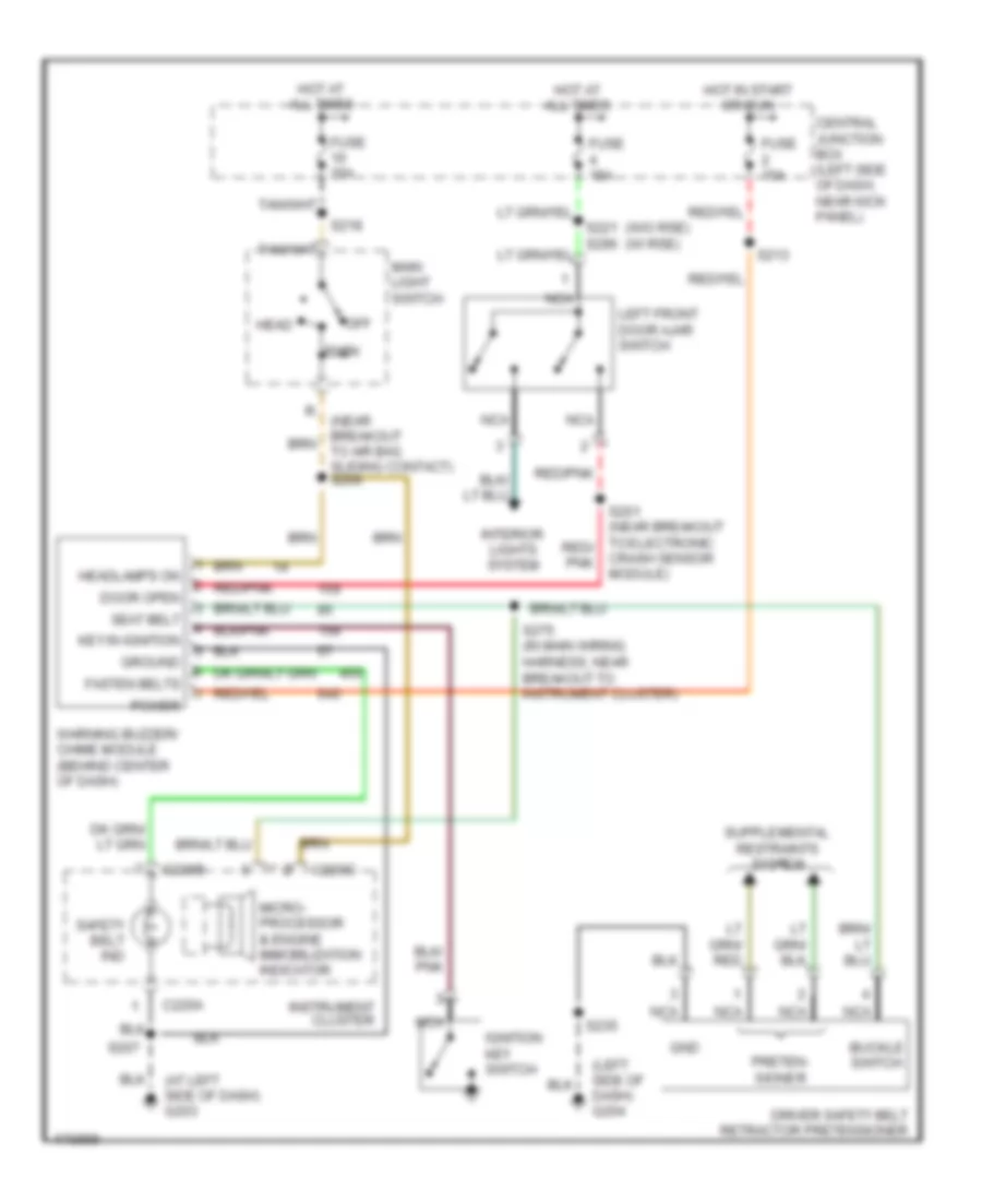
- Driver safety belt retractor pretensioner
- Driver side exterior rear view mirror
- Driver side front seat adjust switch
- E550
- Electronic flasher module
- Ends in harness
- Exterior rear view mirror switch
- From s268
- Front cigar lighter
- Front function selector switch assembly
- Front passenger window/door lock switch
- G203 (left side of dash)
- G204 (left side of dash)
- Instrument cluster
- Left center roof marker lamp
- Left roof marker lamp
- Master window/door lock/unlock switch
- Nca
- Near breakout to c3052)
- Near breakout to c328)
- Parking break switch
- Power point
- Puddle lamp relay
- Radio
- Rear seat entertainment (rse) module
- Remote keyless entry module
- Resistor
- Right center roof marker lamp
- Right roof marker lamp
- S202 (in main wiring harness, near breakout to front function selector switch assembly)
- S223 (in window regulator relay switch harness, near breakout to ignition switch)
- S235 (in window regulator relay switch harness, at bottom of left "b" pillar)
- S299 (in window regulator relay switch harness, in breakout to c3134)
- S315 (in seat control feed jumper harness, near breakout to c3134)
- S500
- S951 (in marker lamp to switch harn, near breakout to right center roof marker lamp)
- Temperature blend door actuator
- To s300 (diagram 4 of 4)
- Trailer electronic brake control connector
- W/ driver's power seat
- W/ manual a/c
- W/ rear seat entertainment system
- W/o driver's power seat
- W/o rear seat entertainment system
- Warning buzzer/ chime module
Ground Distribution Wiring Diagram, without Stripped Chassis (4 of 4) for Ford Econoline E350 Super Duty 2003
List of elements for Ground Distribution Wiring Diagram, without Stripped Chassis (4 of 4) for Ford Econoline E350 Super Duty 2003:
- 951b
- C2188a
- C3077a
- C311)
- C3140a
- Cargo lamp
- Data link connector (dlc)
- From s235 (diagram 3 of 4)
- Front interior/ map lamps assembly
- G200 (right side of dash)
- G204 (left side of dash)
- G301 (center of vehicle floor)
- G400 (left side of vehicle rear end)
- High mounted stoplamp
- Interior lamp
- Left rear park/stop/ turn lamp
- Left reversing lamp
- Left video display
- License plate lamp
- Nca
- Not used
- Overhead console
- Radio
- Rear a/c blower speed relay 1
- Rear a/c blower speed relay 2
- Rear function selector switch assembly
- Rear interior lamp
- Rear seat entertainment (rse) module
- Remote keyless entry module
- Right rear park/stop/ turn lamp
- Right reversing lamp
- Right video display
- S2007 (near breakout to c3053)
- S2008 (near breakout to c3053)
- S260 (in window regulator relay switch harness, near breakout to g204)
- S273 (in breakout to c210)
- S274 (near breakout to radio)
- S289 (near breakout to radio)
- S293 (near breakout to radio)
- S300 (in taillamp wiring harness, near breakout to c311)
- S401 (in a/c blower motor wiring harness, in breakout to c405)
- S406 (in taillamp wiring harness, at right side of vehicle rear end)
- S913 (in interior lamps wiring harness, near breakout to interior lamp)
- S915 (in interior lamps wiring harness, near breakout to c925)
- S920 (in interior lamps wiring harness, in breakout to right video display)
- S930 (in interior illumination wiring harness, in breakout to overhead console)
- Shield
- To c3138)
- Video cassette player
- W/ full headliner
- W/ rear seat entertainment system
- W/ rke
- W/o full headliner
- W/o rear seat entertainment system
HEADLIGHTS
Headlights Wiring Diagram, without Stripped Chassis for Ford Econoline E350 Super Duty 2003
List of elements for Headlights Wiring Diagram, without Stripped Chassis for Ford Econoline E350 Super Duty 2003:
- 507/13
- 527/12
- Batt
- Battery junction box (in left front of engine compartment)
- C202b
- C220a
- C220b
- Central junction box (left side of dash, near kick panel)
- Daytime running lamps (drl) module (mounted to radiator support, under a/c condenser deflector cover)
- Fuse 10a
- Fuse 15a
- Fuse 20a
- Fuse 40a
- G102 (at left front of vehicle)
- G202 (at left side of dash)
- G203 (at left side of dash)
- Gnd
- Head
- Hi beam in
- Hi beam ind
- Hot at all times
- Hot in run
- Ign
- Instrument cluster
- Left headlamp
- Main light switch
- Multi- function switch (at left side of dash)
- Off
- P v lo beam
- Park
- Pass
- Right headlamp
- S116
- S131
- S163
- S164 (in dash panel to headlamp junction wiring harness, near breakout to daytime running lamps module)
- S205
- S207
- S218
- S270 (near breakout to air bag sliding contact)
- S276 (in main wiring harness, under left side of dash)
- S277 (in main wiring harness, in breakout to multifunction switch)
- S278 (in main wiring harness, in breakout to multifunction switch)
- W/ aero headlamp
- W/o aero headlamp
HORN
Horn Wiring Diagram for Ford Econoline E350 Super Duty 2003
List of elements for Horn Wiring Diagram for Ford Econoline E350 Super Duty 2003:
- (at center of dash)
- (near breakout to powertrain control module) s136
- 15a
- Air bag sliding contact
- Battery junction box (in left front of engine compt)
- C3140a
- Cruise control system
- Diesel
- Except diesel
- Except stripped chassis
- Fuse 27
- G207 (w/ stripped chassis)
- High pitch horn
- Horn relay
- Horn switch
- Hot at all times
- Low pitch horn
- Nca
- Powertrain control module (in left rear of engine compt, near brake master cylinder)
- Remote keyless entry module (behind left "b" pillar)
- S116
- S121 (in engine control sensor harness, near breakout to c219)
- S286 (w/ stripped chassis)
- Sig rtn
- Speed control servo (left side of engine compt, near brake master cylinder)
- W/ cruise control
- W/o cruise control
INSTRUMENT CLUSTER
Instrument Cluster Wiring Diagram for Ford Econoline E350 Super Duty 2003
List of elements for Instrument Cluster Wiring Diagram for Ford Econoline E350 Super Duty 2003:
- (4.6l, 5.4l, 6.8l: on lower left front of engine) (7.3l diesel: on top right center of engine) (4.2l: on left front of engine, below a/c compressor) oil pressure switch
- (at center of dash) (stripped chassis) g207
- (at left side of engine compt) g100
- (at left side of dash) g203
- (conn a)
- (conn b)
- (conn c)
- (except stripped (stripped chassis) chassis) (at left rear of (in breakout to c134)
- (except stripped chassis)
- (except stripped chassis) (stripped chassis)
- (except stripped chassis) s268
- (in engine control sensor harness, in breakout to c219) s125
- (near breakout to c219) (except stripped chassis) s120 (stripped chassis) (near breakout to g112)
- (near breakout to c327) s310
- (on fuel tank)
- (stripped chassis)
- 4.6l
- 5.4l cng
- A10
- A11
- A14
- A16
- Air bag ind
- All others
- Anti-lock brake ind
- Anti-lock brakes system
- B11
- B12
- Battery junction box (bjb) (in left front of engine compt)
- Brake warning ind
- C10
- C12
- C220a
- C220b
- C220c
- Central junction box (cjb) (left side of dash, near kick panel)
- Charge ind
- Chassis)
- Cruise control system
- Cutaway, stripped chassis
- Dealer- fitted
- Diesel
- Eng cool temp gauge
- Eng oil press gauge
- Engine compt)
- Engine controls system
- Engine controls system (diesel)
- Engine coolant temperature sender (4.2l, 4.6l: on top front center of engine) (5.4l: on lower intake manifold) (6.8l: on upper left front of engine)
- Engine coolant temperature sender (on lower left front of engine)
- Engine immobilisation indicator
- Except 4.6l
- Except 5.4l cng
- Except diesel
- Exterior lights system
- Fuel pump module (under vehicle, in fuel tank)
- Fuse 10a
- Fuse 15a
- Fuse 5a
- G203 (except stripped chassis) (at left side of dash)
- G203 (left side of dash)
- G207 (stripped chassis) (at center of dash)
- Gas
- Ground
- Headlights system
- Hi beam ind
- Hot at all times
- Hot in start or run
- Illumination
- In-line fuse (behind left side of dash)
- In-transit fuel pump module (under vehicle, on left frame rail)
- Instrument cluster
- Interior lights system
- Left turn ind
- Low fuel ind, fuel gauge
- Low oil pressure/ high coolant temperature
- Malfunction ind lamp (mil)
- Microprocessor
- Natural gas vehicle module (on left front inner fender panel)
- Nca
- Parking brake switch (near left kick panel)
- Power
- Red
- Right turn ind
- S122
- S133
- S146 (except stripped chassis)
- S175
- S207 s284 (stripped chassis)
- S207 s286
- S213 (near breakout to instrument cluster)
- S268
- S284 (stripped chassis)
- S287
- S308
- Safety belt ind
- Seat belt lamp
- Speed control ind
- Speedometer
- Vaccum warning switch (7.3l) (in left front of engine compt)
- Vans/wagons
- Voltmeter
- Wait to start ind
- Warning system
- Warning system (stripped chassis)
- Water in fuel ind
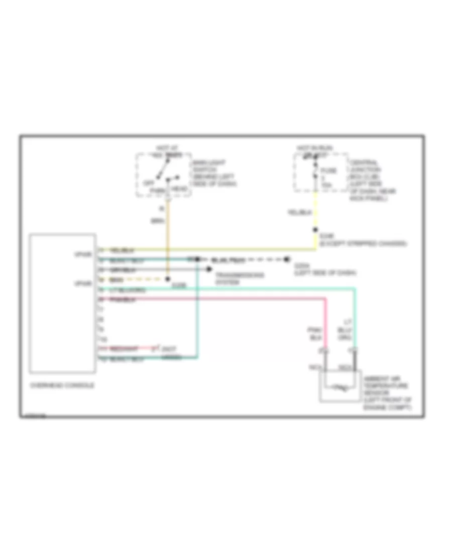
Overhead Console Wiring Diagram for Ford Econoline E350 Super Duty 2003
List of elements for Overhead Console Wiring Diagram for Ford Econoline E350 Super Duty 2003:
- (not
- Ambient air temperature sensor (left front of engine compt)
- Central junction box (cjb) (left side of dash, near kick panel)
- Fuse 15a
- G204 (left side of dash)
- Hot at all times
- Hot in run or acc
- Main light switch (behind left side of dash) head
- Nca
- Off
- Overhead console
- Park
- S206
- S245 (except stripped chassis)
- S930
- Transmissions system
- Used)
- Vpwr
INTERIOR LIGHTS
Courtesy Lamps Wiring Diagram, Dealer Installed for Ford Econoline E350 Super Duty 2003
List of elements for Courtesy Lamps Wiring Diagram, Dealer Installed for Ford Econoline E350 Super Duty 2003:
- (in window regulator relay switch harness, near breakout to c3052) s247
- (not used)
- Central junction box (left side of dash, near kick panel)
- Ends in harness
- Fuse 15a
- Hot at all times
- Interior
- Left front door ajar switch
- Main light switch
- Nca
- Red/ pnk
- Right front door ajar switch
- S221
- S231 (in window regulator relay switch harness, near breakout to c248)
- Warning systems
Courtesy Lamps Wiring Diagram, Except Cutaway with Entertainment System (1 of 2) for Ford Econoline E350 Super Duty 2003
List of elements for Courtesy Lamps Wiring Diagram, Except Cutaway with Entertainment System (1 of 2) for Ford Econoline E350 Super Duty 2003:
- (in taillamp wiring harness, near breakout to c311) s302
- (near breakout to high mounted stoplamp) s405
- 87a
- Battery
- Breakout to c248)
- C3140a
- C3140b
- Central junction box (left side of dash, near kick panel)
- Diesel
- Driver side exterior rear view mirror
- Ends in harness
- Except diesel
- Except rv van
- Front interior/ map lamps assembly
- Fuse 15a
- Fuse 20a
- G204 (left side of dash)
- G400 (at left side of vehicle rear end)
- Ground
- High mounted stoplamp
- Hinged side door
- Hot at all times
- Hot in start or run
- Int lps out
- Interior
- Left front door ajar switch
- Left vanity mirror lamp
- Main light switch
- Nca
- Passenger side exterior rear view mirror
- Puddle lamp relay (bottom of left "b" pillar)
- Rear doors ajar switch
- Red/ pnk
- Remote keyless entry module (behind left "b" pillar)
- Right front door ajar switch
- Right side door ajar switch
- Right sliding door ajar switch
- Right vanity mirror lamp
- Rv van
- S216
- S221
- S223
- S235
- S246 (near breakout to c248)
- S260
- S290
- S294
- S296
- S300
- S404 (in taillamp wiring harness, near breakout to high mounted stoplamp)
- S500
- S900 (near breakout to c934)
- Side door ctsy sw
- Sliding side door
- To s301 and s302 (diagram 2 of 2)
- W/ full headliner
- W/o full headliner
- Warning system
Courtesy Lamps Wiring Diagram, Except Cutaway with Entertainment System (2 of 2) for Ford Econoline E350 Super Duty 2003
List of elements for Courtesy Lamps Wiring Diagram, Except Cutaway with Entertainment System (2 of 2) for Ford Econoline E350 Super Duty 2003:
- (in taillamp wiring harness, near breakout to c311) s302
- Cargo lamp
- From s259 and s296 (diagram 1 of 2)
- Front interior/ map lamps assembly
- G400 (at left side of vehicle rear end)
- High mounted stoplamp
- Illumination wiring harness, near breakout to c934) s900
- Interior lamp
- Left vanity mirror lamp
- Nca
- Near breakout to interior lamp)
- Rear doors ajar switch
- Rear interior lamp
- Right vanity mirror lamp
- S300
- S301 (in taillamp wiring harness, near breakout to c311)
- S402
- S405 (near breakout to high mounted stoplamp)
- S913
- Wiring harness, near breakout to high mounted stoplamp) s404
- Wiring harness, near breakout to interior lamp) s911
Courtesy Lamps Wiring Diagram, Except Cutaway without Entertainment System (1 of 2) for Ford Econoline E350 Super Duty 2003
List of elements for Courtesy Lamps Wiring Diagram, Except Cutaway without Entertainment System (1 of 2) for Ford Econoline E350 Super Duty 2003:
- (at left side of vehicle rear end) g400
- (in taillamp wiring harness, near breakout to c311) s302
- (near breakout to high mounted stoplamp) s405
- 87a
- C3140b
- Central junction box (left side of dash, near kick panel)
- Driver side exterior rear view mirror
- Ends in harness
- Except rv van
- Front interior/ map lamps assembly
- Fuse 15a
- Fuse 20a
- G204 (left side of dash)
- G400 (at left side of vehicle rear end)
- Ground ground battery ground
- High mounted stoplamp
- Hinged side door
- Hot at all times
- Hot in start or run
- Int lps out int lps out
- Interior
- Left front door ajar switch
- Left vanity mirror lamp
- Main light switch
- Nca
- Passenger side exterior rear view mirror
- Puddle lamp relay (bottom of left "b" pillar)
- Rear doors ajar switch
- Red/ pnk
- Remote keyless entry module (behind left "b" pillar)
- Right front door ajar switch
- Right side door ajar switch
- Right sliding door ajar switch
- Right vanity mirror lamp
- Rv van
- S216
- S221
- S223
- S231 (near breakout to c248)
- S235
- S246 (near breakout to c248)
- S259 (near breakout to left middle speaker)
- S260
- S300
- S301 (near breakout to c311)
- S402
- S404 (in taillamp wiring harness, near breakout to high mounted stoplamp)
- S500
- S900 (near breakout to c934)
- Side door ctsy sw c3140a
- Sliding side door
- To s301 and s302 (diagram 2 of 2)
- W/ full headliner
- W/ remote keyless entry
- W/o full headliner
- W/o remote keyless entry
- Warning system
Courtesy Lamps Wiring Diagram, Except Cutaway without Entertainment System (2 of 2) for Ford Econoline E350 Super Duty 2003
List of elements for Courtesy Lamps Wiring Diagram, Except Cutaway without Entertainment System (2 of 2) for Ford Econoline E350 Super Duty 2003:
- (in taillamp wiring harness, near breakout to c311) s302
- Cargo lamp
- From s259 and s296 (diagram 1 of 2)
- Front interior/ map lamps assembly
- G400 (at left side of vehicle rear end)
- High mounted stoplamp
- Illumination wiring harness, near breakout to c934) s900
- Interior lamp
- Left vanity mirror lamp
- Nca
- Near breakout to interior lamp)
- Rear doors ajar switch
- Rear interior lamp
- Right vanity mirror lamp
- S300
- S301 (in taillamp wiring harness, near breakout to c311)
- S402
- S405 (near breakout to high mounted stoplamp)
- S913
- Wiring harness, near breakout to high mounted stoplamp) s404
- Wiring harness, near breakout to interior lamp) s911
Instrument Illumination Wiring Diagram for Ford Econoline E350 Super Duty 2003
List of elements for Instrument Illumination Wiring Diagram for Ford Econoline E350 Super Duty 2003:
- (5) bulbs
- (ends in harness)
- (not used)
- (w/ rse)
- Air bag sliding contact
- C2188a
- C218b
- C220a
- C294e
- C3077a
- C951b
- Central junction box (left side of dash, near kick panel)
- Cutaway
- Dimmer
- Except cutaway
- Except stripped chassis
- Front function selector switch assembly (w/ manual a/c)
- Fuse 20a
- Fuse 5a
- G203 (at left side of dash)
- G207 (at center of dash)
- Head
- Hot at all times
- I/p lamp feed
- Ign
- Illumination
- Instrument cluster
- Instrument cluster, warning system
- Main light switch
- Nca
- Off
- Park
- Radio
- Rear function selector switch assembly
- Rear seat entertainment module (in floor console)
- S202
- S207
- S212 (in main wiring harness, near breakout to instrument cluster)
- S218
- S284
- Side marker lamps
- Speed control switch
- Stripped chassis
- W/ rear seat entertainment system
POWER DISTRIBUTION
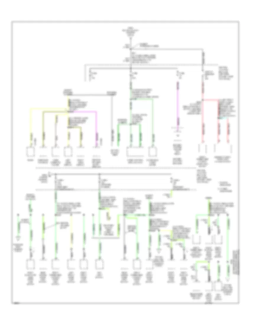
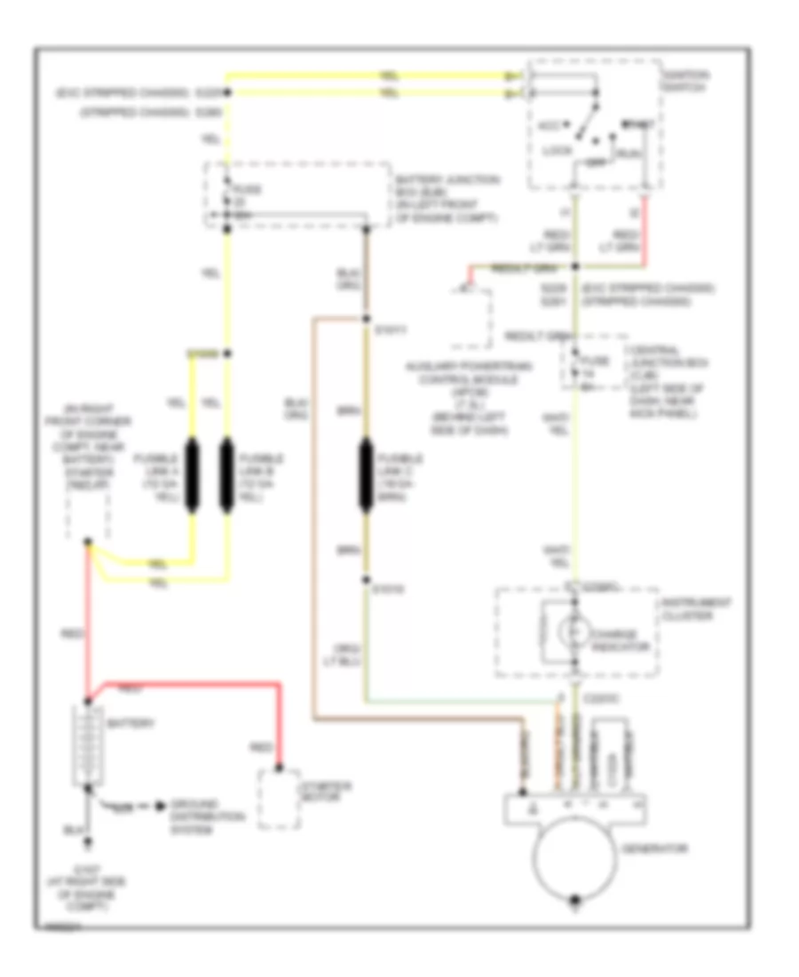
Power Distribution Wiring Diagram (1 of 5) for Ford Econoline E350 Super Duty 2003
List of elements for Power Distribution Wiring Diagram (1 of 5) for Ford Econoline E350 Super Duty 2003:
- module (gpcm)
- (e550 : in engine control sensor harness, near breakout to battery junction box) (5.4l ngv: in engine control sensor harness, near breakout to c219) s183
- (ends in harness)
- (except stripped
- (except stripped chassis) s225 s280
- (in breakout to battery junction box) s101
- (in engine control sensor harness, in breakout to abs control module)
- (in engine control sensor harness, in breakout to battery junction box) s116
- (in engine control sensor harness, near breakout to c219) s115
- (in fuel charge wiring harness, near breakout to glow plug control module) s192
- (in fuel charge wiring harness, near breakout to manifold intake air heater relay)
- (in starter relay to fuse junction panel harness, in breakout to starter relay)
- (in window regulator relay switch harness, near breakout to c248) s254
- (in window regulator relay switch harness, w/o rse: near breakout to central jb) w/ rse: near breakout to c237)
- 5.4l ngv
- A/c clutch relay
- Abs control module
- Battery
- Battery 2 (diesel)
- Battery junction box (bjb) (in left front of engine compt)
- Blower motor relay
- Breakout to c237) (stripped chassis: in breakout to ignition switch)
- C1273a
- C1273b
- C3140b
- California
- Central junction box (cjb) (left side of dash, near kick panel)
- Chassis: near
- Clearance lamp relay (e550)
- Console 1 power point (w/ rear seat entertainment system)
- Console 2 power point (w/ rear seat entertainment system)
- Cutaway
- Daytime running lamps (drl) module
- E550
- Except california
- Except cutaway
- Except stripped chassis
- From a fuse 15 (diagram 1 of 5)
- Fuel pump relay
- Fuse
- Fuse 10a
- Fuse 15a
- Fuse 20a
- Fuse 20a (e550)
- Fuse 30a
- Fuse 30a (diesel)
- Fuse 40a
- Fuse 50a
- Fuse 60a
- Fused battery feed
- Generator
- Glow plug control
- Glow plug relay
- Horn relay
- Injector driver module (idm) power relay
- Main light switch
- Manifold intake air heater relay
- Modified vehicle power
- Natural gas vehicle (ngv) module
- Nca
- Power point (except cutaway)
- Rear a/c blower speed relay 1
- Red
- Remote keyless entry
- Remote keyless entry module
- S1008
- S1010 (in alternator rectifier system wiring harness, in breakout to battery junction box)
- S1011 (in alternator rectifier system wiring harness, in breakout to battery junction box)
- S1012 (7.3l di turbo disel) (in alternator to starter motor solenoid harness, near breakout to starter relay)
- S1020
- S178 (7.3l di turbo disel) (in alternator rectifier system wiring harness, in breakout to c1282)
- S187 (in fuel charge wiring harness, near breaqkout to starter relay)
- S191
- S233
- S235
- S257 (in window regulator relay switch harness, near breakout to c311)
- S266
- Secondary generator (diesel)
- Starter motor
- Starter relay
- Stripped chassis
- To fuse 17 (diagram 1 of 5)
- To fuse 9 (diagram 2 of 5)
- To ignition switch (diagram 3 of 5)
- Trailer electronic brake control connector
- W/ rse
Power Distribution Wiring Diagram (2 of 5) for Ford Econoline E350 Super Duty 2003
List of elements for Power Distribution Wiring Diagram (2 of 5) for Ford Econoline E350 Super Duty 2003:
- (in breakout to battery junction box)
- (in engine control sensor harness, near breakout to c237) (except stripped chassis, cutaway) s129
- (in left front door window regulator harness, near breakout to master window/door lock/unlock switch) s506
- (in main wiring harness, in breakout to c219) s218
- (in main wiring harness, near breakout to c219) (stripped chassis, cutaway) s2020
- (in main wiring harness, under left side of dash) s276
- (in window regulator relay switch harness, near breakout to c248)
- (in window regulator relay switch harness, near breakout to ignition switch) s227
- (in window regulator relay switch harness, near breakout to ignition switch) s230
- (not used)
- (stripped chassis: in engine
- 1.2 mh
- Aux battery
- Auxiliary battery relay
- Batt
- Battery 2
- Battery charge trailer tow relay
- Battery junction box (bjb) (in left front of engine compt)
- Brake pedal position switch
- Brake pressure switch
- Breakout to battery junction box)
- C202a
- C202b
- C2188a
- C220a
- C3077a
- C3140a
- Central junction box (cjb) (left side of dash, near kick panel)
- Control
- Data link connector (dlc)
- Dealer- fitted
- Driver side front seat adjust switch
- Electronic crash sensor (ecs) module
- Except stripped chassis
- Except stripped chassis, cutaway
- Exterior rear view mirror switch
- From b fuse 12 (diagram 1 of 5)
- Front cigar lighter
- Front passenger window/ door lock switch
- Fuse 10a
- Fuse 15a
- Fuse 20a
- Fuse 25a
- Fuse 30a
- Fuse 40a 60a
- Fuse 5a
- Fuse 60a
- G203 (left side of dash)
- Hinged side door
- Instrument cluster
- Main light switch
- Master window/ door lock/ unlock switch
- Memory lock module (sliding side door)
- Multi- function switch
- Nca
- Near kick panel)
- Off
- Parking lamp trailer tow relay
- Pcm power relay
- Power choke 1
- Power point
- Powertrain control module (pcm)
- Radio
- Rear doors door lock switch
- Rear seat entertainment (rse) module
- Red
- Remote keyless entry module
- Reversing lamp trailer tow relay
- Rke only
- Rse system
- S108
- S109 (in engine control sensor harness, in breakout to battery junction box)
- S110 (in engine control sensor harness, in breakout to battery junction box)
- S148
- S175 (except stripped chassis : in engine control sensor harness, in sensor harness, near breakout to c219)
- S207
- S237
- Stop lamp relay
- Stripped chassis
- To fuse 4 (diagram 5 of 5)
- Video cassette player
- W/ remote keyless entry
- W/o aux battery
- W/o remote keyless entry
- W/o rse system
Power Distribution Wiring Diagram (3 of 5) for Ford Econoline E350 Super Duty 2003
List of elements for Power Distribution Wiring Diagram (3 of 5) for Ford Econoline E350 Super Duty 2003:
- (behind left side of dash) in-line fuse
- (dealer- fitted)
- (ends in harness)
- (in engine control sensor harness, in breakout to battery junction box) s113
- (in engine control sensor harness, near breakout to c237) (except stripped chassis) s131
- (in interior illumination wiring harness, near breakout to c934) s900
- (in interior lamps wiring harness, near breakout to interior lamp) s912
- (in main wiring harness, near breakout to c219) (stripped chassis) s282
- (near breakout to overdrive cancel switch) s281 s229 (near breakout to ignition switch)
- (not used)
- (stripped chassis) (except stripped chassis)
- A/c demand signal
- Abs control module
- Acc
- Auxiliary battery
- Auxiliary battery relay
- Auxiliary powertrain control module (apcm) (diesel)
- Brake shift interlock
- Breakout to front function selector switch assembly) s203
- C202a
- C220a
- C294a
- Cargo lamp
- Central junction box (cjb) (left side of dash, near kick panel)
- Daytime running lamps (drl) module
- Dealer fitted
- Dealer- fitted
- Digital transmission range (dtr) sensor
- Electronic crash sensor (ecs) module
- Except stripped chassis
- From fuse 4 j (diagram 5 of 5)
- From splice s225 c (diagram 1 of 5)
- From splice s225 d (diagram 1 of 5)
- Front function selector switch assembly
- Front interior/ map lamps assembly (wagon)
- Full headliner
- Fuse
- Fuse 10a
- Fuse 15a
- Fuse 20a
- Fuse 30a
- Fuse 5a
- High mounted stoplamp
- Ign
- Ignition switch
- Instrument cluster
- Interior lamp
- Left vanity mirror lamp
- Lock
- Multi- function switch
- Nca
- Near breakout to c237)
- Off
- Rear doors door ajar switch
- Rear interior lamp
- Red/
- Right vanity mirror lamp
- Run
- Rv van
- S249 (in window regulator relay switch harness, red/
- S302 (in taillamp wiring harness, near breakout to c311)
- Speed control servo (except stripped chassis)
- Start
- Stripped chassis
- Temperature blend door actuator
- To c237)
- To fuse 2 (diagram 4 of 5)
- To fuse 34 (diagram 4 of 5)
- To fuse 9 (diagram 5 of 5)
- W/o full headliner
Power Distribution Wiring Diagram (4 of 5) for Ford Econoline E350 Super Duty 2003
List of elements for Power Distribution Wiring Diagram (4 of 5) for Ford Econoline E350 Super Duty 2003:
- (4.6l)
- (5.4l) (4.6l)
- (in engine control sensor & fuel charge wiring harness, at right center of engine) (5.4l) s161
- (in engine control sensor & fuel charge wiring harness, at right center of engine) s161
- (in engine control sensor harness, at left rear of engine compartment) s127
- (in window regulator relay switch harness, near breakout to ignition switch)
- (in window regulator relay switch harness, near breakout to inertia fuel shutoff switch) s265
- (in window regulator relay switch wiring harness, at left side of dash) s216
- 4.2l
- 4.6l/5.4l
- 6.8l
- Battery junction box (bjb) (in left front of engine compt)
- C2188a
- C220a
- C220c
- C3217
- Central junction box (cjb) (left side of dash, near kick panel)
- Coil on plug (cop) 1
- Coil on plug (cop) 10
- Coil on plug (cop) 2
- Coil on plug (cop) 3
- Coil on plug (cop) 4
- Coil on plug (cop) 5
- Coil on plug (cop) 6
- Coil on plug (cop) 7
- Coil on plug (cop) 8
- Coil on plug (cop) 9
- Digital transmission range (dtr) sensor
- Except stripped chassis
- From fuse 8 (diagram 4 of 5) (4.2l)
- From fuse 8 (diagram 4 of 5) (4.6l/5.4l)
- From fuse 8 (diagram 4 of 5) (6.8l)
- From ignition switch f (diagram 3 of 5)
- From ignition switch g (diagram 3 of 5)
- Fuel heater (diesel)
- Fuel pump relay
- Fuse 10a
- Fuse 15a
- Fuse 30a
- Fuse 5a
- Idle validation switch (diesel)
- Ignition coil
- Ignition transformer capacitor 1
- Ignition transformer capacitor 2
- Injector driver module (idm) power relay
- Instrument cluster
- Natural gas vehicle (ngv) timer jumper
- Nca
- Overdrive cancel switch
- Pcm power diode
- Pcm power relay
- Puddle lamp relay
- Radio (except stripped chassis)
- S146 (in engine control sensor harness, near breakout to c219)
- S150 (in engine control sensor & fuel charge wiring harness, near breakout to coil on plug 3)
- S156 s193 (in engine control sensor & fuel charge wiring harness, near breakout to coil on plug 8)
- S162 (in engine control sensor & fuel charge wiring harness, near breakout to fuel injector 8)
- S213 (in main wiring harness, near breakout to instrument cluster)
- S267 (in main wiring harness, near breakout to electronic crash sensor module)
- S269
- Stripped chassis
- Tan/ red
- Tan/red
- To ignition coils (gasoline engines) or glow plug relay (diesel engine) (diagram 4 of 5)
- Vacuum warning switch (diesel)
- W/ diesel
- W/ ngv
- Warning buzzer/ chime module (except stripped chassis)
Power Distribution Wiring Diagram (5 of 5) for Ford Econoline E350 Super Duty 2003
List of elements for Power Distribution Wiring Diagram (5 of 5) for Ford Econoline E350 Super Duty 2003:
- (in engine control sensor harness, in breakout to windshield wiper motor) s128
- (in main wiring harness, at center of dash) s208
- (in main wiring harness, near breakout to brake pedal position switch) s219
- (in window regulator relay switch harness, near breakout to temperature blend door actuator) s221
- (in window regulator relay switch harness, near breakout to g204)
- (in window regulator relay switch harness, near breakout to ignition switch) s294
- (in window regulator relay switch harness, near breakout to inertia fuel shutoff switch) s290
- (in window regulator relay switch harness, near breakout to temperature blend door actuator) s221
- Battery charge trailer tow relay
- Battery junction box (bjb)
- C2188a
- C3140a
- Central junction box (cjb) (left side of dash, near kick panel)
- Circuit breaker 20a
- Courtesy switch feed (taped in harness)
- Diesel
- Ends in harness (cutaway)
- Except cutaway
- Except diesel
- Except stripped chassis
- From e fuse 28 (diagram 2 of 5)
- From ignition switch (diagram 3 of 5)
- Front passenger window/ door lock switch
- Fuse 15a
- Fuse 30a
- Fuse 4 15a (stripped chassis)
- Fuse 4 15a (w/ rear seat entertainment)
- Fuse 4 15a (w/o rear seat entertainment)
- Fuse 5a
- Hinged side doors
- Ignition switch feed
- Left front door ajar switch
- Left video display
- Main light switch
- Master window/ door lock unlock switch
- Nca
- Overhead console
- Radio
- Rear doors door lock switch
- Remote keyless entry
- Remote keyless entry module
- Right front door ajar switch
- Right sliding or side door ajar switch
- Right sliding/ side door ajar switch
- Right video display
- S236 (in window regulator relay switch harness, under left side of dash)
- S296
- Shutoff switch) s290
- Sliding side door
- Stripped chassis
- To high mounted stoplamp (diagram 3 of 5)
- To splice s302 (diagram 3 of 5)
- Video cassette player
- Windshield wiper motor
- Wiper control module (wcm)
POWER DOOR LOCKS
Door Lock Wiring Diagram, with Hinged Side Door for Ford Econoline E350 Super Duty 2003
List of elements for Door Lock Wiring Diagram, with Hinged Side Door for Ford Econoline E350 Super Duty 2003:
- (near
- (near breakout to driver side front power window motor) s503
- (not used)
- Breakout to c248) s238
- Breakout to g204) s239
- Central junction box (cjb) (left side of dash, near kick panel)
- Front passenger window/ door lock switch
- Fuse 20a
- G204 (left side of dash)
- Hot at all times
- Left front door lock actuator
- Lock
- Master window/ door lock/ unlock switch
- Rear doors door lock switch
- Rear doors lock actuator
- Red
- Right front door lock actuator
- Right side door lock actuator
- S237
- S502 (in breakout to left front door lock actuator)
- S600
- Unlk
Door Lock Wiring Diagram, with Keyless Entry for Ford Econoline E350 Super Duty 2003
List of elements for Door Lock Wiring Diagram, with Keyless Entry for Ford Econoline E350 Super Duty 2003:
- (in window regulator relay switch harness, near breakout to c311)
- (in window regulator relay switch harness, near breakout to g204)
- (left side of dash) g204
- (near breakout to c248) s238
- Battery
- C3140a
- C3140b
- C3235 c384
- C806
- C807
- Central junction box (cjb) (left side of dash, near kick panel)
- Diesel w/ rse
- Door lock
- Early production
- Exterior lights system
- Front passenger window/ door lock switch
- Fuse 15a
- Fuse 20a
- Fuse 30a
- Fuse 5a
- Ground
- Horn relay ctrl
- Horns system
- Hot at all times
- Hot in acc or run
- Ignition
- Int lamps out
- Interior lights system
- Late production
- Left front door lock actuator
- Lf door lock
- Light switch in
- Lock
- Lock in
- Master window/ door lock/ unlock switch
- Others
- Rear doors door lock switch
- Rear doors lock actuator
- Remote keyless entry module (behind left "b" pillar)
- Rf door lock
- Right front door lock actuator
- Right side door lock actuator
- Right sliding door contact switch
- S221
- S235
- S239 (near breakout to g204)
- S245
- S251
- S252
- S255
- S257
- S258 (near breakout to left middle speaker)
- S260
- S290
- S296
- S506
- Side door lock
- Side door sw in
- Side/rear lock
- Unlock
- Unlock in
- W/ hinged door
- W/ sliding door
Door Lock Wiring Diagram, with Sliding Side Door for Ford Econoline E350 Super Duty 2003
List of elements for Door Lock Wiring Diagram, with Sliding Side Door for Ford Econoline E350 Super Duty 2003:
- (behind left "b" pillar) memory lock module
- (in breakout to left front door lock actuator) s502
- (left side of dash) g204
- (near breakout to c204)
- (near breakout to driver side front power window motor)
- Battery
- C3235
- C384
- C806 c807
- Central junction box (cjb) (left side of dash, near kick panel)
- Early production
- Front passenger window/ door lock switch
- Fuse 20a
- G204 (left side of dash)
- Ground
- Hot at all times
- Late production
- Left front door lock actuator
- Lock
- Lock in
- Lock out
- Master window/ door lock/ unlock switch
- Rear doors door lock switch
- Rear doors lock actuator
- Red
- Right front door lock actuator
- Right side door lock actuator
- Right sliding door contact switch
- S235
- S237
- S238 (near breakout to c248)
- S239
- S503
- S600
- Unlk
- Unlock in
POWER MIRRORS
Power Mirrors Wiring Diagram for Ford Econoline E350 Super Duty 2003
List of elements for Power Mirrors Wiring Diagram for Ford Econoline E350 Super Duty 2003:
- Central junction box (cjb) (left side of dash, near kick panel)
- Down
- Driver side exterior rear view mirror
- Exterior rear view mirror switch
- Fuse 5a
- G204 (left side of dash)
- Horizontal
- Hot at all times
- Interior lights system
- Left
- Left/ right
- Left/ right m
- Mirror select
- Nca
- Passenger side exterior rear view mirror
- Red
- Right
- S500
- S504 (in front top of driver door)
- S506 (w/ remote keyless entry)
- Up/ down m
- Vertical
- W/ puddle lamps
POWER SEATS
Power Seats Wiring Diagram for Ford Econoline E350 Super Duty 2003
List of elements for Power Seats Wiring Diagram for Ford Econoline E350 Super Duty 2003:
- (w/ rse)
- (w/o rse)
- Central junction box (left side of dash, near kick panel)
- Driver seat front height motor
- Driver seat horizontal motor
- Driver seat rear height motor
- Entire seat
- Front driver side seat adjust switch
- Front of seat
- Fuse 30a
- Fwd
- G204 (left side of dash)
- Hot at all times
- Nca
- Rear of seat
- Rwd
- S299
- S315
POWER WINDOWS
Power Windows Wiring Diagram for Ford Econoline E350 Super Duty 2003
List of elements for Power Windows Wiring Diagram for Ford Econoline E350 Super Duty 2003:
- Central junction box (cjb) (left side of dash, near kick panel)
- Circuit breaker 43 20a
- Driver side front power window motor
- Front passenger window/ door lock switch
- G204 (left side of dash)
- Hot in run or acc
- Master window/ door lock/ unlock switch
- Passenger side front power window motor
- S236
- S500
- S501 (in left front door window regulator harness, near breakout to master window/ door lock/unlock switch)
RADIO
Radio Wiring Diagram for Ford Econoline E350 Super Duty 2003
List of elements for Radio Wiring Diagram for Ford Econoline E350 Super Duty 2003:
- (at left side of dash) g203
- (in window regulator relay switch harness, near breakout to temperature blend door actuator)
- (in window regulator relay switch harness, near breakout to c311)
- (not used)
- Antenna
- C2188a
- C3235
- C384
- C806
- C807
- Central junction box (left side of dash, near kick panel)
- Cutaway, e550
- Early production
- Fuse 15a
- Fuse 5a
- G200 (at right side of dash)
- Ground
- Hinged side door
- Hot at all times
- Hot in park or head
- Hot in run or acc
- Hot in start
- Illumination
- L front speaker
- L rear speaker
- Late production
- Left front speaker
- Left middle speaker (w/ 6 speakers)
- Left rear speaker
- Memory power
- Nca
- Noise reduction
- Power
- R front speaker
- R rear speaker
- Radio
- Right front speaker
- Right middle speaker (w/ 6 speakers)
- Right rear speaker
- Right sliding door contact switch
- S202
- S204
- S212
- S240
- S241
- S243
- S244
- S245
- Sliding side door
- Van, wagon
Radio Wiring Diagram, with Rear Entertainment (1 of 2) for Ford Econoline E350 Super Duty 2003
List of elements for Radio Wiring Diagram, with Rear Entertainment (1 of 2) for Ford Econoline E350 Super Duty 2003:
- (at center of vehicle floor) g301
- (at left side of dash) g203
- (in breakout to c210)
- (in breakout to c3138) s2006
- (near breakout to c3053)
- (near breakout to c3053) s2007
- (near breakout to electronic crash sensor module)
- (near breakout to inertia fuel
- (near breakout to radio)
- (near breakout to radio) s274
- Antenna
- C2188a
- C2188b
- Central junction box (left side of dash, near kick panel)
- Fuse 15a
- Fuse 5a
- G200 (at right side of dash)
- Ground
- Hot at all times
- Hot in park or head
- Hot in run or acc
- Hot in start
- Illumination
- L front speaker
- L rear speaker
- Left front speaker
- Memory power
- Nca
- Noise reduction
- Power
- R front speaker
- R rear speaker
- Radio
- Red
- Right front speaker
- S2003
- S2008
- S202
- S204
- S212
- S222
- S245
- S272
- S273
- S289
- S291
- S293
- Shield
- Shutoff switch)
- Signal
- Tan
Radio Wiring Diagram, with Rear Entertainment (2 of 2) for Ford Econoline E350 Super Duty 2003
List of elements for Radio Wiring Diagram, with Rear Entertainment (2 of 2) for Ford Econoline E350 Super Duty 2003:
- (at right side of dash) g200
- (in breakout to c983)
- (in breakout to left video display)
- (in breakout to right video display)
- (in window regulator relay switch harness, near breakout to c311) s243
- (left side of dash) g204
- (near breakout to c311) s298
- (near breakout to c340)
- (near breakout to c925) s914
- (near breakout to right video display)
- C3077a
- C3077b
- C3235
- C384
- C806
- C807
- Early production
- G300 (at center of vehicle floor)
- G400 (at left side of vehicle rear end)
- Ground
- Interior lights system
- Late production
- Left middle speaker
- Left rear speaker
- Left video display
- Nca
- Power
- Power choke 1
- Rear seat entertainment module
- Red
- Right middle speaker
- Right rear speaker
- Right sliding door contact switch
- Right video display
- S2005 (in breakout to c3138)
- S2009 (in breakout to c299)
- S235
- S240 (near breakout to temperature blend door actuator)
- S288 (in window regulator relay switch harness, near breakout to c311)
- S297
- S323
- S381 (in breakout to c299)
- S915
- S916
- S920 (in breakout to right video display)
- S921
- S941
- Shield
- Signal
- Tan
- Video cassette player
SHIFT INTERLOCK
Shift Interlock Wiring Diagram for Ford Econoline E350 Super Duty 2003
List of elements for Shift Interlock Wiring Diagram for Ford Econoline E350 Super Duty 2003:
- Brake pedal position (bpp) switch (on bracket, above brake pedal)
- Brake shift interlock (below right side of steering column)
- Central junction box (left side of dash, near kick panel)
- Fuse 11 15a
- Fuse 6 10a
- G203 (except stripped chassis) (at left side of dash)
- G207 (stripped chassis) (at center of dash)
- Hot at all times
- Hot in run
- S131 (except stripped chassis)
- S134 (except stripped chassis) (at left rear of engine compt)
- S207 (except stripped chassis)
- S282 (stripped chassis)
- S286 (stripped chassis)
- Shift lock solenoid
- Solid state
STARTING/CHARGING
Charging Wiring Diagram, without Dual Generators for Ford Econoline E350 Super Duty 2003
List of elements for Charging Wiring Diagram, without Dual Generators for Ford Econoline E350 Super Duty 2003:
- (exc stripped chassis)
- (exc stripped chassis) (stripped chassis)
- (in right front corner of engine compt, near battery) starter relay
- (stripped chassis)
- Acc
- Auxiliary powertrain control module (apcm) (7.3l) (behind left side of dash)
- Battery
- Battery junction box (bjb) (in left front of engine compt)
- C102a
- C220c
- C22oc
- Central junction box (cjb) (left side of dash, near kick panel)
- Charge indicator
- Fuse 5a
- Fuse 60a
- G107 (at right side of engine compt)
- Generator
- Ground distribution system
- Ignition switch
- Instrument cluster
- Lock
- Off
- Red
- Run
- S1008
- S1010
- S1011
- S225
- S229 s281
- S280
- Start
- Starter motor
Starting Wiring Diagram for Ford Econoline E350 Super Duty 2003
List of elements for Starting Wiring Diagram for Ford Econoline E350 Super Duty 2003:
- (stripped chassis) (exc stripped chassis)
- 5.4l cng
- Acc
- Battery
- Battery junction box (bjb) (in left front of engine compt)
- Central junction box (cjb) (left side of dash, near kick panel)
- Digital transmission range (dtr)
- Fuse 10a
- Fuse 60a
- G107 (at right side of engine compt)
- Ground distribution system
- Ignition switch
- Lock
- Natural gas vehicle (ngv)timer jumper (near pcm, on left rear of engine compt)
- Not used
- Off
- Power distribution system
- Red
- Run
- S1008
- S269
- Sensor (on left side of transmission)
- Start
- Starter motor
- Starter relay (in right front corner of engine compt, near battery)
- Tan/ red
SUPPLEMENTAL RESTRAINTS
Supplemental Restraints Wiring Diagram for Ford Econoline E350 Super Duty 2003
List of elements for Supplemental Restraints Wiring Diagram for Ford Econoline E350 Super Duty 2003:
- (in window regulator relay switch harn, near breakout to c237) s228
- Abs control module (at left side of engine compartment)
- Air bag bracket
- Air bag bracket (right side dash panel)
- Air bag ind
- Air bag indicator
- Air bag sliding contact
- Battery
- C135
- C220c
- C303
- C323
- Central junction box (cjb) (left side of dash, near kick panel)
- Crash sensor
- Data link connector (dlc) (partial) (below left side of dash)
- Door open input
- Driver air bag
- Driver air bag unit
- Driver door open input
- Driver safety belt retractor pretensioner (under driver seat)
- Electronic crash sensor (ecs) module (behind right side of dash)
- Feed
- Forward crash sensor (in front center of engine compartment, behind grille)
- Fuse 2.14 5a
- Fuse 2.19 10a
- Fuse 2.38 10a
- Fuse 2.4 15a
- G204 (left side of dash)
- G206 (right side dash)
- Ground
- Hot at all times
- Hot in run
- Hot in run or start
- Ignition
- Instrument cluster
- Iso bus
- Left front door ajar switch (left rocker panel)
- Nca
- Pass air bag
- Passenger air bag module
- Passenger safety belt retractor pretensioner (under passenger seat)
- Pnk
- Preten feed
- Preten return
- Pretensioner feed
- Pretensioner nca
- Pretensioner return
- Red/ pnk
- Red/pnk
- S201 (in main wiring harn, near breakout to electronic crash sensor module)
- S221
- S235
- S265
- S267
- S275 (in main wiring harn, near breakout to instrument cluster)
- Safety belt buckle sw input
- Safety belt buckle switch input
- Shorting bar
- Shorting bar engaged when module connector is disconnected from harness (shorting bars are connected between following pins: 1-15, 7-21 & 14-28)
- Warning buzzer/ chime module (behind center of dash)
TRANSMISSION
4.2L
4.2L, A/T Wiring Diagram for Ford Econoline E350 Super Duty 2003
List of elements for 4.2L, A/T Wiring Diagram for Ford Econoline E350 Super Duty 2003:
- (center of dash) (w/ stripped chassis) g207
- (center rear of engine compt)
- (eng control harn, near breakout to c1033)
- (in battery junction box)
- (left rear of engine compt)
- (near diff press feed- back egr sensor)
- (top front center of eng) instrumentation engine coolant temperature sensor
- (trans ctrl harn, rear of engine)
- 4r70w transmission
- Abs system, warning buzzer module
- Battery junction box
- Battery junction box (left front of engine compt)
- Bpp
- Brake pedal position switch (on bracket, above brake pedal)
- C220a
- C220b
- C220c
- Central junction box (behind left side of dash)
- Cht
- Cruise control system
- Cylinder head temperature sensor
- Data (+)
- Data (-)
- Data link connector (below left side of dash)
- Digital transmission range sensor
- Ect
- Electronic pressure control solenoid
- Engine controls
- Epc
- Exterior lights
- Fuse 10a
- Fuse 15a
- Fuse 30a
- Fuse 5a
- G101 (right front of eng compt)
- G101 (right front of engine compt)
- G203 (w/o stripped chassis) (left side of dash)
- Gen data
- Gnd
- Hot at all times
- Hot in run or start
- Ignition coil, radio noise capacitor
- Instrument cluster
- Instrument cluster system
- Kapwr
- Maf
- Malfunction indicator lamp
- Mass airflow (maf) sensor (top center of engine compt)
- Mil
- Multifunction switch, deavtiator switch
- Nca
- Od off
- Oss
- Output shaft speed sensor (left side of transmission)
- Overdrive cancel switch
- Pcm diode
- Pcm power relay
- Powertrain control module (pcm) (left rear of engine compartment, near brake master cylinder)
- Pwr in
- Red
- S100
- S102
- S103
- S110
- S127
- S133 (in breakout to c134) (left rear of engine compt)
- S134 (eng ctrl harn, left rear of eng compt)
- S135 (eng ctrl harn, near pcm breakout)
- S137 (eng ctrl harn, near breakout to pcm)
- S138
- S140
- S142
- S169
- S175
- S213
- S268
- Shift solenoids
- Sig rtn
- Speedometer
- Ssa
- Ssb
- Tcc
- Tcil
- Tcs
- Tft
- Throttle position sensor (tps) (on top of engine, near air intake)
- Torque converter clutch solenoid
- Tps
- Tr1
- Tr2
- Tr3
- Tr4
- Transmission fluid temperature sensor
- Vref
- Vss
- W/ stripped chassis
- W/o stripped chassis
4.6L
4.6L, A/T Wiring Diagram for Ford Econoline E350 Super Duty 2003
List of elements for 4.6L, A/T Wiring Diagram for Ford Econoline E350 Super Duty 2003:
- (4.6l) (5.4l)
- (behind center of dash) (w/ stripped chassis) g207
- (center rear of engine compt)
- (eng control harn, near breakout to a/c pressure cutout switch)
- (fuel charge harn, left center of engine)
- (in battery junction box)
- (left rear of engine compt)
- (right front of engine compt)
- (top front center of eng) instrumentation engine coolant temperature sensor
- (trans ctrl harn, rear of engine)
- 4r70w transmission
- Abs system, warning buzzer module
- Battery junction box
- Battery junction box (left front of engine compt)
- Bpp
- Brake pedal position switch (on bracket, above brake pedal)
- C220a
- C220b
- C220c
- Central junction box (behind left side of dash)
- Cht
- Cruise control system
- Cylinder head temperature sensor
- Data (+)
- Data (-)
- Data link connector (below left side of dash)
- Digital transmission range sensor
- Ect
- Electronic pressure control solenoid
- Engine controls
- Epc
- Exterior lights
- Fuse 10a
- Fuse 15a
- Fuse 30a
- Fuse 5a
- G101
- G101 (right front of engine compt)
- G203 (w/o stripped chasis) (behind upper left side of dash)
- Gen data
- Gnd
- Hot at all times
- Hot in run or start
- Ignition coil, radio noise capacitor
- Instrument cluster
- Instrument cluster system
- Kapwr
- Maf
- Malfunction indicator lamp
- Mass airflow (maf) sensor (top center of engine compt)
- Mil
- Multifunction switch, deavtiator switch
- Nca
- Od off
- Oss
- Output shaft speed sensor (left side of transmission)
- Overdrive cancel switch
- Pcm diode
- Pcm power relay
- Powertrain control module (pcm) (left rear of engine compt, near brake master cylinder)
- Pwr in
- Red
- S102
- S110
- S127
- S133 (eng ctrl harn near a/c press cutout switch)
- S134 (eng ctrl harn, left rear of eng compt)
- S135 (eng ctrl harn, near breakout to pcm)
- S137 (eng ctrl harn, near breakout to pcm)
- S138
- S140
- S142
- S154 s157
- S169
- S175
- S213
- S268
- Shift solenoids
- Sig rtn
- Speedometer
- Ssa
- Ssb
- Tcc
- Tcil
- Tcs
- Tft
- Throttle position sensor (tps) (on top of engine, near air intake)
- Torque converter clutch solenoid
- Tps
- Tr1
- Tr2
- Tr3
- Tr4
- Transmission fluid temperature sensor
- Vref
- Vss
5.4L
5.4L, A/T Wiring Diagram for Ford Econoline E350 Super Duty 2003
List of elements for 5.4L, A/T Wiring Diagram for Ford Econoline E350 Super Duty 2003:
- (4.6l) (5.4l)
- (behind center of dash) (w/ stripped chassis) g207
- (center rear of engine compt)
- (eng control harn, near breakout to a/c pressure cutout switch)
- (fuel charge harn, left center of engine)
- (in battery junction box)
- (left rear of engine compt)
- (right front of engine compt)
- (top front center of eng) instrumentation engine coolant temperature sensor
- (trans ctrl harn, rear of engine)
- 4r70w transmission
- Abs system, warning buzzer module
- Battery junction box
- Battery junction box (left front of engine compt)
- Bpp
- Brake pedal position switch (on bracket, above brake pedal)
- C220a
- C220b
- C220c
- Central junction box (behind left side of dash)
- Cht
- Cruise control system
- Cylinder head temperature sensor
- Data (+)
- Data (-)
- Data link connector (below left side of dash)
- Digital transmission range sensor
- Ect
- Electronic pressure control solenoid
- Engine controls
- Epc
- Exterior lights
- Fuse 10a
- Fuse 15a
- Fuse 30a
- Fuse 5a
- G101
- G101 (right front of engine compt)
- G203 (w/o stripped chasis) (behind upper left side of dash)
- Gen data
- Gnd
- Hot at all times
- Hot in run or start
- Ignition coil, radio noise capacitor
- Instrument cluster
- Instrument cluster system
- Kapwr
- Maf
- Malfunction indicator lamp
- Mass airflow (maf) sensor (top center of engine compt)
- Mil
- Multifunction switch, deavtiator switch
- Nca
- Od off
- Oss
- Output shaft speed sensor (left side of transmission)
- Overdrive cancel switch
- Pcm diode
- Pcm power relay
- Powertrain control module (pcm) (left rear of engine compt, near brake master cylinder)
- Pwr in
- Red
- S102
- S110
- S127
- S133 (eng ctrl harn near a/c press cutout switch)
- S134 (eng ctrl harn, left rear of eng compt)
- S135 (eng ctrl harn, near breakout to pcm)
- S137 (eng ctrl harn, near breakout to pcm)
- S138
- S140
- S142
- S154 s157
- S169
- S175
- S213
- S268
- Shift solenoids
- Sig rtn
- Speedometer
- Ssa
- Ssb
- Tcc
- Tcil
- Tcs
- Tft
- Throttle position sensor (tps) (on top of engine, near air intake)
- Torque converter clutch solenoid
- Tps
- Tr1
- Tr2
- Tr3
- Tr4
- Transmission fluid temperature sensor
- Vref
- Vss
WARNING SYSTEMS
Warning Systems Wiring Diagram for Ford Econoline E350 Super Duty 2003
List of elements for Warning Systems Wiring Diagram for Ford Econoline E350 Super Duty 2003:
- (at left side of dash) g203
- (left side of dash) g204
- (w/o rse) (w/ rse)
- Buckle switch
- C220a
- C220b
- C220c
- Central junction box (left side of dash, near kick panel)
- Crash sensor module)
- Door open
- Driver safety belt retractor pretensioner
- Fasten belts
- Fuse 15a
- Fuse 20a
- Gnd
- Ground
- Head
- Headlamps on
- Hot at all times
- Hot in start or run
- Ignition key switch
- Instrument cluster
- Interior lights system
- Key in ignition
- Left front door ajar switch
- Main light switch
- Micro- processor & engine immobilization indicator
- Nca
- Off
- Park
- Power
- Preten- sioner
- Red/pnk
- S201 (near breakout to electronic red/ pnk
- S207
- S213
- S218
- S235
- S275 (in main wiring harness, near breakout to instrument cluster)
- Safety belt ind
- Seat belt
- Warning buzzer/ chime module (behind center of dash)
WIPER/WASHER
Wiper/Washer Wiring Diagram, without Stripped Chassis for Ford Econoline E350 Super Duty 2003
List of elements for Wiper/Washer Wiring Diagram, without Stripped Chassis for Ford Econoline E350 Super Duty 2003:
- C202b
- Central junction box (cjb) (left side of dash, near kick panel)
- Common
- Fuse 30a
- G101 (at right front of engine compartment)
- G202 (at left side of dash)
- Ground
- Hot in run or acc
- Intrvl ctl
- Max
- Min
- Multi-function switch (at left side of dash)
- Off
- Park
- Park sw
- Power
- Run
- S143
- S205
- S208
- Wash
- Windshield washer pump motor (attached to washer fluid reservoir, on right fender apron)
- Windshield wiper motor (left rear of engine compt)
- Wiper control module (wcm) (behind center of dash)
- Wiper high
- Wiper low
- Wiper mode
- Wshr pump