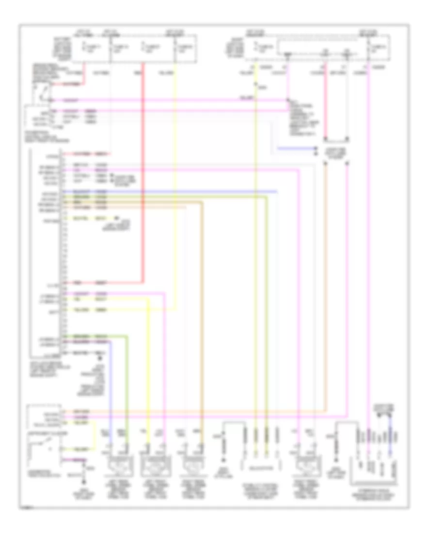
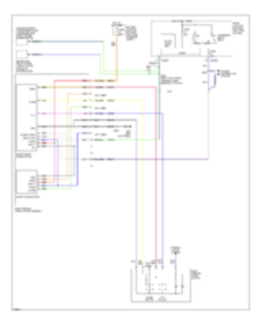
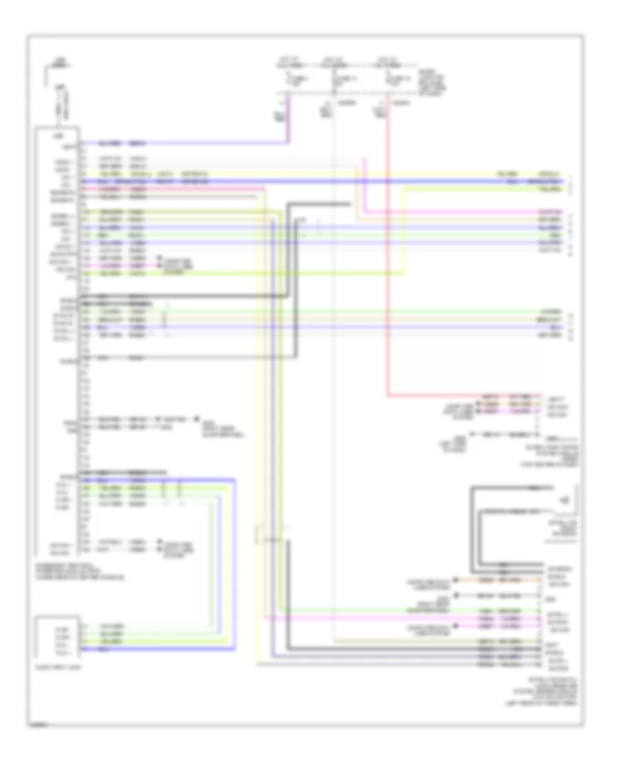
AIR CONDITIONING
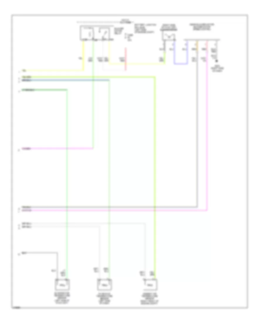
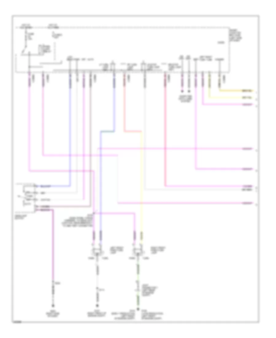
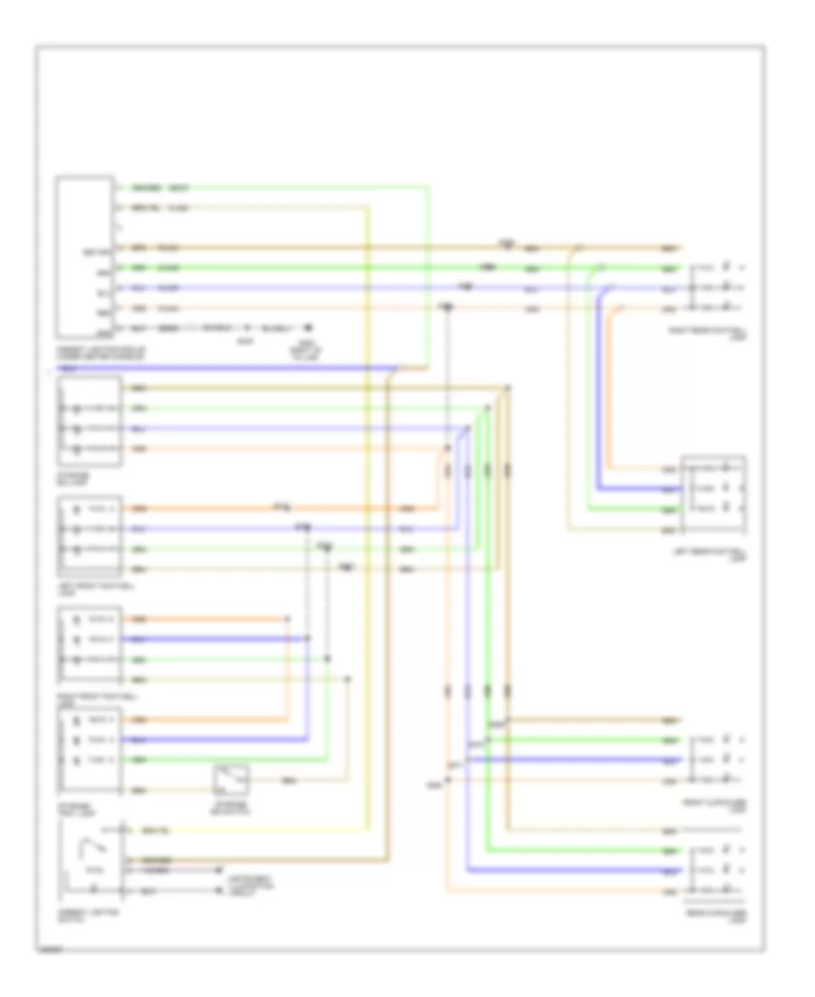
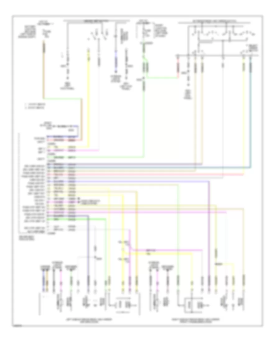
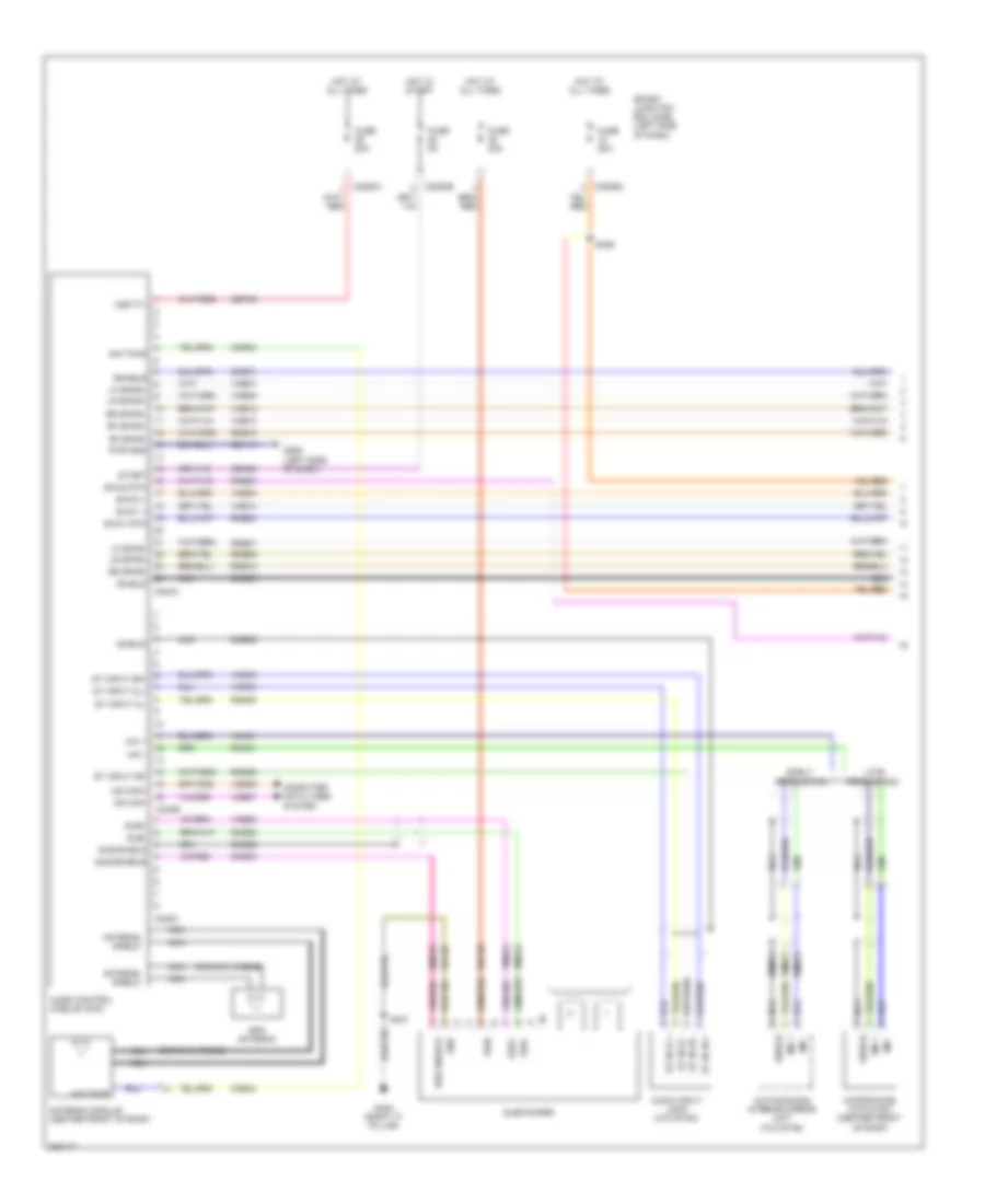
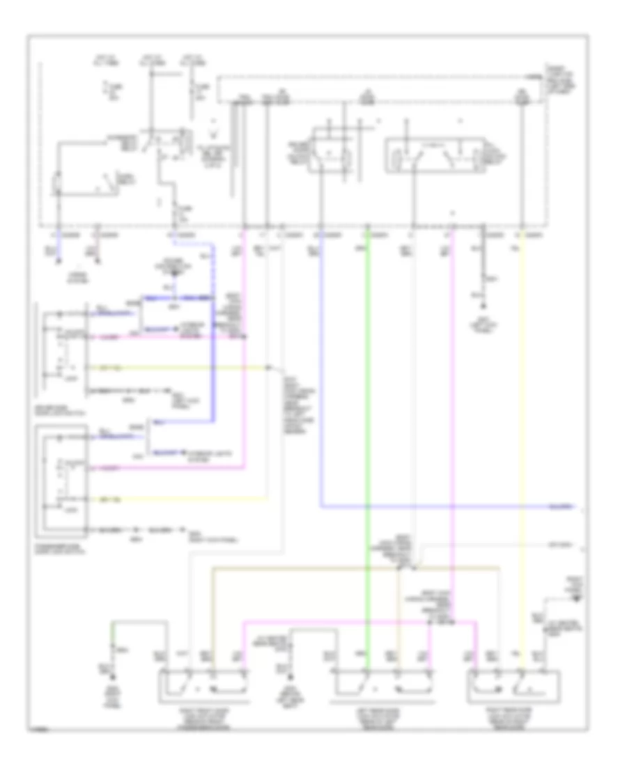
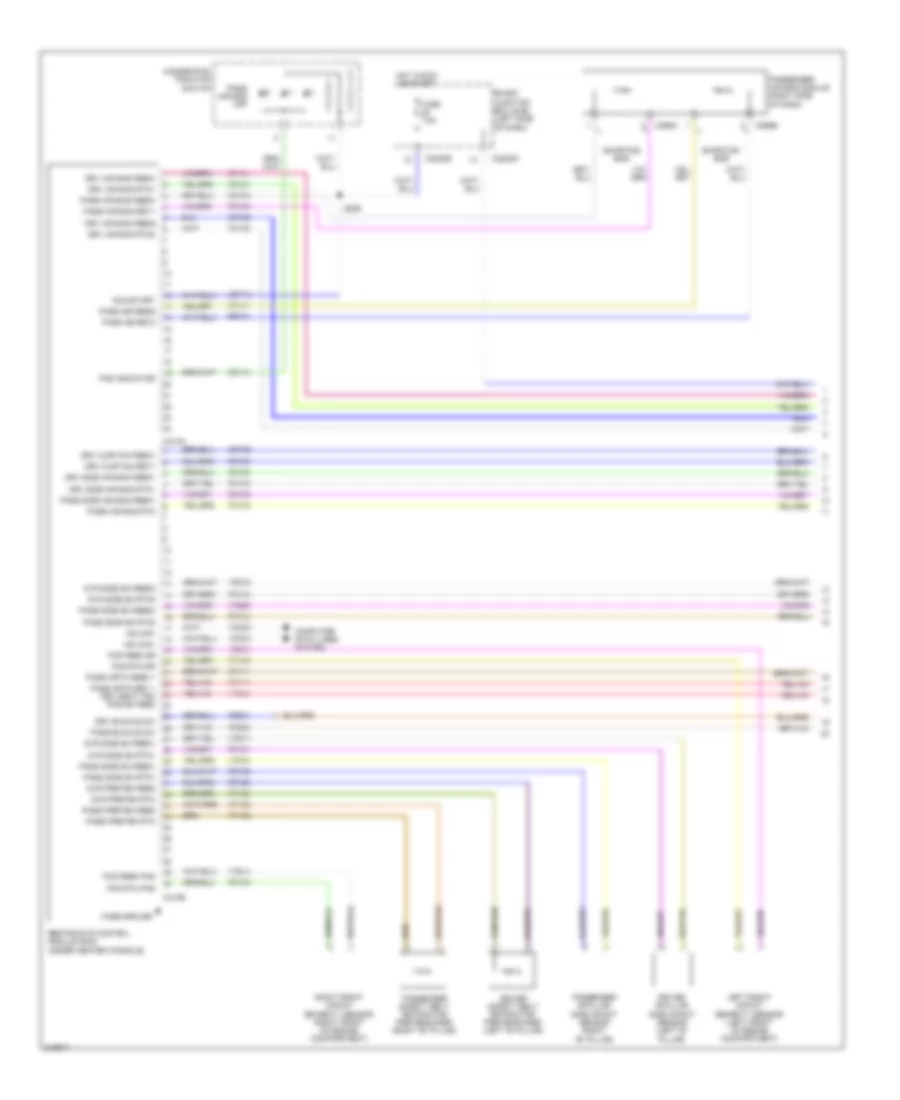
Automatic A/C Wiring Diagram (1 of 3) for Ford Edge SE 2010

List of elements for Automatic A/C Wiring Diagram (1 of 3) for Ford Edge SE 2010:
- (main wiring harness, near breakout to g205)
- Air inlet mode door actuator (middle of hvac unit)
- Amb sig
- Autolp sen in
- Blwr rly
- C2280a
- C2280b
- C2280e
- C228a
- C228b
- Cbp37
- Ch102
- Ch122
- Ch123
- Ch207
- Ch208
- Ch212
- Ch213
- Ch228
- Ch229
- Ch238
- Ch239
- Chs04
- Chs09
- Chs13
- Chs14
- Chs29
- Chs30
- Computer data lines system
- Datc hvac module
- Defogger system
- Defrost req
- Defrost/panel/ floor mode dooor actuator (left side of hvac unit)
- Dr hi led
- Dr hi/lo/off
- Dr lo led
- Dr sunload
- Evap
- Feedback
- Fuse 10a
- Fuse 5a
- G205 (left side of dash)
- Gd115
- Gnd
- Hot at all times
- Hot in run or acc
- Hot in start or run
- In-vh sig
- Left temperature blend door actuator (left side of hvac unit)
- Lh111
- Mscan +
- Mscan -
- Mtr +
- Mtr -
- Pass hi led
- Pass hi/lo/off
- Pass lo led
- Pass sunload
- Power distribution system
- Red
- Rh111
- Right temperature blend door actuator (middle front of hvac unit)
- S104
- S205
- S208
- S217 (a/c wiring harness, near breakout to fresh/ recirculation door actuator)
- S218
- S219
- Sbp15
- Seats system
- Sig return
- Smart junction box (sjb) (left side of dash)
- Solid state
- Sunload sensor
- Var blw feed
- Var blwr ctrl
- Vbatt
- Vdb06
- Vdb07
- Vh101
- Vh406
- Vh407
- Vh414
- Vh416
- Vh417
- Vh436
- Vh440
- Vh441
- Vpwr
- Vref
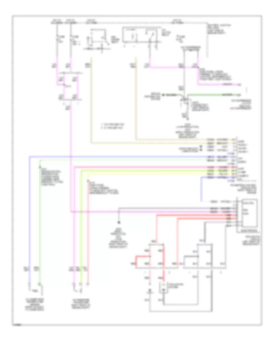
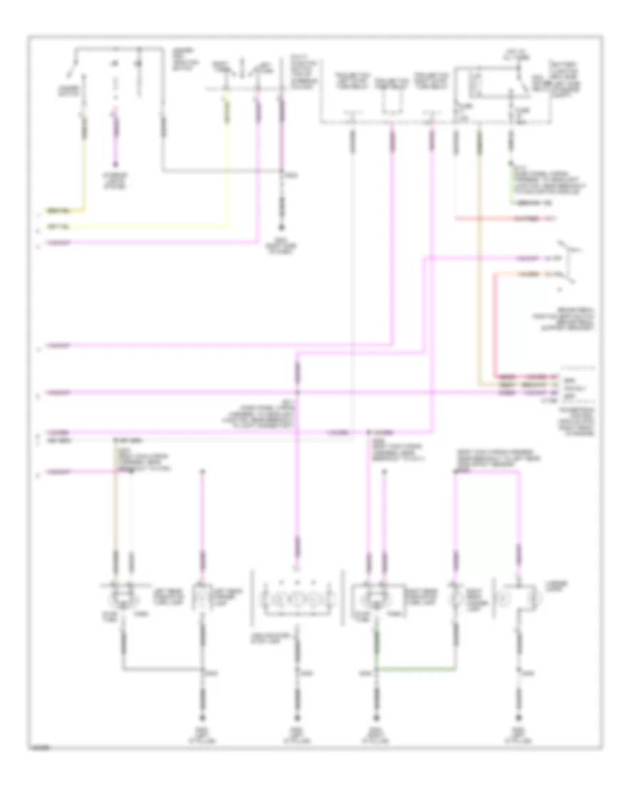
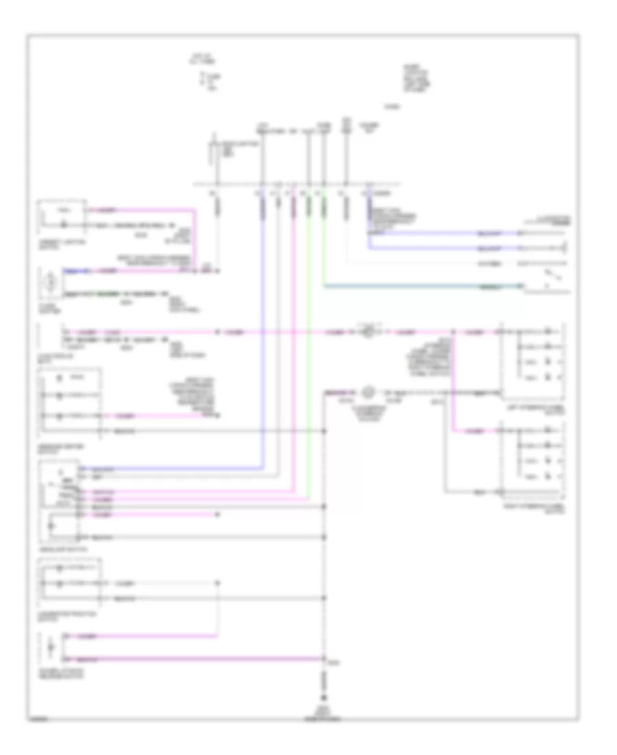
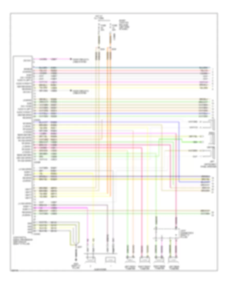
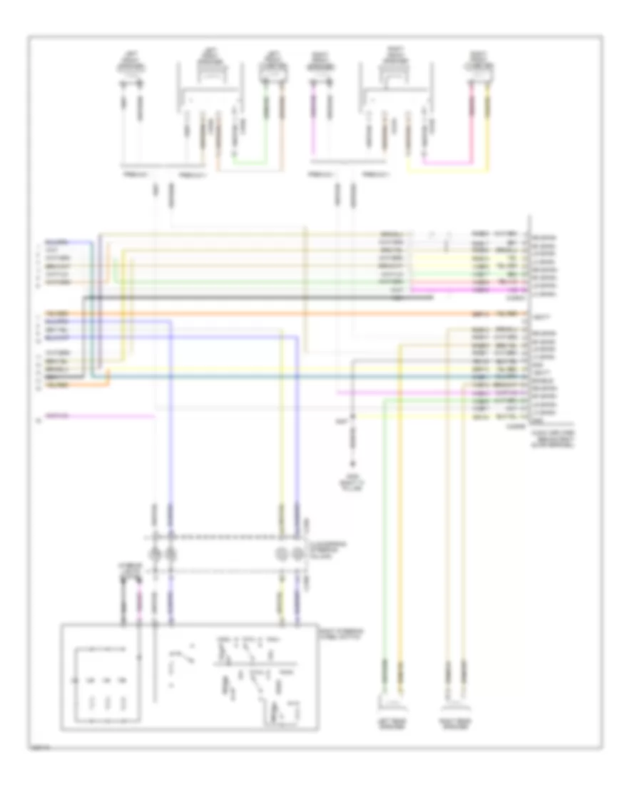
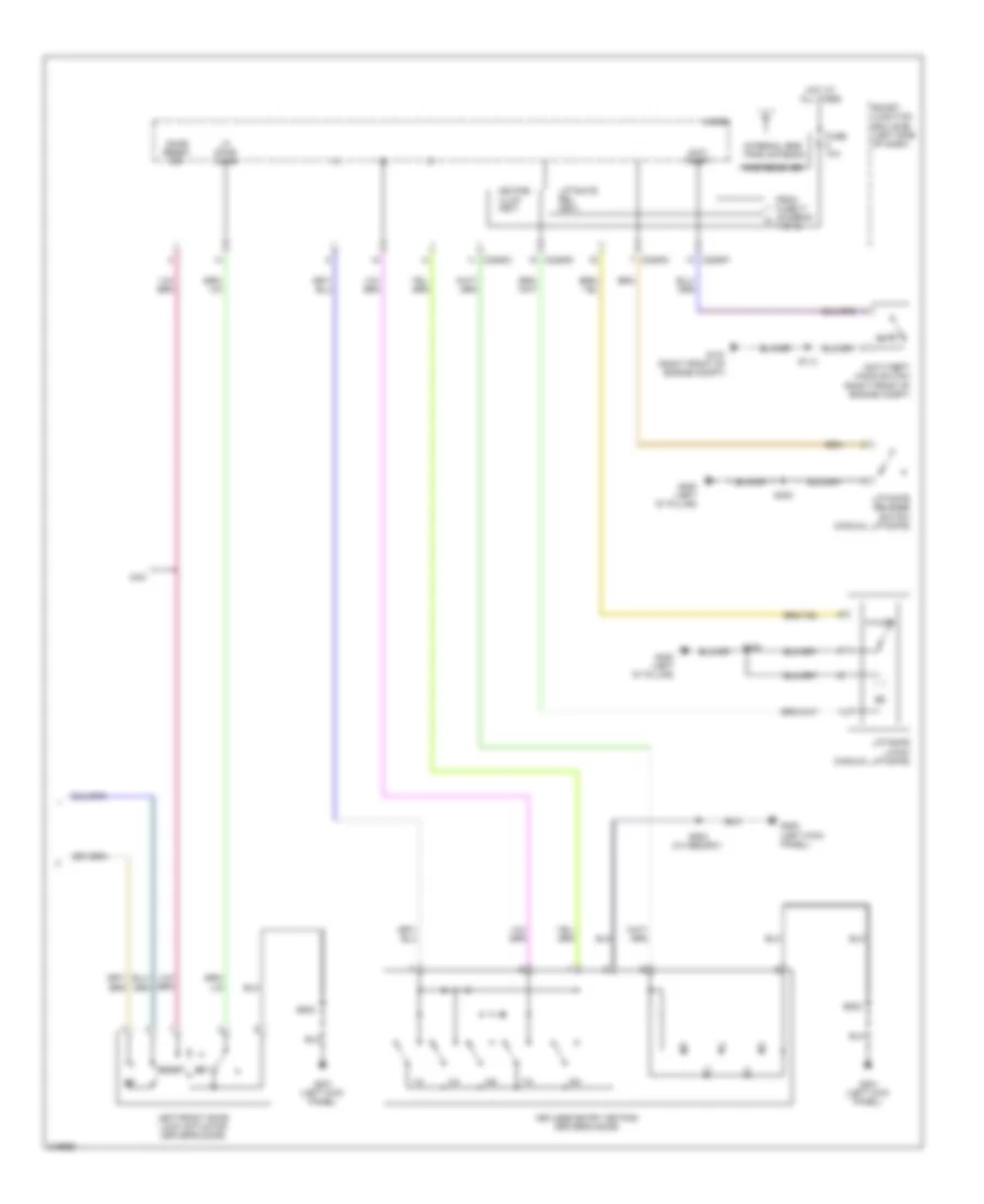
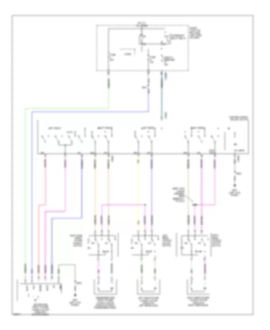
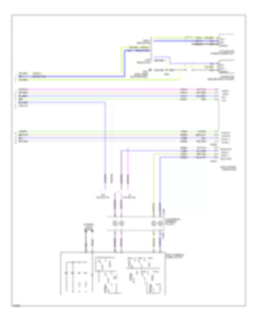
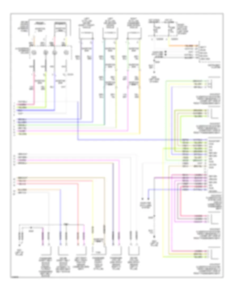
Automatic A/C Wiring Diagram (2 of 3) for Ford Edge SE 2010
List of elements for Automatic A/C Wiring Diagram (2 of 3) for Ford Edge SE 2010:
- (near blower motor) blower motor speed control
- (right side of hvac unit) blower motor
- Ambient air temperature sensor (right front of engine compt)
- Battery junction box (bjb) (left side of engine compt)
- Blower motor relay
- Evaporator temperature sensor (left side of hvac unit)
- Fuse 40a
- G203 (right side of dash)
- Hot at all times
- In-vehicle temperature sensor (left side of dash)
- Red
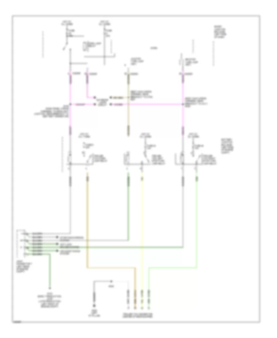
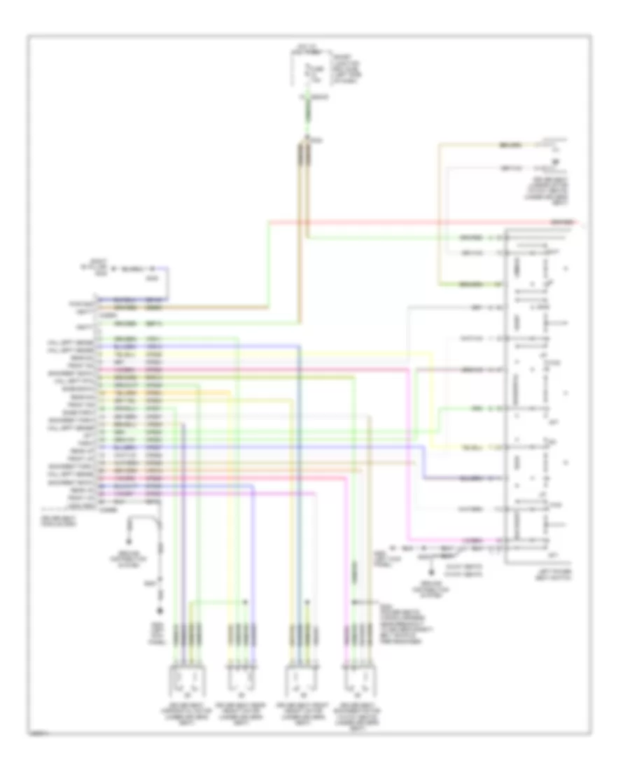
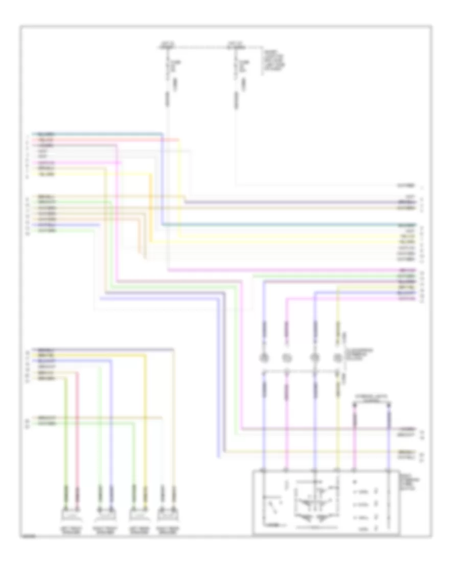
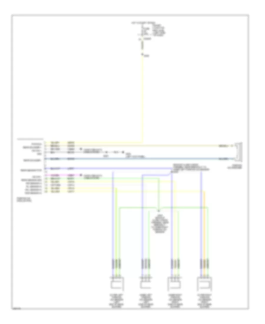
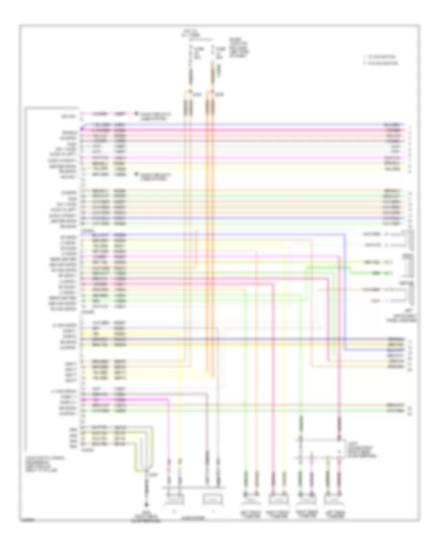
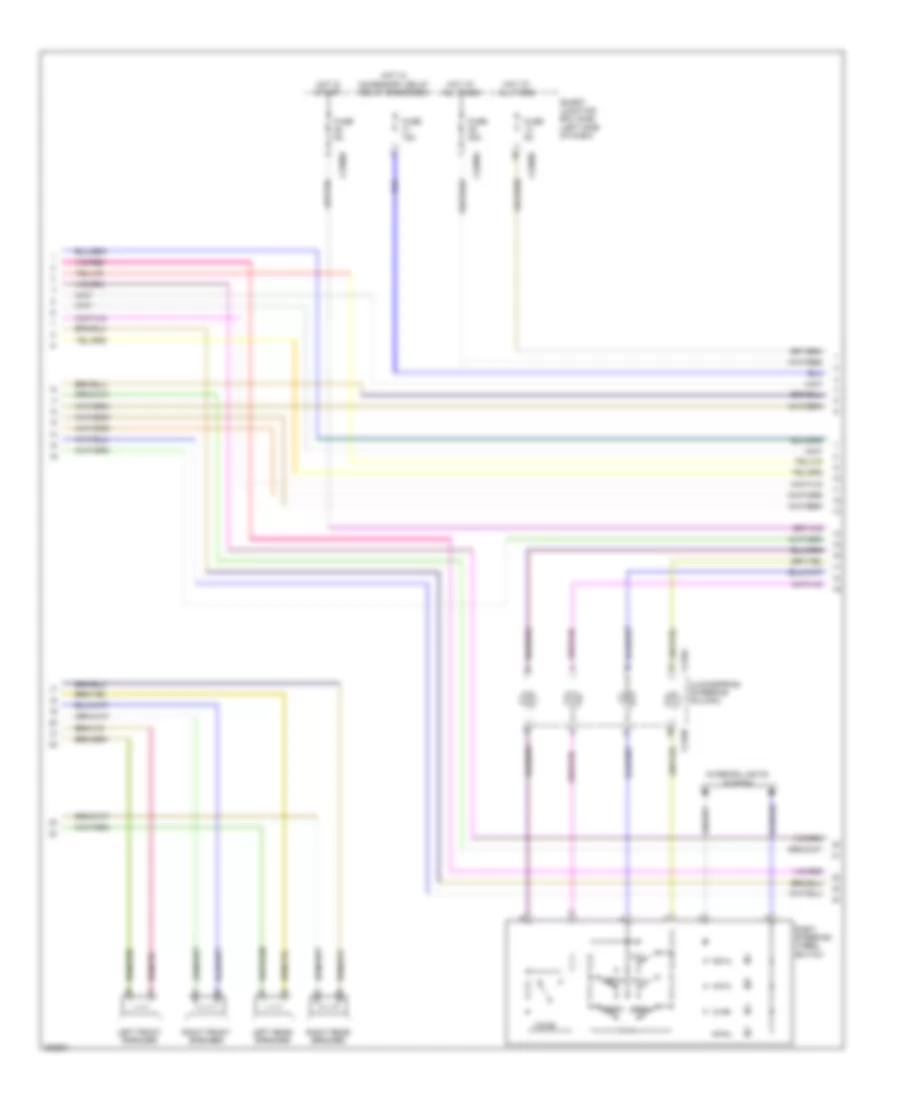
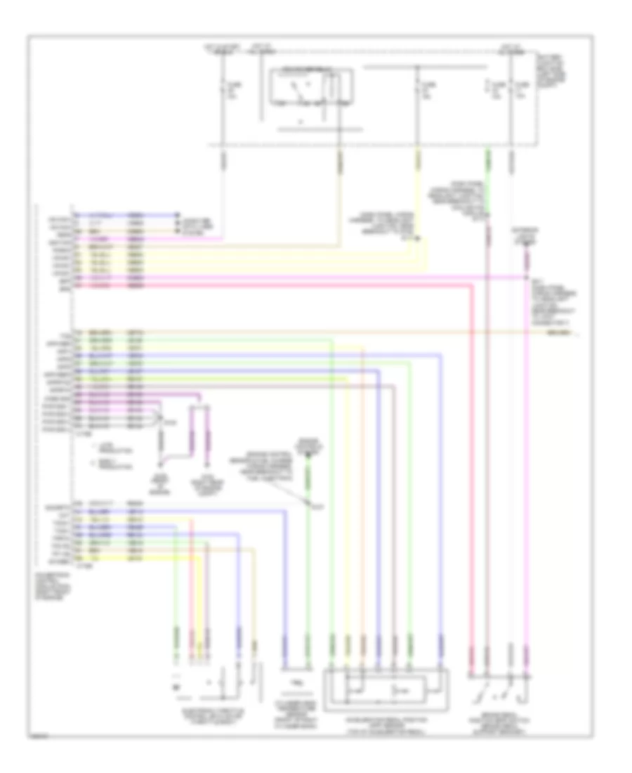
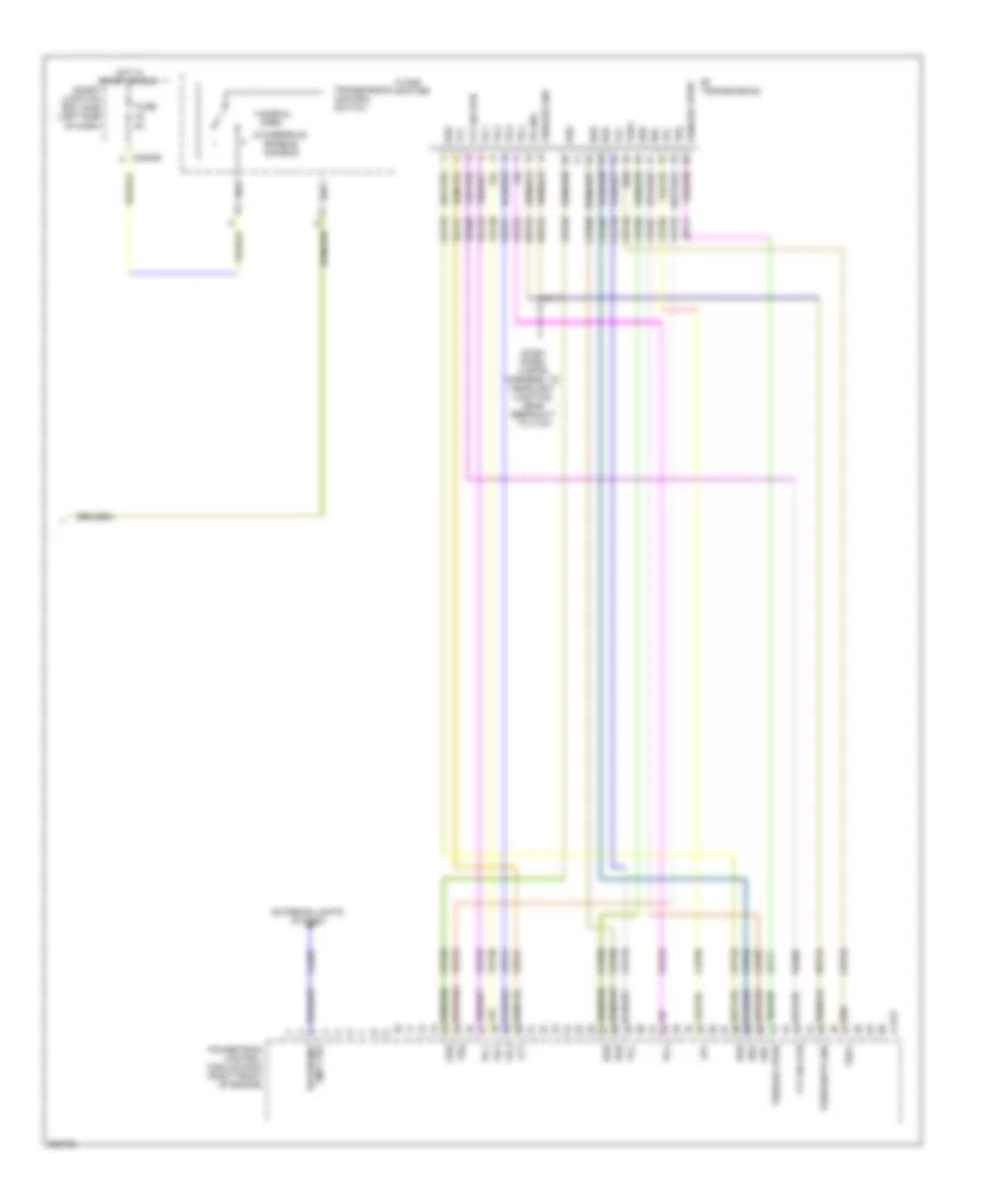
Automatic A/C Wiring Diagram (3 of 3) for Ford Edge SE 2010
List of elements for Automatic A/C Wiring Diagram (3 of 3) for Ford Edge SE 2010:
- A/c clutch relay
- A/c compressor clutch diode
- A/c compressor clutch field coil (a/c compressor)
- A/c pressure transducer (right front of engine compt)
- Accr
- Acpt
- Battery junction box (bjb) (left side of engine compt)
- C-sigrtn
- C-vref
- C175b
- C175e
- Ce237
- Cec05
- Ch302
- Cht
- Computer data lines system
- Cooling fan module (left front of engine compt)
- Cooling fan motors
- Cylinder head temperature sensor (front of right cylinder bank)
- Electronics
- Fan ctrl
- Fcv
- Fuse 10a
- Fuse 40a
- Fuse 60a 40a
- G105 (late production) g104 (early production) (left front of engine compt)
- G106 (early production) g107 (late production) (right front of engine compt)
- Gd123
- Gnd
- Ground distribution system
- Hot at all times
- Hs can +
- Hs can -
- Joint connector 7 (left rear of engine compt)
- Le424
- Pcm power relay
- Pcm rly
- Powertrain control module (pcm) (right front of engine)
- Pwr
- Re405
- Re407
- Red
- S106 (dash panel wiring harness, to headlight junction, near breakout to battery junction box)
- S112
- S119 (dash panel wiring harness, to headlight junction, near breakout to g109)
- S127 (engine control sensor & fuel charge wiring harness, near breakout to fuel injector 6)
- Sigrtn
- Vdb04
- Vdb05
- Ve712
- Vec03
- Vh433
- W/ trailer tow
- W/o trailer tow
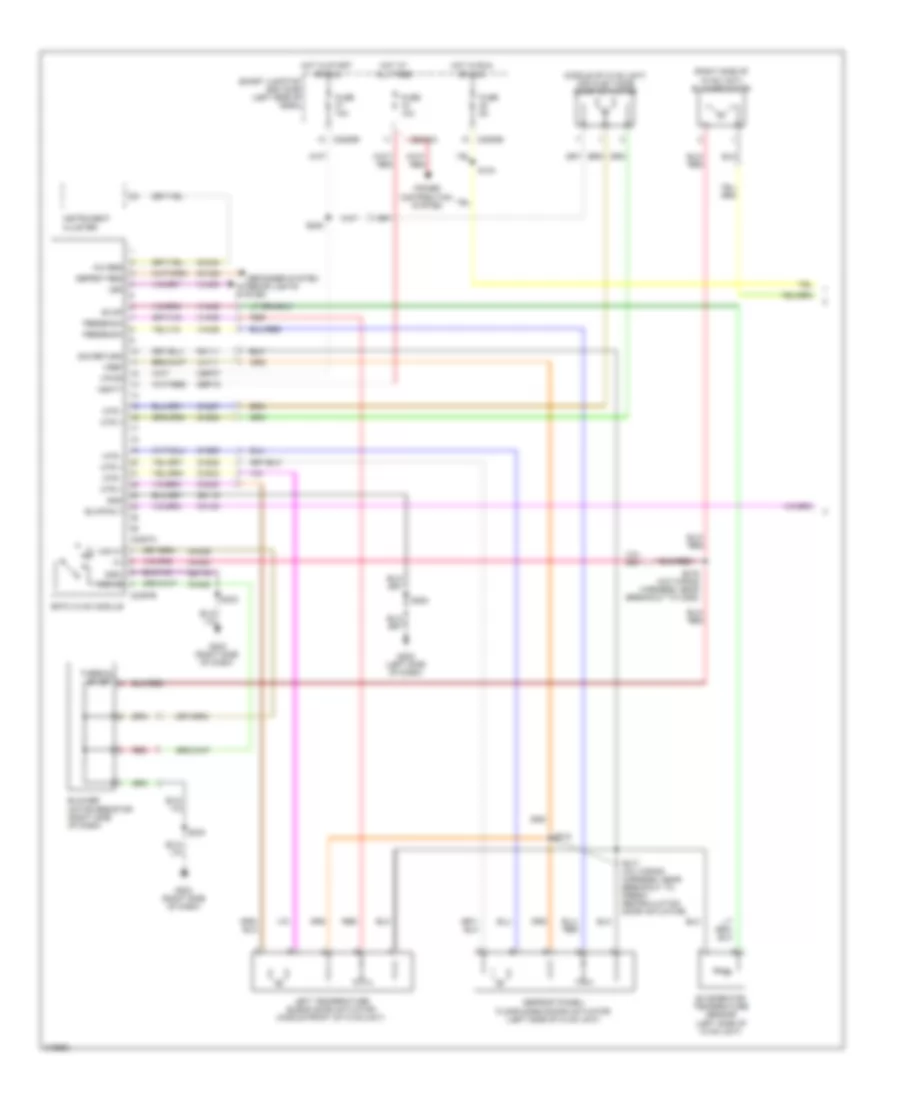
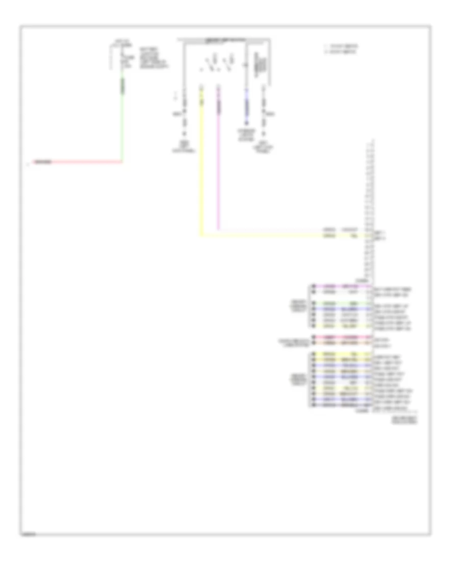
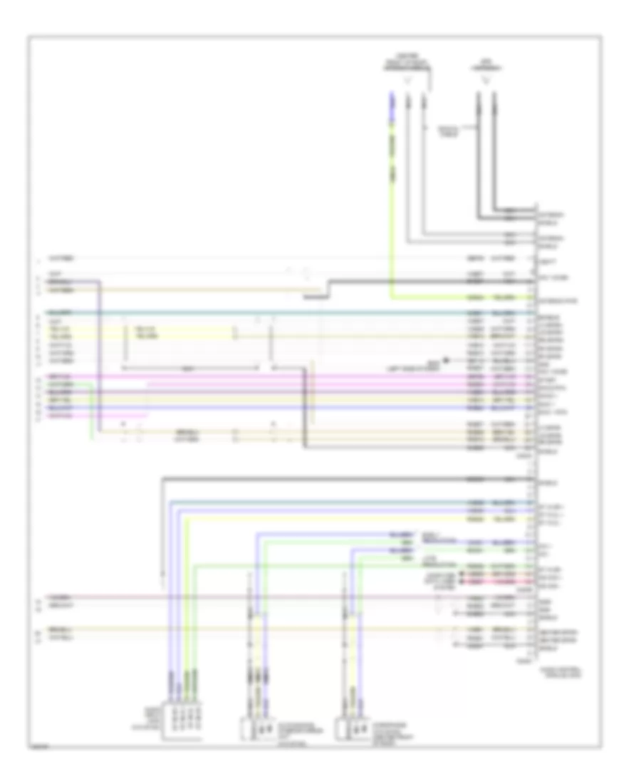
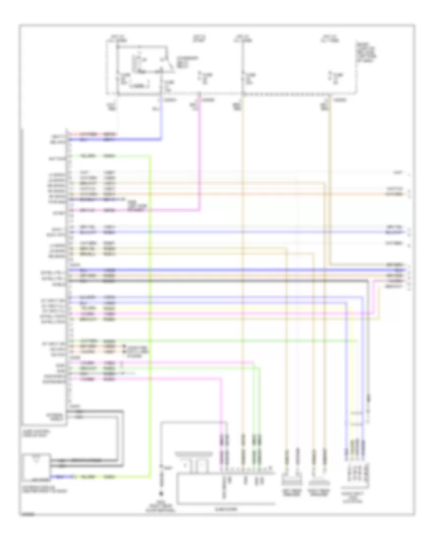
Manual A/C Wiring Diagram (1 of 2) for Ford Edge SE 2010
List of elements for Manual A/C Wiring Diagram (1 of 2) for Ford Edge SE 2010:
- (middle of hvac unit) air inlet mode door actuator
- (right side of hvac unit) blower motor
- A/c req
- Blower motor resistor (right side of dash)
- Blwr rly
- C2280a
- C2280b
- C2280e
- C2357a
- C2357b
- Cbp37
- Ch122
- Ch123
- Ch207
- Ch208
- Ch228
- Ch229
- Ch233
- Ch234
- Ch428
- Ch429
- Ch430
- Ch434
- Defogger system
- Defrost/panel/ floor mode dooor actuator (left side of hvac unit)
- Defrst req
- Emtc hvac module
- Evap
- Evaporator temperature sensor (left side of hvac unit)
- Feedback
- Fuse 10a
- Fuse 5a
- G203 (right side of dash)
- G205 (left side of dash)
- Gd115
- Gd116
- Gnd
- Hot at all times
- Hot in run or acc
- Hot in start or run
- Instrument cluster
- Interior lights system
- Led
- Left temperature blend door actuator (middle front of hvac unit)
- Lh111
- Mid hi
- Mid lo
- Mtr +
- Mtr -
- Power distribution system
- Red
- Rh111
- S104
- S205
- S208
- S216 (a/c wiring harness, near breakout to c263)
- S217 (a/c wiring harness, near breakout to fresh/ recirculation door actuator)
- S218
- S233
- Sbp15
- Sig return
- Smart junction box (sjb) (left side of dash)
- Thermal limiter
- Vbatt
- Vh406
- Vh436
- Vh439
- Vln04
- Vpwr
- Vref
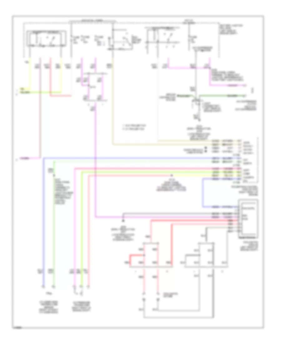
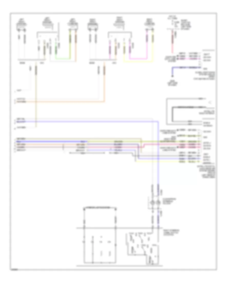
Manual A/C Wiring Diagram (2 of 2) for Ford Edge SE 2010
List of elements for Manual A/C Wiring Diagram (2 of 2) for Ford Edge SE 2010:
- A/c clutch relay
- A/c compressor clutch diode
- A/c compressor clutch field coil (a/c compressor)
- A/c pressure transducer (right front of engine compt)
- Accr
- Acpt
- Battery junction box (bjb) (left side of engine compt)
- Blower motor relay
- C-ref
- C-sigrtn
- C175b
- C175e
- Ce237
- Cec05
- Ch302
- Cht
- Computer data lines system
- Cooling fan module (left front of engine compt)
- Cooling fan motors
- Cylinder head temperature sensor (front of right cylinder bank)
- Electronics
- Fan cntrl
- Fcv
- Fuse 10a
- Fuse 40a
- Fuse 60a 40a
- G104 (early production) g105 (late production) (left front of engine compt)
- G106 (early production) g107 (late production) (right front of engine compt)
- Gd123
- Gnd
- Ground distribution system
- Hot at all times
- Hs can +
- Hs can -
- Joint connector 7 (left rear of engine compt)
- Le424
- Pcm power relay
- Pcm rly
- Powertrain control module (pcm) (right front of engine)
- Pwr
- Re405
- Re407
- Red
- S106 (dash panel wiring harness, to headlight junction, near breakout to battery junction box)
- S112
- S119 (dash panel wiring harness, to headlight junction, near breakout to g109)
- S127 (dash panel wiring harness,to headlight junction,near breakout to powertrain control module)
- Sigrtn
- Vdb04
- Vdb05
- Ve712
- Vec03
- Vh433
- W/ trailer tow
- W/o trailer tow
ANTI-LOCK BRAKES
Anti-lock Brakes Wiring Diagram for Ford Edge SE 2010
List of elements for Anti-lock Brakes Wiring Diagram for Ford Edge SE 2010:
- (brake pedal support bracket) brake pedal position (bpp) switch
- Anti-lock brake system (abs) module (left rear of engine compt)
- Batt
- Battery junction box (bjb) (left side of engine compt)
- Bpp
- C175b
- C2280b
- C2280d
- Cbb50
- Cbp34
- Ces09
- Computer data lines system
- Fuse 15 40a
- Fuse 34 5a
- Fuse 35 10a
- Fuse 50 10a
- Fuse 57 40a
- Fuse 71 10a
- G102 (early production) g103 (late production) (left side of engine compt)
- G103 (left side of engine compt)
- G203 (right side of dash)
- G205 (left side of dash)
- G404 (right "d" pillar)
- Gd115
- Gd121
- Gnd
- Hazard/pad/ traction switch
- Hot at all times
- Hot in on or start
- Hs can +
- Hs can -
- Hs can2 +
- Hs can2 -
- Instrument cluster
- Left front wheel speed sensor (left front wheel hub)
- Left rear wheel speed sensor (left rear wheel hub)
- Lf sens hi
- Lf sens lo
- Lr sens hi
- Lr sens lo
- Ms can +
- Ms can -
- Ms can+
- Ms can-
- Mtr b+
- Nca
- Pmp gnd
- Powertrain control module (right front of engine)
- Rca17
- Rca18
- Rca19
- Rca20
- Red
- Rf sens hi
- Rf sens lo
- Right front wheel speed sensor (right front wheel hub)
- Right rear wheel speed sensor (right rear wheel hub)
- Rr sens hi
- Rr sens lo
- S208
- S211 (dash panel wiring harness, to headlight junction, near breakout to joint connector 7)
- S232
- S308
- S408
- Sbb15
- Sbb57
- Smart junction box (sjb) (left side of dash)
- Solid state
- Stability control sensor cluster (under right side of rear seat)
- Steering angle sensor module (sasm) (steering column)
- Tr ctl on/off
- Vca03
- Vca04
- Vca05
- Vca06
- Vca23
- Vca24
- Vdb04
- Vdb05
- Vlv b+
- Vlv gnd
ANTI-THEFT
Forced Entry Wiring Diagram (1 of 2) for Ford Edge SE 2010
List of elements for Forced Entry Wiring Diagram (1 of 2) for Ford Edge SE 2010:
- (body main wiring harness, near breakout to g200) s312
- (body main wiring harness, near breakout to g200) s313
- (body main wiring harness, near breakout to g200) s314
- (right kick panel) g202
- (w/ heated rear seats) s700
- Accessory delay relay
- All lock/ unlock relay
- C2280b
- C2280c
- C2280d
- C2280e
- Driver door unlock relay
- Driver side door lock switch
- Edge
- Fuse 15a
- Fuse 20a
- G201 (left kick panel)
- G202 (right kick panel)
- G300 (behind left rear seat)
- Horn relay
- Horns system
- Hot at all times
- Interior lights system
- Left rear door lock actuator (rear of left rear door)
- Lock
- Lr door ajar
- Micro
- Mkx
- Passenger side door lock switch
- Power distribution system
- Rf door ajar
- Right front door lock actuator (rear of front passenger's door)
- Right rear door lock actuator (rear of right rear door)
- Rr door ajar
- S201
- S203
- S310 (body main wiring harness, near breakout to left front side impact sensor)
- S501
- S502
- S604
- Smart junction box (sjb) (left side of dash)
- To liftgate rel fet (diagram 2 of 2)
- Trim lock
- Trim unlock
- Unlock
Forced Entry Wiring Diagram (2 of 2) for Ford Edge SE 2010
List of elements for Forced Entry Wiring Diagram (2 of 2) for Ford Edge SE 2010:
- 1/2
- 3/4
- 5/6
- 7/8
- 9/0
- Ajar
- Anti- theft
- Anti-theft hood switch (right front of engine compt)
- C2280c
- C2280d
- C2280f
- Door reset sw
- From fuse 17 (diagram 1 of 2)
- Fuse 10a
- G107 (right front of engine compt)
- G200 (left kick panel)
- G201 (left kick panel)
- G400 (left "d" pillar)
- Hot at all times
- Internal rke/ tpms antenna
- Keyless entry keypad (driver's door)
- Keypad illum (fet)
- Left front door lock actuator (driver's door)
- Lf door ajar
- Liftgate latch (manual liftgate)
- Liftgate rel (fet)
- Liftgate release switch (manual liftgate)
- Micro
- Mkx
- Reset set
- Rke receiver
- S114
- S400
- S502
- S503 (w/ memory)
- Smart junction box (sjb) (left side of dash)
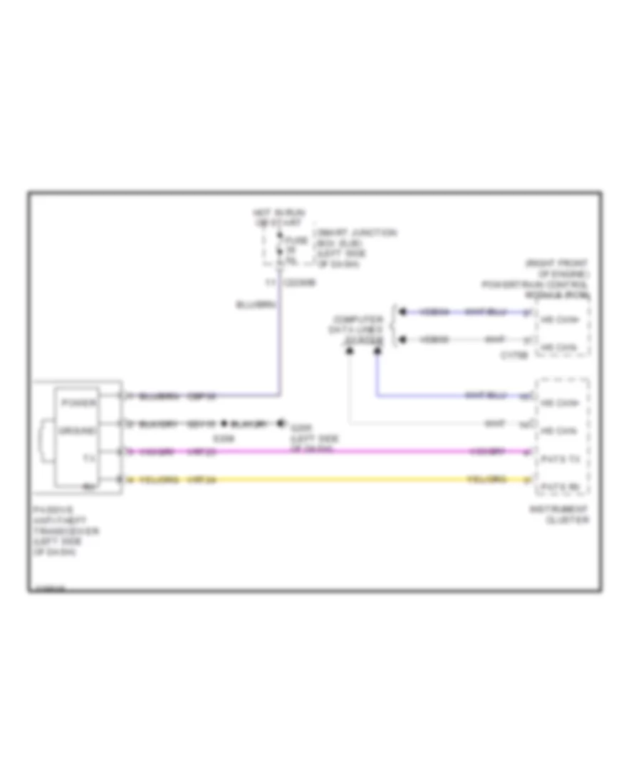
Passive Anti-theft Wiring Diagram for Ford Edge SE 2010
List of elements for Passive Anti-theft Wiring Diagram for Ford Edge SE 2010:
- (right front of engine) powertrain control module (pcm)
- C175b
- C2280b
- Cbp36
- Computer data lines system
- Fuse 5a
- G205 (left side of dash)
- Gd115
- Ground
- Hot in run or start
- Hs can+
- Hs can-
- Instrument cluster
- Passive anti-theft transceiver (left side of dash)
- Pats rx
- Pats tx
- Power
- S208
- Smart junction box (sjb) (left side of dash)
- Vdb04
- Vdb05
- Vrt23
- Vrt24
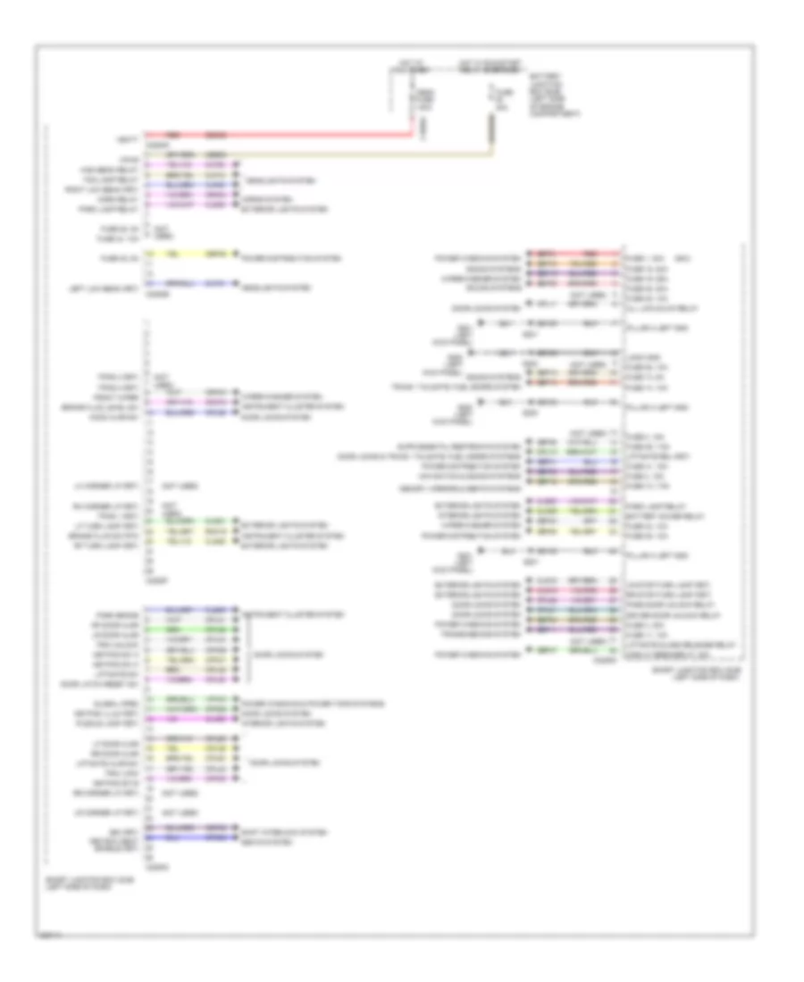
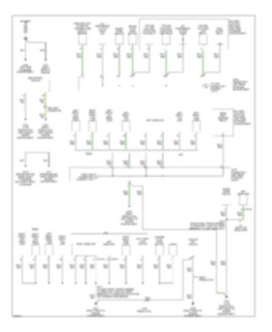
BODY CONTROL MODULES
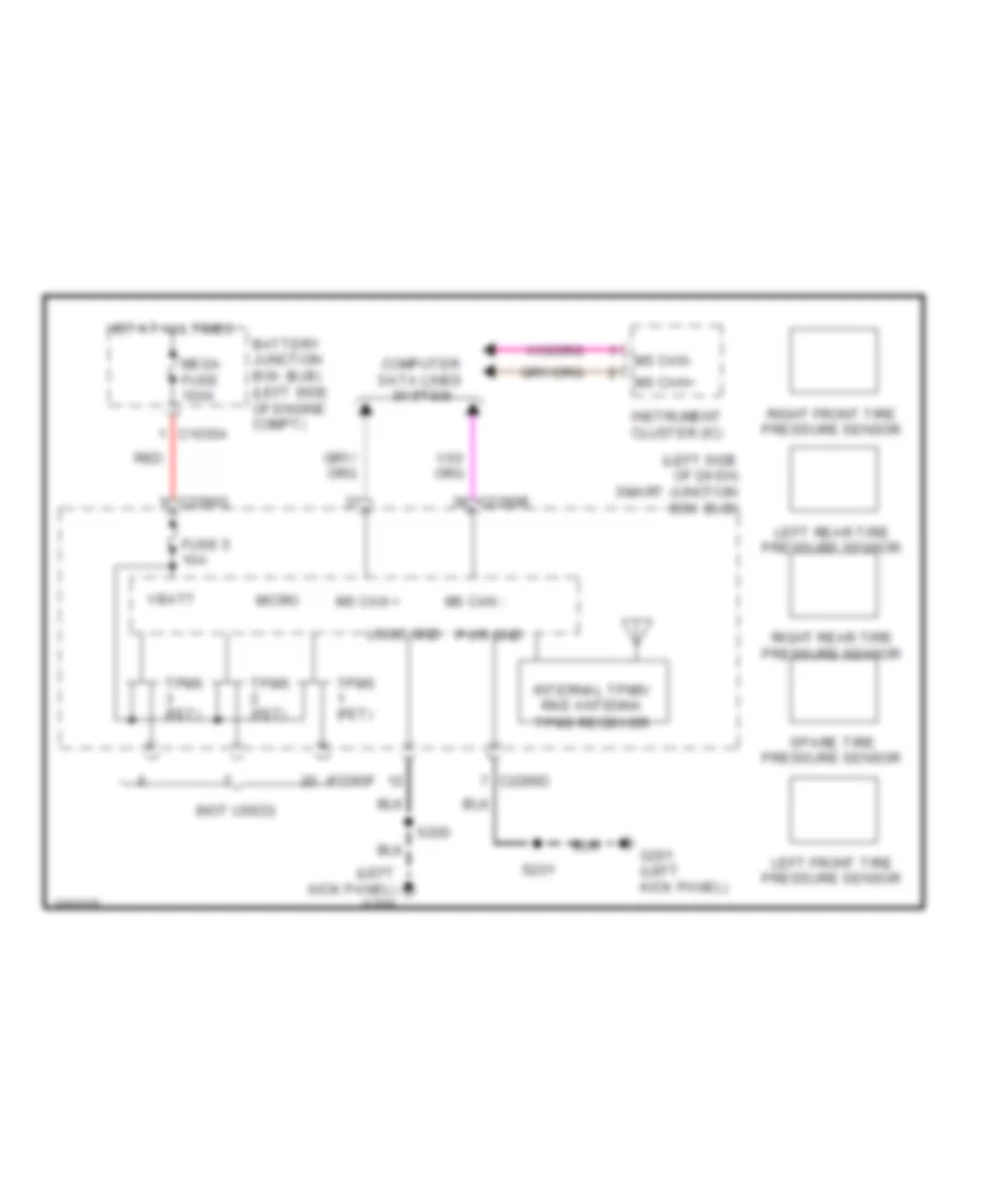
Body Control Modules Wiring Diagram (1 of 2) for Ford Edge SE 2010
List of elements for Body Control Modules Wiring Diagram (1 of 2) for Ford Edge SE 2010:
- (mkx)
- (not used)
- 3rd row seat enable (fet)
- All lck/unlck relay
- Battery junction box (bjb) (left side of engine compartment)
- Battery saver relay
- Brake fluid level sw
- Brake fluid sw rtn
- Bsi (fet)
- C1035a
- C2280c
- C2280d
- C2280e
- C2280f
- C2280g
- Cbb53
- Cbp13
- Cbp35
- Cbp41
- Cbp43
- Cbp45
- Cbp46
- Cbp47
- Cet53
- Circuit breaker 47, 30a
- Clf04
- Clf05
- Clf08
- Clf12
- Cln09
- Cln25
- Cls05
- Cls18
- Cls19
- Cls21
- Cls25
- Cls30
- Cmc19
- Cpk28
- Cpk29
- Cpk30
- Cpk31
- Cpl10
- Cpl11
- Cpl25
- Cpl26
- Cpl28
- Cpl31
- Cpl36
- Cpl39
- Cpl42
- Cpl43
- Cpl45
- Cpl51
- Cpl52
- Cpl60
- Cps48
- Crh04
- Crw01
- Door latch reset sw
- Door locks & trunk, tailgate, fuel doors systems
- Door locks system
- Driver door unlock relay
- Exterior lights system
- Fog lamp relay
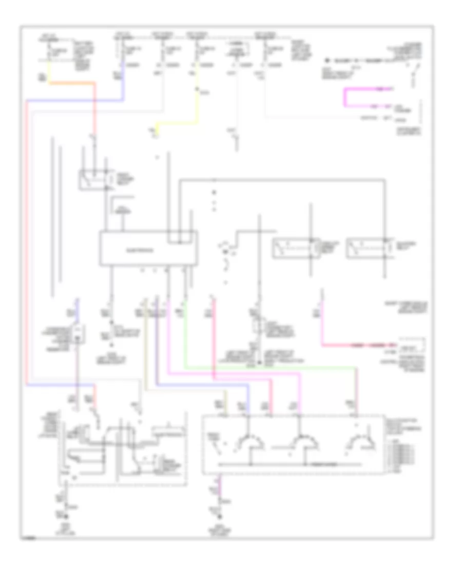
- Front wiper
- Fuse 1, 30a
- Fuse 11, 10a
- Fuse 12, 7.5a
- Fuse 13, 5a
- Fuse 14, 10a
- Fuse 18, 20a
- Fuse 19, 25a
- Fuse 2, 15a
- Fuse 25, 10a
- Fuse 28, 5a
- Fuse 3, 15a
- Fuse 30a
- Fuse 32, 10a
- Fuse 35, 10a
- Fuse 38, 20a
- Fuse 4, 30a
- Fuse 41, 15a
- Fuse 43, 10a
- Fuse 44, 10a
- Fuse 45, 5a
- Fuse 46, 7.5a
- G200 (left kick panel)
- G201 (left kick panel)
- Gd133
- Global open
- Headlights system
- High beam relay
- Hood ajar sw
- Horn relay
- Horns system
- Hot at all times
- Hot w/ run/start relay energized
- Instrument cluster system
- Interior lights system
- Keypad illum (fet)
- Keypad sw a
- Keypad sw b
- Keypad sw c
- Left low beam (fet)
- Lf door ajar
- Lf turn lamp (fet)
- Lh corner lp (fet)
- Liftgate ajar sw
- Liftgate glass release relay
- Liftgate rel (fet)
- Liftgate sw
- Logic gnd
- Lr corner lp (fet)
- Lr door ajar
- Lr stop/turn lamp (fet)
- Mega fuse 100a
- Memory, mirrors & seats systems
- Navigation & sound systems
- Park brake
- Park lamp relay
- Pass door unlock relay
- Pillar a left gnd
- Power distribution system
- Power windows & power tops systems
- Power windows system
- Puddle lamp (fet)
- Red
- Rf door ajar
- Rf turn lamp (fet)
- Rh corner lp (fet)
- Right low beam (fet)
- Rmc19
- Rr corner lp (fet)
- Rr door ajar
- Rr stop/turn lamp (fet)
- S200
- S201
- Sbp01
- Sbp03
- Sbp04
- Sbp11
- Sbp12
- Sbp14
- Sbp18
- Sbp19
- Sbp38
- Sdc02
- Seats system
- Shift interlock system
- Smart junction box (sjb) (left side of dash)
- Sound systems
- Tpms 1 (fet)
- Tpms 2 (fet)
- Tpms 3 (fet)
- Transmissions system
- Trim lock
- Trim unlock
- Trunk, tailgate, fuel doors system
- Vbatt
- Vpw01
- Vpwr
- Wiper/washer system
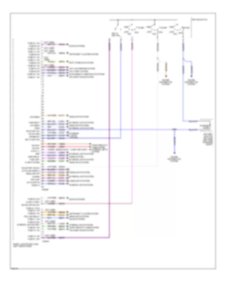
Body Control Modules Wiring Diagram (2 of 2) for Ford Edge SE 2010
List of elements for Body Control Modules Wiring Diagram (2 of 2) for Ford Edge SE 2010:
- (not used)
- (or vln37)
- Air conditioning system
- Anti-lock brakes system
- Anti-theft system
- Autolamp on
- Autolamp snsr in
- Battery junction box (bjb) (left side of engine compt)
- Bpp
- C2280a
- C2280b
- Cbp28
- Cbp29
- Cbp30
- Cbp34
- Cbp36
- Cbp37
- Cbp41
- Cbp46
- Ccb08
- Cdc30
- Cdc33
- Cdc34
- Cdc35
- Clf12
- Clf17
- Clf18
- Clf19
- Clf21
- Clf23
- Clf27
- Cln27
- Cln28
- Cls32
- Cls34
- Cls39
- Cls41
- Computer data lines system
- Computer data lines system interior lights system
- Crh02
- Dim sw gnd
- Dimmer sw
- Dome lp
- Exterior lights system
- Flash-to-pass
- Floor lp (fet)
- Fog lamp
- Fog lamp relay
- Fuse 14, 10a
- Fuse 15, 10a
- Fuse 16, 15a
- Fuse 20, 15a
- Fuse 26, 10a
- Fuse 27, 20a
- Fuse 28, 5a
- Fuse 29, 5a
- Fuse 30, 5a
- Fuse 31, 10a
- Fuse 33, 10a
- Fuse 34, 5a
- Fuse 35, 10a
- Fuse 36, 5a
- Fuse 37, 10a
- Fuse 39, 20a
- Fuse 41, 15a
- Fuse 42, 10a
- Fuse 42, 10a & fuse 44, 10a
- Fuse 43, 10a
- Fuse 46, 7.5a
- Fuse 49, 20a
- Hazard
- Headlamp off
- Headlights system
- High beam
- Horn relay
- Horns system
- I/p sw ill
- Ign run or acc sw
- Ign start sw
- Ignition switch
- Instrument cluster system
- Interior lighting (fet)
- Interior lights system
- Key in ignition
- Lock acc
- Low beam
- Ms can+
- Ms can-
- Off
- Park
- Power distribution system
- Run
- Run/start ign sw
- S133
- Sbp15
- Sbp20
- Sbp26
- Sbp27
- Sbp39
- Shift interlock system
- Smart junction box (sjb) (left side of dash)
- Sound systems
- Start
- Starter diode
- Turn left
- Turn right
- Vdb06
- Vdb07
- Vlf14
- Vln04
- Vln18
- Vln33
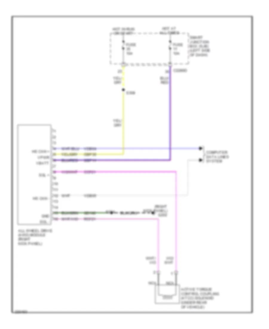
COMPUTER DATA LINES
Computer Data Lines Wiring Diagram (1 of 2) for Ford Edge SE 2010
List of elements for Computer Data Lines Wiring Diagram (1 of 2) for Ford Edge SE 2010:
- (body main wiring harness, near breakout to in-vehicle temperature sensor)
- (left side of dash) g204
- (under front passenger's seat)
- (w/ adaptive headlamps)
- Abs test connector (left side of engine compt)
- All wheel drive module (right kick panel)
- Anti-lock brake system (abs) module (left rear of engine compt)
- Audio control module
- C1021b
- C175b
- C2280a
- C310b
- Cdb08
- Data link connector (dlc) (left side of dash)
- Feps
- Fuse 15a
- G203 (right side of dash)
- Gd115
- Gd116
- Global positioning system module (gpms) (w/ sync & w/o navigation)
- Hot at all times
- Hs can+
- Hs can-
- Hs can2+
- Hs can2-
- Hvac module datc
- Instrument cluster
- J/c 10 (right "b" pillar)
- J/c 11 (left rear of engine compt)
- J/c 2
- J/c 3 (under front passenger's seat)
- J/c 4 (center of dash)
- J/c 5 (left side of dash)
- Left headlamp
- Ms can+
- Ms can+ c228a
- Ms can+ c240b
- Ms can-
- Occupant classification system module (ocsm) (under front passenger's seat)
- Powertrain control module (right front of engine)
- Restraints control module (under center console)
- S230
- S231 (body main wiring harness, near breakout to in-vehicle temperature sensor)
- S232
- S355
- S356
- Sbp20
- Smart junction box (sjb) (left side of dash)
- Stability control sensor cluster (under right side of rear seat)
- Steering angle sensor module (sasm) (steering column)
- Vca23
- Vca24
- Vdb04
- Vdb05
- Vdb06
- Vdb07
Computer Data Lines Wiring Diagram (2 of 2) for Ford Edge SE 2010
List of elements for Computer Data Lines Wiring Diagram (2 of 2) for Ford Edge SE 2010:
- (body main wiring harness, near breakout to cargo light) s420
- (body main wiring harness, near breakout to cargo light) s421
- (left side of dash)
- Accessory protocol interface module (w/ sync) (under rear of center console)
- Audio digital signal processing (dsp) module (right "c" pillar)
- C2280b
- C3036c
- Driver seat module (dsm)
- Dual climate controlled seat module (dcsm) (if equipped)
- Hs can +
- Hs can-
- J/c 8 (left "d" pillar)
- J/c 9 (right "c" pillar)
- Liftgate/trunk module (ltm) (base of left "d" pillar)
- Ms can+
- Ms can+ c4174b
- Ms can+ c4348a
- Ms can-
- Ms can- c3299d
- Parking aid module
- S327 (body main wiring harness, in breakout to c314)
- S350 (console jumper harness, near breakout to accessory protocol interface module)
- S353
- S354
- Satellite digital audio receiver system (sdars) module (w/o navigation) (left rear of cargo area)
- Smart junction box
- Vdb04
- Vdb05
- Vdb06
- Vdb07
- W/ thx
- W/o thx
COOLING FAN
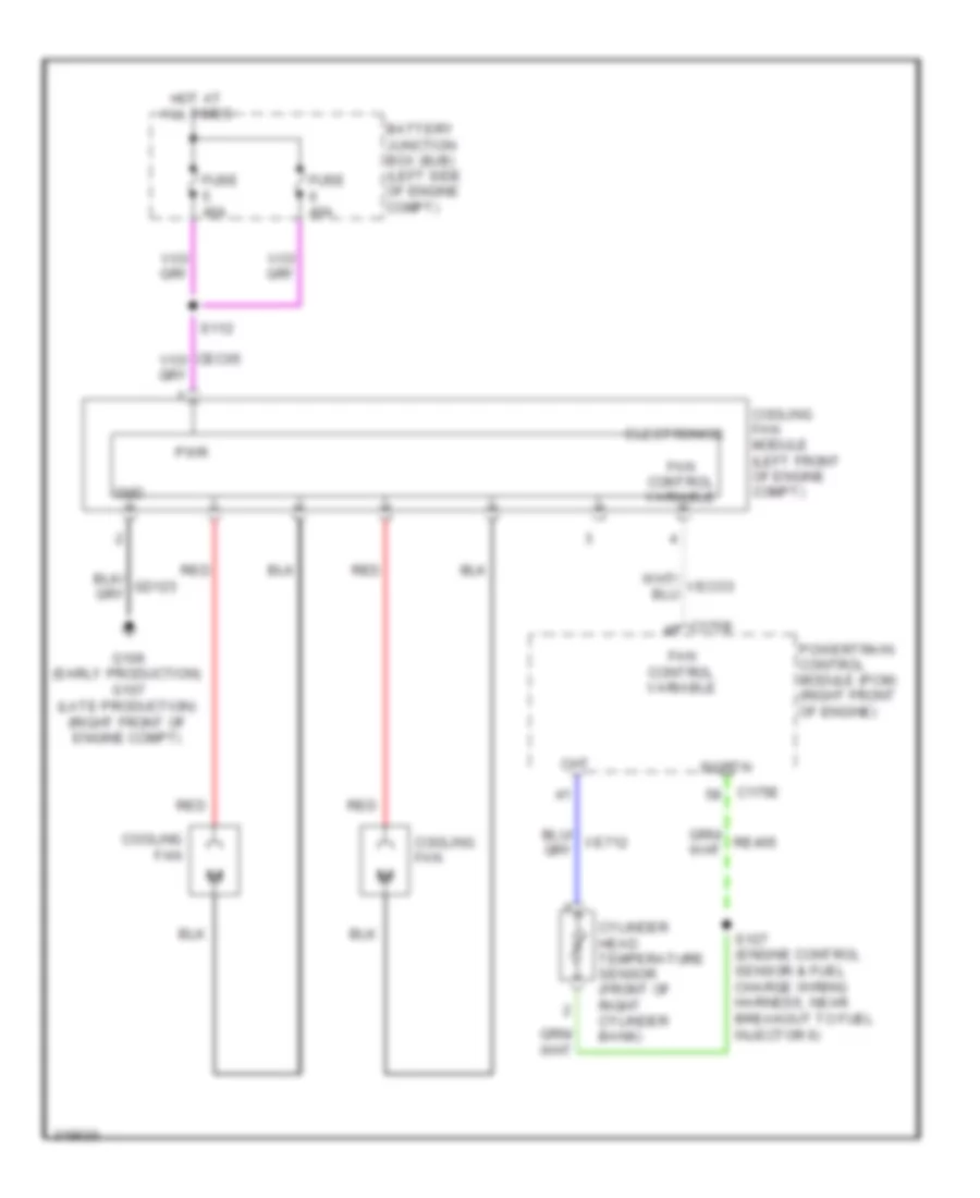
Cooling Fan Wiring Diagram, with Trailer Tow for Ford Edge SE 2010
List of elements for Cooling Fan Wiring Diagram, with Trailer Tow for Ford Edge SE 2010:
- Battery junction box (bjb) (left side of engine compt)
- C175b
- C175e
- Cht
- Cooling fan
- Cooling fan module (left front of engine compt)
- Cylinder head temperature sensor (front of right cylinder bank)
- Electronics
- Fan control variable
- Fuse 40a
- G106 (early production) g107 (late production) (right front of engine compt)
- Gnd
- Hot at all times
- Powertrain control module (pcm) (right front of engine)
- Pwr
- Re405
- Red
- S112
- S127 (engine control sensor & fuel charge wiring harness, near breakout to fuel injector 6)
- Sigrtn
- Ve712
- Veco3
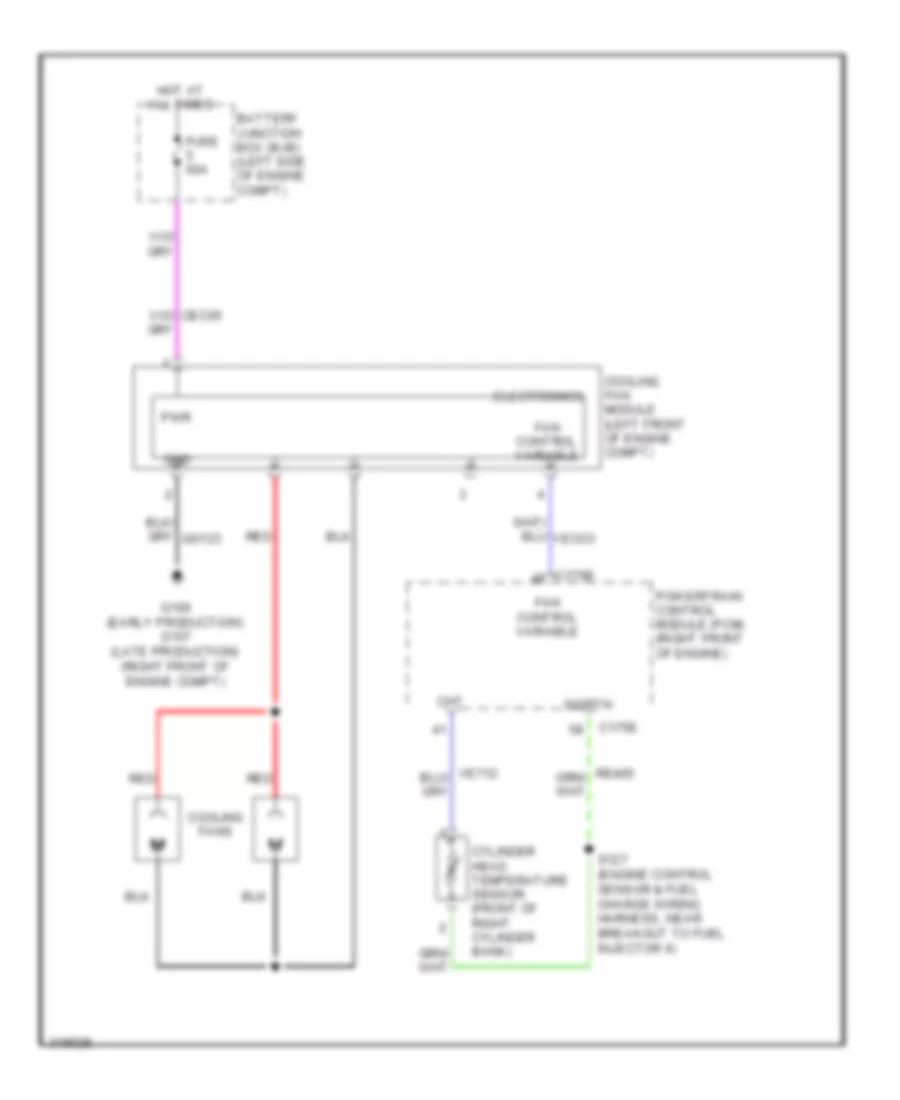
Cooling Fan Wiring Diagram, without Trailer Tow for Ford Edge SE 2010
List of elements for Cooling Fan Wiring Diagram, without Trailer Tow for Ford Edge SE 2010:
- Battery junction box (bjb) (left side of engine compt)
- C175b
- C175e
- Cht
- Cooling fan module (left front of engine compt)
- Cooling fans
- Cylinder head temperature sensor (front of right cylinder bank)
- Electronics
- Fan control variable
- Fuse 60a
- G106 (early production) g107 (late production) (right front of engine compt)
- Gnd
- Hot at all times
- M m
- Powertrain control module (pcm) (right front of engine)
- Pwr
- Re405
- Red
- S127 (engine control sensor & fuel charge wiring harness, near breakout to fuel injector 6)
- Sigrtn
- Ve712
- Veco3
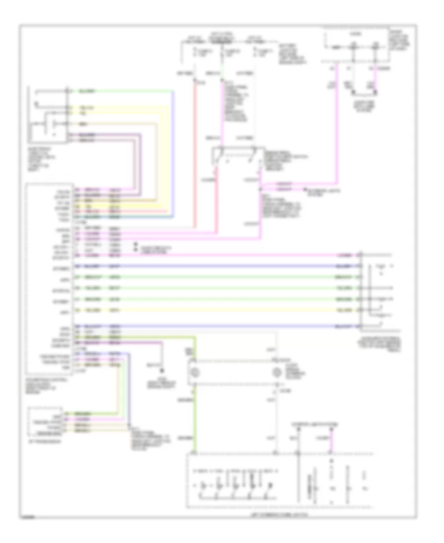
CRUISE CONTROL
Cruise Control Wiring Diagram for Ford Edge SE 2010
List of elements for Cruise Control Wiring Diagram for Ford Edge SE 2010:
- 6f transmission
- Accelerator pedal position (app) sensor (top of accelerator pedal)
- App1
- App2
- App3
- Battery junction box (bjb) (left side of engine compt)
- Bpp
- Bps
- Brake pedal position (bpp) switch (brake pedal support bracket)
- C175b
- C175e
- C175t
- C218a
- C218b
- C2280b
- Case gnd
- Ccb08
- Ce412
- Ce426
- Ces09
- Clock spring (steering column)
- Computer data lines system
- Electronic throttle control (etc) motor (throttle body)
- Etcref
- Etcref1
- Etcref2
- Etcrtn
- Etcrtn1
- Etcrtn2
- Exterior lights system
- Fuse 21 7.5a
- Fuse 32 10a
- Fuse 71 10a
- G108 (right rear of engine compt)
- Gd124
- Hot at all times
- Hot w/ pcm power relay energized
- Hs can +
- Hs can -
- Illumination
- Interior lights system
- Kapwr
- Le111
- Le134
- Le136
- Le137
- Left steering wheel switch
- Micro
- Ms can +
- Ms can -
- Off
- Oss
- Powertrain control module (pcm) (right front of engine)
- Re134
- Re136
- Re137
- Res08
- Resume
- Ret24
- S111 (dash panel wiring harness, to headlight junction, near breakout to c134)
- S113 (dash panel wiring harness, to headlight junction, near breakout to cooling fan module)
- S132
- S211 (dash panel wiring harness, to headlight junction, near breakout to joint connector 7)
- Sbb21
- Sccs
- Sccsrtn
- Set (+)
- Set (-)
- Smart junction box (sjb) (left side of dash)
- Tacm+
- Tacm-
- Tp1 ns
- Tp2 ps
- Tr gnd
- Tss/oss gnd
- Tss/oss vpwr
- Tss/oss/tr gnd
- Vdb04
- Vdb05
- Ve701
- Ve702
- Ve703
- Ve818
- Ve819
- Ves10
- Vet26
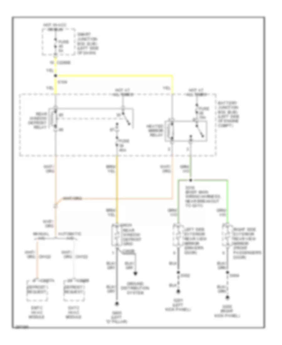
DEFOGGERS
Defoggers Wiring Diagram for Ford Edge SE 2010
List of elements for Defoggers Wiring Diagram for Ford Edge SE 2010:
- Automatic a/c
- Battery junction box (bjb) (left side of engine compt)
- C2280e
- C228b
- C2357a
- C402a
- C402b
- Datc hvac module
- Defrost request
- Emtc hvac module
- Fuse 15a
- Fuse 40a
- Fuse 5a
- G201 (left kick panel)
- G202 (right kick panel)
- G400 (left "d" pillar)
- Ground distribution system
- Heated mirror relay
- Hot at all times
- Hot in acc or run
- Left side exterior rear view mirror (driver's door)
- Manual a/c
- Rear window defrost grid
- Rear window defrost relay
- Right side exterior rear view mirror (front passenger's door)
- S104
- S316 (body main wiring harness, near breakout to g311)
- S502
- S604
- Smart junction box (sjb) (left side of dash)
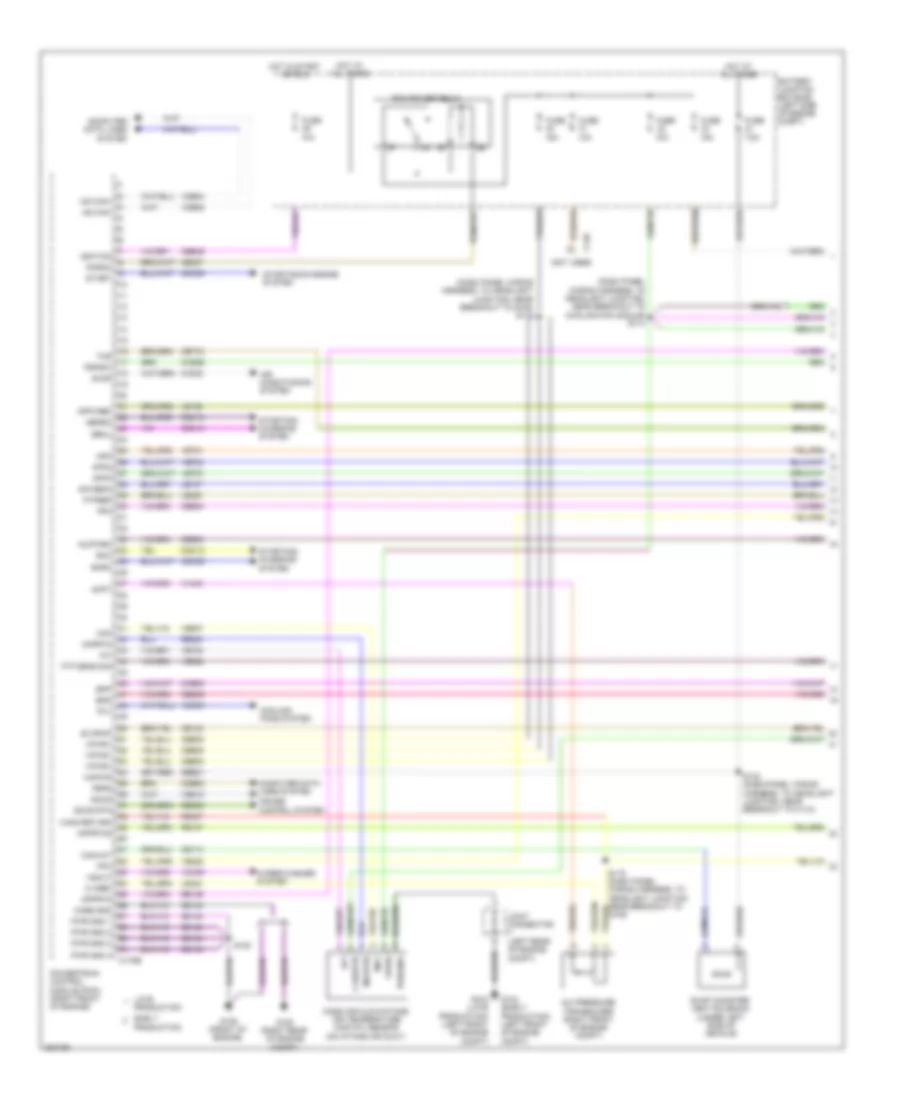
ENGINE PERFORMANCE
3.5L
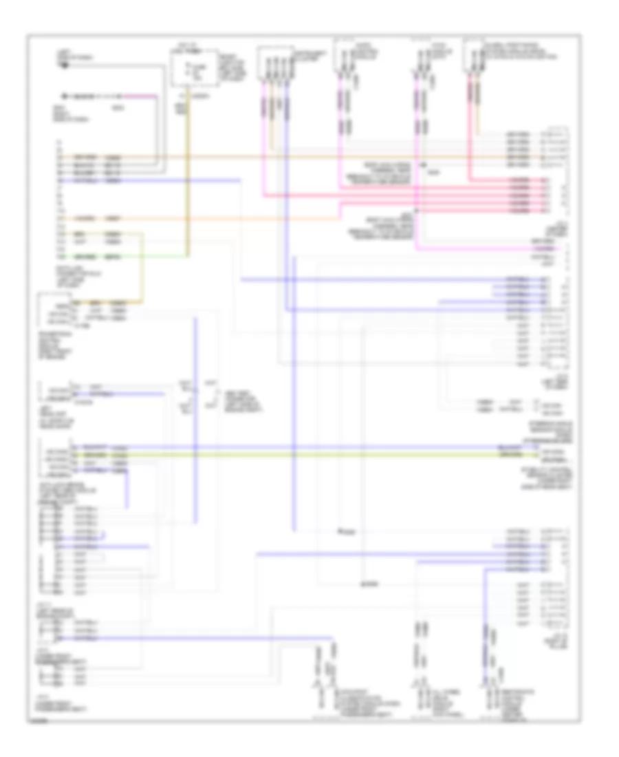
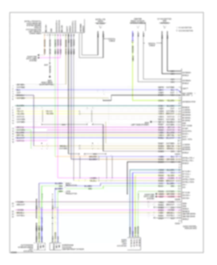
3.5L, Engine Performance Wiring Diagram (1 of 5) for Ford Edge SE 2010
List of elements for 3.5L, Engine Performance Wiring Diagram (1 of 5) for Ford Edge SE 2010:
- (dash panel wiring harness, to headlight junction, near breakout to cooling fan module) s113
- (dash panel wiring harness, to headlight junction, near breakout to g108) s117
- (not used)
- 10a
- 15a
- 7.5a
- A/c pressure transducer (right front of engine compt)
- Accr
- Acpt
- Air conditioning system
- App
- App2
- App3
- Apprtn
- Apprtn2
- Appvref
- Apvref2
- Battery junction box (bjb) (left side of engine compt)
- Bpp
- Bps
- C-sig return
- C-sigrtn
- C-vref
- C140
- C175b
- Canvnt
- Case gnd
- Cbb30
- Cbb49
- Ccb08
- Ccs09
- Cdb08
- Cdc10
- Cdc12
- Cdc15
- Cdc35
- Ce114
- Ce132
- Ce237
- Ce608
- Ces09
- Cet34
- Ch302
- Computer data lines system
- Cooling fans system
- Cruise control system
- Early production
- Evap canister vent solenoid (under left side of vehicle)
- Evapcp
- Fcv
- Feps
- Fpc
- Fpm
- Ftp sens sig
- Ftpref
- Fuse
- G104 (early production) (left front of engine compt)
- G105 (late production) (left front of engine compt)
- G108 (right rear of engine compt)
- G109 (front of engine)
- Gd124
- Genli
- Genrc
- Hot at all times
- Hot in start or run
- Hs can+
- Hs can-
- Iat
- Ignition
- Injpwrm
- Joint connector (left rear of engine compt)
- Kapwr
- Late
- Le136
- Le137
- Le230
- Le424
- Maf
- Mafrtn
- Mass air flow/intake air temperature (maf/iat) sensor (on intake air duct)
- Pcm power relay
- Pcrmc
- Powertrain control module (pcm) (right front of engine)
- Production
- Pspsw
- Pwr gnd 1
- Pwr gnd 2
- Pwr gnd 3
- Pwr gnd 4
- Pwrgnd
- Re136
- Re137
- Re320
- Re407
- Res08
- S119 (dash panel wiring harness, to headlight junction, near breakout to g109)
- S120
- S132 (dash panel wiring harness, to headlight junction, near breakout to c110)
- Sbb21
- Sccs
- Sccs rtn
- Smc
- Smrc
- Start
- Starting/ charging system
- Starting/charging system
- Tcs
- Vdb04
- Vdb05
- Ve225
- Ve701
- Ve702
- Ve703
- Ve740
- Ve807
- Ve922
- Vec03
- Ves10
- Vh433
- Vmc05
- Vpwr
- Vpwr1
- Vsout
- Wiper/washer system
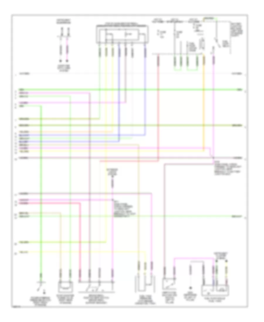
3.5L, Engine Performance Wiring Diagram (2 of 5) for Ford Edge SE 2010
List of elements for 3.5L, Engine Performance Wiring Diagram (2 of 5) for Ford Edge SE 2010:
- (top of accelerator pedal) accelerator pedal position (app) sensor
- 10a
- 15a
- Battery junction box (bjb) (left side of engine compt)
- Brake pedal position (bpp) switch (brake pedal support bracket)
- Computer data lines system
- Evap canister purge valve (right rear of engine)
- Exterior lights system
- Fuel pump module (fuel tank)
- Fuel pump motor diode
- Fuel pump relay
- Fuel tank pressure (ftp) sensor (inside fuel tank)
- Fuse
- G300 (near base of left "c" pillar)
- Hot at all times
- Hot in start or run
- Inertia fuel shutoff (ifs) switch (left "d" pillar)
- Instrument cluster (ic)
- Instrument cluster system
- Ms can+
- Ms can-
- Pnk
- Power steering pressure switch (right front of engine)
- S105 (dash panel wiring harness, to headlight junction, near breakout to battery junction box)
- S211 (dash panel wiring harness, to headlight junction, near breakout to joint connector 7)
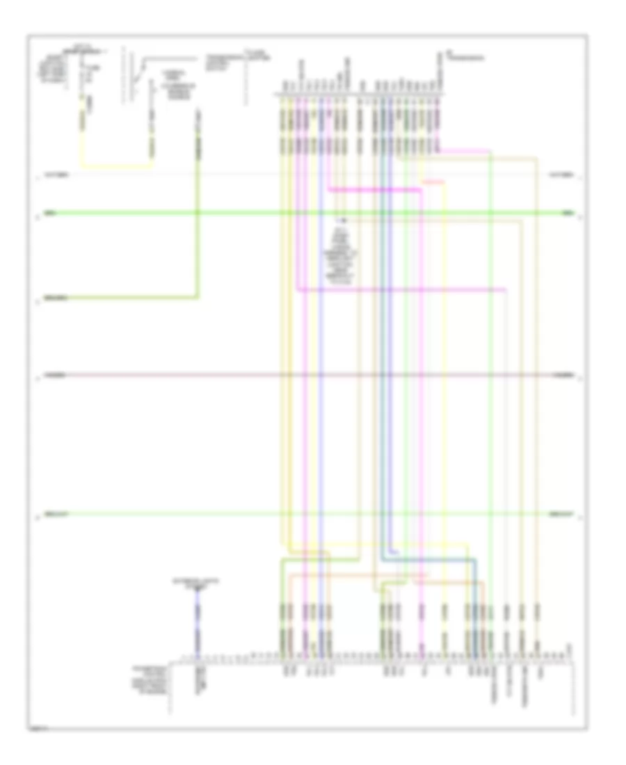
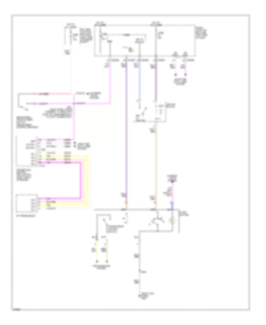
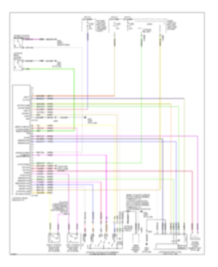
3.5L, Engine Performance Wiring Diagram (3 of 5) for Ford Edge SE 2010
List of elements for 3.5L, Engine Performance Wiring Diagram (3 of 5) for Ford Edge SE 2010:
- 1-normal
- 2-overdrive
- 6f transmission
- C175t
- C2280b
- Cet05
- Cet06
- Cet07
- Cet08
- Cet09
- Cet10
- Cet18
- Cet49
- Cls28
- Enable/ disable
- Exterior lights system
- Floor shifter
- Fuse
- Hot in start or run
- Le111
- Lpc
- Open
- Oss
- Powertrain control module (pcm) (right front of engine)
- Re406
- Ret24
- Reversing lmp ctrl
- S111 (dash panel wiring harness, to headlight junction, near breakout to c134)
- Smart junction box (sjb) (left side of dash)
- Ssa
- Ssb
- Ssc
- Ssd
- Sse
- Tcc
- Tft
- Tft sig rtn
- Tr gnd
- Tr-1
- Tr-2
- Tr-3
- Tr-4
- Transmission control switch
- Tspc
- Tss
- Tss/oss gnd
- Tss/oss vpwr
- Tss/oss/tr gnd
- Vet26
- Vet27
- Vet29
- Vet30
- Vet31
- Vet32
- Vet33
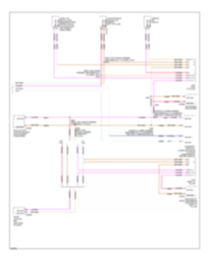
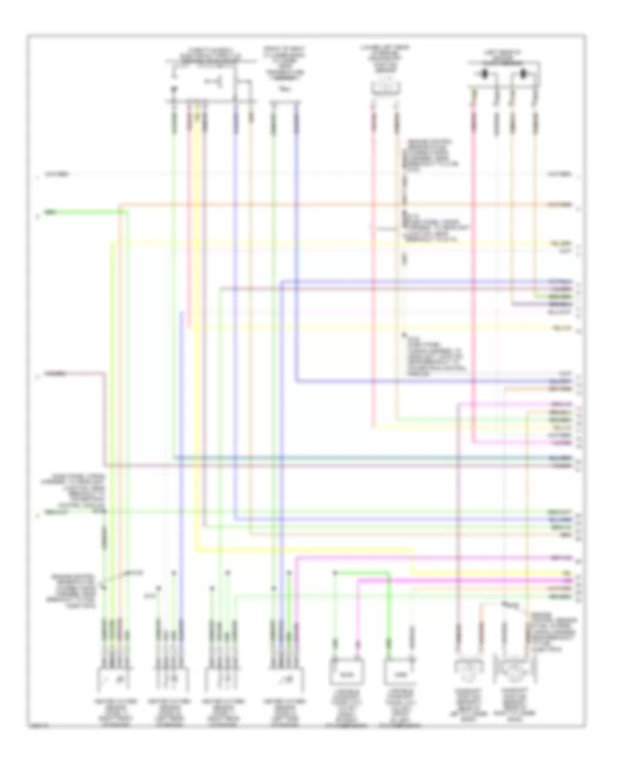
3.5L, Engine Performance Wiring Diagram (4 of 5) for Ford Edge SE 2010
List of elements for 3.5L, Engine Performance Wiring Diagram (4 of 5) for Ford Edge SE 2010:
- (dash panel wiring harness, to headlight junction, near breakout to powertrain control module) s121
- (engine control sensor & fuel charge wiring harness, near breakout to c139) s130
- (engine control sensor & fuel charge wiring harness, near breakout to fuel injector 6)
- (front of right cylinder bank) cylinder head temperature sensor
- (left rear of engine) knock sensor
- (lower left rear of engine) crankshaft position sensor
- (throttle body) electronic throttle control (etc) motor
- Camshaft position sensor 1 (rear of right cylinder bank)
- Camshaft position sensor 2 (rear of left cylinder bank)
- Heated oxygen sensor (ho2s) 11 (right rear of engine)
- Heated oxygen sensor (ho2s) 12 (right front of engine)
- Heated oxygen sensor (ho2s) 21 (left side of engine)
- Heated oxygen sensor (ho2s) 22 (left rear of engine)
- S122 (dash panel wiring harness, to headlight junction, near breakout to powertrain control module)
- S125
- S127
- S128
- Tan
- Variable camshaft timing (vct) valve 1 (front of right cylinder bank)
- Variable camshaft timing (vct) valve 2 (front of left cylinder bank)
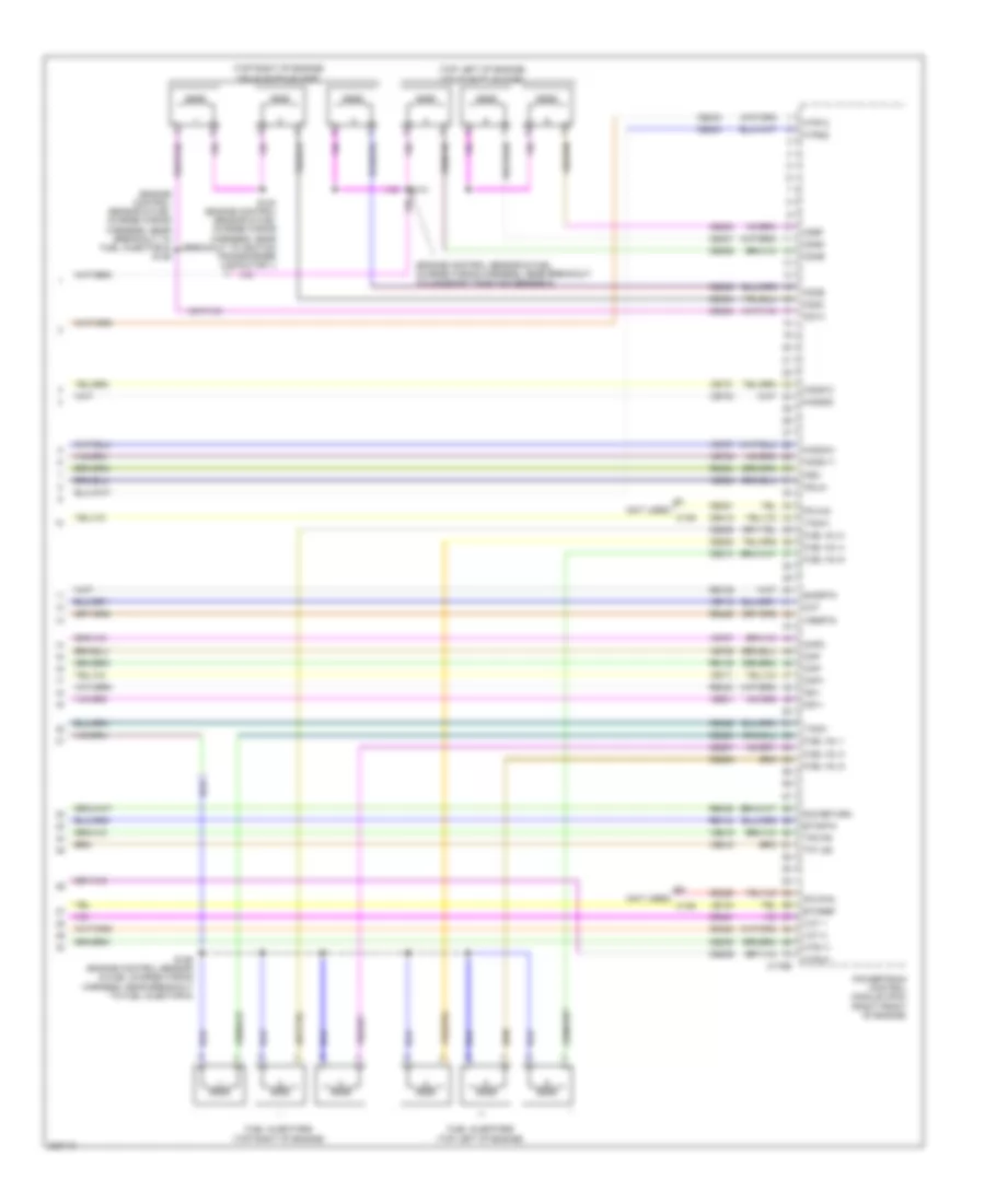
3.5L, Engine Performance Wiring Diagram (5 of 5) for Ford Edge SE 2010
List of elements for 3.5L, Engine Performance Wiring Diagram (5 of 5) for Ford Edge SE 2010:
- (engine control sensor & fuel charge wiring harness, near breakout to camshaft position sensor 2)
- (engine control sensor & fuel charge wiring harness, near breakout to fuel injector 5) s129
- (not used) c139
- (top left of engine) coils on plug (cop)
- (top right of engine) coils on plug (cop)
- C175e
- Cd1a
- Cd2c
- Cd3e
- Cd4b
- Cd5d
- Cd6f
- Ce205
- Ce206
- Ce207
- Ce208
- Ce209
- Ce210
- Ce233
- Ce234
- Ce235
- Ce236
- Ce303
- Ce304
- Ce305
- Ce306
- Ce307
- Ce308
- Ce321
- Ce328
- Ce412
- Ce421
- Ce422
- Ce426
- Cht
- Ckp+
- Ckp-
- Cmp
- Cmp2
- De135
- Etcref
- Etcrtn
- Fuel inj 1
- Fuel inj 2
- Fuel inj 3
- Fuel inj 4
- Fuel inj 5
- Fuel inj 6
- Fuel injectors (top left of engine)
- Fuel injectors (top right of engine)
- Ho2s-11
- Ho2s-21
- Ho2s12
- Ho2s22
- Htr-11
- Htr-21
- Htr12
- Htr22
- Ks1+
- Ks1-
- Ks2-
- Ksl2+
- Le134
- Pcvfhc
- Pcvhc
- Powertrain control module (pcm) (right front of engine)
- Re134
- Re135
- Re323
- Re324
- Re405
- Re429
- S124 (engine control sensor & fuel charge wiring harness, near breakout to ignition transformer capacitor 1)
- S126 (engine control sensor & fuel charge wiring harness, near breakout to fuel injector 6)
- S131
- Shdrtn
- Sig return
- Tacm+
- Tacm-
- Tp1 ns
- Tp2 ps
- Vct 1
- Vct 2
- Ve706
- Ve707
- Ve711
- Ve712
- Ve731
- Ve733
- Ve735
- Ve737
- Ve801
- Ve802
- Ve818
- Ve819
- Vrsrtn
EXTERIOR LIGHTS
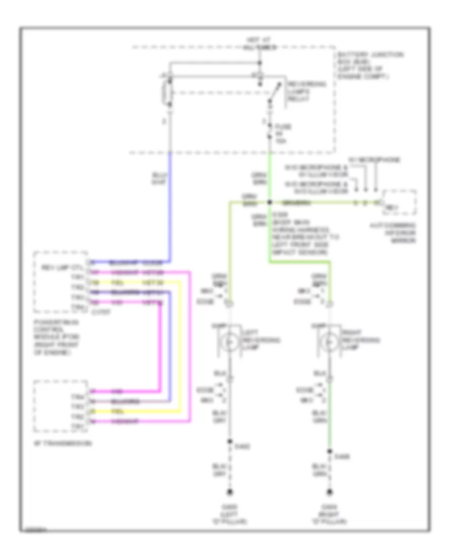
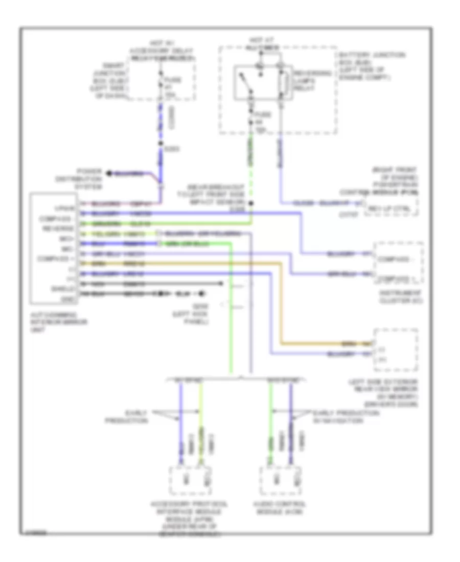
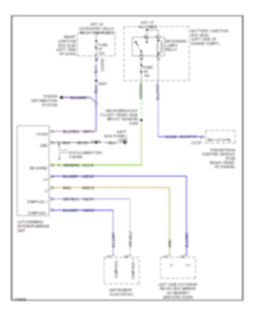
Backup Lamps Wiring Diagram for Ford Edge SE 2010
List of elements for Backup Lamps Wiring Diagram for Ford Edge SE 2010:
- (body main wiring harness, near breakout to left front side impact sensor)
- (right front of engine)
- 6f transmission
- Auto-dimming interior mirror
- Battery junction box (bjb) (left side of engine compt)
- C175t
- Cls28
- Edge
- Fuse 10a
- G400 (left "d" pillar)
- G404 (right "d" pillar)
- Hot at all times
- Left reversing lamp
- Mkx
- Powertrain control module (pcm)
- Rev
- Rev lmp ctl
- Reversing lamps relay
- Right reversing lamp
- S402
- S408
- Tr1
- Tr2
- Tr3
- Tr4
- Vet29
- Vet30
- Vet31
- Vet32
- W/ microphone
- W/o microphone & w/ illum visor
- W/o microphone & w/o illum visor
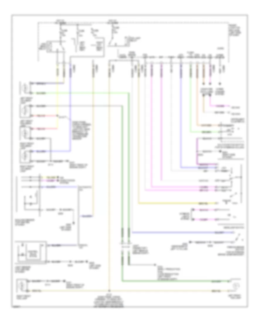
Exterior Lamps Wiring Diagram (1 of 2) for Ford Edge SE 2010
List of elements for Exterior Lamps Wiring Diagram (1 of 2) for Ford Edge SE 2010:
- Auto
- Bpp
- C2280b
- C2280d
- C2280e
- C2280f
- Computer data lines system
- Fuse 15a
- Fuse 6 20a
- G104 (early production) (left front of engine compt)
- G105 (late production) (left front of engine compt)
- G107 (right front of engine compt)
- G203 (right side of dash)
- Hazard
- Headlamp switch
- Hot at all times
- Joint connector 7 (left rear of engine compt)
- Left front park/turn lamp
- Left turn
- Lf turn lamp (fet)
- Low
- Low beam
- Lr stop turn lamp (fet)
- Micro
- Ms can+
- Ms can-
- Off
- Park
- Park lamp relay
- Rf turn lamp (fet)
- Right front park/turn lamp
- Right turn
- Rr stop turn lamp (fet)
- S109 (dash panel wiring harness, to headlight junction, near breakout to abs test connector)
- S114
- S232
- Smart junction box (sjb) (left side of dash)
- Turn
Exterior Lamps Wiring Diagram (2 of 2) for Ford Edge SE 2010
List of elements for Exterior Lamps Wiring Diagram (2 of 2) for Ford Edge SE 2010:
- (body main wiring harness, near breakout to left rear side impact sensor) s305
- (left side of engine compt)
- Battery junction box (bjb)
- Bpp
- Bps
- Brake pedal position (bpp) switch (brake pedal support bracket)
- C175b
- Ccb08
- Ce237
- Ces09
- Fuse 10a
- G203 (right side of dash)
- G400 (left "d" pillar)
- G404 (right "d" pillar)
- Hazard switch
- Hazard/ pad/ traction switch
- High mounted stop lamp
- Hot at all times
- Interior lights system
- Left rear marker lamp
- Left rear park/stop/ turn lamp
- Left turn
- License lamps
- Multi- function switch (top of steering column)
- Park
- Pcm power relay
- Pcm rly
- Powertrain control module (pcm) (right front of engine)
- Right rear marker lamp
- Right rear park/stop/ turn lamp
- Right turn
- S113 (dash panel wiring harness, to headlight junction, near breakout to cooling fan module)
- S211 (dash panel wiring harness, to headlight junction, near breakout to joint connector 7)
- S232
- S307 (body main wiring harness, near breakout to c700)
- S325 (body main wiring harness, near breakout to c311)
- S400
- S402
- S408
- Stop/ turn
- Trailer tow left stop/ turn relay
- Trailer tow park relay
- Trailer tow right stop/ turn relay
Trailer Adapter Wiring Diagram for Ford Edge SE 2010
List of elements for Trailer Adapter Wiring Diagram for Ford Edge SE 2010:
- (body main wiring harness, near breakout to c311) s325
- (body main wiring harness, near breakout to c700) s307
- Air conditioning system
- Anti-lock brakes system
- Battery junction box (bjb) (left side of engine compt)
- C2280d
- C2280e
- Cat06
- Cat09
- Cat11
- Exterior lamps circuit
- Fuse 15a
- Fuse 20a
- Fuse 24 10a
- Fuse 46 10a
- Fuse 9 20a
- G104 (early production) g105 (late production) (left front of engine compt)
- G400 (left "d" pillar)
- Hot at all times
- Joint connector 7 (left rear of engine compt)
- Lr stop/ turn lamp (fet)
- Micro
- Park lamp relay
- Rat08
- Rr stop/ turn lamp (fet)
- S109 (dash panel wiring harness, to headlight junction, near breakout to abs test connector)
- S402
- Smart junction box (sjb) (left side of dash)
- Starting/charging system
- Trailer tow connector (center of rear bumper)
- Trailer tow left stop/turn lamp relay
- Trailer tow park lamp relay
- Trailer tow right stop/turn lamp relay
GROUND DISTRIBUTION
Ground Distribution Wiring Diagram (1 of 4) for Ford Edge SE 2010
List of elements for Ground Distribution Wiring Diagram (1 of 4) for Ford Edge SE 2010:
- A/c compressor clutch diode
- A/c compressor clutch field coil
- Abs control module
- Abs test connector
- Air temperature sensor)
- Anti-theft hood switch
- Battery
- Battery junction box (bjb) (left side of engine compartment)
- Brake fluid level switch
- C1021a
- C1021b
- C1041a
- Cooling fan module
- Early production
- Edge
- From joint connector 7 a (diagram 1 of 4)
- G100 (left side of engine compartment)
- G101 (right rear of engine)
- G102 (early production) (left side of engine compartment)
- G103 (late production) (left side of engine compartment)
- G104 (early production) (left front of engine compartment)
- G105 (late production) (left front of engine compartment)
- G106 (right front of engine compartment)
- G107 (right front of engine compartment)
- G110 (engine ground) (edge: front of engine) (mkx: right front of engine)
- G111 (frame ground) (right rear of engine compartment)
- Horn
- Joint connector 7 (left rear of engine compartment)
- Joint connector 7 (left rear of engine compt)
- Late production
- Left front fog lamp
- Left front high beam lamp
- Left front low beam lamp
- Left front park/ turn lamp
- Left front side lamp
- Left headlamp
- Mass air flow/ intake air temperature (maf/iat) sensor
- Mkx
- Rear seat release relay
- Right front fog lamp
- Right front high beam lamp
- Right front low beam lamp
- Right front park/ turn lamp
- Right front side lamp
- Right headlamp
- Run/ start relay
- S110 (dash panel wiring harness, to headlight junction, near breakout to left headlight)
- Smart wiper module
- To joint connector 7 (diagram 1 of 4)
- Trailer tow left stop/turn lamp relay
- Trailer tow park lamp relay
- Trailer tow right stop/turn lamp relay
- W/ adaptive headlamps
- Washer fluid level switch
Ground Distribution Wiring Diagram (2 of 4) for Ford Edge SE 2010
List of elements for Ground Distribution Wiring Diagram (2 of 4) for Ford Edge SE 2010:
- (edge)
- (left rear of engine compt)
- (left side of dash)
- (mkx)
- All wheel drive (awd) module
- Auto- dimming interior mirror unit
- C175b
- C2280d
- C3299b
- C535b
- C9012
- C911
- Center interior lamps
- Driver seat module (dsm)
- Driver side door lock switch
- Driver side front power window motor
- Early production
- Exterior rear view mirror switch
- Floor shifter
- G108 (right rear of engine compartment)
- G109 (front of engine)
- G200 (left kick panel)
- G201 (left kick panel)
- G202 (right kick panel)
- Harness, near breakout to keyless entry keypad)
- Keyless entry keypad
- Late production
- Left front door lock actuator
- Left power seat switch
- Left rear heated seat module
- Left side exterior rear view mirror
- Left vanity mirror lamp
- Master window adjust switch
- Memory set switch
- Mkx
- Overhead console
- Parking aid module (pam)
- Passenger side door lock switch
- Passenger side front heated seat module
- Passenger side front power window motor
- Powertrain control module
- Right front door lock actuator
- Right rear door lock actuator
- Right rear seat heater switch
- Right side exterior rear view mirror
- Right side front power window switch
- Right vanity mirror lamp
- Roof opening panel motor assembly
- S120 (dash panel wiring harness, to headlight junction, near breakout to g109)
- S200 (body main wiring harness, near breakout to c510)
- S201 (body main wiring harness, near breakout to c212)
- S204 (body main wiring harness, near breakout to c214)
- S502 (left front window regulator wiring harness, near breakout to keyless entry keypad)
- S604 (right front window regulator wiring harness, near breakout to right front door lock actuator)
- S800 (right rear window regulator wiring harness, near breakout to right rear window adjust switch)
- S903 (interior lights wiring harness, near breakout to front interior lights)
- Smart junction box (sjb)
- W/ 10 way power seat
- W/ 10-way power seat
- W/ 6 way power seat
- W/ heated mirror
- W/ heated mirrors
- W/ heated rear seats
- W/ illumination visors
- W/ memory
- W/ microphone
- W/o illumination visors
Ground Distribution Wiring Diagram (3 of 4) for Ford Edge SE 2010
List of elements for Ground Distribution Wiring Diagram (3 of 4) for Ford Edge SE 2010:
- (automatic a/c) sunload sensor
- (body main wiring harness, near breakout to c316)
- (manual a/c) light sensor
- (w/ heated rear seats) left rear seat heater element
- (w/ heated rear seats) left rear seat heater switch
- (w/ sync & w/o navigation) global positioning system module (gpsm)
- Ambient lighting module
- Ambient lighting switch
- Audio control module (acm)
- Automatic a/c
- Blower motor resistor
- Blower motor speed control
- C218a
- C218b
- C228a
- C2357a
- C2357b
- C240a
- C3036a m
- C3299a
- Cargo lamp
- Clock- spring
- Console 1 power point
- Console 2 power point
- Data link connector
- Data link connector (dlc)
- Datc hvac module
- Driver seat module (dsm)
- Dual climate controlled seat module (dcsm)
- Emtc hvac module
- Fuel pump module
- G203 (right side of dash)
- G204 (left side of dash)
- G205 (left side of dash)
- G206 (left side of dash)
- G207 (steering wheel)
- G300 (near base of left "c" pillar)
- G302 (right "b" pillar)
- Hazard/pad traction switch
- Headlamp switch
- Instrument cluster (ic)
- Instrument panel power point
- Left front heated seat element
- Left power seat switch
- Left rear door lock actuator
- Left rear seat release actuator
- Left steering wheel switch
- Manual a/c
- Message center switch
- Mkx
- Multifunction switch
- Parking brake switch
- Passive anti-theft transceiver
- Power liftgate release switch
- Rear console power point
- Right front heated seat element
- Right power seat switch
- Right steering wheel switch
- S208 (body main wiring harness, near breakout to audio unit)
- S232 (body main wiring harness, near breakout to in-vehicle temperature sensor)
- S233 (body main wiring harness, near breakout to g203)
- S301 (w/ heated rear seats) (seat heated pad wiring harness, near breakout to c300)
- S306 (body main wiring harness, near breakout to g300)
- S349 (console jumper harness, near breakout to c313)
- S700 (w/ heated rear seats) (left rear window regulator wiring harness, near breakout to left rear window adjust switch)
- Steering angle sensor module (sasm)
- W/ 10 way power seat
- W/ 6 way power seat
- W/ climate controlled seats
- W/ heated seats
- W/ memory
- W/o memory
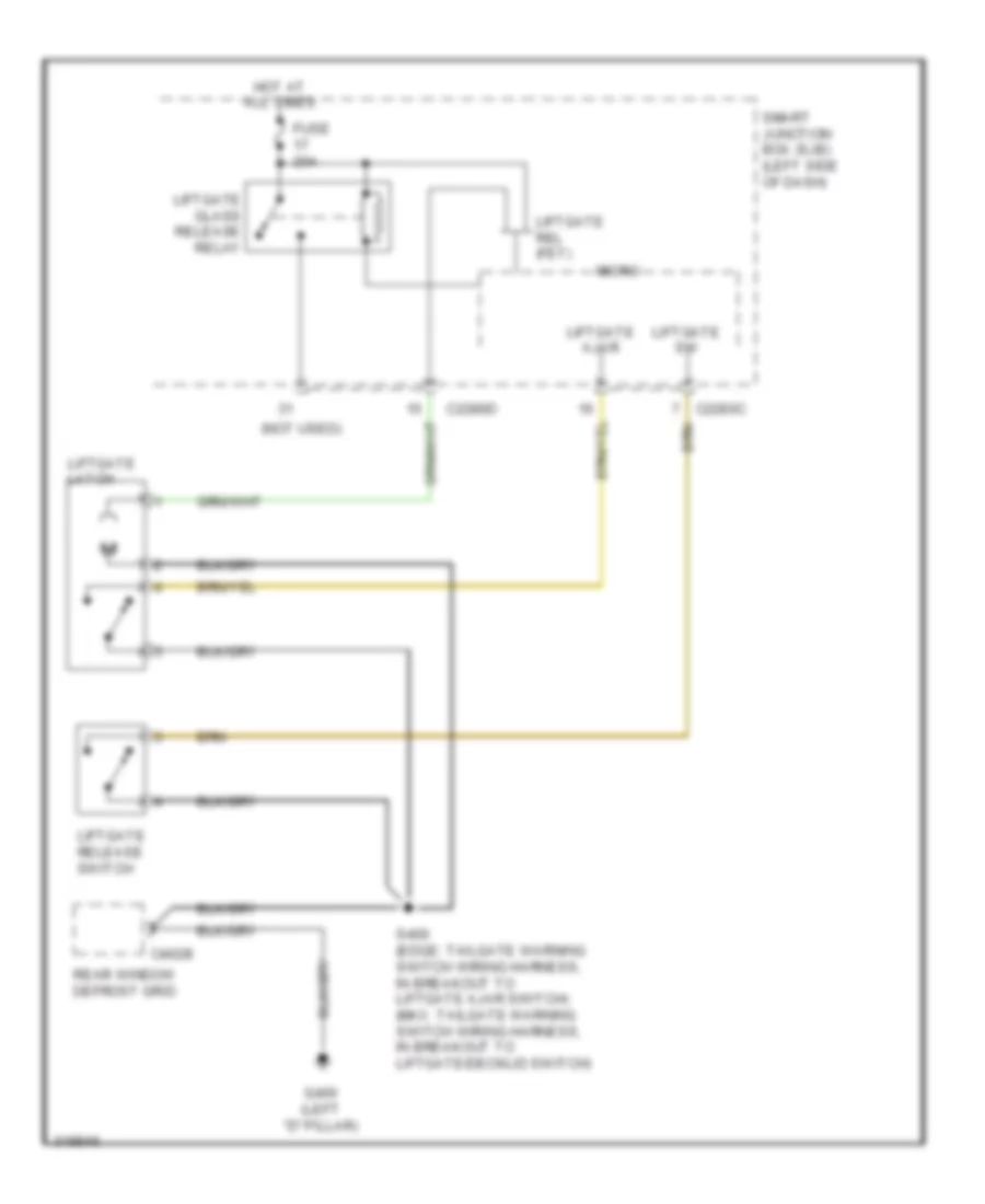
Ground Distribution Wiring Diagram (4 of 4) for Ford Edge SE 2010
List of elements for Ground Distribution Wiring Diagram (4 of 4) for Ford Edge SE 2010:
- (body main wiring harness, near breakout to g402) s407
- (console jumper harness, near breakout to accessory protocol interface module)
- (edge)
- (late production) microphone
- (mkx)
- (w/ thx audio & w/ sync) accessory protocol interface module (apim)
- (w/o thx audio & w/ sync) accessory protocol interface module (apim)
- Accessory protocol interface module (apim)
- Accessory protocol interface module)
- Audio amplifier
- Audio digital signal processing (dsp) module
- C402b
- C4174a
- C4348c
- C451
- C487
- Cargo area power point
- Driver safety belt buckle switch
- Early production
- Edge
- Edge w/ navigation
- G301 (left "b" pillar)
- G400 (left "d" pillar)
- G401 (left "d" pillar)
- G402 (right "c" pillar)
- G403 (right "c" pillar)
- G404 (right "d" pillar)
- High mounted stop lamp
- Left front seat track position sensor
- Left license plate lamp
- Left rear marker lamp
- Left rear park/ stop/ turn lamp
- Left reversing lamp
- License lamps
- Lift gate latch
- Liftgate latch/unlatch assembly
- Liftgate module)
- Liftgate motor/ clutch
- Liftgate rear control switch
- Liftgate release switch
- Liftgate/ trunk module (ltm)
- Mkx
- Mkx, w/ thx audio
- Nca
- Occupant classification system module (ocsm)
- Passenger safety belt buckle switch
- Rear window defrost grid
- Rear window wiper motor
- Right license plate lamp
- Right rear marker lamp
- Right rear park/ stop/ turn lamp
- Right rear seat heater element
- Right rear seat release actuator
- Right reversing lamp
- S323 (power seats wiring harness, near breakout to driver's safety belt buckle pretensioner)
- S352
- S400 (edge: tailgate warning switch wiring harness, in breakout to liftgate ajar switch) (mkx: tailgate warning switch wiring harness, in breakout to liftgate/decklid switch)
- S402 (body main wiring harness, near breakout to cargo area power point)
- S404 (backup alarm wiring harness, near breakout to left license plate light)
- S407 (body main wiring harness, near breakout to g402)
- S408 (body main wiring harness, near breakout to right rear park/stop/turn light)
- Satellite digital audio receiver system (sdars) module
- Stability control sensor cluster
- Subwoofer
- Trailer tow connector
- W/ power liftgate
- W/ premium sound
- W/ premium sound & w/ sync
- W/o audio thx
- W/o power liftgate
HEADLIGHTS
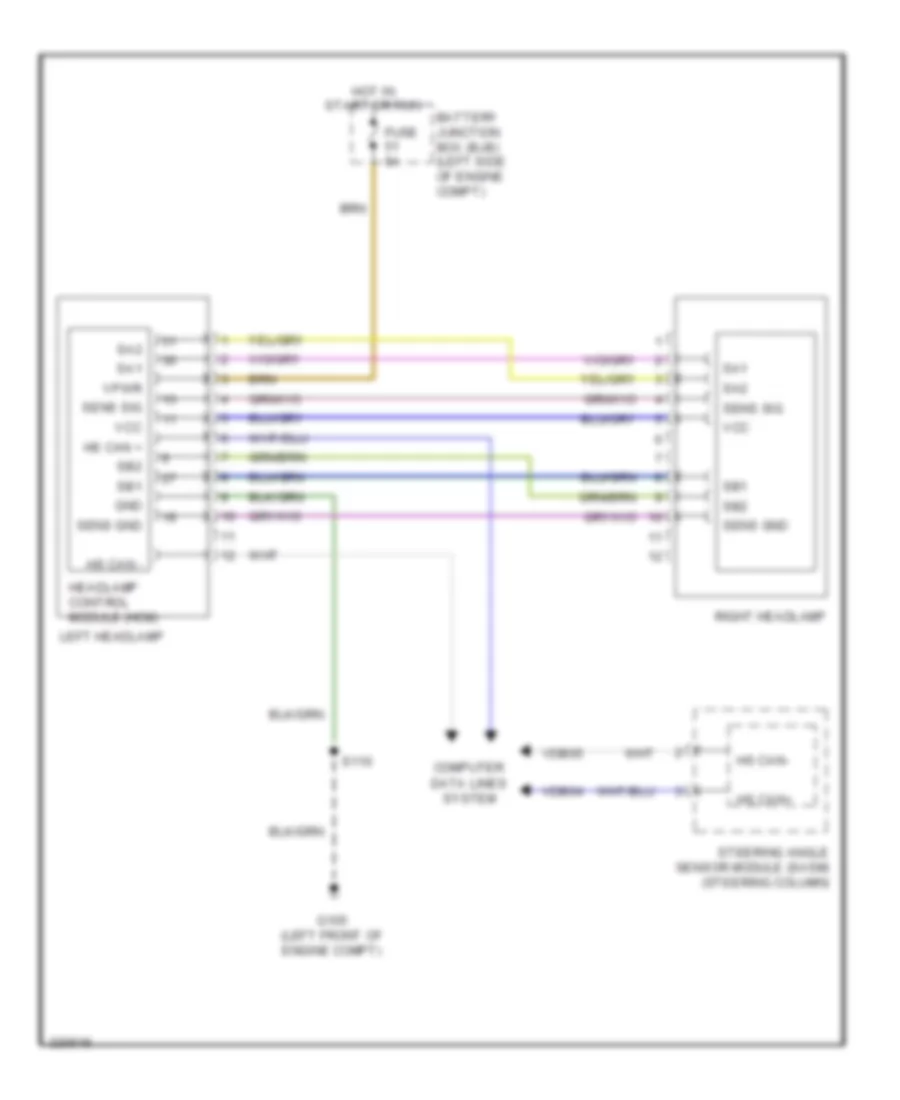
Adaptive Front Lighting Wiring Diagram for Ford Edge SE 2010
List of elements for Adaptive Front Lighting Wiring Diagram for Ford Edge SE 2010:
- Battery junction box (bjb) (left side of engine compt)
- Computer
- Data lines system
- Fuse 5a
- G105 (left front of engine compt)
- Gnd
- Headlamp control module (hcm)
- Hot in start or run
- Hs can +
- Hs can -
- Hs can+
- Hs can-
- Left headlamp
- Right headlamp
- S110
- Sa1
- Sa2
- Sb1
- Sb2
- Sens gnd
- Sens sig
- Steering angle sensor module (sasm) (steering column)
- Vcc
- Vdb04
- Vdb05
- Vpwr
Headlamps Wiring Diagram for Ford Edge SE 2010
List of elements for Headlamps Wiring Diagram for Ford Edge SE 2010:
- (dash panel wiring harness, to headlight junction, near breakout to a/c pressure transducer sensor)
- Air conditioning system
- Auto
- Auto- lamps
- Automatic a/c
- C2280a
- C2280b
- C2280c
- C2280e
- C2280f
- Computer data lines system
- Control solid state
- Flash to pass
- Fog
- Fog ind
- Fog lamp
- Fog lamp relay
- Ftp
- Fuse 10a
- Fuse 15a
- G104 (early production) g105 (late production) (left front of engine compt)
- G107 (right front of engine compt)
- G203 (right side of dash)
- G205 (left side of dash)
- G300 (near base of left "c" pillar)
- Headlamp switch
- Hi beam
- High beam
- High beam relay
- Hot at all times
- Ill
- Instrument cluster (ic)
- Interior lights system
- Joint connector 7 (left rear of engine compt)
- Left front fog lamp
- Left front high beam lamp
- Left front low beam lamp
- Left low beam (fet)
- Light sensor (top center of dash)
- Low
- Low beam
- Manual a/c
- Micro
- Ms can+
- Ms can-
- Multi-function switch (top of steering column)
- Off
- Park
- Park brake sw
- Parking brake switch (top of parking brake lever bracket)
- Right front fog lamp
- Right front high beam lamp
- Right front low beam lamp
- Right low beam (fet)
- S114
- S115 (dash panel wiring harness, to headlight junction, near breakout to mass air flow/intake air temperature sensor)
- S116
- S208
- S232
- S306
- Smart junction box (sjb) (left side of dash)
- Sunload sensor (top center of dash)
- Wiper status
- Wiper/ washer system
HORN
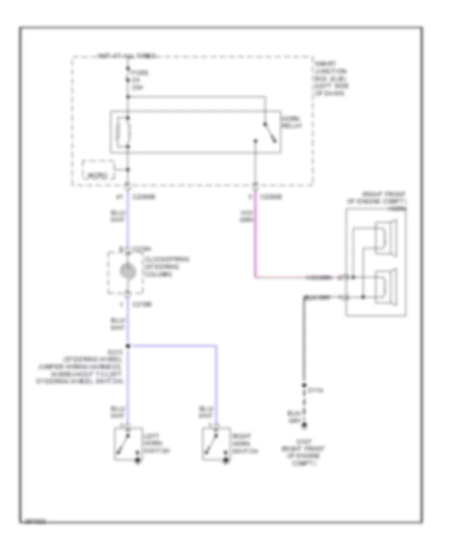
Horn Wiring Diagram for Ford Edge SE 2010
List of elements for Horn Wiring Diagram for Ford Edge SE 2010:
- (right front of engine compt) horn
- C218a
- C218b
- C2280b
- C2280e
- Clockspring (steering column)
- Fuse 20a
- G107 (right front of engine compt)
- Horn relay
- Hot at all times
- Left horn switch
- Micro
- Right horn switch
- S114
- S213 (steering wheel jumper wiring harness, in breakout to left steering wheel switch)
- Smart junction box (sjb) (left side of dash)
INSTRUMENT CLUSTER
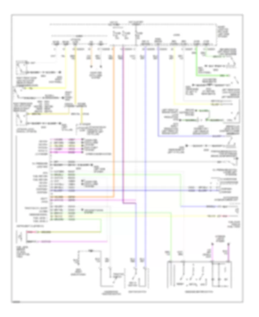
Instrument Cluster Wiring Diagram for Ford Edge SE 2010
List of elements for Instrument Cluster Wiring Diagram for Ford Edge SE 2010:
- (driver's door) left front door lock actuator
- (left front of engine compt) (late production) g105
- (rear of right rear door)
- (right kick panel) g202
- (w/ heated
- (w/o heated rear seats) s306
- A/c req
- Air conditioning system
- Anti-theft system
- Auto-dimming interior mirror unit
- Brake fluid level switch (master cylinder reservoir)
- Brk fl rtn
- Brk fl sw
- C228oa
- C228ob
- C228oc
- C228of
- C4174b
- Cbp29
- Cca15
- Ch434
- Cmc20
- Cmc24
- Cmc29
- Compass+
- Compass-
- Computer data lines system
- Cpl60
- Fuel level 1
- Fuel level 2
- Fuel level sensor (w/ awd) (top of fuel tank)
- Fuel pump module (fuel tank)
- Fuel return
- Fuse 10a
- Fuse 20a
- Fuse 5a
- G104 (early production) (left front of engine compt)
- G201 (left kick panel)
- G202 (right kick panel)
- G203 (right side of dash)
- G205 (left side of dash)
- G300 (near base of left "c" pillar)
- G400 (left "d" pillar)
- Gd115
- Ground distribution system
- Hazard/pad/ traction switch
- Hot at all times
- Hot in start or run
- Hs can+
- Hs can-
- Ignition
- Ignition switch
- Info
- Instrument cluster (ic)
- Interior lights system
- Joint connector 7 (left rear of engine compt)
- Key in
- Key in ignition
- Left rear door lock actuator (rear of left rear door)
- Lf dr ajar
- Liftgate ajar
- Liftgate ajar sw
- Liftgate latch (manual liftgate)
- Liftgate/trunk module (ltm) (base of left "d" pillar)
- Lo washer
- Logic gnd
- Lr dr ajar
- Manual liftgate
- Message center switch
- Message signal
- Micro
- Ms can+
- Ms can-
- Oil pressure
- Oil pressure switch (lower left of engine)
- Park brake sw
- Parking brake switch (top of parking brake lever bracket)
- Pats rx
- Pats tx
- Pnk
- Power liftgate
- Reset
- Rf dr ajar
- Right front door lock actuator (rear of front passenger's door)
- Right rear door lock actuator
- Rmc27
- Rmc32
- Rmc33
- Rr dr ajar
- Rtn
- S208
- S232
- S306
- S400
- S502
- S604
- S700 (w/ heated rear seats)
- S800 s204 (w/o heated rear rear seats) seats)
- Sbp26
- Setup
- Smart junction box (sjb) (left side of dash)
- Switch
- Traction
- Traction ctl on/off
- Vbatt
- Vdb04
- Vdb05
- Vdb06
- Vdb07
- Vmc11
- Vmc23
- Vmc30
- Vmc31
- Vpwr
- Vrt23
- Vrt24
- W/ microphone
- W/o microphone
- Wiper/washer system
INTERIOR LIGHTS
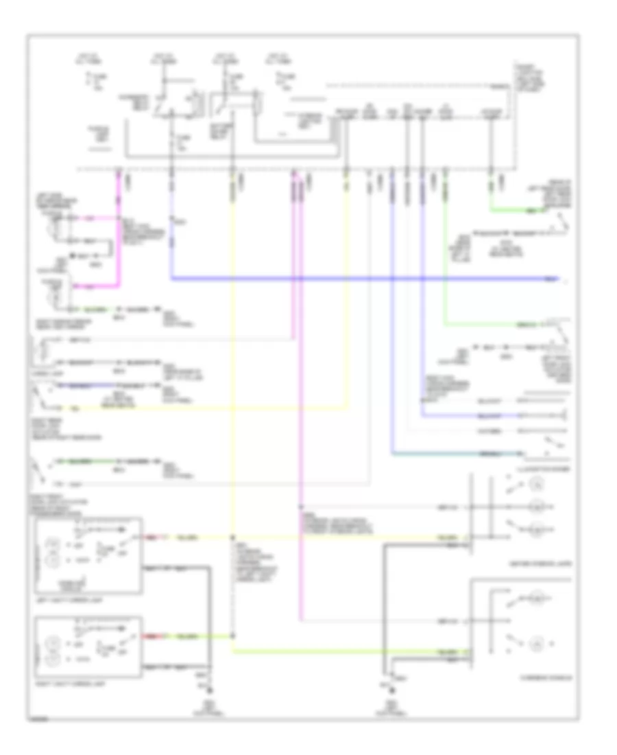
Courtesy Lamps Wiring Diagram (1 of 2) for Ford Edge SE 2010
List of elements for Courtesy Lamps Wiring Diagram (1 of 2) for Ford Edge SE 2010:
- (body main wiring harness, near breakout to c210) s210
- (rear of left rear door) left rear door lock actuator
- Accessory
- Battery saver relay
- C2280a
- C2280b
- C2280c
- C2280d
- Cargo lamp
- Center interior lamps
- Delay relay
- Dim sw gnd
- Dimmer sw
- Dom lp
- Fuse 10a
- Fuse 15a
- Fuse 2a
- G201 (left kick panel)
- G202 (right kick panel)
- G300 (near base of left "c" pillar)
- Homelink module
- Hot at all times
- Illumination dimmer
- Interior lighting (fet)
- Left front door lock actuator (driver's door)
- Left side exterior rear view mirror
- Left vanity mirror lamp
- Lf door ajar
- Lr door ajar
- Micro
- Off
- Overhead console
- Puddle lamp
- Puddle lamp (fet)
- Red
- Rf door ajar
- Right front door lock actuator (rear of front passenger's door)
- Right rear door lock actuator (rear of right rear door)
- Right side exterior rear view mirror
- Right vanity mirror lamp
- Rr door ajar
- S203
- S306
- S315 (body main wiring harness, near breakout to g311)
- S502
- S604
- S700 (w/ heated rear seats)
- S800 (w/ heated rear seats)
- S901 (interior lights wiring harness, near breakout to left vanity mirror light)
- S903
- S906 (interior lights wiring harness, near breakout to front interior lights)
- Smart junction box (sjb) (left side of dash)
Courtesy Lamps Wiring Diagram (2 of 2) for Ford Edge SE 2010
List of elements for Courtesy Lamps Wiring Diagram (2 of 2) for Ford Edge SE 2010:
- Ambient lighting module (under center console)
- Ambient lighting switch
- Cbx07
- Cln44
- Cln45
- Cln46
- Cln54
- Front cupholder lamp
- G302 (right "b" pillar)
- Gd908
- Gnd
- Instrument illumination circuit
- Left front footwell lamp
- Left rear footwell lamp
- Rear cupholder lamp
- Red
- Return
- Right front footwell lamp
- Right rear footwell lamp
- Rln44
- S349
- S364
- S365
- S366
- S367
- S368
- S369
- S370
- S371
- S372
- S373
- S374
- S375
- Storage bin lamp
- Storage bin switch
- Storage tray lamp
Instrument Illumination Wiring Diagram for Ford Edge SE 2010
List of elements for Instrument Illumination Wiring Diagram for Ford Edge SE 2010:
- (body main wiring harness, near breakout to c210) s210
- (body main wiring harness, near breakout to g200) s311
- (body main wiring harness, near breakout to in-vehicle temperature sensor) s209
- Ambient lighting switch
- Auto
- Backlighting led (fet)
- C218a
- C218b
- C2280b
- C2357a
- Clockspring (steering column)
- Dim sw gnd
- Dimmer sw
- Dome lamp
- Floor shifter
- Fuse 15a
- G202 (right kick panel)
- G203 (right side of dash)
- G205 (left side of dash)
- G302 (right "b" pillar)
- Gd115
- Hazard/pad/traction switch
- Headlamp switch
- Hot at all times
- Hvac module emtc
- Illumination dimmer
- Left steering wheel switch
- Low
- Low beam
- Message center switch
- Micro
- Off
- Park
- Power liftgate release switch
- Right steering wheel switch
- S204
- S208
- S212
- S215 (steering wheel jumper wiring harness, in breakout to right steering wheel switch)
- S232
- S349
- Smart junction box (sjb) (left side of dash)
- Vln04
MEMORY SYSTEMS
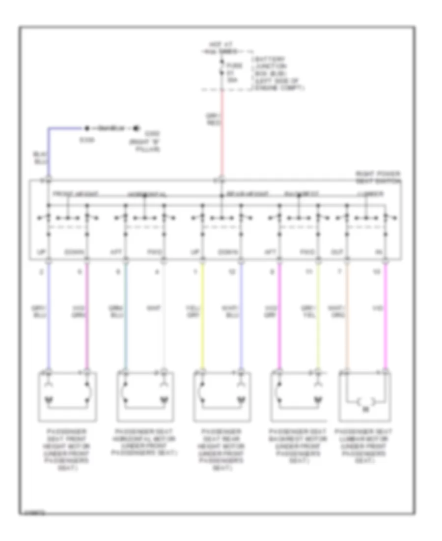
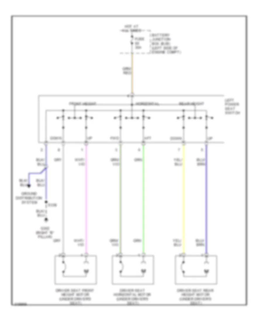
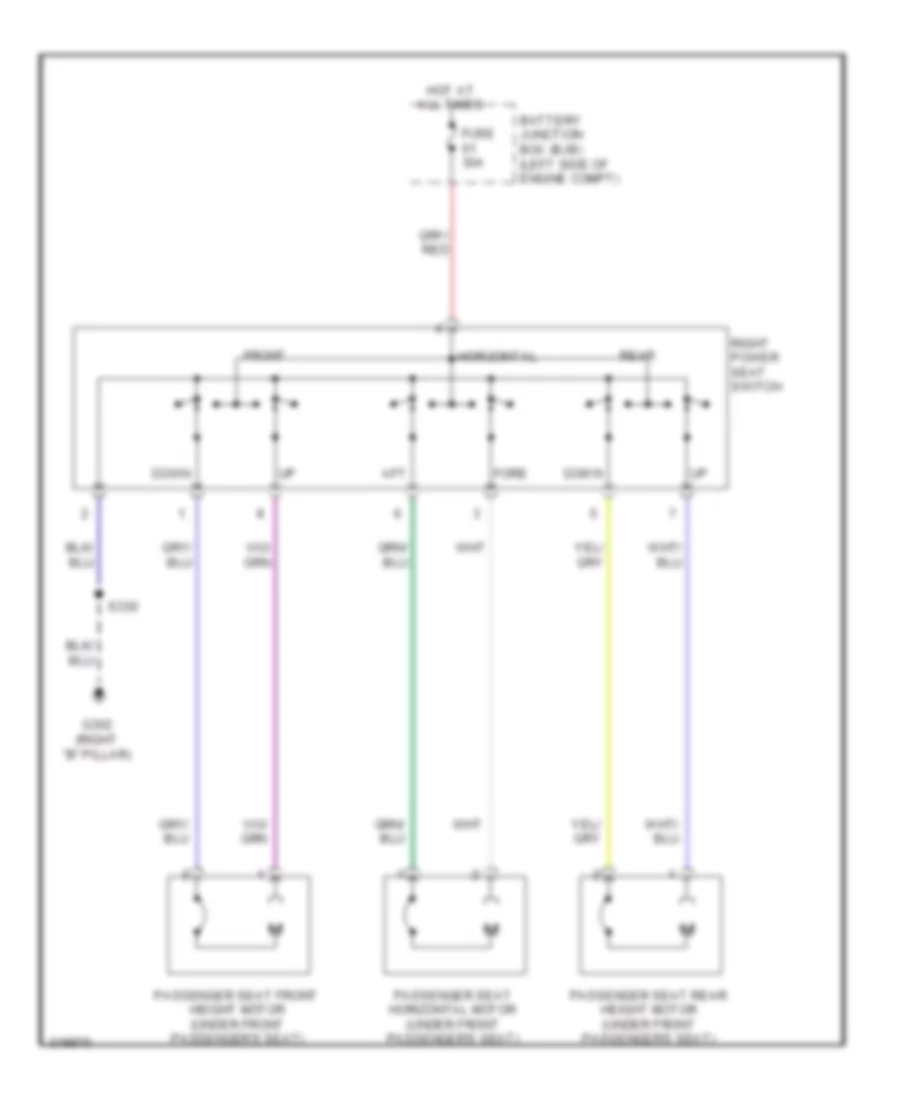
Driver"s Memory Seat Wiring Diagram (1 of 2) for Ford Edge SE 2010
List of elements for Driver"s Memory Seat Wiring Diagram (1 of 2) for Ford Edge SE 2010:
- (right "b" pillar) g302
- 10-way seats
- 6-way seats
- Aft
- Backrest
- Backrest bckw
- Backrest forw
- Base bckw
- Base forw
- C3299a
- C3299b
- Cps01
- Cps02
- Cps03
- Cps04
- Cps05
- Cps06
- Cps07
- Cps08
- Cps23
- Cps24
- Cps25
- Cps26
- Cps27
- Cps28
- Cps29
- Cps30
- Driver seat backrest motor (10-way seats) (under driver's seat)
- Driver seat front height motor (under driver's seat)
- Driver seat horizontal motor (under driver's seat)
- Driver seat lumbar motor (10-way seats) (under driver's seat)
- Driver seat module (dsm)
- Driver seat rear height motor (under driver's seat)
- Forw
- Front
- Front dn
- Front up
- Fuse 7.5a
- Fwd
- G200 (left kick panel)
- Gd133
- Gd145
- Ground distribution system
- Hall efft rtn
- Hall efft sense
- Horizontal
- Hot at all times
- Left power seat switch
- Logic gnd
- Lumbar
- Out
- Pwr gnd
- Rear
- Rear dn
- Rear up
- Rps13
- S200
- S322
- S324 (power seats wiring harness, near breakout to driver's safety belt buckle pretensioner)
- S338
- Sbb60
- Sbp12
- Smart junction box (sjb) (left side of dash)
- Vbatt
- Vps09
- Vps10
- Vps11
- Vps12
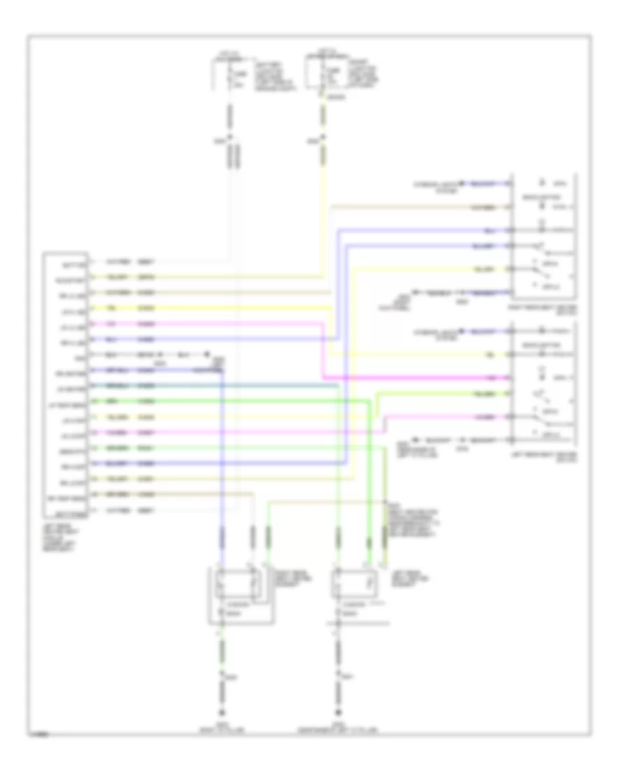
Driver"s Memory Seat Wiring Diagram (2 of 2) for Ford Edge SE 2010
List of elements for Driver"s Memory Seat Wiring Diagram (2 of 2) for Ford Edge SE 2010:
- 10-way seats
- 6-way seats
- Battery junction box (bjb) (left side of engine compt)
- C3299c
- C3299d
- Computer data lines system
- Cpm16
- Cpm17
- Cpm20
- Cpm21
- Cpm23
- Cpm26
- Cpm28
- Cpm29
- Cpm31
- Cpm33
- Cpm34
- Cps15
- Cps16
- Driver seat module (dsm)
- Drv hor pot
- Drv mirr hor sw
- Drv mirr vert sw
- Drv mtr hor rt
- Drv mtr vert dn
- Drv mtr vert up
- Drv vert pot
- Ext mirr pot feed
- Fuse 30a
- G200 (left kick panel)
- G201 (left kick panel)
- Hot at all times
- Illumination (10-way seats)
- Interior lights system
- Lpm30
- Memory mirrors circuit
- Memory set switch
- Mirr com sw
- Mirr pot ret
- Ms can +
- Ms can -
- Pass hor pot
- Pass mirr hor sw
- Pass mirr vert sw
- Pass mtr hor rt
- Pass mtr vert dn
- Pass mtr vert up
- Pass vert pot
- Rpm30
- S502
- S503
- Set 1
- Set 2
- Vdb06
- Vdb07
- Vpm35
- Vpm36
- Vpm37
- Vpm38
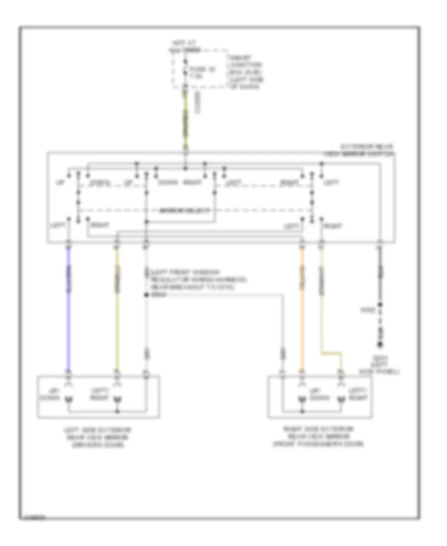
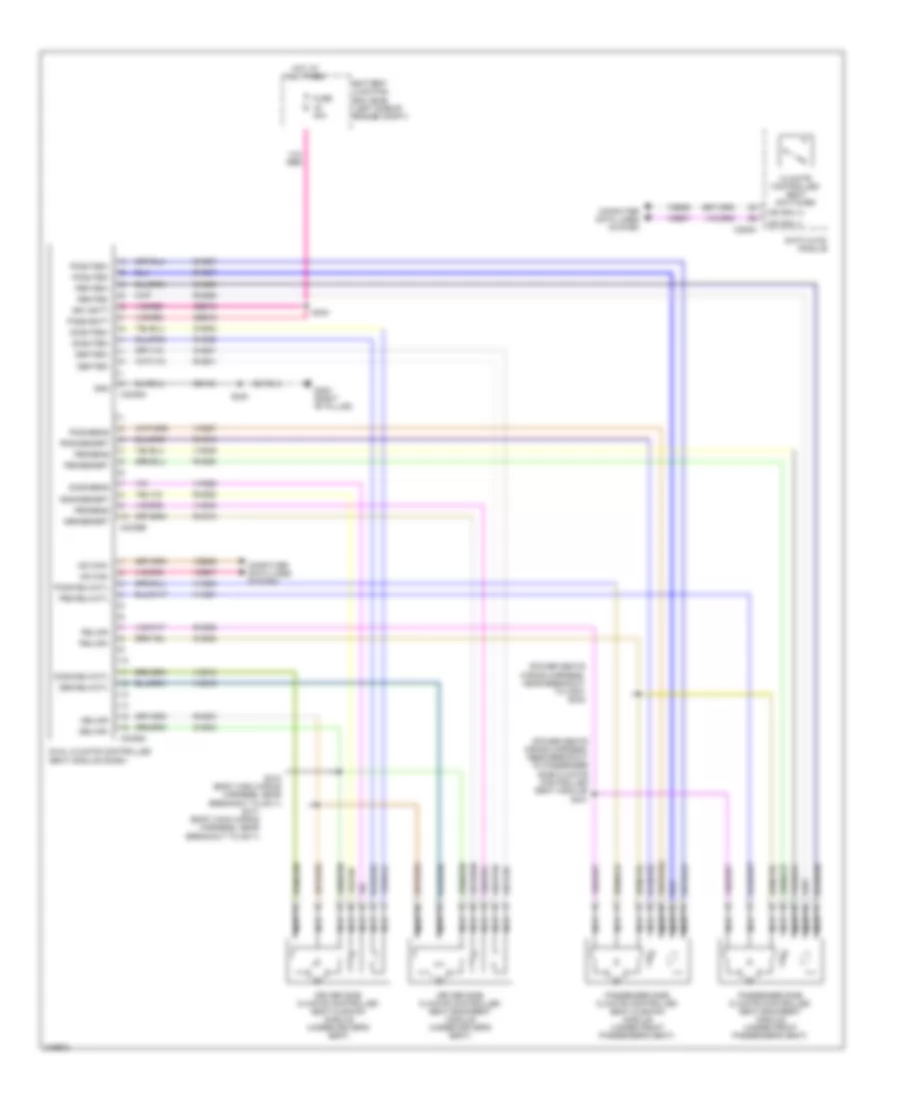
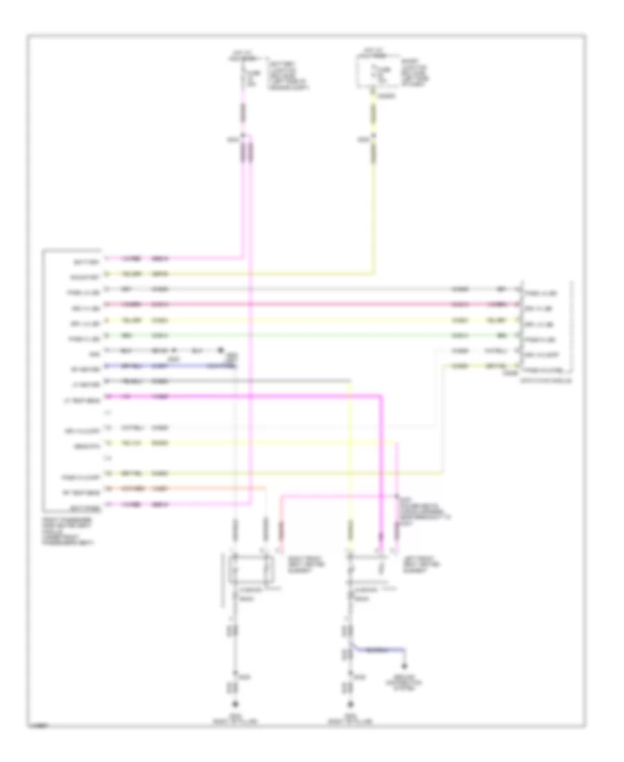
Memory Mirrors Wiring Diagram for Ford Edge SE 2010
List of elements for Memory Mirrors Wiring Diagram for Ford Edge SE 2010:
- (right "b" pillar) g302
- 10-way seats
- 6-way seats
- Battery junction box (bjb) (left side of engine compt)
- C3299a
- C3299b
- C3299c
- C3299d
- Computer data lines system
- Cpm16
- Cpm17
- Cpm20
- Cpm21
- Cpm23
- Cpm26
- Cpm28
- Cpm29
- Cpm31
- Cpm33
- Cpm34
- Cps15
- Cps16
- Defogger system
- Driver seat module (dsm)
- Drv hor pot
- Drv mirr hor sw
- Drv mirr vert sw
- Drv mtr hor rt
- Drv mtr vert dn
- Drv mtr vert up
- Drv vert pot
- Ext mirr feed
- Exterior rear view mirror switch
- Fuse 30a
- Fuse 7.5a
- G200 (left kick panel)
- G201 (left kick panel)
- Gd145
- Hot at all times
- Illumination
- Illumination (10-way seats)
- Interior lights system
- Left side exterior rear view mirror (driver's door)
- Left/ right
- Left/right motor
- Lpm30
- Memory set switch
- Mirr com sw
- Mirr rtn
- Mirror heated
- Mirrors system
- Motor left/right
- Ms can +
- Ms can -
- Pass hor pot
- Pass mirr hor sw
- Pass mirr vert sw
- Pass mtr hor rt
- Pass mtr vert dn
- Pass mtr vert up
- Pass vert pot
- Pwr gnd
- Right left/
- Right side exterior rear view mirror (front passenger's door)
- Rpm30
- S338
- S502
- S503
- S505
- S606
- Sbb60
- Sbp12
- Select mirror switch l
- Set 1
- Set 2
- Smart junction box (sjb) (left side of dash)
- Up/dn
- Up/dn motor
- Vbatt
- Vdb06
- Vdb07
- Vpm35
- Vpm36
- Vpm37
- Vpm38
NAVIGATION
Navigation Wiring Diagram, with THX (1 of 3) for Ford Edge SE 2010
List of elements for Navigation Wiring Diagram, with THX (1 of 3) for Ford Edge SE 2010:
- Audio digital signal processing (dsp) module (right "c" pillar)
- Audio in left+
- Audio in left-
- Audio in right+
- Audio in right-
- C2280d
- C4348a
- C4348b
- C4348c
- Cen csa spkr+
- Cen csa spkr-
- Center
- Center spkr+
- Center spkr-
- Cme31
- Computer data lines system
- Enable
- Fuse 20a
- G402 (right "c" pillar)
- Gd148
- Gnd
- Hot at all times
- Instrument panel speaker
- Joint connector 9 (right "c" pillar)
- Left
- Left front tweeter
- Left rear tweeter
- Lf door +
- Lf door-
- Lf spkr +
- Lf spkr -
- Lh csa spkr+
- Lh csa spkr-
- Lr spkr +
- Lr spkr -
- Lr spkr+
- Lr spkr-
- Ms can +
- Ms can -
- Nav voice+
- Nav voice-
- Rear center+
- Rear center-
- Rf door +
- Rf door-
- Rf spkr +
- Rf spkr-
- Rh csa spkr+
- Rh csa spkr-
- Right
- Right front tweeter
- Right rear tweeter
- Rme01
- Rme02
- Rme06
- Rme07
- Rme08
- Rme09
- Rme10
- Rme11
- Rme12
- Rme22
- Rme28
- Rme29
- Rme30
- Rme51
- Rme58
- Rme59
- Rr spkr+
- Rr spkr-
- S339
- S340
- S407
- Sbp18
- Sbp38
- Smart junction box (sjb) (left side of dash)
- Sub+
- Sub-
- Subw 1+
- Subw 2 +
- Subw1-
- Subw2-
- Subwoofer
- Vbatt
- Vdb06
- Vdb07
- Vme01
- Vme02
- Vme06
- Vme07
- Vme08
- Vme09
- Vme10
- Vme11
- Vme12
- Vme22
- Vme28
- Vme29
- Vme30
- Vme59
Navigation Wiring Diagram, with THX (2 of 3) for Ford Edge SE 2010
List of elements for Navigation Wiring Diagram, with THX (2 of 3) for Ford Edge SE 2010:
- C218a
- C218b
- C2280a
- C2280b
- Clockspring (steering column)
- Fuse 20a
- Fuse 5a
- Hot at all times
- Hot in start
- Interior lights system
- Left front speaker
- Left rear speaker
- Media
- Right front speaker
- Right rear speaker
- Right steering wheel switch
- Seek+
- Seek-
- Smart junction box (sjb) (left side of dash)
- Voice
- Vol+
- Vol-
Navigation Wiring Diagram, with THX (3 of 3) for Ford Edge SE 2010
List of elements for Navigation Wiring Diagram, with THX (3 of 3) for Ford Edge SE 2010:
- (center front of roof) antenna module
- (w/o sync)
- Antenna
- Antenna pwr
- Audio control module (acm)
- Audio input jack
- Auto-dimming interior mirror unit
- C240a
- C240b
- C240c
- Cbp28
- Center spkr+
- Center spkr-
- Cme31
- Cme44
- Coaxial cable
- Computer data lines system
- Dme07
- Dme09
- Dme22
- Dme45
- Dme51
- Dmm13
- Early production
- Enable
- G206 (left side of dash)
- Gd114
- Gnd
- Gps antenna
- Late production
- Lf spkr+
- Lf spkr-
- Lr spkr+
- Lr spkr-
- Mic +
- Mic -
- Microphone (w/o sync) (center front of roof)
- Ms can +
- Ms can -
- Nav voice+
- Nav voice-
- Nca
- Rf spkr+
- Rf spkr-
- Rme07
- Rme09
- Rme10
- Rme12
- Rme22
- Rme24
- Rme45
- Rme46
- Rme51
- Rme54
- Rmm13
- Rmn01
- Rr spkr+
- Rr spkr-
- Sbp39
- Shield
- St in 2l +
- St in 2l -
- St in 2r +
- St in 2r -
- Start
- Sub+
- Sub-
- Swc 1
- Swc 1 rtn
- Swc2 +
- Swc2 rtn
- Vbatt
- Vdb06
- Vdb07
- Vme07
- Vme09
- Vme10
- Vme12
- Vme14
- Vme22
- Vme45
- Vme46
- Vme51
- Vme54
- Vmm13
- Vmn01
Navigation Wiring Diagram, without THX (1 of 2) for Ford Edge SE 2010
List of elements for Navigation Wiring Diagram, without THX (1 of 2) for Ford Edge SE 2010:
- (coaxial cable)
- Ant pwr
- Antenna module (center front of roof)
- Antenna shield
- Audio control module (acm)
- Audio input jack (w/o sync)
- Auto-dimming interior mirror unit (w/o sync)
- C2280b
- C2280d
- C240a
- C240b
- C240c
- Cbp28
- Cme31
- Cme44
- Computer data lines system
- Dme09
- Dme22
- Dme45
- Dmm13
- Early production
- Enable
- Fuse 20a
- Fuse 5a
- G206 (left side of dash)
- G402 (right "c" pillar)
- Gd114
- Gd148
- Gnd
- Gps antenna
- Hot at all times
- Hot in start
- Late production
- Lf spkr+
- Lf spkr-
- Lr spkr+
- Lr spkr-
- Mic +
- Mic -
- Microphone (w/o sync) (center front of roof)
- Ms can+
- Ms can-
- Nca
- Pwr
- Pwr gnd
- Rf spkr+
- Rf spkr-
- Rme07
- Rme09
- Rme10
- Rme12
- Rme22
- Rme24
- Rme45
- Rme46
- Rme54
- Rmm13
- Rmn01
- Rr spkr+
- Rr spkr-
- S339
- S407
- Sbp38
- Sbp39
- Shield
- Smart junction box (sjb) (left side of dash)
- Sme23
- St in 2l +
- St in 2l -
- St in 2r +
- St in 2r -
- St input 2l+
- St input 2l-
- St input 2r+
- St input 2r-
- Start
- Sub enable
- Sub shield
- Sub+
- Sub-
- Subwoofer
- Swc1 +
- Swc1 rtn
- Swc2 +
- Swc2 rtn
- Vbatt+
- Vdb06
- Vdb07
- Vme07
- Vme09
- Vme10
- Vme12
- Vme14
- Vme22
- Vme45
- Vme46
- Vme54
- Vmm13
- Vmn01
Navigation Wiring Diagram, without THX (2 of 2) for Ford Edge SE 2010
List of elements for Navigation Wiring Diagram, without THX (2 of 2) for Ford Edge SE 2010:
- Audio amplifier (behind right quarterpanel)
- C218a
- C218b
- C4364a
- C4364b
- C570a
- C570b
- C612a
- C612b
- Clockspring (steering column)
- Cme31
- Enable
- G402 (right "c" pillar)
- Gd148
- Gnd
- Interior lights system
- Left front speaker
- Left front tweeter
- Left rear speaker
- Lf spkr+
- Lf spkr-
- Lr spkr+
- Lr spkr-
- Media
- Nca
- Premium i
- Premium ii
- Rf spkr+
- Rf spkr-
- Right front speaker
- Right front tweeter
- Right rear speaker
- Right steering wheel switch
- Rme07
- Rme09
- Rme10
- Rme12
- Rme17
- Rme18
- Rme58
- Rme59
- Rr spkr+
- Rr spkr-
- S407
- Sbp18
- Seek+
- Seek-
- Vbatt
- Vme07
- Vme09
- Vme10
- Vme12
- Vme17
- Vme18
- Vme58
- Vme59
- Vol+
- Vol-
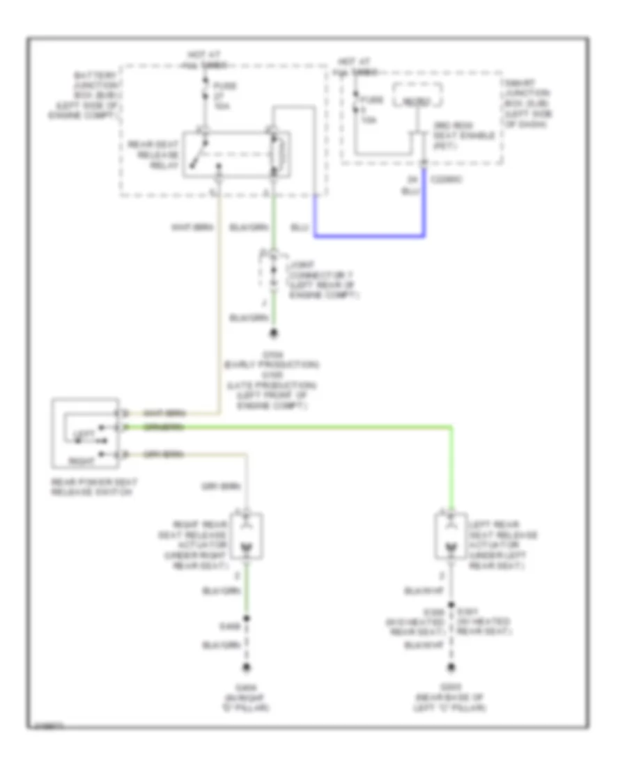
Parking Assistant Wiring Diagram for Ford Edge SE 2010
List of elements for Parking Assistant Wiring Diagram for Ford Edge SE 2010:
- (backup alarm wiring harness, near breakout to inner left parking aid sensor) s405
- C2280d
- Cbp35
- Cmp09
- Computer data lines system
- Fuse 10a
- G200 (left kick panel)
- Gd133
- Gnd
- Hot in start or run
- Inner left parking aid sensor (left side of rear bumper)
- Inner right parking aid sensor (right side of rear bumper)
- Lmp07
- Ms can +
- Ms can -
- Outer left parking aid sensor (left end of rear bumper)
- Outer right parking aid sensor (right end of rear bumper)
- Parking aid module (pam)
- Parking aid speaker
- Pwr run
- Rear sensor gnd
- Rear sensor pwr
- Rear sounder +
- Rear sounder -
- Ril sensor in
- Rir sensor in
- Rmp07
- Rmp09
- Rol sensor in
- Ror sensor in
- S200
- S308
- S403 (backup alarm wiring harness, near breakout to inner right parking aid sensor)
- Smart junction box (sjb) (left side of dash)
- Vdb06
- Vdb07
- Vmp14
- Vmp16
- Vmp17
- Vpm15
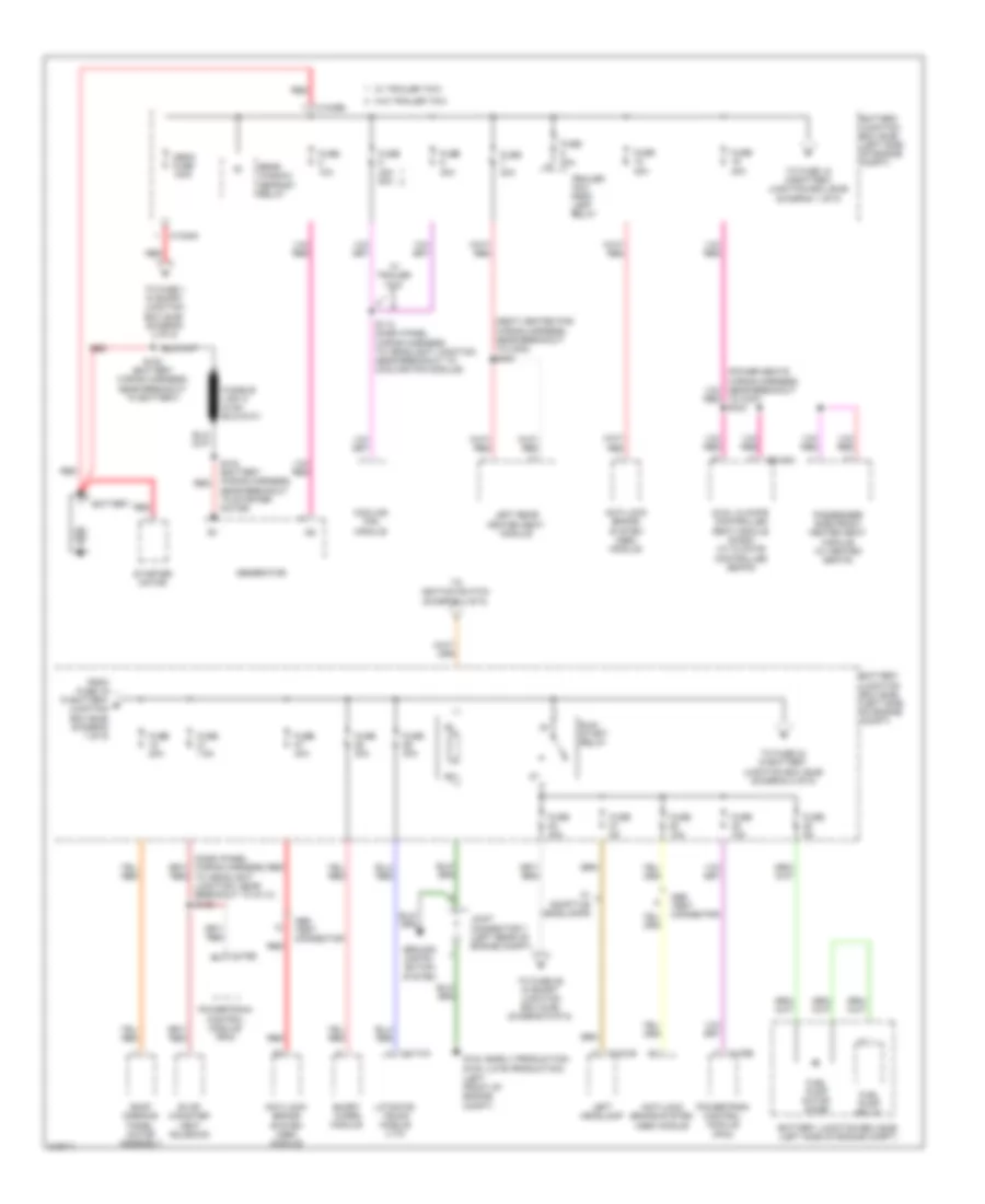
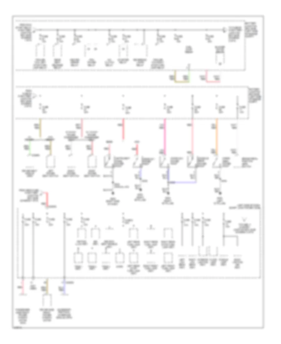
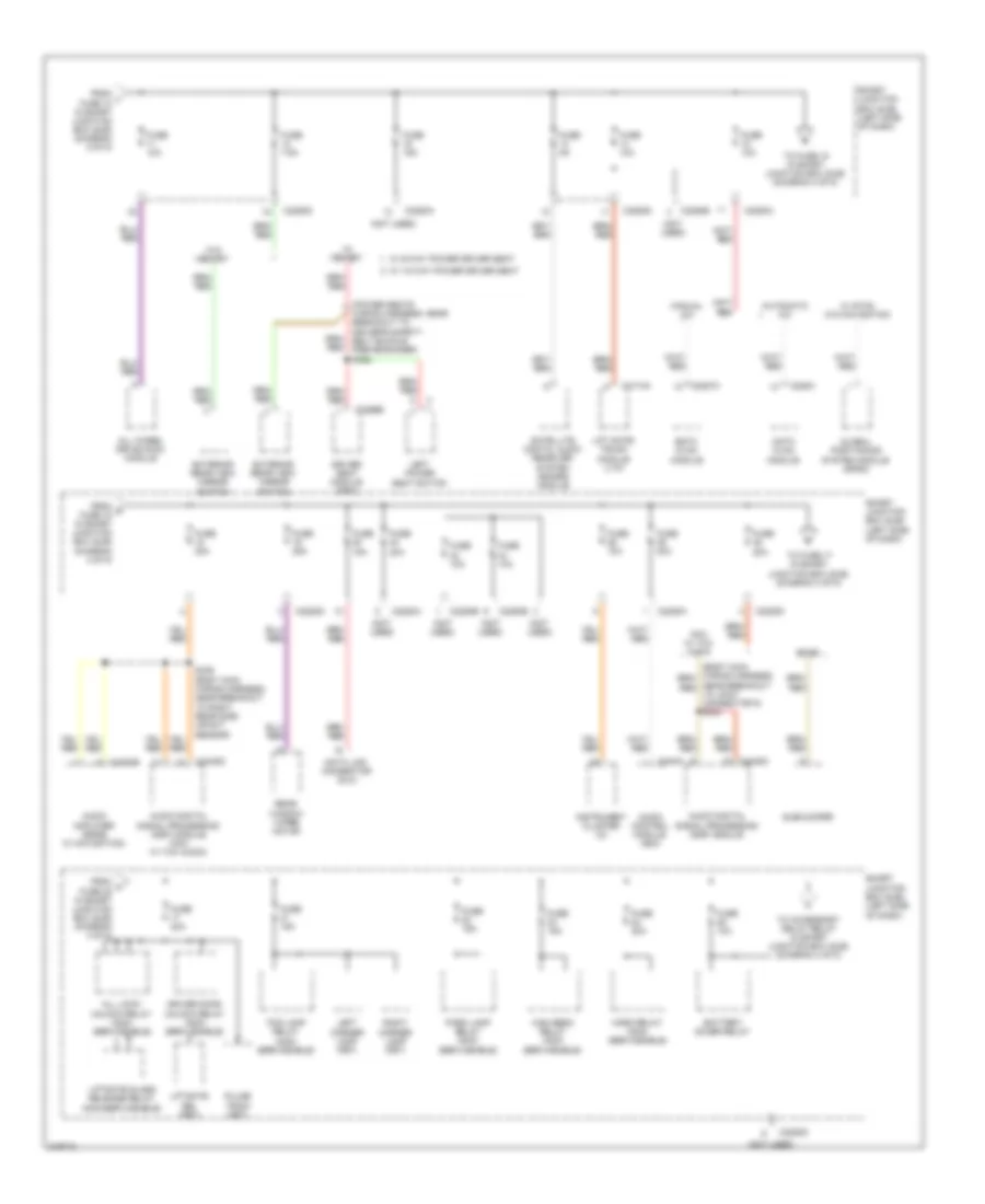
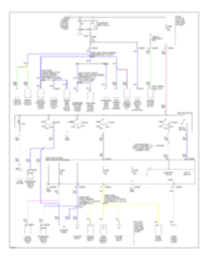
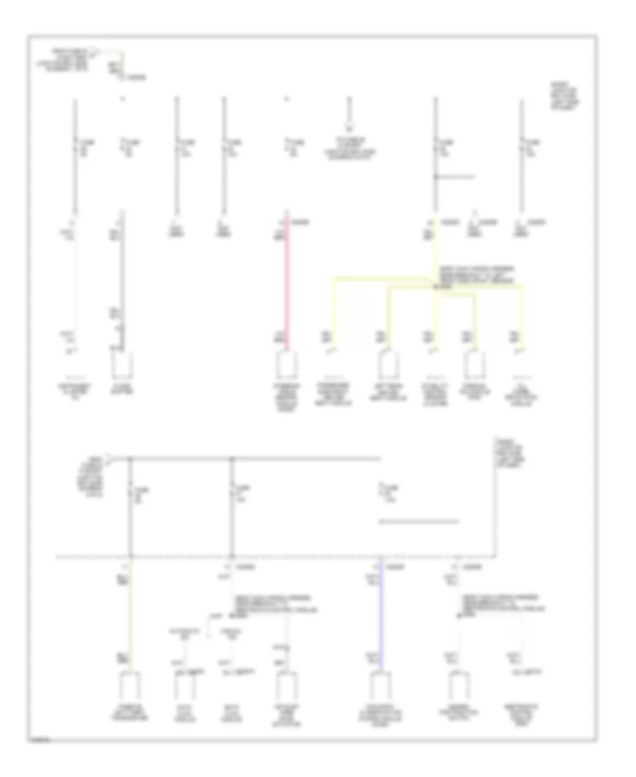
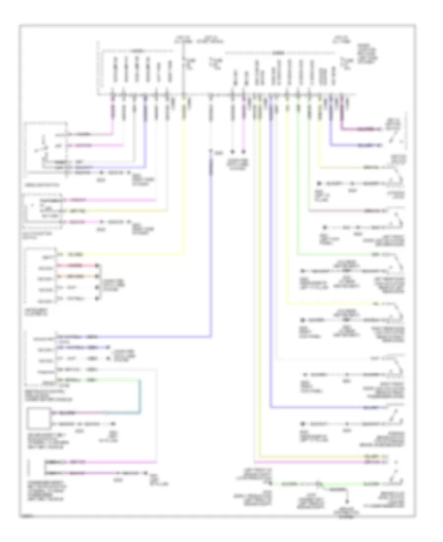
POWER DISTRIBUTION
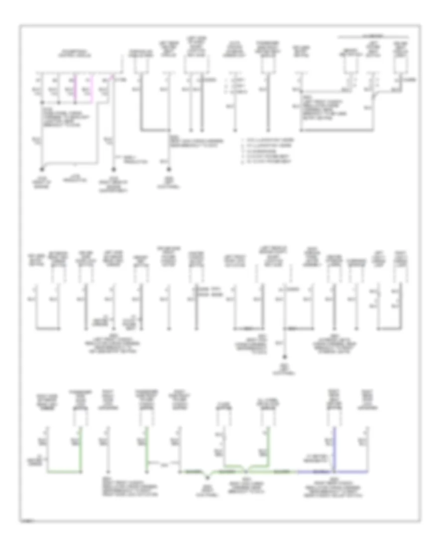
Power Distribution Wiring Diagram (1 of 5) for Ford Edge SE 2010
List of elements for Power Distribution Wiring Diagram (1 of 5) for Ford Edge SE 2010:
- (dash panel wiring harness, to headlight junction, near breakout to c110) s132
- (early production)
- (late production)
- (seat heated pad wiring harness, near breakout to c300) s300
- Abs test connector
- Anti-lock brake system (abs) module
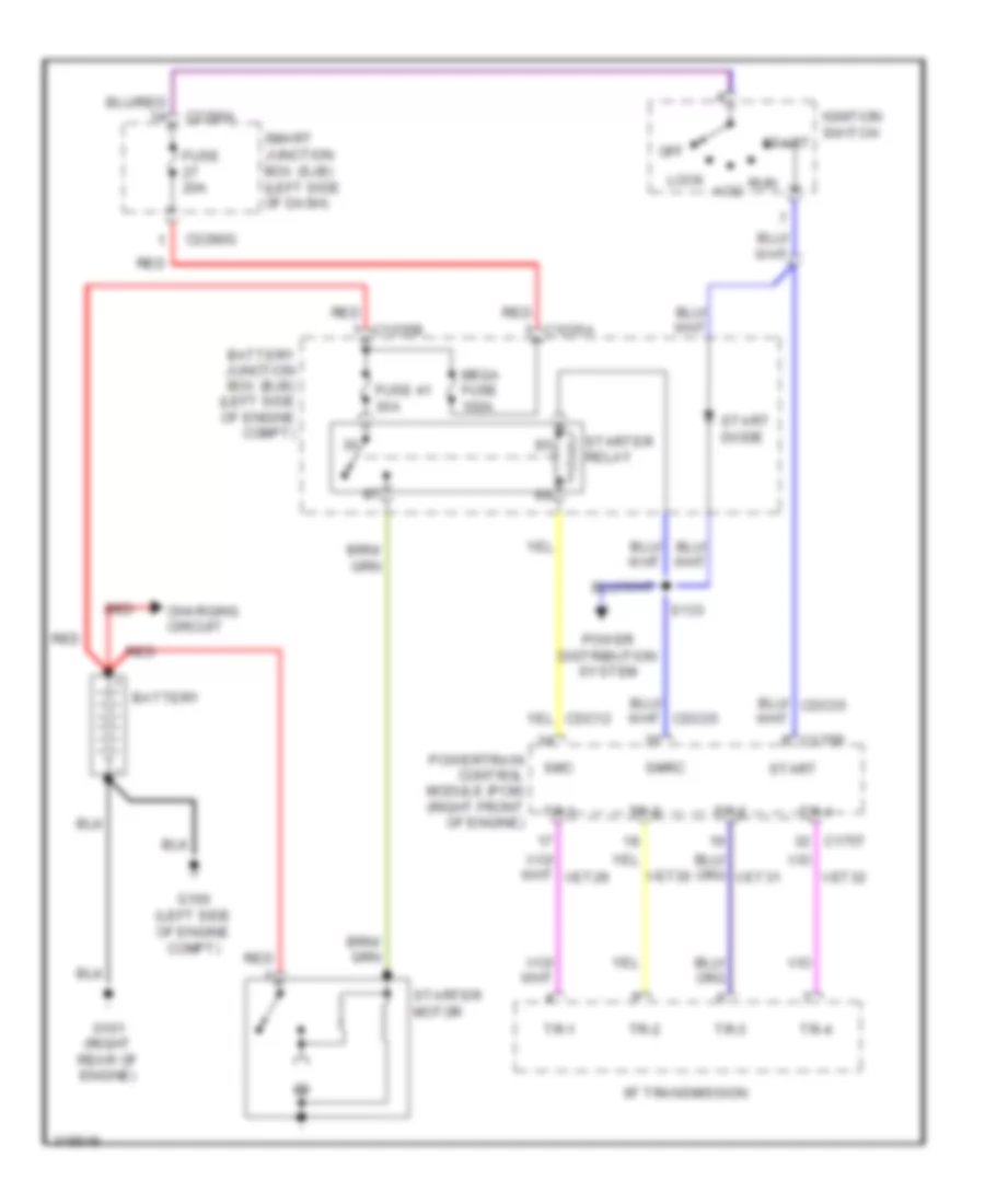
- Battery
- Battery junction box (bjb) (left side of engine compt)
- C1021b
- C1035a
- C1035b
- C175b
- C3036a
- C4174a
- Cooling fan module
- Dual climate controlled seat module (dcsm) (w/ climate controlled seats)
- Evap canister vent solenoid
- From fuse 16 in battery b junction box (bjb) (diagram 1 of 5)
- Fuel pump motor diode
- Fuel pump relay
- Fuse 10a
- Fuse 20a
- Fuse 30a
- Fuse 40a
- Fuse 40a 60a
- Fuse 5a
- Fuse 7.5a
- G104
- G105 (left front of engine compt)
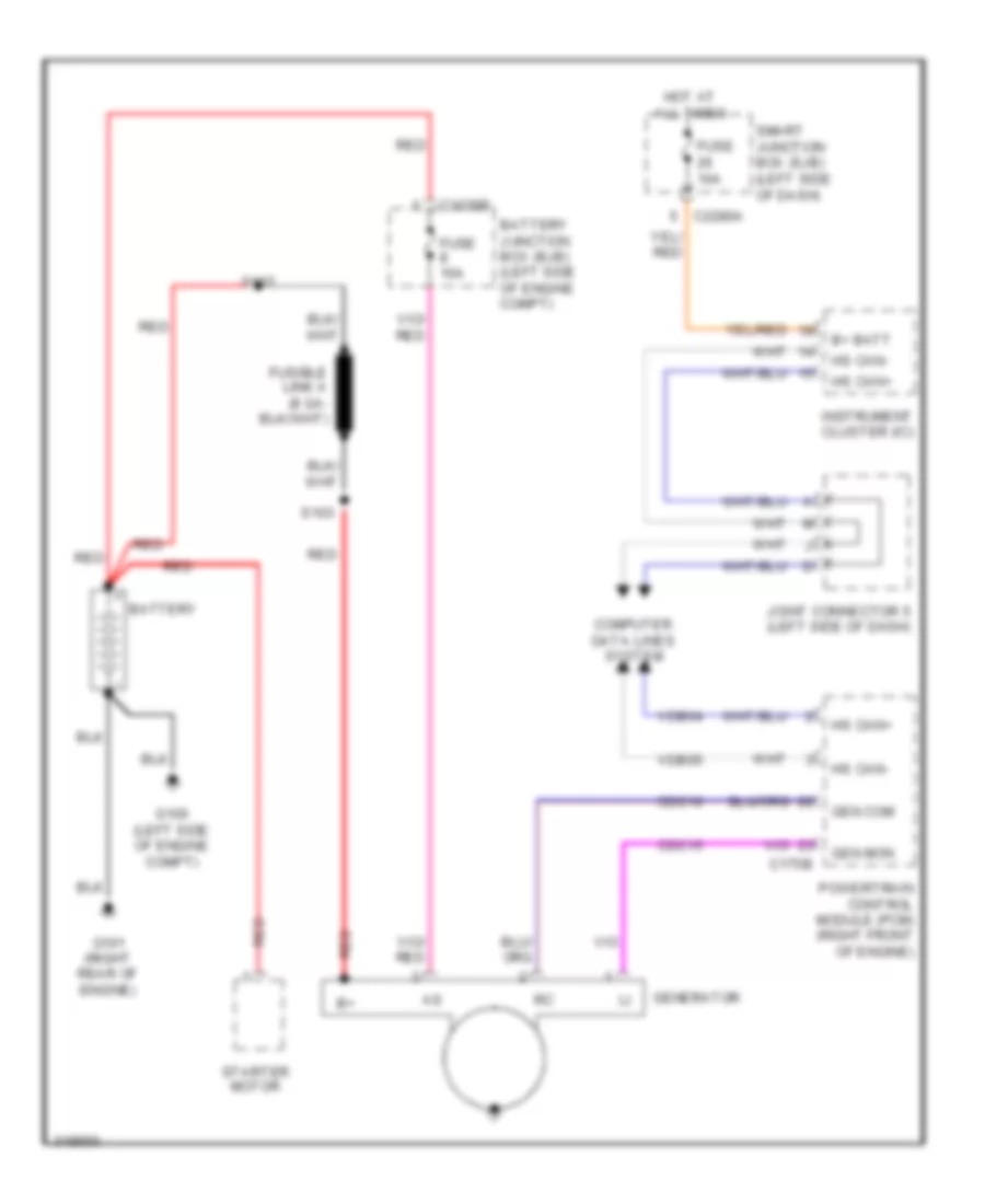
- Generator
- Ground distri- bution system
- Joint connector 7 (left rear of engine compt)
- Left headlamp
- Left rear heated seat module
- Liftgate/ trunk module (ltm)
- Mega fuse 100a
- Passenger side front heated seat module (w/ heated seats)
- Powertrain control module (pcm)
- Rear window defrost relay
- Red
- Roof opening panel motor assembly
- Run/ start relay
- S102 (battery wiring harness, near breakout to battery)
- S103 (battery wiring harness, near breakout to starter motor)
- S112 (dash panel wiring harness, to headlight junction, near breakout to cooling fan module)
- Smart wiper module
- Starter motor
- To c327) s334
- To fuse 1 in smart junction box (sjb) (diagram 2 of 5)
- To fuse 18 in battery junction box (bjb) (diagram 1 of 5)
- To fuse 24 in battery junction box (bjb) (diagram 2 of 5)
- To fuse 29 in smart junction box (sjb) (diagram 5 0f 5)
- To ignition switch (diagram 4 of 5)
- Trailer tow park lamp relay
- W/ adaptive headlamps
- W/ trailer tow
- W/o trailer tow
Power Distribution Wiring Diagram (2 of 5) for Ford Edge SE 2010
List of elements for Power Distribution Wiring Diagram (2 of 5) for Ford Edge SE 2010:
- (left side of dash) smart junction box (sjb)
- (not used)
- 3rd row seat enable (fet)
- A/c clutch relay
- Accessory protocol interface module (apim)
- Back lighting led (fet)
- Battery junction box (bjb) (left side of engine compt)
- Blower motor relay
- Brake pedal position (bpp) switch
- Bsi (fet)
- C2280d
- C2280g
- C3299a
- Cargo area power point
- Console 1 power point
- Console 2 power point
- Console rear power point
- Driver seat module (dsm)
- Driver side front power window motor
- Edge
- Floor lamp (fet)
- From fuse 63 in battery f junction box (bjb) (diagram 2 of 5)
- From mega fuse in battery a junction box (bjb) (diagram 1 of 5)
- From run/ start relay in battery e junction box (bjb) (diagram 1 of 5)
- Fuel pump relay
- Fuse 10a
- Fuse 15a
- Fuse 20a
- Fuse 30a
- Fuse 40a
- Fuse 6 20a
- G203 (right side of dash)
- G302 (right "b" pillar)
- G400 (left "d" pillar)
- Heated mirror relay
- Instrument panel power point
- Interior lighting (fet)
- Keypad illum (fet)
- Left front turn lamp (fet)
- Left low beam (fet)
- Left power seat switch
- Left rear stop/ turn lamp (fet)
- Left rear turn lamp (fet)
- Micro
- Mkx
- Passenger side front power window motor (mkx)
- Pcm power relay
- Puddle lamp (fet)
- Rear seat release relay
- Red
- Reversing lamps relay
- Right front turn lamp (fet)
- Right low beam (fet)
- Right power seat switch
- Right rear stop/turn lamp (fet)
- Right rear turn lamp (fet)
- S233 (manual a/c)
- S338
- S349
- S402
- Starter relay
- To fuse 11 in smart junction box (sjb) (diagram 3 of 5)
- To fuse 60 in battery junction box (bjb) (diagram 2 of 5)
- Tpms 1 (fet)
- Tpms 2 (fet)
- Tpms 3 (fet)
- Trailer tow left stop/turn lamp relay
- Trailer tow right stop/turn lamp relay
- W/ 10-way power passenger seat
- W/ 6-way power passenger seat
- W/ memory
- W/o memory
Power Distribution Wiring Diagram (3 of 5) for Ford Edge SE 2010
List of elements for Power Distribution Wiring Diagram (3 of 5) for Ford Edge SE 2010:
- (not used)
- (power seats wiring harness, near breakout to driver's safety belt buckle pretensioner) s322
- All lock/ unlock relay (non- serviceable)
- All wheel drive (awd) module
- Audio amplifier (edge w/ navigation)
- Audio control module (acm)
- Audio digital signal processing (dsp) module
- Audio digital signal processing (dsp) module (mkx w/ thx audio)
- Automatic a/c
- Battery saver relay
- C2280a
- C2280b
- C2280d
- C2280e
- C228a
- C2357a
- C240a
- C3299b
- C4174a
- C4348c
- C4364b
- Data link connector (dlc)
- Datc hvac module
- Driver door unlock relay (non- serviceable)
- Driver seat module (dsm)
- Edge
- Emtc hvac module
- Exterior rear view mirror switch
- Fog lamp relay (non- serviceable)
- From g fuse 15 in smart junction box (sjb) (diagram 3 of 5)
- From h fuse 38 in smart junction box (sjb) (diagram 3 of 5)
- From l fuse 10 in smart junction box (sjb) (diagram 2 of 5)
- Fuse 10a
- Fuse 15a
- Fuse 20a
- Fuse 25a
- Fuse 5a
- Fuse 7.5a
- Global positioning system module (gpsm)
- High beam relay (non- serviceable)
- Horn relay (non- serviceable)
- Instrument cluster (ic)
- Left corner lamp (fet)
- Left power seat switch
- Lift gate/ trunk module (ltm)
- Liftgate glass release relay (non-serviceable)
- Liftgate rel (fet)
- Manual a/c
- Mkx w/ thx audio
- Park lamp relay (non- serviceable)
- Pulse train (fet)
- Rear window wiper motor
- Right corner lamp (fet)
- Satellite digital audio receiver system (sdars) module
- Smart junction box (sjb) (left side of dash)
- Subwoofer
- To accessory delay relay in smart junction box (sjb) (diagram 4 of 5)
- To fuse 17 in smart junction box (sjb) (diagram 3 of 5)
- To fuse 18 in smart junction box (sjb) (diagram 3 of 5)
- W/ 10-way power driver seat
- W/ 6-way power driver seat
- W/ memory
- W/ sync w/o navigation
- W/o memory
Power Distribution Wiring Diagram (4 of 5) for Ford Edge SE 2010
List of elements for Power Distribution Wiring Diagram (4 of 5) for Ford Edge SE 2010:
- (dash panel wiring harness, to headlight junction, near breakout to c110) s104
- (dash panel wiring harness, to headlight junction, near breakout to c110) s133
- (edge)
- (left front window regulator wiring harness, near breakout to left front tweeter) s501
- (left side of dash) smart junction box (sjb)
- (mkx)
- (not used)
- (right front window regulator wiring harness, near breakout to right front door lock actuator) s603
- Accessory delay relay
- Ambient lighting module
- Ambient lighting switch
- Audio control module (acm)
- Audio control module (acm) (w/o navigation)
- Auto- dimming interior mirror unit
- Battery junction box (bjb) (left side of engine compt)
- Blower motor relay
- C175b
- C2280a
- C2280b
- C2280d
- C2280e
- C240a
- C535a
- C535b
- Circuit breaker 47 30a
- Driver side door lock switch (edge)
- Driver side front power window motor
- Edge
- Floor shifter
- From j fuse 25 in smart junction box (sjb) (diagram 3 of 5)
- From run/start relay in battery c junction box (bjb) (diagram 1 of 5)
- Fuse 10a
- Fuse 15a
- Fuse 20a
- Fuse 5a
- Heated mirror relay
- Ignition switch
- Key in ignition
- Lock
- Lock acc
- Master window adjust switch
- Master window adjust switch (mkx)
- Micro
- Mkx
- Off
- Passenger side door lock switch
- Passenger side front power window motor
- Powertrain control module (pcm)
- Rear window defrost relay
- Rear window wiper motor
- Red
- Right side front power window switch
- Roof opening panel motor assembly
- Run
- Run/start ign sw
- Smart junction box (sjb) (left side of dash)
- Smart wiper module
- Smrc
- Start
- Starter diode
- Starter relay
Power Distribution Wiring Diagram (5 of 5) for Ford Edge SE 2010
List of elements for Power Distribution Wiring Diagram (5 of 5) for Ford Edge SE 2010:
- (body main wiring harness, near breakout to left front side impact sensor) s308
- (body main wiring harness, near breakout to restraints control module) s205
- (body main wiring harness, near breakout to restraints control module) s206
- (not used)
- Air inlet mode door actuator
- All wheel drive (awd) module
- Automatic a/c
- C2280b
- C2280d
- C2280e
- C228a
- C2357a
- C310a
- Datc hvac module
- Emtc hvac module
- Floor shifter
- From fuse 53 d in battery junction box (bjb) (diagram 1 of 5)
- From k fuse 34 in smart junction box (sjb) (diagram 5 of 5)
- Fuse 10a
- Fuse 5a
- Fuse 7.5a
- Hazard/ pad/traction switch
- Instrument cluster (ic)
- Left rear heated seat module
- Manual a/c
- Occupant classification system module (ocsm)
- Parking aid module (pam)
- Passenger side front heated seat module
- Passive anti-theft transceiver
- Restraints control module (rcm)
- Smart junction box (sjb) (left side of dash)
- Stability control sensor cluster
- Steering angle sensor module (sasm)
- To fuse 36 in smart junction box (sjb) (diagram 5 of 5)
POWER DOOR LOCKS
Power Door Locks Wiring Diagram (1 of 2) for Ford Edge SE 2010
List of elements for Power Door Locks Wiring Diagram (1 of 2) for Ford Edge SE 2010:
- (body main wiring harness, near breakout to g200) s312
- (body main wiring harness, near breakout to g200) s313
- (body main wiring harness, near breakout to g200) s314
- (right kick panel) g202
- (w/ heated rear seats) s700
- Accessory delay relay
- All lock/ unlock relay
- C2280b
- C2280c
- C2280d
- C2280e
- Driver door unlock relay
- Driver side door lock switch
- Edge
- Fuse 15a
- Fuse 20a
- G201 (left kick panel)
- G202 (right kick panel)
- G300 (behind left rear seat)
- Horn relay
- Horns system
- Hot at all times
- Interior lights system
- Left rear door lock actuator (rear of left rear door)
- Lock
- Lr door ajar
- Micro
- Mkx
- Passenger side door lock switch
- Power distribution system
- Rf door ajar
- Right front door lock actuator (rear of front passenger's door)
- Right rear door lock actuator (rear of right rear door)
- Rr door ajar
- S201
- S203
- S310 (body main wiring harness, near breakout to left front side impact sensor)
- S501
- S502
- S604
- Smart junction box (sjb) (left side of dash)
- To liftgate rel fet (diagram 2 of 2)
- Trim lock
- Trim unlock
- Unlock
Power Door Locks Wiring Diagram (2 of 2) for Ford Edge SE 2010
List of elements for Power Door Locks Wiring Diagram (2 of 2) for Ford Edge SE 2010:
- 1/2
- 3/4
- 5/6
- 7/8
- 9/0
- Ajar
- Anti- theft
- Anti-theft hood switch (right front of engine compt)
- C2280c
- C2280d
- C2280f
- Door reset sw
- From fuse 17 (diagram 1 of 2)
- Fuse 10a
- G107 (right front of engine compt)
- G200 (left kick panel)
- G201 (left kick panel)
- G400 (left "d" pillar)
- Hot at all times
- Internal rke/ tpms antenna
- Keyless entry keypad (driver's door)
- Keypad illum (fet)
- Left front door lock actuator (driver's door)
- Lf door ajar
- Liftgate latch (manual liftgate)
- Liftgate rel (fet)
- Liftgate release switch (manual liftgate)
- Micro
- Mkx
- Reset set
- Rke receiver
- S114
- S400
- S502
- S503 (w/ memory)
- Smart junction box (sjb) (left side of dash)
POWER MIRRORS
Electrochromic Mirror Wiring Diagram, with Microphone for Ford Edge SE 2010
List of elements for Electrochromic Mirror Wiring Diagram, with Microphone for Ford Edge SE 2010:
- (+)
- (-)
- (near breakout to left front side impact sensor) s309
- (right front of engine) powertrain control module (pcm)
- Accessory protocol interface module module (apim) (under rear of center console)
- Audio control module (acm)
- Auto-dimming interior mirror unit
- Battery junction box (bjb) (left side of engine compt)
- C175t
- C2280d
- Cbp41
- Cls10
- Cls28
- Compass +
- Compass -
- Dmm13
- Early production
- Early production w/ navigation
- Fuse 10a
- Fuse 15a
- G200 (left kick panel)
- Gd133
- Gnd
- Hot at all times
- Hot w/ accessory delay relay energized
- Instrument cluster (ic)
- Left side exterior rear view mirror (w/ memory) (driver's door)
- Lrd12
- Mic+
- Mic-
- Nca
- Power distribution system
- Rev lp ctrl
- Reverse
- Reversing lamps relay
- Rmm13
- Rmn01
- Rrd12
- S200
- S203
- Shield
- Smart junction box (sjb) (left side of dash)
- Vmc30
- Vmc31
- Vmm13
- Vmn01
- Vpwr
- W/ sync
- W/o sync
Electrochromic Mirror Wiring Diagram, without Microphone for Ford Edge SE 2010
List of elements for Electrochromic Mirror Wiring Diagram, without Microphone for Ford Edge SE 2010:
- (+)
- (-)
- (left kick panel) g200
- (near breakout to left front side impact sensor) s309
- Auto-dimming interior mirror unit
- Battery junction box (bjb) (left side of engine compt)
- C175t
- C2280d
- Cbp41
- Cls10
- Cls28
- Compass +
- Compass -
- Fuse 10a
- Fuse 15a
- Gd133
- Gnd
- Hot at all times
- Hot w/ accessory delay relay energized
- Instrument cluster (ic)
- Left side exterior rear view mirror (w/ memory) (driver's door)
- Lrd12
- Power distribution system
- Powertrain control module (pcm) (right front of engine)
- Rev lp ctrl
- Reverse
- Reversing lamps relay
- Rrd12
- S200
- S203
- Smart junction box (sjb) (left side of dash)
- Vmc30
- Vmc31
- Vpwr
- W/o illumination visors
Power Mirrors Wiring Diagram for Ford Edge SE 2010
List of elements for Power Mirrors Wiring Diagram for Ford Edge SE 2010:
- C2280d
- Down
- Exterior rear view mirror switch
- Fuse 12 7.5a
- G201 (left kick panel)
- Hot at all times
- Left
- Left side exterior rear view mirror (driver's door)
- Left/ right
- Left/ right m
- Mirror select
- Right
- Right side exterior rear view mirror (front passenger's door)
- S502
- Smart junction box (sjb) (left side of dash)
- Up/ down
- Up/ down m
POWER SEATS
Climate Control Seats Wiring Diagram for Ford Edge SE 2010
List of elements for Climate Control Seats Wiring Diagram for Ford Edge SE 2010:
- (power seats wiring harness, near breakout to c327) s332
- (power seats wiring harness, near breakout to passenger side climate controlled seat module) s331
- Battery junction box (bjb) (left side of engine compt)
- C228a
- C3036a
- C3036b
- C3036c
- Chs01
- Chs02
- Chs03
- Chs06
- Chs07
- Chs08
- Climate controlled seat switches
- Computer data lines system
- Datc hvac module
- Dbckblwctl
- Dbksensrt
- Dbkted+
- Dbkted-
- Dblwr+
- Dblwr-
- Dcshcblwctl
- Dcshsens
- Dcshsensrt
- Dcshted+
- Dcshted-
- Driver side climate controlled seat backrest module (under driver's seat)
- Driver side climate controlled seat cushion module (under driver's seat)
- Drv batt
- Dual climate controlled seat module (dcsm)
- Fuse 30a
- G302 (right "b" pillar)
- Gd145
- Gnd
- Hot at all times
- Ms can (+)
- Ms can (-)
- Ms can+
- Ms can-
- Nca
- Pass batt
- Passenger side climate controlled seat backrest module (under front passenger's seat)
- Passenger side climate controlled seat cushion module (under front passenger's seat)
- Pbckblwctl
- Pbksens
- Pbksensrt
- Pbkted+
- Pbkted-
- Pblwr+
- Pblwr-
- Pcshcblwctl
- Pcshsens
- Pcshsensrt
- Pcshted+
- Pcshted-
- Rhs01
- Rhs02
- Rhs03
- Rhs05
- Rhs06
- Rhs07
- Rhs08
- Rhs10
- Rhs15
- Rhs20
- S317 (body main wiring harness, near breakout to g311)
- S318 (body main wiring harness, near breakout to g311)
- S330
- S334
- Sbb16
- Vdb06
- Vdb07
- Vhs16
- Vhs18
- Vhs21
- Vhs23
- Vhs26
- Vhs27
- Vhs35
- Vhs36
Front Heated Seats Wiring Diagram for Ford Edge SE 2010
List of elements for Front Heated Seats Wiring Diagram for Ford Edge SE 2010:
- Back
- Batt-drv
- Batt-pass
- Battery junction box (bjb) (left side of engine compt)
- C2280d
- C228b
- Cbp35
- Chs02
- Chs04
- Chs07
- Chs09
- Chs13
- Chs14
- Chs29
- Chs30
- Cushion
- Datc hvac module
- Drv hi led
- Drv hi/lo/off
- Drv lo led
- Front passenger side heated seat module (under front passenger's seat)
- Fuse 10a
- Fuse 30a
- G200 (left kick panel)
- G302 (right "b" pillar)
- Gd133
- Gnd
- Ground distribution system
- Hot at all times
- Left front seat heated element
- Lf heater
- Lf temp sens
- Pass hi led
- Pass hi/lo/off
- Pass lo led
- Rf heater
- Rf temp sens
- Rhs05
- Right front seat heated element
- Run/start
- S200
- S330
- S333 (power seats wiring harness, near breakout to c327)
- S338
- Sbb16
- Sens rtn
- Smart junction box (sjb) (left side of dash)
- Vhs26
- Vhs27
Power Seats Wiring Diagram, 10-Way Passenger Seat for Ford Edge SE 2010
List of elements for Power Seats Wiring Diagram, 10-Way Passenger Seat for Ford Edge SE 2010:
- (right "b" pillar)
- Aft
- Backrest
- Battery junction box (bjb) (left side of engine compt)
- Down
- Front height
- Fuse 30a
- Fwd
- G302
- Horizontal
- Hot at all times
- Lumber
- Out
- Passenger seat backrest motor (under front passenger's seat)
- Passenger seat front height motor (under front passenger's seat)
- Passenger seat horizontal motor (under front passenger's seat)
- Passenger seat lumbar motor (under front passenger's seat)
- Passenger seat rear height motor (under front passenger's seat)
- Rear height
- Right power seat switch
- S330
Power Seats Wiring Diagram, 6-Way Driver Seat for Ford Edge SE 2010
List of elements for Power Seats Wiring Diagram, 6-Way Driver Seat for Ford Edge SE 2010:
- Aft
- Battery junction box (bjb) (left side of engine compt)
- Down
- Driver seat front height motor (under driver's seat)
- Driver seat horizontal motor (under driver's seat)
- Driver seat rear height motor (under driver's seat)
- Front height
- Fuse 30a
- Fwd
- G302 (right "b" pillar)
- Ground distribution system
- Horizontal
- Hot at all times
- Left power seat switch
- Rear height
- S338
Power Seats Wiring Diagram, 6-Way passenger Seat for Ford Edge SE 2010
List of elements for Power Seats Wiring Diagram, 6-Way passenger Seat for Ford Edge SE 2010:
- Aft
- Battery junction box (bjb) (left side of engine compt)
- Down
- Fore
- Front
- Fuse 30a
- G302 (right "b" pillar)
- Horizontal
- Hot at all times
- Passenger seat front height motor (under front passenger's seat)
- Passenger seat horizontal motor (under front passenger's seat)
- Passenger seat rear height motor (under front passenger's seat)
- Rear
- Right power seat switch
- S330
Rear Heated Seats Wiring Diagram for Ford Edge SE 2010
List of elements for Rear Heated Seats Wiring Diagram for Ford Edge SE 2010:
- Back
- Backlighting
- Batt-dr
- Batt-pass
- Battery junction box (bjb) (left side of engine compt)
- C2280d
- Cbp35
- Chs39
- Chs43
- Chs46
- Chs47
- Chs48
- Chs49
- Chs50
- Chs51
- Chs52
- Chs53
- Cushion
- Fuse 10a
- Fuse 30a
- G200 (left kick panel)
- G202 (right kick panel)
- G300 (near base of left "c" pillar)
- G404 (right "d" pillar)
- Gd133
- Gnd
- Hot at all times
- Hot in start or run
- Interior lights system
- Left rear heated seat module (under left rear seat)
- Left rear seat heated element
- Left rear seat heater switch
- Lr heater
- Lr hi led
- Lr hi/off
- Lr lo led
- Lr lo/off
- Lr temp sens
- Off/hi
- Off/lo
- Rhs41
- Right rear seat heated element
- Right rear seat heater switch
- Rr heater
- Rr hi led
- Rr hi/off
- Rr lo led
- Rr lo/off
- Rr temp sens
- Run/start
- S200
- S301
- S302 (seat heated pad wiring harness, near breakout to left rear seat heater element)
- S408
- S700
- S800
- Sbb07
- Sens rtn
- Smart junction box (sjb) (left side of dash)
- Vhs42
- Vhs45
Second Row Seat Release Wiring Diagram for Ford Edge SE 2010
List of elements for Second Row Seat Release Wiring Diagram for Ford Edge SE 2010:
- 3rd row seat enable (fet)
- Battery junction box (bjb) (left side of engine compt)
- C2280c
- Fuse 10a
- G104 (early production) g105 (late production) (left front of engine compt)
- G300 (near base of left "c" pillar)
- G404 (in right "d" pillar)
- Hot at all times
- Joint connector 7 (left rear of engine compt)
- Left
- Left rear seat release actuator (under left rear seat)
- Micro
- Rear power seat release switch
- Rear seat release relay
- Right
- Right rear seat release actuator (under right rear seat)
- S301 (w/ heated rear seat)
- S306 (w/o heated rear seat)
- S408
- Smart junction box (sjb) (left side of dash)
POWER TOP/SUNROOF
Power Top/Sunroof Wiring Diagram for Ford Edge SE 2010
List of elements for Power Top/Sunroof Wiring Diagram for Ford Edge SE 2010:
- (middle of front passenger's door) passenger side front power window motor
- (not used)
- Accessory delay relay
- Battery junction box (bjb) (left side of engine compt)
- C2280c
- C2280d
- Cbp41
- Close
- Cpr31
- Cpr38
- Cpr40
- Delay acc
- Driver side front power window motor (middle of driver's door)
- Fuse 15a
- Fuse 20a
- G201 (left kick panel)
- Gd133
- Global open
- Gnd
- Hot at all times
- Id1
- Interior lights system
- K bus
- Micro
- Mkx
- Open
- Power distribution system
- Pulse train (fet)
- Red
- Roof opening panel motor assembly
- Roof opening panel switch
- S202 (body main wiring harness, near breakout to c212)
- S203
- S903
- Sbb18
- Slide switch
- Smart front glass motor
- Smart junction box (sjb) (left side of dash)
- Smart shade motor
- Tilt
- Tilt switch
- Vbatt
- Vpw01
POWER WINDOWS
Power Windows Wiring Diagram for Ford Edge SE 2010
List of elements for Power Windows Wiring Diagram for Ford Edge SE 2010:
- (4 led's)
- (body main wiring harness, near breakout to c313)
- Accessory delay relay
- Auto
- Batt
- C2280d
- C504a
- C504b
- Circuit breaker 30a
- Down
- Driver side front power window motor (middle of driver's door)
- Fuse 15a
- Fuse 30a
- G201 (left kick panel)
- Gnd
- Hot at all times
- Left front
- Left rear
- Left rear power window motor (middle of left rear door)
- Left rear window adjust switch
- Lock out
- Master window adjust switch
- Micro
- Passenger side front power window motor (middle of front passenger's door)
- Right front
- Right rear
- Right rear power window motor (middle of right rear door)
- Right rear window adjust switch
- Right side front power window switch
- Rly
- S326
- S501
- S502
- Smart junction box (sjb) (left side of dash)
RADIO
Premium Radio Wiring Diagram, with Navigation (1 of 2) for Ford Edge SE 2010
List of elements for Premium Radio Wiring Diagram, with Navigation (1 of 2) for Ford Edge SE 2010:
- (coaxial cable)
- Ant pwr
- Antenna module (center front of roof)
- Antenna shield
- Audio control module (acm)
- Audio input jack (w/o sync)
- Auto-dimming interior mirror unit (w/o sync)
- C2280b
- C2280d
- C240a
- C240b
- C240c
- Cbp28
- Cme31
- Cme44
- Computer data lines system
- Dme09
- Dme22
- Dme45
- Dmm13
- Early production
- Enable
- Fuse 20a
- Fuse 5a
- G206 (left side of dash)
- G402 (right "c" pillar)
- Gd114
- Gd148
- Gnd
- Gps antenna
- Hot at all times
- Hot in start
- Late production
- Lf spkr+
- Lf spkr-
- Lr spkr+
- Lr spkr-
- Mic +
- Mic -
- Microphone (w/o sync) (center front of roof)
- Ms can+
- Ms can-
- Nca
- Pwr
- Pwr gnd
- Rf spkr+
- Rf spkr-
- Rme07
- Rme09
- Rme10
- Rme12
- Rme22
- Rme24
- Rme45
- Rme46
- Rme54
- Rmm13
- Rmn01
- Rr spkr+
- Rr spkr-
- S339
- S407
- Sbp38
- Sbp39
- Shield
- Smart junction box (sjb) (left side of dash)
- Sme23
- St in 2l +
- St in 2l -
- St in 2r +
- St in 2r -
- St input 2l+
- St input 2l-
- St input 2r+
- St input 2r-
- Start
- Sub enable
- Sub shield
- Sub+
- Sub-
- Subwoofer
- Swc1 +
- Swc1 rtn
- Swc2 +
- Swc2 rtn
- Vbatt+
- Vdb06
- Vdb07
- Vme07
- Vme09
- Vme10
- Vme12
- Vme14
- Vme22
- Vme45
- Vme46
- Vme54
- Vmm13
- Vmn01
Premium Radio Wiring Diagram, with Navigation (2 of 2) for Ford Edge SE 2010
List of elements for Premium Radio Wiring Diagram, with Navigation (2 of 2) for Ford Edge SE 2010:
- Audio amplifier (behind right quarterpanel)
- C218a
- C218b
- C4364a
- C4364b
- C570a
- C570b
- C612a
- C612b
- Clockspring (steering column)
- Cme31
- Enable
- G402 (right "c" pillar)
- Gd148
- Gnd
- Interior lights system
- Left front speaker
- Left front tweeter
- Left rear speaker
- Lf spkr+
- Lf spkr-
- Lr spkr+
- Lr spkr-
- Media
- Nca
- Premium i
- Premium ii
- Rf spkr+
- Rf spkr-
- Right front speaker
- Right front tweeter
- Right rear speaker
- Right steering wheel switch
- Rme07
- Rme09
- Rme10
- Rme12
- Rme17
- Rme18
- Rme58
- Rme59
- Rr spkr+
- Rr spkr-
- S407
- Sbp18
- Seek+
- Seek-
- Vbatt
- Vme07
- Vme09
- Vme10
- Vme12
- Vme17
- Vme18
- Vme58
- Vme59
- Vol+
- Vol-
Premium Radio Wiring Diagram, without Navigation (1 of 2) for Ford Edge SE 2010
List of elements for Premium Radio Wiring Diagram, without Navigation (1 of 2) for Ford Edge SE 2010:
- (coaxial cable)
- Accessory delay relay
- Ant pwr
- Antenna module (center front of roof)
- Antenna shield
- Audio control module (acm)
- Audio input jack (w/o sync)
- C2280a
- C2280b
- C2280d
- C240a
- C240b
- C240c
- Cbp28
- Cbp41
- Cme44
- Computer data lines system
- Del/acc
- Dme22
- Dme45
- Fuse 15a
- Fuse 20a
- Fuse 5a
- G206 (left side of dash)
- G403 (right rear quarterpanel)
- Gd114
- Gd148
- Gnd
- Hot at all times
- Hot in start
- Left rear speaker
- Lf spkr+
- Lf spkr-
- Lr spkr+
- Lr spkr-
- Micro
- Ms can+
- Ms can-
- Nca
- Pwr
- Pwr gnd
- Rf spkr+
- Rf spkr-
- Right rear speaker
- Rme07
- Rme09
- Rme10
- Rme12
- Rme22
- Rme24
- Rme45
- Rme46
- Rme52
- Rme53
- Rr spkr+
- Rr spkr-
- S407
- Satellite l+
- Satellite l-
- Satellite r+
- Satellite r-
- Sbp38
- Sbp39
- Shield
- Smart junction box (sjb) (left side of dash)
- Sme23
- St in 2l +
- St in 2l -
- St in 2r +
- St in 2r -
- St input 2l+
- St input 2l-
- St input 2r+
- St input 2r-
- Start
- Sub enable
- Sub shield
- Sub+
- Sub-
- Subwoofer
- Swc1 +
- Swc1 rtn
- Vbatt+
- Vdb06
- Vdb07
- Vme07
- Vme09
- Vme10
- Vme12
- Vme14
- Vme22
- Vme45
- Vme46
- Vme52
- Vme53
Premium Radio Wiring Diagram, without Navigation (2 of 2) for Ford Edge SE 2010
List of elements for Premium Radio Wiring Diagram, without Navigation (2 of 2) for Ford Edge SE 2010:
- (coaxial cable)
- Antenna
- C218a
- C218b
- C2280a
- C570a
- C570b
- C612a
- C612b
- Cbp13
- Clockspring (steering column)
- Computer data lines system
- Dme41
- Edge
- Fuse 10a
- G206 (left side of dash)
- G403 (right rear quarterpanel)
- Gd114
- Gd148
- Global positioning system module (gpsm) (top center of dash)
- Gnd
- Hot at all times
- Interior lights system
- Left front speaker
- Left front tweeter
- Media
- Mkx
- Ms can+
- Ms can-
- Nca
- Right front speaker
- Right front tweeter
- Right steering wheel switch (w/o sync)
- Rme41
- Rme42
- Sate l+
- Sate l-
- Sate r+
- Sate r-
- Satellite digital audio receiver system (sdars) module (left rear of cargo area)
- Satellite radio antenna
- Sbp15
- Seek+
- Seek-
- Shield
- Smart junction box (sjb) (left side of dash)
- Vbat
- Vbatt
- Vdb06
- Vdb07
- Vme41
- Vme42
- Vol+
- Vol-
SYNC Radio Wiring Diagram (1 of 2) for Ford Edge SE 2010
List of elements for SYNC Radio Wiring Diagram (1 of 2) for Ford Edge SE 2010:
- (coaxial cable)
- (or gd148)
- (or rmm13)
- Accessory protocol interface module (apim) (under rear of center console)
- Antenna
- Audio input jack
- C2280a
- C2280d
- Cbp13
- Computer data lines system
- Dme41
- Dme45
- Dmn01
- Dmn14
- Dmn52
- Fuse 13 5a
- Fuse 15 10a
- Fuse 3 15a
- G206 (left side of dash)
- G403 (right erar quarterpanel)
- G403 (right rear quarterpanel)
- Gd114
- Gd148
- Global positioning system module (gpsm) (top center of dash)
- Gnd
- Gnd2
- Hot at all times
- Hs can +
- Hs can -
- In 2l +
- In 2l -
- In 2r +
- In 2r -
- Mic +
- Mic -
- Mic+
- Mono +
- Mono -
- Ms can +
- Ms can -
- Ms can+
- Ms can-
- Nca
- Rme41
- Rme42
- Rme45
- Rme46
- Rme52
- Rme53
- Rme54
- Rmm13
- Rmn01
- Rmn14
- S352
- Sate l+
- Sate l-
- Sate r+
- Sate r-
- Satellite digital audio receiver system (sdars) module (w/o navigation) (left rear of cargo area)
- Satellite radio antenna
- Sbp03
- Sbp15
- Sdars l+
- Sdars l-
- Sdars r+
- Sdars r-
- Shield
- Smart junction box (sjb) (left side of dash)
- Swc2 +
- Swc2 rtn
- Sync l+
- Sync l-
- Sync r+
- Sync r-
- Usb
- Usb cable
- Usb port
- Vbat
- Vbatt
- Vdb04
- Vdb05
- Vdb06
- Vdb07
- Vme41
- Vme42
- Vme45
- Vme46
- Vme52
- Vme53
- Vme54
- Vmm13
- Vmn01
- Vmn14
SYNC Radio Wiring Diagram (2 of 2) for Ford Edge SE 2010
List of elements for SYNC Radio Wiring Diagram (2 of 2) for Ford Edge SE 2010:
- Audio control module (acm)
- Auto-dimming interior mirror unit
- C218a
- C218b
- C240a
- C240b
- Clockspring (steering column)
- Dmm13
- Early production
- G403 (right rear quarterpanel)
- Interior lights system
- Late production
- Media
- Mic +
- Mic -
- Microphone (center front of roof)
- Mono +
- Mono -
- Nca
- Phone
- Right steering wheel switch
- Rme24
- Rme52
- Rme53
- Rme54
- Rmm13
- Rmn01
- Rmn14
- S352
- Seek+
- Seek-
- Shield
- Swc1 +
- Swc1 rtn
- Swc2 +
- Swc2 rtn
- Sync l+
- Sync l-
- Sync r+
- Sync r-
- Vme14
- Vme52
- Vme53
- Vme54
- Vmm13
- Vmn01
- Vmn14
- Voice
- Vol+
- Vol-
- W/ navigation
- W/o navigation
THX Audio Radio Wiring Diagram (1 of 3) for Ford Edge SE 2010
List of elements for THX Audio Radio Wiring Diagram (1 of 3) for Ford Edge SE 2010:
- Audio digital signal processing (dsp) module (right "c" pillar)
- Audio in left+
- Audio in left-
- Audio in right+
- Audio in right-
- C2280d
- C4348a
- C4348b
- C4348c
- Cen csa spkr+
- Cen csa spkr-
- Center
- Center spkr+
- Center spkr-
- Cme31
- Computer data lines system
- Enable
- Fuse 20a
- G402 (right rear quarterpanel)
- Gd148
- Gnd
- Hot at all times
- Instrument panel speaker
- Joint connector 9 (right rear quarterpanel)
- Left
- Left front tweeter
- Left rear tweeter
- Lf door +
- Lf door-
- Lf spkr +
- Lf spkr -
- Lh csa spkr+
- Lh csa spkr-
- Lr spkr +
- Lr spkr -
- Lr spkr+
- Lr spkr-
- Ms can +
- Ms can -
- Nav voice+
- Nav voice-
- Rear center+
- Rear center-
- Rf door +
- Rf door-
- Rf spkr +
- Rf spkr-
- Rh csa spkr+
- Rh csa spkr-
- Right
- Right front tweeter
- Right rear tweeter
- Rme01
- Rme02
- Rme06
- Rme07
- Rme08
- Rme09
- Rme10
- Rme11
- Rme12
- Rme22
- Rme28
- Rme29
- Rme30
- Rme51
- Rme58
- Rme59
- Rr spkr+
- Rr spkr-
- S339
- S340
- S407
- Sbp18
- Sbp38
- Smart junction box (sjb) (left side of dash)
- Sme23
- Sub+
- Sub-
- Subw 1+
- Subw 2 +
- Subw1-
- Subw2-
- Subwoofer
- Vbatt
- Vdb06
- Vdb07
- Vme01
- Vme02
- Vme06
- Vme07
- Vme08
- Vme09
- Vme10
- Vme11
- Vme12
- Vme22
- Vme28
- Vme29
- Vme30
- Vme59
- W/ navigation
- W/o navigation
THX Audio Radio Wiring Diagram (2 of 3) for Ford Edge SE 2010
List of elements for THX Audio Radio Wiring Diagram (2 of 3) for Ford Edge SE 2010:
- C218a
- C218b
- C2280a
- C2280b
- C2280d
- Clockspring (steering column)
- Fuse 15a
- Fuse 20a
- Fuse 5a
- Hot at all times
- Hot in start
- Hot w/ accessory delay relay energized
- Interior lights system
- Left front speaker
- Left rear speaker
- Media
- Right front speaker
- Right rear speaker
- Right steering wheel switch
- Seek+
- Seek-
- Smart junction box (sjb) (left side of dash)
- Voice
- Vol+
- Vol-
THX Audio Radio Wiring Diagram (3 of 3) for Ford Edge SE 2010
List of elements for THX Audio Radio Wiring Diagram (3 of 3) for Ford Edge SE 2010:
- (center front of roof) antenna module
- (right rear quarterpanel)
- (w/ navigation) gps antenna
- (w/o sync)
- Antenna
- Antenna pwr
- Audio control module (acm)
- Audio input jack
- Auto-dimming interior mirror unit (w/o sync)
- C240a
- C240b
- C240c
- Cbp13
- Cbp28
- Cbp41
- Center spkr+
- Center spkr-
- Cme31
- Cme44
- Coaxial cable
- Computer data lines system
- Dme07
- Dme09
- Dme22
- Dme41
- Dme45
- Dme51
- Dmm13
- Early production
- Enable
- G206 (left side of dash)
- G402
- Gd114
- Gd148
- Gnd
- Late production
- Lf spkr+
- Lf spkr-
- Lr spkr+
- Lr spkr-
- Mic +
- Mic -
- Microphone (w/o sync) (center front of roof)
- Ms can +
- Ms can -
- Nav voice+ del/acc
- Nav voice-
- Nca
- Rf spkr+
- Rf spkr-
- Rme07
- Rme09
- Rme10
- Rme12
- Rme22
- Rme24
- Rme41
- Rme42
- Rme45
- Rme46
- Rme51
- Rme52
- Rme53
- Rme54
- Rmm13
- Rmn01
- Rr spkr+
- Rr spkr-
- Satellite digital audio receiver system (sdars) module (w/o navigation) (left rear of cargo area)
- Satellite l+
- Satellite l-
- Satellite r+
- Satellite r-
- Satellite radio antenna
- Sbp39
- Shield
- Sme23
- St in 2l +
- St in 2l -
- St in 2r +
- St in 2r -
- Start
- Sub+
- Sub-
- Swc 1
- Swc 1 rtn
- Swc2 +
- Swc2 rtn
- Vbatt
- Vdb06
- Vdb07
- Vme07
- Vme09
- Vme10
- Vme12
- Vme14
- Vme22
- Vme41
- Vme42
- Vme45
- Vme46
- Vme51
- Vme52
- Vme53
- Vme54
- Vmm13
- Vmn01
- W/ navigation
- W/o navigation
SHIFT INTERLOCK
Shift Interlock Wiring Diagram for Ford Edge SE 2010
List of elements for Shift Interlock Wiring Diagram for Ford Edge SE 2010:
- (right kick panel) g202
- 6f transmission
- Battery junction box (bjb) (left side of engine compt)
- Bpp
- Brake pedal position (bpp) switch (brake pedal support bracket)
- Bsi (fet)
- C175b
- C175t
- C2280a
- C2280b
- C2280c
- Ccb08
- Computer data lines system
- Control
- Exterior lights system
- Floor
- Fuse 10a
- Fuse 20a
- Hot at all times
- Hs can +
- Hs can -
- Ignition switch
- Interior lights system
- Key in ignition
- Lock
- Micro
- Ms can +
- Ms can -
- N d
- Powertrain control module (pcm) (right front of engine)
- Red
- S204
- S211 (dash panel wiring harness, to headlight junction, near breakout to joint connector 7)
- Shifter
- Smart junction box (sjb) (left side of dash)
- Switch
- Tr 1
- Tr 2
- Tr 3
- Tr 4
- Transmission
- Transmissions system
- Vdb04
- Vdb05
- Vet29
- Vet30
- Vet31
- Vet32
STARTING/CHARGING
Charging Wiring Diagram for Ford Edge SE 2010
List of elements for Charging Wiring Diagram for Ford Edge SE 2010:
- B+ batt
- Battery
- Battery junction box (bjb) (left side of engine compt)
- C1035b
- C175b
- C2280a
- Cdc10
- Cdc15
- Computer data lines system
- Fuse 10a
- G100 (left side of engine compt)
- G101 (right rear of engine)
- Gen com
- Gen mon
- Generator
- Hot at all times
- Hs can+
- Hs can-
- Instrument cluster (ic)
- Joint connector 5 (left side of dash)
- Powertrain control module (pcm) (right front of engine)
- Red
- S102
- S103
- Smart junction box (sjb) (left side of dash)
- Starter motor
- Vdb04
- Vdb05
Starting Wiring Diagram for Ford Edge SE 2010
List of elements for Starting Wiring Diagram for Ford Edge SE 2010:
- 6f transmission
- Acc
- Battery
- Battery junction box (bjb) (left side of engine compt)
- C1035a
- C1035b
- C175b
- C175t
- C2280a
- C2280g
- Cdc35
- Charging circuit
- Fuse 20a
- Fuse 41 30a
- G100 (left side of engine compt)
- G101 (right rear of engine)
- Ignition switch
- Lock
- Mega fuse 100a
- Off
- Power distribution system
- Powertrain control module (pcm) (right front of engine)
- Red
- Run
- S133
- Smart junction box (sjb) (left side of dash)
- Smc
- Smrc
- Start
- Start diode
- Starter motor
- Starter relay
- Tr-1
- Tr-2
- Tr-3
- Tr-4
- Vet30
- Vet32
SUPPLEMENTAL RESTRAINTS
Supplemental Restraints Wiring Diagram (1 of 2) for Ford Edge SE 2010
List of elements for Supplemental Restraints Wiring Diagram (1 of 2) for Ford Edge SE 2010:
- C2280b
- C2280d
- C256a
- C256b
- C310a
- C310b
- Case ground
- Cbp46
- Computer data lines system
- Cr101
- Cr102
- Cr103
- Cr104
- Cr105
- Cr106
- Cr109
- Cr111
- Cr116
- Cr120
- Cr122
- Cr201
- Cr203
- Driver b-pillar side impact sensor (left "b" pillar)
- Driver safety belt retractor pretensioner (left "b" pillar)
- Drv air bag feed1
- Drv air bag feed2
- Drv air bag rtn1
- Drv air bag rtn2
- Drv buckle sw
- Drv curtain feed1
- Drv curtain ret1
- Drv side air bag feed1
- Drv side air bag rtn1
- Dvr preten feed
- Dvr preten rtn
- Dvr side sn feed1
- Dvr side sn feed2
- Dvr side sn rtn1
- Dvr side sn rtn2
- Fcs feed dr
- Fcs feed pas
- Fcs rtn dr
- Fcs rtn pas
- Fuse 7.5a
- Hazard/pad/ traction switch
- Hot in run or start
- Hs can+
- Hs can-
- Left front impact severity sensor (left front of engine compartment)
- Pad indicator
- Pass ab feed2
- Pass ab ret2
- Pass air bag feed1
- Pass air bag off
- Pass air bag ret1
- Pass air bag rtn
- Pass buckle sw
- Pass crtn feed 1
- Pass crtn ret 1 drv seat trk pos sn feed
- Pass preten feed
- Pass preten rtn
- Pass side air bag feed1
- Pass side sn feed1
- Pass side sn feed2
- Pass side sn rtn1
- Pass side sn rtn2
- Passenger air bag module (right side of dash)
- Passenger b-pillar side impact sensor (right "b" pillar)
- Passenger safety belt retractor pretensioner (right "b" pillar)
- Restraints control module (rcm) (under center console)
- Right front impact severity sensor (right front of engine compartment)
- Rr101
- Rr102
- Rr103
- Rr104
- Rr105
- Rr106
- Rr109
- Rr111
- Rr120
- Rr122
- Rr129
- Rr130
- Rr131
- Rr132
- Rr133
- Rr134
- Run/start
- S206
- Shorting bar
- Smart junction box (sjb) (left side of dash)
- Vdb04
- Vdb05
- Vr213
- Vr214
- Vr215
- Vr217
- Vr218
- Vr219
- Vr220
Supplemental Restraints Wiring Diagram (2 of 2) for Ford Edge SE 2010
List of elements for Supplemental Restraints Wiring Diagram (2 of 2) for Ford Edge SE 2010:
- (left "b" pillar) driver side air bag module
- (left "d" pillar) driver safety canopy module
- (right "b" pillar) passenger side air bag module
- C218a
- C2280a
- C2280b
- Cbp46
- Clockspring (steering column)
- Computer data lines system
- Cr140
- Cr141
- Cr153
- Cr154
- Driver air bag module (steering wheel)
- Driver c-pillar side impact sensor (left "c" pillar)
- Driver safety belt buckle switch (integral to driver's seat belt buckle)
- Fuse 10a
- Fuse 5a
- G205 (left side of dash)
- G301 (left "b" pillar)
- Gd143
- Ground
- Hot at all times
- Hot in run or start
- Hs can+
- Hs can-
- Instrument cluster
- Left front seat track position sensor (under driver's seat)
- Logic gnd
- Nca
- Occupant classification system (ocs) module (under front passenger's seat)
- Occupant classification system weight sensor bolt 1 (under right side of front passenger's seat)
- Occupant classification system weight sensor bolt 2 (under right side of front passenger's seat)
- Occupant classification system weight sensor bolt 3 (under left side of front passenger's seat)
- Occupant classification system weight sensor bolt 4 (under left side of front passenger's seat)
- Passenger c-pillar side impact sensor (right "c" pillar)
- Passenger safety belt buckle switch (integral to front passenger's seat belt buckle)
- Passenger safety canopy module (right "d" pillar)
- Primary
- Pwr
- Return
- Rr140
- Rr141
- Rr153
- Rr154
- Run/start
- S208
- S323
- S329
- Secondary
- Shorting bar
- Sig
- Smart junction box (sjb) (left side of dash)
- Vbatt
- Vdb04
- Vdb05
- Vpwr
- Vr211
- Vr212
- Vr226
- Vr227
TRANSMISSION
A/T Wiring Diagram (1 of 2) for Ford Edge SE 2010
List of elements for A/T Wiring Diagram (1 of 2) for Ford Edge SE 2010:
- (dash panel wiring harness, to headlight junction, near breakout to cooling fan module) s113
- (dash panel wiring harness, to headlight junction, near breakout to g108) s117
- (engine control sensor & fuel charge wiring harness, near breakout to fuel injector 6)
- 10a
- 15a
- Accelerator pedal position (app) sensor (top of accelerator pedal)
- App1
- App2
- App3
- Apprtn
- Apprtn2
- Appvref
- Appvref2
- Battery junction box (bjb) (left side of engine compt)
- Bpp
- Bps
- Brake pedal position (bpp) switch (brake pedal support bracket)
- C175b
- C175e
- Case gnd
- Cbb30
- Cbb49
- Ccb08
- Cdb08
- Ce237
- Ce412
- Ce426
- Ces09
- Cet34
- Cht
- Computer data lines system
- Cylinder head temperature sensor (front of right cylinder bank)
- E-sigrtn
- Early
- Electronic throttle control (etc) motor (throttle body)
- Engine controls system
- Etcref
- Exterior lights system
- Feps
- Fuse
- Fuse 10a
- G108 (right rear of engine compt)
- G109 (front of engine)
- Gd124
- Hot at all times
- Hot in start or run
- Hs can+
- Hs can-
- Ignition
- Late
- Le134
- Le136
- Le137
- Pcm power relay
- Pcrmc
- Powertrain control module (pcm) (right front of engine)
- Production
- Pwr gnd 1
- Pwr gnd 2
- Pwr gnd 3
- Pwr gnd 4
- Re134
- Re136
- Re137
- Re405
- S120
- S127
- S211 (dash panel wiring harness, to headlight junction, near breakout to joint connector 7)
- Tacm+
- Tacm-
- Tcs
- Tp1 ns
- Tp2 ps
- Tprtn
- Vdb04
- Vdb05
- Ve701
- Ve702
- Ve703
- Ve712
- Ve818
- Ve819
- Vpwr1
A/T Wiring Diagram (2 of 2) for Ford Edge SE 2010
List of elements for A/T Wiring Diagram (2 of 2) for Ford Edge SE 2010:
- (dash panel wiring harness, to headlight junction, near breakout to c134)
- 1-normal
- 2-overdrive
- 6f transmission
- C175t
- C2280b
- Cet05
- Cet06
- Cet07
- Cet08
- Cet09
- Cet10
- Cet18
- Cet49
- Cls28
- Enable/ disable
- Exterior lights system
- Floor shifter
- Fuse
- Hot in start or run
- Le111
- Lpc
- Open
- Oss
- Powertrain control module (pcm) (right front of engine)
- Re406
- Ret24
- Reversing lmp ctrl
- S111
- Smart junction box (sjb) (left side of dash)
- Ssa
- Ssb
- Ssc
- Ssd
- Sse
- Tcc
- Tft
- Tft sig rtn
- Tr gnd
- Tr-1
- Tr-2
- Tr-3
- Tr-4
- Transmission control switch
- Tspc
- Tss
- Tss/oss gnd
- Tss/oss vpwr
- Tss/oss/tr gnd
- Vet26
- Vet27
- Vet29
- Vet30
- Vet31
- Vet32
- Vet33
AWD Wiring Diagram for Ford Edge SE 2010
List of elements for AWD Wiring Diagram for Ford Edge SE 2010:
- (right kick panel) g202
- Active torque control coupling (atcc) solenoid (under rear of vehicle)
- All wheel drive (awd) module (right kick panel)
- C2280d
- Cbp35
- Ccf21
- Computer data lines system
- Fuse 10a
- Gd140
- Gnd
- Hot at all times
- Hot in run or start
- Hs can +
- Hs can -
- Nca
- Rcf21
- S204
- S308
- Sbp11
- Smart junction box (sjb) (left side of dash)
- Sol +
- Sol -
- Vbatt
- Vdb04
- Vdb05
- Vpwr
TRUNK, TAILGATE, FUEL DOOR
Liftgate Release Wiring Diagram for Ford Edge SE 2010
List of elements for Liftgate Release Wiring Diagram for Ford Edge SE 2010:
- (not used)
- C2280c
- C2280d
- C402b
- Fuse 20a
- G400 (left "d" pillar)
- Hot at all times
- Liftgate ajar
- Liftgate glass release relay
- Liftgate latch
- Liftgate rel (fet)
- Liftgate release switch
- Liftgate sw
- Micro
- Rear window defrost grid
- S400 (edge: tailgate warning switch wiring harness, in breakout to liftgate ajar switch) (mkx: tailgate warning switch wiring harness, in breakout to liftgate/decklid switch)
- Smart junction box (sjb) (left side of dash)
Power Liftgate Wiring Diagram for Ford Edge SE 2010
List of elements for Power Liftgate Wiring Diagram for Ford Edge SE 2010:
- (edge: tailgate warning switch wiring harness, in breakout to liftgate ajar switch) (mkx: tailgate warning switch wiring harness, in breakout to liftgate/decklid switch) s400
- (tailgate warning switch wiring harness, in breakout to lieftgate/decklid switch) s401
- 10a
- 20a
- 30a
- Battery junction box (bjb) (left side of engine compt)
- C2280c
- C2280d
- C402b
- C4174a
- C4174b
- Chime+ pinch rtn
- Chime-
- Cinch
- Cinch motor
- Close
- Clutch
- Computer data lines system
- Console open/ close sw gear open sw
- Cpl10
- Cpl60
- Cpr51
- Cpr52
- Cpr55
- Cpr56
- Cpr57
- Cpr58
- Cpr61
- Cpr62
- Cpr63
- Cpr64
- Cpr65
- Cpr66
- Cpr67
- Cpr68
- Cpr69
- Cpr70
- Detent sw
- Fuse
- G203 (right side of dash)
- G400 (left "d" pillar)
- G401 (left "d" pillar)
- Gd149
- Gear close sw
- Gnd
- Hot at all times
- Left liftgate pinch strip (left side of liftgate)
- Lh pinch strip rear interior sw
- Liftgate ajar
- Liftgate latch/unlatch assembly (lower center of liftgate)
- Liftgate motor/clutch (left "d" pillar)
- Liftgate rear control switch
- Liftgate rel
- Liftgate rel (fet)
- Liftgate release circuit
- Liftgate/ trunk module (ltm)
- Micro
- Motor close
- Motor open
- Ms can+
- Ms can-
- Open
- Position sensor
- Power liftgate chime (base of left "d" pillar)
- Power liftgate release switch
- Primary sw
- Rear window defrost grid
- Red sw detent
- Rh pinch strip
- Right liftgate pinch strip (right side of liftgate)
- Rpr52
- Rpr55
- Rpr56
- S232
- S409
- Sbb59
- Sbp14
- Sec
- Secondary sw
- Sensor pwr
- Sensor rtn
- Sensor sig1
- Sensor sig2
- Smart junction box (sjb) (left side of dash)
- Uncinch
- Vbatt
- Vdb06
- Vdb07
- Vpr53
- Vpr54
WARNING SYSTEMS
Chime Wiring Diagram for Ford Edge SE 2010
List of elements for Chime Wiring Diagram for Ford Edge SE 2010:
- (left front of engine compt) (late production) g105
- (w/o rear heated seat) s204
- (w/o rear heated seat) s306
- Auto
- Autolamp on
- Brake fluid level switch (master cylinder reservoir)
- Brk fluid sw
- C2280a
- C2280b
- C2280c
- C2280f
- C310a
- C310b
- Cbp46
- Computer data lines system
- Cr201
- Cr203
- Dr sw
- Driver safety belt buckle switch (integral to driver's seat belt buckle)
- Fuse 10a
- Fuse 20a
- Fuse 7.5a
- G104 (early production) (left front of engine compt)
- G201 (left kick panel)
- G202 (right kick panel)
- G203 (right side of dash)
- G300 (near base of left "c" pillar)
- G301 (left "b" pillar)
- G400 (left "d" pillar)
- Ground distribution system
- Headlamp off
- Headlamp on
- Headlamp switch
- Hot at all times
- Hot in start or run
- Hs can +
- Hs can -
- Ignition switch
- Instrument cluster (ic)
- Joint connector 7 (left rear of engine compt)
- Key in ign
- Key in ignition switch
- Left front door lock actuator (driver's door)
- Left rear door lock actuator (rear of left rear door)
- Left turn
- Lf door ajar
- Lh turn
- Liftgate ajar sw
- Liftgate latch
- Low
- Lr door ajar
- Micro
- Ms can +
- Ms can -
- Multi-function switch
- Nca
- Off
- Park
- Park brk
- Park lamp on
- Parking brake switch (top of parking brake lever bracket)
- Pass sw
- Passenger safety belt buckle switch (integral to front passenger's seat belt buckle)
- Restraints control module (rcm) (under center console)
- Rf door ajar
- Rh turn
- Right front door lock actuator (rear of front passenger's door)
- Right rear door lock actuator (rear of right rear door)
- Right turn
- Rr door ajar
- Run/start
- S206
- S232
- S306
- S323
- S329
- S400
- S502
- S604
- S700 (w/ rear heated seat)
- S800 (w/ rear heated seat)
- Smart junction box (sjb) (left side of dash)
- Sw rtn
- Vbatt
- Vdb04
- Vdb05
Tire Pressure Monitoring Wiring Diagram for Ford Edge SE 2010
List of elements for Tire Pressure Monitoring Wiring Diagram for Ford Edge SE 2010:
- (left kick panel) g200
- (left side of dash) smart junction box (sjb)
- (not used)
- Battery junction box (bjb) (left side of engine compt)
- C1035a
- C2280b
- C2280d
- C2280f
- C2280g
- Computer data lines system
- Fuse 5 10a
- G201 (left kick panel)
- Hot at all times
- Instrument cluster (ic)
- Internal tpms/ rke antenna
- Left front tire pressure sensor
- Left rear tire pressure sensor
- Logic gnd
- Mega fuse 100a
- Micro
- Ms can +
- Ms can -
- Ms can+
- Ms can-
- Pwr gnd
- Red
- Right front tire pressure sensor
- Right rear tire pressure sensor
- S200
- S201
- Spare tire pressure sensor
- Tpms (fet)
- Tpms receiver
- Vbatt
WIPER/WASHER
Front Wiper/Washer Wiring Diagram for Ford Edge SE 2010
List of elements for Front Wiper/Washer Wiring Diagram for Ford Edge SE 2010:
- (left "d" pillar)
- (left front of engine compt) (early production) g104
- (left front of engine compt) (late production) g105
- (washer fluid reservoir) washer fluid level switch
- 1. off 2. interval 1 3. interval 2 4. interval 3 5. interval 4 6. interval 5 7. low 8. high
- Battery junction box (bjb) (left side of engine compt)
- C175b
- C2280b
- C2280d
- C2280e
- C2280f
- Electronics
- Front wash
- Front washer relay
- Front wiper
- Fuse 19 25a
- Fuse 29 5a
- Fuse 43 10a
- Fuse 45 5a
- Fuse 58 30a
- G105 (left front of engine compt)
- G107 (right front of engine compt)
- G203 (right side of dash)
- G400
- Hall sensor
- High/low speed relay
- Hot at all times
- Hot in run or acc
- Hot in run or start
- Instrument cluster (ic)
- Joint connector 7 (left rear of engine compt)
- Liftgate)
- Low washer
- Micro
- Multi-function switch (top of steering column)
- Park
- Powertrain control module (pcm) (right front of engine)
- Rear washer relay
- Rear window wiper motor (inside
- Run
- Run/park relay
- S104
- S110 (w/ adaptive headlights)
- S114
- S232
- S400
- Smart junction box (sjb) (left side of dash)
- Smart wiper module (left rear of engine compt)
- Up wiper relay
- Vmc05
- Vpwr
- Vss out
- Windshield washer pump motor (washer fluid reservoir)
- Wiper status
Rear Washer/Wiper Wiring Diagram for Ford Edge SE 2010
List of elements for Rear Washer/Wiper Wiring Diagram for Ford Edge SE 2010:
- (left front of engine compt)
- 1. off 2. interval 1 3. interval 2 4. rear wash
- C2280d
- Electronics
- Front washer relay
- Fuse 19 25a
- Fuse 43 10a
- G104
- G203 (right side of dash)
- G400 (left "d" pillar)
- Hot at all times
- Hot in run or acc
- Joint connector 7 (left rear of engine compt)
- Multifunction switch
- Rear washer relay
- Rear window wiper motor (inside liftgate)
- Rear wiper
- S232
- S400
- Smart junction box (sjb) (left side of dash)
- Smart wiper module (left rear of engine compt)
- Up wiper relay
- Windshield washer pump motor (washer fluid reservoir)