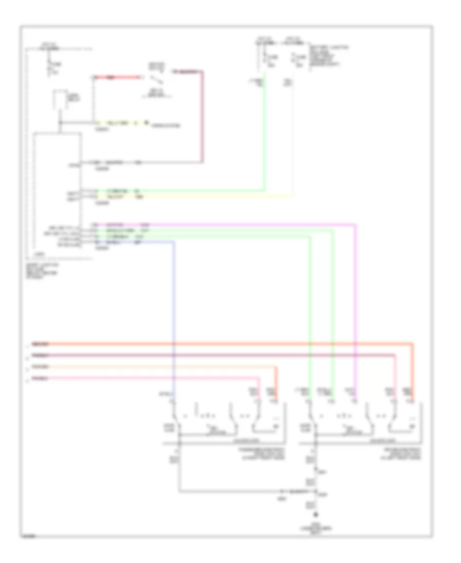
AIR CONDITIONING
2.3L
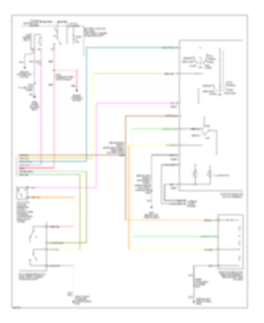
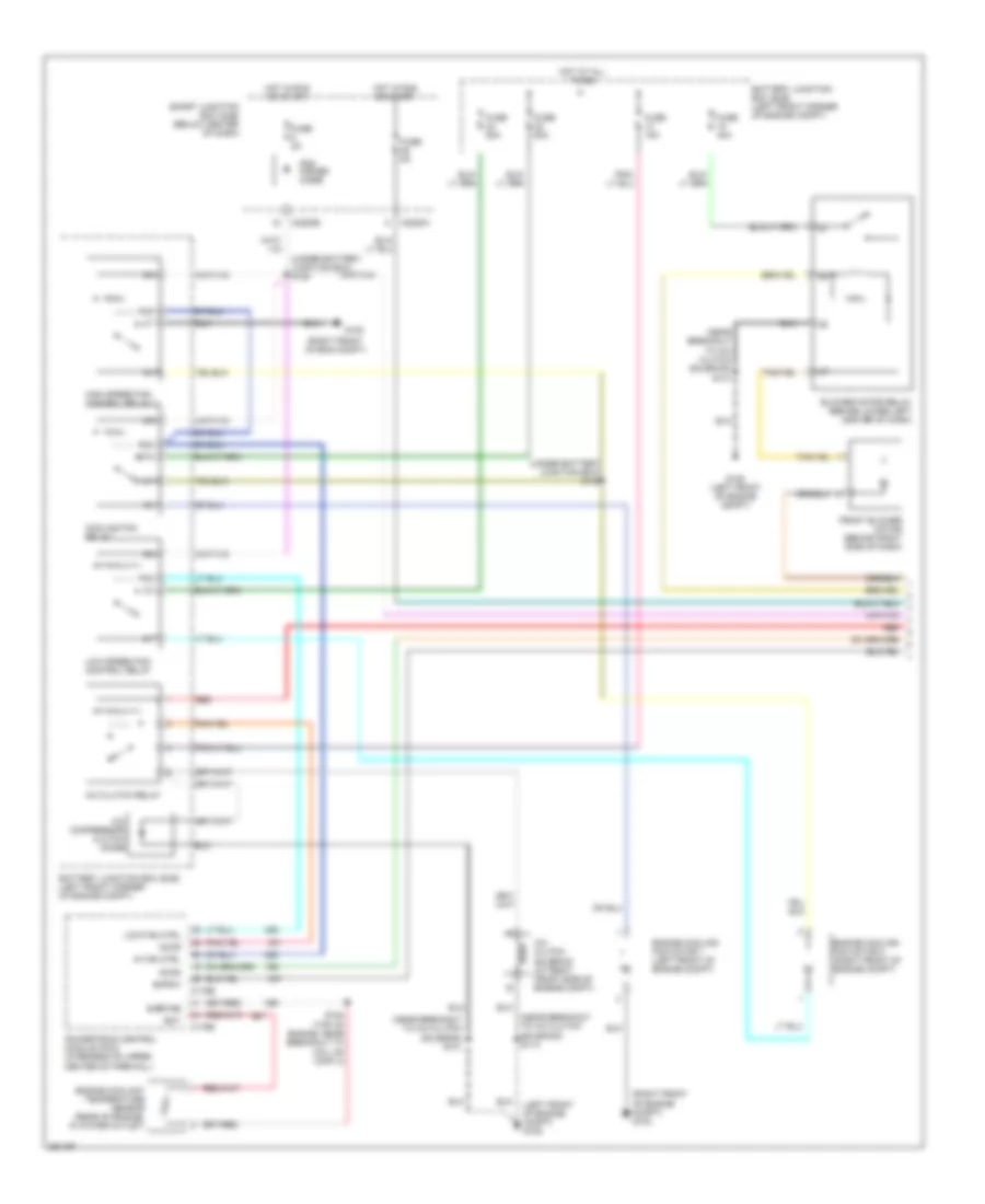
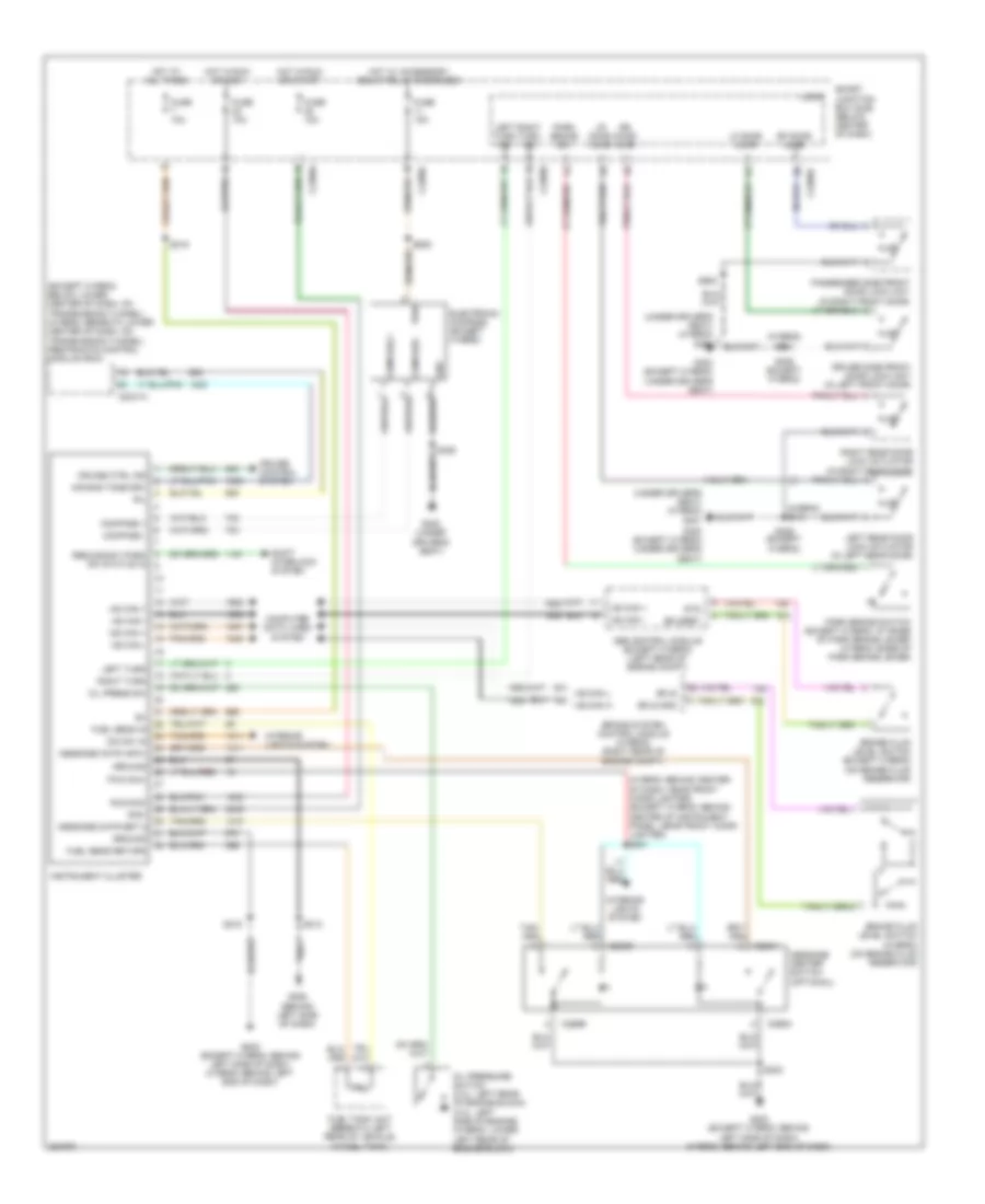
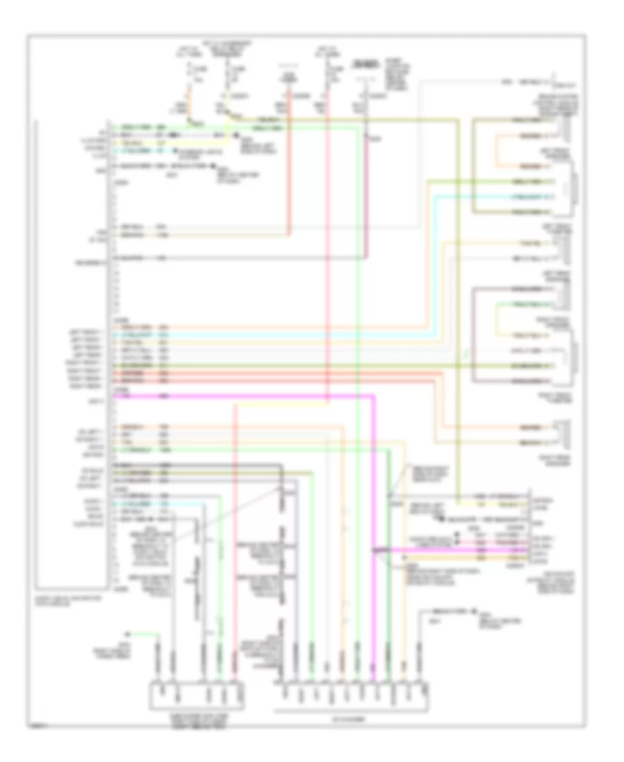
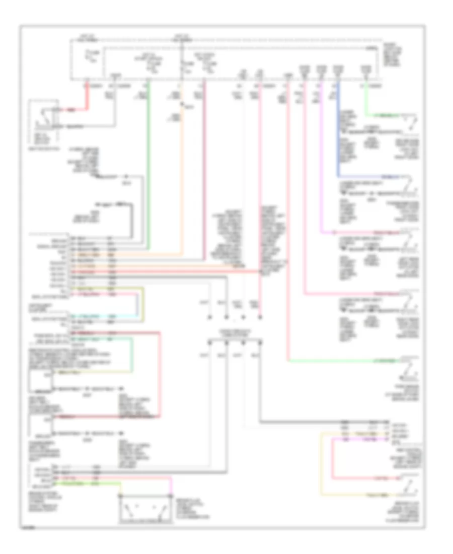
2.3L, Manual A/C Wiring Diagram, Except Hybrid (1 of 2) for Ford Escape 2007

List of elements for 2.3L, Manual A/C Wiring Diagram, Except Hybrid (1 of 2) for Ford Escape 2007:
- (left front of engine compt) g105
- (near breakout to windshield washer pump motor) s114
- (right front of engine compt) g102
- (under battery junction box) s127
- (under battery junction box) s128
- (under battery junction box) s131
- A/c clutch relay
- A/c clutch solenoid (at right front corner of engine compt)
- A/c compressor clutch diode
- Accr
- Accs
- Acpsw
- Battery junction box (bjb) (left front corner of engine compt)
- Blower motor relay (behind lower left center of dash)
- C175b
- C175e
- C2280a
- C2280b
- Cht
- Cooling fan ctrl
- Cooling fan relay
- Cylinder head temperature sensor (top of engine, on cylinder head)
- Engine cooling fan motor 1 (left front of engine compt)
- Engine cooling fan motor 2 (right front of engine compt)
- Front blower motor (behind right side of dash)
- Fuse 15a
- Fuse 2a
- Fuse 40a
- Fuse 5a
- G105 (left front of engine compt)
- Hi fan ctrl
- High speed fan control relay 1
- Hot at all times
- Hot in run or start
- Low fan ctrl
- Low speed fan control relay
- Pcm power diode
- Powertrain control module (pcm) (rear center of firewall)
- Red
- S109 (top of engine, near mass air flow (maf) sensor)
- S144 (under battery junction box)
- Sigrtne
- Smart junction box (sjb) (below center of dash)
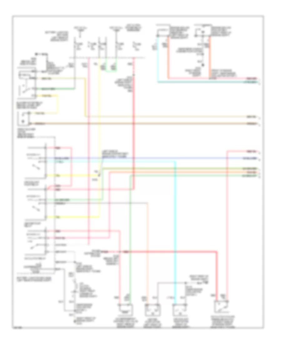
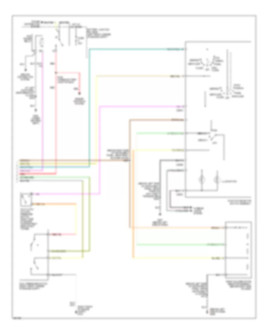
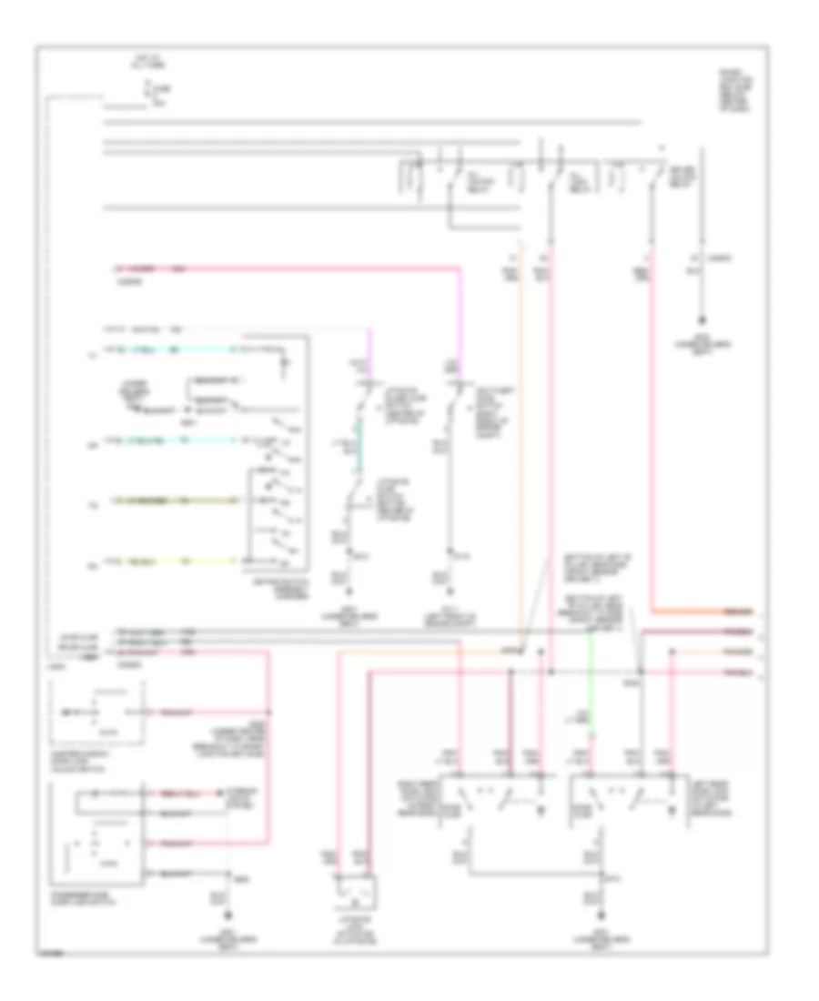
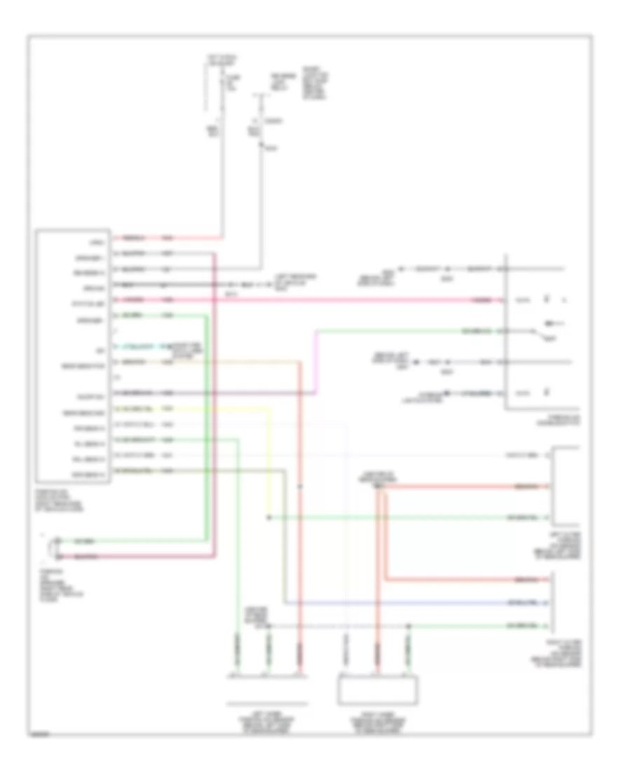
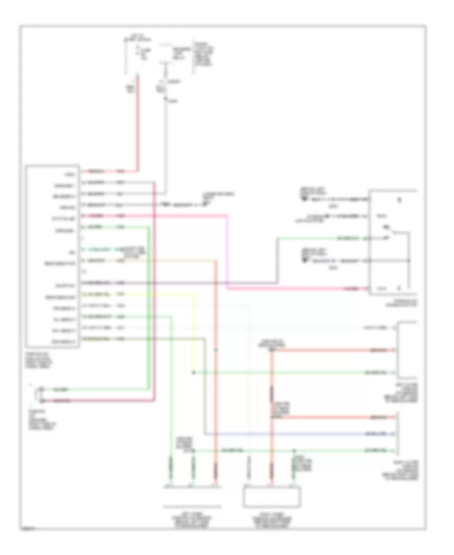
2.3L, Manual A/C Wiring Diagram, Except Hybrid (2 of 2) for Ford Escape 2007
List of elements for 2.3L, Manual A/C Wiring Diagram, Except Hybrid (2 of 2) for Ford Escape 2007:
- (behind left side of dash) g206
- (behind left side of instrument panel, near passive anti-theft transceiver) s208
- (behind right side of instrument panel, near front blower motor) s200
- (near instrument cluster) s214
- (right front of engine compartment) g103
- A/c clutch cycling pressure switch (on right side of engine compartment, near strut tower)
- Battery junction box (bjb) (left front corner of engine compt)
- C294a
- C294b
- C294c
- Def/floor
- Defrost
- Dual pressure switch (right front corner of engine compt)
- Engine controls system
- Floor
- Front blower motor resistor assembly (behind right side of dash)
- Function selector switch assembly
- Fuse 30a
- G207 (behind left side of dash)
- G300 (under driver's seat)
- Ground distribution system
- High
- Hot at all times
- Illumination
- Interior lights system
- Low
- Max
- Medium 1
- Medium 2
- Normal
- Off
- Pan/ floor
- Pan/floor
- Panel
- Pcm power relay
- Power distribution system
- Red
- S129 (under battery junction box)
- S332 (at left kick panel)
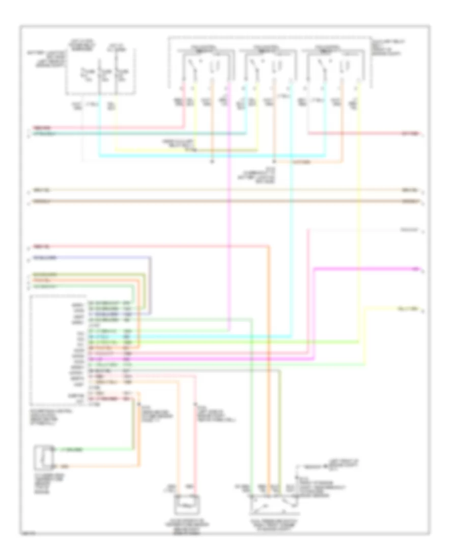
2.3L, Manual A/C Wiring Diagram, Hybrid (1 of 3) for Ford Escape 2007
List of elements for 2.3L, Manual A/C Wiring Diagram, Hybrid (1 of 3) for Ford Escape 2007:
- (front of engine compt, near engine cooling fan motor 1) s120
- (left side of engine compartment, near strut tower)
- (near engine cooling fan motor 1) s119
- (near rear window washer pump motor) s112
- (right front of engine compt) g103
- A/c clutch cycling pressure switch (on right side of of engine compt, near strut tower)
- A/c clutch relay
- A/c clutch solenoid (right front corner of engine compt)
- A/c compressor clutch diode
- A/c refrigerant distribution valve (right rear of engine compt)
- Battery junction box (bjb) (left rear of engine compt)
- Blower motor relay (behind lower left center of dash)
- Engine cooling fan dropping resistor 1 (left front of engine compt)
- Engine cooling fan motor 2 (right front of engine compt)
- Front blower motor (behind right side of dash)
- Fuse 10a
- Fuse 15a
- Fuse 30a
- Fuse 40a
- G103 (right front of engine compt)
- G206 (behind left side of dash)
- Heater pump motor (left front of engine compt)
- Heater pump relay
- Hot at all times
- Hot w/ pcm power relay energized
- M/e coolant pump motor (front of engine compt)
- M/e coolant pump relay
- Power distribution system
- Red
- S119 (near engine cooling fan motor 1)
- S129 (behind left headlight assembly)
- S149 (left side of engine compt, near strut tower)
- S151 (left side of engine compt, near strut tower)
- S152
- S212 (near breakout to instrument cluster)
2.3L, Manual A/C Wiring Diagram, Hybrid (2 of 3) for Ford Escape 2007
List of elements for 2.3L, Manual A/C Wiring Diagram, Hybrid (2 of 3) for Ford Escape 2007:
- (left front of engine compt) g111
- (near auxiliary relay box 1) s134
- A/c evaporative temperature sensor (behind right side of dash)
- Accr
- Accs
- Acet
- Acfds
- Acpsw
- Acrdv
- Acrsw
- Auxiliary relay box 1 (front of engine compt)
- Battery junction box (bjb) (left rear of engine compt)
- C175b
- C175e
- C175t
- Cht
- Cylinder head temperature sensor (top of engine)
- Dual pressure switch (right front corner of engine compt)
- Fan control relay 1
- Fan control relay 2
- Fan control relay 3
- Fc1
- Fc2
- Fc3
- Fuse 10a
- Fuse 40a
- Hot at all times
- Hot w/ pcm power relay energized
- Hpcr
- Mecp
- Powertrain control module (pcm) (rear center of firewall)
- Red
- S103 (near heated oxygen sensor (ho2s) 11)
- S116 (in breakout to battery junction box (bjb))
- S118 (front of engine compt, near breakout to forward crash sensor)
- S144 (left side of engine compt, above wheelwell)
- Sigrtn
- Sigrtne
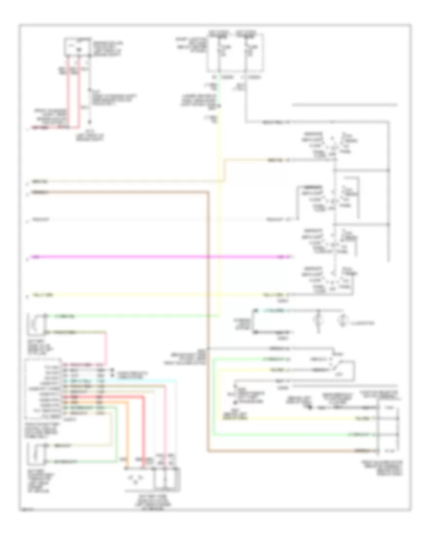
2.3L, Manual A/C Wiring Diagram, Hybrid (3 of 3) for Ford Escape 2007
List of elements for 2.3L, Manual A/C Wiring Diagram, Hybrid (3 of 3) for Ford Escape 2007:
- (behind left side of dash) g206
- (front of engine compt, near engine cooling fan motor 1) s122
- (near breakout to instrument cluster) s214
- (under center of dash, near smart junction box (sjb)) s251
- A/c
- Battery compartment thermistor (left rear corner of vehicle)
- Battery mode door actuator (left rear corner of vehicle)
- Battery zone valve (base of left "d" pillar)
- C2280a
- C2280d
- C294a
- C294b
- C294c
- C4227a
- Computer data lines system
- Def/floor
- Defrost
- Engine cooling fan motor 1 (left front of engine compt)
- Floor
- Front blower motor resistor assembly (behind right side of dash)
- Function selector switch assembly
- Fuse 5a
- G110 (left front of engine compt)
- G207 (behind left side of dash)
- High
- Hot in run or start
- Hs can+
- Hs can-
- Illumination
- Interior lights system
- Low
- Max
- Medium 1
- Medium 2
- Mode mtr+
- Mode mtr-
- Mode pot wiper
- Mode pot+
- Mode pot-
- Off
- Panel
- Panel/ floor
- Panel/ floor off
- Recirc
- Red
- S121 (front of engine compt, near engine cooling fan motor 1)
- S200 (behind right side of dash, near front blower motor)
- Smart junction box (sjb) (below center of dash)
- Traction battery control module (on floor, behind wheelwell)
- Txv sol
- Txv temp
- Txv temp rtn
3.0L
3.0L, Manual A/C Wiring Diagram (1 of 2) for Ford Escape 2007
List of elements for 3.0L, Manual A/C Wiring Diagram (1 of 2) for Ford Escape 2007:
- (left front of engine compt) g105
- (near breakout to a/c clutch solenoid) s114
- (near breakout to a/c clutch solenoid) s131
- (right front of eng compt)
- (right front of engine compt) g102
- (under battery junction box) s128
- (under battery junction box) s145
- 87a
- A/c clutch relay
- A/c clutch solenoid (at right front side of engine compt)
- A/c compressor clutch diode
- Accr
- Accs
- Acpsw
- Battery junction box (bjb) (left front corner of engine compt)
- Blower motor relay (behind lower left center of dash)
- C175b
- C175e
- C2280a
- C2280b
- Cooling fan relay
- Ect
- Engine coolant temperature sensor (rear of engine, in water outlet)
- Engine cooling fan motor 1 (left front of engine compt)
- Engine cooling fan motor 2 (right front of engine compt)
- Front blower motor (behind right side of dash)
- Fuse 15a
- Fuse 2a
- Fuse 40a
- Fuse 50a
- Fuse 5a
- G102
- G105 (left front of engine compt)
- Hi fan ctrl
- High speed fan control relay 2
- Hot at all times
- Hot in run or start
- Low fan ctrl
- Low speed fan control relay
- Pcm power diode
- Powertrain control module (pcm) (in recess on upper center of firewall)
- Red
- S154 (top of engine, near breakout to coil on (cop) 4)
- Sigrtne
- Smart junction box (sjb) (below center of dash)
3.0L, Manual A/C Wiring Diagram (2 of 2) for Ford Escape 2007
List of elements for 3.0L, Manual A/C Wiring Diagram (2 of 2) for Ford Escape 2007:
- (at left kick panel, near breakout to c263) s332
- (behind left side of dash) g206
- (behind left side of instrument panel, near instrument cluster) s214
- (behind left side of instrument panel, near passive anti-theft transceiver) s208
- (behind right side of instrument panel, near front blower motor) s200
- (right front of engine compt) g103
- A/c clutch cycling pressure switch (right side of engine compartment, near strut tower)
- Battery junction box (bjb) (left front corner of engine compt)
- C294a
- C294b
- C294c
- Def/floor
- Defrost
- Dual pressure switch (right front corner of engine compt)
- Engine controls system
- Floor
- Front blower motor resistor assembly (behind right side of dash)
- Function selector switch assembly
- Fuse 30a
- G207 (behind left side of dash)
- G300 (under driver's seat)
- Ground distribution system
- High
- Hot at all times
- Illumination
- Interior lights system
- Low
- Max
- Medium 1
- Medium 2
- Normal
- Off
- Pan/ floor
- Pan/floor
- Panel
- Pcm power relay
- Power distribution system
- Red
- S129 (under battery junction box)
ANTI-LOCK BRAKES
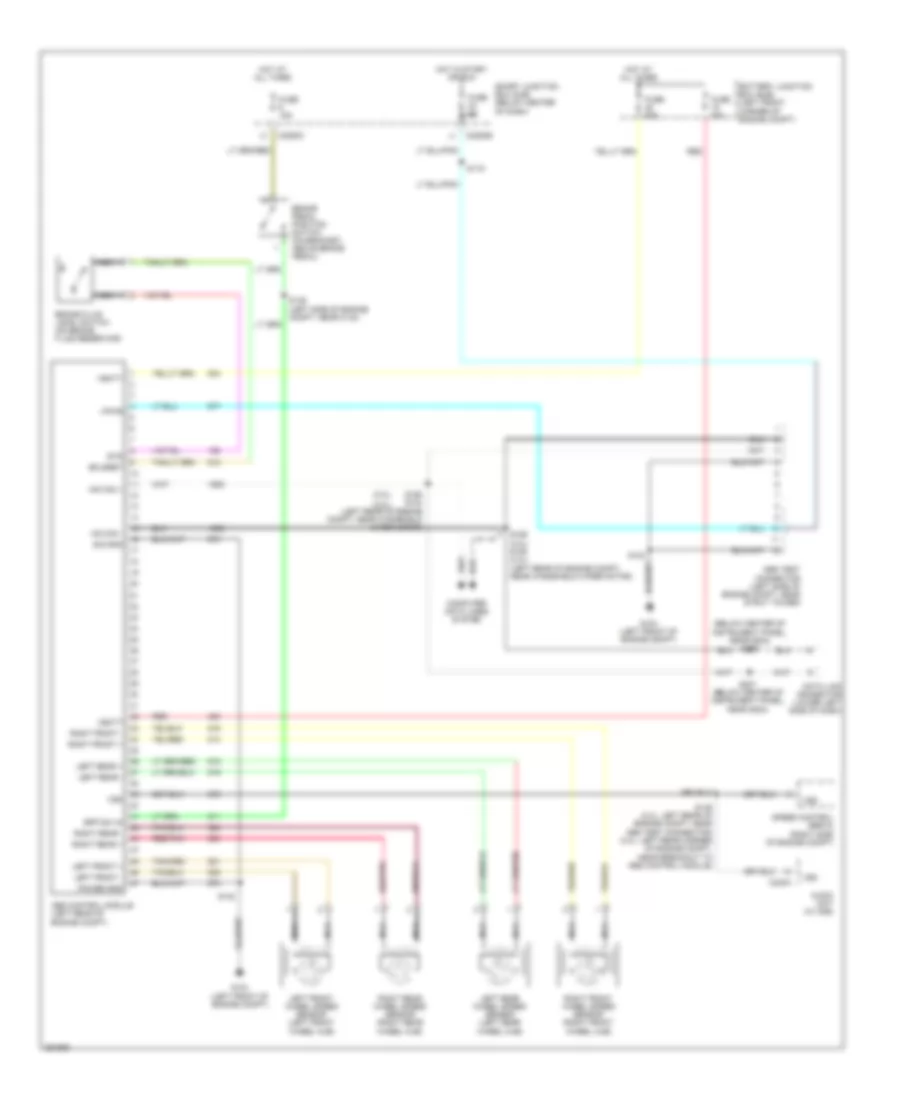
Anti-lock Brakes Wiring Diagram, Except Hybrid for Ford Escape 2007
List of elements for Anti-lock Brakes Wiring Diagram, Except Hybrid for Ford Escape 2007:
- (2.3l)
- (3.0l)
- (below center of instrument panel, near g204) s206
- Abs control module (left rear of engine compt)
- Abs test connector (left side of engine compt, near strut tower)
- Audio unit (w/ cd6)
- Battery junction box (bjb) (left front corner of engine compt)
- Bflsret
- Bpp sw in
- Brake fluid level switch (on brake fluid reservoir)
- Brake pedal position switch (on bracket, above brake pedal)
- C2280b
- C2280c
- C240a
- Computer data lines system
- Data link connector (lower left side of dash)
- Fuse 15a
- Fuse 30a
- Fuse 5a
- Fuse 60a
- G104 (left front of engine compt)
- Hot at all times
- Hot in start or run
- Hs can +
- Hs can -
- Left front +
- Left front -
- Left front wheel speed sensor (left front wheel hub)
- Left rear +
- Left rear -
- Left rear wheel speed sensor (left rear wheel hub)
- Nca
- Power gnd
- Red
- Red/pnk
- Right front +
- Right front -
- Right front wheel speed sensor (right front wheel hub)
- Right rear +
- Right rear -
- Right rear wheel speed sensor (right rear wheel hub)
- S119
- S123
- S139 (left side of engine compt, near c134)
- S146 (2.3l: left rear of engine compt, near abs test connector) (3.0l: left rear corner of engine compt, near breakout to abs control module)
- S158 s124 (left rear of engine compt, near windshield wiper motor)
- S159 (3.0l) s125 (2.3l) (left rear of engine compt, near windshield wiper motor)
- S207 (below center of instrument panel, near g204)
- Sig gnd
- Smart junction box (sjb) (below center of dash)
- Speed control servo (right side of engine compt)
- Sts
- Vbatt
- Vpwr
- Vss
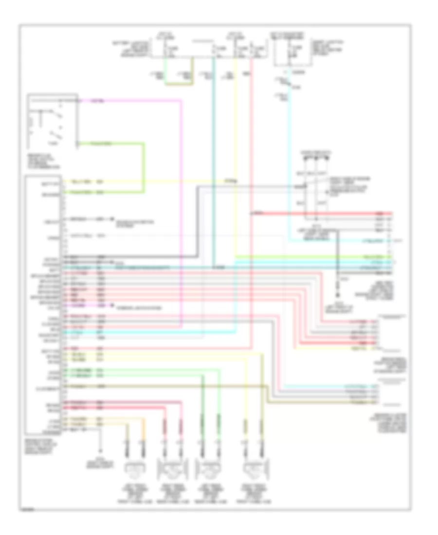
Anti-lock Brakes Wiring Diagram, Hybrid for Ford Escape 2007
List of elements for Anti-lock Brakes Wiring Diagram, Hybrid for Ford Escape 2007:
- (right side of engine compt, near a/c clutch cycling pressure switch) s133
- Abs test connector (left side of engine compt, near strut tower)
- Batt
- Batt-vp1
- Batt-vp2
- Battery junction box (bjb) (left rear of engine compt)
- Bfls
- Bfls-gnd
- Bphigh-gnd
- Bphigh-sensep
- Bphigh-sig
- Bplow-gnd
- Bplow-sensep
- Bplow-sig
- Brake fluid level switch (on brake fluid reservoir)
- Brake pedal position sensor (left rear of engine compt)
- Brake system control module (right rear of engine compt)
- C2280b
- Can2h
- Can2l
- Clus gnd
- Clus sens p
- Computer data lines system
- Fuse 30a
- Fuse 50a
- Fuse 5a
- G102 (right side of engine compt)
- G104 (right side of engine compt)
- G110 (left front of engine compt)
- Hot at all times
- Hot w/ run/start relay energized
- Hs can +
- Hs can -
- Interior lights system
- Left front wheel speed sensor (at left front wheel hub)
- Left rear wheel speed sensor (at left rear wheel hub)
- Lf gnd
- Lf sig
- Lr gnd
- Lr sig
- Nca
- Pwr-gnd
- Red
- Red/pnk
- Rf gnd
- Rf sig
- Right front wheel speed sensor (at right front wheel hub)
- Right rear wheel speed sensor (at right rear wheel hub)
- Rr gnd
- Rr sig
- Run/start
- S113 (left side of engine compt, near rear air box)
- S121
- S124
- S125
- S126
- S132
- S135
- Sensor cluster (four wheel drive) (under center console, near floor shifter)
- Smart junction box (sjb) (below center of dash)
- Sound & navigation systems
- Vss out
- Wk up
ANTI-THEFT
Forced Entry Wiring Diagram, Except Hybrid (1 of 2) for Ford Escape 2007
List of elements for Forced Entry Wiring Diagram, Except Hybrid (1 of 2) for Ford Escape 2007:
- (left rocker panel, near "b" pillar)
- (left rocker panel, next to rear seat)
- (under driver's seat) g300
- 1/2
- 3/4
- 5/6
- 7/8
- 9/0
- All lock relay
- All unlock relay
- Anti-theft hood switch (right front corner of engine compt)
- C2280b
- C2280c
- C2280d
- Door ajar
- Driver unlock relay
- Fuse 30a
- G103 (right front of engine compt)
- G300 (under driver's seat)
- Hot at all times
- Ill
- Interior lights system
- Keypad switch assembly
- Left rear door lock actuator (in left rear door)
- Liftgate ajar switch (bottom center of liftgate)
- Liftgate glass ajar switch (center of liftgate)
- Liftgate lock actuator (center of liftgate)
- Logic
- Lr dr ajar
- Master window/ door lock/ unlock switch
- Passenger side door lock switch
- Right rear door lock actuator (in right rear door)
- Rr dr ajar
- S305
- S308
- S309
- S320 (under driver's seat)
- S332
- S501
- S600
- Smart junction box (sjb) (below center of dash)
- Vref
Forced Entry Wiring Diagram, Except Hybrid (2 of 2) for Ford Escape 2007
List of elements for Forced Entry Wiring Diagram, Except Hybrid (2 of 2) for Ford Escape 2007:
- Battery junction box (bjb) (left front corner of engine compt)
- C2280a
- C2280b
- C2280d
- C2280e
- Door ajar
- Driver side front door lock unit (in left front door)
- Drv key cyl lk
- Drv key cyl unlk
- Fuse 10a
- Fuse 25a
- G300 (under driver's seat)
- Horn relay
- Horns system
- Hot at all times
- Ignition switch
- Key in ignition
- Key status
- Lf dr ajar
- Logic
- Passenger side front door lock unit (in right front door)
- Red
- Rf dr ajar
- S309
- S501
- S600
- Smart junction box (sjb) (below center of dash)
- Unlock/lock
- Vbatt
- Vpwr
Forced Entry Wiring Diagram, Hybrid (1 of 2) for Ford Escape 2007
List of elements for Forced Entry Wiring Diagram, Hybrid (1 of 2) for Ford Escape 2007:
- (bottom of left "b" pillar, near breakout to side impact sensor (driver 1))
- (bottom of left "b" pillar, near side impact sensor (driver 1))
- (under driver's seat) g301
- 1/2
- 3/4
- 5/6
- 7/8
- 9/0
- All lock relay
- All unlock relay
- Anti-theft hood switch (right front of engine compt)
- C2280b
- C2280c
- C2280d
- Door ajar
- Driver unlock relay
- Fuse 30a
- G111 (left front of engine compt)
- G300 (under driver's seat)
- G301 (under driver's seat)
- Hot at all times
- Ill
- Interior lights system
- Keypad switch assembly (mariner)
- Left rear door lock actuator (in left rear door)
- Liftgate ajar switch (bottom center of liftgate)
- Liftgate glass ajar switch (center of liftgate)
- Liftgate lock actuator (in liftgate)
- Logic
- Lr dr ajar
- Master window/ door lock/ unlock switch
- Passenger side door lock switch
- Right rear door lock actuator (in right rear door)
- Rr dr ajar
- S118
- S305
- S308
- S313
- S320 (under center of dash, near breakout to smart junction box (sjb))
- S501
- S600
- Smart junction box (sjb) (below center of dash)
- Vref
Forced Entry Wiring Diagram, Hybrid (2 of 2) for Ford Escape 2007
List of elements for Forced Entry Wiring Diagram, Hybrid (2 of 2) for Ford Escape 2007:
- Battery junction box (bjb) (left rear of engine compt)
- C2280a
- C2280b
- C2280d
- C2280e
- Door ajar
- Driver side front door lock unit (in left front door)
- Drv key cyl lk
- Drv key cyl unlk
- Fuse 10a
- Fuse 25a
- G301 (under driver's seat)
- Horn relay
- Horns system
- Hot at all times
- Ignition switch
- Key in ignition
- Key status
- Lf dr ajar
- Logic
- Passenger side front door lock unit (in right front door)
- Red
- Rf dr ajar
- S313
- S600
- Sjb logic
- Smart junction box (sjb) (below center of dash)
- Unlock/lock
- Vbatt
- Vpwr
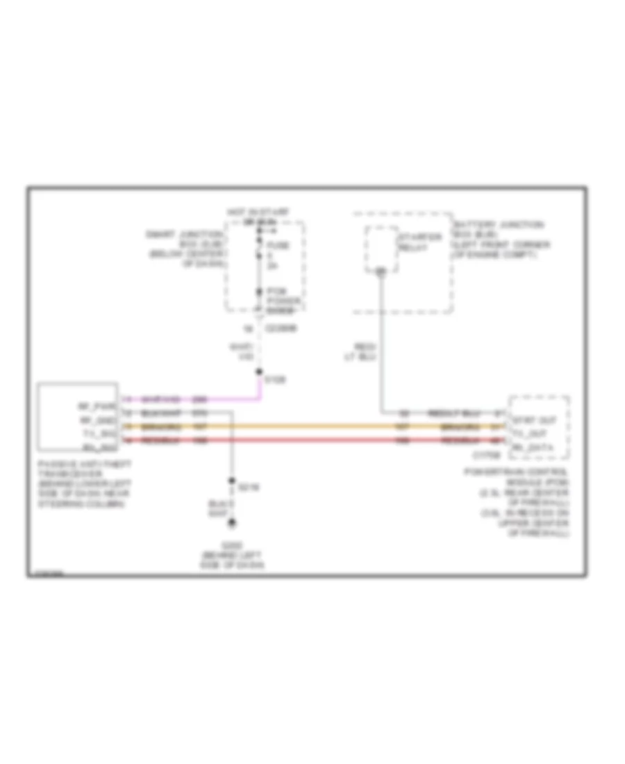
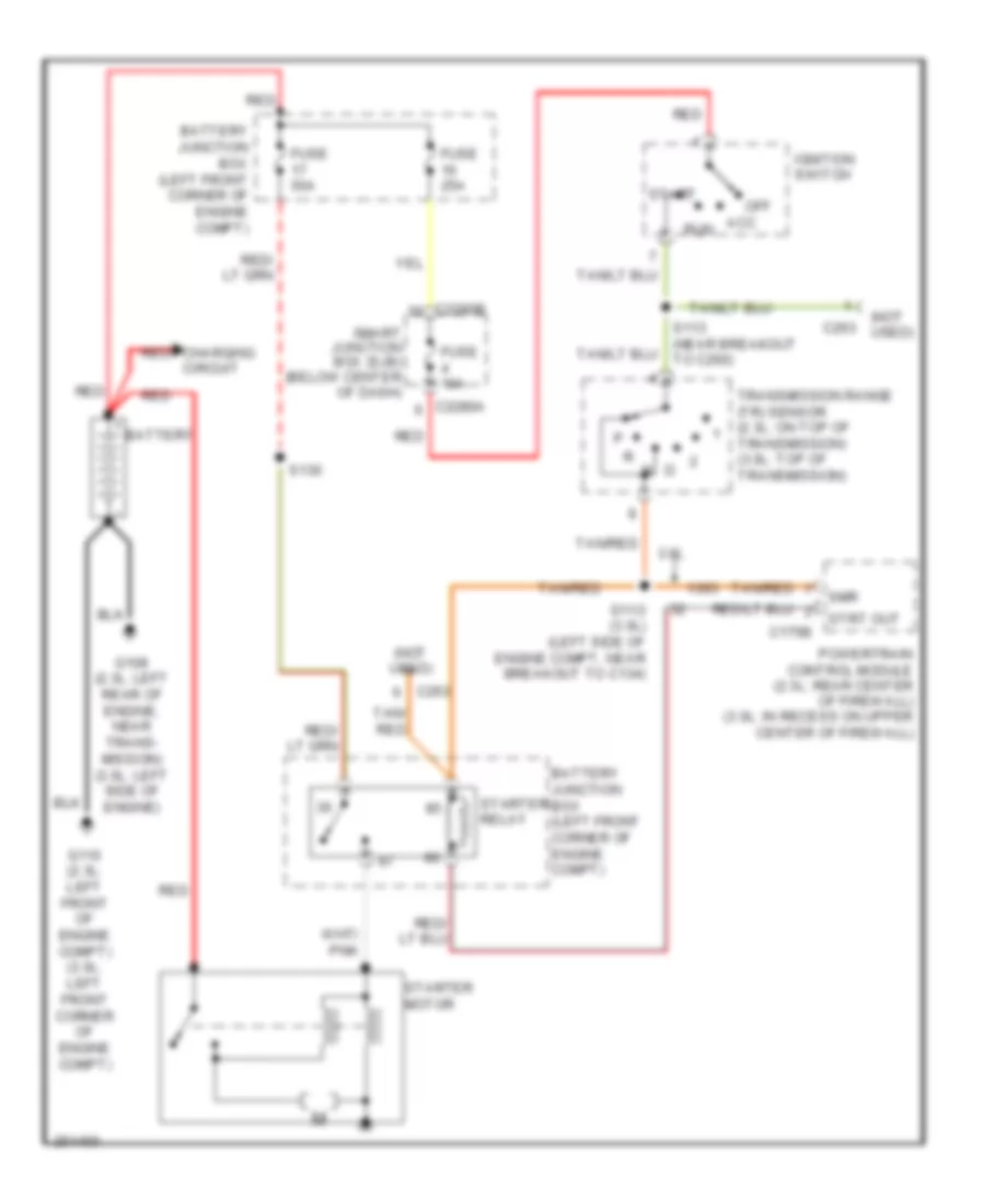
Passive Anti-theft Wiring Diagram, Except Hybrid for Ford Escape 2007
List of elements for Passive Anti-theft Wiring Diagram, Except Hybrid for Ford Escape 2007:
- Battery junction box (bjb) (left front corner of engine compt)
- C175b
- C2280b
- Fuse 2a
- G202 (behind left side of dash)
- Hot in start or run
- Passive anti-theft transceiver (behind lower left side of dash, near steering column)
- Pcm power diode
- Powertrain control module (pcm) (2.3l: rear center of firewall) (3.0l: in recess on upper center of firewall)
- Rf_gnd
- Rf_pwr
- Rx_data
- Rx_sig
- S128
- S218
- Smart junction box (sjb) (below center of dash)
- Starter relay
- Strt out
- Tx_out
- Tx_sig
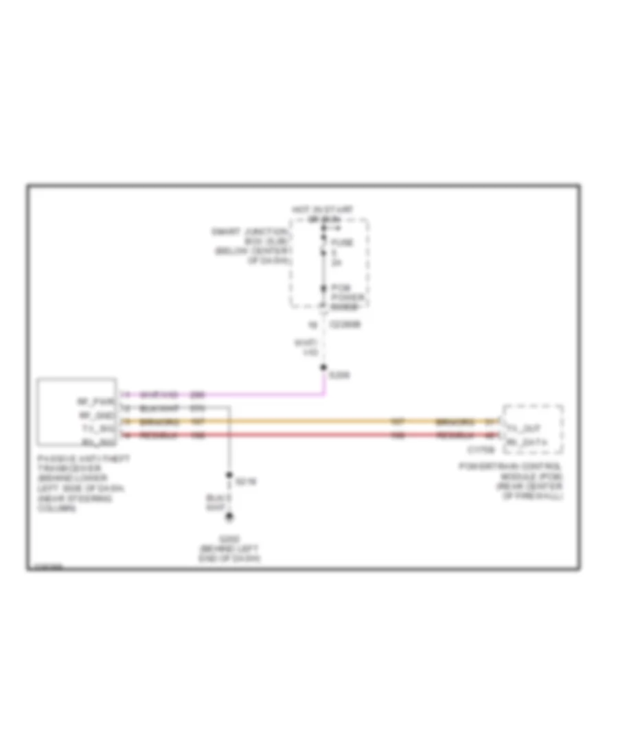
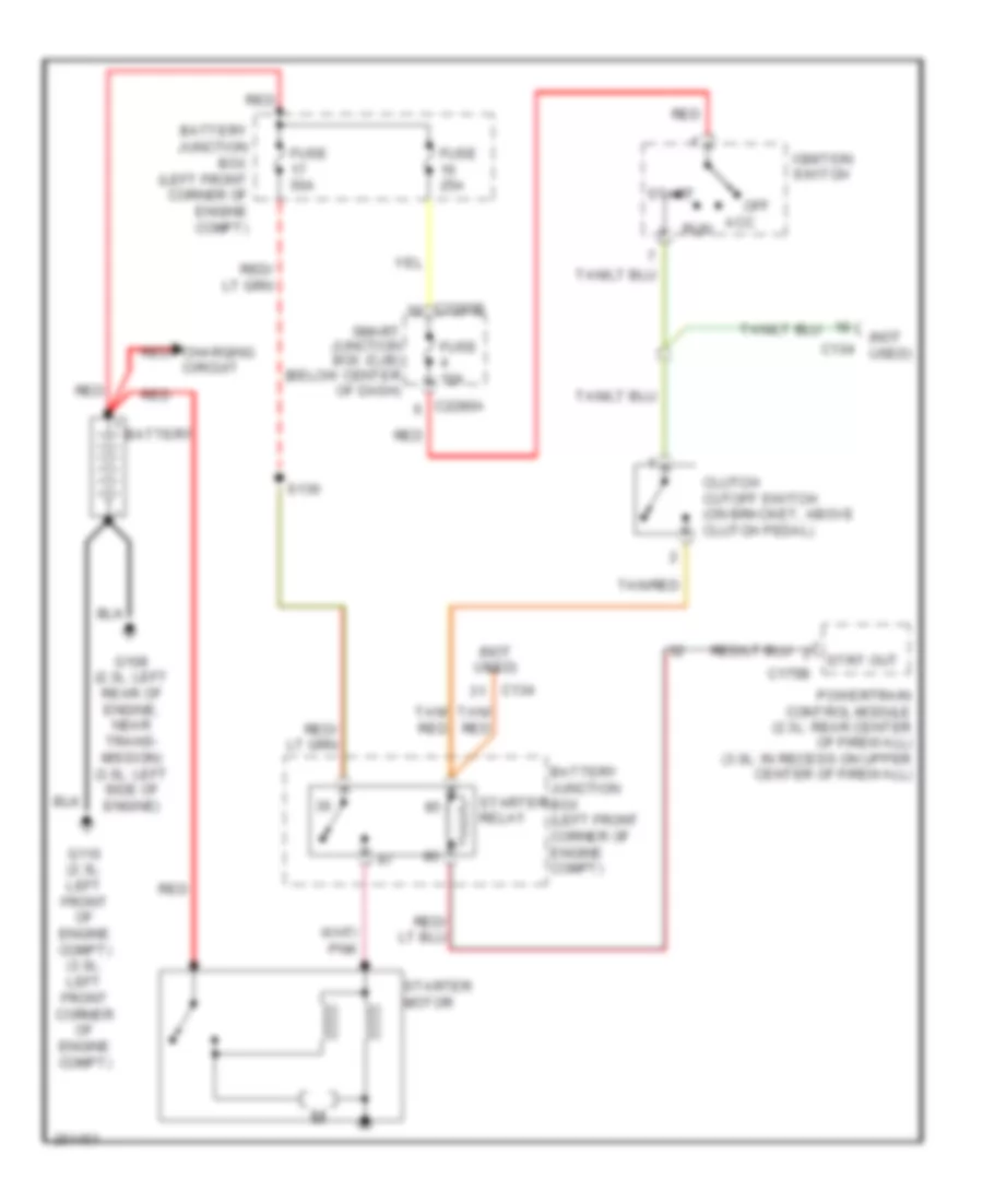
Passive Anti-theft Wiring Diagram, Hybrid for Ford Escape 2007
List of elements for Passive Anti-theft Wiring Diagram, Hybrid for Ford Escape 2007:
- C175b
- C2280b
- Fuse 2a
- G202 (behind left end of dash)
- Hot in start or run
- Passive anti-theft transceiver (behind lower left side of dash, (near steering column)
- Pcm power diode
- Powertrain control module (pcm) (rear center of firewall)
- Rf_gnd
- Rf_pwr
- Rx_data
- Rx_sig
- S209
- S218
- Smart junction box (sjb) (below center of dash)
- Tx_out
- Tx_sig
BODY CONTROL MODULES
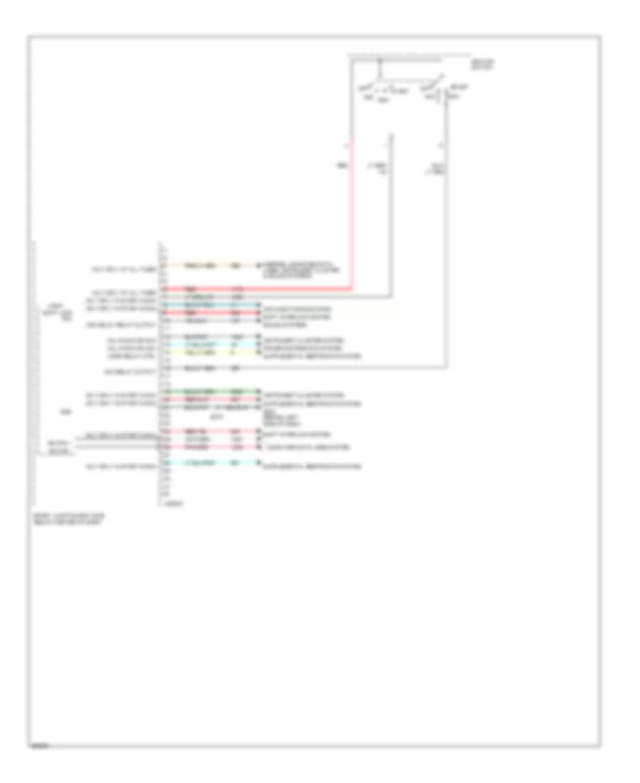
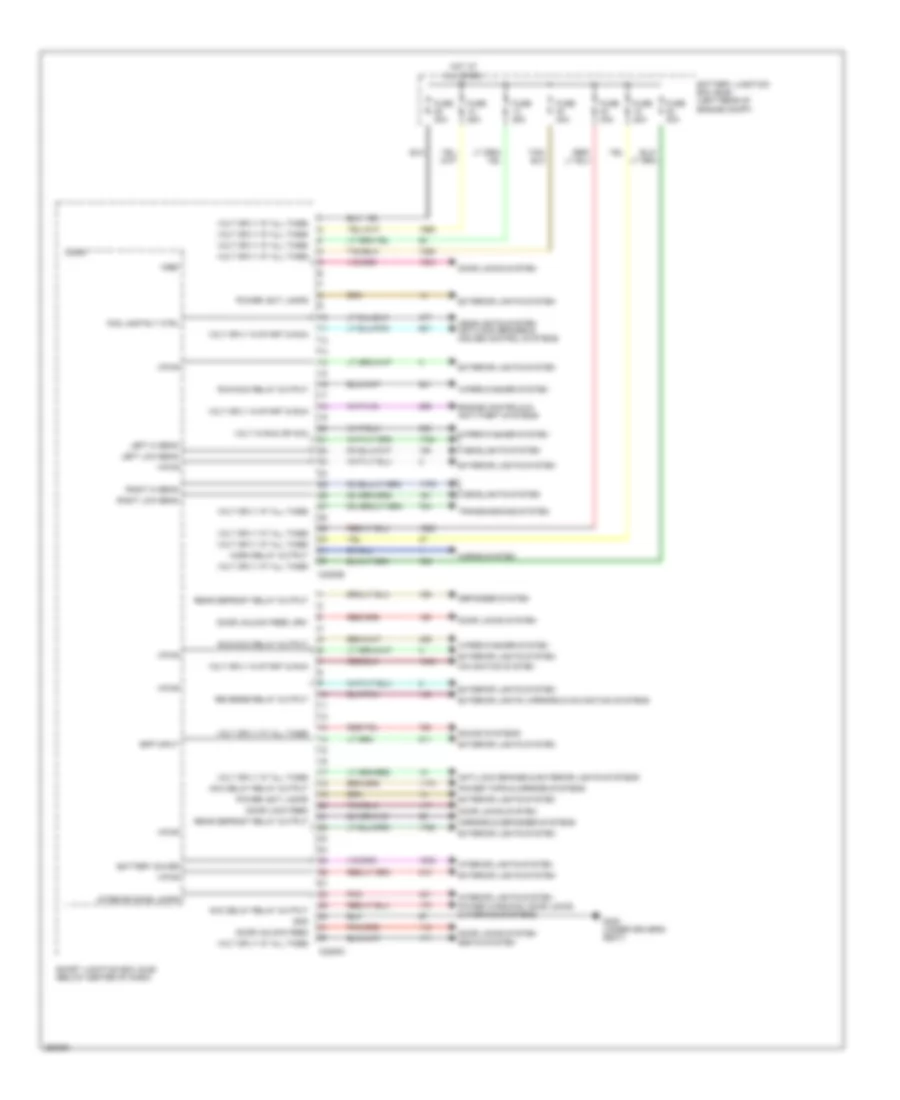
Body Control Modules Wiring Diagram, Except Hybrid (1 of 3) for Ford Escape 2007
List of elements for Body Control Modules Wiring Diagram, Except Hybrid (1 of 3) for Ford Escape 2007:
- Acc
- Acc delay relay output
- Acc relay output
- Air conditioning system
- C2280a
- Computer data lines system
- G202 (behind left side of dash)
- Gnd
- Horn relay ctrl
- Ignition switch
- Instrument cluster system
- Logic
- Mirrors, computer data lines, instrument cluster & sound systems
- Ms can +
- Ms can -
- Off
- Power distribution system
- Red
- Run
- S218
- Shift interlock system
- Shift lock sol
- Smart junction box (sjb) (below center of dash)
- Sound systems
- Start
- Vol in run or acc
- Volt sply at all times
- Volt sply in start & run
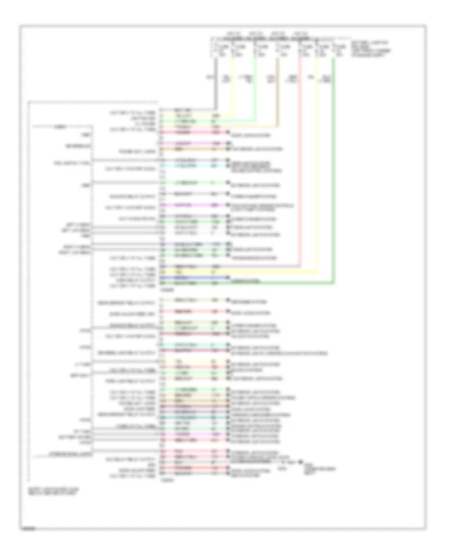
Body Control Modules Wiring Diagram, Except Hybrid (2 of 3) for Ford Escape 2007
List of elements for Body Control Modules Wiring Diagram, Except Hybrid (2 of 3) for Ford Escape 2007:
- Acc delay relay output
- Battery junction box (bjb) (left front corner of engine compt)
- Battery saver
- Bpp input
- C2280b
- C2280c
- Cooling fans, engine controls & anti-theft systems
- Defogger system
- Door lock feed
- Door locks system
- Door unlock feed
- Door unlock feed, drv
- Engine controls system
- Exterior lights system
- Exterior lights, mirrors & navigation systems
- Fog lamp rly ctrl
- Fuse 25a
- Fuse 40a
- Fuse 8 at all times
- G300 (under driver's seat)
- Gnd
- H/l power
- Headlights system
- Headlights system anti-lock brakes & cruise control systems
- Horn relay output
- Horns system
- Hot at all times
- Interior dome lamps
- Interior lights system
- Left hi beam
- Left low beam
- Lighting hsd
- Logic
- Lt turn
- Mirrors & defogger systems
- Navigation system
- Park lamp relay output
- Pnk
- Power tops & mirrors systems
- Power windows, door locks & warning systems
- Power, ext lamps
- Rear defrost relay output
- Reverse lamp relay output
- Reverse sig
- Right hi beam
- Right low beam
- Rt turn
- Run/acc relay output
- S332
- Seats system
- Smart junction box (sjb) (below center of dash)
- Sound systems
- Transmissions system
- Volt in run or acc
- Volt sply at all times
- Volt sply in start & run
- Vpwr
- Vref
- Wiper/washer system
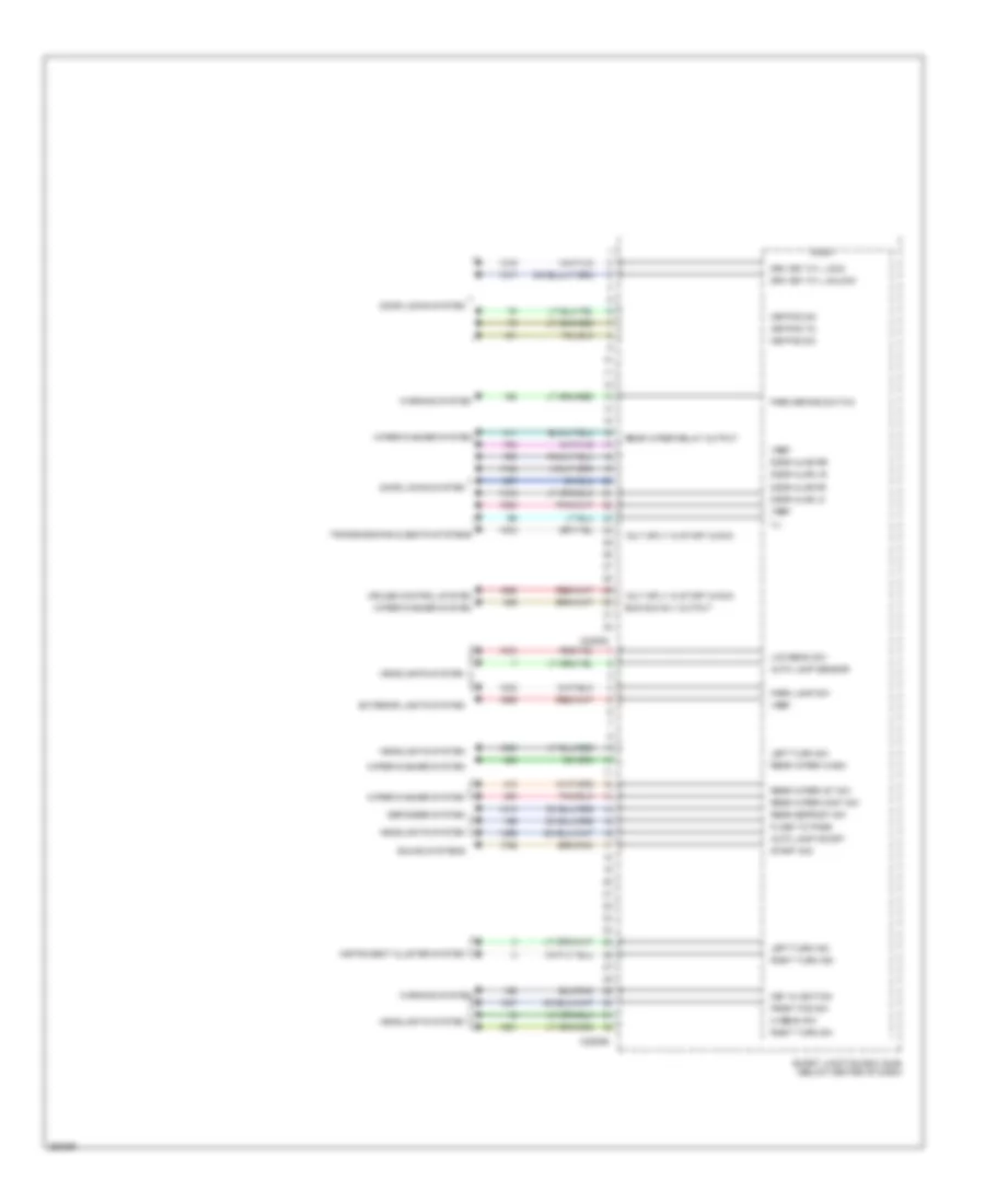
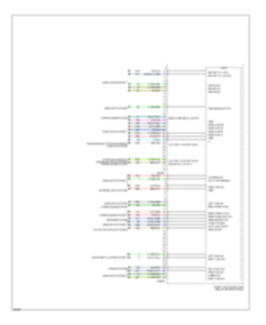
Body Control Modules Wiring Diagram, Except Hybrid (3 of 3) for Ford Escape 2007
List of elements for Body Control Modules Wiring Diagram, Except Hybrid (3 of 3) for Ford Escape 2007:
- Auto lamp on/off
- Auto lamp sensor
- C2280d
- C2280e
- Cruise control system
- Defogger system
- Door ajar lf
- Door ajar lr
- Door ajar rf
- Door ajar rr
- Door locks system
- Drv key cyl lock
- Drv key cyl unlock
- Exterior lights system
- Flash to pass
- Front fog sw
- Headlights system
- Hi beam sw
- Ill
- Instrument cluster system
- Key in ignition
- Keypad 5/6
- Keypad 7/8
- Keypad 9/0
- Left turn ind
- Left turn sw
- Logic
- Low beam sw
- Park brake switch
- Park lamp sw
- Rear defrost sw
- Rear wiper cont sw
- Rear wiper int sw
- Rear wiper relay output
- Rear wiper wash
- Right turn ind
- Right turn sw
- Run/acc rly output
- Smart junction box (sjb) (below center of dash)
- Sound systems
- Start sig
- Transmissions & seats systems
- Volt sply in start & run
- Vref
- Warning system
- Wiper/washer system
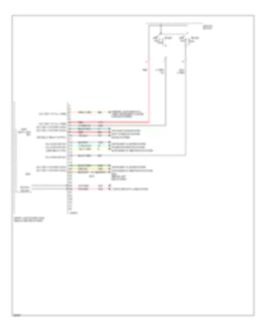
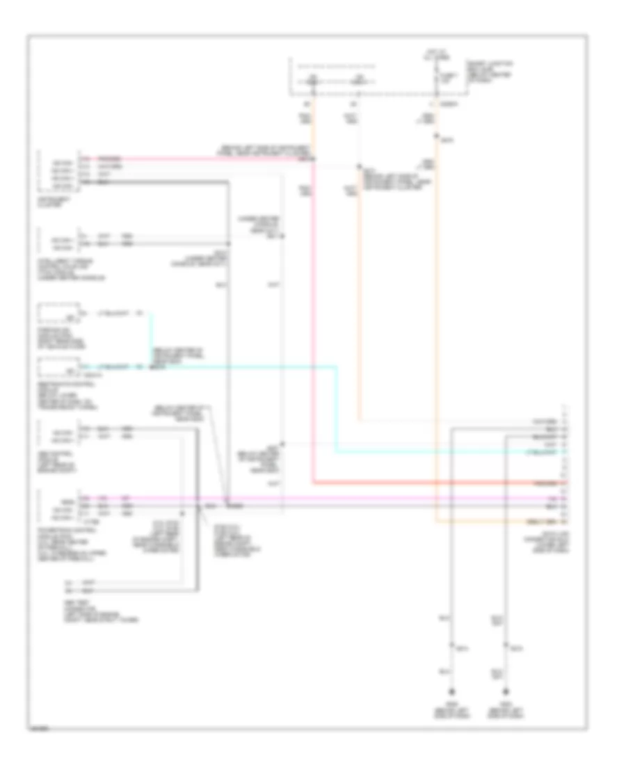
Body Control Modules Wiring Diagram, Hybrid (1 of 3) for Ford Escape 2007
List of elements for Body Control Modules Wiring Diagram, Hybrid (1 of 3) for Ford Escape 2007:
- Acc
- Acc delay relay output
- Air conditioning system
- C2280a
- Computer data lines system
- G202 (behind left end of dash)
- Gnd
- Horn relay ctrl
- Ignition switch
- Instrument cluster system
- Logic
- Mirrors, computer data lines, instrument cluster & sound systems
- Ms can +
- Ms can -
- Off
- Power distribution system
- Red
- Run
- S218
- Shift interlock system
- Shift lock sol
- Smart junction box (sjb) (below center of dash)
- Sound systems
- Start
- Vol in run or acc
- Volt sply at all times
- Volt sply in start & run
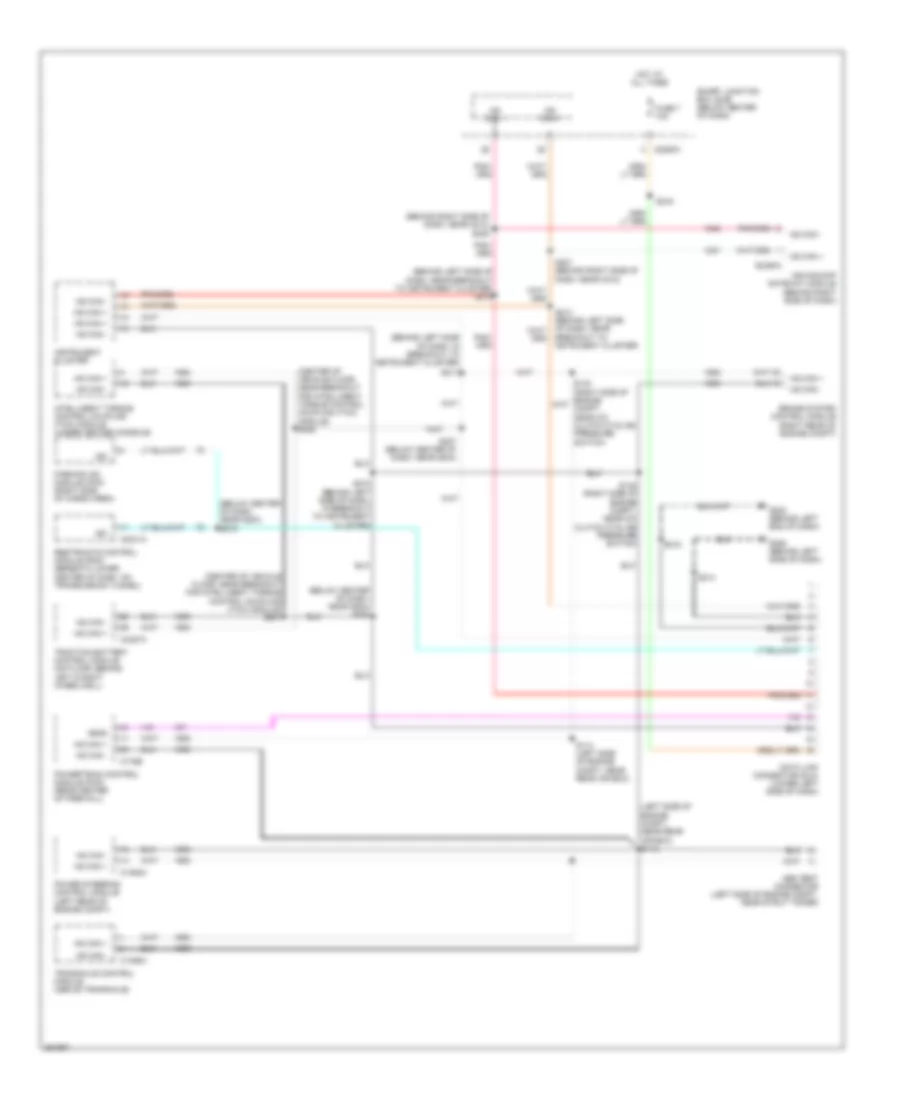
Body Control Modules Wiring Diagram, Hybrid (2 of 3) for Ford Escape 2007
List of elements for Body Control Modules Wiring Diagram, Hybrid (2 of 3) for Ford Escape 2007:
- Acc delay relay output
- Anti-lock brakes & exterior lights systems
- Battery junction box (bjb) (left rear of engine compt)
- Battery saver
- Bpp input
- C2280b
- C2280c
- Defogger system
- Door lock feed
- Door locks system
- Door unlock feed
- Door unlock feed, drv
- Engine controls & anti-theft systems
- Exterior lights system
- Exterior lights, mirrors & navigation systems
- Fog lamp rly ctrl
- Fuse 20a
- Fuse 25a
- Fuse 40a
- G300 (under driver's seat)
- Gnd
- Headlights system
- Headlights system anti-lock brakes & cruise control systems
- Horn relay output
- Horns system
- Hot at all times
- Interior dome lamps
- Interior lights system
- Left hi beam
- Left low beam
- Logic
- Mirrors & defogger systems
- Navigation system
- Pnk
- Power tops & mirrors systems
- Power windows, door locks & warning systems
- Power, ext lamps
- Rear defrost relay output
- Reverse relay output
- Right hi beam
- Right low beam
- Run/acc relay output
- Seats system
- Smart junction box (sjb) (below center of dash)
- Sound systems
- Transmissions system
- Volt in run or acc
- Volt sply at all times
- Volt sply in start & run
- Vpwr
- Vref
- Wiper/washer system
Body Control Modules Wiring Diagram, Hybrid (3 of 3) for Ford Escape 2007
List of elements for Body Control Modules Wiring Diagram, Hybrid (3 of 3) for Ford Escape 2007:
- Auto lamp on/off
- Auto lamp sensor
- C2280d
- C2280e
- Defogger system
- Door ajar lf
- Door ajar lr
- Door ajar rf
- Door ajar rr
- Door locks system
- Drv key cyl lock
- Drv key cyl unlock
- Exterior lights system
- Flash to pass
- Front fog sw
- Headlights system
- Hi beam sw
- Ill
- Instrument cluster system
- Key in ignition
- Keypad 5/6
- Keypad 7/8
- Keypad 9/0
- Left turn ind
- Left turn sw
- Logic
- Low beam sw
- Navigation & sound systems
- Park brake switch
- Park lamp sw
- Radio start
- Rear defrost sw
- Rear wiper cont sw
- Rear wiper int sw
- Rear wiper relay output
- Rear wiper wash
- Right turn ind
- Right turn sw
- Run/acc rly output
- Smart junction box (sjb) (below center of dash)
- Starting/charging & engine controls systems wiper/washer system
- Transmissions, starting/charging & seats systems
- Volt sply in start & run
- Vref
- Warning system
- Wiper/washer system
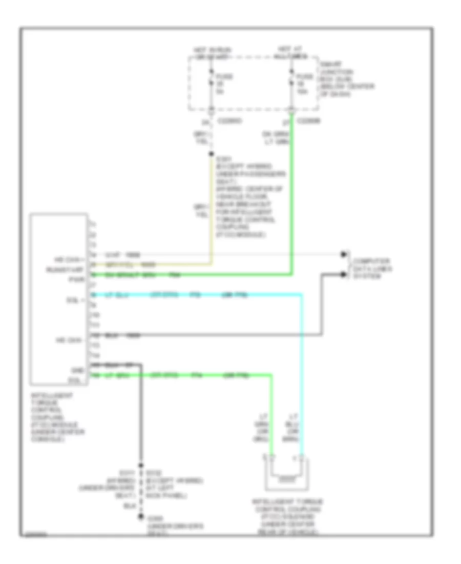
COMPUTER DATA LINES
Computer Data Lines Wiring Diagram, Except Hybrid for Ford Escape 2007
List of elements for Computer Data Lines Wiring Diagram, Except Hybrid for Ford Escape 2007:
- (2.3l) s124 (3.0l) s158 (left rear of engine compt, near windshield wiper motor)
- (behind left side of instrument panel, near instrument cluster) s215
- (below center of instrument panel, near g204)
- (below center of instrument panel, near g204) s219
- (under center console, near c211) s211
- Abs control module (left rear of engine compt)
- Abs test connector (left side of engine compt, near strut tower)
- C175b
- C2041a
- C2280a
- Data link connector (dlc) (lower left side of dash)
- Feps
- Fuse 7 10a
- G202 (behind left side of dash)
- G206 (behind left side of dash)
- Hot at all times
- Hs can +
- Hs can -
- Instrument cluster
- Intelligent torque control coupling (itcc) module (under center console)
- Iso
- Ms can +
- Ms can -
- Parking aid module (pam) (right rear side of vehicle floor)
- Powertrain control module (pcm) (2.3l: rear center of firewall) (3.0l: in recess on upper center of firewall)
- Restraints control module (below lower center of dash, on transmission tunnel)
- S125 (2.3l) s159 (3.0l) (left rear of engine compt, near windshield wiper motor)
- S206
- S207 (below center of instrument panel, near g204)
- S210 (under center console, near c211)
- S213 (behind left side of instrument panel, near instrument cluster)
- S214
- S216
- S218
- Smart junction box (sjb) (below center of dash)
Computer Data Lines Wiring Diagram, Hybrid for Ford Escape 2007
List of elements for Computer Data Lines Wiring Diagram, Hybrid for Ford Escape 2007:
- (behind left side of dash, in breakout to instrument cluster)
- (behind left side of dash, near breakout to instrument cluster) s215
- (behind right side of dash, near c212) s238
- (below center of dash, near g204) s206
- (below center of dash, near g204) s219
- (center of vehicle floor, near breakout for intelligent torque control coupling (itcc) module) s306
- (center of vehicle floor, near breakout for intelligent torque control coupling (itcc) module) s307
- (left side of engine compt, near rear air box) s113
- Abs test connector (left side of engine compt, near strut tower)
- Brake system control module (right rear of engine compt)
- C1458a
- C1463a
- C175b
- C2041a
- C2280a
- C2294a
- C4227a
- Data link connector (dlc) (lower left side of dash)
- Feps
- Fuse 7 10a
- G202 (behind left end of dash)
- G206 (behind left side of dash)
- Hot at all times
- Hs can +
- Hs can -
- Instrument cluster
- Intelligent torque control coupling (itcc) module (under center console)
- Iso
- Ms can +
- Ms can -
- Ms-can/acp gateway module (behind right side of dash)
- Parking aid module (pam) (right side of cargo area)
- Power steering control module (left rear of engine compt)
- Powertrain control module (pcm) (rear center of firewall)
- Restraints control module (rcm) (beneath lower center of dash, on transmission tunnel)
- S114 (left side of engine compt, near rear air box)
- S132 (right side of engine compt, near a/c clutch cycling pressure switch)
- S207 (below center of dash, near g204)
- S210 (behind left side of dash, in breakout to instrument cluster)
- S211
- S213 (behind left side of dash, near breakout to nstrument cluster)
- S214
- S216
- S218
- S237 (behind right side of dash, near c212)
- Smart junction box (sjb) (below center of dash)
- Traction battery control module (on floor, behind left & right wheelwell)
- Transaxle control module (above transaxle)
COOLING FAN
2.3L
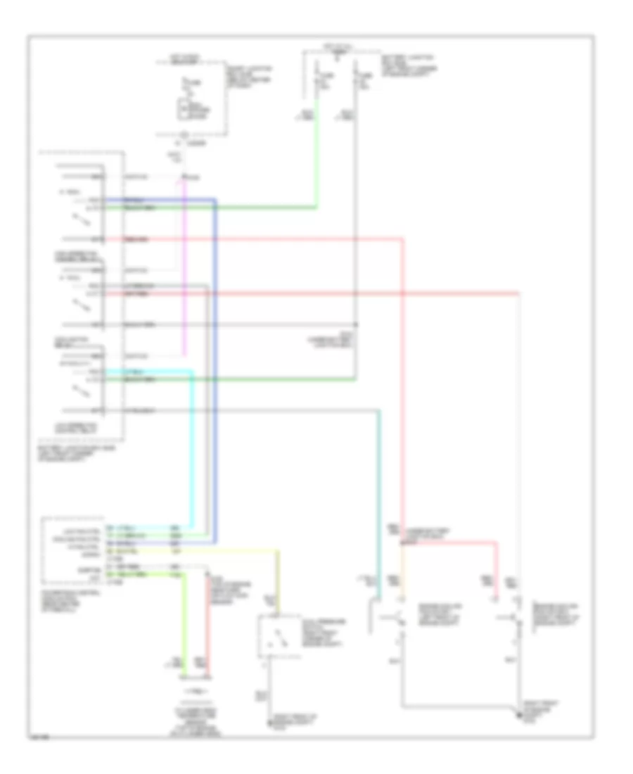
2.3L, Cooling Fan Wiring Diagram, Except Hybrid for Ford Escape 2007
List of elements for 2.3L, Cooling Fan Wiring Diagram, Except Hybrid for Ford Escape 2007:
- (right front of engine compt) g102
- (right front of engine compt) g103
- (under battery junction box) s127
- Acpsw
- Battery junction box (bjb) (left front corner of engine compt)
- C175b
- C175e
- C2280b
- Cht
- Cooling fan ctrl
- Cooling fan relay
- Cylinder head temperature sensor (top of engine, on cylinder head)
- Dual pressure switch (right front corner of engine compt)
- Engine cooling fan motor 1 (left front of engine compt)
- Engine cooling fan motor 2 (right front of engine compt)
- Fuse 2a
- Fuse 40a
- Hi fan ctrl
- High speed fan control relay 1
- Hot at all times
- Hot in run or start
- Low fan ctrl
- Low speed fan control relay
- Pcm power diode
- Powertrain control module (pcm) (rear center of firewall)
- S109 (top of engine, near mass air flow (maf) sensor)
- S128
- S144 (under battery junction box)
- Sigrtne
- Smart junction box (sjb) (below center of dash)
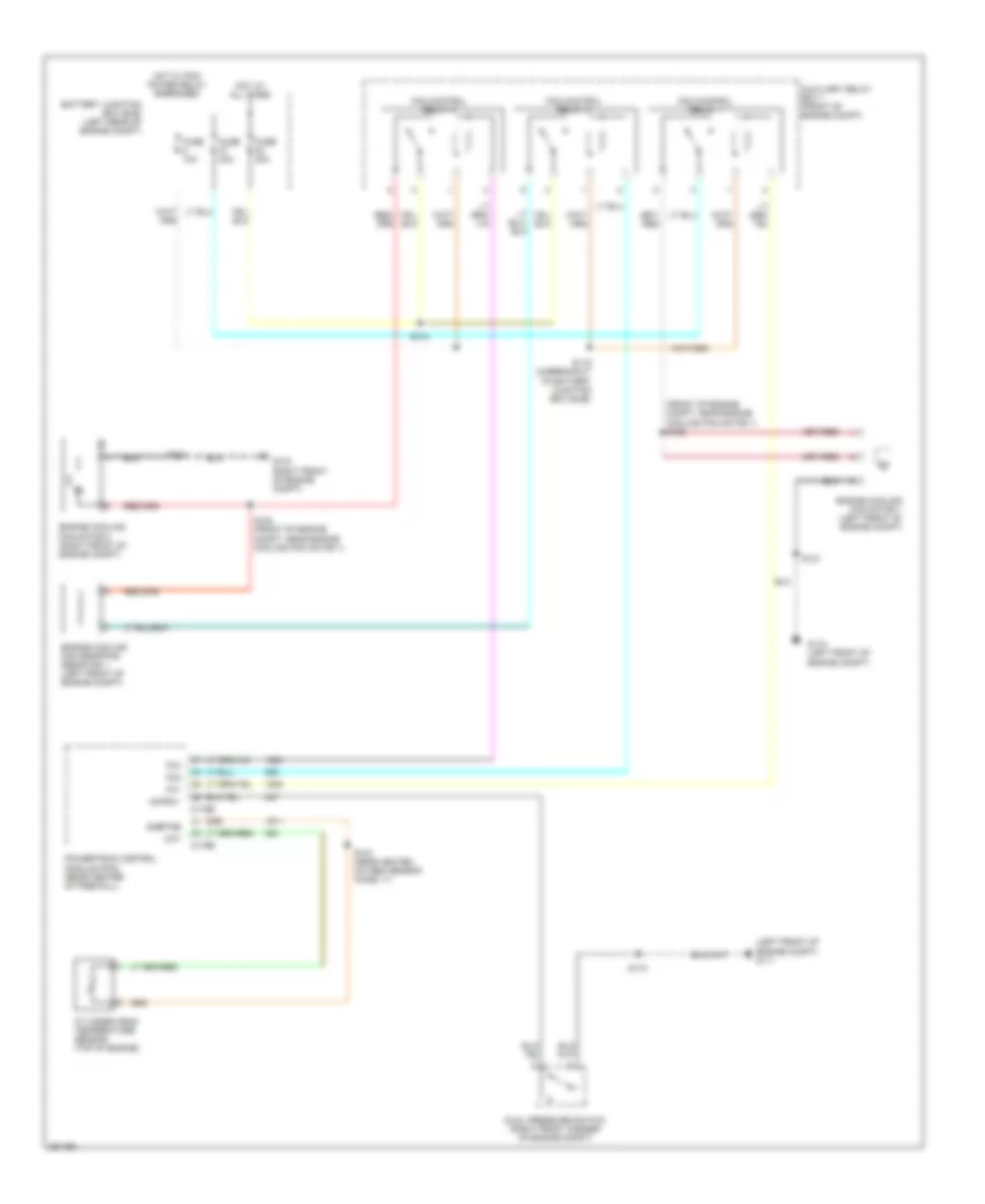
2.3L, Cooling Fan Wiring Diagram, Hybrid for Ford Escape 2007
List of elements for 2.3L, Cooling Fan Wiring Diagram, Hybrid for Ford Escape 2007:
- (front of engine compt, near engine cooling fan motor 1) s122
- (left front of engine compt) g111
- Acpsw
- Auxiliary relay box 1 (front of engine compt)
- Battery junction box (bjb) (left rear of engine compt)
- C175b
- C175e
- Cht
- Cylinder head temperature sensor (top of engine)
- Dual pressure switch (right front corner of engine compt)
- Engine cooling fan dropping resistor 1 (left front of engine compt)
- Engine cooling fan motor 1 (left front of engine compt)
- Engine cooling fan motor 2 (right front of engine compt)
- Fan control relay 1
- Fan control relay 2
- Fan control relay 3
- Fc1
- Fc2
- Fc3
- Fuse 10a
- Fuse 40a
- G103 (right front of engine compt)
- G110 (left front of engine compt)
- Hot at all times
- Hot w/ pcm power relay energized
- Powertrain control module (pcm) (rear center of firewall)
- S103 (near heated oxygen sensor (ho2s) 11)
- S112
- S116 (in breakout to battery junction box (bjb))
- S118
- S120 (front of engine compt, near engine cooling fan motor 1)
- S121
- S134
- Sigrtne
3.0L
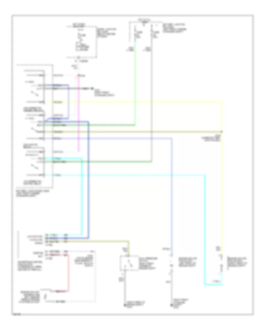
3.0L, Cooling Fan Wiring Diagram for Ford Escape 2007
List of elements for 3.0L, Cooling Fan Wiring Diagram for Ford Escape 2007:
- (right front of engine compt) g102
- (right front of engine compt) g103
- 87a
- Acpsw
- Battery junction box (bjb) (left front corner of engine compt)
- C175b
- C175e
- C2280b
- Cooling fan relay
- Dual pressure switch (right front corner of engine compt)
- Ect
- Engine coolant temperature (ect) sensor (rear of engine in water outlet)
- Engine cooling fan motor 1 (left front of engine compt)
- Engine cooling fan motor 2 (right front of engine compt)
- Fuse 2a
- Fuse 50a
- G102 (right front of engine compt)
- Hi fan ctrl
- High speed fan control relay 2
- Hot at all times
- Hot in run or start
- Low fan ctrl
- Low speed fan control relay
- Pcm power diode
- Powertrain control module (pcm) (in recess on upper center of firewall)
- S128
- S145 (under battery junction box)
- S154 (top of engine near breakout to coil on plug (cop) 4)
- Sigrtne
- Smart junction box (sjb) (below center of dash)
CRUISE CONTROL
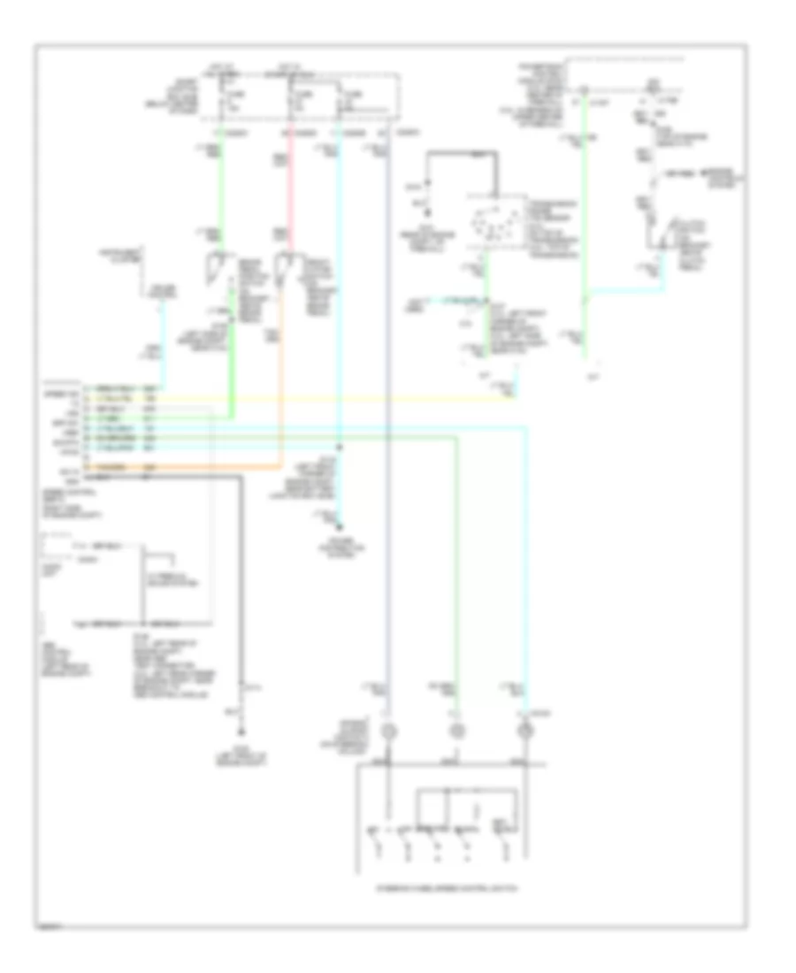
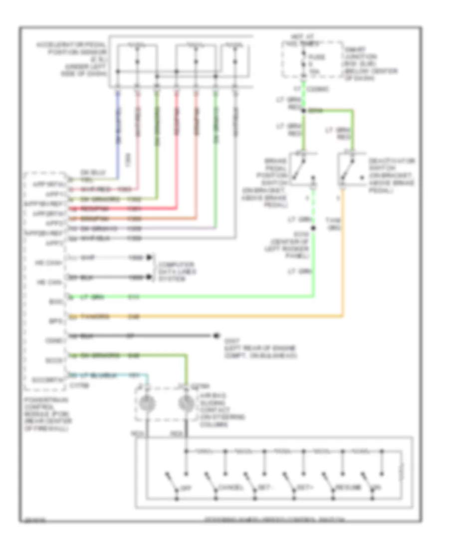
Cruise Control Wiring Diagram, Except Hybrid for Ford Escape 2007
List of elements for Cruise Control Wiring Diagram, Except Hybrid for Ford Escape 2007:
- on
- (not used)
- (right side of engine compt)
- 2.3l
- A/t
- Abs control module (left rear of engine compt)
- Air bag sliding contact (on steering column)
- Audio unit
- Bpp sw
- Brake pedal position switch (on bracket, above brake pedal)
- C175b
- C175t
- C218a
- C2280a
- C2280b
- C2280c
- C2280d
- C240a
- Clutch switch (on bracket, above clutch pedal)
- Coast
- Cruise control
- Deact- ivator switch (on bracket, above brake pedal)
- Engine controls system
- Fuse 15a
- Fuse 5a
- G101 (rear of engine compt, on firewall)
- G105 (left front of engine compt)
- Gnd
- Hot at all times
- Hot in start or run
- Instrument cluster
- M/t
- Nca
- Off
- Power distribution system
- Powertrain control module (pcm) (2.3l: rear center of firewall) (3.0l: in recess on upper center of firewall)
- Resume
- S104
- S114
- S119 (left front corner of engine compt, near battery junction box (bjb))
- S139 (left side of engine compt, near c134)
- S146 (2.3l: left rear of engine compt, near abs test connector) (3.0l: left rear corner of engine compt, near breakout to abs control module)
- S155 (top of engine, near c174)
- Set/ accel
- Sig rtn
- Smart junction box (sjb) (below center of dash)
- Speed control servo
- Speed ind
- Steering wheel/speed control switch
- Sw in
- Transmission range (tr) sensor (2.3l: on top of transmission) (3.0l: top of transmission)
- Vpwr
- Vref
- Vss
- W/ premium sound system
Cruise Control Wiring Diagram, Hybrid for Ford Escape 2007
List of elements for Cruise Control Wiring Diagram, Hybrid for Ford Escape 2007:
- Accelerator pedal position sensor (2.3l) (under left side of dash)
- Air bag sliding contact (on steering column)
- App1
- App1bvref
- App1rtn
- App2
- App2bvref
- App2rtn
- App3
- Boo
- Bps
- Brake pedal position switch (on bracket, above brake pedal)
- C175b
- C218a
- C2280c
- Cancel
- Cgnd
- Computer data lines system
- Deactivator switch (on bracket, above brake pedal)
- Fuse 15a
- G107 (left rear of engine compt, on bulkhead)
- Hot at all times
- Hs can+
- Hs can-
- Nca
- Off
- Powertrain control module (pcm) (rear center of firewall)
- Red/pnk
- Resume
- S310 (center of left rocker panel)
- Sccs
- Sccsrtn
- Set+
- Set-
- Smart junction box (sjb) (below center of dash)
- Steering wheel/speed control switch
DEFOGGERS
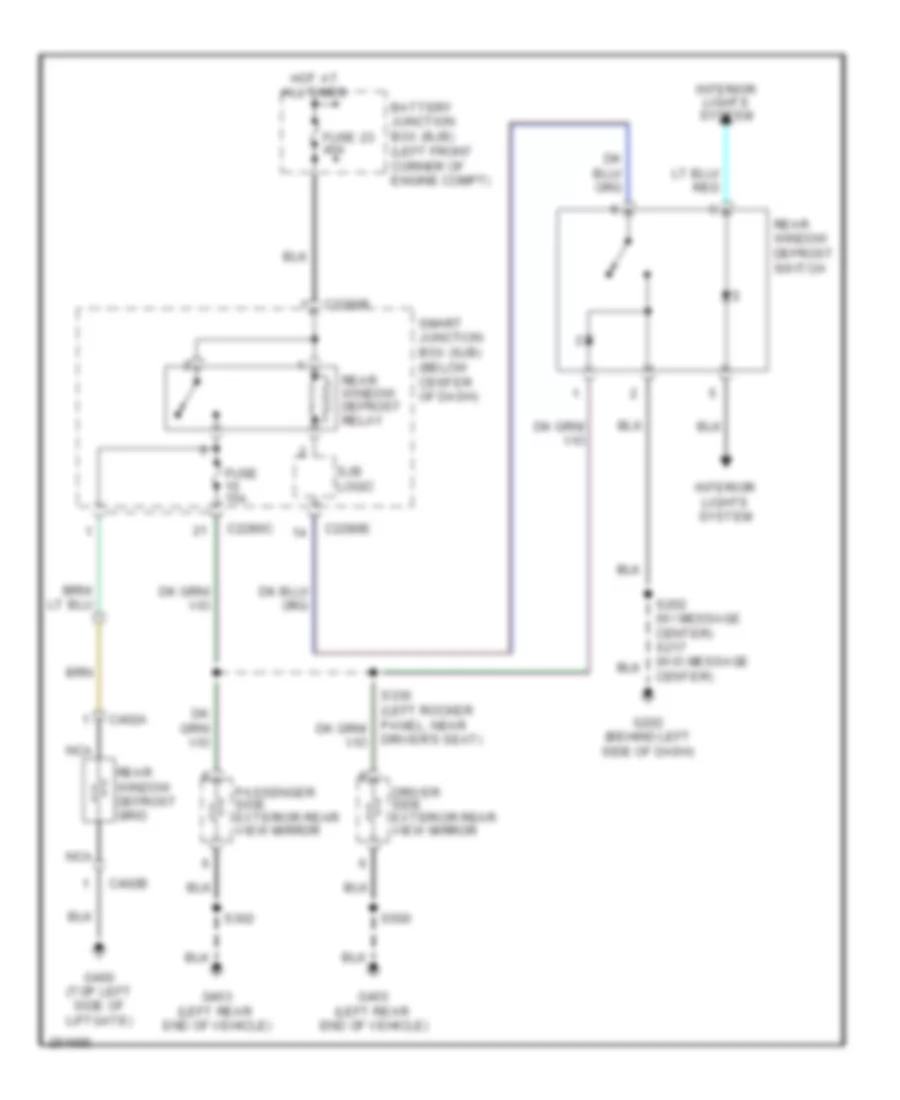
Defoggers Wiring Diagram, Except Hybrid for Ford Escape 2007
List of elements for Defoggers Wiring Diagram, Except Hybrid for Ford Escape 2007:
- Battery junction box (bjb) (left front corner of engine compt)
- C2280b
- C2280c
- C2280e
- C402a
- C402b
- Center)
- Driver side exterior rear view mirror
- Driver's seat)
- Fuse 15a
- Fuse 23 40a
- G202 (behind left side of dash)
- G400 (top left side of liftgate)
- G403 (left rear end of vehicle)
- Hot at all times
- Interior lights system
- Nca
- Passenger side exterior rear view mirror
- Rear window defrost grid
- Rear window defrost relay
- Rear window defrost switch
- S302
- S500
- Sjb logic
- Smart junction box (sjb) (below center of dash)
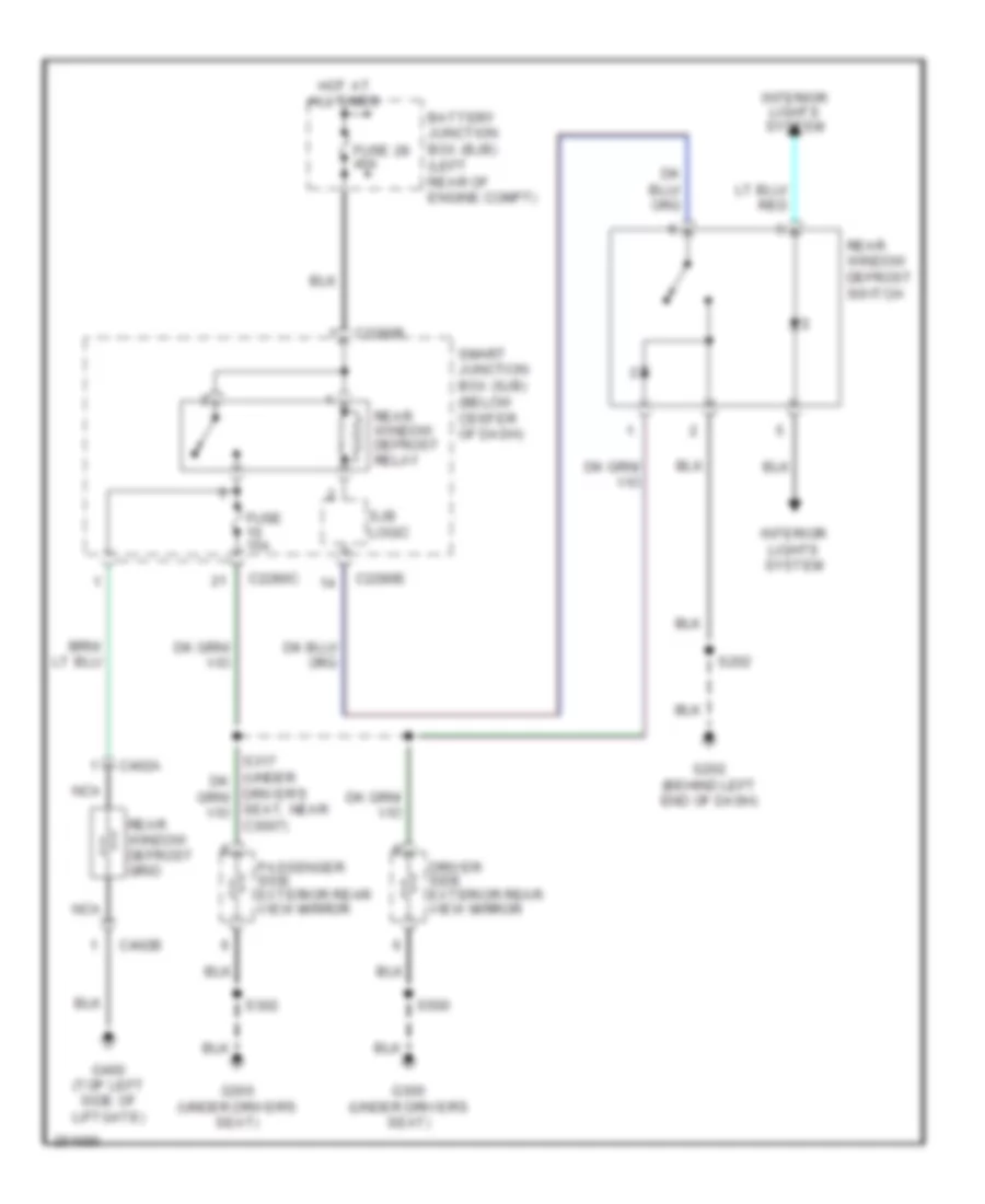
Defoggers Wiring Diagram, Hybrid for Ford Escape 2007
List of elements for Defoggers Wiring Diagram, Hybrid for Ford Escape 2007:
- Battery junction box (bjb) (left rear of engine compt)
- C2280b
- C2280c
- C2280e
- C402a
- C402b
- Driver side exterior rear view mirror
- Driver's seat, near c3007)
- Fuse 15a
- Fuse 28 40a
- G202 (behind left end of dash)
- G300 (under driver's seat)
- G400 (top left side of liftgate)
- Hot at all times
- Interior lights system
- Nca
- Passenger side exterior rear view mirror
- Rear window defrost grid
- Rear window defrost relay
- Rear window defrost switch
- S202
- S302
- S500
- Sjb logic
- Smart junction box (sjb) (below center of dash)
ELECTRONIC POWER STEERING
Electronic Power Steering Wiring Diagram, Hybrid for Ford Escape 2007
List of elements for Electronic Power Steering Wiring Diagram, Hybrid for Ford Escape 2007:
- (left side of engine compt)
- Bat
- Battery junction box (bjb) (left rear of engine compt)
- C1463a
- C1463b
- C1467a
- C1467b
- C2280b
- Computer data lines system
- Control module)
- Electric power steering pump motor (left rear of engine compt)
- Fuse 50a
- Fuse 5a
- G108 (left rear of engine compt, near transaxle control module)
- G109 (left side of engine compt)
- Gnd
- Hot at all times
- Hot in run or start
- Hs can+
- Hs can-
- Main
- Motor +
- Motor -
- Power steering control module (left rear of engine compt)
- Pwr
- Ref
- Run/start
- S101
- S108
- S109
- S125
- S140
- S141 (left rear of engine compt, near power steering control module)
- Smart junction box (sjb) (below center of dash)
- Sub
- Torque sensor (right rear of engine)
- Trq sn gnd
- Trq sn main
- Trq sn pwr
- Trq sn ref
- Trq sn sub
ENGINE PERFORMANCE
2.3L
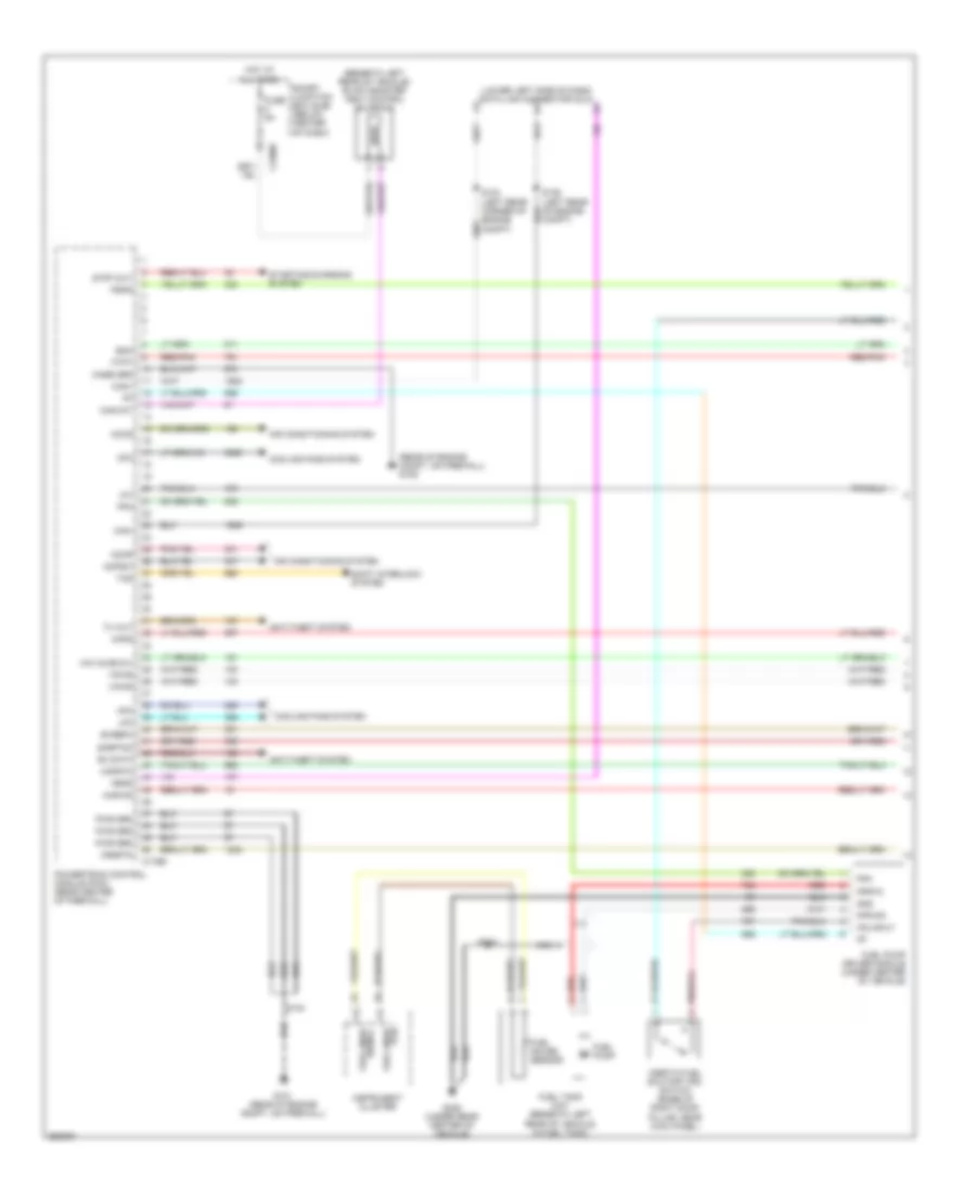
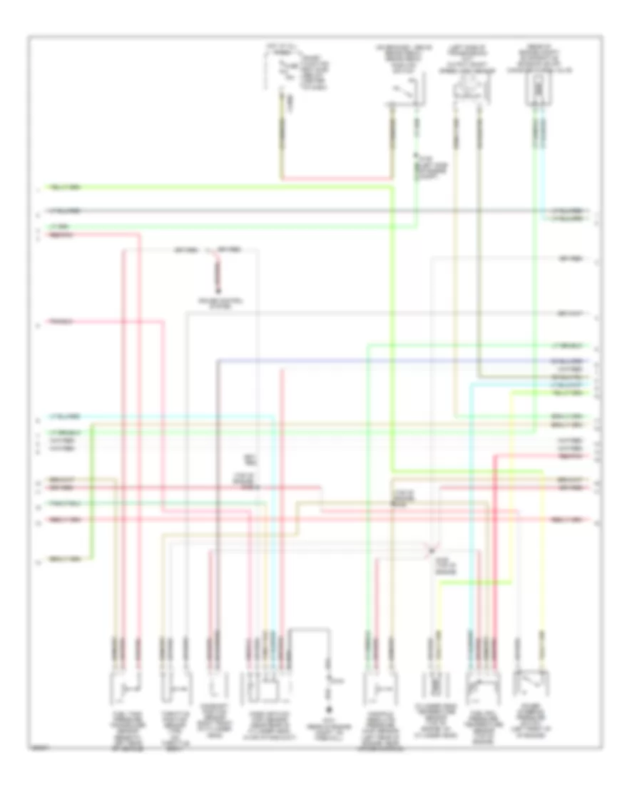
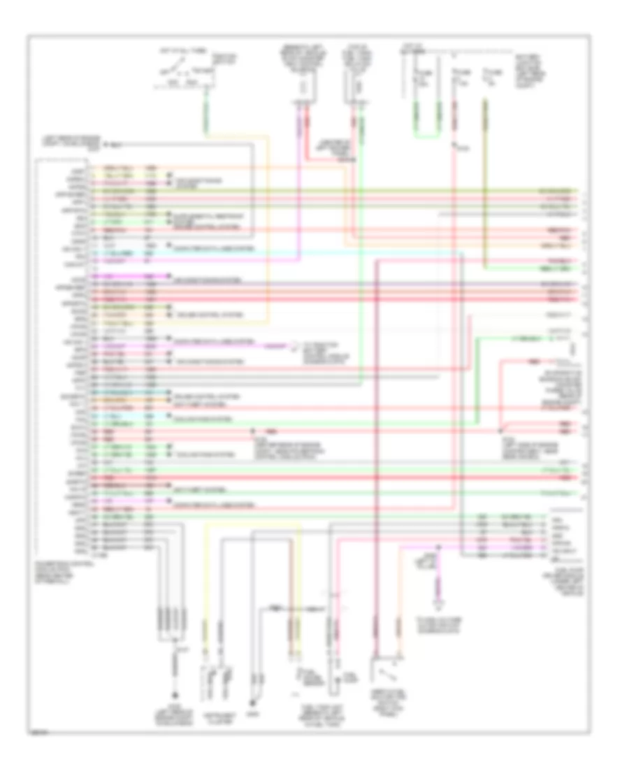
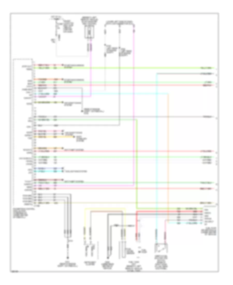
2.3L, Engine Performance Wiring Diagram, Except Hybrid (1 of 5) for Ford Escape 2007
List of elements for 2.3L, Engine Performance Wiring Diagram, Except Hybrid (1 of 5) for Ford Escape 2007:
- (beneath left rear of vehicle) evap canister vent control solenoid
- (lower left side of dash) data link connector (dlc)
- (rear of engine compt, on firewall) g109
- Accr
- Accs
- Acpsw
- Air conditioning system
- Anti-theft system
- Boo
- Bvrefc
- C175b
- C2280c
- Can+
- Can-
- Canvnt
- Case grd
- Cfc
- Compt)
- Cooling fans system
- Feps
- Fpm
- Fppwr
- Fprtn
- Ftpt
- Fuel gauge sensor
- Fuel pump
- Fuel pump driver module (under center of vehicle)
- Fuel sndr rtn
- Fuel sndr signal
- Fuel tank unit (beneath left rear of vehicle, in fuel tank)
- Fuse 5a
- G101 (rear of engine compt, on firewall)
- G405 (under rear center of vehicle)
- Gnd
- Hfc
- Hot at all times
- Iat
- Ifs input
- Inertia fuel shutoff (ifs) switch (base of right door pillar, near kick panel)
- Instrument cluster
- Kapwr
- Lfc
- Mafrtn
- Mafs
- Nca
- Powertrain control module (pcm) (rear center of firewall)
- Psps
- Pwr grd
- Red
- Red/pnk
- Rx data
- S104
- S410
- Shift interlock system
- Sigrtnc
- Smart junction box (sjb) (below center of dash)
- Starting/charging system
- Strt-out
- Tcs
- Tx out
- Vmv-cc/evmv
- Vpwr
- Vrsrtn
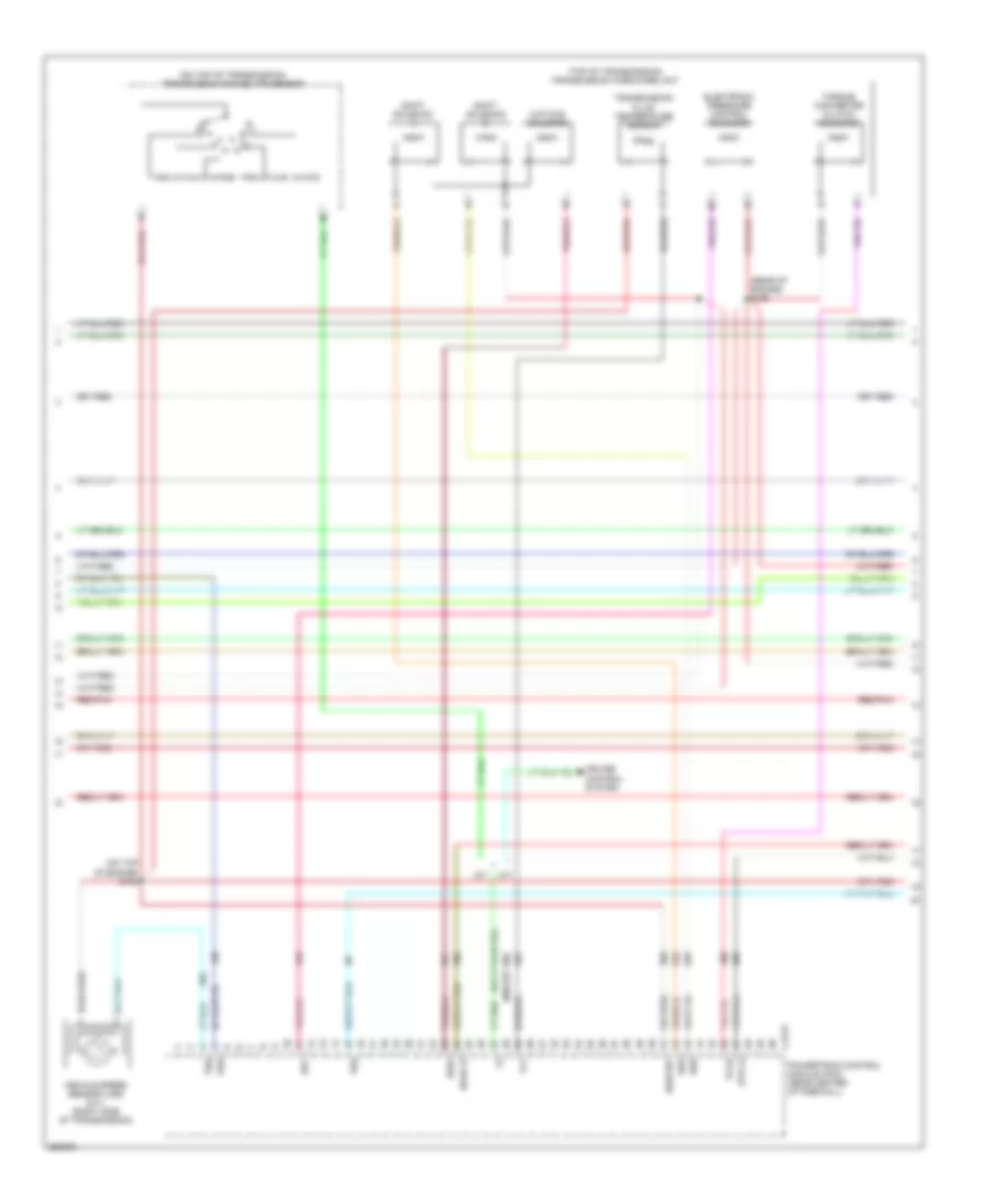
2.3L, Engine Performance Wiring Diagram, Except Hybrid (2 of 5) for Ford Escape 2007
List of elements for 2.3L, Engine Performance Wiring Diagram, Except Hybrid (2 of 5) for Ford Escape 2007:
- (left side of transmission) (a/t) output shaft speed (oss) sensor
- (on bracket, above brake pedal) brake pedal position switch
- (rear of engine compt) evaporative emission (evap) canister purge valve
- (top of engine) s105
- (top of engine) s155
- C2280c
- Camshaft position sensor (right front of cylinder head)
- Cruise control system
- Cylinder head temperature sensor (top of engine, on cylinder head)
- Fuel rail pressure/ temperature sensor (top of engine)
- Fuel tank pressure transducer sensor (beneath left rear of vehicle)
- Fuse 15a
- G101 (rear of engine compt, on firewall)
- Hot at all times
- Manifold absolute pressure (map) sensor (left rear of engine, near intake manifold)
- Mass air flow (maf) sensor (near rear of cylinder head, in air intake duct)
- Of engine compt)
- Power steering pressure switch (left front of of engine)
- Red/pnk
- S104
- S109 (top of engine)
- Smart junction box (sjb) (below center of dash)
- Throttle position sensor (tps) (on throttle body)
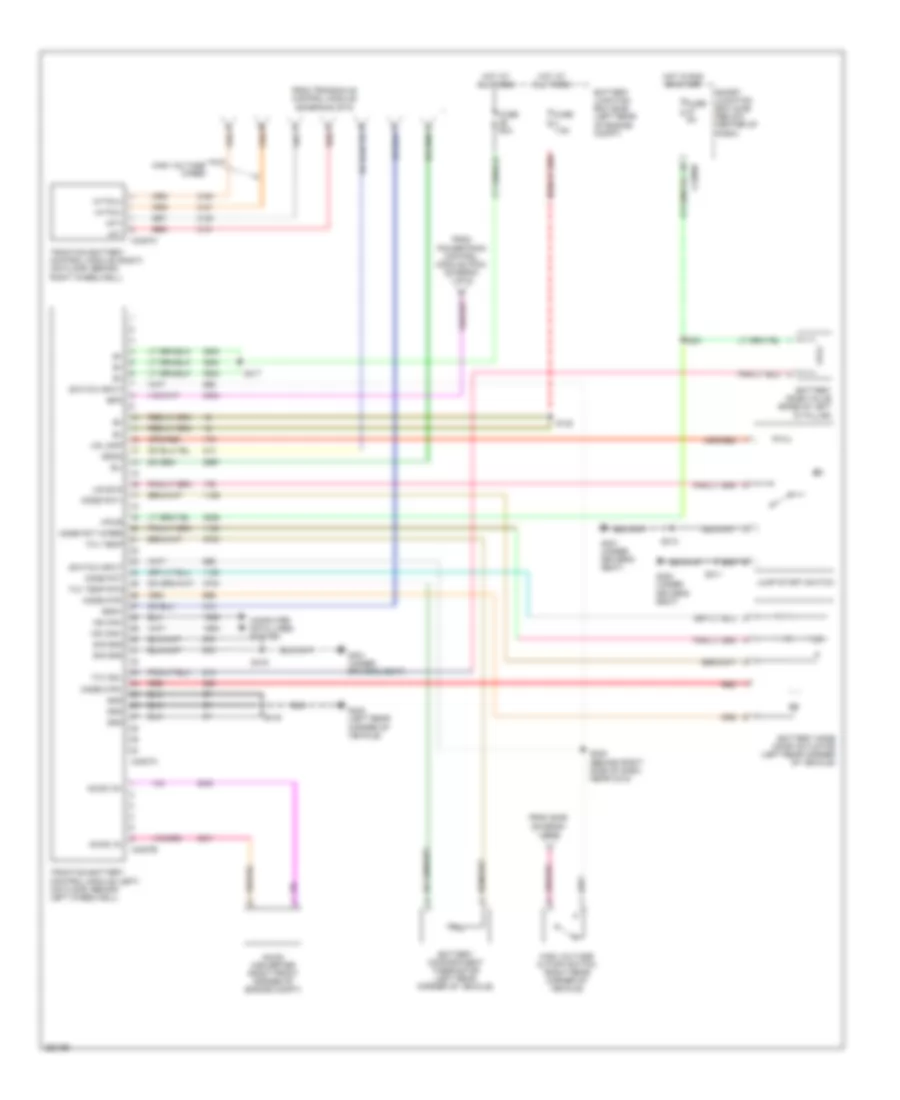
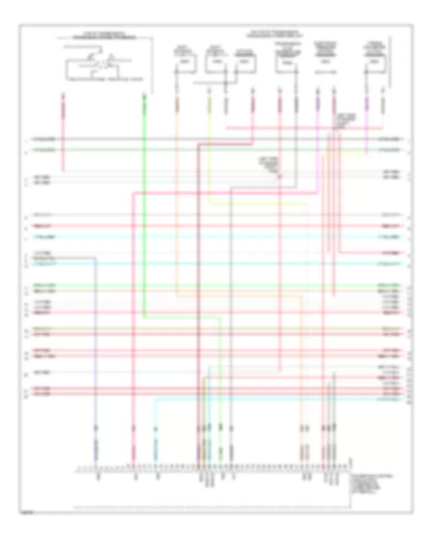
2.3L, Engine Performance Wiring Diagram, Except Hybrid (3 of 5) for Ford Escape 2007
List of elements for 2.3L, Engine Performance Wiring Diagram, Except Hybrid (3 of 5) for Ford Escape 2007:
- (on top of engine) s154
- (on top of transmission) transmission range (tr) sensor
- (rear of engine) s150
- (top of transmission) transmission hardware unit
- 1868 (or 199)
- 3-2t/ccs solenoid
- A/t
- C175t
- Cruise control system
- Electronic pressure control solenoid
- Epc
- Ho2s-12
- Htr-12
- M/t
- Oss
- Powertrain control module (pcm) (rear center of firewall)
- Red/pnk
- Shift solenoid a
- Shift solenoid b
- Sigrtnt
- Ss3l
- Ssa
- Ssb
- Tcch
- Tft
- Torque converter clutch solenoid
- Transmission fluid temperature sensor
- Tss
- Vehicle speed sensor (vss) (m/t) (right side of transmission)
- Vss
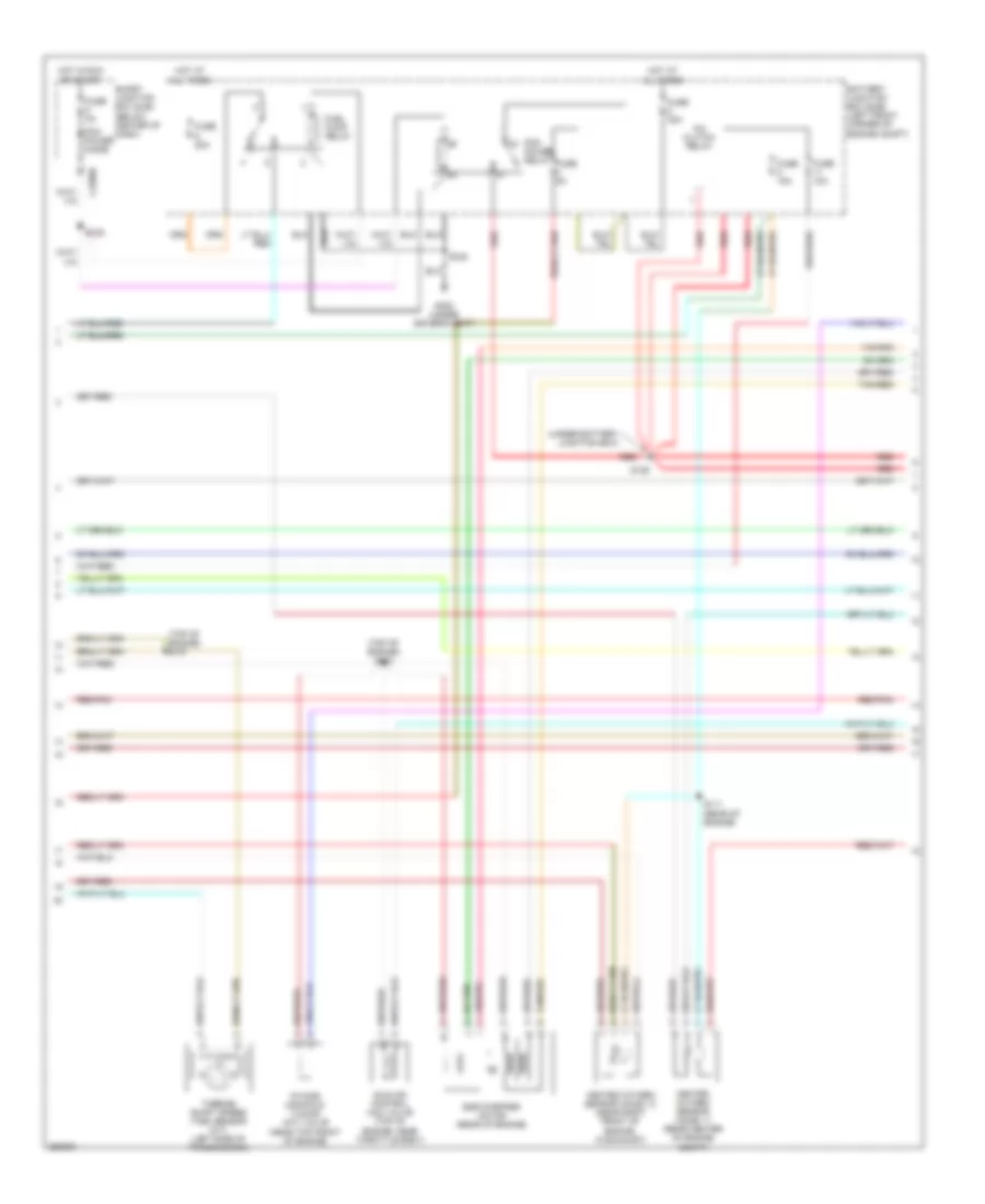
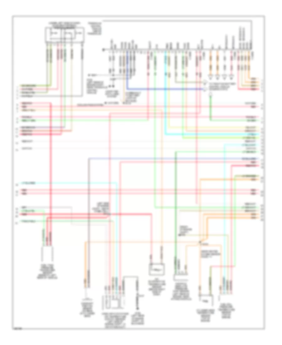
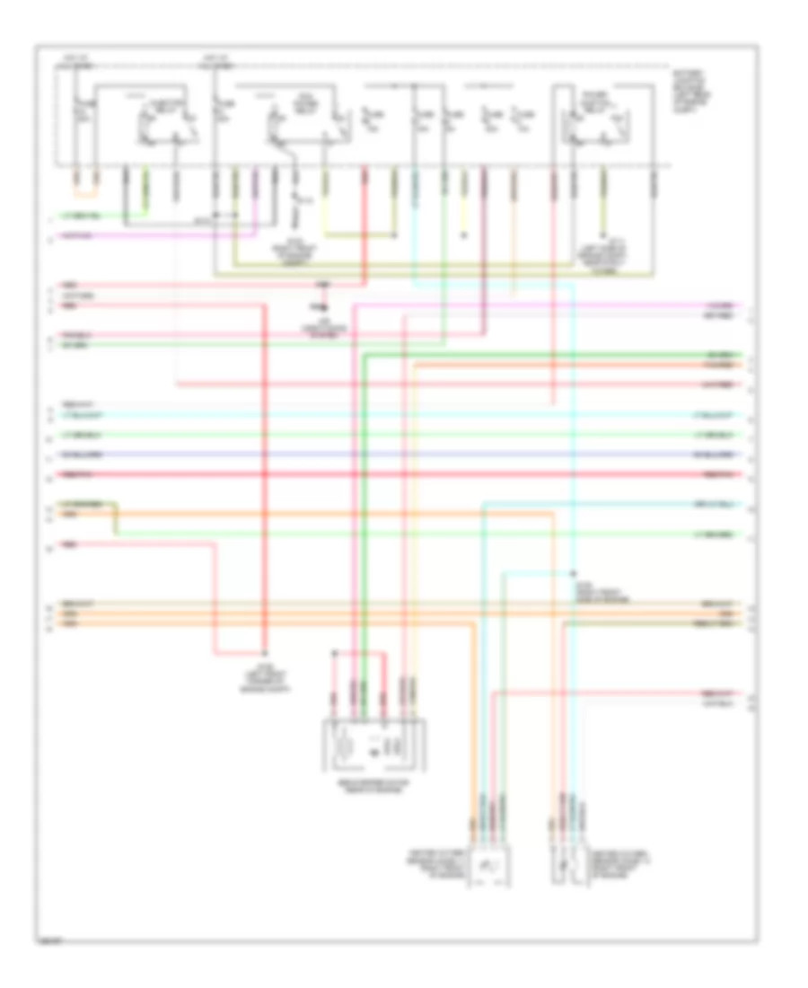
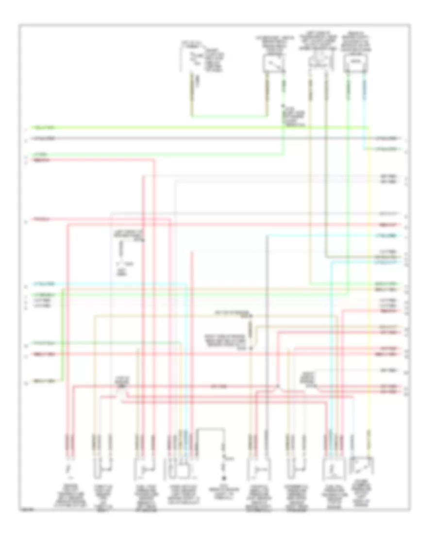
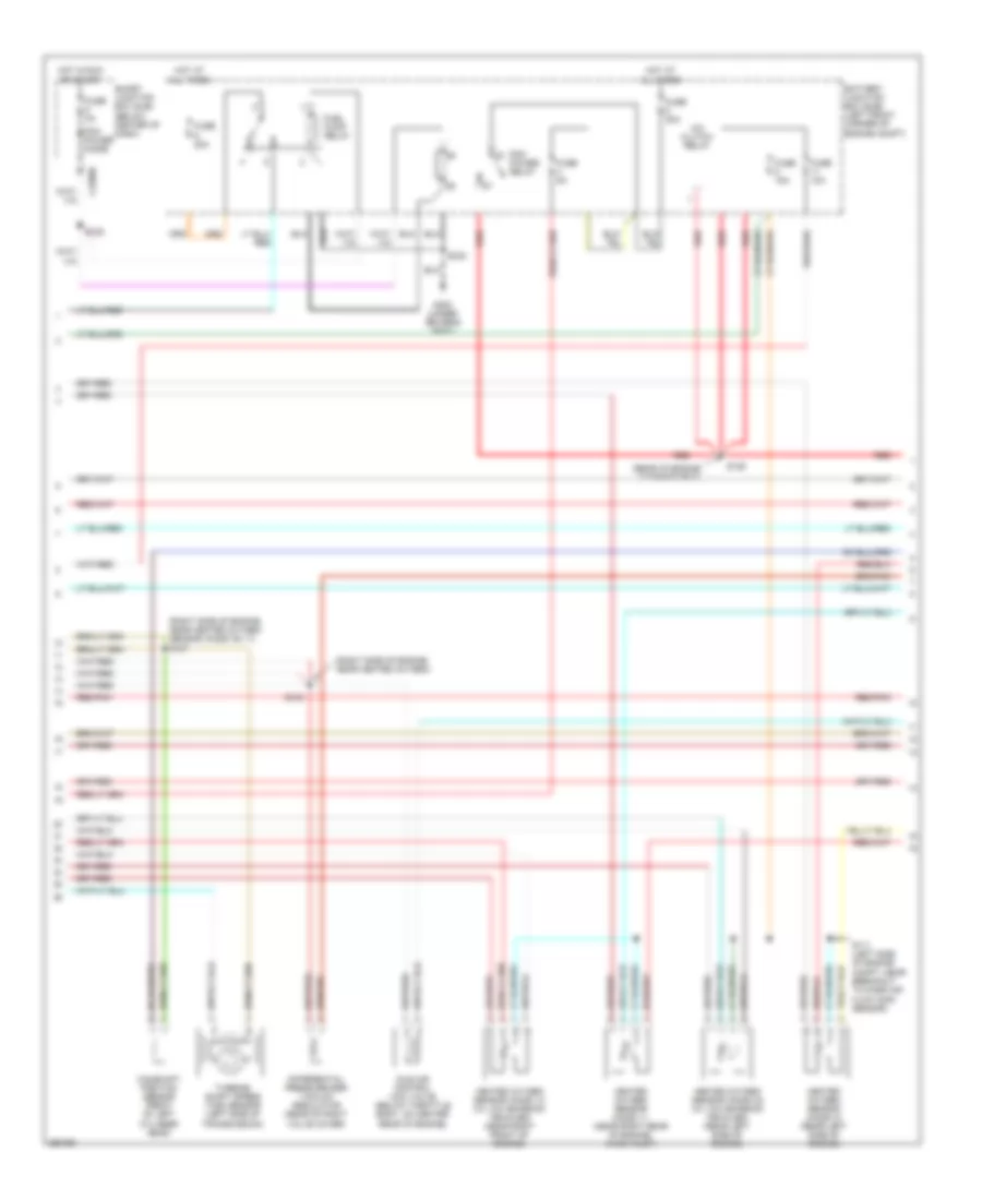
2.3L, Engine Performance Wiring Diagram, Except Hybrid (4 of 5) for Ford Escape 2007
List of elements for 2.3L, Engine Performance Wiring Diagram, Except Hybrid (4 of 5) for Ford Escape 2007:
- (top of engine) s103
- (top of engine) s107
- (under battery junction box)
- A/c clutch relay
- Battery junction box (bjb) (left front corner of engine compt)
- C2280b
- Egr stepper motor (rear of engine)
- Fuel pump relay
- Fuse 10a
- Fuse 15a
- Fuse 20a
- Fuse 2a
- Fuse 30a
- Fuse 5a
- G300 (under driver's seat)
- Heated oxygen sensor (ho2s) 11 (rear center of engine compt)
- Heated oxygen sensor (ho2s) 12 (near right front of engine, in exhaust)
- Hot at all times
- Hot in run or start
- Idle air control (iac) valve (top of engine, near throttle body)
- Intake manifold tuning (imt) valve (near top front of engine)
- Pcm power diode
- Pcm power relay
- Red
- Red/pnk
- S111 (rear of engine)
- S128
- S129
- S332
- Smart junction box (sjb) (below center of dash)
- Tan/red
- Turbine shaft speed (tss) sensor (a/t) (left side of transmission)
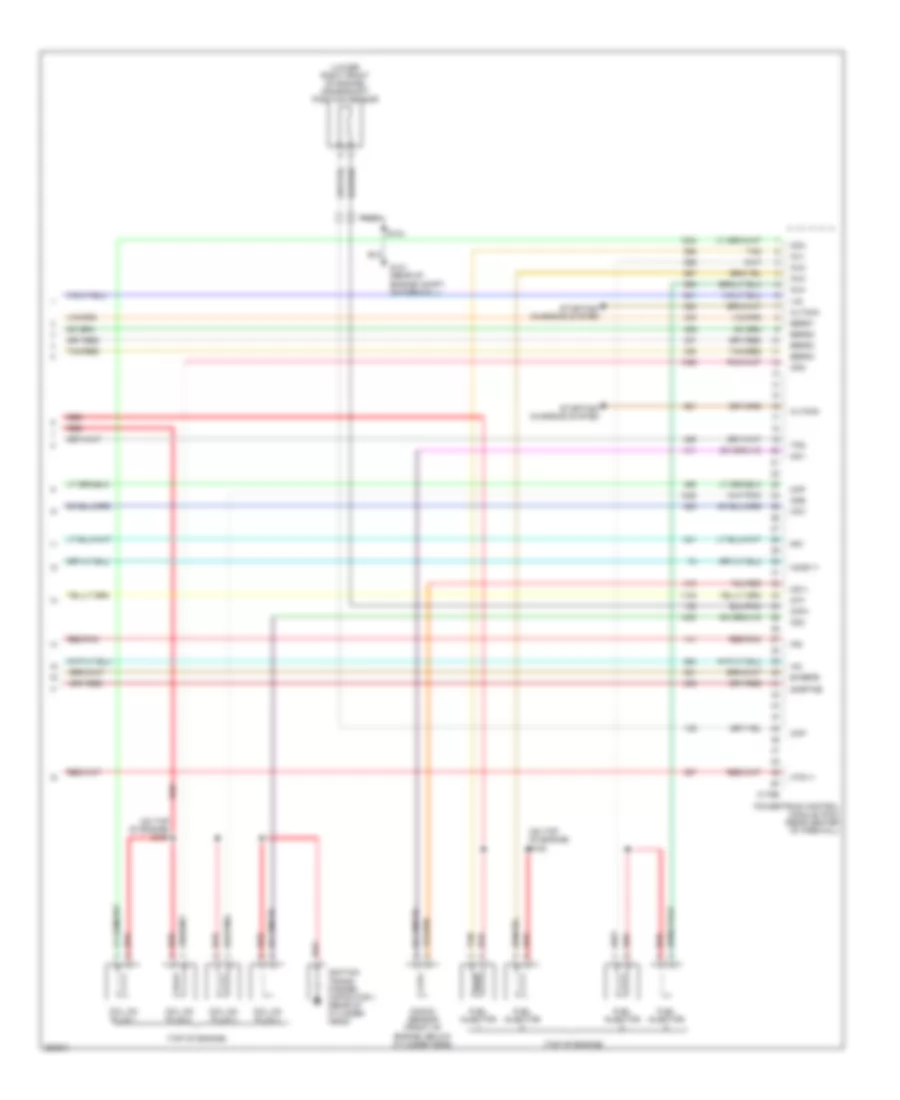
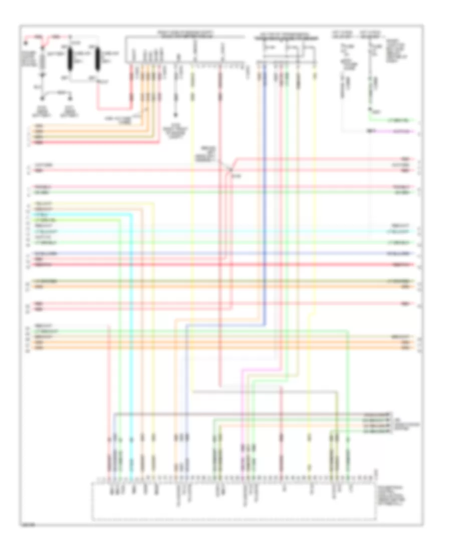
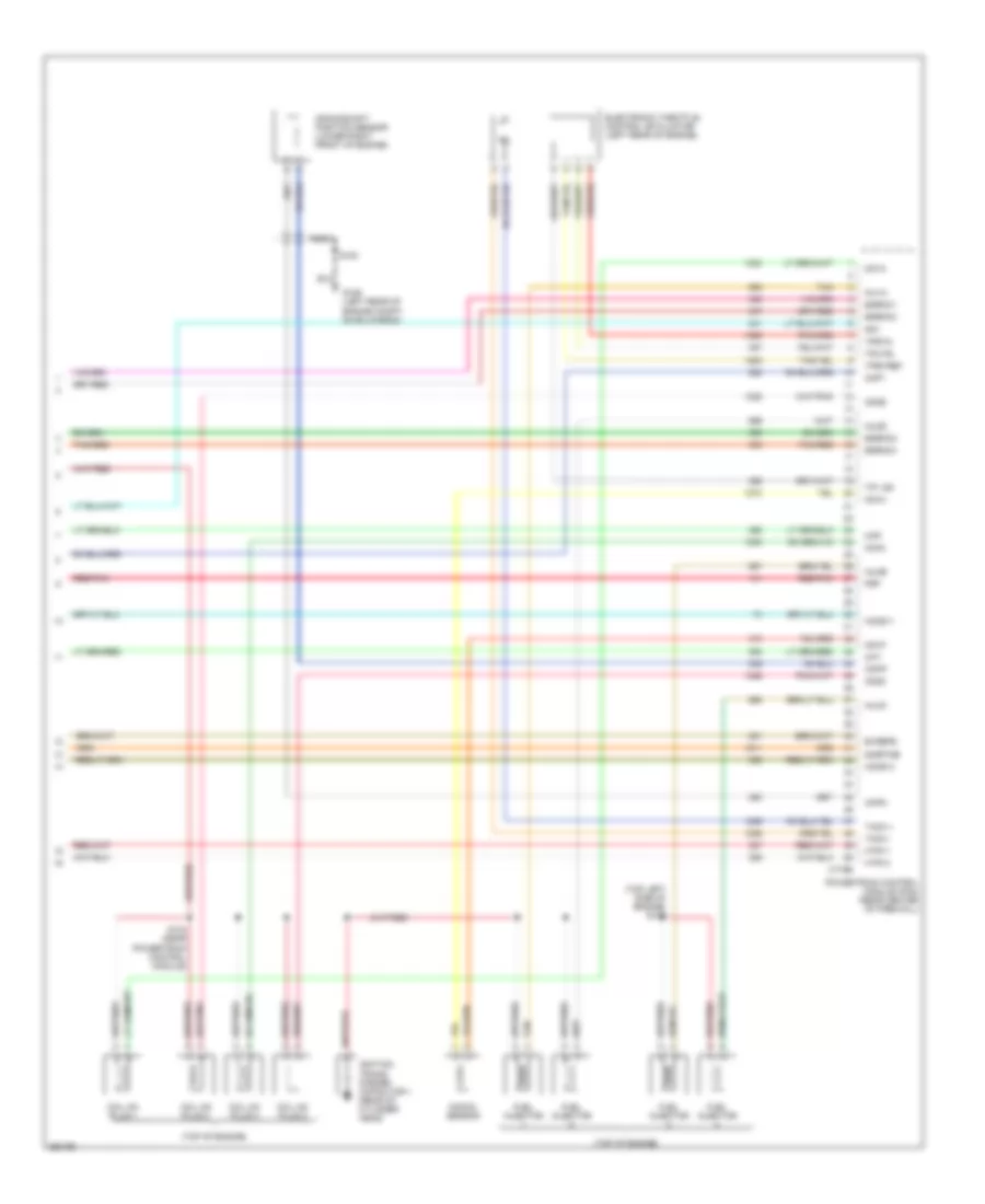
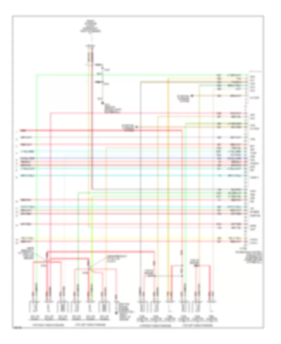
2.3L, Engine Performance Wiring Diagram, Except Hybrid (5 of 5) for Ford Escape 2007
List of elements for 2.3L, Engine Performance Wiring Diagram, Except Hybrid (5 of 5) for Ford Escape 2007:
- (lower right front of engine) crankshaft position sensor
- (on top of engine) s151
- (on top of engine) s152
- (top of engine)
- Altcom
- Altmon
- Bvrefe
- C175e
- Cda
- Cdb
- Cdc
- Cdd
- Cht
- Cid1
- Ckp+
- Ckp-
- Coil on plug 1
- Coil on plug 2
- Coil on plug 3
- Coil on plug 4
- Eerg1
- Eerg2
- Eerg3
- Eerg4
- Frt
- Fuel injector
- G101 (rear of engine compt, on firewall)
- Ho2s-11
- Htr-11
- Iac
- Ignition trans- former capacitor 1 (rear of cylinder head)
- Inj1
- Inj2
- Inj3
- Inj4
- Ips
- Knock sensor (front of engine, below cylinder head)
- Ks1+
- Ks1-
- Map
- Nca
- Powertrain control module (pcm) (rear center of firewall)
- Red
- Red/pnk
- S104
- Sigrtne
- Starting/ charging system
- Tan
- Tan/red
- Tps
- Vis
2.3L, Engine Performance Wiring Diagram, Hybrid (1 of 6) for Ford Escape 2007
List of elements for 2.3L, Engine Performance Wiring Diagram, Hybrid (1 of 6) for Ford Escape 2007:
- (beneath left rear of vehicle) evap canister vent control solenoid
- (center of left rocker panel) s316
- (left rear of engine compt, on bulkhead) g107
- (top of fuel tank) fuel tank isolation valve
- Acc
- Accr
- Accs
- Acet
- Acfds
- Acpsw
- Acrsw
- Air conditioning system
- Anti-theft system
- App1
- App1bvref
- App1rtn
- App2
- App2bvref
- App2rtn
- App3
- Battery junction box (bjb) (left rear of engine compt)
- Boo
- Bpo
- Bps
- Bvref
- C175b
- Canvnt
- Cgnd
- Computer data lines system
- Cooling fans system
- Cruise control system
- Evaporative emission (evap) canister purge valve (rear of engine compt)
- Evmv
- Fc1
- Fc2
- Fc3
- Feps
- Fpm
- Fppwr
- Fprtn
- Ftpt
- Ftv
- Fuel gauge sensor
- Fuel pump
- Fuel pump driver module (under left center of vehicle)
- Fuel sndr
- Fuel tank unit (beneath left rear of vehicle, in fuel tank)
- Fuse 30a
- Fuse 5a
- Fuse 7.5a
- G106 (left rear of engine compt, on bulkhead)
- G405
- Gnd
- Hot at all times
- Hs can +
- Hs can -
- Iat
- Ifs input
- Ignition switch
- Inertia fuel shutoff (ifs) switch (right kick panel)
- Instrument cluster
- Maf
- Mafrtn
- Mfp
- Nca
- Off
- Pat r
- Pat t
- Powertrain control module (pcm) (rear center of firewall)
- Psr
- Rdi
- Red
- Red/pnk
- Rtn
- Run
- S123 (left side of engine compartment, near rear air box)
- S130
- S136 (center rear of engine compt, near powertrain control module (pcm))
- S137
- S406 (left "d" pillar)
- S410
- Sccs
- Sccsrtn
- Sigrtn
- Start
- To high voltage cutoff switch (diagram 6 of 6)
- To traction battery control module (diagram 6 of 6)
- Vbatt
- Vpwr
2.3L, Engine Performance Wiring Diagram, Hybrid (2 of 6) for Ford Escape 2007
List of elements for 2.3L, Engine Performance Wiring Diagram, Hybrid (2 of 6) for Ford Escape 2007:
- (front of engine compt) s102
- (in breakout to battery junction box (bjb)) s116
- (left side of engine compt, above wheelwell) s144
- (near heated oxygen sensor (ho2s) 11)
- (under left side of dash) accelerator pedal position sensor
- A/c evaporative temperature sensor (behind right side of dash)
- C1458a
- C1458b
- C1458c
- C1458d
- C1458e
- Camshaft position sensor (on rear of cylinder head)
- Computer data lines system
- Cooling fans system
- Cto
- Cylinder head temperature sensor (top of engine)
- Dc/dc interlock +
- Dc/dc interlock -
- Dc/dc +
- Dc/dc -
- Ect
- Fuel rail pressure/ temperature sensor (top of engine)
- Fuel tank pressure transducer sensor (beneath left rear of vehicle)
- G106 (left rear of engine compt, on bulkhead)
- G108 (left rear of engine compt, near transaxle control module)
- Gnd
- Gsdn
- Hs can +
- Hs can -
- Hv +
- Hv -
- Interlock +
- Interlock -
- Isdn1
- Isdn2
- Manifold absolute pressure (map) sensor (left rear of engine, near intake manifold)
- Mass air flow/intake air temperature (maf/iat) sensor) (left side of engine compt, in air intake duct)
- Msdn
- Red
- Red/pnk
- S103
- S137
- S142
- Sig rtn
- Tgac
- Tmac
- To traction battery control module (diagram 6 of 6)
- Transaxle control module (above transaxle)
- Vbatt
- Vpwr
2.3L, Engine Performance Wiring Diagram, Hybrid (3 of 6) for Ford Escape 2007
List of elements for 2.3L, Engine Performance Wiring Diagram, Hybrid (3 of 6) for Ford Escape 2007:
- (behind left headlight assembly)
- (on top of transmission) transmission range (tr) sensor
- (right side of engine compt) dc/dc converter module
- Aclpcs
- Acrdv
- Air conditioning system
- Battery
- C1457a
- C1457b
- C1457c
- C1457d
- C175t
- C2280b
- C2280d
- Cto
- Dc/int+
- Dc/int-
- Dce
- Dcf
- Dc_enable
- Dc_fault
- Fuse 2a
- Fuse 5a
- G100 (near battery)
- G101 (near battery)
- G105 (right front of engine compt)
- Gnd
- Gsdn
- High voltage wires
- Hot in run or start
- Hvdc+
- Hvdc-
- Mecp
- Mect
- Msdn
- Pcm power diode
- Power distri- bution system
- Powertrain control module (pcm) (rear center of firewall)
- Red
- Red/pnk
- S115
- S127
- S128
- S129
- S251
- Smart junction box (sjb) (below center of dash)
- Tgac
- Tmac
- Tr a1
- Tr a1bvref
- Tr a1rtn
- Tr a2
- Tr a2bvref
- Tr a2rtn
- Tr a3
- Vbatt
2.3L, Engine Performance Wiring Diagram, Hybrid (4 of 6) for Ford Escape 2007
List of elements for 2.3L, Engine Performance Wiring Diagram, Hybrid (4 of 6) for Ford Escape 2007:
- (left side of engine compt, near strut tower)
- Air conditioning system
- Battery junction box (bjb) (left rear of engine compt)
- Egr stepper motor (rear of engine)
- Fuse 10a
- Fuse 15a
- Fuse 20a
- Fuse 30a
- Fuse 40a
- Fuse 5a
- G103 (right front of engine compt)
- Heated oxygen sensor (ho2s) 11 (right front of engine)
- Heated oxygen sensor (ho2s) 13 (right front of engine)
- Hot at all times
- Injector relay
- Pcm power relay
- Power sustain relay
- Red
- Red/pnk
- S105 (right front side of engine)
- S106 (left front corner of engine compt)
- S110
- S111
- S112
- S151
- Tan/red
2.3L, Engine Performance Wiring Diagram, Hybrid (5 of 6) for Ford Escape 2007
List of elements for 2.3L, Engine Performance Wiring Diagram, Hybrid (5 of 6) for Ford Escape 2007:
- (top left side of engine) s107
- (top of engine)
- Bvrefe
- C175e
- Cd1a
- Cd2d
- Cd3b
- Cd4c
- Cht
- Ckpn
- Ckpp
- Cmp1
- Coil on plug 1
- Coil on plug 2
- Coil on plug 3
- Coil on plug 4
- Crankshaft position sensor (lower right front of engine)
- Egrmc1
- Egrmc2
- Egrmc3
- Egrmc4
- Electronic throttle control (etc) motor (left rear of engine)
- Frp
- Frt
- Fuel injector
- G106 (left rear of engine compt, on bulkhead)
- Ho2s11
- Ho2s13
- Htr11
- Htr13
- Ignition trans- former capacitor 1 (rear of cylinder head)
- Inj1a
- Inj2d
- Inj3b
- Inj4c
- Knock sensor
- Ks1n
- Ks1p
- Map
- Nca
- Powertrain control module (pcm) (rear center of firewall)
- Red/pnk
- S100
- S104 (near powertrain control module)
- Sigrtne
- Tacm +
- Tacm -
- Tan
- Tan/red
- Tp1 ns
- Tp2 ps
- Tpbvref
- Tprtn
2.3L, Engine Performance Wiring Diagram, Hybrid (6 of 6) for Ford Escape 2007
List of elements for 2.3L, Engine Performance Wiring Diagram, Hybrid (6 of 6) for Ford Escape 2007:
- Ac/dc converter (right front corner of engine compt)
- Ac/dc in+
- Ac/dc in-
- Battery compartment thermistor (left rear corner of vehicle)
- Battery junction box (bjb) (left rear of engine compt)
- Battery mode door actuator (left rear corner of vehicle)
- Battery zone valve (base of left "d" pillar)
- Bpo
- C2280d
- C4227a
- C4227b
- C4227c
- Computer data lines system
- Eli
- From powertrain control module (pcm) (diagram 1 of 6)
- From s406 (diagram 1 of 6)
- From transaxle control module (diagram 2 of 6)
- Fuse 50a
- Fuse 5a
- Fuse 7.5a
- G300 (under driver's seat)
- G301 (under driver's seat)
- G403 (left rear corner of vehicle)
- Gnd
- High voltage cutoff switch (right rear corner of vehicle)
- High voltage wires
- Hot at all times
- Hot in run or start
- Hs can+
- Hs can-
- Hvtmu+
- Hvtmu-
- Int+
- Int-
- Isdn1
- Isdn2
- J/s lamp
- J/s swa
- Jump start switch
- Mode mtr+
- Mode mtr-
- Mode pot
- Mode pot wiper
- Mode pot+
- Red
- S130
- S240 (behind right side of dash, near c212)
- S251
- S311
- S313
- S416
- S417
- S419
- Sig gnd
- Smart junction box (sjb) (below center of dash)
- Switch input
- Traction battery control module (left) (on floor, behind left wheelwell)
- Traction battery control module (right) (on floor, behind right wheelwell)
- Txv sol
- Txv temp
- Txv temp rtn
- Vpwr
3.0L
3.0L, Engine Performance Wiring Diagram (1 of 5) for Ford Escape 2007
List of elements for 3.0L, Engine Performance Wiring Diagram (1 of 5) for Ford Escape 2007:
- (beneath left rear of vehicle) evap canister vent control solenoid
- (lower left side of dash) data link connector (dlc)
- (rear of engine compt, on firewall) g109
- Accr
- Accs
- Acpsw
- Air conditioning system
- Anti-theft system
- Boo
- C175b
- C2280c
- Can +
- Can -
- Canvnt
- Case gnd
- Compt)
- Cooling fans system
- Feps
- Fpm
- Fppwr
- Fprtn
- Ftpt
- Fuel gauge sensor
- Fuel pump
- Fuel pump driver module (under center of vehicle)
- Fuel sndr
- Fuel tank unit (beneath left rear of vehicle, in fuel tank)
- Fuse 5a
- G101 (rear of engine compt, on firewall)
- G405 (under rear center of vehicle)
- Gnd
- Hfc
- Hot at all times
- Iat
- Ifs input
- Inertia fuel shutoff (ifs) switch (base of right door pillar, near kick panel)
- Instrument cluster
- Kapwr
- Lfc
- Mafrtn
- Mafs
- Nca
- Powertrain control module (pcm) (in recess on upper center of firewall)
- Psps
- Pwr grd
- Red
- Red/pnk
- Rtn
- Rx-data
- S104
- S410
- Shift interlock system
- Smart junction box (sjb) (below center of dash)
- Smr
- Starting/charging system
- Strt-out
- Tan/red
- Tcs
- Tx-out
- Vmv-cc/evmv
- Vpwr
- Vrsrtn
3.0L, Engine Performance Wiring Diagram (2 of 5) for Ford Escape 2007
List of elements for 3.0L, Engine Performance Wiring Diagram (2 of 5) for Ford Escape 2007:
- (left front of rocker panel) s313
- (left side of transmission, near left axle flange) output shaft speed sensor (oss)
- (not used)
- (on bracket, above brake pedal) brake pedal position switch
- (on top of engine) s151
- (rear of engine compt) evaporative emission (evap) canister purge valve
- (right side of engine) s100
- (top of engine) s154
- C2280c
- C248
- Differential pressure feedback egr (dpfe) sensor (right rear of engine)
- Engine coolant temperature (ect) sensor (rear of engine in water outlet)
- Fuel rail pressure/ temperature sensor (top of engine)
- Fuel tank pressure transducer sensor (beneath left rear of vehicle)
- Fuse 15a
- G101 (rear of engine compt, on firewall)
- Hot at all times
- Manifold absolute pressure (map) sensor (rear of engine compt, on firewall)
- Mass air flow (maf) sensor (left side of engine compt, in air intake duct)
- Near heated oxygen sensor (ho2s) no 11) s105
- Of engine compt, near c134)
- Power steering pressure switch (left front of engine)
- Red/pnk
- S104
- Smart junction box (sjb) (below center of dash)
- Throttle position sensor (tps) (on throttle body)
3.0L, Engine Performance Wiring Diagram (3 of 5) for Ford Escape 2007
List of elements for 3.0L, Engine Performance Wiring Diagram (3 of 5) for Ford Escape 2007:
- (left side of engine compt) s108
- (left side of engine compt) s109
- (on top of transmission) transmission hardware unit
- (top of transmission) transmission range (tr) sensor
- 3-2t/ccs solenoid
- C175t
- Electronic pressure control solenoid
- Epc
- Ho2s-12
- Ho2s-22
- Htr-12
- Htr-22
- Oss
- Powertrain control module (pcm) (in recess on upper center of firewall)
- Red/pnk
- Shift solenoid a
- Shift solenoid b
- Ss3l
- Ssa
- Ssb
- Tcch
- Tft
- Torque converter clutch solenoid
- Transmission fluid temperature sensor
- Trs
- Tss
3.0L, Engine Performance Wiring Diagram (4 of 5) for Ford Escape 2007
List of elements for 3.0L, Engine Performance Wiring Diagram (4 of 5) for Ford Escape 2007:
- (rear of engine compartment)
- (right side of engine, near heated oxygen sensor (ho2s) no 11) s107
- (right side of engine, near heated oxygen)
- A/c clutch relay
- Battery junction box (bjb) (left front corner of engine compt)
- C2280b
- Camshaft position sensor (front of left cylinder head)
- Differential pressure egr vacuum regulator (rear of right valve cover)
- Fuel pump relay
- Fuse 10a
- Fuse 15a
- Fuse 20a
- Fuse 2a
- Fuse 30a
- Fuse 5a
- G300 (under driver's seat)
- Heated oxygen sensor (ho2s) 11 (near right rear of engine, in exhaust)
- Heated oxygen sensor (ho2s) 12 (w/ low emission vehicles) (near right front of engine)
- Heated oxygen sensor (ho2s) 21 (rear left side of engine)
- Heated oxygen sensor (ho2s) 22 (w/ low emission vehicles) (rear left side of engine)
- Hot at all times
- Hot in run or start
- Idle air control (iac) valve (below throttle body, on center rear of engine)
- Pcm power diode
- Pcm power relay
- Red
- Red/pnk
- S103
- S111 (left side of engine compt, near breakout to mass air flow (maf) sensor)
- S128
- S129
- S332
- Smart junction box (sjb) (below center of dash)
- Turbine shaft speed (tss) sensor (left side of transmission)
3.0L, Engine Performance Wiring Diagram (5 of 5) for Ford Escape 2007
List of elements for 3.0L, Engine Performance Wiring Diagram (5 of 5) for Ford Escape 2007:
- (front of engine block) crankshaft position sensor
- (near breakout to coil on plug 4)
- (near breakout to throttle position sensor)
- (top left side of engine)
- (top of engine) s152
- (top of engine) s157
- (top right side of engine)
- Altcom
- Altmon
- Bvrefe
- C175e
- Cda
- Cdb
- Cdc
- Cdd
- Cde
- Cdf
- Cid1
- Ckp+
- Ckp-
- Coil on plug 1
- Coil on plug 2
- Coil on plug 3
- Coil on plug 4
- Coil on plug 5
- Coil on plug 6
- Dpfe
- Ect
- Evr
- Frt
- Fuel injector
- G101 (rear of engine compt, on firewall)
- Ho2s-11
- Ho2s-21
- Htr-11
- Htr-21
- Iac
- Ignition trans- former capacitor 1 (right front of engine)
- Inj1
- Inj2
- Inj3
- Inj4
- Inj5
- Inj6
- Ips
- Nca
- Powertrain control module (pcm) (in recess on upper center of firewall)
- Red
- Red/pnk
- S104
- S153
- S156
- S157
- Sigrtne
- Starting/ charging system
- Tan
- Tmap
- Tps
EXTERIOR LIGHTS
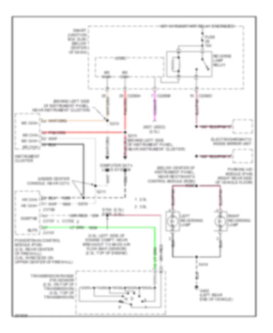
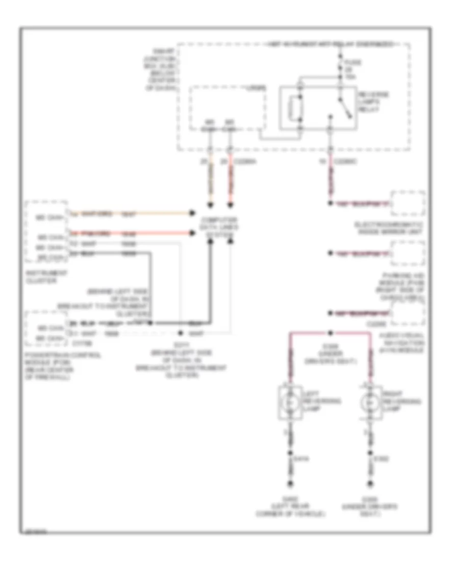
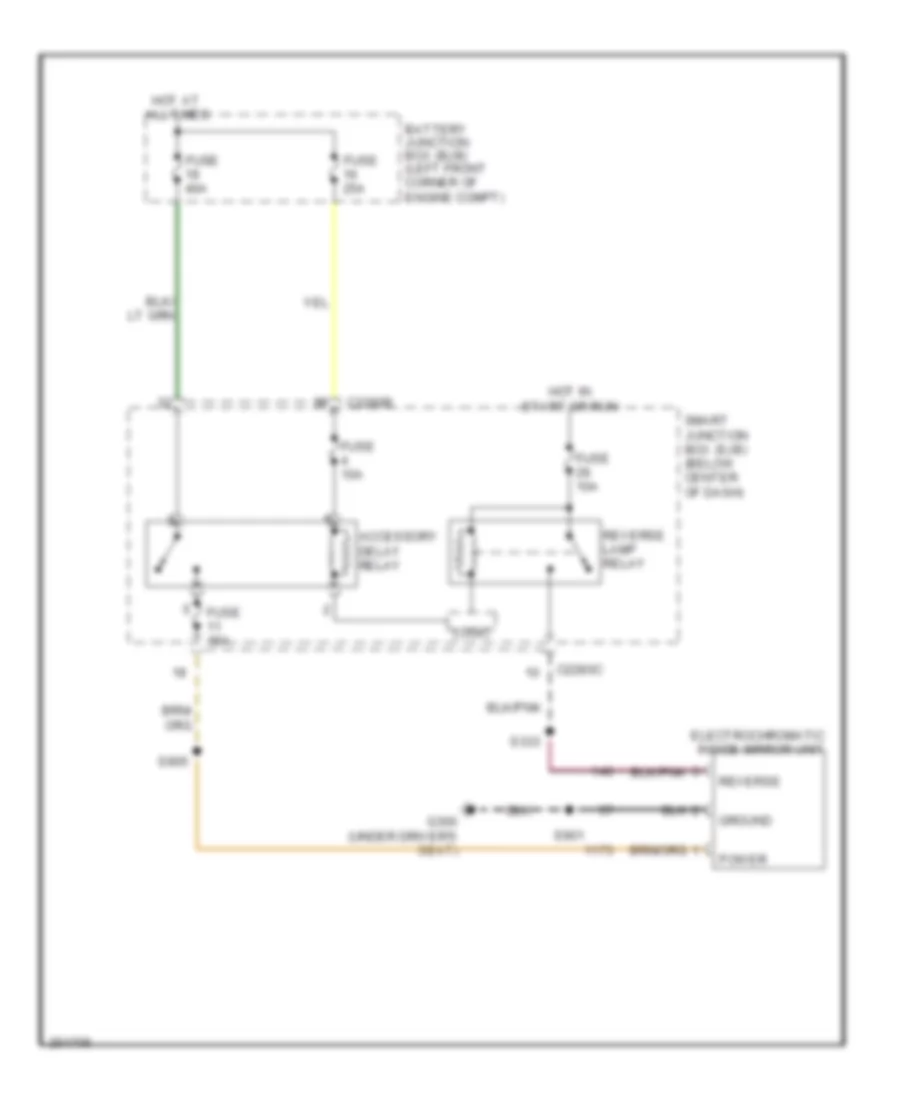
Back-up Lamps Wiring Diagram, A/T Except Hybrid for Ford Escape 2007
List of elements for Back-up Lamps Wiring Diagram, A/T Except Hybrid for Ford Escape 2007:
- (2.3l) (3.0l)
- (3.0l: left side of engine compt, near breakout to mass air flow (maf) sensor) (2.3l: top of engine)
- (behind left side of instrument panel, near instrument cluster)
- (below center of instrument panel, near restraints control module (rcm)) s333
- (not used) (2.3l)
- (under center console, near c211)
- 2.3l
- 3.0l
- C175b
- C175e
- C175t
- C2280a
- C2280b
- C2280c
- Computer data lines system
- Electrochromatic inside mirror unit
- Fuse 10a
- G402 (left rear end of vehicle)
- Hot w/ run/start relay energized
- Hs can+
- Hs can-
- Instrument cluster
- Left reversing lamp
- Logic
- Mlps
- Ms can+
- Ms can-
- Parking aid module (pam) (right rear side of vehicle floor)
- Powertrain control module (pcm) (2.3l: rear center of firewall) (3.0l: in recess on upper center of firewall)
- Reverse lamp relay
- Right reversing lamp
- S154 s109
- S210
- S211
- S213
- S215 (behind left side of instrument panel, near instrument cluster)
- S414
- Sigrtne
- Smart junction box (sjb) (below center of dash)
- Transmission range (tr) sensor (2.3l: on top of transmission) (3.0l: top of transmission)
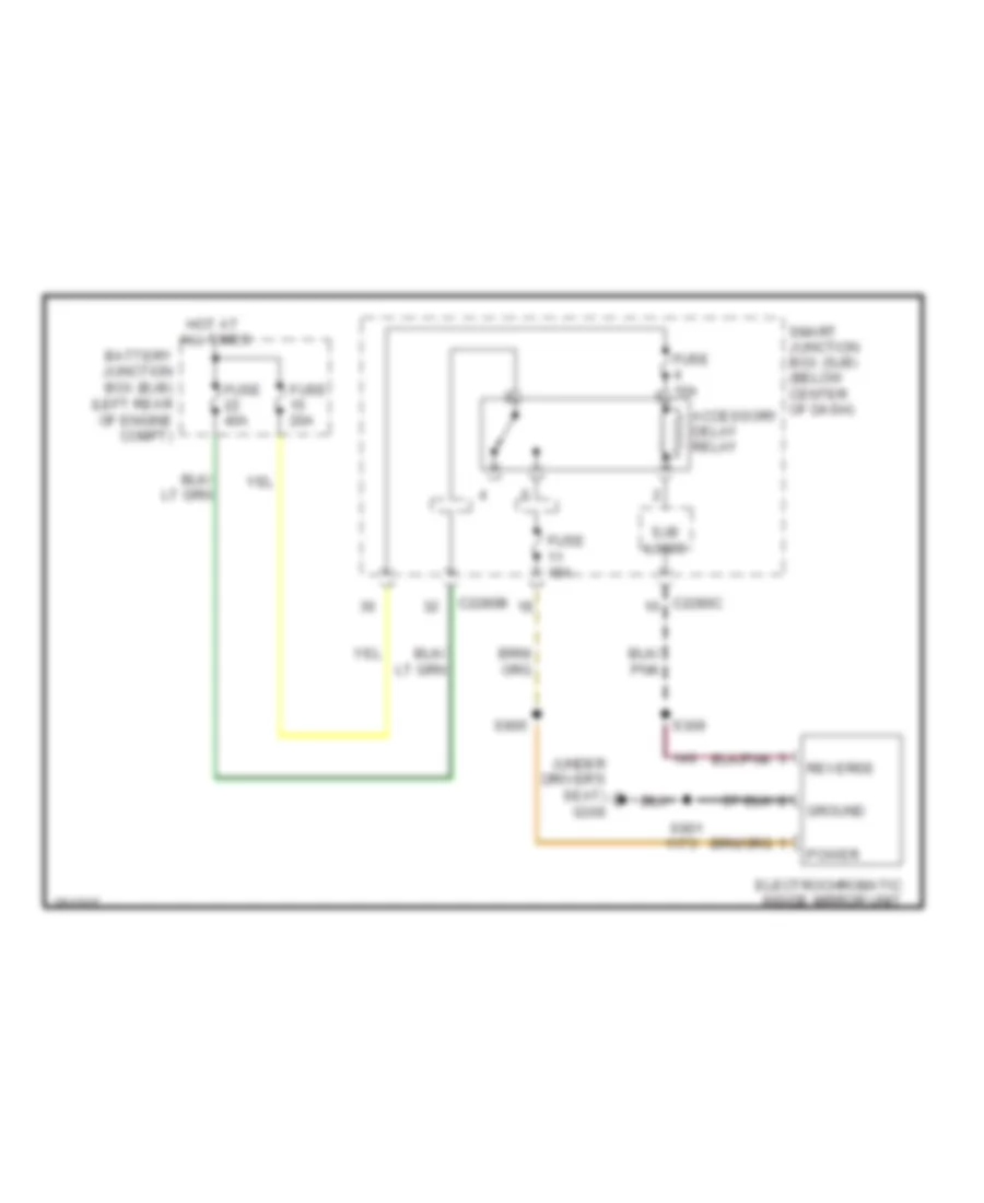
Back-up Lamps Wiring Diagram, Hybrid for Ford Escape 2007
List of elements for Back-up Lamps Wiring Diagram, Hybrid for Ford Escape 2007:
- (behind left side of dash, in breakout to instrument cluster) s210
- Audio visual navigation (avn) module
- C175b
- C2280a
- C2280c
- C229e
- Computer data lines system
- Electrochromatic inside mirror unit
- Fuse 10a
- G300 (under driver's seat)
- G402 (left rear corner of vehicle)
- Hot w/ run/start relay energized
- Instrument cluster
- Left reversing lamp
- Logic
- Ms can+
- Ms can-
- Ms can- ms can+
- Parking aid module (pam) (right side of cargo area)
- Powertrain control module (pcm) (rear center of firewall)
- Reverse lamps relay
- Right reversing lamp
- S211 (behind left side of dash, in breakout to instrument cluster)
- S302
- S309 (under driver's seat)
- S414
- Smart junction box (sjb) (below center of dash)
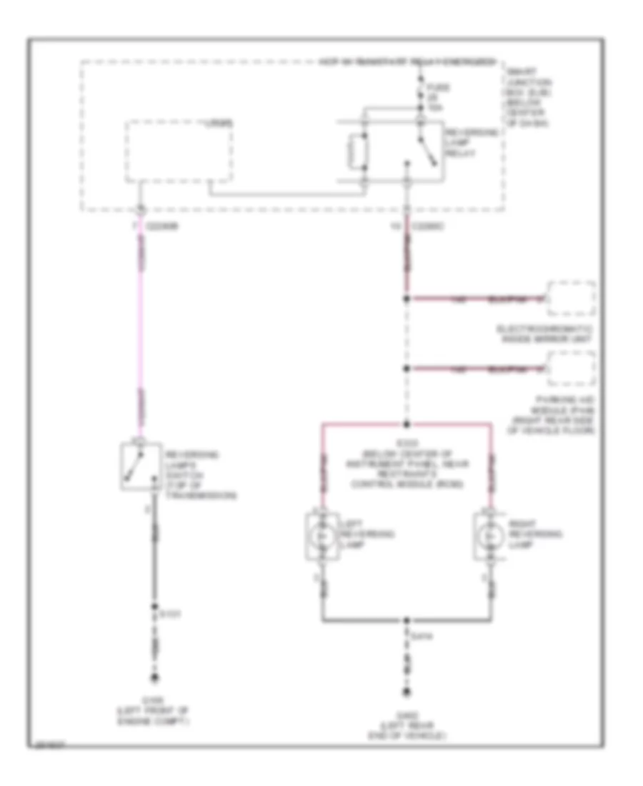
Back-up Lamps Wiring Diagram, M/T Except Hybrid for Ford Escape 2007
List of elements for Back-up Lamps Wiring Diagram, M/T Except Hybrid for Ford Escape 2007:
- C2280b
- C2280c
- Electrochromatic inside mirror unit
- Fuse 10a
- G105 (left front of engine compt)
- G402 (left rear end of vehicle)
- Hot w/ run/start relay energized
- Left reversing lamp
- Logic
- Parking aid module (pam) (right rear side of vehicle floor)
- Reversing lamp relay
- Reversing lamps switch (top of transmission)
- Right reversing lamp
- S131
- S333 (below center of instrument panel, near restraints control module (rcm))
- S414
- Smart junction box (sjb) (below center of dash)
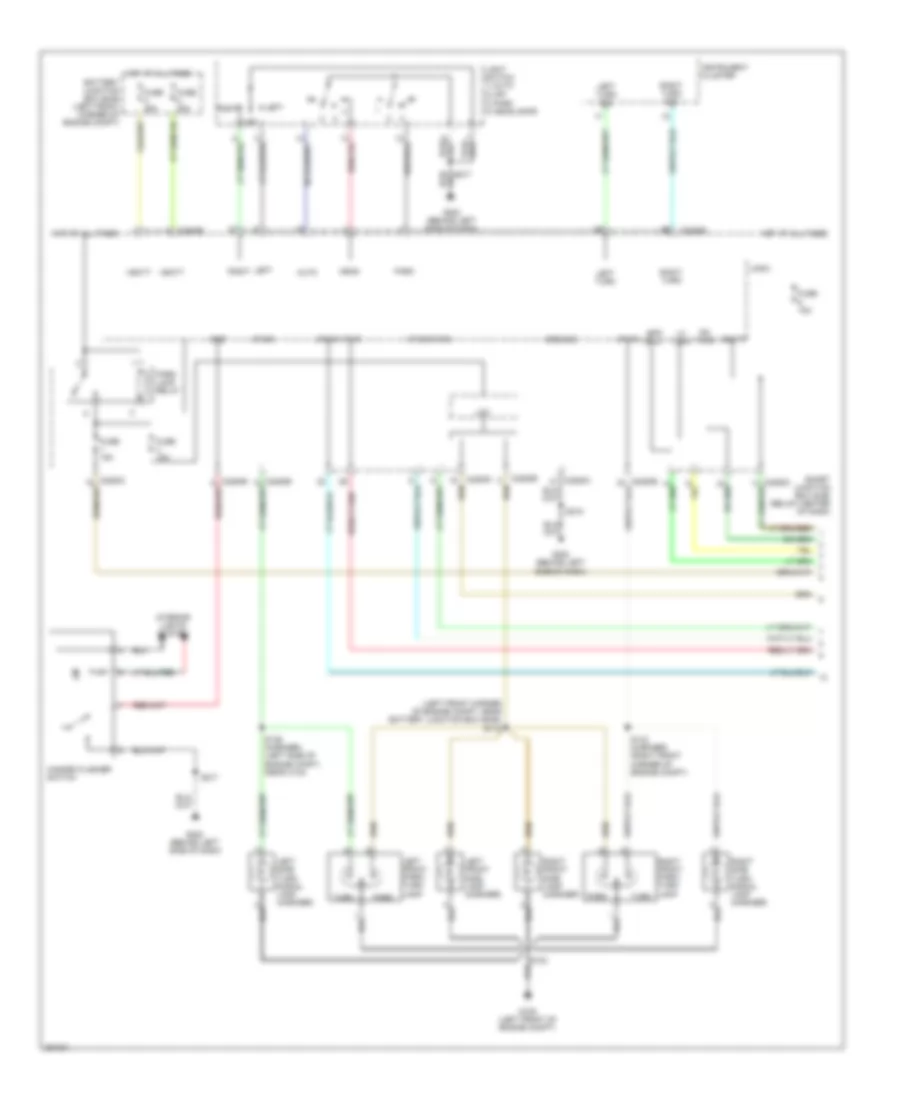
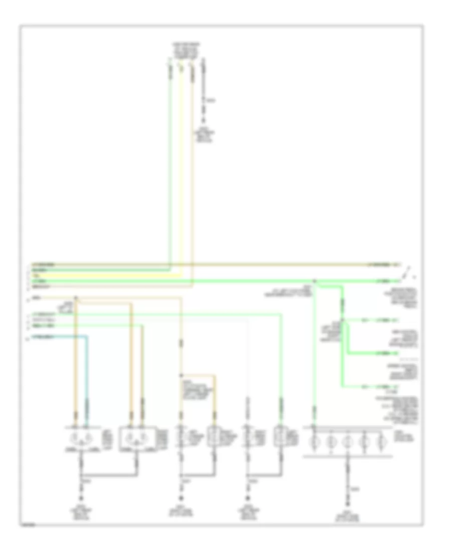
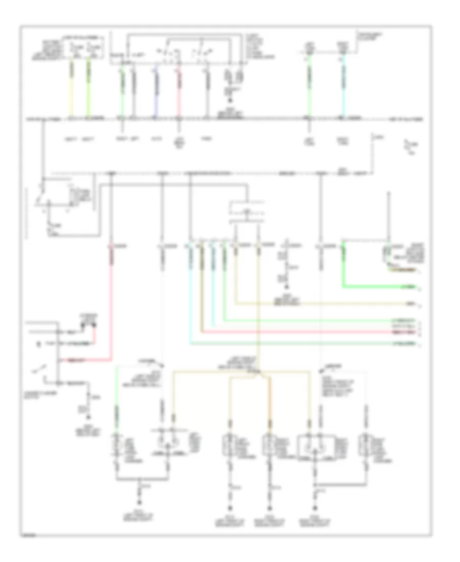
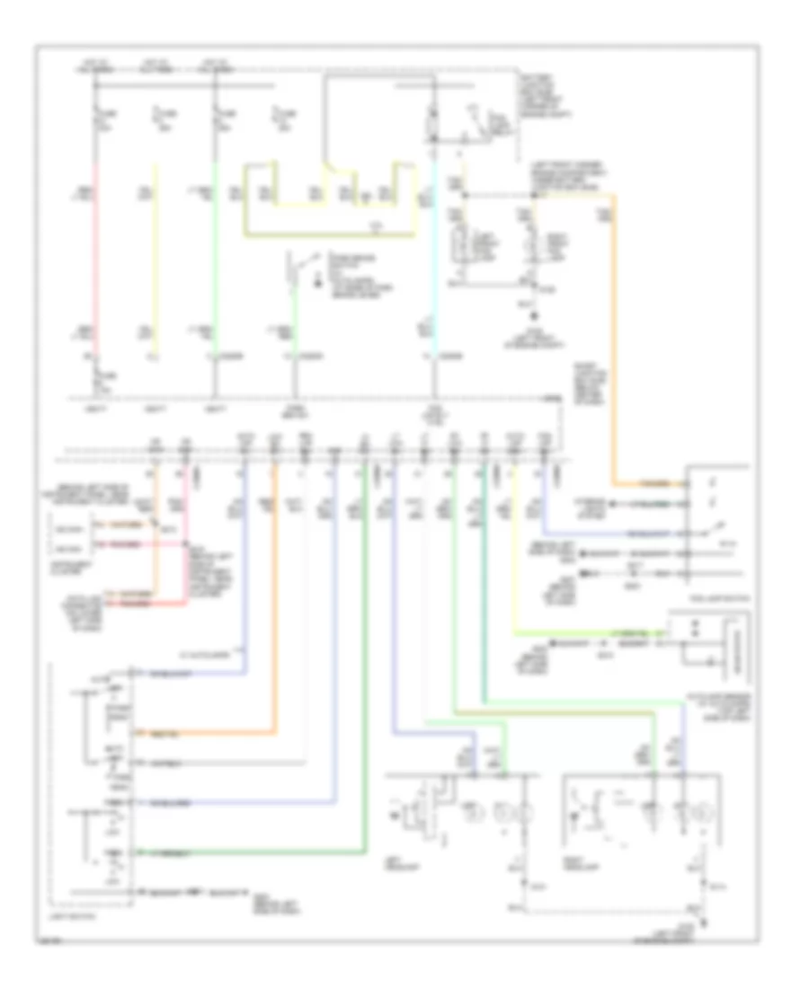
Exterior Lamps Wiring Diagram, Except Hybrid (1 of 2) for Ford Escape 2007
List of elements for Exterior Lamps Wiring Diagram, Except Hybrid (1 of 2) for Ford Escape 2007:
- (left front corner of engine compt, near battery junction box (bjb)) s118
- 3) park 4) headlamps
- Auto
- Battery junction box (bjb) (left front corner of engine compt)
- Bpp input
- C2280a
- C2280b
- C2280e
- Fuse 15a
- Fuse 25a
- G105 (left front of engine compt)
- G202 (behind left side of dash)
- Ground
- Hazard flasher switch
- Head
- Hot at all times
- Instrument cluster
- Interior lights system
- Left
- Left front park/ turn lamp
- Left front side lamp (mariner)
- Left side turn signal lamp (mariner)
- Left turn
- Left turn sig
- Lh turn
- Light switch 1) auto 2) off
- Logic
- Lom
- Off
- Park
- Park lamp relay
- Rh turn
- Right
- Right front park/ turn lamp
- Right front side lamp (mariner)
- Right side turn signal lamp (mariner)
- Right turn
- Right turn sig
- S136 (mariner) (left side of engine compt, near c134)
- S143 (mariner) (right front corner of engine compt)
- S217
- S218
- Smart junction box (sjb) (below center of dash)
- Turn
- Vbatt
- Vpwr
- Vref
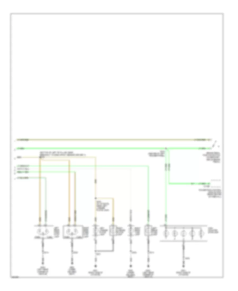
Exterior Lamps Wiring Diagram, Except Hybrid (2 of 2) for Ford Escape 2007
List of elements for Exterior Lamps Wiring Diagram, Except Hybrid (2 of 2) for Ford Escape 2007:
- (center rear of vehicle) trailer tow connector
- Abs control module (left rear of engine compt)
- Brake pedal position switch (on bracket, above brake pedal)
- C175b
- G401 (right side of liftgate)
- G403 (left rear end of vehicle)
- High mounted stoplamp
- Left license plate lamp
- Left rear park/ stop lamp
- Left rear turn lamp
- Park
- Powertrain control module (pcm) (2.3l: rear center of firewall) (3.0l: in recess on upper center of firewall)
- Right license plate lamp
- Right rear park/ stop lamp
- Right rear turn lamp
- S139 (left side of engine compt, near c134)
- S302
- S331 (at left kick panel, near breakout to c263)
- S400
- S401
- S402 (in liftgate harness, near left license plate lamp)
- S406 (left "d" pillar)
- Speed control servo (right side of engine compt)
- Turn
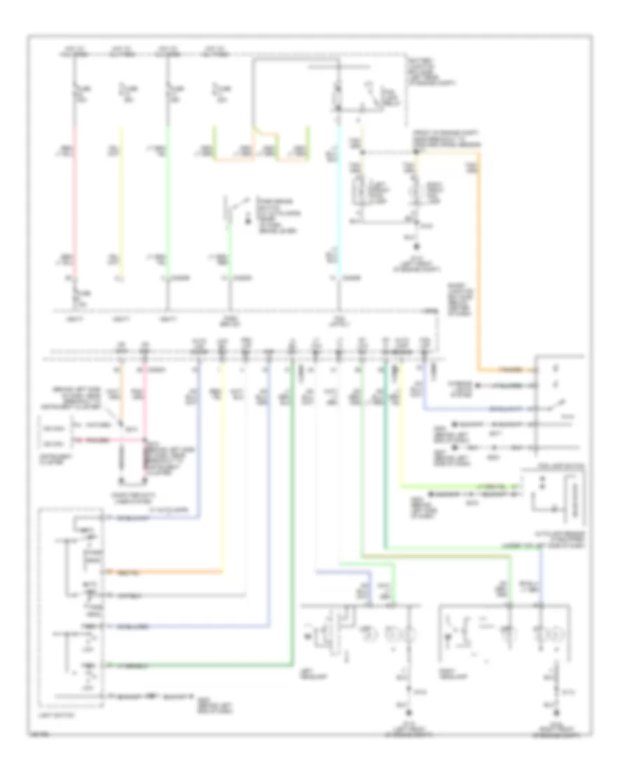
Exterior Lamps Wiring Diagram, Hybrid (1 of 2) for Ford Escape 2007
List of elements for Exterior Lamps Wiring Diagram, Hybrid (1 of 2) for Ford Escape 2007:
- (left side of engine compt, above wheelwell) s146
- 3) park 4) headlamps
- Auto
- Battery junction box (bjb) (left rear of engine compt)
- Bpp input
- C2280a
- C2280b
- C2280e
- Fuse 15a
- Fuse 25a
- G103 (right front of engine compt)
- G110 (left front of engine compt)
- G202 (behind left end of dash)
- G202 (behind left end of dsh)
- Ground
- Hazard flasher switch
- Hot at all times
- Instrument cluster
- Interior lights system
- Left
- Left front park/ turn lamp
- Left front side lamp (mariner)
- Left side turn signal lamp (mariner)
- Left turn
- Left turn sig
- Light switch 1) auto 2) off
- Logic
- Lom
- Low beam sw
- Mariner
- Off
- Park
- Park lamp relay
- Right
- Right front park/ turn lamp
- Right front side lamp (mariner)
- Right side turn signal lamp (mariner)
- Right turn
- Right turn sig
- S112
- S143
- S147 (left side of engine compt, above wheelwell)
- S150 (right front of engine compt, near auxiliary relay box 1)
- S218
- S252
- S314
- Smart junction box (sjb) (below center of dash)
- Turn
- Vbatt
- Vpwr
- Vref
Exterior Lamps Wiring Diagram, Hybrid (2 of 2) for Ford Escape 2007
List of elements for Exterior Lamps Wiring Diagram, Hybrid (2 of 2) for Ford Escape 2007:
- (bottom of left "b" pillar, near breakout to side impact sensor (driver 1)) s315
- Brake pedal position switch (on bracket, above brake pedal)
- C175b
- G300 (under driver's seat)
- G401 (right side of liftgate)
- G402 (left rear corner of vehicle)
- High mounted stoplamp
- Left license plate lamp
- Left rear park/ stop lamp
- Left rear turn lamp
- Park
- Powertrain control module (pcm) (rear center of firewall)
- Right license plate lamp
- Right rear park/ stop lamp
- Right rear turn lamp
- S302
- S310 (center of left rocker panel)
- S400
- S401
- S402 (in liftgate, near left license plate lamp)
- S414
- Turn
GROUND DISTRIBUTION
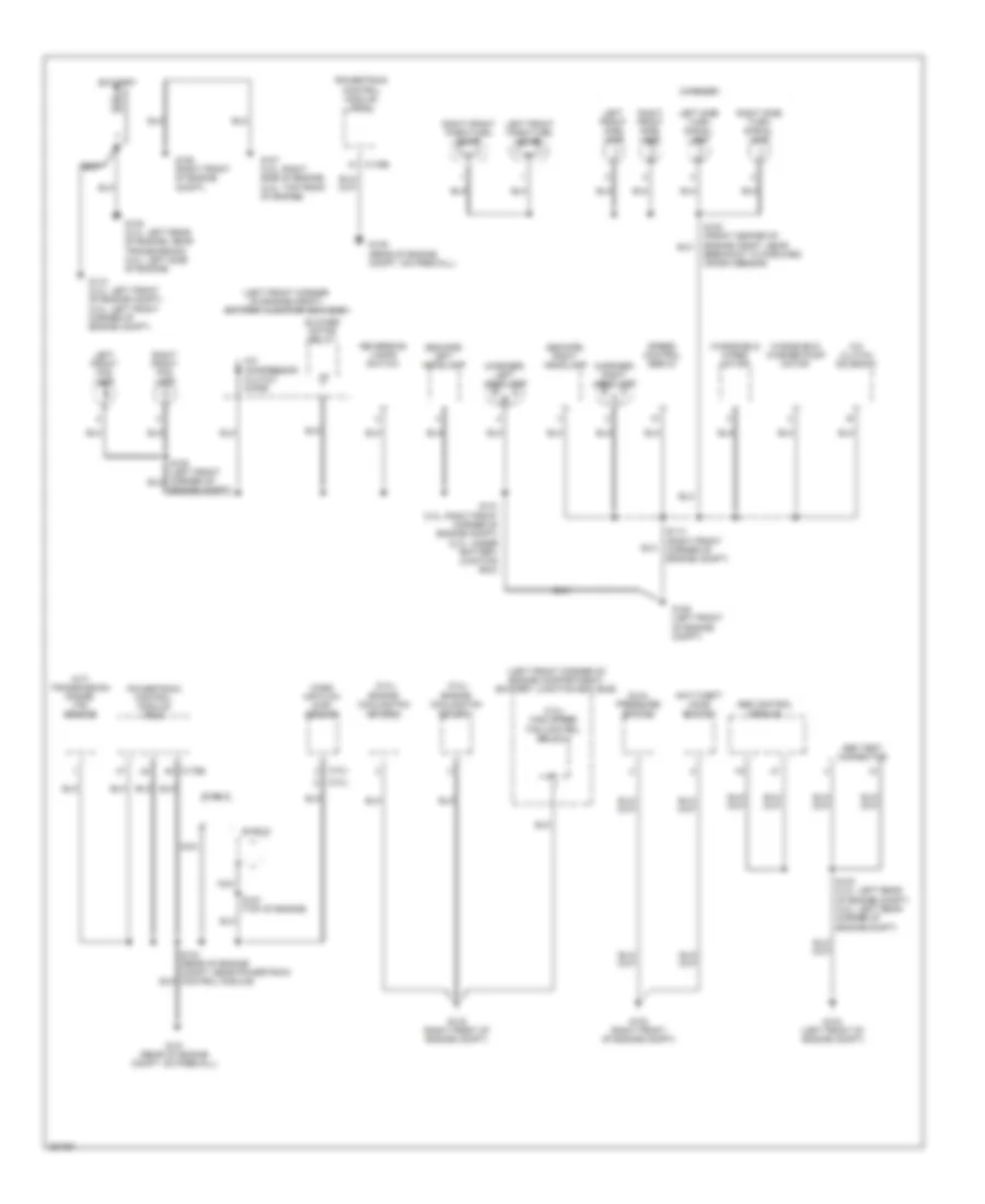
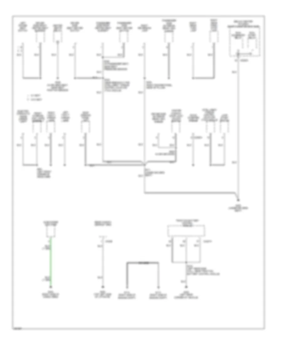
Ground Distribution Wiring Diagram, Except Hybrid (1 of 3) for Ford Escape 2007
List of elements for Ground Distribution Wiring Diagram, Except Hybrid (1 of 3) for Ford Escape 2007:
- (2.3l)
- (3.0l)
- (3.0l) high speed fan control relay 2
- (a/t) transmission range (tr) sensor
- (escape) left headlamp
- (escape) right headlamp
- (left front corner of engine compartment) battery junction box (bjb)
- (left front corner of engine compt) battery junction box (bjb)
- (mariner)
- (mariner) left headlamp
- (mariner) right headlamp
- A/c clutch solenoid
- A/c compressor clutch diode
- Abs control module
- Abs test connector
- Anti-theft hood switch
- Battery
- Blower motor relay
- C175b
- Dual pressure switch
- Engine compt)
- Engine cooling fan motor 1
- Engine cooling fan motor 2
- G101 (rear of engine compt, on firewall)
- G102 (right front of engine compt)
- G103 (right front of engine compt)
- G104 (left front of engine compt)
- G105 (left front of engine compt)
- G106 (right front of engine compt)
- G107 (3.0l: right side of engine) (2.3l: top front of engine)
- G108 (2.3l: left rear of engine, near transmission) (3.0l: left side of engine)
- G109 (rear of engine compt, on firewall)
- G110 (2.3l: left front of engine compt) (3.0l: left front corner of engine compt)
- Left front fog lamp
- Left front park/turn lamp
- Left front side lamp
- Left side turn signal lamp
- Mass air flow (maf) sensor
- Nca
- Powertrain control module (pcm)
- Reversing lamps switch
- Right front fog lamp
- Right front park/turn lamp
- Right front side lamp
- Right side turn signal lamp
- S102 (front center of engine compt, near breakout to forward crash sensor)
- S104 (rear of engine compt, near powertrain control module)
- S114 (right front corner of engine compt)
- S123 (2.3l: left rear of engine compt) (3.0l: left rear corner of engine compt)
- S131 (3.0l: right front corner of engine compt) (2.3l: under battery junction box)
- S157 (top of engine)
- Shield
- Speed control servo
- Windshield washer pump motor
- Windshield wiper motor
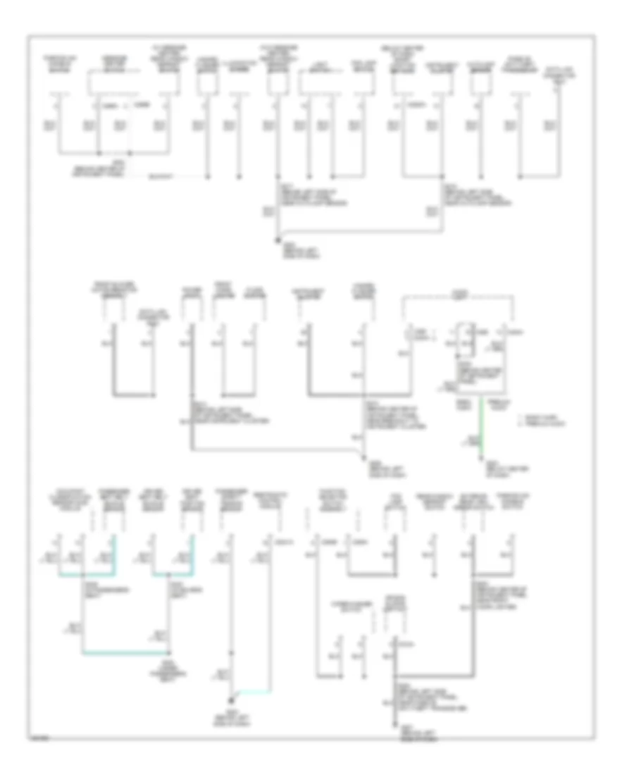
Ground Distribution Wiring Diagram, Except Hybrid (2 of 3) for Ford Escape 2007
List of elements for Ground Distribution Wiring Diagram, Except Hybrid (2 of 3) for Ford Escape 2007:
- (below center of dash) smart junction box (sjb)
- (w/ message center) rear window defrost switch
- (w/o message center) rear window defrost switch
- Air bag sliding contact
- Audio unit
- Autolamp sensor
- Basic audio
- C2041a
- C218a
- C2280a
- C240a
- C269a
- C269b
- C290
- C294b
- C294c
- Data link connector (dlc)
- Driver seat belt buckle sensor
- Driver seat position sensor
- Exterior rear view mirror switch
- Floor shifter
- Fog lamp switch
- Front blower motor resistor assembly
- Front cigar lighter
- Function selector switch assembly
- G202 (behind left side of dash)
- G203 (behind left side of dash)
- G204 (below center of dash)
- G206 (behind left side of dash)
- G207 (behind left side of dash)
- Hazard flasher switch
- Illumination dimmer
- Instrument cluster
- Light switch
- Message center switch
- Occupant classification sensor (ocs) module
- Parking aid disable switch
- Passenger safety tension sensor
- Passenger seat belt buckle sensor
- Passive anti-theft transceiver
- Power point
- Premium audio
- Rear window defrost switch
- Restraints control module
- S202 (behind center of instrument panel)
- S208 (behind left side of instrument panel, near passive anti-theft transceiver)
- S212 (behind center of instrument panel, near breakout to instrument cluster)
- S217 (behind left side of instrument panel, near autolamp sensor)
- S218 (behind left side of instrument panel, near autolamp sensor)
- S300 (under passenger's seat)
- S327 (in driver's seat)
- S329 (in passenger's seat)
- Wiper/washer switch
Ground Distribution Wiring Diagram, Except Hybrid (3 of 3) for Ford Escape 2007
List of elements for Ground Distribution Wiring Diagram, Except Hybrid (3 of 3) for Ford Escape 2007:
- (below center of dash) smart junction box (sjb)
- (left front corner of engine compartment) battery junction box (bjb)
- C2280c
- C402b
- C926a
- Cargo lamp
- Driver side exterior rear view mirror
- Driver side front door lock unit
- Driver side front heated seat element
- Driver side seat heater switch
- Electro- chromatic inside mirror unit
- Electronic compass
- Front interior/ map lamps assembly
- Fuel pump driver module
- Fuel pump relay
- G300 (under driver's seat)
- G400 (top left side of liftgate)
- G401 (right side of liftgate)
- G402 (left rear end of vehicle)
- G403 (left rear end of vehicle)
- G404 (right side of cargo area)
- G405 (under rear center of vehicle)
- Heated seats relay
- High mounted stop lamp
- Intelligent torque control coupling (itcc) module
- Keypad switch assembly
- Left license plate lamp
- Left power seat switch
- Left rear door lock actuator
- Left rear park/stop lamp
- Left rear turn lamp
- Left reversing lamp
- Left vanity mirror lamp
- Liftgate glass ajar switch
- Master window/ door lock/ unlock switch
- Nca
- Parking aid module (pam)
- Passenger side door lock switch
- Passenger side exterior rear view mirror
- Passenger side front door lock unit
- Passenger side front heated seat element
- Passenger side seat heater switch
- Pcm power relay
- Rear window defrost grid
- Rear wiper motor assembly
- Right license plate lamp
- Right rear door lock actuator
- Right rear park/ stop lamp
- Right rear turn lamp
- Right reversing lamp
- Right vanity mirror lamp
- Roof opening panel unit
- Run/ accessory relay
- Run/ start relay
- S302 (front of right rocker panel)
- S309 (left rocker panel, near "b" pillar)
- S326 (in driver's seat)
- S328 (in passenger's seat)
- S332 (at left kick panel)
- S400 (right rear corner of roof)
- S401 (in liftgate harness, near g401)
- S410 (under rear center of vehicle near fuel pump driver module)
- S500 (in left front door, near breakout to door lock unit)
- S501 (in left front door, near breakout to door lock unit)
- S600 (in left front door, near breakout to door lock unit)
- S901 (left front corner of headliner)
- Shield
- Subwoofer amplifier
- Trailer tow connector
- W/ heat
- W/o heat
Ground Distribution Wiring Diagram, Hybrid (1 of 4) for Ford Escape 2007
List of elements for Ground Distribution Wiring Diagram, Hybrid (1 of 4) for Ford Escape 2007:
- (left rear of engine compt) battery junction box (bjb)
- (mariner)
- A/c clutch solenoid
- A/c compressor clutch diode
- Anti-theft hood switch
- Battery
- Brake system control module
- C1457b
- C1458a
- C1462
- C1463b
- Dc/dc converter module
- Dual pressure switch
- Electric power steering pump motor
- Engine cooling fan motor 2
- G100 (left front corner of engine compt, near battery)
- G101 (left front corner of engine compt, near battery)
- G102 (right side of engine compt)
- G103 (right front of engine compt)
- G104 (right side of engine compt)
- G105 (right front of engine compt)
- G106 (left rear of engine compt, on bulkhead)
- G107 (left rear of engine compt, on bulkhead)
- G108 (left rear of engine compt, near transaxle control module)
- G109 (left side of engine compt)
- G111 (left front of engine compt)
- Heater pump motor
- Injector relay
- M/e coolant pump motor
- Mass air flow/ intake air temperature (maf/iat) sensor
- Nca
- Pcm power relay
- Power steering control module
- Powertrain control module (pcm)
- Right front park/ turn lamp
- Right front side lamp
- Right headlamp
- Right side turn signal lamp
- S101 (left side of engine compt, near c134)
- S108 (left side of engine compt)
- S112 (right front corner of engine compt)
- S118 (front of engine compt, near breakout to forward crash sensor)
- S119 (front of engine compt, near engine cooling fan motor 1)
- S131 (behind left headlight assembly)
- S137 (center rear of engine compt, near pcm)
- S140 (left rear of engine compt, near power steering control module)
- S141 (left rear of engine compt, near power steering control module)
- S142 (left rear of engine compt)
- Shield
- Transaxle control module
- Windshield washer pump motor
Ground Distribution Wiring Diagram, Hybrid (2 of 4) for Ford Escape 2007
List of elements for Ground Distribution Wiring Diagram, Hybrid (2 of 4) for Ford Escape 2007:
- (mariner)
- Abs test connector
- C4227a
- C926a
- Cargo lamp
- Driver side front door lock unit
- Engine cooling fan motor 1
- Escape
- Fuel pump driver module
- G110 (left front of engine compt)
- G301 (under driver's seat)
- G401 (right side of liftgate)
- G402 (left rear corner of vehicle)
- G405 (near fuel tank unit)
- High mounted stop lamp
- Jump start switch
- Keypad switch assembly
- Left front fog lamp
- Left front park/ turn lamp
- Left front side lamp
- Left headlamp
- Left license plate lamp
- Left rear door lock actuator
- Left rear park/ stop lamp
- Left rear turn lamp
- Left reversing lamp
- Left side turn signal lamp
- Liftgate ajar switch
- Mariner
- Nca
- Parking aid module (pam)
- Passenger side door lock switch
- Passenger side front door lock unit
- Rear wiper motor assembly
- Right front fog lamp
- Right license plate lamp
- Right rear door lock actuator
- S143 (behind left headlight assembly)
- S313 (under driver's seat)
- S400 (right rear corner of roof)
- S401 (in liftgate, near g401)
- S410 (under rear center of vehicle)
- S414 (left "d" pillar)
- S419 (left rear side wall, near traction battery control module)
- S501 (in driver door)
- S600 (in right front door, near front passenger side door lock unit)
- Shield
- Traction battery control module
- Windshield wiper motor
Ground Distribution Wiring Diagram, Hybrid (3 of 4) for Ford Escape 2007
List of elements for Ground Distribution Wiring Diagram, Hybrid (3 of 4) for Ford Escape 2007:
- (behind left side of dash, near passive anti-theft transceiver) s208
- (below center of dash) smart junction box (sjb)
- (w/ navigation)
- 4 speaker
- 7 speaker
- Air bag sliding contact
- Audio unit
- Audio visual navigation module
- Autolamp sensor
- Blower motor relay
- C2041a
- C218a
- C2280a
- C229a
- C240a
- C269a
- C269b
- C290
- C294b
- C294c
- Cd changer
- Data link connector (dlc)
- Driver seat belt buckle sensor
- Driver seat position sensor
- Exterior rear view mirror switch
- Floor shifter
- Fog lamp switch
- Front blower motor resistor assembly
- Front cigar lighter
- Function selector switch assembly
- G202 (behind left end of dash)
- G203 (behind left end of dash)
- G204 (below center of dash)
- G206 (behind left side of dash)
- G207 (behind left side of dash)
- Hazard flasher switch
- Illumination dimmer
- Instrument cluster
- Light switch
- Message center switch
- Ms can/acp gateway module
- Occupant classification sensor (ocs) module
- Parking aid disable switch
- Passenger seat belt buckle sensor
- Passenger side seat belt tensioner
- Passive anti-theft transceiver
- Power point
- Rear window defrost switch
- Relay)
- Restraints control (rcm) module
- S202 (behind center of dash, near c241)
- S212 (behind left side of dash, near breakout to instrument cluster)
- S214 (behind left side of dash, near breakout to instrument cluster)
- S217 (behind left side of dash, near autolamp sensor)
- S218 (behind left side of dash, near autolamp sensor)
- S224 (behind center of dash, near blower motor relay)
- S232 (behind center of dash, near breakout to c210)
- S233 (behind center of dash, near breakout to c210)
- S241 (w/ navigation) (behind right side of dash, near breakout to c210)
- S252 (behind right side of dash)
- S300 (center of vehicle floor, near breakout for sensor cluster)
- S329 (in passenger seat, near seat pressure sensor)
- Wiper/washer switch
Ground Distribution Wiring Diagram, Hybrid (4 of 4) for Ford Escape 2007
List of elements for Ground Distribution Wiring Diagram, Hybrid (4 of 4) for Ford Escape 2007:
- (below center of dash) smart junction box (sjb)
- Braided
- C2280c
- C2293a
- C402b
- C4227a
- Dc/ac inverter module
- Driver side exterior rear view mirror
- Driver side front heated seat element
- Driver side seat heater switch
- Electro- chromatic inside mirror unit
- Front interior/ map lamps assembly
- G112 (right side of engine compt)
- G113 (right side of engine compt)
- G300 (under driver's seat)
- G400 (top left side of liftgate)
- G403 (left rear corner of vehicle)
- G404 (right side of cargo area)
- Heated seats relay
- Intelligent torque control coupling (itcc) module
- Jump start switch
- Left power seat switch
- Left vanity mirror lamp
- Master window/ door lock/ unlock switch
- Passenger side exterior rear view mirror
- Passenger side front heated seat element
- Passenger side seat heater switch
- Rear window defrost grid
- Right rear park/ stop lamp
- Right rear turn lamp
- Right reversing lamp
- Right vanity mirror lamp
- Roof opening panel unit
- Run/ accessory relay
- Run/ start relay
- S302 (right rocker panel, near "b" pillar)
- S326 (in driver's seat, near seat position sensor)
- S328 (in passenger seat, near seat pressure sensor)
- S332 (near breakout for intelligent torque control coupling (itcc) module)
- S416 (left rear side wall, near traction battery control module)
- S500 (in driver door)
- S901 (left front corner of headliner)
- Subwoofer amplifier
- Traction battery control module
- W/ heat
- W/o heat
HEADLIGHTS
Headlights Wiring Diagram, Except Hybrid for Ford Escape 2007
List of elements for Headlights Wiring Diagram, Except Hybrid for Ford Escape 2007:
- (behind left side of dash) g202
- (behind left side of instrument panel, near instrument cluster)
- (left front corner engine compartment, under battery junction box (bjb)) s117
- 2.3l
- 3.0l
- Auto
- Auto lmp sen
- Auto lmp sw
- Autolamp sensor (w/ autolamps) (top left side of dash)
- Battery junction box (bjb) (left front corner of engine compt)
- C2280a
- C2280b
- C2280d
- C2280e
- Data link connector (on lower left side of dash)
- Fog lamp relay
- Fog lamp switch
- Fog lmp rly ctrl
- Fog lmp sw
- Ftp
- Fuse 15a
- Fuse 20a
- Fuse 25a
- Fuse 40a
- G105 (left front of engine compt)
- G202 (behind left side of dash)
- G207 (behind left side of dash)
- Head
- Hi bm sw
- Hot at all times
- Instrument cluster
- Interior lights system
- Left front fog lamp
- Left headlamp
- Light switch
- Logic
- Low
- Low bm sw
- Lt hi bm
- Lt low bm
- Ms can+
- Ms can-
- Off
- Park
- Park brake switch (w/ autolamps) (at base of park brake lever)
- Park brk sw
- Pass
- Prk lmp sw
- Right front fog lamp
- Right headlamp
- Rt hi bm
- Rt low bm
- S106
- S114
- S131
- S203
- S213
- S215 (behind left side of instrument panel, near instrument cluster)
- S217
- S218
- Smart junction box (sjb) (below center of dash)
- Solid state
- Vbatt
- W/ autolamps
Headlights Wiring Diagram, Hybrid for Ford Escape 2007
List of elements for Headlights Wiring Diagram, Hybrid for Ford Escape 2007:
- (behind left side of dash, near breakout to instrument cluster)
- (front of engine compt, near breakout to forward crash sensor) s117
- Auto
- Auto lamp sensor
- Auto lmp on/off
- Autolamp sensor (if equipped) (under top left side of dash)
- Battery junction box (bjb) (left rear of engine compt)
- C2280a
- C2280b
- C2280d
- C2280e
- Computer data lines system
- Fog lamp relay
- Fog lamp switch
- Fog lmp rly
- Fog lmp sw
- Ftp
- Fuse 15a
- Fuse 20a
- Fuse 25a
- Fuse 40a
- G103 (right front of engine compt)
- G110 (left front of engine compt)
- G202 (behind left end of dash)
- G202 (behind left side of dash)
- G207 (behind left side of dash)
- Head
- Hi bm sw
- Hot at all times
- Instrument cluster
- Interior lights system
- Left front fog lamp
- Left headlamp
- Light switch
- Logic
- Low
- Low bm sw
- Lt hi bm
- Lt low bm
- Ms can+
- Ms can-
- Off
- Park
- Park brake switch (w/ autolamps) (base of park brake lever)
- Park brk sw
- Pass
- Prk lmp sw
- Right front fog lamp
- Right headlamp
- Rt hi bm
- Rt low bm
- S112
- S143
- S203
- S213
- S215 (behind left side of dash, near breakout to instrument cluster)
- S217
- S218
- Smart junction box (sjb) (below center of dash)
- Solid state
- Vbatt
- W/ autolamps
HORN
Horn Wiring Diagram for Ford Escape 2007
List of elements for Horn Wiring Diagram for Ford Escape 2007:
- Air bag sliding contact (on steering column)
- C218a
- C2280a
- C2280b
- Fuse 15a
- G207 (behind left side of dash)
- Horn relay
- Horn switch
- Hot at all times
- Left horn (left front corner of engine compt)
- Nca
- S208
- Sjb logic
- Smart junction box (sjb) (below center of dash)
INSTRUMENT CLUSTER
Instrument Cluster Wiring Diagram for Ford Escape 2007
List of elements for Instrument Cluster Wiring Diagram for Ford Escape 2007:
- (except hybrid: below lower center of dash, on transmission tunnel) (hybrid: beneath lower center of dash, on transmission tunnel) restraints control module (rcm)
- (hybrid) s313
- (hybrid: behind center of dash, near front cigar lighter) (except hybrid: behind center of instrument panel, near front cigar lighter) s201
- (under driver's seat) (hybrid) g301
- Abs control module (except hybrid) (left rear of engine compt)
- Air bag tone drv
- Ajar
- Bfls
- Bfls gnd
- Bflsret
- Brake fluid level switch (except hybrid) (on brake fluid reservoir)
- Brake fluid level switch (hybrid) (on brake fluid reservoir)
- Brake system control module (hybrid) (right rear of engine compt)
- C2041a
- C2280a
- C2280c
- C2280d
- C2280e
- C269a
- C269b
- Compass +
- Compass -
- Computer data lines system
- Cruise control system
- Cruise ctrl ind
- Dim sw in
- Driver side front door lock unit (in left front door)
- Electronic compass (except hybrid)
- Fuel sens in
- Fuel sens return
- Fuel tank unit (beneath left rear of vehicle, in fuel tank)
- Fuse 10a
- Fuse 15a
- G202 (except hybrid: behind left side of dash) (hybrid: behind left end of dash)
- G206 (behind left side of dash)
- G300 (except hybrid) (under driver's seat)
- G300 (under driver's seat)
- Gnd
- Ground
- Hot at all times
- Hot in run or acc
- Hot in run or start
- Hot w/ accessory delay relay energized
- Hs can +
- Hs can -
- Hs-can h
- Hs-can l
- Instrument cluster
- Interior lights system
- Left rear door lock actuator (in left rear door)
- Left turn
- Left turn ind
- Lf door ajar
- Logic
- Lr door ajar
- Message center switch (optional)
- Message cntr info1
- Message cntr set 2
- Ms can +
- Ms can -
- Oil press sw
- Oil pressure switch (2.3l: left rear of engine block) (3.0l: left side of engine) (hybrid: lower left rear of engine block)
- Park brake sw
- Park brake switch (except hybrid: at base of park brake lever) (hybrid: base of park brake lever)
- Passenger side front door lock unit (in right front door)
- Pwm dim+
- Pwr
- R/s1
- Redundant park sw status in
- Rf door ajar
- Right rear door lock actuator (in right rear door)
- Right turn
- Right turn ind
- Ril
- Rr door ajar
- Run/acc
- S202
- S212
- S216
- S218
- S309
- S309 (except hybrid)
- S600
- S905
- Shift interlock system
- Smart junction box (sjb) (below center of dash)
- Sts
INTERIOR LIGHTS
Courtesy Lamps Wiring Diagram, with Roof Opening Panel for Ford Escape 2007
List of elements for Courtesy Lamps Wiring Diagram, with Roof Opening Panel for Ford Escape 2007:
- (except hybrid: left rocker panel, ner "b" pillar) (hybrid: left "d" pillar) s405
- (hybrid) s313
- (under driver's seat) (hybrid) g301
- Ajar
- Battery junction box (bjb) (except hybrid: left front corner of engine compt) (hybrid: left rear of engine compt)
- Battery saver
- Brake system control module (hybrid) (right rear of engine compt)
- C2280a
- C2280b
- C2280c
- C2280d
- C926a pnk
- C926b
- Cargo lamp
- Door
- Driver side front door lock unit (in left front door)
- Except hybrid
- Except hybrid hybrid
- Front interior lamp
- Front interior/ map lamps assembly
- Fuse 25a
- G202 (except hybrid: behind left side of dash) (hybrid: behind left end of dash)
- G300 (except hybrid) (under driver's seat)
- G300 (under driver's seat)
- G402 (left rear corner of vehicle)
- Gnd
- Hot at all times
- Hybrid
- Interior dome lamps
- Left rear door lock actuator (in left rear door)
- Left vanity mirror lamp (except escape hybrid)
- Lf door ajar
- Lr door ajar
- Off
- Passenger side front door lock unit (in right front door)
- Pnk
- Rf door ajar
- Right rear door lock actuator (in right rear door)
- Right vanity mirror lamp (except escape hybrid)
- Rr door ajar
- S218
- S309 (except hybrid)
- S332
- S404 (hybrid: rear of headliner) (except hybrid: left rocker panel, near "b" pillar)
- S414
- S501 (except hybrid)
- S600
- S900 (left front corner of headliner)
- S901
- S903 (except hybrid: left front corner of headliner) (hybrid: left front corner of headliner, near roof opening panel unit)
- Sjb logic
- Smart junction box (sjb) (below center of dash)
- Vbatt
- Wk_up
Courtesy Lamps Wiring Diagram, without Roof Opening Panel for Ford Escape 2007
List of elements for Courtesy Lamps Wiring Diagram, without Roof Opening Panel for Ford Escape 2007:
- (hybrid) s313
- (under driver's seat) (hybrid) g301
- Ajar
- Battery junction box (bjb) (except hybrid: left front corner of engine compt) (hybrid: left rear of engine compt)
- Battery saver
- Brake system control module (hybrid) (right rear of engine compt)
- C2280a
- C2280b
- C2280c
- C2280d
- C926a (except hybrid: pnk
- C926b
- Cargo lamp
- Door
- Driver side front door lock unit (in left front door)
- Except hybrid
- Except hybrid hybrid
- Front interior lamp
- Fuse 25a
- G202 (except hybrid: behind left side of dash) (hybrid: behind left end of dash)
- G300 (except hybrid) (under driver's seat)
- G300 (under driver's seat)
- G402 (left rear corner of vehicle)
- Gnd
- Hot at all times
- Hybrid
- Interior dome lamps
- Left rear door lock actuator (in left rear door)
- Left rocker panel, ner "b" pillar) (hybrid: left "d" pillar) s405
- Left vanity mirror lamp (except escape hybrid)
- Lf door ajar
- Lr door ajar
- Off
- Passenger side front door lock unit (in right front door)
- Pnk
- Rf door ajar
- Right rear door lock actuator (in right rear door)
- Right vanity mirror lamp (except escape hybrid)
- Rr door ajar
- S218
- S309 (except hybrid)
- S332
- S404 (hybrid: rear of headliner) (except hybrid: left rocker panel, near "b" pillar)
- S414
- S501 (except hybrid)
- S600
- S900 (left front corner of headliner)
- S901
- Sjb logic
- Smart junction box (sjb) (below center of dash)
- Vbatt
- Wk_up
Instrument Illumination Wiring Diagram for Ford Escape 2007
List of elements for Instrument Illumination Wiring Diagram for Ford Escape 2007:
- (behind left side of dash) g206
- (except hybrid) s212 s233 (hybrid)
- (except hybrid: behind center of instrument panel, near front cigar lighter) (hybrid: behind center of dash, near front cigar lighter) s201
- (in left front door, near breakout to door lock unit) s601
- (under driver's seat) (except hybrid) g300
- 229a
- Accessory delay relay
- Audio unit
- Audio visual navigation (avn) module (hybrid w/ navigation)
- C2035
- C2280a
- C2280c
- C2339
- C269a
- C269b
- C290
- C294c
- Dim sw in
- Except hybrid
- Except hybrid hybrid
- Floor shifter
- Fog lamp switch
- Function selector switch assembly
- Fuse 10a
- Fuse 30a
- G202 (except hybrid: behind left side of dash) (hybrid: behind left end of dash)
- G206 (behind left side of dash)
- G207 (behind left side of dash)
- Gnd
- Hazard flasher switch
- Hot at all times
- Hot in run & acc
- Hot in run & start
- Hybrid
- Illumination dimmer
- Instrument cluster
- Left rear window adjust switch
- Logic
- Master window/ door lock/unlock switch
- Message center switch
- Off
- Parking aid disable switch
- Passenger side door lock switch
- Passenger side window adjust switch
- Pwm dim +
- R/s1
- Rear window defroster switch
- Right rear window adjust switch
- Run/acc
- S202
- S203
- S212
- S214
- S216
- S217
- S218
- S231 (hybrid) (behind center of dash, near breakout to c210)
- S233
- S330 (hybrid) s310 (except hybrid)
- S600
- Sig gnd
- Smart junction box (sjb) (below center of dash)
NAVIGATION
Navigation Wiring Diagram, Hybrid for Ford Escape 2007
List of elements for Navigation Wiring Diagram, Hybrid for Ford Escape 2007:
- (behind center of dash, in breakout to c213)
- (behind left end of dash) g202
- (behind right side of dash, near c212)
- Acc/del
- Acp a
- Acp b
- Asyson
- Audio +
- Audio -
- Audio shld
- Audio visual navigation (avn) module
- Brake system control module (right rear of engine compt)
- C2280a
- C2280c
- C2280e
- C2294a
- C2294b
- C229a
- C229b
- C229c
- C229d
- C229e
- Cd changer
- Cd left +
- Cd left -
- Cd right +
- Cd right -
- Cd shld
- Computer data lines system
- En/cd
- En/clp
- Fuse 10a
- Fuse 15a
- Fuse 5a
- G204 (below center of dash)
- G206 (behind left side of dash)
- G404 (right side of cargo area)
- Gnd
- Hot at all times
- Hot w/ accessory delay relay energized
- Illum
- Illum gnd
- Interior lights system
- Left +
- Left -
- Left front +
- Left front -
- Left front speaker
- Left front tweeter
- Left rear +
- Left rear -
- Left rear speaker
- Ms can +
- Ms can -
- Ms-can/acp gateway module (behind right side of dash)
- Reverse in
- Reverse lamp relay
- Right +
- Right -
- Right front +
- Right front -
- Right front speaker
- Right front tweeter
- Right rear +
- Right rear -
- Right rear speaker
- S205
- S230
- S233
- S234 (behind center of dash, in breakout to audio visual navigation (avn) module)
- S235
- S236
- S239
- S240
- S241
- S242
- S243
- S250 (behind right side of dash, near ms-can/acp gateway module)
- S252
- S309
- Shld
- Smart junction box (sjb) (below center of dash)
- St sig
- Sub logic
- Subwoofer amplifier (right side of cargo compt, behind trim)
- Tan
- Vbatt
- Vpwr
- Vss
- Vss out
Parking Assistant Wiring Diagram, Except Hybrid for Ford Escape 2007
List of elements for Parking Assistant Wiring Diagram, Except Hybrid for Ford Escape 2007:
- (behind left side of dash) g207
- (center of rear bumper) s412
- (center of rear bumper) s413
- (left rear end of vehicle) g402
- C2280c
- Computer data lines system
- Fuse 10a
- G202 (behind left side of dash)
- Ground
- Hot in run or start
- Interior lights system
- Iso
- Left inner parking aid sensor (behind left side of rear bumper)
- Left outer parking aid sensor (behind left side of rear bumper)
- Off
- On/off sw
- Parking aid disable switch
- Parking aid module (pam) (right rear side of vehicle floor)
- Parking aid speaker (right rear side of vehicle floor)
- Rear sens gnd
- Rear sens pwr
- Reverse in
- Reverse lamp relay
- Right inner parking aid sensor (behind right side of rear bumper)
- Right outer parking aid sensor (behind right side of rear bumper)
- Ril sens in
- Rir sens in
- Rol sens in
- Ror sens in
- S202
- S203
- S333
- S414
- Smart junction box (sjb) (below center of dash)
- Speaker +
- Speaker -
- Status led
- Vprw
Parking Assistant Wiring Diagram, Hybrid for Ford Escape 2007
List of elements for Parking Assistant Wiring Diagram, Hybrid for Ford Escape 2007:
- (behind left end of dash) g202
- (behind left side of dash) g207
- (center of rear bumper) s412
- (center of rear bumper) s413
- (under driver's seat) g301
- C2280c
- Computer data lines system
- Fuse 10a
- Ground
- Hot in start or run
- Interior lights system
- Iso
- Left inner parking aid sensor (behind left side of rear bumper)
- Left outer parking aid sensor (behind left side of rear bumper)
- Off
- On/off sw
- Parking aid disable switch
- Parking aid module (pam) (right side of cargo area)
- Parking aid speaker (right side of cargo area)
- Rear sens gnd
- Rear sens pwr
- Reverse in
- Reverse lamp relay
- Right inner parking aid sensor (behind right side of rear bumper)
- Right outer parking aid sensor (behind right side of rear bumper)
- Ril sens in
- Rir sens in
- Rol sens in
- Ror sens in
- S202
- S203
- S309
- S313
- S423 (center of rear bumper)
- Smart junction box (sjb) (below center of dash)
- Speaker +
- Speaker -
- Status led
- Vprw
POWER DISTRIBUTION
Power Distribution Wiring Diagram, Except Hybrid (1 of 4) for Ford Escape 2007
List of elements for Power Distribution Wiring Diagram, Except Hybrid (1 of 4) for Ford Escape 2007:
- (2.3l)
- (3.0l)
- (3.0l) (2.3l)
- (left front corner of engine compt) battery junction box (bjb)
- (left front corner of engine compt) s196
- (left rocker panel, near driver's seat)
- (not used)
- (under battery junction box) s144
- 2.3l
- 3.0l
- 87a
- A/c clutch relay
- Abs control module
- Abs test connector
- Battery
- Battery junction box (bjb) (left front corner of engine compt)
- Blower motor relay
- C102a
- C102b
- C102c
- C1035a
- C1035c c1035b
- C197a
- C2280b
- C2280c
- Cooling fan relay
- Driver side exterior rear view mirror
- Fog lamp relay
- From fuse 7 (bjb) (diagram 1 of 4)
- Fuel pump relay
- Fuse (2.3l) 40a
- Fuse (3.0l) 50a
- Fuse 10a
- Fuse 15a
- Fuse 20a
- Fuse 30a
- Fuse 40a
- Fuse 5a
- Fuse 60a
- G206 (behind left side of dash)
- Generator
- Heated seats relay
- High speed fan control relay 1
- Logic
- Lom
- Low speed fan control relay
- Park lamp relay
- Passenger side exterior rear view mirror
- Pcm power relay
- Power point
- Powertrain control module (pcm)
- Rear defrost relay
- Rear window defrost grid
- Rear window defrost switch
- Red
- S198
- S199 (left side of engine compt near battery junction box)
- S214
- S330
- Smart junction box (sjb) (below center of dash)
- Starter motor
- To accessory delay relay (sjb) (diagram 3 of 4)
- To accessory relay (sjb) (diagram 3 of 4)
- To fuse 17 (bjb) (diagram 2 of 4)
- To fuse 20 (bjb) (diagram 1 of 4)
- Trailer tow connector
Power Distribution Wiring Diagram, Except Hybrid (2 of 4) for Ford Escape 2007
List of elements for Power Distribution Wiring Diagram, Except Hybrid (2 of 4) for Ford Escape 2007:
- (under battery junction box) s128
- (w/ heated seat) h
- (w/o heated seat)
- 2.3l
- 3.0l
- Air bag sliding contact
- All door lock relay
- Audio unit
- Basic audio
- Battery junction box (bjb) (left front corner of engine compt)
- Brake pedal position switch
- C218a
- C2280a
- C2280b
- C2280c
- C240a
- C290
- Cooling fan relay
- Data link connector (dlc)
- Driver unlock relay
- Evap canister vent control solenoid
- Exterior rear view mirror switch
- From fuse 5 (sjb) (diagram 3 of 4)
- From fuse 7 (bjb) (diagram 1 of 4)
- Fuel pump relay
- Fuse 10a
- Fuse 15a
- Fuse 25a
- Fuse 30a
- Fuse 40a
- Fuse 50a
- Fuse 5a
- High speed fan control relay 1
- High speed fan control relay 2
- Horn relay
- Instrument cluster
- Left horn
- Left power seat switch
- Logic
- Low speed fan control relay
- Passive anti-theft transceiver
- Pcm power relay
- Premium audio
- S130 (under battery junction box)
- Sjb logic board
- Smart junction box (sjb) (below center of dash)
- Starter relay
- To fuse 4 (sjb) (diagram 3 of 4)
Power Distribution Wiring Diagram, Except Hybrid (3 of 4) for Ford Escape 2007
List of elements for Power Distribution Wiring Diagram, Except Hybrid (3 of 4) for Ford Escape 2007:
- (in left front door near breakout to door lock unit) s601
- (not used)
- A/t
- Acc
- Accessory delay relay
- Audio unit
- Basic audio
- C2280a
- C2280b
- C2280c
- C2280e
- C240a
- C290
- Clutch cutoff switch
- Driver's seat)
- Electro- chromatic inside mirror
- Electronic compass
- Floor shifter
- From fuse 1 (bjb) (diagram 2 of 4)
- From fuse 19 (bjb) (diagram 1 of 4)
- From fuse 7 (bjb) (diagram 1 of 4)
- Front cigar lighter
- Fuse 10a
- Fuse 15a
- Fuse 20a
- Fuse 2a
- Fuse 30a
- Fuse 5a
- G206 (behind left side of dash)
- G300 (under
- Ignition switch
- Instrument cluster
- Intelligent torque coupling (itcc) module
- Key in ignition
- Key in ignition switch
- Left rear window adjust switch
- Lock solenoid
- Logic
- M/t
- Master window/ door lock/ unlock switch
- Off
- Passenger side door lock switch
- Passenger side window adjust switch
- Pcm power diode
- Premium audio
- Red
- Right rear window adjust switch
- Roof opening panel unit
- Run
- Run/ accessory relay
- Run/ start relay
- S113 (near breakout to c260)
- S214
- S332
- Smart junction box (sjb) (below center of dash)
- Start
- Subwoofer amplifier
- To (sjb) diagram 2 of 4)
- To fuse 21 (sjb) (diagram 4 of 4)
- To fuse 28 (sjb) (diagram 4 of 4)
- Transmission range (tr) sensor
Power Distribution Wiring Diagram, Except Hybrid (4 of 4) for Ford Escape 2007
List of elements for Power Distribution Wiring Diagram, Except Hybrid (4 of 4) for Ford Escape 2007:
- (behind center of instrument panel)
- (below center of instrument panel, near restraints control module (rcm) s333
- (left front corner of engine compt near battery junction box) s119
- (not used)
- (under passenger's seat) s301
- Abs control module
- Abs test connector
- Air bag sliding contact
- Assembly
- C2041a
- C218a
- C2208d
- C2280a
- C2280b
- C2280c
- C2280d
- C294a
- Deactivator switch
- Electro- chromatic inside mirror
- Floor shifter
- From fuse 26 (sjb) (diagram 4 of 4)
- From fuse h 24 (sjb) (diagram 3 of 4)
- From run/start g
- Function selector switch
- Fuse 10a
- Fuse 15a
- Fuse 20a
- Fuse 5a
- Heated seats relay
- Instrument cluster
- Intelligent torque control coupling (itcc) module
- Left reversing lamp
- Logic
- Occupant classification sensor (ocs) module
- Parking aid module (pam)
- Passenger air bag deactivation indicator
- Rear window washer pump
- Rear wiper motor assembly
- Rear wiper relay
- Relay (diagram 3 of 4)
- Restraints control module
- Reverse lamp relay
- Right reversing lamp
- S204
- Smart junction box (sjb) (below center of dash)
- Speed control servo
- To fuse 33 (sjb) (diagram 4 of 4)
- Windshield wiper motor
- Wiper/ washer switch
Power Distribution Wiring Diagram, Hybrid (1 of 4) for Ford Escape 2007
List of elements for Power Distribution Wiring Diagram, Hybrid (1 of 4) for Ford Escape 2007:
- (front of engine compt, near fuse links) s128
- (left rear of engine compt) battery junction box (bjb)
- (left side of engine compartment, near strut tower) s110
- (not used)
- (under driver's seat) s317
- A/c clutch relay
- Abs test connector
- Auxiliary relay box 1 (front of engine compt)
- Battery
- Battery junction box (bjb) (left rear of engine compt)
- Blower motor relay
- Brake system control module
- C1035a
- C1457c
- C2280b
- C2280c
- C2293a
- Dc/ac inverter module
- Dc/dc converter module
- Driver side exterior rear view mirror
- Fan control relay 1
- Fan control relay 2
- Fan control relay 3
- Fog lamp relay
- From fuse 30 (bjb) (diagram 1 of 4)
- Fuse 15a
- Fuse 20a
- Fuse 25a
- Fuse 30a
- Fuse 40a
- Fuse 50a
- Fuse 5a
- G206 (behind left side of dash)
- H/l power
- Heated seats relay
- Injector relay
- Lighting hsd
- Logic
- Lom
- Near auxiliary relay box 1) s134
- Park lamp relay
- Passenger side exterior rear view mirror
- Pcm power relay
- Power point
- Power sustain relay
- Rear defrost relay
- Rear window defrost grid
- Rear window defrost switch
- Red
- S124 (left side of engine compartment, near strut tower)
- S126 (left side of engine compartment, near strut tower)
- S127 (front of engine compt, near fuse links)
- S214
- Smart junction box (sjb) (below center of dash)
- To accessory delay relay (sjb) (diagram 3 of 4)
- To accessory relay (sjb) (diagram 3 of 4)
- To fuse 15 (bjb) (diagram 2 of 4)
- To fuse 31 (bjb) (diagram 1 of 4)
- Vbatt
Power Distribution Wiring Diagram, Hybrid (2 of 4) for Ford Escape 2007
List of elements for Power Distribution Wiring Diagram, Hybrid (2 of 4) for Ford Escape 2007:
- (4 speaker)
- (7 speaker)
- (behind center of dash, near breakout to c210) s243
- (behind center of dash, near blower motor relay) s216
- (left kick panel) s314
- (left rear side wall, near traction battery control module) s417
- (left side of engine compartment, near strut tower)
- (not used)
- (right front of engine compartment, near auxiliary relay box 1) s135
- (w/o heated)
- Abs test connector
- Air bag sliding contact
- All door lock relay
- Audio unit
- Audio visual navigation (avn) module
- Battery junction box (bjb) (left rear of engine compt)
- Brake pedal position switch
- Brake system control module
- C1458a
- C1463b
- C175b
- C218a
- C2280a
- C2280b
- C2280c
- C229a
- C240a
- C290
- C3016
- C3028
- C352
- C4227a
- Cd changer
- Data link connector (dlc)
- Deactivator switch
- Driver unlock relay
- Exterior rear view mirror switch
- From fuse 21 (bjb) (diagram 1 of 4)
- Fuse 10a
- Fuse 15a
- Fuse 20a
- Fuse 30a
- Fuse 40a
- Fuse 50a
- Fuse 5a
- Fuse 7.5a
- H (w/ heated)
- Heater pump relay
- Horn relay
- Instrument cluster
- Left horn
- Left power seat switch
- Logic
- M/e coolant pump relay
- Navigation
- Power steering control module
- Powertrain control module
- S109 (left side of engine compartment, near strut tower)
- S130
- S152
- Smart junction box (sjb) (below center of dash)
- To fuse 4 (sjb) (diagram 3 of 4)
- Traction battery control module
- Transaxle control module
Power Distribution Wiring Diagram, Hybrid (3 of 4) for Ford Escape 2007
List of elements for Power Distribution Wiring Diagram, Hybrid (3 of 4) for Ford Escape 2007:
- (behind right side of dash, near c212) s240
- (in breakout to battery junction box (bjb)) s115
- (not used)
- 4 speaker
- 7 speaker
- Acc
- Accessory delay relay
- Audio unit
- Audio visual navigation module (w/ navigation)
- Battery junction box (bjb) (left rear of engine compt)
- C175b
- C2280a
- C2280b
- C2280c
- C2280e
- C2294b
- C229a
- C240a
- C290
- Electro- chromatic inside mirror unit
- Floor shifter
- From fuse 15 (bjb) (diagram 2 of 4)
- From fuse 22 (bjb) (diagram 1 of 4)
- From fuse 30 (bjb) (diagram 1 of 4)
- Front cigar lighter
- Fuse 10a
- Fuse 15a
- Fuse 20a
- Fuse 2a
- Fuse 30a
- Fuse 5a
- G206 (behind left side of dash)
- G300 (under driver's seat)
- Ignition switch
- Instrument cluster
- Intelligent torque coupling (itcc) module
- Key in ignition
- Key in ignition switch
- Left rear window adjust switch
- Lock solenoid
- Logic
- Master window/ door lock/ unlock switch
- Ms-can/acp gateway module (w/ navigation)
- Off
- Passenger side door lock switch
- Passenger side window adjust switch
- Passive anti-theft transceiver
- Pcm power diode
- Pcm power relay
- Powertrain control module
- Red
- Right rear window adjust switch
- Roof opening panel unit
- Run
- Run/ accessory relay
- Run/ start relay
- S214
- S905 (left front center of headliner)
- Smart junction box (sjb) (below center of dash)
- Start
- Subwoofer amplifier
- To fuse 21 (sjb) (diagram 4 of 4)
- To fuse 28 (sjb) (diagram 4 of 4)
- Vpwr
Power Distribution Wiring Diagram, Hybrid (4 of 4) for Ford Escape 2007
List of elements for Power Distribution Wiring Diagram, Hybrid (4 of 4) for Ford Escape 2007:
- (center of vehicle floor, near breakout for intelligent torque control coupling (itcc) module) s301
- (left side of engine compartment, near strut tower) s125
- (not used)
- (under center console, near c211) s204
- (under center of dash, near smart junction box (sjb)) s251
- (under driver's seat) s309
- Abs test connector
- Assembly
- Audio visual navigation (avn) module
- Battery junction box (bjb) (left rear of engine compt)
- Battery zone valve
- Brake system control module
- C2041a
- C2208d
- C2280a
- C2280b
- C2280c
- C2280d
- C294a
- Dc/ac inverter module
- Electro- chromatic inside mirror unit
- From fuse 27 (sjb) (diagram 4 of 4)
- From fuse h 24 (sjb) (diagram 3 of 4)
- From run/start g
- Function selector switch
- Fuse 10a
- Fuse 15a
- Fuse 20a
- Fuse 5a
- Heated seats relay
- Injector relay
- Instrument cluster
- Intelligent torque control coupling (itcc) module
- Left reversing lamp
- Logic
- Occupant classification sensor (ocs) module
- Parking aid module (pam)
- Passenger air bag deactivation indicator
- Power steering control module
- Rear washer pump motor
- Rear wiper motor assembly
- Rear wiper relay
- Relay (diagram 3 of 4)
- Restraints control module (rcm)
- Reverse lamps relay
- Right reversing lamp
- Smart junction box (sjb) (below center of dash)
- To fuse 33 (sjb) (diagram 4 of 4)
- Traction battery control module
- Windshield wiper motor
- Wiper/ washer switch
POWER DOOR LOCKS
Power Door Locks Wiring Diagram, Except Hybrid (1 of 2) for Ford Escape 2007
List of elements for Power Door Locks Wiring Diagram, Except Hybrid (1 of 2) for Ford Escape 2007:
- (left rocker panel, near "b" pillar)
- (left rocker panel, next to rear seat)
- (under driver's seat) g300
- 1/2
- 3/4
- 5/6
- 7/8
- 9/0
- All lock relay
- All unlock relay
- Anti-theft hood switch (right front corner of engine compt)
- C2280b
- C2280c
- C2280d
- Door ajar
- Driver unlock relay
- Fuse 30a
- G103 (right front of engine compt)
- G300 (under driver's seat)
- Hot at all times
- Ill
- Interior lights system
- Keypad switch assembly
- Left rear door lock actuator (in left rear door)
- Liftgate ajar switch (bottom center of liftgate)
- Liftgate glass ajar switch (center of liftgate)
- Liftgate lock actuator (center of liftgate)
- Logic
- Lr dr ajar
- Master window/ door lock/ unlock switch
- Passenger side door lock switch
- Right rear door lock actuator (in right rear door)
- Rr dr ajar
- S305
- S308
- S309
- S320 (under driver's seat)
- S332
- S501
- S600
- Smart junction box (sjb) (below center of dash)
- Vref
Power Door Locks Wiring Diagram, Except Hybrid (2 of 2) for Ford Escape 2007
List of elements for Power Door Locks Wiring Diagram, Except Hybrid (2 of 2) for Ford Escape 2007:
- Battery junction box (bjb) (left front corner of engine compt)
- C2280a
- C2280b
- C2280d
- C2280e
- Door ajar
- Driver side front door lock unit (in left front door)
- Drv key cyl lk
- Drv key cyl unlk
- Fuse 10a
- Fuse 25a
- G300 (under driver's seat)
- Horn relay
- Horns system
- Hot at all times
- Ignition switch
- Key in ignition
- Key status
- Lf dr ajar
- Logic
- Passenger side front door lock unit (in right front door)
- Red
- Rf dr ajar
- S309
- S501
- S600
- Smart junction box (sjb) (below center of dash)
- Unlock/lock
- Vbatt
- Vpwr
Power Door Locks Wiring Diagram, Hybrid (1 of 2) for Ford Escape 2007
List of elements for Power Door Locks Wiring Diagram, Hybrid (1 of 2) for Ford Escape 2007:
- (bottom of left "b" pillar, near breakout to side impact sensor (driver 1))
- (bottom of left "b" pillar, near side impact sensor (driver 1))
- (under driver's seat) g301
- 1/2
- 3/4
- 5/6
- 7/8
- 9/0
- All lock relay
- All unlock relay
- Anti-theft hood switch (right front of engine compt)
- C2280b
- C2280c
- C2280d
- Door ajar
- Driver unlock relay
- Fuse 30a
- G111 (left front of engine compt)
- G300 (under driver's seat)
- G301 (under driver's seat)
- Hot at all times
- Ill
- Interior lights system
- Keypad switch assembly (mariner)
- Left rear door lock actuator (in left rear door)
- Liftgate ajar switch (bottom center of liftgate)
- Liftgate glass ajar switch (center of liftgate)
- Liftgate lock actuator (in liftgate)
- Logic
- Lr dr ajar
- Master window/ door lock/ unlock switch
- Passenger side door lock switch
- Right rear door lock actuator (in right rear door)
- Rr dr ajar
- S118
- S305
- S308
- S313
- S320 (under center of dash, near breakout to smart junction box (sjb))
- S501
- S600
- Smart junction box (sjb) (below center of dash)
- Vref
Power Door Locks Wiring Diagram, Hybrid (2 of 2) for Ford Escape 2007
List of elements for Power Door Locks Wiring Diagram, Hybrid (2 of 2) for Ford Escape 2007:
- Battery junction box (bjb) (left rear of engine compt)
- C2280a
- C2280b
- C2280d
- C2280e
- Door ajar
- Driver side front door lock unit (in left front door)
- Drv key cyl lk
- Drv key cyl unlk
- Fuse 10a
- Fuse 25a
- G301 (under driver's seat)
- Horn relay
- Horns system
- Hot at all times
- Ignition switch
- Key in ignition
- Key status
- Lf dr ajar
- Logic
- Passenger side front door lock unit (in right front door)
- Red
- Rf dr ajar
- S313
- S600
- Sjb logic
- Smart junction box (sjb) (below center of dash)
- Unlock/lock
- Vbatt
- Vpwr
POWER MIRRORS
Electrochromic Mirror Wiring Diagram, Except Hybrid for Ford Escape 2007
List of elements for Electrochromic Mirror Wiring Diagram, Except Hybrid for Ford Escape 2007:
- Accessory delay relay
- Battery junction box (bjb) (left front corner of engine compt)
- C2280b
- C2280c
- Electrochromatic inside mirror unit
- Fuse 10a
- Fuse 15a
- Fuse 25a
- Fuse 40a
- G300 (under driver's seat)
- Ground
- Hot at all times
- Hot in start or run
- Logic
- Power
- Reverse
- Reverse lamp relay
- S333
- S901
- S905
- Smart junction box (sjb) (below center of dash)
Electrochromic Mirror Wiring Diagram, Hybrid for Ford Escape 2007
List of elements for Electrochromic Mirror Wiring Diagram, Hybrid for Ford Escape 2007:
- (under driver's seat) g300
- Accessory delay relay
- Battery junction box (bjb) (left rear of engine compt)
- C2280b
- C2280c
- Electrochromatic inside mirror unit
- Fuse 10a
- Fuse 15a
- Fuse 20a
- Fuse 40a
- Ground
- Hot at all times
- Power
- Reverse
- S309
- S901
- S905
- Sjb logic
- Smart junction box (sjb) (below center of dash)
Power Mirrors Wiring Diagram for Ford Escape 2007
List of elements for Power Mirrors Wiring Diagram for Ford Escape 2007:
- C2280a
- Defogger system
- Down
- Exterior rear view mirror switch
- Fuse 10a
- G207 (behind left side of dash)
- Hot at all times
- Left
- Left exterior rear view mirror
- Left mirror select
- Left/ right
- Left/ right m
- Red
- Right
- Right exterior rear view mirror
- Right mirror select
- S203
- S216
- S312 (except hybrid: front of left rocker panel) (hybrid: left kick panel)
- Smart junction box (sjb) (below center of dash)
- Up/ down m
POWER SEATS
Driver Power Seat Wiring Diagram for Ford Escape 2007
List of elements for Driver Power Seat Wiring Diagram for Ford Escape 2007:
- Back
- C2280c
- Front of seat
- Front up/down
- Fuse 30a
- Fwd
- Fwd/back
- G300 (under driver's seat)
- Hot at all times
- Left power seat motor assembly (under driver's seat)
- Left power seat switch
- Nca
- Rear of seat
- Rear up/down
- S311 (hybrid)
- S326 (except hybrid)
- Smart junction box (sjb) (below center of dash)
- W/ heated seats
- W/o heated seats
Heated Seats Wiring Diagram, Except Hybrid for Ford Escape 2007
List of elements for Heated Seats Wiring Diagram, Except Hybrid for Ford Escape 2007:
- (in driver's seat, near heated seats relay) s323
- Battery junction box (bjb) (left front corner of engine compartment)
- C2280d
- Driver side front heated seat element
- Driver side seat heater switch
- Fuse 30a
- Fuse 5a
- G300 (under driver's seat)
- Heated seats relay (under driver's seat)
- Hot at all times
- Hot in start or run
- Nca
- Passenger side front heated seat element
- Passenger side seat heater switch
- Red
- S301
- S326
- S328
- Smart junction box (sjb) (below center of dash)
Heated Seats Wiring Diagram, Hybrid for Ford Escape 2007
List of elements for Heated Seats Wiring Diagram, Hybrid for Ford Escape 2007:
- (in driver's seat, near seat position sensor) s323
- (under driver's seat) driver side front heated seat element
- (under driver's seat) heated seats relay
- (under passenger's seat) passenger side front heated seat element
- Battery junction box (bjb) (left rear of engine compartment)
- C2280d
- Driver side seat heater switch
- Fuse 20a
- Fuse 5a
- G300 (under driver's seat)
- Hot at all times
- Hot in start or run
- Nca
- Passenger side seat heater switch
- Red
- S301
- S326
- S328
- Smart junction box (sjb) (below center of dash)
- Thermo sensor
POWER TOP/SUNROOF
Power Top/Sunroof Wiring Diagram for Ford Escape 2007
List of elements for Power Top/Sunroof Wiring Diagram for Ford Escape 2007:
- Accessory delay relay
- C2280c
- Electronics
- Forward
- Fuse 10a
- Fuse 15a
- G300 (under driver's seat)
- Hot at all times
- Rearward
- Roof opening panel unit (front center of roof, behind trim)
- Roof position switch
- S901
- S905
- Sjb logic
- Smart junction box (sjb) (below center of dash)
POWER WINDOWS
Power Windows Wiring Diagram for Ford Escape 2007
List of elements for Power Windows Wiring Diagram for Ford Escape 2007:
- (except hybrid) s310
- (hybrid) s330
- 10a
- 30a
- 40a
- Accessory delay relay
- Battery junction box (bjb) (except hybrid: left front corner of engine compartment) (hybrid: left rear of engine compt)
- C2280b
- C2280c
- Cpu
- Door locks system system
- Down
- Driver side front power window motor (in left front door)
- Driver's switch
- Except hybrid
- Fuse
- G300 (hybrid) (under driver's seat)
- G403 (except hybrid) (left rear end of vehicle)
- Hot at all times
- Hybrid
- Illumination
- Left rear power window motor (in left rear door)
- Left rear switch
- Left rear window adjust switch
- Lockout switch
- Master window/door lock/unlock switch
- Off
- One- touch down
- One- touch down relay
- Passenger side front power window motor (in right front door)
- Passenger side window adjust switch
- Passenger's switch
- Red
- Rest
- Right rear power window motor (in right rear door)
- Right rear switch
- Right rear window adjust switch
- S500
- S601
- Sjb logic
- Smart junction box (sjb) (below center of dash)
RADIO
Base Radio Wiring Diagram for Ford Escape 2007
List of elements for Base Radio Wiring Diagram for Ford Escape 2007:
- (behind left side of dash) g206
- (except hybrid) s212
- (hybrid) s233
- Acc/del
- Accessory delay relay
- Audio unit
- C2280a
- C2280e
- Dim ill
- Fuse 10a
- Fuse 5a
- G204 (below center of dash)
- Hot at all times
- Illum gnd
- Interior lights system
- Left front speaker
- Left rear speaker
- Lf +
- Lf -
- Logic
- Lr +
- Lr -
- Pa gnd
- Radio gnd
- Rf +
- Rf -
- Right front speaker
- Right rear speaker
- Rr +
- Rr -
- S216
- Smart junction box (sjb) (below center of dash)
- St sig
Premium Radio Wiring Diagram for Ford Escape 2007
List of elements for Premium Radio Wiring Diagram for Ford Escape 2007:
- (hybrid) s233
- (or nca)
- (w/ cd6)
- Acc/del
- Accessory delay relay
- Anti-lock brakes system
- Audio gnd
- Audio input +
- Audio input -
- Audio unit
- Aux audio +
- Aux audio -
- Aux audio enbl
- Battery
- C2280a
- C2280c
- C2280e
- C240a
- C240b
- Dim ill
- Enbl/clip detect
- Except hybrid
- Fuse 10a
- Fuse 15a
- Fuse 5a
- G204 (below center of dash)
- G206 (behind left side of dash)
- G404 (right side of cargo area)
- Gnd
- Hot at all times
- Hybrid
- Ill gnd
- Interior lights system
- Left front speaker
- Left front tweeter
- Left rear speaker
- Lf +
- Lf -
- Logic
- Lr +
- Lr -
- Nca
- Rf +
- Rf -
- Right front speaker
- Right front tweeter
- Right rear speaker
- Rr +
- Rr -
- S212 (except hybrid)
- S216
- S230 (behind center nca of dash, in breakout to c213)
- S234 (behind center of dash, in breakout to audio visual navigation (avn) module)
- Shield
- Smart junction box (sjb) (below center of dash)
- St sig
- Subwoofer amplifier
- Vss
SHIFT INTERLOCK
Shift Interlock Wiring Diagram for Ford Escape 2007
List of elements for Shift Interlock Wiring Diagram for Ford Escape 2007:
- Bpp input
- Brake pedal position switch (on bracket, above brake pedal)
- C175b
- C2280a
- C2280c
- C2280e
- Floor shifter
- Fuse 32 (except hybrid) 10a
- Fuse 4 10a
- Fuse 6 15a
- G206 (behind left side of dash)
- Hot at all times
- Hot in run or start
- Ignition switch
- Instrument cluster
- Interior lights system
- Key in ign
- Key in ignition
- Lock
- Logic
- O/d switch
- Park range
- Powertrain control module (pcm) (except hybrid) (3.0l: in recess on upper center of firewall) (2.3l: rear center of firewall)
- Red
- Redundant park switch status input
- S214
- S314 (hybrid)
- Shift lock sol
- Shift lock solenoid
- Smart junction box (sjb) (below center of dash)
STARTING/CHARGING
Charging Wiring Diagram, Except Hybrid for Ford Escape 2007
List of elements for Charging Wiring Diagram, Except Hybrid for Ford Escape 2007:
- (3.0l) (2.3l)
- (left front corner of engine compt) (2.3l) s196
- (left front corner of engine compt) (2.3l) s197
- (left side of engine compt, near battery junction box (bjb)) (3.0l) s198
- Altcom
- Altmon
- Battery
- Battery junction box (bjb) (left front corner of engine compt)
- C1035a
- C1035c c1035b
- C175b
- C175e
- C2280a
- Fuse 10a
- Fuse 15a
- G108 (2.3l: left rear of engine, near transmission) (3.0l: left side of engine)
- G110 (2.3l: left front of engine compt) (3.0l: left front corner of engine compt)
- Generator
- Hot in start or run
- Hs can+
- Hs can-
- Instrument cluster
- Powertrain control module (2.3l: rear center of firewall) (3.0l: in recess on upper center of firewall)
- R/s1
- Red
- S199 (3.0l) (left side of engine compt, near battery junction box (bjb))
- S210 (under center console, near c211)
- S211 (under center console, near c211)
- Smart junction box (sjb) (below center of dash)
- Starter motor
Starting Wiring Diagram, A/T Except Hybrid for Ford Escape 2007
List of elements for Starting Wiring Diagram, A/T Except Hybrid for Ford Escape 2007:
- (not used)
- 3.0l
- Acc
- Battery
- Battery junction box (left front corner of engine compt)
- C175b
- C2280a
- C2280b
- C263
- Fuse 10a
- Fuse 25a
- Fuse 50a
- G108 (2.3l: left rear of engine, near trans- mission) (3.0l: left side of engine)
- G110 (2.3l: left front of engine compt) (3.0l: left front corner of engine compt)
- Ignition switch
- Off
- Powertrain control module (2.3l: rear center of firewall) (3.0l: in recess on upper center of firewall)
- Red
- Red charging circuit
- Run
- S113 (near breakout to c260)
- S11o (3.0l) (left side of engine compt, near breakout to c134)
- S130
- Smart junction box (sjb) (below center of dash)
- Smr
- Start
- Starter motor
- Starter relay
- Strt out
- Tan/ red
- Tan/red
- Transmission range (tr) sensor (2.3l: on top of transmission) (3.0l: top of transmission)
Starting Wiring Diagram, M/T Except Hybrid for Ford Escape 2007
List of elements for Starting Wiring Diagram, M/T Except Hybrid for Ford Escape 2007:
- (not used)
- Acc
- Battery
- Battery junction box (left front corner of engine compt)
- C134
- C175b
- C2280a
- C2280b
- Clutch cutoff switch (on bracket, above clutch pedal)
- Fuse 10a
- Fuse 25a
- Fuse 50a
- G108 (2.3l: left rear of engine, near trans- mission) (3.0l: left side of engine)
- G110 (2.3l: left front of engine compt) (3.0l: left front corner of engine compt)
- Ignition switch
- Off
- Powertrain control module (2.3l: rear center of firewall) (3.0l: in recess on upper center of firewall)
- Red
- Red charging circuit
- Run
- S130
- Smart junction box (cjb) (below center of dash)
- Start
- Starter motor
- Starter relay
- Strt out
- Tan/ red
- Tan/red
SUPPLEMENTAL RESTRAINTS
Supplemental Restraints Wiring Diagram (1 of 2) for Ford Escape 2007
List of elements for Supplemental Restraints Wiring Diagram (1 of 2) for Ford Escape 2007:
- (behind center of dash, near blower motor relay)
- (hybrid)
- (hybrid) s224
- (in driver's seat, near heated seats relay) s327
- (or 1654)
- C175b
- C2041b
- C2280a
- C2o41a
- Can+
- Can-
- Computer data lines system
- Data link connector (dlc) (lower left side of dash)
- Driver safety belt retractor pretensioner (except hybrid) driver safety belt buckle pretensioner (hybrid) (hybrid: under driver seat) (except hybrid: in driver's seat)
- Driver safety belt retractor pretensioner (hybrid) (base of left "b" pillar)
- Driver seat belt buckle sensor (in driver's seat)
- Driver seat position sensor (in driver's seat)
- Drv buckle sw in
- Drvr crtn return
- Drvr ab1 feed
- Drvr ab1 rtn
- Drvr ab2 feed
- Drvr ab2 rtn
- Drvr air crtn feed
- Drvr pretens feed
- Drvr pretens rtn
- Drvr sab feed
- Drvr sab rtn
- Drvr1 feed
- Drvr1 rtn
- Drvr2 feed
- Drvr2 rtn
- Fcs feed
- Fcs rtn
- Fuse 15a
- G203 (except hybrid: behind left side of dash) (hybrid: behind left end of dash)
- G203 (hybrid: behind left end of dash) (except hybrid: behind left side of dash)
- Gnd
- Ground
- Hot in run or start
- Hybrid
- Id gnd
- Instrument cluster
- Iso
- Left side air bag module (left side of driver's seat)
- Pad lamp
- Pass ab1 feed
- Pass ab1 rtn
- Pass ab2 feed
- Pass ab2 rtn
- Pass air crtn feed
- Pass air crtn rtn
- Pass buckle sw in
- Pass pretens feed
- Pass pretens rtn
- Pass sab feed
- Pass sab rtn
- Pass1 feed
- Pass1 rtn
- Pass2 feed
- Pass2 rtn
- Passenger air bag deactivation indicator
- Passenger safety belt retractor pretensioner (except hybrid) passenger safety belt buckle pretensioner (hybrid) (except hybrid: in passenger's seat)
- Passenger seat belt buckle sensor (in passenger's seat)
- Pin shorting bars engaged
- Powertrain control module (rear center of firewall)
- Red
- Red/pnk
- Restraints control module (rcm) (beneath lower center of dash, on transmission tunnel)
- Right side air bag module (right side of passenger's seat)
- Ril
- Rtc prtn+
- Rtc prtn-
- S204 (hybrid: under center console, near c211) (except hybrid: behind center of instrument panel, near c210)
- S219 (hybrid: below center of dash, near g204) (except hybrid: below center of instrument panel, near g204)
- S300 (except hybrid: under passenger's seat, near c327) (hybrid: near breakout for sensor cluster)
- S329 (hybrid: in passenger seat, near seat pressure sensor) (except hybrid: in passenger's seat, near c334)
- Seat trk feed
- Shorting bar
- Sig
- Smart junction box (sjb) (below center of dash)
- Tas
- Tone
- Vpwr
- When module connector is disconnected from harness. shorting bars are connected between following pins: 1-2, 3-4, 5-6, 13-14 & 15-16) c2041a 1-2, 3-4, 5-6, 21-22, 31-32 & 33-34) c2041b
Supplemental Restraints Wiring Diagram (2 of 2) for Ford Escape 2007
List of elements for Supplemental Restraints Wiring Diagram (2 of 2) for Ford Escape 2007:
- (right "d" pillar)
- Air bag sliding contact (on steering column)
- Bar
- Bts ground
- Bts signal
- C218b
- Can+
- Can-
- Driver air bag module
- Driver side air curtain module (left "d" pillar)
- Driver side impact 1 sensor (w/ side air bags) (hybrid: base of left "b" pillar) (except hybrid: left rocker panel, near "b" pillar)
- Driver side impact 2 sensor (w/ side air bags) (left side of cargo area)
- Forward crash sensor (front of engine compartment)
- G203 (hybrid: behind left end of dash) (except hybrid: behind left side of dash)
- Gnd
- Ground
- Nca
- Occupant classification sensor (ocs) module (in passenger's seat)
- Passenger air bag module (behind right side of dash)
- Passenger safety belt tension sensor
- Passenger side air curtain module
- Passenger side impact 1 sensor (w/ side air bags) (right rocker panel, near "b" pillar)
- Passenger side impact 2 sensor (w/ side air bags) (right side of cargo area)
- Red/ pnk
- Red/pnk
- S300 (hybrid: center of vehicle floor, near breakout for sensor cluster) (except hybrid: under passenger's seat, near c327)
- S329 (hybrid: in passenger seat, near seat pressure sensor) (except hybrid: in passenger's seat, near c334)
- Seat pressure sensor (in passenger's seat)
- Sens ground
- Sens return
- Sens sig
- Shorting
- Shorting bar
- Sig
- Sig rtn
- Sws v-in
- Sws v-out
- Tan/red
- Vpwr
- Vref1
TRANSMISSION
4WD Wiring Diagram for Ford Escape 2007
List of elements for 4WD Wiring Diagram for Ford Escape 2007:
- (or 778)
- (or 779)
- C2280b
- C2280d
- Computer data lines system
- For intelligent torque control coupling (itcc) module)
- Fuse 10a
- Fuse 5a
- G300 (under driver's seat)
- Gnd
- Hot at all times
- Hot in run or start
- Hs can +
- Hs can -
- Intelligent torque control coupling (itcc) module (under center console)
- Intelligent torque control coupling (itcc) solenoid (under center rear of vehicle)
- Pwr
- Run/start
- S311 (hybrid) (under driver's seat)
- S332 (except hybrid) (at left kick panel)
- Smart junction box (sjb) (below center of dash)
- Sol +
- Sol -
A/T Wiring Diagram, Hybrid for Ford Escape 2007
List of elements for A/T Wiring Diagram, Hybrid for Ford Escape 2007:
- (center rear of engine compt, near powertrain control module (pcm)) s137
- (left rear of engine compt, on bulkhead) g106
- (left side of engine compt, above wheelwell) s144
- (left side of engine compt, near rear air box) s114
- (left side of engine compt, near strut tower) s111
- (pcm)) s137
- Battery junction box (bjb) (left rear of engine compt)
- C1457d
- C1458a
- C1458b
- C1458c
- C1458d
- C1458e
- C175b
- C175e
- C175t
- C2280b
- C4227a
- C4227c
- Cht
- Computer data lines system
- Cto
- Cylinder head temperature sensor (top of engine)
- Dc/dc interlock +
- Dc/dc interlock -
- Dc/dc +
- Dc/dc -
- Dc/dc converter module (right side of engine compt)
- Dc/dc interlock +
- Dc/dc interlock -
- Ect
- Engine controls system
- Feps
- Fuse 10a
- Fuse 2a
- Fuse 30a
- Fuse 40a
- Fuse 5a
- G103 (right front of engine compt)
- G106 (left rear of engine compt, on bulkhead)
- G108 (left rear of engine compt, near transaxle control module)
- Gnd
- Gsdn
- Hot at all times
- Hot in run or start
- Hs can +
- Hs can -
- Hv +
- Hv -
- Hvdc +
- Hvdc -
- Hvtmu +
- Hvtmu -
- Iat
- Interlock +
- Interlock -
- Isdn1
- Isdn2
- Maf
- Mafrtn
- Mass air flow/intake air temperature (maf/iat) sensor) (left side of engine compt, in air intake duct)
- Mect
- Msdn
- Pcm power diode
- Pcm power relay
- Power sustain relay
- Powertrain control module (pcm) (rear center of firewall)
- Psr
- Red
- S103 (right side of engine, near heated oxygen sensor (ho2s) no.11)
- S110 (left side of engine compt, near strut tower)
- S113
- S115 (in breakout to battery junction box (bjb))
- S116 (in breakout to battery junction box (bjb))
- S129 (behind left headlight assembly)
- S142 (left rear of engine compt, near c134)
- Sig rtn
- Smart junction box (sjb) (below center of dash)
- Tgac
- Tmac
- Tr a1
- Tr a1bvref
- Tr a1rtn
- Tr a2
- Tr a2bvref
- Tr a2rtn
- Tr a3
- Traction battery control module (left) (on floor, behind left wheelwell)
- Transaxle control module (above transaxle)
- Transmission range (tr) sensor (on top of transmission)
- Vbatt
- Vpwr
2.3L
2.3L, A/T Wiring Diagram, Except Hybrid for Ford Escape 2007
List of elements for 2.3L, A/T Wiring Diagram, Except Hybrid for Ford Escape 2007:
- (left rear of engine compt)
- (lower left side of dash) data link connector (dlc)
- (rear of engine compt, on firewall) g101
- (rear of engine compt, on firewall) g109
- (rear of of engine) s150
- (top of engine) s105
- (top of engine, near mass air flow (maf) sensor) s107
- (top of transmission) transmission hardware unit
- 3-2t/ ccs solenoid
- Battery junction box (bjb) (left front corner of engine compt)
- Boo
- Brake pedal position switch (on bracket, above brake pedal)
- Bvrefe
- C175b
- C175e
- C175t
- C2280b
- C2280c
- C251
- Can +
- Can -
- Case gnd
- Cht
- Cruise control system
- Cylinder head temperature sensor (top of engine)
- Electronic pressure control solenoid
- Engine compt,
- Engine controls system
- Epc
- Feps
- Fuse 10a
- Fuse 15a
- Fuse 2a
- Fuse 30a
- G101 (rear of
- G101 (rear of engine compt, on firewall)
- G300 (under driver's seat)
- Heated oxygen sensor (ho2s) 12 (near right front of engine, in exhaust)
- Ho2s 12
- Hot at all times
- Hot in run or start
- Htr 12
- Iat
- Mafrtn
- Mafs
- Mass air flow (maf) sensor (near rear of cylinder head, in air intake duct)
- On firewall)
- Oss
- Output shaft speed (oss) sensor (left side of transmission)
- Pcm power diode
- Pcm power relay
- Pcm)
- Powertrain control module (pcm) (rear center of firewall)
- Pwr gnd
- Red
- S104 (near pcm)
- S109 (top of engine)
- S111 (rear of of engine)
- S124 (left rear of engine compt)
- S125
- S128 (under battery junction box)
- S129 (under battery junction box)
- S154 (top of engine)
- S155 (top of engine)
- Shift solenoid a
- Shift solenoid b
- Sigrtnc
- Sigrtnt
- Smart junction box (sjb) (below center of dash)
- Ss3l
- Ssa
- Ssb
- Starting/charging system
- Tan/red
- Tcch
- Tft
- Throttle position sensor (tps) (on throttle body)
- Torque converter clutch solenoid
- Tps
- Transmission fluid temperature sensor
- Transmission range (tr) sensor (on top of transmission)
- Trs
- Tss
- Turbine shaft speed (tss) sensor (left side of transmission)
- Vpwr
- Vrsrtn
3.0L
3.0L, A/T Wiring Diagram, Except Hybrid for Ford Escape 2007
List of elements for 3.0L, A/T Wiring Diagram, Except Hybrid for Ford Escape 2007:
- (left side of engine compartment) s108
- (lower left side of dash) data link connector (dlc)
- (rear of engine compt, on firewall) g101
- (rear of engine compt, on firewall) g109
- (right side of engine) s105
- (right side of engine) s107
- (top of engine) s154
- (top of transmission) transmission hardware unit
- 3-2t/ ccs solenoid
- Battery junction box (bjb) (left front corner of engine compt)
- Boo
- Brake pedal position switch (on bracket, above brake pedal)
- Bvrefe
- C175b
- C175e
- C175t
- C2280b
- C2280c
- C251
- Can +
- Can -
- Case gnd
- Compt)
- Cruise control system
- Ect
- Electronic pressure control solenoid
- Engine controls system
- Engine coolant temperature (ect) sensor (rear of engine, in water outlet)
- Epc
- Feps
- Fuse 10a
- Fuse 15a
- Fuse 2a
- Fuse 30a
- G101 (rear of engine compt, on firewall)
- G300 (under driver's seat)
- Heated oxygen sensor (ho2s) 12 (w/ low emission vehicles) (near right front of engine)
- Heated oxygen sensor (ho2s) 22 (w/ low emission vehicles) (rear left side of engine)
- Ho2s 11
- Ho2s 12
- Hot at all times
- Hot in run or start
- Htr 12
- Htr 22
- Iat
- Mafrtn
- Mafs
- Mass air flow (maf) sensor (left side of engine compt, in air intake duct)
- Oss
- Output shaft speed (oss) sensor (left side of transmission, near left axle flange)
- Pcm power diode
- Pcm power relay
- Powertrain control module (pcm) (in recess on upper center of firewall)
- Pwr gnd
- Red
- S100 (right side of engine)
- S103 (right side of engine)
- S104 (rear of engine compartment, near powertrain control module)
- S109 (left side of engine compartment)
- S111 (left side of engine compt)
- S128 (under battery junction box)
- S129 (under battery junction box)
- S151 (on top of engine)
- S158 (left rear of engine compt)
- Shift solenoid a
- Shift solenoid b
- Sigrtne
- Smart junction box (sjb) (below center of dash)
- Ss3l
- Ssa
- Ssb
- Starting/charging system
- System
- Tan/red
- Tcch
- Tft
- Throttle position sensor (tps) (on throttle body)
- Torque converter clutch solenoid
- Tps
- Transmission fluid temperature sensor
- Transmission range (tr) sensor (top of transmission)
- Trs
- Tss
- Turbine shaft speed (tss) sensor (left side of transmission)
- Vpwr
- Vrsrtn
WARNING SYSTEMS
Warning Systems Wiring Diagram for Ford Escape 2007
List of elements for Warning Systems Wiring Diagram for Ford Escape 2007:
- (except hybrid: behind left side of instrument panel, near instrument cluster) (hybrid: behind left side of dash, near breakout to instrument cluster) s213
- (except hybrid: behind left side of instrument panel, near instrument cluster) (hybrid: behind left side of dash, near breakout to instrument cluster) s215
- (hybrid) s313
- (hybrid: behind left end of dash)
- (under driver's seat) (hybrid) g301
- Abs control module (except hybrid) (left rear of engine compt)
- Bckl state/tone
- Bfls
- Bfls gnd
- Bflsret
- Brake fluid level switch (except hybrid) (on brake fluid reservoir)
- Brake fluid level switch (hybrid) (on brake fluid reservoir)
- Brake system control module (hybrid) (right rear of engine compt)
- C2041a
- C2041b
- C2280a
- C2280d
- C2280e
- Computer data lines system
- Door ajar lf
- Door ajar lr
- Door ajar rf
- Door ajar rr
- Driver side front door lock unit (in left front door)
- Driver's seat belt buckle sensor (in driver's seat)
- Drv bckl sw in
- Fuse 10a
- G203 (except hybrid: behind left side of dash)
- G206 (behind left side of dash)
- G300 (except hybrid) (under driver's seat)
- Ground
- Hot at all times
- Hot in run or acc
- Hot in start or run
- Hs can +
- Hs can -
- Hs-canh
- Hs-canl
- Ignition switch
- Instrument cluster
- Key in ignition switch
- Left rear door lock actuator (in left rear door)
- Logic
- Ms can +
- Ms can -
- Park brake switch (at base of park brake lever)
- Pass bckl sw in
- Passenger side front door lock unit (in right front door)
- Passenger's seat belt buckle sensor (in passenger's seat)
- R/s1
- Red
- Restraints control module (rcm) (hybrid: beneath lower center of dash, on transmission tunnel) (except hybrid: below lower center of dash, on transmission tunnel)
- Right rear door lock actuator (in right rear door)
- Ril
- Run/acc
- S212
- S216
- S218
- S309 (except hybrid)
- S327
- S329
- S600
- Sig
- Signal ground
- Smart junction box (sjb) (below center of dash)
- Sts
- Vpwr
- Vref
WIPER/WASHER
Front Wiper/Washer Wiring Diagram for Ford Escape 2007
List of elements for Front Wiper/Washer Wiring Diagram for Ford Escape 2007:
- (except hybrid) (hybrid)
- (except hybrid) s114
- (except hybrid: left front of engine compt)
- C2280b
- Front wiper
- Fuse 20a
- G103 (hybrid) g105 (except hybrid) (hybrid: right front of engine compt)
- G105 (except hybrid)
- G110 (hybrid) (left front of engine compt)
- G207 (behind left side of dash)
- High
- Hot in on or acc
- Int
- Intermittent control
- Intermittent relay
- Low
- Mist
- Off
- Park
- Run
- S114 s143
- S119 (hybrid)
- S208
- Smart junction box (sjb) (below center of dash)
- Tan/red
- Washer
- Windshield washer pump motor (right front of engine compartment)
- Windshield wiper motor (left rear of engine compt)
- Wiper/washer switch
Rear Wiper/Washer Wiring Diagram for Ford Escape 2007
List of elements for Rear Wiper/Washer Wiring Diagram for Ford Escape 2007:
- (behind center of instrument panel, near smart junction box (sjb)) s205
- (center of liftgate)
- (except hybrid)
- (hybrid)
- C2280c
- C2280d
- C2280e
- Fuse 10a
- G207 (behind left side of dash)
- G403 (except hybrid) g401 (hybrid) (except hybrid: left rear end of vehicle) (hybrid: right side of liftgate)
- Hot in on or acc
- Intermittent
- Park
- Rear washer
- Rear window washer pump motor (right front of engine compartment)
- Rear wiper motor assembly
- Rear wiper relay
- Run
- S219 (below center of dash, near g204)
- S400
- Sjb logic
- Smart junction box (sjb) (below center of dash)
- Wiper
- Wiper/washer switch