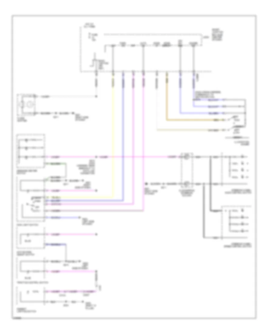
AIR CONDITIONING
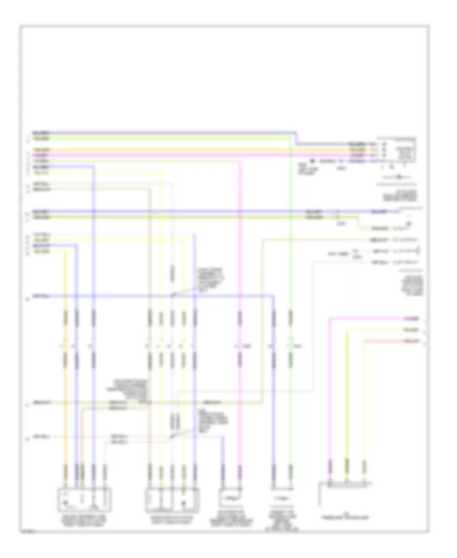
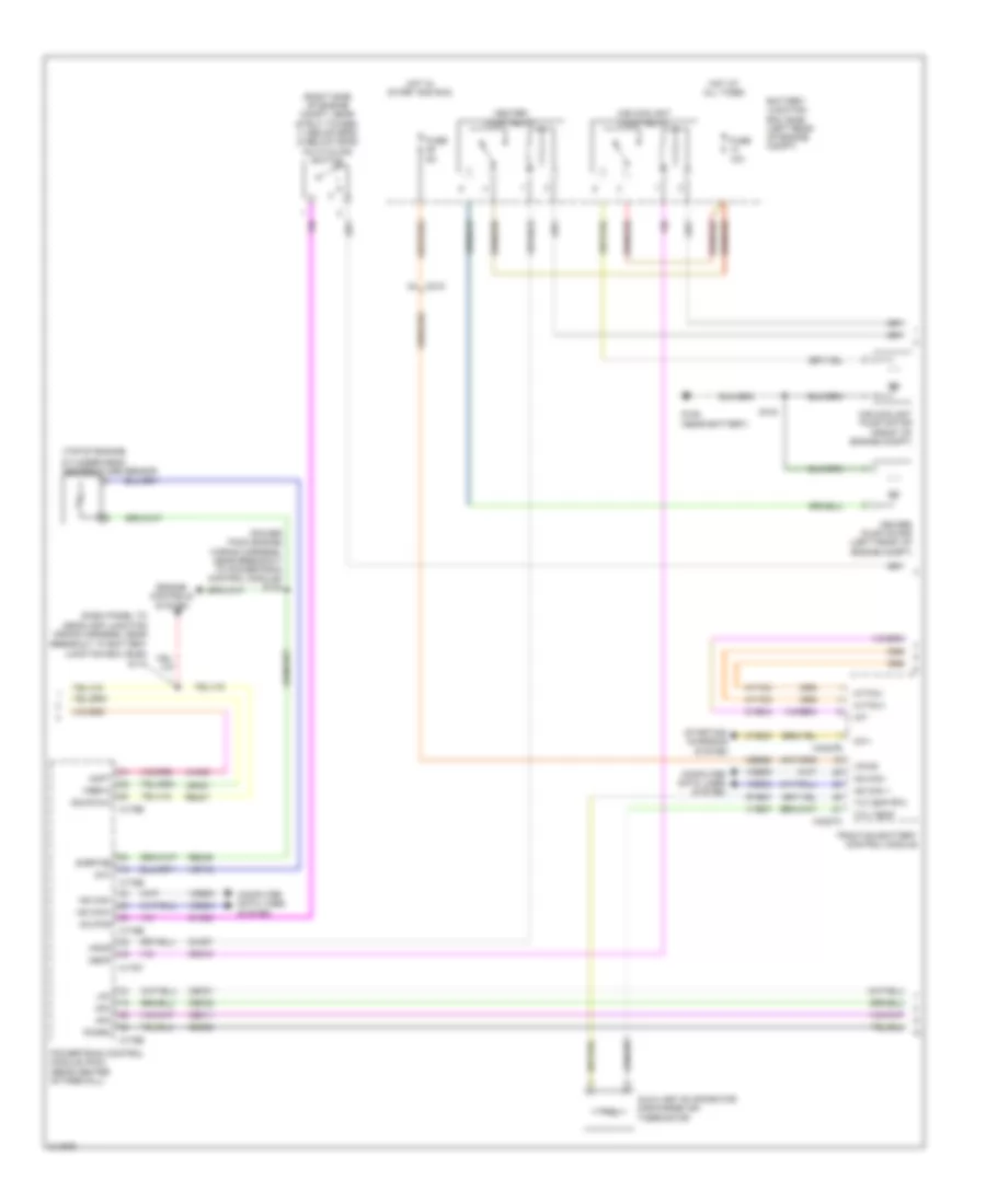
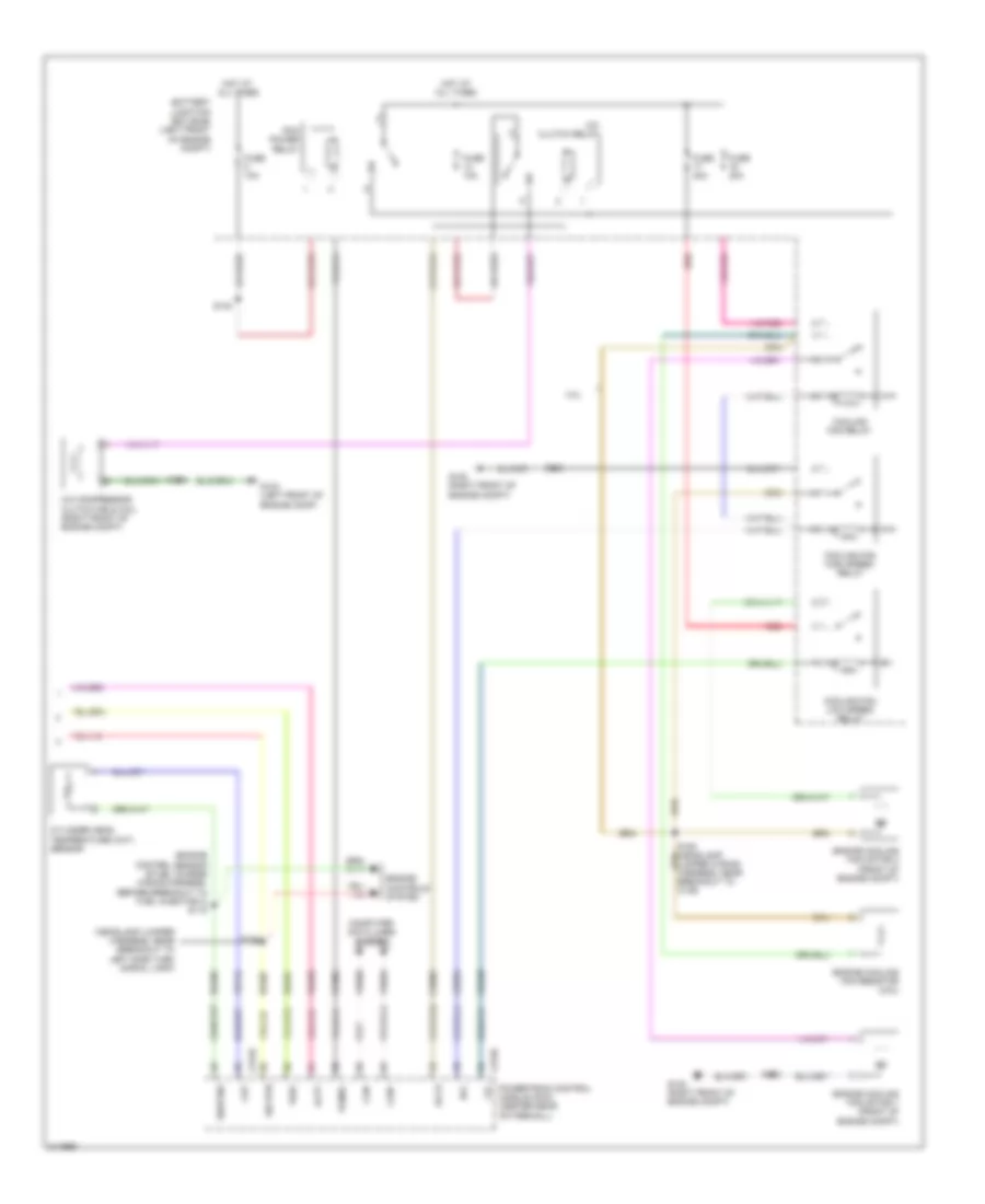
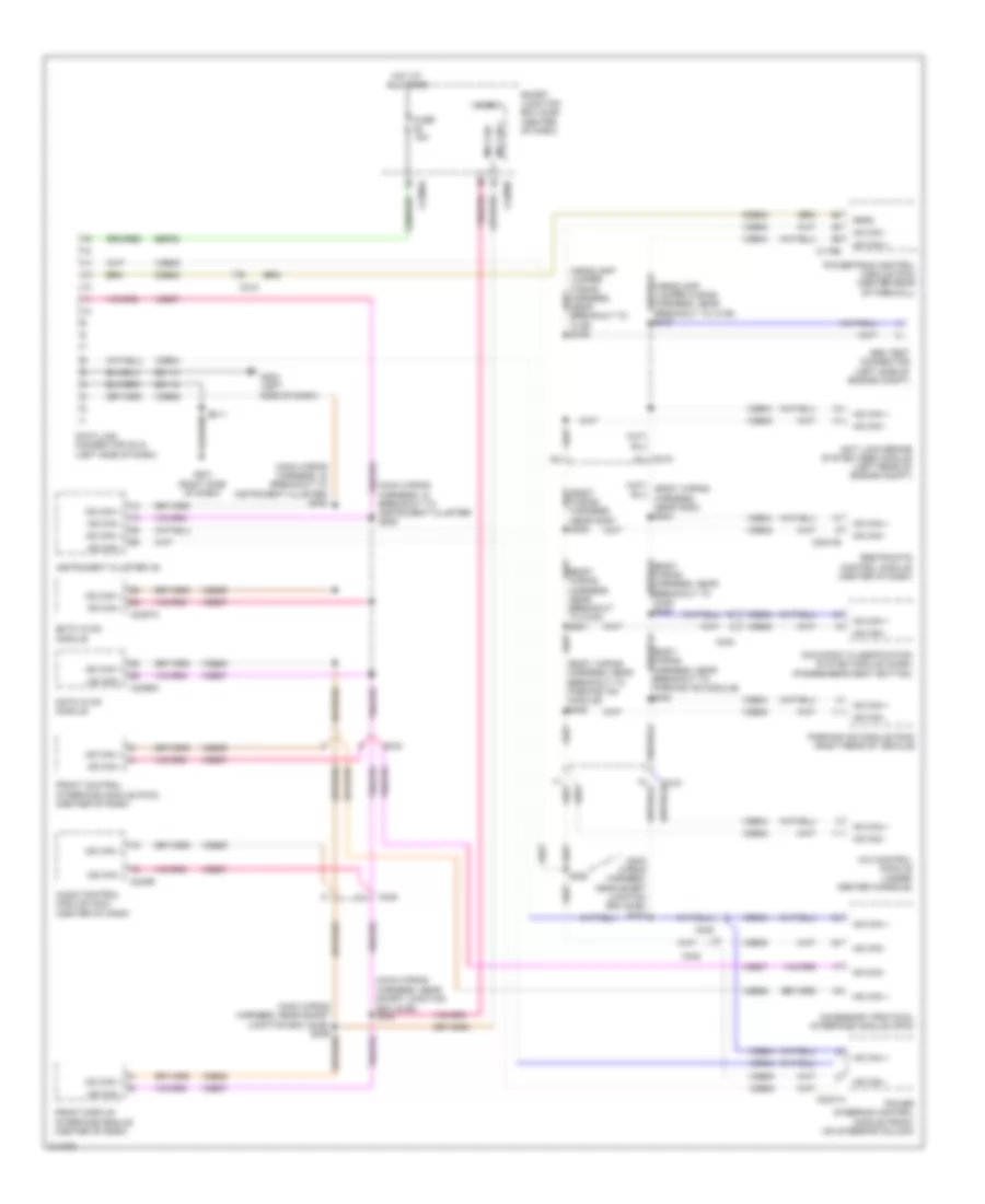
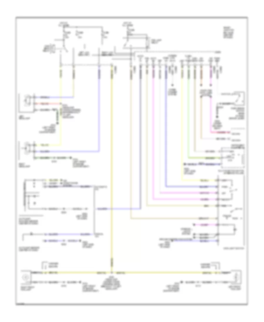
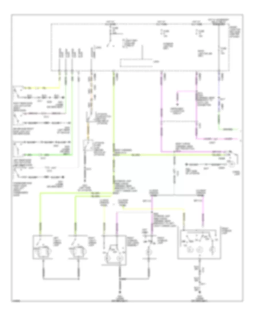
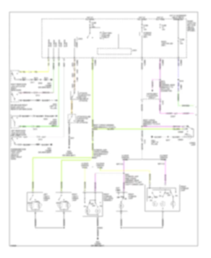
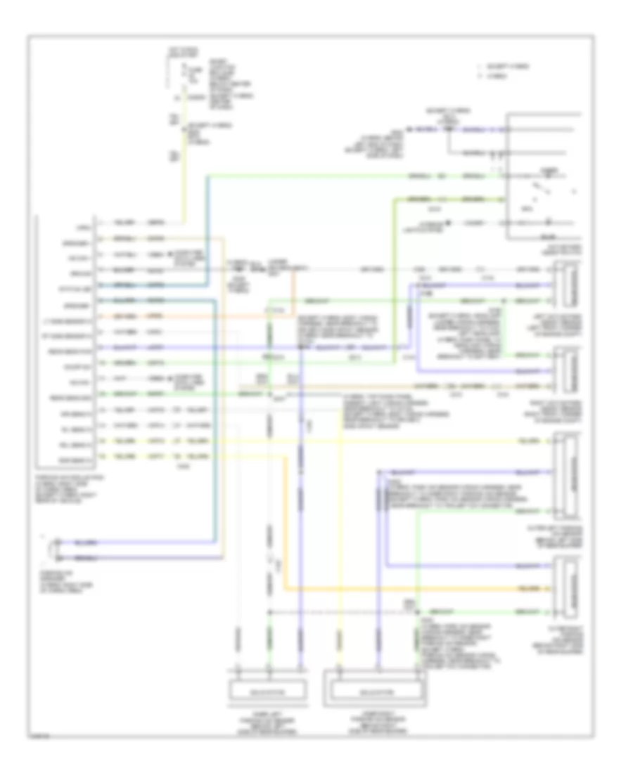
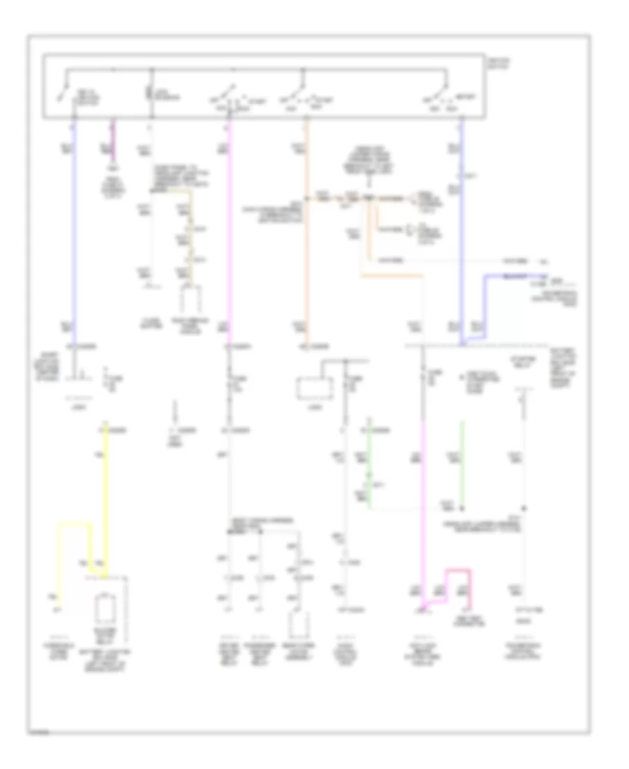
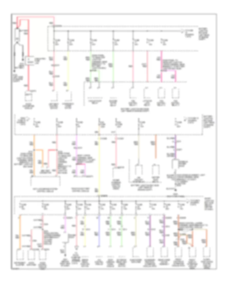
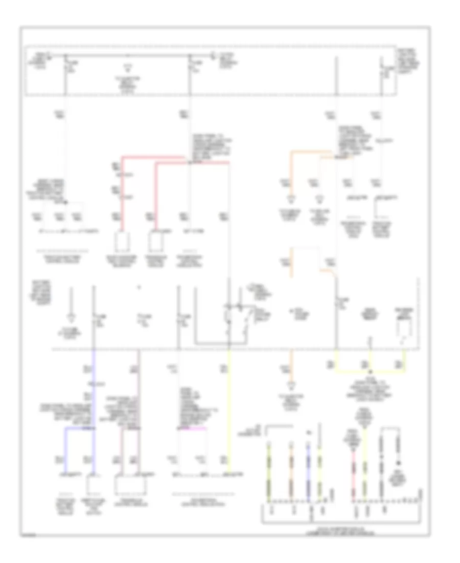
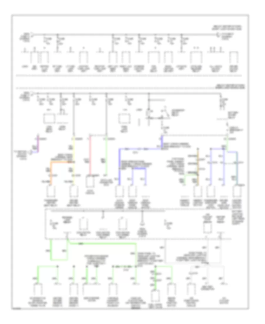
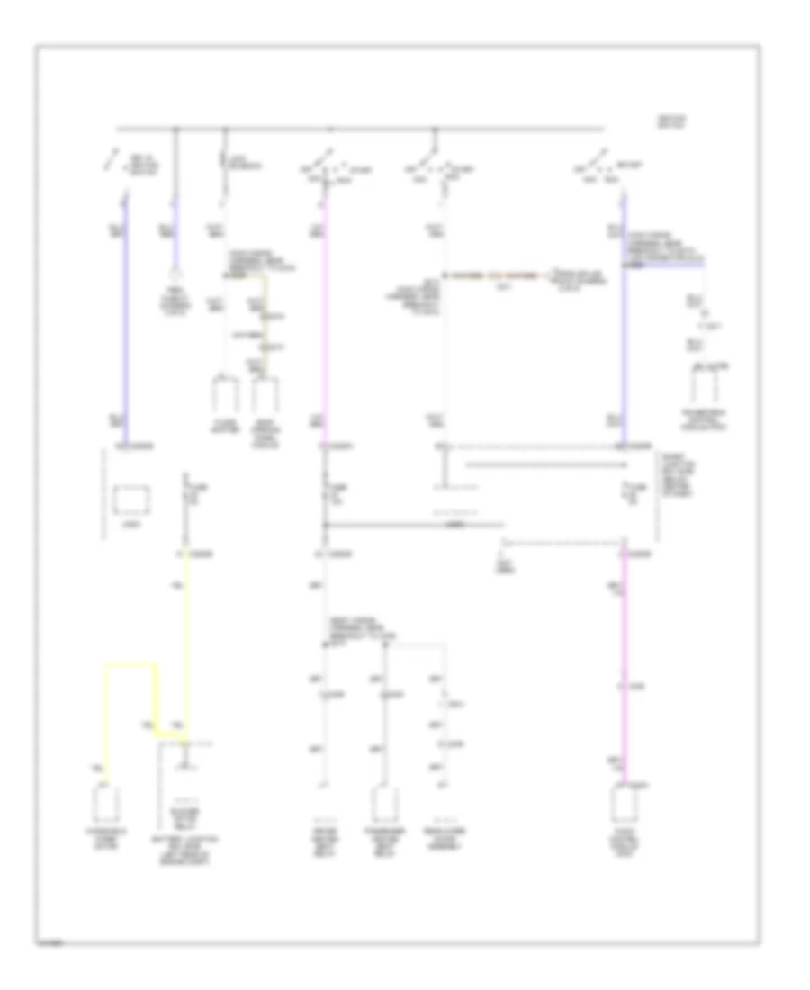
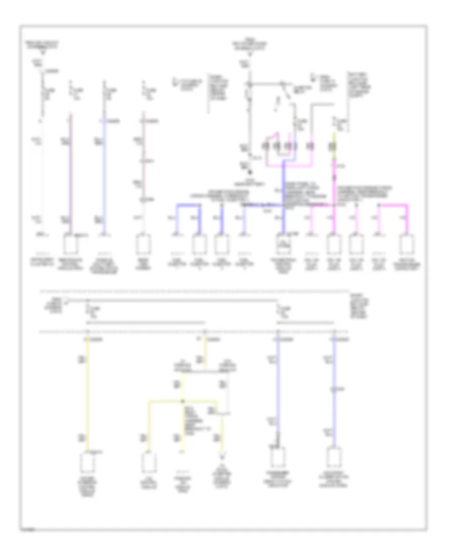
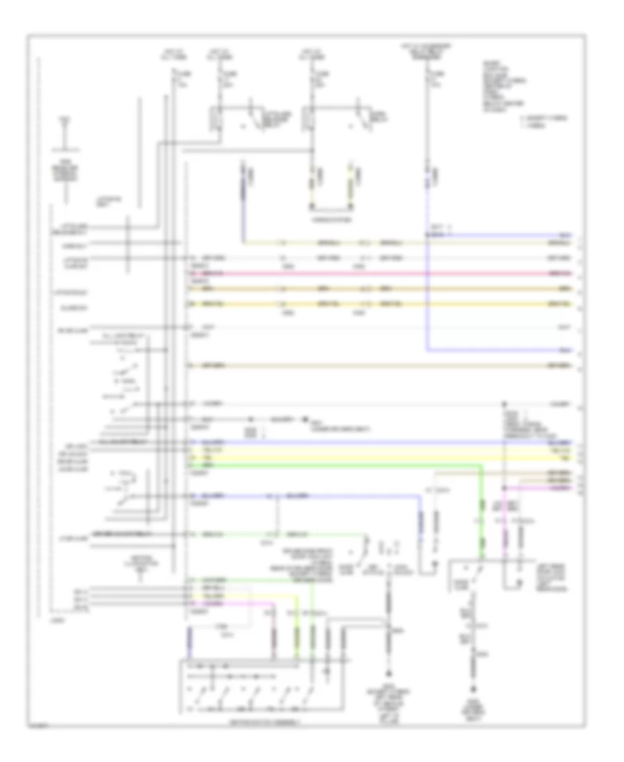
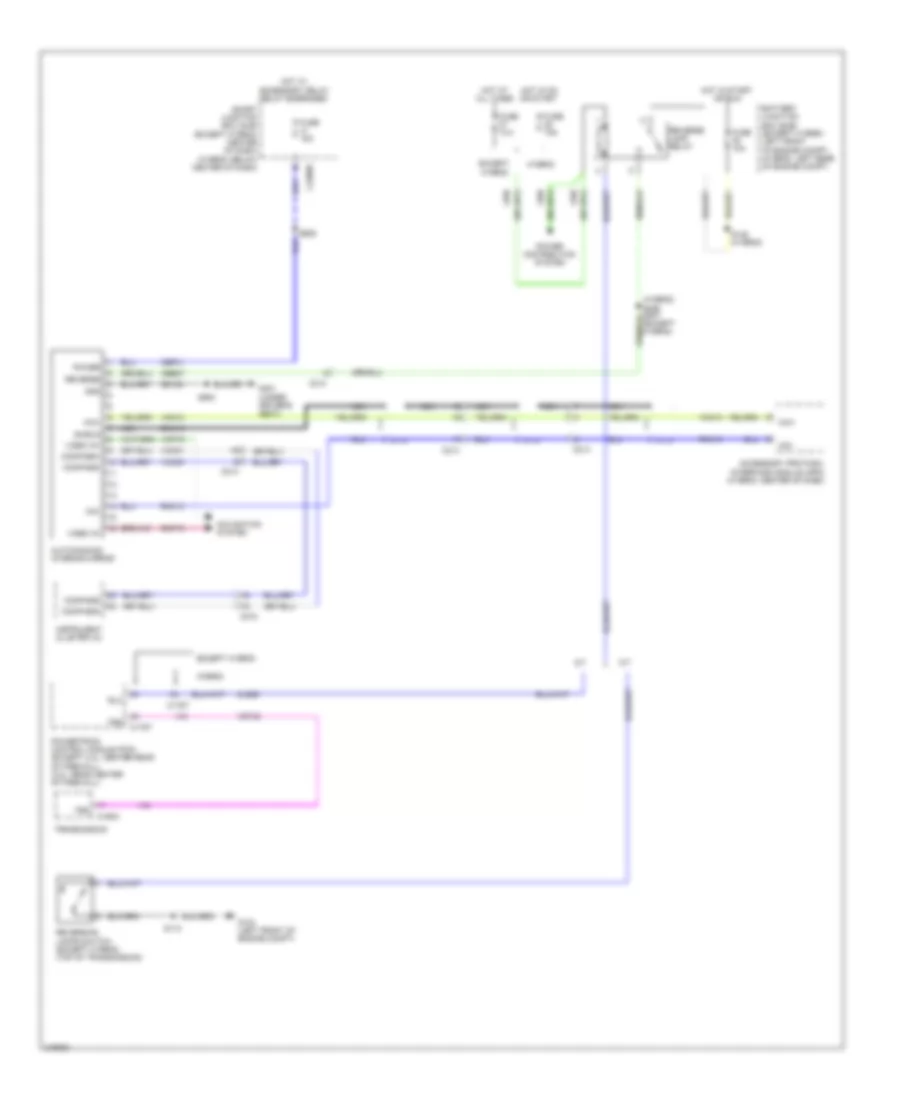
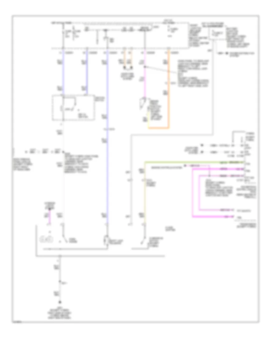
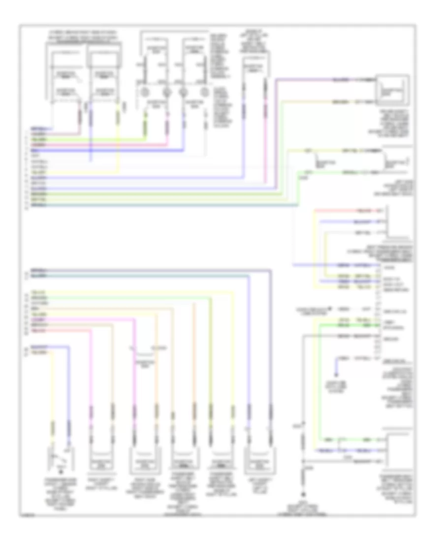
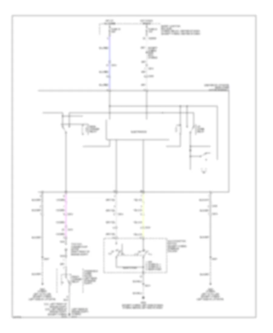
Automatic A/C Wiring Diagram, Except Hybrid (1 of 3) for Ford Escape 2011

List of elements for Automatic A/C Wiring Diagram, Except Hybrid (1 of 3) for Ford Escape 2011:
- (air conditioning jumper wiring harness, near breakout to blower motor)
- 5v vref return
- 5v vref-all act & pots
- Air inlet ccw osa
- Air inlet cw rec
- Ambient temp sens
- Battery junction box (bjb) (left front of engine compt)
- Blower motor
- Blower motor relay
- Blower motor speed control
- C211
- C212
- C2280a
- C2280b
- C2280e
- C2356a
- C2356b
- C237
- C238
- Cbp37
- Ch122
- Ch123
- Ch207
- Ch208
- Ch212
- Ch213
- Ch228
- Ch229
- Ch238
- Ch239
- Chs29
- Chs30
- Computer data lines system
- Defogger
- Drv htd seat rly
- Drv sunload sens
- Drv temp act fdbk
- Drv temp dr ccw (cool)
- Drv temp dr cw (hot)
- Evap temp sens
- Fr blwr relay
- Fuse 10a
- Fuse 40a
- Fuse 5a
- G200 (right side of dash)
- G202 (left side of dash)
- Gd114
- Gnd
- Hot at all times
- Hot in run and start
- Hot in run or acc
- Hvac module-datc
- In car temp sens
- In-vehicle temperature sensor (left side of dash)
- Lh111
- Logic
- Mode 1 act fdbk
- Mode dr 1 ccw def
- Mode dr 1 cw vent
- Mot+
- Mot-
- Mscan+
- Mscan-
- Pass htd seat rly
- Pass sunload sens
- Pass temp act fdbk
- Pass temp dr ccw (hot)
- Pass temp dr cw (cool)
- Passenger temperature blend door actuator (right side of dash)
- Power distribution system
- Pwm
- Rear def/htd mir rly
- Rh111
- S202
- S225
- Sbp15
- Seats system
- Smart junction box (sjb) (center of dash)
- System
- V batt
- V ign
- Variable blwr ctrl (vbc)
- Vdb06
- Vdb07
- Vh101
- Vh406
- Vh407
- Vh414
- Vh416
- Vh417
- Vh436
- Vh440
- Vh441
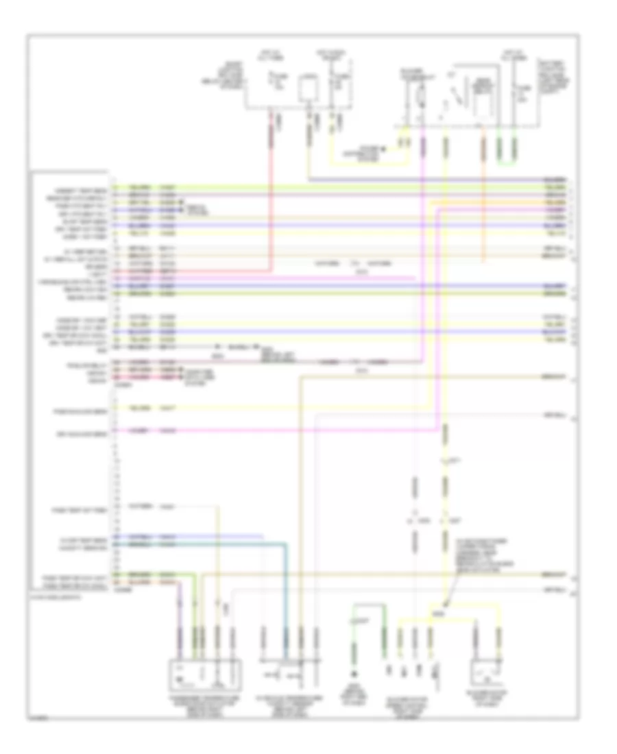
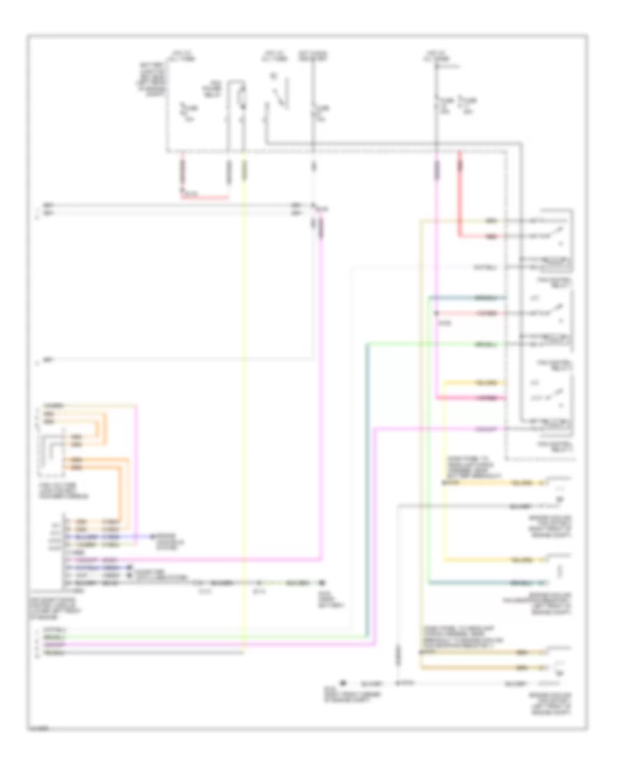
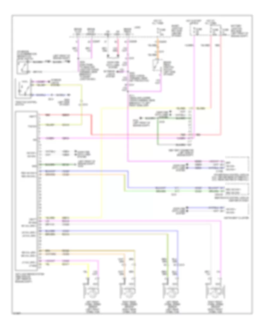
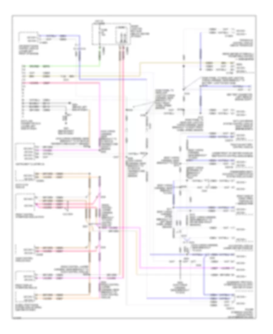
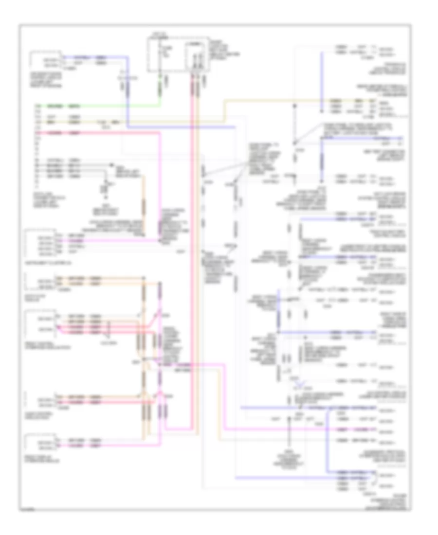
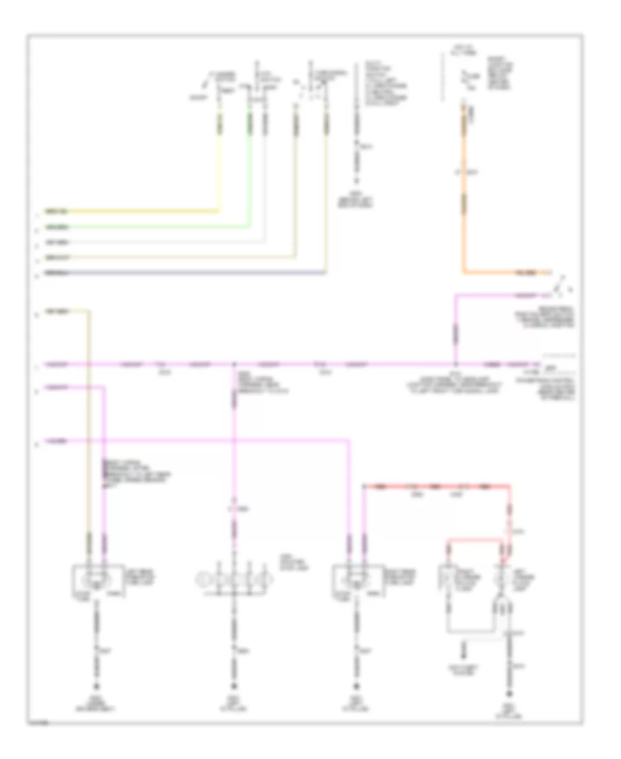
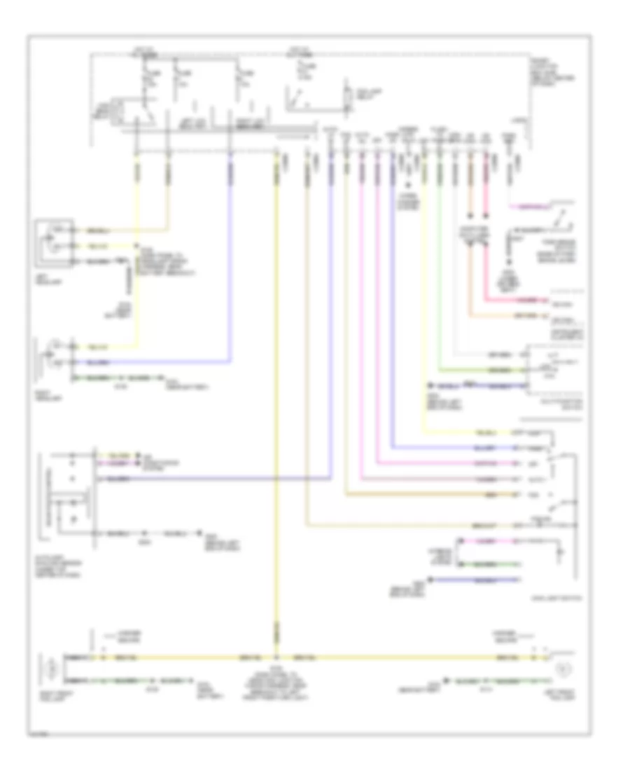
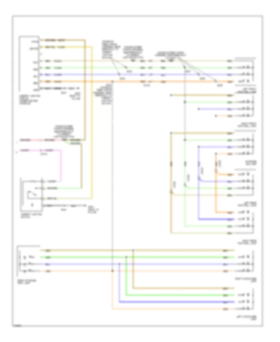
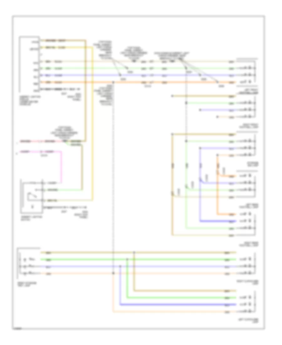
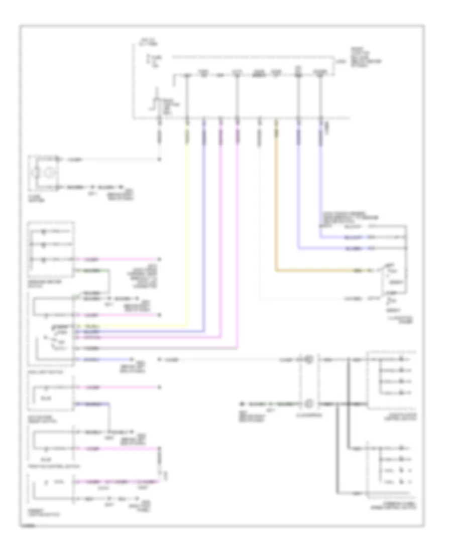
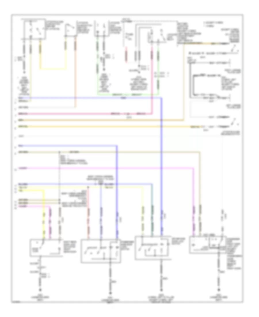
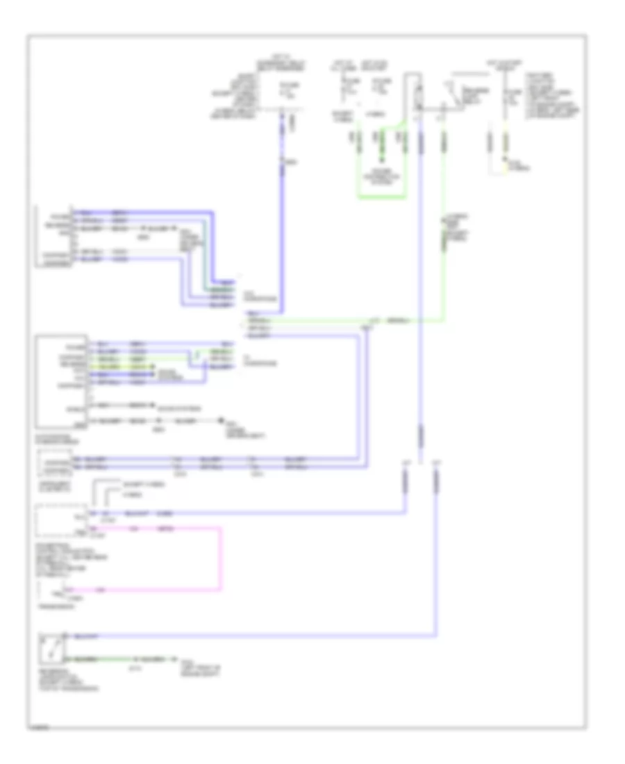
Automatic A/C Wiring Diagram, Except Hybrid (2 of 3) for Ford Escape 2011
List of elements for Automatic A/C Wiring Diagram, Except Hybrid (2 of 3) for Ford Escape 2011:
- (air conditioning jumper wiring harness, near c2029) s222
- (air conditioning wiring harness, near recirculation blend door actuator) s223
- (main wiring harness, in breakout to instrument cluster) s210
- (not used)
- A/c pressure transducer
- Air inlet mode door actuator (right side of dash)
- Ambient air temperature sensor (left side of front grille)
- Autolamp/ sunload sensor (center of dash)
- C212
- C238
- Control solid state
- Driver temperature blend door actuator (right side of dash)
- Evaporator discharge air temperature sensor (right side of dash)
- G202 (left side of dash)
- Mode door actuator (right side of dash)
- S202
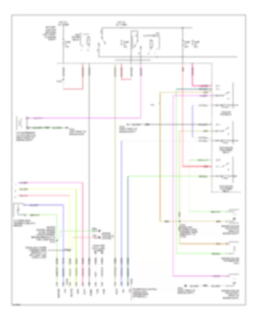
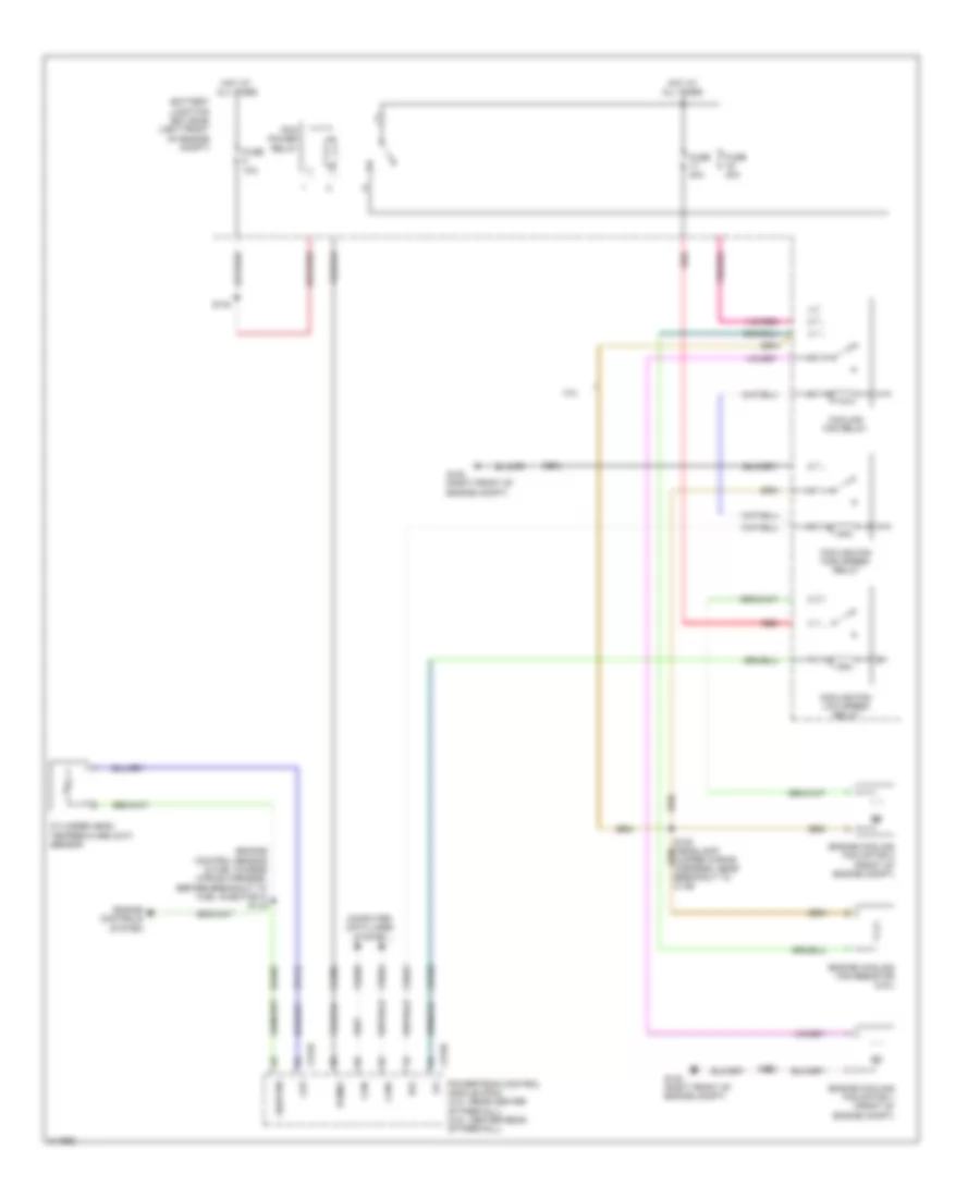
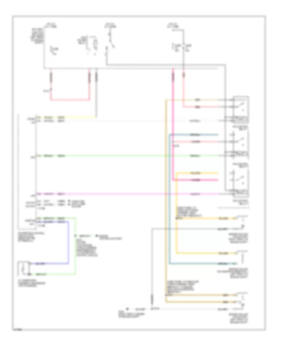
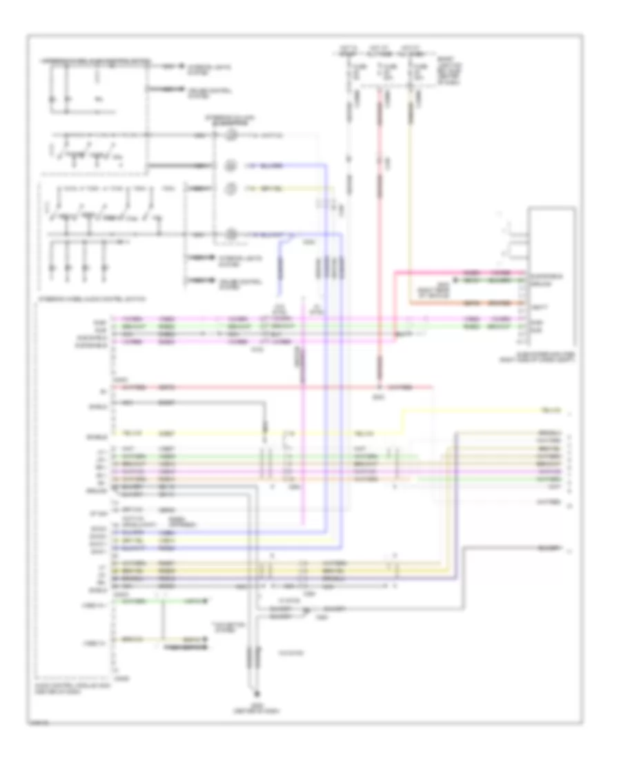
Automatic A/C Wiring Diagram, Except Hybrid (3 of 3) for Ford Escape 2011
List of elements for Automatic A/C Wiring Diagram, Except Hybrid (3 of 3) for Ford Escape 2011:
- (engine control sensor & fuel charge wiring harness, before breakout to fuel injector 3) s118
- (headlamp jumper harness, near breakout to left side turn signal lamp)
- 3.0l
- A/c clutch relay
- A/c compressor clutch field coil (right front of engine compt)
- Accr
- Acpt
- Battery junction box (bjb) (left front of engine compt)
- C175b
- C175e
- Can+
- Can-
- Ce302
- Cec02
- Ceo01
- Ch302
- Cht
- Computer data lines system
- Cooling fan high speed relay
- Cooling fan low speed relay
- Cooling fan relay
- Cylinder head temperature (cht) sensor
- Engine controls system
- Engine cooling fan motor 1 (front of engine compt)
- Engine cooling fan motor 2 (front of engine compt)
- Engine cooling fan resistor (2.5l)
- Fuse 10a
- Fuse 40a
- G102 (right front of engine compt)
- G104 (left front of engine comp)
- Hfc
- Hot at all times
- Le424
- Lfc
- Pcm power relay
- Pcmrc
- Powertrain control module (pcm) (center rear of firewall)
- Re405
- Re407
- Red
- S100
- S102
- S128
- S140
- Sig rtn
- Sigrtne
- Vdb04
- Vdb05
- Ve712
- Vh433
- Vref
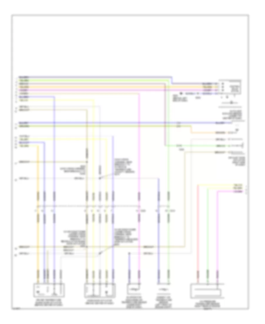
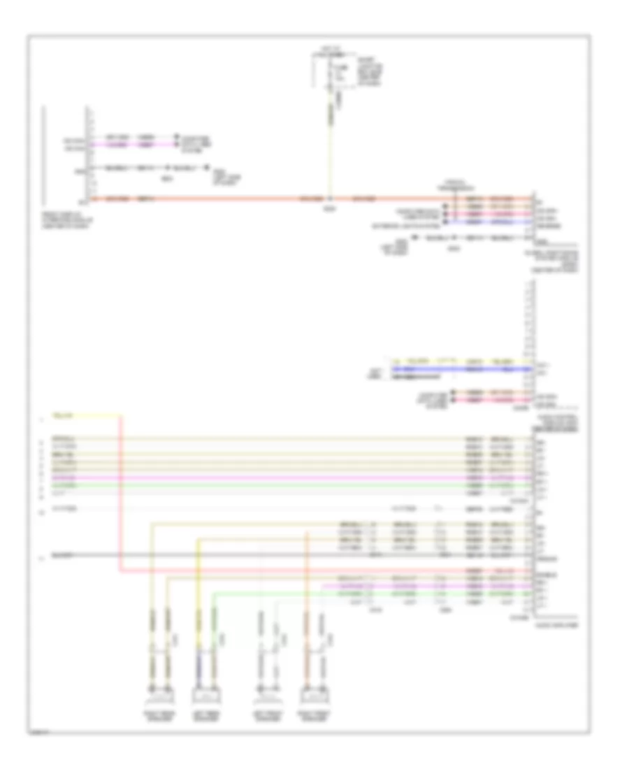
Automatic A/C Wiring Diagram, Hybrid (1 of 4) for Ford Escape 2011
List of elements for Automatic A/C Wiring Diagram, Hybrid (1 of 4) for Ford Escape 2011:
- (in air conditioner jumper wiring harness, near breakout to recirculation blend door actuator)
- 5v vref return
- 5v vref-all act & pots
- Ambient temp sens
- Battery junction box (bjb) (left rear of engine compt)
- Blower motor (right side of dash)
- Blower motor relay
- Blower motor speed control (right side of dash)
- C211
- C212
- C2280a
- C2280b
- C2280e
- C2356a
- C2356b
- C237
- C238
- Ch122
- Ch123
- Ch207
- Ch208
- Ch212
- Ch213
- Ch228
- Ch229
- Ch238
- Ch239
- Chs29
- Chs30
- Computer data lines system
- Drv htd seat rly
- Drv sunload sens
- Drv temp act fdbk
- Drv temp dr ccw (cool)
- Drv temp dr cw (hot)
- Evap temp sens
- Fr blwr relay
- Fuse 10a
- Fuse 40a
- Fuse 5a
- G200 (behind right end of dash)
- G202 (behind left end of dash)
- Gd114
- Gnd
- Hot at all times
- Hot in run or acc
- Humidity sens sig
- Hvac module-datc
- In car temp sens
- In-vehicle temperature/ humidity sensor (behind left side of dash)
- Lh111
- Logic
- Mode 1 act fdbk
- Mode dr 1 ccw def
- Mode dr 1 cw vent
- Mot+
- Mot-
- Mscan+
- Mscan-
- Pass htd seat rly
- Pass sunload sens
- Pass temp act fdbk
- Pass temp dr ccw (hot)
- Pass temp dr cw (cool)
- Passenger temperature blend door actuator (behind right side of dash)
- Power distribution system
- Pwm
- Rear def htd mirr rly
- Rear defrost relay
- Recirc ccw osa
- Recirc cw rec
- Rh111
- Rr defr
- S202
- S225
- Sbp15
- Seats system
- Smart junction box (sjb) (below center of dash)
- V batt
- Variable blwr ctrl (vbc)
- Vdb06
- Vdb07
- Vh101
- Vh406
- Vh407
- Vh413
- Vh414
- Vh416
- Vh417
- Vh436
- Vh438
- Vh440
- Vh441
Automatic A/C Wiring Diagram, Hybrid (2 of 4) for Ford Escape 2011
List of elements for Automatic A/C Wiring Diagram, Hybrid (2 of 4) for Ford Escape 2011:
- (in air conditioner jumper wiring harness, near breakout to recirculation blend door actuator) s223
- (in air conditioner jumper wiring harness, near breakout to temperature blend door actuator) s222
- (main wiring harness, near breakout to in-vehicle temperature/ humidity sensor) s210
- A/c pressure transducer sensor (right rear of engine compt)
- Air inlet door actuator (right side of dash)
- Ambient air temperature sensor (left front of engine compt)
- Autolamp/ sunload sensor (under top center of dash)
- C212
- C238
- Control solid state
- Driver temperature blend door actuator (behind center of dash)
- Evaporator discharge air temperature sensor (under right side of dash)
- G202 (behind left end of dash)
- Mode door actuator (behind center of dash)
- S202
- S242 (main wiring harness, near breakout to c238)
Automatic A/C Wiring Diagram, Hybrid (3 of 4) for Ford Escape 2011
List of elements for Automatic A/C Wiring Diagram, Hybrid (3 of 4) for Ford Escape 2011:
- (dash panel to headlamp junction wiring harness, near breakout to battery
- (power pack engine wiring harness, near breakout to powertrain control module) s104
- (right side of engine compt, near strut tower) 1) above 29psi 2) below 25psi a/c cycling switch
- (top of engine)
- Aclpcs
- Acpt
- Auxiliary evaporator discharge air thermistor
- Battery junction box (bjb) (left rear of engine compt)
- C175b
- C175e
- C175t
- C210
- C4227a
- C4227b
- Cbb25
- Ce302
- Ce318
- Cec01
- Cec02
- Cec11
- Ch307
- Ch422
- Cht
- Computer data lines system
- Cybo3
- Cybo4
- Cylinder-head temperature sensor
- Engine controls system
- Fuse 10a
- Fuse 5a
- G105 (near battery)
- Heater pump motor (left front of engine compt)
- Heater pump relay
- Hfc
- Hot at all times
- Hot in start and run
- Hpcr
- Hs can +
- Hs can -
- Hs can+
- Hs can-
- Hvtmu+
- Hvtmu-
- Hyto3
- Hyto4
- Int+
- Int-
- Junction box (bjb))
- Le424
- Lfc
- M/e coolant pump motor (front of engine compt)
- M/e coolant pump relay
- Mecp
- Mfc
- Pcmrc
- Powertrain control module (pcm) (rear center of firewall)
- Re405
- Re407
- Ryb07
- S111
- S124
- Sig rtn-c
- Sigrtne
- Starting/ charging system
- Traction battery control module
- Txv emp rtn
- Txv temp
- Vdb04
- Vdb05
- Ve712
- Vh433
- Vpwr
- Vref-c
- Vyb07
Automatic A/C Wiring Diagram, Hybrid (4 of 4) for Ford Escape 2011
List of elements for Automatic A/C Wiring Diagram, Hybrid (4 of 4) for Ford Escape 2011:
- (dash panel to headlamp wiring harness, near battery breakout) s130
- (dash panel to headlamp wiring harness, near breakout to engine cooling fan dropping resistor 1) s131
- Air conditioning control module (lower left front of engine)
- Battery junction box (bjb) (left rear of engine compt)
- C113
- C1469a
- C1469b
- Ch401
- Computer data lines system
- Cybo4
- Cybo5
- Engine controls system
- Engine cooling fan dropping resistor 1 (left front of engine compt)
- Engine cooling fan motor 1 (left front of engine compt)
- Engine cooling fan motor 2 (right front of engine compt)
- Fan control relay 1
- Fan control relay 2
- Fan control relay 3
- Fuse 10a
- Fuse 40a
- G102 (right front corner of engine compt)
- G104 (near battery)
- Gd123
- High voltage junction box (non-serviceable)
- Hot at all times
- Hot in run and start
- Hv+
- Hv-
- Hvin
- Hvip
- Hybo3
- Hybo4
- Pcm power relay
- Red
- S113
- S116
- S125
- S134
- S146
- Vdbo4
- Vdbo5
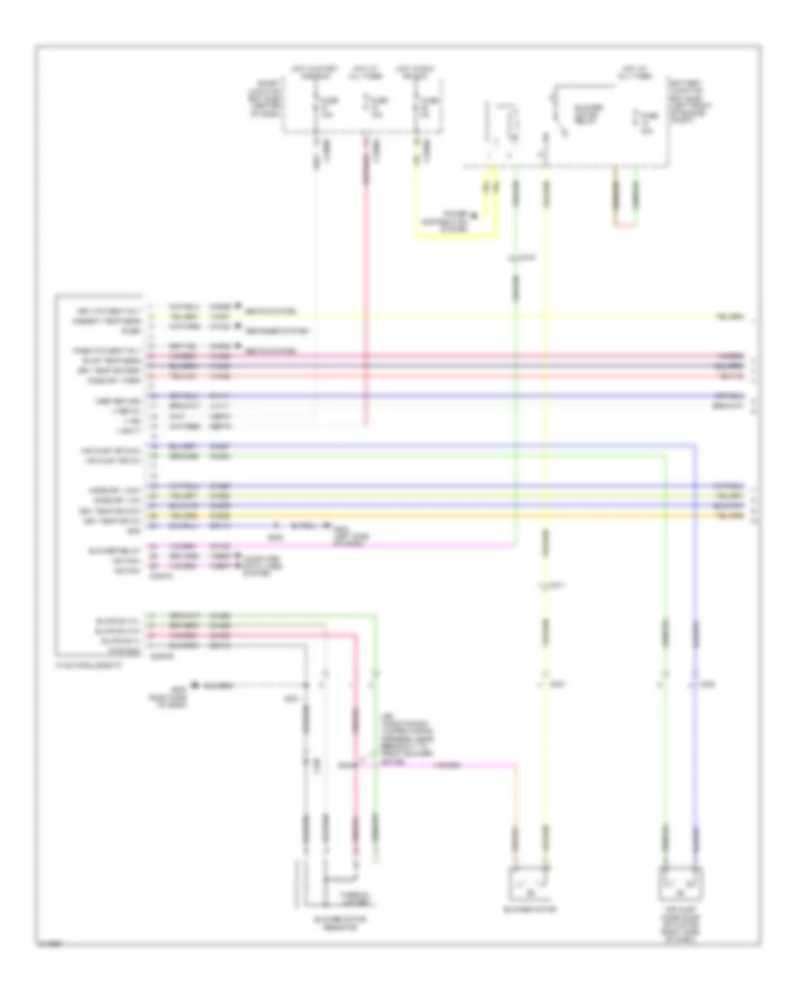
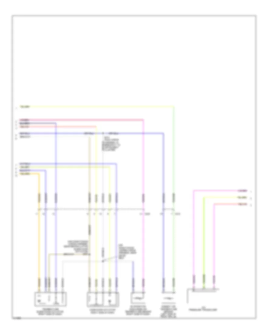
Manual A/C Wiring Diagram (1 of 3) for Ford Escape 2011
List of elements for Manual A/C Wiring Diagram (1 of 3) for Ford Escape 2011:
- (air conditioning jumper wiring harness, near breakout to front blower motor)
- Air inlet dr ccw
- Air inlet dr cw
- Air inlet mode door actuator (right side of dash)
- Ambient temp sens
- Battery junction box (bjb) (left front of engine compt)
- Blower motor
- Blower motor relay
- Blower motor resistor
- Blower relay
- Blwr sw h
- Blwr sw m-h
- Blwr sw m-l
- C211
- C212
- C2280a
- C2280b
- C2280e
- C2357a
- C2357b
- C237
- C238
- Cbp37
- Ch122
- Ch123
- Ch207
- Ch208
- Ch228
- Ch229
- Ch238
- Ch239
- Ch428
- Ch429
- Ch430
- Chs29
- Chs30
- Computer data lines system
- Defogger system
- Drv htd seat rly
- Drv temp dr ccw
- Drv temp dr cw
- Drv temp dr fdbk
- Evap temp sens
- Fuse 10a
- Fuse 40a
- Fuse 5a
- G200 (right side of dash)
- G202 (left side of dash)
- Gd112
- Gd114
- Gnd
- Hot at all times
- Hot in run or acc
- Hot in start and run
- Hvac module-emtc
- Lh111
- Mode dr 1 ccw
- Mode dr 1 cw
- Mode dr 1 fdbk
- Ms can+
- Ms can-
- Pass htd seat rly
- Power distribution system
- Pwr gnd
- R-def
- Rh111
- S201
- S202
- S224
- Sbp15
- Seats system
- Smart junction box (sjb) (center of dash)
- Thermal limiter
- V batt
- V ign
- V ref 5v
- Vdb06
- Vdb07
- Vh406
- Vh407
- Vh436
- Vh440
- Vref return
Manual A/C Wiring Diagram (2 of 3) for Ford Escape 2011
List of elements for Manual A/C Wiring Diagram (2 of 3) for Ford Escape 2011:
- (air conditioning jumper wiring harness, near c2029) s222
- (air conditioning wiring harness, near recirculation blend door actuator) s223
- A/c pressure transducer
- Ambient air temperature sensor (left side of front grille)
- C212
- C238
- Evaporator discharge air temperature sensor (right side of dash)
- Mode door actuator (right side of dash)
- S210 (main wiring harness, in breakout to instrument cluster)
- Temperature blend door actuator (right side of dash)
Manual A/C Wiring Diagram (3 of 3) for Ford Escape 2011
List of elements for Manual A/C Wiring Diagram (3 of 3) for Ford Escape 2011:
- (engine control sensor & fuel charge wiring harness, before breakout to fuel injector 3) s118
- (headlamp jumper harness, near breakout to left side turn signal lamp)
- 3.0l
- A/c clutch relay
- A/c compressor clutch field coil (right front of engine compt)
- Accr
- Acpt
- Battery junction box (bjb) (left front of engine compt)
- C175b
- C175e
- Can+
- Can-
- Ce302
- Cec02
- Ceo01
- Ch302
- Cht
- Computer data lines system
- Cooling fan high speed relay
- Cooling fan low speed relay
- Cooling fan relay
- Cylinder head temperature (cht) sensor
- Engine controls system
- Engine cooling fan motor 1 (front of engine compt)
- Engine cooling fan motor 2 (front of engine compt)
- Engine cooling fan resistor (2.5l)
- Fuse 10a
- Fuse 40a
- G102 (right front of engine compt)
- G104 (left front of engine comp)
- Hfc
- Hot at all times
- Le424
- Lfc
- Pcm power relay
- Pcmrc
- Powertrain control module (pcm) (center rear of firewall)
- Re405
- Re407
- Red
- S100
- S102
- S128
- S140
- Sig rtn
- Sigrtne
- Vdb04
- Vdb05
- Ve712
- Vh433
- Vref
ANTI-LOCK BRAKES
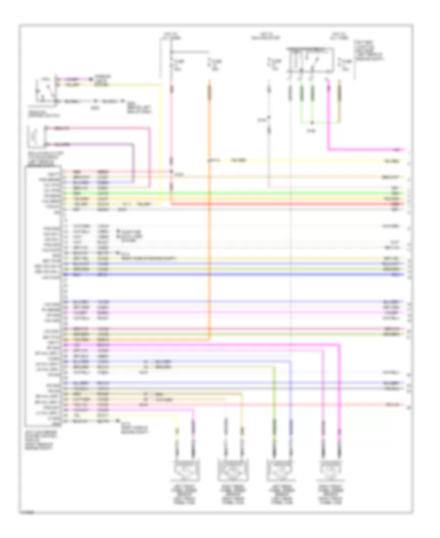
Anti-lock Brakes Wiring Diagram, Except Hybrid for Ford Escape 2011
List of elements for Anti-lock Brakes Wiring Diagram, Except Hybrid for Ford Escape 2011:
- (left front of engine compt) g104
- (left front of engine compt) g105
- (on brake fluid reservoir) brake fluid level switch
- Abs test connector (left side of engine compt)
- Anti-lock brake system (abs) module (left rear of engine compt)
- Battery junction box (bjb) (left front of engine compt)
- Bpp
- Brake fluid rtn sw
- Brake fluid sw
- Brake pedal position switch (left side of dash)
- Brake pedal sw
- C175b
- C2041b
- C210
- C212
- C215
- C2280b
- C2280d
- C2280f
- Cbp34
- Cca15
- Ccb08
- Computer data lines system
- Exterior lights system
- Fuse 15a
- Fuse 20a
- Fuse 50a
- Fuse 5a
- G104 (left front of engine compt)
- G202 (left side of dash)
- Gd120
- Gnd
- Hot at all times
- Hot in start or run
- Hs can +
- Hs can -
- Ign
- Instrument cluster
- Interior lights system
- Left front wheel speed sensor (left front wheel hub)
- Left rear wheel speed sensor (left rear wheel hub)
- Lf gnd
- Lf whl spd +
- Logic
- Lr whl spd +
- Lr whl spd -
- Ms can +
- Ms can -
- Nca
- Powertrain control module (2.5l: center rear of firewall) (3.0l: rear center of firewall)
- Rca17
- Rca18
- Rca19
- Rca20
- Red
- Restraints control module (center of dash)
- Rf gnd
- Rf whl spd +
- Right front wheel speed sensor (right front wheel hub)
- Right rear wheel speed sensor (right rear wheel hub)
- Rr whl spd +
- Rr whl spd -
- Rsc hs can +
- Rsc hs can -
- Rsc hs can h
- Rsc hs can l
- S109
- S111 (headlamp jumper wiring harness, near breakout to left front side lamp)
- S214
- S230 dash panel to headlamp junction wiring harness, near breakout to smart junction box
- S308 (body wiring harness, near key pad switch)
- Sbb09
- Sbb18
- Smart junction box (sjb) (center of dash)
- Tcs sw
- Traction control switch
- Vbatt
- Vca03
- Vca04
- Vca05
- Vca06
- Vca23
- Vca24
- Vdb04
- Vdb05
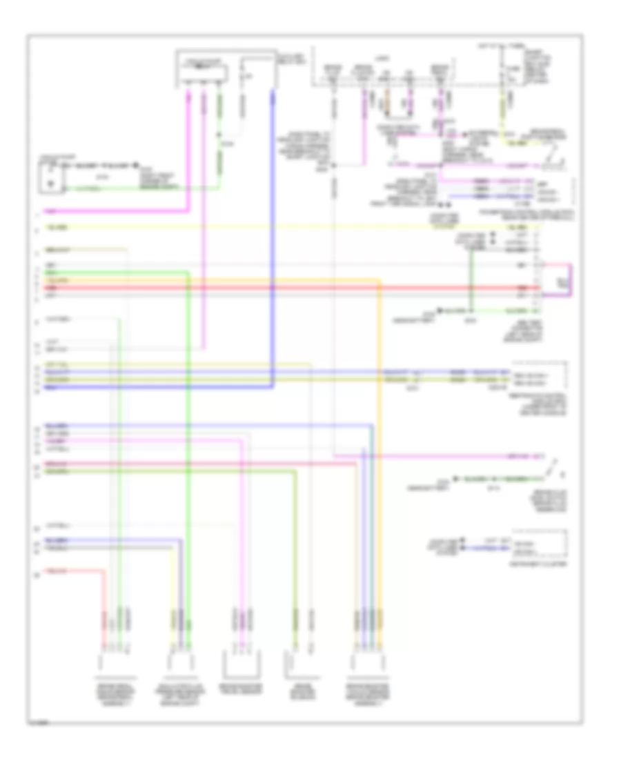
Anti-lock Brakes Wiring Diagram, Hybrid (1 of 2) for Ford Escape 2011
List of elements for Anti-lock Brakes Wiring Diagram, Hybrid (1 of 2) for Ford Escape 2011:
- Anti-lock brake system control module (right rear of engine compt)
- Battery junction box (bjb) (left rear of engine compt)
- Bst pwm
- Bst pwr
- C210
- C212
- Cb101
- Cbb30
- Cbk03
- Cca15
- Cca22
- Ccb30
- Ccb31
- Ccb32
- Ccb33
- Computer data lines system
- Engine compt)
- Fuse 10a
- Fuse 40a
- Fuse 50a
- G110 (right side of engine compt)
- G112 (right side of
- G202 (behind left end of dash)
- Gd179
- Gnd
- Hot at all times
- Hot in run and start
- Hs can +
- Hs can -
- Ign
- Interior lights system
- Lca16
- Lca27
- Lca37
- Left front wheel speed sensor (left front wheel hub)
- Left rear wheel speed sensor (left rear wheel hub)
- Lf gnd
- Lf whl spd +
- Lr whl spd +
- Lr whl spd -
- Mp gnd
- Mp sig
- Nca
- Pas gnd
- Pas sense
- Pas sig1
- Pas sig2
- Pm sense
- Ps gnd
- Ps sens
- Ps sig
- Rca16
- Rca17
- Rca18
- Rca19
- Rca20
- Rca27
- Rca37
- Rcb33
- Red
- Rf gnd
- Rf whl spd +
- Right front wheel speed sensor (right front wheel hub)
- Right rear wheel speed sensor (right rear wheel hub)
- Rr whl spd +
- Rr whl spd -
- Rsc hs can h
- Rsc hs can l
- S112
- S123
- S146
- S155
- S202
- Sbb09
- Sbb18
- Simulator cut-off valve solenoid (left rear of engine compt)
- Tcs sw
- Traction control switch
- Vac gnd
- Vac pump
- Vac sens
- Vac sig1
- Vac sig2
- Vac43
- Vacrc
- Vacuum pump relay
- Vbatt
- Vca03
- Vca04
- Vca05
- Vca06
- Vca13
- Vca22
- Vca23
- Vca24
- Vca30
- Vca38
- Vca39
- Vcb34
- Vdb04
- Vdb05
- Vol pwm
- Vol pwr
Anti-lock Brakes Wiring Diagram, Hybrid (2 of 2) for Ford Escape 2011
List of elements for Anti-lock Brakes Wiring Diagram, Hybrid (2 of 2) for Ford Escape 2011:
- (dash panel to headlamp junction wiring harness, near breakout to smart junction box)
- Abs test connector (left rear of engine compt)
- Auxiliary relay box
- Bpp
- Brake booster solenoid
- Brake booster travel sensor
- Brake booster vacuum sensor (brake booster assembly)
- Brake fluid level switch (brake fluid reservoir)
- Brake fluid sw
- Brake fluid sw rtn
- Brake pedal angle sensor (brake pedal assembly)
- Brake pedal position switch
- Brake pedal sw
- C175b
- C2041b
- C210
- C215
- C2280b
- C2280d
- C2280f
- Ccb08
- Computer data lines system
- Exterior lights system
- Fuse 15a
- G102 (right front corner of engine compt)
- G104 (near battery)
- G105 (near battery)
- Hot at all times
- Hs can +
- Hs can -
- Instrument cluster
- Logic
- Ms can +
- Ms can -
- Powertrain control module (pcm) (rear center of firewall)
- Red
- Restraints control module (rcm) (under front of center console)
- Rsc hs can +
- Rsc hs can -
- S113
- S124
- S134
- S141 (dash panel to headlamp junction harness, near breakout to left front turn signal lamp)
- S148
- S230
- S308 (body wiring harness, near breakout to c314)
- Simulator fluid pressure sensor (left rear of engine compt)
- Smart junction box (sjb) (below center of dash)
- Vacuum pump motor
- Vacuum pump relay
- Vca23
- Vca24
- Vdb04
- Vdb05
ANTI-THEFT
Forced Entry Wiring Diagram (1 of 2) for Ford Escape 2011
List of elements for Forced Entry Wiring Diagram (1 of 2) for Ford Escape 2011:
- (not used)
- 1/2
- 3/4
- 5/6
- 7/8
- 9/0
- Ajar sw
- All lock relay
- All unlock relay
- Below center of dash)
- C2280b
- C2280c
- C2280d
- C2280e
- C313
- C314
- C408
- C922
- Door ajar
- Dr lock
- Dr unlock
- Driver side front door lock unit (hybrid: rear of driver's door) (except hybrid: driver's door)
- Driver unlock relay
- Except hybrid
- Fuse 10a
- Fuse 15a
- Fuse 20a
- G300 (under driver's seat)
- G301 (under driver's seat)
- G402 (except hybrid: left rear
- Glass sw
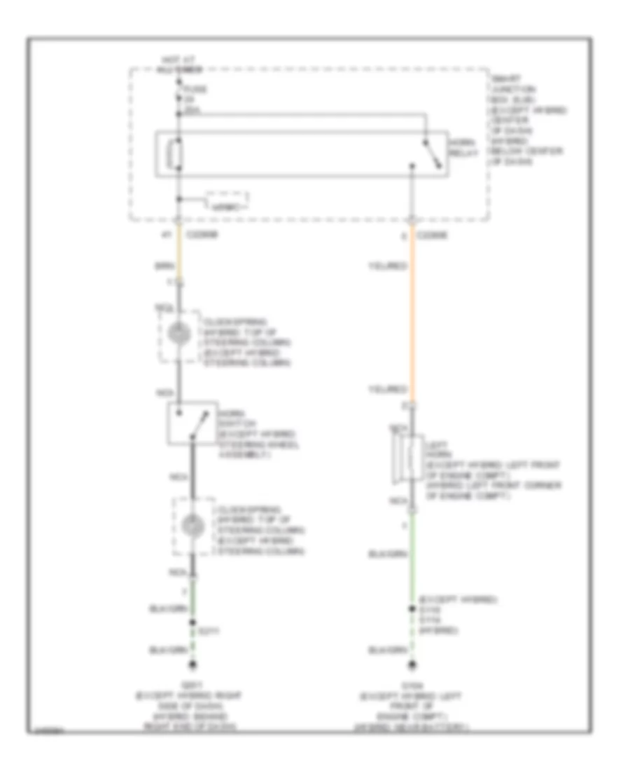
- Horn relay
- Horn rly
- Horns system
- Hot at all times
- Hot w/ accessory delay relay energized
- Hybrid
- Key status
- Keypad illumination (fet)
- Keypad switch assembly
- Left "d" pillar)
- Left rear door lock actuator (left rear door)
- Lf dr ajar
- Liftgate
- Liftgate (fet)
- Liftgate sw
- Liftglass
- Liftglass release relay
- Lock/ unlock
- Logic
- Lr dr ajar
- Of vehicle) (hybrid:
- Release rly
- Rf dr ajar
- Rke receiver internal antenna
- Rr dr ajar
- S303
- S316
- S317
- S338 s325
- S343 s327 (body wiring harness, near breakout to c340)
- S502
- Smart junction box (sjb) (except hybrid: center of dash) (hybrid:
- Sw a
- Sw b
- Sw c
Forced Entry Wiring Diagram (2 of 2) for Ford Escape 2011
List of elements for Forced Entry Wiring Diagram (2 of 2) for Ford Escape 2011:
- (body wiring harness, near breakout to c340) s334 s320
- (except hybrid: center of liftgate) liftgate release switch
- (except hybrid: left rear of engine compartment) (hybrid: left rear of engine compartment)
- Battery junction box (bjb)
- C210
- C311
- C312
- C314
- C410
- C922
- Door ajar
- Door) (hybrid: rear of right front door)
- Driver side door lock switch
- Except hybrid
- Fuse 15a
- G104 (hybrid: near battery) (except hybrid: left front of engine compt)
- G300 (under driver's seat) g401 (left of
- G300 (under driver's seat) g401 (left of side liftgate)
- G301 (under driver's seat)
- G401 (hybrid: left "d" pillar) (except hybrid: left side of liftgate)
- G401 (left "d" pillar)
- G402 (hybrid: left "d" pillar) (except hybrid: left rear of vehicle)
- Hot at all times
- Hybrid
- Key status
- Left license plate lamp
- Liftgate ajar switch (bottom center of liftgate)
- Liftgate glass ajar switch (center of liftgate)
- Liftgate glass release switch
- Liftgate lock actuator (center of liftgate)
- Liftgate lock relay
- Liftgate)
- Lock
- Lock/ unlock
- Nca
- Passenger side door lock switch
- Passenger side front door lock unit (except hybrid: front passenger's
- Right license plate lamp
- Right rear door lock actuator (right rear door)
- S113 s109
- S315 (body wiring harness, near breakout
- S338 s325
- S341 s324 (body wiring harness, near breakout to c340)
- S401
- S401 s410
- S410
- S502
- S600
- Side
- To c340) s313 (body wiring harness, near key pad switch)
- Unlock
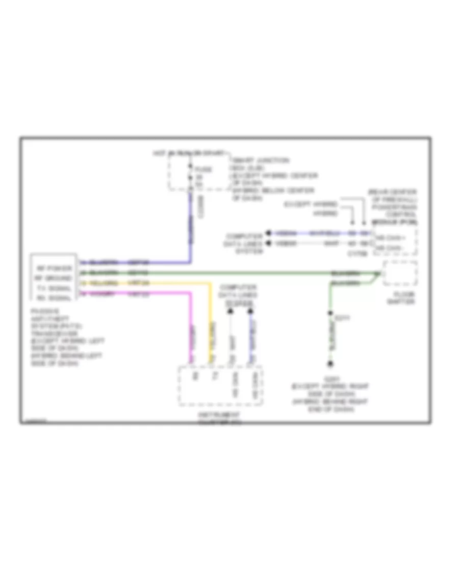
Passive Anti-theft Wiring Diagram for Ford Escape 2011
List of elements for Passive Anti-theft Wiring Diagram for Ford Escape 2011:
- (rear center of firewall) powertrain control module (pcm)
- C175b
- C2280b
- Cbp36
- Computer data lines system
- Except hybrid
- Floor shifter
- Fuse 5a
- G201 (except hybrid: right side of dash) (hybrid: behind right end of dash)
- Gd112
- Hot in run or start
- Hs can +
- Hs can -
- Hs can+
- Hs can-
- Hybrid
- Instrument cluster (ic)
- Passive anti-theft system (pats) transceiver (except hybrid: left side of dash) (hybrid: behind left side of dash)
- Rf ground
- Rf power
- Rx signal
- S211
- Smart junction box (sjb) (except hybrid: center of dash) (hybrid: below center of dash)
- Tx signal
- Vdb04
- Vdb05
- Vrt23
- Vrt24
BODY CONTROL MODULES
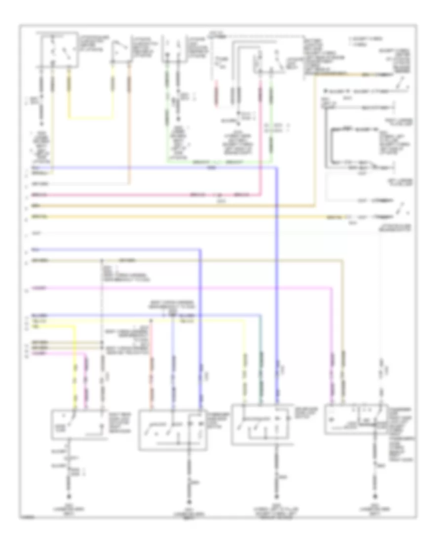
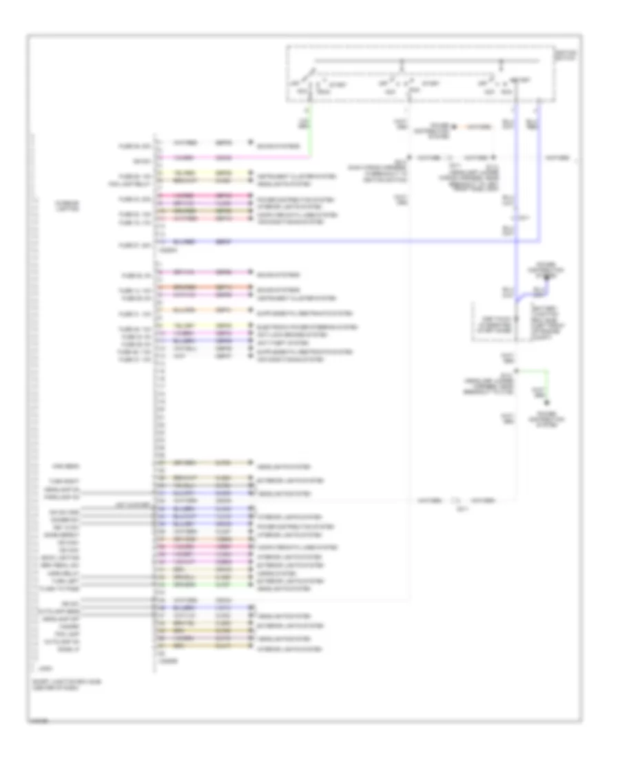
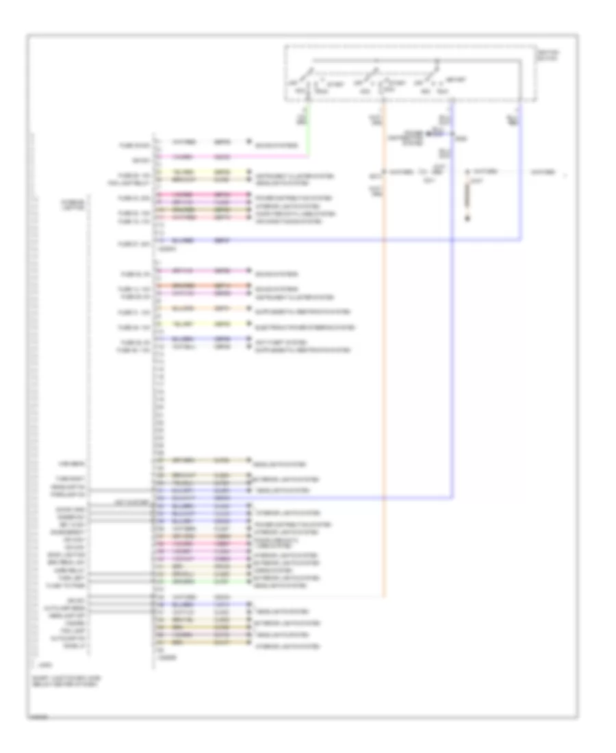
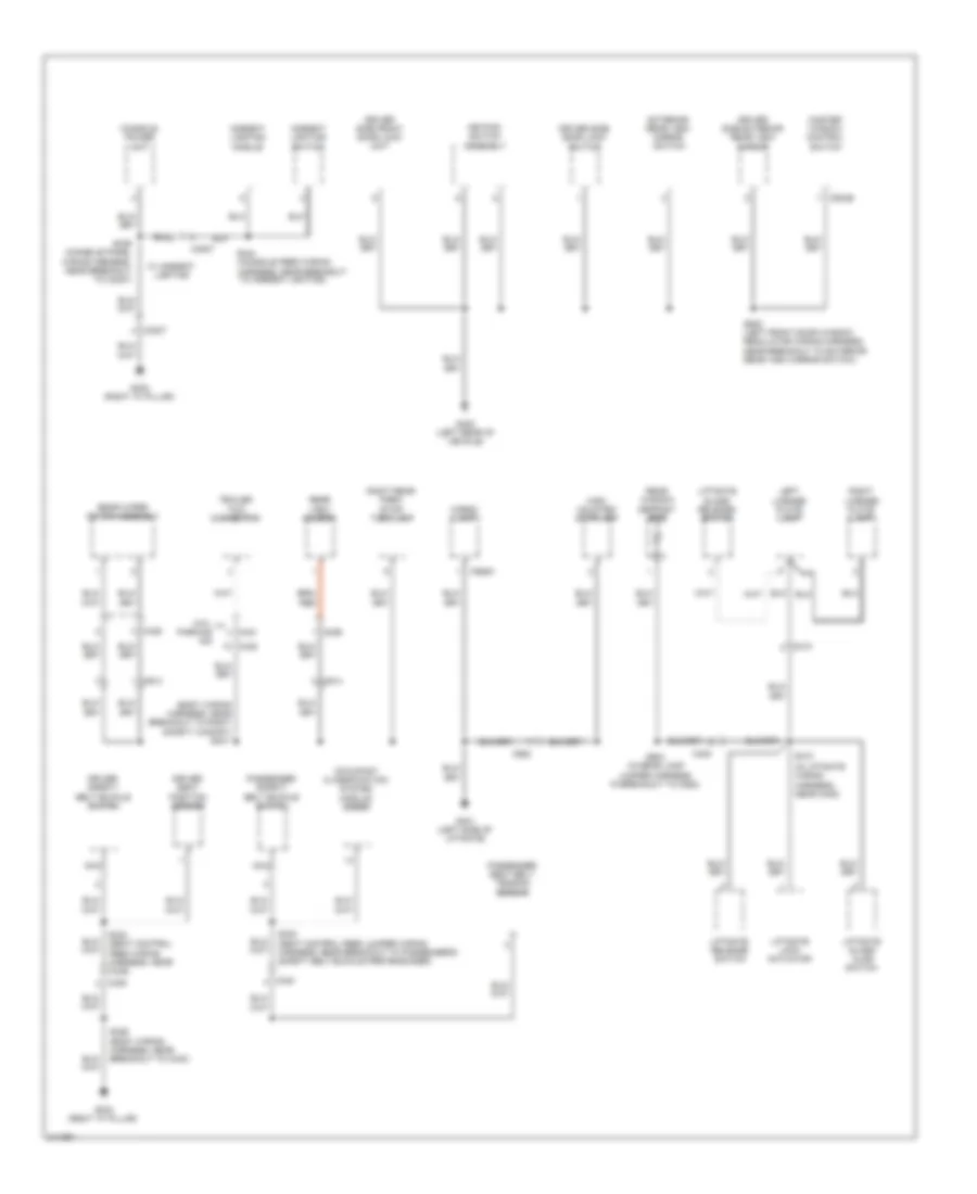
Body Control Modules Wiring Diagram, Except Hybrid (1 of 3) for Ford Escape 2011
List of elements for Body Control Modules Wiring Diagram, Except Hybrid (1 of 3) for Ford Escape 2011:
- (headlamp jumper wiring harness, near breakout to left front side lamp)
- Acc
- Air conditioning system
- Anti-lock brakes system
- Anti-theft system
- Autolamp on
- Autolamp sens
- Back lighting
- Battery junction box (bjb) (left front of engine compt)
- Brk pedal sw
- C211
- C2280a
- C2280b
- Cbp28
- Cbp29
- Cbp31
- Cbp34
- Cbp35
- Cbp36
- Cbp37
- Cbp46
- Ccb08
- Cdc30
- Cdc33
- Cdc34
- Cdc54
- Clf02
- Clf19
- Clf23
- Clf24
- Clf27
- Clf28
- Clf29
- Cln04
- Cln17
- Cln27
- Cls05
- Cls20
- Cls24
- Cls32
- Computer data lines system
- Crh03
- Dim sw gnd
- Dimmer sw
- Dome defeat
- Dome lp
- Electronic power steering system
- Exterior lights system
- Flash to pass
- Fog lamp
- Fog lamp relay
- Fuse 14, 10a
- Fuse 15, 10a
- Fuse 20, 15a
- Fuse 26, 10a
- Fuse 27, 20a
- Fuse 28, 5a
- Fuse 29, 5a
- Fuse 31, 10a
- Fuse 34, 5a
- Fuse 35, 10a
- Fuse 36, 5a
- Fuse 37, 10a
- Fuse 39, 20a
- Fuse 40, 20a
- Fuse 46, 7.5a
- Hazard
- Headlamp off
- Headlamp on
- Headlights system
- High beam
- Horn relay
- Horns system
- Hot in start
- Ign sw
- Ignition switch
- Ignition switch)
- Instrument cluster system
- Interior lighting
- Interior lights system
- Key in sw
- Logic
- Ms can+
- Ms can-
- Off
- One touch integrated start diode
- Parklamp on
- Power distribution system
- Run
- S113
- S141 (headlamp jumper harness, near breakout to c139)
- S213 (main wiring harness, in breakout to
- Sbp14
- Sbp15
- Sbp20
- Sbp26
- Sbp27
- Sbp39
- Sbp40
- Smart junction box (sjb) (center of dash)
- Sound systems
- Start
- Turn left
- Turn right
- Vdb06
- Vdb07
- Vlf14
- Vln04
- Vln18
- Vln33
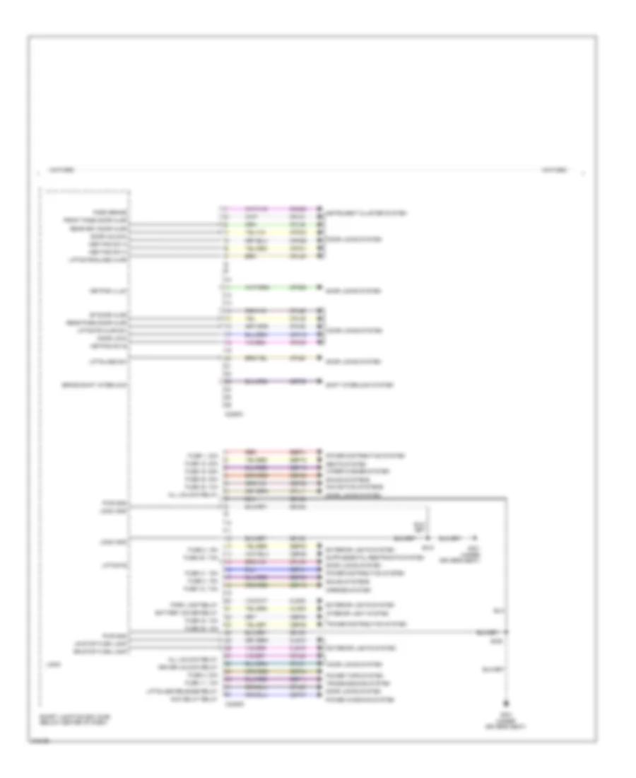
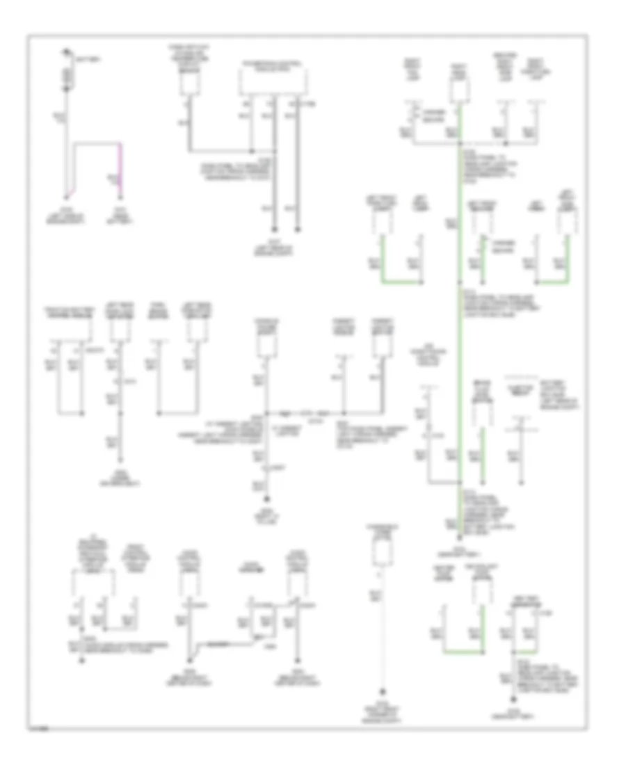
Body Control Modules Wiring Diagram, Except Hybrid (2 of 3) for Ford Escape 2011
List of elements for Body Control Modules Wiring Diagram, Except Hybrid (2 of 3) for Ford Escape 2011:
- Acc delay relay
- All unlock relay
- Battery saver relay
- Brake shift interlock
- C2280c
- C2280d
- Cbp32
- Cbp35
- Cbp41
- Cbp43
- Cbp46
- Cbp47
- Cet53
- Cln09
- Cls18
- Cls19
- Cls30
- Cmc25
- Cpk19
- Cpk23
- Cpk28
- Cpk29
- Cpk30
- Cpk31
- Cpl11
- Cpl26
- Cpl31
- Cpl36
- Cpl39
- Cpl45
- Cpl51
- Cpl52
- Cpl58
- Cpl59
- Cpl60
- Cpl79
- Door lock
- Door locks system
- Door unlock
- Driver door ajar
- Driver unlock relay
- Exterior lights system
- Fuse 11, 10a
- Fuse 12, 7.5a
- Fuse 18, 20a
- Fuse 19, 25a
- Fuse 2, 15a
- Fuse 3, 15a
- Fuse 32, 10a
- Fuse 35, 10a
- Fuse 38, 20a
- Fuse 4, 30a
- Fuse 41, 15a
- Fuse 43, 10a
- Fuse 46, 7.5a
- G301 (under driver's seat)
- Gd182
- Instrument cluster system
- Interior lights system
- Kep pad sw a
- Kep pad sw c
- Keypad illum
- Keypad sw b
- Liftgate
- Liftgate ajar
- Liftgate glass ajar sw
- Liftglass release relay
- Liftglass sw
- Logic
- Logic gnd
- Lr stop/turn lamp
- Mirrors system
- Navigation system
- Park brake
- Park lamp relay
- Pass front door ajar
- Power distribution system
- Power tops system
- Power windows system
- Pwr gnd
- Rear driver door ajar
- Rear pass door ajar
- Rr stop/turn lamp
- S311
- S325
- Sbp02
- Sbp03
- Sbp04
- Sbp11
- Sbp12
- Sbp18
- Sbp19
- Sbp38
- Seats system
- Shift interlock system
- Smart junction box (sjb) (center of dash)
- Sound system
- Sound systems
- Transmissions system
- Wiper/washer system
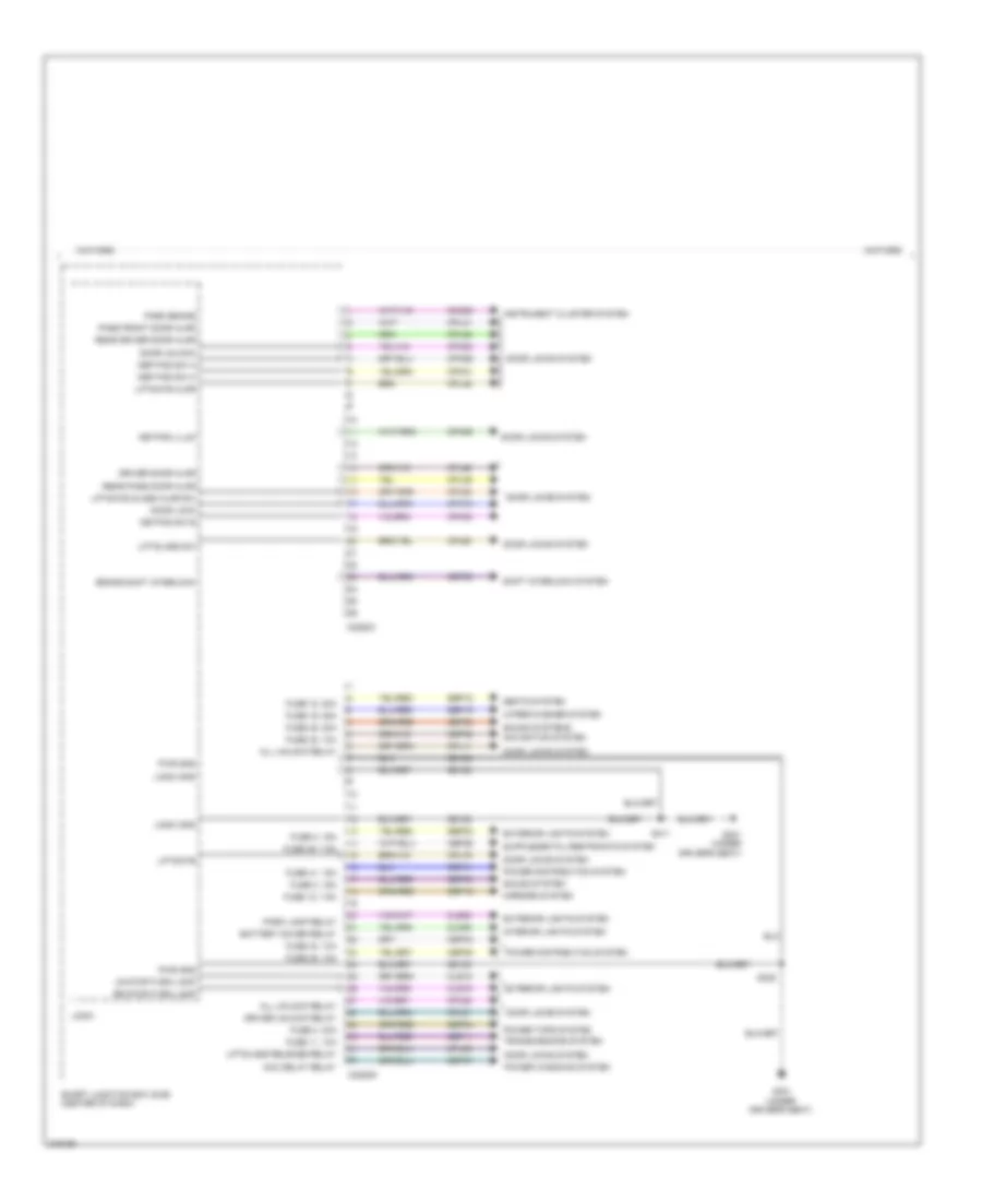
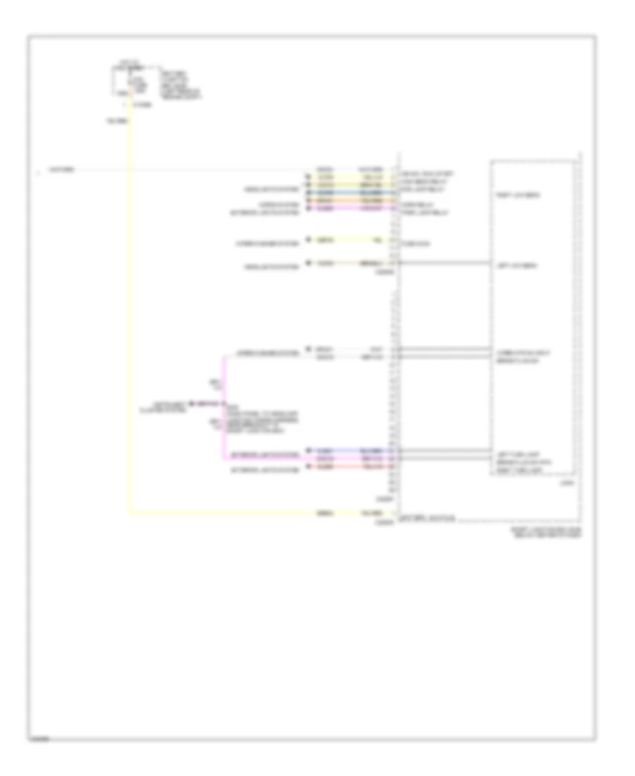
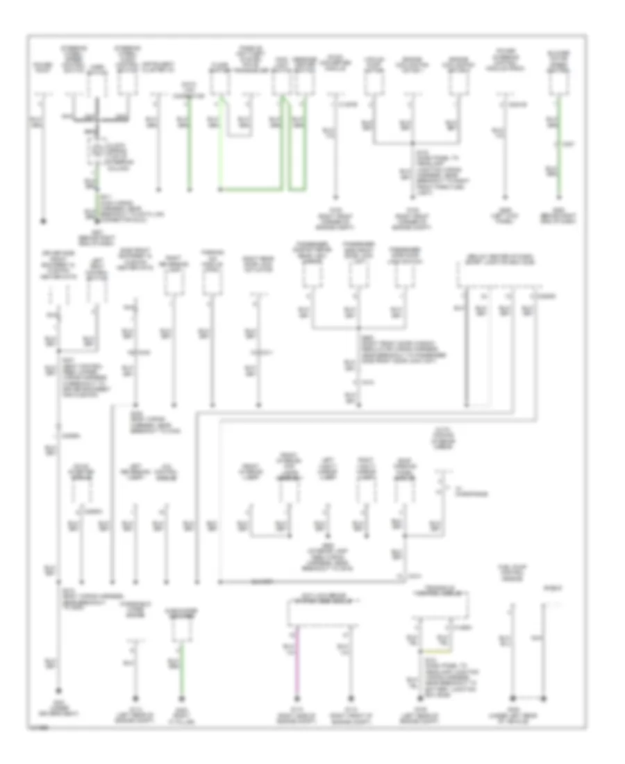
Body Control Modules Wiring Diagram, Except Hybrid (3 of 3) for Ford Escape 2011
List of elements for Body Control Modules Wiring Diagram, Except Hybrid (3 of 3) for Ford Escape 2011:
- Anti-lock brakes system
- Battery junction box (bjb) (left front of engine compt)
- Battery, aux plus
- Brake fluid sw
- Brake fluid sw rtn
- C1035b
- C2280e
- C2280f
- C2280g
- Cbp45
- Cdc34
- Clf04
- Clf05
- Clf08
- Clf12
- Cls21
- Cls25
- Cls30
- Cmc19
- Crw01
- Exterior lights system
- Fog lamp relay
- Fuse 45, 5a
- Headlights system
- High beam relay
- Horn relay
- Horns system
- Hot at all times
- Ign sw, run/ start
- Left low beam
- Left turn lamp
- Logic
- Midi fuse 125a
- Park lamp relay
- Pnk
- Right low beam
- Right turn lamp
- Sbb02
- Smart junction box (sjb) (center of dash)
- Srh01
- Wiper mtr on input
- Wiper/washer system
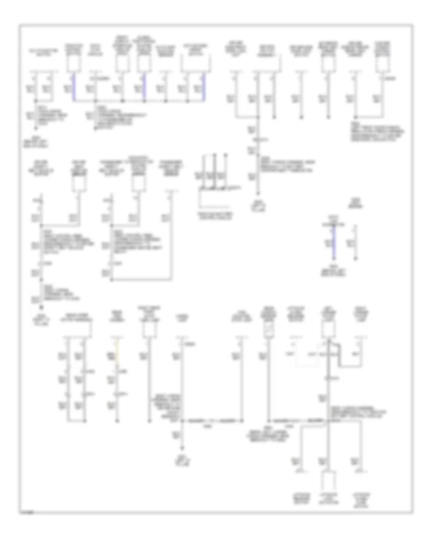
Body Control Modules Wiring Diagram, Hybrid (1 of 3) for Ford Escape 2011
List of elements for Body Control Modules Wiring Diagram, Hybrid (1 of 3) for Ford Escape 2011:
- Acc
- Air conditioning system
- Anti-theft system
- Autolamp on
- Autolamp sens
- Back lighting
- Brk pedal sw
- C211
- C2280a
- C2280b
- Cbp28
- Cbp29
- Cbp31
- Cbp35
- Cbp36
- Cbp46
- Ccb08
- Cdc30
- Cdc33
- Cdc34
- Cdc35
- Clf02
- Clf19
- Clf23
- Clf24
- Clf27
- Clf28
- Clf29
- Cln04
- Cln17
- Cln27
- Cls05
- Cls20
- Cls24
- Cls32
- Computer data lines system
- Crh03
- Dim sw gnd
- Dimmer sw
- Dome defeat
- Dome lp
- Electronic power steering system
- Exterior lights system
- Flash to pass
- Fog lamp
- Fog lamp relay
- Fuse 14, 10a
- Fuse 15, 10a
- Fuse 20, 15a
- Fuse 26, 10a
- Fuse 27, 20a
- Fuse 28, 5a
- Fuse 29, 5a
- Fuse 31, 10a
- Fuse 35, 10a
- Fuse 36, 5a
- Fuse 39 20a
- Fuse 40, 20a
- Fuse 46, 7.5a
- Hazard
- Headlamp off
- Headlamp on
- Headlights system
- High beam
- Horn relay
- Horns system
- Hot in start
- Ign sw
- Ignition switch
- Instrument cluster system
- Interior lighting
- Interior lights system
- Key in sw
- Logic
- Ms can+
- Ms can-
- Off
- Parklamp on
- Power distribution system
- Run
- S107
- S213
- S228
- Sbp14
- Sbp15
- Sbp20
- Sbp26
- Sbp27
- Sbp39
- Sbp40
- Smart junction box (sjb) (below center of dash)
- Sound systems
- Start
- Turn left
- Turn right
- Vdb06
- Vdb07
- Vlf14
- Vln04
- Vln18
- Vln33
Body Control Modules Wiring Diagram, Hybrid (2 of 3) for Ford Escape 2011
List of elements for Body Control Modules Wiring Diagram, Hybrid (2 of 3) for Ford Escape 2011:
- Acc delay relay
- All unlock relay
- Battery saver relay
- Brake shift interlock
- C2280c
- C2280d
- Cbp32
- Cbp35
- Cbp41
- Cbp43
- Cbp46
- Cbp47
- Cet53
- Cln09
- Cls18
- Cls19
- Cls30
- Cmc25
- Cpk19
- Cpk23
- Cpk28
- Cpk29
- Cpk30
- Cpk31
- Cpl11
- Cpl26
- Cpl31
- Cpl36
- Cpl39
- Cpl45
- Cpl51
- Cpl52
- Cpl58
- Cpl59
- Cpl60
- Cpl79
- Df door ajar
- Door lock
- Door locks system
- Door unlock
- Driver unlock relay
- Exterior lights system
- Front pass door ajar
- Fuse 1, 30a
- Fuse 11, 10a
- Fuse 12, 7.5a
- Fuse 18, 20a
- Fuse 19, 25a
- Fuse 2, 15a
- Fuse 3, 15a
- Fuse 32, 10a
- Fuse 35, 10a
- Fuse 38, 20a
- Fuse 4, 30a
- Fuse 41, 15a
- Fuse 43, 10a
- Fuse 46, 7.5a
- G301 (under driver's seat)
- Gd182
- Instrument cluster system
- Interior light system
- Kep pad sw a
- Kep pad sw c
- Keypad illum
- Keypad sw b
- Liftgate
- Liftgate ajar sw
- Liftgate/glass ajar
- Liftglass release relay
- Liftglass sw
- Logic
- Logic gnd
- Lr stop/turn lamp
- Mirrors system
- Navigation systems
- Park brake
- Park lamp relay
- Power distribution system
- Power tops system
- Power windows system
- Pwr gnd
- Rear drv door ajar
- Rear pass door ajar
- Red
- Rr stop/turn lamp
- S310
- S338
- Sbp01
- Sbp02
- Sbp03
- Sbp04
- Sbp11
- Sbp12
- Sbp18
- Sbp19
- Sbp38
- Seats system
- Shift interlock system
- Smart junction box (sjb) (below center of dash)
- Sound systems
- Transmissions system
- Wiper/washer system
Body Control Modules Wiring Diagram, Hybrid (3 of 3) for Ford Escape 2011
List of elements for Body Control Modules Wiring Diagram, Hybrid (3 of 3) for Ford Escape 2011:
- Battery junction box (bjb) (left rear of engine compt)
- Battery, aux plus
- Brake fluid sw
- Brake fluid sw rtn
- C1035b
- C2280e
- C2280f
- C2280g
- Cbp45
- Cdc34
- Clf04
- Clf05
- Clf08
- Clf12
- Cls21
- Cls25
- Cls30
- Cmc19
- Crw01
- Exterior lights system
- For lamp relay
- Fuse 45 5a
- Headlights system
- High beam relay
- Horn relay
- Horns system
- Hot at all times
- Ign sw, run/ start
- Instrument cluster system
- Left low beam
- Left turn lamp
- Logic
- Near breakout to smart junction box)
- Park lamp relay
- Right low beam
- Right turn lamp
- Sbb02
- Smart junction box (sjb) (below center of dash)
- Srh01
- Wiper mtr on input
- Wiper/washer system
COMPUTER DATA LINES
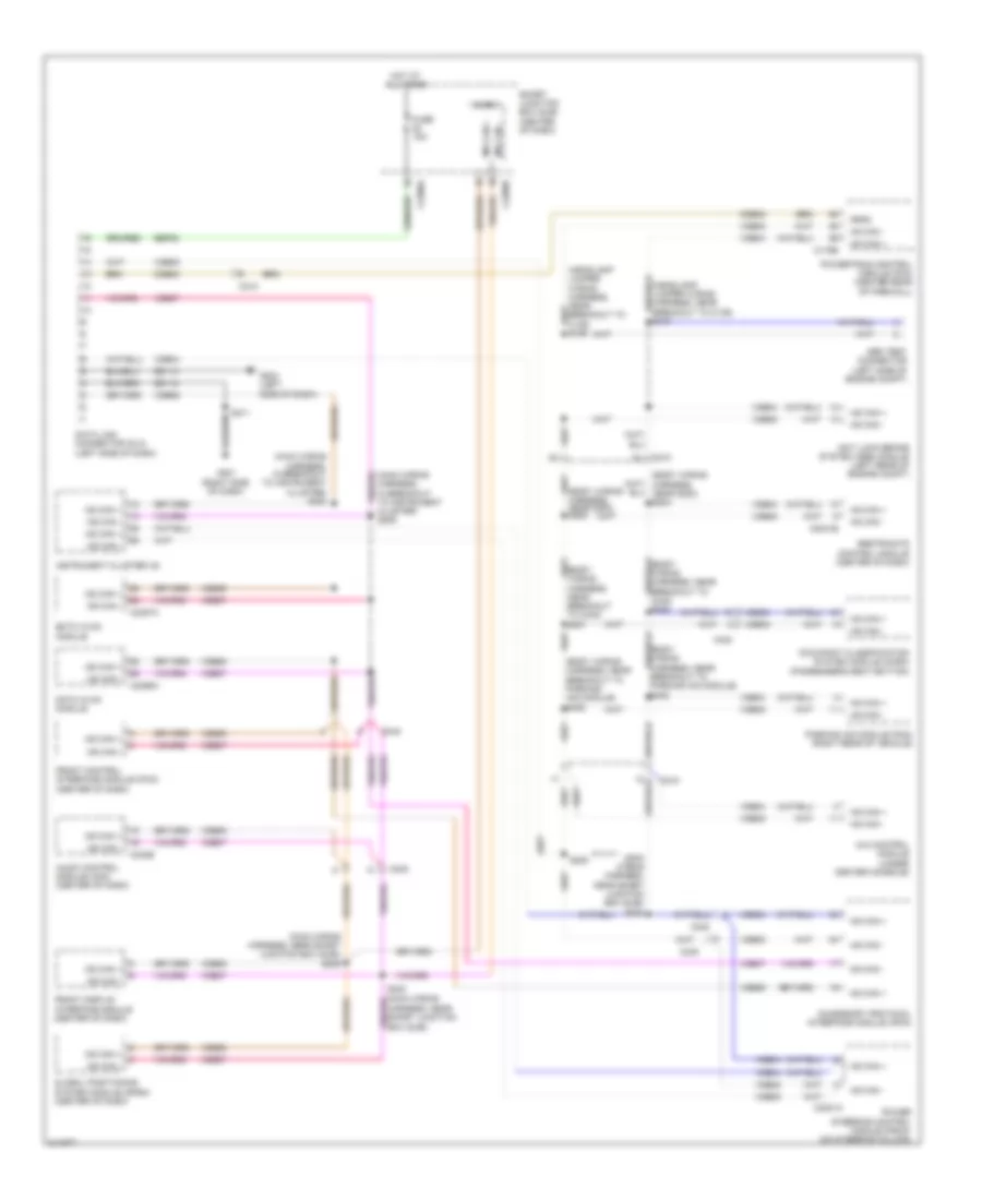
Computer Data Lines Wiring Diagram, Except Hybrid with GPS for Ford Escape 2011
List of elements for Computer Data Lines Wiring Diagram, Except Hybrid with GPS for Ford Escape 2011:
- (body wiring harness, near breakout to c340) s321
- (body wiring harness, near breakout to parking aid module) s408
- (body wiring harness, near breakout to parking aid module) s409
- (body wiring harness, near g300) s304
- (body wiring harness, near g300) s305
- (main wiring harness, in breakout to instrument cluster) s208
- (main wiring harness, in breakout to instrument cluster) s209
- (main wiring harness, near smart junction box (sjb)) s204
- (main wiring harness, near smart junction box (sjb)) s239
- 4x4 control module (under center console)
- Abs test connector (left side of engine compt)
- Accessory protocol interface module (apim)
- Anti lock brake system (abs) module (left rear of engine compt)
- Audio control module (acm) (center of dash)
- C175b
- C2041b
- C210
- C212
- C215
- C2231a
- C2280a
- C2280b
- C2356a
- C2357a
- C240b
- C248
- C340
- Cdb08
- Data link connector (dlc) (left side of dash)
- Datc hvac module
- Emtc hvac module
- Feps
- Front control interface module (fcim) (center of dash)
- Front display interface module (center of dash)
- Fuse 15a
- G201 (right side of dash)
- G203 (left side of dash)
- Gd112
- Gd114
- Global positioning system module (gpsm) (center of dash)
- Harness, near smart junction box (sjb))
- Hot at all times
- Hs can +
- Hs can -
- Instrument cluster (ic)
- Micro
- Ms can +
- Ms can -
- Occupant classification system module (ocsm) (passenger's seat bottom)
- Parking aid module (pam) (right rear of vehicle)
- Power steering control module (pscm) (on steering column)
- Powertrain control module (pcm) (center rear of firewall)
- Restraints control module (center of dash)
- S205
- S211
- Sbp20
- Smart junction box (sjb) (center of dash)
- Vdb04
- Vdb05
- Vdb06
- Vdb07
Computer Data Lines Wiring Diagram, Except Hybrid without GPS for Ford Escape 2011
List of elements for Computer Data Lines Wiring Diagram, Except Hybrid without GPS for Ford Escape 2011:
- (body wiring harness, near breakout to c340) s321
- (body wiring harness, near breakout to parking aid module) s408
- (body wiring harness, near breakout to parking aid module) s409
- (headlamp jumper wiring harness, near breakout to c139) s106
- (headlamp jumper wiring harness, near breakout to c139) s107
- (main wiring
- (main wiring harness, in breakout to instrument cluster) s208
- (main wiring harness, in breakout to instrument cluster) s209
- (main wiring harness, near smart junction box (sjb)) s204
- 4x4 control module (under center console)
- Abs test connector (left side of engine compt)
- Accessory protocol interface module (apim)
- Anti lock brake system (abs) module (left rear of engine compt)
- Audio control module (acm) (center of dash)
- C175b
- C2041b
- C210
- C212
- C2231a
- C2280a
- C2280b
- C2356a
- C2357a
- C240b
- C248
- C340
- Cdb08
- Data link connector (dlc) (left side of dash)
- Datc hvac module
- Emtc hvac module
- Feps
- Front control interface module (fcim) (center of dash)
- Front display interface module (center of dash)
- Fuse 15a
- G201 (right side of dash)
- G203 (left side of dash)
- Gd112
- Gd114
- Harness, near smart junction box (sjb)) s240
- Hot at all times
- Hs can +
- Hs can -
- Instrument cluster (ic)
- Micro
- Ms can +
- Ms can -
- Occupant classification system module (ocsm) (passenger's seat bottom)
- Parking aid module (pam) (right rear of vehicle)
- Power steering control module (pscm) (on steering column)
- Powertrain control module (pcm) (center rear of firewall)
- Restraints control module (center of dash)
- S205
- S211
- Sbp20
- Smart junction box (sjb) (center of dash)
- Vdb04
- Vdb05
- Vdb06
- Vdb07
Computer Data Lines Wiring Diagram, Hybrid with GPS for Ford Escape 2011
List of elements for Computer Data Lines Wiring Diagram, Hybrid with GPS for Ford Escape 2011:
- (body wiring harness, near breakout to c340)
- (body wiring harness, near breakout to g300) s311
- (body wiring harness, near breakout to g300) s312
- (dash panel to headlamp junction wiring harness, near breakout to battery junction box (bjb)) s119
- (dash panel to headlamp junction wiring harness, near breakout to right front wheel speed sensor)
- (main wiring harness, near breakout to c215)
- (main wiring harness, near breakout to in-vehicle temperature/ humidity sensor) s209
- (main wiring harness, near breakout to in-vehicle temperature/humidity sensor) s208
- (passenger's seat) occupant classification system module (ocsm)
- (radio control jumper harness, near breakout to audio control module) s232
- (radio control jumper harness, near breakout to audio control module) s239
- (rear center of firewall) powertrain control module (pcm)
- (right side of cargo area) parking aid module (pam)
- (under front of center console) restraints control module (rcm)
- 4x4 control module (under center console)
- Abs test connector (left rear of engine compt)
- Accessory protocol interface module (apim) (center of dash)
- Air conditioning control module (lower left front of engine)
- Anti-lock brake system control module (right rear of engine compt)
- Audio control module (acm)
- C133
- C1458a
- C1469a
- C175b
- C2041b
- C212
- C215
- C2231a
- C2280a
- C2280b
- C2356a
- C240b
- C248
- C340
- C4227a
- Cdb08
- Data link connector (dlc) (lower left side of dash)
- Datc hvac module
- Feps
- Front control interface module (fcim)
- Front display interface module
- Fuse 15a
- G201 (behind right end of dash)
- G203 (behind left end of dash)
- Gd112
- Gd114
- Global positioning system module (gpsm) (center of dash)
- Harness, in breakout to c340) s337
- Harness, near breakout to in-vehicle temperature/ humidity sensor)
- Hot at all times
- Hs can +
- Hs can -
- Instrument cluster (ic)
- Micro
- Ms can +
- Ms can -
- Power steering control module (pscm) (on steering column)
- S120
- S137 (dash panel to headlamp junction wiring harness, near breakout to right front wheel speed sensor)
- S138
- S154
- S204
- S205 (main wiring harness, near breakout to c215)
- S211
- S227
- S231
- S240 (radio control jumper harness, near breakout to audio control module)
- S339
- S411 (body wiring harness, after breakout to left rear wheel speed sensor)
- S412 (body wiring harness, near breakout to driver side impact sensor 2)
- Sbp20
- Smart junction box (sjb) (below center of dash)
- Traction battery control module
- Transaxle control module (above transaxle)
- Vdb04
- Vdb05
- Vdb06
- Vdb07
- W/o apim
Computer Data Lines Wiring Diagram, Hybrid without GPS for Ford Escape 2011
List of elements for Computer Data Lines Wiring Diagram, Hybrid without GPS for Ford Escape 2011:
- (body wiring harness, in breakout to c340) s337
- (body wiring harness, near breakout to c340)
- (body wiring harness, near breakout to g300) s311
- (body wiring harness, near breakout to g300) s312
- (dash panel to headlamp junction wiring harness, near breakout to battery junction box (bjb)) s119
- (dash panel to headlamp junction wiring harness, near breakout to right front wheel speed sensor)
- (main wiring harness, near breakout to c215)
- (main wiring harness, near breakout to in-vehicle temperature/humidity sensor) s208
- (passenger's seat) occupant classification system module (ocsm)
- (radio control jumper harness, near breakout to audio control module) s232
- (rear center of firewall) powertrain control module (pcm)
- (right side of cargo area) parking aid module (pam)
- (under front of center console) restraints control module (rcm)
- 4x4 control module (under center console)
- Abs test connector (left rear of engine compt)
- Accessory protocol interface module (apim) (center of dash)
- Air conditioning control module (lower left front of engine)
- Anti-lock brake system control module (right rear of engine compt)
- Audio control module (acm)
- C133
- C1458a
- C1469a
- C175b
- C2041b
- C212
- C215
- C2231a
- C2280a
- C2280b
- C2356a
- C240b
- C248
- C340
- C4227a
- Cdb08
- Data link connector (dlc) (lower left side of dash)
- Datc hvac module
- Feps
- Front control interface module (fcim)
- Front display interface module
- Fuse 15a
- G201 (behind right end of dash)
- G203 (behind left end of dash)
- Gd112
- Gd114
- Hot at all times
- Hs can +
- Hs can -
- In-vehicle temperature/ humidity sensor) s209
- Instrument cluster (ic)
- Micro
- Ms can +
- Ms can -
- Power steering control module (pscm) (on steering column)
- S120
- S137 (dash panel to headlamp junction wiring harness, near breakout to right front wheel speed sensor)
- S138
- S154
- S204
- S205 (main wiring harness, near breakout to c215)
- S211
- S227
- S231
- S339
- S411 (body wiring harness, after breakout to left rear wheel speed sensor)
- S412 (body wiring harness, near breakout to driver side impact sensor 2)
- Sbp20
- Smart junction box (sjb) (below center of dash)
- Traction battery control module
- Transaxle control module (above transaxle)
- Vdb04
- Vdb05
- Vdb06
- Vdb07
- W/o apim
COOLING FAN
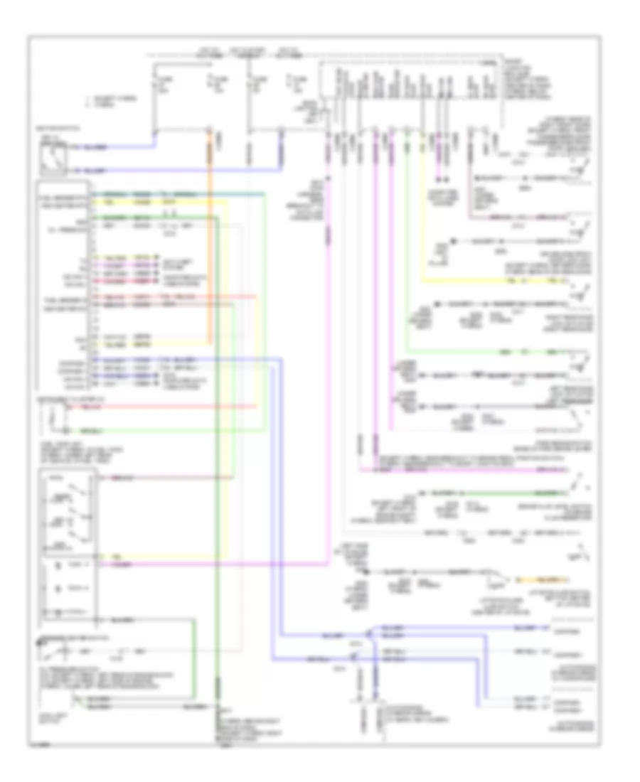
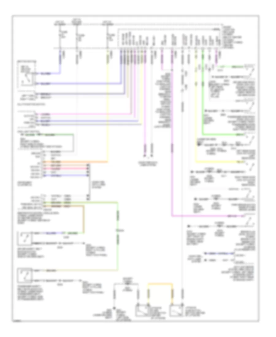
Cooling Fan Wiring Diagram, Except Hybrid for Ford Escape 2011
List of elements for Cooling Fan Wiring Diagram, Except Hybrid for Ford Escape 2011:
- (engine control sensor & fuel charge wiring harness, before breakout to fuel injector 3) s118
- 3.0l
- Battery junction box (bjb) (left front of engine compt)
- C175b
- C175e
- Can+
- Can-
- Ce302
- Cec02
- Ceo01
- Cht
- Computer data lines system
- Cooling fan high speed relay
- Cooling fan low speed relay
- Cooling fan relay
- Cylinder head temperature (cht) sensor
- Engine controls system
- Engine cooling fan motor 1 (front of engine compt)
- Engine cooling fan motor 2 (front of engine compt)
- Engine cooling fan resistor (2.5l)
- Fuse 10a
- Fuse 40a
- G102 (right front of engine compt)
- Hfc
- Hot at all times
- Lfc
- Pcm power relay
- Pcmrc
- Powertrain control module (pcm) (3.0l: rear center of firewall) (2.5l: center rear of firewall)
- Re405
- Red
- S102
- S140
- Sigrtne
- Vdb04
- Vdb05
- Ve712
Cooling Fan Wiring Diagram, Hybrid for Ford Escape 2011
List of elements for Cooling Fan Wiring Diagram, Hybrid for Ford Escape 2011:
- hs can-
- (dash panel to headlamp wiring harness, near battery breakout) s130
- (dash panel to headlamp wiring harness, near breakout to engine cooling fan dropping resistor 1) s131
- Battery junction box (bjb) (left rear of engine compt)
- C175b
- C175e
- Ce302
- Cec01
- Cec02
- Cec11
- Cht
- Computer data lines system
- Cylinder-head temperature sensor (top of engine)
- Engine controls system
- Engine cooling fan dropping resistor 1 (left front of engine compt)
- Engine cooling fan motor 1 (left front of engine compt)
- Engine cooling fan motor 2 (right front of engine compt)
- Fan control relay 1
- Fan control relay 2
- Fan control relay 3
- Fuse 10a
- Fuse 40a
- G102 (right front corner of engine compt)
- Hfc
- Hot at all times
- Hs can+
- Lfc
- Mfc
- Pcm power relay
- Pcmrc
- Powertrain control module (pcm) (rear center of firewall)
- Re405
- Red
- S104 (power pack engine wiring harness, near breakout to powertrain control module)
- S116
- S125
- S134
- Sigrtne
- Vdb04
- Vdb05
- Ve712
CRUISE CONTROL
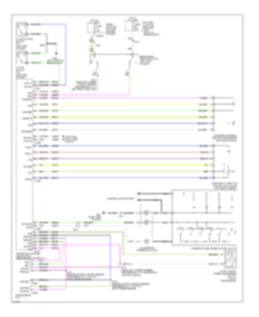
Cruise Control Wiring Diagram, Except Hybrid for Ford Escape 2011
List of elements for Cruise Control Wiring Diagram, Except Hybrid for Ford Escape 2011:
- (headlamp jumper harness , near breakout to powertrain control module)
- (left side of dash)
- Accelerator pedal position (app) sensor (left side of dash)
- App
- Appsrtn
- Appvref
- Appvref2
- Battery junction box (bjb) (left front of engine compt)
- Bpp
- Bps
- Brake pedal position switch (left side of dash)
- C168a
- C168b
- C175b
- C175e
- C175t
- C210
- C212
- C2280d
- Ccb08
- Ce412
- Ce426
- Ce903
- Ces09
- Cet21
- Clockspring (steering column)
- Clutch cutoff switch (m/t) (left side of dash)
- Clutch switch (m/t)
- Computer data lines system
- Cpp-bt
- Cpp-tt
- Electronic throttle control (etc) motor (on throttle body)
- Etcref
- Fuse 15a
- Fuse 20a
- G104 (left front of engine compt)
- G201 (right side of dash)
- Hot at all times
- Hs can+
- Hs can-
- Interior lights system
- Le111
- Le134
- Le136
- Le137
- Nca
- Off
- Oss
- Output shaft speed (oss) sensor (2.5l m/t) (top of transmission)
- Powertrain control module (pcm) (rear center of firewall)
- Re134
- Re136
- Re137
- Re406
- Res08
- Ret24
- Rsm
- S111 (headlamp jumper wiring harness, near breakout to left front side lamp)
- S121
- S142
- S146 (engine control wiring harness, near breakout to output shaft speed sensor)
- S147 (engine control wiring harness, near breakout to output shaft speed sensor)
- S211
- S229
- Scc srtn
- Sccs
- Set+
- Set-
- Sig rtn
- Smart junction box (sjb) (center of dash)
- Steering wheel/speed control switch
- Tacm +
- Tacm -
- Tp1
- Tp2
- Tprtn
- Transmission (a/t)
- Trs
- Trs/oss
- Tss gnd
- Tss pwr
- Tss/oss
- Vdb04
- Vdb05
- Ve701
- Ve702
- Ve818
- Ve819
- Ves10
- Vet26
- Vet32
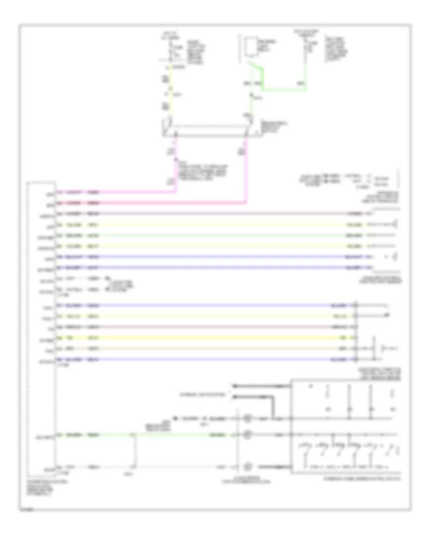
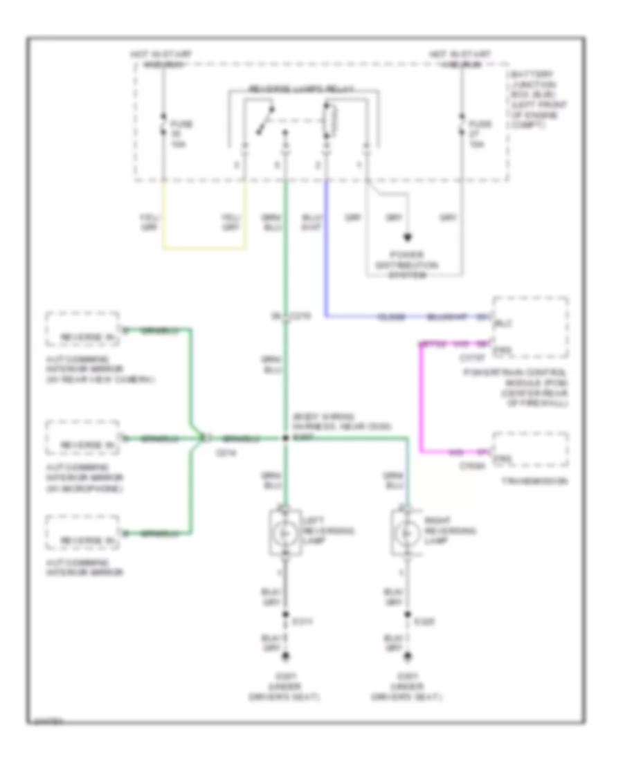
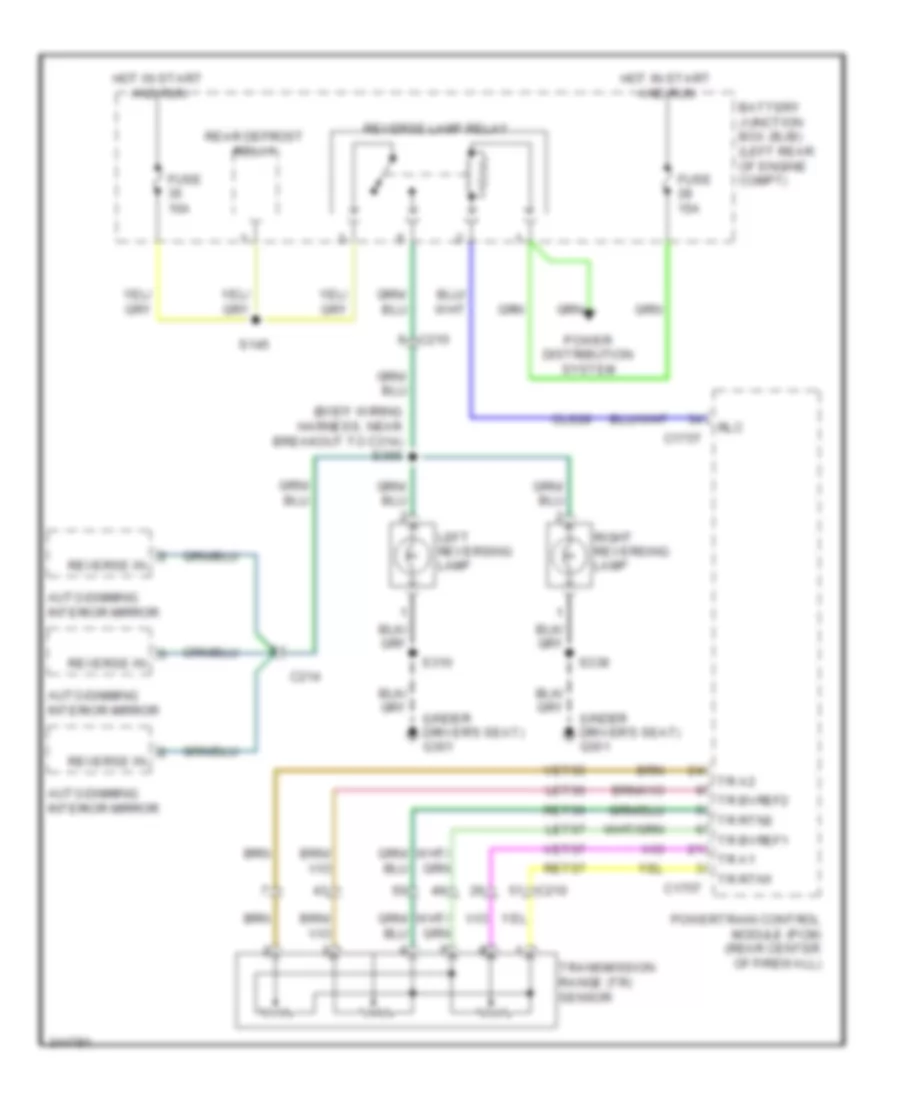
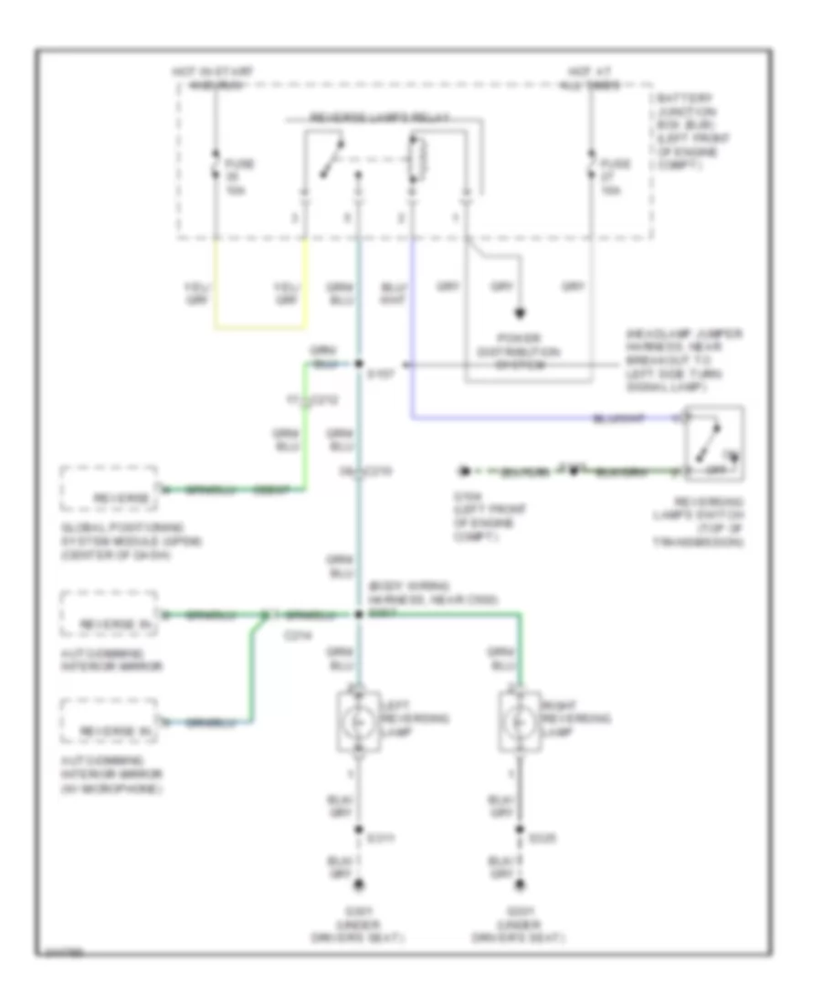
Cruise Control Wiring Diagram, Hybrid for Ford Escape 2011
List of elements for Cruise Control Wiring Diagram, Hybrid for Ford Escape 2011:
- Accelerator pedal position (app) sensor
- App
- App2
- Apprtn
- Apprtn2
- Appvref
- Battery junction box (bjb) (left rear of engine compt)
- Bpp
- Bps
- Brake pedal position switch
- C1458a
- C175b
- C175e
- C210
- C212
- C2280d
- Ccb08
- Ce412
- Ce426
- Ces09
- Clock spring (top of steering column)
- Computer data lines system
- Ectref2
- Electronic throttle control (etc) motor (left rear of engine)
- Etcref
- Etcrtn
- Fuse 15a
- Fuse 5a
- G201 (behind right end of dash)
- Hot at all times
- Hot in start and run
- Hs can+
- Hs can-
- Interior lights system
- Le134
- Le136
- Le137
- Nca
- Off
- Powertrain control module (pcm) (rear center of firewall)
- Re134
- Re136
- Re137
- Res08
- Reverse lamp relay
- Rsm
- S144
- S211
- Scc srtn
- Sccs
- Set+
- Set-
- Smart junction box (sjb) (below center of dash)
- Steering wheel/speed control switch
- Tacm +
- Tacm -
- Tp2
- Tps1
- Transaxle control module (above transaxle)
- Vdb04
- Vdb05
- Ve701
- Ve702
- Ve818
- Ve819
- Ves10
DEFOGGERS
Defoggers Wiring Diagram, Except Hybrid for Ford Escape 2011
List of elements for Defoggers Wiring Diagram, Except Hybrid for Ford Escape 2011:
- Automatic a/c
- Battery junction box (bjb) (left front of engine compt)
- C134
- C210
- C212
- C2356a
- C2357a
- C312
- C402a
- C402b
- C405
- C913
- Ch122
- Datc hvac module
- Driver side exterior rear view mirror
- Emtc hvac module
- Fuse 10a
- Fuse 15a
- Fuse 30a
- G301 (under driver's seat)
- G401 (left side of liftgate)
- G402 (left rear of vehicle)
- Hot at all times
- Hot in run and start
- Htd mir rly
- Manual a/c
- Passenger side exterior rear view mirror
- Power distribution system
- R-def
- R-def/
- Rear window defrost grid
- Rear window defrost relay
- S312
- S502
- S600
- S904
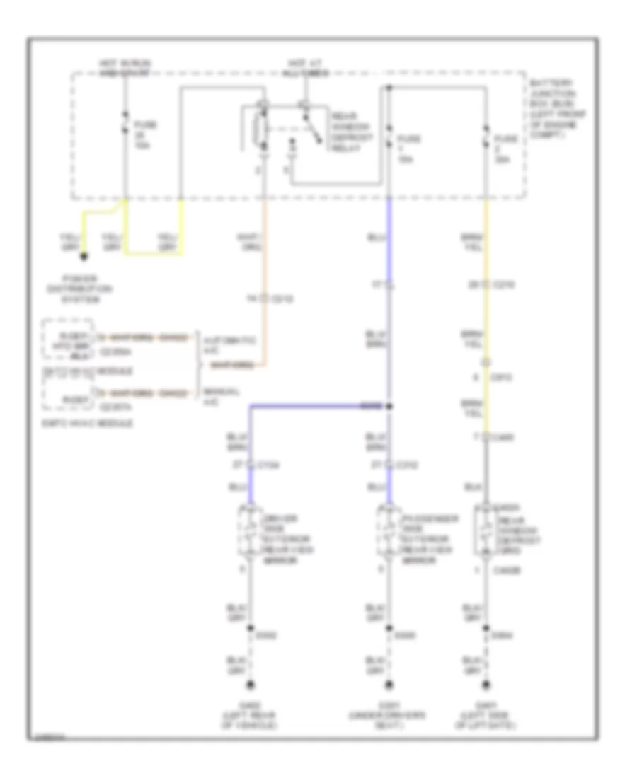
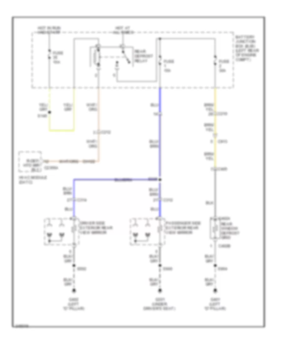
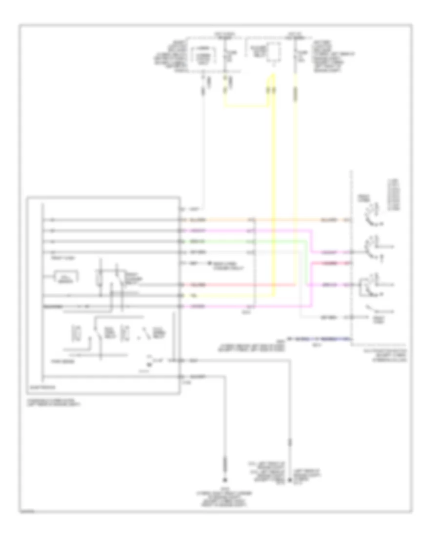
Defoggers Wiring Diagram, Hybrid for Ford Escape 2011
List of elements for Defoggers Wiring Diagram, Hybrid for Ford Escape 2011:
- Battery junction box (bjb) (left rear of engine compt)
- C210
- C212
- C2356a
- C312
- C314
- C402a
- C402b
- C405
- C913
- Ch122
- Driver side exterior rear view mirror
- Fuse 10a
- Fuse 15a
- Fuse 30a
- G301 (under driver's seat)
- G401 (left "d" pillar)
- G402 (left "d" pillar)
- Hot at all times
- Hot in run and start
- Htd mir rly
- Hvac module (datc)
- Passenger side exterior rear view mirror
- R-def/
- Rear defrost relay
- Rear window defrost grid
- S145
- S305
- S502
- S600
- S904
ELECTRONIC POWER STEERING
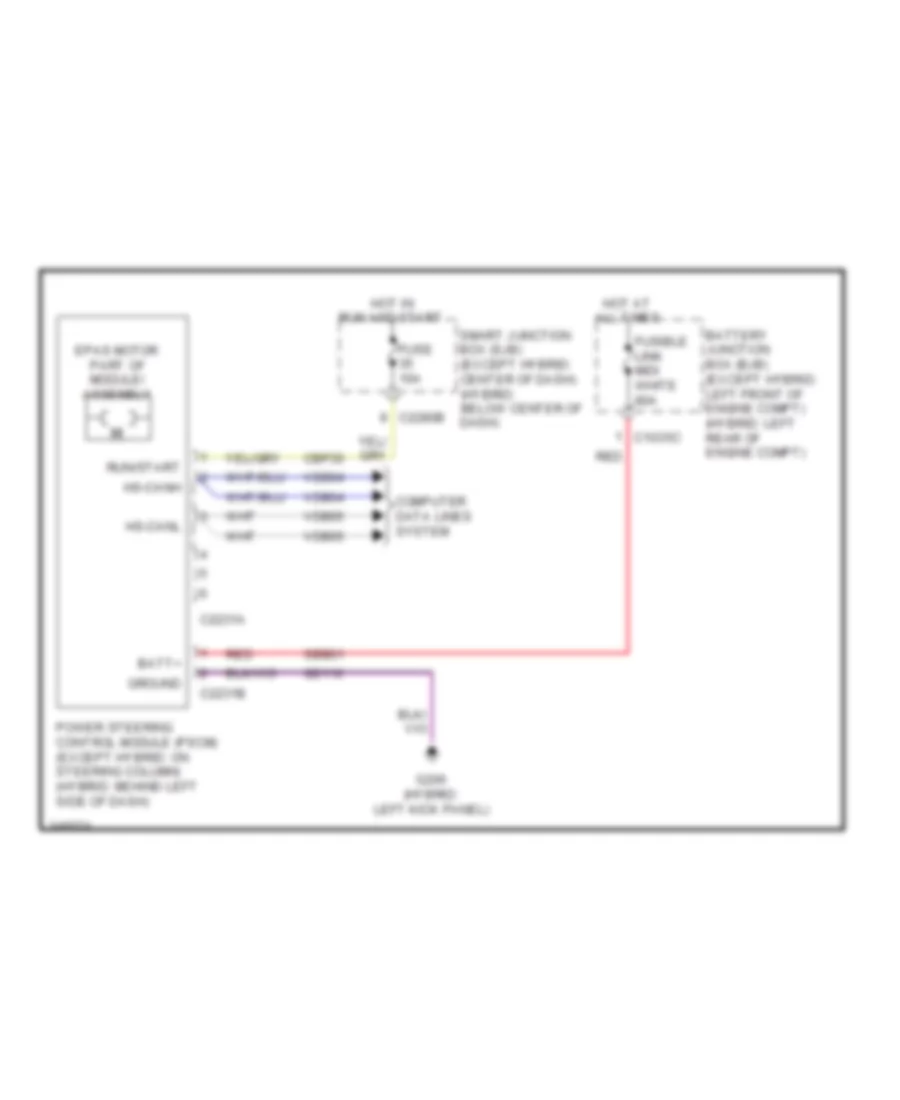
Electronic Power Steering Wiring Diagram for Ford Escape 2011
List of elements for Electronic Power Steering Wiring Diagram for Ford Escape 2011:
- Batt+
- Battery junction box (bjb) (except hybrid: left front of engine compt) (hybrid: left rear of engine compt)
- C1035c
- C2231a
- C2231b
- C2280b
- Cbp35
- Computer data lines system
- Epas motor part of module/ assembly
- Fuse 10a
- Fusible link midi white 80a
- G206 (hybrid: left kick panel)
- Gd116
- Ground
- Hot at all times
- Hot in run and start
- Hs-canh
- Hs-canl
- Power steering control module (pscm) (except hybrid: on steering column) (hybrid: behind left side of dash)
- Red
- Run/start
- Sbb01
- Smart junction box (sjb) (except hybrid: center of dash) (hybrid: below center of dash)
- Vdb04
- Vdb05
ENGINE PERFORMANCE
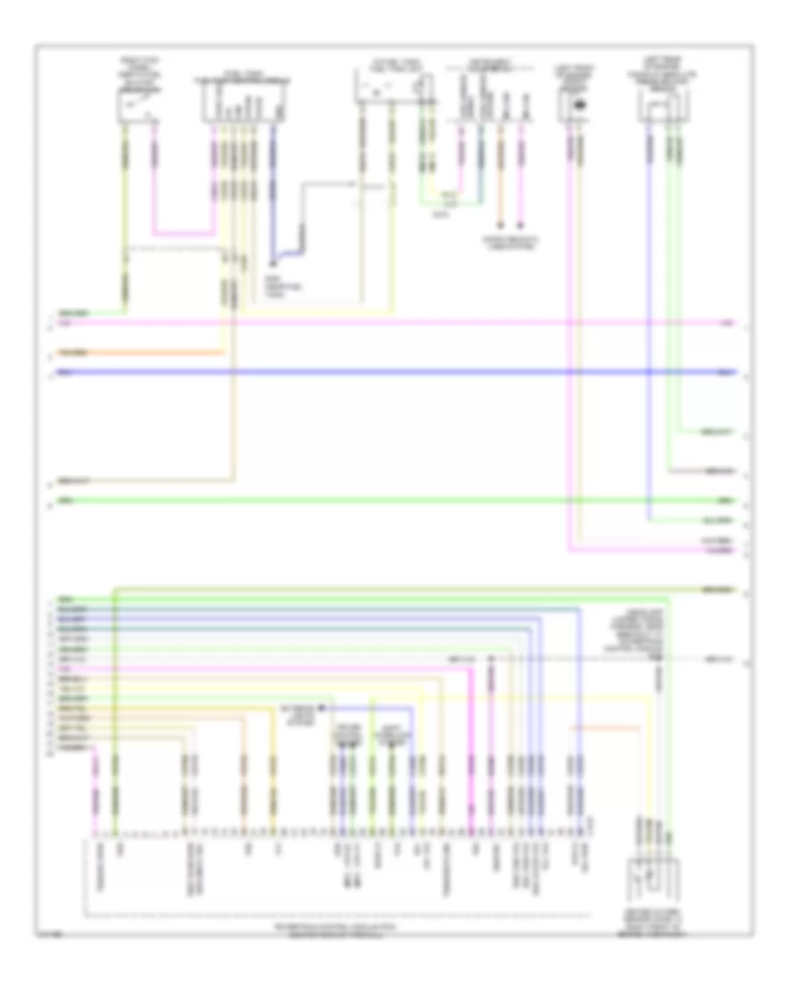
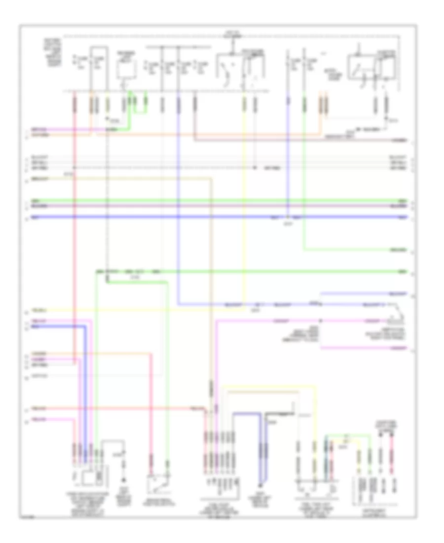
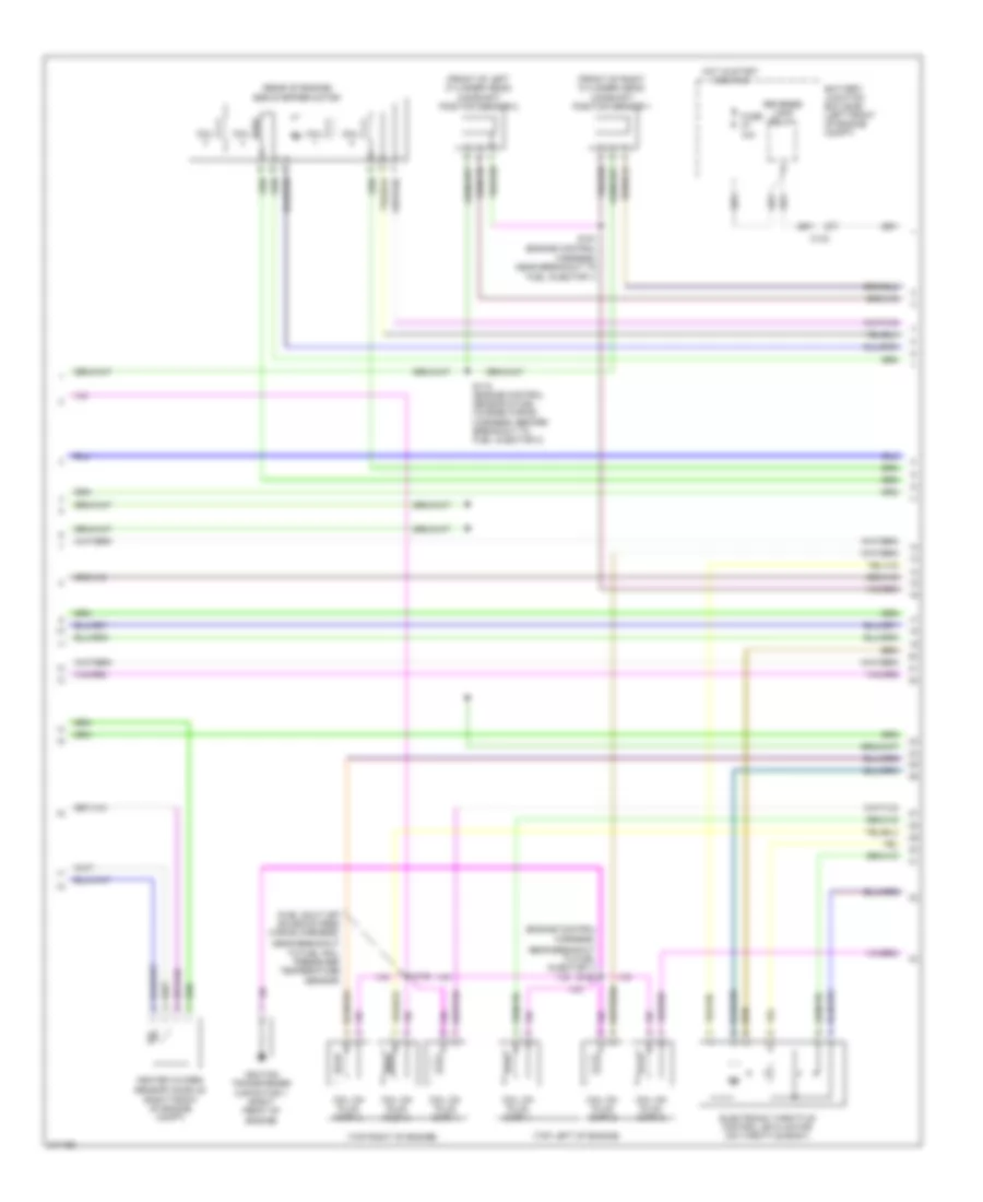
2.5L
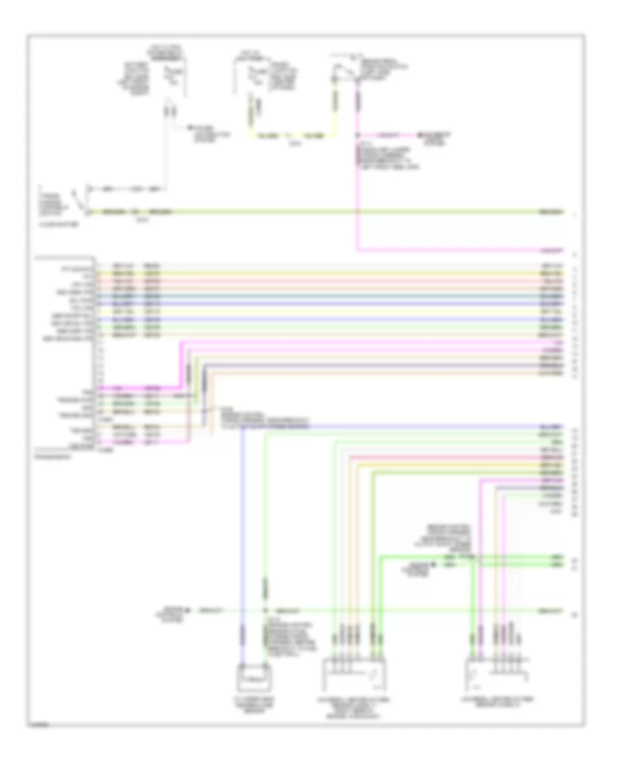
2.5L, Engine Performance Wiring Diagram (1 of 5) for Ford Escape 2011
List of elements for 2.5L, Engine Performance Wiring Diagram (1 of 5) for Ford Escape 2011:
- (m/t)
- 10a
- 15a
- 20a
- A/c cycling pressure transducer (right side of engine compt)
- Accelerator pedal position (app) sensor (left side of dash)
- Accr
- Acpt
- Air conditioning system
- App
- App2
- Apprtn
- Apprtn2
- Appvref
- Appvref2
- Battery junction box (bjb) (left front of engine compt)
- Bpp
- Bps
- C175b
- C210
- Can+
- Can-
- Canv
- Case gnd
- Cbb29
- Cbk01
- Cbk02
- Ccb08
- Cdb08
- Cdc10
- Cdc12
- Cdc15
- Cdc34
- Cdc35
- Cdc54
- Ce114
- Ce226
- Ce302
- Cec01
- Cec02
- Ces09
- Ch302
- Computer data lines system
- Cooling fans system
- Cruise control system
- Exterior lights system
- Feps
- Fpc
- Fpm
- Ftp
- Ftpref
- Fuel tank pressure sensor (in fuel tank)
- Fuse
- G109 (rear of engine compt, on firewall)
- Gd122
- Gencom
- Genmon
- Hfc
- Hot at all times
- Iat
- Isp-r
- Kapwr
- Le136
- Le137
- Le230
- Le424
- Lfc
- Mafrtn
- Mafs
- Pcm power relay
- Pcmrc
- Power gnd
- Powertrain control module (pcm) (center rear of firewall)
- Re136
- Re137
- Re320
- Re407
- Res08
- S114
- S140
- S144 (headlamp jumper harness, near breakout to powertrain control module)
- Sbb05
- Sccs
- Sccsrtn
- Sigrtnc
- Smc
- Smcs
- Smr
- Starting/charging system
- Vdb04
- Vdb05
- Ve518
- Ve701
- Ve702
- Ve740
- Ve807
- Ve922
- Ves10
- Vh433
- Vpwr
- Vpwrtr-pn
- Vref
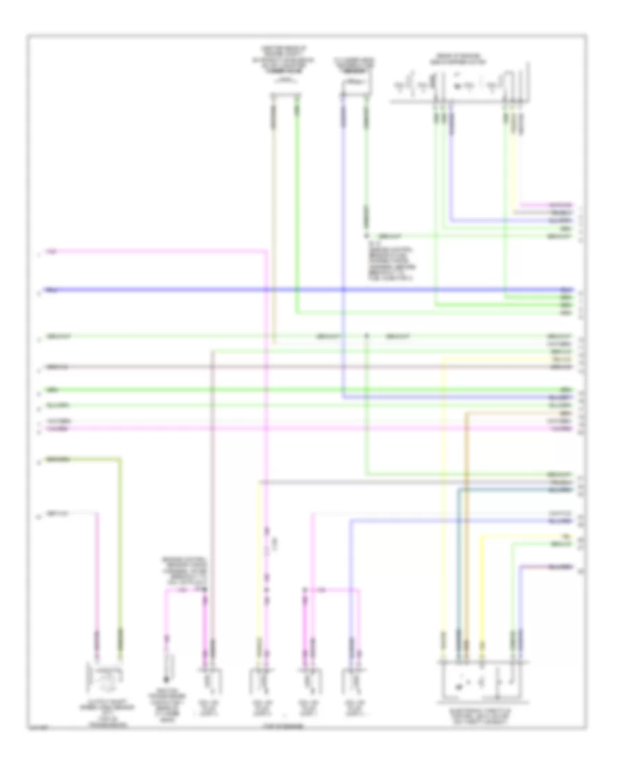
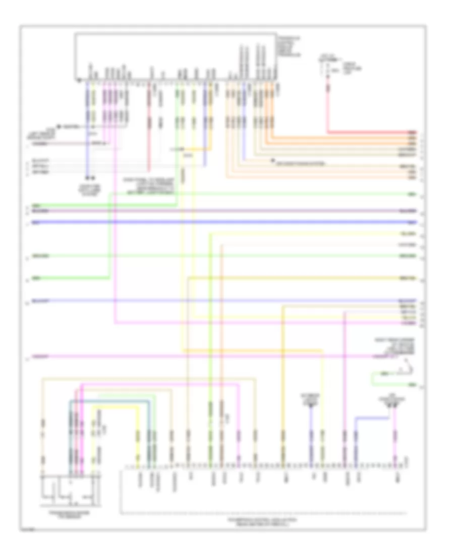
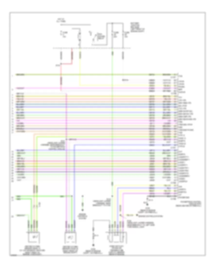
2.5L, Engine Performance Wiring Diagram (2 of 5) for Ford Escape 2011
List of elements for 2.5L, Engine Performance Wiring Diagram (2 of 5) for Ford Escape 2011:
- (m/t)
- (under left side of vehicle) evap canister vent control solenoid
- 15a
- 20a
- Acc
- Battery junction box (bjb) (left front of engine compt)
- Brake pedal position switch (left side of dash)
- C168a
- C168b
- C210
- C327
- Cblr/c456 vfs
- Cet05
- Cet06
- Cet07
- Cet08
- Cet09
- Cet10
- Cet18
- Cet25
- Fuel injector diode
- Fuel injector relay
- Fuse
- Fuse 10a
- G104 (left front of engine compt)
- G109 (rear of engine compt,
- Hot at all times
- Ignition switch (on steering column)
- Le111
- Lpc vfs
- Mass air flow/intake air temperature (maf/iat) sensor (rear of engine)
- Off
- On firewall)
- Oss
- Re406
- Rear window defrost relay
- Ret24
- Reverse lamp relay
- Run
- S109
- S113
- S114
- S142 (headlamp jumper harness, near breakout to c139)
- S143 (headlamp jumper harness, near breakout to powertrain control module)
- S146
- S147 (engine control wiring harness, near breakout to output shaft speed sensor)
- Sol pwr
- Ssa cb1234 vfs
- Ssb c35r vfs
- Ssc cb26 vfs
- Sse on/off sol
- Start
- Tcc vfs
- Tft
- Tft sig rtn
- Transmission
- Trs
- Trs/oss gnd
- Trs/oss pwr
- Tss
- Tss gnd
- Tss pwr
- Vet26
- Vet27
- Vet32
- Vet33
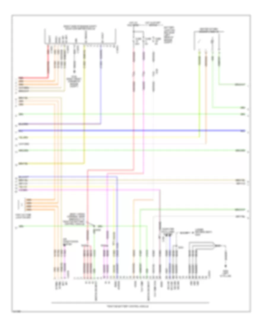
2.5L, Engine Performance Wiring Diagram (3 of 5) for Ford Escape 2011
List of elements for 2.5L, Engine Performance Wiring Diagram (3 of 5) for Ford Escape 2011:
- (fuel tank) fuel pump control module
- (headlamp jumper wiring harness, near breakout to powertrain control module) s121
- (in fuel tank) fuel tank unit
- (left front of engine) knock sensor
- (left rear of engine) manifold absolute pressure (map) sensor
- (m/t)
- (right kick panel) inertia fuel shutoff (ifs) switch
- C175t
- C210
- C215
- Ce226
- Ce233
- Ce515
- Ce903
- Ce911
- Cet05
- Cet06
- Cet07
- Cet08
- Cet09
- Cet10
- Cet18
- Cet21
- Cet25
- Cet34
- Cls28
- Computer data lines system
- Cpp-bt
- Cpp-tt
- Cruise control system
- Exterior lights system
- Fpc
- Fpm
- Fppwr
- Fprtn
- Fuel sender return
- Fuel sender signal
- G400 (near fuel
- Gd159
- Gnd
- Heated oxygen sensor (ho2s) 12 (right front of engine, in exhaust)
- Ho2s-12
- Htr-12
- Instrument cluster (ic)
- Le111
- Lpc vfs
- Ms can+
- Ms can-
- Oss
- Powertrain control module (pcm) (center rear of firewall)
- Re406
- Re515
- Ret24
- Rlc
- Rmc32
- Shift interlock system
- Sigrtnt
- Sol pwr
- Ssa cb1234 vfs
- Ssb c35r vfs
- Ssc cb26 vfs
- Ssd cblr/cb456
- Sse on/off sol
- Tank)
- Tcc vfs
- Tcs
- Tft
- Trs
- Trs/oss vpwr
- Tss
- Tss/oss/tr gnd
- Ve518
- Ve731
- Vet26
- Vet27
- Vet32
- Vet33
- Vmc11
- Vper fuel
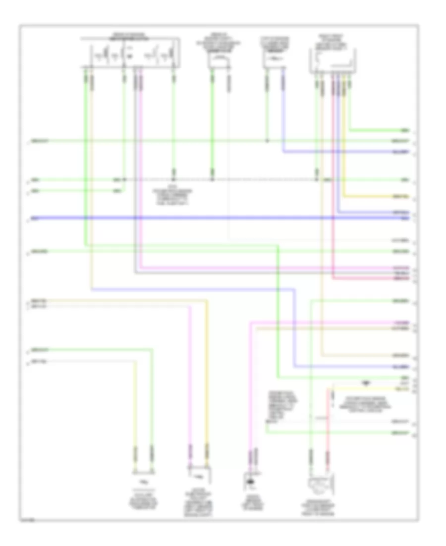
2.5L, Engine Performance Wiring Diagram (4 of 5) for Ford Escape 2011
List of elements for 2.5L, Engine Performance Wiring Diagram (4 of 5) for Ford Escape 2011:
- (center rear of engine compt) evaporative emission (evap) canister purge valve
- (engine control sensor wiring harness, after breakout to coil on plug 4) s135
- (rear of engine) egr stepper motor
- (top of engine)
- C133
- Coil
- Coil on plug (cop) 1
- Coil on plug (cop) 2
- Coil on plug (cop) 3
- Coil on plug (cop) 4
- Cylinder head temperature sensor
- Electronic throttle control (etc) motor (on throttle body)
- Ignition transformer capacitor 1 (rear of cylinder head)
- Output shaft speed (oss) sensor (m/t) (top of transmission)
- S118 (engine control sensor & fuel charge wiring harness, before breakout to fuel injector 3)
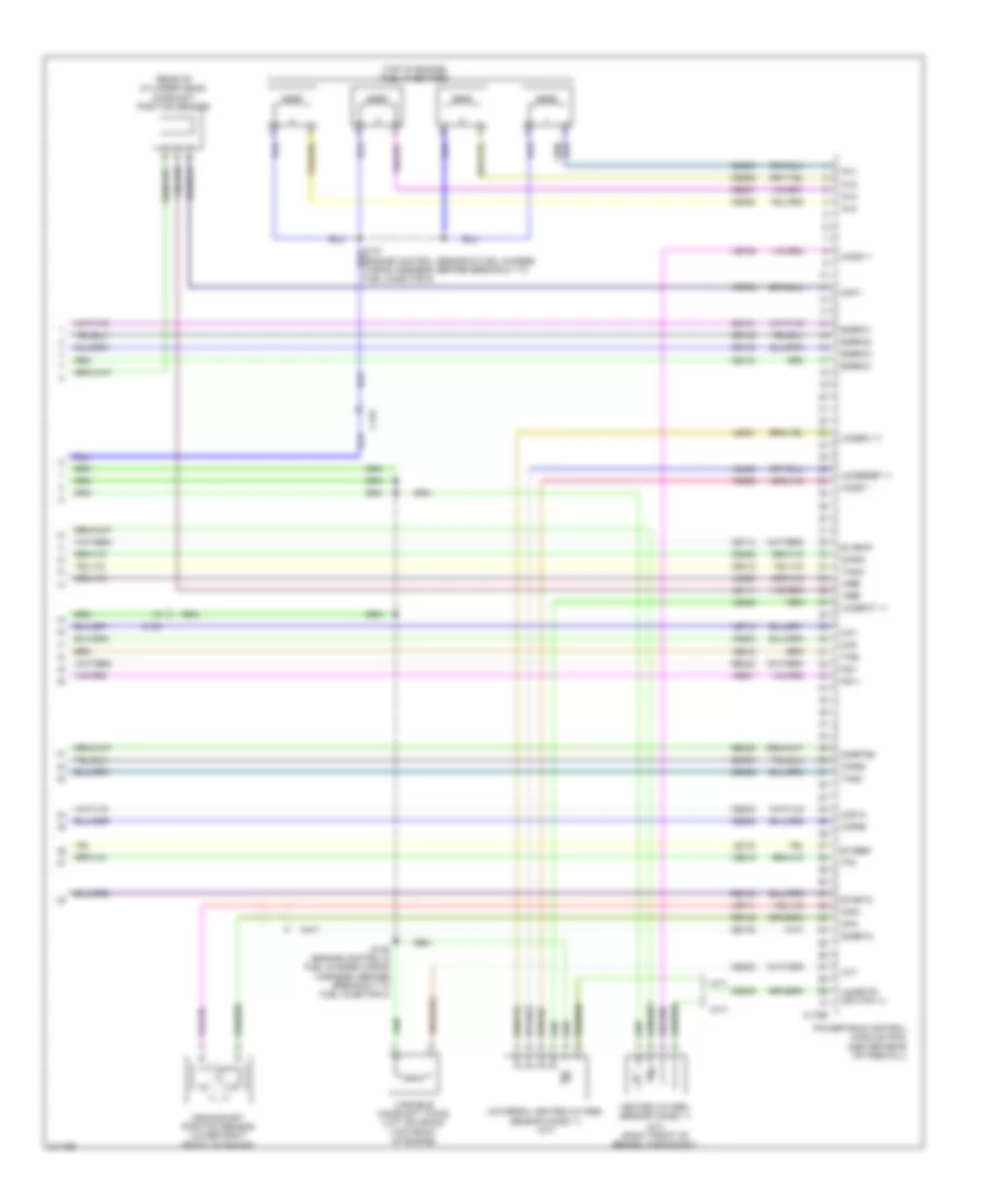
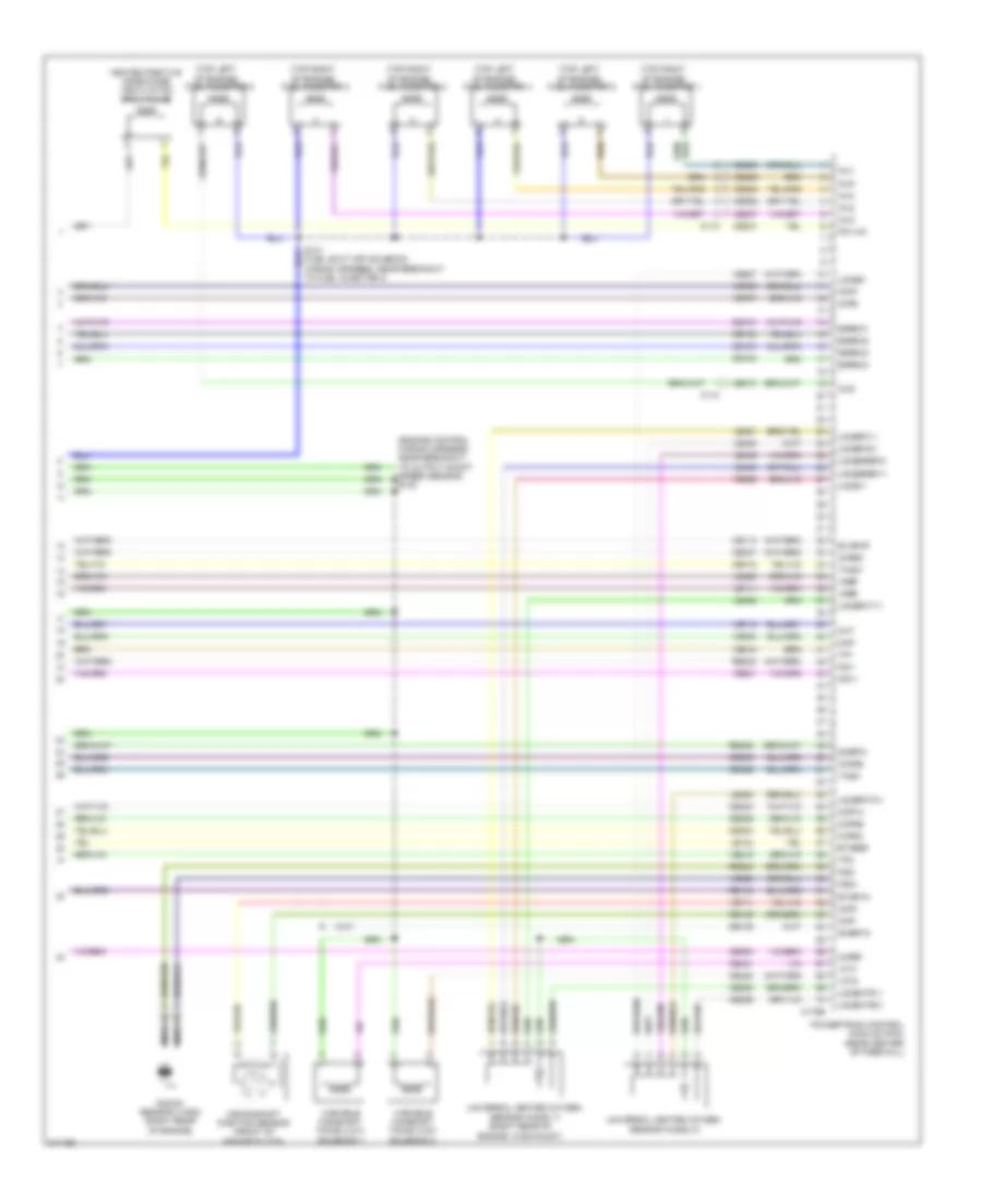
2.5L, Engine Performance Wiring Diagram (5 of 5) for Ford Escape 2011
List of elements for 2.5L, Engine Performance Wiring Diagram (5 of 5) for Ford Escape 2011:
- (a/t)
- (m/t)
- (m/t) (right front of engine, in exhaust)
- (rear of cylinder head) camshaft position sensor
- (top of engine) fuel injectors
- C133
- C175e
- Ce101
- Ce102
- Ce103
- Ce104
- Ce113
- Ce205
- Ce206
- Ce207
- Ce208
- Ce235
- Ce303
- Ce304
- Ce305
- Ce306
- Ce412
- Ce422
- Ce426
- Cht
- Cmp 1
- Cop1a
- Cop2d
- Cop3b
- Cop4c
- Cpk+
- Cpk-
- Crankshaft position sensor (lower right front of engine)
- De135
- Egrmc1
- Egrmc2
- Egrmc3
- Egrmc4
- Etcref
- Etcrtn
- Evapcp
- Heated oxygen sensor (ho2s) 11
- Ho2s-11
- Inj1
- Inj2
- Inj3
- Inj4
- Ks1+
- Ks1-
- Le111
- Le134
- Le423
- Le448
- Le451
- Le452
- Map
- Powertrain control module (pcm) (center rear of firewall)
- Re134
- Re135
- Re323
- Re405
- S136 (engine control & fuel charge wiring harness, before breakout to fuel injector 3)
- Shdrtn
- Sigrtne
- Tacm+
- Tacm-
- Tp2
- Tps1
- Universal heated oxygen sensor (ho2s) 11 (a/t)
- Uo2s11
- Uo2sgref 11
- Uo2shtr (or htr-11)
- Uo2spc 11
- Uo2spct 11
- Variable camshaft timing (vct) solenoid (top front of engine)
- Vct
- Ve706
- Ve711
- Ve712
- Ve735
- Ve801
- Ve803
- Ve818
- Ve819
- Ve826
- Vref
2.5L HYBRID
2.5L Hybrid, Engine Performance Wiring Diagram (1 of 6) for Ford Escape 2011
List of elements for 2.5L Hybrid, Engine Performance Wiring Diagram (1 of 6) for Ford Escape 2011:
- (dash panel to headlamp junction wiring harness, near breakout to battery junction box (bjb)) s111
- (under left rear of vehicle) evap canister vent control solenoid
- Acc
- Accelerator pedal position (app) sensor
- Aclpcs
- Acpt
- Air conditioning system
- App
- App2
- Appref
- Apprtn
- Apprtn2
- Appvref2
- Bpp
- Bps
- C175b
- C210
- C327
- Canv
- Cbb29
- Cbk01
- Ccb08
- Cdb08
- Cdc34
- Cdc35
- Ce114
- Ce132
- Ce226
- Ce302
- Cec01
- Cec02
- Cec11
- Ces09
- Cgnd
- Ch422
- Computer data lines system
- Cooling fans system
- Cruise control system
- Cto
- Cyd04
- Dcf
- Feps
- Fpc
- Fpm
- Ftp
- Ftpref
- Fuel tank pressure sensor
- Fuel vapor vent valve
- Fvvv
- G107 (left rear of engine compt)
- Gd122
- Gnd
- Hfc
- Hot at all times
- Hs can+
- Hs can-
- Iat
- Ignition switch
- Injpwrm
- Isp-r
- Isp-r/s
- Kapwr
- Le136
- Le137
- Le230
- Le424
- Lfc1
- Maf
- Mafrtn
- Mfc
- Off
- Pcmrc
- Powertrain control module (pcm) (rear center of firewall)
- Re136
- Re137
- Re320
- Re407
- Res08
- Run
- S107
- S129
- S132
- S228
- Sbb05
- Sccs
- Sccsrtn
- Sigrtn
- Start
- Tgac
- Tmac
- Vdb04
- Vdb05
- Ve518
- Ve701
- Ve702
- Ve740
- Ve807
- Ve922
- Ves10
- Vh433
- Vmc02
- Vmc05
- Vpwr
- Vref_c
- Vsout
- Vyt05
- Vyt06
2.5L Hybrid, Engine Performance Wiring Diagram (2 of 6) for Ford Escape 2011
List of elements for 2.5L Hybrid, Engine Performance Wiring Diagram (2 of 6) for Ford Escape 2011:
- 10a
- 15a
- 20a
- Battery junction box (bjb) (left rear of engine compt)
- Brake pedal position switch
- C133
- C210
- C215
- Ce226
- Ce515
- Ce911
- Computer data lines system
- Fpc
- Fpm
- Fppwr
- Fprtn
- Fuel pump driver module (under left center of vehicle)
- Fuel sender return
- Fuel sender signal
- Fuel tank unit (under left rear of vehicle, in fuel tank)
- Fuse
- G104 (near battery)
- G107 (left rear of engine compt)
- G400 (under left rear of vehicle)
- Gd159
- Gnd
- Hot at all times
- Ifs vpwr
- Inertia fuel shutoff (ifs) switch (right kick panel)
- Injector relay
- Instrument cluster (ic)
- Mass air flow/intake air temperature (maf/iat) sensor (left side of engine compt, in air intake duct)
- Ms can+
- Ms can-
- Nca
- Pcm power diode
- Pcm power relay
- Re515
- Reverse lamp relay
- Rmc32
- S113
- S116
- S122
- S129
- S144
- S145
- S147
- S340 (body wiring harness, near breakout to c340)
- S405
- Ve518
- Vmc11
2.5L Hybrid, Engine Performance Wiring Diagram (3 of 6) for Ford Escape 2011
List of elements for 2.5L Hybrid, Engine Performance Wiring Diagram (3 of 6) for Ford Escape 2011:
- (dash panel to headlamp junction harness, near breakout to battery junction box)
- (right rear corner of vehicle) high voltage cutoff switch
- 150a
- Air conditioning system
- C133
- C1458a
- C1458b
- C1458d
- C1458e
- C175t
- C210
- Cable pro/fuse link
- Cbb24
- Ce233
- Ce318
- Ch307
- Cls28
- Computer data lines system
- Cto
- Cyb01
- Cyb02
- Cyb03
- Cyb05
- Cyd01
- Cyd03
- Cydo2
- Cyt08
- Dc/dc +
- Dc/dc -
- Dc/dc interlock +
- Dc/dc interlock -
- Dce
- Exterior lights system
- G106 (left rear of engine compt)
- Gd121
- Gnd
- Gsdn
- Ho2s12
- Hot at all times
- Hpcr
- Hs can +
- Hs can -
- Htr12
- Hv +
- Hv -
- Hyt03
- Hyto4
- Isdn1
- Isdn2
- Let56
- Let57
- Mecp
- Mect
- Msdn
- Powertrain control module (pcm) (rear center of firewall)
- Re406
- Red
- Ret56
- Ret57
- Rlc
- S121
- S142
- S143
- Sbb05
- Sigrtn
- Tbcm interlock +
- Tbcm interlock -
- Tgac
- Tmac
- Tr-a1
- Tr-a2
- Tr-bvref1
- Tr-bvref2
- Tr-rtn1
- Tr-rtn2
- Transaxle control module (above transaxle)
- Transmission range (tr) sensor
- Vbatt
- Vdb04
- Vdb05
- Ve731
- Ve810
- Vet55
- Vet57
- Vmc02
- Vpwr
- Vyt05
- Vyt06
2.5L Hybrid, Engine Performance Wiring Diagram (4 of 6) for Ford Escape 2011
List of elements for 2.5L Hybrid, Engine Performance Wiring Diagram (4 of 6) for Ford Escape 2011:
- (body wiring harness, near breakout to traction battery control module)
- (right side of engine compt) dc/dc converter module
- (under driver's seat) g300
- 50a
- Air conditioning system
- Battery junction box (bjb) (left rear of engine compt)
- C1457a
- C1457b
- C1457c
- C1457d
- C210
- C4227a
- C4227b
- Cable-pro
- Cbb25
- Cbb26
- Computer data lines system
- Cyb01
- Cyb02
- Cyb03
- Cyb04
- Cyb15
- Cyd01
- Cyd02
- Cyd03
- Cyd04
- Dc enable
- Dc fault
- Dc int+
- Dc int-
- Fuse
- G108 (right front corner of engine compt)
- G402 (left "d" pillar)
- Gd124
- Gd149
- Gd182
- Gnd
- Heated oxygen sensor (ho2s) 12
- High voltage junction box
- Hot at all times
- Hot in start or run
- Hs can+
- Hs can-
- Hvdc+
- Hvdc-
- Hvipwr
- Hvtmu+
- Hvtmu-
- Hyt03
- Hyt04
- Inertia sw input
- Int+
- Int-
- Isdn1
- Isdn2
- Red
- Ryb07
- S303
- S406
- S409
- S410
- S414
- Sbb08
- Sbb15
- Sig gnd
- Traction battery control module
- Txv temp
- Txv temp rtn
- Vbatt
- Vdb04
- Vdb05
- Vpwr
- Vyb07
2.5L Hybrid, Engine Performance Wiring Diagram (5 of 6) for Ford Escape 2011
List of elements for 2.5L Hybrid, Engine Performance Wiring Diagram (5 of 6) for Ford Escape 2011:
- (power pack engine wiring harness, near breakout to powertrain control module)
- (power pack engine wiring harness, near breakout to powertrain control module) s104
- (rear of engine compt) evaporative emission (evap) canister purge valve
- (rear of engine) egr stepper motor
- (right front of engine) heated oxygen sensor (ho2s) 11
- (top of engine) cylinder head temperature sensor
- Auxiliary evaporator discharge air thermistor
- Coil
- Crankshaft position sensor (lower right front of engine)
- Knock sensor (left front of engine)
- Motor electronics coolant temperature (mect) sensor (left front of engine compt)
- S100 (power pack engine wiring harness, in breakout to fuel injector 1)
- S150
2.5L Hybrid, Engine Performance Wiring Diagram (6 of 6) for Ford Escape 2011
List of elements for 2.5L Hybrid, Engine Performance Wiring Diagram (6 of 6) for Ford Escape 2011:
- (near breakout to ignition transformer capacitor 1) s102
- (rear of cylinder head) camshaft position sensor
- (top of engine)
- (top of engine) fuel injectors
- C133
- C175e
- Ce101
- Ce102
- Ce103
- Ce104
- Ce113
- Ce205
- Ce206
- Ce207
- Ce208
- Ce235
- Ce303
- Ce304
- Ce305
- Ce306
- Ce412
- Ce422
- Ce426
- Cht
- Ckp+
- Ckp-
- Cmp
- Coil on plug (cop) 1
- Coil on plug (cop) 2
- Coil on plug (cop) 3
- Coil on plug (cop) 4
- Cop1a
- Cop2d
- Cop3b
- Cop4c
- De135
- Ectrtn
- Egrmc1
- Egrmc2
- Egrmc3
- Egrmc4
- Electronic throttle control (etc) motor (left rear of engine)
- Etcref
- Evapcp
- Ignition transformer capacitor 1 (top center of engine)
- Inj1
- Inj2
- Inj3
- Inj4
- Ks1+
- Ks1-
- Le111
- Le134
- Le423
- Le448
- Le451
- Le452
- Manifold absolute pressure (map) sensor (left rear of engine, near intake manifold)
- Map
- Powertrain control module (pcm) (rear center of firewall)
- Re134
- Re135
- Re323
- Re405
- S106 (in breakout to fuel injector 1)
- Shortn
- Sigrtne
- Tacm+
- Tacm-
- Tps1
- Tps2
- Uo2s
- Uo2sgref
- Uo2shtr
- Uo2spc
- Uo2spct
- Variable camshaft timing (vct) solenoid (top front of engine)
- Vbpwr
- Vct
- Ve706
- Ve711
- Ve712
- Ve801
- Ve803
- Ve818
- Ve819
- Ve826
- Vref
3.0L
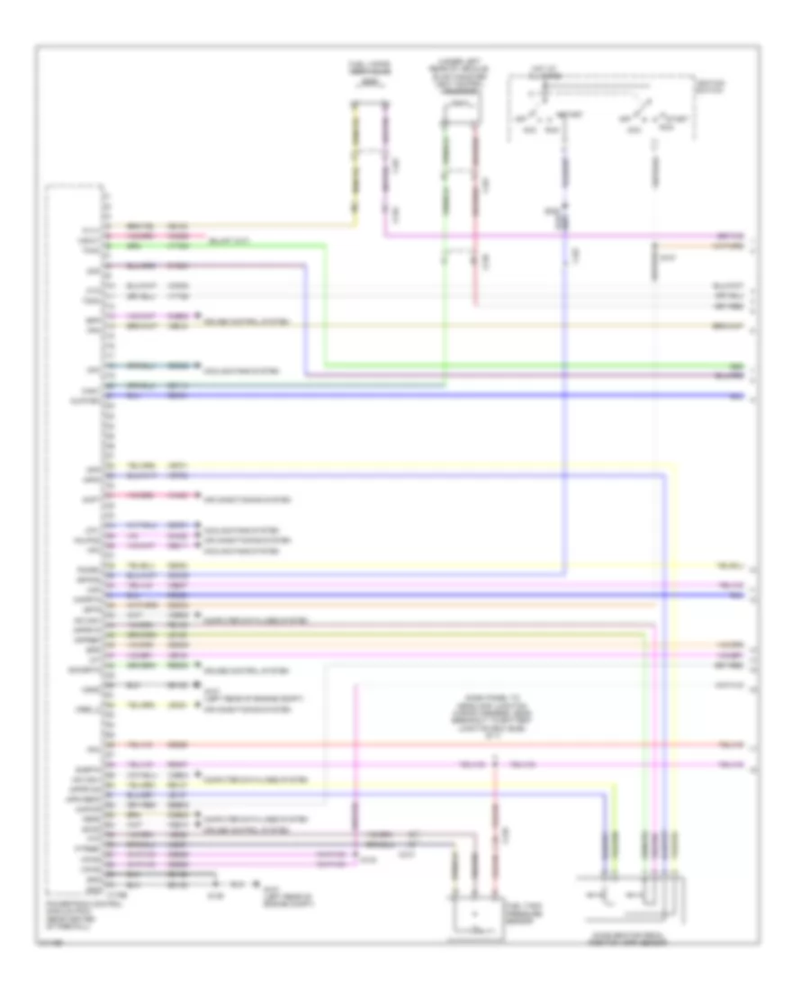
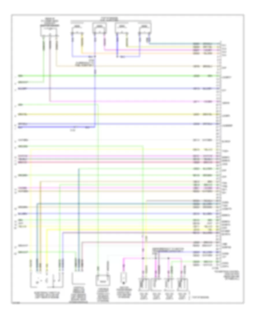
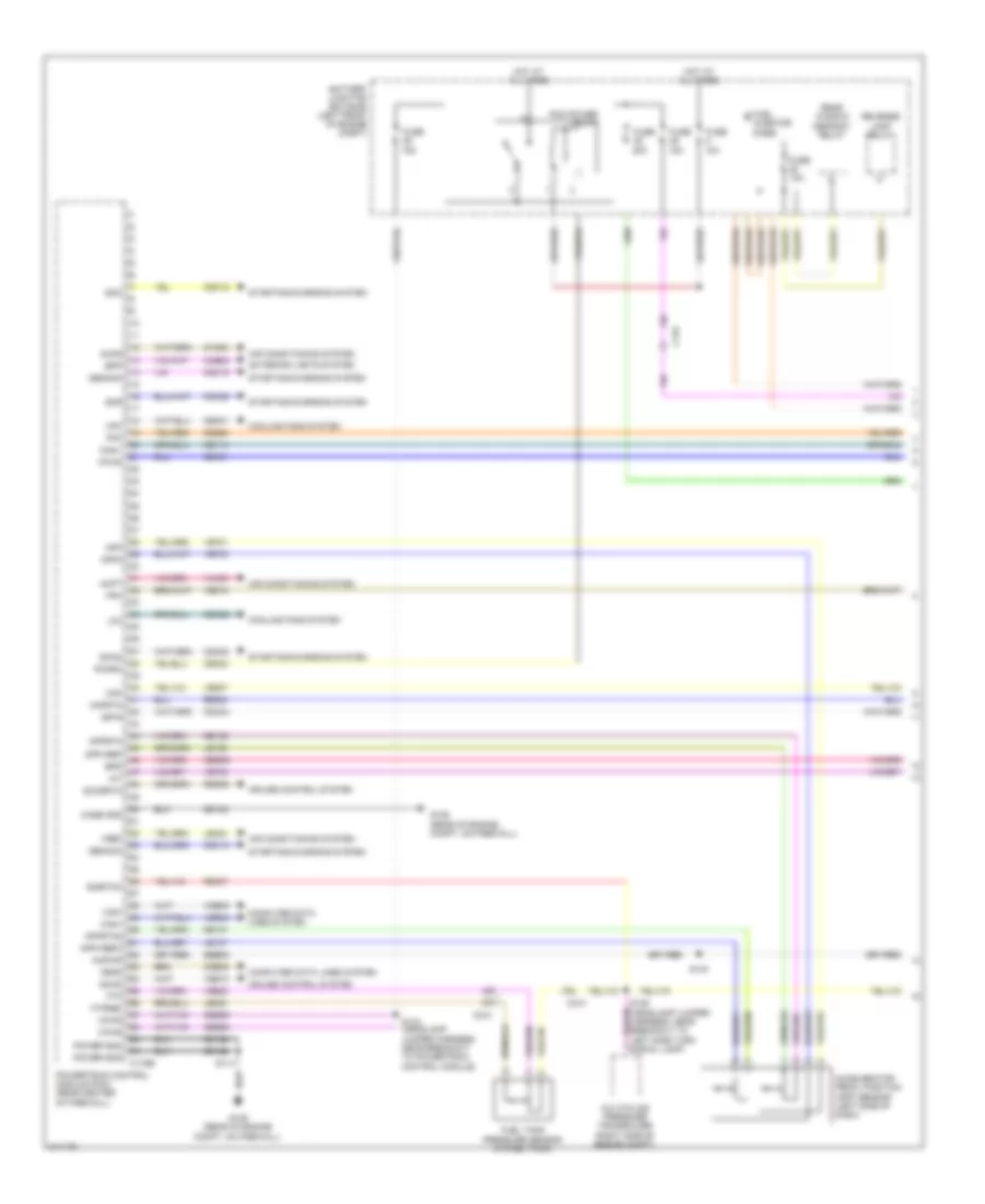
3.0L, Engine Performance Wiring Diagram (1 of 5) for Ford Escape 2011
List of elements for 3.0L, Engine Performance Wiring Diagram (1 of 5) for Ford Escape 2011:
- 10a
- 15a
- 20a
- A/c cycling pressure transducer (right side of engine compt)
- Accelerator pedal position (app) sensor (left side of dash)
- Accr
- Acpt
- Air conditioning system
- App
- App2
- Apprtn
- Apprtn2
- Appvref
- Appvref2
- Battery junction box (bjb) (left front of engine compt)
- Bpp
- Bps
- C133
- C175b
- C210
- Can+
- Can-
- Canv
- Case gnd
- Cbb29
- Cbk01
- Ccb08
- Cdb08
- Cdc10
- Cdc12
- Cdc15
- Cdc34
- Cdc35
- Cdc54
- Ce114
- Ce226
- Ce302
- Cec01
- Cec02
- Ces09
- Ch302
- Computer data lines system
- Cooling fans system
- Cruise control system
- Exterior lights system
- Feps
- Fpc
- Fpm
- Ftp
- Ftpref
- Fuel injector diode
- Fuel tank pressure sensor (in fuel tank)
- Fuse
- Fuse 10a
- G109 (rear of engine compt, on firewall)
- Gd122
- Gencom
- Genmon
- Hfc
- Hot at all times
- Iat
- Isp-r
- Kapwr
- Le136
- Le137
- Le230
- Le424
- Lfc
- Maf
- Mafrtn
- Pcm power relay
- Pcmrc
- Power gnd
- Powertrain control module (pcm) (rear center of firewall)
- Re136
- Re137
- Re320
- Re407
- Rear window defrost relay
- Res08
- Reverse lamp relay
- S114
- S140
- S144 (headlamp jumper harness, near breakout to powertrain control module)
- Sbb05
- Sccs
- Sccsrtn
- Signal lamp)
- Sigrtnc
- Smc
- Smcs
- Smr
- Starting/charging system
- Vdb04
- Vdb05
- Ve518
- Ve701
- Ve702
- Ve740
- Ve807
- Ve922
- Ves10
- Vh433
- Vpwr
- Vref
3.0L, Engine Performance Wiring Diagram (2 of 5) for Ford Escape 2011
List of elements for 3.0L, Engine Performance Wiring Diagram (2 of 5) for Ford Escape 2011:
- (fuel tank) fuel pump control module
- (in fuel tank) fuel tank unit
- (right kick panel) inertia fuel shutoff (ifs) switch
- (under left side of vehicle) evap canister vent control solenoid
- 15a
- 20a
- Battery junction box (bjb) (left front of engine compt)
- Brake pedal position switch (left side of dash)
- C110
- C133
- C168a
- C168b
- C210
- C327
- Cblr/c456 vfs
- Ce226
- Ce515
- Ce911
- Cet05
- Cet06
- Cet07
- Cet08
- Cet09
- Cet10
- Cet18
- Cet25
- Fpc
- Fpm
- Fppwr
- Fprtn
- Fuel injector relay
- Fuse
- G104 (left front of engine compt)
- G109 (rear of engine compt,
- G400 (near fuel
- Gd159
- Gnd
- Hot at all times
- Le111
- Lpc vfs
- Mass air flow/intake air temperature (maf/iat) sensor (rear of engine)
- On firewall)
- Oss
- Re406
- Re515
- Ret24
- Rmc32
- S109
- S114
- S142
- S143 (headlamp jumper harness, near breakout to power control module)
- S146
- S147 (engine control wiring harness, near breakout to output shaft speed sensor)
- Sol pwr
- Ssa cb1234 vfs
- Ssb c35r vfs
- Ssc cb26 vfs
- Sse on/off sol
- Tank)
- Tcc vfs
- Tft
- Tft sig rtn
- Transmission
- Trs
- Trs/oss gnd
- Trs/oss pwr
- Tss
- Tss gnd
- Tss pwr
- Ve518
- Vet26
- Vet27
- Vet32
- Vet33
- Vmc11
- Vpwr fuel
3.0L, Engine Performance Wiring Diagram (3 of 5) for Ford Escape 2011
List of elements for 3.0L, Engine Performance Wiring Diagram (3 of 5) for Ford Escape 2011:
- (center rear of engine compt) evaporative emission (evap) canister purge valve
- (headlamp jumper harness, near breakout to powertrain
- (left rear of engine) knock sensor 1 (ks1)
- (left rear of engine) manifold absolute pressure (map) sensor
- (m/t)
- Acc
- C133
- C175t
- C215
- Ce233
- Ce234
- Ce903
- Cet05
- Cet06
- Cet07
- Cet08
- Cet09
- Cet10
- Cet18
- Cet21
- Cet25
- Cet34
- Cls28
- Column)
- Computer data lines system
- Control module)
- Cpp-bt
- Cpp-tt
- Cruise control system
- Cylinder head temperature sensor
- Exterior lights system
- Fuel sender return
- Fuel sender signal
- Heated oxygen sensor (ho2s) 12 (w/ low emission vehicles)
- Ho2s-12
- Ho2s-22
- Hot at all times
- Htr-12
- Htr-22
- Ignition switch (on steering
- Instrument cluster (ic)
- Le111
- Lpc vfs
- Ms can+
- Ms can-
- Off
- Oss
- Powertrain control module (pcm) (rear center of firewall)
- Re406
- Ret24
- Rlc
- Run
- S113
- S121
- Shift interlock system
- Sigrtnt
- Sol pwr
- Ssa cb1234 vfs
- Ssb c35r vfs
- Ssc cb26 vfs
- Ssd cblr/cb456
- Sse on/off sol
- Start
- Tcc vfs
- Tcs
- Tft
- Trs
- Trs/oss vpwr
- Tss
- Tss/oss/tr gnd
- Ve731
- Ve733
- Vet26
- Vet27
- Vet32
- Vet33
3.0L, Engine Performance Wiring Diagram (4 of 5) for Ford Escape 2011
List of elements for 3.0L, Engine Performance Wiring Diagram (4 of 5) for Ford Escape 2011:
- (engine control
- (front of left cylinder head) camshaft position sensor 2
- (front of right cylinder head) camshaft position sensor 1
- (fuel shut off solenoid feed wiring harness,
- (rear of engine) egr stepper motor
- (right front of engine compt)
- (top left of engine)
- (top right of engine)
- 10a
- Battery junction box (bjb) (left front of engine compt)
- C133
- Coil
- Coil on plug (cop) 1
- Coil on plug (cop) 2
- Coil on plug (cop) 3
- Coil on plug (cop) 4
- Coil on plug (cop) 5
- Coil on plug (cop) 6
- Electronic throttle control (etc) motor (on throttle body)
- Fuse
- Harness,
- Harness, near breakout to fuel injector 1)
- Heated oxygen sensor (ho2s) 22
- Hot in start and run
- Ignition transformer capacitor 1 (right front of engine)
- Near breakout to fuel injector 1) s152
- Near breakout to fuel rail pressure/ temperature sensor)
- Reverse lamp relay
- S118 (engine control sensor & fuel charge wiring harness, before breakout to fuel injector 3)
- S132
- S151 (engine control
3.0L, Engine Performance Wiring Diagram (5 of 5) for Ford Escape 2011
List of elements for 3.0L, Engine Performance Wiring Diagram (5 of 5) for Ford Escape 2011:
- (engine control wiring harness, near breakout to output shaft speed sensor) s120
- (right rear of engine, in exhaust)
- (top left of engine) fuel injector 4
- (top left of engine) fuel injector 5
- (top left of engine) fuel injector 6
- (top right of engine) fuel injector 1
- (top right of engine) fuel injector 2
- (top right of engine) fuel injector 3
- C110
- C175e
- Ce101
- Ce102
- Ce103
- Ce104
- Ce113
- Ce205
- Ce206
- Ce207
- Ce208
- Ce209
- Ce210
- Ce235
- Ce236
- Ce303
- Ce304
- Ce305
- Ce306
- Ce307
- Ce308
- Ce321
- Ce412
- Ce421
- Ce422
- Ce426
- Cht
- Ckp+
- Ckp-
- Cmp1
- Cmp2
- Cop1a
- Cop2c
- Cop3e
- Cop4b
- Cop5d
- Cop6f
- Crankshaft position sensor (front of engine block)
- De135
- Egrmc1
- Egrmc2
- Egrmc3
- Egrmc4
- Etcref
- Etcrtn
- Evapcp
- Heated positive crankcase ventilation (pcv) valve
- Inj1
- Inj2
- Inj3
- Inj4
- Inj5
- Inj6
- Knock sensor 2 (ks2) (right rear of engine)
- Ks1+
- Ks1-
- Ks2+
- Ks2-
- Le111
- Le134
- Le423
- Le448
- Le449
- Le450
- Le451
- Le452
- Le453
- Map
- Nca
- Pcv hc
- Powertrain control module (pcm) (rear center of firewall)
- Re134
- Re135
- Re323
- Re324
- Re405
- S131 (fuel shut off solenoid wiring harness, near breakout to fuel injector 4)
- Shdrtn
- Sigrtn
- Tacm+
- Tacm-
- Tp1
- Tp2
- Universal heated oxygen sensor (ho2s) 11
- Universal heated oxygen sensor (ho2s) 21
- Uo2s11
- Uo2s21
- Uo2sgref11
- Uo2sgref21
- Uo2shtr11
- Uo2shtr21
- Uo2spc11
- Uo2spc21
- Uo2spct11
- Uo2spct21
- Variable camshaft timing (vct) solenoid 1
- Variable camshaft timing (vct) solenoid 2
- Vct1
- Vct2
- Ve706
- Ve707
- Ve711
- Ve712
- Ve801
- Ve802
- Ve803
- Ve818
- Ve819
- Ve826
- Ve827
- Vref
EXTERIOR LIGHTS
Backup Lamps Wiring Diagram, A/T Except Hybrid for Ford Escape 2011
List of elements for Backup Lamps Wiring Diagram, A/T Except Hybrid for Ford Escape 2011:
- (body wiring harness, near c500) s307
- (w/ microphone)
- Auto-dimming interior mirror
- Auto-dimming interior mirror (w/ rear view camera)
- Battery junction box (bjb) (left front of engine compt)
- C168a
- C175t
- C210
- C214
- Cls28
- Fuse 10a
- G301 (under driver's seat)
- Hot in start and run
- Left reversing lamp
- Power distribution system
- Powertrain control module (pcm) (center rear of firewall)
- Reverse in
- Reverse lamps relay
- Right reversing lamp
- Rlc
- S311
- S325
- Transmission
- Trs
- Vet32
Backup Lamps Wiring Diagram, A/T Hybrid for Ford Escape 2011
List of elements for Backup Lamps Wiring Diagram, A/T Hybrid for Ford Escape 2011:
- (body wiring harness, near breakout to c314) s306
- (under driver's seat) g301
- Auto-dimming interior mirror
- Battery junction box (bjb) (left rear of engine compt)
- C175t
- C210
- C214
- Cls28
- Fuse 10a
- Fuse 15a
- Hot in start and run
- Left reversing lamp
- Let56
- Let57
- Power distribution system
- Powertrain control module (pcm) (rear center of firewall)
- Rear defrost relay
- Ret56
- Ret57
- Reverse in
- Reverse lamp relay
- Right reversing lamp
- Rlc
- S145
- S310
- S338
- Tr a1
- Tr a2
- Tr bvref1
- Tr bvref2
- Tr rtn1
- Tr rtn2
- Transmission range (tr) sensor
- Vet55
- Vet57
Backup Lamps Wiring Diagram, M/T for Ford Escape 2011
List of elements for Backup Lamps Wiring Diagram, M/T for Ford Escape 2011:
- (body wiring harness, near c500) s307
- (headlamp jumper harness, near breakout to left side turn signal lamp)
- (w/ microphone)
- Auto-dimming interior mirror
- Battery junction box (bjb) (left front of engine compt)
- C210
- C212
- C214
- Cbb07
- Fuse 10a
- G104 (left front of engine compt)
- G301 (under driver's seat)
- Global positioning system module (gpsm) (center of dash)
- Hot at all times
- Hot in start and run
- Left reversing lamp
- Off
- Power distribution system
- Reverse
- Reverse in
- Reverse lamps relay
- Reversing lamps switch (top of transmission)
- Right reversing lamp
- S110
- S157
- S311
- S325
Exterior Lamps Wiring Diagram, Except Hybrid (1 of 2) for Ford Escape 2011
List of elements for Exterior Lamps Wiring Diagram, Except Hybrid (1 of 2) for Ford Escape 2011:
- (headlamp jumper wiring harness, near breakout to left headlamp) s103
- (headlamp jumper wiring harness, near breakout to right headlamp)
- Auto 1
- Brake pedal sw
- C215
- C2280b
- C2280d
- C2280e
- C2280f
- Computer data lines system
- Fog (pull)
- Ftp
- Fuse 15a
- Fuse 20a
- G104 (left front of engine compt)
- G203 (left side of dash)
- Hazard
- High beam
- Hot at all times
- Left front park/ turn lamp
- Left front side lamp (escape)
- Lf turn
- Lf turn lamp (fet)
- Lh turn
- Lo beam
- Logic
- Lr stop/ turn lamp
- Lr stop/ turn lamp (fet)
- Main light switch
- Ms can +
- Ms can -
- Off
- Park
- Park lamp on
- Park lamp relay
- Rf turn
- Rf turn lamp (fet)
- Rh turn
- Right front park/ turn lamp
- Right front side lamp (escape)
- Rr stop/ turn lamp
- Rr stop/ turn lamp (fet)
- S100
- S110
- Smart junction box (sjb) (center of dash)
- Turn
Exterior Lamps Wiring Diagram, Except Hybrid (2 of 2) for Ford Escape 2011
List of elements for Exterior Lamps Wiring Diagram, Except Hybrid (2 of 2) for Ford Escape 2011:
- Anti-theft system
- Battery junction box (bjb) (left front of engine compt)
- Bpp
- Brake pedal position (bpp) switch (left side of dash) 1) brakel depressed 2) normal position
- C175b
- C210
- C2280d
- C408
- C410
- C922
- Ccb08
- Ftp
- Ftp switch
- Fuse 15a
- G202 (left side of dash)
- G300 (under driver's seat)
- G401 (left side of liftgate)
- Hazard switch
- High
- High mounted stop lamp
- Hot at all times
- Left license plate lamp
- Left rear park/stop/ turn lamp
- Low
- Multi- function switch (steering column) 1) full left 2) lane change 3) neutral 4) lane change 5) full right
- On/off
- Park
- Powertrain control module (pcm) (center rear of firewall)
- Red
- Rest
- Right license plate lamp
- Right rear park/stop/ turn lamp
- S111 (headlamp jumper wiring harness, near breakout to left front side lamp)
- S214
- S303
- S308 (body wiring harness, near key pad switch)
- S309 (w/ trailer tow) (body wiring harness, near key pad switch)
- S319 (body wiring harness, in breakout to c339)
- S407
- S410
- S904
- Smart junction box (sjb) (center of dash)
- Stop/ turn
- Trailer tow left turn relay
- Trailer tow park lamp relay
- Trailer tow right turn relay
- Turn signal switch
- W/ trailer tow
Exterior Lamps Wiring Diagram, Hybrid (1 of 2) for Ford Escape 2011
List of elements for Exterior Lamps Wiring Diagram, Hybrid (1 of 2) for Ford Escape 2011:
- (dash panel to headlamp junction wiring harness, near breakout to right front park/turn light) s133
- Auto 1
- Brake pedal sw
- C2280b
- C2280d
- C2280e
- C2280f
- Computer data lines system
- Fog (pull)
- Ftp
- Fuse 15a
- Fuse 20a
- G104 (near battery)
- G203 (behind left end of dash)
- Hazard
- High beam
- Hot at all times
- Left front park/ turn lamp
- Left front side lamp (escape)
- Lf turn
- Lf turn lamp (fet)
- Lh turn
- Lo beam
- Logic
- Lr stop/ turn lamp
- Lr stop/ turn lamp (fet)
- Main light switch
- Ms can +
- Ms can -
- Off
- Park
- Park lamp on
- Park lamp relay
- Rf turn
- Rf turn lamp (fet)
- Rh turn
- Right front park/ turn lamp
- Right front side lamp (escape)
- Rr stop/ turn lamp
- Rr stop/ turn lamp (fet)
- S114
- S135
- Smart junction box (sjb) (below center of dash)
- Turn
Exterior Lamps Wiring Diagram, Hybrid (2 of 2) for Ford Escape 2011
List of elements for Exterior Lamps Wiring Diagram, Hybrid (2 of 2) for Ford Escape 2011:
- Anti-theft system
- Bpp
- Brake pedal position (bpp) switch 1) brakel depressed 2) normal position
- C175b
- C210
- C215
- C2280d
- C408
- C410
- C922
- Ccb08
- Ftp
- Ftp switch
- Fuse 15a
- G202 (behind left end of dash)
- G300 (under driver's seat)
- G401 (left "d" pillar)
- Hazard switch
- High
- High mounted stop lamp
- Hot at all times
- Left license plate lamp
- Left rear park/stop/ turn lamp
- Low
- Multi- function switch 1) full left 2) lane change 3) neutral 4) lane change 5) full right
- On/off
- Park
- Powertrain control module (pcm) (rear center of firewall)
- Red
- Rest
- Right license plate lamp
- Right rear park/stop/ turn lamp
- S141 (dash panel to headlamp junction harness, near breakout to left front turn signal lamp)
- S214
- S307
- S308 (body wiring harness, near breakout to c314)
- S407
- S410
- S904
- Smart junction box (sjb) (below center of dash)
- Stop/ turn
- Turn signal switch
Trailer/Camper Adapter Wiring Diagram for Ford Escape 2011
List of elements for Trailer/Camper Adapter Wiring Diagram for Ford Escape 2011:
- (left front of engine compt) battery junction box (bjb)
- C210
- C421
- C422
- Cat06
- Cat09
- Cat11
- Connector
- Exterior lamps circuit
- Fuse 15a
- Fuse 20a
- G104 (left front of engine compt)
- G401 (left side of liftgate)
- Hot at all times
- Rat08
- S109
- S407
- Trailer tow
- Trailer tow left turn relay
- Trailer tow parking lamp relay
- Trailer tow right turn relay
- W/ parking aid
- W/o parking aid
GROUND DISTRIBUTION
Ground Distribution Wiring Diagram, Except Hybrid (1 of 3) for Ford Escape 2011
List of elements for Ground Distribution Wiring Diagram, Except Hybrid (1 of 3) for Ford Escape 2011:
- (auto a/c) blower motor speed control
- (escape) left front side lamp
- (escape) right front side lamp
- (if equipped) accessory protocol interface module (apim)
- (if equipped) front controls interface module (fcim)
- (left front of engine compt) battery junction box (bjb)
- (manual a/c)
- (mariner)
- A (escape)
- A/c compressor clutch field coil
- Abs test connector
- Anti-lock brake system (abs) module
- Audio amplifier
- Audio control module (acm)
- Battery
- Blower motor resistor
- Brake fluid level switch
- Breakout to c316)
- C175b
- C2231b
- C2357b
- C237
- C238
- C240a
- C264
- C3154b
- Clock- spring
- Clutch cutoff switch
- Clutch switch
- Cooling fan high speed relay
- Data link connector
- Emtc hvac module
- Engine cooling fan motor 1
- Floor shifter
- Fuel injector relay
- G100 (left front of engine compt)
- G101 (2.5l: rear of engine) (3.0l: near battery)
- G102 (right front of engine compt)
- G103 (right front of engine compt)
- G104 (left front of engine compt)
- G105 (left front of engine compt)
- G107 (right front of engine compt)
- G108 (front of engine)
- G109 (rear of engine compt, on firewall)
- G110 (2.5l: left rear of engine compt) (3.0l: left front of engine compt)
- G200 (right side of dash)
- G201 (right side of dash)
- G203 (left side of dash)
- G205 (center of dash)
- G206 (top left side of dash)
- Horn switch
- Instrument cluster (ic)
- Left front fog lamp
- Left front park/ turn lamp
- Left headlamp
- Left horn
- Liftgate lock relay
- Main light switch
- Mass air flow/intake air temperature (maf/iat) sensor
- Message center switch
- Nca
- Passive anti-theft system transceiver (pats)
- Power point
- Power steering control module (pscm)
- Powertrain control module (pcm)
- Reversing lamps switch
- Right front fog lamp
- Right front park/ turn lamp
- Right headlamp
- S100 (headlamp jumper wiring harness, near breakout to right headlamp)
- S102 (headlamp jumper wiring harness, near breakout to a/c clutch solenoid)
- S109 (headlamp jumper harness, near breakout to c139)
- S110 (headlamp jumper wiring harness, near breakout to left headlamp)
- S114 (engine control sensor & fuel charge wiring harness, before breakout to g109)
- S300
- Steering wheel/ audio control switch
- Steering wheel/ speed control switch
- Trailer tow left turn relay
- Trailer tow park lamp relay
- Trailer tow right turn relay
- W/ sync
- W/o sync
- Windshield wiper motor
Ground Distribution Wiring Diagram, Except Hybrid (2 of 3) for Ford Escape 2011
List of elements for Ground Distribution Wiring Diagram, Except Hybrid (2 of 3) for Ford Escape 2011:
- (base production) front interior lamp
- (center of dash) smart junction box (sjb)
- (main wiring harness, near breakout to audio unit)
- (manual
- 4x4 control module
- A/c)
- Active park assist switch
- Auto- dimming interior mirror
- Autolamp sensor
- Autolamp/ sunload sensor
- C214
- C2280d
- C2356a
- C2357a
- C311
- C312
- C313
- C340
- Datc hvac module
- Driver side front backrest & cushion heater mats
- Emtc hvac module
- Front display interface module (fdim)
- Front interior lamp
- Front interior/ map lamps assembly
- Fuel pump control module
- G202 (left side of dash)
- G300 (under driver's seat)
- G301 (under driver's seat)
- G400 (near fuel tank)
- G403 (right rear of vehicle)
- Global positioning system module (gpsm)
- Left rear door lock actuator
- Left rear park/stop turn lamp
- Left reversing lamp
- Left seat control switch
- Left vanity mirror lamp
- Multifunction switch
- Nca
- Park brake switch
- Parking aid module (pam)
- Passenger side door lock switch
- Passenger side exterior rear view mirror
- Passenger side front backrest & cushion heater mats
- Passenger side front door lock unit
- Right rear door lock actuator
- Right reversing lamp
- Right vanity mirror lamp
- Roof opening panel module
- S202
- S214 (main wiring harness, in breakout to ignition switch)
- S303 (body wiring harness, near c313)
- S311 (body wiring harness, near g300)
- S325 (body wiring harness, near breakout to c340)
- S331 (seat control feed wiring harness, near breakout to c3283)
- S600 (center of instrument panel, near breakout to audio unit)
- S900 (interior lamp feed wiring harness, near breakout to c919)
- Shield
- Subwoofer amplifier
- Traction control switch
- W/ microphone
Ground Distribution Wiring Diagram, Except Hybrid (3 of 3) for Ford Escape 2011
List of elements for Ground Distribution Wiring Diagram, Except Hybrid (3 of 3) for Ford Escape 2011:
- (body wiring harness, near breakout to right safety canopy)
- (in liftgate wiring harness, near c408)
- (in rear lamp jumper harness, in breakout to c922)
- Aid
- Ambient lighting module
- Ambient lighting switch
- C3007
- C339
- C340
- C405
- C408
- C410
- C421
- C422
- C495
- C504b
- C913
- C914
- C922
- C926a
- Cargo lamp
- Console power unit
- Driver safety belt buckle switch
- Driver seat position sensor
- Driver side door lock switch
- Driver side exterior rear view mirror
- Driver side front door lock unit
- Exterior rear view mirror switch
- G302 (right "a" pillar)
- G303 (right "a" pillar)
- G401 (left side of liftgate)
- G402 (left rear of vehicle)
- High mounted stoplamp
- Keypad switch assembly
- Left license plate lamp
- Liftgate glass ajar switch
- Liftgate glass release switch
- Liftgate lock actuator
- Liftgate release switch
- Master window control switch
- Nca
- Occupant classification system module (ocsm)
- Parking
- Passenger safety belt buckle switch
- Passenger seat belt tension sensor
- Rear view camera
- Rear window defrost grid
- Rear wiper motor assembly
- Right license plate lamp
- Right rear park/ stop/ turn lamp
- S326 (body wiring harness, near breakout to c340)
- S330 (seat control feed wiring harness, near c339)
- S332 (seat control feed jumper wiring harness, near breakout to passenger's safety belt buckle pretensioner)
- S339 (console panel wiring harness, near breakout to c3007)
- S344 (console feed wiring harness, near breakout to ambient lighting)
- S407
- S410
- S502 (left front door window regulator wiring harness, near breakout to exterior rear view mirror switch)
- S904
- Trailer tow connector
- W/ ambient lighting
- W/o
Ground Distribution Wiring Diagram, Hybrid (1 of 3) for Ford Escape 2011
List of elements for Ground Distribution Wiring Diagram, Hybrid (1 of 3) for Ford Escape 2011:
- (escape) right front side lamp
- (if equipped) accessory protocol interface module (apim)
- (left rear of engine compt)
- Abs test connector
- Air conditioning control module
- Ambient lighting module
- Ambient lighting switch
- Audio amplifier
- Audio control module (acm)
- Battery
- Battery junction box (bjb)
- Brake fluid level switch
- C126
- C133
- C175b
- C240a
- C264
- C3007
- C313
- C3134
- C3154b
- C4227a
- Console power point
- Escape
- Front control interface module (fcim)
- G100 (left side of engine compt)
- G101 (near battery)
- G103 (right front corner of engine compt)
- G104 (near battery)
- G105 (near battery)
- G107 (left rear of engine compt)
- G204 (behind right center of dash)
- G205 (behind right center of dash)
- G300 (under driver's seat)
- G302 (right "a" pillar)
- Heater pump motor
- Injector relay
- Left front fog lamp
- Left front park/turn lamp
- Left front side lamp
- Left head- lamp
- Left horn
- Left rear door lock actuator
- Left rear park/stop/ turn lamp
- M/e coolant pump motor
- Mariner
- Mass air flow/ intake air temperature (maf/iat) sensor
- Near breakout to c3007)
- Park brake switch
- Powertrain control module (pcm)
- Right front fog lamp
- Right front park/turn lamp
- Right head- lamp
- S113 (dash panel to headlamp junction wiring harness, near breakout to battery junction box (bjb))
- S114 (dash panel to headlamp junction wiring harness, near breakout to battery junction box (bjb))
- S124 (dash panel to headlamp junction wiring harness, near breakout to battery junction box (bjb))
- S129 (dash panel to headlamp junction wiring harness, near breakout to g107)
- S135 (dash panel to headlamp junction wiring harness, near breakout to g102)
- S300 (audio module wiring harness, near breakout to c3290)
- S347 (top finish panel ambient light wiring harness, near breakout to c3134)
- S348 (w/ ambient lighting) (main console ambient light wiring harness,
- Traction battery control module
- W/ ambient lighting
- Windshield wiper motor
Ground Distribution Wiring Diagram, Hybrid (2 of 3) for Ford Escape 2011
List of elements for Ground Distribution Wiring Diagram, Hybrid (2 of 3) for Ford Escape 2011:
- (below center of dash) smart junction box (sjb)
- (right front of engine compt)
- 4x4 control module
- Anti-lock brake system (abs) module
- Auto- dimming interior mirror
- Blower motor speed control
- C1457b
- C1458a
- C214
- C2231b
- C2280d
- C2293a
- C2356a
- C237
- C311
- C312
- C340
- Clock- spring (top of steering column)
- Data link connector
- Dc/ac inverter module
- Dc/dc converter module
- Driver side front backrest & cushion heater mats
- Engine cooling fan motor 1
- Engine cooling fan motor 2
- Floor shifter
- Front interior lamp
- Front interior/ map lamps assembly
- Fuel pump control module
- G102 (right front corner of engine compt)
- G106 (left rear of engine compt)
- G108 (right front corner of engine compt)
- G110 (right side of engine compt)
- G112
- G113 (left rear of engine compt)
- G200 (behind right end of dash)
- G201 (behind right end of dash)
- G206 (left kick panel)
- G301 (under driver's seat)
- G400 (under left rear of vehicle)
- G403 (right "c" pillar)
- Harness, near breakout to right front park/turn light)
- Horn switch
- Instrument cluster (ic)
- Left reversing lamp
- Left seat control switch
- Left vanity mirror lamp
- Main light switch
- Message center switch
- Nca
- Nca nca
- Parking aid module (pam)
- Passenger side door lock switch
- Passenger side exterior rear view mirror
- Passenger side front door lock unit
- Passive anti-theft system (pats) transceiver
- Power point
- Power steering control module (pscm)
- Right rear door lock actuator
- Right reversing lamp
- Right vanity mirror lamp
- Roof opening panel module
- S121 (dash panel to headlamp junction wiring harness, near breakout to battery junction box (bjb))
- S310 (body wiring harness, near breakout to g300)
- S331 (seat control feed jumper wiring harness, in breakout to driver backrest and cushion)
- S338 (body wiring harness, near breakout to c340)
- S600 (right front door window regulator wiring harness, near breakout to passenger side front door lock unit)
- S900 (interior lamp feed wiring harness, near breakout to c919)
- Shield
- Side front backrest & cushion heater mats
- Steering wheel/ audio control switch
- Steering wheel/ speed control switch
- Subwoofer amplifier
- Transaxle control module
- Vacuum pump motor
- W/ microphone
- Windshield wiper motor
Ground Distribution Wiring Diagram, Hybrid (3 of 3) for Ford Escape 2011
List of elements for Ground Distribution Wiring Diagram, Hybrid (3 of 3) for Ford Escape 2011:
- (body wiring harness, near
- (body wiring harness, near breakout to traction battery control module) s410
- (rear light jumper wiring harness, near breakout to c922)
- Active park assist switch
- Autolamp/ sunload sensor
- Breakout to driver side impact sensor 2)
- C2356a
- C314
- C339
- C340
- C405
- C408
- C410
- C4227a
- C495
- C504b
- C913
- C914
- C922
- C926a
- Cargo lamp
- Data link connector
- Datc hvac module
- Driver safety belt buckle switch
- Driver seat position sensor
- Driver side door lock switch
- Driver side exterior rear view mirror
- Driver side front door lock unit
- Exterior rear view mirror switch
- Front display interface module (fdim)
- G202 (behind left end of dash)
- G203 (behind left end of dash)
- G303 (right "a" pillar)
- G401 (left "d" pillar)
- G402 (left "d" pillar)
- Global positioning system module (gpsm)
- High mounted stop lamp
- Keypad switch assembly
- Left license plate lamp
- Liftgate glass ajar switch
- Liftgate glass release switch
- Liftgate lock actuator
- Liftgate release switch
- Main light switch
- Master window control switch
- Multi-function switch
- Nca
- Occupant classification system module (ocsm)
- Passenger heated seat relay)
- Passenger safety belt buckle switch
- Passenger safety belt tension sensor
- Rear view camera
- Rear window defrost grid
- Rear wiper motor assembly
- Right license plate lamp
- Right rear park/ stop/ turn lamp
- S202 (main wiring harness, near breakout to passenger air bag deactivation switch)
- S214 (main wiring harness, near breakout to c212)
- S330 (seat control feed jumper wiring harness, near breakout to driver safety belt buckle switch)
- S342 (body wiring harness, near breakout to c340)
- S407
- S409 (body wiring harness, near breakout to battery compartment thermistor)
- S502 (left front door window regulator wiring harness, near breakout to driver side door lock switch)
- S904
- Traction battery control module
- Traction control switch
HEADLIGHTS
Headlights Wiring Diagram, Except Hybrid for Ford Escape 2011
List of elements for Headlights Wiring Diagram, Except Hybrid for Ford Escape 2011:
- (base of park brake lever)
- Air conditioning system
- Auto 1
- Auto on
- Auto- lp in
- Autolamp sensor (center of dash)
- Autolamp/ sunload sensor (center of dash)
- Automatic a/c
- C2280a
- C2280b
- C2280c
- C2280e
- C2280f
- Computer data lines system
- Escape
- Flash to pass
- Fog
- Fog ind
- Fog lamp relay
- Fog lp
- Ftp
- Fuse 10a
- Fuse 15a
- G104 (left front of engine compartment)
- G202 (left side of dash)
- G203 (left side of dash)
- G300 (under driver's seat)
- Ground distribution system
- High beam
- High beam relay
- Hot at all times
- Instrument cluster (ic)
- Interior lights system
- Left front fog lamp
- Left headlamp
- Left low beam (fet)
- Logic
- Low
- Main light switch
- Manual a/c
- Mariner
- Ms can+
- Ms can-
- Multi-function switch (steering column)
- Nca
- Off
- Park
- Park brake switch
- Park brk
- Park on
- Right front fog lamp
- Right headlamp
- Right low beam (fet)
- S100
- S104 (headlamp wiring harness, near breakout to left headlamp)
- S105 (headlamp jumper wiring harness, near breakout to left headlamp)
- S110
- S202
- S214
- Smart junction box (sjb) (center of dash)
- Solid state control
- Wiper/ washer system
- Wipers mtr on in
Headlights Wiring Diagram, Hybrid for Ford Escape 2011
List of elements for Headlights Wiring Diagram, Hybrid for Ford Escape 2011:
- (base of park brake lever)
- Air conditioning system
- Auto 1
- Auto on
- Auto- lp in
- Autolamp/ sunload sensor (under top center of dash)
- C2280a
- C2280b
- C2280c
- C2280e
- C2280f
- Computer data lines system
- Escape
- Flash to pass
- Fog
- Fog ind
- Fog lamp relay
- Fog lp
- Ftp
- Fuse 10a
- Fuse 15a
- G104 (near battery)
- G202 (behind left end of dash)
- G203 (behind left end of dash)
- G300 (under driver's seat)
- High beam
- High beam relay
- Hot at all times
- Instrument cluster (ic)
- Interior lights system
- Left front fog lamp
- Left headlamp
- Left low beam (fet)
- Logic
- Low
- Main light switch
- Mariner
- Ms can+
- Ms can-
- Multi-function switch
- Nca
- Off
- Park
- Park brake switch
- Park brk
- Park on
- Right front fog lamp
- Right headlamp
- Right low beam (fet)
- S108 (dash panel to headlamp junction wiring harness, near breakout to left front park/turn light)
- S114
- S128 (dash panel to headlamp wiring harness, near battery breakout)
- S135
- S202
- S307
- Smart junction box (sjb) (below center of dash)
- Solid state control
- Wiper/ washer system
- Wipers mtr on in
HORN
Horn Wiring Diagram for Ford Escape 2011
List of elements for Horn Wiring Diagram for Ford Escape 2011:
- (except hybrid) s110 s114 (hybrid)
- C2280b
- C2280e
- Clockspring (hybrid: top of steering column) (except hybrid: steering column)
- Fuse 20a
- G104 (except hybrid: left front of engine compt) (hybrid: near battery)
- G201 (except hybrid: right side of dash) (hybrid: behind right end of dash)
- Horn relay
- Horn switch (except hybrid: steering wheel assembly)
- Hot at all times
- Left horn (except hybrid: left front of engine compt) (hybrid: left front corner of engine compt)
- Logic
- Nca
- S211
- Smart junction box (sjb) (except hybrid: center of dash) (hybrid: below center of dash)
INSTRUMENT CLUSTER
Instrument Cluster Wiring Diagram for Ford Escape 2011
List of elements for Instrument Cluster Wiring Diagram for Ford Escape 2011:
- (except hybrid: near breakout to brake pedal position switch) (hybrid: near breakout to smart junction box) s230
- (fet)
- (hybrid: behind right end of dash) (except hybrid: right side of dash) g201
- (hybrid: rear of right front door) (except hybrid: front passenger's door) passenger side front door lock unit
- (left side of liftgate) (except hybrid) g401
- (under driver's seat)
- (under driver's seat) g300
- Ajar
- Ajar liftgate
- Anti-theft system
- Auto-dimming interior mirror
- Auto-dimming interior mirror (w/ microphone)
- Auto-dimming interior mirror (w/ rear view camera)
- Back lighting led
- Brake fluid level switch (on brake fluid reservoir)
- Brk fluid sw rtn
- C133
- C212
- C214
- C215
- C215 computer data lines system
- C2280a
- C2280b
- C2280c
- C2280f
- C311
- C312
- C313
- C314
- C408
- C922
- Cbp29
- Cmc24
- Cmc29
- Compass +
- Compass -
- Computer data lines system
- Driver side front door lock unit (except hybrid: driver's door) (hybrid: rear of driver's door)
- Except hybrid
- Fluid sw brake
- Fuel sender in
- Fuel sender rtn
- Fuel tank unit (except hybrid: in fuel tank) (hybrid: under left rear of vehicle, in fuel tank)
- Fuse 10a
- Fuse 15a
- Fuse 20a
- Fuse 5a
- G104 (except hybrid: left front of engine compt) (hybrid: near battery)
- G300 (hybrid)
- G301 (under driver's seat)
- G402 (left "d" pillar)
- Gd112
- Gnd
- Hot at all times
- Hot in start and run
- Hs can +
- Hs can -
- Hybrid
- Ignition switch
- Info
- Instrument cluster (ic)
- Key in ign
- Key in ignition
- Left rear door lock actuator (left rear door)
- Lf door ajar
- Liftgate ajar switch (bottom center
- Liftgate glass ajar switch (center of liftgate)
- Logic
- Lr door ajar
- Main light switch
- Message center switch
- Ms can +
- Ms can -
- Ms can+
- Ms can-
- Msg center rtn
- Msg center sw
- Of liftgate)
- Oil press sw
- Oil pressure switch (2.5l except hybrid: left rear of engine block) (3.0l except hybrid: left side of engine) (hybrid: lower left rear of engine block)
- Park brake sw
- Park brake switch (base of park brake lever)
- R/s1
- Reset
- Rf door ajar
- Right rear door lock actuator (right rear door)
- Rmc32
- Rr door ajar
- S109 (except hybrid)
- S113 (hybrid)
- S212 (main harness, near breakout to data link connector)
- S303
- S303 (except hybrid)
- S307 (hybrid)
- S325 (except hybrid)
- S338 (hybrid)
- S401 (hybrid)
- S410 (except hybrid)
- S502
- S600
- Sbp26
- Set up
- Smart junction box (sjb) (except hybrid: center of dash) (hybrid: below center of dash)
- Vdb04
- Vdb05
- Vdb06
- Vdb07
- Vmc11
- Vmc29
- Vmc30
- Vmc31
- Vrt23
- Vrt24
INTERIOR LIGHTS
Courtesy Lamps Wiring Diagram, Except Hybrid (1 of 2) for Ford Escape 2011
List of elements for Courtesy Lamps Wiring Diagram, Except Hybrid (1 of 2) for Ford Escape 2011:
- (body wiring harness, near key pad switch) s314
- (main harness, near breakout to data link connector)
- (not used)
- Back- lighting led (fet)
- Battery saver relay
- C214
- C215
- C2280a
- C2280b
- C2280c
- C2280d
- C3007
- C311
- C312
- C313
- C314
- C408
- C922
- C926a
- C926b
- Cargo lamp
- Driver side front door lock unit (driver's door)
- Front interior lamp
- Front interior/ map lamps assembly
- Fuse 10a
- Fuse 15a
- G300 (under driver's seat)
- G301 (under driver's seat)
- G401 (left side of liftgate)
- G402 (left rear of vehicle)
- Hot at all times
- Hot w/ accessory delay relay energized
- Instrument illumination circuit
- Interior lighting (fet)
- Left rear door lock actuator (left rear door)
- Left vanity mirror lamp
- Lf door ajar
- Liftgate ajar
- Liftgate ajar switch (bottom center of liftgate)
- Liftgate glass ajar (center switch of liftgate)
- Logic
- Lr door ajar
- Off
- Passenger side front door lock unit (front passenger's door)
- Rf door ajar
- Right rear door lock actuator (right rear door)
- Right vanity mirror lamp
- Rr door ajar
- S303
- S311
- S317
- S325
- S407
- S410
- S502
- S600
- S900
- S902 (interior lamp feed wiring harness, near breakout to left vanity mirror lamp)
- Smart junction box (sjb) (center of dash)
- W/ roof opening panel
- W/o roof opening panel
Courtesy Lamps Wiring Diagram, Except Hybrid (2 of 2) for Ford Escape 2011
List of elements for Courtesy Lamps Wiring Diagram, Except Hybrid (2 of 2) for Ford Escape 2011:
- (console feed wiring harness, near breakout to ambient
- (console feed wiring harness, near breakout to ambient lighting switch) s341
- (console feed wiring harness, near breakout to ambient lighting switch) s345
- (console feed wiring harness, near breakout to c3007) s336
- Ambient lighting module (under center console)
- Ambient lighting switch
- C3133
- C3134
- Cbx07
- Cln44
- Cln45
- Cln46
- Cln54
- Front storage tray lamp
- G302 (right "a" pillar)
- Gd908
- Gnd
- Led sig
- Left cupholder lamp
- Left front footwell lamp
- Left rear footwell lamp
- Lighting
- Red
- Right cupholder lamp
- Right front footwell lamp
- Right rear footwell lamp
- Rln44
- Rtn
- S335
- S337
- S338
- S340 (console feed wiring harness, near breakout to ambient
- S342
- S343
- S344
- Storage bin lamp
- Switch)
- Vpwr
Courtesy Lamps Wiring Diagram, Hybrid (1 of 2) for Ford Escape 2011
List of elements for Courtesy Lamps Wiring Diagram, Hybrid (1 of 2) for Ford Escape 2011:
- (body wiring harness, near breakout to c314) s304
- (main harness, near breakout to data link connector)
- (not used)
- Back- lighting led (fet)
- Battery saver relay
- C214
- C215
- C2280a
- C2280b
- C2280c
- C2280d
- C3007
- C311
- C312
- C313
- C314
- C408
- C922
- C926a
- C926b
- Cargo lamp
- Driver side front door lock unit (rear of driver's door)
- Front interior lamp
- Front interior/ map lamps assembly
- Fuse 10a
- Fuse 15a
- G300 (under driver's seat)
- G301 (under driver's seat)
- G401 (left "d" pillar)
- G402 (left "d" pillar)
- Hot at all times
- Hot w/ accessory delay relay energized
- Instrument illumination circuit
- Interior lighting (fet)
- Left rear door lock actuator (left rear door)
- Left vanity mirror lamp
- Lf door ajar
- Liftgate ajar
- Liftgate ajar switch (bottom center of liftgate)
- Liftgate glass ajar switch (center of liftgate)
- Logic
- Lr door ajar
- Off
- Passenger side front door lock unit (rear of right front door)
- Rf door ajar
- Right rear door lock actuator (right rear door)
- Right vanity mirror lamp
- Rr door ajar
- S303
- S309
- S316
- S338
- S401
- S407
- S502
- S600
- S900
- S902 (interior lamp feed wiring harness, near breakout to left vanity mirror lamp)
- Smart junction box (sjb) (below center of dash)
- W/ roof opening panel
- W/o roof opening panel
Courtesy Lamps Wiring Diagram, Hybrid (2 of 2) for Ford Escape 2011
List of elements for Courtesy Lamps Wiring Diagram, Hybrid (2 of 2) for Ford Escape 2011:
- (main console ambient light wiring harness, near breakout to c3007) s356
- (top finish panel ambient light wiring harness, near
- (top finish panel ambient light wiring harness, near breakout to c3134) s346
- (top finish panel ambient light wiring harness, near breakout to c3150) s351
- Ambient lighting module (under center console)
- Ambient lighting switch
- Breakout
- C3133
- C3134
- Cbx07
- Cln44
- Cln45
- Cln46
- Cln54
- Front storage tray lamp
- G302 (right kick panel)
- Gd908
- Gnd
- Led sig
- Left cupholder lamp
- Left front footwell lamp
- Left rear footwell lamp
- Red
- Right cupholder lamp
- Right front footwell lamp
- Right rear footwell lamp
- Rln44
- Rtn
- S347
- S350 (top finish panel ambient light wiring harness, near
- S352
- S353
- S355
- S357
- S358
- Storage bin lamp
- To c3150)
- Vpwr
Instrument Illumination Wiring Diagram, Except Hybrid for Ford Escape 2011
List of elements for Instrument Illumination Wiring Diagram, Except Hybrid for Ford Escape 2011:
- (main wiring harness, in breakout to ignition switch) s215
- Active park assist switch
- Ambient lighting switch
- Auto 1
- Auto on
- Back- lighting led (fet)
- C215
- C2280b
- C3007
- C3134
- Clockspring (steering column)
- Defeat
- Dim
- Dim sw gnd
- Dimmer sw
- Dome defeat
- Dome lp
- Floor shifter
- Fuse 15a
- G201 (right side of dash)
- G202 (left side of dash)
- G203 (left side of dash)
- G302 (right "a" pillar)
- Hot at all times
- Illumination dimmer
- Lo beam
- Logic
- Low
- Main light switch
- Message center switch
- Nca
- Off
- Off dim
- Park
- Park on
- S211
- S212 (main harness, near breakout to data link connector)
- S214
- S344
- Smart junction box (sjb) (center of dash)
- Steering wheel/ audio control switch
- Steering wheel/ speed control switch
- Traction control switch
Instrument Illumination Wiring Diagram, Hybrid for Ford Escape 2011
List of elements for Instrument Illumination Wiring Diagram, Hybrid for Ford Escape 2011:
- (behind left end of dash)
- (main wiring harness, near breakout to message center switch) s215
- Active park assist switch
- Ambient lighting switch
- Audio/climate control switch
- Auto 1
- Auto on
- Back- lighting led (fet)
- C215
- C2280b
- C3007
- C3134
- Clockspring
- Defeat
- Dim
- Dim sw gnd
- Dimmer sw
- Dome defeat
- Dome lp
- Floor shifter
- Fuse 15a
- G201 (behind right end of dash)
- G202 (behind left end of dash)
- G203
- G302 (right kick panel)
- Hot at all times
- Illumination dimmer
- Lo beam
- Logic
- Low
- Main light switch
- Message center switch
- Nca
- Off
- Park
- Park on
- S202
- S211
- S212 (main wiring harness, near breakout to data link connector)
- S347
- Smart junction box (sjb) (below center of dash)
- Steering wheel/ speed control switch
- Traction control switch
NAVIGATION
Navigation Wiring Diagram (1 of 2) for Ford Escape 2011
List of elements for Navigation Wiring Diagram (1 of 2) for Ford Escape 2011:
- (steering column) clockspring
- Audio control module (acm) (center of dash)
- C2280a
- C2280b
- C2280d
- C240a
- C240c
- C240d
- C248
- C264
- C316
- Cbp28
- Cme27
- Cruise control system
- Dme07
- Dme09
- Dme22
- Dmp19
- Enable
- Fuse 20a
- Fuse 5a
- G205 (center of dash)
- G403 (right rear of vehicle)
- Gd115
- Gd151
- Ground
- Hot at all times
- Hot in start
- Interior lights system
- Lf +
- Lf -
- Lr +
- Lr -
- Media
- Navigation system
- Nca
- Phone
- Rf +
- Rf -
- Rme07
- Rme09
- Rme10
- Rme12
- Rme22
- Rme24
- Rme54 (or rme24)
- Rmp19
- Rr +
- Rr -
- S233
- Sbp38
- Sbp39
- Seek+
- Seek-
- Shield
- Smart junction box (sjb) (center of dash)
- Sme23
- St sig
- Steering wheel/audio control switch
- Sub enable
- Sub shield
- Sub+
- Sub-
- Subwoofer amplifier (right side of cargo compt)
- Swc1+
- Swc1-
- Swc2+
- Swc2-
- Vbatt
- Video in +
- Video in -
- Vme07
- Vme09
- Vme10
- Vme12
- Vme14
- Vme22
- Vme54
- Vmp19
- Voice
- Vol+
- Vol-
- W/ sync
- W/o sync
Navigation Wiring Diagram (2 of 2) for Ford Escape 2011
List of elements for Navigation Wiring Diagram (2 of 2) for Ford Escape 2011:
- Audio amplifier
- Audio control module (acm) (center of dash)
- C2280b
- C240b
- C264
- C311
- C312
- C313
- C314
- C3154a
- C3154b
- C316
- Cbb07
- Cme27
- Computer data lines system
- Enable
- Exterior lights system
- Front display interface module (center of dash)
- Fuse 10a
- G202 (left side of dash)
- Gd114
- Gd115
- Global positioning system module (gpsm) (center of dash)
- Gnd
- Ground
- Hot at all times
- Left front speaker
- Left rear speaker
- Lf +
- Lf -
- Lr +
- Lr -
- Manual transmission
- Mic +
- Mic -
- Ms can+
- Ms can-
- Nca
- Not
- Reverse
- Rf +
- Rf -
- Right front speaker
- Right rear speaker
- Rme07
- Rme09
- Rme10
- Rme12
- Rmm13
- Rr +
- Rr -
- S202
- S238
- Sbp14
- Sbp39
- Smart junction box (sjb) (center of dash)
- Used
- Vdb06
- Vdb07
- Vme07
- Vme09
- Vme10
- Vme12
- Vmm13
Parking Assistant Wiring Diagram for Ford Escape 2011
List of elements for Parking Assistant Wiring Diagram for Ford Escape 2011:
- (except hybrid) s214 (hybrid) s202
- (except hybrid) s323 s314 (hybrid)
- (except hybrid: body wiring harness, near breakout to driver 2 side impact sensor) (hybrid: near breakout to c3134) s346
- (hybrid) s338
- (hybrid: top finish panel ambient light wiring harness, near breakout to c3134) (except hybrid: body wiring harness, near breakout to driver 2 side impact sensor)
- (under driver's seat) g301
- Active park assist switch
- Amber
- C134
- C210
- C215
- C2280d
- C422
- Cbp35
- Cmp02
- Cmp09
- Cmp18
- Computer data lines system
- Except hybrid
- Fuse 10a
- G202 (hybrid: behind left end of dash) (except hybrid: left side of dash)
- Gd182
- Ground
- Hot in run and start
- Hs can +
- Hs can -
- Hybrid
- Inner left parking aid sensor (behind left side of rear bumper)
- Inner right parking aid sensor (behind right side of rear bumper)
- Interior lights system
- Left active park assist sensor (left front corner of engine compt)
- Lmp07
- Lt side sensor in
- Near breakout to trailer tow connector)
- Of rear bumper)
- On/off sw
- Outer left parking aid sensor (behind left side of rear bumper)
- Outer right parking aid sensor (behind right side
- Parking aid module (pam) (hybrid: right side of cargo area) (except hybrid: right rear of vehicle)
- Parking aid speaker (hybrid: right side of cargo area)
- Rear sens gnd
- Rear sens pwr
- Right active park assist sensor (right front corner of engine compt)
- Ril sens in
- Rir sens in
- Rmp07
- Rmp09
- Rol sens in
- Ror sens in
- Rpa
- Rt side sensor in
- S158
- S159 (except hybrid: headlamp jumper wiring harness, near breakout to c1021 left headlamp) (hybrid: dash panel to headlamp wiring harness, near breakout to battery)
- S325 (except hybrid)
- S347
- S402 (hybrid: park aid sensor wiring harness, near breakout to inner right parking aid sensor) (except hybrid: park aid sensor wiring harness,
- S403 (hybrid: park aid sensor wiring harness, near breakout to inner right parking aid sensor) (except hybrid: parking aid sensor wiring harness, near breakout to trailer tow connector)
- Smart junction box (sjb) (hybrid: below center of dash) (except hybrid: center of dash)
- Solid state
- Speaker +
- Speaker -
- Status led
- Vdb04
- Vdb05
- Vmp14
- Vmp15
- Vmp16
- Vmp17
- Vmp20
- Vmp21
- Vprw
Rear Camera Wiring Diagram for Ford Escape 2011
List of elements for Rear Camera Wiring Diagram for Ford Escape 2011:
- (except hybrid: center of dash)
- Audio control module (acm) (w/ audio navigation) (except hybrid: center of dash)
- Auto-dimming interior mirror
- C214
- C2280d
- C240d video in +
- C316
- C495
- C913
- C914
- Cbp32
- Dmp19
- Fuse 10a
- G401 (hybrid: left "d" pillar) (except hybrid: left side of liftgate)
- Gd149
- Hot in start and run
- Nca
- Nca gnd
- Nca run/start
- Nca shield
- Nca video +
- Nca video -
- Rear view camera (hybrid: center of liftgate)
- Red
- Rmp19
- Smart junction box (sjb) (hybrid: below center of dash)
- Video in +
- Video in -
- Vmp19
POWER DISTRIBUTION
Power Distribution Wiring Diagram, Except Hybrid (1 of 4) for Ford Escape 2011
List of elements for Power Distribution Wiring Diagram, Except Hybrid (1 of 4) for Ford Escape 2011:
- (engine control sensor & fuel charge wiring harness, before breakout to g109) s150
- (headlamp jumper harness, near breakout to c139)
- (left front of engine compt) battery junction box (bjb)
- (radio feed jumper wiring harness, in breakout to audio control module)
- (radio feed jumper wiring harness, in breakout to c260)
- (right "a" pillar)
- 175a
- 2.5l
- 3.0l
- 4x4 control module
- A/c clutch relay
- Anti-lock brake system (abs) module
- Audio amplifier
- Audio control module (acm)
- Battery
- Battery junction box (bjb) (left front of engine compt)
- Blower motor relay
- Brake pedal position switch
- C1035a
- C1035b
- C1035c
- C126
- C140
- C210
- C214
- C2231b
- C2280a
- C2280b
- C2280d
- C2280g
- C240a
- C248
- C264
- C3007
- C314
- C3154b
- C339
- C377
- C405
- C913
- Console power point
- Cooling fan low speed relay
- Cooling fan relay
- Evap canister vent control solenoid
- Exterior rear view mirror switch
- From fuse 14 (diagram 1 of 4)
- Front controls interface module (fcim)
- Front display interface module (fdim)
- Fuel injector diode
- Fuel injector relay
- Fuse 10a
- Fuse 15a
- Fuse 20a
- Fuse 25a
- Fuse 30a
- Fuse 40a
- Fuse 50a
- Fuse 7.5a
- Fusible link
- G104 (left front of engine compt)
- G201 (right side of dash)
- G302
- Generator
- Global positioning system module (gpsm) (w/ sysn & gpsm)
- Instrument cluster
- Left seat control switch
- Liftgate lock relay
- Midi fuse 125a
- Midi fuse 80a
- Pcm power relay
- Pnk
- Power point
- Power steering control module (pscm)
- Powertrain control module (pcm)
- Rear window defrost relay
- Rear wiper motor assembly
- Red
- Reverse lamp relay
- Roof opening panel module
- S109 (headlamp jumper harness, near breakout to c139)
- S140
- S233
- S238 (w/ sysn & gpsm)
- Smart junction box (sjb) (center of dash)
- Starter motor
- Starter relay
- Subwoofer amplifier
- To fuse 23 (diagram 4 of 4)
- To fuse 5 (diagram 2 of 4)
- To midi fusible link (diagram 1 of 4)
- To splice s113 (diagram 3 of 4)
- Trailer tow left turn relay
- Trailer tow park lamp relay
- Trailer tow right turn relay
- W/ sysn & gpsm
- W/o sysn & gpsm
- Windshield wiper motor
Power Distribution Wiring Diagram, Except Hybrid (2 of 4) for Ford Escape 2011
List of elements for Power Distribution Wiring Diagram, Except Hybrid (2 of 4) for Ford Escape 2011:
- (automatic a/c)
- (body wiring harness, in breakout to c339) s317
- (body wiring harness, in breakout to c339) s318
- (center of dash) smart junction box (sjb)
- (console feed wiring harness, near breakout to ambient lighting switch) s345
- (interior lamp feed wiring harness, near breakout to roof opening panel module) s905
- (manual a/c)
- Accessory delay relay
- Accessory protocol interface module
- All lock & unlock relay
- Ambient lighting module
- Ambient lighting switch
- Auto- dimming interior mirror
- Back- lighting led (fet)
- Battery saver relay
- Bsi (fet)
- C214
- C2280a
- C2280d
- C2356a
- C2357a
- C3007
- C312
- C3134
- C314
- C316
- C339
- C340
- C504a
- Circuit breaker 47 30a
- Data link connector (dlc)
- Driver heated seat relay
- Driver side door lock switch
- Driver unlock relay
- Fog lamp relay
- From fuse 14 (diagram 1 of 4)
- From fuse 17 (diagram 2 of 4)
- Fuse 10a
- Fuse 15a
- Fuse 20a
- High beam relay
- Horn relay
- Hvac module
- Interior lighting (fet)
- Keypad illum (fet)
- Left low beam (fet)
- Lf turn lamp (fet)
- Liftgate (fet)
- Liftglass release relay
- Logic
- Lr stop/ turn lamp (fet)
- Master window control switch
- Park lamp relay
- Passenger heated seat relay
- Passenger side door lock switch
- Rf turn lamp (fet)
- Right low beam (fet)
- Roof opening panel module
- Roof opening panel switch
- Rr stop/ turn lamp (fet)
- To fuse 27 (diagram 2 of 4)
- To ignition switch (diagram 3 of 4)
Power Distribution Wiring Diagram, Except Hybrid (3 of 4) for Ford Escape 2011
List of elements for Power Distribution Wiring Diagram, Except Hybrid (3 of 4) for Ford Escape 2011:
- (body wiring harness, near g300) s306
- (dash panel to headlamp junction harness, near breakout to c2070) s229
- (headlamp jumper wiring harness, near breakout to left front side lamp)
- (not used)
- Abs test connector
- Acc
- Anti-lock brake system (abs) module
- Audio control module (acm)
- Battery junction box (bjb) (left front of engine compt)
- Blower motor relay
- C175b
- C211
- C214
- C215
- C2280a
- C2280b
- C2280d
- C2280e
- C240a
- C248
- C339
- C340
- C405
- C914
- Driver heated seat relay
- Floor shifter
- From fuse 35 (diagram 1 of 4)
- From fuse 27 (diagram 2 of 4)
- Fuse 10a
- Fuse 5a
- Ignition switch
- Key in ignition switch
- Lock solenoid
- Logic
- Off
- One touch integrated start diode
- Passenger heated seat relay
- Powertrain control module (pcm)
- Rear wiper motor assembly
- Roof opening panel module
- Run
- S113
- S141 (headlamp jumper harness, near breakout to c139)
- S213 (main wiring harness, in breakout to ignition switch)
- Smart junction box (sjb) (center of dash)
- Smcs
- Smr
- Start
- Starter relay
- To fuse 29 (diagram 4 of 4)
- Windshield wiper motor
Power Distribution Wiring Diagram, Except Hybrid (4 of 4) for Ford Escape 2011
List of elements for Power Distribution Wiring Diagram, Except Hybrid (4 of 4) for Ford Escape 2011:
- (automatic a/c)
- (body wiring harness, near breakout to c340) s323
- (engine control sensor & fuel charge wiring harness, before breakout to fuel injector 2) s137
- (fuel shut off solenoid wiring harness, near breakout to fuel injector 4) s131
- (headlamp jumper harness, near breakout to powertrain control module)
- (manual a/c)
- 2.5l
- 3.0l
- 4x4 control module
- Battery junction box (bjb) (left front of engine compt)
- C110
- C133
- C175b
- C2041a
- C2231a
- C2280b
- C2280d
- C2280e
- C2356a
- C2357a
- C316
- C340
- C495
- C913
- Control module)
- From fuel injector relay (diagram 1 of 4)
- From splice s113 (diagram 3 of 4)
- Fuel injector
- Fuse 10a
- Fuse 15a
- Fuse 20a
- Fuse 5a
- Fuse 7.5a
- Hvac module
- Inertia fuel shutoff (ifs) switch
- Instrument cluster
- Nca
- Occupant classification system module (ocsm)
- Parking aid module (pam)
- Passenger air bag deactivation switch
- Passive anti-theft system (pats) tranceiver
- Power steering control module (pscm)
- Powertrain control module (pcm)
- Rear view camera
- Restraints control module (rcm)
- S143
- S143 (headlamp jumper harness, near breakout to powertrain
- Smart junction box (sjb) (center of dash)
- Vpwr
Power Distribution Wiring Diagram, Hybrid (1 of 5) for Ford Escape 2011
List of elements for Power Distribution Wiring Diagram, Hybrid (1 of 5) for Ford Escape 2011:
- (body wiring harness, near red breakout to left safety canopy) s414
- (dash panel to headlamp junction harness, near breakout to battery junction box) s155
- (diagram 2 of 5)
- 150a
- 4x4 control module
- Abs test connector
- Accessory protocol interface module (apim)
- Anti-lock brake system control module
- Audio amplifier
- Audio control module (acm)
- Battery
- Battery junction box (bjb) (left rear of engine compt)
- Blower motor relay
- Brake pedal position switch
- C1035a
- C1035b
- C1035c
- C1457c
- C210
- C214
- C2231b
- C2280a
- C2280b
- C2280d
- C2280g
- C240a
- C248
- C264
- C3007
- C314
- C3154b
- C316
- C339
- C405
- C4227a
- C913
- Cable pro/ fuse link
- Console power point
- Dc/dc converter module
- Exterior rear view mirror switch
- Fan control relay 1
- Fan control relay 2
- Fan control relay 3
- From fuse 16 (diagram 1 of 5)
- Front controls interface module (fcim)
- Front display interface module (fdim)
- Fuse 10a
- Fuse 15a
- Fuse 20a
- Fuse 25a
- Fuse 30a
- Fuse 40a
- Fuse 50a
- Fuse 5a
- Fuse 7.5a
- G100 (left side of engine compt)
- G101 (near battery)
- G201 (behind right end of dash)
- G302 (right kick panel)
- Global positioning system module (gpsm)
- Heater pump relay
- Instrument cluster
- Left seat control switch
- Liftgate lock relay
- M/e coolant pump relay
- Midi fuse 125a
- Midi fuse 80a
- Power point
- Power steering control module (pscm)
- Rear wiper motor assembly
- Red
- Roof opening panel module
- S112 (dash panel to headlamp junction wiring harness, near breakout to battery junction box (bjb))
- S123 (dash panel to headlamp junction wiring harness, near breakout to battery junction box (bjb))
- Smart junction box (sjb) (below center of dash)
- Subwoofer amplifier
- To dc/ac inverter module
- To fuse (diagram 1 of 5)
- To fuse 15 (diagram 2 of 5)
- To fuse 5 (diagram 3 of 5)
- Traction battery control module
- Vacuum pump relay
- Vbatt
- Windshield wiper motor
- Wiring harness, near breakout to c3007) (w/ ambient lighting) s348
Power Distribution Wiring Diagram, Hybrid (2 of 5) for Ford Escape 2011
List of elements for Power Distribution Wiring Diagram, Hybrid (2 of 5) for Ford Escape 2011:
- (body wiring harness, near breakout to traction battery control module) s410
- (dash panel to headlamp junction wiring harness, near breakout to battery junction box (bjb))
- (dash panel to headlamp junction wiring harness, near breakout to battery junction box (bjb)) s116
- (dash panel to headlamp junction wiring harness, near breakout to battery junction box (bjb)) s142
- (dash panel to headlamp junction wiring harness, near breakout to left front park/ turn light) s107
- (dash panel to headlamp wiring harness, near breakout to engine cooling fan dropping resistor 1) s132
- Ac outlet connector
- Ac-a
- Ac-b
- Battery junction box (bjb) (left rear of engine compt)
- C1458a
- C175b
- C210
- C2293a
- C2293b
- C327
- C4227a
- Cbp35
- Dc/ac inverter module (under front of center console)
- Evap canister vent control solenoid
- From fuse 1 (diagram 1 of 5)
- From fuse 3 (diagram 1 of 5)
- From fuse 35 (diagram 5 of 5)
- From fuse 5 (diagram 2 of 5)
- Fuse 10a
- Fuse 15a
- Fuse 20a
- Fuse 50a
- Fuse 5a
- G301 (under driver's seat)
- Gd182
- Gnd
- Hya01
- Hya02
- Inertia fuel shutoff (ifs) switch
- Led gnd
- Led+
- Lya03
- Pcm power diode
- Pcm power relay
- Powertrain control module (pcm)
- Rear defrost relay
- Red
- Reverse lamp relay
- Rya03
- S122
- S145 (dash panel to headlamp junction harness, near breakout to battery junction box)
- Sbp01
- To fuse 27 (diagram 3 of 5)
- To fuse 29 (diagram 5 of 5)
- To injector relay (diagram 5 of 5)
- To pcm relay (diagram 2 of 5)
- To splice s213 (diagram 4 of 5)
- Traction battery control module
- Transaxle control module
- Vbatt
- Vpwr
Power Distribution Wiring Diagram, Hybrid (3 of 5) for Ford Escape 2011
List of elements for Power Distribution Wiring Diagram, Hybrid (3 of 5) for Ford Escape 2011:
- (below center of dash) smart junction box (sjb)
- (body wiring harness, near breakout to c340) s316
- (body wiring harness, near breakout to c340) s333
- (dash panel to headlamp junction harness, near breakout to battery junction box) s146
- (power pack engine wiring harness, in breakout to fuel injector 1) s100
- (roof opening panel assembly wiring harness, near breakout to c919) s905
- (top finish panel ambient light wiring harness, near breakout to c3134) s346
- A/c cycling switch
- Abs test connector
- Accessory delay relay
- Air conditioning control module
- All lock & unlock relay
- Ambient lighting module
- Ambient lighting switch
- Auto dimming interior mirror
- Back- lighting led (fet)
- Battery junction box (bjb) (left rear of engine compt)
- Battery saver relay
- Brake pedal position switch
- Bsi (fet)
- C133
- C210
- C214
- C2280a
- C2280d
- C2356a
- C3007
- C312
- C3134
- C314
- C327
- C339
- C340
- C504a
- Circuit breaker 47 30a
- Cooling fan high speed relay
- Cooling fan low speed relay
- Cooling fan relay
- Data link connector (dlc)
- Driver heated seat relay
- Driver side door lock switch
- Driver unlock relay
- Egr stepper motor
- Evaporative emission (evap) canister purge valve
- Fog lamp relay
- From fuse 14 (diagram 1 of 5)
- From fuse 17 (diagram 3 of 5)
- From fuse 26 (diagram 2 of 5)
- Fuel vapor vent valve
- Fuse 10a
- Fuse 15a
- Fuse 20a
- Heated oxygen sensor (ho2s) 11
- Heated oxygen sensor (ho2s) 12
- Heater pump relay
- High beam relay
- Horn relay
- Hvac module
- Interior lighting (fet)
- Keypad illum (fet)
- Left low beam (fet)
- Lf turn lamp (fet)
- Liftgate (fet)
- Liftglass release relay
- Logic
- Lr stop/ turn lamp (fet)
- M/e coolant pump relay
- Mass air flow/intake air temperature (maf/iat) sensor
- Master window control switch
- Park lamp relay
- Passenger heated seat relay
- Passenger side door lock switch
- Reverse lamp relay
- Rf turn lamp (fet)
- Right low beam (fet)
- Roof opening panel module
- Roof opening panel switch
- Rr stop/ turn lamp (fet)
- To fuse 27 (diagram 3 of 5)
- To ignition switch (diagram 4 of 5)
- Variable camshaft timing (vct) solenoid
Power Distribution Wiring Diagram, Hybrid (4 of 5) for Ford Escape 2011
List of elements for Power Distribution Wiring Diagram, Hybrid (4 of 5) for Ford Escape 2011:
- (body wiring harness, near breakout to c339) s313
- (main wiring harness, near breakout to c215)
- (not used)
- Acc
- Audio control module (acm)
- Battery junction box (bjb) (left rear of engine compt)
- Blower motor relay
- C175b
- C211
- C214
- C215
- C2280a
- C2280b
- C2280d
- C2280e
- C240a
- C248
- C339
- C340
- C405
- C914
- Driver heated seat relay
- Floor shifter
- From fuse 27 (diagram 3 of 5)
- From splice s107 (diagram 2 of 5)
- Fuse 10a
- Fuse 5a
- Ignition switch
- Key in ignition switch
- Lock solenoid
- Logic
- Off
- Passenger heated seat relay
- Powertrain control module (pcm)
- Rear wiper motor assembly
- Roof opening panel module
- Run
- S213 (main wiring harness, near breakout to c212)
- S229
- Smart junction box (sjb) (below center of dash)
- Start
- Windshield wiper motor
Power Distribution Wiring Diagram, Hybrid (5 of 5) for Ford Escape 2011
List of elements for Power Distribution Wiring Diagram, Hybrid (5 of 5) for Ford Escape 2011:
- (power pack engine wiring harness, in breakout to fuel injector 1) s106
- (power pack engine wiring harness, near breakout to ignition transformer capacitor 1) s102
- 4x4 control module
- Battery junction box (bjb) (left rear of engine compt)
- C133
- C175b
- C2041a
- C2231a
- C2280b
- C2280d
- C2280e
- C340
- C495
- C913
- Coil on plug (cop) 1
- Coil on plug (cop) 2
- Coil on plug (cop) 3
- Coil on plug (cop) 4
- From fuse 15 (diagram 2 of 5)
- From fuse 32 (diagram 5 of 5)
- From pcm power diode (diagram 2 of 5)
- From splice s107 (diagram 2 of 5)
- Fuel injector
- Fuse 10a
- Fuse 15a
- Fuse 5a
- Fuse 7.5a
- G104 (near battery)
- Ignition transformer capacitor 1
- Inj
- Injector relay
- Instrument cluster (ic)
- Nca
- Occupant classification system module (ocsm)
- Parking aid module (pam)
- Passenger air bag deactivation indicator
- Passive anti-theft system (pats) transceiver
- Power steering control module (pscm)
- Powertrain control module (pcm)
- Pwrm
- Rear view camera
- Restraints control module (rcm)
- S113
- Smart junction box (sjb) (below center of dash)
- To dc/ac inverter module (diagram 2 of 5)
- To fuse 35 (diagram 5 of 5)
- W/ parking aid & 4x4
- W/o parking aid & 4x4
POWER DOOR LOCKS
Power Door Locks Wiring Diagram (1 of 2) for Ford Escape 2011
List of elements for Power Door Locks Wiring Diagram (1 of 2) for Ford Escape 2011:
- 1/2
- 3/4
- 5/6
- 7/8
- 9/0
- Ajar sw
- All lock relay
- All unlock relay
- Below center of dash)
- C2280b
- C2280c
- C2280d
- C2280e
- C313
- C314
- C408
- C922
- Door ajar
- Dr lock
- Dr unlock
- Driver side front door lock unit (hybrid: rear of driver's door) (except hybrid: driver's door)
- Driver unlock relay
- Except hybrid
- Fuse 10a
- Fuse 15a
- Fuse 20a
- G300 (under driver's seat)
- G301 (under driver's seat)
- G402 (except hybrid: left rear of vehicle) (hybrid:
- Glass sw
- Horn relay
- Horn rly
- Horns system
- Hot at all times
- Hot w/ accessory delay relay energized
- Hybrid
- Key status
- Keypad illumination (fet)
- Keypad switch assembly
- Left "d" pillar)
- Left rear door lock actuator (left rear door)
- Lf dr ajar
- Liftgate
- Liftgate (fet)
- Liftgate sw
- Liftglass
- Liftglass release relay
- Lock/ unlock
- Logic
- Lr dr ajar
- Release rly
- Rf dr ajar
- Rke receiver internal antenna
- Rr dr ajar
- S303
- S316
- S317
- S338 s325
- S343 s327 (body wiring harness, near breakout to c340)
- S502
- Smart junction box (sjb) (except hybrid: center of dash) (hybrid:
- Sw a
- Sw b
- Sw c
Power Door Locks Wiring Diagram (2 of 2) for Ford Escape 2011
List of elements for Power Door Locks Wiring Diagram (2 of 2) for Ford Escape 2011:
- (body wiring harness, near breakout to c340) s334 s320
- (except hybrid: center of liftgate) liftgate release switch
- (except hybrid: left rear of engine compartment) (hybrid: left rear of
- (not used)
- Battery junction box (bjb)
- C210
- C311
- C312
- C314
- C410
- C922
- Door ajar
- Door) (hybrid: rear of right front door)
- Driver side door lock switch
- Engine compartment)
- Except hybrid
- Fuse 15a
- G104 (hybrid: near battery) (except hybrid: left front of engine compt)
- G300 (under driver's seat) g401 (left of side liftgate)
- G301 (under driver's seat)
- G401 (hybrid: left "d" pillar) (except hybrid: left side of liftgate)
- G401 (left "d" pillar)
- G402 (hybrid: left "d" pillar) (except hybrid: left rear of vehicle)
- Hot at all times
- Hybrid
- Key status
- Left license plate lamp
- Liftgate ajar switch (bottom center of liftgate)
- Liftgate glass ajar switch (center of liftgate)
- Liftgate glass release switch
- Liftgate lock actuator (center of liftgate)
- Liftgate lock relay
- Lock
- Lock/ unlock
- Nca
- Passenger side door lock switch
- Passenger side front door lock unit (except hybrid: front passenger's
- Right license plate lamp
- Right rear door lock actuator (right rear door)
- S113 s109
- S315 (body wiring harness, near breakout
- S338 s325
- S341 s324 (body wiring harness, near breakout to c340)
- S401
- S401 s410
- S410
- S502
- S600
- To c340) s313 (body wiring harness, near key pad switch)
- Unlock
POWER MIRRORS
Electrochromic Mirror Wiring Diagram, with Rear View Camera for Ford Escape 2011
List of elements for Electrochromic Mirror Wiring Diagram, with Rear View Camera for Ford Escape 2011:
- A/t
- Accessory protocol interface module (apim) (hybrid: center of dash)
- Auto-dimming interior mirror
- Battery junction box (bjb) (except hybrid: left front of engine compt) (hybrid: left rear of engine compt)
- C168a
- C175t
- C214
- C215
- C2280d
- Cbb07
- Cbp41
- Cls28
- Compass+
- Compass-
- Dmm13
- Except hybrid
- Fuse 10a
- Fuse 15a
- G104 (left front of engine compt)
- G301 (under driver's seat)
- Gd182
- Gnd
- Hot at all times
- Hot in on or start
- Hot in start or run
- Hot w/ accessory delay relay energized
- Hybrid
- Instrument cluster (ic)
- M/t
- Mic+
- Mic-
- Navigation system
- Nca
- Power
- Power distribution system
- Powertrain control module (pcm) (except 3.0l: center rear of firewall) (3.0l: rear center of firewall)
- Reverse
- Reverse lamp relay
- Reversing lamps switch (except hybrid) (top of transmission)
- Rlc
- Rmm13
- Rmp19
- S110
- S145 (hybrid)
- S900
- S905
- Shield
- Smart junction box (sjb) (except hybrid: center of dash) (hybrid: below center of dash)
- Transmission
- Trs
- Vet32
- Video in+
- Video in-
- Vmc30
- Vmc31
- Vmm13
- Vmp19
Electrochromic Mirror Wiring Diagram, without Rear View Camera for Ford Escape 2011
List of elements for Electrochromic Mirror Wiring Diagram, without Rear View Camera for Ford Escape 2011:
- (hybrid) s306 s307 (except hybrid)
- A/t
- Auto-dimming interior mirror
- Battery junction box (bjb) (except hybrid: left front of engine compt) (hybrid: left rear of engine compt)
- C168a
- C175t
- C214
- C215
- C2280d
- Cbb07
- Cbp41
- Cls28
- Compass+
- Compass-
- Dmm13
- Except hybrid
- Fuse 10a
- Fuse 15a
- G104 (left front of engine compt)
- G301 (under driver's seat)
- Gd182
- Gnd
- Hot at all times
- Hot in on or start
- Hot in start or run
- Hot w/ accessory delay relay energized
- Hybrid
- Instrument cluster (ic)
- M/t
- Mic+
- Mic-
- Nca
- Power
- Power distribution system
- Powertrain control module (pcm) (except 3.0l: center rear of firewall) (3.0l: rear center of firewall)
- Reverse
- Reverse lamp relay
- Reversing lamps switch (except hybrid) (top of transmission)
- Rlc
- Rmm13
- S110
- S145 (hybrid)
- S900
- S905
- Shield
- Smart junction box (sjb) (except hybrid: center of dash) (hybrid: below center of dash)
- Sound systems
- Transmission
- Trs
- Vet32
- Vmc30
- Vmc31
- Vmm13
- W/ microphone
- W/o microphone
Power Mirrors Wiring Diagram for Ford Escape 2011
List of elements for Power Mirrors Wiring Diagram for Ford Escape 2011:
- C2280d
- C312
- C314
- Defogger system
- Down
- Driver side exterior rear view mirror
- Exterior rear view mirror switch
- Fuse 7.5a
- G402 (except hybrid: left rear of vehicle) (hybrid:
- Hot at all times
- Left
- Left "d" pillar)
- Passenger side exterior rear view mirror
- Right
- S502
- Select
- Smart junction box (sjb) (except hybrid: center of dash) (hybrid: below center of dash)
POWER SEATS
Heated Seats Wiring Diagram for Ford Escape 2011
List of elements for Heated Seats Wiring Diagram for Ford Escape 2011:
- (except hybrid) (hybrid)
- (except hybrid) s318 s333 (hybrid)
- Backrest
- C215
- C2280a
- C2280d
- C2356a
- C2356b
- C2357a
- C339
- C340
- Chs29
- Chs30
- Cushion
- Driver heated seat relay (under driver's
- Driver side front backrest & cushion heater mats (except hybrid: driver's seat bottom)
- Except hybrid automatic a/c
- Except hybrid manual a/c
- Fuse 10a
- Fuse 20a
- G301 (under driver's seat)
- Hot at all times
- Hot in run or acc
- Hvac (emtc) module (manual a/c) hvac (datc) module (automatic a/c)
- Hybrid
- Passenger heated seat relay (under passenger's seat)
- Passenger side front backrest & cushion heater mats (except hybrid: front passenger's seat bottom)
- S306 s313
- S331
- Sbp15
- Seat rly
- Seat)
- Smart junction box (sjb) (except hybrid: center of dash) (hybrid: below center of dash)
- Vbatt
Power Seats Wiring Diagram for Ford Escape 2011
List of elements for Power Seats Wiring Diagram for Ford Escape 2011:
- Back
- Battery junction box (bjb) (except hybrid: left front of engine compt) (hybrid: left rear of engine compt)
- C210
- C339
- Down
- Except hybrid
- Front
- Front up/down
- Fuse 30a
- Fwd
- Fwd/back
- G301 (under driver's seat)
- Hot at all times
- Hybrid
- Left power seat motor assembly (under driver's seat)
- Left seat control switch
- Rear
- Rear up/down
- S331
POWER TOP/SUNROOF
Power Top/Sunroof Wiring Diagram for Ford Escape 2011
List of elements for Power Top/Sunroof Wiring Diagram for Ford Escape 2011:
- (except hybrid: near breakout to c2070) (hybrid:
- (under driver's seat) g301
- Accessory delay relay
- Auto
- C214
- C215
- C2280a
- C2280d
- Cbp41
- Cdc41
- Close
- Common
- Cpr31
- Cpr38
- Cpr39
- Cpr40
- Del acc
- Fuse 15a
- Fuse 20a
- Fuse 30a
- Gd182
- Gnd
- Hot at all times
- Ign
- Ignition switch
- Lock
- Micro
- Near breakout to c215)
- Open
- Power distri- bution system
- Roof opening panel module (except hybrid: right front of headliner)
- Roof opening panel switch
- S229
- S900
- S905
- Sbp04
- Smart junction box (sjb) (except hybrid: center of dash) (hybrid: below center of dash)
- Tilt up/ auto open
POWER WINDOWS
Power Windows Wiring Diagram for Ford Escape 2011
List of elements for Power Windows Wiring Diagram for Ford Escape 2011:
- (except hybrid:
- (hybrid: right front door)
- Accessory delay relay
- Auto dn
- Auto dn circuit
- Battery junction box (bjb) (except hybrid: left front of engine compt) (hybrid: left rear of engine compt)
- C1035b
- C2280d
- C2280g
- C311
- C312
- C313
- C314
- C504a
- C504b
- Circuit breaker 30a
- Door)
- Driver
- Driver side front power window motor (driver's door)
- Front passenger's
- G402 (left "d" pillar)
- Hot at all times
- Left rear
- Left rear power window motor (left rear door)
- Left rear window control switch
- Lock
- Logic
- Master window control switch
- Midi fusible link 125a
- Nca
- Passenger
- Passenger side front power window motor
- Passenger side window control switch
- Relay
- Right rear
- Right rear power window motor (right rear door)
- Right rear window control switch
- S344 (hybrid) s328 (except hybrid) (body wiring harness, near breakout to c340)
- S502
- Sensing resistor
- Smart junction box (sjb) (hybrid: below center of dash) (except hybrid: center of dash)
RADIO
Premium Radio Wiring Diagram, Except Hybrid with Navigation (1 of 2) for Ford Escape 2011
List of elements for Premium Radio Wiring Diagram, Except Hybrid with Navigation (1 of 2) for Ford Escape 2011:
- (radio feed jumper wiring harness, in breakout to c260)
- (steering column) clockspring
- Audio control module (acm) (center of dash)
- C2280a
- C2280b
- C2280d
- C240a
- C240c
- C240d
- C248
- C264
- C316
- Cbp28
- Cme27
- Dme07
- Dme09
- Dme22
- Dmp19
- Enable
- Fuse 20a
- Fuse 5a
- G205 (center of dash)
- G403 (right rear of vehicle)
- Gd115
- Gd151
- Ground
- Hot at all times
- Hot in start
- Interior lights system
- Lf +
- Lf -
- Lr +
- Lr -
- Media
- Navigation system
- Nca
- Phone
- Rf +
- Rf -
- Rme07
- Rme09
- Rme10
- Rme12
- Rme22
- Rme24
- Rme54 (or rme24)
- Rmp19
- Rr +
- Rr -
- S233
- Sbp38
- Sbp39
- Seek+
- Seek-
- Shield
- Smart junction box (sjb) (center of dash)
- Sme23
- St sig
- Steering wheel/audio control switch
- Sub enable
- Sub shield
- Sub+
- Sub-
- Subwoofer amplifier (right side of cargo compt)
- Swc1+
- Swc1-
- Swc2+
- Swc2-
- Vbatt
- Video in +
- Video in -
- Vme07
- Vme09
- Vme10
- Vme12
- Vme14
- Vme22
- Vme54
- Vmp19
- Voice
- Vol+
- Vol-
- W/ sync
- W/o sync
Premium Radio Wiring Diagram, Except Hybrid with Navigation (2 of 2) for Ford Escape 2011
List of elements for Premium Radio Wiring Diagram, Except Hybrid with Navigation (2 of 2) for Ford Escape 2011:
- Audio amplifier
- Audio control module (acm) (center of dash)
- C2280b
- C240b
- C264
- C311
- C312
- C313
- C314
- C3154a
- C3154b
- C316
- Cbb07
- Cme27
- Computer data lines system
- Enable
- Exterior lights system
- Front display interface module (center of dash)
- Fuse 10a
- G202 (left side of dash)
- Gd114
- Gd115
- Global positioning system module (gpsm) (center of dash)
- Gnd
- Ground
- Hot at all times
- Left front speaker
- Left rear speaker
- Lf +
- Lf -
- Lr +
- Lr -
- Manual transmission
- Mic +
- Mic -
- Ms can+
- Ms can-
- Nca
- Not
- Reverse
- Rf +
- Rf -
- Right front speaker
- Right rear speaker
- Rme07
- Rme09
- Rme10
- Rme12
- Rmm13
- Rr +
- Rr -
- S202
- S238
- Sbp14
- Sbp39
- Smart junction box (sjb) (center of dash)
- Used
- Vdb06
- Vdb07
- Vme07
- Vme09
- Vme10
- Vme12
- Vmm13
Premium Radio Wiring Diagram, Except Hybrid without Navigation for Ford Escape 2011
List of elements for Premium Radio Wiring Diagram, Except Hybrid without Navigation for Ford Escape 2011:
- Audio control module (acm) (center of dash)
- Audio input jack
- B +
- C2280a
- C2280b
- C2280d
- C240a
- C240b
- C240c
- C248
- C311
- C312
- C313
- C314
- C316
- Cbp28
- Clockspring (steering column)
- Computer data lines system
- Dme22
- Dme45
- Front control interface module (fcim) (center of dash)
- Front display interface module (center of dash)
- Fuse 10a
- Fuse 20a
- Fuse 5a
- G202 (left side of dash)
- G205 (center of dash)
- G403 (right rear of vehicle)
- Gd115
- Gd151
- Gnd
- Ground
- Hot at all times
- Hot in start
- Interior lights system
- Left front +
- Left front -
- Left front speaker
- Left rear +
- Left rear -
- Left rear speaker
- Media
- Ms can +
- Ms can -
- Ms can+
- Ms can-
- Nca
- R +
- R -
- Right front +
- Right front -
- Right front speaker
- Right rear +
- Right rear -
- Right rear speaker
- Rme07
- Rme09
- Rme10
- Rme12
- Rme22
- Rme24
- Rme45
- Rme46
- Rme54
- S202
- S300 (w/ sync)
- Sbp14
- Sbp38
- Sbp39
- Seek+
- Seek-
- Shld
- Smart junction box (sjb) (center of dash)
- Sme23
- St in 2l +
- St in 2l -
- St in 2r +
- St in 2r -
- St sig
- Steering wheel/audio control switch
- Sub enable
- Sub shield
- Sub+
- Sub-
- Subwoofer amplifier (right side of cargo compt)
- Swc1 +
- Swc1 -
- Swc2 -
- Vbatt
- Vdb06
- Vdb07
- Vme07
- Vme09
- Vme10
- Vme12
- Vme14
- Vme22
- Vme45
- Vme46
- Vol+
- Vol-
Premium Radio Wiring Diagram, Hybrid with Audio Amplifier (1 of 3) for Ford Escape 2011
List of elements for Premium Radio Wiring Diagram, Hybrid with Audio Amplifier (1 of 3) for Ford Escape 2011:
- (or rme24)
- (radio control jumper harness, near breakout to audio control module)
- Audio control module (acm)
- Audio jack
- Audio shld
- C2280a
- C2280d
- C240a
- C240b
- C240c
- C240d
- C248
- C264
- C316
- Cme27
- Computer data line system
- Dme07
- Dme09
- Dme22
- Dmp19
- Enable
- Fuse 20a
- G204 (behind right center of dash)
- G205 (behind right center of dash)
- G403 (right "c" pillar)
- Gd115
- Gd151
- Ground
- Hot at all times
- L +
- L -
- Lf +
- Lf -
- Lr +
- Mic+
- Mic-
- Ms can+
- Ms can-
- Navi- gation system
- Nca
- Not used
- R +
- R -
- Rf +
- Rf -
- Rme07
- Rme09
- Rme10
- Rme12
- Rme22
- Rme24
- Rme45
- Rme46
- Rme54
- Rmm13
- Rmp19
- Rr +
- Rr -
- S233
- Sbp38
- Sbp39
- Shield
- Smart junction box (sjb) (below center of dash)
- Sme23
- St in 2l +
- St in 2l -
- St in 2r +
- St in 2r -
- Sub enable
- Sub shield
- Sub+
- Sub-
- Subwoofer amplifier (right side of cargo compt)
- Swc1+
- Swc1-
- Swc2+
- Swc2-
- Vbatt
- Vdb06
- Vdb07
- Video +
- Video -
- Vme07
- Vme09
- Vme10
- Vme12
- Vme14
- Vme22
- Vme45
- Vme46
- Vme54
- Vmm13
- Vmp19
Premium Radio Wiring Diagram, Hybrid with Audio Amplifier (2 of 3) for Ford Escape 2011
List of elements for Premium Radio Wiring Diagram, Hybrid with Audio Amplifier (2 of 3) for Ford Escape 2011:
- Audio amplifier (under right front passenger's seat)
- C2280b
- C248
- C264
- C311
- C312
- C313
- C314
- C3154a
- C3154b
- C316
- Cd114
- Computer data lines system
- Enable
- Front control interface module (fcim)
- Front display interface module
- Fuse 10a
- G202 (behind left end of dash)
- G205 (behind right center of dash)
- Gd115
- Gnd
- Ground
- Hot at all times
- Left front speaker
- Left rear speaker
- Lf +
- Lf -
- Lr +
- Lr -
- Ms can +
- Ms can -
- Ms can+
- Ms can-
- Rf +
- Rf -
- Right front speaker
- Right rear speaker
- Rr +
- Rr -
- S202
- S238
- S300 (w/ apim)
- Sbp14
- Smart junction box (sjb) (below center of dash)
- Vdb06
- Vdb07
Premium Radio Wiring Diagram, Hybrid with Audio Amplifier (3 of 3) for Ford Escape 2011
List of elements for Premium Radio Wiring Diagram, Hybrid with Audio Amplifier (3 of 3) for Ford Escape 2011:
- C248
- Clock spring (top of steering column)
- Cruise control system
- Interior lights system
- Media
- Media/ voice
- Nca
- Seek+
- Seek-
- Send/ end
- Steering wheel/audio control switch
- Vol+
- Vol-
- W/ sync
- W/o sync
Premium Radio Wiring Diagram, Hybrid without Audio Amplifier (1 of 2) for Ford Escape 2011
List of elements for Premium Radio Wiring Diagram, Hybrid without Audio Amplifier (1 of 2) for Ford Escape 2011:
- (or rme24)
- Audio control module (acm)
- Audio jack
- Audio shld
- B +
- C2280a
- C2280b
- C240a
- C240b
- C248
- C311
- C312
- C313
- C314
- C316
- Cbp28
- Computer data lines system
- Fuse 20a
- Fuse 5a
- G204 (behind right center of dash)
- Gd115
- Gnd
- Hot at all times
- Hot in start
- L +
- L -
- Left front +
- Left front -
- Left front speaker
- Left rear +
- Left rear -
- Left rear speaker
- Ms can +
- Ms can -
- Nca
- R +
- R -
- Right front +
- Right front -
- Right front speaker
- Right rear +
- Right rear -
- Right rear speaker
- Rme07
- Rme09
- Rme10
- Rme12
- Rme24
- Rme45
- Rme46
- Rme54
- Sbp39
- Smart junction box (sjb) (below center of dash)
- St in 2l +
- St in 2l -
- St in 2r +
- St in 2r -
- St sig
- Swc1 +
- Swc1 -
- Swc2 +
- Swc2 -
- Vdb06
- Vdb07
- Vme07
- Vme09
- Vme10
- Vme12
- Vme14
- Vme45
- Vme46
- Vme54
Premium Radio Wiring Diagram, Hybrid without Audio Amplifier (2 of 2) for Ford Escape 2011
List of elements for Premium Radio Wiring Diagram, Hybrid without Audio Amplifier (2 of 2) for Ford Escape 2011:
- C2280b
- C248
- Clock spring (top of steering column)
- Computer data lines system
- Front control interface module (fcim)
- Front display interface module
- Fuse 10a
- G202 (behind left end of dash)
- G205 (behind right center of dash)
- Gnd
- Hot at all times
- Interior lights system
- Media
- Media/ voice
- Ms can +
- Ms can -
- Ms can+
- Ms can-
- Nca
- S202
- S238
- S300 (w/ apim)
- Seek+
- Seek-
- Send/ end
- Smart junction box (sjb) (below center of dash)
- Steering wheel/speed control switch
- Vol+
- Vol-
- W/ sync
- W/o sync
SYNC Radio Wiring Diagram, Except Hybrid for Ford Escape 2011
List of elements for SYNC Radio Wiring Diagram, Except Hybrid for Ford Escape 2011:
- Accessory protocol interface module (apim)
- Audio control module (acm) (center of dash)
- Audio input jack
- Auto-dimming interior mirror
- C214
- C2280d
- C240a
- C240b
- C248
- C316
- Clockspring (steering column)
- Computer data lines system
- Dme45
- Dme52
- Dmn01
- Dmn14
- Fuse 15a
- G205 (center of dash)
- Gd115
- Hot at all times
- Hs can +
- Hs can -
- Interior lights system
- Media
- Mic +
- Mic -
- Mic+
- Mic-
- Mono +
- Mono -
- Ms can +
- Ms can -
- Nca
- Phone
- Pwr gnd
- Pwr gnd 2
- Rme24
- Rme45
- Rme46
- Rme52
- Rme53
- Rme54
- Rmm13
- Rmn01
- Rmn14
- S300
- Sbp03
- Seek+
- Seek-
- Shield
- Smart junction box (sjb) (center of dash)
- St in 2l+
- St in 2l-
- St in 2r+
- St in 2r-
- Steering wheel/audio control switch
- Stereo l+
- Stereo l-
- Stereo r+
- Stereo r-
- Swc1 +
- Swc1 -
- Swc2 +
- Swc2 -
- Usb
- Usb port
- Vbatt
- Vdb04
- Vdb05
- Vdb06
- Vdb07
- Vme14
- Vme45
- Vme46
- Vme52
- Vme53
- Vme54
- Vmm13
- Vmn01
- Vmn14
- Voice
- Vol+
- Vol-
- W/ rear view camera
- W/o rear view camera
SYNC Radio Wiring Diagram, Hybrid for Ford Escape 2011
List of elements for SYNC Radio Wiring Diagram, Hybrid for Ford Escape 2011:
- Accessory protocol interface module (apim) (center of dash)
- Audio control module (acm)
- Audio jack
- Auto-dimming interior mirror
- C214
- C2280d
- C240a
- C240b
- C248
- C316
- Clock spring (top of steering column)
- Computer data lines system
- Dme45
- Dme52
- Dmn01
- Dmn14
- Fuse 15a
- G205 (behind right center of dash)
- Gd115
- Hot at all times
- Hs can +
- Hs can -
- Interior lights system
- Media
- Media/ voice
- Mic +
- Mic -
- Mic+
- Mic-
- Mono +
- Mono -
- Ms can +
- Ms can -
- Nca
- Pwr gnd
- Pwr gnd 2
- Rme24
- Rme45
- Rme46
- Rme52
- Rme53
- Rme54
- Rmm13
- Rmn01
- Rmn14
- S300
- Sbp03
- Seek+
- Seek-
- Send/ end
- Shield
- Smart junction box (sjb) (below center of dash)
- St in 2l+
- St in 2l-
- St in 2r+
- St in 2r-
- Steering wheel/audio control switch
- Stereo l+
- Stereo l-
- Stereo r+
- Stereo r-
- Swc1 +
- Swc1 -
- Swc2 +
- Swc2 -
- Usb
- Usb port
- Vbatt
- Vdb04
- Vdb05
- Vdb06
- Vdb07
- Vme14
- Vme45
- Vme46
- Vme52
- Vme53
- Vme54
- Vmm13
- Vmn01
- Vmn14
- Vol+
- Vol-
- W/ rear view camera
- W/o rear view camera
SHIFT INTERLOCK
Shift Interlock Wiring Diagram for Ford Escape 2011
List of elements for Shift Interlock Wiring Diagram for Ford Escape 2011:
- (dash panel to headlamp junction harness, near breakout to left front turn signal lamp) (hybrid) s141 s111 (except hybrid) (headlamp jumper wiring harness, near breakout to left front side lamp)
- (except hybrid) (dash panel to headlamp junction wiring harness, near breakout to battery junction box (bjb))
- Battery junction box (bjb) (except hybrid: left front of engine compt) (hybrid: left rear of engine compt)
- Brake pedal position switch (except hybrid: left side of dash)
- Brake pedal sw
- Bs1
- Bs1 fet
- C175b
- C175t rtn
- C210
- C212 (except hybrid)
- C215
- C2280a
- C2280b
- C2280c
- C2280d
- Can+
- Can- c175b
- Cet34
- Computer data lines system
- Engine controls system
- Except hybrid
- Floor shifter
- Fuse 10a
- Fuse 2 15a
- Fuse 20a
- Fuse 27 10a
- G201 (except hybrid: right side of dash) (hybrid: behind right end of dash)
- Hot at all times
- Hot w/ pcm power relay energized
- Hybrid
- Ign sw
- Ignition switch
- Interior lights system
- Key in ignition
- Lock
- Logic
- Ms can+
- Ms can-
- Over/drive switch (except hybrid)
- Park range
- Power distribution system
- Powertrain control module (pcm) (rear center of firewall)
- Re406
- Roof opening panel module (except hybrid: right front of headliner)
- S121
- S211
- S229 (except hybrid: dash panel to headlamp junction harness, near breakout to c2070)
- Shift lock solenoid
- Smart junction box (sjb) (except hybrid: below center of dash) (hybrid: center of dash)
- Tcs
- Tft sig
- Tft sig rtn
- Transmission (except hybrid)
- Trs
- Vdb04
- Vdb05
- Vet32
STARTING/CHARGING
Charging Wiring Diagram for Ford Escape 2011
List of elements for Charging Wiring Diagram for Ford Escape 2011:
- 2.5l
- 3.0l
- Battery
- Battery junction box (bjb) (left front of engine compt)
- C102a
- C102b
- C140
- C175b
- C197a
- C2280b
- Cable pro
- Cdc10
- Cdc15
- Computer data lines system
- Fuse 15a
- Fuse 5a
- Fuse link 175a
- G100 (left front of engine compt)
- G101 (2.5l: rear of engine) (3.0l: near battery)
- Gencom
- Generator
- Genmon
- Hot in start or run
- Hs can+
- Hs can-
- Instrument cluster
- Powertrain control module (2.5l: center rear of firewall) (3.0l: rear center of firewall)
- R/s1
- Red
- S150
- Smart junction box (sjb) (center of dash)
- Starter motor
- Vdb04
- Vdb05
Starting Wiring Diagram for Ford Escape 2011
List of elements for Starting Wiring Diagram for Ford Escape 2011:
- 2.5l
- 3.0l
- Acc
- Battery
- Battery junction box (left front of engine compt)
- Breakout
- C1035b
- C139
- C168a
- C175b
- C175t
- C197a
- C197b
- C211
- C2280a
- C2280b
- C2280g
- Cdc12
- Cdc35
- Cdc54
- Ce903
- Charging circuit
- Clutch cutoff switch (m/t) (left side of dash)
- Cpp-bt
- Fuse 20a
- Fuse 30a
- G100 (left front of engine compt)
- G101 (2.5l: rear of engine) (3.0l: near battery)
- G104 (left front of engine compt)
- Ignition switch
- Logic
- Midi fuse 125a
- Off
- One touch integrated start diode
- Pnk
- Powertrain control module (2.5l: center rear of firewall) (3.0l: rear center of firewall)
- Red
- Run
- S141 (headlamp jumper harness, near
- S150 (3.0l)
- S229
- Smart junction box (sjb) (center of dash)
- Smc
- Smcs
- Smr
- Start
- Starter motor
- Starter relay
- To g139)
- Transmission
- Trs
- Vet32
SUPPLEMENTAL RESTRAINTS
Supplemental Restraints Wiring Diagram (1 of 2) for Ford Escape 2011
List of elements for Supplemental Restraints Wiring Diagram (1 of 2) for Ford Escape 2011:
- (except hybrid: right "a" pillar) g303
- (hybrid: under driver seat)
- (hybrid:right kick panel)
- Anti-lock brakes system
- C2041b
- C210
- C2280b
- C2280d
- C2o41a
- C339
- C340
- Cbp31
- Computer data lines system
- Cr101
- Cr102
- Cr103
- Cr104
- Cr105
- Cr106
- Cr109
- Cr111
- Cr120
- Cr122
- Cr146
- Cr147
- Cr201
- Cr202
- Dr 1 feed
- Dr 1 rtn
- Dr 2 feed
- Dr 2 rtn
- Dr ab1 feed
- Dr ab1 rtn
- Dr ab2 feed
- Dr ab2 rtn
- Dr buckle
- Dr crtn feed
- Dr crtn rtn
- Dr pretnd feed
- Dr pretnd rtn
- Dr retrc +
- Dr retrc -
- Dr sab feed
- Dr sab rtn
- Driver safety belt buckle switch (except hybrid: side of driver's seat)
- Driver seat position sensor (except hybrid: under driver's seat) (hybrid: driver's seat)
- Driver side impact 1 sensor (hybrid: base of left "b" pillar) (except hybrid: left rocker panel)
- Driver side impact 2 sensor (hybrid: left "c" pillar) (except hybrid: left side of cargo area)
- Fuse 10a
- Fuse 7.5a
- Hot in run or start
- Hs can+
- Hs can-
- Instrument cluster (ic)
- Left front impact sensor (left front of engine compt)
- Lf fcs feed
- Lf fcs rtn
- Nca
- Oss can bus h
- Oss can bus l
- Pa ctrn feed
- Pa ctrn rtn
- Pad lamp
- Passenger air bag deactivation indicator
- Passenger safety belt buckle switch (except hybrid side of passenger's seat) (hybrid: under front passenger's seat)
- Passenger side impact 2 sensor (hybrid: right "c" pillar) (except hybrid: right side of cargo area)
- Pin shorting bar is engaged when module connector is disconnected from harness. (shorting bars are connected between the following pins: 1-2, 3-4, 7-8, & 9-10 c2041a 5-6, 7-8, 15-16 & 17-18 c2041b
- Ps 1 feed
- Ps 1 rtn
- Ps 2 feed
- Ps 2 rtn
- Ps ab1 feed
- Ps ab1 rtn
- Ps ab2 feed
- Ps ab2 rtn
- Ps buckle
- Ps pretnd feed
- Ps pretnd rtn
- Ps retrc +
- Ps retrc -
- Ps sab feed
- Ps sab rtn
- Restraints control module (rcm) (hybrid: under front of center console) (except hybrid: center of dash)
- Rf fsc feed
- Rf fsc rtn
- Right front impact sensor (right front of engine compt)
- Rr101
- Rr102
- Rr103
- Rr104
- Rr105
- Rr106
- Rr109
- Rr111
- Rr116
- Rr120
- Rr122
- Rr129
- Rr130
- Rr131
- Rr132
- Rr133
- Rr134
- Rr146
- Rr147
- Rsc hs can +
- Rsc hs can -
- S330
- S332
- Seat trck feed
- Smart junction box (sjb) (hybrid: below center of dash) (except hybrid: center of dash)
- Vca23
- Vca24
- Vdb04
- Vdb05
- Vpwr
- Vr213
- Vr214
- Vr215
- Vr217
- Vr218
- Vr219
- Vr220
Supplemental Restraints Wiring Diagram (2 of 2) for Ford Escape 2011
List of elements for Supplemental Restraints Wiring Diagram (2 of 2) for Ford Escape 2011:
- (base of left 'b" pillar) driver safety belt retractor pretensioner
- (except hybrid: base of right "b" pillar)
- (except hybrid: right side of dash) passenger air bag module
- (hybrid: behind right side of dash)
- Bts signal
- C256a
- C256b
- C339
- C340
- Cbp46
- Clock spring (hybrid: top of steering column) (except hybrid: steering column)
- Computer data lines system
- Cr152
- Driver safety belt buckle pretensioner (hybrid: under driver seat) (except hybrid: side of driver seat)
- Driver's air bag module (hybrid: steering wheel) (except hybrid: steering column assembly)
- G303 (except hybrid: right "a"pillar) (hybrid: right kick panel)
- Gd183
- Ground
- Left safety canopy (left "d" pillar)
- Left side air bag module (left side of driver's seat back)
- Lr142
- Nca
- Occupant classification system module (ocsm) (hybrid: passenger's seat) (except hybrid: passenger's seat bottom)
- Oss can (hi)
- Oss can (lo)
- Passenger safety belt buckle pretensioner (hybrid: under front passenger's seat) (except hybrid: side of passenger's seat)
- Passenger safety belt retractor pretensioner (base of right "b" pillar)
- Passenger seat belt tensioner (hybrid: bottom of right "b" pillar)
- Passenger side impact 1 sensor (hybrid: base of right "b" pillar) (except hybrid: right rocker panel)
- Right safety canopy (right "d" pillar)
- Right side air bag module (right side of front passenger's seat back)
- Rr142
- Rr152
- S326
- S332
- Seat pressure sensor (hybrid: front passenger's seat) (except hybrid: under passenger's seat)
- Sens return
- Shorting bar
- Sws v-in
- Sws v-out
- Vbd05
- Vdb04
- Vpwr
- Vr223
- Vref1
TRANSMISSION
2.5L
2.5L, 4WD Wiring Diagram for Ford Escape 2011
List of elements for 2.5L, 4WD Wiring Diagram for Ford Escape 2011:
- 4x4 control module (under center console)
- Active torque control coupling solenoid (hybrid: under center rear of vehicle) (except hybrid: rear differential)
- C2280d
- Cbp35
- Ccf21
- Computer data lines system
- Fuse 10a
- G301 (under driver's seat)
- Gd182
- Gnd
- Hot at all times
- Hot in run and start
- Hs can +
- Hs can -
- Nca
- Pwr
- Rcf21
- Run/start
- S310 (hybrid)
- S311 (except hybrid)
- S314 (hybrid)
- S323 (except hybrid)
- Sbp11
- Smart junction box (sjb) (except hybrid: center of dash) (hybrid: below center of dash)
- Sol +
- Sol -
- Vdb04
- Vdb05
2.5L, A/T Wiring Diagram for Ford Escape 2011
List of elements for 2.5L, A/T Wiring Diagram for Ford Escape 2011:
- (engine control wiring harness, near breakout to output shaft speed sensor)
- (rear of engine compt, on firewall) g109
- 10a
- 15a
- 20a
- Battery junction box (bjb) (left front of engine compt)
- Bpp
- Brake pedal position switch (left side of dash)
- C133
- C168a
- C168b
- C175b
- C175e
- C175t
- C210
- C212
- C2280d
- Cbb29
- Ccb08
- Ce233
- Ce235
- Ce302
- Cet05
- Cet06
- Cet07
- Cet08
- Cet09
- Cet10
- Cet18
- Cet25
- Cet34
- Cht
- Cylinder head temperature sensor
- Engine controls system
- Exterior lights system
- Floor shifter
- Fuse
- Fuse 15a
- G109 (rear of engine compt, on firewall)
- Gd122
- Heated oxygen sensor (ho2s) 11 (right front of engine, in exhaust)
- Heated oxygen sensor (ho2s) 12 (right front of engine, in exhaust)
- Ho2s 12
- Hot at all times
- Hot w/ pcm power relay energized
- Htr 12
- Iat
- Kapwr
- Le111
- Le448
- Le451
- Le452
- Lpc vfs
- Mafrtn
- Mafs
- Mass air flow/ intake air temperature (maf/iat) sensor (rear of engine)
- Oss
- Pcm power relay
- Pcmrc
- Power distribution system
- Power gnd
- Powertrain control module (pcm) (center rear of firewall)
- Re320
- Re405
- Re406
- Re407
- Ret24
- S111 (headlamp jumper wiring harness, near breakout to left front side lamp)
- S114
- S118 (engine control sensor & fuel charge wiring harness, before breakout to fuel injector 3)
- S121 (headlamp jumper harness, near breakout to powertrain control module)
- S136 (engine control & fuel charge wiring harness, before breakout
- S142 (headlamp jumper harness, near breakout to c139)
- S144
- S146
- S147
- Sbb05
- Sigrtnc
- Sigrtne
- Sigrtnt
- Smart junction box (sjb) (center of dash)
- Sol pwr
- Ssa cb1234 vfs
- Ssb c35r vfs
- Ssc cb26 vfs
- Ssd cblr/c456 vfs
- Ssd cblr/cb456 vfs
- Sse on/off sol
- Tcc vfs
- Tcs
- Tft
- Tft sig rtn
- To fuel injector 3)
- Trans- mission control switch
- Transmission
- Trs
- Trs/oss gnd
- Trs/oss pwr
- Trs/oss vpwr
- Tss
- Tss gnd
- Tss pwr
- Tss/oss/tr gnd
- Uo2s11
- Uo2sgref
- Uo2shtr
- Uo2spc11
- Uo2spct11
- Ve712
- Ve731
- Ve740
- Ve807
- Ve826
- Vet26
- Vet27
- Vet32
- Vet33
- Vpwr
2.5L HYBRID
2.5L Hybrid, 4WD Wiring Diagram for Ford Escape 2011
List of elements for 2.5L Hybrid, 4WD Wiring Diagram for Ford Escape 2011:
- 4x4 control module (under center console)
- Active torque control coupling solenoid (hybrid: under center rear of vehicle) (except hybrid: rear differential)
- C2280d
- Cbp35
- Ccf21
- Computer data lines system
- Fuse 10a
- G301 (under driver's seat)
- Gd182
- Gnd
- Hot at all times
- Hot in run and start
- Hs can +
- Hs can -
- Nca
- Pwr
- Rcf21
- Run/start
- S310 (hybrid)
- S311 (except hybrid)
- S314 (hybrid)
- S323 (except hybrid)
- Sbp11
- Smart junction box (sjb) (except hybrid: center of dash) (hybrid: below center of dash)
- Sol +
- Sol -
- Vdb04
- Vdb05
2.5L Hybrid, A/T Wiring Diagram for Ford Escape 2011
List of elements for 2.5L Hybrid, A/T Wiring Diagram for Ford Escape 2011:
- (dash panel to headlamp junction harness, near breakout to battery junction box)
- 10a
- Air conditioning control module (lower left front of engine)
- Battery junction box (bjb) (left rear of engine compt)
- C1457d
- C1458a
- C1458b
- C1458d
- C1458e
- C1469b
- C175b
- C175t
- C210
- C4227a
- C4227b
- Cbb24
- Ce302
- Computer data
- Computer data lines system
- Cto
- Cyb01
- Cyb02
- Cyb03
- Cyb04
- Cyb05
- Cybo3
- Cyd01
- Cyd02
- Cydo2
- Cyt08
- Dc int+
- Dc int-
- Dc/dc converter module (right side of engine compt)
- Dc/dc interlock+
- Dc/dc interlock-
- Dc/dc+
- Dc/dc-
- Dsdn1
- Dsdn2
- Fuse
- G106 (left rear of engine compt)
- Gd121
- Gnd
- Gsdn
- High voltage junction box
- Hot at all times
- Hs can+
- Hs can-
- Hv +
- Hv -
- Hv+
- Hv-
- Hvdc+
- Hvdc-
- Hvtmu+
- Hvtmu-
- Hyt03
- Hyt04
- Int+
- Int-
- Intlk in
- Intlk out
- Let56
- Let57
- Lines system
- Mect
- Motor electronics coolant temperature (mect) sensor (left front of engine compt)
- Msdn
- Pcm power relay
- Pcmrc
- Powertrain control module (pcm) (rear center of firewall)
- Re406
- Ret56
- Ret57
- S116
- S121
- S142 (dash panel to headlamp junction harness, near breakout to battery junction box)
- S143
- Sbb05
- Sigrtn
- Tbcm interlock+
- Tbcm interlock-
- Tgac
- Tmac
- Tr a1
- Tr a2
- Tr bvref1
- Tr bvref2
- Tr rtn1
- Tr rtn2
- Traction battery control module
- Transaxle control module (above transaxle)
- Transmission range (tr) sensor
- Vbatt
- Vdb04
- Vdb05
- Ve810
- Vet55
- Vet57
- Vmc02
- Vpwr
- Vyt05
- Vyt06
3.0L
3.0L, 4WD Wiring Diagram for Ford Escape 2011
List of elements for 3.0L, 4WD Wiring Diagram for Ford Escape 2011:
- 4x4 control module (under center console)
- Active torque control coupling solenoid (hybrid: under center rear of vehicle) (except hybrid: rear differential)
- C2280d
- Cbp35
- Ccf21
- Computer data lines system
- Fuse 10a
- G301 (under driver's seat)
- Gd182
- Gnd
- Hot at all times
- Hot in run and start
- Hs can +
- Hs can -
- Nca
- Pwr
- Rcf21
- Run/start
- S310 (hybrid)
- S311 (except hybrid)
- S314 (hybrid)
- S323 (except hybrid)
- Sbp11
- Smart junction box (sjb) (except hybrid: center of dash) (hybrid: below center of dash)
- Sol +
- Sol -
- Vdb04
- Vdb05
3.0L, A/T Wiring Diagram (1 of 2) for Ford Escape 2011
List of elements for 3.0L, A/T Wiring Diagram (1 of 2) for Ford Escape 2011:
- (engine control wiring harness, near breakout to output shaft speed sensor)
- Battery junction box (bjb) (left front of engine compt)
- Brake pedal position switch (left side of dash)
- C168a
- C168b
- C210
- C212
- C2280d
- Cet05
- Cet06
- Cet07
- Cet08
- Cet09
- Cet10
- Cet18
- Cet25
- Cylinder head temperature sensor
- Engine controls system
- Exterior lights system
- Floor shifter
- Fuse 10a
- Fuse 15a
- Hot at all times
- Hot w/ pcm power relay energized
- Le111
- Lpc vfs
- Oss
- Power distribution system
- Re406
- Ret24
- S120
- S146 (engine control wiring harness, near breakout to output shaft speed sensor)
- S147
- Sensor & fuel charge wiring harness, before breakout to fuel injector 3)
- Smart junction box (sjb) (center of dash)
- Sol pwr
- Ssa cb1234 vfs
- Ssb c35r vfs
- Ssc cb26 vfs
- Ssd cblr/c456 vfs
- Sse on/off sol
- Tcc vfs
- Tft
- Tft sig rtn
- Trans- mission control switch
- Transmission
- Trs
- Trs/oss gnd
- Trs/oss pwr
- Tss
- Tss gnd
- Tss pwr
- Universal heated oxygen sensor (ho2s) 11 (right rear of engine, in exhaust)
- Universal heated oxygen sensor (ho2s) 21
- Vet26
- Vet27
- Vet32
- Vet33
3.0L, A/T Wiring Diagram (2 of 2) for Ford Escape 2011
List of elements for 3.0L, A/T Wiring Diagram (2 of 2) for Ford Escape 2011:
- (rear of engine compt, on firewall)
- 10a
- 15a
- 20a
- Battery junction box (bjb) (left front of engine compt)
- Bpp
- C133
- C175b
- C175e
- C175t
- Cbb29
- Ccb08
- Ce233
- Ce234
- Ce235
- Ce236
- Ce302
- Cet05
- Cet06
- Cet07
- Cet08
- Cet09
- Cet10
- Cet18
- Cet25
- Cet34
- Cht
- Engine controls system
- Fuse
- G109
- G109 (rear of engine compt, on firewall)
- Gd122
- Heated oxygen sensor (ho2s) 12 (w/ low emission vehicles) (right front of engine, in exhaust)
- Heated oxygen sensor (ho2s) 22 (right front of engine compt)
- Ho2s 12
- Ho2s 22
- Hot at all times
- Htr 12
- Htr 22
- Iat
- Kapwr
- Le111
- Le448
- Le449
- Le450
- Le451
- Le452
- Le453
- Lpc vfs
- Maf
- Mafrtn
- Mass air flow/ intake air temperature (maf/iat) sensor (rear of engine)
- Oss
- Pcm power relay
- Pcmrc
- Power gnd
- Powertrain control module (pcm) (rear center of firewall)
- Re320
- Re405
- Re406
- Re407
- Ret24
- S114
- S121 (headlamp jumper harness, near breakout to powertrain control module)
- S128 (headlamp jumper harness, near breakout to left side turn signal lamp)
- S140
- S142 (headlamp jumper harness, near breakout to c139)
- S144
- Sbb05
- Sigrtn
- Sigrtnc
- Sol pwr
- Ssa cb1234 vfs
- Ssb c35r vfs
- Ssc cb26 vfs
- Ssd cblr/c456 vfs
- Sse on/off sol
- Tcc vfs
- Tcs
- Tft
- Trs
- Trs/oss vpwr
- Tss
- Tss/oss/tr gnd
- Uo2s11
- Uo2s21
- Uo2sgref11
- Uo2sgref21
- Uo2shtr11
- Uo2shtr21
- Uo2spc11
- Uo2spc21
- Uo2spct11
- Uo2spct21
- Ve712
- Ve731
- Ve733
- Ve740
- Ve807
- Ve826
- Ve827
- Vet26
- Vet27
- Vet32
- Vet33
- Vpwr
WARNING SYSTEMS
Warning Systems Wiring Diagram for Ford Escape 2011
List of elements for Warning Systems Wiring Diagram for Ford Escape 2011:
- (except hybrid)
- (except hybrid) s410
- (hybrid)
- (hybrid) s113
- (hybrid) s307
- (hybrid) s338
- (hybrid: dash panel to headlamp junction harness,
- (under driver's seat) g300
- Ajar lf door
- Ajar lr door
- Ajar rf door
- Ajar rr door
- Anti-lock brake system (abs) module (except hybrid: left rear of engine compt) (hybrid: right rear of engine compt)
- Auto on
- Brake fluid level switch (hybrid: brake fluid reservoir) (except hybrid: on brake fluid reservoir)
- Brk fluid sw
- Brk fluid sw rtn
- C2041b
- C2280a
- C2280b
- C2280c
- C2280f
- C311
- C312
- C313
- C314
- C339
- C340
- C408
- C922
- Center of dash)
- Computer data lines system
- Cr201
- Cr202
- Driver safety belt buckle switch (except hybrid: side of driver's seat)
- Driver side front door lock unit (except hybrid: driver's door) (hybrid: rear of driver's door)
- Drv bckl sw in
- Fuse 10a
- Fuse 20a
- Fuse 5a
- G104 (except hybrid: left front of engine compt) (hybrid: near battery)
- G201 (except hybrid: right side of dash) (hybrid: behind right end of dash)
- G300 (hybrid) (under driver's seat)
- G300 (under driver's seat)
- G301 (under driver's seat)
- G303 (except hybrid: right "a" pillar) (hybrid: right kick panel)
- G401 (except hybrid) (left side of liftgate)
- Ground
- Hot at all times
- Hot in run and start
- Hs can +
- Hs can -
- Ignition switch
- Instrument cluster (ic)
- Key in ign
- Key in ignition switch
- Left rear door lock actuator (left rear door)
- Left turn
- Lift gate dr ajar
- Liftgate ajar switch (bottom center of liftgate)
- Liftgate glass ajar switch (center of liftgate)
- Logic
- Low
- Main light switch
- Ms can +
- Ms can -
- Multi-function switch
- Nca
- Near breakout smart junction box)
- Of dash) (except hybrid:
- Off
- Park brake switch (base of park brake lever)
- Park brk
- Park on
- Pass bckl sw in
- Passenger safety belt buckle switch (hybrid: under front passenger's seat) (except hybrid: side of passenger's seat)
- Passenger side front door lock unit (except hybrid: front passenger's door) (hybrid: rear of right front door)
- R/s1
- Restraints control module (rcm) (hybrid: under front of center console) (except hybrid: center of dash)
- Right rear door lock actuator (right rear door)
- Right turn
- S109 (except hybrid)
- S211
- S230 (except hybrid: dash panel to headlamp junction harness, near breakout to brake pedal position switch)
- S303
- S303 (except hybrid)
- S313
- S325 (except hybrid)
- S330
- S332
- S401 (hybrid)
- S502
- S600
- Smart junction box (sjb) (hybrid: below center
- Vdb04
- Vdb05
WIPER/WASHER
Front Wiper/Washer Wiring Diagram for Ford Escape 2011
List of elements for Front Wiper/Washer Wiring Diagram for Ford Escape 2011:
- (3.0l: left front of engine compt) (2.5l: left rear of engine compt) (except hybrid) g110
- (except hybrid: center of dash)
- (left rear of engine compt) (hybrid) g113
- 1) off 2) int1 3) int2 4) int3 5) int4 6) int5 7) low 8) high
- Battery junction box (bjb) (hybrid: left rear of engine compt) (except hybrid: left front of engine compt)
- Blower motor relay
- C125
- C212
- C2280e
- C2280f
- Electronics
- Front wash
- Front washer relay
- Front wiper
- Fuse 30a
- Fuse 5a
- G103 (hybrid: right front corner of engine compt) (except hybrid: right front of engine compt)
- G202 (hybrid: behind left end of dash) (except hybrid: left side of dash)
- Hall sensor
- Hi/lo speed relay
- Hot at all times
- Hot in run or acc
- Logic
- Multifunction switch (except hybrid:
- Park sense
- Rear wiper/ washer circuit
- Run/ park relay
- Run/park
- S214
- Smart junction box (sjb) (hybrid: below center of dash)
- Steering column)
- Windshield wiper motor (left rear of engine compt)
- Wipers mtr on input
Rear Wiper/Washer Wiring Diagram for Ford Escape 2011
List of elements for Rear Wiper/Washer Wiring Diagram for Ford Escape 2011:
- (3.0l: left front of engine compt) (2.5l: left rear of engine compt) (except hybrid) g110
- (center of liftgate) rear wiper motor assembly
- (left rear of engine compt) (hybrid) g113
- (left side of liftgate)
- 1. off 2. interval 1 3. interval 2 4. rear wash
- C210
- C215
- C2280d
- C405
- C913
- C914
- Electronics
- Front washer relay
- Fuse 19 25a
- Fuse 43 10a
- G202 (except hybrid: left side of dash) (hybrid: behind left end of dash)
- G401 (hybrid:
- Hot at all times
- Hot in run or acc
- Left "d" pillar) (except hybrid:
- Multi-function switch (except hybrid: steering column)
- Nca
- Rear washer relay
- Rear wiper
- S214
- S407
- Smart junction box (sjb) (hybrid: below center of dash) (except hybrid: center of dash)
- Two way washer pump motor (right front of engine compt)
- Up wiper relay
- Windshield wiper motor (left rear of engine compt)