AIR CONDITIONING
1.8L
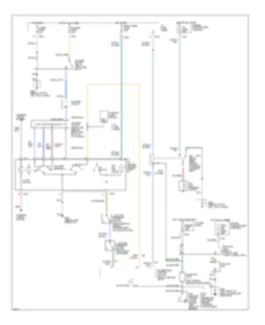
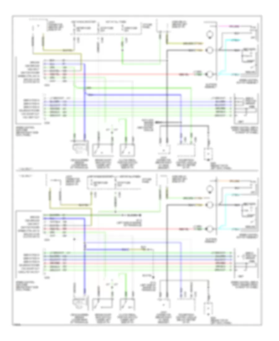
1.8L, A/C Wiring Diagram, A/T for Ford Escort GT 1996

List of elements for 1.8L, A/C Wiring Diagram, A/T for Ford Escort GT 1996:
- (behind top of left cowl panel)
- (below center of i/p)
- (left front of engine)
- (not used)
- (right rear of engine compartment, on accumulator)
- A/c com- pressor clutch
- A/c fuse 20a
- A/c high pressure
- A/c low pressure
- A/c on indi- cator
- A/c relay (right rear corner of engine compart- ment)
- A/c switch
- A/c-
- Blower fuse 30a
- Blower motor
- Blower motor relay (left side of i/p)
- Blower motor resistors (behind right side of i/p, in a/c plenum)
- Blower switch
- C108
- C161
- C200
- C210
- C220
- C260
- C272
- C273
- Cool- ing fan fuse 40a
- Cooling fan
- Cooling fan high speed relay (front of left fender apron)
- Cooling fan relay (in engine compart- ment fuse box)
- Cutoff switch
- Data link connector (left rear corner of engine compartment)
- Engine compart- ment fuse box
- Engine compartment fuse box
- Engine fuse 15a
- Fan coolant temper- ature switch (left front of engine)
- Fuse block:i/p
- G106 (left front of vehicle, near left headlamp)
- G200
- G200 (behind top of left cowl panel)
- G202 (behind left side of i/p)
- Heater control assem- bly
- High speed cooling fan temperature switch
- Hot at all times
- Hot in run
- Hot in run or start
- I/p fuse panel
- Illumi- nation
- Interior lights system
- Nca
- Off
- Powertrain control module
- Rear wiper fuse 10a
- Red
- Shorting plug 2 (left side of engine compt)
- Warning chime module
- Wiper fuse 20a
1.8L, A/C Wiring Diagram, M/T for Ford Escort GT 1996
List of elements for 1.8L, A/C Wiring Diagram, M/T for Ford Escort GT 1996:
- (below center of i/p)
- (left front of engine)
- (not used)
- (right rear of engine compartment, on accumulator)
- A/c com- pressor clutch
- A/c fuse 20a
- A/c high pressure
- A/c low pressure
- A/c on indi- cator
- A/c relay (right rear corner of engine compart- ment)
- A/c switch
- A/c-
- Blower fuse 30a
- Blower motor
- Blower motor relay (left side of i/p)
- Blower motor resistors (behind right side of i/p, in a/c plenum)
- Blower switch
- C108
- C161
- C200
- C210
- C220
- C260
- C272
- C273
- Cool- ing fan fuse 30a
- Cooling fan
- Cooling fan relay (top of left front wheel well)
- Cutoff switch
- Data link connector (left rear corner of engine compartment)
- Engine compartment fuse box
- Engine fuse 15a
- Fan coolant temper- ature switch (left front of engine)
- G106 (left front of vehicle, near left headlamp)
- G200 (behind top of left cowl panel)
- G202 (behind left side of i/p)
- Heater control assem- bly
- Hot at all times
- Hot in run
- Hot in run or start
- I/p fuse panel
- Illumi- nation
- Interior lights system
- Nca
- Off
- Powertrain control module
- Rear wiper fuse 10a
- Red
- Shorting plug (left side of engine compartment)
- Warning chime module
- Wiper fuse 20a
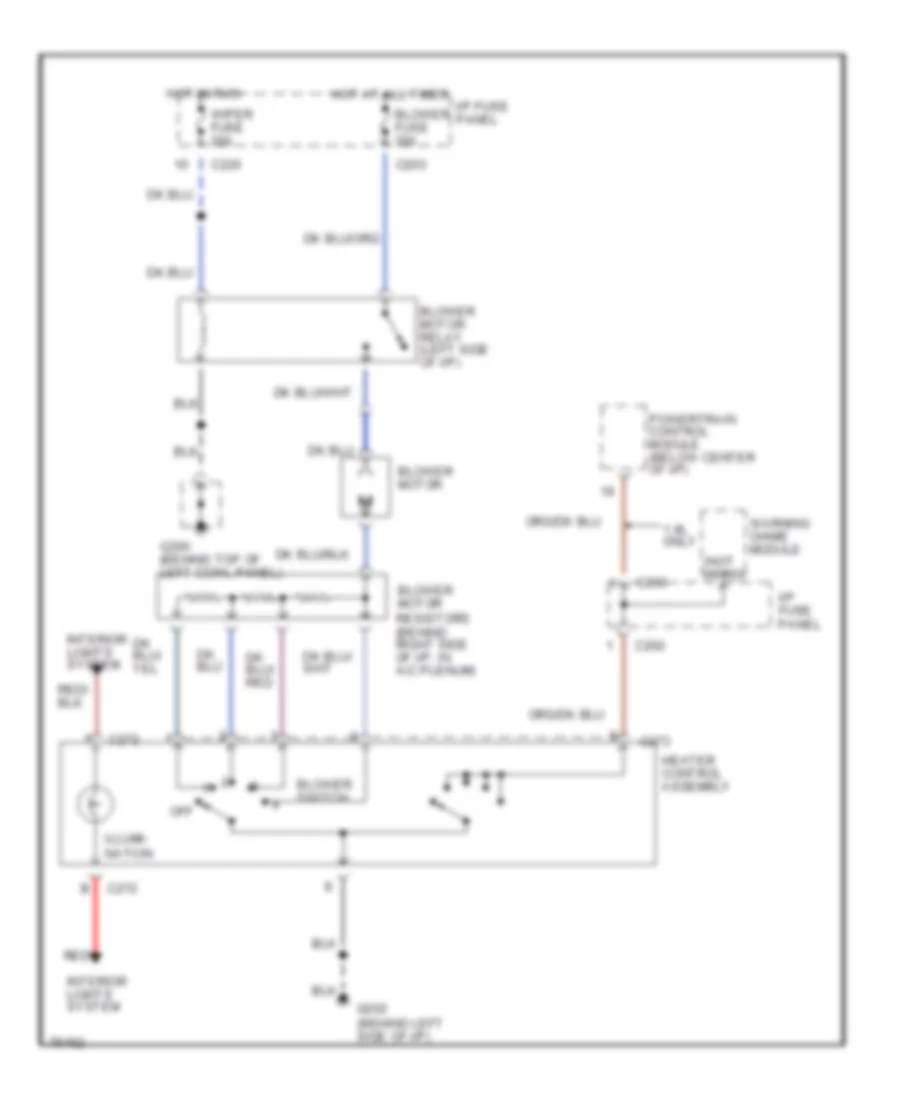
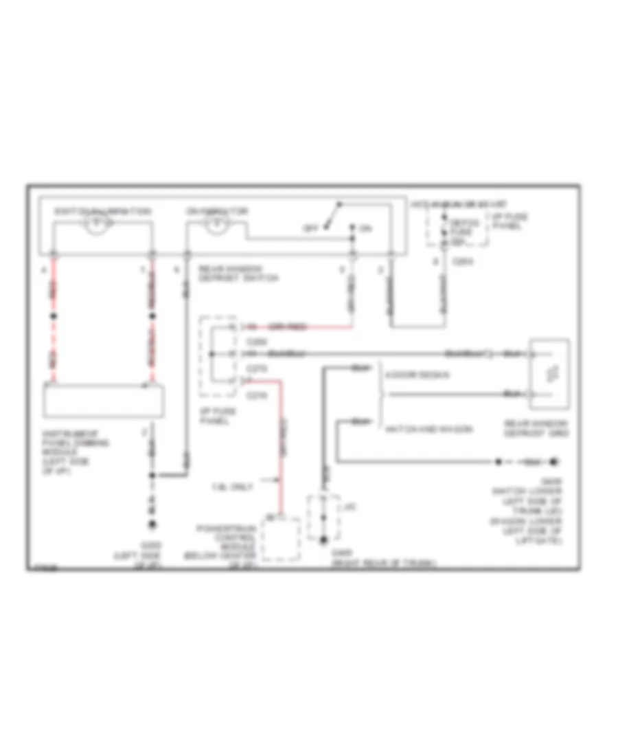
Heater Wiring Diagram for Ford Escort GT 1996
List of elements for Heater Wiring Diagram for Ford Escort GT 1996:
- (not used)
- 1.8l only
- Blower fuse 30a
- Blower motor
- Blower motor relay (left side of i/p)
- Blower motor resistors (behind right side of i/p, in a/c plenum)
- Blower switch
- C200
- C220
- C230
- C260
- C272
- C273
- G200 (behind top of left cowl panel)
- G202 (behind left side of i/p)
- Heater control assembly
- Hot at all times
- Hot in run
- I/p fuse panel
- Illumi- nation
- Interior lights system
- Off
- Powertrain control module (below center of i/p)
- Red
- Warning chime module
- Wiper fuse 20a
1.9L
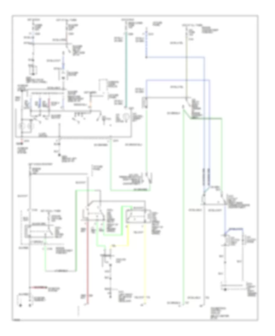
1.9L, A/C Wiring Diagram for Ford Escort GT 1996
List of elements for 1.9L, A/C Wiring Diagram for Ford Escort GT 1996:
- (below center of i/p)
- (front of left fender apron)
- (not used)
- (right rear of engine compartment)
- A/c clutch diode
- A/c clutch field coil
- A/c control assem- bly
- A/c fuse 10a
- A/c low
- A/c on indi- cator
- A/c relay (right rear corner of engine compart- ment)
- A/c switch
- Blower fuse 30a
- Blower motor
- Blower motor relay (left side of i/p)
- Blower motor resistors (behind right side of i/p)
- Blower switch
- C108
- C161
- C200
- C210
- C220
- C260
- C272
- C273
- Cool- ing fan high speed relay
- Cool- ing fan low speed relay
- Cool- ing fan power relay
- Cooling fan
- Cooling fan fuse 40a
- Engine compartment fuse box
- Engine fuse 15a
- G101 (front of right fender apron)
- G101 (left front of vehicle near headlamp)
- G200 (behind top of left cowl panel)
- G202 (behind left side of i/p)
- Hot at all times
- Hot in run
- Hot in run or start
- I/p fuse panel
- Illumi- nation
- Interior lights system
- Nca
- Off
- Powertrain control module
- Pressure switch
- Rear wiper fuse 10a
- Red
- Starter assembly
- Starting system
- Warning chime module
- Wiper fuse 20a
- Wot cutout relay (right rear corner of engine compartment)
Heater Wiring Diagram for Ford Escort GT 1996
List of elements for Heater Wiring Diagram for Ford Escort GT 1996:
- (not used)
- 1.8l only
- Blower fuse 30a
- Blower motor
- Blower motor relay (left side of i/p)
- Blower motor resistors (behind right side of i/p, in a/c plenum)
- Blower switch
- C200
- C220
- C230
- C260
- C272
- C273
- G200 (behind top of left cowl panel)
- G202 (behind left side of i/p)
- Heater control assembly
- Hot at all times
- Hot in run
- I/p fuse panel
- Illumi- nation
- Interior lights system
- Off
- Powertrain control module (below center of i/p)
- Red
- Warning chime module
- Wiper fuse 20a
ANTI-LOCK BRAKES
1.8L
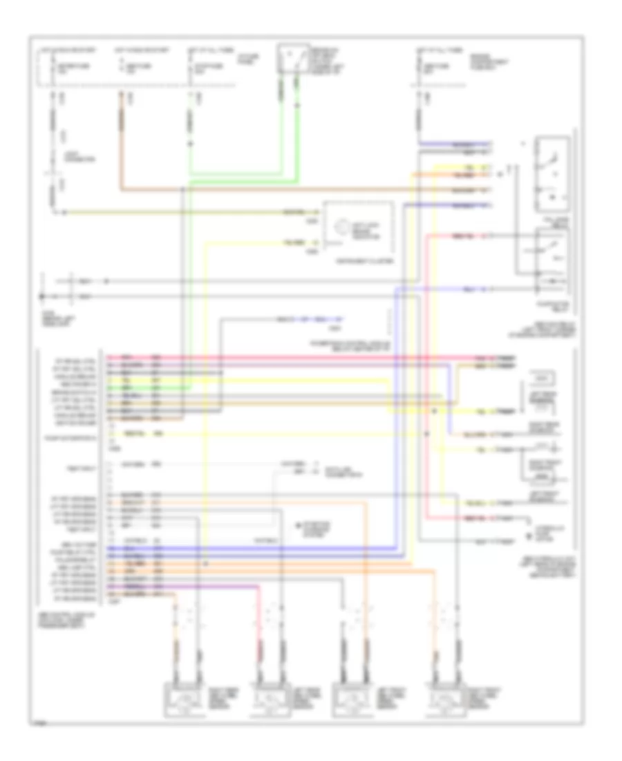
1.8L, Anti-lock Brake Wiring Diagrams for Ford Escort GT 1996
List of elements for 1.8L, Anti-lock Brake Wiring Diagrams for Ford Escort GT 1996:
- Abs control module (on floor, under passenger seat)
- Abs fuse 10a
- Abs fuse 60a
- Abs hydraulic unit (left rear of engine compartment, behind battery)
- Abs lamp ctrl
- Abs main relay (left front corner of engine compartment)
- Abs power in
- Anti-lock brake indicator
- Brake on/ off (boo) switch (under left side of i/p)
- Brake switch in
- C109
- C204
- C210
- C213
- C240
- C252
- C253
- C386
- C387
- Data link connector #1
- Engine compartment fuse box
- Fail safe relay
- Failsafe relay
- G106 (behind left headlamp)
- Gen voltage
- Hot at all times
- Hot in run or start
- Hydraulic pump motor
- I/p fuse panel
- Ignition power
- Instrument cluster
- Joint connector
- Left front abs wheel speed sensor
- Left front solenoid
- Left rear abs wheel speed sensor
- Left rear solenoid
- Lft frt sol ctrl
- Lft frt spd sens
- Lft rr sol ctrl
- Lft rr spd sens
- Meter fuse 15a
- Module ground
- Nca
- Pnk
- Powertrain control module (below center of i/p)
- Pump motor pwr in
- Pump motor relay
- Pump relay ctrl
- Right front abs wheel speed sensor
- Right front solenoid
- Right rear abs wheel speed sensor
- Right rear solenoid
- Rt frt sol ctrl
- Rt frt spd sens
- Rt rr sol ctrl
- Rt rr spd sens
- Starting/ charging system
- Stop fuse 20a
- Test input
COMPUTER DATA LINES
1.8L
1.8L, Computer Data Lines for Ford Escort GT 1996
List of elements for 1.8L, Computer Data Lines for Ford Escort GT 1996:
- (center of i/p)
- (left rear corner of engine compartment)
- (left side of safety wall)
- (not used)
- Abs control module (on floor, under passenger seat)
- C204
- C227
- C253
- Cool fan in
- Cooling fan relay (engine comp't fuse box)
- Data link connector #1
- Data link connector #2
- Distributor ignition module (left side of engine comp't)
- Dlc #1
- Dlc #2
- Fuel pump
- Fuel pump relay (below center of i/p)
- G116 (lower left side of safety wall)
- G206
- Hot at all times
- I/p fuse panel
- Instrument cluster
- J/c
- Mil
- Mil lamp
- Obd ii 10a
- Pcm power relay (engine compartment fuse box)
- Powertrain control module (under center of i/p)
- Shorting plug #2 (left side of engine comp't)
1.9L
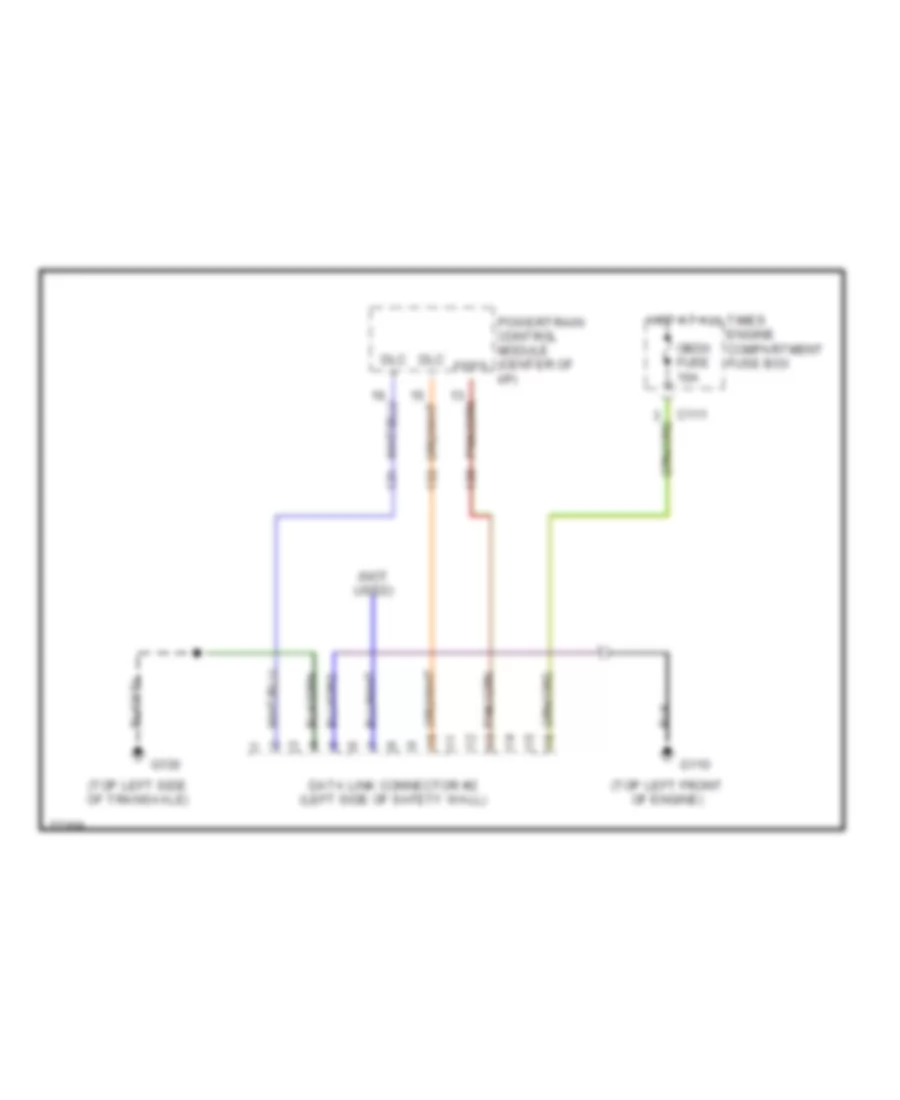
1.9L, Computer Data Lines for Ford Escort GT 1996
List of elements for 1.9L, Computer Data Lines for Ford Escort GT 1996:
- (not used)
- (top left front of engine)
- (top left side of transaxle)
- C111
- Data link connector #2 (left side of safety wall)
- Dlc +
- Dlc -
- Engine compartment fuse box
- Feps
- G110
- G130
- Hot at all times
- Obdii fuse 10a
- Powertrain control module (center of i/p)
COOLING FAN
1.8L
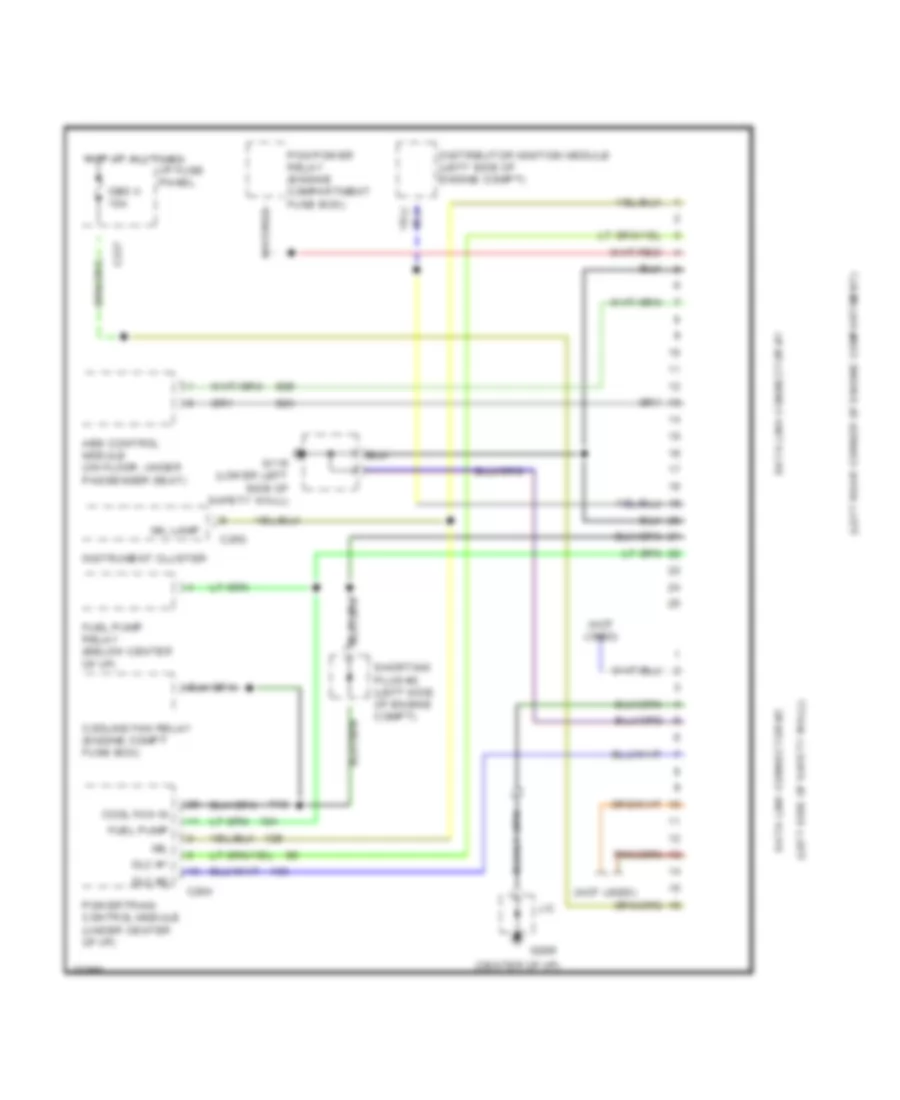
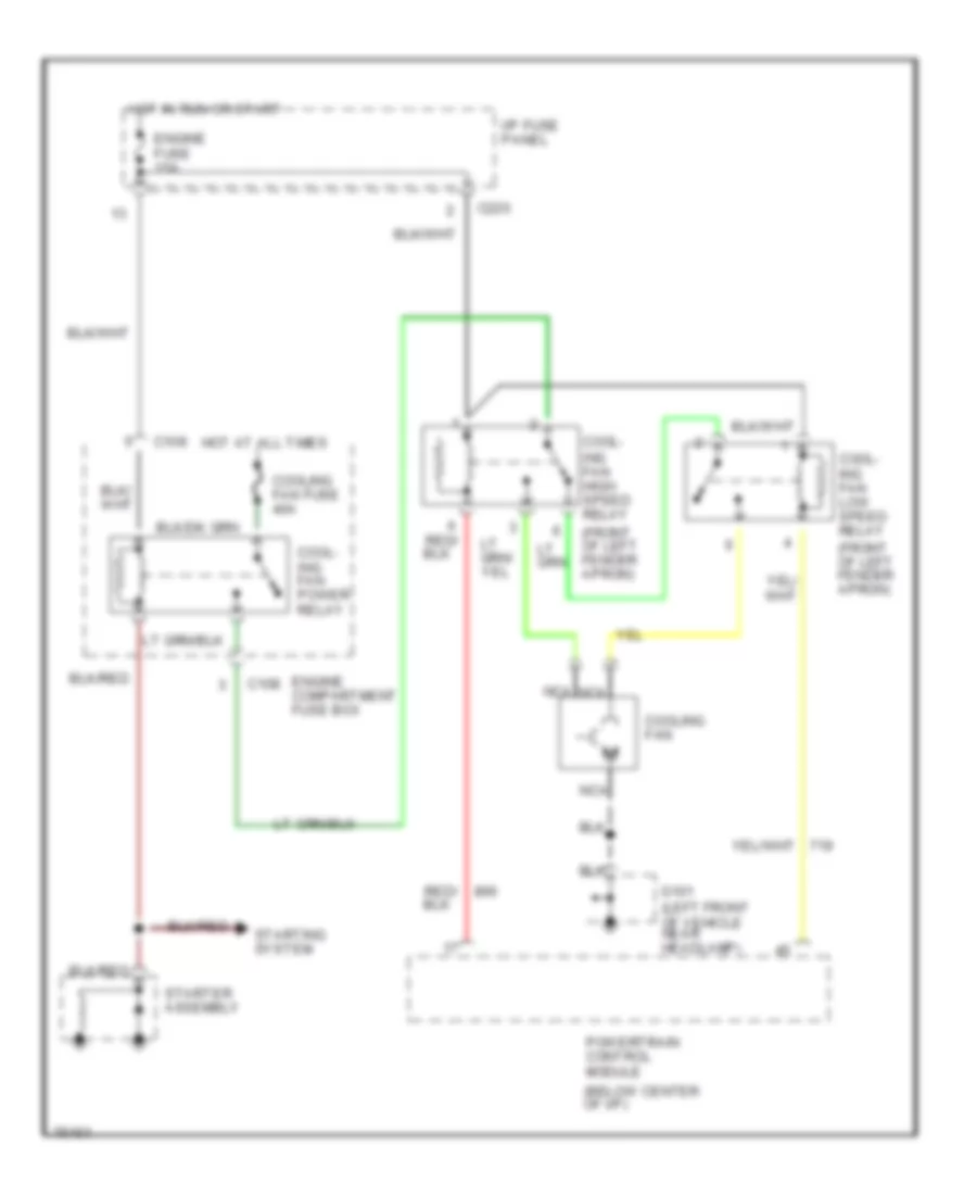
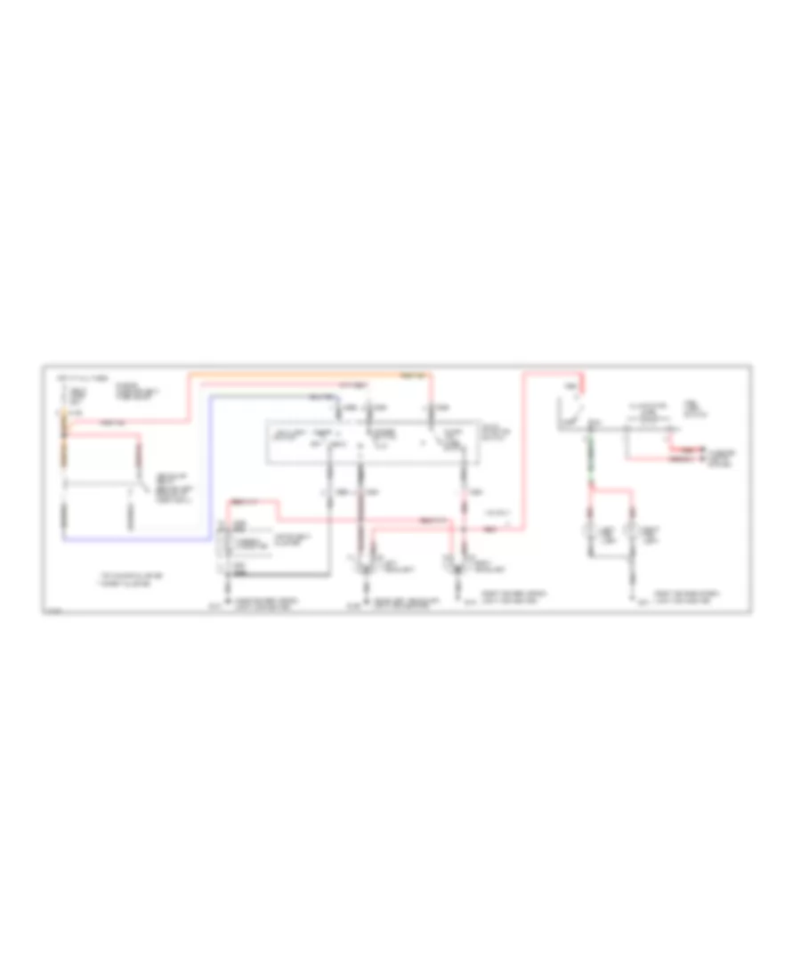
1.8L, Cooling Fan Wiring Diagram, A/T for Ford Escort GT 1996
List of elements for 1.8L, Cooling Fan Wiring Diagram, A/T for Ford Escort GT 1996:
- (below center of i/p)
- (left side of engine compartment)
- A/c high pressure
- A/c relay
- C108
- C220
- Cool- ing fan
- Cool- ing fan fuse 40a
- Cooling fan high speed relay (front of left fender apron)
- Cooling fan relay (in engine compart- ment fuse box)
- Cutoff switch
- Data link connector (left rear corner of engine compartment)
- Engine compart- ment fuse box
- Engine fuse 15a
- Fan coolant temper- ature switch (left front of engine)
- G106 (left front of vehicle, near left headlamp)
- High speed cooling fan temperature switch
- Hot at all times
- Hot in run or start
- I/p fuse panel
- Nca
- Powertrain control module
- Shorting plug
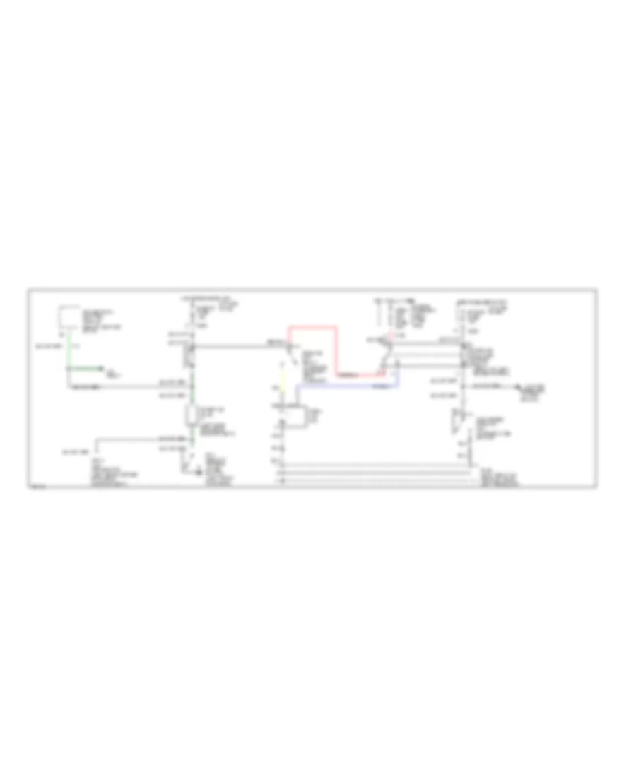
1.8L, Cooling Fan Wiring Diagram, M/T for Ford Escort GT 1996
List of elements for 1.8L, Cooling Fan Wiring Diagram, M/T for Ford Escort GT 1996:
- (below center of i/p)
- A/c system
- C108
- C220
- Cool- ing fan fuse 30a
- Cooling fan
- Cooling fan relay (top of left front wheel well)
- Data link connector (left rear corner of engine compartment)
- Engine compartment fuse box
- Engine fuse 15a
- Fan coolant temper- ature switch (left front of engine)
- G106 (left front of vehicle, near left headlamp)
- Hot at all times
- Hot in run or start
- I/p fuse panel
- Nca
- Powertrain control module
- Shorting plug (left side of engine compartment)
1.9L
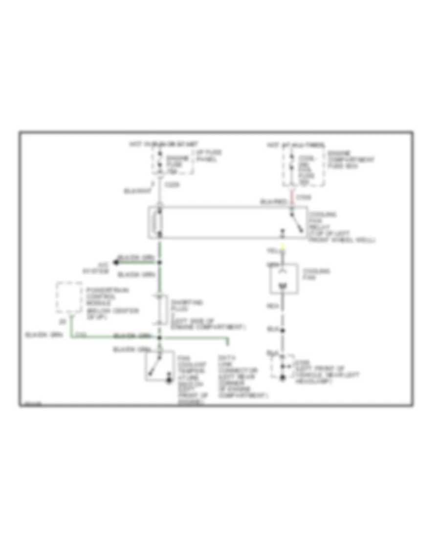
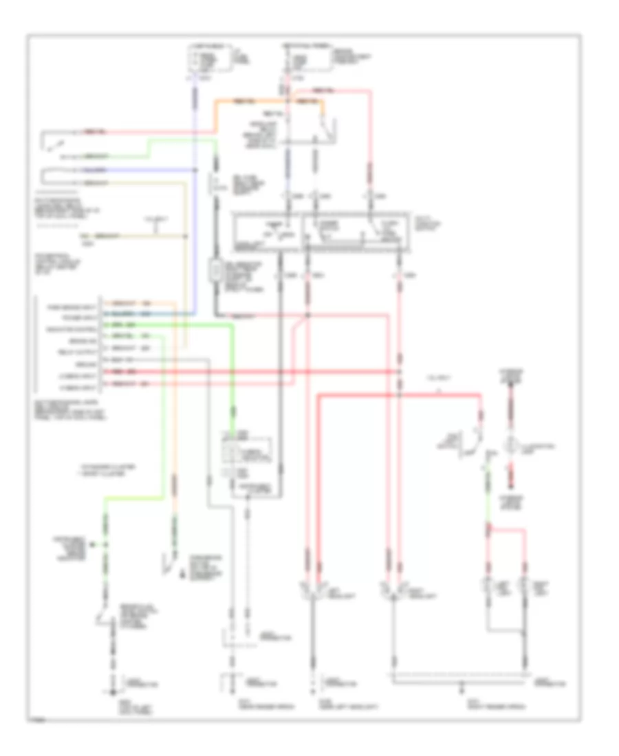
1.9L, Cooling Fan Wiring Diagram for Ford Escort GT 1996
List of elements for 1.9L, Cooling Fan Wiring Diagram for Ford Escort GT 1996:
- (below center of i/p)
- (front of left fender apron)
- C108
- C220
- Cool- ing fan high speed relay
- Cool- ing fan low speed relay
- Cool- ing fan power relay
- Cooling fan
- Cooling fan fuse 40a
- Engine compartment fuse box
- Engine fuse 15a
- G101 (left front of vehicle near headlamp)
- Hot at all times
- Hot in run or start
- I/p fuse panel
- Nca
- Powertrain control module
- Starter assembly
- Starting system
CRUISE CONTROL
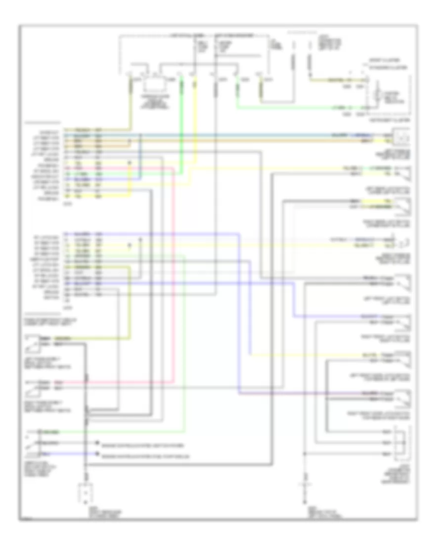
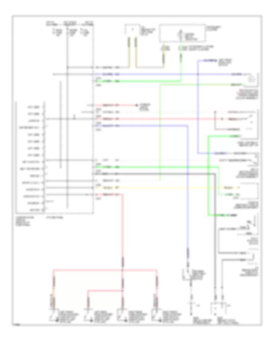
Cruise Control Wiring Diagram for Ford Escort GT 1996
List of elements for Cruise Control Wiring Diagram for Ford Escort GT 1996:
- * 1.8l only *
- * 1.9l only *
- A/t
- Anti-lock brakes system (abs control module)
- Boo sw in or clutch sw in
- Brake on/off (boo) switch (under left side of i/p)
- C204
- C210
- C212
- C227
- C234
- C235
- C240
- Clutch pedal position switch (under left side of i/p)
- Coast
- G112 (left side of engine, on transaxle)
- G200 (behind top of left cowl panel)
- Ground
- Horn fuse 20a
- Horn relay (behind left side of i/p)
- Hot at all times
- Hot in run or start
- I/p fuse panel
- Ignition power
- Joint connector (behind left side of i/p)
- Joint connector (behind right i/p, near grommet)
- M/t
- Meter fuse 15a
- Modulte vac out
- Off
- Powertrain control module (below center of i/p)
- Resume
- Servo pos in
- Servo position sensor
- Set/accel
- Slip ring assembly
- Solenoid power
- Speed control amplifier (behind right side cowl panel)
- Speed control servo (right fender apron, in front of wheel)
- Speed control switch assembly
- Speed ctrl sw in
- Stop fuse 20a
- Tan
- Vac
- Vac on/off out
- Vac vent out
- Vehicle speed sensor (lower rear of transaxle)
- Vent
- Vss ground
- Vss input
DEFOGGERS
Defogger Wiring Diagram for Ford Escort GT 1996
List of elements for Defogger Wiring Diagram for Ford Escort GT 1996:
- 1.8l only
- 4 door sedan
- C210
- C260
- C270
- Defog fuse 20a
- G202 (left side of i/p)
- G405 (right rear of trunk)
- G406 (hatch: lower left side of trunk lid) (wagon: lower left side of liftgate)
- Hatch and wagon
- Hot in run or start
- I/p fuse panel
- Instrument panel dimming module (left side of i/p)
- J/c
- Off
- On indicator
- Powertrain control module (below center of i/p)
- Rear window defrost grid
- Rear window defrost switch
- Red
- Switch illumination
ENGINE PERFORMANCE
1.8L
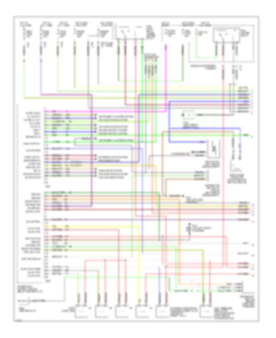
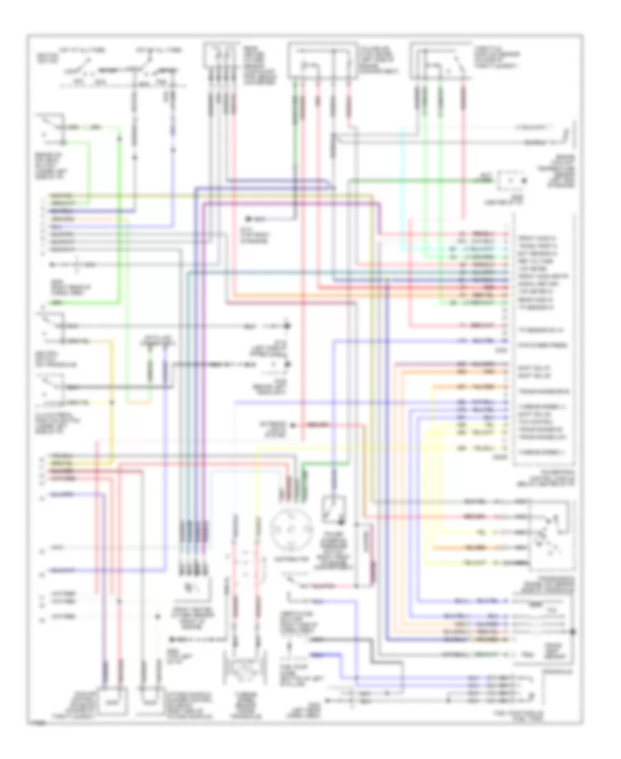
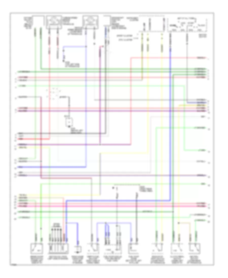
1.8L, Engine Performance Wiring Diagrams (1 of 2) for Ford Escort GT 1996
List of elements for 1.8L, Engine Performance Wiring Diagrams (1 of 2) for Ford Escort GT 1996:
- a/c on in
- a/c relay out
- blwr mtr on
- brake sw in
- coolng fan on
- crank pos in
- dist ign module
- distributor
- drl in
- fprv sol ctrl
- ground
- mil output
- neutral sw
- power (b+)
- rear defog in
- vss (+)
- vss (-)
- (a/t only)
- (m/t only)
- Air conditioning system
- C111
- C204
- C205
- C210
- C220
- C227
- C240
- Cooling fans system
- Crank pos sens
- Crankshaft position sensor (right end of engine)
- Cruise control system
- Data link connector 1
- Defogger system
- Distributor ignition (di) module (left side of engine comp't)
- Dlc #2 conn
- Dlc conn
- Engine compartment fuse box
- Engine fuse 15a
- Evap can purge
- Evaporative emission canister purge valve (center of safety wall)
- Exterior lights system
- Fuel inj 30a
- Fuel injectors
- Fuel pressure regulator vacuum solenoid (right end of intake manifold)
- Fuel pump 20a
- Fuel pump relay (under center of i/p)
- Fuel pump rly
- G110 (top left front of engine)
- G112 (top left side of engine)
- G116 (left side of safety wall)
- G206 (center of i/p)
- Ground
- Headlights system
- Hot at all times
- Hot in run or start
- Hot in start
- I/p fuse panel
- Iac control
- Ignition coil (left side of engine comp't)
- Ignition pwr
- Imr sol ctrl
- Inj #1 ctrl
- Inj #2 ctrl
- Inj #3 ctrl
- Inj #4 ctrl
- Instrument cluster system
- Meter fuse 15a
- Nca
- Obd ii fuse 10a
- Park lmp rly
- Pcm power relay
- Powertrain control module (below center of i/p)
- Radio noise capacitor (on distributor ignition module)
- Room fuse 15a
- Start sig
- Start sig in
- Start signal 10a
- Stop fuse 20a
- To distributor
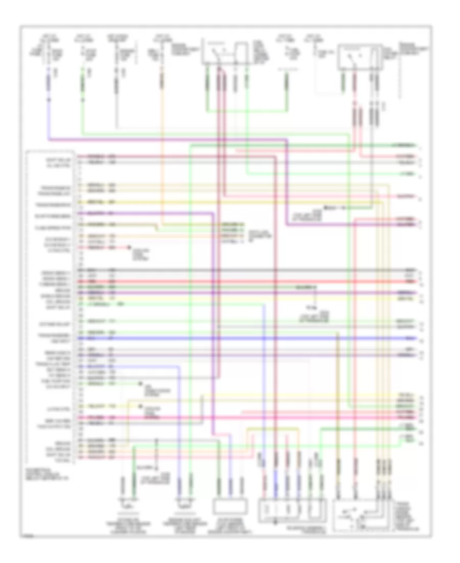
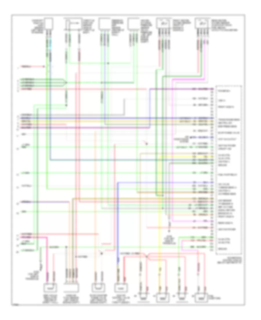
1.8L, Engine Performance Wiring Diagrams (2 of 2) for Ford Escort GT 1996
List of elements for 1.8L, Engine Performance Wiring Diagrams (2 of 2) for Ford Escort GT 1996:
- Acc
- Brake on/ off (boo) switch (under left side of i/p)
- C2009
- C238
- Clutch pedal position switch (under left side of i/p)
- Data link connector 2
- Distributor
- Ect sensor in
- Engine coolant temperature sensor (left end of engine)
- Exterior lights system
- Front heated oxygen sensor (front of engine)
- Front ho2s heatr
- Front ho2s in
- Fuel pump diode (bottom of left 'b' pillar)
- Fuel pump module (fuel tank)
- G106 (behind left headlight)
- G110 (top front of engine)
- G116 (left side of safety wall)
- G202 (top left of i/p)
- G206 (center of i/p)
- G402 (left rear cargo area)
- G405 (right rear of cargo area
- Hot at all times
- Hot at all times ignition switch
- Idle air control solenoid (on side of throttle body)
- Inertia fuel shutoff (right side of cargo area)
- Intake manifold runner control solenoid (right end of intake manifold)
- Lock
- Nca
- Neutral switch (on transaxle)
- Power steering pressure switch (right front of engine compartment)
- Powertrain control module (below center of i/p)
- Pwr steer press
- Rear heated oxygen sensor (in exhaust pipe, behind converter)
- Rear ho2s in
- Red
- Ref voltage
- Run
- Shift sol #1
- Shift sol #2
- Shift sol #3
- Signal return
- Start
- Tcc
- Tcc control
- Throttle position sensor (on side of throttle body)
- Tp sensor in
- Tp sensor sw in
- Trans range-drve
- Trans range-low
- Trans range-od
- Trans temp in
- Trans temp sensor
- Transaxle
- Transmission range (tr) sensor (side of transaxle)
- Turbine speed (+)
- Turbine speed (-)
- Turbine speed sensor (inside transaxle)
- Vaf meter
- Vaf meter in
- Volume air flow meter (left side of engine compartment)
1.9L
1.9L, Engine Performance Wiring Diagrams (1 of 3) for Ford Escort GT 1996
List of elements for 1.9L, Engine Performance Wiring Diagrams (1 of 3) for Ford Escort GT 1996:
- A/c on input
- Air conditioning system
- C111
- C210
- C240
- Coil ground
- Cooling fans system
- Crank sens (+)
- Crank sens (-)
- Data link connector #2
- Dlc #2 bus (+)
- Dlc #2 bus (-)
- Ect sens in
- Egr vac reg
- Engine compartment fuse box
- Engine coolant temperature sensor (left rear of engine)
- Engine fuse 15a
- Evap purge flow sensor (left front of engine compartment)
- Evap purge sens
- Flash eprom pwr
- Fuel inj 30a
- Fuel pump 20a
- Fuel pump mon
- Fuel pump relay (under center of i/p)
- G129 (top left side of transaxle)
- Ground
- Hi fan ctrl
- Hot at all times
- Hot in run or start
- I/p fuse panel
- Iat sens in
- Intake air temperature sensor (front of air cleaner housing)
- Lo fan ctrl
- Maf return
- Mil ind ctrl
- Nca
- Obd ii fuse 10a
- Octane adjust
- Pcm power relay
- Powertrain control module (below center of i/p)
- Rear ho2s in
- Red
- Room fuse 15a
- Shield ground
- Shift sol #1
- Shift sol #2
- Shift sol #3
- Solenoid assembly (transaxle)
- Stop fuse 20a
- Tach output sig
- Tcc sol
- Trans fluid temp
- Trans rnge-drve
- Trans rnge-low
- Trans rnge-od
- Trans rnge-rev
- Trans- mission range sensor (top left side of transaxle)
- Turbine sens (-)
- Vss input
1.9L, Engine Performance Wiring Diagrams (2 of 3) for Ford Escort GT 1996
List of elements for 1.9L, Engine Performance Wiring Diagrams (2 of 3) for Ford Escort GT 1996:
- (a/t only)
- Acc
- Backup/up- shift switch (lower front of transaxle)
- Brake on/off (boo) switch (under left side of i/p)
- Clutch pedal switch (under left side of i/p)
- Crankshaft position (ckp) sensor (lower right side of engine)
- Fuel pump diode (bottom of left 'b' pillar)
- Fuel pump module (top center of fuel tank)
- G106 (behind left headlight)
- G129 (top left side of transaxle)
- G402 (right rear cargo area)
- Hot at all times
- Ignition coil pack (left side of engine)
- Ignition switch
- Inertia fuel shutoff (right side of cargo area)
- Instrument cluster
- Lock
- Mil lamp
- N/a
- Nca
- Neutral switch (lower rear of transaxle)
- Octane adjust plug (below center of i/p)
- Radio noise capacitor (top left of engine)
- Red
- Run
- Spark plugs
- Sport cluster
- Start
- Std. cluster
- Tachometer
- Turbine speed sensor (top of transaxle)
- Upshift lamp
- Vehicle speed sensor (lower rear of transaxle)
1.9L, Engine Performance Wiring Diagrams (3 of 3) for Ford Escort GT 1996
List of elements for 1.9L, Engine Performance Wiring Diagrams (3 of 3) for Ford Escort GT 1996:
- (a/t only)
- (m/t only)
- A/c press sens
- Air con- ditioning pressure sensor (on a/c pressure line, left side of engine comp't)
- Air conditioning system
- Brake sw in
- Cam pos (+)
- Cam pos (-)
- Camshaft position (cmp) sensor (left rear of engine)
- Egr press sens
- Egr vacuum regulator (center of safety wall)
- Evap canister purge valve (left front of engine comp't)
- Evap purge valve
- Feedback pressure egr sensor (center of safety wall)
- Front heated oxygen sensor (front of engine in manifold)
- Front ho2s in
- Fuel injectors
- Fuel pump relay
- G129 (top left side of transaxle)
- Ground
- Iac valve
- Idle air control valve (top of throttle body)
- Ignition power
- Inj #1 ctrl
- Inj #2 ctrl
- Inj #3 ctrl
- Inj #4 ctrl
- Maf sensor
- Mass air flow sensor (left side of engine comp't)
- Nca
- Neutral sw
- Power b(+)
- Powertrain control module (below center of i/p)
- Rear heated oxygen sensor (in exhaust down pipe, behind catalytic converter)
- Rear ho2s in
- Red
- Ref voltage
- Signal return
- Tan
- Throttle position sensor (side of throttle body)
- Tp sensor in
- Trans range sens
- Turbine sens (+)
- Upshift ind
- Vss (+)
- Wot a/c cutout
EXTERIOR LIGHTS
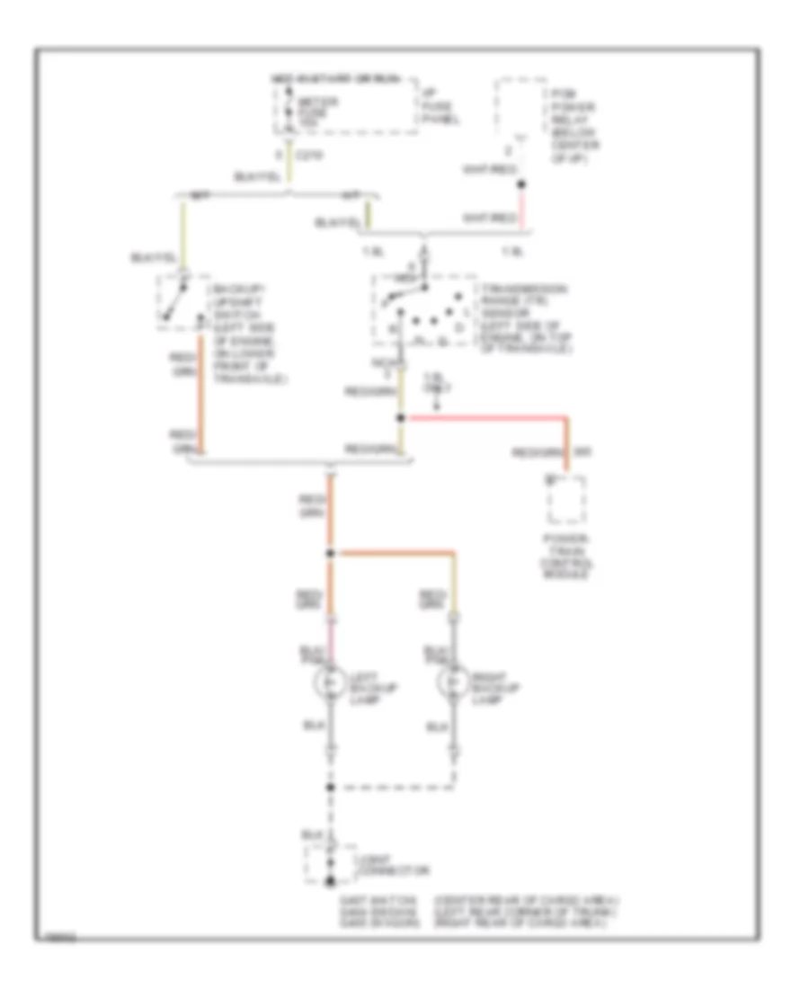
Back-up Lamps Wiring Diagram for Ford Escort GT 1996
List of elements for Back-up Lamps Wiring Diagram for Ford Escort GT 1996:
- (center rear of cargo area) (left rear corner of trunk) (right rear of cargo area)
- 1.8l
- 1.9l
- 1.9l only
- A/t
- Backup/ upshift switch (left side of engine, on lower front of transaxle)
- C210
- G407 (hatch) g404 (sedan) g405 (wagon)
- Hot in start or run
- I/p fuse panel
- Joint connector
- Left backup lamp
- M/t
- Meter fuse 15a
- Nca
- Pcm power relay (below center of i/p)
- Power- train control module
- Red/
- Right backup lamp
- Transmission range (tr) sensor (left side of engine, on top of transaxle)
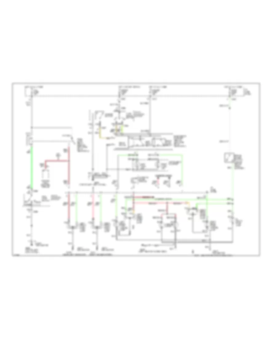
Exterior Lamps Wiring Diagram, Hatchback for Ford Escort GT 1996
List of elements for Exterior Lamps Wiring Diagram, Hatchback for Ford Escort GT 1996:
- (center rear of cargo area)
- (left rear of cargo area)
- (near left headlamp)
- (right fender apron)
- (top of left cowl panel)
- 1.8l only
- Brake on/off switch (top of brake pedal support)
- C210
- C220
- C240
- C267
- C269
- C294
- Electronic flasher (behind left side of i/p, near cowl)
- G101
- G106
- G200
- G200 (top of left cowl panel)
- G406
- G407
- Hazard fuse 15a
- Hazard switch
- Head
- Hi mount stop lamp
- Hot at all times
- Hot in start or run
- I/p fuse panel
- Instrument cluster
- Interior lights
- Joint connector
- Lamps on input
- Left front park/ turn lamp
- Left rear park/ stop lamp
- Left rear turn/ hazard lamp
- Left turn ind.
- Left turn relay
- License lamps
- Main lamp switch
- Meter fuse 15a
- Multi- function switch
- Nca
- Off
- Park
- Park lamp relay (behind left side of i/p, near cowl)
- Power- train control module
- Right front park/ turn lamp
- Right rear park/ stop lamp
- Right rear turn/ hazard lamp
- Right turn ind.
- Right turn relay
- Solid state
- Stop fuse 20a
- Tail fuse 15a
- Tan
- Turn signal switch
- Warning chime module
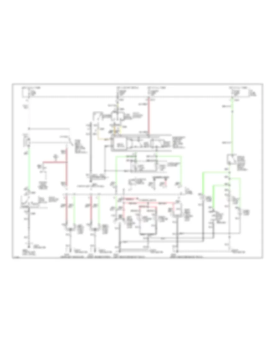
Exterior Lamps Wiring Diagram, Sedan for Ford Escort GT 1996
List of elements for Exterior Lamps Wiring Diagram, Sedan for Ford Escort GT 1996:
- (near left headlamp)
- (right fender apron)
- (top of left cowl panel)
- 1.8l only
- Brake on/off switch (top of brake pedal support)
- C210
- C220
- C240
- C267
- C269
- C294
- Electronic flasher (behind left side of i/p, near cowl)
- G101
- G106
- G200
- G200 (top of left cowl panel)
- G404 (left rear corner of trunk)
- G405 (right rear corner of trunk)
- Hazard fuse 15a
- Hazard switch
- Head
- Hi mount stop lamp
- Hi mount stop lamp (on spoiler)
- Hot at all times
- Hot in start or run
- I/p fuse panel
- Instrument cluster
- Interior lights
- Joint connector
- Lamps on input
- Led
- Left front park/ turn lamp
- Left license lamp
- Left rear turn/ hazard/ park lamp
- Left stop lamp
- Left turn ind.
- Left turn relay
- Main lamp switch
- Meter fuse 15a
- Multi- function switch
- Nca
- Off
- Park
- Park lamp relay (behind left side of i/p, near cowl)
- Power- train control module
- Right front park/ turn lamp
- Right license lamp
- Right rear turn/ hazard/ park lamp
- Right stop lamp
- Right turn ind.
- Right turn relay
- Solid state
- Stop fuse 20a
- Tail fuse 15a
- Turn signal switch
- Warning chime module
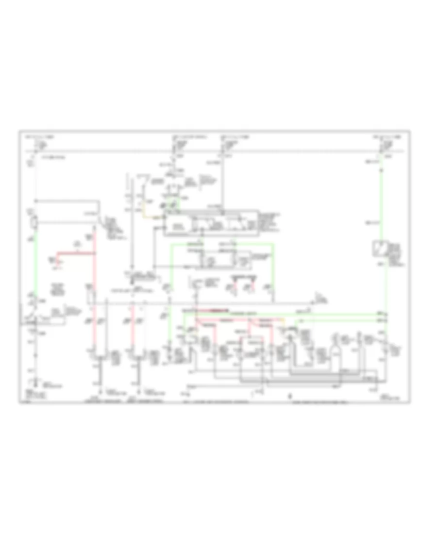
Exterior Lamps Wiring Diagram, Wagon for Ford Escort GT 1996
List of elements for Exterior Lamps Wiring Diagram, Wagon for Ford Escort GT 1996:
- (lower left center of liftgate)
- (near left headlamp)
- (right fender apron)
- (right rear of cargo area)
- (top of left cowl panel)
- 1.8l only
- Brake on/off switch (top of brake pedal support)
- C210
- C220
- C240
- C267
- C269
- C294
- Electronic flasher (behind left side of i/p, near cowl)
- G101
- G106
- G200
- G200 (top of left cowl panel)
- G405
- G411
- Hazard fuse 15a
- Hazard switch
- Head
- Hi mount stop lamp
- Hot at all times
- Hot in start or run
- I/p fuse panel
- Instrument cluster
- Interior lights
- Joint connector
- Lamps on input
- Left backup lamp
- Left front park/ turn lamp
- Left rear park/ stop lamp
- Left rear side marker lamp
- Left rear turn/ hazard lamp
- Left turn ind.
- Left turn relay
- License lamps
- Main lamp switch
- Meter fuse 15a
- Multi- function switch
- Nca
- Off
- Park
- Park lamp relay (behind left side of i/p, near cowl)
- Power- train control module
- Right backup lamp
- Right front park/ turn lamp
- Right rear park/ stop lamp
- Right rear side marker lamp
- Right rear turn/ hazard lamp
- Right turn ind.
- Right turn relay
- Solid state
- Stop fuse 20a
- Tail fuse 15a
- Tan
- Turn signal switch
- Warning chime module
GROUND DISTRIBUTION
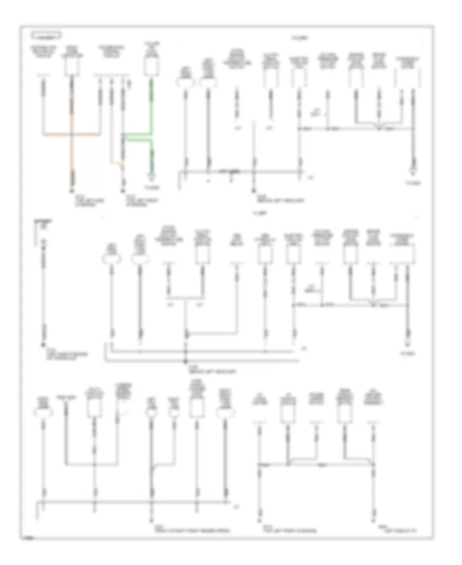
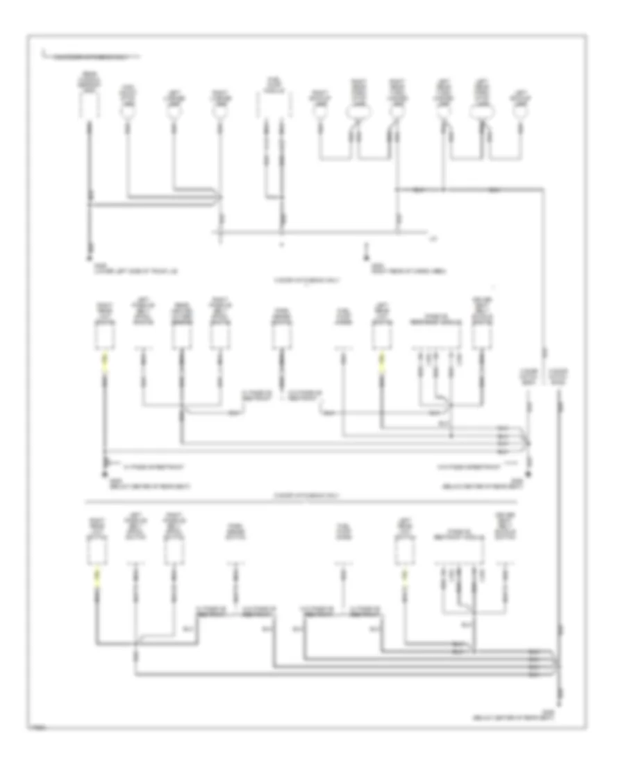
Ground Distribution Wiring Diagram (1 of 7) for Ford Escort GT 1996
List of elements for Ground Distribution Wiring Diagram (1 of 7) for Ford Escort GT 1996:
- (left side of i/p)
- (not used)
- 1.8l only
- A/c high pressure cut-off switch
- A/c- heater control assembly
- A/t
- A/t only
- Abs hydraulic unit
- Abs main relay
- Battery
- Brake fluid level switch
- C205
- Clutch pedal position switch
- Distributor ignition (di) module
- Electric cooling fan
- Engine coolant level switch
- From g200
- G101 (front of right front fender apron)
- G106 (behind left headlamp)
- G110 (top left front of engine)
- G112 (left side of engine, on transaxle)
- G112 (top left side of engine)
- G202
- Hi-fan engine coolant temperature switch
- I/p cigar lighter
- I/p dimming module
- J/c
- Left fog lamp
- Left front park/ turn lamp
- Left head- lamp
- M/t
- Multi- function switch
- Nca
- Power mirror switch
- Powertrain control module
- Radio noise capacitor
- Rear window defrost switch
- Right fog lamp
- Right front park/ turn lamp
- Right head- lamp
- To g200
- To g206
- Turbine speed sensor shield
- Volume air flow meter
- W/ abs
- W/o abs
- Wind- shield washer pump motor
- Windshield wiper motor
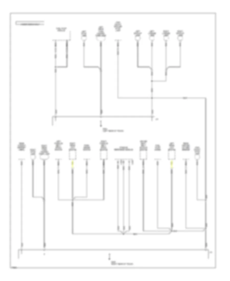
Ground Distribution Wiring Diagram (2 of 7) for Ford Escort GT 1996
List of elements for Ground Distribution Wiring Diagram (2 of 7) for Ford Escort GT 1996:
- (3 door)
- (4 door & wagon)
- (not used)
- 1.8l only
- A/c relay
- Air bag diagnostic monitor
- Blower motor relay
- C252
- C254
- Ckp shield
- Crankshaft position (ckp) sensor
- Data link connector (dlc) #1
- Data link connector (dlc) #2
- Daytime running lamps module
- Distributor
- Door lock/ unlock relay
- Electronic flasher
- Engine compartment fuse box
- From g106
- From g110
- Front heated oxygen sensor shield
- Fuel pump module
- G116 (lower left side of safety wall)
- G200 (behind top of left cowl panel)
- G206 (center of i/p)
- I/p fuse panel
- Instrument cluster
- J/c
- Left front door latch switch
- Left front limit switch
- M/t only
- Master window control switch
- Multi- function switch
- Nca
- Neutral switch
- Pcm power relay
- Rear heated oxygen sensor shield
- Right front door latch switch
- Right front limit switch
- Slip ring assembly
- Speed control amplifier
- Speed control switch assembly
- Tan
- To g101
- Warning chime module
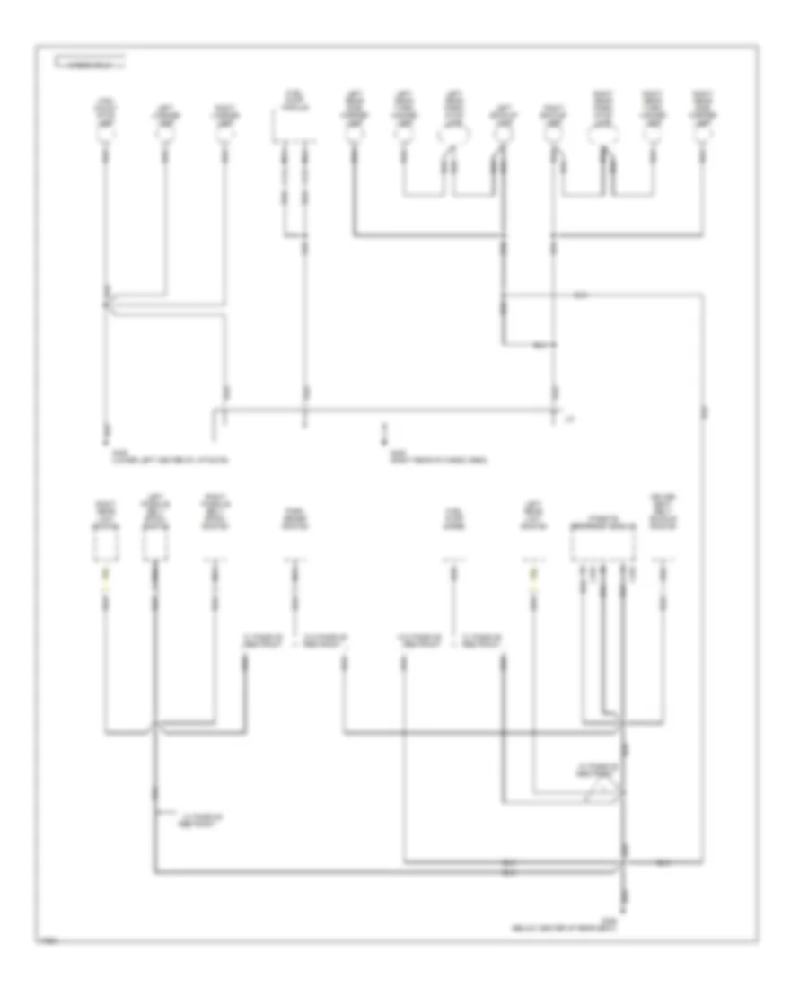
Ground Distribution Wiring Diagram (3 of 7) for Ford Escort GT 1996
List of elements for Ground Distribution Wiring Diagram (3 of 7) for Ford Escort GT 1996:
- (sport cluster)
- (standard cluster)
- 1.9l only
- A/c clutch diode
- A/c clutch field coil
- Air bag diagnostic monitor
- Blower motor relay
- Brake fluid level switch
- Door lock/ unlock relay
- Electric cooling fan
- From j/c
- Fuel pump module
- G101 (front of right fender apron)
- G106 (behind left headlamp)
- G200 (behind top of left cowl panel)
- I/p fuse panel
- Instrument cluster
- J/c
- Left front limit switch
- Left front park/ turn lamp
- Left headlamp
- Liftgate wiper/ washer switch
- Master window control switch
- Multi- function switch
- Nca
- Right front park/ turn lamp
- Right headlamp
- Turbine speed sensor shield
- Warning chime module
- Windshield washer pump motor
- Windshield wiper motor
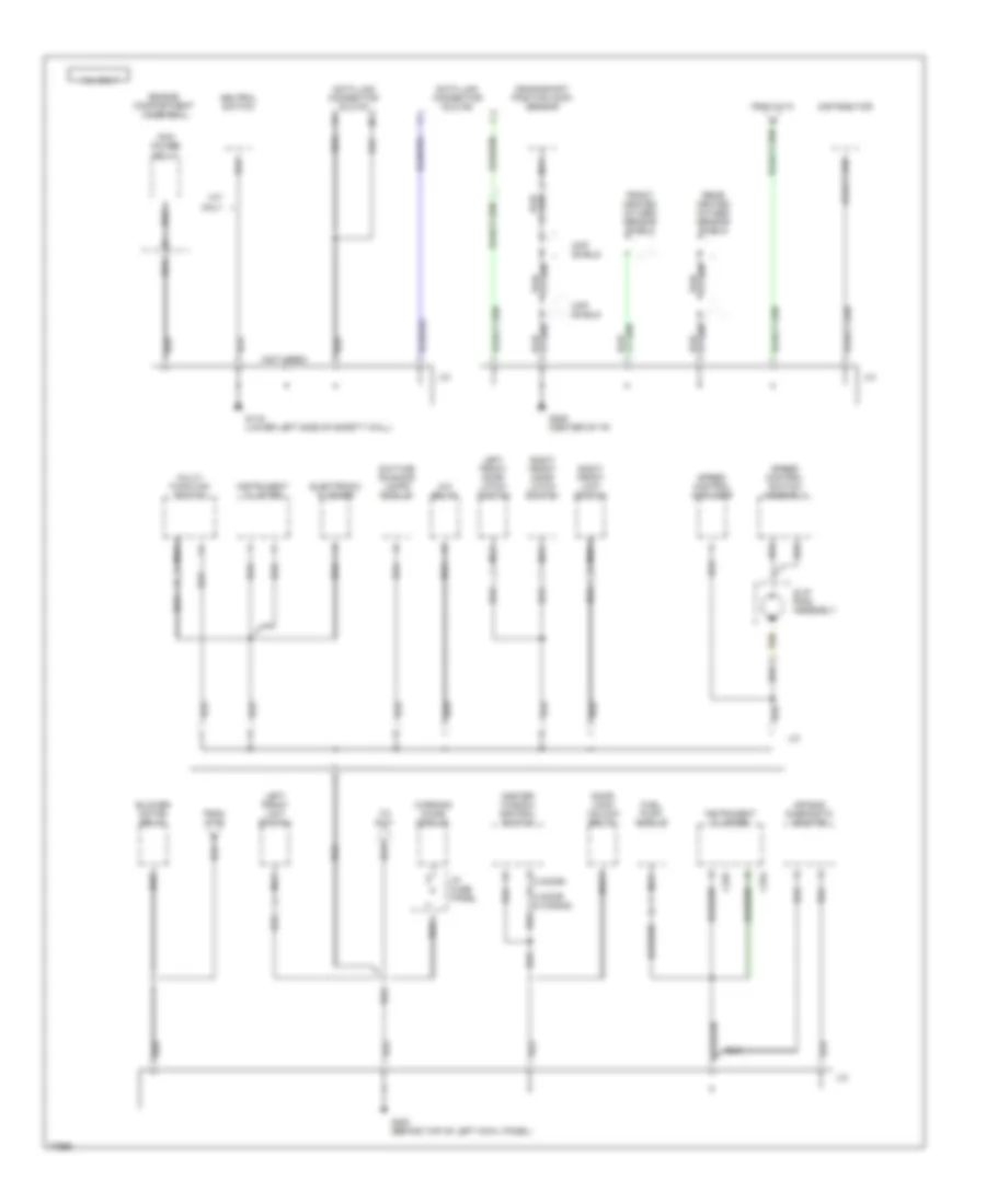
Ground Distribution Wiring Diagram (4 of 7) for Ford Escort GT 1996
List of elements for Ground Distribution Wiring Diagram (4 of 7) for Ford Escort GT 1996:
- (left side of i/p)
- (sport cluster)
- (standard cluster)
- 1.9l only
- A/c- heater control assembly
- Airbag diagnostic monitor
- Battery
- Data link connector (dlc) #2
- Daytime running lamps module
- Electronic flasher
- Engine coolant level switch
- Evaporative emission purge flow sensor
- G110 (top left front of engine)
- G112 (left side of engine, on transaxle)
- G202
- I/p cigar lighter
- I/p dimming module
- Instrument cluster
- J/c
- Left front door latch switch
- Mass air flow sensor
- Multi- function switch
- Nca
- Pcm power relay
- Power mirror switch
- Powertrain control module
- Rear window defrost switch
- Right front door latch switch
- Right front limit switch
- Slip ring assembly
- Speed control amplifier
- Speed control switch assembly
- Sport cluster
- Standard cluster
- Tan
- To g200
- Vehicle speed sensor
- W/ drl
- W/o drl
Ground Distribution Wiring Diagram (5 of 7) for Ford Escort GT 1996
List of elements for Ground Distribution Wiring Diagram (5 of 7) for Ford Escort GT 1996:
- 3 & 5 door hatchback only
- 3 door hatch- back
- 3 door hatchback only
- 5 door hatch- back
- 5 door hatchback only
- C378
- C379
- Driver seat belt buckle switch
- Fuel pump diode
- Fuel pump module
- G306 (below center of rear seat)
- G405 (right rear of cargo area)
- G406 (lower left side of trunk lid)
- High mount stop lamp
- J/c
- Left backup lamp
- Left license lamp
- Left passive belt spool switch
- Left rear limit switch
- Left rear park/ stop lamp
- Left rear turn/ hazard lamp
- Nca
- Park sense switch
- Passive restraint module
- Rear heated oxygen sensor
- Rear window defrost grid
- Right backup lamp
- Right license lamp
- Right passive belt spool switch
- Right rear limit switch
- Right rear park/ stop lamp
- Right rear turn/ hazard lamp
- W/ passive restraint
- W/o passive restraint
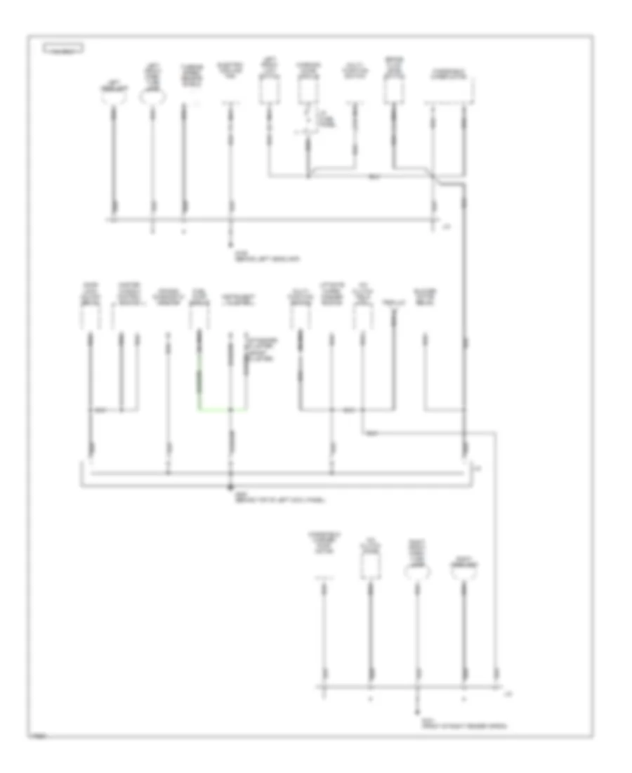
Ground Distribution Wiring Diagram (6 of 7) for Ford Escort GT 1996
List of elements for Ground Distribution Wiring Diagram (6 of 7) for Ford Escort GT 1996:
- 4 door sedan only
- C378
- Driver seat belt buckle switch
- Fuel pump diode
- Fuel pump module
- G404 (left rear of trunk)
- G405 (right rear of trunk)
- High mount spoiler stop lamp
- High mount stop lamp
- J/c
- Left backup lamp
- Left license lamp
- Left passive belt spool switch
- Left rear limit switch
- Left rear turn/ hazard/ park lamp
- Left stop lamp
- Nca
- Park sense switch
- Passive restraint module
- Rear heated oxygen sensor
- Rear window defrost grid
- Right backup lamp
- Right license lamp
- Right passive belt spool switch
- Right rear limit switch
- Right rear turn/ hazard/ park lamp
- Right stop lamp
Ground Distribution Wiring Diagram (7 of 7) for Ford Escort GT 1996
List of elements for Ground Distribution Wiring Diagram (7 of 7) for Ford Escort GT 1996:
- C378
- Driver seat belt buckle switch
- Fuel pump diode
- Fuel pump module
- G306 (below center of rear seat)
- G405 (right rear of cargo area)
- G406 (lower left center of liftgate)
- High mount stop lamp
- J/c
- Left backup lamp
- Left license lamp
- Left passive belt spool switch
- Left rear limit switch
- Left rear park/ stop lamp
- Left rear side marker lamp
- Left rear turn/ hazard lamp
- Nca
- Park sense switch
- Passive restraint module
- Restraint
- Right backup lamp
- Right license lamp
- Right passive belt spool switch
- Right rear limit switch
- Right rear park/ stop lamp
- Right rear side marker lamp
- Right rear turn/ hazard lamp
- W/ passive
- W/ passive restraint
- W/o passive restraint
- Wagon only
HEADLIGHTS
Headlight Wiring Diagram, with DRL for Ford Escort GT 1996
List of elements for Headlight Wiring Diagram, with DRL for Ford Escort GT 1996:
-
-
- instrument cluster system (brake indicator)
- * 11 ** 7
- * standard cluster
- ** 8 * 8
- ** sport cluster
- 1.8l only
- 10a
- Brake fluid level switch (on brake master cylinder)
- Brake ind
- C108
- C204
- C210
- C251 c253
- C253 c251
- C269
- C294
- Daytime running lamps (drl) module (behind right side of inst panel, top of cowl panel)
- Daytime running lamps (drl) relay (behind right side of i/p, top of cowl panel)
- Dimmer switch
- Drl fuse (right rear of engine compt)
- Drl resistor (right rear of engine compt, on rear of strut tower)
- Engine compartment fuse box
- Flash- -to- pass switch
- Fog light switch
- G101 (near fender apron)
- G101 (right fender apron)
- G106 (near left headlight)
- G200 (top of left cowl panel)
- Ground
- Head
- Head fuse 30a
- Headlamp relay (behind left side of i/p, near cowl)
- Hi beam input
- Hi-beam indicator
- Hot at all times
- Hot in run
- I/p fuse panel
- Illumination lamp
- Indicator control
- Instrument cluster
- Interior lights system
- Joint connector
- Left fog light
- Left headlight
- Lo beam input
- Main light
- Multi- function switch
- Nca
- Off
- Park
- Park brake input
- Park brake switch (on top of park brake support)
- Power input
- Powertrain control module (below center of i/p)
- Rear wiper fuse 10a
- Red
- Relay output
- Right fog light
- Right headlight
- Switch
Headlight Wiring Diagram, without DRL for Ford Escort GT 1996
List of elements for Headlight Wiring Diagram, without DRL for Ford Escort GT 1996:
-
-
- (joint connector)
- (near fender apron) (joint connector)
- (near left headlamp) (joint connector)
- (right fender apron)
- * standard cluster
- ** sport cluster
- **8 *8
- *11 **7
- 1.8l only
- C108
- C251 c253
- C253 c251
- C269
- C294
- Dimmer switch
- Engine compartment fuse block
- Flash -to- pass switch
- Fog light switch
- G101
- G106
- Head
- Head fuse 30a
- Headlamp relay (behind left side of i/p, near cowl)
- Hi-beam indicator
- Hot at all times
- Illumination lamp
- Instrument cluster
- Interior lights system
- Left fog light
- Left headlight
- Main light
- Multi- function switch
- Nca
- Off
- Off
- Park
- Red
- Right fog light
- Right headlight
- Switch
HORN
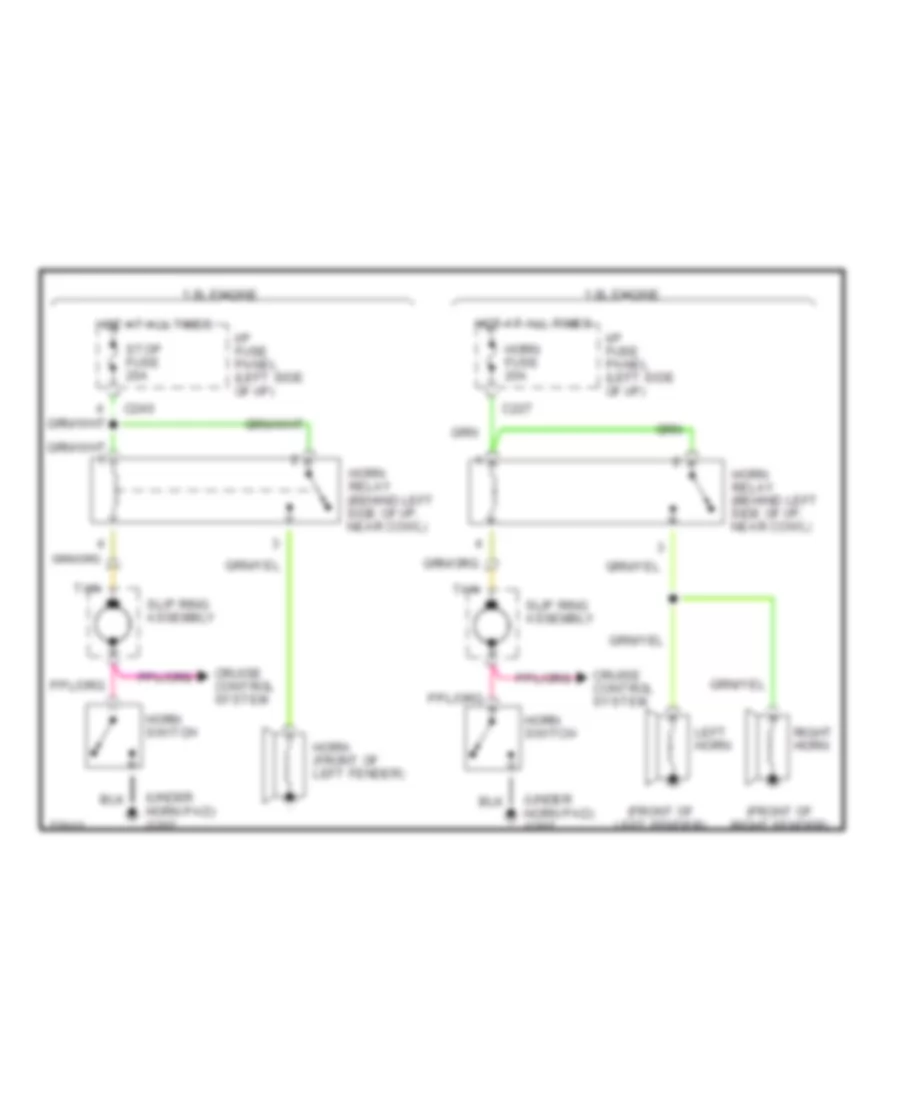
Horn Wiring Diagram for Ford Escort GT 1996
List of elements for Horn Wiring Diagram for Ford Escort GT 1996:
- (front of left fender)
- (front of right fender)
- (under horn pad) g207
- 1.8l engine
- 1.9l engine
- C227
- C240
- Cruise control system
- Horn (front of left fender)
- Horn fuse 20a
- Horn relay (behind left side of i/p, near cowl)
- Horn switch
- Hot at all times
- I/p fuse panel (left side of i/p)
- Left horn
- Right horn
- Slip ring assembly
- Stop fuse 20a
- Tan
INSTRUMENT CLUSTER
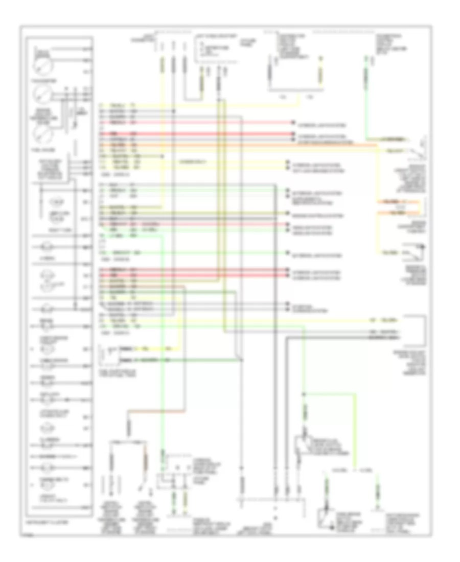
Instrument Cluster Wiring Diagram, Sport Cluster for Ford Escort GT 1996
List of elements for Instrument Cluster Wiring Diagram, Sport Cluster for Ford Escort GT 1996:
- (a/t only)
- (conn a)
- (conn b)
- (conn c)
- (m/t only)
- (w/ drl)
- (w/o drl)
- (wagon only)
- 1.8l
- 1.9l
- 1.9l only
- 50 (or 51)
- A10
- A11
- A12
- Air bag
- Anti-lock
- Anti-lock brakes system
- Anti-slosh/ low fuel warning/ bulb prove- out module
- B12
- Backup/ upshift switch (1.9l m/t only) (left side of engine, on lower front of transaxle)
- Brake
- Brake fluid level switch (top of brake master cylinder)
- C10
- C110
- C157
- C210
- C212
- C220
- C252
- C253
- C254
- Charge
- Check engine
- Check engine coolant
- Daytime running lamps module (top right end of i/p, on cowl panel)
- Distributor ignition module (left side of engine compartment)
- Engine compartment fuse box
- Engine controls system
- Engine coolant level switch (top of radiator coolant reservoir)
- Engine coolant temperature gauge
- Engine oil pressure switch (lower rear of engine)
- Exterior lights system
- Fasten belts
- Fuel gauge
- Fuel pump module (top of fuel tank)
- G200 (behind top of left cowl panel)
- Headlights system
- Hi beam
- Hot in run or start
- I/p fuse panel
- Illum
- Instru- mentation engine coolant temperature sender (left front of engine)
- Instru- mentation engine coolant temperature sender (left side of engine)
- Instrument cluster
- Interior lights system
- Joint connector
- Left turn
- Liftgate ajar (wagon only)
- Meter fuse 15a
- Nca
- Oil press
- Park brake switch (below rear of center console)
- Passive restraint module (on floor, under driver seat)
- Powertrain control module (below center of i/p)
- Red
- Right turn
- Solid state
- Starting/ charging system
- Starting/charging system
- Tachometer
- Upshift (1.9l m/t only)
- W/ drl
- W/o drl
- Warning chime module (back of i/p fuse panel)
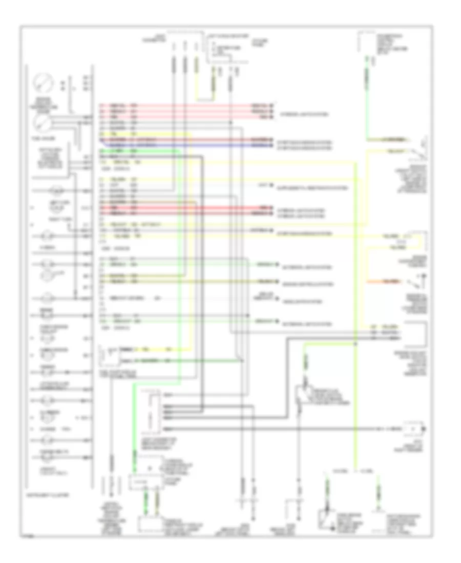
Instrument Cluster Wiring Diagram, Standard Cluster for Ford Escort GT 1996
List of elements for Instrument Cluster Wiring Diagram, Standard Cluster for Ford Escort GT 1996:
- (a/t only)
- (conn a)
- (conn b)
- (conn c)
- (m/t only)
- A10
- Air bag
- Anti-slosh/ low fuel warning/ bulb prove- out module
- B10
- B11
- Backup/ upshift switch (1.9l m/t only) (left side of engine, on lower front of transaxle)
- Brake
- Brake fluid level switch (top of brake master cylinder)
- C11
- C110
- C12
- C210
- C212
- C220
- C249
- C250
- C251
- Charge
- Check engine
- Check engine coolant
- Daytime running lamps module (top right end of i/p, on cowl panel)
- Engine compartment fuse box
- Engine controls system
- Engine coolant level switch (top of radiator coolant reservoir)
- Engine coolant temperature gauge
- Engine oil pressure switch (lower rear of engine)
- Exterior lights system
- Fasten belts
- Fuel gauge
- Fuel pump module (top of fuel tank)
- G101 (front of right fender)
- G106 (behind left headlamp)
- G200 (behind top of left cowl panel)
- Headlights system
- Hi beam
- Hot in run or start
- I/p fuse panel
- Illum
- Instru- mentation engine coolant temperature sender (left side of engine)
- Instrument cluster
- Interior lights system
- Joint connector
- Joint connector (behind right i/p, near grommet)
- Left turn
- Liftgate ajar (wagon only)
- Meter fuse 15a
- Nca
- Oil press
- Park brake switch (below rear of center console)
- Passive restraint module (on floor, under driver seat)
- Powertrain control module (below center of i/p)
- Red
- Right turn
- Starting/charging system
- Upshift (1.9l m/t only)
- W/ drl
- W/o drl
- Warning chime module (back of i/p fuse panel)
INTERIOR LIGHTS
Interior Light Wiring Diagram for Ford Escort GT 1996
List of elements for Interior Light Wiring Diagram for Ford Escort GT 1996:
- (sport) (standard)
- (standard) (sport)
- 1.8l only
- 3 & 5 door hatchback
- 3 & 5 door hatchback & wagon
- 4 door sedan
- 5 door hatchback 4 door notchback & wagon only
- A/c- heater control assembly
- Automatic transaxle selector illumination lamp
- Bus
- C210
- C220
- C230
- C232
- C249
- C249 c254
- C250 c252
- C251
- C252
- C252 c250
- C253
- C254 c249
- C260
- C269
- C270
- C290
- Control illumi- nation
- Dome lamp
- Dome lamp assembly
- Dome lamp switch
- Dome/map lamp assembly
- Door
- Electronic radio or electronic radio/cd player
- Exterior lights system
- Fog lamp switch
- G200 (top of left cowl panel)
- G202 (behind left side of i/p)
- Head
- Hot at all times
- Hot in run or start
- I/p fuse panel (behind left side of i/p)
- I/p fuse panel (behind left side of i/p, left of steering column)
- I/p fuse panel (behind left side of i/p, steering column)
- Ignition switch illumination lamp
- Illumi- nation
- Illumination lamps
- Instrument cluster
- Instrument panel dimming module (left of steering column)
- Joint connector (behind top of left cowl panel)
- Joint connector (behind top of left cowl panel)
- Lamps on input
- Left
- Left front door courtesy lamp switch (on left "b" pillar)
- Left map lamp
- Left rear door courtesy lamp switch (at base of left "c" pillar)
- Liftgate ajar indicator
- Liftgate latch switch (in center rear of cargo area, part of latch assembly)
- Liftgate latch switch (in center rear of liftgate, part of latch assembly)
- Luggage compartment lamp
- Luggage compartment switch (right front of trunk, near hinge support)
- Map lamp assembly
- Map lamp switches
- Meter fuse 15a
- Moonroof drive assembly (center of windshield header)
- Multi- function switch
- Nca
- Near cowl)
- Off
- Park
- Park lamp relay (behind left side of i/p,
- Power tops system (moonroof system)
- Rear window defrost switch
- Red
- Right
- Right front door courtesy lamp switch (on right "b" pillar)
- Right map lamp
- Right rear door courtesy lamp switch (at base of right "c" pillar)
- Room fuse 15a
- Solid state
- Sport only
- Tail fuse 15a
- W/ power moonroof
- W/o power moonroof
- Wagon
- Warning chime module (behind left side of i/p, on rear of i/p fuse panel)
- Warning chime module (behind left side of i/p, on the rear of the i/p fuse panel)
- With power moonroof
PASSIVE RESTRAINTS
Passive Restraint Wiring Diagram for Ford Escort GT 1996
List of elements for Passive Restraint Wiring Diagram for Ford Escort GT 1996:
- Belt fuse 30a
- C210
- C230
- C249
- C251
- C252
- C253
- C270
- C290
- C378
- C379
- Chime out
- Engine controls system (fuel pump module)
- Engine controls system (ignition power)
- Fasten belts indicator
- G200 (behind top of left cowl panel)
- G405 (right rear side of cargo area)
- Ground
- Hot at all times
- Hot in run or start
- I/p fuse panel
- Ignition
- Indicator out
- Inertia fuel shutoff switch (right side of cargo area)
- Inertia shtoff
- Instrument cluster
- Joint connector (behind right side of i/p, near grommet)
- Joint connector (behind top left of i/p)
- Left front door latch switch (top rear of left door)
- Left front limit switch (left 'a' pillar)
- Left passive belt spool switch (between front seats)
- Left passive restraint motor (left 'b' pillar)
- Left rear limit switch (upper left 'b' pillar)
- Lfr rest mtr
- Lft frt lim sw
- Lft latch sw
- Lft rest mtr
- Lft rr lim sw
- Lft spool sw
- Meter fuse 15a
- Nca
- Passive restraint module (under left front seat)
- Pnk
- Power b(+)
- Right front door latch switch (top rear of right door)
- Right front limit switch (right 'a' pillar)
- Right passive belt spool switch (between front seats)
- Right passive restraint motor (right 'b' pillar)
- Right rear limit switch (upper right 'b' pillar)
- Rt frt lim sw
- Rt latch sw
- Rt rest mtr
- Rt rr lim sw
- Rt spool sw
- Sport cluster
- Standard cluster
- Warning chime module (on rear of i/p fuse panel)
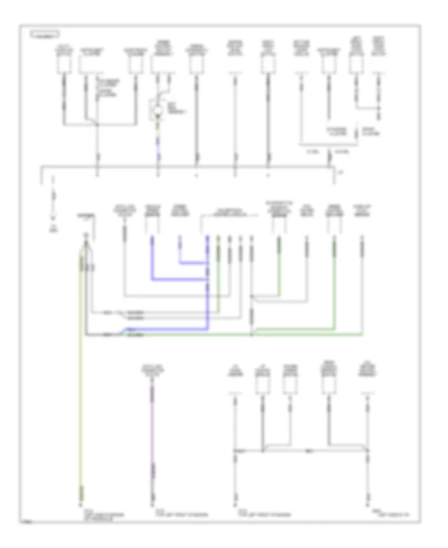
POWER DISTRIBUTION
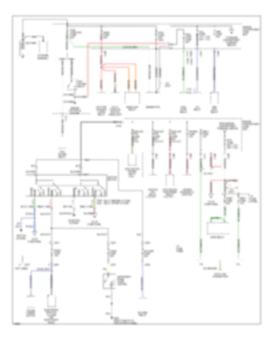
Power Distribution Wiring Diagram (1 of 3) for Ford Escort GT 1996
List of elements for Power Distribution Wiring Diagram (1 of 3) for Ford Escort GT 1996:
- (1.8l a/t)
- (1.8l m/t)
- (1.8l)
- (1.8l) (1.9l)
- (1.9l)
- (1.9l) (1.8l)
- (built before 12/14/95) (built after 12/14/95)
- (not used)
- 1.8l
- 1.8l only
- 1.9l
- 1.9l only
- 20a
- A/c fuse 10a
- A/c relay
- Abs fuse 60a
- Abs main relay
- Acc
- Air bag diagnostic monitor
- Air bag fuse 10a
- Battery
- Blower fuse 30a
- Blower relay
- Btn fuse 60a 40a
- C1023
- C108
- C109
- C111
- C161
- C200
- C227
- C231
- C246 c261
- C247
- C260
- C270
- Cigar fuse 20a
- Cooling fan high speed relay
- Cooling fan power relay
- Cooling fan relay
- Data link connector 2
- Daytime running lamps relay
- Electronic radio/cd player -or- electronic radio
- Engine compartment fuse box
- Engine controls system
- From engine compartment
- Fuel injector fuse 30a
- Fuel pump fuse 20a
- Fuel pump relay
- Fuse box (above)
- G203 (right side of i/p, top of cowl panel)
- Generator
- Head fuse 30a
- Headlamp relay
- Horn fuse 20a
- Horn relay
- I/p fuse panel
- Ignition switch
- Ignition system
- Instrument panel cigar lighter
- Lock
- Main fuse 80a 100a
- Multi- function switch (headlamp)
- Nca
- Obd ii fuse 10a
- Pcm power relay
- Power mirror switch
- Radio fuse 15a
- Red
- Run
- Start
- Starter assembly
- Starting system
- To engine compartment fuse box (below)
- To i/p fuse panel
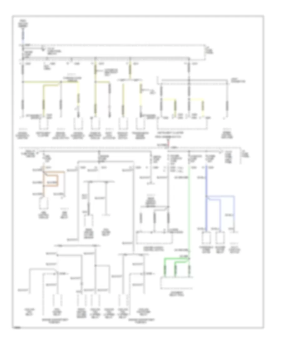
Power Distribution Wiring Diagram (2 of 3) for Ford Escort GT 1996
List of elements for Power Distribution Wiring Diagram (2 of 3) for Ford Escort GT 1996:
- (1.8l)
- (1.9l)
- (3 d00r) (4 & 5 door)
- (not used)
- (standard) (sport)
- 1.8l
- 1.8l only
- 1.9l
- A/t
- Abs control module
- Abs fuse 10a
- Abs main relay
- Air bag diagnostic monitor
- Backup/ upshift switch
- Blower motor relay
- C108
- C210
- C220
- C231
- C232
- C240
- C249
- C250
- C251
- C252
- C253
- C254
- C260
- C270
- C290
- Cooling fan hi speed relay
- Cooling fan lo speed relay
- Cooling fan power relay
- Cooling fan relay
- Defog fuse 20a
- Engine compartment
- Engine coolant level switch
- Engine fuse 10a
- From i/p e fuse panel (above)
- From ignition switch
- Front heated oxygen sensor
- Fuse box
- I/p fuse panel
- Instrument cluster
- Joint connector
- M/t
- Master window control switch
- Meter fuse 15a
- Moonroof relay pack
- Multi- function switch
- Nca
- Passive restraint module
- Pcm power relay
- Power windows fuse 30a
- Rear heated oxygen
- Rear window defrost
- Sensor
- Shift lock actuator
- Speed control amplifier
- Switch
- To i/p fuse panel (below)
- To i/p fuse panel (next page)
- Transmission range sensor
- W/passive restraint only
- Warning chime module
- Windows fuse 30a
- Windshield wiper motor
- Wiper fuse 20a
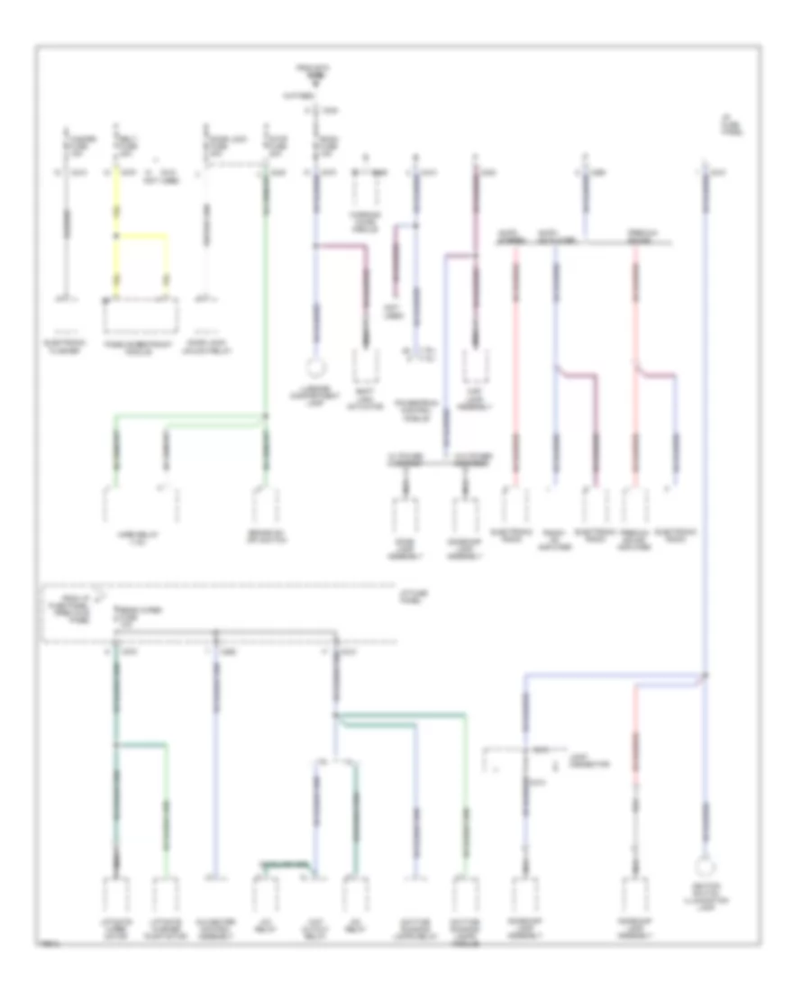
Power Distribution Wiring Diagram (3 of 3) for Ford Escort GT 1996
List of elements for Power Distribution Wiring Diagram (3 of 3) for Ford Escort GT 1996:
- (1.8l)
- (1.9l)
- (not
- (not used)
- 1.8l
- 1.9l
- A/c relay
- A/c-heater control assembly
- Am/fm cd player
- Am/fm stereo
- Belt fuse 30a
- Brake on/ off switch
- C210
- C213
- C232
- C240
- C260
- C270
- C290
- Daytime running lamps module
- Daytime running lamps relay
- Dome lamp assembly
- Dome/map lamp assembly
- Door lock fuse 30a
- Door lock/ unlock relay
- Electronic flasher
- Electronic radio
- From btn
- From i/p f
- Fuse
- Hazard fuse 15a
- Horn relay (1.9l)
- I/p fuse panel
- Ignition switch illumination lamp
- Joint connector
- Liftgate washer pump motor
- Liftgate wiper motor
- Luggage compartment lamp
- Map lamp assembly
- Nca
- Passive restraint module
- Powertrain control module
- Premium sound
- Premium sound amplifier
- Radio/ cd amplifier
- Rear wiper fuse 10a
- Room fuse 15a
- Shift lock actuator
- Stop fuse 20a
- Used)
- W/ power moonroof
- W/o power moonroof
- Warning chime module
- Wot cutout relay
POWER DOOR LOCKS
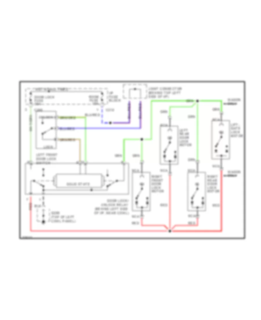
Power Door Lock Wiring Diagram for Ford Escort GT 1996
List of elements for Power Door Lock Wiring Diagram for Ford Escort GT 1996:
- C210
- C240
- Door lock fuse 30a
- Door lock/ unlock relay (behind left side of i/p, near cowl)
- G200 (top of left cowl panel)
- Hot at all times
- I/p fuse block
- Joint connector (behind top left side of i/p)
- Left front door lock switch
- Left rear door lock motor
- Lift- gate lock motor
- Lock
- Nca
- Red
- Right front door lock motor
- Right rear door lock motor
- Room fuse 15a
- Solid state
- Unlock
- Wagon only
POWER MIRRORS
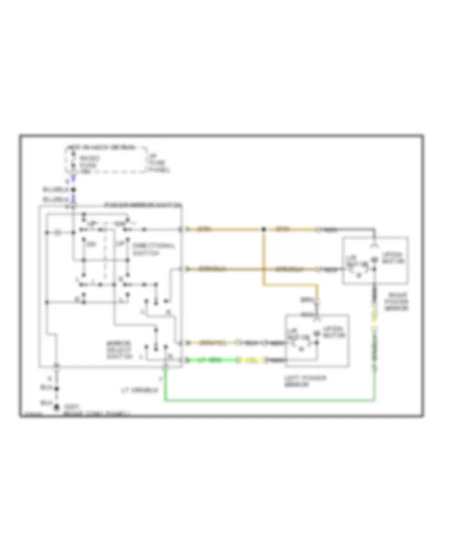
Power Mirror Wiring Diagram for Ford Escort GT 1996
List of elements for Power Mirror Wiring Diagram for Ford Escort GT 1996:
- Directional switch
- G201 (right cowl panel)
- Hot in accy or run
- I/p fuse panel
- L/r motor
- Left power mirror
- Mirror select switch
- Nca
- Power mirror switch
- Radio fuse 15a
- Right power mirror
- Up/dn m motor
- Up/dn motor
POWER TOP/SUNROOF
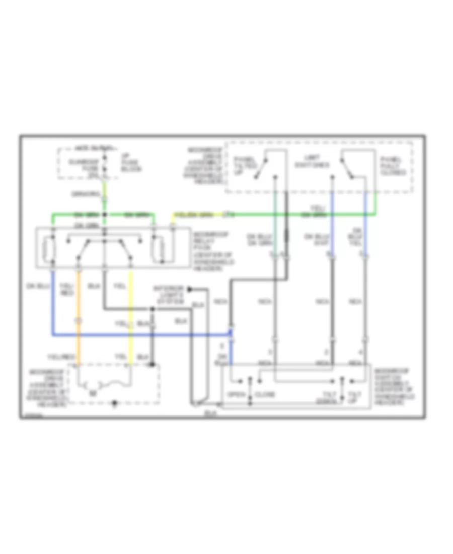
Power Top/Sunroof Wiring Diagrams for Ford Escort GT 1996
List of elements for Power Top/Sunroof Wiring Diagrams for Ford Escort GT 1996:
- Close
- Down
- Hot in run
- I/p fuse block
- Interior lights system
- Limit switches
- Moonroof drive assembly (center of windshield header)
- Moonroof relay pack (center of windshield header)
- Moonroof switch assembly (center of windshield header)
- Nca
- Open
- Panel fully closed
- Panel tilted up
- Sunroof fuse 15a
- Tilt
- Tilt up
POWER WINDOWS
Power Window Wiring Diagram, Hatchback for Ford Escort GT 1996
List of elements for Power Window Wiring Diagram, Hatchback for Ford Escort GT 1996:
- * 1.8l engine
- * 11 ** 2
- * c220
- ** 1.9l engine
- ** c240
- G200 (top of left cowl panel)
- Hot in run
- I/p fuse panel
- Left front window motor
- Lock-out
- Master window control switch
- Nca
- Power windows fuse 30a
- Red
- Right front window motor
- Right front window switch
- Up down
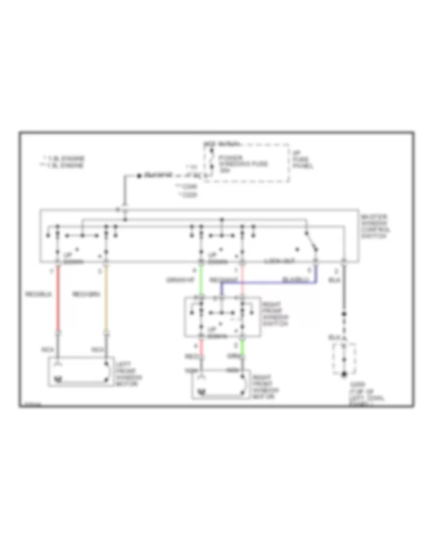
Power Window Wiring Diagram, Sedan & Wagon for Ford Escort GT 1996
List of elements for Power Window Wiring Diagram, Sedan & Wagon for Ford Escort GT 1996:
- * 1.8l engine
- * 11 ** 2
- * c220
- ** 1.9l engine
- ** c240
- G200 (top of left cowl panel)
- Hot in run
- I/p fuse panel
- Left front window motor
- Left rear window motor
- Left rear window switch
- Lock-out
- Master window switch
- Nca
- Power windows fuse 30a
- Red
- Right front window motor
- Right rear window motor
- Right front window switch
- Right rear window switch
- Up down
RADIO
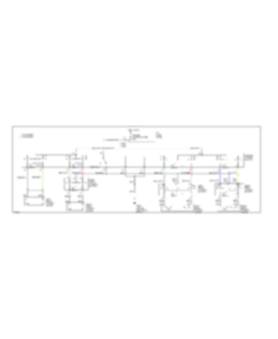
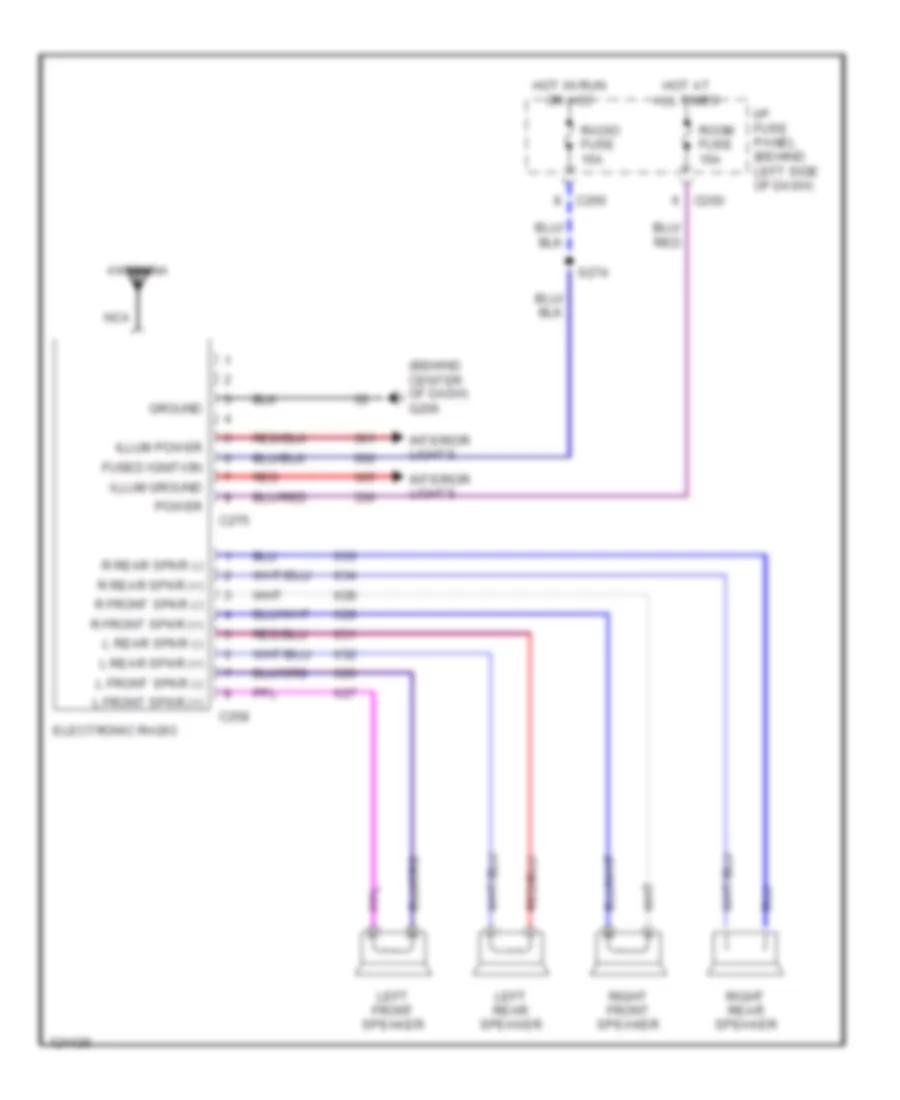
Base Radio for Ford Escort GT 1996
List of elements for Base Radio for Ford Escort GT 1996:
- (behind center of dash) g206
- Antenna
- C258
- C260
- C275
- Electronic radio
- Fused ignition
- Ground
- Hot at all times
- Hot in run or acc
- I/p fuse panel (behind left side of dash)
- Illum ground
- Illum power
- Interior lights
- L front spkr (+)
- L front spkr (-)
- L rear spkr (+)
- L rear spkr (-)
- Left front speaker
- Left rear speaker
- Nca
- Power
- R front spkr (+)
- R front spkr (-)
- R rear spkr (+)
- R rear spkr (-)
- Radio fuse 15a
- Red
- Right front speaker
- Right rear speaker
- Room fuse 15a
- S274
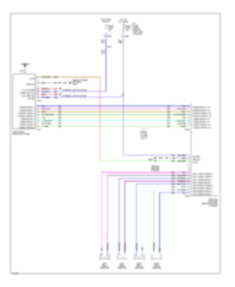
Premium Sound Radio Wiring Diagram for Ford Escort GT 1996
List of elements for Premium Sound Radio Wiring Diagram for Ford Escort GT 1996:
- (behind center of dash)
- (behind center of dash) g206
- Amp l front spkr (+)
- Amp l front spkr (-)
- Amp l rear spkr (+)
- Amp l rear spkr (-)
- Amp r front spkr (+)
- Amp r front spkr (-)
- Amp r rear spkr (+)
- Amp r rear spkr (-)
- Antenna
- C260
- C276
- C277
- C278
- C279
- Electronic radio/cd player
- Fused ignition
- G206
- Ground
- Hot at all times
- Hot in run or acc
- I/p fuse panel (behind left side of dash)
- Illum ground
- Illum power
- Interior lights system
- L front spkr (+)
- L front spkr (+) in
- L front spkr (-)
- L front spkr (-) in
- L rear spkr (+)
- L rear spkr (+) in
- L rear spkr (-)
- L rear spkr (-) in
- Left front speaker
- Left rear speaker
- Mute
- Nca
- Power
- R front spkr (+)
- R front spkr (+) in
- R front spkr (-)
- R front spkr (-) in
- R rear spkr (+)
- R rear spkr (+) in
- R rear spkr (-)
- R rear spkr (-) in
- Radio fuse 15a
- Radio/cd amplifier (behind center of dash)
- Red
- Right front speaker
- Right rear speaker
- Room fuse 10a
- S274
- Sheild (w/ cd player only)
SHIFT INTERLOCKS
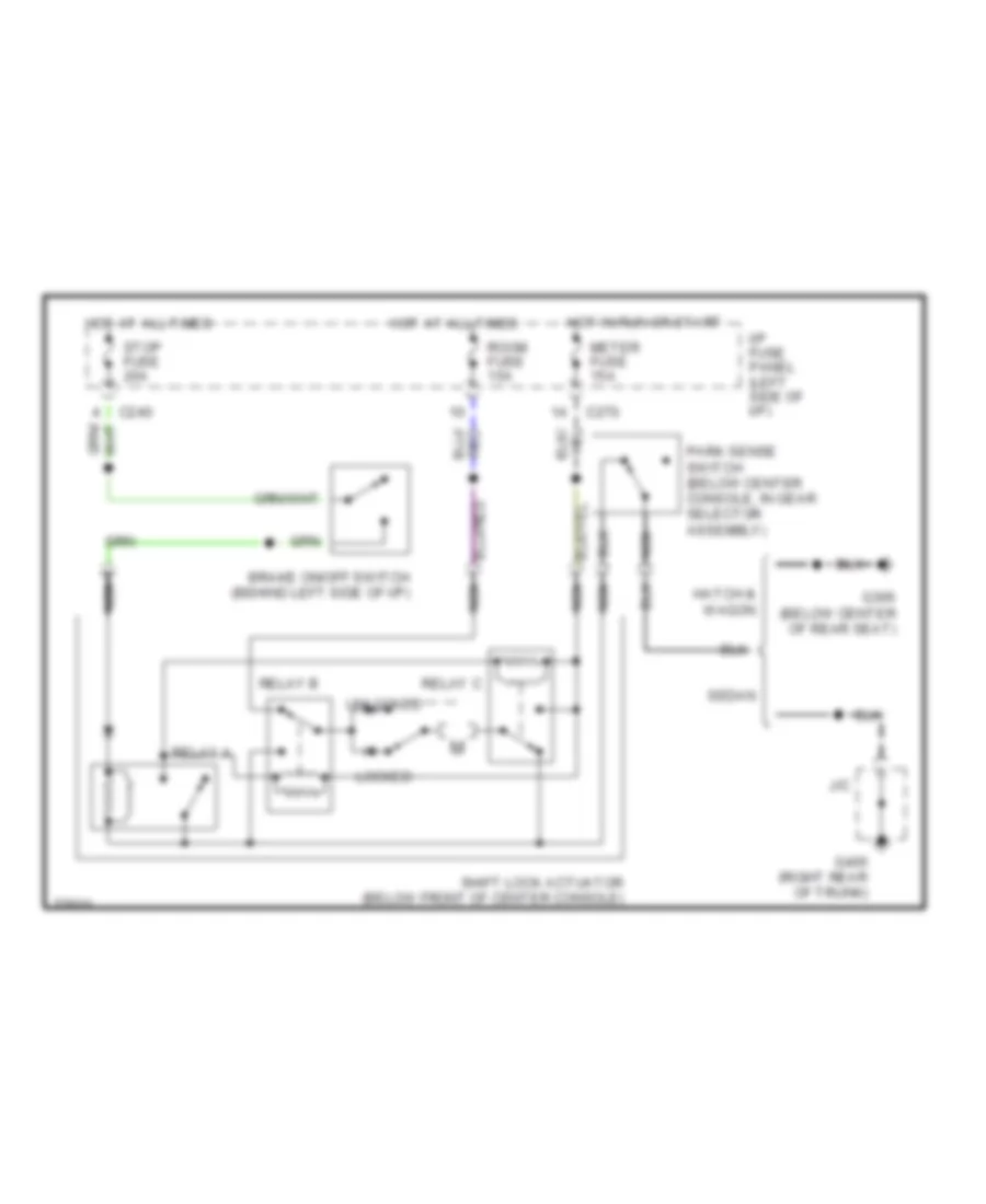
Shift Interlock Wiring Diagram for Ford Escort GT 1996
List of elements for Shift Interlock Wiring Diagram for Ford Escort GT 1996:
- Brake on/off switch (behind left side of i/p)
- C240
- C270
- G306 (below center of rear seat)
- G405 (right rear of trunk)
- Hatch & wagon
- Hot at all times
- Hot in run or start
- I/p fuse panel (left side of i/p)
- J/c
- Locked
- Meter fuse 15a
- Nca
- Park sense switch (below center console, in gear selector assembly)
- Relay a
- Relay b
- Relay c
- Room fuse 15a
- Sedan
- Shift lock actuator (below front of center console)
- Stop fuse 20a
- Unlocked
STARTING/CHARGING
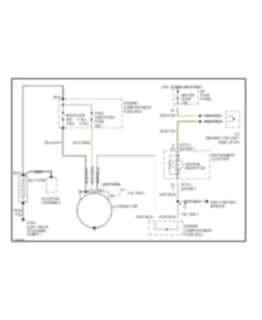
Charging Wiring Diagram for Ford Escort GT 1996
List of elements for Charging Wiring Diagram for Ford Escort GT 1996:
- (1.8l)
- (1.9l)
- (std.) (sport)
- 1.8l only
- 1.9l only
- Abs control module
- Alternator
- Battery
- Charge indicator
- Engine compartment fuse box
- Fuel injection fuse 30a
- G104 (left rear of engine compt)
- Hot in run or start
- I/p fuse panel
- Instrument cluster
- J/c (behind top left side of i/p)
- Main fuse 80a 100a
- Meter fuse 15a
- Starter assembly
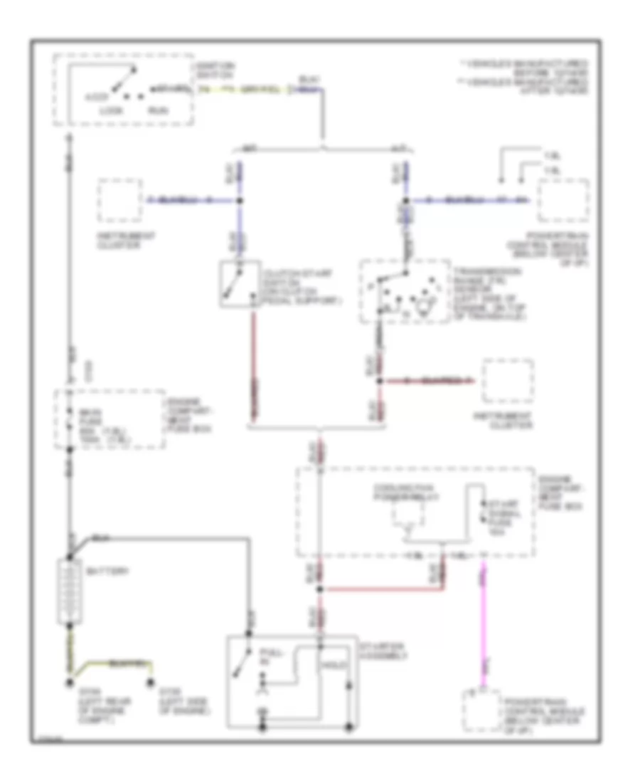
Starting Wiring Diagram for Ford Escort GT 1996
List of elements for Starting Wiring Diagram for Ford Escort GT 1996:
- (1.8l) (1.9l)
- * vehicles manufactured before 12/14/95 ** vehicles manufactured after 12/14/95
- **1
- 1.8l
- 1.9l
- A/t
- Accy
- Battery
- C109
- Clutch start switch (on clutch pedal support)
- Cooling fan power relay
- Engine compart- ment fuse box
- G104 (left rear of engine comp't)
- G130 (left side of engine)
- Hold
- Ignition switch
- Instrument cluster
- Lock
- M/t
- Main fuse 80a 100a
- Nca
- Powertrain control module (below center of i/p)
- Pull- in
- Run
- Start
- Start signal fuse 10a
- Starter assembly
- Transmission range (tr) sensor (left side of engine, on top of transaxle)
SUPPLEMENTAL RESTRAINTS
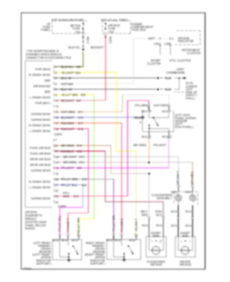
Supplemental Restraint Wiring Diagram for Ford Escort GT 1996
List of elements for Supplemental Restraint Wiring Diagram for Ford Escort GT 1996:
- * pin shorting bar is engaged when module connector is disconnected
- 10*
- 11*
- Air bag diagnostic module (center dash panel below radio)
- Air bag fuse 15a
- Air bag ind
- Air bag indicator
- C108
- C2001
- C2002
- C220
- C250
- C253
- Clockspring assembly
- Driver air bag
- Drvr air bag
- Engine compartment fuse box
- G116 (lower left side of safety wall)
- Gnd
- Hot at all times
- Hot in run or start
- I/p fuse panel
- Instrument cluster
- Joint connector
- L crash sens
- Left front primary crash sensor (left front upper radiator support)
- Left kick panel safing sensor (left kick panel)
- Meter fuse 15a
- Nca
- Pass air bag
- Passenger air bag
- Pwr (bat)
- Pwr (run)
- R crash sens
- Right front primary crash sensor (right front upper radiator support)
- Safing sens
- Short bar
- Sport cluster
- Std. cluster
TRANSMISSION
1.8L
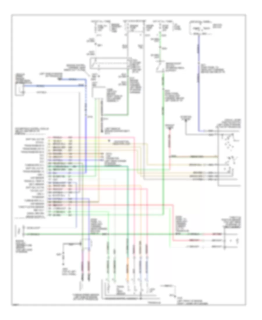
1.8L, Transmission Wiring Diagram for Ford Escort GT 1996
List of elements for 1.8L, Transmission Wiring Diagram for Ford Escort GT 1996:
- (dash panel to headlight harness, behind center of i/p) s123
- (engine control harness, near breakout to dlc) s101
- (left front of engine compt, under air cleaner)
- (lower rear of transaxle) vehicle speed sensor
- (on throttle body) throttle position sensor
- (top left side of engine) engine coolant temperature sensor
- (top of engine) volume air flow meter
- (top of left
- Acc
- Backup lamps
- Brake on/off switch (on brake pedal support)
- Brake sw in
- C2009
- C204
- C210
- C238
- C240
- Cowl panel)
- Data link connector 1 (left rear corner of engine compartment)
- Data link connector 2 (left rear corner of engine compartment)
- Dlc #2 conn
- Dlc conn
- Ect sensor in
- Engine compart- ment fuse box
- Engine fuse 15a
- Fuel inj. fuse 30a
- G100
- G112 (top left of engine)
- G114 (lower left rear of engine compartment, on safety wall)
- G200
- Hot at all times
- Hot in run or start
- I/p fuse panel
- Ignition switch
- Joint conn. c103
- Lock
- Lock up
- Malfunction indicator lamp
- Meter fuse 15a
- Mil output
- Nca
- Pcm power relay
- Powertrain control module (below center of i/p)
- Red
- Ref voltage
- Run
- S117 (engine harness, left rear of engine)
- S121 (engine control harness, near breakout to vss)
- S203
- S223 (dash panel to headlamp harness, behind left side of i/p)
- S261
- S271 (dash panel to headlight harness, near break out to ignition switch)
- Shift sol #1
- Shift sol #2
- Shift sol #3
- Signal return
- Solenoid control assembly
- Start
- Start sig
- Starting system
- Stop fuse 20a
- Tcc control
- Tp sensor in
- Tp sensor sw in
- Trans range-drve
- Trans range-low
- Trans range-od
- Trans temp in
- Trans. fluid temp. sensor
- Transaxle
- Transmission range sensor (left side of engine, on top of transaxle)
- Turbine speed (+)
- Turbine speed (-)
- Turbine speed sensor (left side of engine, on top of transaxle)
- Vaf meter
- Vaf meter in
- Vss (+)
- Vss (-)
1.9L
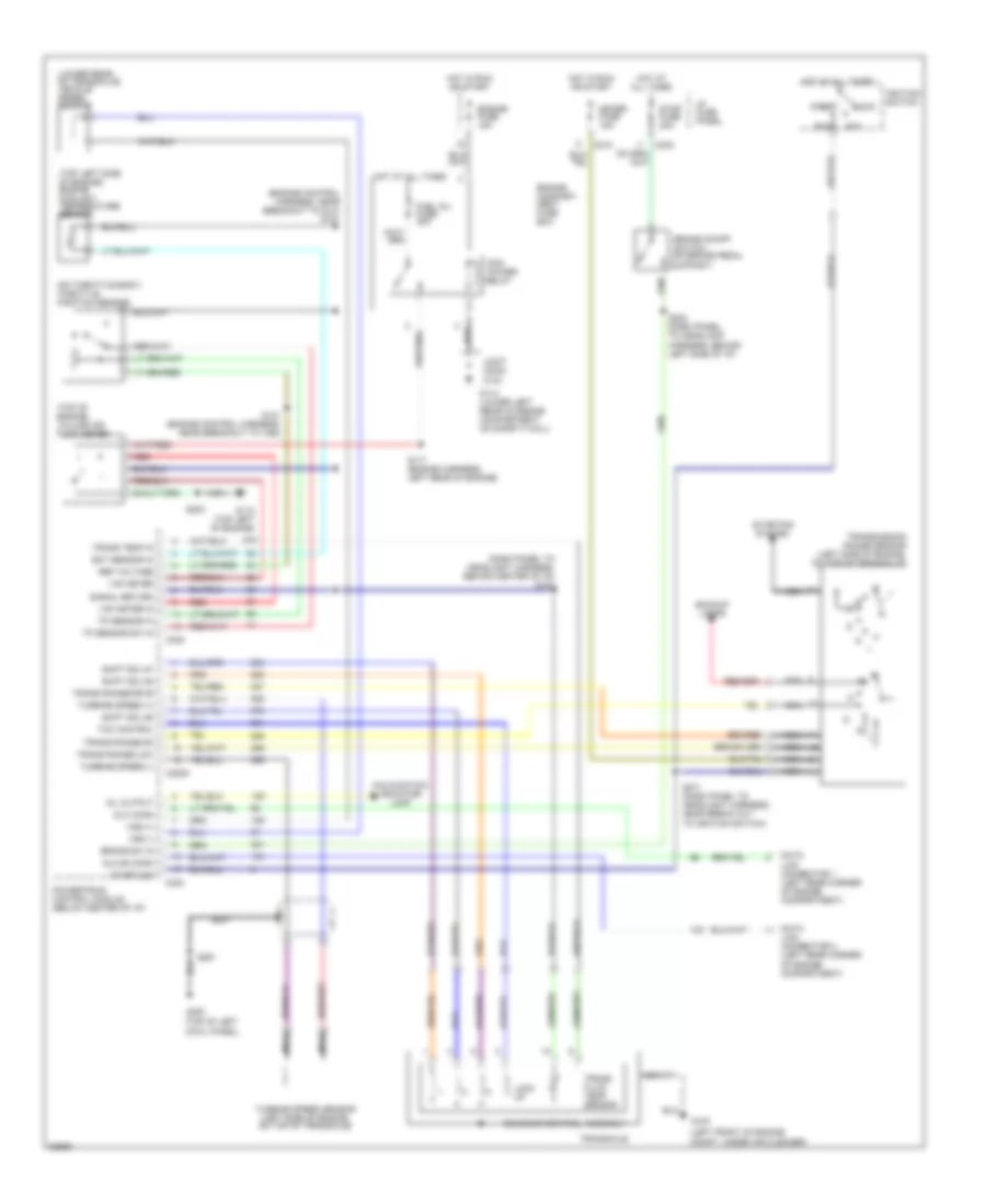
1.9L, Transmission Wiring Diagram for Ford Escort GT 1996
List of elements for 1.9L, Transmission Wiring Diagram for Ford Escort GT 1996:
- (dash panel to headlight harness, in break out to transaxle) s164
- (dash panel to headlight harness, near harness routing shield)
- (ect) sensor
- (engine control harness, near break out to pcm)
- (left front of engine compt, under air cleaner)
- (left rear corner of engine compartment)
- (left rear of engine compartment) g114
- (left side of engine on transaxle) g102
- (top of left
- Acc
- Backup lamps
- Brake on/off in
- Brake on/off switch (on brake pedal support)
- C111
- C210
- C240
- Cowl panel)
- Data link connector
- Dlc
- Engine compart- ment fuse
- Engine coolant temperature sensor (top left side of engine)
- Engine fuse 15a
- Fuel inj. fuse 30a
- G100
- G200
- Hot at all times
- Hot in run or start
- I/p fuse panel
- Ignition switch
- Lock
- Lock up
- Maf sensor
- Malfunction indicator lamp
- Manual lever position switch (left side of engine, on top of transaxle)
- Mass air flow sensor (right side of air cleaner assembly)
- Meter fuse 15a
- Nca
- Pcm power relay (below center of i/p)
- Powertrain control module (below center of i/p) (partial)
- Ref volt
- Run
- S132
- S137 (engine control harness, left rear of engine harness)
- S141
- S142
- S223 (dash panel to headlamp harness, behind left side of i/p)
- S224
- S243
- S254
- S261
- S264
- S271 (dash panel to headlight harness, behind center of i/p)
- S281
- Shft sol out #1
- Shft sol out #2
- Shft sol out #3
- Signal return
- Solenoid control assembly
- Start
- Starting system
- Sto/mil
- Stop fuse 20a
- Tcc sol out
- Throttle pos sensor
- Throttle position sensor (top left rear of engine, on throttle body)
- Tr sensor
- Trans oil temp in
- Trans rnge-drive in
- Trans rnge-low in
- Trans rnge-od in
- Trans rnge-rev in
- Trans. oil temp. sensor
- Transaxle
- Turbine spd in (+)
- Turbine spd in (-)
- Turbine speed sensor (left side of engine, on top of transaxle)
- Vehicle speed sensor (lower rear of transaxle)
- Vss (+)
- Vss (-)
WARNING SYSTEMS
Warning System Wiring Diagrams for Ford Escort GT 1996
List of elements for Warning System Wiring Diagrams for Ford Escort GT 1996:
- (standard cluster) (sport cluster)
- Belt ind driver
- C210
- C220
- C230
- C232
- C249
- C251 c252
- C253
- C270
- C378
- Chime on in
- Door switch
- Driver seat blt
- Driver's seat belt buckle switch
- Fasten belts indicator
- G200 (behind top of left cowl panel)
- G306 (below center of rear seat)
- Ground
- Head
- Hot at all times
- Hot in run or start
- I/p fuse panel
- Ign pwr
- Ign sw illum (-)
- Ignition switch illumination lamp (inside steering column assembly)
- Instrument cluster
- Interior lights system
- J/c
- J/c (behind right side of i/p, near grommet)
- J/c (behind top left side of i/p)
- Key in ignition switch (inside steering column assembly)
- Key in switch
- Lamps on
- Left front door courtesy lamp switch (side of left 'b' pillar)
- Left front door lock switch
- Left rear door courtesy lamp switch (side of left 'c' pillar)
- Meter fuse 15a
- Multi- function switch
- Nca
- Not used
- Off
- Park
- Park lamp relay (behind left i/p)
- Passive restraint module (under driver seat)
- Power b+
- Right front door courtesy lamp switch (side of right 'b' pillar)
- Right rear door courtesy lamp switch (side of right 'c' pillar)
- Room fuse 15a
- Tail fuse 15a
- Warning chime module (back of i/p fuse panel)
WIPER/WASHER
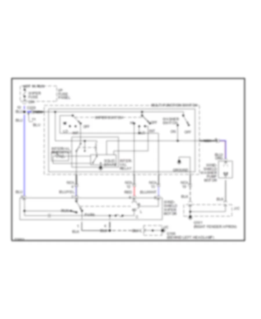
Front Washer/Wiper Wiring Diagram for Ford Escort GT 1996
List of elements for Front Washer/Wiper Wiring Diagram for Ford Escort GT 1996:
- 20a
- C220
- G101 (right fender apron)
- G106 (behind left headlamp)
- Ground
- Hot in run
- I/p fuse panel
- Int
- Inter- val relay
- Interval rheostat
- J/c
- Multi-function switch
- Nca
- Off
- Park
- Red
- Run
- Solid state
- Washer switch
- Wind- shield washer pump motor
- Wind- shield wiper motor
- Wiper fuse
- Wiper switch
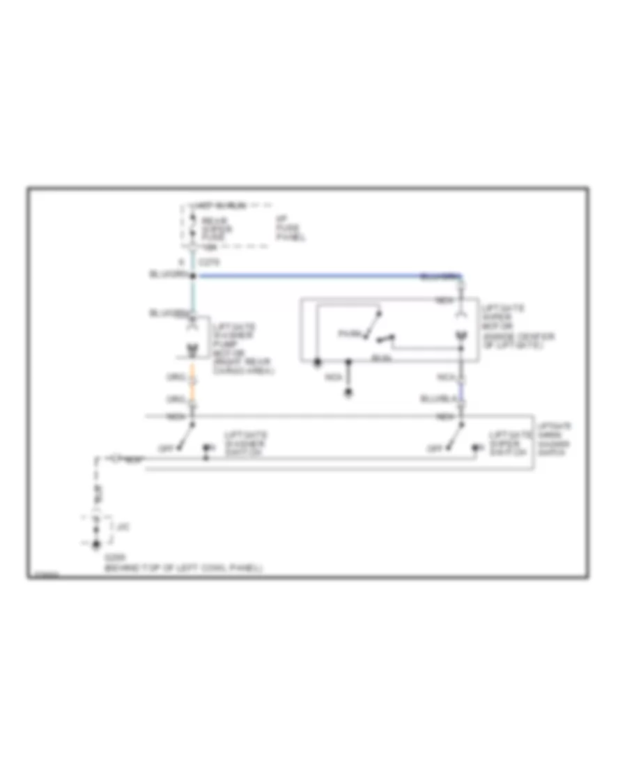
Rear Wiper/Washer Wiring Diagram for Ford Escort GT 1996
List of elements for Rear Wiper/Washer Wiring Diagram for Ford Escort GT 1996:
- C270
- G200 (behind top of left cowl panel)
- Hot in run
- I/p fuse panel
- J/c
- Liftgate washer pump motor (right rear cargo area)
- Liftgate washer switch
- Liftgate wiper motor (inside center of liftgate)
- Liftgate wiper switch
- Liftgate wiper/ washer switch
- Nca
- Off
- Park
- Rear wiper fuse 10a
- Run