AIR CONDITIONING
5.4L
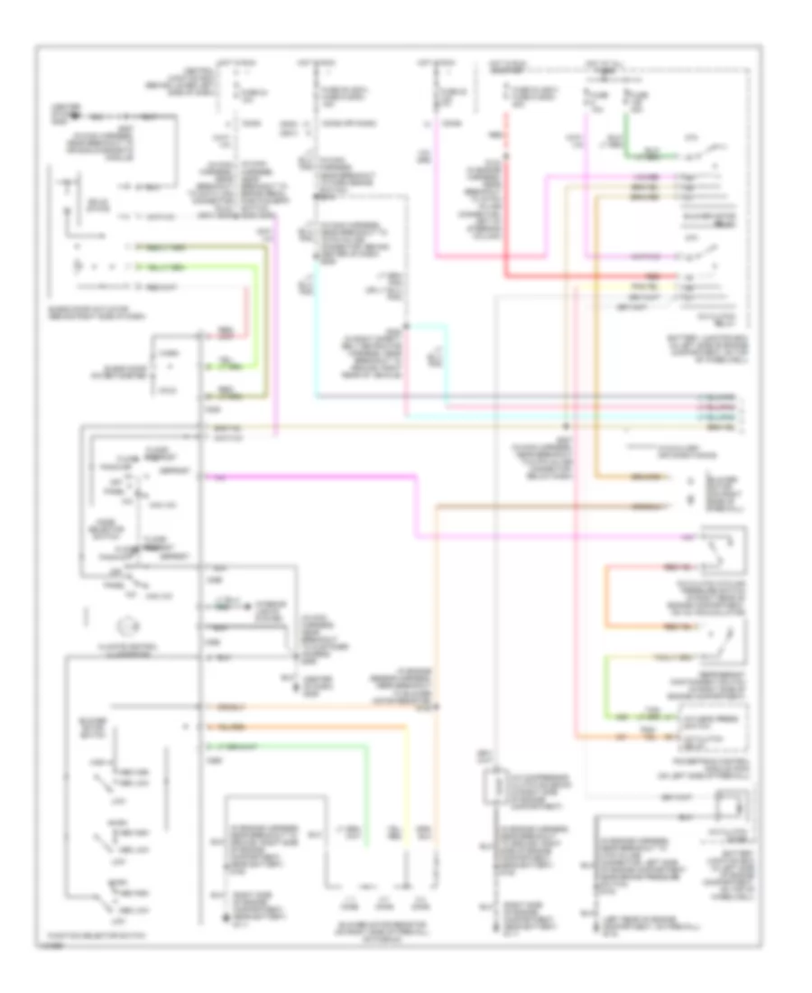
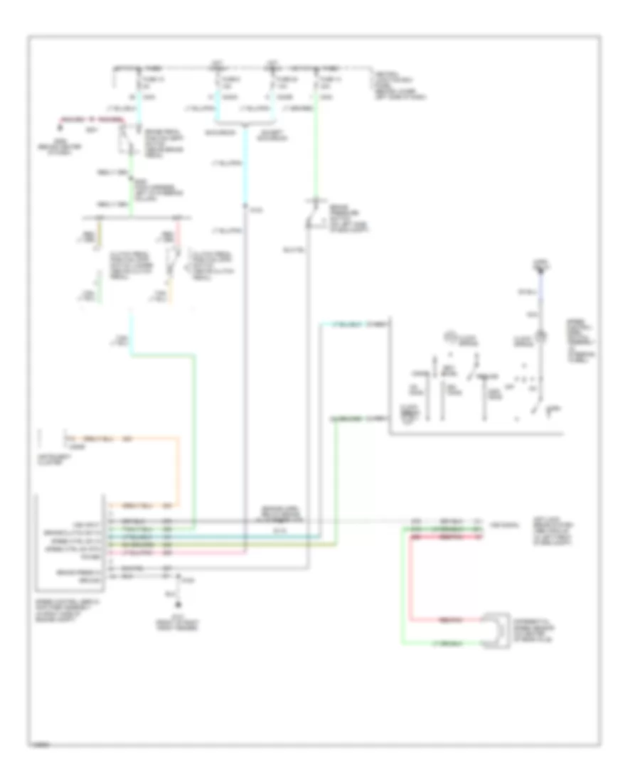
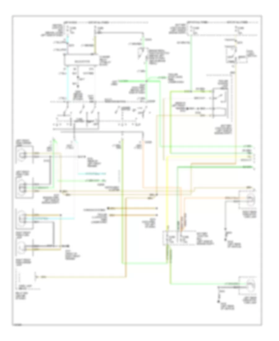
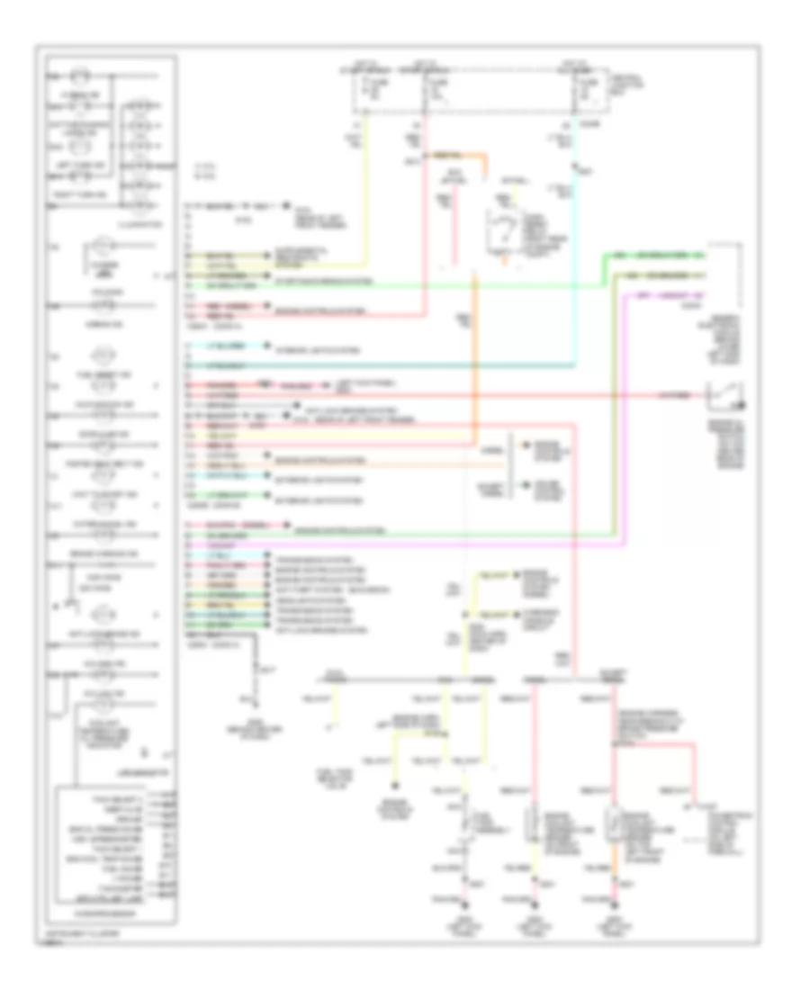
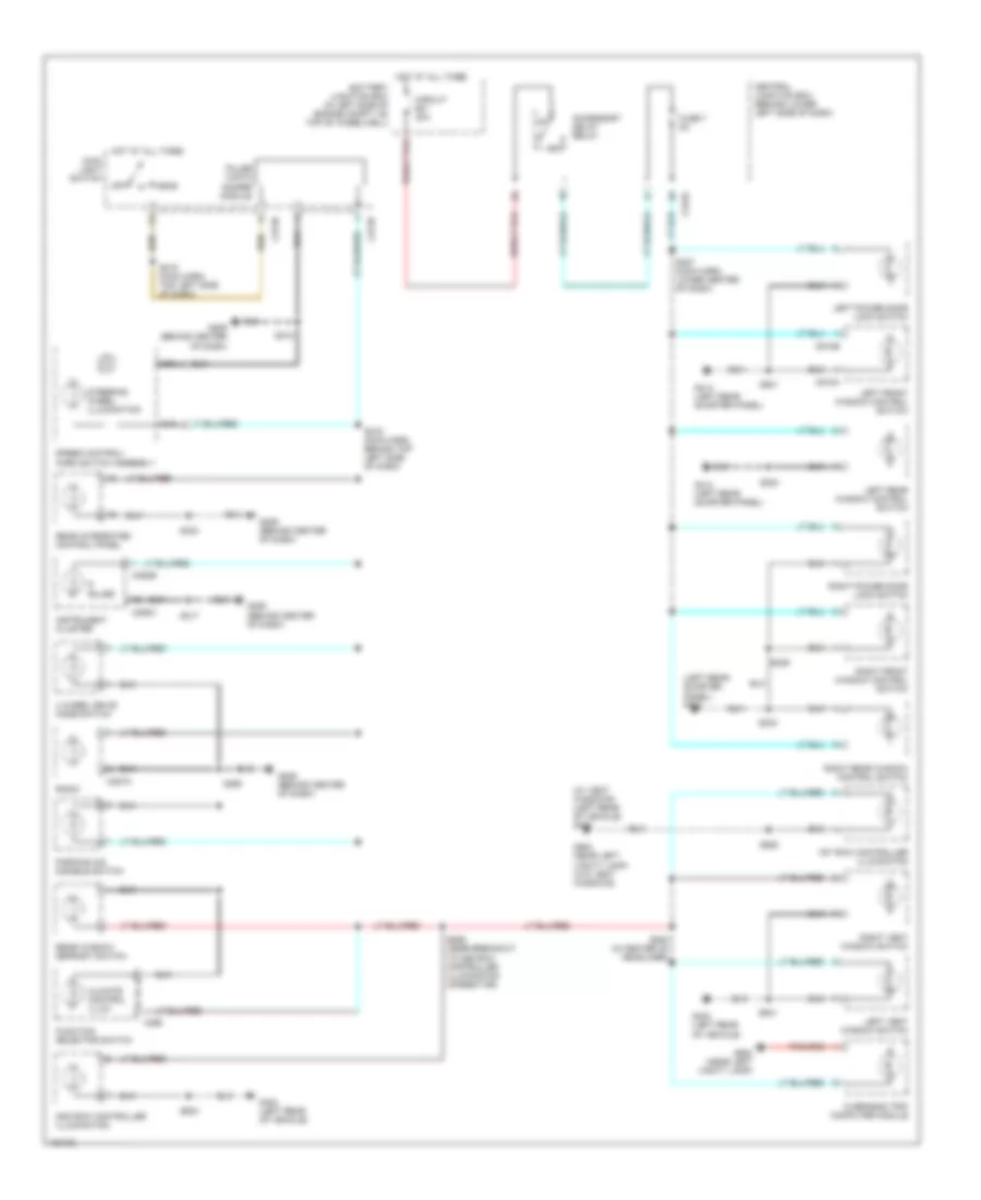
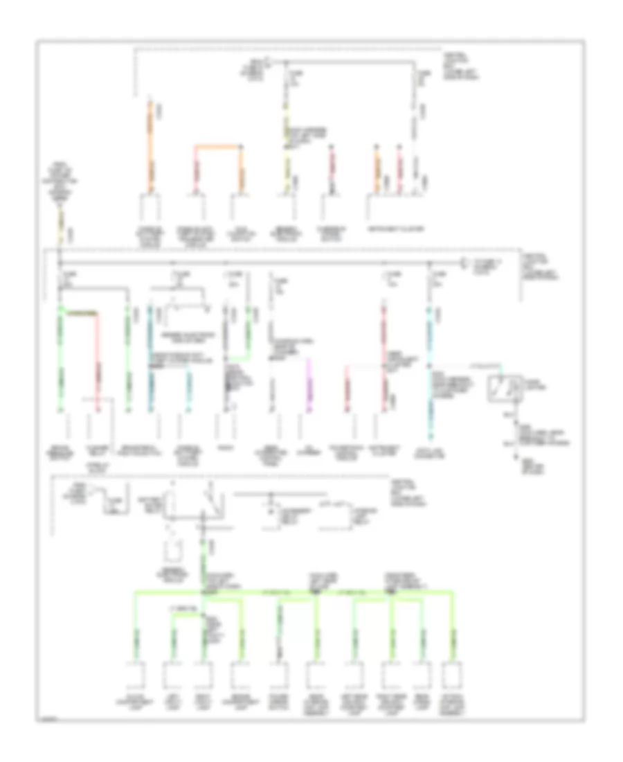
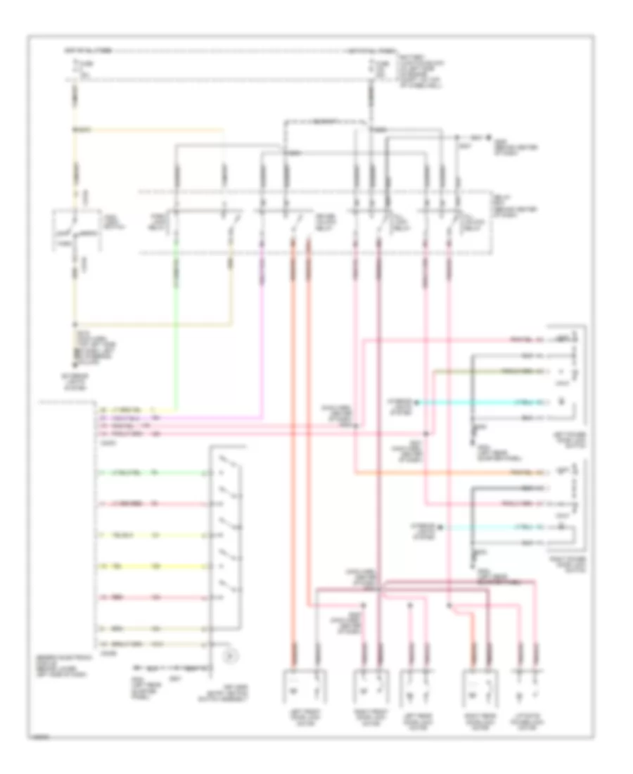
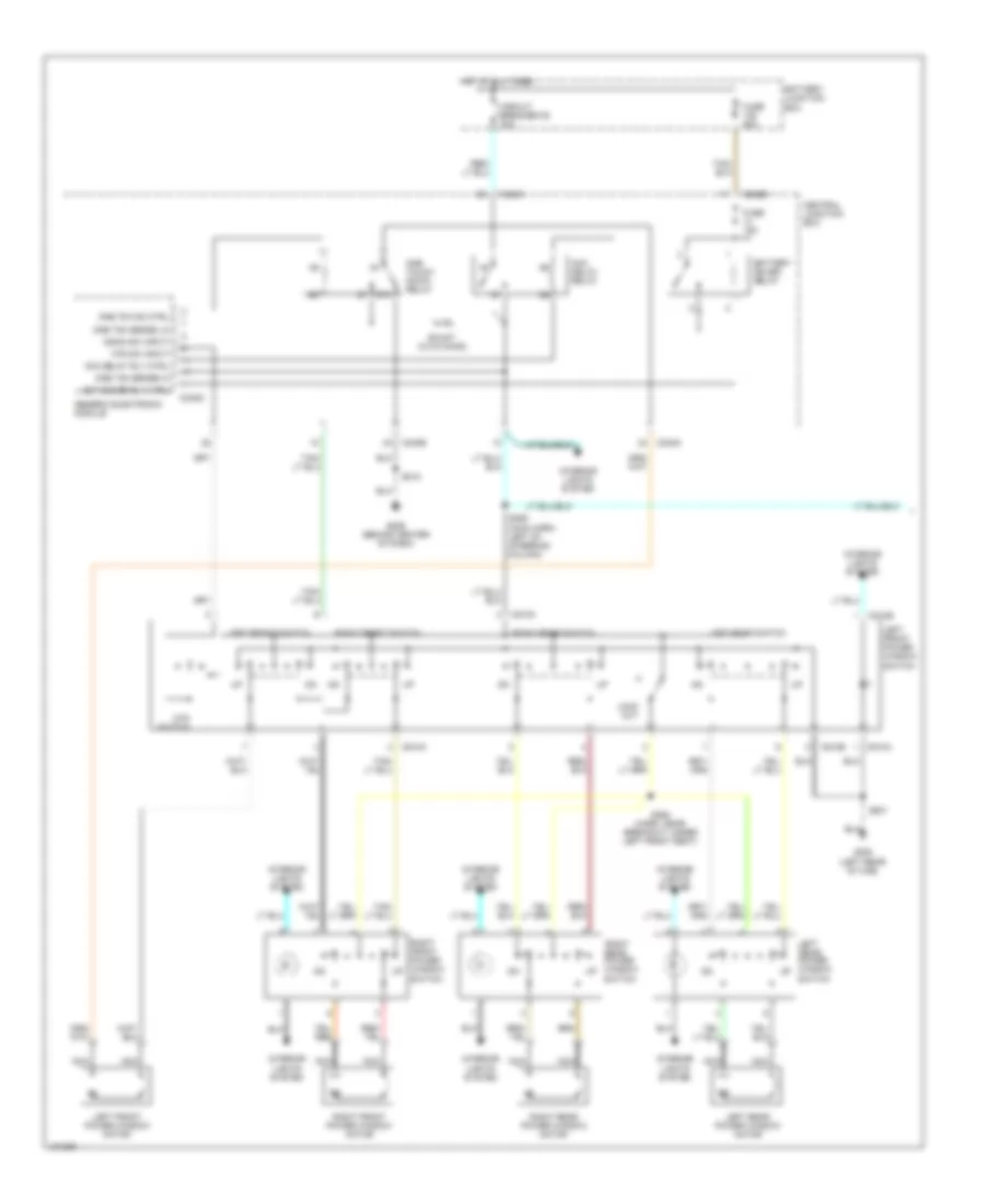
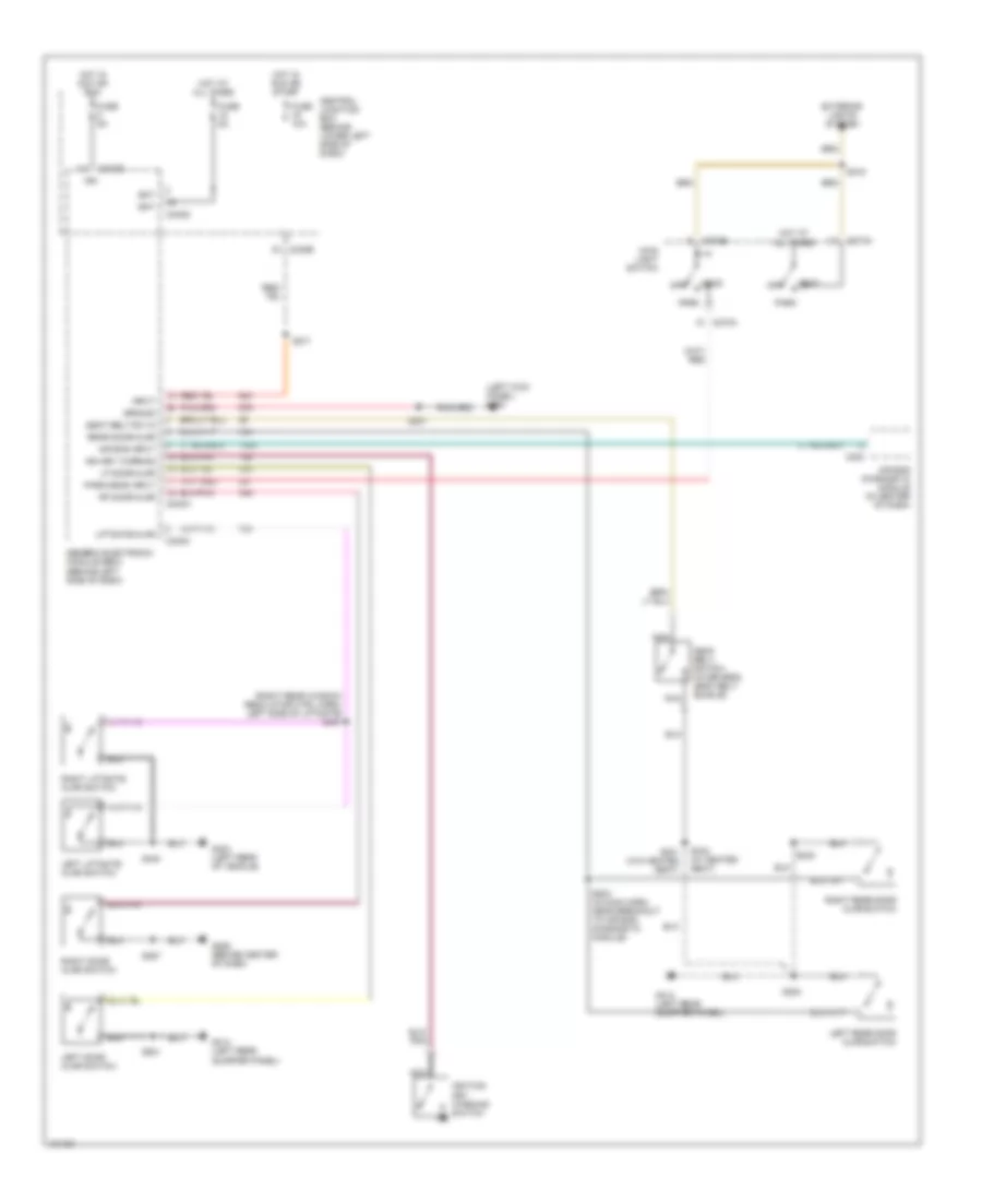
5.4L, Manual A/C Wiring Diagram (1 of 2) for Ford Excursion 2000

List of elements for 5.4L, Manual A/C Wiring Diagram (1 of 2) for Ford Excursion 2000:
- (2000)
- (2001)
- (center of dash) g206
- (in engine harness, near breakout to ground, right side of engine compartment, near battery) s180
- (in engine sensor harness, near breakout to blower motor resistor) s152
- (in main (in main harness, near breakout to data link connector (dlc)) (2001) s235
- (in main harness, near breakout to customer access) s290
- (in main harness, near breakout to park brake switch) s270
- (left rear of engine compartment, on firewall) g116
- (right side of engine compartment, near battery) g111
- 0.3 ohms
- 0.7 ohms
- 1.7 ohms
- 87a
- A/c
- A/c clutch cycling pressure switch (in right rear of engine compartment, on a/c accumulator)
- A/c clutch diode
- A/c clutch relay
- A/c compressor clutch solenoid (in right side of engine compartment)
- A/c head press switch
- Battery junction box (in left side of engine compartment, on top of wheelwell)
- Blend door actuator (behind right side of dash)
- Blend door potentiometer
- Blower motor (on right side of firewall)
- Blower motor relay
- Blower motor resistor (on right side of firewall, on plenum)
- Blower motor switch
- C225
- C242a
- C242a (or c242b)
- C242b
- C260
- C296
- C298
- Central junction box (behind lower left side of dash)
- Climate control illumination
- Cold
- Defrost
- Floor
- Floor/ defrost
- Function selector switch
- Fuse 10a
- Fuse 22 10a
- Fuse 24 (2001) fuse 5 (2000) 20a
- Fuse 24 10a
- Fuse 28 (2001) fuse 6 (2000) 15a
- Fuse 40a
- Harness, near breakout to brake pedal position (bpp) switch) s235 (2000)
- High
- Hot at all times
- Hot in run
- Hot in run or start
- Interior lights system
- Low
- Lt (in main harness, near breakout to 16 pin in-line connector, behind center of dash) s206
- Max a/c
- Med high
- Med low
- Mode selector switch
- Off
- Pan/flr
- Panel
- Powertrain control module (pcm) (on left side of firewall)
- Red
- Refrigerant containment switch (in right side of engine compartment)
- S123 (in engine harness, near breakout to 40 pin in-line connector, left of steering column)
- S257 (in main harness, near breakout to air bag diagnostic module)
- S287 (in main harness, near breakout to 6 pin in-line connector, below dash)
- S322 (in right safety belt retractor harness, near breakout to ground, right rear of vehicle)
- Side of engine compartment, near battery) s180
- Solid state
- W/auxiliary air conditioning
- Warm
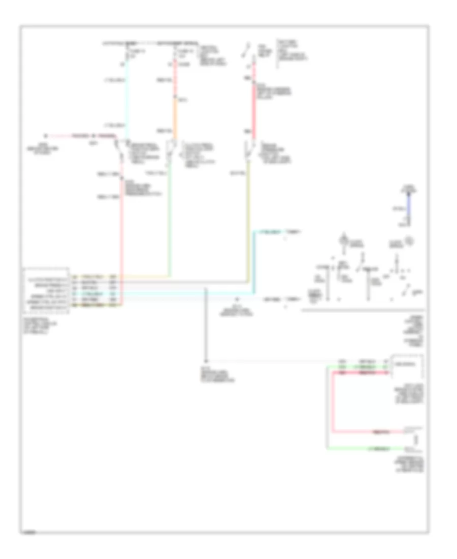
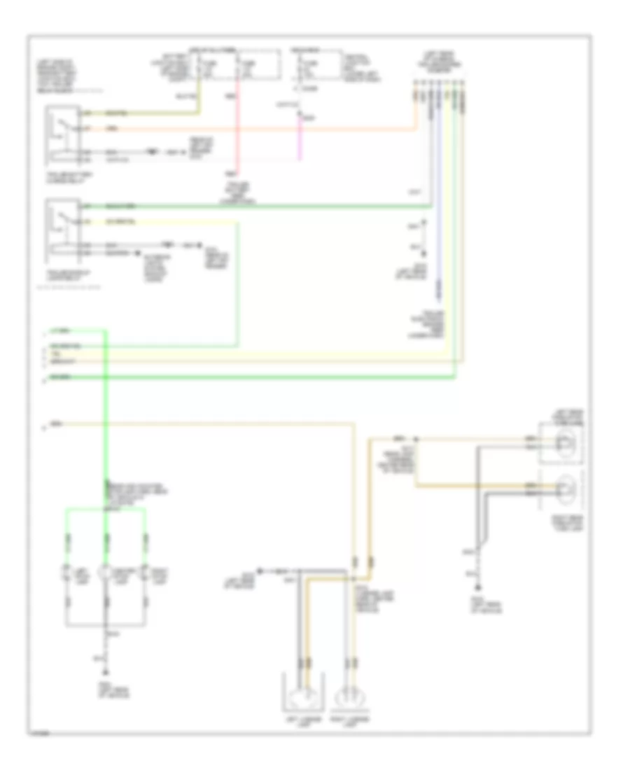
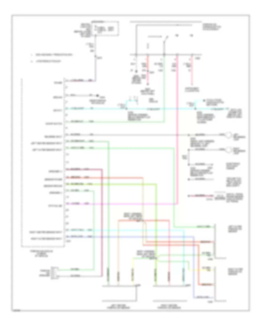
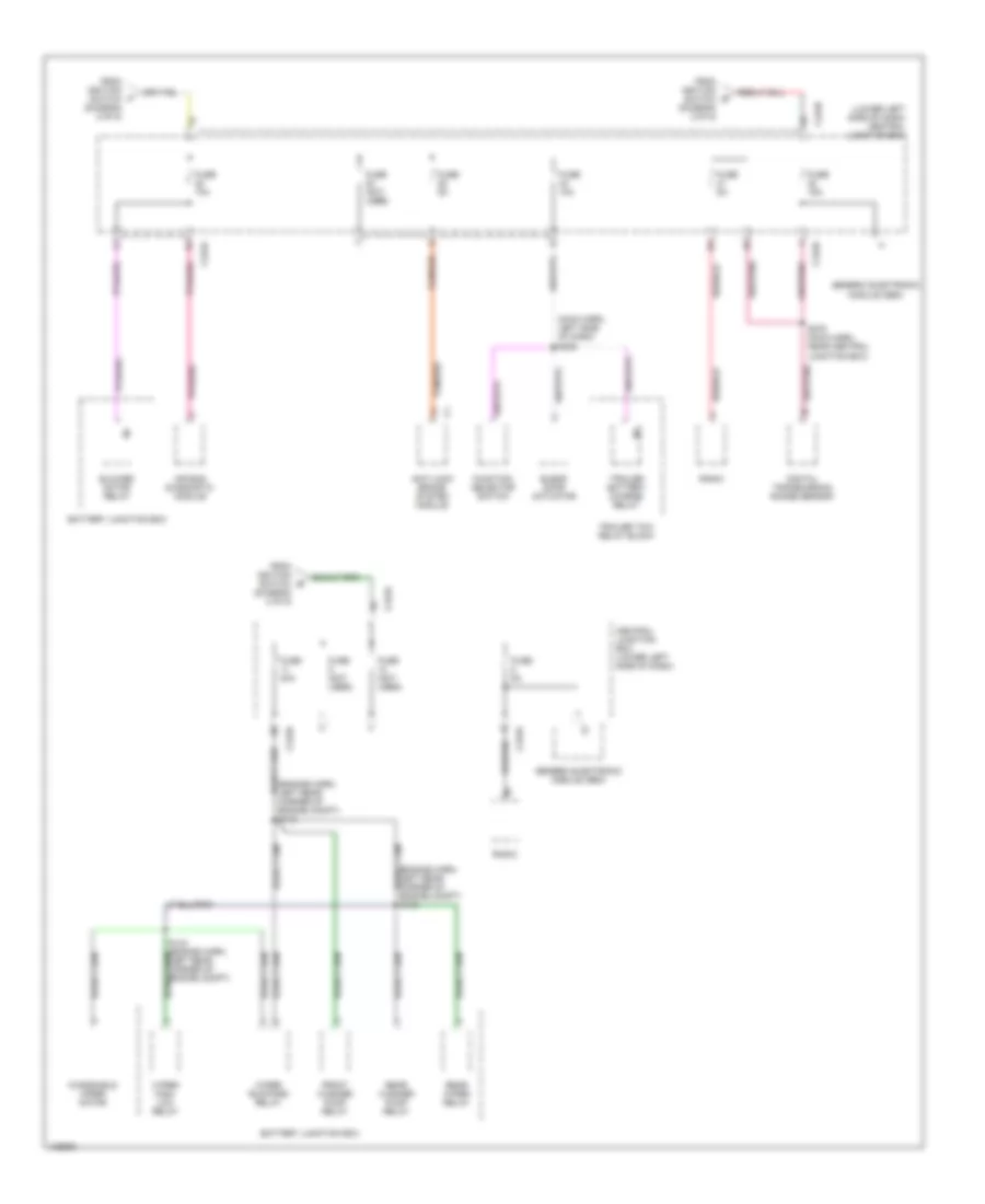
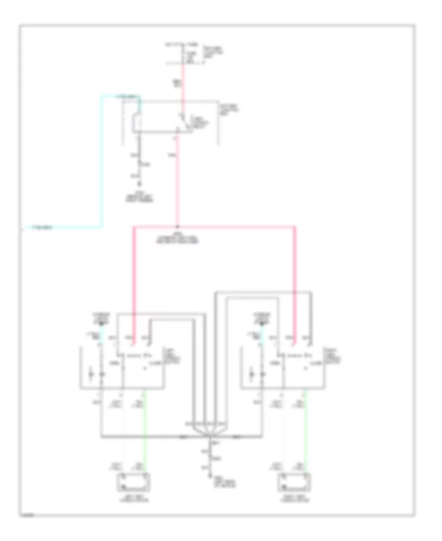
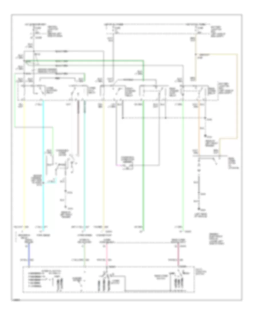
5.4L, Manual A/C Wiring Diagram (2 of 2) for Ford Excursion 2000
List of elements for 5.4L, Manual A/C Wiring Diagram (2 of 2) for Ford Excursion 2000:
- (front of vehicle near left vanity lamp) (w/o vent windows) g902
- (in interior lamps feed harness, near breakout to 2 pin connector in center of headliner) s935
- (in interior lamps feed harness, near breakout to 2nd row controller illumination in center of headliner) s924
- (in interior lamps feed harness, near breakout to 2nd row controller illumination in center of headliner) s925
- (in interior lamps feed harness, near breakout to rear blend potentiometer in center of headliner) s930
- (in interior lamps feed harness, near breakout to rear blend potentiometer in center of headliner) s931
- (in right rear corner of vehicle) auxiliary a/c blower motor resistor
- (in right safety belt retractor harness, near breakout to ground right rear of vehicle) s321
- (in right safety belt retractor harness, near breakout to ground, right rear of vehicle) s320
- (left rear of vehicle) (w/vent windows) g404
- (right rear of vehicle) g405
- 0.6 ohms
- 2.7 ohms
- 3.8 ohms
- 87a
- A/c mode act fbck
- Auxiliary a/c blend door actuator (in right rear corner of vehicle)
- Auxiliary a/c blower motor (in right rear corner of vehicle)
- Auxiliary a/c control module (in right rear corner of vehicle)
- Auxiliary a/c mode actuator (in right rear corner of vehicle)
- Auxiliary a/c relay
- Battery junction box (in left side of engine compartment, on top of wheelwell)
- Blend act feedback
- Blend dr act fbck
- Blend dr pot (+)
- Blend dr pot rtn
- Frnt ctrl wiper posit
- Frnt mode pot (+)
- Frnt mode pot rtn
- Front auxiliary a/c blower motor switch
- Front blend potentiometer (in center of headliner)
- Front mode potentiometer (in center of headliner)
- Fuse 40a
- Ground
- High speed auxiliary a/c relay (in left rear of vehicle)
- Hot at all times
- I/p relay block (behind dash, near instrument panel)
- Ignition
- Mode act feedback
- Off
- Rear auxiliary a/c blower motor switch
- Rear blend potentiometer (in center of headliner)
- Rear mode potentiometer (in center of headliner)
- Red
- Red/ pnk
- Rr ctrl sense line
- Rr ctrl wiper posit
- S927 (in interior lamps feed harness, near breakout to 2nd row controller illumination, in center of headliner)
- S928 (in interior lamps feed harness, near breakout to rear blend potentiometer in center of headliner)
- S929 (in interior lamps feed harness, near breakout to rear blend potentiometer in center of headliner)
6.8L
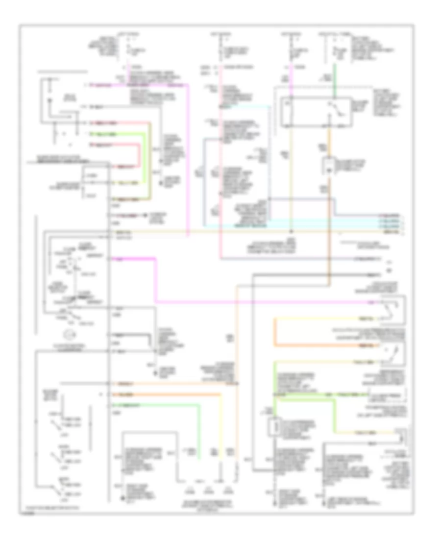
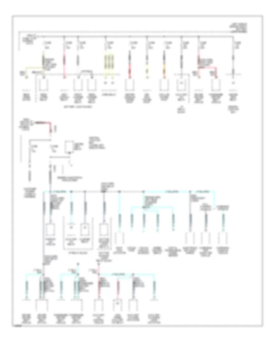
6.8L, Manual A/C Wiring Diagram (1 of 2) for Ford Excursion 2000
List of elements for 6.8L, Manual A/C Wiring Diagram (1 of 2) for Ford Excursion 2000:
- (2000)
- (2001)
- (center of dash) g206
- (in engine harness, near breakout to ground, right side of engine compartment, near battery) s180
- (in engine sensor harness, near breakout to blower motor resistor) s152
- (in main (in main harness, near breakout to data link connector (dlc)) (2001) s235
- (in main harness, near breakout to customer access) s290
- (in main harness, near breakout to park brake switch) s270
- (left rear of engine compartment, on firewall) g116
- (right side of engine compartment, near battery) g111
- 0.3 ohms
- 0.7 ohms
- 1.7 ohms
- 87a
- A/c
- A/c clutch cycling pressure switch (in right rear of engine compartment, on a/c accumulator)
- A/c clutch diode
- A/c clutch relay
- A/c compressor clutch solenoid (in right side of engine compartment)
- A/c head press switch
- Battery junction box (in left side of engine compartment, on top of wheelwell)
- Blend door actuator (behind right side of dash)
- Blend door potentiometer
- Blower motor (on right side of firewall)
- Blower motor relay
- Blower motor resistor (on right side of firewall, on plenum)
- Blower motor switch
- C225
- C242a
- C242a (or c242b)
- C242b
- C260
- C296
- C298
- Central junction box (behind lower left side of dash)
- Climate control illumination
- Cold
- Defrost
- Floor
- Floor/ defrost
- Function selector switch
- Fuse 10a
- Fuse 22 10a
- Fuse 24 (2001) fuse 5 (2000) 20a
- Fuse 24 10a
- Fuse 28 (2001) fuse 6 (2000) 15a
- Fuse 40a
- Harness, near breakout to brake pedal position (bpp) switch) s235 (2000)
- High
- Hot at all times
- Hot in run
- Hot in run or start
- Interior lights system
- Low
- Lt (in main harness, near breakout to 16 pin in-line connector, behind center of dash) s206
- Max a/c
- Med high
- Med low
- Mode selector switch
- Off
- Pan/flr
- Panel
- Powertrain control module (pcm) (on left side of firewall)
- Red
- Refrigerant containment switch (in right side of engine compartment)
- S123 (in engine harness, near breakout to 40 pin in-line connector, left of steering column)
- S257 (in main harness, near breakout to air bag diagnostic module)
- S287 (in main harness, near breakout to 6 pin in-line connector, below dash)
- S322 (in right safety belt retractor harness, near breakout to ground, right rear of vehicle)
- Side of engine compartment, near battery) s180
- Solid state
- W/auxiliary air conditioning
- Warm
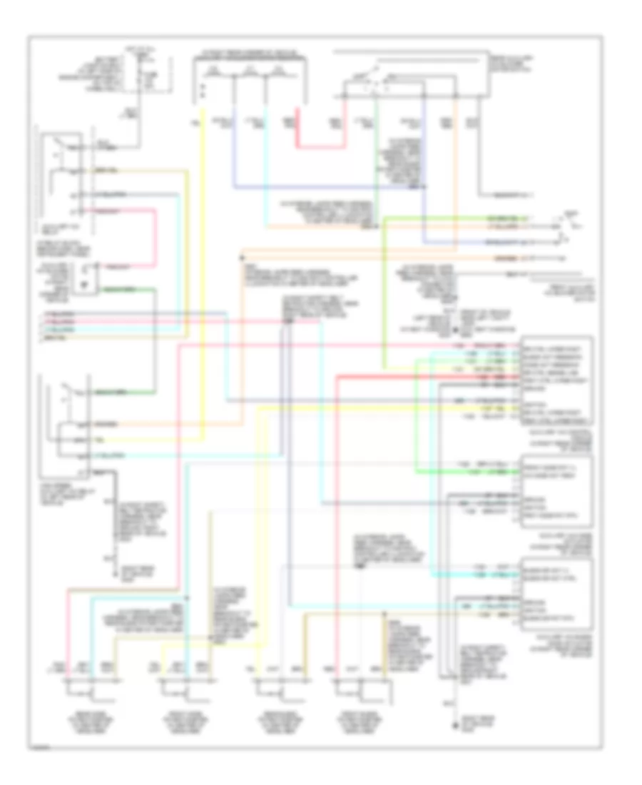
6.8L, Manual A/C Wiring Diagram (2 of 2) for Ford Excursion 2000
List of elements for 6.8L, Manual A/C Wiring Diagram (2 of 2) for Ford Excursion 2000:
- (front of vehicle near left vanity lamp) (w/o vent windows) g902
- (in interior lamps feed harness, near breakout to 2 pin connector in center of headliner) s935
- (in interior lamps feed harness, near breakout to 2nd row controller illumination in center of headliner) s924
- (in interior lamps feed harness, near breakout to 2nd row controller illumination in center of headliner) s925
- (in interior lamps feed harness, near breakout to rear blend potentiometer in center of headliner) s930
- (in interior lamps feed harness, near breakout to rear blend potentiometer in center of headliner) s931
- (in right rear corner of vehicle) auxiliary a/c blower motor resistor
- (in right safety belt retractor harness, near breakout to ground right rear of vehicle) s321
- (in right safety belt retractor harness, near breakout to ground, right rear of vehicle) s320
- (left rear of vehicle) (w/vent windows) g404
- (right rear of vehicle) g405
- 0.6 ohms
- 2.7 ohms
- 3.8 ohms
- 87a
- A/c mode act fbck
- Auxiliary a/c blend door actuator (in right rear corner of vehicle)
- Auxiliary a/c blower motor (in right rear corner of vehicle)
- Auxiliary a/c control module (in right rear corner of vehicle)
- Auxiliary a/c mode actuator (in right rear corner of vehicle)
- Auxiliary a/c relay
- Battery junction box (in left side of engine compartment, on top of wheelwell)
- Blend act feedback
- Blend dr act fbck
- Blend dr pot (+)
- Blend dr pot rtn
- Frnt ctrl wiper posit
- Frnt mode pot (+)
- Frnt mode pot rtn
- Front auxiliary a/c blower motor switch
- Front blend potentiometer (in center of headliner)
- Front mode potentiometer (in center of headliner)
- Fuse 40a
- Ground
- High speed auxiliary a/c relay (in left rear of vehicle)
- Hot at all times
- I/p relay block (behind dash, near instrument panel)
- Ignition
- Mode act feedback
- Off
- Rear auxiliary a/c blower motor switch
- Rear blend potentiometer (in center of headliner)
- Rear mode potentiometer (in center of headliner)
- Red
- Red/ pnk
- Rr ctrl sense line
- Rr ctrl wiper posit
- S927 (in interior lamps feed harness, near breakout to 2nd row controller illumination, in center of headliner)
- S928 (in interior lamps feed harness, near breakout to rear blend potentiometer in center of headliner)
- S929 (in interior lamps feed harness, near breakout to rear blend potentiometer in center of headliner)
7.3L DI TURBO DIESEL
7.3L DI Turbo Diesel, Manual A/C Wiring Diagram (1 of 2) for Ford Excursion 2000
List of elements for 7.3L DI Turbo Diesel, Manual A/C Wiring Diagram (1 of 2) for Ford Excursion 2000:
- (2000)
- (2001)
- (center of dash) g206
- (in engine harness, near breakout to 40 pin in-line connector, left of steering column) s168
- (in engine harness, near breakout to ground, right side of engine compartment, near battery) s180
- (in engine sensor harness, near breakout to blower motor resistor) s152
- (in main harness, near breakout to 16 pin in-line connector, behind center of dash) s206
- (in main harness, near breakout to brake pedal position (bpp) switch) s235 (2000)
- (in main harness, near breakout to customer access) s290
- (in main harness, near breakout to park brake switch) s270
- (left rear of engine compartment, on firewall) g116
- (right side of engine compartment, near battery) g111
- 0.3 ohms
- 0.7 ohms
- 1.7 ohms
- 87a
- A/c
- A/c clutch cycling pressure switch (in right rear of engine compartment, on a/c accumulator)
- A/c clutch diode
- A/c compressor clutch solenoid (in right side of engine compartment)
- A/c head press switch
- Battery junction box (in left side of engine compartment, on top of wheelwell)
- Blend door actuator (behind right side of dash)
- Blend door potentiometer
- Blower motor (on right side of firewall)
- Blower motor relay
- Blower motor resistor (on right side of firewall, on plenum)
- Blower motor switch
- C225
- C242a
- C242a (or c242b)
- C242b
- C260
- C296
- C298
- Central junction box (behind lower left side of dash)
- Climate control illumination
- Cold
- Defrost
- Floor
- Floor/ defrost
- Function selector switch
- Fuse 22 10a
- Fuse 24 10a
- Fuse 28 (2001) fuse 6 (2000) 15a
- Fuse 40a
- High
- Hot at all times
- Hot in run
- Interior lights system
- Low
- Lt (in engine harness, near breakout to ground, left rear of engine compartment, on firewall) s124
- Max a/c
- Med high
- Med low
- Mode selector switch
- Off
- Pan/flr
- Panel
- Powertrain control module (pcm) (on left side of firewall)
- Refrigerant containment switch (in right side of engine compartment)
- S235 (2001) (in main harness, near breakout to data link connector (dlc))
- S287 (in main harness, near breakout to 6 pin in-line connector, below dash)
- S322 (in right safety belt retractor harness, near breakout to ground, right rear of vehicle)
- Side of engine compartment, near battery) s180
- Solid state
- To air bag diagnostic module) s257
- Vacuum pump (in right side of engine compartment)
- W/auxiliary air conditioning
- Warm
7.3L DI Turbo Diesel, Manual A/C Wiring Diagram (2 of 2) for Ford Excursion 2000
List of elements for 7.3L DI Turbo Diesel, Manual A/C Wiring Diagram (2 of 2) for Ford Excursion 2000:
- (front of vehicle near left vanity lamp) (w/o vent windows) g902
- (in interior lamps feed harness, near breakout to 2 pin connector in center of headliner) s935
- (in interior lamps feed harness, near breakout to 2nd row controller illumination in center of headliner) s924
- (in interior lamps feed harness, near breakout to 2nd row controller illumination in center of headliner) s925
- (in interior lamps feed harness, near breakout to rear blend potentiometer in center of headliner) s930
- (in interior lamps feed harness, near breakout to rear blend potentiometer in center of headliner) s931
- (in right rear corner of vehicle) auxiliary a/c blower motor resistor
- (in right safety belt retractor harness, near breakout to ground right rear of vehicle) s321
- (in right safety belt retractor harness, near breakout to ground, right rear of vehicle) s320
- (left rear of vehicle) (w/vent windows) g404
- (right rear of vehicle) g405
- 0.6 ohms
- 2.7 ohms
- 3.8 ohms
- 87a
- A/c mode act fbck
- Auxiliary a/c blend door actuator (in right rear corner of vehicle)
- Auxiliary a/c blower motor (in right rear corner of vehicle)
- Auxiliary a/c control module (in right rear corner of vehicle)
- Auxiliary a/c mode actuator (in right rear corner of vehicle)
- Auxiliary a/c relay
- Battery junction box (in left side of engine compartment, on top of wheelwell)
- Blend act feedback
- Blend dr act (+)
- Blend dr act ctrl
- Blend dr pot rtn
- Frnt ctrl wiper posit
- Frnt mode pot rtn
- Front auxiliary a/c blower motor switch
- Front blend potentiometer (in center of headliner)
- Front mode pot (+)
- Front mode potentiometer (in center of headliner)
- Fuse 40a
- Ground
- High speed auxiliary a/c relay (in left rear of vehicle)
- Hot at all times
- I/p relay block (behind dash, near instrument panel)
- Ignition
- Mode act feedback
- Off
- Rear auxiliary a/c blower motor switch
- Rear blend potentiometer (in center of headliner)
- Rear mode potentiometer (in center of headliner)
- Red
- Red/ pnk
- Rr ctrl sense line
- Rr ctrl wiper posit
- S927 (interior lamps feed harness, near breakout to 2nd row controller illumination in center of headliner)
- S928 (in interior lamps feed harness, near breakout to rear blend potentiometer in center of headliner)
- S929 (in interior lamps feed harness, near breakout to rear blend potentiometer in center of headliner)
ANTI-LOCK BRAKES
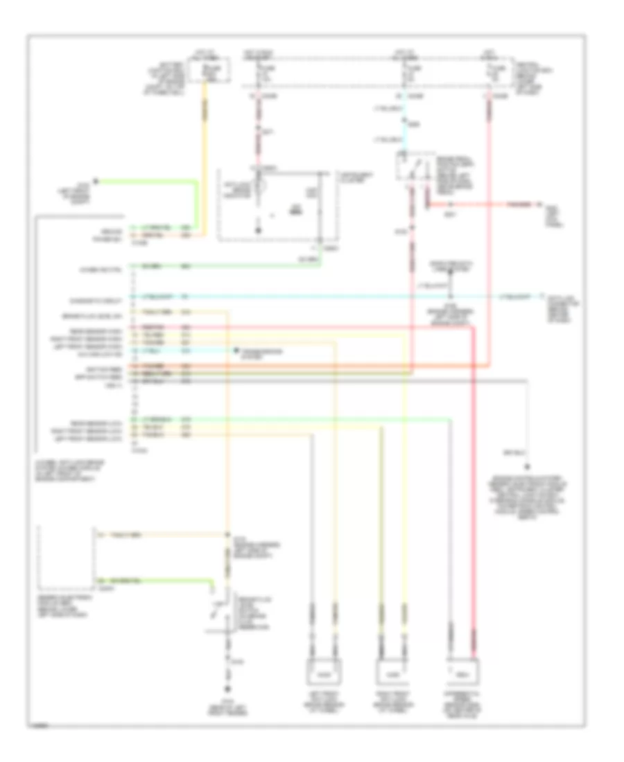
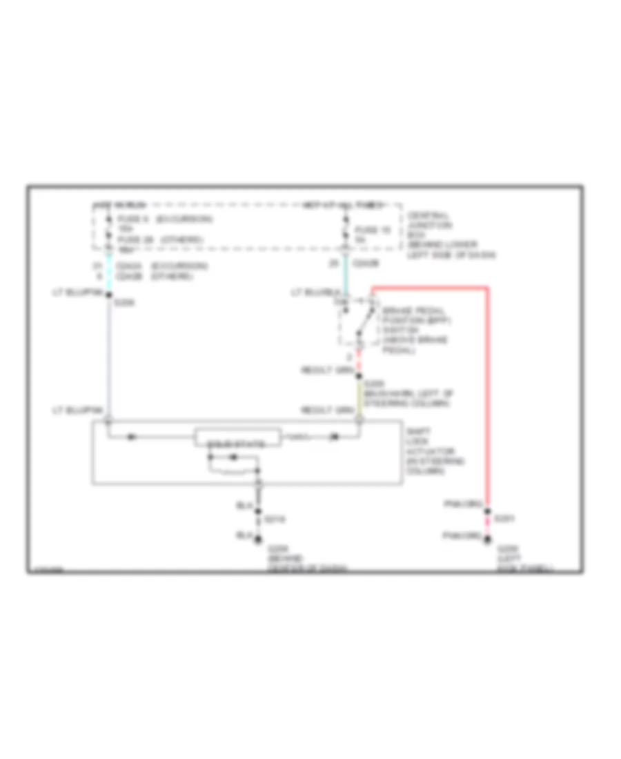
Anti-lock Brakes Wiring Diagram, Early Production for Ford Excursion 2000
List of elements for Anti-lock Brakes Wiring Diagram, Early Production for Ford Excursion 2000:
- 22k ohm
- 4-wheel anti-lock brake system (4wabs) module (in left front of engine compartment)
- 4wabs ind ctrl
- 4x4 high/low ind
- 5.6k ohm
- Anti-lock brake indicator
- Battery junction box (in left side of engine compt, on top of wheelwell)
- Bpp switch feed
- Brake fluid level sw
- Brake fluid level switch (on brake fluid reservoir)
- Brake pedal position (bpp) switch (behind left side of dash, above brake pedal)
- C104a
- C104b
- C240a
- C242b
- C250a
- C250c
- Central junction box (behind lower left side of dash)
- Computer data lines system
- Data link connector (behind center of dash)
- Diagnostic circuit
- Differential speed sensor (dss) (on center of rear axle)
- Engine controls system (generic electronic module (gem), instrument cluster, central junction box, overhead console module, powertrain control module, speed control servo)
- Fuse 10a
- Fuse 5a
- Fuse 60a
- G100 (left front of engine compt)
- G104 (rear of left front fender)
- G200 (left kick panel)
- Generic electronic module (gem) (behind lower left side of dash)
- Ground
- Hot at all times
- Hot in run
- Hot in run or start
- Ignition feed
- Instrument cluster
- Left front anti-lock brake sensor (at wheel)
- Left front sensor (high)
- Left front sensor (low)
- Nca
- Power (b+)
- Rear sensor (high)
- Rear sensor (low)
- Red/pnk
- Right front anti-lock brake sensor (at wheel)
- Right front sensor (high)
- Right front sensor (low)
- S102
- S108
- S165 (engine harness, left side of engine compt)
- S178 (engine harness, left side of engine compt)
- S201
- S271
- S288
- Tan/red
- Transmissions system
- Vss (+)
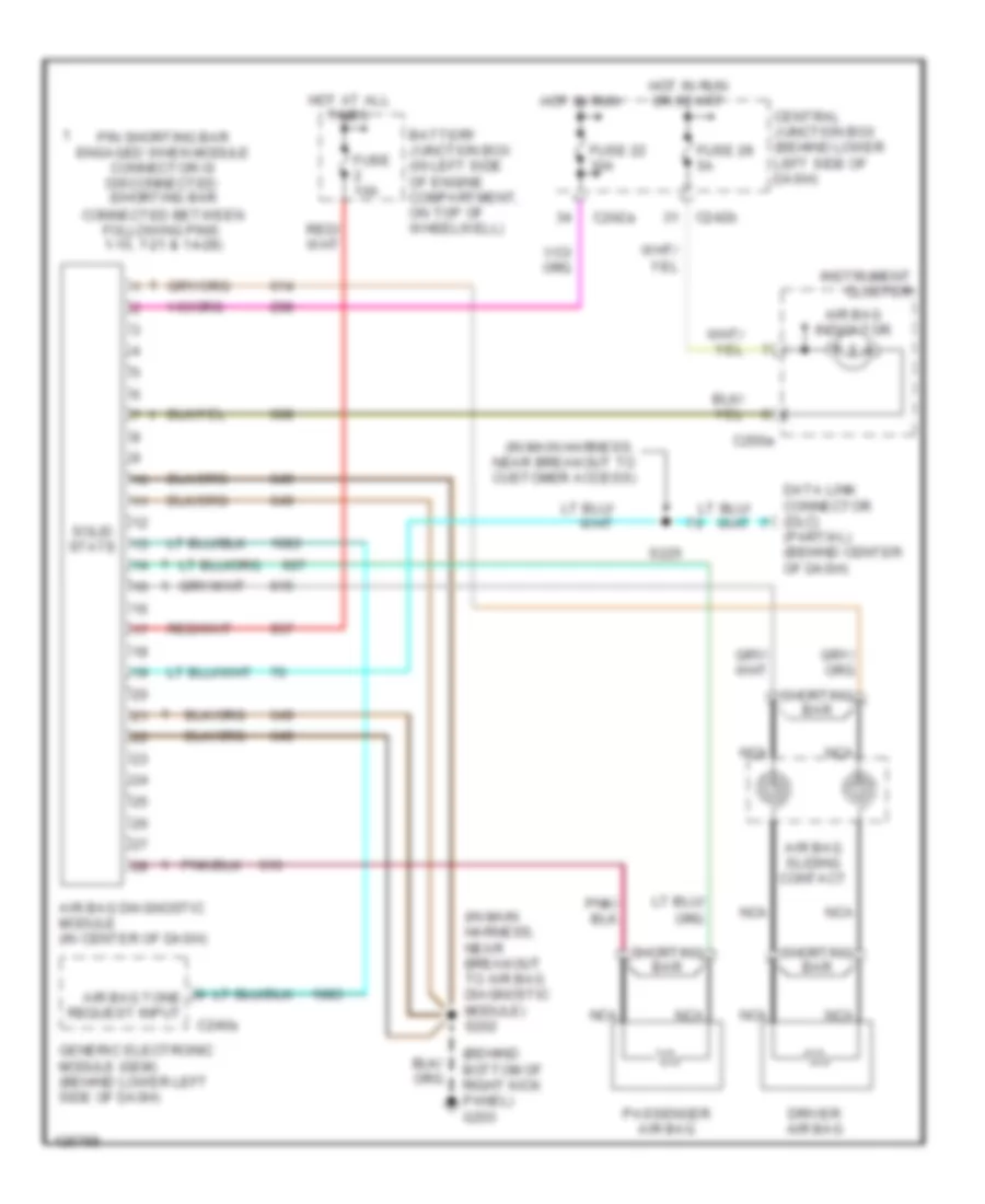
ANTI-THEFT
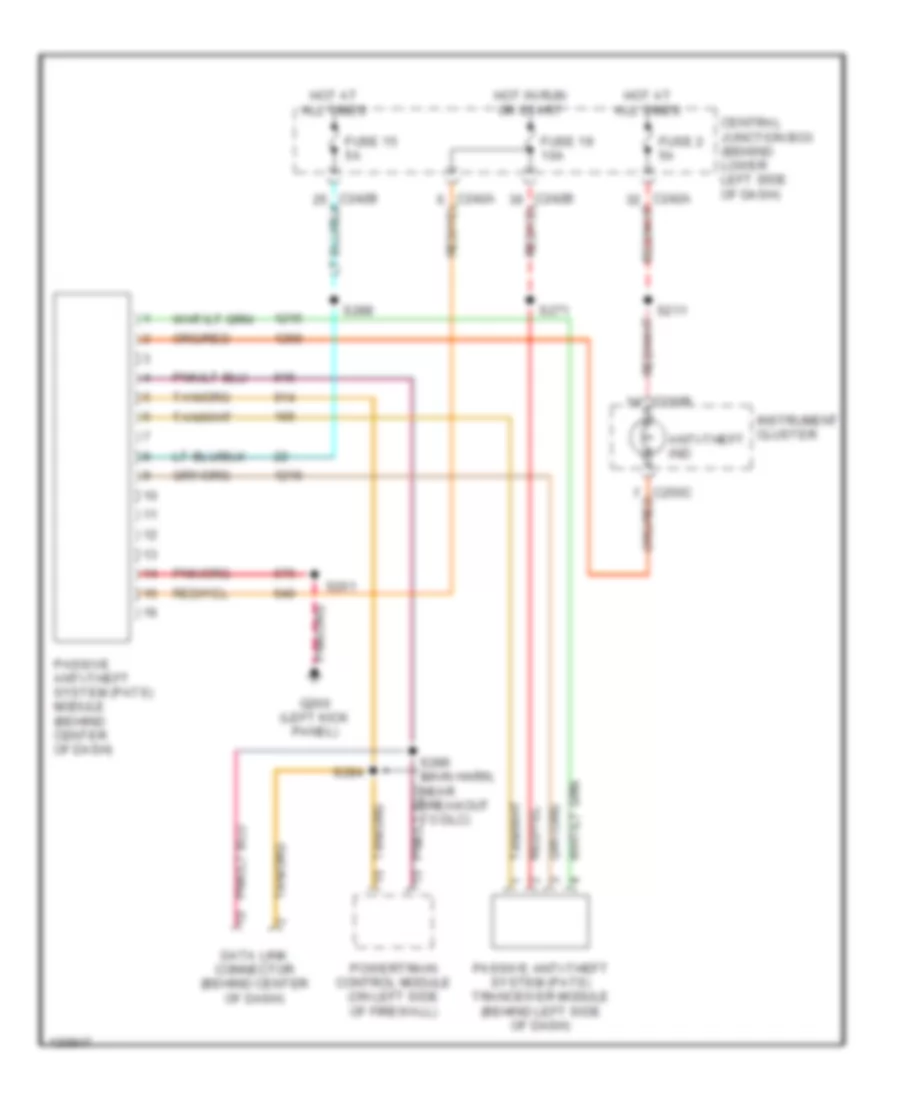
Anti-theft Wiring Diagram for Ford Excursion 2000
List of elements for Anti-theft Wiring Diagram for Ford Excursion 2000:
- Anti-theft ind
- C250b
- Central junction box (behind lower left side of dash)
- Data link connector (behind center of dash)
- Fuse 15 5a
- Fuse 19 10a
- Fuse 2 5a
- G200 (left kick panel)
- Hot at all times
- Hot in run or start
- Instrument cluster
- Passive anti-theft system (pats) module (behind center of dash)
- Passive anti-theft system (pats) tranceiver module (behind left side of dash)
- Powertrain control module (on left side of firewall)
- S201
- S211
- S271
- S284
- S286 (main harn, near breakout to dlc)
- S288
BODY CONTROL MODULES
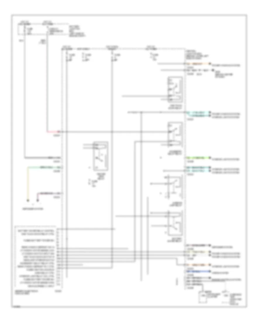
Body Control Modules Wiring Diagram (1 of 2) for Ford Excursion 2000
List of elements for Body Control Modules Wiring Diagram (1 of 2) for Ford Excursion 2000:
- 87a
- Accessory delay relay
- Accessory delay relay ctrl
- Battery junction box (left side of engine compt)
- Battery saver relay
- Battery saver relay control
- C240d
- C242a
- C242b
- C250b
- Central junction box (behind lower left side of dash)
- Circuit breaker 25 30a
- Defogger system
- Engine controls system
- Fuse 15a
- Fuse 40a
- Fuse 5a
- Fused battery power (b+)
- Fused ignition (acc/run)
- G206 (behind center of dash)
- Generic electronic module (gem)
- Headlamp interior switch
- Heated grid relay
- Horn relay ctrl
- Horns system
- Hot at all times
- Hot in run
- Hot in run or acc
- Instrument cluster
- Interior lamp relay
- Interior lamp relay coil ctrl
- Interior lights system
- Lf window motor sense (high)
- Lf window motor sense (low)
- Lf window switch input (dn)
- One touch down relay
- One touch down relay ctrl
- One touch down switch in
- Overhead trip computer (otc) module
- Power windows system
- Rear window defrost rly ctrl
- Rear window defrost sw in
- S218
- Vehicle speed (+) input
- Vss
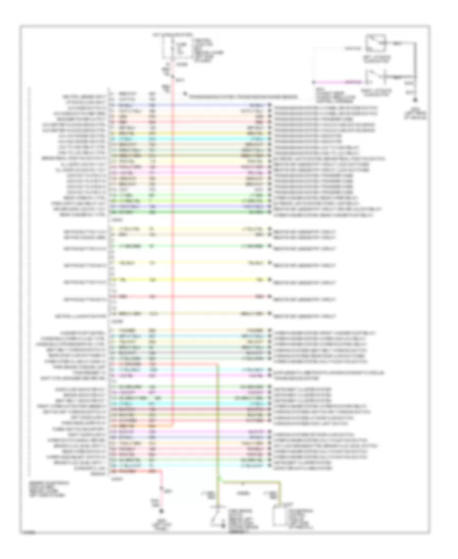
Body Control Modules Wiring Diagram (2 of 2) for Ford Excursion 2000
List of elements for Body Control Modules Wiring Diagram (2 of 2) for Ford Excursion 2000:
- 4x2 center axle solenoid ctrl
- 4x4 center axle solenoid ctrl
- 4x4 high range ind ctrl
- 4x4 low range ind ctrl
- 4x4 mode switch in
- 4x4 mode switch ref (grd)
- All door lock rly out
- All door unlock rly out
- Anti-lock brakes sytem (brake fluid level switch)
- Brake fluid level input 1
- Brake fluid level input 2
- Brake indicator out
- Brake pedal position switch in
- C1027
- C240a
- C240b
- C240c
- C242b
- Central junction box (behind lower left side of dash)
- Computer data lines system
- Contact plate a in
- Contact plate b in
- Contact plate c in
- Contact plate p in
- Diagnostic link
- Diesel
- Door ajar indicator out
- Driver door lock rly out
- Encoder power output
- Exterior lights system (brake pedal position switch)
- Exterior lights system (park lamp relay)
- Front wiper motor park sense in
- Fuse 10a
- Fused ignition (run/start)
- G200 (left kick panel)
- G404 (left rear of vehicle)
- Generic electronic module (gem) (behind lower left side of dash)
- Ground
- High to low relay ctrl
- Hot in run or start
- Ignition key warning switch in
- Instrument cluster system
- Keypad button 1/2 in
- Keypad button 3/4 in
- Keypad button 5/6 in
- Keypad button 7/8 in
- Keypad button 9/0 in
- Keypad commom (grd)
- Keypad illumination pwr
- Left door ajar in
- Left liftgate ajar switch
- Liftgate ajar input
- Low to high relay ctrl
- Neutral sense input
- Park brake switch (behind left side of dash, on park brake assembly)
- Park brake warning lamp
- Park/headlamps on in
- Parklamp flash relay out
- Powertrain control module (left side of firewall)
- Rear door ajar switches in
- Rear washer rly ctrl
- Rear wiper rly ctrl
- Rear wiper switch in
- Red
- Remote keyless entry circuit
- Remote keyless entry circuit (driver unlock relay)
- Remote keyless entry circuit (lock switches)
- Right door ajar in
- Right liftgate ajar switch
- S201
- S213
- S440
- S441 (in right rear window regulator control harness)
- Seat belt indicator out
- Seat belt warning switch in
- Shift ctrl encoder grd return
- Tan/red
- Tone request in
- Transmissions system
- Transmissions system (4 wheel drive mode switch)
- Transmissions system (high to low relay)
- Transmissions system (indicator)
- Transmissions system (low to high relay)
- Transmissions system (transfer case)
- Transmissions system (transmissions range sensor)
- Transmissions system (vacuum hublock solenoid)
- Warning systems (ignition key warning switch)
- Warning systems (lf door ajar switch)
- Warning systems (main light switch)
- Warning systems (rear door ajar switches)
- Warning systems (rf door ajar switch)
- Warning systems (seat belt warning switch)
- Washer pump control
- Windshield wiper hi/lo rly ctrl
- Wiper interval delay/wash in
- Wiper mode select switch in
- Wiper switch signal return
- Wiper/washer system (front washer pump relay)
- Wiper/washer system (multi-function switch)
- Wiper/washer system (rear washer pump relay)
- Wiper/washer system (rear wiper relay)
- Wiper/washer system (wiper high/low relay)
- Wiper/washer system (wiper run/park relay)
- Wndshield wpr brake/pk rly ctrl
COMPUTER DATA LINES
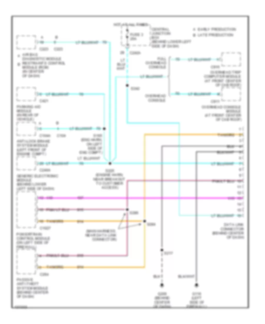
Computer Data Lines Wiring Diagram for Ford Excursion 2000
List of elements for Computer Data Lines Wiring Diagram for Ford Excursion 2000:
- (main harness, near data link connector)
- Air bag a
- Anti-lock brake system module (left front of engine compt)
- C1027
- C104
- C104a
- C223
- C240a
- C242a
- C264
- C421
- C911
- C915
- Central junction box (behind lower left side of dash)
- Data link connector (behind center of dash)
- Diagnostic module restraints control b module (rcm) (in center of dash)
- Early production a
- Full overhead console
- Fuse 3 20a
- G116 (left side of firewall)
- G206 (behind center of dash)
- Generic electronic module (behind lower left side of dash)
- Hot at all times
- Late production b
- Overhead console
- Overhead console module (at front center of cab roof)
- Overhead trip computer module (at front center of cab roof)
- Parking aid module (in rear of vehicle)
- Passive anti-theft system module (behind center of dash)
- Powertrain control module (on left side of firewall)
- S165 (eng harn, on left side of eng compt)
- S217
- S225 (engine harn, near breakout to customer access)
- S242
- S284
- S286
CRUISE CONTROL
5.4L
5.4L, Cruise Control Wiring Diagram for Ford Excursion 2000
List of elements for 5.4L, Cruise Control Wiring Diagram for Ford Excursion 2000:
- (engine harn, below brake fluid reservoir)
- 10a
- 15a
- 20a
- A/t
- Accel
- Anti-lock brake system (abs) module (in left front of eng compt)
- Brake pedal position (bpp) switch (above brake pedal)
- Brake press in
- Brake pressure switch (on left side of eng compt)
- Brake/clutch sw in
- C242
- C242a
- C242b
- C243
- C250b
- Central junction box panel (behind lower left side of dash)
- Clock spring
- Clutch pedal position (cpp) switch (above clutch pedal)
- Clutch pedal position (cpp) switch jumper (above clutch pedal)
- Coast
- Differential speed sensor (on center of rear axle)
- Except excursion
- Excursion
- Fuse 13
- Fuse 15
- Fuse 28
- Fuse 6
- G101 (front of right front fender)
- G206 (behind center of dash)
- Ground
- Horn
- Horn relay
- Hot at all times
- Hot in run
- Instrument cluster
- M/t
- Nca
- Off
- Ohms
- Power
- Red/pnk
- Resume
- S115
- S124
- S180
- S201
- S205 (main harness, left of steering column)
- Set/
- Speed control servo/ amplifier assembly (in right side of engine compt)
- Speed control/ horn switch assembly (in steering wheel)
- Speed ctrl sw in
- Speed ctrl sw rtn
- Vss input
- Vss signal
6.8L
6.8L, Cruise Control Wiring Diagram for Ford Excursion 2000
List of elements for 6.8L, Cruise Control Wiring Diagram for Ford Excursion 2000:
- (engine harn, below brake fluid reservoir)
- 10a
- 15a
- 20a
- A/t
- Accel
- Anti-lock brake system (abs) module (in left front of eng compt)
- Brake pedal position (bpp) switch (above brake pedal)
- Brake press in
- Brake pressure switch (on left side of eng compt)
- Brake/clutch sw in
- C242
- C242a
- C242b
- C243
- C250b
- Central junction box panel (behind lower left side of dash)
- Clock spring
- Clutch pedal position (cpp) switch (above clutch pedal)
- Clutch pedal position (cpp) switch jumper (above clutch pedal)
- Coast
- Differential speed sensor (on center of rear axle)
- Except excursion
- Excursion
- Fuse 13
- Fuse 15
- Fuse 28
- Fuse 6
- G101 (front of right front fender)
- G206 (behind center of dash)
- Ground
- Horn
- Horn relay
- Hot at all times
- Hot in run
- Instrument cluster
- M/t
- Nca
- Off
- Ohms
- Power
- Red/pnk
- Resume
- S115
- S124
- S180
- S201
- S205 (main harness, left of steering column)
- Set/
- Speed control servo/ amplifier assembly (in right side of engine compt)
- Speed control/ horn switch assembly (in steering wheel)
- Speed ctrl sw in
- Speed ctrl sw rtn
- Vss input
- Vss signal
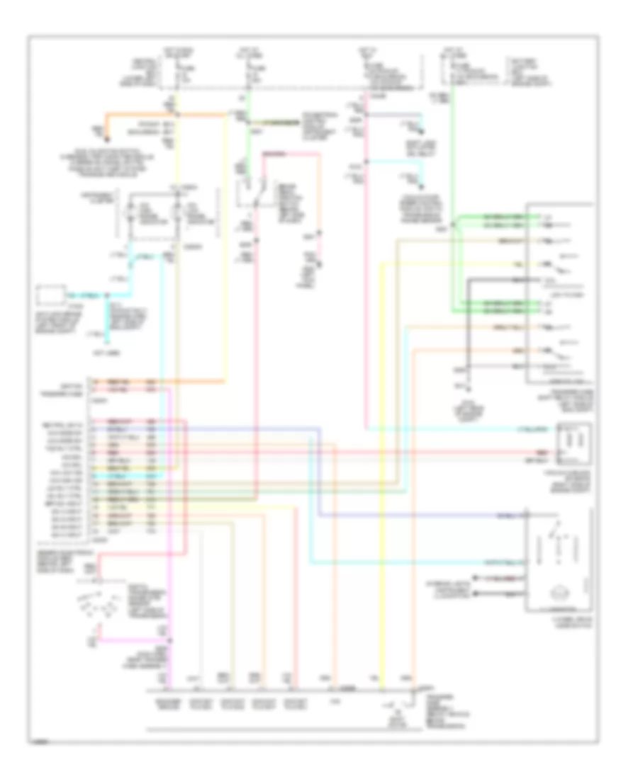
7.3L DI TURBO DIESEL
7.3L DI Turbo Diesel, Cruise Control Wiring Diagram for Ford Excursion 2000
List of elements for 7.3L DI Turbo Diesel, Cruise Control Wiring Diagram for Ford Excursion 2000:
- 10a
- Accel
- Anti-lock brake system (abs) module (in left front of eng compt)
- Battery junction box (left side of engine compt)
- Brake pedal position (bpp) switch (above brake pedal)
- Brake position in
- Brake press in
- Brake pressure switch (on left side of eng compt)
- C242b
- Central junction box (behind left side of dash)
- Clock spring
- Clutch pedal position (cpp) switch (m/t only) (above clutch pedal)
- Clutch position in
- Coast
- Differential speed sensor (on center of rear axle)
- Fuse 15
- Fuse 19
- G206 (behind center of dash)
- Horn
- Horn system
- Hot at all times
- Hot in start or run
- Nca
- Off
- Ohms
- Pcm power relay
- Powertrain control module (on left side of firewall)
- Red
- Red/pnk
- Resume
- S108 (engine harn, near brake pressure switch)
- S114 (engine harn, near b/o to pcm)
- S115 (engine harn, below brake fluid reservoir)
- S123 (engine harness, left of steering column)
- S201
- S213
- Set/
- Speed control/ horn switch assembly (in steering wheel)
- Speed ctrl sw in
- Speed ctrl sw rtn
- Vss input
- Vss signal
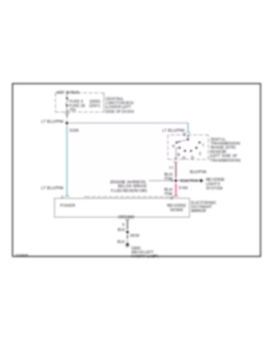
DEFOGGERS
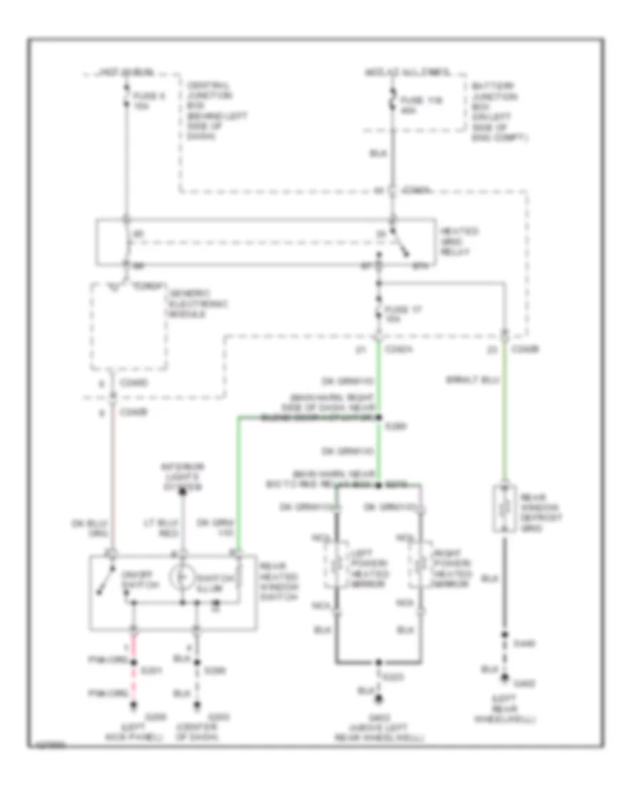
Defoggers Wiring Diagram for Ford Excursion 2000
List of elements for Defoggers Wiring Diagram for Ford Excursion 2000:
- (center of dash)
- (left kick panel)
- (left rear wheelwell)
- (main harn, near b/o to rke relay box)
- (main harn, right side of dash, near blend door actuator)
- 87a
- Battery junction box (on left side of eng compt)
- C240d
- C242a
- C242b
- Central junction box (behind left side of dash)
- Fuse 118 40a
- Fuse 17 15a
- Fuse 6 15a
- G200
- G203
- G402
- G402 (above left rear wheelwell)
- Generic electronic module
- Heated grid relay
- Hot at all times
- Hot in run
- Interior lights system
- Left power/ heated mirror
- Nca
- On/off switch
- Rear heated window switch
- Rear window defrost grid
- Right power/ heated mirror
- S201
- S223
- S279
- S280
- S290
- S440
- Switch illum
ENGINE PERFORMANCE
5.4L
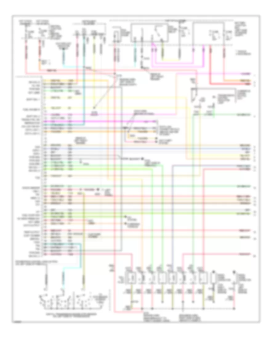
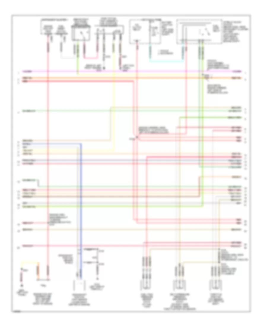
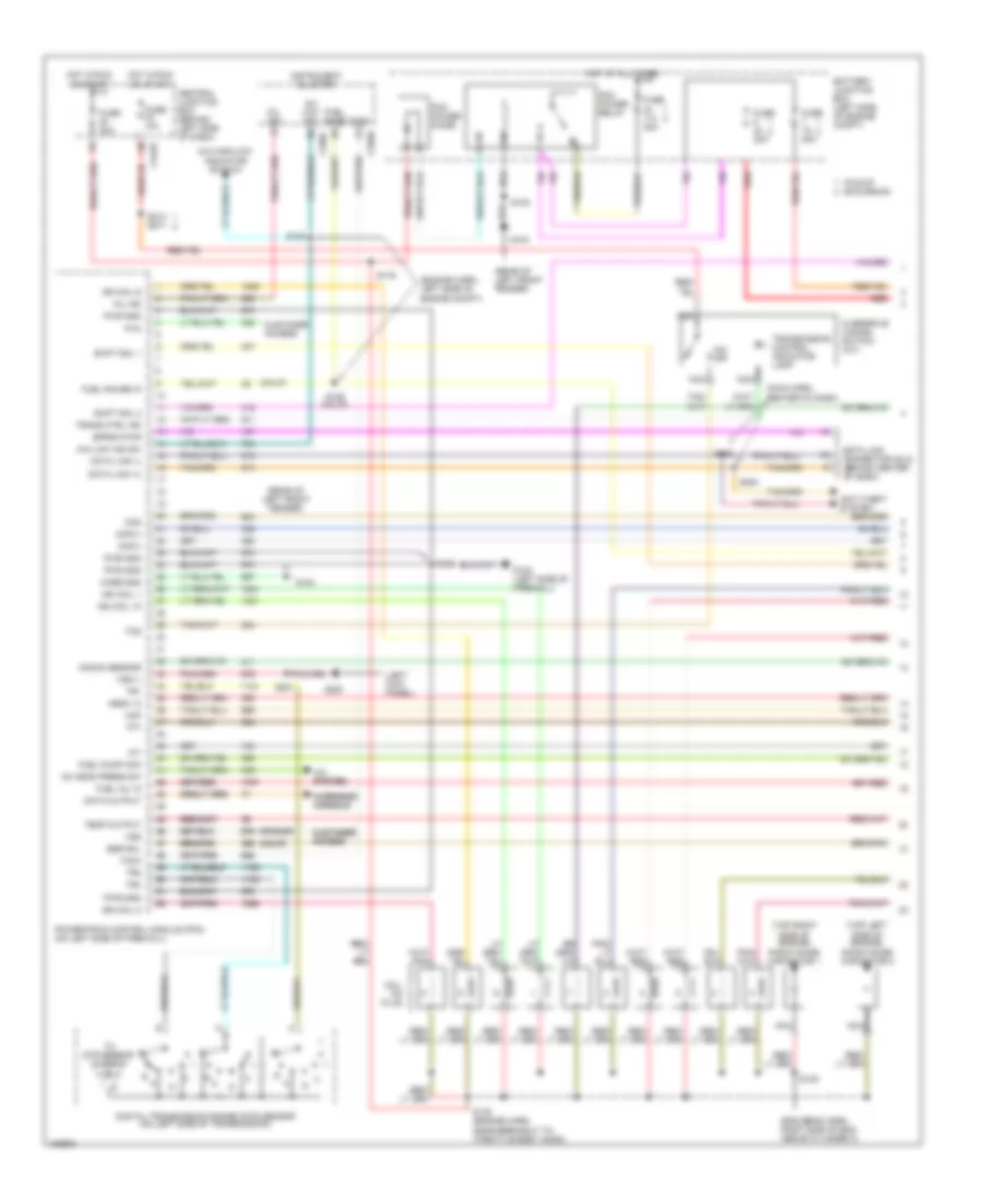
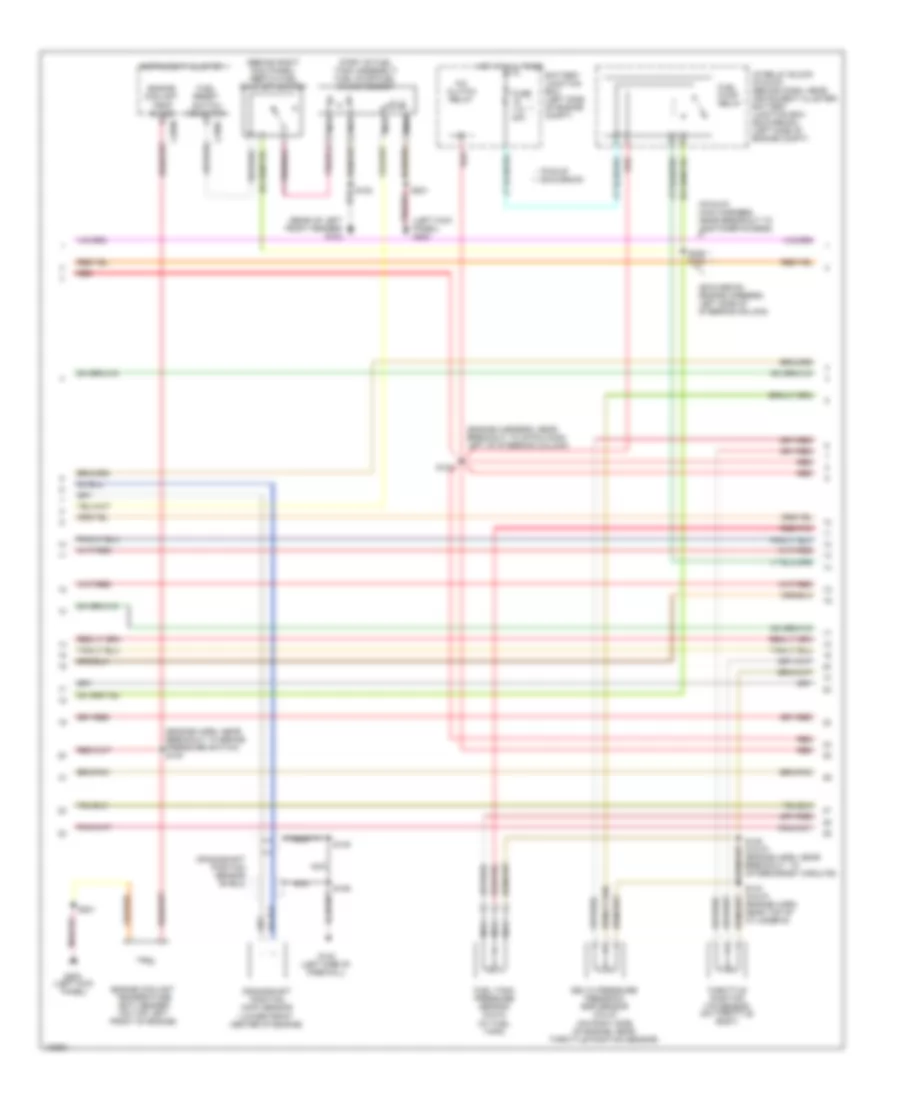
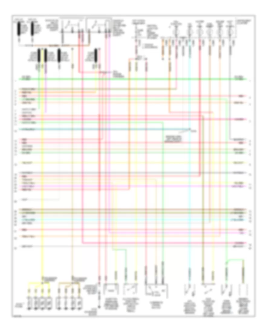
5.4L, Engine Performance Wiring Diagram (1 of 4) for Ford Excursion 2000
List of elements for 5.4L, Engine Performance Wiring Diagram (1 of 4) for Ford Excursion 2000:
- (eng sens harn, right side of eng, above cylinder 3)
- (engine harn, left side of engine compt)
- (left kick panel)
- (main harn, center of dash)
- (not used)
- (pickup)
- (rear of left front fender)
- 4x4 high/low indicator switch
- 4x4 low ind sw
- 4x4 low ind
- A/c system
- Ac head press sw
- Anti-theft system
- Battery junction box (left side of engine compt)
- C242b
- C250b
- C250c
- Ccs
- Central junction box (behind left side of dash)
- Ckp(+)
- Ckp(-)
- Coil on plug
- Cust access
- Customer access
- Data link (+)
- Data link (-)
- Data link connector (dlc) (behind center of dash)
- Data output
- Diag grd
- Digital transmission range (dtr) sensor (on left side of transmission)
- Egr sol
- Fuel gage
- Fuel gauge in
- Fuel pump mon
- Fuse 10a
- Fuse 20a
- Fuse 30a
- G102 (left side of firewall)
- G104
- G200
- Hego 12
- Hot at all times
- Hot in run or start
- Iat
- Ign coil 1
- Ign coil 3
- Ign coil 5
- Ign coil 6
- Instrument cluster
- Knock sensor
- Maf
- Mil ind
- Nca
- Not used
- O/d off
- Overdrive cancel switch (a/t)
- Overhead console
- Pcm power diode
- Pcm power relay
- Pickup excursion
- Powertrain control module (pcm) (on left side of firewall)
- Pwr gnd
- R n
- Radio noise capacitor (top left side of engine)
- Radio noise capacitor (top right side of engine)
- Red
- Reprog pwr
- S102
- S105
- S106
- S129 (calif)
- S130 (engine harn, near breakout to throttle body conn)
- S135
- S179
- S201
- S213 s271
- S284
- S286
- Shift sol 1
- Shift sol 2
- Tach
- Tcs
- Temp output
- Tft
- To dtr sensor (diagram 4 of 4)
- Tr1
- Tr2
- Tr4
- Trans ctrl ind
- Transmission control indicator lamp
- Vss (-)
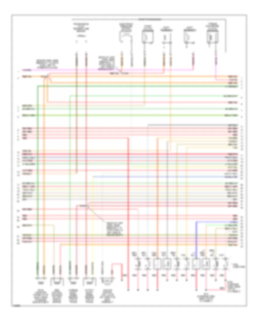
5.4L, Engine Performance Wiring Diagram (2 of 4) for Ford Excursion 2000
List of elements for 5.4L, Engine Performance Wiring Diagram (2 of 4) for Ford Excursion 2000:
- (behind right kick panel) inertia fuel shut-off switch
- (engine harn, near breakout to brake pressure switch) s104
- (engine harness, near breakout to 40-pin conn, left of steering column)
- (excursion: engine harness, left side of steering column)
- (left kick panel) g200
- (part of fuel tank assembly) fuel pump/fuel gauge sender
- (pickup: main harness, near breakout to customer access)
- (rear of left front fender) g104
- A/c clutch relay
- Battery junction box (left side of engine compt)
- C250b
- C250c
- Crankshaft position (ckp) sensor (lower front center of engine)
- Crankshaft position sensor shield
- Delta pressure feedback egr sensor (calif) (on right side of engine, near throttle position sensor)
- Engine coolant temp guage
- Engine coolant temperature (ect) sender (on top left front of engine)
- Fuel pump relay
- Fuel reset switch indicator
- Fuel tank pressure sensor (calif) (at fuel tank)
- Fuse 20a
- G102 (left side of firewall)
- G200 (left kick panel)
- Hot at all times
- I/p relay block (pickup) (behind dash, near instrument cluster) battery junction box (excursion) (left side of engine compt)
- Instrument cluster
- Nca
- Pickup excursion
- Red
- Red/pnk
- S102
- S106
- S123
- S128 (calif) (engine harn, near breakout to aftermarket circuits)
- S133 (calif) (engine harn, near top of cylinder 6)
- S145
- S201
- S226 s164
- Throttle position (tp) sensor (on throttle body)
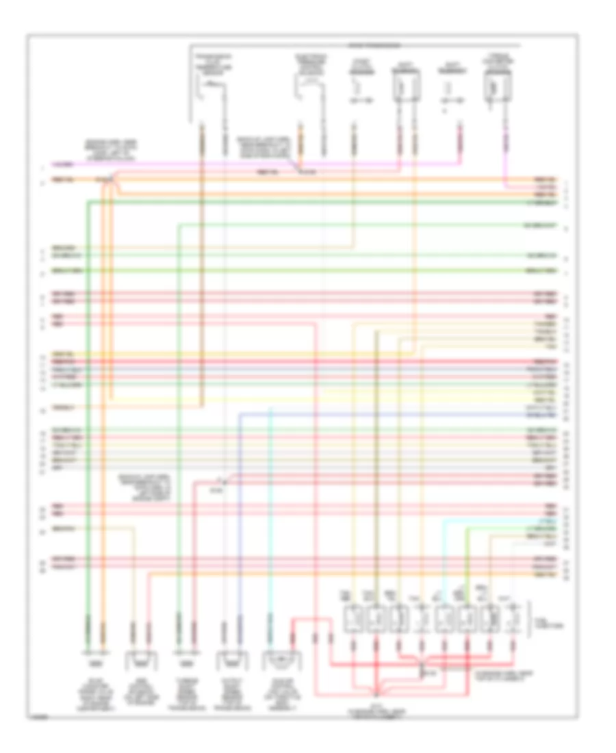
5.4L, Engine Performance Wiring Diagram (3 of 4) for Ford Excursion 2000
List of elements for 5.4L, Engine Performance Wiring Diagram (3 of 4) for Ford Excursion 2000:
- (back-up lamp harn, near breakout to 16-pin conn, in left side of eng compt)
- (backup lamp harn, near breakout to 16-pin conn, in left side of engine compt)
- (engine harn, near breakout to 40-pin conn, left of steering column)
- (in engine harn, near top of cylinder 3)
- (right rear of engine compartment)
- 4r100 transmission
- Coast clutch solenoid
- Egr control solenoid (on left side of engine)
- Electronic pressure control solenoid
- Evap canister purge valve
- Fuel injectors
- Idle air control (iac) valve (on throttle body assembly)
- Output shaft speed sensor (top of transmission)
- Red
- Red/pnk
- S122
- S131 (in engine harn, near top of cylinder 7)
- S136
- S138
- S139
- Shift solenoid 1
- Shift solenoid 2
- Tan
- Tan/ red
- Tan/red
- Torque converter clutch solenoid
- Transmission fluid temperature sensor
- Turbine shaft speed sensor (top of transmission)
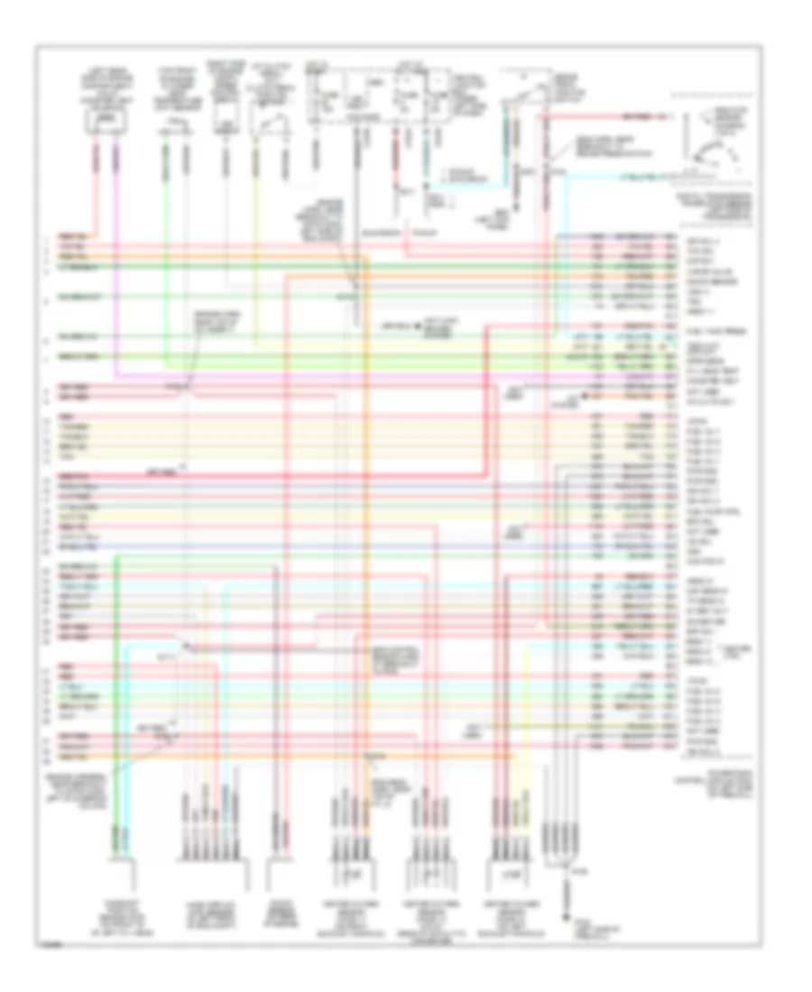
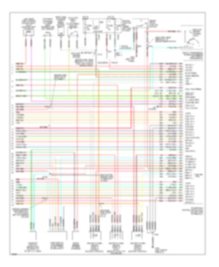
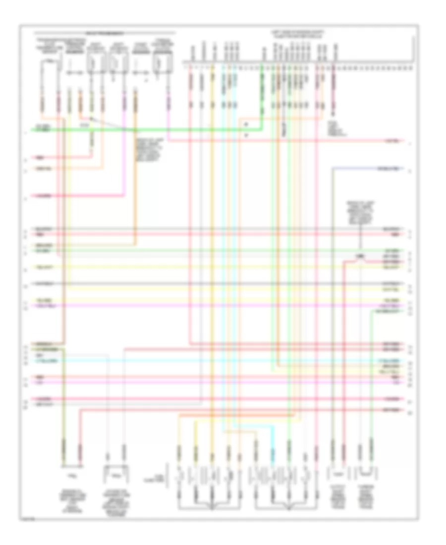
5.4L, Engine Performance Wiring Diagram (4 of 4) for Ford Excursion 2000
List of elements for 5.4L, Engine Performance Wiring Diagram (4 of 4) for Ford Excursion 2000:
- (a/t)
- (at clutch pedal) (m/t) clutch pedal position switch
- (calif)
- (eng control sensor harn, at breakout to pcm)
- (eng harn, near breakout to brake press switch)
- (eng sens harn, near top of cyl 8)
- (engine harn, near breakout to 16-pin conn, left side of eng compt)
- (engine harn, near top of cylinder 7)
- (engine harness, near breakout to 40-pin conn, left of steering column)
- (left rear side of engine compartment) (calif) canister vent solenoid
- (m/t)
- (not used)
- (right side of engine compt) speed control servo
- (top front of engine) cylinder head temperature (cht) sensor
- 5v ref volt
- A/c cltch rly
- A/c system
- Anti-lock brakes system
- Bpp sw
- Brake pedal position switch
- C240d
- C242a
- C242b
- Cam pos in
- Camshaft position sensor (cmp) (on front of of left cyl head)
- Canister vent
- Central junction box (under left side of dash)
- Cyl head temp
- Digital transmission range (dtr) sensor (left side of transmission)
- Dpfe sens
- Epc sol
- Excursion
- From dtr sensor (diagram 1 of 4)
- Fuel inj 1
- Fuel inj 2
- Fuel inj 3
- Fuel inj 4
- Fuel inj 5
- Fuel inj 6
- Fuel inj 7
- Fuel inj 8
- Fuel pump ctrl
- Fuel tank press
- Fuse 15a
- Fuse 5a
- G102 (left side of firewall)
- G200 (left kick panel)
- Gem
- Heated oxygen sensor (ho2s) 11 (on right exhaust manifold)
- Heated oxygen sensor (ho2s) 12 (calif) (rear of catalytic converter)
- Heated oxygen sensor (ho2s) 21 (on left exhaust manifold)
- Heater ctrl
- Hego 11
- Hego 12
- Hego 21
- Hot at all times
- Hot in start
- Iac sol
- Ign coil 2
- Ign coil 4
- Ign coil 7
- Ign coil 8
- Kap b(+)
- Knock sensor
- Knock sensor (on rear of engine)
- Maf sens in
- Mass airflow (maf) sensor (in left front of eng compt)
- Nca
- Not used
- Oss
- Pickup
- Pickup excursion
- Powertrain control module (pcm) (on left side of firewall)
- Pwr gnd
- Red
- Red/pnk
- S106
- S114
- S115
- S129
- S132
- S134
- S211
- S211 s288
- Sig return
- Tan
- Tan/red
- Tcc sol
- Tp sens in
- Tr3a (a/t) cpp (m/t)
- Tss
- Vapor valve
- Vpwr
- Vss (+)
- Vss input
6.8L
6.8L, Engine Performance Wiring Diagram (1 of 4) for Ford Excursion 2000
List of elements for 6.8L, Engine Performance Wiring Diagram (1 of 4) for Ford Excursion 2000:
- (calif)
- (calif) (calif)
- (eng sens harn, right side of eng, above cylinder 3)
- (engine harn, left side of engine compt)
- (left kick panel)
- (main harn, center of dash)
- (pickup) (pickup)
- (rear of left front fender)
- (top left side of engine) radio noise capacitor 2
- (top right side of engine) radio noise capacitor 1
- 4x4 high/low indicator switch
- 4x4 low ind sw
- 4x4 low ind
- A/c system system
- Ac head press sw
- Anti-theft system
- Battery junction box (left side of engine compt)
- C242b
- C250b
- C250c
- Case gnd
- Ccs
- Central junction box (behind left side of dash)
- Ckp(+)
- Ckp(-)
- Coil on plug
- Customer access
- Customer customer access access
- Data link (+)
- Data link (-)
- Data link connector (dlc) (behind center of dash)
- Data output
- Digital transmission range (dtr) sensor (on left side of transmission)
- Egr sol
- Eprom pwr
- Fuel gage
- Fuel gauge in
- Fuel inj 10
- Fuel pump mon
- Fuse 10a
- Fuse 20a
- Fuse 30a
- G102 (left side of firewall)
- G104
- G200
- Hego 12
- Hot at all times
- Hot in run or start
- Iat
- Ign coil 1
- Ign coil 10
- Ign coil 5
- Ign coil 6
- Instrument cluster
- Knock sensor
- Maf
- Mil ind
- Nca
- O/d off
- Overdrive cancel switch (a/t)
- Overhead overhead console console
- Pcm power diode
- Pcm power relay
- Pickup excursion
- Powertrain control module (pcm) (on left side of firewall)
- Pto
- Pwr gnd
- R n
- Red
- S102
- S105
- S106
- S129 (calif)
- S130 (engine harn, near breakout to throttle body conn)
- S135
- S179
- S201
- S213 s271
- S284
- S286
- Shift sol 1
- Shift sol 2
- Tach
- Tcs
- Temp output
- Tft
- To dtr sensor (diagram 4 of 4)
- Tr1
- Tr2
- Tr4
- Trans ctrl ind
- Transmission control indicator lamp
- Vss
- Vss (-)
6.8L, Engine Performance Wiring Diagram (2 of 4) for Ford Excursion 2000
List of elements for 6.8L, Engine Performance Wiring Diagram (2 of 4) for Ford Excursion 2000:
- (behind right kick panel) inertia fuel shut-off switch
- (engine harn, near breakout to brake pressure switch) s104
- (engine harness, near breakout to 40-pin conn, left of steering column)
- (excursion: engine harness, left side of steering column)
- (left kick panel) g200
- (part of fuel tank assembly) fuel pump/fuel gauge sender
- (pickup: main harness, near breakout to customer access)
- (rear of left front fender) g104
- * **
- A/c clutch relay
- Battery junction box (left side of engine compt)
- C250b
- C250c
- Crankshaft position (ckp) sensor (lower front center of engine)
- Crankshaft position sensor shield
- Delta pressure feedback egr sensor (calif) (on right side of engine, near throttle position sensor)
- Engine coolant temp guage
- Engine coolant temperature (ect) sender (on top left front of engine)
- Fuel pump relay
- Fuel reset switch indicator
- Fuel tank pressure sensor (calif) (at fuel tank)
- Fuse 20a
- G102 (left side of firewall)
- G200 (left kick panel)
- Hot at all times
- I/p relay block (pickup) (behind dash, near instrument cluster) battery junction box (excursion) (left side of engine compt)
- Instrument cluster
- Nca
- Pickup * excursion **
- Red
- Red/pnk
- S102
- S106
- S123
- S128 (calif) (engine harn, near breakout to aftermarket circuits)
- S133 (calif) (engine harn, near top of cylinder 6)
- S145
- S201
- S226 s164
- Throttle position (tp) sensor (on throttle body)
6.8L, Engine Performance Wiring Diagram (3 of 4) for Ford Excursion 2000
List of elements for 6.8L, Engine Performance Wiring Diagram (3 of 4) for Ford Excursion 2000:
- (back-up lamp harn, near breakout to 16-pin conn, in left side of engine compt)
- (engine harn, near breakout to 40-pin conn, left of steering column)
- (right rear of engine compartment)
- 4r100 transmission
- Coast clutch solenoid
- Egr control solenoid (on left side of engine)
- Electronic pressure control solenoid
- Evap canister purge valve
- Fuel injectors
- Idle air control (iac) valve (on throttle body assembly)
- Output shaft speed sensor (top of trans)
- Red
- Red/pnk
- S122
- S131 (in engine harn, near top of cylinder 7)
- S136 (in engine harn, near top of cylinder 3)
- S138
- S139
- Shift solenoid 1
- Shift solenoid 2
- Tan
- Tan/ red
- Tan/red
- Torque converter clutch solenoid
- Transmission fluid temperature sensor
- Turbine shaft speed sensor (top of trans)
6.8L, Engine Performance Wiring Diagram (4 of 4) for Ford Excursion 2000
List of elements for 6.8L, Engine Performance Wiring Diagram (4 of 4) for Ford Excursion 2000:
- (a/t)
- (at clutch pedal) (m/t) clutch pedal position switch
- (calif)
- (eng control sensor harn, at breakout to pcm)
- (eng harn, near breakout to brake press switch)
- (eng sens harn, near top of cyl 8)
- (engine harn, near breakout to 16-pin conn, left side of engine compt)
- (engine harn, near top of cylinder 7)
- (engine harness, near breakout to 40-pin conn, left of steering column)
- (left rear side of engine compartment) (calif) canister vent solenoid
- (m/t)
- (right side of engine compt) speed control servo
- (top front of engine) cylinder head temperature (cht) sensor
- 5v ref volt
- A/c cltch rly
- A/c system
- Anti-lock brakes system
- Bpp sw
- Brake pedal position switch
- C240d
- C242a
- C242b
- Cam pos in
- Camshaft position sensor (cmp) (on front of of left cyl head)
- Canister vent
- Central junction box (under left side of dash)
- Cyl head temp
- Digital transmission range (dtr) sensor (left side of transmission)
- Dpfe sens
- Epc sol
- Evap purge
- Excursion
- From dtr sensor (diagram 1 of 4)
- Fuel inj 1
- Fuel inj 2
- Fuel inj 3
- Fuel inj 4
- Fuel inj 5
- Fuel inj 6
- Fuel inj 8
- Fuel inj 9
- Fuel pump ctrl
- Fuel tank press
- Fuse 15a
- Fuse 5a
- G102 (left side of firewall)
- G200 (left kick panel)
- Gem
- Heated oxygen sensor (ho2s) 11 (on right exhaust manifold)
- Heated oxygen sensor (ho2s) 12 (calif) (rear of catalytic converter)
- Heated oxygen sensor (ho2s) 21 (on left exhaust manifold)
- Heater ctrl
- Hego 11
- Hego 12
- Hego 21
- Hot at all times
- Hot in start
- Iac sol
- Ign coil 2
- Ign coil 3
- Ign coil 4
- Ign coil 7
- Ign coil 8
- Ign coil 9
- Kap b(+)
- Knock sensor
- Knock sensor (on rear of engine)
- Maf sens in
- Mass airflow (maf) sensor (in left front of eng compt)
- Nca
- Oss
- Pickup
- Pickup excursion
- Powertrain control module (pcm) (on left side of firewall)
- Pwr gnd
- Red
- Red/pnk
- S106
- S114
- S115
- S129
- S132
- S134
- S211
- S221 s288
- Sig return
- Tan
- Tan/red
- Tcc sol
- Tp sens in
- Tr3a (a/t) cpp (m/t)
- Tss
- Vpwr
- Vss (+)
- Vss input
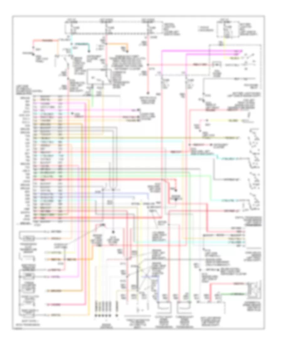
7.3L DI TURBO DIESEL
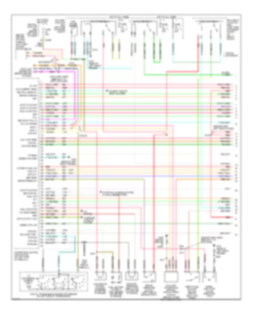
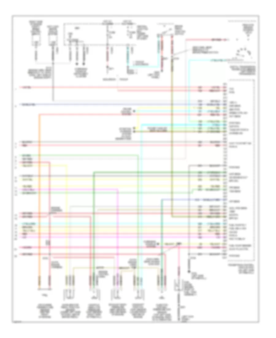
7.3L DI Turbo Diesel, Engine Performance Wiring Diagram (1 of 4) for Ford Excursion 2000
List of elements for 7.3L DI Turbo Diesel, Engine Performance Wiring Diagram (1 of 4) for Ford Excursion 2000:
- (a/t)
- (behind center of dash) passive anti-theft system (pats) module
- (engine harn, left side of dash)
- (engine harn, near breakout to pcm conn)
- (m/t)
- (main harn, near breakout to data link conn)
- (pickup) (behind lower right side of dash)
- 4x4 low range
- A/c head press
- A/c system
- Aux tach feed
- Auxiliary powertrain control module (apcm)
- Battery junction box (left side of engine compt)
- Battery junction box (left side of engine compt) i/p relay block
- Brake press sw
- Brake pressure
- Brake warning
- Bus (+)
- Bus (-)
- C242b
- Cam pos sens
- Ccs sol
- Central junction box (behind left side of dash)
- Cpp (m/t)
- Dash)
- Data link connector (behind center of dash)
- Data output link
- Diesel fuel pump motor (near fuel tank)
- Digital transmission range (dtr) sensor (on left side of transmission)
- Dsl elect drv
- Dtr-tr1
- Dtr-tr2
- Dtr-tr4
- Ebp sens
- Eot
- Epr
- Excursion
- Exhaust pressure regulator (top center of engine)
- Fuel heater/ water in fuel sensor (on center of engine)
- Fuel htr
- Fuel pump pwr
- Fuel pump relay
- Fuse 20a
- Fuse 30a
- G102 (left side of firewall)
- G104 (rear of left front fender)
- Gen pwr sw
- Gen scan tool in
- Glow plug mon
- Hot at all times
- Hot in run or start
- Iat
- Idle validation
- Idm power relay
- Inertia fuel shutoff switch (behind right kick panel)
- Low current sens
- Mil ind
- Nca
- Neutral gear sw
- Overhead console system
- Pcm power diode
- Pcm power relay
- Pickup
- Pickup excursion
- Power take off (body builder)
- Powertrain control module (pcm) (on left side of firewall)
- Pwr gnd
- R n
- Red
- S102
- S106
- S123
- S141
- S154
- S179
- S217
- S250
- S284
- S286
- Speed ctrl ind
- Speed/tach grd
- Ss1
- Ss2
- Starting/ charging system (w/ dual generators)
- Switch (left side of engine compt)
- Tcil
- Tcs (a/t)
- Tft
- To dtr sensor (diagram 4 of 4)
- Tp sens
- Wastegate control solenoid (in center of engine)
- Water in fuel ind
- Wcs sol
7.3L DI Turbo Diesel, Engine Performance Wiring Diagram (2 of 4) for Ford Excursion 2000
List of elements for 7.3L DI Turbo Diesel, Engine Performance Wiring Diagram (2 of 4) for Ford Excursion 2000:
- (engine harn, left rear of engine compt)
- (on engine block)
- (pia engine harness)
- (pia engine harness) s156
- 4x4 high/low indicator switch (near dtr sensor)
- 4x4 low
- C242b
- C250a
- C250b
- C250c
- Central junction box (under left side of dash)
- Clutch pedal position (cpp) switch (above clutch pedal)
- Cruise set lamp
- Fuel reset
- Fuse 10a
- G132
- Generic electronic module (behind lower left side of dash)
- Glow plug relay (left side of engine compt)
- Glow plugs
- Hot at all times
- Hot in run or start
- Idle validation switch (open at idle) (lower left side of dash)
- Injection pressure regulator (top center of engine)
- Instrument cluster
- Mal- function ind
- Manifold intake air heater 58 amp
- Manifold intake air heater relay (center of engine compt)
- Nca
- Overdrive cancel switch
- Park brake switch (on park brake assembly)
- Pickup excursion
- Red
- S105
- S148
- S149
- S158
- S213 s271
- Tach c250b
- Tcil
- Tcs
- Wait to start
- Water in fuel
7.3L DI Turbo Diesel, Engine Performance Wiring Diagram (3 of 4) for Ford Excursion 2000
List of elements for 7.3L DI Turbo Diesel, Engine Performance Wiring Diagram (3 of 4) for Ford Excursion 2000:
- (back-up lamp harn, near breakout to 16-pin conn left side of eng compt)
- (back-up lamp harn, near breakout to 16-pin conn, left side of eng compt)
- (left side of engine compt)
- 4r100 transmission
- Cid sig in
- Coast clutch solenoid
- Electronic pressure control solenoid
- Engine oil temperature (eot) sensor (top front of engine)
- Feedback
- Fuel inj 1
- Fuel inj 2
- Fuel inj 3
- Fuel inj 4
- Fuel inj 5
- Fuel inj 6
- Fuel inj 7
- Fuel inj 8
- Fuel injectors
- Fuel sig
- G102 (left side of firewall)
- Inj feed
- Injector driver module
- Intake air temperature sensor (left side of engine compt, behind air cleaner)
- Nca
- Output shaft speed sensor (top of trans)
- Pwr gnd
- Pwr in
- Red
- S138
- S139
- Shield
- Shift solenoid
- Sig rtn
- Tan
- Tan/red
- Torque converter clutch solenoid
- Transmission fluid temperature sensor
- Turbine shaft speed sensor (top of trans)
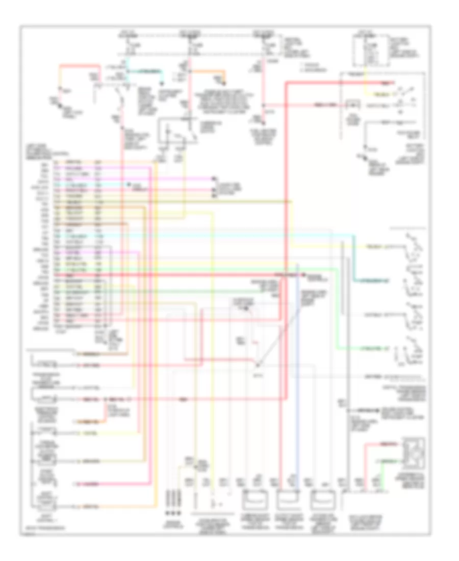
7.3L DI Turbo Diesel, Engine Performance Wiring Diagram (4 of 4) for Ford Excursion 2000
List of elements for 7.3L DI Turbo Diesel, Engine Performance Wiring Diagram (4 of 4) for Ford Excursion 2000:
- (eng harn, near breakout to brake press switch)
- (engine control harn)
- (engine harness) s114
- (in pia engine harn) s151
- (in pia engine harness)
- (left kick panel) g200
- (main harn, near air bag diag mod)
- (right side of engine compt) speed control servo
- Accelerator pedal position sensor (under left side of dash, above brake pedal)
- Accl pos sens
- Act sens
- Air charge temperature sensor (center front of engine)
- Anti-lock brake module system
- Bpp sw
- Brake pedal position switch
- C104a
- C240d
- C242a
- C242b
- Camshaft position (cmp) sensor (lower front center of engine)
- Central junction box (under left side of dash)
- Charge ind
- Cid sig
- Cmp rtn
- Cruise control system
- Digital transmission range (dtr) sensor (left side of transmission)
- Dtr-tr3a
- Epc sol
- Excursion
- Exhaust back pressure (ebp) sensor (center rear of engine)
- From dtr sensor (diagram 1 of 4)
- Fuel deliv sig
- Fuel gauge sender (part of fuel tank assembly)
- Fuel pump rly
- Fuel pump sender
- Fuse 5a
- G102 (left side of firewall)
- G200 (left kick panel)
- Gem
- Gen pwr
- Glow plug ctrl
- Hot at all times
- Icp sens
- Idm enable out
- Injection control pressure (icp) sensor (top left side of engine, right of alternator)
- Ipr sens
- Manifold absolute pressure (map) sensor (right side of firewall)
- Map sens
- Oss sens
- Overhead console system
- Overhead console, instrument cluster
- Pcm to relay
- Pickup
- Pickup excursion
- Power take off (body builder)
- Powertrain control module (pcm) (on left side of firewall)
- Pwr
- Pwr gnd
- Pwr in
- Red
- S106
- S115 (engine harn, near breakout to 16-pin conn, left side of engine compt)
- S128
- S153
- S201
- S208
- S211
- S221 s288
- Sig rtn
- Speed ctrl sw
- Starting/ charging system (w/ dual generators)
- Take off pwr in
- Tcc
- Tss sens
- Vref
- Vss (+)
- Vss in
- Vss out
- Wait to start ind
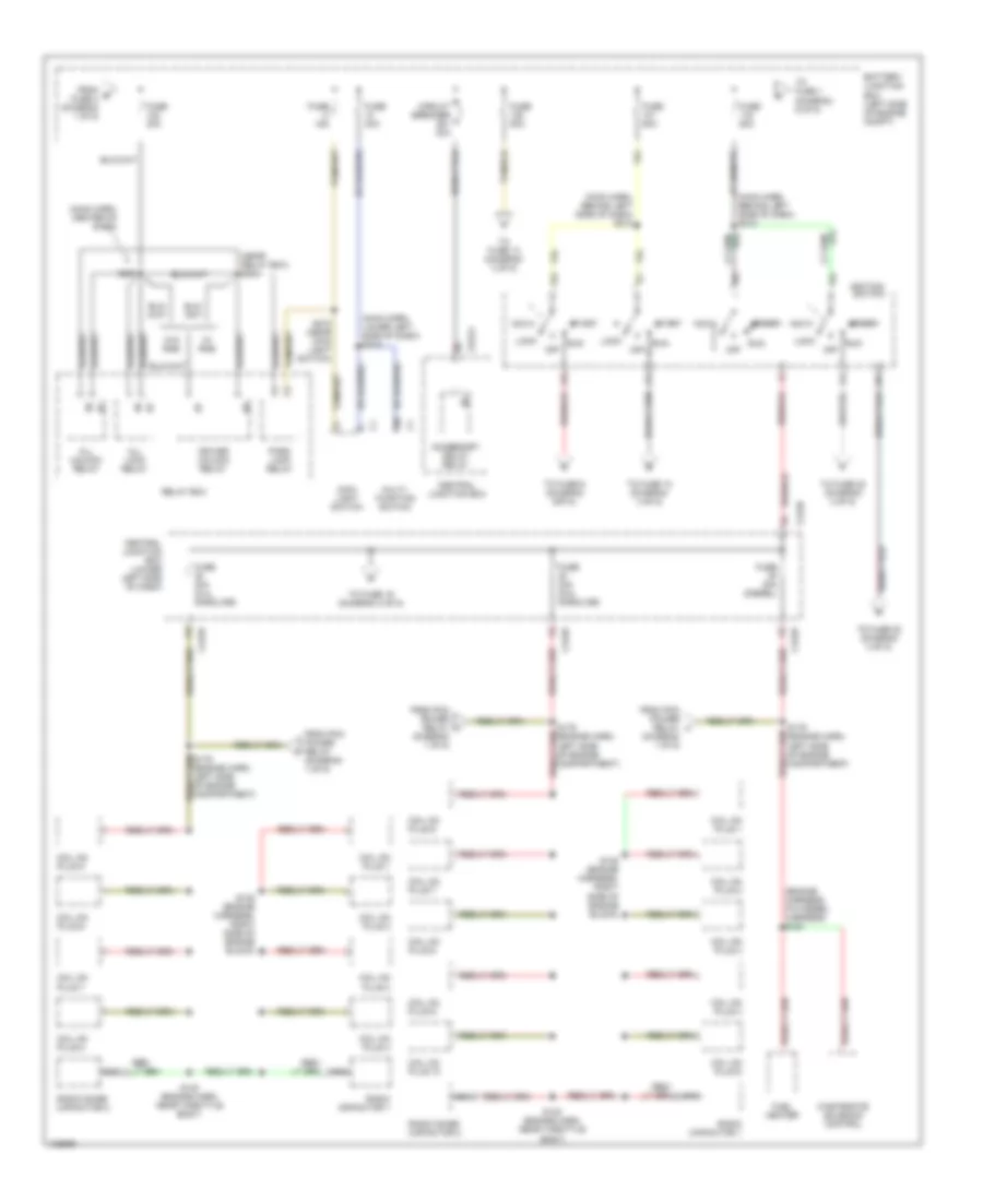
EXTERIOR LIGHTS
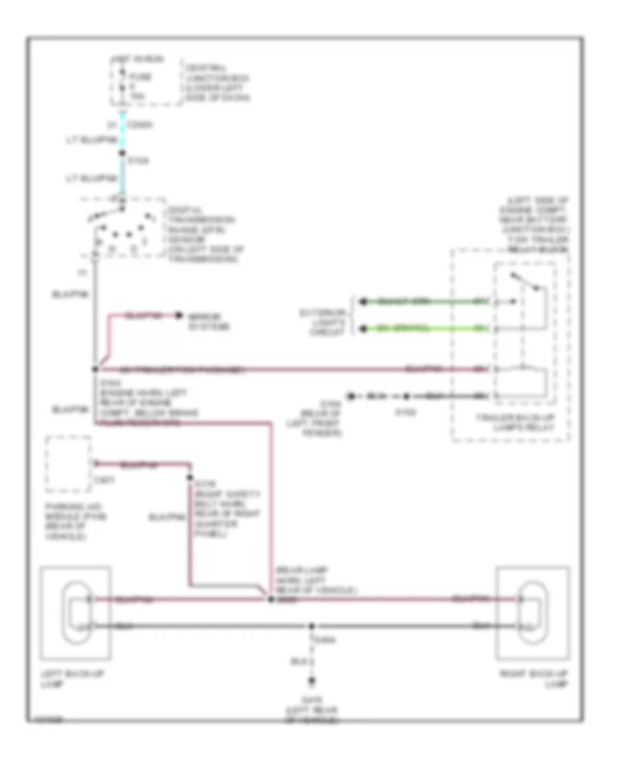
Back-up Lamps Wiring Diagram for Ford Excursion 2000
List of elements for Back-up Lamps Wiring Diagram for Ford Excursion 2000:
- (left side of engine compt, near battery junction box) tow trailer relay block
- (rear lamp harn, left rear of vehicle) s426
- (w/ trailer tow package)
- C242a
- C421
- Central junction box (lower left side of dash)
- Digital transmission range (dtr) sensor (on left side of transmission)
- Exterior lights circuit
- Fuse 15a
- G104 (rear of left front fender)
- G416 (left rear of vehicle)
- Hot in run
- Left back-up lamp
- Mirror systems
- Parking aid module (pam) (rear of vehicle)
- Right back-up lamp
- S102
- S124
- S160 (engine harn, left rear of engine compt, below brake fluid reservoir)
- S404
- Trailer back-up lamps relay
Exterior Lamps & Trailer connector Wiring Diagram (1 of 2) for Ford Excursion 2000
List of elements for Exterior Lamps & Trailer connector Wiring Diagram (1 of 2) for Ford Excursion 2000:
- (rear of left front fender) g104
- 87a
- Battery junction box (left side of engine compt)
- Battery junction box) (left side of engine compt)
- Brake pedal position switch (behind left side of dash, above brake pedal)
- C230b
- C242a
- C250b
- Central junction box (behind lower left side of dash)
- Feed (under dash)
- Flasher relay (i/p relay block)
- Fuse 15a
- Fuse 20a
- Fuse 7.5a
- G101 (front of right front fender)
- G104 (rear of left front fender)
- G206 (behind center of dash)
- G416 (left rear of vehicle)
- Hazard switch
- Head
- Hot at all times
- Hot in run
- Instrument cluster
- Left
- Left front park/turn lamp
- Left front side marker lamp
- Left rear park/stop/ turn lamp
- Main light switch
- Multi- function switch
- Off
- Park
- Park lamp relay
- Relay box (center of dash)
- Right
- Right front park/turn lamp
- Right front side marker lamp
- Right rear park/stop/ turn lamp
- S102
- S107 (engine harn, left side of engine compt)
- S109
- S162
- S180
- S215 (main harn, top left of dash)
- S217
- S240 (main harn, behind left side of dash)
- S270
- S272
- S404
- Solid state
- Trailer illumination feed (under dash)
- Trailer running lamp relay
- Turn switch
- Warning systems
Exterior Lamps & Trailer connector Wiring Diagram (2 of 2) for Ford Excursion 2000
List of elements for Exterior Lamps & Trailer connector Wiring Diagram (2 of 2) for Ford Excursion 2000:
- (left rear of chassis) trailer/camper adapter
- (left side of engine compt, near battery junction box) tow trailer relay block
- (rear high mounted stoplamp harn, rear of vehicle in liftgate) s442
- (rear of left frt fender) g104
- Battery junction box (left side of engine compt)
- C242b
- Center stop- lamp
- Central junction box (lower left side of dash)
- Exterior lights system (backup lamps)
- Fuse 10a
- Fuse 30a
- G104 (rear of left frt fender)
- G404 (left rear of vehicle)
- G416 (left rear of vehicle)
- Hot at all times
- Hot in run
- Left license lamp
- Left rear park/stop/ turn lamp
- Left stop- lamp
- Red
- Right license lamp
- Right rear park/stop/ turn lamp
- Right stop- lamp
- S102
- S235
- S401
- S404
- S417 (rear lamp harness, center rear of vehicle)
- S418 (license lamp harn, center rear of vehicle)
- S443
- Trailer backup lamps relay
- Trailer battery charge relay
- Trailer battery feed (under dash)
- Trailer electronic brakes feed (under dash)
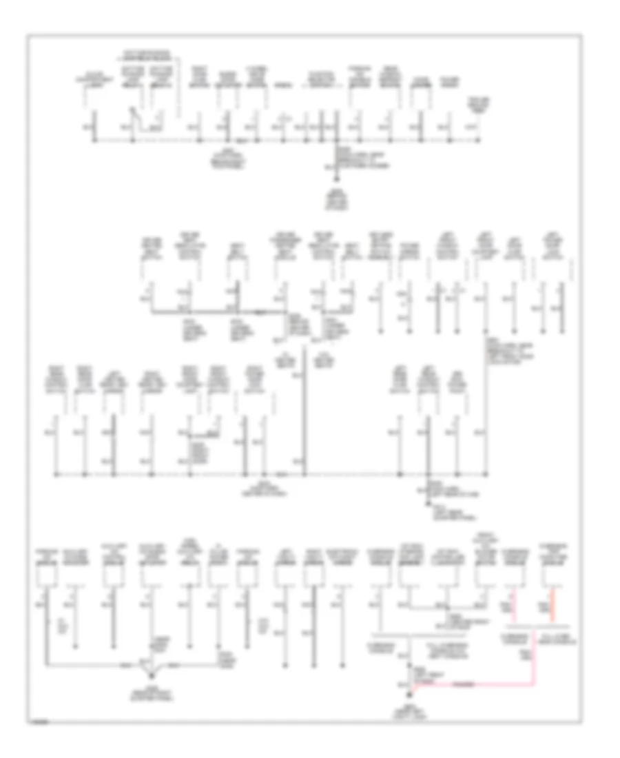
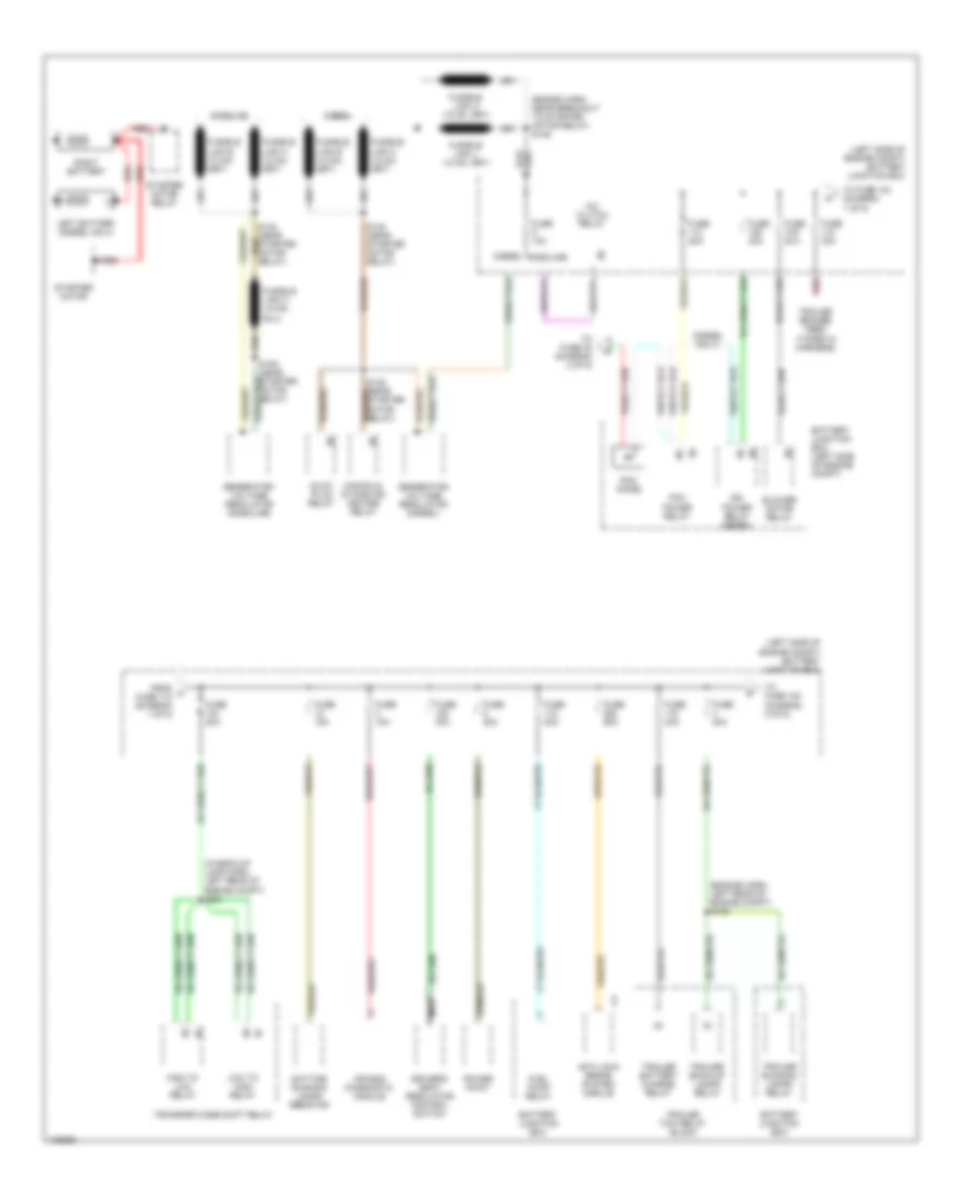
GROUND DISTRIBUTION
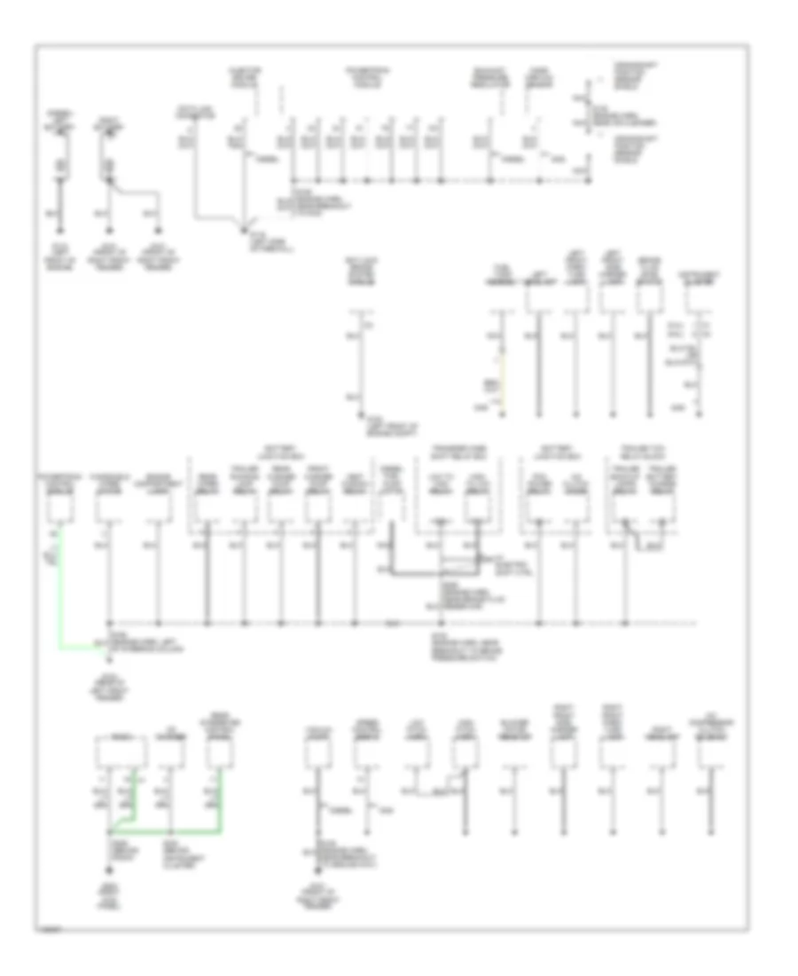
Ground Distribution Wiring Diagram (1 of 3) for Ford Excursion 2000
List of elements for Ground Distribution Wiring Diagram (1 of 3) for Ford Excursion 2000:
- (5.4l)
- (6.8l)
- (diesel) left battery
- 87a
- A/c clutch diode
- A/c compressor clutch solenoid
- Anti-lock brake system module
- Battery junction box
- Blower motor resistor
- Brake fluid level switch
- Cd changer
- Crankshaft position sensor shield
- Data link connector
- Diesel
- Diesel fuel pump motor
- Engine compartment lamp
- Exhaust pressure regulator
- Front washer pump relay
- Fuel tank assembly
- G100 (left front of engine compt)
- G101 (front of right front fender)
- G104 (rear of left front fender)
- G110 (left front of engine)
- G116 (left side of firewall)
- G203 (right kick panel)
- Gas
- High pitch horn
- High to low relay
- Injector driver module
- Instrument cluster
- Left front park/ turn lamp
- Left front side marker lamp
- Left headlamp
- Low pitch horn
- Low to high relay
- Mass airflow sensor
- Nca
- Pcm power relay
- Powertrain control module
- Radio
- Rear integrated control panel
- Rear washer pump relay
- Rear wiper relay
- Right battery
- Right front park/ turn lamp
- Right front side marker lamp
- Right headlamp
- S102 (engine harn, near breakout to brake pressure switch)
- S145 (engine harn, near air cleaner)
- S250 (engine harn, near brake fluid reservoir)
- S285 (behind radio)
- S330 (behind instrument cluster)
- Speed control servo
- Trailer back-up lamps relay
- Trailer battery charge relay
- Trailer running lamp relay
- Trailer tow relay block
- Transfer case shift relay box
- Vacuum pump
- Vent window relay
- W/ electric shift ctrl
- Windshield wiper motor
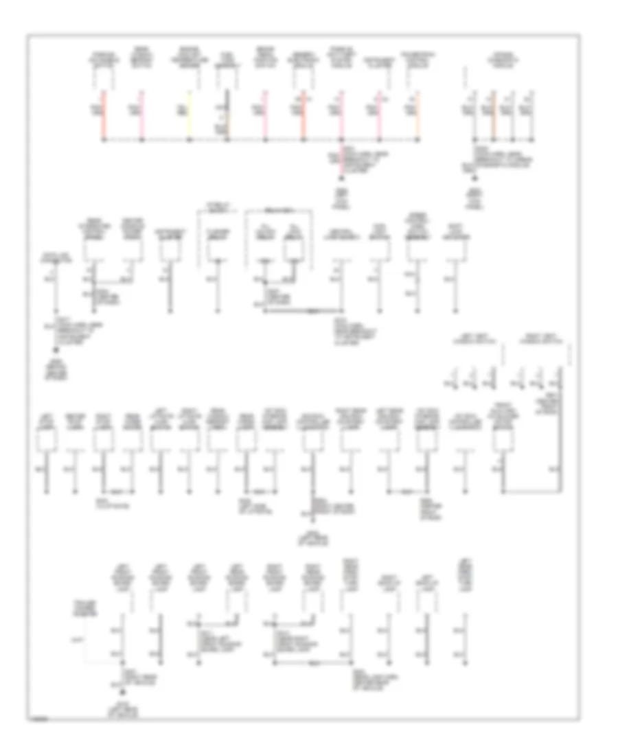
Ground Distribution Wiring Diagram (2 of 3) for Ford Excursion 2000
List of elements for Ground Distribution Wiring Diagram (2 of 3) for Ford Excursion 2000:
- 1st row controller illuminaton
- 1st row interior/ map lamp assembly
- 2nd row controller illuminaton
- 87a
- Air bag diagnostic module
- All lock relay
- All unlock relay
- Brake pedal position switch
- Center console power point
- Center stop- lamp
- Central junction box
- Data link connector
- Engine coolant temperature sender
- Flasher relay
- Front auxiliary a/c blower motor switch
- Fuel tank assembly
- G200 (left kick panel)
- G203 (right kick panel)
- G206 (behind center of dash)
- G404 (left rear of vehicle)
- G416 (left rear of vehicle)
- Generic electronic module
- I/p relay block
- Instrument cluster
- Left back-up lamp
- Left front running board lamp
- Left liftgate ajar switch
- Left rear 2nd row courtesy lamp
- Left rear park/ stop/ turn lamp
- Left rear running board lamp
- Left stop- lamp
- Left vent window switch
- Main light switch
- Nca
- Parking aid disable switch
- Passive anti-theft system module
- Powertrain control module
- Rear cargo lamp
- Rear integrated control panel
- Rear window defrost grid
- Rear window defrost switch
- Rear wiper motor
- Relay box
- Right back-up lamp
- Right front running board lamp
- Right liftgate ajar switch
- Right rear 2nd row courtesy lamp
- Right rear park/ stop/ turn lamp
- Right rear running board lamp
- Right stop- lamp
- Right vent window switch
- S202 (main harn, near breakout to airbag diagnostic module)
- S218 (main harn, near breakout to instrument cluster)
- S311 (near left front running board lamp)
- S313 (near right front running board lamp)
- S404 (rear lamp harn, center rear of vehicle)
- S440 (left side of liftgate)
- S443 (in liftgate)
- S935 (center front of roof)
- S941 (center front of roof)
- Shift lock actuator
- Speed control/ horn switch assembly
- Trailer/ camper adapter
Ground Distribution Wiring Diagram (3 of 3) for Ford Excursion 2000
List of elements for Ground Distribution Wiring Diagram (3 of 3) for Ford Excursion 2000:
- (near g405) s321
- 1st row controller illumination
- 1st row interior/ map lamp assembly
- 3rd row power point
- 4 wheel drive mode switch
- Auxiliary a/c blend door actuator
- Auxiliary a/c control module
- Auxiliary a/c mode actuator
- Blend door actuator
- Cigar lighter
- D- pillar power point
- Daytime running lamp relay 1
- Daytime running lamp relay 2
- Daytime running lamp relay block
- Driver heated seat switch
- Driver passenger heated seat module
- Driver seat regulator control switch
- Electronic day/night mirror
- Front auxiliary a/c blower motor switch
- Full over- head console
- Full overhead console w/o vent windows
- Function selector switch
- G206 (behind center of dash)
- G405 (rear of right quarter panel)
- G414 (left rear quarter panel)
- G902 (near left vanity lamp)
- Glove compartment lamp
- High speed auxiliary a/c relay
- Keyless entry keypad switch assembly
- Left door ajar switch
- Left front door courtesy lamp
- Left front window control switch
- Left heated rear view mirror
- Left power door lock switch
- Left rear door ajar switch
- Left rear window control switch
- Left vanity mirror
- Nca
- Overhead console
- Overhead console module
- Overhead trip computer module
- Parking aid disable switch
- Parking aid module
- Power mirror switch
- Power point
- Radio
- Rear window defrost switch
- Right door ajar switch
- Right front door courtesy lamp
- Right front window control switch
- Right heated rear view mirror
- Right power door lock switch
- Right rear door ajar switch
- Right rear window control switch
- Right vanity mirror
- S233 (main harn center of dash)
- S236 (behind center of dash)
- S239 (right front door)
- S257 (main harn, behind right kick panel)
- S323 (near g405)
- S332 (under driver's seat)
- S333 (under driver's seat)
- S501 (main harn, near breakout to left front door lock motor)
- S936 (left front of roof)
- Seat belt switch
- Trailer ground feed
- W/ aux a/c
- W/ heated seats
- W/o aux a/c
- W/o heated seats
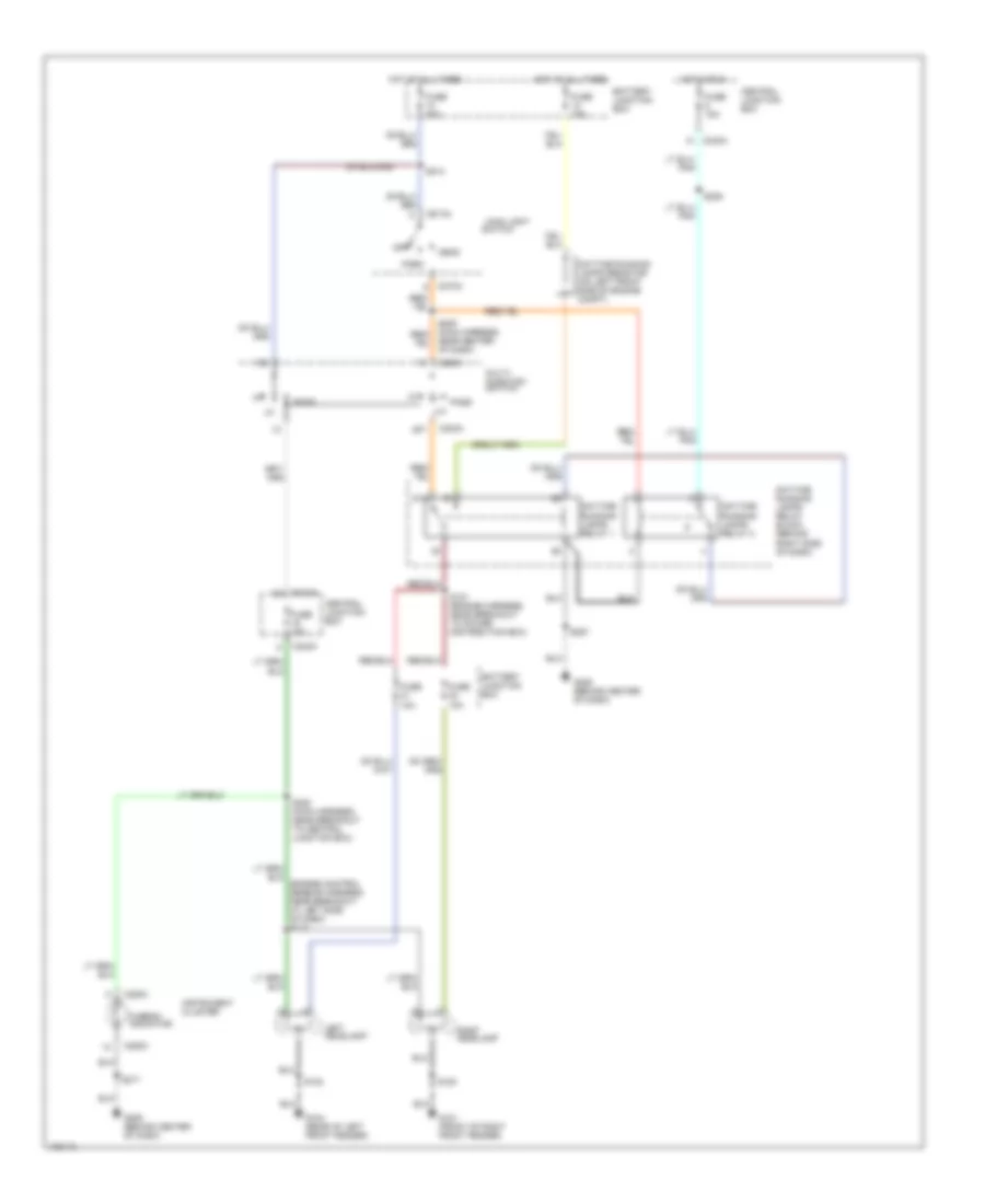
HEADLIGHTS
Headlights Wiring Diagram, with DRL for Ford Excursion 2000
List of elements for Headlights Wiring Diagram, with DRL for Ford Excursion 2000:
- 87a
- Battery junction box
- C230a
- C242a
- C250c
- C273a
- Central junction box
- Daytime running lamps relay 1
- Daytime running lamps relay 2
- Daytime running lamps relay block (behind right side of dash)
- Daytime running lamps resistor (on left front side of engine compt)
- Fuse 10a
- Fuse 15a
- Fuse 30a
- G101 (front of right front fender)
- G104 (rear of left front fender)
- G206 (behind center of dash)
- Head
- Hi-beam indicator
- Hot at all times
- Hot in run
- Instrument cluster
- Left headlamp
- Main light
- Multi- function switch
- Near center of dash)
- Off
- Park
- Pass
- Right headlamp
- S102
- S121 (engine harness, near breakout to power distribution box)
- S180
- S206
- S214
- S217
- S220 (main harness, near breakout to central junction box)
- S257
- Switch
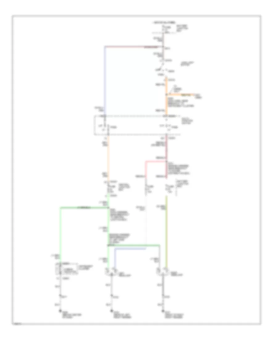
Headlights Wiring Diagram, without DRL for Ford Excursion 2000
List of elements for Headlights Wiring Diagram, without DRL for Ford Excursion 2000:
- (engine harness, near breakout at left side of dash) s113
- (not used)
- Battery junction box
- C230a
- C242a
- C250c
- C273a
- Central junction box
- Fuse 10a
- Fuse 15a
- Fuse 30a
- G101 (front of right front fender)
- G104 (rear of left front fender)
- G206 (behind center of dash)
- Head
- Hi-beam indicator
- Hot at all times
- Instrument cluster
- Left headlamp
- Main light
- Multi- function switch
- Off
- Park
- Pass
- Right headlamp
- S102
- S121 (engine harness, near breakout to power distribution box)
- S180
- S209 (main harn, near breakout to instrument cluster)
- S214
- S217
- S220 (main harness, near breakout to central junction box)
- Switch
- W/ diesel only
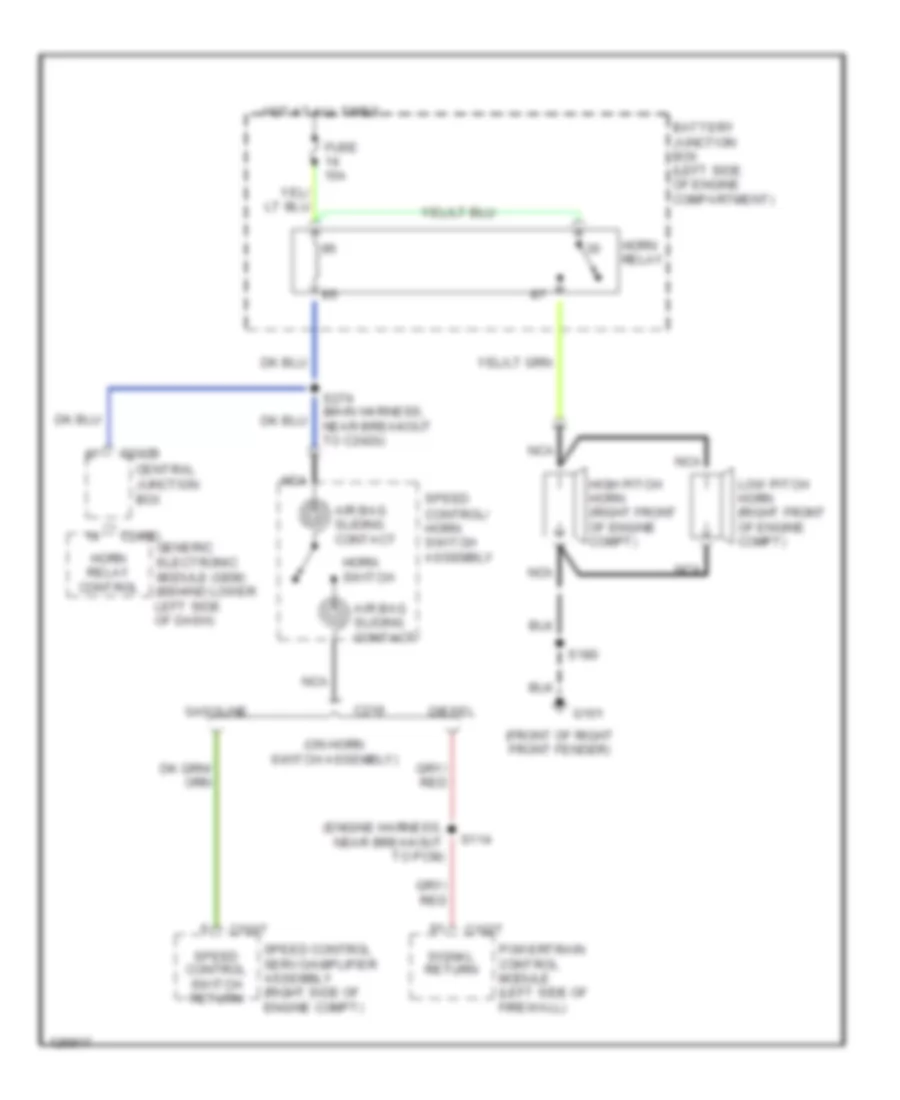
HORN
Horn Wiring Diagram for Ford Excursion 2000
List of elements for Horn Wiring Diagram for Ford Excursion 2000:
- (engine harness, near breakout to pcm)
- (front of right front fender)
- (on horn switch assembly)
- Air bag sliding contact
- Battery junction box (left side of engine compartment)
- C1027
- C1067
- C219
- C240d generic electronic module (gem) (behind lower left side of dash)
- C242b
- Central junction box
- Diesel
- Fuse 15a
- G101
- Gasoline
- High pitch horn (right front of engine compt)
- Horn relay
- Horn relay control
- Horn switch
- Hot at all times
- Low pitch horn (right front of engine compt)
- Nca
- Powertrain control module (left side of firewall)
- S114
- S180
- S274 (main harness, near breakout to c242b)
- Signal return
- Speed control servo/amplifier assembly (right side of engine compt)
- Speed control switch return
- Speed control/ horn switch assembly
INSTRUMENT CLUSTER
Instrument Cluster Wiring Diagram for Ford Excursion 2000
List of elements for Instrument Cluster Wiring Diagram for Ford Excursion 2000:
- (conn a)
- (conn b)
- (conn c)
- (diesel)
- (engine harn, left side of dash)
- (engine harness, near breakout at brake pressure switch) s104
- (excursion)
- (left kick panel) g200
- (rear of left front fender)
- 22k ohms
- 470 ohms
- 4x4 high ind
- 4x4 low ind
- 5.6k ohms
- 87a
- A 5.4l
- A11
- Airbag ind
- Anti-lock brake ind
- Anti-lock brakes system
- Anti-theft system
- B 6.8l
- B10
- B11
- B12
- B13
- B14
- B16
- Bi-fuel
- Brake warning ind
- C10
- C1027
- C11
- C12
- C240a
- C242b
- C250a
- C250c
- C25ob
- Central junction box
- Charge ind
- Coolant temperature/ oil pressure indicator
- Cruise control system
- Dash reset relay (right rear of engine compt)
- Daytime running lamps ind
- Diesel
- Door ajar ind
- Dual tanks
- Eng cool temp gauge
- Eng oil press gauge
- Engine controls system
- Engine controls system (diesel)
- Engine coolant temperature sender (on front of engine)
- Engine coolant temperature sender (on top left front of engine)
- Engine oil pressure switch (on top center rear of engine)
- Exc bi-fuel
- Except diesel
- Exterior lights system
- Fasten seat belt ind
- Fuel gauge
- Fuel reset ind
- Fuel tank assembly
- Fuel tank selector valve
- Fuse 10a
- Fuse 5a
- G104
- G104 (rear of left front fender)
- G200 (left kick panel)
- G206 (behind center of dash)
- Gas
- Generic electronic module (behind lower left side of dash)
- Ground
- Headlights system
- Hi beam ind
- Hot at all times
- Hot in start or run
- Illumination
- Instrument cluster
- Interior lights system
- Keep alive
- Led indicator
- Left turn ind
- Malfunction ind
- Microprocessor
- Nca
- Overhead console circuit
- Powertrain control module (on left side of firewall)
- Red
- Right turn ind
- S102
- S129
- S201
- S208 (main harn, center of dash)
- S213
- S217
- S221
- Spd ctrl set lamp
- Starting/charging system
- Tach select 1
- Tach select 2
- Tachometer
- Transmission system
- V power
- Vss+ (speedometer)
- Wait to start ind
- Water in fuel ind
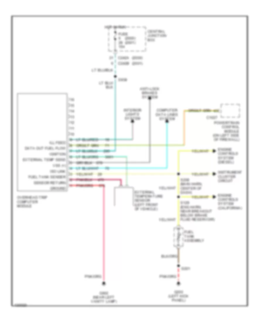
Overhead Console Wiring Diagram for Ford Excursion 2000
List of elements for Overhead Console Wiring Diagram for Ford Excursion 2000:
- (2000)
- (2000) (2001)
- (2001)
- Anti-lock brakes system
- C1027
- C242a
- C242b
- Central junction box
- Computer data lines system
- Data out fuel flow
- Engine controls system (california)
- Engine controls system (diesel)
- External temp sens
- External temperature sensor (left front of vehicle)
- Fuel tank assembly
- Fuel tank sender
- Fuse 15a
- G200 (left kick panel)
- G902 (near left vanity lamp)
- Ground
- Hot in run
- Ignition
- Instrument cluster circuit
- Iso link
- Overhead console module (in roof, at front center of cab)
- Powertrain control module (on left side of firewall)
- S129 (eng harn, near breakout below brake fluid reservoir)
- S201
- S208 (main harn, center of dash)
- S936
- S938
- Sensor return
- Vss (+)
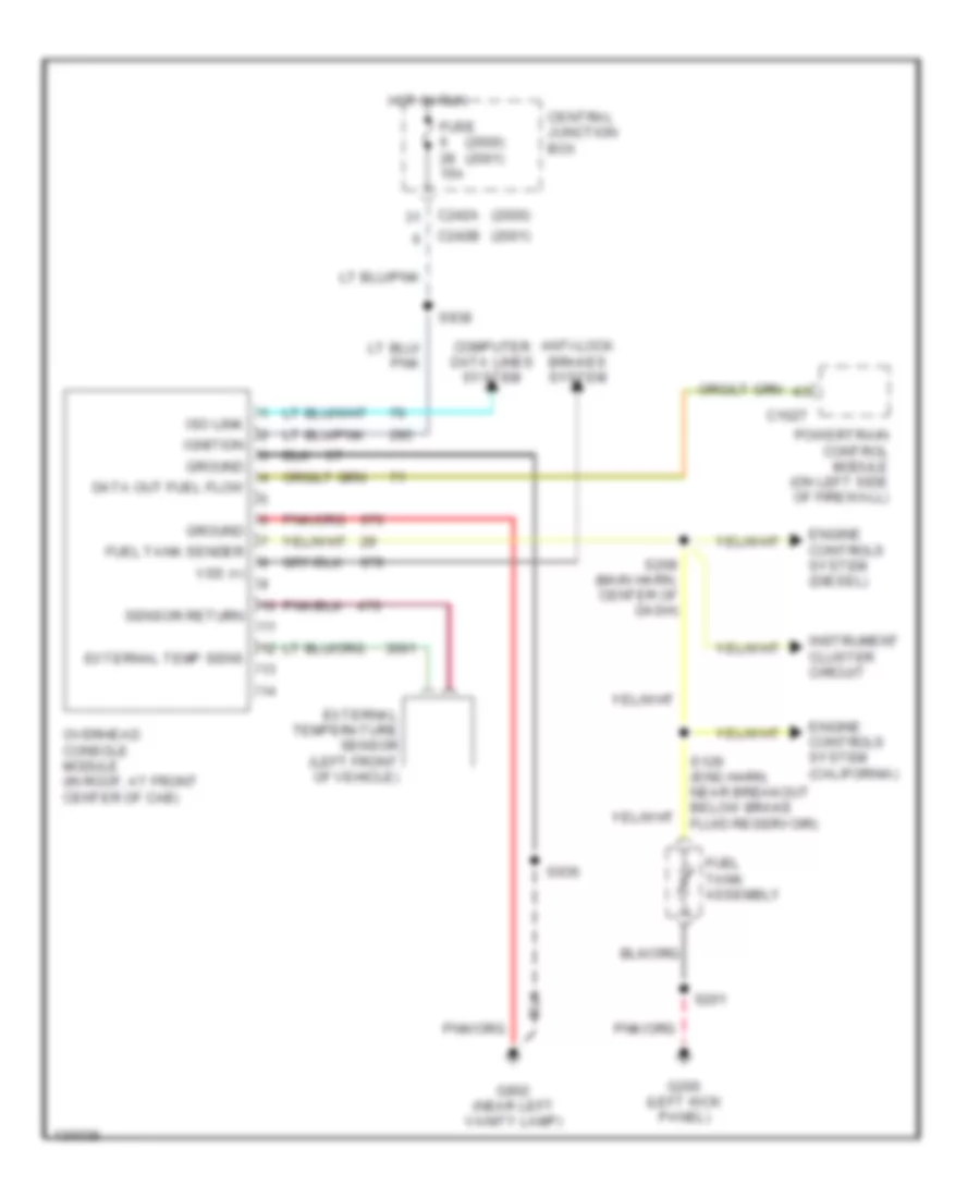
Trip Computer Wiring Diagram for Ford Excursion 2000
List of elements for Trip Computer Wiring Diagram for Ford Excursion 2000:
- (2000)
- (2000) (2001)
- (2001)
- Anti-lock brakes system
- C1027
- C242a
- C242b
- Central junction box
- Computer data lines system
- Data out fuel flow
- Engine controls system (california)
- Engine controls system (diesel)
- External temp sens
- External temperature sensor (left front of vehicle)
- Fuel tank assembly
- Fuel tank sender
- Fuse 15a
- G200 (left kick panel)
- G902 (near left vanity lamp)
- Ground
- Hot in run
- Ignition
- Ill feed
- Instrument cluster circuit
- Interior lights system
- Iso link
- Overhead trip computer module
- Powertrain control module (on left side of firewall)
- S201
- S208 (main harn, center of dash)
- S938
- Sensor return
- Vss (+)
INTERIOR LIGHTS
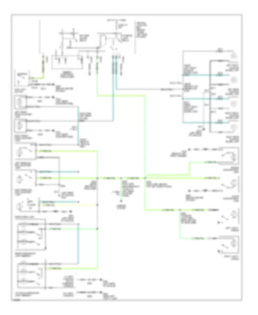
Courtesy Lamps Wiring Diagram for Ford Excursion 2000
List of elements for Courtesy Lamps Wiring Diagram for Ford Excursion 2000:
- (left rear of vehicle) g404
- (main harn, left rear of cab) s905
- (near brake fluid reservoir) s190
- (near left front running board lamp) s309
- (not used)
- (right rear of vehicle) s933
- 1st row interior/map lamp assembly
- Battery saver relay
- C240d
- C242a
- C242b
- C274a
- C274b
- Central junction box (behind lower left side of dash)
- Door
- Engine compartment lamp
- Fuse 107 30a
- G104 (rear of left front fender)
- G206 (behind center of dash)
- G404 (left rear of vehicle)
- G414 (left rear quarter panel)
- G416 (left rear of vehicle)
- G902 (near left vanity lamp)
- Generic electronic module (gem)
- Glove compartment lamp
- Hot at all times
- Interior
- Interior lamp relay
- Left front door courtesy lamp
- Left front running board lamp
- Left rear 2nd row courtesy lamp
- Left rear running board lamp
- Left vanity mirror
- Main light switch
- Map
- Mirrors system
- Nca
- Off
- Quarter panel)
- Rear cargo lamp
- Rear interior/map lamp assembly
- Right front door courtesy lamp
- Right front running board lamp
- Right rear 2nd row courtesy lamp
- Right rear running board lamp
- Right vanity mirror
- S162
- S218
- S229 (main harn, behind top left side of dash)
- S239
- S257
- S311
- S312 (near right front running board lamp)
- S313
- S401
- S440
- S501
- S932 (interior lamp harn. rear center of headliner)
- S932 (rear center of headliner)
- S934
- S935
- W/ vent windows or w/o overhead console
- W/o vent windows
Instrument Illumination Wiring Diagram for Ford Excursion 2000
List of elements for Instrument Illumination Wiring Diagram for Ford Excursion 2000:
- (left rear quarter panel) g414
- (w/ vent windows) (left rear of vehicle) g404
- 1st row controller illuminaton
- 2nd row controller illumination
- 4 wheel drive mode switch
- Accessory delay relay
- Battery junction box (in left side of engine compt, on top of wheelwell)
- Bulbs
- C242a
- C250b
- C250c
- C257a
- C273b
- C298
- C510a
- C510b
- Central junction box (behind lower left side of dash)
- Circuit 30a
- Climate control illum
- Function selector switch
- Fuse 7 5a
- G206 (behind center of dash)
- G404 (left rear of vehicle)
- G414 (left rear quarter panel)
- G902 (near left vanity lamp)
- G902 (near left vanity lamp) (w/o vent windows)
- Head
- Hot at all times
- Instrument cluster
- Left front window control switch
- Left power door lock switch
- Left rear window control switch
- Left vent window switch
- Main light switch
- Nca
- Off
- Overhead trip computer module
- Parking aid disable switch
- Pulse width dimmer module
- Radio
- Rear integrated control panel
- Rear window defrost switch
- Right front window control switch
- Right power door lock switch
- Right rear window control switch
- Right vent window switch
- S215 (main harn, top left side of dash)
- S216 (main harn, behind top left side of dash)
- S217
- S218
- S227 (main harn, lower center of dash)
- S233
- S239
- S290
- S300
- S324
- S501
- S926 (near breakout to 2nd row controller illumination connector)
- S934
- S935
- S940 (in center of headliner)
- S941
- Speed control/ horn switch assembly
- Steering wheel illumination
NAVIGATION
Parking Assistant Wiring Diagram for Ford Excursion 2000
List of elements for Parking Assistant Wiring Diagram for Ford Excursion 2000:
- (2000) (2001)
- (behind center of dash)
- (behind left kick panel)
- (body harness, near left rear of vehicle)
- (near parking aid module)
- 12v in reverse
- 2000 and early production 2001
- Abs module
- C1012
- C263
- C421
- C433
- C434
- C462
- C463
- C464
- C466
- C924
- Central junction box (behind lower left side of dash)
- Data link connector (behind left side of dash)
- Digital trans range sensor module (raps) (on trans)
- Electronic day/night mirror
- Fuse 6 fuse 28 15 a
- G200
- G206
- G403
- Ground
- Hot in run
- Instrument illumination
- Iso 9141
- Late production 2001
- Left center parking aid sensor
- Left center sensor input
- Left outer parking aid sensor
- Left outer sensor input
- Left reversing lamp
- On/off switch
- Parking aid disable switch (in glove box)
- Parking aid module (in rear of vehicle)
- Parking aid speaker
- Power
- Reverse input
- Right center parking aid sensor
- Right center sensor input
- Right outer parking aid sensor
- Right outer sensor input
- Right reversing lamp
- S160 (engine harness below brake fluid reservoir)
- S165 (engine harness below brake fluid reservoir)
- S201
- S225 (main harness, near breakout to customer access)
- S270
- S410
- S411
- S426 (rear lamp harness, near b/o to left reverse lamp)
- Sensor ground
- Sensor power
- Speaker (+)
- Speaker (-)
- Status led
- To multiplex communication network
- Trailer tow relay block (left side of eng compt)
POWER DISTRIBUTION
Power Distribution Wiring Diagram (1 of 5) for Ford Excursion 2000
List of elements for Power Distribution Wiring Diagram (1 of 5) for Ford Excursion 2000:
- (diesel only)
- (engine harn, left rear of engine compt) s109
- (engne harn, near breakout to starter motor relay) s146
- (in back-up lamp harn, left rear of engine compt) s251
- (left side of engine compt) battery junction box
- A/c clutch relay
- Air bag diagnostic module
- Anti-lock brake system module
- Battery junction box
- Battery junction box (left side of engine compt)
- Blower motor relay
- Daytime running lamps resistor
- Diesel
- Driver's seat regulator control switch
- From a fuse 110 (diagram 1 of 5)
- Fuel pump relay
- Fuse 10a
- Fuse 15a
- Fuse 20a
- Fuse 30a
- Fuse 40a
- Fuse 60a
- Gasoline
- Generator/ voltage regulator (diesel)
- Generator/ voltage regulator (gasoline)
- Glow plug relay
- High to low relay
- Idm power relay (diesel)
- Left battery (diesel only)
- Low to high relay
- Manifold intake air heater relay
- Motor relay)
- Nca
- Pcm diode
- Pcm power relay
- Power point
- Red
- Right battery
- S148 (near starter motor relay)
- S149 (near starter motor relay)
- Starter motor
- Starter motor relay
- To fuse 102 (diagram 2 of 5)
- To fuse 104 (diagram 1 of 5)
- To fuse 30 (diagram 2 of 5)
- Trailer back-up lamps relay
- Trailer battery charge relay
- Trailer brakes feed (taped in harness)
- Trailer running lamps relay
- Trailer tow relay block
- Transfer case shift relay
Power Distribution Wiring Diagram (2 of 5) for Ford Excursion 2000
List of elements for Power Distribution Wiring Diagram (2 of 5) for Ford Excursion 2000:
- (engine harness, pia diesel harness) s154
- (main harn, behind left side of dash) s210
- (main harn, behind left side of dash) s212
- (main harn, center of dash)
- (main harn, lower left side of dash) s214
- (near relay box) s234
- Acc
- Accessory delay relay
- All lock relay
- All unlock relay
- Battery junction box (left side of engine compt)
- C242a
- C242b
- Central junction box
- Central junction box (lower left side of dash)
- Circuit breaker 30a
- Coil on plug 1
- Coil on plug 10
- Coil on plug 2
- Coil on plug 3
- Coil on plug 4
- Coil on plug 5
- Coil on plug 6
- Coil on plug 7
- Coil on plug 8
- Coil on plug 9
- Driver unlock relay
- From b fuse 4 (diagram 1 of 5)
- From pcm power relay (diagram 1 of 5)
- Fuel heater
- Fuse 15a
- Fuse 30a
- Fuse 30a (5.4l gasoline)
- Fuse 30a (6.8l gasoline)
- Fuse 30a (diesel)
- Fuse 50a
- Ignition switch
- Lock
- Main light switch
- Multi- function switch
- Nca
- Off
- Park lamp relay
- Radio capacitor 1
- Radio noise capacitor 2
- Relay box
- Run
- S130 (engine harn, near throttle body)
- S135 (engine harness, right side of engine block)
- S179 (engine harn, left side of engine compartment)
- S230
- S272 (near main light switch)
- Start
- To fuse 1 (diagram 5 of 5)
- To fuse 10 (diagram 4 of 5)
- To fuse 13 (diagram 3 of 5)
- To fuse 19 (diagram 3 of 5)
- To fuse 20 (diagram 4 of 5)
- To fuse 22 (diagram 4 of 5)
- To fuse 6 (diagram 5of 5)
- W/ rke
- W/o rke
- Wastegate solenoid control
Power Distribution Wiring Diagram (3 of 5) for Ford Excursion 2000
List of elements for Power Distribution Wiring Diagram (3 of 5) for Ford Excursion 2000:
- (console harn, near cd changer) s328
- (main harn, left rear of cab) s906
- (main harn, top left side of dash) s229
- (main harness, top left side of dash) s271
- (near instrument cluster) s211
- (near passive anti- theft system module) s288
- (near rear interior/map lamp assembly) s932
- 1st row interior/ map lamp assembly
- Accessory delay relay
- Battery saver relay
- Brake pedal position switch
- Brake pressure switch
- C240a
- C242a
- C242b
- C250a
- C250b
- Cd changer
- Central junction box (lower left side of dash)
- Cigar lighter
- Data link connector
- Engine compartment lamp
- Flasher relay
- From fuse 105 (power distribution box) (diagram 2 of 5)
- From fuse 3 l (diagram 3 of 5)
- From h fuse 30 (diagram 2 of 5)
- Fuse 10a
- Fuse 15a
- Fuse 20a
- Fuse 5a
- G206 (center of dash)
- Generic electronic module
- Generic electronic module (gem)
- Glove compartment lamp
- I/p relay block
- Idle validation switch
- Instrument cluster
- Interior lamp relay
- Left rear 2nd row courtesy lamp
- Left vanity lamp
- Nca
- Overdrive cancel switch
- Passive anti- theft system transceiver module
- Passive anti-theft system module
- Power mirror switch
- Powertrain control module
- Radio
- Rear cargo lamp
- Rear integrated control panel
- Rear interior/ map lamp assembly
- Right rear 2nd row courtesy lamp
- Right vanity lamp
- S242 (main harness, near breakout to customer access)
- S273 (near central junction box)
- S932 (near left vanity lamp)
- To fuse 14 (diagram 3 of 5)
Power Distribution Wiring Diagram (4 of 5) for Ford Excursion 2000
List of elements for Power Distribution Wiring Diagram (4 of 5) for Ford Excursion 2000:
- (engine harn, left rear corner of engine compt) s142
- (engine harn, left rear corner of engine compt) s143
- (lower left side of dash) central junction box
- (main harn, left side of dash) s235
- Air bag diagnostic module
- Anti-lock brake system module
- Battery junction box
- Blend door actuator
- Blower motor relay
- C242a
- C242b
- Central junction box (lower left side of dash)
- Digital transmission range sensor
- From ignition switch (diagram 2 of 5)
- Front washer pump relay
- Function selector switch
- Fuse (not used)
- Fuse 10a
- Fuse 15a
- Fuse 30a
- Fuse 5a
- Generic electronic module (gem)
- Radio
- Rear washer pump relay
- Rear wiper relay
- S144 (engine harn, left rear corner of engine compt)
- S275 (main harn, near central junction box)
- Tan/red
- Trailer battery charge relay
- Trailer tow relay block
- Windshield wiper motor
- Wiper high/ low relay
- Wiper run/park relay
Power Distribution Wiring Diagram (5 of 5) for Ford Excursion 2000
List of elements for Power Distribution Wiring Diagram (5 of 5) for Ford Excursion 2000:
- (diagram 2 of 5)
- (engine harn, left rear of engine compt) s124
- (engine harn, left side of dash) s166
- (left side of engine compt) battery junction box
- (main harn, center of dash) s206
- (main harn, center of dash) s238
- (main harn, right side of dash) s281
- 3rd row power point
- Auxiliary a/c blend door actuator
- Auxiliary a/c control module
- Auxiliary a/c mode actuator
- Auxiliary a/c relay
- Battery junction box
- C242a
- Center console power point
- Central junction box
- Central junction box (lower left side of dash)
- Customer access (taped in harness)
- D-pillar power point
- Daytime running lamps relay 2
- Daytime running lamps relay block
- Digital transmission range sensor
- Driver heated seat module
- Driver heated seat switch
- Electronic day/night mirror
- Flasher relay
- From fuse 116 k
- From ignition switch (diagram 2 of 5)
- Front washer pump relay
- Full ovehead console
- Fuse 10a
- Fuse 15a
- Fuse 20a
- Fuse 30a
- Fuse 40a
- Generic electronic module (gem)
- Heated grid relay
- High speed auxiliary a/c relay
- Horn relay
- I/p relay block
- Overhead console
- Overhead console module
- Overhead trip computer module
- Parking aid module
- Passenger heated seat module
- Passenger heated seat switch
- Rear washer pump relay
- Rear wiper motor
- Rear wiper relay
- Red
- S270 (main harn, near top of park brake pedal)
- S320 (right rear of vehicle)
- S322 (right rear of vehicle)
- S334 (near driver heated seat switch)
- S335 (near passenger heated seat switch)
- S938 (near right visor)
- Shift lock actuator
- Speed control servo
- Vacuum hublock solenoid
- Vacuum pump
- Vent window relay
POWER DOOR LOCKS
Remote/Keyless Entry Wiring Diagram for Ford Excursion 2000
List of elements for Remote/Keyless Entry Wiring Diagram for Ford Excursion 2000:
- (main harn, center of dash) s224
- (main harn, center of dash) s232
- 87a
- All lock relay
- All unlock relay
- Battery junction block (in left side of engine compt, on top of wheelwell)
- C240b
- C240c
- C273a
- Driver unlock relay
- Exterior lights system
- Fuse 15a
- Fuse 30a
- G206 (behind center of dash)
- G404 (left rear quarter panel)
- Generic electronic module (behind lower left side of dash)
- Head
- Hot at all times
- Interior lights system
- Keyless entry keypad switch assembly
- Left front door lock motor
- Left power door lock switch
- Left rear door lock motor
- Liftgate power lock motor
- Lock
- Main light switch
- Off
- Park
- Park lamp relay
- Red
- Relay box (behind center of dash)
- Right front door lock motor
- Right power door lock switch
- Right rear door lock motor
- S228 (main harn, center of dash)
- S230
- S231 (main harn, center of dash)
- S233
- S234
- S237
- S272
- S300
- S501
- Unlk
POWER MIRRORS
Electronic Day/Night Mirror Wiring Diagram for Ford Excursion 2000
List of elements for Electronic Day/Night Mirror Wiring Diagram for Ford Excursion 2000:
- (2000) (2001)
- (engine harness, below brake fluid reservoir)
- Central junction box (lower left side of dash)
- Digital transmission range (dtr) sensor (left side of transmission)
- Electronic day/night mirror
- Fuse 6 fuse 28 15a
- G900 (near left vanity lamp)
- Ground
- Hot in run
- Power
- Reverse
- Reverse lights system
- S160
- S206
- S936
- Sense
Power Mirrors Wiring Diagram for Ford Excursion 2000
List of elements for Power Mirrors Wiring Diagram for Ford Excursion 2000:
- (left rear of cab) g308
- Battery saver relay
- C240d
- C242a
- C242b
- Central junction box (behind lower left side of dash)
- Direct- ional control switch
- Down
- Except excursion
- Excursion
- Fuse 10a
- Fuse 15a
- Generic electronic module (behind lower left side of dash)
- Hot at all times
- Illum
- Interior lights system
- L/r
- Left
- Left power mirror
- Nca
- Power mirror switch
- Red
- Right
- Right power mirror
- S261 (body harn, near breakout to seat harn)
- S301 (1999) s906 (2000)
- S500
- U/d
POWER SEATS
6-Way Power Seat Wiring Diagram for Ford Excursion 2000
List of elements for 6-Way Power Seat Wiring Diagram for Ford Excursion 2000:
- (1999)
- (2000-01)
- Battery junction box (left side of engine compt)
- Driver seat motor assembly
- Driver seat regulator control switch
- Entire seat
- Except excursion w/ heated seats
- Excursion w/ heated seats
- Forward/reverse motor
- Front height motor
- Front of seat
- Fuse 18 fuse 108 30a
- Fwd
- G308 (left rear of cab)
- Hot at all times
- Nca
- Rear height motor
- Rear of seat
- Rwd
- S298 (2001)
- S300
Heated Seats Wiring Diagram for Ford Excursion 2000
List of elements for Heated Seats Wiring Diagram for Ford Excursion 2000:
- (left rear quater panel)
- (seat harness, near b/o to heated seat switch)
- Battery junction box (left side of engine compt)
- C333
- C334
- C342
- C343
- Central junction box (behind left side of dash)
- Driver's seat back heater
- Driver's heated seat module (under driver's seat)
- Driver's heated seat switch (under driver's seat)
- Driver's seat heater & temp sensor (under driver's seat)
- Fuse 107 (excursion) fuse 15 (pickup) 30a
- Fuse 6 (2000) fuse 28 (2001) 15a
- G414
- Hot at all times
- Hot in run
- Not used
- Pass seat back heater
- Passenger's heated seat module (under passenger's seat)
- Passenger's heated seat switch (under passenger's seat)
- Passenger's seat heater & temp sensor (under passenger's seat)
- Red
- S238
- S281
- S334
- S335
POWER WINDOWS
Power Windows Wiring Diagram (1 of 2) for Ford Excursion 2000
List of elements for Power Windows Wiring Diagram (1 of 2) for Ford Excursion 2000:
- 87a
- Acc delay relay
- Acc delay rly ctrl
- Bat saver rly ctrl
- Battery junction box
- Battery saver relay
- C240d
- C242a
- C242b
- C510a
- C510b
- Central junction box
- Circuit breaker 25 30a
- Down sw input
- Fuse 15a
- Fuse 50a
- G206 (behind center of dash)
- G308 (left rear of cab)
- Generic electronic module
- Hot at all times
- Interior lights system
- Left front power window motor
- Left front power window switch
- Left front switch
- Left rear power window motor
- Left rear power window switch
- Left rear switch
- Lock out
- Nca
- One tch dn ctrl
- One tch sense hi
- One tch sense lo
- One touch down relay
- Otd sw input
- Otd switch
- Right front power window motor
- Right front power window switch
- Right front switch
- Right rear power window motor
- Right rear power window switch
- Right rear switch
- S218
- S262 (harn, near breakout under left front seat)
- S289 (main harn, left of steering column)
- S501
- Shunt (0.015 ohms)
Power Windows Wiring Diagram (2 of 2) for Ford Excursion 2000
List of elements for Power Windows Wiring Diagram (2 of 2) for Ford Excursion 2000:
- Battery junction box
- Close
- Fuse 50a
- G104 (rear of left front fender)
- G404 (left rear of vehicle)
- Hot at all times
- Interior lights system
- Left vent window motor
- Left vent window switch
- Open
- Pnk
- Right vent window motor
- Right vent window switch
- S162
- S935
- S939 (interior lamp harn, center of headliner)
- S941
- Vent window relay
RADIO
Radio Wiring Diagram, Base Radio for Ford Excursion 2000
List of elements for Radio Wiring Diagram, Base Radio for Ford Excursion 2000:
- (behind center of dash) g206
- (in main harness, near breakout to rke relay box)
- (in main harness, near breakout under front seats)
- Antenna
- C242a
- C242b
- C257a
- Central junction box (behind lower left side of dash)
- Fuse 20a
- Fuse 5a
- G203 (right kick panel)
- Ground
- Hot at all times
- Hot in run or acc
- Hot in start
- Ign
- Ill
- Interior lights system
- L f spkr
- L r spkr
- Left front speaker
- Left rear door speaker
- Left rear speaker
- Nca
- Power
- R f spkr
- R r spkr
- Radio
- Right front speaker
- Right rear door speaker
- Right rear speaker
- S273
- S285
- S290
- S291
- S292
- S293
- S294
Radio Wiring Diagram, Premium Radio for Ford Excursion 2000
List of elements for Radio Wiring Diagram, Premium Radio for Ford Excursion 2000:
- (in i/p console harn, near breakout to cd changer)
- (in i/p console harn, near breakout to rear integrated control panel)
- (in main harn, near breakout to radio)
- (in main harn, near breakout to rke relay box
- (in main harn, near breakout under front seat)
- (in main harn, near breakout, in center of dash)
- (main harn, near breakout to air bag diagnostic module)
- (right kick panel)
- Acp a
- Acp b
- Antenna
- Asys on
- Aud ntwrk
- Audio shield
- Bare
- Bare s330
- Bare s331
- C242a
- C242b
- C257a
- C257b
- C266
- Cd changer
- Cd l sig in
- Cd l sig out
- Cd r sig in
- Cd r sig out
- Central junction box (under left side of dash)
- Fuse 10a
- Fuse 25a
- Fuse 5a
- G203
- G203 (right kick panel)
- G206 (behind center of dash)
- Ground
- Hot at all times
- Hot in run or acc
- Hot in start
- Ignition
- Illum
- Interior lights
- Interior lights system
- L f spkr
- L r amp +
- L r spkr
- Left front speaker
- Left rear door speaker
- Left rear speaker
- Left sig (+)
- Left sig (-)
- Lr sig +
- Lr sig -
- Nca
- Power
- Protocol a
- Protocol b
- R f spkr
- R r spkr
- Radio
- Rear integrated control panel
- Right front speaker
- Right rear door speaker
- Right rear speaker
- Right sig (+)
- Right sig (-)
- Rr amp +
- Rr sig +
- Rr sig -
- S273
- S276
- S277
- S282
- S283
- S285
- S290
- S291
- S292
- S293
- S294
- S324
- S325
- S326
- S328
- S329
- S330
- Shield
- Tan
SHIFT INTERLOCK
Shift Interlock Wiring Diagram for Ford Excursion 2000
List of elements for Shift Interlock Wiring Diagram for Ford Excursion 2000:
- (excursion)
- (excursion) (others)
- (others)
- Brake pedal position (bpp) switch (above brake pedal)
- C242a c242b
- C242b
- Central junction box (behind lower left side of dash)
- Fuse 15 5a
- Fuse 28 10a
- Fuse 6 15a
- G200 (left kick panel)
- G206 (behind center of dash)
- Hot at all times
- Hot in run
- S201
- S205 (main harn, left of steering column)
- S206
- S218
- Shift lock actuator (in steering column)
- Solid state
STARTING/CHARGING
Starting Wiring Diagram for Ford Excursion 2000
List of elements for Starting Wiring Diagram for Ford Excursion 2000:
- Acc
- Battery junction box (left side of engine compt)
- C1012
- C242b
- Central junction box (behind lower left side of dash)
- Digital transmission range sensor (left side of transmission)
- Fuse 15a
- Fuse 50a
- Fusible link a (12 ga-gray) (near starter motor relay)
- Fusible link j (12 ga-gray) (near starter motor relay)
- G101 (front of right front fender)
- G110 (left front of engine)
- Ignition switch
- Left battery (diesel)
- Lock
- Off
- Red
- Right battery
- Run
- S275 (main harn, near central junction box)
- Sta
- Start
- Starter motor
- Starter motor relay (right front inner fender panel, behind battery)
- Tan/red
5.4L
5.4L, Charging Wiring Diagram for Ford Excursion 2000
List of elements for 5.4L, Charging Wiring Diagram for Ford Excursion 2000:
- (eng harn, near breakout to starter motor relay) s146
- (near starter motor relay) (12 ga-gray) fusible link h
- 0hms
- Acc
- Battery
- Battery junction box (left side of engine compt)
- C153a
- C153b
- C242b
- C250a
- Central junction box (behind lower left side of dash)
- Charge indicator
- Fuse 50a
- Fuse 5a
- Fusible link a (12 ga-gray) (near starter motor relay)
- Fusible link b (12 ga-gray) (near starter motor relay)
- Fusible link c (18 ga-gray) (near starter motor relay)
- Fusible link j (12 ga-gray) (near starter motor relay)
- G101 (front of right front fender)
- Generator
- Ignition switch
- Instrument cluster
- Lock
- Off
- Red
- Run
- S148 (eng harn, near starter motor relay)
- Start
- Starter motor
- Starter motor relay (behind battery)
6.8L
6.8L, Charging Wiring Diagram for Ford Excursion 2000
List of elements for 6.8L, Charging Wiring Diagram for Ford Excursion 2000:
- (eng harn, near breakout to starter motor relay) s146
- (near starter motor relay) (12 ga-gray) fusible link h
- 0hms
- Acc
- Battery
- Battery junction box (left side of engine compt)
- C153a
- C153b
- C242b
- C250a
- Central junction box (behind lower left side of dash)
- Charge indicator
- Fuse 50a
- Fuse 5a
- Fusible link a (12 ga-gray) (near starter motor relay)
- Fusible link b (12 ga-gray) (near starter motor relay)
- Fusible link c (18 ga-gray) (near starter motor relay)
- Fusible link j (12 ga-gray) (near starter motor relay)
- G101 (front of right front fender)
- Generator
- Ignition switch
- Instrument cluster
- Lock
- Off
- Red
- Run
- S148 (eng harn, near starter motor relay)
- Start
- Starter motor
- Starter motor relay (behind battery)
7.3L DIESEL
7.3L Diesel, Charging Wiring Diagram, without Dual Generators for Ford Excursion 2000
List of elements for 7.3L Diesel, Charging Wiring Diagram, without Dual Generators for Ford Excursion 2000:
- (california) s147 (non-california) s149 (eng harn, near starter motor relay)
- (w/dual generator giveaway)
- (w/o dual generator giveaway)
- 0hms
- Acc
- Battery junction box (left side of eng compt)
- Battery junction box (left side of engine compt)
- C185
- C242b
- C250a
- Central junction box (behind lower left side of dash)
- Charge indicator
- Fuse 10a
- Fuse 50a
- Fuse 5a
- Fusible link a (12 ga-gray) (near starter motor relay)
- Fusible link b (12 ga-gray) (near starter motor relay)
- Fusible link h (12 ga-gray) (near starter motor relay)
- Fusible link j (12 ga-gray) (near starter motor relay)
- G101 (front of right front fender)
- G110 (left front of engine)
- Generator
- Ignition switch
- Instrument cluster
- Left battery
- Lock
- Off
- Power distribution
- Red
- Right battery
- Run
- S146 (engine harn, near starter motor relay)
- S148 (eng harn, near starter motor relay)
- Start
- Starter motor
- Starter motor relay (behind battery)
- W/dual generator giveaway
- W/o dual generator giveaway
SUPPLEMENTAL RESTRAINTS
Supplemental Restraints Wiring Diagram for Ford Excursion 2000
List of elements for Supplemental Restraints Wiring Diagram for Ford Excursion 2000:
- (behind bottom of right kick panel) g203
- (in main harness, near breakout to air bag diagnostic module) s202
- (in main harness, near breakout to customer access)
- (partial) (behind center of dash)
- Air bag diagnostic module (in center of dash)
- Air bag indicator
- Air bag sliding contact
- Air bag tone request input
- Battery junction box (in left side of engine compartment, on top of wheelwell)
- C240a
- C242a
- C242b
- C250a
- Central junction box (behind lower left side of dash)
- Data link connector (dlc)
- Driver air bag
- Fuse 10a
- Fuse 22 10a
- Fuse 29 5a
- Generic electronic module (gem) (behind lower left side of dash)
- Hot at all times
- Hot in run
- Hot in run or start
- Instrument cluster
- Nca
- Passenger air bag
- Pin shorting bar engaged when module connector is disconnected: (shorting bar connected between following pins: 1-15, 7-21 & 14-28)
- S225
- Shorting bar
- Solid state
TRANSMISSION
4WD Wiring Diagram for Ford Excursion 2000
List of elements for 4WD Wiring Diagram for Ford Excursion 2000:
- (excursion)
- (pickup)
- 4 wheel drive mode switch
- 4x2 sol
- 4x4 high ind
- 4x4 high range indicator
- 4x4 low ind
- 4x4 low range indicator
- 4x4 mode sw
- 4x4 sol
- 87a
- Anti-lock brake system module (left front of engine compt)
- Battery junction box (left side of engine compt)
- Bpp sw input
- Brake pedal position switch (behind left side of dash)
- C1040
- C240a
- C240c
- C242b
- C250a
- C2530c
- C285a
- C285b
- Central junction box (lower left side of dash)
- Contact plate a
- Contact plate b
- Contact plate c
- Contact plate p
- Digital transmission range (dtr) sensor (left side of transmission)
- Encoder ground
- Fuse 10a
- Fuse 17 (pickup) 104 (excursion) 30a
- Fuse 20a
- Fuse 28 (pickup) 6 (excursion) 10a (pickup) 15a (excursion)
- G104 (left rear of engine compt)
- G200 (left kick panel)
- Generic electronic module (gem) (behind left side of dash)
- H2l rly ctrl
- High to low
- Hot at all times
- Hot in run
- Hot in run or start
- Idle validation switch, overhead trip computer module, overdrive cancel switch, passive anti-theft system transceiver module
- Ignition
- Illumination
- Instrument cluster
- Interior lights (instrument illumination)
- L2h rly ctrl
- Low to high
- Neutral sw in
- Not used
- Powertrain control module, instrument cluster
- Red
- S111 (pickup only) (engine harn, left side of eng compt)
- S124
- S201
- S205
- S206
- S213
- S221
- S250
- S251
- S255 (main harn, near transer case assembly)
- S271
- Shift lock actuator, drl relay
- Shift motor
- Sw a input
- Sw b input
- Sw c input
- Sw d input
- Tod rly ctrl
- Transfer case
- Transfer case assembly (below vehicle, behind transmission)
- Transfer case shift relay module (left side of eng compt)
- Vacuum hublock solenoid (right side of engine compt)
- Vacuum pump, speed control module, digital transmission range sensor
- Vcc
5.4L
5.4L, A/T Wiring Diagram for Ford Excursion 2000
List of elements for 5.4L, A/T Wiring Diagram for Ford Excursion 2000:
- (bi-fuel only)
- (engine harn, left side of dash) s122
- (engine harn, left side of eng compt)
- (engine harn, near aftermarket circuits breakout)
- (engine harn, near breakout to fuel injector 6 or 7)
- (in back-up lamp harn)
- (left side of firewall) powertrain control module (pcm)
- (top left front of eng) engine coolant temperature sender
- (vcl/sens harn, right rear of eng compt)
- 4r100 transmission
- 4wd circuit
- 4wd low
- Anti-lock brake system module (left front of engine compt)
- Battery junction box (left side of engine compt)
- Bi-fuel
- Boo
- Brake pedal position switch (under left side of dash)
- C1027
- C242b
- Calif only w/o bi- fuel
- Ccs
- Central junction box (lower left side of dash)
- Coast clutch control
- Computer data lines system
- Cruise control, body computer, instrument cluster
- Data
- Differential speed sensor (center of rear axle)
- Digital transmission range sensor (left side of transmission)
- Dlc (+)
- Dlc (-)
- Ect
- Electronic pressure cntrl sol
- Engine controls
- Epc
- Fuse 10a
- Fuse 20a
- Fuse 30a
- Fuse 30a 20a
- Fuse 5a
- G104 (rear of left front fender)
- G116 (left side of fire- wall)
- G116 (left side of firewall)
- G200 (left kick panel)
- Gasoline
- Ground
- Hot at all times
- Hot in run or start
- Iat
- Ignition coils, radio noise capacitor
- Instrument cluster
- Instrument cluster, pcm
- Maf
- Mass airlow sensor (left front of eng compt)
- Nca
- Oss
- Output shaft speed sensor (top of transmission)
- Overdrive cancel switch (end of transmission selector lever)
- Passive anti-theft transciever module, clutch pedal position switch, idle validation switch, overhead trip computer, instrument cluster
- Pcm power diode
- Pcm power relay
- Pickup excursion
- R p
- Red
- Red/ pnk
- Red/pnk
- S102
- S104 (eng harn, left side of eng compt)
- S106
- S114
- S115 (engine harn, left side of dash)
- S123 (eng harn, left side of dash)
- S128
- S132
- S133
- S138
- S139
- S179
- S201
- S213
- S271
- S4021
- Shift cntrl 1
- Shift cntrl 2
- Side of eng compt)
- Sig rtn
- Ss1
- Ss2
- Tcc
- Tcil
- Tcs
- Tft
- Throttle position (tp) sensor (on throttle body)
- Torque converter clutch sol
- Tr1
- Tr2
- Tr3
- Tr4
- Transmission fluid temperature sensor
- Tss
- Turbine shaft speed sensor (top of transmission)
- Vpwr
- Vref
- Vss in
6.8L
6.8L, A/T Wiring Diagram for Ford Excursion 2000
List of elements for 6.8L, A/T Wiring Diagram for Ford Excursion 2000:
- (bi-fuel only)
- (engine harn, left side of dash) s122
- (engine harn, left side of eng compt)
- (engine harn, near aftermarket circuits breakout)
- (engine harn, near breakout to fuel injector 6 or 7)
- (in back-up lamp harn)
- (left side of firewall) powertrain control module (pcm)
- (top left front of eng) engine coolant temperature sender
- (vcl/sens harn, right rear of eng compt)
- 4r100 transmission
- 4wd circuit
- 4wd low
- Anti-lock brake system module (left front of engine compt)
- Battery junction box (left side of engine compt)
- Bi-fuel
- Boo
- Brake pedal position switch (under left side of dash)
- C1027
- C242b
- Calif only w/o bi- fuel
- Ccs
- Central junction box (lower left side of dash)
- Coast clutch control
- Computer data lines system
- Cruise control, body computer, instrument cluster
- Data
- Differential speed sensor (center of rear axle)
- Digital transmission range sensor (left side of transmission)
- Dlc (+)
- Dlc (-)
- Ect
- Electronic pressure cntrl sol
- Engine controls
- Epc
- Fuse 10a
- Fuse 20a
- Fuse 30a
- Fuse 30a 20a
- Fuse 5a
- G104 (rear of left front fender)
- G116 (left side of fire- wall)
- G116 (left side of firewall)
- G200 (left kick panel)
- Gasoline
- Ground
- Hot at all times
- Hot in run or start
- Iat
- Ignition coils, radio noise capacitor
- Instrument cluster
- Instrument cluster, pcm
- Maf
- Mass airlow sensor (left front of eng compt)
- Nca
- Oss
- Output shaft speed sensor (top of transmission)
- Overdrive cancel switch (end of transmission selector lever)
- Passive anti-theft transciever module, clutch pedal position switch, idle validation switch, overhead trip computer, instrument cluster
- Pcm power diode
- Pcm power relay
- Pickup excursion
- R p
- Red
- Red/ pnk
- Red/pnk
- S102
- S104 (eng harn, left side of eng compt)
- S106
- S114
- S115 (engine harn, left side of dash)
- S123 (eng harn, left side of dash)
- S128
- S132
- S133
- S138
- S139
- S179
- S201
- S213
- S271
- S4021
- Shift cntrl 1
- Shift cntrl 2
- Side of eng compt)
- Sig rtn
- Ss1
- Ss2
- Tcc
- Tcil
- Tcs
- Tft
- Throttle position (tp) sensor (on throttle body)
- Torque converter clutch sol
- Tr1
- Tr2
- Tr3
- Tr4
- Transmission fluid temperature sensor
- Tss
- Turbine shaft speed sensor (top of transmission)
- Vpwr
- Vref
- Vss in
7.3L DIESEL
7.3L Diesel, A/T Wiring Diagram for Ford Excursion 2000
List of elements for 7.3L Diesel, A/T Wiring Diagram for Ford Excursion 2000:
- (eng harn) s128
- (engine harn, left side of dash)
- (engine harn, left side of engine compt)
- (in backup lamp harn) s139
- (left side of fire- wall) g116
- (left side of firewall) powertrain control module (pcm)
- 4r100 transmission
- 4wd circuit
- 4wd low
- Accelerator position sensor (under left side of dash)
- Anti-lock brake system module (left front of engine compt)
- Aps
- Battery junction box (left side of engine compt)
- Boo
- Brake pedal position switch (under left side of dash)
- C1027
- C242b
- Ccs
- Central junction box (lower left side of dash)
- Coast clutch control
- Computer data lines system
- Cruise control, body computer, instrument cluster
- Data
- Differential speed sensor (center of rear axle)
- Digital transmission range sensor (left side of transmission)
- Dlc (+)
- Dlc (-)
- Electronic pressure control solenoid
- Engine controls
- Epc
- Excursion
- Fuel heater, wastegate solenoid control
- Fuse 10a
- Fuse 30a
- Fuse 30a 20a
- Fuse 5a
- G104 (rear of left rear fender)
- G200 (left kick panel)
- Ground
- Hot at all times
- Hot in run or start
- Iat
- Instrument cluster, pcm
- Intake air temperature sensor (left side of eng compt)
- Nca
- Oss
- Output shaft speed sensor (top of transmission)
- Overdrive cancel switch
- Passive anti-theft transceiver module, clutch pedal position switch, idle validation switch, overhead trip computer, instrument cluster
- Pcm power diode
- Pcm power relay
- Pickup
- R p
- Red
- Red/ pnk
- Red/pnk
- S102
- S106
- S108 (engine ctrl harn, left side of eng compt)
- S114
- S115 (engine harn, left side of dash)
- S123
- S138 (in back-up lamp harn)
- S179
- S201
- S213
- S221
- S271
- Shift control 1
- Shift control 2
- Sig rtn
- Ss1
- Ss2
- Tcc
- Tcil
- Tcs
- Tft
- Torque converter clutch solenoid
- Tr1
- Tr2
- Tr3
- Tr4
- Transmission fluid temperature sensor
- Tss
- Turbine shaft speed sensor (top of transmission)
- Vpwr
- Vref
- Vss in
WARNING SYSTEMS
Warning Systems Wiring Diagram for Ford Excursion 2000
List of elements for Warning Systems Wiring Diagram for Ford Excursion 2000:
- (left kick panel) g200
- (right rear window regulator ctrl harn, left side of liftgate) s441
- Air bag diagnostic module (in center of dash)
- Air bag input
- Bat
- C223
- C240a
- C240c
- C240d
- C242b
- C273a
- C273b
- Central junction box (behind lower left side of dash)
- Exterior lights system
- Fuse 10a
- Fuse 5a
- G206 (behind center of dash)
- G404 (left rear of vehicle)
- G414 (left rear quarter panel)
- Generic electronic module (gem)/ (behind left side of dash)
- Ground
- Head
- Hot at all times
- Hot in acc or run
- Hot in run or start
- Ign
- Ign key warning
- Ignition key warning switch
- Input
- Left door ajar switch
- Left liftgate ajar switch
- Left rear door ajar switch
- Lf door ajar
- Liftgate ajar
- Main light switch
- Nca
- Off
- Park
- Park/head input
- Rear door ajar
- Rf door ajar
- Right door ajar switch
- Right liftgate ajar switch
- Right rear door ajar switch
- S201
- S204 (in main harn, near breakout to air bag diagnostic module)
- S215
- S233
- S257
- S271
- S300
- S301 (w/o heated seat)
- S332 (w/ heated seat)
- S440
- S501
- Seat belt sw in
- Seat belt switch (in driver's seat belt buckle)
WIPER/WASHER
Wiper/Washer Wiring Diagram for Ford Excursion 2000
List of elements for Wiper/Washer Wiring Diagram for Ford Excursion 2000:
- (engine harness, left side of dash) s116
- (engine harness, near b/o to g104)
- (left rear of vehicle)
- (rear of left front fender)
- (rear of left front fender)
- 1370 ohms
- 1910 ohms
- 1k ohms
- 2.9k ohms
- 249 ohms
- 2670 ohms
- 330 ohms
- 402 ohms
- 634 ohms
- 953 ohms
- Battery junction box (left side of eng compt)
- Brake/run relay
- C230a
- C230b
- C240a
- C240c
- C242b
- Central junction box (behind left side of dash)
- Front washer pump relay
- Fuse 10a
- Fuse 20a
- Fuse 30a
- G104
- G404
- Generic electronic module (lower left side of dash)
- Hot at all times
- Hot in run or acc
- Int
- Interval delay/wash
- Interval switch
- Multi- function switch
- Off
- Park
- Park sense
- Rear washer pump relay
- Rear wiper motor (in liftgate)
- Rear wiper relay
- Rear wiper switch
- Rear wiper switch input
- Red
- Run
- S102
- S142
- S143
- S144
- S162
- S166
- S440
- Signal return
- Tan/ red
- Tan/red
- Wash
- Wash off
- Washer pump
- Washer switch
- Windshield wiper motor
- Windshield wiper pump motor
- Wiper hi/lo relay
- Wiper mode select
- Wiper run/park relay
- Wiper speed
- Wiper switch