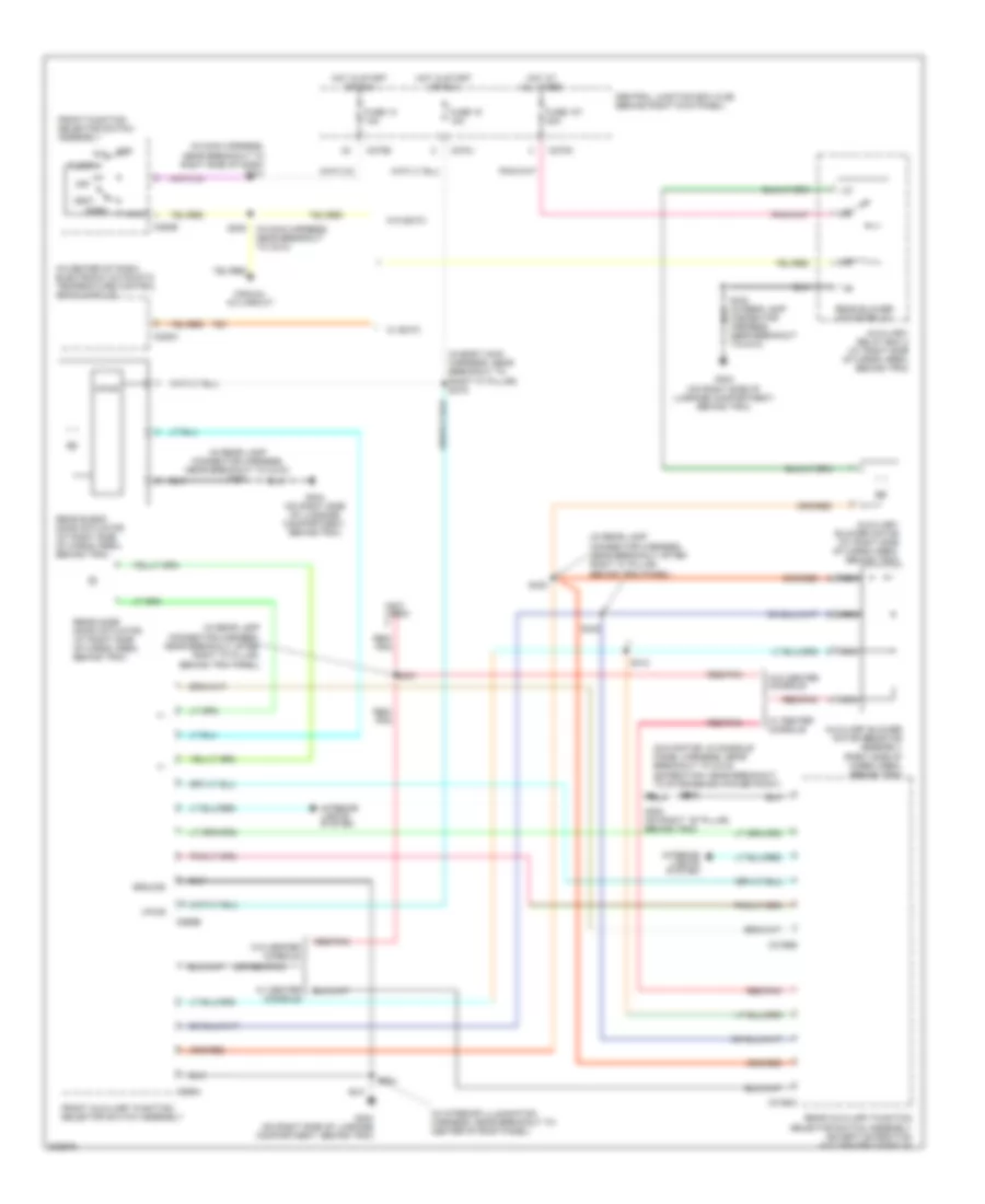
AIR CONDITIONING
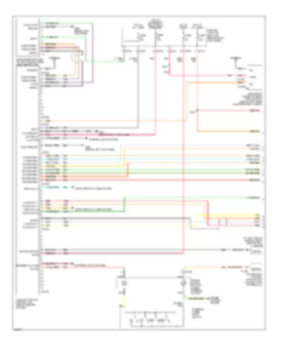
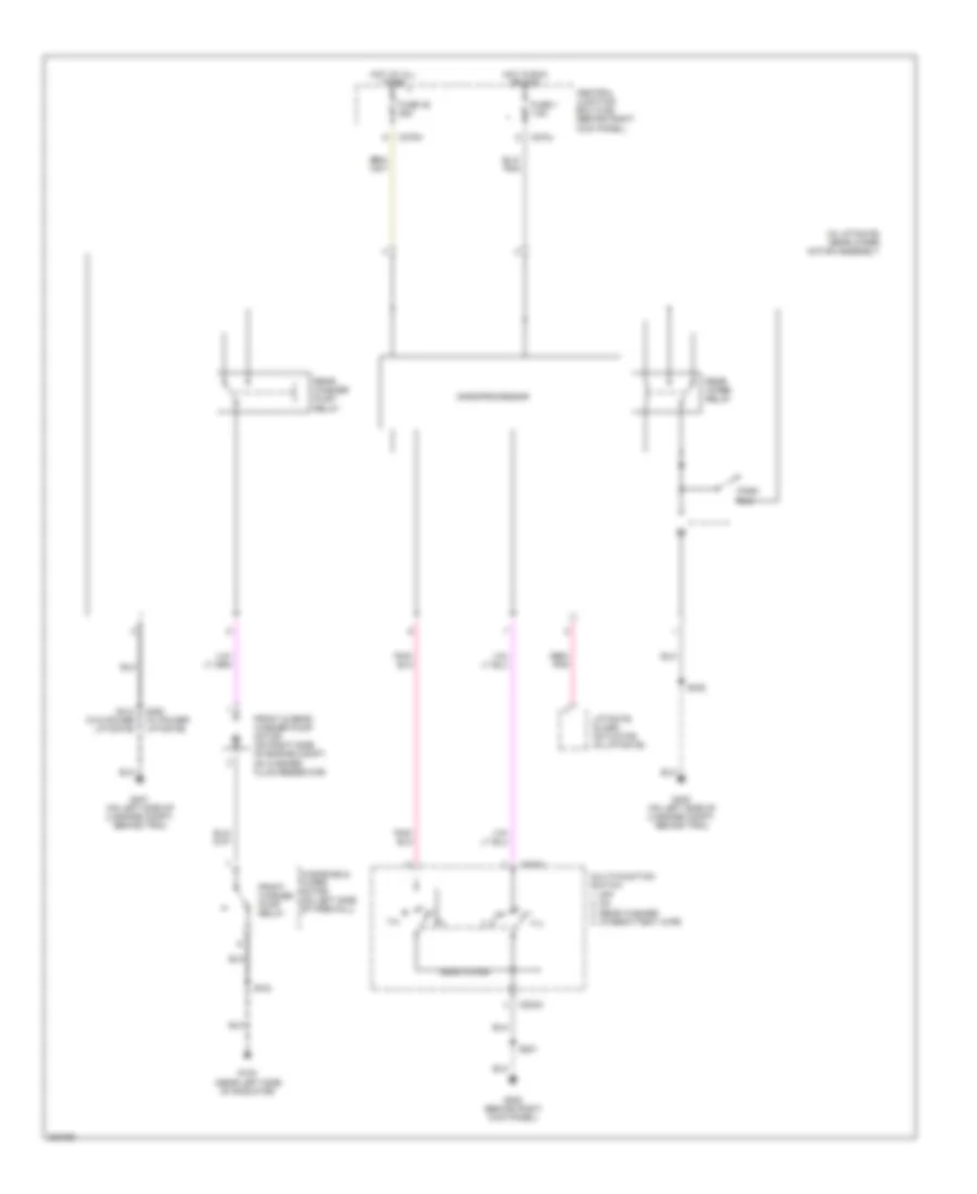
Automatic A/C Wiring Diagram (1 of 2) for Ford Expedition 2005

List of elements for Automatic A/C Wiring Diagram (1 of 2) for Ford Expedition 2005:
- (behind left kick panel) g301
- (behind right
- (behind right kick panel) g200
- (behind right side of dash) heater blower control module
- (in left side of dash) in-vehicle temperature/ humidity sensor
- (in main harness, near breakout to center of dash) s293
- (in main harness, near breakout to glove box lamp) s203
- (in main harness, near breakout to top of dash) s208
- (or 235)
- +/-
- Ambient air temperature sensor (behind right side of radiator grille)
- Auxiliary heater a/c circuit
- C228a
- C228b
- C270e
- C270g
- Central junction box (cjb) (behind right kick panel)
- Computer data lines system
- Defogger system
- Electronic automatic temperature control (eatc) module (in center of dash)
- Expedition
- Front blower motor relay
- Fuse 116 fuse 116 40a 40a
- Fuse 13 10a
- Fuse 5 7.5a
- G200 (behind right kick panel)
- Gnd
- Hot at all times
- Hot in start or run
- Hum sn
- Illum
- In temp
- In-vehicle temperature sensor (in left side of dash)
- Int temp
- Interior lights system
- Ms can+
- Ms can-
- Mtr ctrl
- Navigator
- Pos sig
- Pwr
- Remote solenoid assembly (under center of dash)
- Return
- Rr defr ind
- Rr defr req
- S203 (in main harness, near breakout to glove box lamp)
- S241 (main harness, near breakout to right side of dash)
- S277 (main harness, at breakout to brake pedal position switch)
- Side of dash) heater blower motor
- Sig rtn
- Sn pwr
- Vbatt
- Vbc fb
- Vbc hbr
- Vbc pwm
- Vpwr
- Vref
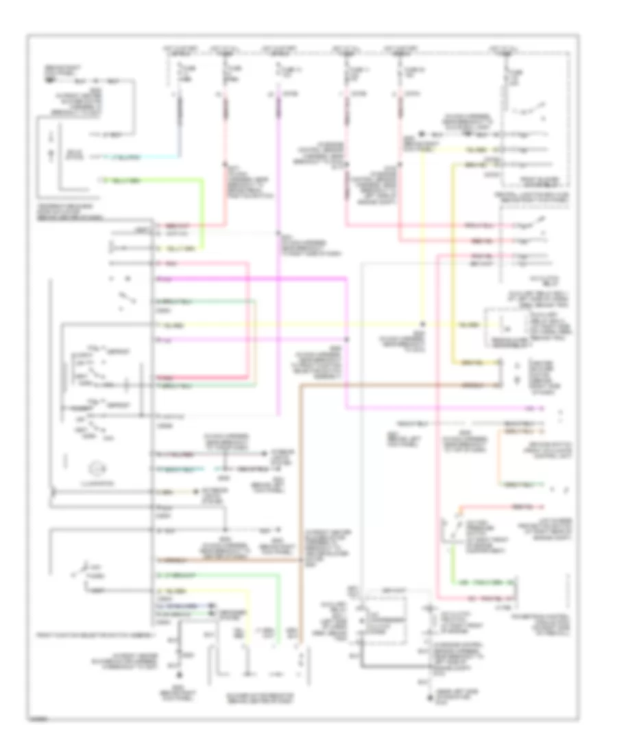
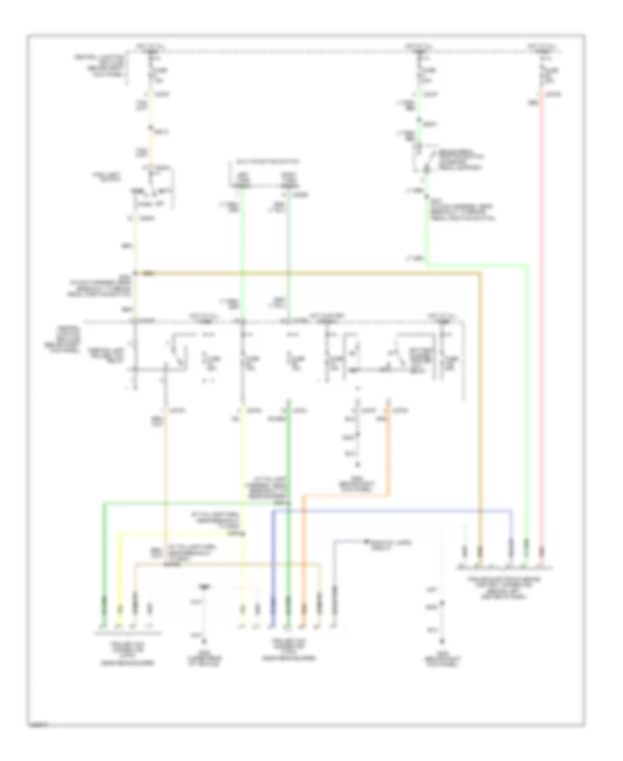
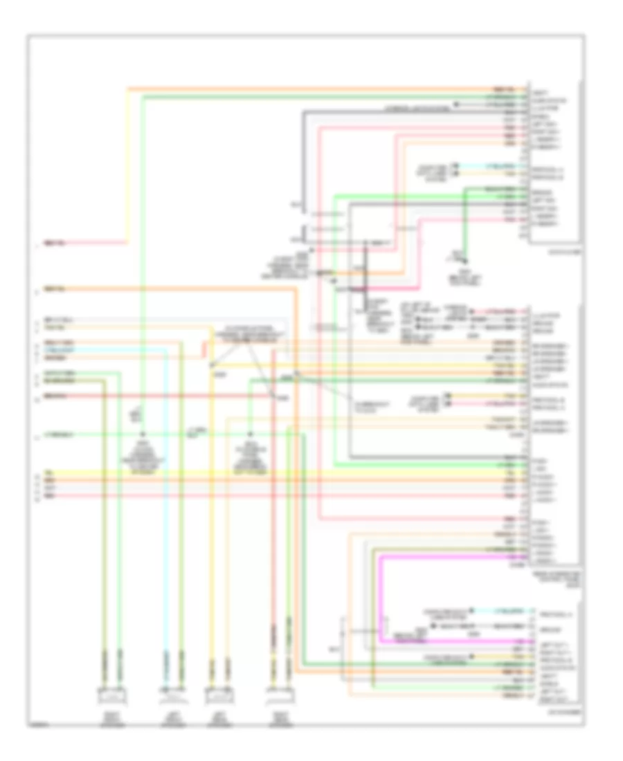
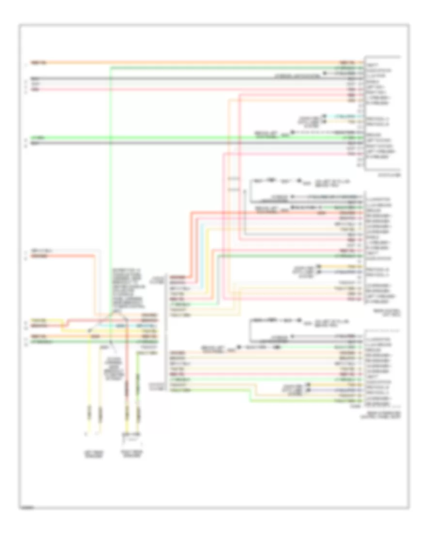
Automatic A/C Wiring Diagram (2 of 2) for Ford Expedition 2005
List of elements for Automatic A/C Wiring Diagram (2 of 2) for Ford Expedition 2005:
- (in engine control sensor harness, near breakout to g102) s113
- (in engine control sensor harness, near breakout to left side of engine compt) s104
- (in front heater blower motor harness, near breakout to right side of dash)
- A/c clutch field coil (at right front of engine)
- A/c clutch relay
- A/c compressor clutch diode
- A/c high pressure switch (at right front of engine compartment)
- Air bag sliding contact (under steering column)
- Auto lamps sens sig
- Auxiliary relay box 1 (at left front of engine compartment)
- C175b
- C2113b
- C218b
- C270a
- C270b
- Central junction box (cjb) (behind right kick panel)
- Cruise control system
- De-icing switch (on front of climate control unit)
- Driver temperature blend door actuator (behind center of dash)
- Fan speed (+)
- Fan speed (-)
- Fuse 11 10a
- Fuse 32 15a
- G100 (near left side of radiator)
- G301 (behind left kick panel)
- Hot at all times
- Hot in start or run
- Low charge protection switch (at right rear of engine compt)
- Microprocessor
- Nca
- Passenger temperature blend door actuator (behind center of dash)
- Pats ind
- Powertrain control module (on right side of firewall)
- Pressure sw
- Red
- Rtn sig
- S105 (in engine control sensor harness, near breakout to left side of engine compt)
- S2025 (in front heater blower motor harness, near breakout to right side of dash)
- S2026
- S208 (in main harness, near breakout to top of dash)
- Steering wheel radio switch
- Sunload sensor (to center of dash)
- Tan
- Temp (+)
- Temp (-)
- Vehicle security module (vsm) (under right side of dash)
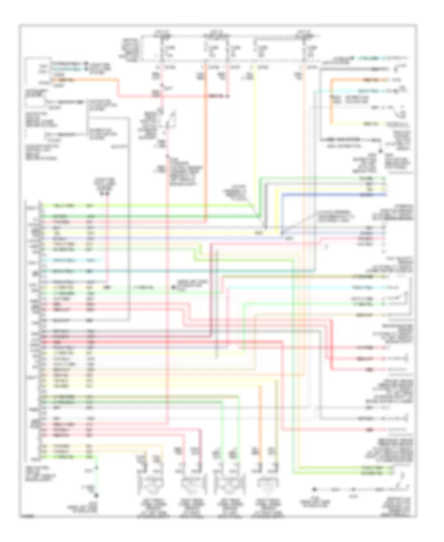
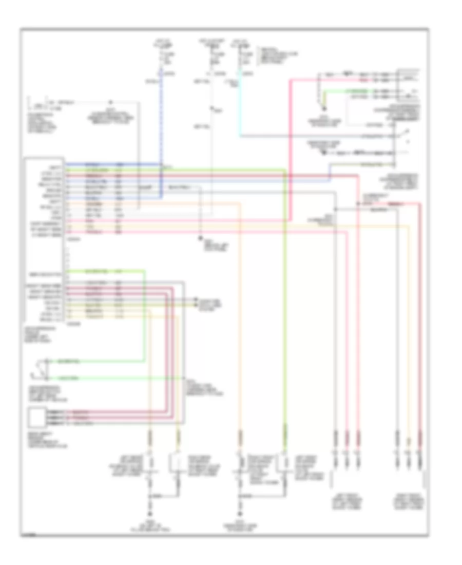
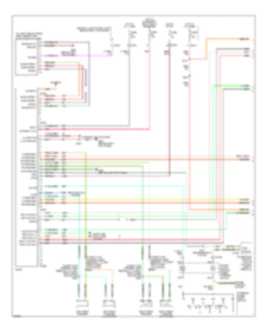
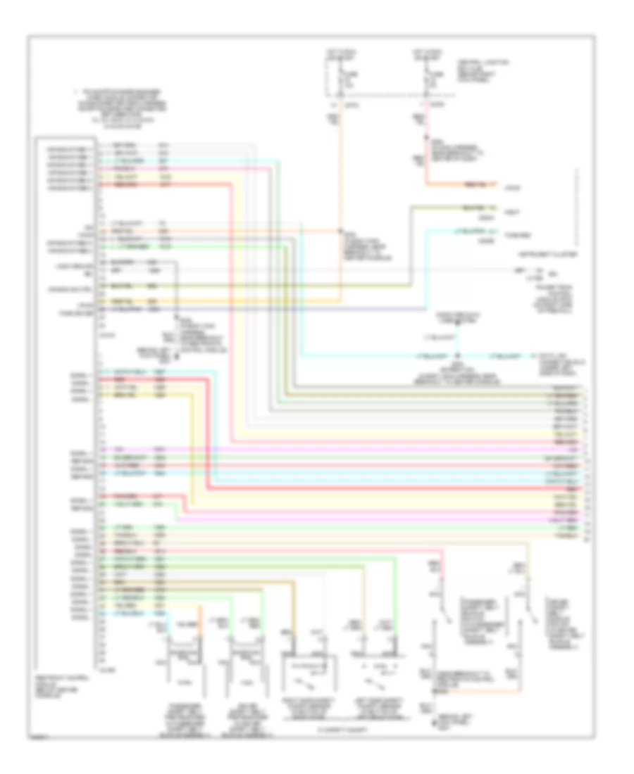
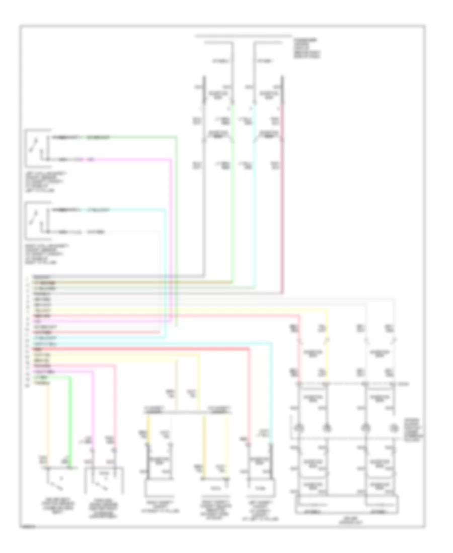
Auxiliary Heater-A/C Wiring Diagram for Ford Expedition 2005
List of elements for Auxiliary Heater-A/C Wiring Diagram for Ford Expedition 2005:
- (in body main harness, near breakout to right "c" pillar) s319
- (in center of dash) electronic automatic temperature control (eatc) module
- (in interior illumination harness, near breakout to center of roof panel)
- (in main harness, near breakout to right side of dash) s241
- (in rear lamp connector harness, near breakout after right "c" pillar, behind trim panel)
- (in rear lamp connector harness, near breakout to c410) s424
- (navigator: in console panel harness, near breakout to c315) (expedition: near breakout to storage bin power point)
- (not used)
- (or red/pnk)
- +/-
- Auxiliary blower motor (at right side of cargo area, behind trim)
- Auxiliary blower motor resistor assembly (right side of cargo area, behind trim)
- Auxiliary relay box 2 (at right side of cargo area, behind trim)
- C228a
- C270e
- C270j
- C270n
- C294b
- C3198a
- C3198b
- C989a
- C989b
- Central junction box (cjb) (behind right kick panel)
- Def
- Floor
- Front auxiliary function selector switch assembly
- Front function selector switch assembly
- Fuse 107 30a
- Fuse 13 10a
- Fuse 18 10a
- G300 (on right ``b" pillar, behind trim)
- G404 (on right side of luggage compartment, behind trim)
- Ground
- Hot at all times
- Hot in start or run
- Interior lights system
- Manual a/c circuit
- Max
- Mix
- Nca
- Near breakout to c410)
- Norm
- Off
- Rear auxiliary function selector switch assembly (except expedition w/o center console)
- Rear blend door actuator (at right side of cargo area, behind trim)
- Rear blower motor relay
- Rear mode door actuator (at right side of cargo area, behind trim)
- Red/ pnk
- Red/pnk
- S205
- S230 (in main harness, near breakout to c210)
- S412
- S423
- S431
- S432
- S904
- Vent
- Vpwr
- W/ center console
- W/ eatc
- W/o center console
- W/o eatc
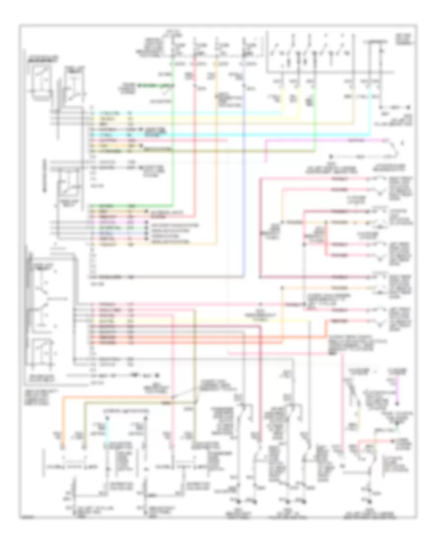
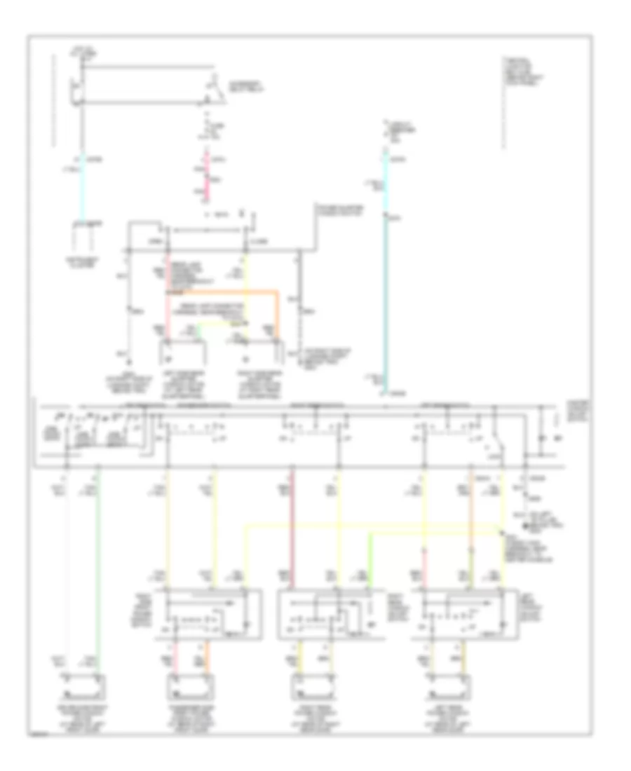
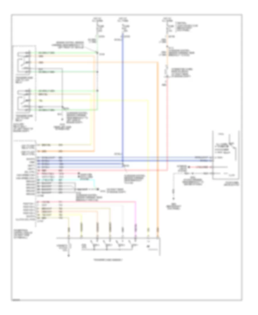
Manual A/C Wiring Diagram for Ford Expedition 2005
List of elements for Manual A/C Wiring Diagram for Ford Expedition 2005:
- (behind right kick panel) g200
- (in engine control sensor harness, near breakout to g102) s113
- (in front heater blower motor harness, in breakout to c237)
- (in front heater blower motor harness, in breakout to heater blower motor) s291
- (in main harness, near breakout to glove box lamp) s203
- (in main harness, near breakout to top of dash)
- (near left side of radiator) g100
- A/c clutch field coil (at right front of engine)
- A/c clutch relay
- A/c compressor clutch diode
- A/c high pressure switch (at right front of engine compartment)
- Auxiliary relay box 1 (at left side of cargo area, behind trim)
- Auxiliary relay box 1 (left side of cargo area, behind trim)
- Auxiliary relay box 2 (at right side of cargo area, behind trim) rear blower motor relay
- Blower motor resistor (behind center of dash)
- C175b
- C270a
- C270b
- C270e
- C270g
- C294a
- C294b
- C294c
- Central junction box (cjb) (behind right kick panel)
- De-icing switch (front of climate control unit)
- Defogger system
- Defrost
- Exterior lights system
- Floor
- Front blower motor relay
- Front function selector switch assembly
- Fuse 10a
- Fuse 11 10a
- Fuse 13 10a
- Fuse 32 15a
- Fuse 40a
- Fuse 7.5a
- G200 (behind right kick panel)
- G301 (behind left kick panel)
- Heater blower motor (behind right side of dash)
- Hot at all times
- Hot in start or run
- Illumination
- Interior lights system
- Low charge protection switch (at right rear of engine compt)
- Max
- Mix
- Near breakout to left side of engine compt) s104
- Norm
- Off
- Pnk
- Powertrain control module (pcm) (on right side of firewall)
- S105 (in engine control sensor harness, near breakout to left side of engine compt)
- S200
- S200 (in front heater blower motor harness, in breakout to c237)
- S202 (in main harness, near breakout to center of dash)
- S208
- S208 (in main harness, near breakout to top of dash)
- S230 (in main harness, near breakout to c210)
- S241 (in main harness, near breakout to right side of dash)
- S262 (in main harness, near breakout to front function selector switch assembly)
- S277 (in main harness, near breakout to brake pedal position switch)
- Solid state
- Temperature blend door actuator (behind center of dash)
- Vbatt
- Vent
ANTI-LOCK BRAKES
Anti-lock Brakes Wiring Diagram for Ford Expedition 2005
List of elements for Anti-lock Brakes Wiring Diagram for Ford Expedition 2005:
- (expedition)
- (expedition) (navigator)
- (in main harness, in breakout to c210)
- (in main harness, near breakout to glove box lamp)
- (navigator)
- (near left side of radiator) g100
- - sig rtn
- A/1
- Abs control module (at left side of engine compt)
- Audio/navigation control unit (behind center of dash)
- B/2
- Brake booster sensor (w/ stability assist) (at left rear of engine compt)
- Brake fluid level switch (in brake fluid reservoir, near firewall)
- Brake pedal position switch (on brake pedal support)
- C2123c
- C220a
- C220b
- C2279a
- C270b
- C270c
- C270d
- C270e
- C270f
- Can +
- Can -
- Central junction box (cjb) (behind right kick panel)
- Computer data lines system
- Expedition w/ navigation system
- Feed
- Fuse 10a
- Fuse 30a
- Fuse 5a
- Fuse 7.5a
- G100 (near left side of radiator)
- G200 (navigator) (behind right kick panel)
- G300 (expedition) (on left "b" pillar, behind trim)
- Gnd
- Hot at all times
- Hot in start or run
- Illum
- Ind
- Instrument cluster
- Interior lights system
- Left front wheel speed sensor (at left side of engine compt)
- Left rear wheel speed sensor (at left rear wheel)
- Low
- Navigation module (behind lower center of dash)
- Navigator, w/ navigation system
- Nca
- On/ off
- Primary brake pressure sensor (w/ stability assist) (at left rear of engine compt, on brake master cylinder)
- Pwr
- Red
- Red/ pnk
- Red/pnk
- Right front wheel speed sensor (at right side of engine compt)
- Right rear wheel speed sensor (at right rear wheel)
- S101
- S104
- S150 (in engine control sensor harness, near breakout to left rear of engine compt)
- S202
- S204
- S205
- S277
- S281
- S387 s282
- Secondary brake pressure sensor (w/ stability assist) (at left rear of engine compt, on brake master cylinder booster)
- Sig
- Steering position sensor (w/ stability assist) (on steering column)
- Tan/ red
- Tan/red
- Traction control switch (w/ stability assist)
- Vbatt
- Vpwr
- Vref
- Vss
- Yaw velocity sensor (w/ stability assist) (under center console)
ANTI-THEFT
Forced Entry Wiring Diagram for Ford Expedition 2005
List of elements for Forced Entry Wiring Diagram for Ford Expedition 2005:
- (behind right kick panel) g201
- (expedition) (navigator)
- (in body main harness, (near breakout to left ``c" pillar s313
- (in body main harness, near breakout to c214)
- (in right rear window regulator control switch & wiring assembly, near breakout to liftgate) s465
- (navigator) (expedition)
- (near breakout to g201)
- (on left ``b" pillar, behind trim) g300
- (or pnk)
- 1/2
- 3/4
- 5/6
- 7/8
- 9/0
- Air conditioning system
- C2113a
- C2113b
- C2113c
- C270f
- C270h
- C270j
- C270k
- Central junction box (cjb) (behind right kick panel)
- Computer data lines system
- Door lock relay
- Driver door unlock relay
- Driver side door lock switch
- Driver side rear door ajar switch (at rear of left
- Exterior lights
- Fuse 15a
- Fuse 20a
- Fuse 30a
- Fuse 7.5a
- G201 (behind right kick panel)
- G300 (on left "b" pillar, behind trim)
- G300 (on left ``b" pillar, behind trim)
- G402 (on left side of luggage compartment, behind trim)
- Headlamp relay
- Headlights system
- Horns system
- Hot at all times
- Illumination
- Interior lights system
- Key pad switch assembly
- Left front door ajar switch (at rear of left front door)
- Left front door lock actuator (at rear of left front door)
- Left rear door lock actuator (at rear of left rear door)
- Liftgate ajar switch (in center bottom of liftgate)
- Liftgate glass actuator (in liftgate)
- Liftgate glass release relay
- Liftgate glass release switch
- Liftgate lock actuator (in liftgate)
- Lock
- Microprocessor
- Navigator
- Nca
- Park lamp relay
- Passenger side door lock switch
- Passenger side rear door ajar switch (at rear of right
- Power windows system
- Rear door)
- Red/ pnk
- Right front door ajar switch (at rear of right front door)
- Right front door lock actuator (at rear of right front door)
- Right rear door lock actuator (at rear of right rear door)
- S2013 (expedition) s392 (navigator)
- S212
- S314 (near breakout to c328)
- S343 (near breakout to g201)
- S344
- S356
- S358
- S359
- S379
- S391
- S402
- S501
- S506
- S600
- S700
- S800 (navigator)
- Seats system
- System
- Tan
- Trunk, tailgate, fuel doors system
- Unlock
- Vehicle security module (vsm) (under right side of dash)
- W/ power liftgate
- W/o power liftgate
- Wiper/ washer system
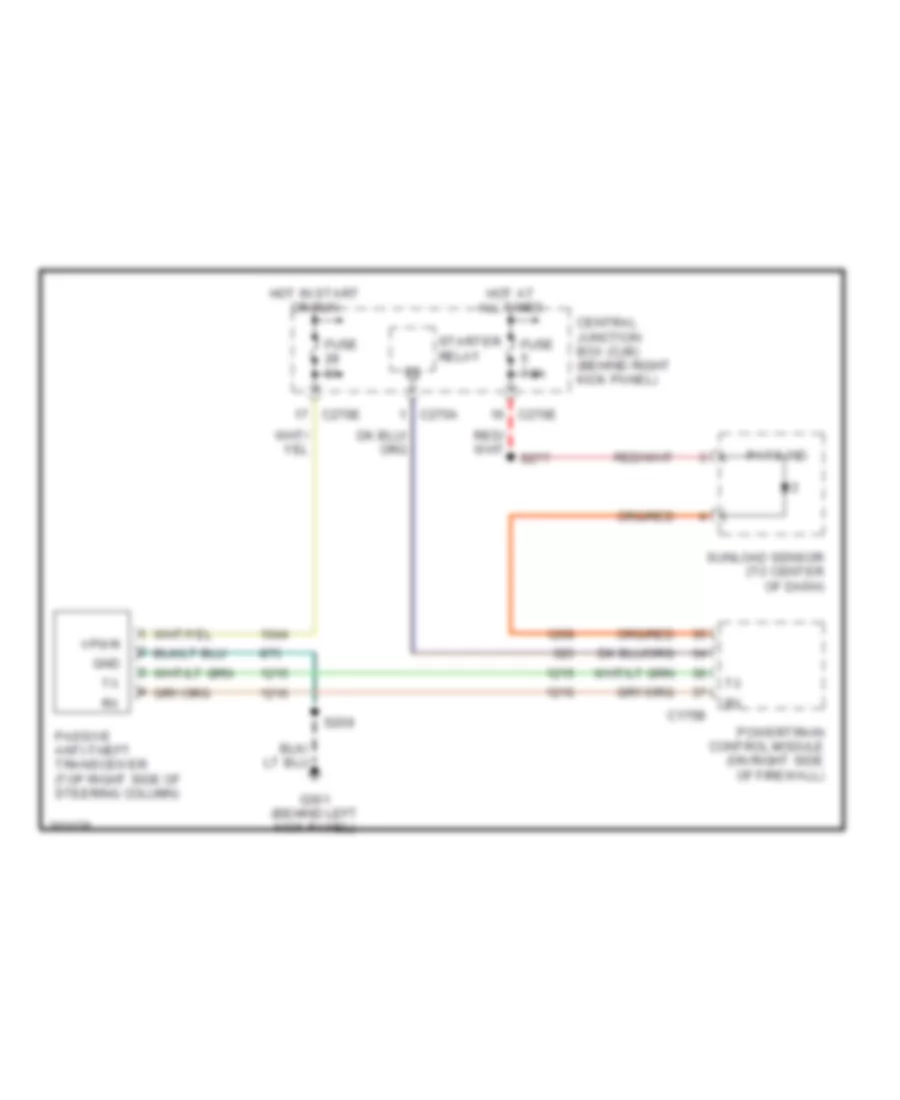
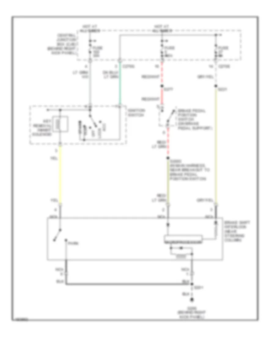
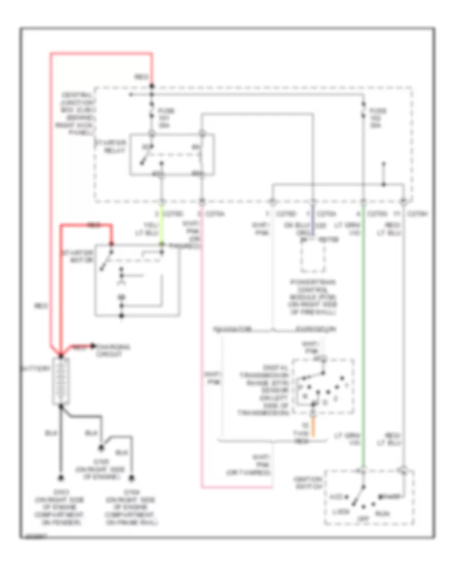
Passive Anti-theft Wiring Diagram for Ford Expedition 2005
List of elements for Passive Anti-theft Wiring Diagram for Ford Expedition 2005:
- C175b
- C270a
- C270e
- Central junction box (cjb) (behind right kick panel)
- Fuse 5a
- Fuse 7.5a
- G301 (behind left kick panel)
- Gnd
- Hot at all times
- Hot in start or run
- Passive anti-theft transceiver (top right side of steering column)
- Pats ind
- Powertrain control module (on right side of firewall)
- S208
- S277
- Starter relay
- Sunload sensor (to center of dash)
- Vpwr
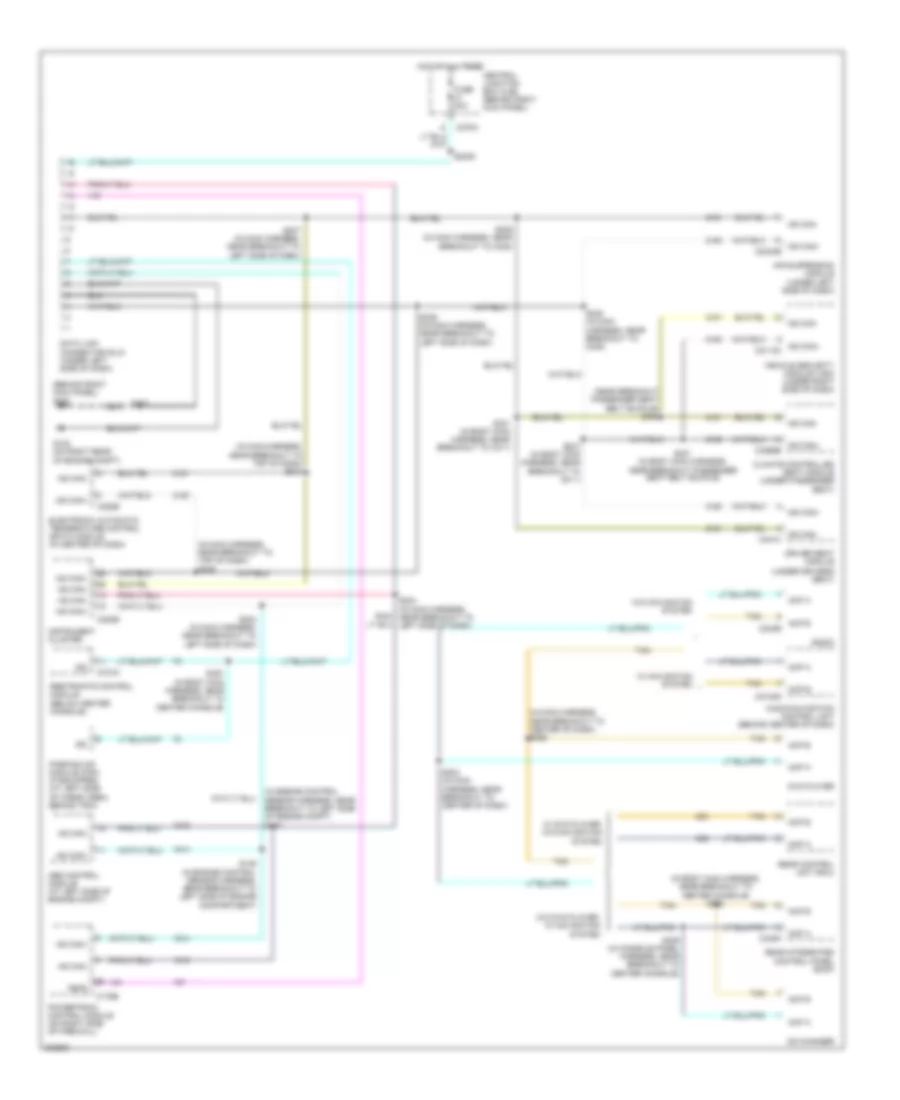
COMPUTER DATA LINES
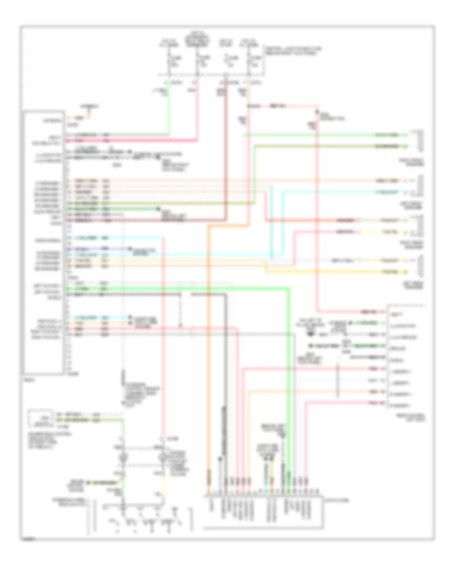
Computer Data Lines Wiring Diagram for Ford Expedition 2005
List of elements for Computer Data Lines Wiring Diagram for Ford Expedition 2005:
- (behind right kick panel) g200
- (in body main harness, near breakout to center console) s323
- (in engine control sensor harness, near breakout to left side of engine compt) s147
- (in main harness, near breakout to center of dash) s285
- (in main harness, near breakout to top of dash) s239
- (in main harness, near breakout to top of dash) s240
- (near breakout passenger seat belt buckle) s302
- (under driver's seat)
- Abs control module (at left side of engine compt)
- Acp a
- Acp a c349a
- Acp b
- Acp b c240b
- Air suspension module (under left side of dash)
- Audio/navigation control unit (behind center of dash)
- C175b
- C2123d
- C220b
- C228b
- C270h
- C310a
- Cd changer
- Central junction box (cjb) (behind right kick panel)
- Climate controlled seat module (under passenger seat)
- Data link connector (dlc) (under left side of dash)
- Driver seat module
- Dvd player
- Electronic automatic temperature control (eatc) module (in center of dash)
- Feps
- Fuse 20a
- G102 (on right rear of engine compt)
- Hot at all times
- Hs can+
- Hs can-
- Instrument cluster
- Iso
- Ms can+
- Ms can+ c2113c
- Ms can+ c2324b
- Ms can+ c3265b
- Ms can-
- Ms can- c341c
- Parking aid module (pam) (if equipped) (at left side of cargo area, behind trim)
- Powertrain control module (on right side of firewall)
- Radio
- Rear control unit (rcu)
- Rear integrated control panel (ricp)
- Restraints control module (below center console)
- S146 (in engine control sensor harness, near breakout to left side of engine compartment)
- S2005
- S202
- S233 (in main harness, near breakout to left side of dash)
- S234 (in main harness, near breakout to left side of dash)
- S236 (in main harness, near breakout to left side of dash)
- S237 (in main harness, near breakout to left side of dash)
- S248 (in main harness, near breakout to c238)
- S249 (in main harness, near breakout to c238)
- S284 (in main harness, near breakout to center of dash)
- S300 (in body main harness, near breakout to center console)
- S301 (in body main harness, near breakout passenger seat belt buckle)
- S306 (in console panel harness, near breakout to center console)
- S330 (in body main harness, near breakout to c311)
- S331 (in body main harness, near breakout to c311)
- Tan
- Vehicle security module (vsm) (under right side of dash)
- W/ dvd player, w/o navigation system
- W/ navigation system
- W/o dvd player, w/ navigation system
- W/o navigation system
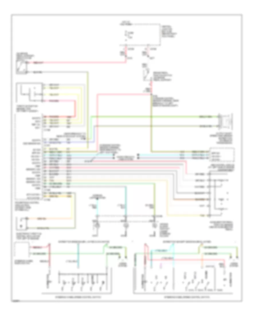
CRUISE CONTROL
Cruise Control Wiring Diagram for Ford Expedition 2005
List of elements for Cruise Control Wiring Diagram for Ford Expedition 2005:
- (in engine control sensor harness, near breakout to left kick panel)
- (near breakout to rear of exhaust system) s141
- (on brake pedal support) deactivator switch
- Abs control module (at left side of engine compartment)
- Accelerator pedal position sensor (above accelerator pedal)
- Air bag sliding contact (under steering column)
- Bpp sw
- Brake pedal position switch (on brake pedal support)
- C175b
- C175e
- C175t
- C218b
- C270b
- C270e
- Central junction box (cjb) (behind right kick panel)
- Computer data lines system
- Electronic throttle control (etc) motor (top left of engine)
- Etc motor +
- Etc motor -
- Expedition (except eddie bauer & limited)
- Expedition eddie bauer, limited & navigator
- Fuse 7.5a
- Horns system
- Hot at all times
- Hs can +
- Hs can -
- Illumination
- Interior lights system
- Nca
- Off
- Oss sensor sig
- Output shaft speed (oss) sensor (expedition) (on rear of transmission)
- Powertrain control module (pcm) (on right side of firewall)
- Ref vol
- Resume
- S133
- S148
- S150 (in engine control sensor harness, near breakout to left rear of engine compt)
- S277
- Sensor 1 sig
- Sensor 2 sig
- Sensor 3 sig
- Set (+)
- Set (-)
- Sig 1
- Sig 2
- Sig rtn
- Steering wheel radio switch
- Steering wheel/speed control switch
- Sw sig
- Tan
- Throttle position sensor (tps) (on throttle body)
- Vref
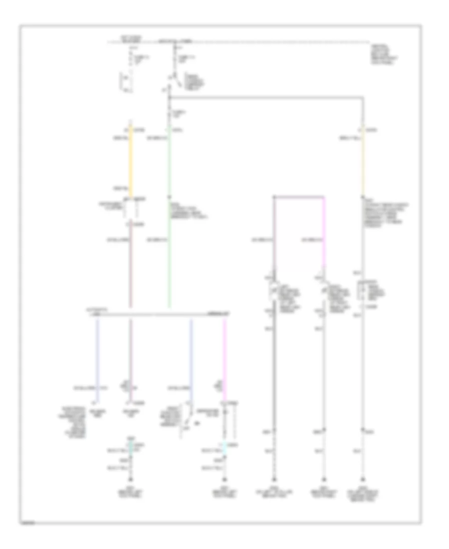
DEFOGGERS
Defoggers Wiring Diagram for Ford Expedition 2005
List of elements for Defoggers Wiring Diagram for Ford Expedition 2005:
- (in right rear window regulator control switch & wiring assembly, near breakout to rear window)
- Automatic a/c
- C208a
- C220b
- C228b
- C270e
- C270j
- C270n
- C294c
- C402a
- C402b
- Central junction box (cjb) (behind right kick panel)
- Defroster on ind
- Electronic automatic temperature control (etac) module (in center of dash)
- Front function selector switch assembly
- Fuse 114 40a
- Fuse 13 10a
- Fuse 8 10a
- G201 (behind right kick panel)
- G300 (on left ``b" pillar, behind trim)
- G301 (behind left kick panel)
- G402 (on left side of luggage compt, behind trim)
- Gnd
- Hot at all times
- Hot in run or start
- Instrument cluster
- Left exterior rear view mirror (at left rear view mirror)
- Manual a/c
- Nca
- Off
- Rear window defrost grid
- Rear window defrost relay
- Right exterior rear view mirror (at right rear view mirror)
- Rr defr ind
- Rr defr req
- S208
- S348 (in body main harness, near breakout to g301)
- S402
- S427
- S501
- S600
ELECTRONIC SUSPENSION
Electronic Suspension Wiring Diagram for Ford Expedition 2005
List of elements for Electronic Suspension Wiring Diagram for Ford Expedition 2005:
- (in breakout to c110) s119
- (near right side of radiator) g101
- Air suspension compressor assembly (at right front of engine compt)
- Air suspension compressor relay (at right front of engine compt)
- Air suspension module (under left side of dash)
- Air suspension service switch (at left rear corner of vehicle)
- C175b
- C2324a
- C2324b
- C270c
- C270d
- C270e
- Central junction box (cjb) (behind right kick panel)
- Comp assembly
- Computer data lines system
- Fuse 25a
- Fuse 50a
- Fuse 5a
- G101 (near right side of radiator)
- G300 (on left "b" pillar, behind trim)
- G301 (behind left kick panel)
- Ground
- Height sens feed
- Height sens rtn
- Height sens sig
- Hot at all times
- Hot in start or run
- Left front air spring solenoid valve (at left front shock tower)
- Left front height sensor (at left front shock tower)
- Left rear air spring solenoid valve (at left rear shock tower)
- Lf height sens
- Lf sol vlv
- Lr sol vlv
- Ms can +
- Ms can -
- Nca
- Pnk
- Powertrain control module(pcm) (on right side of firewall)
- Rear height sensor (under rear of vehicle, near axle)
- Relay ctrl
- Rf height sens
- Rf sol vlv
- Right front air spring solenoid valve (at right front shock tower)
- Right front height sensor (at right front shock tower)
- Right rear air spring solenoid valve (at right rear shock tower)
- Rr sol vlv
- S106
- S107 (in engine control sensor harness, near breakout to g102)
- S116
- S117
- S120
- S121 (in breakout to c110)
- S221
- S374 (in body main harness, near breakout to c328)
- S454
- Sens pwr
- Sens rtn
- Service switch
- Tan
- Vbatt
- Vpwr
- Vss +
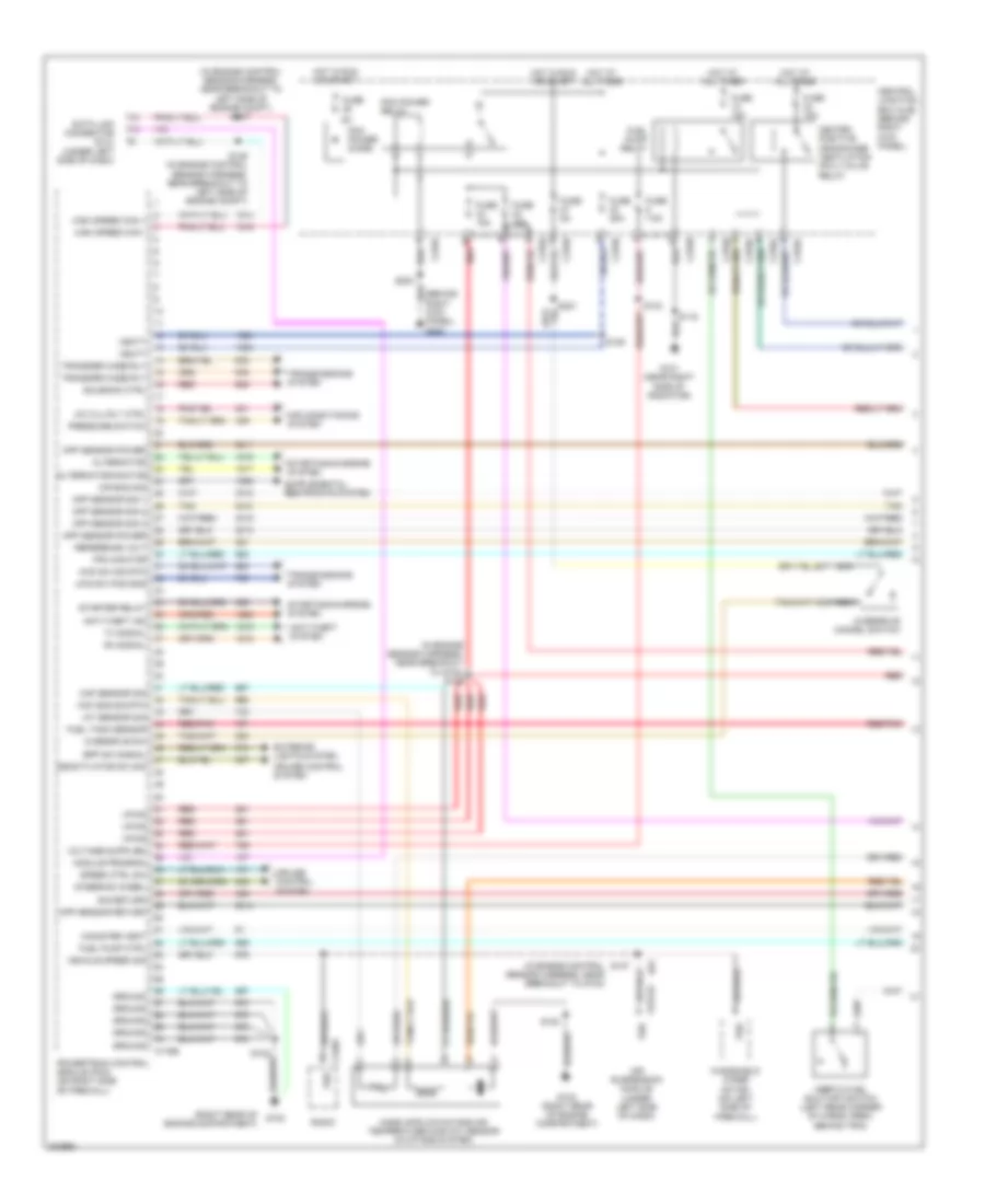
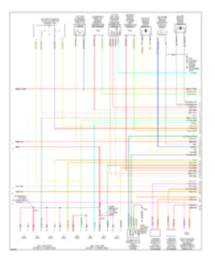
ENGINE PERFORMANCE
Engine Performance Wiring Diagram (1 of 5) for Ford Expedition 2005
List of elements for Engine Performance Wiring Diagram (1 of 5) for Ford Expedition 2005:
- (in engine control sensor harness, near breakout to g102)
- (in engine control sensor harness, near breakout to left side of engine compt) s147
- (in engine sensor harness, near breakout to g102) s109
- (right rear of engine compartment)
- 4wd sw pos sns
- 4wd sw sig rtn
- A/c clu rly ctrl
- Air bag sig
- Air conditioning system
- Air suspension module (under left side of dash)
- Alternator
- Alternator monitor
- Anti-theft ind
- Anti-theft system
- App sensor power
- App sensor return
- App sensor sig 1
- App sensor sig 2
- App sensor sig 3
- Bpp sw signal
- C175b
- C2324a
- C240a
- C270a
- C270b
- C270d
- C270e
- C270f
- C270g
- C270k
- Canister vent
- Central junction box (cjb) (behind right kick panel)
- Cruise control system
- Data link connector (dlc) (under left side of dash)
- Deactivator sw sig
- Exterior lights system
- Fpm monitor
- Fuel pump ctrl
- Fuel pump relay
- Fuel tank sensor
- Fuse
- Fuse 15a
- Fuse 25a
- Fuse 5a
- Fuse 7.5a
- G101 (near right side of radiator)
- G102
- G102 (right rear of engine compartment)
- Ground
- Heated positive crankcase ventilation (pcv) valve relay
- High speed can +
- High speed can -
- Hot at all times
- Hot in run or start
- Iat sensor sig
- Inertia fuel shut-off switch (left rear corner of cargo area, behind trim)
- Kick panel) g200
- Maf sensor sig
- Maf sns sig rtn
- Mass air flow/intake air temperature (maf/iat) sensor (in intake system)
- Module program
- Nca
- Overdrive cancel switch
- Overdrive sw
- Pcm power diode
- Pcm power relay
- Powertrain control module (pcm) (on right side of firewall)
- Pressure switch
- Radio
- Red
- Red/pnk
- Reference volt
- Rx signal
- S107
- S108
- S116
- S133
- S146 (in engine control sensor harness, near breakout to left side of engine compt)
- S152
- S153
- S203
- S221
- Sig return
- Solenoid ctrl
- Speed ctrl sw
- Starter relay
- Starting/charging system
- Steering wheel
- Tan
- Transfer case rly
- Transmissions system
- Tx signal
- Vbatt
- Vehicle speed sig
- Vpwr
- Vss
- Windshield wiper motor (on left side of firewall)
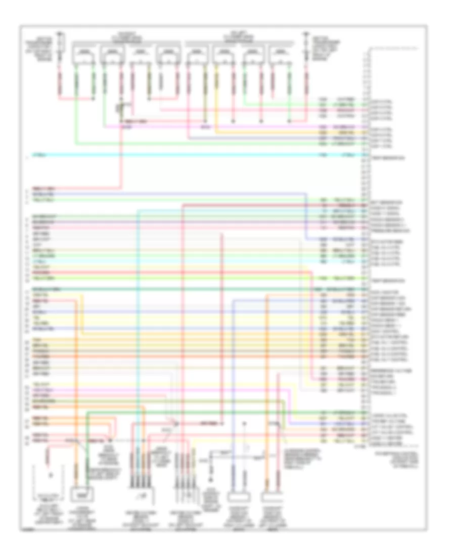
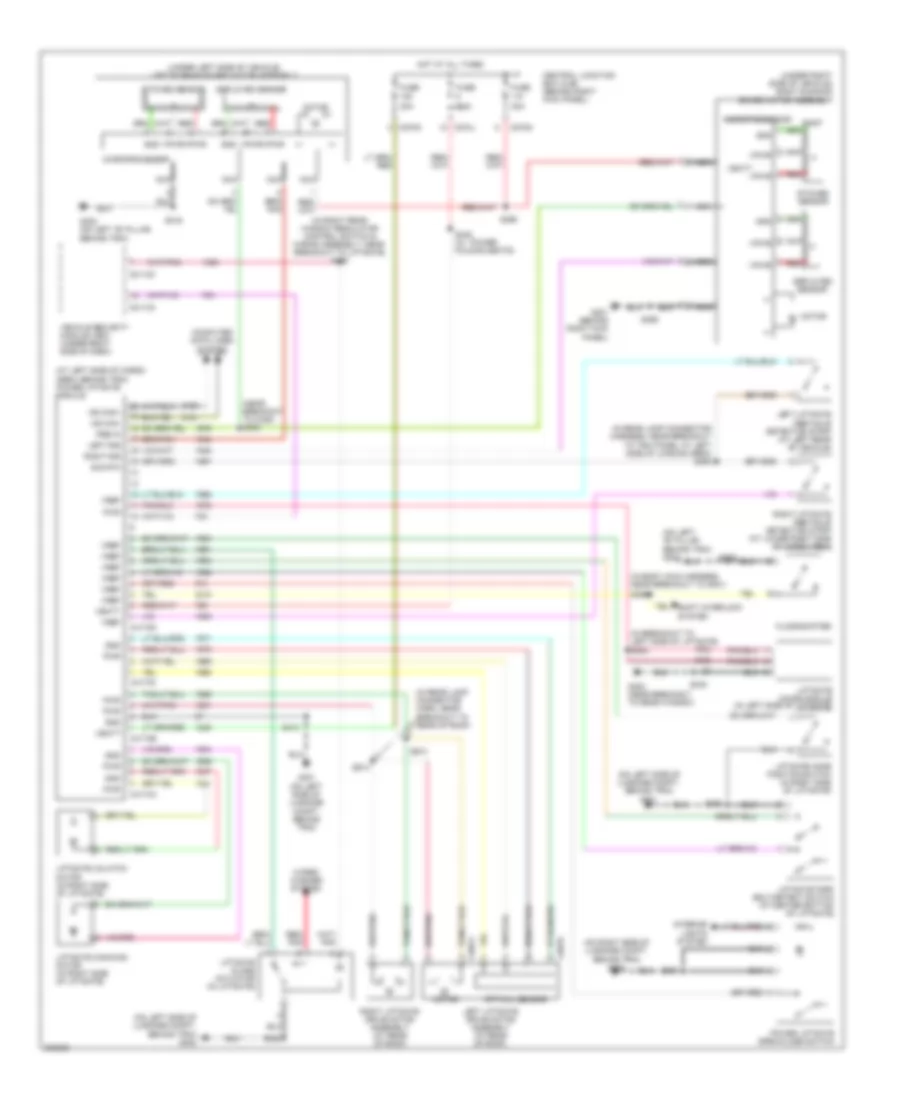
Engine Performance Wiring Diagram (2 of 5) for Ford Expedition 2005
List of elements for Engine Performance Wiring Diagram (2 of 5) for Ford Expedition 2005:
- (above accelerator pedal) accelerator pedal position sensor
- (in back-up lamp switch to rear lamp feed harness, near breakout to right side of firewall)
- (in fuel tank) fuel tank pressure transducer sensor
- (left rear of engine) heated positive crankcase ventilation (pcv) valve
- (on right rear of engine compt) g102
- Acc
- Fuel pump driver module (at left rear of chassis)
- Fuel tank unit (in fuel tank)
- G403 (at rear of vehicle)
- Gnd
- Heated oxygen sensor (ho2s) 12 (on rear of exhaust system)
- Heated oxygen sensor (ho2s) 22 (on rear of exhaust system)
- Hot at all times
- Ignition switch
- Instrument cluster system
- Lock
- Nca
- Off
- Output shaft speed (oss) sensor (rear of transmission)
- Red
- Red/pnk
- Run
- S138
- S140
- S153
- S459
- S461
- Start
- Tan
- Turbine shaft speed (tss) sensor (left side of transmission)
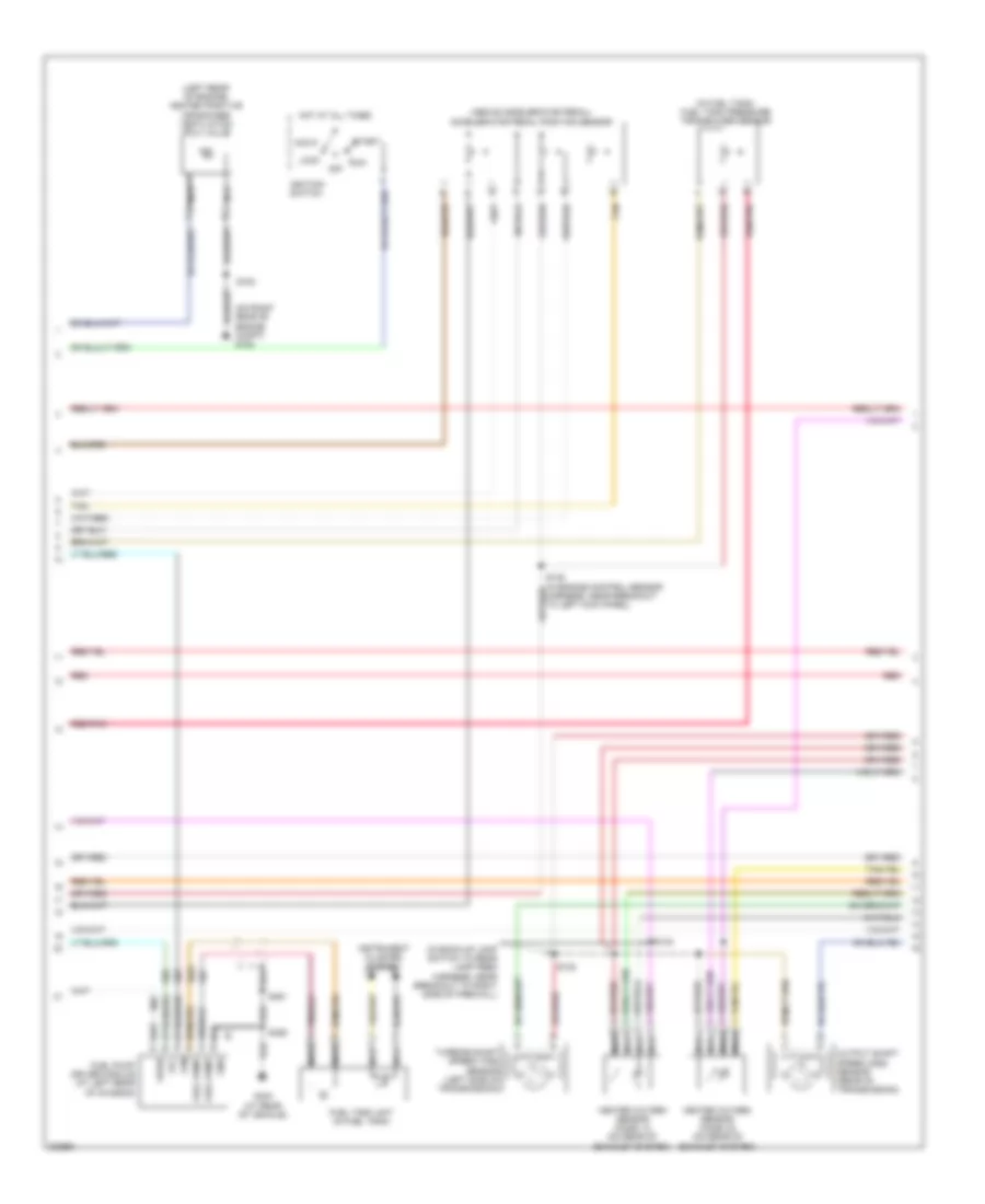
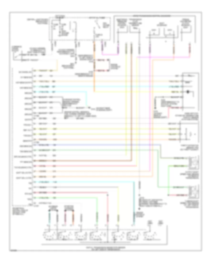
Engine Performance Wiring Diagram (3 of 5) for Ford Expedition 2005
List of elements for Engine Performance Wiring Diagram (3 of 5) for Ford Expedition 2005:
- (on left side of transmission) digital transmission range (dtr) sensor
- 4r75e transmission control solenoids
- C175t
- Diff lock sol
- Dtr sens tr4
- Electronic pressure control (epc) solenoid
- Epc sol ctrl
- Ho2s 12 htr
- Ho2s 12 sig
- Ho2s 22 htr
- Ho2s 22 sig
- Motor a
- Motor b
- Motor c
- Motor d
- Motor return
- N r
- Of firewall)
- Oss sens sig
- Powertrain control module (pcm) (on right side
- Red
- Sensor tr1
- Sensor tr2
- Sensor tr3a
- Shift sol a
- Shift sol b
- Shift solenoids
- Sig return
- Tcc sol ctrl
- Tft sens sig
- Torque converter clutch (tcc) solenoid
- Transmission fluid temperature sensor
- Transmissions system
- Tss sens sig
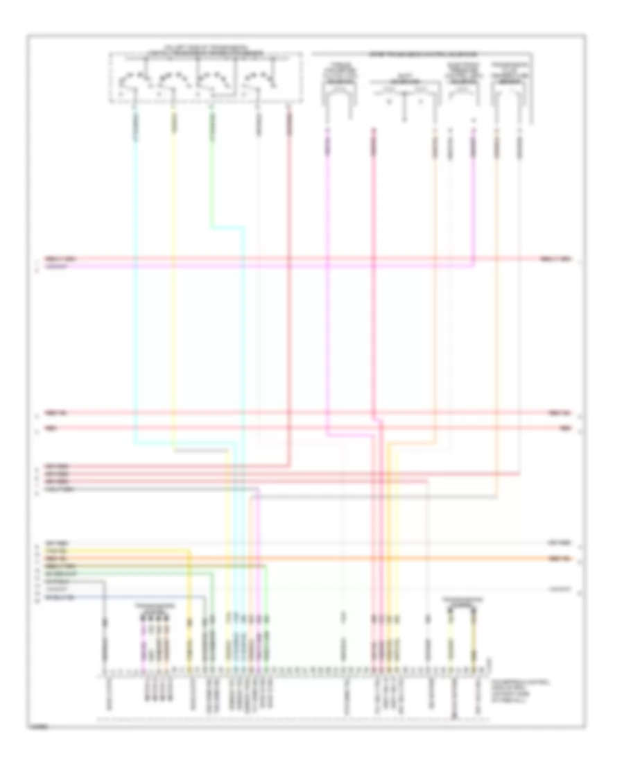
Engine Performance Wiring Diagram (4 of 5) for Ford Expedition 2005
List of elements for Engine Performance Wiring Diagram (4 of 5) for Ford Expedition 2005:
- (at breakout to right cylinder head)
- (at top left side of engine) fuel rail pressure/ temperature sensor
- (lower right front of engine) engine oil temperature (eot) sensor
- (near breakout to left cylinder head)
- (on left rear of engine) knock sensor 2
- (on lower front of engine) crankshaft position sensor
- (on right rear of engine) cylinder head temperature sensor
- (on right rear of engine) knock sensor 1
- (on right side of engine compt, on fender) g103
- (on throttle body) throttle position sensor (tps)
- (top left of engine) electronic throttle control (etc) motor
- Charge motion control valve (cmcv) (at rear of engine)
- Cmcvc
- Cmcvm
- Evap canister vent control solenoid (under rear of vehicle, above rear axle)
- Frp
- Fuel injectors (on left cylinder head)
- Fuel injectors (on right cylinder head)
- G102 (on right rear of engine compt)
- Gnd
- Nca
- Prt
- Red
- Red/pnk
- S126
- S131
- S153
- Sig rtn
- Tan
- Tan/red
- Variable camshaft timing (vct) valve 1 (right front of engine)
- Variable camshaft timing (vct) valve 2 (left side of engine)
- Vpwr
- Vref
Engine Performance Wiring Diagram (5 of 5) for Ford Expedition 2005
List of elements for Engine Performance Wiring Diagram (5 of 5) for Ford Expedition 2005:
- (in engine control sensor harness, near breakout to right side of firewall)
- (near breakout to left cylinder head)
- (on left cylinder head) coils on plug
- (on right cylinder head) coils on plug
- A/c clutch relay
- Auxiliary relay box 1 (at left front of engine compartment)
- C175e
- Camshaft position sensor 1 (on front of right cylinder bank)
- Camshaft position sensor 2 (on front of left cylinder head)
- Ckp sensor feed
- Ckp sensor return
- Cmcv control
- Cmcv monitor
- Cmp sensor 1 sig
- Cmp sensor 2 sig
- Cop 1 ctrl
- Cop 2 ctrl
- Cop 3 ctrl
- Cop 4 ctrl
- Cop 5 ctrl
- Cop 6 ctrl
- Cop 7 ctrl
- Cop 8 ctrl
- Eot sensor sig
- Etc motor feed
- Etc motor return
- Fuel inj 1 control
- Fuel inj 2 ctrl
- Fuel inj 3 control
- Fuel inj 4 ctrl
- Fuel inj 5 control
- Fuel inj 6 ctrl
- Fuel inj 7 control
- Fuel inj 8 ctrl
- G103 (on right side of engine compt, on fender)
- Heated oxygen sensor (ho2s) 11 (on right exhaust downpipe)
- Heated oxygen sensor (ho2s) 21 (on left exhaust downpipe)
- Ho2s 11 heater
- Ho2s 11 signal
- Ho2s 21 heater
- Ho2s 21 signal
- Ignition transformer capacitor 1 (on top right front of engine)
- Ignition transformer capacitor 2 (on top left front of engine)
- Knock sens 1 +
- Knock sens 1 -
- Knock sensor 2 +
- Knock sensor 2 -
- Nca
- Powertrain control module (pcm) (on right side of firewall)
- Pressure sens sig
- Red/pnk
- Reference voltage
- S105
- S124
- S127
- S128 (near breakout to rear of engine)
- S129
- S153
- S154
- Sig return
- Tan
- Tan/red
- Temp sensor sig
- Tps ref voltage
- Tps return
- Tps signal 1
- Tps signal 2
- Vapor management valve (at left rear of engine compartment)
- Vapor valve ctrl
- Vct valve 1 control
- Vct valve 2 control
EXTERIOR LIGHTS
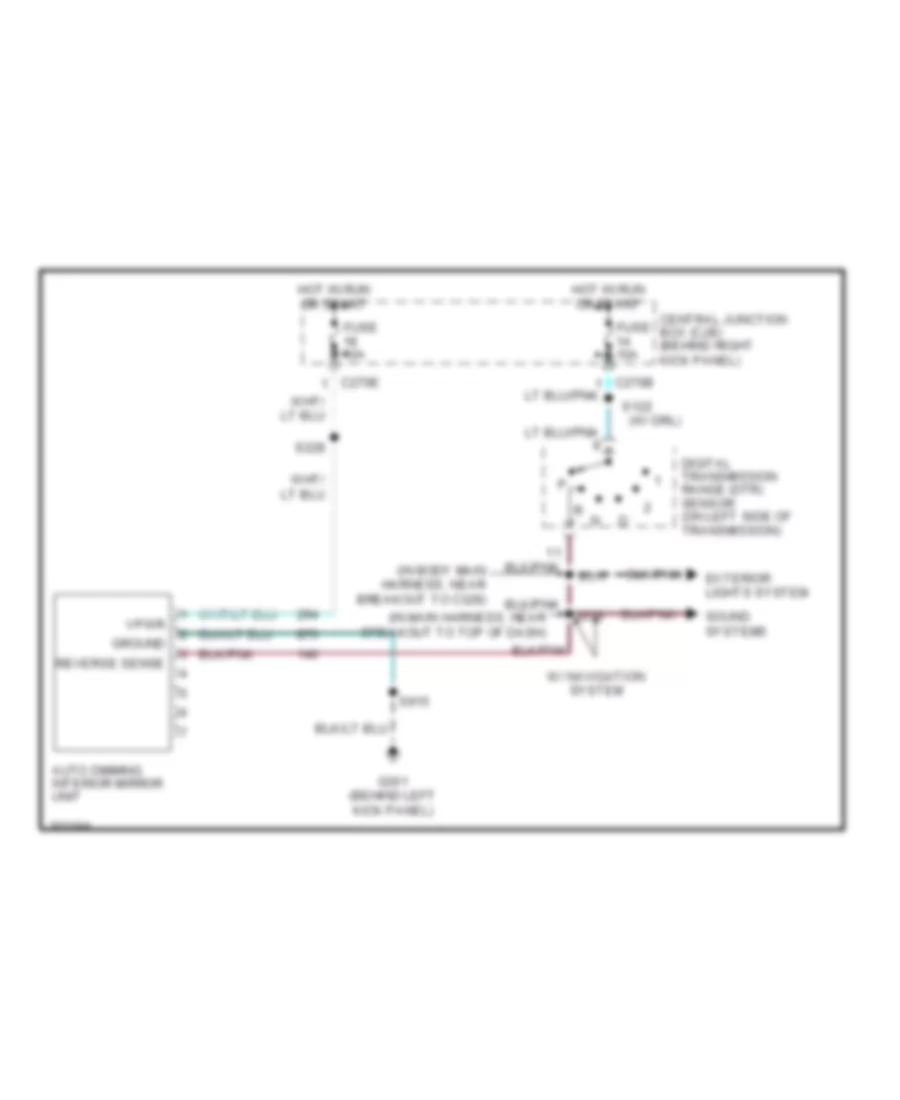
Back-up Lamps Wiring Diagram for Ford Expedition 2005
List of elements for Back-up Lamps Wiring Diagram for Ford Expedition 2005:
- (in body main harness, near breakout to c328) s317
- (in right rear window regulator control switch & wiring assembly, near breakout to right side of liftgate) s464
- Automatic transmission
- Auxiliary relay box 1 (at left front of engine compartment)
- C270b
- C270e
- C270f
- C270j
- Central junction box (cjb) (behind right kick panel)
- Digital transmission range (dtr) p
- Expedition
- Fuse 10 20a
- Fuse 14 10a
- G200 (behind right kick panel)
- G401 (on left side of luggage compartment, behind trim)
- G402 (on left side of luggage compartment, behind trim)
- G404 (on left side of luggage compartment, behind trim)
- Hot at all times
- Hot in start or run
- Left reversing lamp
- Navigator
- Parking aid module (pam) (at left side of cargo area, behind trim)
- Reversing lamp trailer tow relay
- Reversing lamps relay
- Right reversing lamp
- S122 (w/ drl)
- S203
- S402
- S414
- S436
- Sensor (on left side of transmission)
- Sound, mirrors systems
- Tan/red
- Trailer tow connector (7-pin) (near rear bumper)
Exterior Lamps Wiring Diagram for Ford Expedition 2005
List of elements for Exterior Lamps Wiring Diagram for Ford Expedition 2005:
- "b" pillar, behind trim)
- (behind left side of dash)
- (in body main harness,
- (in main harn, near breakout to g202) s246
- (in rear lamp connector harn, near breakout to c465) s403
- (near breakout to brake pedal
- (near breakout to right side of dash)
- Auto
- Auxiliary relay box 3
- Brake pedal position switch (on brake pedal support)
- C202b
- C205a
- C2113b
- C220b
- C270e
- C270f
- C270h
- C270j
- C270k
- Central junction box (cjb) (behind right kick panel)
- Door locks system
- Fuse 10a
- Fuse 15a
- Fuse 20a
- G100 (near left side of radiator)
- G101 (near right side of radiator)
- G200 (behind right kick panel)
- G201 (behind right kick panel)
- G300 (on left
- G401 (on left side of luggage compt, behind trim)
- G402 (on left side of luggage compt, behind trim)
- G404 (on right side of luggage compt, behind trim)
- Hazard
- Head
- Headlights, interior lights systems
- High mounted stop lamp
- Hot at all times
- Hot in start or run
- Indicator flasher relay
- Instrument cluster
- Left
- Left exterior rear view mirror (at left rear view mirror)
- Left front park/ turn lamp
- Left license plate lamp
- Left rear park/ stop/ turn lamp
- Left turn indicator
- Main light switch
- Microprocessor
- Multi- function switch
- Nca
- Near breakout to c465) s312
- Off
- Park
- Park lamp relay
- Position switch)
- Right
- Right exterior rear view mirror (at right rear view mirror)
- Right front park/ turn lamp
- Right license plate lamp
- Right rear park/ stop/ turn lamp
- Right turn indicator
- S100
- S102 (near breakout to c1450)
- S116
- S2001
- S201
- S2013
- S212
- S224 (near breakout to brake pedal position switch)
- S228
- S231
- S247
- S402
- S414
- S436
- S501
- S600
- Tan/
- Trailer/camper adapter circuit
- Vehicle security module (vsm) (under right side of dash)
Trailer/Camper Adapter Wiring Diagram for Ford Expedition 2005
List of elements for Trailer/Camper Adapter Wiring Diagram for Ford Expedition 2005:
- (behind left center of dash)
- (in taillamp harn, near breakout to g400)
- (in taillamp harn, near breakout to g400) s452
- (in taillamp harness, near breakout to rear bumper) s451
- (near rear bumper)
- Auto
- Back-up lamps circuit
- Battery charge trailer tow relay
- Brake pedal position switch (on brake pedal support)
- C202b
- C205a
- C270e
- C270f
- C270g
- C270j
- C270k
- C270n
- Central junction box (cjb) (behind right kick panel)
- Fuse 10a
- Fuse 15a
- Fuse 20a
- Fuse 30a
- G200 (behind right kick panel)
- G400 (under rear of vehicle)
- Head
- Hot at all times
- Hot in start or run
- Left turn signal
- Main light switch
- Multi-function switch
- Off
- Park
- Parking lamp trailer tow relay
- Red
- Right turn signal
- S2001
- S2013
- S202
- S203
- S224 (in main harness, near breakout to brake pedal position switch)
- S231 (in main harness, near breakout to brake pedal position switch)
- S450
- S453
- Trailer electronic brake control connector
- Trailer tow connector (4-pin)
- Trailer tow connector (7-pin)
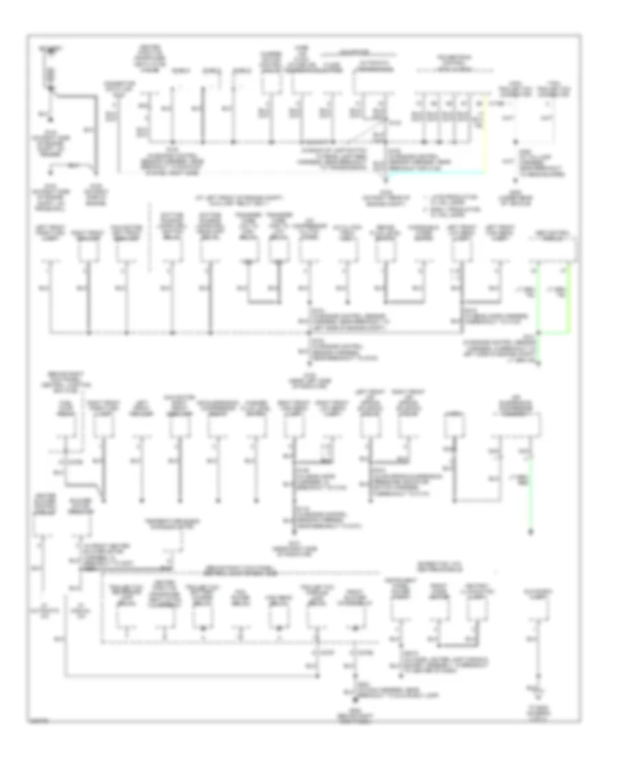
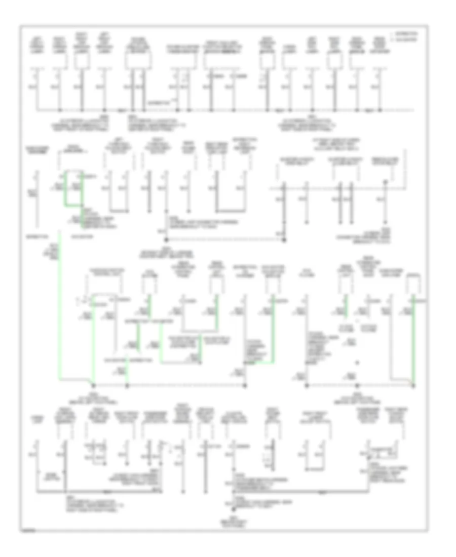
GROUND DISTRIBUTION
Ground Distribution Wiring Diagram (1 of 4) for Ford Expedition 2005
List of elements for Ground Distribution Wiring Diagram (1 of 4) for Ford Expedition 2005:
- (at left front of engine compt) auxiliary relay box 1
- (behind right kick panel) central junction box (cjb)
- (in back-up lamp switch to rear lamp feed harness, near breakout to transmission)
- (navigator) left front side lamp
- (navigator) right front side lamp
- 4-pin trailer tow connector
- 7-pin trailer tow connector
- 87a
- A/c clutch field coil
- A/c compressor clutch diode
- Abs control module
- Air suspension compressor assembly
- Air suspension compressor relay
- Ashtray illumination lamp
- Automatic transmission
- Battery
- Blower motor resistor
- Brake fluid level switch
- Breakout for c145)
- C175b
- C270b
- C270e
- C270f
- Charge motion control valve
- Connector data link (dlc)
- Daytime running lamps (drl) headlamp relay
- Daytime running lamps (drl) ignition relay
- Early production
- Expedition, w/o center console
- Floor shifter
- Front blower motor relay
- Front cigar lighter
- Fuel pump relay
- G100 (near left side of radiator)
- G101 (near right side of radiator)
- G102 (on right rear of engine compt)
- G103 (on right side of engine compt, on fender)
- G104 (on right side of engine compt, on frame rail)
- G105 (on right side of engine)
- G200 (behind right kick panel)
- G400 (under rear of vehicle)
- Glove box lamp
- Heated positive crankcase ventilation valve
- Heated positive crankcase ventilation valve relay
- Heater blower control module
- High beam relay
- Horn
- Instrument panel power point
- Late production
- Left front air spring solenoid valve
- Left front fog lamp
- Left front high beam lamp
- Left front low beam lamp
- Left front park/turn lamp
- Mass air flow/ intake air temperature
- Navigator
- Nca
- Near breakout to g101)
- Pcm power relay
- Powertrain control module (pcm)
- Right front air spring solenoid valve
- Right front fog lamp
- Right front high beam lamp
- Right front low beam lamp
- Right front park/turn lamp
- S100 (in engine control sensor harness, near breakout to g100)
- S101 (in engine control sensor harness, in breakout to left side of engine compt)
- S104 (in engine control sensor harness, near breakout to left side of engine compt)
- S135 (in headlamps harness, in breakout to c133)
- S143
- S153 (in engine control sensor harness, near breakout to exhaust system, right side)
- S450 (in taillamp harness, near breakout to rear bumper)
- Shield
- Temperature blend door actuator
- To center of dash)
- To s202 (diagram 2 of 4)
- Trailer tow battery charge relay
- Trailer tow parking lamp relay
- Trailer tow reversing lamp relay
- Transfer case high to low relay
- Transfer case low to high relay
- W/ automatic a/c
- W/ hid lamps
- W/ manual a/c
- Washer fluid level switch
- Windshield wiper motor
Ground Distribution Wiring Diagram (2 of 4) for Ford Expedition 2005
List of elements for Ground Distribution Wiring Diagram (2 of 4) for Ford Expedition 2005:
- (behind left side of dash) auxiliary relay box 3
- (expedition w/o dvd player) rear integrated control panel (ricp)
- (expedition)
- (expedition) traction control switch
- (navigator w/ dvd player)
- (navigator)
- (navigator) floor shifter
- (navigator) master window adjust switch
- Adjustable pedal switch
- Ashtray illumination lamp
- Audio/ navigation control unit
- Brake shift interlock
- C202a
- C205b
- C205c
- C2123a
- C220a
- C2253a
- C240a
- C294a b
- C294c
- C3193a
- C3193b
- C3198b
- C341a
- C349a
- Clock
- Console 1 power point
- Console 2 power point
- Data link connector (dlc)
- Driver seat module
- Driver side rear door ajar switch
- Electronic park brake release relay
- Electronic park brake reset relay
- Expedition
- Four-wheel driver switch
- From s203 (diagram 1 of 4)
- Front cigar lighter
- Front function selector switch assembly
- G300 (on left ``b" pillar, behind trim)
- Indicator flasher relay
- Instrument cluster
- Left front lumbar adjust switch
- Left power seat switch
- Left rear air spring solenoid valve
- Left rear window adjust switch
- Left running board motor assembly
- Main light switch
- Message center switch
- Multi-function switch
- Navigation system
- Navigator
- Nca
- Parking brake switch
- Radio
- Rear auxiliary function selector switch assembly
- Rear control unit (rcu)
- Right rear air spring solenoid valve
- S201 (in main harness, near breakout to left side of dash)
- S205 (navigator: in console panel harness, near breakout to c315) (expedition: in console panel harness, near breakout to storage bin power point)
- S385 (in power seats harness, near breakout under driver seat)
- Storage bin power point
- To s501 (diagram 3 of 4)
- Traction control switch
- Trailer electronic brake control connector
- W/ memory
- W/ navigation
- W/o memory
- W/o navigation
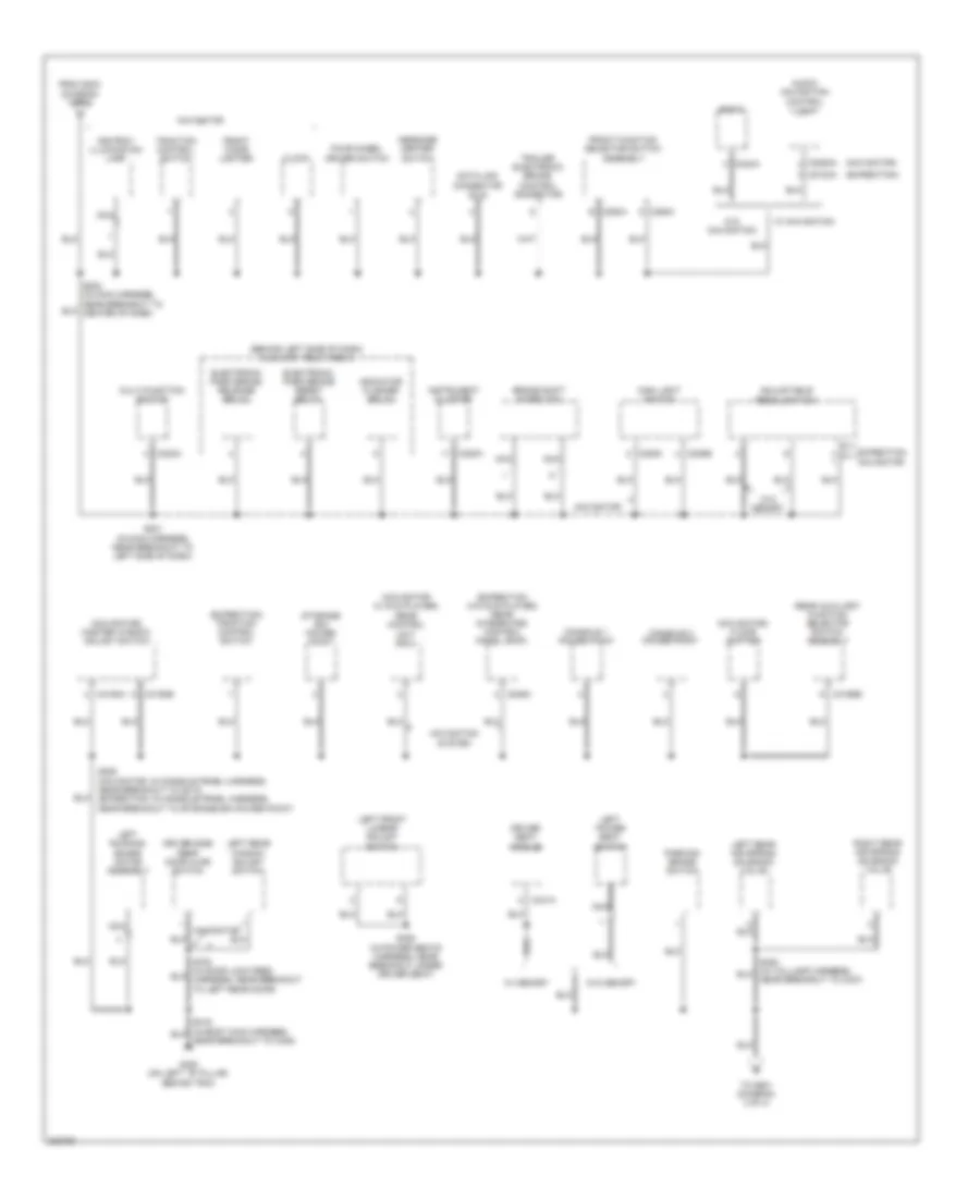
Ground Distribution Wiring Diagram (3 of 4) for Ford Expedition 2005
List of elements for Ground Distribution Wiring Diagram (3 of 4) for Ford Expedition 2005:
- (expedition) left reversing lamp
- (expedition) liftgate glass release switch
- (navigator) driver side front power window motor
- (w/ memory) exterior rear view mirror switch
- 6 way power seat
- 8 way power seat
- Adjustable pedal switch
- Air suspension module
- Auto- dimming interior mirror unit
- C2131a
- C220a
- C228a
- C2324a
- C294c
- C310a
- C341c
- C4014b
- C402b
- C4174b
- C504b
- De-icing switch
- Driver safety belt buckle switch
- Driver seat module
- Driver side door lock switch
- Driver side front power window motor
- Electronic automatic temperature control (eatc) module
- Electronic compass
- Expedition
- Exterior rear view mirror switch
- From s316 (diagram 2 of 4)
- Front function selector switch assembly
- Fuel pump driver module
- G301 (behind left kick panel)
- G401 (on left side of luggage compartment, behind trim)
- G402 (on left side of luggage compartment, behind trim)
- G403 (at rear of vehicle)
- G500 (on bottom of left front door, behind trim)
- G600 (on bottom of right front door, behind trim)
- Harness, near breakout to left side of engine compt)
- High mounted stoplamp
- Instrument cluster
- Key pad switch assembly
- Left exterior rear view mirror
- Left front door ajar switch
- Left license plate lamp
- Left power seat switch
- Left rear park/stop/ turn lamp
- Left reversing lamp
- Left tail lamp
- Liftgate chime module
- Liftgate fork bolt/detent switch
- Liftgate glass actuator
- Liftgate glass release switch
- Liftgate home position switch
- Master window adjust switch
- Memory set switch
- Navigator
- Nca
- Near breakout to restraints control module)
- Near breakout to top of dash)
- Parking aid module (pam)
- Passenger safety belt buckle switch
- Passive anti-theft transceiver
- Power liftgate module
- Rear window defrost grid
- Rear wiper motor assembly
- Restraints control module
- Right license plate lamp
- Right reversing lamp
- Right tail lamp
- S346 (in body main harness, near breakout to g301)
- S383 (in power seats harness, near breakout under driver seat)
- S414 (in rear lamp connector harness, near breakout to g401)
- S459 (in taillamp harness, near breakout to rear bumper)
- S501 (in body main harness, near breakout to left front door)
- S506 (in body main harness, near breakout to left front door)
- S915
- Shield
- Sunload sensor
- W/ automatic a/c
- W/ manual a/c
- W/ memory
- W/ power liftgate
- W/o memory
- Windshield wiper motor
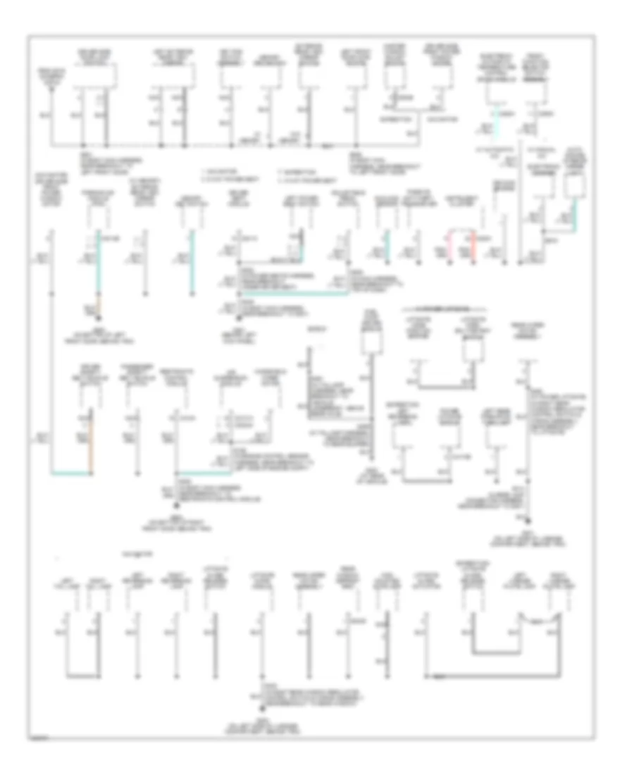
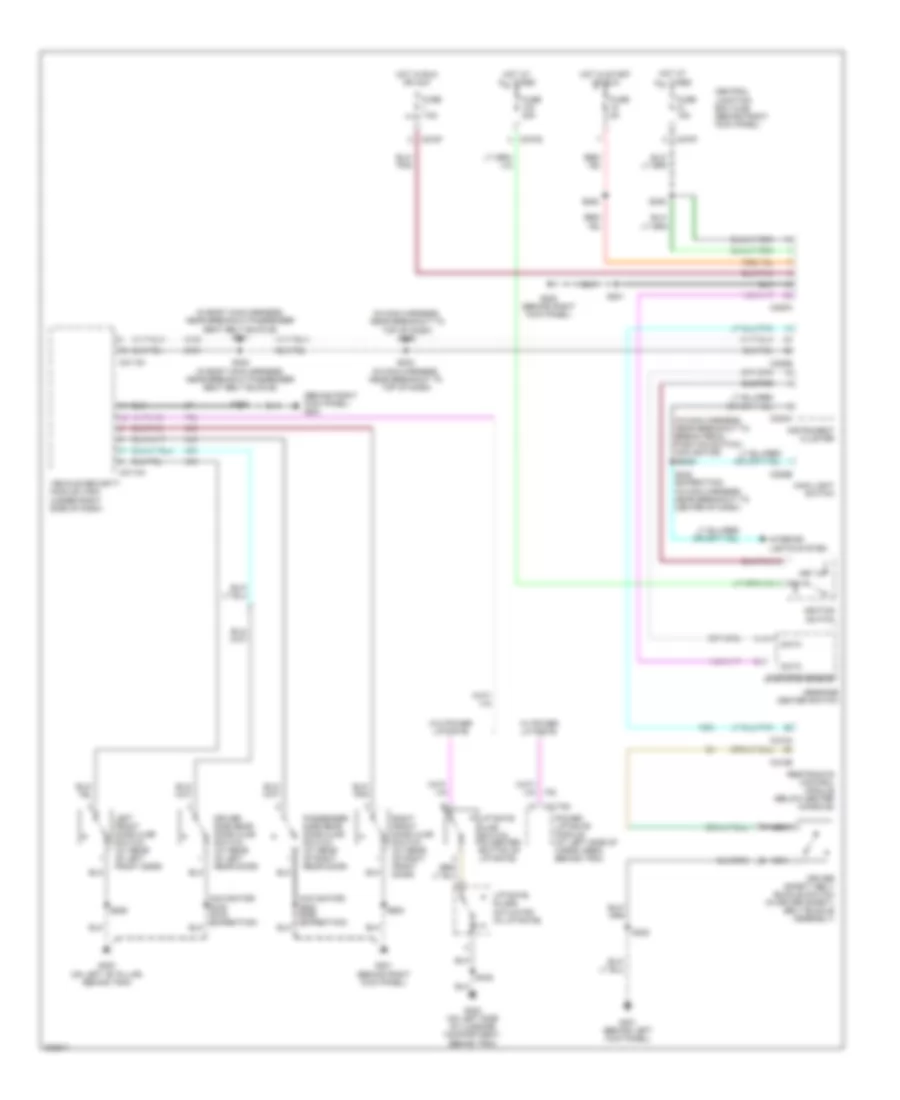
Ground Distribution Wiring Diagram (4 of 4) for Ford Expedition 2005
List of elements for Ground Distribution Wiring Diagram (4 of 4) for Ford Expedition 2005:
- (at right side of cargo area, behind trim) auxiliary relay box 2
- (expedition) cd changer
- (expedition) right reversing lamp
- (in interior illumination harness, near breakout to right side of roof panel)
- (in main harness, near breakout to g202) (except expedition xls/xlt) s290
- (in main harness, near breakout to g202) s290
- (navigator) navigation module
- Audio/navigation control unit
- Base lighting
- C2113a
- C2123a
- C2253a
- C2279a
- C2291a
- C240a
- C3265b
- C349a
- C989a
- C989b
- Cargo lamp
- Climate controlled seat module
- Dvd player
- Expedition
- Front auxiliary function selector switch assembly
- Front interior/ map lamps assembly
- G201 (behind right kick panel)
- G202 (w/ navigation) (behind left kick panel)
- G202 (w/o navigation) (behind left kick pane)
- G404 (on right side of luggage compartment, behind trim)
- Left front map reading lamp
- Left side rail lamp
- Left third row folding seat switch
- Left vanity mirror lamp
- Navigator
- Navigator w/ dvd player
- Navigator w/o dvd player & expedition
- Nca
- Passenger side door lock switch
- Passenger side rear door ajar switch
- Power liftgate open/close switch
- Power point
- Power quarter window switch
- Quarter window close relay
- Quarter window open relay
- Radio
- Radio amplifier
- Rear
- Rear blend door actuator
- Rear blower motor relay
- Rear control unit
- Rear control unit (rcu)
- Rear integrated control panel
- Rear integrated control panel (ricp)
- Right exterior rear view mirror
- Right front door ajar switch
- Right front lumbar adjust switch
- Right front map reading lamp
- Right power seat switch
- Right rear park/stop/ turn lamp
- Right rear window adjust switch
- Right running board motor assembly
- Right side rail lamp
- Right third row folding seat switch
- Right vanity mirror lamp
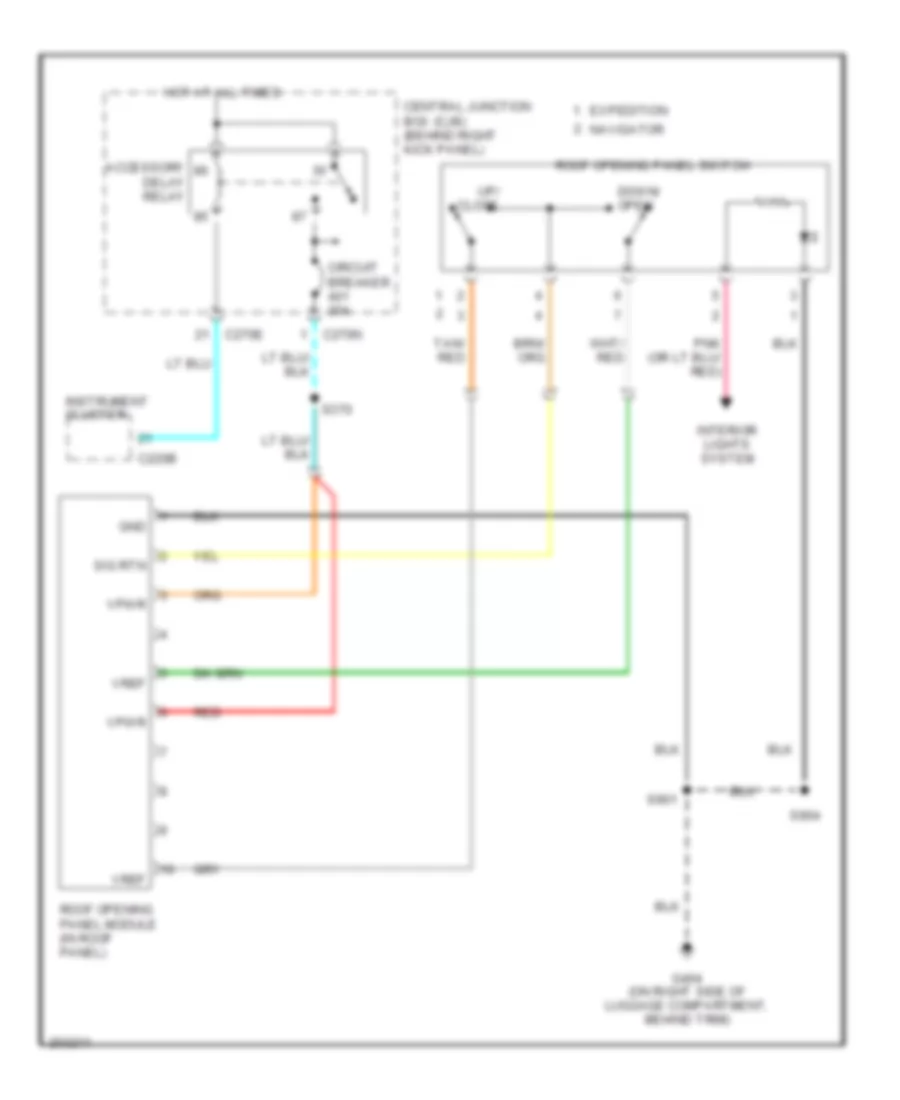
- Roof opening panel module
- Roof opening panel switch
- S207 (in main harness, near breakout to center of dash)
- S329 (in power seats harness, near breakout to passenger seat)
- S424 (in rear lamp connector harness, near breakout to c410)
- S436 (in rear lamp connector harness, near breakout to g404)
- S600 (in body main harness, near breakout to right right front door)
- S901
- S901 (in interior illumination harness, near breakout to right side of roof panel)
- S904 (in interior illumination harness, near breakout to center of roof panel)
- S906 (in interior illumination harness, near breakout to right front of roof panel)
- Subwoofer amplifier
- Vehicle security module (vsm)
- W/ dvd player
- W/o dvd player
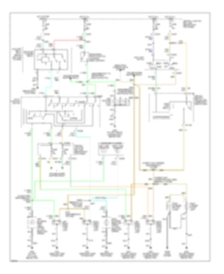
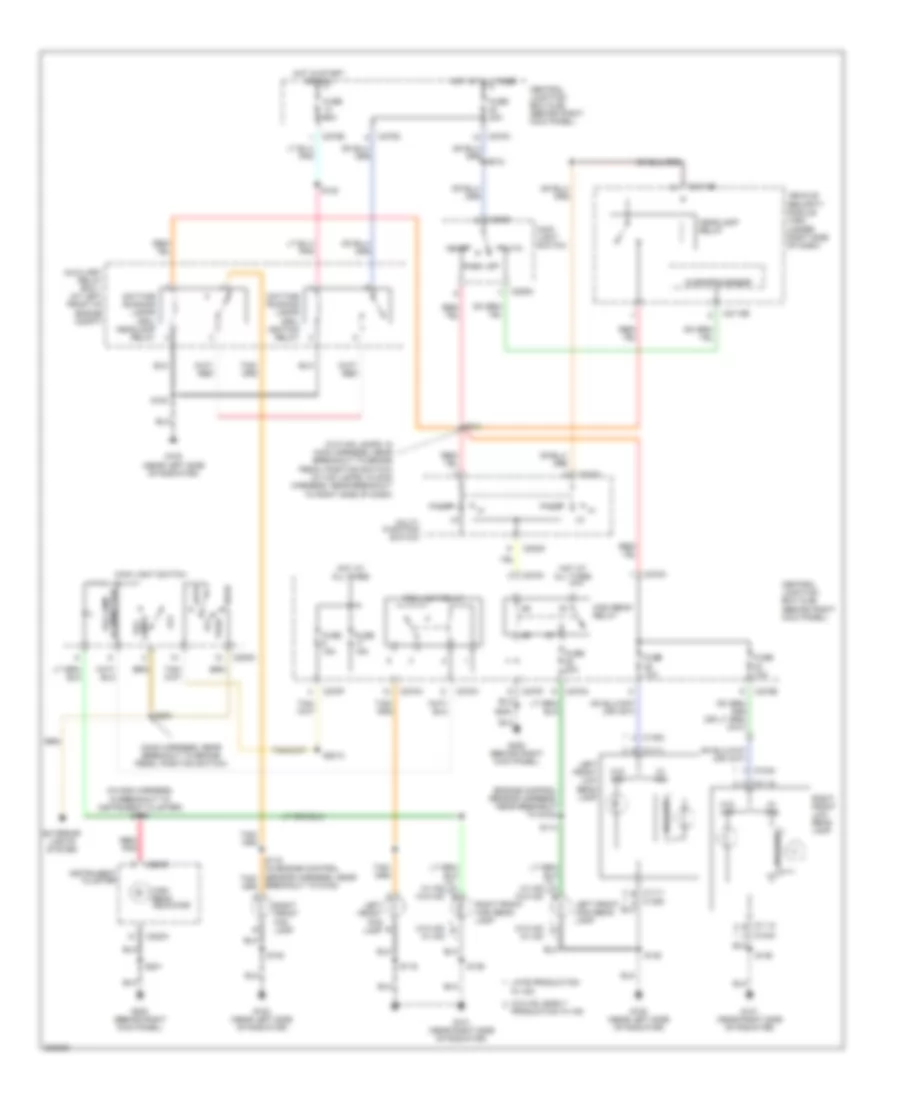
HEADLIGHTS
Headlights Wiring Diagram, with DRL for Ford Expedition 2005
List of elements for Headlights Wiring Diagram, with DRL for Ford Expedition 2005:
- (engine control sensor harness, near breakout to g102)
- (in main harness, in breakout to instrument cluster) s266
- (main harness, near breakout to brake pedal position switch)
- (w/o hid lamps: in main harness, near breakout to brake pedal position switch) (w/ hid lamps: in main harness, near breakout to right side of dash)
- A c1111
- A c1112
- Auto
- Auxiliary relay box 1 (at left front of engine compt)
- Ballast
- Breakout to g102)
- C1111 b
- C1112 b
- C1353
- C1354
- C202c
- C205a
- C2113b
- C220a
- C220b
- C270a
- C270b
- C270d
- C270f
- C270h
- Central junction box (cjb) (behind right kick panel)
- Daytime running lamps (drl) headlamp relay
- Daytime running lamps (drl) ignition relay
- Exterior lights system
- Fog lamp relay
- Fog lamps
- Fuse 10a
- Fuse 15a
- Fuse 20a
- G100 (near left side of radiator)
- G101 (near right side of radiator)
- G200 (behind right kick panel)
- Head
- Headlamp relay
- High beam indicator
- High beam relay
- Hot at all times
- Hot in start or run
- Illumination fog lamp
- Instrument cluster
- Late production
- Left front fog lamp
- Left front high beam lamp
- Left front low beam lamp
- Main light switch
- Microprocessor
- Multi- function switch
- Off
- Park
- Pass
- Production w/ hid
- Red/ pnk
- Right front fog lamp
- Right front high beam lamp
- Right front low beam lamp
- S100
- S114
- S116
- S122
- S135
- S136
- S201
- S2013
- S203
- S224
- S244
- Vehicle security module (vsm) (under right side of dash)
- W/ hid
- W/ hid w/o hid
- W/o hid
- W/o hid w/ hid
- W/o hid, early
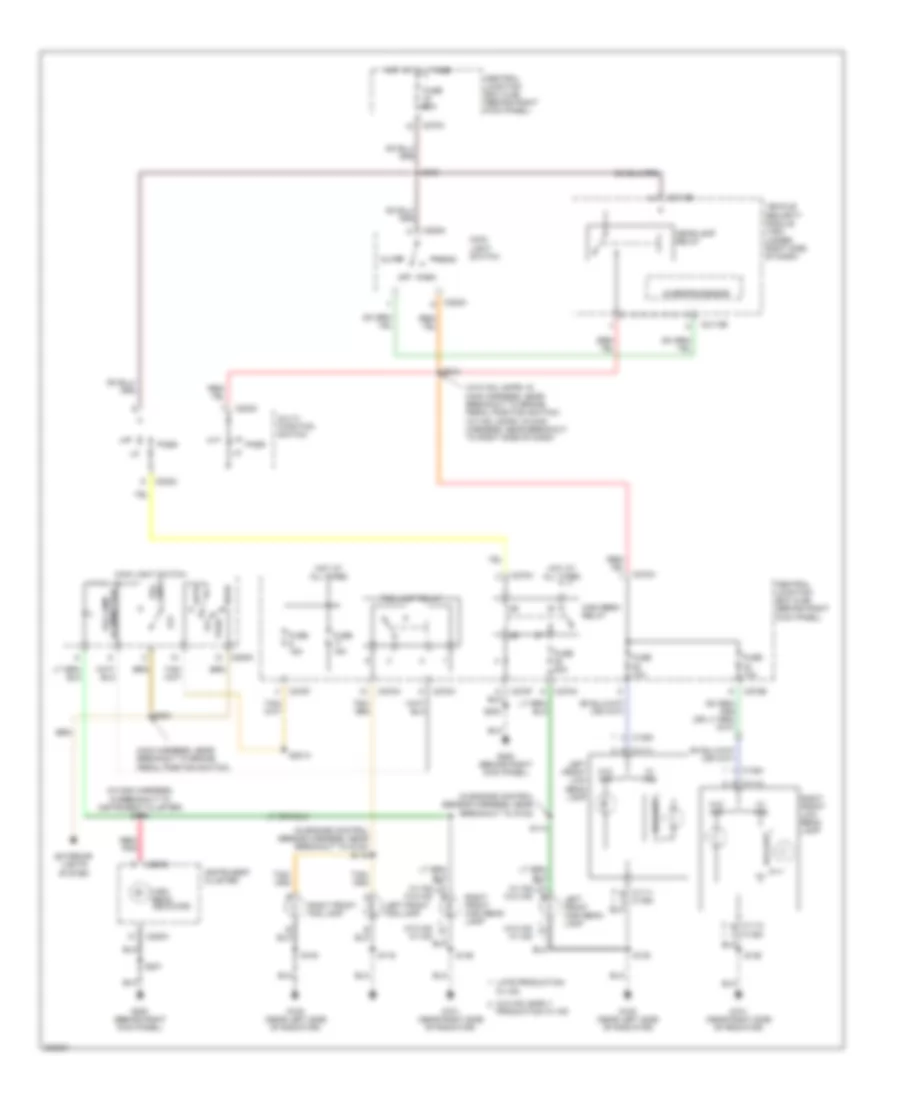
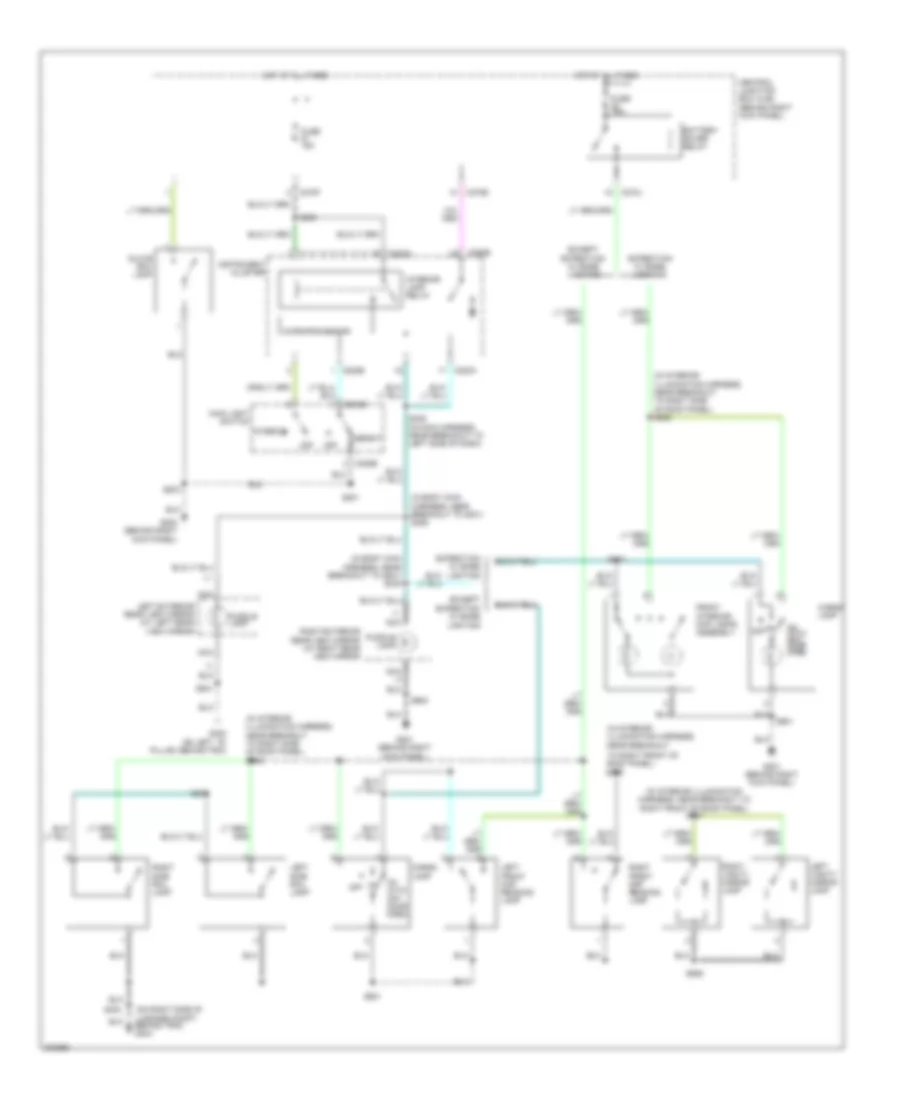
Headlights Wiring Diagram, without DRL for Ford Expedition 2005
List of elements for Headlights Wiring Diagram, without DRL for Ford Expedition 2005:
- (in engine control sensor harness, near breakout to g102)
- (in engine control sensor harness, near breakout to g102) s115
- (in main harness, in breakout to instrument cluster) s266
- (w/o hid lamps: in main harness, near breakout to brake pedal position switch) (w/ hid lamps: in main harness, near breakout to right side of dash)
- Auto
- Ballast
- C1111 a
- C1112 a
- C1112 b
- C1353
- C1354
- C202c
- C205a
- C2113b
- C220a
- C220b
- C270a
- C270b
- C270f
- C270h
- Central junction box (cjb) (behind right kick panel)
- Exterior lights system
- Fog lamp relay
- Fog lamps
- Fuse 10a
- Fuse 15a
- Fuse 20a
- G100 (near left side of radiator)
- G101 (near right side of radiator)
- G200 (behind right kick panel)
- Head
- Headlamp relay
- High beam indicator
- High beam relay
- Hot at all times
- Illumination fog lamp
- Instrument cluster
- Late production
- Left front fog lamp
- Left front high beam lamp
- Left front low beam lamp
- Main harness, near breakout to brake pedal position switch)
- Main light switch
- Microprocessor
- Multi- function switch
- Off
- Park
- Pass
- Production w/ hid
- Red/ pnk
- Right front fog lamp
- Right front high beam lamp
- Right front low beam lamp
- S100
- S114
- S116
- S135
- S136
- S201
- S2013
- S203
- S212
- S224
- S244
- Vehicle security module (vsm) (under right side of dash)
- W/ hid
- W/ hid w/o hid
- W/o hid
- W/o hid w/ hid
- W/o hid, early
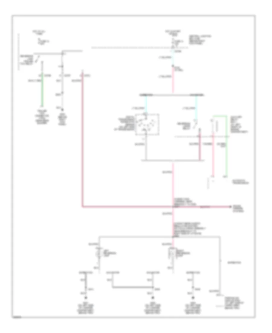
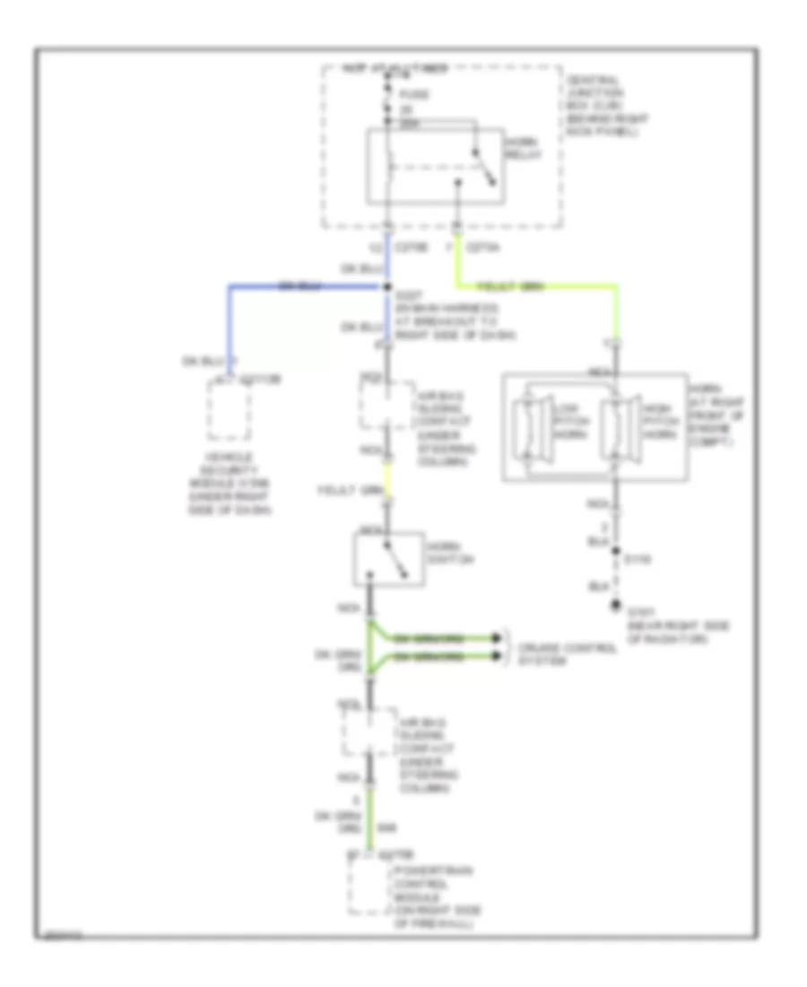
HORN
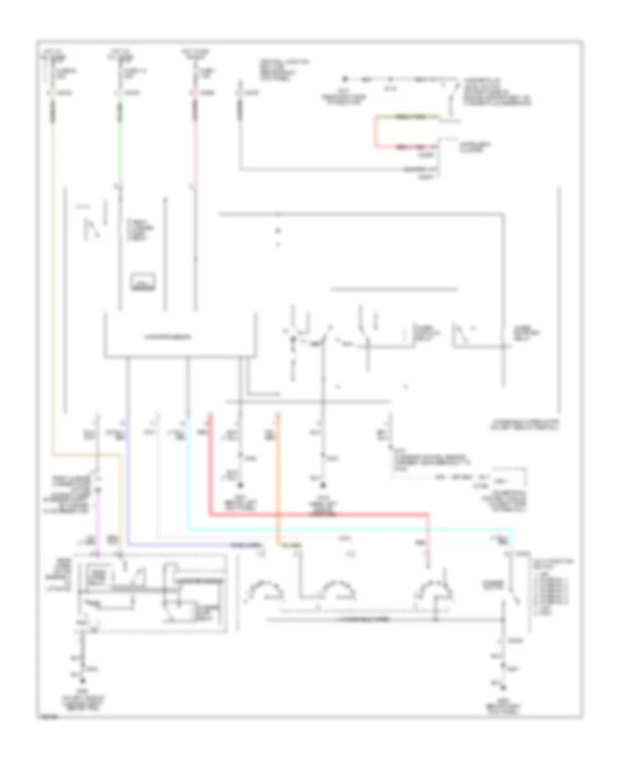
Horn Wiring Diagram for Ford Expedition 2005
List of elements for Horn Wiring Diagram for Ford Expedition 2005:
- (under steering column)
- 20a
- Air bag sliding contact
- Air bag sliding contact (under steering column)
- C175b
- C2113b
- C270a
- C270e
- Central junction box (cjb) (behind right kick panel)
- Cruise control system
- Fuse
- G101 (near right side of radiator)
- High pitch horn
- Horn (at right front of engine compt)
- Horn relay
- Horn switch
- Hot at all times
- Low pitch horn
- Nca
- Powertrain control module (on right side of firewall)
- Right side of dash)
- S116
- Vehicle security module (vsm) (under right side of dash)
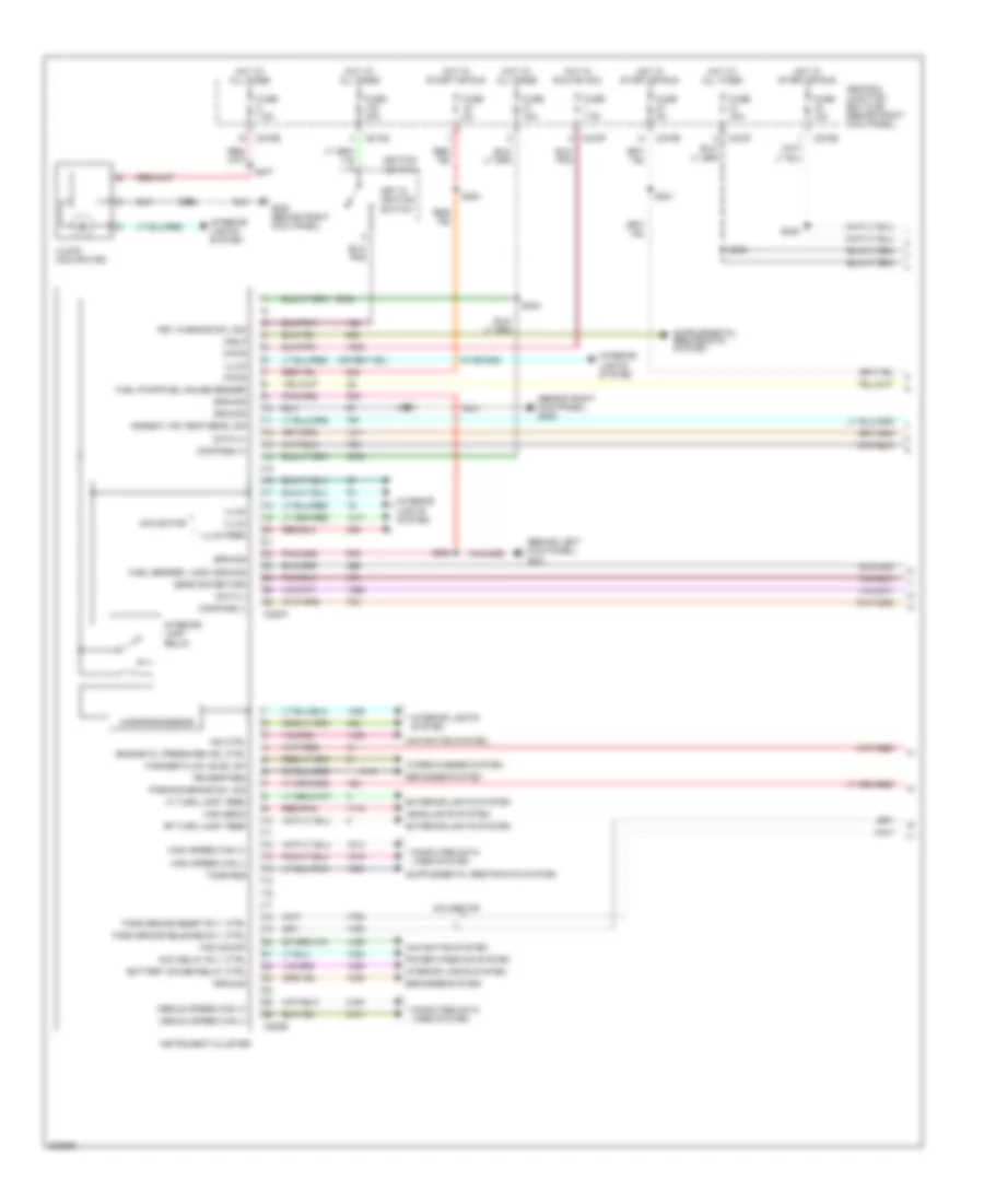
INSTRUMENT CLUSTER
Instrument Cluster Wiring Diagram (1 of 2) for Ford Expedition 2005
List of elements for Instrument Cluster Wiring Diagram (1 of 2) for Ford Expedition 2005:
- (behind left kick panel) g301
- (behind right kick panel) g200
- (or 505)
- A/blp
- Acc delay rly, ctrl
- Ambient air temp sens, sig
- Battery saver relay ctrl
- C220a
- C220b
- C270e
- C270f
- C270g
- Central junction box (cjb) (behind right kick panel)
- Clock (navigator)
- Compass (+)
- Compass (-)
- Computer data lines system
- Data (+)
- Data (-)
- Defogger system
- Engine oil pressure ind, ctrl
- Exterior lights system
- Fuel pump/fuel gauge sender
- Fuel sender, logic ground
- Fuse 10a
- Fuse 15a
- Fuse 30a
- Fuse 5a
- Fuse 7.5a
- G200 (behind right kick panel)
- Ground
- Headlights system
- High beam
- High speed can (+)
- High speed can (-)
- Hot at all times
- Hot in run or acc
- Hot in start or run
- Ignition switch
- Illum
- Illum feed
- Ind ctrl
- Instrument cluster
- Interior lamp relay
- Interior lights system
- Key in ignition switch
- Key warning sw, sig
- Lf turn lamp, feed
- Medium speed can (+)
- Medium speed can (-)
- Microprocessor
- Navigation system
- Navigator
- Pam on/off
- Park brake release rly, ctrl
- Park brake reset rly, ctrl
- Parking brake sw, sig
- Power windows system
- Red/pnk
- Rf turn lamp, feed
- Rr defr req
- S201
- S202
- S208
- S221
- S228
- S238
- S277
- S282
- Sens sig return
- Tone req
- Vpwr
- Washer fluid level sw
- Wiper/washer system
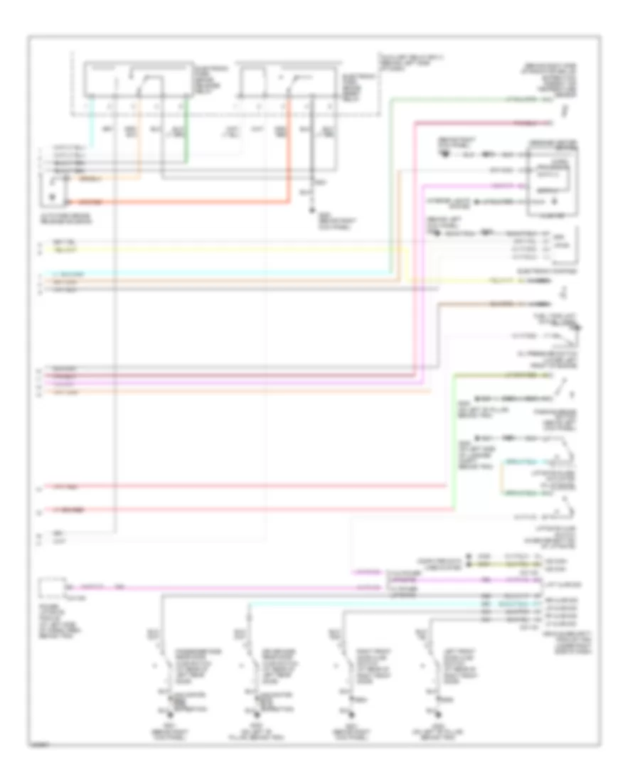
Instrument Cluster Wiring Diagram (2 of 2) for Ford Expedition 2005
List of elements for Instrument Cluster Wiring Diagram (2 of 2) for Ford Expedition 2005:
- (behind left kick panel) g301
- (behind right kick panel)
- (behind right side of radiator grille) (expedition) ambient air temperature sensor
- Auto park brake release solenoid
- Auxiliary relay box 3 (behind left side of dash)
- C2113a
- C2113c
- C4174d
- Computer data lines system
- Data (+)
- Data (-)
- Driver side rear door ajar switch (at rear of left rear door)
- Electronic compass
- Electronic park brake release relay
- Electronic park brake reset relay
- Fuel tank unit (in fuel tank)
- G200
- G200 (behind right kick panel)
- G201 (behind right kick panel)
- G300 (on left "b" pillar, behind trim)
- G402 (on left side of luggage compt, behind trim)
- Gnd
- Illum ind
- Interior lights system
- Left front door ajar switch (at rear of right front door)
- Lf ajar sig
- Lift ajar sig
- Liftgate ajar switch (in center bottom of liftgate)
- Liftgate glass actuator (in liftgate)
- Lr ajar sig
- Message center switch
- Micro- processor
- Ms can+
- Ms can-
- Nca
- Oil pressure switch (lower left front of engine)
- Parking brake switch (above left kick panel)
- Passenger side rear door ajar switch (at rear of left rear door)
- Power liftgate module (at left side of cargo area, behind trim)
- Rf ajar sig
- Right front door ajar switch (at rear of right front door)
- Rr ajar sig
- S201
- S202
- S308
- S316
- S402
- S506
- S600
- Vehicle security module (vsm) (under right side of dash)
- Vpwr
- W/ power liftgate
- W/o power liftgate
INTERIOR LIGHTS
Courtesy Lamps Wiring Diagram for Ford Expedition 2005
List of elements for Courtesy Lamps Wiring Diagram for Ford Expedition 2005:
- (in body main harness, near breakout to g201) s345
- (in body main harness, near breakout to g301) s355
- (in interior illumination harness,
- (in interior illumination harness, near breakout to
- (in interior illumination harness, near breakout to right side of roof panel) s902
- (on right side of luggage compt, behind trim) g404
- Battery saver relay
- C205b
- C220a
- C220b
- C270e
- C270f
- C270j
- Cargo lamp
- Central junction box (cjb) (behind right kick panel)
- Defeat
- Except expedition w/ base
- Except expedition w/ base lighting
- Expedition w/ base
- Expedition w/ base lighting
- Front interior/ map lamps assembly
- Fuse 15a
- G200 (behind right kick panel)
- G201 (behind right kick panel)
- G300 (on left ``b" pillar, behind trim)
- Glove box lamp
- Hot at all times
- Instrument cluster
- Interior
- Interior lamp relay
- Lamp
- Left exterior rear view mirror (at left rear view mirror
- Left front map reading lamp
- Left side rail lamp
- Left vanity mirror lamp
- Lighting
- Main light switch
- Microprocessor
- Nca
- Near breakout
- Off
- On with any door open
- Puddle
- Puddle lamp
- Right exterior rear view mirror (at right rear view mirror
- Right front map reading lamp
- Right front of roof panel) s907
- Right side rail lamp
- Right vanity mirror lamp
- S201
- S203
- S235 (in main harness, near breakout to left side of dash)
- S238
- S424
- S501
- S600
- S900
- S901
- S906
- To right front of roof panel) s905
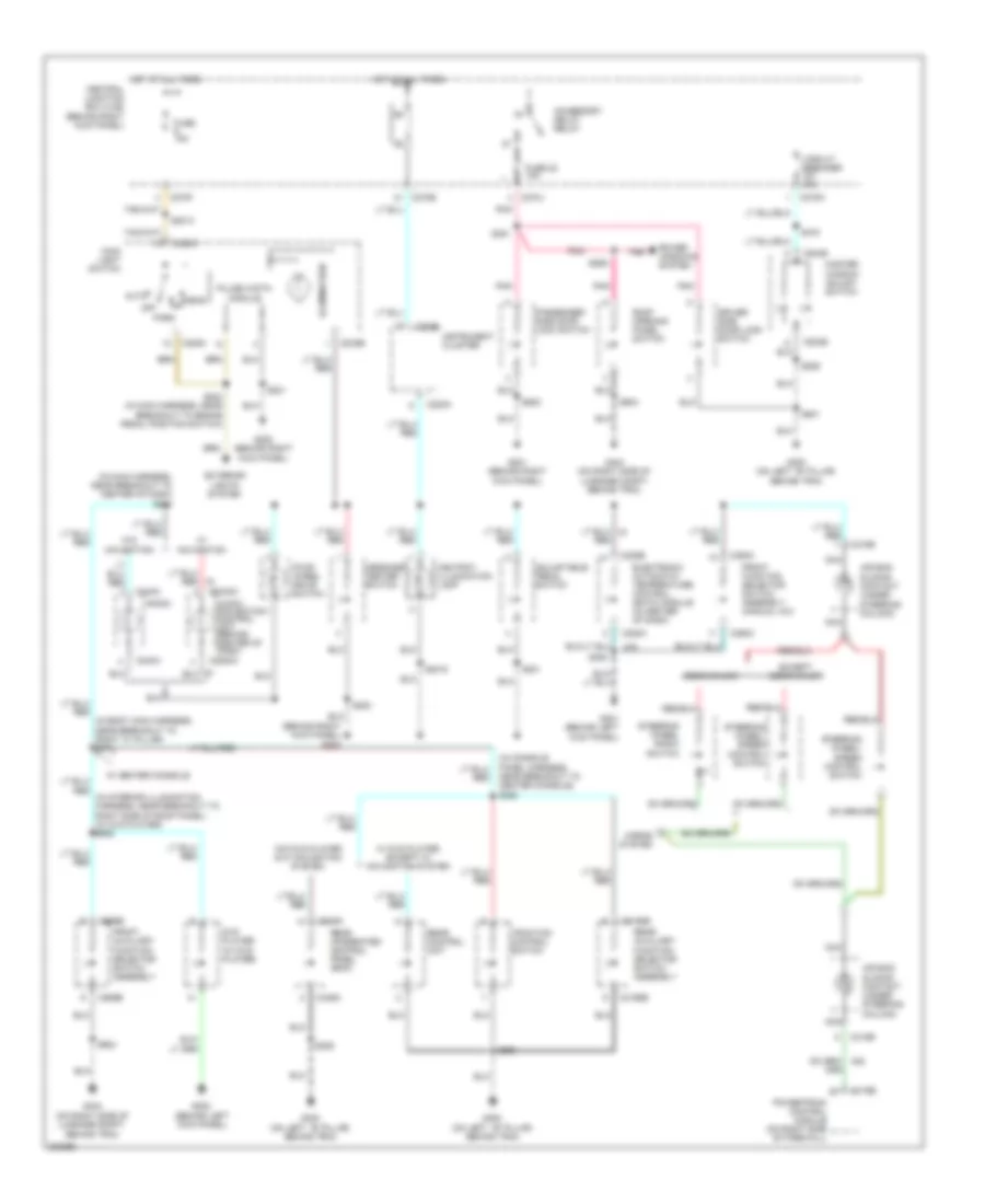
Instrument Illumination Wiring Diagram for Ford Expedition 2005
List of elements for Instrument Illumination Wiring Diagram for Ford Expedition 2005:
- (behind left kick panel)
- (behind right kick panel) g200
- (in body main harness, near breakout to right "c" pillar) s371
- (in console panel harness, near breakout to center console) s350
- (in main harness, near breakout to center of dash) s242
- (on left ``b" pillar, behind trim)
- (on right side of luggage compt, behind trim)
- Accessory delay relay
- Adjustable pedal switch
- Air bag sliding contact (under steering column)
- Ashtray illumination lamp
- Audio/ navigation control unit (behind center of dash)
- Auto
- C175b
- C205a
- C205b
- C218b
- C220a
- C220b
- C2253a
- C228a
- C228b
- C240a
- C270e
- C270f
- C270j
- C270n
- C294c
- C3198b
- C349a
- C504b
- C989b
- Central junction box (cjb) (behind right kick panel)
- Circuit breaker 30a
- Driver side door lock switch
- Dvd player (w/ dvd player)
- Eddie bauer
- Electronic automatic temperature control (eatc) module (in center of dash)
- Except eddie bauer
- Exterior lights system
- Four- wheel drive switch
- Front auxiliary function selector switch assembly
- Front function selector switch assembly (manual a/c)
- Fuse 15a
- Fuse 22 10a
- G200 (behind right kick panel)
- G201 (behind right kick panel)
- G202
- G300
- G300 (on left ``b" pillar, behind trim)
- G301 (behind left kick panel)
- G404
- G404 (on right side of luggage compt, behind trim)
- Head
- Horns system
- Hot at all times
- Illumination
- Instrument cluster
- Main light switch
- Master window adjust switch
- Message center switch
- Nca
- Off
- Park
- Passenger side door lock switch
- Pnk
- Power windows system
- Powertrain control module (on right side of firewall)
- Pulse width module
- Radio
- Rear auxiliary function selector switch assembly
- Rear control unit
- Rear integrated control panel (ricp)
- Red
- Roof opening panel switch
- S201
- S2013
- S2018
- S202
- S205
- S208
- S224 (in main harness, near breakout to brake pedal position switch)
- S370
- S381
- S501
- S506
- S600
- S904
- S909
- Steering wheel radio switch
- Steering wheel/ speed control switch
- Traction control switch
- W/ center console
- W/ dvd player, except w/ navigation system
- W/ navigation
- W/o dvd player & w/ navigation system
- W/o navigation
MEMORY SYSTEMS
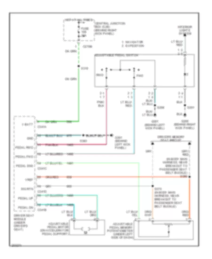
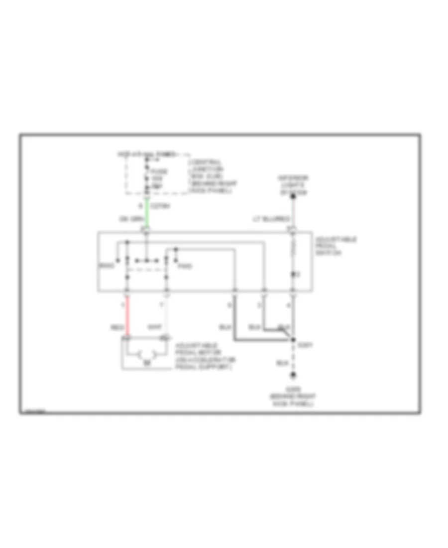
Adjustable Pedal Wiring Diagram for Ford Expedition 2005
List of elements for Adjustable Pedal Wiring Diagram for Ford Expedition 2005:
- (in body main harness, near breakout to passenger seat belt buckle) s380
- Adjustable pedal memory potentiometer (under left side of dash)
- Adjustable pedal motor (on accelerator pedal support)
- Adjustable pedal switch
- C270m
- C341a
- C341b
- C341c
- C341d
- Central junction box (cjb) (behind right kick panel)
- Driver seat module (under driver's seat)
- Driver's memory seat circuit
- Fuse 30a
- Fwd
- G200 (behind right kick panel)
- G301 (behind left kick panel)
- Gnd
- Hot at all times
- Interior lights system
- Navigator expedition
- Pedal dn
- Pedal fwd
- Pedal rwd
- Pedal sns
- Pedal up
- Rwd
- S201
- S208
- S310
- S376 (in body main harness, near breakout to passenger seat belt buckle)
- S383
- Sig rtn
- V batt
- Vref
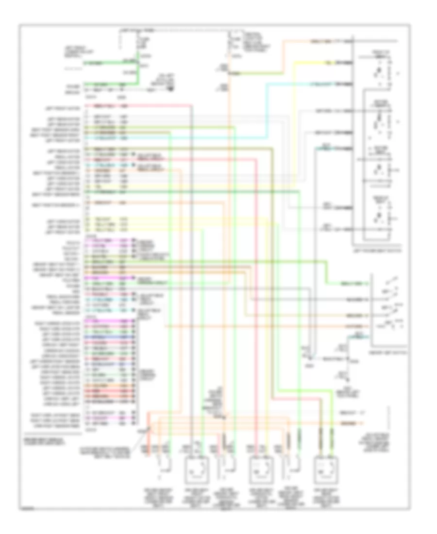
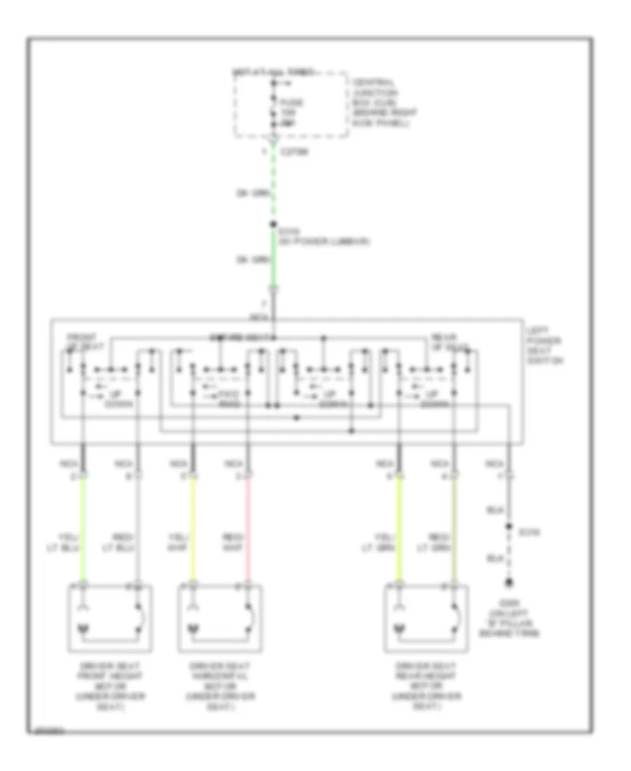
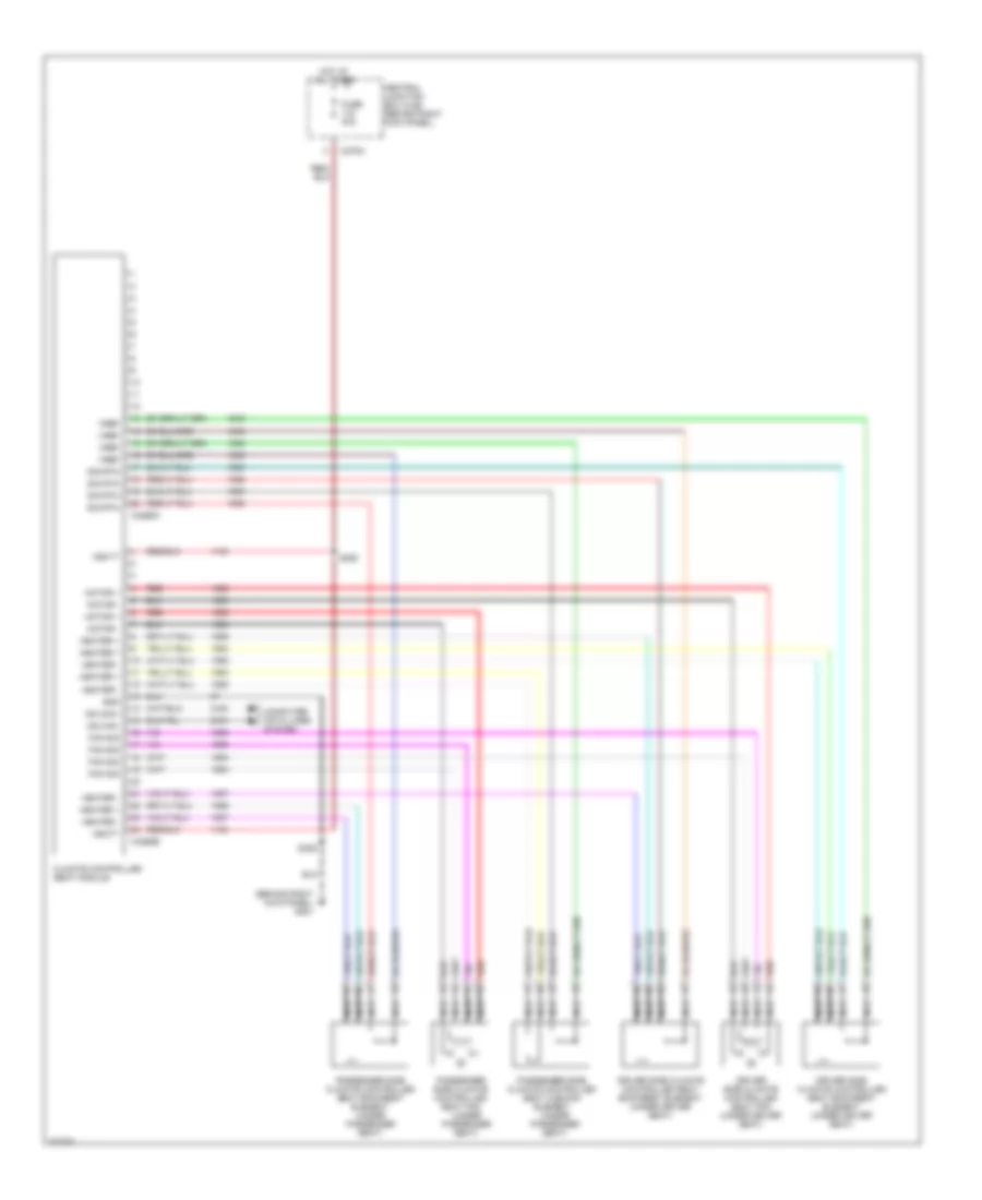
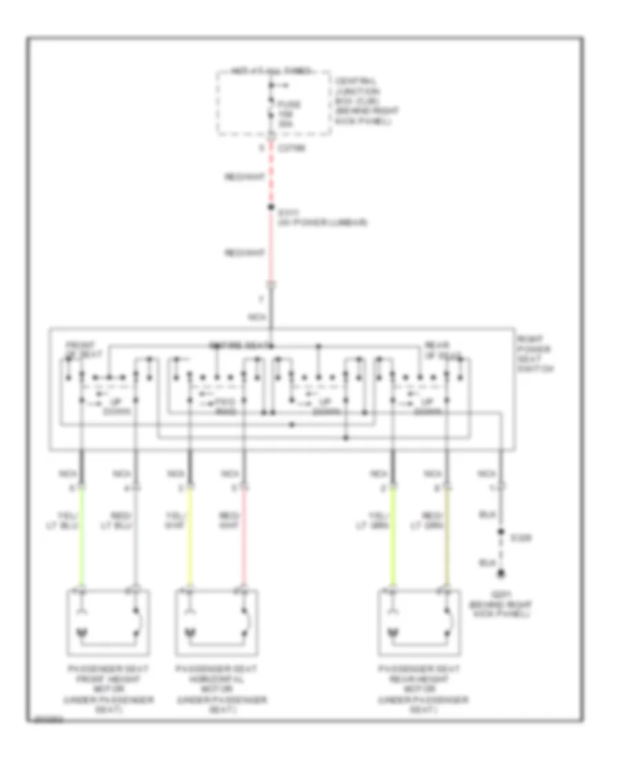
Driver"s Memory Seat Wiring Diagram for Ford Expedition 2005
List of elements for Driver"s Memory Seat Wiring Diagram for Ford Expedition 2005:
- (in power seats harness, near breakout to c311) s309
- (in power seats harness, near breakout to driver seat belt buckle)
- (on left "b" pillar, behind trim) g300
- Adjustable pedal circuit
- Adjustable pedal memory potentiometer (under left side of dash)
- C270j
- C270m
- C341a
- C341b
- C341c
- C341d
- Central junction box (cjb) (behind right kick panel)
- Computer data lines system
- Driver memory seat front height sensor (under driver seat)
- Driver memory seat horizontal sensor (under driver seat)
- Driver memory seat rear height sensor (under driver seat)
- Driver seat front height motor (under driver seat)
- Driver seat horizontal motor (under driver seat)
- Driver seat module driver seat module (under driver's seat)
- Driver seat rear height motor (under driver seat)
- Entire seat
- Fold in
- Fold out
- Fold reg
- Front of seat
- Fuse 30a
- Fuse 7.5a
- Fwd
- G301 (behind left kick panel)
- Gnd
- Ground
- Hot at all times
- Left front lumbar adjust switch
- Left front motor
- Left horiz motor
- Left mirr up/dn mtr
- Left mirr up/dn pos sens
- Left mirror l/r mtr
- Left mirror posit sensor
- Left power seat switch
- Left rear motor
- Memory mirrors circuit
- Memory seat sw lamp dr
- Memory seat sw posit 1
- Memory seat sw posit 2
- Memory seat sw set
- Memory set switch
- Mirr posit sens gnd
- Mirr posit sensor feed
- Mirr sw horiz left
- Mirr sw horiz right
- Mirr sw vert left
- Mirr sw vert right
- Mirror sw common
- Ms can +
- Ms can -
- Nca
- Pedal backward
- Pedal forward
- Pedal motor
- Pedal sensor
- Power
- Rear of seat
- Red
- Right mirr l/r posit sens
- Right mirr u/d posit sens
- Right mirr up/dn mtr
- Right mirror l/r mtr
- Right mirror up/dn mtr
- Rwd
- S310
- S346
- S382
- S383
- S384
- S385
- Seat posit sensor front
- Seat posit sensor horiz
- Seat posit sensor rear
- Seat position sensor (+)
- Seat position sensor (-)
- Set
- Set 1
- Set 2
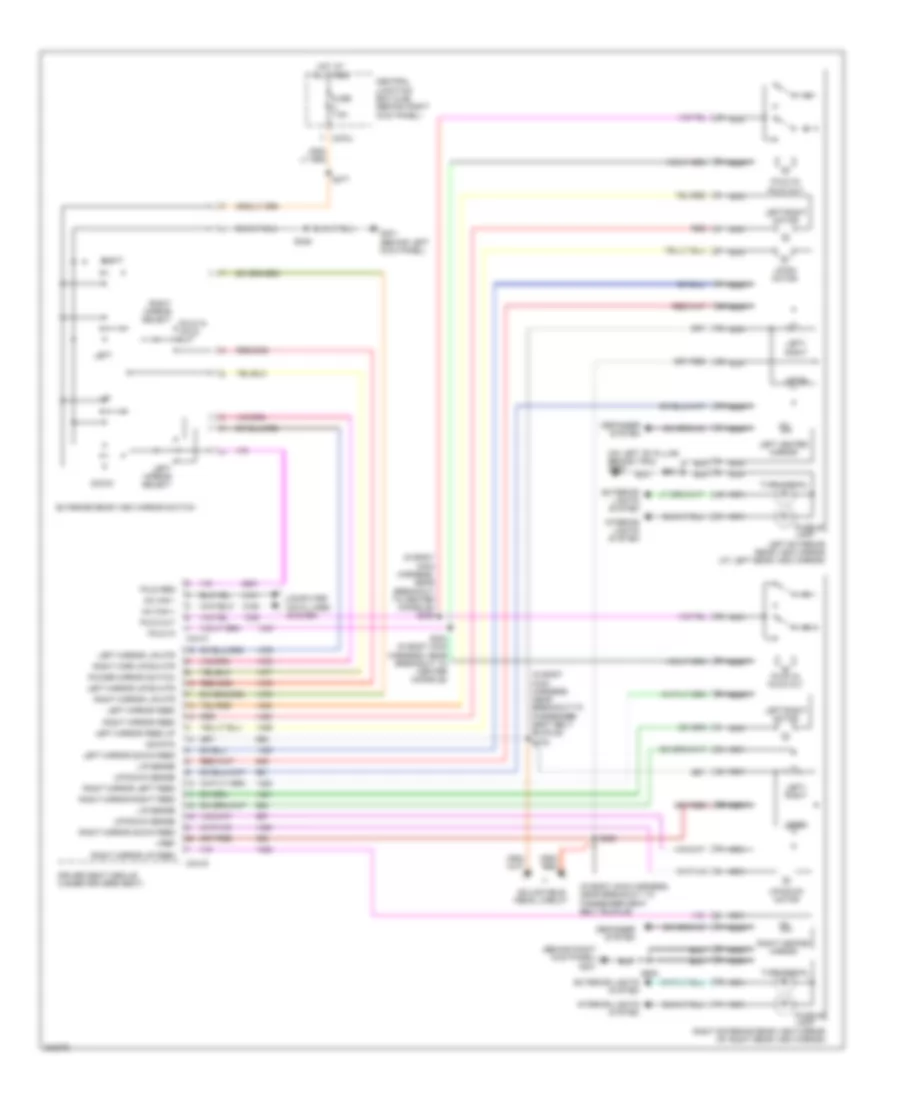
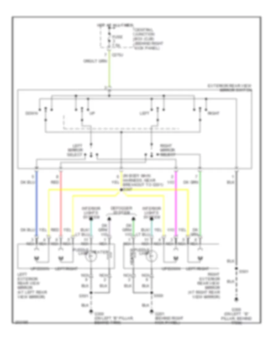
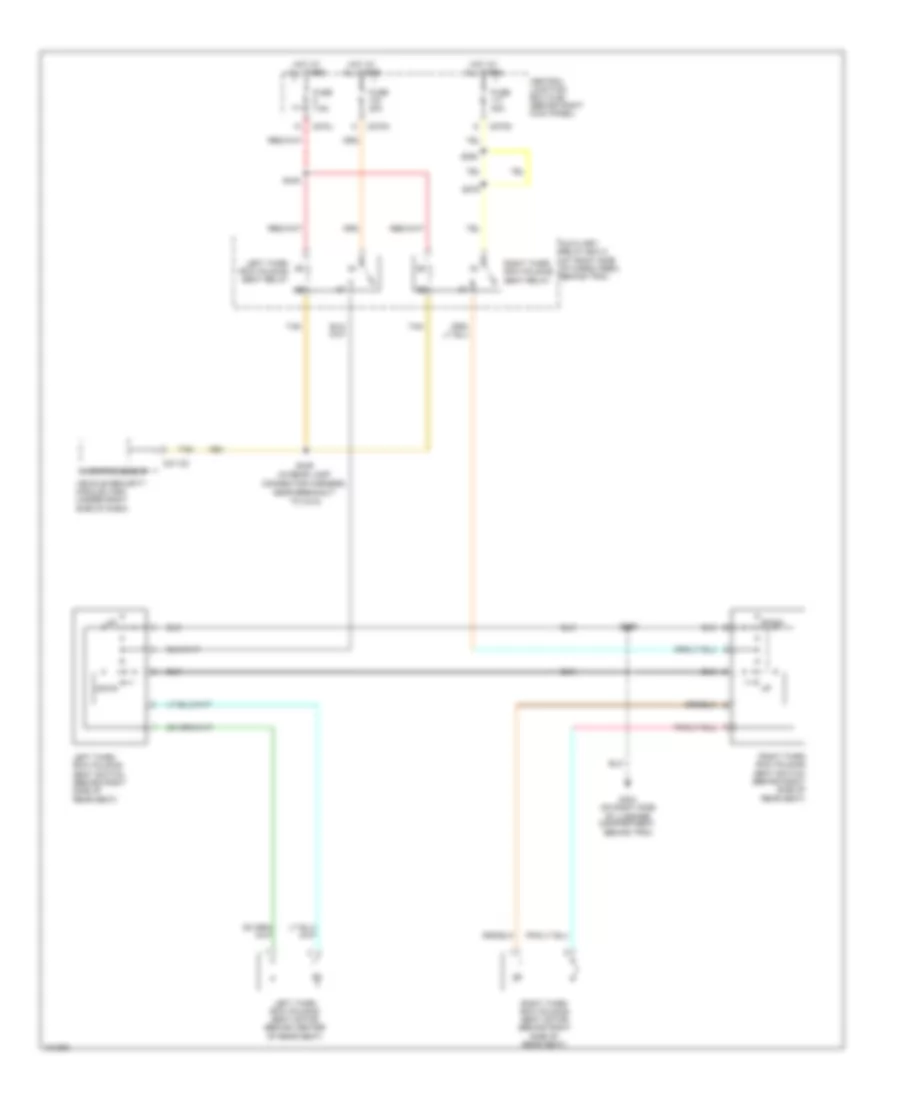
Memory Mirrors Wiring Diagram for Ford Expedition 2005
List of elements for Memory Mirrors Wiring Diagram for Ford Expedition 2005:
- (behind right kick panel) g201
- (in body main harness, near breakout to center console) s305
- (in body main harness, near breakout to passenger seat belt buckle)
- (on left "b" pillar, behind trim) g300
- Adjustable pedal circuit
- C270j
- C341c
- C341d
- Central junction box (cjb) (behind right kick panel)
- Computer data lines system
- Defogger system
- Down
- Driver seat module (under driver's seat)
- Exterior lights system
- Exterior rear view mirror switch
- Fold in
- Fold in /fold out
- Fold in/ fold out
- Fold out
- Fold req
- Fuse 7.5a
- G301 (behind left kick panel)
- Hot at all times
- Interior lights system
- L/r sense
- Left
- Left exterior rear view mirror (at left rear view mirror)
- Left heated mirror
- Left mirror down feed
- Left mirror feed
- Left mirror feed up
- Left mirror l/r mtr
- Left mirror select
- Left mirror up/dn mtr
- Left/ right
- Left/right motor
- Mc can +
- Mc can -
- Nca
- Power mirror switch
- Puddle lamp
- Red
- Right
- Right exterior rear view mirror (at right rear view mirror)
- Right heated mirror
- Right mirr up/dn mtr
- Right mirror down feed
- Right mirror feed
- Right mirror l/r mtr
- Right mirror left feed
- Right mirror right feed
- Right mirror select
- Right mirror up feed
- S304 (in body main harness, near breakout to center console)
- S346
- S376
- S377
- S380
- S501
- S600
- Sig rtn
- Turn signal
- Up/dn
- Up/dn motor
- Up/down motor
- Up/down sense
- Vref
NAVIGATION
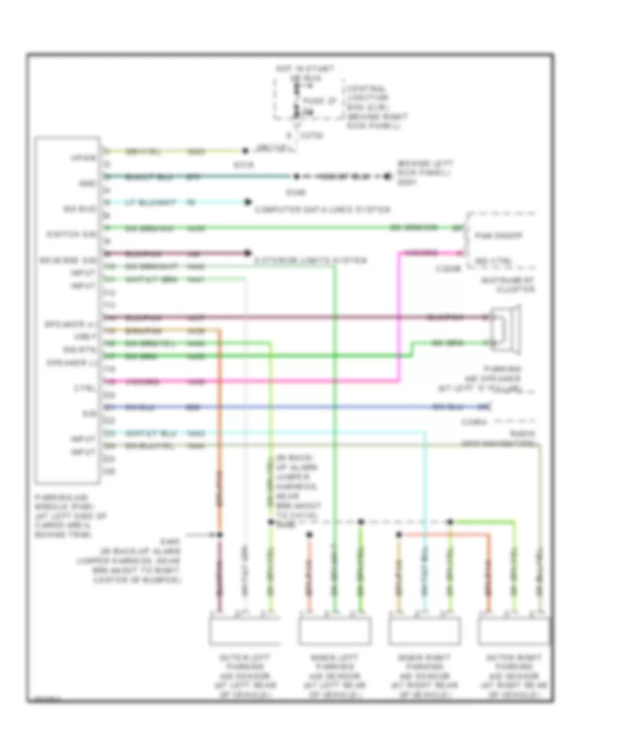
Parking Assistant Wiring Diagram for Ford Expedition 2005
List of elements for Parking Assistant Wiring Diagram for Ford Expedition 2005:
- (behind left kick panel) g301
- (in back- up alarm jumper harness, near breakout to c4110) s440
- C220b
- C240a
- C270j
- Central junction box (cjb) (behind right kick panel)
- Computer data lines system
- Ctrl
- Exterior lights system
- Fuse 27 5a
- Gnd
- Hot in start or run
- Ind ctrl
- Inner left parking aid sensor (at left rear of vehicle)
- Inner right parking aid sensor (at right rear of vehicle)
- Input
- Instrument cluster
- Iso bus
- Outer left parking aid sensor (at left rear of vehicle)
- Outer right parking aid sensor (at right rear of vehicle)
- Pam on/off
- Parking aid module (pam) (at left side of cargo area, behind trim)
- Parking aid speaker (at left "c" pillar)
- Radio (w/o navigation)
- Reverse sig
- S318
- S346
- S445 (in back-up alarm jumper harness, near breakout to right center of bumper)
- Sig
- Sig rtn
- Speaker (+)
- Speaker (-)
- Switch sig
- Vpwr
- Vref
POWER DISTRIBUTION
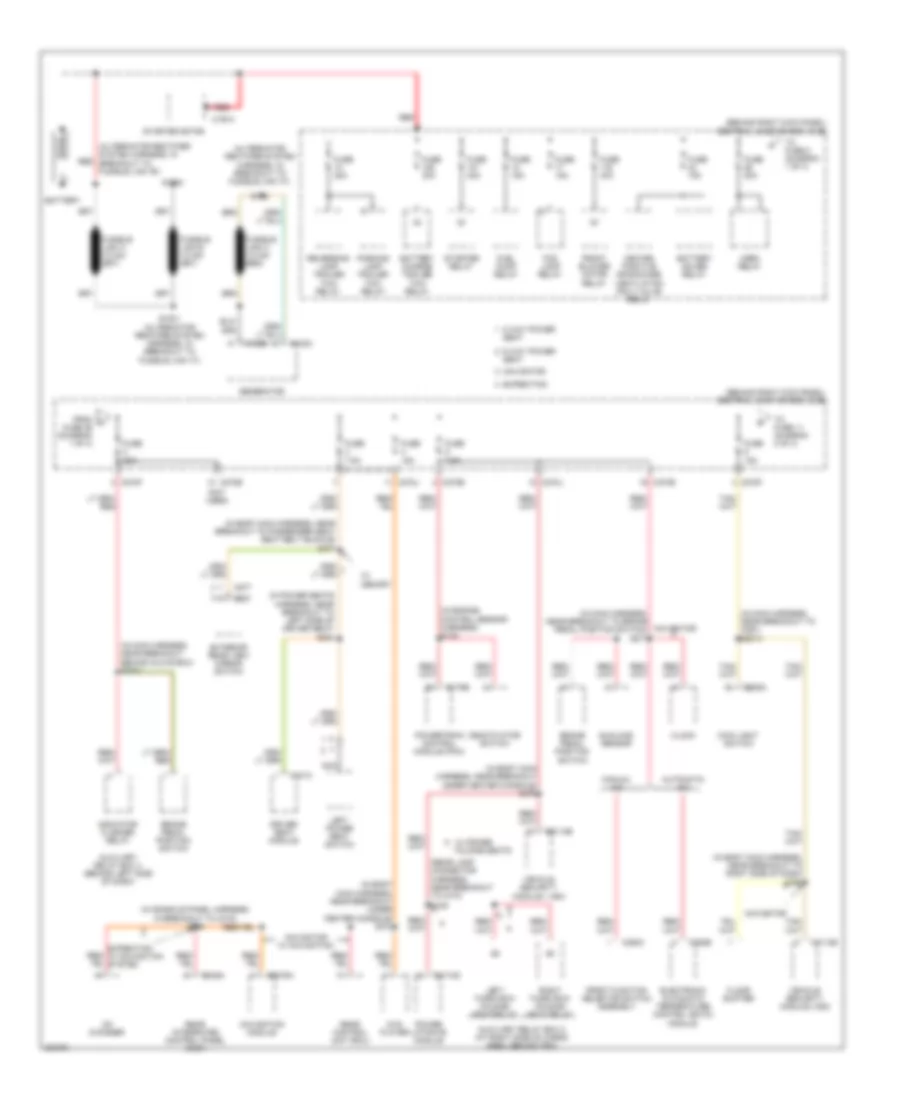
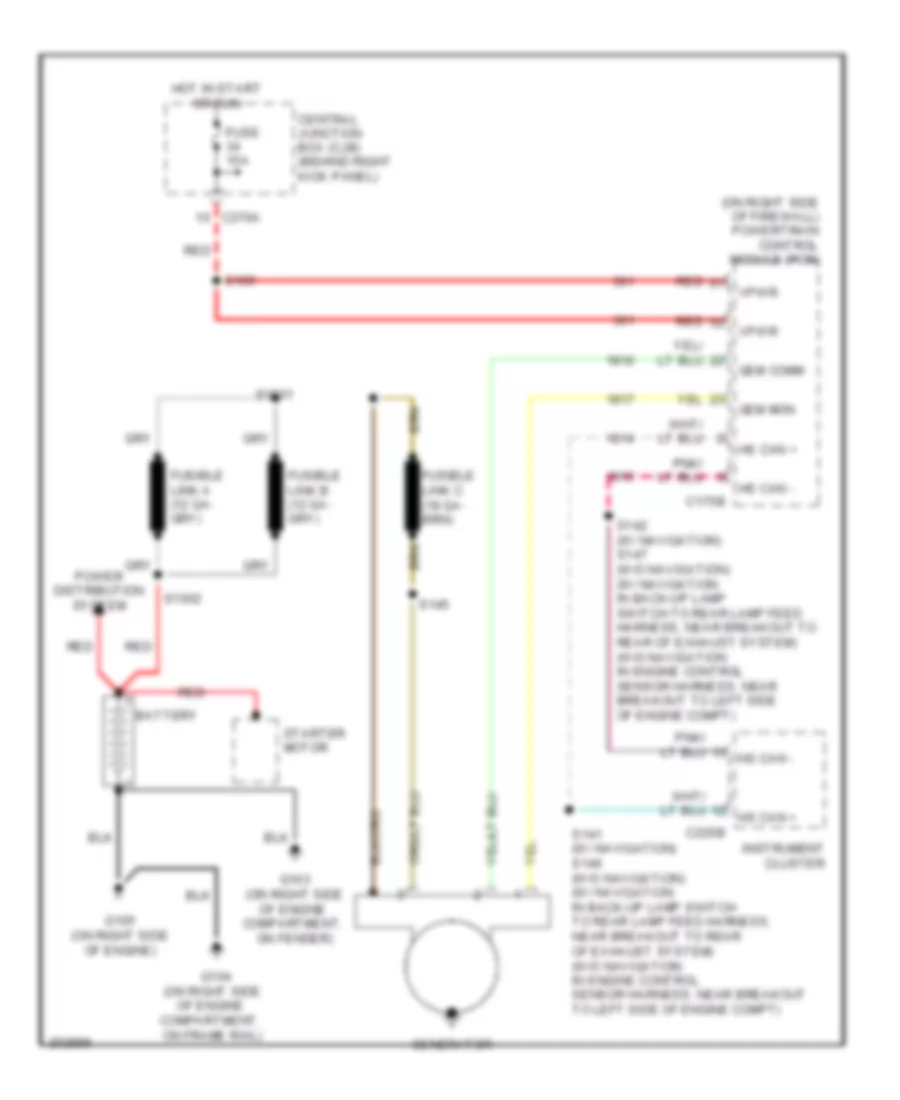
Power Distribution Wiring Diagram (1 of 4) for Ford Expedition 2005
List of elements for Power Distribution Wiring Diagram (1 of 4) for Ford Expedition 2005:
- (alternator rectifier system harness, in breakout to fusible link "b")
- (alternator rectifier system harness, in breakout to fusible link "c")
- (behind right kick panel) central junction box (cjb)
- (in body main harness, near breakout to passenger seat seat belt buckle) s377
- (in body main harness, near breakout to right side of dash) s392
- (in body main harness, near breakout under center console) s372
- (in body main harness, near breakout under center console) s379
- (in console panel harness, in breakout to c315) s388
- (in engine control sensor harness) s133
- (in main harness, near breakout behind glove box) s2001
- (in main harness, near breakout to brake pedal position switch) s277
- (in main harness, near breakout to c291) s2013
- (in power seats harness, near breakout to left side of driver seat) s384
- (not used)
- (rear lamp connector harness, near breakout to c410)
- 6 way power seat
- 8 way power seat
- Automatic a/c
- Auxiliary relay box 2 (at right side of cargo area, behind trim)
- Auxiliary relay box 3 (behind left side of dash)
- Battery
- Battery charge trailer tow relay
- Battery saver relay
- Brake pedal position switch
- C102a
- C102b
- C175b
- C197a
- C205a
- C2113b
- C2279a
- C228b
- C270b
- C270e
- C270f
- C270j
- C294c
- C341c
- C349a
- C4174d
- C527
- C577
- Cd changer
- Clock
- Deactivator switch
- Driver seat module
- Dvd player
- Electronic automatic temperature control (eatc) module
- Expedition
- Exterior rear view mirror switch
- Floor shifter
- Fog lamp relay
- From a fuse 26 (diagram 1 of 4)
- Front blower motor relay
- Front function selector switch assembly
- Fuel pump relay
- Fuse 15a
- Fuse 20a
- Fuse 30a
- Fuse 40a
- Fuse 7.5a
- Generator
- Heated positive crankcase ventilation (pcv) valve relay
- Horn relay
- Indicator flasher relay
- Left power seat switch
- Left third row folding seat relay
- Main light switch
- Manual a/c
- Navigation module
- Navigator
- Navigator w/ navigation
- Nca
- Parking lamp trailer tow relay
- Power liftgate module
- Powertrain control module (pcm)
- Rear control unit (rcu)
- Rear integrated control panel (ricp)
- Red
- Reversing lamp trailer tow relay
- Right third row folding seat relay
- S1001 (alternator rectifier system harness, in breakout to fusible link "c")
- S1002
- S145
- S448
- Starter motor
- Starter relay
- Sunload sensor
- To fuse 11 (diagram 2 of 4)
- To fuse 2 (diagram 1 of 4)
- Vehicle security module ( vsm)
- Vehicle security module (vsm)
- W/ memory
- W/ power folding seats
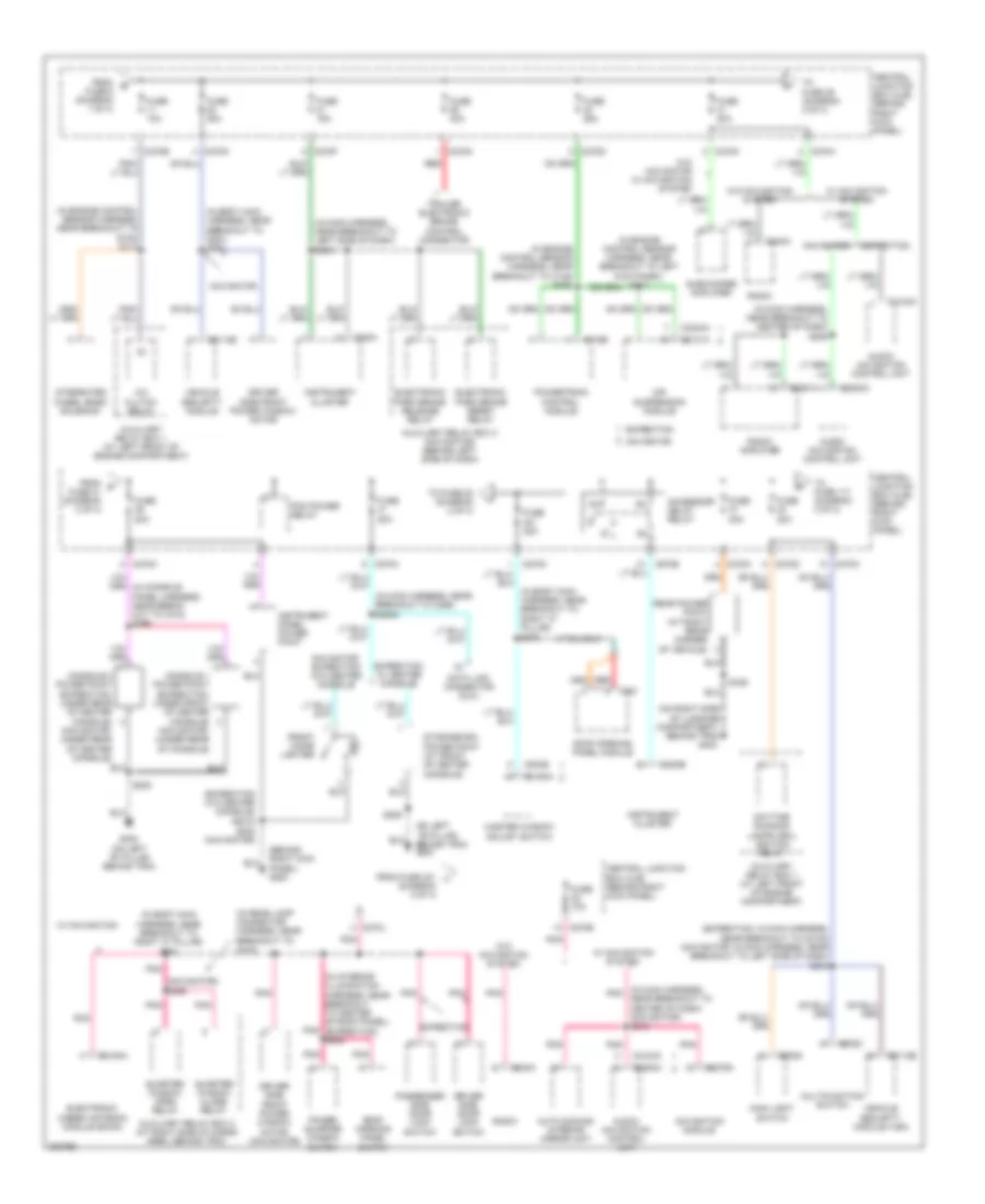
Power Distribution Wiring Diagram (2 of 4) for Ford Expedition 2005
List of elements for Power Distribution Wiring Diagram (2 of 4) for Ford Expedition 2005:
- (behind right kick panel) g200
- (expedition w/o center console) s2018
- (expedition: in main harness, near breakout to c2108) (navigator: in main harness, near breakout to left side of dash) s212
- (in body main harness, near breakout to g201) s391
- (in body main harness, near breakout to right "c" pillar)
- (in body main harness, near breakout to right "c" pillar) s381
- (in engine control sensor harness, near breakout to c145) s152
- (in engine control sensor harness, near breakout to g102) s113
- (in engine control sensor harness, near breakout to left kick panel) s117
- (in interior illumination harness, near breakout to center of roof panel) pnk (expedition) s909
- (in main harness, near breakout to c256) s2005
- (in main harness, near breakout to center of dash) s206
- (in main harness, near breakout to left side of dash) s238
- (in main harness, pnk near breakout to center of dash) (navigator) s215
- (in rear lamp connector harness, near breakout to c410)
- (navigator) s455
- (on left ``b" pillar, behind trim) g300
- (on right side of luggage compartment, behind trim) g404
- A/c clutch relay
- Accessory delay relay
- Air suspension module
- Audio/ navigation control unit
- Auto dimming interior mirror unit
- Auxiliary relay box 1 (at left front of engine compartment)
- Auxiliary relay box 2 (at right side of cargo area, behind trim)
- Auxiliary relay box 3 (navigator) (behind left side of dash)
- C175b
- C202c
- C205a
- C2113b
- C2123a
- C2131a
- C220a
- C220b
- C2253a
- C2279a
- C2291a
- C2324a
- C240a
- C270b
- C270d
- C270e
- C270f
- C270g
- C270h
- C270j
- C270k
- C270m
- C3193a
- C4194a
- C504b
- C921
- Central junction box (cjb) (behind right kick panel)
- Console 1 power point (expedition: under front of center console) (navigator: (under rear of console)
- Console 2 power point (expedition: under rear of center console) (navigator: under rear of center console)
- Data link connector (dlc)
- Daytime running lamps (drl) ignition relay
- Driver side door lock switch
- Driver side front power window motor
- Driver side front power window motor (navigator)
- Electronic hidden antenna module (eham)
- Electronic park brake release relay
- Electronic park brake reset relay
- Expedition
- Expedition w/ center console
- From b fuse 6 (diagram 1 of 4)
- From c fuse 31 (diagram 2 of 4)
- From fuse 401 (diagram 2 of 4)
- Front cigar lighter
- Fuse 10a
- Fuse 15a
- Fuse 20a
- Fuse 25a
- Fuse 30a
- G300 (on left ``b" pillar, behind trim)
- Instrument cluster
- Instrument panel power point
- Integrated wheel ends solenoid
- Main light switch
- Master window adjust switch
- Multifunction switch
- Navigation module
- Navigator
- Navigator, expedition w/o center console
- Passenger side door lock switch
- Pcm power relay
- Pnk
- Power quarter window switch
- Powertrain control module
- Quarter window close relay
- Quarter window open relay
- Radio
- Radio amplifier
- Rear power point (at right rear corner of vehicle)
- Red
- Roof opening panel module
- Roof opening panel switch
- S202 (navigator)
- S205
- S370
- S436
- Storage bin power point (at front of center console)
- Subwoofer amplifier
- To fuse 117 (diagram 3 of 4)
- To fuse 22 (diagram 2 of 4)
- To fuse 39 (diagram 2 of 4)
- Trailer electronic brake control connector
- Vehicle security module
- Vehicle security module (vsm)
- W/ navigation
- W/ navigation system
- W/o navigation system
- W/o navigator w/ navigation system
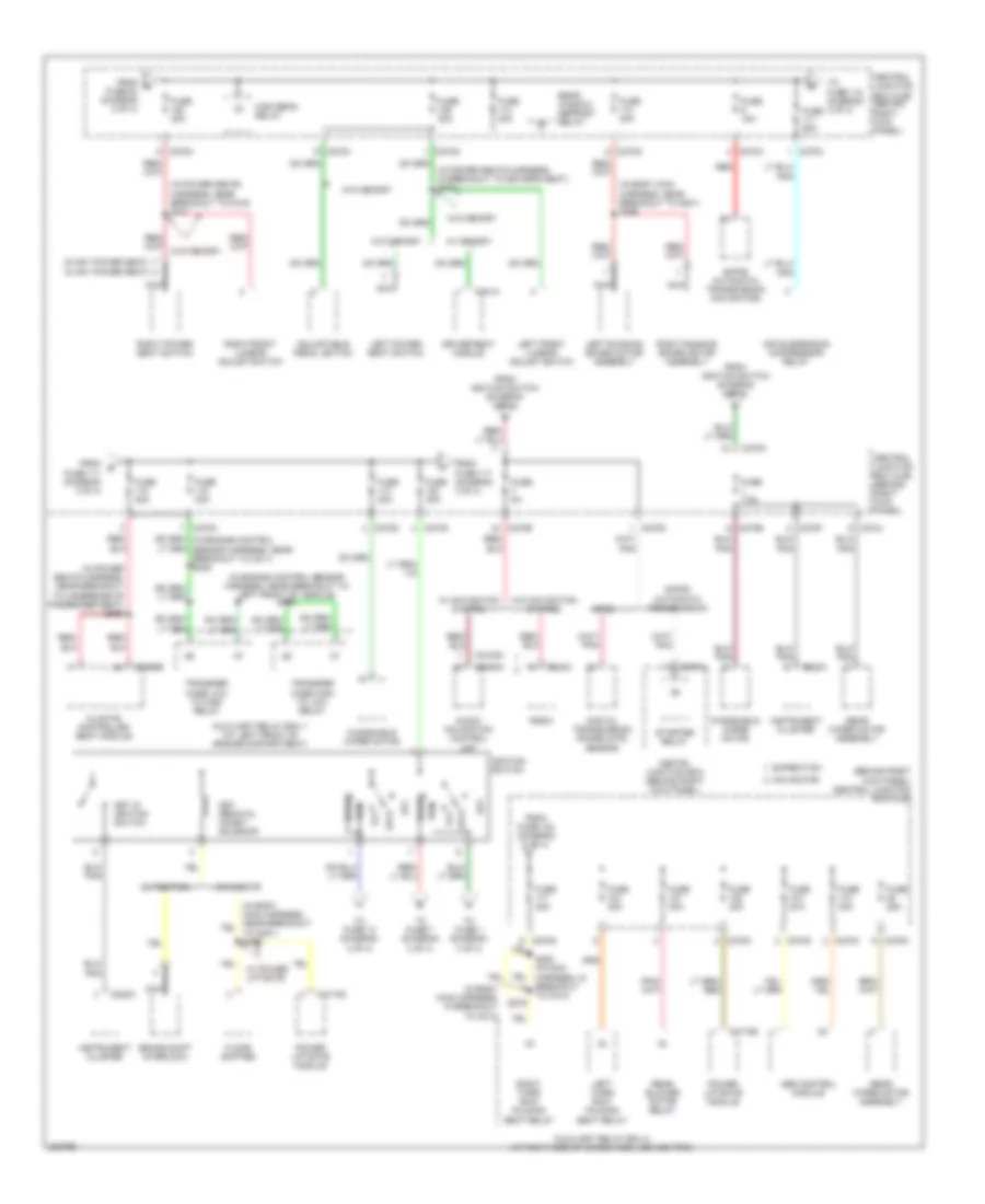
Power Distribution Wiring Diagram (3 of 4) for Ford Expedition 2005
List of elements for Power Distribution Wiring Diagram (3 of 4) for Ford Expedition 2005:
- (6 way power seat) (8 way power seat)
- (behind right kick panel) central junction box (cjb)
- (in body main harness, in breakout to c214)
- (in body main harness, near breakout to g301) s395
- (in engine control sensor harness, near breakout to left front of vehicle) s149
- (in power seats harness, in breakout to driver's seat) s310
- (in power seats harness, near breakout to c316) s311
- (in power seats harness, near breakout to underside of passenger seat) s360
- 4r75e
- 6hp26 automatic transmission
- 6hp26 automatic transmission (navigator)
- Abs control module
- Acc
- Adjustable pedal switch
- Air suspension compressor relay
- Audio/ navigation control unit
- Auxiliary relay box 1 (at left front of engine compartment)
- Auxiliary relay box 2 (at right side of cargo area, behind trim)
- Brake shift interlock
- C2123c
- C220a
- C2253a
- C240a
- C270a
- C270b
- C270c
- C270d
- C270e
- C270f
- C270g
- C270h
- C270j
- C270m
- C270n
- C3265b
- C341a
- C4174b
- C4174d
- Central junction box (cjb) (behind right kick panel)
- Centrl junction box (behind right kick panel)
- Climate controlled seat module
- Digital transmission range (dtr) sensor
- Driver seat module
- Expedition
- Floor shifter
- From d fuse 38 (diagram 2 of 4)
- From e fuse 111 (diagram 3 of 4)
- From fuse 102 (diagram 3 of 4)
- From fuse 117 (diagram 3 of 4)
- From ignition switch (diagram 3 of 4)
- Fuse 15a
- Fuse 25a
- Fuse 30a
- Fuse 40a
- Fuse 50a
- Fuse 5a
- Fuse 7.5a
- High beam relay
- Ignition switch
- Instrument cluster
- Key in ignition switch
- Key removal inhibit solenoid
- Left front lumbar adjust switch
- Left power seat switch
- Left running board motor assembly
- Left third row folding seat relay
- Lock
- Navigator
- Nca
- Off
- Power liftgate module
- Radio
- Rear blower motor relay
- Rear window defrost relay
- Rear wiper motor assembly
- Red
- Right front lumbar adjust switch
- Right power seat switch
- Right running board motor assembly
- Right third row folding seat relay
- Run
- S279
- S280 (in main harness, in breakout to c214)
- Start
- Starter relay
- To fuse 1 (diagram 3 of 4)
- To fuse 118 (diagram 3 of 4)
- To fuse 13 (diagram 4 of 4)
- To fuse 7 (diagram 3 of 4)
- Transfer case high to low relay
- Transfer case low to high relay
- W/ memory
- W/ navigation system
- W/ power liftgate
- W/o memory
- W/o navigation system
- Windshield wiper motor
Power Distribution Wiring Diagram (4 of 4) for Ford Expedition 2005
List of elements for Power Distribution Wiring Diagram (4 of 4) for Ford Expedition 2005:
- (behind right kick panel) central junction box (cjb)
- (expedition)
- (in body main harness, near breakout to center console) s320
- (in body main harness, near breakout to right "c" pillar) s319
- (in console panel harness, in breakout to center of dash)
- (in engine control sensor & fuel charge harness, near breakout to heated oxygen sensor 21) s124
- (in engine control sensor & fuel charge harness, near breakout to right cylinder head) s132
- (in main harness, at breakout to right side of dash) s221
- (in main harness, near breakout to right side of dash) s241
- (navigator)
- (not used)
- 4r75e
- 6hp26 automatic transmission
- Abs control module
- Air suspension module
- At breakout to right side of dash) s228
- Auto-dimming interior mirror unit (except navigator w/ navigator)
- Auxiliary relay box 1 (at left front of engine compt)
- Auxiliary relay box 3 (behind left side of dash)
- Battery charge trailer tow relay
- Brake shift interlock
- C2131a
- C220a
- C228a
- C2324a
- C270b
- C270d
- C270e
- C270f
- C270g
- C270j
- C294b
- C294c
- C310a
- C4014b
- C989b
- Central junction box (cjb) (behind right kick panel)
- Coil on plug (cop) 1
- Coil on plug (cop) 2
- Coil on plug (cop) 3
- Coil on plug (cop) 4
- Coil on plug (cop) 5
- Coil on plug (cop) 6
- Coil on plug (cop) 7
- Coil on plug (cop) 8
- Daytime running lamps (drl) ignition relay
- De-icing switch
- Digital transmission range (dtr) sensor
- Electronic automatic temperature control (eatc) module
- Electronic compass
- Electronic park brake release relay
- Electronic park brake reset relay
- Expedition
- Floor shifter (navigator)
- From fuse 27 k (diagram 4 of 4)
- From ignition switch (diagram 3 of 4)
- From j fuse 16 (diagram 4 of 4)
- Front auxiliary function selector switch assembly
- Front function selector switch assembly
- Fuse 10a
- Fuse 5a
- Fuse pump relay
- Heated positive crank case ventilation valve relay
- Ignition transformer capacitor 1
- Ignition transformer capacitor 2
- Indicator flasher relay
- Instrument cluster
- Navigator
- Nca
- Overdrive cancel switch (expedition)
- Parking aid module (pam)
- Passive anti-theft transceiver
- Pcm power diode
- Pcm power relay
- Rear blend door actuator
- Rear window defrost relay
- Restraints control module
- Reversing lamps relay
- S129 (in engine control sensor & fuel charge harness, near breakout to right cylinder head)
- S282 (in main harness, near breakout to center of dash)
- S387
- Tan/ red
- Temperature blend door actuator
- To fuse 18 (diagram 4 of 4)
- To fuse 19 (diagram 4 of 4)
- Traction control switch
- W/ drl
- W/ eatc
- W/ manual a/c
POWER DOOR LOCKS
Power Door Locks Wiring Diagram for Ford Expedition 2005
List of elements for Power Door Locks Wiring Diagram for Ford Expedition 2005:
- (behind right kick panel) g201
- (expedition) (navigator)
- (in body main harness, (near breakout to left ``c" pillar s313
- (in body main harness, near breakout to c214)
- (in right rear window regulator control switch & wiring assembly, near breakout to liftgate) s465
- (navigator) (expedition)
- (near breakout to g201)
- (on left ``b" pillar, behind trim) g300
- (or pnk)
- 1/2
- 3/4
- 5/6
- 7/8
- 9/0
- Air conditioning system
- C2113a
- C2113b
- C2113c
- C270f
- C270h
- C270j
- C270k
- Central junction box (cjb) (behind right kick panel)
- Computer data lines system
- Door lock relay
- Driver door unlock relay
- Driver side door lock switch
- Driver side rear door ajar switch (at rear of left
- Exterior lights
- Fuse 15a
- Fuse 20a
- Fuse 30a
- Fuse 7.5a
- G201 (behind right kick panel)
- G300 (on left "b" pillar, behind trim)
- G300 (on left ``b" pillar, behind trim)
- G402 (on left side of luggage compartment, behind trim)
- Headlamp relay
- Headlights system
- Horns system
- Hot at all times
- Illumination
- Interior lights system
- Key pad switch assembly
- Left front door ajar switch (at rear of left front door)
- Left front door lock actuator (at rear of left front door)
- Left rear door lock actuator (at rear of left rear door)
- Liftgate ajar switch (in center bottom of liftgate)
- Liftgate glass actuator (in liftgate)
- Liftgate glass release relay
- Liftgate glass release switch
- Liftgate lock actuator (in liftgate)
- Lock
- Microprocessor
- Navigator
- Nca
- Park lamp relay
- Passenger side door lock switch
- Passenger side rear door ajar switch (at rear of right
- Power windows system
- Rear door)
- Red/ pnk
- Right front door ajar switch (at rear of right front door)
- Right front door lock actuator (at rear of right front door)
- Right rear door lock actuator (at rear of right rear door)
- S2013 (expedition) s392 (navigator)
- S212
- S314 (near breakout to c328)
- S343 (near breakout to g201)
- S344
- S356
- S358
- S359
- S379
- S391
- S402
- S501
- S506
- S600
- S700
- S800 (navigator)
- Seats system
- System
- Tan
- Trunk, tailgate, fuel doors system
- Unlock
- Vehicle security module (vsm) (under right side of dash)
- W/ power liftgate
- W/o power liftgate
- Wiper/ washer system
POWER MIRRORS
Electronic Day/Night Mirror Wiring Diagram for Ford Expedition 2005
List of elements for Electronic Day/Night Mirror Wiring Diagram for Ford Expedition 2005:
- (in body main harness, near breakout to c328)
- (in main harness, near breakout to top of dash)
- (w/ drl)
- Auto dimming interior mirror unit
- C270b
- C270e
- Central junction box (cjb) (behind right kick panel)
- Digital transmission range (dtr) sensor (on left side of transmission)
- Exterior lights system
- Fuse 10a
- G301 (behind left kick panel)
- Ground
- Hot in run or start
- Reverse sense
- S122
- S220
- S228
- S317
- S915
- Sound systems
- Vpwr
- W/ navigation system
Power Mirrors Wiring Diagram for Ford Expedition 2005
List of elements for Power Mirrors Wiring Diagram for Ford Expedition 2005:
- (in body main
- C270j
- Central junction box (cjb) (behind right kick panel)
- Defogger system
- Down
- Exterior rear view mirror switch
- Fuse 7.5a
- G201 (behind right kick panel)
- G300 (on left "b" pillar, behind trim)
- G300 (on left ``b" pillar, behind trim)
- Heater
- Hot at all times
- Interior lights system
- Left
- Left exterior rear view mirror (at left rear view mirror)
- Left mirror select
- Left/right
- Nca
- Puddle lamp
- Red
- Right
- Right exterior rear view mirror (at right rear view mirror)
- Right mirror select
- S501
- S600
- Up/down
POWER SEATS
Adjustable Pedal Wiring Diagram for Ford Expedition 2005
List of elements for Adjustable Pedal Wiring Diagram for Ford Expedition 2005:
- Adjustable pedal motor (on accelerator pedal support)
- Adjustable pedal switch
- C270h
- Central junction box (cjb) (behind right kick panel)
- Fuse 30a
- Fwd
- G200 (behind right kick panel)
- Hot at all times
- Interior lights system
- Red
- Rwd
- S201
Driver Power Seat Wiring Diagram for Ford Expedition 2005
List of elements for Driver Power Seat Wiring Diagram for Ford Expedition 2005:
- C270m
- Central junction box (cjb) (behind right kick panel)
- Driver seat front height motor (under driver seat)
- Driver seat horizontal motor (under driver seat)
- Driver seat rear height motor (under driver seat)
- Entire seat
- Front of seat
- Fuse 30a
- Fwd rwd
- G300 (on left ``b" pillar, behind trim)
- Hot at all times
- Left power seat switch
- Nca
- Rear of seat
- S310 (w/ power lumbar)
- S316
- Up down
Heated Seats Wiring Diagram for Ford Expedition 2005
List of elements for Heated Seats Wiring Diagram for Ford Expedition 2005:
- (behind right kick panel) g201
- (under passenger seat)
- C270m
- C3265a
- C3265b
- Central junction box (cjb) (behind right kick panel)
- Climate controlled seat module
- Computer data lines system
- Driver side climate controlled seat backrest element (under driver seat)
- Driver side climate controlled seat fan (under driver seat)
- Fan sig
- Fuse 30a
- Gnd
- Heater +
- Heater -
- Hot at all times
- Motor +
- Motor -
- Ms can+
- Ms can-
- Nca
- Passenger side climate controlled seat backrest element (under passenger seat)
- Passenger side climate controlled seat cushion element (under passenger seat)
- Passenger side climate controlled seat fan
- Red
- S329
- S360
- Sig rtn
- Vbatt
- Vref
Passenger Power Seat Wiring Diagram for Ford Expedition 2005
List of elements for Passenger Power Seat Wiring Diagram for Ford Expedition 2005:
- (under passenger seat)
- C270m
- Central junction box (cjb) (behind right kick panel)
- Down
- Entire seat
- Front of seat
- Fuse 30a
- Fwd rwd
- G201 (behind right kick panel)
- Hot at all times
- Nca
- Passenger seat front height motor (under passenger seat)
- Passenger seat horizontal motor
- Passenger seat rear height motor
- Rear of seat
- Right power seat switch
- S311 (w/ power lumbar)
- S329
Third Row Folding Seat Wiring Diagram for Ford Expedition 2005
List of elements for Third Row Folding Seat Wiring Diagram for Ford Expedition 2005:
- Auxiliary relay box 2 (at right side of cargo area, behind trim)
- C2113c
- C270g
- C270j
- C270n
- Central junction box (cjb) (behind right kick panel)
- Connector harness,
- Down
- Fuse 30a
- Fuse 7.5a
- G404 (on right side of luggage compartment, behind trim)
- Hot at all times
- Left third row folding seat motor (behind center of rear seat)
- Left third row folding seat relay
- Left third row folding seat switch (behind right side of rear seat)
- Microprocessor
- Near breakout to c410)
- Right third row folding seat motor (behind right side of rear seat)
- Right third row folding seat relay
- Right third row folding seat switch (behind right side of rear seat)
- S279
- S280
- S436
- S448
- S449 (in rear lamp
- Tan
- Vehicle security module (vsm) (under right side of dash)
POWER TOP/SUNROOF
Power Top/Sunroof Wiring Diagram for Ford Expedition 2005
List of elements for Power Top/Sunroof Wiring Diagram for Ford Expedition 2005:
- Accessory delay relay
- C220b
- C270e
- C270n
- Central junction box (cjb) (behind right kick panel)
- Circuit breaker 30a
- Down/ open
- Expedition
- G404 (on right side of luggage compartment, behind trim)
- Gnd
- Hot at all times
- Instrument cluster
- Interior lights system
- Navigator
- Red
- Roof opening panel module (in roof panel)
- Roof opening panel switch
- S370
- S901
- S904
- Sig rtn
- Tan/ red
- Up/ close
- Vpwr
- Vref
POWER WINDOWS
Power Windows Wiring Diagram for Ford Expedition 2005
List of elements for Power Windows Wiring Diagram for Ford Expedition 2005:
- (in body main harness, near breakout to center console)
- (on right side of luggage compt, behind trim) g404
- (rear lamp connector harness, near breakout to c410)
- (rear lamp connector harness, near breakout to c410) s446
- Accessory delay relay
- C220b
- C270e
- C270j
- C270n
- C504a
- C504b
- Central junction box (cjb) (behind right kick panel)
- Circuit breaker 30a
- Close
- Driver side front power window motor (at rear of left front door)
- Driver switch
- Fuse 10a
- G404 (on right side of luggage compt, behind trim)
- Hot at all times
- Instrument cluster
- Left rear power window motor (at rear of left rear door)
- Left rear switch
- Left rear window adjust switch
- Left side rear quarter window motor (at left rear quarterpanel)
- Lock
- Master window adjust switch
- One- touch down
- Open
- Passenger side front power window motor (at rear of right front door)
- Passenger switch
- Pnk
- Power quarter window switch
- Right rear power window motor (at rear of right rear door)
- Right rear switch
- Right rear window adjust switch
- Right side front power window switch
- Right side rear quarter window motor (at right rear quarterpanel)
- S321
- S370
- S381
- S447
- S506
- S904
- ``b" pillar, behind trim) g300
RADIO
Radio Wiring Diagram, with Navigation (1 of 2) for Ford Expedition 2005
List of elements for Radio Wiring Diagram, with Navigation (1 of 2) for Ford Expedition 2005:
- (at left side of engine compt) abs control module
- Acc relay
- Air bag sliding contact (under steering column)
- Antenna
- Audio ground
- Audio mute
- Audio sys on
- Audio/navigation control unit (behind center of dash)
- C175b
- C2123a
- C2123b
- C2123c
- C2123d
- C2123e
- C2123f
- C2123g
- C218b
- C270e
- C270h
- C270j
- C270m
- C4194a
- C4194b
- Central junction box (cjb) (behind right kick panel)
- Computer data lines system
- Cruise control system
- Electronic hidden antenna module (eham) (above right rear quarterpanel window)
- Exterior lights system
- Fuse 10a
- Fuse 15a
- Fuse 20a
- Fuse 5a
- G200 (behind right kick panel)
- G202 (behind left kick panel)
- Ground
- Hot at all times
- Hot in start
- Hot w/ accessory delay relay energized
- Illum ground
- Illum pwr
- Interior lights system
- L audio out +
- L audio out -
- Lf speaker +
- Lf speaker -
- Lr speaker +
- Lr speaker -
- Media
- Mute
- Nca
- Next
- Pnk
- Powertrain control module (pcm) (on right side of firewall)
- Protocol a
- Protocol b
- R audio out +
- R audio out -
- Red
- Reverse voltage
- Rf speaker +
- Rf speaker -
- Rr speaker +
- Rr speaker -
- S202
- S372
- S381
- Shield
- Sig
- Sig rtn
- Steering wheel radio switch
- Subwoofer +
- Subwoofer -
- Subwoofer amplifier (at left side of cargo area, behind trim)
- Sw sig
- Tan
- Vbatt
- Vehicle spd sig
- Vol+
- Vol-
- Vpwr
- Vss sig
Radio Wiring Diagram, with Navigation (2 of 2) for Ford Expedition 2005
List of elements for Radio Wiring Diagram, with Navigation (2 of 2) for Ford Expedition 2005:
- (in body main harness, near breakout to c260)
- (in breakout to c315)
- (in console panel harness, near breakout to center console)
- (on left "b" pillar, behind trim) g300
- Audio sys on
- C349a
- C349b
- Cd changer
- Computer data lines system
- Dvd player
- G202 (behind left kick panel)
- Ground
- Illum pwr
- Interior lights system
- L audio +
- L audio -
- L headph +
- L headph -
- L radio +
- L radio -
- L sig +
- L sig -
- Left front speaker
- Left out +
- Left out -
- Left rear speaker
- Left sig +
- Left sig -
- Lr speaker +
- Lr speaker -
- Nca
- Pnk
- Protocol a
- Protocol b
- R audio +
- R audio -
- R headph +
- R headph -
- R radio +
- R radio -
- R sig +
- R sig -
- Rear integrated control panel (ricp)
- Red
- Right front speaker
- Right out +
- Right out -
- Right rear speaker
- Right sig +
- Right sig -
- Rr speaker +
- Rr speaker -
- S205
- S283 (in main harness, near breakout to center of dash)
- S290
- S303 (in console panel harness, near break- out to c260)
- S325
- S326
- S327
- S328 (in body main harness, near breakout to center console)
- S388
- S389
- S390
- Shield
- Tan
- Vbatt
Radio Wiring Diagram, without Navigation with Center Console (1 of 2) for Ford Expedition 2005
List of elements for Radio Wiring Diagram, without Navigation with Center Console (1 of 2) for Ford Expedition 2005:
- (at left side of cargo area, behind trim) subwoofer amplifier
- (in body main harness, near breakout to left front door) (navigator) s503
- (in body main harness, near breakout to left front door) (navigator) s504
- (in body main harness, near breakout to right front door) (navigator) s602
- (or 235)
- Acc relay out
- Air bag sliding contact (under steering column)
- Antenna
- Audio ground
- Audio sys on
- Breakout to right front door) (navigator) s601
- C175b
- C218b
- C240a
- C240b
- C240c
- C240d
- C270e
- C270h
- C270j
- C270m
- Central junction box (cjb) (behind right kick panel)
- Computer data lines system
- Control
- Cruise
- Enable/clip
- Fuse 10a
- Fuse 15a
- Fuse 20a
- Fuse 5a
- G200 (behind right kick panel)
- G202 (behind left kick panel)
- Ground
- Hot at all times
- Hot in start
- Hot w/ accessory delay relay energized
- Illum ground
- Illumination
- Interior lights system
- Left dvd sig +
- Left dvd sig -
- Left front speaker
- Left front tweeter (navigator)
- Lf speaker +
- Lf speaker -
- Lr speaker +
- Lr speaker -
- Media
- Mute
- Navigation system
- Nca
- Next
- Pnk
- Power
- Powertrain control module (on right side of firewall)
- Protocol a
- Protocol b
- Radio
- Red
- Rf speaker +
- Rf speaker -
- Right dvd sig +
- Right dvd sig -
- Right front speaker
- Right front tweeter (navigator)
- Rr speaker +
- Rr speaker -
- S107 (near breakout to g102)
- S202
- S372
- S388
- Shield
- Sig rtn
- Steering wheel radio switch
- Subwoofer +
- Subwoofer -
- Sw sig
- System
- Tan
- Vbatt
- Vol +
- Vol -
- Vpwr
- Vss+
Radio Wiring Diagram, without Navigation with Center Console (2 of 2) for Ford Expedition 2005
List of elements for Radio Wiring Diagram, without Navigation with Center Console (2 of 2) for Ford Expedition 2005:
- (behind left kick panel)
- (expedition: in console panel harness, near breakout to center console) (navigator: in console panel harness, near breakout to rear control unit)
- (in main harness, near breakout to center of dash)
- (on left "b" pillar, behind trim)
- Audio sys on
- C349a
- Computer data lines system
- Dvd player
- G202
- G300
- Ground
- Illum ground
- Illum pwr
- Illumination
- Interior lights system
- L wireless +
- Left dvd sig -
- Left rear speaker
- Left sig +
- Left wireless -
- Lr speaker +
- Lr speaker -
- Pnk
- Protocol a
- Protocol b
- R wireless -
- Rear control unit (rcu)
- Rear integrated control panel (ricp)
- Red
- Right dvd sig -
- Right rear speaker
- Right sig +
- Rr speaker +
- Rr speaker -
- S205
- S283
- S290
- S389
- S390
- Shield
- Tan
- Vbatt
- W/dvd player
- W/o dvd player
Radio Wiring Diagram, without Navigation without Center Console for Ford Expedition 2005
List of elements for Radio Wiring Diagram, without Navigation without Center Console for Ford Expedition 2005:
- (behind left kick panel) g202
- (in engine control sensor harness, near breakout to g102) s107
- (on left "b" pillar, behind trim) g300
- (or 235)
- Acc delay rly
- Air bag sliding contact (under steering column)
- Antenna
- Audio ground
- C175b
- C218b
- C240a
- C240b
- C240d
- C270e
- C270h
- C270j
- Central junction box (cjb) (behind right kick panel)
- Computer data lines system
- Cruise control system
- Dvd player
- Fuse 10a
- Fuse 15a
- Fuse 20a
- Fuse 5a
- G200 (behind right kick panel)
- G202 (behind left kick panel)
- Ground
- Hot at all times
- Hot in start
- Hot w/ accessory delay relay energized
- Illum ground
- Illum pwr
- Illumination
- Interior lights system
- L headph +
- L headph -
- Left -
- Left dvd sig +
- Left dvd sig -
- Left front speaker
- Left rear speaker
- Left sig +
- Lf speaker +
- Lf speaker -
- Lr speaker +
- Lr speaker -
- Media
- Mute signal
- Navigation system
- Nca
- Next
- Pnk
- Powertrain control module (pcm) (on right side of firewall)
- Protocol a
- Protocol b
- R headph +
- R headph -
- Radio
- Radio signal
- Rear control unit (rcu)
- Red
- Rf speaker +
- Rf speaker -
- Right -
- Right dvd sig +
- Right dvd sig -
- Right front speaker
- Right rear speaker
- Right sig +
- Rr speaker +
- Rr speaker -
- S202
- S205
- S290
- S372
- S388 (expedition)
- Shield
- Sig rtn
- Steering wheel radio switch
- Tan
- Vbatt
- Vol +
- Vol -
- Vpwr
- Vss +
- Vss+
SHIFT INTERLOCK
Shift Interlock Wiring Diagram for Ford Expedition 2005
List of elements for Shift Interlock Wiring Diagram for Ford Expedition 2005:
- Acc
- Brake pedal position switch (on brake pedal support)
- Brake shift interlock (near steering column)
- C270e
- C270g
- Central junction box (cjb) (behind right kick panel)
- Fuse 30a
- Fuse 5a
- Fuse 7.5a
- G200 (behind right kick panel)
- Hot at all times
- Ignition switch
- Key removal inhibit solenoid
- Lock
- Microprocessor
- Nca
- Off
- Park
- Run
- S2003 (in main harness, near breakout to brake pedal position switch)
- S201
- S221
- S277
- Start
STARTING/CHARGING
Charging Wiring Diagram for Ford Expedition 2005
List of elements for Charging Wiring Diagram for Ford Expedition 2005:
- (on right side of firewall) powertrain control module (pcm)
- Battery
- C175b
- C220b
- C270a
- Central junction box (cjb) (behind right kick panel)
- Fuse 15a
- G103 (on right side of engine compartment, on fender)
- G104 (on right side of engine compartment, on frame rail)
- G105 (on right side of engine)
- Gem comm
- Gem mon
- Generator
- Hot in start or run
- Hs can +
- Hs can -
- Instrument cluster
- Power distribution system
- Red
- S1001
- S1002
- S109
- S141 (w/ navigation) s146 (w/o navigation) (w/ navigation: in back-up lamp switch to rear lamp feed harness, near breakout to rear of exhaust system) (w/o navigation: in engine control sensor harness, near breakout to left side of engine compt)
- S142 (w/ navigation) s147 (w/o navigation) (w/ navigation: in back-up lamp switch to rear lamp feed harness, near breakout to rear of exhaust system) (w/o navigation: in engine control sensor harness, near breakout to left side of engine compt)
- S145
- Starter motor
- Vpwr
Starting Wiring Diagram for Ford Expedition 2005
List of elements for Starting Wiring Diagram for Ford Expedition 2005:
- Acc
- Battery
- C175b
- C270a
- C270d
- C270g
- C270h
- Central junction box (cjb) (behind right kick panel)
- Charging circuit
- Digital transmission range (dtr) sensor (on left side of transmission)
- Expedition
- Fuse 30a
- G103 (on right side of engine compartment, on fender)
- G104 (on right side of engine compartment, on frame rail)
- G105 (on right side of engine)
- Ignition switch
- Lock
- Navigator
- Off
- Powertrain control module (pcm) (on right side of firewall)
- Red
- Run
- Start
- Starter motor
- Starter relay
- Tan/ red
SUPPLEMENTAL RESTRAINTS
Supplemental Restraints Wiring Diagram (1 of 2) for Ford Expedition 2005
List of elements for Supplemental Restraints Wiring Diagram (1 of 2) for Ford Expedition 2005:
- (behind left kick panel) g301
- A/blp
- Air bag ind ctrl
- Air bag stage 1+
- Air bag stage 1-
- Air bag stage 2+
- Air bag stage 2-
- C175b
- C220a
- C220b
- C270f
- C270j
- C310a
- C310b
- Central junction box (cjb) (behind right kick panel)
- Computer data lines system
- Connector (dlc) (under left side of dash)
- Data link
- Driver safety belt buckle switch (in driver safety belt buckle assembly)
- Driver safety belt pretensioner (in driver safety belt buckle assembly)
- Fuse 10a
- Fuse 5a
- Hot in run or start
- Instrument cluster
- Iso
- Left door safety canopy sensor (in bottom of left front door)
- Logic ground
- Nca
- Passenger safety belt buckle switch (in passenger safety belt buckle assembly)
- Passenger safety belt pretensioner (in passenger safety belt buckle assembly)
- Pin shorting bars engaged when module connector is disconnected from harness (shorting bars are connected between pins: 1-2, 3-4, 5-6 & 13-14 c310a 3-4 & 5-6 c310b
- Power train control module (pcm) (on right side of firewall)
- Rdi
- Red
- Ref/gnd
- Restraint control module (below center console)
- Right door safety canopy sensor (in bottom of right door)
- S282 (in main harness, near breakout to center of dash)
- S300 (expedition) (in body main harness, near breakout to center console)
- S308
- S308 (in body main harness, near breakout to restraints control module)
- S320 (in body main harness, near breakout to center console)
- Shorting bar
- Signal
- Signal +
- Signal -
- Tone driver
- Tone req
- Vpwr
- W/ safety canopy
Supplemental Restraints Wiring Diagram (2 of 2) for Ford Expedition 2005
List of elements for Supplemental Restraints Wiring Diagram (2 of 2) for Ford Expedition 2005:
- Air bag sliding contact (under steering column)
- C218a
- Driver air bag unit
- Driver seat position sensor (under driver's seat)
- Forward crash sensor (center front of engine compartment)
- Left c-pillar safety canopy sensor (w/ safety canopy) (at base of left "c" pillar)
- Left safety canopy (w/ safety canopy) (at left "c" pillar)
- Nca
- Passenger air bag module (behind right side of dash)
- Red
- Right c-pillar safety canopy sensor (w/ safety canopy) (at base of right "c" pillar)
- Right safety canopy (at right "c" pillar)
- Right safety canopy delete resistor (on right side of roof)
- Shorting bar
- Stage 1
- Stage 2
- W/ safety canopy
- W/o safety canopy
TRANSMISSION
4WD Wiring Diagram for Ford Expedition 2005
List of elements for 4WD Wiring Diagram for Ford Expedition 2005:
- (engine control sensor harness, near breakout to left front of vehicle)
- (in engine control sensor harness, near breakout to c145)
- (in engine control sensor harness, near breakout to left side of engine compt)
- (on right rear of engine compt)
- 87a
- All wheel drive
- Auxiliary relay box 1 (at left front of engine compt)
- C175b
- C175t
- C270b
- C270d
- C270m
- Central junction box (cjb) (behind right kick panel)
- Clutch coil pwr
- Computer data lines system
- Four-wheel drive switch
- Fuse 10a
- Fuse 25a
- Fuse 30a
- G100 (near left side of radiator)
- G102
- G200 (behind right kick panel)
- Ground
- High
- High speed can+
- High speed can-
- High to low relay ctrl
- Hot at all times
- Illum
- Integrated wheel ends solenoid (at right rear of engine compt)
- Interior lights system
- Low
- Low to high relay ctrl
- Magnetic clutch coil
- Off
- Pos 1
- Pos 2
- Pos 3
- Pos 4
- Pos rtn
- Position 1
- Position 2
- Position 3
- Position 4
- Powertrain control module (on right side of firewall)
- Red
- S104
- S108 (in engine control sensor harness, near breakout for c145)
- S113 (in engine control sensor harness, near breakout to g102)
- S149
- S152
- S202 (in main harness, near breakout to center of dash)
- Sig rtn
- Sol ctrl
- Transfer case assembly
- Transfer case high to low relay
- Transfer case low to high relay
- Vbatt
- Vref
A/T Wiring Diagram for Ford Expedition 2005
List of elements for A/T Wiring Diagram for Ford Expedition 2005:
- (engine control sensor & fuel charge harness, near breakout to left cylinder head) s127
- (in engine control sensor harness, near breakout for c145) s108
- (in main harness, at breakout to right side of dash) s221
- (in main harness, near breakout to glove box lamp)
- (not used)
- (on right rear of engine compt)
- 4r75e transmission control solenoids
- C175b
- C175e
- C175t
- C270a
- C270e
- C270f
- Central junction box (behind right kick panel)
- Digital transmission range (dtr) sensor (on left side of transmission)
- Electronic pressure control solenoid
- Engine controls system
- Epc solenoid ctrl
- Exterior lights system
- Fuse
- Fuse 32 15a
- G102
- G102 (on right rear of engine compt)
- G200 (behind right kick panel)
- Ground
- Hot at all times
- Hot in run or start
- Iat sens sig
- Maf sens sig
- Maf sens sig rtn
- Mass air flow/ intake air temperature (maf/iat) sensor (in intake system)
- Nca
- Od cancel sw
- Oss sens sig
- Output shaft speed (oss) sensor (on rear of transmission)
- Overdrive cancel switch
- Pcm power diode
- Pcm power relay
- Powertrain control module (on right side of firewall)
- Ref volt
- Rtn sig
- S128 (near breakout to rear of engine)
- S153 (near breakout to exhaust system, right side)
- Sens rtn
- Shift sol a ctrl
- Shift sol b ctrl
- Shift solenoids
- Sig rtn
- Starting/ charging system
- Tan/red
- Tcc solenoid ctrl
- Tft sens sig
- Throttle position sensor (tps) (on throttle body)
- Torque converter clutch solenoid
- Tps sig 1
- Tps sig 2
- Tr1
- Tr2
- Tr3a
- Tr4
- Transmission fluid temperature sensor
- Tss sens sig
- Turbine shaft speed (tss) sensor (at left side of transmission)
TRUNK, TAILGATE, FUEL DOOR
Trunk, Tailgate, Fuel Door Wiring Diagram for Ford Expedition 2005
List of elements for Trunk, Tailgate, Fuel Door Wiring Diagram for Ford Expedition 2005:
- (at left side of cargo area, behind trim) power liftgate module
- (in body main harness, near breakout to g301)
- (in breakout to left side of liftgate) s400
- (in rear lamp connector harn, near breakout to rear of roof)
- (in rear lamp connector harness, near breakout to trim panel at left side of loading area) s458
- (in right rear window regulator control switch & wiring assembly, near breakout to liftgate) s465
- (near breakout to c328) s394
- (on left "b" pillar behind trim) g300
- (on left side of luggage compt, behind trim) g401
- (on left side of luggage compt, behind trim) g402
- (on right side of luggage compt, behind trim) g404
- (under left side of vehicle) left running board motor assembly
- (under right side of vehicle) right running board motor assembly
- +/-
- 30a
- 7.5a
- C2113a
- C2113c
- C270g
- C270j
- C270n
- C4174a
- C4174b
- C4174c
- C4174d
- C997a
- C997b
- Central junction box (cjb) (behind right kick panel)
- Computer data lines system
- Deployed sensor
- Floor shifter
- Fuse
- G201 (behind right kick panel)
- G300 (on left "b" pillar, behind trim)
- G401 (on left side of luggage compt, behind trim)
- G402 (near breakout to rear window)
- Gnd
- Hot at all times
- Interior lights system
- Left liftgate drive motor assembly (at rear of roof)
- Left liftgate obstacle detection strip (at left rear of vehicle)
- Left r/b
- Liftgate chime module (in left side of liftgate)
- Liftgate cinching motor (in right side of liftgate)
- Liftgate fork bolt/detent switch (at center bottom of liftgate)
- Liftgate glass actuator (in liftgate)
- Liftgate home position switch (in right side of liftgate)
- Liftgate unlatch motor (in right side of liftgate)
- Microprocessor
- Motor
- Ms can+
- Ms can-
- Nca
- Optical sensor
- Power liftgate open/close switch
- Prb in
- Pwr
- Red
- Red/ pnk
- Right liftgate drive motor assembly (at rear of roof)
- Right liftgate obstacle detection strip (at lower right side of cargo area)
- Right r/b
- S205
- S316
- S356
- S369
- S395
- S402
- S414
- S448 (w/ power folding seats)
- S463
- S904
- S910
- S914
- Shift interlock system
- Sig rtn
- Stowed sensor
- Vbatt
- Vehicle security module (vsm) (under right side of dash)
- Vpwr
- Vref
- Wiper/ washer system
WARNING SYSTEMS
Key Reminder & Seat Belt Warning Wiring Diagram for Ford Expedition 2005
List of elements for Key Reminder & Seat Belt Warning Wiring Diagram for Ford Expedition 2005:
- (behind right kick panel) g201
- (in body main harness, near breakout passenger seat belt buckle) s301
- (in main harness, near breakout to break pedal position switch) (navigator) s2024
- (in main harness, near breakout to top of dash) s239
- (navigator)
- C205b
- C2113a
- C2113c
- C220a
- C220b
- C270f
- C270g
- C310a
- C310b
- C4174d
- Central junction box (cjb) (behind right kick panel)
- Data
- Driver safety belt buckle switch (in driver safety belt buckle assembly)
- Driver side rear door ajar switch (at rear of left rear door)
- Fuse 15a
- Fuse 30a
- Fuse 5a
- Fuse 7.5a
- G200 (behind right kick panel)
- G201 (behind right kick panel)
- G300 (on left "b" pillar, behind trim)
- G301 (behind left kick panel)
- G402 (on left side of luggage compartment, behind trim)
- Hot at all times
- Hot in run or acc
- Hot in start or run
- Ignition switch
- Instrument cluster
- Interior lights system
- Key in
- Left front door ajar switch (at rear of left front door)
- Liftgate ajar switch (in center bottom of liftgate)
- Liftgate glass actuator (in liftgate)
- Main light switch
- Message center switch
- Microprocessor
- Nca
- Passenger side rear door ajar switch (at rear of right rear door)
- Power liftgate module (at left side of cargo area, behind trim)
- Restraints control module (below center console)
- Right front door ajar switch (at rear of right front door)
- S201
- S238
- S240 (in main harness, near breakout to top of dash)
- S242 (expedition) (in main harness, near breakout to center of dash)
- S282
- S302 (in body main harness, near breakout passenger seat belt buckle)
- S308
- S356
- S402
- S506
- S600
- Vehicle security module (vsm) (under right side of dash)
- W/ power liftgate
- W/o power liftgate
WIPER/WASHER
Front Wiper/Washer Wiring Diagram for Ford Expedition 2005
List of elements for Front Wiper/Washer Wiring Diagram for Ford Expedition 2005:
- (in engine control sensor harness, near breakout to g102)
- (on left side of luggage compt, behind trim)
- 1. off 2. interval 1 3. interval 2 4. interval 3 5. interval 4 6. interval 5 7. low 8. high
- C175b
- C202a
- C220a
- C220b
- C270b
- C270d
- C270f
- C270m
- Central junction box (cjb) (behind right kick panel)
- Front & rear washer pump motor (on right side of engine compt, on washer fluid reservoir)
- Front washer pump relay
- Fuse 1 7.5a
- Fuse 113 30a
- Fuse 38 25a
- G100 (near left side of radiator)
- G101 (near right side of radiator)
- G200 (behind right kick panel)
- G301 (behind left kick panel)
- G402
- Hall sensor
- Hot at all times
- Hot in run or acc
- Instrument cluster
- Liftgate)
- Microprocessor
- Multi-function switch
- Park
- Powertrain control module (on right side of firewall)
- Rear wiper motor assembly (in
- Rear wiper relay
- Red
- Rest
- Run
- S104
- S106
- S107
- S116
- S201
- S402
- Vss +
- Washer fluid level switch (on right side of engine compartment, on washer fluid reservoir)
- Washer pump relay
- Washer switch
- Windshield wiper
- Windshield wiper motor (on left side of firewall)
- Wiper high/low relay
- Wiper run/park relay
Rear Washer/Wiper Wiring Diagram for Ford Expedition 2005
List of elements for Rear Washer/Wiper Wiring Diagram for Ford Expedition 2005:
- (in liftgate) rear wiper motor assembly
- (near left side of radiator)
- 1. off 2. on 3. rear washer 4. intermittent wipe
- C202a
- C270j
- C270m
- Central junction box (cjb) (behind right kick panel)
- Front & rear washer pump motor (on right side of engine compt, on washer fluid reservoir)
- Front washer pump relay
- Fuse 1 7.5a
- Fuse 38 25a
- G100
- G200 (behind right kick panel)
- G401 (on left side of luggage compt, behind trim)
- G402 (on left side of luggage compt, behind trim)
- Hot at all times
- Hot in run or acc
- Liftgate glass actuator (in liftgate)
- Microprocessor
- Multi-function switch
- Park
- Rear washer pump relay
- Rear wiper
- Rear wiper relay
- Red/ pnk
- Run
- S104
- S201
- S402
- S414 (w/o power liftgate)
- S463 (w/ power liftgate)
- Windshield wiper motor (on left side of firewall)