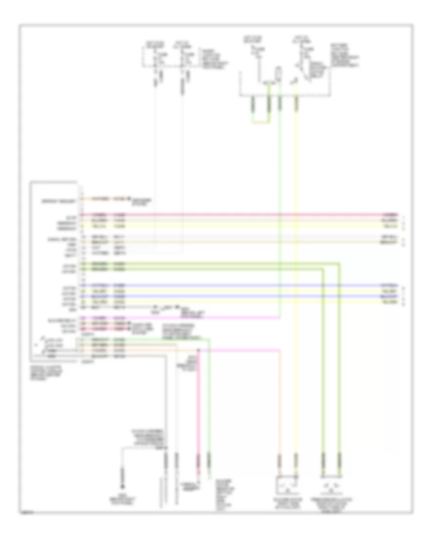
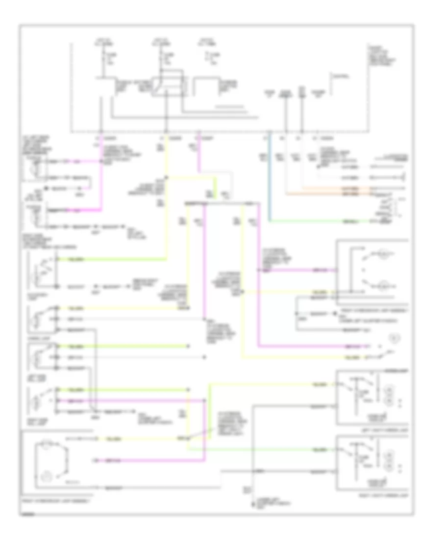
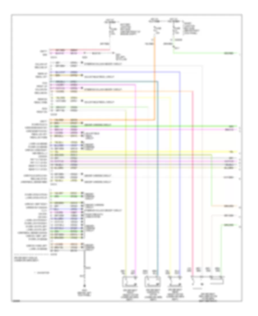
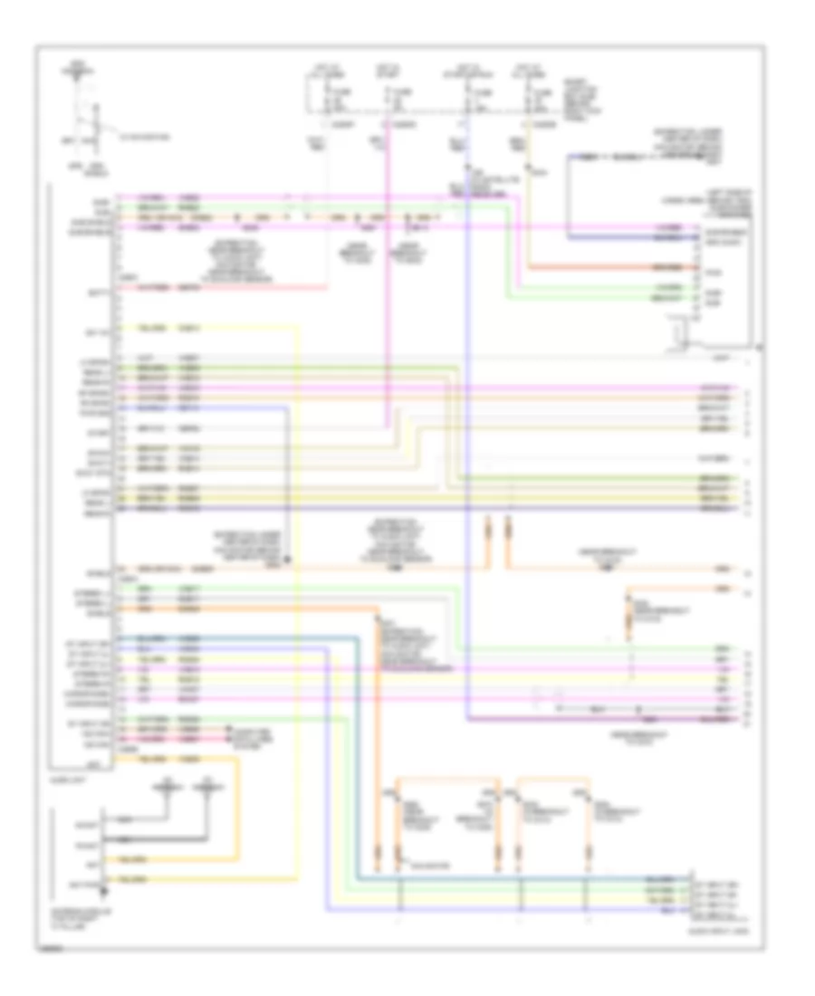
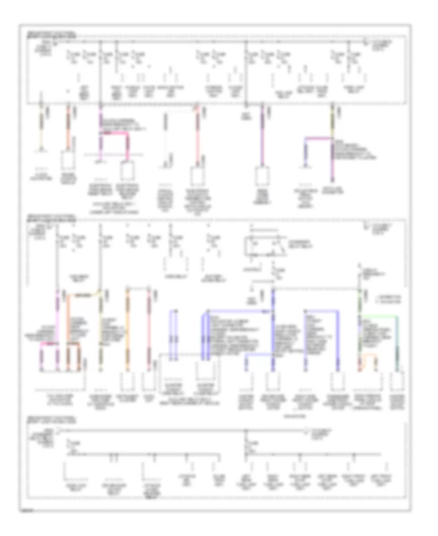
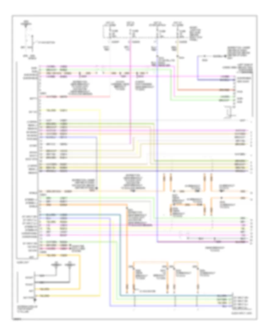
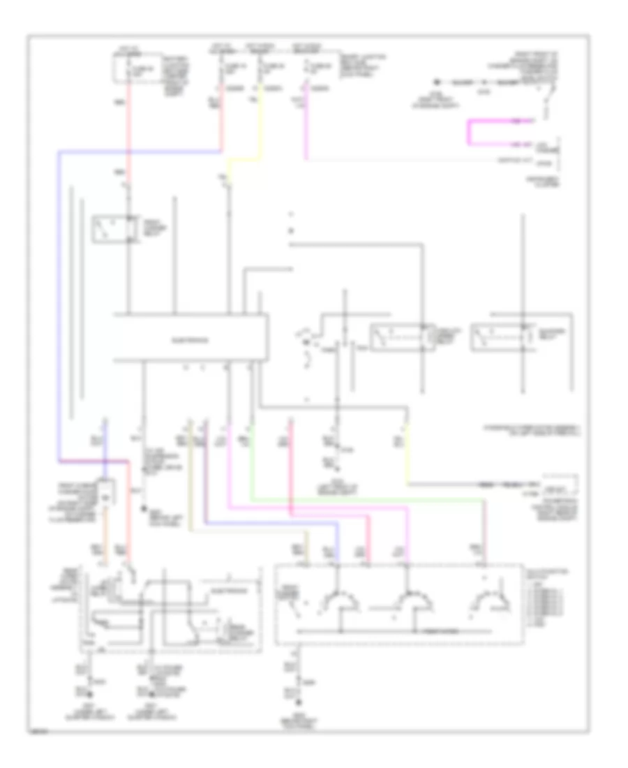
AIR CONDITIONING
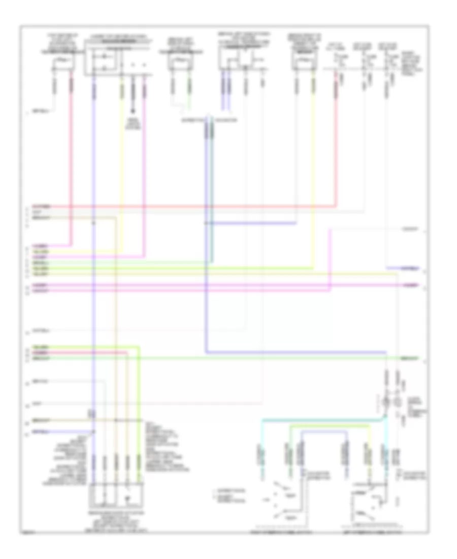
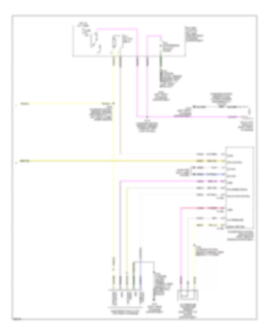
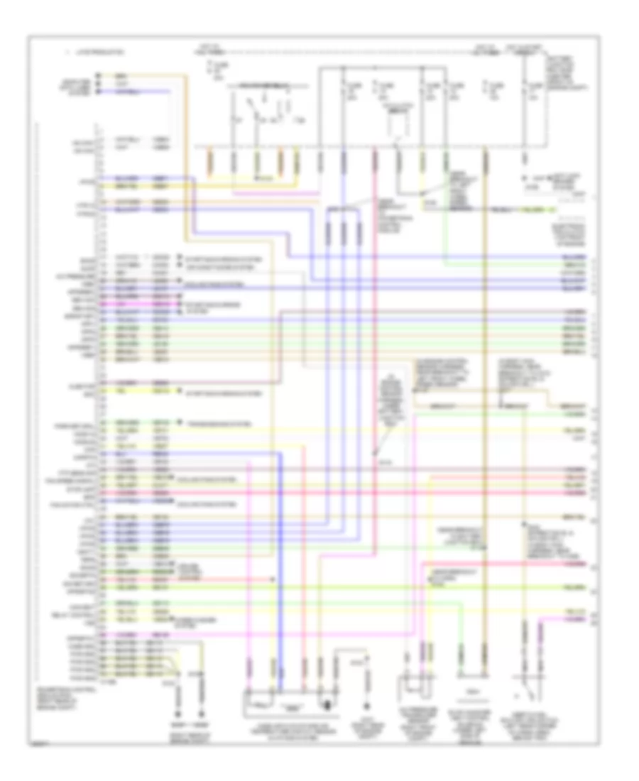
Automatic A/C Wiring Diagram, with Auxiliary Climate Control (1 of 3) for Ford Expedition EL 2007

List of elements for Automatic A/C Wiring Diagram, with Auxiliary Climate Control (1 of 3) for Ford Expedition EL 2007:
- (bottom left side of hvac unit) driver temperature blend door actuator
- (in console panel harness, near to satellite radio receiver) s349
- (in front heater blower motor harness, near breakout to c299) s217
- (left side of hvac unit) mode door actuator
- (near breakout to driver temperature blend door actuator) s220
- (near breakout to glove box light)
- (near breakout to instrument panel power point)
- (near breakout to passenger air bag module) s227
- (on left "b" pillar) g301
- (right side of hvac unit) fresh/ recirculation door actuator
- Ambient signal
- Battery junction box (bjb) (center front of engine compartment)
- Blower
- Blower motor (right side of hvac unit)
- Blower relay
- C228a
- C228b
- Cbp37
- Ch112
- Ch113
- Ch114
- Ch122
- Ch123
- Ch202
- Ch203
- Ch207
- Ch208
- Ch212
- Ch213
- Ch228
- Ch229
- Ch233
- Ch234
- Ch238
- Ch239
- Ch402
- Ch447
- Computer data lines system
- Defogger system
- Defrost request
- Driver sunload
- Electronic automatic temperature control (eatc) module (in center of dash)
- Evap
- Except expedition el
- Expedition el
- Feedback
- Front blower motor relay
- Fuse 10a
- Fuse 40a
- G200 (behind right kick panel)
- G203 (behind left kick panel)
- Gd113
- Gd138
- Gnd
- Heater blower motor control module (right side of hvac unit)
- Hot at all times
- Hot in on or start
- Humidity signal
- In-vehicle signal
- Interior lights system
- Lh111
- Lh115
- Mode/temp
- Motor+
- Motor-
- Ms can+
- Ms can-
- Passenger sunload
- Passenger temperature blend door actuator (top front of hvac unit)
- Rear auxiliary function switch assembly
- Rear mode door actuator (expedition el: left side of hvac unit) (except expedition el: top left side of hvac unit)
- Redundant cc signal
- Relay 1
- Relay 2
- Relay 3
- Rh111
- S219 (near breakout to passenger temperature blend door actuator)
- S222
- S223
- S228
- Sbp15
- Signal return
- Variable blower control
- Vbatt
- Vdb06
- Vdb07
- Vh101
- Vh301
- Vh406
- Vh407
- Vh413
- Vh414
- Vh416
- Vh417
- Vh436
- Vh438
- Vh439
- Vh440
- Vh441
- Vha15
- Vha17
- Vpwr
- Vref
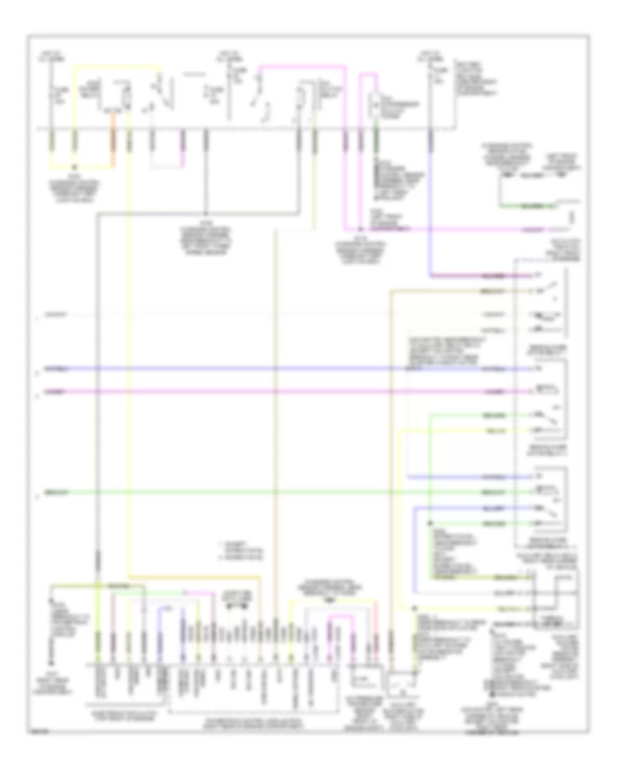
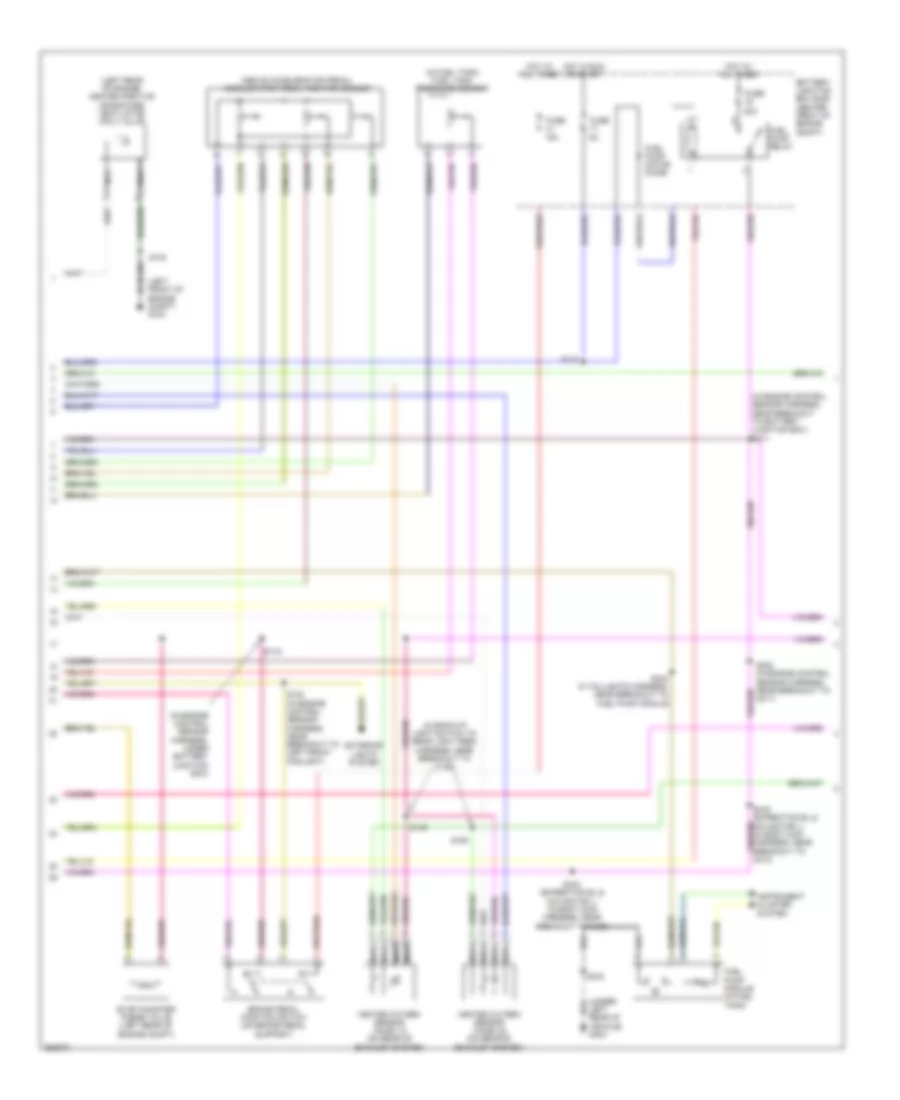
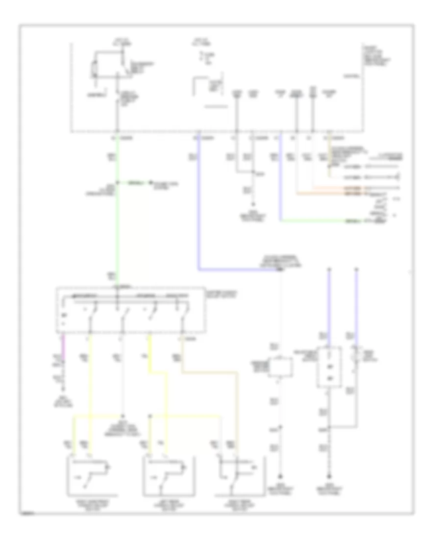
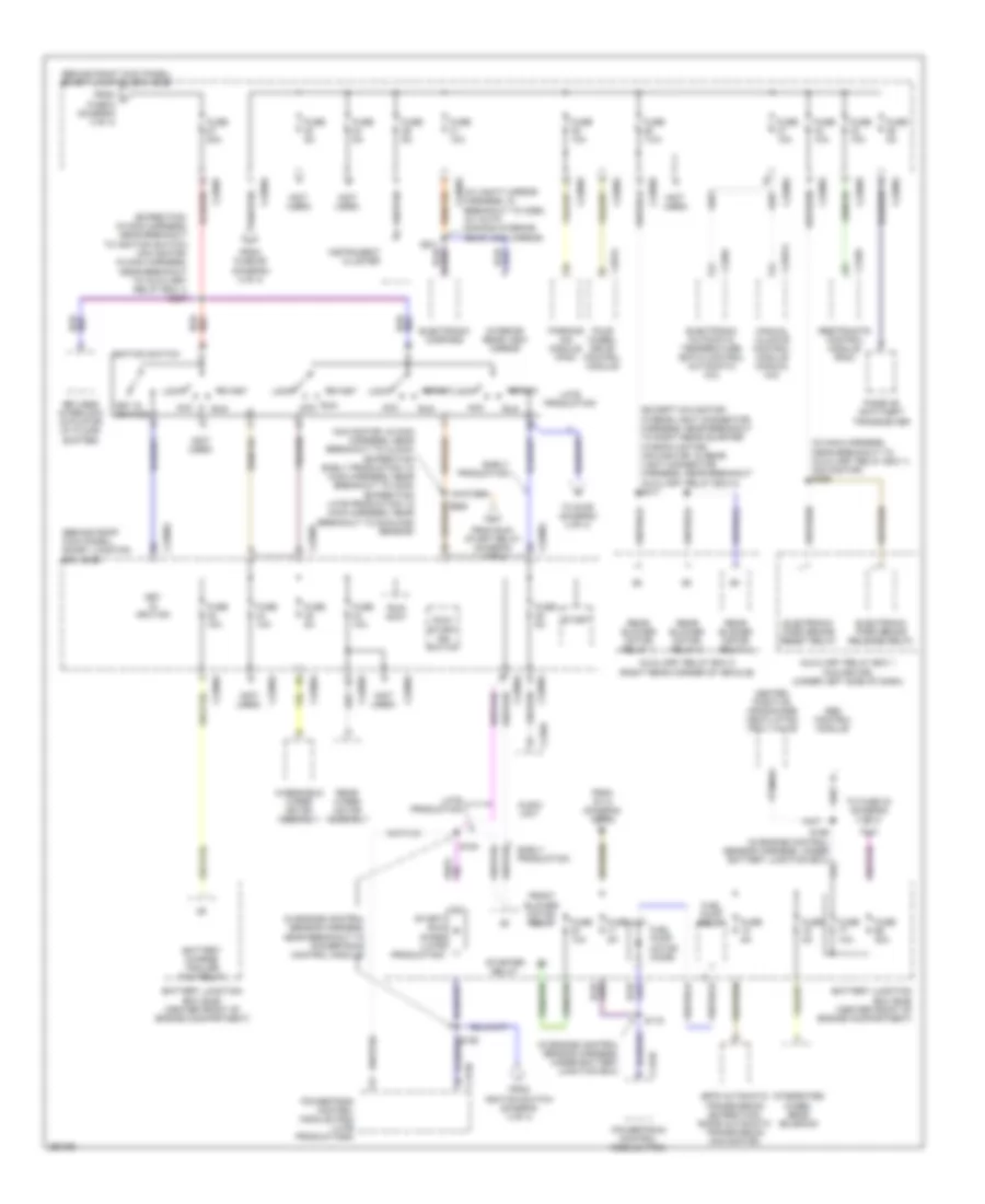
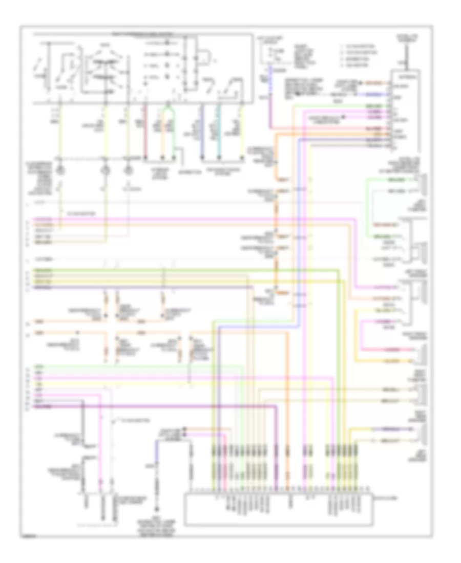
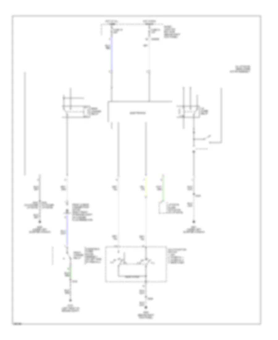
Automatic A/C Wiring Diagram, with Auxiliary Climate Control (2 of 3) for Ford Expedition EL 2007
List of elements for Automatic A/C Wiring Diagram, with Auxiliary Climate Control (2 of 3) for Ford Expedition EL 2007:
- (behind front of radiator grille) ambient air temperature sensor
- (behind left side of dash) (navigator) in-vehicle temperature/ humidity sensor
- (behind left side of dash) in-vehicle temperature sensor
- (top center of hvac unit) evaporator discharge air temperature sensor
- (under top center of dash) sunload sensor
- C218a
- C218b
- C2280e
- C2280f
- C2280g
- Clock spring (in steering wheel)
- Except expedition el
- Expedition
- Expedition el
- Fan+
- Fan-
- Fuse 10a
- Fuse 7.5a
- Head- lights system
- Hot at all times
- Hot in on or start
- Left steering wheel switch
- Navigator
- Rear blend door actuator (expedition el: left side of hvac unit) (except expedition el: center of auxiliary hvac unit)
- Right steering wheel switch
- S410 (except expedition el) (in breakout to rear mode door actuator) s430 (expedition el) (in auxiliary case jumper, near breakout to rear mode door actuator)
- S411 (except expedition el) (in breakout to rear mode door actuator) s429 (expedition el) (in auxiliary case jumper, near breakout to rear mode door actuator)
- Smart junction box (sjb) (behind right kick panel)
- Solid state
- Temp+
- Temp-
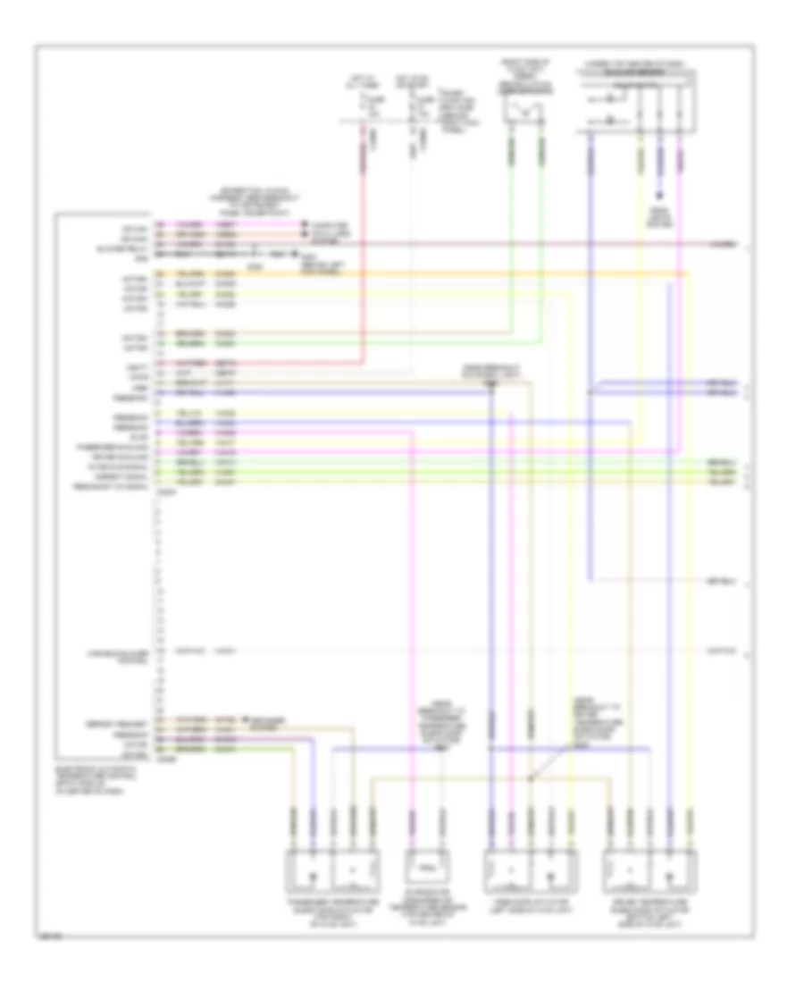
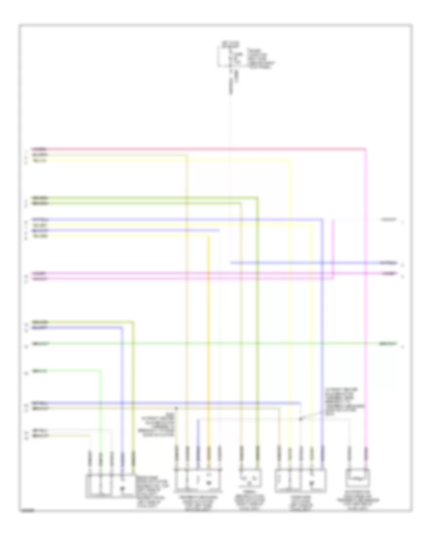
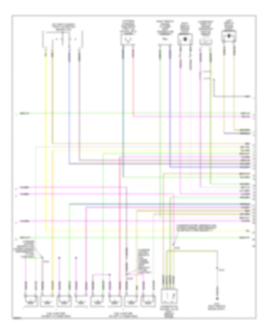
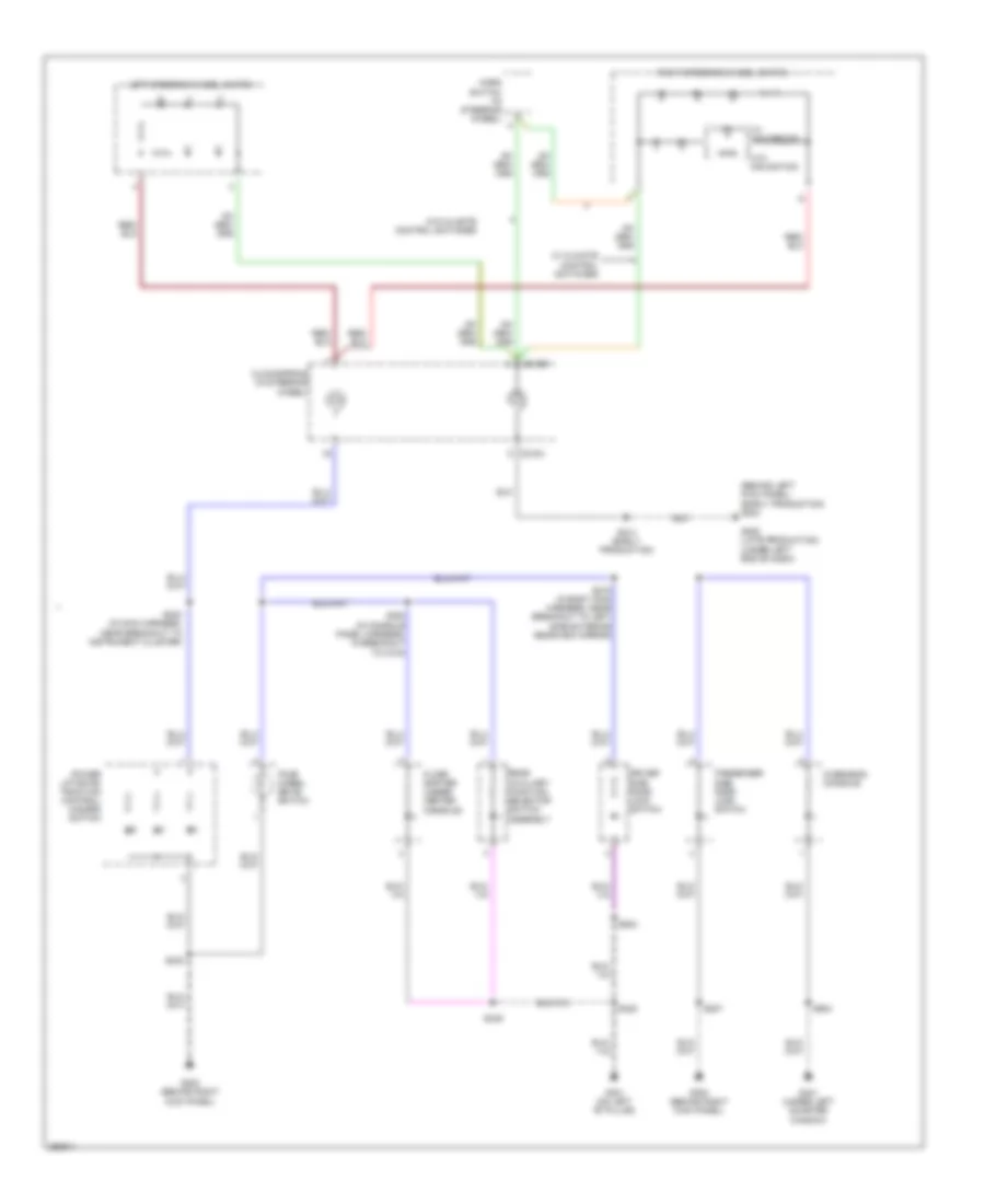
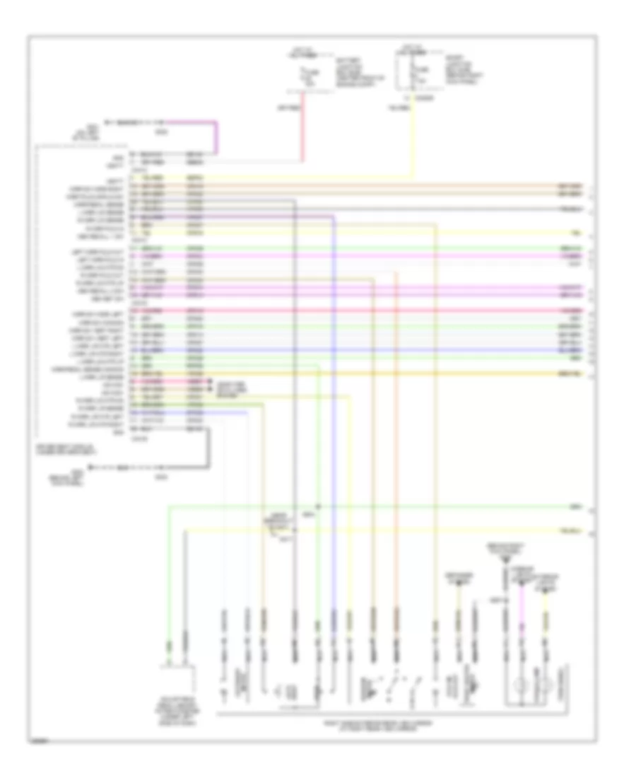
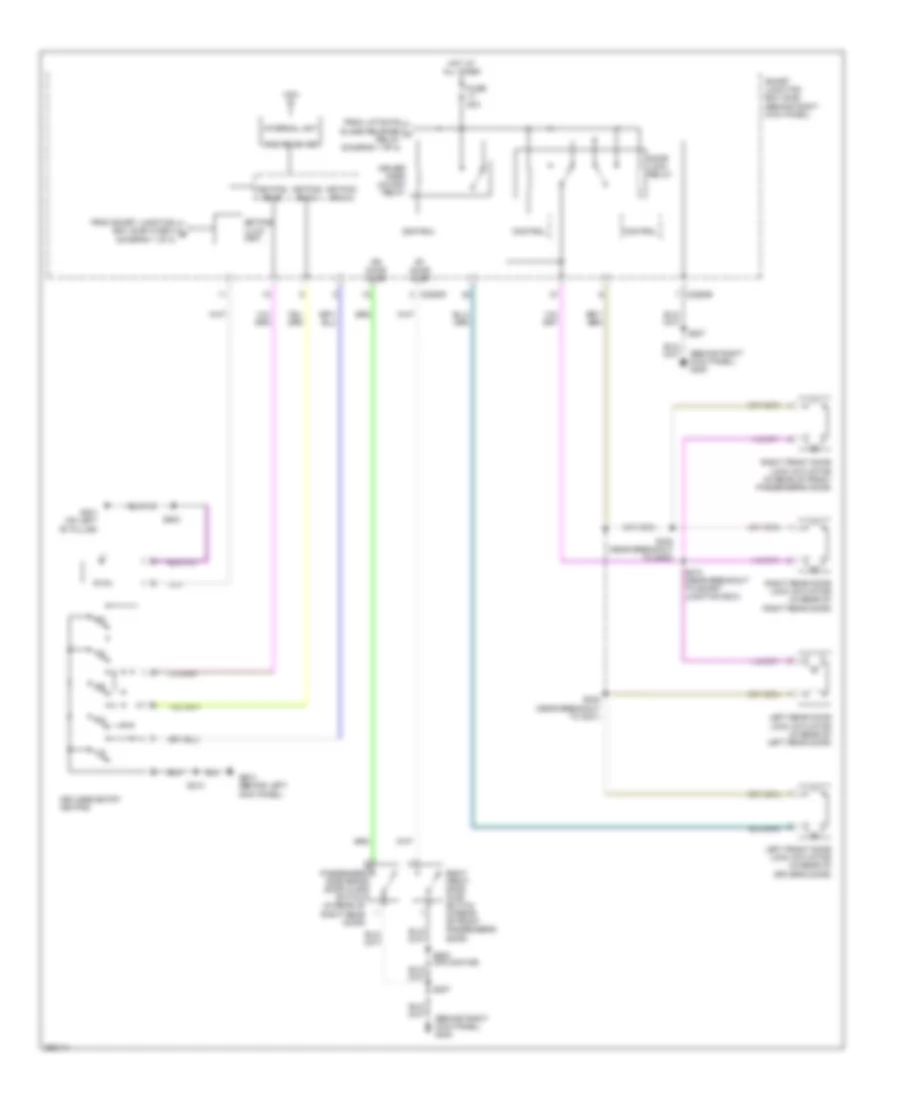
Automatic A/C Wiring Diagram, with Auxiliary Climate Control (3 of 3) for Ford Expedition EL 2007
List of elements for Automatic A/C Wiring Diagram, with Auxiliary Climate Control (3 of 3) for Ford Expedition EL 2007:
- (in engine control sensor & fuel charge harness, near breakout to c145) s140
- (in engine control sensor harness, near breakout to horn) s122
- (left front of engine compartment) g103
- (navigator: near breakout to auxiliary relay box 2) (except navigator: breakout to right rear quarter window motor) s417
- (near breakout to powertrain control module)
- (right rear of engine compartment)
- A/c clutch field coil (right front of engine)
- A/c clutch relay
- A/c compressor clutch diode
- A/c pressure
- A/c pressure transducer sensor (right front of engine compt)
- Accr
- Auxiliary blower motor (right side of auxiliary hvac unit)
- Auxiliary blower motor resistor assembly (right side of auxiliary hvac unit)
- Auxiliary relay box 2 (right rear corner of vehicle)
- Battery junction box (bjb) (center front of engine compartment)
- C175b
- C175e
- Ce607
- Ch302
- Ch421
- Computer data lines system
- Control fan motor
- Electronic fan clutch (top front of engine)
- Except expedition el
- Expedition el
- Fan motor control
- Fan speed signal
- Fuse 10a
- Fuse 20a
- Fuse 30a
- G103 (left front of engine compartment)
- G107
- G403 (navigator: left rear corner of vehicle) (except navigator: right rear corner of vehicle)
- Gnd
- Hot at all times
- Hs can+
- Hs can-
- Le423
- Pcm control
- Pcm power relay
- Pcm power rly sw out
- Powertrain control module (pcm) (right rear of engine compartment)
- Re407
- Rear blower motor relay 1
- Rear blower motor relay 2
- Rear blower motor relay 3
- S102
- S106 (in engine control sensor harness, near breakout to left front wheel speed sensor)
- S119 (in engine control sensor harness, under battery junction box)
- S120 (in engine control sensor harness, under battery junction box)
- S418 (w/ power vent windows) (navigator: breakout to g402) (except navigator: near breakout right rear quarter window motor)
- S422 (expedition el) (near breakout to c408) s414 (except expedition el) (near breakout to g402)
- S428 (near breakout to rear mode door actuator) s412 (near breakout to auxiliary blower motor resistor assembly)
- Signal return
- Thermal limiter
- Vdb04
- Vdb05
- Vec03
- Vec10
- Vh433
- Vref
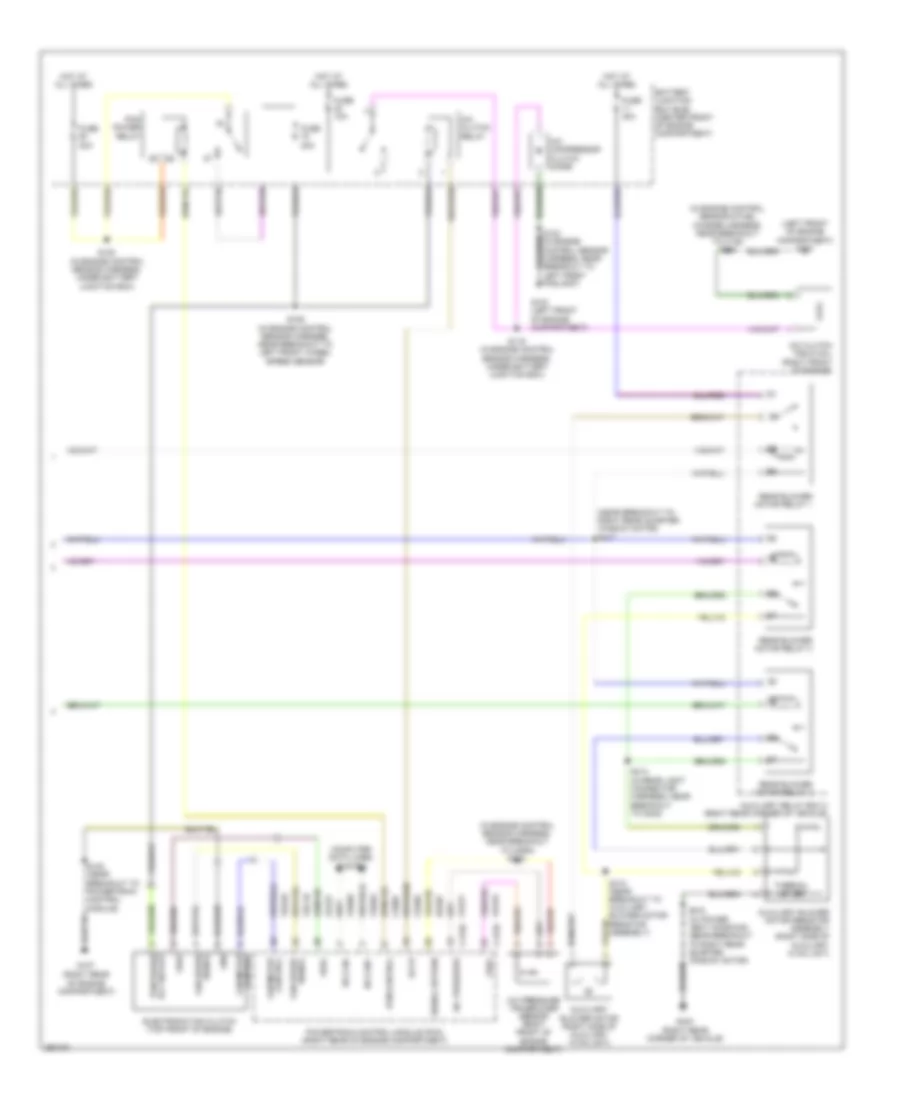
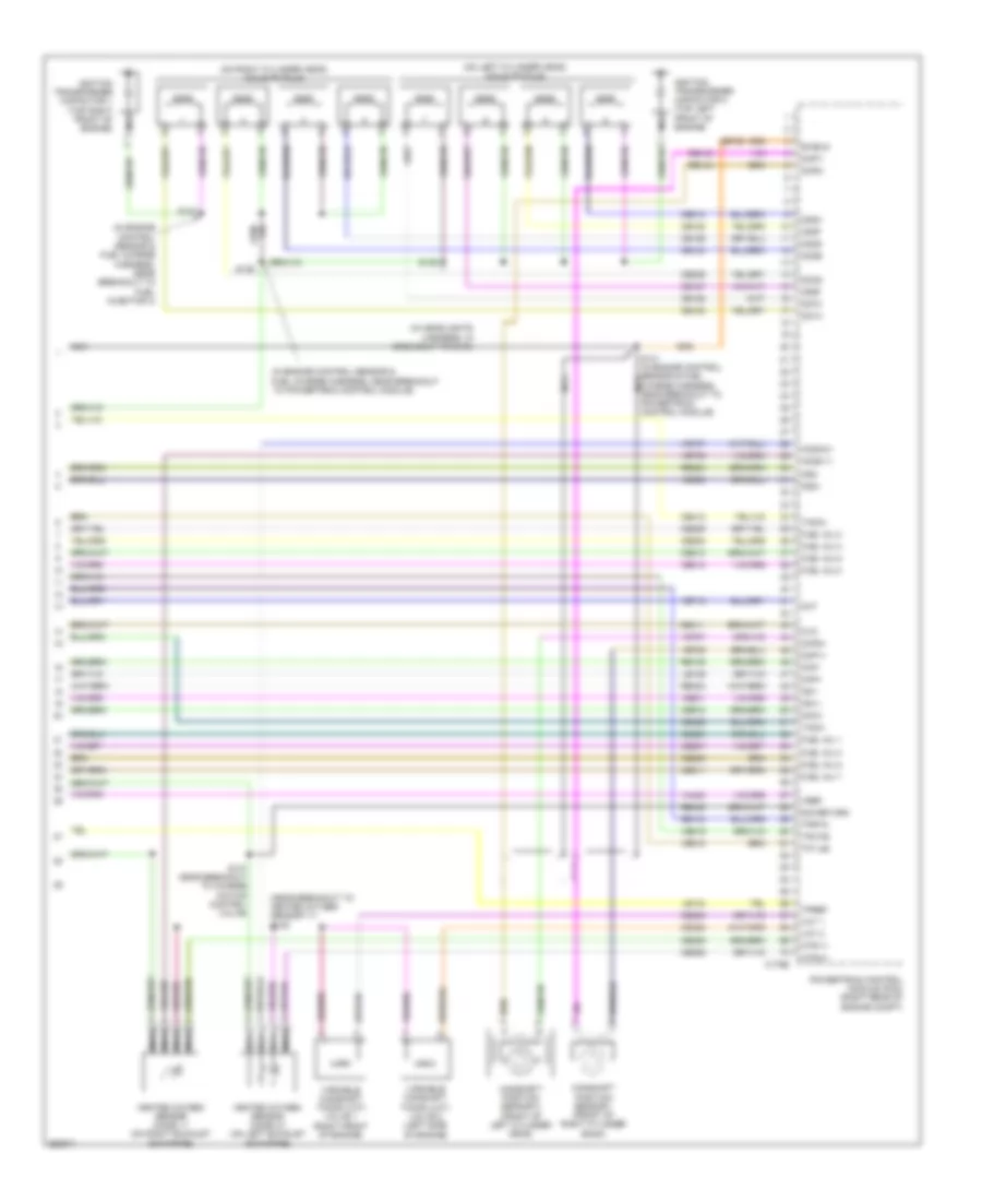
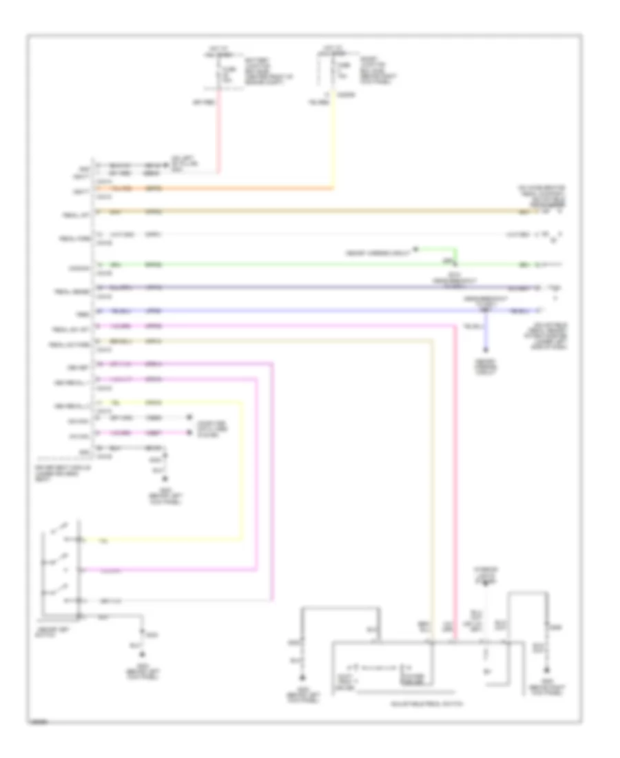
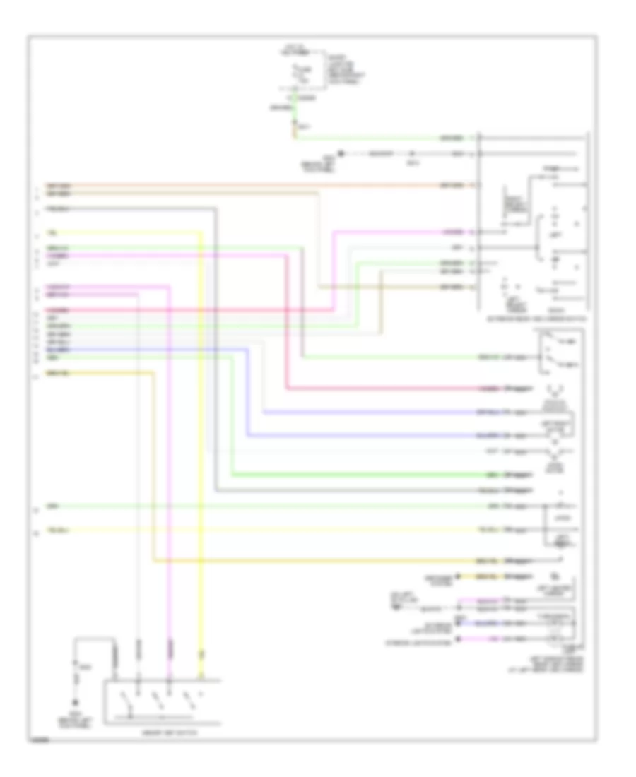
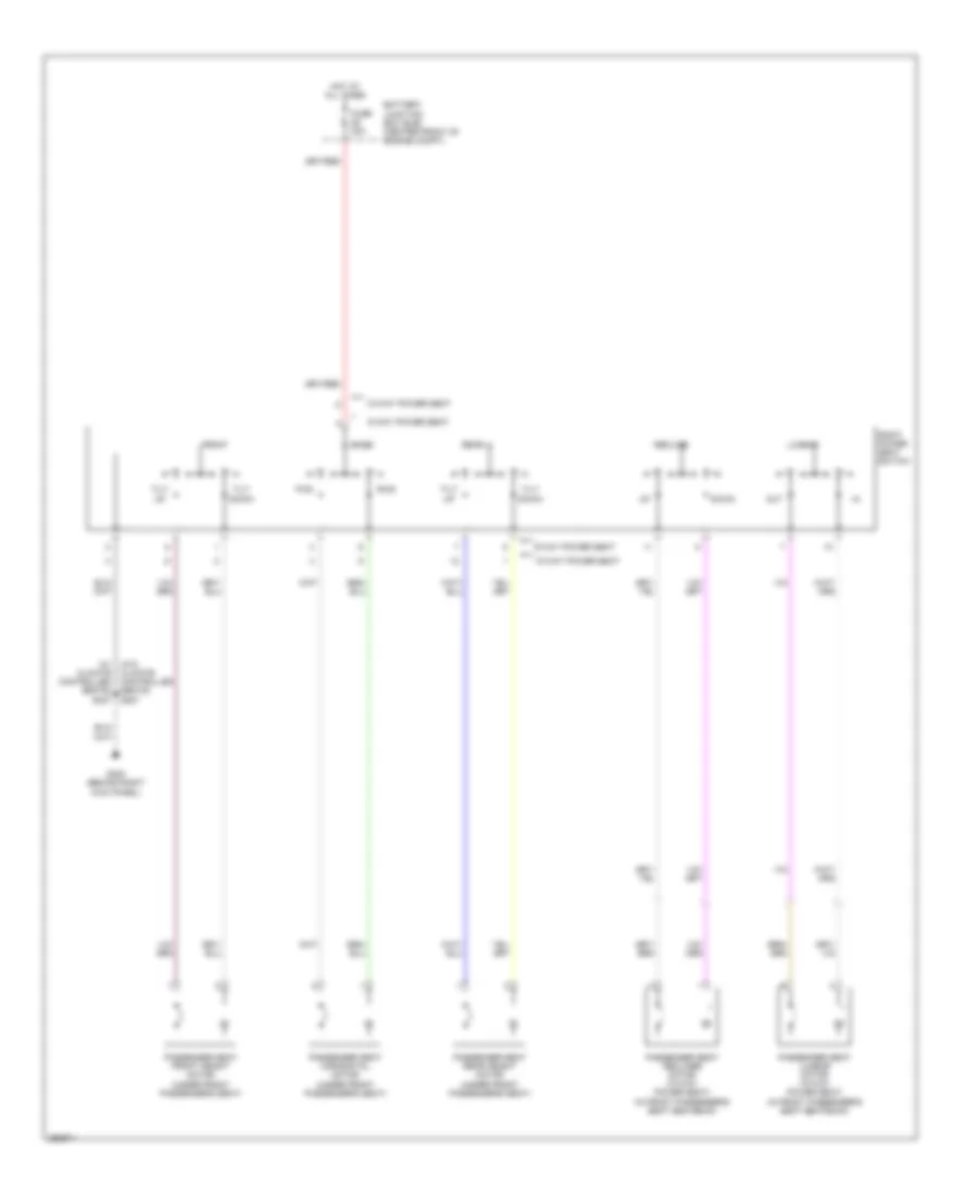
Automatic A/C Wiring Diagram, without Auxiliary Climate Control (1 of 3) for Ford Expedition EL 2007
List of elements for Automatic A/C Wiring Diagram, without Auxiliary Climate Control (1 of 3) for Ford Expedition EL 2007:
- (expedition: in main harness, near breakout to instrument panel power point)
- (near breakout glove box light) s223
- (near breakout to driver temperature blend door actuator) s220
- (near breakout to passenger temperature blend door actuator) s219
- (right side of hvac unit) fresh/ recirculation door actuator
- (under top center of dash) sunload sensor
- Ambient signal
- Blower relay
- C2280f
- C2280g
- C228a
- C228b
- Cbp37
- Ch122
- Ch123
- Ch202
- Ch203
- Ch212
- Ch213
- Ch228
- Ch229
- Ch238
- Ch239
- Ch447
- Computer data lines system
- Defogger system
- Defrost request
- Driver sunload
- Driver temperature blend door actuator (bottom left side of hvac unit)
- Electronic automatic temperature control (eatc) module (in center of dash)
- Evap
- Evaporator discharge air temperature sensor (top center of hvac unit)
- Feedback
- Fuse 10a
- G203 (behind left kick panel)
- Gd113
- Gnd
- Head- lights system
- Hot at all times
- Hot in on or start
- In-vehicle signal
- Lh111
- Mode door actuator (left side of hvac unit)
- Motor+
- Motor-
- Ms can+
- Ms can-
- Passenger sunload
- Passenger temperature blend door actuator (top front of hvac unit)
- Redundant cc signal
- S228
- Sbp15
- Smart junction box (sjb) (behind right kick panel)
- Solid state
- Variable blower control
- Vbatt
- Vdb06
- Vdb07
- Vh101
- Vh406
- Vh407
- Vh414
- Vh416
- Vh417
- Vh436
- Vh440
- Vh441
- Vpwr
- Vref
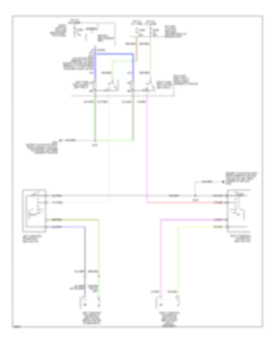
Automatic A/C Wiring Diagram, without Auxiliary Climate Control (2 of 3) for Ford Expedition EL 2007
List of elements for Automatic A/C Wiring Diagram, without Auxiliary Climate Control (2 of 3) for Ford Expedition EL 2007:
- (behind front of radiator grille) ambient air temperature sensor
- (behind left side of dash) in-vehicle temperature sensor
- (in front heater blower motor harness, near breakout to c299) s217
- (in main harness, near breakout to passenger air bag module) s227
- Battery junction box (bjb) (center front of engine compartment)
- Blower motor (right side of hvac unit)
- C218a
- C218b
- Ch402
- Clock spring (in steering wheel)
- Fan+
- Fan-
- Front blower motor relay
- Fuse 10a
- Fuse 20a
- Fuse 30a
- Fuse 40a
- G200 (behind right kick panel)
- Gd138
- Heater blower motor control module (right side of hvac unit)
- Hot at all times
- Hot in on or start
- Left steering wheel switch
- Pcm power relay
- Right steering wheel switch
- S120 (in engine control sensor harness, under battery junction box)
- Temp+
- Temp-
- Vh101
- Vh301
Automatic A/C Wiring Diagram, without Auxiliary Climate Control (3 of 3) for Ford Expedition EL 2007
List of elements for Automatic A/C Wiring Diagram, without Auxiliary Climate Control (3 of 3) for Ford Expedition EL 2007:
- (in engine control sensor & fuel charge harness, near breakout to c145) s140
- (right rear of engine compartment)
- A/c clutch field coil (right front of engine)
- A/c clutch relay
- A/c compressor clutch diode
- A/c pressure
- A/c pressure transducer sensor (right front of engine compartment)
- Accr
- Battery junction box (bjb) (center front of engine compartment)
- C175b
- C175e
- Ce607
- Ch302
- Ch421
- Computer data lines system
- Control fan motor
- Electronic fan clutch (top front of engine)
- Fan motor control
- Fan speed signal
- Fuse 10a
- G103 (left front of engine compartment)
- G107
- Gnd
- Hot at all times
- Hs can+
- Hs can-
- Le423
- Pcm control
- Pcm power rly sw out
- Powertrain control module (pcm) (right rear of engine compartment)
- Re407
- S102 (in engine control sensor harness, near breakout to powertrain control module)
- S106 (in engine control sensor harness, near breakout to left front wheel speed sensor)
- S119 (in engine control sensor harness, under battery junction box)
- S122 (in engine control sensor harness, near breakout to horn)
- Signal return
- Vdb04
- Vdb05
- Vec03
- Vec10
- Vh433
- Vref
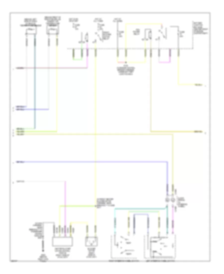
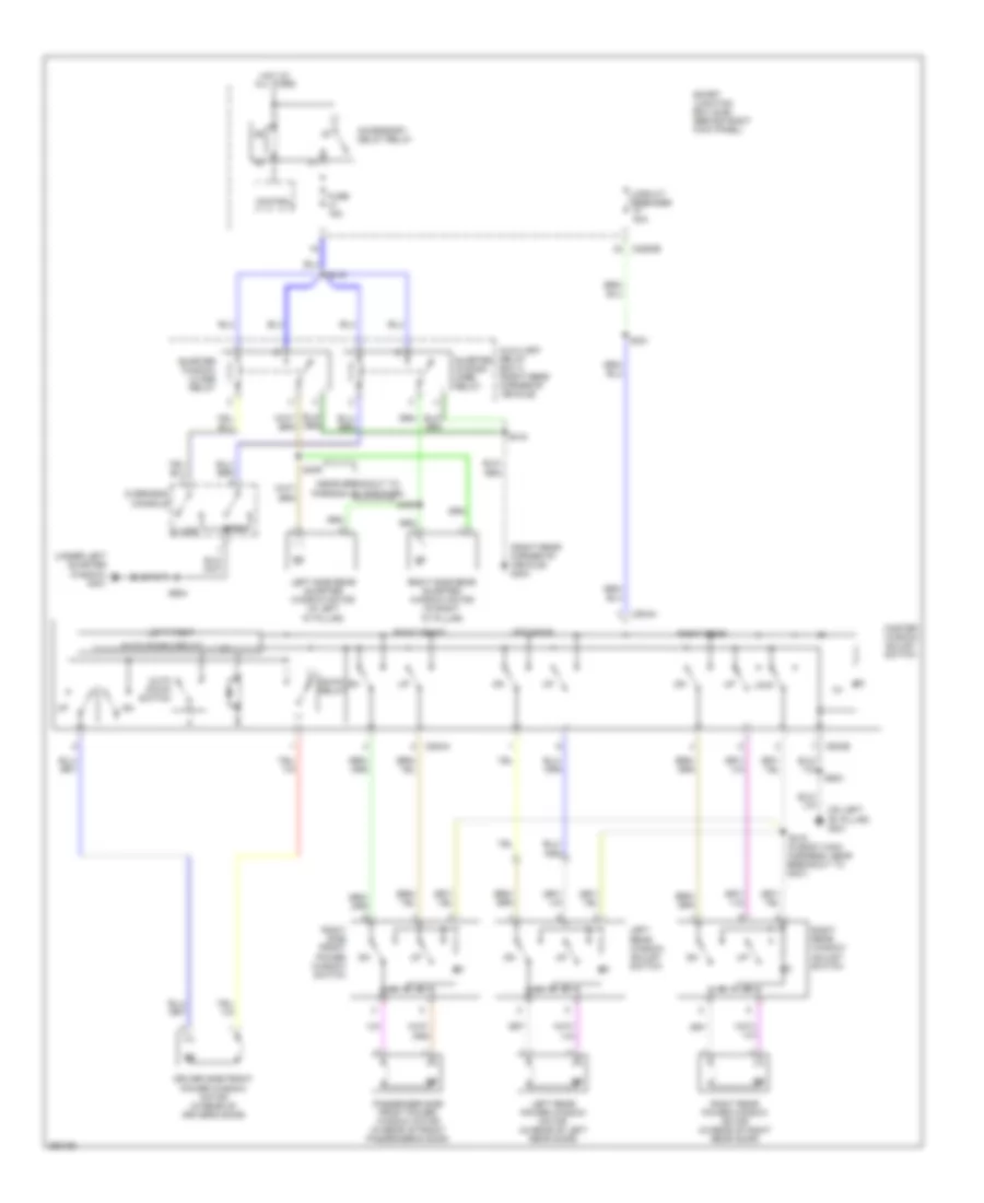
Manual A/C Wiring Diagram, with Auxiliary Climate Control (1 of 3) for Ford Expedition EL 2007
List of elements for Manual A/C Wiring Diagram, with Auxiliary Climate Control (1 of 3) for Ford Expedition EL 2007:
- (in front heater blower motor harness, near breakout to c237)
- (in main harness, near breakout to glove box light) s222
- (in main harness, near breakout to instrument panel power point)
- (near to satellite radio receiver) s349
- (on left "b" pillar) g301
- Battery junction box (bjb) (center front of engine compartment)
- Blower
- Blower motor (right side of hvac unit)
- Blower motor resistor (bottom right side of hvac unit)
- Blower relay
- C2280f
- C2280g
- C2357a
- C2357b
- C2357c
- Cbp37
- Ch112
- Ch113
- Ch114
- Ch122
- Ch123
- Ch202
- Ch203
- Ch207
- Ch208
- Ch228
- Ch229
- Ch233
- Ch234
- Ch238
- Ch239
- Ch428
- Ch429
- Ch430
- Computer data lines system
- Defogger system
- Defrost request
- Evap
- Feedback
- Front blower motor relay
- Fuse 10a
- Fuse 40a
- G200 (behind right kick panel)
- G203 (behind left kick panel)
- Gd113
- Gd138
- Gnd
- High
- Hot at all times
- Hot in on or start
- Interior lights system
- Lh111
- Manual climate control module (behind center of dash)
- Mid high
- Mid low
- Mode/temp
- Motor+
- Motor-
- Ms can+
- Ms can-
- Rear auxiliary function switch assembly
- Rear blend door actuator (expedition el: left side of auxiliary hvac unit) (except expedition el: center of auxiliary hvac unit)
- Relay 1
- Relay 2
- Relay 3
- Rh111
- S218
- S223 (in main harness, near breakout to glove box light)
- S227 (in main harness, near breakout to passenger air bag module)
- S228
- Sbp15
- Signal return
- Smart junction box (sjb) (behind right kick panel)
- Thermal limiter
- Vbatt
- Vdb06
- Vdb07
- Vh406
- Vh436
- Vh438
- Vh439
- Vh440
- Vha15
- Vha17
- Vpwr
- Vref
Manual A/C Wiring Diagram, with Auxiliary Climate Control (2 of 3) for Ford Expedition EL 2007
List of elements for Manual A/C Wiring Diagram, with Auxiliary Climate Control (2 of 3) for Ford Expedition EL 2007:
- (in front heater blower motor harness, near breakout to temperature blend door actuator) s219
- C2280e
- Evaporator discharge air temperature sensor (top center of hvac unit)
- Fresh/ recirculation door actuator (right side of hvac unit)
- Fuse 7.5a
- Hot in on or start
- Mode door actuator (left side of hvac unit)
- Rear mode door actuator (expedition: top left side of hvac unit) (expedition el: left side of hvac unit)
- S220 (in front heater blower motor harness, in breakout to mode door actuator)
- Smart junction box (sjb) (behind right kick panel)
- Temperature blend door actuator (top left side of hvac unit)
Manual A/C Wiring Diagram, with Auxiliary Climate Control (3 of 3) for Ford Expedition EL 2007
List of elements for Manual A/C Wiring Diagram, with Auxiliary Climate Control (3 of 3) for Ford Expedition EL 2007:
- (in engine control sensor & fuel charge harness, near breakout to c145) s140
- (in engine control sensor harness, near breakout to horn) s122
- (left front of engine compartment) g103
- (near breakout to right rear quarter window motor) s417
- (right rear corner of vehicle)
- (right rear of engine compartment)
- A/c clutch field coil (right front of engine)
- A/c clutch relay
- A/c compressor clutch diode
- A/c pressure
- A/c pressure transducer sensor (right front of engine compartment)
- Accr
- Auxiliary blower motor (right side of auxiliary hvac unit)
- Auxiliary blower motor resistor assembly (right side of auxiliary hvac unit)
- Auxiliary relay box 2 (right rear corner of vehicle)
- Battery junction box (bjb) (center front of engine compartment)
- C175b
- C175e
- Ce607
- Ch302
- Ch421
- Computer data lines system
- Control
- Control fan motor
- Electronic fan clutch (top front of engine)
- Fan motor
- Fan speed
- Fuse 10a
- Fuse 20a
- Fuse 30a
- G103 (left front of engine compartment)
- G107
- G403
- Gnd
- Hot at all times
- Hs can+
- Hs can-
- Le423
- Pcm control
- Pcm power relay
- Pcm power rly sw out
- Powertrain control module (pcm) (right rear of engine compartment)
- Re407
- Rear blower motor relay 1
- Rear blower motor relay 2
- Rear blower motor relay 3
- S102 (near breakout to powertrain control module)
- S106 (in engine control sensor harness, near breakout to left front wheel speed sensor)
- S119 (in engine control sensor harness, under battery junction box)
- S120 (in engine control sensor harness, under battery junction box)
- S412 (near breakout to auxiliary blower motor resistor assembly)
- S414 (in rear light connector harness, near breakout to g402)
- S418 (w/ power vent windows) (near breakout to right rear quarter window motor)
- Signal
- Signal fan speed
- Signal return
- Thermal limiter
- Vdb04
- Vdb05
- Vec03
- Vec10
- Vh433
- Vref
Manual A/C Wiring Diagram, without Auxiliary Climate Control (1 of 2) for Ford Expedition EL 2007
List of elements for Manual A/C Wiring Diagram, without Auxiliary Climate Control (1 of 2) for Ford Expedition EL 2007:
- (in main harness, near breakout to instrument panel power point)
- (in main harness, near breakout to passenger air bag module) s227
- Battery junction box (bjb) (center front of engine compartment)
- Blower motor (right side of hvac unit)
- Blower motor resistor (bottom right side of hvac unit)
- Blower relay
- C2280f
- C2280g
- C2357a
- C2357c
- Cbp37
- Ch122
- Ch123
- Ch202
- Ch203
- Ch228
- Ch229
- Ch238
- Ch239
- Ch428
- Ch429
- Ch430
- Computer data lines system
- Defogger system
- Defrost request
- Evap
- Feedback
- Fresh/recirculation door actuator (right side of hvac unit)
- Front blower motor relay
- Fuse 10a
- Fuse 40a
- G200 (behind right kick panel)
- G203 (behind left kick panel)
- Gd113
- Gd138
- Gnd
- High
- Hot at all times
- Hot in on or start
- Lh111
- Manual climate control module (behind center of dash)
- Mid high
- Mid low
- Motor+
- Motor-
- Ms can+
- Ms can-
- Rh111
- S218 (near breakout to c237)
- S228
- Sbp15
- Signal return
- Smart junction box (sjb) (behind right kick panel)
- Thermal limiter
- Vbatt
- Vdb06
- Vdb07
- Vh406
- Vh436
- Vh440
- Vpwr
- Vref
Manual A/C Wiring Diagram, without Auxiliary Climate Control (2 of 2) for Ford Expedition EL 2007
List of elements for Manual A/C Wiring Diagram, without Auxiliary Climate Control (2 of 2) for Ford Expedition EL 2007:
- (in engine control sensor harness, near breakout to horn) s122
- (in front heater blower motor harness, near breakout to temperature blend door actuator) s219
- (near breakout to powertrain control module) s102
- (right front of engine compartment) a/c pressure transducer sensor
- (right front of engine) a/c clutch field coil
- (right rear of engine compartment)
- A/c
- A/c compressor clutch diode
- A/c pressure
- Accr
- Battery junction box (bjb) (center front of engine compartment)
- C175b
- C175e
- Ce607
- Ch302
- Ch421
- Clutch
- Computer data lines system
- Control fan motor
- Electronic fan clutch (top front of engine)
- Evaporator discharge air temperature sensor (top center of hvac unit)
- Fuse 10a
- Fuse 20a
- Fuse 30a
- G103 (left front of engine compartment)
- G107
- Gnd
- Hot at all times
- Hs can+
- Hs can-
- Le423
- Mode door actuator (left side of hvac unit)
- Pcm
- Pcm control
- Pcm power rly sw out
- Power relay
- Powertrain control module (pcm) (right rear of engine compartment)
- Re407
- Relay
- S106 (in engine control sensor harness, near breakout to left front wheel speed sensor)
- S119 (in engine control sensor harness, under battery junction box)
- S120 (in engine control sensor harness, under battery junction box)
- S123 (in engine control sensor harness, near breakout to left front foglight)
- S140 (near breakout to c145)
- S220 (in breakout to mode door actuator)
- Signal fan speed
- Signal return
- Temperature blend door actuator (top left side of hvac unit)
- Vdb04
- Vdb05
- Vec03
- Vec10
- Vh433
- Vref
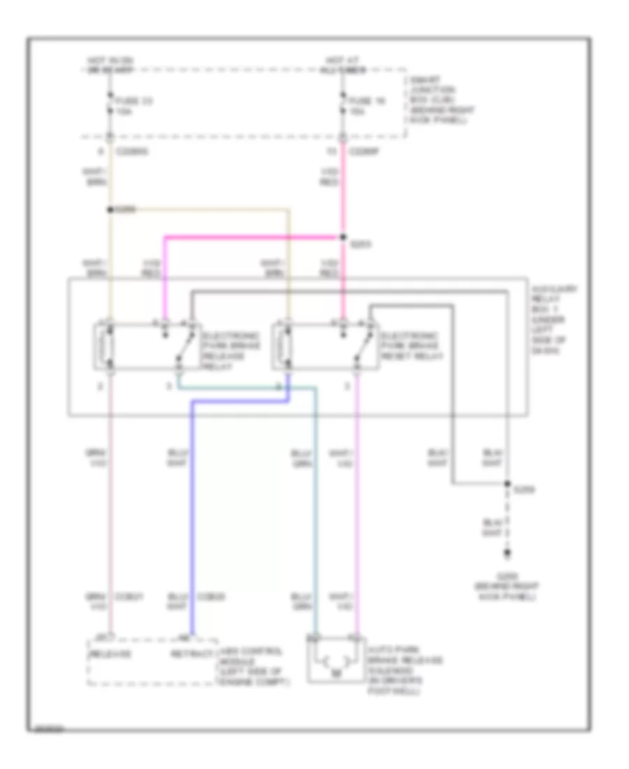
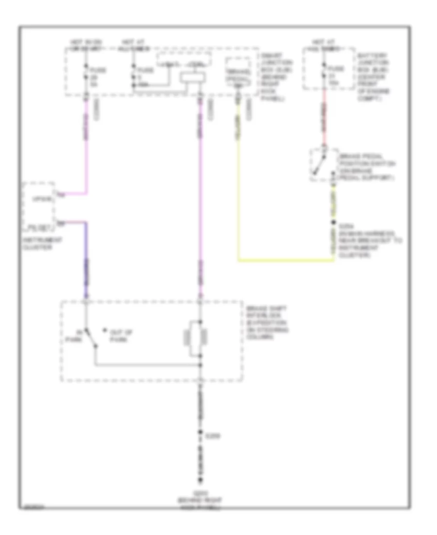
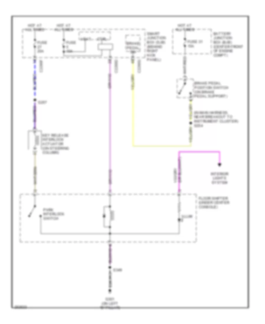
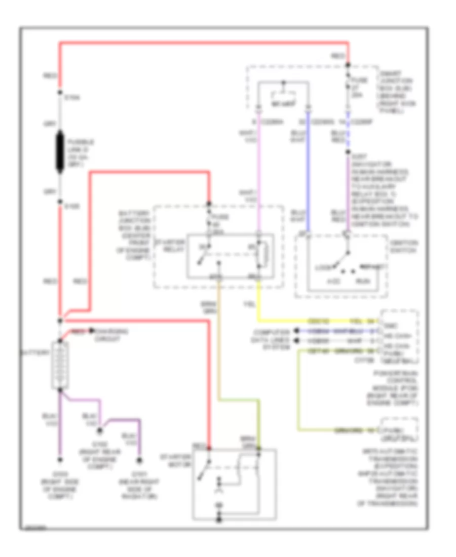
ANTI-LOCK BRAKES
Anti-lock Brakes Wiring Diagram for Ford Expedition EL 2007
List of elements for Anti-lock Brakes Wiring Diagram for Ford Expedition EL 2007:
- (in engine control sensor harness, near breakout to left front foglight) s124
- (left front of engine compt) g104
- (navigator) s227 (expedition) s232
- Abs control module (left side of engine compt)
- Angle a/1
- Angle b/2
- Battery junction box (bjb) (center front of engine compt)
- Bpfs nc
- Bpfs no
- Bpfs sig
- Brake booster sensor (left rear of engine compt)
- Brake pedal position switch (on brake pedal support)
- Bst pwm
- Bst pwr
- Can2 +
- Can2 -
- Cbb77
- Cca09
- Cca15
- Cca22
- Cca25
- Cca26
- Cca29
- Ccb20
- Ccb21
- Ccs01
- Cls17
- Clus gnd
- Clus sensep
- Computer data lines system
- Fuse 31 15a
- Fuse 6 60a
- Fuse 77 10a
- Fuse 9 60a
- G200 (behind right kick panel)
- Gd120
- Hot at all times
- Hot in on or start
- Hs can +
- Hs can -
- Interior lights
- Left front wheel speed sensor (left side of engine compt)
- Left rear wheel speed sensor (at left rear wheel)
- Lf sensor +
- Lf sensor -
- Lr sensor +
- Lr sensor -
- Mtr gnd
- Mtr pwr
- Nca
- Power liftgate/ traction control/ hazard switch
- Rca09
- Rca17
- Rca18
- Rca19
- Rca20
- Rcs02
- Red
- Release
- Retract
- Rf sensor +
- Rf sensor -
- Right front wheel speed sensor (right side of engine compt)
- Right rear wheel speed sensor (at right rear wheel)
- Rr sensor +
- Rr sensor -
- Run/start
- S156
- Sbb06
- Sbb09
- Shift interlock system
- Solid state
- Sr gnd
- Sr sen sep
- Stability control sensor cluster (under center console)
- Steering position sensor (on steering column)
- Stop lp sw
- System
- Tc crl sw
- Valve pwr
- Vca03
- Vca04
- Vca05
- Vca06
- Vca22
- Vca23
- Vca24
- Vcs06
- Vcs07
- Vdb04
- Vdb05
ANTI-THEFT
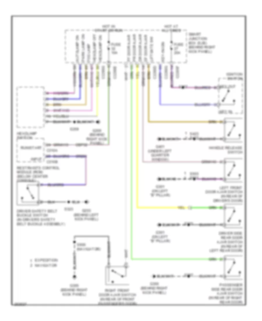
Forced Entry Wiring Diagram (1 of 2) for Ford Expedition EL 2007
List of elements for Forced Entry Wiring Diagram (1 of 2) for Ford Expedition EL 2007:
- (in liftgate) liftgate glass actuator
- (in liftgate) liftgate latch
- (in liftgate) rear wiper motor assembly
- (left side of cargo area, behind trim) power liftgate module
- (navigator)
- (navigator) s427
- (navigator) s501
- (near breakout to smart junction box) s208
- (near breakout to smart junction box) s211
- (under left quarter window) g401
- C2280d
- C2280e
- C4174b
- Control
- Cpl10
- Cpl58
- Cpr50
- Df door ajar
- Door lock
- Door unlock
- Dr door ajar
- Driver side door lock switch
- Driver side rear door ajar switch (in rear of left rear door)
- Except navigator
- Fuse 10a
- G300 (behind right kick panel)
- G301 (on left "b" pillar)
- G302 (behind right kick panel)
- G401 (under left quarter window)
- Gnd
- Handle release switch
- Hot at all times
- Interior lights system
- Left front door ajar switch (in rear of driver's door)
- Left license plate lamp
- Liftgate glass release relay
- Liftgate glass release switch
- Liftgate rel (fet)
- Liftgate switch
- Liftgate/ glass decklid ajar
- Liftglass switch
- Lock
- Navigator
- Passenger side door lock switch
- Right license plate lamp
- S207
- S276
- S322
- S423
- S423 (except navigator)
- S427
- S427 s423 (except navigator)
- S503
- Smart junction box (sjb) (behind right kick panel)
- Status
- To driver door unlock relay (diagram 2 of 2)
- To keypad illum (fet) (diagram 2 of 2)
- Unlock
- Vpwr
- W/ power liftgate
- W/o power liftgate
Forced Entry Wiring Diagram (2 of 2) for Ford Expedition EL 2007
List of elements for Forced Entry Wiring Diagram (2 of 2) for Ford Expedition EL 2007:
- (behind right kick panel) g300
- 1/2
- 3/4
- 5/6
- 7/8
- 9/0
- C2280d
- C2280e
- Control
- Door lock relay
- Driver door unlock relay
- From liftgate glass release a relay (diagram 1 of 2)
- From smart junction box (sjb) fuse 5 b (diagram 1 of 2)
- Fuse 20a
- G203 (behind left kick panel)
- G301 (on left "b" pillar)
- Hot at all times
- Internal ant
- Keyless entry keypad
- Keypad illum (fet)
- Keypad sw a
- Keypad sw b
- Keypad sw c
- Left front door lock actuator (in rear of driver's door)
- Left rear door lock actuator (in rear of left rear door)
- Passenger side rear door ajar switch (in rear of right rear door)
- Pf door ajar
- Pr door ajar
- Right front door ajar switch (in rear of front passenger's door)
- Right front door lock actuator (in rear of front passenger's door)
- Right rear door lock actuator (in rear of right rear door)
- Rke receiver
- S207
- S210 (near breakout to smart junction box)
- S213
- S302 (near breakout to g300)
- S320 (near breakout to g301)
- S503
- S600 (navigator)
- Smart junction box (sjb) (behind right kick panel)
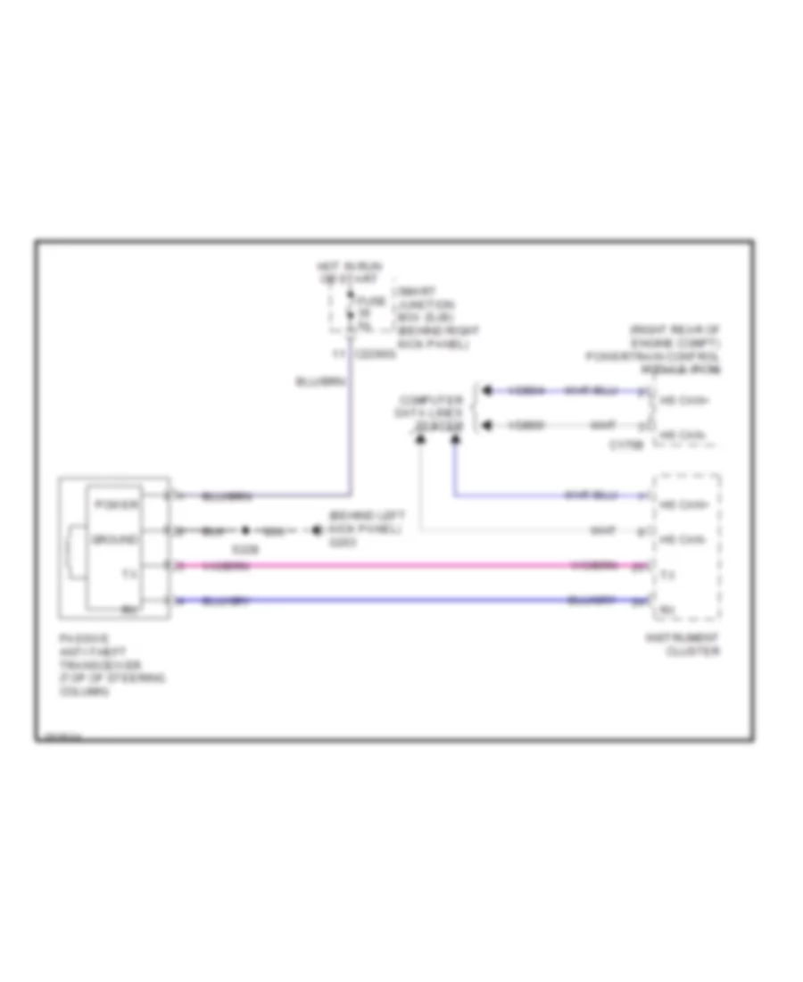
Passive Anti-theft Wiring Diagram for Ford Expedition EL 2007
List of elements for Passive Anti-theft Wiring Diagram for Ford Expedition EL 2007:
- (behind left kick panel) g203
- (right rear of engine compt) powertrain control module (pcm)
- C175b
- C2280g
- Computer data lines system
- Fuse 5a
- Ground
- Hot in run or start
- Hs can+
- Hs can-
- Instrument cluster
- Passive anti-theft transceiver (top of steering column)
- Power
- S228
- Smart junction box (sjb) (behind right kick panel)
- Vdb04
- Vdb05
BODY CONTROL MODULES
Body Control Modules Wiring Diagram (1 of 2) for Ford Expedition EL 2007
List of elements for Body Control Modules Wiring Diagram (1 of 2) for Ford Expedition EL 2007:
- 3rd row seat enable (fet)
- Air conditioning system
- Anti-lock brakes & instrument cluster systems
- Battery junction box (bjb) (center front of engine compartment)
- Battery saver relay
- Brake fluid sw
- Brake fluid sw rtn
- Bsi (fet)
- C2280a
- C2280b
- C2280c
- C2280d
- C2280e
- Cbb69
- Cbp32
- Cbp35
- Cbp41
- Cbp43
- Cbp45
- Cbp46
- Cbp47
- Ccb01
- Cdc37
- Cdc38
- Circuit breaker 47, 30a
- Clf04
- Clf05
- Clf08
- Clf21
- Cln09
- Cln25
- Cls18
- Cls19
- Cls21
- Cls25
- Cls30
- Cmc19
- Cpk28
- Cpk29
- Cpk30
- Cpk31
- Cpl10
- Cpl11
- Cpl26
- Cpl27
- Cpl30
- Cpl31
- Cpl36
- Cpl39
- Cpl45
- Cpl51
- Cpl52
- Cpl58
- Cpl59
- Cpl60
- Cps48
- Crh02
- Df door ajar
- Door all unlk sig
- Door lock
- Door lock relay
- Door locks system
- Door locks system power windows system navigation & sound systems mirrors & seats systems
- Door unlock
- Dr door ajar
- Driver door unlock relay
- Exterior lights system
- Fog lamp relay
- Fuse 1, 30a
- Fuse 12, 7.5a
- Fuse 14, 10a
- Fuse 19, 25a
- Fuse 2, 15a
- Fuse 3, 15a
- Fuse 30a
- Fuse 32, 10a
- Fuse 35, 10a
- Fuse 38, 20a
- Fuse 4, 30a
- Fuse 41, 15a
- Fuse 43, 10a
- Fuse 45, 5a
- Fuse 46, 7.5a
- G300 (behind right kick panel)
- G302 (behind right kick panel)
- Gd138
- Headlights system
- High beam relay
- Horn relay
- Horns system
- Hot in start
- Hot in start or run
- Instrument cluster & anti-lock brakes systems door locks system
- Interior lights system
- Keypad illum (fet)
- Keypad sw a
- Keypad sw b
- Keypad sw c
- Left low beam (fet)
- Lf turn lamp (fet)
- Liftgate ajar sw sig
- Liftgate glass release relay
- Liftgate rel (fet)
- Liftgate sw
- Liftglass sw
- Logic gnd
- Lr stop/turn lamp (fet)
- Memory systems
- Navigation & sound systems
- Navigation system
- Park brake
- Park lamp relay
- Pf door ajar
- Power distribution system
- Power gnd
- Power tops system
- Power windows system
- Pr door ajar
- Puddle lamp (fet)
- Red
- Rf turn lamp (fet)
- Right low beam (fet)
- Rmc19
- Rr stop/turn lamp (fet)
- S207
- S276
- Sbp01
- Sbp02
- Sbp03
- Sbp04
- Sbp12
- Sbp14
- Sbp19
- Sbp38
- Sdc04
- Seats system
- Shift interlock system
- Smart junction box (sjb) (behind right kick panel)
- Starting/charging system
- Trunk, tailgate, fuel doors system
- Vbatt
- Vpwr
- Wiper/washer system
Body Control Modules Wiring Diagram (2 of 2) for Ford Expedition EL 2007
List of elements for Body Control Modules Wiring Diagram (2 of 2) for Ford Expedition EL 2007:
- (early production)
- (late production)
- Acc
- Air conditioning system
- Anti-theft system
- Autolamp on
- Autolamp snsr in
- Backlighting led (fet)
- Brake pedal sw
- C2280f
- C2280g
- Cat23
- Cbp28
- Cbp29
- Cbp31
- Cbp33
- Cbp35
- Cbp36
- Cbp37
- Cdc30
- Cdc32
- Cdc33
- Cdc34
- Cdc35
- Clf02
- Clf19
- Clf23
- Clf24
- Clf27
- Clf28
- Clf29
- Cln27
- Cln28
- Cln30
- Cls05
- Cls17
- Cls20
- Cls24
- Computer data lines system
- Dim sw gnd
- Dimmer sw
- Dome defeat
- Dome lp
- Exterior lights system
- Flash-to-pass
- Fog lamp
- Fog lamp relay
- Fuse 14, 10a
- Fuse 15, 10a
- Fuse 16, 15a
- Fuse 20, 15a
- Fuse 26, 10a
- Fuse 27, 20a
- Fuse 28, 5a
- Fuse 29, 5a
- Fuse 31, 10a
- Fuse 33, 10a
- Fuse 35, 10a
- Fuse 36, 5a
- Fuse 37, 10a
- Fuse 39, 20a
- Fuse 40, 20a
- Fuse 42, 10a
- Hazard
- Headlamp off
- Headlamp on
- Headlights system
- High beam
- Horn relay
- Horns system
- Ignition switch
- Instrument cluster & mirrors systems
- Instrument cluster system
- Interior lighting (fet)
- Interior lights system
- Interior lights system computer data lines & seats systems
- Key in ignition
- Lock
- Ms can+
- Ms can-
- Navigation & sound systems
- Not used
- Park lamp on
- Power distribution system
- Rln29
- Run
- Run/start ign sw
- S257
- S258
- Sbp14
- Sbp15
- Sbp16
- Sbp20
- Sbp26
- Sbp27
- Sbp39
- Sbp40
- Shift interlock system
- Smart junction box (sjb) (behind right kick panel)
- Sound systems
- Srh01
- Start
- Starting/ charging system
- Transmissions system
- Turn left
- Turn right
- Vdb06
- Vdb07
- Vlf14
- Vln04
- Vln18
- Vln33
- Vln36
- White light (fet)
COMPUTER DATA LINES
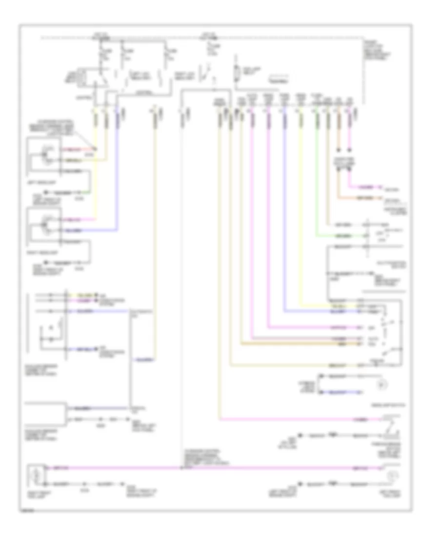
Computer Data Lines Wiring Diagram for Ford Expedition EL 2007
List of elements for Computer Data Lines Wiring Diagram for Ford Expedition EL 2007:
- (behind right kick panel) g200
- (below center console) restraints control module (rcm)
- (expedition: near breakout to c3050) (navigator: near breakout to g300)
- (expedition: near breakout to g401) (expedition-el: near breakout to c405) (navigator: near breakout to power liftgate module) s405
- (expedition: near breakout to g401) (expedition-el: near breakout to c405) (navigator: near breakout to power liftgate module) s406
- (expedtion: near breakout to audio unit) (navigator: near breakout to clock) s242
- (in breakout to c315)
- (in breakout to c494) s401
- (in breakout to c494) s402
- (in breakout to dvd player) s908
- (in breakout to dvd player) s909
- (left side of engine compartment) abs control module
- (near breakout brake fluid level switch) s128
- (near breakout to audio unit)
- (near breakout to c211)
- (near breakout to c3051)
- (near breakout to c314) s306
- (near breakout to g301) s333
- (near breakout to g301) s334
- (near breakout to heated oxygen sensor 12) s151
- (near breakout to heated oxygen sensor 12) s152
- (near breakout to instrument cluster) s250
- (near breakout to instrument cluster) s251
- (near breakout to left front wheel speed sensor) s130
- (near breakout to passenger air bag module) s224
- (near breakout to passenger air bag module) s225
- (near breakout to satellite radio receiver)
- (right rear of transmission) (expedition) 6r75 automatic transmission
- (right rear of transmission) (navigator) 6hp26 automatic transmission
- (under left end of dash) air suspension module
- Audio unit
- Auxiliary audio module (rear of center console)
- C175b
- C2131a
- C2280f
- C2280g
- C228a
- C2357a
- C2364c
- C240b
- C281a
- C310b
- C3265c
- C3313b
- C341e
- C4174b
- Cdb08
- Climate control seat module
- Data link connector (dlc) (under left side of dash)
- Driver seat module (under driver's seat)
- Dvd player
- Electronic automatic climate control (eatc) module (w/ automatic a/c)
- Except expedition el/ navigator l
- Expedition el/ navigator l
- Feps
- Four wheel drive module (behind right kick panel)
- Fuse 15a
- G108 (right rear of engine compartment)
- Hot at all times
- Hs can+
- Hs can-
- Instrument cluster
- Manual climate control module (w/ manual a/c) (behind center of dash)
- Ms can+
- Ms can-
- Parking aid module (pam) (under center rear of vehicle)
- Power folding running board module (in left "b" pillar)
- Power liftgate module (left side of cargo area, behind trim)
- Powertrain control module (pcm) (right rear of engine compartment)
- S100
- S103
- S127 (near breakout brake fluid level switch)
- S132 (near breakout to windshield wiper motor assembly)
- S200
- S232
- S243
- S244
- S248 (w/o memory)
- S252 (near breakout to instrument cluster)
- S253 (near breakout to instrument cluster)
- S304
- S313
- S314
- S343
- S345
- S350
- S351
- Satelite radio receiver (under front of center console)
- Smart junction box (cjb) (behind right kick panel)
- Smart junction box (sjb) (behind right kick panel)
- Thx amplifier (under center of dash)
- Vdb04
- Vdb05
- Vdb06
- Vdb07
COOLING FAN
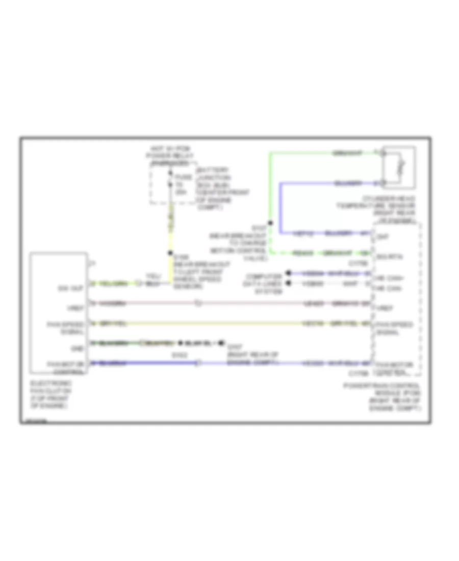
Cooling Fan Wiring Diagram for Ford Expedition EL 2007
List of elements for Cooling Fan Wiring Diagram for Ford Expedition EL 2007:
- Battery junction box (bjb) (center front of engine compt)
- C175e
- Cht
- Computer data lines system
- Cylinder head temperature sensor (right rear of engine)
- Electronic fan clutch (top front of engine)
- Fan motor control
- Fan motor control c175b
- Fan speed signal
- Fuse 20a
- G107 (right rear of engine compt)
- Gnd
- Hot w/ pcm power relay energized
- Hs can+
- Hs can-
- Le423
- Powertrain control module (pcm) (right rear of engine compt)
- Re405
- S102
- S106 (near breakout to left front wheel speed sensor)
- S137 (near breakout to charge motion control valve)
- Sig rtn
- Sw out
- Vdb04
- Vdb05
- Ve712
- Vec03
- Vec10
- Vref
CRUISE CONTROL
Cruise Control Wiring Diagram for Ford Expedition EL 2007
List of elements for Cruise Control Wiring Diagram for Ford Expedition EL 2007:
- Accelerator pedal position sensor (above accelerator pedal)
- App1
- App2
- App3
- Appsref1
- Appsref2
- Appsrtn1
- Appsrtn2
- Battery junction box (bjb) (center front of engine compt)
- Bps
- Brake pedal position switch (on brake pedal support)
- C175b
- C175e
- C218a
- C218b
- Case gnd
- Ce105
- Ce412
- Ce414
- Ce415
- Ce426
- Ce509
- Cl517
- Clock spring (in steering wheel)
- Computer data lines system
- Electronic throttle control (etc) motor (top rear of engine)
- Except navigator
- Fuse 31 15a
- Fuse 36 10a
- Fuse 74 20a
- G108 (right rear of engine compt)
- Gd113
- Hot at all times
- Hot w/ pcm power relay energized
- Hs can +
- Hs can -
- Illumination
- Interior lights system
- Le134
- Le136
- Le137
- Left steering wheel switch
- Navigator
- Off
- Powertrain control module (pcm) (right rear of engine compt)
- Re134
- Re136
- Re137
- Res08
- Resume
- S103
- S112
- S115
- S124 (in engine control sensor harness, near breakout to left front foglight)
- S133 (in engine control sensor harness, near breakout to c212)
- Sbb36
- Sccs
- Sccsrtn
- Set (+)
- Set (-)
- Stoplamp
- Tacm+
- Tacm-
- Throttle position sensor (tps) (on throttle body)
- Tp1 ns
- Tp2 ps
- Tpref
- Tprtn
- Vbat
- Vdb04
- Vdb05
- Ve818
- Ve819
- Ves10
DEFOGGERS
Defoggers Wiring Diagram for Ford Expedition EL 2007
List of elements for Defoggers Wiring Diagram for Ford Expedition EL 2007:
- Automatic a/c
- Battery junction box (bjb) (center front of engine compartment)
- C228b
- C2357a
- C2357b
- C402a
- C402b
- Climate control
- Control sensor harness, under battery junction box)
- Defrost request
- Electronic automatic temperature control (eatc) module (in center of dash)
- Fuse 15a
- Fuse 40a
- G301 (on left "b" pillar)
- G401 (under left quarter window)
- Hot at all times
- Left side exterior rear view mirror (at left rear view mirror)
- Manual a/c
- Manual climate control module (behind center of dash)
- Nca
- Rear window defrost grid
- Rear window defrost relay
- Right side exterior rear view mirror (at right rear view mirror)
- S121
- S204 (in body main harness, in breakout to c211)
- S207
- S423
- S426 (in switch & wiring assembly, near breakout to rear window defrost grid)
- S503
- W/ auxiliary
- W/o auxiliary
ELECTRONIC SUSPENSION
Electronic Suspension Wiring Diagram for Ford Expedition EL 2007
List of elements for Electronic Suspension Wiring Diagram for Ford Expedition EL 2007:
- Air suspension compressor (right front of engine compt)
- Air suspension compressor relay
- Air suspension module (under left end of dash)
- Batt
- Battery junction box (bjb) (center front of engine compt)
- C2131a
- C2131b
- Cbb65
- Ccl01
- Ccl05
- Ccl07
- Ccl14
- Comp
- Computer data lines system
- Fuse 10a
- Fuse 30a
- Fuse 50a
- G103 (left front of engine compt)
- G105 (right front of engine compt)
- G106 (right front of engine compt)
- G203 (behind left kick panel)
- Gd120
- Gd133
- Gnd
- Hot at all times
- Hot in on or start
- Hs can +
- Hs can -
- Lcl12
- Left rear air spring solenoid valve (left rear shock tower)
- Left rear height sensor (left rear shock tower)
- Lh rear sol
- Lr ht sens
- Nca
- Pwr
- Rcl12
- Return
- Rh rear sol
- Right rear air spring solenoid valve (right rear shock tower)
- Right rear height sensor (right rear shock tower)
- Rr ht sens
- S108
- S118
- S125
- S131
- S203
- S431 (in taillights harness, near breakout to fuel pump module)
- S432 (in taillights harness, near breakout to fuel pump module)
- S435
- Sbb47
- Sens pwr
- Sig
- Sw ign
- Vcl12
- Vcl13
- Vdb04
- Vdb05
- Vent
ENGINE PERFORMANCE
5.4L
5.4L, Engine Performance Wiring Diagram (1 of 4) for Ford Expedition EL 2007
List of elements for 5.4L, Engine Performance Wiring Diagram (1 of 4) for Ford Expedition EL 2007:
- (in body main harness, near breakout to c212) (expedition el & navigator l) s267
- (in engine control sensor harness, near breakout to left front wheel speed sensor) s129
- (in engine control sensor harness, under battery junction box)
- (near breakout to battery junction box) s112
- (near breakout to horn) s122
- (near breakout to left front wheel speed sensor)
- (near breakout to powertrain control module)
- (right rear of engine compt)
- 10a
- 20a
- 30a
- A/c clutch relay
- A/c pressure
- A/c pressure transducer sensor (right front of engine compt)
- Accr
- Air conditioning system
- Anti-lock brakes system
- App1
- App2
- App3
- Appsref1
- Appsref2
- Appsrtn1
- Appsrtn2
- Battery junction box (bjb) (center front of engine compt)
- Bps
- C175b
- Canvent
- Case gnd
- Cbb71
- Cbb76
- Cdb08
- Cdc10
- Cdc12
- Cdc15
- Cdc35
- Cdc38
- Ce105
- Ce114
- Ce132
- Ce226
- Ce233
- Ce234
- Ce414
- Ce415
- Ce509
- Ce607
- Ce608
- Cet40
- Ch302
- Ch421
- Cl517
- Computer data lines system
- Cooling fans system
- Cruise control system
- Electronic fan clutch (top front of engine)
- Evap canister vent control solenoid (under left side of vehicle)
- Fan motor ctrl
- Fan speed signal
- Feps
- Ftp sens sig
- Fuse
- G107
- G107 (right rear of engine compt)
- G108
- Gd113
- Gen com
- Gen mon
- Ho2s-12
- Ho2s-22
- Hot at all times
- Hot in start or run
- Hs can+
- Hs can-
- Htr-12
- Htr-22
- Iat
- Inertia fuel shutoff (ifs) switch (left rear corner of cargo area, behind trim)
- Injector
- Late production
- Le136
- Le137
- Le230
- Le423
- Maf
- Mafrtn
- Mass air flow/intake air temperature (maf/iat) sensor (in intake system)
- Nca
- Park/netural
- Pcm power relay
- Powertrain control module (pcm) (right rear of engine compt)
- Pwr gnd
- Re136
- Re137
- Re320
- Re407
- Re508
- Relay control
- S101
- S102
- S103
- S106
- S115
- S120
- S156
- S442 (expedition el & navigator l) (in body main harness, near breakout to c465)
- Sbb36
- Sccs
- Sccsrtn
- Sig return
- Smc
- Smcs
- Smr/start
- Starting/charging system
- Stoplamp
- Transmissions system
- Vbatt
- Vdb04
- Vdb05
- Ve510
- Ve518
- Ve731
- Ve733
- Ve740
- Ve807
- Ve822
- Ve922
- Vec03
- Vec10
- Vmv
- Vpwr
- Vref
- Vss
- Wiper/washer system
5.4L, Engine Performance Wiring Diagram (2 of 4) for Ford Expedition EL 2007
List of elements for 5.4L, Engine Performance Wiring Diagram (2 of 4) for Ford Expedition EL 2007:
- (above accelerator pedal) accelerator pedal position sensor
- (in back-up light switch to rear light feed harness, near breakout to c146)
- (in engine control sensor harness, near breakout to battery junction box) s111
- (in engine control sensor harness, under battery junction box)
- (in fuel tank) fuel tank pressure sensor
- (left front of engine compt) g103
- (left rear of engine) heated positive crankcase ventilation (pcv) valve
- (under left rear of vehicle) g404
- 15a
- 20a
- Battery junction box (bjb) (center front of engine compt)
- Brake pedal position switch (on brake pedal support)
- C211)
- Evap canister purge valve (left rear of engine compt)
- Exterior lights system
- Fuel pump module (in fuel tank)
- Fuel pump motor diode
- Fuel pump relay
- Fuse
- Heated oxygen sensor (ho2s) 12 (on rear of exhaust system)
- Heated oxygen sensor (ho2s) 22 (on rear of exhaust system)
- Hot at all times
- Hot in run or start
- Instrument cluster system
- Nca
- S115
- S116
- S124 (in engine control sensor harness, near breakout to left front foglight)
- S140
- S149
- S150
- S433
- S434 in taillights harness, near breakout to fuel pump module
- S443 (expedition el & navigator l) (in body main harness, near breakout to c405)
5.4L, Engine Performance Wiring Diagram (3 of 4) for Ford Expedition EL 2007
List of elements for 5.4L, Engine Performance Wiring Diagram (3 of 4) for Ford Expedition EL 2007:
- (in engine control sensor & fuel charge harness, near breakout to fuel injector 3)
- (in engine control sensor & fuel charge harness, near breakout to fuel injector 7)
- (in engine control sensor & fuel charge harness, near breakout to heated oxygen sensor 11)
- (left rear of engine) knock sensor 2
- (lower right front of engine) crankshaft position sensor
- (on throttle body) throttle position sensor (tps)
- (right rear of engine) cylinder head temperature sensor
- (right rear of engine) knock sensor 1
- (top rear of engine) electronic throttle control (etc) motor
- Charge motion control valve (cmcv) (rear of engine)
- Fuel injectors (on left cylinder head)
- Fuel injectors (on right cylinder head)
- G107 (right rear of engine compt)
- Nca
- S136
- S138
- S140
- S142
5.4L, Engine Performance Wiring Diagram (4 of 4) for Ford Expedition EL 2007
List of elements for 5.4L, Engine Performance Wiring Diagram (4 of 4) for Ford Expedition EL 2007:
- (in engine control sensor & fuel charge harness, near breakout to fuel injector 3)
- (in engine control sensor & fuel charge harness, near breakout to powertrain control module)
- (in headlights harness, in breakout to c133)
- (near breakout to heated oxygen sensor 11) s138
- (on left cylinder head) coils on plug
- (on right cylinder head) coils on plug
- C175e
- Camshaft position sensor 1 (front of right cylinder bank)
- Camshaft position sensor 2 (front of left cylinder head)
- Cd1a
- Cd2d
- Cd3b
- Cd4g
- Cd5f
- Cd6f
- Cd7c
- Cd8h
- Ce123
- Ce124
- Ce125
- Ce126
- Ce127
- Ce128
- Ce205
- Ce206
- Ce207
- Ce208
- Ce209
- Ce210
- Ce211
- Ce212
- Ce235
- Ce236
- Ce309
- Ce310
- Ce411
- Ce412
- Ce422
- Ce426
- Ce918
- Cht
- Ckp+
- Ckp-
- Cmcv
- Cmp1+
- Cmp1-
- Cmp2+
- Cmp2-
- Cvm
- De706
- Fuel inj 1
- Fuel inj 2
- Fuel inj 3
- Fuel inj 4
- Fuel inj 5
- Fuel inj 6
- Fuel inj 7
- Fuel inj 8
- Heated oxygen sensor (ho2s) 11 (on right exhaust downpipe)
- Heated oxygen sensor (ho2s) 21 (on left exhaust downpipe)
- Ho2s-11
- Ho2s-21
- Htr-11
- Htr-21
- Ignition transformer capacitor 1 (top right front of engine)
- Ignition transformer capacitor 2 (top left front of engine)
- Ks1+
- Ks1-
- Ks2+
- Ks2-
- Le134
- Le135
- Nca
- Powertrain control module (pcm) (right rear of engine compt)
- Re134
- Re135
- Re143
- Re144
- Re323
- Re324
- Re405
- S135
- S137 near breakout to charge motion control valve)
- S139
- S141 (in engine control sensor & fuel nca charge harness, near breakout to powertrain control module)
- S143
- Shield
- Sig return
- Tacm+
- Tacm-
- Tp1 ns
- Tp2 ps
- Tpref
- Tprtn
- Variable camshaft timing (vct) valve 1 (right front of engine)
- Variable camshaft timing (vct) valve 2 (left side of engine)
- Vct 1
- Vct 2
- Ve706
- Ve707
- Ve712
- Ve735
- Ve737
- Ve801
- Ve802
- Ve818
- Ve819
- Vh433
- Vref
EXTERIOR LIGHTS
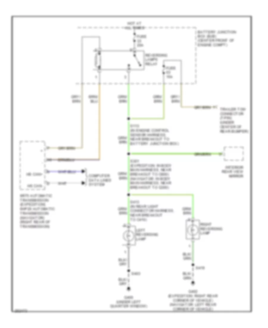
Back-up Lamps Wiring Diagram for Ford Expedition EL 2007
List of elements for Back-up Lamps Wiring Diagram for Ford Expedition EL 2007:
- 6r75 automatic transmission (expedition) 6hp26 automatic transmission (navigator) (right rear of transmission)
- Battery junction box (bjb) (center front of engine compt)
- Computer data lines system
- Fuse 15a
- Fuse 20a
- G400 (under left quarter window)
- G402 (expedition: right rear corner of vehicle) (navigator: left rear corner of vehicle)
- Hot at all times
- Hs can+
- Hs can-
- Interior rear view mirror
- Left reversing lamp
- Reversing lamps relay
- Right reversing lamp
- S301 (expedition: in body main harness, near breakout to c800) (navigator: in body main harness, near breakout to g300)
- S403
- S419
- Trailer tow connector (7-pin) (under center of rear bumper)
Exterior Lamps Wiring Diagram (1 of 2) for Ford Expedition EL 2007
List of elements for Exterior Lamps Wiring Diagram (1 of 2) for Ford Expedition EL 2007:
- (behind right kick panel) smart junction box (sjb)
- (in engine control sensor harness, near breakout to battery junction box) s110
- Auto
- Auto- lamp on
- Brake pedal sw
- Ctrl
- Fuse 22 15a
- Fuse 5 15a
- Fuse 6 20a
- G103 (left front of engine compt)
- G106 (right front of engine compt)
- G200 (behind right kick panel)
- G300 (behind right kick panel)
- G301 (on left "b" pillar)
- G302 (behind right kick panel)
- Hazard
- Head lamp off
- Head lamp on
- Headlamp switch
- Hot at all times
- Left
- Left front park/ turn lamp
- Left front side lamp
- Left front turn lamp (fet)
- Left rear stop/ turn lamp (fet)
- Left side exterior rear view mirror
- Left turn
- Lf turn
- Logic gnd
- Low
- Lr stop/ turn lamp
- Multifunction switch
- Nca
- Off
- Park
- Park lamp on
- Park lamp relay
- Rf turn
- Right
- Right front park/ turn lamp
- Right front side lamp
- Right front turn lamp (fet)
- Right rear stop/ turn lamp (fet)
- Right side exterior rear view mirror
- Right turn
- Rr stop/ turn lamp
- S108
- S118
- S123
- S125
- S126 (in engine control sensor harness, near breakout to left front side light)
- S201 (in engine control sensor harness, near breakout to c211)
- S207
- S259
- S276
- S503
- Turn
- Vbat
Exterior Lamps Wiring Diagram (2 of 2) for Ford Expedition EL 2007
List of elements for Exterior Lamps Wiring Diagram (2 of 2) for Ford Expedition EL 2007:
- (in engine control sensor harness, near breakout to left front foglight) s124
- (in main harness, near breakout to instrument cluster) s254
- Abs control module (left side of engine compt)
- Anti-lock brakes system
- Battery junction box (bjb) (center front of engine compt)
- Boo
- Bps
- Brake pedal position switch (on brake pedal support)
- C175b
- Ces09
- Cls17
- Cls30
- Door locks system
- Fuse 15a
- Fuse 20a
- G200 (behind right kick panel)
- G400 (under left quarter window)
- G401 (under left quarter window)
- G402 (right rear corner of vehicle)
- Hazard
- High mounted stoplamp
- Hot at all times
- Hot in start or run
- Interior lights system
- Left license plate lamp
- Left rear park/ stop/ turn lamp
- Left turn trailer tow relay
- Nca
- Park
- Park lps
- Parking lamp trailer tow relay
- Power liftgate
- Power liftgate/ traction control/ hazard switch
- Powertrain control module (right rear of engine compt)
- Right license plate lamp
- Right rear park/ stop/ turn lamp
- Right turn trailer tow relay
- S115
- S133 (in engine control sensor harness, near breakout to c212)
- S205 (in body main harness, near breakout to smart junction box)
- S206 (in body main harness, near breakout to c214)
- S232
- S300 (in body main harness, near breakout to g300)
- S319 (in body main harness, near breakout to g301)
- S403
- S404 (in rear light connector harness, near breakout to g400)
- S419
- Stop lp sw
- Stop/ turn
- Traction
- Trailer electronic brake control module (under center of dash)
- Trunk, tailgate, fuel doors system
Trailer/Camper Adapter Wiring Diagram for Ford Expedition EL 2007
List of elements for Trailer/Camper Adapter Wiring Diagram for Ford Expedition EL 2007:
- (in taillights harness, near breakout to 4-pin trailer tow connector) (heavy duty) s438
- (in taillights harness, near breakout to g405) (heavy duty) s436
- (in taillights harness, near breakout to g405) (heavy duty) s437
- (not used)
- Back-up lamps circuit
- Battery charge trailer tow relay
- Battery junction box (bjb) (center front of engine compt)
- Boo
- C2280g
- Cat19
- Cls17
- Cls30
- Exterior lamps circuit
- Exterior lights circuit
- Fuse 10a
- Fuse 25a
- Fuse 30a
- Fuse 40a
- G106 (right front of engine compt)
- G200 (behind right kick panel)
- G405 (under left rear of vehicle)
- Gd138
- Ground
- Heavy duty
- Hot at all times
- Hot in run
- Left turn trailer tow relay
- Light duty
- Nca
- Park lps
- Parking lamp trailer tow relay
- Pwr
- Right turn trailer tow relay
- S118
- S232
- S439 (heavy duty)
- Sbb05
- Smart junction box (sjb) (behind right kick panel)
- Trailer brake
- Trailer electronic brake control module (expedition: under center of dash) (navigator: under left side of dash)
- Trailer tow connector (4-pin) (under center of rear bumper)
- Trailer tow connector (7-pin) (heavy duty) (under center of rear bumper)
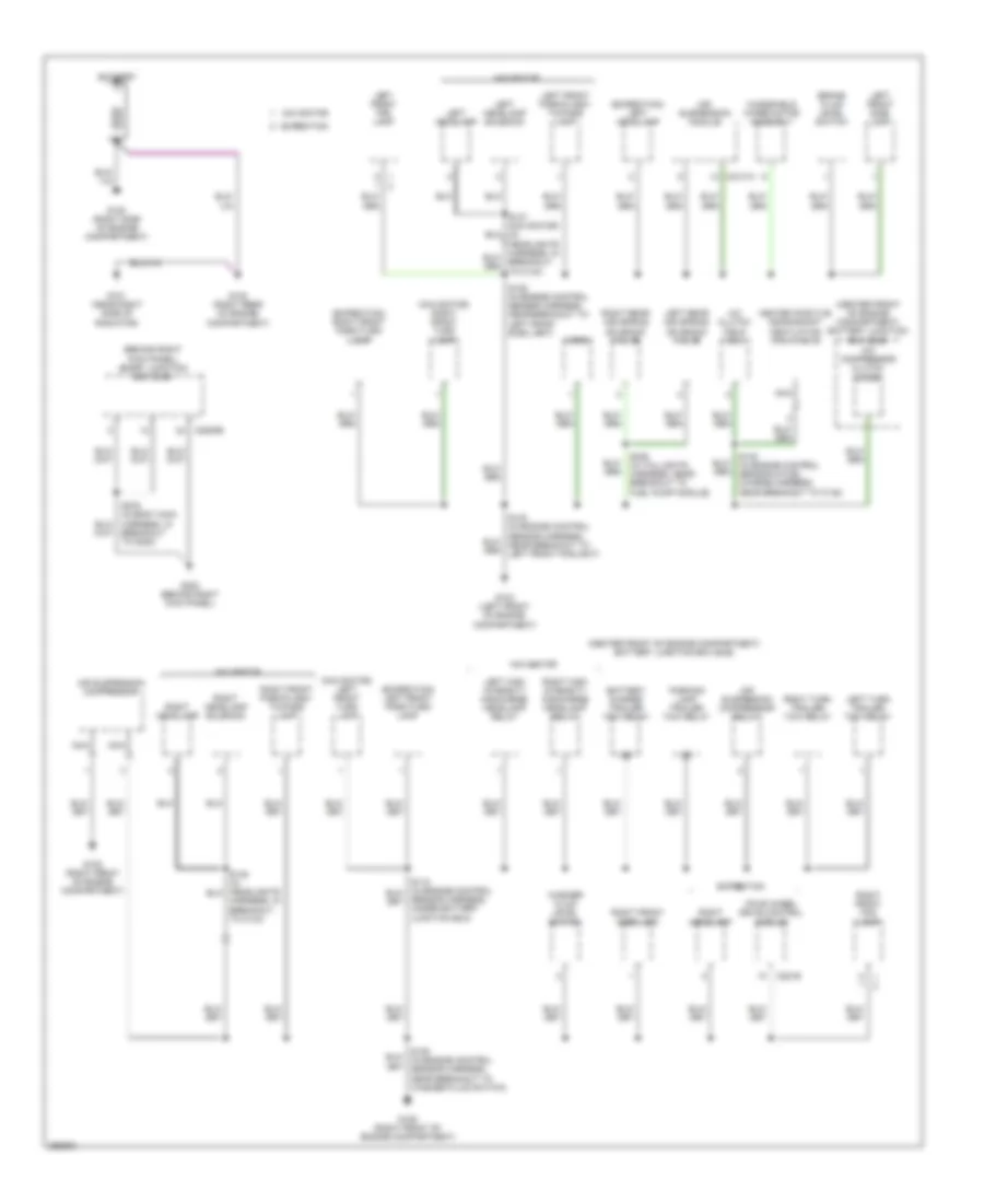
GROUND DISTRIBUTION
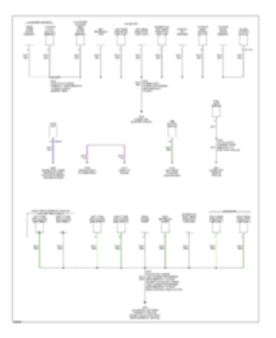
Ground Distribution Wiring Diagram (1 of 5) for Ford Expedition EL 2007
List of elements for Ground Distribution Wiring Diagram (1 of 5) for Ford Expedition EL 2007:
- (behind right kick panel) smart junction box (sjb)
- (center front of engine compartment) battery junction box (bjb)
- (expedition) left front park/turn lamp
- (expedition) left headlamp
- (expedition) right front park/turn lamp
- (navigator) left front turn lamp
- (navigator) right front turn lamp
- A/c clutch field coil
- A/c compressor clutch diode
- Air suspension compressor
- Air suspension compressor relay
- Air suspension module
- Battery
- Battery charge trailer tow relay
- Brake fluid level switch
- C2131a
- C2280e
- C281b
- Expedition
- Four wheel drive control module
- G100 (right side of engine compartment)
- G101 (near right side of radiator)
- G102 (right rear of engine compartment)
- G103 (left front of engine compartment)
- G105 (right front of engine compartment)
- G106 (right front of engine compartment)
- G302 (behind right kick panel)
- Harness, in breakout to c134)
- Heated positive crankshaft ventilation (pcv) valve
- Horn
- Left front fog lamp
- Left front park/flash- to-pass lamp
- Left front side lamp
- Left headlamp
- Left headlamp solenoid
- Left high intensity discharge headlamp relay
- Left rear air spring solenoid valve
- Left turn trailer tow relay
- Navigator
- Nca
- Parking lamp trailer tow relay
- Right front fog lamp
- Right front park/flash- to-pass lamp
- Right front side lamp
- Right headlamp
- Right headlamp solenoid
- Right high intensity discharge headlamp relay
- Right rear air spring solenoid valve
- Right turn trailer tow relay
- S123 (in engine control sensor harness, near breakout to left front foglight)
- S125 (in engine control sensor harness, near breakout to left front side light)
- S140 (in engine control sensor & fuel charge harness, near breakout to c145)
- S435 (in taillights harness, near breakout to fuel pump module)
- Sensor harness, under battery junction box)
- Washer fluid level switch
- Windshield wiper motor assembly
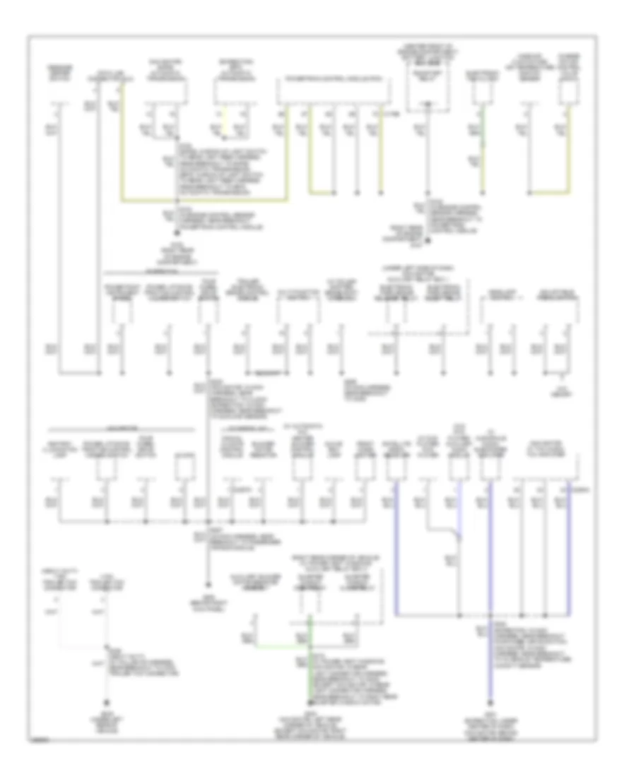
Ground Distribution Wiring Diagram (2 of 5) for Ford Expedition EL 2007
List of elements for Ground Distribution Wiring Diagram (2 of 5) for Ford Expedition EL 2007:
- (center front of engine compartment) battery junction box (bjb)
- (expedition) 6r75 automatic transmission
- (heavy duty) 7 pin trailer tow connector
- (navigator w/ thx audio) thx amplifier
- (navigator) 6hp26 automatic transmission
- (right rear corner of vehicle) (w/ power vent windows) auxiliary relay box 2
- (right rear of engine compartment) g107
- (under left side of dash) (navigator) auxiliary relay box 1
- (w audiophile audio) subwoofer amplifier
- (w/ automatic a/c) heater blower control module
- (w/ column shifter) brake shift interlock
- (w/ dvd player) dvd player
- (w/o dvd player) auxiliary audio module
- 4 pin trailer tow connector
- Adjustable pedal switch
- Ashtray illumination lamp
- Auxiliary blower motor resistor assembly
- Blower motor resistor
- C175b
- C2357c
- C2364a
- Charge motion control valve (cmcv)
- Clock
- Data link connector (dlc)
- Electronic fan clutch
- Electronic park brake release relay
- Electronic park brake reset relay
- Expedition
- Four wheel drive switch
- Front cigar lighter
- G108 (right rear of engine compartment)
- G200 (behind right kick panel)
- G201 (expedition: under center of dash) (navigator: behind center of dash)
- G403 (navigator: left rear corner of vehicle) (except navigator: right rear corner of vehicle)
- G405 (under left rear of vehicle)
- Glove box lamp
- Headlamp switch
- Manual climate control module
- Mass air flow/intake air temperature (maf/iat) sensor
- Message center switch
- Multi-function switch
- Navigator
- Near breakout to 4-pin trailer tow connector)
- Near breakout to 6hp26 automatic transmission) (6r75: in back-up light switch to rear light feed harness, near breakout to 6r75 automatic transmission)
- Power liftgate/ traction control hazard switch
- Power point instrument panel
- Powertrain control module (pcm)
- Quarter window close relay
- Quarter window open relay
- Run/start relay
- S245 (expedition: in main harness, near breakout four-wheel drive switch) (navigator: in main harness, near breakout to in-vehicle temperature/ humidity sensor)
- S259 (in main harness, near breakout to c238)
- Satellite radio receiver
- Trailer electronic brake control module
- W/ manual a/c
- W/o memory
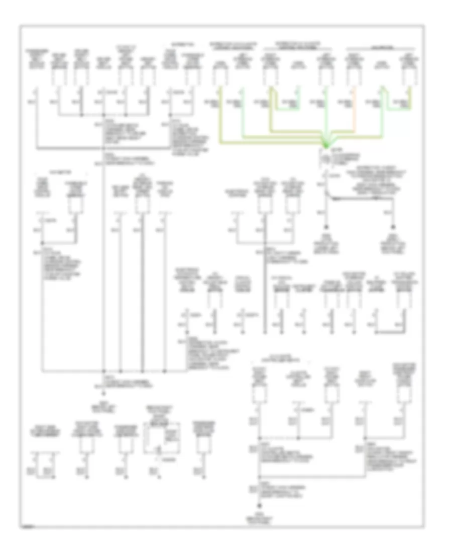
Ground Distribution Wiring Diagram (3 of 5) for Ford Expedition EL 2007
List of elements for Ground Distribution Wiring Diagram (3 of 5) for Ford Expedition EL 2007:
- (10 way w/ memory) left power seat switch
- (10 way) right power seat switch
- (6 way) right power seat switch
- (behind right kick panel) smart junction box (sjb)
- (expedition: in body main harness, near breakout to parking brake switch) (navigator: in body main harness, near breakout to c238) (early production) s214
- (if equipped) floor shifter
- (navigator) passenger side front power window motor
- (navigator) right side front power window switch
- (navigator) steering column position switch
- (w/ column shifter) transmission control switch
- (w/ manual a/c) sunload sensor
- (w/ memory) adjustable pedal switch
- (w/ memory) exterior rear view mirror switch
- (w/ navigation) interior rear view mirror
- (w/o navigation) interior rear view mirror
- C218a
- C218b
- C228a
- C228oe
- C2357a
- C281b
- C341e
- Climate controlled seat module
- Clockspring (in steering wheel)
- Door lock relay
- Driver safety belt buckle switch
- Driver seat module
- Driver seat position sensor
- Electronic automatic temperature control (eatc) module
- Electronic compass
- Expedition
- Expedition w/ climate control switches
- Expedition w/o climate control switches
- Four wheel drive control module
- G203 (behind left kick panel)
- G204 (early production) (behind left kick panel)
- G205 (late production) (under left end of dash)
- G300 (behind right kick panel)
- Horn switch
- Instrument cluster
- Keyless entry keypad
- Left steering wheel switch
- M c3265a
- Manual climate control module
- Memory set switch
- Navigator
- Parking aid module (pam)
- Passenger safety belt buckle switch
- Passenger side door lock switch
- Passenger side rear door ajar switch
- Passive anti-theft transceiver
- Right front door ajar switch
- Right side exterior rear view mirror
- Right steering wheel switch
- S131 (w/ four wheel drive) (expedition) (in engine control sensor harness, near breakout to evap canister purge valve)
- S131 (w/ four wheel drive) (in engine control sensor harness, near breakout to evap canister purge valve)
- S207 (in body main harness, near breakout to smart junction box)
- S228 (expedition: in main harness, near breakout to instrument panel power point) (navigator: in main harness, near breakout to clock)
- S323 (in power seats harness, near breakout to driver seat rear height motor)
- S912 (in vanity mirror light harness, in breakout to c298)
- W/ climate controlled seats
- Windshield wiper motor assembly
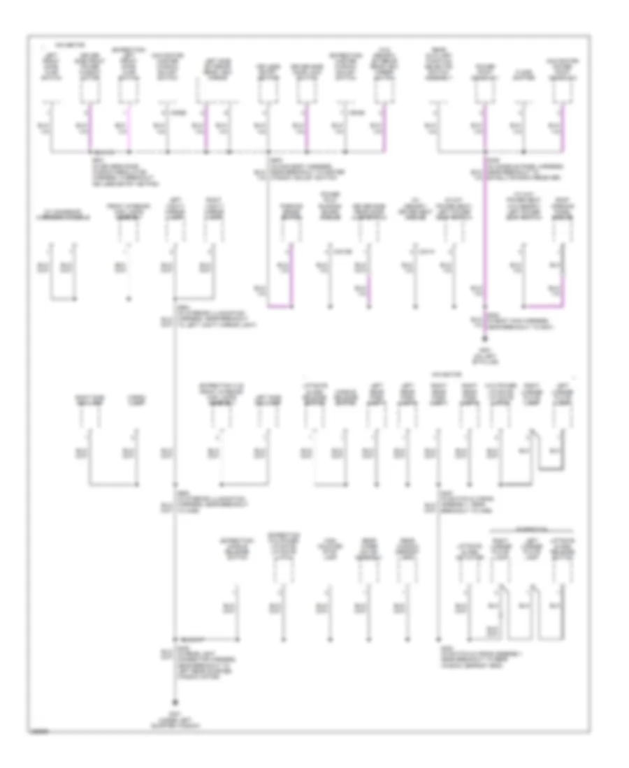
Ground Distribution Wiring Diagram (4 of 5) for Ford Expedition EL 2007
List of elements for Ground Distribution Wiring Diagram (4 of 5) for Ford Expedition EL 2007:
- (10 way power seat w/o memory) left power seat switch
- (6 way power seat) left power seat switch
- (expedition w/o power liftgate) liftgate latch
- (expedition xls) front interior/ map lamps assembly
- (expedition) handle release switch
- (expedition) left front door ajar switch
- (expedition) master window adjust switch
- (navigator) master window adjust switch
- (navigator) power point console 2
- (w/ memory) driver seat module
- (w/ moonroof) overhead console
- (w/o memory) exterior rear view mirror switch
- (w/o power liftgate) liftgate latch
- C3313b
- C341a
- C504b
- C535b
- Cargo lamp
- Driver side door lock switch
- Driver side front power window motor
- Driver side rear door ajar switch
- Expedition
- Floor shifter
- Front interior/ map lamps assembly
- G301 (on left "b" pillar)
- G401 (under left quarter window)
- Handle release switch
- High mounted stop lamp
- Keyless entry keypad
- Left front door ajar switch
- Left license plate lamp
- Left rear park lamp 1
- Left rear park lamp 2
- Left side exterior rear view mirror
- Left side rail lamp
- Left vanity mirror lamp
- Liftgate glass actuator
- Liftgate glass release switch
- Navigator
- Parking brake switch
- Power fold running board module
- Power point console 1
- Rear auxiliary function selector switch assembly
- Rear window defrost grid
- Rear wiper motor assembly
- Right license plate lamp
- Right rear park lamp 1
- Right rear park lamp 2
- Right side rail lamp
- Right vanity mirror lamp
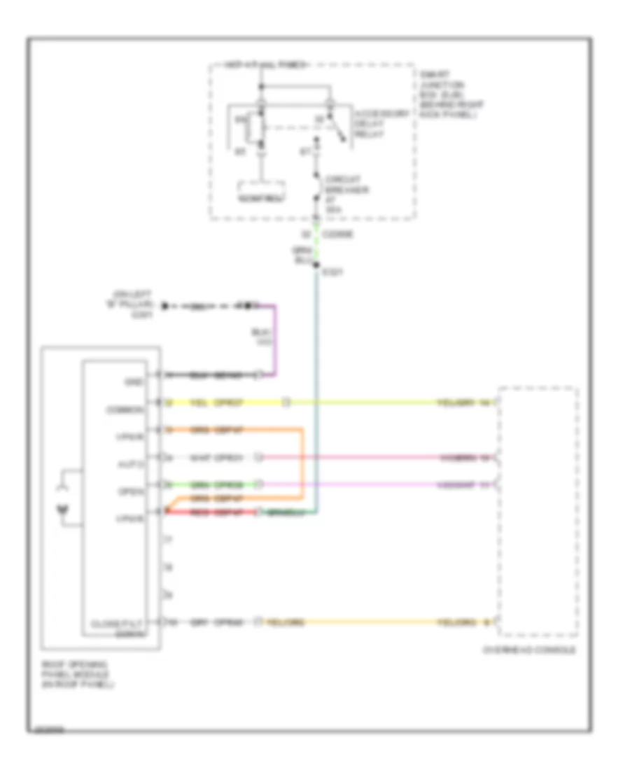
- Roof opening panel module
- S349 (in console panel harness, near breakout to satellite radio receiver)
- S423 (in switch & wiring assembly, near breakout to rear window defrost grid)
- S501 (in driver's door window regulator harness, in breakout keyless entry keypad)
- S503 (in main body harness, near breakout to master window adjust switch)
Ground Distribution Wiring Diagram (5 of 5) for Ford Expedition EL 2007
List of elements for Ground Distribution Wiring Diagram (5 of 5) for Ford Expedition EL 2007:
- (expedition) left rear park/stop/ turn lamp
- (expedition) right rear park/stop/ turn lamp
- (right rear corner of vehicle) auxiliary relay box 2
- (w/o power liftgate) rear wiper motor assembly
- Abs control module
- Audio unit
- C240a
- C4174a
- Fuel pump module
- G104 (left front of engine compartment)
- G109 (rear of right cylinder bank)
- G110 (front of engine)
- G202 (expedition: under center of dash) (navigator: behind center of dash)
- G400 (under left quarter window)
- G402 (navigator: left rear corner of vehicle) (except navigator: right rear corner of vehicle)
- G404 (under left rear of vehicle)
- Left rear park/stop/ turn lamp 1
- Left rear park/stop/ turn lamp 2
- Left reversing lamp
- Left third row folding seat relay
- Left third row folding seat switch
- Liftgate drive motor assembly
- Liftgate latch/ unlatch assembly
- Liftgate rear control switch
- Navigator
- Parking aid speaker
- Power liftgate module
- Rear power point
- Rear wiper motor assembly
- Right rear park/stop/ turn lamp 1
- Right rear park/stop/ turn lamp 2
- Right reversing lamp
- Right third row folding seat relay
- Right third row folding seat switch
- S419 (navigator: in rear light connector harness, near breakout to g402) (except navigator: in rear light connector harness, near breakout to right rear quarter window motor)
- S424 (in switch & wiring assembly, near breakout to rear window defrost grid)
- S433 (in taillights harness, near breakout to fuel pump module)
- W/ power liftgate
HEADLIGHTS
Headlights Wiring Diagram for Ford Expedition EL 2007
List of elements for Headlights Wiring Diagram for Ford Expedition EL 2007:
- (in engine control sensor harness, near breakout to battery junction box)
- (in engine control sensor harness, near breakout to battery junction box) s107
- Air conditioning system
- Auto
- Auto- lamp on
- Automatic a/c
- C2280a
- C2280d
- C2280f
- C2280g
- Computer data lines system
- Control
- Flash to pass
- Fog
- Fog ind
- Fog lamp
- Fog lamp relay
- Ftp
- Fuse 10a
- Fuse 15a
- G103 (left front of engine compt)
- G106 (right front of engine compt)
- G200 (behind right kick panel)
- G203 (behind left kick panel)
- G301 (on left "b" pillar)
- Head- lamp off
- Head- lamp on
- Headlamp switch
- High beam
- High beam relay
- Hot at all times
- Instrument cluster
- Interior lights system
- Left front fog lamp
- Left headlamp
- Left low beam (fet)
- Low
- Manual a/c
- Ms can+
- Ms can-
- Multi-function switch
- Off
- Park
- Park brake
- Park lamp on
- Parking brake switch (above left kick panel)
- Right front fog lamp
- Right headlamp
- Right low beam (fet)
- S108
- S109
- S125
- S228
- S259
- S322
- Smart junction box (sjb) (behind right kick panel)
- Sunload sensor (under top center of dash)
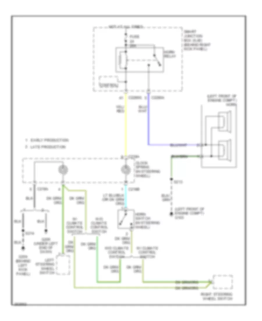
HORN
Horn Wiring Diagram for Ford Expedition EL 2007
List of elements for Horn Wiring Diagram for Ford Expedition EL 2007:
- (left front of engine compt) g103
- (left front of engine compt) horn
- 20a
- C218a
- C218b
- C2280a
- C2280g
- Clock spring (in steering wheel)
- Control
- Early production
- Fuse
- G204 (behind left kick panel)
- G205 (under left end of dash)
- Horn relay
- Horn switch (in steering wheel)
- Hot at all times
- Late production
- Left steering wheel switch
- Right steering wheel switch
- S213
- S214
- Smart junction box (sjb) (behind right kick panel)
- W/ climate control switch
- W/o climate control switch
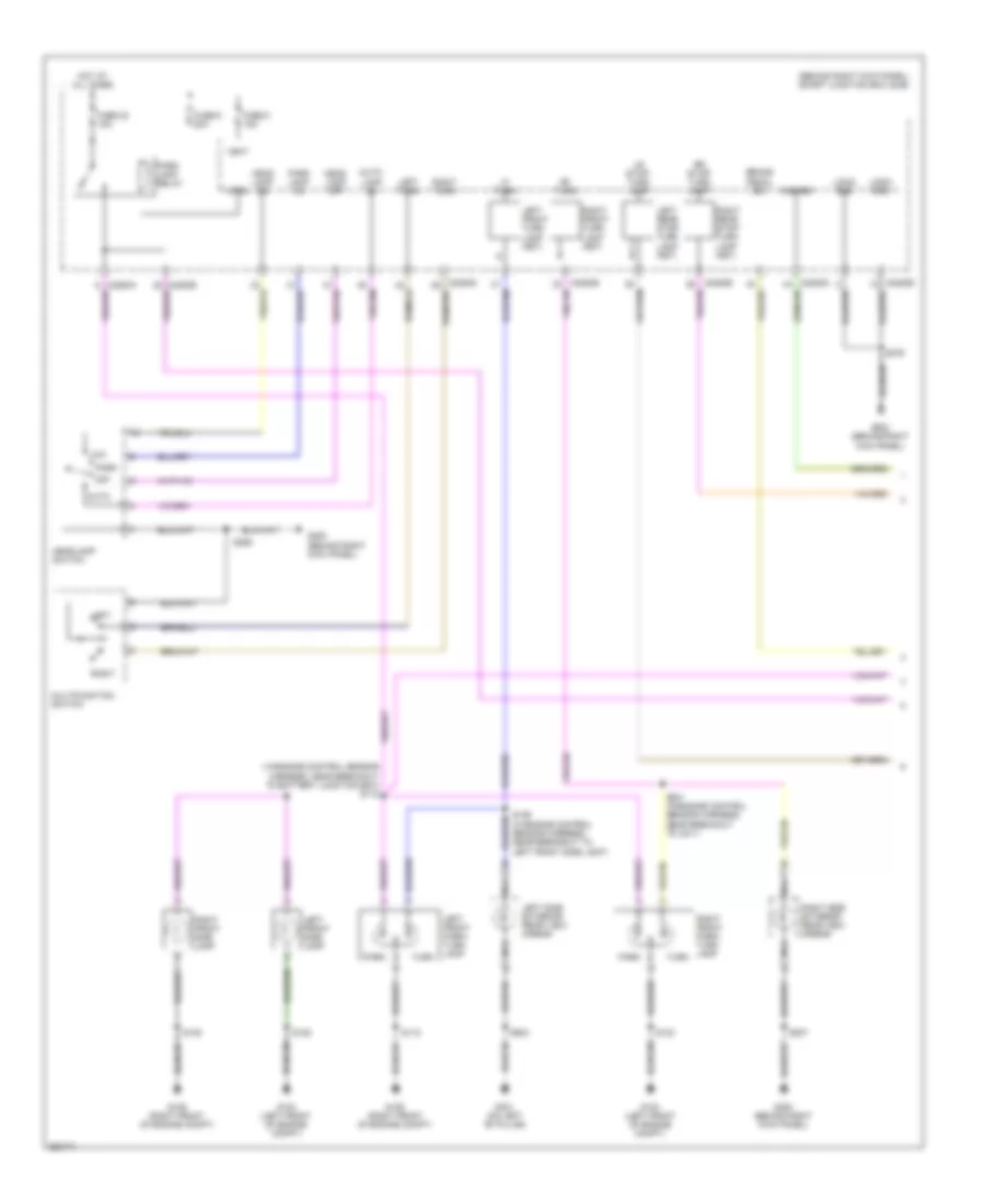
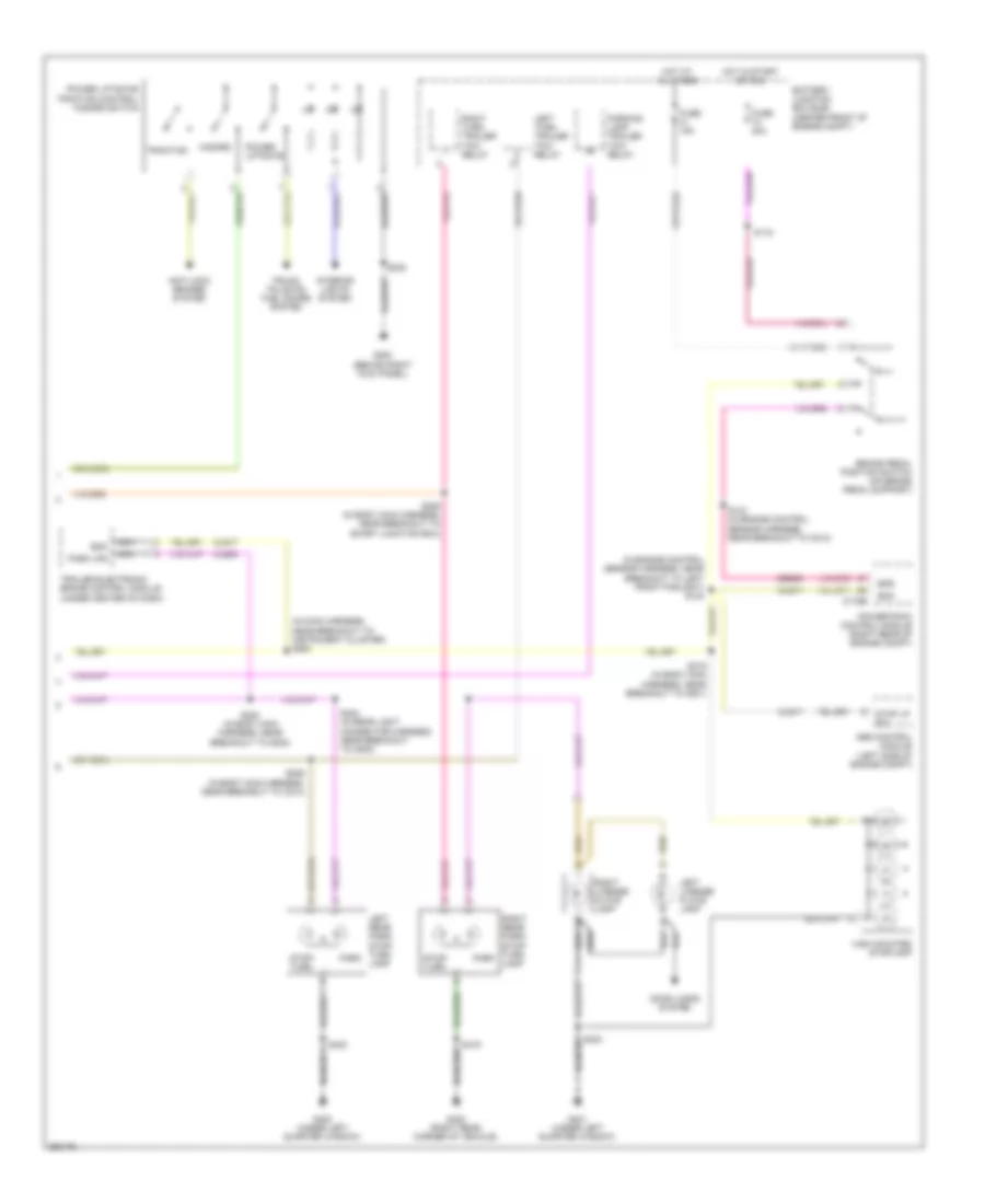
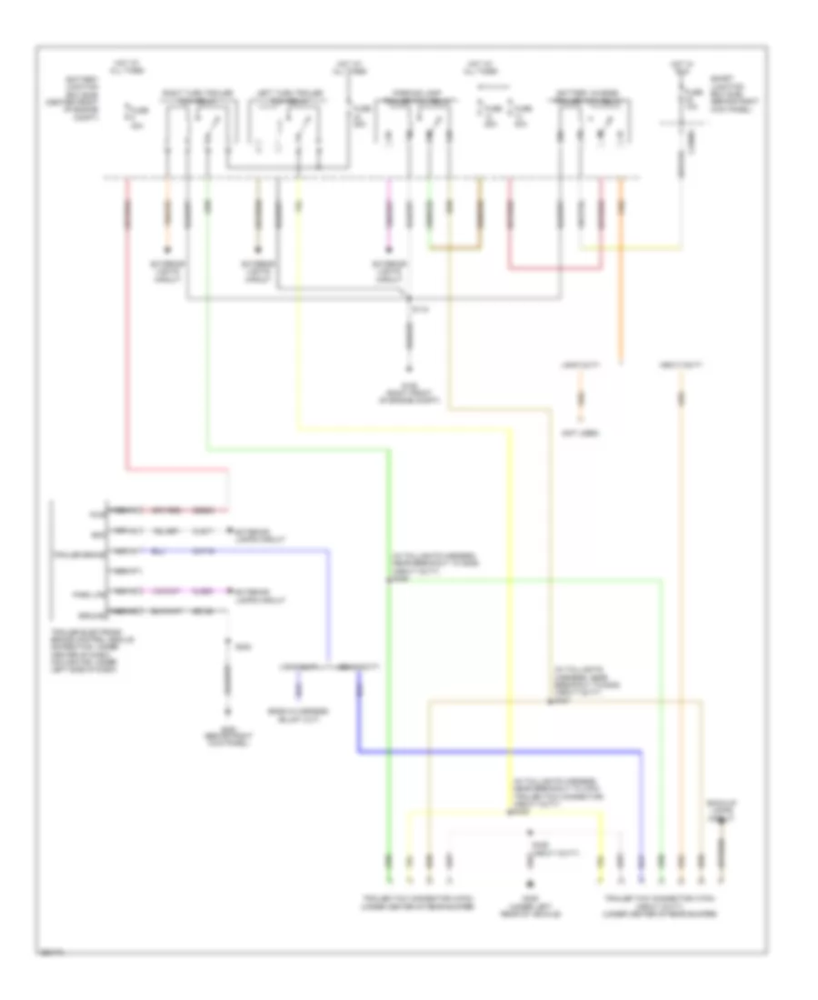
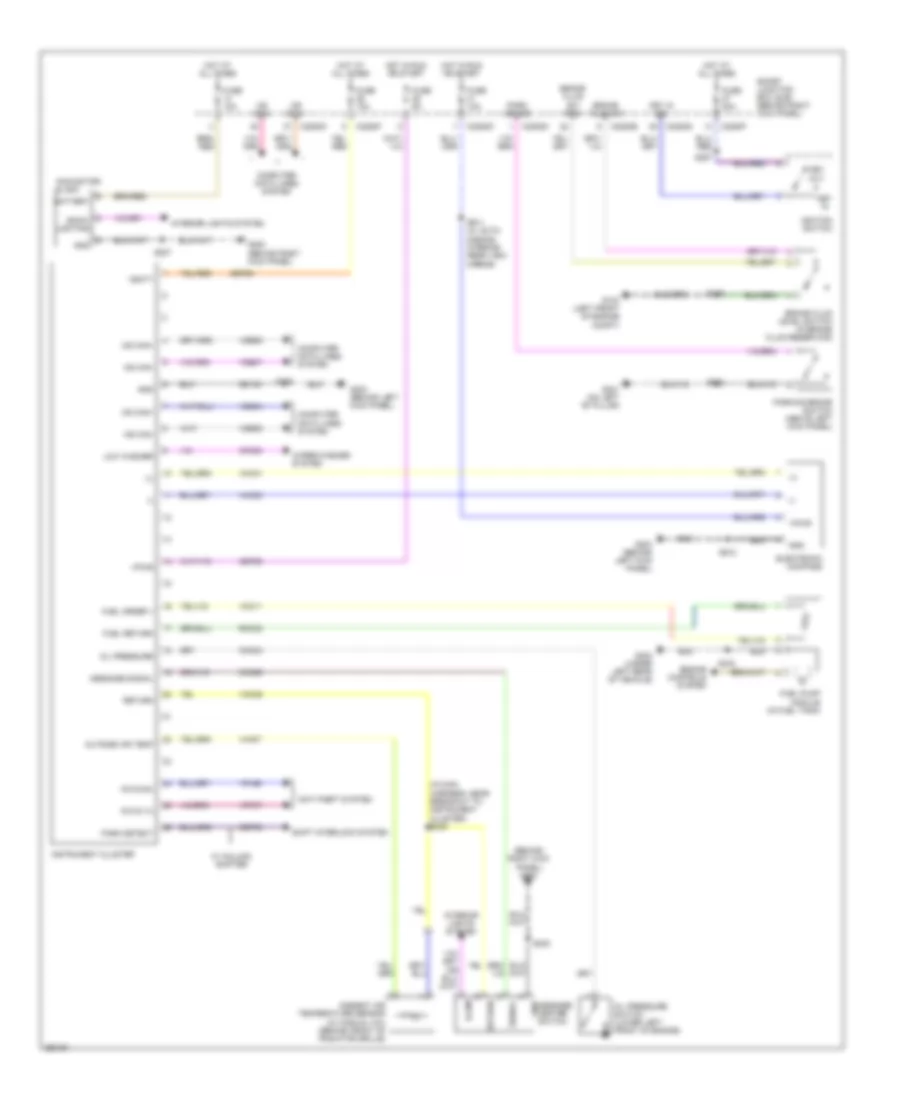
INSTRUMENT CLUSTER
Instrument Cluster Wiring Diagram for Ford Expedition EL 2007
List of elements for Instrument Cluster Wiring Diagram for Ford Expedition EL 2007:
- (+)
- (-)
- (behind right kick panel) g200
- (in main harness, near breakout to instrument cluster) s249
- (navigator) clock
- Ambient air temperature sensor (w/ manual a/c) (behind front of radiator grille)
- Anti-theft system
- Back- lighting
- Battery
- Brake fluid level switch (in brake fluid reservoir)
- Brake fluid sw
- Brake fluid sw rtn
- C2280b
- C2280d
- C2280f
- C2280g
- Cbp29
- Cet53
- Cmc20
- Cmc24
- Cmc29
- Computer data lines system
- Electronic compass
- Engine controls system
- Fuel order 1
- Fuel pump module (in fuel tank)
- Fuel return
- Fuse 10a
- Fuse 20a
- Fuse 5a
- G103 (left front of engine compt)
- G200 (behind right kick panel)
- G203 (behind left kick panel)
- G301 (on left "b" pillar)
- G404 (under left rear of vehicle)
- Gd133
- Gnd
- Gnd message center switch
- Hot at all times
- Hot in run or start
- Ignition switch
- Illum
- Instrument cluster
- Interior lights system
- Key in
- Key in ign
- Key out
- Low washer
- Message signal
- Ms can+
- Ms can-
- Oil pressure
- Oil pressure switch (lower left front of engine)
- Outside air temp
- Park brake
- Park detect
- Parking brake switch (above left kick panel)
- Pats rx
- Pats tx
- Return
- Rmc32
- S125
- S227
- S228
- S232
- S257
- S322
- S433
- S911 (w/ auto- dimming interior rear view mirror)
- S912
- Sbp26
- Shift interlock system
- Signal
- Smart junction box (sjb) (behind right kick panel)
- Vbatt
- Vdb04
- Vdb05
- Vdb06
- Vdb07
- Vh407
- Vmc11
- Vmc29
- Vmc30
- Vmc31
- Vpl56
- Vpwr
- Vrt07
- W/ column shifter
- Wiper/washer system
INTERIOR LIGHTS
Courtesy Lamps Wiring Diagram for Ford Expedition EL 2007
List of elements for Courtesy Lamps Wiring Diagram for Ford Expedition EL 2007:
- (at left rear view mirror) left side exterior rear view mirror
- (behind right kick panel) g200
- (in body main harness, near breakout to smart junction box) s209
- (in interior illumination harness, near breakout to c406)
- (in interior illumination harness, near breakout to c406) s901
- (in interior illumination harness, near breakout to c406) s902
- (in interior illumination harness, near breakout to left vanity mirror light)
- (in main harness, near breakout to headlight switch) s260
- (under left quarter window)
- (under left quarter window) g401
- Battery saver relay
- C2280d
- C2280e
- C2280f
- C2280g
- Cargo lamp
- Control
- Defeat
- Dim sw gnd
- Dimmer sw
- Dome
- Dome defeat
- Dome lp
- Except xls
- Front interior/map lamp assembly
- Fuse 10a
- Fuse 15a
- Fuse 2a
- G301 (on left "b" pillar)
- G401
- G401 (under left quarter window)
- Glove box lamp
- Homelink module
- Hot at all times
- Illumination dimmer
- Interior lighting (fet)
- Left side rail lamp
- Left vanity mirror lamp
- Nca
- Off
- Off dome
- Puddle lamp
- Puddle lamp (fet)
- Right side exterior rear view mirror (at right rear view mirror)
- Right side rail lamp
- Right vanity mirror lamp
- S207
- S227
- S316 (in body main harness, near breakout to g301)
- S503
- S900
- S901 (in interior illumination harness, near breakout to c406)
- S902
- S903
- S904
- Smart junction box (sjb) (behind right kick panel)
- Xls
Instrument Illumination Wiring Diagram (1 of 2) for Ford Expedition EL 2007
List of elements for Instrument Illumination Wiring Diagram (1 of 2) for Ford Expedition EL 2007:
- (in main harness, near breakout to headlight switch) s260
- (in main harness, near breakout to instrument cluster) s233
- Accessory delay relay
- Adjustable pedal switch
- C2280e
- C2280g
- C504a
- C504b
- Circuit breaker fuse 47 30a
- Control
- Defeat
- Dim sw gnd
- Dimmer sw
- Dome
- Dome defeat
- Dome lp
- Fuse 15a
- G200 (behind right kick panel)
- G301 (on left "b" pillar)
- G302 (behind right kick panel)
- Head- lamp switch
- Hot at all times
- Illumination dimmer
- Left rear
- Left rear window adjust switch
- Logic gnd
- Master window adjust switch
- Message center switch
- Off
- Off dome
- Power tops system
- Right front
- Right rear
- Right rear window adjust switch
- Right side front window adjust switch
- S232
- S259
- S276
- S315 (in body main harness, near breakout to g301)
- S321 (w/ roof opening panel)
- S503
- Smart junction box (sjb) (behind right kick panel)
- White light (fet)
Instrument Illumination Wiring Diagram (2 of 2) for Ford Expedition EL 2007
List of elements for Instrument Illumination Wiring Diagram (2 of 2) for Ford Expedition EL 2007:
- (behind left kick panel) (early production) g204
- C218a
- C218b
- Clockspring (in steering wheel)
- Driver side door lock switch
- Floor shifter (under center console)
- Four wheel drive switch
- G200 (behind right kick panel)
- G205 (late production) (under left end of dash)
- G300 (behind right kick panel)
- G301 (on left "b" pillar)
- G401 (under left quarter window)
- Horn switch (in steering wheel)
- Left steering wheel switch
- Overhead console
- Passenger side door lock switch
- Power liftgate/ traction control/ hazard switch
- Rear auxiliary function selector switch assembly
- Right steering wheel switch
- S207
- S214 (early production)
- S215 (in body main harness, near breakout to left side exterior rearview mirror)
- S232
- S233 (in main harness, near breakout to instrument cluster)
- S322
- S349
- S353 (in console panel harness, in breakout to c315)
- S503
- S904
- W/ climate control switches
- W/ navigation
- W/o climate control switches
- W/o navigation
MEMORY SYSTEMS
Adjustable Pedal Wiring Diagram for Ford Expedition EL 2007
List of elements for Adjustable Pedal Wiring Diagram for Ford Expedition EL 2007:
- (near breakout to g301) s317
- (on accelerator pedal support) adjustable pedal motor
- (on left "b" pillar) g301
- Adjustable pedal memory potentiometer (under left side of dash)
- Adjustable pedal switch
- Away from driver
- Battery junction box (bjb) (center front of engine compt)
- C2280e
- C341a
- C341b
- C341c
- C341d
- C341e
- Common
- Computer data lines system
- Cpp01
- Cpp02
- Cpp09
- Cpp10
- Cps14
- Cps15
- Cps16
- Driver seat module (under driver's seat)
- Feed
- Fuse 15a
- Fuse 30a
- G200 (behind right kick panel)
- G203 (behind left kick panel)
- Gd133
- Gd143
- Gnd
- Hot at all times
- Interior lights system
- Lpp06
- Ma can-
- Mem recall 1
- Mem recall 2
- Mem set
- Memory mirrors circuit
- Memory set
- Ms can+
- Pedal aft
- Pedal fore
- Pedal sense
- Pedal sw aft
- Pedal sw fore
- Rpp06
- S228
- S259
- S318 (near breakout to g301)
- S323
- Sbb45
- Sbp02
- Smart junction box (sjb) (behind right kick panel)
- Switch
- Toward driver
- Vbatt
- Vdb06
- Vdb07
- Vpp16
Driver"s Memory Seat Wiring Diagram (1 of 2) for Ford Expedition EL 2007
List of elements for Driver"s Memory Seat Wiring Diagram (1 of 2) for Ford Expedition EL 2007:
- Adjustable pedal circuit
- Battery junction box (bjb) (center front of engine compt)
- C2280e
- C341a
- C341b
- C341c
- C341e
- Column dn
- Column up
- Common
- Computer data lines system
- Cpm07
- Cpm14
- Cpm15
- Cpm18
- Cpm19
- Cpm22
- Cpm23
- Cpm27
- Cpm28
- Cpm29
- Cpm31
- Cpm32
- Cpm33
- Cpp01
- Cpp02
- Cpp04
- Cpp05
- Cpp09
- Cpp10
- Cps01
- Cps02
- Cps03
- Cps04
- Cps05
- Cps06
- Cps07
- Cps08
- Cps16
- Cps23
- Cps24
- Cps25
- Cps26
- Cps27
- Cps28
- Cps29
- Driver seat front height motor (under driver's seat)
- Driver seat horizontal motor (under driver's seat)
- Driver seat module (under driver's seat)
- Driver seat rear height motor (under driver's seat)
- Driver seat recliner motor (in driver's seat seatback)
- Front dn
- Front up
- Frt tilt dn sw
- Frt tilt up sw
- Fuse 15a
- Fuse 30a
- Fuse 7.5a
- Fwd
- G203 (behind left kick panel)
- G301 (on left "b" pillar)
- Gd133
- Gd143
- Gnd
- Horz base back sw
- Horz base fwd sw
- Hot at all times
- L mirr l/r mtr left
- L mirr l/r mtr right
- L mirr l/r sense
- L mirr u/d sense
- L mirr up/dn mtr up
- Lpp06
- Lpp08
- Mem recall 2
- Memory mirrors circuit
- Mirr fold/unfold sw
- Mirr sw horz left
- Mirr sw horz right
- Mirr sw vert left
- Mirr sw vert right
- Mirr/pedal sense common
- Mirr/pedal sense feed
- Mirror sw common
- Ms can+
- Ms can-
- Navigator
- Pedal aft
- Pedal fore
- Pedal sw aft
- Pedal sw fore
- R mirr fold in
- R mirr l/r mtr left
- R mirr l/r mtr right
- R mirr l/r sense
- R mirr u/d sense
- R mirr up/dn mtr dn
- Rear dn
- Rear tilt dn sw
- Rear tilt up sw
- Rear up
- Recline dn
- Recline up
- Recline up sw
- Rpp06
- Rps13
- Rwd
- S311
- S322
- S323
- Sbb45
- Sbp02
- Smart junction box (sjb) (behind right kick panel)
- Steering column memory circuit
- Tilt+
- Vbatt
- Vdb06
- Vdb07
- Vpm35
- Vpm36
- Vpm37
- Vpm38
Driver"s Memory Seat Wiring Diagram (2 of 2) for Ford Expedition EL 2007
List of elements for Driver"s Memory Seat Wiring Diagram (2 of 2) for Ford Expedition EL 2007:
- (near breakout to c327) s324
- Adjustable pedal circuit
- Back
- Base
- C341d
- Column sw dn
- Column sw up
- Cpm04
- Cpm26
- Cpm34
- Cpm39
- Cpm40
- Cpp14
- Cpp15
- Cps14
- Cps15
- Cps30
- Driver memory seat front height position sensor (under driver's seat)
- Driver memory seat horizontal position sensor (under driver's seat)
- Driver memory seat rear height position sensor (under driver's seat)
- Driver seat lumbar motor (in driver's seat seatback)
- Driver seat module (under driver's seat)
- Front
- Ft height sense
- Fwd
- G203 (behind left kick panel)
- Horz sense
- L mirr fold in
- L mirr fold out
- L mirr u/d mtr dn
- Left power seat switch
- Lumbar
- Mem recall 1
- Mem set
- Memory mirrors circuit
- Memory set switch
- Navigator
- Pedal sense
- R mirr fold out
- R mirr u/d mtr up
- Rear
- Recline
- Recline dn sw
- Recline sense
- Rpp08
- Rr height sense
- S323
- Steering column memory circuit
- Tilt dn
- Tilt up
- Tilt-
- Vpp16
- Vps09
- Vps10
- Vps11
- Vps12
Memory Mirrors Wiring Diagram (1 of 2) for Ford Expedition EL 2007
List of elements for Memory Mirrors Wiring Diagram (1 of 2) for Ford Expedition EL 2007:
- (behind right kick panel) g300
- (near breakout to g301)
- Adjustable pedal memory potentiometer (under left side of dash)
- Battery junction box (bjb) (center front of engine compt)
- C2280e
- C341a
- C341c
- C341d
- C341e
- Computer data lines system
- Cpm04
- Cpm07
- Cpm14
- Cpm15
- Cpm18
- Cpm19
- Cpm22
- Cpm23
- Cpm26
- Cpm27
- Cpm28
- Cpm29
- Cpm31
- Cpm32
- Cpm33
- Cpm34
- Cpm39
- Cpm40
- Cps14
- Cps15
- Cps16
- Defogger system
- Driver seat module (under driver's seat)
- Exterior lights system
- Fold out fold in/
- Fuse 30a
- Fuse 7.5a
- G203 (behind left kick panel)
- G301 (on left "b" pillar)
- Gd133
- Gd143
- Gnd
- Hot at all times
- Interior lights system
- L mirr l/r mtr left
- L mirr l/r mtr right
- L mirr l/r sense
- L mirr u/d mtr dn
- L mirr u/d mtr up
- L mirr u/d sense
- Left mirr fold in
- Left mirr fold out
- Left/ right
- Left/right motor
- Lpp06
- Mem recall 1 sw
- Mem recall 2 sw
- Mem set sw
- Mirr fold/unfold sw
- Mirr sw common
- Mirr sw horz left
- Mirr sw horz right
- Mirr sw vert left
- Mirr sw vert right
- Mirr/pedal sense
- Mirr/pedal sense common
- Mirror right heated
- Ms can+
- Ms can-
- Nca
- Puddle lamp
- R mirr fold in
- R mirr fold out
- R mirr l/r mtr left
- R mirr l/r mtr right
- R mirr l/r sense
- R mirr u/d mtr dn
- R mirr u/d mtr up
- R mirr u/d sense
- Right side exterior rear view mirror (at right rear view mirror)
- Rpp06
- S207
- S317
- S318
- S322
- S323
- Sbb45
- Sbp02
- Smart junction box (sjb) (behind right kick panel)
- Turn signal
- Up/dn
- Up/down motor
- Vbatt
- Vdb06
- Vdb07
- Vpm35
- Vpm36
- Vpm37
- Vpm38
Memory Mirrors Wiring Diagram (2 of 2) for Ford Expedition EL 2007
List of elements for Memory Mirrors Wiring Diagram (2 of 2) for Ford Expedition EL 2007:
- (on left "b" pillar) g301
- C2280e
- Defogger system
- Down
- Exterior lights system
- Exterior rear view mirror switch
- Fold in/ fold out
- Fuse 7.5a
- G203 (behind left kick panel)
- Hot at all times
- Interior lights system
- Left
- Left heated mirror
- Left side exterior rear view mirror (at left rear view mirror)
- Left/ right
- Left/right motor
- Memory set switch
- Nca
- Puddle lamp
- Right
- S213
- S311
- S323
- S503
- Select mirror
- Smart junction box (sjb) (behind right kick panel)
- Turn signal
- Up/dn
- Up/dn motor
NAVIGATION
Navigation Wiring Diagram, Audiophile Sound Radio Wiring Diagram with DVD (1 of 2) for Ford Expedition EL 2007
List of elements for Navigation Wiring Diagram, Audiophile Sound Radio Wiring Diagram with DVD (1 of 2) for Ford Expedition EL 2007:
- (expedition: near breakout to audio unit) (navigator: (near breakout to sunload sensor)
- (expedition: near breakout to audio unit) (navigator: near breakout to sunload sensor) s234
- (expedition: under center of dash) (navigator: behind center of dash) g201
- (expedition: under center of dash) (navigator: behind center of dash) g202
- (in body main harness, near breakout to g203)
- (in breakout to c314) s344
- (in breakout to c315) s339
- (in breakout to c315) s341
- (in main harness, near breakout to c238)
- (left side of cargo area, behind trim) subwoofer amplifier
- (near breakout to c210)
- (or nca)
- Am ant
- Am antenna
- Ant
- Ant pwr
- Antenna module (top of right "c" pillar)
- Audio input jack
- Audio unit
- Batt+
- C2280e
- C2280f
- C2280g
- C290a
- C290b
- C290c
- Cbp28
- Cme13
- Computer data lines system
- Dme09
- Dme22
- Dme45
- Fm ant
- Fm antenna
- Fuse 15a
- Fuse 20a
- Fuse 5a
- Gd114
- Gnd audio
- Gps
- Gps antenna
- Gps shield
- Hot at all times
- Hot in start
- Hot in start or run
- Lf spkr+
- Lf spkr-
- Microphone+
- Microphone-
- Ms can+
- Ms can-
- Nca
- Pwr
- Pwr gnd
- Rear l+
- Rear l-
- Rear r+
- Rear r-
- Rf spkr+
- Rf spkr-
- Rme07
- Rme09
- Rme10
- Rme12
- Rme14
- Rme17
- Rme18
- Rme22
- Rme45
- Rme46
- Rmn07
- S212
- S221
- S231 (expedition: near breakout to audio unit) (navigator: near breakout to sunload sensor)
- S235
- S245
- S261
- S262 (near breakout to c238)
- S273 (in breakout to c238)
- S312 (w/ satellite radio receiver)
- S332 (in breakout to c314)
- S337 (near breakout to c315)
- S338 (near breakout to c315)
- S340 (in breakout to c314)
- S354 (in breakout to c314)
- S444
- Sbp39
- Shield
- Smart junction box (sjb) (behind right kick panel)
- Sme23
- St input 2l+
- St input 2l-
- St input 2r+
- St input 2r-
- Start
- Stereo l+
- Stereo l-
- Stereo r+
- Stereo r-
- Sub enable
- Sub shield
- Sub+
- Sub-
- Sw 12v
- Swc1 rtn
- Swc1+
- Swc2+
- Vdb06
- Vdb07
- Vme07
- Vme09
- Vme10
- Vme12
- Vme14
- Vme17
- Vme18
- Vme22
- Vme35
- Vme45
- Vme46
- Vmn07
- Vmn16
- W/ navigation
- W/ navigator
Navigation Wiring Diagram, Audiophile Sound Radio Wiring Diagram with DVD (2 of 2) for Ford Expedition EL 2007
List of elements for Navigation Wiring Diagram, Audiophile Sound Radio Wiring Diagram with DVD (2 of 2) for Ford Expedition EL 2007:
- (expedition: under center of dash) (navigator: behind center of dash) g201
- (in breakout to c298) s910
- (in breakout to c314) s342
- (in breakout to c913) s915
- (in breakout to satellite radio receiver) s347
- (near breakout to c314) s309
- (near breakout to c913) s906
- Air conditioning system
- Antenna
- C218a
- C218b
- C2280e
- C523a
- C523b
- C612a
- C612b
- Clockspring (expedtion) (in steering wheel) air bag sliding contact (navigator)
- Computer data lines system
- Dme17
- Dvd player
- Expedition
- Fuse 15a
- G201 (expedition: under center of dash) (navigator: behind center of dash)
- Gd114
- Gnd
- Hot in start or run
- Interior lights system
- Interior rear view mirror
- Left front speaker
- Left front tweeter
- Left rear speaker
- Lr spkr+
- Lr sprk-
- Media
- Microphone+
- Microphone-
- Ms can+
- Ms can-
- Navigator
- Nca
- Rear l+
- Rear l-
- Rear r+
- Rear r-
- Right front speaker
- Right front tweeter
- Right rear speaker
- Right steering wheel switch
- Rme09
- Rme12
- Rme17
- Rme18
- Rme41
- Rme42
- Rr spkr+
- Rr sprk-
- S245
- S308 (near breakout to c314)
- S310 (near breakout to c314)
- S312
- S907 (near breakout to c913)
- S913 (near breakout to electronic compass)
- S916 (in breakout to c913)
- S917 (in breakout to c913)
- Satellite antenna
- Satellite radio receiver (under front of center console)
- Sbp03
- Seek+
- Seek-
- Shield
- Smart junction box (sjb) (behind right kick panel)
- Stereo l+
- Stereo l-
- Stereo r+
- Stereo r-
- Temp+
- Temp-
- Vbat
- Vdb06
- Vdb07
- Vme09
- Vme12
- Vme17
- Vme18
- Vme41
- Vme42
- Voice
- Vol+
- Vol-
- W/ navigation
- W/o navigation
Navigation Wiring Diagram, Audiophile Sound Radio Wiring Diagram without DVD (1 of 2) for Ford Expedition EL 2007
List of elements for Navigation Wiring Diagram, Audiophile Sound Radio Wiring Diagram without DVD (1 of 2) for Ford Expedition EL 2007:
- (expedition: near breakout to audio unit) (navigator: near breakout to sunload sensor)
- (expedition: near breakout to audio unit) (navigator: near breakout to sunload sensor) s234
- (expedition: under center of dash) (navigator: behind center of dash) g201
- (expedition: under center of dash) (navigator: behind center of dash) g202
- (left side of cargo area, behind trim) subwoofer amplifier
- (near breakout to c210)
- (near breakout to c238)
- (near breakout to c315) s337
- (near breakout to g203)
- (or nca)
- (w/ satellite radio receiver)
- Am ant
- Am antenna
- Ant
- Ant pwr
- Antenna module (top of right "c" pillar)
- Audio input jack
- Audio unit
- Batt+
- C2280e
- C2280f
- C2280g
- C290a
- C290b
- C290c
- Cbp28
- Cme13
- Computer data lines system
- Dme09
- Dme22
- Dme45
- Fm ant
- Fm antenna
- Fuse 15a
- Fuse 20a
- Fuse 5a
- Gd114
- Gnd audio
- Gps
- Gps antenna
- Gps shield
- Hot at all times
- Hot in start
- Hot in start or run
- Lf spkr+
- Lf spkr-
- Microphone+
- Microphone-
- Ms can+
- Ms can-
- Navigator
- Nca
- Pwr
- Pwr gnd
- Rear l+
- Rear l-
- Rear r+
- Rear r-
- Rf spkr+
- Rf spkr-
- Rme07
- Rme09
- Rme10
- Rme12
- Rme14
- Rme17
- Rme18
- Rme22
- Rme45
- Rme46
- Rmn07
- S212
- S221
- S231 (expedition: near breakout to audio unit) (navigator: near breakout to sunload sensor)
- S235
- S245
- S261
- S262 (near breakout to c238)
- S273 (in breakout to c238)
- S332 (in breakout to c314)
- S338 (near breakout to c315)
- S354 (in breakout to c314)
- S444
- Sbp39
- Shield
- Smart junction box (sjb) (behind right kick panel)
- Sme23
- St input 2l+
- St input 2l-
- St input 2r+
- St input 2r-
- Start
- Stereo l+
- Stereo l-
- Stereo r+
- Stereo r-
- Sub enable
- Sub shield
- Sub+
- Sub-
- Sw 12v
- Swc1 rtn
- Swc1+
- Swc2+
- Vdb06
- Vdb07
- Vme07
- Vme09
- Vme10
- Vme12
- Vme14
- Vme17
- Vme18
- Vme22
- Vme35
- Vme45
- Vme46
- Vmn07
- Vmn16
- W/ navigation
Navigation Wiring Diagram, Audiophile Sound Radio Wiring Diagram without DVD (2 of 2) for Ford Expedition EL 2007
List of elements for Navigation Wiring Diagram, Audiophile Sound Radio Wiring Diagram without DVD (2 of 2) for Ford Expedition EL 2007:
- (expedition: under center of dash) (navigator: behind center of dash) g201
- (in breakout to c298) s910
- Air conditioning system
- Antenna
- Auxiliary audio module (rear of center console)
- C218a
- C218b
- C2280e
- C523a
- C523b
- C612a
- C612b
- Clockspring (expedition) (in steering wheel) air bag sliding contact (navigator)
- Computer data lines system
- Dme17
- Expedition
- Fuse 15a
- G201 (expedition: under center of dash) (navigator: behind center of dash)
- Gd114
- Gnd
- Hot in start or run
- Interior lights system
- Interior rear view mirror
- Left front speaker
- Left front tweeter
- Left rear speaker
- Lr spkr+
- Lr sprk-
- Media
- Microphone+
- Microphone-
- Ms can+
- Ms can-
- Navigator
- Nca
- Rear l+
- Rear l-
- Rear r+
- Rear r-
- Right front speaker
- Right front tweeter
- Right rear speaker
- Right steering wheel switch
- Rme09
- Rme12
- Rme17
- Rme18
- Rme41
- Rme42
- Rr spkr+
- Rr sprk-
- S245
- S312
- S339 (in breakout to c315)
- S341 (in breakout to c315)
- S348 (in breakout to satellite radio receiver)
- S352 (in breakout to auxiliary audio module)
- S913 (near breakout to electronic compass)
- Satellite antenna
- Satellite radio receiver (under front of center console)
- Sbp03
- Seek+
- Seek-
- Shield
- Smart junction box (sjb) (behind right kick panel)
- Stereo l+
- Stereo l-
- Stereo r+
- Stereo r-
- Temp+
- Temp-
- Vbat
- Vdb06
- Vdb07
- Vme09
- Vme12
- Vme17
- Vme18
- Vme41
- Vme42
- Voice
- Vol+
- Vol-
- W/ navigation
- W/o navigation
Parking Assistant Wiring Diagram for Ford Expedition EL 2007
List of elements for Parking Assistant Wiring Diagram for Ford Expedition EL 2007:
- Buzzer
- C2280e
- Cbp35
- Cls03
- Computer data lines system
- Fuse 10a
- G203 (behind left kick panel)
- G400 (under left quarter window)
- Gd133
- Gnd
- Hot in start or run
- Integrated radar sensor
- Ms can+
- Ms can-
- Parking aid module (under center rear of vehicle)
- Parking aid speaker (at left ``c'' pillar)
- Rear sounder+
- S213
- S403
- Smart junction box (sjb) (behind right kick panel)
- Vdb06
- Vdb07
- Vpwr
POWER DISTRIBUTION
Power Distribution Wiring Diagram (1 of 4) for Ford Expedition EL 2007
List of elements for Power Distribution Wiring Diagram (1 of 4) for Ford Expedition EL 2007:
- (center front of engine compartment) battery junction box (bjb)
- (in alternator rectifier system harness, near breakout to battery) s145
- (in alternator rectifier system harness, near breakout to battery) s146
- (in engine control sensor harness, near breakout to battery junction box) s112
- 6r75 automatic transmission (expedition) 6hp26 automatic transmission (navigator)
- Abs control module
- Air suspension compressor relay
- Air suspension module
- Auxiliary relay box 2 (right rear corner of vehicle)
- Battery
- Battery charge trailer tow relay
- Brake pedal position switch
- C175b
- C2131a
- C281b
- C3265a
- C3313b
- C4174a
- Climate controlled seat module
- Console 1 power point
- Evap canister vent solenoid
- Four wheel drive control module
- From a fuse 7 (diagram 1 of 4)
- From b fuse 29 (diagram 1 of 4)
- Fuse (expedition) 20a
- Fuse 10a
- Fuse 15a
- Fuse 20a
- Fuse 25a
- Fuse 30a
- Fuse 40a
- Fuse 50a
- Fuse 60a
- G107 (right rear of engine compartment)
- G301 (on left "b" pillar)
- Generator
- Left third row folding seat relay
- Nca
- Parking lamp trailer tow relay
- Power fold running board module (navigator)
- Power liftgate module
- Powertrain control module (pcm)
- Rear blower motor relay 1
- Rear window defrost relay
- Red
- Right power seat switch
- Right third row folding seat relay
- Run/ start relay
- S102
- S104 red (in engine control sensor harness, near breakout to c140)
- S121 (in engine control sensor harness, under battery junction box)
- S144 (in alternator rectifier system harness, near breakout to battery)
- S328 (in power seats harness, near breakout to climate controlled seat module)
- Starter motor
- To fuse 1 (diagram 2 of 4)
- To fuse 31 (diagram 1 of 4)
- To fuse 41 (diagram 2 of 4)
- To fuse 67 (diagram 4 of 4)
- To fuse 8 (diagram 1 of 4)
- To s258 (diagram 4 of 4)
- Trailer electronic brake control module
- W/ 10-way power seat
- W/ 6-way power seat
Power Distribution Wiring Diagram (2 of 4) for Ford Expedition EL 2007
List of elements for Power Distribution Wiring Diagram (2 of 4) for Ford Expedition EL 2007:
- (behind right kick panel) smart junction box (sjb)
- (center front of engine compartment) battery junction box (bjb)
- (in console panel harness, in breakout to c314) (w/ satellite radio receiver & w/o dvd player) s346
- (not used)
- 3rd row seat enable (fet)
- A/c clutch relay
- Auxiliary audio module
- Bsi (fet)
- C2280e
- C341a
- C341c
- Console 2 power point (navigator)
- Driver seat module
- Driver seat module (w/ 10-way power seat & memory)
- Driver side front power window motor (navigator)
- Dvd player
- Exterior rear view mirror swith
- From d fuse 48 (diagram 2 of 4)
- From fuse 46 (diagram 1 of 4)
- From r s104 (diagram 1 of 4)
- Front blower motor relay
- Front cigar lighter
- Fuel pump relay
- Fuse 10a
- Fuse 15a
- Fuse 20a
- Fuse 25a
- Fuse 30a
- Fuse 40a
- Fuse 7.5a
- G200 (behind right kick panel)
- G301 (on left "b" pillar)
- G402 (navigator: left rear corner of vehicle (except navigator: right rear corner of vehicle)
- Instrument panel power point (expedition)
- Keypad illum (fet)
- Left high intensity discharge headlamp relay (navigator)
- Left power seat switch
- Left power seat switch (w/ memory)
- Left turn trailer tow relay
- Passenger side front power window motor (navigator)
- Pcm power relay
- Rear power point
- Red
- Reversing lamps relay
- Right high intensity discharge headlamp relay (navigator)
- Right turn trailer tow relay
- S120 (in engine control sensor harness, under battery junction box)
- S227
- S419
- Satellite radio receiver
- Starter relay
- To fuse 14 (diagram 3 of 4)
- To fuse 33 (diagram 2 of 4)
- Tpms 1 (fet)
- Tpms 2 (fet)
- Tpms 3 (fet)
- Vbat
- W/ 10-way power seat w/o memory
- W/ 6-way power seat
- Windshield wiper motor assembly
Power Distribution Wiring Diagram (3 of 4) for Ford Expedition EL 2007
List of elements for Power Distribution Wiring Diagram (3 of 4) for Ford Expedition EL 2007:
- (behind right kick panel) smart junction box (sjb)
- (in body main harness, in breakout to subwoofer amplifier) s444
- (in driver's door window regulator harness, in breakout keyless entry keypad) s500
- (in main harness, near breakout to audio unit) s246
- (in main harness, near breakout to audio unit) s247
- (in main harness, near breakout to auxiliary relay box 1) s255
- (navigator)
- (not used)
- Accessory delay relay
- Adjustable pedal switch (w/o memory)
- Audio unit
- Auxiliary relay box 1 (navigator) (under left side of dash)
- Auxiliary relay box 2 (right rear corner of vehicle)
- Backlighting led (fet)
- Battery saver relay
- C2280e
- C2280f
- C2280g
- C228a
- C2357a
- C2364a
- C240a
- C4174a
- Circuit breaker 47 30a
- Clock (navigator)
- Control
- Data link connector
- Door lock relay
- Driver door unlock relay
- Driver side front power window motor
- Electronic automatic temperature control (eatc) module (automatic a/c)
- Electronic park brake release relay
- Electronic park brake reset relay
- Expedition
- Flooor lamp (fet)
- Fog lamp relay
- From s fuse 13 (diagram 2 of 4)
- From t fuse 22 (diagram 3 of 4)
- From u accessory delay relay (diagram 3 of 4)
- Fuse 10a
- Fuse 15a
- Fuse 20a
- Fuse 25a
- High beam relay
- Horn relay
- Instrument cluster
- Interior lighting (fet)
- Left front turn lamp (fet)
- Left low beam (fet)
- Left rear stop/ turn lamp (fet)
- Left rear turn lamp (fet)
- Liftgate glass release relay
- Liftgate rel (fet)
- Manual climate control module (manual a/c)
- Master window adjust switch
- Navigator
- Park lamp relay
- Passenger side front power window motor
- Power liftgate module
- Puddle lamp (fet)
- Pulse train (fet)
- Quarter window close relay
- Quarter window open relay
- Rear wiper motor assembly
- Red
- Right front turn lamp (fet)
- Right low beam (fet)
- Right rear stop/ turn lamp (fet)
- Right rear turn lamp (fet)
- Right side front power window switch
- Roof opening panel module (w/ roof opening panel)
- S248 (w/o memory) (in main harness, near breakout to instrument cluster)
- S321 (w/ roof opening panel) (in body main harness, near breakout to g301)
- S601 (in body main harness, near breakout to right side exterior rearview mirror)
- Subwoofer amplifier (w/ audiophile audio)
- Thx amplifier (navigator w/ thx audio)
- To fuse 17 (diagram 3 of 4)
- To fuse 27 (diagram 4 of 4)
- To fuse 40 (diagram 3 of 4)
- White light (fet)
Power Distribution Wiring Diagram (4 of 4) for Ford Expedition EL 2007
List of elements for Power Distribution Wiring Diagram (4 of 4) for Ford Expedition EL 2007:
- (behind right kick panel) smart junction box (sjb)
- (except navigator: in rear light connector harness, near breakout to right rear quarter window motor) (navigator: in rear light connector harness, near breakout auxiliary relay box 2) s417
- (expedition: in main harness, near breakout to ignition switch) (navigator: in main harness, near breakout to auxiliary relay box 1) s257
- (in engine control sensor harness, near breakout to powertrain control module)
- (in engine control sensor harness, under battery junction box)
- (in main harness, near breakout to auxiliary relay box 1) (navigator) s256
- (in vanity mirror harness, in breakout to c298) (w/ auto- dimming interior rear view mirror)
- (navigator: in main harness, near breakout to clock) (expedition early production: in main harness, near breakout to c238) (expedition late production: in main harness, near breakout to sunload sensor)
- (not used)
- 6r75 automatic transmission (expedition) 6hp26 automatic transmission (navigator)
- Abs control module
- Acc
- Audio unit
- Auxiliary relay box 1 (navigator) (under left side of dash)
- Auxiliary relay box 2 (right rear corner of vehicle)
- Battery charge trailer tow relay
- Battery junction box (bjb) (center front of engine compartment)
- C175b
- C2280a
- C2280e
- C2280f
- C2280g
- C228a
- C2357a
- C240a
- C281a
- C310a
- Early production
- Electronic automatic temperature (eatc) control (automatic a/c)
- Electronic compass
- Electronic park brake release relay
- Electronic park brake reset relay
- Four wheel drive control module
- From fuse 69 (diagram 4 of 4)
- From ignition switch (diagram 4 of 4)
- From run/ start relay (diagram 1 of 4)
- From s114 (diagram 1 of 4)
- From v fuse 6 (diagram 3 of 4)
- Front blower motor relay
- Fuel pump motor diode
- Fuel pump relay
- Fuse 10a
- Fuse 20a
- Fuse 30a
- Fuse 5a
- Fuse 7.5a
- Heated positive crankcase ventilation (pcv) valve
- Ignition switch
- Instrument cluster
- Integrated wheel ends solenoid
- Interior rear view mirror
- Key in ignition
- Keyless interlock actuator (w/ floor shifter)
- Late production
- Lock
- Manual climate control module (manual a/c)
- Nca
- Parking aid module (pam)
- Passive anti-theft transceiver
- Powertrain control module (pcm)
- Powertrain control module (pcm) (late productionm)
- Rear blower motor relay 1
- Rear blower motor relay 2
- Rear blower motor relay 3
- Rear wiper motor assembly
- Restraints control module (rcm)
- Run
- Run/ accy
- Run/ start ign switch
- S116
- S154
- S156 (in engine control sensor harness, under battery junction box)
- S258
- S911
- Start
- Start/ run diode (late production)
- Starter relay
- To fuse 30 (diagram 4 of 4)
- To s155 (diagram 4 of 4)
- Windshield wiper motor assembly
POWER DOOR LOCKS
Power Door Locks Wiring Diagram (1 of 2) for Ford Expedition EL 2007
List of elements for Power Door Locks Wiring Diagram (1 of 2) for Ford Expedition EL 2007:
- (in liftgate) liftgate glass actuator
- (in liftgate) liftgate latch
- (in liftgate) rear wiper motor assembly
- (left side of cargo area, behind trim) power liftgate module
- (navigator)
- (navigator) s427
- (navigator) s501
- (near breakout to smart junction box) s208
- (near breakout to smart junction box) s211
- (under left quarter window) g401
- C2280d
- C2280e
- C4174b
- Control
- Cpl10
- Cpl58
- Cpr50
- Df door ajar
- Door lock
- Door unlock
- Dr door ajar
- Driver side door lock switch
- Driver side rear door ajar switch (in rear of left rear door)
- Except navigator
- Fuse 10a
- G300 (behind right kick panel)
- G301 (on left "b" pillar)
- G302 (behind right kick panel)
- G401 (under left quarter window)
- Gnd
- Handle release switch
- Hot at all times
- Interior lights system
- Left front door ajar switch (in rear of driver's door)
- Left license plate lamp
- Liftgate glass release relay
- Liftgate glass release switch
- Liftgate rel (fet)
- Liftgate switch
- Liftgate/ glass decklid ajar
- Liftglass switch
- Lock
- Navigator
- Passenger side door lock switch
- Right license plate lamp
- S207
- S276
- S322
- S423
- S423 (except navigator)
- S427
- S427 s423 (except navigator)
- S503
- Smart junction box (sjb) (behind right kick panel)
- Status
- To driver door unlock relay (diagram 2 of 2)
- To keypad illum (fet) (diagram 2 of 2)
- Unlock
- Vpwr
- W/ power liftgate
- W/o power liftgate
Power Door Locks Wiring Diagram (2 of 2) for Ford Expedition EL 2007
List of elements for Power Door Locks Wiring Diagram (2 of 2) for Ford Expedition EL 2007:
- (behind right kick panel) g300
- 1/2
- 3/4
- 5/6
- 7/8
- 9/0
- C2280d
- C2280e
- Control
- Door lock relay
- Driver door unlock relay
- From liftgate glass release a relay (diagram 1 of 2)
- From smart junction box (sjb) fuse 5 b (diagram 1 of 2)
- Fuse 20a
- G203 (behind left kick panel)
- G301 (on left "b" pillar)
- Hot at all times
- Internal ant
- Keyless entry keypad
- Keypad illum (fet)
- Keypad sw a
- Keypad sw b
- Keypad sw c
- Left front door lock actuator (in rear of driver's door)
- Left rear door lock actuator (in rear of left rear door)
- Passenger side rear door ajar switch (in rear of right rear door)
- Pf door ajar
- Pr door ajar
- Right front door ajar switch (in rear of front passenger's door)
- Right front door lock actuator (in rear of front passenger's door)
- Right rear door lock actuator (in rear of right rear door)
- Rke receiver
- S207
- S210 (near breakout to smart junction box)
- S213
- S302 (near breakout to g300)
- S320 (near breakout to g301)
- S503
- S600 (navigator)
- Smart junction box (sjb) (behind right kick panel)
POWER MIRRORS
Electronic Day/Night Mirror Wiring Diagram for Ford Expedition EL 2007
List of elements for Electronic Day/Night Mirror Wiring Diagram for Ford Expedition EL 2007:
- (behind left kick panel) g203
- (in breakout to c298)
- (w/ navigation) audio unit
- C2280g
- C240b
- Cbp31
- Cls10
- Dmn07
- Exterior lights system
- Fuse 10a
- Gd133
- Gnd
- Hot in run or start
- Interior rear view mirror
- Microphone+
- Microphone+ microphone-
- Microphone-
- Nav shield
- Nca
- Reverse
- Rmn07
- S221 (near breakout to c210)
- S910
- S911
- S912
- S913 (near breakout to electronic compass)
- Smart junction box (sjb) (behind right kick panel)
- Vmn07
- Vpwr
- W/ navigation
- W/o navigation
Power Mirrors Wiring Diagram for Ford Expedition EL 2007
List of elements for Power Mirrors Wiring Diagram for Ford Expedition EL 2007:
- (in breakout to
- C2280e
- Defogger system
- Down
- Exterior rear view mirror switch
- Fuse 7.5a
- G300 (behind right kick panel)
- G301 (on left "b" pillar)
- Heater
- Hot at all times
- Interior lights system
- Left
- Left mirror select
- Left side exterior rear view mirror (at left rear view mirror)
- Left/right
- Nca
- Puddle lamp
- Right
- Right mirror select
- Right side exterior rear view mirror (at right rear view mirror)
- S207
- S322
- S503
- Smart junction box (sjb) (behind right kick panel)
- Up/down
POWER SEATS
Adjustable Pedal Wiring Diagram for Ford Expedition EL 2007
List of elements for Adjustable Pedal Wiring Diagram for Ford Expedition EL 2007:
- (behind right kick panel) g200
- Adjustable pedal motor (on accelerator pedal support)
- Adjustable pedal switch
- Away from driver
- C2280f
- Fuse 15a
- Hot at all times
- Interior lights system
- S248
- S259
- Smart junction box (sjb) (behind right kick panel)
- Toward driver
Climate Control Seats Wiring Diagram for Ford Expedition EL 2007
List of elements for Climate Control Seats Wiring Diagram for Ford Expedition EL 2007:
- Battery junction box (bjb) (center front of engine compt)
- C3265a
- C3265b
- C3265c
- Chs01
- Chs02
- Chs03
- Chs04
- Chs06
- Chs07
- Chs08
- Chs09
- Chs13
- Chs14
- Climate controlled seat module
- Computer data lines system
- Dbckblwctl
- Dbksensrt
- Dbkted+
- Dbkted-
- Dblwr+
- Dblwr-
- Dcshcblwctl
- Dcshsens
- Dcshsensrt
- Dcshted+
- Dcshted-
- Driver side climate controlled seat backrest thermo-electric device (ted) (in driver's seat seatback)
- Driver side climate controlled seat cushion thermo-electric device (ted) (under driver seat)
- Drv batt
- Fuse 40a
- G300 (behind right kick panel)
- Gd138
- Gnd
- Hot at all times
- Ms can+
- Ms can-
- Nca
- Pass batt
- Passenger side climate controlled seat backrest thermo-electric device (ted) (in front passenger's seat seatback)
- Passenger side climate controlled seat cushion thermo-electric device (ted) (under front passenger's seat)
- Pbckblwctl
- Pbksens
- Pbksensrt
- Pbkted+
- Pbkted-
- Pblwr+
- Pblwr-
- Pcshcblwctl
- Pcshsens
- Pcshsensrt
- Pcshted+
- Pcshted-
- Rhs01
- Rhs02
- Rhs03
- Rhs05
- Rhs06
- Rhs07
- Rhs08
- Rhs10
- Rhs15
- Rhs20
- S325 (in power seats harness, near breakout to c327)
- S326 (near breakout to driver seat rear height motor)
- S327
- S328
- S329 (near breakout to passenger side climate controlled seat cushion thermo-electric device)
- S330 (near breakout to passenger side climate controlled seat cushion thermo-electric device)
- Sbb08
- Vdb06
- Vdb07
- Vhs26
- Vhs27
- Vhs35
- Vhs36
Driver Power Seat Wiring Diagram for Ford Expedition EL 2007
List of elements for Driver Power Seat Wiring Diagram for Ford Expedition EL 2007:
- 10-way power seat
- 6-way power seat
- Base
- Battery junction box (bjb) (center front of engine compt)
- Down
- Driver seat front height motor (under driver's seat)
- Driver seat horizontal motor (under driver's seat)
- Driver seat lumbar motor (10-way power seat) (in driver's seat seatback)
- Driver seat rear height motor (under driver's seat)
- Driver seat recliner motor (10-way power seat) (in driver's seat seatback)
- Front
- Fuse 30a
- Fwd
- G301 (on left "b" pillar)
- Hot at all times
- Left power seat switch
- Lumbar
- Out
- Rear
- Recline
- Rwd
- S322
- Tilt down
- Tilt up
Passenger Power Seat Wiring Diagram for Ford Expedition EL 2007
List of elements for Passenger Power Seat Wiring Diagram for Ford Expedition EL 2007:
- (w/ climate controlled seats) s327
- (w/o climate controlled seats) s207
- 10-way power seat
- 6-way power seat
- Base
- Battery junction box (bjb) (center front of engine compt)
- Down
- Front
- Fuse 30a
- Fwd
- G300 (behind right kick panel)
- Hot at all times
- Lumbar
- Out
- Passenger seat front height motor (under front passenger's seat)
- Passenger seat horizontal motor (under front passenger's seat)
- Passenger seat lumbar motor (10-way power seat) (in front passenger's seat seatback)
- Passenger seat rear height motor (under front passenger's seat)
- Passenger seat recliner motor (10-way power seat) (in front passenger's seat seatback)
- Rear
- Recline
- Right power seat switch
- Rwd
- Tilt down
- Tilt up
Third Row Folding Seat Wiring Diagram for Ford Expedition EL 2007
List of elements for Third Row Folding Seat Wiring Diagram for Ford Expedition EL 2007:
- (except navigator: right rear corner of vehicle) (navigator: left rear corner of vehicle) g402
- 3rd row seat enable (fet)
- Auxiliary relay box 2 (right rear corner of vehicle)
- Battery junction box (bjb) (center front of engine compt)
- C2280d
- Control
- Down
- Fuse 10a
- Fuse 30a
- G402 (except navigator: right rear corner of vehicle) (navigator: left rear corner of vehicle)
- Hot at all times
- Left third row folding seat relay
- Left third row power-fold seat motor (behind center of rear seat)
- Left third row power-fold seat switch
- Right third row folding seat relay
- Right third row power-fold seat motor (behind right side of rear seat)
- Right third row power-fold seat switch
- S415 (navigator: near breakout to g402) (except navigator: near breakout to right rear quarter window motor)
- S419
- Smart junction box (sjb) (behind right kick panel)
POWER TOP/SUNROOF
Power Top/Sunroof Wiring Diagram for Ford Expedition EL 2007
List of elements for Power Top/Sunroof Wiring Diagram for Ford Expedition EL 2007:
- (on left "b" pillar) g301
- Accessory delay relay
- Auto
- C2280e
- Cbp47
- Circuit breaker 30a
- Close/tilt down
- Common
- Control
- Cpr31
- Cpr37
- Cpr39
- Cpr40
- Gd143
- Gnd
- Hot at all times
- Open
- Overhead console
- Red
- Roof opening panel module (in roof panel)
- S321
- S322
- Smart junction box (sjb) (behind right kick panel)
- Vpwr
POWER WINDOWS
Power Windows Wiring Diagram for Ford Expedition EL 2007
List of elements for Power Windows Wiring Diagram for Ford Expedition EL 2007:
- (in body main harness, near breakout to g301)
- (near breakout to parking aid speaker)
- (on left "b" pillar) g301
- (right rear corner of vehicle) g403
- (under left quarter window) g401
- Accessory delay relay
- Auto down circuit
- Auto down switch
- Auxiliary relay box 2 (right rear corner of vehicle)
- C2280e
- C504a
- C504b
- Circuit breaker 30a
- Close
- Control
- Down relay
- Driver side front power window motor (in rear of driver's door)
- Fuse 15a
- Hot at all times
- Left front
- Left rear
- Left rear power window motor (in rear of left rear door)
- Left rear window adjust switch
- Left side rear quarter window motor (in left "d" pillar)
- Lock
- Master window adjust switch
- Open
- Overhead console
- Passenger side front power window motor (in rear of front passenger's door)
- Quarter window close relay
- Quarter window open relay
- Right front
- Right rear
- Right rear power window motor (in rear of right rear door)
- Right rear window adjust switch
- Right side front power window switch
- Right side rear quarter window motor (in right "d" pillar)
- S315
- S321
- S408
- S409
- S416
- S418
- S503
- S904
- Smart junction box (sjb) (behind right kick panel)
RADIO
Audiophile Sound Radio Wiring Diagram, with DVD (1 of 2) for Ford Expedition EL 2007
List of elements for Audiophile Sound Radio Wiring Diagram, with DVD (1 of 2) for Ford Expedition EL 2007:
- (expedition: near breakout to audio unit) (navigator: (near breakout to sunload sensor)
- (expedition: near breakout to audio unit) (navigator: near breakout to sunload sensor) s234
- (expedition: under center of dash) (navigator: behind center of dash) g201
- (expedition: under center of dash) (navigator: behind center of dash) g202
- (in body main harness, near breakout to g203)
- (in breakout to c314) s344
- (in breakout to c315) s339
- (in breakout to c315) s341
- (in main harness, near breakout to c238)
- (left side of cargo area, behind trim) subwoofer amplifier
- (near breakout to c210)
- (or nca)
- Am ant
- Am antenna
- Ant
- Ant pwr
- Antenna module (top of right "c" pillar)
- Audio input jack
- Audio unit
- Batt+
- C2280e
- C2280f
- C2280g
- C290a
- C290b
- C290c
- Cbp28
- Cme13
- Computer data lines system
- Dme09
- Dme22
- Dme45
- Fm ant
- Fm antenna
- Fuse 15a
- Fuse 20a
- Fuse 5a
- Gd114
- Gnd audio
- Gps
- Gps antenna
- Gps shield
- Hot at all times
- Hot in start
- Hot in start or run
- Lf spkr+
- Lf spkr-
- Microphone+
- Microphone-
- Ms can+
- Ms can-
- Nca
- Pwr
- Pwr gnd
- Rear l+
- Rear l-
- Rear r+
- Rear r-
- Rf spkr+
- Rf spkr-
- Rme07
- Rme09
- Rme10
- Rme12
- Rme14
- Rme17
- Rme18
- Rme22
- Rme45
- Rme46
- Rmn07
- S212
- S221
- S231 (expedition: near breakout to audio unit) (navigator: near breakout to sunload sensor)
- S235
- S245
- S261
- S262 (near breakout to c238)
- S273 (in breakout to c238)
- S312 (w/ satellite radio receiver)
- S332 (in breakout to c314)
- S337 (near breakout to c315)
- S338 (near breakout to c315)
- S340 (in breakout to c314)
- S354 (in breakout to c314)
- S444
- Sbp39
- Shield
- Smart junction box (sjb) (behind right kick panel)
- Sme23
- St input 2l+
- St input 2l-
- St input 2r+
- St input 2r-
- Start
- Stereo l+
- Stereo l-
- Stereo r+
- Stereo r-
- Sub enable
- Sub shield
- Sub+
- Sub-
- Sw 12v
- Swc1 rtn
- Swc1+
- Swc2+
- Vdb06
- Vdb07
- Vme07
- Vme09
- Vme10
- Vme12
- Vme14
- Vme17
- Vme18
- Vme22
- Vme35
- Vme45
- Vme46
- Vmn07
- Vmn16
- W/ navigation
- W/ navigator
Audiophile Sound Radio Wiring Diagram, with DVD (2 of 2) for Ford Expedition EL 2007
List of elements for Audiophile Sound Radio Wiring Diagram, with DVD (2 of 2) for Ford Expedition EL 2007:
- (expedition: under center of dash) (navigator: behind center of dash) g201
- (in breakout to c298) s910
- (in breakout to c314) s342
- (in breakout to c913) s915
- (in breakout to satellite radio receiver) s347
- (near breakout to c314) s309
- (near breakout to c913) s906
- Air conditioning system
- Antenna
- C218a
- C218b
- C2280e
- C523a
- C523b
- C612a
- C612b
- Clockspring (expedtion) (in steering wheel) air bag sliding contact (navigator)
- Computer data lines system
- Dme17
- Dvd player
- Expedition
- Fuse 15a
- G201 (expedition: under center of dash) (navigator: behind center of dash)
- Gd114
- Gnd
- Hot in start or run
- Interior lights system
- Interior rear view mirror
- Left front speaker
- Left front tweeter
- Left rear speaker
- Lr spkr+
- Lr sprk-
- Media
- Microphone+
- Microphone-
- Ms can+
- Ms can-
- Navigator
- Nca
- Rear l+
- Rear l-
- Rear r+
- Rear r-
- Right front speaker
- Right front tweeter
- Right rear speaker
- Right steering wheel switch
- Rme09
- Rme12
- Rme17
- Rme18
- Rme41
- Rme42
- Rr spkr+
- Rr sprk-
- S245
- S308 (near breakout to c314)
- S310 (near breakout to c314)
- S312
- S907 (near breakout to c913)
- S913 (near breakout to electronic compass)
- S916 (in breakout to c913)
- S917 (in breakout to c913)
- Satellite antenna
- Satellite radio receiver (under front of center console)
- Sbp03
- Seek+
- Seek-
- Shield
- Smart junction box (sjb) (behind right kick panel)
- Stereo l+
- Stereo l-
- Stereo r+
- Stereo r-
- Temp+
- Temp-
- Vbat
- Vdb06
- Vdb07
- Vme09
- Vme12
- Vme17
- Vme18
- Vme41
- Vme42
- Voice
- Vol+
- Vol-
- W/ navigation
- W/o navigation
Audiophile Sound Radio Wiring Diagram, without DVD (1 of 2) for Ford Expedition EL 2007
List of elements for Audiophile Sound Radio Wiring Diagram, without DVD (1 of 2) for Ford Expedition EL 2007:
- (expedition: near breakout to audio unit) (navigator: near breakout to sunload sensor)
- (expedition: near breakout to audio unit) (navigator: near breakout to sunload sensor) s234
- (expedition: under center of dash) (navigator: behind center of dash) g201
- (expedition: under center of dash) (navigator: behind center of dash) g202
- (left side of cargo area, behind trim) subwoofer amplifier
- (near breakout to c210)
- (near breakout to c238)
- (near breakout to c315) s337
- (near breakout to g203)
- (or nca)
- (w/ satellite radio receiver)
- Am ant
- Am antenna
- Ant
- Ant pwr
- Antenna module (top of right "c" pillar)
- Audio input jack
- Audio unit
- Batt+
- C2280e
- C2280f
- C2280g
- C290a
- C290b
- C290c
- Cbp28
- Cme13
- Computer data lines system
- Dme09
- Dme22
- Dme45
- Fm ant
- Fm antenna
- Fuse 15a
- Fuse 20a
- Fuse 5a
- Gd114
- Gnd audio
- Gps
- Gps antenna
- Gps shield
- Hot at all times
- Hot in start
- Hot in start or run
- Lf spkr+
- Lf spkr-
- Microphone+
- Microphone-
- Ms can+
- Ms can-
- Navigator
- Nca
- Pwr
- Pwr gnd
- Rear l+
- Rear l-
- Rear r+
- Rear r-
- Rf spkr+
- Rf spkr-
- Rme07
- Rme09
- Rme10
- Rme12
- Rme14
- Rme17
- Rme18
- Rme22
- Rme45
- Rme46
- Rmn07
- S212
- S221
- S231 (expedition: near breakout to audio unit) (navigator: near breakout to sunload sensor)
- S235
- S245
- S261
- S262 (near breakout to c238)
- S273 (in breakout to c238)
- S332 (in breakout to c314)
- S338 (near breakout to c315)
- S354 (in breakout to c314)
- S444
- Sbp39
- Shield
- Smart junction box (sjb) (behind right kick panel)
- Sme23
- St input 2l+
- St input 2l-
- St input 2r+
- St input 2r-
- Start
- Stereo l+
- Stereo l-
- Stereo r+
- Stereo r-
- Sub enable
- Sub shield
- Sub+
- Sub-
- Sw 12v
- Swc1 rtn
- Swc1+
- Swc2+
- Vdb06
- Vdb07
- Vme07
- Vme09
- Vme10
- Vme12
- Vme14
- Vme17
- Vme18
- Vme22
- Vme35
- Vme45
- Vme46
- Vmn07
- Vmn16
- W/ navigation
Audiophile Sound Radio Wiring Diagram, without DVD (2 of 2) for Ford Expedition EL 2007
List of elements for Audiophile Sound Radio Wiring Diagram, without DVD (2 of 2) for Ford Expedition EL 2007:
- (expedition: under center of dash) (navigator: behind center of dash) g201
- (in breakout to c298) s910
- Air conditioning system
- Antenna
- Auxiliary audio module (rear of center console)
- C218a
- C218b
- C2280e
- C523a
- C523b
- C612a
- C612b
- Clockspring (expedition) (in steering wheel) air bag sliding contact (navigator)
- Computer data lines system
- Dme17
- Expedition
- Fuse 15a
- G201 (expedition: under center of dash) (navigator: behind center of dash)
- Gd114
- Gnd
- Hot in start or run
- Interior lights system
- Interior rear view mirror
- Left front speaker
- Left front tweeter
- Left rear speaker
- Lr spkr+
- Lr sprk-
- Media
- Microphone+
- Microphone-
- Ms can+
- Ms can-
- Navigator
- Nca
- Rear l+
- Rear l-
- Rear r+
- Rear r-
- Right front speaker
- Right front tweeter
- Right rear speaker
- Right steering wheel switch
- Rme09
- Rme12
- Rme17
- Rme18
- Rme41
- Rme42
- Rr spkr+
- Rr sprk-
- S245
- S312
- S339 (in breakout to c315)
- S341 (in breakout to c315)
- S348 (in breakout to satellite radio receiver)
- S352 (in breakout to auxiliary audio module)
- S913 (near breakout to electronic compass)
- Satellite antenna
- Satellite radio receiver (under front of center console)
- Sbp03
- Seek+
- Seek-
- Shield
- Smart junction box (sjb) (behind right kick panel)
- Stereo l+
- Stereo l-
- Stereo r+
- Stereo r-
- Temp+
- Temp-
- Vbat
- Vdb06
- Vdb07
- Vme09
- Vme12
- Vme17
- Vme18
- Vme41
- Vme42
- Voice
- Vol+
- Vol-
- W/ navigation
- W/o navigation
Base Radio Wiring Diagram for Ford Expedition EL 2007
List of elements for Base Radio Wiring Diagram for Ford Expedition EL 2007:
- (near breakout to audio unit) s231
- (under center of dash) g202
- Am ant
- Am antenna
- Ant
- Ant pwr
- Antenna module (top of right "c" pillar)
- Audio input jack
- Audio unit
- Batt+
- C2280f
- C2280g
- C240a
- C240b
- C512a
- C512b
- C523a
- C523b
- Cbp28
- Cme13
- Computer data lines system
- Dme45
- Fm ant
- Fm antenna
- Fuse 20a
- Fuse 5a
- Gd114
- Hot at all times
- Hot in start
- Left front speaker
- Left front tweeter
- Left rear speaker
- Lf spkr+
- Lf spkr-
- Lr spkr+
- Lr spkr-
- Ms can+
- Ms can-
- Nca
- Pwr gnd
- Rf spkr+
- Rf spkr-
- Right front speaker
- Right front tweeter
- Right rear speaker
- Rme07
- Rme09
- Rme10
- Rme12
- Rme45
- Rme46
- Rr spkr+
- Rr spkr-
- Sbp39
- Shield
- Smart junction box (sjb) (behind right kick panel)
- St input 2l+
- St input 2l-
- St input 2r+
- St input 2r-
- Start
- Sw 12v
- Vdb06
- Vdb07
- Vme07
- Vme09
- Vme10
- Vme12
- Vme35
- Vme45
- Vme46
SHIFT INTERLOCK
Park Brake Release Wiring Diagram for Ford Expedition EL 2007
List of elements for Park Brake Release Wiring Diagram for Ford Expedition EL 2007:
- Abs control module (left side of engine compt)
- Auto park brake release solenoid (in driver's footwell)
- Auxiliary relay box 1 (under left side of dash)
- C2280f
- C2280g
- Electronic park brake release relay
- Electronic park brake reset relay
- Fuse 16 15a
- Fuse 33 10a
- G200 (behind right kick panel)
- Hot at all times
- Hot in on or start
- Release
- Retract
- S255
- S256
- S259
- Smart junction box (cjb) (behind right kick panel)
Shift Interlock Wiring Diagram, with Column Shift for Ford Expedition EL 2007
List of elements for Shift Interlock Wiring Diagram, with Column Shift for Ford Expedition EL 2007:
- Battery junction box (bjb) (center front of engine compt)
- Brake pedal position switch (on brake pedal support)
- Brake pedal sw
- Brake shift interlock (expedition: on steering column)
- C2280d
- C2280g
- Ctrl
- Fuse 10a
- Fuse 15a
- Fuse 5a
- G200 (behind right kick panel)
- Hot at all times
- Hot in on or start
- In park
- Instrument cluster
- Out of park
- Pk det
- S254 (in main harness, near breakout to instrument cluster)
- S259
- Smart junction box (sjb) (behind right kick panel)
- Vbat
- Vpwr
Shift Interlock Wiring Diagram, with Floor Shift for Ford Expedition EL 2007
List of elements for Shift Interlock Wiring Diagram, with Floor Shift for Ford Expedition EL 2007:
- (in main harness, near breakout to instrument cluster) s254
- Battery junction box (bjb) (center front of engine compt)
- Brake pedal position switch (on brake pedal support)
- Brake pedal sw
- C2280d
- C2280f
- C2280g
- Ctrl
- Floor shifter (under center console)
- Fuse 10a
- Fuse 20a
- Fuse 31 15a
- G301 (on left "b" pillar)
- Hot at all times
- Illum
- Interior lights system
- Key release interlock actuator (on steering column)
- Park interlock switch
- S257
- S349
- Smart junction box (sjb) (behind right kick panel)
- Vbat
STARTING/CHARGING
Charging Wiring Diagram for Ford Expedition EL 2007
List of elements for Charging Wiring Diagram for Ford Expedition EL 2007:
- (right rear of engine compt) powertrain control module (pcm)
- Battery
- Battery junction box (bjb) (center front of engine compt)
- C175b
- Cbb76
- Cdc10
- Cdc15
- Fuse 20a
- Fusible link c (18 ga-
- G100 (right side of engine compt)
- G101 (near right side of radiator)
- G102 (right rear of engine compt)
- Gen com
- Gen mon
- Generator
- Hot w/ pcm power relay energized
- Hs can +
- Hs can -
- Instrument cluster
- Power distribution system
- Red
- S101 (in engine control sensor harness, near breakout to powertrain control module)
- S144
- S145
- S146
- S252 (in main harness, near breakout to instrument cluster)
- S253 (in main harness, near breakout to instrument cluster)
- Starter motor
- Vdb04
- Vdb05
- Vpwr
Starting Wiring Diagram, Early Production for Ford Expedition EL 2007
List of elements for Starting Wiring Diagram, Early Production for Ford Expedition EL 2007:
- 6r75 automatic transmission (expedition) 6hp26 automatic transmission (navigator) (right rear of transmission)
- Acc
- Battery
- Battery junction box (bjb) (center front of engine compt)
- C175b
- C2280a
- C2280f
- C2280g
- Cdc12
- Cet40
- Charging circuit
- Computer data lines system
- Fuse 20a
- Fuse 30a
- G100 (right side of engine compt)
- G101 (near right side of radiator)
- G102 (right rear of engine compt)
- Hs can+
- Hs can- park/ neutral
- Ignition switch
- Lock
- Park/ neutral
- Powertrain control module (pcm) (right rear of engine compt)
- Red
- Run
- S104
- S105
- Smart junction box (sjb) (behind right kick panel)
- Smc
- Start
- Starter motor
- Starter relay
- Vdb04
- Vdb05
Starting Wiring Diagram, Late Production for Ford Expedition EL 2007
List of elements for Starting Wiring Diagram, Late Production for Ford Expedition EL 2007:
- (not used)
- 6r75 automatic transmission (expedition) 6hp26 automatic transmission (navigator) (right rear of transmission)
- Acc
- Battery
- Battery junction box (bjb) (center front of engine compt)
- C175b
- C2280a
- C2280f
- C2280g
- Cdc12
- Cdc38
- Cet40
- Charging circuit
- Computer data lines system
- Fuse 20a
- Fuse 30a
- G100 (right side of engine compt)
- G101 (near right side of radiator)
- G102 (right rear of engine compt)
- Hs can-
- Ignition switch
- Lock
- Powertrain control module (pcm) (right rear of engine compt)
- Red
- Run
- S104
- S105
- Smart junction box (sjb) (behind right kick panel)
- Smc park/ neutral hs can+
- Smr/ start smcs
- Start
- Start/ run diode
- Starter motor
- Starter relay
- Vdb04
- Vdb05
SUPPLEMENTAL RESTRAINTS
Supplemental Restraints Wiring Diagram for Ford Expedition EL 2007
List of elements for Supplemental Restraints Wiring Diagram for Ford Expedition EL 2007:
- (behind right side of dash) passenger air bag module
- (center of steering wheel) driver air bag module
- (in driver's door) driver 1 safety canopy sensor
- (in driver's safety belt buckle assembly) driver safety belt pretensioner
- (in front passenger's door) passenger 1 safety canopy sensor
- (in passenger's safety belt buckle assembly) passenger safety belt pretensioner
- C216a
- C216b
- C218a
- C2280e
- C310a
- C310b
- Cbp32
- Clock spring (in steering wheel)
- Computer data lines system
- Cr101
- Cr102
- Cr103
- Cr104
- Cr109
- Cr110
- Cr111
- Cr112
- Cr120
- Cr122
- Cr201
- Cr202
- Driver 2 safety canopy sensor (base of left "c" pillar)
- Driver safety belt buckle switch (in driver's safety belt buckle assembly)
- Driver seat position sensor (under driver's seat)
- Driver side thorax air bag module (in driver's seat seatback)
- Drv air bag
- Feed
- Feed 1
- Feed 2
- Feed 2 drv air bag rtn 2
- Front impact severity sensor (right front of engine compartment)
- Fuse 10a
- G203 (behind left kick panel)
- Hot in start or run
- Hs can+
- Hs can-
- Input
- Left safety canopy (top of left "c" pillar)
- Nca
- Pass air bag
- Passenger 2 safety canopy sensor (base of right "c" pillar)
- Passenger safety belt buckle switch (in front passenger's safety belt buckle assembly)
- Passenger side thorax air bag module (in front passenger's seat seatback)
- Pin shorting bars engaged when module connector is disconnected from harness: (shorting bars are connected between following pins: c310a: 1-2, 3-4, 5-6 & 15-16, c310b: 1-2, 7-8, 9-10 & 21-22)
- Restraints control module (rcm) (below center console)
- Ret 1
- Ret 2
- Return
- Right safety canopy (top of right "c" pillar)
- Rr101
- Rr102
- Rr103
- Rr104
- Rr109
- Rr110
- Rr111
- Rr112
- Rr120
- Rr122
- Rr129
- Rr130
- Rr131
- Rr132
- Rr133
- Rtn 1
- Run/start
- S303 (in body main harness, near breakout to c3051)
- S323 (in power seats harness, near breakout to driver seat rear height motor)
- Shorting bar
- Smart junction box (sjb) (behind right kick panel)
- Vdb04
- Vdb05
- Vr213
- Vr215
- Vr217
- Vr218
- Vr219
- Vr220
TRANSMISSION
4WD Wiring Diagram (1 of 2) for Ford Expedition EL 2007
List of elements for 4WD Wiring Diagram (1 of 2) for Ford Expedition EL 2007:
- (behind left kick g203
- (near breakout to evap canister purge valve)
- Batt
- C2280g
- C281a
- C281b
- Cbp35
- Ccf03
- Ccf04
- Ccf05
- Ccf07
- Ccf08
- Ccf13
- Ccf14
- Ccf15
- Ccf16
- Ccf17
- Clutch
- Clutch coil
- Clutch rtn
- Computer data lines system
- Expe- dition
- Expedition
- Four-wheel drive control module (behind right kick panel)
- Fuse 10a
- G106 (behind right kick panel)
- Gd123
- Gd133
- Gnd
- Hot in start or run
- Hs can+
- Hs can-
- Iwe
- Mod sw rtn
- Mode sw
- Motor ccw
- Motor cw
- Panel)
- Pos 1
- Pos 2
- Pos 3
- Pos 4
- Pos rtn
- Rcf09
- Rcf13
- S108 (near breakout to washer fluid switch)
- S131
- Sbb35
- Sbb43
- Shift motor
- Smart junction box (sjb) (behind right kick panel)
- Transfer case assembly
- Vdb04
- Vdb05
- Vpwr
4WD Wiring Diagram (2 of 2) for Ford Expedition EL 2007
List of elements for 4WD Wiring Diagram (2 of 2) for Ford Expedition EL 2007:
- (near breakout to smart junction box (sjb)) s232
- 2 high
- 4 high
- 4 low
- Auto
- Awd
- Battery junction box (bjb) (center front of engine compt)
- Expedition
- Four-wheel drive switch
- Fuse 20a
- Fuse 5a
- G200 (behind right kick panel)
- Hot at all times
- Hot in start or run
- Integrated wheel ends solenoid (right front of engine compt)
- Interior lights system
- Navigator
- S227
A/T Wiring Diagram for Ford Expedition EL 2007
List of elements for A/T Wiring Diagram for Ford Expedition EL 2007:
- (6r75) (6hp26)
- (expedition: near breakout to instrument panel power point) (navigator: near breakout to clock) s228
- (expedition: on steering column) transmission control switch
- (right rear of transmission)
- 6hp26 & 6r75 w/ floor shifter
- 6r75 w/ column shifter
- Automatic transmission
- Battery junction box (bjb) (center front of engine compt)
- C175b
- Cat03
- Cbb73
- Cet34
- Cet40
- Computer data lines system
- Electronic pressure control valve 1
- Electronic pressure control valve 2
- Electronic pressure control valve 3
- Electronic pressure control valve 4
- Electronic pressure control valve 5
- Electronic pressure control valve 6
- Exterior lights system
- Floor shifter (under center console)
- Fuse 15a
- Fuse 5a
- G108 (right rear of engine compt)
- G203 (behind left kick panel)
- Gd113
- Gnd
- Hot at all times
- Hot in start or run
- Hs can+
- Hs can-
- Ign
- Micro processor
- Od cancel m-shift hs can-
- Output speed sensor
- Park/neutral
- Powertrain control module (pcm) (right rear of engine compt)
- Ret24
- S153 (6r75: near breakout to 6r75 automatic transmission) (6hp26: near breakout to 6hp26 automatic transmission)
- Sbb37
- Solenoid valve 1
- Temperature sensor
- Transmission control switch
- Transmission range switch
- Turbine speed sensor
- Vbatt
- Vdb04
- Vdb05
TRUNK, TAILGATE, FUEL DOOR
Trunk Release Wiring Diagram for Ford Expedition EL 2007
List of elements for Trunk Release Wiring Diagram for Ford Expedition EL 2007:
- (expedition) s232
- (expedition: near breakout to g401) (expedition-el: near breakout to c405) (navigator: near breakout to power liftgate module) s407
- 10a
- 20a
- 30a
- Ajar sw
- Battery junction box (bjb) (center front of engine compartment)
- C2280e
- C4174a
- C4174b
- Chime+ pinch rtn
- Chime-
- Cinch
- Clutch
- Computer data lines system
- Control
- Cpl10
- Cpl58
- Cpr50
- Cpr51
- Cpr55
- Cpr56
- Cpr57
- Cpr58
- Cpr61
- Cpr62
- Cpr63
- Cpr64
- Cpr65
- Cpr66
- Cpr67
- Cpr68
- Cpr69
- Cpr70
- Door locks system
- Encoder 1
- Encoder 2
- Encoder pwr
- Encoder rtn
- Full position sw
- Fuse
- G200 (behind right kick panel)
- G400 (under left quarter window)
- Gd149
- Gear close sw
- Glass ajar sw
- Gnd
- Half position sw
- Handle sw
- Hot at all times
- Left liftgate obstacle detection strip (left rear corner of vehicle)
- Lh pinch strip
- Liftgate drive motor assembly (left rear corner of vehicle)
- Liftgate latch/ unlatch assembly (in right side of liftgate)
- Liftgate rear control switch
- Liftgate rel (fet)
- Master open/ close sw gear open sw
- Motor down
- Motor unlatch
- Motor up
- Ms can+
- Ms can-
- Pawl sw
- Power liftgate chime (left rear corner of vehicle)
- Power liftgate module (left side of cargo area, behind trim)
- Power liftgate/ traction control/ hazard switch
- Rear close sw
- Rh pinch strip
- Right liftgate obstacle detection strip (right rear corner of vehicle)
- Rpr52
- Rpr55
- Rpr56
- S227 (navigator)
- S403
- S424
- Sbb27
- Sbp14
- Smart junction box (sjb) (behind right kick panel)
- Vbatt
- Vdb06
- Vdb07
- Vpr53
- Vpr54
WARNING SYSTEMS
Warning Systems Wiring Diagram for Ford Expedition EL 2007
List of elements for Warning Systems Wiring Diagram for Ford Expedition EL 2007:
- Autolamp on
- C2280d
- C2280e
- C2280f
- C2280g
- C310a
- C310b
- Cbp32
- Cr201
- Df door ajar
- Dr door ajar
- Driver safety belt buckle switch (in driver's safety belt buckle assembly)
- Driver side rear door ajar switch (in rear of left rear door)
- Expedition
- Fog lamp
- Fuse 10a
- Fuse 20a
- G200 (behind right kick panel)
- G203 (behind left kick panel)
- G300 (behind right kick panel)
- G301 (on left "b" pillar)
- G401 (under left quarter window)
- Handle release switch
- Headlamp off
- Headlamp on
- Headlamp switch
- Hot at all times
- Hot in start or run
- Ignition switch
- Input
- Key in
- Key out
- Key-in-ign
- Left front door ajar switch (in rear of driver's door)
- Liftgate sw
- Navigator
- Park lamp on
- Passenger side rear door ajar switch (in rear of right rear door)
- Pf door ajar
- Pr door ajar
- Restraints control module (rcm) (below center console)
- Right front door ajar switch (in rear of front passenger's door)
- Run/start
- S207
- S257
- S259
- S322
- S323
- S423 s427
- S503 s501
- S600 (navigator)
- Smart junction box (sjb) (behind right kick panel)
WIPER/WASHER
Front Wiper/Washer Wiring Diagram for Ford Expedition EL 2007
List of elements for Front Wiper/Washer Wiring Diagram for Ford Expedition EL 2007:
- (right front of engine compt, on washer fluid reservoir) washer fluid level switch
- (under left quarter window)
- (w/ air suspension & four wheel drive) s131
- 1. off 2. interval 1 3. interval 2 4. interval 3 5. interval 4 6. interval 5 7. low 8. high
- Battery junction box (bjb) (center front of engine compt)
- C175b
- C2280a
- C2280e
- C2280g
- Electronics
- Front & rear washer pump motor (on right side of engine compt, on washer fluid reservoir)
- Front washer relay
- Front washer switch
- Front wiper
- Fuse 19 25a
- Fuse 29 5a
- Fuse 45 5a
- Fuse 49 30a
- G103 (left front of engine compt)
- G106 (right front of engine compt)
- G200 (behind right kick panel)
- G203 (behind left kick panel)
- G401
- High/low speed relay
- Hot at all times
- Hot in run or acc
- Hot in run or start
- Instrument cluster
- Liftgate)
- Low washer
- Multi-function switch
- Park
- Powertrain control module (right rear of engine compt)
- Rear washer relay
- Rear wiper motor assembly (in
- Red
- Run
- Run/park relay
- S108
- S125
- S259
- S423
- Smart junction box (sjb) (behind right kick panel)
- Up wiper relay
- Ve822
- Vpwr
- Vss out
- Windshield wiper motor assembly (on left side of firewall)
Rear Washer/Wiper Wiring Diagram for Ford Expedition EL 2007
List of elements for Rear Washer/Wiper Wiring Diagram for Ford Expedition EL 2007:
- (in liftgate) rear wiper motor assembly
- (left front of engine compt)
- 1. off 2. interval 1 3. interval 2 4. rear wash
- C2280e
- Electronics
- Front & rear washer pump motor (right front of engine compt, on washer fluid reservoir)
- Front washer relay
- Fuse 19 25a
- Fuse 43 10a
- G103
- G200 (behind right kick panel)
- G400 (under left quarter window)
- G401 (under left quarter window)
- Hot at all times
- Hot in run or acc
- Liftgate glass actuator (in liftgate)
- Multi-function switch
- Rear washer relay
- Rear wiper
- S125
- S259
- S403 (w/o power liftgate)
- S423
- S424 (w/ power liftgate)
- Smart junction box (sjb) (behind right kick panel)
- Up wiper relay
- Windshield wiper motor assembly (on left side of firewall)