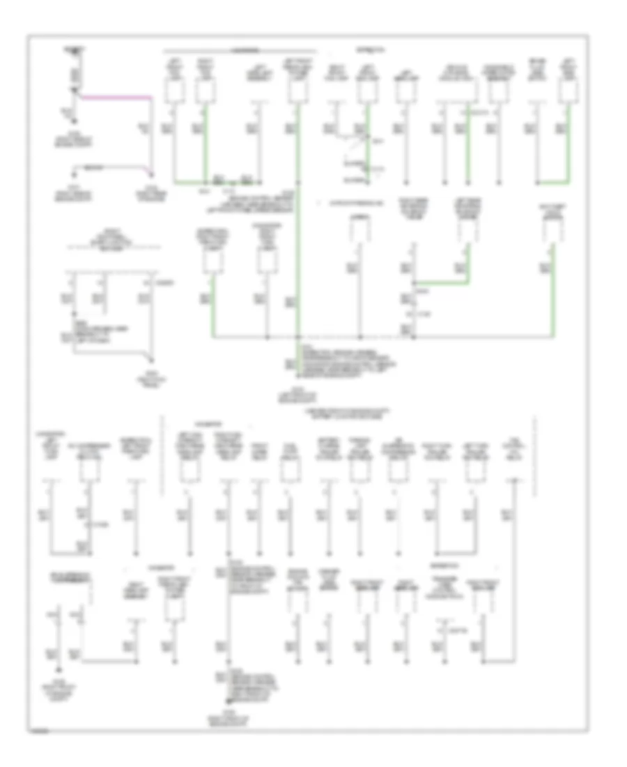
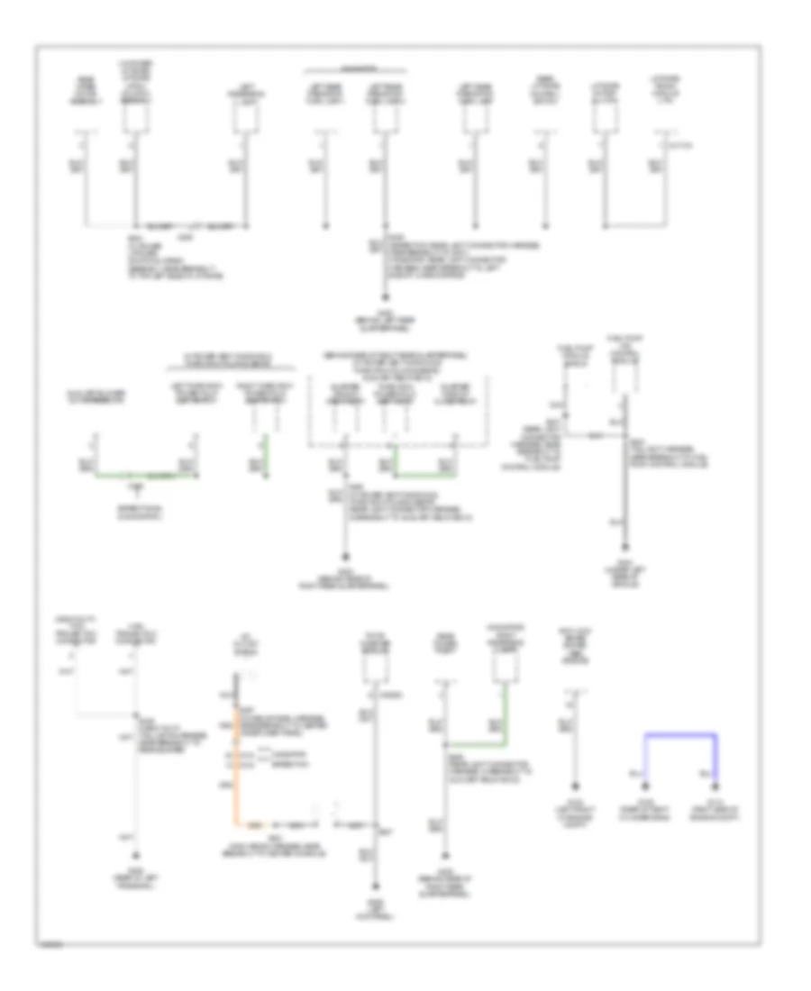
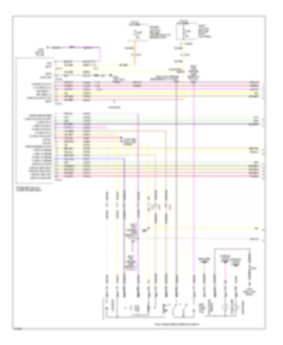
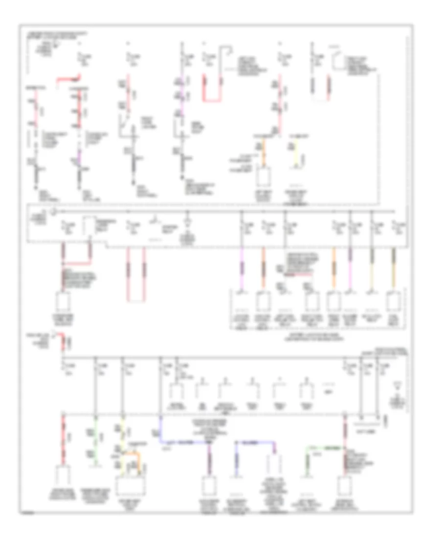
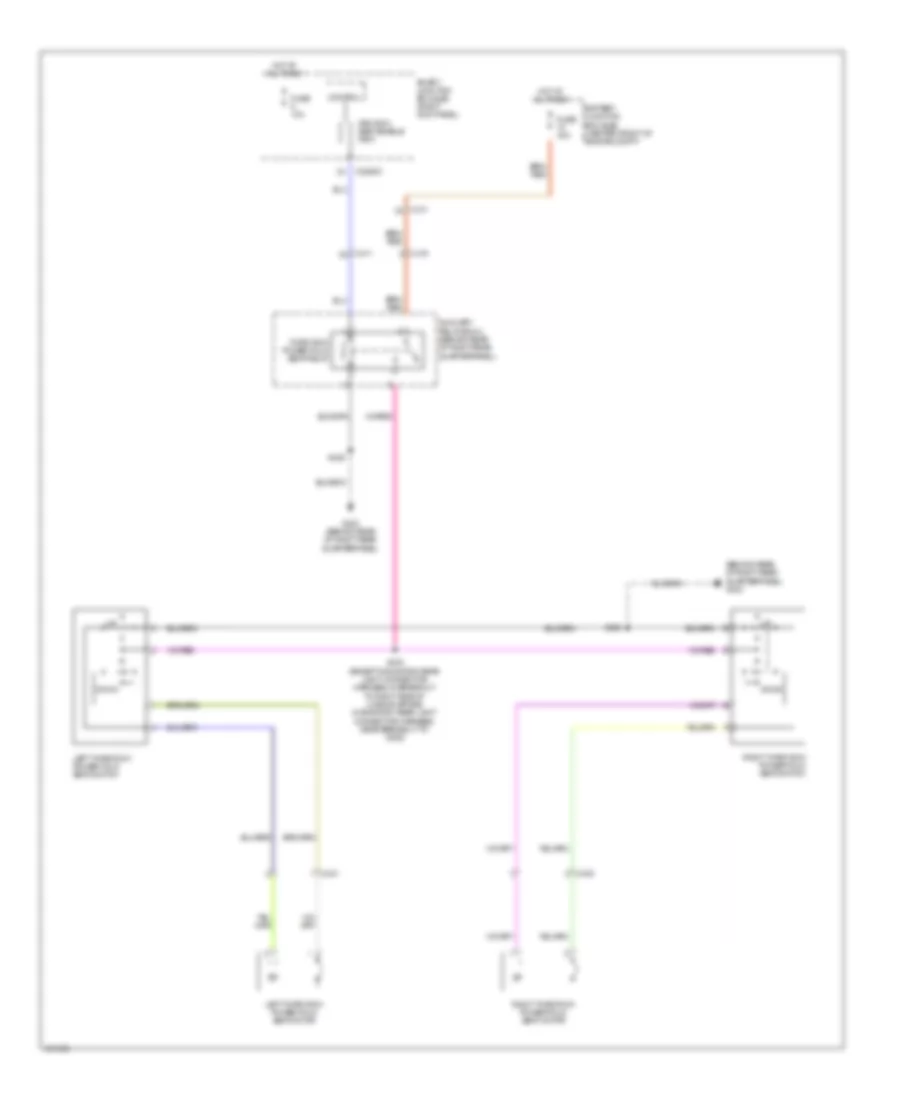
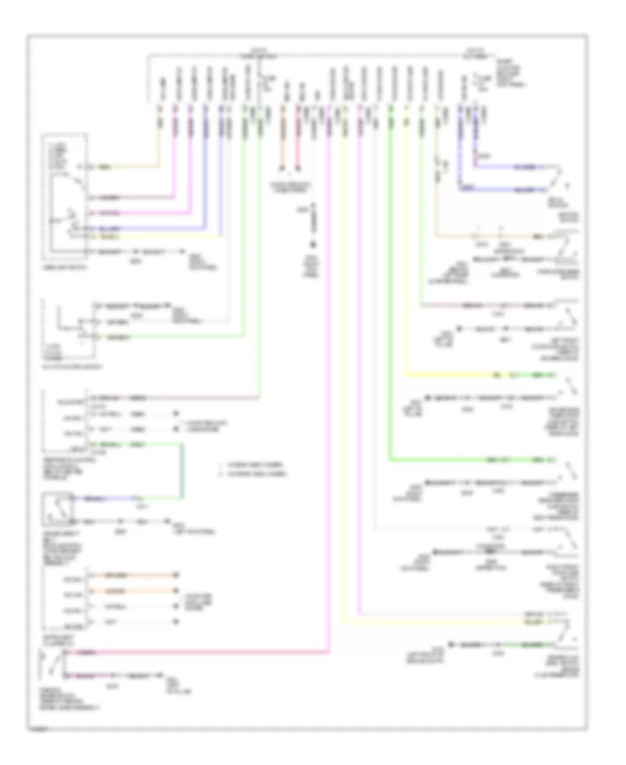
AIR CONDITIONING
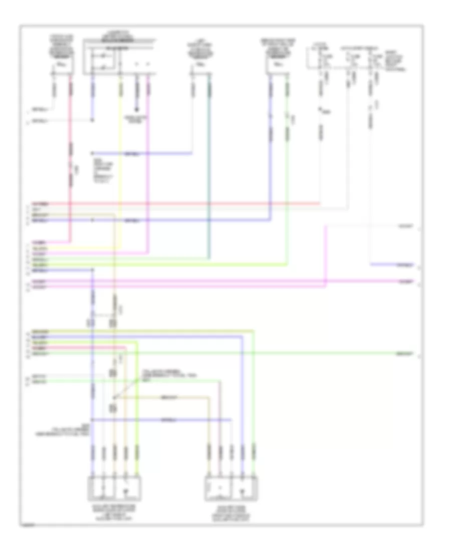
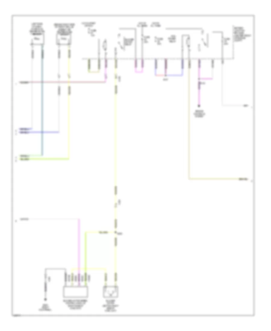
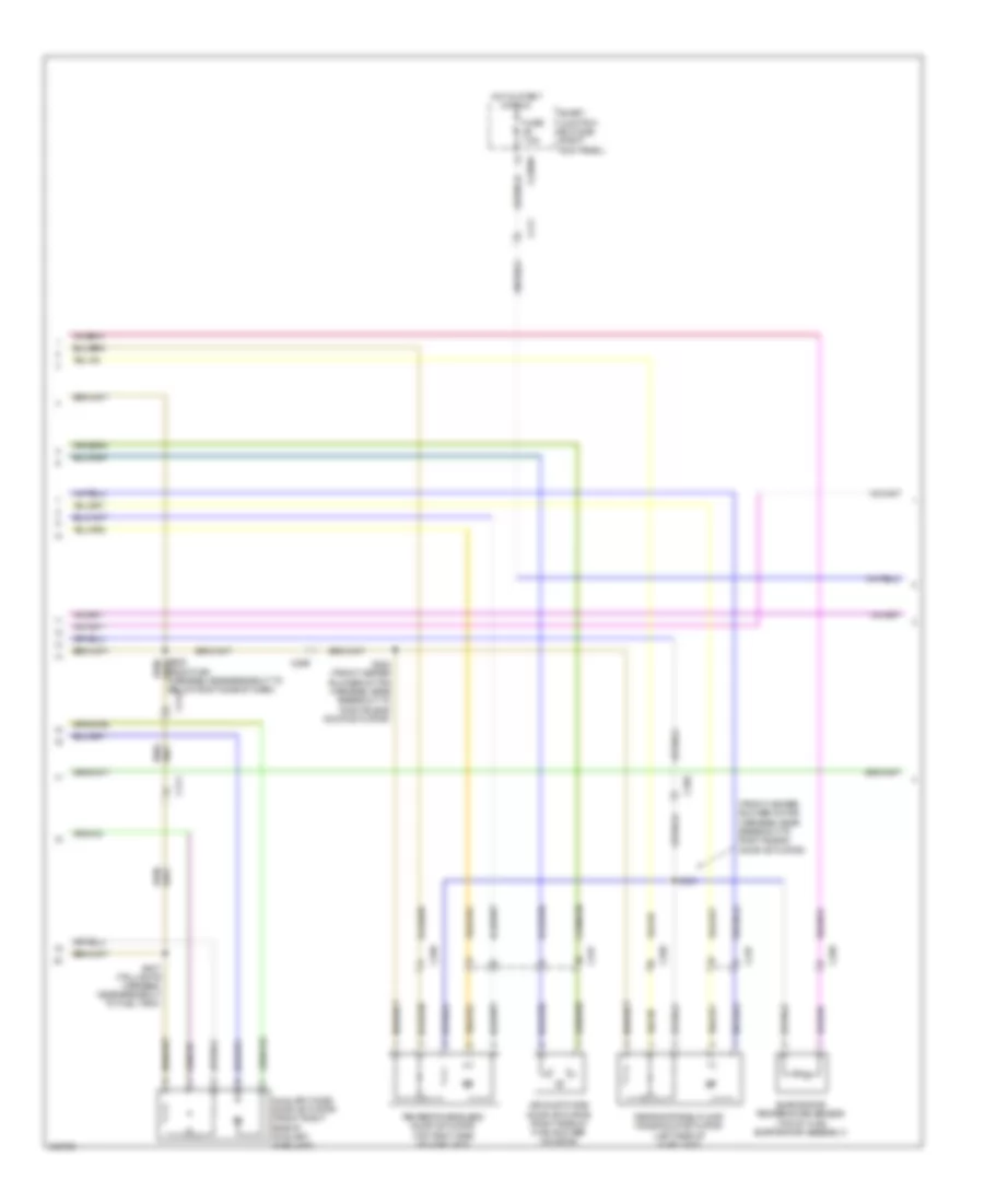
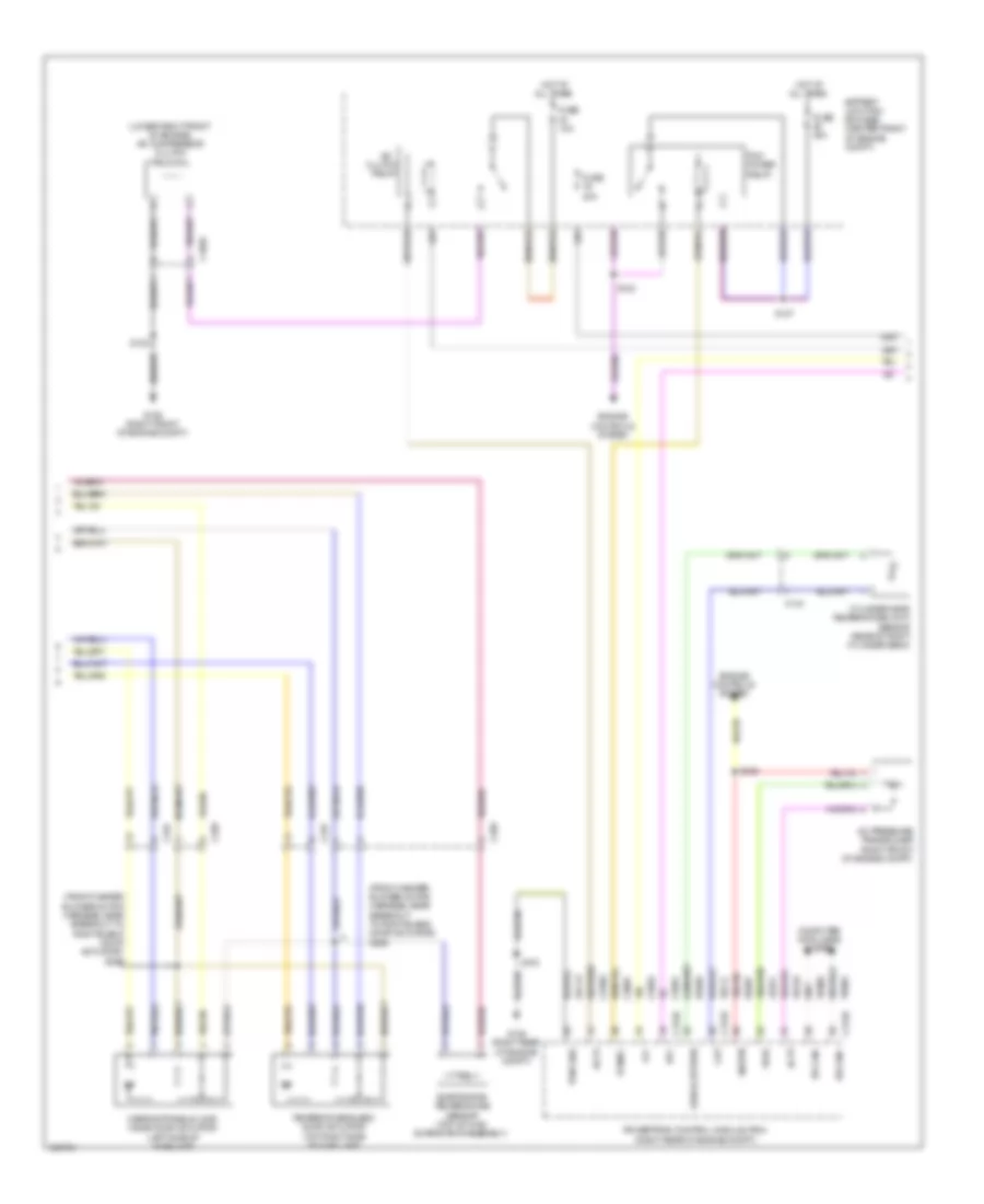
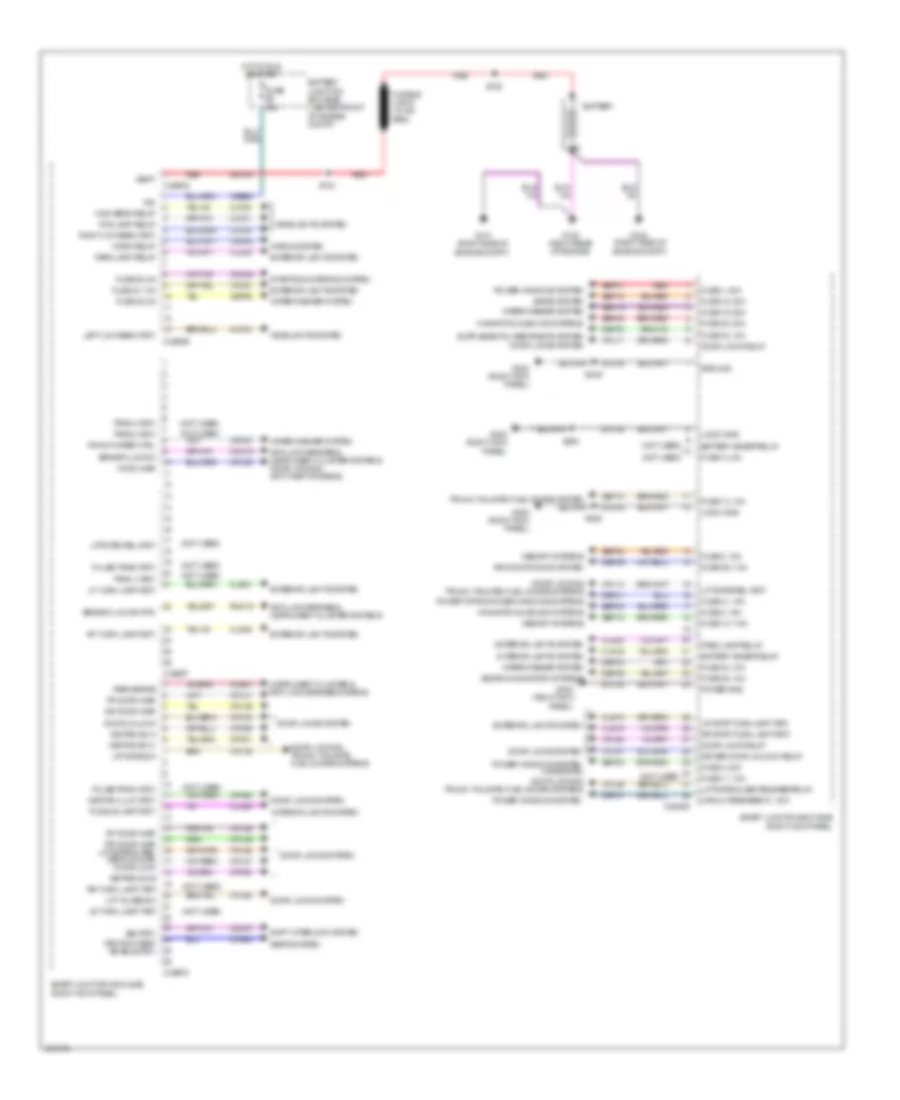
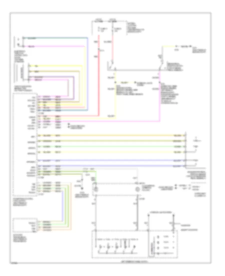
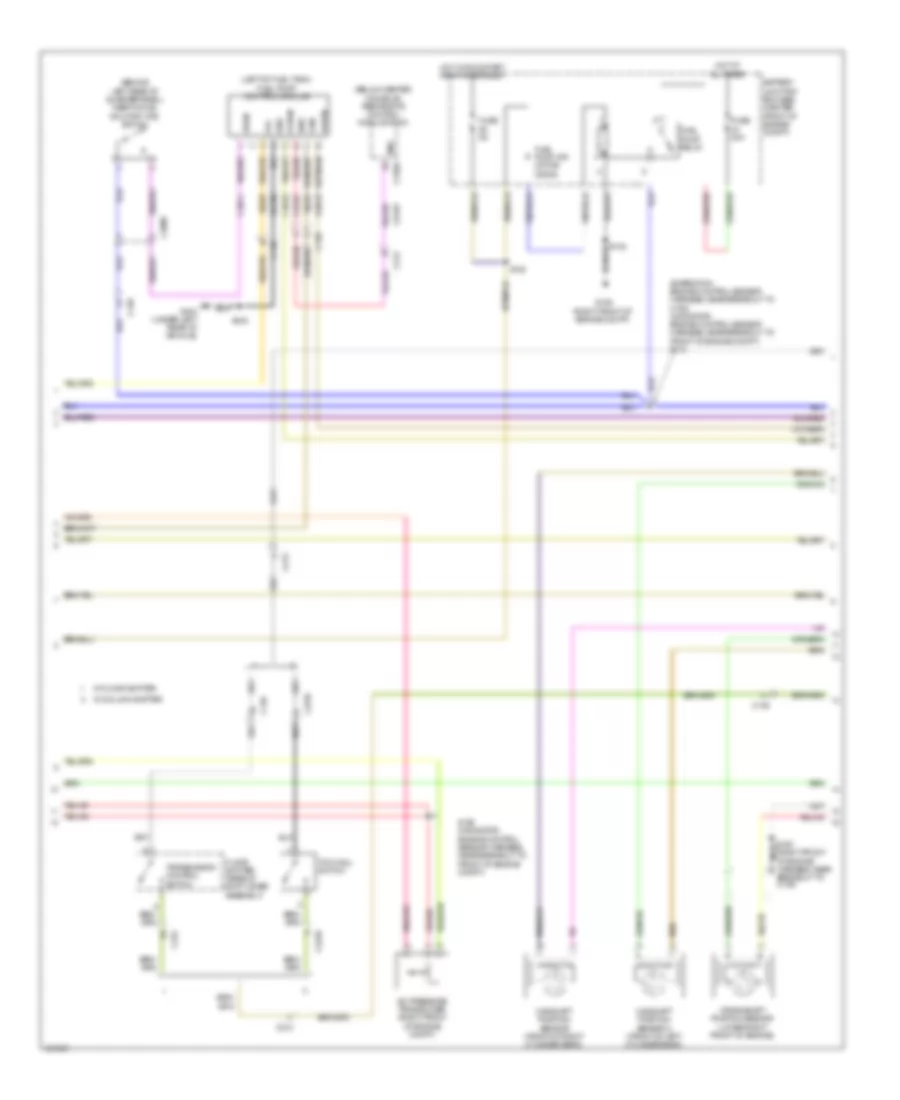
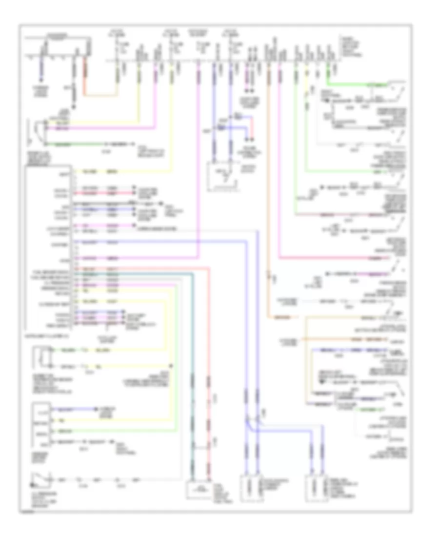
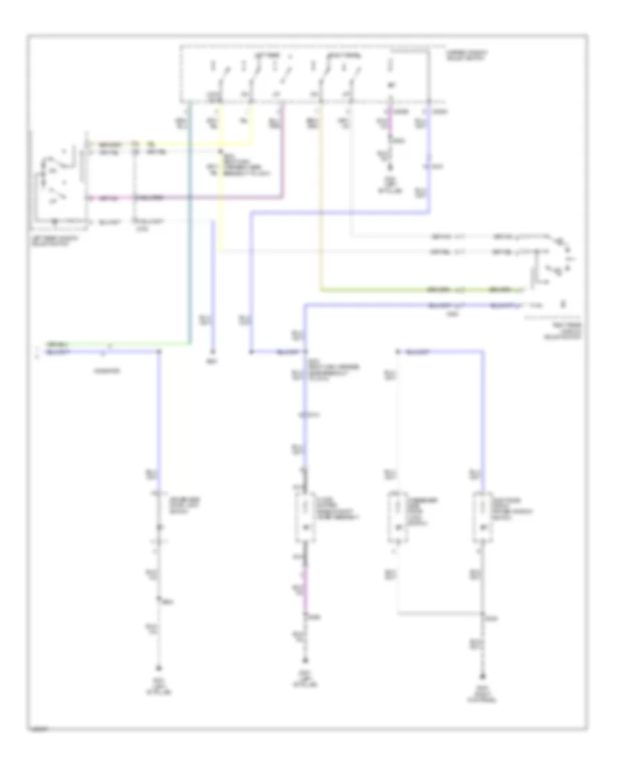
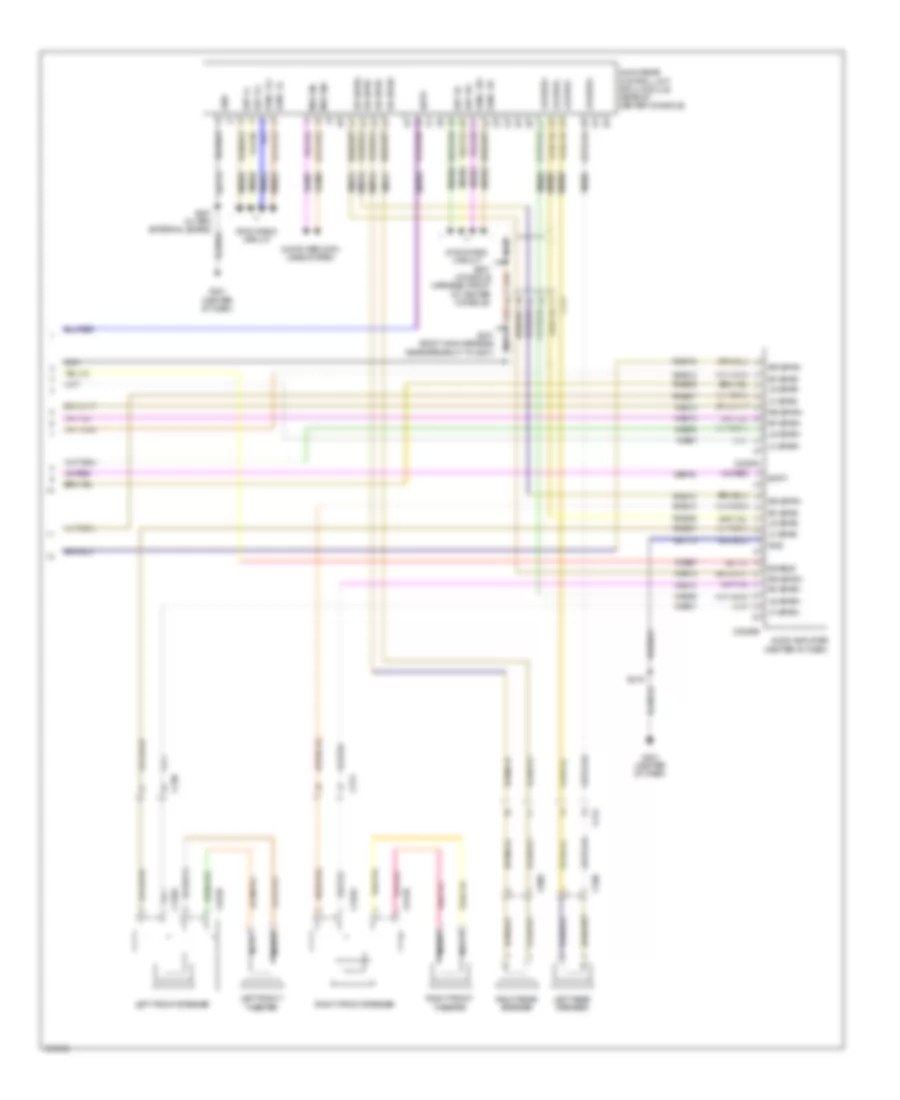
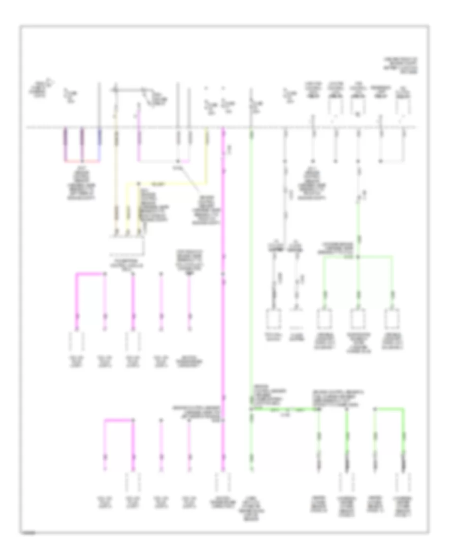
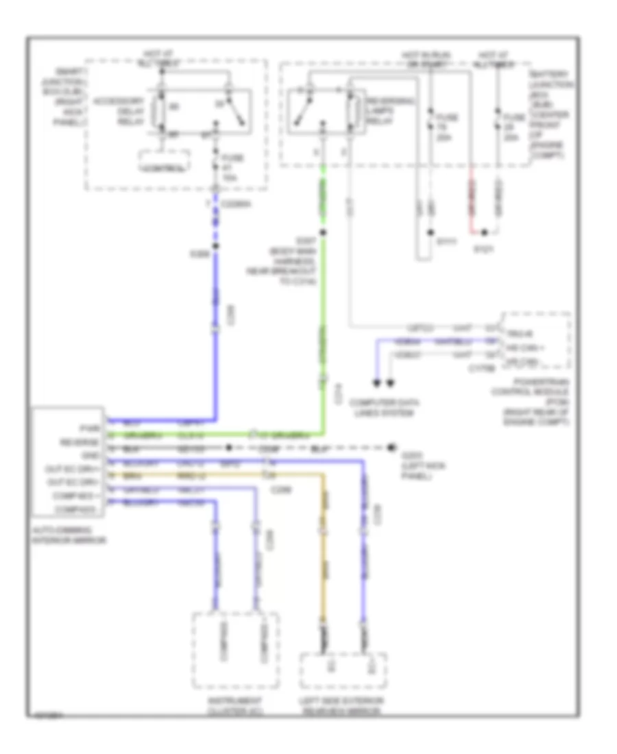
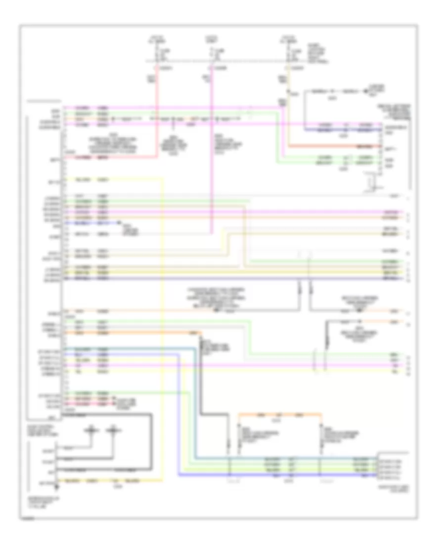
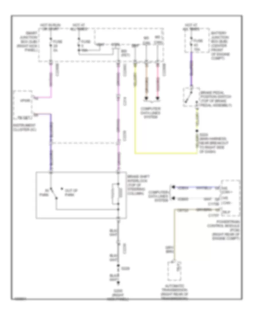
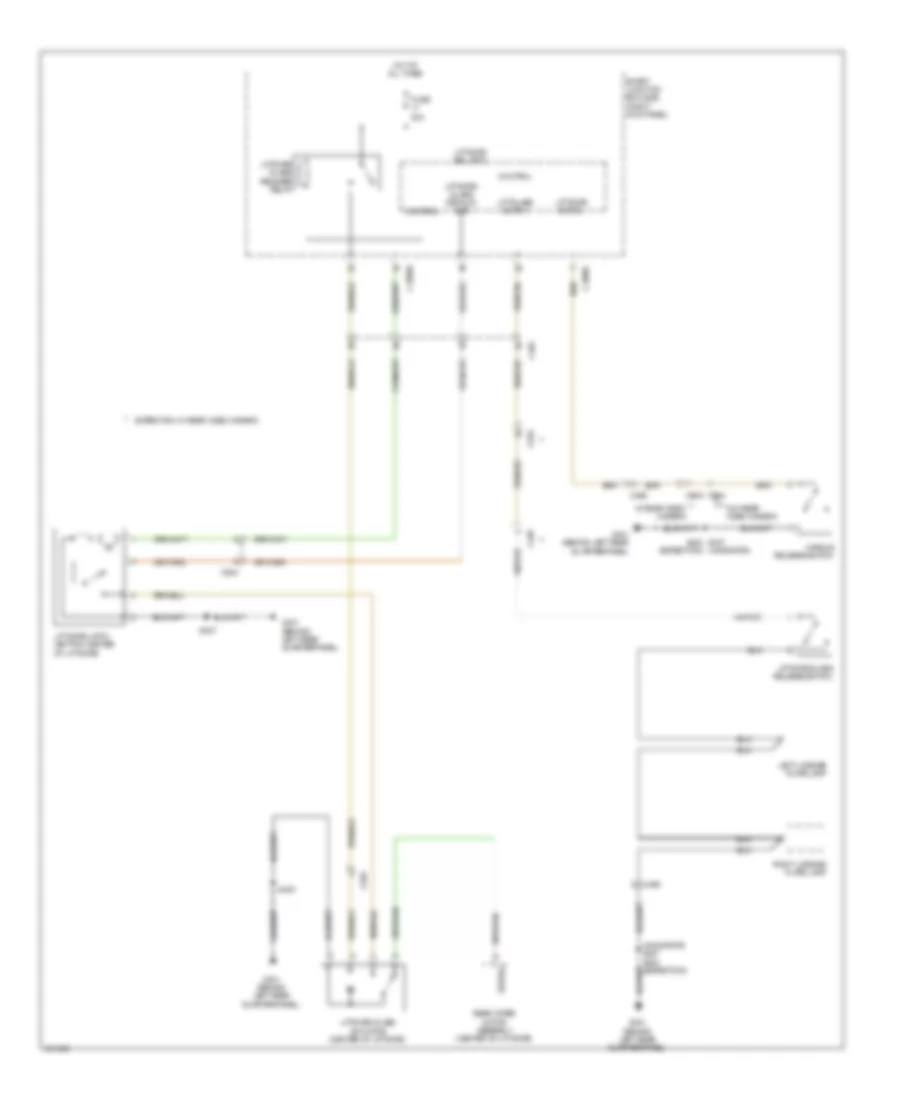
Automatic A/C Wiring Diagram, with Auxiliary Climate Control (1 of 4) for Ford Expedition XL 2014

List of elements for Automatic A/C Wiring Diagram, with Auxiliary Climate Control (1 of 4) for Ford Expedition XL 2014:
- (body main harness, near breakout to below right side of dash)
- (front heater blower motor harness, near breakout to right blend door actuator)
- (left side of hvac unit) defrost/panel/floor/ mode door actuator
- (lower center of hvac unit) left temperature blend door actuator (eatc)
- (right side of hvac blower housing) air inlet mode door actuator (eatc)
- Ambient signal
- Battery junction box (bjb) (center front of engine compt)
- Blower
- Blower motor (bottom right side of hvac unit)
- Blower motor relay
- Blower motor speed control (right side of hvac unit)
- Blower relay
- C210
- C214
- C228a
- C228b
- C238
- C291
- C299
- C315
- C411
- Cbp37
- Ch112
- Ch113
- Ch114
- Ch122
- Ch123
- Ch202
- Ch203
- Ch207
- Ch208
- Ch212
- Ch213
- Ch228
- Ch229
- Ch233
- Ch234
- Ch238
- Ch239
- Ch402
- Computer data lines system
- Defogger system
- Defrost request
- Driver sunload
- Evap
- Expedition
- Feedback
- Fuse 10a
- Fuse 40a
- G203 (left kick panel)
- G204 (right kick panel)
- G301 (left "b" pillar)
- Gd133
- Gd138
- Gnd
- Hot at all times
- Hot in start or run
- Hvac (datc) module
- In-vehicle signal
- Interior lights system
- Lh111
- Mode/temp
- Motor+
- Motor-
- Ms can+
- Ms can-
- Navigator
- Passenger sunload
- Rear auxiliary climate control assembly
- Relay 1
- Relay 2
- Relay 3
- Rh111
- Right temperature blend door actuator (upper center of hvac unit)
- S205
- S211
- S253
- S254
- S255 (front heater blower motor harness, near breakout to right blend door actuator)
- S369
- Sbp15
- Signal return
- Variable blower control
- Vbatt
- Vdb06
- Vdb07
- Vh101
- Vh301
- Vh406
- Vh407
- Vh414
- Vh416
- Vh417
- Vh436
- Vh438
- Vh439
- Vh440
- Vh441
- Vha15
- Vha17
- Vpwr
- Vref
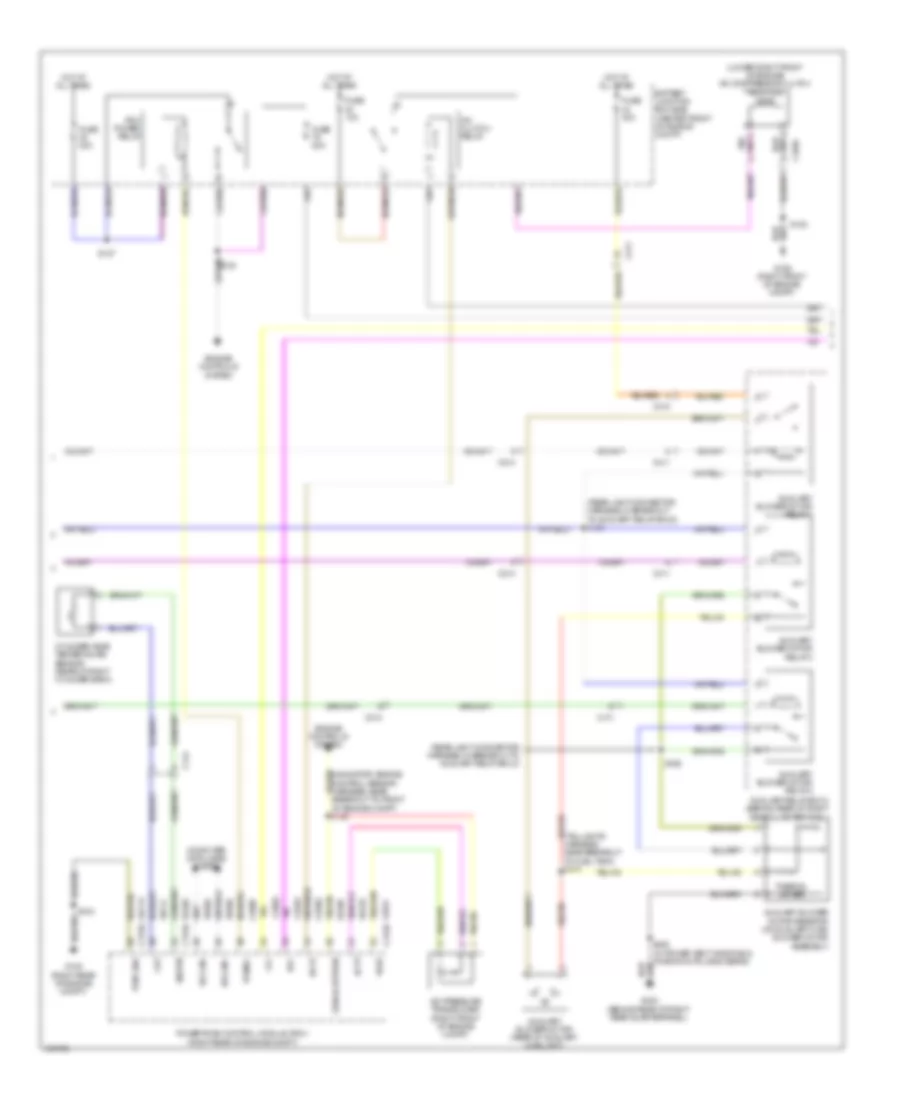
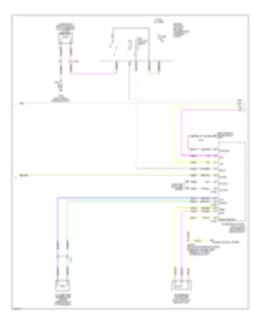
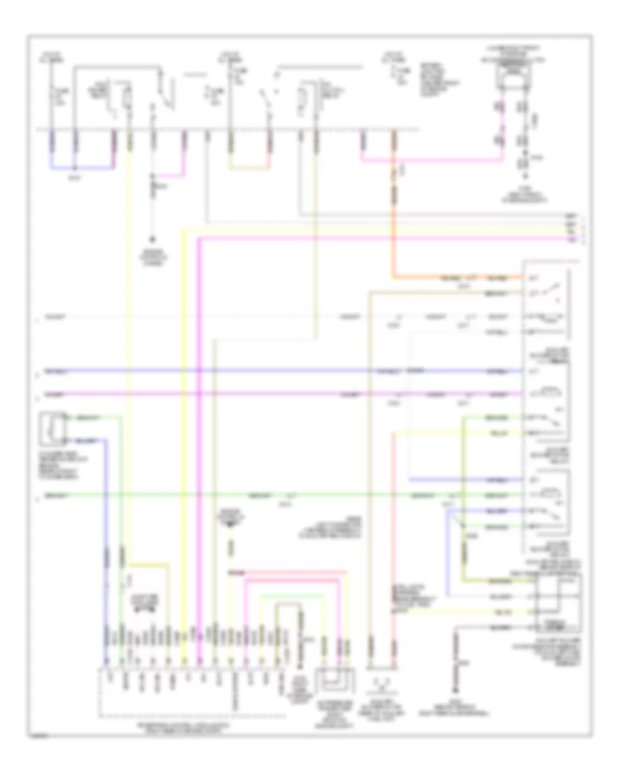
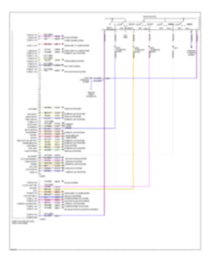
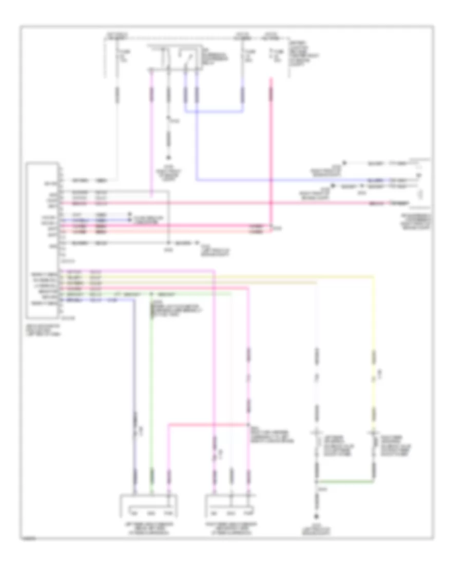
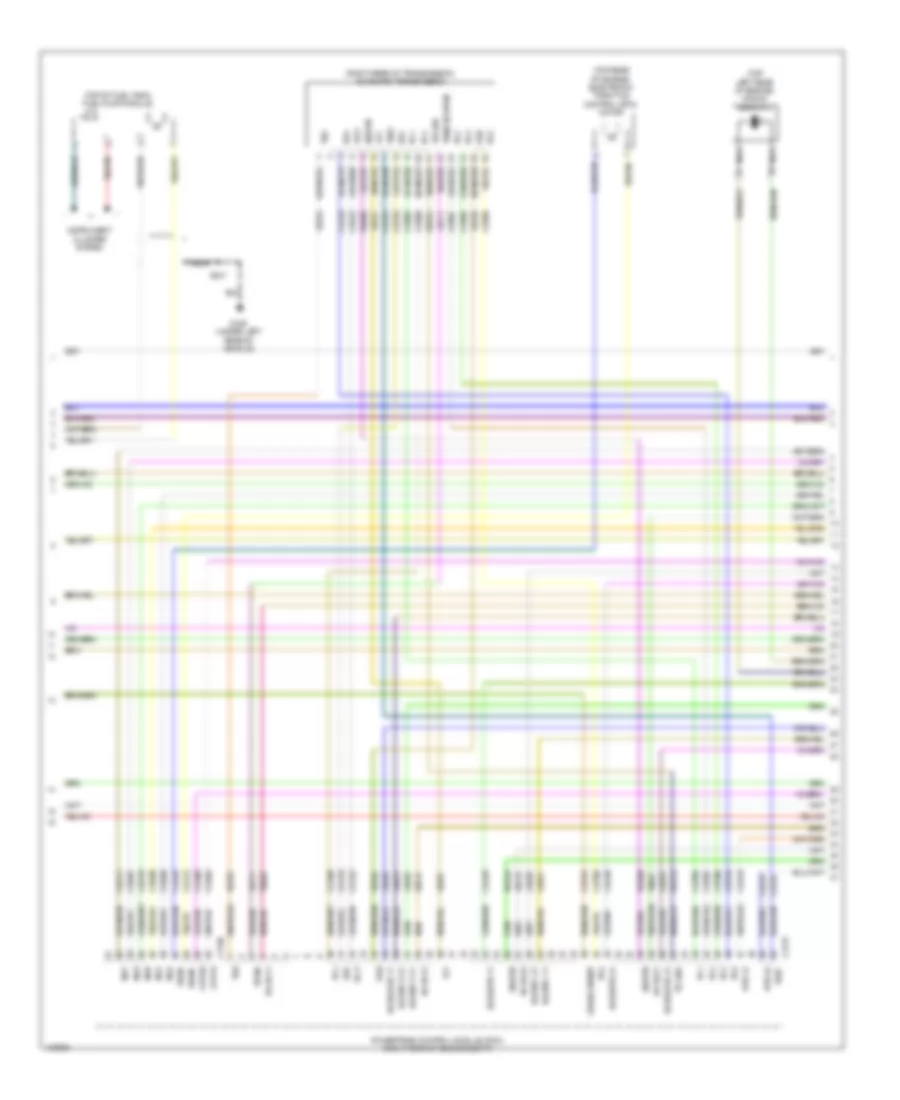
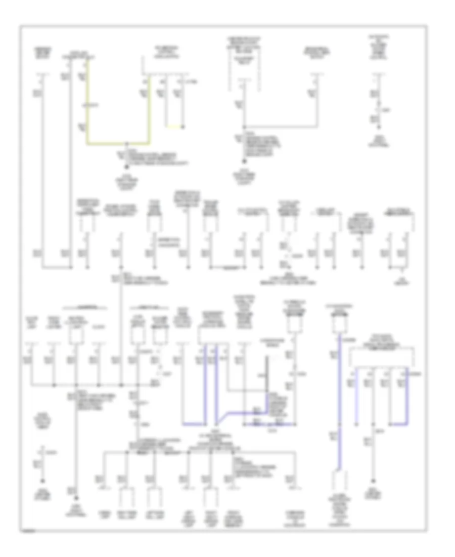
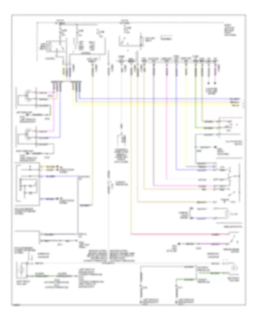
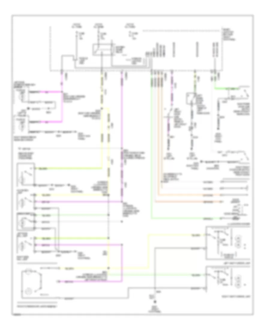
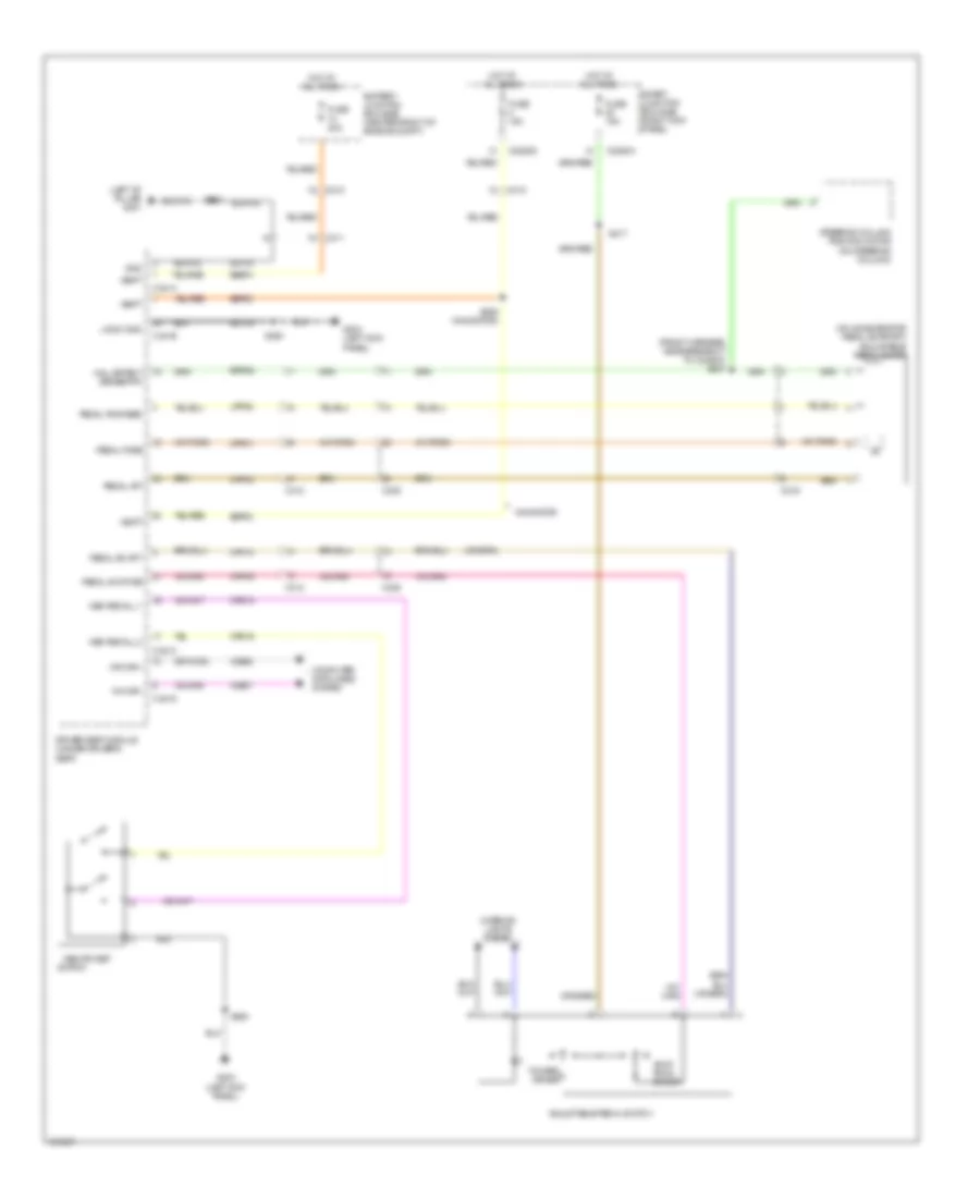
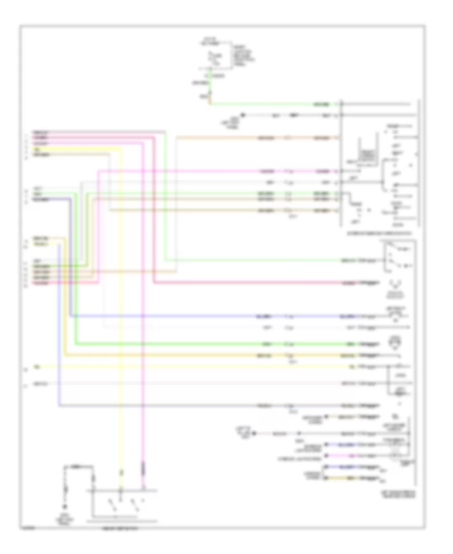
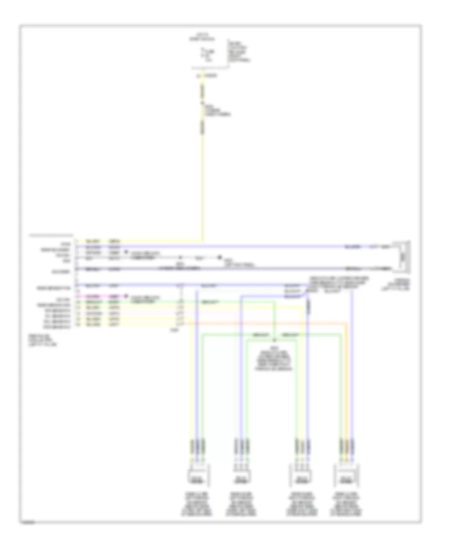
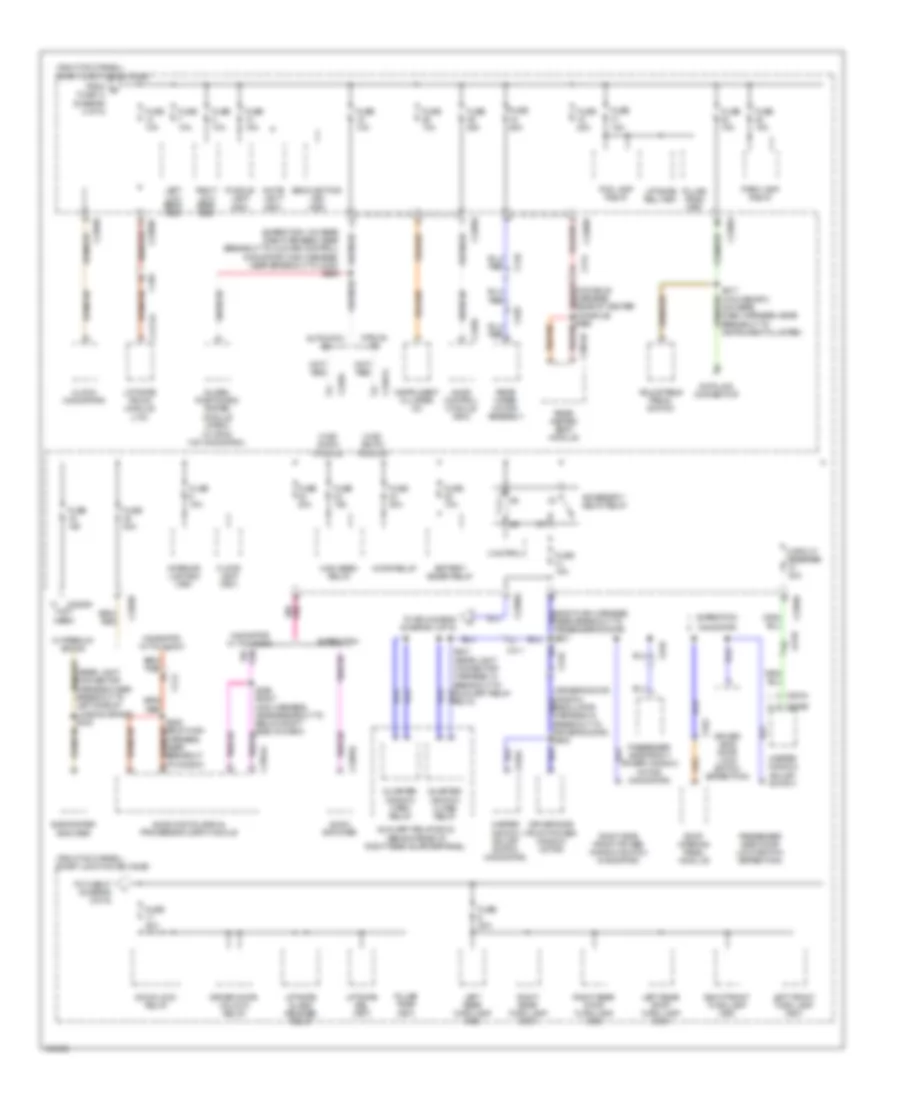
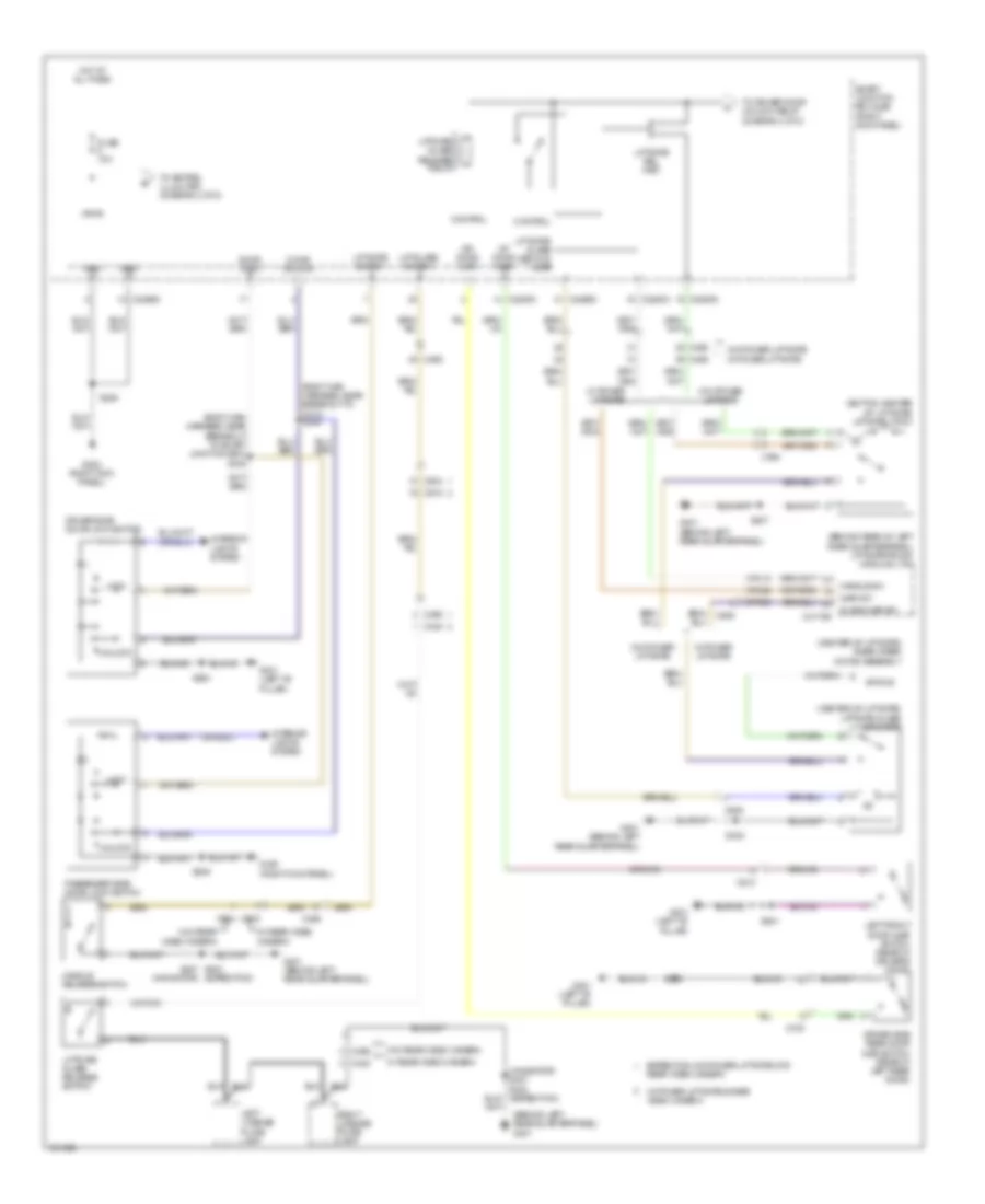
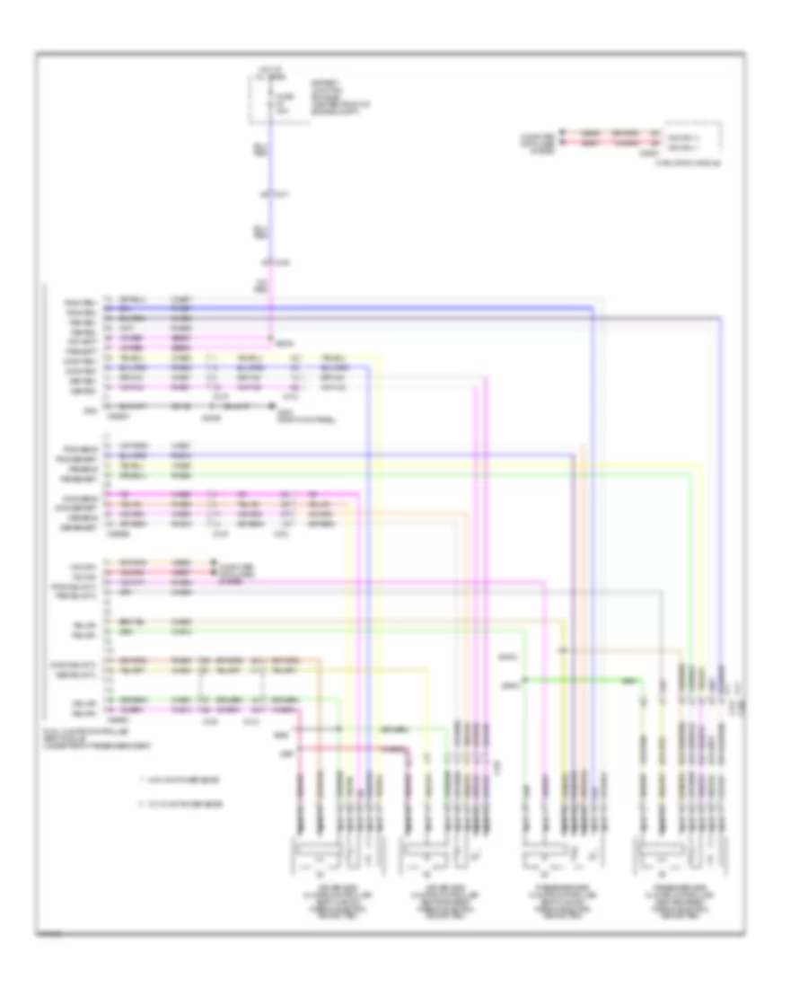
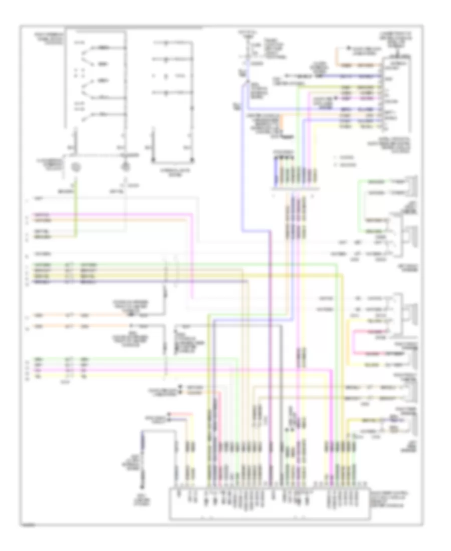
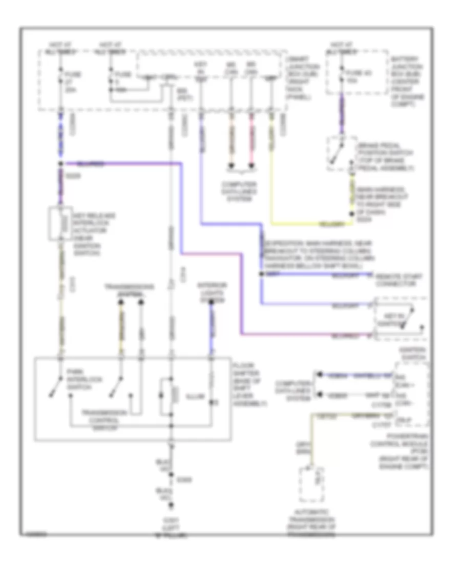
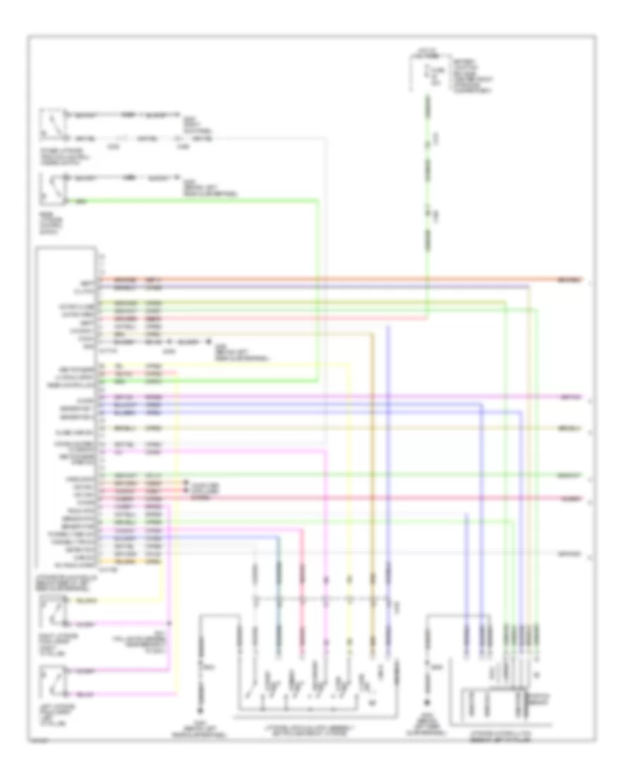
Automatic A/C Wiring Diagram, with Auxiliary Climate Control (2 of 4) for Ford Expedition XL 2014
List of elements for Automatic A/C Wiring Diagram, with Auxiliary Climate Control (2 of 4) for Ford Expedition XL 2014:
- (behind right side of front grille) ambient air temperature sensor
- (left side of dash) in-vehicle temperature sensor
- (taillights harness, near breakout to fuel tank) s437
- (top of hvac evaporator assembly) evaporator temperature sensor
- (under top center of dash) sunload sensor
- Auxiliary mode door actuator (front right side of auxiliary hvac unit)
- Auxiliary temperature blend door actuator (left side of auxiliary hvac unit)
- C210
- C214
- C2280a
- C2280b
- C2280d
- C299
- C411
- Fuse 10a
- Fuse 7.5a
- Headlights system
- Hot at all times
- Hot in start or run
- S204 (body main harness, in breakout to c211)
- S266
- S436 (taillights harness, near breakout to fuel tank)
- Smart junction box (sjb) (right kick panel)
- Solid state
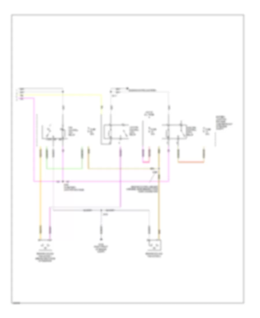
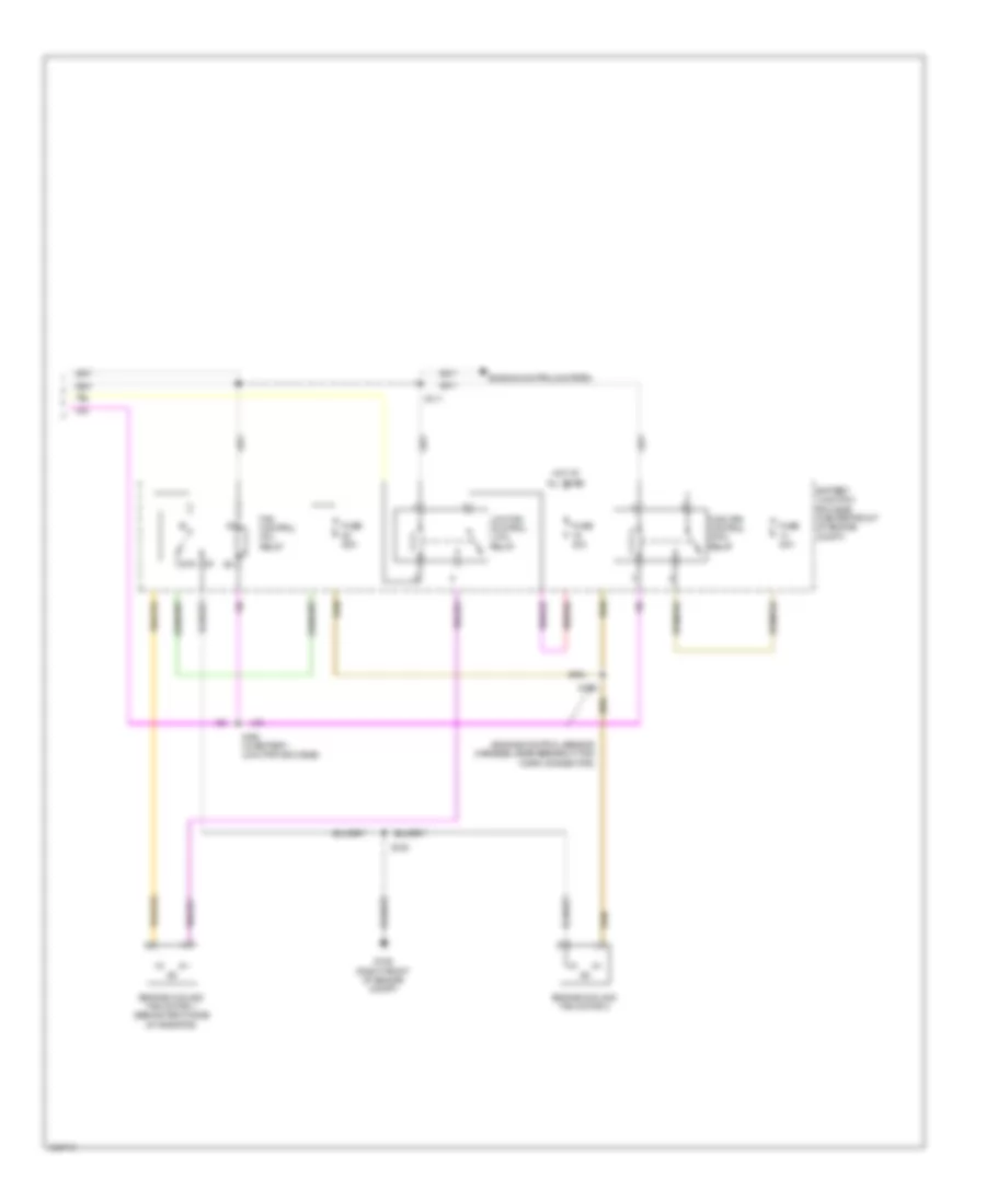
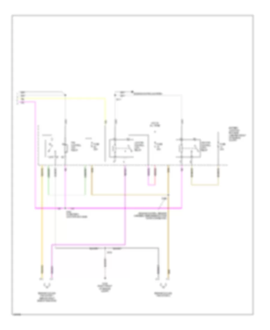
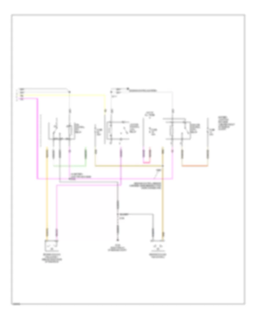
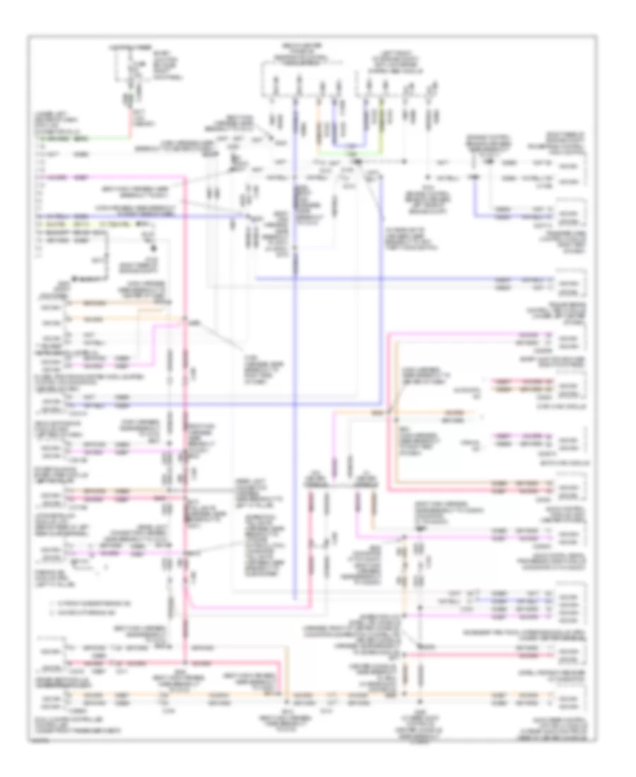
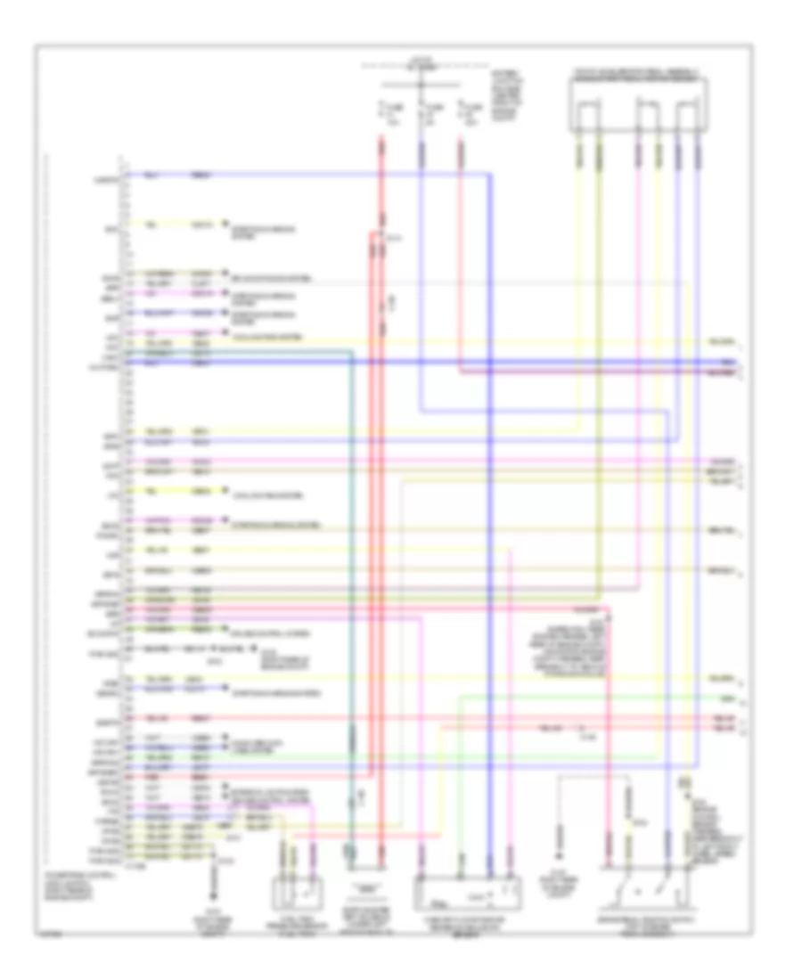
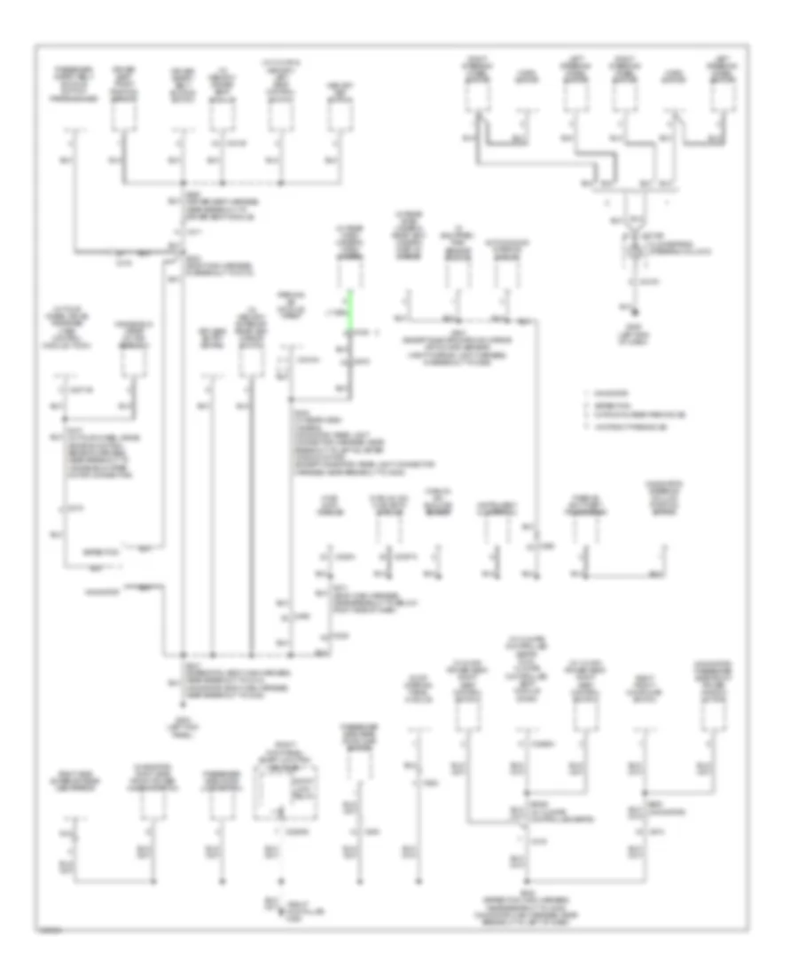
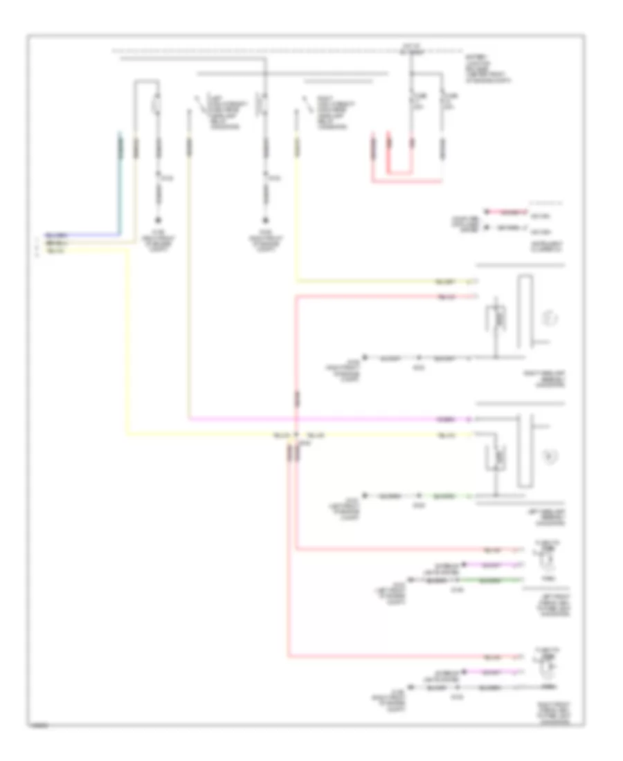
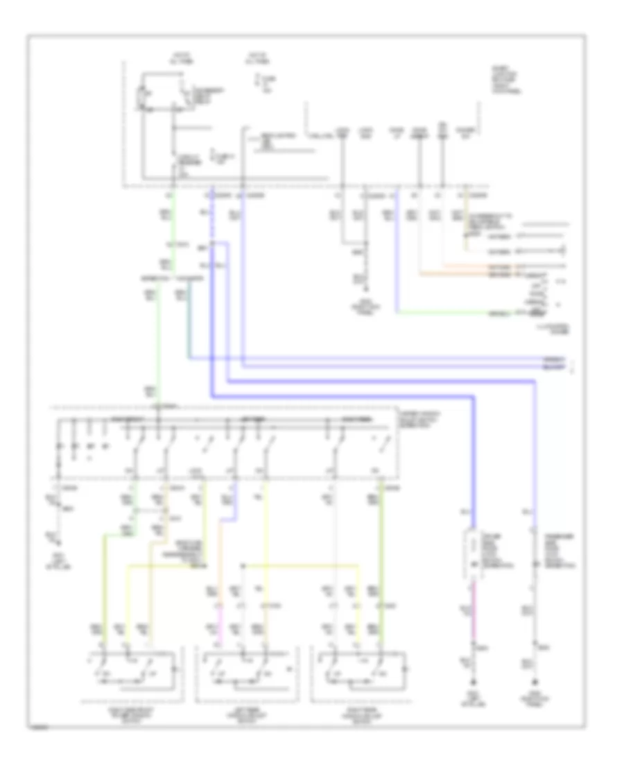
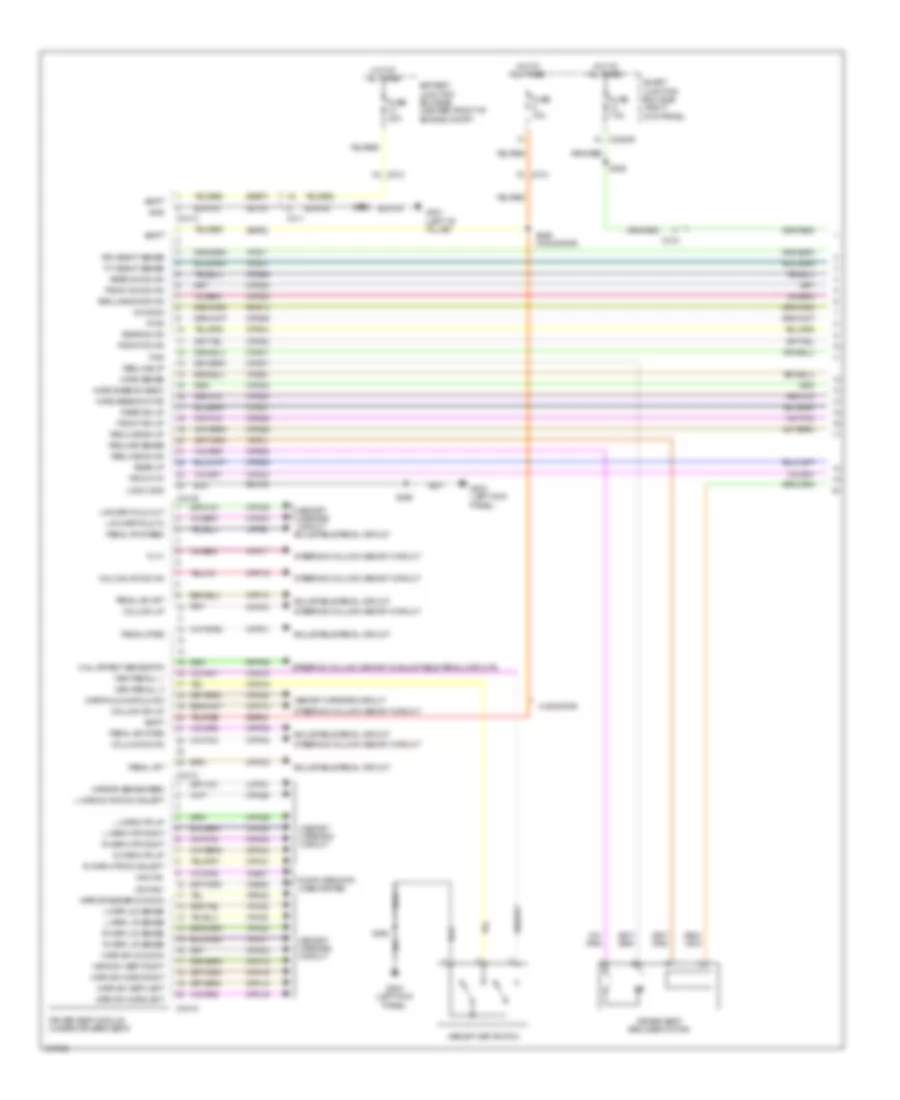
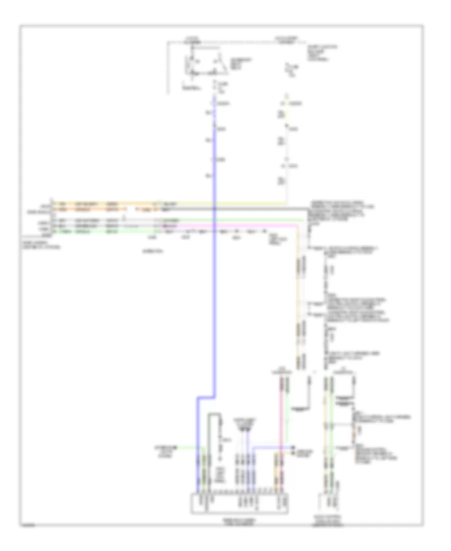
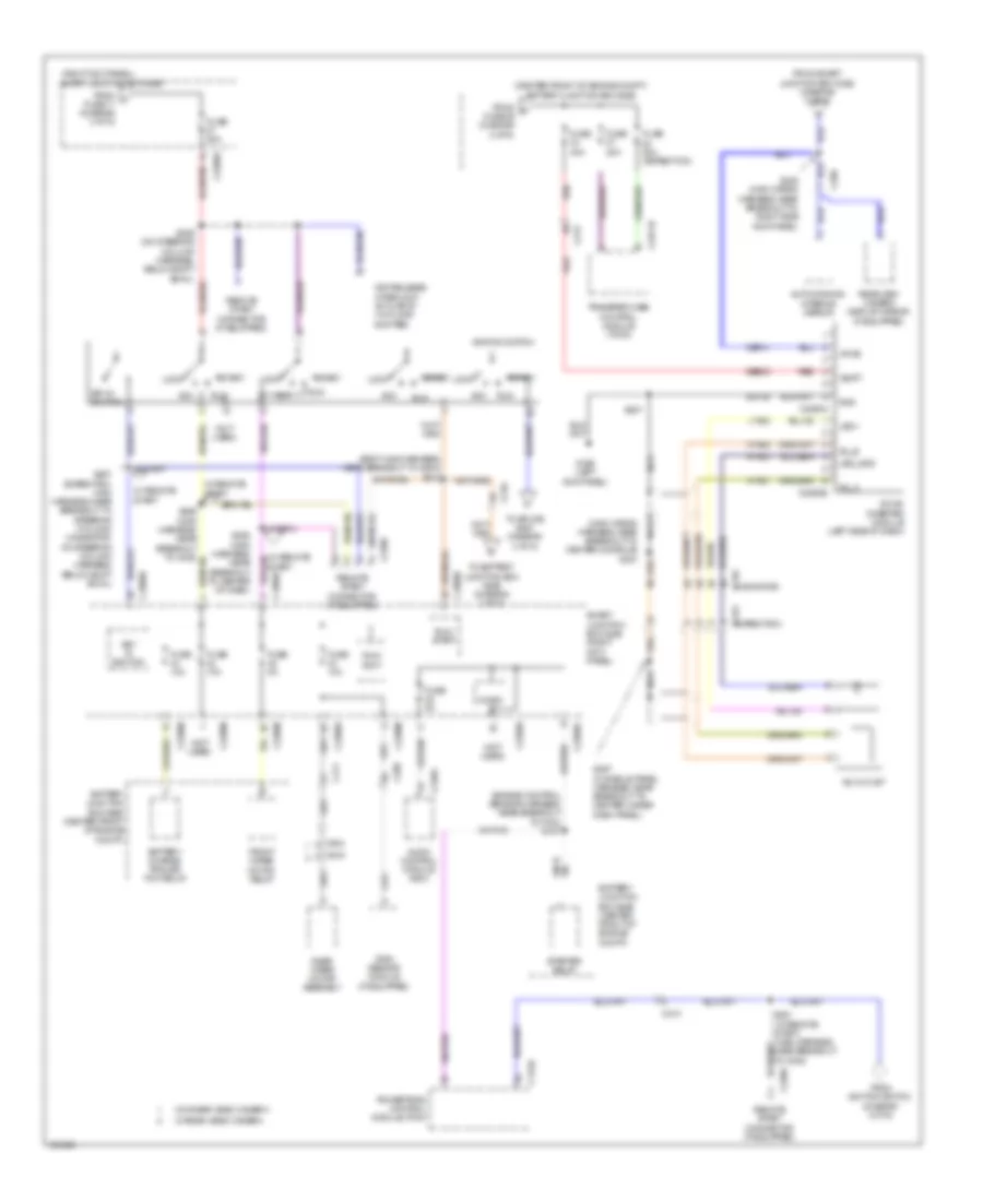
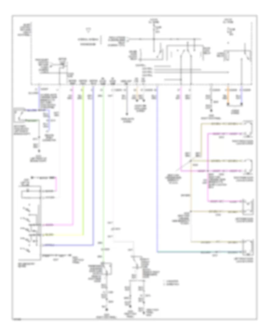
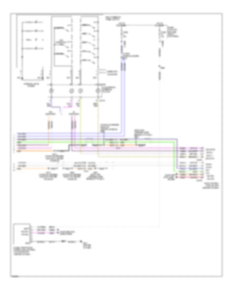
Automatic A/C Wiring Diagram, with Auxiliary Climate Control (3 of 4) for Ford Expedition XL 2014
List of elements for Automatic A/C Wiring Diagram, with Auxiliary Climate Control (3 of 4) for Ford Expedition XL 2014:
- (lower right front of engine) a/c compressor clutch field coil
- (navigator: engine control sensor harness, near breakout to front of engine compt) s126
- (rear light connector harness, in breakout to auxiliary relay box 2)
- (rear light connector harness, in breakout to auxiliary relay box 2) s420
- (right front of engine compt)
- (taillights harness, near breakout to fuel tank) s435
- A/c clutch relay
- A/c pressure transducer (right front of engine compt)
- Accr
- Acpt
- Auxiliary blower motor (rear of auxiliary hvac unit)
- Auxiliary blower motor relay 1
- Auxiliary blower motor relay 2
- Auxiliary blower motor relay 3
- Auxiliary blower motor resistor (on auxiliary hvac blower motor assembly)
- Auxiliary relay box 2 (behind rear of right rear quarterpanel)
- Battery junction box (bjb) (center front of engine compt)
- C1026
- C144
- C175b
- C175e
- C211
- C214
- C410
- C411
- Ce201
- Ce202
- Ce607
- Ch302
- Cht
- Computer data lines system
- Cylinder head temperature sensor (rear of right cylinder bank)
- Engine controls system
- Fuse 10a
- Fuse 20a
- Fuse 30a
- Fuse 40a
- G106
- G108 (right rear of engine compt)
- G403 (behind rear of right rear quarterpanel)
- Gd113
- Hfc
- Hot at all times
- Hs can+
- Hs can-
- Le424
- Lfc
- Pcm power relay
- Pcmrc
- Powertrain control module (pcm) (right rear of engine compt)
- Pwr gnd
- Re405
- Re407
- S103
- S122
- S127
- S422
- S428 (w/ power vent windows & third row folding seats)
- Signal return
- Sigrtn
- Thermal limiter
- Vdb04
- Vdb05
- Ve712
- Vh433
- Vref
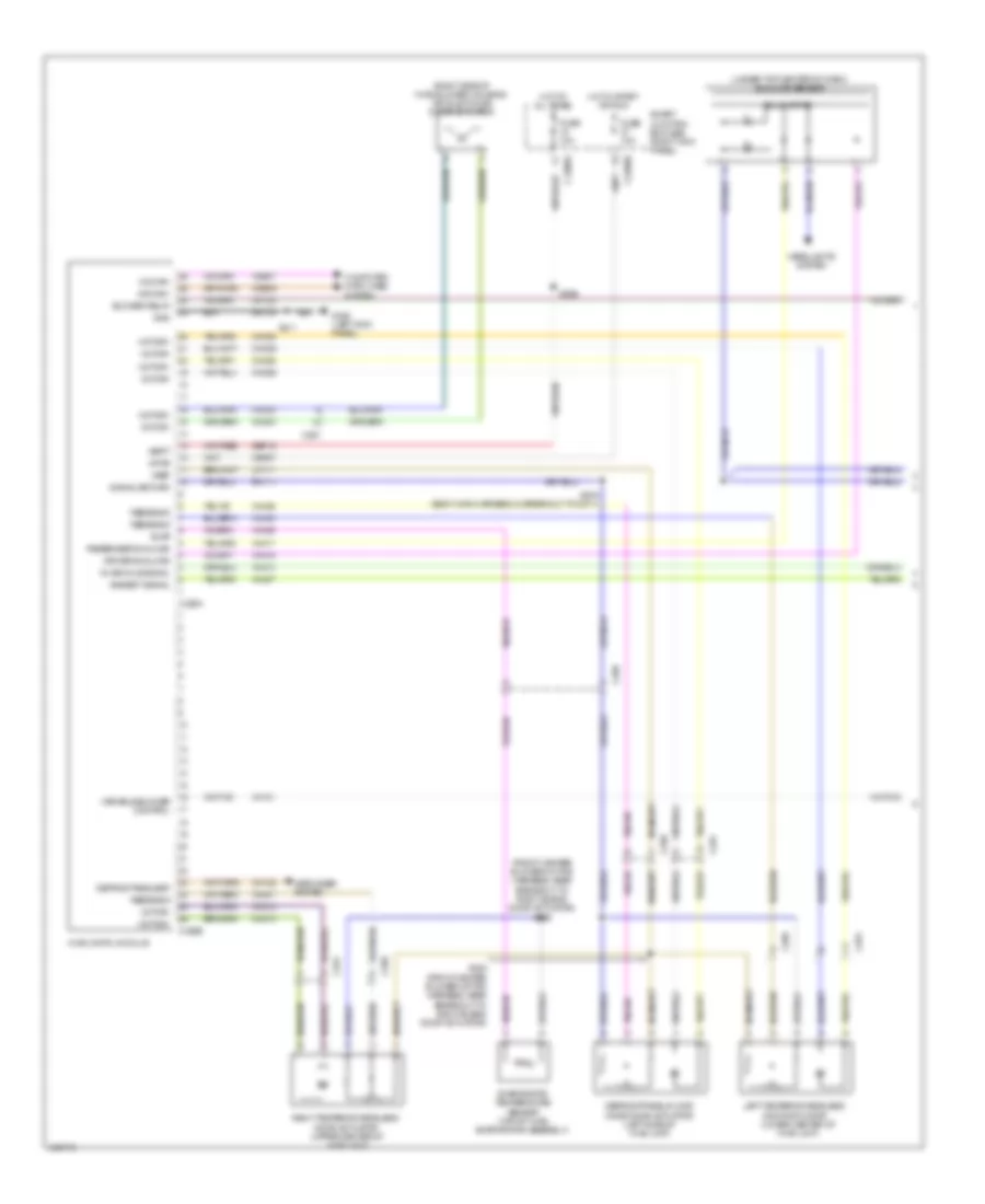
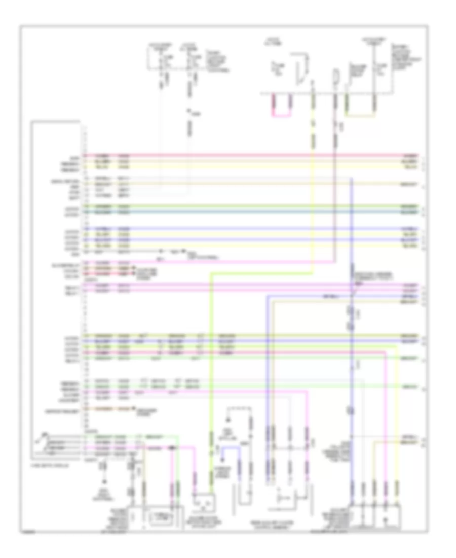
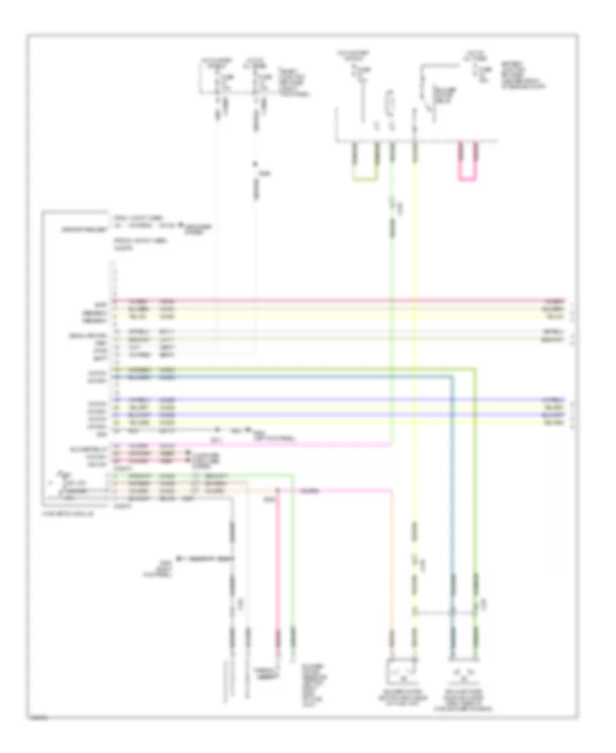
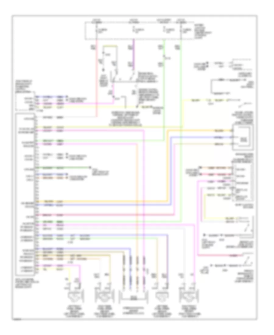
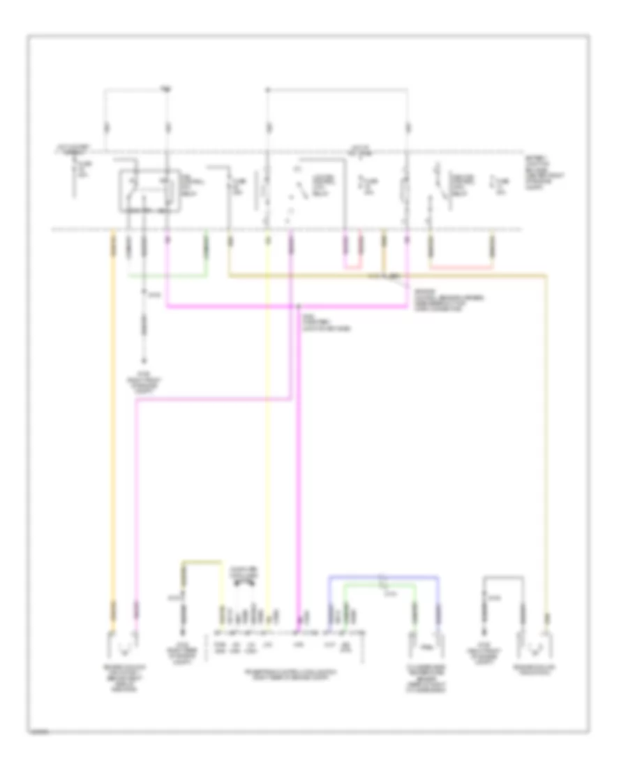
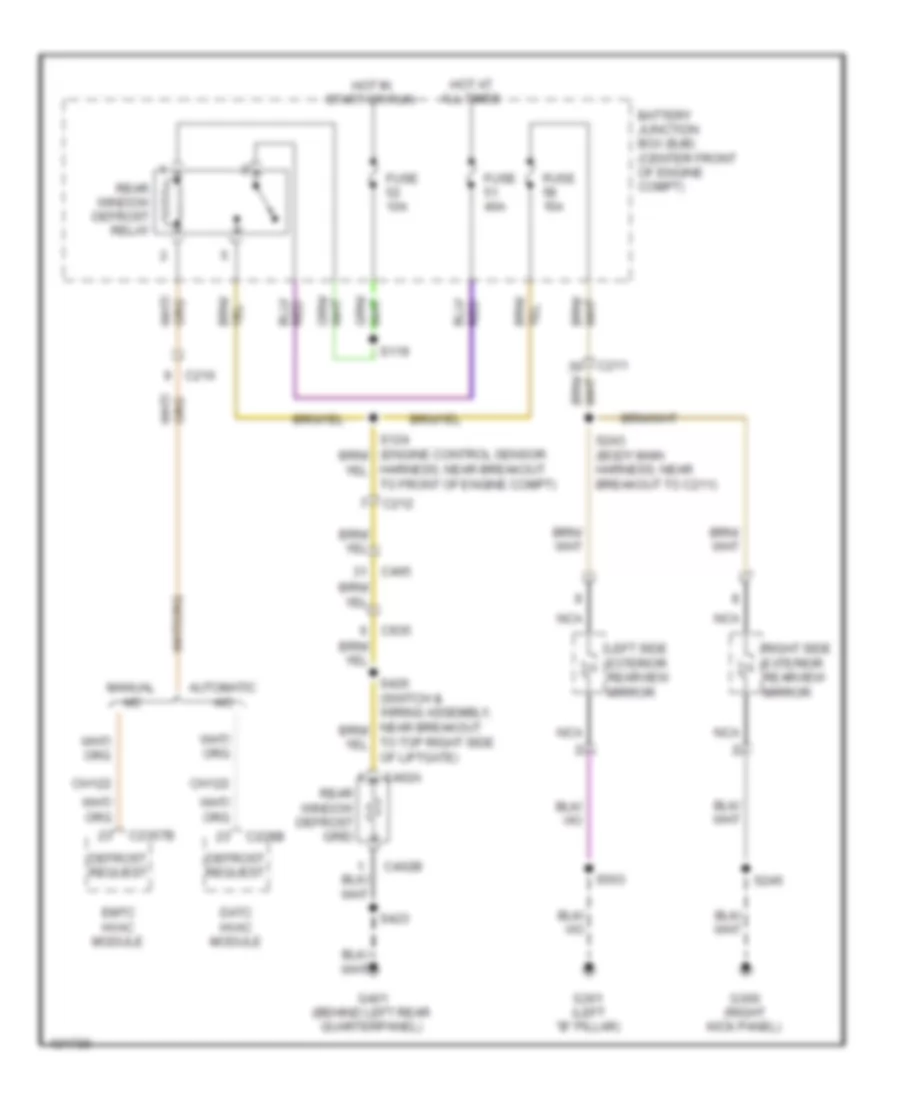
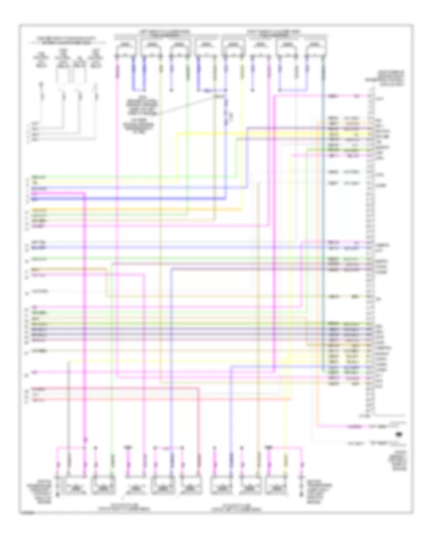
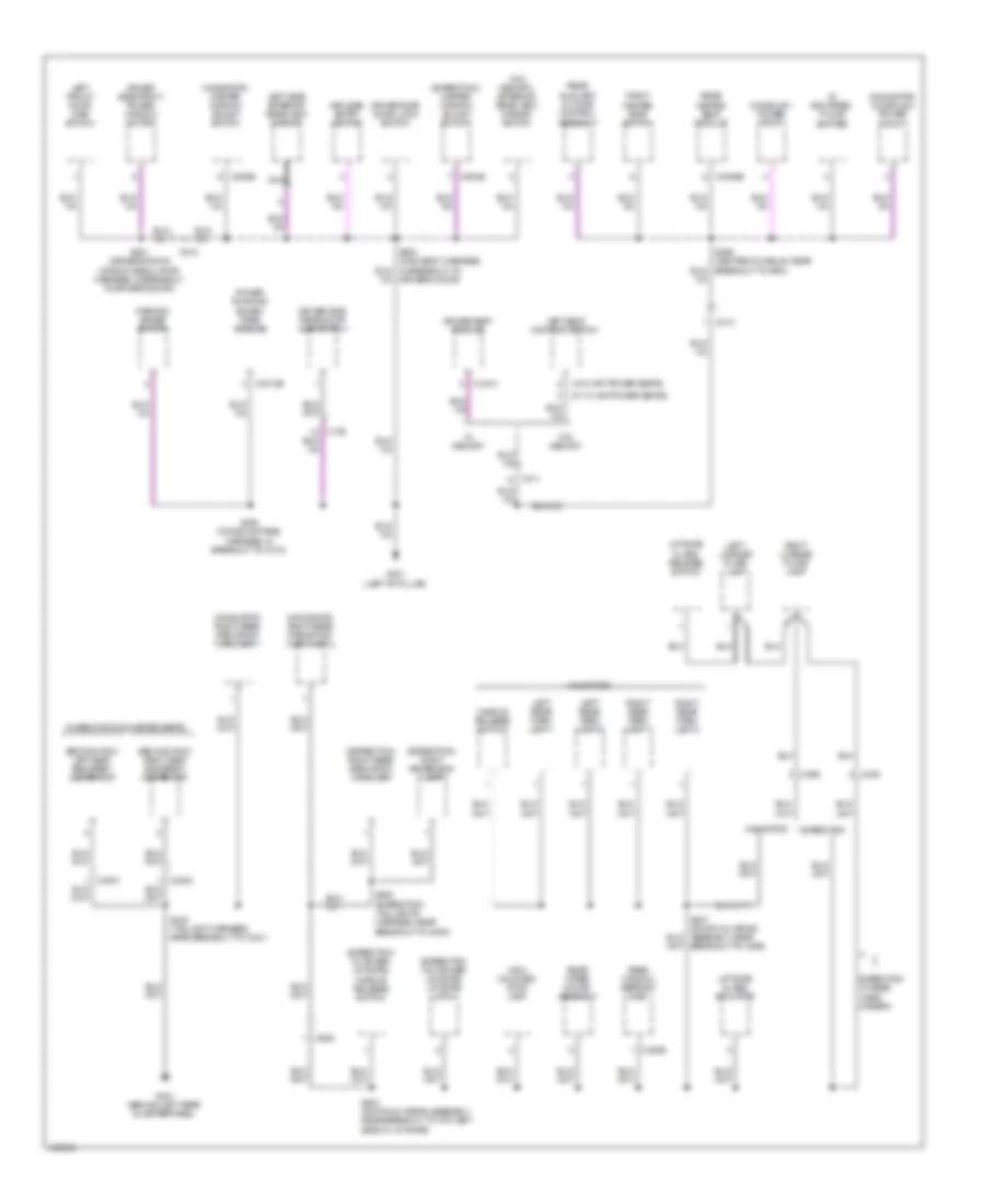
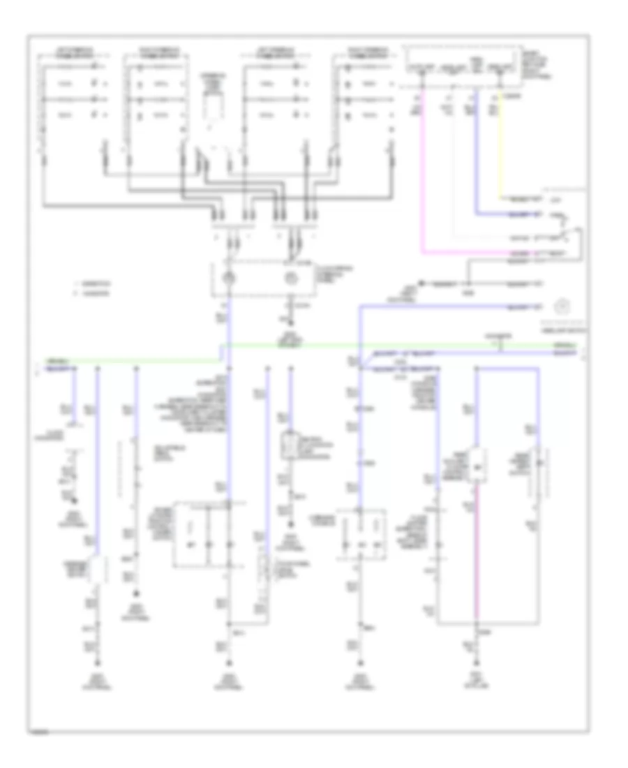
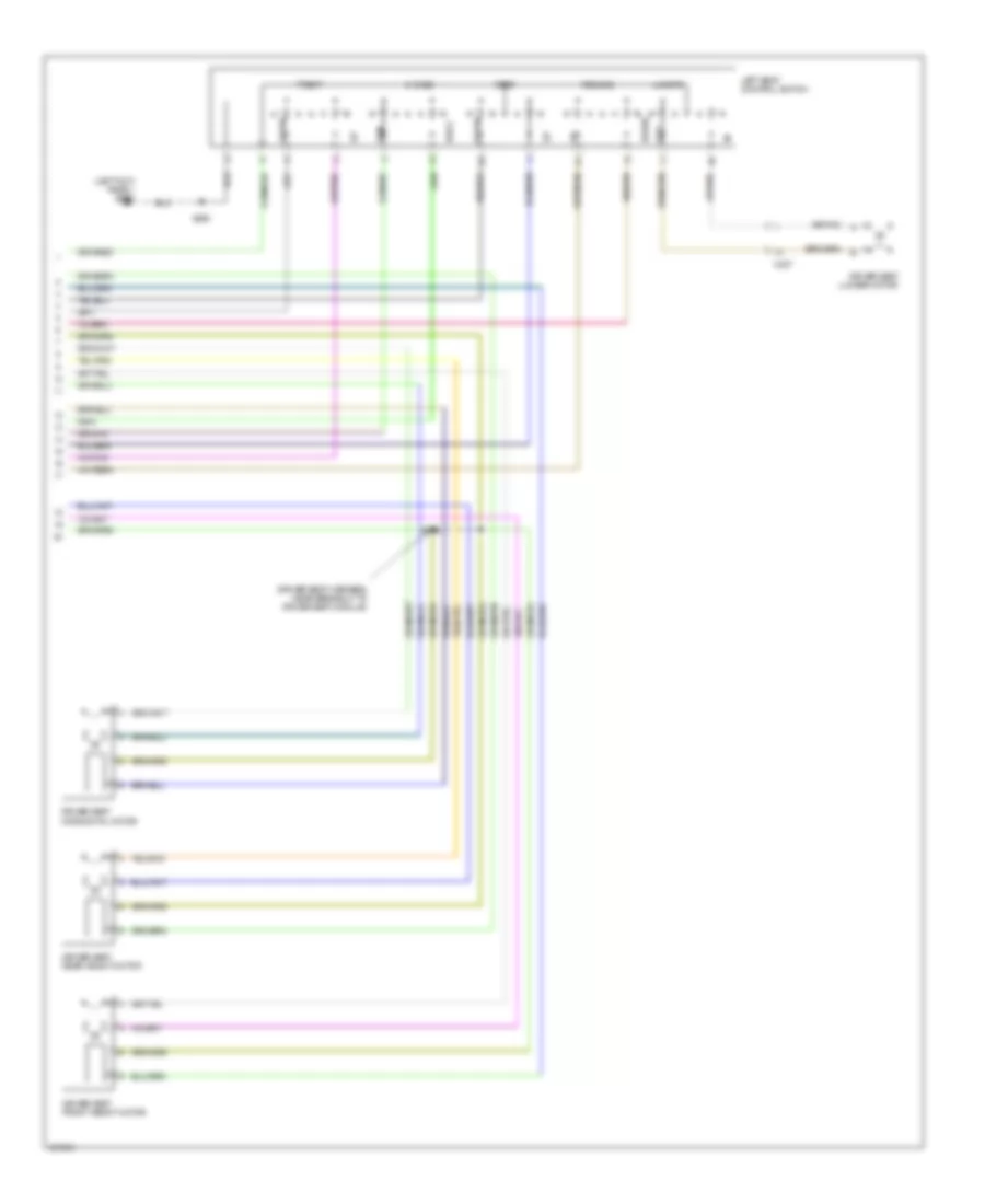
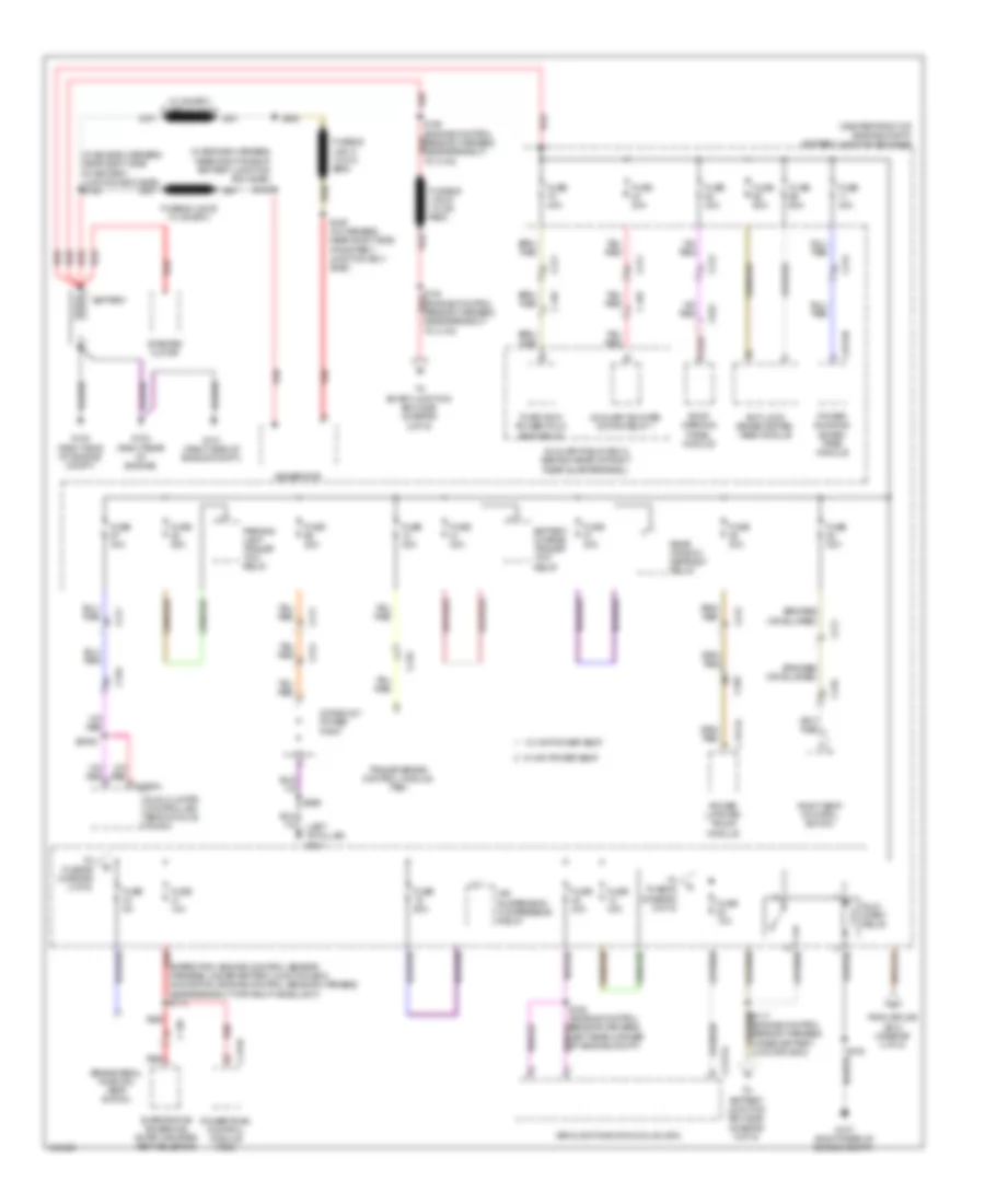
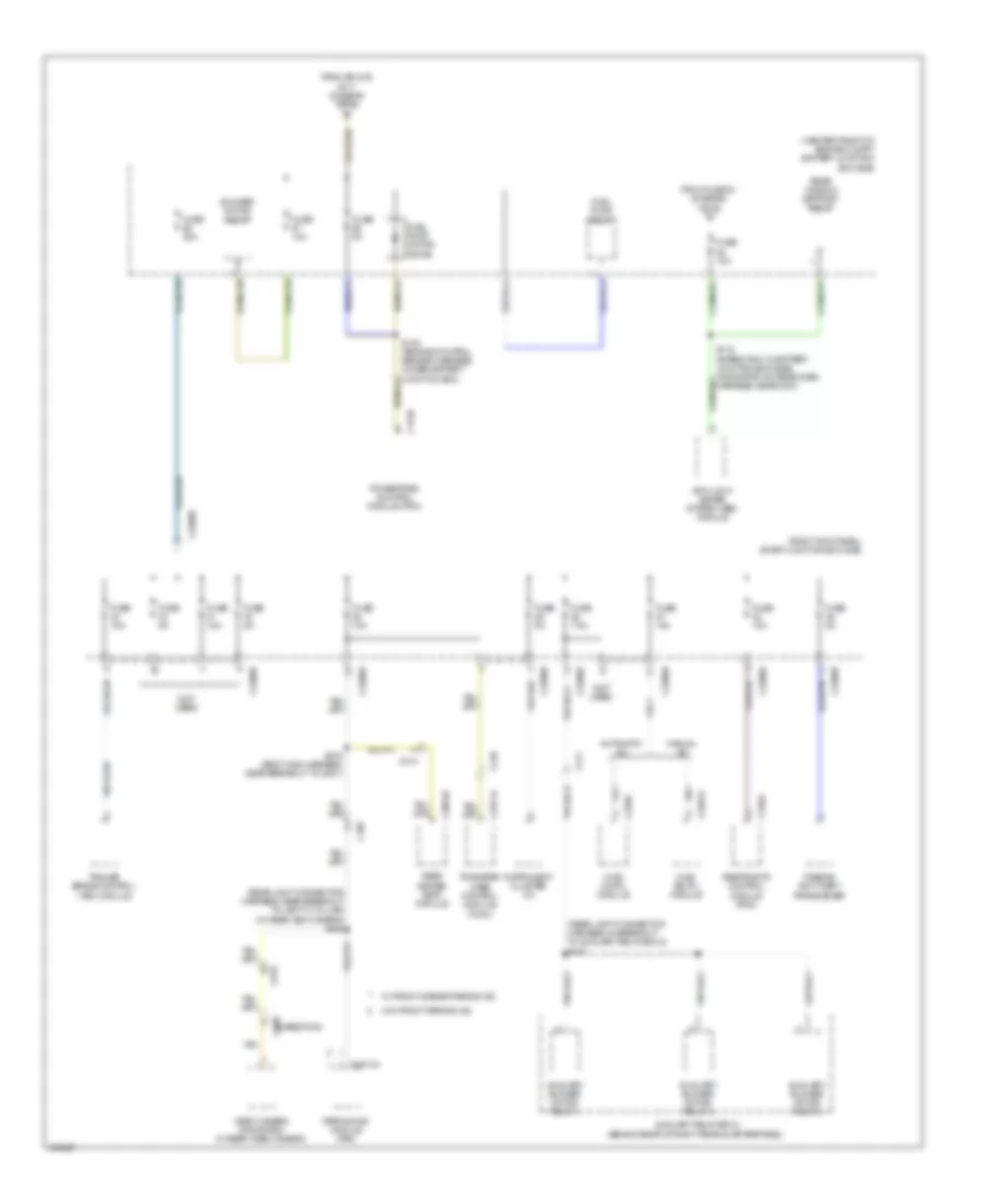
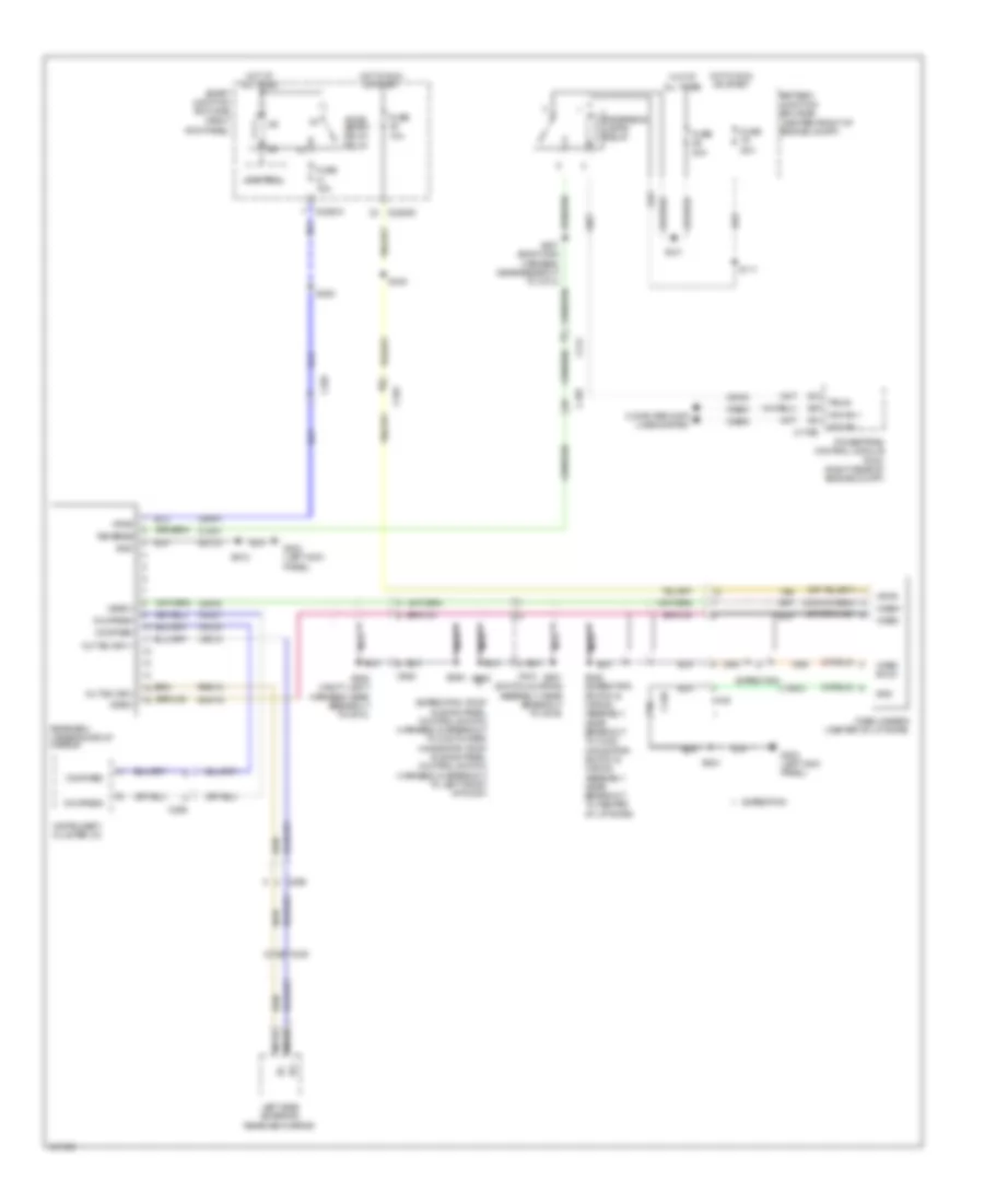
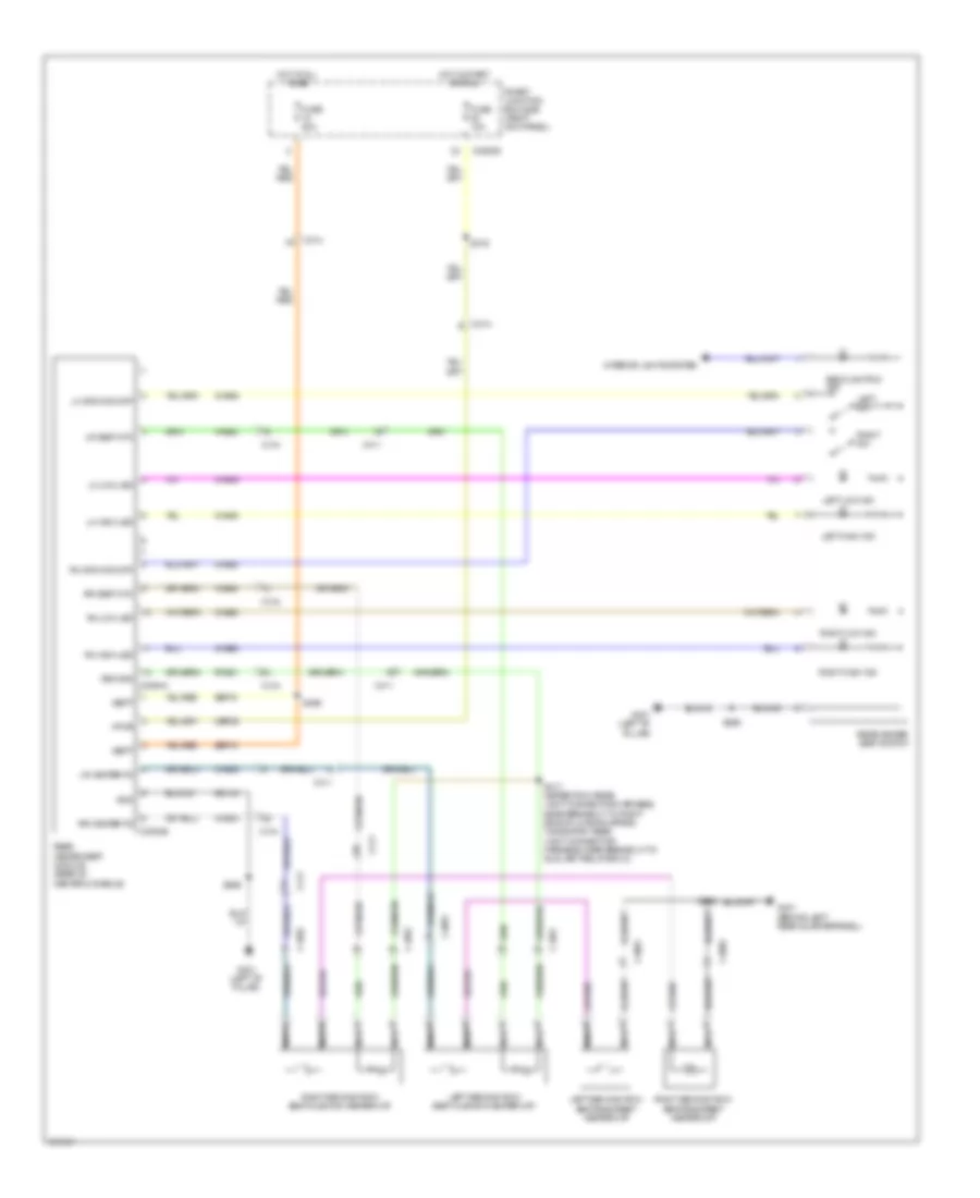
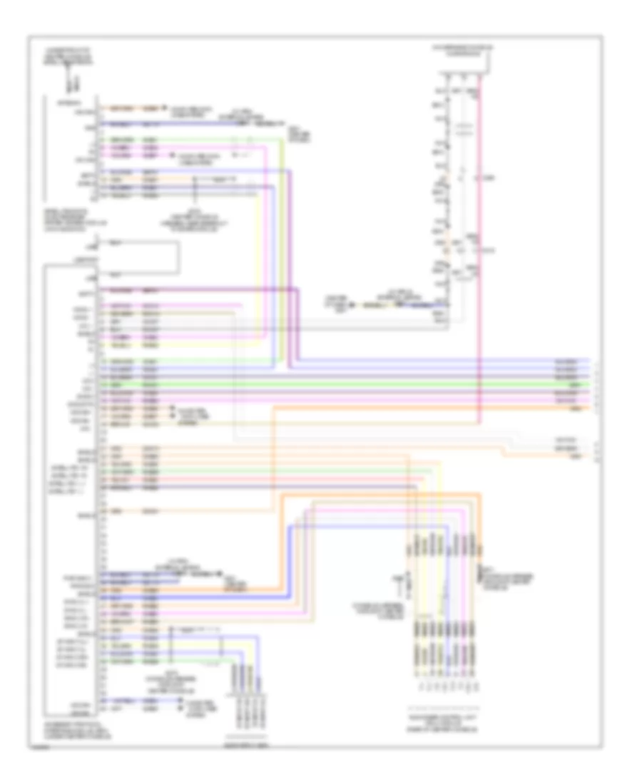
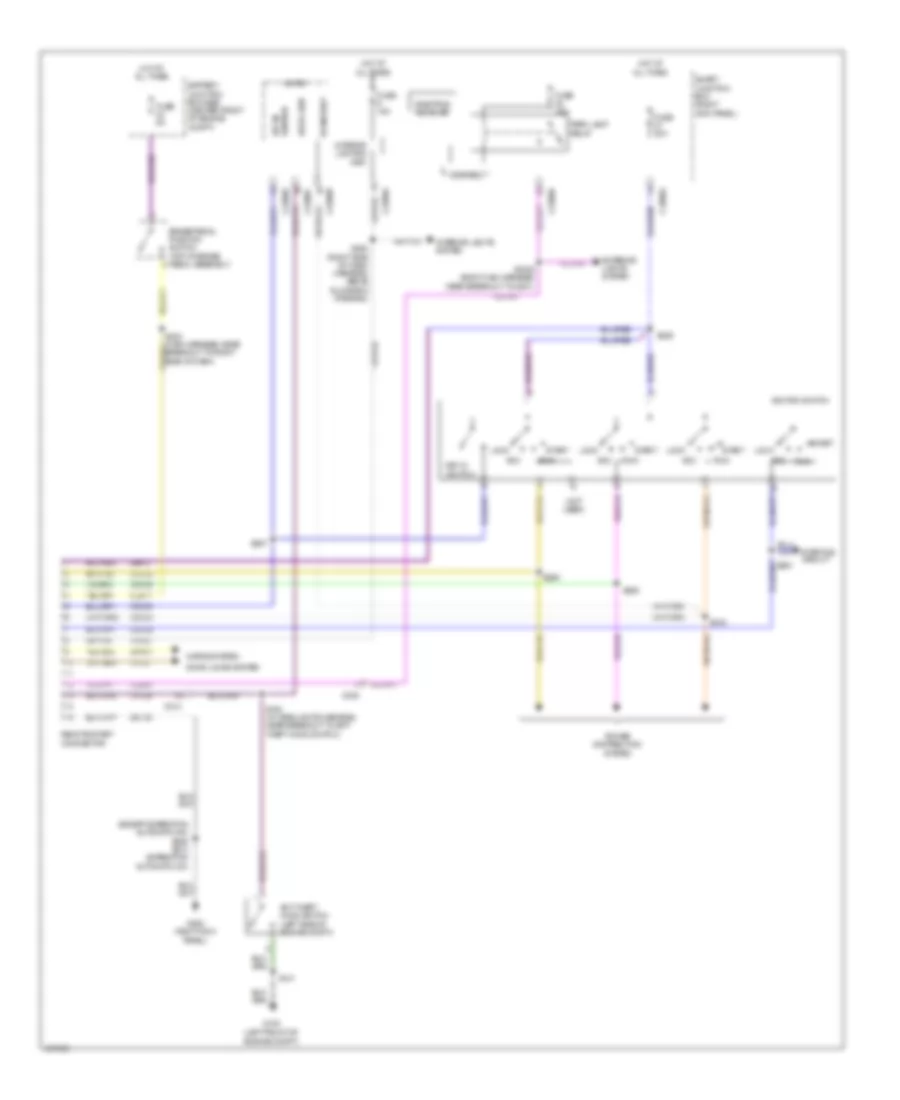
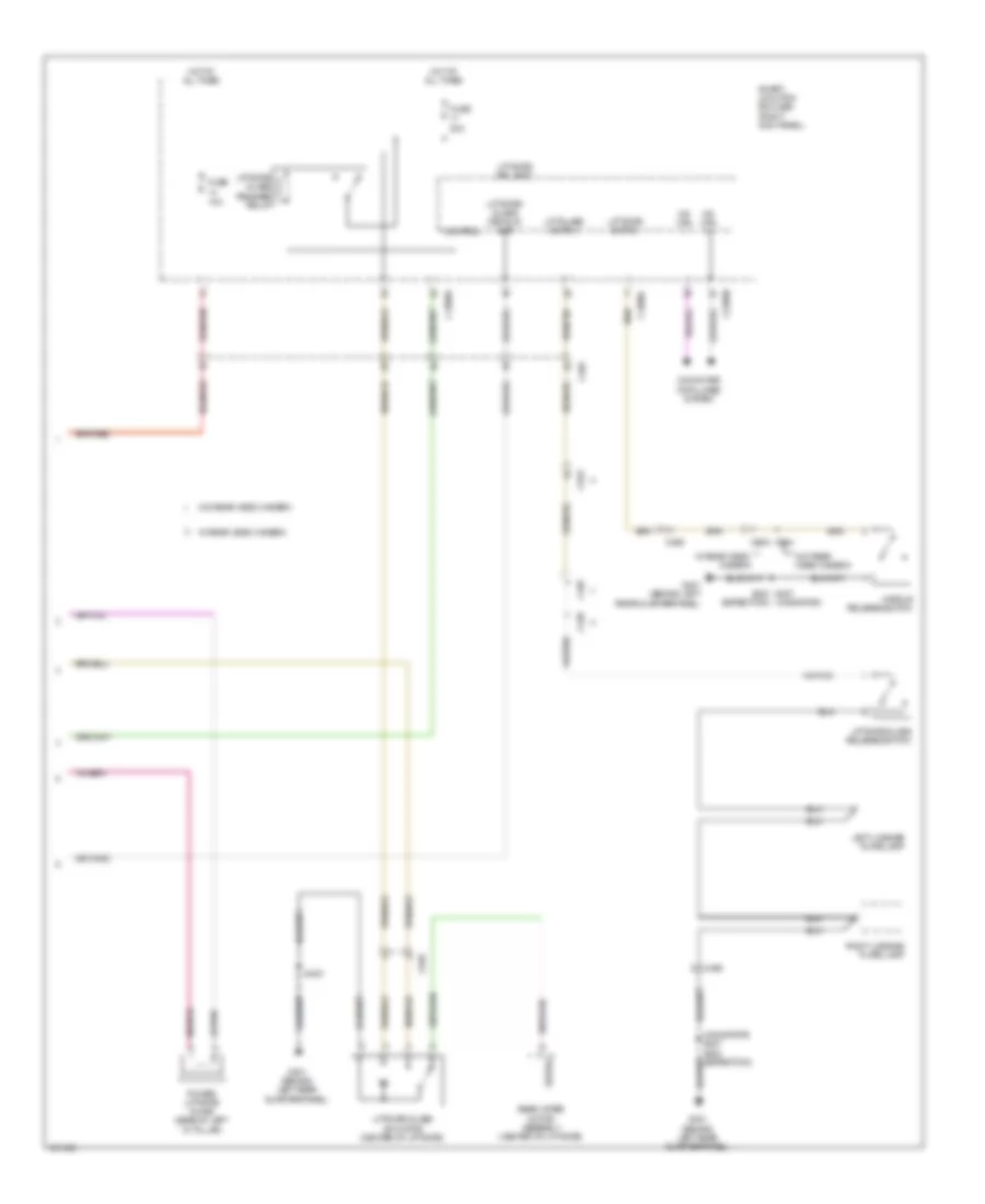
Automatic A/C Wiring Diagram, with Auxiliary Climate Control (4 of 4) for Ford Expedition XL 2014
List of elements for Automatic A/C Wiring Diagram, with Auxiliary Climate Control (4 of 4) for Ford Expedition XL 2014:
- (engine control sensor harness, near breakout for horn connector)
- 87a
- Battery junction box (bjb) (center front of engine compt)
- Engine controls system
- Engine cooling fan motor 1 (behind right side of radiator)
- Engine cooling fan motor 2
- Fan control (fc) relay
- Fuse 25a
- Fuse 40a
- G106 (right front of engine compt)
- High fan control (hfc) relay
- Hot at all times
- Low fan control (lfc) relay
- S108
- S111
- S162 (in battery junction box (bjb))
- S163
Automatic A/C Wiring Diagram, without Auxiliary Climate Control (1 of 4) for Ford Expedition XL 2014
List of elements for Automatic A/C Wiring Diagram, without Auxiliary Climate Control (1 of 4) for Ford Expedition XL 2014:
- (front heater blower motor harness, near breakout to right blend door actuator) s255
- (right side of hvac blower housing) air inlet mode door actuator
- (under top center of dash) sunload sensor
- Ambient signal
- Blower relay
- C2280a
- C2280b
- C228a
- C228b
- C291
- C299
- Cbp37
- Ch122
- Ch123
- Ch202
- Ch203
- Ch212
- Ch213
- Ch228
- Ch229
- Ch238
- Ch239
- Computer data lines system
- Defogger system
- Defrost request
- Defrost/panel/floor mode door actuator (left side of hvac unit)
- Driver sunload
- Evap
- Evaporator temperature sensor (top of hvac evaporator assembly)
- Feedback
- Fuse 10a
- G203 (left kick panel)
- Gd133
- Gnd
- Headlights system
- Hot at all times
- Hot in start or run
- Hvac (datc) module
- In-vehicle signal
- Left temperature blend door actuator (lower center of hvac unit)
- Lh111
- Motor+
- Motor-
- Ms can+
- Ms can-
- Passenger sunload
- Rh111
- Right temperature blend door actuator (upper center of hvac unit)
- S204 (body main harness, in breakout to c211)
- S211
- S254 (front heater blower motor harness, near breakout to right blend door actuator)
- S266
- Sbp15
- Signal return
- Smart junction box (sjb) (right kick panel)
- Solid state
- Variable blower control
- Vbatt
- Vdb06
- Vdb07
- Vh101
- Vh406
- Vh407
- Vh414
- Vh416
- Vh417
- Vh436
- Vh440
- Vh441
- Vpwr
- Vref
Automatic A/C Wiring Diagram, without Auxiliary Climate Control (2 of 4) for Ford Expedition XL 2014
List of elements for Automatic A/C Wiring Diagram, without Auxiliary Climate Control (2 of 4) for Ford Expedition XL 2014:
- (behind right side of front grille) ambient air temperature sensor
- (left side of dash) in-vehicle temperature sensor
- Battery junction box (bjb) (center front of engine compt)
- Blower motor (bottom right side of hvac unit)
- Blower motor relay
- Blower motor speed control module (right side of hvac unit)
- C210
- C291
- Ch402
- Engine controls system
- Fuse 10a
- Fuse 20a
- Fuse 40a
- G204 (right kick panel)
- Gd138
- Hot at all times
- Hot in start or run
- Pcm power relay
- S127
- S253
- Vh101
- Vh301
Automatic A/C Wiring Diagram, without Auxiliary Climate Control (3 of 4) for Ford Expedition XL 2014
List of elements for Automatic A/C Wiring Diagram, without Auxiliary Climate Control (3 of 4) for Ford Expedition XL 2014:
- (lower right front of engine) a/c compressor clutch field coil
- (right rear of engine compt) g108
- A/c clutch relay
- A/c pressure transducer (right front of engine compt)
- Accr
- Acpt
- Battery junction box (bjb) (center front of engine compt)
- C1026
- C144
- C175b
- C175e
- Ce201
- Ce202
- Ce607
- Ch302
- Cht
- Computer data lines system
- Cylinder head temperature sensor (rear of right cylinder bank)
- Engine control system
- Fuse 10a
- G106 (right front of engine compt)
- Gd113
- Hfc
- Hot at all times
- Hs can+
- Hs can-
- Le424
- Lfc
- Of engine compt)
- Pcmrc
- Powertrain control module (pcm) (right rear of engine compt)
- Pwr gnd
- Re405
- Re407
- S103
- S122
- Signal return
- Sigrtn
- Vdb04
- Vdb05
- Ve712
- Vh433
- Vref
Automatic A/C Wiring Diagram, without Auxiliary Climate Control (4 of 4) for Ford Expedition XL 2014
List of elements for Automatic A/C Wiring Diagram, without Auxiliary Climate Control (4 of 4) for Ford Expedition XL 2014:
- (engine control sensor harness, near breakout for horn connector)
- 87a
- Battery junction box (bjb) (center front of engine compt)
- Engine controls system
- Engine cooling fan motor 1 (behind right side of radiator)
- Engine cooling fan motor 2
- Fan control (fc) relay
- Fuse 25a
- Fuse 40a
- G106 (right front of engine compt)
- High fan control (hfc) relay
- Hot at all times
- Low fan control (lfc) relay
- S108
- S111
- S162 (in battery junction box (bjb))
- S163
Manual A/C Wiring Diagram, with Auxiliary Climate Control (1 of 4) for Ford Expedition XL 2014
List of elements for Manual A/C Wiring Diagram, with Auxiliary Climate Control (1 of 4) for Ford Expedition XL 2014:
- (body main harness, in breakout to c211) s204
- Auxiliary temperature blend door actuator (left side of auxiliary hvac unit)
- Battery junction box (bjb) (center front of engine compt)
- Blower
- Blower motor (bottom right side of hvac unit)
- Blower motor relay
- Blower motor resistor (bottom right side of hvac unit)
- Blower relay
- C210
- C214
- C2280a
- C2280b
- C2357a
- C2357b
- C2357c
- C237
- C238
- C315
- C411
- Cbp37
- Ch112
- Ch113
- Ch114
- Ch122
- Ch123
- Ch202
- Ch203
- Ch207
- Ch208
- Ch228
- Ch229
- Ch233
- Ch234
- Ch238
- Ch239
- Ch428
- Ch429
- Ch430
- Computer data lines system
- Defogger system
- Defrost request
- Evap
- Feedback
- Fuse 10a
- Fuse 40a
- G200 (right kick panel)
- G203 (left kick panel)
- G301 (left "b" pillar)
- Gd113
- Gd138
- Gnd
- High
- Hot at all times
- Hot in start or run
- Hvac (emtc) module
- Interior lights system
- Lh111
- Mid high
- Mid low
- Mode/temp
- Motor+
- Motor-
- Ms can+
- Ms can-
- Off
- Rear auxiliary climate control assembly
- Relay 1
- Relay 2
- Relay 3
- Rh111
- S211
- S252
- S266
- S369
- S436 (taillights harness, near breakout to fuel tank)
- Sbp15
- Signal return
- Smart junction box (sjb) (right kick panel)
- Thermal limiter
- Vbatt
- Vdb06
- Vdb07
- Vh406
- Vh436
- Vh438
- Vh439
- Vh440
- Vha15
- Vha17
- Vpwr
- Vref
Manual A/C Wiring Diagram, with Auxiliary Climate Control (2 of 4) for Ford Expedition XL 2014
List of elements for Manual A/C Wiring Diagram, with Auxiliary Climate Control (2 of 4) for Ford Expedition XL 2014:
- (front heater blower motor harness, near breakout to right blend door actuator)
- Air inlet mode door actuator (right side of hvac blower housing)
- Auxiliary mode door actuator (front right side of auxiliary hvac unit)
- Below right side of dash)
- C214
- C2280d
- C237
- C299
- C411
- Defrost/panel/floor mode door actuator (left side of hvac unit)
- Evaporator temperature sensor (top of hvac evaporator assembly)
- Fuse 7.5a
- Hot in start or run
- S254 (front heater blower motor harness, near breakout to right blend door actuator)
- S255
- S437 (taillights harness, near breakout to fuel tank)
- Smart junction box (sjb) (right kick panel)
- Temperature blend door actuator (top right side of hvac unit)
Manual A/C Wiring Diagram, with Auxiliary Climate Control (3 of 4) for Ford Expedition XL 2014
List of elements for Manual A/C Wiring Diagram, with Auxiliary Climate Control (3 of 4) for Ford Expedition XL 2014:
- (lower right front of engine) a/c compressor clutch field coil
- (rear light connector harness, in breakout to auxiliary relay box 2)
- A/c clutch relay
- A/c pressure transducer (right front of engine compt)
- Accr
- Acpt
- Auxiliary blower motor (rear of auxiliary hvac unit)
- Auxiliary blower motor relay 1
- Auxiliary blower motor relay 2
- Auxiliary blower motor relay 3
- Auxiliary blower motor resistor assembly (on auxiliary hvac blower motor assembly)
- Auxiliary relay box 2 (behind rear of right rear quarterpanel)
- Battery junction box (bjb) (center front of engine compt)
- C1026
- C144
- C175b
- C175e
- C211
- C214
- C410
- C411
- Ce201
- Ce202
- Ce607
- Ch302
- Cht
- Computer data lines system
- Cylinder head temperature (cht) sensor (rear of right cylinder bank)
- Engine controls system
- Fuse 10a
- Fuse 20a
- Fuse 30a
- G106 (right front of engine compt)
- G108 (right rear of engine compt)
- G403 (behind rear of right rear quarterpanel)
- Gd113
- Hfc
- Hot at all times
- Hs can+
- Hs can-
- Le424
- Lfc
- Pcm power relay
- Pcmrc
- Powertrain control module (pcm) (right rear of engine compt)
- Pwr gnd
- Re405
- Re407
- S103
- S122
- S123
- S126
- S127
- S420
- S422
- S428
- Signal return
- Sigrtn
- Thermal limiter
- Vdb04
- Vdb05
- Ve712
- Vh433
- Vref
Manual A/C Wiring Diagram, with Auxiliary Climate Control (4 of 4) for Ford Expedition XL 2014
List of elements for Manual A/C Wiring Diagram, with Auxiliary Climate Control (4 of 4) for Ford Expedition XL 2014:
- (engine control sensor harness, near breakout for horn connector)
- 87a
- Battery junction box (bjb) (center front of engine compt)
- Engine controls system
- Engine cooling fan motor 1 (behind right side of radiator)
- Engine cooling fan motor 2
- Fan control (fc) relay
- Fuse 25a
- Fuse 40a
- G106 (right front of engine compt)
- High fan control (hfc) relay
- Hot at all times
- Low fan control (lfc) relay
- S108
- S111
- S162 (in battery junction box (bjb))
- S163
Manual A/C Wiring Diagram, without Auxiliary Climate Control (1 of 3) for Ford Expedition XL 2014
List of elements for Manual A/C Wiring Diagram, without Auxiliary Climate Control (1 of 3) for Ford Expedition XL 2014:
- (pins 1-22 not used)
- (pins 24 -26 not used)
- Air inlet mode door actuator (right side of hvac blower housing)
- Battery junction box (bjb) (center front of engine compt)
- Blower motor (bottom right side of hvac unit)
- Blower motor relay
- Blower motor resistor (bottom right side of hvac unit)
- Blower relay
- C210
- C2280a
- C2280b
- C2357a
- C2357b
- C2357c
- C237
- Cbp37
- Ch122
- Ch123
- Ch202
- Ch203
- Ch228
- Ch229
- Ch238
- Ch239
- Ch428
- Ch429
- Ch430
- Computer data lines system
- Defogger system
- Defrost request
- Evap
- Feedback
- Fuse 10a
- Fuse 40a
- G200 (right kick panel)
- G203 (left kick panel)
- Gd113
- Gd138
- Gnd
- High
- Hot at all times
- Hot in start or run
- Hvac (emtc) module
- Lh111
- Mid high
- Mid low
- Motor+
- Motor-
- Ms can+
- Ms can-
- Off
- Rh111
- S210
- S211
- S252
- S266
- Sbp15
- Signal return
- Smart junction box (sjb) (right kick panel)
- Thermal limiter
- Vbatt
- Vdb06
- Vdb07
- Vh406
- Vh436
- Vh440
- Vpwr
- Vref
Manual A/C Wiring Diagram, without Auxiliary Climate Control (2 of 3) for Ford Expedition XL 2014
List of elements for Manual A/C Wiring Diagram, without Auxiliary Climate Control (2 of 3) for Ford Expedition XL 2014:
- (front heater blower motor harness, near breakout to right blend door actuator) s254
- (front heater blower motor harness, near breakout to right blend door actuator) s255
- (lower right front of engine) a/c compressor clutch field coil
- A/c
- A/c pressure transducer (right front of engine compt)
- Accr
- Acpt
- Battery junction box (bjb) (center front of engine compt)
- C1026
- C144
- C175b
- C175e
- C237
- C299
- Ce201
- Ce202
- Ce607
- Ch302
- Cht
- Clutch
- Computer data lines system
- Cylinder head temperature (cht) sensor (rear of right cylinder bank)
- Defrost/panel/floor mode door actuator (left side of hvac unit)
- Engine controls system
- Evaporator temperature sensor (top of hvac evaporator assembly)
- Fuse 10a
- Fuse 20a
- Fuse 30a
- G106 (right front of engine compt)
- G108 (right rear of engine compt)
- Gd113
- Hfc
- Hot at all times
- Hs can+
- Hs can-
- Le424
- Lfc
- Pcm power relay
- Pcmrc
- Powertrain control module (pcm) (right rear of engine compt)
- Pwr gnd
- Re405
- Re407
- Relay
- S103
- S122
- S123
- S126
- S127
- Signal return
- Sigrtn
- Temperature blend door actuator (top right side of hvac unit)
- Vdb04
- Vdb05
- Ve712
- Vh433
- Vref
Manual A/C Wiring Diagram, without Auxiliary Climate Control (3 of 3) for Ford Expedition XL 2014
List of elements for Manual A/C Wiring Diagram, without Auxiliary Climate Control (3 of 3) for Ford Expedition XL 2014:
- (engine control sensor harness, near breakout for horn connector)
- (in battery junction box (bjb)) s162
- 87a
- Battery junction box (bjb) (center front of engine compt)
- Engine controls system
- Engine cooling fan motor 1 (behind right side of radiator)
- Engine cooling fan motor 2
- Fan control (fc) relay
- Fuse 25a
- Fuse 40a
- G106 (right front of engine compt)
- High fan control (hfc) relay
- Hot at all times
- Low fan control (lfc) relay
- S108
- S111
- S163
ANTI-LOCK BRAKES
Anti-lock Brakes Wiring Diagram for Ford Expedition XL 2014
List of elements for Anti-lock Brakes Wiring Diagram for Ford Expedition XL 2014:
- (expedition: rear engine harness, left rear of engine compt) (navigator: engine compt harness, near breakout to vehicle dynamics module)
- (right front wheel hub assembly)
- (right rear of engine compt)
- (top of brake pedal assembly)
- Angle a/1
- Angle b/2
- Anti-lock brake system (abs) module (left front of engine compt)
- Battery junction box (bjb) (center front of engine compt)
- Bpp
- Bps
- Brake booster sensor (on brake vacuum booster assembly)
- Brake fluid level switch (brake fluid reservoir)
- Brake pedal position switch
- Brk fluid sw
- Brk fluid sw rtn
- C139
- C175b
- C210
- C213
- C2280b
- C2280c
- C2280f
- Can 2 +
- Can 2 -
- Cbb52
- Cca15
- Ccb01
- Ccs01
- Ces09
- Cls17
- Cmc19
- Computer data lines system
- Exterior lights system
- Fuse 43 5a
- Fuse 52 10a
- Fuse 68 60a
- Fuse 69 60a
- G103 (left front of engine compt)
- G104 (left front of engine compt)
- G107 (right rear of engine compt)
- G200 (right kick panel)
- G301 (left "b" pillar)
- Gd120
- Hot at all times
- Hot in start or run
- Hs can +
- Hs can -
- Instrument cluster (ic)
- Lca37
- Left front wheel speed sensor (left front wheel hub assembly)
- Left rear wheel speed sensor (left rear wheel hub assembly)
- Lf sensor +
- Lf sensor -
- Lr sensor +
- Lr sensor -
- Ms can +
- Ms can -
- Mtr gnd
- Mtr pwr
- Nca
- Parking brake switch (base of parking brake lever assembly)
- Power liftgate/ traction control/ hazard switch (disengage stability assist)
- Powertrain control module (pcm)
- Prk brake
- Rca17
- Rca18
- Rca19
- Rca20
- Rca37
- Rcs02
- Rf sensor +
- Rf sensor -
- Right front wheel speed sensor
- Right rear wheel speed sensor (right rear wheel hub assembly)
- Rmc19
- Rr sensor +
- Rr sensor -
- Run/start
- S102
- S119
- S129
- S151
- S213
- S340
- Sbb68
- Sbb69
- Smart junction box (sjb)
- Solid state
- Steering position sensor (steering column)
- Swar gnd
- Swar sen sep
- Tc ivd crl sw
- Vac gnd
- Vac sensep
- Vac sig
- Valve pwr
- Vca03
- Vca04
- Vca05
- Vca06
- Vca23
- Vca24
- Vca38
- Vcs06
- Vcs07
- Vdb04
- Vdb05
- Vdb06
- Vdb07
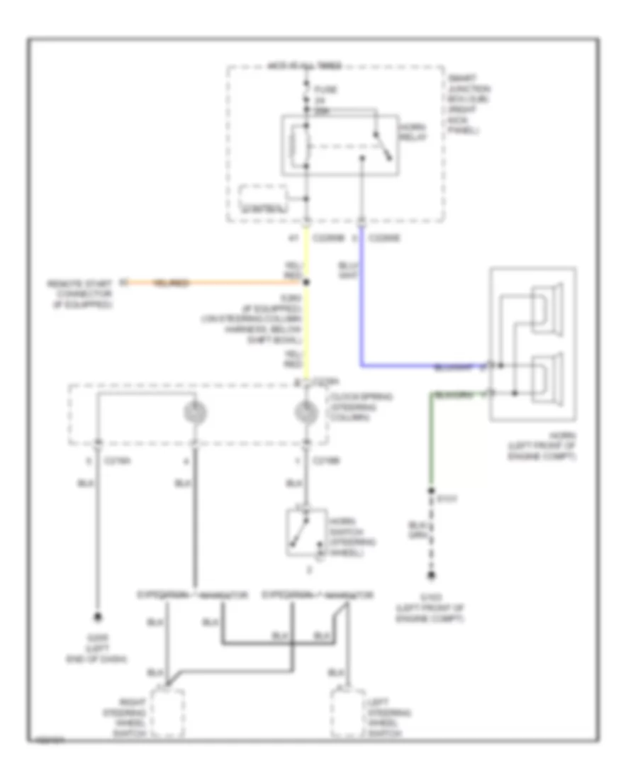
ANTI-THEFT
Forced Entry Wiring Diagram (1 of 2) for Ford Expedition XL 2014
List of elements for Forced Entry Wiring Diagram (1 of 2) for Ford Expedition XL 2014:
- (behind left rear quarterpanel) g401
- (behind rear of left rear quarterpanel) liftgate/trunk module (ltm)
- (body main harness, near breakout to c214) s246
- (body main harness, near breakout to smart junction box) s248
- (bottom center of liftgate) liftgate latch
- (center of liftgate) liftgate glass actuator
- (center of liftgate) rear wiper motor assembly
- (navigator)
- (navigator) s427
- Ajar sw
- C2280c
- C2280d
- C4174b
- C438
- C465
- C495
- C510
- C700
- C919
- C934
- C935
- Control
- Cpl10
- Cpl58
- Cpr50
- Df door ajar
- Door lock
- Door unlock
- Dr door ajar
- Driver side door lock switch
- Driver side rear door ajar switch (rear of left rear door)
- Expedition w/o power liftgate (or) rear video camera
- Fuse 10a
- G300 (right kick panel)
- G301 (left "b" pillar)
- G302 (right kick panel)
- G401 (behind left rear quarterpanel)
- Glass ajar sw
- Gnd
- Handle release switch
- Handle sw
- Hot at all times
- Interior lights system
- Left front door ajar switch (rear of driver's door)
- Left license plate lamp
- Liftgate glass release relay
- Liftgate glass release switch
- Liftgate rel (fet)
- Liftgate switch
- Liftgate/ glass decklid ajar
- Liftglass switch
- Lock
- Passenger side door lock switch
- Right license plate lamp
- S245
- S250
- S340
- S423
- S427
- S427 s423 (expedition)
- S501
- S503
- Smart junction box (sjb) (right kick panel)
- Status
- To driver door unlock relay (diagram 2 of 2)
- To keypad illum (fet) (diagram 2 of 2)
- Unlock
- Vpwr
- W/ power liftgate
- W/ power liftgate & rear video camera
- W/ rear video camera
- W/o power liftgate
- W/o rear video camera
Forced Entry Wiring Diagram (2 of 2) for Ford Expedition XL 2014
List of elements for Forced Entry Wiring Diagram (2 of 2) for Ford Expedition XL 2014:
- (body main harness,near breakout to c314)
- (in headlights harness, near breakout to anti theft hood switch) (if equipped) s150
- (right kick panel) g300
- 1/2
- 3/4
- 5/6
- 7/8
- 9/0
- Anti-theft hood switch (left side of engine compt)
- C213
- C2280b
- C2280c
- C2280d
- C2280e
- C2280f
- C510
- C610
- C700
- C800
- Computer data lines system
- Control
- Door lock relay
- Driver door unlock relay
- Expedition
- From liftgate glass release a relay (diagram 1 of 2)
- From smart junction box (sjb) b fuse 5 (diagram 1 of 2)
- Fuse 20a
- G103 (left front of engine compt)
- G203 (left kick panel)
- G300 (right kick panel)
- G301 (left "b" pillar)
- Headlamp on
- Headlights system
- Hood ajar
- Horn relay
- Horns system
- Hot at all times
- Internal antenna
- Keyless entry keypad
- Keypad illum (fet)
- Keypad sw a
- Keypad sw b
- Keypad sw c
- Left front door lock actuator
- Left rear door lock actuator
- Ms can +
- Ms can -
- Navigator
- Passenger side rear door ajar switch (rear of right rear door)
- Pf door ajar
- Pr door ajar
- Remote start connector
- Right front door ajar switch (rear of front passenger's door)
- Right front door lock actuator
- Right rear door lock actuator
- Rke receiver
- S131
- S245
- S308
- S335 (body main harness, near breakout to g301)
- S347
- S503
- S600
- Smart junction box (sjb) (right kick panel)
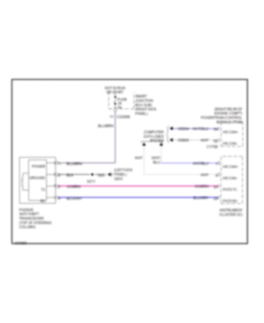
Passive Anti-theft Wiring Diagram for Ford Expedition XL 2014
List of elements for Passive Anti-theft Wiring Diagram for Ford Expedition XL 2014:
- (left kick panel) g203
- (right rear of engine compt) powertrain control module (pcm)
- C175b
- C2280b
- Computer data lines system
- Fuse 5a
- Ground
- Hot in run or start
- Hs can+
- Hs can-
- Instrument cluster (ic)
- Passive anti-theft transceiver (top of steering column)
- Pats rx
- Pats tx
- Power
- S211
- Smart junction box (sjb) (right kick panel)
- Vdb04
- Vdb05
BODY CONTROL MODULES
Body Control Modules Wiring Diagram (1 of 2) for Ford Expedition XL 2014
List of elements for Body Control Modules Wiring Diagram (1 of 2) for Ford Expedition XL 2014:
- (not used)
- (right side of engine compt)
- 3rd row seat enable (fet)
- Air conditioning system
- Anti-lock brakes & instrument cluster systems
- Anti-lock brakes & instrument cluster systems door locks & anti-theft systems
- Battery
- Battery junction box (bjb) (center front of engine compt)
- Battery saver relay
- Brake fluid sw
- Brake fluid sw rtn
- Bsi (fet)
- C2280c
- C2280d
- C2280e
- C2280f
- C2280g
- Cat23
- Cbb56
- Cbp32
- Cbp35
- Cbp41
- Cbp43
- Cbp45
- Cbp46
- Cbp47
- Ccb01
- Cdc37
- Cdc38
- Circuit breaker 47, 30a
- Clf04
- Clf05
- Clf08
- Clf21
- Cln09
- Cln25
- Cls18
- Cls19
- Cls21
- Cls25
- Cls30
- Cmc19
- Cpk28
- Cpk29
- Cpk30
- Cpk31
- Cpl10
- Cpl11
- Cpl25
- Cpl26
- Cpl27
- Cpl30
- Cpl31
- Cpl36
- Cpl39
- Cpl45
- Cpl51
- Cpl52
- Cpl58
- Cpl59
- Cpl60
- Cps48
- Crh02
- Crw01
- Df door ajar
- Door lock relay
- Door locks & trunk, tailgate, fuel doors systems
- Door locks system
- Door unlock
- Dr door ajar
- Driver door unlock relay
- Exterior lights system
- Fog lamp relay
- Front wiper ctrl
- Fuse 1, 30a
- Fuse 11, 10a
- Fuse 12, 7.5a
- Fuse 13, 5a
- Fuse 14, 10a
- Fuse 18, 20a
- Fuse 19, 25a
- Fuse 2, 15a
- Fuse 28, 5a
- Fuse 3, 15a
- Fuse 30a
- Fuse 32, 10a
- Fuse 35, 10a
- Fuse 38, 20a
- Fuse 4, 30a
- Fuse 41, 15a
- Fuse 43, 10a
- Fuse 44, 10a
- Fuse 45, 5a
- Fuse 46, 7.5a
- Fusible link d (10 ga- red)
- G100
- G101 (right side of engine compt)
- G102 (right rear of engine)
- G300 (right kick panel)
- G302 (right kick panel)
- Gd138
- Ground
- Headlights system
- High beam relay
- Hood ajar
- Horn relay
- Horns system
- Hot in run or start
- Ign
- Instrument cluster & anti-lock brakes systems
- Interior lights system
- Keypad illum (fet)
- Keypad sw a
- Keypad sw b
- Keypad sw c
- Left low beam (fet)
- Lf turn lamp (fet)
- Lift glass sw
- Liftgate glass release relay
- Liftgate rel (fet)
- Liftgate sw
- Logic gnd
- Lr stop/turn lamp (fet)
- Lr turn lamp (fet)
- Memory systems
- Navigation & sound systems
- Park brake
- Park lamp relay
- Pf door ajar
- Power gnd
- Power tops & power windows systems
- Power windows system
- Power windows system (navigator)
- Pr door ajar liftgate/glass/ decklid ajar door lock
- Puddle lamp (fet)
- Pulse train (fet)
- Red
- Rf turn lamp (fet)
- Right low beam (fet)
- Rmc19
- Rr stop/turn lamp (fet)
- Rr turn lamp (fet)
- S104
- S105
- S245
- S250
- Sbp01
- Sbp02
- Sbp03
- Sbp04
- Sbp12
- Sbp14
- Sbp18
- Sbp19
- Sbp38
- Sdc04
- Seats & navigation systems
- Seats system
- Shift interlock system
- Smart junction box (sjb) (right kick panel)
- Starting/charging system
- Tpms 1 (fet)
- Tpms 2 (fet)
- Tpms 3 (fet)
- Trunk, tailgate, fuel doors system
- Vbatt
- Wiper/washer system
Body Control Modules Wiring Diagram (2 of 2) for Ford Expedition XL 2014
List of elements for Body Control Modules Wiring Diagram (2 of 2) for Ford Expedition XL 2014:
- (not used)
- Acc
- Air conditioning & navigation systems
- Air conditioning system
- Anti-theft system
- Autolamp on
- Autolamp sense in
- Backlighting led (fet)
- Brake pedal sw
- C2280a
- C2280b
- Cbp28
- Cbp29
- Cbp33
- Cbp35
- Cbp36
- Cbp37
- Cbp41
- Cbp43
- Cdc30
- Cdc32
- Cdc33
- Cdc34
- Clf02
- Clf19
- Clf23
- Clf24
- Clf27
- Clf28
- Clf29
- Cln27
- Cln28
- Cln30
- Cls05
- Cls17
- Cls20
- Cls24
- Computer data lines system
- Dim sw gnd
- Dimmer sw
- Dome defeat
- Dome lp
- Exterior lights system
- Flash-to-pass
- Floor lamp (fet)
- Fog lamp
- Fog lamp relay
- Fuse 14, 10a
- Fuse 15, 10a
- Fuse 16, 15a
- Fuse 20, 15a
- Fuse 26, 10a
- Fuse 27, 20a
- Fuse 28, 5a
- Fuse 29, 5a
- Fuse 30, 5a
- Fuse 31, 10a
- Fuse 33, 10a
- Fuse 34, 5a
- Fuse 35, 10a
- Fuse 36, 5a
- Fuse 37, 10a
- Fuse 39, 20a
- Fuse 40, 20a
- Fuse 41, 15a
- Fuse 42, 10a
- Fuse 43, 10a
- Fuse 46, 7.5a
- Hazard
- Headlamp off
- Headlamp on
- Headlights system
- High beam
- Horn relay
- Horns system
- Ignition switch
- Instrument cluster system
- Interior lighting (fet)
- Interior lights system
- Key in ignition
- Lock
- Ms can+
- Ms can-
- Navigation & sound systems
- Not used
- Park lamp on
- Power distribution system
- Remote start connector
- Rln29
- Run
- Run/acc
- Run/start
- S212
- S229
- Sbp14
- Sbp15
- Sbp20
- Sbp26
- Sbp27
- Sbp39
- Sbp40
- Shift interlock system
- Smart junction box (sjb) (right kick panel)
- Sound systems
- Srh01
- Start
- Starting/ charging system
- Transmissions system
- Turn left
- Turn right
- Vdb06
- Vdb07
- Vlf14
- Vln18
- Vln33
- Vln36
- Wiper/washer system
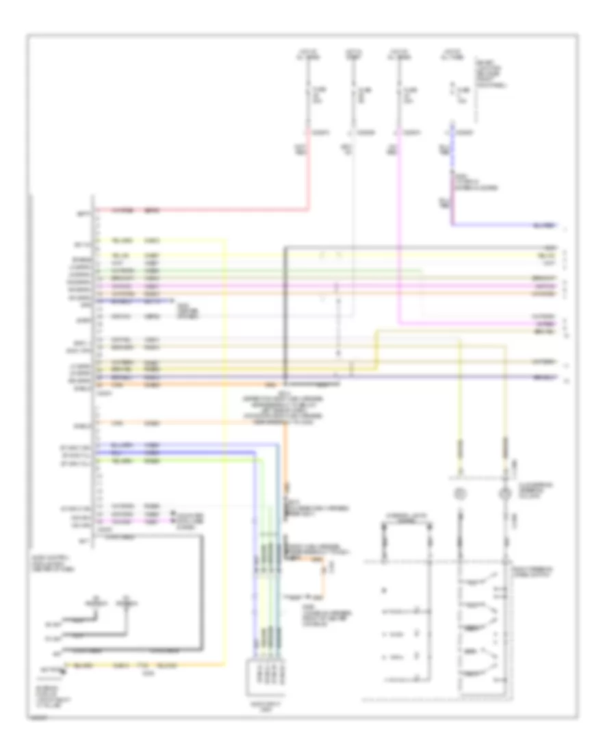
COMPUTER DATA LINES
Computer Data Lines Wiring Diagram for Ford Expedition XL 2014
List of elements for Computer Data Lines Wiring Diagram for Ford Expedition XL 2014:
- (below center console) restraints control module (rcm)
- (body main harness, near breakout to c2364c) (navigator w/ thx audio) s265
- (body main harness, near breakout to c3051) s313
- (body main harness, near breakout to c312) s330
- (body main harness, near breakout to c314)
- (body main harness, near breakout to c316)
- (body main harness, near breakout to g301)
- (body main harness, near breakout to g301) s333
- (center console, near breakout to apim)
- (engine control sensor harness, near breakout to c211) s201
- (expedition w/o satellite: console harness, front of center console) (navigator & expedition w/ satellite: center console harness, near breakout to sdars module) s377
- (expedition: taillights harness, near breakout to liftgate motor/clutch) (navigator: taillights harness, near breakout to subwoofer)
- (in headlights harness, near breakout to anti theft hood switch)
- (left front of engine compt) anti-lock brake system (abs) module
- (main harness,
- (main harness, near breakout to center of dash)
- (main harness, near breakout to center of dash) s223
- (main harness, near breakout to right side of dash)
- (rear light connector harness, near breakout to c410) s413
- (rear light connector harness, near breakout to left "c" pillar)
- (right rear of engine compt) powertrain control module (pcm)
- (under left center of dash) data link connector (dlc)
- Accessory protocol interface module (apim) (under center console)
- Audio control module (acm) (center of dash)
- Audio digital signal processing (dsp) module (navigator w/ thx audio)
- Audio rear control unit (rcu) module (w/ rear audio controls) (rear of center console)
- Automatic a/c
- C175b
- C210
- C212
- C2131a
- C2280a
- C2280b
- C228a
- C2357a
- C2364c
- C2371a
- C238
- C240c
- C310b
- C311
- C314
- C315
- C316
- C3265c
- C3313b
- C341d
- C4014a
- C4174b
- C465
- Can - hs
- Can2 +
- Can2 -
- Datc hvac module
- Driver seat module (under driver's seat)
- Dual climate controlled controlled (under front passenger's seat)
- Emtc hvac module
- Fuse 15a
- G108 (right rear of engine compt)
- G200 (right kick panel)
- Gd113
- Gd138
- Global positioning system module (gpsm) (w/ sync w/o navigation) (center of dash)
- Hot at all times
- Hs can +
- Hs can -
- Hs can+
- Hs can-
- Instrument cluster (ic)
- Liftgate/trunk module (ltm) (behind rear of left rear quarterpanel)
- Manual a/c
- Ms can+
- Ms can-
- Near breakout to apim) (w/ rear audio controls) s368
- Near breakout to c315) s337
- Parking aid module (pam) (left "c" pillar)
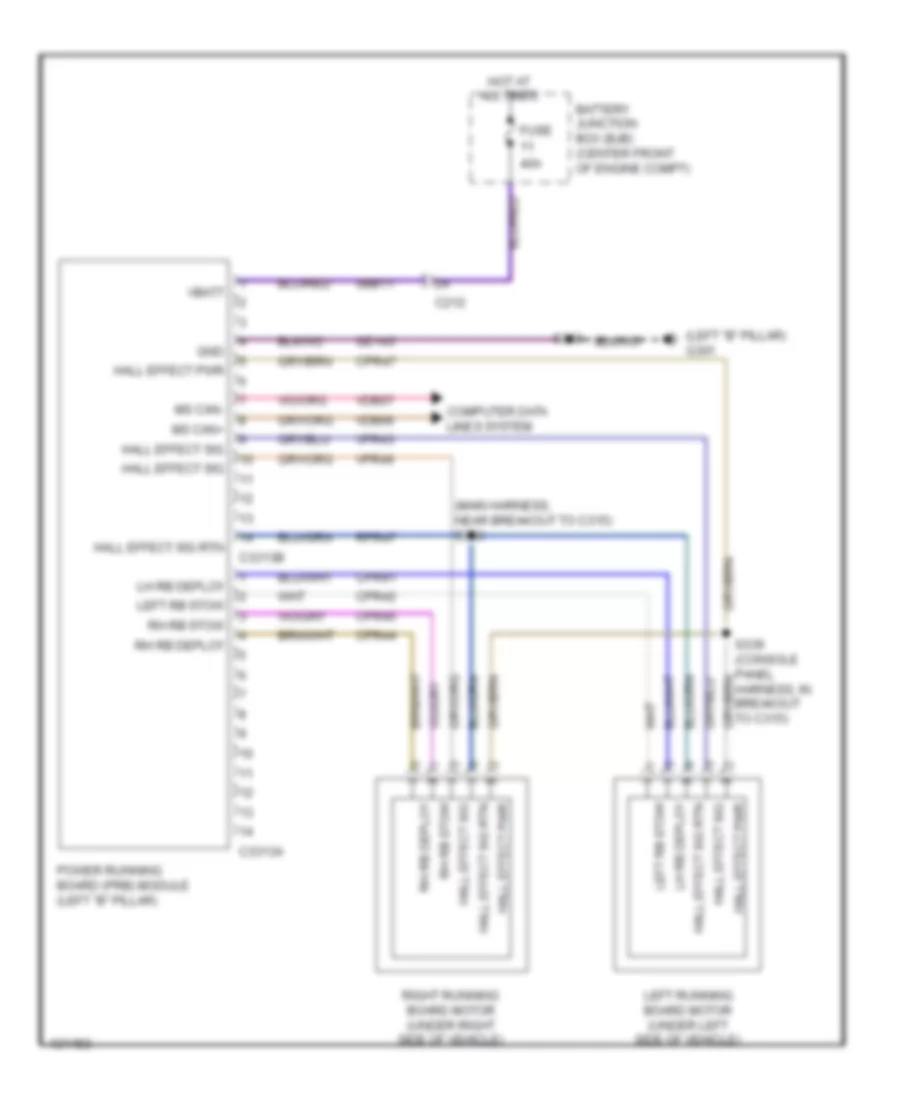
- Power running board (prb) module (left "b" pillar)
- S100
- S103
- S134 (engine control sensor harness, left rear of engine compt)
- S135
- S213
- S217 (w/o memory)
- S221 (main harness, near breakout to right end of dash)
- S222
- S225
- S227
- S238 (navigator w/ thx audio) (body main harness, near breakout to c2364c)
- S312
- S323
- S328 (body main harness, near breakout to c312)
- S367 (w/ rear audio controls)
- S376
- S409
- S412
- Satellite radio receiver (w/ navigation)
- Sbp20
- Smart junction box (sjb) (right kick panel)
- Trailer brake control (tbc) module (under left center of dash)
- Transfer case control module (right end of dash)
- Vca23
- Vca24
- Vdb04
- Vdb05
- Vdb06
- Vdb07
- Vehicle dynamics module (vdm) (left end of dash)
- W/ center console
- W/ front & rear parking aid
- W/o center console
- W/o front parking aid
COOLING FAN
Cooling Fan Wiring Diagram for Ford Expedition XL 2014
List of elements for Cooling Fan Wiring Diagram for Ford Expedition XL 2014:
- (engine control sensor harness, near breakout for horn connector)
- (in battery junction box (bjb))
- (right front of engine compt)
- 87a
- Battery junction box (bjb) (center front of engine compt)
- C144
- C175b
- C175e
- Ce201
- Ce202
- Cht
- Computer data lines system
- Cylinder head temperature sensor (rear of right cylinder bank)
- Engine cooling fan motor 1 (behind right side of radiator)
- Engine cooling fan motor 2
- Fan control (fc) relay
- Fuse 20a
- Fuse 25a
- Fuse 40a
- G106
- G108 (right rear of engine compt)
- Gd113
- Ha can+
- Hfc
- High fan control (hfc) relay
- Hot at all times
- Hot in start or run
- Hs can-
- Lfc
- Low fan control (lfc) relay
- Powertrain control module (pcm) (right rear of engine compt)
- Pwr gnd
- Re405
- S103
- S108
- S111
- S162
- S163
- Sig rtn
- Vdb04
- Vdb05
- Ve712
CRUISE CONTROL
Cruise Control Wiring Diagram for Ford Expedition XL 2014
List of elements for Cruise Control Wiring Diagram for Ford Expedition XL 2014:
- Accelerator pedal position sensor (top of accelerator pedal assembly)
- App1
- App2
- Apprtn
- Apprtn2
- Appvref
- Appvref2
- Automatic transmission (right rear of transmission)
- Battery junction box (bjb) (center front of engine compt)
- Bpp
- Bps
- Brake pedal position switch (top of brake pedal assembly)
- C175b
- C175e
- C175t
- C210
- C218a
- C218b
- Ce412
- Ce426
- Ces09
- Cet22
- Clockspring (steering column)
- Cls17
- Computer data lines system
- Electronic throttle control (etc) motor (top rear of engine)
- Etc ref
- Etc rtn
- Except navigator
- Exterior lights system
- Fuse 41 10a
- Fuse 43 15a
- G107 (right rear of engine compt)
- G108 (right rear of engine compt)
- Gd113
- Hot at all times
- Hs can +
- Hs can -
- Illumination
- Instrument cluster (ic)
- Interior lights system
- Kapwr
- Le134
- Le136
- Le137
- Left rear of engine compt) (navigator: engine compt harness,
- Left steering wheel switch
- Navigator
- Near breakout to vehicle dynamics module)
- Off
- Oss
- Powertrain control module (pcm) (right rear of engine compt)
- Pwr gnd
- Re134
- Re136
- Re137
- Red
- Res08
- Resume
- Ret24
- S102
- S103
- S114
- Sbb41
- Sccs
- Sccsrtn
- Set (+)
- Set (-)
- Solid state
- Tacm+
- Tacm-
- Throttle position sensor (tps) (on throttle body)
- Tp1
- Tp2
- Tr-gnd
- Tr-p
- Tss
- Vdb04
- Vdb05
- Ve701
- Ve702
- Ve818
- Ve819
- Ves10
- Vet26
- Vet33
DEFOGGERS
Defoggers Wiring Diagram for Ford Expedition XL 2014
List of elements for Defoggers Wiring Diagram for Ford Expedition XL 2014:
- Automatic a/c
- Battery junction box (bjb) (center front of engine compt)
- C210
- C211
- C212
- C228b
- C2357b
- C402a
- C402b
- C465
- C935
- Ch122
- Datc hvac module
- Defrost request
- Emtc hvac module
- Fuse 10a
- Fuse 15a
- Fuse 40a
- G300 (right kick panel)
- G301 (left "b" pillar)
- G401 (behind left rear quarterpanel)
- Harness, near breakout to front of engine compt)
- Hot at all times
- Hot in start or run
- Left side exterior rearview mirror
- Manual a/c
- Nca
- Rear window defrost grid
- Rear window defrost relay
- Right side exterior rearview mirror
- S119
- S243 (body main harness, near breakout to c211)
- S245
- S423
- S503
- To top right side of liftgate)
ELECTRONIC SUSPENSION
Electronic Suspension Wiring Diagram for Ford Expedition XL 2014
List of elements for Electronic Suspension Wiring Diagram for Ford Expedition XL 2014:
- Air suspension compressor (right front of engine compt)
- Air suspension compressor relay
- Batt
- Battery junction box (bjb) (center front of engine compt)
- C139
- C2131a
- C2131b
- Cbb53
- Ccl01
- Ccl05
- Ccl07
- Ccl14
- Comp
- Computer data lines system
- Fuse 10a
- Fuse 30a
- Fuse 60a
- G103 (left front of engine compt)
- G105 (right front of engine compt)
- G106 (right front of engine compt)
- Gd120
- Gnd
- Hot at all times
- Hot in run or start
- Hs can +
- Hs can -
- Lcl12
- Left rear air spring solenoid valve (on left rear shock tower)
- Left rear height sensor (above left side of rear suspension)
- Lh rear sol
- Nca
- Pwr
- Rcl12
- Rear ht sens
- Return
- Rh rear sol
- Right rear air spring solenoid valve (on right rear shock tower)
- Right rear height sensor (above right side of rear suspension)
- S108
- S122
- S129
- S136
- S443
- S444 (body main harness, in breakout to left side of loading space)
- S445 (rear light connector harness, near breakout to fuel tank)
- Sbb48
- Sens pwr
- Sig
- Sw ign
- Vcl12
- Vcl13
- Vdb04
- Vdb05
- Vehicle dynamics module (vdm) (left end of dash)
- Vent
ENGINE PERFORMANCE
5.4L FLEX FUEL
5.4L Flex Fuel, Engine Performance Wiring Diagram (1 of 5) for Ford Expedition XL 2014
List of elements for 5.4L Flex Fuel, Engine Performance Wiring Diagram (1 of 5) for Ford Expedition XL 2014:
- (top of accelerator pedal assembly) accelerator pedal position sensor
- Accr
- Acpt
- Air conditioning system
- App1
- App2
- Apprtn
- Apprtn2
- Appvref
- Appvref2
- Battery junction box (bjb) (center front of engine compt)
- Bpp
- Bps
- Brake pedal position switch (top of brake pedal assembly)
- C139
- C175b
- Canv
- Cbb55
- Cbb75
- Cbk01
- Cdc10
- Cdc12
- Cdc15
- Cdc35
- Cdc38
- Ce114
- Ce201
- Ce202
- Ce607
- Ces09
- Cet23
- Ch302
- Cls17
- Computer data lines system
- Cooling fans system
- Cruise control system
- Evap canister vent solenoid (under left side of vehicle)
- Exterior lights system
- Fpc
- Fpm
- Ftp
- Ftpref
- Fuel tank pressure sensor (fuel tank)
- Fuse 10a
- Fuse 30a
- Fuse 5a
- G107 (right rear of engine compt)
- G108 (right rear of engine compt)
- Gd113
- Genli
- Genrc
- Hfc
- Hot at all times
- Hs can+
- Hs can-
- Iat
- Inj pwrm
- Isp-r
- Kapwr
- Le136
- Le137
- Le230
- Le424
- Lfc
- Maf
- Mafrtn
- Mass air flow/intake air temperature (maf/iat) sensor
- Pcmrc
- Powertrain control module (pcm) (right rear of engine compt)
- Pwr gnd
- Re136
- Re137
- Re320
- Re407
- Red
- Res08
- S101
- S102
- S103
- S114
- S130 (engine control sensor harness, near breakout to left front wheel speed sensor)
- S151 (expedition: rear engine harness, left rear of engine compt) (navigator: engine compt harness, near breakout to vehicle dynamics module)
- Sbb41
- Sccs
- Sccs rtn
- Sigrtn
- Smc
- Smcs
- Smr
- Starting/charging system
- Tro-r
- Vdb04
- Vdb05
- Ve225
- Ve518
- Ve701
- Ve702
- Ve740
- Ve807
- Ve922
- Ves10
- Vh433
- Vpwr
- Vref
5.4L Flex Fuel, Engine Performance Wiring Diagram (2 of 5) for Ford Expedition XL 2014
List of elements for 5.4L Flex Fuel, Engine Performance Wiring Diagram (2 of 5) for Ford Expedition XL 2014:
- (behind left rear of quarterpanel) inertia fuel shutoff (ifs) switch
- (below center console) restraints control module (rcm)
- (expedition: engine control sensor harness, near breakout to c192) (navigator: engine control sensor harness, near breakout to front of engine compt) s113
- (left of fuel tank) fuel pump control module
- A/c pressure transducer (right front of engine compt)
- Battery junction box (bjb) (center front of engine compt)
- C135
- C139
- C146
- C210
- C212
- C213
- C2239
- C310a
- C315
- C4000
- Camshaft position sensor (front of right cylinder bank)
- Camshaft position sensor 2 (front of left cylinder bank)
- Ce515
- Ce911
- Cr167
- Crankshaft position sensor (lower right front of engine)
- Ens
- Floor shifter (base of shift lever assembly)
- Fpc
- Fpm
- Fppwr
- Fprtn
- Fuel pump (fp) motor diode
- Fuel pump relay
- Fuse 20a
- Fuse 5a
- G106 (right front of engine compt)
- G404 (under left rear of vehicle)
- Gd180
- Gnd
- Harness, near breakout to c145)
- Hot at all times
- Hot w/ run/start relay energized
- Re515
- S120
- S122
- S126 (navigator: engine control sensor harness, near breakout to front of engine compt)
- S160 (right front of engine nca
- S442
- Tow haul switch
- Transmission control switch
- Ve225
- Ve518
- Vpwr
- W/ column shifter
- W/ floor shifter
5.4L Flex Fuel, Engine Performance Wiring Diagram (3 of 5) for Ford Expedition XL 2014
List of elements for 5.4L Flex Fuel, Engine Performance Wiring Diagram (3 of 5) for Ford Expedition XL 2014:
- (right rear of transmission) automatic transmission
- (top left rear of engine) knock sensor 2
- (top of fuel tank) fuel pump module
- (top rear of engine) electronic throttle control (etc) motor
- C175e
- C175t
- Ce206
- Ce207
- Ce208
- Ce210
- Ce211
- Ce233
- Ce234
- Ce235
- Ce236
- Ce303
- Ce308
- Ce412
- Ce426
- Cet05
- Cet06
- Cet07
- Cet08
- Cet09
- Cet10
- Cet18
- Cet22
- Cet25
- Cet34
- Cop1a
- Cop6e
- G404 (under left rear of vehicle)
- Grade assist
- Ho2s-12
- Ho2s-22
- Htr-12
- Htr-22
- Inj2
- Inj3
- Inj4
- Inj6
- Inj7
- Instrument cluster system
- Le111
- Le448
- Le449
- Le450
- Le451
- Le452
- Le453
- Nca
- Oss
- Pc1
- Pc2
- Pc3
- Pc4
- Pc5
- Pc6
- Powertrain control module (pcm) (right rear of engine compt)
- Re242
- Re406
- Ret24
- S447
- Sigrtn
- Ss1
- Tacm+
- Tacm-
- Tft
- Tr gnd
- Tr-p
- Tspc
- Tss
- Tss/oss vpwr
- Uo2s-11
- Uo2s-21
- Uo2sgref-11
- Uo2sgref-21
- Uo2shtr-11
- Uo2shtr-21
- Uo2spc-11
- Uo2spc-21
- Uo2spct-11
- Uo2spct-21
- Ve731
- Ve733
- Ve826
- Ve827
- Vet26
- Vet27
- Vet33
- Vpwr
5.4L Flex Fuel, Engine Performance Wiring Diagram (4 of 5) for Ford Expedition XL 2014
List of elements for 5.4L Flex Fuel, Engine Performance Wiring Diagram (4 of 5) for Ford Expedition XL 2014:
- (on throttle body) throttle position sensor (tps)
- (rear of right cylinder bank) cylinder head temperature sensor
- Battery junction box (bjb) (center front of engine compt)
- C144
- C145
- C146
- Evaporative emissions (evap) canister purge valve (top of engine)
- Fuse 15a
- Fuse 20a
- Heated oxygen sensor (ho2s) 12 (right exhaust, downstream of catalytic converter)
- Heated oxygen sensor (ho2s) 22 (left exhaust, downstream of catalytic converter)
- Nca
- Pcm power relay
- Red
- Reversing lamps relay
- S111
- S116
- S123
- S127
- S143
- S144 (on automatic transmission harness, below breakout to c146)
- S156
- Universal heated oxygen sensor (ho2s) 11 (on right exhaust manifold)
- Universal heated oxygen sensor (ho2s) 21 (on left exhaust manifold)
- Variable camshaft timing (vct) solenoid 1 (top front of right cylinder bank)
- Variable camshaft timing (vct) solenoid 2 (top front of left cylinder bank)
5.4L Flex Fuel, Engine Performance Wiring Diagram (5 of 5) for Ford Expedition XL 2014
List of elements for 5.4L Flex Fuel, Engine Performance Wiring Diagram (5 of 5) for Ford Expedition XL 2014:
- (center front of engine compt) battery junction box (bjb)
- (left side of cylinder head) fuel injectors
- (on rear engine harness, near breakout to tps)
- (right rear of engine compt) powertrain control module (pcm)
- (right side of cylinder head) fuel injectors
- A/c clutch relay
- C145
- C175e
- Ce113
- Ce205
- Ce209
- Ce212
- Ce304
- Ce305
- Ce306
- Ce307
- Ce309
- Ce310
- Ce421
- Ce422
- Cht
- Ckp+
- Ckp-
- Cmp1
- Cmp2
- Coils on plugs (top of left cylinder bank)
- Coils on plugs (top of right cylinder bank)
- Cop2d
- Cop3b
- Cop4g
- Cop5f
- Cop7c
- Cop8h
- De135
- Etc ref
- Etc rtn
- Evapcp
- Fan control (fc) relay
- High fan control (hfc) relay
- Ignition transformer capacitor 1 (top right front of engine)
- Ignition transformer capacitor 2 (top left front of engine)
- Inj1
- Inj5
- Inj8
- Knock sensor 1 (top right rear of engine)
- Ks1+
- Ks1-
- Ks2+
- Ks2-
- Le134
- Low fan control (lfc) relay
- Nca
- Re134
- Re135
- Re143
- Re144
- Re323
- Re324
- Re405
- S154 (engine control sensor harness, near top left rear of engine)
- S155
- S157
- S158
- Shdrtn
- Sigrtn
- Tp1
- Tp2
- Vct1
- Vct2
- Ve706
- Ve707
- Ve711
- Ve712
- Ve801
- Ve802
- Ve818
- Ve819
- Vrsrtn-
- Vrsrtn2-
EXTERIOR LIGHTS
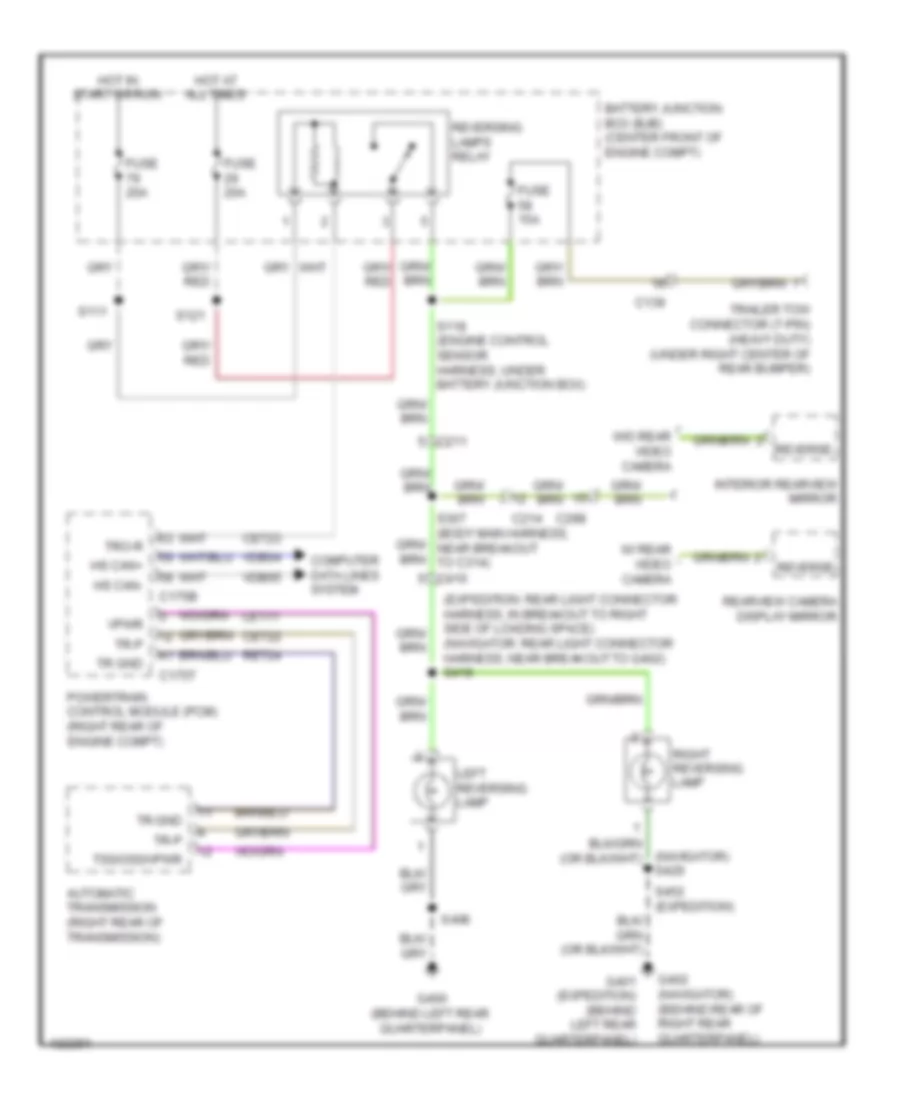
Backup Lamps Wiring Diagram for Ford Expedition XL 2014
List of elements for Backup Lamps Wiring Diagram for Ford Expedition XL 2014:
- (expedition: rear light connector harness, in breakout to right side of loading space) (navigator: rear light connector harness, near breakout to g402) s418
- (navigator) s429
- Automatic transmission (right rear of transmission)
- Battery junction box (bjb) (center front of engine compt)
- C139
- C175b
- C175t
- C211
- C214
- C298
- Cet22
- Cet23
- Computer data lines system
- Fuse 15a
- Fuse 20a
- G400 (behind left rear quarterpanel)
- G401 (expedition) (behind left rear quarterpanel)
- G402 (navigator) (behind rear of right rear quarterpanel)
- Hot at all times
- Hot in start or run
- Hs can+
- Hs can-
- Interior rearview mirror
- Le111
- Left reversing lamp
- Powertrain control module (pcm) (right rear of engine compt)
- Rearview camera display mirror
- Ret24
- Reverse
- Reversing lamps relay
- Right reversing lamp
- S111
- S118 (engine control sensor harness, under battery junction box)
- S121
- S307 (body main harness, near breakout to c314) c410
- S406
- S452 (expedition)
- Tr gnd
- Tr-p
- Trailer tow connector (7-pin) (heavy duty) (under right center of rear bumper)
- Tro-r
- Tss/oss/vpwr
- Vdb04
- Vdb05
- Vpwr
- W/ rear video camera
- W/o rear video camera
Exterior Lamps Wiring Diagram (1 of 2) for Ford Expedition XL 2014
List of elements for Exterior Lamps Wiring Diagram (1 of 2) for Ford Expedition XL 2014:
- (engine control sensor harness, near breakout to front of engine compt) s112
- (right front of engine compt) g106
- (right kick panel) smart junction box (sjb)
- Auto
- Autolamp on
- Bpp
- C211
- C212
- C2280b
- C2280d
- C2280e
- C2280f
- Computer data lines system
- Ctrl
- Flash to pass
- Fuse 22 15a
- Fuse 23 15a
- Fuse 5 15a
- Fuse 6 20a
- G103 (left front of engine compt)
- G106 (right front of engine compt)
- G200 (right kick panel)
- G300 (right kick panel)
- G301 (left "b" pillar)
- G302 (right kick panel)
- G400 (behind left rear quarterpanel)
- Hazard
- Headlamp off
- Headlamp switch
- Headlights system
- High beam relay
- Hot at all times
- Left
- Left front park/ flash to pass lamp (navigator)
- Left front park/ turn lamp (expedition)
- Left front side lamp
- Left front turn lamp (fet)
- Left rear park/ stop/ turn lamp 1 (navigator)
- Left rear park/ stop/ turn lamp 2 (navigator)
- Left rear stop/ turn lamp (fet)
- Left side exterior rearview mirror
- Left turn
- Logic gnd
- Low
- Ms can +
- Ms can -
- Multi-function switch
- Nca
- Off
- On headlamp
- Park
- Park lamp on
- Park lamp relay
- Right
- Right front park/ turn lamp (expedition)
- Right front park/flash to pass lamp (navigator)
- Right front side lamp
- Right front turn lamp (fet)
- Right rear stop/ turn lamp (fet)
- Right side exterior rearview mirror
- Right turn
- S108
- S122
- S129
- S131
- S200 (engine control sensor harness, near breakout to c211)
- S228
- S245
- S250
- S406
- S503
- Stop/ turn
- Turn
- Vbatt
Exterior Lamps Wiring Diagram (2 of 2) for Ford Expedition XL 2014
List of elements for Exterior Lamps Wiring Diagram (2 of 2) for Ford Expedition XL 2014:
- (behind left rear quarterpanel) g401
- (body main harness, near breakout to c214) s244
- (expedition: rear engine harness, left rear of engine compt) (navigator: engine compt harness, near breakout to vehicle dynamics module) s151
- (expedition: rear light connector harness, near breakout to g401) (navigator: rear light connector harness, near breakout to left side of loading space)
- (main harness, near breakout to right side of dash) s224
- (right rear of engine compt) g107
- (switch & wiring assembly, near breakout to top right side of liftgate) (navigator) s425
- Anti-lock brakes system
- Battery junction box (bjb) (center front of engine compt)
- Bpp
- Bps
- Brake pedal position switch (top of brake pedal assembly)
- C175b
- C211
- C212
- C238
- C411
- C438
- C465
- C495
- C919
- C934
- C935
- Ces09
- Cls17
- Computer data lines system
- Fuse 5a
- G200 (right kick panel)
- G400 (behind left rear quarterpanel)
- G401 (behind left rear quarterpanel)
- Ground distribution system
- Hazard
- High mounted stoplamp
- Hot at all times
- Instrument cluster (ic)
- Interior lights system
- Ivd
- Left license plate lamp
- Left rear park lamp 1
- Left rear park lamp 2
- Left rear park/ stop/ turn lamp (expedition)
- Left turn trailer tow relay
- Ms can +
- Ms can -
- Navigator
- Near breakout to g301)
- Park
- Parking lamp trailer tow relay
- Power liftgate
- Power liftgate/ traction control/ hazard switch
- Powertrain control module (pcm) (right rear of engine compt)
- Remote start connector (if equipped)
- Right license plate lamp
- Right rear park lamp 1
- Right rear park lamp 2
- Right rear park/ stop/ turn lamp (expedition)
- Right rear park/ stop/ turn lamp 1 (navigator)
- Right rear park/ stop/ turn lamp 2 (navigator)
- Right turn trailer tow relay
- S102
- S213
- S245 (expedition: main harness, near breakout to c248) (navigator: main harness, near breakout to left of dash)
- S3002 (body main harness,
- S336 (body main harness, near breakout to g301)
- S405 (navigator)
- S406
- S407
- S431 (navigator) (taillights harness, near breakout to fuel tank)
- S432
- S452
- Stop/ turn
- Trailer brake control (tbc) module (under left center of dash)
- Trunk, tailgate, fuel doors system
- W/ rear video camera
- W/o rear video camera
Trailer/Camper Adapter Wiring Diagram for Ford Expedition XL 2014
List of elements for Trailer/Camper Adapter Wiring Diagram for Ford Expedition XL 2014:
- (expedition: rear light connector harness, near breakout to g400) (heavy duty) s440
- (not used)
- (rear light connector harness, in breakout to left rear tweeter) (heavy duty) s441
- (right kick panel) g200
- (taillights harness, near breakout to rear bumper) (heavy duty) s438
- Backup lamps circuit
- Battery charge trailer tow relay
- Battery junction box (bjb) (center front of engine compt)
- Bpp
- C139
- C210
- C213
- C2280b
- C2280e
- Cat06
- Cat09
- Cat11
- Cat14
- Cat16
- Cat19
- Cbp33
- Cls17
- Computer data lines system
- Exterior lamps circuit
- Exterior lights circuit
- Fuse 10a
- Fuse 25a
- Fuse 30a
- G106 (right front of engine compt)
- G405 (rear of left frame rail)
- Gd138
- Gnd run start
- Heavy duty
- Hot at all times
- Hot in run
- Hot w/ run start relay energized
- Hs can+
- Hs can-
- Left turn trailer tow relay
- Light duty
- Parking lamp trailer tow relay
- Pwr
- Rat08
- Right turn trailer tow relay
- S122
- S125
- S213
- S439 (heavy duty)
- Sbb18
- Smart junction box (sjb) (right kick panel)
- Trailer brake
- Trailer brake control (tbc) module (under left center of dash)
- Trailer tow connector (4-pin) (under left center of rear bumper)
- Trailer tow connector (7-pin) (heavy duty) (under right center of rear bumper)
- Vdb04
- Vdb05
GROUND DISTRIBUTION
Ground Distribution Wiring Diagram (1 of 5) for Ford Expedition XL 2014
List of elements for Ground Distribution Wiring Diagram (1 of 5) for Ford Expedition XL 2014:
- (center front of engine compt) battery junction box (bjb)
- (expedition) left front park/turn lamp
- (expedition) right front park/turn lamp
- (navigator) left front turn lamp
- (navigator) right front turn lamp
- (right kick panel) smart junction box (sjb)
- A/c compressor clutch field coil
- Air suspension compressor
- Air suspension compressor relay
- Anti-theft hood switch
- Battery
- Battery charge trailer tow relay
- Brake fluid level switch
- C1026
- C110
- C139
- C2131a
- C2280d
- C2371b
- Engine cooling fan motor 2
- Expedition
- Fan control (fc) relay
- Front wiper relay
- Fuel pump relay
- G100 (right side of engine compt)
- G101 (right side of engine compt)
- G102 (right rear of engine)
- G103 (left front of engine compt)
- G105 (right front of engine compt)
- G106 (right front of engine compt)
- G302 (right kick panel)
- Horn
- Left front fog lamp
- Left front park/flash- to-pass lamp
- Left front side lamp
- Left headlamp
- Left headlamp assembly
- Left high intensity discharge headlamp relay
- Left rear air spring solenoid valve
- Left turn trailer tow relay
- Navigator
- Nca
- Parking lamp trailer tow relay
- Right front fog lamp
- Right front park/flash- to-pass lamp
- Right front side lamp
- Right headlamp
- Right headlamp assembly
- Right high intensity discharge headlamp relay
- Right rear air spring solenoid valve
- Right turn trailer tow relay
- S129 (engine control sensor harness, near breakout to left front wheel speed sensor)
- S131 (expedition: engine harness, near breakout to maf/iat sensor) (navigator: engine control sensor harness, near breakout to left rear of engine compt)
- S141
- S443
- Sensor harness, near breakout to front of engine compt)
- Transfer case control module (tccm)
- Vehicle dynamics module (vdm)
- W/ front parking aid
- Washer fluid level switch
- Windshield wiper motor assembly
Ground Distribution Wiring Diagram (2 of 5) for Ford Expedition XL 2014
List of elements for Ground Distribution Wiring Diagram (2 of 5) for Ford Expedition XL 2014:
- (automatic a/c) blower motor speed control
- (center front of engine compt) battery junction box (bjb)
- (except expedition & automatic a/c) remote start connector
- (expedition & automatic a/c) remote start connector
- (expedition)
- (expedition) instrument panel power point
- (interior illumination harness,near breakout to c406) s900
- (navigator)
- (navigator) satellite digital audio receiver system (sdars) module
- (thx audio) audio digital signal processing (dsp) module
- (w/ column shifter) brake shift interlock
- (w/ navigation) audio amplifier
- (w/ premium sound) subwoofer amplifier
- Accessory protocol interface module (apim)
- Adjustable pedal switch
- Ashtray illumination lamp
- Audio control module (acm)
- Audio rear control unit (rcu) module
- Blower motor resistor
- Brake pedal position (bpp) switch
- C175b
- C210
- C211
- C2239
- C2357c
- C2364a
- C237
- C238
- C2385b
- C240a
- C291
- C315
- C925
- Cargo lamp
- Clock
- Data link connector (dlc)
- Four wheel drive switch
- Front cigar lighter
- Front interior/ map lamps assembly
- G107 (right rear of engine compt)
- G108 (right rear of engine compt)
- G200 (right kick panel)
- G201 (center of dash)
- G202 (center of dash)
- G204 (right kick panel)
- Global positioning system module (gpsm) (w/ sync w/o navigation)
- Glove box lamp
- Headlamp switch
- Hvac module (emtc)
- Left side rail lamp
- Left vanity mirror lamp
- Manual a/c
- Message center switch
- Microphone shield
- Multi-function switch
- Navigator
- Nca
- Overhead console (w/ moonroof)
- Power liftgate/ traction control hazard switch
- Powertrain control module (pcm)
- Right side rail lamp
- Right vanity mirror lamp
- Run/start relay
- S213 (body main harness, near breakout to g203)
- S219
- S228 (main harness, near breakout to center of dash)
- S387 (w/ apim external sdars) (console harness, front of center console)
- S388 (console harness, front of center console)
- Trailer brake control module
- W/o memory
Ground Distribution Wiring Diagram (3 of 5) for Ford Expedition XL 2014
List of elements for Ground Distribution Wiring Diagram (3 of 5) for Ford Expedition XL 2014:
- (if equipped) rain sensor module
- (manual a/c) hvac emtc module
- (manual a/c) sunload sensor
- (navigator) passenger side front power window motor
- (navigator) right side front power window switch
- (navigator) steering column position switch
- (navigator: body main harness, near breakout to c238)
- (right kick panel) smart junction box (sjb)
- (right kick pillar) g300
- (w/ 10-way & memory) left seat control switch
- (w/ 10-way power seat) right seat control switch
- (w/ 6-way power seat) right seat control switch
- (w/ climate controlled seats) dual climate controlled seat module (dcsm)
- (w/ four wheel drive) transfer case control module (tccm)
- (w/ memory) driver seat module
- (w/ memory) exterior rear view mirror switch
- (w/ rear video camera) rear view camera display mirror
- (w/ rear video camera) video camera
- Auto-dimming interior mirror
- C212
- C218a
- C218b
- C2280d
- C228a
- C2357a
- C2371b
- C238
- C298
- C311
- C316
- C341b
- C4014a
- C438
- C465
- C610
- C800
- C919
- C922
- Clockspring (steering column)
- Door lock relay
- Driver safety belt buckle switch
- Driver seat track position sensor
- Expedition
- G203 (left kick panel)
- G205 (left end of dash)
- Horn switch
- Hvac datc module
- Instrument cluster (ic)
- Keyless entry keypad
- Left steering wheel switch
- M c3265a
- Memory set switch
- Navigator
- Nca
- Parking aid module (pam)
- Passenger safety belt buckle switch/ pretensioner
- Passenger side door lock switch
- Passenger side rear door ajar switch
- Passive anti-theft transceiver
- Right front door ajar switch
- Right side exterior rear view mirror
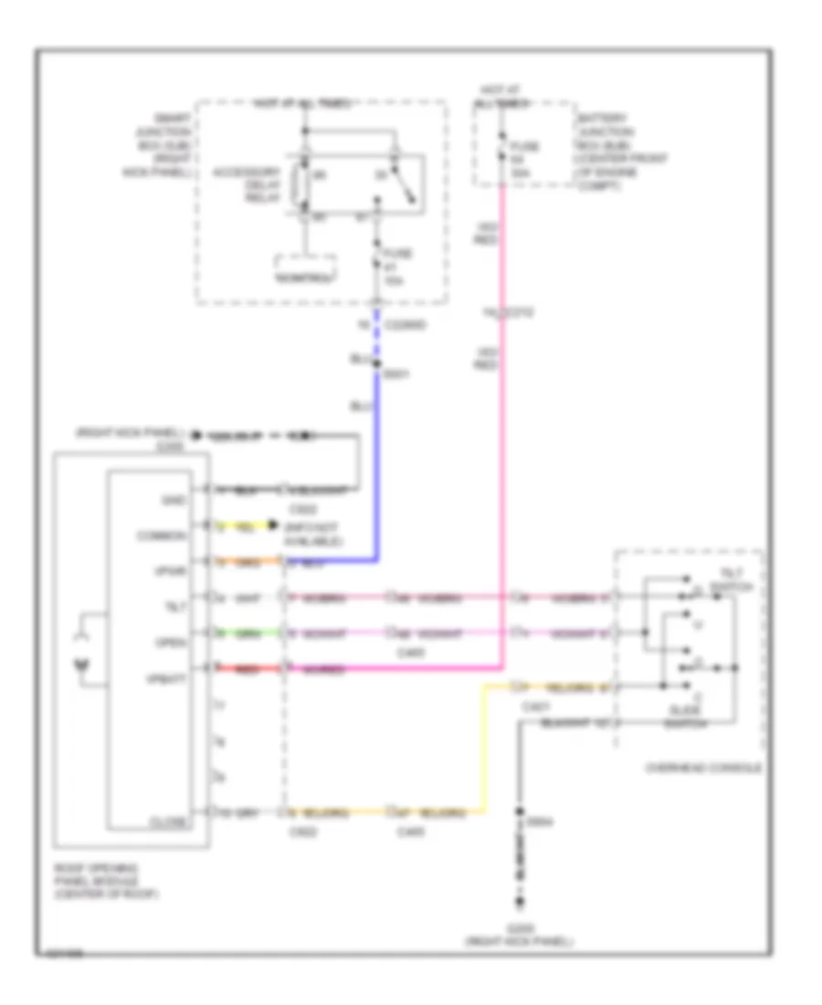
- Right steering wheel switch
- Roof opening panel module
- S137 (w/ four wheel drive) (engine control sensor harness, near breakout to windshield wiper motor connector)
- S211 (body main harness, near breakout to below right side of dash)
- S245 (expedition: main harness, near breakout to c248) (navigator: main harness, near breakout to left of dash)
- S332 (body main harness, in breakout to c312)
- S360 (driver seat harness, near breakout to driver seat module)
- S404 (w/ rear video camera) (navigator: rear light connector harness, near breakout to left quarter window motor) (except navigator: rear light connector harness, near breakout to g400)
- S912 (except electrochromic mirror or w/o rain sensor) (vanity mirror light harness, in breakout to c298)
- W/ front & rear parking aid
- W/o front parking aid
- Windshield wiper motor assembly
Ground Distribution Wiring Diagram (4 of 5) for Ford Expedition XL 2014
List of elements for Ground Distribution Wiring Diagram (4 of 5) for Ford Expedition XL 2014:
- (expedition w/ power liftgate) handle release switch
- (expedition w/o power liftgate) liftgate latch
- (expedition) master window adjust switch
- (expedition) right rear park/stop/ turn lamp
- (expedition) right reversing lamp
- (if equipped) floor shifter
- (navigator) console 2 power point
- (navigator) master window adjust switch
- (navigator) right rear park/stop/ turn lamp 1
- (navigator) right rear park/stop/ turn lamp 2
- (w/ 10 way power seats)
- (w/ 6 way power seats)
- (w/o memory) exterior rear view mirror switch
- C3054b
- C311
- C314
- C3313b
- C341a
- C4001
- C4002
- C402b
- C438
- C495
- C504b
- C510
- C535b
- C700
- C935
- Console 1 power point
- Driver seat module
- Driver side door lock switch
- Driver side front power window motor
- Driver side rear door ajar switch
- Expedition
- Expedition w/ rear video camera
- G301 (left "b" pillar)
- G401 (behind left rear quarterpanel)
- Handle release switch
- High mounted stop lamp
- Keyless entry keypad
- Left front door ajar switch
- Left license plate lamp
- Left rear park lamp 1
- Left rear park lamp 2
- Left seat control switch
- Left side exterior rear view mirror
- Liftgate glass actuator
- Liftgate glass release switch
- Navigator
- Nca
- Parking brake switch
- Power running board (prb) module
- Rear auxiliary climate control assembly
- Rear heated seat module
- Rear window defrost grid
- Rear wiper motor assembly
- Right heated seat switch
- Right license plate lamp
- Right rear park lamp 1
- Right rear park lamp 2
- S340 (console panel harness, in breakout to c315)
- S369 (center console, near breakout to apim)
- S423 (switch & wiring assembly, near breakout to top left side of liftgate)
- S432 (taillight harness, near breakout to c421)
- S452 (expedition) (taillights harness, near breakout to g400)
- S501 (driver's door window regulator harness, in breakout to driver's door)
- S503 (main body harness, in breakout to driver's door)
- Second row left seat backrest heater mat
- Second row right seat backrest heater mat
- W/ memory
- W/ second row heated seats
- W/o memory
Ground Distribution Wiring Diagram (5 of 5) for Ford Expedition XL 2014
List of elements for Ground Distribution Wiring Diagram (5 of 5) for Ford Expedition XL 2014:
- (behind rear of right rear quarterpanel) (w/ power vent windows & third row folding seats) auxiliary relay box 2
- (heavy duty) 7 pin trailer tow connector
- (navigator) right reversing lamp
- (w/ power liftgate) liftgate latch/ unlatch assembly
- 4 pin trailer tow connector
- A/c outlet shield
- Anti-lock brake system (abs) module
- Auxiliary blower motor resistor
- C2293a
- C315
- C408
- C4174a
- C935
- Dc/ac inverter module
- Expedition
- Expedition el & navigator l
- Fuel pump (fp) control module
- Fuel pump module shield
- G104 (left front of engine compt)
- G109 (rear of right cylinder bank)
- G110 (right side of engine compt)
- G206 (left kick panel)
- G400 (behind left rear quarterpanel)
- G402 (behind rear of right rear quarterpanel)
- G403 (behind rear of right rear quarterpanel)
- G404 (under left rear of vehicle)
- G405 (rear of left frame rail)
- Left rear park/stop/ turn lamp
- Left rear park/stop/ turn lamp 1
- Left rear park/stop/ turn lamp 2
- Left reversing lamp
- Left third row power-fold seat switch
- Liftgate motor/ clutch
- Liftgate/ trunk module (ltm)
- Navigator
- Nca
- Near breakout to rear bumper)
- Quarter window close relay
- Quarter window open relay
- Rear liftgate control switch
- Rear power point
- Rear wiper motor assembly
- Right third row power-fold seat switch
- S207
- S351 (main wiring harness, near breakout to center console)
- S397 (console panel harness, near breakout to center under dash panel)
- S424 (w/ power liftgate) (switch & wiring assembly, near breakout to top left side of liftgate)
- S429 (rear light connector harness, in breakout to auxiliary relay box 2)
- S442 (taillight harness, near breakout to fuel pump control module)
- S447 (rear light connector harness, near breakout to fuel pump control module)
- Third row power-fold seat relay
- W/ power vent windows & third row folding seats
HEADLIGHTS
Headlights Wiring Diagram (1 of 2) for Ford Expedition XL 2014
List of elements for Headlights Wiring Diagram (1 of 2) for Ford Expedition XL 2014:
- (engine control sensor harness, behind left front bumper fascia) (w/ front parking aid) s142
- (engine control sensor harness, near breakout to front of engine compt) (w/o front parking aid) s110
- (left front of engine compt) (w/ front parking aid) g103 g106 (w/o front parking aid) (right front of engine compt)
- (left front of engine compt) g103
- Air conditioning system
- Auto
- Auto lamp sens in
- Autolamp on
- Automatic a/c
- C110
- C2280a
- C2280b
- C2280c
- C2280e
- C2280f
- Computer data lines system
- Control
- Expedition
- Flash to pass
- Fog
- Fog ind
- Fog lamp
- Fog lamp relay
- Ftp
- Fuse 10a
- Fuse 15a
- G103 (left front of engine compt)
- G106 (right front of engine compt)
- G200 (right kick panel)
- G203 (left kick panel)
- G301 (left "b" pillar)
- Headlamp off
- Headlamp on
- Headlamp switch
- High beam
- High beam relay
- Hot at all times
- Illum
- Interior lights system
- Left front fog lamp
- Left headlamp
- Left low beam (fet)
- Low
- Manual a/c
- Ms can+
- Ms can-
- Multi-function switch
- Navigator
- Off
- Park
- Park brake
- Park lamp on
- Parking brake switch
- Right front fog lamp
- Right headlamp
- Right low beam (fet)
- S108
- S108 (w/o front parking aid) s141 (w/ front parking aid)
- S109
- S129
- S141
- S211
- S228
- S340
- Smart junction box (sjb) (right kick panel)
- Solid state
- Sunload sensor (under top center of dash)
- W/ front parking aid
- W/o front parking aid
- Windshield wiper motor assembly (under left side of cowl cover)
- Wiper on input
Headlights Wiring Diagram (2 of 2) for Ford Expedition XL 2014
List of elements for Headlights Wiring Diagram (2 of 2) for Ford Expedition XL 2014:
- (left front of engine compt)
- (right front of engine compt)
- Battery junction box (bjb) (center front of engine compt)
- Computer data lines system
- Exterior lights system
- Flash-to- pass
- Fuse 20a
- G103
- G103 (left front of engine compt)
- G106
- G106 (right front of engine compt)
- Hot at all times
- Instrument cluster (ic)
- Left front park/flash- to-pass lamp (navigator)
- Left headlamp assembly (navigator)
- Left high intensity discharge headlamp relay (navigator)
- Ms can+
- Ms can-
- Park
- Red
- Right front park/flash- to-pass lamp (navigator)
- Right headlamp assembly (navigator)
- Right high intensity discharge headlamp relay (navigator)
- S108
- S109
- S122
- S129
HORN
Horn Wiring Diagram for Ford Expedition XL 2014
List of elements for Horn Wiring Diagram for Ford Expedition XL 2014:
- C218a
- C218b
- C2280b
- C2280e
- Clockspring (steering column)
- Control
- Expedition
- Fuse 20a
- G103 (left front of engine compt)
- G205 (left end of dash)
- Horn (left front of engine compt)
- Horn relay
- Horn switch (steering wheel)
- Hot at all times
- Left steering wheel switch
- Navigator
- Remote start connector (if equipped)
- Right steering wheel switch
- S131
- S260 (if equipped) (on steering column harness, below shift bowl)
- Smart junction box (sjb) (right kick panel)
INSTRUMENT CLUSTER
Instrument Cluster Wiring Diagram for Ford Expedition XL 2014
List of elements for Instrument Cluster Wiring Diagram for Ford Expedition XL 2014:
- "b" pillar)
- (behind left rear quarterpanel) g401
- (behind rear of left rear quarterpanel)
- (left "b" pillar) g301
- (navigator) clock
- (navigator) s600
- (rear of front
- (right kick panel)
- (right kick panel) g300
- Ajar df door
- Ajar sw
- Ambient air temperature sensor (manual a/c) (behind right side of front grille)
- Anti-theft system
- Auto-dimming interior mirror
- Back- lighting
- Battery
- Brake
- Brake fluid level switch (brake fluid reservoir)
- C139
- C145
- C210
- C213
- C2280a
- C2280b
- C2280f
- C298
- C465
- C510
- C610
- C700
- C800
- C934
- C935
- Cbp29
- Cet53
- Close
- Cmc20
- Cmc24
- Cmc29
- Compass +
- Compass -
- Computer data lines system
- Cpl58
- Cpr50
- Decklid ajar
- Dr door ajar
- Driver side rear door ajar switch (rear of left rear door)
- Fluid sw brake
- Fuel pump module (top of fuel tank)
- Fuel sender return
- Fuel sender signal
- Fuse 10a
- Fuse 20a
- Fuse 5a
- G103 (left front of engine compt)
- G200
- G200 (right kick panel)
- G203 (left kick panel)
- G301 (left
- G301 (left "b" pillar)
- Gd133
- Glass ajar sw c4174b
- Gnd
- Hot at all times
- Hot in run or start
- Hs can +
- Hs can -
- Ign
- Ignition switch
- Illum
- Instrument cluster (ic)
- Interior lights system
- Key in
- Key in ign
- Left front door ajar switch (rear of driver's door)
- Liftgate glass actuator (center of liftgate)
- Liftgate latch (bottom center of liftgate)
- Liftgate/ glass/
- Liftgate/trunk module (ltm)
- Low washer
- Message center switch
- Message signal
- Ms can +
- Ms can -
- Oil pressure
- Oil pressure switch (on oil filter bracket)
- Open
- Outside air temp
- Park brake
- Park detect
- Parking brake switch (base of parking brake lever assembly)
- Passenger side rear door ajar switch (rear of right rear door)
- Passenger's door)
- Pats rx
- Pats tx
- Pf door ajar
- Power distribution system
- Pr door ajar c2280c
- Rear view camera display mirror (w/ rear video camera)
- Rear wiper motor assembly (center of liftgate)
- Return
- Right front door ajar switch
- Rmc32
- Rtn fluid sw
- S129
- S211
- S213
- S216 (rear dash harness, near breakout to instrument cluster)
- S229
- S245
- S257
- S340
- S423
- S501
- Sbp26
- Shift interlock system
- Signal
- Smart junction box (sjb) (right kick panel)
- Status
- Vbatt
- Vdb04
- Vdb05
- Vdb06
- Vdb07
- Vh407
- Vmc11
- Vmc29
- Vmc30
- Vmc31
- Vpl56
- Vpwr
- Vrt07
- W/ column shifter
- W/ power liftgate
- W/o power liftgate
- Wiper/washer system
INTERIOR LIGHTS
Courtesy Lamps Wiring Diagram for Ford Expedition XL 2014
List of elements for Courtesy Lamps Wiring Diagram for Ford Expedition XL 2014:
- (interior illumination harness, near breakout to c406)
- (on breakout to adjustable pedal switch) s230
- (right kick panel)
- Battery saver relay
- C214
- C2280a
- C2280b
- C2280c
- C2280d
- C298
- C510
- C610
- C700
- C800
- C925
- Cargo lamp
- Ctrl ctrl
- Df door ajar
- Dim sw gnd
- Dimmer sw
- Dome
- Dome defeat
- Dome lp ctrl
- Dr door ajar
- Front interior/map lamps assembly
- Fuse 10a
- Fuse 15a
- Fuse 2a
- G200
- G200 (right kick panel)
- G300 (right kick panel)
- G301 (left "b" pillar)
- Glove box lamp
- Homelink module
- Hot at all times
- Illumination dimmer
- Interior lighting (fet)
- Left front door ajar switch (rear of left front door)
- Left rear door ajar switch (rear of left rear door)
- Left side exterior rearview mirror
- Left side rail lamp
- Left vanity mirror lamp
- Nca
- Off
- Off dome
- Pf door ajar
- Pr door ajar
- Puddle lamp
- Puddle lamp (fet)
- Remote start connector (if equipped)
- Right front door ajar switch (rear of right front door)
- Right rear door ajar switch (rear of right rear door)
- Right side exterior rearview mirror
- Right side rail lamp
- Right vanity mirror lamp
- S206 (body main harness, near breakout to c214)
- S210
- S245
- S247 (body main harness, near breakout to c214)
- S263 (right side of dash harness, above glove box opening)
- S340
- S501
- S503
- S600 (navigator)
- S900
- S901 (interior illumination harness, near breakout to c406)
- S902
- S903 (interior illumination harness, near breakout to left front of roof)
- S904
- Smart junction box (sjb) (right kick panel)
Instrument Illumination Wiring Diagram (1 of 3) for Ford Expedition XL 2014
List of elements for Instrument Illumination Wiring Diagram (1 of 3) for Ford Expedition XL 2014:
- (body main harness, near breakout to g301) s334
- (on breakout to adjustable pedal switch) s230
- Accessory delay relay
- Backlighting led (fet)
- C2280b
- C2280d
- C504a
- C504b
- C510
- C700
- C800
- Circuit breaker 30a
- Ctrl
- Defeat
- Dim sw gnd
- Dimmer sw
- Dome
- Dome defeat
- Dome lp
- Driver side door lock switch (expedition)
- Expedition
- Fuse 15a
- Fuse 41 15a
- G300 (right kick panel)
- G301 (left "b" pillar)
- G302 (right kick panel)
- Hot at all times
- Illumination dimmer
- Left rear
- Left rear window adjust switch
- Lock out
- Logic gnd
- Master window adjust switch (expedition)
- Navigator
- Off
- Off dome
- Passenger side door lock switch (expedition)
- Right front
- Right rear
- Right rear window adjust switch
- Right side front power window switch
- S245
- S250
- S503
- S601
- Smart junction box (sjb) (right kick panel)
Instrument Illumination Wiring Diagram (2 of 3) for Ford Expedition XL 2014
List of elements for Instrument Illumination Wiring Diagram (2 of 3) for Ford Expedition XL 2014:
- (steering wheel) horn switch
- Adjustable pedal switch
- Ashtray illumination lamp (navigator)
- Auto
- Autolamp on
- C218a
- C218b
- C2280b
- C238
- C298
- C315
- C925
- Clock (navigator)
- Clock spring (steering wheel)
- Expedition
- Floor shifter (expedition) (base of shift lever assembly)
- Four-wheel drive switch
- G200 (right kick panel)
- G205 (left end of dash)
- G301 (left "b" pillar)
- Headlamp off
- Headlamp on
- Headlamp switch
- Left steering wheel switch
- Low
- Message center switch
- Navigator
- Nca
- Off
- Overhead console
- Park
- Park lamp on
- Power liftgate/ traction control/ hazard switch
- Rear auxiliary climate control assembly
- Rear heated seat switch
- Right steering wheel switch
- S210
- S213
- S218 (expedition) s231 (navigator) (expedition: rear dash harness, near breakout to instrument cluster) (navigator: main harness, near breakout to center of dash)
- S228
- S369
- S386 (console harness, front of center console)
- S904
- Smart junction box (sjb) (right kick panel)
Instrument Illumination Wiring Diagram (3 of 3) for Ford Expedition XL 2014
List of elements for Instrument Illumination Wiring Diagram (3 of 3) for Ford Expedition XL 2014:
- C314
- C510
- C535a
- C535b
- C700
- C800
- Driver side door lock switch
- Floor shifter (base of shift lever assembly)
- G300 (right kick panel)
- G301 (left "b" pillar)
- Left rear
- Left rear window adjust switch
- Lock out
- Master window adjust switch
- Navigator
- Nca
- Passenger side door lock switch
- Right rear
- Right rear window adjust switch
- Right side front power window switch
- S245
- S251
- S310 (body main harness, near breakout to c314)
- S334 (body main harness, near breakout to c301)
- S369
- S503
MEMORY SYSTEMS
Adjustable Pedal Wiring Diagram for Ford Expedition XL 2014
List of elements for Adjustable Pedal Wiring Diagram for Ford Expedition XL 2014:
- (front harness, near breakout to c2364c) s237
- (left "b" pillar) g301
- (on accelerator pedal support) adjustable pedal motor
- Adjustable pedal switch
- Away from driver
- Battery junction box (bjb) (center front of engine compt)
- C212
- C219
- C2280a
- C2280d
- C238
- C311
- C312
- C341a
- C341b
- C341c
- C341d
- Computer data lines system
- Cpp01
- Cpp02
- Cpp09
- Cpp10
- Cps15
- Cps16
- Driver seat module (under driver's seat)
- Fuse 15a
- Fuse 30a
- G203 (left kick panel)
- Gd133
- Gd143
- Gnd
- Hall effect sense rtn
- Hot at all times
- Interior lights system
- Logic gnd
- Lpp06
- Ma can-
- Mem recall 1
- Mem recall 2
- Memory set
- Ms can+
- Navigator
- Pedal aft
- Pedal fore
- Pedal pos feed
- Pedal sw aft
- Pedal sw fore
- Rpp06
- S217
- S340
- S359 (navigator)
- S360
- Sbb74
- Sbp02
- Smart junction box (sjb) (right kick panel)
- Steering column position motor (on steering column)
- Switch
- Toward driver
- Vbatt
- Vdb06
- Vdb07
Driver"s Memory Seat Wiring Diagram (1 of 2) for Ford Expedition XL 2014
List of elements for Driver"s Memory Seat Wiring Diagram (1 of 2) for Ford Expedition XL 2014:
- Adjustable pedal circuit
- Battery junction box (bjb) (center front of engine compt)
- C212
- C2280d
- C311
- C312
- C341a
- C341b
- C341c
- C341d
- Column down
- Column sw down
- Column sw up
- Column up
- Common
- Computer data lines system
- Cpm04
- Cpm14
- Cpm15
- Cpm18
- Cpm19
- Cpm22
- Cpm23
- Cpm26
- Cpm28
- Cpm29
- Cpm31
- Cpm33
- Cpm34
- Cpm39
- Cpp01
- Cpp02
- Cpp04
- Cpp05
- Cpp09
- Cpp10
- Cpp14
- Cpp15
- Cps01
- Cps02
- Cps03
- Cps04
- Cps05
- Cps06
- Cps07
- Cps08
- Cps15
- Cps16
- Cps23
- Cps24
- Cps25
- Cps26
- Cps27
- Cps28
- Cps29
- Cps30
- Driver seat module (under driver's seat)
- Driver seat recliner motor
- Front down
- Front sw down
- Front sw up
- Front up
- Ft height sense
- Fuse 15a
- Fuse 30a
- Fuse 7.5a
- Fwd
- G203 (left kick panel)
- G301 (left "b" pillar)
- Gd133
- Gd143
- Gnd
- Hall effect sense rtn
- Horz base sw back
- Horz base sw fwd
- Horz sense
- Hot at all times
- L mirr l/r sense
- L mirr motor down/left
- L mirr mtr right
- L mirr mtr up
- L mirr u/d sense
- L/r mirr fold in
- L/r mirr fold out
- Lmp30
- Logic gnd
- Lpp06
- Mem recall 1
- Mem recall 2
- Memory mirrors circuit
- Memory set switch
- Mirr fold/unfold sw
- Mirr sw common
- Mirr sw horz left
- Mirr sw horz right
- Mirr sw vert left
- Mirr sw vert right
- Mirror sense common
- Mirror sense feed
- Ms can+
- Ms can-
- Navigator
- Pedal aft
- Pedal fore
- Pedal pos feed
- Pedal sw aft
- Pedal sw fore
- R mirr l/r sense
- R mirr mtr down/left
- R mirr mtr right
- R mirr mtr up
- R mirr u/d sense
- Rear down
- Rear sw down
- Rear sw up
- Rear up
- Recline down
- Recline sense
- Recline sw down
- Recline sw up
- Recline up
- Rpm30
- Rpp06
- Rps13
- Rr height sense
- Rwd
- S325
- S340
- S359 (navigator)
- S360
- Sbb74
- Sbp02
- Smart junction box (sjb) (right kick panel)
- Steering column memory & adjustable pedal circuits
- Steering column memory circuit
- Tilt+
- Vbatt
- Vdb06
- Vdb07
- Vpm35
- Vpm36
- Vpm37
- Vpm38
- Vpp17
- Vps09
- Vps10
- Vps11
- Vps12
Driver"s Memory Seat Wiring Diagram (2 of 2) for Ford Expedition XL 2014
List of elements for Driver"s Memory Seat Wiring Diagram (2 of 2) for Ford Expedition XL 2014:
- (driver seat harness, near breakout to driver seat module)
- (left kick panel) g203
- Back
- Base
- C327
- Down
- Driver seat front height motor
- Driver seat horizontal motor
- Driver seat lumbar motor
- Driver seat rear height motor
- Front
- Fwd
- Left seat control switch
- Lumbar
- Out
- Rear
- Recline
- S358
- S360
Memory Mirrors Wiring Diagram (1 of 2) for Ford Expedition XL 2014
List of elements for Memory Mirrors Wiring Diagram (1 of 2) for Ford Expedition XL 2014:
- (body main harness, near breakout to c3051) s314
- (body main harness, near breakout to c312) s331
- (body main harness, near breakout to c314)
- (navigator) s359
- Battery junction box (bjb) (center front of engine compt)
- C212
- C2280d
- C311
- C312
- C341a
- C341b
- C341c
- C341d
- Computer data lines system
- Cpm04
- Cpm14
- Cpm15
- Cpm18
- Cpm19
- Cpm22
- Cpm23
- Cpm26
- Cpm28
- Cpm29
- Cpm31
- Cpm33
- Cpm34
- Cpm39
- Cps15
- Cps16
- Defogger system
- Driver seat module (under driver's seat)
- Exterior lights system
- Fold out fold in/
- Fuse 15a
- Fuse 30a
- G203 (left kick panel)
- G300 (right kick panel)
- G301 (left "b" pillar)
- Gd133
- Gd143
- Gnd
- Hot at all times
- Interior lights system
- L mirr l/r sense
- L mirr motor down/left
- L mirr mtr right
- L mirr mtr up
- L mirr u/d sense
- L/r mirr fold in
- L/r mirr fold out
- Left/ right
- Left/right
- Logic gnd
- Lpm30
- Mem recall 1
- Mem recall 2
- Mirr fold/unfold sw
- Mirr sw common
- Mirr sw horz left
- Mirr sw horz right
- Mirr sw vert left
- Mirr sw vert right
- Mirror sense common
- Mirror sense feed
- Ms can+
- Ms can-
- Navigator
- Nca
- Puddle lamp
- R mirr l/r sense
- R mirr mtr dn/left
- R mirr mtr right
- R mirr mtr up
- R mirr u/d sense
- Right heated mirror
- Right side exterior rearview mirror
- Rpm30
- S245
- S309
- S311
- S340
- Sbb74
- Sbp02
- Smart junction box (sjb) (right kick panel)
- Turn signal
- Up/dn
- Up/down
- Vbatt
- Vdb06
- Vdb07
- Vpm35
- Vpm36
- Vpm37
- Vpm38
Memory Mirrors Wiring Diagram (2 of 2) for Ford Expedition XL 2014
List of elements for Memory Mirrors Wiring Diagram (2 of 2) for Ford Expedition XL 2014:
- (left "b" pillar) g301
- C2280d
- C311
- C312
- Defogger system
- Down
- Ec+
- Ec-
- Exterior lights system
- Exterior rearview mirror switch
- Fold in/ fold out
- Fuse 7.5a
- G203 (left kick panel)
- Hot at all times
- Interior lights system
- Left
- Left heated mirror
- Left side exterior rearview mirror
- Left/ right
- Left/right motor
- Memory set switch
- Mirrors system
- Nca
- Puddle lamp
- Right
- S325
- S347
- S360
- S503
- Select mirror switch
- Smart junction box (sjb) (right kick panel)
- Turn signal
- Up/dn
- Up/dn motor
Steering Column Memory Wiring Diagram for Ford Expedition XL 2014
List of elements for Steering Column Memory Wiring Diagram for Ford Expedition XL 2014:
- (front harness, near breakout to c2364c)
- (left "b" pillar) g301
- (left kick panel) g203
- Adjustable pedal motor (on accelerator pedal support)
- Battery junction box (bjb) (center front of engine compt)
- C212
- C219
- C2280d
- C238
- C311
- C312
- C341a
- C341b
- C341c
- C341d
- Column dn
- Column sw dn
- Column sw up
- Column up
- Computer data lines system
- Cpp04
- Cpp05
- Cpp14
- Cpp15
- Cps15
- Cps16
- Driver seat module (under driver's seat)
- Fuse 15a
- Fuse 30a
- G203 (left kick panel)
- Gd133
- Gd143
- Gnd
- Hall effect sense rtn
- Hot at all times
- Logic gnd
- Mem recall 1
- Mem recall 2
- Memory set switch
- Ms can+
- Ms can-
- Navigator
- Rpp06
- S211
- S237
- S340
- S359 (navigator)
- S360
- Sbb74
- Sbpo2
- Smart junction box (sjb) (right kick panel)
- Steering column position motor (on steering column)
- Steering column position switch
- Tilt+
- Vbatt
- Vdb06
- Vdb07
- Vpp17
NAVIGATION
Navigation Wiring Diagram (1 of 2) for Ford Expedition XL 2014
List of elements for Navigation Wiring Diagram (1 of 2) for Ford Expedition XL 2014:
- (body main harness, near breakout to g201) s306
- Am ant
- Am antenna
- Ant
- Ant pwr
- Antenna module (top of right "c" pillar)
- Audio control module (acm) (center of dash)
- Audio input jack
- Batt+
- C218a
- C218b
- C2280a
- C2280b
- C2280d
- C238
- C240a
- C240c
- C315
- Cbp28
- Clockspring (steering column)
- Cme13
- Cme27
- Coax cable
- Computer data lines system
- Dme09
- Dme45
- Enable
- Fm ant
- Fm antenna
- Fuse 15a
- Fuse 20a
- Fuse 5a
- G202 (center of dash)
- Gd114
- Gnd
- Hot at all times
- Hot in start
- Interior lights system
- Lf spkr+
- Lf spkr-
- Lr spkr+
- Lr spkr-
- Media
- Ms can+
- Ms can-
- Nca
- Rf spkr+
- Rf spkr-
- Right steering wheel switch
- Rme07
- Rme09
- Rme10
- Rme12
- Rme14
- Rme45
- Rme46
- Rr spkr+
- Rr spkr-
- S214 (expedition: body main harness, near breakout to below left side of dash) (navigator: body main harness, near breakout to c238)
- S215 (on rear dash harness, near g201) nca
- S382 (w/ apim & external sdars)
- S395 (console harness, front of center console)
- Sbp39
- Seek+
- Seek-
- Shield
- Smart junction box (sjb) (right kick panel)
- St in 2l +
- St in 2l -
- St in 2r +
- St in 2r -
- St input 2l+
- St input 2l-
- St input 2r+
- St input 2r-
- Start
- Sw 12v
- Swc1 +
- Swc1 rtn
- Vdb06
- Vdb07
- Vme07
- Vme09
- Vme10
- Vme12
- Vme14
- Vme45
- Vme46
- Vol+
- Vol-
Navigation Wiring Diagram (2 of 2) for Ford Expedition XL 2014
List of elements for Navigation Wiring Diagram (2 of 2) for Ford Expedition XL 2014:
- Audio amplifier (center of dash)
- Audio rear control unit (rcu) module (rear of center console)
- Batt+
- C214
- C238
- C2385a
- C2385b
- C314
- C315
- C523a
- C523b
- C612a
- C612b
- C700
- C800
- Cme27
- Computer data lines system
- Enable
- G201 (center of dash)
- Gd114
- Gnd
- Left front speaker
- Left front tweeter
- Left rear speaker
- Lf spkr+
- Lf spkr-
- Lr spkr+
- Lr spkr-
- Ms can+
- Ms can-
- Nca
- Rf spkr+
- Rf spkr-
- Right front speaker
- Right front tweeter
- Right rear speaker
- Rme07
- Rme09
- Rme10
- Rme12
- Rme52
- Rme53
- Rme58
- Rme59
- Rr spkr+
- Rr spkr-
- S219
- S301 (body main harness, near breakout to g201)
- S391 (console harness, front of center console)
- Sat 1l+
- Sat 1l-
- Sat 1r+
- Sat 1r-
- Sbp03
- Sbp40
- Sync 2l+
- Sync 2l-
- Sync 2r+
- Sync 2r-
- Sync radio circuit
- Vdb06
- Vdb07
- Vme07
- Vme09
- Vme10
- Vme12
- Vme52
- Vme53
- Vme58
- Vme59
Parking Assistant Wiring Diagram for Ford Expedition XL 2014
List of elements for Parking Assistant Wiring Diagram for Ford Expedition XL 2014:
- (backup alarm jumper harness, near breakout to rear inner right parking aid sensor) s403
- C2280d
- C494
- Cbp35
- Cmp09
- Computer data lines system
- Fuse 10a
- G203 (left kick panel)
- Gd133
- Gnd
- Hot in start or run
- Lmp07
- Ms can+
- Ms can-
- Nca
- Parking aid module (pam) (left "c" pillar)
- Parking aid speaker (left "c" pillar)
- Rear inner left parking aid sensor (behind rear inner left side of rear bumper)
- Rear inner right parking aid sensor (behind rear inner right side of rear bumper)
- Rear outer left parking aid sensor (behind rear outer left end of rear bumper)
- Rear outer right parking aid sensor (behind rear outer right end of rear bumper)
- Rear sensor gnd
- Rear sensor pwr
- Rear sounder+
- Ril sensor in
- Rir sensor in
- Rmp07
- Rmp09
- Rol sensor in
- Ror sensor in
- S402 (backup alarm jumper harness, near breakout to rear inner right parking aid sensor)
- S404 (w/ rear video camera)
- S408 (w/ rear video camera)
- Smart junction box (sjb) (right kick panel)
- Solid state
- Sounder-
- Vdb06
- Vdb07
- Vmp14
- Vmp15
- Vmp16
- Vmp17
- Vpwr
Rear Camera Wiring Diagram for Ford Expedition XL 2014
List of elements for Rear Camera Wiring Diagram for Ford Expedition XL 2014:
- (expedition: switch & wiring assembly, near breakout to c438) (navigator: switch & wiring assembly, near breakout to center of liftgate) s446
- (switch & wiring assembly, near breakout to c919) s921
- (vanity light harness, near breakout to c910) s920
- Accessory delay relay
- Audio control module (acm) (center of dash)
- C2280a
- C2280d
- C240b
- C298
- C438
- C910
- C919
- C925
- Cbp35
- Cbp41
- Cls10
- Comp+
- Comp-
- Control
- Dmp19
- Ec drv+
- Ec drv-
- Expedition
- Exterior lights system
- Fuse 10a
- Fuse 15a
- G203 (left kick panel)
- Gd133
- Gnd
- Hot at all times
- Hot in start or run
- Instrument cluster system
- Lrd12
- Mirrors system
- Nca
- Rearview camera display mirror
- Reverse
- Rmp19
- Rrd12
- S203 (engine control sensor harness, in breakout to left side of dash)
- S208
- S404
- S408
- S905
- S909 (expedition: roof sliding panel control switch harness, in breakout to dvd player) (navigator: roof sliding panel control switch harness, in breakout to left front of roof)
- S911 (vanity mirror light harness, in breakout to c298)
- S912
- Smart junction box (sjb) (right kick panel)
- Tan
- Video camera (center of liftgate)
- Video shield
- Video+
- Video-
- Vmc30
- Vmc31
- Vmp19
- Vpwr
- W/ navigation
- W/o navigation
POWER DISTRIBUTION
Power Distribution Wiring Diagram (1 of 6) for Ford Expedition XL 2014
List of elements for Power Distribution Wiring Diagram (1 of 6) for Ford Expedition XL 2014:
- (center front of engine compt) battery junction box (bjb)
- (expedition: engine control sensor harness, under battery junction box) (navigation: engine control sensor harness, near breakout for right headlight) s114
- (in engine harness, near right side of battery junction box (bjb))
- (in engine harness, near right side of battery junction box (bjb)) s148
- 10-way power seat
- 6-way power seat
- Air suspension compressor relay
- Anti-lock brake system (abs) module
- Auxiliary blower motor relay 1
- Auxiliary relay box 2 (behind rear of right rear quarterpanel)
- Battery
- Battery charge trailer tow relay
- Brake pedal position (bpp) switch
- C139
- C175b
- C210
- C211
- C212
- C2131a
- C314
- C316
- C3265a f
- C3313b
- C410
- C4174a
- C465
- C922
- Console 1 power point
- Dual climate controlled seat module (dcsm)
- Evaporative emissions (evap) canister vent solenoid
- From splice s212 (diagram 4 of 6)
- Fuse 10a
- Fuse 20a
- Fuse 25a
- Fuse 30a
- Fuse 40a
- Fuse 5a
- Fuse 60a
- Fusible link d (10 ga- red)
- G100 (right side of engine compt)
- G101 (right side of engine compt)
- G102 (right rear of engine)
- G107 (right rear of engine compt)
- Generator
- Left rear corner of engine compt)
- Parking lamp trailer tow relay
- Power liftgate/ trunk module
- Power running board (prb) module
- Powertrain control module (pcm)
- Rear window defrost relay
- Red
- Right seat control switch
- Roof opening panel module
- Run/ start relay
- S102
- S104 red (engine control sensor harness, near breakout to c140)
- S105 (engine control sensor harness, near breakout red to c140)
- S149
- S159 (in harness, near right side of battery junction box (bjb))
- S3005
- S369
- Starter motor
- Third row power-fold seat relay
- To battery junction box (bjb) (diagram 5 of 6)
- To fuse 52 (diagram 5 of 6)
- To fuse 65 (diagram 2 of 6)
- To smart junction box (sjb) (diagram 2 of 6)
- Trailer brake control module (tbc)
- Vehicle dynamics module (vdm)
Power Distribution Wiring Diagram (2 of 6) for Ford Expedition XL 2014
List of elements for Power Distribution Wiring Diagram (2 of 6) for Ford Expedition XL 2014:
- (center front of engine compt)
- (center front of engine compt) battery junction box (bjb)
- (console harness, front of center console) (w/ apim & external
- (not used)
- (right kick panel) smart junction box (sjb)
- 10-way power seat
- 3rd row seat enable (fet)
- 6-way power seat
- A/c clutch relay
- Accessory protocol interface (aim) module
- Audio rear control unit (rcu) module
- Battery junction box (bjb)
- Blower motor relay
- Bsi (fet)
- C210
- C211
- C212
- C213
- C2280d
- C2280g
- C311
- C312
- C314
- C341a
- C341b
- C341c
- C410
- C510
- C610
- Console 2 power point
- Driver seat module (10-way power seat)
- Driver seat module (dsm)
- Driver side front power window motor
- Expedition
- Exterior rear view mirror switch
- From fuse 43 (diagram 1 of 6)
- From splice a s104 (diagram 1 of 6)
- Front cigar lighter
- Front wiper relay
- Fuel pump relay
- Fuse 10a
- Fuse 10a (or 15a)
- Fuse 15a
- Fuse 20a
- Fuse 25a
- Fuse 30a
- Fuse 40a
- Fuse 5a
- Fuse 7.5a
- G200 (right kick panel)
- G301 (left "b" pillar)
- G402 (behind rear of right rear quarterpanel)
- High fan control (hfc) relay
- Instrument panel power point
- Integrated wheel end solenoid
- Keypad illum (fet)
- Left high intensity discharge headlamp relay (navigator)
- Left seat control switch
- Left seat control switch (w/ memory)
- Left turn trailer tow relay
- Low fan control (lfc) relay
- Navigator
- Passenger side front power window motor (navigator)
- Rear power point
- Red
- Reversing lamps relay
- Right high intensity discharge headlamp relay (navigator)
- Right turn trailer tow relay
- S121 (engine control sensor harness, under battery junction box)
- S359
- S369
- Satellite digital audio receiver system (sdars) module (navigator satellite radio w/o navigation)
- Sdars) s382
- Starter relay
- To fuse 14 (diagram 3 of 6)
- To fuse 33 (diagram 4 of 6)
- To fuse 35 (diagram 6 of 6)
- Tpms 1 (fet)
- Tpms 2 (fet)
- Tpms 3 (fet)
- Vbat
- W/ memory
- W/o memory
Power Distribution Wiring Diagram (3 of 6) for Ford Expedition XL 2014
List of elements for Power Distribution Wiring Diagram (3 of 6) for Ford Expedition XL 2014:
- (expedition: on rear dash harness, near breakout to climate control) (navigator: main harness, near breakout to c238) s266
- (right kick panel) smart junction box (sjb)
- 25a
- Accessory delay relay
- Adjustable pedal switch
- Audio amplifier
- Audio control module (acm)
- Audio digital signal processing (dsp) module
- Automatic a/c
- Auxiliary relay box 2 (behind rear of right rear quarterpanel)
- Backlighting led (fet)
- Battery saver relay
- C214
- C2280a
- C2280a (not used)
- C2280b
- C2280d
- C228a
- C2357a
- C2364a
- C2385b
- C240a
- C3054b
- C314
- C410
- C411
- C4174a
- C465
- C504a
- C510
- C535a
- C535b
- C610
- C922
- C935
- Circuit breaker 30a
- Clock (navigator)
- Control
- Data link connector
- Door lock relay
- Driver door unlock relay
- Driver side door lock switch (expedition)
- Driver side front power window motor
- Expedition
- Floor lamp (fet)
- Fog lamp relay
- From g fuse 13 (diagram 2 of 6)
- Fuse
- Fuse 10a
- Fuse 15a
- Fuse 20a
- Global positioning system
- High beam relay
- Horn relay
- Hvac (datc) module
- Hvac (emtc) module
- Instrument cluster (ic)
- Interior lighting (fet)
- Left front turn lamp (fet)
- Left low beam (fet)
- Left rear stop/ turn lamp (fet)
- Left rear turn lamp (fet)
- Liftgate glass release relay
- Liftgate rel (fet)
- Liftgate/ trunk module (ltm)
- Manual a/c
- Master window adjust switch
- Master window adjust switch (navigator)
- Module (gpsm) (w/ sync w/o navigation)
- Navigator
- Navigator w/ thx audio
- Near breakout to passenger's door) s601
- Park lamp relay
- Passenger side door lock switch (expedition)
- Passenger side front power window motor (navigator)
- Puddle lamp (fet)
- Pulse train (fet)
- Quarter window close relay
- Quarter window open relay
- Rear heated seat module
- Rear wiper motor assembly
- Right front turn lamp (fet)
- Right low beam (fet)
- Right rear stop/ turn lamp (fet)
- Right rear turn lamp (fet)
- Right side front power window switch (navigator)
- Roof opening panel module
- S209 (body main harness, near breakout to below right side of dash)
- S217 (w/o memory) (on rear dash harness, near breakout to instrument cluster)
- S236 (body main harness, near breakout to c2364c)
- Subwoofer amplifier
- To fuse 27 (diagram 4 of 6)
- To splice s208 (diagram 4 of 6)
- W/ premium sound
- White light (fet)
Power Distribution Wiring Diagram (4 of 6) for Ford Expedition XL 2014
List of elements for Power Distribution Wiring Diagram (4 of 6) for Ford Expedition XL 2014:
- (body main harness, near breakout to g203) s212
- (center front of engine compt) battery junction box (bjb)
- (engine control sensor harness, near breakout to pcm) s107
- (expedition) c315
- (main wiring nca
- (navigator) c315
- (not used)
- (right kick panel) smart junction box (sjb)
- A/c outlet
- Acc
- Ac_a
- Ac_b
- Audio control module (acm)
- Auto-dimming interior mirror
- Battery charge trailer tow relay
- Battery junction box (bjb) (center front of engine compt)
- C175b
- C210
- C213
- C2280a
- C2280b
- C2280d
- C2280e
- C2293a
- C2293b
- C2371b
- C2390
- C240a
- C298
- C411
- C919
- C934
- Cbp41
- Dc/ac inverter module (left side of dash)
- From f fuse 29 (diagram 2 of 6)
- From ignition switch (diagram 4 of 6)
- From j fuse 17 (diagram 3 of 6)
- From smart junction box (sjb) (diagram 3 of 6)
- Front wiper motor relay
- Fuse 10a
- Fuse 20a
- Fuse 20a (expedition)
- Fuse 40a
- Fuse 5a
- G206 (left kick panel)
- Gd138
- Gnd
- Hya01
- Hya02
- Ignition switch
- Key in ignition
- Key release interlock actuator (w/ floor shifter)
- Led +
- Led_gnd
- Lock
- Lya03
- Micro
- Nca
- Powertrain control module (pcm)
- Rain sensor module (if equipped)
- Rear view camera display mirror (if equipped)
- Rear wiper motor assembly
- Red
- Remote start connector (if equipped)
- Run
- Run/ accy
- Run/ start
- Rya03
- S207
- S208 (main wiring harness, near breakout to right side kick panel)
- S257 (expedition: main harness, near breakout to steering column) (navigator: on steering column harness, below shift bowl)
- S258 (main harness, near breakout to center of dash)
- S397 (console panel harness, near breakout to center under dash panel)
- Sbb33
- Smart junction box (sjb) (right kick panel)
- Start
- Starter relay
- To battery junction box (bjb) (diagram 1 of 6)
- To splice s261 (diagram 4 of 6)
- Transfer case control module (tccm)
- Vbatt
- Vpwr
- W/ rear video camera
- W/ remote start
- W/o rear video camera
Power Distribution Wiring Diagram (5 of 6) for Ford Expedition XL 2014
List of elements for Power Distribution Wiring Diagram (5 of 6) for Ford Expedition XL 2014:
- (center front of engine compt) battery junction box (bjb)
- (not used)
- (rear light connector harness, in breakout to auxiliary relay box 2) s420
- (rear light connector harness, near breakout to left "c" pillar)
- (right kick panel) smart junction box (sjb)
- (w/ rear view camera) s408
- Anti-lock brake system (abs) module
- Automatic a/c
- Auxiliary blower motor relay 1
- Auxiliary blower motor relay 2
- Auxiliary blower motor relay 3
- Auxiliary relay box 2 (behind rear of right rear quarterpanel)
- Blower motor relay
- C175b
- C210
- C2280b
- C2280d
- C2280e
- C228a
- C2357a
- C2371a
- C3054b
- C310a
- C314
- C4014a
- C411
- C438 (expedition)
- C465
- C919
- From fuse 53 (diagram 1 of 6) c
- From splice s117 (diagram 1 of 6)
- Fuel pump motor diode
- Fuel pump relay
- Fuse 10a
- Fuse 30a
- Fuse 5a
- Fuse 7.5a
- Hvac (datc) module
- Hvac (emtc) module
- Instrument cluster (ic)
- Manual a/c
- Parking aid module (pam)
- Passive anti-theft transceiver
- Powertrain control module (pcm)
- Rear heated seat module
- Rear window defrost relay
- Restraints control module (rcm)
- S119 (expedition: in battery junction box (bjb)) (navigator: on rear dash harness, near g201)
- S120 (engine control sensor harness, under battery junction box)
- S316 (body main harness, near breakout to g301)
- Tan
- Trailer brake control (tbc) module
- Transfer case control module (tccm)
- Video camera (navigation w/ rear video camera)
- W/ front & rear parking aid
- W/o front parking aid
Power Distribution Wiring Diagram (6 of 6) for Ford Expedition XL 2014
List of elements for Power Distribution Wiring Diagram (6 of 6) for Ford Expedition XL 2014:
- (center front of engine compt) battery junction box (bjb)
- (engine control sensor & fuel charge harness, near breakout top of right cylinder head)
- (engine control sensor harness, near breakout to front of engine compt)
- (engine control sensor harness, near top left rear of engine) s155
- (engine control sensor harness, under battery junction box) s116
- (on rear engine harness, near breakout to c144) s156
- (top front of engine, near breakout to coil on plug 3 connector) s158
- A/c clutch relay
- C145
- C146
- C175b
- C213
- C2239
- C315
- Coil on plug (cop) 1
- Coil on plug (cop) 2
- Coil on plug (cop) 3
- Coil on plug (cop) 4
- Coil on plug (cop) 5
- Coil on plug (cop) 6
- Coil on plug (cop) 7
- Coil on plug (cop) 8
- Evaporative emission (evap) canister purge valve
- Fan control (fc) relay
- Floor shifter
- From k fuse 16 (diagram 2 of 6)
- Fuse 15a
- Fuse 20a
- Fuse 30a
- Heated oxygen sensor (ho2s) 12
- Heated oxygen sensor (ho2s) 22
- High fan control (hfc) relay
- Ignition transformer capacitor 1
- Ignition transformer capacitor 2
- Low fan control (lfc) relay
- Mass air flow intake air temperature (maf/iat) sensor
- Nca
- Pcm power relay
- Powertrain control module (pcm)
- Reversing lamp relay
- S111 (engine control sensor harness, near breakout to front of engine compt)
- S123
- S127 (engine control sensor harness, near breakout to left rear of engine compt)
- S143
- Tow haul switch
- Universal heated oxygen sensor (ho2s) 11
- Universal heated oxygen sensor (ho2s) 21
- Variable camshaft timing (vct) solenoid 1
- Variable camshaft timing (vct) solenoid 2
- W/ column shifter
POWER DOOR LOCKS
Power Door Locks Wiring Diagram (1 of 2) for Ford Expedition XL 2014
List of elements for Power Door Locks Wiring Diagram (1 of 2) for Ford Expedition XL 2014:
- (behind left rear quarterpanel) g401
- (behind rear of left rear quarterpanel) liftgate/trunk module (ltm)
- (body main harness, near breakout to c214) s246
- (body main harness, near breakout to smart junction box) s248
- (bottom center of liftgate) liftgate latch
- (center of liftgate) liftgate glass actuator
- (center of liftgate) rear wiper motor assembly
- (navigator)
- (navigator) s427
- Ajar sw
- C2280c
- C2280d
- C4174b
- C438
- C465
- C495
- C510
- C700
- C919
- C934
- C935
- Control
- Cpl10
- Cpl58
- Cpr50
- Df door ajar
- Door lock
- Door unlock
- Dr door ajar
- Driver side door lock switch
- Driver side rear door ajar switch (rear of left rear door)
- Expedition w/o power liftgate (or) rear video camera
- Fuse 10a
- G300 (right kick panel)
- G301 (left "b" pillar)
- G302 (right kick panel)
- G401 (behind left rear quarterpanel)
- Glass ajar sw
- Gnd
- Handle release switch
- Handle sw
- Hot at all times
- Interior lights system
- Left front door ajar switch (rear of driver's door)
- Left license plate lamp
- Liftgate glass release relay
- Liftgate glass release switch
- Liftgate rel (fet)
- Liftgate switch
- Liftgate/ glass decklid ajar
- Liftglass switch
- Lock
- Passenger side door lock switch
- Right license plate lamp
- S245
- S250
- S340
- S423
- S427
- S427 s423 (expedition)
- S501
- S503
- Smart junction box (sjb) (right kick panel)
- Status
- To driver door unlock relay (diagram 2 of 2)
- To keypad illum (fet) (diagram 2 of 2)
- Unlock
- Vpwr
- W/ power liftgate
- W/ power liftgate & rear video camera
- W/ rear video camera
- W/o power liftgate
- W/o rear video camera
Power Door Locks Wiring Diagram (2 of 2) for Ford Expedition XL 2014
List of elements for Power Door Locks Wiring Diagram (2 of 2) for Ford Expedition XL 2014:
- (body main harness,near breakout to c314)
- (in headlights harness, near breakout to anti theft hood switch) (if equipped) s150
- (right kick panel) g300
- 1/2
- 3/4
- 5/6
- 7/8
- 9/0
- Anti-theft hood switch (left side of engine compt)
- C213
- C2280b
- C2280c
- C2280d
- C2280e
- C2280f
- C510
- C610
- C700
- C800
- Computer data lines system
- Control
- Door lock relay
- Driver door unlock relay
- Expedition
- From liftgate glass release a relay (diagram 1 of 2)
- From smart junction box (sjb) b fuse 5 (diagram 1 of 2)
- Fuse 20a
- G103 (left front of engine compt)
- G203 (left kick panel)
- G300 (right kick panel)
- G301 (left "b" pillar)
- Headlamp on
- Headlights system
- Hood ajar
- Horn relay
- Horns system
- Hot at all times
- Internal antenna
- Keyless entry keypad
- Keypad illum (fet)
- Keypad sw a
- Keypad sw b
- Keypad sw c
- Left front door lock actuator
- Left rear door lock actuator
- Ms can +
- Ms can -
- Navigator
- Passenger side rear door ajar switch (rear of right rear door)
- Pf door ajar
- Pr door ajar
- Remote start connector
- Right front door ajar switch (rear of front passenger's door)
- Right front door lock actuator
- Right rear door lock actuator
- Rke receiver
- S131
- S245
- S308
- S335 (body main harness, near breakout to g301)
- S347
- S503
- S600
- Smart junction box (sjb) (right kick panel)
POWER MIRRORS
Electrochromic Mirror Wiring Diagram, with Rear View Camera for Ford Expedition XL 2014
List of elements for Electrochromic Mirror Wiring Diagram, with Rear View Camera for Ford Expedition XL 2014:
- (expedition: roof sliding panel control switch harness, in breakout to dvd player) (navigator: roof sliding panel control switch harness, in breakout to left front of roof)
- (right kick panel)
- Acce- ssory delay relay
- Battery junction box (bjb) (center front of engine compt)
- C175b
- C214
- C2280a
- C2280d
- C238
- C298
- C438
- C910
- C919
- C925
- Cbp41
- Cet23
- Cls10
- Compass+
- Compass-
- Computer data lines system
- Control
- Ec+
- Ec-
- Expedition
- Fuse 10a
- Fuse 15a
- Fuse 20a
- G203 (left kick panel)
- Gd133
- Gnd
- Hot at all times
- Hot in run or start
- Hs can +
- Hs can -
- Instrument cluster (ic)
- Left side exterior rearview mirror
- Lrd12
- Nca
- Out ec drv +
- Out ec drv -
- Powertrain control module (pcm) (right rear of engine compt)
- Rearview camera display mirror
- Reverse
- Reversing lamps relay
- Rmp19
- Rrd12
- S111
- S121
- S208
- S307 (body main harness, near breakout to c314)
- S404
- S408
- S446 (expedition: switch & wiring assembly, near breakout to c438) (navigator: switch & wiring assembly, near breakout to center of liftgate)
- S905
- S909
- S912
- S920 (vanity light harness, near breakout to c910)
- S921 (switch & wiring assembly, near breakout to c919)
- Smart junction box (sjb)
- Tan
- Tro-r
- Vdb04
- Vdb05
- Video camera (center of liftgate)
- Video shld
- Video+
- Video-
- Vmc30
- Vmc31
- Vmp19
- Vpwr
Electrochromic Mirror Wiring Diagram, without Rear View Camera for Ford Expedition XL 2014
List of elements for Electrochromic Mirror Wiring Diagram, without Rear View Camera for Ford Expedition XL 2014:
- Accessory delay relay
- Auto-dimming interior mirror
- Battery junction box (bjb) (center front of engine compt)
- C175b
- C214
- C2280a
- C238
- C298
- Cbp41
- Cet23
- Cls10
- Compass +
- Compass -
- Computer data lines system
- Control
- Ec+
- Ec-
- Fuse 15a
- Fuse 20a
- G203 (left kick panel)
- Gd133
- Gnd
- Hot at all times
- Hot in run or start
- Hs can +
- Hs can -
- Instrument cluster (ic)
- Left side exterior rearview mirror
- Lrd12
- Nca
- Out ec drv+
- Out ec drv-
- Powertrain control module (pcm) (right rear of engine compt)
- Pwr
- Reverse
- Reversing lamps relay
- Rrd12
- S111
- S121
- S208
- S307 (body main harness, near breakout to c314)
- S912
- Smart junction box (sjb) (right kick panel)
- Tro-r
- Vdb04
- Vdb05
- Vmc30
- Vmc31
POWER SEATS
Climate Control Seats Wiring Diagram for Ford Expedition XL 2014
List of elements for Climate Control Seats Wiring Diagram for Ford Expedition XL 2014:
- Battery junction box (bjb) (center front of engine compt)
- C211
- C228a
- C312
- C313
- C316
- C3265a
- C3265b
- C3265c
- C327
- C328
- Chs01
- Chs02
- Chs03
- Chs04
- Chs06
- Chs07
- Chs08
- Chs09
- Chs13
- Chs14
- Computer data lines system
- Dbckblwctl
- Dbksens
- Dbksensrt
- Dbkted+
- Dbkted-
- Dblwr+
- Dblwr-
- Dcshcblwctl
- Dcshsens
- Dcshsensrt
- Dcshted+
- Dcshted-
- Driver side climate controlled seat backrest thermo-electric device (ted)
- Driver side climate controlled seat cushion thermo-electric device (ted)
- Drv batt
- Dual climate controlled seat module (under front passenger's seat)
- Fuse 40a
- G300 (right kick panel)
- Gd138
- Gnd
- Hot at all times
- Hvac (datc) module
- Ms can (+)
- Ms can (-)
- Ms can+
- Ms can-
- Nca
- Pass batt
- Passenger side climate controlled seat backrest thermo-electric device (ted)
- Passenger side climate controlled seat cushion thermo-electric device (ted)
- Pbckblwctl
- Pbksens
- Pbksensrt
- Pbkted+
- Pbkted-
- Pblwr+
- Pblwr-
- Pcshcblwctl
- Pcshsens
- Pcshsensrt
- Pcshted+
- Pcshted-
- Rhs01
- Rhs02
- Rhs03
- Rhs05
- Rhs06
- Rhs07
- Rhs08
- Rhs10
- Rhs15
- Rhs20
- S3003
- S3004
- S3005
- S3006
- S356
- S357
- Sbb08
- Vdb06
- Vdb07
- Vhs26
- Vhs27
- Vhs35
- Vhs36
- W/ 10-way power seats
- W/ 6-way power seats
Passenger Power Seat Wiring Diagram for Ford Expedition XL 2014
List of elements for Passenger Power Seat Wiring Diagram for Ford Expedition XL 2014:
- (10-way power seat)
- (6-way power seat)
- (w/ climate controlled seats) s3006
- 10-way
- 10-way power seat
- 6-way
- 6-way power seat
- Back
- Base
- Battery junction box (bjb) (center front of engine compt)
- C211
- C316
- C328
- Down
- Front
- Fuse 30a
- Fwd
- G300 (right kick panel)
- Ground distribution system
- Hot at all times
- Lumbar
- Out
- Passenger seat front height motor
- Passenger seat horizontal motor
- Passenger seat lumbar motor (10-way power seat)
- Passenger seat rear height motor
- Passenger seat recliner motor (10-way power seat)
- Power seat
- Rear
- Recline
- Right seat control switch
- S245
- S245 (w/o climate controlled seats)
Rear Heated Seats Wiring Diagram for Ford Expedition XL 2014
List of elements for Rear Heated Seats Wiring Diagram for Ford Expedition XL 2014:
- Backlighting ind
- C2280d
- C3054b
- C314
- C4001
- C4002
- C411
- Cbp35
- Chs39
- Chs43
- Chs46
- Chs48
- Chs49
- Chs50
- Chs52
- Chs53
- Fuse 10a
- Fuse 20a
- G301 (left "b" pillar)
- G401 (behind left rear quarterpanel)
- Gd143
- Gnd
- Hot at all times
- Hot in start or run
- Interior lights system
- Left high ind
- Left low ind
- Left second row seat backrest heater mat
- Left second row seat cushion heater mat
- Left sw
- Lh high led
- Lh low led
- Lh sys high/off
- Lr heater fd
- Lr seat ntc
- Nca
- Rear heated seat module (rear of center console)
- Rear heated seat switch
- Return c3054a
- Rh high led
- Rh low led
- Rh sys high/off
- Rhs41
- Right high ind
- Right low ind
- Right second row seat backrest heater mat
- Right second row seat cushion heater mat
- Right sw
- Rr heater fd
- Rr seat ntc
- S316
- S366
- S369
- S417 (expedition: rear light connector harness, near breakout to right side of loading space) (navigator: rear light connector harness, near breakout to auxiliary relay box 2)
- S432
- Sbp18
- Smart junction box (sjb) (right kick panel)
- Vbatt
- Vhs42
- Vhs45
- Vpwr
Third Row Folding Seat Wiring Diagram for Ford Expedition XL 2014
List of elements for Third Row Folding Seat Wiring Diagram for Ford Expedition XL 2014:
- (behind rear of right rear quarterpanel) g403
- 3rd row seat enable (fet)
- Auxiliary relay box 2 (behind rear of right rear quarterpanel)
- Battery junction box (bjb) (center front of engine compt)
- C211
- C2280c
- C410
- C411
- C431
- C432
- Control
- Down
- Fuse 10a
- Fuse 40a
- G403 (behind rear of right rear quarterpanel)
- Hot at all times
- Left third row power-fold seat motor
- Left third row power-fold seat switch
- Right third row power-fold seat motor
- Right third row power-fold seat switch
- S419 (except navigator: rear light connector harness, in breakout to right side of loading space) (navigator: rear light connector harness, near breakout to g402)
- S428
- Smart junction box (sjb) (right kick panel)
- Third row power-fold seat relay
POWER TOP/SUNROOF
Power Top/Sunroof Wiring Diagram for Ford Expedition XL 2014
List of elements for Power Top/Sunroof Wiring Diagram for Ford Expedition XL 2014:
- (info not available)
- (right kick panel) g300
- Accessory delay relay
- Battery junction box (bjb) (center front of engine compt)
- C212
- C2280d
- C421
- C465
- C922
- Close
- Common
- Control
- Fuse 15a
- Fuse 30a
- G200 (right kick panel)
- Gnd
- Hot at all times
- Open
- Overhead console
- Red
- Roof opening panel module (center of roof)
- S245
- S601
- S904
- Slide switch
- Smart junction box (sjb) (right kick panel)
- Tilt
- Tilt switch
- Vpbatt
- Vpwr
POWER WINDOWS
Power Windows Wiring Diagram for Ford Expedition XL 2014
List of elements for Power Windows Wiring Diagram for Ford Expedition XL 2014:
- (body main harness, near breakout to g301) s334
- (driver's door window regulator harness, in breakout to driver's door)
- (not used)
- (right kick panel) g200
- Accessory delay relay
- Auto
- Auxiliary relay box 2 (behind rear of right rear quarterpanel)
- Batt
- C2280d
- C421
- C504a
- C504b
- C510
- C610
- C700
- C800
- Circuit breaker 47 30a
- Close
- Control
- Down
- Driver side front power window motor
- Fuse 15a
- Fuse 30a
- G301 (left "b" pillar)
- G403 (behind rear of right rear quarterpanel)
- Gnd
- Hot at all times
- Left front
- Left rear
- Left rear power window motor
- Left rear window adjust switch
- Left side rear quarter window motor (left rear "d" pillar)
- Lock out
- Master window adjust switch
- Open
- Overhead console
- Passenger side front power window motor
- Quarter window close relay
- Quarter window open relay
- Red
- Right front
- Right rear
- Right rear power window motor
- Right rear window adjust switch
- Right side front power window switch
- Right side rear quarter window motor (right rear "d" pillar)
- Rly
- S415
- S416 (rear light connector harness, in breakout to right side of loading space)
- S428
- S501
- S503
- S504
- S505
- S601
- S904
- Smart junction box (sjb) (right kick panel)
- Vent switch
RADIO
Base Radio Wiring Diagram for Ford Expedition XL 2014
List of elements for Base Radio Wiring Diagram for Ford Expedition XL 2014:
- (on rear dash harness, near g201) s215
- Am ant
- Am antenna
- Ant
- Ant pwr
- Antenna module (top of right "c" pillar)
- Audio control module (acm) (center of dash)
- Audio input jack (w/o sync)
- Batt+
- C214
- C2280a
- C2280b
- C238
- C240a
- C240c
- C315
- C523a
- C523b
- C612a
- C612b
- C700
- C800
- Cbp28
- Cme13
- Coax cable
- Computer data lines system
- Dme45
- Fm ant
- Fm antenna
- Fuse 20a
- Fuse 5a
- G202 (center of dash)
- Gd114
- Gnd
- Hot at all times
- Hot in start
- Left front speaker
- Left front tweeter
- Left rear speaker
- Lf spkr+
- Lf spkr-
- Lr spkr+
- Lr spkr-
- Ms can+
- Ms can-
- Nca
- Rf spkr+
- Rf spkr-
- Right front speaker
- Right front tweeter
- Right rear speaker
- Rme07
- Rme09
- Rme10
- Rme12
- Rme45
- Rme46
- Rr spkr+
- Rr spkr-
- S306 (body main harness, near breakout to g201)
- S395 (console harness, front of center console)
- Sbp39
- Shield
- Smart junction box (sjb) (right kick panel)
- St input 2l+
- St input 2l-
- St input 2r+
- St input 2r-
- Start
- Sw 12v
- Vdb06
- Vdb07
- Vme07
- Vme09
- Vme10
- Vme12
- Vme45
- Vme46
Premium Radio Wiring Diagram, with Navigation (1 of 2) for Ford Expedition XL 2014
List of elements for Premium Radio Wiring Diagram, with Navigation (1 of 2) for Ford Expedition XL 2014:
- (body main harness, near breakout to g201) s306
- Am ant
- Am antenna
- Ant
- Ant pwr
- Antenna module (top of right "c" pillar)
- Audio control module (acm) (center of dash)
- Audio input jack
- Batt+
- C218a
- C218b
- C2280a
- C2280b
- C2280d
- C238
- C240a
- C240c
- C315
- Cbp28
- Clockspring (steering column)
- Cme13
- Cme27
- Coax cable
- Computer data lines system
- Dme09
- Dme45
- Enable
- Fm ant
- Fm antenna
- Fuse 15a
- Fuse 20a
- Fuse 5a
- G202 (center of dash)
- Gd114
- Gnd
- Hot at all times
- Hot in start
- Interior lights system
- Lf spkr+
- Lf spkr-
- Lr spkr+
- Lr spkr-
- Media
- Ms can+
- Ms can-
- Nca
- Rf spkr+
- Rf spkr-
- Right steering wheel switch
- Rme07
- Rme09
- Rme10
- Rme12
- Rme14
- Rme45
- Rme46
- Rr spkr+
- Rr spkr-
- S214 (expedition: body main harness, near breakout to below left side of dash) (navigator: body main harness, near breakout to c238)
- S215 (on rear dash harness, near g201) nca
- S382 (w/ apim & external sdars)
- S395 (console harness, front of center console)
- Sbp39
- Seek+
- Seek-
- Shield
- Smart junction box (sjb) (right kick panel)
- St in 2l +
- St in 2l -
- St in 2r +
- St in 2r -
- St input 2l+
- St input 2l-
- St input 2r+
- St input 2r-
- Start
- Sw 12v
- Swc1 +
- Swc1 rtn
- Vdb06
- Vdb07
- Vme07
- Vme09
- Vme10
- Vme12
- Vme14
- Vme45
- Vme46
- Vol+
- Vol-
Premium Radio Wiring Diagram, with Navigation (2 of 2) for Ford Expedition XL 2014
List of elements for Premium Radio Wiring Diagram, with Navigation (2 of 2) for Ford Expedition XL 2014:
- Audio amplifier (center of dash)
- Audio rear control unit (rcu) module (rear of center console)
- Batt+
- C214
- C238
- C2385a
- C2385b
- C314
- C315
- C523a
- C523b
- C612a
- C612b
- C700
- C800
- Cme27
- Computer data lines system
- Enable
- G201 (center of dash)
- Gd114
- Gnd
- Left front speaker
- Left front tweeter
- Left rear speaker
- Lf spkr+
- Lf spkr-
- Lr spkr+
- Lr spkr-
- Ms can+
- Ms can-
- Nca
- Rf spkr+
- Rf spkr-
- Right front speaker
- Right front tweeter
- Right rear speaker
- Rme07
- Rme09
- Rme10
- Rme12
- Rme52
- Rme53
- Rme58
- Rme59
- Rr spkr+
- Rr spkr-
- S219
- S301 (body main harness, near breakout to g201)
- S391 (console harness, front of center console)
- Sat 1l+
- Sat 1l-
- Sat 1r+
- Sat 1r-
- Sbp03
- Sbp40
- Sync 2l+
- Sync 2l-
- Sync 2r+
- Sync 2r-
- Sync radio circuit
- Vdb06
- Vdb07
- Vme07
- Vme09
- Vme10
- Vme12
- Vme52
- Vme53
- Vme58
- Vme59
Premium Radio Wiring Diagram, without Navigation (1 of 2) for Ford Expedition XL 2014
List of elements for Premium Radio Wiring Diagram, without Navigation (1 of 2) for Ford Expedition XL 2014:
- (behind left rear quarterpanel) subwoofer amplifier
- (body main harness, near breakout to g201) s301
- (center of dash) g201
- (navigator: body main harness, near breakout to c238) (expedition: body main harness, near breakout to below left side of dash) s214
- Am ant
- Am antenna
- Ant
- Ant pwr
- Antenna module (top of right "c" pillar)
- Audio control module (acm) (center of dash)
- Audio input jack (w/o sync)
- Batt +
- Batt+
- C2280a
- C2280b
- C2280d
- C238
- C240a
- C240c
- C240d
- C315
- Cbp28
- Cme13
- Coax cable
- Computer data lines system
- Dme09
- Dme22
- Dme45
- Fm ant
- Fm antenna
- Fuse 20a
- Fuse 5a
- G202 (center of dash)
- Gd114
- Gnd
- Hot at all times
- Hot in start
- Lf spkr+
- Lf spkr-
- Lr spkr+
- Lr spkr-
- Ms can+
- Ms can-
- Nca
- Rf spkr+
- Rf spkr-
- Rme07
- Rme09
- Rme10
- Rme12
- Rme14
- Rme17
- Rme18
- Rme22
- Rme45
- Rme46
- Rr spkr+
- Rr spkr-
- S215 (on rear dash harness, near nca g201)
- S219
- S220 (expedition: on rear dash harness, near g201) (navigator: rear harness, near breakout to c240a)
- S264 (rear dash harness, near breakout to c248)
- S302 (body main harness, near breakout to g201)
- S306 (body main harness, near breakout to g201)
- S355 (body main harness, near breakout to c212)
- S395 (console harness, front of center console)
- S400
- Sbp39
- Shield
- Smart junction box (sjb) (right kick panel)
- Sme23
- St input 2l+
- St input 2l-
- St input 2r+
- St input 2r-
- Start
- Stereo l+
- Stereo l-
- Stereo r+
- Stereo r-
- Sub enable
- Sub shield
- Sub+
- Sub-
- Sw 12v
- Swc1 rtn
- Swc1+
- Vdb06
- Vdb07
- Vme07
- Vme09
- Vme10
- Vme12
- Vme14
- Vme17
- Vme18
- Vme22
- Vme45
- Vme46
Premium Radio Wiring Diagram, without Navigation (2 of 2) for Ford Expedition XL 2014
List of elements for Premium Radio Wiring Diagram, without Navigation (2 of 2) for Ford Expedition XL 2014:
- (center console harness,near breakout to sdars module) (w/satellite) s378
- (console harness, front of center console)
- (console harness, front of center console) s391
- (or rme52)
- (or rme53)
- (or vme52)
- (or vme53)
- (under front of center console) satellite antenna
- (w/ apim exterinal sdars) s387
- Antenna
- Audio rear control unit (rcu) module (rear of center console)
- Batt +
- Batt+
- C214
- C218a
- C218b
- C2280d
- C238
- C314
- C315
- C523a
- C523b
- C612a
- C612b
- C700
- C800
- Circuit sync radio
- Clockspring (steering column)
- Computer data lines system
- Dme17
- Dme41
- Fuse 15a
- G201 (center of dash)
- Gd114
- Gnd
- Hot at all times
- Interior lights system
- L+ sync 2l-
- Left front speaker
- Left front tweeter
- Left rear speaker
- Lr spkr+
- Lr spkr-
- Media
- Ms can+
- Ms can-
- Ms can- l-
- Nca
- Nca vme43
- Rear spkr+
- Rear spkr-
- Right front speaker
- Right front tweeter
- Right rear speaker
- Right steering wheel switch (w/o sync)
- Rme09
- Rme12
- Rme17
- Rme18
- Rme41
- Rme42
- Rme58
- Rme59
- Rr spkr+
- Rr spkr-
- S363 (console harness, rear of center console) nca
- S382 (w/ apim & external sdars)
- S387 (w/ apim external sdars)
- S394
- Sat 1l+
- Sat 1l-
- Sat 1r+
- Sat 1r-
- Satellite digital audio receiver system (sdars) module (w/o sync)
- Sbp03
- Seek+
- Seek-
- Shield
- Smart junction box (sjb) (right kick panel)
- Stereo l+
- Stereo l-
- Stereo r+
- Stereo r-
- Sync 2l+
- Sync 2r+ r+
- Sync 2r- r-
- Sync radio circuit
- Vdb06
- Vdb07
- Vme09
- Vme12
- Vme17
- Vme18
- Vme41
- Vme42
- Vme58
- Vme59
- Vol+
- Vol-
- W/ sync
- W/o sync
SYNC Radio Wiring Diagram (1 of 2) for Ford Expedition XL 2014
List of elements for SYNC Radio Wiring Diagram (1 of 2) for Ford Expedition XL 2014:
- (center of dash) g201
- (console harness, middle of center console)
- (in overhead console) microphone
- (under front of center console) satellite antenna
- (w/ apim & external sdras) s387
- (w/ apim/ external sdars) s387
- 1 l +
- 1 l -
- 1 r +
- 1 r -
- 2 l+
- 2 l-
- 2 r +
- 2 r -
- Accessory protocol interface module (apim) (under center console)
- Antenna
- Audio input jack
- Audio rear control unit (rcu) module (rear of center console)
- Batt+
- C298
- C315
- Computer
- Computer data lines system
- Data lines
- Dme41
- Dme45
- Dme52
- Dme58
- Dmn01
- Dmn07
- Dmn14
- G201 (center of dash)
- Gd114
- Gnd
- Hs can+
- Hs can-
- Mic +
- Mic+
- Mic-
- Mono +
- Mono -
- Ms can+
- Ms can-
- Nca
- Pwr gnd
- Pwr gnd 2
- Rme41
- Rme42
- Rme45
- Rme46
- Rme52
- Rme53
- Rme54
- Rme58
- Rme59
- Rmn01
- Rmn14
- S202
- S304
- S370 (console harness, middle of center console)
- S371 (console harness, middle of center console)
- S372
- S378 (center console harness, near breakout to sdars module)
- S388
- S392
- S910
- S913
- Satellite 1 l +
- Satellite 1 l -
- Satellite 1 r+
- Satellite 1 r-
- Satellite digital audio receiver system (sdars) module (w/o navigation)
- Sbp03
- Shield
- St input 2l+
- St input 2l-
- St input 2r+
- St input 2r-
- Swc2 rtn
- Swc2+
- Sync 2 l+
- Sync 2 l-
- Sync 2 r+
- Sync 2 r-
- System
- Usb
- Usb port
- Vdb04
- Vdb05
- Vdb06
- Vdb07
- Vme41
- Vme42
- Vme43
- Vme45
- Vme46
- Vme52
- Vme53
- Vme54
- Vme58
- Vme59
- Vmm23
- Vmn01
- Vmn07
- Vmn14
SYNC Radio Wiring Diagram (2 of 2) for Ford Expedition XL 2014
List of elements for SYNC Radio Wiring Diagram (2 of 2) for Ford Expedition XL 2014:
- (body main harness, near breakout to g201) s305
- (console harness, front of center console) s396
- (w/ apim external sdars) s382
- (w/o navigation) ok
- Audio control module (acm) (center of dash)
- C218a
- C218b
- C2280a
- C2280d
- C240a
- C240c
- C315
- Clockspring (steering column)
- Computer
- Computer data lines system
- Data lines
- Expedition
- Fuse 10a
- Fuse 15a
- G201 (center of dash)
- Gd114
- Global positioning system module (gpsm) (w/o navigation) (center of dash)
- Gnd
- Hot at all times
- Interior lights system
- Media
- Mic+
- Mic-
- Mono+
- Mono-
- Ms can +
- Ms can -
- Ms can+
- Ms can-
- Navigator
- Nca
- Phone
- Right steering
- Rme14
- Rme54
- Rmn01
- Rmn14
- S219
- S266
- S303 (body main harness, near breakout to g201)
- S373 (console harness, middle of center console)
- S374 (console harness, middle of center console)
- S393 (console harness, front of center console)
- Sbp15
- Seek+
- Seek-
- Smart junction box (sjb) (right kick panel)
- Swc rtn
- Swc1 +
- Swc2 +
- Swc2 rtn
- System
- Vbatt
- Vdb06
- Vdb07
- Vme14
- Vme54
- Vmn01
- Vmn14
- Voice/pitt
- Vol+
- Vol-
- W/ navigation
- W/o navigation
- Wheel switch
SHIFT INTERLOCK
Shift Interlock Wiring Diagram, with Column Shift for Ford Expedition XL 2014
List of elements for Shift Interlock Wiring Diagram, with Column Shift for Ford Expedition XL 2014:
- Automatic transmission (right rear of transmission)
- Battery junction box (bjb) (center front of engine compt)
- Bpp
- Brake pedal position switch (top of brake pedal assembly)
- Brake shift interlock (top of steering column)
- Bsi (fet)
- C175t
- C214
- C2239
- C2280b
- C2280c
- Can +
- Can -
- Can - c175b
- Cet22
- Computer data lines system
- Ctrl
- Fuse 10a
- Fuse 15a
- Fuse 5a
- G200 (right kick panel)
- Hot at all times
- Hot in run or start
- Hs can +
- In park
- Instrument cluster (ic)
- Out of park
- Pk det
- Powertrain control module (pcm) (right rear of engine compt)
- S224 (main harness, near breakout to right side of dash)
- S228
- Smart junction box (sjb) (right kick panel)
- Tr-p
- Vbat
- Vdb04
- Vdb05
- Vpwr
Shift Interlock Wiring Diagram, with Floor Shift for Ford Expedition XL 2014
List of elements for Shift Interlock Wiring Diagram, with Floor Shift for Ford Expedition XL 2014:
- (expedition: main harness, near breakout to steering column) (navigator: on steering column harness bellow shift bowl) s257
- (main harness, near breakout to right side of dash) s224
- Automatic transmission (right rear of transmission)
- Battery junction box (bjb) (center front of engine compt)
- Bpp
- Brake pedal position switch (top of brake pedal assembly)
- Bsi (fet)
- C2280a
- C2280b
- C2280c
- C314
- C315
- Cet22
- Computer data lines system
- Ctrl
- Floor shifter (base of shift lever assembly)
- Fuse 10a
- Fuse 20a
- Fuse 43 15a
- G301 (left "b" pillar)
- Hot at all times
- Hs can +
- Hs can - c175b
- Ignition switch
- Illum
- Interior lights system
- Key in ign
- Key in ignition
- Key release interlock actuator (near ignition switch)
- Ms can +
- Ms can -
- Park interlock switch
- Powertrain control module (pcm) (right rear of engine compt)
- Remote start connector
- S229
- S369
- Smart junction box (sjb) (right kick panel)
- Tr-p
- Tr-p c175t
- Transmission control switch
- Transmissions system
- Vbat
- Vdb04
- Vdb05
STARTING/CHARGING
Charging Wiring Diagram for Ford Expedition XL 2014
List of elements for Charging Wiring Diagram for Ford Expedition XL 2014:
- Battery
- C175b
- C192
- Cdc10
- Cdc15
- Computer data lines system
- Fusible link c (18 ga-
- G100 (right side of engine compt)
- G101 (right side of engine compt)
- G102 (right rear of engine)
- Gen com
- Gen mon
- Generator
- Hs can +
- Hs can -
- Instrument cluster (ic)
- Power distribution system
- Powertrain control module (pcm) (right rear of engine compt)
- Red
- S148
- S149
- S159
- Starter motor
- Vdb04
- Vdb05
Remote Starting Wiring Diagram for Ford Expedition XL 2014
List of elements for Remote Starting Wiring Diagram for Ford Expedition XL 2014:
- (except expedition automatic a/c) s228 s213 (expedition automatic a/c)
- (left front of engine compt)
- (not used)
- Acc
- Anti theft hood switch (left side of engine compt)
- Battery junction box (bjb) (center front of engine compt)
- Brake pedal position switch (top of brake pedal assembly)
- C213
- C2280a
- C2280b
- C2280d
- C2280f
- C238
- Cdc30
- Cdc32
- Cdc33
- Cdc34
- Cdc35
- Cls17
- Cls30
- Control
- Cpl25
- Cpl27
- Door locks system
- Exterior lights system
- Fuse 15a
- Fuse 20a
- Fuse 5a
- G103
- G200 (right kick panel)
- Gd138
- Hood ajar
- Horns system
- Hot at all times
- Ignition switch
- Interior lighting (fet)
- Interior lights system
- Key in ignition
- Lock
- Micro
- Park lamp relay
- Power distribution system
- Remote start connector
- Rke/tpms receiver
- Run
- Run/start
- S131
- S150 (in headlights harness, near breakout to anti theft hood switch)
- S212
- S224 (main harness, near breakout to right side of dash)
- S229
- S257
- S258
- S259
- S261
- S263 (right side of dash harness, above glove box opening)
- S3002 (body main harness, near breakout to g301)
- Sbp27
- Smart junction box (right kick panel)
- Srh01
- Start
- Starting circuit
- Vln33
Starting Wiring Diagram for Ford Expedition XL 2014
List of elements for Starting Wiring Diagram for Ford Expedition XL 2014:
- (not used)
- Acc
- Automatic transmission (right rear of transmission)
- Battery
- Battery junction box (bjb) (center front of engine compt)
- C1026
- C175b
- C175t
- C210
- C2280a
- C2280b
- C2280e
- Cdc12
- Cdc35
- Cdc38
- Cet22
- Charging circuit
- Computer data lines system
- Fuse 20a
- Fuse 30a
- G100 (right side of engine compt)
- G101 (right side of engine compt)
- G102 (right rear of engine)
- Hot at all times
- Hs can+
- Hs can-
- Ignition switch
- Lock
- Micro
- Ms can+
- Ms can-
- Power distribution system
- Powertrain control module (pcm) (right rear of engine compt)
- Red
- Remote starting circuit
- Run
- S229
- Smart junction box (sjb) (right kick panel)
- Smc
- Smcs
- Smr/start
- Start
- Start)
- Starter motor
- Starter relay
- Tr-p
- Vdb04
- Vdb05
SUPPLEMENTAL RESTRAINTS
Supplemental Restraints Wiring Diagram for Ford Expedition XL 2014
List of elements for Supplemental Restraints Wiring Diagram for Ford Expedition XL 2014:
- (base of passenger safety belt buckle assembly) passenger safety belt buckle pretensioner
- (bottom of passenger "c" pillar) passenger side impact sensor "c" pillar
- (center front of engine compt) front impact severity sensor
- (center of driver door) driver front door side impact sensor
- (center of passenger door)
- (center of steering wheel) driver air bag module
- (right side of dash) passenger air bag module
- (top of fuel tank) fuel pump module
- C139
- C211
- C212
- C216a
- C216b
- C218a
- C2280d
- C238
- C3049
- C3050
- C3051
- C3052
- C310a
- C310b
- C311
- C316
- C510
- C610
- Can 2+
- Can 2-
- Case ground
- Cbp32
- Clock spring (steering column)
- Computer data lines system
- Cr101
- Cr102
- Cr103
- Cr104
- Cr109
- Cr110
- Cr111
- Cr112
- Cr120
- Cr122
- Cr167
- Cr201
- Cr202
- Driver safety belt buckle pretensioner (base of driver safety belt buckle assembly)
- Driver safety belt buckle switch (in driver's safety belt buckle assembly)
- Driver seat track position sensor (under left side of driver's seat)
- Driver side impact sensor "c" pillar (bottom of driver "c" pillar)
- Driver side thorax air bag module (inner side of driver seatback)
- Drv air bag
- Ens
- Feed
- Feed 1
- Feed 2
- Fuse 10a
- G203 (left kick panel)
- Hot in start or run
- Hs can+
- Hs can-
- Input
- Instrument cluster (ic)
- Left safety canopy (top of left "c" pillar)
- Nca
- Pass air bag
- Passenger front door side impact sensor
- Passenger side thorax air bag module (inner side of passenger seatback)
- Pin shorting bars engaged when module connector is disconnected from harness: (shorting bars are connected between following pins: c310a: 1-2, 3-4, 7-8 & 9-10 c310b: 5-6, 7-8, 15-16 & 17-18
- Restraints control module (rcm) (below center console)
- Ret 1
- Ret 2
- Return
- Right safety canopy (top of right "c" pillar)
- Rr101
- Rr102
- Rr103
- Rr104
- Rr109
- Rr110
- Rr111
- Rr112
- Rr120
- Rr122
- Rr129
- Rr130
- Rr131
- Rr132
- Rr133
- Rtn 1
- Rtn 2
- Run/start
- S332
- S360
- Shorting bar
- Smart junction box (sjb) (right kick panel)
- Vca23
- Vca24
- Vdb04
- Vdb05
- Vr213
- Vr215
- Vr217
- Vr218
- Vr219
- Vr220
TRANSMISSION
4WD Wiring Diagram for Ford Expedition XL 2014
List of elements for 4WD Wiring Diagram for Ford Expedition XL 2014:
- (left kick panel) g203
- (not used)
- 2 h
- 4 h
- 4 l
- Auto
- Awd
- Batt
- Battery junction box (bjb) (center front of engine compt)
- C146
- C210
- C2280b
- C2371a
- C2371b
- Cbp35
- Ccf03
- Ccf05
- Ccf07
- Ccf08
- Ccf13
- Ccf14
- Ccf15
- Ccf16
- Ccf17
- Clutch
- Clutch coil
- Computer data lines system
- Expedition
- Four-wheel drive switch
- Fuse 10a
- Fuse 20a
- G106 (right front of engine compt)
- Gd123
- Gd133
- Gnd
- Hot at all times
- Hot w/ run/start relay energized
- Hs can+
- Hs can-
- Integrated wheel end solenoid (left rear of engine compt)
- Interior lights system
- Iwe
- Mod sw rtn
- Mode sw
- Motor ccw
- Motor cw
- Navigator
- Pos 1
- Pos 2
- Pos 3
- Pos 4
- Pos rtn
- Rcf09
- Rcf13
- S108
- S121
- S137
- Sbb20
- Sbb27
- Shift motor
- Smart junction box (sjb) (right kick panel)
- Transfer case assembly (expedition)
- Transfer case assembly (navigator)
- Transfer case control module (tccm) (right end of dash)
- Vdb04
- Vdb05
- Vpwr
A/T Wiring Diagram for Ford Expedition XL 2014
List of elements for A/T Wiring Diagram for Ford Expedition XL 2014:
- (right rear of engine compt) powertrain control module (pcm)
- Automatic transmission (right rear of transmission)
- Battery junction box (bjb) (center front of engine compt)
- C146
- C175b
- C175t
- C210
- C213
- C2239
- C315
- Ce607
- Cet05
- Cet06
- Cet07
- Cet08
- Cet09
- Cet10
- Cet18
- Cet22
- Cet25
- Cet34
- Engine controls system
- Floor shifter (base of shift lever assembly)
- Fuse 20a
- Fuse 30a
- G107 (right rear of engine compt)
- Gd113
- Grade assist
- Hot at all times
- Le111
- Oss
- Pc1
- Pc2
- Pc3
- Pc4
- Pc5
- Pc6
- Pcm power relay
- Pcmrc
- Pwr gnd
- Re406
- Ret24
- S102
- S111
- S123
- S127
- Sigrtn
- Ss1
- Tft
- Tow haul switch
- Tr gnd
- Tr-p
- Transmission control switch
- Tspc
- Tss
- Tss/oss vpwr
- Vet26
- Vet27
- Vet33
- Vpwr
- W/ column shifter
- W/ floor shifter
TRUNK, TAILGATE, FUEL DOOR
Liftgate Release Wiring Diagram for Ford Expedition XL 2014
List of elements for Liftgate Release Wiring Diagram for Ford Expedition XL 2014:
- (navigator)
- (navigator) s427
- 20a
- C2280c
- C2280d
- C465
- C495
- C919
- C934
- C935
- Control
- Expedition w/ rear video camera
- Fuse
- G401 (behind left rear quarterpanel)
- Handle release switch
- Hot at all times
- Left license plate lamp
- Liftgate glass actuator (center of liftgate)
- Liftgate glass release relay
- Liftgate glass release switch
- Liftgate latch (bottom center of liftgate)
- Liftgate rel (fet)
- Liftgate switch
- Liftgate/ glass decklid ajar
- Liftglass switch
- Rear wiper motor assembly (center of liftgate)
- Right license plate lamp
- S423
- S423 (expedition)
- S427
- S427 s423 (expedition)
- Smart junction box (sjb) (right kick panel)
- Status
- W/ rear video camera
- W/o rear video camera
Power Liftgate Wiring Diagram (1 of 2) for Ford Expedition XL 2014
List of elements for Power Liftgate Wiring Diagram (1 of 2) for Ford Expedition XL 2014:
- 30a
- Ajar sw
- Battery junction box (bjb) (center front of engine compartment)
- C212
- C238
- C4174a
- C4174b
- C465
- C919
- Chime+ pinch rtn
- Chime-
- Cinch
- Close sw
- Clutch
- Computer data lines system
- Console open/
- Cpl10
- Cpl58
- Cpr50
- Cpr51
- Cpr52
- Cpr55
- Cpr56
- Cpr57
- Cpr58
- Cpr61
- Cpr62
- Cpr63
- Cpr64
- Cpr65
- Cpr66
- Cpr67
- Cpr68
- Cpr69
- Cpr70
- Detent sw
- Forkbolt pr sw
- Forkbolt sec sw
- Fuse
- G200 (right kick panel)
- G400 (behind left rear quarterpanel)
- Gd149
- Glass ajar sw
- Gnd
- Handle sw
- Hot at all times
- Left liftgate pinch strip (left "d" pillar)
- Lh pinch strip
- Liftgate latch/unlatch assembly (bottom center of liftgate)
- Liftgate motor/clutch (base of left "d" pillar)
- Liftgate/trunk module (behind rear of left rear quarterpanel)
- Motor close
- Motor open
- Ms can+
- Ms can-
- Power liftgate/ traction control/ hazard switch
- Rear control sw
- Rear liftgate control switch
- Rh pinch strip
- Right liftgate pinch strip (right "d" pillar)
- Rpr52
- Rpr55
- Rpr56
- S213
- S406
- S411 (taillights harness, near breakout to g401)
- S424
- Sbb36
- Sbp14
- Sector gear
- Sector gear open sw
- Sens pwr
- Sens rtn
- Sens sig1
- Sens sig2 position sensor
- Sensor pwr
- Sensor rtn
- Sensor sig 1
- Sensor sig 2
- Sw close
- Sw detent
- Sw open
- Sw primary
- Sw secondary
- Uncinch
- Vbatt
- Vdb06
- Vdb07
- Vpr53
- Vpr54
Power Liftgate Wiring Diagram (2 of 2) for Ford Expedition XL 2014
List of elements for Power Liftgate Wiring Diagram (2 of 2) for Ford Expedition XL 2014:
- (navigator)
- (navigator) s427
- 10a
- 20a
- C2280b
- C2280c
- C2280d
- C438
- C465
- C495
- C919
- C934
- C935
- Computer data lines system
- Control
- Fuse
- G401 (behind left rear quarterpanel)
- Handle release switch
- Hot at all times
- Left license plate lamp
- Liftgate glass actuator (center of liftgate)
- Liftgate glass release relay
- Liftgate glass release switch
- Liftgate rel (fet)
- Liftgate switch
- Liftgate/ glass decklid ajar
- Liftglass switch
- Ms can +
- Ms can -
- Power liftgate chime (base of left "d" pillar)
- Rear wiper motor assembly (center of liftgate)
- Right license plate lamp
- S423
- S423 (expedition)
- S427 s423 (expedition)
- Smart junction box (sjb) (right kick panel)
- Status
- W/ rear video camera
- W/o rear video camera
Retractable Running Boards Wiring Diagram for Ford Expedition XL 2014
List of elements for Retractable Running Boards Wiring Diagram for Ford Expedition XL 2014:
- (left "b" pillar) g301
- (main harness, near breakout to c315) s338
- 40a
- Battery junction box (bjb) (center front of engine compt)
- C212
- C3313a
- C3313b
- Computer data lines system
- Cpr41
- Cpr42
- Cpr44
- Cpr45
- Cpr47
- Fuse
- Gd143
- Gnd
- Hall effect pwr
- Hall effect sig
- Hall effect sig rtn
- Hot at all times
- Left rb stow
- Left running board motor (under left side of vehicle)
- Lh rb deploy
- Ms can+
- Ms can-
- Power running board (prb) module (left "b" pillar)
- Rh rb deploy
- Rh rb stow
- Right running board motor (under right side of vehicle)
- Rpr47
- S339 (console panel harness, in breakout to c315)
- S340
- Sbb11
- Vbatt
- Vdb06
- Vdb07
- Vpr43
- Vpr46
WARNING SYSTEMS
Chime Wiring Diagram for Ford Expedition XL 2014
List of elements for Chime Wiring Diagram for Ford Expedition XL 2014:
- (expedition) s423
- (navigator) s600
- 1) ftp 2) low 3) high
- 1) low 2) park 3) off 4) auto 5) fog
- Autolamp on
- Brake fluid level switch (brake fluid reservoir)
- Brk fluid sw
- C2280a
- C2280b
- C2280c
- C2280d
- C2280f
- C310a
- C310b
- C311
- C465
- C510
- C610
- C700
- C800
- C919
- C934
- Cbp32
- Computer data lines system
- Cr201
- Df door ajar
- Dr door ajar
- Driver safety belt buckle switch (in driver seat belt buckle assembly)
- Driver side rear door ajar switch (rear of left
- Driver's door)
- Flash to pass
- Fog lamp
- Fuse 10a
- Fuse 20a
- G103 (left front of engine compt)
- G200 (right kick panel)
- G203 (left kick panel)
- G300 (right kick panel)
- G301 (left "b" pillar)
- G302 (right kick panel)
- G401 (behind left rear quarterpanel)
- Gnd
- Handle release switch
- Headlamp off
- Headlamp on
- Headlamp switch
- High beam
- Hot at all times
- Hot in start or run
- Hs can +
- Hs can -
- Ignition switch
- Input
- Instrument cluster (ic)
- Key in ignition
- Key-in-ign
- Left front door ajar switch (rear of
- Liftgate sw
- Ms can +
- Ms can -
- Multi-function switch
- Park brk sw
- Park lamp on
- Parking brake switch (base of parking brake lever assembly)
- Passenger side rear door ajar switch (rear of right rear door)
- Pf door ajar
- Pr door ajar
- Rear door)
- Restraints control module (rcm) (below center console)
- Right front door ajar switch (rear of front passenger's door)
- Run/start
- S129
- S228
- S229
- S245
- S245 (expedition)
- S250
- S257
- S340
- S360
- S427 (navigator)
- S501
- Smart junction box (sjb) (right kick panel)
- Sw rtn brk fluid sw
- Vdb04
- Vdb05
- W/ rear video camera
- W/o rear video camera
Tire Pressure Monitoring Wiring Diagram for Ford Expedition XL 2014
List of elements for Tire Pressure Monitoring Wiring Diagram for Ford Expedition XL 2014:
- (not used)
- (right kick panel) g302
- C2280b
- C2280d
- C2280f
- Computer data lines system
- Fuse 10a
- Gnd
- Hot at all times
- Instrument cluster (ic)
- Internal rke/ tpms antenna
- Left front tire pressure sensor
- Left rear tire pressure sensor
- Ms can+
- Ms can-
- Right front tire pressure sensor
- Right rear tire pressure sensor
- S250
- Smart junction box (sjb) (right kick panel)
- Tpms (fet)
- Tpms receiver
- Vbatt
WIPER/WASHER
Front Wiper/Washer Wiring Diagram for Ford Expedition XL 2014
List of elements for Front Wiper/Washer Wiring Diagram for Ford Expedition XL 2014:
- Battery junction box (bjb) (center front of engine compt)
- C210
- C211
- C213
- C2280b
- C2280d
- C2280e
- C2280f
- C298
- C410
- C935
- Cbp43
- Computer data lines
- Electronics
- Front & rear washer pump motor (on washer fluid reservoir)
- Front wash switch
- Front washer relay
- Front wiper
- Front wiper relay
- Fuse 10a
- Fuse 19 25a
- Fuse 29 5a
- Fuse 30a
- Fuse 45 5a
- G103 (left front of engine compt)
- G106 (right front of engine compt)
- G200 (right kick panel)
- G203 (left kick panel)
- G400 (behind left rear quarterpanel)
- G401 (behind left rear quarterpanel)
- Gd133
- Gnd
- Hall sensor
- High/low speed relay
- Hot at all times
- Hot in run or acc
- Hot in run or start
- Instrument cluster (ic)
- Liftgate)
- Low washer
- Motor connector)
- Ms can+
- Ms can-
- Multi-function switch 1) off 2) auto 3) interval 1 4) interval 2 5) interval 3 6) interval 4 7) low 8) high
- Park
- Park sense
- Pwr
- Rain sensor module (if equipped) (integral to inside rearview mirror assembly)
- Rear wash
- Rear washer relay
- Rear wiper motor assembly (center of liftgate)
- Run
- Run/ park
- Run/park relay
- S108
- S122
- S129
- S137 (4wd)
- S228
- S423
- S912
- Sense
- Sig
- Smart junction box (sjb) (right kick panel)
- System
- Up wiper relay
- Vpwr
- Vrw06
- Washer fluid level switch (in washer fluid reservoir)
- Windshield wiper motor assembly (under left side of cowl cover)
Rear Wiper/Washer Wiring Diagram for Ford Expedition XL 2014
List of elements for Rear Wiper/Washer Wiring Diagram for Ford Expedition XL 2014:
- (center of liftgate) rear wiper motor assembly
- 1) off 2) interval 1 3) interval 2 4) rear wash
- C211
- C2280d
- C238
- C410
- C411
- C465
- C919
- C935
- Electronics
- Front & rear washer pump motor (on washer fluid reservoir)
- Front washer relay
- Fuse 19 25a
- Fuse 43 10a
- G103 (left front of engine compt)
- G200 (right kick panel)
- G400 (behind left rear quarterpanel)
- G401 (behind left rear quarterpanel)
- Hot at all times
- Hot in run or acc
- Liftgate glass actuator (center of liftgate)
- Multi-function switch
- Rear washer relay
- Rear wiper
- S129
- S228
- S423
- S424 (w/ power liftgate)
- Smart junction box (sjb) (right kick panel)
- Up wiper relay
- Windshield wiper motor assembly (under left side of cowl cover)