AIR CONDITIONING
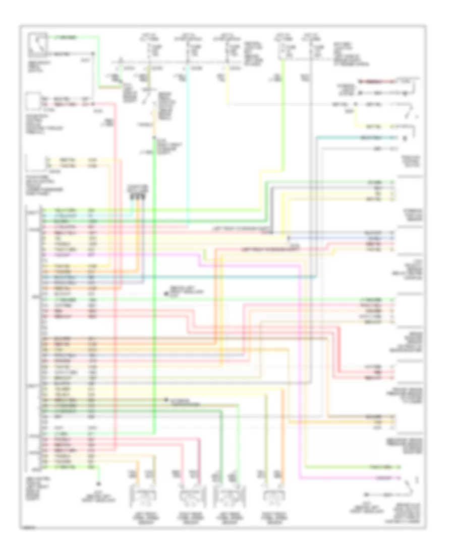
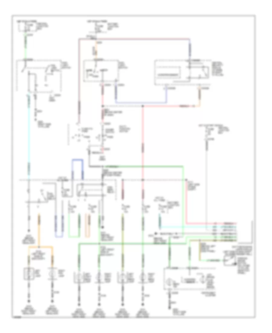
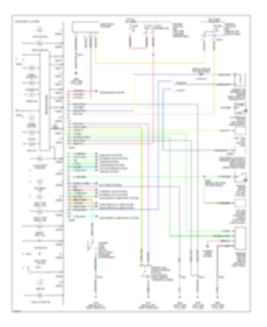
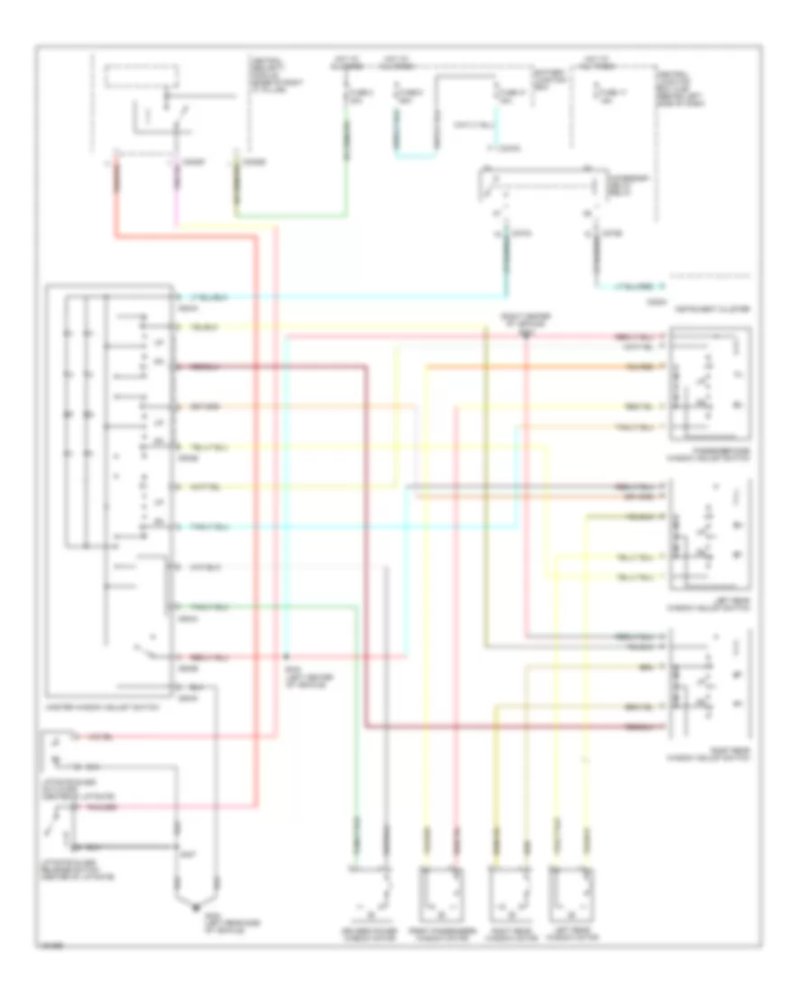
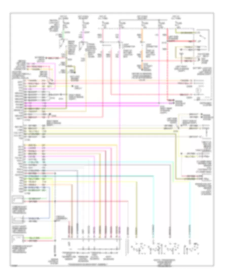
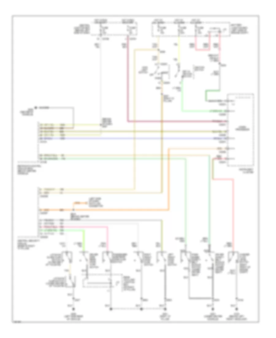
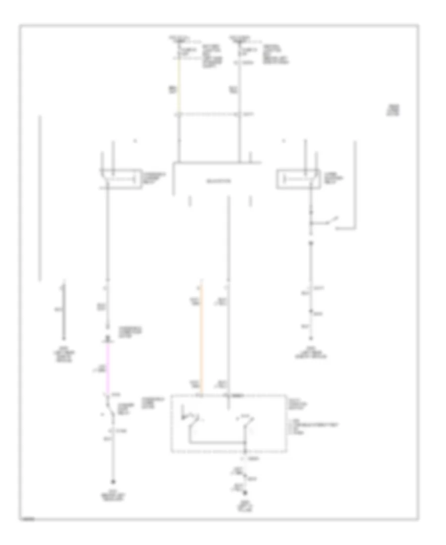
Automatic A/C Wiring Diagram, Early Production (1 of 2) for Ford Explorer 2002

List of elements for Automatic A/C Wiring Diagram, Early Production (1 of 2) for Ford Explorer 2002:
- A/c clutch relay
- A/c indicator diode
- Ambient air temperature sensor (right front of engine compt, near radiator support)
- Battery junction box (bjb) (left side of engine compt, at fender apron)
- Blower motor relay
- C201b
- C220a
- C228a
- C228b
- C270a
- C270b
- C270h
- Central junction box (cjb) (behind left side of dash)
- Computer data lines system
- Dash)
- Drivers temperature blend door actuator
- Electronic automatic temperature control module (eatc) (under left side of dash)
- Exterior lamps system
- Front blower motor
- Front blower motor speed controller
- Fuse 10 10a
- Fuse 15 5a
- Fuse 30 5a
- Fuse 36 40a
- Fuse 37 15a
- Fuse 7 15a
- G101 (behind left headlamp)
- G206 (behind center of dash)
- G300 (left side "a" pillar)
- Generic electric module (gem) (behind right side of dash)
- Generic electronic module (gem) (behind right side of dash)
- Hot at all times
- Hot in run and start
- In-vehicle temperature sensor (top left side of dash)
- Instrument cluster
- Interior lamps system
- J/c 1
- J/c 2
- Passenger temperature blend door actuator
- Remote solenoid assembly (behind right side of dash)
- S219
- S230
- S242 (behind center of dash)
- S243 (behind center of dash)
- S247 (behind center of dash)
- S317 (left center of vehicle)
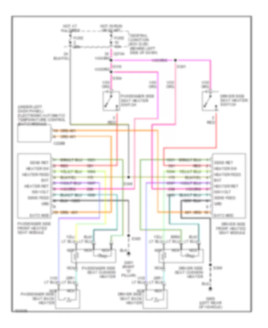
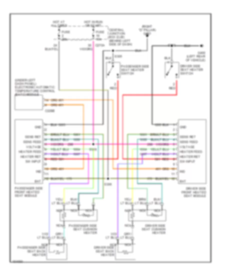
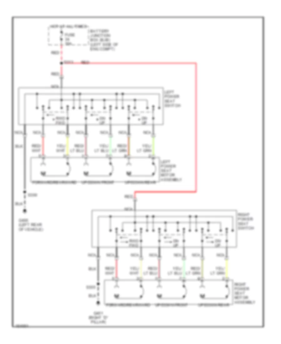
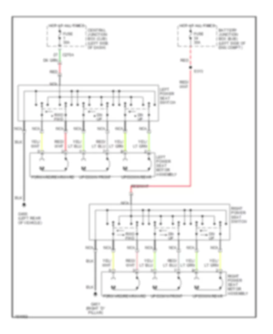
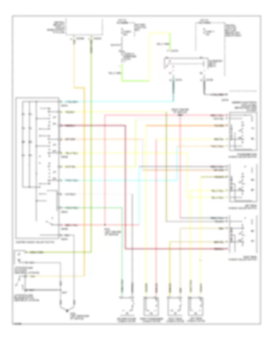
- Seats system
- Sunload sensor
- Tan
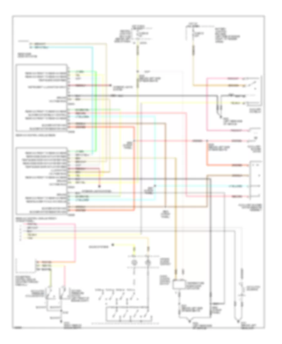
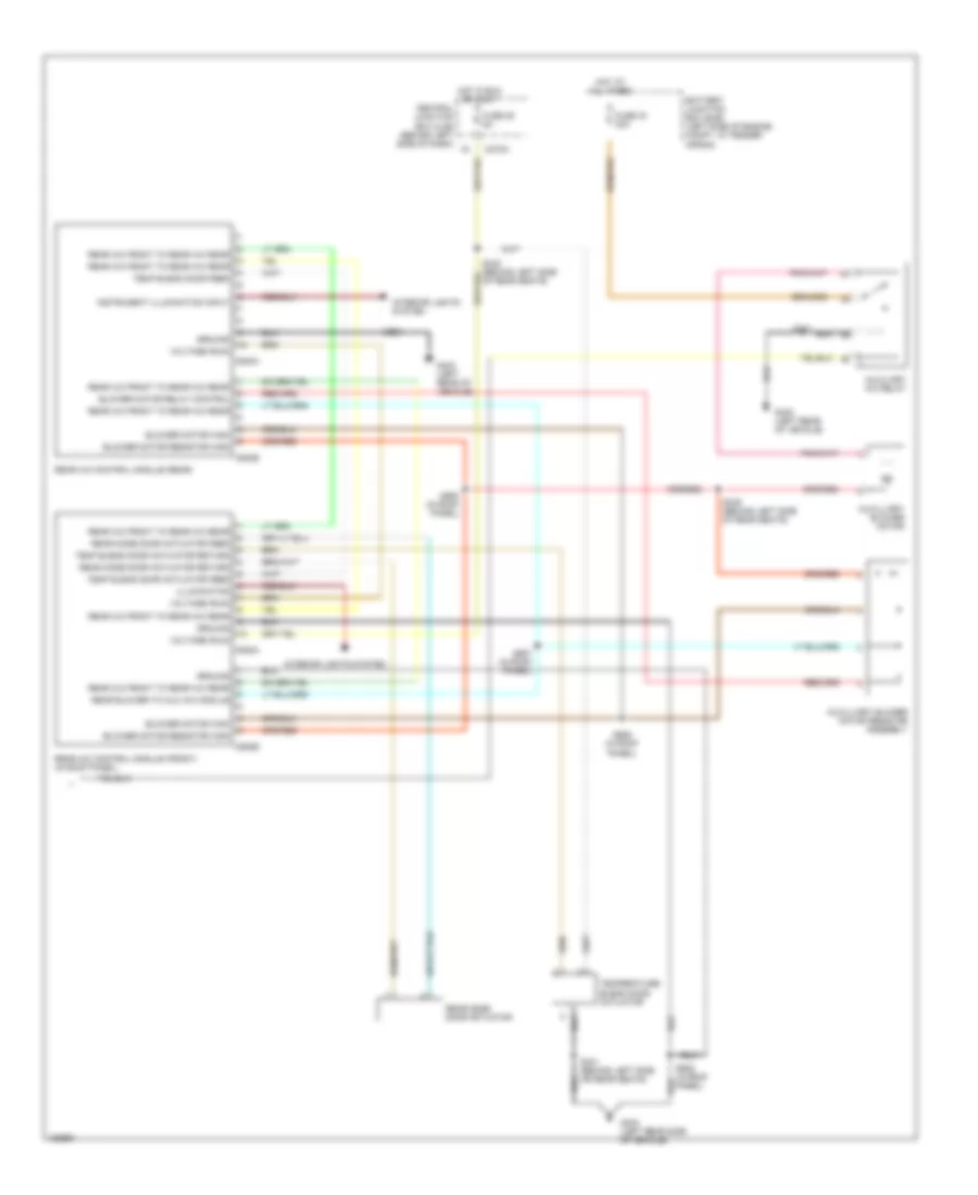
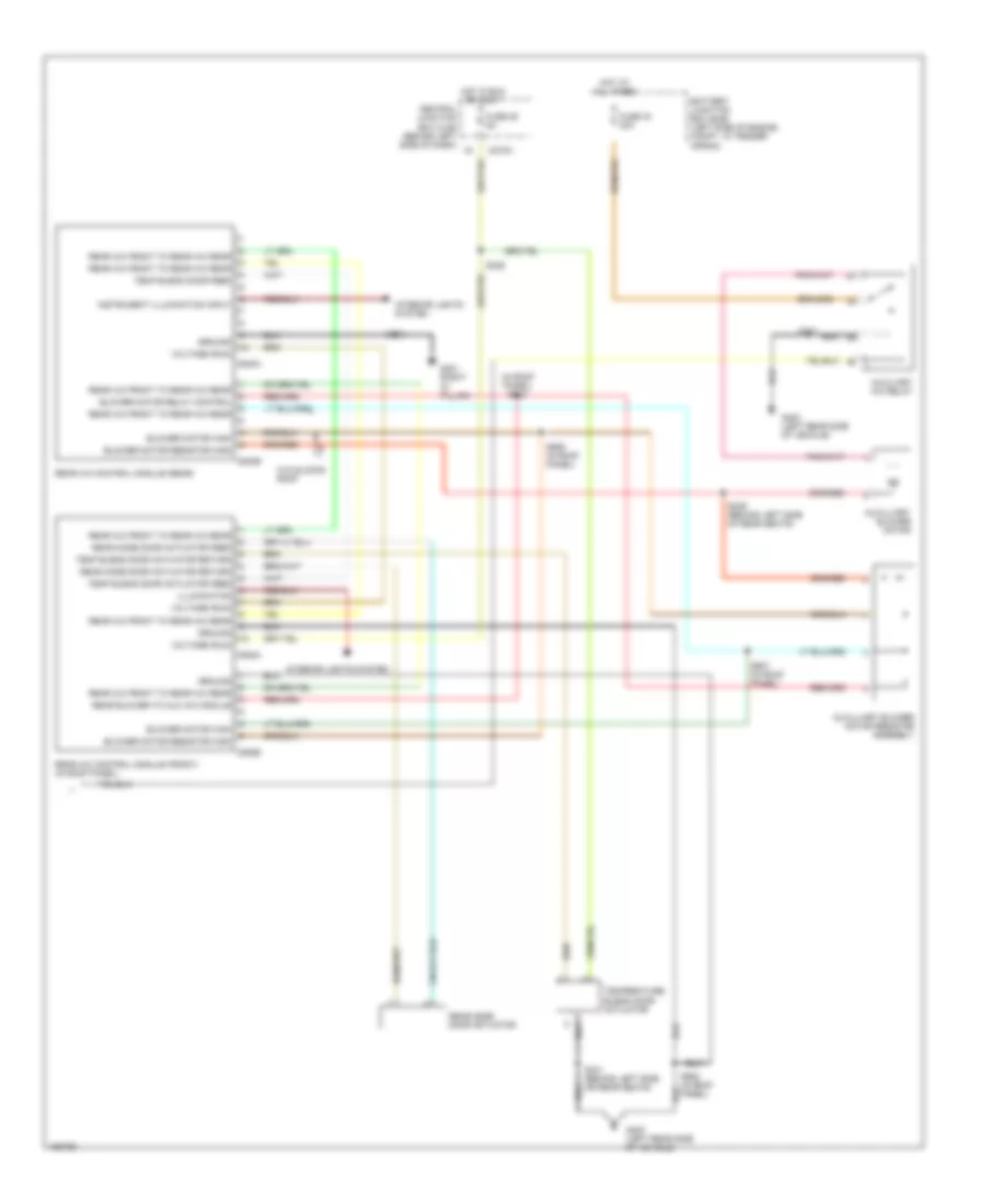
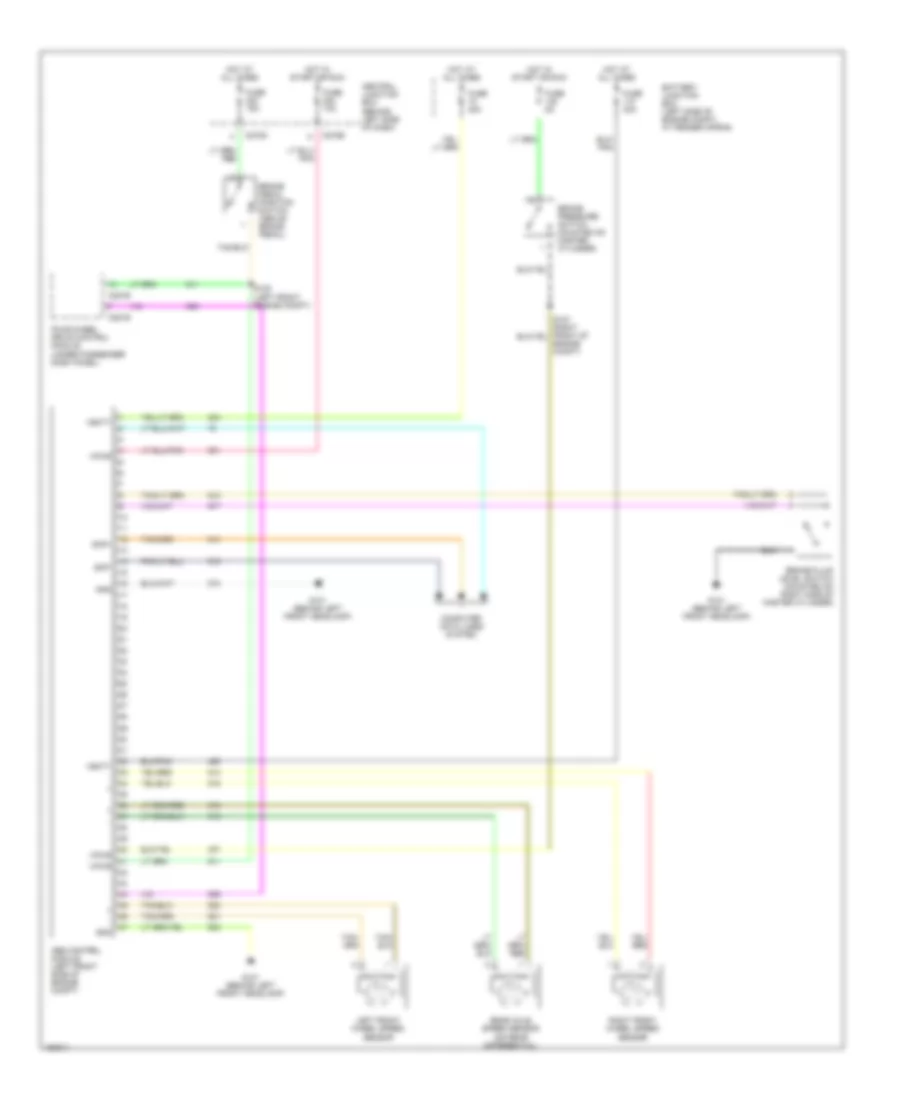
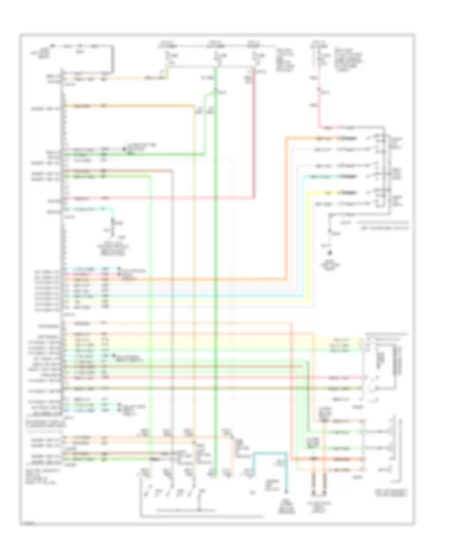
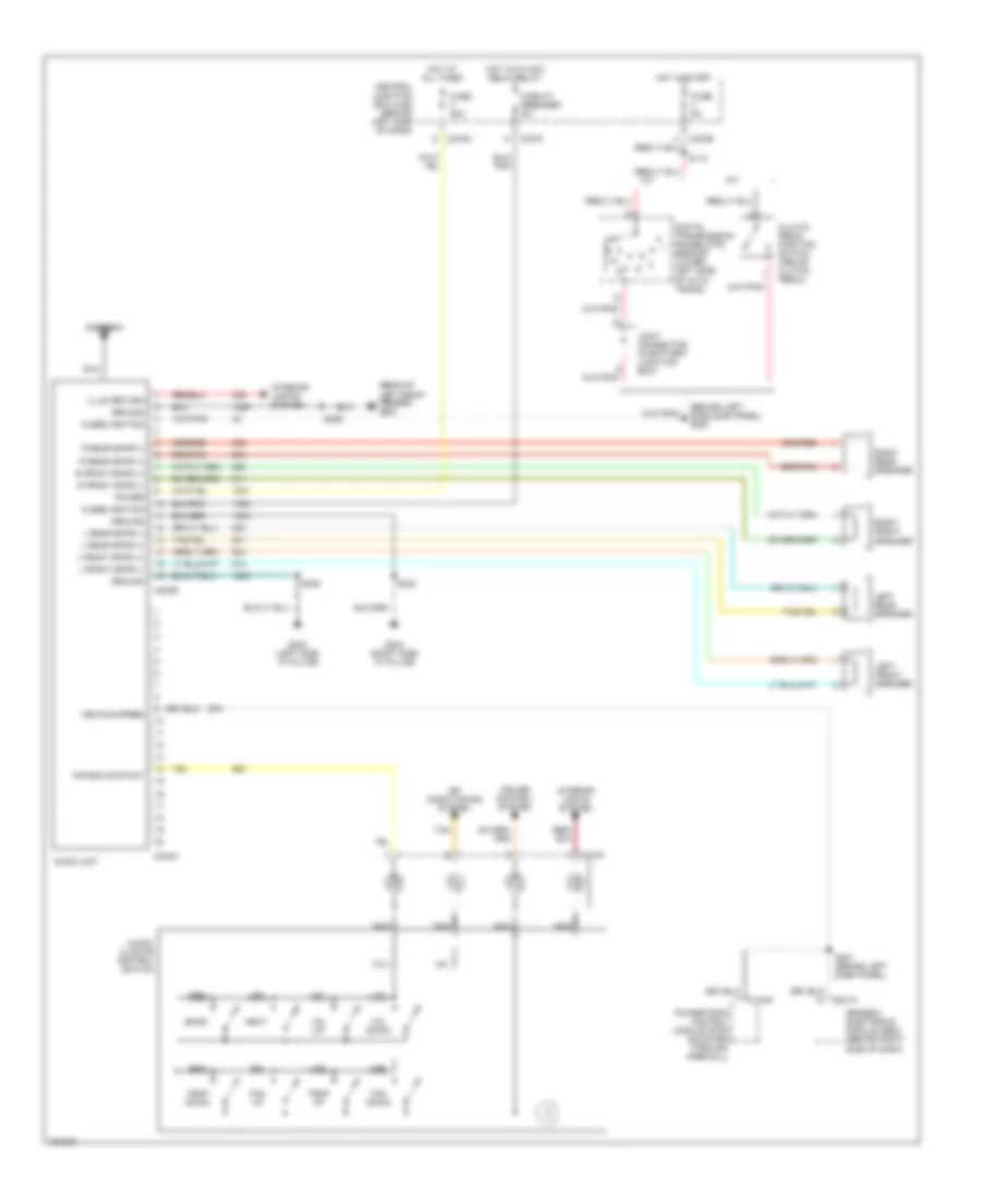
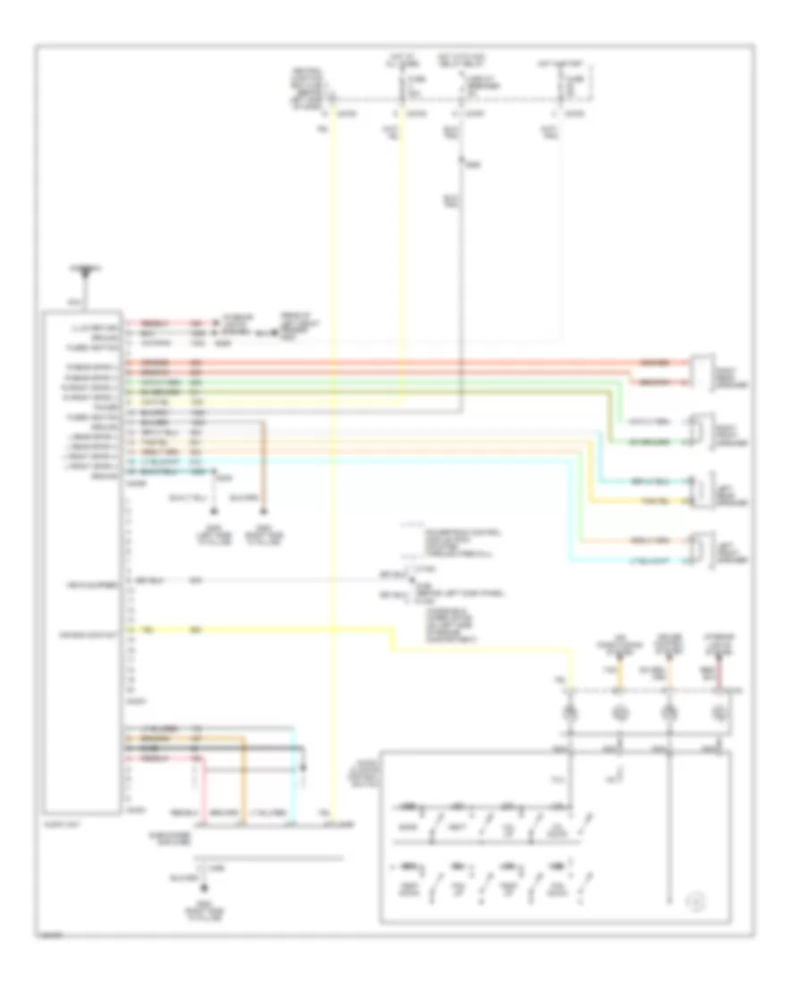
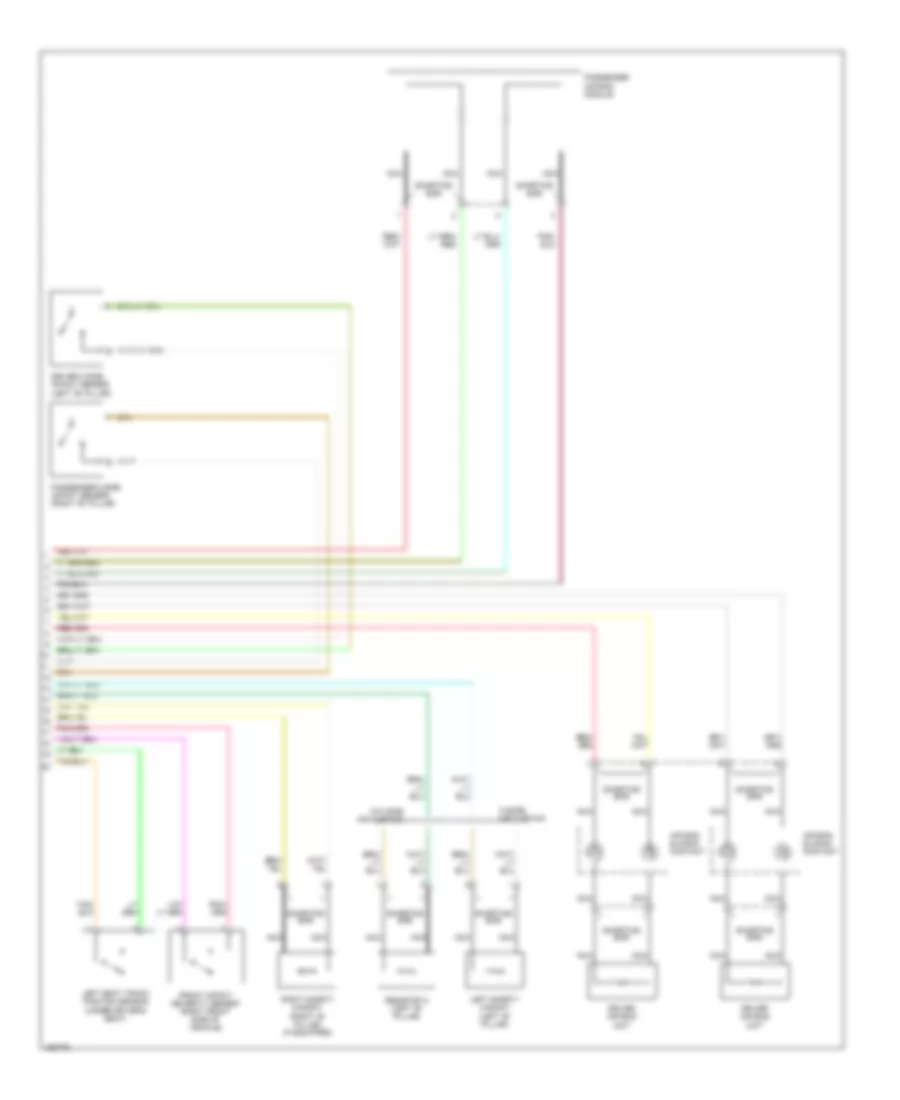
Automatic A/C Wiring Diagram, Early Production (2 of 2) for Ford Explorer 2002
List of elements for Automatic A/C Wiring Diagram, Early Production (2 of 2) for Ford Explorer 2002:
- A/c clutch pressure cycling swtch
- A/c clutch solenoid
- A/c high pressure switch (left front of engine compt)
- Air bag sliding contact
- Audio/ climate control switch
- Auxiliary a/c relay
- Auxilliary blower motor
- Auxilliary blower motor resistor assembly
- Battery junction box (bjb) (left side of engine compt, at fender apron)
- Blower motor high
- Blower motor relay control
- Blower motor resistor high
- C270a
- C938a
- C938b
- C940a
- C940b
- Central junction box (cjb) (behind left side of dash)
- Fuse 25 5a
- Fuse 33 30a
- G101 (behind left headlamp)
- G104 (right rear of engine compt)
- G403 (left rear side of vehicle)
- Ground
- Hot at all times
- Hot in run or accy
- Illumination
- Instrument illumination input
- Interior lights system
- Powertrain control module (mounted through firewall)
- Rear a/c control module (front) (in roof panel)
- Rear a/c control module (rear)
- Rear a/c front to rear a/c rear
- Rear blower to aux a/c module
- Rear mode door actuator
- Rear mode door actuator feed
- Rear mode door actuator return
- S135
- S339 (behind left side of rear seats)
- S341
- S341 (behind left side or rear seats)
- S905 (in roof panel)
- S906 (in roof panel)
- S907 (in roof panel)
- S908
- S908 (in roof panel)
- Sound systems
- Tan
- Temp blend door actuator feed
- Temp blend door actuator return
- Temp blend door feed
- Temperature blend door actuator
- Voltage (run)
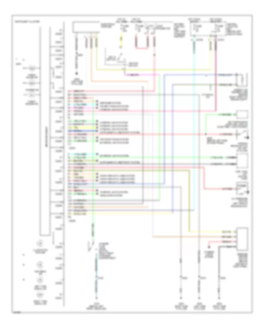
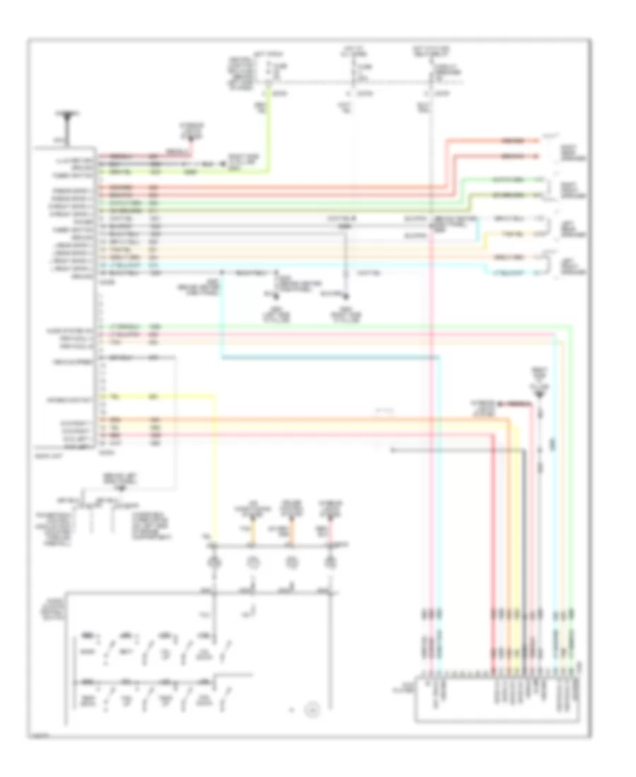
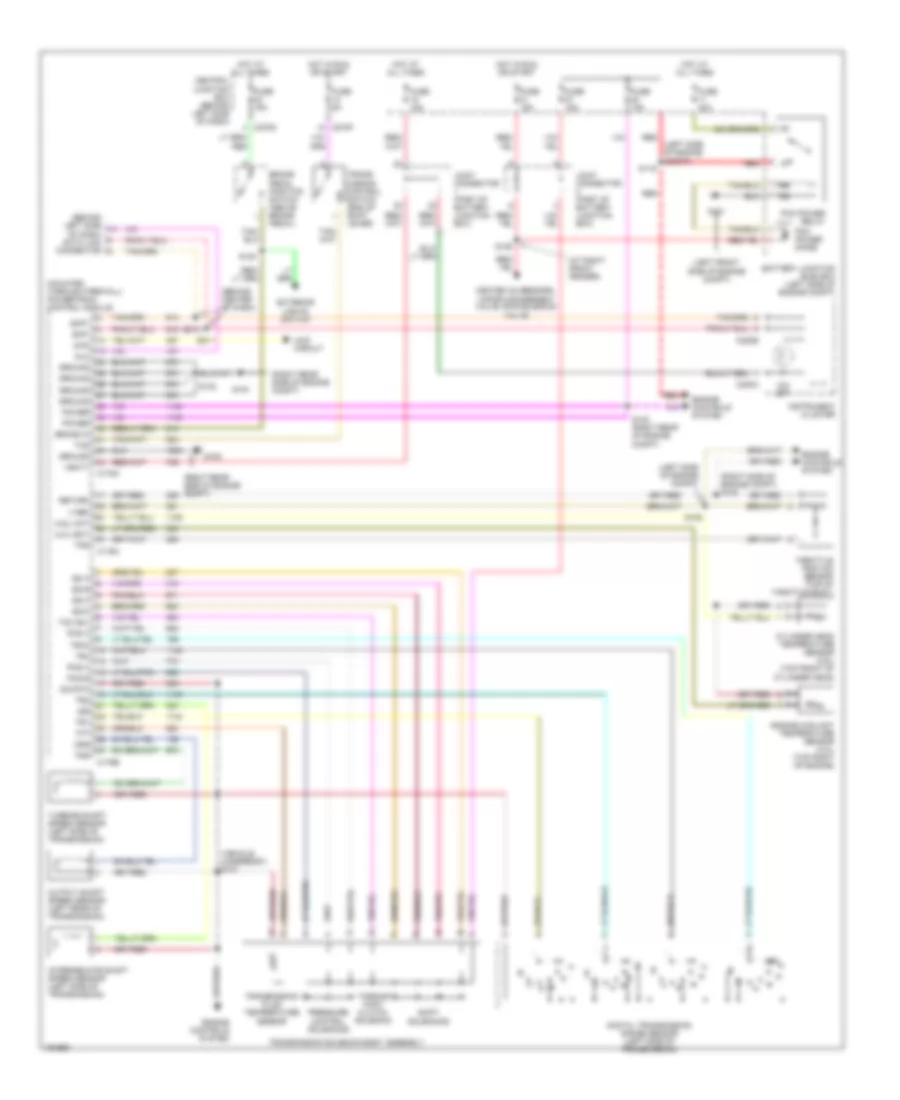
Automatic A/C Wiring Diagram, Late Production (1 of 2) for Ford Explorer 2002
List of elements for Automatic A/C Wiring Diagram, Late Production (1 of 2) for Ford Explorer 2002:
- (behind center of dash)
- A/c clutch relay
- A/c indicator diode
- Ambient air temperature sensor (right front of engine compt, near radiator support)
- Battery junction box (bjb) (left side of engine compt, at fender apron)
- Blower motor relay
- C220a
- C228a
- C228b
- C270a
- C270b
- C270e
- C270h
- C3008e
- Central junction box (cjb) (behind left side of dash)
- Central security module (base of right "c" pillar)
- Computer data lines system
- Drivers temperature blend door actuator
- Electronic automatic temperature control module (eatc) (under left side of dash)
- Exterior lamps system
- Front blower motor
- Front blower motor speed controller
- Fuse 10 10a
- Fuse 15 5a
- Fuse 20 5a
- Fuse 30 5a
- Fuse 36 40a
- Fuse 37 15a
- Fuse 7 15a
- G101 (behind left headlamp)
- G200 (right side "a" pillar)
- G206 (behind center of dash)
- G300 (left side "a" pillar)
- Hot at all times
- Hot in run and start
- In-vehicle temperature sensor (top left side of dash)
- Instrument cluster
- Interior lamps system
- J/c 1
- J/c 2
- Passenger temperature blend door actuator
- Remote solenoid assembly (behind right side of dash)
- S219
- S229
- S233 (behind center of dash)
- S242 (behind center of dash)
- S243
- S247 (behind center of dash)
- S317 (left center of vehicle)
- Seats system
- Sunload sensor
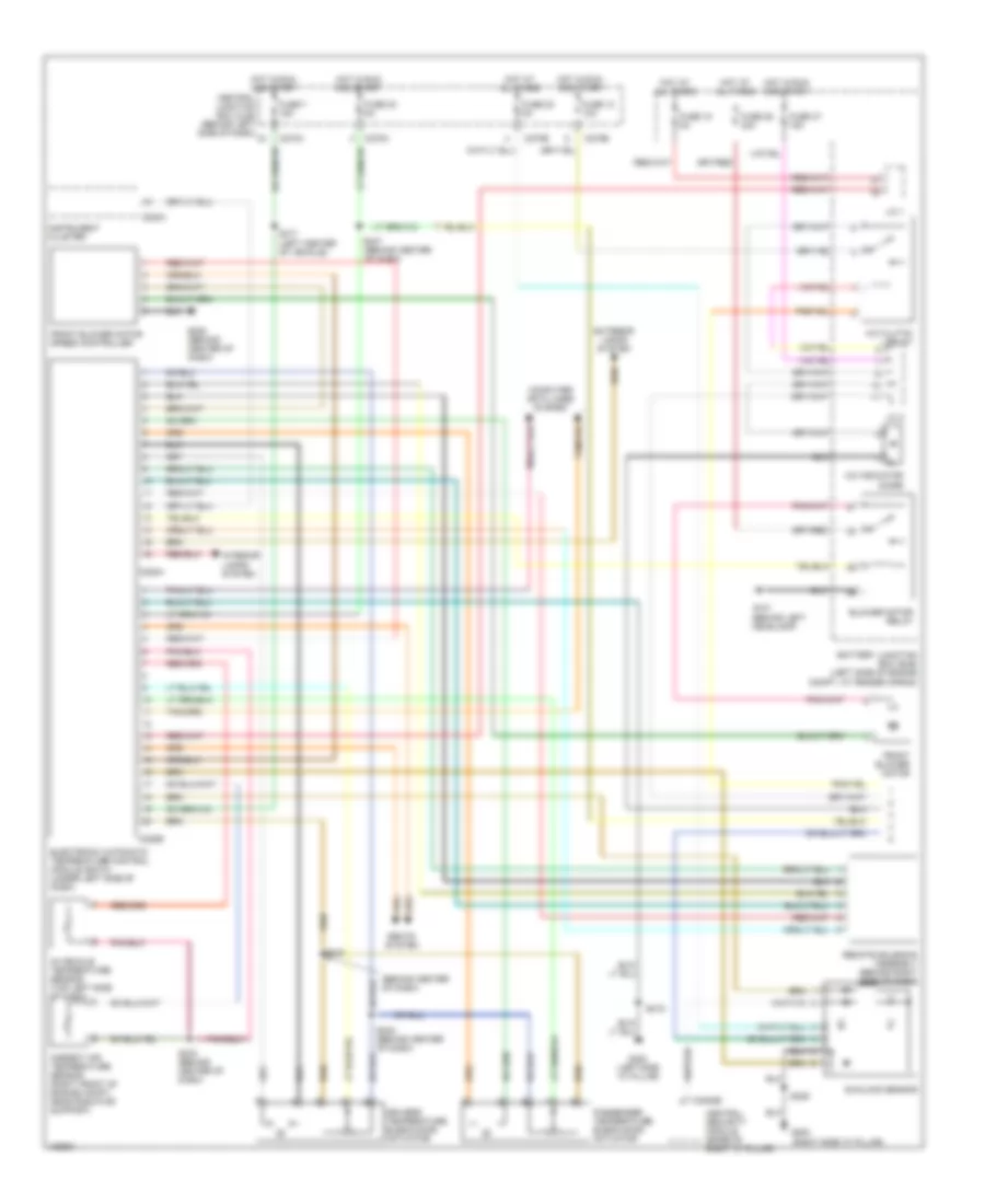
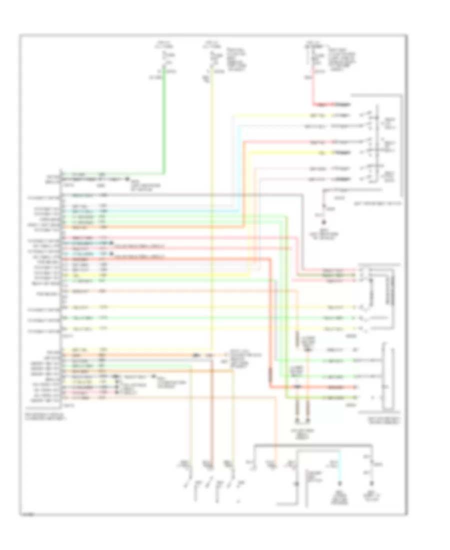
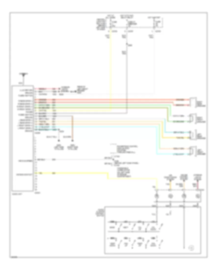
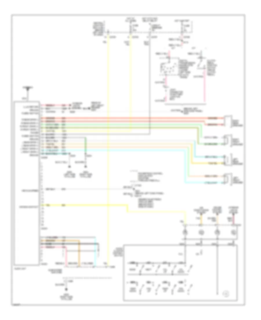
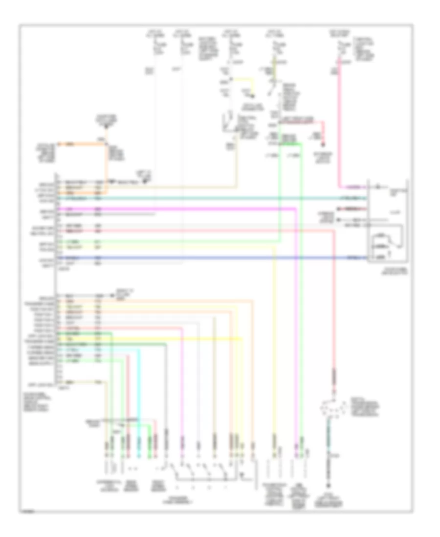
Automatic A/C Wiring Diagram, Late Production (2 of 2) for Ford Explorer 2002
List of elements for Automatic A/C Wiring Diagram, Late Production (2 of 2) for Ford Explorer 2002:
- A/c clutch pressure cycling siitch
- A/c clutch solenoid
- A/c high pressure switch (left front of engine compt)
- Auxiliary a/c relay
- Auxilliary blower motor
- Auxilliary blower motor resistor assembly
- Battery junction box (bjb) (left side of engine compt, at fender apron)
- Blower motor high
- Blower motor relay control
- Blower motor resistor high
- C270a
- C938a
- C938b
- C940a
- C940b
- Central junction box (cjb) (behind left side of dash)
- Fuse 25 5a
- Fuse 33 30a
- G101 (behind left headlamp)
- G104 (right rear of engine compt)
- G400 (left rear side of vehicle)
- G401 (right "d" pillar)
- G403 (left rear side of vehicle)
- Ground
- Hot at all times
- Hot in run or accy
- Illumination
- Instrument illumination input
- Interior lights system
- Powertrain control module (mounted through firewall)
- Rear a/c control module (front) (in roof panel)
- Rear a/c control module (rear)
- Rear a/c front to rear a/c rear
- Rear blower to aux a/c module
- Rear mode door actuator
- Rear mode door actuator feed
- Rear mode door actuator return
- S135
- S341
- S341 (behind left side or rear seats)
- S903
- S906 (in roof panel)
- S907 (in roof panel)
- S908
- S908 (in roof panel)
- S910 (in roof panel)
- Temp blend door actuator feed
- Temp blend door actuator return
- Temp blend door feed
- Temperature blend door actuator
- Voltage (run)
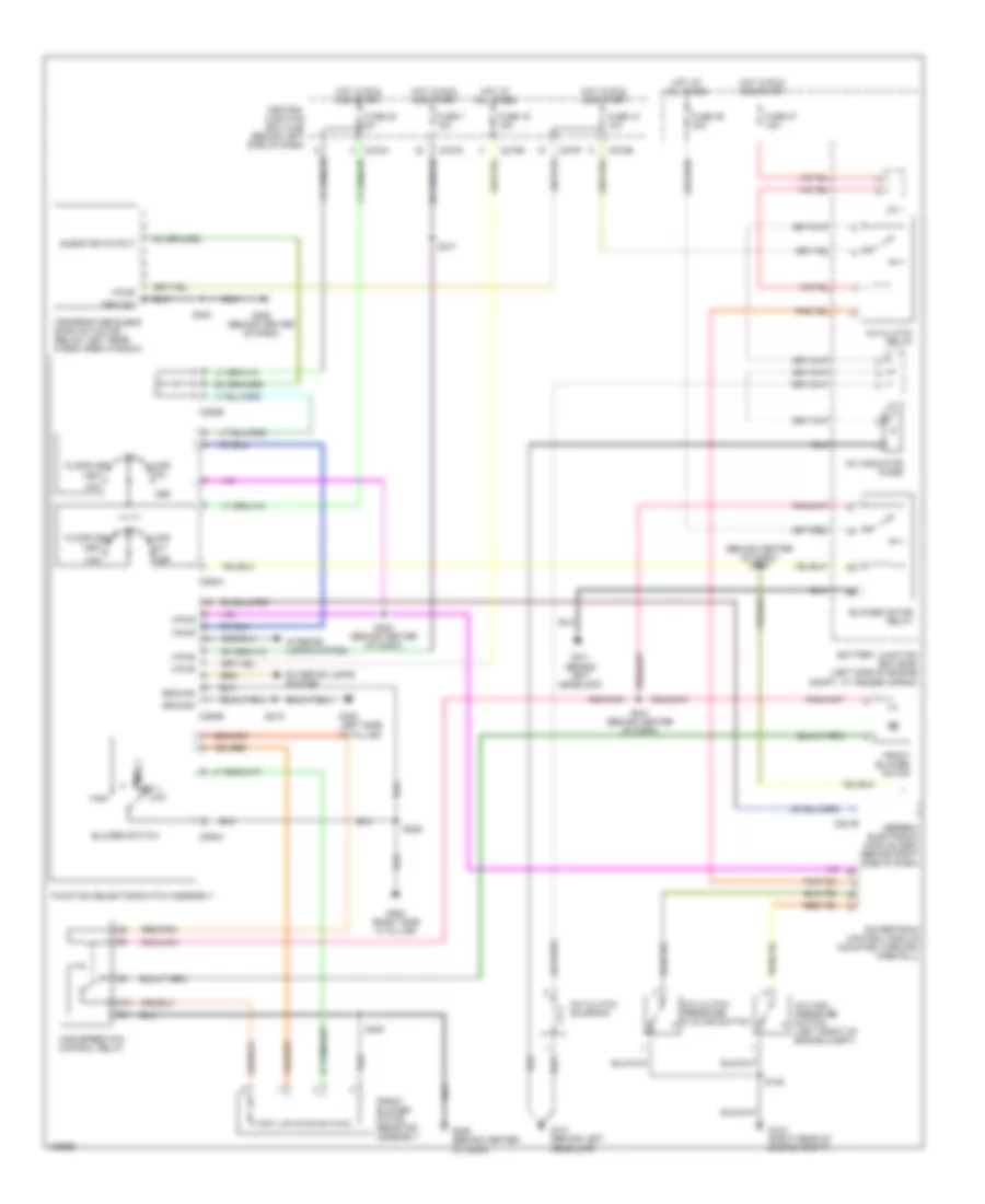
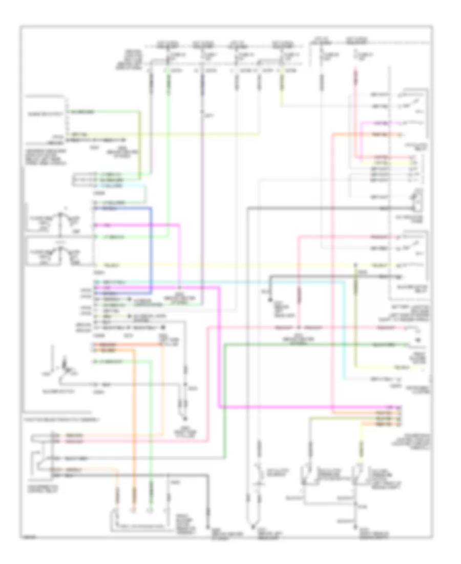
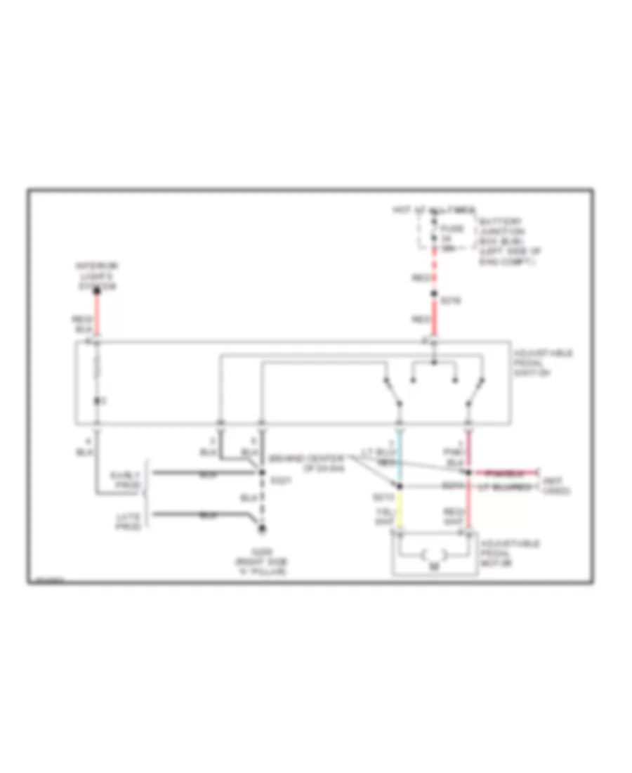
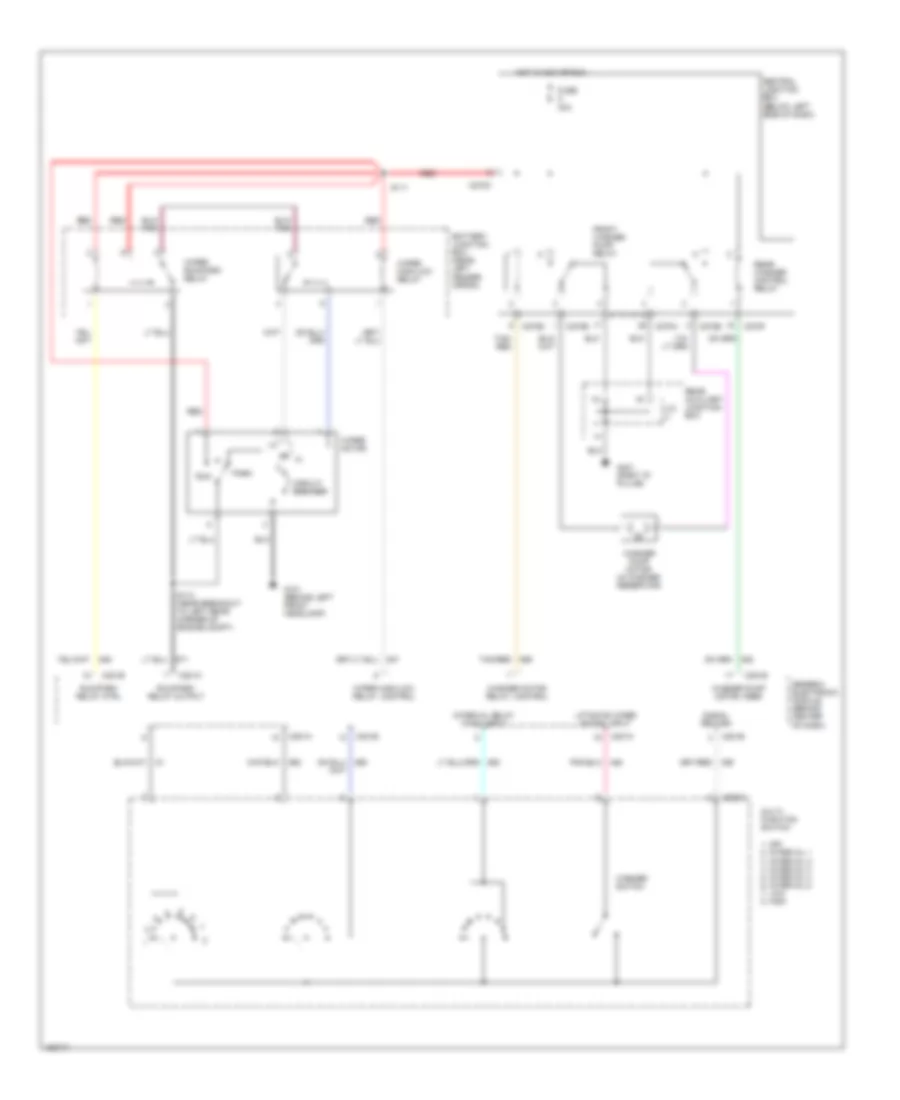
Manual A/C Wiring Diagram, Early Production (1 of 2) for Ford Explorer 2002
List of elements for Manual A/C Wiring Diagram, Early Production (1 of 2) for Ford Explorer 2002:
- (behind center of dash) s249
- 87a
- A/c clutch pressure cycling switch
- A/c clutch relay
- A/c clutch solenoid
- A/c high pressure switch (left front of engine compt)
- A/c indicator diode
- Battery junction box (bjb) (left side of engine compt, at fender apron)
- Blend dr output
- Blower motor relay
- Blower switch
- C201b
- C270a
- C270b
- C270e
- C270f
- C270h
- C294a
- C294b
- C294c
- Central junction box (cjb) (behind left side of dash)
- Def
- Exterior lamps system
- Floor
- Floor/vent
- Front blower motor
- Front blower motor resistor assembly
- Function selector switch assembly
- Fuse 10 10a
- Fuse 16 15a
- Fuse 30 5a
- Fuse 36 40a
- Fuse 37 15a
- Fuse 7 15a
- G101 (behind left headlamp)
- G104 (right rear of engine compt)
- G200 (right side "a" pillar)
- G206 (behind center of dash)
- G300 (left side "a" pillar)
- Gereric electronic module (gem) (behind right side of dash)
- Ground
- High
- High speed fan control relay
- Hot at all times
- Hot in run and start
- Interior lamps system
- J/c 1
- J/c 2
- Low
- Max
- Med 1 med 2
- Mix
- Off
- Powertrain control module (mounted through firewall)
- S135
- S219
- S222 (behind center of dash)
- S229
- S240
- S241 (behind center of dash)
- S317
- Temperature blend door actuator (below left rear cargo area window)
- Vent
- Vpwr
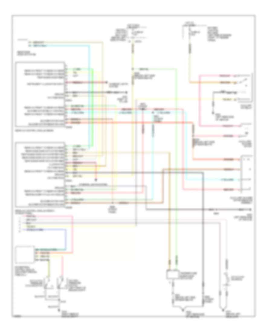
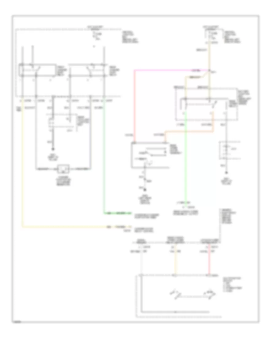
Manual A/C Wiring Diagram, Early Production (2 of 2) for Ford Explorer 2002
List of elements for Manual A/C Wiring Diagram, Early Production (2 of 2) for Ford Explorer 2002:
- Auxiliary a/c relay
- Auxilliary blower motor
- Auxilliary blower motor resistor assembly
- Battery junction box (bjb) (left side of engine compt, at fender apron)
- Blower motor high
- Blower motor relay control
- Blower motor resistor high
- C270a
- C938a
- C938b
- C940a
- C940b
- Central junction box (cjb) (behind left side of dash)
- Fuse 25 5a
- Fuse 33 30a
- G403 (left rear of vehicle)
- G403 (left rear side of vehicle)
- Ground
- Hot at all times
- Hot in run or accy
- Illumination
- Instrument illumination input
- Interior lights system
- Rear a/c control module (front) (in roof panel)
- Rear a/c control module (rear)
- Rear a/c front to rear a/c rear
- Rear blower to aux a/c module
- Rear mode door actuator
- Rear mode door actuator feed
- Rear mode door actuator return
- S339 (behind left side of rear seats)
- S341
- S341 (behind left side or rear seats)
- S905 (in roof panel)
- S906 (in roof panel)
- S907 (in roof panel)
- S908
- S908 (in roof panel)
- Temp blend door actuator feed
- Temp blend door actuator return
- Temp blend door feed
- Temperature blend door actuator
- Voltage (run)
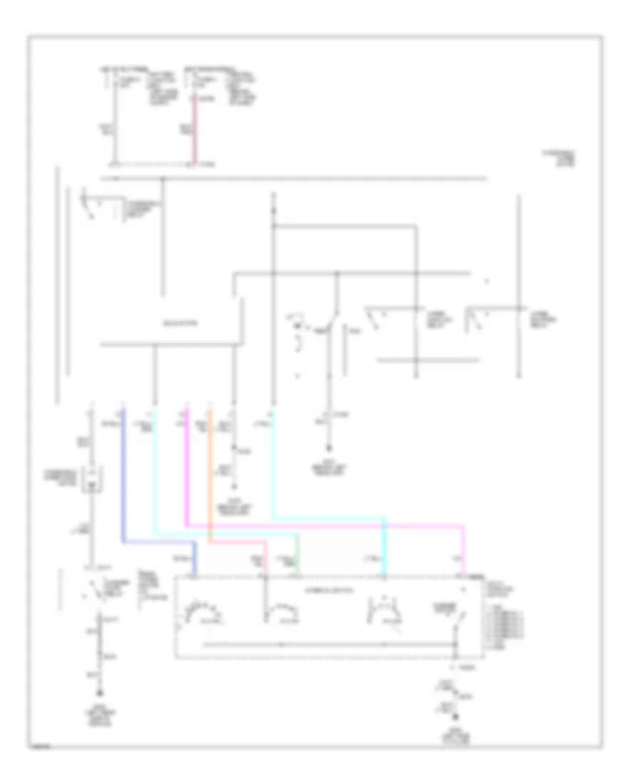
Manual A/C Wiring Diagram, Late Production (1 of 2) for Ford Explorer 2002
List of elements for Manual A/C Wiring Diagram, Late Production (1 of 2) for Ford Explorer 2002:
- 87a
- A/c clutch pressure cycling switch
- A/c clutch relay
- A/c clutch solenoid
- A/c high pressure switch (left front of engine compt)
- A/c indicator diode
- Battery junction box (bjb) (left side of engine compt, at fender apron)
- Blend dr output
- Blower motor relay
- Blower switch
- C220a
- C270a
- C270b
- C270e
- C270f
- C270h
- C294a
- C294b
- C294c
- Central junction box (cjb) (behind left side of dash)
- Def
- Exterior lamps system
- Floor
- Floor/vent
- Front blower motor
- Front blower motor resistor assembly
- Function selector switch assembly
- Fuse 10 10a
- Fuse 16 5a
- Fuse 30 5a
- Fuse 36 40a
- Fuse 37 15a
- Fuse 7 15a
- G101 (behind left headlamp)
- G104 (right rear of engine compt)
- G200 (right side "a" pillar)
- G206 (behind center of dash)
- G300 (left side "a" pillar)
- Ground
- High
- High speed fan control relay
- Hot at all times
- Hot in run and start
- Instrument cluster
- Interior lamps system
- J/c 2
- Low
- Max
- Med 1 med 2
- Mix
- Off
- Powertrain control module (mounted through firewall)
- S135
- S216
- S219
- S222 (behind center of dash)
- S240
- S241 (behind center of dash)
- S249
- S317
- Temperature blend door actuator (below left rear cargo area window)
- Vent
- Vpwr
Manual A/C Wiring Diagram, Late Production (2 of 2) for Ford Explorer 2002
List of elements for Manual A/C Wiring Diagram, Late Production (2 of 2) for Ford Explorer 2002:
- (in roof panel)
- Auxiliary a/c relay
- Auxilliary blower motor
- Auxilliary blower motor resistor assembly
- Battery junction box (bjb) (left side of engine compt, at fender apron)
- Blower motor high
- Blower motor relay control
- Blower motor resistor high
- C270a
- C938a
- C938b
- C940a
- C940b
- Central junction box (cjb) (behind left side of dash)
- Fuse 25 5a
- Fuse 33 30a
- G400 (left rear side of vehicle)
- G401 (right "d" pillar)
- G403 (left rear side of vehicle)
- Ground
- Hot at all times
- Hot in run or accy
- Illumination
- Instrument illumination input
- Interior lights system
- Rear a/c control module (front) (in roof panel)
- Rear a/c control module (rear)
- Rear a/c front to rear a/c rear
- Rear blower to aux a/c module
- Rear mode door actuator
- Rear mode door actuator feed
- Rear mode door actuator return
- S326
- S339 (behind left side of rear seats)
- S341
- S341 (behind left side or rear seats)
- S903
- S906 (in roof panel)
- S907 (in roof panel)
- S908 (in roof panel)
- S910
- Temp blend door actuator feed
- Temp blend door actuator return
- Temp blend door feed
- Temperature blend door actuator
- Voltage (run)
- W/o sliding roof
ANTI-LOCK BRAKES
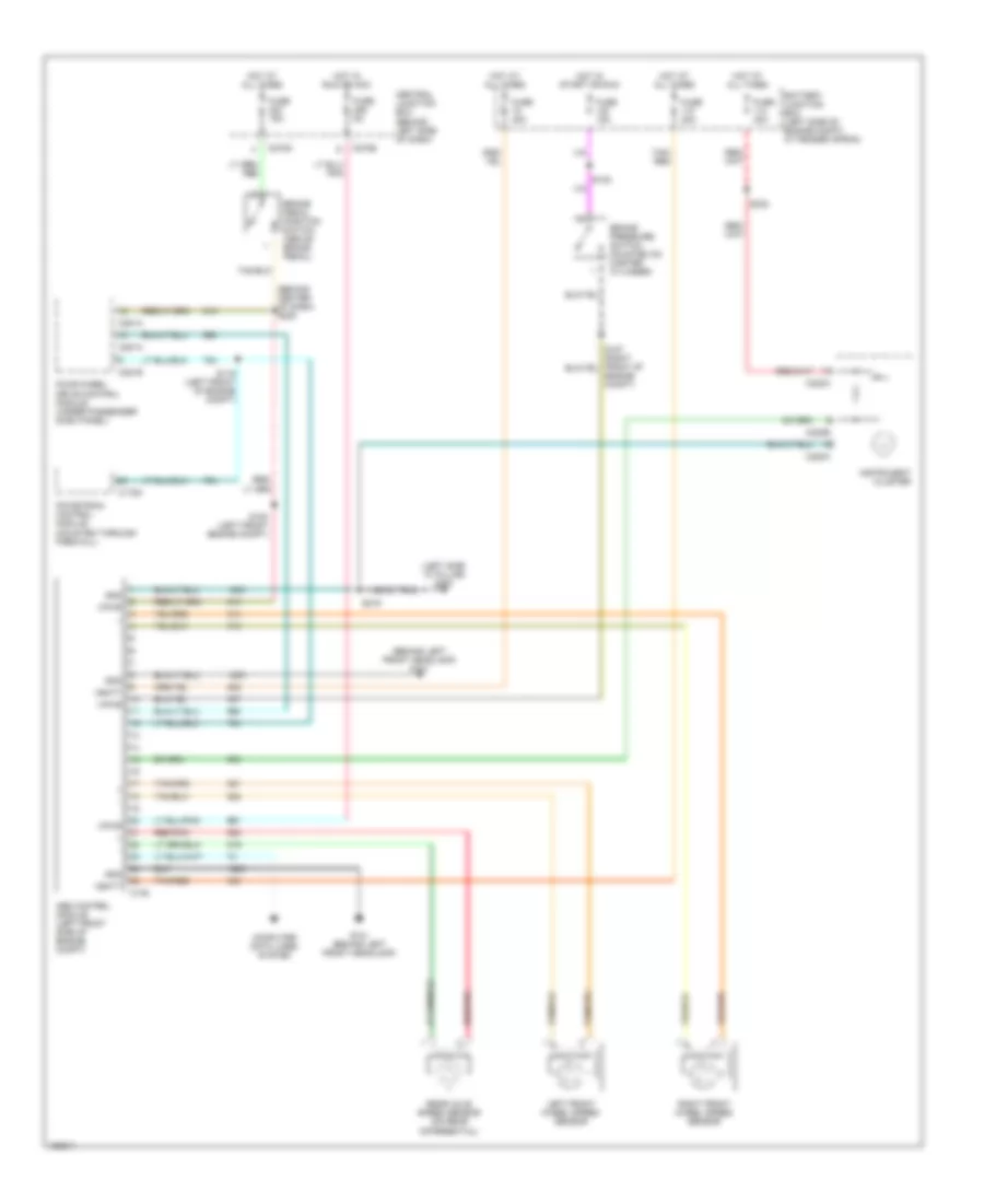
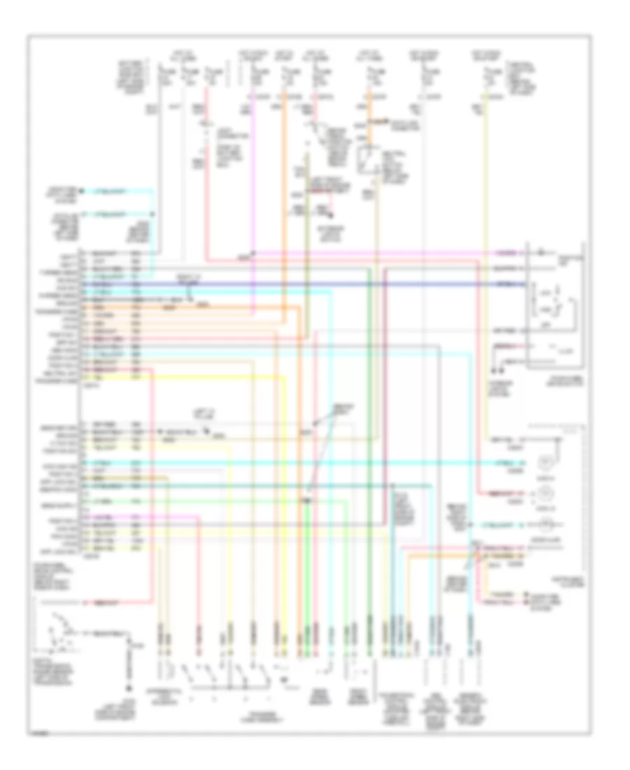
Anti-lock Brake Wiring Diagrams, Early Production for Ford Explorer 2002
List of elements for Anti-lock Brake Wiring Diagrams, Early Production for Ford Explorer 2002:
- (behind center of dash) s220
- (behind left front headlamp) g101
- (left side "a" pillar) g300
- Abs control module (left front side of engine compt)
- Battery junction box (left side of engine compt, at fender apron)
- Brake pedal position switch (above brake pedal)
- Brake pressure switch mounted on master cylinder)
- C135
- C175a
- C220a
- C220b
- C270b
- C270d
- C281a
- C281b
- Central junction box (behind left side of dash)
- Computer data lines system
- Engine compt)
- Four-wheel drive control module (under passenger dash panel)
- Fuse 15a
- Fuse 20a
- Fuse 30a
- Fuse 40a
- Fuse 5a
- G101 (behind left front headlamp)
- Gnd
- Hot at all times
- Hot in run or acc
- Hot in start or run
- Instrument cluster
- Left front wheel speed sensor
- Powetrain control module (mounted through firewall)
- Rear axle speed sensor (on rear differential)
- Red/pnk
- Right front wheel speed sensor
- S119 (left front of engine compt)
- S120 (left front engine compt)
- S130
- S219
- S232
- Tan/ red
- Tan/red
- Vbatt
- Vpwr
Anti-lock Brake Wiring Diagrams, Late Production with Traction Control for Ford Explorer 2002
List of elements for Anti-lock Brake Wiring Diagrams, Late Production with Traction Control for Ford Explorer 2002:
- (behind left front headlamp) g101
- (left front of engine compt) s175
- Abs control module (left front side of engine compt)
- Battery junction box (left side of engine compt, at fender apron)
- Brake booster sensor (on front of brake booster)
- Brake fluid level switch (mounted on right side of master cylinder)
- Brake pedal position switch (above brake pedal)
- C175a
- C270a
- C270b
- C270d
- C270h
- C281b
- Central junction box (behind left side of dash)
- Computer data lines system
- Exterior lights system
- Four-wheel drive control module (under passenger dash panel)
- Fuse 10a
- Fuse 15a
- Fuse 30a
- Fuse 40a
- Fuse 7.5a
- G101 (behind left front headlamp)
- Gnd
- Hot at all times
- Hot in start or run
- Interior lights system
- Left front wheel speed sensor
- Left rear wheel speed sensor
- Powetrain control module (mounted through firewall)
- Primary brake pressure sensor (on master cylinder)
- Red
- Red/ pnk
- Red/pnk
- Redundant pedal switch
- Right front wheel speed sensor
- Right rear wheel speed sensor
- S120
- S127
- S171 (left side of engine compt)
- S176 (left front of engine compt)
- S179 (right front of engine compt)
- S264
- Secondary brake pressure sensor (on brake booster)
- Steering position sensor
- Tan
- Traction control switch
- Vbatt
- Vpwr
- Yaw velocity sensor (below center console)
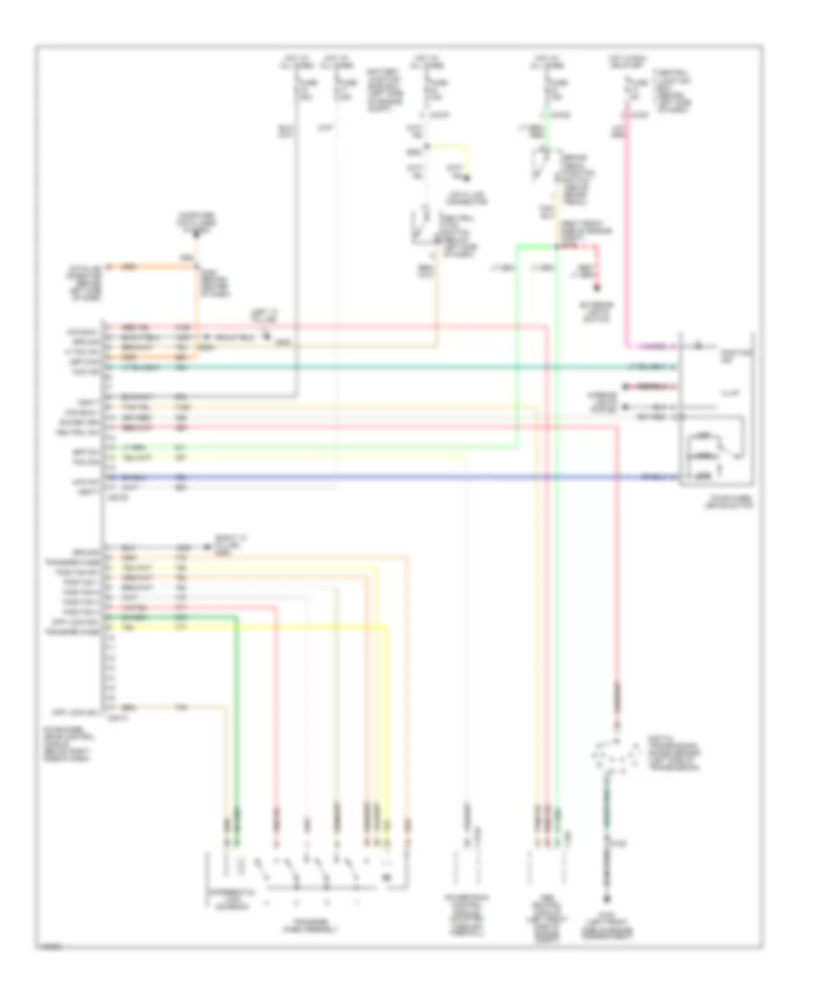
Anti-lock Brake Wiring Diagrams, Late Production without Traction Control for Ford Explorer 2002
List of elements for Anti-lock Brake Wiring Diagrams, Late Production without Traction Control for Ford Explorer 2002:
- Abs control module (left front side of engine compt)
- Battery junction box (left side of engine compt, at fender apron)
- Brake fluid level switch (mounted on right side of master cylinder)
- Brake pedal position switch (above brake pedal)
- Brake pressure switch mounted on master cylinder)
- C270b
- C270d
- C281b
- Central junction box (behind left side of dash)
- Computer data lines system
- Engine compt)
- Four-wheel drive control module (under passenger dash panel)
- Fuse 10a
- Fuse 15a
- Fuse 30a
- Fuse 40a
- Fuse 5a
- G101 (behind left front headlamp)
- Gnd
- Hot at all times
- Hot in start or run
- Left front wheel speed sensor
- Rear axle speed sensor (on rear differential)
- Right front wheel speed sensor
- S120 (left front engine compt)
- Scp+
- Scp-
- Vbatt
- Vpwr
ANTI-THEFT
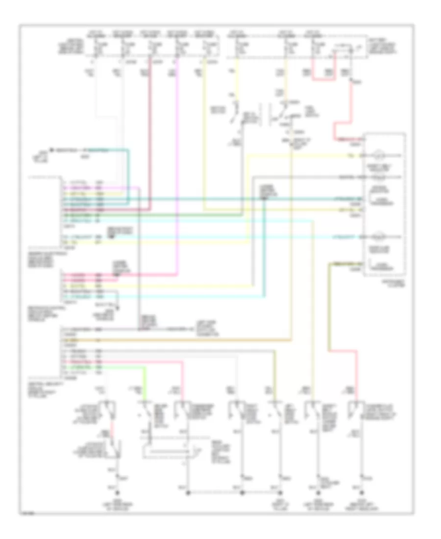
Forced Entry Wiring Diagram, Early Production for Ford Explorer 2002
List of elements for Forced Entry Wiring Diagram, Early Production for Ford Explorer 2002:
- (behind right side of dash) generic electronic module
- (not used)
- (right "d" pillar)
- 1/2
- 3/4
- 5/6
- 7/8
- 9/0
- Anti- theft hood switch
- Anti- theft inhibit switch
- Anti-theft sw
- Auxiliary junction box (on rear "d" pillar)
- Battery junction box (left side of engine compt, at fender apron)
- C201a
- C270a
- C270e
- C270f
- C3008a
- C3008b
- C3008c
- Central junction box (behind left side of dash)
- Central security module (on base of right "c" pillar)
- Data link connector (dlc) (behind left side of dash)
- Disarm sw
- Dk (under driver side dash panel) s320
- Door ajar sw
- Door lock
- Door locks system
- Door locks systems
- Door relay
- Door unlock
- Driver side rear door ajar switch
- Engine controls system
- Exterior lights system
- Fuse 10a
- Fuse 15a
- Fuse 20a
- Fuse 5a
- Fuse 7.5a
- G101 (behind left front headlamp)
- G103 (behind right front headlamp)
- G401
- G401 (right "d" pillar)
- G402 (right "d" pillar)
- Glass release
- Gnd
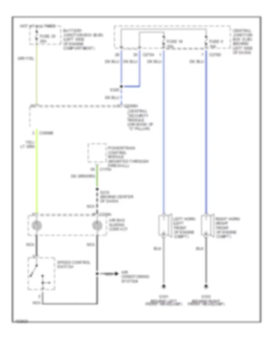
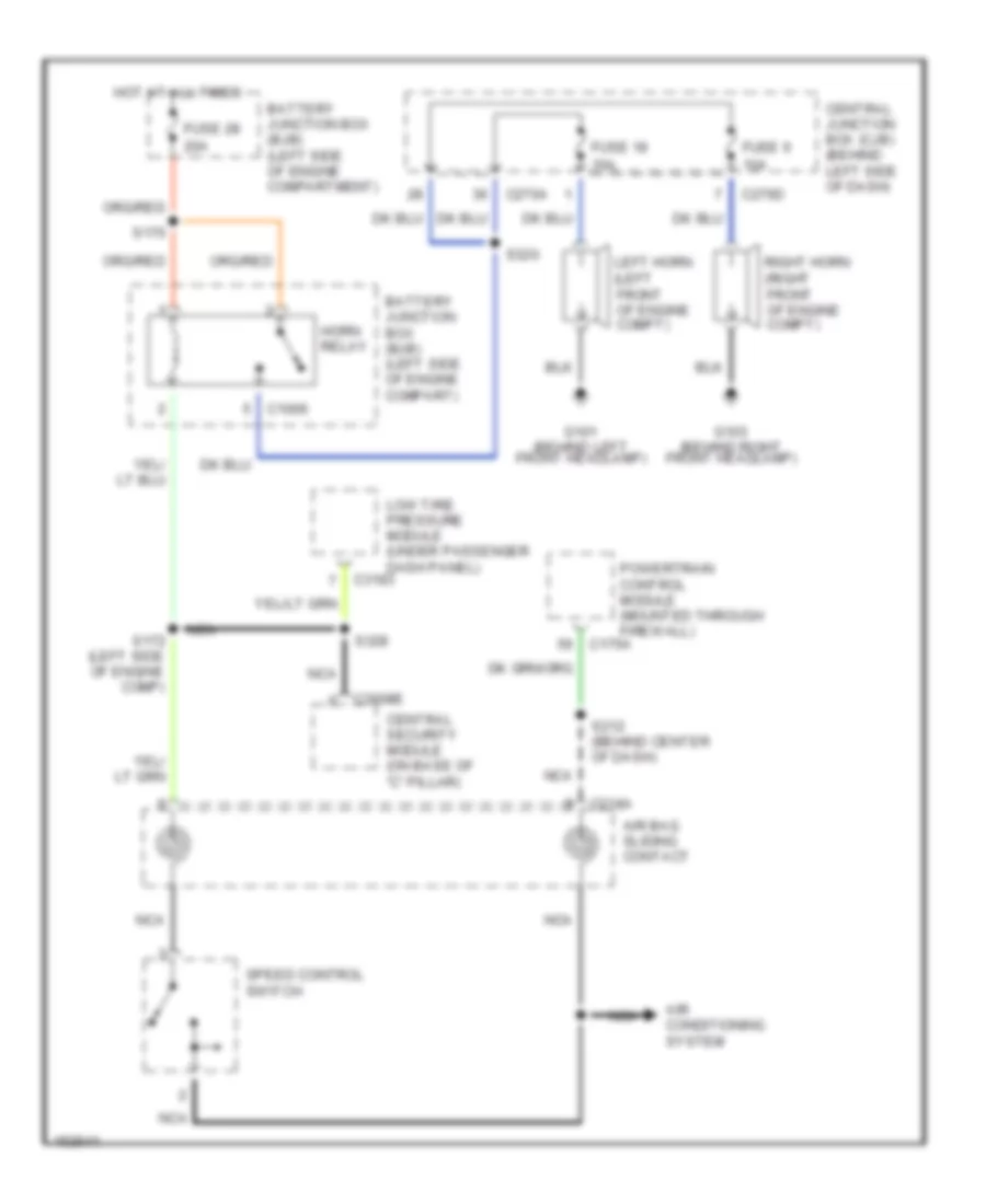
- Horn relay
- Horn switch
- Horns system
- Hot at all times
- Hot in accy or run
- Hot in start or run
- Joint conn- ector 3
- Key pad com
- Key pad illum
- Key pad out
- Key pad switch assembly
- Lamp pwr
- Left front door ajar switch
- Left horn
- Liftgate ajar
- Liftgate ajar switch
- Liftgate glass ajar switch
- Liftgate out
- Memory sw
- Memory systems
- Passen- ger side rear door ajar switch
- Pnk
- Power windows system
- Red
- Right front door ajar switch
- Right horn
- S209 (behind center dash panel)
- S347
- S407
- S502
- S503
- S602
- Tan
- Upb diag
- Vbatt
- Vpwr
Forced Entry Wiring Diagram, Late Production for Ford Explorer 2002
List of elements for Forced Entry Wiring Diagram, Late Production for Ford Explorer 2002:
- (left side of engine compt) s172
- (not used)
- (right "d" pillar)
- (right "d" pillar) g401
- 1/2
- 3/4
- 5/6
- 7/8
- 9/0
- Anti- theft hood switch
- Anti- theft inhibit switch
- Anti-theft sw
- Autolmp relay
- Autolmp sig autolmp relay
- Auxiliary junction box (on rear "d" pillar)
- Battery junction box (left side of engine compt, at fender apron)
- C220b
- C270a
- C270e
- C3008d
- C3008e
- C3008f
- Central junction box (behind left side of dash)
- Central security module (on base of right "c" pillar)
- Data link connector (dlc) (behind left side of dash)
- Disarm sw
- Door ajar sw
- Door lock
- Door locks system
- Door unlock
- Driver side rear door ajar switch
- Exterior lights system
- Fuse 10a
- Fuse 15a
- Fuse 20a
- Fuse 30a
- Fuse 5a
- G101 (behind left front headlamp)
- G103 (behind right front headlamp)
- G401
- G401 (right "d" pillar)
- Glass release
- Gnd
- Headlights system
- Horn relay
- Hot at all times
- Instrument cluster
- Joint conn- ector 3
- Key pad a
- Key pad b
- Key pad c
- Key pad com
- Key pad illum
- Key pad switch assembly
- Lamp pwr
- Left front door ajar switch
- Left horn
- Liftgate ajar
- Liftgate ajar switch
- Liftgate glass
- Liftgate glass ajar switch
- Passen- ger side rear door ajar switch
- Pnk
- Power windows system
- Red
- Right front door ajar switch
- Right horn
- S170
- S246 (behind center dash panel)
- S259
- S263
- S320 (under driver side dash panel)
- S407
- S502
- S503
- S602
- Switched pwr
- Tan
- Ubp diag
- Vbatt
- Vpwr
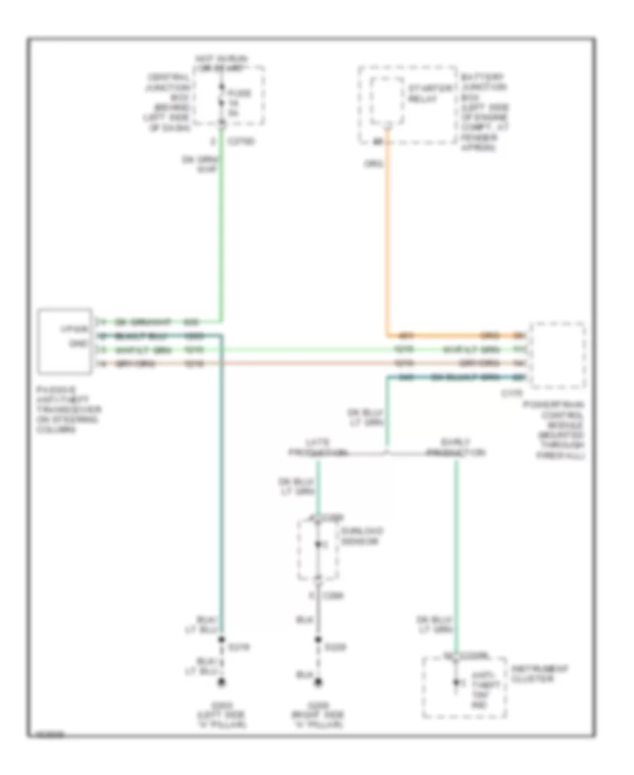
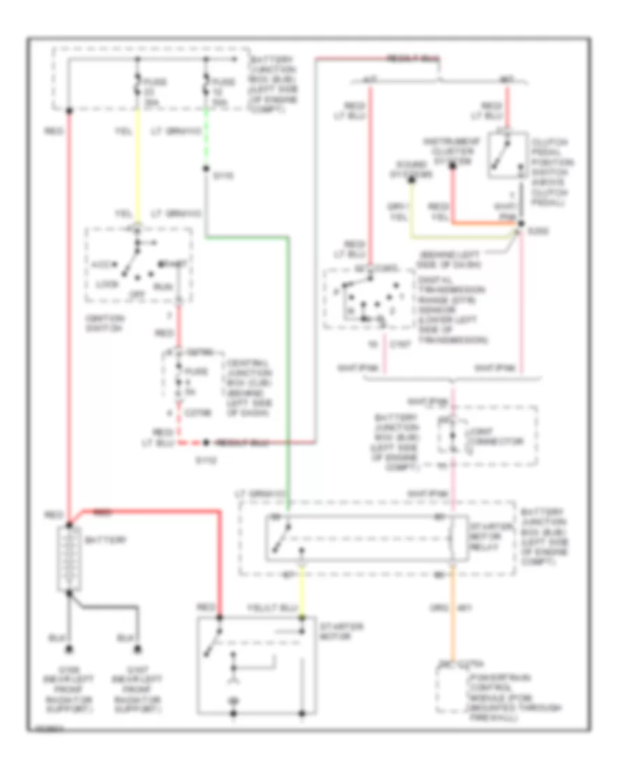
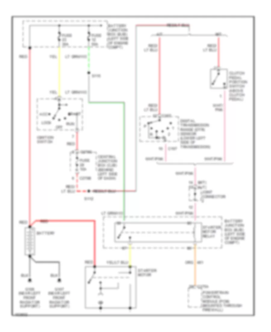
Passive Anti-theft Wiring Diagram for Ford Explorer 2002
List of elements for Passive Anti-theft Wiring Diagram for Ford Explorer 2002:
- Anti- theft "on" ind
- Battery junction box (left side of engine compt, at fender apron)
- C175
- C220b
- C270d
- C286
- Central junction box (behind left side of dash)
- Early production
- Fuse 5a
- G200 (right side "a" pillar)
- G300 (left side "a" pillar)
- Gnd
- Hot in run or start
- Instrument cluster
- Late production
- Passive anti-theft transceiver on steering column)
- Powertrain control module (mounted through firewall)
- S219
- S229
- Starter relay
- Sunload sensor
- Vpwr
BODY COMPUTER
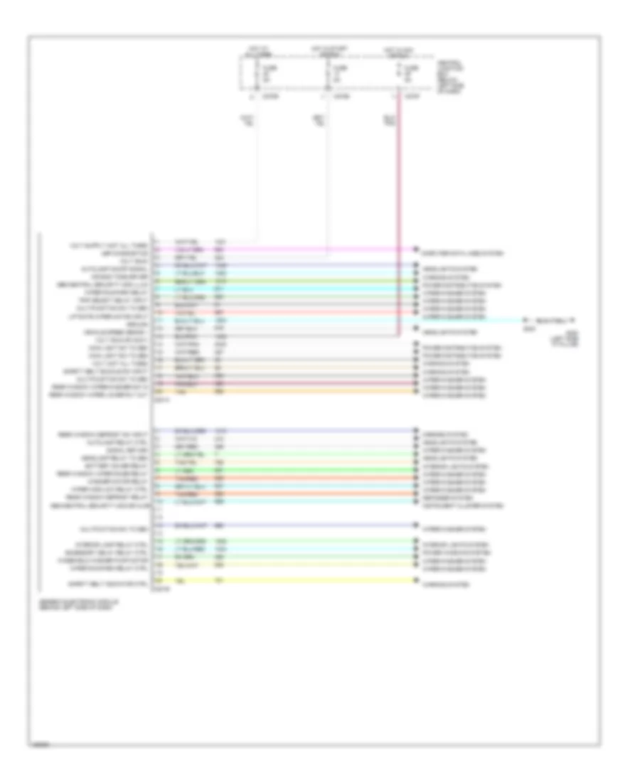
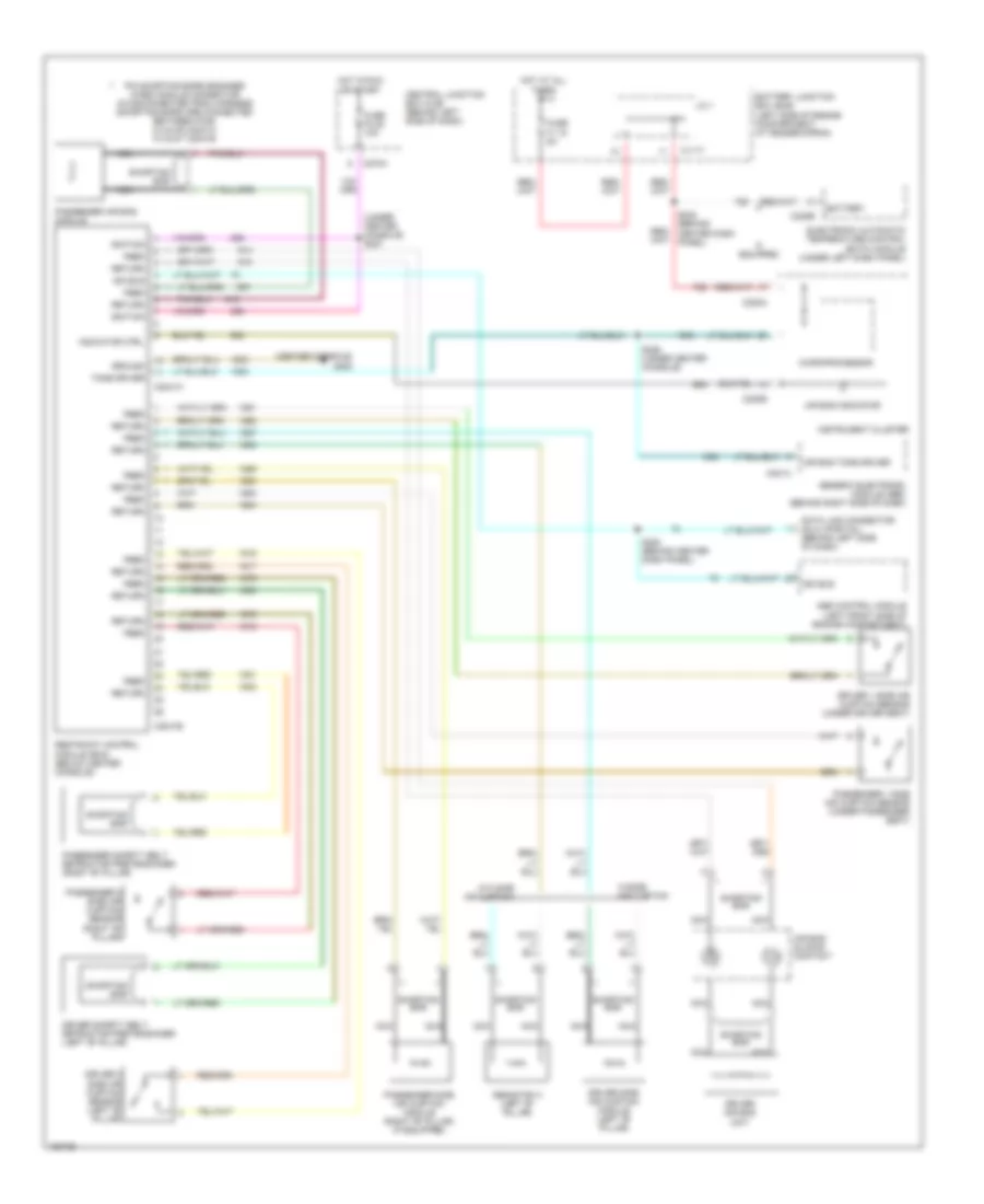
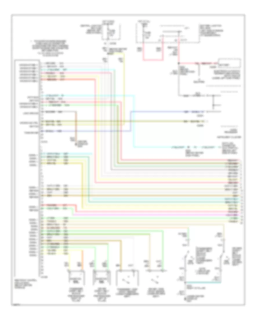
Body Computer Wiring Diagrams for Ford Explorer 2002
List of elements for Body Computer Wiring Diagrams for Ford Explorer 2002:
- Accessory delay relay ctrl
- Air bag tone driver
- Autolamp on/off signal
- Autolamp relay ctrl
- Battery saver relay
- C201a
- C201b
- C270e
- C270f
- Central junction box (below left side of dash)
- Computer data lines system
- Defogger system
- Fuse 5a
- G300 (left side "a" pillar)
- Gem/central security mod dr ajar
- Gem/central security mod illum
- Generic electronic module (behind left side of dash)
- Ground
- Headlamp relay to gem
- Headlights system
- Hot at all times
- Hot in acc or run
- Hot in start or run
- Instrument cluster system
- Interior lamp relay ctrl
- Interior lights system
- Liftgate wiper motor input
- Main light sw to gem
- Mirrors system
- Multifuction sw to gem
- Multifunction sw to gem
- Power distribution system
- Power windows system
- Rear window defrost relay
- Rear window defrost sw input
- Rear window wiper lower rly out
- Rear window wiper raise relay
- Rear window wiper/washer sw in
- S230
- Safety belt buckle sw input
- Safety belt indicator ctrl
- Signal return
- Tan
- Tan/red
- Trip select delay input
- Ubp diagnostics
- Vehicle speed senor +
- Volt (hot all times)
- Volt (run or accy)
- Volt (run)
- Warning system
- Washer motor relay
- Windshield washer pump motor
- Wiper high/low relay ctrl
- Wiper run/park relay
- Wiper run/park relay ctrl
- Wiper/washer system
COMPUTER DATA LINES
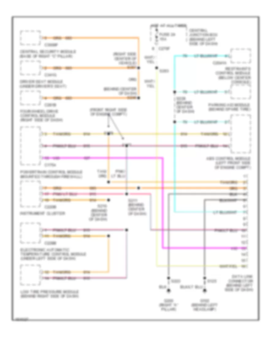
Computer Data Lines, Early Production for Ford Explorer 2002
List of elements for Computer Data Lines, Early Production for Ford Explorer 2002:
- Abs control module (left front side of engine compt)
- C175a
- C201a
- C2041a
- C220b
- C228b
- C270f
- C281a
- C3008c
- C341c
- Central junction box (behind left side of dash)
- Central security module (base of right "c" pillar)
- Data link connector (behind left side of dash)
- Driver seat module (under driver's seat)
- Electronic automatic temperature control module (under left side of dash)
- Four-wheel drive control module (right side of dash)
- Fuse 24 15a
- G102 (behind left headlamp)
- G200 (right "a" pillar)
- Generic electronic module (behind right side of dash)
- Hot at all times
- Instrument cluster
- Parking aid module (behind spare tire)
- Powertrain control module (pcm) (mounted through firewall)
- Restraints control module (below center console)
- S125
- S209 (behind center of dash)
- S210 (behind center of dash)
- S223
- S228 (behind center of dash)
- S245
- S325 (right side center of vehicle)
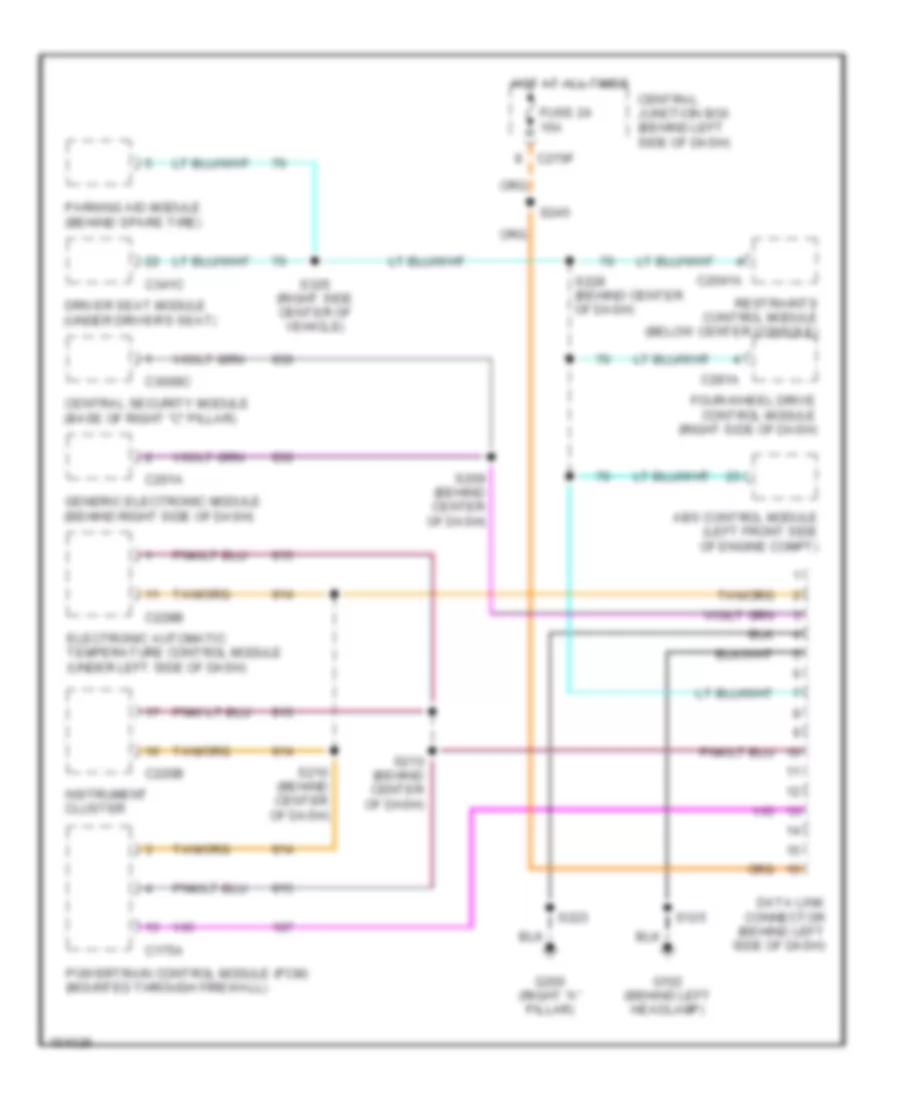
Computer Data Lines, Late Production for Ford Explorer 2002
List of elements for Computer Data Lines, Late Production for Ford Explorer 2002:
- (behind center of dash) s246
- (front right side of engine compt)
- (right side center of vehicle) s351
- Abs control module (left front side of engine compt)
- C175a
- C2041a
- C220b
- C228b
- C270f
- C281b
- C3008f
- C341g
- Central junction box (behind left side of dash)
- Central security module (base of right "c" pillar)
- Data link connector (behind left side of dash)
- Driver seat module (under driver's seat)
- Electronic automatic temperature control module (under left side of dash)
- Four-wheel drive control module (right side of dash)
- Fuse 24 15a
- G102 (behind left headlamp)
- G200 (right "a" pillar)
- Hot at all times
- Instrument cluster
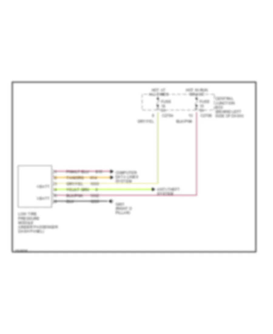
- Low tire pressure module (behind right side of dash)
- Parking aid module (behind spare tire)
- Powertrain control module (mounted through firewall)
- Restraints control module (below center console)
- S125
- S177
- S178
- S210 (behind center of dash)
- S211 (behind center of dash)
- S223
- S228 (behind center of dash)
- S263
CRUISE CONTROL
Cruise Control Wiring Diagram, Early Production for Ford Explorer 2002
List of elements for Cruise Control Wiring Diagram, Early Production for Ford Explorer 2002:
- (dtr) sensor
- 1k ohms
- Abs control module (left front side of engine compartment)
- Air bag sliding contact
- Auto clutch mode select switch (top of clutch pedal bracket)
- Automatic transmission
- Battery junction box (left side of engine compt, at fender apron
- Brake press sw in
- Brake pressure switch (mounted to master cylinder
- C122
- C135
- C175a
- C175b
- C220a
- C220b
- Cancel
- Central junction box (behind left side of dash)
- Computer data lines system
- Cruise crtl set ind
- Cruise ctrl set ind
- Digital transmission range (dtr) sensor (lower left side of automatic transmission)
- Fuse 15a
- Fuse 5a
- Horn switch
- Horns system
- Hot at all times
- Hot in run or start
- Instrument cluster
- Joint connector 1 (in battery junction box)
- Manual transmission
- Microprocessor
- Nca
- Off
- Ohms
- P r
- Pnk/
- Power
- Powertrain control module (mounted through firewall)
- Res
- S101 (vehicle underbody)
- S130
- S211 (behind center dash panel)
- S232
- Scp bus +
- Scp bus -
- Set +
- Set -
- Side of engine compt)
- Signal return
- Sound systems, air conditioning system (audio/climate control switch)
- Speed cntrl ind
- Speed cont sw rtn
- Speed control actuator (right front of engine compartment)
- Speed control switch
- Speed ctrl sw gnd
- Speed ctrl sw in
- Speed ctrl sw rtn
Cruise Control Wiring Diagram, Late Production with IVD for Ford Explorer 2002
List of elements for Cruise Control Wiring Diagram, Late Production with IVD for Ford Explorer 2002:
- (dtr) sensor
- (front right side of engine compt)
- 1k ohms
- Air bag sliding contact
- Auto clutch mode select switch (top of clutch pedal bracket)
- Automatic transmission
- Battery junction box (left side of engine compt, at fender apron
- Brake press sw in
- C122
- C175a
- C175b
- C220a
- C220b
- C270h
- Cancel
- Central junction box (behind left side of dash)
- Computer data lines system
- Cruise crtl set ind
- Cruise ctrl set ind
- Digital transmission range (dtr) sensor (lower left side of automatic transmission)
- Fuse 15a
- Fuse 5a
- Horn switch
- Horns system
- Hot at all times
- Hot in run or start
- Instrument cluster
- Joint connector 1
- Manual transmission
- Microprocessor
- Nca
- Off
- Ohms
- P r
- Pnk/
- Power
- Powertrain control module (mounted through firewall)
- Redundant pedal switch
- Res
- S101 (vehicle underbody)
- S127 (right front side of engine compt)
- S130
- S171
- S177
- S178
- S211 (behind center dash panel)
- Scp bus +
- Scp bus -
- Set +
- Set -
- Signal return
- Sound systems, air conditioning system (audio/climate control switch)
- Speed cntrl ind
- Speed cont sw rtn
- Speed control actuator (right front of engine compartment)
- Speed control switch
- Speed ctrl sw gnd
- Speed ctrl sw in
- Speed ctrl sw rtn
Cruise Control Wiring Diagram, Late Production without IVD for Ford Explorer 2002
List of elements for Cruise Control Wiring Diagram, Late Production without IVD for Ford Explorer 2002:
- (dtr) sensor
- (front right side of engine compt)
- 1k ohms
- Abs control module (left front side of engine compartment)
- Air bag sliding contact
- Auto clutch mode select switch (top of clutch pedal bracket)
- Automatic transmission
- Battery junction box (left side of engine compt, at fender apron
- Brake press sw in
- Brake pressure switch (mounted to master cylinder
- C122
- C155
- C175a
- C175b
- C220a
- C220b
- Cancel
- Central junction box (behind left side of dash)
- Computer data lines system
- Cruise crtl set ind
- Cruise ctrl set ind
- Digital transmission range (dtr) sensor (lower left side of automatic transmission)
- Fuse 15a
- Fuse 5a
- Horn switch
- Horns system
- Hot at all times
- Hot in run or start
- Instrument cluster
- Joint connector 1
- Manual transmission
- Microprocessor
- Nca
- Off
- Ohms
- P r
- Pnk/
- Power
- Powertrain control module (mounted through firewall)
- Res
- S101 (vehicle underbody)
- S130
- S177
- S178
- S211 (behind center dash panel)
- S232
- Scp bus +
- Scp bus -
- Set +
- Set -
- Side of engine compt)
- Signal return
- Sound systems, air conditioning system (audio/climate control switch)
- Speed cntrl ind
- Speed cont sw rtn
- Speed control actuator (right front of engine compartment)
- Speed control switch
- Speed ctrl sw gnd
- Speed ctrl sw in
- Speed ctrl sw rtn
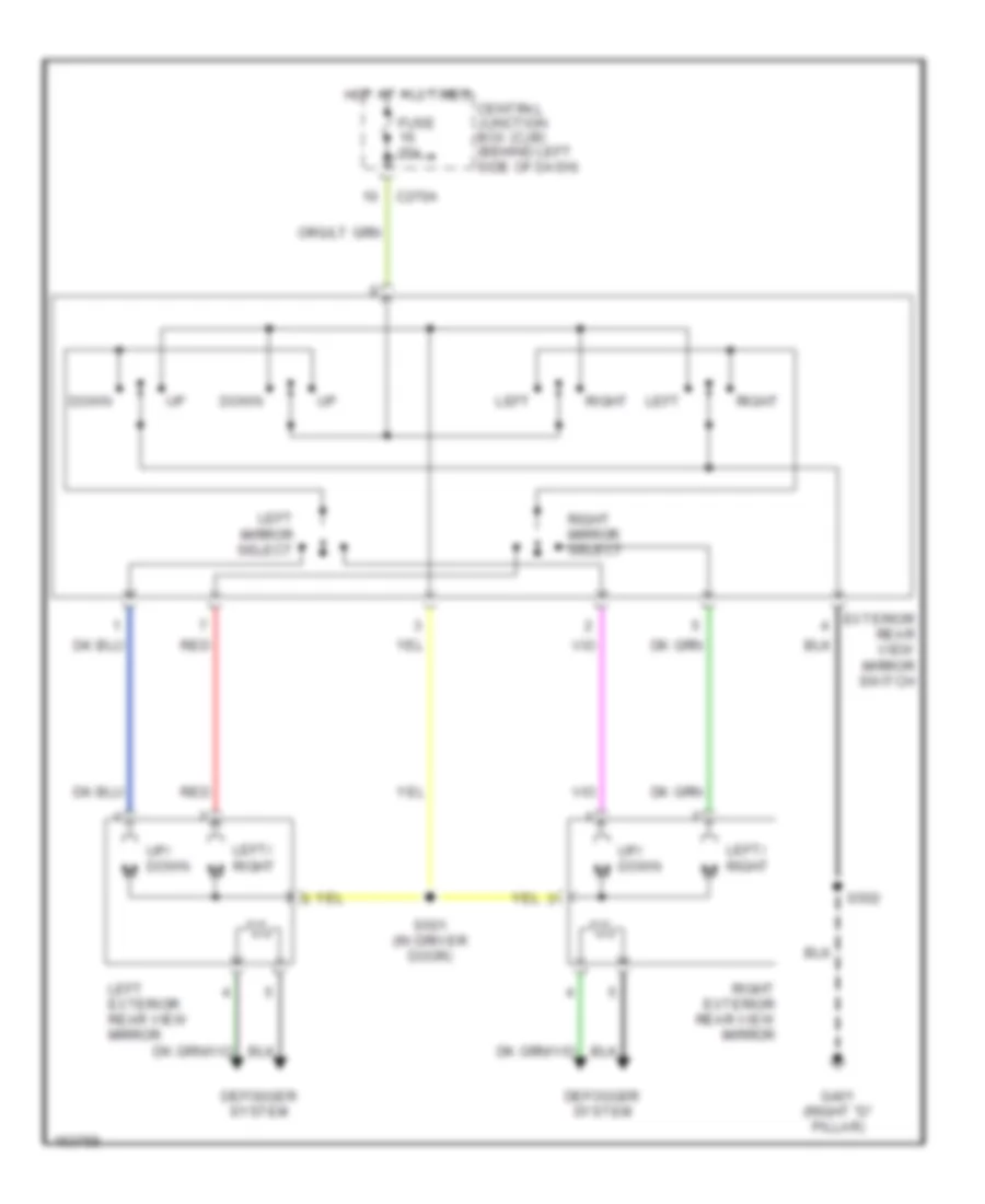
DEFOGGERS
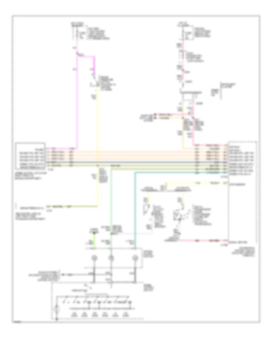
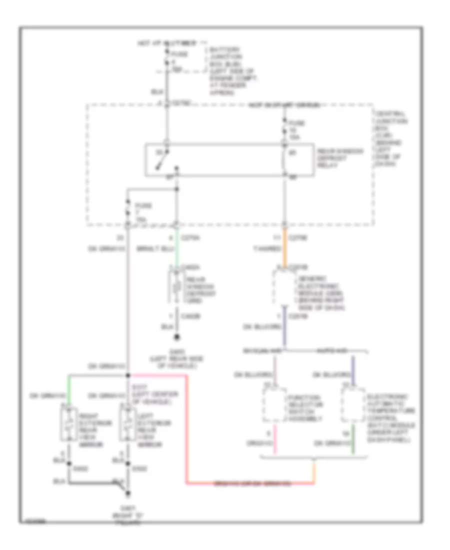
Defogger Wiring Diagram, Early Production for Ford Explorer 2002
List of elements for Defogger Wiring Diagram, Early Production for Ford Explorer 2002:
- Auto a/c
- Battery junction box (bjb) (left side of engine compt, at fender apron)
- C201b
- C270a
- C270c
- C270e
- C402a
- C402b
- Central junction box (cjb) (behind left side of dash)
- Electronic automatic temperature control (eatc) module (under left dash panel)
- Function selector switch assembly
- Fuse 10a
- Fuse 15a
- Fuse 30a
- G401 (right "d" pillar)
- G403 (left rear side of vehicle)
- Generic electronic module (gem) (behind right side of dash)
- Hot at all times
- Hot in start or run
- Left exterior rear view mirror
- Manual a/c
- Of vehicle)
- Rear window defrost grid
- Rear window defrost relay
- Right exterior rear view mirror
- S502
- S602
- Tan/red
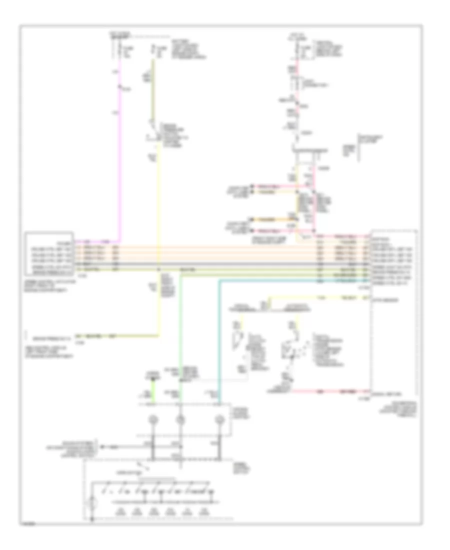
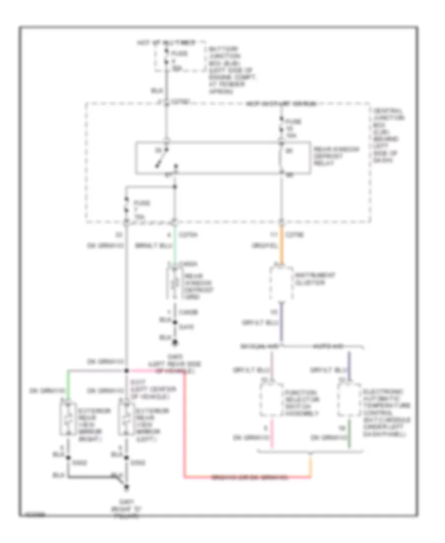
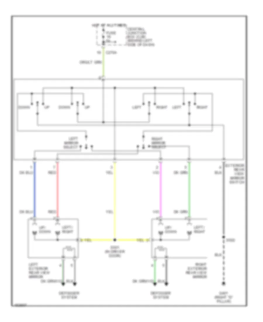
Defogger Wiring Diagram, Late Production for Ford Explorer 2002
List of elements for Defogger Wiring Diagram, Late Production for Ford Explorer 2002:
- Auto a/c
- Battery junction box (bjb) (left side of engine compt, at fender apron)
- C270a
- C270c
- C270e
- C402a
- C402b
- Central junction box (cjb) (behind left side of dash)
- Electronic automatic temperature control (eatc) module (under left dash panel)
- Exterior rear view mirror (left)
- Exterior rear view mirror (right)
- Function selector switch assembly
- Fuse 10a
- Fuse 15a
- Fuse 30a
- G401 (right "d" pillar)
- G403 (left rear side of vehicle)
- Hot at all times
- Hot in start or run
- Instrument cluster
- Manual a/c
- Of vehicle)
- Rear window defrost grid
- Rear window defrost relay
- S415
- S502
- S602
ENGINE PERFORMANCE
4.0L
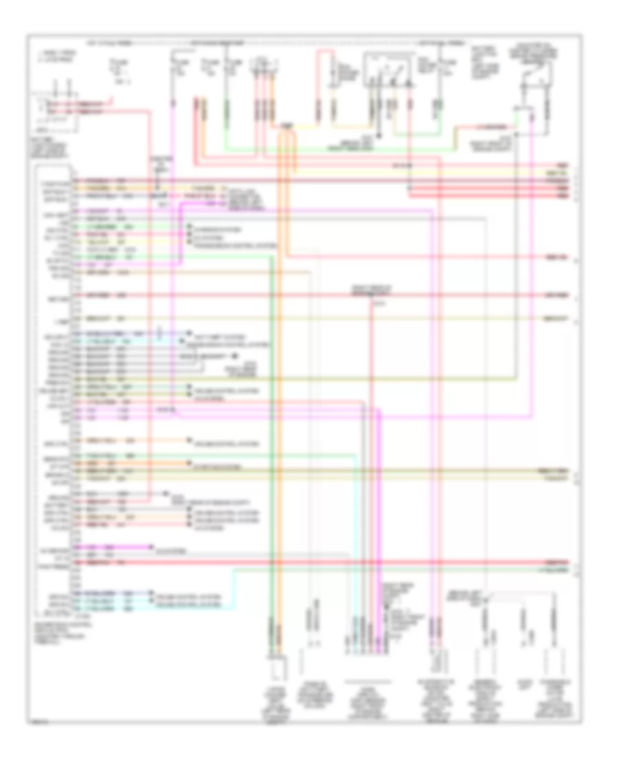
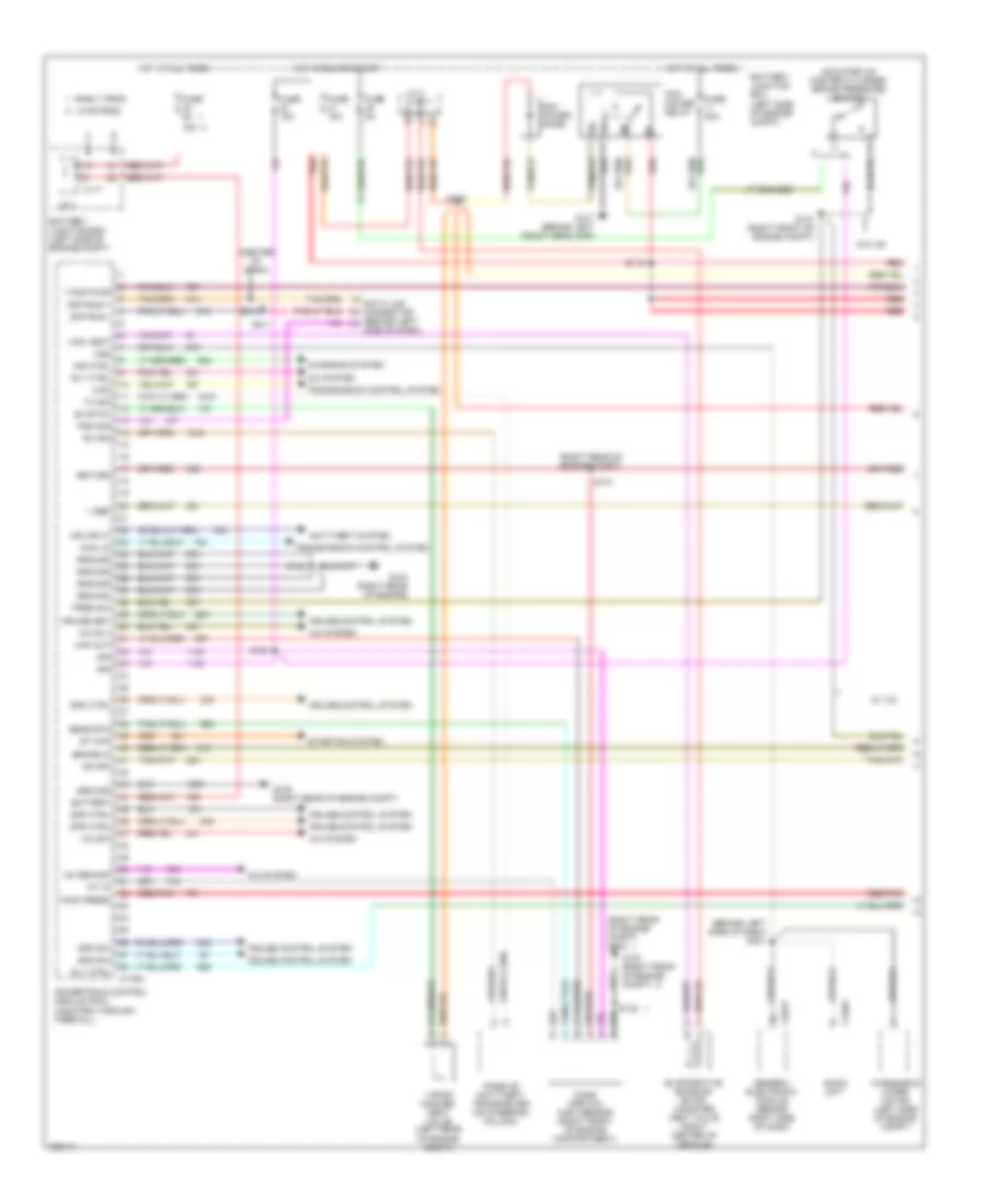
4.0L, Engine Performance Wiring Diagrams (1 of 4) for Ford Explorer 2002
List of elements for 4.0L, Engine Performance Wiring Diagrams (1 of 4) for Ford Explorer 2002:
- (behind left side of dash) s231
- (center of dash)
- (mounted on master cylinder) brake pressure switch
- (right rear of engine compt)
- (right rear of engine compt) g104
- 15a
- 4wd
- 4wd lo
- A/c rly
- A/c sw
- A/c system
- Ac demand
- Anti-theft system
- Audio unit
- Battery
- Battery junction box (left side of engine compt)
- Brake in
- C1117
- C175a
- C201a
- C240a
- Can vent
- Charging system
- Cruise control system
- Cruise set
- Data link connector (behind left side of dash)
- Early prod
- Evap pu
- Evaporative emission (evap) canister vent valve (right center of vehicle)
- F pmp pwr
- Fuse 15a
- Fuse 40a
- Fuse 5a
- G101 (behind left front headlamp)
- G103 (right front of engine compt)
- G104 (right rear of engine)
- G105 (right rear of engine compt)
- Generic electronic module (early production) (behind right side of dash)
- Ground
- Hot at all times
- Hot in run or start
- Iat in
- Ign
- Ind ctrl
- Ind input
- J/c 1
- J/c 2
- Late prod
- Maf out
- Mass airflow (maf) sensor (right front of engine compartment)
- Od off
- Passive anti-theft transceiver (on steering column)
- Pcm power diode
- Pcm power relay
- Pgm sig
- Powertrain control module (pcm) (mounted through firewall)
- Pres sw
- Red
- Red/pnk
- Return
- Rly ctrl
- Rx sig
- S116
- S127 (right front of engine compt)
- S129
- S130
- S131
- S132
- S135
- S210
- S211
- Scp bus +
- Scp bus -
- Sens rtn
- Spd ctrl
- Spd sw
- St mtr
- Starting system
- Tank press
- Transmission control system
- Tx sig
- V ref
- Vapor manage- ment valve (left rear of engine compt)
- Vss
- Windshield wiper motor (late production) (left side of engine compt)
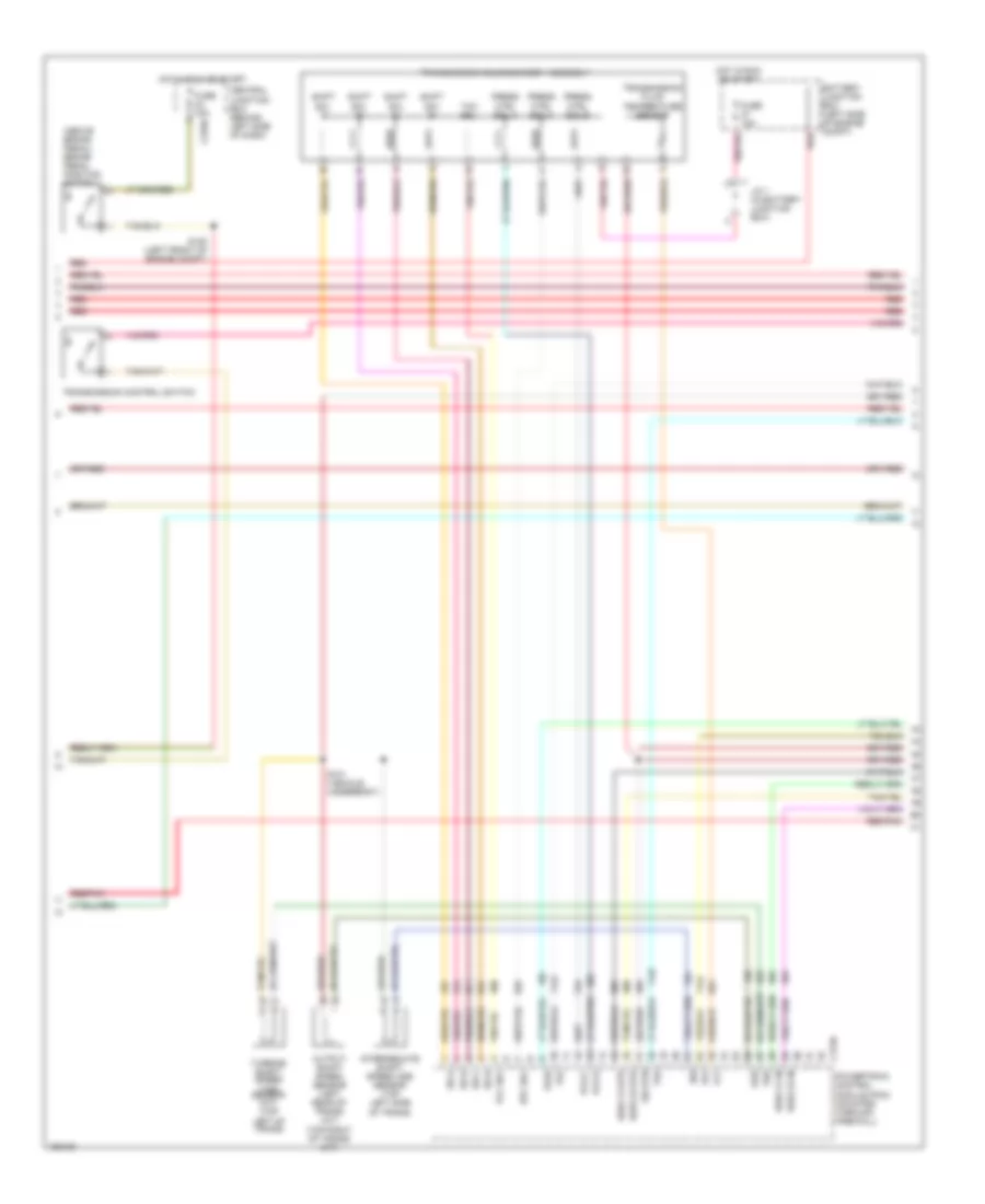
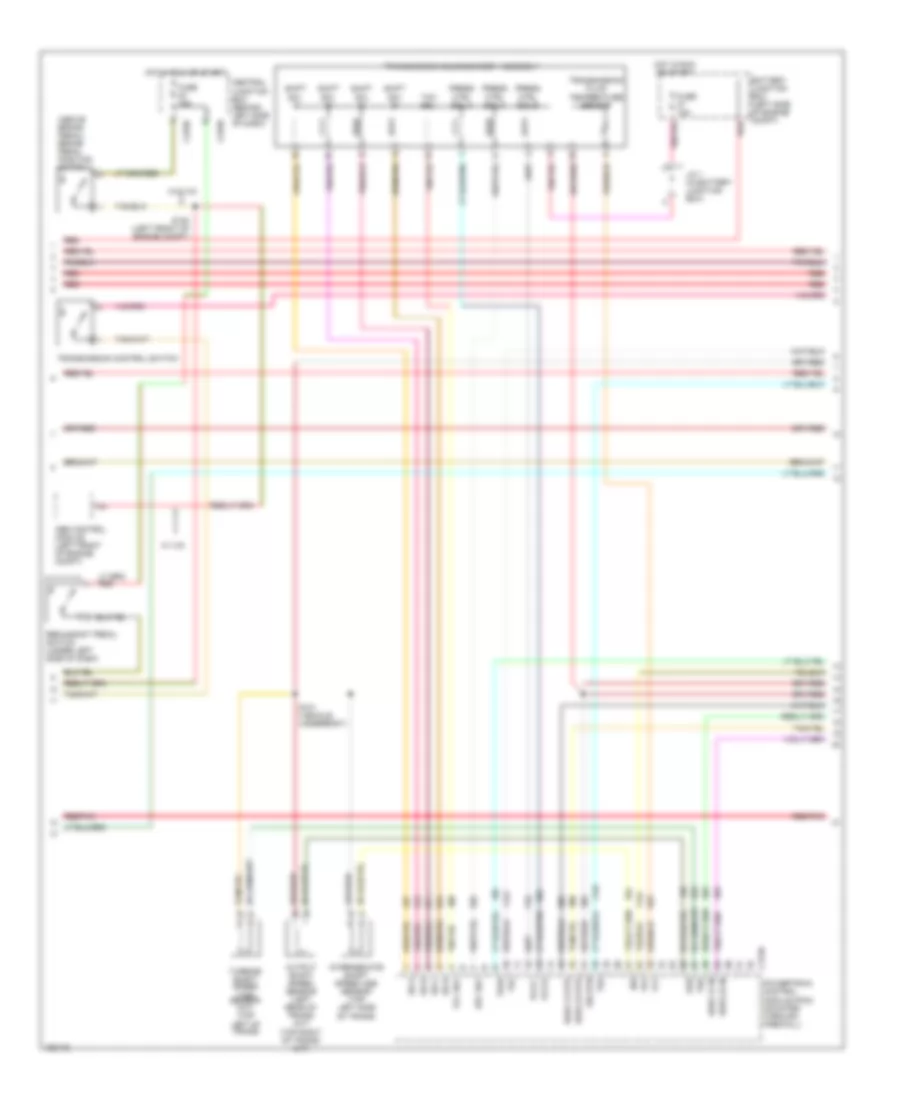
4.0L, Engine Performance Wiring Diagrams (2 of 4) for Ford Explorer 2002
List of elements for 4.0L, Engine Performance Wiring Diagrams (2 of 4) for Ford Explorer 2002:
- (above brake pedal) brake pedal position switch
- Battery junction box (left side of engine compt)
- C175b
- C270d
- Central junction box (behind left side of dash)
- Epc sol
- Fuse 15a
- H2os 12 htr
- H2os 12 in
- H2os 22 htr
- H2os 22 in
- Hot in run or start
- Intermediate shaft speed (iss) sensor (top left side of trans)
- Iss
- J/c 1 (in battery junction box)
- Oss
- Output shaft speed sensor (left rear of trans) (a/t) (top right of trans) (m/t)
- Pcs b
- Pcs c
- Powertrain control module (pcm) (mounted through firewall)
- Press ctrl sol a
- Press ctrl sol b
- Press ctrl sol c
- Red
- Red/pnk
- S101 (vehicle underbody)
- S120 (left front of engine compt)
- Shift sol a
- Shift sol b
- Shift sol c
- Shift sol d
- Sig rtn
- Ss a
- Ss b
- Ss c
- Ss d
- Tcc sol
- Tft
- Tr1
- Tr2
- Tr3a
- Tr4
- Transmission control switch
- Transmission fluid temperature sensor
- Transmission solenoid body assembly
- Tss
- Turbine shaft speed (tss) sensor (a/t) (top left of trans)
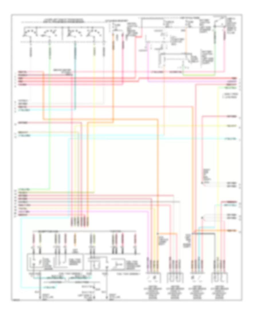
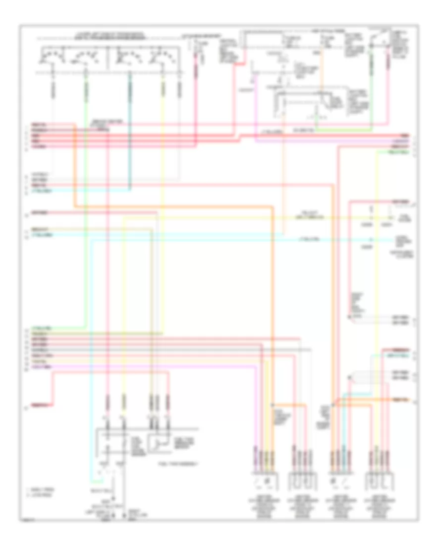
4.0L, Engine Performance Wiring Diagrams (3 of 4) for Ford Explorer 2002
List of elements for 4.0L, Engine Performance Wiring Diagrams (3 of 4) for Ford Explorer 2002:
- (behind center of dash) s208
- (left side "a" pillar) g300
- (lower left side of transmission) digital transmission range sensor
- (not used)
- (right "d" pillar) g401
- (right side of eng compt)
- Battery junction box (left side of engine compt)
- C270a
- Central junction box (behind left side of dash) c270f
- Early prod
- Except flex fuel
- Flex fuel
- Fuel pump relay
- Fuel pump/ fuel gauge sender
- Fuel tank assembly
- Fuel tank pressure sensor
- Fuel tank pressure transducer sensor
- Fuse 15a
- Fuse 46 15a 30a
- Fuse 5a
- Heated oxygen sensor (ho2s) 11 (on exhaust, pipe of engine)
- Heated oxygen sensor (ho2s) 12 (on exhaust, pipe of engine)
- Heated oxygen sensor (ho2s) 21 (on exhaust, pipe of engine)
- Heated oxygen sensor (ho2s) 22 (on exhaust, pipe of engine)
- Hot at all times
- Hot in run or start
- Inertia fuel shutoff switch (base of right "a" pillar)
- J/c 1 (in battery junction box)
- Late prod
- N r
- Nca
- Red
- Red/pnk
- S100 (vehicle under- body)
- S102
- S103 (left side of engine compt)
- S230
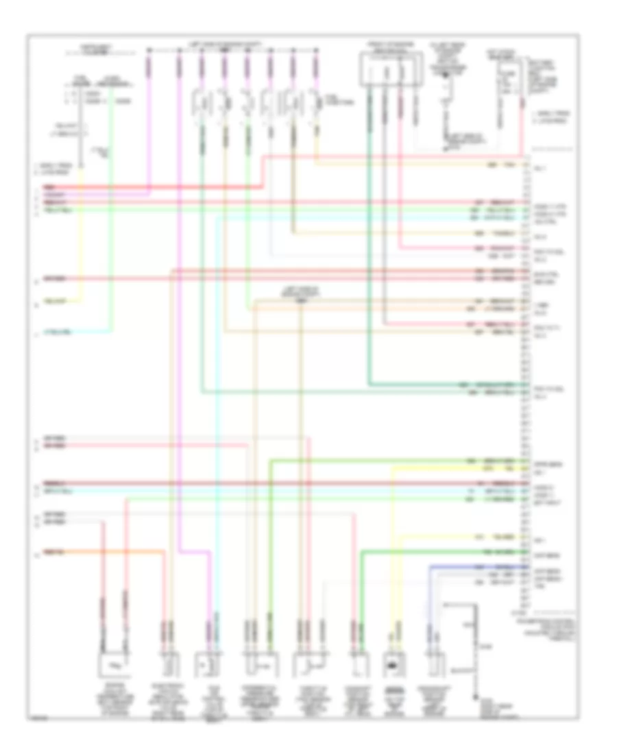
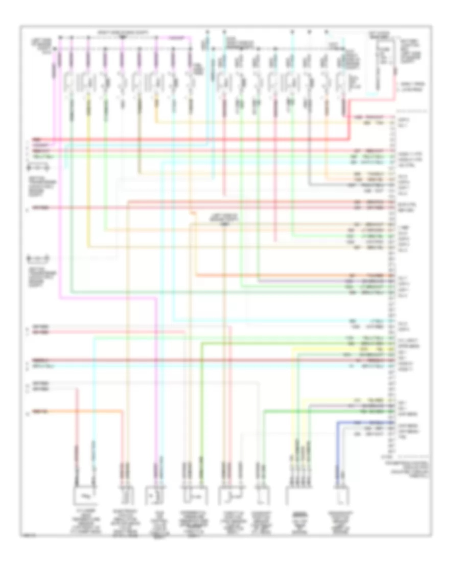
4.0L, Engine Performance Wiring Diagrams (4 of 4) for Ford Explorer 2002
List of elements for 4.0L, Engine Performance Wiring Diagrams (4 of 4) for Ford Explorer 2002:
- (front of engine) ignition coil
- (in left rear of engine compt) ignition transformer capacitor
- (left side of engine compt) s104
- (left side of engine compt) s105
- (left side of engine compt) s134
- (on top rear of engine)
- 25a
- Battery junction box (left side of engine compt)
- C175c
- C220a
- C220b
- Camshaft position sensor (top front of left cyl head)
- Ckp sens +
- Ckp sens -
- Cmp sens
- Crankshaft position sensor (left front of engine)
- Dfpe sens
- Differential pressure feedback egr (dfpe) sensor (top of throttle body)
- Early prod
- Ect input
- Electronic vacuum regulator (evr) solenoid valve (right rear of cyl head)
- Engine coolant temperature (ect) sensor (top right of engine)
- Evr ctrl
- Fuel gauge
- Fuel injectors
- Fuse 15a
- G105 (right rear side of engine compt)
- Ho2s 11
- Ho2s 11 htr
- Ho2s 21
- Ho2s 21 htr
- Hot in run or start
- Iac ctrl
- Idle air control valve (top of throttle body)
- Inj 1
- Inj 2
- Inj 3
- Inj 4
- Inj 5
- Inj 6
- Instrument cluster
- Knock sensor
- Ks 1
- Late prod
- Micro- processor
- Nca
- Pcm to coil
- Pcm to t1
- Powertrain control module (pcm) (mounted through firewall)
- Red
- Return
- S106
- Tan
- Throttle position (tps) sensor (top of throttle body)
- Tps
- V ref
4.6L
4.6L, Engine Performance Wiring Diagrams (1 of 4) for Ford Explorer 2002
List of elements for 4.6L, Engine Performance Wiring Diagrams (1 of 4) for Ford Explorer 2002:
- (behind left side of dash) s231
- (center of dash)
- (mounted on master cylinder) brake pressure switch
- (right rear of engine compt)
- (right rear of engine compt) g104
- 15a
- 4wd
- 4wd lo
- A/c rly
- A/c sw
- A/c system
- Ac demand
- Anti-theft system
- Audio unit
- Battery
- Battery junction box (left side of engine compt)
- Brake in
- C117
- C175a
- C201a
- C240a
- Can vent
- Charging system
- Cruise control system
- Cruise set
- Data link connector (behind left side of dash)
- Early prod
- Evap pu
- Evaporative emission (evap) canister vent valve (right center of vehicle)
- F pmp pwr
- Fuse 15a
- Fuse 40a
- Fuse 5a
- G101 (behind left front headlamp)
- G103 (right front of engine compt)
- G104 (right rear of engine)
- G105 (right rear of engine compt)
- Generic electronic module (behind right side of dash)
- Ground
- Hot at all times
- Hot in run or start
- Iat in
- Ign
- Ind ctrl
- Ind input
- J/c 1
- J/c 2
- Late prod
- Maf out
- Mass airflow (maf) sensor (right front of engine compartment)
- Od off
- Passive anti-theft transceiver (on steering column)
- Pcm power diode
- Pcm power relay
- Pgm sig
- Powertrain control module (pcm) (mounted through firewall)
- Pres sw
- Red
- Red/pnk
- Return
- Rly ctrl
- Rx sig
- S116
- S127 (right front of engine compt)
- S129
- S130
- S131
- S132
- S135
- S210
- S211
- Scp bus +
- Scp bus -
- Sens rtn
- Spd ctrl
- Spd sw
- St mtr
- Starting system
- Tank press
- Transmission control system
- Tx sig
- V ref
- Vapor manage- ment valve (left rear of engine compt)
- Vss
- W/ ivd
- W/o ivd
- Windshield wiper motor (left side of engine compt)
4.6L, Engine Performance Wiring Diagrams (2 of 4) for Ford Explorer 2002
List of elements for 4.6L, Engine Performance Wiring Diagrams (2 of 4) for Ford Explorer 2002:
- (above brake pedal) brake pedal position switch
- Abs control module (left front of engine compt)
- Battery junction box (left side of engine compt)
- C175b
- C270d
- C270h
- Central junction box (behind left side of dash)
- Epc sol
- Fuse 15a
- H2os 12 htr
- H2os 12 in
- H2os 22 htr
- H2os 22 in
- Hot in run or start
- Intermediate shaft speed (iss) sensor (top left side of trans)
- Iss
- J/c 1 (in battery junction box)
- Oss
- Output shaft speed sensor (left rear of trans) (a/t) (top right of trans) (m/t)
- Pcs b
- Pcs c
- Powertrain control module (pcm) (mounted through firewall)
- Press ctrl sol a
- Press ctrl sol b
- Press ctrl sol c
- Red
- Red/pnk
- Redundant pedal switch (under left side of dash)
- S101 (vehicle underbody)
- S120 (left front of engine compt)
- Shift sol a
- Shift sol b
- Shift sol c
- Shift sol d
- Sig rtn
- Ss a
- Ss b
- Ss c
- Ss d
- Tcc sol
- Tft
- Tr1
- Tr2
- Tr3a
- Tr4
- Transmission control switch
- Transmission fluid temperature sensor
- Transmission solenoid body assembly
- Tss
- Turbine shaft speed (tss) sensor (a/t) (top left of trans)
- W/ ivd
- W/o ivd
4.6L, Engine Performance Wiring Diagrams (3 of 4) for Ford Explorer 2002
List of elements for 4.6L, Engine Performance Wiring Diagrams (3 of 4) for Ford Explorer 2002:
- (behind center
- (left side "a" pillar) g300
- (lower left side of transmission) digital transmission range sensor
- (right "d" pillar) g401
- (right side of eng compt)
- Battery junction box (left side of engine compt)
- C220a
- C220b
- C270f
- Central junction box (behind left side of dash)
- Early prod
- Fuel gauge
- Fuel pump relay
- Fuel pump/ fuel gauge sender
- Fuel tank assembly
- Fuel tank pressure sensor
- Fuse 15a
- Fuse 46 15a 30a
- Fuse 5a
- Heated oxygen sensor (ho2s) 11 (on exhaust, pipe of engine)
- Heated oxygen sensor (ho2s) 12 (on exhaust, pipe of engine)
- Heated oxygen sensor (ho2s) 21 (on exhaust, pipe of engine)
- Heated oxygen sensor (ho2s) 22 (on exhaust, pipe of engine)
- Hot at all times
- Hot in run or start
- Inertia fuel shutoff switch (base of right "a" pillar)
- Instrument cluster
- J/c 1 (in battery junction box)
- Late prod
- Micro- proces- sor
- N r
- Nca
- Of dash) s208
- Red
- Red/pnk
- S100 (vehicle under- body)
- S102
- S103 (left side of engine compt)
- S230
4.6L, Engine Performance Wiring Diagrams (4 of 4) for Ford Explorer 2002
List of elements for 4.6L, Engine Performance Wiring Diagrams (4 of 4) for Ford Explorer 2002:
- (left side of engine compt) s104
- (left side of engine compt) s105
- (on top rear of engine)
- (right side of eng compt) s108
- Battery junction box (left side of engine compt)
- C175c
- Camshaft position sensor (top front of left cyl head)
- Ckp sens +
- Ckp sens -
- Cmp sens
- Coil on plug
- Cop 1
- Cop 2
- Cop 3
- Cop 4
- Cop 5
- Cop 6
- Cop 7
- Cop 8
- Crankshaft position sensor (left front of engine)
- Cyl input
- Cylinder head temperature sensor (top front of cylinder head)
- Dfpe sens
- Differential pressure feedback egr (dfpe) sensor (top of throttle body)
- Early prod
- Electronic vacuum regulator (evr) solenoid valve (right rear of cyl head)
- Evr ctrl
- Fuel injec- tors
- Fuse 15a 25a
- Ho2s 11
- Ho2s 11 htr
- Ho2s 21
- Ho2s 21 htr
- Hot in run or start
- Iac ctrl
- Idle air control valve (top of throttle body)
- Ignition transformer capacitor 2 (engine compt)
- Inj 1
- Inj 2
- Inj 3
- Inj 4
- Inj 5
- Inj 6
- Inj 7
- Inj 8
- Knock sensor
- Ks 1
- Late prod
- Nca
- Powertrain control module (pcm) (mounted through firewall)
- Red
- Return
- S109 (right side of engine compt)
- Tan
- Tan/red
- Throttle position (tps) sensor (top of throttle body)
- Tps
- V ref
EXTERIOR LIGHTS
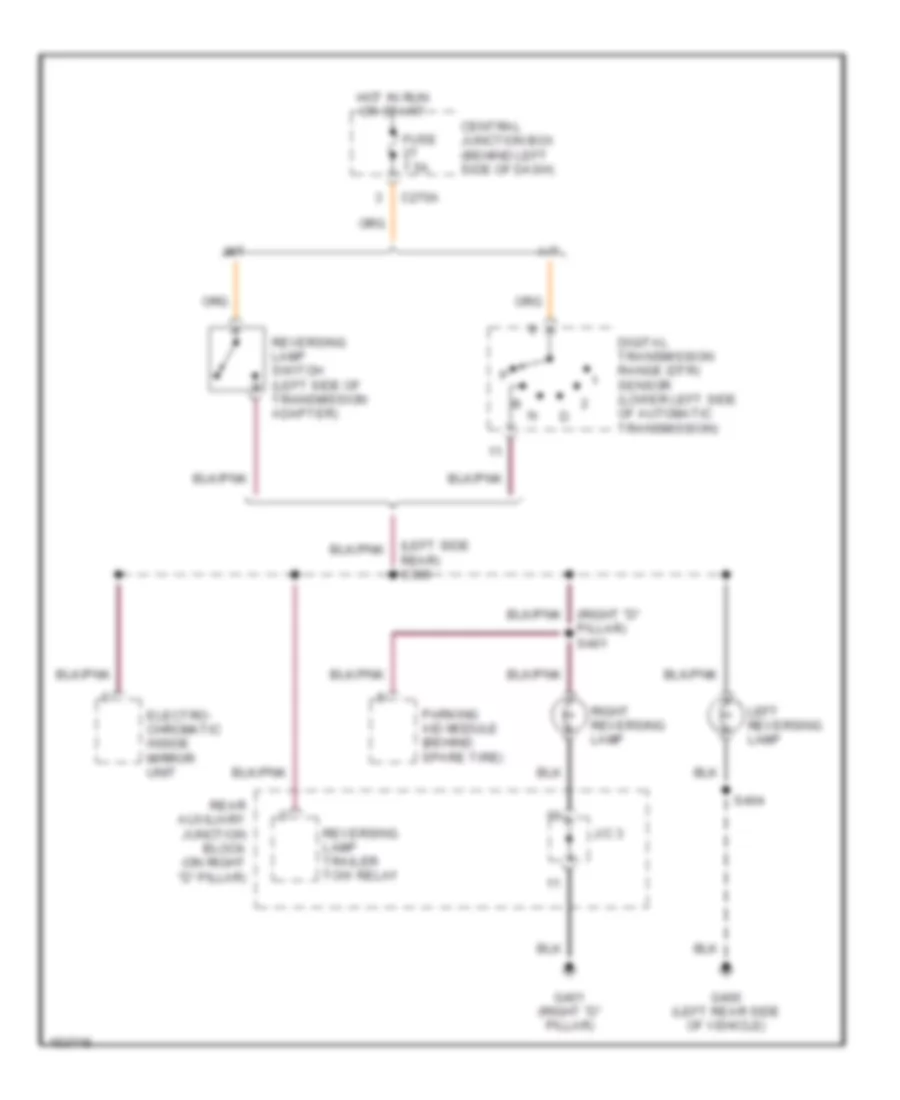
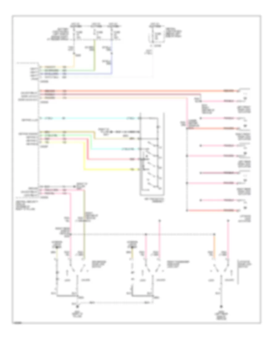
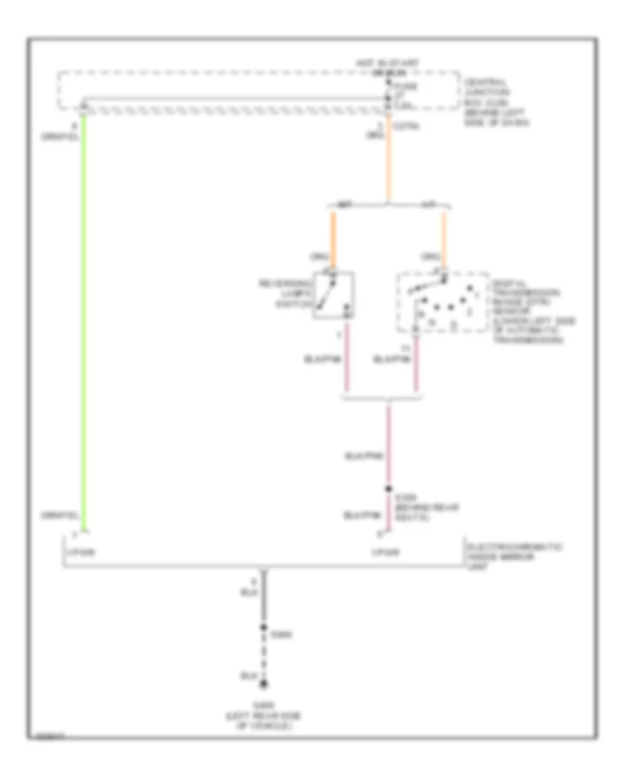
Back-up Lamps Wiring Diagram for Ford Explorer 2002
List of elements for Back-up Lamps Wiring Diagram for Ford Explorer 2002:
- (left side rear) s309
- (right "d" pillar) s401
- A/t
- C270a
- Central junction box (behind left side of dash)
- Digital transmission range (dtr) sensor (lower left side of automatic transmission)
- Electro- chromatic inside mirror unit
- Fuse 7.5a
- G400 (left rear side of vehicle)
- G401 (right "d" pillar)
- Hot in run or start
- J/c 3
- Left reversing lamp
- M/t
- Parking aid module (behind spare tire)
- Rear auxiliary junction block (on right "d" pillar)
- Reversing lamp switch (left side of transmission adapter)
- Reversing lamp trailer tow relay
- Right reversing lamp
- S404
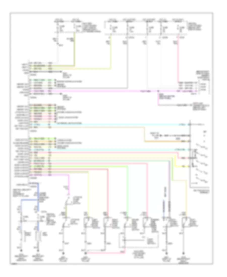
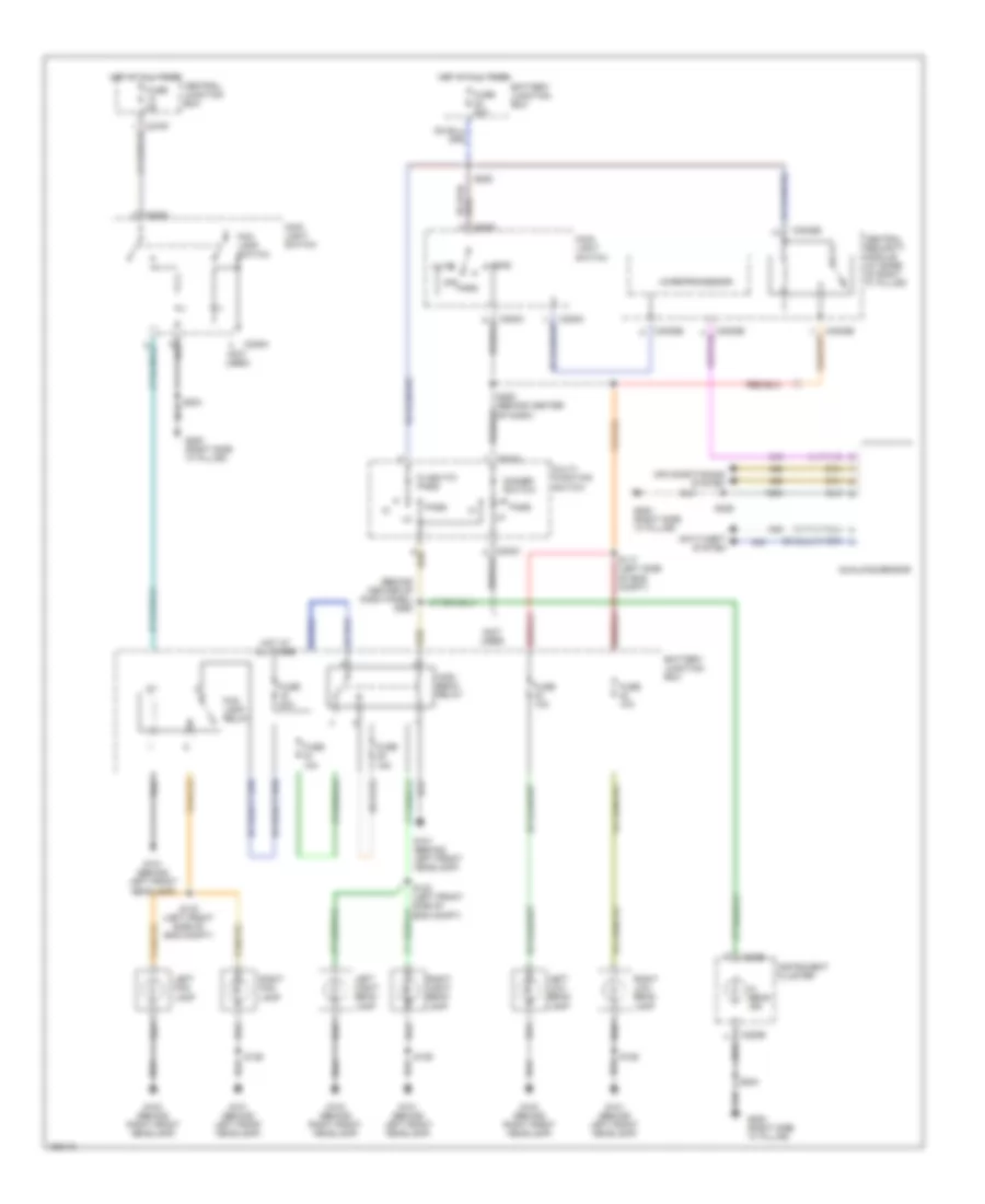
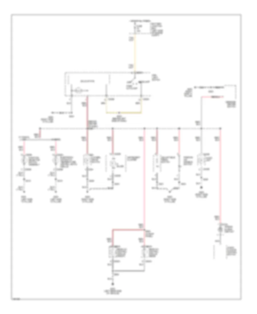
Exterior Lamps Wiring Diagram, Early Production for Ford Explorer 2002
List of elements for Exterior Lamps Wiring Diagram, Early Production for Ford Explorer 2002:
- (behind center of dash)
- (behind center of dash) s250
- (behind center of dash) s251
- (front left side of engine compt) s122
- (not used)
- (on right "d" pillar) rear auxiliary junction box
- (right "d" pillar) s307
- Battery junction box (left side of engine compt)
- Brake pedal position switch (above brake pedal)
- C202b
- C205a
- C220b
- C270a
- C270d
- C3008a
- C3008c
- Center of dash)
- Central junction box (behind left side of dash)
- Central security module (base of right "c" pillar)
- Driver side door lock switch
- Fuse 15a
- Fuse 5a
- G101 (behind left front headlamp)
- G103 (behind right front headlamp)
- G200 (right "a" pillar)
- G400 (left rear side of vehicle)
- G400 (left side rear)
- G401 (right "d" pillar)
- Hazard
- Head
- High mounted stoplamp
- Hot at all times
- Hot in run or star
- Indicator flasher relay
- Instrument cluster
- J/c
- Left front park/ turn lamp
- Left license plate lamp
- Left rear park/ stop/ turn lamp
- Left turn indicator
- Liftgate door lock switch
- Main light switch
- Multifunction switch
- Nca
- Normal
- Off
- Park
- Parking lamp trailer tow relay
- Passenger side front door lock unit
- Rear auxiliary junction box (on right "d" pillar)
- Right front park/ turn lamp
- Right license plate lamp
- Right rear park/ stop/ turn lamp
- Right turn indicator
- S204
- S220 (behind center of dash)
- S311 (left side center of vehicle)
- S407
- S502
- S602
- Trailer/ camper adapter circuit (left/right turn trailer tow relays)
- Turn left
- Turn right
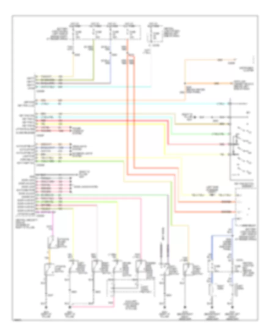
Exterior Lamps Wiring Diagram, Late Production with IVD for Ford Explorer 2002
List of elements for Exterior Lamps Wiring Diagram, Late Production with IVD for Ford Explorer 2002:
- (behind center of dash)
- (behind center of dash) s250
- (behind center of dash) s251
- (front left side of engine compt) s122
- (left side of dash) s203
- (on right "d" pillar) rear auxiliary junction box
- (right "d" pillar) s307
- Abs control module (left front side of engine compt)
- Battery junction box (left side of engine compt)
- Brake pedal position switch (above brake pedal)
- Brake pedal relay
- C202b
- C205a
- C220a
- C220b
- C270a
- C270d
- C270h
- C3008e
- Center of dash)
- Central junction box (behind left side of dash)
- Central security module (base of right "c" pillar)
- Fuse 15a
- Fuse 5a
- G101 (behind left front headlamp)
- G103 (behind right front headlamp)
- G200 (right "a" pillar)
- G400 (left rear side of vehicle)
- G400 (left side rear)
- G401 (right "d" pillar)
- Hazard
- Head
- High mounted stoplamp
- Hot at all times
- Hot in run or star
- Indicator flasher relay
- Instrument cluster
- Ivd stop lamp relay
- J/c
- Left front park/ turn lamp
- Left license plate lamp
- Left rear park/ stop/ turn lamp
- Left turn indicator
- Main light switch
- Multifunction switch
- Nca
- Normal
- Off
- Park
- Parking lamp trailer tow relay
- Rear auxiliary junction box (on right "d" pillar)
- Right front park/ turn lamp
- Right license plate lamp
- Right rear park/ stop/ turn lamp
- Right turn indicator
- S171
- S179 (front right side of engine compt)
- S204
- S259
- S407
- Trailer/ camper adapter circuit (left/right turn trailer tow relays)
- Turn left
- Turn right
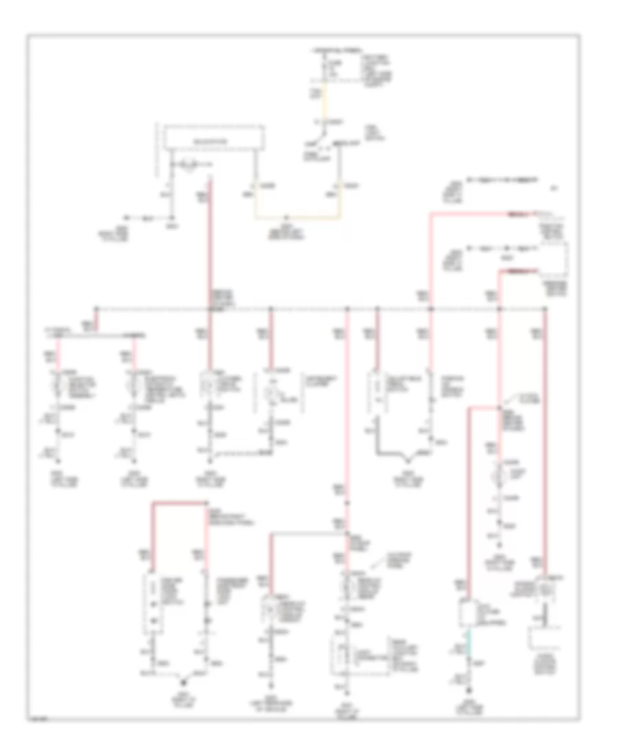
Exterior Lamps Wiring Diagram, Late Production without IVD for Ford Explorer 2002
List of elements for Exterior Lamps Wiring Diagram, Late Production without IVD for Ford Explorer 2002:
- (behind center of dash)
- (behind center of dash) s250
- (behind center of dash) s251
- (front left side of engine compt) s122
- (on right "d" pillar) rear auxiliary junction box
- (right "d" pillar) s307
- Battery junction box (left side of engine compt)
- Brake pedal position switch (above brake pedal)
- C202b
- C205a
- C220a
- C220b
- C270a
- C270d
- C3008e
- Center of dash)
- Central junction box (behind left side of dash)
- Central security module (base of right "c" pillar)
- Fuse 15a
- Fuse 5a
- G101 (behind left front headlamp)
- G103 (behind right front headlamp)
- G200 (right "a" pillar)
- G400 (left rear side of vehicle)
- G400 (left side rear)
- G401 (right "d" pillar)
- Hazard
- Head
- High mounted stoplamp
- Hot at all times
- Hot in run or star
- Indicator flasher relay
- Instrument cluster
- J/c
- Left front park/ turn lamp
- Left license plate lamp
- Left rear park/ stop/ turn lamp
- Left turn indicator
- Main light switch
- Multifunction switch
- Nca
- Normal
- Off
- Park
- Parking lamp trailer tow relay
- Rear auxiliary junction box (on right "d" pillar)
- Right front park/ turn lamp
- Right license plate lamp
- Right rear park/ stop/ turn lamp
- Right turn indicator
- S120 (front left side of engine compt)
- S204
- S259
- S407
- Trailer/ camper adapter circuit (left/right turn trailer tow relays)
- Turn left
- Turn right
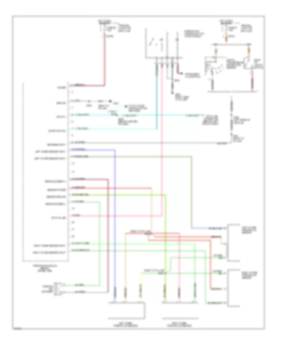
Trailer Tow Wiring Diagram, Early Production for Ford Explorer 2002
List of elements for Trailer Tow Wiring Diagram, Early Production for Ford Explorer 2002:
- (main light switch) exterior lights system
- Battery charge trailer tow relay
- Battery junction box (left side of engine compt)
- Brake pedal position switch (above brake pedal)
- C270a
- C270d
- Central junction box (behind left side of dash)
- Class ii
- Class iii/iv
- Exterior lights system (back-up lamps circuit)
- Exterior lights system (main light switch)
- Exterior lights system (multi- function switch)
- Fuse 15a
- Fuse 20a
- Fuse 30a
- Fuse 5a
- G103 (behind right front headlamp)
- G202 (right "a" pillar)
- G401 (right "d" pillar)
- Hot at all times
- Hot in run or start
- J/c
- Left turn trailer tow relay
- Nca
- Parking lamp trailer tow relay
- Rear auxiliary junction box (on right "d" pillar)
- Reversing lamp trailer tow relay
- Right turn trailer tow relay
- S121
- S216
- S220 (behind center of dash)
- S410
- S412
- Trailer electronic brake control module (under left side of dash)
- Trailer tow auxiliary junction box (right side of engine compt)
- Trailer tow connector (class ii)
- Trailer tow connector (class iii/iv)
Trailer Tow Wiring Diagram, Late Production for Ford Explorer 2002
List of elements for Trailer Tow Wiring Diagram, Late Production for Ford Explorer 2002:
- (main light switch) exterior lights system
- Battery charge trailer tow relay
- Battery junction box (left side of engine compt)
- Brake pedal position switch (above brake pedal)
- C270a
- C270d
- Central junction box (behind left side of dash)
- Class ii
- Class iii/iv
- Exterior lights system (back-up lamps circuit)
- Exterior lights system (main light switch)
- Exterior lights system (multi- function switch)
- Fuse 15a
- Fuse 20a
- Fuse 30a
- Fuse 40a
- Fuse 5a
- G103 (behind right front headlamp)
- G200 (right "a" pillar)
- G401 (left rear side of vehicle)
- G401 (right "d" pillar)
- Hot at all times
- Hot in run or start
- J/c
- Left turn trailer tow relay
- Nca
- Parking lamp trailer tow relay
- Rear auxiliary junction box (on right "d" pillar)
- Reversing lamp trailer tow relay
- Right turn trailer tow relay
- S120 (front left side of engine compt)
- S121
- S216
- S410
- S412
- Trailer electronic brake control module (under left side of dash)
- Trailer tow connector (class ii)
- Trailer tow connector (class iii/iv)
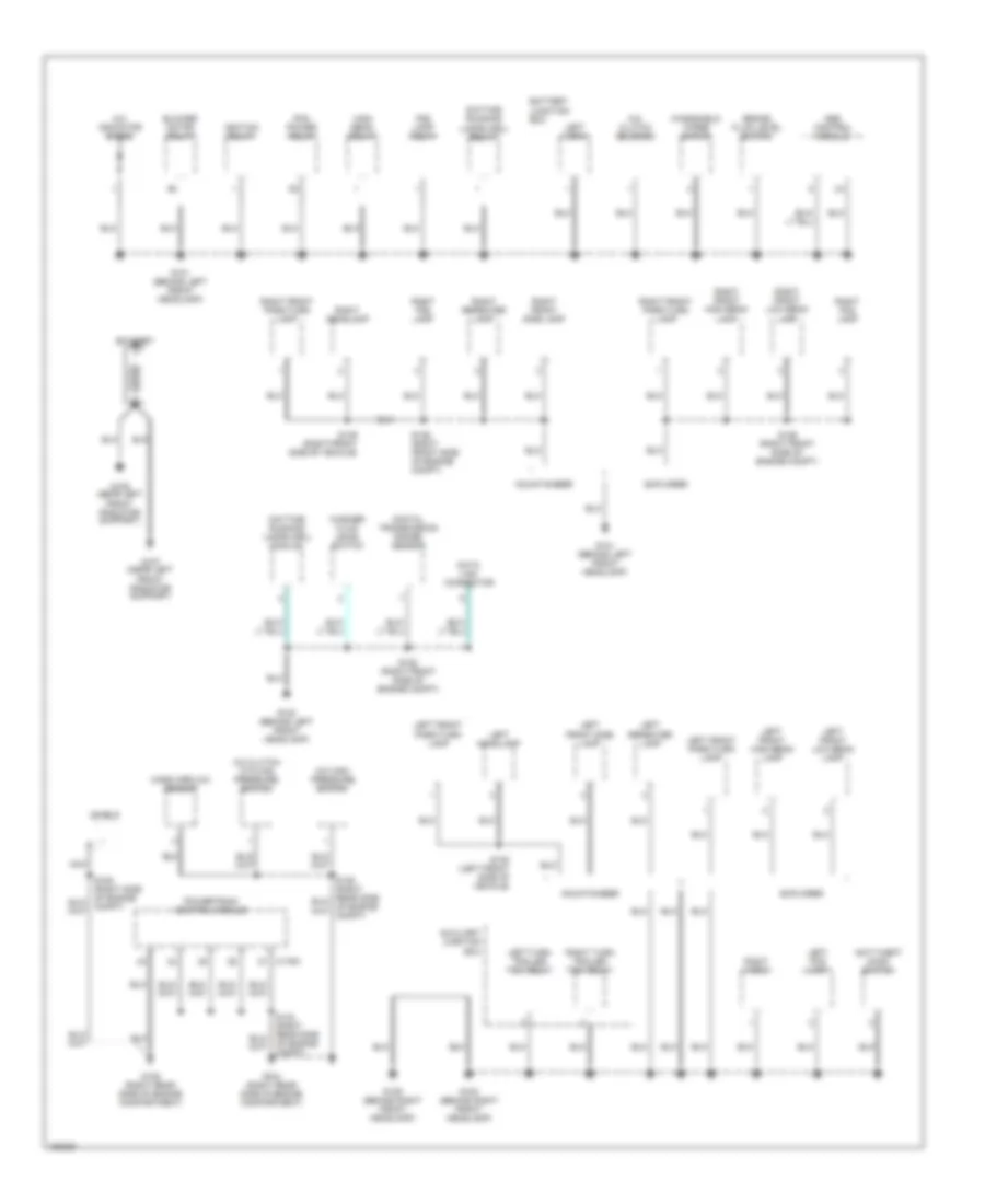
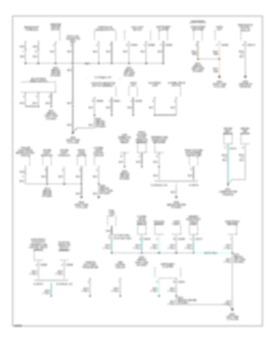
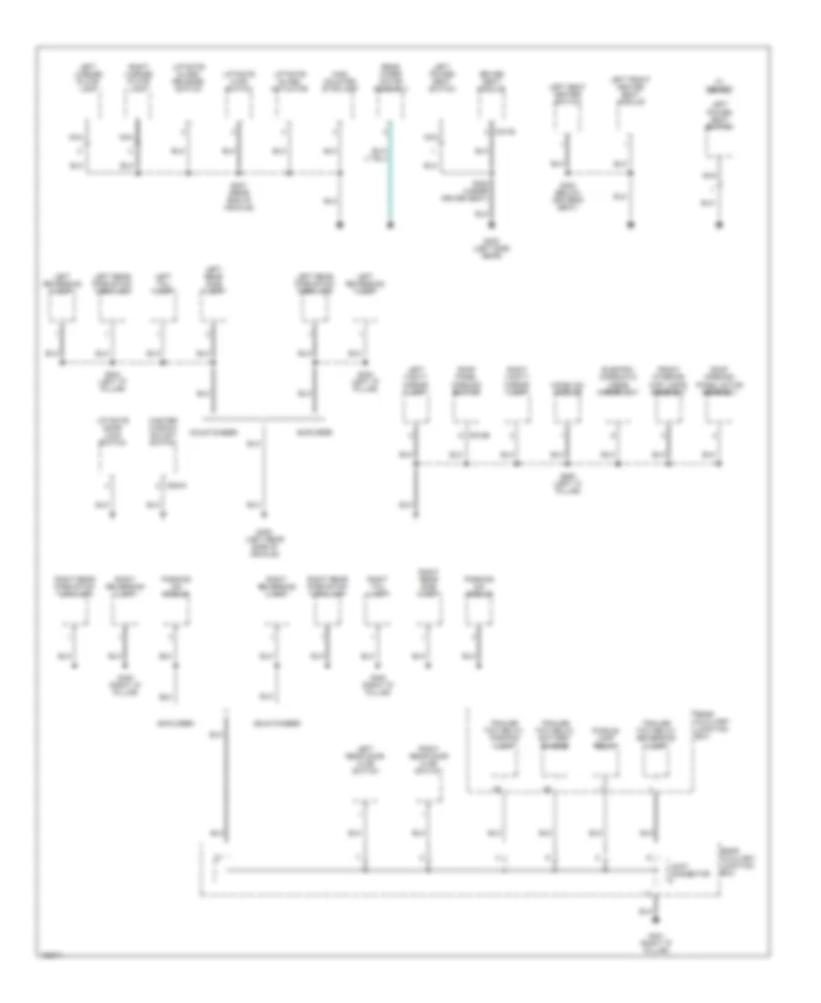
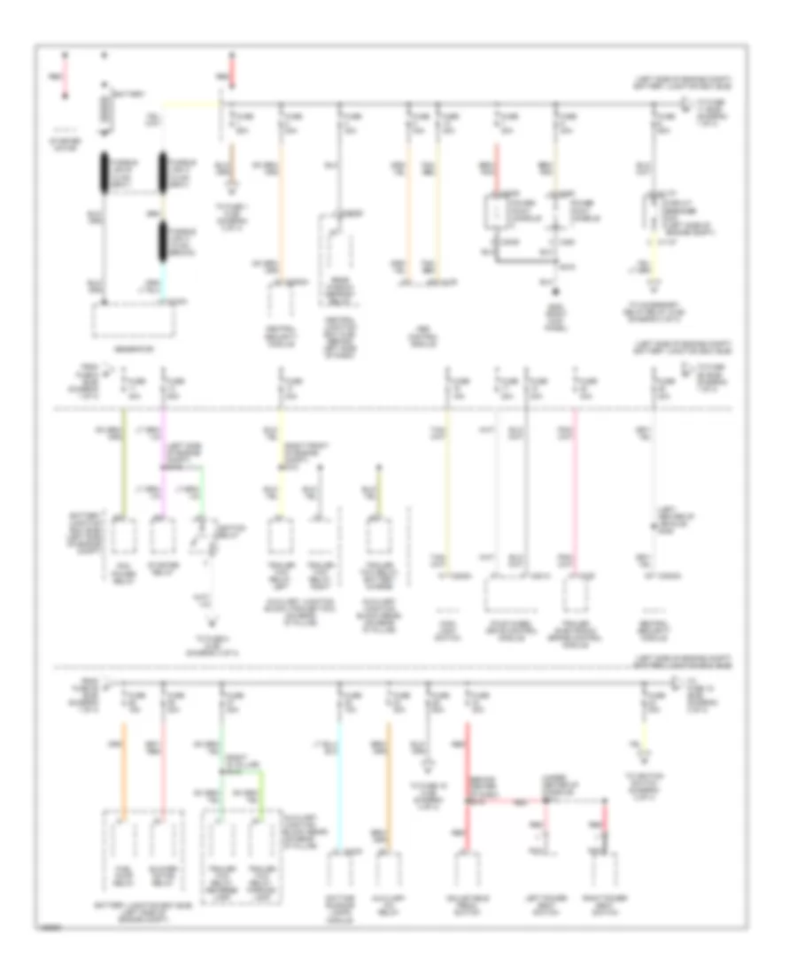
GROUND DISTRIBUTION
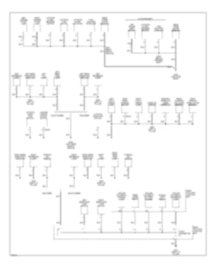
Ground Distribution Wiring Diagram, Early Production (1 of 4) for Ford Explorer 2002
List of elements for Ground Distribution Wiring Diagram, Early Production (1 of 4) for Ford Explorer 2002:
- A/c clutch cycling pressure switch
- A/c clutch solenoid
- A/c high pressure switch
- A/c indicator diode
- Abs control module
- Anti-theft hood switch
- Auxiliary junction box
- Battery
- Battery junction box
- Blower motor relay
- Brake fluid level switch
- C175a
- Data link connector
- Daytime running lamps (drl) module
- Daytime running lamps (drl) relay
- Digital transmission range sensor
- Explorer
- Fog lamp relay
- G101 (behind left front headlamp)
- G102 (behind left front headlamp)
- G103 (behind right front headlamp)
- G104 (right rear side of engine compartment)
- G105 (right rear side of engine compartment)
- G106 (near left front radiator support)
- G107 (near left front radiator support)
- G109 (behind right front headlamp)
- High beam relay
- Ignition relay
- Left fog lamp
- Left front high beam lamp
- Left front low beam lamp
- Left front park/turn lamp
- Left front side lamp
- Left headlamp
- Left horn
- Left repeater lamp
- Left turn trailer tow relay
- Mass airflow sensor
- Mountaineer
- Nca
- Of engine compt)
- Pcm power relay
- Powertrain control module
- Right fog lamp
- Right front high beam lamp
- Right front low beam lamp
- Right front park/turn lamp
- Right front side lamp
- Right headlamp
- Right horn
- Right repeater lamp
- Right turn trailer tow relay
- S125 (right front side of engine compt)
- S126 (right front side of engine compt)
- S138 (left front side of vehicle)
- S139 (right front side of vehicle)
- Shield
- Washer fluid level switch
- Windshield wiper motor
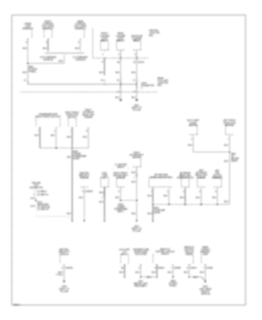
Ground Distribution Wiring Diagram, Early Production (2 of 4) for Ford Explorer 2002
List of elements for Ground Distribution Wiring Diagram, Early Production (2 of 4) for Ford Explorer 2002:
- (w/ flex fuel)
- (w/o flex fuel)
- 4-wheel drive control module
- 4-wheel drive switch
- Abs control module
- Adjustable pedal switch
- Audio unit
- Brake shift interlock
- C201a
- C2041a
- C205a
- C205b
- C220a
- C220b
- C228b
- C240b
- C281b
- C294b
- C294c
- C341c
- Data link connector (dlc)
- Driver seat module
- Electronic automatic temperature control (eatc) module
- Electronic compass
- Front blower motor resistor assembly
- Front blower motor speed controller
- Front cigar lighter
- Fuel tank unit
- Function selector switch assembly
- G200 (right side "a" pillar)
- G202 (right side "a" pillar)
- G204 (right side "a" pillar)
- G205 (center of console)
- G206 (behind center of dash)
- G300 (left side "a" pillar)
- G301 (under center console)
- Generic electronic module (gem)
- Glove box lamp
- High speed fan control relay
- Instrument cluster
- Mach radio
- Main light switch
- Memory set switch
- Message center switch
- Nca
- Of dash)
- Parking aid disable switch
- Passive anti-theft transceiver
- Power point console 1
- Power point console 2
- Restraints control module
- S204 (behind left side of dash)
- S216 (behind center of dash)
- S219 (behind center of dash)
- S221 (behind right side of dash)
- S223 (behind center of dash)
- S230 (behind right side of dash)
- S234 (behind right side of dash)
- S240 (behind center of dash)
- S319 (behind left side of dash)
- Subwoofer amplifier
- Sunload sensor
- Temperature blend door actuator
- Trailer electronic brake control module
- W/ eatc
- W/ eatc
- W/ manual a/c
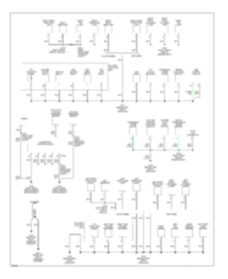
Ground Distribution Wiring Diagram, Early Production (3 of 4) for Ford Explorer 2002
List of elements for Ground Distribution Wiring Diagram, Early Production (3 of 4) for Ford Explorer 2002:
- C504a
- C912a
- Electro- chromatic inside mirror unit
- Explorer
- Front interior/ map lamps assembly
- G400 (left rear side of vehicle)
- G400 (left side rear)
- G401 (right "d" pillar)
- High mounted stoplamp
- Homelink module
- Joint connector
- Left license plate lamp
- Left power seat switch
- Left rear door ajar switch
- Left rear park/stop/ turn lamp
- Left rear side lamp
- Left reversing lamp
- Left tail lamp
- Left vanity mirror lamp
- Liftgate ajar switch
- Liftgate door lock switch
- Liftgate glass actuator
- Liftgate glass release switch
- Master window adjust switch
- Mountaineer
- Nca
- Parking aid module
- Puddle lamp relay
- Rear auxiliary junction box
- Rear wiper motor assembly
- Rear wiper relay
- Right license plate lamp
- Right rear door ajar switch
- Right rear park/stop/ turn lamp
- Right rear side lamp
- Right reversing lamp
- Right tail lamp
- Right vanity mirror lamp
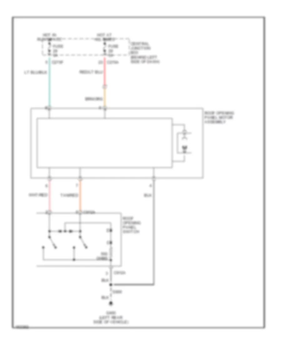
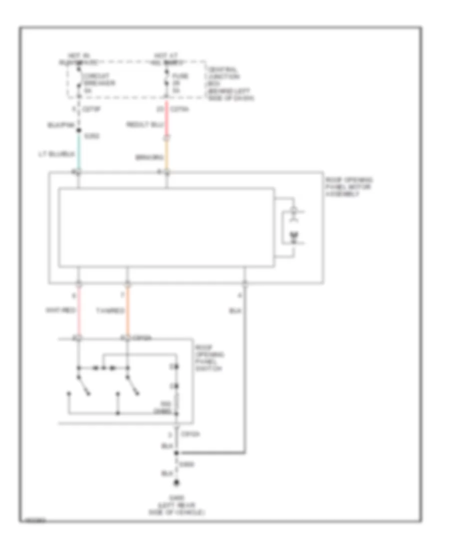
- Roof opening panel motor assembly
- Roof panel opening switch
- S300 (below driver's seat)
- S400 (right "d" pillar)
- S404 (left "d" pillar)
- S407 (rear end of vehicle)
- S900 (left "a" pillar)
- Trailer tow relay, battery charge
- Trailer tow relay, parking lamp
- Trailer tow relay, reversing lamp
- W/ power seat
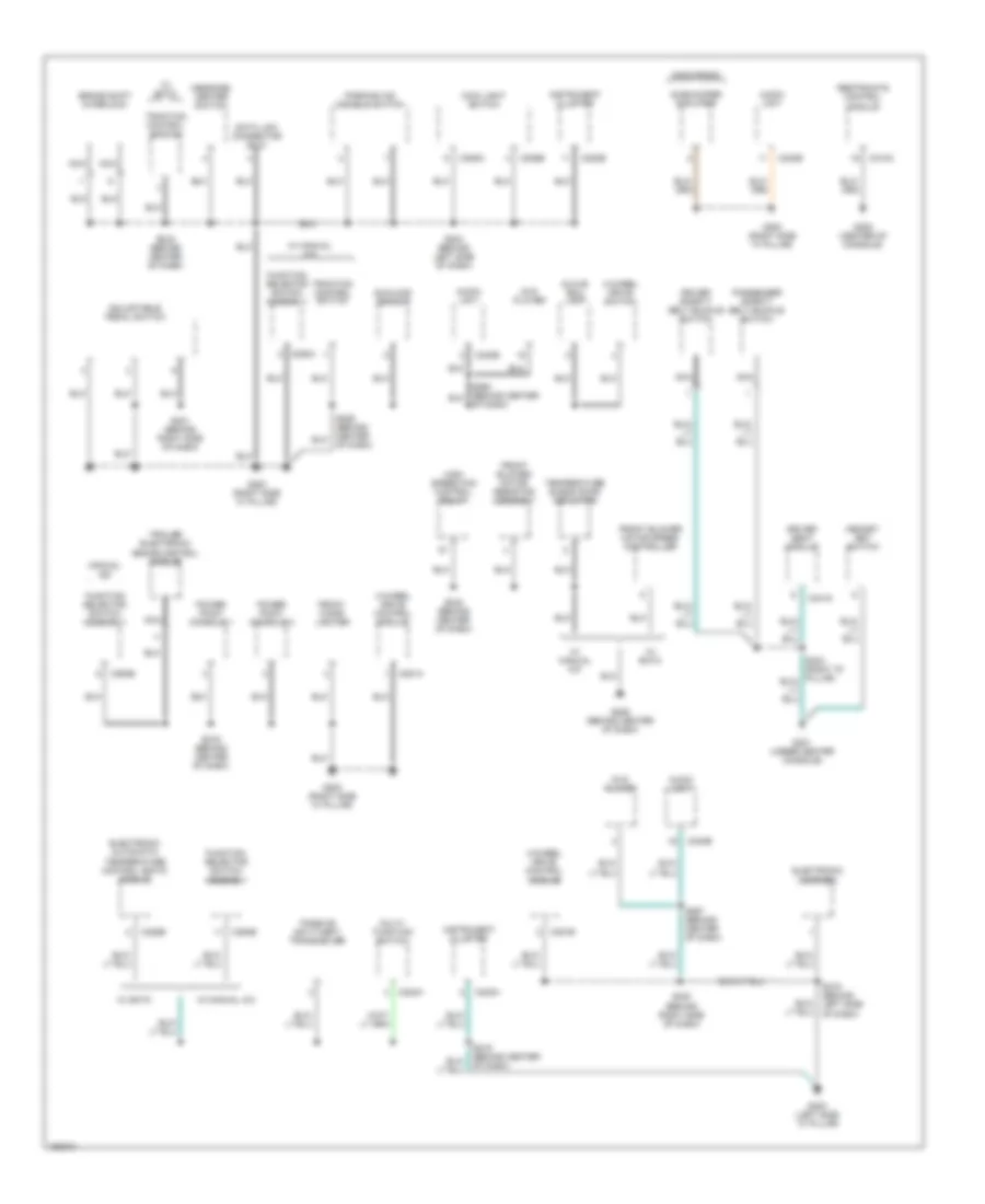
Ground Distribution Wiring Diagram, Early Production (4 of 4) for Ford Explorer 2002
List of elements for Ground Distribution Wiring Diagram, Early Production (4 of 4) for Ford Explorer 2002:
- (class 2)
- (class 3/4)
- Anti-theft inhibit switch
- Auxiliary a/c relay
- C270a
- C3008a
- C3008c
- C402b
- C938a
- C938b
- C940a
- Cargo lamp assembly
- Central junction box
- Central security module
- Driver side door lock switch
- Exterior rear view mirror switch
- Front interior/ map lamps assembly
- Front washer pump relay
- Fuel tank unit
- G401 (right "d" pillar)
- G402 (right "d" pillar)
- G403 (left rear side of vehicle)
- Indicator flasher relay
- Joint connector
- Key pad switch assembly
- Left exterior rear view mirror
- Left front door ajar switch
- Nca
- Passenger side front door lock unit
- Rear a/c control module (front)
- Rear a/c control module (rear)
- Rear auxiliary junction box
- Rear interior/ map lamps assembly
- Rear washer pump relay
- Rear window defrost grid
- Right exterior rear view mirror
- Right front door ajar switch
- Right front heated seat module
- Right power seat switch
- S305 (under passenger seat)
- S341 (behind left rear seat)
- S410 (rear end of vehicle) (class 3/4)
- S503 (in driver door)
- S908 (in roof panel)
- Temperature blend door actuator
- Trailer tow connector
- W/ heated seats
- W/ overhead console
- W/o overhead console
Ground Distribution Wiring Diagram, Late Production (1 of 4) for Ford Explorer 2002
List of elements for Ground Distribution Wiring Diagram, Late Production (1 of 4) for Ford Explorer 2002:
- A/c clutch cycling pressure switch
- A/c clutch solenoid
- A/c high pressure switch
- A/c indicator diode
- Abs control module
- Anti-theft hood switch
- Battery
- Battery junction box
- Blower motor relay
- Brake fluid level switch
- C175a
- Data link connector
- Daytime running lamps (drl) module
- Digital transmission range sensor
- Explorer
- Fog lamp relay
- G101 (behind left front headlamp)
- G102 (behind left front headlamp)
- G103 (behind right front headlamp)
- G104 (right rear side of engine compartment)
- G105 (right rear side of engine compartment)
- G106 (near left front radiator support)
- G107 (near left front radiator support)
- G109 (behind right front headlamp)
- High beam relay
- Ignition relay
- Ivd stop lamp relay
- Left fog lamp
- Left front high beam lamp
- Left front low beam lamp
- Left front park/turn lamp
- Left front side lamp
- Left headlamp
- Left horn
- Left repeater lamp
- Left turn trailer tow relay
- Mass airflow sensor
- Mountaineer
- Nca
- Pcm power relay
- Powertrain control module
- Right fog lamp
- Right front high beam lamp
- Right front low beam lamp
- Right front park/turn lamp
- Right front side lamp
- Right headlamp
- Right horn
- Right repeater lamp
- Right turn trailer tow relay
- S125 (right front side of engine compt)
- S126 (right front side of engine compt)
- S132 (right rear side of engine compt)
- S138 (left front side of vehicle)
- S139 (right front side of vehicle)
- Shield
- Washer fluid level switch
- Windshield wiper motor
Ground Distribution Wiring Diagram, Late Production (2 of 4) for Ford Explorer 2002
List of elements for Ground Distribution Wiring Diagram, Late Production (2 of 4) for Ford Explorer 2002:
- 4-wheel drive control module
- 4-wheel drive switch
- Adjustable pedal switch
- Audio unit
- Brake shift interlock
- C202a
- C205a
- C205b
- C220a
- C220b
- C228b
- C240b
- C281a
- C281b
- C294b
- C294c
- C310a
- C341g
- Data link connector (dlc)
- Driver safety belt buckle switch
- Driver seat module
- Dvd player
- Electronic automatic temperature control (eatc) module
- Electronic compass
- Front blower motor resistor assembly
- Front blower motor speed controller
- Front cigar lighter
- Function selector switch assembly
- G200 (right side "a" pillar)
- G205 (center of console)
- G206 (behind center of dash)
- G300 (left side "a" pillar)
- G301 (under center console)
- Glove box lamp
- High speed fan control relay
- Instrument cluster
- Mach radio
- Main light switch
- Manual a/c
- Memory set switch
- Message center switch
- Multi- function switch
- Nca
- Of dash)
- Parking aid disable switch
- Passenger safety belt buckle switch
- Passive anti-theft transceiver
- Power point console 1
- Power point console 2
- Restraints control module
- S204 (behind left side of dash)
- S216 (behind center of dash)
- S219 (behind center of dash)
- S221 (behind right side of dash)
- S223 (behind center of dash)
- S230 (behind right side of dash)
- S240 (behind center of dash)
- S267 (behind center of dash)
- S319 (behind left side of dash)
- Subwoofer amplifier
- Sunload sensor
- Temperature blend door actuator
- Traction control switch
- Trailer electronic brake control module
- W/ eatc
- W/ eatc
- W/ manual a/c
Ground Distribution Wiring Diagram, Late Production (3 of 4) for Ford Explorer 2002
List of elements for Ground Distribution Wiring Diagram, Late Production (3 of 4) for Ford Explorer 2002:
- C341e
- C504a
- C912b
- Driver seat module
- Electro- chromatic inside mirror unit
- Explorer
- Front interior/ map lamps assembly
- G400 (left rear side of vehicle)
- G400 (left side rear)
- G401 (right "d" pillar)
- High mounted stoplamp
- Homelink module
- Joint connector
- Left front heated seat module
- Left license plate lamp
- Left power seat switch
- Left rear door ajar switch
- Left rear park/stop/ turn lamp
- Left rear side lamp
- Left reversing lamp
- Left seat heater switch
- Left tail lamp
- Left vanity mirror lamp
- Liftgate ajar switch
- Liftgate door lock switch
- Liftgate glass actuator
- Liftgate glass release switch
- Master window adjust switch
- Mountaineer
- Nca
- Parking aid module
- Puddle lamp relay
- Rear auxiliary junction box
- Rear wiper motor assembly
- Right license plate lamp
- Right rear door ajar switch
- Right rear park/stop/ turn lamp
- Right rear side lamp
- Right reversing lamp
- Right tail lamp
- Right vanity mirror lamp
- Roof opening panel motor assembly
- Roof panel opening switch
- S300 (below driver's seat)
- S352 (under driver seat)
- S400 (right "d" pillar)
- S404 (left "d" pillar)
- S407 (rear end of vehicle)
- S900 (left "a" pillar)
- Trailer tow relay, battery charge
- Trailer tow relay, parking lamp
- Trailer tow relay, reversing lamp
- W/ memory
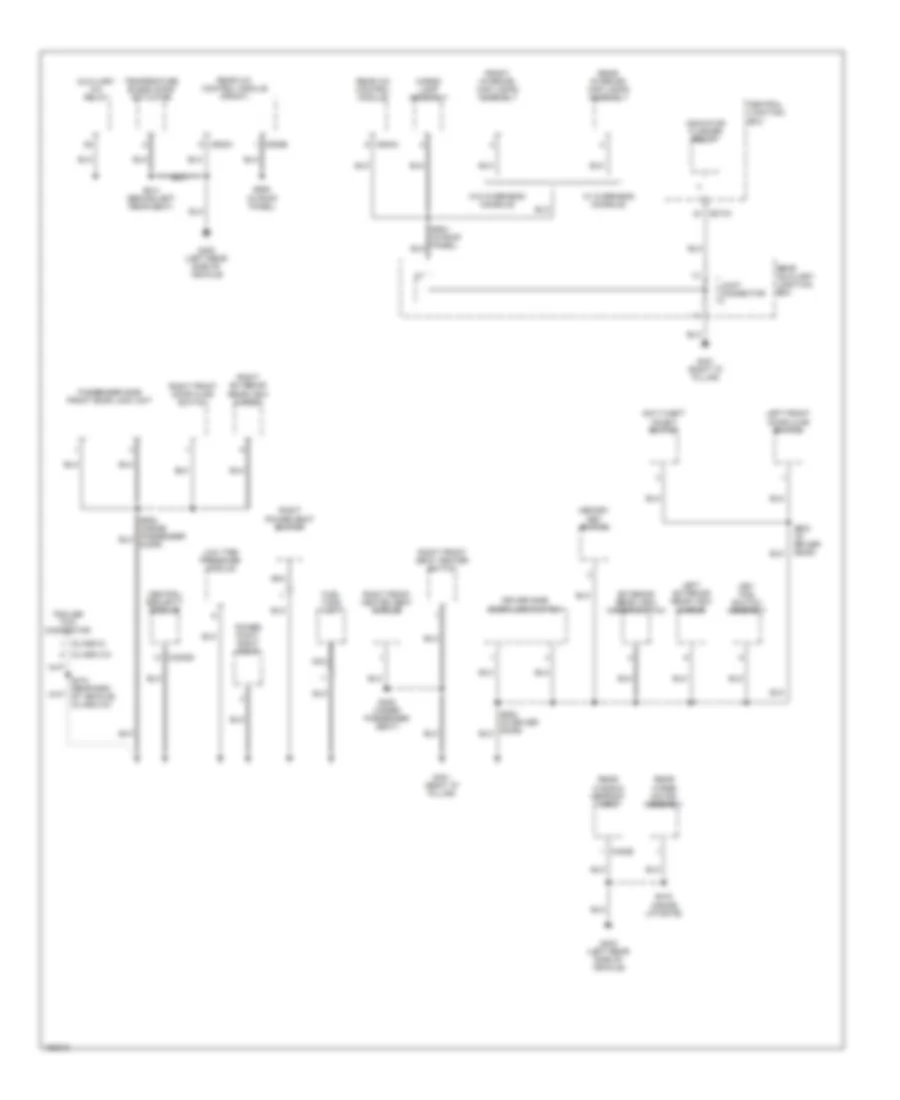
Ground Distribution Wiring Diagram, Late Production (4 of 4) for Ford Explorer 2002
List of elements for Ground Distribution Wiring Diagram, Late Production (4 of 4) for Ford Explorer 2002:
- (class 2)
- (class 3/4)
- Anti-theft inhibit switch
- Auxiliary a/c relay
- C270a
- C3008d
- C402b
- C938a
- C938b
- C940a
- Cargo lamp assembly
- Central junction box
- Central security module
- Driver side door lock switch
- Exterior rear view mirror switch
- Front interior/ map lamps assembly
- Fuel tank unit
- G400 (left rear side of vehicle)
- G401 (right "d" pillar)
- G403 (left rear side of vehicle)
- Indicator flasher relay
- Joint connector
- Key pad switch assembly
- Left exterior rear view mirror
- Left front door ajar switch
- Low tire pressure module
- Memory set switch
- Nca
- Passenger side front door lock unit
- Power point, right rear
- Rear a/c control module
- Rear a/c control module (front)
- Rear auxiliary junction box
- Rear interior/ map lamps assembly
- Rear window defrost grid
- Rear wiper motor assembly
- Right exterior rear view mirror
- Right front door ajar switch
- Right front heated seat module
- Right front seat heater switch
- Right power seat switch
- S305 (under passenger seat)
- S341 (behind left rear seat)
- S415 (inside liftgate)
- S503 (in driver door)
- S908 (in roof panel)
- Temperature blend door actuator
- Trailer tow connector
- W/ overhead console
- W/o overhead console
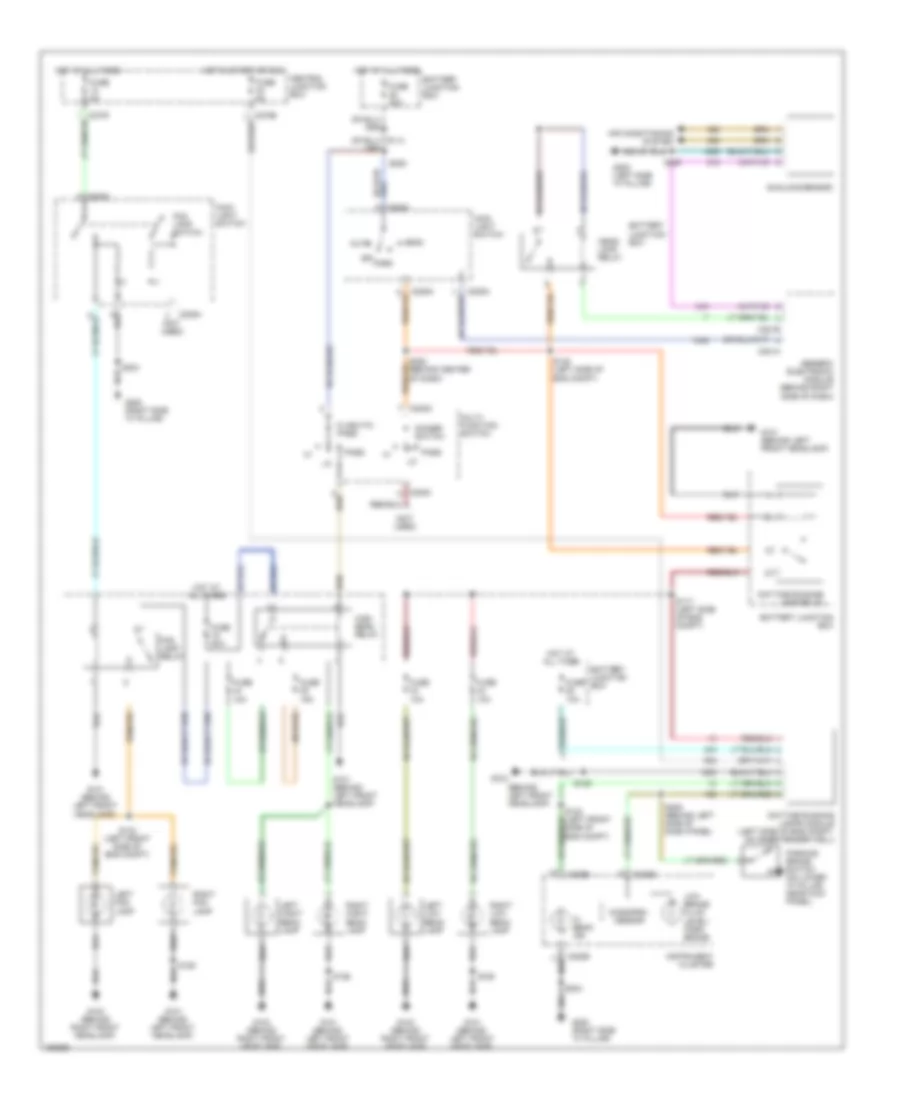
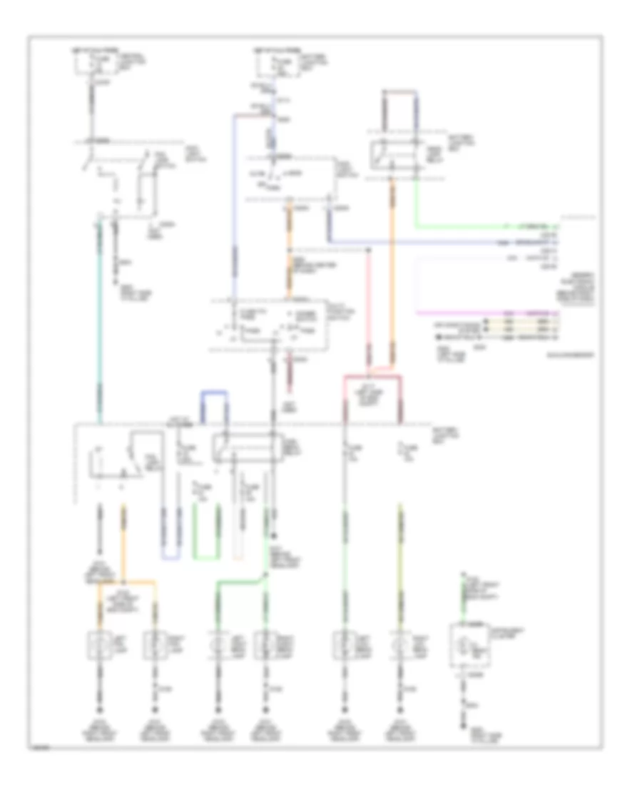
HEADLIGHTS
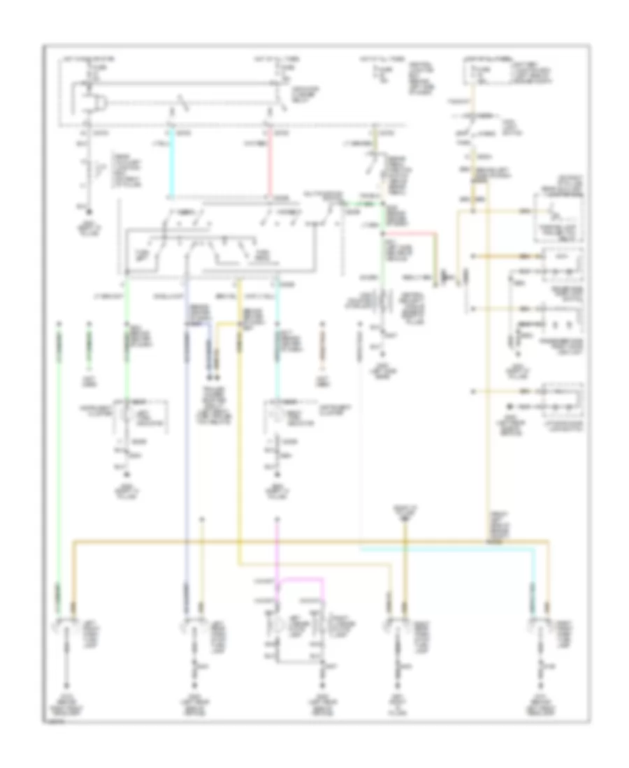
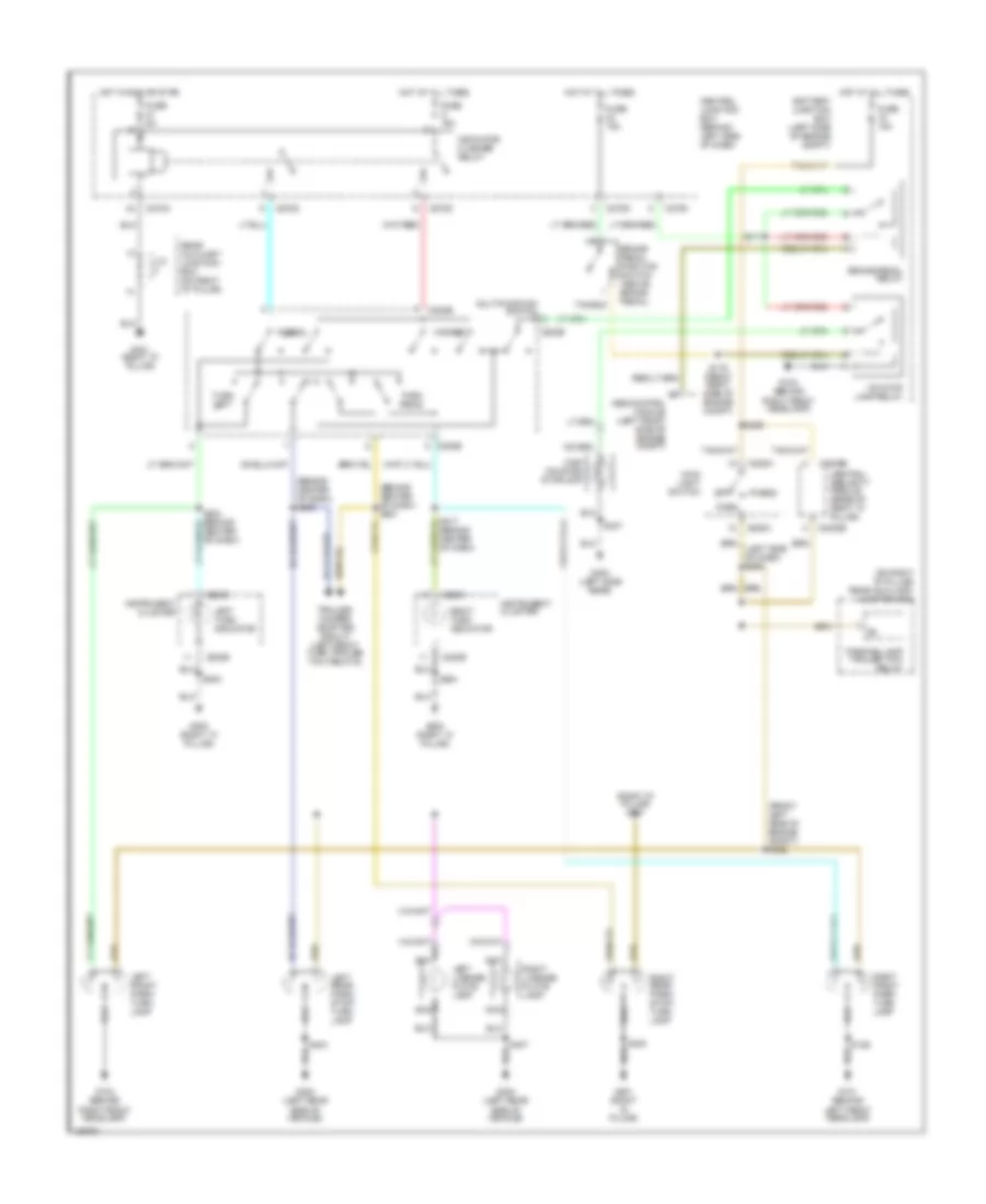
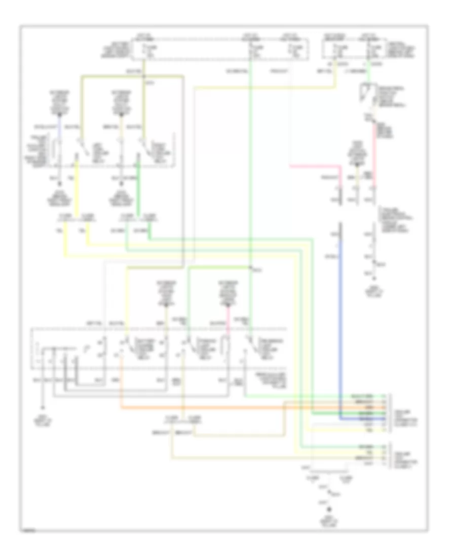
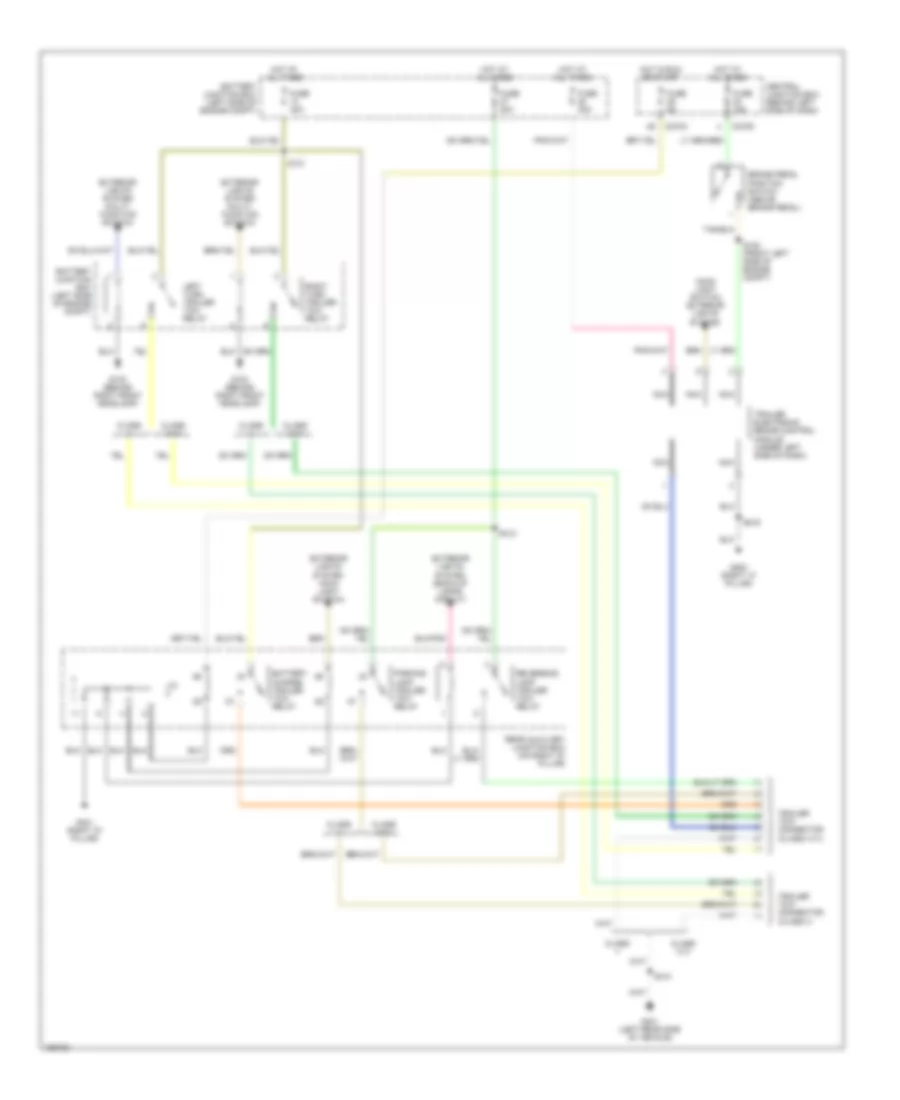
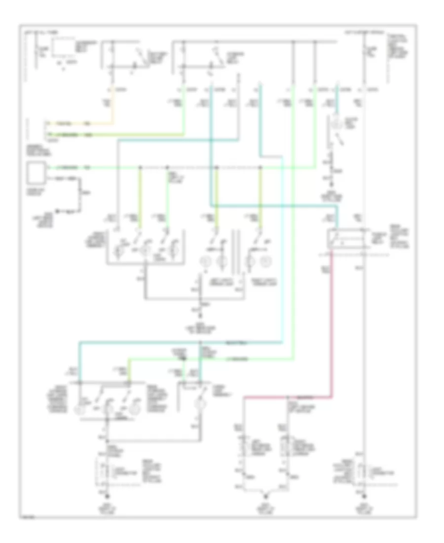
Headlight Wiring Diagram, Early Production with DRL for Ford Explorer 2002
List of elements for Headlight Wiring Diagram, Early Production with DRL for Ford Explorer 2002:
- (behind left front headlamp)
- (not used)
- Air conditioning system
- Auto
- Battery junction box
- C201a
- C201b
- C202c
- C205a
- C220b
- C270b
- C270f
- Central junction box
- Daytime running lamp relay
- Daytime running lamps module (left side of eng compt, on inner fender well)
- Dimmer switch
- Flash-to- pass
- Fog lamp relay
- Fog lamp switch
- Fuse 10a
- Fuse 15a
- Fuse 20a
- Fuse 5a
- G101 (behind left front headlamp)
- G102
- G103 (behind right front headlamp)
- G200 (right side "a" pillar)
- G300 (left side "a" pillar)
- Generic electronic module (behind right side of dash)
- Head
- Head- lamp relay
- Hi beam ind
- High beam relay
- Hot at all times
- Hot in start or run
- Instrument cluster
- Left fog lamp
- Left hight beam lamp
- Left low beam lamp
- Low brake fluid level/ park brake
- Main light switch
- Micropro- cessor
- Multi- function switch
- Off
- Park
- Parking brake switch (on lower "a" pillar, near kick panel)
- Pass
- Right fog lamp
- Right hight beam lamp
- Right low beam lamp
- S117 (left side of eng compt)
- S123 (left front side of eng compt)
- S125
- S126
- S133 (left front side of eng compt)
- S145 (left side of eng compt)
- S204
- S205
- S206 (behind left side of dash panel)
- S230
- S252 (behind center of dash)
- Sunload sensor
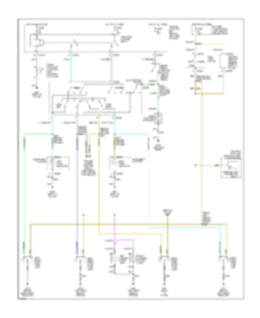
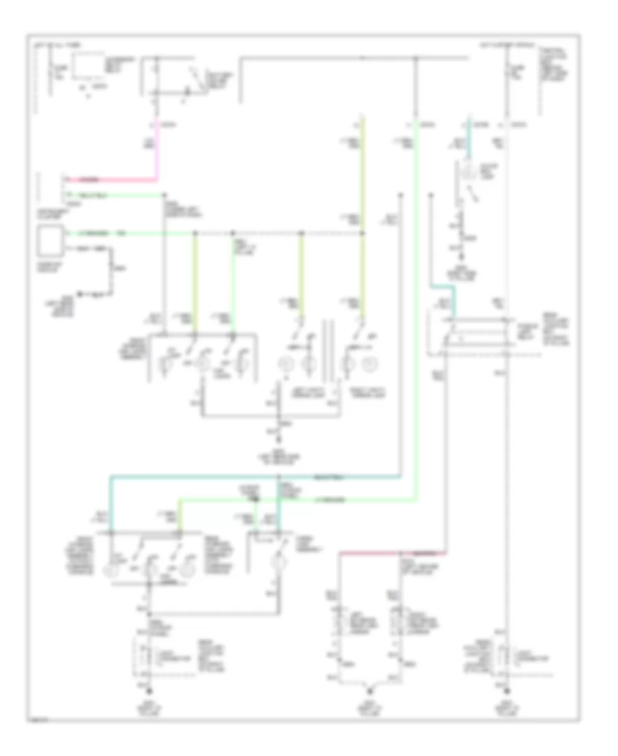
Headlight Wiring Diagram, Early Production without DRL for Ford Explorer 2002
List of elements for Headlight Wiring Diagram, Early Production without DRL for Ford Explorer 2002:
- (not used)
- Air conditioning system
- Auto
- Battery junction box
- C201a
- C201b
- C202c
- C205a
- C220b
- C270f
- Central junction box
- Dimmer switch
- Flash-to- pass
- Fog lamp relay
- Fog lamp switch
- Fuse 10a
- Fuse 15a
- Fuse 20a
- Fuse 5a
- G101 (behind left front headlamp)
- G103 (behind right front headlamp)
- G200 (right side "a" pillar)
- G300 (left side "a" pillar)
- Generic electronic module (behind right side of dash)
- Head
- Head- lamp relay
- Hi beam ind
- High beam relay
- Hot at all times
- Instrument cluster
- Left fog lamp
- Left hight beam lamp
- Left low beam lamp
- Main light switch
- Multi- function switch
- Off
- Park
- Pass
- Right fog lamp
- Right hight beam lamp
- Right low beam lamp
- S114
- S117 (left side of eng compt)
- S123 (left front side of eng compt)
- S126
- S133 (left front side of eng compt)
- S204
- S205
- S230
- S252 (behind center of dash)
- Sunload sensor
Headlight Wiring Diagram, Late Production with DRL for Ford Explorer 2002
List of elements for Headlight Wiring Diagram, Late Production with DRL for Ford Explorer 2002:
- (behind left front headlamp)
- (not used)
- Auto
- Battery junction box
- C202c
- C205a
- C220a
- C220b
- C270b
- C270f
- C3008e
- Central junction box
- Central security module (at base of right "c" pillar)
- Daytime running lamps module (left side of eng compt, on inner fender well)
- Dimmer switch
- Flash-to- pass
- Fog lamp relay
- Fog lamp switch
- Fuse 10a
- Fuse 15a
- Fuse 20a
- Fuse 5a
- G101 (behind left front headlamp)
- G102
- G103 (behind right front headlamp)
- G200 (right side "a" pillar)
- Head
- Hi beam ind
- High beam relay
- Hot at all times
- Hot in start or run
- Instrument cluster
- Left fog lamp
- Left hight beam lamp
- Left low beam lamp
- Low brake fluid level/ park brake
- Main light switch
- Micropro- cessor
- Microprocessor
- Multi- function switch
- Off
- Park
- Parking brake switch (on lower "a" pillar, near kick panel)
- Pass
- Right fog lamp
- Right hight beam lamp
- Right low beam lamp
- S117 (left side of eng compt)
- S123 (left front side of eng compt)
- S125
- S126
- S133 (left front side of eng compt)
- S204
- S205
- S206 (behind left side of dash panel)
- S252 (behind center of dash)
- S260 (behind center of dash panel)
Headlight Wiring Diagram, Late Production without DRL for Ford Explorer 2002
List of elements for Headlight Wiring Diagram, Late Production without DRL for Ford Explorer 2002:
- (behind center of dash panel) s260
- (not used)
- Air conditioning system
- Anti-theft system
- Auto
- Battery junction box
- C202c
- C205a
- C220b
- C270f
- C3008e
- Central junction box
- Central security module (at base of right "c" pillar)
- Dimmer switch
- Flash-to- pass
- Fog lamp relay
- Fog lamp switch
- Fuse 10a
- Fuse 15a
- Fuse 20a
- Fuse 5a
- G101 (behind left front headlamp)
- G103 (behind right front headlamp)
- G200 (right side "a" pillar)
- Head
- Hi beam ind
- High beam relay
- Hot at all times
- Instrument cluster
- Left fog lamp
- Left hight beam lamp
- Left low beam lamp
- Main light switch
- Microprocessor
- Multi- function switch
- Off
- Park
- Pass
- Right fog lamp
- Right hight beam lamp
- Right low beam lamp
- S117 (left side of eng compt)
- S123 (left front side of eng compt)
- S126
- S133 (left front side of eng compt)
- S204
- S205
- S229
- S252 (behind center of dash)
- Sunload sensor
HORN
Horn Wiring Diagram, Early Production for Ford Explorer 2002
List of elements for Horn Wiring Diagram, Early Production for Ford Explorer 2002:
- 10a
- 20a
- Air bag sliding contact
- Air conditioning system
- Battery junction box (bjb) (left side of engine compartment)
- C175a
- C218a
- C270a
- C270d
- C3008a
- C3008b
- Central junction box (cjb) (behind left side of dash)
- Central security module (on base of "c" pillar)
- Fuse 18
- Fuse 25
- Fuse 6
- G101 (behind left front headlamp)
- G103 (behind right front headlamp)
- Hot at all times
- Left horn (left front of engine compt)
- Nca
- Powertrain control module (mounted through firewall)
- Right horn (right front of engine compt)
- S212 (behind center of dash)
- S320
- Speed control switch
Horn Wiring Diagram, Late Production for Ford Explorer 2002
List of elements for Horn Wiring Diagram, Late Production for Ford Explorer 2002:
- 10a
- 20a
- Air bag sliding contact
- Air conditioning system
- Battery junction box (bjb) (left side of engine compart)
- Battery junction box (bjb) (left side of engine compartment)
- C1006
- C175a
- C218a
- C270a
- C270d
- C3008e
- C3183
- Central junction box (cjb) (behind left side of dash)
- Central security module (on base of "c" pillar)
- Fuse 18
- Fuse 28
- Fuse 6
- G101 (behind left front headlamp)
- G103 (behind right front headlamp)
- Horn relay
- Hot at all times
- Left horn (left front of engine compt)
- Low tire pressure module (under passenger dash panel)
- Nca
- Powertrain control module (mounted through firewall)
- Right horn (right front of engine compt)
- S170
- S172 (left side of engine comp)
- S212 (behind center of dash)
- S320
- S328
- Speed control switch
INSTRUMENT CLUSTER
Instrument Cluster Wiring Diagram, Early Production for Ford Explorer 2002
List of elements for Instrument Cluster Wiring Diagram, Early Production for Ford Explorer 2002:
- (behind center of dash panel) s233
- (w/ eatc)
- 4wd high ind
- 4wd low
- Abs ind
- Air bag ind
- Ambient air temperature sensor (right front of engine compt)
- Anti-theft "on" ind
- Anti-theft system
- Antilock brake system
- Battery junction box (left side of engine compartment)
- Brake fluid level warning switch (mounted on right side of master cylinder)
- C220a
- C220b
- C228b
- C270h
- Central junction box (behind left side of dash)
- Charge ind
- Check gauge ind
- Check ind
- Computer data lines system
- Daytime running lamps (drl) module (in battery junction box)
- Door ajar ind
- Electronic automatic temperature control (eatc) module (behind right side of dash panel)
- Electronic compass
- Exterior lights system
- Fuel cut-off ind
- Fuel tank unit (on fuel tank)
- Fuse 5a
- G101 (behind left front headlamp)
- G102 (behind left front headlamp)
- G200 (right side "a" pillar)
- G300 (left side "a" pillar)
- Headlights system
- High beam ind
- Hot at all times
- Hot in run or start
- Illumination (6 bulbs)
- Instrument cluster
- Interior lights system
- Joint connector
- Left turn signal ind
- Low
- Message center switch (behind center of dash panel)
- Microprocessor
- Normal
- O/d off
- Ohms
- Oil pressure switch (left side of engine block)
- Parking brake switch (on left "a" pillar)
- Right turn signal ind
- S125
- S204
- S206 (behind left side of dash panel)
- S219
- S223
- Safety belt ind
- Speed control
- Transmission system
- W/ eatc
- W/o eatc
- Warning system
- Washer fluid level switch (right front of engine compartment)
Instrument Cluster Wiring Diagram, Late Production for Ford Explorer 2002
List of elements for Instrument Cluster Wiring Diagram, Late Production for Ford Explorer 2002:
- 220a
- Air conditioning system
- Ambient air temperature sensor (right front of engine compt)
- Battery junction box (left side of engine compart)
- C220a
- C220b
- C270e
- C270h
- Central junction box (behind left side of dash)
- Charge ind
- Check engine ind
- Check gauge ind
- Computer data lines system
- Daytime running lamps (drl) module (in battery junction box)
- Defogger system
- Electronic compass
- Exterior lights system
- Fuel tank unit (on fuel tank)
- Fuse 30a
- Fuse 5a
- G102 (behind left front headlamp)
- G200 (right side "a" pillar)
- G300 (left side "a" pillar)
- Headlamps system
- High beam ind
- Hot at all times
- Hot in run or acc
- Hot in run or start
- Ignition switch
- Illumination (6 bulbs)
- Instrument cluster
- Interior lights system
- Joint connector
- Key in ignition
- Left turn signal ind
- Low
- Message center switch (behind center of dash panel)
- Microprocessor
- Nca
- Normal
- Oil pressure switch (left side of engine block)
- Parking brake switch (on left "a" pillar)
- Power windows system
- Right turn signal ind
- S125
- S204
- S206 (behind left side of dash panel)
- S219
- S223
- W/ manual a/c
- Washer fluid level switch (right front of engine compartment)
INTERIOR LIGHTS
Courtesy Lamps Wiring Diagram, Early Production for Ford Explorer 2002
List of elements for Courtesy Lamps Wiring Diagram, Early Production for Ford Explorer 2002:
- (behind left side of dash)
- (in roof panel) s902
- Accessory delay relay
- Battery saver relay
- C2075
- C270a
- C270e
- C270f
- C270h
- Cargo lamp assembly
- Central junction box
- Front interior/ map lamps assembly
- Front interior/ map lamps assembly (without overhead console)
- Fuse 15a
- Fuse 7.5a
- G200 (right side "a" pillar)
- G400 (left rear side of vehicle)
- G401 (right "d" pillar)
- Generic electronic module (gem)
- Glove box lamp
- Homelink module
- Hot at all times
- Hot in start or run
- Int lamp
- Interior lamp relay
- Joint connector
- Left exterior rear view mirror
- Left vanity mirror lamp
- Map lamps
- Off
- Puddle lamp relay
- Rear auxiliary junction box (on right "d" pillar)
- Rear interior/ map lamps assembly (with overhead console)
- Right exterior rear view mirror
- Right vanity mirror lamp
- S229
- S310 (left center of vehicle)
- S502
- S602
- S900
- S901 (left "a" pillar)
- S904 (in roof panel)
Courtesy Lamps Wiring Diagram, Late Production for Ford Explorer 2002
List of elements for Courtesy Lamps Wiring Diagram, Late Production for Ford Explorer 2002:
- (behind left side of dash)
- (in roof panel) s902
- Accessory delay relay
- Battery saver relay
- C2075
- C220a
- C270a
- C270e
- C270h
- Cargo lamp assembly
- Central junction box
- Front interior/ map lamps assembly
- Front interior/ map lamps assembly (without overhead console)
- Fuse 15a
- Fuse 7.5a
- G200 (right side "a" pillar)
- G400 (left rear side of vehicle)
- G401 (right "d" pillar)
- Glove box lamp
- Homelink module
- Hot at all times
- Hot in start or run
- Instrument cluster
- Int lamp
- Joint connector
- Left exterior rear view mirror
- Left vanity mirror lamp
- Map lamps
- Off
- Puddle lamp relay
- Rear auxiliary junction box (on right "d" pillar)
- Rear interior/ map lamps assembly (with overhead console)
- Right exterior rear view mirror
- Right vanity mirror lamp
- S229
- S310 (left center of vehicle)
- S350 (under left side of dash)
- S502
- S602
- S900
- S901 (left "a" pillar)
- S904 (in roof panel)
Instrument Illumination Wiring Diagram, Early Production for Ford Explorer 2002
List of elements for Instrument Illumination Wiring Diagram, Early Production for Ford Explorer 2002:
- (behind center of dash) s225
- 4-wheel drive switch
- Adjustable pedal switch
- Air bag sliding contact
- Audio unit
- Audio/ climate control switch
- Autolamp
- Battery junction box (left side of engine compt)
- Bulbs
- C205a
- C205b
- C218a
- C220b
- C228a
- C228b
- C240b
- C284
- C294b
- C938a
- C940a
- Electronic automatic temperature control (eatc) module
- Function selector switch assembly
- Fuse 15a
- G200 (right side "a" pillar)
- G300 (left side "a" pillar)
- G403 (left rear side of vehicle)
- Headlamp
- Hot at all times
- Instrument cluster
- Main light switch
- Message center switch
- Nca
- Off
- Park
- Parking aid disable switch
- Rear a/c control module (front)
- Rear a/c control module (rear)
- S203 (behind left side of dash)
- S204
- S219
- S221
- S223
- S229
- S908
- S909 (in roof panel)
- Solid state
- W/ eatc
- W/ manual a/c
Instrument Illumination Wiring Diagram, Late Production for Ford Explorer 2002
List of elements for Instrument Illumination Wiring Diagram, Late Production for Ford Explorer 2002:
- (behind center of dash) s225
- 4-wheel drive switch
- Adjustable pedal switch
- Air bag sliding contact
- Audio unit
- Audio/ climate control switch
- Autolamp
- Battery junction box (left side of engine compt)
- Bulbs
- C205a
- C205b
- C218a
- C220b
- C228a
- C228b
- C240b
- C284
- C294b
- C938a
- C940a
- Driver side door lock switch
- Dvd player (if equipped)
- Electronic automatic temperature control (eatc) module
- Function selector switch assembly
- Fuse 15a
- G200 (right side "a" pillar)
- G300 (left side "a" pillar)
- G400 (left rear side of vehicle)
- G401 (right "d" pillar)
- Headlamp
- Hot at all times
- Instrument cluster
- Joint connector
- Main light switch
- Message center switch
- Nca
- Off
- Park
- Parking aid disable switch
- Passenger side front door lock unit
- Rear a/c control module (front)
- Rear a/c control module (rear)
- Rear auxiliary junction box (on right "d" pillar)
- S203 (behind left side of dash)
- S204
- S219
- S223
- S229
- S267
- S268 (behind center of dash)
- S349 (behind right side dash panel)
- S502
- S602
- S903
- S908
- S909 (in roof panel)
- Solid state
- Traction control switch
- W/ dvd player
- W/ eatc
- W/ manual a/c
- W/o roof opening panel
MEMORY SYSTEMS
Adjustable Pedal Wiring Diagram, Early Production for Ford Explorer 2002
List of elements for Adjustable Pedal Wiring Diagram, Early Production for Ford Explorer 2002:
- (not used)
- (right side "a" pillar) g200
- (under driver seat) s303
- Adj pedal mtr
- Adj pedal pot
- Adj pedal sw
- Adjustable pedal memory potentiometer (on top of accelerator pedal bracket)
- Adjustable pedal motor (on pedal assembly, left of brake pedal)
- Adjustable pedal switch
- Battery junction box (left side of engine compt)
- C210
- C270a
- C341a
- C341b
- C341d
- Central junction box (behind left side of dash)
- Driver seat module (under driver's seat)
- Forward
- Fuse 30a
- G400 (left side rear)
- Ground
- Hot at all times
- Interior lights system
- Pos sens +
- Pos sens -
- Power
- Power seat motor assembly
- Rearward
- Red
- S213
- S214 (behind center dash panel)
- S218
- S221
- S300
- S302
Adjustable Pedal Wiring Diagram, Late Production for Ford Explorer 2002
List of elements for Adjustable Pedal Wiring Diagram, Late Production for Ford Explorer 2002:
- (left rear side
- (not used)
- (right side "a" pillar) g200
- (under driver seat) s303
- Adj pedal mtr
- Adj pedal pot
- Adj pedal sw
- Adjustable pedal memory potentiometer (on top of accelerator pedal bracket)
- Adjustable pedal motor (on pedal assembly, left of brake pedal)
- Adjustable pedal switch
- Battery junction box (left side of engine compt)
- C210
- C270a
- C341e
- C341f
- C341g
- Central junction box (behind left side of dash)
- Driver seat module (under driver's seat)
- Forward
- Fuse 30a
- G400
- Ground
- Hot at all times
- Interior lights system
- Of vehicle)
- Pos sens +
- Pos sens -
- Power
- Power seat motor assembly
- Rearward
- Red
- S213
- S214 (behind center dash panel)
- S221
- S302
- S313
- S352
Driver's Memory Seat Wiring Diagram, Early Production for Ford Explorer 2002
List of elements for Driver's Memory Seat Wiring Diagram, Early Production for Ford Explorer 2002:
- (left center of vehicle)
- (under center console) g301
- (under driver seat)
- (under driver seat) s303
- Adj pedal mtr
- Adj pedal sens
- Adj pedal sw
- Adjustable pedal circuit
- Battery junction box (left side of engine compt, at fender apron)
- C251
- C270a
- C3008a
- C3008c
- C3016
- C341a
- C341b
- C341c
- C341d
- C353a
- C353b
- Central junction box (behind left side of dash)
- Central security module (on base of right "c" pillar)
- Data link connector (dlc) (behind left side of dash)
- Driver seat module (under driver's seat)
- Front hght sens
- Front up/ down
- Front up/down
- Fuse 30a
- Fuse 5a
- G301 (under center console)
- G400 (left side rear)
- Ground
- Horiz sens
- Hot at all times
- Hot in start
- Iso bus
- Left power seat motor assembly
- Left power seat switch
- Memory set sw
- Memory set switch
- Nca
- Pos sense +
- Pos sense -
- Power
- Pwr seat motor
- Pwr seat sw
- Rear hgt sens
- Rear up/ down
- Rear up/down
- Red
- S228
- S300
- S302
- S313
- S321
- S322 (left center of vehicle)
- S323
- S324
- S344
- Seat fwd/ back
- Seat fwd/back
- Set
Driver's Memory Seat Wiring Diagram, Late Production for Ford Explorer 2002
List of elements for Driver's Memory Seat Wiring Diagram, Late Production for Ford Explorer 2002:
- (under driver seat)
- (under driver seat) s303
- Adj pedal mtr
- Adj pedal pot
- Adj pedal sw
- Adjustable pedal circuit
- Battery junction box (left side of engine compt, at fender apron)
- C270a
- C270e
- C3016
- C341e
- C341f
- C341g
- C353a
- C353b
- Central junction box (behind left side of dash)
- Data link connector (dlc) (behind c251 left side of dash)
- Driver seat module (under driver's seat)
- Front hght sens
- Front up/ down
- Front up/down
- Fuse 30a
- Fuse 5a
- G301 (under center console)
- G400 (left rear side of vehicle)
- G401 (right "d" pillar)
- Ground
- Horiz sens
- Hot at all times
- Left power seat motor assembly
- Left power seat switch
- Memory set sw
- Memory set switch
- Nca
- Pos sense +
- Pos sense -
- Power
- Pwr seat motor
- Pwr seat sw
- Rear hgt sens
- Rear up/ down
- Rear up/down
- Red
- S246
- S302
- S333
- S352
- S502
- Seat fwd/ back
- Seat fwd/back
- Set
- Ubp diag
NAVIGATION
Parking Assistant Wiring Diagram for Ford Explorer 2002
List of elements for Parking Assistant Wiring Diagram for Ford Explorer 2002:
- (right "d" pillar)
- A/t
- Back- up lights switch
- C270a
- C270e
- Central junction box (cjb)
- Data link connector (behind left side of dash)
- Digital transmission range (dtr) sensor
- Fuse 26 7.5a
- Fuse 27 7.5a
- G200 (right side "a" pillar)
- G401
- Ground
- Hot in run or start
- Instrument illumination
- Iso 9141
- Left inner parking aid sensor
- Left inner sensor input
- Left outer parking aid sensor
- Left outer sensor input
- M/t
- On/off switch
- Parking aid disable switch (in glove box)
- Parking aid module (behind spare tire)
- Parking aid sounder
- Pnk
- Power
- Rear sounder (+)
- Rear sounder (-)
- Reverse input
- Right inner parking aid sensor
- Right inner sensor input
- Right outer parking aid sensor
- Right outer sensor input
- S204
- S228 (behind center of dash)
- S309 (left rear of vehicle)
- S400
- S401 (right "d" pillar)
- S408
- S409
- Sensor ground
- Sensor power
- Status led
- To multiplex communication network
POWER DISTRIBUTION
Power Distribution Wiring Diagram, Early Production (1 of 4) for Ford Explorer 2002
List of elements for Power Distribution Wiring Diagram, Early Production (1 of 4) for Ford Explorer 2002:
- (behind center of dash) s218
- (left center of vehicle) s346
- (left side of engine compt) battery junction box (bjb)
- (left side of engine compt) s115
- (right "d" pillar) s412
- (right front of engine compt) s121
- (under center of console) s313
- Abs control module
- Adjustable pedal switch
- Auxiliary a/c relay
- Auxiliary junction block (rear) (on rear "d" pillar)
- Auxiliary junction block (trailer tow) (on rear "d" pillar)
- Battery
- Battery junction box (bjb) (left side of engine compt)
- Blower motor relay
- C102a
- C1030
- C1137
- C135
- C205a
- C239
- C270c
- C281a
- C3008a
- C3009
- C380
- Central junction box (cjb) (behind left side of dash)
- Central security module
- Circuit breaker 30a (left side of engine compt)
- Daytime running lamps module
- Four wheel drive control module
- From fuse 25 (bjb) (diagram 1 of 4)
- From fuse 6 (bjb) (diagram 1 of 4)
- Fuel pump relay
- Fuse 10a
- Fuse 15a
- Fuse 20a
- Fuse 30a
- Fuse 40a
- Fuse 50a
- Fuse 60a
- Fusible link a (12 ga, gray)
- Fusible link b (12 ga, gray)
- Fusible link c (18 ga, brown)
- G202 (right kick panel)
- Generator
- Ignition relay
- Left power seat switch
- Main light switch
- Nca
- Pcm power relay
- Power point console
- Rear window defrost relay
- Red
- Right power seat switch
- S216
- Starter motor
- Starter relay
- Tan/ red
- To accessory delay relay (cjb) (diagram 3 of 4)
- To fuse 1 (cjb) (diagram 3 of 4)
- To fuse 11 (bjb) (diagram 1 of 4)
- To fuse 15 (bjb) (diagram 3 of 4)
- To fuse 16 (cjb) (diagram 4 of 4)
- To fuse 26 (bjb) (diagram 1 of 4)
- To fuse 8 (cjb) (diagram 3 of 4)
- To ignition switch (diagram 2 of 4)
- Trailer electronic brake control module
- Trailer tow relay, battery charge
- Trailer tow relay, left
- Trailer tow relay, parking lamp
- Trailer tow relay, reverse lamp
- Trailer tow relay, right
Power Distribution Wiring Diagram, Early Production (2 of 4) for Ford Explorer 2002
List of elements for Power Distribution Wiring Diagram, Early Production (2 of 4) for Ford Explorer 2002:
- (behind center of dash) s207
- (behind left side of dash) central junction box (cjb)
- (left side of engine compt) battery junction box (bjb)
- (under center console) s227
- A/t
- Abs control module
- Acc
- Brake shift interlock
- C201a
- C270a
- C270b
- C270d
- C270e
- C270f
- C270g
- C270h
- Clutch pedal position switch
- Digital digital transmission transmission range sensor range sensor
- Driver seat module
- Electronic compass
- Electronic vacuum regulator solenoid valve
- Engine compt) s113
- Engine compt) s129
- Evaporative emission canister vent valve
- Four wheel drive control module
- Four wheel drive switch
- From fuse 23 (bjb) (diagram 1 of 4)
- From s207 (diagram 2 of 4)
- Fuse 10a
- Fuse 15a
- Fuse 5a
- Generic electronic module
- Generic electronic module (gem)
- Heated oxygen sensor (ho2s)
- Ignition relay
- Ignition switch
- Indicator flasher relay
- Instrument cluster
- Joint connector 2
- Key in ignition switch
- Key removal inhibit solenoid
- M/t
- Nca
- Off
- Pcm power diode
- Pcm power relay
- Red
- Restraints control module
- Roof opening panel motor assembly
- Run
- Start
- To fuse 25 (cjb) (diagram 4 of 4)
- To ignition relay (bjb) (diagram 2 of 4)
- Vapor management valve
Power Distribution Wiring Diagram, Early Production (3 of 4) for Ford Explorer 2002
List of elements for Power Distribution Wiring Diagram, Early Production (3 of 4) for Ford Explorer 2002:
- (behind center of dash) s232
- (behind left side of dash) central junction box (cjb)
- (behind left side of dash) s205
- (left "a" pillar) s306
- (left side of engine compt) battery junction box (bjb)
- (left side of engine compt) s111
- (right "d" pillar) s411
- (under driver seat) s301
- A/c clutch relay
- Accessory delay relay
- Audio unit
- Auxiliary junction block (ajb) (rear) (on rear "d" pillar)
- Battery junction box (bjb) (left side of engine compt)
- C175a
- C228b
- C270a
- C270b
- C270c
- C270d
- C270f
- C270g
- C341d
- Central junction box (cjb) (behind left side of dash)
- Driver seat module
- Driver side heated seat module
- Electronic automatic temperature control (eatc) module
- From circuit breaker 30a (diagram 1 of 4)
- From fuse 1 (bjb) (diagram 1 of 4) a
- From fuse 23 (bjb) (diagram 1 of 4)
- From ignition relay (bjb) (diagram 1 of 4) e
- Front washer pump relay
- Fuse 10a
- Fuse 15a
- Fuse 20a
- Fuse 30a
- Fuse 5a
- Headlamp relay (w/ autolamps)
- High beam relay
- Indicator flasher relay
- Instrument cluster
- Joint connector 1
- Left heated seat module
- Left seat heater switch
- Main light switch
- Multifunction switch
- Passenger side heated seat module
- Powertrain control module
- Rear washer pump relay
- Rear window defrost relay
- Rear wiper motor assembly
- Rear wiper relay
- Red
- Right heated seat module
- Right seat heater switch
- Roof opening panel motor assembly
- S114 (left side of engine compt)
- Subwoofer amplifier
- Temperature blend door actuator
- To fuse 12 (cjb) (diagram 4 of 4)
- Windshield wiper motor
- Wiper high/low relay
- Wiper run/park relay
Power Distribution Wiring Diagram, Early Production (4 of 4) for Ford Explorer 2002
List of elements for Power Distribution Wiring Diagram, Early Production (4 of 4) for Ford Explorer 2002:
- (behind center of dash) s245
- (behind center of dash) s247
- (behind left rear seats) s340
- (behind left side of dash) central junction box (cjb)
- A/t
- Accessory delay relay
- Auxiliary a/c relay
- Auxiliary junction block (ajb) (rear) (on rear "d" pillar)
- Battery saver relay
- Brake pedal position switch
- Brake shift interlock
- C201a
- C205a
- C228b
- C270a
- C270b
- C270c
- C270d
- C270e
- C270f
- C270g
- C270h
- C281b
- C3008a
- C3008c
- C341c
- C503
- C938a
- Central security module
- Cigar lighter (front)
- Data link connector
- Daytime running lamps module
- Digital transmission range sensor
- Driver seat module
- Eatc
- Electro- chromatic inside mirror unit
- Electronic automatic temperature control (eatc) module
- Exterior rear view mirror switch
- Four- wheel drive control module
- From fuse 10 (cjb) (diagram 3 of 4)
- From fuse 17 (cjb) (diagram 4 of 4)
- From fuse 21 (cjb) (diagram 2 of 4)
- From fuse 26 (cjb) (diagram 4 of 4)
- From fuse 29 (bjb) (diagram 1 of 4) f
- Fuel tank unit
- Function selector switch assembly
- Fuse 15a
- Fuse 5a
- Fuse 7.5a
- G202 (right kick panel)
- Generic electronic module (gem)
- M/t
- Main light switch
- Manual a/c
- Memory set switch
- Nca
- Neutral tow switch
- Parking aid module
- Passive anti-theft transceiver
- Puddle lamp relay
- Rear a/c control module
- Reversing lamps switch
- S216
- Temperature blend door actuator
- To fuse 20 (cjb) (diagram 4 of 4)
- To fuse 27 (cjb) (diagram 4 of 4)
- Trailer tow relay (battery)
- Transmission control switch
Power Distribution Wiring Diagram, Late Production (1 of 4) for Ford Explorer 2002
List of elements for Power Distribution Wiring Diagram, Late Production (1 of 4) for Ford Explorer 2002:
- (behind center of dash) s259
- (left side of engine compt) battery junction box (bjb)
- (left side of engine compt) s115
- (right front of engine compt) s121
- (under center of console) s313
- Abs control module
- Adjustable pedal switch
- Auxiliary a/c relay
- Auxiliary junction block (rear) (on rear "d" pillar)
- Battery
- Battery junction box (bjb) (left side of engine compt)
- Blower motor relay
- C102a
- C155
- C270c
- C281b
- C3008a
- C3008e
- C3009
- C380
- Central junction box (cjb) (behind left side of dash)
- Central security module
- Daytime running lamps module
- Four wheel drive control module
- From fuse 14 (bjb) (diagram 1 of 4)
- From fuse 6 (bjb) (diagram 1 of 4)
- Fuel pump relay
- Fuse 10a
- Fuse 15a
- Fuse 20a
- Fuse 30a
- Fuse 40a
- Fuse 50a
- Fuse 60a
- Fusible link a (12 ga, gray)
- Fusible link b (12 ga, gray)
- Fusible link c (18 ga, brown)
- G200 (right kick panel)
- G401 (right "d" pillar)
- Generator
- Horn relay
- Ignition relay
- Main light switch
- Nca
- Pcm power relay
- Power point console
- Rear window defrost relay
- Rear wiper motor assembly
- Red
- Right power seat switch
- Right rear power point
- S216
- Starter motor
- Starter relay
- To accessory delay relay (cjb) (diagram 3 of 4)
- To fuse 1 (cjb) (diagram 3 of 4)
- To fuse 10 (cjb) (diagram 3 of 4)
- To fuse 11 (bjb) (diagram 1 of 4)
- To fuse 15 (bjb) (diagram 3 of 4)
- To fuse 16 (cjb) (diagram 4 of 4)
- To fuse 26 (bjb) (diagram 1 of 4)
- To ignition switch (diagram 2 of 4)
- Trailer electronic brake control module
- Trailer tow relay, battery charge
- Trailer tow relay, left
- Trailer tow relay, parking lamp
- Trailer tow relay, reverse lamp
- Trailer tow relay, right
Power Distribution Wiring Diagram, Late Production (2 of 4) for Ford Explorer 2002
List of elements for Power Distribution Wiring Diagram, Late Production (2 of 4) for Ford Explorer 2002:
- (behind center of dash) s207
- (behind center of dash) s261
- (behind left side of dash) central junction box (cjb)
- (left side of engine compt) battery junction box (bjb)
- A/t
- Abs control module
- Acc
- Audio unit
- Brake pressure switch
- Brake shift interlock
- C220b
- C270a
- C270b
- C270d
- C270e
- C270f
- C270g
- C270h
- C310a
- Clutch pedal position switch
- Digital digital transmission transmission range sensor range sensor
- Electronic compass
- Electronic vacuum regulator solenoid valve
- Engine compt) s113
- Engine compt) s129
- Evaporative emission canister vent valve
- From fuse 23 (bjb) (diagram 1 of 4)
- From s207 (diagram 2 of 4)
- Fuse 10a
- Fuse 15a
- Fuse 5a
- Heated oxygen sensor (ho2s)
- Ignition relay
- Ignition switch
- Indicator flasher relay
- Instrument cluster
- Joint connector 2
- Key in ignition switch
- Key removal inhibit solenoid
- Low tire pressure module
- M/t
- Micro- processor
- Nca
- Off
- Pcm power diode
- Pcm power relay
- Rear wiper motor assembly
- Red
- Restraints control module
- Run
- Start
- To fuse 25 (cjb) (diagram 4 of 4)
- To ignition relay (bjb) (diagram 2 of 4)
- Vapor management valve
- Windshield wiper motor
Power Distribution Wiring Diagram, Late Production (3 of 4) for Ford Explorer 2002
List of elements for Power Distribution Wiring Diagram, Late Production (3 of 4) for Ford Explorer 2002:
- (behind center of dash) s232
- (behind left side of dash) central junction box (cjb)
- (behind left side of dash) s205
- (left "a" pillar) s306
- (left side of engine compt) battery junction box (bjb)
- (left side of engine compt) s171
- A/c clutch relay
- Accessory delay relay
- Audio unit
- Battery junction box (bjb) (left side of engine compt)
- Brake pedal position switch
- Brake pedal relay
- C175a
- C228b
- C270a
- C270b
- C270c
- C270d
- C270f
- C270g
- C270h
- C3008e
- C341e
- Central junction box (cjb) (behind left side of dash)
- Central security module
- Driver seat module
- Driver side heated seat module
- Dvd player (if equipped)
- Electronic automatic temperature control (eatc) module
- From fuse 1 (bjb) (diagram 1 of 4) a
- From fuse 23 (bjb) (diagram 1 of 4)
- From fuse 24 (cjb) (diagram 4 of 4) n
- From fuse 47 (bjb) (diagram 1 of 4)
- From ignition relay (bjb) (diagram 1 of 4) e
- Fuse 10a
- Fuse 15a
- Fuse 20a
- Fuse 30a
- Fuse 40a
- High beam relay
- Indicator flasher relay
- Instrument cluster
- Ivd stop lamp relay
- Joint connector 1
- Left heated seat module
- Left power seat switch
- Main light switch
- Multifunction switch
- Nca
- Not used
- Passenger side heated seat module
- Powertrain control module
- Rear window defrost relay
- Red
- Redundant pedal switch
- Right heated seat module
- Roof opening panel motor assembly
- Subwoofer amplifier
- Temperature blend door actuator
- To fuse 12 (cjb) (diagram 4 of 4)
- W/ memory
- W/o memory
- Windshield wiper motor
Power Distribution Wiring Diagram, Late Production (4 of 4) for Ford Explorer 2002
List of elements for Power Distribution Wiring Diagram, Late Production (4 of 4) for Ford Explorer 2002:
- (behind center of dash) s247
- (behind center of dash) s263
- (behind left rear seats) s326
- (behind left side of dash) central junction box (cjb)
- (center console) s264
- A/t
- Accessory delay relay
- Auxiliary a/c relay
- Auxiliary junction block (ajb) (rear) (on rear "d" pillar)
- Battery saver relay
- Brake shift interlock
- C205a
- C228b
- C270a
- C270b
- C270c
- C270d
- C270e
- C270f
- C270g
- C270h
- C284
- C3008e
- C341c
- C938a
- Central security module
- Cigar lighter (front)
- Data link connector
- Daytime running lamps module
- Digital transmission range sensor
- Driver seat module
- Eatc
- Electro- chromatic inside mirror unit
- Electronic automatic temperature control (eatc) module
- Exterior rear view mirror switch
- Four- wheel drive switch
- From fuse 10 (cjb) (diagram 3 of 4)
- From fuse 17 (cjb) (diagram 4 of 4)
- From fuse 22 (cjb) (diagram 2 of 4)
- From fuse 26 (cjb) (diagram 4 of 4)
- From fuse 29 (bjb) (diagram 1 of 4) f
- Fuel tank unit
- Function selector switch assembly
- Fuse 15a
- Fuse 5a
- Fuse 7.5a
- G200 (right kick panel)
- Left power seat switch
- Low tire pressure module
- M/t
- Main light switch
- Manual a/c
- Nca
- Neutral tow switch
- Parking aid module
- Passive anti-theft transceiver
- Puddle lamp relay
- Rear a/c control module
- Red
- Reversing lamps switch
- S216
- Sunload sensor
- Temperature blend door actuator
- To fuse 20 (cjb) (diagram 4 of 4)
- To fuse 23 (cjb) (diagram 3 of 4)
- To fuse 27 (cjb) (diagram 4 of 4)
- Traction control switch
- Trailer tow relay (battery)
- Transmission control switch
POWER DOOR LOCKS
Power Door Lock Wiring Diagram, Early Production for Ford Explorer 2002
List of elements for Power Door Lock Wiring Diagram, Early Production for Ford Explorer 2002:
- (right "d" pillar)
- (right center of vehicle) s318
- (right rear side of vehicle)
- (under center console) s312
- 1/2
- 3/4
- 5/6
- 7/8
- 9/0
- Battery junction box (left side of engine compt, at fender apron)
- C270a
- C3008a
- C3008b
- C3008c
- Central junction box (behind left side of dash)
- Central security module (on base of right "c" pillar)
- Door lck out
- Door lock
- Door unlck out
- Driver side door lock switch
- Front passenger side door lock unit
- Fuse 15a
- Fuse 20a
- Fuse 7.5a
- G400 (left rear side of vehicle)
- G401
- G401 (right "d" pillar)
- G402 (right "d" pillar)
- Gnd
- Hot at all times
- Hot in start or run
- Interior lights system
- Key pad com
- Key pad illum
- Key pad out
- Key pad switch assembly
- Left front door lock actuator
- Left rear door lock actuator
- Liftgate door lock switch
- Liftgate lock actuator
- Lock
- Lock relay in
- Red
- Right front door lock actuator
- Right rear door lock actuator
- S308
- S315 (right center of vehicle)
- S347
- S502
- S602
- Unlock
- Unlock relay
- Unlock relay in
- Vbatt
- Vpwr
Power Door Lock Wiring Diagram, Late Production for Ford Explorer 2002
List of elements for Power Door Lock Wiring Diagram, Late Production for Ford Explorer 2002:
- (right "d" pillar)
- (right "d" pillar) g401
- (right rear side of vehicle)
- (under center console) s312
- 1/2
- 3/4
- 5/6
- 7/8
- 9/0
- Battery junction box (left side of engine compt, at fender apron)
- C270e
- C3008d
- C3008e
- C3008f
- Central junction box (behind left side of dash)
- Central security module (on base of right "c" pillar)
- Door lck out
- Door unlck out
- Driver side door lock switch
- Front passenger side door lock unit
- Fuse 15a
- Fuse 20a
- Fuse 30a
- Fuse 5a
- G400 (left rear side of vehicle)
- G401
- G401 (right "d" pillar)
- Ground
- Hot at all times
- Interior lights system
- Key pad switch assembly
- Keypad a
- Keypad b
- Keypad c
- Keypad common
- Keypad illum
- Left front door lock actuator
- Left rear door lock actuator
- Liftgate door lock switch
- Liftgate lock actuator
- Lock
- Lock relay
- Red
- Right front door lock actuator
- Right rear door lock actuator
- S259
- S308
- S315 (right center of vehicle)
- S502
- S602
- Unlock
- Unlock relay
- Vbatt
- Vpwr
POWER MIRRORS
Electronic Day/Night Mirror Wiring Diagram for Ford Explorer 2002
List of elements for Electronic Day/Night Mirror Wiring Diagram for Ford Explorer 2002:
- A/t
- C270a
- Central junction box (cjb) (behind left side of dash)
- Digital transmission range (dtr) sensor (lower left side of automatic transmission)
- Electrochromatic inside mirror unit
- Fuse 7.5a
- G400 (left rear side of vehicle)
- Hot in start or run
- M/t
- Reversing lamps switch
- S309 (behind rear seats)
- S900
- Vpwr
Power Mirrors Wiring Diagram, Early Production for Ford Explorer 2002
List of elements for Power Mirrors Wiring Diagram, Early Production for Ford Explorer 2002:
- C270a
- Central junction box (cjb) (behind left side of dash)
- Defogger system
- Down
- Exterior rear view mirror switch
- Fuse 15a
- G401 (right "d" pillar)
- Hot at all times
- Left
- Left exterior rear view mirror
- Left mirror select
- Left/ right
- Red
- Right
- Right exterior rear view mirror
- Right mirror select
- S501 (in driver door)
- S502
- Up/ down m
Power Mirrors Wiring Diagram, Late Production for Ford Explorer 2002
List of elements for Power Mirrors Wiring Diagram, Late Production for Ford Explorer 2002:
- C270a
- Central junction box (cjb) (behind left side of dash)
- Defogger system
- Down
- Exterior rear view mirror switch
- Fuse 5a
- G401 (right "d" pillar)
- Hot at all times
- Left
- Left exterior rear view mirror
- Left mirror select
- Left/ right
- Red
- Right
- Right exterior rear view mirror
- Right mirror select
- S501 (in driver door)
- S502
- Up/ down m
POWER SEATS
Adjustable Pedal Wiring Diagram for Ford Explorer 2002
List of elements for Adjustable Pedal Wiring Diagram for Ford Explorer 2002:
- (behind center of dash)
- (not used)
- Adjustable pedal motor
- Adjustable pedal switch
- Battery junction box (bjb) (left side of eng compt)
- Early prod
- Fuse 30a
- G200 (right side "a" pillar)
- Hot at all times
- Interior lights system
- Late prod
- Red
- S213
- S214
- S218
- S221
Heated Seats Wiring Diagram, Early Production for Ford Explorer 2002
List of elements for Heated Seats Wiring Diagram, Early Production for Ford Explorer 2002:
- (under left dash panel) electronic automatic temperature control (eatc) module
- Bat
- C228b
- C270a
- Central junction box (cjb) (behind left side of dash)
- Driver side front heated seat module
- Driver side seat cushion heater
- Driver side seat heater switch
- Eatc mod
- Fuse 10a
- Fuse 20a
- G400 (left rear of vehicle)
- G401 (right "d" pillar)
- Grd
- Heater feed
- Heater ret
- Heater sw
- Hot at all times
- Hot in run or start
- Ign volt
- Nca
- Nca driver side seat back heater
- Nca passenger side seat back heater
- Passenger side front heated seat module
- Passenger side seat cushion heater
- Passenger side seat heater switch
- Red
- S300
- S301
- S304
- S305
- S306
- Sens feed
- Sens ret
Heated Seats Wiring Diagram, Late Production for Ford Explorer 2002
List of elements for Heated Seats Wiring Diagram, Late Production for Ford Explorer 2002:
- (right "d" pillar) g401
- (under left dash panel) electronic automatic temperature control (eatc) module
- Bat
- C228b
- C270a
- Central junction box (cjb) (behind left side of dash)
- Driver side front heated seat module
- Driver side seat cushion heater
- Driver side seat heater switch
- Fuse 10a
- Fuse 20a
- G400 (left rear of vehicle)
- Gnd
- Heater feed
- Heater ret
- Hot at all times
- Hot in run or start
- Ind
- Nca
- Nca driver side seat back heater
- Nca passenger side seat back heater
- Passenger side front heated seat module
- Passenger side seat cushion heater
- Passenger side seat heater switch
- Red
- S300
- S306
- S316
- Sens feed
- Sens ret
- Sw input
- Voltage
Power Seats Wiring Diagram, Early Production for Ford Explorer 2002
List of elements for Power Seats Wiring Diagram, Early Production for Ford Explorer 2002:
- Battery junction box (bjb) (left side of eng compt)
- Dn up
- Forward/rearward
- Fuse 30a
- G400 (left rear of vehicle)
- G401 (right "d" pillar)
- Hot at all times
- Left power seat motor assembly
- Left power seat switch
- Nca
- Red
- Right power seat motor assembly
- Right power seat switch
- Rwd fwd
- S300
- S305
- S313
- Up/down front
- Up/down rear
Power Seats Wiring Diagram, Late Production for Ford Explorer 2002
List of elements for Power Seats Wiring Diagram, Late Production for Ford Explorer 2002:
- Battery junction box (bjb) (left side of eng compt)
- C270a
- Central junction box (cjb) (left side of dash)
- Dn up
- Forward/rearward
- Fuse 30a
- G400 (left rear of vehicle)
- G401 (right "d" pillar)
- Hot at all times
- Left power seat motor assembly
- Left power seat switch
- Nca
- Red
- Right power seat motor assembly
- Right power seat switch
- Rwd fwd
- S313
- Up/down front
- Up/down rear
POWER TOP/SUNROOF
Power Top/Sunroof Wiring Diagrams, Early Production for Ford Explorer 2002
List of elements for Power Top/Sunroof Wiring Diagrams, Early Production for Ford Explorer 2002:
- C270a
- C270f
- C912a
- Central junction box (behind left side of dash)
- Fuse 5a
- G400 (left rear side of vehicle)
- Hot at all times
- Hot in run or acc
- Ohms
- Roof opening panel motor assembly
- Roof opening panel switch
- S900
- Tan/red
Power Top/Sunroof Wiring Diagrams, Late Production for Ford Explorer 2002
List of elements for Power Top/Sunroof Wiring Diagrams, Late Production for Ford Explorer 2002:
- C270a
- C270f
- C912a
- Central junction box (behind left side of dash)
- Circuit breaker 6a
- Fuse 5a
- G400 (left rear side of vehicle)
- Hot at all times
- Hot in run or acc
- Ohms
- Roof opening panel motor assembly
- Roof opening panel switch
- S262
- S900
- Tan/red
POWER WINDOWS
Power Window Wiring Diagram, Early Production for Ford Explorer 2002
List of elements for Power Window Wiring Diagram, Early Production for Ford Explorer 2002:
- (left center of vehicle)
- (right center of vehicle)
- Accessory delay relay
- Battery junction box
- C201b
- C270a
- C270c
- C270e
- C3008a
- C3008b
- C504a
- C504b
- Central junction box (cjb) (behind left side of dash)
- Central security module (base of right "c" pillar)
- Circuit breaker (30a)
- Drivers power window motor
- Front passengers window motor
- Fuse 17 15a
- Fuse 6 60a
- G400 (left rear side of vehicle)
- Gereric electronic module (gem) (behind right side of dash)
- Hot at all times
- Left rear window adjust switch
- Left rear window motor
- Liftgate glass actuator (center of liftgate)
- Liftgate glass release switch (center of liftgate)
- Master window adjust switch
- Passenger side window adjust switch
- Right rear window adjust switch
- Right rear window motor
- S342
- S343
- S407
- Tan
Power Window Wiring Diagram, Late Production for Ford Explorer 2002
List of elements for Power Window Wiring Diagram, Late Production for Ford Explorer 2002:
- (right center of vehicle)
- Accessory delay relay
- Battery junction box
- C220a
- C270a
- C270c
- C270e
- C3008e
- C3008f
- C504a
- C504b
- Central junction box (cjb) (behind left side of dash)
- Central security module (base of right "c" pillar)
- Drivers power window motor
- Front passengers window motor
- Fuse 17 15a
- Fuse 2 30a
- Fuse 47 30a
- Fuse 6 60a
- G400 (left rear side of vehicle)
- Hot at all times
- Instrument cluster
- Left rear window adjust switch
- Left rear window motor
- Liftgate glass actuator (center of liftgate)
- Liftgate glass release switch (center of liftgate)
- Master window adjust switch
- Passenger side window adjust switch
- Right rear window adjust switch
- Right rear window motor
- S342 (left center of vehicle)
- S343
- S407
RADIO
Base Radio Wiring Diagram, Early Production for Ford Explorer 2002
List of elements for Base Radio Wiring Diagram, Early Production for Ford Explorer 2002:
- (behind left side dash panel) s202
- (rear of left front fender) g200
- 73.2
- A/t
- Air bag contact
- Air conditioning system
- Antenna
- Audio unit
- Audio/ climate control switch
- Band
- C175a
- C201a
- C218a
- C240a
- C240b
- C270b
- C270f
- C270g
- Central junction box (cjb) (behind left side of dash)
- Circuit breaker 6a
- Clutch pedal position switch (above clutch pedal)
- Cruise control system
- Digital transmission range (dtr) sensor (lower left side of auto trans)
- Fan down
- Fan up
- Fuse 20a
- Fuse 5a
- Fused ignition
- G204 (right side "a" pillar)
- G300 (left side "a" pillar)
- Generic electronic module (gem) (behind right side of dash)
- Ground
- Hot at all times
- Hot in start
- Hot with acc delay relay
- Illum return
- Interior lights system
- Joint connector (in battery junction box)
- L front spkr (+)
- L front spkr (-)
- L rear spkr (+)
- L rear spkr (-)
- Left front speaker
- Left rear speaker
- M/t
- Nca
- Next
- Power
- Powertrain control module (pcm) (mounted through firewall)
- R front spkr (+)
- R front spkr (-)
- R rear spkr (+)
- R rear spkr (-)
- Right front speaker
- Right rear speaker
- S112
- S229
- S230
- S231 (behind left dash panel)
- S234
- Tan
- Temp down
- Temp up
- Vehicle speed
- Vol down
- Vol up
Base Radio Wiring Diagram, Late Production for Ford Explorer 2002
List of elements for Base Radio Wiring Diagram, Late Production for Ford Explorer 2002:
- (rear of left front fender) g200
- 73.2
- Air bag contact
- Air conditioning system
- Antenna
- Audio unit
- Audio/ climate control switch
- Band
- C1348
- C175a
- C218a
- C240a
- C240b
- C270d
- C270f
- C270g
- Central junction box (cjb) (behind left side of dash)
- Circuit breaker 6a
- Cruise control system
- Fan down
- Fan up
- Fuse 20a
- Fuse 5a
- Fused ignition
- G200 (right side "a" pillar)
- G300 (left side "a" pillar)
- Ground
- Hot at all times
- Hot in start
- Hot with acc delay relay
- Illum return
- Interior lights system
- L front spkr (+)
- L front spkr (-)
- L rear spkr (+)
- L rear spkr (-)
- Left front speaker
- Left rear speaker
- Nca
- Next
- Power
- Powertrain control module (pcm) (mounted through firewall)
- R front spkr (+)
- R front spkr (-)
- R rear spkr (+)
- R rear spkr (-)
- Right front speaker
- Right rear speaker
- S168 (behind left dash panel)
- S229
- S230
- S262
- Tan
- Temp down
- Temp up
- Vehicle speed
- Vol down
- Vol up
- Windshield wiper motor (on left side of engine compartment)
Premium Sound Radio Wiring Diagram, Early Production for Ford Explorer 2002
List of elements for Premium Sound Radio Wiring Diagram, Early Production for Ford Explorer 2002:
- (behind left side dash panel) s202
- (rear of left front fender) g200
- 73.2
- A/t
- Air bag contact
- Air conditioning system
- Antenna
- Audio unit
- Audio/ climate control switch
- Band
- Bare
- C175a
- C201a
- C218a
- C240a
- C240b
- C240c
- C270b
- C270d
- C270f
- C270g
- C466
- Central junction box (cjb) (behind left side of dash)
- Circuit breaker 6a
- Clutch pedal position switch (above clutch pedal)
- Cruise control system
- Digital transmission range (dtr) sensor (lower left side of auto trans)
- Fan down
- Fan up
- Fuse 20a
- Fuse 5a
- Fused ignition
- G200 (right side "a" pillar)
- G204 (right side "a" pillar)
- G300 (left side "a" pillar)
- Generic electronic module (gem) (behind right side of dash)
- Ground
- Hot at all times
- Hot in start
- Hot with acc delay relay
- Illum return
- Interior lights system
- Joint connector (in battery junction box)
- L front spkr (+)
- L front spkr (-)
- L rear spkr (+)
- L rear spkr (-)
- Left front speaker
- Left rear speaker
- M/t
- Nca
- Next
- Power
- Powertrain control module (pcm) (mounted through firewall)
- R front spkr (+)
- R front spkr (-)
- R rear spkr (+)
- R rear spkr (-)
- Right front speaker
- Right rear speaker
- S112
- S229
- S230
- S231 (behind left dash panel)
- S234
- Subwoofer amplifier
- Tan
- Temp down
- Temp up
- Vehicle speed
- Vol down
- Vol up
Premium Sound Radio Wiring Diagram, Late Production for Ford Explorer 2002
List of elements for Premium Sound Radio Wiring Diagram, Late Production for Ford Explorer 2002:
- (rear of left front fender) g200
- 73.2
- Air bag contact
- Air conditioning system
- Antenna
- Audio unit
- Audio/ climate control switch
- Band
- Bare
- C1348
- C175a
- C218a
- C240a
- C240b
- C240c
- C270d
- C270f
- C270g
- C466
- Central junction box (cjb) (behind left side of dash)
- Circuit breaker 6a
- Cruise control system
- Fan down
- Fan up
- Fuse 20a
- Fuse 5a
- Fused ignition
- G200 (right side "a" pillar)
- G300 (left side "a" pillar)
- Ground
- Hot at all times
- Hot in start
- Hot with acc delay relay
- Illum return
- Interior lights system
- L front spkr (+)
- L front spkr (-)
- L rear spkr (+)
- L rear spkr (-)
- Left front speaker
- Left rear speaker
- Nca
- Next
- Power
- Powertrain control module (pcm) (mounted through firewall)
- R front spkr (+)
- R front spkr (-)
- R rear spkr (+)
- R rear spkr (-)
- Right front speaker
- Right rear speaker
- S168 (behind left dash panel)
- S229
- S230
- S262
- Subwoofer amplifier
- Tan
- Temp down
- Temp up
- Vehicle speed
- Vol down
- Vol up
- Windshield wiper motor (on left side of engine compartment)
Rear Seat Entertainment Wiring Diagram for Ford Explorer 2002
List of elements for Rear Seat Entertainment Wiring Diagram for Ford Explorer 2002:
- (behind center dash panel)
- (behind center dash panel) s269
- (behind left dash panel) s168
- (right side "a" pillar) g200
- (right side "a" pillar) g200
- 73.2
- Acc delay
- Air bag contact
- Air conditioning system
- Antenna
- Asyson
- Audio system on
- Audio unit
- Audio/ climate control switch
- Band
- Bare
- C1348
- C175a
- C218a
- C240a
- C240b
- C270d
- C270f
- C270g
- C949
- Central junction box (cjb) (behind left side of dash)
- Circuit breaker 6a
- Cruise control system
- Dvd left +
- Dvd left -
- Dvd player
- Dvd right +
- Dvd right -
- Fan down
- Fan up
- Fuse 20a
- Fuse 5a
- Fused ignition
- G200 (right side "a" pillar)
- G300 (left side "a" pillar)
- Ground
- Hot at all times
- Hot in run
- Hot with acc delay relay
- Illum
- Illum return
- Interior lights system
- L front spkr (+)
- L front spkr (-)
- L rear spkr (+)
- L rear spkr (-)
- Left front speaker
- Left rear speaker
- Nca
- Next
- Power
- Powertrain control module (pcm) (mounted through firewall)
- Protocol a
- Protocol b
- R front spkr (+)
- R front spkr (-)
- R rear spkr (+)
- R rear spkr (-)
- Red
- Right front speaker
- Right rear speaker
- S230 (behind center dash panel)
- S265
- S266
- S267
- Shield
- Spkr lf+
- Spkr lf-
- Spkr rt+
- Spkr rt-
- Tan
- Temp down
- Temp up
- Vehicle speed
- Vol down
- Vol up
- Windshield wiper motor (on left side of engine compartment)
SHIFT INTERLOCKS
Shift Interlock Wiring Diagram for Ford Explorer 2002
List of elements for Shift Interlock Wiring Diagram for Ford Explorer 2002:
- (left front of engine compt) s120 (late prod & w/o ivd)
- Battery junction box (left side of engine compt, at fender apron)
- Brake pedal position switch (above brake pedal)
- Brake shift interlock (on steering column)
- C270d
- C270e
- Central junction box (behind left side of dash)
- Fuse 23 15a
- Fuse 23 30a
- Fuse 26 7.5a
- G200 (right side "a" pillar)
- Hot at all times
- Hot in start or run
- Ignition switch
- Key removal inhibit solenoid
- S179 (w/ ivd) (right front of engine compt)
- S220 (early prod) (behind center of dash)
- S223
STARTING/CHARGING
Charging Wiring Diagram for Ford Explorer 2002
List of elements for Charging Wiring Diagram for Ford Explorer 2002:
- (early production)
- (early production) (late production)
- (late production
- Acc
- Battery
- Battery junction box (bjb) (left side of engine compt)
- C102a
- C102b
- C220a
- C220b c220b
- C270h
- Central junction box (cjb) (under left side of dash)
- Charge indicator
- Computer data lines system
- Fuse 5a
- G106 (near left front radiator support)
- G107 (near left front radiator support)
- Generator
- Hot at all times
- Ignition switch
- Ind ctrl
- Instrument cluster
- Lock
- Off
- Powertrain control module (pcm) (mounted through firewall)
- Red
- Run
- S207
- Scp bus +
- Scp bus -
- Start
- Starter motor
Starting Wiring Diagram, Early Production for Ford Explorer 2002
List of elements for Starting Wiring Diagram, Early Production for Ford Explorer 2002:
- (behind left side of dash)
- A/t
- Acc
- Battery
- Battery junction box (bjb) (left side of engine compt)
- C167
- C175a
- C270b
- C270g
- Central junction box (cjb) (behind left side of dash)
- Clutch pedal position switch (above clutch pedal)
- Digital transmission range (dtr) sensor (lower left side of transmission)
- Fuse 30a
- Fuse 50a
- Fuse 5a
- G106 (near left front radiator support)
- G107 (near left front radiator support)
- Ignition switch
- Instrument cluster system
- Joint connector
- Lock
- M/t
- Off
- Powertrain control module (pcm) (mounted through firewall)
- Red
- Run
- S112
- S115
- S202
- Sound systems
- Start
- Starter motor
- Starter motor relay
Starting Wiring Diagram, Late Production for Ford Explorer 2002
List of elements for Starting Wiring Diagram, Late Production for Ford Explorer 2002:
- (a/t)
- (m/t)
- A/t
- Acc
- Battery
- Battery junction box (bjb) (left side of engine compt)
- C167
- C175a
- C270b
- C270g
- Central junction box (cjb) (behind left side of dash)
- Clutch pedal position switch (above clutch pedal)
- Digital transmission range (dtr) sensor (lower left side of transmission)
- Fuse 10a
- Fuse 30a
- Fuse 50a
- G106 (near left front radiator support)
- G107 (near left front radiator support)
- Ignition switch
- Joint connector
- Lock
- M/t
- Off
- Powertrain control module (pcm) (mounted through firewall)
- Red
- Run
- S112
- S115
- Start
- Starter motor
- Starter motor relay
SUPPLEMENTAL RESTRAINTS
Supplemental Restraint Wiring Diagram, Early Production for Ford Explorer 2002
List of elements for Supplemental Restraint Wiring Diagram, Early Production for Ford Explorer 2002:
- (behind left side of dash)
- (center console) g205
- (under center console) s227
- Abs control module (left front side of engine compartment)
- Air bag indicator
- Air bag sliding contact
- Air bag tone driver
- Battery
- Battery junction box (bjb) (left side of engine compartment, at fender apron)
- C1117
- C201a
- C2041a
- C2041b
- C220a
- C220b
- C228b
- C270h
- Central junction box (cjb) (behind left side of dash)
- Data link connector (dlc) (partial)
- Driver 1 side air curtain sensor (under driver seat)
- Driver 2 side air curtain sensor (left "b" pillar)
- Driver air bag unit
- Driver safety belt retractor pretensioner (left "b" pillar)
- Driver side air curtain module (left "b" pillar)
- Electronic automatic temperature control (eatc) module (under left dash panel)
- Feed
- Fuse f1.15 5a
- Fuse f2.28 10a
- Generic electronic module (gem) (behind right side of dash)
- Ground
- Hot at all times
- Hot in run or start
- If equipped
- Ignition
- Indicator ctrl
- Instrument cluster
- Iso bus
- J/c 1
- Microprocessor
- Nca
- Passenger 1 side air curtain sensor (under passenger seat)
- Passenger 2 side air curtain sensor (right "b" pillar)
- Passenger air bag module
- Passenger safety belt retractor pretensioner (right "b" pillar)
- Passenger side air curtain module (right "b" pillar) (if equipped)
- Pin shorting bars engaged when module connector is disconnected from harness (shorting bars are connected between pins: 2-3 & 5-6 c2041a 3-4 & 6-7 c2041b
- Resistor a (left "b" pillar)
- Restraint control module (rcm) (below center console)
- Return
- S226 (under center console)
- S228 (behind center dash panel)
- S232 (behind center dash panel)
- Shorting bar
- Tone driver
- W/o side air curtain
- W/side air curtain
Supplemental Restraint Wiring Diagram, Late Production (1 of 2) for Ford Explorer 2002
List of elements for Supplemental Restraint Wiring Diagram, Late Production (1 of 2) for Ford Explorer 2002:
- (center console) g205
- (under center console) g301
- Air bag ind ctrl
- Air bag stage 1+
- Air bag stage 1-
- Air bag stage 2+
- Air bag stage 2-
- Battery
- Battery junction box (bjb) (left side of engine compartment, at fender apron)
- C1117
- C220a
- C220b
- C228b
- C270e
- C310a
- C310b
- Central junction box (cjb) (behind left side of dash)
- Data bus
- Data link connector (dlc) (partial) (behind left side of dash)
- Driver 1 side impact sensor (under driver's seat)
- Driver safety belt buckle pretensioner (left "b" pillar)
- Driver's safety belt buckle switch (under driver's seat)
- Electronic automatic temperature control (eatc) module (under left dash panel)
- Fuse f1.15 15a
- Fuse f2.19 10a
- Hot at all times
- Hot in run or start
- If equipped
- Ignition
- Instrument cluster
- J/c 1
- Logic ground
- Micro- processor
- Nca
- Note: 1: unbuckled 2: buckled
- Passenger 1 side impact sensor (under passenger's seat)
- Passenger safety belt buckle pretensioner (right "b" pillar)
- Passenger's safety belt buckle switch (under passenger's seat)
- Pin shorting bars engaged when module connector is disconnected from harness (shorting bars are connected between pins: 1-2, 3-4, 5-6 & 13-14 c310a 3-4 & 5-6 c310b
- Ref/gnd
- Restraint control module (rcm) (below center console)
- S228 (behind center dash panel)
- S232 (behind center dash panel)
- S333 (right "d" pillar)
- See note
- Shorting bar
- Signal
- Signal +
- Signal -
- Tone driver
Supplemental Restraint Wiring Diagram, Late Production (2 of 2) for Ford Explorer 2002
List of elements for Supplemental Restraint Wiring Diagram, Late Production (2 of 2) for Ford Explorer 2002:
- Air bag sliding contact
- Driver 2 side impact sensor (left "b" pillar)
- Driver air bag unit
- Front impact severity sensor (right front side of vehicle)
- Left safety canopy (left "b" pillar)
- Left seat track position sensor (under driver's seat)
- Nca
- Passenger 2 side impact sensor (right "b" pillar)
- Passenger air bag module
- Resistor a (left "b" pillar)
- Right safety canopy (right "b" pillar) (if equipped)
- Shorting bar
- W/o side air curtain
- W/side air curtain
TRANSMISSION
4.0L
4.0L, A/T Wiring Diagram, Early Production for Ford Explorer 2002
List of elements for 4.0L, A/T Wiring Diagram, Early Production for Ford Explorer 2002:
- (4.0l)
- (4.6l)
- (behind center of dash)
- (behind left side of dash) data link connector
- (left front side of engine compt)
- (left side of engine compt)
- (mounted through firewall) powertrain control module
- (right rear side of engine compt)
- (right side of engine compt) s102
- (vehicle underbody) s101
- 4wd
- 4wd circuit
- Anti-lock brakes system
- Battery junction (bjb) box (left side of engine compt)
- Brake in
- Brake pedal position switch (above brake pedal)
- C175a
- C175b
- C175c
- C220a
- C220b
- C270d
- C270f
- Central junction box (behind left side of dash)
- Cht
- Cylinder head temperature sensor (4.6l) (top front of cylinder head)
- Digital transmission range sensor (left side of transmission)
- Dlc
- Ect
- Engine controls system
- Engine coolant temperature sensor (4.0l) (top right of engine)
- Exterior lights switch
- Fuse 15a
- Fuse 40a
- Fuse 5a
- G101
- G104
- G105
- Ground
- Heated o2 sensors, vapor management valve, evr solenoid valve
- Hot at all times
- Hot in run or start
- Instrument cluster
- Intermediate shaft speed sensor (left side of transmission)
- Iss
- Joint connector (part of battery junction box)
- O/d off
- Oss
- Output shaft speed sensor (left rear of transmission)
- Pcm power diode
- Pcm power relay
- Pcs a
- Pcs b
- Pcs c
- Power
- Pressure control solenoids
- Red
- Return
- S105
- S116
- S120
- S129 (at right front fender)
- S130 (right rear of engine compt)
- S132
- S210
- S211
- S220
- Scp+
- Scp-
- Shift solenoids
- Sig rtn
- Ss a
- Ss b
- Ss c
- Ss d
- Tcc sol
- Tcs
- Tft
- Throttle postion sensor (top of throttle body)
- Torque conv clutch solenoid
- Tps
- Tr1
- Tr2
- Tr3a
- Tr4
- Trans- mission control switch (end of shift lever)
- Transmission fluid temperature sensor
- Transmission solenoid body assembly
- Tss
- Turbine shaft speed sensor (left side of transmission)
- V ref
- Vbatt
4.0L, A/T Wiring Diagram, Late Production for Ford Explorer 2002
List of elements for 4.0L, A/T Wiring Diagram, Late Production for Ford Explorer 2002:
- (4.0l)
- (4.6l)
- (at right front fender)
- (behind center of dash)
- (behind left side of dash) data link connector
- (left front side of engine compt)
- (left side of engine compt)
- (mounted through firewall) powertrain control module
- (right rear side of engine compt)
- (right side of engine compt) s102
- (vehicle underbody) s101
- 4wd
- 4wd circuit
- Battery junction (bjb) box (left side of engine compt)
- Brake in
- Brake pedal position switch (above brake pedal)
- C175a
- C175b
- C175c
- C220a
- C220b
- C270d
- C270f
- Central junction box (behind left side of dash)
- Cht
- Cylinder head temperature sensor (4.6l) (top front of cylinder head)
- Digital transmission range sensor (left side of transmission)
- Dlc
- Ect
- Engine controls system
- Engine coolant temperature sensor (4.0l) (top right of engine)
- Exterior lights switch
- Fuse 15a
- Fuse 40a
- Fuse 5a
- G101
- G104
- G105
- Ground
- Heated o2 sensors, vapor management valve, evr solenoid valve
- Hot at all times
- Hot in run or start
- Instrument cluster
- Intermediate shaft speed sensor (left side of transmission)
- Iss
- Joint connector (part of battery junction box)
- O/d off
- Oss
- Output shaft speed sensor (left rear of transmission)
- Pcm power diode
- Pcm power relay
- Pcs a
- Pcs b
- Pcs c
- Power
- Pressure control solenoids
- Red
- Return
- S105
- S116
- S120
- S129
- S130 (right rear of engine compt)
- S132
- S210
- S211
- Scp+
- Scp-
- Shift solenoids
- Sig rtn
- Ss a
- Ss b
- Ss c
- Ss d
- Tcc sol
- Tcs
- Tft
- Throttle postion sensor (top of throttle body)
- Torque conv clutch solenoid
- Tps
- Tr1
- Tr2
- Tr3a
- Tr4
- Trans- mission control switch (end of shift lever)
- Transmission fluid temperature sensor
- Transmission solenoid body assembly
- Tss
- Turbine shaft speed sensor (left side of transmission)
- V ref
- Vbatt
4WD Wiring Diagram, Early Production for Ford Explorer 2002
List of elements for 4WD Wiring Diagram, Early Production for Ford Explorer 2002:
- (behind center of dash)
- (behind dash)
- (behind right side of dash) s237
- (left "a" pillar)
- (left front side of engine compartment)
- (right "a" pillar)
- 4wd hi
- 4wd high ind
- 4wd ind
- 4wd lo
- 4wd sw
- Abs comm
- Abs control module (left front side of engine compt)
- Abs/pcm comm
- Battery junction (bjb) box (left side of engine compt)
- Bpp sw
- Brake pedal position switch (above brake pedal)
- C155
- C175a
- C201b
- C220a
- C220b
- C270d
- C270e
- C270f
- C270h
- C281a
- C281b
- Central junction box (behind left side of dash)
- Computer data lines system
- Data link conector
- Datalink conector (behind left side of dash)
- Diff lock sol
- Differential lock solenoid
- Digital transmission range sensor (left side of transmission)
- Door ajar
- Exterior lights switch
- F speed sens
- Four-wheel drive control module (below right side of dash)
- Four-wheel drive switch
- Front speed sensor
- Fuse 15a
- Fuse 20a
- Fuse 5a
- G102 (left front side of engine compartment)
- G202
- G300
- Generic electronic module (behind right side of dash)
- Ground
- High
- Hot at all times
- Hot in run or acc
- Hot in run or start
- Hot in start
- Illum
- Instrument cluster
- Interior lights system
- Iso bus
- Joint connector (part of battery junction box)
- Low
- N tow sw
- Neutral sw
- Neutral tow switch (below left side of dash)
- Off
- Pcm comm
- Position 1
- Position 2
- Position 3
- Position 4
- Position ind
- Position sw
- Powertrain control module (mounted through firewall)
- R speed sens
- Rear speed sensor
- S119 (left front side of engine compt)
- S125
- S200
- S201
- S210
- S211
- S220
- S228 (behind center of dash)
- S230
- S235
- S236
- S245
- Sens return
- Transfer case
- Transfer case assembly
- Vbatt
- Vpwr
4WD Wiring Diagram, Late Production with Traction Control for Ford Explorer 2002
List of elements for 4WD Wiring Diagram, Late Production with Traction Control for Ford Explorer 2002:
- (left "a" pillar)
- (rght front side of engine compt) s179
- (right "a" pillar) g200
- 4wd ind
- 4wd sw
- Abs control module (left front side of engine compt)
- Battery junction (bjb) box (left side of engine compt)
- Bpp sw
- Brake pedal position switch (above brake pedal)
- C155
- C175a
- C270d
- C270f
- C281a
- C281b
- Can bus +
- Can bus -
- Central junction box (behind left side of dash)
- Computer data lines system
- Data link connector
- Datalink conector (behind left side of dash)
- Diff lock sol
- Differential lock solenoid
- Digital transmission range sensor (left side of transmission)
- Exterior lights switch
- Four-wheel drive control module (below right side of dash)
- Four-wheel drive switch
- Fuse 15a
- Fuse 20a
- Fuse 5a
- G102 (left front side of engine compartment)
- G300
- Ground
- High
- Hot at all times
- Hot in run or start
- Illum
- Interior lights system
- Low
- N tow sw
- Neutral sw
- Neutral tow switch (below left side of dash)
- Off
- Pcm sig
- Position 1
- Position 2
- Position 3
- Position 4
- Position ind
- Position sw
- Powertrain control module (mounted through firewall)
- S125
- S230
- S246 (behind center of dash)
- S263
- Sig return
- Transfer case
- Transfer case assembly
- Ubp diag
- Vbatt
4WD Wiring Diagram, Late Production without Traction Control for Ford Explorer 2002
List of elements for 4WD Wiring Diagram, Late Production without Traction Control for Ford Explorer 2002:
- (behind dash)
- (left "a" pillar) g300
- (right "a" pillar) g200
- 4wd ind
- 4wd sw
- Abs control module (left front side of engine compt)
- Abs sig
- Battery junction (bjb) box (left side of engine compt)
- Bpp sw
- Brake pedal position switch (above brake pedal)
- C155
- C175a
- C270d
- C270f
- C281a
- C281b
- Central junction box (behind left side of dash)
- Computer data lines system
- Data link connector
- Datalink conector (behind left side of dash)
- Diff lock sol
- Differential lock solenoid
- Digital transmission range sensor (left side of transmission)
- Exterior lights switch
- F speed sens
- Four-wheel drive control module (below right side of dash)
- Four-wheel drive switch
- Front speed sensor
- Fuse 15a
- Fuse 20a
- Fuse 5a
- G102 (left front side of engine compartment)
- Ground
- High
- Hot at all times
- Hot in run or start
- Illum
- Interior lights system
- Low
- N tow sw
- Neutral sw
- Neutral tow switch (below left side of dash)
- Off
- Pcm sig
- Position 1
- Position 2
- Position 3
- Position 4
- Position ind
- Position sw
- Powertrain control module (mounted through firewall)
- R speed sens
- Rear speed sensor
- S120
- S125
- S200
- S201
- S220
- S230
- S246 (behind center of dash)
- S263
- Sens return
- Sig return
- Transfer case
- Transfer case assembly
- Ubp diag
- Vbatt
4.6L
4.6L, A/T Wiring Diagram, Early Production for Ford Explorer 2002
List of elements for 4.6L, A/T Wiring Diagram, Early Production for Ford Explorer 2002:
- (4.0l)
- (4.6l)
- (behind center of dash)
- (behind left side of dash) data link connector
- (left front side of engine compt)
- (left side of engine compt)
- (mounted through firewall) powertrain control module
- (right rear side of engine compt)
- (right side of engine compt) s102
- (vehicle underbody) s101
- 4wd
- 4wd circuit
- Anti-lock brakes system
- Battery junction (bjb) box (left side of engine compt)
- Brake in
- Brake pedal position switch (above brake pedal)
- C175a
- C175b
- C175c
- C220a
- C220b
- C270d
- C270f
- Central junction box (behind left side of dash)
- Cht
- Cylinder head temperature sensor (4.6l) (top front of cylinder head)
- Digital transmission range sensor (left side of transmission)
- Dlc
- Ect
- Engine controls system
- Engine coolant temperature sensor (4.0l) (top right of engine)
- Exterior lights switch
- Fuse 15a
- Fuse 40a
- Fuse 5a
- G101
- G104
- G105
- Ground
- Heated o2 sensors, vapor management valve, evr solenoid valve
- Hot at all times
- Hot in run or start
- Instrument cluster
- Intermediate shaft speed sensor (left side of transmission)
- Iss
- Joint connector (part of battery junction box)
- O/d off
- Oss
- Output shaft speed sensor (left rear of transmission)
- Pcm power diode
- Pcm power relay
- Pcs a
- Pcs b
- Pcs c
- Power
- Pressure control solenoids
- Red
- Return
- S105
- S116
- S120
- S129 (at right front fender)
- S130 (right rear of engine compt)
- S132
- S210
- S211
- S220
- Scp+
- Scp-
- Shift solenoids
- Sig rtn
- Ss a
- Ss b
- Ss c
- Ss d
- Tcc sol
- Tcs
- Tft
- Throttle postion sensor (top of throttle body)
- Torque conv clutch solenoid
- Tps
- Tr1
- Tr2
- Tr3a
- Tr4
- Trans- mission control switch (end of shift lever)
- Transmission fluid temperature sensor
- Transmission solenoid body assembly
- Tss
- Turbine shaft speed sensor (left side of transmission)
- V ref
- Vbatt
4.6L, A/T Wiring Diagram, Late Production for Ford Explorer 2002
List of elements for 4.6L, A/T Wiring Diagram, Late Production for Ford Explorer 2002:
- (4.0l)
- (4.6l)
- (at right front fender)
- (behind center of dash)
- (behind left side of dash) data link connector
- (left front side of engine compt)
- (left side of engine compt)
- (mounted through firewall) powertrain control module
- (right rear side of engine compt)
- (right side of engine compt) s102
- (vehicle underbody) s101
- 4wd
- 4wd circuit
- Battery junction (bjb) box (left side of engine compt)
- Brake in
- Brake pedal position switch (above brake pedal)
- C175a
- C175b
- C175c
- C220a
- C220b
- C270d
- C270f
- Central junction box (behind left side of dash)
- Cht
- Cylinder head temperature sensor (4.6l) (top front of cylinder head)
- Digital transmission range sensor (left side of transmission)
- Dlc
- Ect
- Engine controls system
- Engine coolant temperature sensor (4.0l) (top right of engine)
- Exterior lights switch
- Fuse 15a
- Fuse 40a
- Fuse 5a
- G101
- G104
- G105
- Ground
- Heated o2 sensors, vapor management valve, evr solenoid valve
- Hot at all times
- Hot in run or start
- Instrument cluster
- Intermediate shaft speed sensor (left side of transmission)
- Iss
- Joint connector (part of battery junction box)
- O/d off
- Oss
- Output shaft speed sensor (left rear of transmission)
- Pcm power diode
- Pcm power relay
- Pcs a
- Pcs b
- Pcs c
- Power
- Pressure control solenoids
- Red
- Return
- S105
- S116
- S120
- S129
- S130 (right rear of engine compt)
- S132
- S210
- S211
- Scp+
- Scp-
- Shift solenoids
- Sig rtn
- Ss a
- Ss b
- Ss c
- Ss d
- Tcc sol
- Tcs
- Tft
- Throttle postion sensor (top of throttle body)
- Torque conv clutch solenoid
- Tps
- Tr1
- Tr2
- Tr3a
- Tr4
- Trans- mission control switch (end of shift lever)
- Transmission fluid temperature sensor
- Transmission solenoid body assembly
- Tss
- Turbine shaft speed sensor (left side of transmission)
- V ref
- Vbatt
4WD Wiring Diagram, Early Production for Ford Explorer 2002
List of elements for 4WD Wiring Diagram, Early Production for Ford Explorer 2002:
- (behind center of dash)
- (behind dash)
- (behind right side of dash) s237
- (left "a" pillar)
- (left front side of engine compartment)
- (right "a" pillar)
- 4wd hi
- 4wd high ind
- 4wd ind
- 4wd lo
- 4wd sw
- Abs comm
- Abs control module (left front side of engine compt)
- Abs/pcm comm
- Battery junction (bjb) box (left side of engine compt)
- Bpp sw
- Brake pedal position switch (above brake pedal)
- C155
- C175a
- C201b
- C220a
- C220b
- C270d
- C270e
- C270f
- C270h
- C281a
- C281b
- Central junction box (behind left side of dash)
- Computer data lines system
- Data link conector
- Datalink conector (behind left side of dash)
- Diff lock sol
- Differential lock solenoid
- Digital transmission range sensor (left side of transmission)
- Door ajar
- Exterior lights switch
- F speed sens
- Four-wheel drive control module (below right side of dash)
- Four-wheel drive switch
- Front speed sensor
- Fuse 15a
- Fuse 20a
- Fuse 5a
- G102 (left front side of engine compartment)
- G202
- G300
- Generic electronic module (behind right side of dash)
- Ground
- High
- Hot at all times
- Hot in run or acc
- Hot in run or start
- Hot in start
- Illum
- Instrument cluster
- Interior lights system
- Iso bus
- Joint connector (part of battery junction box)
- Low
- N tow sw
- Neutral sw
- Neutral tow switch (below left side of dash)
- Off
- Pcm comm
- Position 1
- Position 2
- Position 3
- Position 4
- Position ind
- Position sw
- Powertrain control module (mounted through firewall)
- R speed sens
- Rear speed sensor
- S119 (left front side of engine compt)
- S125
- S200
- S201
- S210
- S211
- S220
- S228 (behind center of dash)
- S230
- S235
- S236
- S245
- Sens return
- Transfer case
- Transfer case assembly
- Vbatt
- Vpwr
4WD Wiring Diagram, Late Production with Traction Control for Ford Explorer 2002
List of elements for 4WD Wiring Diagram, Late Production with Traction Control for Ford Explorer 2002:
- (left "a" pillar)
- (rght front side of engine compt) s179
- (right "a" pillar) g200
- 4wd ind
- 4wd sw
- Abs control module (left front side of engine compt)
- Battery junction (bjb) box (left side of engine compt)
- Bpp sw
- Brake pedal position switch (above brake pedal)
- C155
- C175a
- C270d
- C270f
- C281a
- C281b
- Can bus +
- Can bus -
- Central junction box (behind left side of dash)
- Computer data lines system
- Data link connector
- Datalink conector (behind left side of dash)
- Diff lock sol
- Differential lock solenoid
- Digital transmission range sensor (left side of transmission)
- Exterior lights switch
- Four-wheel drive control module (below right side of dash)
- Four-wheel drive switch
- Fuse 15a
- Fuse 20a
- Fuse 5a
- G102 (left front side of engine compartment)
- G300
- Ground
- High
- Hot at all times
- Hot in run or start
- Illum
- Interior lights system
- Low
- N tow sw
- Neutral sw
- Neutral tow switch (below left side of dash)
- Off
- Pcm sig
- Position 1
- Position 2
- Position 3
- Position 4
- Position ind
- Position sw
- Powertrain control module (mounted through firewall)
- S125
- S230
- S246 (behind center of dash)
- S263
- Sig return
- Transfer case
- Transfer case assembly
- Ubp diag
- Vbatt
4WD Wiring Diagram, Late Production without Traction Control for Ford Explorer 2002
List of elements for 4WD Wiring Diagram, Late Production without Traction Control for Ford Explorer 2002:
- (behind dash)
- (left "a" pillar) g300
- (right "a" pillar) g200
- 4wd ind
- 4wd sw
- Abs control module (left front side of engine compt)
- Abs sig
- Battery junction (bjb) box (left side of engine compt)
- Bpp sw
- Brake pedal position switch (above brake pedal)
- C155
- C175a
- C270d
- C270f
- C281a
- C281b
- Central junction box (behind left side of dash)
- Computer data lines system
- Data link connector
- Datalink conector (behind left side of dash)
- Diff lock sol
- Differential lock solenoid
- Digital transmission range sensor (left side of transmission)
- Exterior lights switch
- F speed sens
- Four-wheel drive control module (below right side of dash)
- Four-wheel drive switch
- Front speed sensor
- Fuse 15a
- Fuse 20a
- Fuse 5a
- G102 (left front side of engine compartment)
- Ground
- High
- Hot at all times
- Hot in run or start
- Illum
- Interior lights system
- Low
- N tow sw
- Neutral sw
- Neutral tow switch (below left side of dash)
- Off
- Pcm sig
- Position 1
- Position 2
- Position 3
- Position 4
- Position ind
- Position sw
- Powertrain control module (mounted through firewall)
- R speed sens
- Rear speed sensor
- S120
- S125
- S200
- S201
- S220
- S230
- S246 (behind center of dash)
- S263
- Sens return
- Sig return
- Transfer case
- Transfer case assembly
- Ubp diag
- Vbatt
WARNING SYSTEMS
Tire Pressure Monitoring Wiring Diagram for Ford Explorer 2002
List of elements for Tire Pressure Monitoring Wiring Diagram for Ford Explorer 2002:
- Anti-theft system
- C270a
- C270e
- Central junction box (behind left side of dash)
- Computer data lines system
- Fuse 5a
- G401 (right d pillar)
- Hot at all times
- Hot in run or acc
- Low tire pressure module (under passenger dash panel)
- Vbatt
Warning System Wiring Diagrams, Early Production for Ford Explorer 2002
List of elements for Warning System Wiring Diagrams, Early Production for Ford Explorer 2002:
- (behind center of dash) s209
- (behind right side of dash) s237
- (left side of dash) data link connector
- (under center console) s226
- (under center console) s227
- Air bag indicator
- Battery junction box (left side of engine compt)
- C201a
- C201b
- C2041a
- C205a
- C220a
- C220b
- C270e
- C270f
- C270h
- C3008a
- C3008b
- C3008c
- Central junction box (behind left side of dash)
- Central security module (base of right "c" pillar)
- Door ajar indicator
- Driver side rear door ajar switch
- Fuse 10a
- Fuse 15a
- Fuse 30a
- Fuse 5a
- G102 (behind left front headlamp)
- G205 (center of console)
- G300 (left "a" pillar)
- G400 (left side rear of vehicle)
- G401 (right "d" pillar)
- Generic electronic module (gem) (behind right side of dash)
- Head
- Hot at all times
- Hot in run or acc
- Hot in run or start
- Ignition switch
- Instrument cluster
- J/c
- Key in ignition switch
- Left front door ajar switch
- Liftgate ajar switch (lower center of tailgate)
- Liftgate glass ajar switch (in center of tailgate)
- Main light switch
- Micro- processor
- Off
- Park
- Passenger side rear door ajar switch
- Pillar) s307
- Rear auxiliary junction box (0n right "d" pillar)
- Retraints control module (rcm) (below center console
- Right front door ajar switch
- S125
- S230
- S232
- S300 (w power seat)
- S407
- S503
- S602
- Safety belt buckle switch (under driver seat)
- Safety belt indicator
- Washer fluid level switch (right front of engine compt)
Warning System Wiring Diagrams, Late Production for Ford Explorer 2002
List of elements for Warning System Wiring Diagrams, Late Production for Ford Explorer 2002:
- (behind center of dash) s261
- (left side of dash) data link connector
- Battery junction box (left side of engine compt)
- C205a
- C220a
- C220b
- C270e
- C270h
- C3008d
- C3008e
- C3008f
- C310a
- C310b
- Central junction box (behind left side of dash)
- Central security module (base of right "c" pillar)
- Driver safety belt buckle switch (under driver seat)
- Driver side rear door ajar switch
- Fuse 10a
- Fuse 15a
- Fuse 30a
- Fuse 5a
- G102 (behind left front headlamp)
- G205 (center of console)
- G301 (under center console)
- G400 (left side rear of vehicle)
- G401 (right "d" pillar)
- Head
- Hot at all times
- Hot in run or start
- Ignition switch
- Instrument cluster
- J/c
- Key in ignition switch
- Left front door ajar switch
- Liftgate ajar switch (lower center of tailgate)
- Liftgate glass ajar switch (in center of tailgate)
- Main light switch
- Micro- processor
- Nca
- Off
- Park
- Pass- enger safety belt buckle switch (under driver seat)
- Passenger side rear door ajar switch
- Rear auxiliary junction box (0n right "d" pillar)
- Retraints control module (rcm) (below center console
- Right front door ajar switch
- S125
- S232
- S246 (behind center of dash)
- S259
- S307 (right "d" pillar)
- S333
- S407
- S503
- S602
- Tan
- Washer fluid level switch (right front of engine compt)
WIPER/WASHER
Front Wiper/Washer Wiring Diagram, Early Production for Ford Explorer 2002
List of elements for Front Wiper/Washer Wiring Diagram, Early Production for Ford Explorer 2002:
- 1. off 2. interval 1 3. interval 2 4. interval 3 5. interval 4 6. interval 5 7. low 8. high
- Battery junction box (near left fender apron)
- C201a
- C201b
- C202a
- C270a
- C270b
- C270c
- C270e
- C270f
- Central junction box (below left side of dash)
- Circuit breaker
- Front washer pump relay
- Fuse 30a
- G101 (behind left front headlamp)
- G401 (right "d" pillar)
- Generic electronic module (behind center of dash)
- Hot in acc or run
- Interval delay wash input
- J/c
- Liftgate wiper motor, input
- Multi- function switch
- Park
- Rear auxiliary junction box
- Rear washer control relay
- Red
- Run
- Run/park relay ctrl
- Run/park relay output
- S110 (near breakout to left rear corner of engine compt)
- S111
- Signal return
- Tan/ red
- Tan/red
- Washer motor relay, control
- Washer pump motor (in washer reservoir)
- Washer pump motor, feed
- Washer switch
- Wiper high/low relay
- Wiper high/low relay, control
- Wiper motor
- Wiper run/park relay
Front Wiper/Washer Wiring Diagram, Late Production for Ford Explorer 2002
List of elements for Front Wiper/Washer Wiring Diagram, Late Production for Ford Explorer 2002:
- 1. off 2. interval 1 3. interval 2 4. interval 3 5. interval 4 6. interval 5 7. low 8. high
- Battery junction box (left side of engine compt)
- C1348
- C202a
- C270b
- C4171
- Central junction box (behind left side of dash)
- Fuse 21 20a
- Fuse 4 5a
- G101 (behind left headlamp)
- G102 (behind left headlamp)
- G300 (left side "a" pillar)
- G403 (left rear side of vehicle)
- Hot at all times
- Hot in run or acc
- Interval switch
- Multi- function switch
- Rear wiper motor (in liftgate)
- Rest
- Run
- S125
- S219
- S415
- Solid state
- Washer pump relay
- Washer switch
- Windshield washer relay
- Windshield wiper motor
- Windshield wiper pump motor
- Wiper high/low relay
- Wiper run/park relay
Rear Washer/Wiper Wiring Diagram, Early Production for Ford Explorer 2002
List of elements for Rear Washer/Wiper Wiring Diagram, Early Production for Ford Explorer 2002:
- Battery junction box (near left fender apron)
- C201a
- C201b
- C202a
- C270a
- C270b
- C270e
- C270f
- Central junction box (behind left side of dash)
- Front washer pump relay
- Fuse 15a
- Fuse 30a
- G400 (left rear side of vehicle)
- G401 (right "d" pillar)
- Generic electronic module (behind center of dash)
- Hot in start or run
- J/c 3
- J/c 4
- Liftgate wiper motor, input
- Multifunction switch 1. off 2. low 3. intermittent 4. wash
- Park
- Rear auxiliary junction box
- Rear washer pump relay
- Rear window wiper lower relay, output
- Rear window wiper raise relay, output
- Rear wiper motor assembly
- Rear wiper relay
- Run
- S300
- S411
- Signal return
- Tan
- Tan/ red
- Tan/red
- Washer motor relay, control
- Washer pump motor (in washer reservoir)
- Windshield washer pump motor, feed
Rear Washer/Wiper Wiring Diagram, Late Production for Ford Explorer 2002
List of elements for Rear Washer/Wiper Wiring Diagram, Late Production for Ford Explorer 2002:
- 1. off 2. variable intermittent 3. on 4. wash
- Battery junction box (left side of engine compt)
- C125
- C1348
- C202a
- C270a
- C4171
- Central junction box (behind left side of dash)
- Fuse 15 5a
- Fuse 30 20a
- G101 (behind left headlamp)
- G300 (left "a" pillar)
- G400 (left rear side of vehicle)
- G403 (left rear side of vehicle)
- Hot at all times
- Hot in run or acc
- Multi- function switch
- Rear wiper motor
- S219
- S415
- Solid state
- Washer pump relay
- Windshield washer relay
- Windshield wiper motor
- Windshield wiper pump motor
- Wiper run/park relay