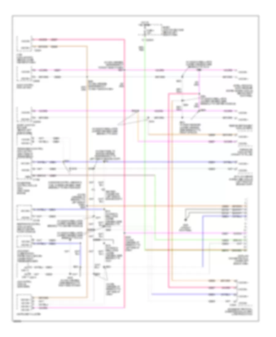
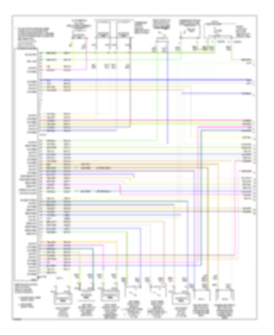
AIR CONDITIONING
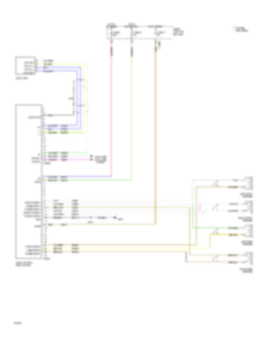
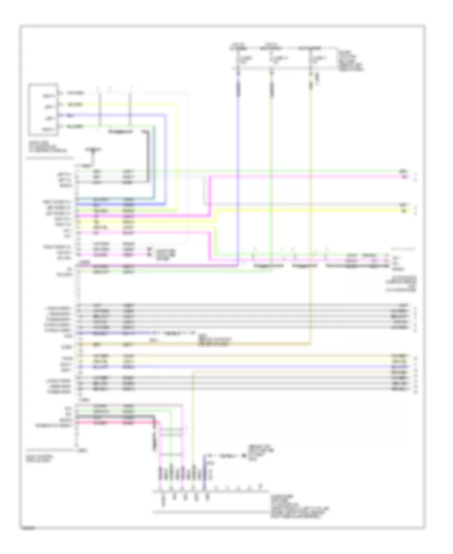
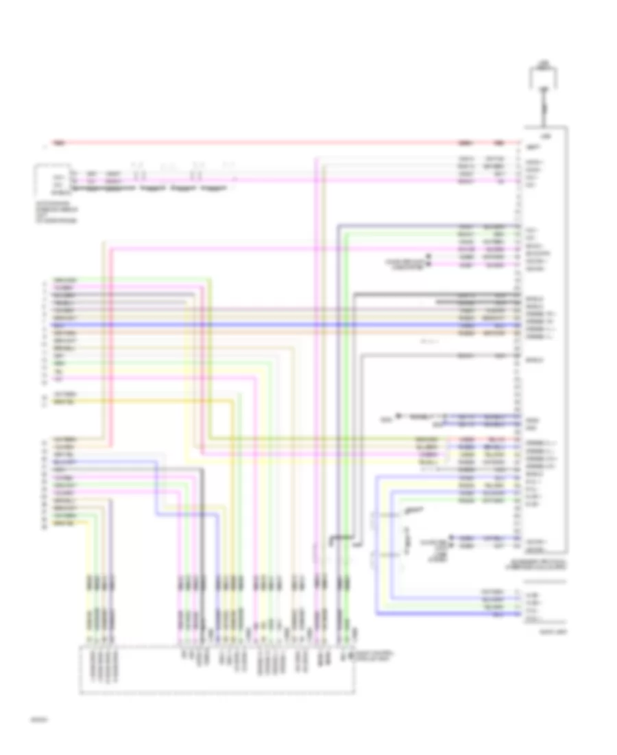
Automatic A/C Wiring Diagram (1 of 2) for Ford Explorer 2008

List of elements for Automatic A/C Wiring Diagram (1 of 2) for Ford Explorer 2008:
- (in air conditioner harness, near breakout for c211) s231
- Amb temp
- Ambient air temperature sensor (left front of engine compt, near radiator support)
- Anti theft
- Autolamp/ sunload sensor (behind glove box)
- Battery junction box (bjb) (left side of engine compt, at fender apron)
- Bd pot
- Bd pot 5v
- Blower ctrl
- Blower motor relay 1
- C2280c
- C2280d
- C228a
- C228b
- Cbp20
- Ch123
- Ch211
- Ch213
- Ch217
- Ch218
- Ch220
- Ch221
- Ch222
- Ch223
- Ch224
- Ch237
- Ch239
- Cln04
- Computer data lines system
- Datc hvac module (behind lower center of dash)
- Dimming in
- Driver temperature blend door actuator (rear left side of hvac unit)
- Explorer & mountaineer
- Fb out
- Front blower motor (right side of hvac unit)
- Front blower motor speed controller (center of hvac unit)
- Fuse 16 40a
- Fuse 20 10a
- Fuse 24 10a
- Fuse 28 10a
- G105 (left side of engine compt)
- G201 (under right side of dash)
- G302 (base of right "b" pillar)
- Gd145
- Gnd
- Ground
- Hat
- Hbr sw in
- Hot at all times
- Hot w/ run/start relay energized
- In car temp
- In-vehicle temperature sensor (behind left center of dash)
- Instrument cluster
- Interior lights system
- Left bd a+
- Left bd b-
- Left bd feedback
- Left sunload
- Lh111
- Ms can+
- Ms can-
- Mtr sink
- Passenger temperature blend door actuator (front left side of hvac unit)
- Pwr gnd
- Remote solenoid assembly (behind center of dash)
- Rh104
- Rh111
- Rh226
- Right bd a+
- Right bd b-
- Right bd feedback
- Right sunload
- Run/start
- S131 (4.0l: in dash panel to engine harness, near breakout to left side of dash) (4.6l: in dash panel to engine harness, near breakout to engine compt bulkhead)
- S202 (in main harness, near breakout to right side of dash)
- S219
- Sbp28
- Sense a/d
- Smart junction box (sjb) (behind left side of dash)
- Sn gnd
- Vac 1
- Vac 2
- Vac 3
- Vac 4
- Vac 5
- Vac 5 hcwv
- Vac gnd
- Var spd in
- Vbc fb
- Vbc hbr
- Vbc out
- Vdb06
- Vdb07
- Vh219
- Vh407
- Vh414
- Vh416
- Vh417
- Vh440
- Vh441
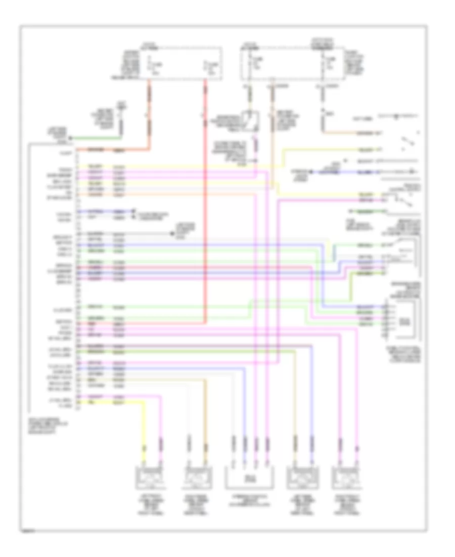
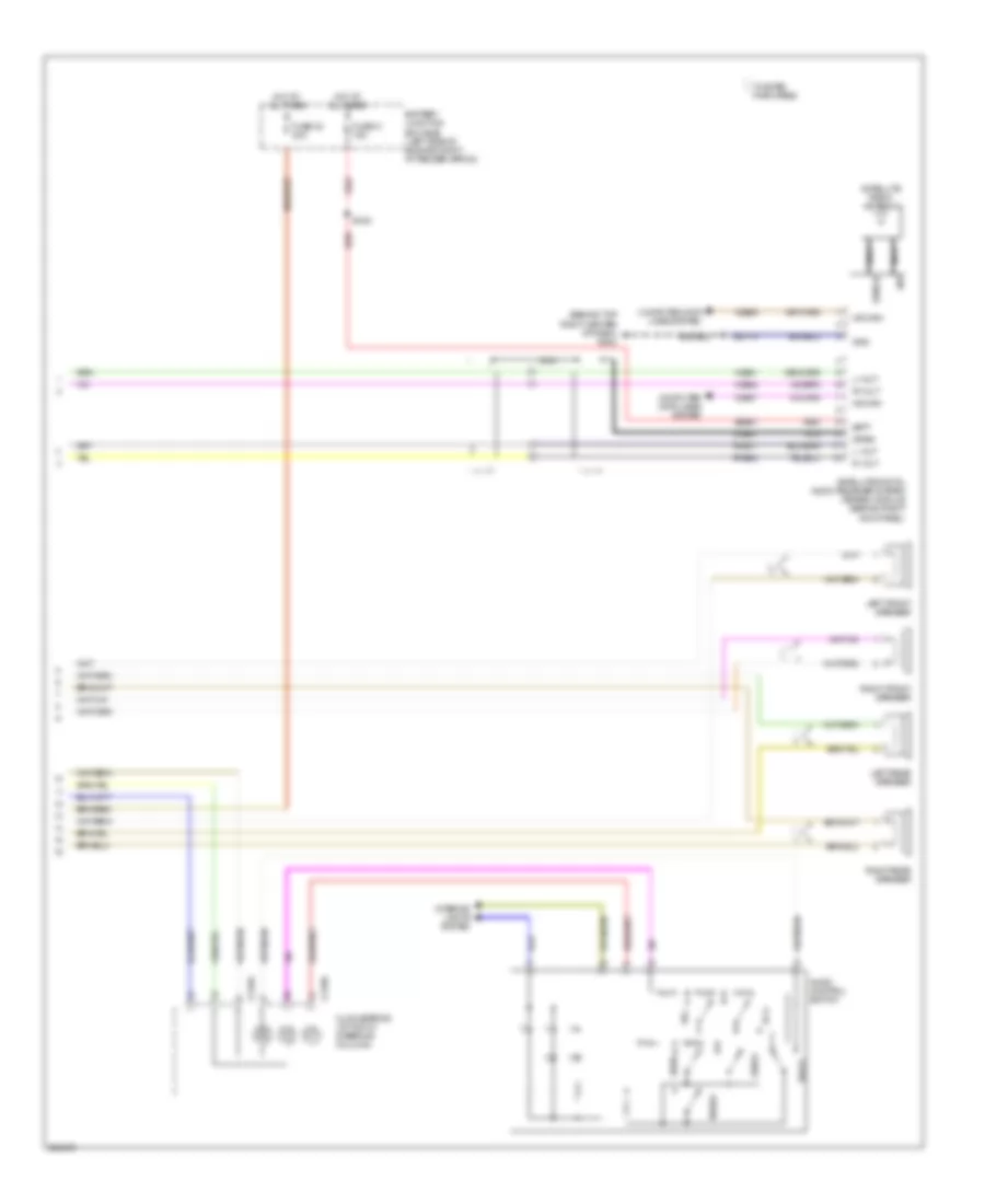
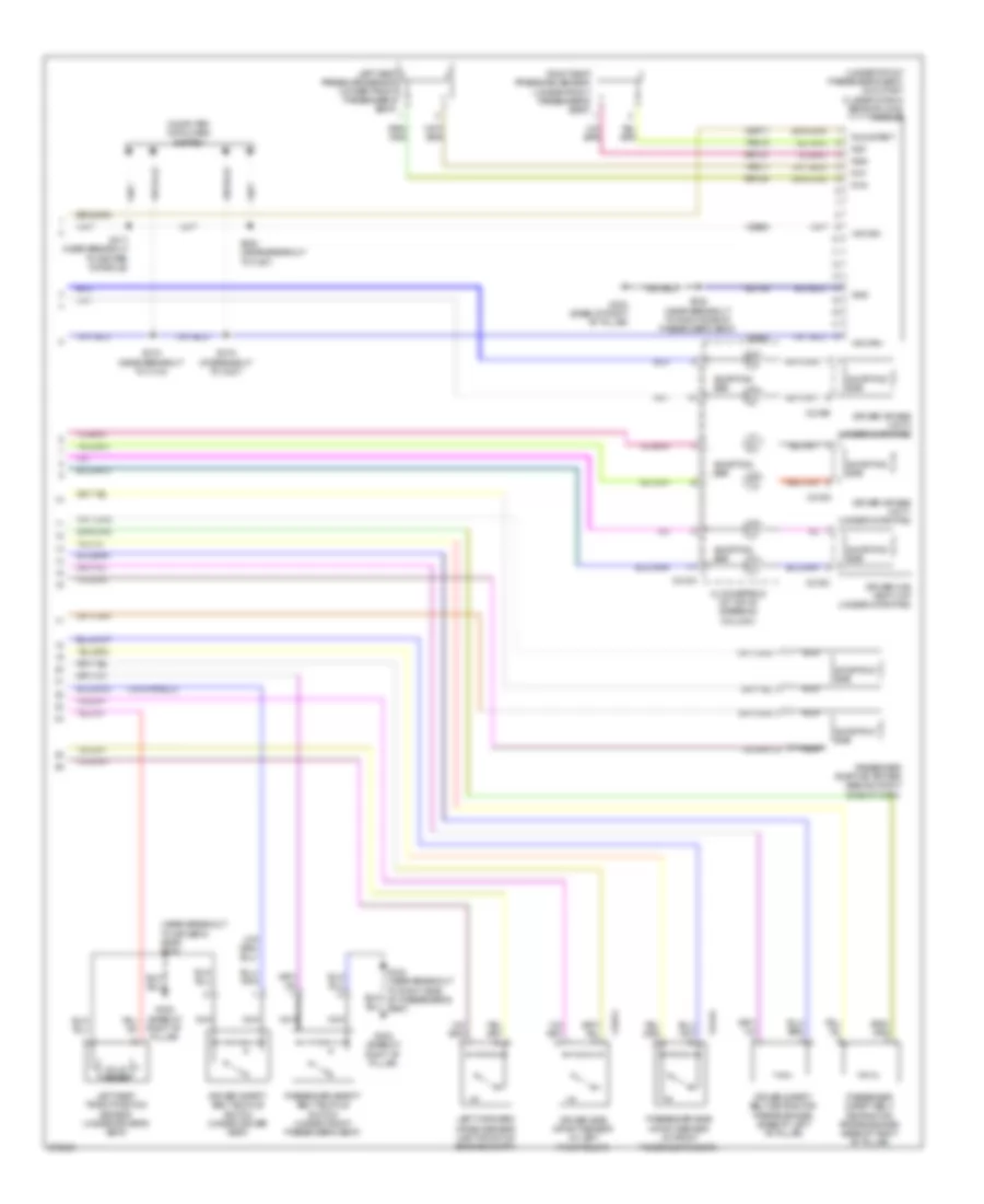
Automatic A/C Wiring Diagram (2 of 2) for Ford Explorer 2008
List of elements for Automatic A/C Wiring Diagram (2 of 2) for Ford Explorer 2008:
- (4.0l) (4.6l)
- (4.0l: at left front of engine) (4.6l: right front of engine) a/c clutch solenoid
- (4.0l: near breakout to right cylinder head valve cover) (4.6l: near breakout to right side of engine compt) s107
- (in air conditioning jumper harness, near breakout to left rear quarterpanel) s391
- (in dash panel to engine harness, near breakout to g106) s114
- (left rear corner of vehicle) g400
- A/c clutch cycling pressure switch (right side of engine compt)
- A/c clutch relay
- A/c pressure transducer (left front of engine compt)
- Accr
- Acds1
- Acpt
- Auxiliary blower motor (left side of cargo area)
- Auxiliary blower motor relay (on auxiliary blower motor assembly)
- Auxiliary blower motor resistor assembly (on auxiliary blower motor)
- Battery junction box (bjb) (left side of engine compt, at fender apron)
- C175b
- C175e
- C2280a
- C951a
- C951b
- Cbp18
- Ch302
- Ch423
- Cha06
- Cha07
- Cha08
- Cha11
- Cha12
- Cha16
- Cln04
- Ect
- Electronic fan clutch (center front of engine)
- Engine controls system
- Engine coolant temperature (ect) sensor (4.0l) (top center front of engine)
- Explorer & mountaineer
- Fc v
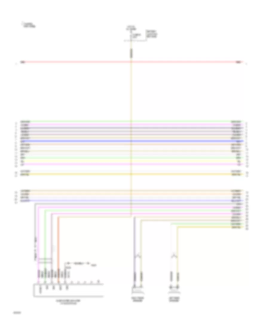
- Front auxiliary climate control assembly assembly
- Fss
- Fuse 10a
- Fuse 15a
- Fuse 18 10a
- Fuse 30a
- G105 (left side of engine compt)
- G106 (right side of engine compt)
- G400 (left rear corner of vehicle)
- Gd149
- Gnd
- Ground
- High speed
- Hot at all times
- Hot w/ pcm relay energized
- Hot w/ run/start relay energized
- Illum
- Interior lights system
- Le111
- Le423
- Low
- Medium high
- Medium low
- Mode out ceiling
- Mode out floor
- Powertrain control module (pcm) (right side of engine)
- Re405
- Re407
- Rear blend door actuator (behind left rear quarterpanel)
- Rear mode door actuator (behind left rear quarterpanel)
- S103
- S105 (in engine control sensor & fuel charge harness, at breakout to right side of engine compt)
- S113 s119
- S346
- S392
- S396 (in interior light harness, near breakout to c315)
- Sig rtn
- Sigrtnc
- Sigrtne
- Smart junction box (sjb) (behind left side of dash)
- Temp
- Thermal lumber
- Vbpwr
- Ve716
- Vec03
- Vec10
- Vh433
- Vha09
- Vpwr
- Vref
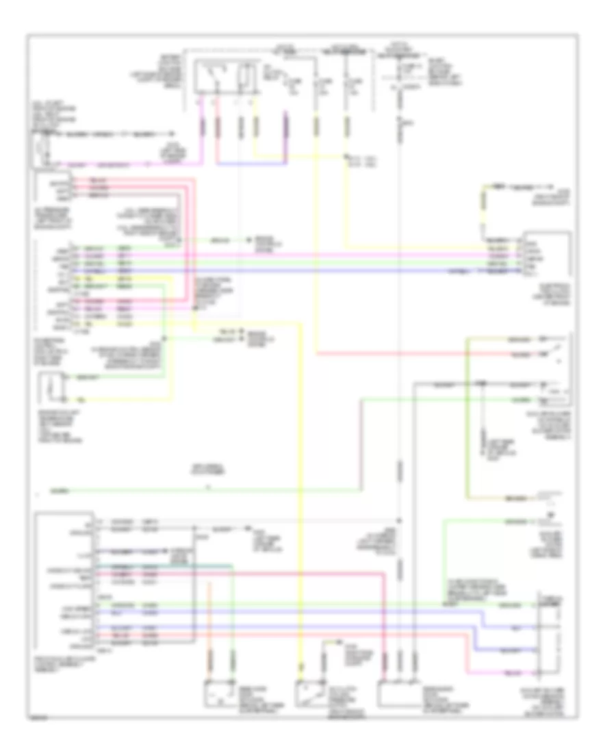
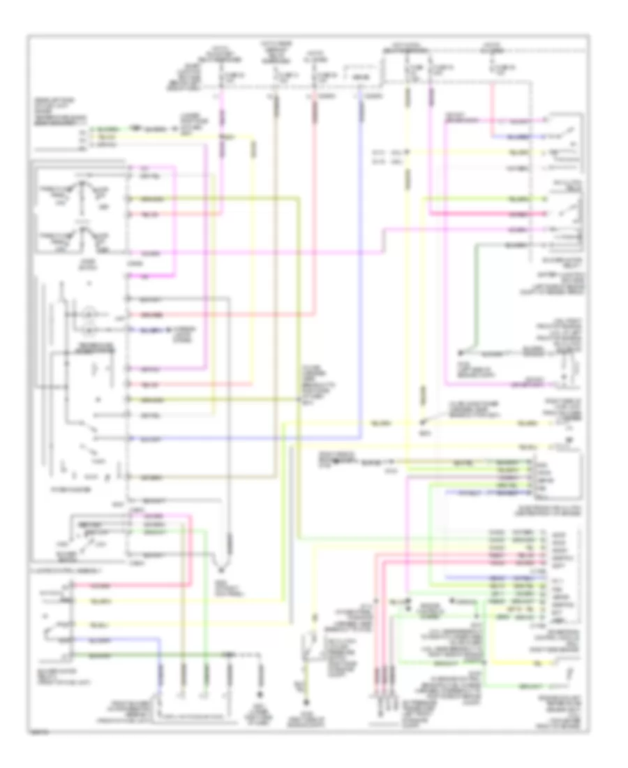
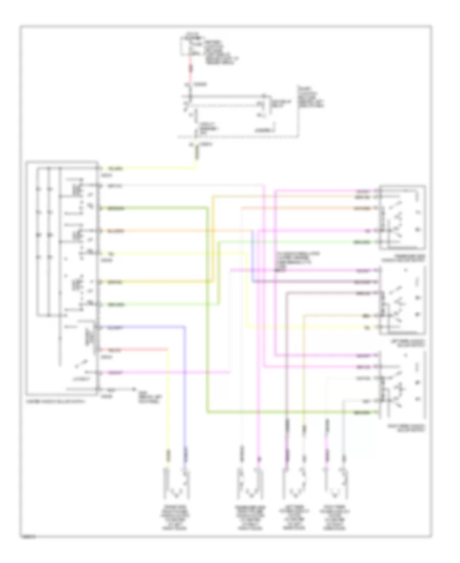
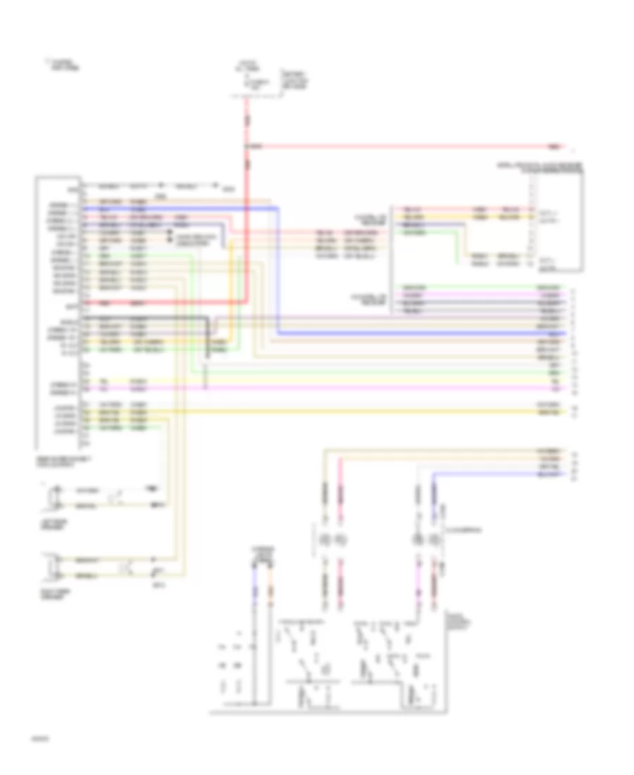
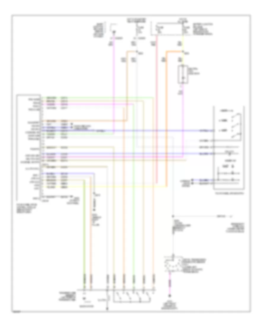
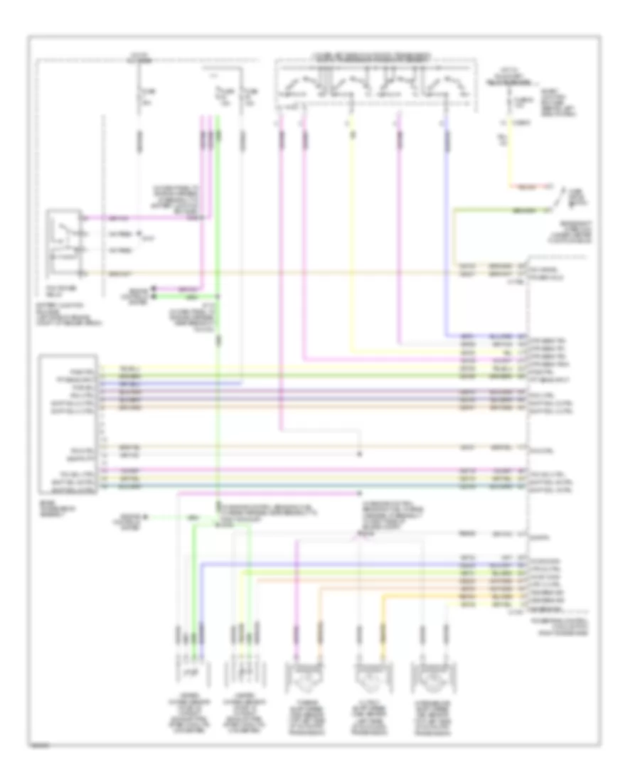
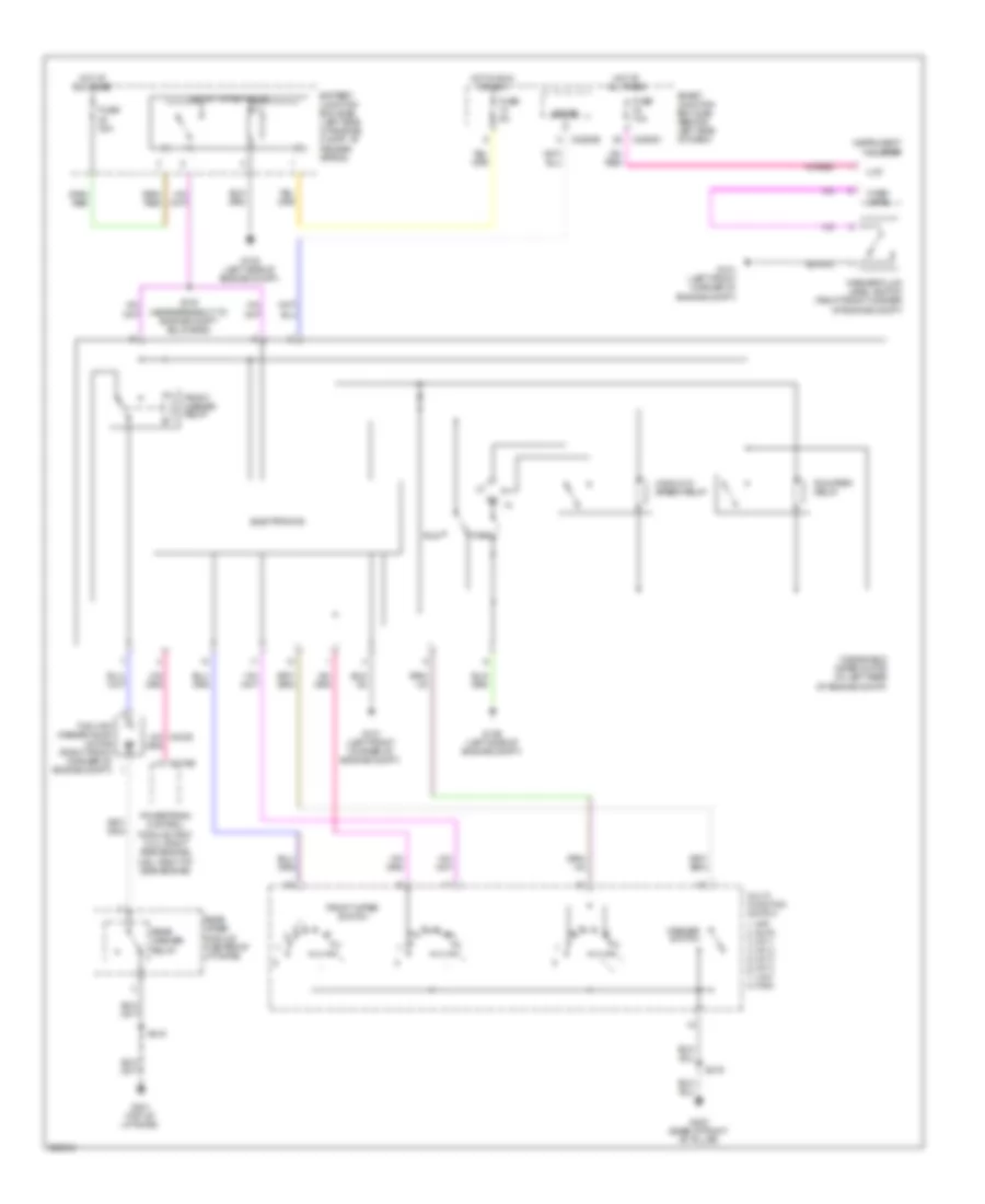
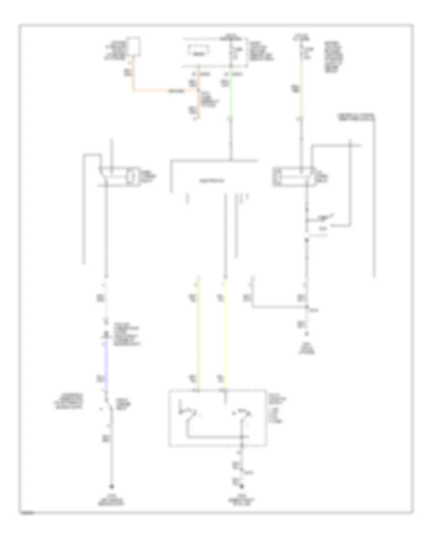
Manual A/C Wiring Diagram for Ford Explorer 2008
List of elements for Manual A/C Wiring Diagram for Ford Explorer 2008:
- (4.0l)
- (4.6l)
- (4.6l: right front of engine) (4.0l: at left front of engine) a/c clutch solenoid
- (in air conditioner harness, near breakout for g201)
- (in main harness, near breakout to right side of dash) s213
- (rear left side of hvac unit) driver temperature blend door actuator
- (right side of engine compt) g106
- (right side of hvac unit) front blower motor
- (under right side of dash) g201
- 87a
- A/c clutch cycling pressure switch (right side of engine compt)
- A/c clutch relay
- A/c pressure transducer (left front of engine compt)
- Accr
- Accs
- Acds1
- Acpt
- Battery junction box (bjb) (left side of engine compt, at fender apron)
- Blower motor relay 1
- Blower motor relay 2 (front of hvac unit)
- Blower switch
- C175b
- C175e
- C2280c
- C2280d
- C294a
- C294b
- C294c
- Ch302
- Ch423
- Ch443
- Climate control assembly
- Def
- Ect
- Electronic fan clutch (center front of engine)
- Engine controls system
- Engine coolant temperature sensor (ect) (4.0l) (top center front of engine)
- Fc v
- Floor
- Front blower motor resistor assembly (front of hvac unit)
- Fss
- Fuse 13 15a
- Fuse 15a
- Fuse 16 40a
- Fuse 20 10a
- Fuse 28 10a
- Fuse 35 10a
- G105 (left side of engine compt)
- G106 (right side of engine compt)
- G200 (at right kick panel)
- G201 (under right side of dash)
- Gnd
- Hat
- High
- Hot at all times
- Hot w/ pcm relay energized
- Hot w/ rear defrost relay energized
- Hot w/ run/start relay energized
- Interior lights system
- Le111
- Le423
- Low
- Max
- Med high
- Med low
- Mix
- Mode switch
- Off
- Panel
- Panel/floor
- Potentiometer
- Powertrain control module (pcm) (right side engine)
- Re405
- Re407
- S103
- S105 (in engine control sensor & fuel charge harness, at breakout to right side of engine compt)
- S107 (4.0l: near breakout to right cylinder head valve cover) (4.6l: near breakout to right side of engine compt)
- S113
- S114 (in dash panel to engine harness, near breakout to g106)
- S119
- S201
- S232
- S233
- Sense
- Sig rtn
- Sigrtnc
- Sigrtne
- Smart junction box (sjb) (behind left side of dash)
- Temperature potentiometer
- Vbpwr
- Ve716
- Vec03
- Vec10
- Vh433
- Vpwr
- Vref
ANTI-LOCK BRAKES
Anti-lock Brakes Wiring Diagram for Ford Explorer 2008
List of elements for Anti-lock Brakes Wiring Diagram for Ford Explorer 2008:
- (in dash panel to engine harness, near breakout to left front of vehicle) s128
- (left side of engine compt) g105
- (not used)
- Abs test connector (left side of engine compt)
- Anti-lock brake system (abs) module (left front of engine compt)
- Battery junction box (bjb) (left side of engine compt, at fender apron)
- Boo logic
- Bpfs nc
- Bpfs no
- Bpfs sig
- Brake booster sensor (on front of brake booster)
- Brake fluid level switch (mounted on side of master cylinder)
- Brake pedal position switch (above brake pedal)
- Bst pwm
- Bst pwr
- C2280c
- C2280e
- Can2 hi
- Can2 lo
- Cbp18
- Cca09
- Cca15
- Cca22
- Cca25
- Cca26
- Cca29
- Ccb08
- Ccs01
- Clus gnd
- Clus sensep
- Cmc19
- Computer data lines system
- Fl gnd
- Fluid lvl sw
- Fluid sw ret
- Fr gnd
- Fuse 10a
- Fuse 15a
- Fuse 30a
- Fuse 40a
- G105 (left side of engine compt)
- G200 (at right kick panel)
- Gd120
- Ground p
- Hot at all times
- Hot w/ run/ start relay energized
- Hs can+
- Hs can-
- Ign
- Interior lights system
- Kl30 p
- Kl30 v
- Left front wheel speed sensor (at left front wheel)
- Left rear wheel speed sensor (at left rear wheel)
- Lf whl spd+
- Lr whl spd+
- Lr whl spd-
- Rca09
- Rca17
- Rca18
- Rca19
- Rca20
- Rcs02
- Red
- Rf whl spd+
- Right front wheel speed sensor (at right front wheel)
- Right rear wheel speed sensor (at right rear wheel)
- Rmc19
- Rr whl spd+
- Rr whl spd-
- S208
- Sbb06
- Sbb33
- Smart junction box (sjb) (behind left side of dash)
- Solid state
- St ang 1(cha)
- St ang 2(chb)
- Stability control sensor cluster (below center floor console)
- Steering position sensor (on steering column)
- Swar gnd
- Swar sensep
- Tcs sw
- Traction control switch
- Vca03
- Vca04
- Vca05
- Vca06
- Vca22
- Vca23
- Vca24
- Vcs06
- Vcs07
- Vdb04
- Vdb05
ANTI-THEFT
Forced Entry Wiring Diagram for Ford Explorer 2008
List of elements for Forced Entry Wiring Diagram for Ford Explorer 2008:
- 1/2
- 3/4
- 5/6
- 7/8
- 9/0
- All lock & unlock relay
- C2280a
- C2280b
- Cntrl
- Door locks system
- Driver side front door ajar switch (at rear of left front door)
- Driver side rear door ajar switch (at rear of left rear door)
- Driver unlock & liftgate release relay
- Fuse 20a
- G300 (behind left kick panel)
- G301 (base of left "b" pillar)
- G402 (right rear corner of vehicle)
- Hot at all times
- Hsd
- Key pad switch assembly
- Liftgate ajar switch (lower center of liftgate)
- Liftgate glass ajar switch (in center of liftgate)
- Liftgate glass release switch
- Off
- Passenger side front door ajar switch (at rear of right front door)
- Passenger side rear door ajar switch (at rear of right rear door)
- S410 (in tailgate warning switch harness, near breakout to c432)
- S411
- S501
- S600
- Sense
- Smart junction box (sjb) (behind left side of dash)
- Wiper/ washer system
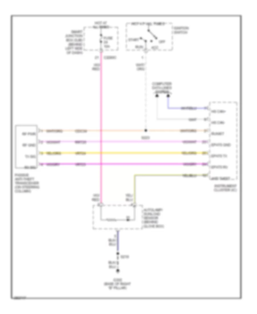
Passive Anti-theft Wiring Diagram for Ford Explorer 2008
List of elements for Passive Anti-theft Wiring Diagram for Ford Explorer 2008:
- Acc
- Anti theft
- Autolamp/ sunload sensor (behind glove box)
- C2280c
- Cdc34
- Computer data lines system
- Epats gnd
- Epats rx
- Epats tx
- Fuse 10a
- G302 (base of right "b" pillar)
- Hot at all times
- Hs can+
- Hs can-
- Ignition switch
- Instrument cluster (ic)
- Off
- Passive anti-theft transceiver (on steering column)
- Rf gnd
- Rf pwr
- Rrt25
- Run
- Run/st
- Rx sig
- S219
- S223
- Smart junction box (sjb) (behind left side of dash)
- Start
- Tx sig
- Vrt23
- Vrt24
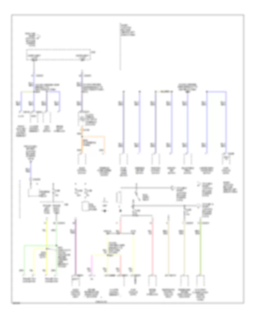
BODY CONTROL MODULES
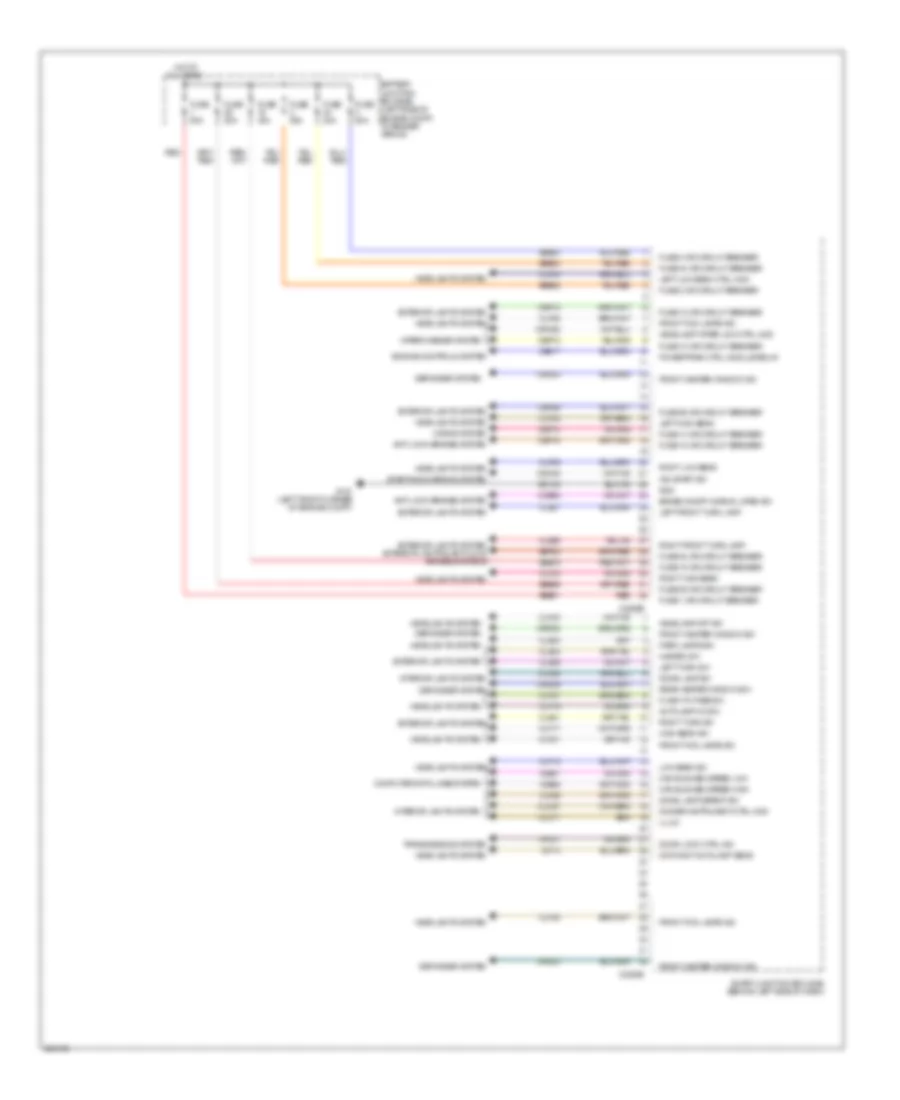
Body Control Modules Wiring Diagram (1 of 2) for Ford Explorer 2008
List of elements for Body Control Modules Wiring Diagram (1 of 2) for Ford Explorer 2008:
- 3rd row seat ctrl mod relay
- Acc
- Air conditioning system
- All excluding drv
- Anti-lock brakes system
- Anti-theft system
- Backup lamps relay
- Battery saver relay
- Brake on/off normal open sw
- C2280a
- C2280b
- C2280c
- Cat06
- Cat09
- Cat16
- Cat17
- Cbp05
- Cbp11
- Cbp12
- Cbp13
- Cbp15
- Cbp17
- Cbp18
- Cbp20
- Cbp26
- Cbp80
- Ccb08
- Ccb09
- Cdc33
- Cdc34
- Cln01
- Cln03
- Cln04
- Cln15
- Cln25
- Cls18
- Cls19
- Cls44
- Computer data lines system
- Cpk28
- Cpk29
- Cpk30
- Cpk31
- Cpl11
- Cpl26
- Cpl31
- Cpl36
- Cpl39
- Cpl42
- Cpl43
- Cpl45
- Cpl51
- Cpl52
- Cpl58
- Cpl59
- Cps48
- Crd06
- Crh02
- Defogger system
- Door lock all lock
- Door locks system
- Dr lock drv unlock ctrl mod
- Dr lock liftgate glass rls rly
- Elec park brake on sw
- Exterior lights system
- Fuse 1 or circuit breaker
- Fuse 11 or circuit breaker
- Fuse 12 or circuit breaker
- Fuse 13 or circuit breaker
- Fuse 15 or circuit breaker
- Fuse 17 or circuit breaker
- Fuse 18 or circuit breaker
- Fuse 20 or circuit breaker
- Fuse 24 or circuit breaker
- Fuse 26 or circuit breaker
- Fuse 28 or circuit breaker
- Fuse 3 or circuit breaker
- Fuse 4 or circuit breaker
- Fuse 5 or circuit breaker
- Fuse 8 or circuit breaker
- Fuse 80 or circuit breaker
- G300 (behind left kick panel)
- Gd133
- Glove box lamp sw
- Gnd
- Horn sw
- Horns system
- Ign run acc sw
- Ign run start sw
- Ignition switch
- Illum
- Instrument cluster system
- Int illum ctrl mod
- Interior lights
- Interior lights system
- Keyless keypad ctrl mod sw
- Keyless keypad line a sw
- Keyless keypad line b sw
- Keyless keypad line c sw
- Latch drv ajar sw
- Latch pass ajar sw
- Latch rear drv side ajar sw
- Latch rear pass side ajar sw
- Left stop/turn ctrl mod
- Left trailer turn sig ctrl mod
- Liftgate/decklid glass ajar sw
- Liftgate/decklid release sw
- Mirrors & exterior lights systems
- Mirrors system
- Navigation, mirrors, instrument cluster & air conditioning systems
- Off
- Power tops & seats systems
- Power tops system
- Power windows system
- Puddle lamps relay
- Rear heater window relay
- Red
- Right stop/turn ctrl mod
- Right turn sig
- Rpk27
- Run
- S300
- Sbp01
- Sbp03
- Sbp04
- Sbp08
- Sbp24
- Sbp28
- Seats & memory systems
- Seats system
- Shift interlock system
- Smart junction box (sjb) (behind left side of dash)
- Sound systems
- Start
- Stop ctrl mod
- Trailer tow park lamps rly
- Transmissions, seats & anti-lock brakes systems
- Trim door lock (drv) lock sw
- Trim door lock (drv) unlock sw
- Wiper/washer system
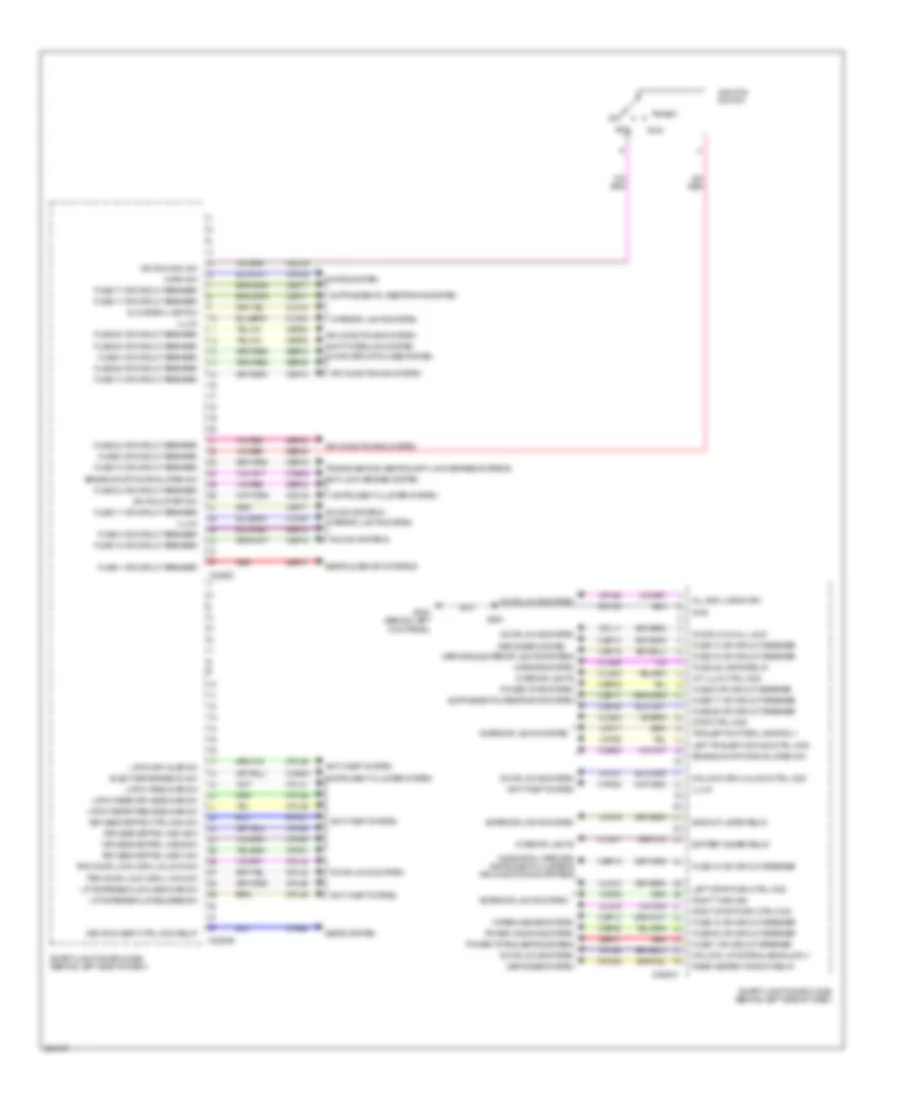
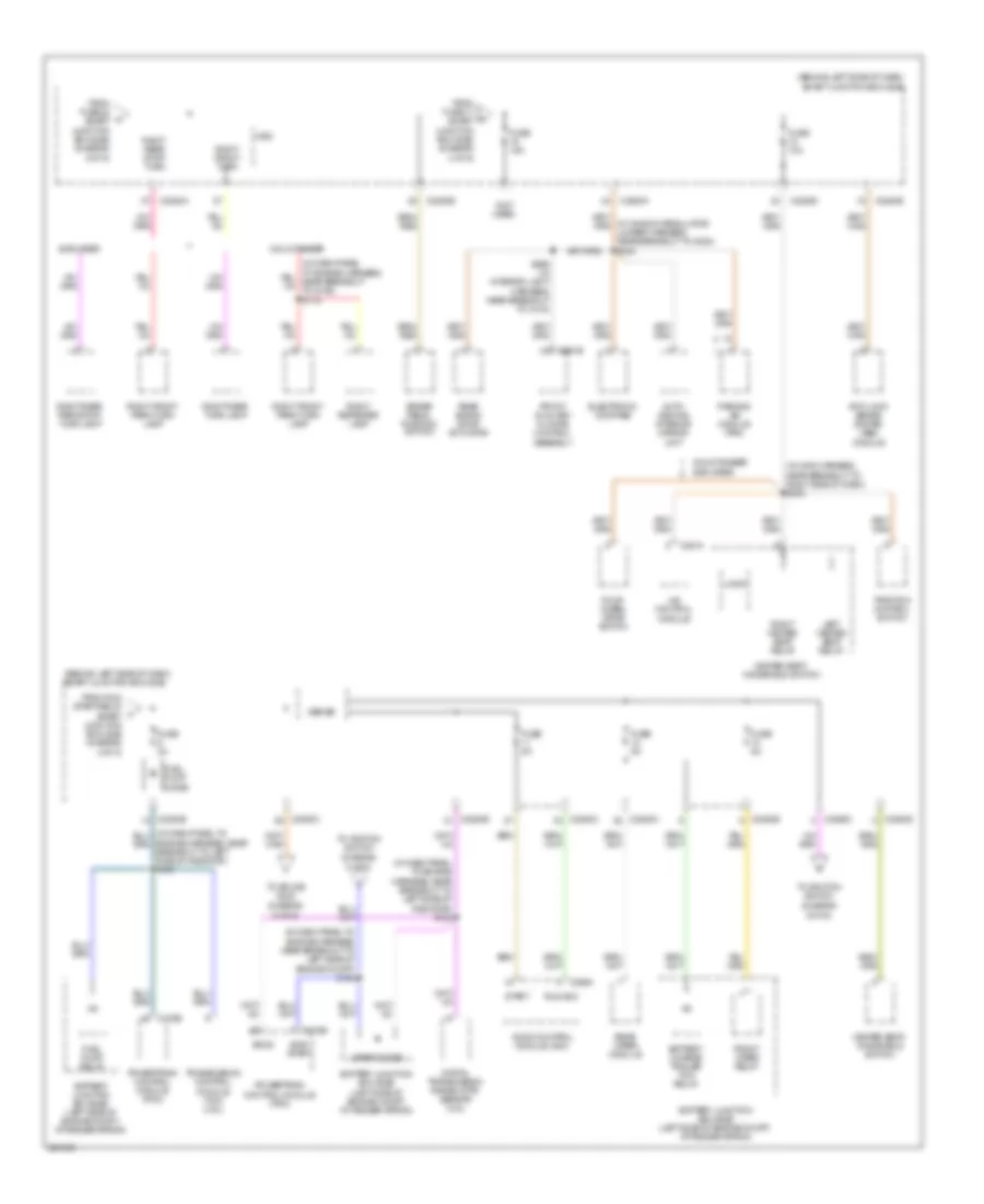
Body Control Modules Wiring Diagram (2 of 2) for Ford Explorer 2008
List of elements for Body Control Modules Wiring Diagram (2 of 2) for Ford Explorer 2008:
- Anti lock brakes system
- Anti-lock brakes system
- Autolamp on sw
- Battery junction box (bjb) (left side of engine compt, at fender apron)
- Brake on/off normal open sw
- C2280d
- C2280e
- Can bus med speed high
- Can bus med speed low
- Cbp10
- Cbp12
- Cbp14
- Cbp18
- Cbp26
- Ccb08
- Cdc38
- Ce517
- Clf02
- Clf03
- Clf04
- Clf05
- Clf17
- Clf18
- Clf19
- Clf21
- Clf23
- Clf27
- Clf28
- Cln17
- Cln27
- Cln28
- Cls21
- Cls25
- Cls32
- Cls34
- Cls39
- Cls41
- Computer data lines system
- Cpl01
- Crd03
- Crd08
- Crd09
- Crw22
- Day/night autolamp sens
- Defogger system
- Dimmer instrument ctrl mod
- Dome lamp defeat sw
- Dome lamp sw
- Door lock ctrl ind
- Engine controls system
- Exterior lights system
- Exterior lights system exterior lights & anti-lock brakes systems
- Flash to pass sw
- Front fog lamps ind
- Front fog lamps sw
- Front heater window ind
- Front heater window sw
- Fuse 1 or circuit breaker
- Fuse 10 or circuit breaker
- Fuse 12 or circuit breaker
- Fuse 14 or circuit breaker
- Fuse 15 or circuit breaker
- Fuse 18 or circuit breaker
- Fuse 2 or circuit breaker
- Fuse 20a
- Fuse 22 or circuit breaker
- Fuse 26 or circuit breaker
- Fuse 29 or circuit breaker
- Fuse 3 or circuit breaker
- Fuse 34 or circuit breaker
- Fuse 40a
- Fuse 50a
- G101 (left front corner of engine compt)
- Gd108
- Gnd
- Hazard sw
- Headlamp off sw
- Headlamp wiper link ctrl mod
- Headlights system
- High beam sw
- Horns system
- Hot at all times
- Ign start sw
- Illum
- Interior lights system
- Left front turn lamp
- Left high beam
- Left low beam ctrl mod
- Left turn sw
- Low beam sw
- Park lamps sw
- Powertrain ctrl module relay
- Rear heater window sw
- Red
- Right front turn lamp
- Right high beam
- Right low beam
- Right turn sw
- Sbb01
- Sbb02
- Sbb03
- Sbb15
- Sbb29
- Sbb34
- Sbp22
- Smart junction box (sjb) (behind left side of dash)
- Starting/charging system
- Transmissions system
- Vdb06
- Vdb07
- Vlf14
- Vln36
- Wiper/washer system
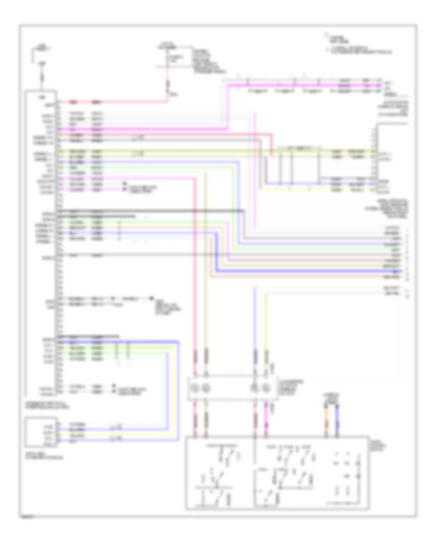
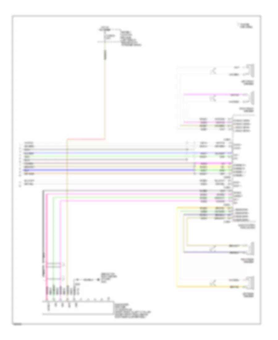
COMPUTER DATA LINES
4.0L
4.0L, Computer Data Lines Wiring Diagram for Ford Explorer 2008
List of elements for 4.0L, Computer Data Lines Wiring Diagram for Ford Explorer 2008:
- (in dash panel to engine harness, near breakout to left side of engine compt) s124
- (in main harness, at breakout to left side of dash)
- (in main harness, at breakout to left side of dash) s226
- (in main harness, near breakout to right side of dash) s207
- (in window regulator jumper harness, in breakout to g402)
- (in window regulator jumper harness, near breakout to c144)
- (in window regulator jumper harness, near breakout to c214) s322
- (in window regulator jumper harness, near breakout to c340) s316
- (in window regulator jumper harness, near breakout to center console)
- (in window regulator jumper harness, near breakout to g302)
- 4x4 control module (explorer)
- Accessory protocol interface module (apim) (late production)
- Anti-lock brake system (abs) module (left front of engine compt)
- Audio control module (acm)
- C175b
- C2280c
- C2280d
- C228a
- C290b
- C310b
- C3342
- C341c
- Data link connector (dlc) (under left side of dash)
- Driver seat module (dsm) (in driver's seat)
- Feps
- Fuse 4 10a
- G200 (at right kick panel)
- Gd138
- Hot at all times
- Hs can +
- Hs can -
- Hs can - c281a
- Hvac module (datc) (behind lower center of dash)
- Instrument cluster
- Ms can +
- Ms can -
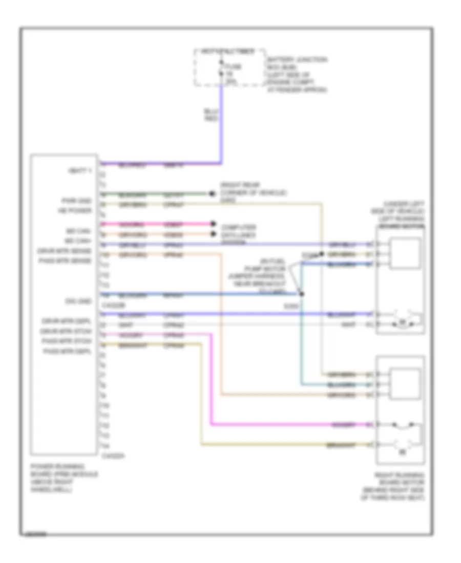
- Occupant classification system module(ocsm) (under front passenger's seat)
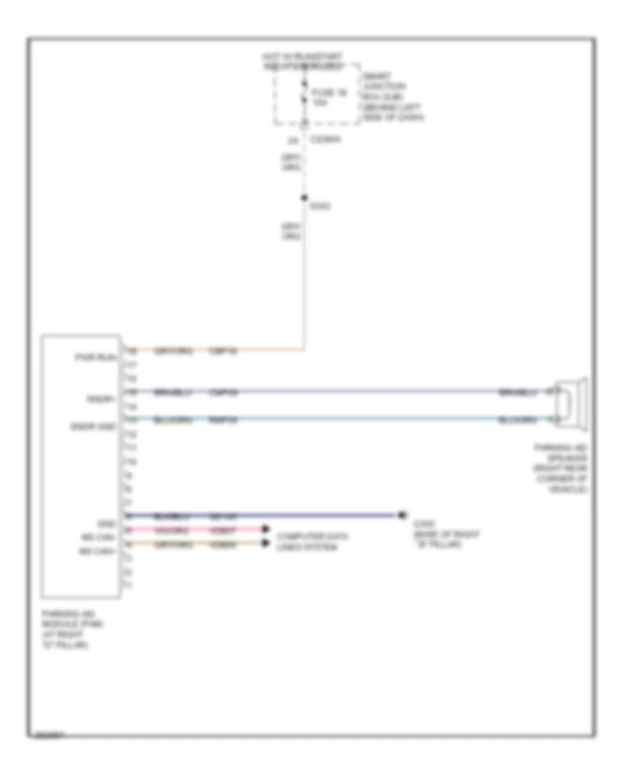
- Parking aid module (pam) (at right "d" pillar)
- Power running board (prb) module (above right wheelwell)
- Powertrain control module (pcm) (right side engine)
- Rear entertainment module (retm)
- Restraints control module (rcm) (below center floor console)
- S122
- S204
- S205 (in main harness, near breakout to right side of dash)
- S220
- S224
- S225 (in main harness, at breakout to left side of dash)
- S315
- S317
- S320
- S323
- S325
- S326
- S354
- S355
- S356
- S401
- S402
- S909
- S910 (in radio receiver jumper harness, near breakout to front of roof)
- Satellite digital audio receiver system (sdars) module (behind right kick panel)
- Sbp04
- Smart junction box (sjb) (behind left side of dash)
- To right side of dash)
- Vdb04
- Vdb05
- Vdb06
- Vdb07
- Vdb09
4.6L
4.6L, Computer Data Lines Wiring Diagram for Ford Explorer 2008
List of elements for 4.6L, Computer Data Lines Wiring Diagram for Ford Explorer 2008:
- (in dash panel to engine harness, near breakout to left side of engine compt) s124
- (in engine control sensor & fuel charge harness, near breakout to right exhaust)
- (in main harness, at breakout to left side of dash)
- (in main harness, at breakout to left side of dash) s226
- (in main harness, near breakout to right side of dash) s207
- (in window regulator jumper harness, near breakout to c144)
- (in window regulator jumper harness, near breakout to c214) s322
- (in window regulator jumper harness, near breakout to center console)
- (in window regulator jumper harness, near breakout to g303)
- 4x4 control module (explorer)
- Abs test connector (left side of engine compt)
- Accessory protocol interface module (apim) (late production)
- Anti-lock brake system (abs) module (left front of engine compt)
- Audio control module (acm)
- C175b
- C2280c
- C2280d
- C228a
- C290b
- C310b
- C3342
- Data link connector (dlc) (under left side of dash)
- Feps
- Fuse 4 10a
- G200 (at right kick panel)
- Gd138
- Harness, near breakout to c327)
- Hot at all times
- Hs can +
- Hs can -
- Hs can - c281a
- Hvac module (datc) (behind lower center of dash)
- Instrument cluster
- Ms can +
- Ms can -
- Occupant classification system module(ocsm) (under front passenger's seat)
- Parking aid module (pam) (at right "d" pillar)
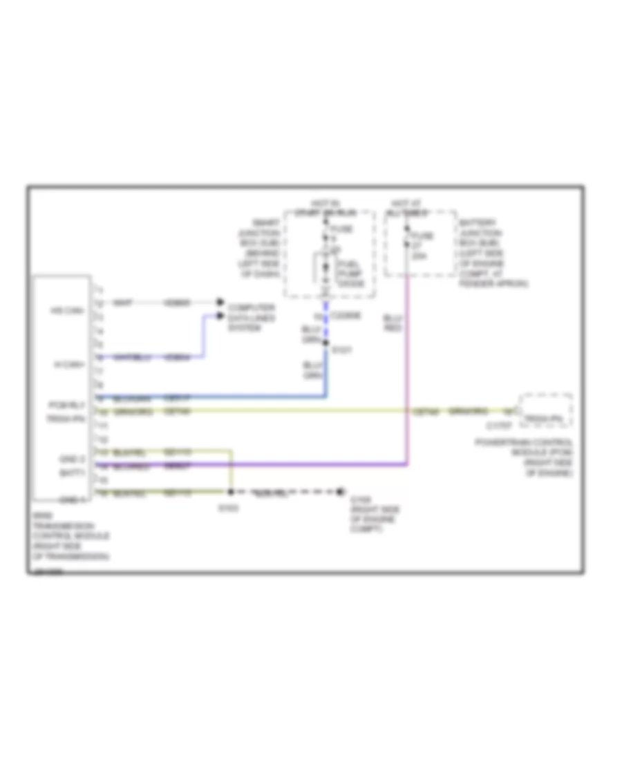
- Powertrain control module (pcm) (right side engine)
- Rear entertainment module (retm)
- Restraints control module (rcm) (below center floor console)
- S101
- S102
- S122
- S204
- S205 (in main harness, near breakout to right side of dash)
- S220
- S224
- S225 (in main harness, at breakout to left side of dash)
- S317
- S320
- S323
- S344
- S345
- S354
- S355
- S356
- S909
- S910 (in radio receiver jumper harness, near breakout to front of roof)
- Satellite digital audio receiver system (sdars) module (behind right kick panel)
- Sbp04
- Smart junction box (sjb) (behind left side of dash)
- To right side of dash)
- Transmission control module (tcm) (right side of transmission)
- Vdb04
- Vdb05
- Vdb06
- Vdb07
- Vdb09
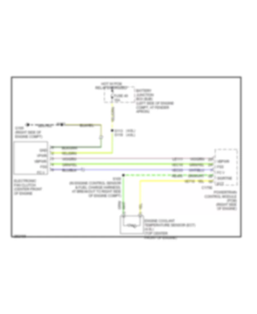
COOLING FAN
Cooling Fan Wiring Diagram for Ford Explorer 2008
List of elements for Cooling Fan Wiring Diagram for Ford Explorer 2008:
- (4.0l) (4.6l)
- Battery junction box (bjb) (left side of engine compt, at fender apron)
- C175e
- Ect
- Electronic fan clutch (center front of engine
- Engine coolant temperature sensor (ect) (4.0l) (top center front of engine)
- Fc v
- Fss
- Fuse 40 15a
- G106 (right side of engine compt)
- Gnd
- Hot w/ pcm relay energized
- Le111
- Powertrain control module (pcm) (right side of engine)
- Re405
- S103
- S105 (in engine control sensor & fuel charge harness, at breakout to right side of engine compt)
- S113 s119
- Sigrtne
- Vbpwr
- Ve716
- Vec03
- Vec10
- Vpwr
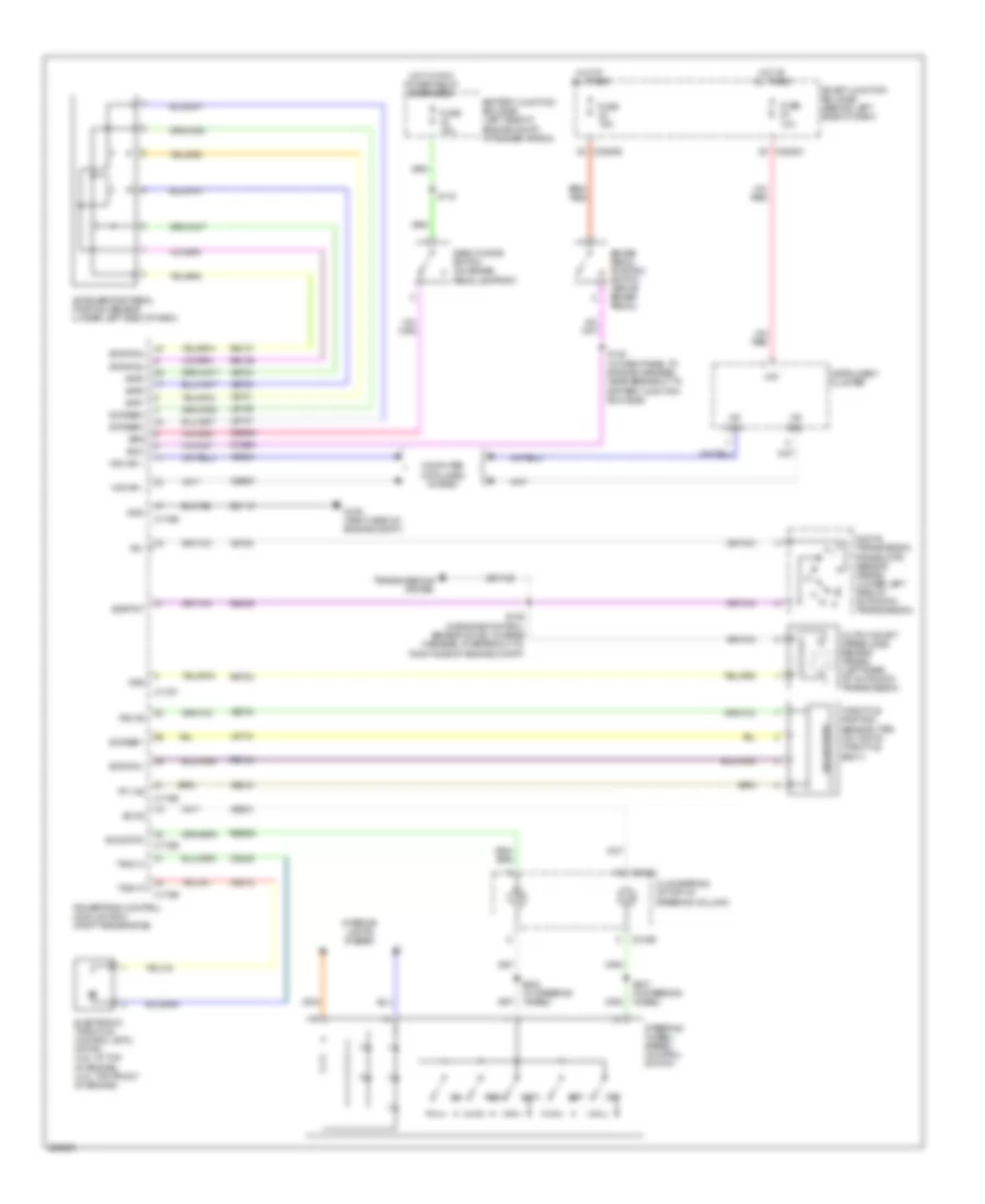
CRUISE CONTROL
Cruise Control Wiring Diagram for Ford Explorer 2008
List of elements for Cruise Control Wiring Diagram for Ford Explorer 2008:
- Accelerator pedal position sensor (under left side of dash)
- App1
- App2
- App3
- Battery junction box (bjb) (left side of engine compt, at fender apron)
- Boo
- Bps
- Brake pedal position switch (above brake pedal)
- C175b
- C175e
- C175t
- C218a
- C218b
- C2280c
- C2280e
- Ccb08
- Ce412
- Ce426
- Ces09
- Clockspring (at top of steering column)
- Computer data lines system
- Deactivator switch (on brake pedal support)
- Digital transmission range (dtr) sensor (5r55s) (lower left side of automatic transmission)
- Electronic throttle control (etc) motor (4.6l: at top of engine) (4.0l: top front of engine)
- Etcref1
- Etcref2
- Etcref3
- Etcrtn1
- Etcrtn2
- Etcrtn3
- Fuse 10a
- Fuse 15a
- G106 (right side of engine compt)
- Gd113
- Gnd
- Hat
- Hot at all times
- Hot w/ pcm power relay energized
- Hs can +
- Hs can -
- Hs can+
- Hs can-
- Instrument cluster
- Interior lights system
- Le134
- Le136
- Le137
- Off
- Oss
- Output shaft speed (oss) sensor (5r55s) (left rear of automatic transmission)
- Powertrain control module (pcm) (right side engine)
- Re134
- Re136
- Re137
- Re406
- Res
- Res08
- Ret04
- S106 (in engine control sensor & fuel charge harness, at breakout to right side of engine compt)
- S118
- S128 (in dash panel to engine harness, near breakout to battery junction box (bjb))
- S237 (in steering wheel)
- S238 (in steering wheel)
- Sccs
- Sccs rtn
- Set+
- Set-
- Sigrtnt
- Smart junction box (sjb) (behind left side of dash)
- Solid state
- Steering wheel/ speed control switch
- Tacm n
- Tacm p
- Throttle position sensor (tps) (on top of throttle body)
- Tp1 ns
- Tp2 ps
- Tr1
- Transmissions system
- Vdb04
- Vdb05
- Ve701
- Ve702
- Ve703
- Ve818
- Ve819
- Ves10
- Vet28
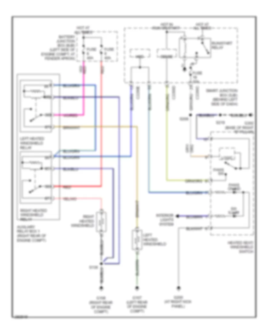
DEFOGGERS
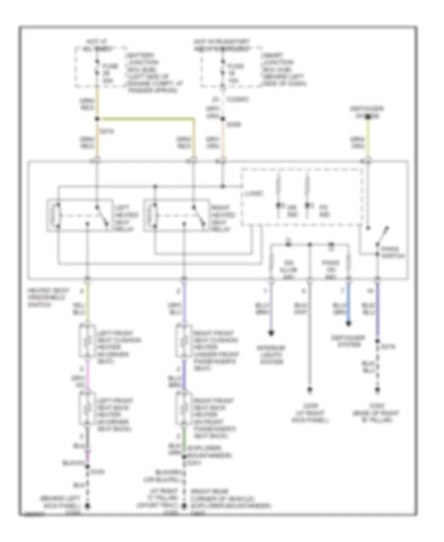
Heated Windshield Wiring Diagram for Ford Explorer 2008
List of elements for Heated Windshield Wiring Diagram for Ford Explorer 2008:
- (right rear of engine compt)
- Auxiliary relay box 1 (right rear of engine compt)
- Battery junction box (bjb) (left side of engine compt, at fender apron)
- C2280c
- C2280d
- C2280e
- Fhws on ind
- Fhws sw
- Fuse 10a
- Fuse 40a
- G107 (left rear of engine compt)
- G108
- G200 (at right kick panel)
- G302 (base of right "b" pillar)
- Heated seat/ windshield switch
- Hot at all times
- Hot in run or start
- Hsd
- Interior lights system
- Left heated windshield
- Left heated windshield relay
- Logic
- Red
- Right heated windshield
- Right heated windshield relay
- Run/start relay
- S208
- S219
- Sense
- Smart junction box (sjb) (behind left side of dash)
- Sw illum
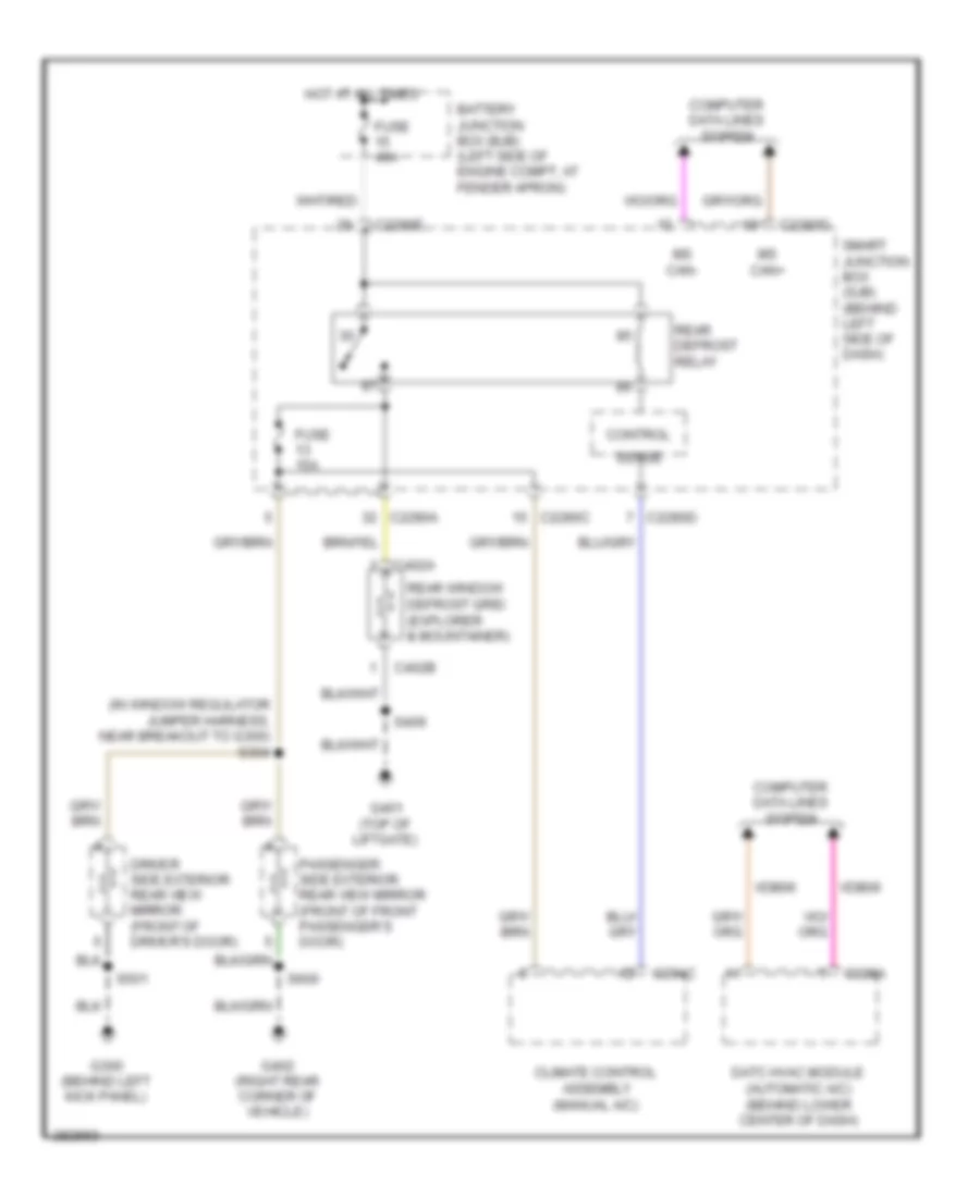
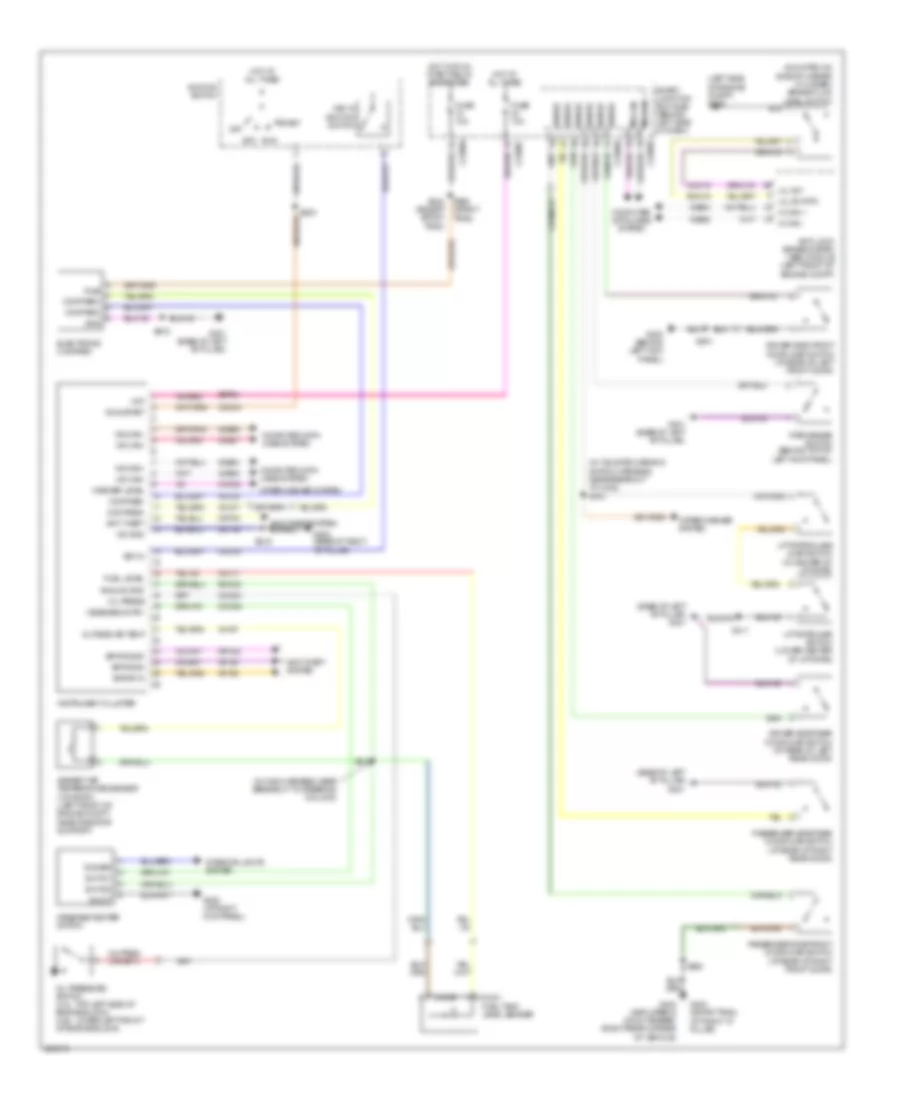
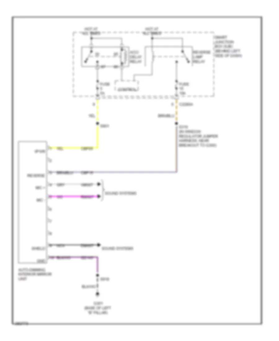
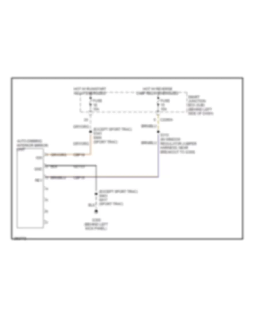
Rear Defogger Wiring Diagram for Ford Explorer 2008
List of elements for Rear Defogger Wiring Diagram for Ford Explorer 2008:
- (in window regulator jumper harness, near breakout to g300) s304
- Battery junction box (bjb) (left side of engine compt, at fender apron)
- C2280a
- C2280c
- C2280d
- C2280e
- C228a
- C294c
- C402a
- C402b
- Climate control assembly (manual a/c)
- Computer data lines system
- Control
- Datc hvac module (automatic a/c) (behind lower center of dash)
- Driver side exterior rear view mirror (front of driver's door)
- Fuse 15a
- Fuse 40a
- G300 (behind left kick panel)
- G401 (top of liftgate)
- G402 (right rear corner of vehicle)
- Hot at all times
- Ms can+
- Ms can-
- Passenger side exterior rear view mirror (front of front passenger's door)
- Rear defrost relay
- Rear window defrost grid (explorer & mountainer)
- S409
- S501
- S600
- Sense
- Smart junction box (sjb) (behind left side of dash)
- Vdb06
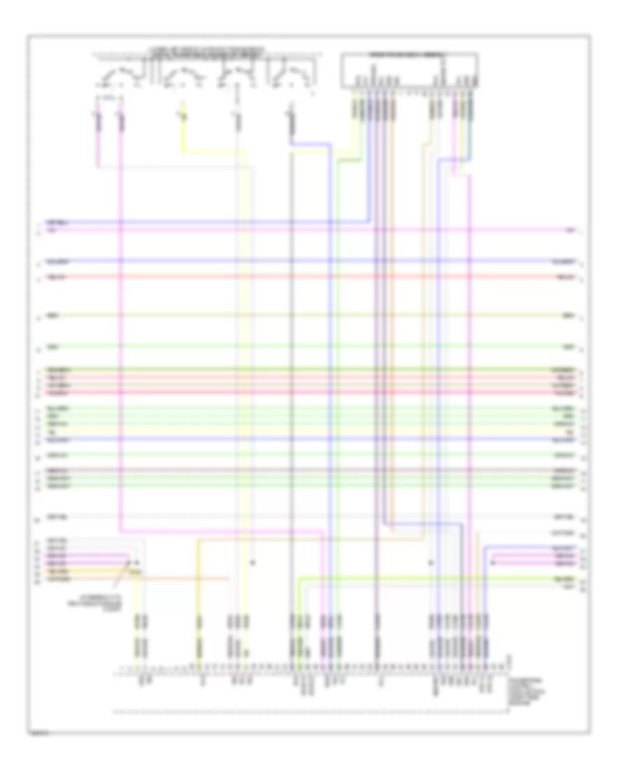
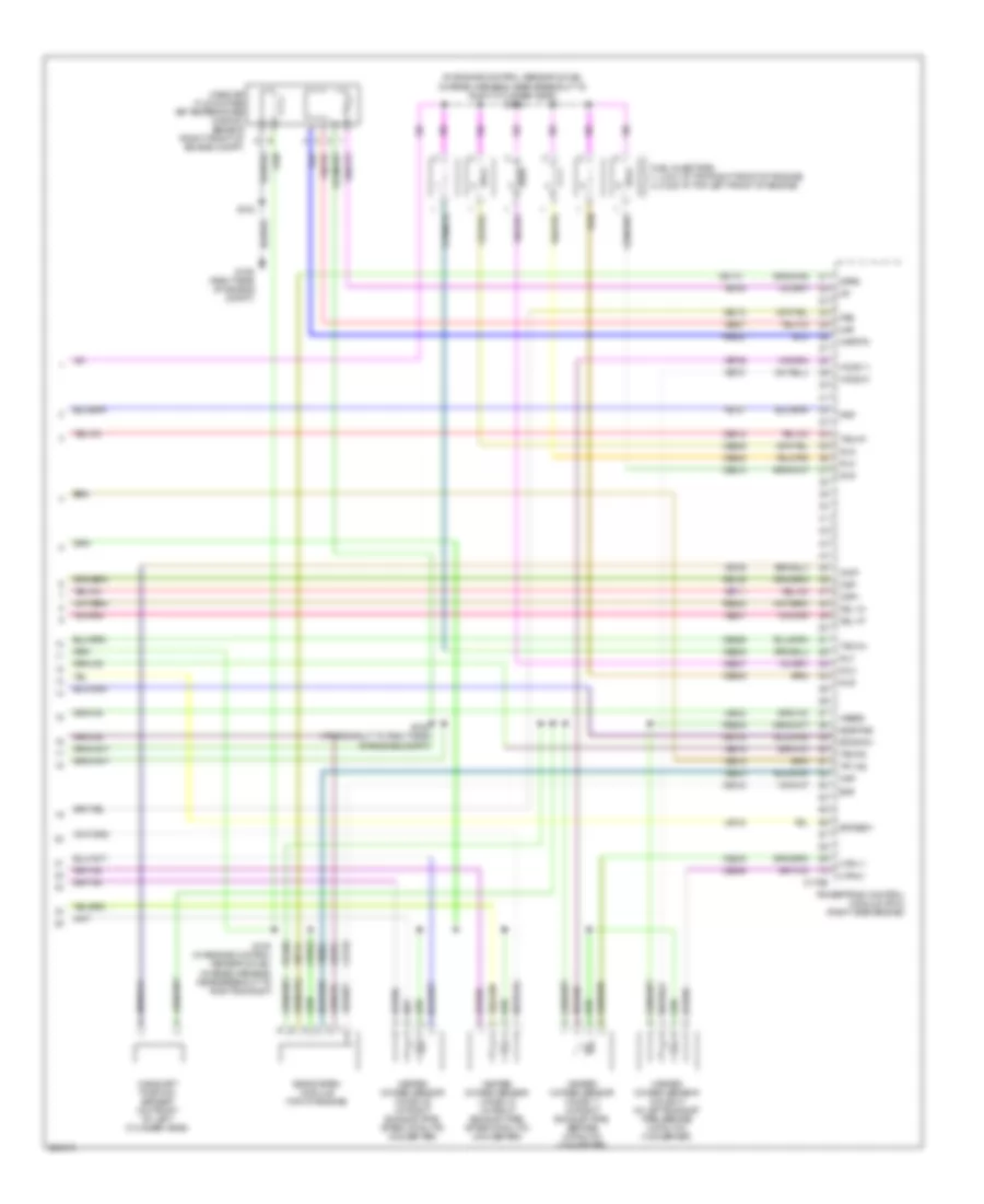
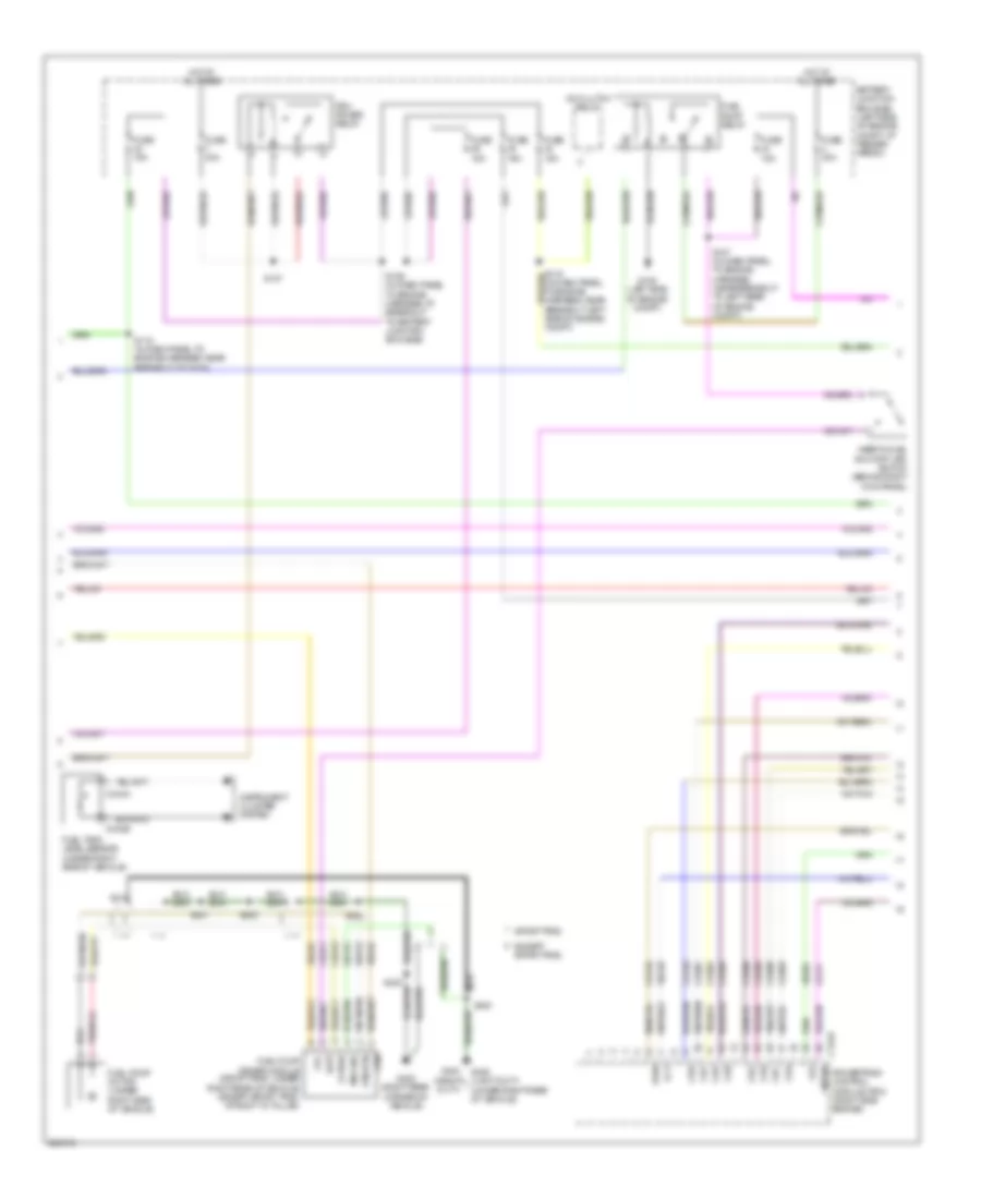
ENGINE PERFORMANCE
4.0L
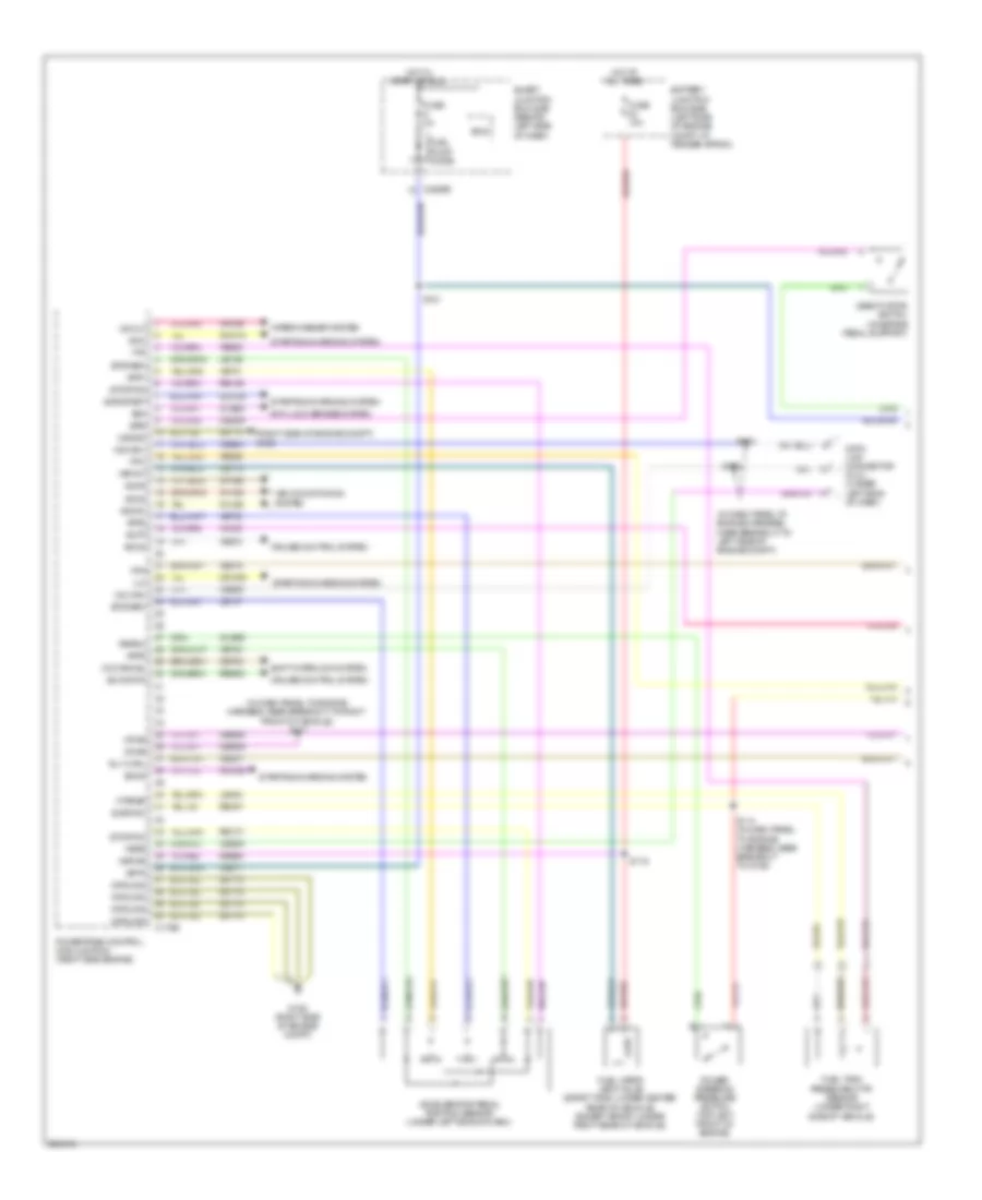
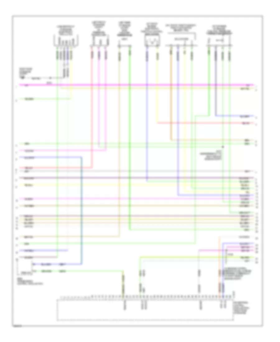
4.0L, Engine Performance Wiring Diagram (1 of 5) for Ford Explorer 2008
List of elements for 4.0L, Engine Performance Wiring Diagram (1 of 5) for Ford Explorer 2008:
- (in dash panel to engine harness, near breakout to left side of engine compt)
- (in dash panel to engine harness, near breakout to right front of vehicle) s117
- (right side of engine compt) g106
- Accelerator pedal position sensor (under left side of dash)
- Accr
- Accs
- Acds1
- Acpt
- Air conditioning system
- Anti-lock brakes system
- App1
- App2
- App3
- B00
- Battery junction box (bjb) (left side of engine compt, at fender apron)
- Bps
- C175b
- C2280e
- Cbb39
- Ccb08
- Ccs09
- Cdc09
- Cdc12
- Cdc38
- Ce114
- Ce237
- Ce517
- Ces09
- Cet34
- Ch302
- Ch423
- Ch443
- Cruise control system
- Csgnd
- Data link connector (dlc) (under left side of dash)
- Deactivator switch (on brake pedal support)
- Etcref2
- Etcref3
- Etcrtn2
- Etcrtn3
- Feps
- Fpc
- Fpm
- Ftp
- Ftpref
- Fuel pump diode
- Fuel tank pressure (ftp) sensor (under right side of vehicle)
- Fuel vapor vent valve (sport trac: under center rear of vehicle) (except sport: under right rear of vehicle)
- Fuse 10a
- Fuse 2a
- G106 (right side of engine compt)
- Gd113
- Ground
- Hot at all times
- Hot in start or run
- Hs can+
- Hs can-
- Ilc
- Isp-r
- Kapwr
- Le136
- Le137
- Le424
- Od cancel
- Power steering pressure switch (top left front of engine)
- Powertrain control module (pcm) (right side engine)
- Pspsw
- Re136
- Re137
- Re407
- Res08
- Rly ctrl
- S114 (in dash panel to engine harness, near breakout to g106)
- S116
- S121
- S122
- S124
- Sbb24
- Sccs
- Sccs rtn
- Shift interlock system
- Sigrtnc
- Smart junction box (sjb) (behind left side of dash)
- Smc
- Smcs
- Smr/start
- Sns
- Starting/charging system
- Vapvnt
- Vdb04
- Vdb05
- Vdb09
- Ve225
- Ve518
- Ve701
- Ve702
- Ve703
- Ve922
- Ves10
- Vh433
- Vmc05
- Vpwr
- Vs out
- Wiper/washer system
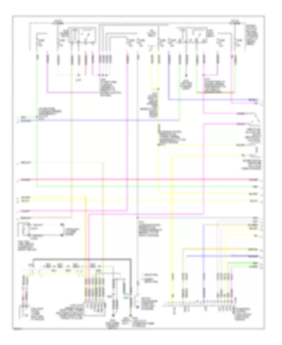
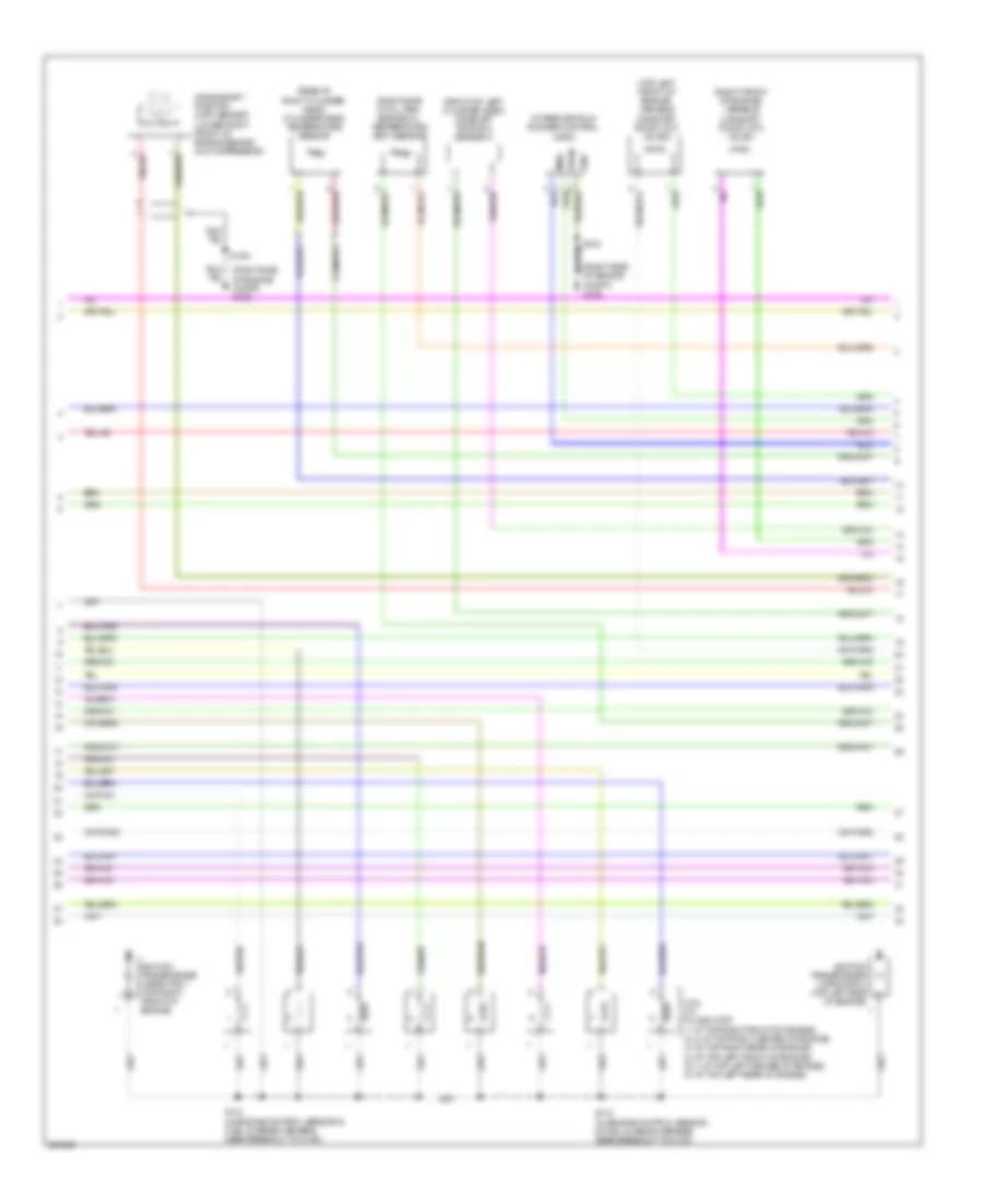
4.0L, Engine Performance Wiring Diagram (2 of 5) for Ford Explorer 2008
List of elements for 4.0L, Engine Performance Wiring Diagram (2 of 5) for Ford Explorer 2008:
- (in dash panel to engine harness, near breakout to g104) s118
- (in engine control sensor & fuel charge harness, near breakout to top rear of engine) s113
- A/c clutch relay
- Batt
- Battery junction box (bjb) (left side of engine compt, at fender apron)
- C175e
- C434a
- C434b
- Cda
- Cdb
- Cdc
- Ce123
- Ce124
- Ce125
- Ce132
- Ce321
- Ce515
- Ce911
- Ect
- Evap
- Except sport trac
- Fc-v
- Fp pwr
- Fpc
- Fpm
- Fpm rtn
- Frt
- Fuel pump driver module (sport trac: under right rear of vehicle) (except sport trac: at right "d" pillar)
- Fuel pump motor (under right side of vehicle)
- Fuel pump relay
- Fuel tank level sensor (under right side of vehicle)
- Fuse 15a
- Fuse 30a
- Fuse 40a
- G105 (left side of engine compt)
- G402 (right rear corner of vehicle)
- G404 (heavy duty)
- G405 (light duty) (under right rear of vehicle)
- Gd151
- Heated positive crankcase (pcv) valve (rear of engine)
- Hot at all times
- Ignition transformer capacitor (at top left of engine)
- Inertia fuel shutoff (ifs) switch (behind right kick panel)
- Instrument cluster system
- Le111
- Md gnd
- Nca
- Pcm power relay
- Pcv hc
- Powertrain control module (pcm) (right side engine)
- Re515
- S110 (in engine control sensor & fuel charge harness, at breakout to top front of engine)
- S119 (in dash panel to engine harness, near breakout left side of engine compt)
- S126 (in dash panel to engine harness, at breakout to battery junction box (bjb))
- S127
- S137 (in dash panel to engine harness, near breakout to left rear of engine compt)
- S400
- S403
- S405
- S421
- S430
- Sport trac
- Vbpwr
- Ve225
- Ve518
- Ve716
- Ve728
- Vec03
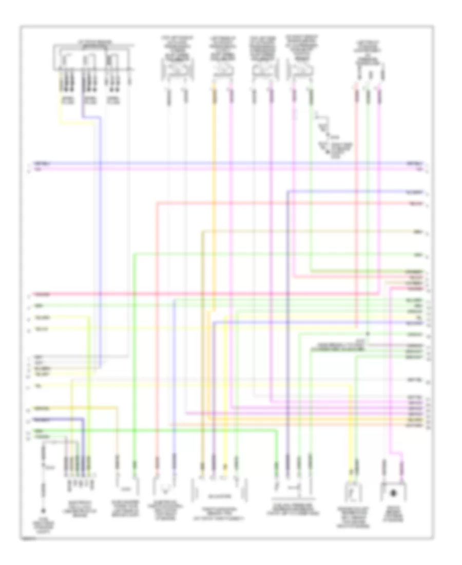
4.0L, Engine Performance Wiring Diagram (3 of 5) for Ford Explorer 2008
List of elements for 4.0L, Engine Performance Wiring Diagram (3 of 5) for Ford Explorer 2008:
- (at top of engine) ignition coil
- (left front of engine compartment) a/c pressure transducer
- (left rear of automatic transmission) output shaft speed (oss) sensor
- (on right side of engine, behind a/c compressor) crankshaft position sensor
- (on top of throttle body)
- (right side of engine compt) g106
- (top center front of engine)
- (top left side of automatic transmission) intermediate shaft speed (iss) sensor
- (top left side of automatic transmission) turbine shaft speed (tss) sensor
- Acpt
- Electronic fan clutch (center front of engine)
- Electronic throttle control (etc) motor (top front of engine)
- Engine coolant temperature (ect) sensor
- Evap canister purge valve (left rear of engine compt)
- Fcv
- Fss
- Fuel rail pressure/ temperature sensor (top of left cylinder head)
- G106 (right side of engine compt)
- Gnd
- Knock sensor (top rear of engine)
- Nca
- S103
- S107 (near breakout to right cylinder head valve cover)
- S109
- Sig rtn
- Solid state
- Spark plugs
- Throttle position sensor (tps)
- Vbpwr
- Vpwr
- Vref
4.0L, Engine Performance Wiring Diagram (4 of 5) for Ford Explorer 2008
List of elements for 4.0L, Engine Performance Wiring Diagram (4 of 5) for Ford Explorer 2008:
- (at breakout to right side of engine compt)
- (lower left side of automatic transmission) digital transmission range (dtr) sensor
- 5r55s transmission assembly
- C175t
- Ce233
- Ce234
- Ce418
- Cet05
- Cet06
- Cet07
- Cet18
- Cet19
- Cet44
- Cet45
- Ho2s 12
- Ho2s 22
- Htr 12
- Htr 22
- Iss
- Oss
- Pca
- Pcb
- Pcc
- Powertrain control module (pcm) (right side engine)
- Pwr sol
- Re406
- Ret04
- S106
- Sigrtn tft
- Sigrtnt
- Ssa
- Ssb
- Ssc
- Ssd
- Tcc
- Tft
- Tr1
- Tr2
- Tr3a
- Tr4
- Tss
- Ve731
- Ve733
- Ve739
- Vet27
- Vet28
- Vet29
- Vet30
- Vet31
- Vet33
4.0L, Engine Performance Wiring Diagram (5 of 5) for Ford Explorer 2008
List of elements for 4.0L, Engine Performance Wiring Diagram (5 of 5) for Ford Explorer 2008:
- (in engine control sensor & fuel charge harness, near breakout to right cylinder head) s104
- C175e
- Camshaft position sensor (on front of left cylinder head)
- Cbb42
- Ce133
- Ce205
- Ce206
- Ce207
- Ce208
- Ce209
- Ce210
- Ce235
- Ce236
- Ce412
- Ce426
- Ckp+
- Ckp-
- Cmp1
- Dpfe
- Egr system module (top of engine)
- Etcref1
- Etcrtn1
- Evr
- Frp
- Fss
- Fuel injectors (1, 2 & 3: at top right front of engine) (4, 5 & 6: at top left front of engine)
- G106 (right side of engine compt)
- Heated oxygen sensor (ho2s) 11 (in right exhaust pipe, before catalytic converter)
- Heated oxygen sensor (ho2s) 12 (in right exhaust pipe, after catalytic converter)
- Heated oxygen sensor (ho2s) 21 (in left exhaust pipe, before catalytic converter)
- Heated oxygen sensor (ho2s) 22 (in right exhaust pipe, after catalytic converter)
- Ho2s 11
- Ho2s 21
- Htr 21
- Htr-11
- Iat
- Inj1
- Inj2
- Inj3
- Inj4
- Inj5
- Inj6
- Ksl 1n
- Ksl 1p
- Le134
- Le423
- Maf
- Mafrtn
- Map
- Mass air flow/intake air temperature (maf/iat) sensor (right front of engine compt)
- Powertrain control module (pcm) (right side engine)
- Re134
- Re135
- Re320
- Re323
- Re405
- S100 (in engine control sensor & fuel charge harness, near breakout to right exhaust)
- S103
- S105 (at breakout to right side of engine compt)
- Sigrtne
- Tacm n
- Tacm p
- Tp1 ns
- Tp2-ps
- Ve706
- Ve711
- Ve713
- Ve727
- Ve735
- Ve737
- Ve740
- Ve801
- Ve803
- Ve807
- Ve818
- Ve819
- Vec10
- Vrefe
4.6L
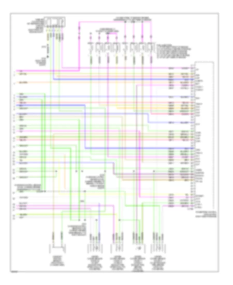
4.6L, Engine Performance Wiring Diagram (1 of 5) for Ford Explorer 2008
List of elements for 4.6L, Engine Performance Wiring Diagram (1 of 5) for Ford Explorer 2008:
- (in dash panel to engine harness, near breakout to right side of engine compt)
- (in engine control sensor & fuel charge harness, near breakout to right exhaust)
- (right side of engine compt) g106
- Accelerator pedal position sensor (under left side of dash)
- Accr
- Acds1
- Acpt
- Air conditioning system
- Anti-lock brakes system
- App1
- App2
- App3
- B00
- Battery junction box (bjb) (left side of engine compt, at fender apron)
- Bps
- C175b
- C2280e
- Cbb39
- Ccb08
- Cdc09
- Cdc12
- Cdc35
- Cdc38
- Ce114
- Ce237
- Ce517
- Ces09
- Cet34
- Ch302
- Ch423
- Cruise control system
- Csgnd
- Data link connector (dlc) (under left side of dash)
- Deactivator switch (on brake pedal support)
- Etcref2
- Etcrf3
- Etcrtn2
- Etcrtn3
- Feps
- Fpc
- Fpm
- Ftp
- Ftpref
- Fuel pump diode
- Fuel tank pressure (ftp) sensor (under right side of vehicle)
- Fuel vapor vent valve (sport trac: under center rear of vehicle) (except sport: under right rear of vehicle)
- Fuse 10a
- Fuse 2a
- G106 (right side of engine compt)
- Gd113
- Ground
- Hot at all times
- Hot in start or run
- Hs can +
- Hs can -
- Ilc
- Isp-r
- Kapwr
- Le136
- Le137
- Le424
- Od cancel
- Powertrain control module (pcm) (right side of engine)
- Re136
- Re137
- Re407
- Res08
- Rly ctrl
- S101
- S102
- S114 (in dash panel to engine harness, near breakout to g106)
- S116
- S117
- S121
- Sbb24
- Sccs
- Sccs rtn
- Shift interlock system
- Sigrtnc
- Smart junction box (sjb) (behind left side of dash)
- Smc
- Smcs
- Smr/start
- Sns
- Starting/charging system
- Vapnt
- Vdb04
- Vdb05
- Vdb09
- Ve225
- Ve518
- Ve701
- Ve702
- Ve703
- Ve922
- Ves10
- Vh433
- Vmc05
- Vpwr1-a
- Vpwr1-b
- Vs out
- Wiper/washer system
4.6L, Engine Performance Wiring Diagram (2 of 5) for Ford Explorer 2008
List of elements for 4.6L, Engine Performance Wiring Diagram (2 of 5) for Ford Explorer 2008:
- A/c clutch relay
- Batt
- Battery junction box (bjb) (left side of engine compt, at fender apron)
- C175e
- C434a
- C434b
- Cda
- Cdb
- Cdc
- Cdd
- Cde
- Cdf
- Cdg
- Cdh
- Ce132
- Ce303
- Ce304
- Ce305
- Ce306
- Ce307
- Ce308
- Ce309
- Ce310
- Ce515
- Ce911
- Evap
- Except sport trac
- Fc v
- Fp pwr
- Fpc
- Fpm
- Fpm rtn
- Frt
- Fuel pump driver module (sport trac: under right rear of vehicle) (except sport trac: at right "d" pillar)
- Fuel pump motor (under right side of vehicle)
- Fuel pump relay
- Fuel tank level sensor (under right side of vehicle)
- Fuse 15a
- Fuse 30a
- Fuse 40a
- G105 (left side of engine compt)
- G402 (right rear corner of vehicle)
- G404 (heavy duty)
- G405 (light duty) (under right rear of vehicle)
- Gd151
- Hot at all times
- Inertia fuel shutoff (ifs) switch (behind right kick panel)
- Instrument cluster system
- Le111
- Md gnd
- Nca
- Pcm power relay
- Powertrain control module (pcm) (right side engine)
- Re515
- S118 (in dash panel to engine harness, near breakout to g104)
- S126 (in dash panel to engine harness, at breakout to battery junction box (bjb))
- S127
- S137 (in dash panel to engine harness, (near breakout to left rear of engine compt)
- S400
- S403
- S405
- S421
- S430
- Sport trac
- Vbpwr
- Ve225
- Ve518
- Ve728
- Vec03
4.6L, Engine Performance Wiring Diagram (3 of 5) for Ford Explorer 2008
List of elements for 4.6L, Engine Performance Wiring Diagram (3 of 5) for Ford Explorer 2008:
- (at top of engine) electronic throttle control (etc) motor
- (at top rear of engine) fuel rail pressure transducer sensor
- (center front of engine) electronic fan clutch
- (in engine control sensor & fuel charge harness, at breakout to right side of engine compt)
- (left front of engine compt) a/c pressure transducer
- (left rear of engine compt) evap canister purge valve
- (on top of throttle body) throttle position sensor (tps)
- (right side
- 6r60 transmission control module (tcm)
- Acpt
- C175t
- Ce233
- Ce234
- Ce517
- Cet40
- Fcv
- Fss
- G106
- Gnd
- Ho2s 12
- Ho2s 22
- Htr 12
- Htr 22
- Of engine compt)
- Powertrain control module (pcm) (right side of engine)
- Re406
- S103
- S106
- S107 (near breakout to right side of engine compt)
- Sig rtn
- Sigrtnt
- Solid state
- Trsw pn
- Trsw-pn
- Vbpwr
- Ve731
- Ve733
- Vpwr
- Vref
4.6L, Engine Performance Wiring Diagram (4 of 5) for Ford Explorer 2008
List of elements for 4.6L, Engine Performance Wiring Diagram (4 of 5) for Ford Explorer 2008:
- (front of left cylinder head) camshaft position sensor 2
- (rear of right cylinder head) cylinder-head temperature sensor
- (right front of engine) variable camshaft timing (vct) valve 1
- (right side of engine compt) g106
- (right side of oil pan) engine oil temperature (eot) sensor
- (top left front of engine) variable camshaft timing (vct) valve 2
- Coil on plugs (cop) (1: at top right front of engine) (2, 3: at top right center of engine) (4: at top right rear of engine) (5: at top left front of engine) (6, 7: at top left center of engine) (8: at top left rear of engine)
- Crankshaft position (ckp) sensor (lower right front of engine, behind a/c compressor)
- Gnd
- Ignition transformer capacitor 1 (top right front of engine)
- Ignition transformer capacitor 2 (top left side of engine)
- Imrc
- Intake manifold runner control (imrc)
- S103
- S109
- S110 (in engine control sensor & fuel charge harness, near breakout to c139)
- S112 (in engine control sensor & fuel charge harness, near breakout to c133)
- Vpwr
4.6L, Engine Performance Wiring Diagram (5 of 5) for Ford Explorer 2008
List of elements for 4.6L, Engine Performance Wiring Diagram (5 of 5) for Ford Explorer 2008:
- (in dash panel to engine harness, near breakout to left rear of engine) s111
- (in engine control sensor & fuel charge harness, near breakout to c1442) s108
- (near breakout to right cylinder head) s104
- C175e
- Camshaft position sensor 1 (front right cylinder head)
- Ce205
- Ce206
- Ce207
- Ce208
- Ce209
- Ce210
- Ce211
- Ce212
- Ce235
- Ce236
- Ce315
- Ce412
- Ce421
- Ce422
- Ce426
- Cht
- Ckp+
- Ckp-
- Cmp1
- Cmp2
- Eot
- Etcref1
- Etcrtn1
- Frp
- Fss
- Fuel injectors (1: at top right front of engine) (2,3: at top right center of engine) (4: at top right rear of engine) (5: at top left front of engine) (6,7: at top left center of engine) (8: at top left rear of engine)
- G106 (right side of engine compt)
- Heated oxygen sensor (ho2s) 11 (in right exhaust pipe, before catalytic converter)
- Heated oxygen sensor (ho2s) 12 (in right exhaust pipe, after catalytic converter)
- Heated oxygen sensor (ho2s) 21 (in left exhaust pipe, before catalytic converter)
- Heated oxygen sensor (ho2s) 22 (in left exhaust pipe, after catalytic converter)
- Ho2s 11
- Ho2s 21
- Htr 11
- Htr 21
- Iat
- Imrc
- Inj 5
- Inj1
- Inj2
- Inj3
- Inj4
- Inj6
- Inj7
- Inj8
- Le134
- Le423
- Maf
- Mafrtn
- Mass air flow/intake air temperature (maf/iat) sensor (right front of engine compt)
- Powertrain control module (pcm) (right side of engine)
- Re134
- Re135
- Re320
- Re405
- S100 (in engine control sensor & fuel charge harness, near breakout to right exhaust)
- S103
- S105 (in engine control sensor & fuel charge harness, at breakout to right side of engine compt)
- Sigrtne
- Tacm n
- Tacm p
- Tp1 ns
- Tp2-ps
- Vct1
- Vct2
- Ve706
- Ve707
- Ve711
- Ve712
- Ve717
- Ve727
- Ve735
- Ve737
- Ve740
- Ve807
- Ve818
- Ve819
- Vec10
- Vrefe
EXTERIOR LIGHTS
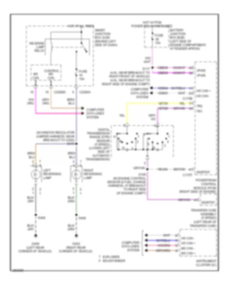
Backup Lamps Wiring Diagram for Ford Explorer 2008
List of elements for Backup Lamps Wiring Diagram for Ford Explorer 2008:
- (in window regulator jumper harness, near breakout to g300) s310
- (left rear of transfer case)
- Battery junction box (bjb) (left side of engine compartment, at fender apron)
- C175b
- C175t
- C2280a
- C2280d
- Cbb39
- Computer data lines system
- Control ms can +
- Digital transmission range (dtr) sensor (5 speed) (lower left side of automatic transmission)
- Explorer mountaineer
- Fuse 10a
- Fuse 15a
- G400 (left rear corner of vehicle)
- G402 (right rear corner of vehicle)
- Hot at all times
- Hot w/ pcm power relay energized
- Hs can +
- Hs can -
- Instrument cluster (ic)
- Left reversing lamp
- Ms can +
- Ms can -
- N d
- Powertrain control module (pcm) (right side of engine)
- Re406
- Reverse lamp relay
- Right reversing lamp
- S106 (in engine control sensor & fuel charge harness, at breakout to right side of engine compt)
- S117 (4.0l: near breakout to right front of vehicle) (4.6l: near breakout to right side of engine compt)
- S406
- S408
- Sigrtnt
- Smart junction box (sjb) (behind left side of dash)
- Tr1
- Tr2
- Transfer case assembly (5 speed)
- Vdb04
- Vdb05
- Vet28
- Vet30
- Vpwr
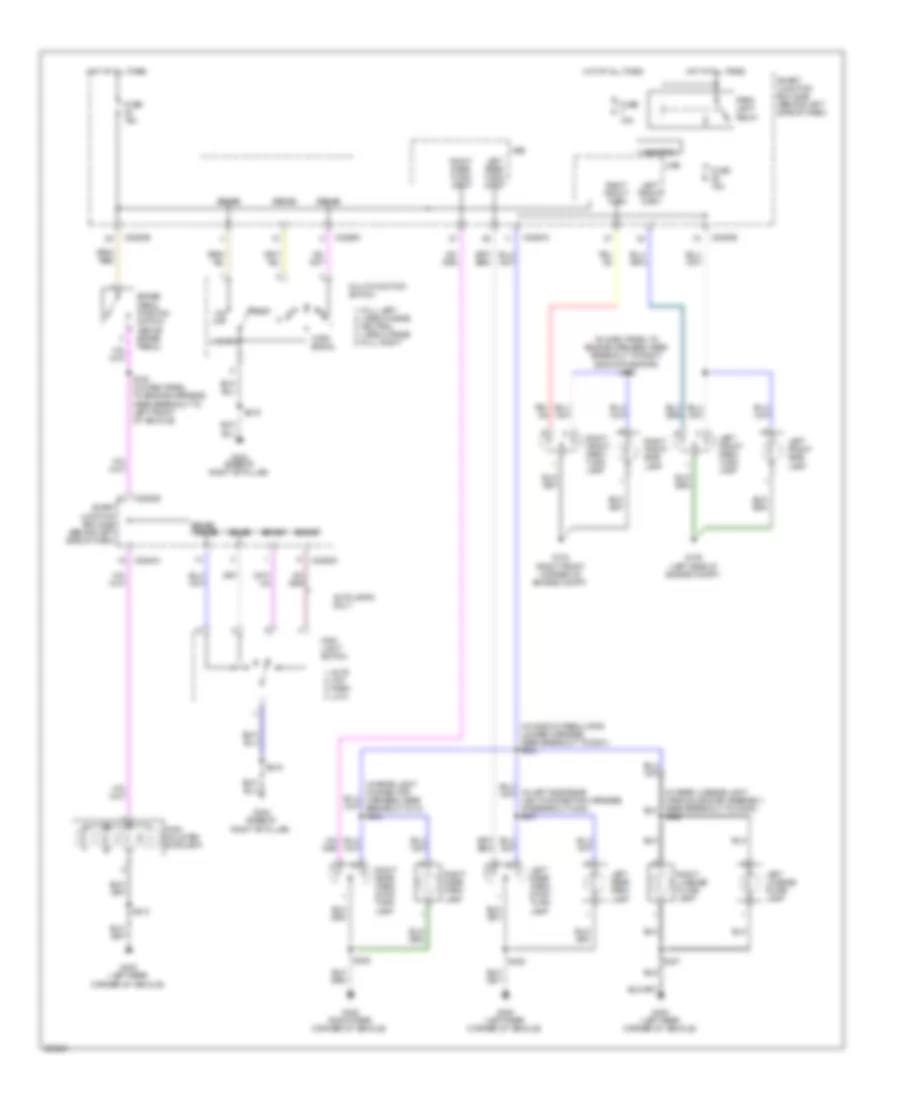
Exterior Lamps Wiring Diagram for Ford Explorer 2008
List of elements for Exterior Lamps Wiring Diagram for Ford Explorer 2008:
- (in dash panel to engine harness, near breakout to right side of radiator) s120
- (in window regulator jumper harness, near breakout to g301) s324
- 1. auto 2. off 3. park 4. low
- 1. full left 2. lane change 3. neutral 4. lane change 5. full right
- Autolamps only
- Brake pedal position switch (above brake pedal)
- C2280a
- C2280d
- C2280e
- Control
- Fuse 15a
- G104 (right front corner of engine compt)
- G105 (left side of engine compt)
- G302 (base of right "b" pillar)
- G400 (left rear corner of vehicle)
- G402 (right rear corner of vehicle)
- Hazard
- High mounted stoplamp
- Hot at all times
- Hsd
- Left front park/ turn lamp
- Left front side lamp
- Left front turn
- Left license plate lamp
- Left rear park lamp
- Left rear park/ stop/ turn lamp
- Left rear turn/ stop
- Main light switch
- Multi-function switch
- On/ off
- Park lamp relay
- Rest
- Right front park/ turn lamp
- Right front side lamp
- Right front turn
- Right license plate lamp
- Right rear park lamp
- Right rear park/ stop/ turn lamp
- Right rear turn/ stop
- S128 (in dash panel to engine harness, near breakout to left front of vehicle)
- S219
- S406
- S408
- S412
- S426
- S427
- Sense
- Sense sense
- Smart junction box (sjb) (behind left side of dash)
- Turn signal
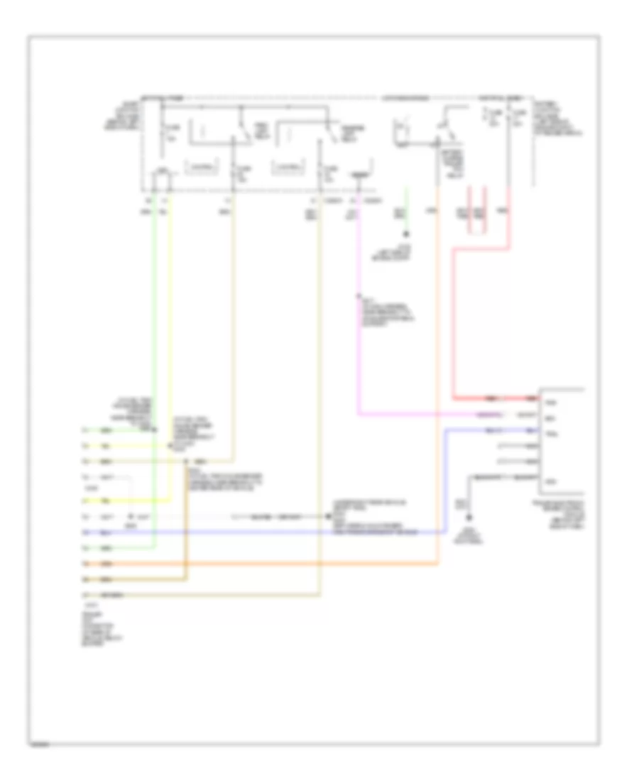
Trailer Tow Wiring Diagram, with Heavy Duty for Ford Explorer 2008
List of elements for Trailer Tow Wiring Diagram, with Heavy Duty for Ford Explorer 2008:
- (in fuel tank gauge sender harness, near breakout to c423) s422
- (in fuel tank gauge sender harness, near breakout to c423) s423
- (under right rear vehicle) (sport trac) g404
- Battery charge trailer tow relay
- Battery junction box (bjb) (left side of engine compt, at fender apron)
- Boo
- C2280a
- C2280c
- C439
- C473
- Control
- Fuse 10a
- Fuse 15a
- Fuse 30a
- G105 (left side of engine compt)
- G200 (at right kick panel)
- G402 (explorer & mountaineer) (right rear corner of vehicle)
- Gnd
- Hot at all times
- Hot in run or acc
- Hsd
- Nca
- Park lamp relay
- Pwr
- Red
- Reverse lamp relay
- S217 (in main harness, near breakout to accelerator pedal support)
- S424 (in fuel tank gauge sender harness, near breakout to center rear of vehicle)
- S425
- Sense
- Smart junction box (sjb) (behind left side of dash)
- Trail
- Trailer electronic brake control module (behind left side of dash)
- Trailer tow connector (at rear of vehicle, below bumper)
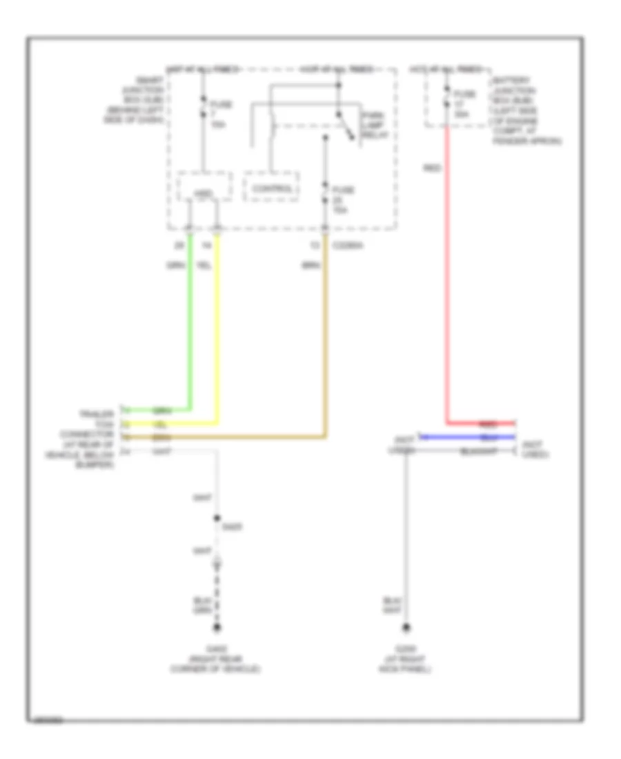
Trailer Tow Wiring Diagram, with Light Duty for Ford Explorer 2008
List of elements for Trailer Tow Wiring Diagram, with Light Duty for Ford Explorer 2008:
- (not used)
- Battery junction box (bjb) (left side of engine compt, at fender apron)
- C2280a
- Control
- Fuse 15a
- Fuse 30a
- G200 (at right kick panel)
- G402 (right rear corner of vehicle)
- Hot at all times
- Hsd
- Park lamp relay
- Red
- S425
- Smart junction box (sjb) (behind left side of dash)
- Trailer tow connector (at rear of vehicle, below bumper)
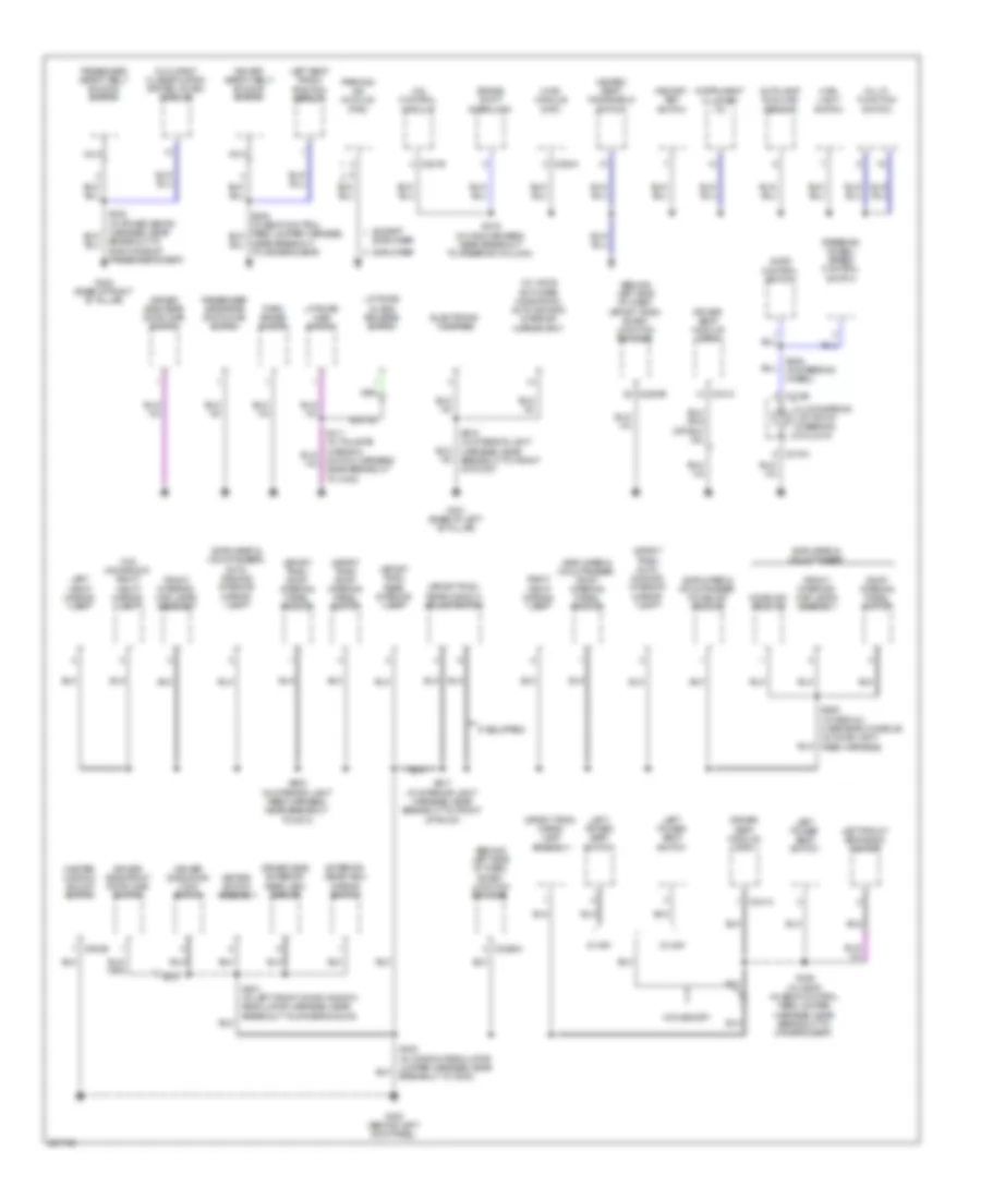
GROUND DISTRIBUTION
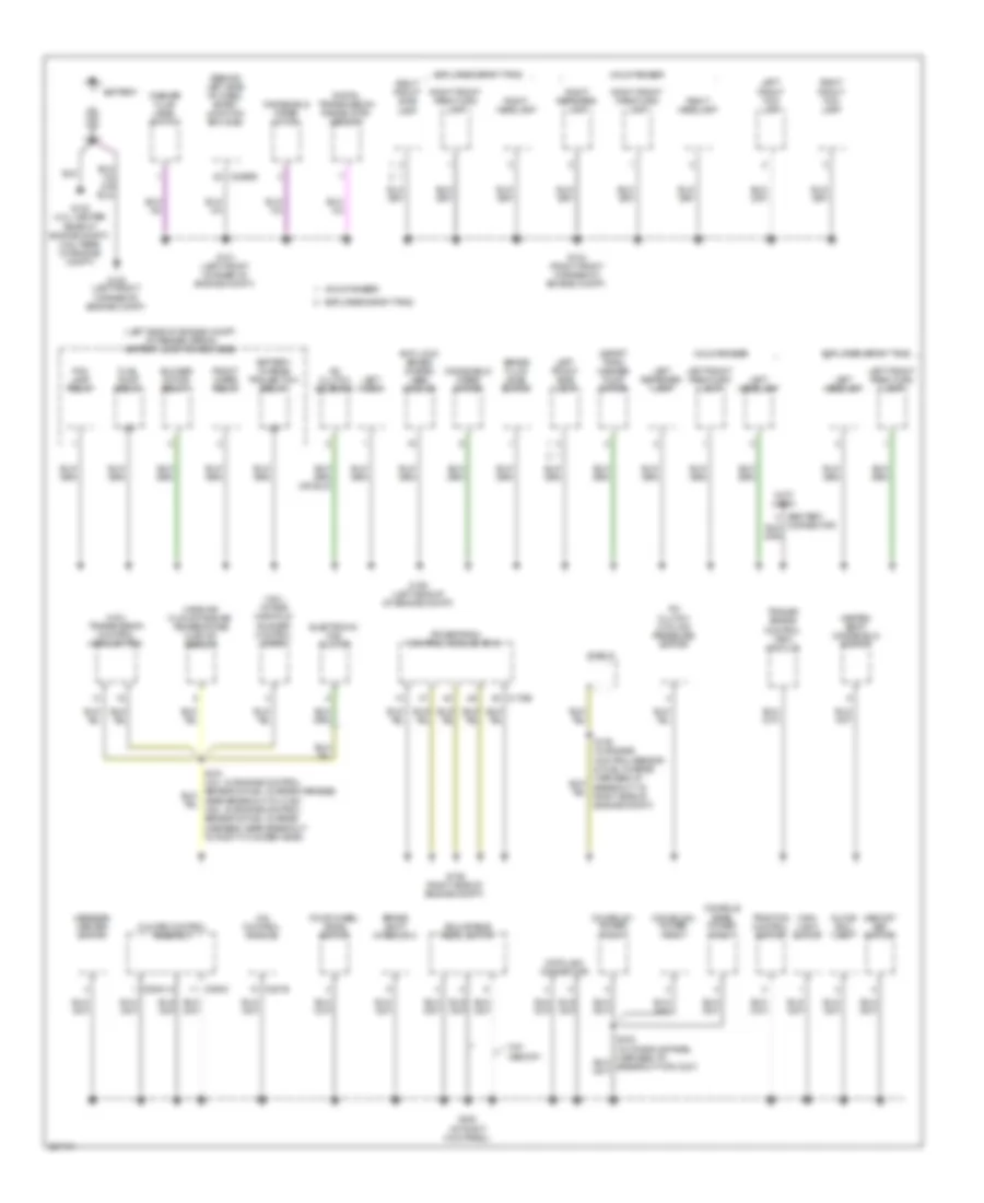
Ground Distribution Wiring Diagram (1 of 4) for Ford Explorer 2008
List of elements for Ground Distribution Wiring Diagram (1 of 4) for Ford Explorer 2008:
- (4.6l) intake manifold runner control (imrc)
- (4.6l) transmission control module (tcm)
- (behind left side of dash) smart junction box (sjb)
- (left side of engine compt, at fender apron) battery junction box (bjb)
- (not used)
- (sport trac) washer pump motor
- 4x4 control module
- A/c clutch cycling pressure switch
- A/c clutch solenoid
- Adjustable pedal switch
- Anti-lock brake system (abs) module
- Battery
- Battery charge trailer tow relay
- Blower motor relay 1
- Brake fluid level switch
- Brake shift interlock
- C175b
- C2280e
- C281b
- C294a
- C294c
- Climate control assembly
- Console 1 power point
- Console 2 power point
- Console rear power point
- Data link connector
- Digital transmission range (dtr) sensor
- Electronic fan clutch
- Explorer sport trac
- Fog lamp relay
- Four wheel drive switch
- Front wiper relay
- Fuel pump relay
- G100 (left front corner of engine compt)
- G101 (left front corner of engine compt)
- G102 (4.0l: center rear of engine compt) (4.6l: rear of engine compt)
- G104 (right front corner of engine compt)
- G105 (left side of of engine compt)
- G106 (right side of engine compt)
- G200 (at right kick panel)
- Glove box lamp
- Heated seat/ windshield switch
- Left front fog lamp
- Left front park/turn lamp
- Left front side lamp
- Left headlamp
- Left horn
- Left repeater lamp
- Main light switch
- Mass air flow/intake air temperature (maf/iat) sensor
- Memory set switch
- Message center switch
- Mountaineer
- Powertrain control module (pcm)
- Right front fog lamp
- Right front park/turn lamp
- Right front side lamp
- Right headlamp
- Right repeater lamp
- S109 (in engine control sensor & fuel charge harness, at breakout to right side of engine compt)
- Shield
- Traction control switch
- Trailer brake control (tbc) module
- W/o memory
- Washer fluid level switch
- Windshield wiper motor
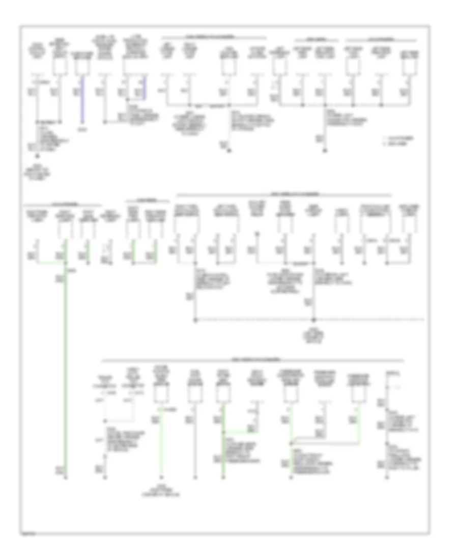
Ground Distribution Wiring Diagram (2 of 4) for Ford Explorer 2008
List of elements for Ground Distribution Wiring Diagram (2 of 4) for Ford Explorer 2008:
- (behind left side of dash) (sport trac) smart junction box (sjb)
- (behind left side of dash) smart junction box (sjb)
- (explorer & mountaineer) auto- dimming interior mirror unit
- (explorer & mountaineer) homelink module
- (explorer & mountaineer) roof opening panel module
- (sport trac) auto- dimming interior mirror unit
- (sport trac) cargo lamp assembly
- (sport trac) rear interior lamp
- (sport trac) rear window adjust switch
- (sport trac) roof opening panel module
- (sport trac) roof opening panel switch
- (w/ voice activated navigation) auto-dimming interior mirror unit
- (w/o moonroof) right vanity mirror lamp
- 10-way
- 4x4 control module
- 6-way
- Audio control switch
- Autolamp/ sunload sensor
- Brake shift interlock
- Breakout to right side of passenger's seat)
- C218a
- C218b
- C2280a
- C2280b
- C228a
- C281b
- C341a
- C341c
- C504b
- Clockspring (at top of steering column)
- Driver safety belt buckle switch
- Driver seat module (dsm)
- Driver side door lock switch
- Driver side exterior rear view mirror
- Driver side front door ajar switch
- Driver side rear door ajar switch
- Electronic compass
- Except
- Explorer
- Explorer & mountaineer
- Exterior rear view mirror switch
- Front interior/ map lamps assembly
- G300 (behind left kick panel)
- G301 (base of left "b" pillar)
- G302 (base of right "b" pillar)
- Heated seat/ windshield switch
- Homelink module
- Hvac module datc
- If equipped
- Instrument cluster (ic)
- Keypad switch assembly
- Left front seat back heater
- Left power seat switch
- Left seat track position sensor
- Left vanity mirror lamp
- Liftgate ajar switch
- Liftgate glass release switch
- Main light switch
- Master window adjust switch
- Memory set switch
- Multi- function switch
- Nca
- Near breakout to driver's seat)
- Occupant classification system (ocsm) module
- Park brake switch
- Parking aid module (pam)
- Passenger safety belt buckle switch
- Passenger side rear door ajar switch
- Right vanity mirror lamp
- Roof opening panel switch
- S219 (in main harness, near breakout to steering column)
- S239 (in steering wheel)
- S300 (in window regulator jumper harness, near breakout to g300)
- S336 (w/ heat) (in seat control feed jumper harness, near breakout to driver's seat)
- S411 (in tailgate warning switch harness, near breakout to c432)
- S501 (in left front door window regulator harness, near breakout to driver's door)
- S903 (in interior light feed harness, near breakout to c913)
- S905 (w/ medium overhead console) (in dome light feed harness)
- S917 (in interior light harness, near breakout to front of roof)
- S918 (in interior light harness, near breakout to front of roof)
- Steering wheel/ speed control switch
- W/o memory
Ground Distribution Wiring Diagram (3 of 4) for Ford Explorer 2008
List of elements for Ground Distribution Wiring Diagram (3 of 4) for Ford Explorer 2008:
- (explorer) interior lamp
- (heavy duty) trailer tow connector
- (late production) accessory protocol interface module (apim)
- Audio control module (acm)
- Auxiliary blower motor relay
- C290a
- C4322b
- C439
- C473
- C951a
- C951b
- Cargo lamp
- Explorer
- Explorer & mountaineer
- Front auxiliary climate control assembly
- Fuel pump driver module
- G202 (behind top right center of dash)
- G400 (left rear corner of vehicle)
- G402 (right rear corner of vehicle)
- Harness, at breakout c410)
- High mounted stoplamp
- Left license plate lamp
- Left rear park lamp
- Left rear park/stop lamp
- Left rear park/stop turn lamp
- Left rear side lamp
- Left rear turn lamp
- Left reversing lamp
- Left third row folding seat switch
- Liftgate glass actuator
- Mountaineer
- Nca
- Passenger side door lock switch
- Passenger side exterior rear view mirror
- Passenger side front door ajar switch
- Passenger's seat)
- Power running board (prb) module
- Rear blend door actuator
- Rear entertain- ment module (retm)
- Rear interior lamp
- Regulator harness, near breakout to passenger's door)
- Right front seat back heater
- Right license plate lamp
- Right power seat switch
- Right rear park lamp
- Right rear park/stop lamp
- Right rear park/stop turn lamp
- Right rear side lamp
- Right rear turn lamp
- Right reversing lamp
- Right third row folding seat switch
- S214 (in main harness, near breakout to center of dash)
- S328
- S329 (in console panel harness, near breakout to c237)
- S346 (in interior light harness, near breakout to c3053)
- S392 (in air conditioning jumper harness, near breakout to left rear quarterpanel)
- S400 (in window regulator jumper harness, in breakout to right "d" pillar)
- S406
- S408 (in rear light connector harness, at breakout c4004)
- S412 (in tailgate warning switch harness, near breakout to bottom of liftgate)
- S416 (in seat control feed harness, at breakout to left relay switch)
- S425 (in fuel tank gauge sender harness, near breakout to center rear of vehicle)
- S427 (in rear license light wiring & socket assembly, near breakout to c4000)
- Satellite digital audio receiver system (sdars) module
- Shield
- Subwoofer amplifier
- Trailer tow connector
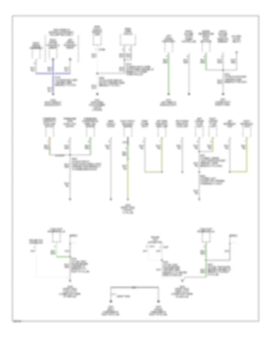
Ground Distribution Wiring Diagram (4 of 4) for Ford Explorer 2008
List of elements for Ground Distribution Wiring Diagram (4 of 4) for Ford Explorer 2008:
- (right rear of engine compartment) auxiliary relay box 1
- Blower motor relay 2
- Breakout to right "d" pillar)
- C402b
- C439
- C473
- Driver temperature blend door actuator
- Front blower motor resistor assembly
- Front blower motor speed controller
- Fuel pump driver module
- G107 (left rear of engine compt)
- G108 (right rear of engine compt)
- G201 (under right side of dash)
- G303 (sport trac) (at right "c" pillar)
- G304 (body) (near base of right "b" pillar)
- G305 (frame) (near base of right "b" pillar)
- G401 (explorer) (mountaineer) (top of liftgate)
- G404 (sport trac) (heavy duty) (under right rear of vehicle)
- G405 (sport trac) (light duty) (under right rear of vehicle)
- Harness, at breakout to right "d" pillar)
- Left heated windshield
- Left heated windshield relay
- Left license plate lamp
- Left rear park/stop/ turn lamp
- Left reversing lamp
- Motor feed harness, at breakout to rear wiper module)
- Nca
- Passenger side door lock switch
- Passenger side exterior rear view mirror
- Passenger side front door ajar switch
- Rear power point
- Rear window defrost grid
- Rear window motor
- Rear wiper module
- Right front seat back heater
- Right heated windshield
- Right heated windshield relay
- Right license plate lamp
- Right rear park/stop/ turn lamp
- Right reversing lamp
- S136 (in windshield heat harness, near breakout to g108)
- S232 (in air conditioner harness, near breakout for g201)
- S408 (in rear light connector harness, at breakout c4004)
- S409 (in tailgate warning switch harness, near breakout to c431)
- S425 (in fuel tank gauge sender harness, near breakout to center rear of vehicle)
- S427 (in rear license light wiring & socket assembly, near breakout to c4000)
- S600 (in right front door window regulator harness, near breakout to passenger's door)
- Shield
- Sport trac
- Trailer tow connector
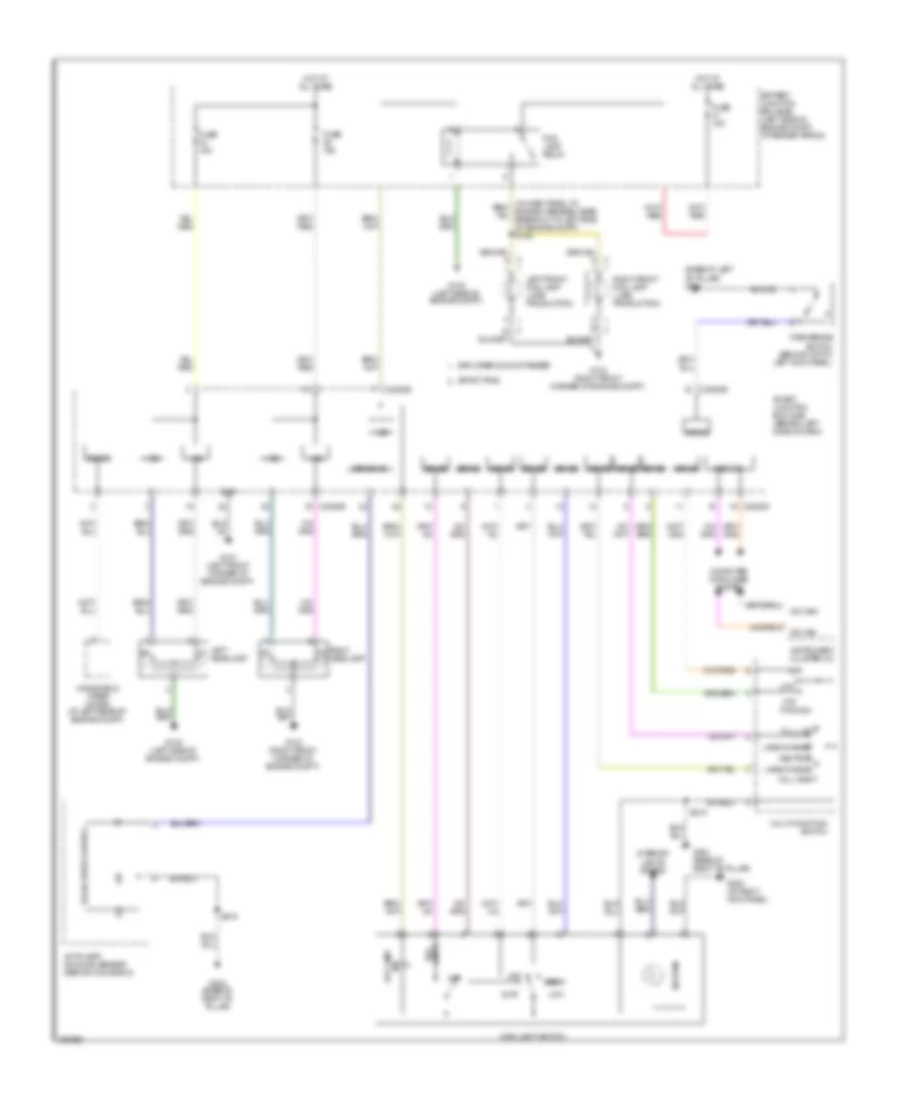
HEADLIGHTS
Headlights Wiring Diagram, with Autolamps for Ford Explorer 2008
List of elements for Headlights Wiring Diagram, with Autolamps for Ford Explorer 2008:
- (base of left "b" pillar) g301
- (left side of engine compt)
- Auto
- Autolamp/ sunload sensor (behind glove box)
- Battery junction box (bjb) (left side of engine compt, at fender apron)
- C2280b
- C2280d
- C2280e
- Computer data lines system
- Explorer & mountaineer
- Fog lamp ind
- Fog lamp relay
- Ftp ftp/high
- Full left
- Full right
- Fuse 15a
- G101 (left front corner of engine compt)
- G104 (right front corner of engine compt)
- G105
- G105 (left side of engine compt)
- G200 (at right kick panel)
- G302 (base of right "b" pillar)
- Gnd
- Hot at all times
- Hsd
- Instrument cluster (ic)
- Interior lights system
- Lamps fog
- Lane change
- Left front fog lamp (late production)
- Left headlamp
- Low
- Main light switch
- Med can
- Ms can+
- Ms can-
- Multi-function switch
- Neutral
- Off
- Park
- Park brake switch (behind top of left kick panel)
- Right front fog lamp (late production)
- Right headlamp
- S219
- Sense
- Sense a/d
- Sig pwm
- Smart junction box (sjb) (behind left side of dash)
- Solid state control
- Sport trac
- Windshield wiper motor (at left rear of engine compt)
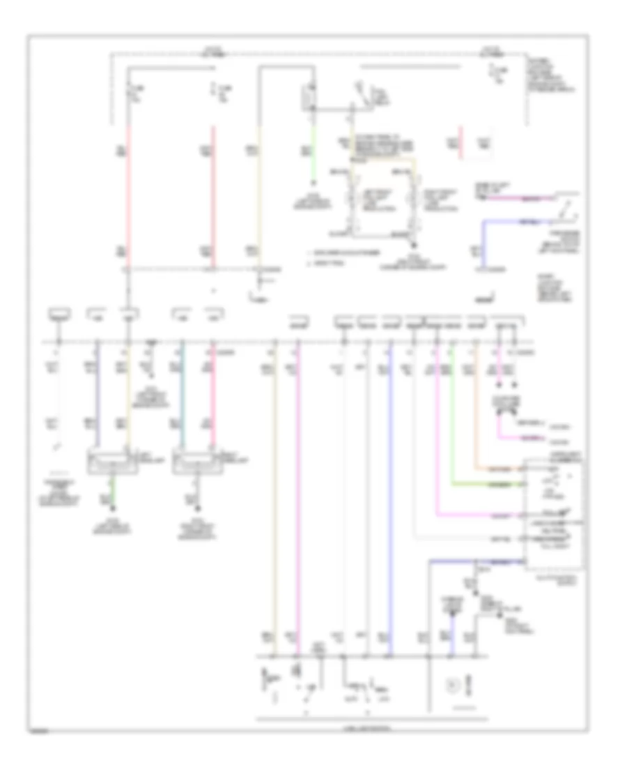
Headlights Wiring Diagram, without Autolamps for Ford Explorer 2008
List of elements for Headlights Wiring Diagram, without Autolamps for Ford Explorer 2008:
- (base of left "b" pillar) g301
- (left side of engine compt)
- (not used)
- Auto
- Battery junction box (bjb) (left side of engine compt, at fender apron)
- C2280b
- C2280d
- C2280e
- Computer data lines system
- Explorer & mountaineer
- Fog lamp ind
- Fog lamp relay
- Ftp ftp/high
- Full left
- Full right
- Fuse 15a
- G101 (left front corner of engine compt)
- G104 (right front corner of engine compt)
- G105
- G105 (left side of engine compt)
- G200 (at right kick panel)
- G302 (base of right "b" pillar)
- Gnd
- Hot at all times
- Hsd
- Instrument cluster (ic)
- Interior lights system
- Lamps fog
- Lane change
- Left front fog lamp (late production)
- Left headlamp
- Low
- Main light switch
- Med can
- Ms can+
- Ms can-
- Multi-function switch
- Neutral
- Off
- Park
- Park brake switch (behind top of left kick panel)
- Right front fog lamp (late production)
- Right headlamp
- S219
- Sense
- Sig pwm
- Smart junction box (sjb) (behind left side of dash)
- Sport trac
- Windshield wiper motor (at left rear of engine compt)
HORN
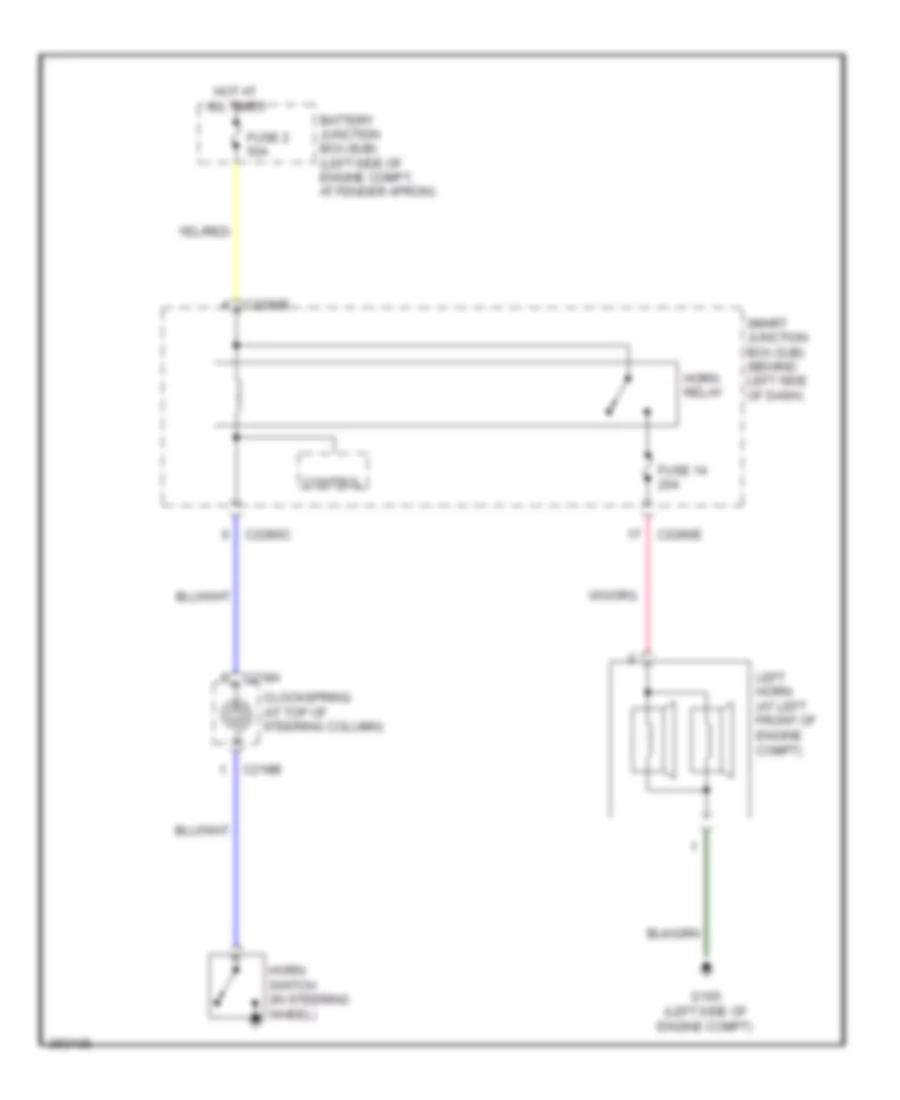
Horn Wiring Diagram for Ford Explorer 2008
List of elements for Horn Wiring Diagram for Ford Explorer 2008:
- Battery junction box (bjb) (left side of engine compt, at fender apron)
- C218a
- C218b
- C2280c
- C2280e
- Clockspring (at top of steering column)
- Control
- Fuse 14 20a
- Fuse 2 50a
- G105 (left side of engine compt)
- Horn relay
- Horn switch (in steering wheel)
- Hot at all times
- Left horn (at left front of engine compt)
- Smart junction box (sjb) (behind left side of dash)
INSTRUMENT CLUSTER
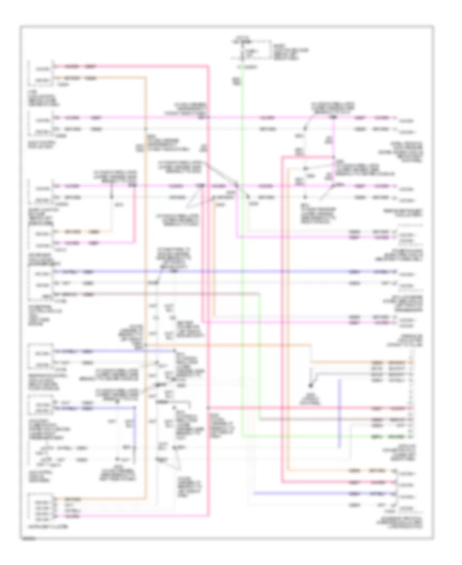
Instrument Cluster Wiring Diagram for Ford Explorer 2008
List of elements for Instrument Cluster Wiring Diagram for Ford Explorer 2008:
- (base of left "b" pillar) g301
- (except sport trac)
- (in main harness, near breakout to steering column)
- (in tailgate warning switch harness, near breakout to c432) s410
- (left side of engine compt) g105
- (mounted on side of master cylinder) brake fluid level switch
- Acc
- Ambient air temperature sensor (w/o eatc) (left front of engine compt, near radiator support)
- Analog gnd
- Anti theft
- Anti-lock brake system (abs) module (left front of engine compt)
- Anti-theft system
- C2280a
- C2280b
- C2280c
- C2280d
- C434a
- C434b
- Cdc30
- Cdc34
- Cmc19
- Cmc20
- Cmc24
- Cmc29
- Compass+
- Compass-
- Computer data lines system
- Crt04
- Dimmer
- Driver side front door ajar switch (at rear of left front door)
- Driver side rear door ajar switch (at rear of left rear door)
- Electronic compass
- Epats gnd
- Epats rx
- Epats tx
- Fuel level
- Fuel tank level sender
- Fuse 10a
- G200 (at right kick panel)
- G300 (behind left kick panel)
- G301 (base of left "b" pillar)
- G302 (base of right "b" pillar)
- G303 (sport trac) (at right "c" pillar)
- G402 (explorer & mountaineer) (right rear corner of vehicle)
- Gd145
- Gnd p
- Hat
- Hi can +
- Hi can -
- Hot at all times
- Hot w/ run/ start relay energized
- Hs can+
- Hs can-
- Ignition switch
- Instrument cluster
- Interior lights system
- Key in
- Key in ignition switch
- Liftgate ajar switch (lower center of liftgate)
- Liftgate glass ajar switch (in center of liftgate)
- Lvl sw
- Lvl sw rtn
- Md gnd
- Message center switch
- Message cntr+
- Ms can+
- Ms can-
- Off
- Oil press
- Oil pressure switch (4.0l: top left side of engine block) (4.6l: lower left front of engine block)
- Outside air temp
- Park brake switch (behind top of left kick panel)
- Passenger side front door ajar switch (at rear of right front door)
- Passenger side rear door ajar switch (at rear of right rear door)
- Pwr compass+ compass- gnd
- Rmc19
- Rmc32
- Rrt25
- Run
- Run/start
- S218
- S219
- S223
- S343 s906 (sport trac)
- S411
- S501
- S600
- S918
- Sbp24
- Sense
- Smart junction box (sjb) (behind left side of dash)
- Start
- Sw fd1
- Sw fd2
- Vdb04
- Vdb05
- Vdb06
- Vdb07
- Vh407
- Vmc11
- Vmc30
- Vmc31
- Vrt23
- Vrt24
- Washer level
- Wiper/washer system
INTERIOR LIGHTS
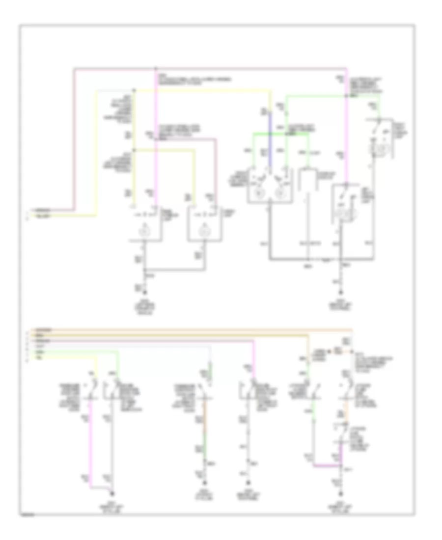
Courtesy Lamps Wiring Diagram (1 of 2) for Ford Explorer 2008
List of elements for Courtesy Lamps Wiring Diagram (1 of 2) for Ford Explorer 2008:
- (behind left side of dash) smart junction box (sjb)
- (in body main harness, near breakout to g300) s305
- (in interior light harness, near breakout to c3053) s347
- (in window regulator jumper harness, near breakout to g300) s309
- Battery saver interior lamp
- C2280a
- C2280c
- C2280d
- Cargo lamp
- Ctrl
- Ctsy
- Driver side exterior rear view mirror
- Front interior/ map lamps assembly
- Fuse 15a
- G200 (at right kick panel)
- G300 (behind left kick panel)
- G400 (left rear corner of vehicle)
- G402 (right rear corner of vehicle)
- Glove box lamp
- Homelink module
- Hot at all times
- Hsd
- Lamp puddle
- Left vanity mirror lamp
- Mountaineer/ltd
- Off
- Passenger side exterior rear view mirror
- Power distribution system
- Puddle lamp
- Puddle lamp relay
- Rear interior lamp
- Right vanity mirror lamp
- S307 (in window regulator jumper harness, near breakout to g300)
- S346
- S397 (in interior light harness, near breakout to c315)
- S501
- S600
- S902 (in interior light feed harness, near breakout to front of roof)
- S903
- S917
- Sense
- W/ medium overhead console
- W/ moonroof
- W/o medium overhead console
Courtesy Lamps Wiring Diagram (2 of 2) for Ford Explorer 2008
List of elements for Courtesy Lamps Wiring Diagram (2 of 2) for Ford Explorer 2008:
- (in dome light feed harness) s904
- (in interior light feed harness, near breakout to front of roof) s902
- (in window regulator jumper harness, near breakout to g303) s345
- Cargo lamp
- Driver side front door ajar switch (at rear of left front door)
- Driver side rear door ajar switch (at rear of left rear door)
- Front interior/ map lamps assembly
- G300 (behind left kick panel)
- G301 (base of left "b" pillar)
- G303 (at right "c" pillar)
- G400 (left rear corner of vehicle)
- Homelink module
- Left vanity mirror lamp
- Liftgate ajar switch (lower center of liftgate)
- Liftgate glass ajar switch (in center of liftgate)
- Liftgate glass release switch
- Off
- Passenger side front door ajar switch (at rear of right front door)
- Passenger side rear door ajar switch (at rear of right rear door)
- Rear interior lamp
- Right vanity mirror lamp
- S307 (in window regulator jumper harness, near breakout to g300)
- S309 (in window regulator jumper harness, near breakout to g300)
- S346
- S347 (in interior light harness, near breakout to c3053)
- S410 (in tailgate warning switch harness, near breakout to c432)
- S411
- S501
- S600
- S903
- S905
- Wiper/ washer system
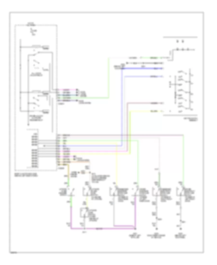
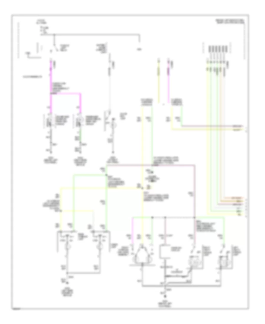
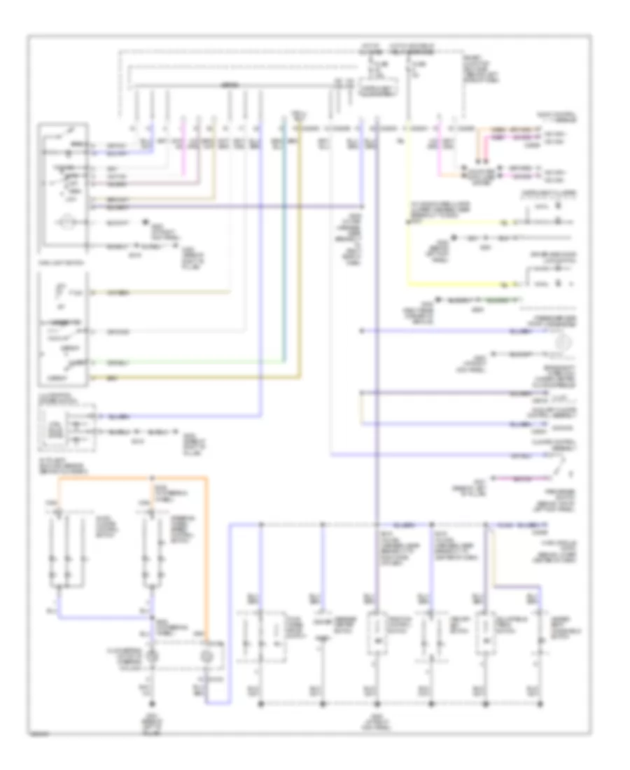
Instrument Illumination Wiring Diagram for Ford Explorer 2008
List of elements for Instrument Illumination Wiring Diagram for Ford Explorer 2008:
- (in window regulator jumper harness, near breakout to g300) s301
- Adjustable pedal switch
- Audio control module
- Audio/ climate control switch
- Auto
- Autolamp/ sunload sensor (behind glove box)
- Auxiliary climate control assembly
- Brake shift interlock (under center floor console)
- C218a
- C218b
- C2280a
- C2280b
- C2280c
- C2280d
- C228b
- C290b
- C294c
- C951b
- Climate control assembly
- Cln04
- Clockspring (at top of steering column)
- Computer data lines system
- Ctrl solid state
- Defeat
- Dim
- Dimmer
- Dimming
- Dome
- Driver side door lock switch
- Fog
- Fog ind
- Four wheel drive switch
- Fuse 15a
- Fuse 5a
- G200 (at right kick panel)
- G300 (behind left kick panel)
- G301 (base of left "b" pillar)
- G302 (base of right "b" pillar)
- G402 (right rear corner of vehicle)
- Gnd
- Heated seat/ windshield switch
- Hot at all times
- Hot w/ acc/delay relay energized
- Hvac module (datc) (behind lower center of dash)
- Illum
- Illumination dimmer switch
- Ins ill pot-
- Instrument cluster
- Instrument illumination
- Low
- Main light switch
- Memory set switch
- Message center switch
- Ms can +
- Ms can -
- Off
- Park
- Park brake switch (behind top of left kick panel)
- Passenger side door lock switch
- S209 (in main harness, near breakout to right side of dash)
- S215 (in main harness, near breakout to right side of dash)
- S216 (in main harness, near breakout to center of dash)
- S219
- S236 (in steering wheel)
- S239 (in steering wheel)
- S501
- S600
- Sense
- Smart junction box (sjb) (behind left side of dash)
- Steering wheel/ speed control switch
- Traction control switch
- Undefeated
- Vdb06
- Vdb07
MEMORY SYSTEMS
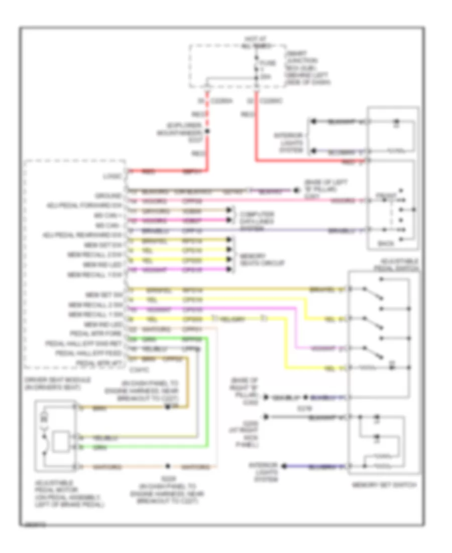
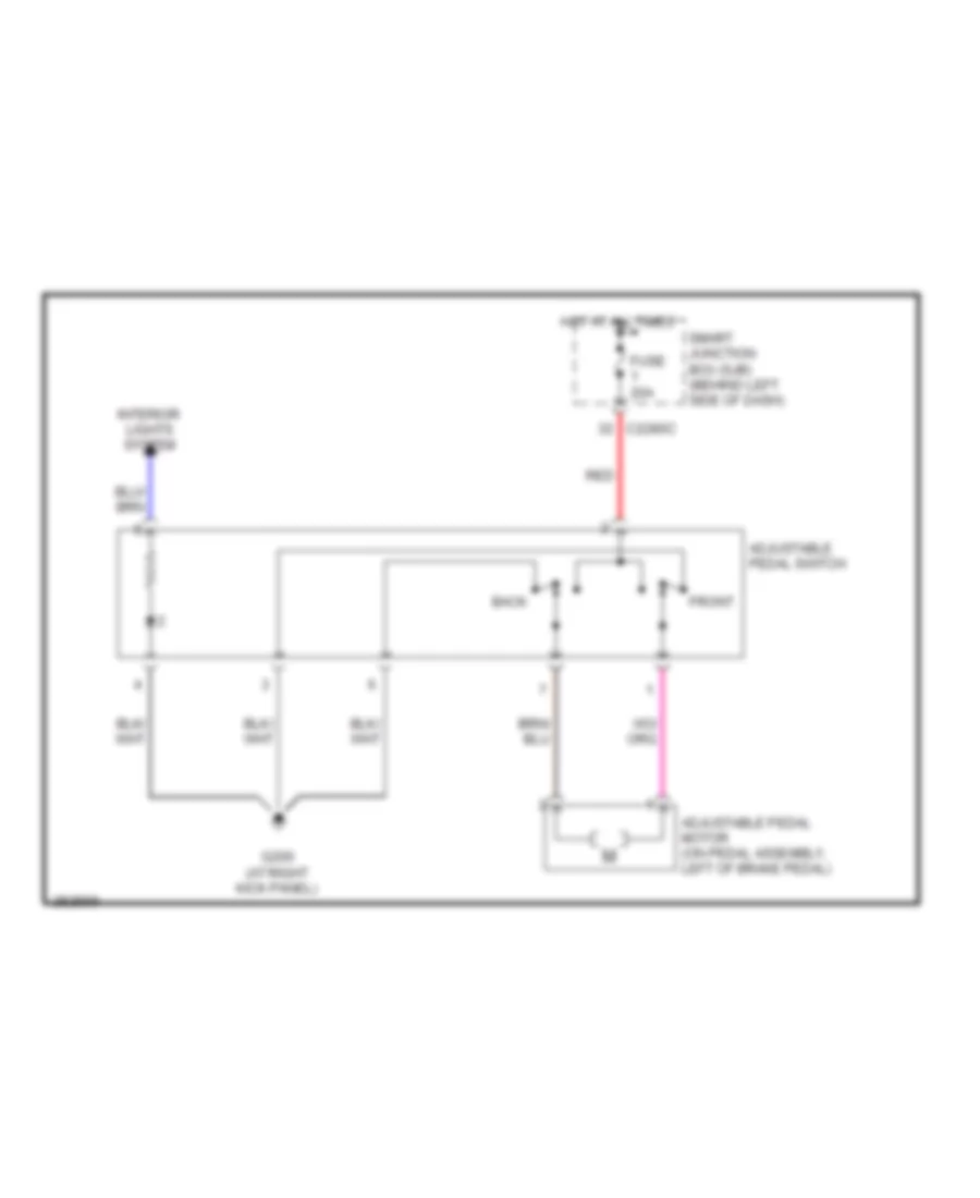
Adjustable Pedal Wiring Diagram for Ford Explorer 2008
List of elements for Adjustable Pedal Wiring Diagram for Ford Explorer 2008:
- (base of left "b" pillar) g301
- (base of right "b" pillar) g302
- (explorer, mountaineer) s337
- (in dash panel to engine harness, near breakout to c227) s228
- Adj pedal forward sw
- Adj pedal rearward sw
- Adjustable pedal motor (on pedal assembly, left of brake pedal)
- Adjustable pedal switch
- Back
- C2280a
- C2280c
- C341c
- Computer data lines system
- Cpp01
- Cpp02
- Cpp09
- Cpp10
- Cps15
- Cps16
- Cps55
- Driver seat module (in driver's seat)
- Front
- Fuse 20a
- G200 (at right kick panel)
- Gd143
- Ground
- Hot at all times
- Interior lights system
- Logic
- Lpp06
- Mem ind led
- Mem recall 1 sw
- Mem recall 2 sw
- Mem set sw
- Memory seats circuit
- Memory set switch
- Ms can +
- Ms can -
- Pedal hall eff feed
- Pedal hall eff sns ret
- Pedal mtr aft
- Pedal mtr fore
- Red
- Rpp06
- Rps14
- S219
- S229 (in dash panel to engine harness, near breakout to c227)
- Sbp01
- Smart junction box (sjb) (behind left side of dash)
- Vdb06
- Vdb07
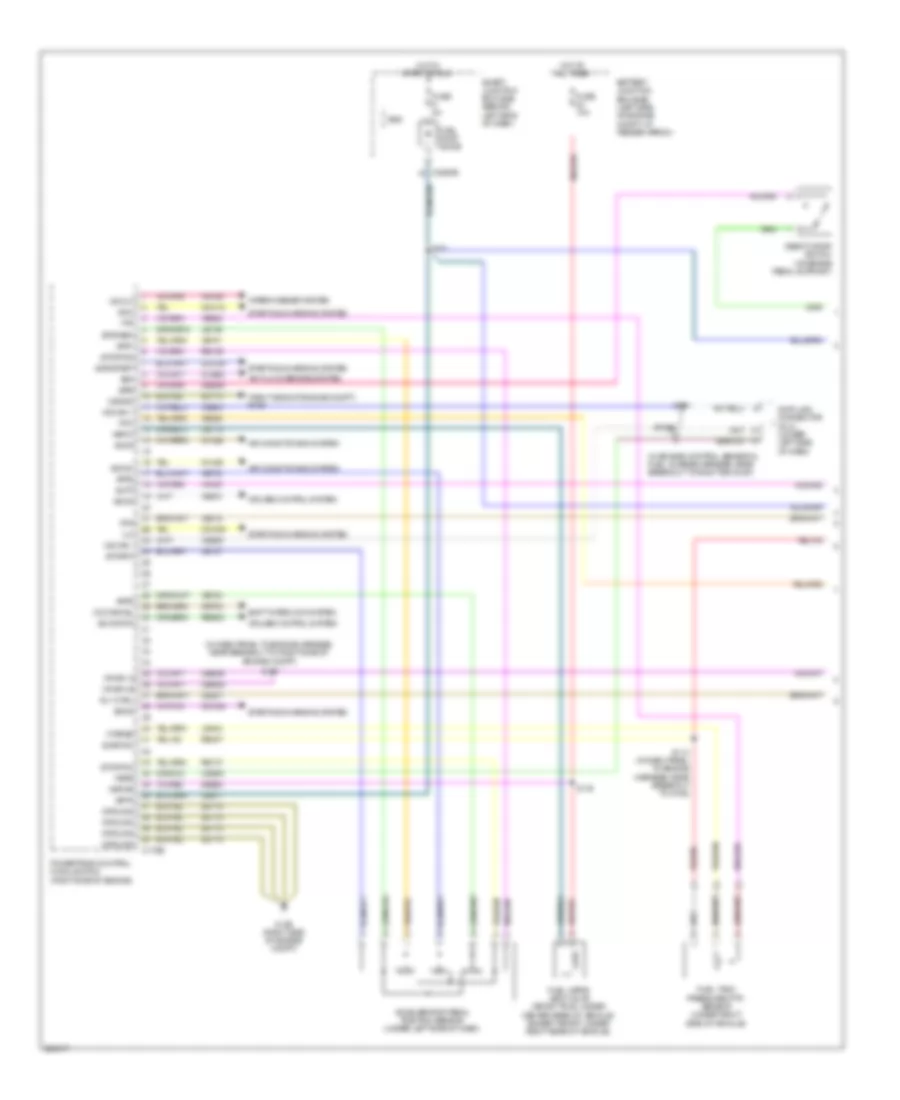
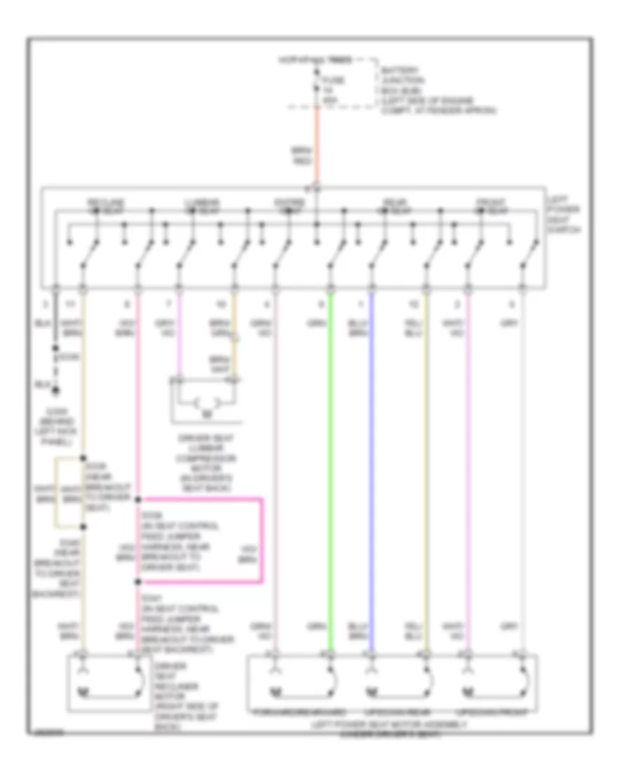
Driver"s Memory Seat Wiring Diagram for Ford Explorer 2008
List of elements for Driver"s Memory Seat Wiring Diagram for Ford Explorer 2008:
- (behind left kick panel) g300
- Adj pedal forward sw
- Adj pedal rearward sw
- Adjustable pedal circuit
- Battery junction box (bjb) (left side of engine compt, at fender apron)
- C2280a
- C341a
- C341b
- C341c
- C353
- C357
- Computer data lines system
- Cpp01
- Cpp02
- Cpp09
- Cpp10
- Cps01
- Cps02
- Cps03
- Cps04
- Cps05
- Cps06
- Cps07
- Cps08
- Cps15
- Cps16
- Cps23
- Cps24
- Cps25
- Cps26
- Cps27
- Cps28
- Cps29
- Cps30
- Cps55
- Driver seat lumbar compressor motor (in driver's seat back)
- Driver seat module (in driver's seat)
- Driver seat recliner motor (right side of driver's seat back)
- Entire seat
- Front of seat
- Front up/down
- Frt tilt dn sw
- Frt tilt hall efect sn
- Frt tilt mtr dn
- Frt tilt mtr up
- Frt tilt up sw
- Fuse 20a
- Fuse 30a
- Fwd
- Fwd/rwd horizontal
- G200 (at right kick panel)
- G300 (behind left kick panel)
- G301 (base of left "b" pillar)
- G302 (base of right "b" pillar)
- Gd133
- Gd143
- Horz base aft
- Horz base aft sw
- Horz base fore
- Horz base fore sw
- Horz base hall effect sn
- Hot at all times
- Interior lights system
- Left power seat motor assembly (under driver's seat)
- Left power seat switch
- Logic
- Logic gnd
- Lpp06
- Lumbar of seat
- Mem ind led
- Mem recall 1 sw
- Mem recall 2 sw
- Mem set sw
- Memory set switch
- Ms can+
- Ms can-
- Out
- Pedal hall eff feed
- Pedal hall eff sns ret
- Pedal mtr aft
- Pedal mtr fore
- Pwr gnd
- Rear of seat
- Rear tilt dn sw
- Rear tilt hall effect sn
- Rear tilt mtr dn
- Rear tilt mtr up
- Rear tilt up sw
- Rear up/down
- Recline dn sw
- Recline hall effect sn
- Recline mtr on
- Recline mtr up
- Recline of seat
- Recline up sw
- Red
- Rpp06
- Rps13
- Rps14
- Rwd
- S219
- S334 (in seat control feed jumper harness, near breakout to driver's seat backrest)
- S336
- S337 (explorer, mountaineer) red
- Sbb14
- Sbp01
- Seat hall eff
- Smart junction box (sjb) (behind left side of dash)
- Vbatt
- Vdb06
- Vdb07
- Vps09
- Vps10
- Vps11
- Vps12
NAVIGATION
Parking Assistant Wiring Diagram for Ford Explorer 2008
List of elements for Parking Assistant Wiring Diagram for Ford Explorer 2008:
- C2280a
- Cbp18
- Cmp09
- Computer data lines system
- Fuse 18 10a
- G302 (base of right ``b" pillar)
- Gd145
- Gnd
- Hot w/ run/start relay energized
- Ms can+
- Ms can-
- Parking aid module (pam) (at right "d" pillar)
- Parking aid speaker (right rear corner of vehicle)
- Pwr run
- Rmp09
- S343
- Smart junction box (sjb) (behind left side of dash)
- Sndr gnd
- Sndr+
- Vdb06
- Vdb07
POWER DISTRIBUTION
Power Distribution Wiring Diagram (1 of 6) for Ford Explorer 2008
List of elements for Power Distribution Wiring Diagram (1 of 6) for Ford Explorer 2008:
- (in battery harness, at breakout to generator) s133
- (in seat control feed harness, at breakout to c438) s413
- (left side of engine compt, at fender apron) battery junction box (bjb)
- (w/ 10-way)
- (w/ memory)
- (w/o 10-way)
- (w/o memory)
- 4.0l
- 4.6l
- 40a
- 4x4 control module
- Anti-lock brakes system (abs) module
- Auxiliary blower motor relay
- Battery
- Battery charge trailer tow
- Blower motor relay 1
- C102a
- C1035a
- C1035b
- C1104a
- C175b
- C2280e
- C281b
- C341a
- C4322b
- Console 1 power point
- Console 2 power point
- Driver seat module (dsm) (w/ memory)
- From fuse 17, a battery junction box (bjb) (diagram 1 of 6)
- Fuel pump relay
- Fuel vapor vent valve
- Fuse 10a
- Fuse 20a
- Fuse 30a
- Fuse 40a
- Fuse 50a
- G200 (at right kick panel)
- Generator
- Generator) s135
- Left power seat switch (w/o memory)
- Left third row folding seat relay
- Pcm power relay
- Power running board (prb) module
- Powertrain control module (pcm)
- Rear defrost relay
- Red
- Relay
- Right power seat switch
- Right third row folding seat relay
- S127 (in dash panel to engine harness, at breakout to battery junction box (bjb))
- S134 (in battery harness, at breakout to generator)
- S333
- Smart junction box (sjb) (behind left side of dash)
- Starter motor
- Starter relay
- Subwoofer amplifier
- To acc/ delay relay smart junction box (sjb) (diagram 2 of 6)
- To fuse 16 battery junction box (bjb) (diagram 1 of 6)
- To fuse 26 battery junction box (bjb) (diagram 2 of 6)
- To horn relay smart junction box (sjb) (diagram 3 of 6)
- To reverse lamp relay smart junction box (sjb) (diagram 4 of 6)
- Trailer brake control (tbc) module
Power Distribution Wiring Diagram (2 of 6) for Ford Explorer 2008
List of elements for Power Distribution Wiring Diagram (2 of 6) for Ford Explorer 2008:
- (in air conditioning harness, near red
- (in seat control feed jumper harness, near breakout to driver seat) s337
- (in window regulator jumper harness, near breakout to g300) s301
- (in window regulator jumper harness, near breakout to g300) s395
- (left side of engine compt, at fender apron) battery junction box (bjb)
- 4x4 control module
- A/c clutch relay
- Acc/ delay relay
- Accessory protocol interface module (apim) (late production)
- Adjustable pedal switch
- Auto- dimming interior mirror unit
- Auxiliary relay box 1 (right rear of engine compt)
- Breakout to left rear quarterpanel) s342
- C2280a
- C2280c
- C2280e
- C281b
- C341c
- C504a
- Circuit breaker 1 25a
- Control
- Del acc
- Driver seat module
- Driver side door lock switch
- Exterior rear view mirror switch
- Fog lamp relay
- From fuse 1 battery junction box (bjb) (diagram 1 of 6)
- From fuse 25 b battery junction box (bjb) (diagram 1 of 6)
- Front wiper relay
- Fuse 10a
- Fuse 15a
- Fuse 20a
- Fuse 25a
- Fuse 30a
- Fuse 40a
- Fuse 5a
- G200 (at right kick panel)
- Heated seat/ windshield switch
- Hsd
- Left headlamp
- Left heated seat relay
- Left heated windshield relay
- Left power seat switch
- Logic
- Master window adjust switch
- Neutral tow indicator
- Passenger side door lock switch
- Rear console power point
- Rear entertainment module (retm)
- Rear wiper module
- Red
- Right headlamp
- Right heated seat relay
- Right heated windshield relay
- Roof opening panel module
- S210 (in main harness, near breakout to right side of dash)
- S222 (in main harness, at breakout to left side of dash.)
- S333
- Satellite digital audio receiver system (sdars) module
- Smart junction box (sjb) (behind left side of dash)
- Transmission control module (tcm)
Power Distribution Wiring Diagram (3 of 6) for Ford Explorer 2008
List of elements for Power Distribution Wiring Diagram (3 of 6) for Ford Explorer 2008:
- (behind left side of dash) smart junction box (sjb)
- (in dome light feed harness) s904
- (in interior light harness, near breakout to c315) s397
- (in window regulator jumper harness, near breakout to g300) s307
- (not used)
- Auto a/c
- Autolamp/ sunload sensor
- Bat saver
- Breakout to c3053) s347
- C2280a
- C2280c
- C2280e
- C228a
- C294c
- Cargo lamp
- Climate control assembly
- Control
- Driver side exterior rear view mirror
- Explorer
- From fuse 2 battery junction box (bjb) (diagram 1 of 6)
- From fuse 23 smart junction box (sjb) (diagram 3 of 6)
- Front interior/ map lamp assembly
- Fuse 10a
- Fuse 15a
- Glove box lamp
- Hat
- Homelink module
- Horn relay
- Hsd
- Hvac module (datc)
- Instrument cluster (ic)
- Interior lamp (xls)
- Interior lamps
- Jumper harness, near breakout to g300) s390
- Left front park/ turn lamp
- Left front park/turn lamp
- Left front turn/ stop
- Left rear park/ stop lamp
- Left rear park/ stop/ turn lamp
- Left rear turn lamp
- Left rear turn/ stop
- Left repeater lamp
- Left vanity mirror lamp
- Manual a/c
- Mountaineer
- Park lamp relay
- Passenger side exterior rear view mirror
- Puddle lamp relay
- Rear interior lamp
- Right rear park/ stop lamp
- Right vanity mirror lamp
- S305 (in window regulator jumper harness, near breakout to g300)
- S309 (in window regulator jumper harness, near breakout to g300)
- S902 (in interior light feed harness, near breakout to front of roof)
- To fuse 28 smart junction box (sjb) (diagram 3 of 6)
- To hsd smart junction box (sjb) (diagram 4 of 6)
- To hsd smart junction box (sjb) (diagram 5 of 6)
- Tricolor stop
- W/ medium overhead console
- W/o medium overhead console
Power Distribution Wiring Diagram (4 of 6) for Ford Explorer 2008
List of elements for Power Distribution Wiring Diagram (4 of 6) for Ford Explorer 2008:
- (in main harness, near breakout to center of dash) s216
- (in main harness, near breakout to right side of dash) s209
- Adjustable pedal switch
- Audio control module (acm)
- Audio control switch
- Auto a/c
- Batt+
- Brake shift interlock
- C218a
- C218b
- C2280a
- C2280c
- C2280e
- C228a
- C228b
- C290a
- C294b
- C294c
- C310a
- C951b
- Climate control assembly
- Clock spring (at top of steering column)
- Dimm
- Dimm in
- Driver temperature blend door actuator
- Four- wheel drive switch
- From fuse 3 battery junction box (bjb) (diagram 1 of 6)
- From hsd smart junction box (sjb) (diagram 3 of 6)
- Front auxiliary climate control assembly
- Fuse 10a
- Fuse 15a
- Fuse 20a
- Fuse 5a
- Heated seat/ windshield switch
- Hsd
- Hvac module (datc)
- Illum
- Instrument illum bulb
- Instrument illum led
- Main light switch
- Manual a/c
- Memory set switch
- Message center switch
- Occupant classification system module (ocsm)
- Of dash)
- Passenger air bag deactivation indicator
- Restraints control module (rcm)
- Reverse lamp relay
- Run/ start relay
- Run/st
- S201
- S236 (in steering wheel)
- S422 (heavy duty) (in fuel tank gauge sender harness, near breakout to c423)
- S423 (heavy duty)
- Sjb micro power
- Smart junction box (sjb) (behind left side of dash)
- Steering wheel/speed control switch
- To fuse 18 smart junction box (sjb) (diagram 5 of 6)
- To fuse 8 smart junction box (sjb) (diagram 6 of 6)
- To fuse 9 smart junction box (sjb) (diagram 5 of 6)
- Traction control switch
- Trailer left stop/ turn
- Trailer right stop/ turn
- Trailer tow connector
- Var1
Power Distribution Wiring Diagram (5 of 6) for Ford Explorer 2008
List of elements for Power Distribution Wiring Diagram (5 of 6) for Ford Explorer 2008:
- (behind left side of dash) smart junction box (sjb)
- (in dash panel to engine harness, near breakout to left side of engine compt) s142
- (in dash panel to engine harness, near breakout to left side of radiator) s143
- (in main harness, near breakout to right side of dash) s208
- (not used)
- 4x4 control module
- Anti-lock brake system (abs) module
- Audio control module (acm)
- Auto- dimming interior mirror unit
- Battery charge trailer tow relay
- Battery junction box (bjb) (left side of engine compt, at fender apron)
- Brake pedal position switch
- C175b
- C2280a
- C2280c
- C2280d
- C2280e
- C281a
- C290a
- C951b
- Digital transmission range (dtr) sensor (4.0l)
- Electronic compass
- Engine harness, near breakout to left side of radiator) s121
- Explorer
- Four- wheel drive switch
- From fuse 17 smart junction box (sjb) (diagram 4 of 6)
- From fuse 22 smart junction box (sjb) (diagram 3 of 6)
- From run start/relay smart junction box (sjb) (diagram 4 of 5)
- Front auxiliary climate control assembly
- Front wiper relay
- Fuel pump diode
- Fuel pump relay
- Fuse 10a
- Fuse 15a
- Fuse 2a
- Fuse 5a
- Heated seat/ windshield switch
- Hsd
- Left heated seat relay
- Logic
- Mountaineer
- Parking aid module (pam)
- Powertrain control module (pcm)
- Rear blend door actuator
- Rear wiper module
- Right front park/turn lamp
- Right front turn
- Right heated seat relay
- Right rear park/stop/ turn lamp
- Right rear stop/ turn
- Right rear turn lamp
- Right repeater lamp
- Run/acc
- S396 (in interior light harness, near breakout to c315)
- Sense
- Smcs
- Smr/ start
- Start
- Start diode
- To ignition switch (diagram 6 of 6)
- To splice s223 (diagram 6 of 6)
- Traction control switch
- Transmission control module (tcm) (4.6l)
Power Distribution Wiring Diagram (6 of 6) for Ford Explorer 2008
List of elements for Power Distribution Wiring Diagram (6 of 6) for Ford Explorer 2008:
- (in main harness, near breakout to steering column) s223
- (not used)
- Acc
- All lock & unlock relay
- Brake shift interlock
- C2280c
- Data link connector (dlc)
- Driver unlock & liftgate release relay
- From fuse 10 smart junction box (sjb) (diagram 5 of 6)
- From fuse 11 smart junction box (sjb) (diagram 5 of 6)
- From fuse 9 smart junction box (sjb) (diagram 5 of 6)
- From run/ start relay smart junction box (sjb) (diagram 4 of 6)
- Fuse 10a
- Fuse 15a
- Fuse 20a
- Ignition switch
- Instrument cluster (ic)
- Key in
- Key in ignition switch
- Lock
- Off
- Passive anti-theft transceiver
- Run
- Run/ st
- Smart junction box (sjb) (behind left side of dash)
- Start
POWER DOOR LOCKS
Power Door Locks Wiring Diagram for Ford Explorer 2008
List of elements for Power Door Locks Wiring Diagram for Ford Explorer 2008:
- (in window regulator jumper harness, near breakout to c339) s313
- All lock & unlock relay
- Anti-theft system
- C2280a
- C2280b
- Ctrl
- Driver side door lock actuator (at rear of left front door)
- Driver side door lock switch
- Driver unlock & liftgate release relay
- Fuse 20a
- G300 (behind left kick panel)
- G400 (left rear corner of vehicle)
- G402 (right rear corner of vehicle)
- Hot at all times
- Hsd
- Interior lights system
- Left rear door lock actuator (at rear of left rear door)
- Liftgate glass actuator
- Liftgate lock actuator (lower center of liftgate)
- Lock
- Passenger side door lock actuator (at rear of right front door)
- Passenger side door lock switch
- Right rear door lock actuator (at rear of right rear door)
- S306 (in window regulator jumper harness, near breakout to g300)
- S308 (in window regulator jumper harness, near breakout to g300)
- S314 (in window regulator jumper harness, near breakout to c339)
- S412
- S501
- S600
- Sense
- Smart junction box (sjb) (behind left side of dash)
- Unlk
POWER MIRRORS
Electrochromic Mirror Wiring Diagram, with Microphone for Ford Explorer 2008
List of elements for Electrochromic Mirror Wiring Diagram, with Microphone for Ford Explorer 2008:
- Acc/ delay relay
- Auto-dimming interior mirror unit
- C2280a
- Cbp05
- Cbp15
- Control
- Dmn07
- Fuse 10a
- Fuse 5a
- G301 (base of left "b" pillar)
- Gd143
- Gnd
- Hot at all times
- Mic +
- Mic -
- Nca
- Reverse
- Reverse lamp relay
- Rmn07
- S310 (in window regulator jumper harness, near breakout to g300)
- S901
- S918
- Shield
- Smart junction box (sjb) (behind left side of dash)
- Sound systems
- Vmn07
- Vpwr
Electrochromic Mirror Wiring Diagram, without Microphone for Ford Explorer 2008
List of elements for Electrochromic Mirror Wiring Diagram, without Microphone for Ford Explorer 2008:
- (except sport trac) s343 s906 (sport trac)
- Auto-dimming interior mirror unit
- C2280a
- Cbp15
- Cbp18
- Fuse 10a
- G300 (behind left kick panel)
- Gd133
- Gnd
- Hot w/ reverse lamp relay energized
- Hot w/ run/start relay energized
- Ign
- Rev
- S310 (in window regulator jumper harness, near breakout to g300)
- Smart junction box (sjb) (behind left side of dash)
Power Mirrors Wiring Diagram, with Heated Mirrors for Ford Explorer 2008
List of elements for Power Mirrors Wiring Diagram, with Heated Mirrors for Ford Explorer 2008:
- Battery junction box (bjb) (left side of engine compt, at fender apron)
- Defogger system
- Down
- Driver side exterior rear view mirror (front of driver's door)
- Exterior rear view mirror switch
- Fuse 5a
- G300 (behind left kick panel)
- Hot at all times
- Interior lights system
- Left
- Left/ right
- Mirror select
- Passenger side exterior rear view mirror (front of front passenger's door)
- Puddle lamp
- Right
- S500 (in left front door window regulator harness, near breakout to driver's door)
- S501
- Up/ down m
Power Mirrors Wiring Diagram, without Heated Mirrors for Ford Explorer 2008
List of elements for Power Mirrors Wiring Diagram, without Heated Mirrors for Ford Explorer 2008:
- Battery junction box (bjb) (left side of engine compt, at fender apron)
- Down
- Driver side exterior rear view mirror (front of driver's door)
- Exterior rear view mirror switch
- Fuse 5a
- G300 (behind left kick panel)
- Hot at all times
- Interior lights system
- Left
- Left/ right
- Mirror select
- Passenger side exterior rear view mirror (front of front passenger's door)
- Right
- S500 (in left front door window regulator harness, near breakout to driver's door)
- S501
- Up/ down m
POWER SEATS
Adjustable Pedal Wiring Diagram for Ford Explorer 2008
List of elements for Adjustable Pedal Wiring Diagram for Ford Explorer 2008:
- Adjustable pedal motor (on pedal assembly, left of brake pedal)
- Adjustable pedal switch
- Back
- C2280c
- Front
- Fuse 20a
- G200 (at right kick panel)
- Hot at all times
- Interior lights system
- Red
- Smart junction box (sjb) (behind left side of dash)
Driver Power Seat Wiring Diagram, with 10-Way Power Seat for Ford Explorer 2008
List of elements for Driver Power Seat Wiring Diagram, with 10-Way Power Seat for Ford Explorer 2008:
- Battery junction box (bjb) (left side of engine compt, at fender apron)
- Breakout to driver seat)
- Driver seat lumbar compressor motor (in driver's seat back)
- Driver seat recliner motor (right side of driver's seat back)
- Entire seat
- Forward/rearward
- Front of seat
- Fuse 40a
- G300 (behind left kick panel)
- Hot at all times
- Left power seat motor assembly (under driver's seat)
- Left power seat switch
- Lumbar of seat
- Rear of seat
- Recline of seat
- S336
- S340 (near breakout to driver seat backrest)
- Up/down front
- Up/down rear
Driver Power Seat Wiring Diagram, with 6-Way Power Seat for Ford Explorer 2008
List of elements for Driver Power Seat Wiring Diagram, with 6-Way Power Seat for Ford Explorer 2008:
- Battery junction box (bjb) (left side of engine compt, at fender apron)
- Entire seat
- Forward/rearward
- Front of seat
- Fuse 40a
- G300 (behind left kick panel)
- Hot at all times
- Left power seat motor assembly (under driver's seat)
- Left power seat switch
- Rear of seat
- S300
- Up/down front
- Up/down rear
Heated Seats Wiring Diagram for Ford Explorer 2008
List of elements for Heated Seats Wiring Diagram for Ford Explorer 2008:
- (at right "c" pillar) (sport trac) g303
- (behind left kick panel) g300
- (right rear corner of vehicle) (explorer,mountaineer) g402
- Battery junction box (bjb) (left side of engine compt, at fender apron)
- C2280c
- Defogger system
- Dr ind
- Fhws on ind
- Fhws switch
- Fuse 10a
- Fuse 20a
- G200 (at right kick panel)
- G302 (base of right "b" pillar)
- Heated seat/ windshield switch
- Hot at all times
- Hot w/ run/start relay energized
- Interior lights system
- Left front seat back heater (in driver seat back)
- Left front seat cushion heater (in driver seat)
- Left heated seat relay
- Logic
- Ps ind
- Right front seat back heater (in front passenger's seat back)
- Right front seat cushion heater (under front passenger's seat)
- Right heated seat relay
- S208
- S210
- S219
- S336
- Smart junction box (sjb) (behind left side of dash)
- Sw illum ind
Passenger Power Seat Wiring Diagram for Ford Explorer 2008
List of elements for Passenger Power Seat Wiring Diagram for Ford Explorer 2008:
- Battery junction box (bjb) (left side of engine compt, at fender apron)
- Entire seat
- Forward/rearward
- Front of seat
- Fuse 30a
- G402 (right rear corner of vehicle)
- Hot at all times
- Rear of seat
- Right power seat motor assembly (under front passenger's seat)
- Right power seat switch
- S351
- Up/down front
- Up/down rear
Third Row Folding Seat Wiring Diagram for Ford Explorer 2008
List of elements for Third Row Folding Seat Wiring Diagram for Ford Explorer 2008:
- Battery junction box (bjb) (left side of engine compt, at fender apron)
- C2280b
- Fuse 30a
- G400 (left rear corner of vehicle)
- Hot at all times
- Left third row folding seat motor (behind left side of third row seat)
- Left third row folding seat relay (left rear corner of vehicle)
- Left third row folding seat switch
- Lsd
- Right third row folding seat motor (right rear of vehicle interior)
- Right third row folding seat relay (left rear corner of vehicle)
- Right third row folding seat switch
- S413
- S414 (in seat control feed harness, at breakout to c438)
- S415
- S416
- Smart junction box (sjb) (behind left side of dash)
POWER TOP/SUNROOF
Power Top/Sunroof Wiring Diagram, with Medium Overhead Console for Ford Explorer 2008
List of elements for Power Top/Sunroof Wiring Diagram, with Medium Overhead Console for Ford Explorer 2008:
- (behind left kick panel) g300
- Accessory/ delay relay
- Battery junction box (bjb) (left side of engine compt, at fender apron)
- C2280a
- C2280e
- Cbp05
- Close
- Cpr31
- Cpr40
- Del acc
- Fuse 20a
- Fuse 50a
- Fuse 5a
- G300 (behind left kick panel)
- Gd133
- Gnd
- Hot at all times
- Open
- Red
- Roof opening panel module (center front of roof)
- Roof opening panel switch
- S395
- S905
- S917
- Sbp01
- Smart junction box (sjb) (behind left side of dash)
- Tan/ red
Power Top/Sunroof Wiring Diagram, without Medium Overhead Console for Ford Explorer 2008
List of elements for Power Top/Sunroof Wiring Diagram, without Medium Overhead Console for Ford Explorer 2008:
- (behind left kick panel) g300
- Accessory/ delay relay
- Battery junction box (bjb) (left side of engine compt, at fender apron)
- C2280a
- C2280e
- Cbp05
- Close
- Cpr31
- Cpr39
- Cpr40
- Del acc
- Fuse 20a
- Fuse 50a
- Fuse 5a
- Gd133
- Gnd
- Hot at all times
- Open
- Red
- Roof opening panel module (center front of roof)
- Roof opening panel switch
- S395
- S903
- Sbp01
- Smart junction box (sjb) (behind left side of dash)
- Sw common
POWER WINDOWS
Power Windows Wiring Diagram for Ford Explorer 2008
List of elements for Power Windows Wiring Diagram for Ford Explorer 2008:
- (in window regulator jumper harness, near breakout to c339) s312
- Acc/delay relay
- Battery junction box (bjb) (left side of engine compt, at fender apron)
- C2280a
- C2280e
- C504a
- C504b
- Circuit breaker 1 25a
- Control
- Driver side front power window motor (in center of left front door)
- Fuse 50a
- G300 (behind left kick panel)
- Hot at all times
- Left rear
- Left rear power window motor (in center of left rear door)
- Left rear window adjust switch
- Lockout
- Master window adjust switch
- One shot elect
- Passenger side front power window motor (in center of right front door)
- Passenger side window adjust switch
- Red
- Right front
- Right rear
- Right rear power window motor (in center of right rear door)
- Right rear window adjust switch
- Smart junction box (sjb) (behind left side of dash)
RADIO
Base Radio Wiring Diagram for Ford Explorer 2008
List of elements for Base Radio Wiring Diagram for Ford Explorer 2008:
- Audio control module (acm)
- Audio jack
- Audio shld
- B +
- C2280c
- C290a
- C290b
- Cbp11
- Cbp12
- Computer data lines system
- Fuse 11 5a
- Fuse 12 5a
- Fuse 3 20a
- G202
- Gd114
- Gnd
- Hot at all times
- Hot in run or acc
- Hot in start
- L +
- L -
- L front spkr +
- L front spkr -
- L rear spkr +
- L rear spkr -
- Left front speaker
- Left rear speaker
- Ms can +
- Ms can -
- Nca
- Pair wires
- R +
- R -
- R front spkr +
- R front spkr -
- R rear spkr +
- R rear spkr -
- R/acc
- Right front speaker
- Right rear speaker
- Rme07
- Rme09
- Rme10
- Rme12
- Rme45
- Rme46
- S214
- Sbp03
- Smart junction box (sjb)
- St in 2l +
- St in 2l -
- St in 2r +
- St in 2r -
- Start
- Twisted
- Vdb06
- Vdb07
- Vme07
- Vme09
- Vme10
- Vme12
- Vme45
- Vme46
Premium Radio Wiring Diagram, with SYNC (1 of 2) for Ford Explorer 2008
List of elements for Premium Radio Wiring Diagram, with SYNC (1 of 2) for Ford Explorer 2008:
- Accessory protocol interface module (apim)
- Audio control switch
- Audio jack (in center console)
- Auto-dimming interior mirror unit (w/ microphone)
- Battery junction box (bjb) (left side of engine compt, at fender apron)
- C218a
- C218b
- Clockspring (at top of steering column)
- Computer data lines system
- Dme41
- Dme45
- Dme52
- Dmn01
- Dmn07
- Dmn14
- Drain
- Fuse 41 15a
- G202 (behind top right center of dash)
- Gd114
- Gnd
- Gnd2
- Hot at all times
- Hs can +
- Hs can -
- In 2l +
- In 2l -
- In 2r +
- In 2r -
- Interior lights system
- Media
- Mic +
- Mic -
- Mono +
- Mono -
- Ms can +
- Ms can -
- Nca
- Out l +
- Out l -
- Out r +
- Out r -
- Pair wires
- Phone
- Red
- Rh106
- Rme41
- Rme42
- Rme45
- Rme46
- Rme52
- Rme53
- Rmn01
- Rmn07
- Rmn14
- S329
- S342
- Satellite digital audio receiver system (sdars) module (behind right kick panel)
- Sbb41
- Seek+
- Seek-
- Shield
- Stereo 1l +
- Stereo 1l -
- Stereo 1r +
- Stereo 1r -
- Stereo l +
- Stereo l -
- Stereo r +
- Stereo r -
- Swc2 +
- Swc2 rtn
- Twisted
- Usb
- Usb port
- Vbatt
- Vdb04
- Vdb05
- Vdb06
- Vdb07
- Vme41
- Vme42
- Vme45
- Vme46
- Vme52
- Vme53
- Vmn01
- Vmn02
- Vmn07
- Vmn14
- Vnm07
- Voice
- Vol+
- Vol-
- W/ satellite radio & w/o rear entertainment module
Premium Radio Wiring Diagram, with SYNC (2 of 2) for Ford Explorer 2008
List of elements for Premium Radio Wiring Diagram, with SYNC (2 of 2) for Ford Explorer 2008:
- (behind top right center of dash) g202
- Audio control module (acm)
- Batt
- Battery junction box (bjb) (left side of engine compt, at fender apron)
- C290a
- C290b
- C290c
- Detect
- Dme22
- Fuse 22 20a
- Gd114
- Gnd
- Hot at all times
- L front spkr +
- L front spkr -
- L rear spkr +
- L rear spkr -
- Left front speaker
- Left rear speaker
- Mic +
- Mic -
- Mono +
- Mono -
- Nca
- Pair wires
- R front spkr +
- R front spkr -
- R rear spkr +
- R rear spkr -
- Right front speaker
- Right rear speaker
- Rme07
- Rme09
- Rme10
- Rme12
- Rme17
- Rme18
- Rme22
- Rme24
- Rmn01
- Rmn14
- S328
- Sbb22
- Shield
- Sme23
- Stereo l +
- Stereo l -
- Stereo r +
- Stereo r -
- Subwoofer amplifier (w/ audiophile) (sport track: in left "c" pillar) (except sport track: behind right rear quarterpanel)
- Sw +
- Sw -
- Sw+
- Sw-
- Swc1 +
- Swc1 -
- Twisted
- Vme07
- Vme09
- Vme10
- Vme12
- Vme14
- Vme17
- Vme18
- Vme22
- Vnm01
- Vnm14
Premium Radio Wiring Diagram, without SYNC (1 of 2) for Ford Explorer 2008
List of elements for Premium Radio Wiring Diagram, without SYNC (1 of 2) for Ford Explorer 2008:
- (behind top right center of dash) g202
- Antenna
- Audio control module (acm)
- Audio jack (w/ audiophile) (in center console)
- Auto-dimming interior mirror unit (w/ microphone)
- Batt
- C2280c
- C290a
- C290b
- C290c
- Cbp11
- Cbp12
- Computer data lines system
- Detect
- Dme22
- Dme4
- Dmn07
- Enable/clip detect
- Fuse 11 5a
- Fuse 12 5a
- Fuse 3 20a
- G202 (behind top right center of dash)
- Gd114
- Gnd
- Hot at all times
- Hot in run or acc
- Hot in start
- L front spkr +
- L front spkr -
- L rear spkr +
- L rear spkr -
- Left +
- Left -
- Left in +
- Left in -
- Left start in +
- Left start in -
- Mic +
- Mic -
- Ms can +
- Ms can -
- Nca
- R front spkr +
- R front spkr -
- R rear spkr +
- R rear spkr -
- Right +
- Right -
- Right in +
- Right in -
- Right start in +
- Right start in -
- Rme07
- Rme09
- Rme10
- Rme12
- Rme17
- Rme18
- Rme22
- Rme24
- Rme45
- Rme46
- Rmn07
- Run/acc
- S214
- S328
- Sbb22
- Sbp03
- Shield
- Smart junction box (sjb) (behind left side of dash)
- Sme23
- Start
- Subwoofer amplifier (w/ audiophile) (sport track: in left "c" pillar) (except sport track: behind right rear quarterpanel)
- Sw+
- Sw-
- Swc1+
- Swc1-
- Vdb06
- Vdb07
- Vme07
- Vme09
- Vme10
- Vme12
- Vme14
- Vme17
- Vme18
- Vme22
- Vme45
- Vme46
- Vmn02
- Vmn07
- Vnm07
- Voice
Premium Radio Wiring Diagram, without SYNC (2 of 2) for Ford Explorer 2008
List of elements for Premium Radio Wiring Diagram, without SYNC (2 of 2) for Ford Explorer 2008:
- (behind top right center of dash) g202
- Ant
- Audio control switch
- Batt
- Battery junction box (bjb) (left side of engine compt, at fender apron)
- C218a
- C218b
- Clockspring (at top of steering column)
- Computer data lines system
- Dme41
- Drain
- Fuse 22 20a
- Fuse 41 15a
- Gd114
- Gnd
- Hot at all times
- Interior lights system
- L+ out
- L- out
- Left front speaker
- Left rear speaker
- Media
- Ms can+
- Ms can-
- Nca
- Pair wires
- R+ out
- R- out
- Red
- Right front speaker
- Right rear speaker
- Rme17
- Rme42
- S342
- Satellite digital audio receiver system (sdars) module (behind right kick panel)
- Satellite radio antenna
- Sbb41
- Seek+
- Seek-
- Shield
- Twisted
- Vdb06
- Vdb07
- Vme41
- Vme42
- Voice
- Vol+
- Vol-
Rear Entertainment Radio Wiring Diagram (1 of 3) for Ford Explorer 2008
List of elements for Rear Entertainment Radio Wiring Diagram (1 of 3) for Ford Explorer 2008:
- Audio control switch
- Batt
- Battery junction box (bjb)
- C218a
- C218b
- Clockspring
- Computer data lines system
- Dme19
- Fuse 41 15a
- G202
- Gd114
- Gnd
- Hot at all times
- Interior lights system
- Left rear speaker
- Lr spkr +
- Lr spkr -
- Media
- Ms can +
- Ms can -
- Nca
- Out l +
- Out l -
- Out r +
- Out r -
- Pair wires
- Phone
- R+ out
- R- out
- Rear entertainment module (retm)
- Red
- Right rear speaker
- Rme09
- Rme12
- Rme17
- Rme18
- Rme41
- Rme42
- Rme52
- Rme53
- Rr spkr +
- Rr spkr -
- S328
- S342
- S911
- S912
- S913
- S916
- Satellite digital audio receiver system (sdars) module
- Sbp41
- Seek+
- Seek-
- Shield
- Stereo 1 l+
- Stereo 1 l-
- Stereo 1r +
- Stereo 1r -
- Stereo 2 l +
- Stereo 2 l -
- Stereo l +
- Stereo l -
- Stereo r +
- Stereo r -
- Twisted
- Vdb06
- Vdb07
- Vme09
- Vme12
- Vme17
- Vme18
- Vme41
- Vme42
- Vme52
- Vme53
- Voice
- Vol+
- Vol-
- W/ satellite receiver
- W/o satellite receiver
Rear Entertainment Radio Wiring Diagram (2 of 3) for Ford Explorer 2008
List of elements for Rear Entertainment Radio Wiring Diagram (2 of 3) for Ford Explorer 2008:
- Batt
- Battery junction box (bjb)
- Detect
- Fuse 22 20a
- G202
- Gd114
- Gnd
- Hot at all times
- Left rear speaker
- Nca
- Pair wires
- Red
- Right rear speaker
- Rme22
- S328
- Sbb22
- Sme23
- Subwoofer amplifier (w/ audiophile)
- Sw+
- Sw-
- Twisted
- Vme22
Rear Entertainment Radio Wiring Diagram (3 of 3) for Ford Explorer 2008
List of elements for Rear Entertainment Radio Wiring Diagram (3 of 3) for Ford Explorer 2008:
- Accessory protocol interface module (apim)
- Audio control module (acm)
- Audio jack
- Auto-dimming interior mirror unit (w/ microphone)
- C290a
- C290b
- C290c
- Computer data lines system
- Detect
- Dme22
- Dme45
- Dmn01
- Dmn07
- Dmn14
- Dmn52
- G202
- Gd114
- Gnd
- Gnd2
- Hs can +
- Hs can -
- In 2l +
- In 2l -
- In 2r +
- In 2r -
- L rear spkr +
- L rear spkr -
- Lr spkr +
- Mic +
- Mic -
- Mono +
- Mono -
- Ms can +
- Ms can -
- Nca
- R rear spkr +
- R rear spkr -
- Red
- Rh106
- Rme09
- Rme12
- Rme17
- Rme18
- Rme22
- Rme24
- Rme45
- Rme46
- Rme52
- Rme53
- Rme58
- Rme59
- Rmn01
- Rmn07
- Rmn14
- Rr sprk +
- Rr sprk -
- S329
- Sbb41
- Shield
- Sme23
- Stereo 1l +
- Stereo 1l -
- Stereo 1r +
- Stereo 1r -
- Stereo 2 l +
- Stereo 2 l -
- Stereo 2 r +
- Stereo 2 r -
- Stereo l +
- Stereo l -
- Stereo r +
- Stereo r -
- Sw +
- Sw -
- Swc1 +
- Swc1 -
- Swc2 +
- Swc2 rtn
- Usb
- Usb port
- Vbatt
- Vdb04
- Vdb05
- Vdb06
- Vdb07
- Vme09
- Vme12
- Vme14
- Vme17
- Vme18
- Vme22
- Vme45
- Vme46
- Vme52
- Vme53
- Vme58
- Vme59
- Vmn01
- Vmn02
- Vmn07
- Vmn14
- Vnm01
- Vnm07
- Vnm14
SHIFT INTERLOCK
Shift Interlock Wiring Diagram for Ford Explorer 2008
List of elements for Shift Interlock Wiring Diagram for Ford Explorer 2008:
- (in main harness, near breakout to c215) s200
- (under center floor console)
- All times
- Brake pedal position switch (above brake pedal)
- Brake shift interlock
- C175b
- C2280c
- C2280d
- C2280e
- C281a
- Can +
- Can -
- Cet34
- Computer data lines system
- Digital transmission range (dtr) sensor (4.0l) (lower left side of automatic transmission)
- Four-wheel drive control module (behind right side of dash)
- Fuse 20 10a
- Fuse 22 15a
- Fuse 8 15a
- G101 (left front corner of engine compt)
- G200 (at right kick panel)
- G302 (base of right "b" pillar)
- Hot at
- Hot w/
- Ignition switch
- Instrument cluster (ic)
- Interior lights system
- Key in ignition
- Key in sw
- Lock
- Ms can +
- Ms can -
- Neutral switch
- Od cancel
- Over drive switch
- Park detection switch
- Powertrain control module (pcm) (right side engine)
- Run/start relay energized
- S128 (in dash panel to engine harness, near breakout to left front of vehicle)
- S217 (in main harness, near breakout to accelerator pedal support)
- S219
- Sense
- Shift lock solenoid
- Smart junction box (sjb) (behind left side of dash)
- Vdb04
- Vdb05
STARTING/CHARGING
Charging Wiring Diagram for Ford Explorer 2008
List of elements for Charging Wiring Diagram for Ford Explorer 2008:
- (4.0l)
- (4.6l)
- (in main harness, at breakout to left side of dash) s220
- (in main harness, at breakout to left side of dash) s224
- 4.ol
- Battery
- Battery junction box (bjb) (left side of engine compt, at fender apron)
- C102a
- C102c
- C1035b
- C1104a
- C175b
- C2280c
- Cdc09
- Fuse 10a
- G100 (left front corner of engine compt)
- G102 (4.0l: center rear of engine compt) (4.6l: rear of engine compt)
- Generator
- Hat
- Hot at all times
- Hs can+
- Hs can-
- Ilc
- Instrument cluster
- Powertrain control module (pcm) (right side of engine)
- Red
- Red c1035a
- S133
- S134
- S135
- Smart junction box (sjb) (behind left side of dash)
- Starting circuit
- Vdb04
- Vdb05
Starting Wiring Diagram for Ford Explorer 2008
List of elements for Starting Wiring Diagram for Ford Explorer 2008:
- (behind left side of dash) smart junction box (sjb)
- (left side of engine compt, at fender apron) battery junction box (bjb)
- 4.0l
- 4.6l
- Acc
- Battery
- C1035a red
- C1757
- C175b
- C2280c
- C2280e
- Cdc12
- Cdc35
- Cdc38
- Cet40
- Digital transmission range (dtr) sensor (lower left side of automatic transmission)
- Fuse 15a
- Fuse 30a
- Fuse 50a
- G100 (left front corner of engine compt)
- G102 (4.0l: center rear of engine compt) (4.6l: rear of engine compt)
- Ignition switch
- Off
- Powertrain control module (pcm) (right side of engine)
- Red
- Run
- S142
- S143
- Sense
- Smcs
- Sms
- Sms/start
- Start
- Start diode
- Starter motor
- Starter relay
- Transmssion control module (tcm) (right side of transmssion)
- Trsw_pn
SUPPLEMENTAL RESTRAINTS
Supplemental Restraints Wiring Diagram (1 of 2) for Ford Explorer 2008
List of elements for Supplemental Restraints Wiring Diagram (1 of 2) for Ford Explorer 2008:
- (on steering column) deployable steering column
- (or tan)
- (right front of engine compt) right forward crash sensor
- C2280a
- C2280c
- C310a
- C310b
- Cbp17
- Cr101
- Cr102
- Cr103
- Cr104
- Cr105
- Cr106
- Cr109
- Cr111
- Cr116
- Cr120
- Cr122
- Cr139
- Cr143
- Cr144
- Cr145
- Cr146
- Cr147
- Cr201
- Cr203
- Dr seat track
- Driver safety belt buckle pretensioner (under driver seat)
- Drv buckle sw
- Except explorer
- Explorer
- Fuse 10a
- Gnd
- Hot in run or start
- Hs can+
- Hs can-
- Left rear side impact sensor (over left rear wheelwell) (in left "c" pillar)
- Left safety canopy (at left "c" pillar)
- Left side air bag module (left side of driver's seat back)
- Nca
- Pad ind
- Pad lamp
- Pass buckle sw
- Pass sens feed
- Pass sens rtn
- Passenger air bag deactivation (pad) indicator
- Passenger air bag module (behind right side of dash)
- Passenger safety belt buckle pretensioner (under front passenger's seat)
- Pin shorting bars engaged when module connector is disconnected from harness (shorting bars are connected between pins: 13-14, 1-2, 3-4, 5-6, & 15-16 c310a, 5-6, 3-4, 8-7, 9-10, 21-22 & 1-2 c310b)
- Restraints control module (rcm) (below center floor console)
- Right rear side impact sensor (over right rear wheelwell) (in right "c" pillar)
- Right safety canopy (at right "c" pillar)
- Right side air bag module (right side of front passenger's seat back)
- Rr101
- Rr102
- Rr103
- Rr104
- Rr105
- Rr106
- Rr109
- Rr111
- Rr120
- Rr122
- Rr129
- Rr130
- Rr131
- Rr132
- Rr135
- Rr136
- Rr139
- Rr143
- Rr144
- Rr145
- Rr146
- Rr147
- Run/start
- Sens feed
- Sens rtn
- Shorting bar
- Sig feed
- Sig rtn
- Smart junction box (sjb) (behind left side of dash)
- Sport trac
- Vdb04
- Vdb05
- Vr213
- Vr214
- Vr215
- Vr217
- Vr218
- Vr221
- Vr222
Supplemental Restraints Wiring Diagram (2 of 2) for Ford Explorer 2008
List of elements for Supplemental Restraints Wiring Diagram (2 of 2) for Ford Explorer 2008:
- (near breakout to driver's seat) s335
- (under front passenger's seat) occupant classification sensor (ocs) module
- C216a
- C216b
- C216c
- C218a
- C567a
- C644a
- Cbp17
- Clockspring (at top of steering column)
- Computer data lines system
- Driver air bag unit 1 (under horn pad)
- Driver air bag unit 2 (under horn pad)
- Driver can vent unit (under horn pad)
- Driver safety belt buckle switch (under driver seat)
- Driver safety belt retractor pretensioner (base of left "b" pillar)
- Driver side impact sensor (in left front door)
- G302 (base of right "b" pillar)
- Gd145
- Gnd
- Hs can+
- Hs can-
- Left forward crash sensor (left front of engine compt)
- Left seat pressure sensor (under front passenger's seat)
- Left seat track position sensor (under driver's seat)
- Nca
- Passenger adaptive tether (behind right side of dash)
- Passenger safety belt buckle switch (under front passenger's seat)
- Passenger safety belt retractor pretensioner (base of right "b" pillar)
- Passenger side impact sensor (in front passenger's door)
- R1f
- R1r
- R2f
- R2r
- Right seat pressure sensor (under front passenger's seat)
- Rr140
- Rr141
- Run/start
- S317 (near breakout to center console)
- S318 (near breakout to c144)
- S319 (at breakout to c327)
- S320 (near breakout to c327)
- S332 (near breakout to right side of passenger's seat)
- Shorting bar
- Solid state
- Vdb04
- Vdb05
- Vr211
- Vr212
TRANSMISSION
4WD Wiring Diagram for Ford Explorer 2008
List of elements for 4WD Wiring Diagram for Ford Explorer 2008:
- 4wd mod led
- 4x4 low
- Amber ind
- Auto
- Battery junction box (bjb) (left side of engine compt, at fender apron)
- Bi-dir motor
- Brake shift interlock (under center floor console)
- C2280c
- C2280d
- C281a
- C281b
- Ccf03
- Ccf06
- Ccf07
- Ccf08
- Ccf13
- Ccf14
- Ccf15
- Ccf16
- Ccf17
- Ccf20
- Ccf21
- Clutch
- Clutch coil
- Computer data lines system
- Cpb18
- Cpl01
- Digital transmission range (dtr) sensor (4.0l) (lower left side of automatic transmission)
- Door ajar
- Four-wheel drive control module (behind right side of dash)
- Four-wheel drive switch
- Fuse 10a
- Fuse 20a
- G101 (left front corner of engine compt)
- G200 (at right kick panel)
- G302 (base of right "b" pillar)
- Gd138
- Gd145
- Gnd 1
- Gnd 2
- Hat1
- Hat2
- High
- Hot at all times
- Hot w/ run/start relay energized
- Hs can+
- Hs can-
- Illum
- Interior lights system
- Low
- Lsd
- Mode sel sw
- Mode sel sw rtn
- Mtr ccw
- Mtr cw
- Neu tow ind
- Neutral tow indicator
- Pos a-msb
- Pos b
- Pos c
- Pos d-lsb
- Pos rtn
- Rcf09
- Rcf13
- Run/start
- S200 (in main harness, near breakout to c215)
- S208
- S219
- S222
- Sbb23
- Sbb26
- Smart junction box (sjb) (behind left side of dash)
- Trans neu
- Transfer case assembly (left rear of transfer case)
- Vdb04
- Vdb05
4.0L
4.0L, A/T Wiring Diagram for Ford Explorer 2008
List of elements for 4.0L, A/T Wiring Diagram for Ford Explorer 2008:
- (in dash panel to engine harness, at breakout to battery junction box (bjb)) s126
- (in engine control sensor & fuel charge harness, at breakout to right side of engine compt) s106
- (in engine control sensor & fuel charge harness, near breakout to right exhaust) s100
- (left rear of automatic transmission)
- (lower left side of automatic transmission) digital transmission range (dtr) sensor
- (top left side of automatic transmission)
- 5r55s transmission assembly
- Battery junction box (bjb) (left side of engine compt, at fender apron)
- Brake shift interlock (under center floor console)
- C175b
- C175t
- C2280c
- Ce233
- Ce234
- Ce237
- Ce418
- Cet05
- Cet06
- Cet07
- Cet18
- Cet19
- Cet34
- Cet44
- Cet45
- Dtr sens tr1
- Dtr sens tr2
- Dtr sens tr3a
- Dtr sens tr4
- Engine controls system
- Fuse 15a
- Fuse 20 10a
- Fuse 40a
- Heated oxygen sensor (ho2s) 12 (in right exhaust pipe, after catalytic converter)
- Heated oxygen sensor (ho2s) 22 (in right exhaust pipe, after catalytic converter)
- Ho2s 12 sig
- Ho2s 22 sig
- Hot at all times
- Hot w/
- Htr 12 ctrl
- Htr 22 ctrl
- Intermediate shaft speed (iss) sensor
- Iss sens sig
- Od cancel
- Oss sens sig
- Output shaft speed (oss) sensor
- Over drive switch
- Pca ctrl
- Pcb ctrl
- Pcc ctrl
- Pcm power relay
- Power hold
- Powertrain control module (pcm) (right side engine)
- Pwr sol
- Re406
- Ret04
- Run/start relay energized
- S118 (in dash panel to engine harness, near breakout to g104)
- S127
- Shift sol a ctrl
- Shift sol b ctrl
- Shift sol c ctrl
- Shift sol d ctrl
- Sig rtn
- Sigrtn tft
- Smart junction box (sjb) (behind left side of dash)
- Tcc sol ctrl
- Tft sens input
- Tss sens sig
- Turbine shaft speed (tss) sensor (top left side of automatic transmission)
- Ve731
- Ve733
- Ve739
- Vet27
- Vet28
- Vet29
- Vet30
- Vet31
- Vet33
4.6L
4.6L, A/T Wiring Diagram for Ford Explorer 2008
List of elements for 4.6L, A/T Wiring Diagram for Ford Explorer 2008:
- 6r60 transmission control module (right side of transmission)
- Batt1
- Battery junction box (bjb) (left side of engine compt, at fender apron)
- C175t
- C2280e
- Ce517
- Cet40
- Computer data lines system
- Fuel pump diode
- Fuse 20a
- Fuse 2a
- G106 (right side of engine compt)
- Gd113
- Gnd 1
- Gnd 2
- H can+
- Hot at all times
- Hot in start or run
- Hs can-
- Pcm rly
- Powertrain control module (pcm) (right side of engine)
- S103
- S121
- Sbb27
- Smart junction box (sjb) (behind left side of dash)
- Trsw-pn
- Vdb04
- Vdb05
TRUNK, TAILGATE, FUEL DOOR
Power Running Boards Wiring Diagram for Ford Explorer 2008
List of elements for Power Running Boards Wiring Diagram for Ford Explorer 2008:
- (in fuel pump motor jumper harness, near breakout to c495)
- (right rear corner of vehicle) g402
- (under left side of vehicle) left running board motor
- Battery junction box (bjb) (left side of engine compt, at fender apron)
- C4322a
- C4322b
- Computer data lines system
- Cpr41
- Cpr42
- Cpr44
- Cpr45
- Cpr47
- Dig gnd
- Drvr mtr depl
- Drvr mtr sense
- Drvr mtr stow
- Fuse 30a
- Gd151
- He power
- Hot at all times
- Ms can+
- Ms can-
- Pass mtr depl
- Pass mtr sense
- Pass mtr stow
- Power running board (prb) module (above right wheelwell)
- Pwr gnd
- Right running board motor (behind right side of third row seat)
- Rpr47
- S349
- S350
- Sbb19
- Vbatt 1
- Vdb06
- Vdb07
- Vpr43
- Vpr46
WARNING SYSTEMS
Chime Wiring Diagram for Ford Explorer 2008
List of elements for Chime Wiring Diagram for Ford Explorer 2008:
- (base of left "b" pillar) g301
- Anti-lock brake system (abs) module (left front of engine compt)
- Auto lp
- Autolp on
- Brake fluid level switch (mounted on side of master cylinder)
- C2280b
- C2280c
- C2280d
- C310a
- C310b
- Cbp32
- Cmc19
- Computer data lines system
- Cr201
- Driver safety belt buckle switch (under driver seat)
- Driver side front door ajar switch (at rear of left front door)
- Driver side rear door ajar switch (at rear of left rear door)
- Drv buckle sw
- Fluid lvl sw
- Fluid sw ret
- Fog lp
- Fuse 10a
- Fuse 15a
- G105 (left side of engine compt)
- G300 (behind left kick panel)
- G301 (base of left "b" pillar)
- G302 (base of right "b" pillar)
- G402 (explorer & mountaineer) (right rear corner of vehicle) g303 (sport trac) (at right "c" pillar)
- Gnd
- Hdlp off
- Hdlp on
- Hot at all times
- Hot w/ run/ start relay energized
- Hs can +
- Hs can -
- Ignition switch
- Instrument cluster (ic)
- Key in
- Key in ignition switch
- Left turn
- Lh turn
- Liftgate ajar switch (lower center of liftgate)
- Liftgate glass ajar switch (in center of liftgate)
- Main light switch
- Ms can +
- Ms can -
- Ms can+
- Ms can-
- Multi-function switch
- Nca
- Park brake switch (behind top of left kick panel)
- Park lp
- Park lp on
- Parking brake switch (behind top of left kick panel)
- Passenger side front door ajar switch (at rear of right front door)
- Passenger side rear door ajar switch (at rear of right rear door)
- Restraints control module (rcm) (below cent floor console)
- Rh turn
- Right turn
- Rmc19
- Run/start
- S219
- S335
- S410 (in tailgate warning switch harness, near breakout to c432)
- S411
- S501
- S600
- Sense
- Smart junction box (sjb) (behind left side of dash)
- Vdb04
- Vdb05
- Wiper/ washer system
Tire Pressure Monitoring Wiring Diagram for Ford Explorer 2008
List of elements for Tire Pressure Monitoring Wiring Diagram for Ford Explorer 2008:
- Battery junction box (bjb) (left side of engine compt, at fender apron)
- C2280d
- C2280e
- Computer data lines system
- Fuse 50a
- Fuse 5a
- G101 (left front corner of engine compt)
- Gnd
- Hot at all times
- Left front tire pressure sensor
- Left rear tire pressure sensor
- Micro
- Ms can +
- Power
- Right front tire pressure sensor
- Right rear tire pressure sensor
- Smart junction box (sjb) (behind left side of dash)
- Spare tire pressure sensor
- Var 1
WIPER/WASHER
Front Wiper/Washer Wiring Diagram for Ford Explorer 2008
List of elements for Front Wiper/Washer Wiring Diagram for Ford Explorer 2008:
- 1. off 2. auto 3. int 1 4. int 2 5. int 3 6. int 4 7. low 8. high
- Battery junction box (bjb) (left side of engine compt, at fender apron)
- C175b
- C2280c
- C2280e
- Electronics
- Front washer relay
- Front wiper relay
- Front wiper switch
- Fuse 10a
- Fuse 30a
- Fuse 5a
- G101 (left front corner of engine compt)
- G105 (left side of engine compt)
- G302 (base of right "b" pillar)
- G401 (top of liftgate)
- Hat
- High/low speed relay
- Hot at all times
- Hot in run or acc
- Instrument cluster
- Multi- function switch
- Park
- Powertrain control module (pcm) (4.0l: right side engine) (4.6l: right of side engine)
- Rear washer relay
- Rear wiper module (center of liftgate)
- Run
- Run/park relay
- S130 (near breakout to engine compt bulkhead)
- S219
- S419
- Sense
- Smart junction box (sjb) (behind left side of dash)
- Two-way washer pump motor (right front corner of engine compt)
- Wash level
- Washer fluid level switch (right front corner of engine compt)
- Washer switch
- Windshield wiper motor (at left rear of engine compt)
Rear Washer/Wiper Wiring Diagram for Ford Explorer 2008
List of elements for Rear Washer/Wiper Wiring Diagram for Ford Explorer 2008:
- (center of liftgate) rear wiper module
- 1. off 2. int 3. on 4. wash
- 2280a
- 2280b
- Battery junction box (bjb) (left side of engine compt, at fender apron)
- Electronics
- Front washer relay
- Fuse 25a
- Fuse 5a
- G105 (left side of engine compt)
- G302 (base of right "b" pillar)
- G401 (top of liftgate)
- Hot at all times
- Hot in run or acc
- Liftgate glass ajar switch (in center of liftgate)
- Multi- function switch
- Park
- Rear washer relay
- Run
- S219
- S410 (near breakout to c432)
- S419
- Sense
- Smart junction box (sjb) (behind left side of dash)
- Two-way washer pump motor (right front corner of engine compt)
- Up wiper relay
- Windshield wiper motor (at left rear of engine compt)