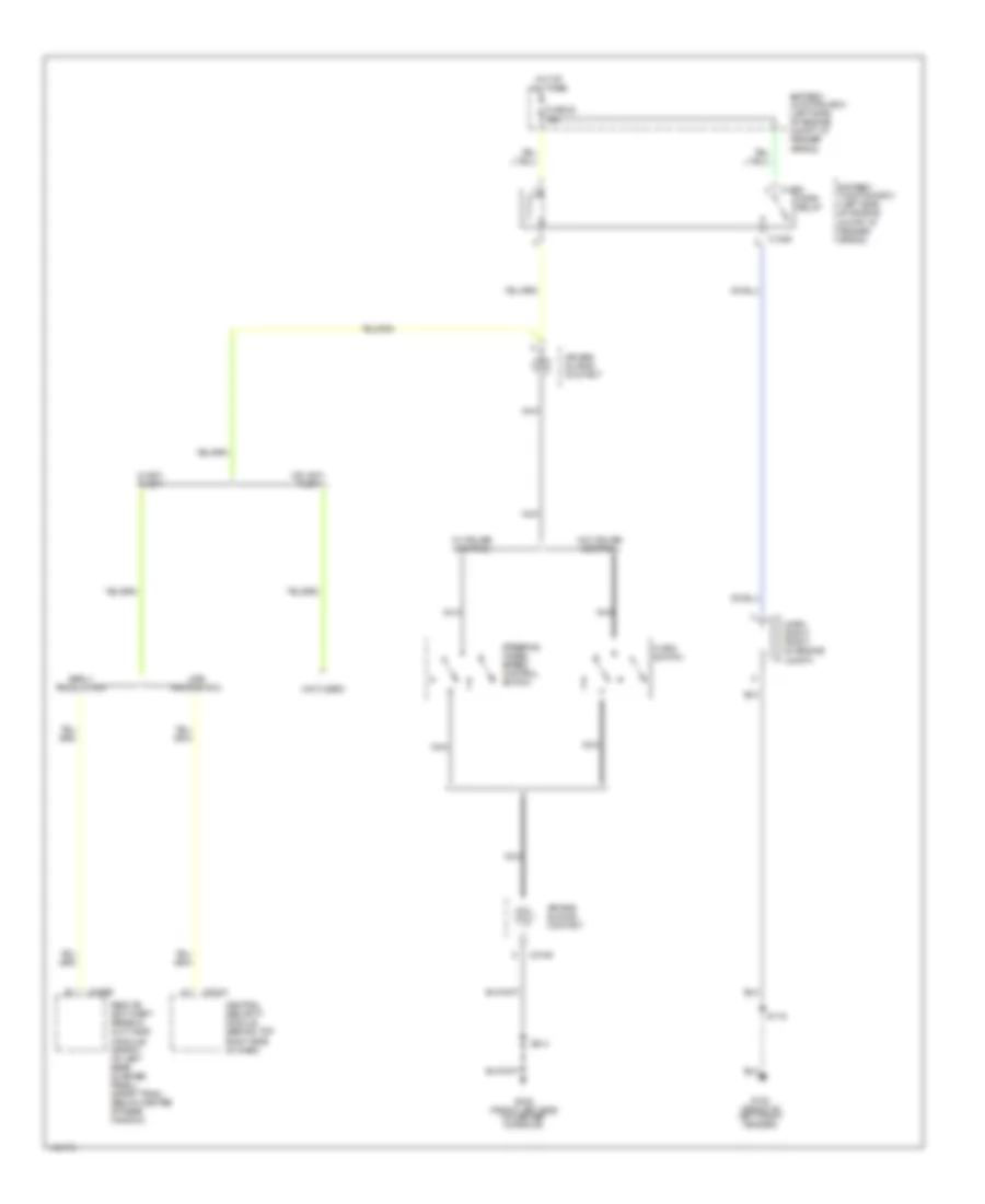
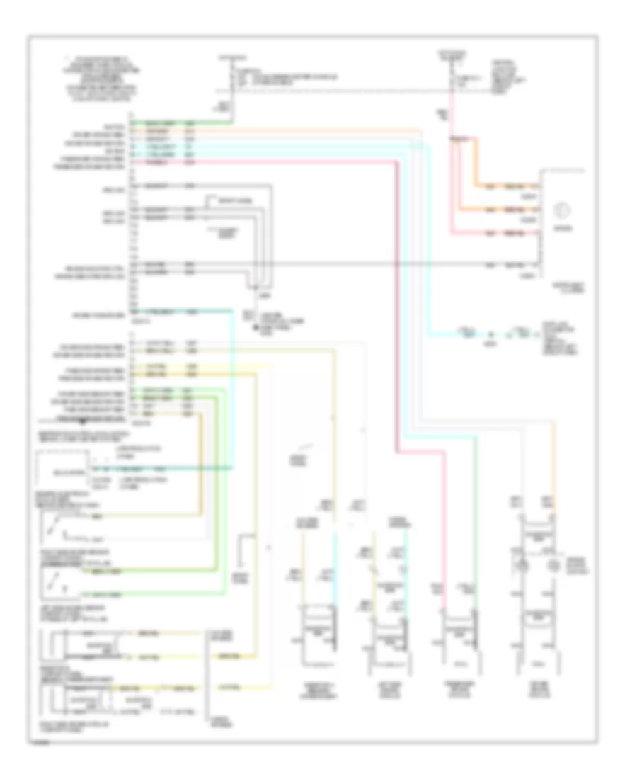
AIR CONDITIONING
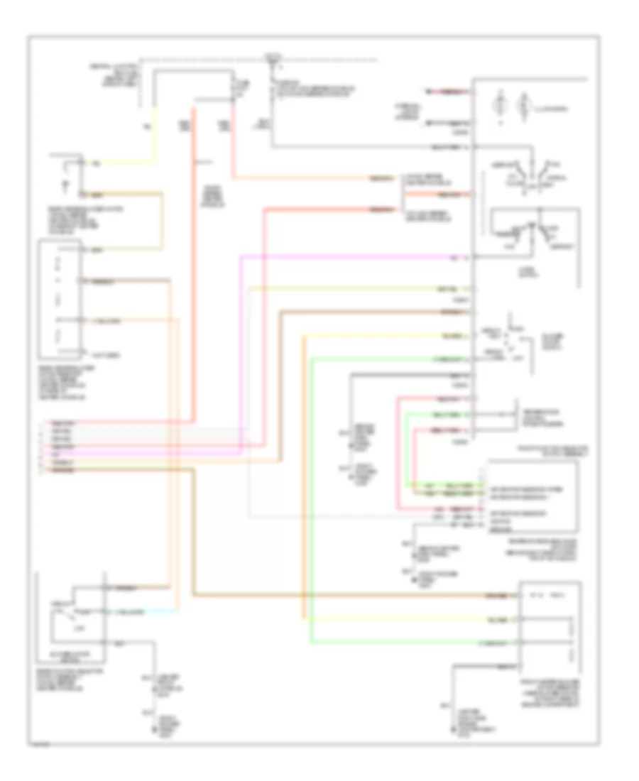
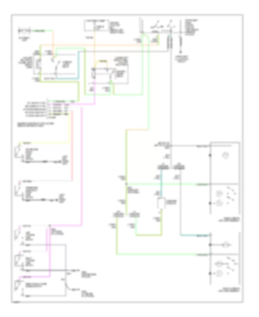
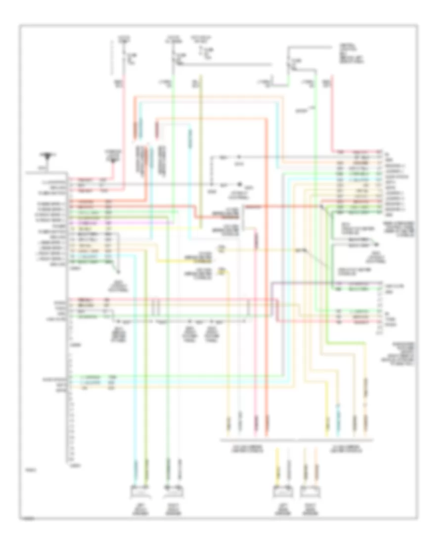
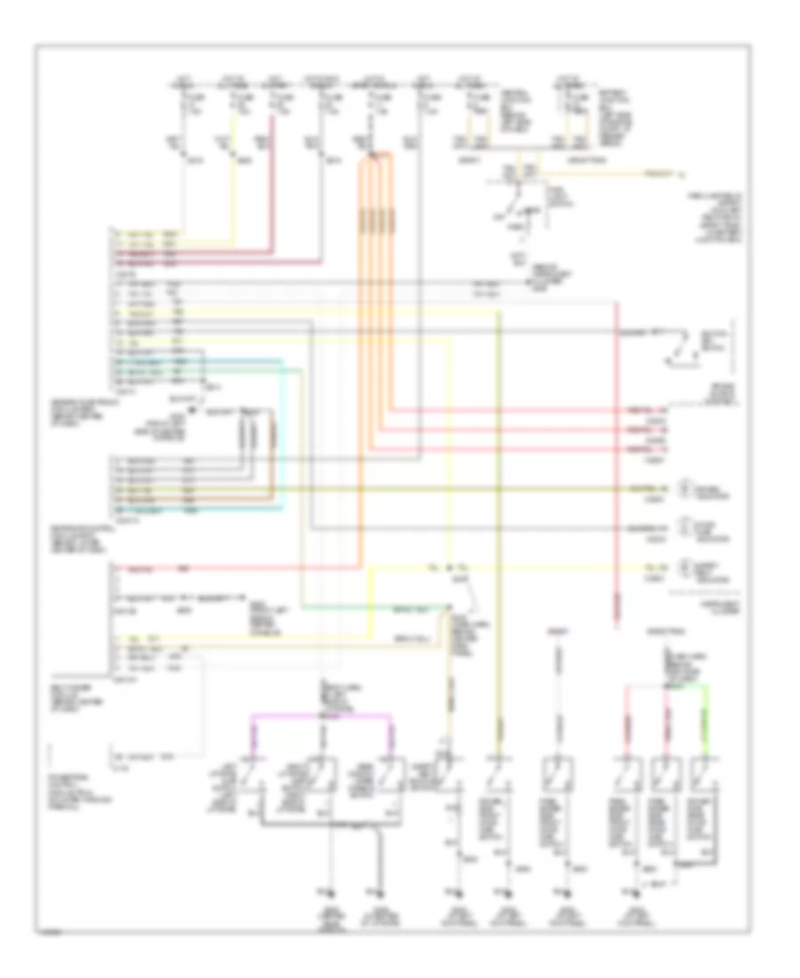
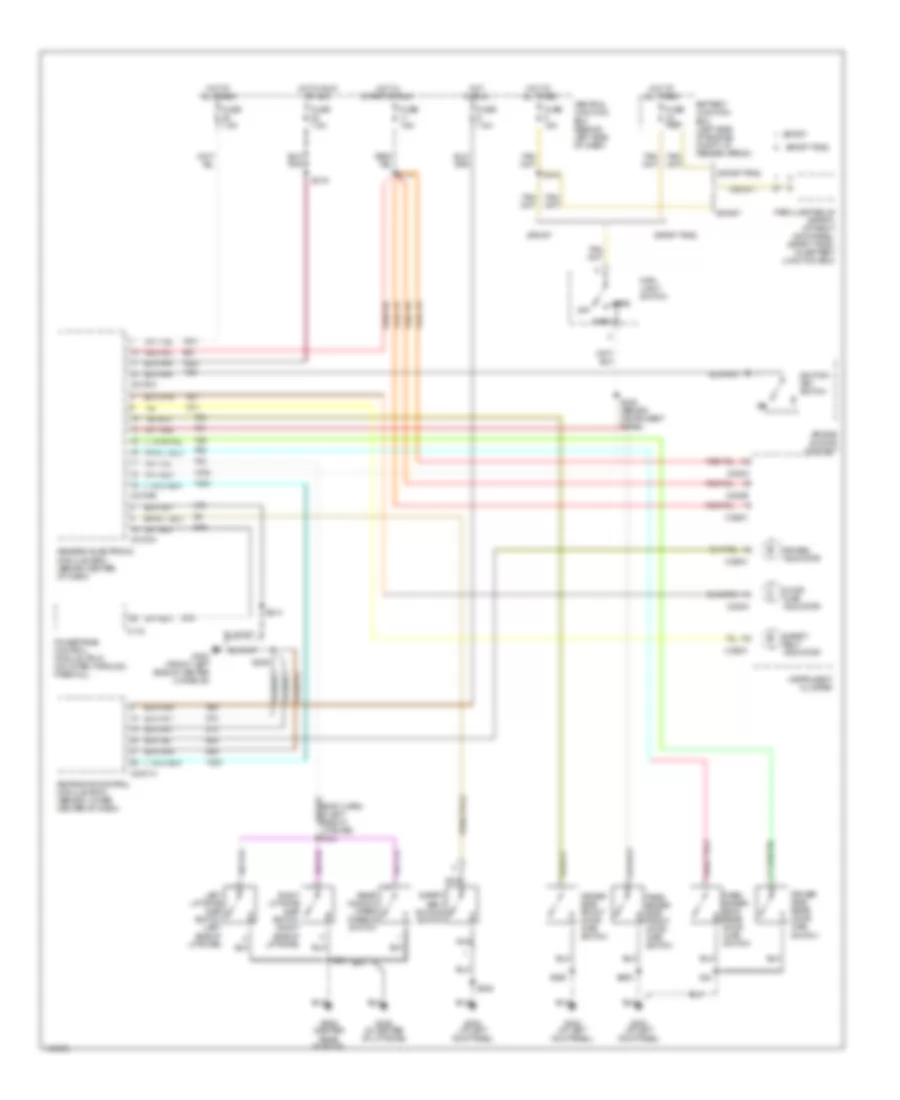
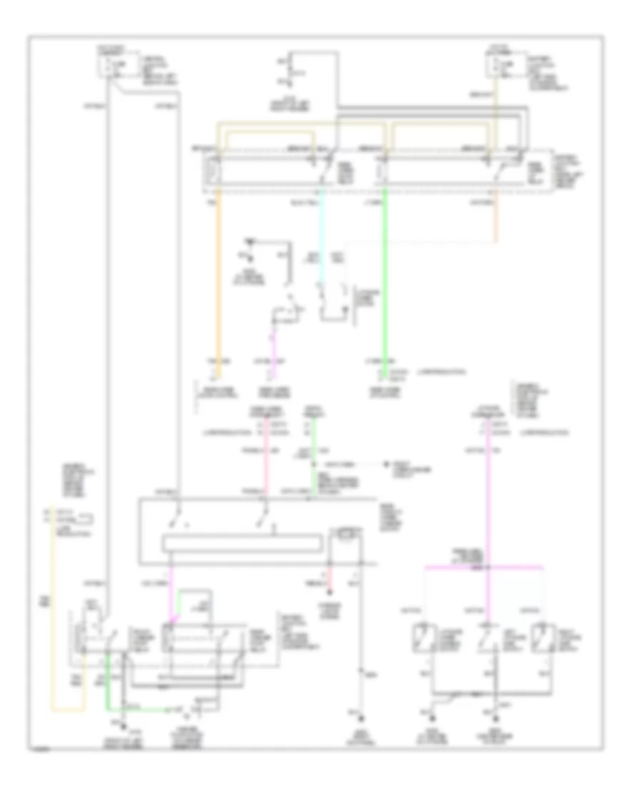
Manual A/C Wiring Diagram (1 of 2) for Ford Explorer Sport 2001

List of elements for Manual A/C Wiring Diagram (1 of 2) for Ford Explorer Sport 2001:
- (behind instrument cluster) s216
- (center front engine compartment) s125
- (center right side engine compartment) g103
- (left front side engine compartment) g100
- (left front side engine compartment) g108
- (left front side of engine compartment) g108
- (left rear side engine compartment) s110
- 87a
- A/c clutch relay
- A/c clutch relay ctrl
- A/c clutch relay output
- A/c clutch solenoid (center front of engine compartment)
- A/c compressor clutch diode (left side of engine compartment, near a/c compressor clutch, taped in harness)
- A/c compressor cycling switch (in right side of engine compartment, on a/c accumulator)
- A/c demand signal
- A/c high pressure switch (at front center of engine, compartment)
- Auxiliary relay box 1 (right side of engine compartment)
- Battery junction box (bjb) (left side of engine compartment, at fender apron)
- Blower motor relay
- Central junction box (cjb) (behind left side of dash)
- Engine controls system
- Front heater blower motor (right side of engine compartment)
- Fuse f1.16 40a
- Fuse f1.25 10a
- Fuse f1.7 30a
- Fuse f2.10 7.5a
- Fuse f2.19 25a
- High speed fan control relay
- Hot at all times
- Hot in run
- Hot in run or start
- Pcm module power diode
- Pcm power relay
- Powertrain control module (pcm) (mounted through firewall)
- Red
- S113 (left rear side engine compartment)
- S124 (center right side engine compartment)
- S126 (center front engine compartment)
- W/high series center console
- W/o high series center console
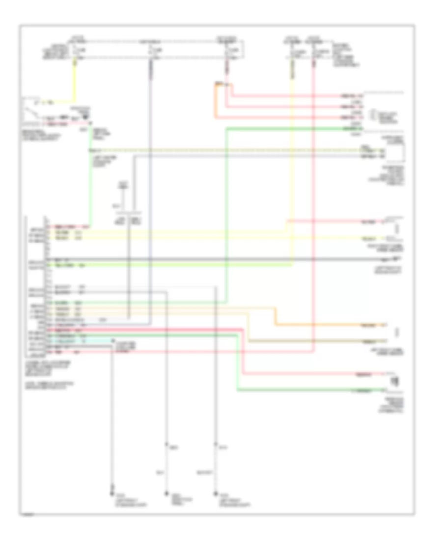
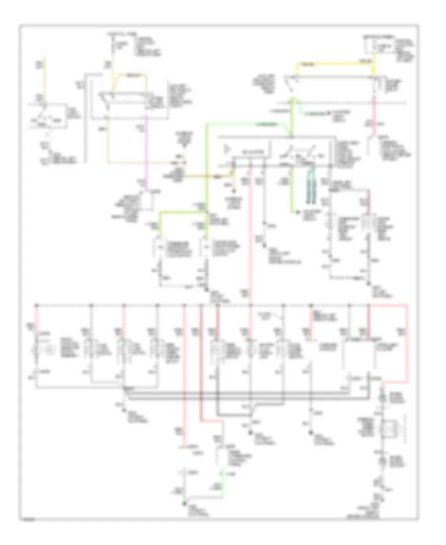
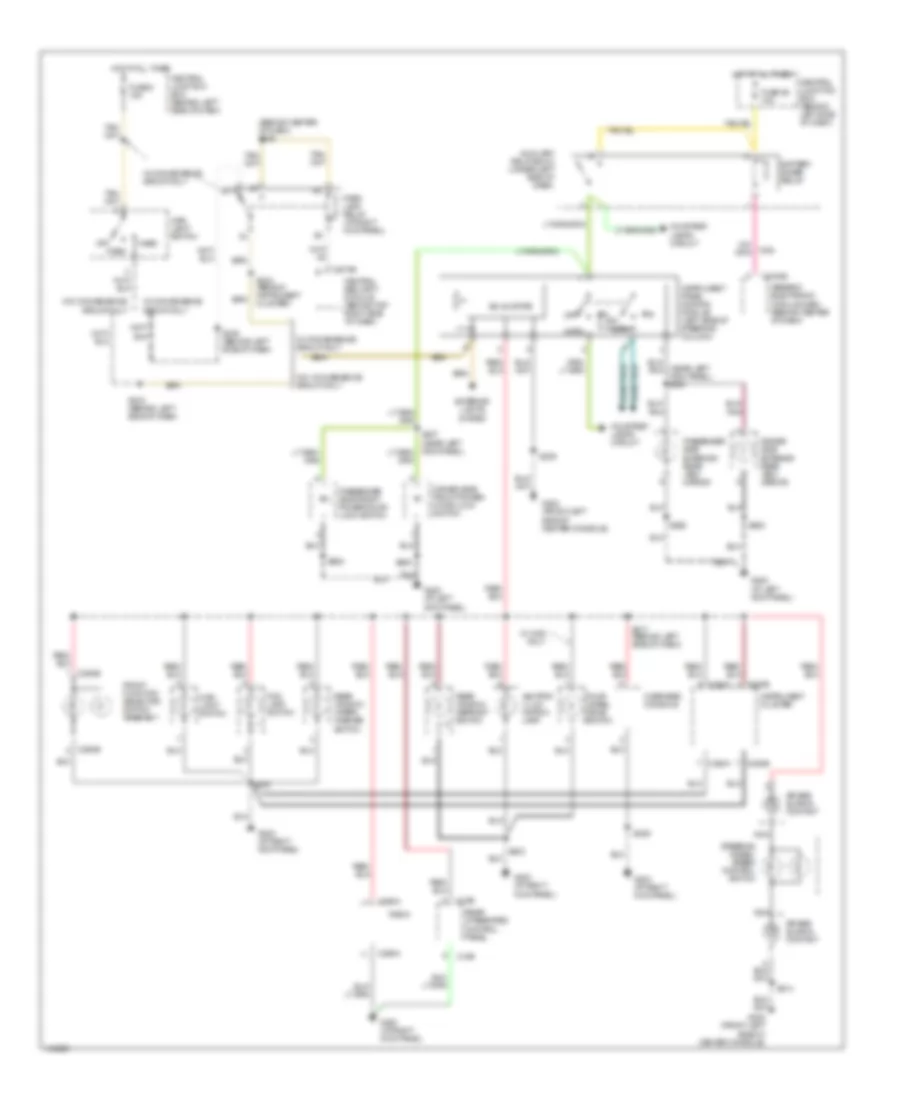
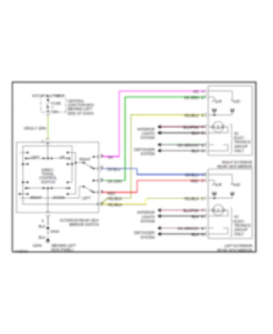
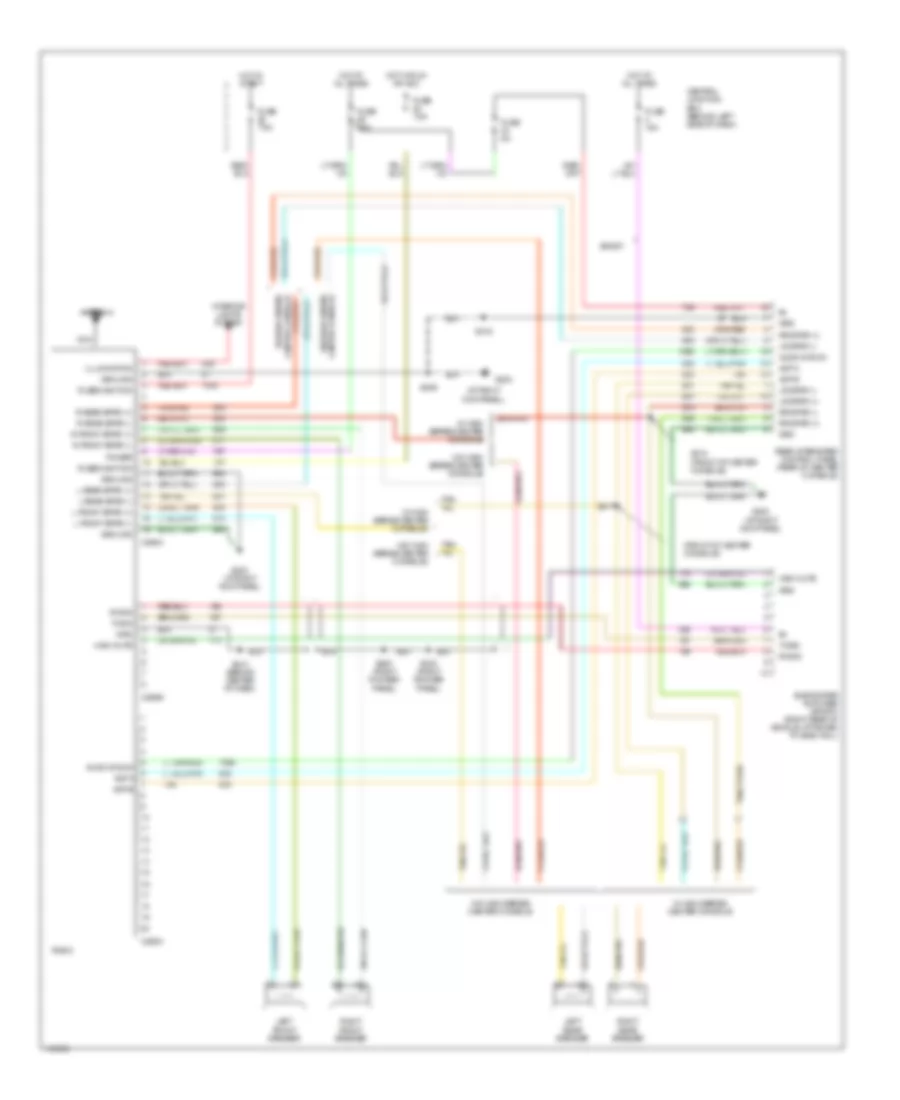
Manual A/C Wiring Diagram (2 of 2) for Ford Explorer Sport 2001
List of elements for Manual A/C Wiring Diagram (2 of 2) for Ford Explorer Sport 2001:
- (behind center dash panel) s206
- (center right side engine compartment) g103
- (not used)
- (right rocker panel) g203
- Air temp dr resistor +
- Air temp dr resistor -
- Air temp dr resistor wiper
- Blower motor switch
- C294a
- C294b
- C294c
- C294d
- Central junction box (cjb) (behind left side of dash)
- Dash panel) s203
- Defrost
- Floor
- Front console) s316
- Front function selector switch assembly
- Front heater blower motor resistor (near blower motor, on right rear of engine compartment)
- Fuse f2.31 5a
- Fuse f2.6 7.5a (w/0 high series console) 15a (w/high series console)
- Ground
- High
- Hot in run
- Ignition
- Illumination
- Interior lights systems
- Low
- Max
- Medium
- Medium high
- Medium low
- Mix
- Mode switch
- Normal
- Off
- Rear function selector switch assembly (w/high series center console)
- Rear heater blower motor (w/high series center console) (in rear of center console)
- Rear heater blower motor resistor (w/high series center console) (in rear of center console)
- Temperature blend door actuator (behind right side of dash, top of a/c plenum)
- Temperature control potentiometer
- Vent
- W/high series center console
- W/o high series center console
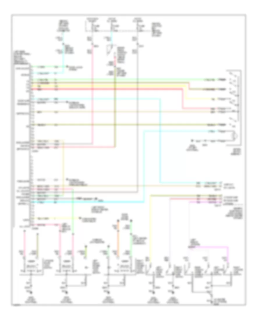
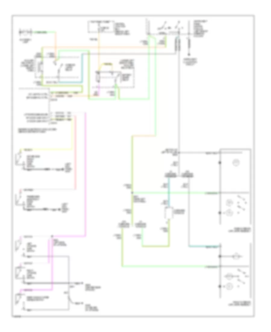
ANTI-LOCK BRAKES
Anti-lock Brake Wiring Diagrams for Ford Explorer Sport 2001
List of elements for Anti-lock Brake Wiring Diagrams for Ford Explorer Sport 2001:
- (behind left dash panel)
- (left center of engine compt)
- (left front of engine compt)
- (left front of engine compt)
- (not used)
- (right kick panel) g203
- 4-wheel anti-lock brake system (4wabs) module (left front of engine compt)
- Abs ind
- Anti-lock brakes indicator
- Battery junction box (left rear of engine compartment)
- Bpp sw
- Brake pedal position (bpp) switch (on pedal support)
- C220a
- C220b
- C220c
- Central junction box (behind left side of dash)
- Computer data lines system
- Cpu fd
- Differential)
- Early prod
- Fuse 10a
- Fuse 28 30a
- Fuse 6 50a
- Fuse 7.5a
- G100
- G203 (right kick panel)
- Ground
- Hot at all times
- Hot in run
- Hot in run or start
- Ign
- Instrument cluster
- Iso link
- Late prod
- Left front wheel speed sensor
- Lf sens
- Note: there is a shorting bar across pins 8 & 16
- Ohms
- Powertrain control module (pcm) (mounted through firewall)
- Pump fd
- Rear axle sensor (top of rear
- Red
- Red/pnk
- Rf sens
- Right front wheel speed sensor
- Rr sens
- S117
- S118
- S203
- S218
- S227
- Vss
ANTI-THEFT
Forced Entry Wiring Diagram, Early Production for Ford Explorer Sport 2001
List of elements for Forced Entry Wiring Diagram, Early Production for Ford Explorer Sport 2001:
- (behind left side of dash) data link connector
- (in center of liftgate) g406
- (left front side of center console)
- (left rear of vehicle) s310
- (left rear quarter panel) remote anti-theft personality (rap) module
- (left side of liftgate) s402
- 1/2
- 3/4
- 5/6
- 7/8
- 9/0
- Ajar out
- All lock
- All unlock
- Bpp switch
- Brake pedal position switch (above brake pedal)
- C201a
- C201c
- C309a
- C309b
- Central junction box (behind left side of dash)
- Door ajar
- Door locks system
- Dvr unlock
- Exterior lights system (backup lamps)
- Exterior lights system (parklamp relay)
- Fuse 20a
- Fuse 7.5a
- G200 (at left kick panel)
- G203 (at right kick panel)
- G302
- Generic electronic module (gem) (behind center of dash)
- Ground
- Horn
- Horn system (horn relay)
- Hot at all times
- Hot in run or acc
- Ignition
- Int lights
- Interior lights system
- Iso bus
- Keypad com
- Keypad ill
- Keypad switch assembly
- Left front door ajar switch
- Left front power door lock switch
- Left liftgate ajar switch
- Lf door ajar
- Liftgate
- Liftgate door lock switch
- Lock
- Nca
- Parklamps
- Power
- Rear window wiper disable switch
- Red
- Reverse in
- Rf door ajar
- Right front door ajar switch
- Right front power door lock switch
- Right liftgate ajar switch
- Rke jumper
- S208 (behind center of dash)
- S227 (under left side of dash)
- S232
- S309
- S311 (left center of vehicle underbody)
- S312
- S323
- S401
- S500
- S600
- Unlock
Forced Entry Wiring Diagram, Late Production for Ford Explorer Sport 2001
List of elements for Forced Entry Wiring Diagram, Late Production for Ford Explorer Sport 2001:
- (at right kick panel)
- (behind left side of dash) data link connector
- (behind top right side of dash) central security module
- (in center of liftgate) g406
- (left center of vehicle underbody)
- (left center of vehicle underbody) s313
- (left front side of center console)
- (left side of liftgate) s402
- Ajar out
- All lock
- All unlock
- Bpp switch
- Brake pedal position switch (above brake pedal)
- C2100b
- C274a
- C274b
- Central junction box (behind left side of dash)
- Door ajar
- Dvr unlock
- Exterior lights system
- Exterior lights system (parklamp relay)
- Fuse 20a
- Fuse 7.5a
- G200 (at left kick panel)
- G203
- G203 (at right kick panel)
- G302
- Generic electronic module (gem) (behind center of dash)
- Ground
- Horn
- Horn system (horn relay)
- Hot at all times
- Hot in run or start
- Ignition
- Int lights
- Interior lights system
- Iso bus
- Keypad com
- Keypad ill
- Keypad in
- Keypad switch assembly
- Left front door ajar switch
- Left front door lock actuator
- Left front power door lock switch
- Left liftgate ajar switch
- Lf door ajar
- Liftgate
- Liftgate door lock switch
- Liftgate lock actuator
- Lock
- Lock doors
- Parklamps
- Power
- Rear window wiper disable switch
- Reverse in
- Rf door ajar
- Right front door ajar switch
- Right front door lock actuator
- Right front power door lock switch
- Right liftgate ajar switch
- S203
- S208 (behind center of dash)
- S214
- S218
- S227 (under left side of dash)
- S309
- S310 (left rear of vehicle)
- S311
- S314 (left center of vehicle underbody)
- S401
- S500
- S600
- Unlk doors
- Unlock
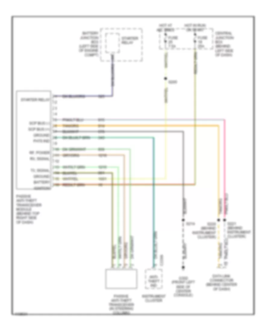
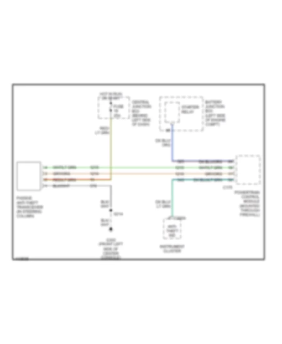
Passive Anti-theft Wiring Diagram, Early Production for Ford Explorer Sport 2001
List of elements for Passive Anti-theft Wiring Diagram, Early Production for Ford Explorer Sport 2001:
- Anti- theft ind
- Battery
- Battery junction box (left side of engine compt)
- C220a
- Central junction box (behind left side of dash)
- Data link connector (behind center of dash)
- Fuse 25a
- Fuse 7.5a
- G302 (front left side of center console)
- Ground
- Hot at all times
- Hot in run or start
- Ignition
- Instrument cluster
- Passive anti-theft transceiver (in steering column)
- Passive anti-theft transceiver module (behind top right side of dash)
- Pats ind
- Rf, power
- Rx, signal
- S205
- S214
- S220 (behind instrument cluster)
- S221 (behind instrument cluster)
- Scp bus (+)
- Scp bus (-)
- Starter relay
- Tx, signal
Passive Anti-theft Wiring Diagram, Late Production for Ford Explorer Sport 2001
List of elements for Passive Anti-theft Wiring Diagram, Late Production for Ford Explorer Sport 2001:
- Anti- theft ind
- Battery junction box (left side of engine compt)
- C175
- C220a
- Central junction box (behind left side of dash)
- Fuse 25a
- G302 (front left side of center console)
- Hot in run or start
- Instrument cluster
- Passive anti-theft transceiver (in steering column)
- Powertrain control module (mounted through firewall)
- S214
- Starter relay
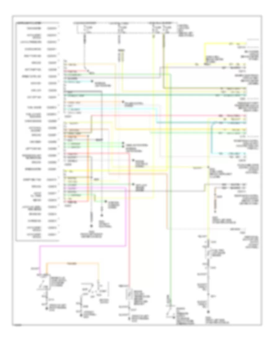
BODY COMPUTER
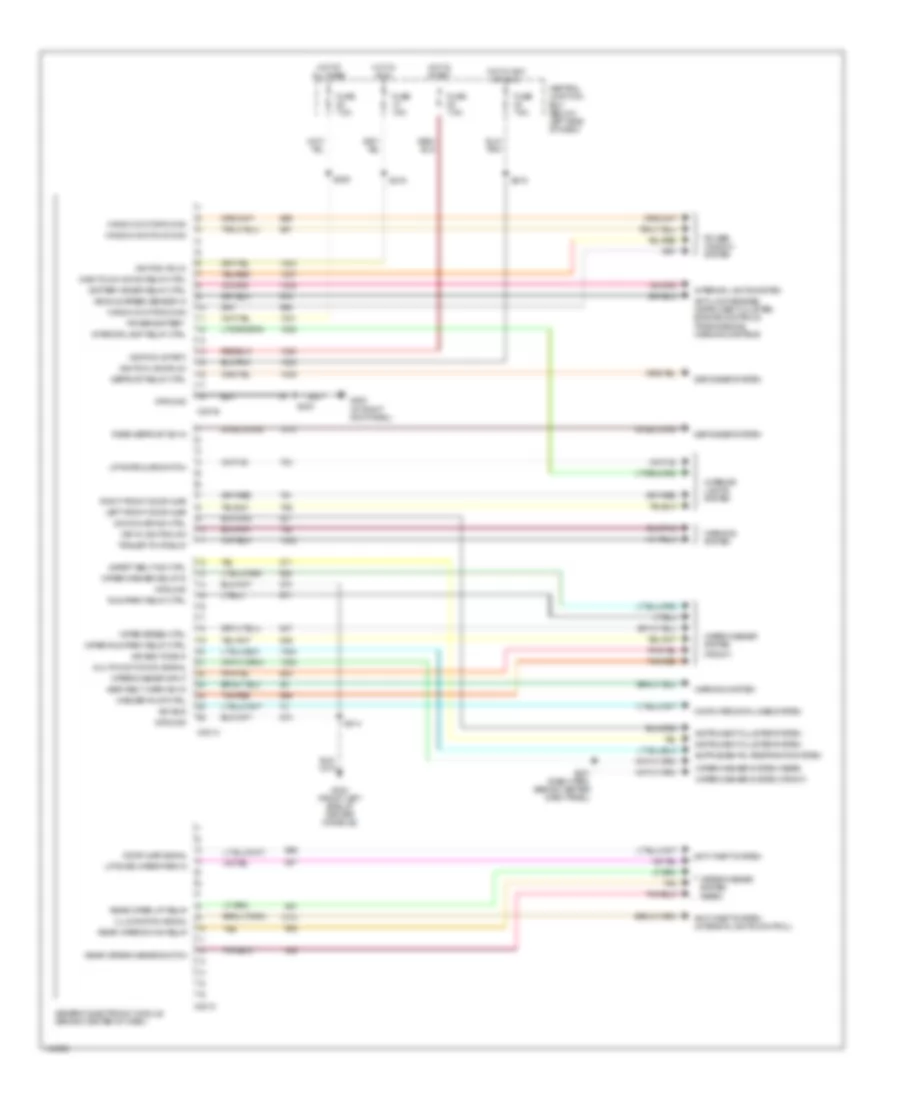
Body Computer Wiring Diagrams, Early Production for Ford Explorer Sport 2001
List of elements for Body Computer Wiring Diagrams, Early Production for Ford Explorer Sport 2001:
- (front)
- Air bag tone in
- Anti-lock brakes, instrument cluster, engine controls, tranmissions, warning systems
- Anti-theft system
- Anti-theft system (interior lights control)
- Battery saver relay ctrl
- C201a
- C201b
- C201c
- Central junction box (below left side of dash)
- Computer data lines system
- Defogger system
- Defrost relay ctrl
- Door ajar ind ctrl
- Door ajar signal
- Fuse 7.5a
- G203 (at right kick panel)
- G302 (front left side of center console)
- Generic electronic module (behind center of dash)
- Ground
- Hot at all times
- Hot in acc or run
- Hot in run
- Hot in start
- Ignition (acc/run)
- Ignition (run)
- Ignition (start)
- Illumination signal
- Instrument cluster system
- Interior lamp relay ctrl
- Interior lights system
- Iso bus
- Key in ignition sw
- Left front door ajar
- Liftgate ajar switch
- Liftgate wiper park in
- Multifunction sw signal
- One-touch down relay ctrl
- Power window system
- Power-battery
- Rear defrost sw in
- Rear wiper down relay
- Rear wiper up relay
- Rear wiper/washer switch
- Right front door ajar
- Run/park relay ctrl
- S203
- S205
- S207 (dash harn, behind center dash panel)
- S214
- S216
- S219
- Safety belt ind ctrl
- Seat belt warn sw in
- Tan
- Tan/red
- Trailer tow relay
- Vehicle speed sensor in
- Warning system
- Washer pump ctrl
- Window motor down
- Window switch down
- Wiper run/park relay ctrl
- Wiper speed ctrl
- Wiper/washer delay in
- Wiper/washer input
- Wiper/washer system
- Wiper/washer system (front)
- Wiper/washer system (rear)
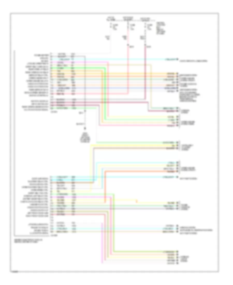
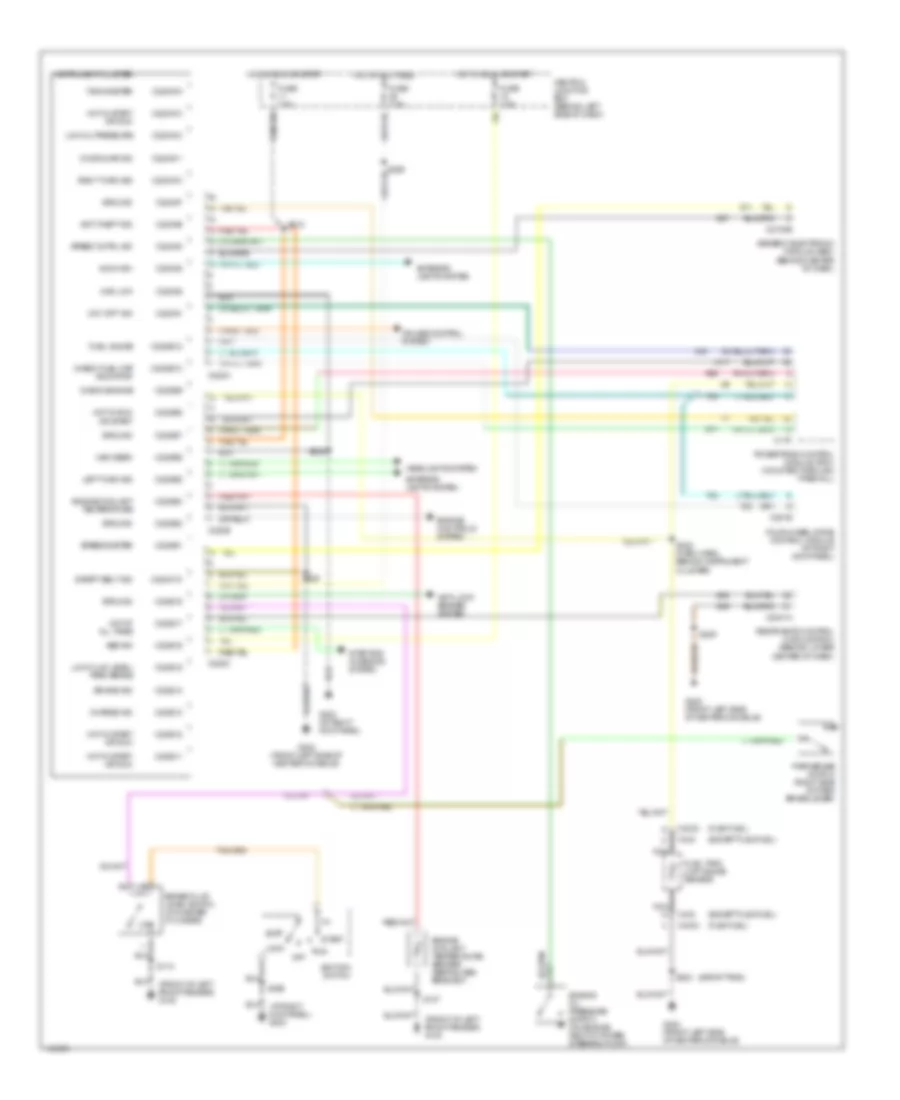
Body Computer Wiring Diagrams, Late Production for Ford Explorer Sport 2001
List of elements for Body Computer Wiring Diagrams, Late Production for Ford Explorer Sport 2001:
- Air bag tone in
- Anti-lock brakes, instrument cluster, engine controls, tranmissions, warning systems
- Anti-theft system
- Battery saver relay ctrl
- C2100a
- C2100b
- Central junction box (below left side of dash)
- Computer data lines system
- Defogger system
- Defrost relay ctrl
- Door ajar ind ctrl
- Door ajar signal
- Fuse 7.5a
- G302 (front left side of center console)
- Generic electronic module (behind center of dash)
- Ground
- Hot at all times
- Hot in acc or run
- Hot in run or start
- Ignition (acc/run)
- Ignition (start/run)
- Illumination signal
- Instrument cluster system
- Interior lamp relay ctrl
- Interior lights system
- Iso bus
- Key in ignition sw
- Left front door ajar
- Liftgate ajar switch
- Liftgate wiper park in
- Multifunction sw signal
- One-touch down relay ctrl
- Power windows system
- Power-battery
- Rear defrost sw in
- Rear wiper down relay
- Rear wiper up relay
- Rear wiper/washer switch
- Right front door ajar
- Run/park relay ctrl
- S214
- S216
- S219
- Safety belt ind ctrl
- Safety belt warn sw in
- Tan
- Tan/red
- Trailer tow relay
- Vehicle speed sensor in
- Warning system
- Washer pump ctrl
- Window motor down
- Window switch down
- Window switch up
- Wiper run/park relay ctrl
- Wiper speed ctrl
- Wiper/washer delay in
- Wiper/washer input
- Wiper/washer system (front)
- Wiper/washer system (rear)
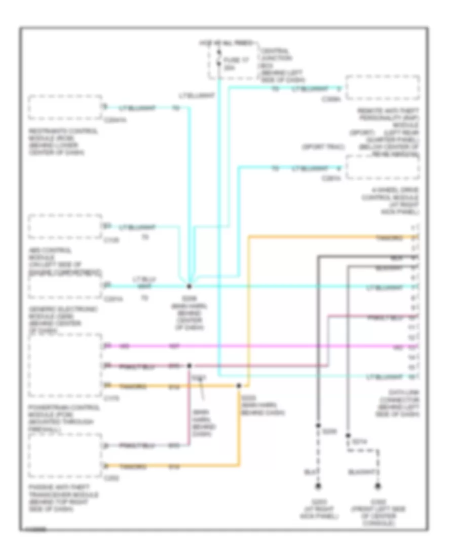
COMPUTER DATA LINES
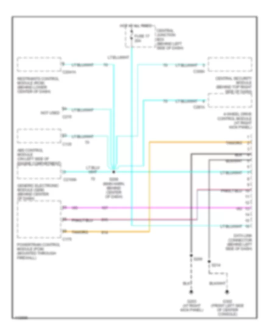
Computer Data Lines, Early Production for Ford Explorer Sport 2001
List of elements for Computer Data Lines, Early Production for Ford Explorer Sport 2001:
- (main harn, behind dash)
- (sport trac)
- (sport)
- 4-wheel drive control module (at right kick panel)
- Abs control module (on left side of engine compartment)
- C135
- C175
- C201a
- C2041a
- C252
- C281a
- C309a
- Central junction box (behind left side of dash)
- Data link connector (behind left side of dash)
- Fuse 17 20a
- G203 (at right kick panel)
- G302 (front left side of center console)
- Generic electronic module (gem) (behind center of dash)
- Hot at all times
- Passive anti-theft transceiver module (behind top right side of dash)
- Powertrain control module (pcm) (mounted through firewall)
- Remote anti-theft personality (rap) module (left rear quarter panel) (below center of rear window)
- Restraints control module (rcm) (behind lower center of dash)
- S206
- S208 (main harn, behind center of dash)
- S214
- S220 (main harn, behind dash)
- S221
Computer Data Lines, Late Production for Ford Explorer Sport 2001
List of elements for Computer Data Lines, Late Production for Ford Explorer Sport 2001:
- 4-wheel drive control module (at right kick panel)
- Abs control module (on left side of engine compartment)
- C135
- C175
- C2041a
- C2100a
- C215
- C281a
- C309a
- Central junction box (behind left side of dash)
- Central security module (behind top right side of dash)
- Data link connector (behind left side of dash)
- Fuse 17 20a
- G203 (at right kick panel)
- G302 (front left side of center console)
- Generic electronic module (gem) (behind center of dash)
- Hot at all times
- Not used
- Powertrain control module (pcm) (mounted through firewall)
- Restraints control module (rcm) (behind lower center of dash)
- S206
- S208 (main harn, behind center of dash)
- S214
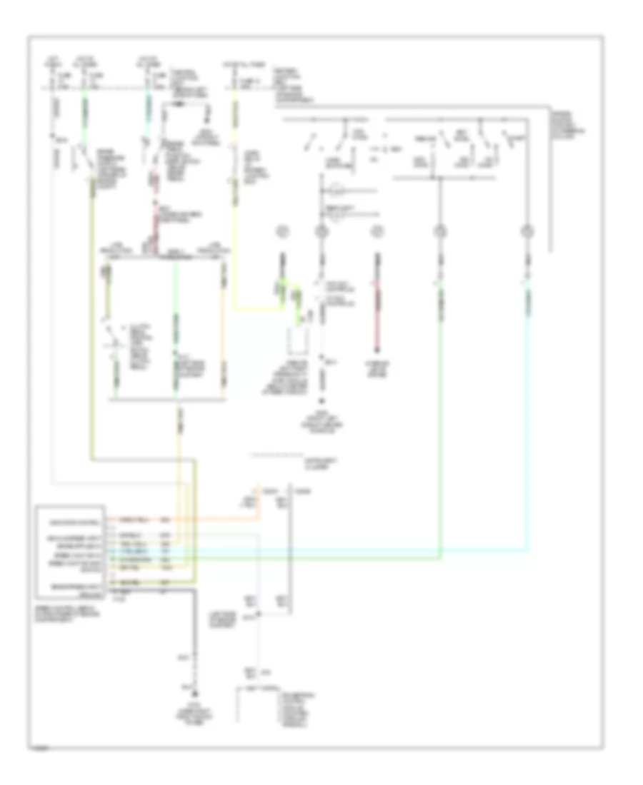
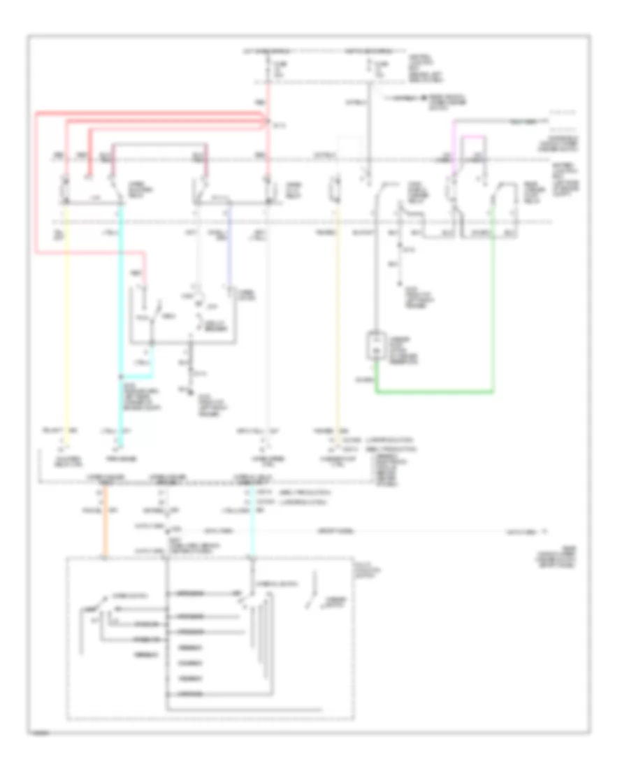
CRUISE CONTROL
Cruise Control Wiring Diagram for Ford Explorer Sport 2001
List of elements for Cruise Control Wiring Diagram for Ford Explorer Sport 2001:
- (left side of engine compart)
- (w/ aux controls)
- (w/o aux controls)
- A/t
- Accel
- Air bag sliding contact (in steering column)
- Back light
- Battery junction box (left side of engine compartment)
- Brake pedal position (bpp) switch (above brake pedal)
- Brake press input
- Brake pressure switch (left rear corner of engine compt)
- C122
- C175
- C220a
- C220b
- C338
- Central junction box (behind left side of dash)
- Clutch pedal position (cpp) switch (above clutch pedal)
- Coast
- Early production
- Fuse 10 15a
- Fuse 15a
- Fuse 7.5a
- G103 (near right front shock tower)
- G203 (at right kick panel)
- G302 (front left side of center console)
- Ground
- Horn relay (in battery junction box)
- Horn switches
- Hot at all times
- Hot in run
- Ignition
- Indicator control
- Instrument cluster
- Interior lights system
- Late production
- M/t
- Nca
- Of engine compart)
- Off
- Ohms
- Powertrain control module (mounted through firewall)
- Red/
- Remote anti-theft personality (rap) module (below center of rear window)
- Resume
- S116
- S127
- S206
- S214
- S216
- S227 (under driver's dash panel)
- Set/
- Speed cont sw gnd
- Speed cont sw in
- Speed control servo (in right rear of engine compartment)
- Vehicle speed input
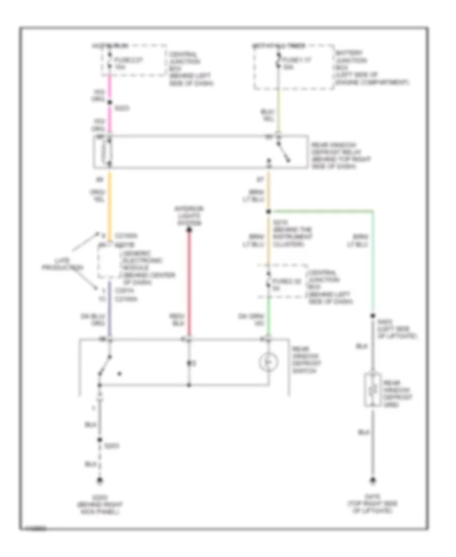
DEFOGGERS
Defogger Wiring Diagram for Ford Explorer Sport 2001
List of elements for Defogger Wiring Diagram for Ford Explorer Sport 2001:
- Battery junction box (left side of engine compartment)
- C201a
- C201b
- C2100a
- Central junction box (behind left side of dash)
- Fuse1.17 30a
- Fuse2.27 15a
- Fuse2.32 5a
- G203 (behind right kick panel)
- G410 (top right side of liftgate)
- Generic electronic module (behind center of dash)
- Hot at all times
- Hot in run
- Interior lights system
- Late production
- Rear window defrost grid
- Rear window defrost relay (behind top right side of dash)
- Rear window defrost switch
- S203
- S215 (behind the instrument cluster)
- S223
- S403 (left side of liftgate)
ENGINE PERFORMANCE
4.0L
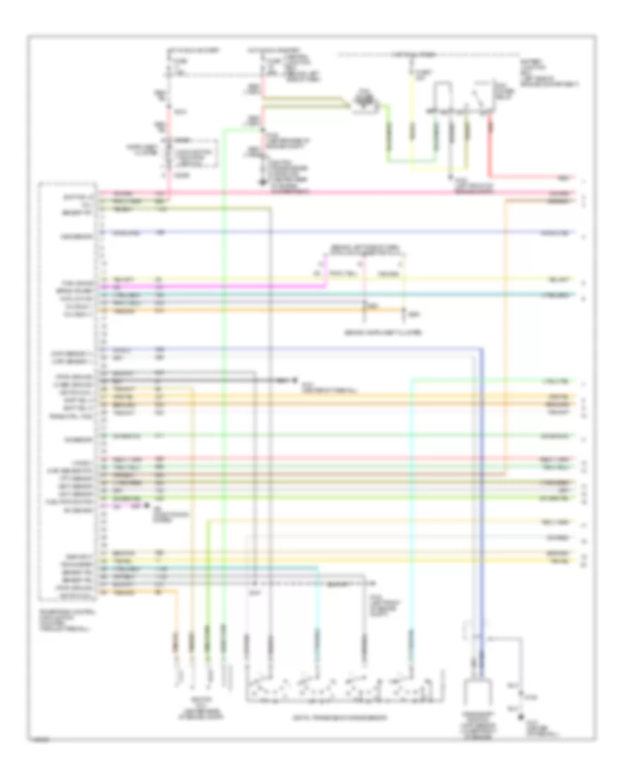
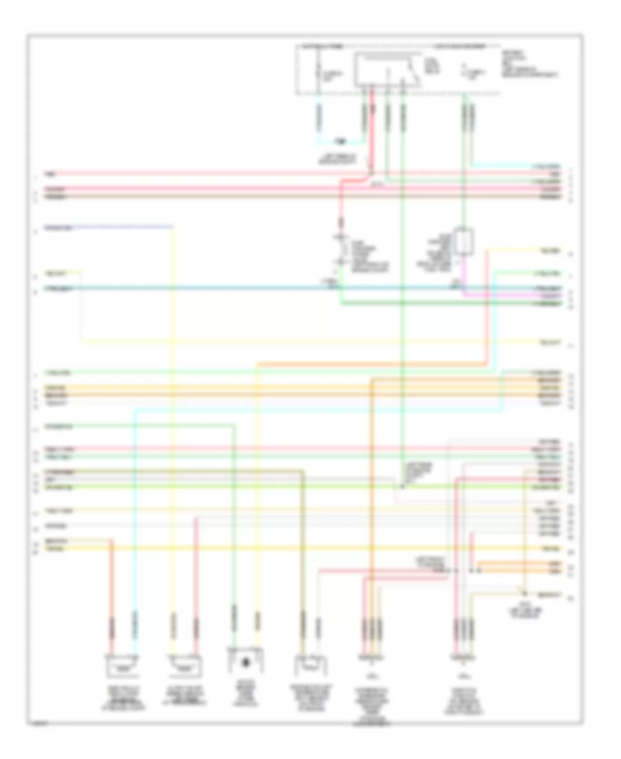
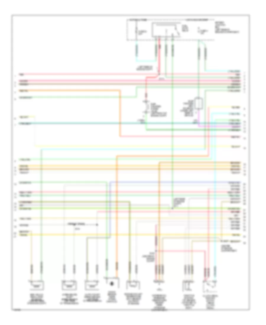
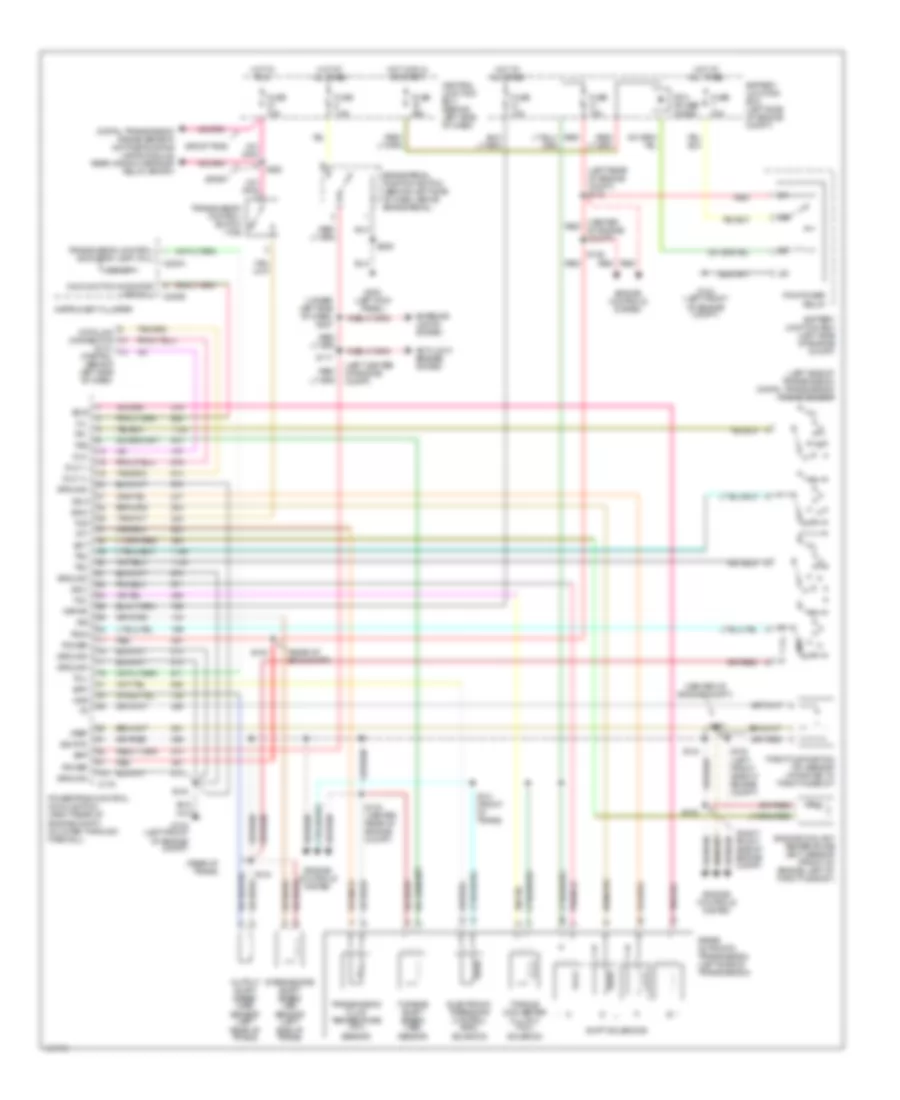
4.0L, Engine Performance Wiring Diagrams, Early Production (1 of 4) for Ford Explorer Sport 2001
List of elements for 4.0L, Engine Performance Wiring Diagrams, Early Production (1 of 4) for Ford Explorer Sport 2001:
- (act) sensor
- (behind instrument cluster)
- (behind left side of dash) data link connector (dlc)
- (case) ground
- (ckp) sensor (+)
- (ckp) sensor (-)
- (ect) sensor
- (ho2s) 3
- (maf) sensor rtn
- (mil)
- (pwr) ground
- (tft) sensor
- 4wd low ind
- A/c demand
- Air conditioning system
- Battery junction box (left side of engine compartment)
- C220b
- Central junction box (behind left side of dash)
- Crankshaft position (ckp) sensor (lower front of engine)
- Digital transmission range sensor
- Dlc bus (+)
- Dlc bus (-)
- Egr input
- Eprom power
- Fuel gauge
- Fuel pmp monitor
- Fuse 25a
- Fuse 7 30a
- Fuse 7.5a
- G100 (left front of engine compt)
- G121 (center of firewall)
- Hot at all times
- Hot in run or start
- Ignition coil
- Ignition coil (center rear of engine compt)
- Ignition transformer capacitor (center rear of engine compartment)
- Instrument cluster
- Ks sensor
- Malfunction indicator lamp (mil)
- Oss sensor
- Pcm power diode
- Pcm power relay
- Powertrain control module (pcm) (mounted through firewall)
- Red
- S105 (center rear of engine compt)
- S107
- S128
- S218
- S220
- S221
- Sensor tr1
- Sensor tr2
- Sensor tr4
- Shift sol a
- Shift sol b
- Shift sol d
- Tachometer
- Trans ctrl (tcs)
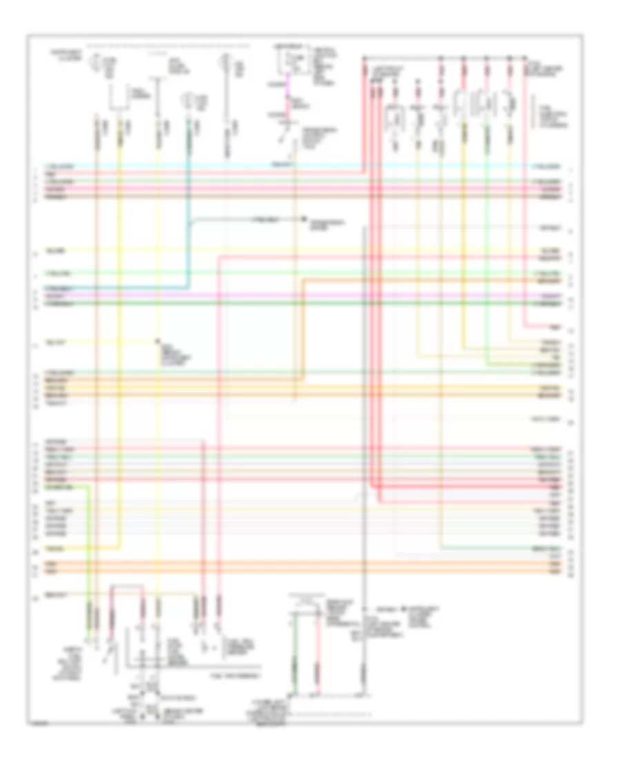
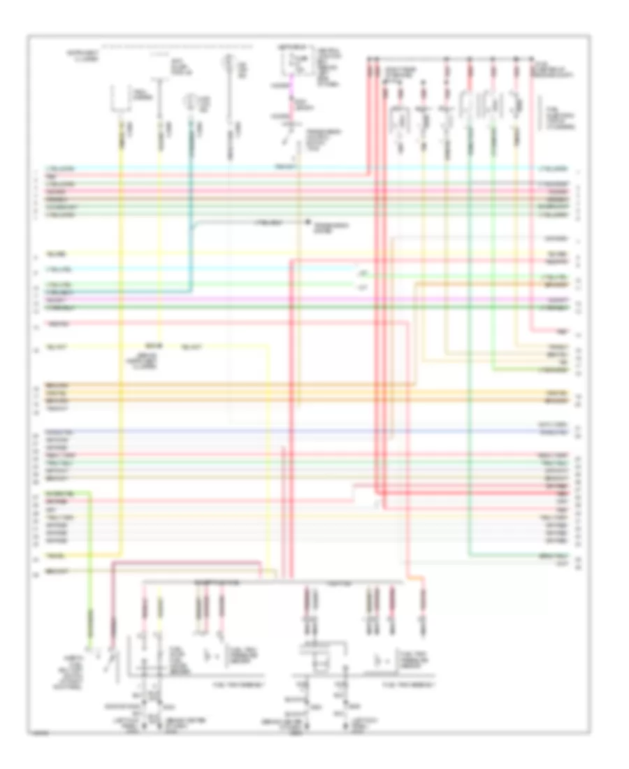
4.0L, Engine Performance Wiring Diagrams, Early Production (2 of 4) for Ford Explorer Sport 2001
List of elements for 4.0L, Engine Performance Wiring Diagrams, Early Production (2 of 4) for Ford Explorer Sport 2001:
- (left front of engine) s102
- (left rear of engine compt)
- (left rear of engine compt) s111
- Battery junction box (left rear of engine compartment)
- Differential pressure fedback egr sensor (rear of engine compartment)
- Egr vacuum regulator solenoid (center rear of engine compt)
- Engine coolant temperature (ect) sensor (on front of engine)
- Evap canister purge valve (left front of engine compt)
- Evap canister vent solenoid (rear of vehicle, near fuel tank)
- Fuel pump relay
- Fuse 23 20a
- Fuse 41 15a
- Hot at all times
- Hot in run or start
- Knock sensor (near intake manifold)
- Output shaft speed sensor (left rear of transmission)
- Red
- S103 (left center of engine)
- S113
- S116
- Throttle position (tp) sensor (attached to throttle body)
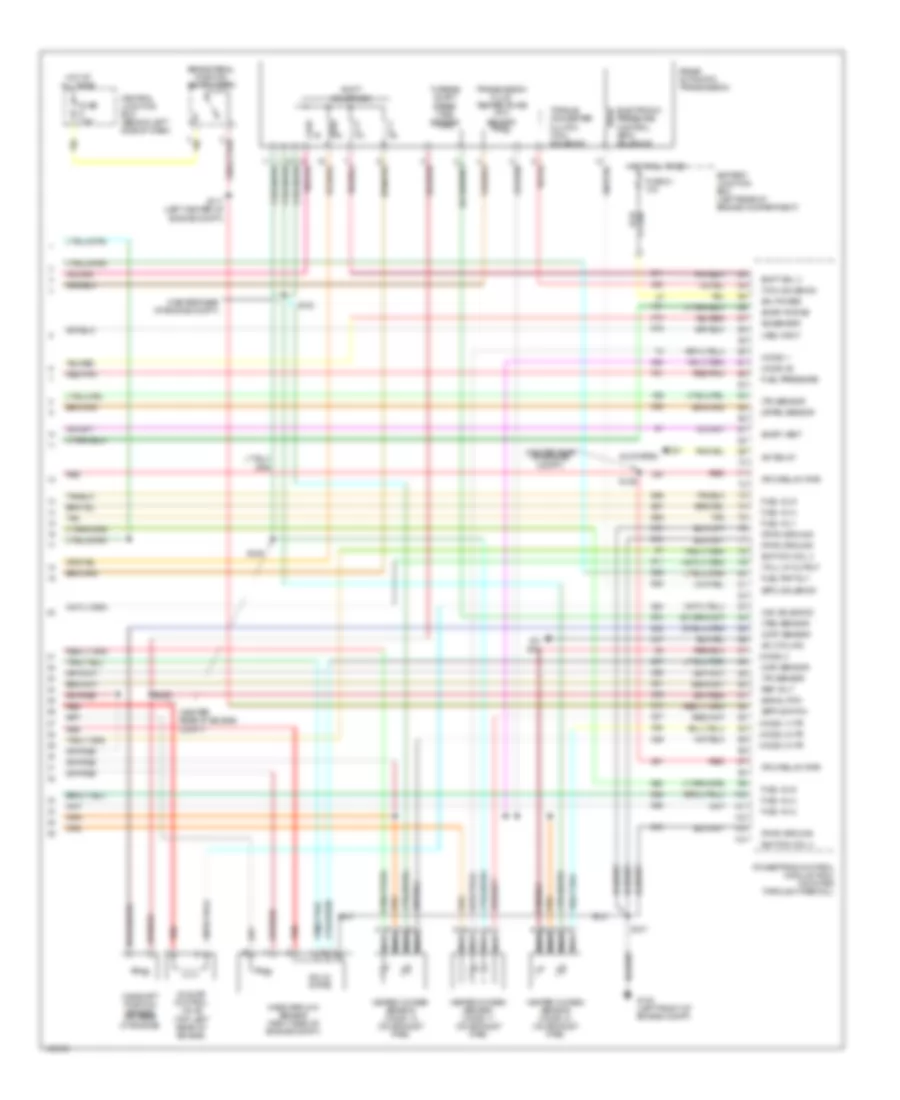
4.0L, Engine Performance Wiring Diagrams, Early Production (3 of 4) for Ford Explorer Sport 2001
List of elements for 4.0L, Engine Performance Wiring Diagrams, Early Production (3 of 4) for Ford Explorer Sport 2001:
- (behind center of dash) g206
- (left front of engine) s101
- (left kick panel) g200
- 4-wheel anti- lock brake system module (left front of eng compt)
- 4wd low ind
- Anti- slosh module
- C220a
- C220b
- Central junction box (behind left side of dash)
- Fuel cut off ind
- Fuel injectors (top of cylinders)
- Fuel pump/ fuel gauge sender
- Fuel tank assembly
- Fuel tank pressure sensor
- Fuse 15a
- Hot in run
- Inertia fuel shut-off switch (at right kick panel)
- Instrument cluster
- Instrument cluster, cruise control
- O/d off ind
- Rear axle sensor (top of rear differential)
- Red
- Red/pnk
- S104 (left center of engine)
- S116 (left center of engine compartment)
- S222 (behind instrument cluster)
- S223 (sport)
- S315 (or s323)
- S409
- Tach- ometer
- Tan
- Transmission control switch (tcs)
- Transmission system
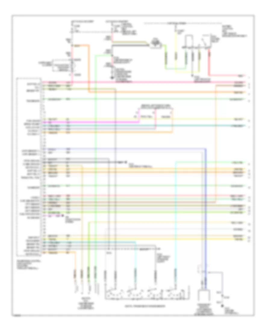
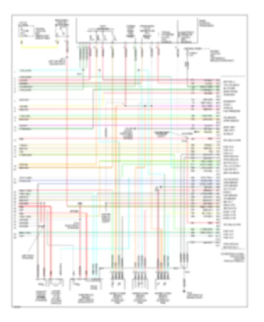
4.0L, Engine Performance Wiring Diagrams, Early Production (4 of 4) for Ford Explorer Sport 2001
List of elements for 4.0L, Engine Performance Wiring Diagrams, Early Production (4 of 4) for Ford Explorer Sport 2001:
- (b+) power
- (bpp) switch
- (center rear of engine compt)
- (cmp) sensor
- (dfpe) sensor
- (epc) solenoid
- (evap) purge
- (evap) vent
- (ho2s) 1
- (ho2s) 1 htr
- (ho2s) 2
- (ho2s) 2 htr
- (ho2s) 22
- (ho2s) 3 htr
- (iac) solenoid
- (maf) sensor
- (pcm relay) pwr
- (pwr) ground
- (tcc) solenoid
- (tcil) lp output
- (tp) sensor
- (tr) sensor
- (tss) sensor
- (vss) input
- 5r55e automatic transmission
- A/c cycling
- A/c relay
- A/c sys
- A/c system
- Battery junction box (left rear of engine compartment)
- Brake pedal position switch (bpp)
- Camshaft position sensor (on rear of engine)
- Central junction box (behind left side of dash)
- Electronic pressure control (epc) solenoid
- Fuel inj 1
- Fuel inj 2
- Fuel inj 3
- Fuel inj 4
- Fuel inj 5
- Fuel inj 6
- Fuel pmp rly
- Fuel pressure
- Fuse 21 10a
- Fuse 7.5a
- G100 (left front of engine compt)
- Heated oxygen sensor (ho2s) 11 (on exhaust pipe)
- Heated oxygen sensor (ho2s) 12 (on exhaust pipe)
- Heated oxygen sensor (ho2s) 21 (on exhaust pipe)
- Hot at all times
- Idle air control valve (top left rear of engine)
- Ignition coil 3
- Ignition coil 4
- Ks sensor
- Mass airflow sensor (right side of engine compt)
- Nca
- Powertrain control module (pcm) (mounted through firewall)
- Red
- Red/pnk
- Ref volt
- S100
- S106
- S107
- S108
- S117 (left center of engine compt)
- S129
- Shift sol 3
- Shift solenoids
- Signal rtn
- Solid state
- Tan
- Torque converter clutch (tcc) solenoid
- Transmission fluid temperature (tft) sensor
- Turbine shaft speed (tss) sensor
4.0L, Engine Performance Wiring Diagrams, Late Production (1 of 4) for Ford Explorer Sport 2001
List of elements for 4.0L, Engine Performance Wiring Diagrams, Late Production (1 of 4) for Ford Explorer Sport 2001:
- (act) sensor
- (behind left side of dash) data link connector (dlc)
- (case) ground
- (ckp) sensor (+)
- (ckp) sensor (-)
- (ect) sensor
- (ho2s) 3
- (maf) sensor rtn
- (mil)
- (pwr) ground
- (tft) sensor
- 4wd low ind
- A/c demand
- Air conditioning system
- Battery junction box (left side of engine compartment)
- C220b
- Central junction box (behind left side of dash)
- Crankshaft position (ckp) sensor (lower front of engine compt)
- Digital transmission range sensor
- Dlc bus (+)
- Dlc bus (-)
- Egr input
- Eprom power
- Fuel gauge
- Fuel pmp monitor
- Fuse 25a
- Fuse 7 30a
- Fuse 7.5a
- G100 (left front of engine compt)
- G121 (center of firewall)
- Hot at all times
- Hot in run or start
- Ignition coil
- Ignition coil (center rear of engine compartment)
- Ignition transformer capacitor (center rear of engine compartment)
- Instrument cluster
- Ks sensor
- Malfunction indicator lamp (mil)
- Pcm power diode
- Pcm power relay
- Powertrain control module (pcm) (mounted through firewall)
- Red
- S138 (center rear of engine compt)
- S142
- S145
- S218
- Sensor tr1
- Sensor tr2
- Sensor tr4
- Shift sol a
- Shift sol b
- Shift sol d
- Tachometer
- Trans ctrl (tcs)
- Tss sensor
4.0L, Engine Performance Wiring Diagrams, Late Production (2 of 4) for Ford Explorer Sport 2001
List of elements for 4.0L, Engine Performance Wiring Diagrams, Late Production (2 of 4) for Ford Explorer Sport 2001:
- (center of engine compartment)
- (center of engine compt)
- (left rear of engine compt)
- (left rear of engine compt) s111
- (rear of trans)
- Battery junction box (left rear of engine compartment)
- Clutch pedal position switch (above clutch pedal)
- Differential pressure fedback egr sensor (rear of engine compartment)
- Egr vacuum regulator solenoid (center rear of engine compt)
- Engine coolant temperature (ect) sensor (on front of engine)
- Evap canister purge valve (left front of engine compt)
- Evap canister vent solenoid (under left rear of vehicle)
- Fuel pump relay
- Fuse 23 20a
- Fuse 41 15a
- Hot at all times
- Hot in run or start
- Intermediate shaft speed sensor (left side of transmission)
- Knock sensor (near intake manifold)
- Output shaft speed sensor (left rear of transmission)
- Red
- S113
- S137
- S139
- S144
- Throttle position (tp) sensor (attached to throttle body)
4.0L, Engine Performance Wiring Diagrams, Late Production (3 of 4) for Ford Explorer Sport 2001
List of elements for 4.0L, Engine Performance Wiring Diagrams, Late Production (3 of 4) for Ford Explorer Sport 2001:
- (behind center of dash) g206
- (behind instrument cluster)
- (left kick panel) g200
- (right rear of engine) s134
- 4wd low ind
- A/t
- Anti- slosh module
- C220a
- C220b
- Central junction box (behind left side of dash)
- Except flex fuel
- Flex fuel
- Fuel injectors (top of cylinders)
- Fuel pump/ fuel gauge sender
- Fuel tank assembly
- Fuel tank pressure sensor
- Fuse 15a
- Hot in run
- Inertia fuel shut-off switch (at right kick panel)
- Instrument cluster
- M/t
- Nca
- O/d off ind
- Red
- Red/pnk
- S136 (center of engine compt)
- S222
- S223 (sport)
- S323
- S409
- S409 (or s405)
- Tach- ometer
- Tan
- Transmission control switch (tcs)
- Transmission system
4.0L, Engine Performance Wiring Diagrams, Late Production (4 of 4) for Ford Explorer Sport 2001
List of elements for 4.0L, Engine Performance Wiring Diagrams, Late Production (4 of 4) for Ford Explorer Sport 2001:
- (b+) power
- (bpp) switch
- (center rear of engine compt)
- (cmp) sensor
- (dfpe) sensor
- (epc) solenoid
- (evap) purge
- (evap) vent
- (ho2s) 1
- (ho2s) 1 htr
- (ho2s) 2
- (ho2s) 2 htr
- (ho2s) 22
- (ho2s) 3 htr
- (iac) solenoid
- (left front of engine)
- (maf) sensor
- (oss) sensor
- (pcm relay) pwr
- (pwr) ground
- (tcc) solenoid
- (tcil) lp output
- (tp) sensor
- (tr) sensor
- (vss) input
- 5r55e automatic transmission
- A/c cycling
- A/c relay
- A/c sys
- A/c system
- Battery junction box (left rear of engine compartment)
- Brake pedal position switch (bpp)
- Camshaft position sensor (on rear of engine)
- Central junction box (behind left side of dash)
- Cruise contrl, instrument cluster systems
- Electronic pressure control (epc) solenoid
- Fuel inj 1
- Fuel inj 2
- Fuel inj 3
- Fuel inj 4
- Fuel inj 5
- Fuel inj 6
- Fuel pmp rly
- Fuel pressure
- Fuse 21 10a
- Fuse 7.5a
- G100 (left front of engine compt)
- Heated oxygen sensor (ho2s) 11 (on exhaust pipe)
- Heated oxygen sensor (ho2s) 12 (on exhaust pipe)
- Heated oxygen sensor (ho2s) 21 (on exhaust pipe)
- Hot at all times
- Idle air control valve (on left of intake manifold)
- Ignition coil 3
- Ignition coil 4
- Iss sensor
- Ks sensor
- Mass airflow sensor (right side of engine compt)
- Nca
- Powertrain control module (pcm) (mounted through firewall)
- Red
- Red/pnk
- Ref volt
- S117 (left center of engine compt)
- S133 (right front of engine)
- S135
- S141
- S142
- S143
- S146
- Shift sol 3
- Shift solenoids
- Signal rtn
- Solid state
- Tan
- Torque converter clutch (tcc) solenoid
- Transmission fluid temperature (tft) sensor
- Turbine shaft speed (tss) sensor
EXTERIOR LIGHTS
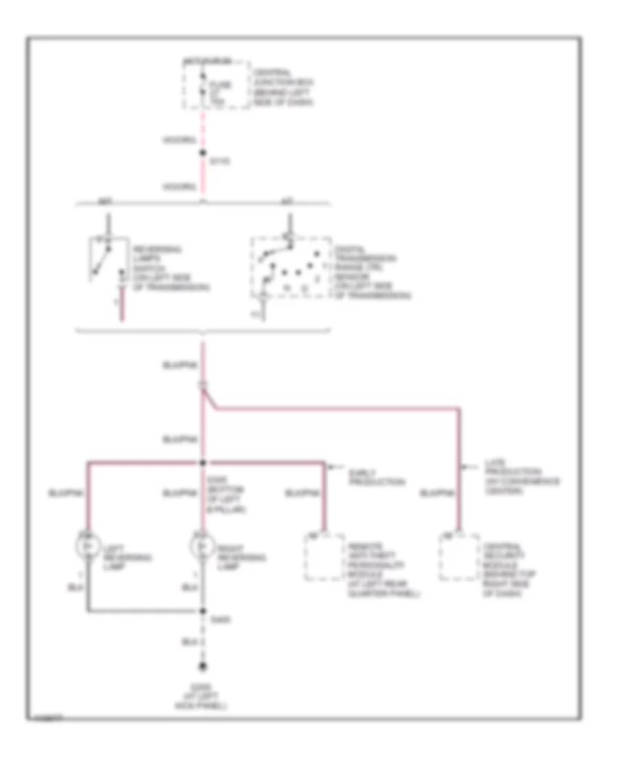
Back-up Lamps Wiring Diagram for Ford Explorer Sport 2001
List of elements for Back-up Lamps Wiring Diagram for Ford Explorer Sport 2001:
- A/t
- Central junction box (behind left side of dash)
- Central security module (behind top right side of dash)
- Digital transmission range (tr) sensor (on left side of transmission)
- Early production
- Fuse 15a
- G200 (at left kick panel)
- Hot in run
- Late production (w/ convenience center)
- Left reversing lamp
- M/t
- Of left b pillar)
- Remote anti-theft personality module (at left rear quarter panel)
- Reversing lamps switch (on left side of transmission)
- Right reversing lamp
- S115
- S405
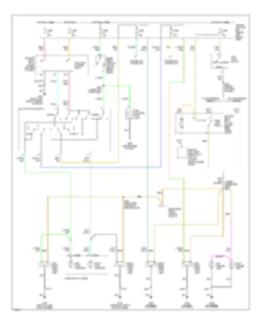
Exterior Lamps Wiring Diagram, Early Production for Ford Explorer Sport 2001
List of elements for Exterior Lamps Wiring Diagram, Early Production for Ford Explorer Sport 2001:
- (under passenger seat) s301
- 87a
- Auxiliary relay box 2 (under left side of dash)
- Auxiliary relay box 3 (on left side of rear cargo compt)
- Brake pedal position switch (above brake pedal)
- C220a
- C220b
- Central junction box (behind left side of dash)
- Fuse 15a
- Fuse 7.5a
- G100 (front of left front fender)
- G103 (near right front shock tower)
- G200 (at left kick panel)
- G203 (at right kick panel)
- G302 (front left side of center console)
- G406 (in center of liftgate)
- G909 (center rear of roof)
- Hazard
- Head
- High mounted stop lamp
- Hot at all times
- Hot in run
- Indicator flasher relay
- Instrument cluster
- Instrument panel dimming module
- Left
- Left front park/ turn lamp
- Left license lamp
- Left rear park/ turn lamp
- Left turn indicator
- Main light switch
- Multi-function switch
- Normal
- Off
- Park
- Park lamp relay
- Remote anti-theft personality module (at left rear quarter panel)
- Right
- Right front park/ turn lamp
- Right license lamp
- Right rear park/ turn lamp
- Right turn indicator
- S119
- S121 (right side center of engine compt)
- S123
- S209
- S225 (under left dash panel)
- S235 (behind left side of dash)
- S300
- S309
- S401
- Trailer tow connector
- W/ convenience group
- W/o convenience group
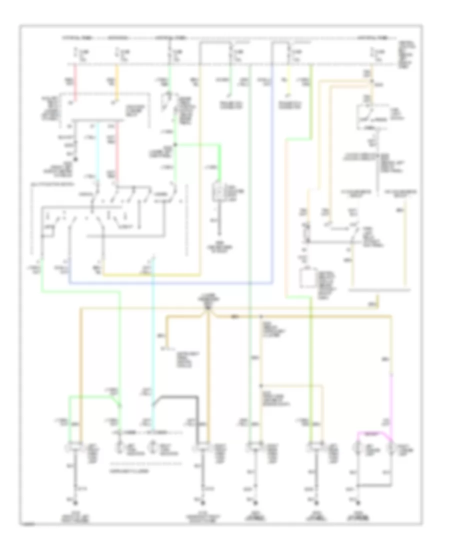
Exterior Lamps Wiring Diagram, Late Production for Ford Explorer Sport 2001
List of elements for Exterior Lamps Wiring Diagram, Late Production for Ford Explorer Sport 2001:
- (under passenger seat) s301
- (w/ conv group) (w/o conv group)
- 87a
- Auxiliary relay box 2 (under left side of dash)
- Brake pedal position switch (above brake pedal)
- C220a
- C220b
- Central junction box (behind left side of dash)
- Central security module (behind top right side of dash)
- Fuse 15a
- Fuse 7.5a
- G100 (front of left front fender)
- G103 (near right front shock tower)
- G200 (at left kick panel)
- G203 (at right kick panel)
- G302 (front left side of center console)
- G406 (in center of liftgate)
- G909 (center rear of roof)
- Hazard
- Head
- High mounted stop lamp
- Hot at all times
- Hot in run
- Indicator flasher relay
- Instrument cluster
- Instrument panel dimming module
- Left
- Left front park/ turn lamp
- Left license lamp
- Left rear park/ turn lamp
- Left turn indicator
- Main light switch
- Multi-function switch
- Normal
- Off
- Park
- Park lamp relay (at right kick panel)
- Right
- Right front park/ turn lamp
- Right license lamp
- Right rear park/ turn lamp
- Right turn indicator
- S119
- S121 (right side center of engine compt)
- S123
- S209
- S225 (under left dash panel)
- S235 s243 (behind left side of dash panel)
- S244 (behind instrument cluster)
- S245
- S300
- S309
- S401
- Trailer tow connector
- W/ convenience group
- W/o convenience group
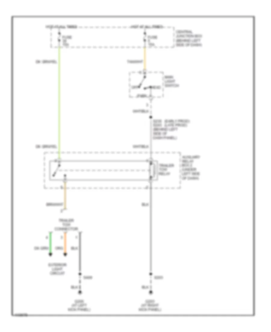
Trailer Tow Wiring Diagram for Ford Explorer Sport 2001
List of elements for Trailer Tow Wiring Diagram for Ford Explorer Sport 2001:
- (early prod) (late prod)
- Auxiliary relay box 2 (under left side of dash)
- Central junction box (behind left side of dash)
- Exterior light circuit
- Fuse 15a
- G200 (at left kick panel)
- G203 (at right kick panel)
- Head
- Hot at all times
- Main light switch
- Off
- Park
- S203
- S235 s243 (behind left side of dash panel)
- S409
- Trailer tow connector
- Trailer tow relay
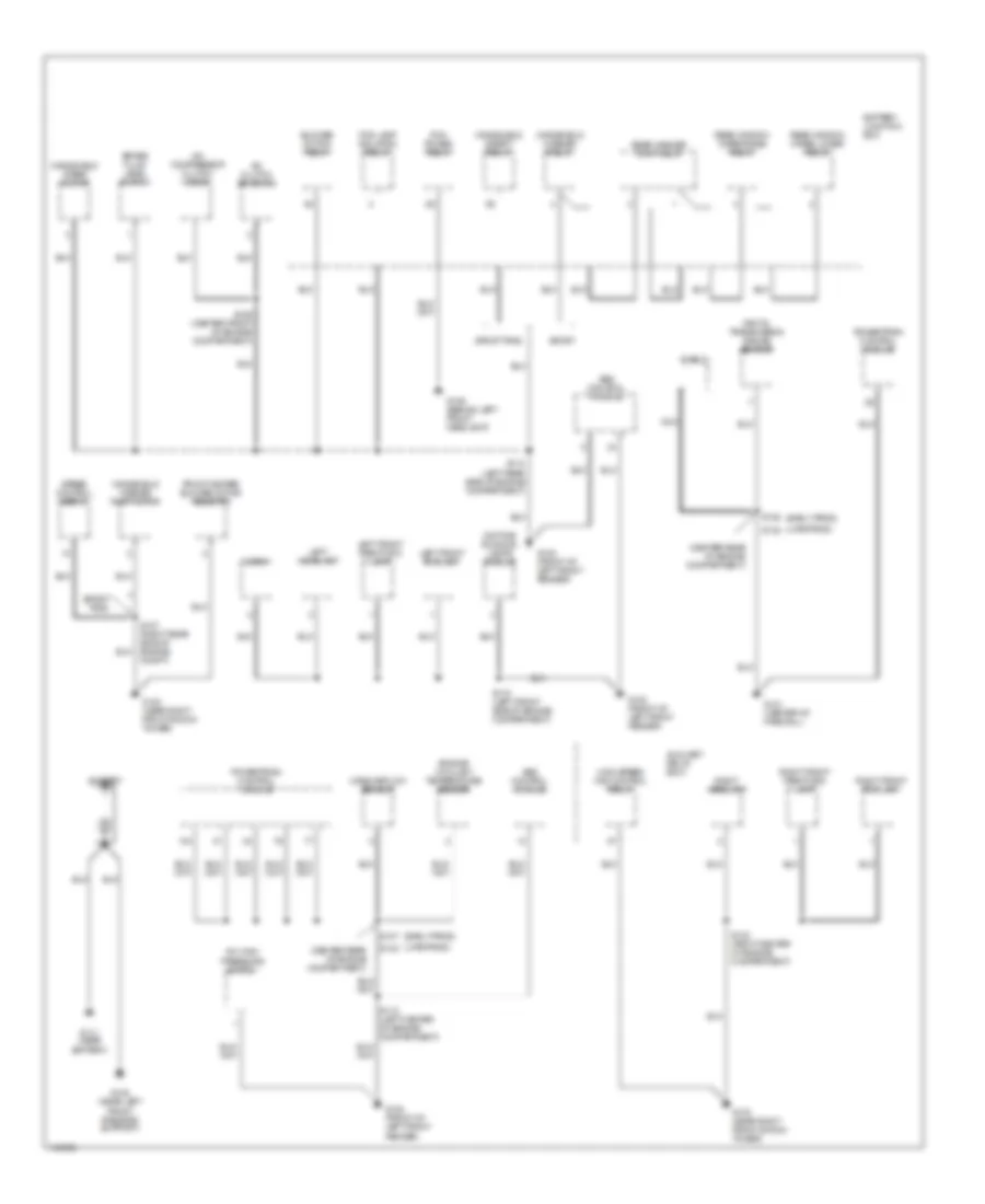
GROUND DISTRIBUTION
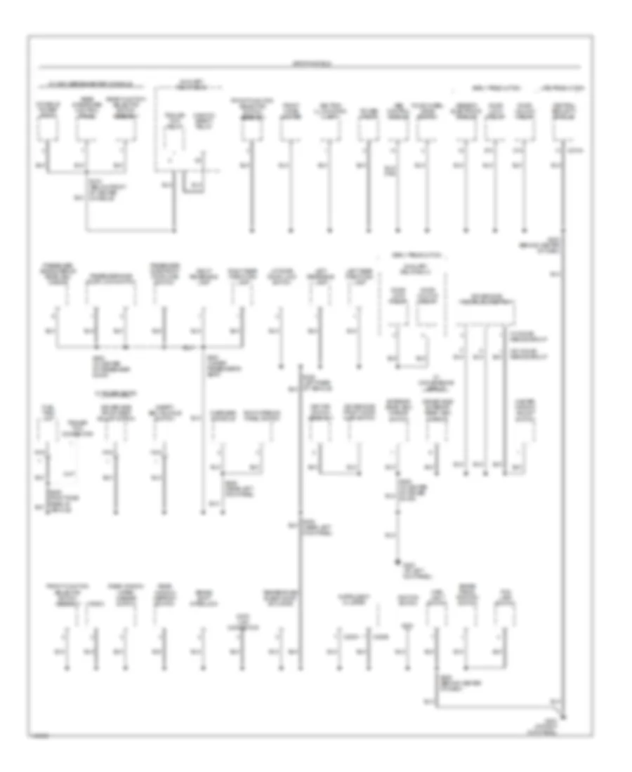
Ground Distribution Wiring Diagram (1 of 4) for Ford Explorer Sport 2001
List of elements for Ground Distribution Wiring Diagram (1 of 4) for Ford Explorer Sport 2001:
- (center rear of engine compartment)
- (early prod)
- (late prod)
- A/c clutch solenoid
- A/c compressor clutch diode
- A/c high pressure switch
- Abs control module
- Auxiliary relay box 1
- Battery
- Battery junction box
- Blower motor relay
- Brake fluid level switch
- Daytime running lamps module
- Digital transmission range sensor
- Engine coolant temperature sender
- Fog lamp isolation relay
- Front heater blower motor resistor
- G100 (front of left front fender)
- G103 (near right front shock tower)
- G106 (behind left front headlamp)
- G108 (near left front radiator support)
- G111 (near battery)
- G121 (center of firewall)
- High speed fan control relay
- Horn
- Left front fog lamp
- Left front park/turn lamp
- Left headlamp
- Mass airflow sensor
- Nca
- Pcm power relay
- Powertrain control module
- Rear washer pump relay
- Rear window wiper lower relay
- Rear window wiper raise relay
- Right front fog lamp
- Right front park/turn lamp
- Right headlamp
- S107
- S110 (left rear side of engine compartment)
- S118 (left center of engine compartment)
- S119 (left front side of engine compartment)
- S123 (right center of engine compartment)
- S126 (center front of engine compartment)
- S127 (right rear side of engine compt)
- S128
- S142
- S145
- Shield
- Speed control servo
- Sport
- Sport trac
- Windshield safety relay
- Windshield washer pump motor
- Windshield washer relay
- Windshield wiper motor
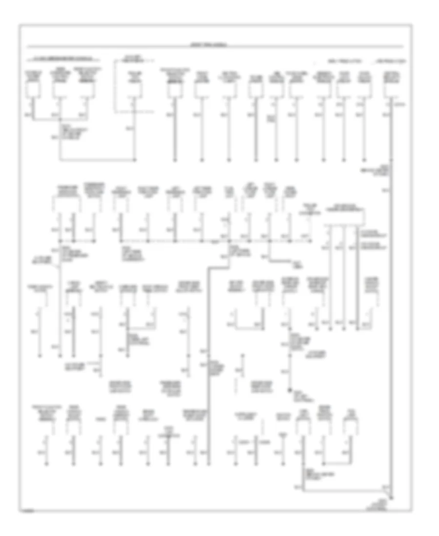
Ground Distribution Wiring Diagram (2 of 4) for Ford Explorer Sport 2001
List of elements for Ground Distribution Wiring Diagram (2 of 4) for Ford Explorer Sport 2001:
- 87a
- Abs control module
- Ashtray illumination lamp
- Auxiliary relay box 2
- Auxiliary relay box 3
- Brake pedal position switch
- Brake shift interlock
- C220a
- C220b
- C274a
- Central security module
- Console power point
- Data link connector
- Door lock relay
- Door unlock relay
- Driver side door lock switch
- Driver side exterior rear view mirror
- Driver side front door ajar switch
- Driver side front seat adjust switch
- Early production
- Exterior rear view mirror switch
- Fog lamp switch
- Four-wheel drive switch
- Front cigar lighter
- Front function selector switch assembly
- Fuel tank unit
- G200 (at left kick panel)
- G203 (at right kick panel)
- Generic electronic module
- Gnd
- Ignition switch
- Instrument cluster
- Key pad switch assembly
- Late production
- Left rear park/turn lamp
- Left reversing lamp
- Liftgate door lock switch
- Main light switch
- Master window adjust switch
- Nca
- Overhead console
- Passenger side door lock switch
- Passenger side exterior rear view mirror
- Passenger side front door ajar switch
- Power point
- Radio
- Rear function selector switch assembly
- Rear integrated control panel
- Rear window defrost switch
- Rear window wiper/ washer switch
- Right rear park/turn lamp
- Right reversing lamp
- Roof opening panel switch
- S203 (behind center of dash)
- S206 (behind center of dash)
- S229 (near left kick panel)
- S300 (under passenger's seat)
- S316 (below front of center console)
- S600 (in center of passenger door)
- Safety belt buckle switch
- Sport models
- Temperature blend door actuator
- Trailer tow connector
- Trailer tow relay
- W/ conve- nience group
- W/ convenience group
- W/ high series center console
- W/ power seats
- W/0 conve- nience group
- Window safety relay
Ground Distribution Wiring Diagram (3 of 4) for Ford Explorer Sport 2001
List of elements for Ground Distribution Wiring Diagram (3 of 4) for Ford Explorer Sport 2001:
- (not used)
- 87a
- Abs control module
- Ashtray illumination lamp
- Auxiliary relay box 2
- Brake pedal position switch
- Brake shift interlock
- C220a
- C220b
- C274a
- Cargo lamp assembly
- Central security module
- Console power point
- Data link connector
- Door lock relay
- Door unlock relay
- Driver side door lock switch
- Driver side exterior rear view mirror
- Driver side front door ajar switch
- Driver side front seat adjust switch
- Driver side rear door ajar switch
- Early production
- Exterior rear view mirror switch
- Fog lamp switch
- Four-wheel drive switch
- Front cigar lighter
- Front function selector switch assembly
- Fuel tank unit
- G200 (at left kick panel)
- G203 (at right kick panel)
- Generic electronic module
- Gnd
- Ignition switch
- Instrument cluster
- Key pad switch assembly
- Late production
- Left license plate lamp
- Left rear park/turn lamp
- Left reversing lamp
- Main light switch
- Master window adjust switch
- Nca
- Overhead console
- Passenger side door lock switch
- Passenger side front door ajar switch
- Passenger side rear door ajar switch
- Power point
- Radio
- Rear function selector switch assembly
- Rear integrated control panel
- Rear power point
- Rear window adjust switch
- Rear window defrost switch
- Rear window motor
- Right license plate lamp
- Right rear park/turn lamp
- Right reversing lamp
- Roof opening panel switch
- S203 (behind center of dash)
- S206 (behind center of dash)
- S229 (near left kick panel)
- S316 (below front of center console)
- S405 (left rear of vehicle underbody)
- S600 (in center of passenger door)
- Safety belt buckle switch
- Sport trac models
- Temperature blend door actuator
- Trailer tow connector
- Trailer tow relay
- W/ conve- nience group
- W/ high series center console
- W/ power equipment
- W/0 conve- nience group
- W/o power equipment
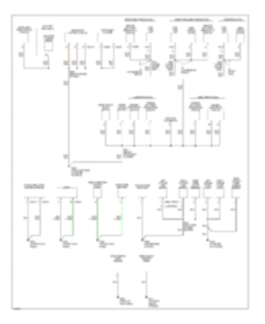
Ground Distribution Wiring Diagram (4 of 4) for Ford Explorer Sport 2001
List of elements for Ground Distribution Wiring Diagram (4 of 4) for Ford Explorer Sport 2001:
- (early prod)
- (late prod)
- Airbag sliding contact
- Auxiliary relay box 2
- C2041a
- C220b
- C220c
- C281a
- C281b
- C290a
- C309b
- Cluster)
- Data link connector
- Early production
- Four-wheel drive control module
- Fuel tank unit
- G203 (at right kick panel)
- G302 (front left side of center console)
- G406 (in center of liftgate)
- G411 (top right side of liftgate)
- G908 (front of roof panel)
- G909 (center rear of roof)
- Generic electronic module
- High mounted stop lamp
- Indicator flasher relay
- Instrument cluster
- Instrument panel dimming module
- Late production
- Left license plate lamp
- Left liftgate ajar switch
- Nca
- Passive anti-theft transceiver module
- Radio
- Rear integrated control panel
- Rear window adjust switch
- Rear window defrost grid
- Rear window motor
- Rear window wiper disable switch
- Rear wiper motor assembly
- Remote anti-theft personality module
- Restraints control module
- Right license plate lamp
- Right liftgate ajar switch
- Roof opening panel module
- S209 (behind center of dash)
- S323 (under driver seat)
- Seat)
- Sport trac, early production
- Sport, early production
- Subwoofer amplifier
- W/ convenience group
- W/ sport trac
HEADLIGHTS
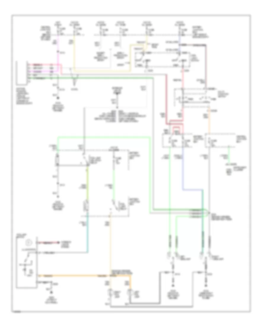
Headlight Wiring Diagram for Ford Explorer Sport 2001
List of elements for Headlight Wiring Diagram for Ford Explorer Sport 2001:
- (all others) (dash harness,
- (engine harness, center right side) s122
- 15a
- 25a
- Battery junction box
- Battery junction box (left side of engine compt)
- C202b
- C205
- C220b
- Central junction box
- Central junction box (behind left side of dash)
- Daytime running lamps (drl) module (left front corner of engine compt)
- Early production sport
- Except early production sport
- Exterior lights system
- Fog lamp isolation relay
- Fog lamp relay
- Fog lamp switch
- Fuse
- Fuse 10a
- Fuse 15a
- G100 (front of left front fender)
- G103 (near right front shock tower)
- G203 (at right kick panel)
- Head
- High beam ind
- Hot at all times
- Hot in run
- Illumination
- Instrument cluster
- Interior lights system
- Left fog lamp
- Left headlamp
- Left side of dash)
- Low
- Main light switch
- Multi- function switch
- Off
- On ind
- Park
- Pass
- Pass low
- Right fog lamp
- Right headlamp
- S110
- S115
- S119
- S120 (engine harness, center right side)
- S123
- S206
- S226
- S235 s243 (sport, late prod, w/o convenience group) (dash harness, behind instrument cluster)
- Sport
- Sport trac
- W/ drl
HORN
Horn Wiring Diagram for Ford Explorer Sport 2001
List of elements for Horn Wiring Diagram for Ford Explorer Sport 2001:
- (not used)
- 15a
- Air bag sliding contact
- Battery junction box (left side of engine compt, at fender apron)
- C1006
- C218a
- C274a
- C309b
- Central security module (behind top right side of dash)
- Early production
- Fuse 22
- G100 (front of left front fender)
- G302 (front left side of center console)
- Horn (right front of engine compt)
- Horn relay
- Horn switch
- Hot at all times
- Late production
- Nca
- Remote anti-theft person- ality (rap) (module) (sport) (at left rear quarter panel) (sport trac) (below center of rear window)
- S119
- S214
- Steering wheel speed control switch
- W/ ant- theft
- W/ cruise control
- W/o anti- theft
- W/o cruise control
INSTRUMENT CLUSTER
Instrument Cluster Wiring Diagram, Early Production for Ford Explorer Sport 2001
List of elements for Instrument Cluster Wiring Diagram, Early Production for Ford Explorer Sport 2001:
- (at right kick panel) g203
- (dash harn, behind center of dash) s241
- (front of left front fender) g100
- 4wd high
- 4wd low
- Abs ind
- Acc
- Air bag ind
- Anti-lock brakes system
- Anti-theft ind
- Belt minder module (behind center of dash)
- Brake fluid level switch (on master cylinder)
- C175
- C2013a
- C201a
- C2041a
- C220a
- C220a/1
- C220a/10
- C220a/11
- C220a/12
- C220a/13
- C220a/15
- C220a/2
- C220a/3
- C220a/4
- C220a/6
- C220a/7
- C220b
- C220b/1
- C220b/10
- C220b/12
- C220b/2
- C220b/3
- C220b/5
- C220b/6
- C220b/7
- C220b/8
- C220b/9
- C220c
- C220c/1
- C220c/10
- C220c/2
- C220c/3
- C220c/4
- C220c/5
- C220c/6
- C220c/7
- C220c/8
- C252
- C281b
- C282
- C433
- Central junction box (behind left side of dash)
- Charge ind
- Check engine
- Cruise control system
- Door ajar ind
- Engine controls system
- Engine coolant temperature
- Engine coolant temperature sender (behind gen bracket)
- Engine oil pressure switch (on engine, next to power steering pump)
- Exterior lights system
- Four-wheel drive control module (at right kick panel)
- Fuel cut-off indicator
- Fuel gauge
- Fuel tank unit gauge sensor
- Fuse 25a
- Fuse 7.5a
- G203 (at right kick panel)
- G302 (front left side of center console)
- Generic electronic module (gem) (behind center of dash)
- Ground
- Headlights system
- High beam
- Hot at all times
- Hot in run or start
- Hot in start or run
- Ignition switch
- Inertia fuel shut-off (ifs) switch (at right kick panel)
- Instrument cluster
- Left turn sig
- Lock
- Low
- Low fluid level/ park brake
- Low oil pressure
- Nca
- O/d "off" ind
- Off
- Passive anti-theft transceiver module (behind top right side of dash)
- Powertrain control module (pcm) (mounted through firewall)
- Restraints control module (rcm) (behind lower center of dash)
- Right turn sig
- Run
- S107
- S110
- S205
- S206
- S209
- S214
- S218
- S222 (dash harn, behind instrument cluster)
- Safety belt ind
- Speed cntrl ind
- Speedometer
- Start
- Starting/ charging system
- Tachometer
Instrument Cluster Wiring Diagram, Late Production for Ford Explorer Sport 2001
List of elements for Instrument Cluster Wiring Diagram, Late Production for Ford Explorer Sport 2001:
- (at right kick panel) g203
- (except flex fuel)
- (flex fuel)
- (front of left front fender) g100
- (sport trac)
- 4wd high
- 4wd low
- Abs ind
- Acc
- Air bag ind
- Anti-lock brakes system
- Anti-theft ind
- Brake fluid level switch (on master cylinder)
- C175
- C2041a
- C2100b
- C220a
- C220a/1
- C220a/10
- C220a/11
- C220a/12
- C220a/13
- C220a/15
- C220a/2
- C220a/3
- C220a/4
- C220a/6
- C220a/7
- C220b
- C220b/1
- C220b/10
- C220b/12
- C220b/2
- C220b/3
- C220b/5
- C220b/6
- C220b/7
- C220b/8
- C220b/9
- C220c
- C220c/1
- C220c/10
- C220c/2
- C220c/3
- C220c/4
- C220c/5
- C220c/6
- C220c/7
- C220c/8
- C281b
- C4033
- C433
- Central junction box (behind left side of dash)
- Charge ind
- Check engine
- Check fuel cap indicator
- Cruise control system
- Door ajar ind
- Engine controls system
- Engine coolant temperature
- Engine coolant temperature sender (behind gen bracket)
- Engine oil pressure switch (on engine, next to power steering pump)
- Exterior lights system
- Four-wheel drive control module (at right kick panel)
- Fuel gauge
- Fuel tank unit gauge sensor
- Fuse 7.5a
- G203 (at right kick panel)
- G302 (front left side of center console)
- Generic electronic module (gem) (behind center of dash)
- Ground
- Headlights system
- High beam
- Hot at all times
- Hot in run or start
- Hot in start or run
- Ignition switch
- Instrument cluster
- Left turn sig
- Lock
- Low
- Low fluid level/ park brake
- Low oil pressure
- Nca
- O/d "off" ind
- Off
- Park brake switch (right side of park brake lever)
- Powertrain control module (pcm) (mounted through firewall)
- Restraints control module (rcm) (behind lower center of dash)
- Right turn sig
- Run
- S107
- S110
- S206
- S209
- S218
- S222 (dash harn, behind instrument cluster)
- S323
- Safety belt ind
- Speed cntrl ind
- Speedometer
- Start
- Starting/ charging system
- Tachometer
INTERIOR LIGHTS
Courtesy Lamps Wiring Diagram, Early Production for Ford Explorer Sport 2001
List of elements for Courtesy Lamps Wiring Diagram, Early Production for Ford Explorer Sport 2001:
- (bottom of left "b" pillar) s306
- (left kick panel) g200
- (under left side of dash) auxiliary relay box 2
- Auxiliary relay box 2 (under left side of dash)
- Bat saver rly ctrl
- Battery saver relay
- C201a
- C201b
- Central junction box (behind left side of dash)
- Driver side front door ajar switch
- Front interior/ map lamps assembly
- Fuse 26 10a
- G406 (in center of liftgate)
- G909 (center rear of roof)
- Generic electronic module (gem) (behind center of dash)
- Glove box lamp
- Hot at all times
- Instrument illumination circuit
- Instrument panel dimming module (left side of steering column)
- Int lamp rly ctrl
- Interior lamps relay
- Left liftgate ajar switch
- Lf door ajar input
- Liftgate disable/ajar
- Norm
- Off
- Overhead console
- Passenger side front door ajar switch
- Rear interior/ map lamps assembly
- Rear window wiper disable switch
- Rf door ajar input
- Right liftgate ajar switch
- S307 (near left kick panel)
- S401
- S402 (left side of liftgate)
- S500
- S600
- W/ overhead console
- W/o overhead console
Courtesy Lamps Wiring Diagram, Late Production for Ford Explorer Sport 2001
List of elements for Courtesy Lamps Wiring Diagram, Late Production for Ford Explorer Sport 2001:
- (bottom of left "b" pillar) s306
- (left kick panel) g200
- (under left side of dash) auxiliary relay box 2
- Auxiliary relay box 2 (under leftr side of dash)
- Bat saver rly ctrl
- Battery saver relay
- C2100b
- Central junction box (behind left side of dash)
- Driver side front door ajar switch
- Front interior/ map lamps assembly
- Fuse 26 10a
- G406 (in center of liftgate)
- G909 (center rear of roof)
- Generic electronic module (gem) (behind center of dash)
- Glove box lamp
- Hot at all times
- Instrument illumination circuit
- Instrument panel dimming module (left side of steering column)
- Int lamp rly ctrl
- Interior lamps relay
- Left liftgate ajar switch
- Lf door ajar input
- Liftgate disable/ajar
- Norm
- Off
- Overhead console
- Passenger side front door ajar switch
- Rear interior/ map lamps assembly
- Rear window wiper disable switch
- Rf door ajar input
- Right liftgate ajar switch
- S307 (near left kick panel)
- S401
- S402 (left side of liftgate)
- S500
- S600
- W/ overhead console
- W/o overhead console
Instrument Illumination Wiring Diagram, Early Production for Ford Explorer Sport 2001
List of elements for Instrument Illumination Wiring Diagram, Early Production for Ford Explorer Sport 2001:
- (near left kick panel) s231
- Air bag sliding contact
- Ashtray illum- ination lamp
- Auxiliary relay box 2 (under left side of dash)
- Auxiliary relay box 3 (on left side of rear cargo compt)
- Battery saver relay
- C201b
- C220a
- C220b
- C290a
- C294b
- C309b
- C349
- Central junction box (behind left side of dash)
- Courtesy lamps circuit
- Driver side exterior rear view mirror
- Driver side front power door lock switch
- Exterior lights system
- Fog lamp switch
- Four- wheel drive switch
- Front function selector switch assembly
- Fuse 26 10a
- Fuse 5 15a
- G200 (at left kick panel)
- G203 (at right
- G203 (at right kick panel)
- G302 (front left
- Generic electronic module (gem) (behind center of dash)
- Head
- Hot at all times
- Instrument cluster
- Instrument panel dimming module (left side of steering column)
- Kick panel)
- Main light switch
- Nca
- Norm
- Off
- Overhead console
- Park
- Park lamp relay
- Passenger side exterior rear view mirror
- Passenger side front power door lock switch
- Radio
- Rear integrated control panel
- Rear window defrost switch
- Rear window wiper/ washer switch
- Remote anti-theft personality module (at left rear quarter panel)
- S203
- S206
- S209
- S214
- S217 (behind left side of dash)
- S229
- S235 (behind left side of dash)
- S301 (under passenger seat)
- S500
- S600
- Side of center console)
- Solid state
- Steering wheel/ speed control switch
- W/ 4wd only
Instrument Illumination Wiring Diagram, Late Production for Ford Explorer Sport 2001
List of elements for Instrument Illumination Wiring Diagram, Late Production for Ford Explorer Sport 2001:
- (behind center of dash) s245
- (near left kick panel) s231
- 87a
- Air bag sliding contact
- Ashtray illum- ination lamp
- Auxiliary relay box 2 (under left side of dash)
- Battery saver relay
- C2100b
- C220a
- C220b
- C274b
- C290a
- C294b
- C349
- Central junction box (behind left side of dash)
- Central security module (behind top right side of dash)
- Courtesy lamps circuit
- Driver side exterior rear view mirror
- Driver side front power door lock switch
- Exterior lights system
- Fog lamp switch
- Four- wheel drive switch
- Front function selector switch assembly
- Fuse 26 10a
- Fuse 5 15a
- G200 (at left kick panel)
- G203 (at right
- G203 (at right kick panel)
- G302 (front left
- Generic electronic module (gem) (behind center of dash)
- Head
- Hot at all times
- Instrument cluster
- Instrument panel dimming module (left side of steering column)
- Kick panel)
- Main light switch
- Nca
- Norm
- Off
- Overhead console
- Park
- Park lamp relay (at right kick panel)
- Passenger side exterior rear view mirror
- Passenger side front power door lock switch
- Radio
- Rear integrated control panel
- Rear window defrost switch
- Rear window wiper/ washer switch
- S203
- S206
- S209
- S214
- S217 (behind left side of dash)
- S229
- S235 (behind left side of dash)
- S243 (behind left side of dash)
- S244 (behind instrument cluster)
- S500
- S600
- Side of center console)
- Solid state
- Steering wheel/ speed control switch
- W/ 4wd only
- W/ convenience group only
- W/0 convenience group only
- W/o convenience group only
POWER DISTRIBUTION
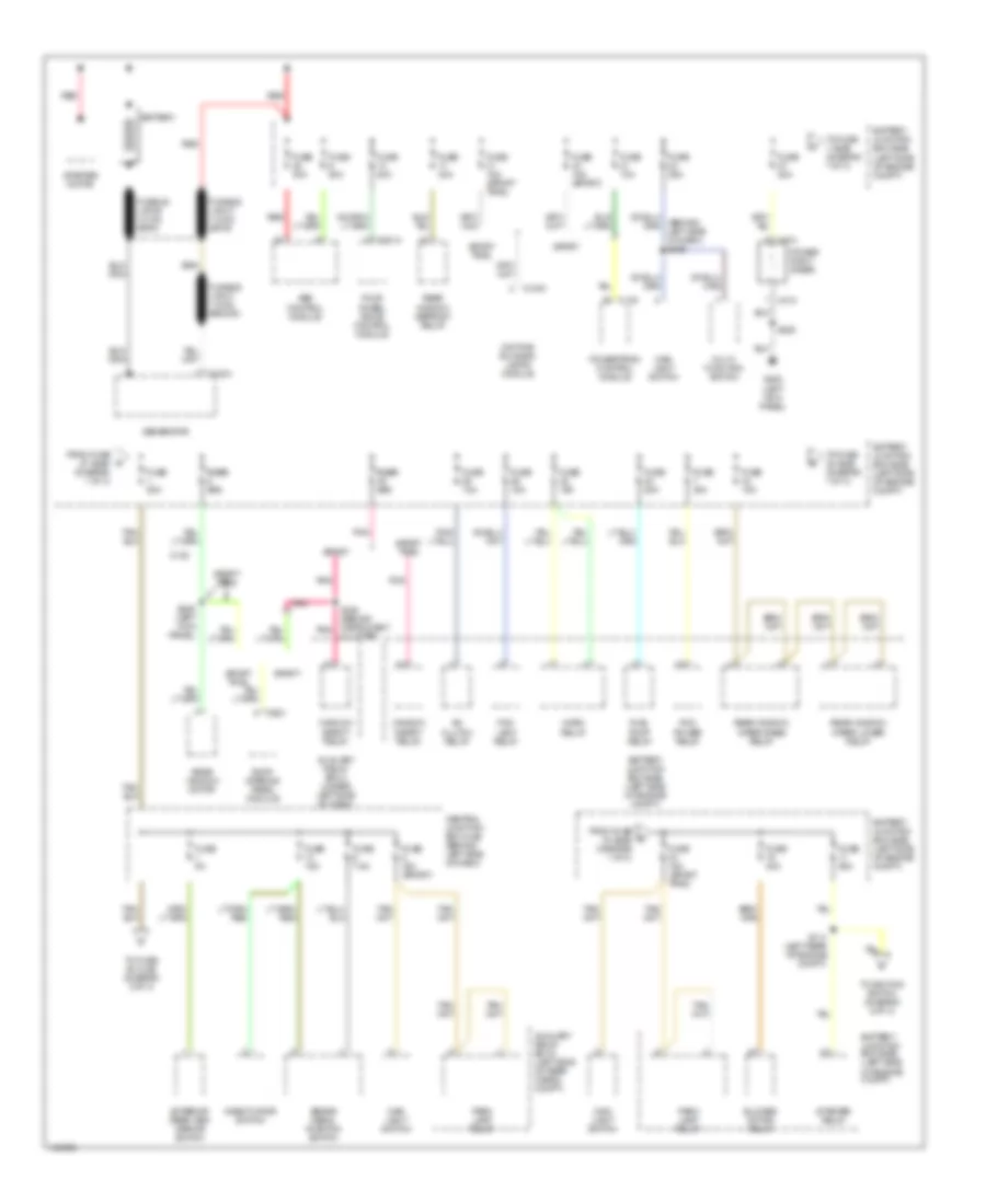
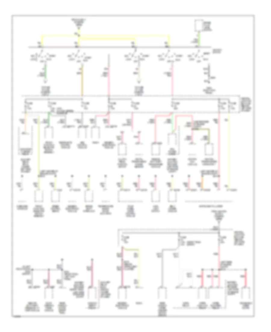
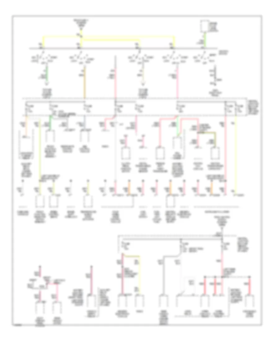
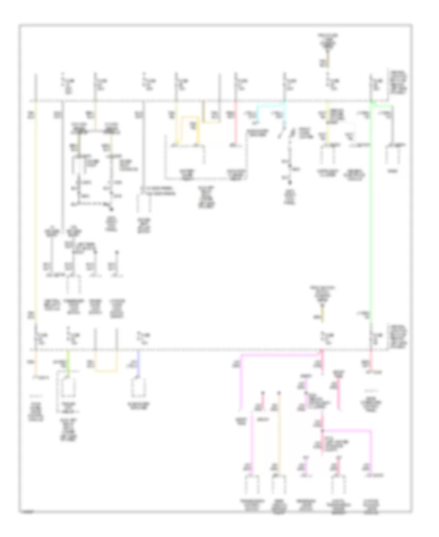
Power Distribution Wiring Diagram, Early Production (1 of 3) for Ford Explorer Sport 2001
List of elements for Power Distribution Wiring Diagram, Early Production (1 of 3) for Ford Explorer Sport 2001:
- A/c clutch relay
- Abs control module
- Auxiliary relay box 2 (under left side of dash)
- Auxiliary relay box 3 (left side of rear cargo compt)
- Battery
- Battery junction box (bjb) (left side of engine compt)
- Blower motor relay
- Brake pedal position switch
- C102a
- C1030
- C135
- C175
- C281a
- C474
- C921
- Central junction box (cjb) (behind left side of dash)
- Cluster)
- Daytime running lamps module
- Deactivator switch
- Exterior rear view mirror switch
- Fog lamp relay
- Four wheel drive control module
- From fuse 27 (bjb) (diagram 1 of 3)
- From fuse 34 (bjb) (diagram 1 of 3)
- Fuel pump relay
- Fuse 10a
- Fuse 15a
- Fuse 15a (sport trac)
- Fuse 15a (sport)
- Fuse 20a
- Fuse 25a
- Fuse 30a
- Fuse 40a
- Fuse 50a
- Fuse 5a
- Fuse 7.5a
- Fuse fuse 30a 30a
- Fusible link a (12 ga, gray)
- Fusible link b (12 ga, gray)
- Fusible link c (18 ga, brown)
- G200 (left kick panel)
- Generator
- Horn relay
- Main light switch
- Multi- function switch
- Park lamp relay
- Pcm power relay
- Pnk
- Power point (rear)
- Powertrain control module
- Rear window defrost relay
- Rear window motor
- Rear window wiper lower relay
- Rear window wiper raise relay
- Red
- Roof opening panel module
- S114 (left rear of engine compt)
- S224 (behind instrument pnk
- S239 (left kick panel)
- S405
- Sport
- Sport trac
- Starter motor
- Starter relay
- To fuse 1 (bjb) (diagram 1 of 3)
- To fuse 25 (cjb) (diagram 3 of 3)
- To fuse 33 (bjb) (diagram 1 of 3)
- To ignition switch (diagram 2 of 3)
- Window safety relay
Power Distribution Wiring Diagram, Early Production (2 of 3) for Ford Explorer Sport 2001
List of elements for Power Distribution Wiring Diagram, Early Production (2 of 3) for Ford Explorer Sport 2001:
- (in left front door) s232 (sport)
- (left center of engine compt) s216
- (left center of engine compt) s218
- (left rear of engine compt) s112
- (sport trac) (sport)
- (w/o) (w/ high series console)
- 2013b
- A/t
- Abs control module
- Acc
- Auxiliary relay box 2 (sport) (under left side of dash)
- Auxiliary relay box 2 (under left side of dash)
- Battery junction box (bjb) (left side
- Battery junction box (bjb) (left side of engine compt)
- Battery junction box (bjb) (sport trac) (left side of engine compt)
- Belt minder module
- Brake fluid level switch
- Brake shift interlock
- C122
- C135
- C201b
- C2041a
- C220a
- C220b
- C220c
- C252
- C281a
- C281b
- C309a
- C921
- Central junction box (cjb) (behind left side of dash)
- Cluster)
- Clutch pedal position switch
- Digital transmission range sensor
- Four wheel drive control module
- From fuse 11 (diagram 1 of 3)
- From ignition switch (diagram 2 of 3)
- Front function selector switch assembly
- Fuse 10a
- Fuse 25a
- Fuse 30a
- Fuse 7.5a
- Fuse 7.5a 10a
- Fuse 7.5a 15a
- G203 (right kick panel)
- Generic electronic module
- Gnd
- Horn relay
- Ignition coil module
- Ignition switch
- Ignition transformer capacitor 1
- Indicator flasher relay
- Instrument cluster
- Lock
- M/t
- Main light switch
- Of engine compt)
- Off
- Overhead console
- Passive anti-theft transceiver module
- Pcm power diode
- Pnk
- Radio
- Rear window motor (sport trac)
- Rear window wiper/ washer switch (sport)
- Red
- Remote anti-theft personality (rap) module
- Restraints control module
- Roof opening panel module
- Run
- S206
- S324 (sport trac) (left kick panel)
- Speed control servo
- Sta
- Start
- Temperature blend door actuator
- To fuse 16 (cjb) (diagram 2 of 3)
- To fuse 27 (cjb) (diagram 3 of 3)
- Window safety relay
- Windshield wiper motor
- Wiper high/low relay
- Wiper run/park relay
Power Distribution Wiring Diagram, Early Production (3 of 3) for Ford Explorer Sport 2001
List of elements for Power Distribution Wiring Diagram, Early Production (3 of 3) for Ford Explorer Sport 2001:
- (behind center of dash) s205
- (left rear of vehicle) s304
- (left rear of vehicle) s312
- (sport) (sport trac)
- (sport) subwoofer amplifier
- (w/ side airbag)
- (w/o side airbag)
- 309b
- A/t
- Auxiliary relay box 2 (under left side of dash)
- Auxiliary relay box 3 (left side of rear cargo compartment)
- Battery saver relay
- C1030
- C201b
- C2033
- C220c
- C252
- C281a
- C290a
- C349
- C380
- Central junction box (cjb) (behind left side of dash)
- Daytime running lamps module
- Digital transmission range sensor
- Door lock relay
- Door unlock relay
- Driver door lock switch
- Driver door unlock relay
- Driver seat adjust switch
- Four wheel drive control module
- From fuse 1 (bjb) (diagram 1 of 3) c
- From ignition switch (diagram 2 of 3)
- Front cigar lighter
- Fuse 10a
- Fuse 15a
- Fuse 20a
- Fuse 20a 25a
- Fuse 25a
- Fuse 5a
- Fuse 7.5a
- G203 (right kick panel)
- Generic electronic module
- Indicator flasher relay
- Instrument cluster
- Liftgate door lock switch
- M/t
- Passenger door lock switch
- Passive anti-theft transceiver module
- Power point
- Power point (console)
- Radio
- Rear integrated control panel
- Rear window defrost relay
- Remote anti-theft personality (rap) module
- Reversing lamps switch
- S115 (left center of engine compt)
- S203
- S223 (behind instrument cluster)
- S236 (behind center of dash)
- S316
- S322 (left center of vehicle) underbody)
- Sport
- Sport trac
- Subwoofer amplifier
- Trailer tow relay
- Transmission control switch
- W/ high series console
- W/ keyless entry
- W/o high series console
- W/o keyless entry
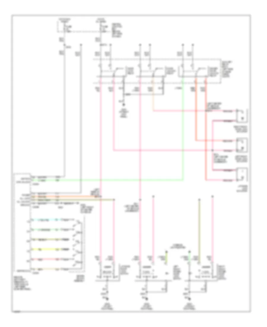
Power Distribution Wiring Diagram, Late Production (1 of 3) for Ford Explorer Sport 2001
List of elements for Power Distribution Wiring Diagram, Late Production (1 of 3) for Ford Explorer Sport 2001:
- A/c clutch relay
- Abs control module
- Auxiliary relay box 2 (under left side of dash)
- Battery
- Battery junction box (bjb) (left side of engine compt)
- Blower motor relay
- Brake pedal position switch
- C102a
- C1030
- C135
- C175
- C281a
- C474
- C921
- Central junction box (cjb) (behind left side of dash)
- Cluster)
- Daytime running lamps module
- Deactivator switch
- Exterior rear view mirror switch
- Fog lamp relay
- Four wheel drive control module
- From fuse 27 (bjb) (diagram 1 of 3)
- From fuse 34 (bjb) (diagram 1 of 3)
- Fuel pump relay
- Fuse 10a
- Fuse 15a
- Fuse 15a (sport trac)
- Fuse 15a (sport)
- Fuse 20a
- Fuse 25a
- Fuse 30a
- Fuse 40a
- Fuse 50a
- Fuse 5a
- Fuse 7.5a
- Fusible link a (12 ga, gray)
- Fusible link b (12 ga, gray)
- Fusible link c (18 ga, brown)
- G200 (left kick panel)
- Generator
- Horn relay
- Main light switch
- Multi- function switch
- Park lamp relay
- Pcm power relay
- Pnk
- Power point (rear)
- Powertrain control module
- Rear window defrost relay
- Rear window motor
- Rear window wiper lower relay
- Rear window wiper raise relay
- Red
- Roof opening panel module
- S114 (left rear of engine compt)
- S224 (behind instrument pnk
- S239 (left kick panel)
- S405
- Sport
- Sport trac
- Starter motor
- Starter relay
- To fuse 1 (bjb) (diagram 1 of 3)
- To fuse 25 (cjb) (diagram 3 of 3)
- To fuse 33 (bjb) (diagram 1 of 3)
- To ignition switch (diagram 2 of 3)
- Window safety relay
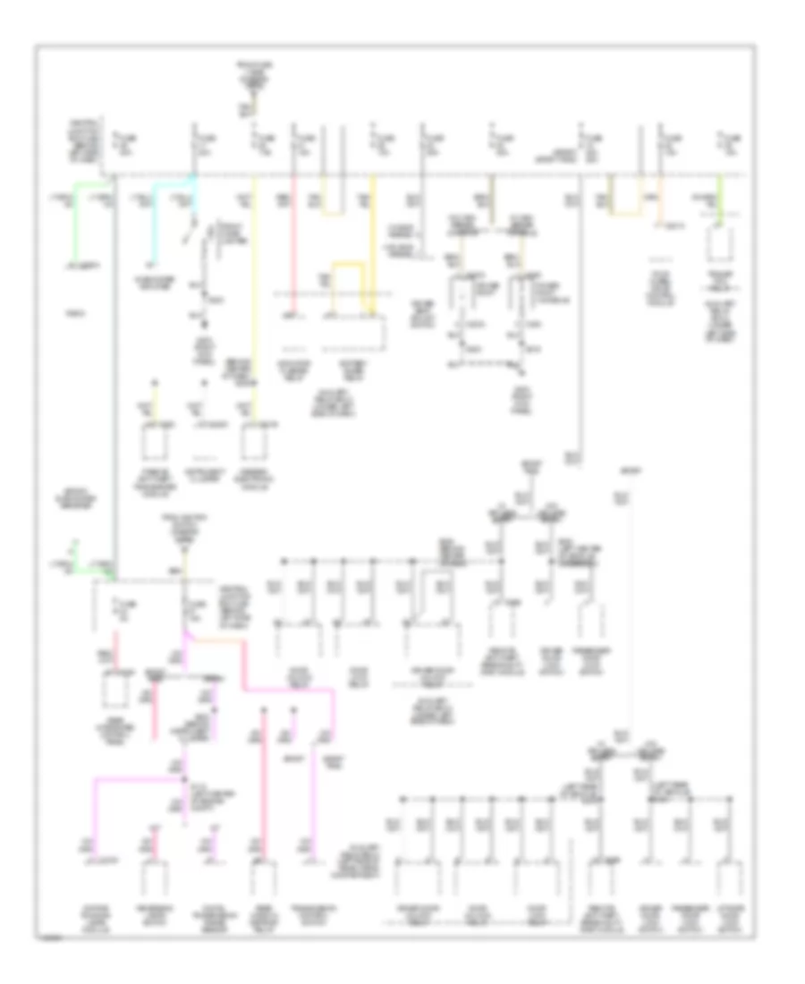
Power Distribution Wiring Diagram, Late Production (2 of 3) for Ford Explorer Sport 2001
List of elements for Power Distribution Wiring Diagram, Late Production (2 of 3) for Ford Explorer Sport 2001:
- (left center of engine compt) s216
- (left center of engine compt) s218
- (left kick panel)
- (left rear of engine compt) s112
- (sport trac) (sport)
- (w/o) (w/ high series console)
- A/t
- Abs control module
- Acc
- Auxiliary relay box 2 (sport) (under left side of dash)
- Auxiliary relay box 2 (under left side of dash)
- Battery junction box (bjb) (left side
- Battery junction box (bjb) (left side of engine compt)
- Battery junction box (bjb) (sport trac) (left side of engine compt)
- Brake fluid level switch
- Brake shift interlock
- C122
- C135
- C2041
- C2100a
- C220a
- C220b
- C220c
- C274a
- C281a
- C281b
- C921
- Central junction box (cjb) (behind left side of dash)
- Central security module (keyless entry)
- Cluster)
- Clutch pedal position switch
- Digital transmission range sensor
- Four wheel drive control module
- From fuse 11 (diagram 1 of 3)
- From ignition switch (diagram 2 of 3)
- Front function selector switch assembly
- Fuel tank unit (w/ flex fuel)
- Fuse 10a
- Fuse 25a
- Fuse 30a
- Fuse 7.5a
- Fuse 7.5a 10a
- Fuse 7.5a 15a
- G203 (right kick panel)
- Generic electronic module
- Gnd
- Horn relay
- Ignition coil module
- Ignition switch
- Ignition transformer capacitor 1
- Indicator flasher relay
- Instrument cluster
- Lock
- M/t
- Main light switch
- Of engine compt)
- Off
- Overhead console
- Passive anti- theft transceiver
- Pcm power diode
- Pnk
- Radio
- Rear window motor
- Rear window wiper/ washer switch (sport)
- Red
- Restraints control module
- Roof opening panel module
- Run
- S206
- S324
- Speed control servo
- Sport
- Sport trac
- Sta
- Start
- Temperature blend door actuator
- To fuse 16 (cjb) (diagram 2 of 3)
- To fuse 27 (cjb) (diagram 3 of 3)
- Window safety relay
- Windshield wiper motor
- Wiper high/low relay
- Wiper run/park relay
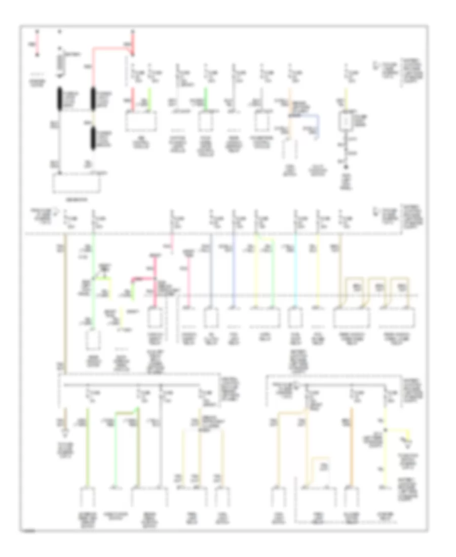
Power Distribution Wiring Diagram, Late Production (3 of 3) for Ford Explorer Sport 2001
List of elements for Power Distribution Wiring Diagram, Late Production (3 of 3) for Ford Explorer Sport 2001:
- (behind center of dash) s205
- (w/ side airbag)
- (w/o side airbag)
- A/t
- Auxiliary relay box 2 (under left side of dash)
- Battery saver relay
- C1030
- C2033
- C2100a
- C220c
- C274b
- C281a
- C290a
- C349
- C380
- Central junction box (cjb) (behind left side of dash)
- Central security module
- Daytime running lamps module
- Digital transmission range sensor
- Driver door lock switch
- Driver seat adjust switch
- Four wheel drive control module
- From fuse 1 (bjb) (diagram 1 of 3) c
- From ignition switch (diagram 2 of 3)
- Front cigar lighter
- Fuse 10a
- Fuse 15a
- Fuse 20a
- Fuse 20a 25a
- Fuse 25a
- Fuse 5a
- Fuse 7.5a
- G203 (right kick panel)
- Generic electronic module
- Indicator flasher relay
- Instrument cluster
- Liftgate door lock switch (sport)
- M/t
- Of engine compt)
- Passenger door lock switch
- Power point
- Power point (console)
- Radio
- Rear integrated control panel
- Rear window defrost relay
- Reversing lamps switch
- S203
- S223 (behind instrument cluster)
- S316
- Sport
- Sport trac
- Subwoofer amplifier
- Trailer tow relay
- Transmission control switch
- W/ high series console
- W/ keyless entry
- W/o high series console
- W/o keyless entry
POWER DOOR LOCKS
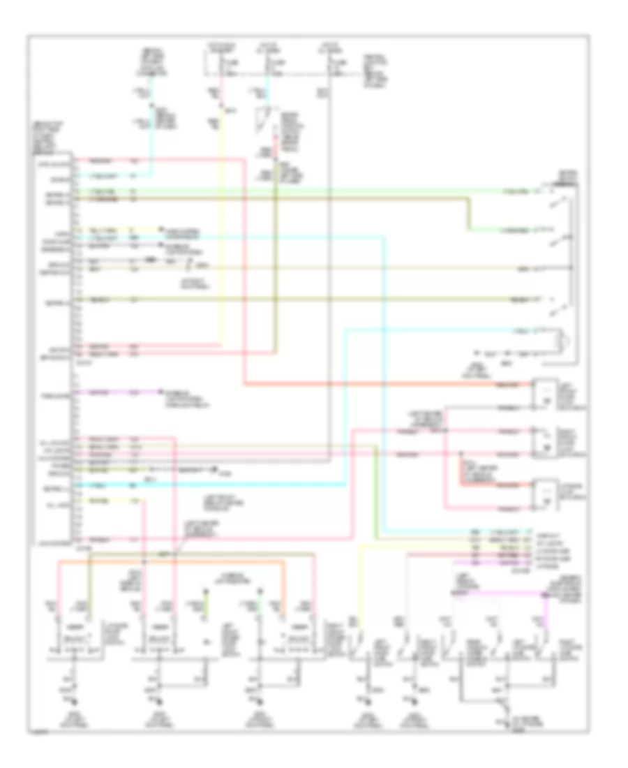
Keyless Entry Wiring Diagram, Early Production for Ford Explorer Sport 2001
List of elements for Keyless Entry Wiring Diagram, Early Production for Ford Explorer Sport 2001:
- (left center of vehicle underbody) s314
- (left rear of vehicle) s310
- 1/2
- 3/4
- 5/6
- 7/8
- 9/0
- All lock
- All unlock
- Auxiliary relay box 3 (left side of rear cargo compt)
- C309a
- C309b
- Central junction box (behind left side of dash)
- Door lock relay
- Door unlock relay
- Driver door unlock relay
- Dvr unlock
- Fuse 20a
- Fuse 7.5a
- G200 (at left kick panel)
- G203 (at right kick panel)
- G302 (left front of center console)
- Ground
- Hot at all times
- Hot in run or acc
- Ignition
- Interior lights system
- Keypad com
- Keypad switch assembly
- Left front door lock actuator
- Left front power door lock switch
- Liftgate door lock switch
- Liftgate lock actuator
- Lock
- Nca
- Power
- Red
- Remote anti-theft personality (rap) module (left rear quarter panel)
- Right front door lock actuator
- Right front power door lock switch
- S232
- S309
- S311 (left center of vehicle underbody)
- S312
- S313 (left center of vehicle underbody)
- S323
- S500
- S600
- Unlock
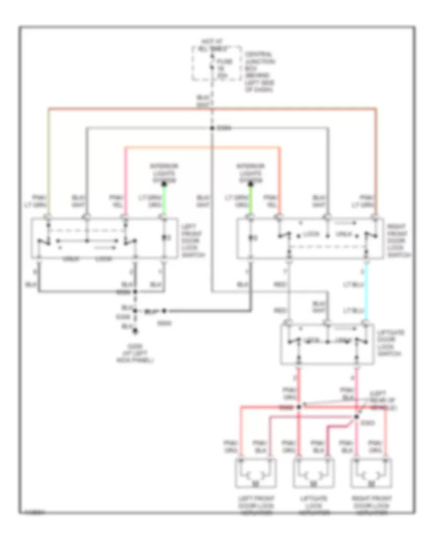
Keyless Entry Wiring Diagram, Late Production for Ford Explorer Sport 2001
List of elements for Keyless Entry Wiring Diagram, Late Production for Ford Explorer Sport 2001:
- (at right kick panel)
- (behind left side of dash) data link connector
- (behind top right side of dash) central security module
- (in center of liftgate) g406
- (left center of vehicle underbody)
- (left center of vehicle underbody) s313
- (left front side of center console)
- (left side of liftgate) s402
- Ajar out
- All lock
- All unlock
- Bpp switch
- Brake pedal position switch (above brake pedal)
- C2100b
- C274a
- C274b
- Central junction box (behind left side of dash)
- Door ajar
- Dvr unlock
- Exterior lights system
- Exterior lights system (parklamp relay)
- Fuse 20a
- Fuse 7.5a
- G200 (at left kick panel)
- G203
- G203 (at right kick panel)
- G302
- Generic electronic module (gem) (behind center of dash)
- Ground
- Horn
- Horn system (horn relay)
- Hot at all times
- Hot in run or start
- Ignition
- Int lights
- Interior lights system
- Iso bus
- Keypad com
- Keypad ill
- Keypad in
- Keypad switch assembly
- Left front door ajar switch
- Left front door lock actuator
- Left front power door lock switch
- Left liftgate ajar switch
- Lf door ajar
- Liftgate
- Liftgate door lock switch
- Liftgate lock actuator
- Lock
- Lock doors
- Parklamps
- Power
- Rear window wiper disable switch
- Reverse in
- Rf door ajar
- Right front door ajar switch
- Right front door lock actuator
- Right front power door lock switch
- Right liftgate ajar switch
- S203
- S208 (behind center of dash)
- S214
- S218
- S227 (under left side of dash)
- S309
- S310 (left rear of vehicle)
- S311
- S314 (left center of vehicle underbody)
- S401
- S500
- S600
- Unlk doors
- Unlock
Power Door Locks Wiring Diagram, without Keyless Entry for Ford Explorer Sport 2001
List of elements for Power Door Locks Wiring Diagram, without Keyless Entry for Ford Explorer Sport 2001:
- (left rear of vehicle)
- Central junction box (behind left side of dash)
- Fuse 20a
- G200 (at left kick panel)
- Hot at all times
- Interior lights system
- Left front door lock actuator
- Left front door lock switch
- Liftgate door lock switch
- Liftgate lock actuator
- Lock
- Red
- Right front door lock actuator
- Right front door lock switch
- S302
- S303
- S304
- S308
- S500
- S600
- Unlk
POWER MIRRORS
Power Mirrors Wiring Diagram for Ford Explorer Sport 2001
List of elements for Power Mirrors Wiring Diagram for Ford Explorer Sport 2001:
- (behind left kick panel)
- Central junction box (behind left side of dash)
- Defogger system
- Direc- tional control switch
- Down
- Exterior rear view mirror switch
- Fuse 7.5a
- G200
- Hot at all times
- Interior lights system
- L/r
- Left
- Left exterior rear view mirror
- Red
- Right
- Right exterior rear view mirror
- S500
- U/d
- W/ elec- tronics group only
POWER SEATS
Power Seat Wiring Diagram for Ford Explorer Sport 2001
List of elements for Power Seat Wiring Diagram for Ford Explorer Sport 2001:
- (sport trac)
- (w/side air bags)
- Backrest
- Backrest forward/rearward
- C357
- C360
- C360 (w/side air bags)
- C369
- Central junction box (behind left side of dash)
- Entire seat
- Entire seat forward/rearward
- Front of seat
- Front of seat up/down
- Fuse f2.30 25a
- Fwd
- G200 (at left kick panel)
- Hot at all times
- Nca
- Power seat motor assembly
- Rwd
- S308 s320
- Seat adjust switch
POWER TOP/SUNROOF
Power Top/Sunroof Wiring Diagrams for Ford Explorer Sport 2001
List of elements for Power Top/Sunroof Wiring Diagrams for Ford Explorer Sport 2001:
- (sport trac) 30a
- (sport)
- Battery junction box (left side of engine compt, at fender apron
- C219
- C912
- C921
- Central junction box (behind left side of dash)
- Down/ open
- Fuse
- Fuse 7.5a
- G200 (at left kick panel)
- G908 (front of roof panel)
- Hot at all times
- Hot in run or acc
- Panel switch
- Red
- Roof opening
- Roof opening panel module (at front center of roof)
- S229
- Up/ close
POWER WINDOWS
Power Window Wiring Diagram for Ford Explorer Sport 2001
List of elements for Power Window Wiring Diagram for Ford Explorer Sport 2001:
- (early prod) (late prod)
- (near steering column) s204
- Auxiliary relay box (left side of rear cargo area)
- Battery junction box (left side of engine compt)
- C201b c2100a
- C201b c2100b
- C2100b
- C504a
- C504b
- Central junction box (behind left side of dash)
- Close
- Early prod late prod
- Fuse 30a
- Fuse 7.5a
- G100 (front of left front fender)
- G200 (left
- G200 (left kick panel)
- G302 (front left side of center console)
- Generic electronic module (behind center of dash)
- Hot at all times
- Hot in run or acc
- Interior lights system
- Kick panel)
- Late production
- Left front power window motor
- Left front window
- Master window adjust switch
- One-touch window relay
- Open
- Pnk
- Rear window adjust switch
- Rear window motor
- Red
- Right front power window motor
- Right front window
- Right front window adjust switch
- S110
- S202 (behind center of dash panel)
- S210 (near steering column)
- S212 (near steering column)
- S214
- S219
- S224
- S230 (in driver's door)
- S320
- S323
- S324
- S500
- Solid state
- Vent
- Window safety relay
RADIO
Radio Wiring Diagrams, Early Production for Ford Explorer Sport 2001
List of elements for Radio Wiring Diagrams, Early Production for Ford Explorer Sport 2001:
- (at right kick panel)
- (front of center console)
- Acp a
- Acp b
- Antenna
- Audio sys on
- C290a
- C290b
- C290c
- Central junction box (behind left side of dash)
- Fuse 25a
- Fuse 5a
- Fuse 7.5a
- Fused ignition
- G203
- G203 (at right kick panel)
- Grd
- Ground
- High mute
- Hot at all times
- Hot in run or acc
- Hot in start
- Illumination
- Interior lights system
- L front spkr (+)
- L front spkr (-)
- L rear spkr (+)
- L rear spkr (-)
- Left front speaker
- Left rear speaker
- Lr spkr (+)
- Lr spkr (-)
- Nca
- Power
- R front spkr (+)
- R front spkr (-)
- R rear spkr (+)
- R rear spkr (-)
- Radio
- Rear integrated control panel (rear of center console)
- Right front speaker
- Right rear speaker
- Rr spkr (+)
- Rr spkr (-)
- Rx sig
- S200 (right rocker panel)
- S206
- S210 (behind center of dash)
- S233 (right rocker panel)
- S316
- S317
- S318
- Sport
- Subwoofer amplifier (sport) (right rear of vehicle, attached to side wall)
- Tan
- Tx sig
- W/ high series center console
- W/ high series center console)
- W/0 high series center console
- W/o high series center console
- W/o high series center console)
Radio Wiring Diagrams, Late Production for Ford Explorer Sport 2001
List of elements for Radio Wiring Diagrams, Late Production for Ford Explorer Sport 2001:
- (at right kick panel)
- (front of center console)
- Acp a
- Acp b
- Antenna
- Audio sys on
- C290a
- C290b
- C290c
- Central junction box (behind left side of dash)
- Fuse 15a
- Fuse 20a
- Fuse 5a
- Fuse 7.5a
- Fused ignition
- G203
- G203 (at right kick panel)
- Grd
- Ground
- High mute
- Hot at all times
- Hot in run or acc
- Hot in start
- Illumination
- Interior lights system
- L front spkr (+)
- L front spkr (-)
- L rear spkr (+)
- L rear spkr (-)
- Left front speaker
- Left rear speaker
- Lr spkr (+)
- Lr spkr (-)
- Nca
- Power
- R front spkr (+)
- R front spkr (-)
- R rear spkr (+)
- R rear spkr (-)
- Radio
- Rear integrated control panel (rear of center console)
- Right front speaker
- Right rear speaker
- Rr spkr (+)
- Rr spkr (-)
- Rx sig
- S200 (right rocker panel)
- S206
- S210 (behind center of dash)
- S233 (right rocker panel)
- S316
- S317
- S318
- Sport
- Subwoofer amplifier (sport) (right rear of vehicle, attached to side wall)
- Tan
- Tx sig
- W/ high series center console
- W/ high series center console)
- W/0 high series center console
- W/o high series center console
- W/o high series center console)
SHIFT INTERLOCKS
Shift Interlock Wiring Diagram for Ford Explorer Sport 2001
List of elements for Shift Interlock Wiring Diagram for Ford Explorer Sport 2001:
- Brake pedal position (bpp) switch (above brake pedal)
- Central junction box (behind left side of dash)
- Fuse 2.10 7.5a
- Fuse 2.9 7.5a
- G203 (right kick panel)
- Hot at all times
- Hot in run
- S206
- S216
- S227 (under driver side of dash)
- Shift lock actuator (in steering column)
- Solid state
STARTING/CHARGING
Charging Wiring Diagram for Ford Explorer Sport 2001
List of elements for Charging Wiring Diagram for Ford Explorer Sport 2001:
- Battery
- Battery junction box (left side of engine compt)
- C102a
- C220c
- Central junction box (behind left side of dash)
- Charge warning lamp
- Fuse 7.5a
- Fuse link a (12 ga-gray) (left center of eng compt)
- Fuse link b (12 ga- gray) (left center of eng compt)
- Fuse link c (18 ga- brown) (left center of eng compt)
- G108 (near left front radiator support)
- G111 (near battery)
- Generator
- Hot in start or run
- Instrument cluster
- Red
- Starter motor
Starting Wiring Diagram for Ford Explorer Sport 2001
List of elements for Starting Wiring Diagram for Ford Explorer Sport 2001:
- A/t
- Acc
- Battery
- Battery junction box (left rear of engine compt)
- C167
- C252
- Central junction box (behind left side of dash)
- Clutch pedal position switch (above clutch pedal)
- Digital transmission range (dtr) sensor (left side of transmission)
- Early production
- Fuse 50a
- Fuse 7.5a
- G100 (left front of engine compartment)
- G111 (near battery)
- Ignition switch
- Late production
- Lock
- M/t
- Off
- Passive anti-theft transceiver module (behind top right side of dash)
- Pnk
- Powertrain control module (right rear of engine compartment)
- Red
- Run
- S114
- Sta
- Start
- Starter motor
- Starter relay
- Tan/red
SUPPLEMENTAL RESTRAINTS
Supplemental Restraint Wiring Diagram for Ford Explorer Sport 2001
List of elements for Supplemental Restraint Wiring Diagram for Ford Explorer Sport 2001:
- (center console, under dash panel) g302
- (late production)
- (other)
- (w/high series center console) (other models)
- Air bag
- Air bag dedicated ground
- Air bag indicator ctrl
- Air bag sliding contact
- Air bag tone driver
- C201a
- C2041a
- C2041b
- C2100b
- C220a
- C220b
- C220c
- Central junction box (cjb) (behind left side of dash)
- Data link connector (dlc) (partial) (behind left side of dash)
- Driver air bag feed
- Driver air bag module
- Driver air bag return
- Driver side air bag feed
- Driver side air bag return
- Driver side sensor feed
- Driver side sensor return
- Except sport
- Fuse f2.11 7.5a
- Fuse f2.6 15a 7.5a
- Generic electronic module (gem) (behind center of dash)
- Ground
- Hot in run
- Hot in run or start
- Ignition
- Instrument cluster
- Iso bus
- Late production
- Left side air bag module
- Left side air bag sensor (w/sport model) (at base of left "b" pillar)
- Nca
- Other
- Pass side air bag feed
- Pass side air bag return
- Pass side sensor feed
- Pass side sensor return
- Passenger air bag feed
- Passenger air bag module
- Passenger air bag return
- Pin shorting bar is engaged when module connector is disconnected from harness (shorting bar is connected between pins: 3-4, 6-7, 20-21 conn. c2041a 2-3 & 5-6 conn. c2041b)
- Resistor a (beneath driver's seat)
- Resistor b (w/sport model) (beneath passenger's seat)
- Restraints control module (rcm) (behind lower center of dash)
- Right side air bag module (w/sport model)
- Right side air bag sensor (w/sport model) (at base of right "b" pillar)
- S208
- S209
- S218
- Shorting bar
- Solid state
- Sport model
- W/o side air bags
- W/side air bags
TRANSMISSION
4WD Wiring Diagram, Early Production for Ford Explorer Sport 2001
List of elements for 4WD Wiring Diagram, Early Production for Ford Explorer Sport 2001:
- (behind instrument cluster) s213
- (left side of transmission) digital transmission range sensor
- (under left side of dash) s227
- 4wd hi
- 4wd hi ind
- 4wd lo
- 4wd lo ind
- 4wd switch
- Battery junction box (left side of engine compt)
- Bpp switch
- Brake pedal position switch (above brake pedal)
- Brake shift interlock, speed control servo, function select switch assembly, temp blend door actuator, gem module, overhead console
- C175
- C220a
- C220b
- C220c
- C281a
- C281b
- Central junction box (behind left side of dash)
- Computer data lines system
- Data link connector (behind left side of dash)
- Exterior lights system
- Four-wheel drive control module (at right kick panel)
- Four-wheel drive switch
- Fuse 15a
- Fuse 20a
- Fuse 7.5a
- G100 (center rear of engine compt)
- G200 (right kick panel)
- G201 (right kick panel)
- Ground
- Hot at all times
- Hot in run
- Hot in run or start
- Ign (run)
- Ign (st/run)
- Illum
- Instrument cluster
- Interior lights system
- Iso bus
- Main light switch, belt minder module
- Motor 1
- Motor 2
- Motor 3
- Motor 4
- Motor 5
- Nca
- Neutral sens
- Off
- Overhead console, instrument cluster, gem module
- Powertrain control module (mounted through firewall)
- S145
- S206
- S208 (behind center of dash)
- S216
- S218
- Sig return
- Speed control servo
- Transfer case
- Transfer case assembly
- Vss input
4WD Wiring Diagram, Late Production for Ford Explorer Sport 2001
List of elements for 4WD Wiring Diagram, Late Production for Ford Explorer Sport 2001:
- (behind instrument cluster) s213
- (left side of transmission) digital transmission range sensor
- (under left side of dash) s227
- 4wd hi
- 4wd hi ind
- 4wd lo
- 4wd lo ind
- 4wd switch
- A/t
- Battery junction box (left side of engine compt)
- Bpp switch
- Brake pedal position switch (above brake pedal)
- Brake shift interlock, speed control servo, function select switch assembly, temp blend door actuator, overhead console
- C175
- C220a
- C220b
- C220c
- C281a
- C281b
- Central junction box (behind left side of dash)
- Computer data lines system
- Data link connector (behind left side of dash)
- Exterior lights system
- Four-wheel drive control module (at right kick panel)
- Four-wheel drive switch
- Fuse 15a
- Fuse 20a
- Fuse 7.5a
- G100 (center rear of engine compt)
- G201 (right kick panel)
- G300 (left kick panel)
- Gem module, instrument cluster, overhead console
- Ground
- Hot at all times
- Hot in run
- Hot in run or start
- Hot in start
- Ign (run)
- Ign (st/run)
- Illum
- Instrument cluster
- Instrument cluster, fuel tank unit, gem module, central security module, main light switch
- Interior lights system
- Iso bus
- M/t
- Motor 1
- Motor 2
- Motor 3
- Motor 4
- Motor 5
- Nca
- Neutral sens
- Off
- Powertrain control module (mounted through firewall)
- S145
- S206
- S208 (behind center of dash)
- S216
- S218
- Sig return
- Speed control servo
- Transfer case
- Transfer case assembly
- Vss input
A/T Wiring Diagram, Early Production for Ford Explorer Sport 2001
List of elements for A/T Wiring Diagram, Early Production for Ford Explorer Sport 2001:
- (behind instrument cluster
- (center rear of engine compt)
- (dlc) (partial) (behind left side of dash)
- (left center of engine compt)
- (left rear of engine compt) s113
- (left side of engine)
- (left side of transmission) digital transmission range sensor
- (under left side of dash) s227
- 5r55e automatic transmission (left side of transmission)
- Battery junction box (left side of engine compt)
- Bpp
- Brake pedal position switch (behind left side of dash, above brake pedal)
- C175
- C220a
- C220b
- Central junction box (behind left side of dash)
- Data link connector
- Digital transmission range sensor, daytime running lamps module, rear window defrost relay (sport)
- Dlc
- Dlc (+)
- Dlc (-)
- Ect
- Electronic pressure control (epc) solenoid
- Engine controls system
- Engine coolant temperature (ect) sensor (front of engine, left of throttle body)
- Epc
- Exterior lights system
- Fuse 10a
- Fuse 15a
- Fuse 25a
- Fuse 30a
- Fuse 7.5a
- G103 (left front of engine compt)
- G104 (left front of engine compt)
- G200 (right kick panel)
- Ground
- Hot at all times
- Hot in run
- Hot in run or start
- Instrument cluster
- Kapwr
- Malfunction indicator lamp (mil)
- Mil
- O/d off
- Of engine)
- Oss
- Output shaft speed (oss) sensor (left rear of trans)
- Passive anti-theft transceiver module
- Pcm power diode
- Pcm power relay
- Power
- Powertrain control module (pcm) (right rear of engine compt, mounted through firewall)
- R p
- Red
- S100
- S102
- S103
- S104 (left side red
- S106
- S107
- S108 (center rear of engine compt)
- S117
- S129 (center rear of engine compt)
- S132
- S206
- S220
- S221
- S223
- Shift solenoids
- Sig rtn
- Sport
- Sport trac
- Ss a
- Ss b
- Ss c
- Ss d
- Tcc
- Tcil
- Tcs
- Tft
- Throttle position (tp) sensor (attached to throttle body)
- Torque converter clutch (tcc) solenoid
- Tr1
- Tr2
- Tr3a
- Tr4
- Transmission control indicator lamp (tcil)
- Transmission control switch (tcs)
- Transmission fluid temperature (tft) sensor
- Tss
- Turbine shaft speed (tss) sensor
- Vref
A/T Wiring Diagram, Late Production for Ford Explorer Sport 2001
List of elements for A/T Wiring Diagram, Late Production for Ford Explorer Sport 2001:
- (center of engine compt)
- (center red of engine compt)
- (dlc) (partial) (behind left side of dash)
- (left center of engine compt)
- (left rear of engine compt) s113
- (left side of transmission) digital transmission range sensor
- (rear of eng compt)
- (rear of trans)
- (right front side of engine compt)
- (under left side of dash) s227
- 5r55e automatic transmission (left side of transmission)
- Anti-lock brakes system
- Battery junction box (left side of engine compt)
- Bpp
- Brake pedal position switch (behind left side of dash, above brake pedal)
- C175
- C220a
- C220b
- Central junction box (behind left side of dash)
- Data link connector
- Digital transmission range sensor, daytime running lamps module, rear window defrost relay (sport)
- Dlc
- Dlc (+)
- Dlc (-)
- Ect
- Electronic pressure control (epc) solenoid
- Engine controls system
- Engine coolant temperature (ect) sensor (front of engine, left of throttle body)
- Epc
- Exterior lights system
- Fuse 10a
- Fuse 15a
- Fuse 25a
- Fuse 30a
- Fuse 7.5a
- G103 (left front of engine compt)
- G104 (left front of engine compt)
- G300 (left kick panel)
- Ground
- Hot at all times
- Hot in run
- Hot in run or start
- Instrument cluster
- Intermediate shaft speed (iss) sensor (left side of trans)
- Iss
- Kapwr
- Malfunction indicator lamp (mil)
- Mil
- O/d off
- Oss
- Output shaft speed (oss) sensor (left rear of trans)
- Pcm power diode
- Pcm power relay
- Power
- Powertrain control module (pcm) (right rear of engine compt, mounted through firewall)
- R p
- Red
- S117
- S133
- S135 (left front side of engine compt)
- S136
- S137
- S140 (center rear of engine compt)
- S141 (front of trans)
- S142
- S143
- S144
- S145
- S206
- S223
- Shift solenoids
- Sig rtn
- Sport
- Sport trac
- Ss a
- Ss b
- Ss c
- Ss d
- Tcc
- Tcil
- Tcs
- Tft
- Throttle position (tp) sensor (attached to throttle body)
- Torque converter clutch (tcc) solenoid
- Tr1
- Tr2
- Tr3a
- Tr4
- Transmission control indicator lamp (tcil)
- Transmission control switch (tcs)
- Transmission fluid temperature (tft) sensor
- Tss
- Turbine shaft speed (tss) sensor
- Vref
WARNING SYSTEMS
Warning System Wiring Diagrams, Early Production for Ford Explorer Sport 2001
List of elements for Warning System Wiring Diagrams, Early Production for Ford Explorer Sport 2001:
- (behind instrument cluster) s235
- (dash harn, behind left side of dash) s234
- Air bag indicator
- Air bag sliding contact
- Battery junction box (left side of engine compt, at fender apron)
- Belt minder module (behind center of dash)
- C175
- C2013a
- C2013b
- C201a
- C201b
- C2041a
- C220a
- C220b
- C220c
- Central junction box (behind left side of dash)
- Door ajar indicator
- Driver side front door ajar switch
- Driver side rear door ajar switch
- Fuse 15a
- Fuse 7.5a
- G200 (at left kick panel)
- G302 (front left side of center console)
- G406 (in center of liftgate)
- G909 (center rear of roof)
- Generic electronic module (gem) (behind center of dash)
- Head
- Hot at all times
- Hot in run
- Hot in run or acc
- Hot in start
- Hot in start or run
- Ignition key switch
- Instrument cluster
- Left liftgate ajar switch (left side of liftgate)
- Main light switch
- Nca
- Off
- Park
- Park lamp relay (sport) (auxiliary relay box 3) (sport trac) (in battery junction box)
- Pass- enger side front door ajar switch
- Pass- enger side rear door ajar switch
- Powertrain control module (pcm) (mounted through firewall)
- Rear window wiper disable switch
- Retraints control module (rcm) (behind lower center of dash)
- Right liftgate ajar switch (right side of liftgate)
- S205
- S209
- S214
- S216
- S218
- S219
- S241
- S242 (dash harn, behind center dash panel)
- S308
- S320
- S401
- S500
- S600
- Safety belt buckle switch
- Safety belt indicator
- Sport
- Sport trac
Warning System Wiring Diagrams, Late Production for Ford Explorer Sport 2001
List of elements for Warning System Wiring Diagrams, Late Production for Ford Explorer Sport 2001:
- Air bag indicator
- Air bag sliding contact
- Battery junction box (left side of engine compt, at fender apron)
- C175
- C2041a
- C2100a
- C2100b
- C220a
- C220b
- C220c
- Central junction box (behind left side of dash)
- Door ajar indicator
- Driver side front door ajar switch
- Driver side rear door ajar switch
- Fuse 15a
- Fuse 7.5a
- G200 (at left kick panel)
- G302 (front left side of center console)
- G406 (in center of liftgate)
- G909 (center rear of roof)
- Generic electronic module (gem) (behind center of dash)
- Head
- Hot at all times
- Hot in run
- Hot in run or acc
- Hot in start or run
- Ignition key switch
- Instrument cluster
- Left liftgate ajar switch (left side of liftgate)
- Main light switch
- Nca
- Off
- Park
- Park lamp relay (sport) (at right kick panel) (sport trac) (in battery junction box)
- Pass- enger side front door ajar switch
- Pass- enger side rear door ajar switch
- Powertrain control module (pcm) (mounted through firewall)
- Rear window wiper disable switch
- Retraints control module (rcm) (behind lower center of dash)
- Right liftgate ajar switch (right side of liftgate)
- S209
- S214
- S218
- S219
- S235 (behind instrument panel)
- S245
- S308
- S401
- S500
- S600
- Safety belt buckle switch
- Safety belt indicator
- Sport
- Sport trac
WIPER/WASHER
Front Washer/Wiper Wiring Diagram for Ford Explorer Sport 2001
List of elements for Front Washer/Wiper Wiring Diagram for Ford Explorer Sport 2001:
- (early production)
- (late production)
- (sport model)
- 1370 ohms
- 1910 ohms
- 249 ohms
- 2670 ohms
- 401 ohms
- 402 ohms
- 634 ohms
- 955 ohms
- 956 ohms
- Battery junction box (left side of engine compt)
- C201a
- C2100a
- C2100b
- Central junction box (behind left side of dash)
- Circuit breaker
- Fuse 10a
- Fuse 30a
- G100 (front of left front fender)
- Generic electronic module (behind center of dash)
- High
- Hot in acc or run
- Int
- Interval delay wash input
- Interval switch
- Low
- Multi- function switch
- Off
- Park
- Park sense
- Rear washer pump relay
- Rear window wiper/ washer switch (sport model)
- Red
- Run
- Run/park relay ctrl
- S109 (engine harn, left rear corner of engine compt)
- S110
- S112
- Tan/red
- Washer pump ctrl
- Washer pump motor (in washer reservoir)
- Washer switch
- Wind- shield washer relay
- Windshield window wiper/ washer switch
- Wiper hi-lo relay
- Wiper motor
- Wiper run/park relay
- Wiper speed ctrl
- Wiper switch
- Wiper/washer input
- Wiper/washer return
Rear Washer/Wiper Wiring Diagram for Ford Explorer Sport 2001
List of elements for Rear Washer/Wiper Wiring Diagram for Ford Explorer Sport 2001:
- (front of left front fender)
- (late production)
- (rear harn, left side of liftgate) s402
- Battery junction box (left side of engine compartment)
- Battery junction box (near left fender apron)
- C201a
- C2100a
- C2100b
- C211a
- C2o1c
- Central junction box (behind left side of dash)
- Front washer pump relay
- Front wiper/washer circuit
- Fuse 10a
- Fuse 15a
- G100
- G101 (front of left front fender)
- G203 (right kick panel)
- G406 (in center of liftgate)
- G909 (center rear of roof)
- Generic electronic module (behind center of dash)
- Hot at all times
- Hot in acc or run
- Illumination
- Interior lights system
- Left liftgate ajar switch
- Liftgate disable/ajar
- Liftgate wiper disable switch
- Liftgate wiper motor
- Rear washer pump relay
- Rear window wiper/ washer switch
- Rear wiper down control
- Rear wiper down relay
- Rear wiper mode select
- Rear wiper park sense
- Rear wiper up control
- Rear wiper up relay
- Right liftgate ajar switch
- S110
- S206
- S207 (dash harness, behind center of dash)
- S401
- Signal return
- Tan
- Tan/ red
- Washer pump motor (in washer reservoir)