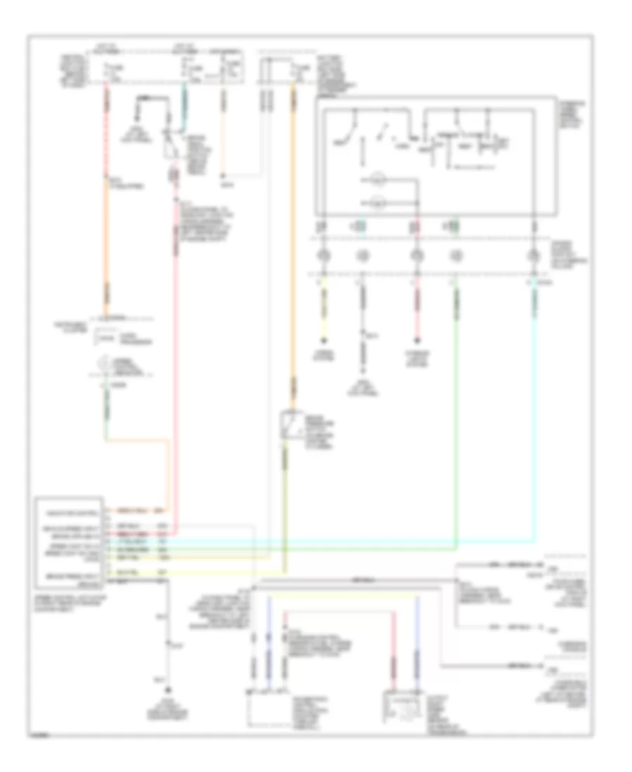
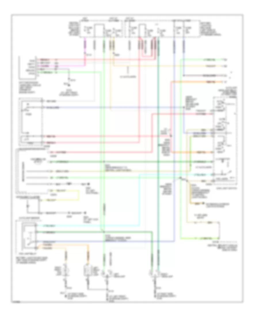
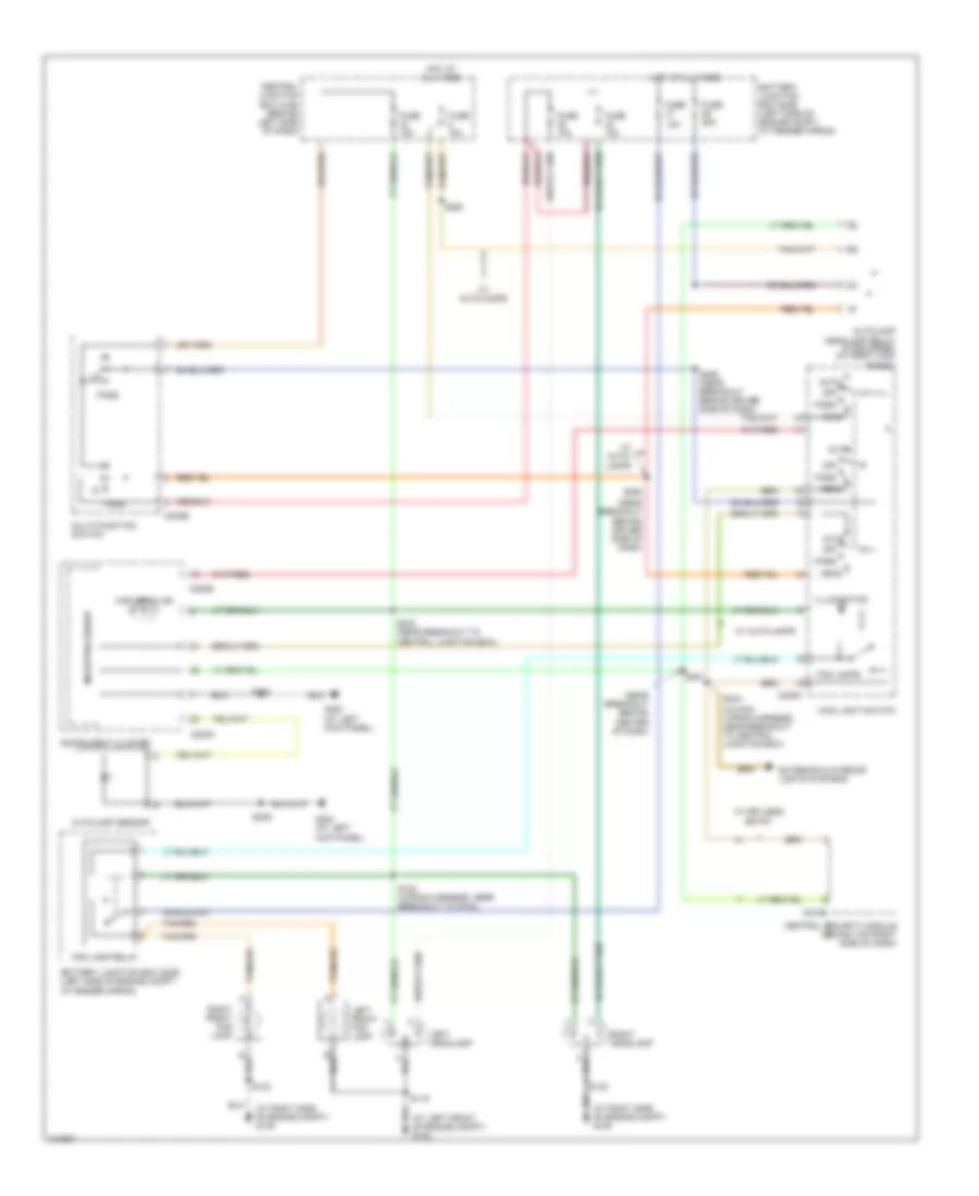
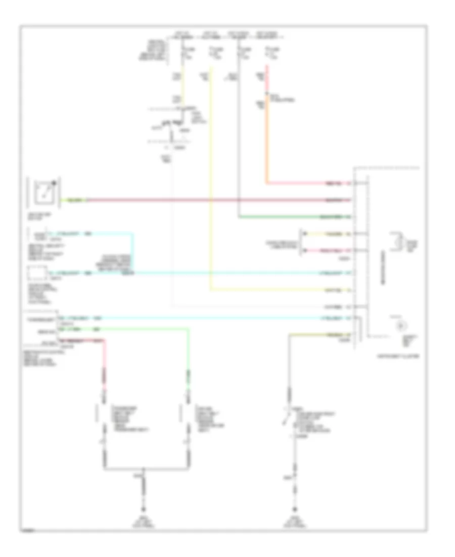
AIR CONDITIONING
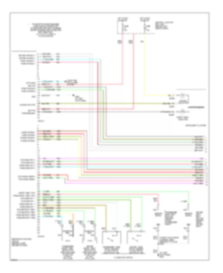
Manual A/C Wiring Diagram (1 of 2) for Ford Explorer Sport Trac 2005

List of elements for Manual A/C Wiring Diagram (1 of 2) for Ford Explorer Sport Trac 2005:
- (at left front of engine compartment) g103
- (at right side of engine compartment) g105
- (in main wiring harness, near breakout behind instrument cluster) s216
- (near breakout at right rear side of engine compt) s110
- 87a
- A/c clutch field coil (at left front of engine compartment)
- A/c clutch relay
- A/c clutch relay ctrl
- A/c compressor clutch diode
- A/c compressor cycling switch (in right side of engine compartment, on a/c accumulator)
- A/c compressor sw input
- A/c demand signal
- A/c high pressure switch (at front center of engine compartment)
- Auxiliary relay box 1 (right side of engine compartment)
- Battery junction box (bjb) (left side of engine compartment, at fender apron)
- Blower motor relay
- Central junction box (cjb) (behind left side of dash)
- Engine coolant temperature sensor (ect) (mounted on front of engine, left of throttle body)
- Fuse 10a
- Fuse 15a
- Fuse 40a
- Fuse 7.5a
- G101 (at left front of engine compartment)
- Heater blower motor (at right rear of engine compartment)
- High speed fan control relay
- Hot at all times
- Hot in run
- Hot in run or start
- Powertrain control module (pcm) (mounted through firewall)
- Red
- S110 (near breakout at right rear side of engine compt)
- S124 (in dash panel to headlamp junction wiring harness, near breakout to auxiliary relay box 1)
- S140 (in engine control sensor & fuel charge wiring harness, near breakout at rear center of engine)
- Sig rtn
- Vref
- W/ high series center console
- W/o high series center console
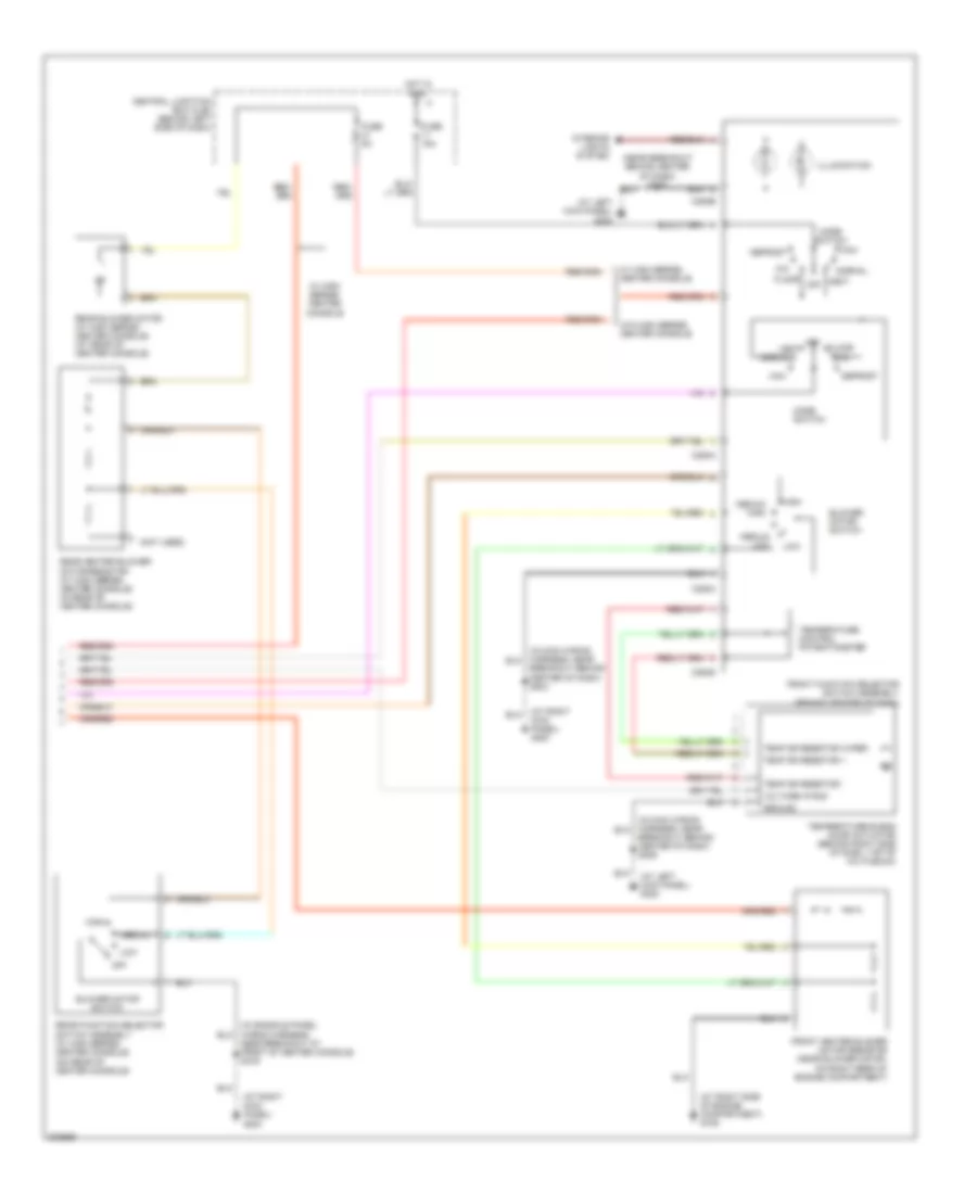
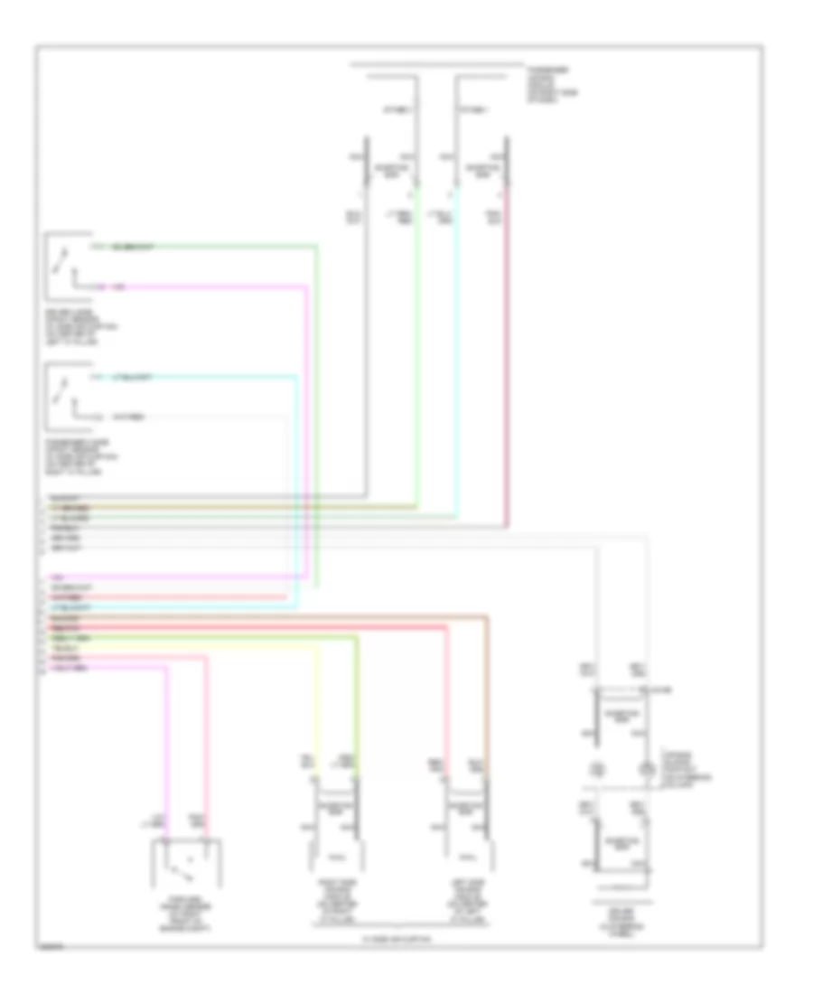
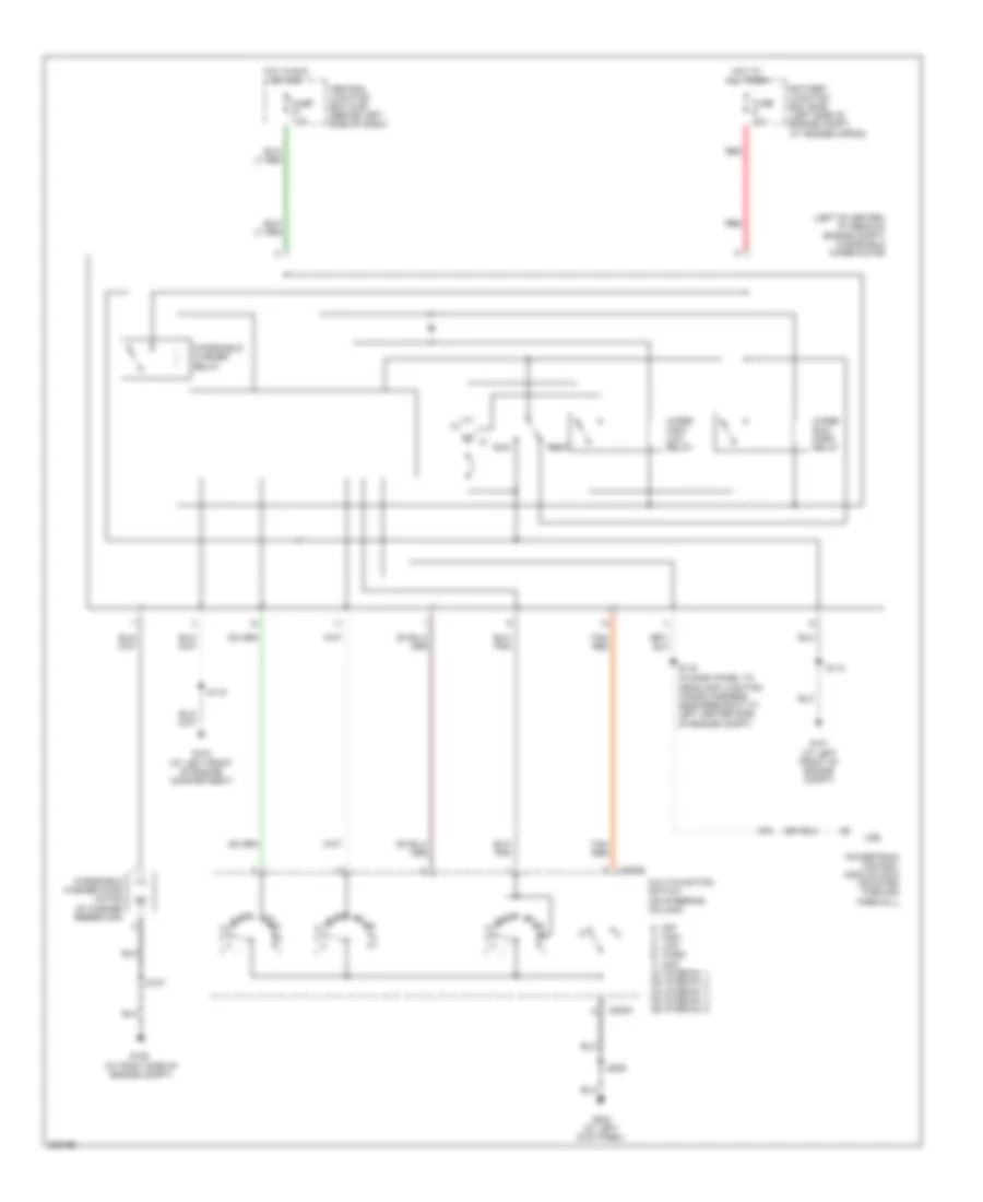
Manual A/C Wiring Diagram (2 of 2) for Ford Explorer Sport Trac 2005
List of elements for Manual A/C Wiring Diagram (2 of 2) for Ford Explorer Sport Trac 2005:
- (at left kick panel) g300
- (at right kick panel) g200
- (at right side of engine compartment) g106
- (near breakout behind center of dash) s206
- (not used)
- Blower motor switch
- Breakout behind center of dash) s203
- Breakout behind center of dash) s206
- C294a
- C294b
- C294c
- C294d
- Central junction box (cjb) (behind left side of dash)
- Defrost
- Floor
- Front function selector switch assembly (behind center of dash)
- Front heater blower motor resistor (near blower motor, on right rear of engine compartment)
- Fuse 15a
- Fuse 5a
- Ground
- High
- Hot in run
- Illumination
- Interior lights system
- Low
- Max
- Medium
- Medium high
- Medium low
- Mix
- Mode switch
- Near breakout at front of center console) s316
- Normal
- Off
- Rear blower motor (w/ high series center console) (at rear of center console)
- Rear function selector switch assembly (w/ high series center console) (on rear of center console)
- Rear heater blower motor resistor (w/ high series center console) (in rear of center console)
- Temp dr resistor +
- Temp dr resistor -
- Temp dr resistor wiper
- Temperature blend door actuator (behind right side of dash, top of a/c plenum)
- Temperature control potentiometer
- Vent
- Voltage in run
- W/ high series center console
- W/o high series center console
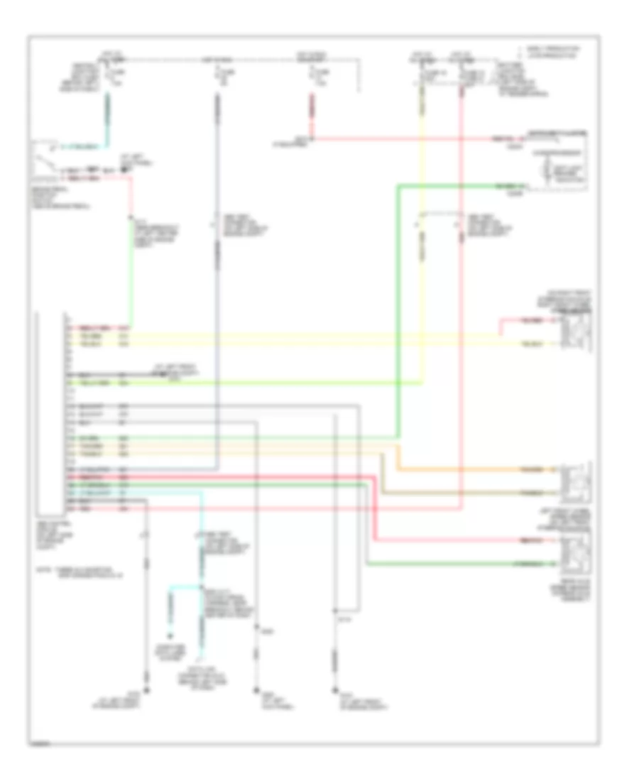
ANTI-LOCK BRAKES
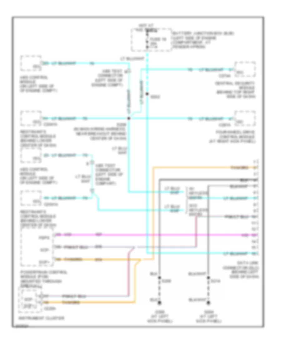
Anti-lock Brakes Wiring Diagram for Ford Explorer Sport Trac 2005
List of elements for Anti-lock Brakes Wiring Diagram for Ford Explorer Sport Trac 2005:
- (at left front of engine compt) g101
- (at left kick panel) g300
- (behind left side of dash)
- (on right front steering knuckle) right front wheel speed sensor
- Abs control module (on left side of engine compt)
- Abs test connector (on left side of engine compt)
- Anti-lock brakes indicator
- Bar across pins 8 & 16
- Battery junction box (bjb) (left side of engine compt, at fender apron)
- Brake pedal position switch (above brake pedal)
- C220a
- C220b
- Central junction box (cjb) (behind left side of dash)
- Computer data lines system
- Data link connector (dlc)
- Early production
- Fuse 16 50a
- Fuse 18 fuse 21 30a
- Fuse 5a
- Fuse 7.5a
- G102 (at left front of engine compt)
- G103 (at left front of engine compt)
- G300 (at left kick panel)
- Hot at all times
- Hot in run
- Hot in run or start
- Instrument cluster
- Late production
- Left front wheel speed sensor (on left front steering knuckle)
- Microprocessor
- Note: there is a shorting
- Rear axle speed sensor (on rear axle assembly)
- Red
- Red/pnk
- S117 (near breakout at left center side of engine compt)
- S118
- S218 (if equipped)
- S320
ANTI-THEFT
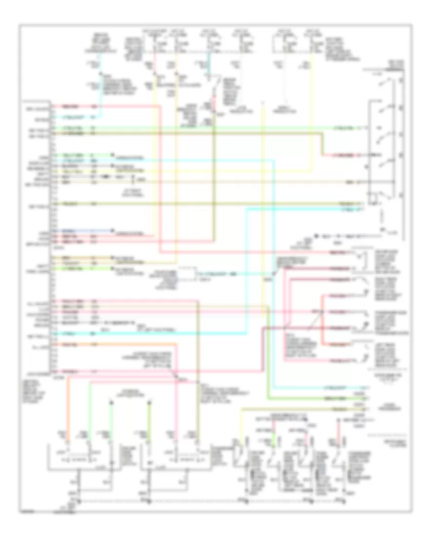
Forced Entry Wiring Diagram, with Keyless Entry for Ford Explorer Sport Trac 2005
List of elements for Forced Entry Wiring Diagram, with Keyless Entry for Ford Explorer Sport Trac 2005:
- (at left kick panel)
- (at right kick panel)
- (behind left side of dash) data link connector (dlc)
- (in body main wiring harness, near breakout at bottom of left "b" pillar)
- (near breakout at bottom of right "b" pillar)
- (near breakout behind center of dash)
- (near breakout behind driver side of dash)
- 1/2
- 3/4
- 5/6
- 57o
- 7/8
- 9/0
- All lock
- All unlock
- Autolamps)
- Battery junction box (bjb) (left side of engine compt, at fender apron)
- Bpp switch
- Brake pedal position switch (above brake pedal)
- C220a
- C220b
- C274a
- C274b
- C281a
- C526a
- C602a
- C715a
- C820a
- Central junction box (cjb) (behind left side of dash)
- Central security module (behind top right side of dash)
- Door ajar
- Door ajar ind
- Driver side door lock actuator (in rear bottom of driver door)
- Driver side door lock switch
- Driver side front door ajar switch (in rear top of c526b driver door) s500
- Driver side rear door ajar switch (in top rear of c715b left rear door)
- Drv unlock
- Early production
- Exterior lights system
- Four-wheel drive control module (at right kick panel)
- Fuse 15a
- Fuse 20a
- Fuse 7.5a
- G200
- G204 (at left kick panel)
- G300
- G300 (at left kick panel)
- Ground
- Horn
- Horns system
- Hot at all times
- Hot in start or run
- Illum
- Instrument cluster
- Interior lights system
- Iso bus
- Key pad com
- Key pad ill
- Key pad in
- Key pad switch assembly
- Late production
- Left rear door lock actuator (in bottom rear of left rear door)
- Lock
- Lock doors
- Micro- processor
- Park lamps
- Pass- enger side rear door ajar switch (in top c820b rear of right rear door)
- Passenger side door lock actuator (in bottom rear of passenger door)
- Passenger side door lock switch
- Passenger side front door ajar switch (in rear top of passenger door) c602b
- Power
- Reverse in
- Right rear door lock actuator (in bottom rear of right rear door)
- S203
- S208 (in main wiring harness, near breakout behind center of dash)
- S214
- S218 (if equipped)
- S220
- S227
- S250 (w/
- S302
- S310
- S311 (in body main wiring harness, near breakout at bottom of right "b" pillar)
- S313 (in body main wiring harness, near breakout at bottom of right "b" pillar)
- S314
- S320
- S500
- S600
- Unlk
- Unlk doors
- Vbatt
- Vpwr
Forced Entry Wiring Diagram, without Keyless Entry for Ford Explorer Sport Trac 2005
List of elements for Forced Entry Wiring Diagram, without Keyless Entry for Ford Explorer Sport Trac 2005:
- (in body main wiring harness, near breakout at bottom of right "b" pillar) s313
- (in body main wiring harness, near breakout at bottom of right "b" pillar) s314
- (in main wiring harness, near breakout behind center of dash) s205
- (near breakout at bottom of right "b" pillar) s311
- Auxiliary relay box 2 (under left side of dash, near steering column)
- Battery junction box (bjb) (left side of engine compt, at fender apron)
- Central junction box (cjb) (behind left side of dash)
- Door lock relay
- Door unlock relay
- Driver side door lock actuator (in rear bottom of driver door)
- Driver side door lock switch
- Early production
- Fuse 20a
- G200 (at right kick panel)
- G300 (at left kick panel)
- Hot at all times
- Interior lights system
- Late production
- Left rear door lock actuator (in bottom rear of left rear door)
- Lock
- Passenger side door lock actuator (in bottom rear of passenger door)
- Passenger side door lock switch
- Right rear door lock actuator (in bottom rear of right rear door)
- S203
- S310 (near breakout at bottom of left "b" pillar)
- S500
- S600
- Unlock
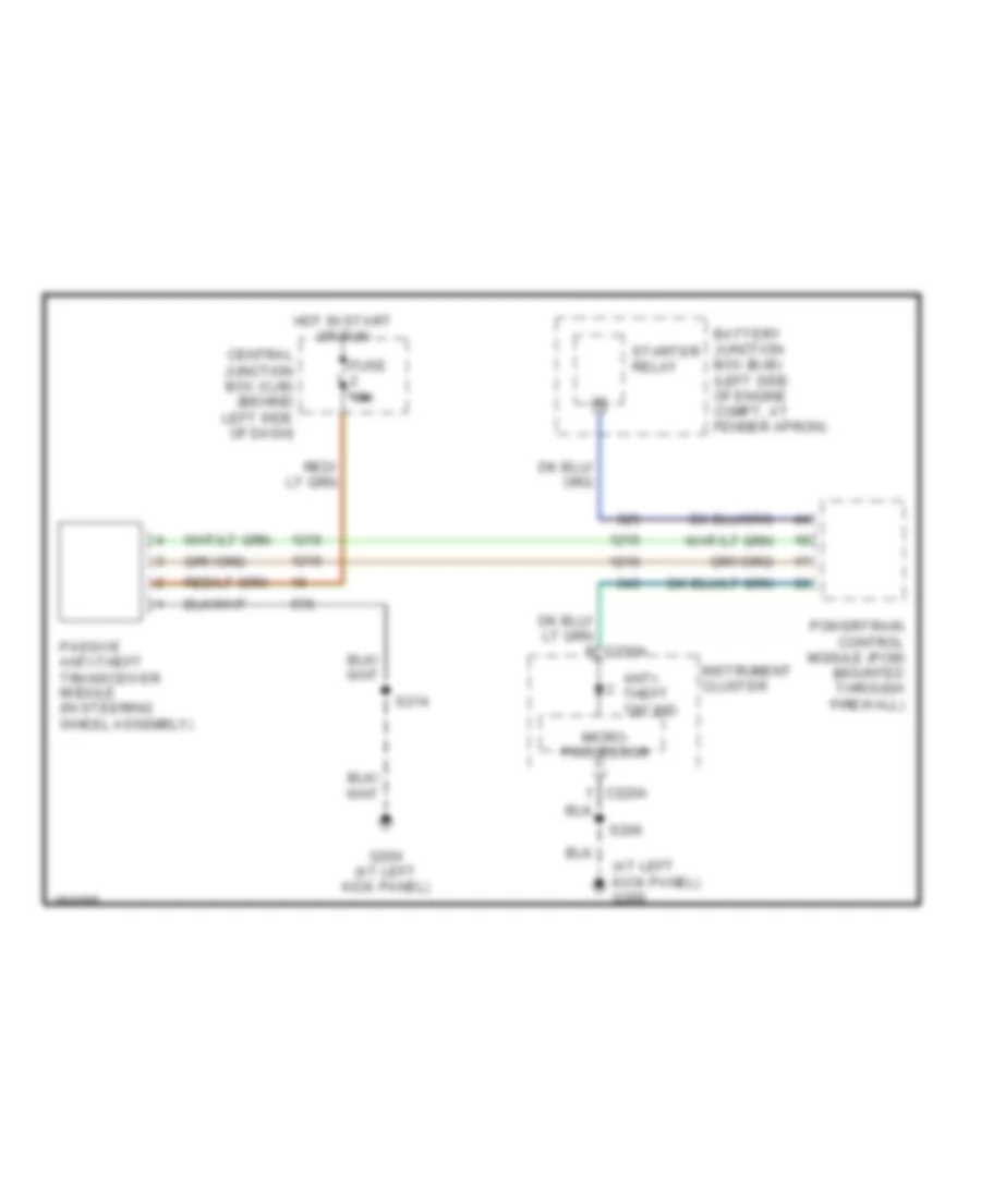
Passive Anti-theft Wiring Diagram for Ford Explorer Sport Trac 2005
List of elements for Passive Anti-theft Wiring Diagram for Ford Explorer Sport Trac 2005:
- (at left kick panel) g300
- Anti- theft "on" ind
- Battery junction box (bjb) (left side of engine compt, at fender apron)
- Central junction box (cjb) (behind left side of dash)
- Fuse 15a
- G204 (at left kick panel)
- Hot in start or run
- Instrument cluster
- Micro- processor
- Passive anti-theft transceiver module (in steering wheel assembly)
- Powertrain control module (pcm) (mounted through firewall)
- S206
- S214
- Starter relay
COMPUTER DATA LINES
Computer Data Lines Wiring Diagram for Ford Explorer Sport Trac 2005
List of elements for Computer Data Lines Wiring Diagram for Ford Explorer Sport Trac 2005:
- Abs control module (on left side of of engine compt)
- Abs test
- Abs test connector (left side of engine compart)
- Battery junction box (bjb) (left side of engine compartment, at fender apron)
- C2041a
- C220a
- C274a
- C281a
- Central security module (behind top right side of dash)
- Connector (left side of engine compt)
- Data link connector (dlc) (behind left side of dash)
- Feps
- Four-wheel drive control module (at right kick panel)
- Fuse 19 20a
- G204 (at left kick panel)
- G300 (at left kick panel)
- Hot at all times
- Instrument cluster
- Iso
- Iso c2041a
- Powertrain control module (pcm) (mounted through firewall)
- Restraints control module (behind lower center of dash)
- S202
- S206
- S208 (in main wiring harness, near breakout behind center of dash)
- S214
- Scp+
- Scp-
- W/ keyless entry
- W/o keyless entry
CRUISE CONTROL
Cruise Control Wiring Diagram for Ford Explorer Sport Trac 2005
List of elements for Cruise Control Wiring Diagram for Ford Explorer Sport Trac 2005:
- (if equipped)
- Air bag sliding contact (on steering column)
- Battery junction box (bjb) (left side of engine compartment, at fender apron)
- Brake pedal position switch (above brake pedal)
- Brake press input
- Brake pressure switch (on brake master cylinder)
- C218a
- C220a
- C220b
- C281b
- Central junction box (cjb) (behind left side of dash)
- Coast
- Four-wheel drive control module (at right kick panel)
- Fuse 2a
- Fuse 7.5a
- G105 (at right side of engine compartment)
- G204 (at left kick panel)
- G300 (at left kick panel)
- Ground
- Horn
- Horns system
- Hot at all times
- Hot in run
- Indicator control
- Instrument cluster
- Interior lights system
- Micro- processor
- Off
- Output shaft speed (oss) sensor (on rear of transmission)
- Overhead console
- Powertrain control module (pcm) (mounted through firewall)
- Red/
- Rest
- Resume
- S116 (in dash panel to headlamp junction wiring harness, near breakout at left center side of engine compartment)
- S117 (in dash panel to headlamp junction wiring harness, near breakout at left center side of engine compt)
- S127
- S143 (in engine control sensor & fuel charge wiring harness, near breakout to g100)
- S206
- S213 (in main wiring harness, near breakout to c215)
- S214
- S216
- S218
- Set/ acc
- Speed cont sw gnd
- Speed cont sw in
- Speed control actuator (in right rear of engine compartment)
- Speed control indicator
- Steering wheel/ speed control switch
- Vehicle speed input
- Vpwr
- Vss
- Windshield wiper motor (left of center, at rear of engine compt)
ENGINE PERFORMANCE
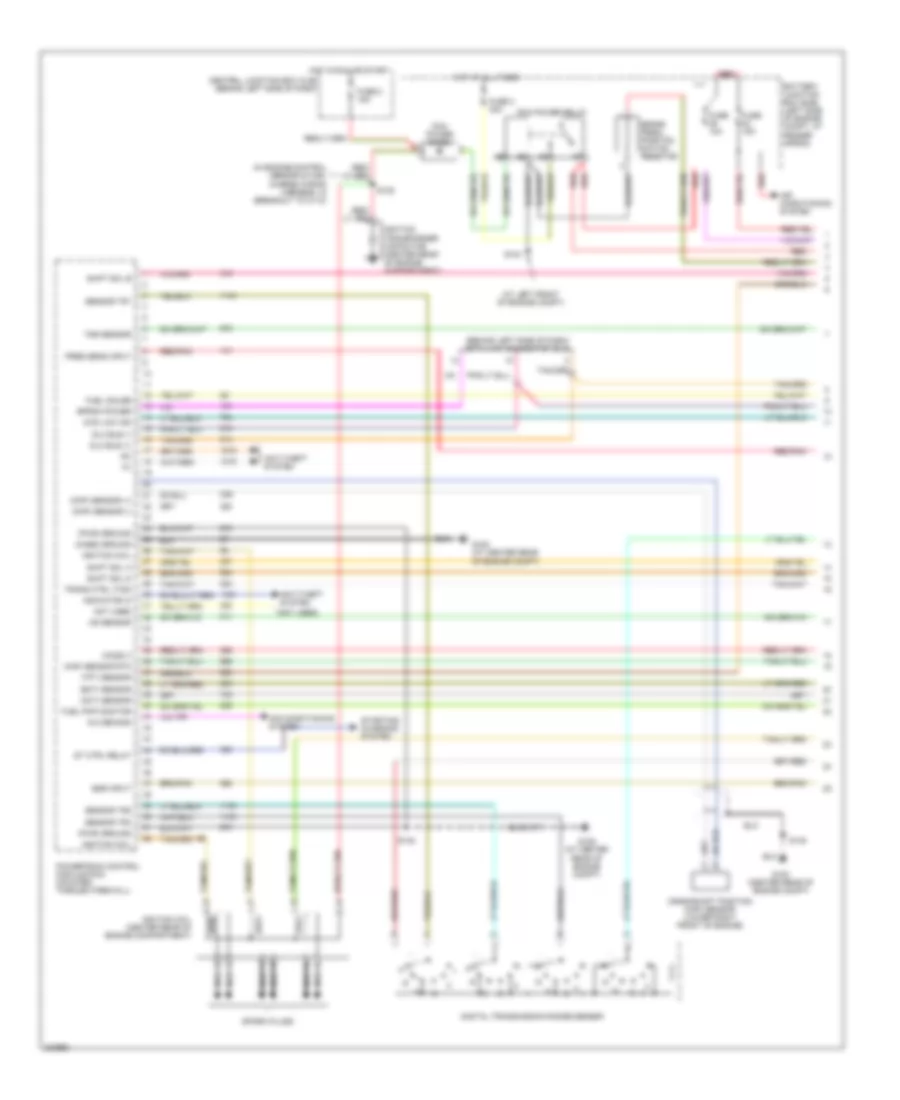
4.0L
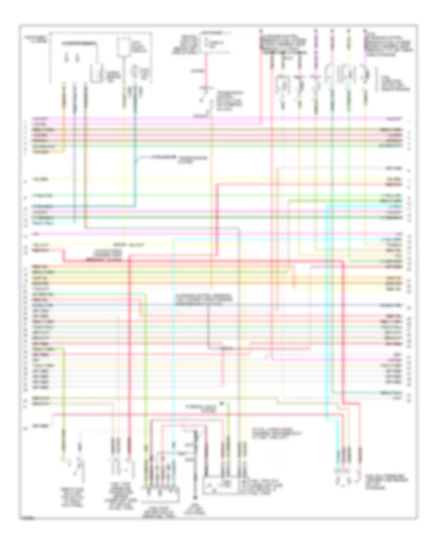
4.0L, Engine Performance Wiring Diagram (1 of 4) for Ford Explorer Sport Trac 2005
List of elements for 4.0L, Engine Performance Wiring Diagram (1 of 4) for Ford Explorer Sport Trac 2005:
- (act) sensor
- (at left front of engine compt)
- (behind left side of dash) data link connector (dlc)
- (case) ground
- (ckp) sensor (+)
- (ckp) sensor (-)
- (ect) sensor
- (ho2s) 3
- (in engine control sensor & fuel charge wiring harness, in breakout to c110)
- (maf) sensor rtn
- (not used)
- (pwr) ground
- (tft) sensor
- 4wd low ind
- A/c demand
- Air conditioning system
- Anti-theft system
- Battery junction box (bjb) (left side of engine compt, at fender apron)
- Brake pedal position switch resistor
- Central junction box (cjb) (behind left side of dash)
- Crankshaft position (ckp) sensor (lower right front of engine)
- Digital transmission range sensor
- Dlc bus (+)
- Dlc bus (-)
- Egr input
- Eprom power
- Fuel gauge
- Fuel pmp monitor
- Fuse 10a
- Fuse 15a
- Fuse 2 15a
- Fuse 3 30a
- G100 (at center rear of engine compt)
- G100 (center rear of engine compt)
- G104
- G109 (at center rear of engine compt)
- Hot at all times
- Hot in run or start
- Ignition coil
- Ignition coil (center rear of engine compartment)
- Ignition transformer capacitor (center rear of engine compartment)
- Indicator in
- Ks sensor
- Nca
- Not used
- Pcm power diode
- Pcm power relay
- Powertrain control module (pcm) (mounted through firewall)
- Pres sens input
- Red
- Red/pnk
- S105
- S145
- S148
- Sensor tr1
- Sensor tr2
- Sensor tr4
- Shift sol a
- Shift sol b
- Shift sol d
- Spark plugs
- St ctrl relay
- Starting/ charging system
- Trans ctrl (tcs)
- Tss sensor
4.0L, Engine Performance Wiring Diagram (2 of 4) for Ford Explorer Sport Trac 2005
List of elements for 4.0L, Engine Performance Wiring Diagram (2 of 4) for Ford Explorer Sport Trac 2005:
- (at left front of engine compt)
- (in dash panel to headlamp junction wiring harness, near breakout to c144)
- (in engine control sensor & fuel charge wiring harness, near breakout at left center side of engine)
- Battery junction box (bjb) (left side of engine compt, at fender apron)
- Differential pressure feedback egr (dpfe) sensor (on center left side of intake manifold)
- Egr vacuum regulator solenoid (on top of engine)
- Engine coolant temperature (ect) sensor (mounted on front of engine, left of throttle body)
- Evap canister purge valve (left front corner of engine compt)
- Evap emission (evap) canister vent valve (under left rear of vehicle)
- Fuel pump relay
- Fuse 15a
- Fuse 5 (early production) fuse 30 (late production) 20a
- G101
- Hot at all times
- Intermediate shaft speed (iss) sensor (on left side of transmission)
- Knock sensor (near right side of intake manifold)
- Output shaft speed (oss) sensor (rear of transmission)
- Red
- Red/pnk
- S111
- S137 (in engine control sensor & fuel charge wiring harness, near breakout to c110)
- S139
- Throttle position (tp) sensor (attached to throttle body)
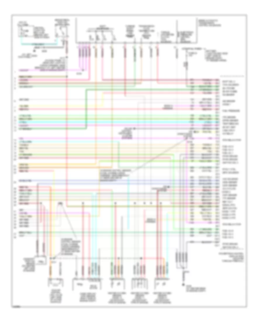
4.0L, Engine Performance Wiring Diagram (3 of 4) for Ford Explorer Sport Trac 2005
List of elements for 4.0L, Engine Performance Wiring Diagram (3 of 4) for Ford Explorer Sport Trac 2005:
- (in engine control sensor & fuel charge wiring harness, near breakout to g100)
- (in main wiring harness, near breakout to c215)
- (in tail lamps wiring harness, near breakout at fuel tank unit)
- 4wd low ind
- Anti- slosh module
- C220a
- C220b
- Central junction box (cjb) (behind left side of dash)
- Check engine ind
- Fpm
- Fuel injectors (on top left side of engine)
- Fuel pump driver module (near fuel tank)
- Fuel rail pressure/ temperature sensor (on top of engine)
- Fuel tank pressure transducer sensor (under left side of vehicle, in fuel tank)
- Fuel tank unit (under left side of vehicle, in fuel tank)
- Fuse 19 15a
- G300 (at left kick panel)
- Gnd
- Hot in run
- Inertia fuel shut-off (ifs) switch (at right kick panel)
- Instrument cluster
- Interior lights system
- Microprocessor
- Nca
- Nca s410
- Red/pnk
- Rev pol
- S143
- S222
- S405
- Scp +
- Scp -
- Tan
- Transmission control switch (tcs) (on steering column)
- Transmissions system
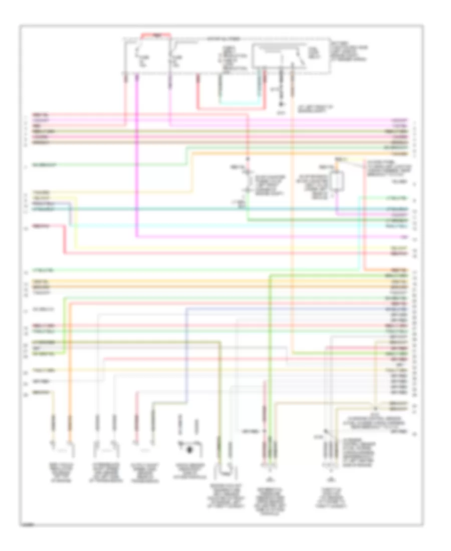
4.0L, Engine Performance Wiring Diagram (4 of 4) for Ford Explorer Sport Trac 2005
List of elements for 4.0L, Engine Performance Wiring Diagram (4 of 4) for Ford Explorer Sport Trac 2005:
- (at left kick panel)
- (b+) power
- (bpp) switch
- (cmp) sensor
- (dfpe) sensor
- (epc) solenoid
- (evap) purge
- (evap) vent
- (ho2s) 1
- (ho2s) 1 htr
- (ho2s) 2
- (ho2s) 2 htr
- (ho2s) 3 htr
- (iac) solenoid
- (in engine control sensor & fuel charge wiring harness, near breakout at rear center of engine compt)
- (in engine control sensor & fuel charge wiring harness, near breakout at rear center of engine)
- (maf) sensor
- (oss) sensor
- (pcm relay) pwr
- (pwr) ground
- (tcc) solenoid
- (tp) sensor
- (tr) sensor
- (vss) input
- 5r55e automatic transmission control solenoids
- A/c cycling
- A/c relay
- Air conditioning system
- Battery junction box (bjb) (left side of engine compt, at fender apron)
- Brake pedal position switch (bpp)
- Camshaft position sensor (on center left side of engine)
- Central junction box (cjb) (behind left side of dash)
- Cruise control, instrument cluster systems
- Electronic pressure control (epc) solenoid
- Ends in harness
- Fp rly ctrl
- Fuel inj 1
- Fuel inj 2
- Fuel inj 3
- Fuel inj 4
- Fuel inj 5
- Fuel inj 6
- Fuel pressure
- Fuse 24 10a
- Fuse 7.5a
- G109 (at center rear of engine compt)
- G3oo
- Heated oxygen sensor (ho2s) 11 (on exhaust pipe of engine)
- Heated oxygen sensor (ho2s) 12 (on exhaust pipe of engine)
- Heated oxygen sensor (ho2s) 21 (on exhaust pipe of engine)
- Hot at all times
- Idle air control (iac) valve (left side of intake manifold)
- Ignition coil 3
- Ignition coil 4
- Iss sensor
- Ks sensor
- Mass airflow (maf) sensor (right side of engine compt)
- Powertrain control module (pcm) (mounted through firewall)
- Red/pnk
- Ref volt
- S117 (in dash panel to headlamp junction wiring harness, near breakout at left center side of engine compt)
- S138
- S140
- S141
- S146
- S148
- S206
- Shift sol 3
- Shift solenoids
- Signal rtn
- Solid state
- Tan
- Temp sens sig
- Torque converter clutch (tcc) solenoid
- Transmission fluid temperature (tft) sensor
- Turbine shaft speed (tss) sensor
EXTERIOR LIGHTS
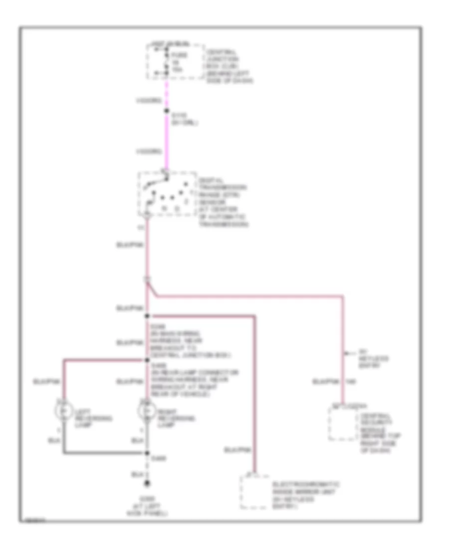
Back-up Lamps Wiring Diagram for Ford Explorer Sport Trac 2005
List of elements for Back-up Lamps Wiring Diagram for Ford Explorer Sport Trac 2005:
- Breakout at right rear of vehicle)
- Breakout to central junction box)
- C274a
- Central junction box (cjb) (behind left side of dash)
- Central security module (behind top right side of dash)
- Digital transmission range (dtr) sensor (at center of automatic transmission)
- Electrochromatic inside mirror unit (w/ keyless entry)
- Fuse 15a
- G300 (at left kick panel)
- Hot in run
- Left reversing lamp
- Right reversing lamp
- S115 (w/ drl)
- S406
- W/ keyless entry
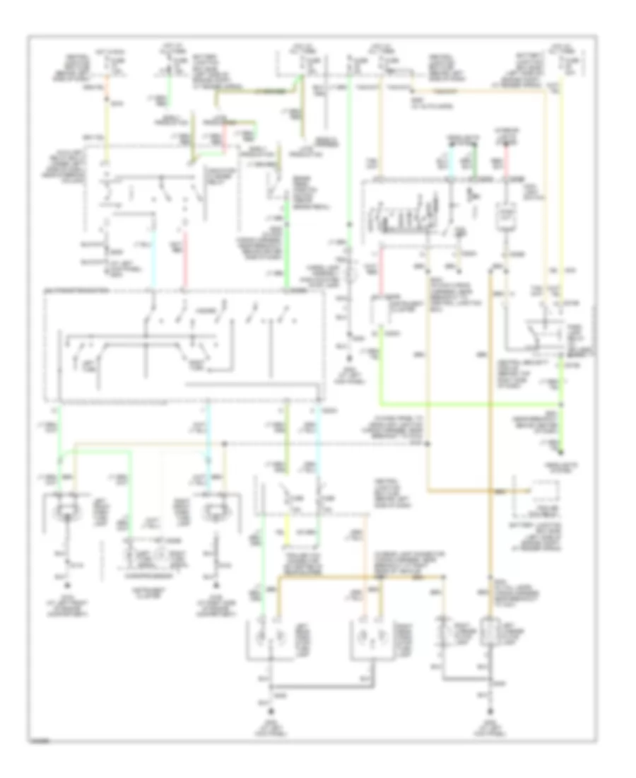
Exterior Lamps Wiring Diagram for Ford Explorer Sport Trac 2005
List of elements for Exterior Lamps Wiring Diagram for Ford Explorer Sport Trac 2005:
- (at left kick panel) g204
- (in dash panel to headlamp junction wiring harness, near breakout to g104) s121
- (in rear lamp connector wiring harness, near breakout at right rear of vehicle) s407
- Auto
- Auxiliary relay box 2 (under left side of dash, near steering column)
- Battery junction box (bjb) (left side of engine compt, at fender apron)
- Brake pedal position switch (above brake pedal)
- C202a
- C202b
- C205a
- C205b
- C220a
- C220b
- C274b
- Cargo lamp assembly (high mounted stop lamp)
- Central junction box (cjb) (behind left side of dash)
- Central security module (behind top right side of dash)
- Early production
- Ends in harness
- Fog lamp
- Fuse 15a
- Fuse 20a
- Fuse 5a
- Fuse 7.5a
- G102 (at left front of engine compartment)
- G106 (at right side of engine compartment)
- G300 (at left kick panel)
- Hazard
- Head
- Headlights system
- Hot at all times
- Hot in run
- Illum
- Indicator flasher relay
- Instrument cluster
- Interior lights system
- Late production
- Left front park/ turn lamp
- Left license plate lamp
- Left rear park/ stop/ turn lamp
- Left turn
- Left turn signal
- Main light switch
- Microprocessor
- Multi-function switch
- Nca
- Off
- Off park
- Park
- Park lamp relay (w/ keyless entry)
- Pwr out
- Right front park/ turn lamp
- Right license plate lamp
- Right rear park/ stop/ turn lamp
- Right turn
- Right turn signal
- S119
- S123
- S209
- S216
- S225 (in main wiring harness, near breakout behind driver side of dash)
- S244 (in main wiring harness, near breakout to central junction box)
- S250 (w/ autolamps)
- S251 (near breakout behind center of dash)
- S320
- S404 (in tail lamps wiring harness, near breakout to c421)
- S405
- S406
- Trailer tow connector (on center of rear bumper)
- Trailer tow relay
- Vpwr
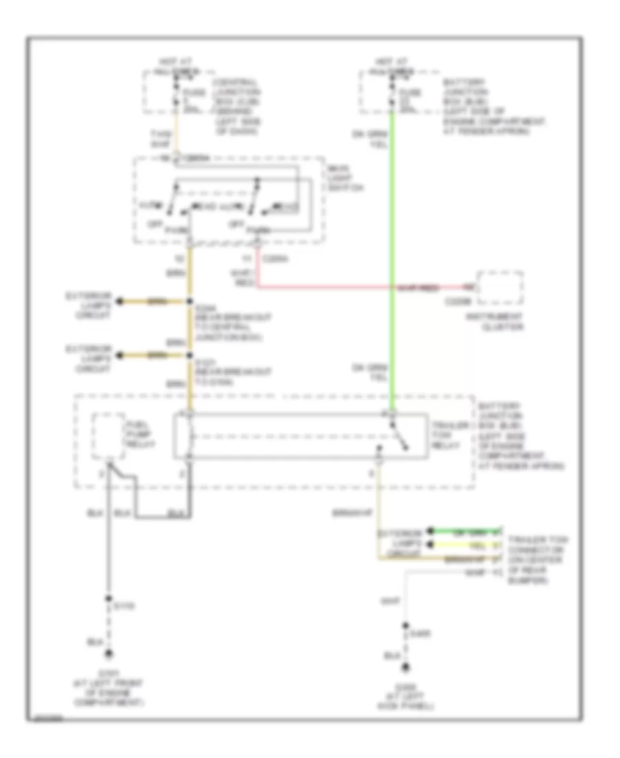
Trailer Tow Wiring Diagram for Ford Explorer Sport Trac 2005
List of elements for Trailer Tow Wiring Diagram for Ford Explorer Sport Trac 2005:
- Auto
- Battery junction box (bjb) (left side of engine compartment, at fender apron)
- C205a
- C220b
- Central junction box (cjb) (behind left side of dash)
- Exterior lamps circuit
- Fuel pump relay
- Fuse 15a
- G101 (at left front of engine compartment)
- G300 (at left kick panel)
- Head
- Hot at all times
- Instrument cluster
- Main light switch
- Off park
- S110
- S244 (near breakout to central junction box)
- S405
- Trailer tow connector (on center of rear bumper)
- Trailer tow relay
GROUND DISTRIBUTION
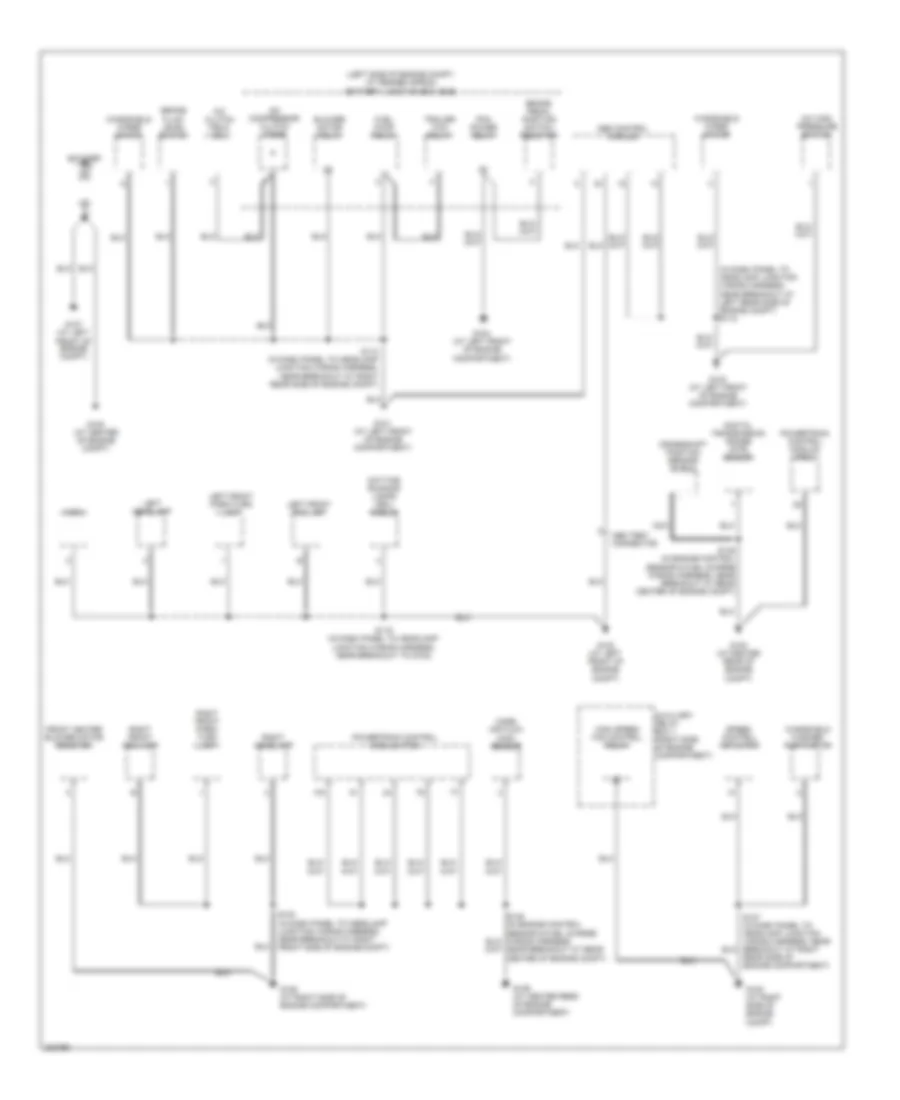
Ground Distribution Wiring Diagram (1 of 3) for Ford Explorer Sport Trac 2005
List of elements for Ground Distribution Wiring Diagram (1 of 3) for Ford Explorer Sport Trac 2005:
- (in dash panel to headlamp junction wiring harness, near breakout at left rear side of engine compt) s118
- (left side of engine compt, at fender apron) battery junction box (bjb)
- A/c clutch field coil
- A/c compressor clutch diode
- A/c high pressure switch
- Abs control module
- Abs test connector
- Auxiliary relay box 1 (right side of engine compartment)
- Battery
- Blower motor relay
- Brake fluid level switch
- Brake pedal position switch resistor
- Crankshaft position sensor shield
- Daytime running lamps (drl) module
- Digital transmission range (dtr) sensor
- Front heater blower motor resistor
- Fuel pump relay
- G100 (at center rear of engine compt)
- G101 (at left front of engine compartment)
- G102 (at left front of engine compt)
- G103 (at left front of engine compartment)
- G104 (at left front of engine compartment)
- G105 (at right side of engine compt)
- G106 (at right side of engine compartment)
- G107 (at left front of engine compt)
- G108 (at center of engine compt)
- G109 (at center rear of engine compartment)
- High speed fan control relay
- Horn
- Left front fog lamp
- Left front park/turn lamp
- Left headlamp
- Mass air flow (maf) sensor
- Nca
- Pcm power relay
- Powertrain control module (pcm)
- Rear side of engine compartment)
- Right front fog lamp
- Right front park/ turn lamp
- Right headlamp
- S110 (in dash panel to headlamp junction wiring harness, near breakout at right rear side of engine compt)
- S119 (in dash panel to headlamp junction wiring harness, near breakout to g102)
- S123 (in dash panel to headlamp junction wiring harness, near breakout at right front side of engine compt)
- S145 (in engine control sensor & fuel charge wiring harness, near breakout at rear center of engine compt)
- Speed control actuator
- Trailer tow relay
- Windshield washer pump motor
- Windshield wiper motor
Ground Distribution Wiring Diagram (2 of 3) for Ford Explorer Sport Trac 2005
List of elements for Ground Distribution Wiring Diagram (2 of 3) for Ford Explorer Sport Trac 2005:
- (not used)
- (under left side of dash, near steering column)
- (under left side of dash, near steering column) auxiliary relay box 2
- (w/ adrenalin audio) radio amplifier
- (w/o high series center console) power point
- Air bag sliding contact
- Ashtray illumination lamp
- Audiophile sound
- Audiophile sound system
- Autolamp sensor
- Auxiliary relay box 2
- Base audio
- C2031b
- C2041a
- C205b
- C2188a
- C218a
- C220a
- C274a
- C274b
- C281a
- C281b
- C290a
- C294c
- C3154b
- C466a
- Central security module
- Console power point
- Data link connector (dlc)
- Door lock relay
- Door unlock relay
- Driver seat belt buckle sensor
- Four-wheel drive control module
- Four-wheel drive switch
- Front cigar lighter
- Front function selector switch assembly
- Function selector switch assembly
- G200 (at right kick panel)
- G201 (at right kick panel)
- G202 (at right kick panel)
- G203 (at right kick panel)
- G204 (at left kick panel)
- G205 (at left kick panel)
- G301 (behind rear seats)
- G901 (at front of roof panel)
- Indicator flasher relay
- Instrument cluster
- Main light switch
- Nca
- Passenger seat belt buckle sensor
- Passive anti-theft transceiver module
- Pioneer ultimate audio
- Radio
- Rear
- Rear window adjust switch
- Rear window motor
- Restraints control module
- Roof opening panel module
- S203 (in main wiring harness, near breakout behind center of dash)
- S209 (in main wiring harness, near breakout at center console)
- S214 (in main wiring harness, near breakout behind instrument cluster)
- S300
- S316 (in console panel wiring harness, near breakout at front of center console)
- S326 (in body main wiring harness, near breakout to c316)
- Subwoofer amplifier
- W/ high series center console
- W/ xls
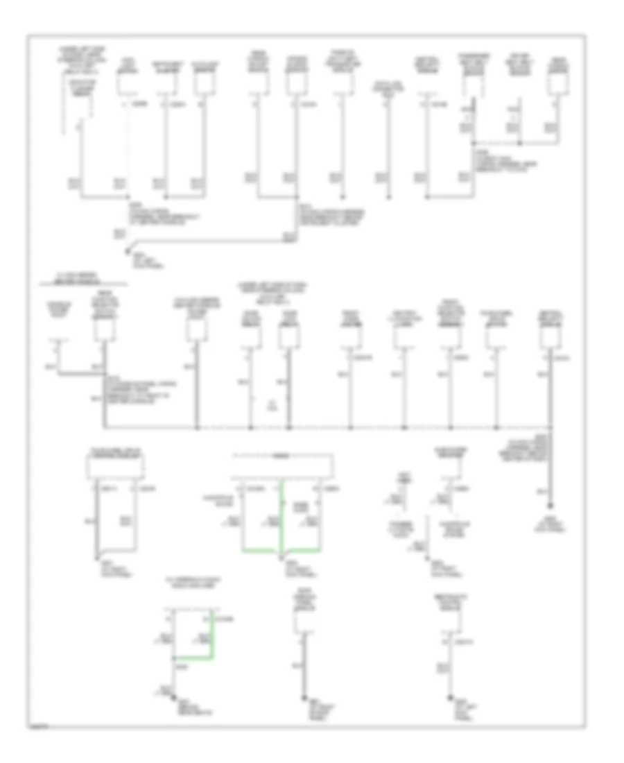
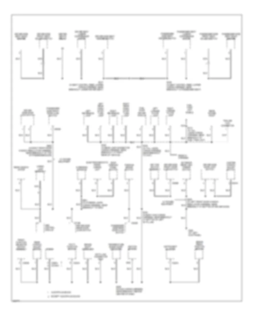
Ground Distribution Wiring Diagram (3 of 3) for Ford Explorer Sport Trac 2005
List of elements for Ground Distribution Wiring Diagram (3 of 3) for Ford Explorer Sport Trac 2005:
- Abs control module
- At bottom of left "b" pillar)
- Audiophile sound
- Brake pedal position switch
- Brake shift interlock
- C202a
- C2188a
- C220a
- C290a
- C294b
- C504a
- C526b
- C602b
- C715b
- C820b
- Cargo lamp assembly
- Data link connector (dlc)
- Driver seat lumbar compressor motor
- Driver side door lock switch
- Driver side front door ajar switch
- Driver side front seat adjust switch
- Driver side rear door ajar switch
- Driver side seat back heater
- Driver side seat heater switch
- Electrochromatic inside mirror unit
- Ends in harness
- Except audiophile sound
- Exterior rear view mirror switch
- Front function selector switch assembly
- Fuel pump driver module
- Fuel tank unit shield
- Fuel tank unit)
- G300 (at left kick panel)
- Gnd
- Heated seats relay
- Ignition switch
- Instrument cluster
- Key pad switch assembly
- Left license plate lamp
- Left rear park/ stop/ turn lamp
- Left reversing lamp
- Master window adjust switch
- Multi- function switch
- Nca
- Overhead console
- Parking brake switch
- Passenger seat lumbar compressor motor
- Passenger side front door ajar switch
- Passenger side front seat adjust switch
- Passenger side rear door ajar switch
- Passenger side seat back heater
- Passenger side seat heater switch
- Radio
- Rear power point
- Rear window adjust switch
- Rear window motor
- Right license plate lamp
- Right rear park/ stop/ turn lamp
- Right reversing lamp
- Roof opening panel switch
- S206 (in main wiring harness, near breakout behind center of dash)
- S336 (in seat control feed jumper wiring harness, near breakout in passenger seat)
- S337 (in seat control feed jumper wiring harness, near breakout under driver seat)
- S406 (in rear lamp connector wiring harness, near breakout at right rear of vehicle)
- S600 (in right front door window regulator harness, near breakout at top of passenger door)
- S901 (in interior lamps wiring harness, near breakout to c934)
- Temperature blend door actuator
- Trailer tow connector
- W/ power equipment
HEADLIGHTS
Headlights Wiring Diagram, with DRL for Ford Explorer Sport Trac 2005
List of elements for Headlights Wiring Diagram, with DRL for Ford Explorer Sport Trac 2005:
- (at left front of engine compt) g102
- (at right side of engine compt) g106
- (in main wiring harness, near breakout to central junction box)
- (near breakout behind center of dash)
- (near breakout behind driver side of dash)
- (near breakout behind driver side of dash) s226
- 15a
- Auto
- Autolamp headlamp relay (if equipped) (at right kick panel)
- Autolamp sensor
- Battery junction box (bjb) (left side of engine compt, at fender apron)
- C202b
- C205a
- C220a
- C220b
- C274b
- Central junction box (cjb) (behind left side of dash)
- Central security module (behind top right side of dash)
- Daytime running lamps (drl) module (left front corner of engine compt)
- Exterior & interior lights systems
- Fog lamp relay
- Fog lamps
- Fuse
- Fuse 10a
- Fuse 15a
- Fuse 25a
- G102 (at left front of engine compt)
- G204 (at left kick panel)
- G300 (at left kick panel)
- Ground
- Head
- High beam ind
- Hot at all times
- Hot in run
- Illumination
- Instrument cluster
- Left front fog lamp
- Left headlamp
- Main light switch
- Microprocessor
- Multi-function switch
- Off
- Park
- Pass
- Pwr
- Right front fog lamp
- Right headlamp
- S115
- S119
- S120 (wiring harness, near breakout to g104)
- S123
- S206
- S209
- S243 (near breakout to central junction box)
- S244
- S250
- S251
- S252
- Vbatt
- Vpwr
- W/ auto- lamps
- W/ autolamps
- W/ keyless entry
Headlights Wiring Diagram, without DRL for Ford Explorer Sport Trac 2005
List of elements for Headlights Wiring Diagram, without DRL for Ford Explorer Sport Trac 2005:
- (at left front of engine compt) g102
- (at right side of engine compt) g106
- (in main wiring harness, near breakout to central junction box)
- (near breakout behind center of dash)
- (near breakout behind driver side of dash)
- 15a
- Auto
- Autolamp headlamp relay (if equipped) (at right kick panel)
- Autolamp sensor
- Battery junction box (bjb) (left side of engine compt, at fender apron)
- C202b
- C205a
- C220a
- C220b
- C274b
- Central junction box (cjb) (behind left side of dash)
- Central security module (behind top right side of dash)
- Exterior & interior lights systems
- Fog lamp relay
- Fog lamps
- Fuse
- Fuse 10a
- Fuse 15a
- Fuse 25a
- G204 (at left kick panel)
- G300 (at left kick panel)
- Head
- High beam ind
- Hot at all times
- Illumination
- Instrument cluster
- Left front fog lamp
- Left headlamp
- Main light switch
- Microprocessor
- Multi-function switch
- Off
- Park
- Pass
- Right front fog lamp
- Right headlamp
- S119
- S120 (wiring harness, near breakout to g104)
- S123
- S206
- S209
- S226 (near breakout behind driver side of dash)
- S243 (near breakout to central junction box)
- S244
- S250
- S251
- S252
- W/ auto- lamps
- W/ autolamps
- W/ keyless entry
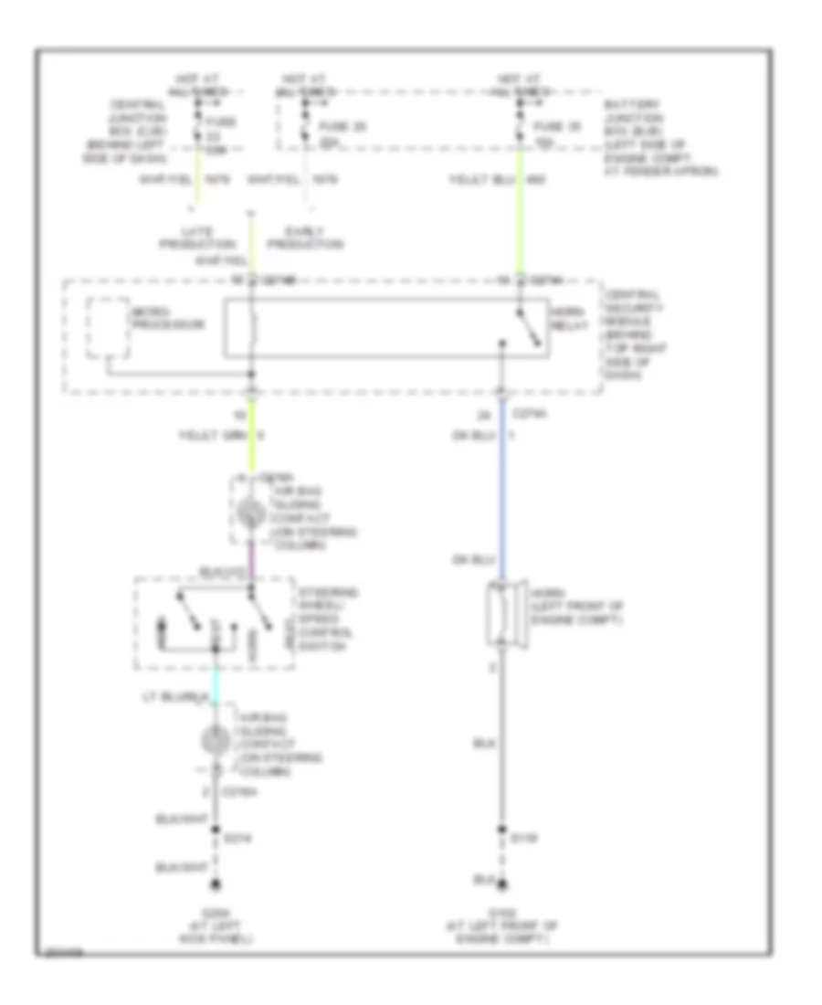
HORN
Horn Wiring Diagram, with Keyless Entry for Ford Explorer Sport Trac 2005
List of elements for Horn Wiring Diagram, with Keyless Entry for Ford Explorer Sport Trac 2005:
- 15a
- 20a
- Air bag sliding contact (on steering column)
- Battery junction box (bjb) (left side of engine compt, at fender apron)
- C218a
- C274a
- C274b
- Central junction box (cjb) (behind left side of dash)
- Central security module (behind top right side of dash)
- Early production
- Fuse
- Fuse 26
- Fuse 35
- G102 (at left front of engine compt)
- G204 (at left kick panel)
- Horn
- Horn (left front of engine compt)
- Horn relay
- Hot at all times
- Late production
- Micro- processor
- Rest
- S119
- S214
- Steering wheel/ speed control switch
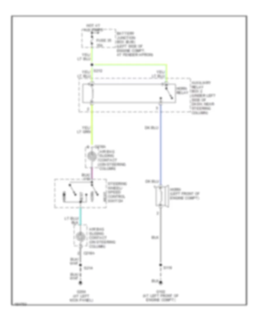
Horn Wiring Diagram, without Keyless Entry for Ford Explorer Sport Trac 2005
List of elements for Horn Wiring Diagram, without Keyless Entry for Ford Explorer Sport Trac 2005:
- 15a
- Air bag sliding contact (on steering column)
- Auxiliary relay box 2 (under left side of dash, near steering column)
- Battery junction box (bjb) (left side of engine compt, at fender apron)
- C218a
- Fuse 35
- G102 (at left front of engine compt)
- G204 (at left kick panel)
- Horn
- Horn (left front of engine compt)
- Horn relay
- Hot at all times
- Rest
- S119
- S214
- Steering wheel/ speed control switch
INSTRUMENT CLUSTER
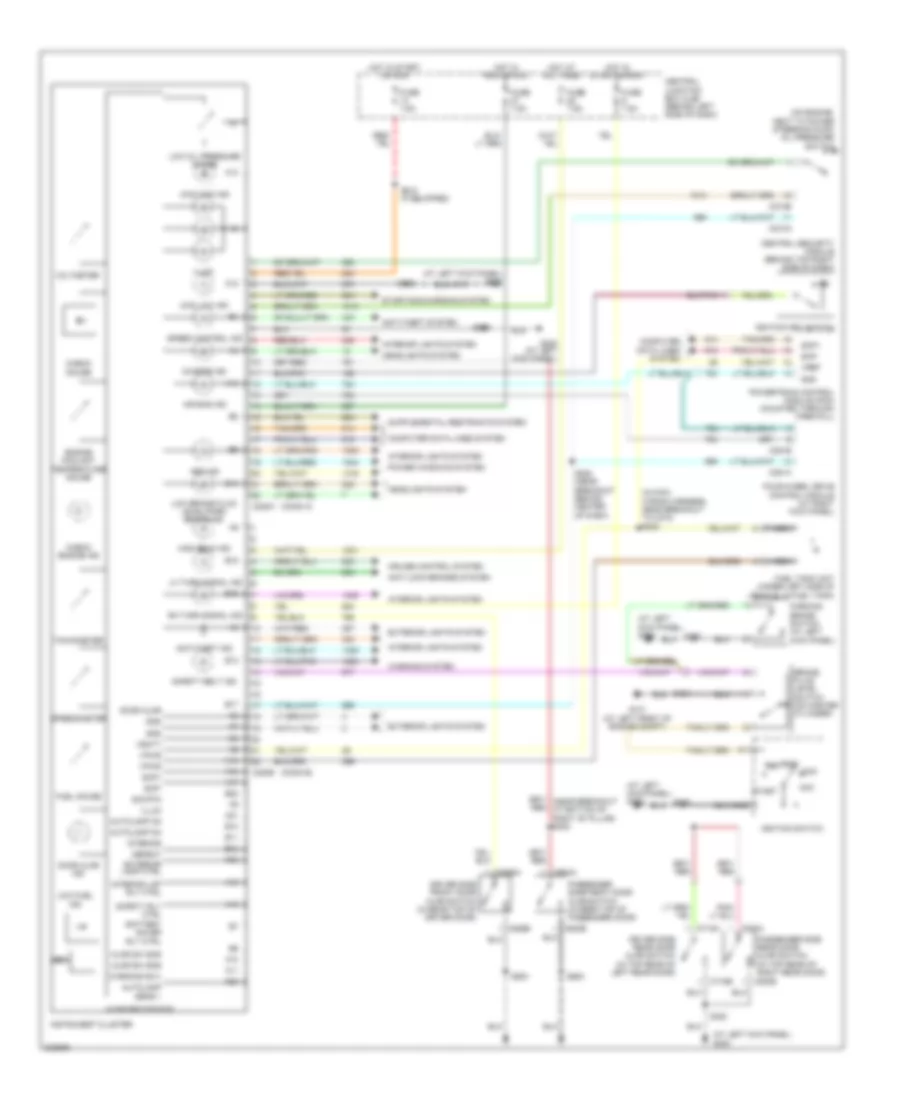
Instrument Cluster Wiring Diagram for Ford Explorer Sport Trac 2005
List of elements for Instrument Cluster Wiring Diagram for Ford Explorer Sport Trac 2005:
- (at left kick panel) g204
- (at left kick panel) g300
- (conn a)
- (conn b)
- (in main wiring harness, near breakout to c215) s222
- (on engine, next to power steering pump) oil pressure switch
- 4wd high ind
- 4wd low ind
- A10
- A11
- A12
- A13
- A14
- A15
- A16
- A17
- A18
- A19
- A20
- A21
- A22
- Abs ind
- Acc
- Air bag ind
- Ajar sw sns
- Anti-lock brakes system
- Anti-theft ind
- Anti-theft system
- Autolamp on
- Autolamp sens +
- B10
- B11
- B12
- B13
- B14
- B17
- B18
- B19
- B21
- B22
- Battery saver rly ctrl
- Brake fluid level switch (on master cylinder)
- C220a
- C220b
- C274a
- C274b
- C281a
- C281b
- C526a
- C526b
- C602a
- C602b
- C715a
- C715b
- C820a
- C820b
- Central junction box (cjb) (behind left side of dash)
- Central security module (behind top right side of dash)
- Charge ind
- Check engine ind
- Check gauge
- Computer data lines system
- Cruise control system
- Defeat
- Door ajar
- Door ajar ind
- Driver side front door ajar switch (in rear top of driver door)
- Driver side rear door ajar switch (in top rear of left rear door)
- Engine coolant temperature gauge
- Exterior lamp ctrl
- Exterior lights system
- Four-wheel drive control module (at right kick panel)
- Fuel gauge
- Fuel tank unit (under left side of vehicle, in fuel tank)
- Fuse 7.5a
- G101 (at left front of engine compt)
- G300 (at left kick panel)
- Gnd
- Headlights system
- High beam ind
- Hot at all times
- Hot in run or acc
- Hot in start or run
- Ignition key switch
- Ignition switch
- Illum
- Instrument cluster
- Interior
- Interior lights system
- Interior lmp rly ctrl
- Lh turn signal ind
- Lock
- Low brake fluid level/park brake ind
- Low fuel ind
- Low oil pressure gauge
- Microprocessor
- Nca
- Off
- Parking brake switch (at left kick panel)
- Passenger side front door ajar switch (in rear top of passenger door)
- Passenger side rear door ajar switch (in top rear of right rear door)
- Power windows system
- Powertrain control module (pcm) (mounted through firewall)
- Red
- Rh turn signal ind
- Run
- S110
- S206
- S209
- S218 (if equipped)
- S220 (near breakout behind center of dash)
- S320
- S500
- S600
- Safety belt ind
- Safety rly ctrl
- Scp+
- Scp-
- Sig rtn
- Speed control ind
- Speedometer
- Start
- Starting/charging system
- Tachometer
- Vbatt
- Voltmeter
- Vpwr
- Vref
- Warning sw+
- Warning system
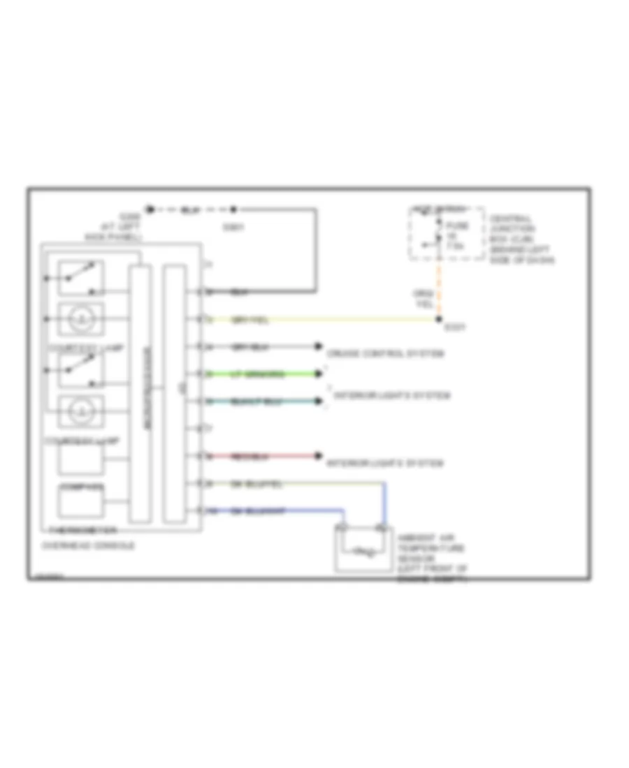
Overhead Console Wiring Diagram for Ford Explorer Sport Trac 2005
List of elements for Overhead Console Wiring Diagram for Ford Explorer Sport Trac 2005:
- Ambient air temperature sensor (left front of engine compt)
- Central junction box (cjb) (behind left side of dash)
- Compass
- Courtesy lamp
- Cruise control system
- Fuse 7.5a
- G300 (at left kick panel)
- Hot in run
- I/o
- Interior lights system
- Microprocessor
- Overhead console
- S331
- S901
- Thermometer
INTERIOR LIGHTS
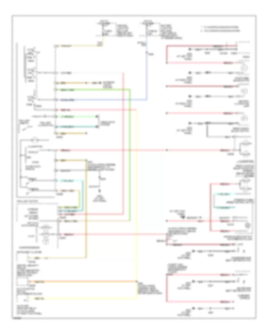
Courtesy Lamps Wiring Diagram for Ford Explorer Sport Trac 2005
List of elements for Courtesy Lamps Wiring Diagram for Ford Explorer Sport Trac 2005:
- (at left kick panel) g300
- (in body main wiring harness, near breakout to g300) s327
- (in body main wiring harness, near breakout to g300) s329
- (under left side of dash, near steering column) auxiliary relay box 2
- Auto
- Battery saver relay
- C205a
- C205b
- C220a
- C220b
- C274b
- C931a
- C931b
- C932a
- C932b
- Cargo lamp assembly
- Cargo lamps
- Central junction box (cjb) (behind left side of dash)
- Central security module (w/ keyless entry) (behind top right side of dash)
- Defeat
- Driver side door lock switch
- Exterior lights system
- Front interior/ map lamps assembly
- Fuse 26 10a
- Fuse 5 15a
- G204 (at left kick panel)
- G300 (at left kick panel)
- Gnd
- Head
- High mounted stoplamp
- Hot at all times
- Illum
- Illumination
- Illumination circuit
- Instrument cluster
- Interior
- Interior lamp
- Interior lamps relay
- Main light switch
- Map lamps
- Microprocessor
- Nca
- Off
- Overhead console
- Park
- Park or head
- Passenger side door lock switch
- Pulse width module
- Pwr out
- Rear interior/ map lamps assembly
- Rly ctrl
- S209
- S244 (near breakout to central junction box)
- S320
- S500
- S600
- Vpwr
- W/ overhead console
- W/o overhead console
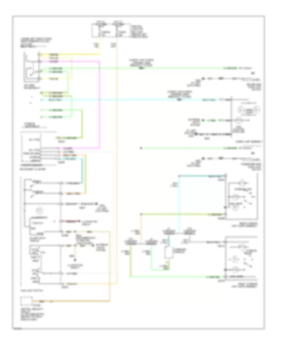
Instrument Illumination Wiring Diagram for Ford Explorer Sport Trac 2005
List of elements for Instrument Illumination Wiring Diagram for Ford Explorer Sport Trac 2005:
- (at left kick panel) g204
- (in body main wiring harness, near breakout to g300) s330
- (in main wiring harness, near breakout behind center of dash) s217
- Air bag sliding contact (on steering column)
- Ashtray illumination lamp
- Auto
- Autolamp headlamp relay (w/ autolamps) (at right kick panel)
- Battery junction box (bjb) (left side of engine compt, at fender apron)
- C202b
- C205a
- C205b
- C2188a
- C218a
- C220a
- C220b
- C274b
- C290a
- C294b
- Central junction box (cjb) (behind left side of dash)
- Central security module (w/ keyless entry) (behind top right side of dash)
- Defeat
- Driver side seat heater switch
- Exterior lights system
- Fog lamp illumination
- Fog lamp switch
- Four-wheel drive switch
- Front function selector switch assembly (behind center of dash)
- Fuse 29 25a
- Fuse 5 15a
- G200 (at right kick panel)
- G204 (at left kick panel)
- G300 (at left kick panel)
- Gnd
- Head
- Headlights system
- Hot at all times
- Hot in park or head
- Hot with autolamps on
- Illum
- Illumination
- Instrument cluster
- Interior
- Main light switch
- Microprocessor
- Multi-function switch (on steering column)
- Off
- Overhead console
- Park
- Passenger side seat heater switch
- Pulse width module
- Pwr out
- Radio
- Rear window adjust switch
- S203
- S206
- S209
- S214
- S226
- S244 (in main wiring harness, near breakout to central junction box)
- S252 (in main wiring harness, near breakout behind driver side of dash)
- S336
- S337
- S901
- Steering wheel/ speed control switch
- Vpwr
- W/ audiophile sound system
- W/o audiophile sound system
- Xlt
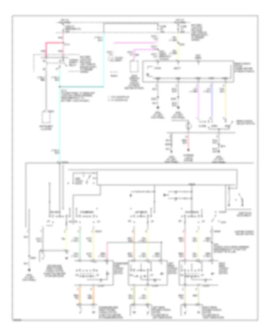
POWER DISTRIBUTION
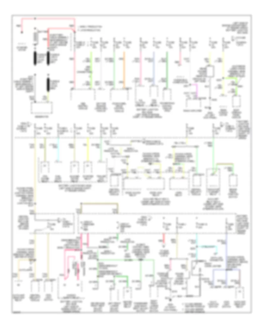
Power Distribution Wiring Diagram (1 of 2) for Ford Explorer Sport Trac 2005
List of elements for Power Distribution Wiring Diagram (1 of 2) for Ford Explorer Sport Trac 2005:
- (at right kick panel)
- (in battery cable assembly, red near breakout at left center side of engine compt) s130
- (in dash panel to headlamp junction wiring harness, near breakout to battery junction box) s147
- (in interior lamps wiring harness, near breakout at front of roof)
- (in main wiring harness, near breakout behind center of dash) s250
- (in main wiring harness, near breakout behind driver side of dash) s226
- (in main wiring harness, near breakout in steering wheel) s211
- (in seat control feed jumper wiring harness, near breakout to c315) s335
- (left side of engine compartment, at fender apron) battery junction box (bjb)
- (near breakout under driver seat) s338
- (not used)
- 15a
- 20a
- A/c clutch relay
- Abs control module
- Abs test connector
- Autolamp headlamp relay
- Auxiliary relay box 2 (under left side of dash, near steering column)
- Battery
- Battery junction box (bjb) (left side of engine compt, at fender apron)
- Blower motor relay
- Brake pedal position switch
- C202b
- C2031a
- C2031b
- C205a
- C274a
- C274b
- C281a
- C3154b
- Center console
- Central junction box (cjb) (behind left side of dash)
- Central security module
- Circuit breaker 47a 20a
- Circuit breaker 47b 20a
- Console power point (in front of center console)
- Data link connector
- Daytime running lamps (drl) module
- Door lock relay
- Door unlock relay
- Driver side front seat adjust switch
- Early production
- Fog lamp relay
- Four-wheel drive control module
- From fuse 10 (diagram 1 of 2)
- From fuse 22 (diagram 2 of 2)
- From fuse 34 (diagram 1 of 2)
- Front cigar lighter
- Fuel pump relay
- Fuse 10a
- Fuse 15a
- Fuse 18 fuse 21 30a
- Fuse 19
- Fuse 20a
- Fuse 25a
- Fuse 30a
- Fuse 4
- Fuse 40a
- Fuse 5 fuse 30 20a
- Fuse 50a
- G200
- G300 (at left kick panel)
- Generator
- Harness, near breakout in steering wheel) s212
- Heated seats relay
- Horn relay
- Indicator flasher relay
- Late production
- Left front lumbar adjust switch
- Main light switch
- Multi- function switch
- Nca
- Passenger side front seat adjust switch
- Pcm power relay
- Pnk
- Pnk (near breakout to battery junction box) (early production) s114
- Power point (under center of dash)
- Powertrain control module (pcm)
- Production early
- Production late
- Radio amplifier
- Rear power point (rear of vehicle, on left side)
- Rear window motor
- Red
- Right front lumbar adjust switch
- Roof opening panel module
- S131 (in battery cable assembly, near breakout at left center side of engine compt)
- S202
- S203
- S301
- S303
- S316
- S405
- S900
- Starter motor
- Starter relay
- To fuse (diagram 1 of 2)
- To fuse 1 (diagram 2 of 2)
- To fuse 14 (diagram 1 of 2)
- To s228 (diagram 2 of 2)
- Trailer tow relay
- W/ autolamps
- W/ high series
- W/o high series
- Window safety relay
- Windshield wiper motor
- Xls
- Xlt
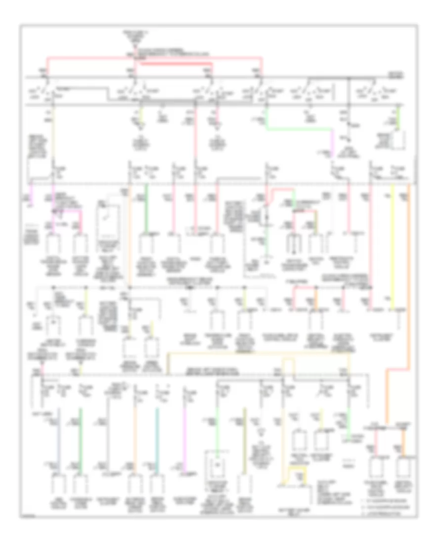
Power Distribution Wiring Diagram (2 of 2) for Ford Explorer Sport Trac 2005
List of elements for Power Distribution Wiring Diagram (2 of 2) for Ford Explorer Sport Trac 2005:
- (behind left side of dash) central junction box (cjb)
- (in main wiring harness, near breakout to c215) (if equipped) s218
- (in main wiring harness, near breakout to steering column) red
- (near breakout behind instrument cluster) s216
- (not used)
- Abs control module
- Acc
- Auxiliary relay box 2 (under left side of dash, near steering column)
- Battery junction box (bjb) (left side of engine compt, at fender apron)
- Battery saver relay
- Brake fluid level switch
- Brake pedal position switch
- Brake pressure switch
- Brake shift interlock
- C2041a
- C2188a
- C220a
- C220b
- C274a
- C281a
- C281b
- C290a
- C294a
- C466a
- Central security module
- Central security module (if equipped)
- Daytime running lamps (drl) module
- Digital transmission range (dtr) sensor
- Electro- chromatic inside mirror unit (if equipped)
- Except xls
- Exterior rear view mirror switch
- Four-wheel drive control module
- From fuse 14 (diagram 1 of 2)
- From fuse 5 (diagram 1 of 2)
- From ignition switch (diagram 2 of 2)
- Front function selector switch assembly
- Fuse 0a
- Fuse 10a
- Fuse 15a
- Fuse 20a
- Fuse 2a
- Fuse 5a
- Fuse 7.5a
- G300 (at left kick panel)
- Gnd
- Heated seats relay
- If equipped
- Ignition coil
- Ignition switch
- Ignition transformer capacitor 1
- Indicator flasher relay
- Instrument cluster
- Late production
- Lock
- Neutral tow indicator
- Off
- Overhead console
- Passive anti-theft transceiver module
- Pcm power diode
- Pcm power relay
- Radio
- Red
- Restraints control module
- Run
- S206
- S228
- Speed control actuator
- Sta
- Start
- Subwoofer amplifier
- Temperature blend door actuator
- To fuse 27 (diagram 2 of 2)
- To fuse 35 (diagram 2 of 2)
- To s211 (xls) central security module (xlt) (diagram 1 of 2)
- Trans- mission control switch
- W/ audiophile sound
- W/ drl
- W/o audiophile sound
- Windshield wiper motor
- Xls
POWER DOOR LOCKS
Power Door Locks Wiring Diagram, with Keyless Entry for Ford Explorer Sport Trac 2005
List of elements for Power Door Locks Wiring Diagram, with Keyless Entry for Ford Explorer Sport Trac 2005:
- (at left kick panel)
- (at right kick panel)
- (behind left side of dash) data link connector (dlc)
- (in body main wiring harness, near breakout at bottom of left "b" pillar)
- (near breakout at bottom of right "b" pillar)
- (near breakout behind center of dash)
- (near breakout behind driver side of dash)
- 1/2
- 3/4
- 5/6
- 57o
- 7/8
- 9/0
- All lock
- All unlock
- Autolamps)
- Battery junction box (bjb) (left side of engine compt, at fender apron)
- Bpp switch
- Brake pedal position switch (above brake pedal)
- C220a
- C220b
- C274a
- C274b
- C281a
- C526a
- C602a
- C715a
- C820a
- Central junction box (cjb) (behind left side of dash)
- Central security module (behind top right side of dash)
- Door ajar
- Door ajar ind
- Driver side door lock actuator (in rear bottom of driver door)
- Driver side door lock switch
- Driver side front door ajar switch (in rear top of c526b driver door) s500
- Driver side rear door ajar switch (in top rear of c715b left rear door)
- Drv unlock
- Early production
- Exterior lights system
- Four-wheel drive control module (at right kick panel)
- Fuse 15a
- Fuse 20a
- Fuse 7.5a
- G200
- G204 (at left kick panel)
- G300
- G300 (at left kick panel)
- Ground
- Horn
- Horns system
- Hot at all times
- Hot in start or run
- Illum
- Instrument cluster
- Interior lights system
- Iso bus
- Key pad com
- Key pad ill
- Key pad in
- Key pad switch assembly
- Late production
- Left rear door lock actuator (in bottom rear of left rear door)
- Lock
- Lock doors
- Micro- processor
- Park lamps
- Pass- enger side rear door ajar switch (in top c820b rear of right rear door)
- Passenger side door lock actuator (in bottom rear of passenger door)
- Passenger side door lock switch
- Passenger side front door ajar switch (in rear top of passenger door) c602b
- Power
- Reverse in
- Right rear door lock actuator (in bottom rear of right rear door)
- S203
- S208 (in main wiring harness, near breakout behind center of dash)
- S214
- S218 (if equipped)
- S220
- S227
- S250 (w/
- S302
- S310
- S311 (in body main wiring harness, near breakout at bottom of right "b" pillar)
- S313 (in body main wiring harness, near breakout at bottom of right "b" pillar)
- S314
- S320
- S500
- S600
- Unlk
- Unlk doors
- Vbatt
- Vpwr
Power Door Locks Wiring Diagram, without Keyless Entry for Ford Explorer Sport Trac 2005
List of elements for Power Door Locks Wiring Diagram, without Keyless Entry for Ford Explorer Sport Trac 2005:
- (in body main wiring harness, near breakout at bottom of right "b" pillar) s313
- (in body main wiring harness, near breakout at bottom of right "b" pillar) s314
- (in main wiring harness, near breakout behind center of dash) s205
- (near breakout at bottom of right "b" pillar) s311
- Auxiliary relay box 2 (under left side of dash, near steering column)
- Battery junction box (bjb) (left side of engine compt, at fender apron)
- Central junction box (cjb) (behind left side of dash)
- Door lock relay
- Door unlock relay
- Driver side door lock actuator (in rear bottom of driver door)
- Driver side door lock switch
- Early production
- Fuse 20a
- G200 (at right kick panel)
- G300 (at left kick panel)
- Hot at all times
- Interior lights system
- Late production
- Left rear door lock actuator (in bottom rear of left rear door)
- Lock
- Passenger side door lock actuator (in bottom rear of passenger door)
- Passenger side door lock switch
- Right rear door lock actuator (in bottom rear of right rear door)
- S203
- S310 (near breakout at bottom of left "b" pillar)
- S500
- S600
- Unlock
POWER MIRRORS
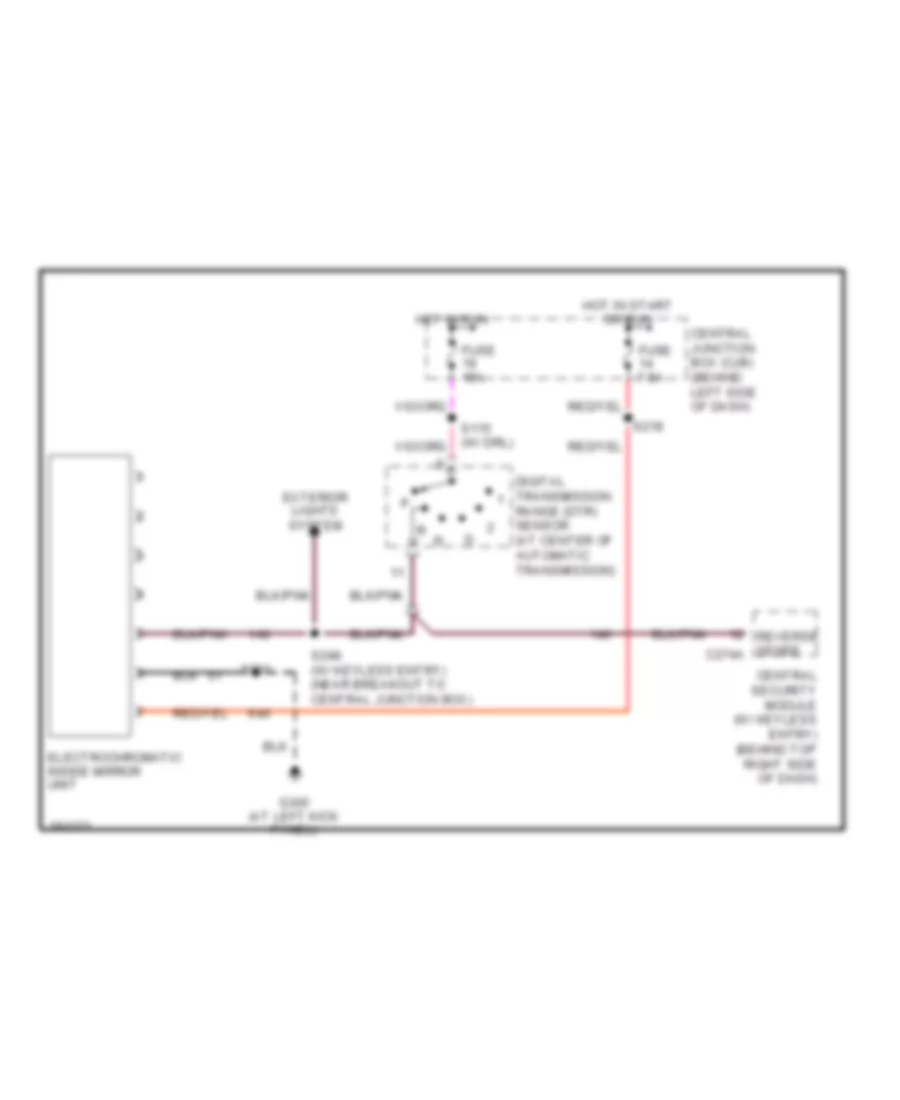
Electronic Day/Night Mirror Wiring Diagram for Ford Explorer Sport Trac 2005
List of elements for Electronic Day/Night Mirror Wiring Diagram for Ford Explorer Sport Trac 2005:
- Central junction box (cjb) (behind left side of dash)
- Central security module (w/ keyless entry) (behind top right side of dash)
- Digital transmission range (dtr) sensor (at center of automatic transmission)
- Electrochromatic inside mirror unit
- Exterior lights system
- Fuse 15a
- Fuse 7.5a
- G300 (at left kick panel)
- Hot in run
- Hot in start or run
- Reverse sense c274a
- S218
- S248 (w/ keyless entry) (near breakout to central junction box)
- S901
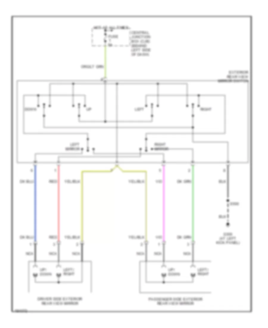
Power Mirrors Wiring Diagram for Ford Explorer Sport Trac 2005
List of elements for Power Mirrors Wiring Diagram for Ford Explorer Sport Trac 2005:
- Central junction box (cjb) (behind left side of dash)
- Down
- Driver side exterior rear view mirror
- Exterior rear view mirror switch
- Fuse 5a
- G300 (at left kick panel)
- Hot at all times
- Left
- Left mirror
- Left/ right
- Nca
- Passenger side exterior rear view mirror
- Red
- Right
- Right mirror
- S500
- Up/ down m
POWER SEATS
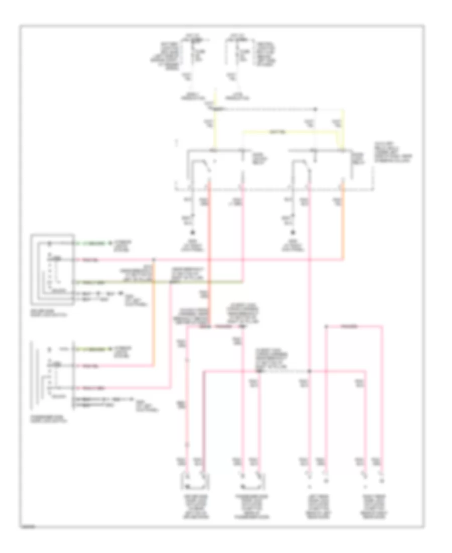
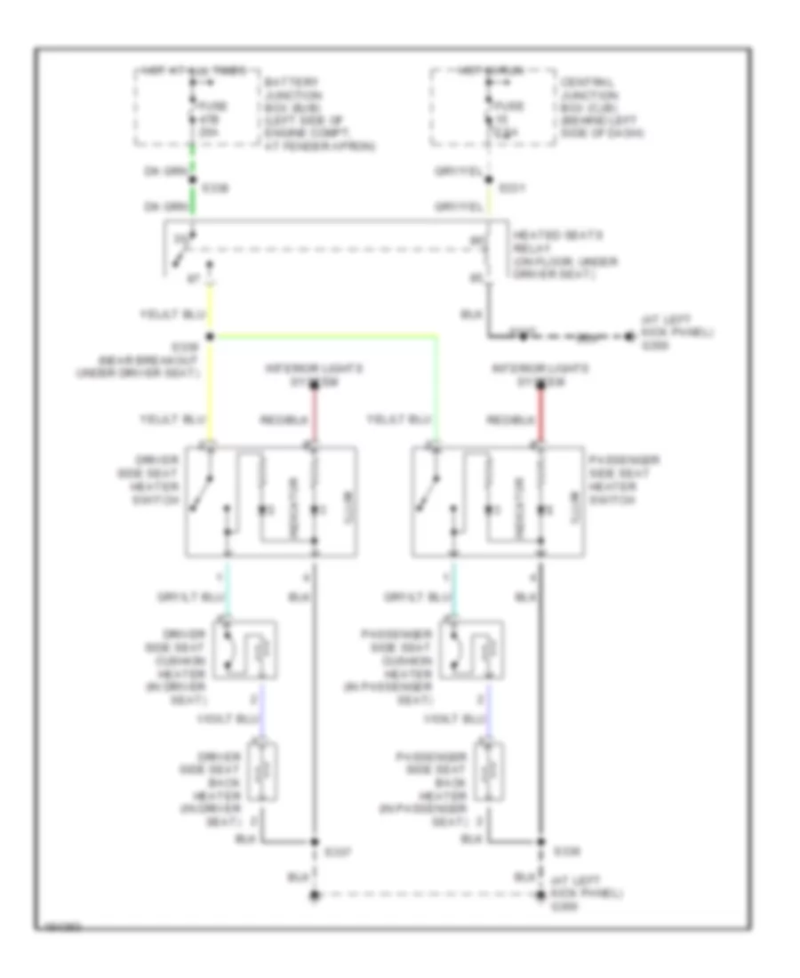
Heated Seats Wiring Diagram for Ford Explorer Sport Trac 2005
List of elements for Heated Seats Wiring Diagram for Ford Explorer Sport Trac 2005:
- (at left kick panel) g300
- Battery junction box (bjb) (left side of engine compt, at fender apron)
- Central junction box (cjb) (behind left side of dash)
- Driver side seat back heater (in driver seat)
- Driver side seat cushion heater (in driver seat)
- Driver side seat heater switch
- Fuse 47b 20a
- Fuse 7.5a
- Heated seats relay (on floor, under driver seat)
- Hot at all times
- Hot in run
- Illum
- Indicator
- Interior lights system
- Passenger side seat back heater (in passenger seat)
- Passenger side seat cushion heater (in passenger seat)
- Passenger side seat heater switch
- S331
- S336
- S337
- S338
- S339 (near breakout under driver seat)
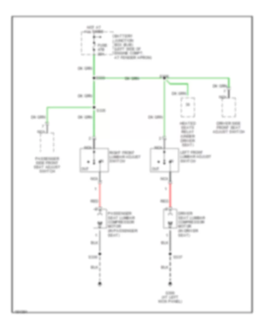
Lumbar Wiring Diagram for Ford Explorer Sport Trac 2005
List of elements for Lumbar Wiring Diagram for Ford Explorer Sport Trac 2005:
- Battery junction box (bjb) (left side of engine compt, at fender apron)
- Driver seat lumbar compressor motor (in driver seat)
- Driver side front seat adjust switch
- Fuse 47b 20a
- G300 (at left kick panel)
- Heated seats relay (under driver seat)
- Hot at all times
- Left front lumbar adjust switch
- Nca
- Out
- Passenger seat lumbar compressor motor (in passenger seat)
- Passenger side front seat adjust switch
- Red
- Right front lumbar adjust switch
- S333
- S335
- S336
- S337
- S338
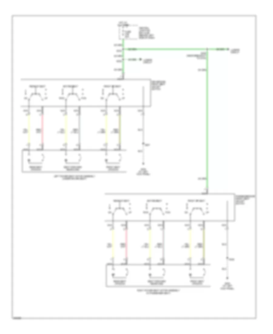
Power Seats Wiring Diagram for Ford Explorer Sport Trac 2005
List of elements for Power Seats Wiring Diagram for Ford Explorer Sport Trac 2005:
- Central junction box (cjb) (behind left side of dash)
- Driver side front seat adjust switch
- Entire seat
- Front of seat
- Front seat up/down
- Fuse 47b 20a
- Fwd
- G300 (at left kick panel)
- Hot at all times
- Left power seat motor assembly (under driver seat)
- Lumbar circuit
- Nca
- Passenger side front seat adjust switch
- Rear of seat
- Rear seat up/down
- Right power seat motor assembly (in passenger seat)
- Rwd
- S333
- S335 (near breakout to c315)
- S336
- S337
- S338
- Seat forward/ rearward
POWER TOP/SUNROOF
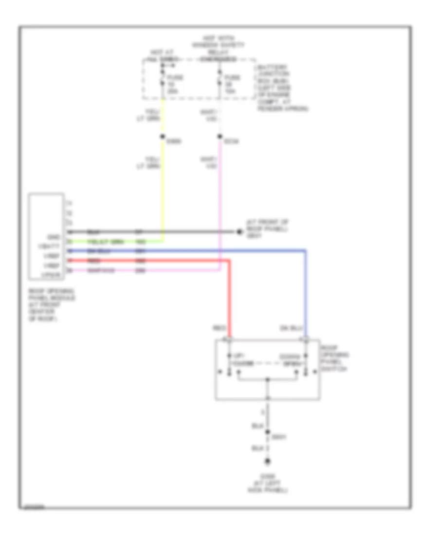
Power Top/Sunroof Wiring Diagram for Ford Explorer Sport Trac 2005
List of elements for Power Top/Sunroof Wiring Diagram for Ford Explorer Sport Trac 2005:
- (at front of roof panel) g901
- Battery junction box (bjb) (left side of engine compt, at fender apron)
- Down/ open
- Fuse 10a
- Fuse 20a
- G300 (at left kick panel)
- Gnd
- Hot at all times
- Hot with window safety relay energized
- Red
- Roof opening panel module (at front center of roof)
- Roof opening panel switch
- S334
- S900
- S901
- Up/ close
- Vbatt
- Vpwr
- Vref
POWER WINDOWS
Power Windows Wiring Diagram for Ford Explorer Sport Trac 2005
List of elements for Power Windows Wiring Diagram for Ford Explorer Sport Trac 2005:
- (not used)
- Battery junction box (bjb) (left side of engine compt, at fender apron)
- Breakout to c510)
- C2188a c290a
- C220a
- C504a
- C504b
- Circuit breaker 47a 20a
- Close
- Driver
- Driver side front power window motor (in bottom center of driver door)
- Fuse 10a
- Fuse 20a
- G204 (at left kick panel)
- G300 (at left kick panel)
- Gnd
- Hot at all times
- Illum
- Instrument cluster
- Interior lights system
- Left rear
- Left rear power window motor (in center of left rear door)
- Left rear window adjust switch
- Lock
- Master window adjust switch
- One- touch down
- One-touch down relay
- Open
- Passenger
- Passenger side front power window motor (in bottom center of passenger door)
- Passenger side window adjust switch
- Pnk
- Radio
- Rear window adjust switch
- Rear window motor (under center of rear window)
- Right rear
- Right rear power window motor (in center of right rear door)
- Right rear window adjust switch
- Roof opening panel module (at front center of roof)
- S113 (in dash panel to headlamp junction wiring harness, near breakout to battery junction box)
- S114
- S206
- S214
- S303
- S320
- S321 (in body main wiring harness, near breakout at bottom of right "b" pillar)
- S326
- S500
- Vbatt
- Vent
- Vpwr
- Vref
- W/ audiophile
- W/o audiophile
- Window safety relay
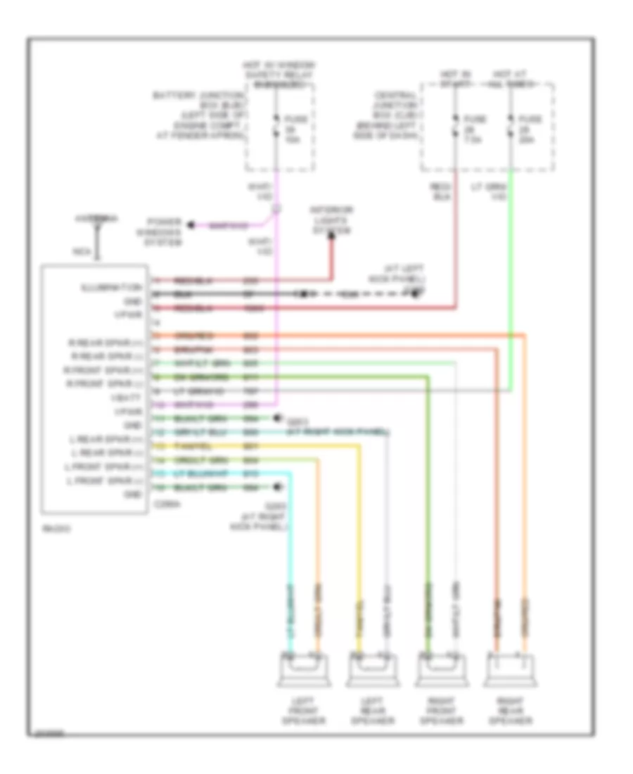
RADIO
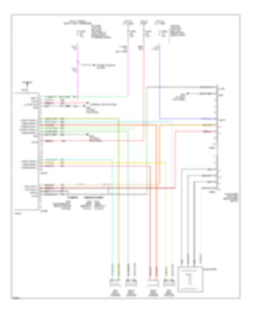
Base Radio Wiring Diagram for Ford Explorer Sport Trac 2005
List of elements for Base Radio Wiring Diagram for Ford Explorer Sport Trac 2005:
- (+)
- (-)
- (near breakout behind center of dash)
- (near breakout to c264)
- Amp enable/ clip detect
- Antenna
- Battery junction box (bjb) (left side of engine compt, at fender apron)
- C290a
- C290b
- C3154a
- C3154b
- Central junction box (cjb) (behind left side of dash)
- Clip detect
- Fuse 10a
- Fuse 20a
- Fuse 50a
- Fuse 7.5a
- G203 (at right kick panel)
- G300 (at left kick panel)
- G301 (behind rear seats)
- Gnd
- Ground
- Hot at all times
- Hot in start
- Hot w/ window safety relay energized
- Illum
- Interior lights system
- Late production
- Left front speaker
- Left rear speaker
- Lf +
- Lf -
- Lr +
- Lr -
- Nca
- Radio
- Radio amplifier (behind rear seats)
- Rf +
- Rf -
- Right front speaker
- Right rear speaker
- Rr +
- Rr -
- S206
- S255 (near breakout to c264)
- S256
- S260
- S261 (near breakout behind center of dash)
- S300
- S301
- S340
- S341 (near breakout to c264)
- Shield
- Subwoofer
- Subwoofer clip detect
- Vbatt
- Vpwr
Premium Sound Radio Wiring Diagram, Adrenalin Audio for Ford Explorer Sport Trac 2005
List of elements for Premium Sound Radio Wiring Diagram, Adrenalin Audio for Ford Explorer Sport Trac 2005:
- (at left kick panel) g300
- Antenna
- Battery junction box (bjb) (left side of engine compt, at fender apron)
- C290a
- Central junction box (cjb) (behind left side of dash)
- Fuse 10a
- Fuse 20a
- Fuse 7.5a
- G203 (at right kick panel)
- Gnd
- Hot at all times
- Hot in start
- Hot w/ window safety relay energized
- Illumination
- Interior lights system
- L front spkr (+)
- L front spkr (-)
- L rear spkr (+)
- L rear spkr (-)
- Left front speaker
- Left rear speaker
- Nca
- Power windows system
- R front spkr (+)
- R front spkr (-)
- R rear spkr (+)
- R rear spkr (-)
- Radio
- Right front speaker
- Right rear speaker
- S206
- Vbatt
- Vpwr
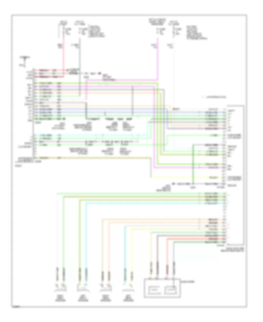
Premium Sound Radio Wiring Diagram, with Audiophile System for Ford Explorer Sport Trac 2005
List of elements for Premium Sound Radio Wiring Diagram, with Audiophile System for Ford Explorer Sport Trac 2005:
- (+)
- (-)
- Antenna
- Battery junction box (bjb) (left side of engine compt, at fender apron)
- C2188a
- C2188b
- C466a
- C466b
- Central junction box (cjb) (behind left side of dash)
- Fuse 10a
- Fuse 15a
- Fuse 20a
- Fuse 7.5a
- G202 (at right kick panel)
- G203 (at right kick panel)
- G300 (at left kick panel)
- Gnd
- High audio +
- High audio -
- Hot at all times
- Hot in start
- Hot w/ window safety relay energized
- Illumination
- Interior lights system
- L front spkr (+)
- L front spkr (-)
- L rear spkr (+)
- L rear spkr (-)
- Left front speaker
- Left rear speaker
- Mute
- Nca
- Power windows system
- R front spkr (+)
- R rear spkr (+)
- R rear spkr (-)
- Radio
- Right front speaker
- Right rear speaker
- S200 (near breakout to c211)
- S201 (near breakout behind center of dash)
- S206
- S233 (near breakout to c210)
- Shield
- Subwoofer
- Subwoofer amplifier (behind rear seats)
- Vbatt
- Vpwr
SHIFT INTERLOCK
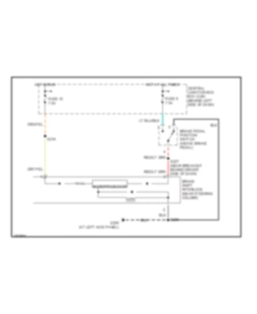
Shift Interlock Wiring Diagram for Ford Explorer Sport Trac 2005
List of elements for Shift Interlock Wiring Diagram for Ford Explorer Sport Trac 2005:
- Brake pedal position switch (above brake pedal)
- Brake shift interlock (near steering column)
- Central junction box box (cjb) (behind left side of dash)
- Fuse 15 7.5a
- Fuse 9 7.5a
- G300 (at left kick panel)
- Hot at all times
- Hot in run
- Microprocessor
- S206
- S216
- S227 (near breakout behind driver side of dash)
STARTING/CHARGING
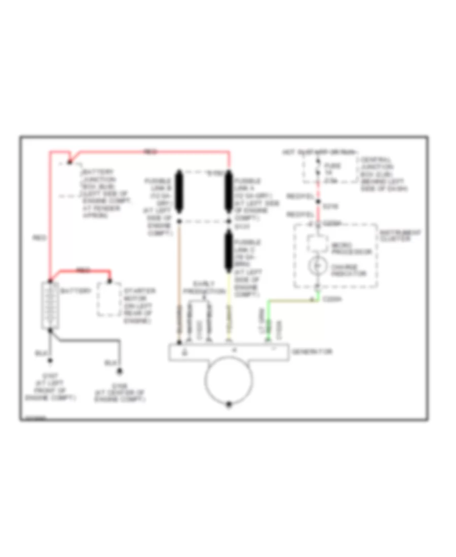
Charging Wiring Diagram for Ford Explorer Sport Trac 2005
List of elements for Charging Wiring Diagram for Ford Explorer Sport Trac 2005:
- (at left side of engine compt)
- 7.5a
- Battery
- Battery junction box (bjb) (left side of engine compt, at fender apron)
- C102a
- C102c
- C220a
- Central junction box (cjb) (behind left side of dash)
- Charge indicator
- Early production
- Fuse
- G107 (at left front of engine compt)
- G108 (at center of engine compt)
- Generator
- Hot in start or run
- Instrument cluster
- Micro processor
- Red
- S130
- S131
- S218
- Starter motor (on left rear of engine)
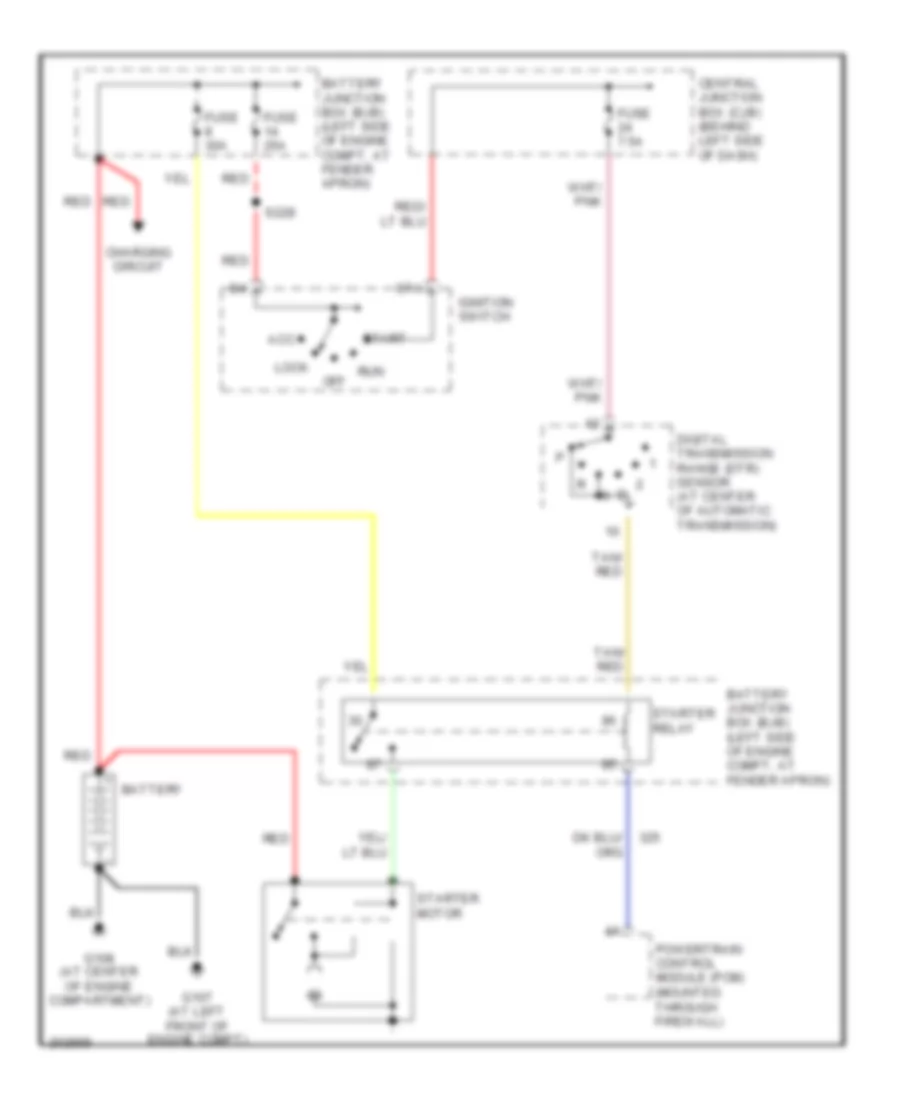
Starting Wiring Diagram for Ford Explorer Sport Trac 2005
List of elements for Starting Wiring Diagram for Ford Explorer Sport Trac 2005:
- Acc
- Battery
- Battery junction box (bjb) (left side of engine compt, at fender apron)
- Central junction box (cjb) (behind left side of dash)
- Charging circuit
- Digital transmission range (dtr) sensor (at center of automatic transmission)
- Fuse 25a
- Fuse 30a
- Fuse 7.5a
- G107 (at left front of engine compt)
- G108 (at center of engine compartment)
- Ignition switch
- Lock
- Off
- Powertrain control module (pcm) (mounted through firewall)
- Red
- Run
- S228
- Sta
- Start
- Starter motor
- Starter relay
- Tan/ red
SUPPLEMENTAL RESTRAINTS
Supplemental Restraints Wiring Diagram (1 of 2) for Ford Explorer Sport Trac 2005
List of elements for Supplemental Restraints Wiring Diagram (1 of 2) for Ford Explorer Sport Trac 2005:
- (at left kick panel) g204
- (in body main wiring harness, near breakout to c316) s326
- Air bag ind ctrl
- Air bag indicator
- C2041a
- C2041b
- C220a
- C220b
- Central junction box (cjb) (behind left side of dash)
- Computer data lines system
- Data bus
- Driver 1 side impact sensor (at bottom of left "b" pillar)
- Driver air bag 1+
- Driver air bag 1-
- Driver safety belt retractor pretensioner (at bottom of left "b" pillar)
- Driver seat belt buckle sensor (near driver seat)
- Dvr retract pre +
- Dvr retract pre -
- Dvr side imp 1 +
- Dvr side imp 1 -
- Dvr side imp 2 +
- Dvr side imp 2 -
- Fuse 10a
- Fuse 7.5a
- Fwd crash sens +
- Fwd crash sens -
- G205 (at left kick panel)
- Gnd
- Hot in run or start
- Ignition
- Instrument cluster
- L side air bag +
- L side air bag -
- Microprocessor
- Nca
- Pass air bag 1+
- Pass air bag 1-
- Pass air bag 2
- Pass retract pre +
- Pass retract pre -
- Pass safety belt sw+
- Pass side imp 1 +
- Pass side imp 1 -
- Pass side imp 2 +
- Pass side imp 2 -
- Passenger 1 side impact sensor (at bottom of right "b" pillar)
- Passenger safety belt retractor pretensioner (at bottom of right "b" pillar)
- Passenger seat belt buckle sensor (near passenger seat)
- Pin shorting bars engaged when module connector is disconnected from harness (shorting bars are connected between pins: 1-2, 3-4 & 13-14 c2041a 3-4 & 5-6 c2041b)
- R side air bag +
- R side air bag -
- Red/pnk
- Restraints control module (behind lower center of dash)
- Safety belt indicator
- Safety belt sw+
- Sensor signal
- Shorting bar
- Tone request
- W/ side air curtain
Supplemental Restraints Wiring Diagram (2 of 2) for Ford Explorer Sport Trac 2005
List of elements for Supplemental Restraints Wiring Diagram (2 of 2) for Ford Explorer Sport Trac 2005:
- Air bag sliding contact (on steering column)
- C218b
- Driver 2 side impact sensor (w/ side air curtain) (on center of left "c" pillar)
- Driver air bag (in steering wheel)
- Forward crash sensor (at right front of engine compt)
- Left side air bag module (on center of left "c" pillar)
- Nca
- Passenger 2 side impact sensor (w/ side air curtain) (on center of right "c" pillar)
- Passenger air bag module (on right side of dash)
- Red/ pnk
- Red/pnk
- Right side air bag module (on center of right "c" pillar)
- Shorting bar
- Stage 1
- Stage 2
- W/ side air curtain
TRANSMISSION
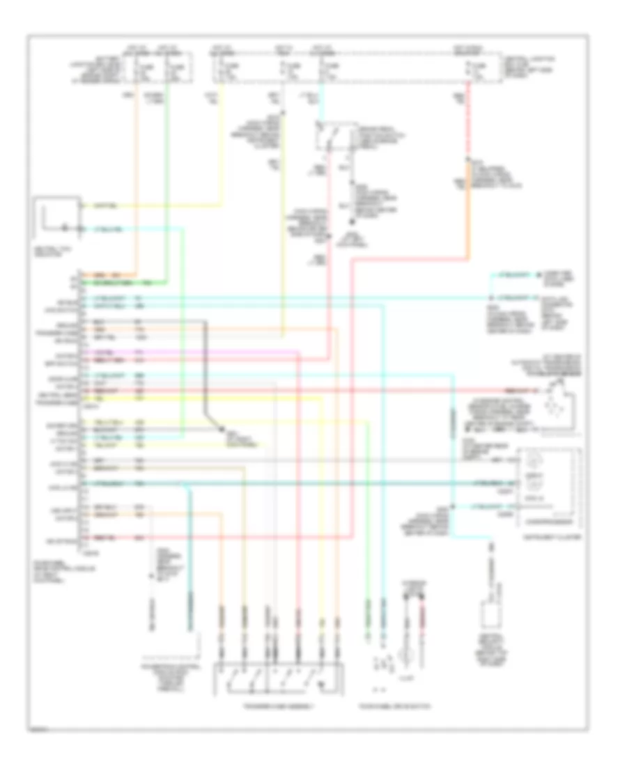
4WD Wiring Diagram for Ford Explorer Sport Trac 2005
List of elements for 4WD Wiring Diagram for Ford Explorer Sport Trac 2005:
- (at center of automatic transmission) digital transmission range (dtr) sensor
- (in engine control sensor & fuel charge wiring harness, near breakout at rear center of engine compt) s145
- (main harness, near breakout to c215) s213
- (main wiring harness, near breakout behind driver side of dash) s227
- 4wd hi
- 4wd hi ind
- 4wd lo
- 4wd lo ind
- 4wd switch
- Battery junction box (bjb) (left side of engine compt, at fender apron)
- Behind center of dash)
- Bpp switch
- Brake pedal position switch (above brake pedal)
- Breakout to c215)
- C220a
- C220b
- C274a
- C281a
- C281b
- Central junction box (cjb) (behind left side of dash)
- Central security module (behind top right side of dash)
- Computer data lines system
- Data link connector (dtc) (behind left side of dash)
- Door ajar
- Four-wheel drive control module (at right kick panel)
- Four-wheel drive switch
- Fuse 15a
- Fuse 20a
- Fuse 7.5a
- G100 (at center rear of engine compt)
- G201 (at right kick panel)
- G300 (at left kick panel)
- Ground
- Hot at all times
- Hot in run
- Hot in run or start
- Ign (run)
- Ign (st/run)
- Illum
- Instrument cluster
- Interior lights system
- Iso bus
- Microprocessor
- Motor 1
- Motor 2
- Motor 3
- Motor 4
- Motor 5
- N tow sw
- Nca
- Neutral sens
- Neutral tow indicator
- Off
- Powertrain control module (pcm) (mounted through firewall)
- S208 (in main wiring harness, near breakout behind center of dash)
- S216 (main wiring harness, near breakout behind instrument cluster)
- S220 (main wiring harness, near breakout behind center of dash)
- Sig return
- Transfer case
- Transfer case assembly
- Vss input
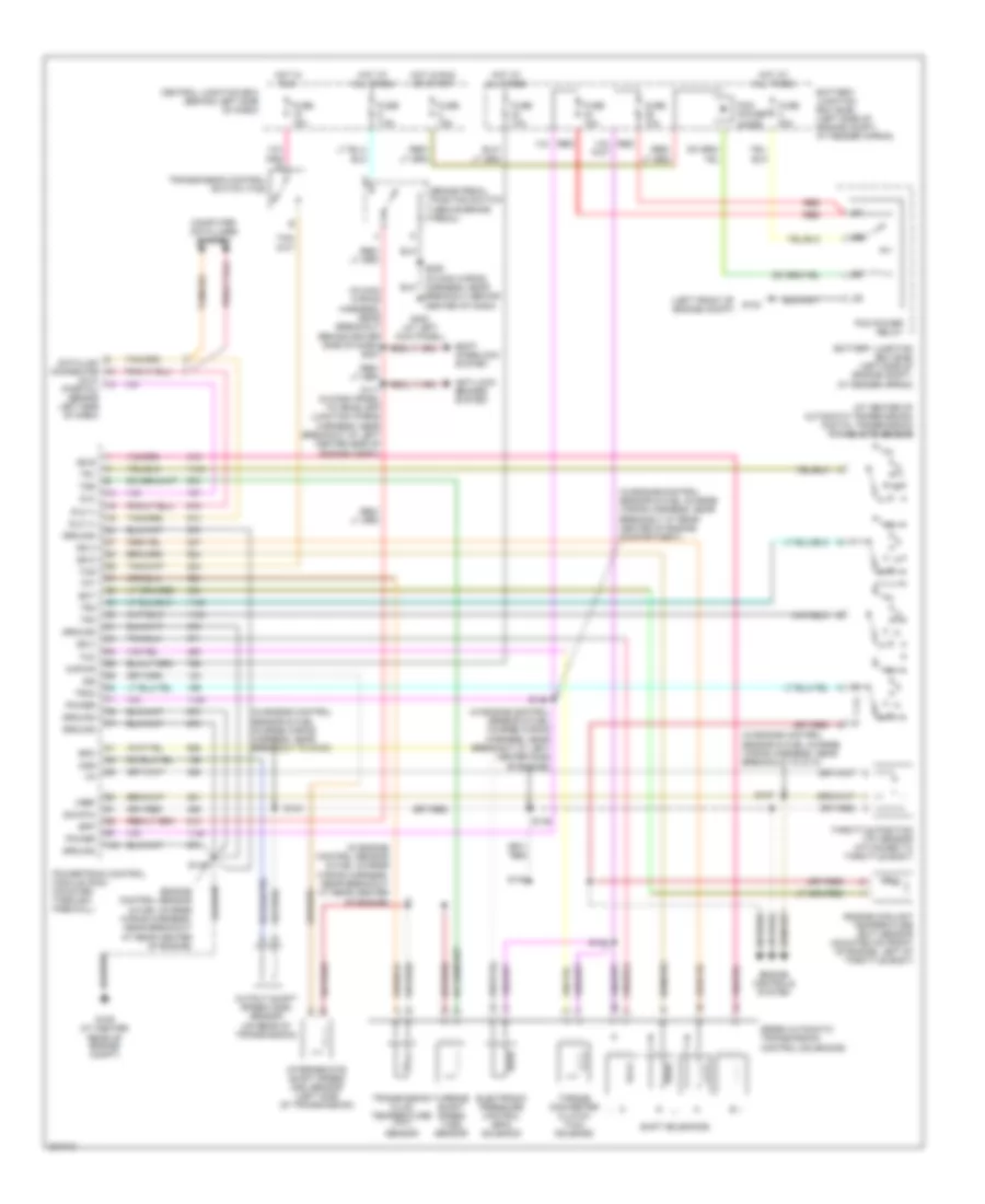
A/T Wiring Diagram for Ford Explorer Sport Trac 2005
List of elements for A/T Wiring Diagram for Ford Explorer Sport Trac 2005:
- (at center of automatic transmission) digital transmission range (dtr) sensor
- (dlc) (partial) (behind left side of dash)
- (engine control sensor & fuel charge wiring harness, near breakout at rear center of engine)
- (in engine control sensor & fuel charge wiring harness, near breakout at left center side of engine)
- (in engine control sensor & fuel charge wiring harness, near breakout at rear center of engine compartment)
- (in engine control sensor & fuel charge wiring harness, near breakout at rear center of engine)
- (in engine control sensor & fuel charge wiring harness, near breakout to c110)
- (in engine control sensor & fuel charge wiring harness, near breakout to g100)
- (in main wiring harness, near breakout behind driver side of dash) s227
- (left front of engine compt)
- 5r55e automatic transmission control solenoids
- Anti-lock brakes system
- Battery junction box (bjb) (left side of engine compt, at fender apron)
- Bpp
- Brake pedal position switch (above brake pedal)
- Central junction box (behind left side of dash)
- Computer data lines system
- Data link connector
- Dlc
- Dlc (+)
- Dlc (-)
- Ect
- Electronic pressure control (epc) solenoid
- Engine controls system
- Engine coolant temperature (ect) sensor (mounted on front of engine, left of throttle body)
- Epc
- Fuse 10a
- Fuse 15a
- Fuse 30a
- Fuse 7.5a
- G104
- G109 (at center rear of engine compt)
- G300 (at left kick panel)
- Ground
- Hot at all times
- Hot in run
- Hot in run or start
- Intermediate shaft speed (iss) sensor (left side of transmission)
- Iss
- Kapwr
- Oss
- Output shaft speed (oss) sensor (on rear of transmission)
- Pcm power diode
- Pcm power relay
- Power
- Powertrain control module (pcm) (mounted through firewall)
- R p
- Red
- S117 (in dash panel to headlamp junction wiring harness, near breakout at left center side of engine compt)
- S137
- S138
- S139
- S140
- S143
- S146
- S148
- S206 (in main wiring harness, near breakout behind center of dash)
- Shift interlock system
- Shift solenoids
- Sig rtn
- Ss a
- Ss b
- Ss c
- Ss d
- Tcc
- Tcs
- Tft
- Throttle position (tp) sensor (attached to throttle body)
- Torque converter clutch (tcc) solenoid
- Tr1
- Tr2
- Tr3a
- Tr4
- Transmission control switch (tcs)
- Transmission fluid temperature (tft) sensor
- Tss
- Turbine shaft speed (tss) sensor
- Vref
WARNING SYSTEMS
Warning Systems Wiring Diagram for Ford Explorer Sport Trac 2005
List of elements for Warning Systems Wiring Diagram for Ford Explorer Sport Trac 2005:
- (in main wiring harness, near breakout behind center of dash) s220
- Auto
- C2041a
- C2041b
- C205a
- C220a
- C220b
- C274a
- C281a
- C526a
- C526b
- Central junction box (cjb) (behind left side of dash)
- Central security module (behind top right side of dash)
- Computer data lines system
- Door ajar
- Door ajar ind
- Driver seat belt buckle sensor (near driver seat)
- Driver side front door ajar switch (in rear top of driver door)
- Four-wheel drive control module (at right kick panel)
- Fuse 15a
- Fuse 7.5a
- G204 (at left kick panel)
- G300 (at left kick panel)
- Head
- Hot at all times
- Hot in run or acc
- Hot in run or start
- Ignition key switch
- Instrument cluster
- Main light switch
- Microprocessor
- Nca
- Park off
- Passenger seat belt buckle sensor (near passenger seat)
- Restraints control module (behind lower center of dash)
- S218 (if equipped)
- S326
- S500
- Safety belt ind
- Sens sig
- Sw sig
- Tone request
WIPER/WASHER
Wiper/Washer Wiring Diagram for Ford Explorer Sport Trac 2005
List of elements for Wiper/Washer Wiring Diagram for Ford Explorer Sport Trac 2005:
- (at right side of engine compt)
- (in dash panel to headlamp junction wiring harness, near breakout at left center side of engine compt)
- (left of center, at rear of engine compt) windshield wiper motor
- 0) off 1) high 2) low 6) wash 7) mist 21) interval 1 22) interval 2 23) interval 3 24) interval 4 25) interval 5
- Battery junction box (bjb) (left side of engine compt, at fender apron)
- C202a
- Central junction box (cjb) (behind left side of dash)
- Fuse 20a
- Fuse 7.5a
- G101 (at left front of engine compt)
- G103 (at left front of engine compartment)
- G105
- G300 (at left kick panel)
- Hot at all times
- Hot in run or acc
- Multi-function switch (on steering column)
- Powertrain control module (pcm) (mounted through firewall)
- Red
- Rest
- Run
- S110
- S116
- S118
- S127
- S206
- Tan/ red
- Vss
- Windshield washer pump motor (in washer reservoir)
- Windshield washer relay
- Wiper high/ low relay
- Wiper run/ park relay