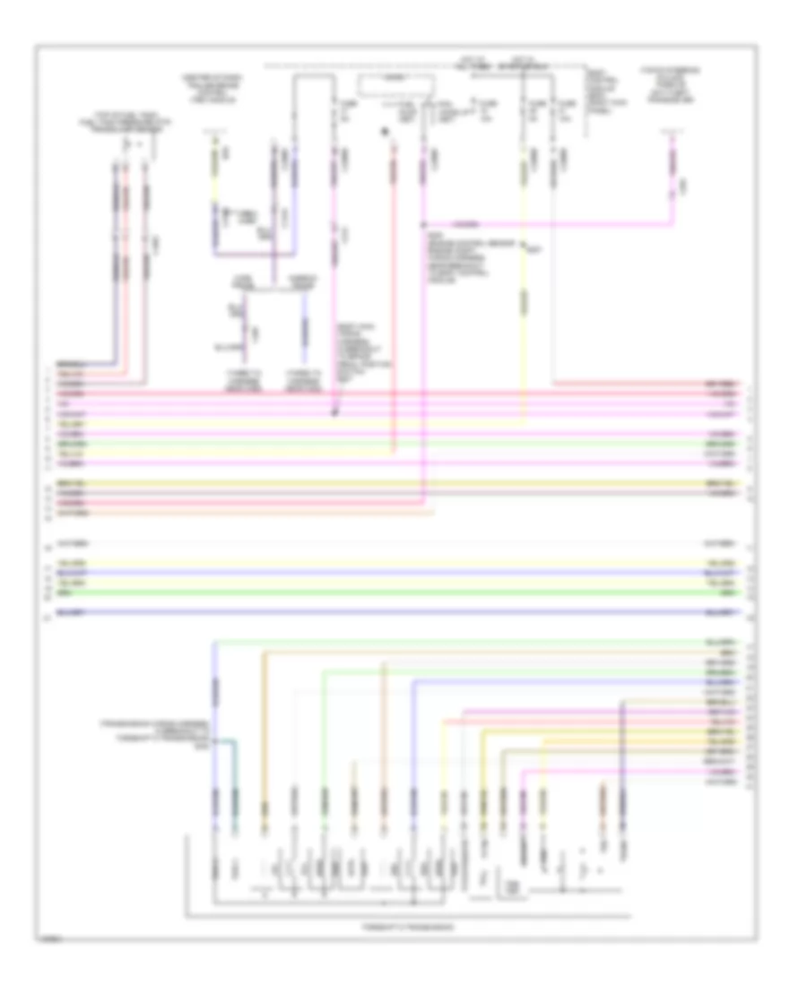
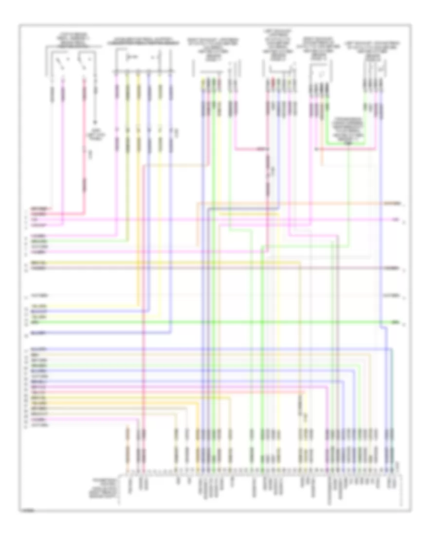
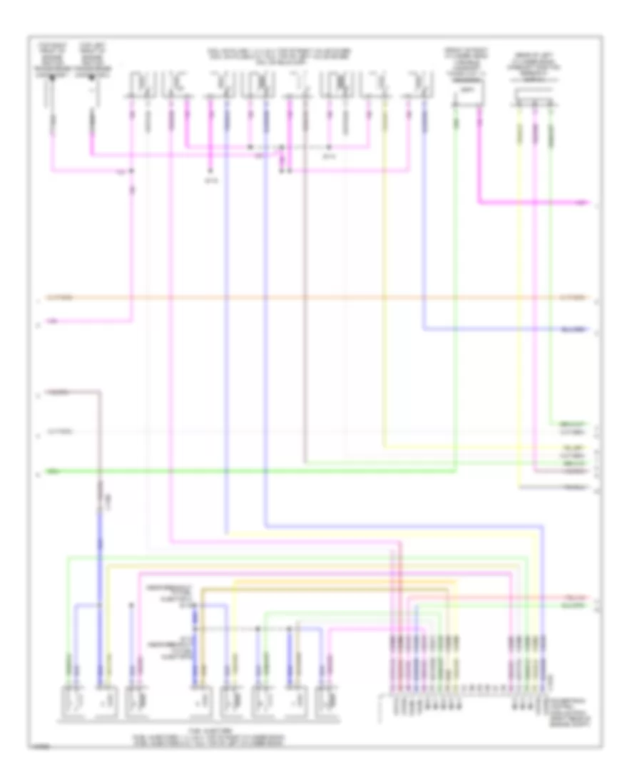
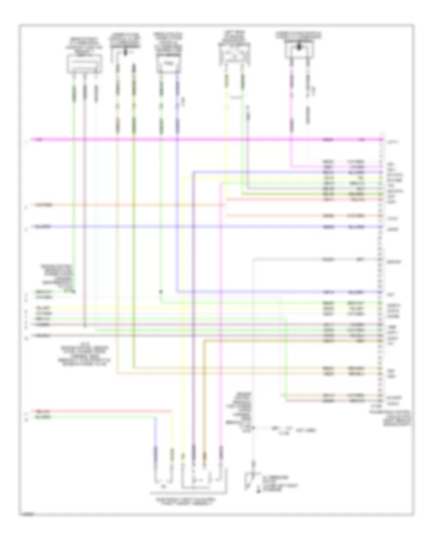
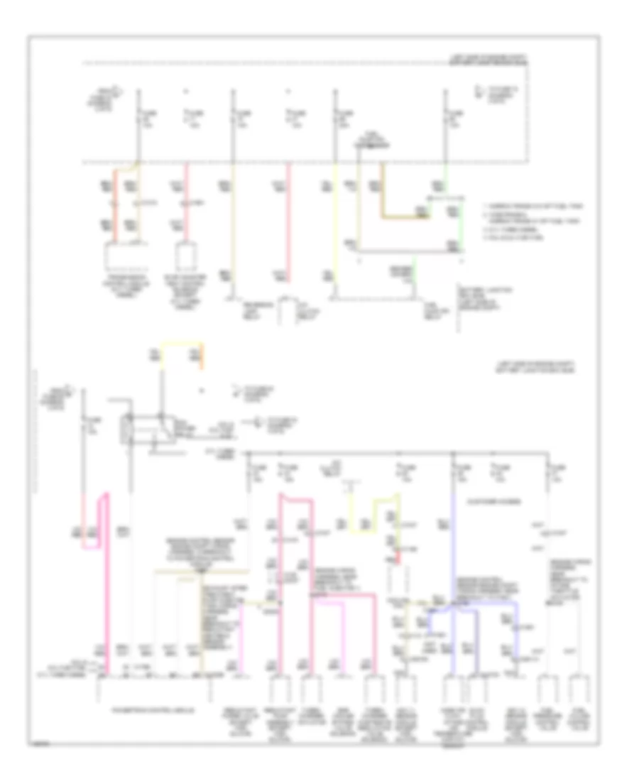
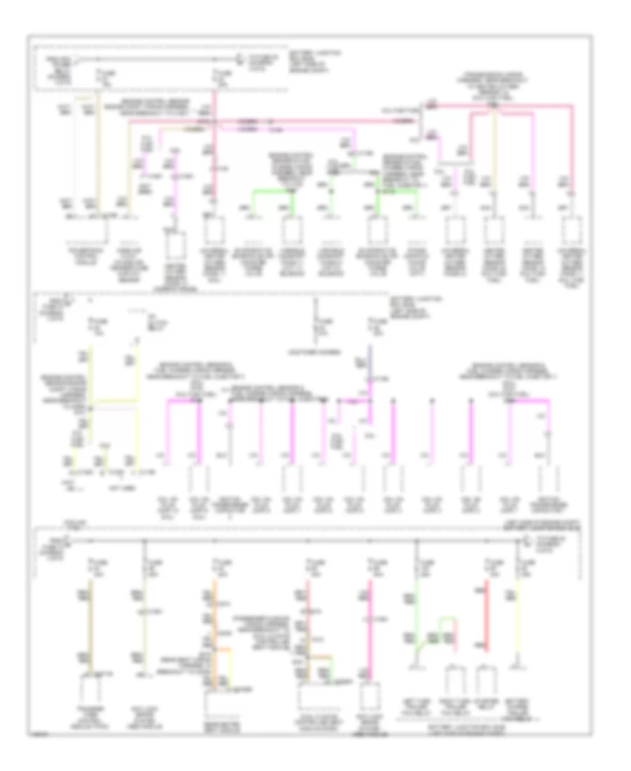
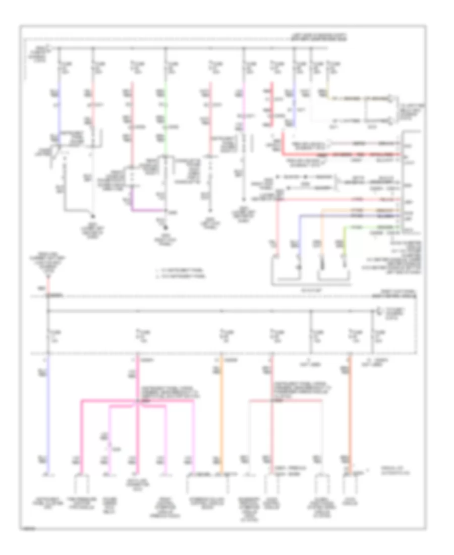
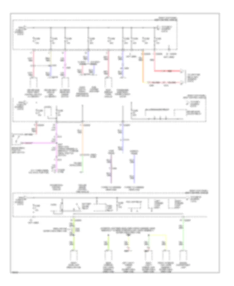
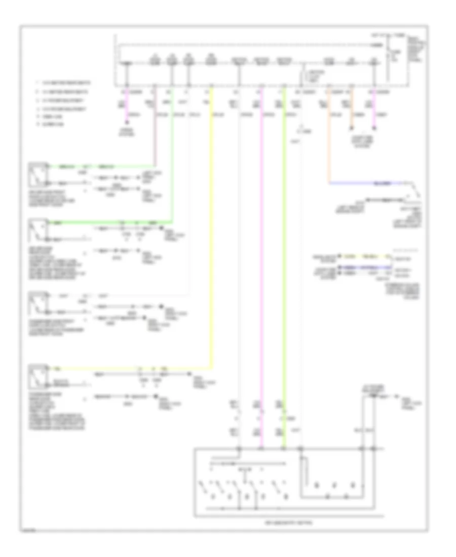
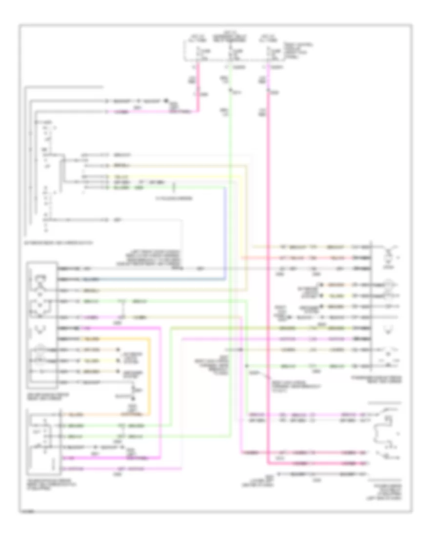
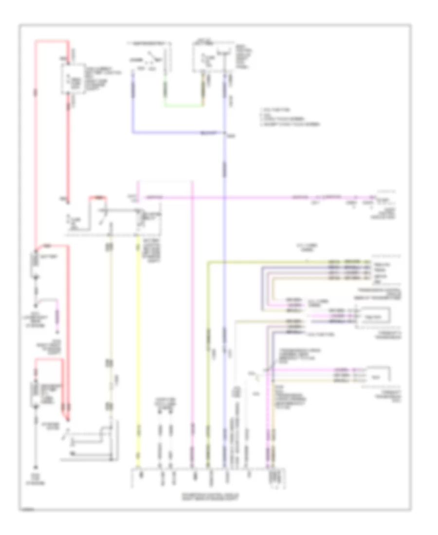
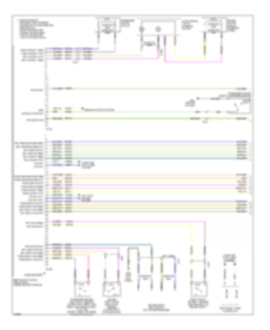
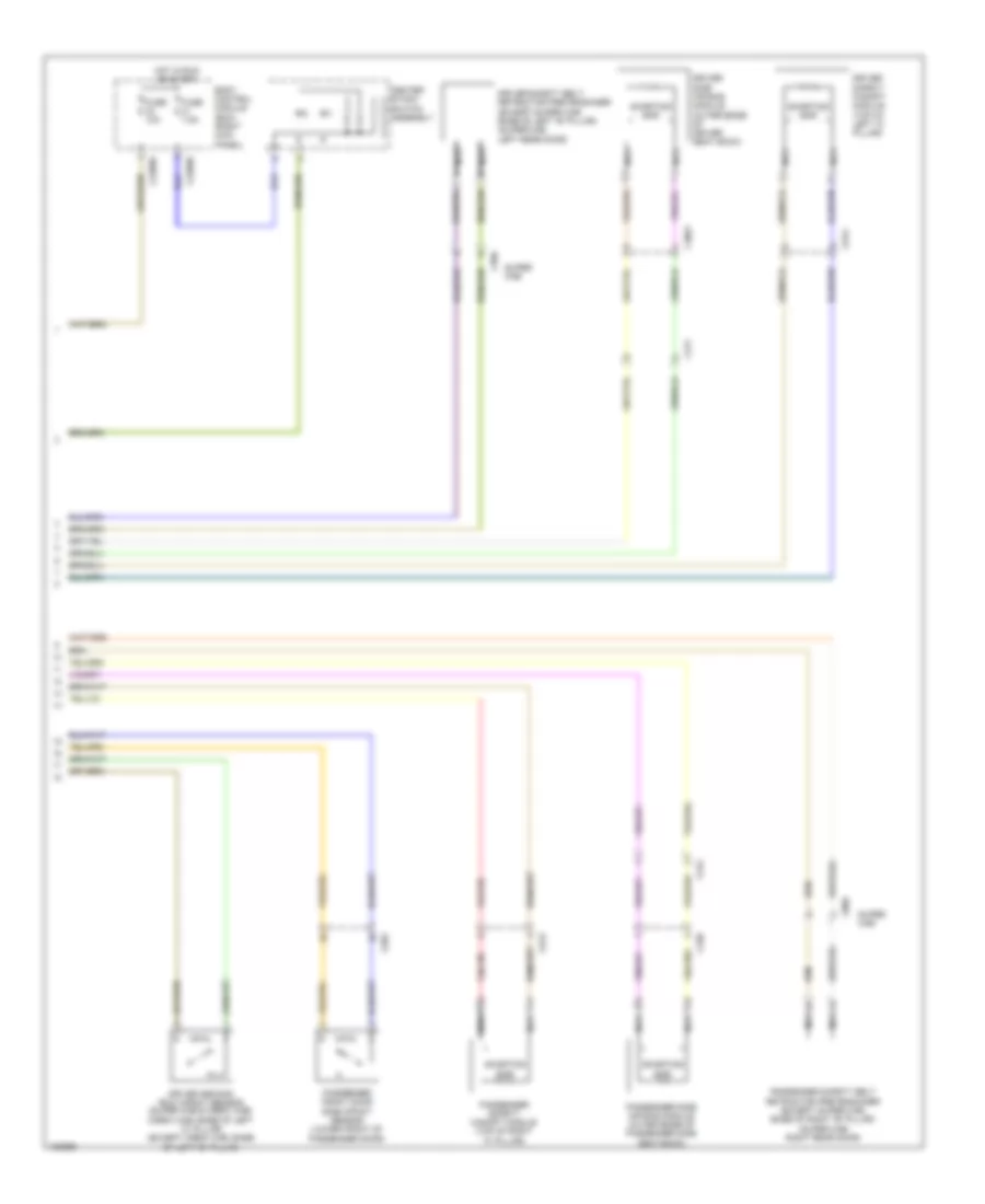
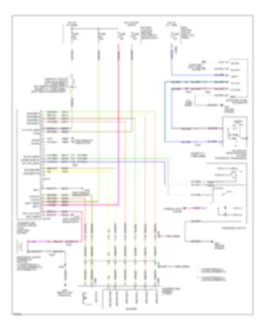
Разделы схем — 30 (всего 108)
AIR CONDITIONING ANTI-LOCK BRAKES ANTI-THEFT BODY CONTROL MODULES COMPUTER DATA LINES COOLING FAN CRUISE CONTROL DEFOGGERS ENGINE PERFORMANCE EXTERIOR LIGHTS GROUND DISTRIBUTION HEADLIGHTS HORN INSTRUMENT CLUSTER INTERIOR LIGHTS MEMORY SYSTEMS NAVIGATION POWER DISTRIBUTION POWER DOOR LOCKS POWER MIRRORS POWER SEATS POWER TOP/SUNROOF POWER WINDOWS RADIO SHIFT INTERLOCK STARTING/CHARGING SUPPLEMENTAL RESTRAINTS TRANSMISSION WARNING SYSTEMS WIPER/WASHER
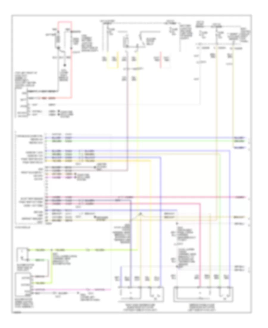
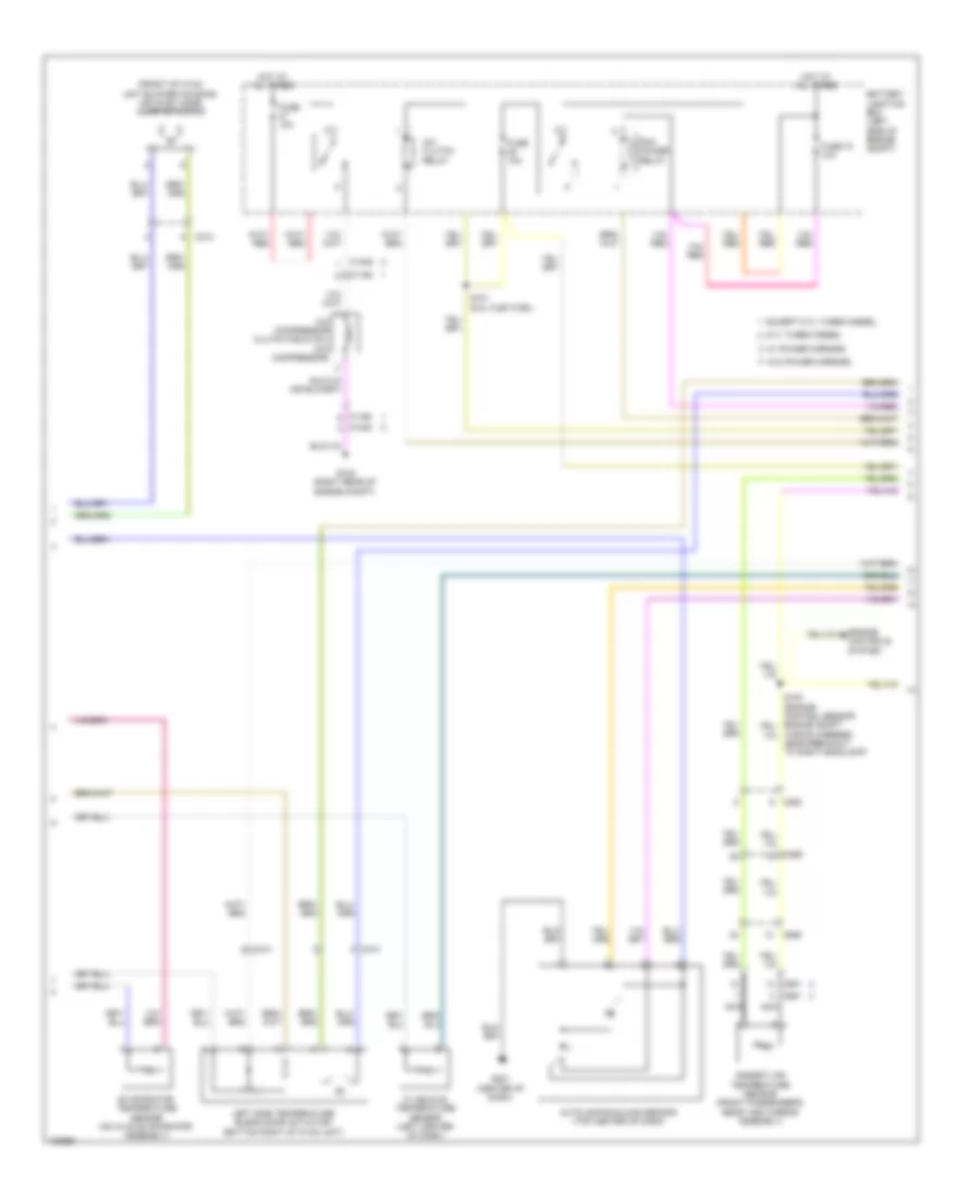
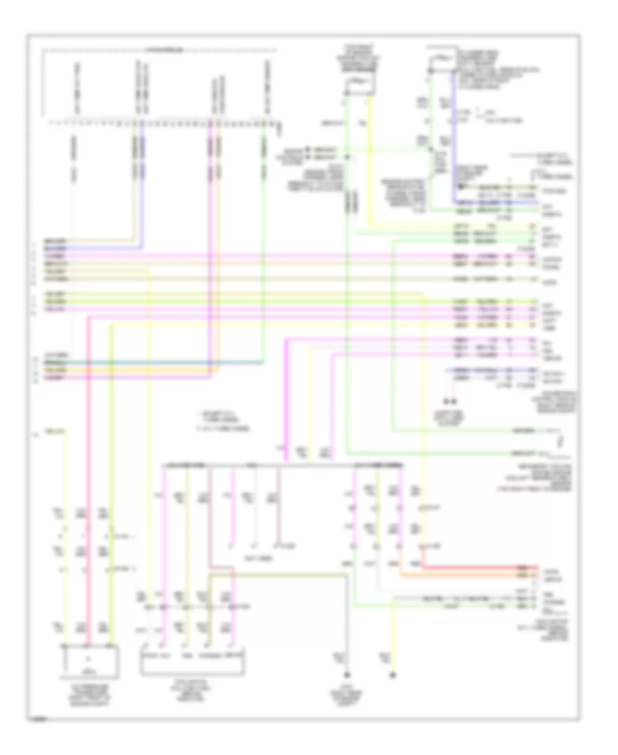
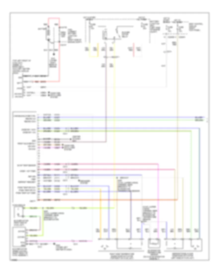
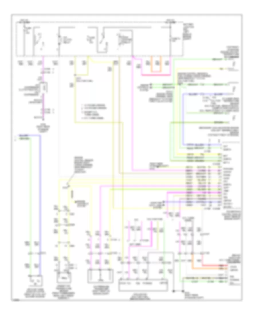
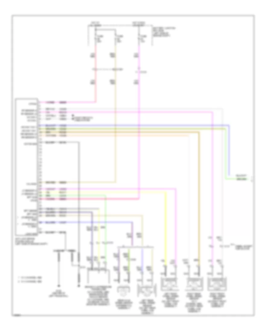
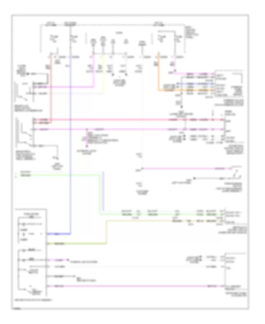
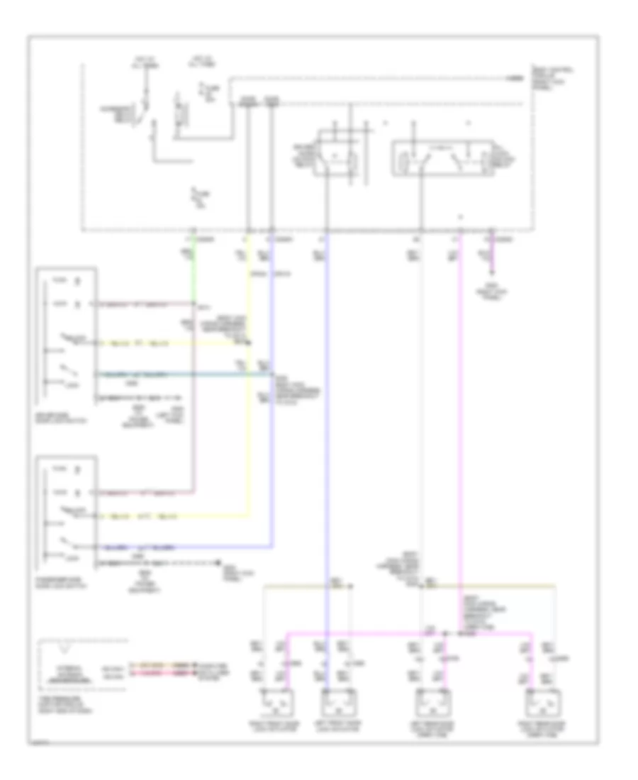
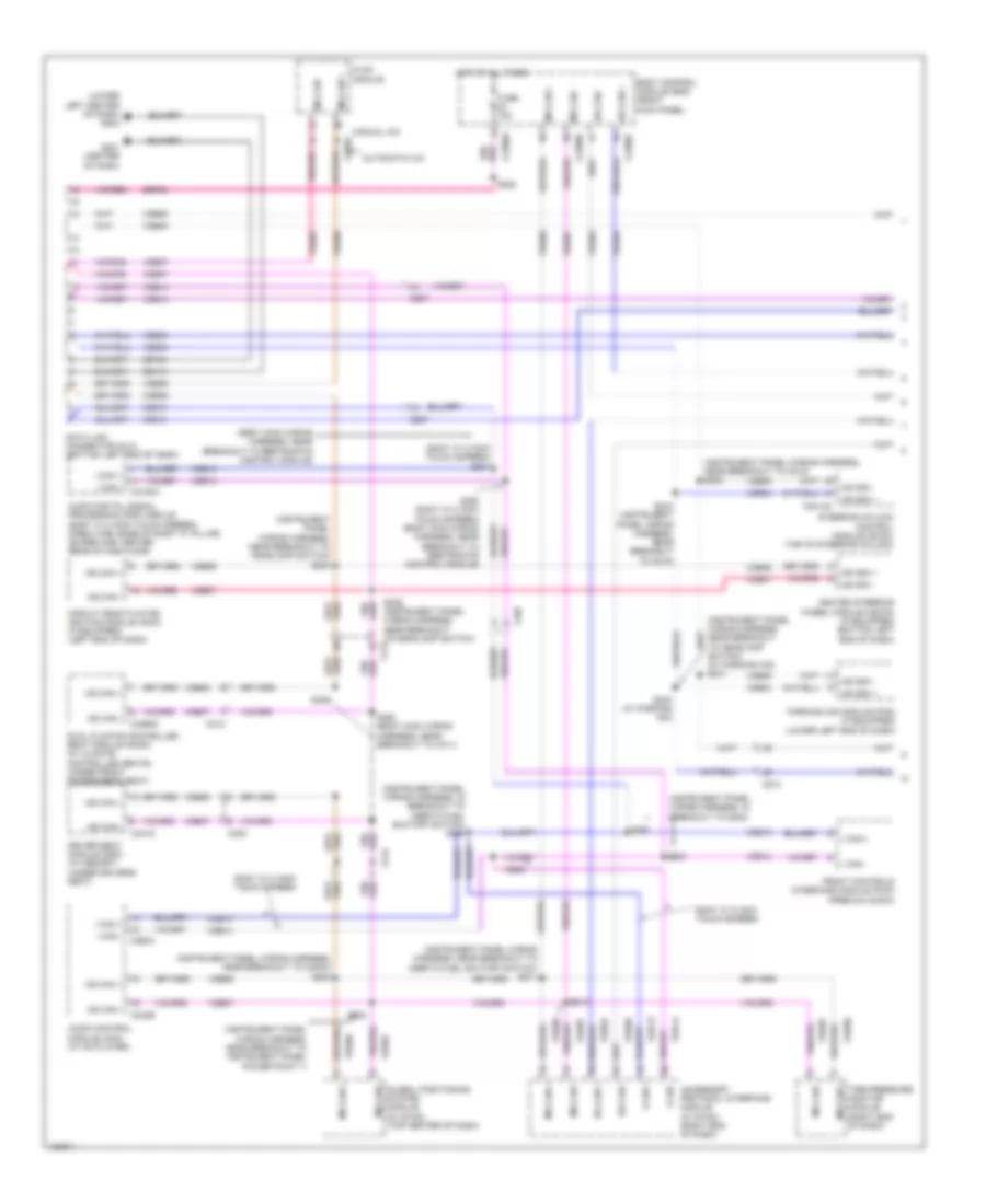
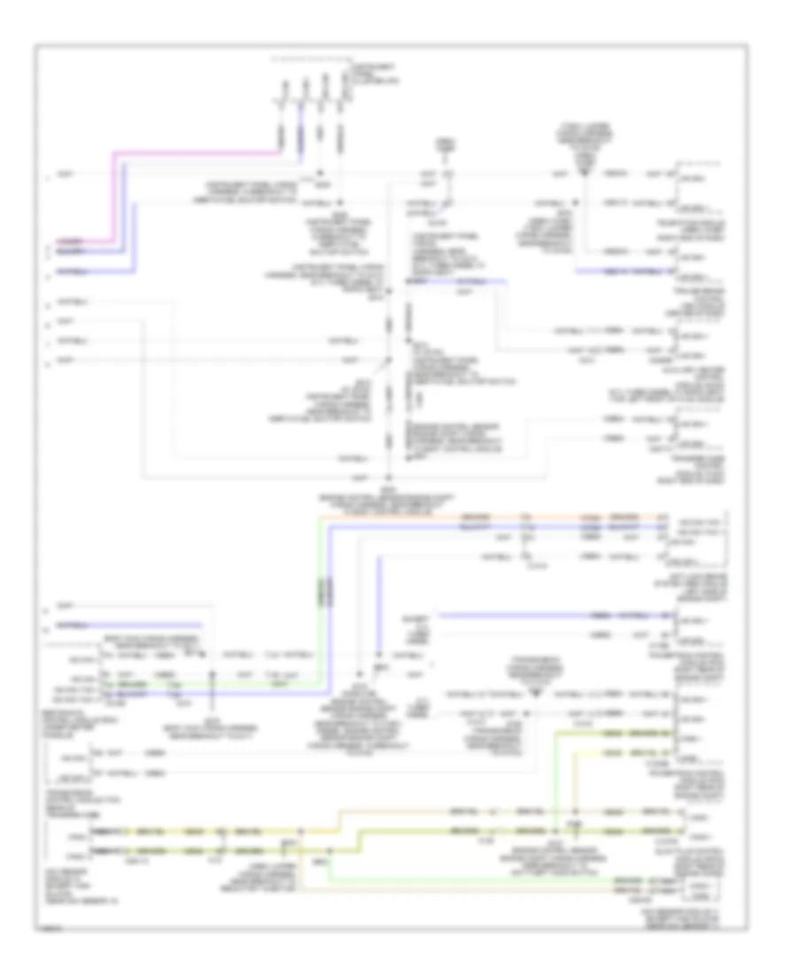
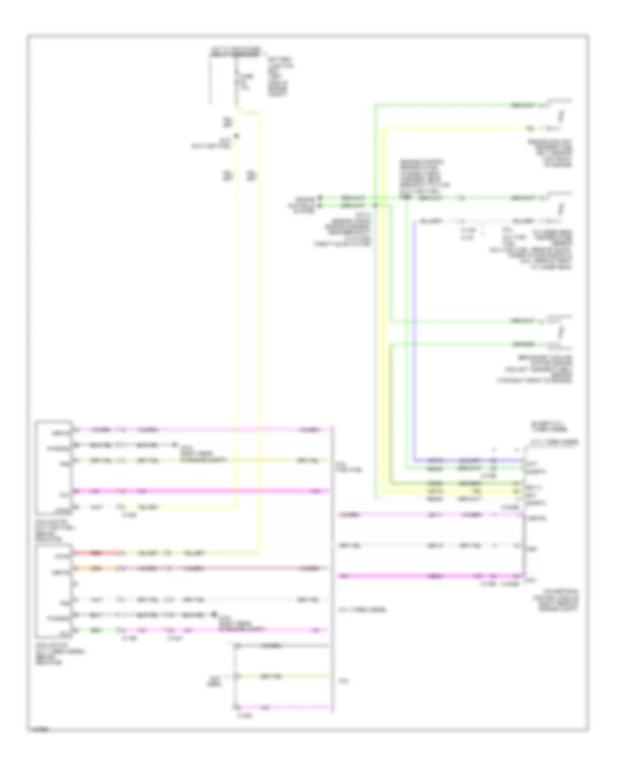
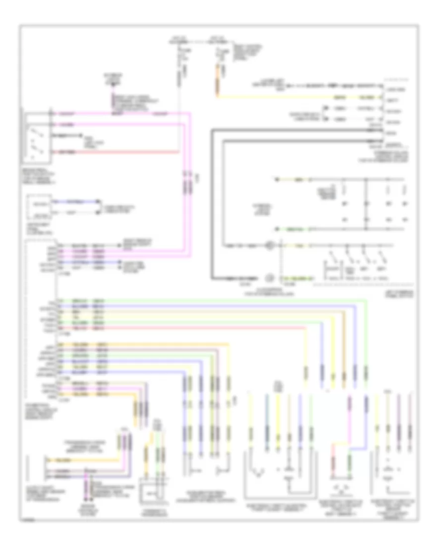
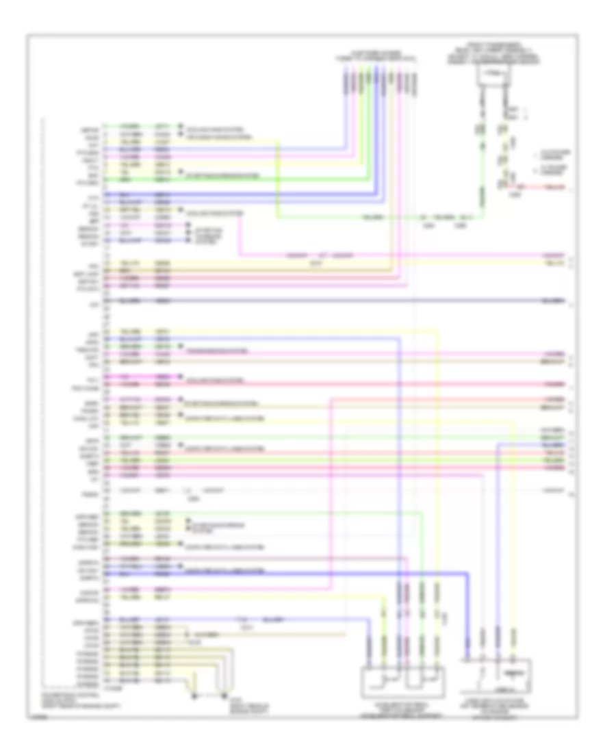
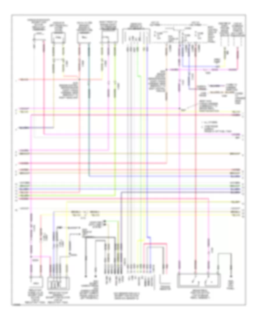
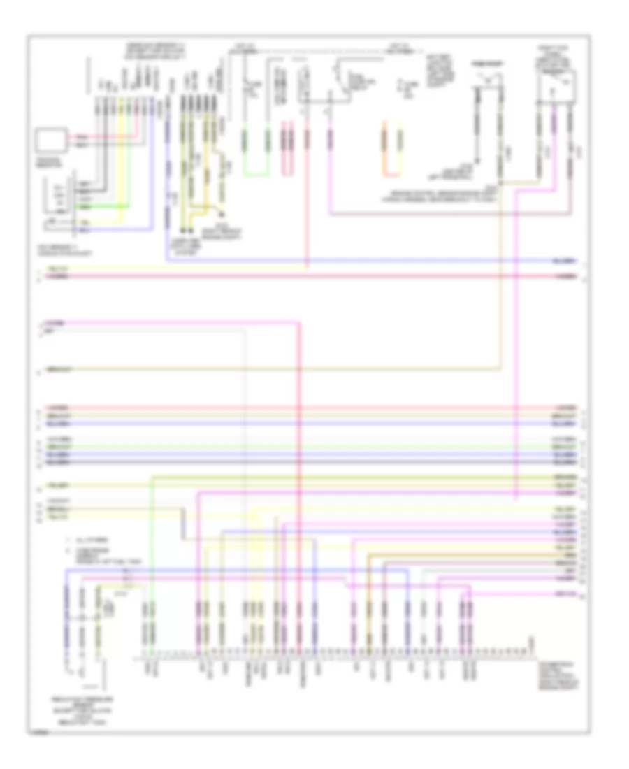
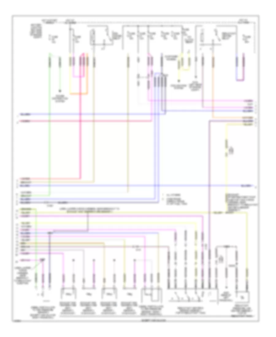
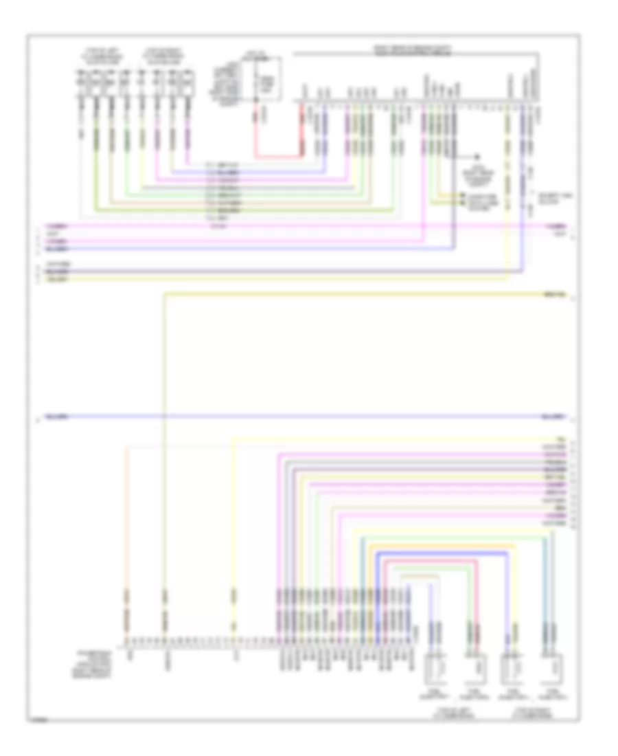
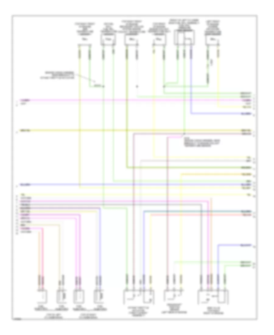
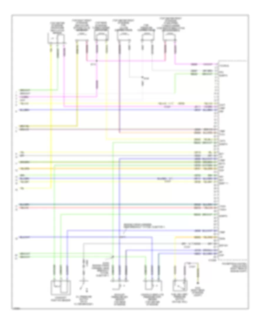
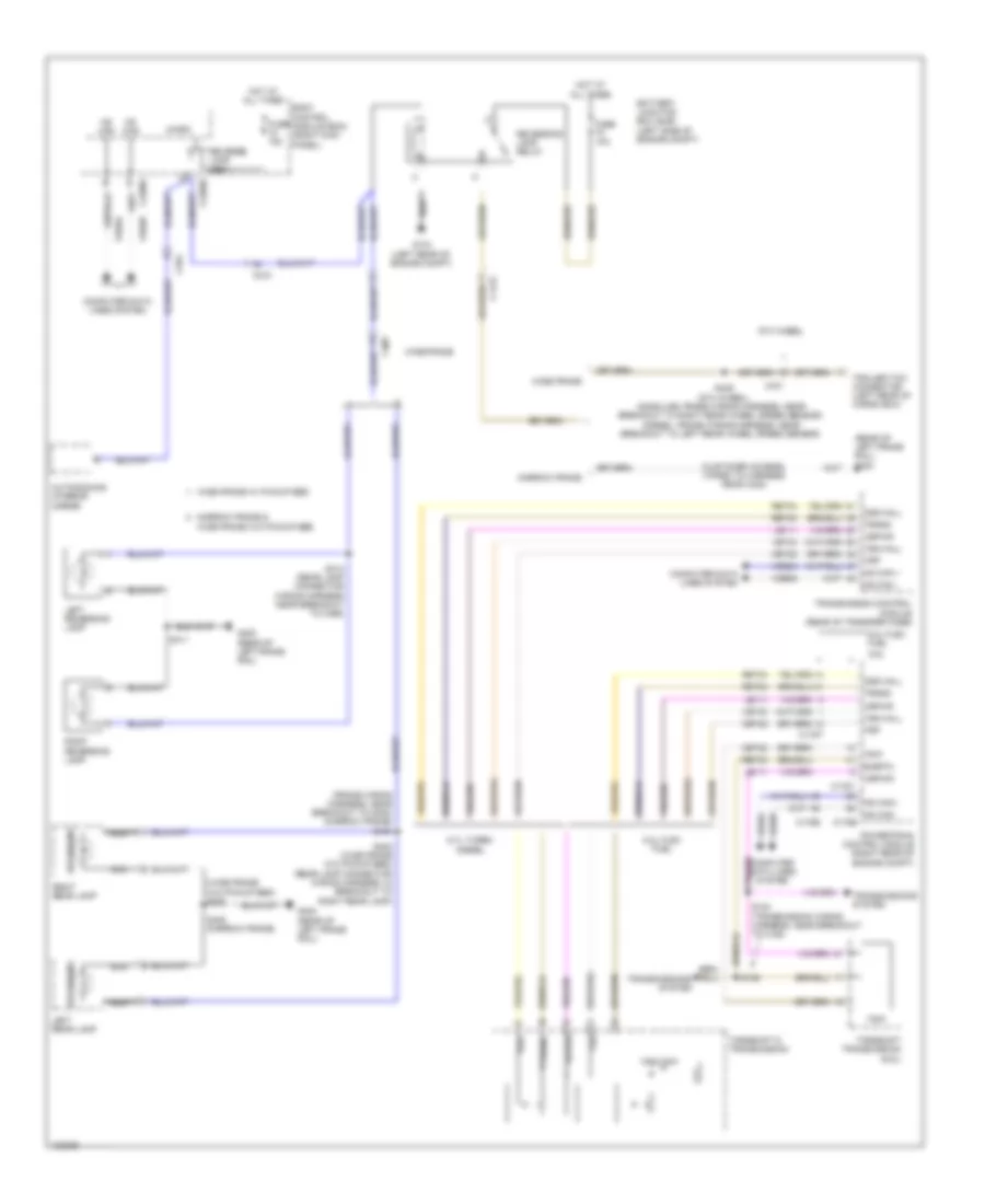
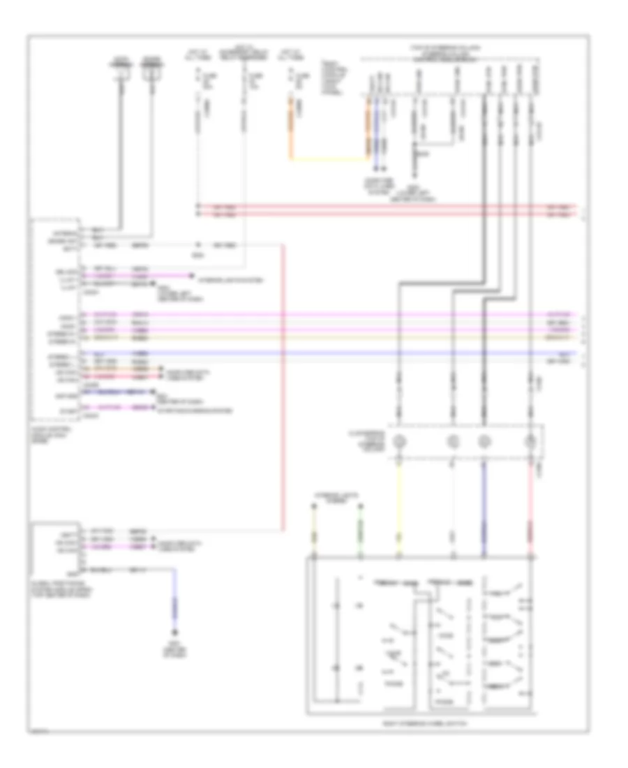
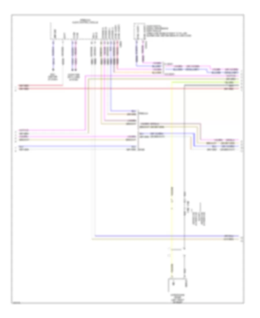
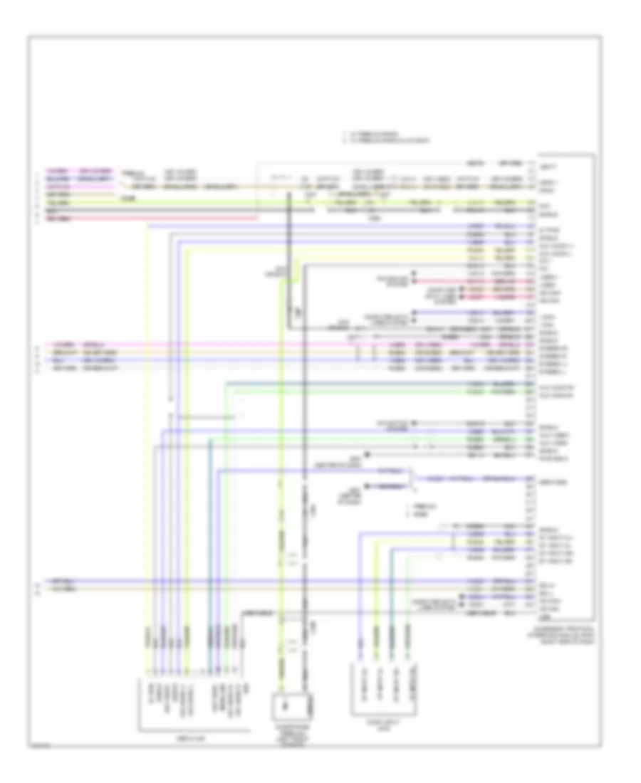
AIR CONDITIONING Automatic A/C Wiring Diagram (1 of 3) for Ford F-350 Super Duty XLT 2014 List of elements for Automatic A/C Wiring Diagram (1 of 3) for Ford F-350 Super Duty XLT 2014: 86 (center of dash) g201 (hvac jumper wiring harness, near breakout to evaporator temperature sensor) s251 (top left front of hvac unit) (diesel w/ rapid heat) auxiliary heater control module (ahcm) Autolamp sensor in Batt Battery Battery junction box (bjb) (left side of engine compt) Blower motor (right end of hvac unit) Blower motor relay Blower motor speed control (right front of hvac assembly) Body control module (right kick panel) C1617e C1617f C211 C213 C214 C2280a C2280b C228a Cbp37 Ch122 Ch123 Ch202 Ch203 Ch207 Ch208 Ch238 Ch239 Computer data lines system Defogger system Defrost request Defrost/panel/floor mode door actuator (left side of hvac unit) Evap temp sensor Front blower rly Fuse 10a Fuse 40a G101 (lower right rear of engine) G203 (lower left center of dash) Gd108 Gd184 Gnd Harness, near breakout to g201) High current battery junction box (bjb) (right side of engine compt) Hot at all times Hot in start or run Hs can+ Hs can- Hvac module Lh111 Mega fuse 125a Micro Mode 1 act fdbk Mode dr 1 ccw Mode dr 1 cw Motor+ Motor- Ms can+ Ms can- Nca Pass temp act fdbk Pass temp dr ccw Pass temp dr cw Pwm Recirc ccw Recirc cw Red Return Rh111 Right side temperature blend door actuator (top right side of hvac unit) S250 (hvac jumper wiring harness, near breakout to evaporator temperature sensor) S257 (hvac jumper wiring harness, near breakout to blower motor) Sbp46 Sdf05 Variable blower ctrl Vbat Vdb04 Vdb05 Vdb06 Vdb07 Vh101 Vh406 Vh437 Vh440 Vlf14 Vpwr Vref Automatic A/C Wiring Diagram (2 of 3) for Ford F-350 Super Duty XLT 2014 List of elements for Automatic A/C Wiring Diagram (2 of 3) for Ford F-350 Super Duty XLT 2014: 32 (front of hvac unit blower housing) air inlet mode door actuator 6.7l turbo diesel A/c clutch relay A/c compressor clutch field coil (a/c compressor) Ambient air temperature sensor (front passenger's rear view mirror assembly) Autolamp/sunload sensor (top center of dash) Battery junction box (left side of engine compt) C1046 C1168 C213 C214 C263 C265 C601 C651 C655 Engine controls system Evaporator temperature sensor (on hvac evaporator assembly) Except 6.7l turbo diesel Fuse 10a Fuse 72 10a G108 (right rear of engine compt) G201 (center of dash) Hot at all times In vehicle temperature sensor (left center of dash) Left side temperature blend door actuator (bottom right of hvac unit) Nca Pcm power relay S101 (6.2l flex fuel) W/ power mirrors W/o power mirrors Wiring harness, near breakout to right headlamp) Automatic A/C Wiring Diagram (3 of 3) for Ford F-350 Super Duty XLT 2014 List of elements for Automatic A/C Wiring Diagram (3 of 3) for Ford F-350 Super Duty XLT 2014: 81 (engine control sensor & fuel charge wiring harness, near breakout to c133) (not used) (right rear of engine compt) g103 (top front of engine) engine coolant temperature (ect) sensor 6.2l flex fuel 6.7l turbo diesel 6.8l A/c pressure transducer (right front of engine compt) Aat Accr Acpt C1046 C1047 C1148 C1163 C1165 C1220 C1232b C1232e C133 C175b C175e C228b Ce237 Ch212 Ch213 Ch302 Cht Computer data lines system Cooling fan (6.2l flex fuel) (behind radiator) Cooling fan (6.7l turbo diesel) (behind radiator) Cylinder head temperature (cht) sensor (6.2l flex fuel: rear of block, under intake manifold) (6.8l: rear of right cylinder head) Drv sunload Drv temp act fdbk Drv temp door ccw Drv temp door cw Ect Ect 2 Engine controls system Except 6.7l Except 6.7l turbo diesel Fcv Fss G103 (right rear of engine compt) Gd113 Hs can + Hs can - Hvac module In car temp sensor Kapwr Le111 Le424 Pass sunload Pcmrc Powertrain control module (right rear of engine compt) Pwr gnd Pwrgnd Re405 Re407 Red S116 (6.2l flex fuel) Sbb72 Secondary cooling system engine coolant temperature 2 sensor (top right front of engine) Sigrtn Turbo diesel Vbpwr Vdb04 Vdb05 Ve203 Ve712 Ve716 Ve759 Vec10 Vh407 Vh414 Vh416 Vh417 Vh433 Vh441 Vpwr Vref Manual A/C Wiring Diagram (1 of 2) for Ford F-350 Super Duty XLT 2014 List of elements for Manual A/C Wiring Diagram (1 of 2) for Ford F-350 Super Duty XLT 2014: 81 (center of dash) g201 (top left front of hvac unit) (diesel w/ rapid heat) auxiliary heater control module (ahcm) Batt Battery Battery junction box (left side of engine compt) Blower motor (right end of hvac unit) Blower motor relay Blower motor speed control (right front of hvac assembly) Body control module (right kick panel) C1617e C1617f C211 C213 C214 C2280a C2280b Cbp37 Ch122 Ch123 Ch202 Ch203 Ch207 Ch208 Ch238 Ch239 Computer data lines system Defogger system Defrost request Defrost/panel/floor mode door actuator (left side of hvac unit) Evap temp sensor Evaporator temperature sensor (on hvac evaporator assembly) Front blower rly Fuse 10a Fuse 40a G101 (lower right rear of engine) G203 (lower left center of dash) Gd108 Gd184 Gnd High current battery junction box (right side of engine compt) Hot at all times Hot in start or run Hs can+ Hs can- Hvac module Lh111 Mega fuse 125a Mode 1 act fdbk Mode dr 1 ccw Mode dr 1 cw Motor+ Motor- Ms can+ Ms can- Nca Pass temp act fdbk Pass temp dr ccw Pass temp dr cw Pwm Recirc ccw Recirc cw Red Return Rh111 Right side temperature blend door actuator (top right of hvac unit) S250 (hvac jumper wiring harness, near breakout to evaporator temperature sensor) S257 (hvac jumper wiring harness, near breakout to blower motor) Sbp46 Sdf05 Variable blower ctrl Vbatt Vdb04 Vdb05 Vdb06 Vdb07 Vh101 Vh406 Vh437 Vh440 Vpwr Vref Manual A/C Wiring Diagram (2 of 2) for Ford F-350 Super Duty XLT 2014 List of elements for Manual A/C Wiring Diagram (2 of 2) for Ford F-350 Super Duty XLT 2014: 89 (behind radiator) (6.7l turbo diesel) cooling fan (engine control sensor & fuel charge wiring harness, near breakout to c133) (6.2l flex fuel) s116 (engine control sensor engine compt wiring harness, near breakout to right headlamp) (not used) (right rear of engine compt) g103 (top front of engine) engine coolant temperature (ect) sensor 6.2l flex fuel 6.7l turbo diesel 6.8l A/c clutch relay A/c compressor clutch field coil (a/c compressor) A/c pressure transducer (right front of engine compt) Aat Accr Acpt Air inlet mode door actuator (front of hvac unit blower housing) Ambient air temperature sensor (front passenger's rear view mirror assembly) Battery junction box (left side of engine compt) C1046 C1047 C1148 C1163 C1165 C1168 C1220 C1232b C1232e C133 C175b C175e C213 C263 C265 C601 C651 C655 Ce237 Ch302 Cht Computer data lines system Cooling fan (6.2l flex fuel) (behind radiator) Cylinder head temperature sensor (6.2l flex fuel: rear of block, under intake manifold) (6.8l: rear of right cylinder head) Ect Ect 2 Engine controls system Except 6.7l Fcv Fss Fuse 10a Fuse 72 10a G103 (right rear of engine compt) G108 (right rear of engine compt) Gd113 Hot at all times Hs can + Hs can - Kapwr Le111 Le424 Nca Pcm power relay Pcmrc Powertrain control module (right rear of engine compt) Pwr gnd Pwrgnd Re405 Re407 Red S100 S101 (6.2l flex fuel) S1013 (engine wiring harness, near breakout to intake throttle actuator) Sbb72 Secondary cooling system engine coolant temperature 2 sensor (top right front of engine) Sigrtn Turbo diesel Vbpwr Vdb04 Vdb05 Ve203 Ve712 Ve716 Ve759 Vec10 Vh407 Vh433 Vpwr Vref W/ power mirrors W/o power mirrors
ANTI-LOCK BRAKES Anti-lock Brakes Wiring Diagram (1 of 2) for Ford F-350 Super Duty XLT 2014 List of elements for Anti-lock Brakes Wiring Diagram (1 of 2) for Ford F-350 Super Duty XLT 2014: 64 Anti-lock brake system module (left side of engine compt) Battery junction box (bjb) (left side of engine compt) Bpt gnd Bpt sense Bpt sub Brake fluid pressure transducer (w/ 3 channel abs) brake booster vacuum sensor (w/ 4 channel abs) (on brake vacuum booster assembly) C110 C1415 C1581 C438 Cbb54 Computer data lines system Diesel Diesel except high sulfur Fuse 10a Fuse 25a Fuse 50a G135 (center of left frame rail) Gd163 Hc can + Hc can - Hot at all times Hot in run or start Hs can yaw + Hs can yaw - Lca16 Left front wheel speed sensor (on left front wheel hub assembly) Left rear wheel speed sensor (on left rear wheel hub assembly) Lf sensor hi Lf sensor lo Logic gnd Lr sensor hi dss+ Lr sensor lo dss- Motor gnd Mtr b+ Nca Rca16 Rca17 Rca19 Rca20 Rca21 Rear axle speed sensor (differential assembly) Rf sensor hi Rf sensor lo Right front wheel speed sensor (on right front wheel hub assembly) Right rear wheel speed sensor (w/ 4 channel abs) (on right rear wheel hub assembly) Rr sensor hi Rr sensor lo S170 Sbb86 Sbb96 Valve b+ Vca03 Vca05 Vca06 Vca07 Vca13 Vca23 Vca24 Vdb04 Vdb05 Vpwr W/ 3 channel abs W/ 4 channel abs Anti-lock Brakes Wiring Diagram (2 of 2) for Ford F-350 Super Duty XLT 2014 List of elements for Anti-lock Brakes Wiring Diagram (2 of 2) for Ford F-350 Super Duty XLT 2014: 80 (lower right rear of engine) g101 (not used) Amber Body control module (right kick panel) Bpp Bps Brake fluid level switch (brake fluid reservoir) Brake pedal position switch (top of brake pedal assembly) Brk fluid sw Brk fluid sw rtn C1232b C1415 C175b C210 C212 C2280a C2280b C2280c C2280d C2280f C2414a C2414b C310a C310b Ccb08 Center stack switch assembly Ces09 Cmc19 Cmc25 Computer data lines system Customer access Diesel Exterior lights system Fuse 10a Fuse 15a Fuse 5a Fuse 7.5a G201 (center of dash) G202 (lower left center of dash) G300 (left kick panel) Gasoline Gd185 Hill descent switch Hot at all times Hot in run or start Hs can + Hs can - Hs can yaw + Hs can yaw - Hs can+ Hs can- Instrument panel cluster (ipc) Interior lights system Logic gnd Micro Pad ind Park brake Parking brake switch (top of parking brake lever assembly) Pass air bag off Powertrain control module (right rear of engine compt) Pwr gnd Red Restraints control module (under center console) Rmc19 Rr116 S207 (body main wiring harness, in breakout to brake pedal position switch) S228 S239 S304 Sbp24 Sbp26 Steering column control module (top of steering column) Steering wheel angle sensor Tcs Tcs off switch Vbatt Vca23 Vca24 Vdb04 Vdb05
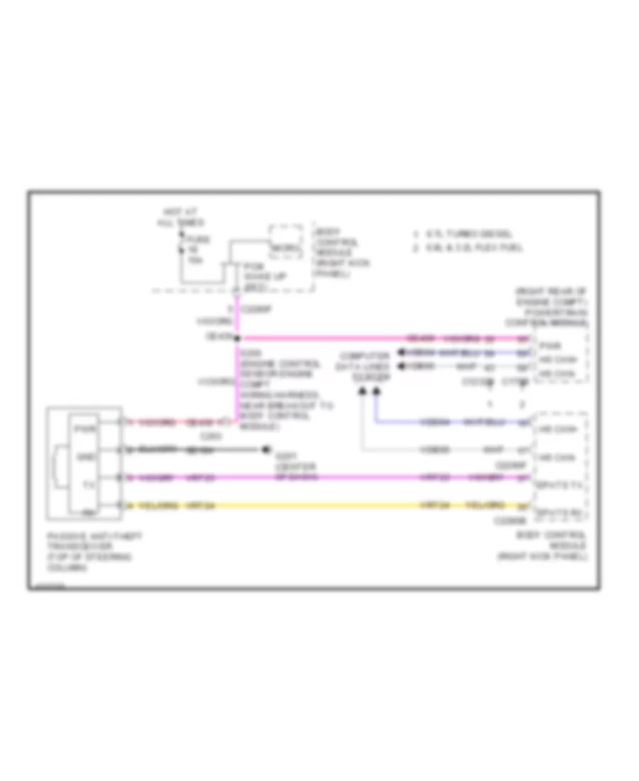
ANTI-THEFT Forced Entry Wiring Diagram (1 of 2) for Ford F-350 Super Duty XLT 2014 List of elements for Forced Entry Wiring Diagram (1 of 2) for Ford F-350 Super Duty XLT 2014: 42 (body main wiring harness, near breakout to c312) (crew cab) s382 (body main wiring harness, near breakout to c312) s302 (body main wiring harness, near breakout to c312) s305 Accessory delay relay All lock/ unlock relay Body control module (right kick panel) C2280c C2280d C555 C655 C755 C855 Computer data lines system Cpk19 Cpk23 Door lock Door unlock Driver door unlock relay Driver side door lock switch Fuse 15a Fuse 20a G300 (left kick panel) G302 (right kick panel) Hot at all times Internal antenna rke receiver Left front door lock actuator Left rear door lock actuator (crew cab) Lock Micro Ms can + Ms can - Passenger side door lock switch Right front door lock actuator Right rear door lock actuator (crew cab) S306 (body main wiring harness, near breakout to c312) S314 S505 (w/ power equipment) S638 (w/ power equipment) Tire pressure monitor module (right end of dash) Unlock Vdb06 Vdb07 Forced Entry Wiring Diagram (2 of 2) for Ford F-350 Super Duty XLT 2014 List of elements for Forced Entry Wiring Diagram (2 of 2) for Ford F-350 Super Duty XLT 2014: 73 (left kick panel) g300 (w/ power equipment) s505 1/2 3/4 5/6 7/8 9/0 Anti-theft hood switch (left front of engine compt) Body control module (right kick panel) C2280b C2280c C2280f C2414a C555 C655 C755 C756 C855 C856 Clf24 Computer data lines system Cpk29 Cpk30 Cpk31 Cpl25 Cpl26 Cpl31 Cpl36 Cpl39 Crew cab Crh04 Driver side front door ajar switch (lower rear of driver side front door) Driver side rear door ajar switch (super cab & crew cab) (crew cab: lower rear of driver side rear door) (super cab: lower front of driver side rear door) Fuse 10a G104 (left rear of engine compt) G300 (left kick panel) G302 (right kick panel) Hdlp on Headlights system Hood ajar Horn Horns system Hot at all times Hs can + Hs can - Keyless entry keypad Keypad illum (fet) Keypad sw a Keypad sw b Keypad sw c Lf door ajar Lr door ajar Micro Ms can + Ms can - Passenger side front door ajar switch (lower rear of passenger side front door) Passenger side rear door ajar switch (super cab & crew cab) (crew cab: lower rear of passenger side rear door) (super cab: lower front of passenger side rear door) Rf door ajar Rr door ajar S505 S638 S700 S802 Steering column control module (top of steering column) Super cab Vdb04 Vdb05 Vdb06 Vdb07 W/ heated rear seats W/ power equipment W/o heated rear seats W/o power equipment Passive Anti-theft Wiring Diagram for Ford F-350 Super Duty XLT 2014 List of elements for Passive Anti-theft Wiring Diagram for Ford F-350 Super Duty XLT 2014: 28 (right rear of engine compt) powertrain control module 6.7l turbo diesel 6.8l & 3.2l flex fuel Body control module (right kick panel) C1232b C175b C2280b C2280f C263 Ce436 Computer data lines system Epats rx Epats tx Fuse 10a G201 (center of dash) Gd184 Gnd Hot at all times Hs can+ Hs can- Micro Passive anti-theft transceiver (top of steering column) Pcm wake up (fet) Pwr Vdb04 Vdb05 Vrt23 Vrt24
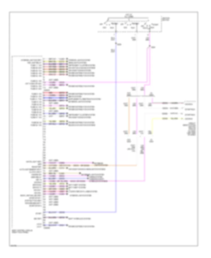
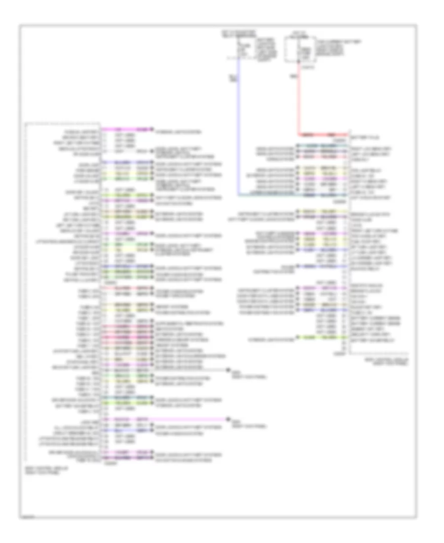
BODY CONTROL MODULES Body Control Modules Wiring Diagram (1 of 2) for Ford F-350 Super Duty XLT 2014 List of elements for Body Control Modules Wiring Diagram (1 of 2) for Ford F-350 Super Duty XLT 2014: 113 (not used) (or cdc62) (or cdc63) Acc Acc/run Air conditioning & headlights systems Air conditioning system Anti-theft system Autolamp sensor input Back lighting led (fet) Body control module (right kick panel) Bpp Bsi (fet) C2280a C2280b Cbp31 Cbp32 Cbp34 Cbp35 Cbp36 Cbp37 Cbp38 Cbp41 Cbp44 Ccb08 Cdc30 Cdc33 Cdc34 Cdc35 Cdc62 Cdc63 Cet53 Circuit deactivation ignition module (w/ cdim) (left end of dash) Clf12 Cls32 Clutch input Computer data lines system Crh04 Epats rx Epats tx Exterior lights system Fog lamp relay Fuse 11, 10a Fuse 23, 15a Fuse 24, 15a Fuse 26, 5a Fuse 27, 20a Fuse 28, 15a Fuse 29, 20a Fuse 31, 5a Fuse 32, 15a Fuse 34, 10a Fuse 35, 5a Fuse 36, 10a Fuse 37, 10a Fuse 38, 10a Fuse 41, 7.5a Fuse 42, 5a Fuse 44, 10a Fuse 45, 5a Fuse 46, 10a Fuse 9, 10a Hazard sw Headlights system Horn relay Horns system Hot at all times Hot in run or acc Ignition switch Instrument cluster system Interior lighting (fet) Interior lights system Key in Lin 01 Lin 04 Ms can + Ms can - Navigation & sound systems Off Power distribution system Red Ripcord security Run Run/start S284 S285 Sbp09 Sbp11 Sbp24 Sbp26 Sbp28 Sbp29 Sbp46 Seats system Shift interlock system Sound & navigation systems Start Start/run Start/stop 1 Start/stop 2 Strt button (fet) Vdb06 Vdb07 Vdn01 Vlf14 Vln04 Vln33 Vrt23 Vrt24 W/ cdim W/o cdim Warning & shift interlock systems White light (fet) Body Control Modules Wiring Diagram (2 of 2) for Ford F-350 Super Duty XLT 2014 List of elements for Body Control Modules Wiring Diagram (2 of 2) for Ford F-350 Super Duty XLT 2014: 179 (not used) 3rd row seat (fet) All lock/unlock relay Anti-theft & door locks systems Anti-theft & engine controls systems engine controls system Battery current sense Battery junction box (bjb) (left side of engine compt) Battery plus Battery saver relay Body control module (right kick panel) Brake fluid sw Brake fluid sw rtn Bsi (fet) C1617c C2280c C2280d C2280e C2280f C2280g Cbb56 Cbp01 Cbp30 Cbp31 Cbp32 Cbp33 Cbp34 Cbp40 Cbp43 Cdc55 Cdc64 Ce226 Ce436 Circuit breaker 48, 30a Clf02 Clf03 Clf04 Clf05 Clf12 Cln09 Cln25 Cls18 Cls19 Cls21 Cls23 Cls25 Cls27 Cls28 Cls52 Cmc19 Cmc25 Computer data lines system Cpk19 Cpk23 Cpk28 Cpk29 Cpk30 Cpk31 Cpl11 Cpl25 Cpl26 Cpl31 Cpl36 Cpl39 Cpl51 Cpl52 Cpw73 Decklid key unlock Decklid/liftgate sw Door key lock Door key unlock Door lock Door locks & anti-theft systems Door locks, anti-theft, interior lights & instrument cluster systems Door unlock Driver door unlock & all lock/unlock rly fuse 19, 20a Driver door unlock rly Energy mgt (fet) Exterior lights & mirrors systems Exterior lights system Fog lamp relay Front led turn outage Fuel pump (fet) Fuse 1, 30a Fuse 2, 15a Fuse 20a Fuse 21, 10a Fuse 3, 30a Fuse 30, 15a Fuse 31, 5a Fuse 32, 15a Fuse 33, 10a Fuse 34, 10a Fuse 4, 10a Fuse 40, 10a Fuse 41, 7.5a Fuse 43, 10a Fuse 5, 20a Fuse 6, 5a Fuse 7, 7.5a Fuse 8, 10a Fuse 9, 10a G302 (right kick panel) Gd179 Gnd Gnd rtn analog Headlights system High current battery junction box (right side of engine compt) Hood ajar Horn rly Horns system Hot at all times Hot in run or start Hot w/ run/start relay energized Hs can + Hs can - Instrument cluster system Interior lights system Keypad illum (fet) Keypad sw a Keypad sw b Keypad sw c Left hi beam (fet) Left led turn outage Left low beam (fet) Lf door ajar Lf turn lamp (fet) Lh corner lamp (fet) Liftgate glass release relay Liftgate sw Liftgate/glass/decklid ajar sw Lin 02 Lin 03 Logic gnd Lr door ajar Lr stop/turn lamp (fet) Lr turn lamp (fet) Mega fuse 125a Memory systems Mirrors & memory systems Navigation & sound systems Navigation system Park brake Pcm wake up (fet) Power distribution system Power tops system Power windows system Puddle lamp (fet) Pulse train (fet) Red Rev lp (fet) Rf door ajar Rf turn lamp (fet) Rh corner lamp (fet) Right hi beam (fet) Right led turn outage Right low beam (fet) Rmc19 Rr door ajar Rr stop/turn lamp (fet) Rr turn lamp (fet) Run/acc relay Run/start (fet) Sbf03 Sbp02 Sbp03 Sbp05 Sbp06 Sbp07 Sbp08 Sbp19 Sbp21 Seats system Security horn (fet) Srh01 Stop/chmsl (fet) Vdb04 Vdb05 Vdn03 Wiper/washer system
COMPUTER DATA LINES Computer Data Lines Wiring Diagram (1 of 2) for Ford F-350 Super Duty XLT 2014 List of elements for Computer Data Lines Wiring Diagram (1 of 2) for Ford F-350 Super Duty XLT 2014: 73 (body main wiring harness, near breakout to restraints control module) (instrument panel wiring harness, in breakout to g203) (instrument panel wiring harness, in breakout to inertia fuel shutoff switch) s254 (instrument panel wiring harness, near breakout to c215) s233 (instrument panel wiring harness, near breakout to c240c) s224 (instrument panel wiring harness, near breakout to headlamp switch) (w/ parking aid) s241 (instrument panel wiring harness, near breakout to headlamp switch) s235 (instrument panel wiring harness, near breakout to inertia fuel shutoff switch) s211 (instrument panel wiring harness, near breakout to instrument panel power point 1) (lower left center of dash) g203 (sony w/ 8 inch touch screen) s307 Accessory protocol interface module (w/ sync) (right end of dash) Audio control module (acm) (w/ cd player) Audio digital signal processing (dsp) module (sony w/ 8 inch touch screen) (crew cab: base of right "c" pillar) (super cab: center rear of cab floor) Automatic a/c Body control module (bcm) (right kick panel) C207 C212 C2280a C2280b C2280f C228a C240b C2414a C290a C300 C312 C3154a C3265c C341d Circuit deactivation ignition module (cdim) (if equipped) (left end of dash) Data link connector (dlc) (bottom left end of dash) Driver seat module (dsm) (w/ memory) (under driver's seat) Dual climate controlled seat module (dcsm) (w/ climate controlled seats) (under front passenger's seat) Front controls interface module (fcim) (premium audio) Fuse 15a G201 (center of dash) Gd115 Gd184 Global positioning system module (w/ sync) (top center of dash) Heated steering wheel module (hswm) (if equipped) (bottom left end of dash) Hot at all times Hs can + Hs can - Hvac module I can + I can - Manual a/c Ms can + Ms can - Parking aid module (pam) (if equipped) (lower left end of dash) S210 S223 S228 S234 (instrument panel wiring harness, near breakout to c215) S236 (instrument panel wiring harness, near breakout to headlamp switch) c212 S240 (w/ parking aid) S253 S255 S256 S308 (sony w/ 8 inch touch screen) (body main wiring harness, near breakout to restraints control module) S380 (body main wiring harness, near breakout to c311) S381 Sbp24 Sony w/ 8 inch touch screen Steering column control module (sccm) (top of steering column) Tire pressure monitor module (right end of dash) Vdb04 Vdb05 Vdb06 Vdb07 Vdb13 Vdb14 Computer Data Lines Wiring Diagram (2 of 2) for Ford F-350 Super Duty XLT 2014 List of elements for Computer Data Lines Wiring Diagram (2 of 2) for Ford F-350 Super Duty XLT 2014: 71 (body main wiring harness, near breakout to c311) s377 (instrument panel wiring harness, in breakout to inertia fuel shutoff switch) (instrument panel wiring harness, near breakout to c213) (6.7l turbo diesel w/ rapid heat) s218 (instrument panel wiring harness, near breakout to c213) (6.7l turbo diesel w/ rapid heat) s221 (t-box jumper wiring harness, near breakout to c2108) (crew chief) s271 (transmission wiring harness, near breakout to c1010) s187 (urea jumper wiring harness, near breakout to reductant injector) 6.7l turbo diesel Anti-lock brake system (abs) module (left side of engine compt) Auxiliary heater control module (ahcm) (6.7l turbo diesel w/ rapid heat) (top left front of hvac module) C1010 C1232b C1273c C1415 C146 C175b C1i0 C210 C2108 C214 C2371a C2463b C263 C310b C3611a C3619a Can2 + Can2 - Crew chief Except 6.7l turbo diesel Glow plug control module (gpcm) (right rear of engine compt) Hs can + Hs can - Hs can yaw + Hs can yaw - Hsc1-a Hsc1-c Hsc2-a Hsc2-c I can + I can - Instrument panel cluster (ipc) Nca Nox sensor module 11 (except high sulfur) (near nox sensor 11) Nox sensor module 12 (except high sulfur) (near nox sensor 12) Powertrain control module (pcm) (right rear of engine compt) Restraints control module (rcm) (under center console) S102 S103 (gasoline: engine control sensor engine compt wiring harness, near breakout to c1581) (diesel: engine control sensor engine compt wiring harness, in breakout to c140) S106 S107 (engine control sensor engine compt wiring harness, near breakout to anti-theft hood switch) S188 (transmission wiring harness, near breakout to c1010) S202 (engine control sensor engine compt wiring harness, near breakout to body control module) S212 (w/ sync) (instrument panel wiring harness, near breakout to inertia fuel shutoff switch) S213 (w/ sync) (instrument panel wiring harness, near breakout to inertia fuel shutoff switch) S229 (instrument panel wiring harness, in breakout to inertia fuel shutoff switch) S230 S270 (crew chief) (t-box jumper wiring harness, near breakout to c2108) S378 (body main wiring harness, near breakout to c311) S403 S404 Telematics module (crew chief) (right end of dash) Trailer brake control (tbc) module (center of dash) Transfer case control module (tccm) (right end of dash) Transmission control module (tcm) (rear of transfer case) Vca23 Vca24 Vdb04 Vdb05 Ve348 Ve349
COOLING FAN Cooling Fan Wiring Diagram for Ford F-350 Super Duty XLT 2014 List of elements for Cooling Fan Wiring Diagram for Ford F-350 Super Duty XLT 2014: 45 (engine control sensor & fuel charge wiring harness, near breakout to c133) (6.2l flex fuel) s116 (not used) 6.2l flex fuel 6.7l turbo diesel 6.8l Battery junction box (left side of engine compt) C1047 C1163 C1165 C1220 C1232b C1232e C133 C175b C175e Cht Cooling fan (6.2l flex fuel) (behind radiator) Cooling fan (6.7l turbo diesel) (behind radiator) Cylinder head temperature sensor (6.2l flex fuel: rear of block, under intake manifold) (6.8l: rear of right cylinder head) Ect Ect 2 Engine controls system Engine coolant temperature (ect) sensor (top front of engine) Except 6.7l turbo diesel Fcv Fss Fuse 10a G103 (right rear of engine compt) Hot w/ pcm power relay energized Le111 Powertrain control module (right rear of engine compt) Pwrgnd Re405 Red S101 (6.2l flex fuel) S1013 (engine wiring engine harness, near breakout to intake throttle actuator) Secondary cooling system engine coolant temperature 2 sensor (top right front of engine) Sigrtn Vbpwr Ve203 Ve712 Ve716 Ve759 Vec10 Vpwr
CRUISE CONTROL
6.2L FLEX FUEL 6.2L Flex Fuel, Cruise Control Wiring Diagram for Ford F-350 Super Duty XLT 2014 List of elements for 6.2L Flex Fuel, Cruise Control Wiring Diagram for Ford F-350 Super Duty XLT 2014: 94 (body main wiring harness, in breakout to brake pedal position switch) s207 (lower left center of dash) g202 (right rear of engine compt) g103 (transmission wiring harness, near breakout to c145) 6.2l flex fuel 6.8l Accelerator pedal position sensor (accelerator pedal support) App1 App2 Apprtn Apprtn2 Appverf2 Appvref Body control module (bcm) (right kick panel) Bpp Bps Brake pedal position switch (top of brake pedal assembly) C175b C175e C175t C210 C218b C218c C2280b C2280d C2414a C2414d Ccb08 Ce412 Ce426 Ces09 Clockspring (top of steering column) Cncl/ rsm Computer data lines system Electronic throttle control (throttle body assembly) Electronic throttle control motor (etc) (throttle body assembly) Electronic throttle control position sensor (throttle body assembly) Engine controls system Etcref Etcrtn Exterior lights system Fuse 10a Fuse 5a G300 (left kick panel) Gd113 Gd185 Gnd Hot at all times Hs can + Hs can - Hs can+ Hs can- Instrument panel cluster (ipc) Interior lights system Le111 Le134 Le136 Le137 Left steering wheel switch Logic gnd Nca On/off Oss Output shaft speed (oss) sensor (top rear of transmission) Powertrain control module (right rear of engine compt) Re134 Re136 Re137 Ret04 Ret24 S184 S239 Sbp26 Sccrtn Sccs Set+ Set- Steering column control module (top of steering column) Tacm+ Tacm- Tan Torqshift 6 transmission Tp1 Tp2 Tr gnd Vbatt Vbpwr Vdb04 Vdb05 Ve701 Ve702 Ve818 Ve819 W/ 5-button message center
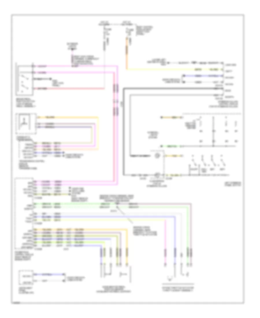
6.7L TURBO DIESEL 6.7L Turbo Diesel, Cruise Control Wiring Diagram for Ford F-350 Super Duty XLT 2014 List of elements for 6.7L Turbo Diesel, Cruise Control Wiring Diagram for Ford F-350 Super Duty XLT 2014: 85 (engine wiring harness, near breakout to engine coolant temperature sensor) s123 (engine wiring harness, near breakout to intake throttle actuator) (lower left center of dash) g202 Accelerator pedal position sensor (accelerator pedal support) App App2 Apprtn Apprtn2 Appverf2 Appvref Body control module (bcm) (right kick panel) Bps bpp Brake pedal position switch (top of brake pedal assembly) C1232b C1232e C210 C218b C218c C2280b C2280d C2414a C2414d Ccb08 Ce412 Ce426 Ces09 Clockspring (top of steering column) Cncl/ rsm Computer data lines system Exterior lights system Fuse 10a Fuse 5a G103 (right rear of engine compt) G300 (left kick panel) Gd113 Gd185 Gnd Hot at all times Hs can + Hs can - Hs can+ Hs can- Instrument panel cluster (ipc) Intake throttle actuator (throttle body assembly) Interior lights system Le111 Le136 Le137 Le423 Left steering wheel switch Logic gnd Nca On/off Oss hall Powertrain control module (right rear of engine compt) Re136 Re137 Re405 Ret04 Ret24 S1013 S207 S239 Sbp26 Sccrtn Sccs Set+ Set- Sigrtn Steering column control module (top of steering column) Tacm+ Tacm- Tan Torqshift 6 transmission Transmission control module (rear of transfer case) Trgnd Vbatt Vbpwr Vdb04 Vdb05 Ve701 Ve702 Ve820 Vref W/ 5-button message center
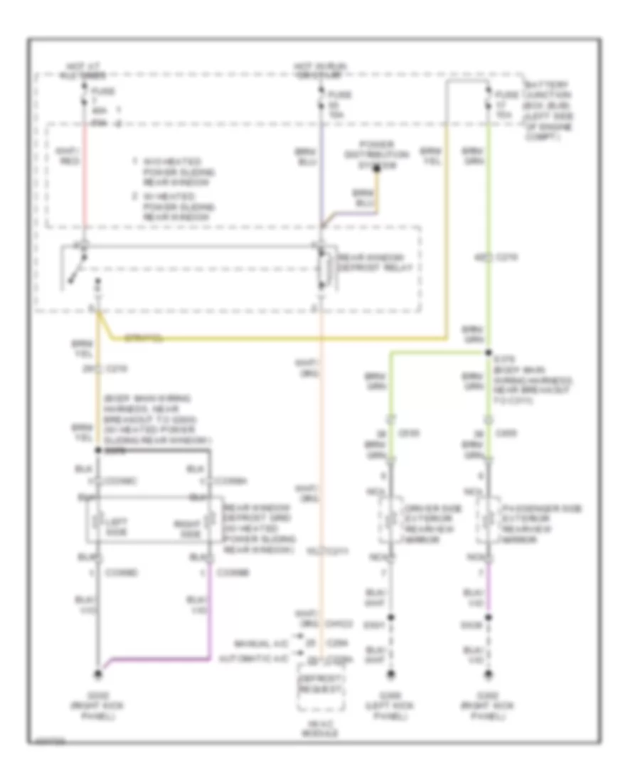
DEFOGGERS Defoggers Wiring Diagram for Ford F-350 Super Duty XLT 2014 List of elements for Defoggers Wiring Diagram for Ford F-350 Super Duty XLT 2014: 37 (body main wiring harness, near breakout to g300) (w/ heated power sliding rear window) s379 50a Automatic a/c Battery junction box (bjb) (left side of engine compt) C210 C211 C228a C294 C3368a C3368b C3368c C3368d C555 C655 Defrost request Driver side exterior rearview mirror Fuse 10a Fuse 15a Fuse 40a G300 (left kick panel) G302 (right kick panel) Hot at all times Hot in run or start Hvac module Left side Manual a/c Nca Passenger side exterior rearview mirror Power distribution system Rear window defrost grid (w/ heated power sliding rear window) Rear window defrost relay Right side S376 (body main wiring harness, near breakout to c311) S501 S639 W/ heated power sliding rear window W/o heated power sliding rear window
ENGINE PERFORMANCE
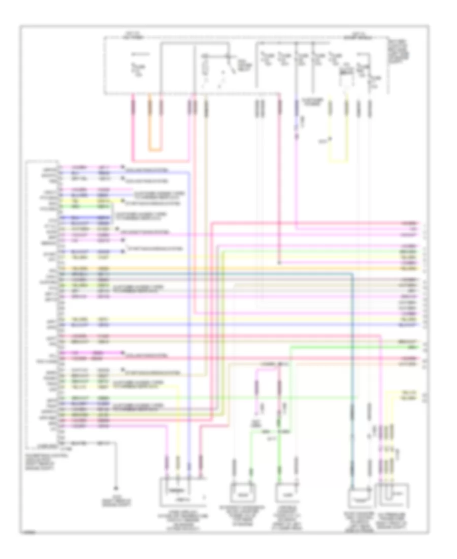
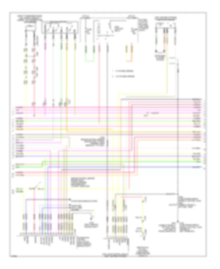
6.2L FLEX FUEL 6.2L Flex Fuel, Engine Performance Wiring Diagram (2 of 6) for Ford F-350 Super Duty XLT 2014 List of elements for 6.2L Flex Fuel, Engine Performance Wiring Diagram (2 of 6) for Ford F-350 Super Duty XLT 2014: 77 (engine control sensor engine compt wiring harness, near breakout to right headlamp) (front passenger's rear view mirror assembly) ambient air temperature (aat) sensor (left center of frame) fuel pump module Apprtn2 Appvref2 Battery junction box (bjb) (left side of engine compt) C1415 C1581 C175b C210 C211 C263 C265 C310a C601 C651 C655 Cbb33 Cdc10 Ce515 Ce608 Computer data lines system Cr167 Ens Fpc Fpm Fppwr Fprtn Ftp Fuel pump (fp) relay Fuel pump control module (left center of frame) Fuse 10a Fuse 20a G103 (right rear of engine compt) G136 (wide frame/narrow frame w/ mid fuel tank) (center of left frame rail) G402 (narrow frame w/ aft fuel tank) (left side of frame, near axle) Gd113 Gd177 Gencom Gnd Hot at all times Hs can + Hs can - Instrument cluster system Kapwr Le137 Le230 Le424 Nca Powertrain control module (pcm) (right rear of engine compt) Pwr gnd R/s Re137 Re407 Re515 Restraints control module (rcm) (under center console) S100 S156 (engine control sensor engine compt wiring harness, near breakout to c1581) S196 (wide frame/narrow frame w/ mid fuel tank) s462 (narrow frame w/ aft fuel tank) Sbb72 Sig rtn Sigrtn Sst-d Sst-u Starting/charging system Tow haul switch Tows Vdb04 Vdb05 Ve225 Ve518 Ve922 Vpwr Vpwr fuel Vref W/ power mirrors W/o power mirrors 6.2L Flex Fuel, Engine Performance Wiring Diagram (3 of 6) for Ford F-350 Super Duty XLT 2014 List of elements for 6.2L Flex Fuel, Engine Performance Wiring Diagram (3 of 6) for Ford F-350 Super Duty XLT 2014: 47 (body main wiring harness, in breakout to brake pedal position switch) s207 (center of dash) trailer brake control (tbc) module (taped to harness near c422) (taped to harness near c465) (top of fuel tank) fuel tank pressure (ftp) transducer sensor (top of steering column) passive anti-theft transceiver (transmission wiring harness, in breakout to torqshift 6 transmission) s182 Body control module (bcm) (right kick panel) Boo C1415 C1581 C2108 C212 C2280b C2280d C2280f C263 C465 Crew chief Fuel pump (fet) Fuse 10a Fuse 5a Hot at all times Hot in start or run Lpc Micro Narrow frame Oss Pcm wake up (fet) S200 (engine control sensor engine compt wiring harness, near breakout to body control module) S227 Ssa Ssb Ssc Ssd Sse Tcc Tftin Tftout/sigrtn Torqshift 6 transmission Trgnd Trs/ tr-p Tspc1 Tspc2 Tss Vbpwr Wide frame 6.2L Flex Fuel, Engine Performance Wiring Diagram (4 of 6) for Ford F-350 Super Duty XLT 2014 List of elements for 6.2L Flex Fuel, Engine Performance Wiring Diagram (4 of 6) for Ford F-350 Super Duty XLT 2014: 77 (accelerator pedal support) accelerator pedal position sensor (left exhaust, downstream of catalytic converter) heated oxygen sensor (ho2s) 22 (left exhaust, upstream of catalytic converter) universal heated oxygen sensor (ho2s) 21 (right exhaust, downstream of catalytic converter) heated oxygen sensor (ho2s) 12 (right exhaust, upstream of catalytic converter) universal heated oxygen sensor (ho2s) 11 (top of brake pedal assembly) brake pedal position switch (transmission wiring harness, near breakout to universal heated oxygen sensor 11) s180 C145 C175t C210 Cat15 Ce233 Ce234 Ce235 Ce236 Cet05 Cet06 Cet07 Cet08 Cet09 Cet22 Cet25 Cet49 Cet50 G300 (left kick panel) Ho2s12 Ho2s22 Htr12 Htr22 Le111 Le448 Le449 Le450 Le451 Le452 Le453 Lpc Nca Oss hall Powertrain control module (pcm) (right rear of engine compt) Re242 Re406 Red Ret04 Ret24 S181 Sigrtn Ssa Ssb Ssc Ssd Sse Tcc Tftin Tftout/sigrtn Tows Trgnd Trp Tspc1 Tss hall Uo2s11 Uo2s21 Uo2sgref11 Uo2sgref21 Uo2shtr11 Uo2shtr21 Uo2spc11 Uo2spc21 Uo2spct11 Uo2spct21 Vbpwr Ve730 Ve733 Ve826 Ve827 Vet27 Vet33 6.2L Flex Fuel, Engine Performance Wiring Diagram (5 of 6) for Ford F-350 Super Duty XLT 2014 List of elements for 6.2L Flex Fuel, Engine Performance Wiring Diagram (5 of 6) for Ford F-350 Super Duty XLT 2014: 40 (coil on plugs 1, 2, 3, & 4: top of right valve cover) (coil on plugs 5, 6, 7 & 8: top of left valve cover) coil on plug (cop) (front of right cylinder head) variable camshaft timing (vct 11) solenoid (near breakout to fuel injector 3) s119 (rear of left cylinder bank) camshaft position sensor 21 (cmp 21) (top left front of engine) ignition transformer capacitor 2 (top right front of engine) ignition transformer capacitor 1 C1168 C175e Ce205 Ce206 Ce207 Ce208 Ce209 Ce210 Ce211 Ce212 Ce303 Ce304 Ce308 Ce310 Ce412 Ce426 Cop1a Cop2h Cop6e Cop8d powertrain control module (pcm) (right rear of engine compt) Fuel injectors (fuel injectors 1, 2, 3 & 4: top of right cylinder bank) (fuel injectors 5, 6, 7 & 8: top of left cylinder bank) Inj-1 Inj-2 Inj-3 Inj-4 Inj-5 Inj-6 Inj-7 Inj-8 S113 (near breakout to fuel injector 6) S114 S118 Tacm + Tacm - 6.2L Flex Fuel, Engine Performance Wiring Diagram (6 of 6) for Ford F-350 Super Duty XLT 2014 List of elements for 6.2L Flex Fuel, Engine Performance Wiring Diagram (6 of 6) for Ford F-350 Super Duty XLT 2014: 63 (engine control sensor & fuel charge wiring harness, near breakout to c1168) s120 (engine control sensor & fuel charge wiring harness, near breakout to c133) s116 (left rear of engine) crankshaft position sensor (not used) (rear of block, under intake manifold) cylinder head temperature (cht) sensor (rear of right cylinder bank) camshaft position sensor 11 (cmp 11) (under intake manifold, in left cylinder bank) knock sensor 2 (under intake manifold, in right cylinder bank) knock sensor 1 C1168 C133 C175e Ce113 Ce305 Ce306 Ce307 Ce309 Ce421 Ce422 Cht Ckp+ Ckp- Cmc24 Cmp11 Cmp21 Cop3f Cop4c Cop5b Cop7g De135 Electronic throttle control (throttle body assembly) Eop-sw Etc ref Etc rtn Evapcp Ks1+ Ks1- Ks2+ Ks2- Le111 Le134 Oil pressure switch (lower left front of engine) Powertrain control module (pcm) (right rear of engine compt) Re134 Re135 Re323 Re324 Re405 S115 (engine control sensor & fuel charge wiring harness, near breakout to evaporative emission purge valve) Shd rtn Sigrtn Tp1 Tp2 Vct11 Vct21 Ve711 Ve712 Ve736 Ve738 Ve801 Ve802 Ve818 Ve819 Vref
6.7L TURBO DIESEL 6.7L Turbo Diesel, Engine Performance Wiring Diagram (2 of 7) for Ford F-350 Super Duty XLT 2014 List of elements for 6.7L Turbo Diesel, Engine Performance Wiring Diagram (2 of 7) for Ford F-350 Super Duty XLT 2014: 74 (body main wiring harness, in breakout to brake pedal position switch) (center of dash) trailer brake control module (middle of exhaust) (except high sulfur) reductant injector (middle of left frame rail) water- in-fuel sensor (near nox sensor 12) nox sensor 12 (on oil filter bracket) engine oil temperature sensor (right front of engine compt) a/c pressure transducer (taped to harness near c422) (top of steering column) passive anti-theft transceiver 10a All others B00 Body control module (bcm) (right kick panel) Brake pedal position switch (top of brake pedal assembly) C1046 C110 C139 c3047 C1415 C1581 C210 C2108 C212 C2280b C2280d C2280f C263 C3047 c139 C3611a C3611b C465 Can2 + Can2 - Cbb36 Ccb08 Com Computer data lines system Crew chief Fuse G300 (left kick panel) G400 (rear of left frame rail) G401 (except narrow frame) g403 (narrow frame) (except narrow frame: middle of left frame rail) Gd180 Gnd Heater + Heater - Hot at all times Ip1 Ip2 Memory + Memory - Micro Narrow frame Narrow frame w/ aft fuel tank Nca Nox sensor module 12 (except high sulfur) (near nox sensor 12) Pcm wake up (fet) Pnk Pwr gnd Rdpc Reductant pump assembly (except high sulfur) (top of reductant tank) Reductant purge valve (except high sulfur) (top of reductant tank) S100 (engine control sensor engine compt wiring harness, near breakout to right headlamp) S207 S3000 S3002 S405 Sig gnd Trimming resistor Ve348 Ve349 Vpwr Vs + Wide frame Wide frame/ 6.7L Turbo Diesel, Engine Performance Wiring Diagram (3 of 7) for Ford F-350 Super Duty XLT 2014 List of elements for 6.7L Turbo Diesel, Engine Performance Wiring Diagram (3 of 7) for Ford F-350 Super Duty XLT 2014: 84 (near nox sensor 11) (except high sulfur) nox sensor module 11 (right kick panel) inertia fuel shutoff (ifs) switch 20a All others Battery junction box (bjb) (left side of engine compt) C110 C1232t C146 C1581 C211 C3047 c139 C3619a C3619b Can2 + Can2 - Cbb36 Ce354 Ce355 Com Computer data lines system Dpf Dpf12 Egt 11 Egt 12 Egt 13 Egt 14 Fuel pump Fuel pump (fp) motor diode Fuel pump (fp) relay Fuse Fuse 10a G103 (right rear of engine compt) G135 (center of left frame rail) Gd113 Heater + Heater - Hot at all times Ip1 Ip2 Le425 Le461 Memory + Memory - Nca Nox sensor 11 (middle of exhaust) Pnk Powertrain control module (pcm) (right rear of engine compt) Pwr gnd Rdinjgnd Rdinjpwr Rdl1 Rdl2 Rdl3 Rdlrtn Rdp Rdpc Rdpgc Rdt Re406 Re839 Reductant pressure sensor (except high sulfur) (top of reductant tank) S124 (engine control sensor engine compt wiring harness, near breakout to c1581) Sig gnd Sigrtn Trimming resistor Ve348 Ve349 Ve350 Ve351 Ve713 Ve722 Ve726 Ve747 Ve752 Ve754 Ve833 Ve838 Ve839 Ve840 Ve841 Vpwr Vref Vs + Wide frame/ narrow frame w/ aft fuel tank 6.7L Turbo Diesel, Engine Performance Wiring Diagram (4 of 7) for Ford F-350 Super Duty XLT 2014 List of elements for 6.7L Turbo Diesel, Engine Performance Wiring Diagram (4 of 7) for Ford F-350 Super Duty XLT 2014: 41 (customer access) (exhaust aftertreatment pump injector tank wiring harness, near breakout to reductant heater & sensor assembly) s3001 (urea jumper wiring harness, near breakout to exhaust gas temperature sensor 1) (urea jumper wiring harness, near breakout to reductant injector) 10a A/c clutch relay All others Battery junction box (bjb) (left side of engine compt) C1047 C110 C139 c3047 C1581 Cooling fans system Diesel particulate filter pressure sensor 1 bank 1 (right frame rail) Diesel particulate filter pressure sensor 2 (except high sulfur) (right frame rail) Except high sulfur Exhaust gas temperature (egt) sensor 1 (in exhaust) Exhaust gas temperature (egt) sensor 2 (in exhaust) Exhaust gas temperature (egt) sensor 3 (in exhaust) Exhaust gas temperature (egt) sensor 4 (in exhaust) Fuse Fuse 10a Fuse 15a Fuse 25a Fuse n/a G104 (left rear of engine compt) G400 (rear of left frame rail) Hot at all times Hot in start or run Nca Pcm power relay Power distribution system Reductant heater & sensor assembly (top of reductant tank) Reductant heater relay Reductant pressure line heater assembly (top of reductant tank) S108 S122 S3002 S405 S408 Wide frame/ narrow frame w/ aft fuel tank 6.7L Turbo Diesel, Engine Performance Wiring Diagram (6 of 7) for Ford F-350 Super Duty XLT 2014 List of elements for 6.7L Turbo Diesel, Engine Performance Wiring Diagram (6 of 7) for Ford F-350 Super Duty XLT 2014: 19 (engine wiring harness, near breakout to intake throttle actuator) (front of left cylinder bank fuel rail assembly) fuel rail pressure (frp) sensor (left front of engine) charge air cooler temperature (cact) sensor (on fuel rail) fuel rail temperature sensor (top front of engine) engine coolant temperature (ect) sensor (top of left cylinder bank) (top of right cylinder bank) (top right front of engine) egr temperature sensor (top right front of engine) secondary cooling system engine coolant temperature 2 sensor C1047 Crankshaft position sensor (left rear of engine) Egr valve (top right front of engine) Fuel injector 2 Fuel injector 3 Fuel injector 5 Fuel injector 8 Intake throttle actuator (throttle body assembly) S1013 S123 (engine wiring harness, near breakout to engine coolant temperature sensor) 6.7L Turbo Diesel, Engine Performance Wiring Diagram (7 of 7) for Ford F-350 Super Duty XLT 2014 List of elements for 6.7L Turbo Diesel, Engine Performance Wiring Diagram (7 of 7) for Ford F-350 Super Duty XLT 2014: 65 (engine wiring harness, near breakout to fuel injector 1) (top center front of engine) (if equipped) turbocharger wastegate regulating valve solenoid (top center front of engine) fuel volume control valve (top center of engine) crankcase ventilation sensor (top rear of engine) turbocharger actuator (top right front of engine) egr cooler bypass valve solenoid C1046 C1047 C1232e Cact Camshaft position sensor Ce256 Ce257 Ce412 Ce426 Ce435 Ce460 Ce932 Ckp Cmc24 Cmp Ect Ect2 Egrt 11 Eop sw Eot Exhaust pressure (ep) sensor (top rear of engine) Fdps Fpc Frp Frt Fuel delivery pressure switch (on fuel rail) Fuel pressure control valve Fvcv G103 (right rear of engine compt) Le111 Le152 Le423 Le458 Manifold absolute pressure (map) sensor (top center of engine) Map Oil pressure switch (on oil filter bracket) Powertrain control module (pcm) (right rear of engine compt) Re405 S1002 (engine wiring harness, near breakout to fuel injector 1) S109 S110 S111 Sigrtn Tacm+ Tacm- Tcwrvs Ve701 Ve716 Ve718 Ve726 Ve727 Ve728 Ve736 Ve755 Ve759 Ve803 Ve820 Vgtc Vref
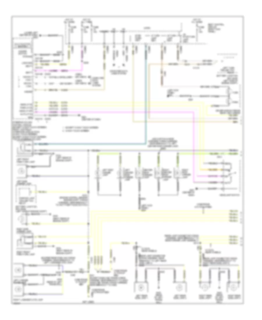
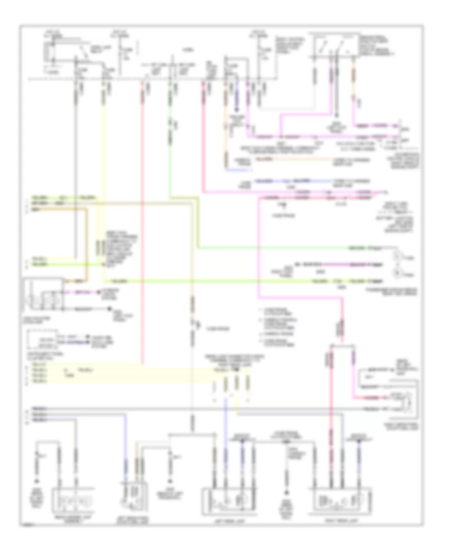
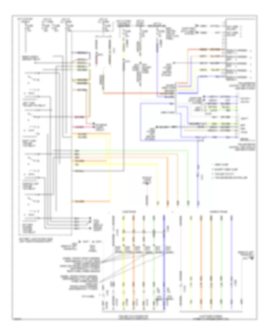
EXTERIOR LIGHTS Backup Lamps Wiring Diagram for Ford F-350 Super Duty XLT 2014 List of elements for Backup Lamps Wiring Diagram for Ford F-350 Super Duty XLT 2014: 74 (customer access) (taped to harness near c422) (frame wiring harness, near breakout to g400) (narrow frame) s440 (rear of left frame rail) g400 (wide frame w/o pickup bed) s400 5th wheel 6.2l flex fuel 6.7l turbo 6.8l Auto-dimming interior mirror Battery junction box (bjb) (left side of engine compt) Body control module (bcm) (right kick panel) C1415 C175b C175t C210 C2280d C2280f C264 C431 C465 Cet22 Computer data lines system Diesel Fuse 10a Fuse 15a G104 (left rear of engine compt) G400 (rear of left frame rail) Hot at all times Hs can + Hs can - Hs can+ Hs can- Le111 Left rear lamp Left reversing lamp Micro Narrow frame Narrow frame & wide frame w/o pickup bed Nca Oss Oss hall Powertrain control module (right rear of engine compt) Ret04 Ret24 Reverse lamp (fet) Reversing Reversing lamp relay Right rear lamp Right reversing lamp S184 (transmission wiring harness, near breakout to c145) S185 S402 (wide frame w/o pickup bed) (rear lamp connector wiring harness, in breakout to right rear lamp) S405 (narrow frame) S411 S414 (rear lamp connector wiring harness near breakout to c465) S446 (5th wheel) (gasoline: frame wiring harness, near breakout to right rear wheel speed sensor) (diesel: frame wiring harness, near breakout to left rear wheel speed sensor) Sigrtn Torqshift 6 transmission Torqshift transmission (6.8l) Tr-p Trailer tow connector (left rear of cargo box) Transmission control module (rear of transfer case) Transmissions system Trgnd Trp Trs/tr-p Tss Tss hall Vbpwr Vdb04 Vdb05 Vet33 Wide frame Wide frame w/ pickup bed Exterior Lamps Wiring Diagram (2 of 2) for Ford F-350 Super Duty XLT 2014 List of elements for Exterior Lamps Wiring Diagram (2 of 2) for Ford F-350 Super Duty XLT 2014: 72 (body main wiring harness, in breakout to dual climate controlled seat module) (w/ power mirrors) s374 (rear lamp connector wiring harness, in breakout to right rear lamp) s422 (rear of left frame rail) g400 (wide frame w/o pickup bed) s400 6.7l turbo diesel 6.8l & 6.2l flex fuel Backup lamps circuit Battery junction box (bjb) (left side of engine compt) Body control module (bcm) (right kick panel) Bpp Bps Brake pedal position (bpp) switch (top of brake pedal assembly) C1232b C1415 C175b C210 C212 C2280b C2280c C2280d C2280e C2280f C465 C555 C655 Ccb08 Ces09 Computer data lines system Fuse 10a Fuse 15a Fuse 5a G300 (left kick panel) G302 (right kick panel) G400 (rear of left frame rail) High mounted stoplamp Hot at all times Hs can + Hs can - Instrument panel cluster (ipc) Interior lights system Left rear lamp Left rear park/ stop/turn lamp Micro Narrow frame Narrow frame & Nca Park Park lamp relay Passenger side exterior rear view mirror Powertrain control module (right rear of engine compt) Rear marker lamp assembly Reversing Rf turn lamp (fet) Right rear lamp Right rear park/ stop/turn lamp Right turn trailer tow relay Rr stop/ turn lamp (fet) Rr turn lamp (fet) S207 (body main wiring harness, in breakout to brake pedal position switch) S405 (narrow frame) S411 S639 Stop/ turn Stop/turn Taped to harness near c422 Taped to harness near c465 Trailer tow circuit Turn W/o pickup bed Wide frame Wide frame w/ pickup bed Wide frame w/o pickup bed Trailer Tow Wiring Diagram for Ford F-350 Super Duty XLT 2014 List of elements for Trailer Tow Wiring Diagram for Ford F-350 Super Duty XLT 2014: 92 (5th wheel) (customer access) (taped to harness near c422) (diesel: frame wiring harness, near breakout to left rear wheel speed sensor) (gasoline: frame wiring harness, near breakout to g400) (diesel: frame wiring harness, near breakout to left rear wheel speed sensor) (gasoline: frame wiring harness, near breakout to right rear wheel speed sensor) (except crew chief) (not used) (rear of left frame rail) g400 5th wheel Backup lamps circuit Battery charge trailer tow relay Battery junction box (bjb) (left side of engine compt) Body control module (right kick panel) Boo Bpp Bptgnd Bptsig Brake C1415 C1581 C2108 C211 C2280b C2280e C431 C432 Cat06 Cat09 Cat14 Cat16 Cat17 Cat19 Cbp31 Cbp35 Computer data lines system Crew chief Ends in harness bpp Ends in harness brake Ends in harness gnd Ends in harness vbatt Ends in harness vpwr Except crew chief Exterior lamps circuit Fuse 10a Fuse 15a Fuse 25a Fuse 30a Fuse 5a G104 (left rear of engine compt) G203 (lower left center of dash) G400 (rear of left frame rail) Gd115 Gnd Gnd-a Hot at all times Hot in start or run Hot w/ park lamp relay energized Hs can + Hs can - Hsc1-a Hsc2-a Igrun-a Lca16 Left turn trailer tow relay Narrow frame Not used hs can+ Not used hs can- Parking lamp trailer tow relay Rat08 Rear window defrost relay Right turn trailer tow relay S121 S272 S273 S443 (5th wheel) S444 (5th wheel) S445 (5th wheel) S446 (5th wheel) S447 (5th wheel) S448 (5th wheel) S449 (5th wheel) Sbb22 Tbo Trailer brake control (tbc) module (center of dash) Trailer brake controller Trailer tow connector (left rear of cargo box) Trailer tow kit Vb-a Vbatt Vdb04 Vdb05 Vpwr Wide frame
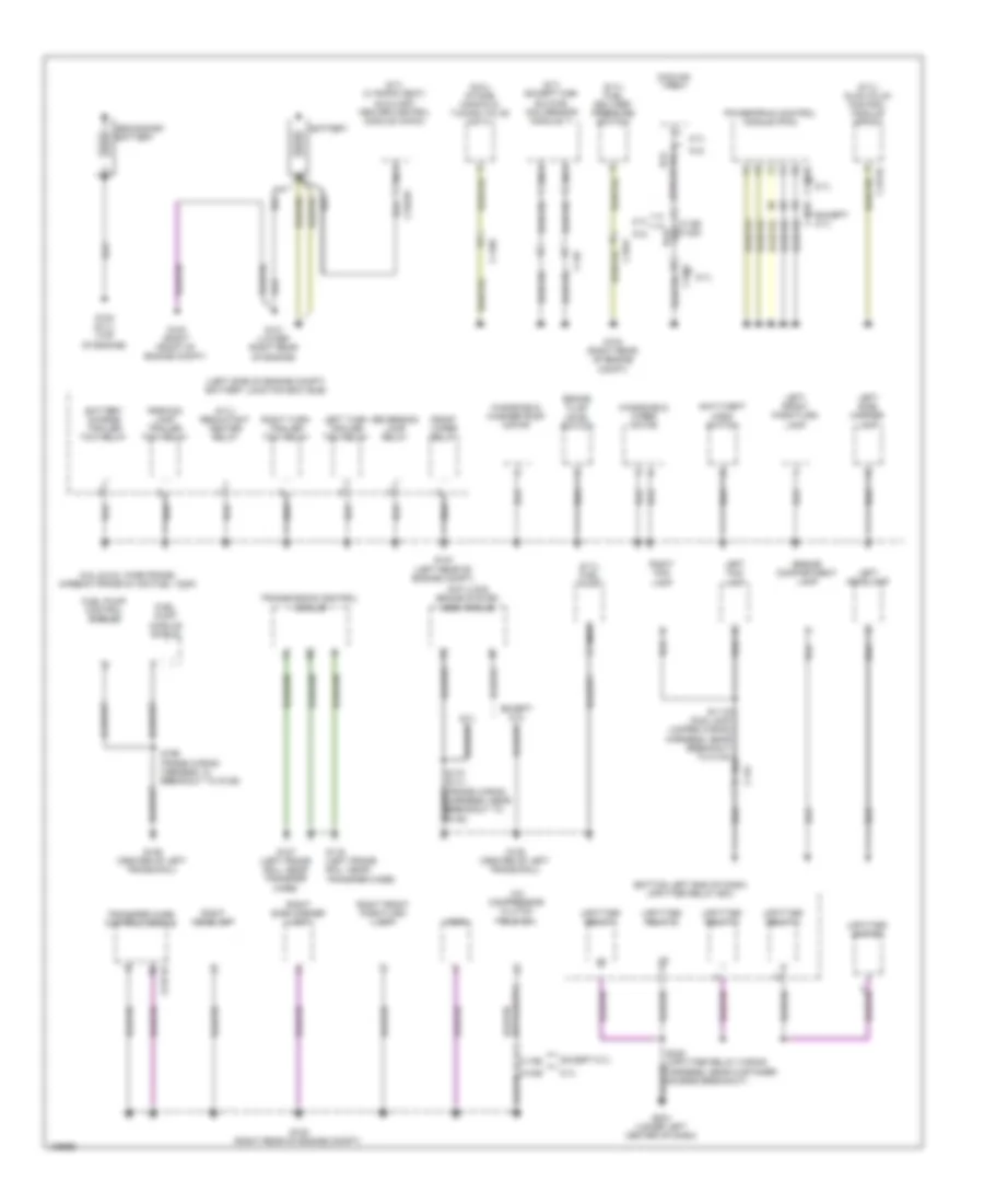
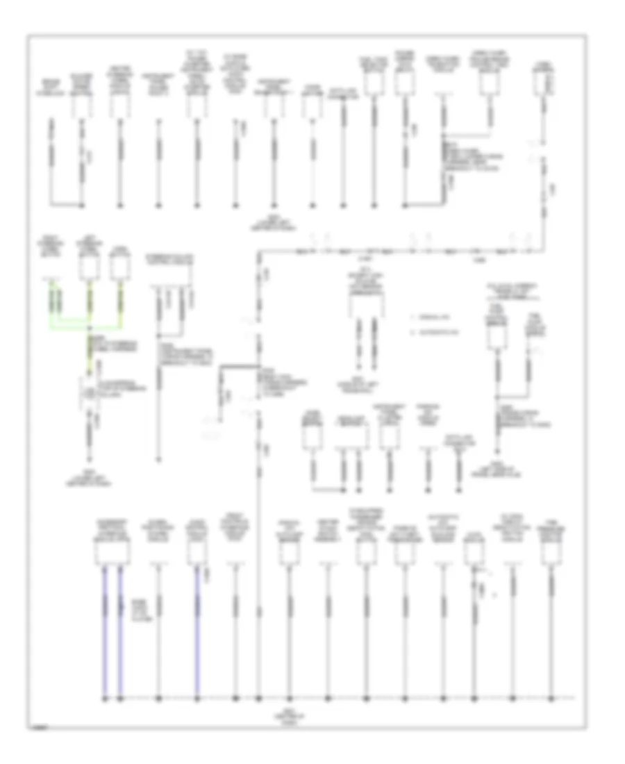
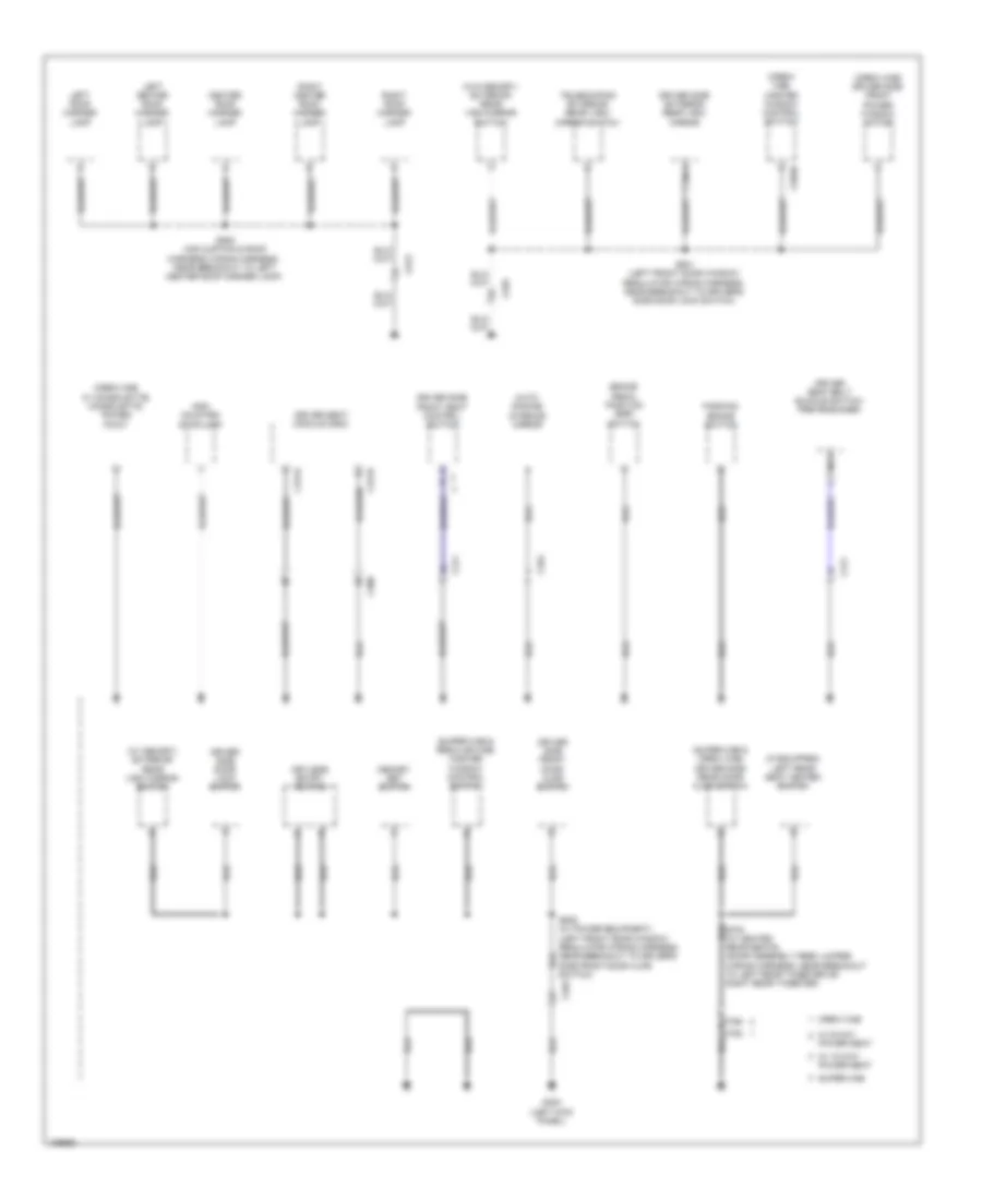
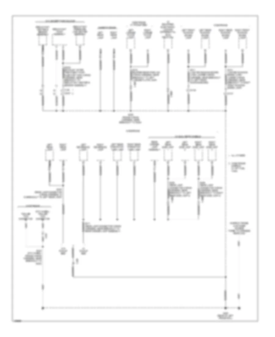
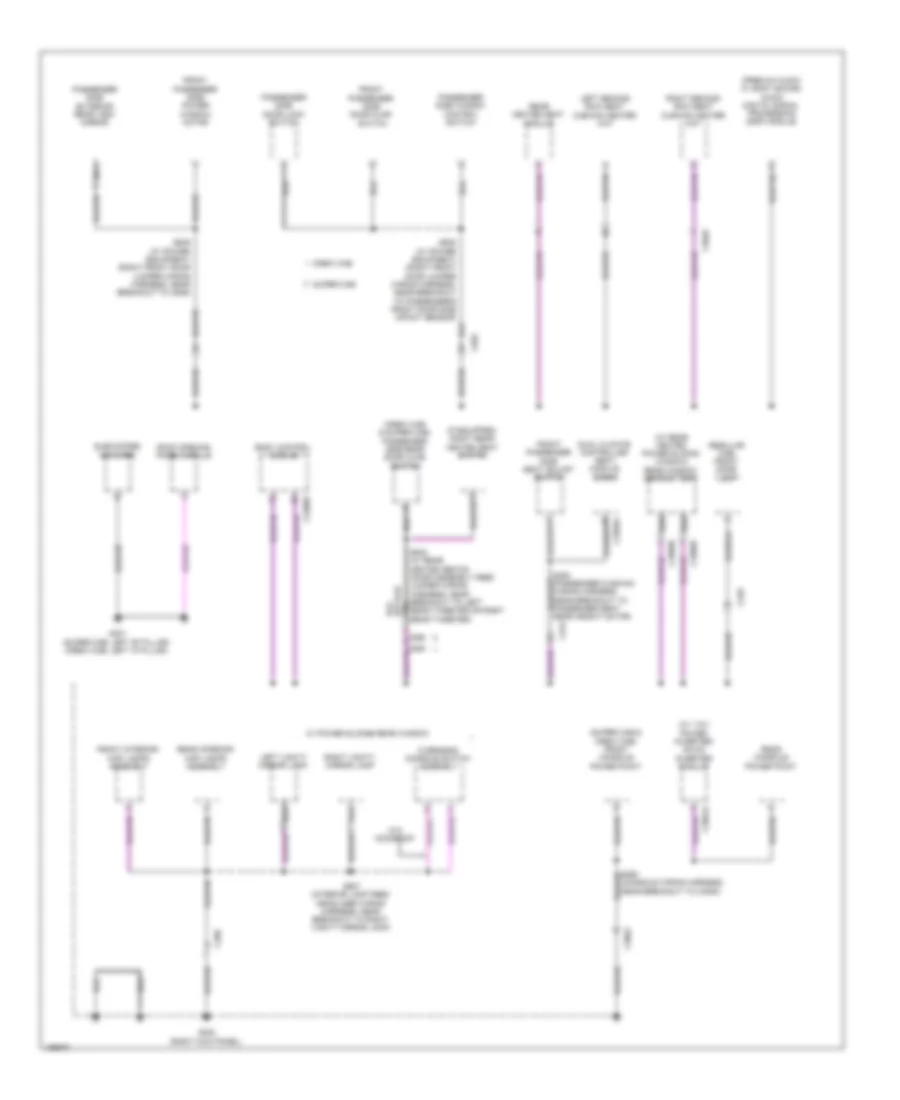
GROUND DISTRIBUTION Ground Distribution Wiring Diagram (1 of 5) for Ford F-350 Super Duty XLT 2014 List of elements for Ground Distribution Wiring Diagram (1 of 5) for Ford F-350 Super Duty XLT 2014: 73 (6.7l except high sulfur) nox sensor module 11 (6.7l w/ rapid heat) auxiliary heater control module (ahcm) (6.7l) fuel delivery pressure switch (6.7l) fuel pump (6.7l) glow plug control module (gpcm) (6.7l) reductant heater relay (6.8l) intake manifold tuning valve (imtv) (bottom left end of dash) upfitter relay box (left side of engine compt) battery junction box (bjb) 6.2l 6.2l & 6.8l wide frame/ narrow frame w/ mid fuel tank 6.7l A/c compressor clutch field coil Anti-lock brake system (abs) module Anti-theft hood switch Battery Battery charge trailer tow relay Brake fluid level switch C1046 C1047 C1168 C1232b C1273c C134 C146 C175b C2371b C2463a Cooling fan Engine compartment lamp Except 6.7l Front wiper relay Fuel pump control module Fuel pump module shield G100 (right front of engine compt) G101 (lower right rear of engine) G102 (6.7l) (top of engine) G103 (right rear of engine compt) G104 (left rear of engine compt) G107 (left frame rail, near transfer case) G108 (right rear of engine compt) G116 (left frame rail, near transfer case) G135 (center of left frame rail) G136 (center of left frame rail) G204 (lower left center of dash) Horn Left fog lamp Left front park/turn lamp Left headlamp Left side marker lamp Left turn trailer tow relay Nca Parking lamp trailer tow relay Powertrain control module (pcm) Reversing lamp relay Right fog lamp Right front park/turn lamp Right headlamp Right side marker lamp Right turn trailer tow relay S170 (6.7l) (frame wiring harness, near breakout to g135) S196 (frame wiring harness, in breakout to g136) S249 (upfitter relay wiring harness, near customer access breakout) Secondary battery Transfer case control module Transmission control module Upfitter relay 1 Upfitter relay 2 Upfitter relay 3 Upfitter relay 4 Upfitter switch Windshield washer pump motor Windshield wiper motor Ground Distribution Wiring Diagram (2 of 5) for Ford F-350 Super Duty XLT 2014 List of elements for Ground Distribution Wiring Diagram (2 of 5) for Ford F-350 Super Duty XLT 2014: 68 (6.7l except high sulfur) nox sensor module 12 (automatic a/c) autolamp/ sunload sensor (crew chief) telematics module (crew chief) trailer brake control (tbc) module (if equipped) passenger air bag deactivation (pad) switch (manual a/c) autolamp sensor (pia to steering wheel harness) (w/ 110v power inverter instrument panel) dc/ac inverter module (w/ base audio & cd player) audio control module (acm) (w/ cdim) circuit deactivation ignition module 6.2l & 6.8l narrow frame w/ aft fuel tank Accessory protocol interface module (apim) Audio control module (acm) Automatic a/c Base audio w/ cd player Blower motor speed control Brake shift interlock C1581 C210 C2108 C213 C218a C218b C228a C238 C240a C2414a C2414b C264 C265 C465 C497 Center stack switch assembly Cigar lighter Clockspring (top of steering column) Data link connector Data link connector (dlc) Front controls interface module (fcim) Fuel pump control module Fuel pump module shield Fuel tank selector switch G201 (center of dash) G202 (lower left center of dash) G203 (lower left center of dash) G401 (middle of left frame rail) G402 (left side of frame, near axle) Global positioning system module Headlamp switch Heated steering wheel module (hswm) Horn switch Hvac module Instrument panel cluster (ipc) Instrument panel power point 1 Instrument panel power point 2 Left steering wheel switch Manual a/c Mode select switch Nca Parking aid module (pam) Passive anti-theft transceiver Power mirror fold relay Right steering wheel switch S239 (instrument panel wiring harness, in breakout to g203) S340 (body main wiring harness, in breakout to c265) Shield Steering column control module Tire pressure monitor module Video camera Ground Distribution Wiring Diagram (3 of 5) for Ford F-350 Super Duty XLT 2014 List of elements for Ground Distribution Wiring Diagram (3 of 5) for Ford F-350 Super Duty XLT 2014: 45 (crew cab w/ consolette) consolette power point (crew cab) driver side front power window motor (crew cab) master window control switch (if equipped) left rear seat heated switch (super cab & crew cab) driver side rear door ajar switch (super cab & regular cab) master window control switch (w/ memory) exterior rear view mirror switch (w/o memory) exterior rear view mirror switch Auto- dimming interior mirror Brake pedal position (bpp) switch C264 C300 C311 C341a C341b C555 C566b C756 c755 C913 Center roof marker lamp Crew cab Driver seat belt buckle switch/ pretensioner Driver seat module (dsm) Driver side door lock switch Driver side exterior rear view mirror Driver side front door ajar switch Driver side front seat control switch G300 (left kick panel) High mounted stoplamp Keyless entry keypad Left center roof marker lamp Left roof marker lamp Memory set switch Nca Parking brake switch Power seat Right center roof marker lamp Right roof marker lamp S501 (left front door window regulator wiring harness, near breakout to driver's side door lock switch) S505 (w/ power equipment) (left front door window regulator wiring harness, near breakout to driver's side front door ajar switch) S905 (air curtain & roof markers wiring harness, near breakout to left center roof marker lamp) Super cab Telescoping exterior rear view mirror switch W/ 10-way power seat W/ 6-way Ground Distribution Wiring Diagram (4 of 5) for Ford F-350 Super Duty XLT 2014 List of elements for Ground Distribution Wiring Diagram (4 of 5) for Ford F-350 Super Duty XLT 2014: 50 (5th wheel) trailer tow connector (bumper rear park aid wiring harness, near breakout to left license plate lamp) (if equipped) electronic locking differential (eld) field coil (narrow frame) customer access taped to harness near c422 6.7l except high sulfur All others C139 C3007 C3047 C3138 C4000 C4002 C408 C432 C465 G400 (rear of left frame rail) Jumper wiring harness, near breakout to right front running board lamp) Left front running board lamp Left license plate lamp Left rear lamp Left rear park/stop/ turn lamp Left rear running board lamp Left rear side lamp Left reversing lamp Lh/rh jumper wiring harness, near breakout to left front running board) Narrow frame Narrow w/ aft fuel tank Nca Rear marker lamp assembly Reductant heater & sensor assembly Reductant pressure line heater assembly Reductant pump assembly Right front running board lamp Right license plate lamp Right rear lamp Right rear park/stop/ turn lamp Right rear running board lamp Right rear side lamp Right reversing lamp S400 (rear lamp connector wiring harness, in in breakout to left rear lamp) S405 (frame wiring harness, near breakout to g400) S411 (rear lamp connector wiring harness, near breakout to rear marker lamp assembly) S443 (5th wheel) (frame wiring harness, near breakout to g400) Trailer tow connector W/ dual rear wheels W/ pickup bed W/o pickup bed Wide frame Wide frame w/ pickup bed Wide frame/ Ground Distribution Wiring Diagram (5 of 5) for Ford F-350 Super Duty XLT 2014 List of elements for Ground Distribution Wiring Diagram (5 of 5) for Ford F-350 Super Duty XLT 2014: 49 (console wiring harness, near breakout to c3052) (crew cab & super cab) passenger side rear door ajar switch (if equipped) right rear heated seat switch (premium audio w/ sony sound) audio digital signal processing (dsp) module (regular cab) front dome lamp (super cab & crew cab) front console power point (w/ 110v power inverter) dc/ac inverter module (w/ rear heated power sliding window) rear window defrost grid Body control module C2280d C248 C268 C3049 C3052 C312 C3265a C3368b C3368d C3501a C655 C856 c855 Crew cab Dual climate controlled seat module (dcsm) Front interior/ map lamps assembly Front passenger side door ajar switch Front passenger side power window motor Front passenger side seat adjust switch G301 (super cab: left "b" pillar) (crew cab: left "c" pillar) G302 (right kick panel) Left second row seat cushion heater mat Left vanity mirror lamp Nca Overhead console switch assembly Passenger side door lock switch Passenger side exterior rear view mirror Passenger side window control switch Rear console power point Rear heated seat module Rear interior/ map lamps assembly Right second row seat cushion heater mat Right vanity mirror lamp Roof opening panel module S638 (w/ power equipment) (right front door jumper wiring harness, near breakout to passenger's front door side impact sensor) S639 (w/ power equipment) (right front door jumper wiring harness, near breakout to c646) S907 (interior lamp feed headliner wiring harness, near breakout to right vanity mirror lamp) Subwoofer amplifier Super cab W/ power sliding rear window W/o moonroof
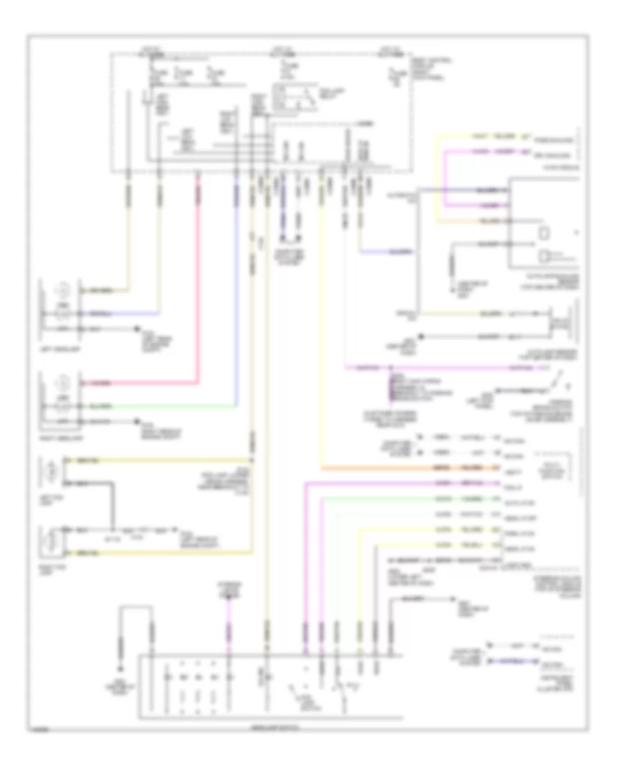
HEADLIGHTS Headlights Wiring Diagram for Ford F-350 Super Duty XLT 2014 List of elements for Headlights Wiring Diagram for Ford F-350 Super Duty XLT 2014: 79 (center of dash) g201 (customer access) (taped to harness near c210) Auto Auto lp on Auto lp sens in Autolamp sensor (top center of dash) Autolamp/sunload sensor (top center of dash) Automatic a/c Body control module (right kick panel) C134 C2280a C2280b C2280c C2280e C2280f C2414a Clf19 Clf21 Clf23 Clf24 Clf34 Cmc25 Computer data lines system Drv sunload Fog ind Fog lamp relay Fog lamp switch Fog lp Fuse 10a Fuse 15a Fuse 5a G104 (left rear of engine compt) G108 (right rear of engine compt) G201 (center of dash) G202 (lower left center of dash) G300 (left kick panel) Gd185 Head Head lp off Head lp on Headlamp switch High Hot at all times Hs can+ Hs can- Hvac module Instrument panel cluster (ipc) Interior lights system Left fog lamp Left headlamp Left high beam (fet) Left low beam (fet) Logic gnd Low Manual a/c Micro Multi- function switch Off Park Park brake Park lp on Parking brake switch (top of parking brake lever assembly) Pass sunload Right fog lamp Right headlamp Right high beam (fet) Right low beam (fet) S1119 S142 (fog lamp jumper wiring harness, near breakout to c134) S239 Sbp26 Solid state Steering column control module (top of steering column) Vbatt Vdb04 Vdb05 Vh416 Vh417 Vlf14
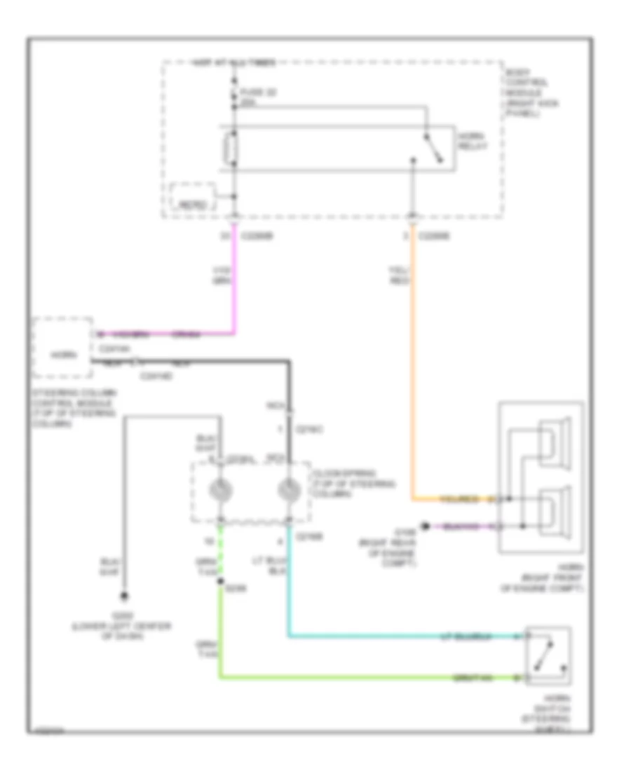
HORN Horn Wiring Diagram for Ford F-350 Super Duty XLT 2014 List of elements for Horn Wiring Diagram for Ford F-350 Super Duty XLT 2014: 22 Body control module (right kick panel) C218a C218b C218c C2280b C2280e C2414a C2414d Clockspring (top of steering column) Crh04 Fuse 22 20a G108 (right rear of engine compt) G202 (lower left center of dash) Horn Horn (right front of engine compt) Horn relay Horn switch (steering wheel) Hot at all times Micro Nca S299 Steering column control module (top of steering column)
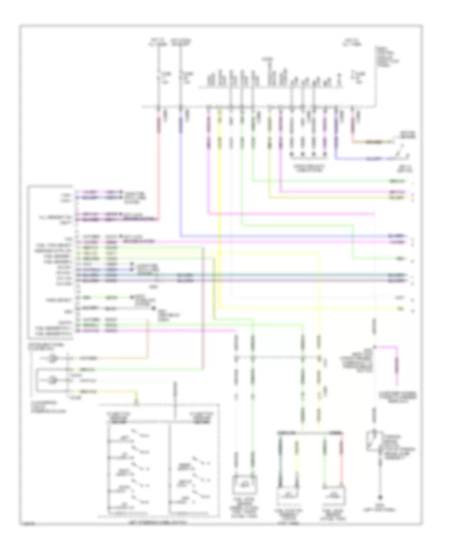
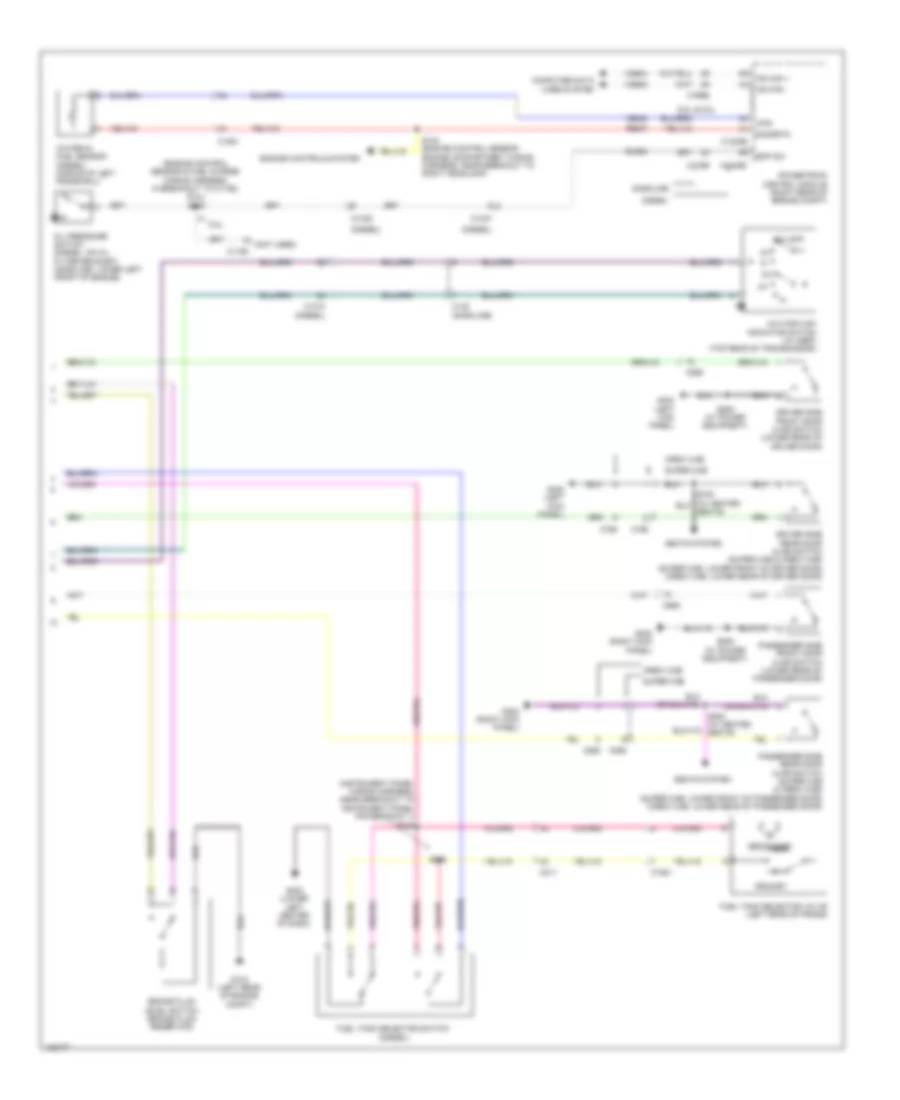
INSTRUMENT CLUSTER Instrument Cluster Wiring Diagram (1 of 2) for Ford F-350 Super Duty XLT 2014 List of elements for Instrument Cluster Wiring Diagram (1 of 2) for Ford F-350 Super Duty XLT 2014: 100 (customer access) (taped to harness near c210) 4x4 high 4x4 low Ajar lf door Ajar lr door Anti-lock brakes system Body control module (right kick panel) Brake fluid sw Brake park C1581 C211 C218a C218b C2280a C2280b C2280c C2280f C263 Can+ hs Can+ ms Can- hs Can- ms Cca10 Ccf06 Ccf22 Cdc30 Ce929 Cet52 Cet59 Clockspring (top of steering column) Cmc19 Cmc25 Cmc29 Computer data lines system Cpl26 Cpl31 Cpl36 Cpl39 Diesel Down Fuel level sensor (diesel w/ dual fuel tanks) (in fuel tank) Fuel level sensor (in fuel tank) Fuel pump (fp) assembly (top of fuel tank) Fuel sender 1 Fuel sender 2 Fuel sender rtn 1 Fuel sender rtn 2 Fuel tank select Fuse 10a Fuse 15a G201 (center of dash) G300 (left kick panel) Gasoline Gd184 Gnd Hill descent sw Hot at all times Hot in run or start Hs can + Hs can - I can + I can - Ignition switch Info Instrument panel cluster (ipc) Key in Key in ignition Left Left steering wheel switch Message cntrl sw Micro Ms rtn Nca Park detect Parking brake switch (top of parking brake lever assembly) Reset Rf door ajar Right Rmc19 Rmc27 Rmc32 Rmc33 Rr door ajar S304 (body main wiring harness, in breakout to parking brake switch) Sbp11 Setup Shift interlock system Sw rtn brake fluid Tcs Vbatt Vdb04 Vdb05 Vdb06 Vdb07 Vdb13 Vdb14 Vmc11 Vmc23 W/ 3-button message center W/ 5-button message center Instrument Cluster Wiring Diagram (2 of 2) for Ford F-350 Super Duty XLT 2014 List of elements for Instrument Cluster Wiring Diagram (2 of 2) for Ford F-350 Super Duty XLT 2014: 65 (diesel) (engine control sensor & fuel charge wiring harness, in breakout to c1168) (6.2l) s120 (gasoline) (instrument panel wiring harness, near breakout to instrument panel power point 1) s245 (not used) 2h (off) 4x4 high/low indicator switch (w/ msof) (top rear of transmission) 6.2l 6.8l & 6.2l B-sigrtn Brake fluid level switch (brake fluid reservoir) C1010 C1046 C1047 C1168 C1232b C1232e C145 C1581 C175b C175e C211 C555 C655 C755 C756 C855 C856 Cmc24 Computer data lines system Crew cab Diesel Driver side front door ajar switch (lower rear of driver door) Driver side rear door ajar switch (super cab & crew cab) (super cab: lower front of driver door) (crew cab: lower rear of driver door) Engine controls system Eop sw Fuel tank selector switch Fuel tank selector valve (left rear of frame) G104 (left rear of engine compt) G203 (lower left center of dash) G300 (left kick panel) G302 (right kick panel) Gasoline Hs can + Hs can - Oil pressure switch (diesel: on oil filter bracket) (gasoline: lower left front of engine) Passenger side front door ajar switch (lower rear of passenger door) Passenger side rear door ajar switch (super cab & crew cab) (super cab: lower front of passenger door) (crew cab: lower rear of passenger door) Powertrain control module (right rear of engine compt) Primary Re407 S100 (engine control sensor engine compartment wiring harness, near breakout to right headlamp) S246 S505 (w/ power equipment) S638 (w/ power equipment) S802 (w/ heated seats) Seats system Seats) Secondary Super cab Vdb04 Vdb05 Ve823 Water-in fuel sensor (diesel) (middle of left frame rail) Wfs
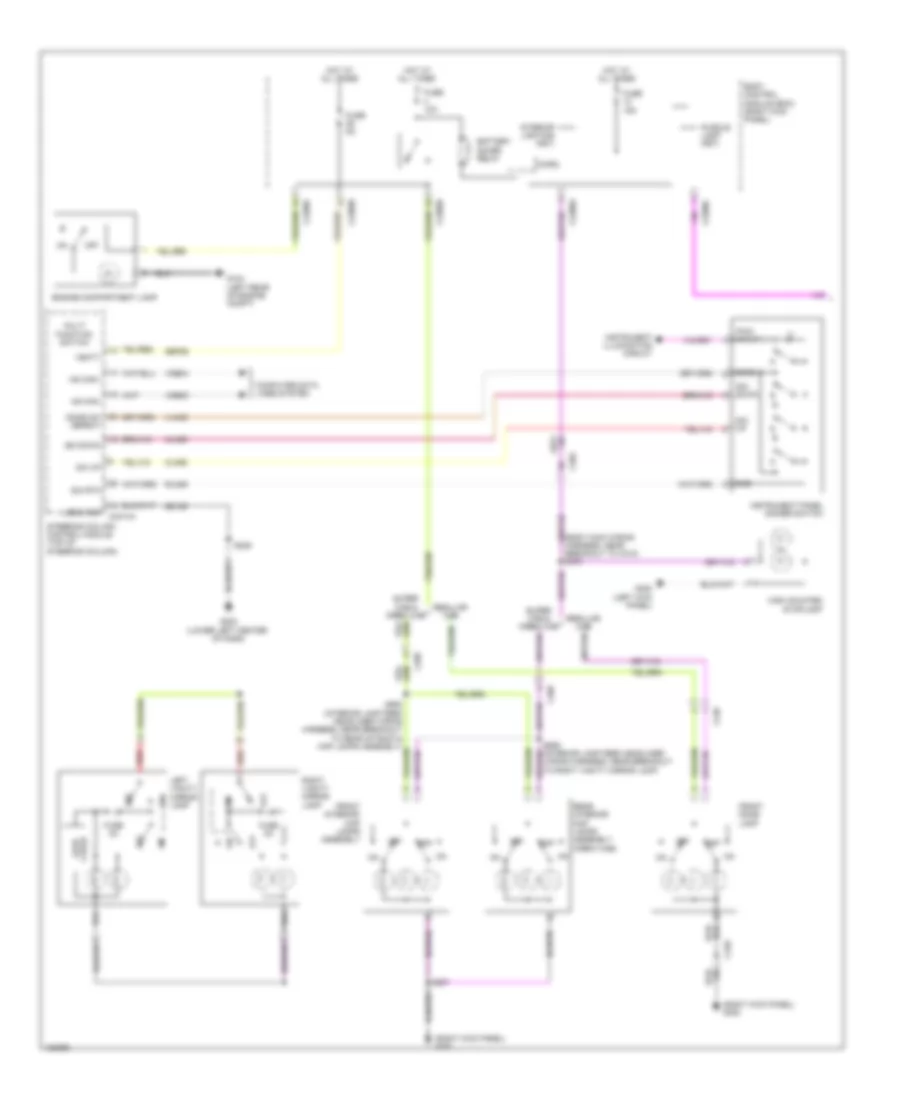
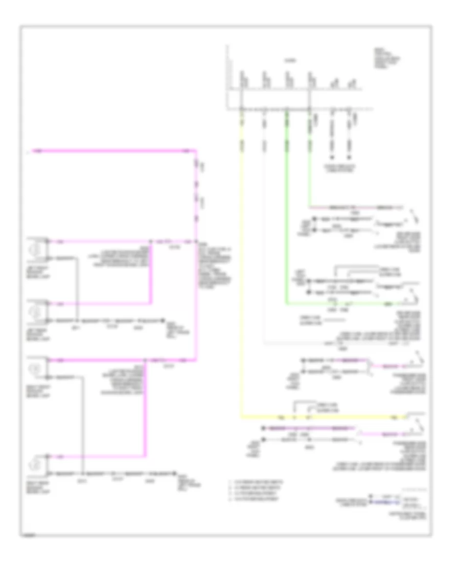
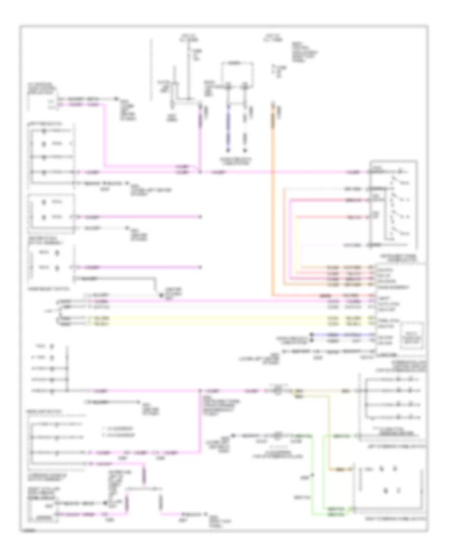
INTERIOR LIGHTS Courtesy Lamps Wiring Diagram (1 of 2) for Ford F-350 Super Duty XLT 2014 List of elements for Courtesy Lamps Wiring Diagram (1 of 2) for Ford F-350 Super Duty XLT 2014: 64 (body main wiring harness, near breakout to c312) s370 (right kick panel) g302 Battery saver relay Body control module (bcm) (right kick panel) C2280a C2280b C2280c C2280d C2280f C2414a C248 C265 C268 Car2u lear Cln55 Cln56 Computer data lines system Dim down Dim rtn Dim up Dome Dome on/ defeat Engine compartment lamp Front dome lamp Front interior/ map lamps assembly Fuse 10a Fuse 15a Fuse 2a Fuse 5a G104 (left rear of engine compt) G202 (lower left center of dash) G300 (left kick panel) Gd185 Gnd High mounted stoplamp Hot at all times Hs can+ Hs can- Instrument illumination circuit Instrument panel dimmer switch Interior lighting (fet) Left vanity mirror lamp Logic gnd Micro Multi function switch Off Puddle lamp (fet) Pwm input Rear interior/ map lamps assembly (crew cab) Red Regular cab Right vanity mirror lamp Rln29 S239 S907 S908 (interior lamp feed headliner wiring harness, near breakout to rear of roof & map lamps assembly) S909 (interior lamp feed headliner wiring harness, near breakout to right vanity mirror lamp) Sbp26 Steering column control module (top of steering column) Super cab & crew cab Vbatt Vdb04 Vdb05 Vln36 Courtesy Lamps Wiring Diagram (2 of 2) for Ford F-350 Super Duty XLT 2014 List of elements for Courtesy Lamps Wiring Diagram (2 of 2) for Ford F-350 Super Duty XLT 2014: 58 (left kick panel) g300 Ajar lf door Ajar lr door Body control module (bcm) (right kick panel) C1415 C210 C2280c C2280f C3137 C3138 C555 C655 C755 C756 C855 C856 Can+ hs Can- hs Computer data lines system Cpl26 Cpl31 Cpl36 Cpl39 Crew cab Driver side front door ajar switch (lower rear of driver door) Driver side rear door ajar switch (super cab (& crew cab) (crew cab: lower rear of driver door) (super cab: lower front of driver door) G300 (left kick panel) G302 (right kick panel) G400 (rear of left frame rail) Hs can + Hs can - Instrument panel cluster (ipc) Left front running board lamp Left rear running board lamp Micro Passenger side front door ajar switch (lower rear of passenger door) Passenger side rear door ajar switch (super cab (& crew cab) (crew cab: lower rear of passenger door) (super cab: lower front of passenger door) Rf door ajar Right front running board lamp Right rear running board lamp Rr door ajar S311 S312 (lighted running board lh/rh jumper wiring harness, near breakout to right front running board lamp) S313 S328 (lighted running board lh/rh jumper wiring harness, near breakout to left front running board lamp) S396 (6.2l flex fuel & 6.8l: frame wiring harness, near breakout to c327) (6.7l turbo diesel: frame wiring harness, near breakout to c328) S405 S505 S638 S700 S802 Super cab Vdb04 Vdb05 W/ power equipment W/ rear heated seats W/o power equipment W/o rear heated seats Instrument Illumination Wiring Diagram for Ford F-350 Super Duty XLT 2014 List of elements for Instrument Illumination Wiring Diagram for Ford F-350 Super Duty XLT 2014: 82 (center of dash) g201 (not used) (right "c" pillar) roof opening panel module (super cab: left "b" pillar) (crew cab: left "c" pillar) g301 (w/ am/fm/cd) audio control module (acm) Auto Auto lp on Back- lighting led (fet) Body control module (bcm) (right kick panel) C218a C218b C2280b C2280f C2414a C265 C268 Center stack switch assembly Clf19 Clf23 Clf24 Clf34 Cln55 Cln56 Clockspring (top of steering column) Common Computer data lines system Cpr39 Dim down Dim rtn Dim up Dome Done on/defeat Fuse 15a Fuse 5a G201 (center of dash) G202 (lower left center of dash) G203 (lower left center of dash) G204 (lower left center of dash) G302 (right kick panel) Gd115 Gd143 Gd185 Gnd Hdlp off Hdlp on Head Headlamp switch Hot at all times Hs can+ Hs can- Ill+ Ill- Instrument panel dimmer switch Left steering wheel switch Logic gnd Micro Mode select switch Multi- function switch Off Overhead console switch assembly Park Park lp on Pwm input Right steering wheel switch Rln29 S220 (instrument panel wiring harness, near breakout to g201) S239 S249 S299 S907 Sbp26 Steering column control module (top of steering column) Upfitter switch Vbatt Vdb04 Vdb05 Vln04 Vln36 W/ 5-button message center W/ moonroof W/o moonroof White led (fet)
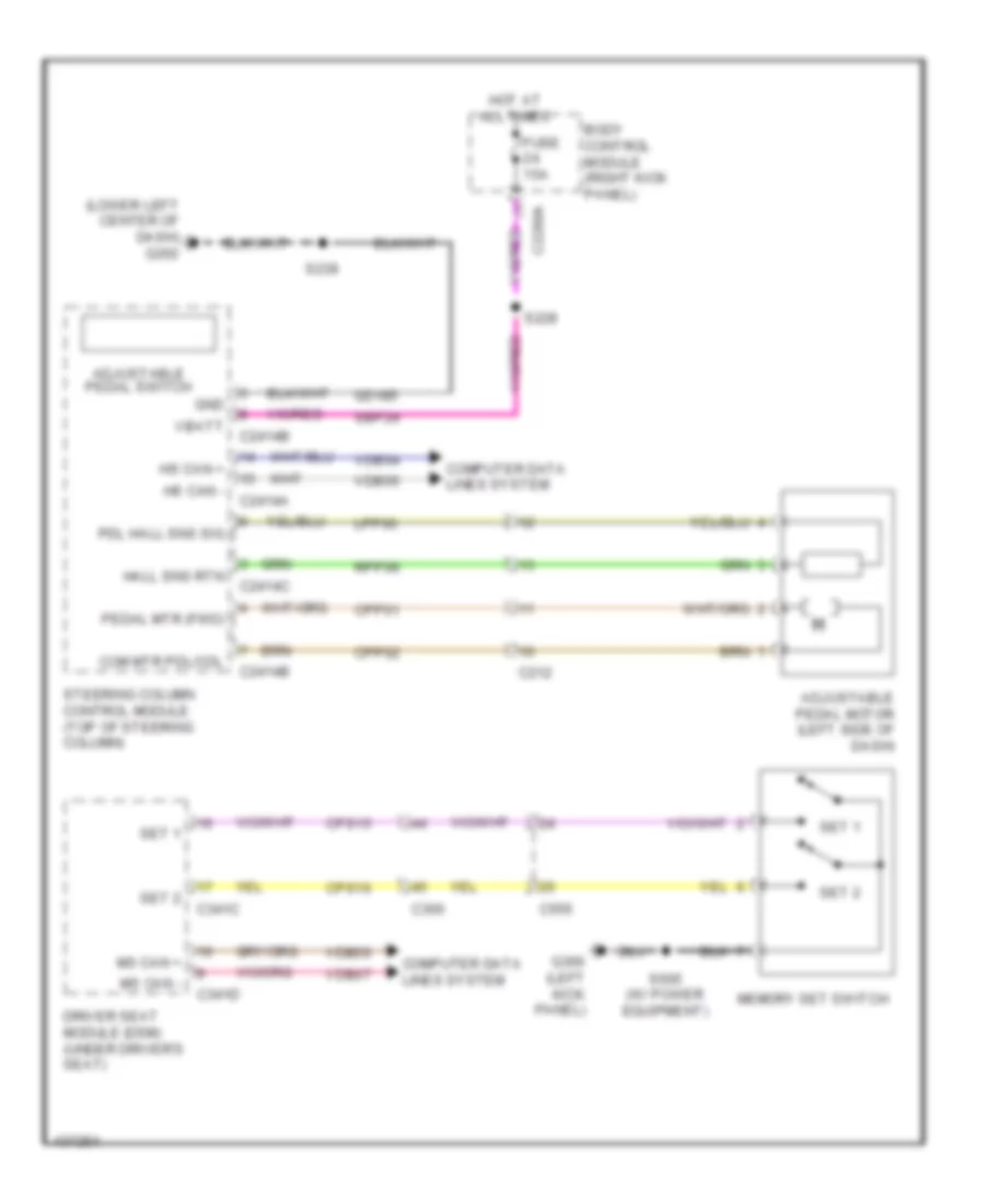
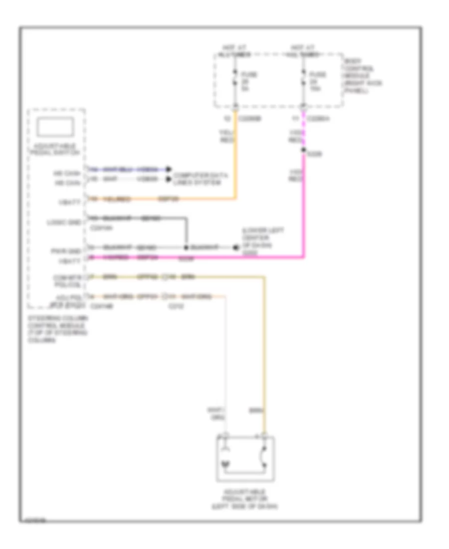
MEMORY SYSTEMS Adjustable Pedal Wiring Diagram for Ford F-350 Super Duty XLT 2014 List of elements for Adjustable Pedal Wiring Diagram for Ford F-350 Super Duty XLT 2014: 47 (lower left center of dash) g202 Adjustable pedal motor (left side of dash) Adjustable pedal switch Body control module (right kick panel) C212 C2280a C2414a C2414b C2414c C300 C341c C341d C555 Com mtr pdl/col Computer data lines system Cpp01 Cpp02 Cps15 Cps16 Driver seat module (dsm) (under driver's seat) Fuse 15a G300 (left kick panel) Gd185 Gnd Hall sns rtn Hot at all times Hs can + Hs can - Lpp06 Memory set switch Ms can + Ms can - Pdl hall sns sig Pedal mtr (fwd) Rpp06 S228 S239 S505 (w/ power equipment) Sbp24 Set 1 Set 2 Steering column control module (top of steering column) Vbatt Vdb04 Vdb05 Vdb06 Vdb07 Driver"s Memory Seat Wiring Diagram (1 of 2) for Ford F-350 Super Duty XLT 2014 List of elements for Driver"s Memory Seat Wiring Diagram (1 of 2) for Ford F-350 Super Duty XLT 2014: 66 Aft Base backward Base forward Body control module (right kick panel) C2280d C300 C3050 C311 C341a C341b Cbx03 Cbx05 Cps01 Cps02 Cps03 Cps04 Cps05 Cps06 Cps07 Cps08 Cps23 Cps24 Cps25 Cps26 Cps27 Cps28 Cps29 Cps30 Deflate Driver seat front height motor Driver seat horizontal motor Driver seat lumbar motor Driver seat module (dsm) (under driver's seat) Driver seat rear height motor Driver seat recliner motor Driver side front seat control switch Forward Front dn Front height Front up Fuse 5a Fuse 7.5a Fwd G300 (left kick panel) Gd905 Gd906 Hall effect rtn Hall effect sns Height rear Horizontal Hot at all times Incline Inflate Logic gnd Lumbar Pwr gnd Rear dn Rear up Recline Rps13 S368 (driver cushion wiring harness, near breakout to c3050) Vbatt Vps09 Vps10 Vps11 Vps12 Driver"s Memory Seat Wiring Diagram (2 of 2) for Ford F-350 Super Duty XLT 2014 List of elements for Driver"s Memory Seat Wiring Diagram (2 of 2) for Ford F-350 Super Duty XLT 2014: 69 (not used) Adjustable pdl fwd sw Battery junction box (bjb) (left side of engine compt) C210 C300 C311 C341c C341d C555 Computer data lines system Cpm04 Cpm16 Cpm17 Cpm20 Cpm21 Cpm22 Cpm26 Cpm28 Cpm29 Cpm31 Cpm33 Cpm34 Cpm39 Cpp09 Cps14 Cps15 Cps16 Driver seat module (dsm) (under driver's seat) Drv hor pot Drv mirr hor sw Drv mirr mtr hor rt Drv mirr mtr vert up Drv mirr vert sw Drv mtr dn/lt Drv vert pot Ext mirr pot feed Fuse 30a G300 (left kick panel) Hot at all times Lpm30 Memory mirrors circuit Memory set switch Mirr com sw Mirr fold sw Mirr mtr fold in Mirr mtr fold out Mirr pot ret Ms can + Ms can - Pass hor pot Pass mirr hor sw Pass mirr mtr dn/lt Pass mirr mtr hor rt Pass mirr mtr vert up Pass mirr vert sw Pass vert pot Red Rpm11 Rpm30 S505 (w/ power equipment) Set Set 1 Set 2 Vdb06 Vdb07 Vpm35 Vpm36 Vpm37 Vpm38 Memory Mirrors Wiring Diagram for Ford F-350 Super Duty XLT 2014 List of elements for Memory Mirrors Wiring Diagram for Ford F-350 Super Duty XLT 2014: 92 (body main wiring harness, near breakout to c311) (body main wiring harness, near breakout to restraints control module) (left front door window regulator wiring harness, near breakout to exterior rear view mirror switch) (right front door jumper wiring harness, in breakout to passenger's side exterior rear view mirror) Battery junction box (bjb) (left side of engine compt) Body control module (right kick panel) C210 C2280d C300 C311 C341a C341b C341c C341d C555 C655 Cbx03 Cbx05 Computer data lines system Cpm16 Cpm17 Cpm20 Cpm21 Cpm26 Cpm28 Cpm29 Cpm31 Cpm33 Cpm34 Cps15 Cps16 Defogger system Driver seat module (dsm) (under driver's seat) Driver side exterior rear view mirror Drv mirr hor pot Drv mirr hor sw Drv mirr vert pot Drv mirr vert sw Drv mtr dn/lt Drv mtr hor rt Drv mtr vert up Ext mirr pot feed Exterior lights system Exterior rear view mirror switch Fuse 10a Fuse 30a Fuse 5a G300 (left kick panel) G302 (right kick panel) Gd906 Hot at all times Left/right Lpm30 Memory set switch Mirr com sw Mirr pot rtn Mirror heated Mirrors system Ms can + Ms can - Nca Park Pass hor pot Pass mirr hor sw Pass mirr vert sw Pass mtr dn/lt Pass mtr hor rt Pass mtr vert up Pass vert pot Passenger side exterior rear view mirror Pwr gnd Red Rpm11 Rpm30 S318 S336 S501 S505 S513 S609 S639 Set 1 Set 2 Turn Up/dn Vbatt Vdb06 Vdb07 Vpm35 Vpm36 Vpm37 Vpm38
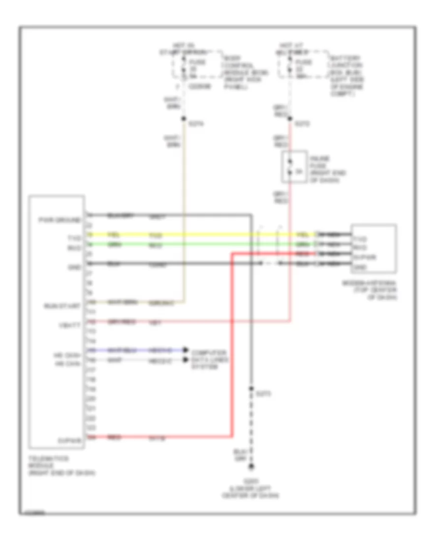
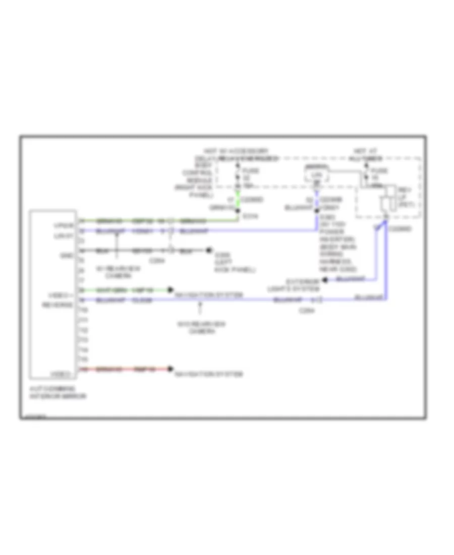
NAVIGATION Crew Chief Wiring Diagram for Ford F-350 Super Duty XLT 2014 List of elements for Crew Chief Wiring Diagram for Ford F-350 Super Duty XLT 2014: 33 5vpwr 5vtb Battery junction box (bjb) (left side of engine compt) Body control module (bcm) (right kick panel) C2280b Cgnd Computer data lines system Fuse 30a Fuse 5a G203 (lower left center of dash) Gnd Gnd1 Hot at all times Hot in start or run Hs can+ Hs can- Hsc1-c Hsc2-c Igrun-c Inline fuse (right end of dash) Modem-antenna (top center of dash) Nca Pwr ground Red Run start Rxd S272 S273 S274 Telematics module (right end of dash) Txd Vb1 Vbatt Navigation Wiring Diagram, with Sony (2 of 3) for Ford F-350 Super Duty XLT 2014 List of elements for Navigation Wiring Diagram, with Sony (2 of 3) for Ford F-350 Super Duty XLT 2014: 50 (base of right "c" pillar) subwoofer amplifier (top of steering column) Audio pwr Audio rtn C218c C2414a C2414b C2414d Clockspring (top of steering column) Cls32 Computer data lines system Front controls interface module (fcim) G201 (center of dash) G202 (lower left center of dash) Gd184 Gd185 Gnd Hazard Hazard switch Hs can + Hs can - I can + I can - Interior lights system Logic gnd Media Nca Phone Pwr gnd Right steering wheel switch S239 Sbp24 Sbp26 Seek+ Seek- Steering column control module Subw 1+ Subw 1- Subw 2+ Subw 2- Sync pwr Sync rtn Vbatt Vdb04 Vdb05 Vdb13 Vdb14 Voice Vol+ Vol- Navigation Wiring Diagram, with Sony (3 of 3) for Ford F-350 Super Duty XLT 2014 List of elements for Navigation Wiring Diagram, with Sony (3 of 3) for Ford F-350 Super Duty XLT 2014: 49 Am/fm antenna Amp gnd Antenna Audio control module (acm) Batt Battery junction box (bjb) (left side of engine compt) C211 C265 C290a C290b Cdc38 Computer data lines system Dme17 Enable G201 (center of dash) Gd114 I can+ I can- Lf spkr + Lf spkr - Nca Rf spkr + Rf spkr - Rme17 Rme18 Rme52 Rme53 Sbp29 Sdars ant Sdars antenna Sdl-h Sdl-l Shield Sme23 Start Starting/ charging system Stereo l+ Stereo l- Stereo r+ Stereo r- Sync radio circuit Vdb13 Vdb14 Vme17 Vme18 Vme52 Vme53 Vme90 Vme91 Navigation Wiring Diagram, without Sony (1 of 2) for Ford F-350 Super Duty XLT 2014 List of elements for Navigation Wiring Diagram, without Sony (1 of 2) for Ford F-350 Super Duty XLT 2014: 80 (audio jumper wiring harness, in breakout to right front tweeter) s602 Am/fm antenna Amp gnd Antenna Audio control module (acm) Batt Battery junction box (bjb) (left side of engine compt) Body control module (right kick panel) C211 C212 C2280a C2280b C2280d C265 C290a C510 C555 C610 C655 C756 C856 Cdc38 Cls32 Computer data lines system Front controls interface module (fcim) Fuse 15a Fuse 20a Fuse 5a G201 (center of dash) Gd114 Gd184 Global positioning system module (gpsm) (w/ sync) (top center of dash) Gnd Hazard Hazard switch Hot at all times I can + I can - I can+ I can- Left front speaker Left front tweeter Left rear speaker Lf spkr + Lf spkr - Lr spkr + Lr spkr - Ms can+ Ms can- Rf spkr + Rf spkr - Right front speaker Right front tweeter Right rear speaker Rme09 Rme12 Rme17 Rme18 Rr spkr + Rr spkr - S222 S228 S502 (audio jumper wiring harness, in breakout left front tweeter) S503 S603 Sbp24 Sbp29 Sdars ant Sdars antenna Start Starting/charging system Vbatt Vdb06 Vdb07 Vdb13 Vdb14 Vme09 Vme12 Vme17 Vme18 Navigation Wiring Diagram, without Sony (2 of 2) for Ford F-350 Super Duty XLT 2014 List of elements for Navigation Wiring Diagram, without Sony (2 of 2) for Ford F-350 Super Duty XLT 2014: 68 (base of right "c" pillar) subwoofer amplifier (crew cab: left "c" pillar) (super cab: left "b" pillar) (top of steering column) steering column control module Audio control module (acm) Audio pwr Audio rtn Aux aud sh C212 C218b C218c C2414a C2414b C2414d C265 C290b Clockspring (top of steering column) Computer data lines system Dme22 Enable/ clip detect G202 (lower left center of dash) G301 Gd185 Gnd Hs can + Hs can - Interior lights system Logic gnd Media Nca Phone Pwr gnd Right steering wheel switch Rme22 Rme52 Rme53 Rme80 S239 Sbp24 Sbp26 Sdl-l Seek+ Seek- Sme23 Spl-h Stereo l+ Stereo l- Stereo r+ Stereo r- Subw + Subw - Subw - enable/ clip detect Sync alert + Sync alert - Sync pwr Sync radio circuit Sync rtn Vbatt Vdb04 Vdb05 Vme22 Vme52 Vme53 Vme80 Vme90 Vme91 Voice Vol+ Vol- Parking Assistant Wiring Diagram for Ford F-350 Super Duty XLT 2014 List of elements for Parking Assistant Wiring Diagram for Ford F-350 Super Duty XLT 2014: 44 (bumper rear park aid wiring harness, near breakout to left license plate lamp) s415 (left side of rear bumper) Body control module (bcm) (right kick panel) C1581 C211 C2280b C408 Cbp35 Cmp09 Computer data lines system Fuse 5a G201 (center of dash) Gd184 Gnd Hot in start or run Hs can+ Hs can- Inner left parking aid sensor Inner right parking aid sensor (right side of rear bumper) Lmp07 Outer left parking aid sensor (left side of rear bumper) Outer right parking aid sensor (right side of rear bumper) Parking aid module (pam) (lower left end of dash) Parking aid speaker (left end of dash) Ril sensor in Rir sensor in Rmp07 Rmp09 Rol sensor in Ror sensor in S227 S416 (bumper rear park aid wiring harness, near breakout to c408) Sensor gnd Sensor pwr Sndr+ Sndr- Solid state Vdb04 Vdb05 Vmp14 Vmp15 Vmp16 Vmp17 Vpwr Rear Camera Wiring Diagram for Ford F-350 Super Duty XLT 2014 List of elements for Rear Camera Wiring Diagram for Ford F-350 Super Duty XLT 2014: 33 (body main wiring harness, in breakout to c264) s373 Accessory protocol interface module (premium audio) (right end of dash) Auto dimming interior mirror Base audio Battery junction box (bjb) (left side of engine compt) Body control module (right kick panel) C1581 C210 C2280c C264 C265 C465 C497 Cbb49 Dmp19 Fuse 10a G201 (center of dash) Hot in start or run Lin Micro Nca Rmp19 S340 (body main wiring harness, in breakout to c265) S372 Shield Vdn03 Video + Video - Video camera (middle of tail gate) Video+ Video- Vmp19 Vpwr
POWER DISTRIBUTION Power Distribution Wiring Diagram (1 of 9) for Ford F-350 Super Duty XLT 2014 List of elements for Power Distribution Wiring Diagram (1 of 9) for Ford F-350 Super Duty XLT 2014: 68 (6.2l flex fuel & 6.8l) (6.7l turbo diesel) (6.7l turbo diesel: battery cable wiring assembly, in breakout to battery) (except 6.7l turbo diesel: alternator rectifier system wiring assembly, in breakout to battery) (alternator rectifier system wiring harness, near breakout to battery) (crew chief) (left side of engine compt) battery junction box (bjb) (right side of engine compt) high current battery junction box (w/ 10 way power seat) (w/ 6 way 6.7l turbo diesel w/ dual generators Auxiliary heater control module (ahcm) (6.7l turbo diesel w/ rapid heat) Battery Battery junction box (bjb) (left side of engine compt) Blower motor relay C1273a C1617a C1617b C1617c C1617d C1617e C1617f C210 C2108 C211 C2463a C311 C312 C341a C555 Crew chief Driver side front power window motor Driver side front seat control switch (w/o memory) Driver's seat module (dsm) (w/ memory) Front wiper relay Fuse 25a Fuse 30a Fuse 40a Fuse 40a 50a Fusible link b (20 ga- red) (right front of engine, in battery wiring assembly) Fusible link c (12 ga- red) (right front of engine, in battery wiring assembly) Fusible link d (12 ga- red) (right front of engine, in battery wiring assembly) Generator Glow plug control module (6.7l turbo diesel) Inline fuse (right end of dash) Mega fuse 125a Mega fuse 175a 275a Mega fuse 200a Nca Parking lamp trailer tow relay Passenger side front seat control switch Power seat) Rear window defrost relay Red Reductant heater relay (6.7l turbo diesel) S137 S138 S139 S140 (alternator rectifier system wiring harness, near breakout to c144) S141 (alternator rectifier system wiring harness, between fusible link b & c) S272 (t-box jumper wiring harness, near breakout to c2108) Secondary battery (6.7l) Secondary generator Starter motor Telematics module To body control module (diagram 5 of 9) To fuse 39 (diagram 2 of 9) Trailer brake control (tbc) module W/ rear heated power sliding window W/o rear heated power sliding window Power Distribution Wiring Diagram (2 of 9) for Ford F-350 Super Duty XLT 2014 List of elements for Power Distribution Wiring Diagram (2 of 9) for Ford F-350 Super Duty XLT 2014: 58 (crew chief) (left side of engine compt) battery junction box (bjb) (not used) (t-box jumper wiring harness, near breakout to c2108) (crew chief) s274 6.7l turbo diesel 6.8l & 6.2l flex fuel Anti-lock brake system (abs) module Auxiliary heater control module (ahcm) (6.7l turbo diesel w/ rapid heat) Battery charge trailer tow relay Battery junction box (bjb) (left side of engine compt) Blower motor relay Body control module (right kick panel) C1010 C1232b C1415 C1581 C175b C2108 C214 C2280b C2280d C2280e C2280f C2371a C2371b C2463b C3049 C310a C3162b C465 C497 Center stack switch assembly Constant vacuum hub lock (cvh) solenoid From fuse 23 (diagram 1 of 9) Fuel tank selector switch Fuse 10a Fuse 15a Fuse 20a Fuse 5a Fuse 7.5a Heated steering wheel module (hswm) Micro Nca Parking aid module (pam) Powertrain control module (pcm) Rear heated seat module Rear window defrost relay Restraints control module Run/ start (fet) Run/ start relay S227 (instrument panel wiring harness, near breakout to inertia fuel shutoff switch) Telematics module (crew chief) To fuse 46 (diagram 3 of 9) Tow haul switch Trailer brake control (tbc) module Transfer case control module Transmission control module (tcm) (6.7l turbo diesel) Video camera Power Distribution Wiring Diagram (3 of 9) for Ford F-350 Super Duty XLT 2014 List of elements for Power Distribution Wiring Diagram (3 of 9) for Ford F-350 Super Duty XLT 2014: 57 (customer access) (engine control sensor engine compt wiring harness, in breakout to powertrain control module) s105 (engine control sensor engine compt wiring harness, near breakout to c1581) s122 (engine wiring harness, near breakout to fuel injector 1) s110 (engine wiring harness, near breakout to intake throttle actuator) s109 (left side of engine compt) battery junction box (bjb) (not used) 6.7l turbo diesel 6.8l & 6.2l flex fuel A/c clutch relay Battery junction box (bjb) (left side of engine compt) C1010 C1047 C110 C1165 C1232b C1273c C139 C1415 C1581 C175b C3047 C3611a C3619a Cooling fan Egr cooler bypass valve solenoid Evap canister vent control solenoid (except 6.7l turbo diesel) From c fuse 40 (diagram 2 of 9) From d fuse 68 (diagram 3 of 9) Fuel pressure control valve Fuel pump (fp) motor diode Fuel pump (fp) relay Fuel volume control valve Fuse 10a Fuse 15a Fuse 20a Fuse n/a Glow plug control module Mass air flow/ intake air temperature (maf/iat) sensor Narrow frame w/o aft fuel tank Nca Nox 11 sensor module (except high sulfur) Nox 12 sensor module (except high sulfur) Pcm power relay Powertrain control module Red Reductant pump assembly (except high sulfur) Reductant purge valve (except high sulfur) Reversing lamp relay S3000 To fuse 33 (diagram 4 of 9) To fuse 72 (diagram 3 of 9) To fuse 84 (diagram 4 of 9) Transmission control module (6.7l turbo diesel) Turbo- charger actuator Turbo- charger wastegate regulating valve solenoid Wide frame & narrow frame w/ aft fuel tank Power Distribution Wiring Diagram (4 of 9) for Ford F-350 Super Duty XLT 2014 List of elements for Power Distribution Wiring Diagram (4 of 9) for Ford F-350 Super Duty XLT 2014: 78 (customer access) (engine control sensor & fuel charge wiring harness, near breakout to c133) s117 (engine control sensor & fuel charge wiring harness, near breakout to fuel injector 1) (6.8l) s127 (6.2l flex fuel) s118 (engine control sensor & fuel charge wiring harness, near breakout to fuel injector 1) s112 (engine control sensor & fuel charge wiring harness, near breakout to fuel injector 5) (engine control sensor & fuel charge wiring harness, near breakout to fuel injector 7) (6.8l) s135 (6.2l flex fuel) s114 (engine control sensor engine compt wiring harness, near breakout to c1581) (engine control sensor engine compt wiring harness, near breakout to horn) s101 (left side of engine compt) battery junction box (bjb) (not used) (passenger cushion wiring harness, near breakout to dual climate controlled seat module) (transmission wiring harness, near breakout to heated oxygen sensor 12) (6.2l flex fuel) s181 6.2l flex fuel 6.8l A/c clutch relay Anti-lock brake system (abs) module Battery charge trailer tow relay Battery junction box (bjb) (left side of engine compt) C1168 C1220 C145 C1581 C175b C210 C2371b C312 C3162b C3265a e Coil on plug (cop) 1 Coil on plug (cop) 10 (6.8l) Coil on plug (cop) 2 Coil on plug (cop) 3 Coil on plug (cop) 4 Coil on plug (cop) 5 Coil on plug (cop) 6 Coil on plug (cop) 7 Coil on plug (cop) 8 Coil on plug (cop) 9 (6.8l) Cooling fan Dual climate controlled seat module (dcsm) Evaporative emission (evap) canister purge valve From e fuse 72 (diagram 3 of 9) From g fuse 34 (diagram 4 of 9) From pcm f power relay (diagram 3 of 9) Fuse 10a Fuse 15a Fuse 20a Fuse 25a Fuse 30a Fuse 40a Fuse 50a Fuse n/a Heated oxygen sensor (ho2s) 12 (6.2l flex fuel) Heated oxygen sensor (ho2s) 12 (narrow frame) Heated oxygen sensor (ho2s) 22 (6.2l flex fuel) Ignition transformer capacitor Ignition transformer capacitor 1 Intake manifold tuning valve (imtv) Left turn trailer tow relay Mass air flow/ intake air temperature (maf/iat) sensor Nca Not used Powertrain control module Rear heated seat module Red Right turn trailer tow relay S104 S315 (rear seat wiring harness, in breakout to c3049) S341 Starter relay To fuse 35 (diagram 4 of 9) To fuse 83 (diagram 5 of 9) Transfer case control module (tccm) Universal heated oxygen sensor (ho2s) 11 (6.2l flex fuel) Universal heated oxygen sensor (ho2s) 11 (6.8l) Universal heated oxygen sensor (ho2s) 21 Variable camshaft timing 11 (vct 11) solenoid Variable camshaft timing 21 (vct 21) solenoid Power Distribution Wiring Diagram (5 of 9) for Ford F-350 Super Duty XLT 2014 List of elements for Power Distribution Wiring Diagram (5 of 9) for Ford F-350 Super Duty XLT 2014: 81 (base) (instrument panel wiring harness, near breakout to inertia fuel shutoff switch) s228 (instrument panel wiring harness, near breakout to passenger airbag module) (w/ sync) s222 (left side of engine compt) battery junction box (bjb) (not used) (or sbb99) (premium) (right kick panel) body control module Ac outlet Ac-a Ac-b Acc Accessory protocol interface module (apim) (w/ sync) Audio control module Automatic a/c C210 C211 C215 C2280a C2280b C2280g C228a C2293a C2293b C238 C240a C2414a C2414b C290a C3052 C3501a C3501b Cbp32 Cigar lighter Consolette power point (crew cab w/ consolette) Data link connector (dlc) Dc/ac inverter module (w/ 110v power inverter) (w/ center console: under center console) (w/o center console: bottom left end of dash) From h fuse 90 (diagram 4 of 9) From high current battery junction box (diagram 1 of 9) From splice s314 l (diagram 7 of 9) From splice s383 m (diagram 7 of 9) Front console power point (super cab & crew cab) Front control interface module (premium audio) Fuse 10a Fuse 15a Fuse 20a Fuse 25a Fuse 40a Fuse 5a G203 (lower left center of dash) G300 (left kick panel) G302 (right kick panel) Gd179 (or gd115) Global positioning system (gpsm) module (w/ sync) Gnd Hot Hvac module Hya01 Hya02 Instrument panel cluster (ipc) Instrument panel power point 1 Instrument panel power point 2 Led+ Led- Lin 01 Lya03 Manual a/c Neut Power mirror fold relay Rear console power point Red Rya03 S390 Sbb97 Steering column control module (sccm) Tire pressure monitor (tpm) module To fuse 7 (diagram 6 of 9) To upfitter relay box (diagram 9 of 9) Vdn01 W/ instrument panel W/o instrument panel Power Distribution Wiring Diagram (6 of 9) for Ford F-350 Super Duty XLT 2014 List of elements for Power Distribution Wiring Diagram (6 of 9) for Ford F-350 Super Duty XLT 2014: 70 (crew chief) (interior lamp feed headliner wiring harness, near breakout to rear interior & map lamps assembly) (super cab & crew cab) s908 (not used) (right kick panel) body control module (taped to harness near c422) (taped to harness near c465) 6.7l turbo diesel 6.8l & 6.2l flex fuel All lock/unlock relay Audio digital signal processing (dsp) module Battery saver relay Brake pedal position (bpp) switch C1232b C1415 C175b C210 C2108 C212 C215 C2280b C2280d C2280f C248 c268 C265 C300 C3154c C341b C465 C555 C655 Driver door unlock relay Driver seat module (dsm) (w/ memory) Driver side front seat control switch (w/ memory) Engine compartment lamp Exterior rearview mirror switch Fog lamp relay From n fuse 27 (diagram 5 of 9) From o fuse 9 (diagram 6 of 9) From r fuse 20 (diagram 6 of 9) Front dome lamp (regular cab) Front interior/ map lamps assembly (super cab & crew cab) Fuse 10a Fuse 15a Fuse 20a Fuse 30a Fuse 5a Fuse 7.5a Left corner lamp (fet) Left vanity mirror lamp (super cab & crew cab) Micro Narrow frame Park lamp relay Passenger side front power window motor Powertrain control module Rear interior/ map lamps assembly (crew cab) Red Regular cab Right corner lamp (fet) Right vanity mirror lamp (super cab & crew cab) Roof opening panel module S207 (body main wiring harness, in breakout to brake pedal position switch) Sub- woofer amplifier Super cab & crew cab To fuse 21 (diagram 6 of 9) To fuse 39 (diagram 7 of 9) To fuse 4 (diagram 6 of 9) To upfitter relay box (diagram 9 of 9) Trailer brake control (tbc) module W/ sony sound W/o sony sound Wide frame Power Distribution Wiring Diagram (7 of 9) for Ford F-350 Super Duty XLT 2014 List of elements for Power Distribution Wiring Diagram (7 of 9) for Ford F-350 Super Duty XLT 2014: 65 (body main wiring harness, near breakout to c312) s314 (body main wiring harness, near breakout to c312) s371 (right kick panel) body control module 3rd row seat (fet) Accessory delay relay Audio control module (w/ single cd/ base audio) Auto dimming interior mirror Back-lighting led (fet) Bsi (fet) C2280a C2280b C2280d C240a C264 C265 C268 C3052 C555 C566b C655 C755 C855 Circuit breaker 48 30a Driver side door lock switch Driver side front power window motor From s fuse 47 (diagram 6 of 9) From t accessory delay relay (diagram 7 of 9) Fuse 10a Fuse 15a Interior lighting (fet) Keypad illum (fet) Left high beam (fet) Left low beam (fet) Left rear heated seat switch Lf turn lamp (fet) Liftgate glass release relay Lin Lr stop/ turn lamp (fet) Lr turn lamp (fet) Master window control switch (crew cab) Master window control switch (regular cab & super cab) Micro Overhead console switch assembly (w/ power sliding rear window) Passenger side door lock switch Passenger side front power window motor Passenger side window control switch Pcm wake up (fet) Puddle lamp (fet) Rev lp (fet) Rf turn lamp (fet) Right high beam (fet) Right low beam (fet) Right rear heated seat switch Roof opening panel module Rr stop/ turn lamp (fet) Rr turn lamp (fet) Start button (fet) Stop/chmsl (fet) Telescoping exterior rear view mirror switch To dc/ac inverter module (diagram 5 of 9) To fuse 18 (diagram 7 of 9) To fuse 22 (diagram 8 of 9) W/ instrument panel W/o instrument panel White light (fet) Power Distribution Wiring Diagram (8 of 9) for Ford F-350 Super Duty XLT 2014 List of elements for Power Distribution Wiring Diagram (8 of 9) for Ford F-350 Super Duty XLT 2014: 55 (customer access tapped to harness near c210) (instrument panel wiring harness, in breakout to g203) s285 (instrument panel wiring harness, near breakout to c213) s284 (not used) (right kick panel) body control module 6.8l & 6.2l flex fuel 6.7l turbo diesel Acc Acc/ run Acc/run Battery junction box (bjb) (left side of engine compt) Body control module (right kick panel) Brake shift interlock C1232b C175b C211 C2280a C2280b C2280e C2280f Cdc33 Cdc34 Cdc62 Cdc63 Circuit deactivation ignition module (left end of dash) Computer data lines system From u fuse 17 (diagram 7 of 9) Front wiper relay Fuse 10a Fuse 15a Fuse 20a Fuse 5a G201 (center of dash) Gd184 Gnd Horn relay Ignition switch Key in Key in ignition Lock Micro Ms can+ Ms can- Nca Off Powertrain control module Run Run/acc relay Start Start/ run Start/run To upfitter switch (diagram 9 of 9) Vdb06 Vdb07 W/ cdim W/o cdim Power Distribution Wiring Diagram (9 of 9) for Ford F-350 Super Duty XLT 2014 List of elements for Power Distribution Wiring Diagram (9 of 9) for Ford F-350 Super Duty XLT 2014: 15 (located behind upfitter relay box) C215 From battery junction box (bjb) (diagram 5 of 9) From body control module (diagram 6 of 9) From body control module (diagram 8 of 9) G204 (lower left center of dash) Interior lights system Red S249 Upfitter relay 1 Upfitter relay 2 Upfitter relay 3 Upfitter relay 4 Upfitter relay box (bottom left end of dash) Upfitter switch
POWER DOOR LOCKS Power Door Locks Wiring Diagram (1 of 2) for Ford F-350 Super Duty XLT 2014 List of elements for Power Door Locks Wiring Diagram (1 of 2) for Ford F-350 Super Duty XLT 2014: 42 (body main wiring harness, near breakout to c312) (crew cab) s382 (body main wiring harness, near breakout to c312) s302 (body main wiring harness, near breakout to c312) s305 Accessory delay relay All lock/ unlock relay Body control module (right kick panel) C2280c C2280d C555 C655 C755 C855 Computer data lines system Cpk19 Cpk23 Door lock Door unlock Driver door unlock relay Driver side door lock switch Fuse 15a Fuse 20a G300 (left kick panel) G302 (right kick panel) Hot at all times Internal antenna rke receiver Left front door lock actuator Left rear door lock actuator (crew cab) Lock Micro Ms can + Ms can - Passenger side door lock switch Right front door lock actuator Right rear door lock actuator (crew cab) S306 (body main wiring harness, near breakout to c312) S314 S505 (w/ power equipment) S638 (w/ power equipment) Tire pressure monitor module (right end of dash) Unlock Vdb06 Vdb07 Power Door Locks Wiring Diagram (2 of 2) for Ford F-350 Super Duty XLT 2014 List of elements for Power Door Locks Wiring Diagram (2 of 2) for Ford F-350 Super Duty XLT 2014: 73 (left kick panel) g300 (w/ power equipment) s505 1/2 3/4 5/6 7/8 9/0 Anti-theft hood switch (left front of engine compt) Body control module (right kick panel) C2280b C2280c C2280f C2414a C555 C655 C755 C756 C855 C856 Clf24 Computer data lines system Cpk29 Cpk30 Cpk31 Cpl25 Cpl26 Cpl31 Cpl36 Cpl39 Crew cab Crh04 Driver side front door ajar switch (lower rear of driver side front door) Driver side rear door ajar switch (super cab & crew cab) (crew cab: lower rear of driver side rear door) (super cab: lower front of driver side rear door) Fuse 10a G104 (left rear of engine compt) G300 (left kick panel) G302 (right kick panel) Hdlp on Headlights system Hood ajar Horn Horns system Hot at all times Hs can + Hs can - Keyless entry keypad Keypad illum (fet) Keypad sw a Keypad sw b Keypad sw c Lf door ajar Lr door ajar Micro Ms can + Ms can - Passenger side front door ajar switch (lower rear of passenger side front door) Passenger side rear door ajar switch (super cab & crew cab) (crew cab: lower rear of passenger side rear door) (super cab: lower front of passenger side rear door) Rf door ajar Rr door ajar S505 S638 S700 S802 Steering column control module (top of steering column) Super cab Vdb04 Vdb05 Vdb06 Vdb07 W/ heated rear seats W/ power equipment W/o heated rear seats W/o power equipment
POWER MIRRORS Electrochromic Mirror Wiring Diagram for Ford F-350 Super Duty XLT 2014 List of elements for Electrochromic Mirror Wiring Diagram for Ford F-350 Super Duty XLT 2014: 30 Auto-dimming interior mirror Body control module (right kick panel) C2280b C2280d C264 Cbp32 Cls28 Exterior lights system Fuse 15a G300 (left kick panel) Gd133 Gnd Hot at all times Hot w/ accessory delay relay energized Lin Lin 01 Micro Navigation system Rev lp (fet) Reverse Rmp19 S314 S383 (w/ 110v power inverter) (body main wiring harness, near g302) Vdn01 Video + Video - Vmp19 Vpwr W/ rearview camera W/o rearview camera Power Mirrors Wiring Diagram for Ford F-350 Super Duty XLT 2014 List of elements for Power Mirrors Wiring Diagram for Ford F-350 Super Duty XLT 2014: 42 (body main wiring harness, near breakout to c311) (left front door window regulator wiring harness, near breakout to driver's side exterior rear view mirror) s500 (right kick panel) g302 Body control module (right kick panel) C212 C2280a C2280d C238 C555 C655 Defogger Defogger system Driver side exterior rear view mirror Exterior Exterior lights system Exterior rear view mirror switch Fuse 10a Fuse 15a G203 (lower left center of dash) G300 (left kick panel) Hot at all times Hot w/ accessory delay relay energized L/r Lights system Nca Nca park Nca turn Out Park Passenger side exterior rear view mirror Power mirror fold relay (if equipped) (left end of dash) S228 S314 S325 S327 (body main wiring harness, near breakout to g300) S501 S639 System Telescoping exterior rear view mirror switch (if equipped) Turn Up/dn W/ folding mirrors
POWER SEATS Adjustable Pedal Wiring Diagram for Ford F-350 Super Duty XLT 2014 List of elements for Adjustable Pedal Wiring Diagram for Ford F-350 Super Duty XLT 2014: 29 (lower left center of dash) g202 Adj pdl mtr (fwd) c2414b Adjustable pedal motor (left side of dash) Adjustable pedal switch Body control module (right kick panel) C212 C2280a C2280b C2414a Com mtr pdl/col Computer data lines system Cpp01 Cpp02 Fuse 15a Fuse 5a Gd185 Hot at all times Hs can+ Hs can- Logic gnd Pwr gnd S228 S239 Sbp24 Sbp26 Steering column control module (top of steering column) Vbatt Vdb04 Vdb05 Climate Control Seats Wiring Diagram for Ford F-350 Super Duty XLT 2014 List of elements for Climate Control Seats Wiring Diagram for Ford F-350 Super Duty XLT 2014: 88 (driver cushion wiring harness, in breakout to driver's side seat cushion thermoelectric device) (passenger cushion wiring harness, near breakout to dual climate controlled Battery junction box (bjb) (left side of engine compt) C210 C228a C3050 C311 C312 C3265a C3265b C3265c C340 Cbx01 Chs01 Chs02 Chs03 Chs06 Chs07 Chs08 Chs09 Chs14 Chs29 Computer data lines system Dbckblwctl Dbksensrt Dbkted+ Dbkted- Dblwr+ Dblwr- Dcshcblwctl Dcshsens Dcshsensrt Dcshted+ Dcshted- Driver side seat backrest thermo-electric device Driver side seat cushion thermo-electric device Drv batt Dual climate controlled seat module (under front passenger's seat) Fuse 30a G302 (right kick panel) Gd903 Gnd Hot at all times Hvac module Ms can + Ms can - Ms can+ Ms can- Nca Pass batt Passenger side seat backrest thermo-electric device Passenger side seat cushion thermo-electric device Pbckblwctl Pbksens Pbksensrt Pbkted+ Pbkted- Pblwr+ Pblwr- Pcshcblwctl Pcshsens Pcshsensrt Pcshted+ Pcshted- Rhs01 Rhs02 Rhs03 Rhs05 Rhs06 Rhs07 Rhs08 Rhs10 Rhs20 S341 S350 S364 S365 S366 S367 Seat module) Vdb06 Vdb07 Vhs18 Vhs21 Vhs23 Vhs26 Vhs27 Vhs36 Heated Steering Wheel Wiring Diagram for Ford F-350 Super Duty XLT 2014 List of elements for Heated Steering Wheel Wiring Diagram for Ford F-350 Super Duty XLT 2014: 35 Body control module (bcm) (right kick panel) C218d C218e C2280b C2414a Cbp34 Chs71 Chs72 Clock spring (top of steering column) Computer data lines system Fuse 10a G203 (lower left center of dash) Gd115 Gnd Heated steering wheel module (bottom left end of dash) Heater Hot in run or start Hs can + Hs can - Htr Htr rtn Isp-r Ms can + Ms can - Nca Rhs72 Rhs73 Steering column control module (top of steering column) Steering wheel Therm fd Therm rtn Vdb04 Vdb05 Vdb06 Vdb07 Power Seats Wiring Diagram, 10-Way Driver Seat for Ford F-350 Super Duty XLT 2014 List of elements for Power Seats Wiring Diagram, 10-Way Driver Seat for Ford F-350 Super Duty XLT 2014: 26 (not used) Aft Battery junction box (bjb) (left side of engine compt) C210 C3050 C311 Deflate Down Driver seat front height motor Driver seat horizontal motor Driver seat lumbar motor Driver seat rear height motor Driver seat recliner motor Driver side front seat control switch Fore Front height Fuse 30a G300 (left kick panel) Horizontal Hot at all times Incline Inflate Lumbar Rear height Recline Red Power Seats Wiring Diagram, 10-Way Passenger Seat for Ford F-350 Super Duty XLT 2014 List of elements for Power Seats Wiring Diagram, 10-Way Passenger Seat for Ford F-350 Super Duty XLT 2014: 26 (not used) Aft Battery junction box (bjb) (left side of engine compt) C210 C312 C340 Deflate Down Fore Front height Fuse 30a G302 (right kick panel) Horizontal Hot at all times Incline Inflate Lumbar Passenger seat front height motor Passenger seat horizontal motor Passenger seat lumbar motor Passenger seat rear height motor Passenger seat recliner motor Passenger side front seat control switch Rear height Recline S350 Power Seats Wiring Diagram, 6-Way Driver Seat for Ford F-350 Super Duty XLT 2014 List of elements for Power Seats Wiring Diagram, 6-Way Driver Seat for Ford F-350 Super Duty XLT 2014: 17 Aft Battery junction box (bjb) (left side of engine compt) C210 C311 Down Driver seat front height motor Driver seat horizontal motor Driver seat rear height motor Driver side front seat control switch Fore Front height Fuse 30a G300 (left kick panel) Horizontal Hot at all times Rear height Red Rear Heated Seats Wiring Diagram for Ford F-350 Super Duty XLT 2014 List of elements for Rear Heated Seats Wiring Diagram for Ford F-350 Super Duty XLT 2014: 67 (rear seat wiring harness, in breakout to c3163a & c3163b) s316 (right kick panel) g302 Backlighting Battery junction box (bjb) (left side of engine compt) Body control module (right kick panel) C210 C2280d C3049 C3162a C3162b C755 C855 Cbp34 Chs40 Chs44 Chs46 Chs47 Chs48 Chs49 Chs50 Chs51 Chs52 Chs53 Fuse 10a Fuse 15a Fuse 20a G300 (left kick panel) G302 (right kick panel) Gd134 Gnd High ind Hot at all times Hot in run or start Left rear heated seat switch Left second row seat backrest heater mat Left second row seat cushion heater mat Low ind Lr heater Lr high led Lr high/off Lr low led Lr low/off Lr temp sens Off/ high Off/ low Power distribution system Rear heated seat module Rhs41 Right rear heated seat switch Right second row seat backrest heater mat Right second row seat cushion heater mat Rr heater Rr high led Rr high/off Rr low led Rr low/off Rr temp sens S314 S315 S700 S802 Sbb34 Sens rtn Vbatt Vhs62 Vhs66 Vpwr
POWER TOP/SUNROOF Power Top/Sunroof Wiring Diagram for Ford F-350 Super Duty XLT 2014 List of elements for Power Top/Sunroof Wiring Diagram for Ford F-350 Super Duty XLT 2014: 32 (not used) (super cab: left "b" pillar) (crew cab: left "c" pillar) g301 Accessory delay relay Body control module (bcm) (right kick panel) C2280d C268 Cbp32 Close Close/up Common Cpr31 Cpr38 Cpr39 Cpr40 Del acc Fuse 15a Fuse 20a Gd143 Gnd Hot at all times Interior lights system Micro Open Open/down Overhead console switch assembly Roof opening panel module (right "c" pillar) S314 Sbp05 Slide switch Switch common Tilt Tilt switch
POWER WINDOWS Power Windows Wiring Diagram, Crew Cab (1 of 2) for Ford F-350 Super Duty XLT 2014 List of elements for Power Windows Wiring Diagram, Crew Cab (1 of 2) for Ford F-350 Super Duty XLT 2014: 40 (left kick panel) g300 (right kick panel) g302 566a 566b Accessory delay relay Auto Body control module (bcm) (right kick panel) C2280c C2280d C555 C566b C655 Circuit breaker 48 30a Del acc Down Driver side front power window motor Fuse 15a Fuse 30a G300 (left kick panel) Glb open Gnd Hot at all times Left front Left rear Lock out Master window control switch Micro Passenger side front power window motor Power distribution system Pulse train (fet) Red Right front Right rear S314 S371 S501 S639 S640 (right front door jumper wiring harness, near breakout to passenger's front door side impact sensor) S641 Vbatt Power Windows Wiring Diagram, Crew Cab (2 of 2) for Ford F-350 Super Duty XLT 2014 List of elements for Power Windows Wiring Diagram, Crew Cab (2 of 2) for Ford F-350 Super Duty XLT 2014: 18 (body main wiring harness, near breakout to c3052) s303 Auto Battery junction box (bjb) (left side of engine compt) C210 C555 C655 C755 C855 Fuse 30a G302 (right kick panel) Hot at all times Left rear power window motor Left rear window control switch Passenger side window control switch Red Right rear power window motor Right rear window control switch S638 Power Windows Wiring Diagram, Except Crew Cab for Ford F-350 Super Duty XLT 2014 List of elements for Power Windows Wiring Diagram, Except Crew Cab for Ford F-350 Super Duty XLT 2014: 37 (body main wiring harness, in breakout to body control module) s385 (right front door jumper wiring harness, near breakout to passenger's front door side impact sensor) s640 (right front door jumper wiring harness, near breakout to passenger's front door side impact sensor) s641 Accessory delay relay Auto Battery junction box (bjb) (left side of engine compt) Body control module (bcm) (right kick panel) C210 C2280c C2280d C555 C655 Del acc Down Driver side front power window motor Fuse 15a Fuse 30a G300 (left kick panel) G302 (right kick panel) Glb open Gnd Hot at all times Left front Master window control switch Micro Passenger side front power window motor Passenger side window control switch Power distribution system Pulse train (fet) Red Right front S314 S501 S505 S638 S639 Vbatt Sliding Rear Window Wiring Diagram for Ford F-350 Super Duty XLT 2014 List of elements for Sliding Rear Window Wiring Diagram for Ford F-350 Super Duty XLT 2014: 23 (not used) Accessory delay relay Body control module (bcm) (right kick panel) C2280d C268 Common Fuse 30a G302 (right kick panel) Glass switch Hot at all times Interior lights system Micro Nca Overhead console switch assembly Pdrg close Pdrg open Rear power sliding window motor Roof opening panel module (right "c" pillar) S371 S907 Switch common W/ moonroof W/o moonroof
RADIO Base Radio Wiring Diagram for Ford F-350 Super Duty XLT 2014 List of elements for Base Radio Wiring Diagram for Ford F-350 Super Duty XLT 2014: 96 (center of dash) (if equipped) sdars antenna Accessory delay relay Am/fm antenna Am/fm/cd Antenna Audio control module (acm) Audio input jack (w/o sync) Batt Battery junction box (bjb) (left side of engine compt) Body control module (right kick panel) C211 C212 C2280a C2280b C240a C240b C265 C555 C655 C756 C856 Cbp38 Cdc38 Computer data lines system Del/acc Dme45 Fuse 10a Fuse 20a G201 G203 (lower left center of dash) Gd114 Gd115 Hot at all times Illum+ Illum- Interior lights system Left front speaker Left rear speaker (am/fm/cd) Lf spkr+ Lf spkr- Lr spkr+ Lr spkr- Micro Mono+ Mono- Ms can+ Ms can- Nca Pwr gnd Rf spkr+ Rf spkr- Right front speaker Right rear speaker (am/fm/cd) Rme07 Rme09 Rme10 Rme12 Rme45 Rme46 Rme53 Rmn14 Rr spkr+ Rr spkr- S222 (w/ sync) Sbp29 Sdars ant St input 2l+ St input 2l- St input 2r+ St input 2r- Start Starting/charging system Stereo 2l+ Stereo 2l- Stereo 2r+ Stereo 2r- Stereo l+ Stereo l- Stereo r+ Stereo r- Stereo shield Super cab Sync radio circuit Vdb06 Vdb07 Vln04 Vme07 Vme09 Vme10 Vme12 Vme45 Vme46 Vme52 Vme53 Vmn14 Premium Radio Wiring Diagram, with Sony (2 of 3) for Ford F-350 Super Duty XLT 2014 List of elements for Premium Radio Wiring Diagram, with Sony (2 of 3) for Ford F-350 Super Duty XLT 2014: 50 (base of right "c" pillar) subwoofer amplifier (top of steering column) Audio pwr Audio rtn C218c C2414a C2414b C2414d Clockspring (top of steering column) Cls32 Computer data lines system Front controls interface module (fcim) G201 (center of dash) G202 (lower left center of dash) Gd184 Gd185 Gnd Hazard Hazard switch Hs can + Hs can - I can + I can - Interior lights system Logic gnd Media Nca Phone Pwr gnd Right steering wheel switch S239 Sbp24 Sbp26 Seek+ Seek- Steering column control module Subw 1+ Subw 1- Subw 2+ Subw 2- Sync pwr Sync rtn Vbatt Vdb04 Vdb05 Vdb13 Vdb14 Voice Vol+ Vol- Premium Radio Wiring Diagram, with Sony (3 of 3) for Ford F-350 Super Duty XLT 2014 List of elements for Premium Radio Wiring Diagram, with Sony (3 of 3) for Ford F-350 Super Duty XLT 2014: 49 Am/fm antenna Amp gnd Antenna Audio control module (acm) Batt Battery junction box (bjb) (left side of engine compt) C211 C265 C290a C290b Cdc38 Computer data lines system Dme17 Enable G201 (center of dash) Gd114 I can+ I can- Lf spkr + Lf spkr - Nca Rf spkr + Rf spkr - Rme17 Rme18 Rme52 Rme53 Sbp29 Sdars ant Sdars antenna Sdl-h Sdl-l Shield Sme23 Start Starting/ charging system Stereo l+ Stereo l- Stereo r+ Stereo r- Sync radio circuit Vdb13 Vdb14 Vme17 Vme18 Vme52 Vme53 Vme90 Vme91 Premium Radio Wiring Diagram, without Sony (1 of 2) for Ford F-350 Super Duty XLT 2014 List of elements for Premium Radio Wiring Diagram, without Sony (1 of 2) for Ford F-350 Super Duty XLT 2014: 80 (audio jumper wiring harness, in breakout to right front tweeter) s602 Am/fm antenna Amp gnd Antenna Audio control module (acm) Batt Battery junction box (bjb) (left side of engine compt) Body control module (right kick panel) C211 C212 C2280a C2280b C2280d C265 C290a C510 C555 C610 C655 C756 C856 Cdc38 Cls32 Computer data lines system Front controls interface module (fcim) Fuse 15a Fuse 20a Fuse 5a G201 (center of dash) Gd114 Gd184 Global positioning system module (gpsm) (w/ sync) (top center of dash) Gnd Hazard Hazard switch Hot at all times I can + I can - I can+ I can- Left front speaker Left front tweeter Left rear speaker Lf spkr + Lf spkr - Lr spkr + Lr spkr - Ms can+ Ms can- Rf spkr + Rf spkr - Right front speaker Right front tweeter Right rear speaker Rme09 Rme12 Rme17 Rme18 Rr spkr + Rr spkr - S222 S228 S502 (audio jumper wiring harness, in breakout left front tweeter) S503 S603 Sbp24 Sbp29 Sdars ant Sdars antenna Start Starting/charging system Vbatt Vdb06 Vdb07 Vdb13 Vdb14 Vme09 Vme12 Vme17 Vme18 Premium Radio Wiring Diagram, without Sony (2 of 2) for Ford F-350 Super Duty XLT 2014 List of elements for Premium Radio Wiring Diagram, without Sony (2 of 2) for Ford F-350 Super Duty XLT 2014: 68 (base of right "c" pillar) subwoofer amplifier (crew cab: left "c" pillar) (super cab: left "b" pillar) (top of steering column) steering column control module Audio control module (acm) Audio pwr Audio rtn Aux aud sh C212 C218b C218c C2414a C2414b C2414d C265 C290b Clockspring (top of steering column) Computer data lines system Dme22 Enable/ clip detect G202 (lower left center of dash) G301 Gd185 Gnd Hs can + Hs can - Interior lights system Logic gnd Media Nca Phone Pwr gnd Right steering wheel switch Rme22 Rme52 Rme53 Rme80 S239 Sbp24 Sbp26 Sdl-l Seek+ Seek- Sme23 Spl-h Stereo l+ Stereo l- Stereo r+ Stereo r- Subw + Subw - Subw - enable/ clip detect Sync alert + Sync alert - Sync pwr Sync radio circuit Sync rtn Vbatt Vdb04 Vdb05 Vme22 Vme52 Vme53 Vme80 Vme90 Vme91 Voice Vol+ Vol- SYNC Radio Wiring Diagram (1 of 3) for Ford F-350 Super Duty XLT 2014 List of elements for SYNC Radio Wiring Diagram (1 of 3) for Ford F-350 Super Duty XLT 2014: 84 (top of steering column) steering column control module (sccm) Am/fm antenna Amp gnd Antenna Audio control module (acm) (base) Audio pwr Audio rtn Base Batt Body control module (right kick panel) C218b C218c C2280a C2280b C240a C240b C2414a C2414b C2414d Cbp38 Cdc38 Clockspring (top of steering column) Computer data lines system Del/acc Fuse 10a Fuse 20a Fuse 5a G201 (center of dash) G202 (lower left center of dash) G203 (lower left center of dash) Gd114 Gd115 Gd185 Global positioning system module (gpsm) (top center of dash) Gnd Hot at all times Hot w/ accessory delay relay energized Hs can+ Hs can- Illum + Illum - Interior lights system Logic gnd Media Mono + Mono - Ms can+ Ms can- Nca Phone Premium Pwr gnd Right steering wheel switch Rme52 Rme53 Rmn14 S222 S239 Sbp26 Sbp29 Sdars ant Sdars antenna Seek+ Seek- Start Starting/charging system Stereo l + Stereo l - Stereo r + Stereo r - Sync pwr Sync rtn Vbatt Vdb04 Vdb05 Vdb06 Vdb07 Vln04 Vme52 Vme53 Vmn14 Voice Vol+ Vol- SYNC Radio Wiring Diagram (2 of 3) for Ford F-350 Super Duty XLT 2014 List of elements for SYNC Radio Wiring Diagram (2 of 3) for Ford F-350 Super Duty XLT 2014: 41 & crew cab super cab except (premium) audio control module Amp-gnd Audio digital signal processing (dsp) module (crew cab: base of right "c" pillar) (super cab: center rear of cab floor) Base Batt C248 C268 C290b C3154a Computer data lines system G201 (center of dash) Gd114 I can+ I can- Mic + Microphone (base) (left front of roof) Premium Rme52 Rme53 Rme80 Sbp29 Sdl-h Sdl-l Shield Stereo l+ Stereo l- Stereo r+ Stereo r- Super cab & crew cab Sync alert+ Sync alert- Vdb13 Vdb14 Vme52 Vme53 Vme80 Vme90 Vme91 W/ sony W/o sony SYNC Radio Wiring Diagram (3 of 3) for Ford F-350 Super Duty XLT 2014 List of elements for SYNC Radio Wiring Diagram (3 of 3) for Ford F-350 Super Duty XLT 2014: 92 (or dme80) (or rme52) (or rme53) (or rme80) (or vme52) (or vme53) (or vme80) 5v pwr Accessory protocol Audio input jack Aux audio l+ Aux audio l- Aux audio r+ Aux audio r- Aux video+ Aux video- Base C207 C265 C268 Computer data lines system Dme45 Dme52 Dme88 Dmm13 Dmn14 Dmp19 G201 (center of dash) Gd114 Hs can+ Hs can- I can+ I can- Interface module (apim) (right end of dash) Lme89 Media gnd Media hub Mic + Mic - Mic+ Microphone (premium) (left front of roof) Mono + Mono - Ms can+ Ms can- Navigation system Nca Premium Pwr gnd 2 Rme45 Rme46 Rme52 Rme53 Rme88 Rme89 Rmn14 Rmp19 Sbp29 Sdl-h Sdl-l Shield St input 2l+ St input 2l- St input 2r+ St input 2r- Stereo l+ Stereo l- Stereo r+ Stereo r- Usb Usb cable Vbatt Vdb04 Vdb05 Vdb06 Vdb07 Vdb13 Vdb14 Video + Video - Vme45 Vme46 Vme52 Vme53 Vme88 Vme90 Vme91 Vmm13 Vmn14 Vmp19 W/ premium radio W/ premium radio & w/o sony
SHIFT INTERLOCK Shift Interlock Wiring Diagram for Ford F-350 Super Duty XLT 2014 List of elements for Shift Interlock Wiring Diagram for Ford F-350 Super Duty XLT 2014: 57 (not used) (transmission wiring harness, near breakout to c145) 6.2l flex fuel 6.2l flex fuel & 6.7l turbo diesel 6.7l turbo diesel 6.8l 6.8l & 6.2l flex fuel Body control module (right kick panel) Bpp Brake pedal position switch (top of brake pedal assembly) Brake shift interlock (top of steering column) Bsi (fet) C1232b C175b C175t C210 C212 C2280a C2280b C2280c C2280d C2280f Ccb08 Cet22 Computer data lines system Detect Fuse 10a Fuse 15a G203 (lower left center of dash) Hot at all times Hs can+ Hs can- Ignition switch In park Instrument panel cluster (ipc) Key in Key in ignition switch Le111 Lock Micro Nca Park Powertrain control module (right rear of engine compt) Ret24 S184 (6.8l) (transmission wiring harness, near breakout to c145) S185 (6.8l) S207 (body main wiring harness, near breakout to c248) Sigrtn/ trgnd vpwr Sigrtn/trgnd Torqshift 6 transmission (6.2l flex fuel & 6.7l turbo diesel) torqshift transmission (6.8l) Transmission control module (tcm) (6.7l turbo diesel) (rear of transfer case) Trgnd Trp Trs/trp (6.2l flex fuel & 6.7l turbo diesel) trp (6.8l) Vbpwr Vdb04 Vdb05
STARTING/CHARGING
6.2L FLEX FUEL 6.2L Flex Fuel, Charging Wiring Diagram for Ford F-350 Super Duty XLT 2014 List of elements for 6.2L Flex Fuel, Charging Wiring Diagram for Ford F-350 Super Duty XLT 2014: 25 Battery C1148 C1617e C175b Cdc10 Cdc15 Computer data lines system G100 (right front of engine compt) G101 (lower right rear of engine) G103 (right rear of engine compt) Gencom Generator Genmon High current battery junction box (right side of engine compt) c1617a Hs can+ Hs can- Instrument panel cluster (ipc) Mega fuse 175a Powertrain control module (pcm) (right rear of engine compt) Red S137 S138 Starter motor Vdb04 Vdb05 6.2L Flex Fuel, Starting Wiring Diagram for Ford F-350 Super Duty XLT 2014 List of elements for 6.2L Flex Fuel, Starting Wiring Diagram for Ford F-350 Super Duty XLT 2014: 68 (6.7l turbo diesel) (except 6.7l turbo diesel) (transmission wiring harness, near breakout to c145) s184 6.2l flex fuel 6.7l turbo diesel 6.8l 6.8l 8-inch touch screen Acc Audio control module (acm) Battery Battery junction box (bjb) (left side of engine compt) Body control module (right kick panel) C1010 C1045 C1232b C1617d C1617e C175b C211 C2280a C2280b C240a C290a Cdc12 Cdc35 Cdc38 Cet22 Cet40 Computer data lines system Except 8-inch touch screen Fuse 15a Fuse 40a G100 (right front of engine compt) G101 (lower right rear of engine) G102 (top of engine) High current battery junction box (right side of engine compt) Hot at all times Hs can+ Hs can- Ignition switch Le111 Mega fuse 200a Off Powertrain control module (right rear of engine compt) Red Ret24 Run S185 (6.8l) (transmission wiring harness, near breakout to c145) S285 Secondary battery (6.7l turbo diesel) Sigrtn Smc Smrc Start Starter motor Starter relay Torqshift 6 transmission Torqshift transmission (6.8l) Tr-p Transmission control module (rear of transfer case) Trgnd Trgnd vpbwr Trp Trs/tr-p Trsw-pn Vbpwr Vdb04 Vdb05
6.7L TURBO DIESEL 6.7L Turbo Diesel, Charging Wiring Diagram, with Dual Generators for Ford F-350 Super Duty XLT 2014 List of elements for 6.7L Turbo Diesel, Charging Wiring Diagram, with Dual Generators for Ford F-350 Super Duty XLT 2014: 40 Auxiliary heater control module (ahcm) (w/ rapid heat) (top left front of hvac unit) Battery C1046 C1232b C144 C1617a C1617e Cdc09 Cdc15 Cdc47 Cdc48 Computer data lines system Fusible link b (20 ga- red) Fusible link c (12 ga- red) Fusible link d (12 ga- red) G100 (right front of engine compt) G101 (lower right rear of engine) G102 (top of engine) G103 (right rear of engine compt) Gencom Generator Genmon High current battery junction box (right side of engine compt) Hs can+ Hs can- Instrument panel cluster (ipc) Mega fuse 275a Nca Powertrain control module (pcm) (right rear of engine compt) Red S137 S138 S139 S140 S141 Secondary battery Secondary generator Starter motor Vdb04 Vdb05 6.7L Turbo Diesel, Charging Wiring Diagram, with Single Generator for Ford F-350 Super Duty XLT 2014 List of elements for 6.7L Turbo Diesel, Charging Wiring Diagram, with Single Generator for Ford F-350 Super Duty XLT 2014: 31 (top left front of hvac unit) Auxiliary heater control module (ahcm) (w/ rapid heat) Battery C1046 C1232b C1617a C1617e Cdc09 Cdc15 Computer data lines system G100 (right front of engine compt) G101 (lower right rear of engine) G102 (top of engine) G103 (right rear of engine compt) Gencom Generator Genmon High current battery junction box (right side of engine compt) Hs can+ Hs can- Instrument panel cluster (ipc) Mega fuse 275a Nca Powertrain control module (pcm) (right rear of engine compt) Red S137 S138 Secondary battery Starter motor Vdb04 Vdb05 6.7L Turbo Diesel, Starting Wiring Diagram for Ford F-350 Super Duty XLT 2014 List of elements for 6.7L Turbo Diesel, Starting Wiring Diagram for Ford F-350 Super Duty XLT 2014: 68 (6.7l turbo diesel) (except 6.7l turbo diesel) (transmission wiring harness, near breakout to c145) s184 6.2l flex fuel 6.7l turbo diesel 6.8l 6.8l 8-inch touch screen Acc Audio control module (acm) Battery Battery junction box (bjb) (left side of engine compt) Body control module (right kick panel) C1010 C1045 C1232b C1617d C1617e C175b C211 C2280a C2280b C240a C290a Cdc12 Cdc35 Cdc38 Cet22 Cet40 Computer data lines system Except 8-inch touch screen Fuse 15a Fuse 40a G100 (right front of engine compt) G101 (lower right rear of engine) G102 (top of engine) High current battery junction box (right side of engine compt) Hot at all times Hs can+ Hs can- Ignition switch Le111 Mega fuse 200a Off Powertrain control module (right rear of engine compt) Red Ret24 Run S185 (6.8l) (transmission wiring harness, near breakout to c145) S285 Secondary battery (6.7l turbo diesel) Sigrtn Smc Smrc Start Starter motor Starter relay Torqshift 6 transmission Torqshift transmission (6.8l) Tr-p Transmission control module (rear of transfer case) Trgnd Trgnd vpbwr Trp Trs/tr-p Trsw-pn Vbpwr Vdb04 Vdb05
SUPPLEMENTAL RESTRAINTS Supplemental Restraints Wiring Diagram (1 of 2) for Ford F-350 Super Duty XLT 2014 List of elements for Supplemental Restraints Wiring Diagram (1 of 2) for Ford F-350 Super Duty XLT 2014: 97 (not used) Air bag cutoff sw Anti-lock brakes system C212 C218a C219 C310a C310b C311 C555 Case grounded Cbp33 Clock spring (top of steering column) Computer data lines system Cr101 Cr103 Cr105 Cr106 Cr109 Cr111 Cr120 Cr122 Cr167 Cr201 Cr224 Driver air bag module (steering wheel) Driver front door side impact sensor (lower front of driver door) Driver safety belt buckle switch/pretensioner Drv 2row im sn feed Drv 2row im sn rtn Drv air bag 1 feed Drv air bag 1 rtn Drv buckle sw Drv canopy feed Drv canopy rtn Drv pretensioner feed Drv pretensioner rtn Drv side air feed Drv side air rtn Drv side im sn feed Drv side im sn rtn Engine controls system Ens Front impact severity sensor (center front of engine compt) Frt cr sn feed Frt cr sn rtn G201 (center of dash) G300 (left kick panel) Hs can yaw+ Hs can yaw- Hs can+ Hs can- Instrument panel cluster (ipc) Nca Pad indicator Pass 2row im sn feed Pass 2row im sn rtn Pass air bag 1 feed Pass air bag 1 rtn Pass canopy feed Pass canopy rtn Pass pretensioner feed Pass pretensioner rtn Pass side air feed Pass side air rtn Pass side im sn feed Pass side im sn rtn Passenger air bag deactivation (pad) switch Passenger air bag module Passenger second row impact sensor (super cab & crew cab) (crew cab: base of right "c" pillar) (except crew cab: base of right "b" pillar) Restraints control module (rcm) (under center console) Rr101 Rr103 Rr105 Rr106 Rr109 Rr111 Rr116 Rr120 Rr122 Rr129 Rr131 Rr132 Rr133 Rr134 Run/start Shorting bar Shorting bar is engaged when harness connector is disconnected from module (shorting bars are connected between the following pins: 1-2 & 3-4 of conn c310a) Vca23 Vca24 Vdb04 Vdb05 Vr213 Vr217 Vr218 Vr219 Vr220 Supplemental Restraints Wiring Diagram (2 of 2) for Ford F-350 Super Duty XLT 2014 List of elements for Supplemental Restraints Wiring Diagram (2 of 2) for Ford F-350 Super Duty XLT 2014: 26 Body control module (bcm) (right kick panel) C2280b C2280d C3051 C311 C312 C339 C655 C756 C856 C913 Center stack switch assembly Driver safety belt retractor pretensioner (except super cab: base of left "b" pillar) (super cab: left rear door) Driver safety canopy module (top of left "a" pillar) Driver second row impact sensor (super cab & crew cab) (crew cab: base of left "c" pillar) (except crew cab: base of left "b" pillar) Driver side air bag module (outer edge of driver seat back) Fuse 10a Fuse 7.5a Hot in run or start Nca Passenger front door side impact sensor (lower front of passenger door) Passenger safety belt retractor pretensioner (except super cab: base of right "b" pillar) (super cab: right rear door) Passenger safety canopy module (top of right "a" pillar) Passenger side air bag module (outer edge of passenger side seat back) Shorting bar Super cab
TRANSMISSION
6.2L FLEX FUEL 6.2L Flex Fuel, 4WD Wiring Diagram for Ford F-350 Super Duty XLT 2014 List of elements for 6.2L Flex Fuel, 4WD Wiring Diagram for Ford F-350 Super Duty XLT 2014: 85 (6.7l turbo diesel) (except 6.7l turbo diesel) 2h (off) 4x4 high 4x4 high/low indicator switch (w/ msof) (top rear of transmission) 4x4 low 6.7l turbo diesel Battery junction box (bjb) (left side of engine compt) Body control module (right kick panel) C1010 C145 C1581 C2280a C2371a C2371b C263 C3007 C350a C350b Cbb53 Ccf05 Ccf07 Ccf08 Ccf13 Ccf14 Ccf15 Ccf16 Ccf17 Ccf31 Ccf32 Computer data lines system Constant vacuum hublock solenoid (6.7l turbo diesel: left rear of engine compt) (except 6.7l turbo diesel: right front of engine compt) Cvh ctrl (esof) Diff lock ctrl Electronic locking differential field coil (w/ electronically locking differential) (on differential) Encoder Encoder a Encoder b Encoder c Encoder d Encoder pwr Encoder ref Esof Except 6.7l turbo diesel Fuse 10a Fuse 15a Fuse 30a G108 (right rear of engine compt) G201 (center of dash) G400 (rear of left frame rail) Gd124 Gnd Gnd 1 Gnd 2 (esof) Hi to low Hot at all times Hot in start or run Hs can + Hs can - Hs can+ Hs can- Instrument panel cluster (ipc) Interior lights system Lcf24 Locker mode sw Low to hi Mode select switch Mtr-ccw Mtr-cw Rcf09 Rcf13 S405 Sbb40 Sbb84 Sw ctrl (esof) Sw rtn (esof) Transfer case assembly (w/ esof) Transfer case control module (tccm) (right end of dash) Vbatt Vbatt (esof) Vdb04 Vdb05 Vpwr W/ electronically locking differential W/o electronically locking differential 6.2L Flex Fuel, A/T Wiring Diagram for Ford F-350 Super Duty XLT 2014 List of elements for 6.2L Flex Fuel, A/T Wiring Diagram for Ford F-350 Super Duty XLT 2014: 68 Body control module (right kick panel) C145 C175b C175t C211 C2280b Cat15 Cet05 Cet06 Cet07 Cet08 Cet09 Cet22 Cet25 Cet42 Cet43 Cet49 Cet50 Computer data lines system Engine controls system Fuse 5a G103 (right rear of engine compt) Gd113 Hot in start or run Hs can + Hs can - Instrument panel cluster (ipc) Le111 Lpc Nca Oss Oss hall Powertrain control module (pcm) (right rear of engine compt) Pwr gnd R/s Re406 Re407 Ret04 Ret24 S100 (engine control sensor engine compt wiring harness, near breakout to right headlamp) S182 (transmission wiring harness, in breakout to torqshift 6 transmission) S227 Sigrtn Ssa Ssb Ssc Ssd Sse Sst-d Sst-u Tcc Tftin Tftout/sigrtn Torqshift 6 transmission Tow haul switch Tows Trgnd Trp Trs/ tr-p Tspc1 Tspc2 Tss Tss hall Vbpwr Vdb04 Vdb05 Vet27 Vet33
6.7L TURBO DIESEL 6.7L Turbo Diesel, 4WD Wiring Diagram for Ford F-350 Super Duty XLT 2014 List of elements for 6.7L Turbo Diesel, 4WD Wiring Diagram for Ford F-350 Super Duty XLT 2014: 85 (6.7l turbo diesel) (except 6.7l turbo diesel) 2h (off) 4x4 high 4x4 high/low indicator switch (w/ msof) (top rear of transmission) 4x4 low 6.7l turbo diesel Battery junction box (bjb) (left side of engine compt) Body control module (right kick panel) C1010 C145 C1581 C2280a C2371a C2371b C263 C3007 C350a C350b Cbb53 Ccf05 Ccf07 Ccf08 Ccf13 Ccf14 Ccf15 Ccf16 Ccf17 Ccf31 Ccf32 Computer data lines system Constant vacuum hublock solenoid (6.7l turbo diesel: left rear of engine compt) (except 6.7l turbo diesel: right front of engine compt) Cvh ctrl (esof) Diff lock ctrl Electronic locking differential field coil (w/ electronically locking differential) (on differential) Encoder Encoder a Encoder b Encoder c Encoder d Encoder pwr Encoder ref Esof Except 6.7l turbo diesel Fuse 10a Fuse 15a Fuse 30a G108 (right rear of engine compt) G201 (center of dash) G400 (rear of left frame rail) Gd124 Gnd Gnd 1 Gnd 2 (esof) Hi to low Hot at all times Hot in start or run Hs can + Hs can - Hs can+ Hs can- Instrument panel cluster (ipc) Interior lights system Lcf24 Locker mode sw Low to hi Mode select switch Mtr-ccw Mtr-cw Rcf09 Rcf13 S405 Sbb40 Sbb84 Sw ctrl (esof) Sw rtn (esof) Transfer case assembly (w/ esof) Transfer case control module (tccm) (right end of dash) Vbatt Vbatt (esof) Vdb04 Vdb05 Vpwr W/ electronically locking differential W/o electronically locking differential 6.7L Turbo Diesel, A/T Wiring Diagram for Ford F-350 Super Duty XLT 2014 List of elements for 6.7L Turbo Diesel, A/T Wiring Diagram for Ford F-350 Super Duty XLT 2014: 83 (left frame rail, near transfer case) g116 Battery junction box (bjb) (left side of engine compt) Body control module (right kick panel) C1010 C1232b C211 C2280b Case gnd Cat15 Cbb52 Cet05 Cet06 Cet07 Cet08 Cet09 Cet21 Cet22 Cet25 Cet40 Cet42 Cet43 Cet49 Cet50 Cls05 Computer data lines system Customer access (taped to harness near c210) Fuse 10a Fuse 5a G107 (left frame rail, near transfer case) G116 (left frame rail, near transfer case) Gd120 Gd177 Hot at all times Hot in start or run Hs can + Hs can - Hs can+ Hs can- Instrument panel cluster (ipc) Isp-r Le111 Lpc Nca Nca r/s Oss hall Powertrain control module (pcm) (right rear of engine compt) Pwr gnd Re406 Ret04 Ret24 S186 (transmission wiring harness, near breakout to g107) S227 Sbb46 Sigrtn Ssa Ssb Ssc Ssd Sse Sst-d Sst-u Tcc Tftin Tftout/sigrtn Torqshift 6 transmission Tow haul switch Tows Transmission control module (tcm) (rear of transfer case) Trgnd Tron Trop Trp Trs/ tr-p Trsw-pn Tspc1 Tspc2 Tss hall Vbatt Vbpwr Vdb04 Vdb05 Vet27 Vet33
WARNING SYSTEMS Chime Wiring Diagram for Ford F-350 Super Duty XLT 2014 List of elements for Chime Wiring Diagram for Ford F-350 Super Duty XLT 2014: 90 (body main wiring harness, in breakout to parking brake switch) s304 Auto Auto lamp on Body control module (right kick panel) Brake fluid level switch (brake fluid reservoir) Brk fluid sw Brk fluid sw rtn C2280a C2280b C2280c C2280d C2280f C2414a C310b C311 C555 C655 C755 C756 C855 C856 Cdc30 Clf19 Clf23 Clf24 Clf34 Cmc19 Cmc25 Computer data lines system Cpl26 Cpl31 Cpl36 Cpl39 Cr201 Crew cab Customer access taped to harness near c210 Driv buckle sw Driver safety belt buckle switch/pretensioner Driver side front door ajar switch (lower rear of driver door) Driver side rear door ajar switch (super cab & crew cab) (crew cab: lower rear of driver door) (super cab: lower front of driver door) Equipment Fuse 15a G104 (left rear of engine compt) G201 (center of dash) G300 (left kick panel) G302 (right kick panel) Gd179 Head Headlamp off Headlamp on Headlamp switch Hot at all times Hs can + Hs can - Hs can+ Hs can- Ignition switch Instrument panel cluster (ipc) Key in Key in ignition Lf door ajar Logic gnd Lr door ajar Micro Multi-function switch Nca Off Park Park brake Park lamp on Parking brake switch (top of parking brake lever assembly) Passenger side front door ajar switch (lower rear of passenger door) Passenger side rear door ajar switch (super cab & crew cab) (crew cab: lower rear of passenger door) (super cab: lower front of passenger door) Restraints control module (under center console) Rf door ajar Rmc19 Rr door ajar S505 S638 S700 S802 Shorting bar Steering column control module (top of steering column) Super cab Vdb04 Vdb05 W/ power equipment W/ rear heated seats W/o power equipment W/o rear heated seats Tire Pressure Monitoring Wiring Diagram for Ford F-350 Super Duty XLT 2014 List of elements for Tire Pressure Monitoring Wiring Diagram for Ford F-350 Super Duty XLT 2014: 23 Antenna Body control module (right kick panel) C2280a Coax cable Computer data lines system Fuse 15a G201 (center of dash) Gd184 Gnd Hot at all times Hs can + Hs can - Instrument panel cluster (ipc) Internal antenna rke receiver Ms can + Ms can - S228 Sbp24 Tire pressure monitor (tpm) module (right end of dash) Tpms receiver Vbatt Vdb06 Vdb07
WIPER/WASHER Wiper/Washer Wiring Diagram for Ford F-350 Super Duty XLT 2014 List of elements for Wiper/Washer Wiring Diagram for Ford F-350 Super Duty XLT 2014: 47 (not used) Battery junction box (bjb) (left side of engine compt) Body control module (bcm) (right kick panel) C211 C2280a C2280b C2280e C2414a C2414b Computer data lines system Crw15 Front wiper relay Frt wiper hi Fuse 10a Fuse 15a Fuse 30a Fuse 5a G104 (left rear of engine compt) G202 (lower left center of dash) Gd185 Hi input Hot at all times Hot in run or acc Hs can + Hs can - Instrument panel cluster (ipc) Lgc gnd Lin Logic gnd Multi- function switch Pwr gnd Red Rr wash rly Rr wiper mtr S228 S239 Sbp24 Sbp26 Steering column control module (sccm) (top of steering column) Vbatt Vdb04 Vdb05 Vdn05 Vign Wash Windshield washer pump motor (on washer fluid reservoir) Windshield wiper motor (left side of firewall)