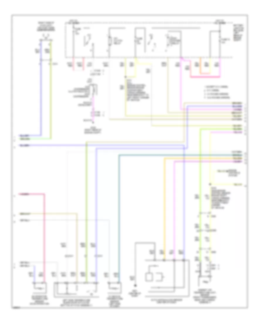
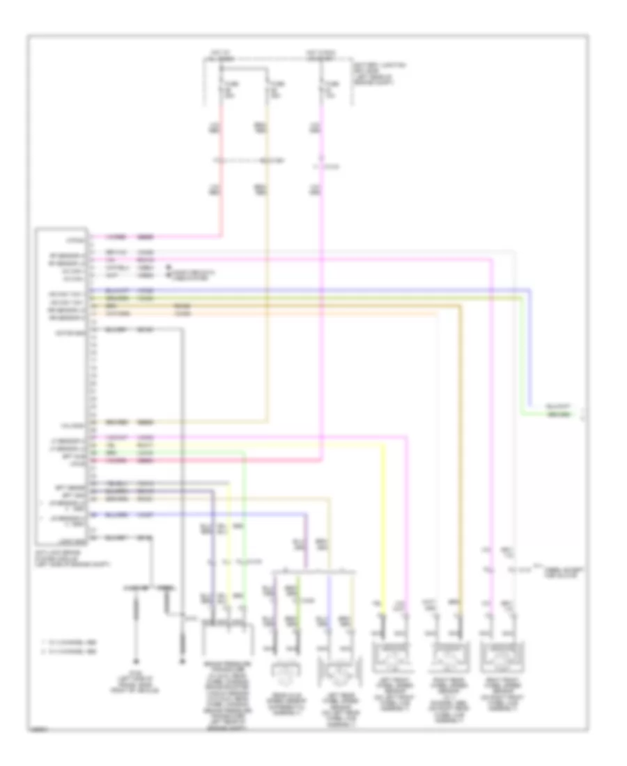
AIR CONDITIONING
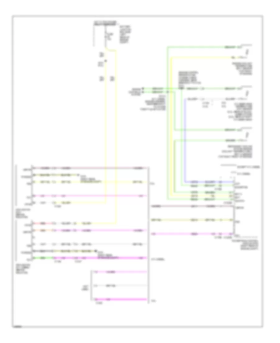
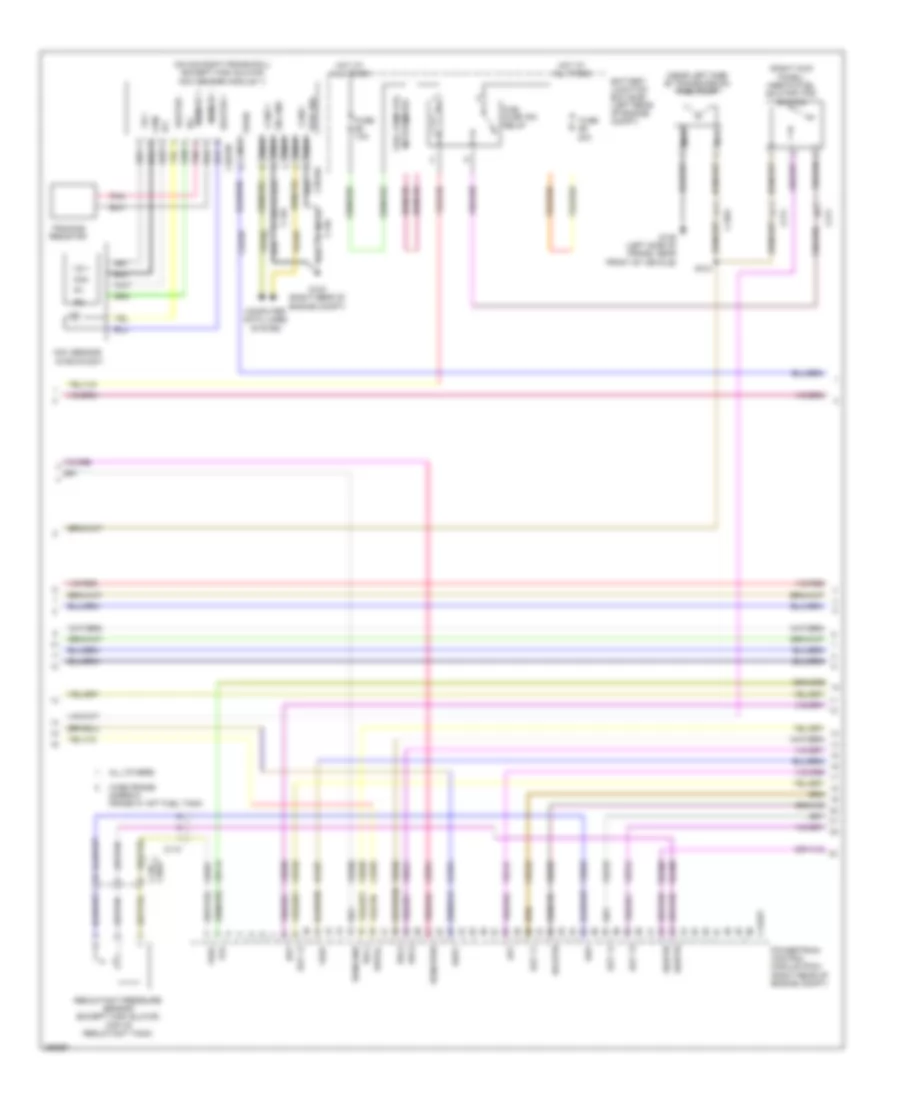
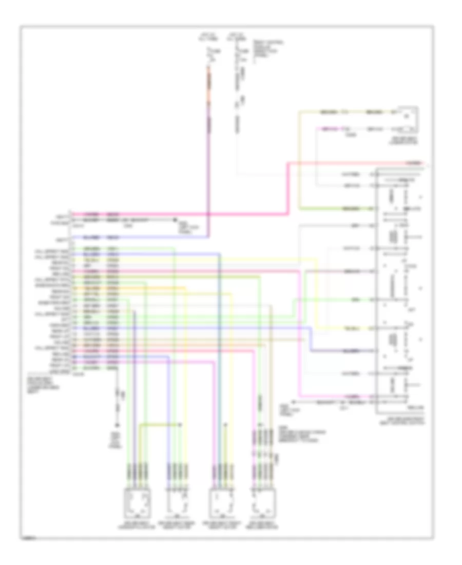
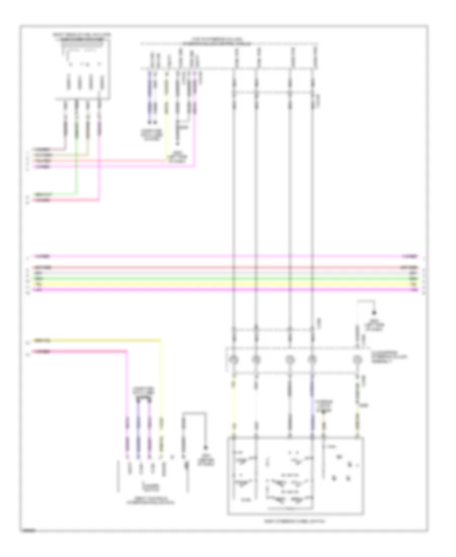
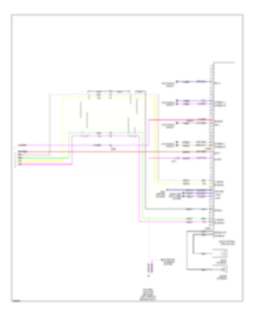
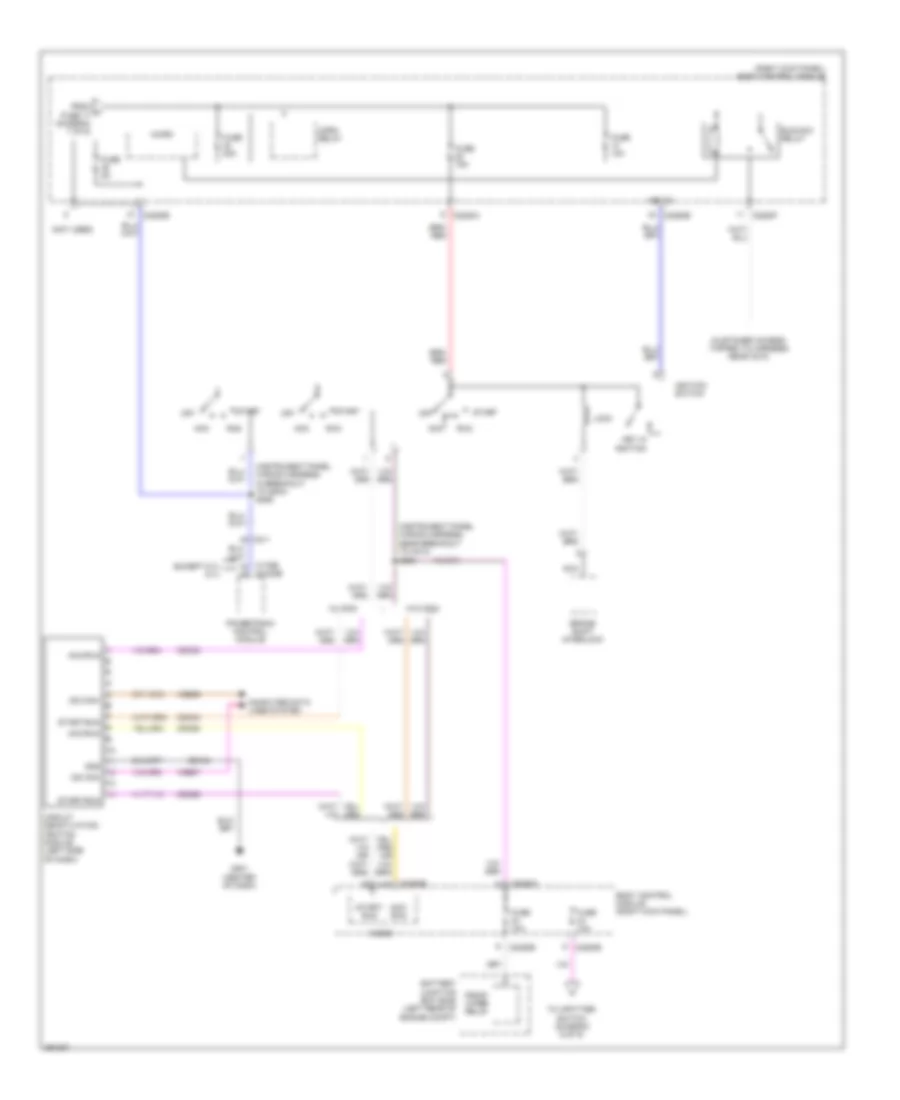
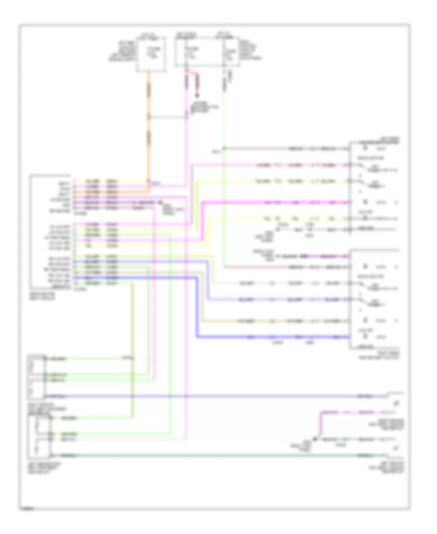
Automatic A/C Wiring Diagram (1 of 3) for Ford F-450 Super Duty Platinum 2013

List of elements for Automatic A/C Wiring Diagram (1 of 3) for Ford F-450 Super Duty Platinum 2013:
- (center of dash) g201
- (top left of hvac module) (diesel w/ rapid heat) auxiliary heater control module (ahcm)
- Autolamp sensor in
- Batt
- Battery
- Battery junction box (bjb) (left rear of engine compt)
- Blower motor (right end of hvac unit)
- Blower motor relay
- Blower motor speed control (right side of hvac assembly)
- Body control module (bcm) (right kick panel)
- C1617e
- C1617f
- C211
- C213
- C214
- C2280a
- C2280b
- C228a
- C2463a
- C2463b
- Cbp37
- Ch122
- Ch123
- Ch202
- Ch203
- Ch207
- Ch208
- Ch238
- Ch239
- Computer data lines system
- Defogger system
- Defrost request
- Defrost/panel/floor mode door actuator (left side of hvac assembly)
- Evap temp sensor
- Front blower rly
- Fuse 10a
- Fuse 40a
- G101 (lower right rear of engine)
- G203 (left side of dash)
- Gd108
- Gd184
- Gnd
- Harness, near breakout to g201)
- High current battery junction box (bjb) (right side of engine compt)
- Hot at all times
- Hot in start or run
- Hs can+
- Hs can-
- Hvac module
- Lh111
- Mega fuse 125a
- Micro
- Mode 1 act fdbk
- Mode dr 1 ccw
- Mode dr 1 cw
- Motor+
- Motor-
- Ms can+
- Ms can-
- Nca
- Pass temp act fdbk
- Pass temp dr ccw
- Pass temp dr cw
- Pwm
- Recirc ccw
- Recirc cw
- Red
- Return
- Rh111
- Right side temperature blend door actuator (top middle of hvac assembly)
- S250 (hvac jumper wiring harness, near breakout to top center of hvac housing)
- S257 (hvac jumper wiring harness, near breakout to right side of hvac housing)
- Sbp46
- Sdf05
- Top center of hvac housing) s251
- Variable blower ctrl
- Vbat
- Vdb04
- Vdb05
- Vdb06
- Vdb07
- Vh101
- Vh406
- Vh437
- Vh440
- Vlf14
- Vpwr
- Vref
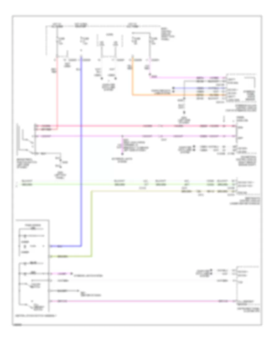
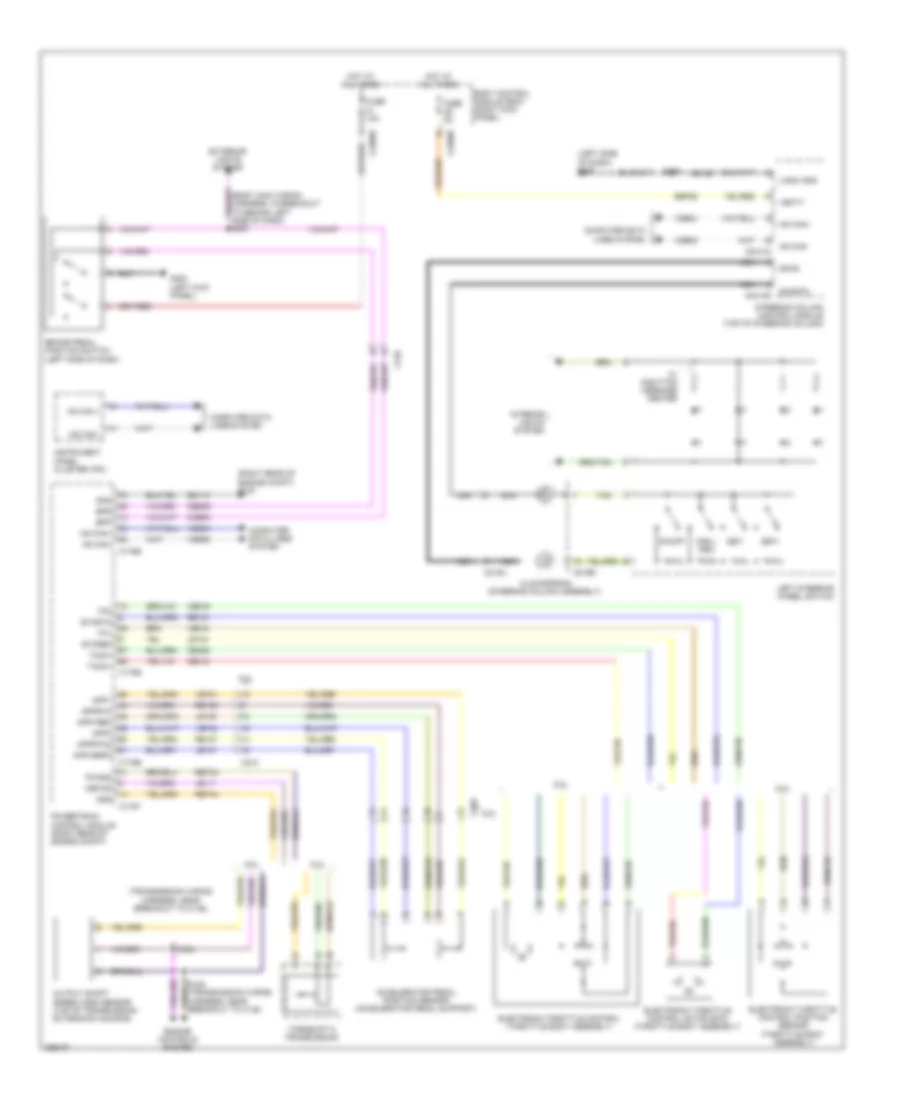
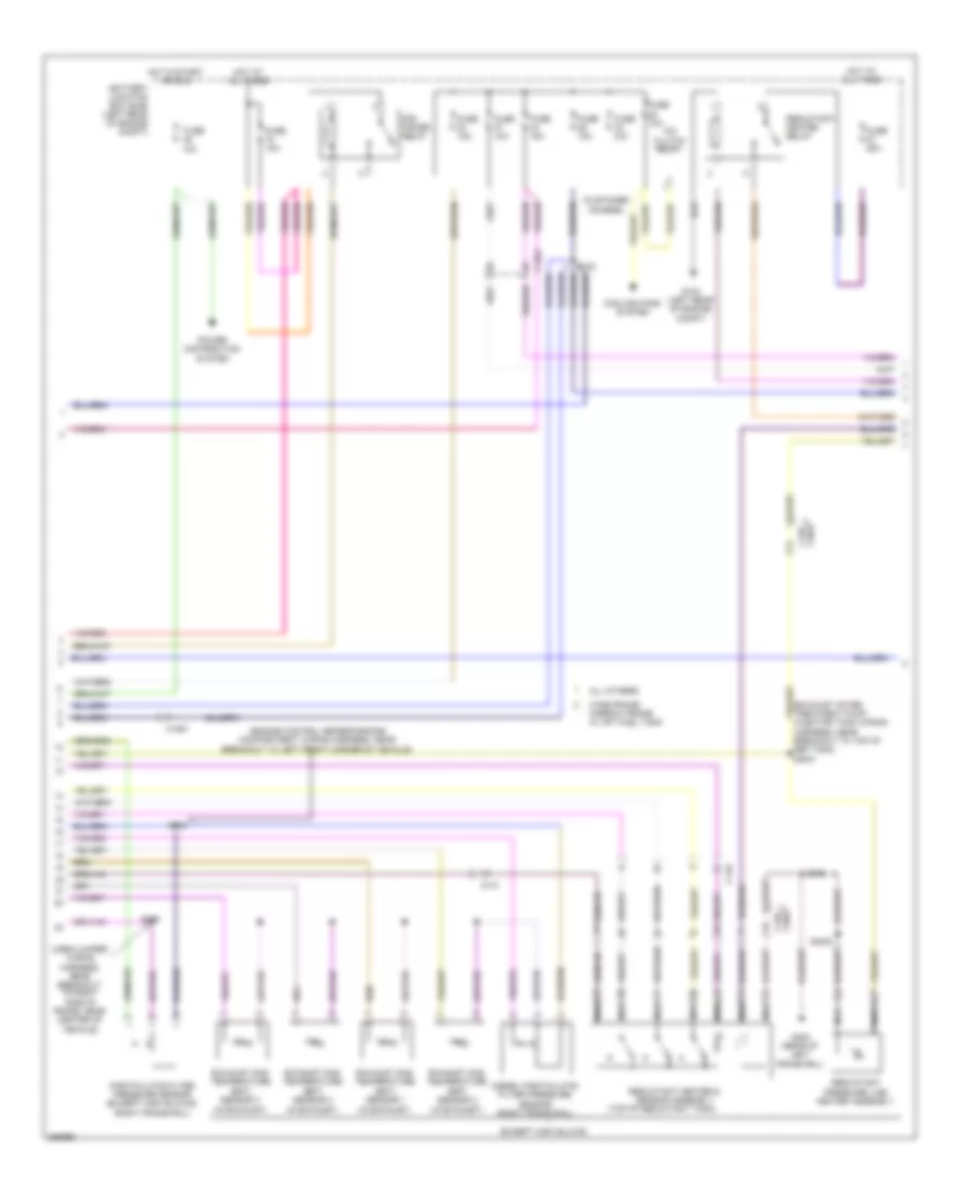
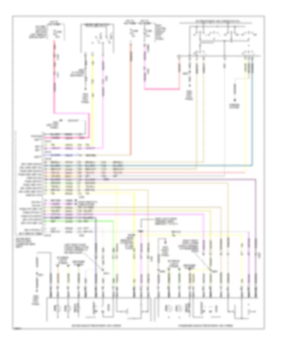
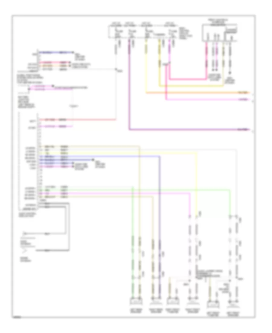
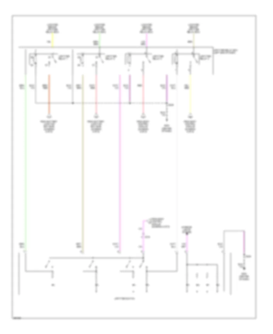
Automatic A/C Wiring Diagram (2 of 3) for Ford F-450 Super Duty Platinum 2013
List of elements for Automatic A/C Wiring Diagram (2 of 3) for Ford F-450 Super Duty Platinum 2013:
- (right side of hvac unit) air inlet mode door actuator
- 10a
- 6.7l diesel
- A/c clutch relay
- A/c compressor clutch field coil (a/c compressor)
- Ambient air temperature (aat) sensor (front passenger's rear view mirror assembly)
- Autolamp/sunload sensor (center of dash)
- Battery junction box (bjb) (left rear of engine compt)
- C1046
- C1168
- C213
- C214
- C263
- C265
- C601
- C651
- C655
- Engine controls system
- Evaporator temperature sensor (on evaporator)
- Except 6.7l diesel
- Fuse 10a
- Fuse 72
- G108 (right rear of engine compt)
- G201 (center of dash)
- Hot at all times
- In vehicle temperature sensor (left side of dash)
- Left side temperature blend door actuator (bottom of hvac assembly)
- Nca
- Pcm power relay
- Sensor engine compartment wiring harness, near breakout to left front corner of vehicle)
- W/ power mirrors
- W/o power mirrors
- Wiring harness, near breakout to right front corner of vehicle)
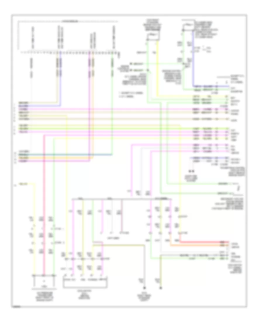
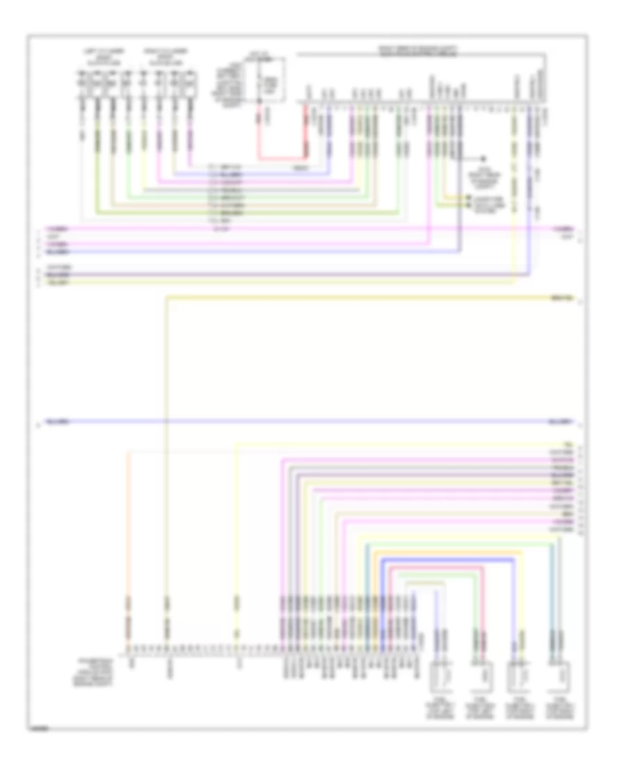
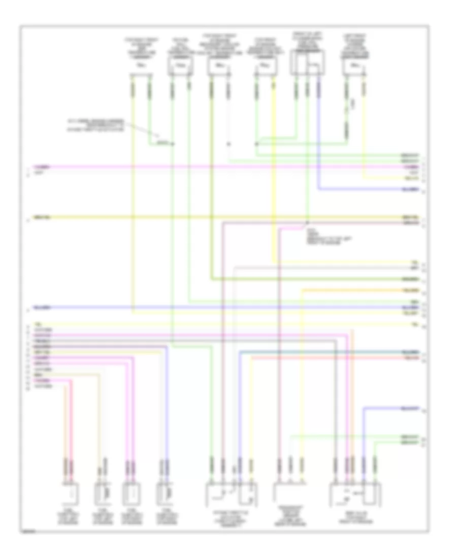
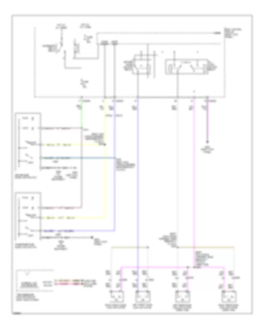
Automatic A/C Wiring Diagram (3 of 3) for Ford F-450 Super Duty Platinum 2013
List of elements for Automatic A/C Wiring Diagram (3 of 3) for Ford F-450 Super Duty Platinum 2013:
- (engine control sensor & fuel charge wiring harness, near breakout to c133)
- (not used)
- (top front of engine) engine coolant temperature (ect) sensor
- 6.2l
- 6.7l diesel
- 6.8l
- A/c pressure transducer (right front of engine compt)
- Aat
- Accr
- Acpt
- C1046
- C1047
- C1148
- C1163
- C1165
- C1220
- C1232b
- C1232e
- C133
- C175b
- C175e
- C228b
- Ce237
- Ch212
- Ch213
- Ch302
- Cht
- Computer data lines system
- Cooling fan (6.2l) (behind radiator)
- Cooling fan (6.7l diesel) (behind radiator)
- Cylinder head temperature (cht) sensor (6.2l: rear of block, under intake) (6.8l: rear of right cylinder head)
- Diesel
- Drv sunload
- Drv temp act fdbk
- Drv temp door ccw
- Drv temp door cw
- E-sigrtne
- Ect
- Ect 2
- Engine controls system
- Except 6.7l
- Except 6.7l diesel
- Fcv
- Fss
- G103 (right rear of engine compt)
- Hs can +
- Hs can -
- Hvac module
- In car temp sensor
- Kapwr
- Le111
- Le424
- Pass sunload
- Pcmrc
- Powertrain control module (pcm) (right rear of engine compt)
- Pwrgnd
- Re405
- Re407
- Red
- S1013 (6.7l diesel engine harness, near breakout to intake throttle actuator)
- S116 (6.2l)
- Sbb72
- Secondary cooling system engine coolant temperature 2 (ect 2) sensor (top right front of engine)
- Sig rtn
- Sigrtn
- Vbpwr
- Vdb04
- Vdb05
- Ve203
- Ve712
- Ve716
- Ve759
- Vec10
- Vh407
- Vh414
- Vh416
- Vh417
- Vh433
- Vh441
- Vpwr
- Vref
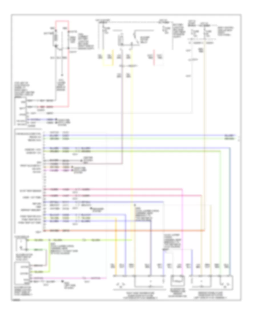
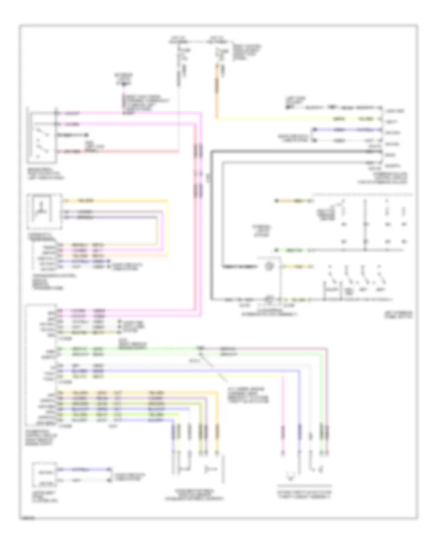
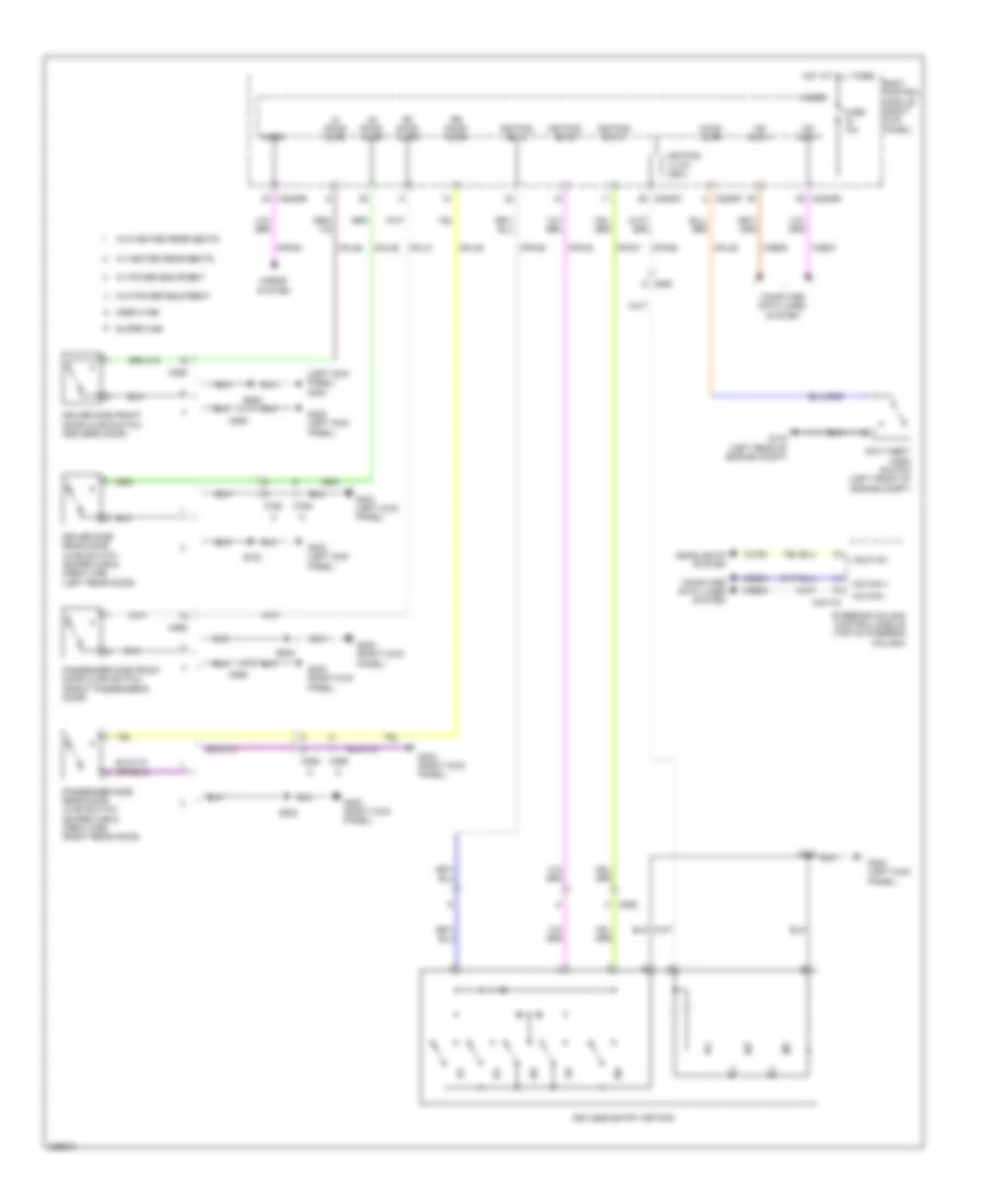
Manual A/C Wiring Diagram (1 of 2) for Ford F-450 Super Duty Platinum 2013
List of elements for Manual A/C Wiring Diagram (1 of 2) for Ford F-450 Super Duty Platinum 2013:
- (center of dash) g201
- (hvac jumper wiring harness, near breakout to top center of hvac housing) s251
- (top left of hvac module) (diesel w/ rapid heat) auxiliary heater control module (ahcm)
- Batt
- Battery
- Battery junction box (bjb) (left rear of engine compt)
- Blower motor (right end of hvac unit)
- Blower motor relay
- Blower motor speed control (right side of hvac assembly)
- Body control module (bcm) (right kick panel)
- C1617e
- C1617f
- C211
- C213
- C214
- C2280a
- C2280b
- C2463a
- C2463b
- Cbp37
- Ch122
- Ch123
- Ch202
- Ch203
- Ch207
- Ch208
- Ch238
- Ch239
- Computer data lines system
- Defogger system
- Defrost request
- Defrost/panel/floor mode door actuator (left side of hvac assembly)
- Evap temp sensor
- Evaporator temperature sensor (on evaporator)
- Front blower rly
- Fuse 10a
- Fuse 40a
- G101 (lower right rear of engine)
- G203 (left side of dash)
- Gd108
- Gd184
- Gnd
- High current battery junction box (bjb) (right side of engine compt)
- Hot at all times
- Hot in start or run
- Hs can+
- Hs can-
- Hvac module
- Lh111
- Mega fuse 125a
- Mode 1 act fdbk
- Mode dr 1 ccw
- Mode dr 1 cw
- Motor+
- Motor-
- Ms can+
- Ms can-
- Nca
- Pass temp act fdbk
- Pass temp dr ccw
- Pass temp dr cw
- Pwm
- Recirc ccw
- Recirc cw
- Red
- Return
- Rh111
- Right side temperature blend door actuator (top middle of hvac assembly)
- S250 (hvac jumper wiring harness, near breakout to top center of hvac housing)
- S257 (hvac jumper wiring harness, near breakout to right side of hvac housing)
- Sbp46
- Sdf05
- Variable blower ctrl
- Vbat
- Vdb04
- Vdb05
- Vdb06
- Vdb07
- Vh101
- Vh406
- Vh437
- Vh440
- Vpwr
- Vref
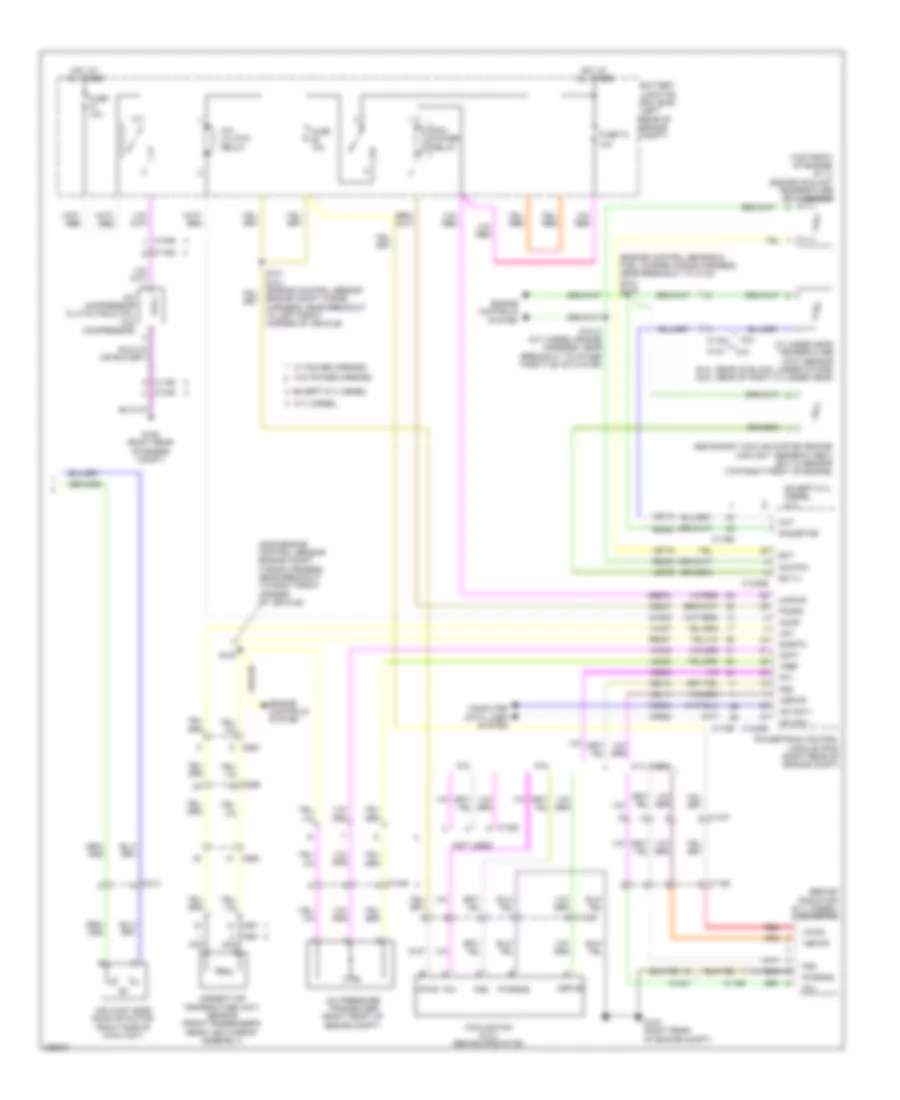
Manual A/C Wiring Diagram (2 of 2) for Ford F-450 Super Duty Platinum 2013
List of elements for Manual A/C Wiring Diagram (2 of 2) for Ford F-450 Super Duty Platinum 2013:
- (behind radiator) (6.7l diesel) cooling fan
- (engine control sensor & fuel charge wiring harness, near breakout to c133) (6.2l) s116
- (not used)
- (s239 engine control sensor engine compt wiring harness, near breakout to right front corner of vehicle)
- (top front of engine) (6.7l) engine coolant temperature (ect) sensor
- 10a
- 6.2l
- 6.7l diesel
- 6.8l
- A/c clutch relay
- A/c compressor clutch field coil (a/c compressor)
- A/c pressure transducer (right front of engine compt)
- Aat
- Accr
- Acpt
- Air inlet mode door actuator (right side of hvac unit)
- Ambient air temperature (aat) sensor (front passenger's rear view mirror assembly)
- Battery junction box (bjb) (left rear of engine compt)
- C1046
- C1047
- C1163
- C1165
- C1168
- C1220
- C1232b
- C1232e
- C133
- C175b
- C175e
- C213
- C263
- C265
- C601
- C651
- C655
- Ce237
- Ch302
- Cht
- Computer data lines system
- Cooling fan (6.2l) (behind radiator)
- Cylinder head temperature (cht) sensor (6.2l: rear of block, under intake) (6.8l: rear of right cylinder head)
- E-sigrtne
- Ect
- Ect 2
- Engine compt wiring harness, near breakout to left front corner of vehicle)
- Engine controls system
- Except 6.7l diesel
- Except 6.7l diesel 6.7l
- Fcv
- Fss
- Fuse 10a
- Fuse 72
- G103 (right rear of engine compt)
- G108 (right rear of engine compt)
- Hot at all times
- Hs can +
- Hs can -
- Kapwr
- Le111
- Le424
- Nca
- Pcm power relay
- Pcmrc
- Powertrain control module (pcm) (right rear of engine compt)
- Pwrgnd
- Re405
- Re407
- Red
- S100
- S1013 (6.7l diesel engine harness, near breakout to intake throttle actuator)
- Sbb72
- Secondary cooling system engine coolant temperature 2 (ect 2) sensor (top right front of engine)
- Sig rtn
- Sigrtn
- Vbpwr
- Vdb04
- Vdb05
- Ve203
- Ve712
- Ve716
- Ve759
- Vec10
- Vh407
- Vh433
- Vpwr
- Vref
- W/ power mirrors
- W/o power mirrors
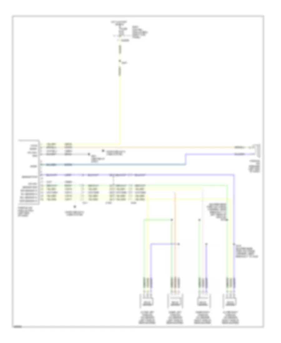
ANTI-LOCK BRAKES
Anti-lock Brakes Wiring Diagram (1 of 2) for Ford F-450 Super Duty Platinum 2013
List of elements for Anti-lock Brakes Wiring Diagram (1 of 2) for Ford F-450 Super Duty Platinum 2013:
- Anti-lock brake system module (left side of engine compt)
- Battery junction box (bjb) (left rear of engine compt)
- Bpt gnd
- Bpt sense
- Bpt sub
- Brake pressure transducer (w/ dual rear wheel chassis) brake booster vaccum sensor (w/o dual rear wheel chassis) (brake pressure transducer: left rear of engine compt)
- C110
- C1415
- C1581
- C438
- Cbb54
- Computer data lines system
- Diesel except high sulfur
- Fuse 10a
- Fuse 25a
- Fuse 50a
- G135 (left side of frame, near front of vehicle)
- Gasoline
- Gd163
- Hc can +
- Hc can -
- Hot at all times
- Hot in run or start
- Hs can yaw +
- Hs can yaw -
- Lca16
- Left front wheel speed sensor (on left front wheel hub assembly)
- Left rear wheel speed sensor (on left rear wheel hub assembly)
- Lf sensor hi
- Lf sensor lo
- Logic gnd
- Lr sensor hi dss+
- Lr sensor lo dss-
- Motor gnd
- Mtr b+
- Nca
- Rca16
- Rca17
- Rca19
- Rca20
- Rca21
- Rear axle speed sensor (differential assembly)
- Rf sensor hi
- Rf sensor lo
- Right front wheel speed sensor (on right front wheel hub assembly)
- Right rear wheel speed sensor (w/ 4 channel abs) (on right rear wheel hub assembly)
- Rr sensor hi
- Rr sensor lo
- S170
- Sbb86
- Sbb96
- Valve b+
- Vca03
- Vca05
- Vca06
- Vca07
- Vca13
- Vca23
- Vca24
- Vdb04
- Vdb05
- Vpwr
- W/ 3 channel abs
- W/ 4 channel abs
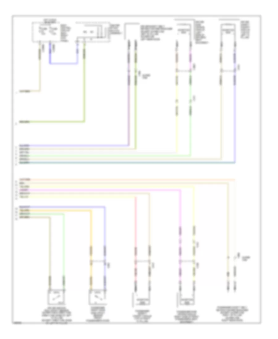
Anti-lock Brakes Wiring Diagram (2 of 2) for Ford F-450 Super Duty Platinum 2013
List of elements for Anti-lock Brakes Wiring Diagram (2 of 2) for Ford F-450 Super Duty Platinum 2013:
- (not used)
- Amber
- Body control module (right kick panel)
- Bpp
- Bps
- Brake pedal position switch (left side of dash)
- C1232b
- C1415
- C175b
- C210
- C212
- C2280a
- C2280b
- C2280d
- C2280f
- C2414a
- C2414b
- C310a
- C310b
- Ccb08
- Central stack switch assembly
- Ces09
- Computer data lines system
- Diesel
- Exterior lights system
- Fuse 10a
- Fuse 15a
- Fuse 5a
- Fuse 7.5a
- G201 (center of dash)
- G202 (left side of dash)
- G300 (left kick panel)
- Gasoline
- Gd185
- Hill descent switch
- Hot at all times
- Hot in run or start
- Hs can +
- Hs can -
- Hs can yaw +
- Hs can yaw -
- Hs can+
- Hs can-
- Instrument panel cluster (ipc)
- Interior lights system
- Logic gnd
- Micro
- Ms can +
- Ms can -
- Pad ind
- Pass air bag off
- Powertrain control module (right rear of engine compt)
- Pwr gnd
- Red
- Restraints control module (under center console)
- Rr116
- S207 (body main wiring harness, in breakout to behind left side of dash)
- S228
- S239
- S326
- Sbp24
- Sbp26
- Steering column control module (top of steering column)
- Steering wheel angle sensor
- Tcs
- Tcs off switch
- Vbatt
- Vca23
- Vca24
- Vdb04
- Vdb05
ANTI-THEFT
Forced Entry Wiring Diagram (1 of 2) for Ford F-450 Super Duty Platinum 2013
List of elements for Forced Entry Wiring Diagram (1 of 2) for Ford F-450 Super Duty Platinum 2013:
- (body main wiring harness, near breakout to c312) (crew cab) s382
- (body main wiring harness, near breakout to c312) s302
- (body main wiring harness, near breakout to c312) s305
- Accessory delay relay
- All lock/ unlock relay
- Body control module (right kick panel)
- C2280c
- C2280d
- C555
- C655
- C755
- C855
- Computer data lines system
- Cpk19
- Cpk23
- Door lock
- Door unlock
- Driver door unlock relay
- Driver side door lock switch
- Fuse 15a
- Fuse 20a
- G300 (left kick panel)
- G302 (right kick panel)
- Hot at all times
- Internal ant rke receiver
- Left front door lock actuator
- Left rear door lock actuator (crew cab)
- Lock
- Micro
- Ms can +
- Ms can -
- Passenger side door lock switch
- Right front door lock actuator
- Right rear door lock actuator (crew cab)
- S306 (body main wiring harness, near breakout to c312)
- S314
- S505 (w/ power equipment)
- S638 (w/ power equipment)
- Tire pressure monitor module (right end of dash)
- Unlock
- Vdb06
- Vdb07
Forced Entry Wiring Diagram (2 of 2) for Ford F-450 Super Duty Platinum 2013
List of elements for Forced Entry Wiring Diagram (2 of 2) for Ford F-450 Super Duty Platinum 2013:
- (left kick panel) g300
- 1/2
- 3/4
- 5/6
- 7/8
- 9/0
- Anti-theft hood switch (left front of engine compt)
- Body control module (right kick panel)
- C2280b
- C2280c
- C2280f
- C2414a
- C555
- C655
- C755
- C756
- C855
- C856
- Clf24
- Computer data lines system
- Cpk28
- Cpk29
- Cpk30
- Cpk31
- Cpl25
- Cpl26
- Cpl31
- Cpl36
- Cpl39
- Crew cab
- Crh04
- Driver side front door ajar switch (driver's door)
- Driver side rear door ajar switch (super cab & crew cab) (left rear door)
- Fuse 10a
- G104 (left rear of engine compt)
- G300 (left kick panel)
- G302 (right kick panel)
- Hdlp on
- Headlights system
- Hood ajar
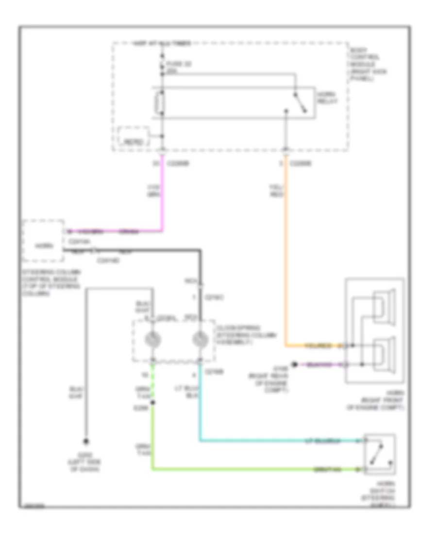
- Horn
- Horns system
- Hot at all times
- Hs can +
- Hs can -
- Keyless entry keypad
- Keypad illum (fet)
- Keypad sw a
- Keypad sw b
- Keypad sw c
- Lf door ajar
- Lr door ajar
- Micro
- Ms can +
- Ms can -
- Passenger side front door ajar switch (front passenger's door)
- Passenger side rear door ajar switch (super cab & crew cab) (right rear door)
- Rf door ajar
- Rr door ajar
- S505
- S638
- S700
- S802
- Steering column control module (top of steering column)
- Super cab
- Vdb04
- Vdb05
- Vdb06
- Vdb07
- W/ heated rear seats
- W/ power equipment
- W/o heated rear seats
- W/o power equipment
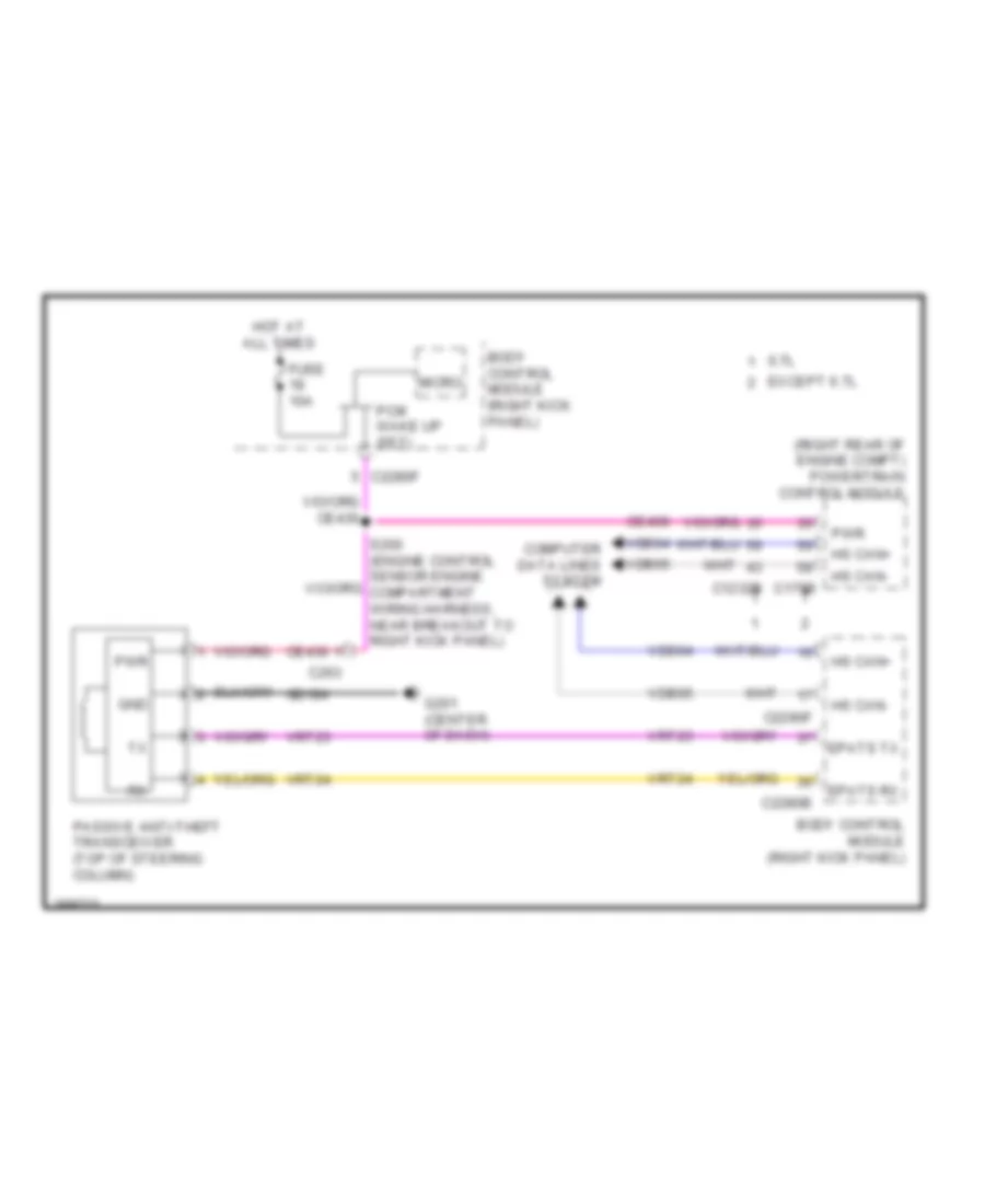
Passive Anti-theft Wiring Diagram for Ford F-450 Super Duty Platinum 2013
List of elements for Passive Anti-theft Wiring Diagram for Ford F-450 Super Duty Platinum 2013:
- (right rear of engine compt) powertrain control module
- 6.7l
- Body control module (right kick panel)
- C1232b
- C175b
- C2280b
- C2280f
- C263
- Ce436
- Computer data lines system
- Epats rx
- Epats tx
- Except 6.7l
- Fuse 10a
- G201 (center of dash)
- Gd184
- Gnd
- Hot at all times
- Hs can+
- Hs can-
- Micro
- Passive anti-theft transceiver (top of steering column)
- Pcm wake up (fet)
- Pwr
- Vdb04
- Vdb05
- Vrt23
- Vrt24
BODY CONTROL MODULES
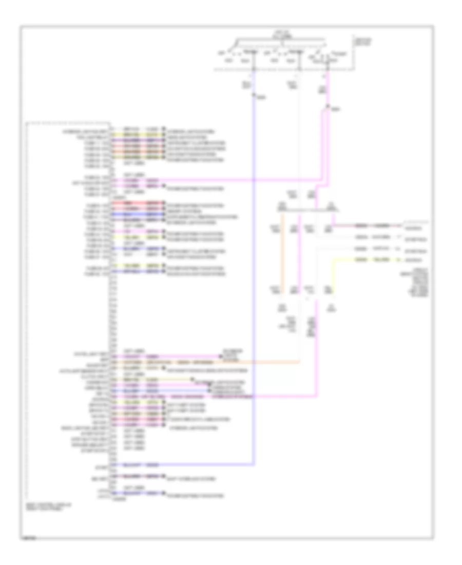
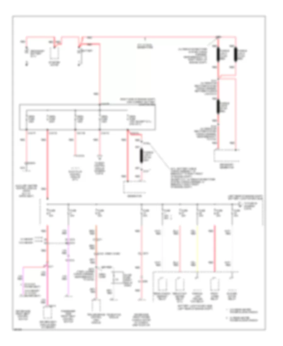
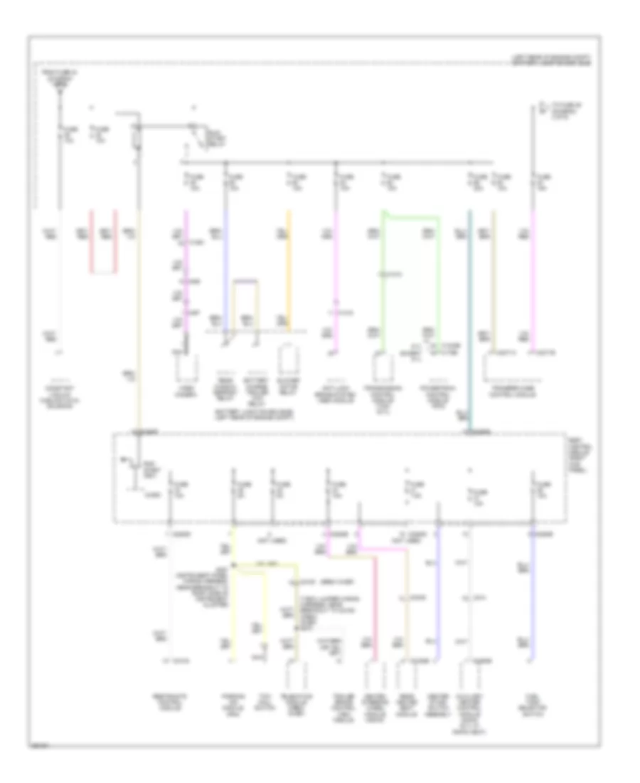
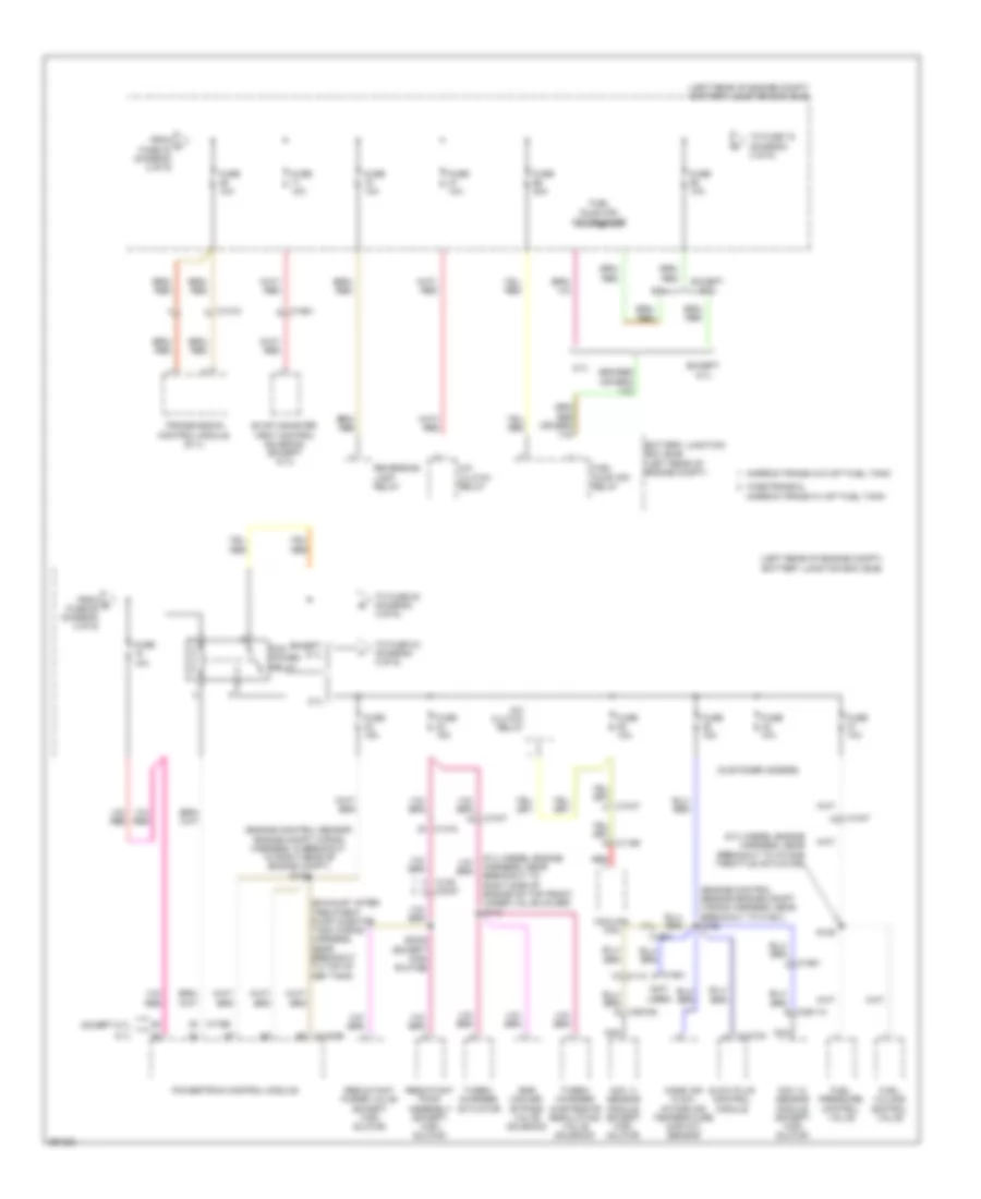
Body Control Modules Wiring Diagram (1 of 2) for Ford F-450 Super Duty Platinum 2013
List of elements for Body Control Modules Wiring Diagram (1 of 2) for Ford F-450 Super Duty Platinum 2013:
- (not used)
- (or cdc62)
- (or cdc63)
- Acc
- Acc/run
- Air conditioning & headlights systems
- Air conditioning system
- Anti-theft system
- Autolamp sensor input
- Back lighting led (fet)
- Body control module (right kick panel)
- Bpp
- Bsi (fet)
- C2280a
- C2280b
- Cbp31
- Cbp34
- Cbp35
- Cbp36
- Cbp37
- Cbp38
- Cbp41
- Cbp44
- Ccb08
- Cdc30
- Cdc33
- Cdc34
- Cdc35
- Cdc62
- Cdc63
- Cet53
- Circuit deactivation ignition module (w/ cdim) (left side of dash)
- Clf12
- Cls32
- Clutch input
- Computer data lines system
- Crh04
- Epats rx
- Epats tx
- Exterior lights system
- Fog lamp relay
- Fuse 11, 10a
- Fuse 23, 15a
- Fuse 24, 15a
- Fuse 26, 5a
- Fuse 27, 20a
- Fuse 28, 15a
- Fuse 29, 20a
- Fuse 31, 5a
- Fuse 32, 15a
- Fuse 34, 10a
- Fuse 35, 5a
- Fuse 36, 10a
- Fuse 37, 10a
- Fuse 38, 10a
- Fuse 41, 7.5a
- Fuse 42, 5a
- Fuse 44, 10a
- Fuse 45, 5a
- Fuse 46, 10a
- Fuse 9, 10a
- Hazard sw
- Headlights system
- Horn relay
- Horns system
- Hot at all times
- Hot in run or acc
- Ignition switch
- Instrument cluster system
- Interior lighting (fet)
- Interior lights system
- Key in
- Lin 01
- Lin 04
- Memory systems
- Ms can +
- Ms can -
- Navigation & sound systems
- Off
- Power distribution system
- Red
- Ripcord security
- Run
- Run/start
- S284
- S285
- Sbp09
- Sbp11
- Sbp24
- Sbp26
- Sbp28
- Sbp29
- Sbp46
- Shift interlock system
- Sound & navigation systems
- Start
- Start/run
- Start/stop 1
- Start/stop 2
- Strt button (fet)
- Vdb06
- Vdb07
- Vdn01
- Vlf14
- Vln04
- Vln33
- Vrt23
- Vrt24
- W/ cdim
- W/o cdim
- Warning & shift interlock systems
- White light (fet)
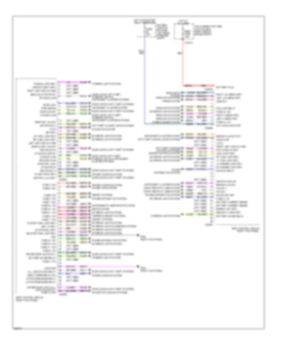
Body Control Modules Wiring Diagram (2 of 2) for Ford F-450 Super Duty Platinum 2013
List of elements for Body Control Modules Wiring Diagram (2 of 2) for Ford F-450 Super Duty Platinum 2013:
- (not used)
- 3rd row seat (fet)
- All lock/unlock relay
- Anti-theft & door locks systems
- Anti-theft & engine controls systems engine controls system
- Battery current sense
- Battery junction box (bjb) (left rear of engine compt)
- Battery plus
- Battery saver relay
- Body control module (right kick panel)
- Brake fluid sw
- Brake fluid sw rtn
- Bsi (fet)
- C1617c
- C2280c
- C2280d
- C2280e
- C2280f
- C2280g
- Cbb56
- Cbp01
- Cbp30
- Cbp31
- Cbp32
- Cbp33
- Cbp34
- Cbp40
- Cbp43
- Cdc55
- Cdc64
- Ce226
- Ce436
- Circuit breaker 48, 30a
- Clf02
- Clf03
- Clf04
- Clf05
- Clf12
- Cln09
- Cln25
- Cls18
- Cls19
- Cls21
- Cls23
- Cls25
- Cls27
- Cls28
- Cls52
- Cmc19
- Cmc25
- Computer data lines system
- Cpk19
- Cpk23
- Cpk28
- Cpk29
- Cpk30
- Cpk31
- Cpl11
- Cpl25
- Cpl26
- Cpl31
- Cpl36
- Cpl39
- Cpl51
- Cpl52
- Cpw73
- Decklid key unlock
- Decklid/liftgate sw
- Door key lock
- Door key unlock
- Door lock
- Door locks & anti-theft systems
- Door locks, anti-theft, interior lights & instrument cluster systems
- Door unlock
- Driver door lock & all lock/unlock rly fuse 19, 20a
- Driver door unlock rly
- Energy mgt (fet)
- Exterior lights & mirrors systems
- Exterior lights system
- Fog lamp relay
- Front led turn outage
- Fuel pump (fet)
- Fuse 1, 30a
- Fuse 2, 15a
- Fuse 20a
- Fuse 21, 10a
- Fuse 3, 30a
- Fuse 30, 15a
- Fuse 31, 5a
- Fuse 32, 15a
- Fuse 33, 10a
- Fuse 34, 10a
- Fuse 4, 10a
- Fuse 40, 10a
- Fuse 41, 7.5a
- Fuse 43, 10a
- Fuse 5, 20a
- Fuse 6, 5a
- Fuse 7, 7.5a
- Fuse 8, 10a
- Fuse 9, 10a
- G302 (right kick panel)
- Gd133
- Gd179
- Gnd
- Gnd rtn analog
- Headlights system
- Headlights system headlights system
- High current battery junction box (right side of engine compt)
- Hood ajar
- Horn rly
- Horns system
- Hot at all times
- Hot in run or start
- Hot w/ run/start relay energized
- Hs can +
- Hs can -
- Instrument cluster system
- Interior lights system
- Keypad illum (fet)
- Keypad sw a
- Keypad sw b
- Keypad sw c
- Left hi beam (fet)
- Left led turn outage
- Left low beam (fet)
- Lf door ajar
- Lf turn lamp (fet)
- Lh corner lamp (fet)
- Liftgate ajar sw
- Liftgate release relay
- Liftgate sw
- Lin 02
- Lin 03
- Logic gnd
- Lr door ajar
- Lr stop/turn lamp (fet)
- Lr turn lamp (fet)
- Mega fuse 125a
- Memory systems
- Mirrors & memory systems
- Navigation & sound systems
- Navigation system
- Park brake
- Pcm wake up (fet)
- Power distribution system
- Power tops system
- Power windows system
- Puddle lamp (fet)
- Pulse train (fet)
- Red
- Rev lp (fet)
- Rf door ajar
- Rf turn lamp (fet)
- Rh corner lamp (fet)
- Right hi beam (fet)
- Right led turn outage
- Right low beam (fet)
- Rmc19
- Rr door ajar
- Rr stop/turn lamp (fet)
- Rr turn lamp (fet)
- Run/acc relay
- Run/start fet
- Sbf03
- Sbp02
- Sbp03
- Sbp05
- Sbp06
- Sbp07
- Sbp08
- Sbp19
- Sbp21
- Seats system
- Security horn (fet)
- Srh01
- Stop/chmsl (fet)
- Vdb04
- Vdb05
- Vdn03
- Wiper/washer system
COMPUTER DATA LINES
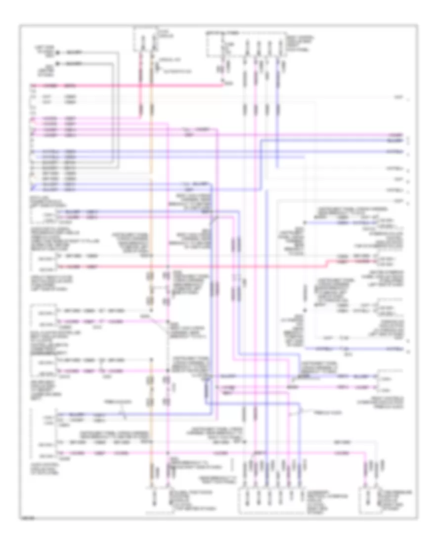
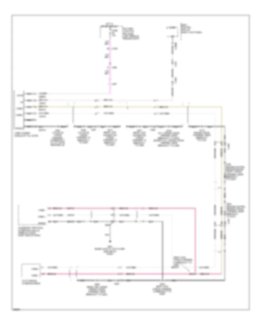
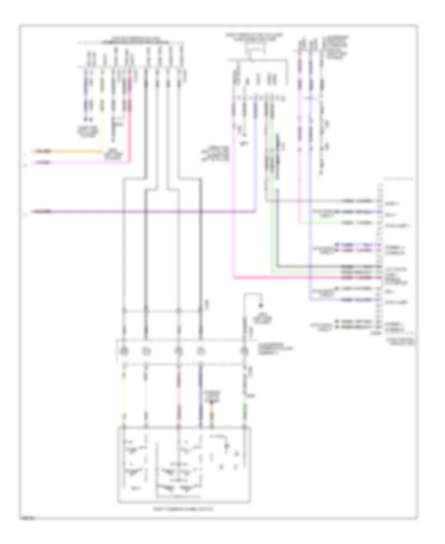
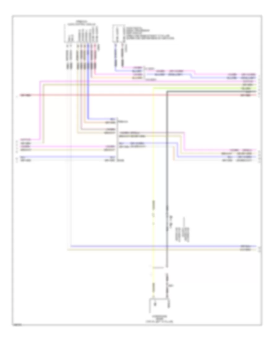
Computer Data Lines Wiring Diagram (1 of 2) for Ford F-450 Super Duty Platinum 2013
List of elements for Computer Data Lines Wiring Diagram (1 of 2) for Ford F-450 Super Duty Platinum 2013:
- (body main wiring harness, near breakout to center of cab floor) s307
- (instrument panel wiring harness, in breakout to g203) s256
- (instrument panel wiring harness, in breakout to right side of instrument cluster) s254
- (instrument panel wiring harness, near breakout to behind left side of dash) s235
- (instrument panel wiring harness, near breakout to c215) s233
- (instrument panel wiring harness, near breakout to center of dash) s224
- (instrument panel wiring harness, near breakout to right kick panel) s211
- (left side of dash) g203
- (near breakout to right kick panel)
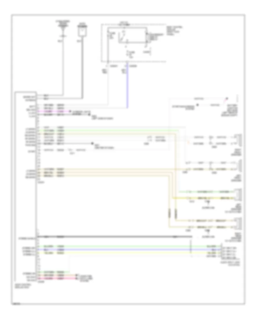
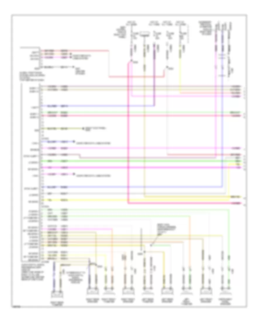
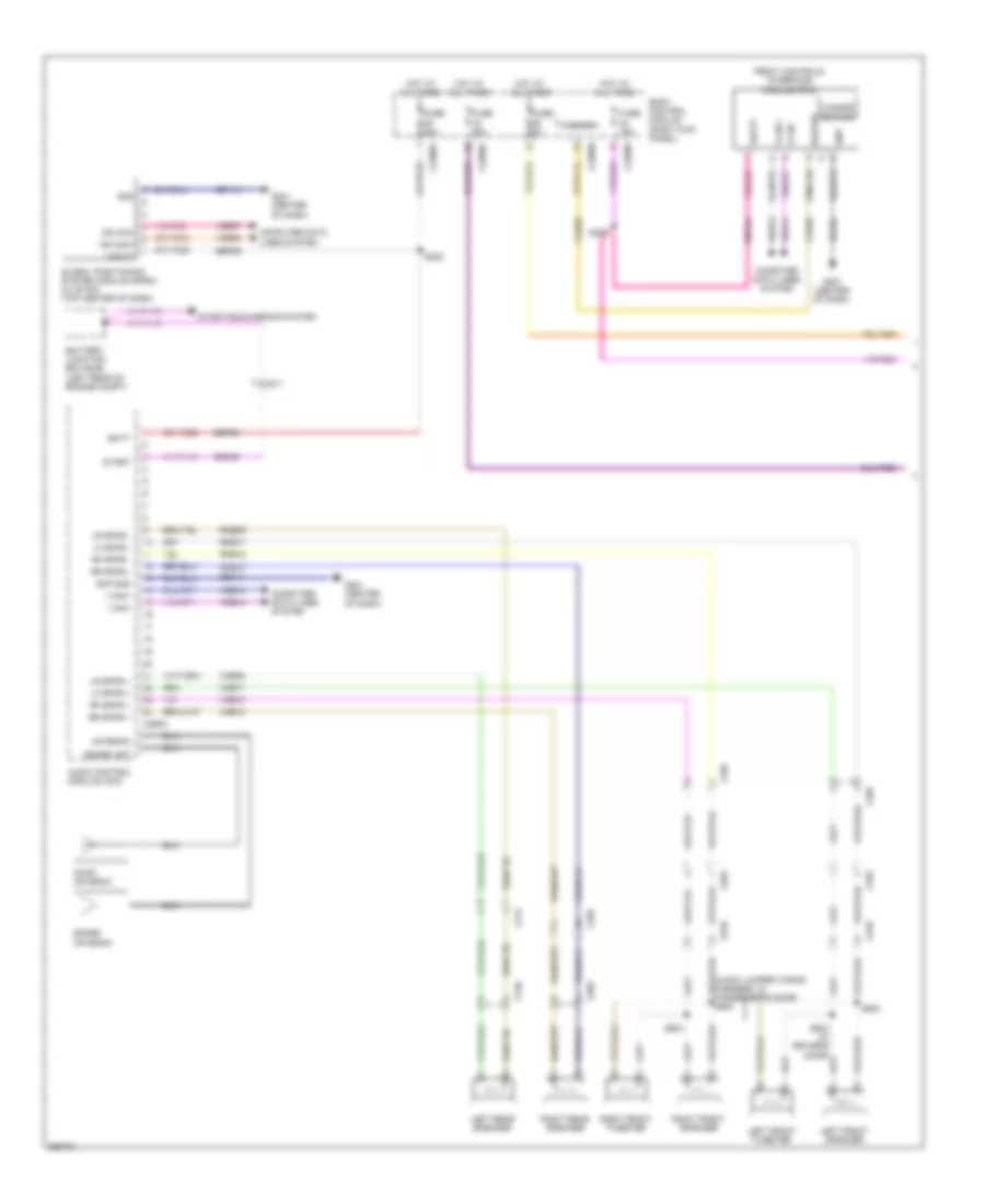
- Accessory protocol interface module (w/ sync) (right end of dash)
- Audio control module (acm) (w/ cd player)
- Audio digital signal processing (dsp) module (premium audio) (crew cab: base of right "c" pillar) (super cab: center rear of cab floor)
- Automatic a/c
- Body control module (bcm) (right kick panel)
- C207
- C212
- C2280a
- C2280b
- C2280f
- C228a
- C240b
- C2414a
- C290a
- C300
- C312
- C3154a
- C3265c
- C341d
- Circuit deactivation ignition module (cdim) (if equipped) (left side of dash)
- Data link connector (dlc) (left side of dash)
- Driver seat module (dsm) (w/ memory) (under driver's seat)
- Dual climate controlled seat module (dcsm) (w/ climate controlled seats) (under front passenger's seat)
- Front controls interface module (fcim) (premium audio)
- Fuse 15a
- G201 (center of dash)
- Gd115
- Gd184
- Global positioning system module (w/ sync) (top center of dash)
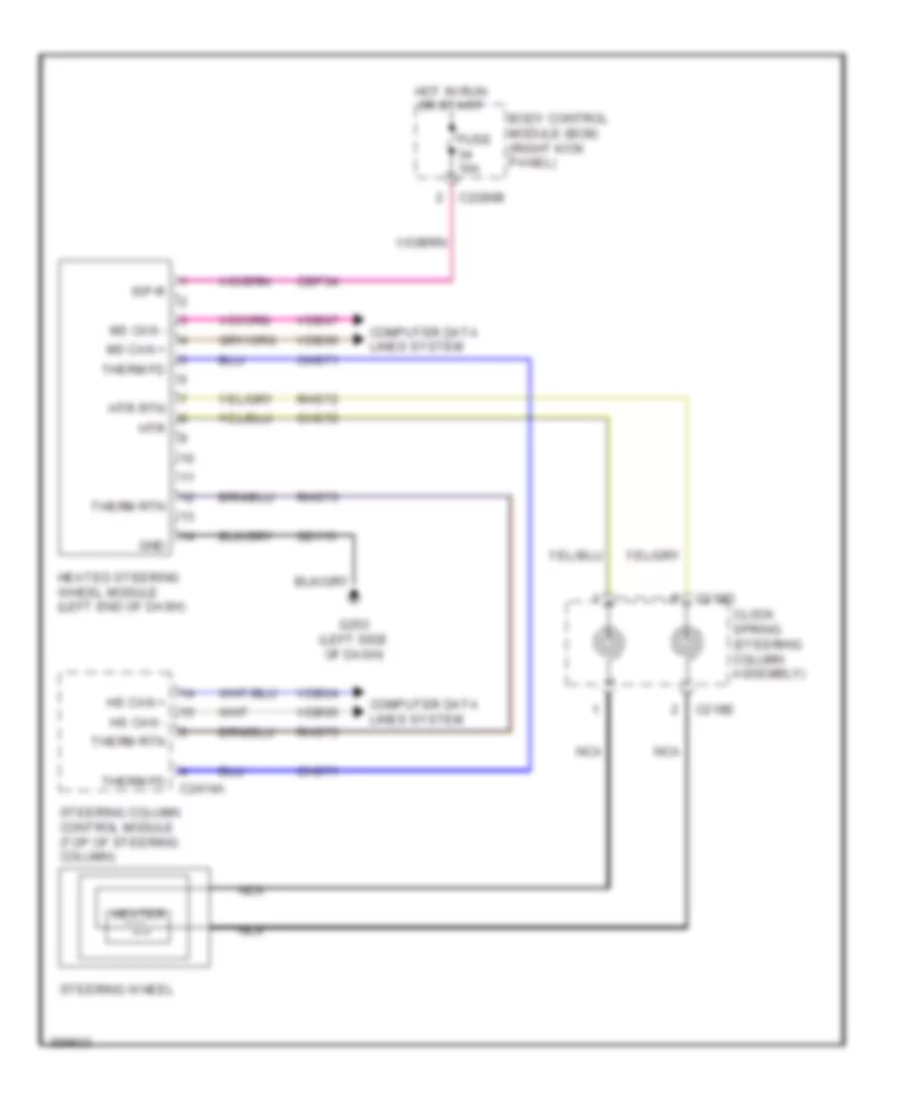
- Heated steering wheel module (hswm) (if equipped) (left end of dash)
- Hot at all times
- Hs can +
- Hs can -
- Hvac module
- I can +
- I can -
- Manual a/c
- Ms can +
- Ms can -
- Premium audio
- S210
- S228
- S234 (instrument panel wiring harness, near breakout to c215)
- S236 (instrument panel wiring harness, near breakout to behind left c212 side of dash)
- S240 (w/ parking aid) (near breakout to behind left side of dash)
- S253
- S255
- S308 (body main wiring harness, near breakout to center of cab floor)
- S380 (body main wiring harness, near breakout to c311)
- S381
- Sbp24
- Steering column control module (sccm) (top of steering column)
- Tire pressure monitor module (right end of dash)
- Vdb04
- Vdb05
- Vdb06
- Vdb07
- Vdb13
- Vdb14
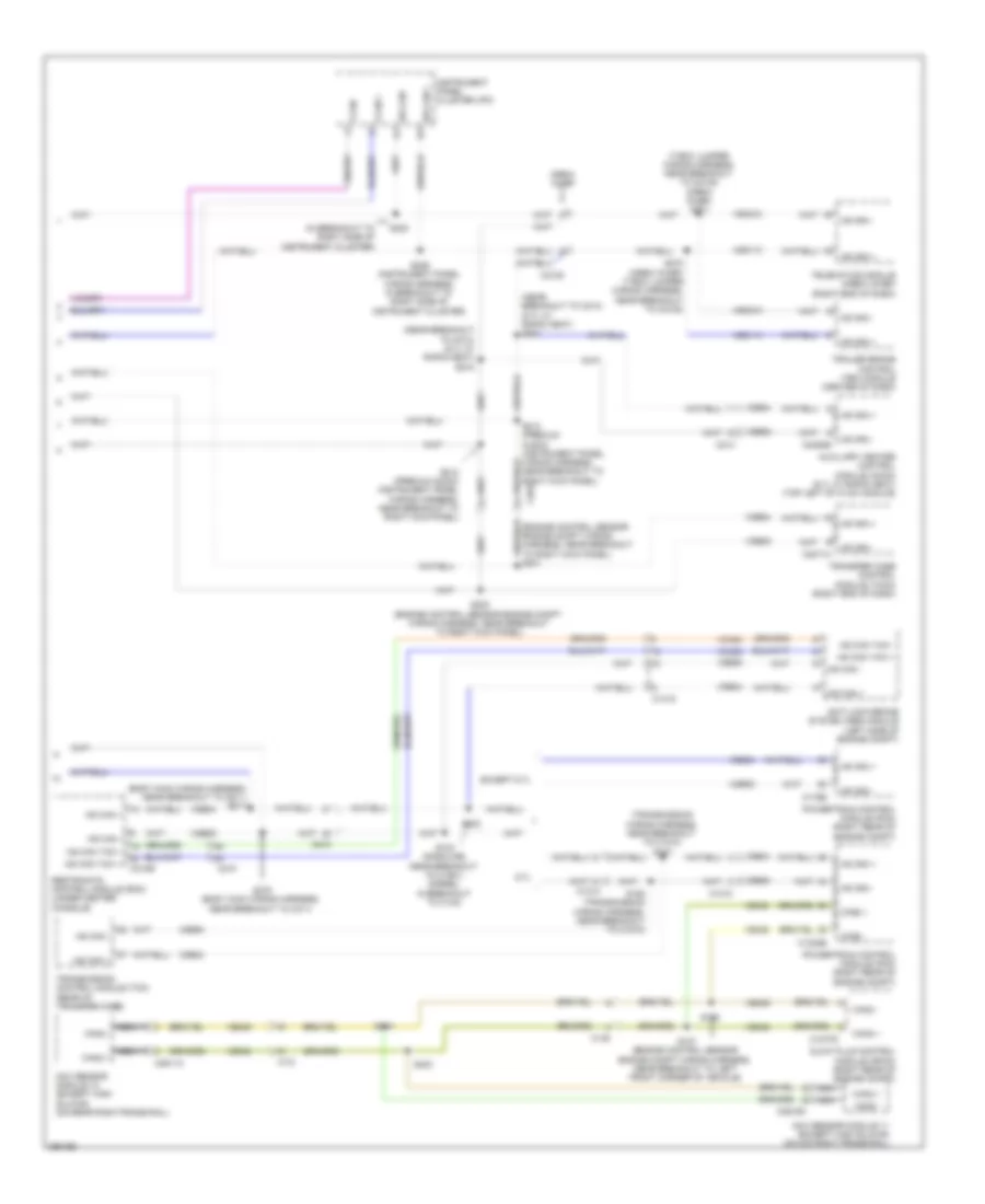
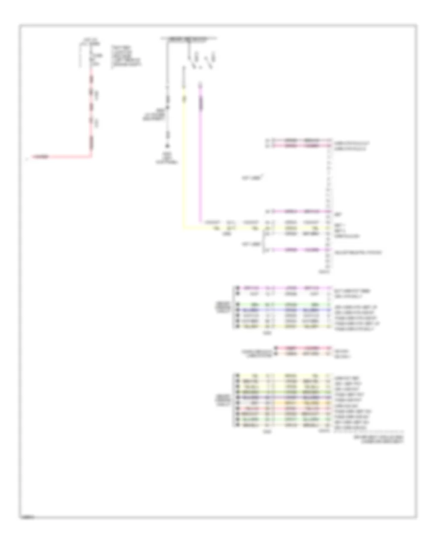
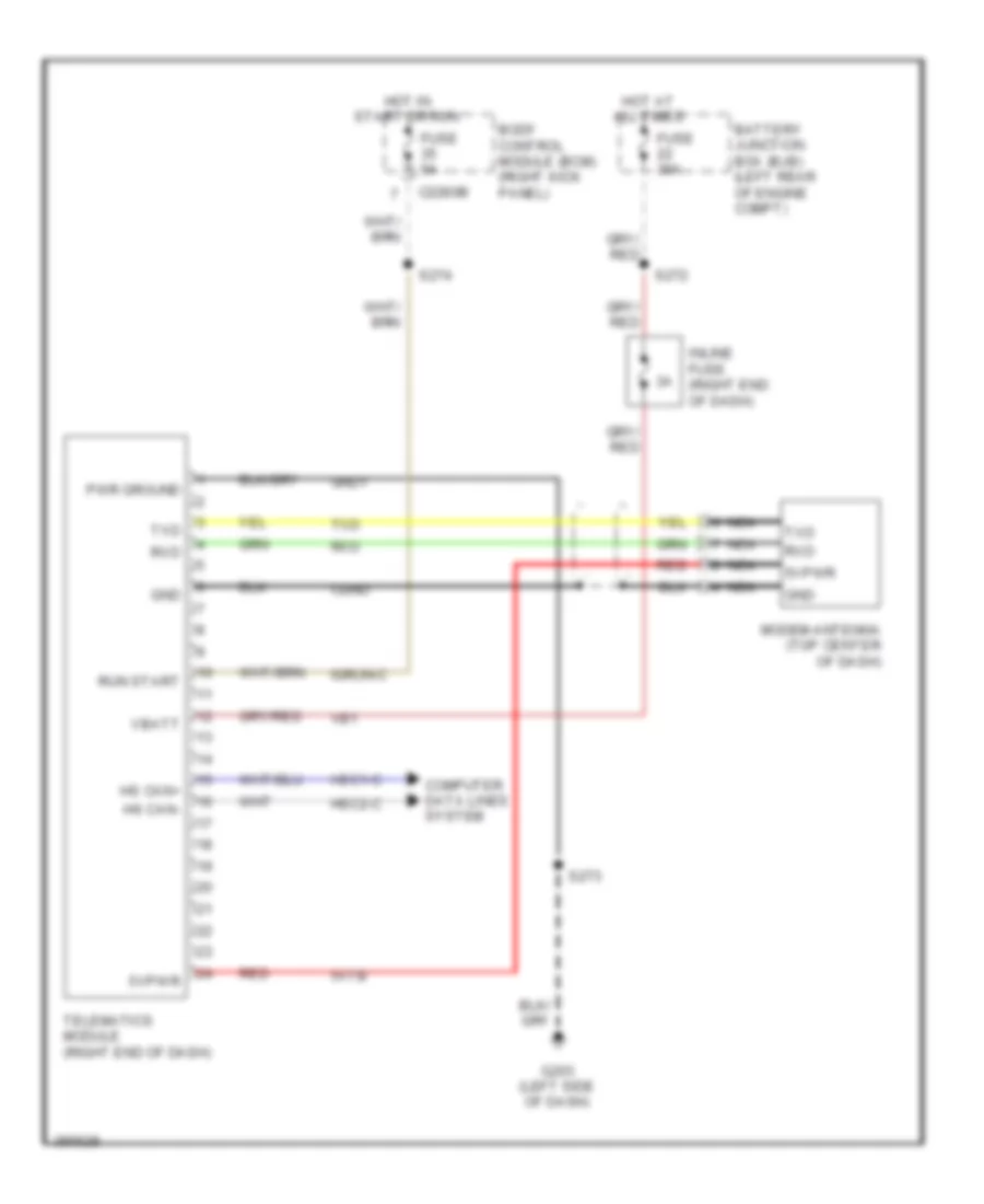
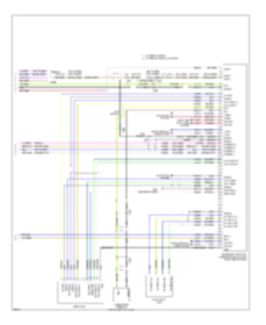
Computer Data Lines Wiring Diagram (2 of 2) for Ford F-450 Super Duty Platinum 2013
List of elements for Computer Data Lines Wiring Diagram (2 of 2) for Ford F-450 Super Duty Platinum 2013:
- (body main wiring harness, near breakout to c311) s377
- (in breakout to right side of instrument cluster)
- (near breakout to c213) (6.7l w/ rapid heat) s218
- (near breakout to c213) (6.7l w/ rapid heat) s221
- (t-box jumper wiring harness, near breakout to c2108) (crew chief) s271
- (transmission wiring harness, near breakout to c1010) s187
- 6.7l
- Anti-lock brake system (abs) module (left side of engine compt)
- Auxiliary heater control module (ahcm) (6.7l w/ rapid heat) (top left of hvac module)
- C1010
- C1232b
- C1273c
- C1415
- C146
- C175b
- C1i0
- C210
- C2108
- C214
- C2371a
- C2463b
- C263
- C310b
- C3611a
- C3619a
- Can2 +
- Can2 -
- Crew chief
- Except 6.7l
- Glow plug control module (gpcm) (right rear of engine compt)
- Hs can +
- Hs can -
- Hs can yaw +
- Hs can yaw -
- Hsc1-a
- Hsc1-c
- Hsc2-a
- Hsc2-c
- I can +
- I can -
- Instrument panel cluster (ipc)
- Nca
- Nox sensor module 11 (except high sulfur) (on mid right frame rail)
- Nox sensor module 12 (except high sulfur) (on rear right frame rail)
- Powertrain control module (pcm) (right rear of engine compt)
- Restraints control module (rcm) (under center console)
- S102
- S103 (gasoline: near breakout to c1581) (diesel: in breakout to c140)
- S106
- S107 (engine control sensor engine compt wiring harness, near breakout to left front corner of vehicle)
- S188 (transmission wiring harness, near breakout to c1010)
- S202 (engine control sensor engine compt wiring harness, near breakout to right kick panel)
- S212 (premium audio) (instrument panel wiring harness, near breakout to right kick panel)
- S213 (premium audio) (instrument panel wiring harness, near breakout to right kick panel)
- S229 (instrument panel wiring harness, in breakout to right side of instrument cluster)
- S230
- S270 (crew chief) (t-box jumper wiring harness, near breakout to c2108)
- S378 (body main wiring harness, near breakout to c311)
- S403
- S404
- Telematics module (crew chief) (right end of dash)
- Trailer brake control (tbc) module (center of dash)
- Transfer case control module (tccm) (right end of dash)
- Transmission control module (tcm) (rear of transfer case)
- Vca23
- Vca24
- Vdb04
- Vdb05
- Ve348
- Ve349
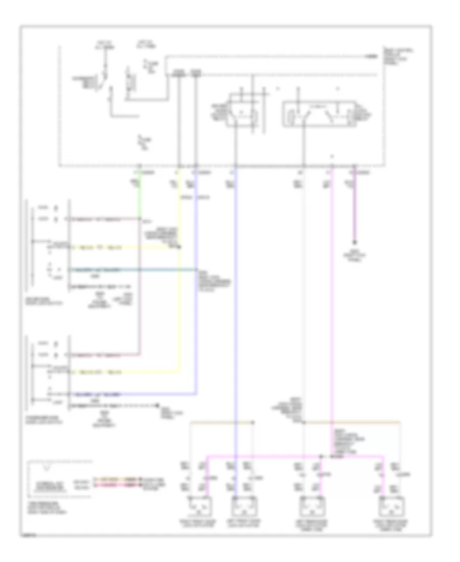
COOLING FAN
Cooling Fan Wiring Diagram for Ford F-450 Super Duty Platinum 2013
List of elements for Cooling Fan Wiring Diagram for Ford F-450 Super Duty Platinum 2013:
- (engine control sensor & fuel charge wiring harness, near breakout to c133) (6.2l) s116
- (not used)
- 6.2l
- 6.7l diesel
- 6.8l
- Battery junction box (bjb) (left rear of engine compt)
- C1047
- C1163
- C1165
- C1220
- C1232b
- C1232e
- C133
- C175b
- C175e
- Cht
- Cooling fan (6.2l) (behind radiator)
- Cooling fan (6.7l diesel) (behind radiator)
- Cylinder head temperature (cht) sensor (6.2l: rear of block, under intake) (6.8l: rear of right cylinder head)
- E-sigrtne
- Ect
- Ect 2
- Engine controls system
- Engine coolant temperature (ect) sensor (top front of engine)
- Except 6.7l diesel
- Fcv
- Fss
- Fuse 10a
- G103 (right rear of engine compt)
- Hot w/ pcm power relay energized
- Le111
- Powertrain control module (pcm) (right rear of engine compt)
- Pwrgnd
- Re405
- Red
- S101 (6.2l)
- S1013 (6.7l diesel engine harness, near breakout to intake throttle actuator)
- Secondary cooling system engine coolant temperature 2 (ect 2) sensor (top right front of engine)
- Sig rtn
- Vbpwr
- Ve203
- Ve712
- Ve716
- Ve759
- Vec10
- Vpwr
CRUISE CONTROL
6.2L FLEX FUEL
6.2L Flex Fuel, Cruise Control Wiring Diagram for Ford F-450 Super Duty Platinum 2013
List of elements for 6.2L Flex Fuel, Cruise Control Wiring Diagram for Ford F-450 Super Duty Platinum 2013:
- (body main wiring harness, in breakout to behind left side of dash) s207
- (left side of dash) g202
- (right rear of engine compt) g103
- (transmission wiring harness, near breakout to c145)
- 6.2l
- 6.8l
- Accelerator pedal position sensor (accelerator pedal support)
- App1
- App2
- Apprtn
- Apprtn2
- Appverf2
- Appvref
- Body control module (bcm) (right kick panel)
- Bpp
- Bps
- Brake pedal position switch (left side of dash)
- C175b
- C175e
- C175t
- C210
- C218b
- C218c
- C2280b
- C2280d
- C2414a
- C2414d
- Ccb08
- Ce412
- Ce426
- Ces09
- Clockspring (steering column assembly)
- Cncl/ rsm
- Computer data lines system
- Electronic throttle control (throttle body assembly)
- Electronic throttle control motor (etc) (throttle body assembly)
- Electronic throttle control position sensor (throttle body assembly)
- Engine controls system
- Etcref
- Etcrtn
- Exterior lights system
- Fuse 10a
- Fuse 5a
- G300 (left kick panel)
- Gd113
- Gd185
- Gnd
- Hot at all times
- Hs can +
- Hs can -
- Hs can+
- Hs can-
- Instrument panel cluster (ipc)
- Interior lights system
- Le111
- Le134
- Le136
- Le137
- Left steering wheel switch
- Logic gnd
- Nca
- On/off
- Oss
- Output shaft speed (oss) sensor (top of transmission extension housing)
- Powertrain control module (right rear of engine compt)
- Re134
- Re136
- Re137
- Ret04
- Ret24
- S184
- S239
- Sbp26
- Sccrtn
- Sccs
- Set+
- Set-
- Steering column control module (top of steering column)
- Tacm+
- Tacm-
- Tan
- Torqshift 6 transmission
- Tp1
- Tp2
- Tr gnd
- Vbatt
- Vbpwr
- Vdb04
- Vdb05
- Ve701
- Ve702
- Ve818
- Ve819
- W/ 5-button message center
6.7L TURBO DIESEL
6.7L Turbo Diesel, Cruise Control Wiring Diagram for Ford F-450 Super Duty Platinum 2013
List of elements for 6.7L Turbo Diesel, Cruise Control Wiring Diagram for Ford F-450 Super Duty Platinum 2013:
- (6.7l diesel engine harness, near breakout to intake throttle actuator)
- (left side of dash) g202
- Accelerator pedal position sensor (accelerator pedal support)
- App
- App2
- Apprtn
- Apprtn2
- Appverf2
- Appvref
- Body control module (bcm) (right kick panel)
- Bps bpp
- Brake pedal position switch (left side of dash)
- C1232b
- C1232e
- C210
- C218b
- C218c
- C2280b
- C2280d
- C2414a
- C2414d
- Ccb08
- Ce412
- Ce426
- Ces09
- Clockspring (steering column assembly)
- Cncl/ rsm
- Computer data lines system
- Exterior lights system
- Fuse 10a
- Fuse 5a
- G103 (right rear of engine compt)
- G300 (left kick panel)
- Gd113
- Gd185
- Gnd
- Hot at all times
- Hs can +
- Hs can -
- Hs can+
- Hs can-
- Instrument panel cluster (ipc)
- Intake throttle actuator (throttle body assembly)
- Interior lights system
- Le111
- Le136
- Le137
- Le423
- Left steering wheel switch
- Logic gnd
- Nca
- On/off
- Oss hall
- Powertrain control module (right rear of engine compt)
- Re136
- Re137
- Re405
- Ret04
- Ret24
- S1013
- S123
- S207
- S239
- Sbp26
- Sccrtn
- Sccs
- Set+
- Set-
- Sigrtn
- Steering column control module (top of steering column)
- Tacm+
- Tacm-
- Tan
- Torqshift 6 transmission
- Transmission control module (rear of transfer case)
- Trgnd
- Vbatt
- Vbpwr
- Vdb04
- Vdb05
- Ve701
- Ve702
- Ve820
- Vref
- W/ 5-button message center
6.8L
6.8L, Cruise Control Wiring Diagram for Ford F-450 Super Duty Platinum 2013
List of elements for 6.8L, Cruise Control Wiring Diagram for Ford F-450 Super Duty Platinum 2013:
- (body main wiring harness, in breakout to behind left side of dash) s207
- (left side of dash) g202
- (right rear of engine compt) g103
- (transmission wiring harness, near breakout to c145)
- 6.2l
- 6.8l
- Accelerator pedal position sensor (accelerator pedal support)
- App1
- App2
- Apprtn
- Apprtn2
- Appverf2
- Appvref
- Body control module (bcm) (right kick panel)
- Bpp
- Bps
- Brake pedal position switch (left side of dash)
- C175b
- C175e
- C175t
- C210
- C218b
- C218c
- C2280b
- C2280d
- C2414a
- C2414d
- Ccb08
- Ce412
- Ce426
- Ces09
- Clockspring (steering column assembly)
- Cncl/ rsm
- Computer data lines system
- Electronic throttle control (throttle body assembly)
- Electronic throttle control motor (etc) (throttle body assembly)
- Electronic throttle control position sensor (throttle body assembly)
- Engine controls system
- Etcref
- Etcrtn
- Exterior lights system
- Fuse 10a
- Fuse 5a
- G300 (left kick panel)
- Gd113
- Gd185
- Gnd
- Hot at all times
- Hs can +
- Hs can -
- Hs can+
- Hs can-
- Instrument panel cluster (ipc)
- Interior lights system
- Le111
- Le134
- Le136
- Le137
- Left steering wheel switch
- Logic gnd
- Nca
- On/off
- Oss
- Output shaft speed (oss) sensor (top of transmission extension housing)
- Powertrain control module (right rear of engine compt)
- Re134
- Re136
- Re137
- Ret04
- Ret24
- S184
- S239
- Sbp26
- Sccrtn
- Sccs
- Set+
- Set-
- Steering column control module (top of steering column)
- Tacm+
- Tacm-
- Tan
- Torqshift 6 transmission
- Tp1
- Tp2
- Tr gnd
- Vbatt
- Vbpwr
- Vdb04
- Vdb05
- Ve701
- Ve702
- Ve818
- Ve819
- W/ 5-button message center
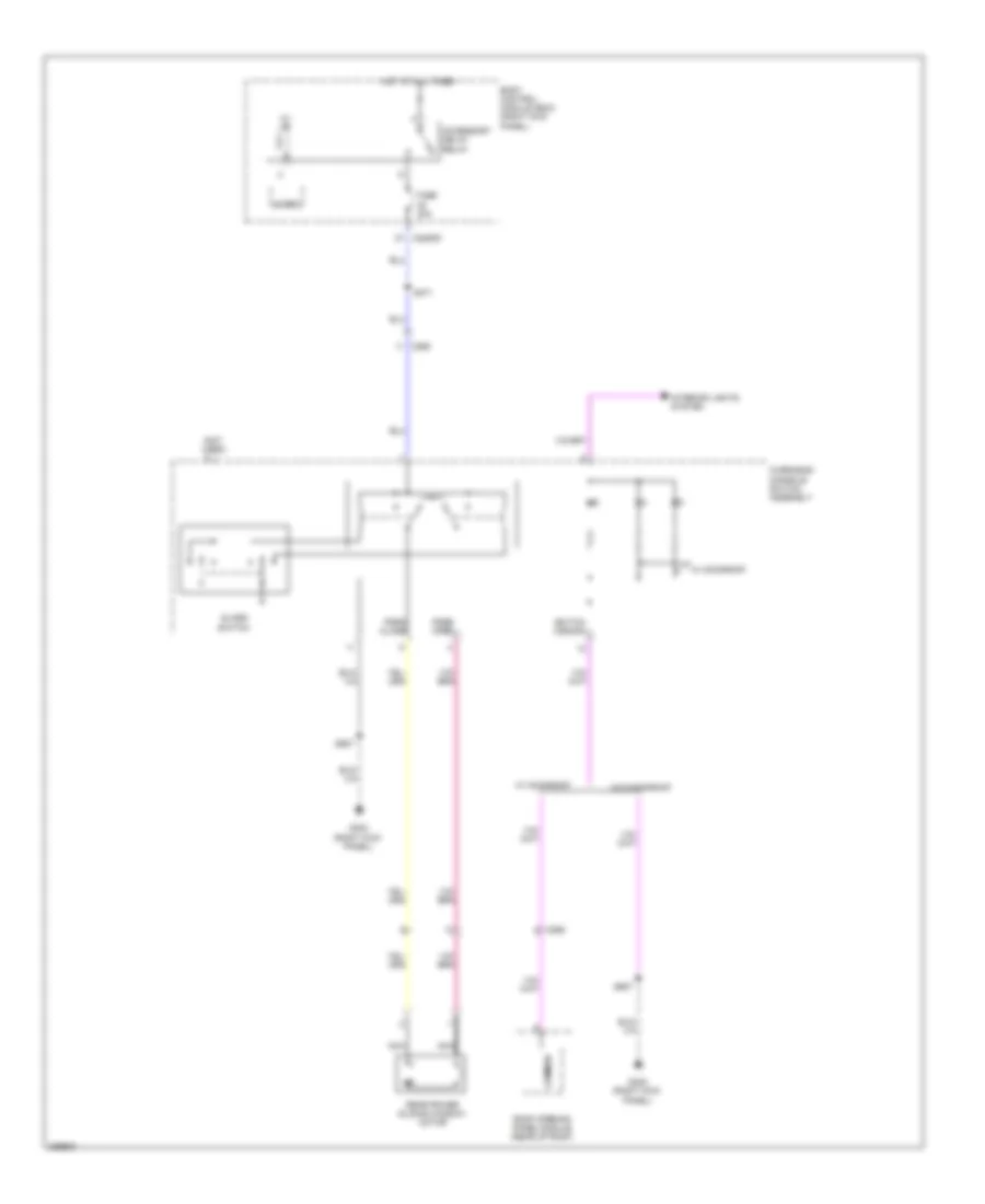
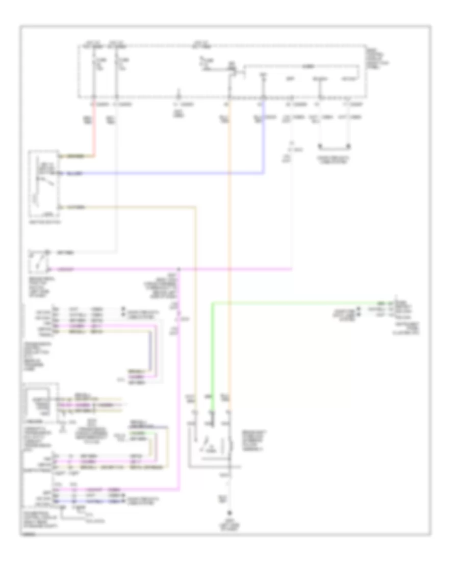
DEFOGGERS
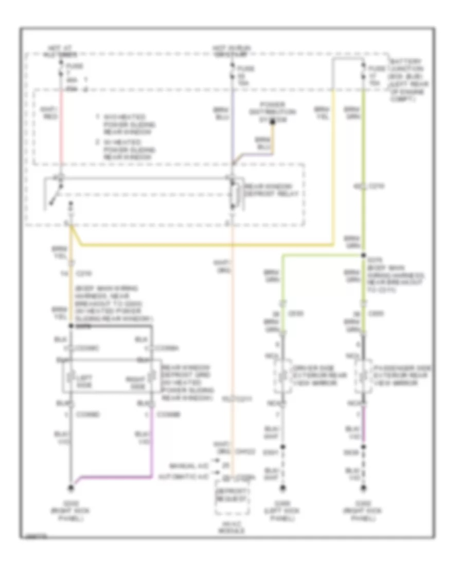
Defoggers Wiring Diagram for Ford F-450 Super Duty Platinum 2013
List of elements for Defoggers Wiring Diagram for Ford F-450 Super Duty Platinum 2013:
- (body main wiring harness, near breakout to g300) (w/ heated power sliding rear window) s379
- 50a
- Automatic a/c
- Battery junction box (bjb) (left rear of engine compt)
- C210
- C211
- C228a
- C3368a
- C3368b
- C3368c
- C3368d
- C555
- C655
- Defrost request
- Driver side exterior rear view mirror
- Fuse 10a
- Fuse 15a
- Fuse 40a
- G300 (left kick panel)
- G302 (right kick panel)
- Hot at all times
- Hot in run or start
- Hvac module
- Left side
- Manual a/c
- Nca
- Passenger side exterior rear view mirror
- Power distribution system
- Rear window defrost grid (w/ heated power sliding rear window)
- Rear window defrost relay
- Right side
- S376 (body main wiring harness, near breakout to c311)
- S501
- S639
- W/ heated power sliding rear window
- W/o heated power sliding rear window
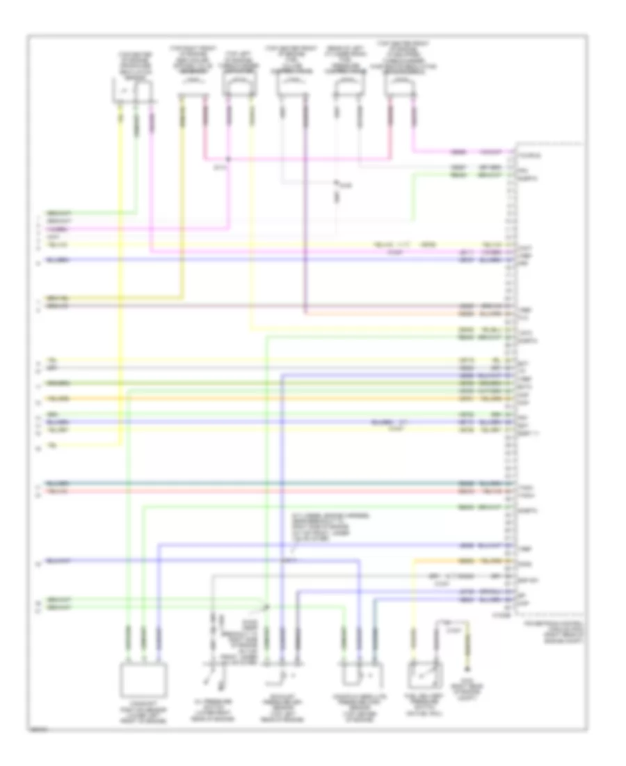
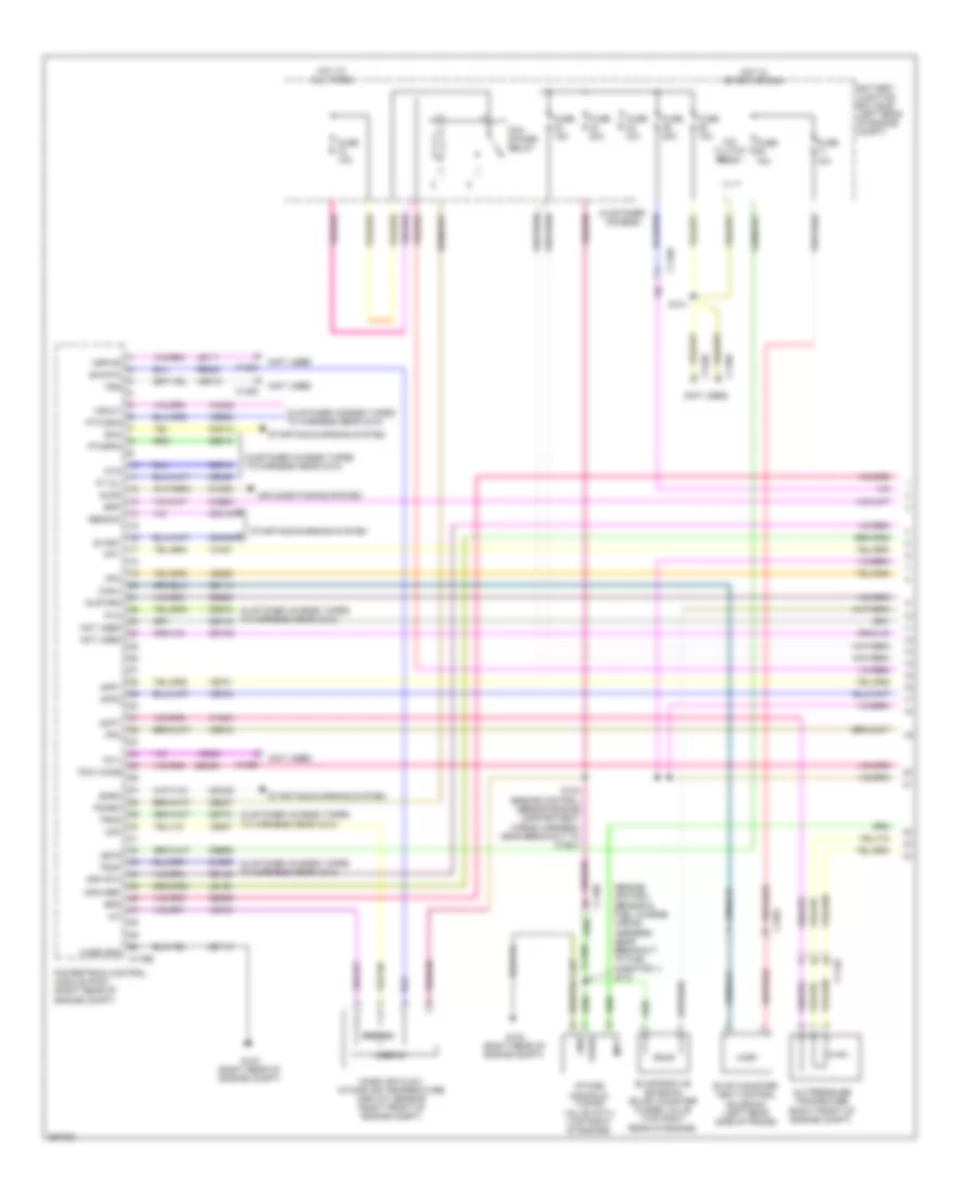
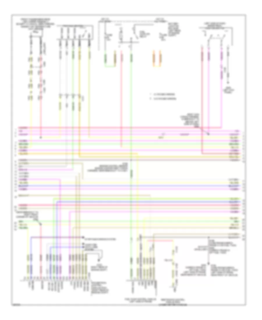
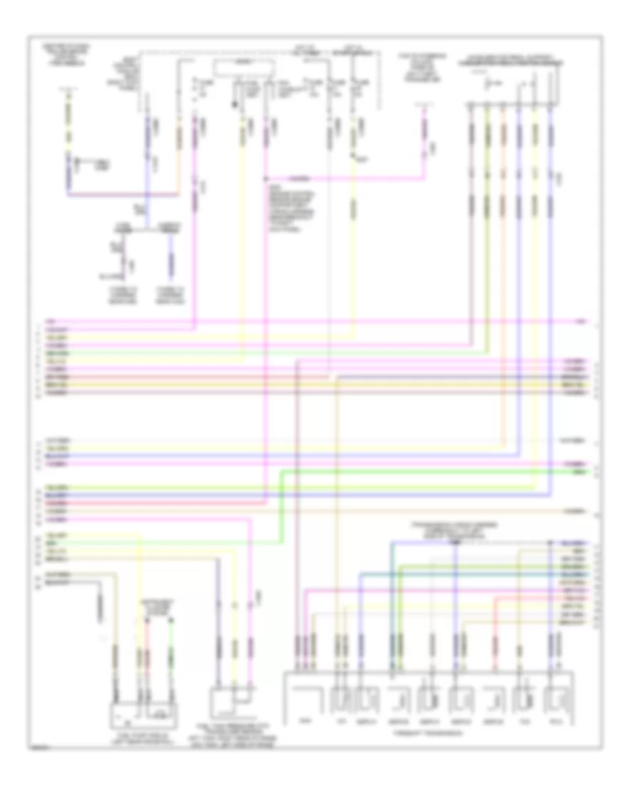
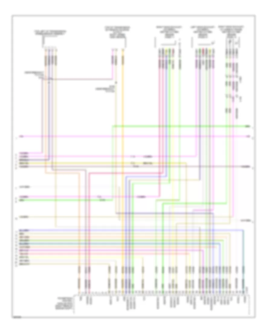
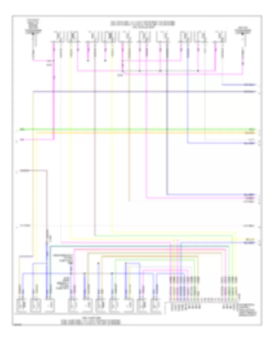
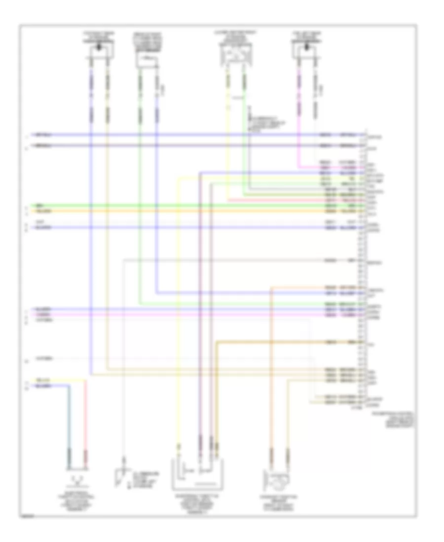
ENGINE PERFORMANCE
6.2L FLEX FUEL
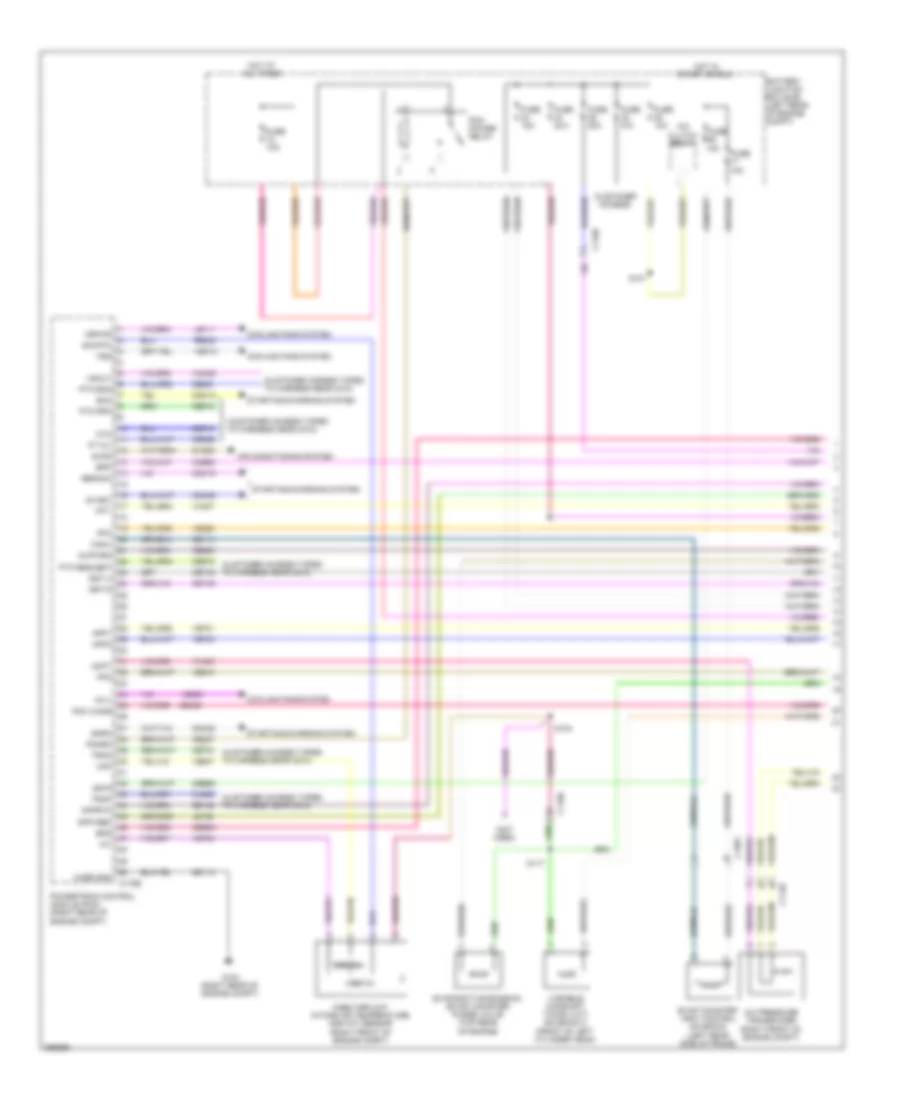
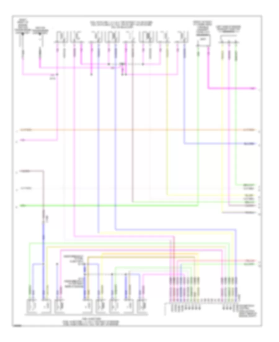
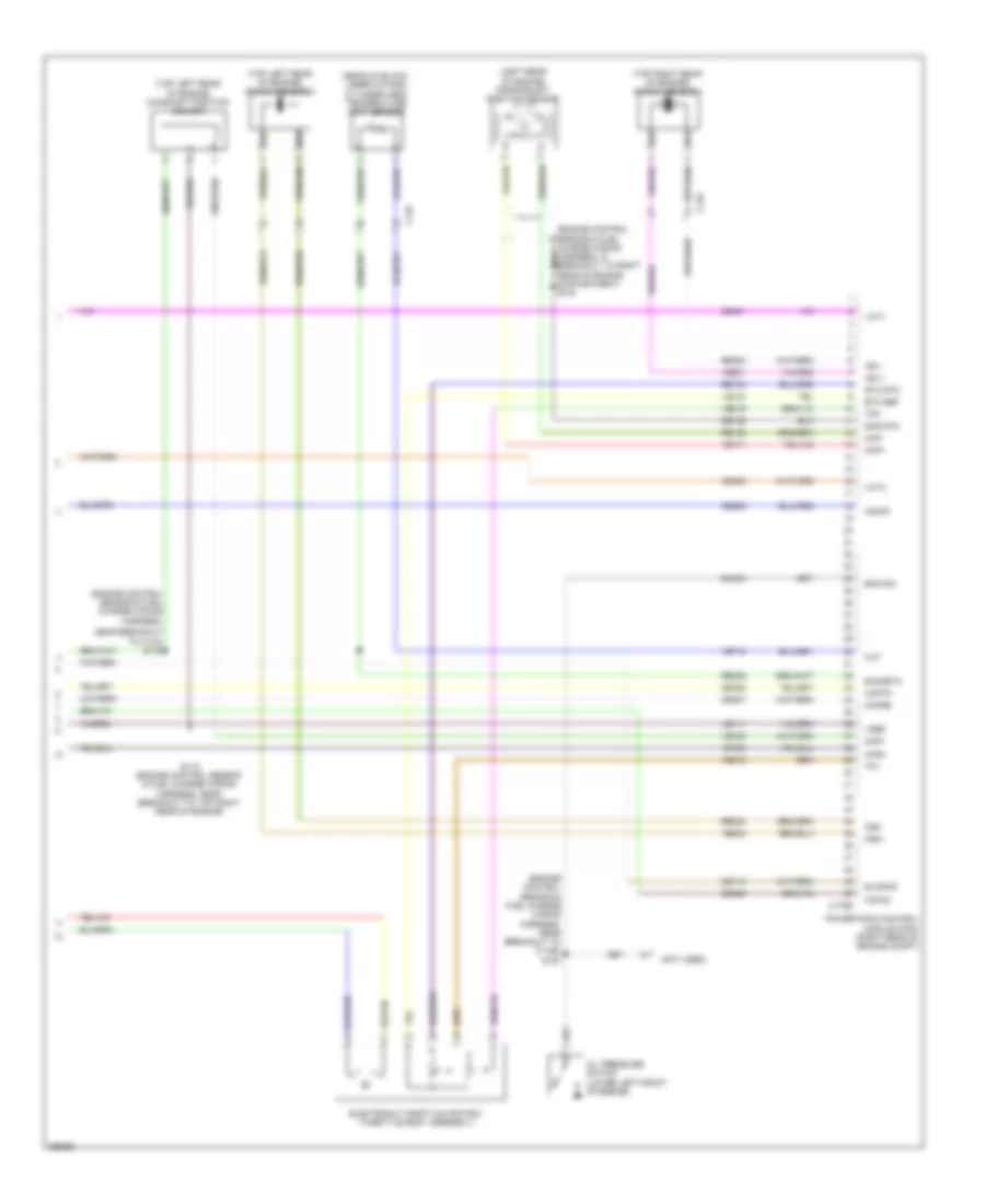
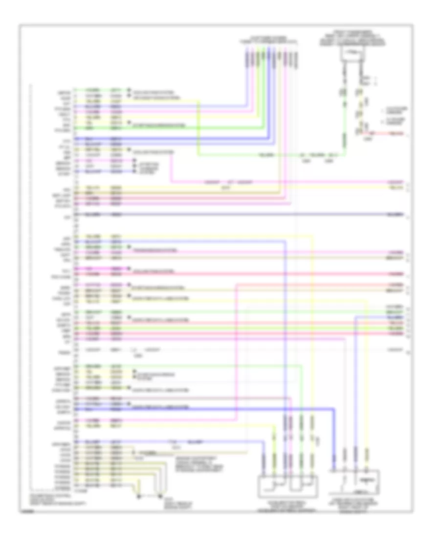
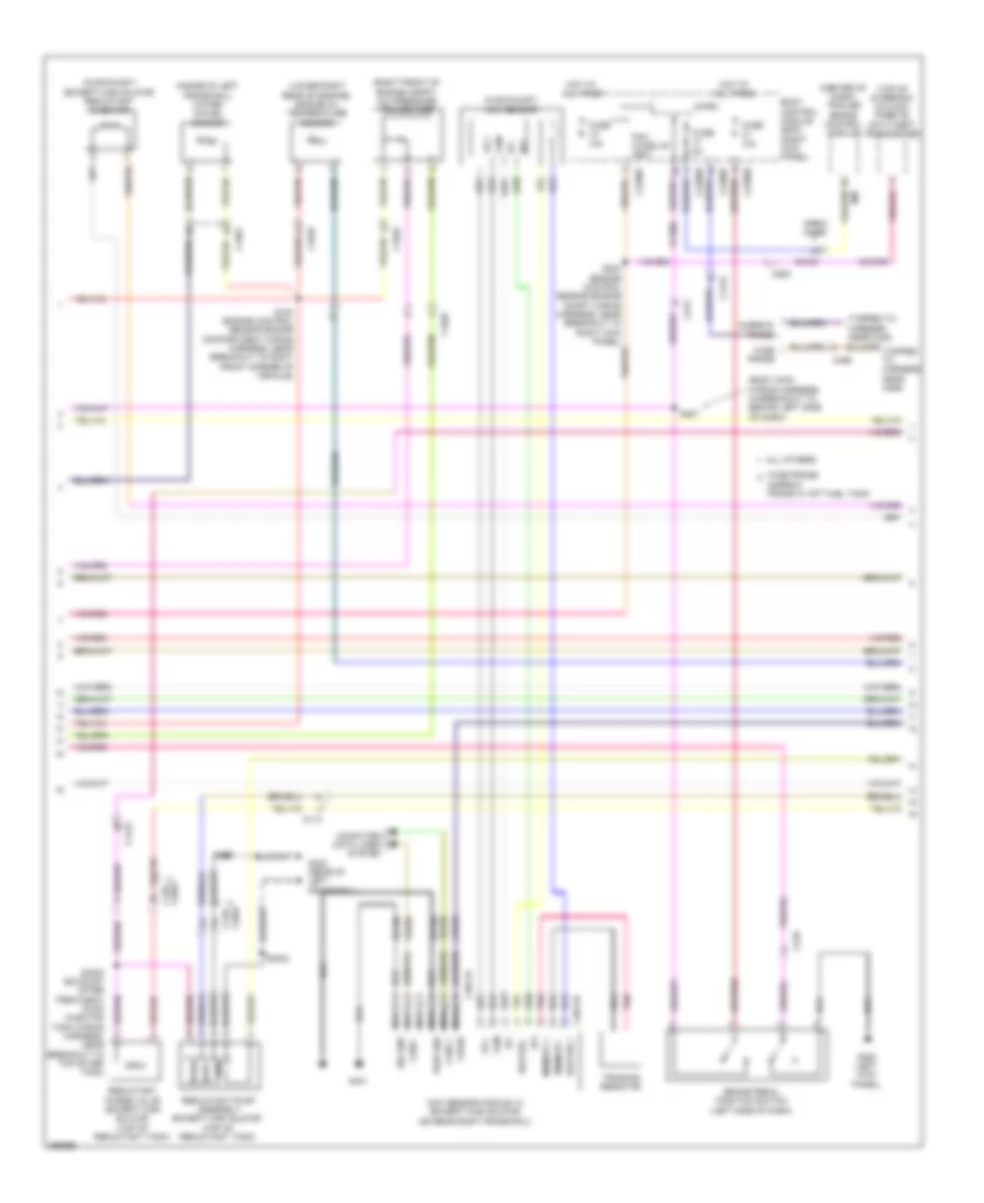
6.2L Flex Fuel, Engine Performance Wiring Diagram (1 of 6) for Ford F-450 Super Duty Platinum 2013
List of elements for 6.2L Flex Fuel, Engine Performance Wiring Diagram (1 of 6) for Ford F-450 Super Duty Platinum 2013:
- (customer access taped to harness near c210)
- (customer access)
- (not used)
- 10a
- A/c clutch relay
- A/c pressure transducer (right front of engine compt)
- Aat
- Accr
- Acpt
- Air conditioning system
- App1
- App2
- Apprtn
- Appvref
- Battery junction box (bjb) (left rear of engine compt)
- Bpp
- Bps
- C1148
- C1168
- C1581
- C175b
- Canv
- Case gnd
- Cbb52
- Ccb08
- Cdc12
- Cdc15
- Cdc35
- Cdc38
- Ce114
- Ce237
- Ce326
- Ce436
- Ce608
- Ce912
- Ce913
- Ce914
- Ce933
- Ces09
- Cet21
- Cet42
- Cet43
- Ch302
- Cls05
- Cooling fans system
- Cto
- Digital
- Evap canister vent control solenoid (left rear side of frame)
- Evaporative emission (evap) canister purge valve (top rear of engine)
- Fc-v
- Fpc
- Fpm
- Fss
- Fuse
- Fuse 10a
- Fuse 15a
- Fuse 20a
- Fuse n/a
- G103 (right rear of engine compt)
- Gd113
- Genmon
- Hot at all times
- Hot in start or run
- Iat
- Injpwrm
- Isp-r
- Le111
- Le136
- Maf
- Mass airflow/ intake air temperature (maf/iat) sensor (right front of engine compt)
- Pcm power relay
- Pcm wake
- Pcmrc
- Powertrain control module (pcm) (right rear of engine compt)
- Pt oil
- Pto eng
- Pto request
- Pto rpm
- Re136
- Re320
- S101
- S104
- S117
- Sig rtn
- Smc
- Smrc
- Sst-d
- Sst-u
- Start
- Starting/charging system
- Tron
- Trop
- Variable camshaft timing (vct) solenoid 2 (front of left cylinder head)
- Vbpwr
- Ve203
- Ve225
- Ve518
- Ve701
- Ve702
- Ve740
- Ve807
- Vec10
- Vh407
- Vh433
- Vmc05
- Vref 5v
- Vsout
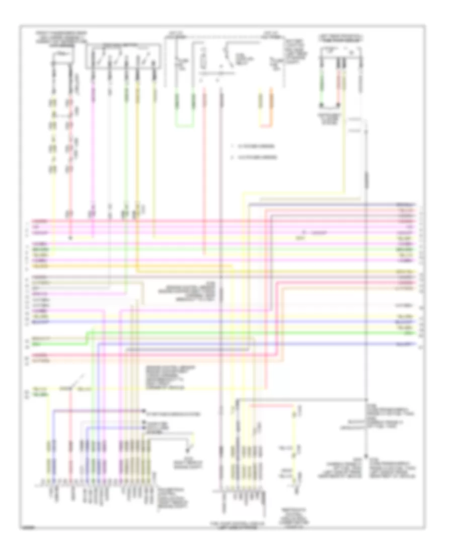
6.2L Flex Fuel, Engine Performance Wiring Diagram (2 of 6) for Ford F-450 Super Duty Platinum 2013
List of elements for 6.2L Flex Fuel, Engine Performance Wiring Diagram (2 of 6) for Ford F-450 Super Duty Platinum 2013:
- (engine control sensor engine compartment wiring harness, near breakout to right front corner of vehicle)
- (front passenger's rear view mirror assembly) ambient air temperature (aat) sensor
- (left rear frame rail) fuel pump module
- Apprtn2
- Appvref2
- Battery junction box (bjb) (left rear of engine compt)
- C1415
- C1581
- C175b
- C210
- C211
- C263
- C265
- C310a
- C601
- C651
- C655
- Cbb33
- Cdc10
- Ce515
- Ce608
- Computer data lines system
- Cr167
- Ens
- Fpc
- Fpm
- Fppwr
- Fprtn
- Ftp
- Ftpref
- Fuel pump (fp) relay
- Fuel pump control module (left side of frame)
- Fuse 10a
- Fuse 20a
- G103 (right rear of engine compt)
- G136 (wide frame/narrow frame w/ mid fuel tank) (left side of frame, near front of vehicle)
- G402 (narrow frame w/ aft fuel tank) (left side of frame, near rear of vehicle)
- Gd113
- Gd177
- Gencom
- Gnd
- Hot at all times
- Hs can +
- Hs can -
- Instrument cluster system
- Kapwr
- Le137
- Le230
- Le424
- Nca
- Powertrain control module (pcm) (right rear of engine compt)
- Pwr gnd
- R/s
- Re137
- Re407
- Re515
- Restraints control module (rcm) (under center console)
- S100
- S156 (engine control sensor engine compartment wiring harness, near breakout to c1581)
- Sbb72
- Sig rtn
- Sigrtn
- Sst-d
- Sst-u
- Starting/charging system
- Tow haul switch
- Tows
- V ref
- Vdb04
- Vdb05
- Ve225
- Ve518
- Ve922
- Vpwr
- Vpwr fuel
- W/ power mirrors
- W/o power mirrors
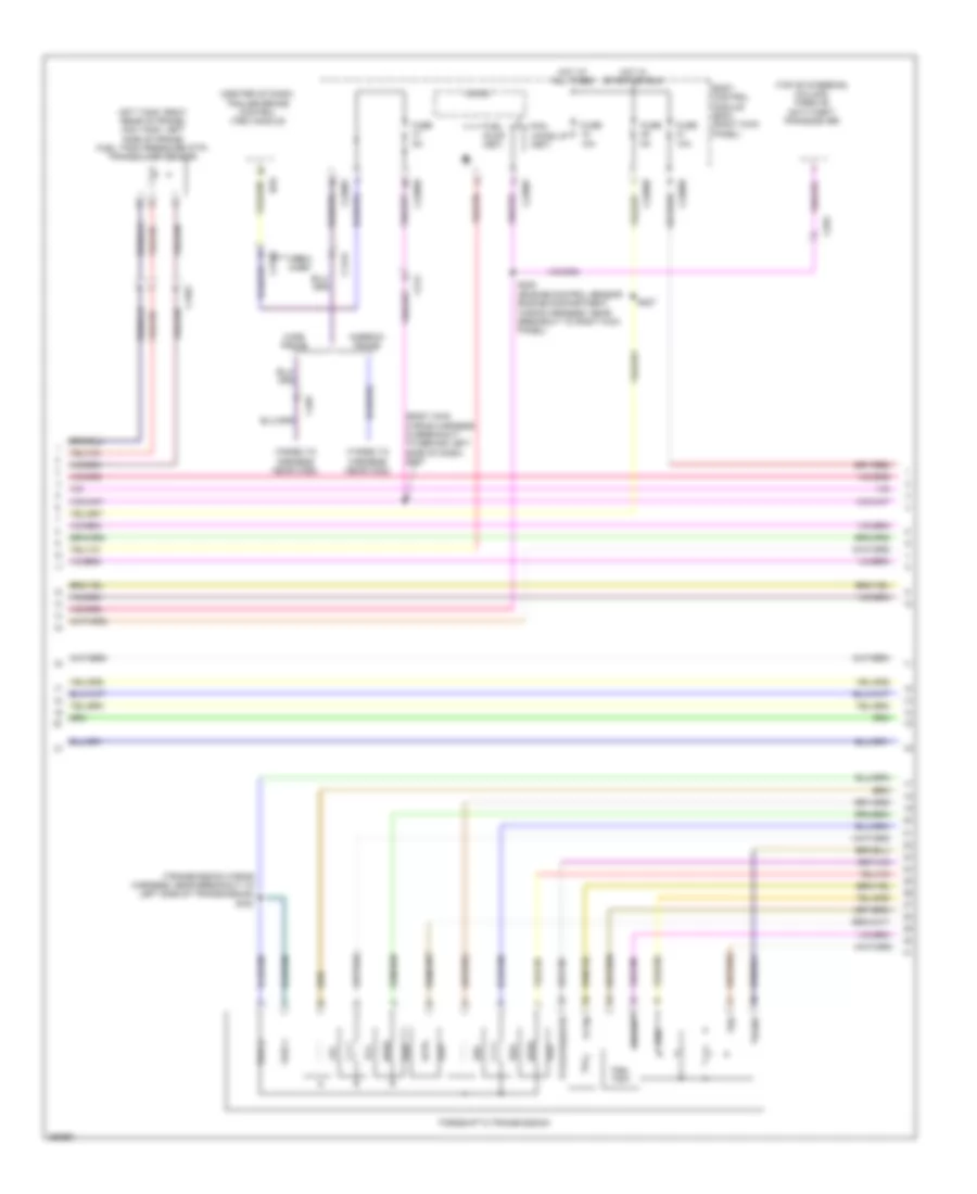
6.2L Flex Fuel, Engine Performance Wiring Diagram (3 of 6) for Ford F-450 Super Duty Platinum 2013
List of elements for 6.2L Flex Fuel, Engine Performance Wiring Diagram (3 of 6) for Ford F-450 Super Duty Platinum 2013:
- (aft tank: right rear of frame) (mid tank: left side of frame) fuel tank pressure (ftp) transducer sensor
- (body main wiring harness in breakout to behind left side of dash) s207
- (center of dash) trailer brake control (tbc) module
- (taped to harness near c422)
- (taped to harness near c465)
- (top of steering column) passive anti-theft transceiver
- (transmission wiring harness, near breakout to left side of transmission) s182
- Body control module (bcm) (right kick panel)
- Boo
- C1415
- C1581
- C2108
- C212
- C2280b
- C2280d
- C2280f
- C263
- C465
- Crew chief
- Fuel pump (fet)
- Fuse 10a
- Fuse 5a
- Hot at all times
- Hot in start or run
- Lpc
- Micro
- Narrow frame
- Oss
- Pcm wake up (fet)
- S200 (engine control sensor engine compartment wiring harness, near breakout to right kick panel)
- S227
- Ssa
- Ssb
- Ssc
- Ssd
- Sse
- Tcc
- Tftin
- Tftout/sigrtn
- Torqshift 6 transmission
- Trgnd
- Trs/ tr-p
- Tspc1
- Tspc2
- Tss
- Vbpwr
- Wide frame
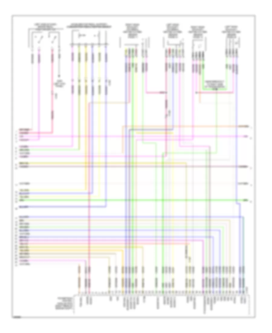
6.2L Flex Fuel, Engine Performance Wiring Diagram (4 of 6) for Ford F-450 Super Duty Platinum 2013
List of elements for 6.2L Flex Fuel, Engine Performance Wiring Diagram (4 of 6) for Ford F-450 Super Duty Platinum 2013:
- (accelerator pedal support) accelerator pedal position sensor
- (left bank exhaust) heated oxygen sensor (ho2s) 22
- (left bank exhaust) universal heated oxygen sensor (ho2s) 21
- (left side of dash) brake pedal position switch
- (near breakout to right side of transmission) s180
- (right bank exhaust) heated oxygen sensor (ho2s) 12
- (right bank exhaust) universal heated oxygen sensor (ho2s) 11
- C145
- C175t
- C210
- Cat15
- Ce233
- Ce234
- Ce235
- Ce236
- Cet05
- Cet06
- Cet07
- Cet08
- Cet09
- Cet22
- Cet25
- Cet49
- Cet50
- G300 (left kick panel)
- Ho2s12
- Ho2s22
- Htr12
- Htr22
- Le111
- Le448
- Le449
- Le450
- Le451
- Le452
- Le453
- Lpc
- Nca
- Oss hall
- Powertrain control module (pcm) (right rear of engine compt)
- Re242
- Re406
- Red
- Ret04
- Ret24
- S181
- Sigrtn
- Ssa
- Ssb
- Ssc
- Ssd
- Sse
- Tcc
- Tftin
- Tftout/sigrtn
- Tows
- Trgnd
- Trp
- Tspc1
- Tss hall
- Uo2s11
- Uo2s21
- Uo2sgref11
- Uo2sgref21
- Uo2shtr11
- Uo2shtr21
- Uo2spc11
- Uo2spc21
- Uo2spct11
- Uo2spct21
- Vbpwr
- Ve730
- Ve733
- Ve826
- Ve827
- Vet27
- Vet33
6.2L Flex Fuel, Engine Performance Wiring Diagram (5 of 6) for Ford F-450 Super Duty Platinum 2013
List of elements for 6.2L Flex Fuel, Engine Performance Wiring Diagram (5 of 6) for Ford F-450 Super Duty Platinum 2013:
- (coil on plugs 1, 2, 3, & 4: top of right valve cover) (coil on plugs 5, 6, 7 & 8: top of left valve cover) coil on plug (cop)
- (front of right cylinder head) variable camshaft timing (vct) solenoid 1
- (left side of engine) camshaft position sensor 2
- (near breakout to fuel injector 3) s119
- (right front of engine) ignition transformer capacitor 1
- C1168
- C175e
- Ce205
- Ce206
- Ce207
- Ce208
- Ce209
- Ce210
- Ce211
- Ce212
- Ce303
- Ce304
- Ce308
- Ce310
- Ce412
- Ce426
- Cop1a
- Cop2h
- Cop6e
- Cop8d powertrain control module (pcm) (right rear of engine compt)
- Fuel injectors (fuel injectors 1, 2, 3 & 4: top right of engine) (fuel injectors 5, 6, 7 & 8: top left of engine)
- Ignition transformer capacitor 2
- Inj-1
- Inj-2
- Inj-3
- Inj-4
- Inj-5
- Inj-6
- Inj-7
- Inj-8
- S113 (near breakout to top right rear of engine)
- S114
- S118
- Tacm +
- Tacm -
6.2L Flex Fuel, Engine Performance Wiring Diagram (6 of 6) for Ford F-450 Super Duty Platinum 2013
List of elements for 6.2L Flex Fuel, Engine Performance Wiring Diagram (6 of 6) for Ford F-450 Super Duty Platinum 2013:
- (engine control sensor & fuel charge wiring harness,
- (engine control sensor & fuel charge wiring harness, in breakout to right rear of engine compartment) s134
- (engine control sensor & fuel charge wiring harness, near breakout to c1168) s120
- (left rear of engine) crankshaft position sensor
- (not used)
- (rear of block, under intake) cylinder head temperature (cht) sensor
- (top left rear of engine) camshaft position sensor
- (top left rear of engine) knock sensor 2
- (top right rear of engine) knock sensor 1
- C133
- C175e
- Ce113
- Ce305
- Ce306
- Ce307
- Ce309
- Ce421
- Ce422
- Cht
- Ckp+
- Ckp-
- Cmc24
- Cmp1
- Cmp2
- Cop3f
- Cop4c
- Cop5b
- Cop7g
- De135
- E-sigrtn
- Electronic throttle control (throttle body assembly)
- Eop-sw
- Etc ref
- Etc rtn
- Evapcp
- Ks1+
- Ks1-
- Ks2+
- Ks2-
- Le111
- Le134
- Nca
- Near breakout to c133) s116
- Oil pressure switch (lower left front of engine)
- Powertrain control module (pcm) (right rear of engine compt)
- Re134
- Re135
- Re323
- Re324
- Re405
- S115 (engine control sensor & fuel charge wiring harness, near breakout to top right rear of engine)
- Shd rtn
- Tp1
- Tp2
- Vct1
- Vct2
- Ve711
- Ve712
- Ve736
- Ve738
- Ve801
- Ve802
- Ve818
- Ve819
- Vref
6.7L TURBO DIESEL
6.7L Turbo Diesel, Engine Performance Wiring Diagram (1 of 7) for Ford F-450 Super Duty Platinum 2013
List of elements for 6.7L Turbo Diesel, Engine Performance Wiring Diagram (1 of 7) for Ford F-450 Super Duty Platinum 2013:
- (customer access taped to harness near c210)
- (engine compartment wiring harness, in breakout to right rear of engine compartment)
- (front passenger's rear view mirror assembly) (except w/ manual aero mirrors) ambient air temperature sensor
- Aat
- Accelerator pedal position sensor (accelerator pedal support)
- Accr
- Acpt
- Air conditioning system
- App
- App2
- Apprtn
- Apprtn2
- Appvref
- Appvref2
- Bcp lamp
- Bcp sw
- Bpp
- Bps
- C1232b
- C210
- C263
- C265
- C601
- C651
- C655
- Can2 high
- Can2 low
- Cbb33
- Cbb52
- Ccb08
- Cdc09
- Cdc12
- Cdc15
- Cdc35
- Cdc38
- Cdc47
- Cdc48
- Ce140
- Ce226
- Ce237
- Ce326
- Ce436
- Ce911
- Ce912
- Ce913
- Ce914
- Ce926
- Ce933
- Ces09
- Cet40
- Ch302
- Computer data lines system
- Cooling fans system
- Cto
- Digital
- Fc-v
- Fdsom
- Fpc
- Fpm
- Fss
- G103 (right rear of engine compt)
- Gd113
- Gencom
- Genmon
- Hs can+
- Hs can-
- Iat
- Isp-r
- Kapwr
- Le111
- Le136
- Le137
- Le424
- Le434
- Maf
- Mass air flow/intake air temperature sensor (right front of engine compt)
- Nca
- Pcm wake
- Pcmrc
- Powertrain control module (pcm) (right rear of engine compt)
- Pt oil
- Pto
- Pto eng
- Pto ref
- Pto rpm
- Pto rtn
- Pwrgnd
- Re136
- Re137
- Re320
- Re327
- Re407
- S105
- Sbb72
- Sigrtn
- Smc
- Smrc
- Start
- Starting/ charging system
- Starting/charging system
- Transmissions system
- Trsw-pn
- Vbpwr
- Vdb04
- Vdb05
- Ve203
- Ve348
- Ve349
- Ve518
- Ve701
- Ve702
- Ve740
- Ve807
- Ve823
- Vec10
- Vh407
- Vh433
- Vmc05
- Vpwr
- Vref
- Vref 5v
- Vsout
- W/ power mirrors
- W/o power mirrors
- Wif
6.7L Turbo Diesel, Engine Performance Wiring Diagram (2 of 7) for Ford F-450 Super Duty Platinum 2013
List of elements for 6.7L Turbo Diesel, Engine Performance Wiring Diagram (2 of 7) for Ford F-450 Super Duty Platinum 2013:
- (body main wiring harness, in breakout to behind left side of dash)
- (center of dash) trailer brake control module
- (in exhaust) (except high sulfur) reductant injector
- (in exhaust) nox sensor
- (inside of left frame rail) water- in-fuel sensor
- (lower right rear of engine) engine oil temperature sensor
- (right front of engine compt) a/c pressure transducer
- (tapped to harness near c422)
- (top of steering column) passive anti-theft transceiver
- 10a
- All others
- B00
- Body control module (bcm) (right kick panel)
- Brake pedal position switch (left side of dash)
- C1046
- C110
- C139 c3047
- C1415
- C1581
- C210
- C2108
- C212
- C2280b
- C2280d
- C2280f
- C263
- C3047 c139
- C3611a
- C3611b
- C465
- Can2 +
- Can2 -
- Cbb36
- Ccb08
- Com
- Computer data lines system
- Crew chief
- Fuse
- G300 (left kick panel)
- G400 (rear of left frame rail)
- G401
- Gd180
- Gnd
- Heater +
- Heater -
- Hot at all times
- Ip1
- Ip2
- Memory +
- Memory -
- Micro
- Narrow frame
- Narrow frame w/ aft fuel tank
- Nca
- Nox sensor module 12 (except high sulfur) (on rear right frame rail)
- Pcm wake up (fet)
- Pnk
- Pwr gnd
- Rdpc
- Reductant pump assembly (except high sulfur) (top of reductant tank)
- Reductant purge valve (except high sulfur) (top of reductant tank)
- S100 (engine control sensor engine compartment wiring harness, near breakout to right front corner of vehicle)
- S207
- S3000 (exhaust after treatment pump injector tank wiring harness, near breakout to top of def tank)
- S3002
- S405
- Sig gnd
- Trimming resistor
- Ve348
- Ve349
- Vpwr
- Vs +
- Wide frame
- Wide frame/
6.7L Turbo Diesel, Engine Performance Wiring Diagram (3 of 7) for Ford F-450 Super Duty Platinum 2013
List of elements for 6.7L Turbo Diesel, Engine Performance Wiring Diagram (3 of 7) for Ford F-450 Super Duty Platinum 2013:
- (near left side of transmission) fuel pump
- (on mid right frame rail) (except high sulfur) nox sensor module 11
- (right kick panel) inertia fuel shutoff (ifs) switch
- 20a
- All others
- Battery junction box (bjb) (left rear of engine compt)
- C110
- C1232t
- C146
- C1581
- C211
- C3047 c139
- C3619a
- C3619b
- Can2 +
- Can2 -
- Cbb36
- Ce354
- Ce355
- Com
- Computer data lines system
- Dpf
- Egt 11
- Egt 12
- Egt 13
- Egt 14
- Fuel pump (fp) motor diode
- Fuel pump (fp) relay
- Fuse
- Fuse 10a
- G103 (right rear of engine compt)
- G135 (left side of frame, near front of vehicle)
- Gd113
- Heater +
- Heater -
- Hot at all times
- Ip1
- Ip2
- Le425
- Le461
- Memory +
- Memory -
- Nca
- Nox sensor (in exhaust)
- Pfp
- Pnk
- Powertrain control module (pcm) (right rear of engine compt)
- Pwr gnd
- Rdinjgnd
- Rdinjpwr
- Rdl1
- Rdl2
- Rdl3
- Rdlrtn
- Rdp
- Rdpc
- Rdpgc
- Rdt
- Re406
- Re839
- Reductant pressure sensor (except high sulfur) (top of reductant tank)
- S124
- Sig gnd
- Sigrtn
- Trimming resistor
- Ve348
- Ve349
- Ve350
- Ve351
- Ve713
- Ve722
- Ve726
- Ve747
- Ve752
- Ve754
- Ve833
- Ve838
- Ve839
- Ve840
- Ve841
- Vpwr
- Vref
- Vs +
- Wide frame/ narrow frame w/ aft fuel tank
6.7L Turbo Diesel, Engine Performance Wiring Diagram (4 of 7) for Ford F-450 Super Duty Platinum 2013
List of elements for 6.7L Turbo Diesel, Engine Performance Wiring Diagram (4 of 7) for Ford F-450 Super Duty Platinum 2013:
- (customer access)
- (engine control sensor engine compartment wiring harness, near breakout to left front corner of vehicle)
- (exhaust after treatment pump injector tank wiring harness, near breakout to top of def tank) s3001
- (top of reductant tank)
- (urea jumper wiring harness, near breakout to right side of frame, near center of vehicle)
- 10a
- A/c clutch relay
- All others
- Battery junction box (bjb) (left rear of engine compt)
- C1047
- C110
- C139 c3047
- C1581
- Cooling fans system
- Diesel particulate filter pressure sensor (right frame rail)
- Except high sulfur
- Exhaust gas temperature (egt) sensor 1 (in exhaust)
- Exhaust gas temperature (egt) sensor 2 (in exhaust)
- Exhaust gas temperature (egt) sensor 3 (in exhaust)
- Exhaust gas temperature (egt) sensor 4 (in exhaust)
- Fuse
- Fuse 10a
- Fuse 15a
- Fuse 25a
- Fuse n/a
- G104 (left rear of engine compt)
- G400 (rear of left frame rail)
- Hot at all times
- Hot in start or run
- Nca
- Particulate filter pressure sensor (except high sulfur) (right frame rail)
- Pcm power relay
- Power distribution system
- Reductant heater & sensor assembly
- Reductant heater relay
- Reductant pressure line heater assembly
- S108
- S122
- S3002
- S405
- S408
- Wide frame/ narrow frame w/ aft fuel tank
6.7L Turbo Diesel, Engine Performance Wiring Diagram (5 of 7) for Ford F-450 Super Duty Platinum 2013
List of elements for 6.7L Turbo Diesel, Engine Performance Wiring Diagram (5 of 7) for Ford F-450 Super Duty Platinum 2013:
- (left cylinder bank) glow plugs
- (right cylinder bank) glow plugs
- (right rear of engine compt) glow plug control module
- 125a
- Batt
- C110
- C1147
- C1232e
- C1273a
- C1273b
- C1273c
- C146
- C1617b
- Can2 +
- Can2 -
- Cbb36
- Ccv
- Ce101
- Ce102
- Ce205
- Ce206
- Ce207
- Ce208
- Ce209
- Ce210
- Ce211
- Ce212
- Ce243
- Ce244
- Ce245
- Ce246
- Ce247
- Ce248
- Ce251
- Ce252
- Ce352
- Ce356
- Ce513
- Ce609
- Computer data lines system
- Egr
- Egrcbv
- Egrvch
- Egrvcl
- Fuel injector 1 (top right of engine)
- Fuel injector 4 (top right of engine)
- Fuel injector 6 (top left of engine)
- Fuel injector 7 (top left of engine)
- G103 (right rear of engine compt)
- Gd113
- Gnd
- Gp1
- Gp2
- Gp3
- Gp4
- Gp5
- Gp6
- Gp7
- Gp8
- High current battery junction box (bjb) (right side of engine compt)
- Hot at all times
- Inj1
- Inj1rtn
- Inj2
- Inj2rtn
- Inj3
- Inj3rtn
- Inj4
- Inj4rtn
- Inj5
- Inj5rtn
- Inj6
- Inj6rtn
- Inj7
- Inj7rtn
- Inj8
- Inj8rtn
- Mega fuse
- Nca
- Powertrain control module (pcm) (right rear of engine compt)
- Rdhtrc1
- Rdhtrc2
- Rdhtrpc
- Rdhtrpwr
- Re205
- Re206
- Re207
- Re208
- Re209
- Re210
- Re211
- Re212
- Red
- Sbf04
- Ve348
- Ve349
- Ve721
- Ve763
- Ve917
- Vpwr
6.7L Turbo Diesel, Engine Performance Wiring Diagram (6 of 7) for Ford F-450 Super Duty Platinum 2013
List of elements for 6.7L Turbo Diesel, Engine Performance Wiring Diagram (6 of 7) for Ford F-450 Super Duty Platinum 2013:
- (6.7l diesel engine harness near breakout to intake throttle actuator)
- (front of left cylinder bank) fuel rail pressure (frp) sensor
- (left front of engine) charge air cooler temperature (cact) sensor
- (on fuel rail) fuel rail temperature sensor
- (top front of engine) engine coolant temperature (ect) sensor
- (top right front of engine) egr temperature sensor
- (top right front of engine) secondary cooling system engine coolant temperature 2 sensor
- C1047
- Crankshaft position sensor (lower left rear of engine)
- Egr valve (top right front of engine)
- Fuel injector 2 (top right of engine)
- Fuel injector 3 (top right of engine)
- Fuel injector 5 (top left of engine)
- Fuel injector 8 (top left of engine)
- Intake throttle actuator (throttle body assembly)
- S1013
- S121 (near breakout to top left front of engine)
6.7L Turbo Diesel, Engine Performance Wiring Diagram (7 of 7) for Ford F-450 Super Duty Platinum 2013
List of elements for 6.7L Turbo Diesel, Engine Performance Wiring Diagram (7 of 7) for Ford F-450 Super Duty Platinum 2013:
- (6.7l diesel engine harness, near breakout to right side of engine on top front, under valve cover)
- (rear of left cylinder bank) fuel pressure control valve
- (top center front of engine) (if equipped) turbocharger wastegate regulating valve solenoid
- (top center front of engine) fuel volume control valve
- (top center of engine) crankcase ventilation sensor
- (top left of engine) turbocharger actuator
- (top right front of engine) egr cooler bypass valve solenoid
- C1046
- C1047
- C1232e
- Cact
- Camshaft position sensor (lower left front of engine)
- Ce256
- Ce257
- Ce412
- Ce426
- Ce435
- Ce460
- Ce932
- Ckp
- Cmc24
- Cmp
- Ect
- Ect2
- Egrt 11
- Eop sw
- Eot
- Exhaust pressure (ep) sensor (top left rear of engine)
- Fdps
- Fpc
- Frp
- Frt
- Fuel delivery pressure switch (on fuel rail)
- Fvc
- G103 (right rear of engine compt)
- Le111
- Le152
- Le423
- Le458
- Manifold absolute pressure (map) sensor (top center of engine)
- Map
- Oil pressure switch (lower right rear of engine)
- Powertrain control module (pcm) (right rear of engine compt)
- Re405
- S1002 (near breakout to right side of engine on top front, under valve cover)
- S109
- S110
- S111
- Sigrtn
- Tacm+
- Tacm-
- Tcwrvs
- Ve701
- Ve716
- Ve718
- Ve726
- Ve727
- Ve728
- Ve736
- Ve755
- Ve759
- Ve803
- Ve820
- Vgtc
- Vref
6.8L
6.8L, Engine Performance Wiring Diagram (1 of 6) for Ford F-450 Super Duty Platinum 2013
List of elements for 6.8L, Engine Performance Wiring Diagram (1 of 6) for Ford F-450 Super Duty Platinum 2013:
- (customer access taped to harness near c210)
- (customer access)
- (engine control sensor & fuel charge wiring harness, near breakout to fuel injector 1) s112
- (not used)
- 10a
- A/c clutch relay
- A/c pressure transducer (right front of engine compt)
- Aat
- Accr
- Acpt
- Air conditioning system
- App rtn
- App1
- App2
- Appvref
- Battery junction box (bjb) (left rear of engine compt)
- Bpp
- Bps
- C1148
- C1168
- C1220
- C1581
- C175b
- Canv
- Case gnd
- Cbb52
- Ccb08
- Cdc12
- Cdc15
- Cdc35
- Cdc38
- Ce114
- Ce237
- Ce326
- Ce436
- Ce608
- Ce912
- Ce913
- Ce914
- Ce933
- Ces09
- Cet21
- Cet42
- Cet43
- Ch302
- Cls05
- Cto
- Digital
- Evap canister vent control solenoid (left rear side of frame)
- Evaporative emission (evap) canister purge valve (top right rear of engine)
- Fc-v
- Fpc
- Fpm
- Fss
- Fuse
- Fuse 10a
- Fuse 15a
- Fuse 20a
- Fuse n/a
- G103 (right rear of engine compt)
- Gd113
- Genmon
- Gnd
- Hot at all times
- Hot in start or run
- Iat
- Imtv
- Injpwrm
- Intake manifold tuning valve (imtv) (top right of engine)
- Isp-r
- Le111
- Le136
- Maf
- Mass air flow/ intake air temperature (maf/iat) sensor (right front of engine compt)
- Not used
- Pcm power relay
- Pcm wake
- Pcmrc
- Powertrain control module (pcm) (right rear of engine compt)
- Pt oil
- Pto
- Pto eng
- Ptorpm
- Re136
- Re320
- S101
- S104 (engine control sensor engine compartment wiring harness, near breakout to c1581)
- Sig rtn
- Smc
- Smrc
- Start
- Starting/charging system
- Tron
- Trop
- Vbpwr
- Ve203
- Ve225
- Ve518
- Ve701
- Ve702
- Ve740
- Ve807
- Vec10
- Vh407
- Vh433
- Vmc05
- Vpwr
- Vref 5v
- Vsout
6.8L, Engine Performance Wiring Diagram (2 of 6) for Ford F-450 Super Duty Platinum 2013
List of elements for 6.8L, Engine Performance Wiring Diagram (2 of 6) for Ford F-450 Super Duty Platinum 2013:
- (body main wiring harness, in breakout to behind left side of dash) s207
- (front passenger's rear view mirror assembly) (except w/ manual aero mirrors) ambient air temperature (aat) sensor
- (left side of dash) brake pedal position switch
- (near breakout to right front corner of vehicle) s100
- Apprtn2
- Appvref2
- Battery junction box (bjb) (left rear of engine compt)
- C1415
- C1581
- C175b
- C210
- C211
- C263
- C265
- C310a
- C601
- C651
- C655
- Cbb33
- Cdc10
- Ce515
- Ce608
- Computer data lines system
- Cr167
- Ens
- Fpc
- Fpm
- Fppwr
- Fprtn
- Ftp
- Ftpref
- Fuel pump (fp) relay
- Fuel pump control module (left side of frame)
- Fuse 10a
- Fuse 20a
- G103 (right rear of engine compt)
- G136 (wide frame/narrow frame w/ mid fuel tank) (left side of frame, near front of vehicle)
- G300 (left kick panel)
- G402 (narrow frame w/ aft fuel tank) (left side of frame, near rear of vehicle)
- Gd113
- Gd177
- Gencom
- Gnd
- Hot at all times
- Hs can +
- Hs can -
- Kapwr
- Le137
- Le230
- Le424
- Nca
- Not used
- Powertrain control module (pcm) (right rear of engine compt)
- Pwr gnd
- R/s
- Re137
- Re407
- Re515
- Restraints control module (rcm) (under center console)
- S156 (engine control sensor engine compartment wiring harness, near breakout to c1581)
- Sbb72
- Sigrtn
- Starting/charging system
- Tow
- Tow haul switch
- V ref
- Vdb04
- Vdb05
- Ve225
- Ve518
- Ve922
- Vpwr
- Vpwr fuel
- W/ power mirrors
- W/o power mirrors
6.8L, Engine Performance Wiring Diagram (3 of 6) for Ford F-450 Super Duty Platinum 2013
List of elements for 6.8L, Engine Performance Wiring Diagram (3 of 6) for Ford F-450 Super Duty Platinum 2013:
- (accelerator pedal support) accelerator pedal position sensor
- (center of dash) trailer brake control (tbc) module
- (taped to harness near c422)
- (taped to harness near c465)
- (top of steering column) passive anti-theft transceiver
- (transmission wiring harness in breakout to left side of transmission) s183
- Body control module (bcm) (right kick panel)
- Boo
- C1415
- C1581
- C210
- C2108
- C212
- C2280b
- C2280d
- C2280f
- C263
- C465
- Crew chief
- Fuel pump (fet)
- Fuel pump module (left rear frame rail)
- Fuel tank pressure (ftp) transducer sensor (aft tank: right rear of frame) (mid tank: left side of frame)
- Fuse 10a
- Fuse 5a
- Hot at all times
- Hot in start or run
- Instrument cluster system
- Micro
- Narrow frame
- Nca
- Pc-a
- Pcm wake up (fet)
- S200 (engine control sensor engine compartment wiring harness near breakout to right kick panel)
- S227
- Sspc-a
- Sspc-b
- Sspc-c
- Sspc-d
- Sspc-e
- Tcc
- Tft
- Torqshift transmission
- Tr-p
- Wide frame
6.8L, Engine Performance Wiring Diagram (4 of 6) for Ford F-450 Super Duty Platinum 2013
List of elements for 6.8L, Engine Performance Wiring Diagram (4 of 6) for Ford F-450 Super Duty Platinum 2013:
- (left bank exhaust) universal heated oxygen sensor (ho2s) 21
- (near breakout to c145) s184
- (right bank exhaust) (w/ narrow frame) heated oxygen sensor (ho2s) 12
- (right bank exhaust) universal heated oxygen sensor (ho2s) 11
- (top left of transmission) speed sensor assembly
- (top of transmission extension housing) output shaft speed (oss) sensor
- C145
- C1581
- C175t
- Cat15
- Ce235
- Ce236
- Ce239
- Cet05
- Cet06
- Cet07
- Cet08
- Cet09
- Cet22
- Cet25
- Cet49
- Cet50
- Ho2s12
- Htr12
- Iss
- Le111
- Le448
- Le449
- Le450
- Le451
- Le452
- Le453
- Nca
- Oss
- Pc-a
- Powertrain control module (pcm) (right rear of engine compt)
- Re242
- Re406
- Red
- Ret04
- Ret24
- S185 (near breakout to c145)
- Sigrtn
- Sspc-a
- Sspc-b
- Sspc-c
- Sspc-d
- Sspc-e
- Tcc
- Tft
- Tows
- Tr-p
- Tss
- Uo2s11
- Uo2s21
- Uo2sgref11
- Uo2sgref21
- Uo2shtr11
- Uo2shtr21
- Uo2spc11
- Uo2spc21
- Uo2spct11
- Uo2spct21
- Vbpwr
- Ve744
- Ve745
- Ve826
- Ve827
- Vet27
- Vet33
- Vpwr
6.8L, Engine Performance Wiring Diagram (5 of 6) for Ford F-450 Super Duty Platinum 2013
List of elements for 6.8L, Engine Performance Wiring Diagram (5 of 6) for Ford F-450 Super Duty Platinum 2013:
- (coil on plugs 1, 2, 3, 4 & 5: top of right valve cover) (coil on plugs 6, 7, 8, 9 & 10: top of left valve cover) coil on plug (cop)
- (near breakout to fuel injector 4) s132
- (top right front of engine) ignition transformer capacitor 1
- C1168
- C175e
- Ce205
- Ce206
- Ce207
- Ce209
- Ce210
- Ce211
- Ce212
- Ce214
- Ce303
- Ce304
- Ce306
- Ce309
- Ce412
- Ce426
- Cop1a
- Cop2e powertrain control module (pcm) (right rear of engine compt)
- Cop4i
- Cop7f
- Fuel injectors (fuel injectors 1, 2, 3, 4 & 5: top right of engine) (fuel injectors 6, 7, 8, 9 & 10: top left of engine)
- Ignition transformer capacitor 2
- Inj-1
- Inj-10
- Inj-2
- Inj-3
- Inj-5
- Inj-6
- Inj-7
- Inj-8
- S127
- S135
- S136 (near breakout to fuel injector 7)
- Tacm +
- Tacm -
6.8L, Engine Performance Wiring Diagram (6 of 6) for Ford F-450 Super Duty Platinum 2013
List of elements for 6.8L, Engine Performance Wiring Diagram (6 of 6) for Ford F-450 Super Duty Platinum 2013:
- (in breakout to right rear of engine compt) s134
- (lower center front of engine) crankshaft position sensor
- (rear of right cylinder head) cylinder head temperature (cht) sensor
- (top left rear of engine) knock sensor 1
- (top right rear of engine) knock sensor 2
- C1163
- C175e
- Camshaft position sensor (front of right cylinder bank)
- Ce113
- Ce208
- Ce213
- Ce305
- Ce307
- Ce308
- Ce310
- Ce311
- Ce312
- Ce316
- Cht
- Ckp+
- Ckp-
- Cmc24
- Cmp1
- Cop10d
- Cop3g
- Cop5c
- Cop6b
- Cop8h
- Cop9j
- De135
- Electronic throttle control (etc) motor (throttle body assembly)
- Electronic throttle control (etc) position sensor (throttle body assembly)
- Eop-sw
- Etc ref
- Etc rtn
- Evapcp
- Imtv
- Inj-4
- Inj-9
- Ks1+
- Ks1-
- Ks2+
- Ks2-
- Le134
- Nca
- Oil pressure switch (lower left of engine)
- Powertrain control module (pcm) (right rear of engine compt)
- Re134
- Re135
- Re323
- Re324
- Re405
- Re429
- Shd rtn
- Sigrtn
- Tp1
- Tp2
- Ve706
- Ve711
- Ve712
- Ve801
- Ve802
- Ve818
- Ve819
- Vrs rtn
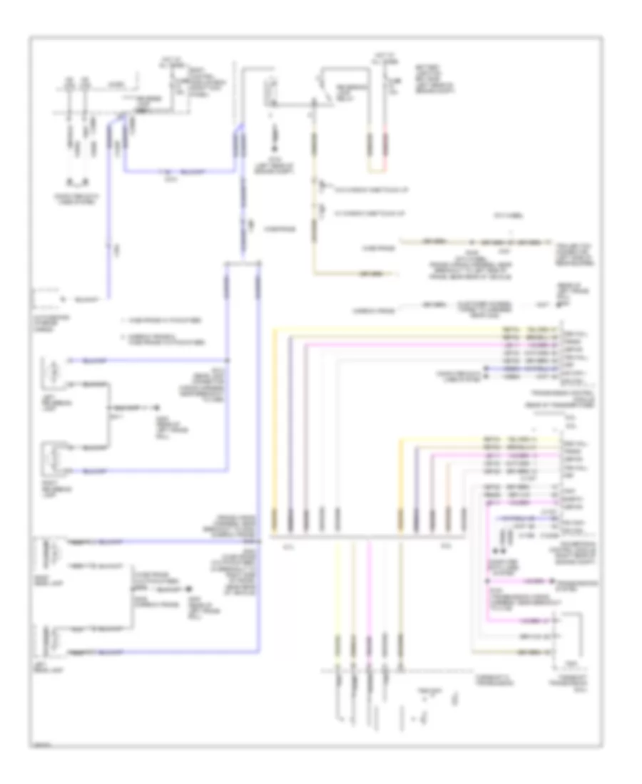
EXTERIOR LIGHTS
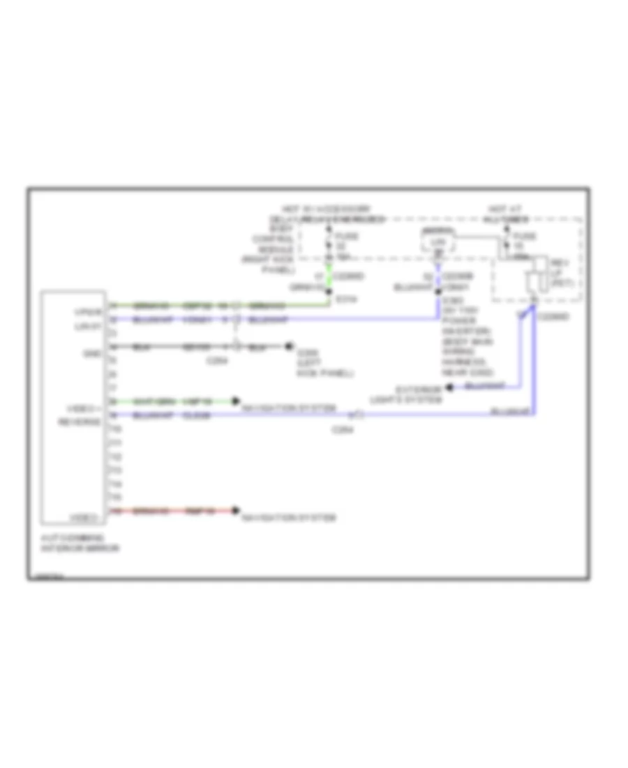
Backup Lamps Wiring Diagram for Ford F-450 Super Duty Platinum 2013
List of elements for Backup Lamps Wiring Diagram for Ford F-450 Super Duty Platinum 2013:
- (customer access) (taped to harness near c422)
- (frame wiring harness, near breakout to g400) (narrow frame) s440
- (rear of left frame rail) g400
- (wide frame w/o pickup bed) s400
- 5th wheel
- 6.2l
- 6.7l
- 6.8l
- Auto-dimming interior mirror
- Battery junction box (bjb) (left rear of engine compt)
- Body control module (bcm) (right kick panel)
- C1232b
- C140
- C1415
- C175b
- C175t
- C210
- C2280d
- C2280f
- C264
- C431
- C465
- Cet22
- Cls28
- Computer data lines system
- Fuse 10a
- Fuse 15a
- G104 (left rear of engine compt)
- G400 (rear of left frame rail)
- Hot at all times
- Hs can +
- Hs can -
- Hs can+
- Hs can-
- Le111
- Left rear lamp
- Left reversing lamp
- Micro
- Narrow frame
- Narrow frame & wide frame w/o pickup bed
- Nca
- Oss
- Oss hall
- Powertrain control module (right rear of engine compt)
- Re406
- Ret04
- Ret24
- Reverse lamp (fet)
- Reversing
- Reversing lamp relay
- Right rear lamp
- Right reversing lamp
- S184 (transmission wiring harness, near breakout to c145)
- S402 (wide frame w/o pickup bed) (in breakout to right side of frame, near rear of vehicle)
- S405 (narrow frame)
- S411
- S414 (rear lamp connector wiring harness near breakout to c465)
- S446 (5th wheel) (frame wiring harness, near breakout to left side of frame, near rear of vehicle)
- Sigrtn
- Torqshift 6 transmission
- Torqshift transmission (6.8l)
- Tr-p
- Trailer tow connector (left side of rear bumper)
- Transmission control module (rear of transfer case)
- Transmissions system
- Trgnd
- Trp
- Trs/tr-p
- Tss
- Tss hall
- Vbpwr
- Vdb04
- Vdb05
- Vet33
- W/ window one-touch up
- W/o window one-touch up
- Wide frame
- Wide frame w/ pickup bed
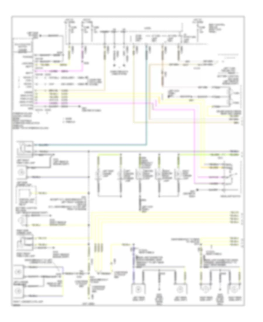
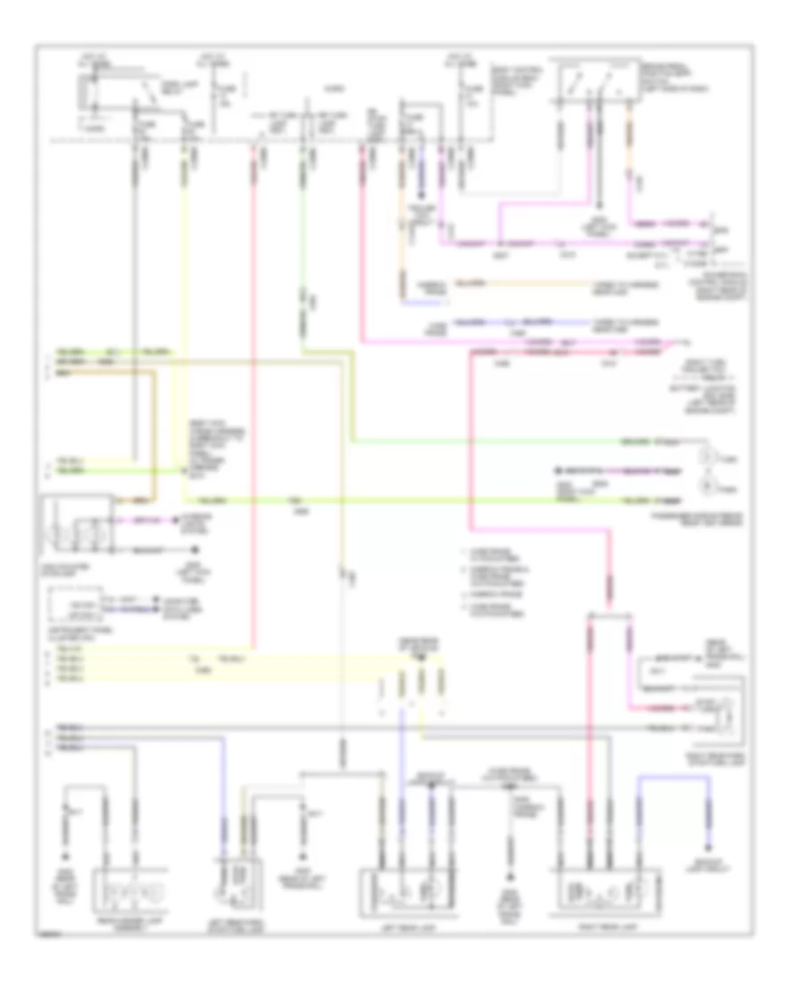
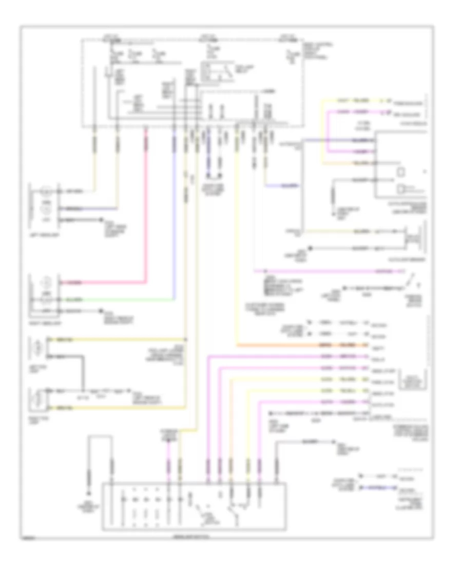
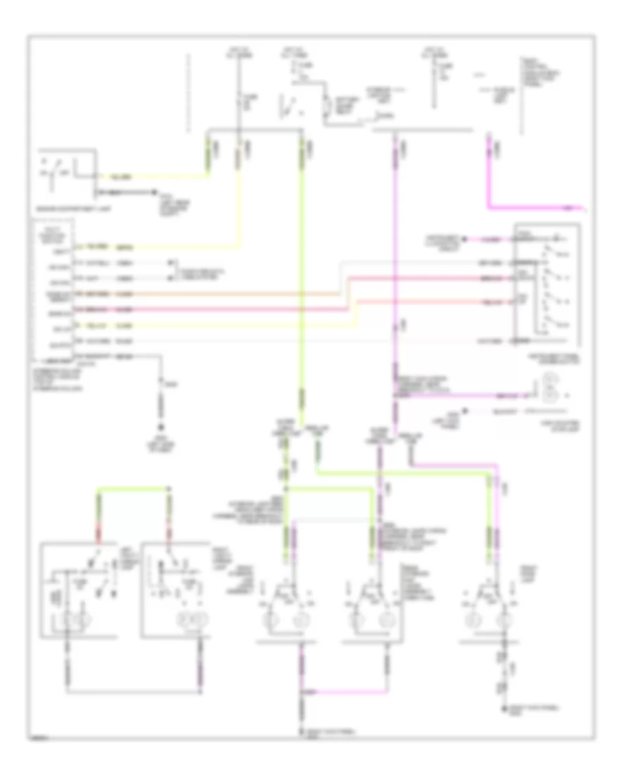
Exterior Lamps Wiring Diagram (1 of 2) for Ford F-450 Super Duty Platinum 2013
List of elements for Exterior Lamps Wiring Diagram (1 of 2) for Ford F-450 Super Duty Platinum 2013:
- (left kick panel) g300
- (left side of dash) g202
- (near breakout to left license plate lamp)
- (near breakout to rear of vehicle) s412
- (not used)
- (rear lamp connector wiring c4000 harness, near breakout to right rear fender) s424
- (rear lamp connector wiring harness, near c4002 breakout to left rear fender) s423
- Auto
- Auto lp on
- Base
- Battery junction box (bjb) (left rear of engine compt)
- Body control module (right kick panel)
- C1415
- C210
- C2280a
- C2280b
- C2280c
- C2280d
- C2280f
- C2402
- C2414a
- C2414b
- C408
- C465
- C555
- C913
- Center roof marker lamp
- Clf19
- Clf23
- Clf24
- Clf34
- Cls32
- Computer data lines system
- Driver side exterior rear view mirror
- Fuse 15a
- Fuse 5a
- G104 (left rear of engine compt)
- G108 (right rear of engine compt)
- G201 (center of dash)
- G400 (rear of left frame rail)
- Gd184
- Gd185
- Gnd
- Hazard
- Hazard switch
- Head
- Head lp off
- Head lp on
- Headlamp switch
- Hot at all times
- Hs can +
- Hs can -
- I can +
- I can -
- Left center roof marker lamp
- Left front park/turn lamp
- Left license plate lamp
- Left rear side lamp 1
- Left rear side lamp 2
- Left roof marker lamp
- Left side marker lamp
- Left turn trailer tow relay
- Lf turn lamp (fet)
- Logic gnd
- Lr stop/turn lamp (fet)
- Lr turn lamp (fet)
- Micro
- Multi-fuction switch
- Nca
- Off
- Park
- Park lp on
- Parking lamp trailer tow relay
- Premium
- Pwr gnd
- Right center roof marker lamp
- Right front park/turn lamp
- Right license plate lamp
- Right rear side lamp 1
- Right rear side lamp 2
- Right roof marker lamp
- Right side marker lamp
- S121 (except 6.7l: near breakout to left front corner of vehicle) (6.7l: near breakout to top left front of engine)
- S228
- S239
- S418
- S425
- S426
- S436
- S441 (near breakout to g400)
- S501
- S905
- S906 (near breakout to front of roof)
- Sbp24
- Sbp26
- Steering column control module (base) front controls interface module (fcim) (premium) (base: top of steering column)
- Stop/ chmsl (fet)
- Turn
- Vbatt
- Vdb04
- Vdb05
- W/ dual rear wheels
- Wide frame w/ pickup bed
- Wide frame w/o pickup bed
Exterior Lamps Wiring Diagram (2 of 2) for Ford F-450 Super Duty Platinum 2013
List of elements for Exterior Lamps Wiring Diagram (2 of 2) for Ford F-450 Super Duty Platinum 2013:
- (body main wiring harness, in breakout to right kick panel) (w/ power mirrors) s374
- (near rear of vehicle) s422
- (rear of left frame rail) g400
- (wide frame w/o pickup bed) s400
- 6.7l
- Backup lamp circuit
- Backup lamps circuit
- Battery junction box (bjb) (left rear of engine compt)
- Body control module (bcm) (right kick panel)
- Bpp
- Bps
- Brake pedal position (bpp) switch (left side of dash)
- C1232b
- C1415
- C175b
- C210
- C212
- C2280b
- C2280c
- C2280d
- C2280e
- C2280f
- C465
- C555
- C655
- Ccb08
- Ces09
- Computer data lines system
- Except 6.7l
- Fuse 10a
- Fuse 15a
- Fuse 5a
- G300 (left kick panel)
- G302 (right kick panel)
- G400 (rear of left frame rail)
- High mounted stoplamp
- Hot at all times
- Hs can +
- Hs can -
- Instrument panel cluster (ipc)
- Interior lights system
- Left rear lamp
- Left rear park/ stop/turn lamp
- Micro
- Narrow frame
- Narrow frame &
- Nca
- Park
- Park lamp relay
- Passenger side exterior rear view mirror
- Powertrain control module (right rear of engine compt)
- Rear marker lamp assembly
- Reversing
- Rf turn lamp (fet)
- Right rear lamp
- Right rear park stop/turn lamp
- Right turn trailer tow relay
- Rr stop/ turn lamp (fet)
- Rr turn lamp (fet)
- S207
- S405 (narrow frame)
- S411
- S639
- Stop/ turn
- Stop/turn
- Taped to harness near c422
- Taped to harness near c465
- Trailer tow circuit
- Turn
- W/o pickup bed
- Wide frame
- Wide frame w/ pickup bed
- Wide frame w/o pickup bed
Trailer Tow Wiring Diagram for Ford F-450 Super Duty Platinum 2013
List of elements for Trailer Tow Wiring Diagram for Ford F-450 Super Duty Platinum 2013:
- (5th wheel)
- (customer access) (taped to harness near c422)
- (not used)
- (rear of left frame rail) g400
- (w/o crew chief)
- 5th wheel
- Backup lamps circuit
- Battery charge trailer tow relay
- Battery junction box (bjb) (left rear of engine compt)
- Body control module (right kick panel)
- Boo
- Bpp
- Bptgnd
- Bptsig
- Brake
- C1415
- C1581
- C2108
- C211
- C2280b
- C2280e
- C431
- C432
- Cat06
- Cat09
- Cat14
- Cat16
- Cat17
- Cat19
- Cat7+
- Cbp31
- Cbp35
- Computer data lines system
- Crew chief
- Ends in harness bpp
- Ends in harness brake
- Ends in harness gnd
- Ends in harness vbatt
- Ends in harness vpwr
- Except crew chief
- Exterior lamps circuit
- Fuse 10a
- Fuse 15a
- Fuse 25a
- Fuse 30a
- Fuse 5a
- G104 (left rear of engine compt)
- G203 (left side of dash)
- G400 (rear of left frame rail)
- Gd115
- Gnd
- Gnd-a
- Hot at all times
- Hot in start or run
- Hot w/ park lamp relay energized
- Hs can +
- Hs can -
- Hsc1-a
- Hsc2-a
- Igrun-a
- Lca16
- Left turn trailer tow relay
- Narrow frame
- Not used hs can+
- Not used hs can-
- Parking lamp trailer tow relay
- Rat08
- Rear window defrost relay
- Right turn trailer tow relay
- S121
- S272
- S443 (5th wheel)
- S444 (5th wheel) (diesel: near breakout to g400) (gasoline: rear of vehicle)
- S446 (5th wheel) (near rear of vehi- cle)
- S447 (5th wheel)
- S448 (5th wheel) (near rear of vehi- cle)
- S449 (5th wheel) (near rear of vehi- cle)
- Sbb22
- Tbo
- Trailer brake control (tbc) module (center of dash)
- Trailer brake controller
- Trailer tow connector (left side of rear bumper)
- Trailer tow kit
- Vb-a
- Vbatt
- Vdb04
- Vdb05
- Vpwr
- Wheel) s445
- Wide frame
GROUND DISTRIBUTION
Ground Distribution Wiring Diagram (1 of 5) for Ford F-450 Super Duty Platinum 2013
List of elements for Ground Distribution Wiring Diagram (1 of 5) for Ford F-450 Super Duty Platinum 2013:
- (6.7l except high sulfur) nox sensor module 11
- (6.7l w/ rapid heat) auxiliary heater control module (ahcm)
- (6.7l) fuel delivery pressure switch
- (6.7l) fuel pump
- (6.7l) glow plug control module (gpcm)
- (6.7l) reductant heater relay
- (6.8l) intake manifold tuning valve (imtv)
- (left end of dash) upfitter relay box
- (left rear of engine compt) battery junction box (bjb)
- 6.2l
- 6.2l & 6.8l wide frame/ narrow frame w/ mid fuel tank
- 6.7l
- A/c compressor clutch field coil
- Anti-lock brake system (abs) module
- Anti-theft hood switch
- Battery
- Battery charge trailer tow relay
- Brake fluid level switch
- C1046
- C1047
- C1168
- C1232b
- C1273c
- C134
- C146
- C175b
- C2371b
- C2463a
- Cooling fan
- Engine compartment lamp
- Except 6.7l
- Front wiper relay
- Fuel pump control module
- Fuel pump module shield
- G100 (right front of engine compt)
- G101 (lower right rear of engine)
- G102 (6.7l) (top rear of engine)
- G103 (right rear of engine compt)
- G104 (left rear of engine compt)
- G107 (left frame rail, near transfer case)
- G108 (right rear of engine compt)
- G116 (left frame rail, near transfer case)
- G135 (left side of frame, near front of vehicle)
- G136 (left side of frame, near front of vehicle)
- G204 (center of dash)
- Horn
- Left fog lamp
- Left front park/turn lamp
- Left headlamp
- Left side marker lamp
- Left turn trailer tow relay
- Nca
- Parking lamp trailer tow relay
- Powertrain control module (pcm)
- Reversing lamp relay
- Right fog lamp
- Right front park/turn lamp
- Right headlamp
- Right side marker lamp
- Right turn trailer tow relay
- S170 (6.7l) (frame wiring harness, near breakout to g135)
- S196 (frame wiring harness, in breakout to g136)
- S249 (upfitter relay wiring harness, near customer access breakout)
- Secondary battery
- Transfer case control module
- Transmission control module
- Upfitter relay 1
- Upfitter relay 2
- Upfitter relay 3
- Upfitter relay 4
- Upfitter switch
- Windshield washer pump motor
- Windshield wiper motor
Ground Distribution Wiring Diagram (2 of 5) for Ford F-450 Super Duty Platinum 2013
List of elements for Ground Distribution Wiring Diagram (2 of 5) for Ford F-450 Super Duty Platinum 2013:
- (6.7l except high sulfur) nox sensor module 12
- (automatic a/c) autolamp/ sunload sensor
- (crew chief) telematics module
- (frame wiring harness, near breakout to c140) s172
- (if equipped) passenger air bag deactivation (pad) switch
- (manual a/c) autolamp sensor
- (pia to steering wheel harness)
- (rear lamp connector wiring harness, in breakout to c465) s401
- (w/ 110v power inverter instrument panel) dc/ac inverter module
- (w/ base audio & cd player) audio control module (acm)
- (w/ cdim) circuit deactivation ignition module
- 6.2l & 6.8l narrow frame w/ aft fuel tank
- Accessory protocol interface module (apim)
- Audio control module (acm)
- Automatic a/c
- Base audio w/ cd player
- Blower motor speed control
- Brake shift interlock
- C1581
- C210
- C2108
- C213
- C218a
- C218b
- C228a
- C238
- C240a
- C2414a
- C2414b
- C248
- C264
- C265
- C268
- C465
- C497
- Center stack switch assembly
- Cigar lighter
- Clockspring (steering column assembly)
- Crew chief
- Data link connector
- Data link connector (dlc)
- Front controls interface module (fcim)
- Fuel pump control module
- Fuel pump module shield
- Fuel tank selector switch
- G201 (center of dash)
- G202 (left side of dash)
- G203 (left side of dash)
- G401
- G402 (left side of frame, near rear of vehicle)
- Global positioning system module
- Headlamp switch
- Heated steering wheel module (hswm)
- Horn switch
- Hvac module
- Instrument panel cluster (ipc)
- Instrument panel power point 1
- Instrument panel power point 2
- Left steering wheel switch
- Manual a/c
- Microphone
- Mode select switch
- Nca
- Parking aid module (pam)
- Passive anti-theft transceiver
- Power mirror fold relay
- Regular cab
- Right steering wheel switch
- S195 (engine control sensor engine compt wiring harness, near breakout to c1581)
- S231
- S239 (instrument panel wiring harness, in breakout to g203)
- S340 (body main wiring harness, in breakout to c265)
- S410 (rear lamp connector wiring harness, in breakout to c497)
- S442 (diesel: frame wiring harness, near breakout to g400) (except diesel: frame wiring harness, near breakout to c465)
- S461 (tailgate nca wiring harness, in breakout to lift gate release le) nca
- Shield nca
- Steering column control module
- Super cab & crew cab
- Tire pressure monitor module
- Trailer brake control (tbc) module
- Video camera
Ground Distribution Wiring Diagram (3 of 5) for Ford F-450 Super Duty Platinum 2013
List of elements for Ground Distribution Wiring Diagram (3 of 5) for Ford F-450 Super Duty Platinum 2013:
- (crew cab w/ consolette) consolette power point
- (crew cab) master window control switch
- (if equipped) left rear seat heated switch
- (super cab & crew cab) driver side rear door ajar switch
- (super cab & regular cab) master window control switch
- (w/ memory) exterior rear view mirror switch
- (w/o memory) exterior rear view mirror switch
- Auto- dimming interior mirror
- Brake pedal position (bpp) switch
- C264
- C300
- C311
- C341a
- C341b
- C555
- C566b
- C756 c755
- C913
- Center roof marker lamp
- Crew cab
- Driver seat belt buckle switch/ pretensioner
- Driver seat module (dsm)
- Driver side door lock switch
- Driver side exterior rear view mirror
- Driver side front door ajar switch
- Driver side front power window motor
- Driver side front seat control switch
- G300 (left kick panel)
- High mounted stoplamp
- Keyless entry keypad
- Left center roof marker lamp
- Left roof marker lamp
- Memory set switch
- Nca
- Parking brake switch
- Power seat
- Right center roof marker lamp
- Right roof marker lamp
- S501 (left front door window regulator wiring harness, in driver's door)
- S505 (w/ power equipment) (left front door window regulator wiring harness, in driver's door)
- S905 (air curtain & roof markers wiring harness, near breakout to front of roof)
- Super cab
- Telescoping exterior rear view mirror switch
- W/ 10-way power seat
- W/ 6-way
Ground Distribution Wiring Diagram (4 of 5) for Ford F-450 Super Duty Platinum 2013
List of elements for Ground Distribution Wiring Diagram (4 of 5) for Ford F-450 Super Duty Platinum 2013:
- (5th wheel) trailer tow connector
- (bumper rear park aid wiring harness, near breakout to left license plate lamp)
- (if equipped) electronic locking differential (eld) field coil
- (narrow frame) customer access taped to harness near c422
- (not used)
- 6.7l except high sulfur
- All others
- C139
- C3007
- C3047
- C3137
- C3138
- C4000
- C4002
- C408
- C432
- C465
- G400 (rear of left frame rail)
- Jumper wiring harness, near breakout to front of right running board)
- Left front running board lamp
- Left license plate lamp
- Left rear lamp
- Left rear park/stop/ turn lamp
- Left rear running board lamp
- Left rear side lamp
- Left reversing lamp
- Lh/rh jumper wiring harness, near breakout to front of left running board)
- Narrow frame
- Narrow w/ aft fuel tank
- Nca
- Rear marker lamp assembly
- Reductant heater & sensor assembly
- Reductant pressure line heater assembly
- Reductant pump assembly
- Right front running board lamp
- Right license plate lamp
- Right rear lamp
- Right rear park/stop/ turn lamp
- Right rear running board lamp
- Right rear side lamp
- Right reversing lamp
- S405 (frame wiring harness, near breakout to g400)
- S411 (rear lamp connector wiring harness, near breakout to rear of vehicle)
- S443 (5th wheel) (frame wiring harness, near breakout to g400)
- Trailer tow connector
- W/ dual rear wheels
- W/ pickup bed
- W/o pickup bed
- Wide frame
- Wide frame w/ pickup bed
- Wide frame/
Ground Distribution Wiring Diagram (5 of 5) for Ford F-450 Super Duty Platinum 2013
List of elements for Ground Distribution Wiring Diagram (5 of 5) for Ford F-450 Super Duty Platinum 2013:
- (crew cab & super cab) passenger side rear door ajar switch
- (crew cab) rear interior/ map lamps assembly
- (crew cab) roof opening panel module
- (if equipped) right rear heated seat switch
- (premium audio w/ sony sound) audio digital signal processing (dsp) module
- (premium audio w/o sony sound) subwoofer amplifier
- (regular cab) front dome lamp
- (super cab & crew cab) front console power point
- (super cab & crew cab) front interior/ map lamps assembly
- (super cab) front dome lamp
- (w/ 110v power inverter) dc/ac inverter module
- (w/ rear heated power sliding window) rear window defrost grid
- (wiring harness- console (14b079) near breakout to center of cab floor)
- Body control module
- C2280d
- C248
- C268
- C3049
- C3052
- C312
- C3265a
- C3368b
- C3368d
- C3501a
- C655
- C856 c855
- Crew cab
- Dual climate controlled seat module (dcsm)
- Front passenger side door ajar switch
- Front passenger side power window motor
- Front passenger side seat adjust switch
- G301 (super cab: left "b" pillar) (crew cab: left "c" pillar)
- G302 (right kick panel)
- Left second row seat cushion heater mat
- Left vanity mirror lamp
- Nca
- Overhead console switch assembly
- Passenger side door lock switch
- Passenger side exterior rear view mirror
- Passenger side window control switch
- Rear console power point
- Rear heated seat module
- Right second row seat cushion heater mat
- Right vanity mirror lamp
- S638 (w/ power equipment) (right front door jumper wiring harness, in passenger's door)
- S639 (w/ power equipment) (right front door jumper wiring harness, in passenger's door)
- S802 (w/ rear heated seats)
- S907 (interior lamp feed headliner wiring harness, near breakout to right front of roof)
- Super cab
- W/ power sliding rear window
- W/o moonroof
HEADLIGHTS
Headlights Wiring Diagram for Ford F-450 Super Duty Platinum 2013
List of elements for Headlights Wiring Diagram for Ford F-450 Super Duty Platinum 2013:
- (center of dash) g201
- (customer access) (taped to harness near c210)
- (left side of dash)
- Auto
- Auto lp on
- Auto lp sens in
- Autolamp sensor
- Autolamp/sunload sensor (center of dash)
- Automatic a/c
- Body control module (right kick panel)
- C134
- C2280a
- C2280b
- C2280c
- C2280e
- C2280f
- C2414a
- C314
- Clf19
- Clf21
- Clf23
- Clf24
- Clf34
- Cmc25
- Computer data lines system
- Drv sunload
- Fog ind
- Fog lamp relay
- Fog lamp switch
- Fog lp
- Fuse 10a
- Fuse 15a
- Fuse 5a
- G104 (left rear of engine compt)
- G108 (right rear of engine compt)
- G201 (center of dash)
- G202
- G300 (left kick panel)
- Gd185
- Head
- Head lp off
- Head lp on
- Headlamp switch
- High
- Hot at all times
- Hs can+
- Hs can-
- Hvac module
- Instrument panel cluster (ipc)
- Interior lights system
- Left fog lamp
- Left headlamp
- Left high beam (fet)
- Left low beam (fet)
- Logic gnd
- Low
- Manual a/c
- Micro
- Multi- function switch
- Off
- Park
- Park brake
- Park lp on
- Parking brake switch
- Pass sunload
- Right fog lamp
- Right headlamp
- Right high beam (fet)
- Right low beam (fet)
- S1119
- S142 (fog lamp jumper wiring harness, near breakout to c134)
- S239
- S326
- Sbp26
- Solid state
- Steering column control module (top of steering column)
- Vbatt
- Vdb04
- Vdb05
- Vh416
- Vh417
- Vlf14
- W/ drl
- W/o drl
HORN
Horn Wiring Diagram for Ford F-450 Super Duty Platinum 2013
List of elements for Horn Wiring Diagram for Ford F-450 Super Duty Platinum 2013:
- Body control module (right kick panel)
- C218a
- C218b
- C218c
- C2280b
- C2280e
- C2414a
- C2414d
- Clockspring (steering column assembly)
- Crh04
- Fuse 22 20a
- G108 (right rear of engine compt)
- G202 (left side of dash)
- Horn
- Horn (right front of engine compt)
- Horn relay
- Horn switch (steering wheel)
- Hot at all times
- Micro
- Nca
- S299
- Steering column control module (top of steering column)
INSTRUMENT CLUSTER
Instrument Cluster Wiring Diagram (1 of 2) for Ford F-450 Super Duty Platinum 2013
List of elements for Instrument Cluster Wiring Diagram (1 of 2) for Ford F-450 Super Duty Platinum 2013:
- (customer access) (taped to harness near c210)
- 4x4 high
- 4x4 low
- Ajar lf door
- Ajar lr door
- Anti-lock brakes system
- Body control module (right kick panel)
- Brake fluid sw
- Brake park
- C1581
- C211
- C218a
- C218b
- C2280a
- C2280b
- C2280c
- C2280f
- C263
- Can+ hs
- Can+ ms
- Can- hs
- Can- ms
- Cca10
- Ccf06
- Ccf22
- Cdc30
- Ce929
- Cet52
- Cet59
- Clockspring (steering column assembly)
- Cmc19
- Cmc25
- Cmc29
- Computer data lines system
- Cpl26
- Cpl31
- Cpl36
- Cpl39
- Diesel
- Down
- Fuel level sensor (diesel w/ dual fuel tanks) (fuel tank assembly)
- Fuel level sensor (fuel tank assembly)
- Fuel pump (fp) module (left rear frame rail)
- Fuel sender 1
- Fuel sender 2
- Fuel sender rtn 1
- Fuel sender rtn 2
- Fuel tank select
- Fuse 10a
- Fuse 15a
- G201 (center of dash)
- G300 (left kick panel)
- Gasoline
- Gd184
- Gnd
- Hill descent sw
- Hot at all times
- Hot in run or start
- Hs can +
- Hs can -
- I can +
- I can -
- Ignition switch
- Info
- Instrument panel cluster (ipc)
- Key in
- Key in ignition
- Left
- Left steering wheel switch
- Message cntrl sw
- Micro
- Ms rtn
- Nca
- Park detect
- Parking brake switch
- Reset
- Rf door ajar
- Right
- Rmc19
- Rmc27
- Rmc32
- Rmc33
- Rr door ajar
- S304 (body main wiring harness, in breakout to left end of dash)
- Sbp11
- Setup
- Shift interlock system
- Sw rtn brake fluid
- Tcs
- Vbatt
- Vdb04
- Vdb05
- Vdb06
- Vdb07
- Vdb13
- Vdb14
- Vmc11
- Vmc23
- W/ 3-button message center
- W/ 5-button message center
Instrument Cluster Wiring Diagram (2 of 2) for Ford F-450 Super Duty Platinum 2013
List of elements for Instrument Cluster Wiring Diagram (2 of 2) for Ford F-450 Super Duty Platinum 2013:
- (6.2l) s120
- (diesel)
- (gasoline)
- (instrument panel wiring harness, near breakout to behind right side of dash) s245
- (not used)
- 2h (off)
- 4x4 high/low indicator switch (w/ msof) (top rear of transmission)
- 6.2l
- 6.8l & 6.2l
- B-sigrtn
- Brake fluid level switch (brake fluid reservoir)
- C1010
- C1046
- C1047
- C1168
- C1232b
- C1232e
- C145
- C1581
- C175b
- C175e
- C211
- C555
- C655
- C755
- C756
- C855
- C856
- Cmc24
- Computer data lines system
- Crew cab
- Diesel
- Driver side front door ajar switch (driver's door)
- Driver side rear door ajar switch (super cab & crew cab) (left rear door)
- Engine controls system
- Eop sw
- Fuel tank selector switch
- Fuel tank selector valve (left rear of frame)
- G104 (left rear of engine compt)
- G203 (left side of dash)
- G300 (left kick panel)
- G302 (right kick panel)
- Gasoline
- Hs can +
- Hs can -
- Oil pressure switch (diesel: lower right rear of engine) (gasoline: lower left front of engine)
- Passenger side front door ajar switch (front passenger's door)
- Passenger side rear door ajar switch (super cab & crew cab) (right rear door)
- Powertrain control module (right rear of engine compt)
- Primary
- Re407
- S100 (engine control sensor engine compartment wiring harness, near breakout to right front corner of vehicle)
- S246
- S505 (w/ power equipment)
- S638 (w/ power equipment)
- S802 (w/ heated seats)
- Seats system
- Seats)
- Secondary
- Super cab
- Vdb04
- Vdb05
- Ve823
- Water-in fuel sensor (diesel) (inside of left frame rail)
- Wfs
INTERIOR LIGHTS
Courtesy Lamps Wiring Diagram (1 of 2) for Ford F-450 Super Duty Platinum 2013
List of elements for Courtesy Lamps Wiring Diagram (1 of 2) for Ford F-450 Super Duty Platinum 2013:
- (body main wiring harness, near breakout to c312) s370
- (right kick panel) g302
- Battery saver relay
- Body control module (bcm) (right kick panel)
- C2280a
- C2280b
- C2280c
- C2280d
- C2280f
- C2414a
- C248
- C265
- C268
- Car2u lear
- Cln55
- Cln56
- Computer data lines system
- Dim down
- Dim rtn
- Dim up
- Dome
- Dome on
- Dome on/ defeat
- Engine compartment lamp
- Front dome lamp
- Front interior/ map lamps assembly
- Fuse 10a
- Fuse 15a
- Fuse 2a
- Fuse 5a
- G104 (left rear of engine compt)
- G202 (left side of dash)
- G300 (left kick panel)
- Gd185
- Gnd
- High mounted stoplamp
- Hot at all times
- Hs can+
- Hs can-
- Instrument illumination circuit
- Instrument panel dimmer switch
- Interior lighting (fet)
- Left vanity mirror lamp
- Logic gnd
- Micro
- Multi function switch
- Off
- Puddle lamp (fet)
- Pwm input
- Rear interior/ map lamps assembly (crew cab)
- Red
- Regular cab
- Right vanity mirror lamp
- Rln29
- S239
- S907
- S908 (interior lamp feed headliner wiring harness, near breakout to rear of roof)
- Sbp26
- Steering column control module (top of steering column)
- Super cab & crew cab
- Vbatt
- Vdb04
- Vdb05
- Vln36
Courtesy Lamps Wiring Diagram (2 of 2) for Ford F-450 Super Duty Platinum 2013
List of elements for Courtesy Lamps Wiring Diagram (2 of 2) for Ford F-450 Super Duty Platinum 2013:
- (left kick panel) g300
- Ajar lf door
- Ajar lr door
- Body control module (bcm) (right kick panel)
- C1415
- C210
- C2280c
- C2280f
- C3137
- C3138
- C328
- C555
- C655
- C755
- C756
- C855
- C856
- Can+ hs
- Can- hs
- Computer data lines system
- Cpl26
- Cpl31
- Cpl36
- Cpl39
- Crew cab
- Driver side front door ajar switch (driver's door)
- Driver side rear door ajar switch (super cab (& crew cab) (left rear door)
- G300 (left kick panel)
- G302 (right kick panel)
- G400 (rear of left frame rail)
- Hs can +
- Hs can -
- Instrument panel cluster (ipc)
- Left front running board lamp
- Left rear running board lamp
- Micro
- Passenger side front door ajar switch (front passenger's door)
- Passenger side rear door ajar switch (super cab (& crew cab) (right rear door)
- Rf door ajar
- Right front running board lamp
- Right rear running board lamp
- Rr door ajar
- S311
- S312 (lighted running board lh/rh jumper wiring harness, near breakout to front of right running board)
- S313
- S328 (lighted running board lh/rh jumper wiring harness, near breakout to front of left running board)
- S396 (frame wiring harness, near breakout to c328)
- S405
- S505
- S638
- S700
- S802
- Super cab
- Vdb04
- Vdb05
- W/ power equipment
- W/ rear heated seats
- W/o power equipment
- W/o rear heated seats
Instrument Illumination Wiring Diagram for Ford F-450 Super Duty Platinum 2013
List of elements for Instrument Illumination Wiring Diagram for Ford F-450 Super Duty Platinum 2013:
- (center of dash) g201
- (not used)
- (rear of roof) roof opening panel module
- (w/ single cd/ base audio) audio control module (acm)
- Auto
- Auto lp on
- Back- lighting led (fet)
- Body control module (bcm) (right kick panel)
- C218a
- C218b
- C2280b
- C2280f
- C2414a
- C265
- C268
- Center stack switch assembly
- Clf19
- Clf23
- Clf24
- Clf34
- Cln55
- Cln56
- Clockspring (steering column assembly)
- Computer data lines system
- Cpr39
- Dim down
- Dim rtn
- Dim up
- Dome
- Done on/defeat
- Fuse 15a
- Fuse 5a
- G201 (center of dash)
- G202 (left side of dash)
- G203 (left side of dash)
- G204 (center of dash)
- G302 (right kick panel)
- Gd115
- Gd185
- Gnd
- Hdlp off
- Hdlp on
- Head
- Headlamp switch
- Hot at all times
- Hs can+
- Hs can-
- Ill+
- Ill-
- In-dash computer
- Instrument panel dimmer switch
- Left steering wheel switch
- Logic gnd
- Micro
- Mode select switch
- Multi- function switch
- Off
- Overhead console switch assembly
- Park
- Park lp on
- Pwm input
- Right steering wheel switch
- Rln29
- S220 (instrument panel wiring harness, near breakout to g201)
- S239
- S249
- S286
- S299
- S907
- Sbp26
- Steering column control module (top of steering column)
- Upfitter switch
- Vbatt
- Vdb04
- Vdb05
- Vln36
- Vnl04
- W/ 5-button message center
- W/ moonroof
- W/o moonroof
- White led (fet)
MEMORY SYSTEMS
Adjustable Pedal Wiring Diagram for Ford F-450 Super Duty Platinum 2013
List of elements for Adjustable Pedal Wiring Diagram for Ford F-450 Super Duty Platinum 2013:
- (left side of dash) g202
- Adjustable pedal motor (left side of dash)
- Adjustable pedal switch
- Body control module (right kick panel)
- C212
- C2280a
- C2414a
- C2414b
- C2414c
- C300
- C341c
- C341d
- C555
- Com mtr pdl/col
- Computer data lines system
- Cpp01
- Cpp02
- Cps15
- Cps16
- Driver seat module (dsm) (under driver's seat)
- Fuse 15a
- G300 (left kick panel)
- Gd185
- Gnd
- Hall sns rtn
- Hot at all times
- Hs can +
- Hs can -
- Lpp06
- Memory set switch
- Ms can +
- Ms can -
- Pdl hall sns sig
- Pedal mtr fwd
- Rpp06
- S228
- S239
- S505 (w/ power equipment)
- Sbp24
- Set 1
- Set 2
- Steering column control module (top of steering column)
- Vbatt
- Vdb04
- Vdb05
- Vdb06
- Vdb07
Driver"s Memory Seat Wiring Diagram (1 of 2) for Ford F-450 Super Duty Platinum 2013
List of elements for Driver"s Memory Seat Wiring Diagram (1 of 2) for Ford F-450 Super Duty Platinum 2013:
- Aft
- Base backward
- Base forward
- Body control module (right kick panel)
- C2280d
- C300
- C3050
- C311
- C341a
- C341b
- Cbx03
- Cbx05
- Cps01
- Cps02
- Cps03
- Cps04
- Cps05
- Cps06
- Cps07
- Cps08
- Cps23
- Cps24
- Cps25
- Cps26
- Cps27
- Cps28
- Cps29
- Cps30
- Deflate
- Driver seat front height motor
- Driver seat horizontal motor
- Driver seat lumbar motor
- Driver seat module (dsm) (under driver's seat)
- Driver seat rear height motor
- Driver seat recliner motor
- Driver side front seat control switch
- Forward
- Front dn
- Front height
- Front up
- Fuse 5a
- Fuse 7.5a
- Fwd
- G300 (left kick panel)
- Gd905
- Gd906
- Hall effect rtn
- Hall effect sns
- Height rear
- Horizontal
- Hot at all times
- Incline
- Inflate
- Logic gnd
- Lumbar
- Pwr gnd
- Rear dn
- Rear up
- Recline
- Rps13
- S368 (driver cushion wiring harness, near breakout to c3050)
- Vbatt
- Vps09
- Vps10
- Vps11
- Vps12
Driver"s Memory Seat Wiring Diagram (2 of 2) for Ford F-450 Super Duty Platinum 2013
List of elements for Driver"s Memory Seat Wiring Diagram (2 of 2) for Ford F-450 Super Duty Platinum 2013:
- Adjustable pdl fwd sw
- Battery junction box (bjb) (left rear of engine compt)
- C210
- C300
- C311
- C341c
- C341d
- C555
- Computer data lines system
- Cpm04
- Cpm16
- Cpm17
- Cpm20
- Cpm21
- Cpm22
- Cpm26
- Cpm28
- Cpm29
- Cpm31
- Cpm33
- Cpm34
- Cpm39
- Cpp09
- Cps14
- Cps15
- Cps16
- Driver seat module (dsm) (under driver's seat)
- Drv hor pot
- Drv mirr hor sw
- Drv mirr mtr hor rt
- Drv mirr mtr vert up
- Drv mirr vert sw
- Drv mtr dn/lt
- Drv vert pot
- Ext mirr pot feed
- Fuse 30a
- G300 (left kick panel)
- Hot at all times
- Lpm30
- Memory mirrors circuit
- Memory set switch
- Mirr com sw
- Mirr fold sw
- Mirr mtr fold in
- Mirr mtr fold out
- Mirr pot ret
- Ms can +
- Ms can -
- Not used
- Pass hor pot
- Pass mirr hor sw
- Pass mirr mtr dn/lt
- Pass mirr mtr hor rt
- Pass mirr mtr vert up
- Pass mirr vert sw
- Pass vert pot
- Red
- Rpm11
- Rpm30
- S505 (w/ power equipment)
- Set
- Set 1
- Set 2
- Vdb06
- Vdb07
- Vpm35
- Vpm36
- Vpm37
- Vpm38
Memory Mirrors Wiring Diagram for Ford F-450 Super Duty Platinum 2013
List of elements for Memory Mirrors Wiring Diagram for Ford F-450 Super Duty Platinum 2013:
- (body main wiring harness, near breakout to c311)
- (left front door window regulator wiring harness, in driver's door)
- (right front door jumper wiring harness, in passenger's door)
- Battery junction box (bjb) (left rear of engine compt)
- Body control module (right kick panel)
- C210
- C2280d
- C300
- C311
- C341a
- C341b
- C341c
- C341d
- C555
- C655
- Cbx03
- Cbx05
- Computer data lines system
- Cpm16
- Cpm17
- Cpm20
- Cpm21
- Cpm26
- Cpm28
- Cpm29
- Cpm31
- Cpm33
- Cpm34
- Cps15
- Cps16
- Defogger system
- Driver seat module (dsm) (under driver's seat)
- Driver side exterior rear view mirror
- Drv mirr hor pot
- Drv mirr hor sw
- Drv mirr vert pot
- Drv mirr vert sw
- Drv mtr dn/lt
- Drv mtr hor rt
- Drv mtr vert up
- Ext mirr pot feed
- Exterior lights system
- Exterior rear view mirror switch
- Fuse 10a
- Fuse 30a
- Fuse 5a
- G300 (left kick panel)
- G302 (right kick panel)
- Gd906
- Hot at all times
- Left/right
- Lpm30
- Memory set switch
- Mirr com sw
- Mirr pot rtn
- Mirror heated
- Mirrors system
- Ms can +
- Ms can -
- Nca
- Park
- Pass hor pot
- Pass mirr hor sw
- Pass mirr vert sw
- Pass mtr dn/lt
- Pass mtr hor rt
- Pass mtr vert up
- Pass vert pot
- Passenger side exterior rear view mirror
- Pwr gnd
- Red
- Rpm11
- Rpm30
- S318
- S336 (near breakout to center of cab floor)
- S501
- S505
- S513
- S609
- S639
- Set 1
- Set 2
- Turn
- Up/dn
- Vbatt
- Vdb06
- Vdb07
- Vpm35
- Vpm36
- Vpm37
- Vpm38
NAVIGATION
Crew Chief Wiring Diagram for Ford F-450 Super Duty Platinum 2013
List of elements for Crew Chief Wiring Diagram for Ford F-450 Super Duty Platinum 2013:
- 5vpwr
- 5vtb
- Battery junction box (bjb) (left rear of engine compt)
- Body control module (bcm) (right kick panel)
- C2280b
- Cgnd
- Computer data lines system
- Fuse 30a
- Fuse 5a
- G203 (left side of dash)
- Gnd
- Gnd1
- Hot at all times
- Hot in start or run
- Hs can+
- Hs can-
- Hsc1-c
- Hsc2-c
- Igrun-c
- Inline fuse (right end of dash)
- Modem-antenna (top center of dash)
- Nca
- Pwr ground
- Red
- Run start
- Rxd
- S272
- S273
- S274
- Telematics module (right end of dash)
- Txd
- Vb1
- Vbatt
Navigation Wiring Diagram, with Sony (1 of 3) for Ford F-450 Super Duty Platinum 2013
List of elements for Navigation Wiring Diagram, with Sony (1 of 3) for Ford F-450 Super Duty Platinum 2013:
- (at breakout to audio digital signal processing module)
- (body main wiring harness, near breakout to c311) s291
- (right kick panel) g302
- Accessory protocol interface module (right end of dash)
- Audio digital signal processing (dsp) module (crew cab: base of right "c" pillar) (super cab: center rear of cab floor)
- Body control module (right kick panel)
- C207
- C2280a
- C2280b
- C2280d
- C3154a
- C3154b
- C3154c
- C555
- C655
- C755
- C855
- Cls32
- Computer data lines system
- Dme80
- Enable
- Fuse 15a
- Fuse 20a
- Fuse 25a
- Fuse 5a
- G201 (center of dash)
- Gd114
- Gd139
- Global positioning system module (gpsm) (w/ sync) (top center of dash)
- Gnd
- Hazard
- Hot at all times
- I can +
- I can -
- Instrument panel speaker
- Ip spkr +
- Ip spkr -
- Left front speaker
- Left front tweeter
- Left rear speaker
- Left rear tweeter
- Lf spkr +
- Lf spkr -
- Lf tweeter +
- Lf tweeter -
- Lr spkr +
- Lr spkr -
- Ms can+
- Ms can-
- Nca
- Rf spkr +
- Rf spkr -
- Rf tweeter +
- Rf tweeter -
- Right front speaker
- Right front tweeter
- Right rear speaker
- Right rear tweeter
- Rme06
- Rme07
- Rme08
- Rme09
- Rme10
- Rme11
- Rme12
- Rme17
- Rme18
- Rme22
- Rme55
- Rme80
- Rr spkr +
- Rr spkr -
- S222
- S228
- S292
- S300
- S301
- Sbp19
- Sbp29
- Shield
- Sme23
- Subw 1+
- Subw 1-
- Subw 2+
- Subw 2-
- Sync alert +
- Sync alert -
- V batt
- Vbatt
- Vdb06
- Vdb07
- Vdb13
- Vdb14
- Vme06
- Vme07
- Vme08
- Vme09
- Vme10
- Vme11
- Vme12
- Vme17
- Vme18
- Vme22
- Vme55
- Vme80
Navigation Wiring Diagram, with Sony (2 of 3) for Ford F-450 Super Duty Platinum 2013
List of elements for Navigation Wiring Diagram, with Sony (2 of 3) for Ford F-450 Super Duty Platinum 2013:
- (right rear of cab, on floor) subwoofer amplifier
- (top of steering column)
- Audio pwr
- Audio rtn
- C218a
- C218b
- C218c
- C2414a
- C2414b
- C2414d
- Clockspring (steering column assembly)
- Cls32
- Computer data lines system
- Front controls interface module (fcim)
- G201 (center of dash)
- G202 (left side of dash)
- Gd184
- Gd185
- Gnd
- Hazard
- Hazard switch
- Hs can +
- Hs can -
- I can +
- I can -
- Interior lights system
- Logic gnd
- Media
- Nca
- Phone
- Pwr gnd
- Right steering wheel switch
- S239
- S299
- Sbp24
- Sbp26
- Seek+
- Seek-
- Steering column control module
- Subw 1+
- Subw 1-
- Subw 2+
- Subw 2-
- Sync pwr
- Sync rtn
- Vbatt
- Vdb04
- Vdb05
- Vdb13
- Vdb14
- Voice
- Vol+
- Vol-
Navigation Wiring Diagram, with Sony (3 of 3) for Ford F-450 Super Duty Platinum 2013
List of elements for Navigation Wiring Diagram, with Sony (3 of 3) for Ford F-450 Super Duty Platinum 2013:
- Am/fm antenna
- Amp gnd
- Antenna
- Audio control module (acm)
- Batt
- Battery junction box (bjb) (left rear of engine compt)
- C211
- C265
- C290a
- C290b
- Cdc38
- Computer data lines system
- Dme17
- Enable
- G201 (center of dash)
- Gd114
- I can+
- I can-
- Lf spkr +
- Lf spkr -
- Nca
- Rf spkr +
- Rf spkr -
- Rme17
- Rme18
- Rme52
- Rme53
- Sbp29
- Sdars ant
- Sdars antenna
- Sdl-h
- Sdl-l
- Shield
- Sme23
- Start
- Starting/ charging system
- Stereo l+
- Stereo l-
- Stereo r+
- Stereo r-
- Sync radio circuit
- Vdb13
- Vdb14
- Vme17
- Vme18
- Vme52
- Vme53
- Vme90
- Vme91
Navigation Wiring Diagram, without Sony (1 of 2) for Ford F-450 Super Duty Platinum 2013
List of elements for Navigation Wiring Diagram, without Sony (1 of 2) for Ford F-450 Super Duty Platinum 2013:
- Am/fm antenna
- Amp gnd
- Antenna
- Audio control module (acm)
- Batt
- Battery junction box (bjb) (left rear of engine compt)
- Body control module (right kick panel)
- C211
- C212
- C2280a
- C2280b
- C2280d
- C265
- C290a
- C510
- C555
- C610
- C655
- C756
- C856
- Cdc38
- Cls32
- Computer data lines system
- Front controls interface module (fcim)
- Fuse 15a
- Fuse 20a
- Fuse 5a
- G201 (center of dash)
- Gd114
- Gd184
- Global positioning system module (gpsm) (w/ sync) (top center of dash)
- Gnd
- Hazard
- Hazard switch
- Hot at all times
- I can +
- I can -
- I can+
- I can-
- Left front speaker
- Left front tweeter
- Left rear speaker
- Lf spkr +
- Lf spkr -
- Lr spkr +
- Lr spkr -
- Ms can+
- Ms can-
- Rf spkr +
- Rf spkr -
- Right front speaker
- Right front tweeter
- Right rear speaker
- Rme09
- Rme12
- Rme17
- Rme18
- Rr spkr +
- Rr spkr -
- S222
- S228
- S502
- S503 (in driver's door)
- S602
- S603
- Sbp24
- Sbp29
- Sdars ant
- Sdars antenna
- Start
- Starting/charging system
- Vbatt
- Vdb06
- Vdb07
- Vdb13
- Vdb14
- Vme09
- Vme12
- Vme17
- Vme18
Navigation Wiring Diagram, without Sony (2 of 2) for Ford F-450 Super Duty Platinum 2013
List of elements for Navigation Wiring Diagram, without Sony (2 of 2) for Ford F-450 Super Duty Platinum 2013:
- (crew cab: left "c" pillar) (super cab: left "b" pillar)
- (right rear of cab, on floor) subwoofer amplifier
- (top of steering column) steering column control module
- Accessory protocol interface module (right end of dash)
- Audio control module (acm)
- Audio pwr
- Audio rtn
- Aux aud sh
- C207
- C212
- C218a
- C218b
- C218c
- C2414a
- C2414b
- C2414d
- C265
- C290b
- Clockspring (steering column assembly)
- Computer data lines system
- Dme22
- Dme80
- Enable/ clip detect
- G202 (left side of dash)
- G301
- Gd185
- Gnd
- Hs can +
- Hs can -
- Interior lights system
- Logic gnd
- Media
- Nca
- Phone
- Pwr gnd
- Right steering wheel switch
- Rme22
- Rme52
- Rme53
- Rme80
- S239
- S299
- Sbp24
- Sbp26
- Sdl-l
- Seek+
- Seek-
- Shield
- Sme23
- Spl-h
- Stereo l+
- Stereo l-
- Stereo r+
- Stereo r-
- Subw +
- Subw -
- Subw - enable/ clip detect
- Sync alert +
- Sync alert -
- Sync pwr
- Sync radio circuit
- Sync rtn
- Vbatt
- Vdb04
- Vdb05
- Vme22
- Vme52
- Vme53
- Vme80
- Vme90
- Vme91
- Voice
- Vol+
- Vol-
Parking Assistant Wiring Diagram for Ford F-450 Super Duty Platinum 2013
List of elements for Parking Assistant Wiring Diagram for Ford F-450 Super Duty Platinum 2013:
- (bumper rear park aid wiring harness, near breakout to left rear of vehicle) s415
- (left side of rear bumper)
- Body control module (bcm) (right kick panel)
- C1581
- C211
- C2280b
- C408
- Cbp35
- Cmp09
- Computer data lines system
- Fuse 5a
- G201 (center of dash)
- Gd184
- Gnd
- Hot in start or run
- Hs can+
- Hs can-
- Inner left parking aid sensor
- Inner right parking aid sensor (right side of rear bumper)
- Lmp07
- Outer left parking aid sensor (left side of rear bumper)
- Outer right parking aid sensor (right side of rear bumper)
- Parking aid module (pam) (left end of dash)
- Parking aid speaker (left end of dash)
- Ril sensor in
- Rir sensor in
- Rmp07
- Rmp09
- Rol sensor in
- Ror sensor in
- S227
- S416 (bumper rear park aid wiring harness, near breakout to c408)
- Sensor gnd
- Sensor pwr
- Sndr+
- Sndr-
- Solid state
- Vdb04
- Vdb05
- Vmp14
- Vmp15
- Vmp16
- Vmp17
- Vpwr
Rear Camera Wiring Diagram for Ford F-450 Super Duty Platinum 2013
List of elements for Rear Camera Wiring Diagram for Ford F-450 Super Duty Platinum 2013:
- (body main wiring harness, in breakout to c264) s373
- Accessory protocol interface module (premium audio) (right end of dash)
- Auto dimming interior mirror
- Battery junction box (bjb) (left rear of engine compt)
- Body control module (right kick panel)
- C1581
- C210
- C2280c
- C264
- C265
- C465
- C497
- Cbb49
- Dmp19
- Fuse 10a
- G201 (base audio w/ cd player) (center of dash)
- Hot in start or run
- Lin
- Micro
- Nca
- Rmp19
- S172 (frame wiring harness, near breakout to c140)
- S195 (engine control sensor engine compt wiring harness, near breakout to c1581)
- S204 (engine control sensor wiring harness, near breakout to c210)
- S260 (rear view inside mirror wiring harness, near breakout to c264)
- S340 (body main wiring harness, in breakout to c265)
- S372
- S401 (rear lamp connector wiring harness, in breakout to c465)
- S410 (rear lamp connector wiring harness, in breakout to c497)
- S442 (6.7l: frame wiring harness, near breakout to g400) (except 6.7l: frame wiring harness, near breakout to c465)
- S460 (tailgate wiring harness, in breakout to c497)
- S461 (tailgate wiring harness, in breakout to lift gate release le)
- Shield
- Vdn03
- Video +
- Video -
- Video camera (middle of tail gate)
- Video+
- Video-
- Vmp19
- Vpwr
POWER DISTRIBUTION
Power Distribution Wiring Diagram (1 of 9) for Ford F-450 Super Duty Platinum 2013
List of elements for Power Distribution Wiring Diagram (1 of 9) for Ford F-450 Super Duty Platinum 2013:
- (6.7l: battery cable wiring assembly, in breakout to right front of engine compt) (except 6.7l: alternator rectifier system wiring harness, in breakout right front of engine compt)
- (alternator rectifier system wiring harness, near breakout to right front of engine compt)
- (crew chief)
- (except 6.7l) (6.7l)
- (left rear of engine compt) battery junction box (bjb)
- (right side of engine compt) high current battery junction box
- (w/ 6 way
- (w/o memory w/ 10 way power seat)
- 6.7l w/ dual generators
- Auxiliary heater control module (ahcm) (6.7l w/ rapid heat)
- Battery
- Battery junction box (bjb) (left rear of engine compt)
- Blower motor relay
- C1273a
- C1617a
- C1617b
- C1617c
- C1617d
- C1617e
- C1617f
- C210
- C2108
- C211
- C2463a
- C311
- C312
- C341a
- C555
- Crew chief
- Driver side front power window motor (w/ window one-touch up)
- Driver side front seat control switch
- Driver's seat module (dsm) (w/ memory)
- Front wiper relay
- Fuse 25a
- Fuse 30a
- Fuse 40a
- Fuse 40a 50a
- Fusible link b (20 ga- red)
- Fusible link c (12 ga- red)
- Fusible link d (12 ga- red)
- Generator
- Glow plug control module (6.7l)
- Inline fuse (right end of dash)
- Mega fuse 125a
- Mega fuse 175a 275a
- Mega fuse 200a
- Nca
- Parking lamp trailer tow relay
- Passenger side front seat control switch
- Power seat)
- Rear window defrost relay
- Red
- Reductant heater relay (6.7l)
- S137
- S138
- S139
- S140 (alternator rectifier system wiring harness, near breakout to c144)
- S141 (alternator rectifier system wiring harness, between fusible link b & c)
- S272 (t-box jumper wiring harness, near breakout to c2108)
- Secondary battery (6.7l)
- Secondary generator
- Starter motor
- Telematics module
- To body control module (diagram 5 of 9)
- To fuse 39 (diagram 2 of 9)
- Trailer brake control (tbc) module
- W/ memory
- W/ rear heated power sliding window
- W/o memory
- W/o rear heated power sliding window
Power Distribution Wiring Diagram (2 of 9) for Ford F-450 Super Duty Platinum 2013
List of elements for Power Distribution Wiring Diagram (2 of 9) for Ford F-450 Super Duty Platinum 2013:
- (crew chief)
- (left rear of engine compt) battery junction box (bjb)
- (not used)
- (t-box jumper wiring harness, near breakout to c2108) (crew chief) s274
- 6.7l
- Anti-lock brake system (abs) module
- Auxiliary heater control module (ahcm) (6.7l w/ rapid heat)
- Battery charge trailer tow relay
- Battery junction box (bjb) (left rear of engine compt)
- Blower motor relay
- Body control module (right kick panel)
- C1010
- C1232b
- C1415
- C1581
- C175b
- C2108
- C214
- C2280b
- C2280d
- C2280e
- C2280f
- C2371a
- C2371b
- C2463b
- C3049
- C310a
- C3162b
- C465
- C497
- Center stack switch assembly
- Constant vacuum hublock (cvh) solenoid
- Except 6.7l
- From fuse 23 (diagram 1 of 9)
- Fuel tank selector switch
- Fuse 10a
- Fuse 15a
- Fuse 20a
- Fuse 5a
- Fuse 7.5a
- Heated steering wheel module (hswm)
- Micro
- Nca
- Parking aid module (pam)
- Powertrain control module (pcm)
- Rear heated seat module
- Rear window defrost relay
- Restraints control module
- Run/ start (fet)
- Run/ start relay
- S227 (instrument panel wiring harness, near breakout to right side of instrument cluster)
- Telematics module (crew chief)
- To fuse 46 (diagram 3 of 9)
- Tow haul switch
- Trailer brake control (tbc) module
- Transfer case control module
- Transmission control module (tcm) (6.7l)
- Video camera
Power Distribution Wiring Diagram (3 of 9) for Ford F-450 Super Duty Platinum 2013
List of elements for Power Distribution Wiring Diagram (3 of 9) for Ford F-450 Super Duty Platinum 2013:
- (6.7l diesel engine harness, near breakout to intake throttle actuator)
- (6.7l diesel engine harness, near breakout to right side of engine on top front, under valve cover) s110
- (customer access)
- (engine control sensor engine compt wiring harness, in breakout to right rear of engine compt) s105
- (engine control sensor engine compt wiring harness, near breakout to c1581) s122
- (exhaust after treatment pump injector tank wiring harness, near breakout to top of def tank)
- (left rear of engine compt) battery junction box (bjb)
- (not used)
- 6.7l
- A/c clutch relay
- Battery junction box (bjb) (left rear of engine compt)
- C1010
- C1047
- C110
- C1165
- C1232b
- C1273c
- C139
- C1415
- C1581
- C175b
- C3047
- C3611a
- C3619a
- Cooling fan
- Egr cooler bypass valve solenoid
- Evap canister vent control solenoid (except 6.7l)
- Except 6.7l
- From c fuse 40 (diagram 2 of 9)
- From d fuse 68 (diagram 3 of 9)
- Fuel pressure control valve
- Fuel pump (fp) motor diode
- Fuel pump (fp) relay
- Fuel volume control valve
- Fuse 10a
- Fuse 15a
- Fuse 20a
- Fuse n/a
- Glow plug control module
- Mass air flow/ intake air temperature (maf/iat) sensor
- Narrow frame w/o aft fuel tank
- Nca
- Nox 11 sensor module (except high sulfur)
- Nox 12 sensor module (except high sulfur)
- Pcm power relay
- Powertrain control module
- Red
- Reductant pump assembly (except high sulfur)
- Reductant purge valve (except high sulfur)
- Reversing lamp relay
- S109
- S3000 (except high sulfur)
- To fuse 33 (diagram 4 of 9)
- To fuse 72 (diagram 3 of 9)
- To fuse 84 (diagram 4 of 9)
- Transmission control module (6.7l)
- Turbo- charger actuator
- Turbo- charger wastegate regulating valve solenoid
- Wide frame & narrow frame w/ aft fuel tank
Power Distribution Wiring Diagram (4 of 9) for Ford F-450 Super Duty Platinum 2013
List of elements for Power Distribution Wiring Diagram (4 of 9) for Ford F-450 Super Duty Platinum 2013:
- (customer access)
- (engine control sensor & fuel charge wiring harness, near breakout to c133)
- (engine control sensor & fuel charge wiring harness, near breakout to fuel injector 1) (6.8l) s127 (6.2l) s118
- (engine control sensor & fuel charge wiring harness, near breakout to fuel injector 1) s112
- (engine control sensor & fuel charge wiring harness, near breakout to fuel injector 5)
- (engine control sensor & fuel charge wiring harness, near breakout to fuel injector 7) (6.8l) s135 (6.2l) s114
- (engine control sensor engine compt wiring harness, near breakout to c1581)
- (engine control sensor engine compt wiring harness, near breakout to left front corner of vehicle) s101
- (left rear of engine compt) battery junction box (bjb)
- (not used)
- (passenger cushion wiring harness, near breakout to bottom of passenger's seat)
- (transmission wiring harness, near breakout to right side of transmission) (6.2l) s181
- 6.2l
- 6.8l
- A/c clutch relay
- Anti-lock brake system
- Anti-lock brake system (abs) module
- Battery charge trailer tow relay
- Battery junction box (bjb) (left rear of engine compt)
- C1168
- C1220
- C145
- C1581
- C175b
- C210
- C2371b
- C312
- C3162b
- C3265a e
- Coil on plug (cop) 1
- Coil on plug (cop) 10 (6.8l)
- Coil on plug (cop) 2
- Coil on plug (cop) 3
- Coil on plug (cop) 4
- Coil on plug (cop) 5
- Coil on plug (cop) 6
- Coil on plug (cop) 7
- Coil on plug (cop) 8
- Coil on plug (cop) 9 (6.8l)
- Cooling fan
- Dual climate controlled seat module (dcsm) (abs) module
- Evaporative emission (evap) canister purge valve
- From e fuse 72 (diagram 3 of 9)
- From g fuse 34 (diagram 4 of 9)
- From pcm f power relay (diagram 3 of 9)
- Fuse 10a
- Fuse 15a
- Fuse 20a
- Fuse 25a
- Fuse 30a
- Fuse 40a
- Fuse 50a
- Fuse n/a
- Heated oxygen sensor (ho2s) 12 (6.2l)
- Heated oxygen sensor (ho2s) 13 (narrow frame)
- Heated oxygen sensor (ho2s) 22 (6.2l)
- Ignition transformer capacitor
- Ignition transformer capacitor 1
- Intake manifold tuning valve (imtv)
- Left turn trailer tow relay
- Mass air flow/ intake air temperature (maf/iat) sensor
- Nca
- Not used
- Powertrain control module
- Rear heated seat module
- Red
- Right turn trailer tow relay
- S104
- S117
- S315
- S341
- Starter relay
- To fuse 35 (diagram 4 of 9)
- To fuse 83 (diagram 5 of 9)
- Transfer case control module (tccm)
- Universal heated oxygen sensor (ho2s) 11 (6.2l)
- Universal heated oxygen sensor (ho2s) 11 (6.8l)
- Universal heated oxygen sensor (ho2s) 21
- Variable camshaft timing (vct) solenoid 1
- Variable camshaft timing (vct) solenoid 2
Power Distribution Wiring Diagram (5 of 9) for Ford F-450 Super Duty Platinum 2013
List of elements for Power Distribution Wiring Diagram (5 of 9) for Ford F-450 Super Duty Platinum 2013:
- (instrument panel wiring harness, near breakout to behind right side of dash) (w/ sync) s222
- (instrument panel wiring harness, near breakout to right side of instrument cluster) s228
- (left rear of engine compt) battery junction box (bjb)
- (not used)
- (or gd115)
- (or sbb99)
- (right kick panel) body control module
- Ac outlet
- Ac-a
- Ac-b
- Acc
- Accessory protocol interface module (apim) (w/ sync)
- Audio control module (w/ sync)
- Automatic a/c
- C210
- C211
- C215
- C2280a
- C2280b
- C2280g
- C228a
- C2293a
- C2293b
- C238
- C240a
- C2414a
- C2414b
- C3052
- C3501a
- C3501b
- Cbp32
- Cigar lighter
- Consolette power point (crew cab w/ consolette)
- Data link connector (dlc)
- Dc/ac inverter module (w/ 110v power inverter) (under center console)
- From h fuse 90 (diagram 4 of 9)
- From high current battery junction box (diagram 1 of 9)
- From splice s314 l (diagram 7 of 9)
- From splice s383 m (diagram 7 of 9)
- Front console power point (super cab & crew cab)
- Front control interface module (premium audio)
- Fuse 10a
- Fuse 15a
- Fuse 20a
- Fuse 25a
- Fuse 40a
- Fuse 5a
- G203 (left side of dash)
- G300 (left kick panel)
- G302 (right kick panel)
- Gd179
- Global positioning system (gpsm) module (w/ sync w/o navigation)
- Gnd
- Hot
- Hvac module
- Hya01
- Hya02
- Instrument panel cluster (ipc)
- Instrument panel power point 1
- Instrument panel power point 2
- Led+
- Led-
- Lin 01
- Lya03
- Manual a/c
- Neut
- Power mirror fold relay
- Rear console power point
- Red
- Rya03
- S390
- S390 (w/o instrument panel)
- Sbb97
- Steering column control module (sccm)
- Tire pressure monitor (tpm) module
- To fuse 7 (diagram 6 of 9)
- To upfitter relay box (diagram 9 of 9)
- Vdn01
- W/ instrument panel
- W/o instrument panel
Power Distribution Wiring Diagram (6 of 9) for Ford F-450 Super Duty Platinum 2013
List of elements for Power Distribution Wiring Diagram (6 of 9) for Ford F-450 Super Duty Platinum 2013:
- (crew chief)
- (interior lamp feed headliner wiring harness, near breakout to rear of roof) (super cab & crew cab) s908
- (not used)
- (right kick panel) body control module
- (taped to harness near c422)
- (taped to harness near c465)
- 6.7l except 6.7l
- All lock/unlock relay
- Audio digital signal processing (dsp) module
- Battery saver relay
- Brake pedal position (bpp) switch
- C1232b
- C1415
- C175b
- C210
- C2108
- C212
- C215
- C2280b
- C2280d
- C2280f
- C248 c268
- C265
- C300
- C3154c
- C341b
- C465
- C555
- C655
- Driver door unlock relay
- Driver seat module (dsm) (w/ memory)
- Driver side front seat control switch
- Engine compartment lamp
- Exterior rear view mirror switch
- Fog lamp relay
- From n fuse 27 (diagram 5 of 9)
- From o fuse 9 (diagram 6 of 9)
- From r fuse 20 (diagram 6 of 9)
- Front dome lamp (regular cab & super cab)
- Front interior/ map lamps assembly
- Fuse 10a
- Fuse 15a
- Fuse 20a
- Fuse 30a
- Fuse 5a
- Fuse 7.5a
- Left corner lamp (fet)
- Left vanity mirror lamp
- Micro
- Narrow frame
- Park lamp relay
- Passenger side front power window motor
- Powertrain control module
- Rear interior/ map lamps assembly (crew cab)
- Red
- Regular cab
- Right corner lamp (fet)
- Right vanity mirror lamp
- Roof opening panel module
- S207 (body main wiring harness, in breakout to behind left side of dash)
- Sub- woofer amplifier
- Super cab & crew cab
- To fuse 21 (diagram 6 of 9)
- To fuse 39 (diagram 7 of 9)
- To fuse 4 (diagram 6 of 9)
- To upfitter relay box (diagram 9 of 9)
- Trailer brake control (tbc) module
- W/ sony sound
- W/o sony sound
- Wide frame
Power Distribution Wiring Diagram (7 of 9) for Ford F-450 Super Duty Platinum 2013
List of elements for Power Distribution Wiring Diagram (7 of 9) for Ford F-450 Super Duty Platinum 2013:
- (body main wiring harness, near g302) (w/ 110v power inverter) s383
- (right kick panel) body control module
- 3rd row seat (fet)
- Accessory delay relay
- Audio control module (w/ single cd/ base audio)
- Auto dimming interior mirror
- Back-lighting led (fet)
- Bsi (fet)
- C2280a
- C2280b
- C2280d
- C240a
- C264
- C265
- C268
- C3052
- C537
- C540
- C555
- C566b
- C624
- C646
- C655
- C755
- C855
- Circuit breaker 48 30a
- Driver side door lock switch
- Driver side front power window motor (crew cab & regular cab)
- From s fuse 47 (diagram 6 of 9)
- From t accessory delay relay (diagram 7 of 9)
- Fuse 10a
- Fuse 15a
- Interior lighting (fet)
- Keypad illum (fet)
- Left high beam (fet)
- Left low beam (fet)
- Left rear heated seat switch
- Lf turn lamp (fet)
- Liftgate glass release relay
- Lin
- Lr stop/ turn lamp (fet)
- Lr turn lamp (fet)
- Master window control switch (crew cab)
- Master window control switch (regular cab & super cab)
- Micro
- Overhead console switch assembly (crew cab & super cab w/ power sliding rear window)
- Passenger side door lock switch
- Passenger side front power window motor (crew cab)
- Passenger side window control switch (crew cab)
- Pcm wake up (fet)
- Puddle lamp (fet)
- Rev lp (fet)
- Rf turn lamp (fet)
- Right high beam (fet)
- Right low beam (fet)
- Right rear heated seat switch
- Roof opening panel module
- Rr stop/ turn lamp (fet)
- Rr turn lamp (fet)
- Start button (fet)
- Stop/chmsl (fet)
- Telescoping exterior rear view mirror switch
- To dc/ac inverter module (diagram 5 of 9)
- To fuse 18 (diagram 7 of 9)
- To fuse 22 (diagram 8 of 9)
- W/ instrument panel
- W/o instrument panel
- White led (fet)
Power Distribution Wiring Diagram (8 of 9) for Ford F-450 Super Duty Platinum 2013
List of elements for Power Distribution Wiring Diagram (8 of 9) for Ford F-450 Super Duty Platinum 2013:
- (center of dash)
- (customer access tapped to harness near c210)
- (instrument panel wiring harness, in breakout to g203) s285
- (instrument panel wiring harness, near breakout to c213)
- (not used)
- (right kick panel) body control module
- Acc
- Acc/ run
- Acc/run
- Battery junction box (bjb) (left rear of engine compt)
- Body control module (right kick panel)
- Brake shift interlock
- C1232b
- C175b
- C211
- C2280a
- C2280b
- C2280e
- C2280f
- Cdc33
- Cdc34
- Cdc62
- Cdc63
- Circuit deactivation ignition module (left side of dash)
- Computer data lines system
- Except 6.7l 6.7l
- From u fuse 17 (diagram 7 of 9)
- Front wiper relay
- Fuse 10a
- Fuse 15a
- Fuse 20a
- Fuse 5a
- G201
- Gd184
- Gnd
- Horn relay
- Ignition switch
- Key in
- Key in ignition
- Lock
- Micro
- Ms can+
- Ms can-
- Nca
- Off
- Powertrain control module
- Run
- Run/acc relay
- S284
- Start
- Start/ run
- Start/run
- To upfitter switch (diagram 9 of 9)
- Vdb06
- Vdb07
- W/ cdim
- W/o cdim
Power Distribution Wiring Diagram (9 of 9) for Ford F-450 Super Duty Platinum 2013
List of elements for Power Distribution Wiring Diagram (9 of 9) for Ford F-450 Super Duty Platinum 2013:
- (center of dash)
- (located behind upfitter relay box)
- C215
- From battery junction box (bjb) (diagram 5 of 9)
- From body control module (diagram 6 of 9)
- From body control module (diagram 8 of 9)
- G204
- Interior lights system
- Red
- S249
- Upfitter relay 1
- Upfitter relay 2
- Upfitter relay 3
- Upfitter relay 4
- Upfitter relay box (left end of dash)
- Upfitter switch
POWER DOOR LOCKS
Power Door Locks Wiring Diagram (1 of 2) for Ford F-450 Super Duty Platinum 2013
List of elements for Power Door Locks Wiring Diagram (1 of 2) for Ford F-450 Super Duty Platinum 2013:
- (body main wiring harness, near breakout to c312) (crew cab) s382
- (body main wiring harness, near breakout to c312) s302
- (body main wiring harness, near breakout to c312) s305
- Accessory delay relay
- All lock/ unlock relay
- Body control module (right kick panel)
- C2280c
- C2280d
- C555
- C655
- C755
- C855
- Computer data lines system
- Cpk19
- Cpk23
- Door lock
- Door unlock
- Driver door unlock relay
- Driver side door lock switch
- Fuse 15a
- Fuse 20a
- G300 (left kick panel)
- G302 (right kick panel)
- Hot at all times
- Internal ant rke receiver
- Left front door lock actuator
- Left rear door lock actuator (crew cab)
- Lock
- Micro
- Ms can +
- Ms can -
- Passenger side door lock switch
- Right front door lock actuator
- Right rear door lock actuator (crew cab)
- S306 (body main wiring harness, near breakout to c312)
- S314
- S505 (w/ power equipment)
- S638 (w/ power equipment)
- Tire pressure monitor module (right end of dash)
- Unlock
- Vdb06
- Vdb07
Power Door Locks Wiring Diagram (2 of 2) for Ford F-450 Super Duty Platinum 2013
List of elements for Power Door Locks Wiring Diagram (2 of 2) for Ford F-450 Super Duty Platinum 2013:
- (left kick panel) g300
- 1/2
- 3/4
- 5/6
- 7/8
- 9/0
- Anti-theft hood switch (left front of engine compt)
- Body control module (right kick panel)
- C2280b
- C2280c
- C2280f
- C2414a
- C555
- C655
- C755
- C756
- C855
- C856
- Clf24
- Computer data lines system
- Cpk28
- Cpk29
- Cpk30
- Cpk31
- Cpl25
- Cpl26
- Cpl31
- Cpl36
- Cpl39
- Crew cab
- Crh04
- Driver side front door ajar switch (driver's door)
- Driver side rear door ajar switch (super cab & crew cab) (left rear door)
- Fuse 10a
- G104 (left rear of engine compt)
- G300 (left kick panel)
- G302 (right kick panel)
- Hdlp on
- Headlights system
- Hood ajar
- Horn
- Horns system
- Hot at all times
- Hs can +
- Hs can -
- Keyless entry keypad
- Keypad illum (fet)
- Keypad sw a
- Keypad sw b
- Keypad sw c
- Lf door ajar
- Lr door ajar
- Micro
- Ms can +
- Ms can -
- Passenger side front door ajar switch (front passenger's door)
- Passenger side rear door ajar switch (super cab & crew cab) (right rear door)
- Rf door ajar
- Rr door ajar
- S505
- S638
- S700
- S802
- Steering column control module (top of steering column)
- Super cab
- Vdb04
- Vdb05
- Vdb06
- Vdb07
- W/ heated rear seats
- W/ power equipment
- W/o heated rear seats
- W/o power equipment
POWER MIRRORS
Electrochromic Mirror Wiring Diagram for Ford F-450 Super Duty Platinum 2013
List of elements for Electrochromic Mirror Wiring Diagram for Ford F-450 Super Duty Platinum 2013:
- Auto-dimming interior mirror
- Body control module (right kick panel)
- C2280b
- C2280d
- C264
- Cbp32
- Cls28
- Exterior lights system
- Fuse 15a
- G300 (left kick panel)
- Gd133
- Gnd
- Hot at all times
- Hot w/ accessory delay relay energized
- Lin
- Lin 01
- Micro
- Navigation system
- Rev lp (fet)
- Reverse
- Rmp19
- S314
- S383 (w/ 110v power inverter) (body main wiring harness, near g302)
- Vdn01
- Video +
- Video -
- Vmp19
- Vpwr
Power Mirrors Wiring Diagram for Ford F-450 Super Duty Platinum 2013
List of elements for Power Mirrors Wiring Diagram for Ford F-450 Super Duty Platinum 2013:
- (body main wiring harness, near breakout to c311)
- (left front door window regulator wiring harness, in driver's door) s500
- (right kick panel) g302
- Body control module (right kick panel)
- C212
- C2280a
- C2280d
- C238
- C555
- C655
- Defogger
- Defogger system
- Driver side exterior rear view mirror
- Exterior
- Exterior lights system
- Exterior rear view mirror switch
- Fuse 10a
- Fuse 15a
- G203 (left side of dash)
- G300 (left kick panel)
- Hot at all times
- Hot w/ accessory delay relay energized
- L/r
- Lights system
- Nca
- Nca park
- Nca turn
- Out
- Park
- Passenger side exterior rear view mirror
- Power mirror fold relay (if equipped) (left end of dash)
- S228
- S314
- S325
- S327 (body main wiring harness, near breakout to g300)
- S501
- S639
- System
- Telescoping exterior rear view mirror switch (if equipped)
- Turn
- Up/dn
POWER SEATS
Adjustable Pedal Wiring Diagram for Ford F-450 Super Duty Platinum 2013
List of elements for Adjustable Pedal Wiring Diagram for Ford F-450 Super Duty Platinum 2013:
- (left side of dash) g202
- Adj pdl mtr (fwd) c2414b
- Adjustable pedal motor (left side of dash)
- Adjustable pedal switch
- Body control module (right kick panel)
- C212
- C2280a
- C2280b
- C2414a
- Com mtr pdl/col
- Computer data lines system
- Cpp01
- Cpp02
- Fuse 15a
- Fuse 5a
- Gd185
- Hot at all times
- Hs can+
- Hs can-
- Logic gnd
- Pwr gnd
- S228
- S239
- Sbp24
- Sbp26
- Steering column control module (top of steering column)
- Vbatt
- Vdb04
- Vdb05
Climate Control Seats Wiring Diagram for Ford F-450 Super Duty Platinum 2013
List of elements for Climate Control Seats Wiring Diagram for Ford F-450 Super Duty Platinum 2013:
- (driver cushion wiring harness, in breakout to bottom of driver's seat)
- (passenger cushion wiring harness, near breakout to bottom of passenger's seat)
- Battery junction box (bjb) (left rear of engine compt)
- C210
- C3050
- C311
- C312
- C3265a
- C3265b
- C3265c
- C340
- Cbx01
- Chs01
- Chs02
- Chs03
- Chs06
- Chs07
- Chs08
- Chs09
- Chs14
- Chs29
- Computer data lines system
- Dbckblwctl
- Dbksensrt
- Dbkted+
- Dbkted-
- Dblwr+
- Dblwr-
- Dcshcblwctl
- Dcshsens
- Dcshsensrt
- Dcshted+
- Dcshted-
- Driver seat backrest thermo-electric device (driver's seat backrest)
- Driver seat cushion thermo-electric device (under driver's seat)
- Drv batt
- Dual climate controlled seat module (under front passenger's seat)
- Fuse 30a
- G302 (right kick panel)
- Gd903
- Gnd
- Hot at all times
- Hvac module
- Ms can +
- Ms can -
- Ms can+
- Ms can-
- Nca
- Pass batt
- Passenger seat backrest thermo-electric device (front passenger's seat backrest)
- Passenger seat cushion thermo-electric device (under front passenger's seat)
- Pbckblwctl
- Pbksens
- Pbksensrt
- Pbkted+
- Pbkted-
- Pblwr+
- Pblwr-
- Pcshcblwctl
- Pcshsens
- Pcshsensrt
- Pcshted+
- Pcshted-
- Rhs01
- Rhs02
- Rhs03
- Rhs05
- Rhs06
- Rhs07
- Rhs08
- Rhs10
- Rhs20
- S341
- S350
- S364
- S365
- S366
- S367
- Vdb06
- Vdb07
- Vhs18
- Vhs21
- Vhs23
- Vhs26
- Vhs27
- Vhs36
Heated Steering Wheel Wiring Diagram for Ford F-450 Super Duty Platinum 2013
List of elements for Heated Steering Wheel Wiring Diagram for Ford F-450 Super Duty Platinum 2013:
- Body control module (bcm) (right kick panel)
- C218d
- C218e
- C2280b
- C2414a
- Cbp34
- Chs71
- Chs72
- Clock spring (steering column assembly)
- Computer data lines system
- Fuse 10a
- G203 (left side of dash)
- Gd115
- Gnd
- Heated steering wheel module (left end of dash)
- Heater
- Hot in run or start
- Hs can +
- Hs can -
- Htr
- Htr rtn
- Isp-r
- Ms can +
- Ms can -
- Nca
- Rhs72
- Rhs73
- Steering column control module (top of steering column)
- Steering wheel
- Therm fd
- Therm rtn
- Vdb04
- Vdb05
- Vdb06
- Vdb07
Power Seats Wiring Diagram, 10-Way Driver Seat for Ford F-450 Super Duty Platinum 2013
List of elements for Power Seats Wiring Diagram, 10-Way Driver Seat for Ford F-450 Super Duty Platinum 2013:
- (not used)
- Aft
- Battery junction box (bjb) (left rear of engine compt)
- C210
- C3050
- C311
- Deflate
- Down
- Driver seat front height motor
- Driver seat horizontal motor
- Driver seat lumbar motor
- Driver seat rear height motor
- Driver seat recliner motor
- Driver side front seat control switch
- Fore
- Front height
- Fuse 30a
- G300 (left kick panel)
- Horizontal
- Hot at all times
- Incline
- Inflate
- Lumbar
- Rear height
- Recline
- Red
Power Seats Wiring Diagram, 10-Way Passenger Seat for Ford F-450 Super Duty Platinum 2013
List of elements for Power Seats Wiring Diagram, 10-Way Passenger Seat for Ford F-450 Super Duty Platinum 2013:
- (not used)
- Aft
- Battery junction box (bjb) (left rear of engine compt)
- C210
- C312
- C340
- Deflate
- Down
- Fore
- Front height
- Fuse 30a
- G302 (right kick panel)
- Horizontal
- Hot at all times
- Incline
- Inflate
- Lumbar
- Passenger seat front height motor
- Passenger seat horizontal motor
- Passenger seat lumbar motor
- Passenger seat rear height motor
- Passenger seat recliner motor
- Passenger side front seat control switch
- Rear height
- Recline
- S350
Power Seats Wiring Diagram, 6-Way Driver Seat for Ford F-450 Super Duty Platinum 2013
List of elements for Power Seats Wiring Diagram, 6-Way Driver Seat for Ford F-450 Super Duty Platinum 2013:
- Aft
- Battery junction box (bjb) (left rear of engine compt)
- C210
- C311
- Down
- Driver seat front height motor
- Driver seat horizontal motor
- Driver seat rear height motor
- Driver side front seat control switch
- Fore
- Front height
- Fuse 30a
- G300 (left kick panel)
- Horizontal
- Hot at all times
- Rear height
- Red
Rear Heated Seats Wiring Diagram for Ford F-450 Super Duty Platinum 2013
List of elements for Rear Heated Seats Wiring Diagram for Ford F-450 Super Duty Platinum 2013:
- (right kick panel) g302
- Backlighting
- Battery junction box (bjb) (left rear of engine compt)
- Body control module (right kick panel)
- C2280d
- C3049
- C3162a
- C3162b
- C755
- C855
- Cbp34
- Chs40
- Chs43
- Chs46
- Chs47
- Chs48
- Chs49
- Chs50
- Chs51
- Chs52
- Chs53
- Fuse 10a
- Fuse 15a
- Fuse 20a
- G300 (left kick panel)
- G302 (right kick panel)
- Gd134
- Gnd
- High ind
- Hot at all times
- Hot in run or start
- Left rear heated seat switch
- Left second row seat backrest heater mat
- Left second row seat cushion heater mat
- Low ind
- Lr heater
- Lr high led
- Lr high/off
- Lr low led
- Lr low/off
- Lr temp sens
- Off/ high
- Off/ low
- Power distribution system
- Rear heated seat module
- Rhs41
- Right rear heated seat switch
- Right second row seat backrest heater mat
- Right second row seat cushion heater mat
- Rr heater
- Rr high led
- Rr high/off
- Rr low led
- Rr low/off
- Rr temp sens
- S314
- S315
- S316
- S700
- S800
- Sbb34
- Sens rtn
- Vbatt
- Vhs62
- Vhs66
- Vpwr
POWER TOP/SUNROOF
Power Top/Sunroof Wiring Diagram for Ford F-450 Super Duty Platinum 2013
List of elements for Power Top/Sunroof Wiring Diagram for Ford F-450 Super Duty Platinum 2013:
- (not used)
- (super cab: left "b" pillar) (crew cab: left "c" pillar) g301
- Accessory delay relay
- Body control module (bcm) (right kick panel)
- C2280d
- C268
- Cbp32
- Close
- Close/up
- Common
- Cpr31
- Cpr38
- Cpr39
- Cpr40
- Del acc
- Fuse 15a
- Fuse 20a
- Gd143
- Gnd
- Hot at all times
- Interior lights system
- Micro
- Open
- Open/down
- Overhead console switch assembly
- Roof opening panel module (rear of roof)
- S314
- Sbp05
- Slide switch
- Switch common
- Tilt
- Tilt switch
POWER WINDOWS
Power Windows Wiring Diagram, Crew Cab (1 of 2) for Ford F-450 Super Duty Platinum 2013
List of elements for Power Windows Wiring Diagram, Crew Cab (1 of 2) for Ford F-450 Super Duty Platinum 2013:
- (body main wiring harness, near breakout to c2280c) s385
- (left kick panel) g300
- (right kick panel) g302
- 566a
- 566b
- Accessory delay relay
- Auto
- Body control module (bcm) (right kick panel)
- C2280c
- C2280d
- C555
- C566b
- C655
- Circuit breaker 48 30a
- Del acc
- Down
- Driver side front power window motor
- Fuse 15a
- Fuse 30a
- G300 (left kick panel)
- Glb open
- Gnd
- Hot at all times
- Left front
- Left rear
- Lock out
- Master window control switch
- Micro
- Passenger side front power window motor
- Power distribution system
- Pulse train (fet)
- Red
- Right front
- Right rear
- S314
- S371
- S501
- S639
- S640 (right front door jumper wiring harness, in passenger's door)
- Vbatt
Power Windows Wiring Diagram, Crew Cab (2 of 2) for Ford F-450 Super Duty Platinum 2013
List of elements for Power Windows Wiring Diagram, Crew Cab (2 of 2) for Ford F-450 Super Duty Platinum 2013:
- (body main wiring harness, near breakout to center of cab floor) s303
- Auto
- Battery junction box (bjb) (left rear of engine compt)
- C210
- C555
- C655
- C755
- C855
- Fuse 30a
- G302 (right kick panel)
- Hot at all times
- Left rear power window motor
- Left rear window control switch
- Passenger side window control switch
- Red
- Right rear power window motor
- Right rear window control switch
- S638
Power Windows Wiring Diagram, Except Crew Cab for Ford F-450 Super Duty Platinum 2013
List of elements for Power Windows Wiring Diagram, Except Crew Cab for Ford F-450 Super Duty Platinum 2013:
- (body main wiring harness, near breakout to c2280c) s385
- (right front door jumper wiring harness, in passenger's door) s640
- (right front door jumper wiring harness, in passenger's door) s641
- Accessory delay relay
- Auto
- Battery junction box (bjb) (left rear of engine compt)
- Body control module (bcm) (right kick panel)
- C210
- C2280c
- C2280d
- C555
- C655
- Del acc
- Down
- Driver side front power window motor
- Fuse 15a
- Fuse 30a
- G300 (left kick panel)
- G302 (right kick panel)
- Glb open
- Gnd
- Hot at all times
- Left front
- Master window adjust switch
- Micro
- Passenger side front power window motor
- Passenger side window control switch
- Power distribution system
- Pulse train (fet)
- Red
- Right front
- S314
- S501
- S505
- S638
- S639
- Vbatt
Sliding Rear Window Wiring Diagram for Ford F-450 Super Duty Platinum 2013
List of elements for Sliding Rear Window Wiring Diagram for Ford F-450 Super Duty Platinum 2013:
- (not used)
- Accessory delay relay
- Body control module (bcm) (right kick panel)
- C2280d
- C268
- Common
- Fuse 30a
- G302 (right kick panel)
- Glass switch
- Hot at all times
- Interior lights system
- Micro
- Nca
- Overhead console switch assembly
- Pdrg close
- Pdrg open
- Rear power sliding window motor
- Roof opening panel module (rear of roof)
- S371
- S907
- Switch common
- W/ moonroof
- W/o moonroof
RADIO
Base Radio Wiring Diagram for Ford F-450 Super Duty Platinum 2013
List of elements for Base Radio Wiring Diagram for Ford F-450 Super Duty Platinum 2013:
- (center of dash)
- (if equipped) sdars antenna
- Accessory delay relay
- Am/fm antenna
- Antenna
- Audio control module (acm)
- Audio input jack (w/o sync)
- Batt
- Battery junction box (bjb) (left rear of engine compt)
- Body control module (right kick panel)
- C211
- C212
- C2280a
- C2280b
- C240a
- C240b
- C265
- C555
- C655
- C756
- C856
- Cbp38
- Cdc38
- Computer data lines system
- Del/acc
- Dme45
- Fuse 10a
- Fuse 20a
- G201
- G203 (left side of dash)
- Gd114
- Gd115
- Hot at all times
- Illum+
- Illum-
- Interior lights system
- Left front speaker
- Left rear speaker (w/ cd player)
- Lf spkr+
- Lf spkr-
- Lr spkr+
- Lr spkr-
- Micro
- Ms can+
- Ms can-
- Nca
- Pwr gnd
- Rf spkr+
- Rf spkr-
- Right front speaker
- Right rear speaker (w/ cd player)
- Rme07
- Rme09
- Rme10
- Rme12
- Rme45
- Rme46
- Rr spkr+
- Rr spkr-
- Sbp29
- Sdars ant
- St input 2l+
- St input 2l-
- St input 2r+
- St input 2r-
- Start
- Starting/charging system
- Stereo 2l+
- Stereo 2l-
- Stereo 2r+
- Stereo 2r-
- Stereo shield
- Super cab
- Vdb06
- Vdb07
- Vln04
- Vme07
- Vme09
- Vme10
- Vme12
- Vme45
- Vme46
Premium Radio Wiring Diagram, with Sony (1 of 3) for Ford F-450 Super Duty Platinum 2013
List of elements for Premium Radio Wiring Diagram, with Sony (1 of 3) for Ford F-450 Super Duty Platinum 2013:
- (at breakout to audio digital signal processing module)
- (body main wiring harness, near breakout to c311) s291
- (right kick panel) g302
- Accessory protocol interface module (right end of dash)
- Audio digital signal processing (dsp) module (crew cab: base of right "c" pillar) (super cab: center rear of cab floor)
- Body control module (right kick panel)
- C207
- C2280a
- C2280b
- C2280d
- C3154a
- C3154b
- C3154c
- C555
- C655
- C755
- C855
- Cls32
- Computer data lines system
- Dme80
- Enable
- Fuse 15a
- Fuse 20a
- Fuse 25a
- Fuse 5a
- G201 (center of dash)
- Gd114
- Gd139
- Global positioning system module (gpsm) (w/ sync) (top center of dash)
- Gnd
- Hazard
- Hot at all times
- I can +
- I can -
- Instrument panel speaker
- Ip spkr +
- Ip spkr -
- Left front speaker
- Left front tweeter
- Left rear speaker
- Left rear tweeter
- Lf spkr +
- Lf spkr -
- Lf tweeter +
- Lf tweeter -
- Lr spkr +
- Lr spkr -
- Ms can+
- Ms can-
- Nca
- Rf spkr +
- Rf spkr -
- Rf tweeter +
- Rf tweeter -
- Right front speaker
- Right front tweeter
- Right rear speaker
- Right rear tweeter
- Rme06
- Rme07
- Rme08
- Rme09
- Rme10
- Rme11
- Rme12
- Rme17
- Rme18
- Rme22
- Rme55
- Rme80
- Rr spkr +
- Rr spkr -
- S222
- S228
- S292
- S300
- S301
- Sbp19
- Sbp29
- Shield
- Sme23
- Subw 1+
- Subw 1-
- Subw 2+
- Subw 2-
- Sync alert +
- Sync alert -
- V batt
- Vbatt
- Vdb06
- Vdb07
- Vdb13
- Vdb14
- Vme06
- Vme07
- Vme08
- Vme09
- Vme10
- Vme11
- Vme12
- Vme17
- Vme18
- Vme22
- Vme55
- Vme80
Premium Radio Wiring Diagram, with Sony (2 of 3) for Ford F-450 Super Duty Platinum 2013
List of elements for Premium Radio Wiring Diagram, with Sony (2 of 3) for Ford F-450 Super Duty Platinum 2013:
- (right rear of cab, on floor) subwoofer amplifier
- (top of steering column)
- Audio pwr
- Audio rtn
- C218a
- C218b
- C218c
- C2414a
- C2414b
- C2414d
- Clockspring (steering column assembly)
- Cls32
- Computer data lines system
- Front controls interface module (fcim)
- G201 (center of dash)
- G202 (left side of dash)
- Gd184
- Gd185
- Gnd
- Hazard
- Hazard switch
- Hs can +
- Hs can -
- I can +
- I can -
- Interior lights system
- Logic gnd
- Media
- Nca
- Phone
- Pwr gnd
- Right steering wheel switch
- S239
- S299
- Sbp24
- Sbp26
- Seek+
- Seek-
- Steering column control module
- Subw 1+
- Subw 1-
- Subw 2+
- Subw 2-
- Sync pwr
- Sync rtn
- Vbatt
- Vdb04
- Vdb05
- Vdb13
- Vdb14
- Voice
- Vol+
- Vol-
Premium Radio Wiring Diagram, with Sony (3 of 3) for Ford F-450 Super Duty Platinum 2013
List of elements for Premium Radio Wiring Diagram, with Sony (3 of 3) for Ford F-450 Super Duty Platinum 2013:
- Am/fm antenna
- Amp gnd
- Antenna
- Audio control module (acm)
- Batt
- Battery junction box (bjb) (left rear of engine compt)
- C211
- C265
- C290a
- C290b
- Cdc38
- Computer data lines system
- Dme17
- Enable
- G201 (center of dash)
- Gd114
- I can+
- I can-
- Lf spkr +
- Lf spkr -
- Nca
- Rf spkr +
- Rf spkr -
- Rme17
- Rme18
- Rme52
- Rme53
- Sbp29
- Sdars ant
- Sdars antenna
- Sdl-h
- Sdl-l
- Shield
- Sme23
- Start
- Starting/ charging system
- Stereo l+
- Stereo l-
- Stereo r+
- Stereo r-
- Sync radio circuit
- Vdb13
- Vdb14
- Vme17
- Vme18
- Vme52
- Vme53
- Vme90
- Vme91
Premium Radio Wiring Diagram, without Sony (1 of 2) for Ford F-450 Super Duty Platinum 2013
List of elements for Premium Radio Wiring Diagram, without Sony (1 of 2) for Ford F-450 Super Duty Platinum 2013:
- Am/fm antenna
- Amp gnd
- Antenna
- Audio control module (acm)
- Batt
- Battery junction box (bjb) (left rear of engine compt)
- Body control module (right kick panel)
- C211
- C212
- C2280a
- C2280b
- C2280d
- C265
- C290a
- C510
- C555
- C610
- C655
- C756
- C856
- Cdc38
- Cls32
- Computer data lines system
- Front controls interface module (fcim)
- Fuse 15a
- Fuse 20a
- Fuse 5a
- G201 (center of dash)
- Gd114
- Gd184
- Global positioning system module (gpsm) (w/ sync) (top center of dash)
- Gnd
- Hazard
- Hazard switch
- Hot at all times
- I can +
- I can -
- I can+
- I can-
- Left front speaker
- Left front tweeter
- Left rear speaker
- Lf spkr +
- Lf spkr -
- Lr spkr +
- Lr spkr -
- Ms can+
- Ms can-
- Rf spkr +
- Rf spkr -
- Right front speaker
- Right front tweeter
- Right rear speaker
- Rme09
- Rme12
- Rme17
- Rme18
- Rr spkr +
- Rr spkr -
- S222
- S228
- S502
- S503 (in driver's door)
- S602
- S603
- Sbp24
- Sbp29
- Sdars ant
- Sdars antenna
- Start
- Starting/charging system
- Vbatt
- Vdb06
- Vdb07
- Vdb13
- Vdb14
- Vme09
- Vme12
- Vme17
- Vme18
Premium Radio Wiring Diagram, without Sony (2 of 2) for Ford F-450 Super Duty Platinum 2013
List of elements for Premium Radio Wiring Diagram, without Sony (2 of 2) for Ford F-450 Super Duty Platinum 2013:
- (crew cab: left "c" pillar) (super cab: left "b" pillar)
- (right rear of cab, on floor) subwoofer amplifier
- (top of steering column) steering column control module
- Accessory protocol interface module (right end of dash)
- Audio control module (acm)
- Audio pwr
- Audio rtn
- Aux aud sh
- C207
- C212
- C218a
- C218b
- C218c
- C2414a
- C2414b
- C2414d
- C265
- C290b
- Clockspring (steering column assembly)
- Computer data lines system
- Dme22
- Dme80
- Enable/ clip detect
- G202 (left side of dash)
- G301
- Gd185
- Gnd
- Hs can +
- Hs can -
- Interior lights system
- Logic gnd
- Media
- Nca
- Phone
- Pwr gnd
- Right steering wheel switch
- Rme22
- Rme52
- Rme53
- Rme80
- S239
- S299
- Sbp24
- Sbp26
- Sdl-l
- Seek+
- Seek-
- Shield
- Sme23
- Spl-h
- Stereo l+
- Stereo l-
- Stereo r+
- Stereo r-
- Subw +
- Subw -
- Subw - enable/ clip detect
- Sync alert +
- Sync alert -
- Sync pwr
- Sync radio circuit
- Sync rtn
- Vbatt
- Vdb04
- Vdb05
- Vme22
- Vme52
- Vme53
- Vme80
- Vme90
- Vme91
- Voice
- Vol+
- Vol-
SYNC Radio Wiring Diagram (1 of 3) for Ford F-450 Super Duty Platinum 2013
List of elements for SYNC Radio Wiring Diagram (1 of 3) for Ford F-450 Super Duty Platinum 2013:
- (top of steering column) steering column control module (sccm)
- Am/fm antenna
- Amp gnd
- Antenna
- Audio control module (acm) (base)
- Audio pwr
- Audio rtn
- Base
- Batt
- Body control module (right kick panel)
- C218a
- C218b
- C218c
- C2280a
- C2280b
- C240a
- C240b
- C2414a
- C2414b
- C2414d
- Cbp38
- Cdc38
- Clockspring (steering column assembly)
- Computer data lines system
- Del/acc
- Fuse 10a
- Fuse 20a
- Fuse 5a
- G201 (center of dash)
- G202 (left side of dash)
- G203 (left side of dash)
- Gd114
- Gd115
- Gd185
- Global positioning system module (gpsm) (top center of dash)
- Gnd
- Hot at all times
- Hot w/ accessory delay relay energized
- Hs can+
- Hs can-
- Illum +
- Illum -
- Interior lights system
- Logic gnd
- Media
- Mono +
- Mono -
- Ms can+
- Ms can-
- Nca
- Phone
- Premium
- Pwr gnd
- Right steering wheel switch
- Rme52
- Rme53
- Rmn14
- S222
- S239
- S299
- Sbp26
- Sbp29
- Sdars ant
- Sdars antenna
- Seek+
- Seek-
- Start
- Starting/charging system
- Stereo l +
- Stereo l -
- Stereo r +
- Stereo r -
- Sync pwr
- Sync rtn
- Vbatt
- Vdb04
- Vdb05
- Vdb06
- Vdb07
- Vln04
- Vme52
- Vme53
- Vmn14
- Voice
- Vol+
- Vol-
SYNC Radio Wiring Diagram (2 of 3) for Ford F-450 Super Duty Platinum 2013
List of elements for SYNC Radio Wiring Diagram (2 of 3) for Ford F-450 Super Duty Platinum 2013:
- & crew cab super cab except
- (premium)
- Audio control module
- Audio digital signal processing (dsp) module (crew cab: base of right "c" pillar) (super cab: center rear of cab floor)
- Base
- C248
- C268
- C290b
- C3154a
- Mic +
- Microphone (base) (top of left "a" pillar)
- Nca
- Premium
- Rme52
- Rme53
- Rme80
- S901
- Sdl-h
- Sdl-l
- Shield
- Stereo l+
- Stereo l-
- Stereo r+
- Stereo r-
- Super cab & crew cab
- Sync alert+
- Sync alert-
- Vme52
- Vme53
- Vme80
- Vme90
- Vme91
- W/ sony
- W/o sony
SYNC Radio Wiring Diagram (3 of 3) for Ford F-450 Super Duty Platinum 2013
List of elements for SYNC Radio Wiring Diagram (3 of 3) for Ford F-450 Super Duty Platinum 2013:
- (or dme80)
- (or rme52)
- (or rme53)
- (or rme80)
- (or vme52)
- (or vme53)
- (or vme80)
- 5v pwr
- Accessory protocol
- Audio input jack
- Aux audio l+
- Aux audio l-
- Aux audio r+
- Aux audio r-
- Aux video+
- Aux video-
- Base
- C207
- C265
- C268
- Computer data lines system
- Dme45
- Dme52
- Dme88
- Dmm13
- Dmn14
- Dmp19
- G201 (center of dash)
- Gd114
- Hs can+
- Hs can-
- I can+
- I can-
- Interface module (apim) (right end of dash)
- Lme89
- Media gnd
- Media hub
- Mic +
- Mic -
- Mic+
- Microphone (premium) (top of left "a" pillar)
- Mono +
- Mono -
- Ms can+
- Ms can-
- Navigation system
- Nca
- Premium
- Pwr gnd 2
- Rme45
- Rme46
- Rme52
- Rme53
- Rme88
- Rme89
- Rmn14
- Rmp19
- Sbp29
- Sdl-h
- Sdl-l
- Shield
- St input 2l+
- St input 2l-
- St input 2r+
- St input 2r-
- Stereo l+
- Stereo l-
- Stereo r+
- Stereo r-
- Usb
- Usb cable
- Vbatt
- Vdb04
- Vdb05
- Vdb06
- Vdb07
- Vdb13
- Vdb14
- Video +
- Video -
- Vme45
- Vme46
- Vme52
- Vme53
- Vme88
- Vme90
- Vme91
- Vmm13
- Vmn14
- Vmp19
- W/ premium radio
- W/ premium radio & w/o sony
SHIFT INTERLOCK
Shift Interlock Wiring Diagram for Ford F-450 Super Duty Platinum 2013
List of elements for Shift Interlock Wiring Diagram for Ford F-450 Super Duty Platinum 2013:
- (not used)
- (or re406)
- 6.2l
- 6.2l & 6.7l
- 6.7l
- 6.8l
- 6.8l & 6.2l
- Body control module (right kick panel)
- Bpp
- Brake pedal position switch (left side of dash)
- Brake shift interlock (steering column assembly)
- Bsi (fet)
- C1232b
- C175b
- C175t
- C210
- C212
- C2280a
- C2280b
- C2280c
- C2280d
- C2280f
- Ccb08
- Cet22
- Computer data lines system
- Detect
- Fuse 10a
- Fuse 15a
- G203 (left side of dash)
- Hot at all times
- Hs can+
- Hs can-
- Ignition switch
- In park
- Instrument panel cluster (ipc)
- Key in
- Key in ignition switch
- Le111
- Lock
- Micro
- Nca
- Park
- Powertrain control module (right rear of engine compt)
- Ret24
- S184 (6.8l) (transmission wiring harness, near breakout to c145)
- S207 (body main wiring harness, in breakout to behind left side of dash)
- Sigrtn/ trgnd vpwr
- Sigrtn/trgnd
- Torshift 6 transmission (6.2l & 6.7l) torshift transmission (6.8l)
- Transmission control module (tcm) (6.7l) (rear of transfer case)
- Trgnd
- Trp
- Trs/trp
- Vbpwr
- Vdb04
- Vdb05
STARTING/CHARGING
6.2L FLEX FUEL
6.2L Flex Fuel, Charging Wiring Diagram for Ford F-450 Super Duty Platinum 2013
List of elements for 6.2L Flex Fuel, Charging Wiring Diagram for Ford F-450 Super Duty Platinum 2013:
- Battery
- C1148
- C1617e
- C175b
- Cdc10
- Cdc15
- Computer data lines system
- G100 (right front of engine compt)
- G101 (lower right rear of engine)
- Gencom
- Generator
- Genmon
- High current battery junction box (right side of engine compt) c1617a
- Hs can+
- Hs can-
- Instrument panel cluster (ipc)
- Mega fuse 175a
- Powertrain control module (pcm) (right rear of engine compt)
- Red
- S137
- S138
- Starter motor
- Vdb04
- Vdb05
6.2L Flex Fuel, Starting Wiring Diagram for Ford F-450 Super Duty Platinum 2013
List of elements for 6.2L Flex Fuel, Starting Wiring Diagram for Ford F-450 Super Duty Platinum 2013:
- (6.7l turbo diesel)
- (except 6.7l turbo diesel)
- (transmission wiring harness, near breakout to c145) s184
- 6.2l
- 6.7l turbo diesel
- 6.8l
- Acc
- Audio control module (acm)
- Battery
- Battery junction box (bjb) (left rear of engine compt)
- Body control module (right kick panel)
- C1010
- C1045
- C1232b
- C1617d
- C1617e
- C175b
- C175t
- C211
- C2280a
- C2280b
- C240a
- Cdc12
- Cdc35
- Cdc38
- Cet22
- Cet40
- Computer data lines system
- Fuse 15a
- Fuse 40a
- G100 (right front of engine compt)
- G101 (lower right rear of engine)
- G102 (top rear of engine)
- High current battery junction box (right side of engine compt)
- Hot at all times
- Hs can+
- Hs can-
- Ignition switch
- Le111
- Mega fuse 200a
- Off
- Powertrain control module (right rear of engine compt)
- Re406
- Red
- Ret24
- Run
- S285
- Secondary battery (6.7l turbo diesel)
- Sigrtn
- Smc
- Smrc
- Start
- Starter motor
- Starter relay
- Torqshift 6 transmission
- Torqshift transmission (6.8l)
- Tr-p
- Transmission control module (rear of transfer case)
- Trgnd
- Trp
- Trs/tr-p
- Trsw-pn
- Vbpwr
- Vdb04
- Vdb05
- Vpbwr
6.7L TURBO DIESEL
6.7L Turbo Diesel, Charging Wiring Diagram, with Dual Generators for Ford F-450 Super Duty Platinum 2013
List of elements for 6.7L Turbo Diesel, Charging Wiring Diagram, with Dual Generators for Ford F-450 Super Duty Platinum 2013:
- Battery
- C1046
- C1232b
- C144
- C1617a
- C1617e
- Cdc09
- Cdc15
- Cdc47
- Cdc48
- Computer data lines system
- Fusible link b (12 ga- red)
- Fusible link c (12 ga- red)
- Fusible link d (12 ga- red)
- G100 (right front of engine compt)
- G101 (lower right rear of engine)
- G102 (top rear of engine)
- Gencom
- Generator
- Genmon
- High current battery junction box (bjb) (right side of engine compt)
- Hs can+
- Hs can-
- Instrument panel cluster (ipc)
- Mega fuse 275a
- Powertrain control module (pcm) (right rear of engine compt)
- Red
- S137
- S138
- S139
- S140
- S141
- Secondary battery
- Secondary generator
- Starter motor
- Vdb04
- Vdb05
6.7L Turbo Diesel, Charging Wiring Diagram, with Single Generator for Ford F-450 Super Duty Platinum 2013
List of elements for 6.7L Turbo Diesel, Charging Wiring Diagram, with Single Generator for Ford F-450 Super Duty Platinum 2013:
- Battery
- C1046
- C1232b
- C1617a
- C1617e
- Cdc09
- Cdc15
- Computer data lines system
- G100 (right front of engine compt)
- G101 (lower right rear of engine)
- G102 (top rear of engine)
- Gencom
- Generator
- Genmon
- High current battery junction box (right side of engine compt)
- Hs can+
- Hs can-
- Instrument panel cluster (ipc)
- Mega fuse 275a
- Powertrain control module (pcm) (right rear of engine compt)
- Red
- S137
- S138
- Secondary battery
- Starter motor
- Vdb04
- Vdb05
6.7L Turbo Diesel, Starting Wiring Diagram for Ford F-450 Super Duty Platinum 2013
List of elements for 6.7L Turbo Diesel, Starting Wiring Diagram for Ford F-450 Super Duty Platinum 2013:
- (6.7l turbo diesel)
- (except 6.7l turbo diesel)
- (transmission wiring harness, near breakout to c145) s184
- 6.2l
- 6.7l turbo diesel
- 6.8l
- Acc
- Audio control module (acm)
- Battery
- Battery junction box (bjb) (left rear of engine compt)
- Body control module (right kick panel)
- C1010
- C1045
- C1232b
- C1617d
- C1617e
- C175b
- C175t
- C211
- C2280a
- C2280b
- C240a
- Cdc12
- Cdc35
- Cdc38
- Cet22
- Cet40
- Computer data lines system
- Fuse 15a
- Fuse 40a
- G100 (right front of engine compt)
- G101 (lower right rear of engine)
- G102 (top rear of engine)
- High current battery junction box (right side of engine compt)
- Hot at all times
- Hs can+
- Hs can-
- Ignition switch
- Le111
- Mega fuse 200a
- Off
- Powertrain control module (right rear of engine compt)
- Re406
- Red
- Ret24
- Run
- S285
- Secondary battery (6.7l turbo diesel)
- Sigrtn
- Smc
- Smrc
- Start
- Starter motor
- Starter relay
- Torqshift 6 transmission
- Torqshift transmission (6.8l)
- Tr-p
- Transmission control module (rear of transfer case)
- Trgnd
- Trp
- Trs/tr-p
- Trsw-pn
- Vbpwr
- Vdb04
- Vdb05
- Vpbwr
6.8L
6.8L, Charging Wiring Diagram for Ford F-450 Super Duty Platinum 2013
List of elements for 6.8L, Charging Wiring Diagram for Ford F-450 Super Duty Platinum 2013:
- Battery
- C1148
- C1617e
- C175b
- Cdc10
- Cdc15
- Computer data lines system
- G100 (right front of engine compt)
- G101 (lower right rear of engine)
- Gencom
- Generator
- Genmon
- High current battery junction box (right side of engine compt) c1617a
- Hs can+
- Hs can-
- Instrument panel cluster (ipc)
- Mega fuse 175a
- Powertrain control module (pcm) (right rear of engine compt)
- Red
- S137
- S138
- Starter motor
- Vdb04
- Vdb05
6.8L, Starting Wiring Diagram for Ford F-450 Super Duty Platinum 2013
List of elements for 6.8L, Starting Wiring Diagram for Ford F-450 Super Duty Platinum 2013:
- (6.7l turbo diesel)
- (except 6.7l turbo diesel)
- (transmission wiring harness, near breakout to c145) s184
- 6.2l
- 6.7l turbo diesel
- 6.8l
- Acc
- Audio control module (acm)
- Battery
- Battery junction box (bjb) (left rear of engine compt)
- Body control module (right kick panel)
- C1010
- C1045
- C1232b
- C1617d
- C1617e
- C175b
- C175t
- C211
- C2280a
- C2280b
- C240a
- Cdc12
- Cdc35
- Cdc38
- Cet22
- Cet40
- Computer data lines system
- Fuse 15a
- Fuse 40a
- G100 (right front of engine compt)
- G101 (lower right rear of engine)
- G102 (top rear of engine)
- High current battery junction box (right side of engine compt)
- Hot at all times
- Hs can+
- Hs can-
- Ignition switch
- Le111
- Mega fuse 200a
- Off
- Powertrain control module (right rear of engine compt)
- Re406
- Red
- Ret24
- Run
- S285
- Secondary battery (6.7l turbo diesel)
- Sigrtn
- Smc
- Smrc
- Start
- Starter motor
- Starter relay
- Torqshift 6 transmission
- Torqshift transmission (6.8l)
- Tr-p
- Transmission control module (rear of transfer case)
- Trgnd
- Trp
- Trs/tr-p
- Trsw-pn
- Vbpwr
- Vdb04
- Vdb05
- Vpbwr
SUPPLEMENTAL RESTRAINTS
Supplemental Restraints Wiring Diagram (1 of 2) for Ford F-450 Super Duty Platinum 2013
List of elements for Supplemental Restraints Wiring Diagram (1 of 2) for Ford F-450 Super Duty Platinum 2013:
- (not used)
- Air bag cutoff sw
- Anti-lock brakes system
- C210
- C212
- C218a
- C310a
- C310b
- C311
- C555
- Case grounded
- Cbp33
- Clockspring (steering column assembly)
- Computer data lines system
- Cr101
- Cr103
- Cr105
- Cr106
- Cr109
- Cr111
- Cr120
- Cr122
- Cr167
- Cr201
- Cr224
- Driver air bag module
- Driver front door side impact sensor (driver's door)
- Driver safety belt buckle switch/pretensioner
- Drv 2row im sn feed
- Drv 2row im sn rtn
- Drv air bag 1 feed
- Drv air bag 1 rtn
- Drv buckle sw
- Drv canopy feed
- Drv canopy rtn
- Drv pretensioner feed
- Drv pretensioner rtn
- Drv side air feed
- Drv side air rtn
- Drv side im sn feed
- Drv side im sn rtn
- Engine controls system
- Ens
- Front impact severity sensor (center front of engine compt)
- Frt cr sn feed
- Frt cr sn rtn
- G201 (center of dash)
- G300 (left kick panel)
- Hs can yaw+
- Hs can yaw-
- Hs can+
- Hs can-
- Instrument panel cluster (ipc)
- Nca
- Pad indicator
- Pass 2row im sn feed
- Pass 2row im sn rtn
- Pass air bag 1 feed
- Pass air bag 1 rtn
- Pass canopy feed
- Pass canopy rtn
- Pass pretensioner feed
- Pass pretensioner rtn
- Pass side air feed
- Pass side air rtn
- Pass side im sn feed
- Pass side im sn rtn
- Passenger air bag deactivation (pad) switch
- Passenger air bag module (right side of dash)
- Passenger second row impact sensor (super cab & crew cab) (crew cab: base of right "c" pillar) (except crew cab: base of right "b" pillar)
- Restraints control module (rcm) (under center console)
- Rr101
- Rr103
- Rr105
- Rr106
- Rr109
- Rr111
- Rr116
- Rr120
- Rr122
- Rr129
- Rr131
- Rr132
- Rr133
- Rr134
- Run/start
- Shorting bar
- Shorting bar is engaged when harness connector is disconnected from module (shorting bars are connected between the following pins: 1-2 & 3-4 of conn c310a)
- Vca23
- Vca24
- Vdb04
- Vdb05
- Vr213
- Vr217
- Vr218
- Vr219
- Vr220
Supplemental Restraints Wiring Diagram (2 of 2) for Ford F-450 Super Duty Platinum 2013
List of elements for Supplemental Restraints Wiring Diagram (2 of 2) for Ford F-450 Super Duty Platinum 2013:
- Body control module (bcm) (right kick panel)
- C2280b
- C2280d
- C3051
- C311
- C312
- C339
- C655
- C756
- C856
- C913
- Center stack switch assembly
- Driver safety belt retractor pretensioner (except super cab: left "b" pillar) (super cab: left rear door)
- Driver safety canopy module (top of left "a" pillar)
- Driver second row impact sensor (super cab & crew cab) (crew cab: base of left "c" pillar) (except crew cab: base of left "b" pillar)
- Driver side air bag module (left side of driver's seat backrest)
- Fuse 10a
- Fuse 7.5a
- Hot in run or start
- Nca
- Passenger front door side impact sensor (front passenger's door)
- Passenger safety belt retractor pretensioner (except super cab: right "b" pillar) (super cab: right rear door)
- Passenger safety canopy module (top of right "a" pillar)
- Passenger side air bag module (right side of front passenger's seat backrest)
- Shorting bar
- Super cab
TRANSMISSION
6.2L FLEX FUEL
6.2L Flex Fuel, 4WD Wiring Diagram for Ford F-450 Super Duty Platinum 2013
List of elements for 6.2L Flex Fuel, 4WD Wiring Diagram for Ford F-450 Super Duty Platinum 2013:
- (6.7l)
- (except 6.7l)
- 2h (off)
- 4x4 high
- 4x4 high/low indicator switch (w/ msof) (top rear of transmission)
- 4x4 low
- 6.7l
- Battery junction box (bjb) (left rear of engine compt)
- Body control module (right kick panel)
- C1010
- C145
- C1581
- C2280a
- C2371a
- C2371b
- C263
- C3007
- C350a
- C350b
- Cbb53
- Ccf05
- Ccf07
- Ccf08
- Ccf13
- Ccf14
- Ccf15
- Ccf16
- Ccf17
- Ccf31
- Ccf32
- Computer data lines system
- Constant vacuum hublock solenoid (6.7l: left rear of engine compt) (except 6.7l: right front of engine compt)
- Cvh ctrl (esof)
- Diff lock ctrl
- Electronic locking differential field coil (w/ electronically locking differential) (on differential)
- Encoder
- Encoder a
- Encoder b
- Encoder c
- Encoder d
- Encoder pwr
- Encoder ref
- Except 6.7l
- Fuse 10a
- Fuse 15a
- Fuse 30a
- G108 (right rear of engine compt)
- G201 (center of dash)
- G400 (rear of left frame rail)
- Gd124
- Gnd
- Gnd 1
- Gnd 2 (esof)
- Hi to low
- Hot at all times
- Hot in start or run
- Hs can +
- Hs can -
- Hs can+
- Hs can-
- Instrument panel cluster (ipc)
- Interior lights system
- Lcf24
- Locker mode sw
- Low to hi
- Mode select switch
- Mtr-ccw
- Mtr-cw
- Rcf09
- Rcf13
- S405
- Sbb40
- Sbb84
- Sw ctrl (esof)
- Sw rtn (esof)
- Transfer case assembly (w/ esof)
- Transfer case control module (tccm) (right end of dash)
- Vbatt
- Vbatt (esof)
- Vdb04
- Vdb05
- Vpwr
- W/ electronically locking differential
- W/o electronically locking differential
6.2L Flex Fuel, A/T Wiring Diagram for Ford F-450 Super Duty Platinum 2013
List of elements for 6.2L Flex Fuel, A/T Wiring Diagram for Ford F-450 Super Duty Platinum 2013:
- Body control module (right kick panel)
- C145
- C175b
- C175t
- C211
- C2280b
- Cat15
- Cet05
- Cet06
- Cet07
- Cet08
- Cet09
- Cet22
- Cet25
- Cet42
- Cet43
- Cet49
- Cet50
- Computer data lines system
- Engine controls system
- Fuse 5a
- Hot in start or run
- Hs can +
- Hs can -
- Instrument panel cluster (ipc)
- Le111
- Lpc
- Nca
- Oss
- Oss hall
- Powertrain control module (pcm) (right rear of engine compt)
- R/s
- Re406
- Re407
- Ret04
- Ret24
- S100 (engine control sensor engine compartment wiring harness, near breakout to right front corner of vehicle)
- S182 (transmission wiring harness, near breakout to left side of transmission)
- S227
- Sigrtn
- Ssa
- Ssb
- Ssc
- Ssd
- Sse
- Sst-d
- Sst-u
- Tcc
- Tftin
- Tftout/sigrtn
- Torqshift 6 transmission
- Tow haul switch
- Tows
- Trgnd
- Trp
- Trs/ tr-p
- Tspc1
- Tspc2
- Tss
- Tss hall
- Vbpwr
- Vdb04
- Vdb05
- Vet27
- Vet33
6.7L TURBO DIESEL
6.7L Turbo Diesel, 4WD Wiring Diagram for Ford F-450 Super Duty Platinum 2013
List of elements for 6.7L Turbo Diesel, 4WD Wiring Diagram for Ford F-450 Super Duty Platinum 2013:
- (6.7l)
- (except 6.7l)
- 2h (off)
- 4x4 high
- 4x4 high/low indicator switch (w/ msof) (top rear of transmission)
- 4x4 low
- 6.7l
- Battery junction box (bjb) (left rear of engine compt)
- Body control module (right kick panel)
- C1010
- C145
- C1581
- C2280a
- C2371a
- C2371b
- C263
- C3007
- C350a
- C350b
- Cbb53
- Ccf05
- Ccf07
- Ccf08
- Ccf13
- Ccf14
- Ccf15
- Ccf16
- Ccf17
- Ccf31
- Ccf32
- Computer data lines system
- Constant vacuum hublock solenoid (6.7l: left rear of engine compt) (except 6.7l: right front of engine compt)
- Cvh ctrl (esof)
- Diff lock ctrl
- Electronic locking differential field coil (w/ electronically locking differential) (on differential)
- Encoder
- Encoder a
- Encoder b
- Encoder c
- Encoder d
- Encoder pwr
- Encoder ref
- Except 6.7l
- Fuse 10a
- Fuse 15a
- Fuse 30a
- G108 (right rear of engine compt)
- G201 (center of dash)
- G400 (rear of left frame rail)
- Gd124
- Gnd
- Gnd 1
- Gnd 2 (esof)
- Hi to low
- Hot at all times
- Hot in start or run
- Hs can +
- Hs can -
- Hs can+
- Hs can-
- Instrument panel cluster (ipc)
- Interior lights system
- Lcf24
- Locker mode sw
- Low to hi
- Mode select switch
- Mtr-ccw
- Mtr-cw
- Rcf09
- Rcf13
- S405
- Sbb40
- Sbb84
- Sw ctrl (esof)
- Sw rtn (esof)
- Transfer case assembly (w/ esof)
- Transfer case control module (tccm) (right end of dash)
- Vbatt
- Vbatt (esof)
- Vdb04
- Vdb05
- Vpwr
- W/ electronically locking differential
- W/o electronically locking differential
6.7L Turbo Diesel, A/T Wiring Diagram for Ford F-450 Super Duty Platinum 2013
List of elements for 6.7L Turbo Diesel, A/T Wiring Diagram for Ford F-450 Super Duty Platinum 2013:
- (left frame rail, near transfer case) g116
- Battery junction box (bjb) (left rear of engine compt)
- Body control module (right kick panel)
- C1010
- C1232b
- C211
- C2280b
- Case gnd
- Cat15
- Cbb52
- Cet05
- Cet06
- Cet07
- Cet08
- Cet09
- Cet21
- Cet22
- Cet25
- Cet40
- Cet42
- Cet43
- Cet49
- Cet50
- Cls05
- Computer data lines system
- Customer access (taped to harness near c210)
- Fuse 10a
- Fuse 5a
- G107 (left frame rail, near transfer case)
- G116 (left frame rail, near transfer case)
- Gd120
- Gd177
- Hot at all times
- Hot in start or run
- Hs can +
- Hs can -
- Hs can+
- Hs can-
- Instrument panel cluster (ipc)
- Isp-r
- Le111
- Lpc
- Nca
- Nca r/s
- Oss hall
- Powertrain control module (pcm) (right rear of engine compt)
- Pwr gnd
- Re406
- Ret04
- Ret24
- S186 (transmission wiring harness, near breakout to g107)
- S227
- Sbb46
- Sigrtn
- Ssa
- Ssb
- Ssc
- Ssd
- Sse
- Sst-d
- Sst-u
- Tcc
- Tftin
- Tftout/sigrtn
- Torqshift 6 transmission
- Tow haul switch
- Tows
- Transmission control module (tcm) (rear of transfer case)
- Trgnd
- Tron
- Trop
- Trp
- Trs/ tr-p
- Trsw-pn
- Tspc1
- Tspc2
- Tss hall
- Vbatt
- Vbpwr
- Vdb04
- Vdb05
- Vet27
- Vet33
6.8L
6.8L, 4WD Wiring Diagram for Ford F-450 Super Duty Platinum 2013
List of elements for 6.8L, 4WD Wiring Diagram for Ford F-450 Super Duty Platinum 2013:
- (6.7l)
- (except 6.7l)
- 2h (off)
- 4x4 high
- 4x4 high/low indicator switch (w/ msof) (top rear of transmission)
- 4x4 low
- 6.7l
- Battery junction box (bjb) (left rear of engine compt)
- Body control module (right kick panel)
- C1010
- C145
- C1581
- C2280a
- C2371a
- C2371b
- C263
- C3007
- C350a
- C350b
- Cbb53
- Ccf05
- Ccf07
- Ccf08
- Ccf13
- Ccf14
- Ccf15
- Ccf16
- Ccf17
- Ccf31
- Ccf32
- Computer data lines system
- Constant vacuum hublock solenoid (6.7l: left rear of engine compt) (except 6.7l: right front of engine compt)
- Cvh ctrl (esof)
- Diff lock ctrl
- Electronic locking differential field coil (w/ electronically locking differential) (on differential)
- Encoder
- Encoder a
- Encoder b
- Encoder c
- Encoder d
- Encoder pwr
- Encoder ref
- Except 6.7l
- Fuse 10a
- Fuse 15a
- Fuse 30a
- G108 (right rear of engine compt)
- G201 (center of dash)
- G400 (rear of left frame rail)
- Gd124
- Gnd
- Gnd 1
- Gnd 2 (esof)
- Hi to low
- Hot at all times
- Hot in start or run
- Hs can +
- Hs can -
- Hs can+
- Hs can-
- Instrument panel cluster (ipc)
- Interior lights system
- Lcf24
- Locker mode sw
- Low to hi
- Mode select switch
- Mtr-ccw
- Mtr-cw
- Rcf09
- Rcf13
- S405
- Sbb40
- Sbb84
- Sw ctrl (esof)
- Sw rtn (esof)
- Transfer case assembly (w/ esof)
- Transfer case control module (tccm) (right end of dash)
- Vbatt
- Vbatt (esof)
- Vdb04
- Vdb05
- Vpwr
- W/ electronically locking differential
- W/o electronically locking differential
6.8L, A/T Wiring Diagram for Ford F-450 Super Duty Platinum 2013
List of elements for 6.8L, A/T Wiring Diagram for Ford F-450 Super Duty Platinum 2013:
- (transmission wiring harness, in breakout to left side of transmission) s183
- (transmission wiring harness, near breakout to c145)
- B-sigrtn
- Body control module (right kick panel)
- C145
- C175b
- C175t
- C211
- C2280b
- Cat15
- Cet05
- Cet06
- Cet07
- Cet08
- Cet09
- Cet22
- Cet25
- Cet42
- Cet43
- Cet49
- Cet50
- Computer data lines system
- Engine controls system
- Fuse 5a
- Hot in start or run
- Hs can +
- Hs can -
- Instrument panel cluster (ipc)
- Iss
- Le111
- Nca
- Not used
- Oss
- Output shaft speed (oss) sensor (top of transmission extension housing)
- Pc-a
- Powertrain control module (pcm) (right rear of engine compt)
- R/s
- Re406
- Re407
- Ret04
- Ret24
- S100 (engine control sensor engine compartment wiring harness, near breakout to right front corner of vehicle)
- S184
- S185 (transmission wiring harness, near breakout to c145)
- S227
- Sigrtn
- Speed sensor assembly (top left of transmission)
- Sspc-a
- Sspc-b
- Sspc-c
- Sspc-d
- Sspc-e
- Tcc
- Tft
- Torqshift transmission
- Tow haul switch
- Tows
- Tr-p
- Tss
- Vbpwr
- Vdb04
- Vdb05
- Ve744
- Vet27
- Vet33
- Vpwr
WARNING SYSTEMS
Chime Wiring Diagram for Ford F-450 Super Duty Platinum 2013
List of elements for Chime Wiring Diagram for Ford F-450 Super Duty Platinum 2013:
- (body main wiring harness, in breakout to left end of dash) s304
- Auto
- Auto lamp on
- Body control module (right kick panel)
- Brake fluid level switch (brake fluid reservoir)
- Brk fluid sw
- Brk fluid sw rtn
- C2280a
- C2280b
- C2280c
- C2280f
- C2414a
- C310b
- C311
- C555
- C655
- C755
- C756
- C855
- C856
- Cdc30
- Clf19
- Clf23
- Clf24
- Clf34
- Cmc19
- Cmc25
- Computer data lines system
- Cpl26
- Cpl31
- Cpl36
- Cpl39
- Cr201
- Crew cab
- Customer access taped to harness near c210
- Driv buckle sw
- Driver safety belt buckle switch/pretensioner
- Driver side front door ajar switch (driver's door)
- Driver side rear door ajar switch (super cab & crew cab) (left rear door)
- Equipment
- Fuse 15a
- G104 (left rear of engine compt)
- G201 (center of dash)
- G300 (left kick panel)
- G302 (right kick panel)
- Head
- Headlamp off
- Headlamp on
- Headlamp switch
- Hot at all times
- Hs can +
- Hs can -
- Hs can+
- Hs can-
- Ignition switch
- Instrument panel cluster (ipc)
- Key in
- Key in ignition
- Lf door ajar
- Lr door ajar
- Multi-function switch
- Nca
- Off
- Park
- Park brake
- Park lamp on
- Parking brake switch
- Passenger side front door ajar switch (front passenger's door)
- Passenger side rear door ajar switch (super cab & crew cab) (right rear door)
- Restraints control module (under center console)
- Rf door ajar
- Rmc19
- Rr door ajar
- S505
- S638
- S700
- S802
- Shorting bar
- Steering column control module (top of steering column)
- Super cab
- Vdb04
- Vdb05
- W/ power equipment
- W/ rear heated seats
- W/o power equipment
- W/o rear heated seats
Tire Pressure Monitoring Wiring Diagram for Ford F-450 Super Duty Platinum 2013
List of elements for Tire Pressure Monitoring Wiring Diagram for Ford F-450 Super Duty Platinum 2013:
- Antenna
- Body control module (right kick panel)
- C2280a
- Coax cable
- Computer data lines system
- Fuse 15a
- G201 (center of dash)
- Gd184
- Gnd
- Hot at all times
- Hs can +
- Hs can -
- Instrument panel cluster (ipc)
- Internal antenna rke receiver
- Ms can +
- Ms can -
- S228
- Sbp24
- Tire pressure monitor (tpm) module (right end of dash)
- Tpms receiver
- Vbatt
- Vdb06
- Vdb07
WIPER/WASHER
Wiper/Washer Wiring Diagram for Ford F-450 Super Duty Platinum 2013
List of elements for Wiper/Washer Wiring Diagram for Ford F-450 Super Duty Platinum 2013:
- (not used)
- Battery junction box (bjb) (left rear of engine compt)
- Body control module (bcm) (right kick panel)
- C211
- C2280a
- C2280b
- C2280e
- C2414a
- C2414b
- Computer data lines system
- Crw15
- Front wiper relay
- Frt wiper hi
- Fuse 10a
- Fuse 15a
- Fuse 30a
- Fuse 5a
- G104 (left rear of engine compt)
- G202 (left side of dash)
- Gd185
- Hi input
- Hot at all times
- Hot in run or acc
- Hs can +
- Hs can -
- Instrument panel cluster (ipc)
- Lgc gnd
- Lin
- Logic gnd
- Multi- function switch
- Pwr gnd
- Red
- Rr wiper mtr
- Rr wiper rly
- S228
- S239
- Sbp24
- Sbp26
- Steering column control module (sccm) (top of steering column)
- Vbatt
- Vdb04
- Vdb05
- Vdn05
- Vign
- Wash
- Windshield washer pump motor (right front of engine compt)
- Windshield wiper motor (left side of firewall)