AIR CONDITIONING
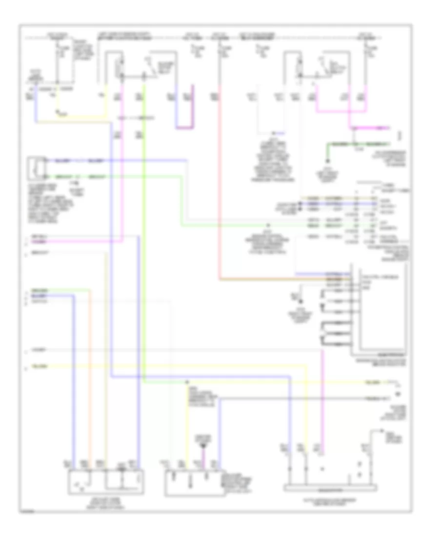
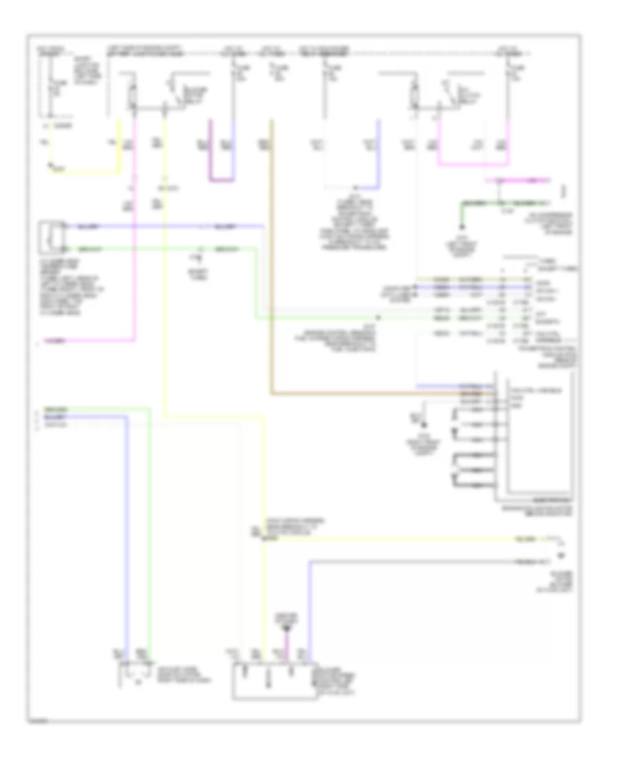
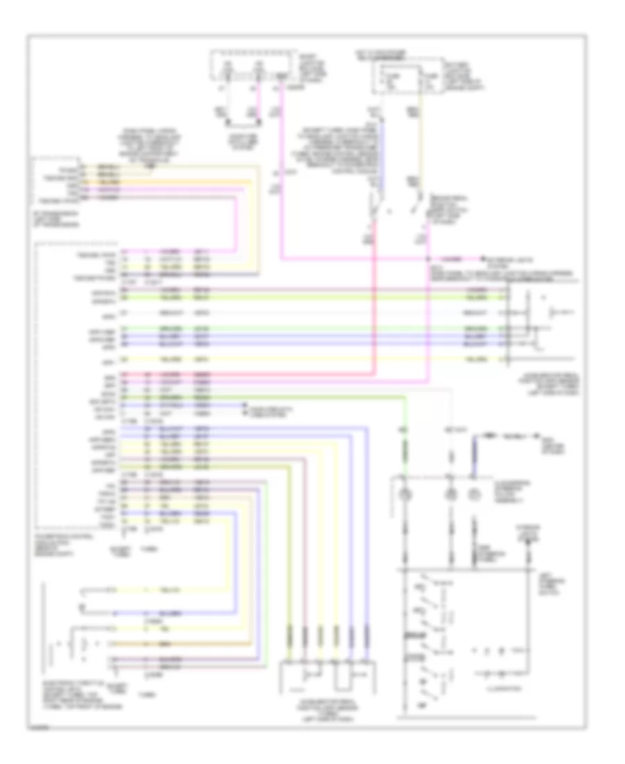
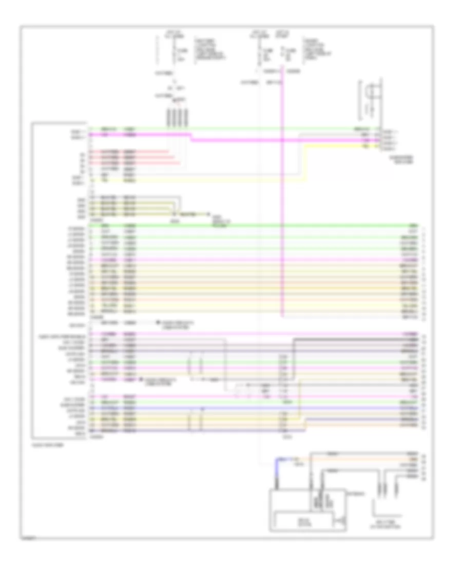
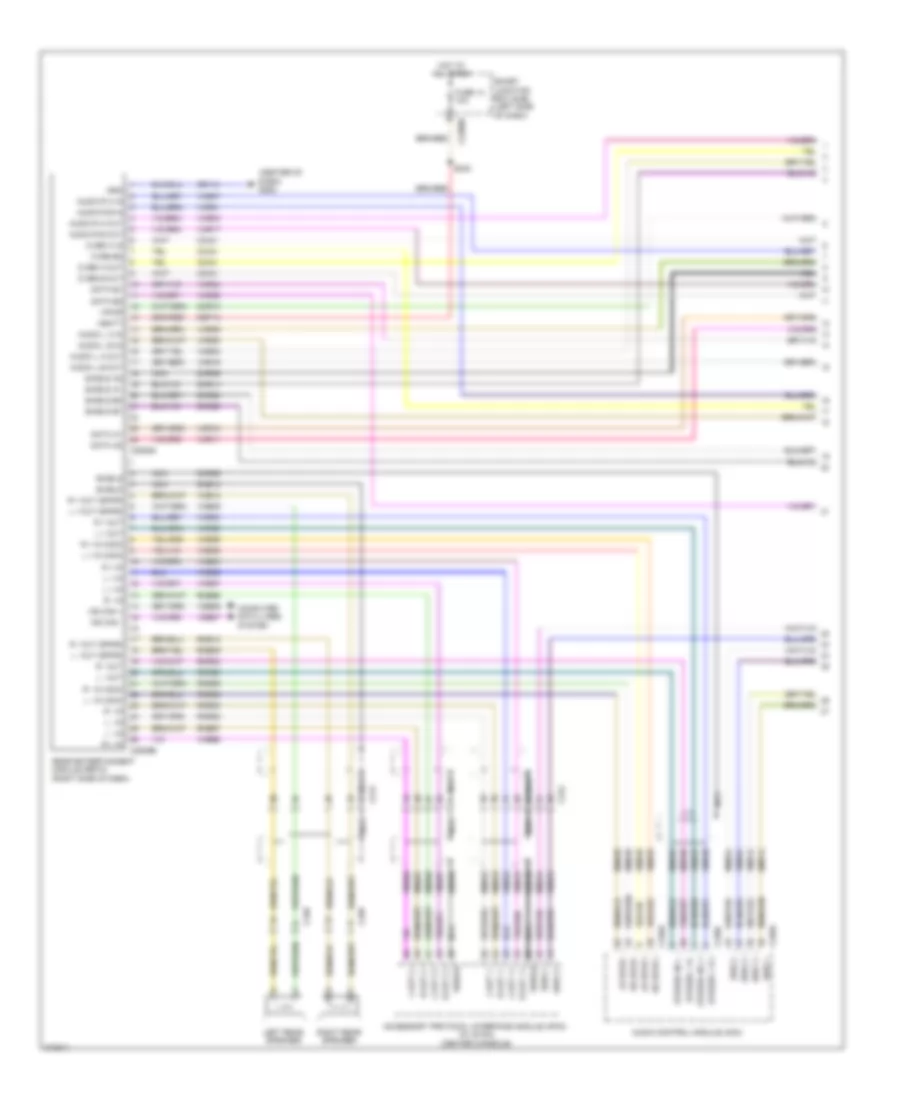
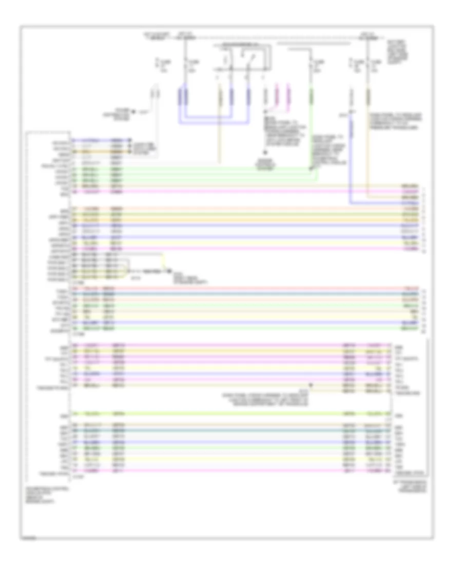
Automatic A/C Wiring Diagram (1 of 2) for Ford Flex SE 2011

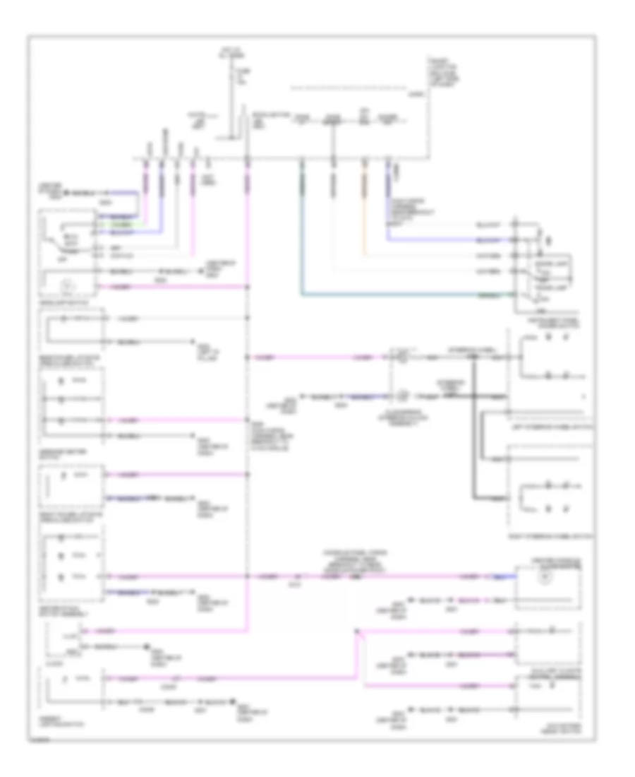
List of elements for Automatic A/C Wiring Diagram (1 of 2) for Ford Flex SE 2011:
- Ambient air temp sens
- Ambient air temperature sensor (behind center of front bumper)
- Aux blwr pwr
- Aux blwr rly request
- Aux mode door ccw
- Aux mode door cw
- Aux mode door fdbk
- Aux temp door ccw
- Aux temp door cw
- Aux temp door fdbk
- Auxiliary blower circuit
- Auxiliary climate control assembly (w/ auxiliary
- Auxiliary mode door actuator (w/ auxiliary climate control) (left rear quarterpanel)
- Auxiliary temperature blend door actuator (w/ auxiliary climate control) (left rear quarterpanel)
- C210
- C213
- C2239
- C2280a
- C228a
- C228b
- C3007
- C312
- Ch112
- Ch122
- Ch123
- Ch207
- Ch208
- Ch212
- Ch213
- Ch228
- Ch229
- Ch238
- Ch239
- Ch242
- Ch243
- Ch244
- Ch245
- Cha34
- Cha35
- Cha36
- Cha37
- Chs04
- Chs09
- Chs13
- Chs14
- Chs29
- Chs30
- Climate control)
- Computer data lines system
- Defogger system
- Defrost request
- Defrost/panel/floor mode door actuator
- Driver sunload
- Driver temp door ccw
- Driver temperature blend door actuator (left side of hvac unit)
- Drv hs high status
- Drv hs low status
- Drv hs request
- Drv temp door cw
- Drv temp door fdbk
- Evap temp sens
- Evaporator discharge air temperature sensor (left side of hvac unit)
- Front blower pwm
- Front blower relay
- Fuse 10a
- G203 (center of dash)
- Gd116
- Gnd
- Hot at all times
- Hvac module (center of dash)
- In car temp sensor
- In-vehicle temperature sensor (left center of dash)
- Lh111
- Mode door ccw
- Mode door cw
- Mode door fdbk
- Ms can+
- Ms can-
- Pass hs high status
- Pass hs low status
- Pass hs request
- Pass temp act fdbk
- Pass temp door ccw
- Pass temp door cw
- Passenger sunload
- Passenger temperature blend door actuator (right side of dash)
- Rear blower pot
- Rear in-vehicle temperature sensor (w/ auxiliary climate control) (behind left quarterpanel)
- Rear led sig 1
- Rear led sig 2
- Rear led sig 3
- Rear mode
- Rear temp pot
- Recirc door ccw
- Recirc door cw
- Return
- Rh111
- S201 (main wiring harness, near breakout to instrument cluster)
- S202 (main wiring harness, near breakout to hvac module)
- Sbp15
- Seats system
- Smart junction box (sjb) (left side of dash)
- Vbatt
- Vdb06
- Vdb07
- Vh101
- Vh406
- Vh407
- Vh414
- Vh416
- Vh417
- Vh436
- Vh440
- Vh441
- Vha09
- Vha15
- Vha17
- Vha18
- Vha25
- Vref
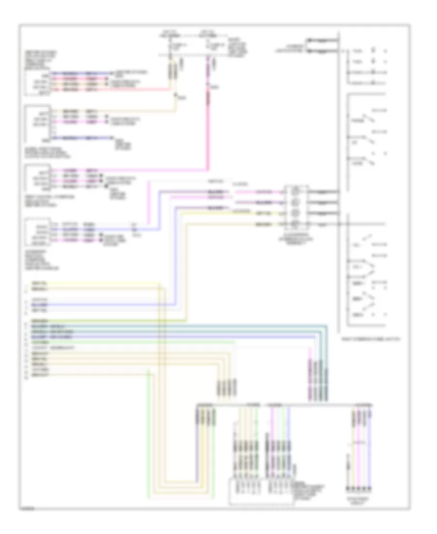
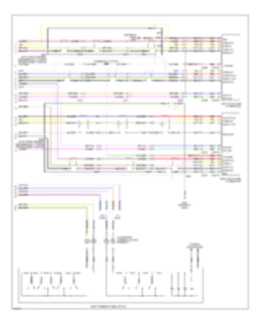
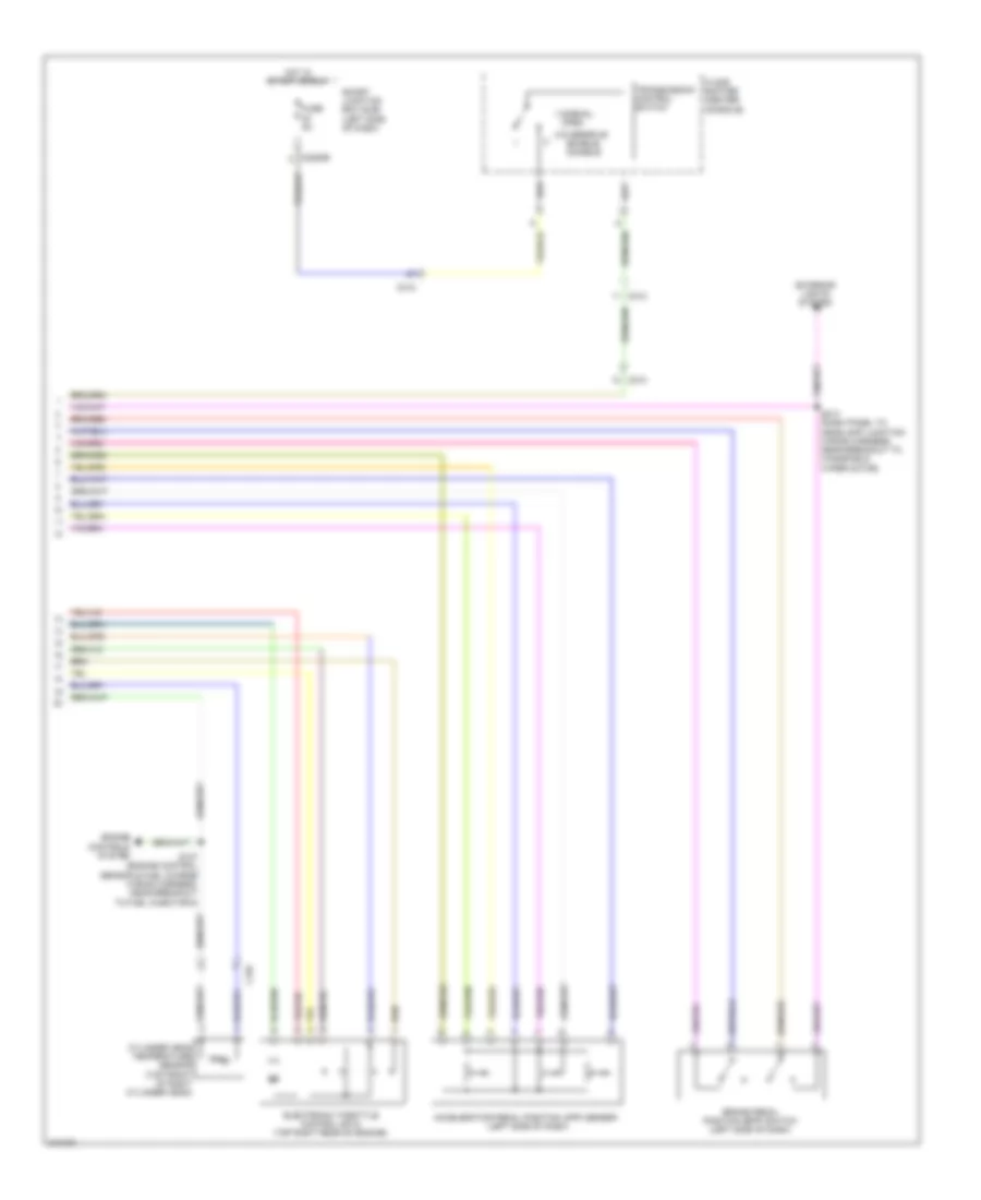
Automatic A/C Wiring Diagram (2 of 2) for Ford Flex SE 2011
List of elements for Automatic A/C Wiring Diagram (2 of 2) for Ford Flex SE 2011:
- (center of dash) g203
- (left side of engine compt) battery junction box (bjb)
- (not used)
- A/c clutch relay
- A/c compressor clutch field coil (left front of engine)
- Accr
- Air inlet mode door actuator (right side of dash)
- Auto- lamp sensor in
- Autolamp/sunload sensor (center of dash)
- Blower motor (right side of hvac unit)
- Blower motor relay
- Blower motor speed controller (right side of hvac unit)
- C1381b
- C1381e
- C145
- C175b
- C175e
- C192
- C210
- C2280b
- C2280e
- Ch302
- Cht
- Computer data lines system
- Cylinder head temperature sensor (turbo (left): rear of left cylinder head) (turbo (right): front of right cylinder head) (non-turbo: top front of right cylinder head)
- E-sigrtn
- Electronics
- Engine cooling fan motor (behind radiator)
- Except turbo
- Fan ctrl variable
- Fuse 10a
- Fuse 15a
- Fuse 40a
- Fuse 5a
- Fuse 80a
- G100 (right front of engine compt)
- G101 (left front of engine compt)
- G202 (center of dash)
- Gnd
- Hot at all times
- Hot in run or acc
- Hot w/ pcm power relay energized
- Hs can +
- Hs can -
- Motor +
- Motor -
- Nca
- Powertrain control module (pcm) (rear of engine compt)
- Pwm
- Pwr
- Re405
- S127 (engine control sensor & fuel charge wiring harness, near breakout to fuel injector 6)
- S141 (turbo: near breakout to powertrain control module) (except turbo: dash panel to headlamp junction wiring harness, in breakout to a/c pressure transduer)
- S167
- S262 (main wiring harness, near breakout to hvac module)
- Smart junction box (sjb) (left side of dash)
- Solid state
- Turbo
- Vdb04
- Vdb05
- Ve712
- Vec03
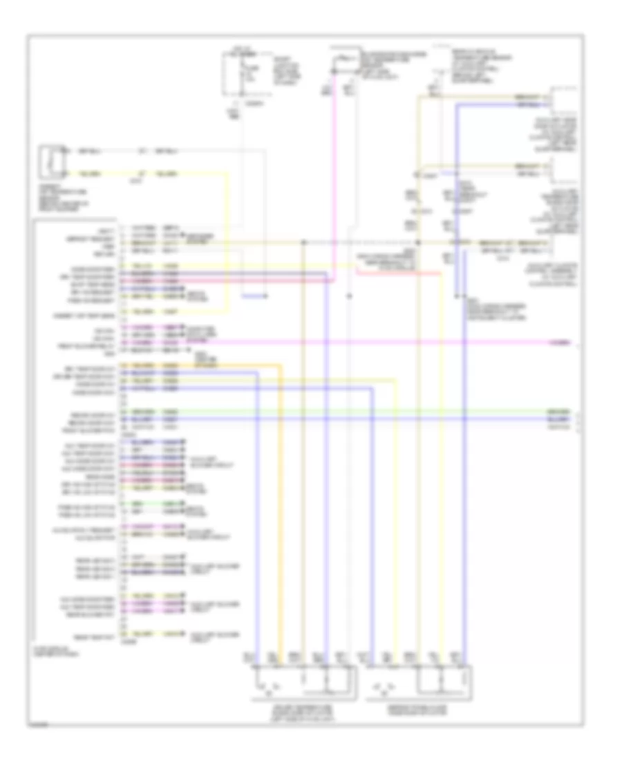
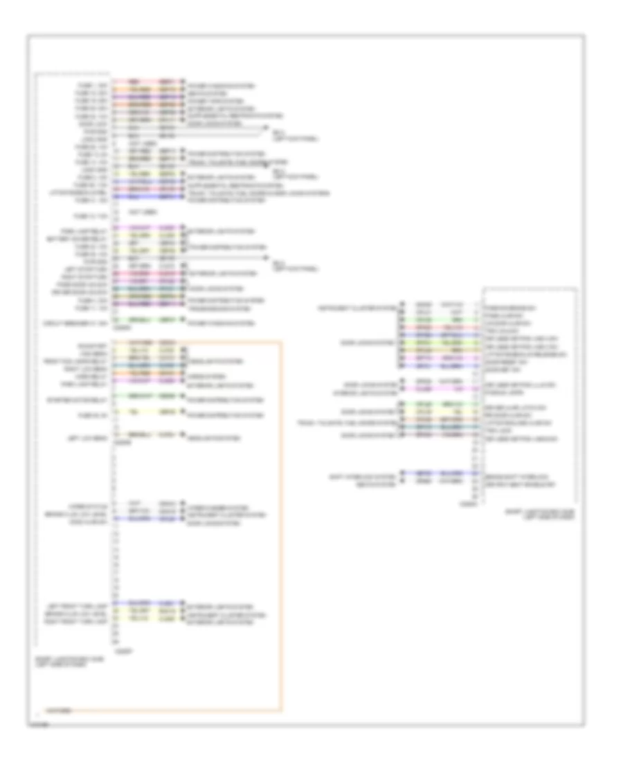
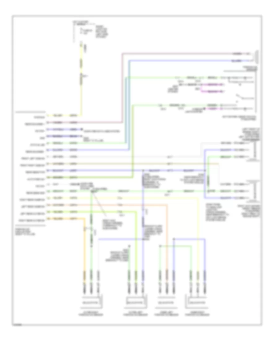
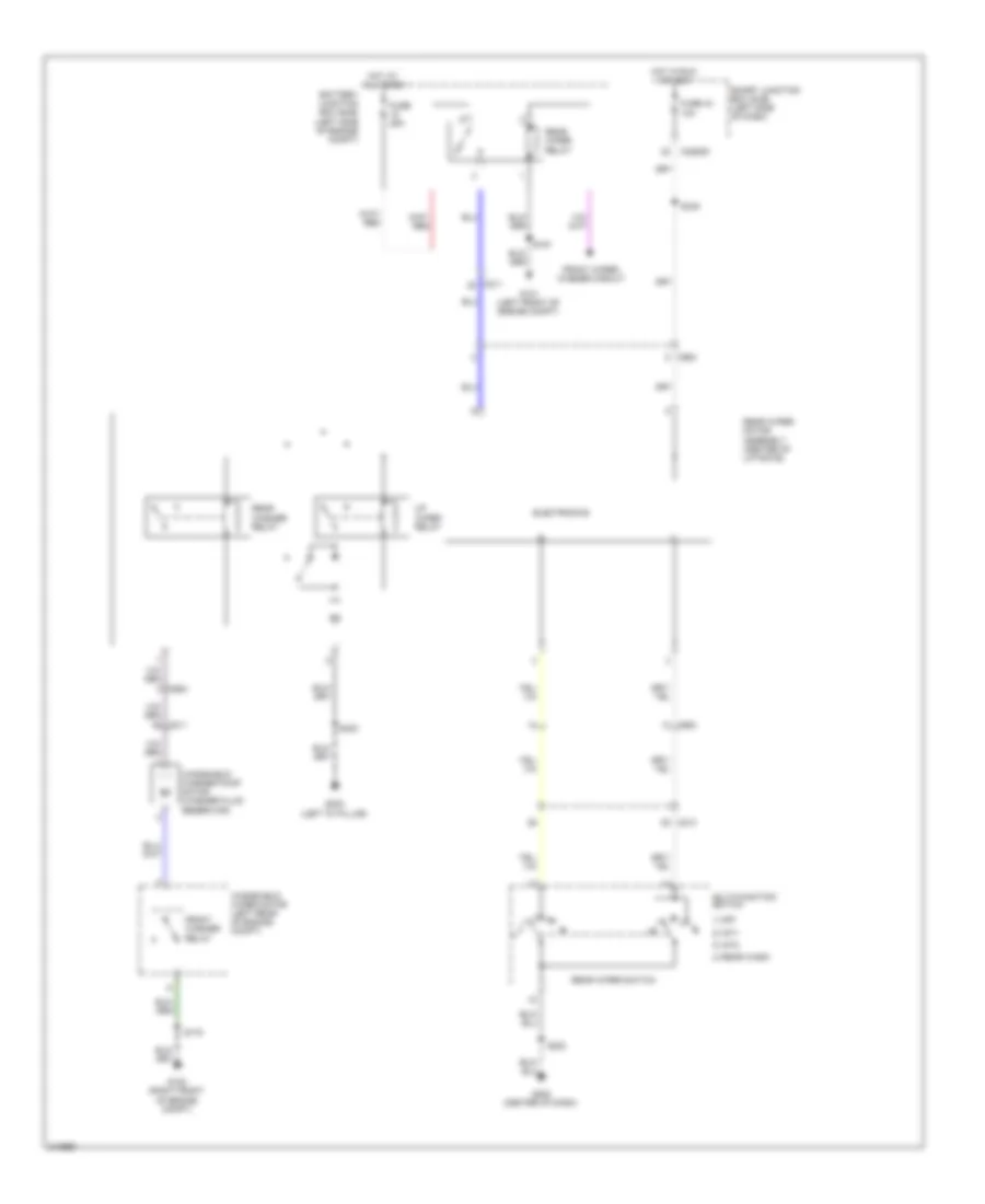
Auxiliary Blower Wiring Diagram for Ford Flex SE 2011
List of elements for Auxiliary Blower Wiring Diagram for Ford Flex SE 2011:
- (+)
- (-)
- (left "d" pillar) g302
- (not used)
- Aux blw power
- Aux blw rly request
- Aux mode door ccw
- Aux mode door cw
- Aux mode door fdbk
- Aux temp door ccw
- Aux temp door cw
- Aux temp door fdbk
- Auxiliary blower control module (left rear quarterpanel)
- Auxiliary blower motor (left rear quarterpanel)
- Auxiliary blower motor relay
- Auxiliary climate control assembly
- Auxiliary mode door actuator (left rear quarterpanel)
- Auxiliary temperature blend door actuator (left rear quarterpanel)
- Battery junction box (bjb) (left side of of engine compt)
- Blower output
- C210
- C211
- C213
- C2280a
- C2280d
- C228a
- C228b
- C3007
- C312
- Ch112
- Ch242
- Ch243
- Ch244
- Ch245
- Cha02
- Cha34
- Cha35
- Cha36
- Cha37
- Chs47
- Chs48
- Chs49
- Chs51
- Chs52
- Chs53
- Fuse 10a
- Fuse 30a
- G203 (center of dash)
- Gd116
- Gd149
- Gnd
- Ground
- Hot at all times
- Hot in run or acc
- Hvac module (center of dash)
- Illum in
- Interior lights system
- Lh high led
- Lh low led
- Lh sys low/hi/off
- Lh111
- Manual a/c & automatic a/c circuit
- Mode output
- Pwm
- Rear blower pot
- Rear in-vehicle temperature sensor (behind left quarterpanel)
- Rear led sig 1
- Rear led sig 2
- Rear led sig 3
- Rear mode
- Rear temp pot
- Return
- Rh high led
- Rh low led
- Rh sys low/hi/off
- Rh111
- S193
- S202 (main wiring harness, near breakout to hvac module)
- S381
- S410 (near breakout c3007)
- S412 (near breakout c3007)
- Sbp15
- Seats system
- Sig feed 1
- Sig feed 2
- Sig feed 3
- Smart junction box (sjb) (left side of dash)
- Temp output
- Vbatt
- Vha09
- Vha15
- Vha17
- Vha18
- Vha19
- Vha25
- Vln04
- Vref
- Vref 5v
- Vref rtn
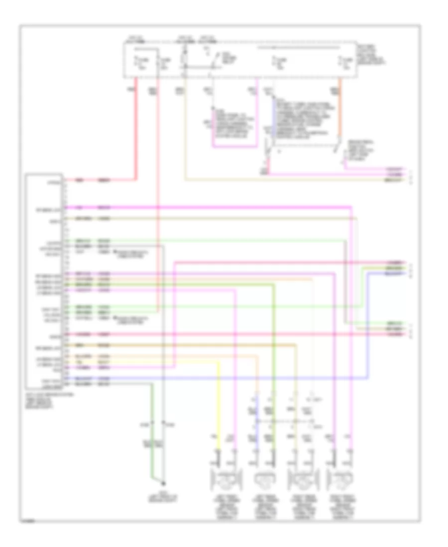
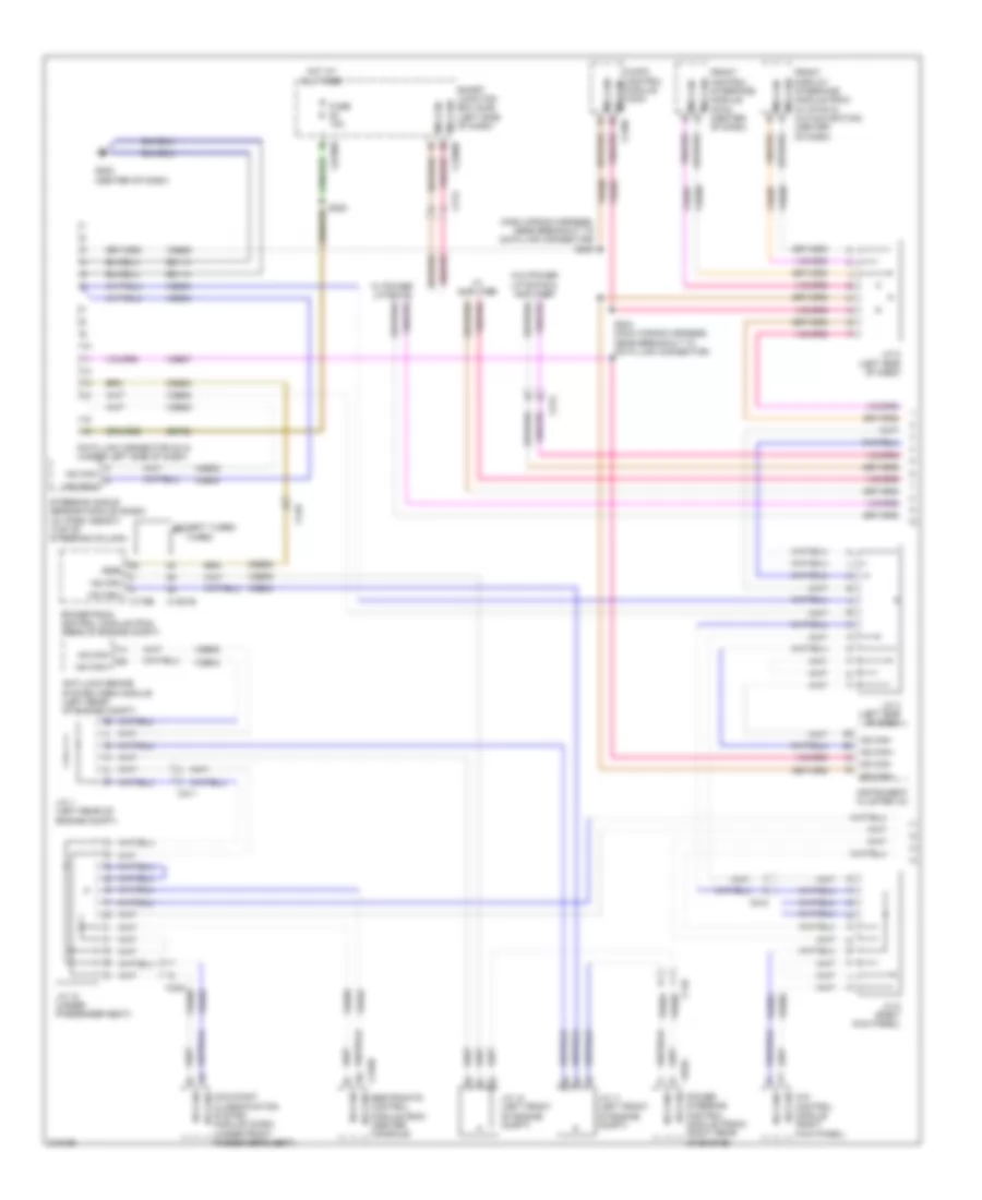
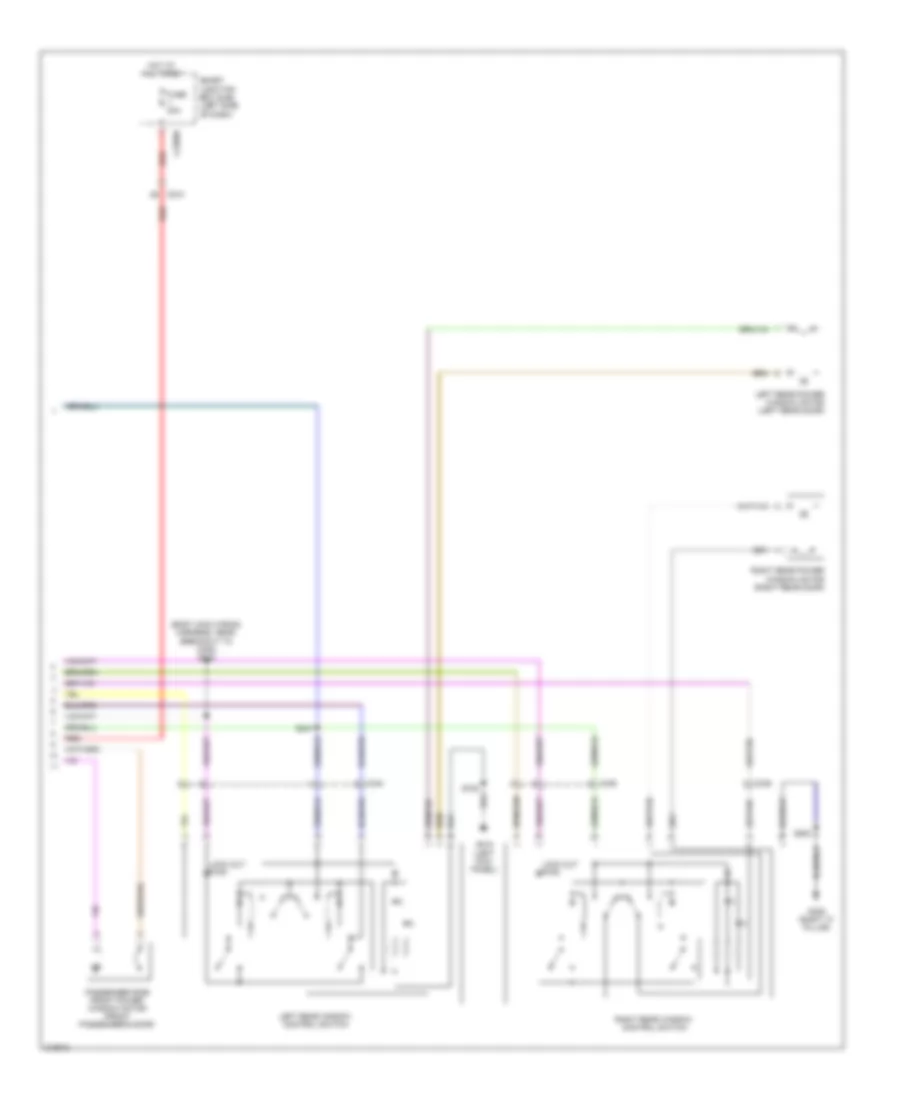
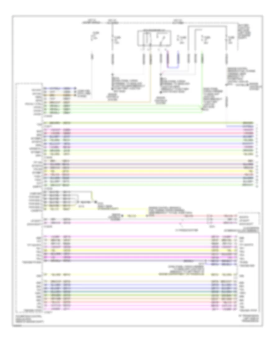
Manual A/C Wiring Diagram (1 of 2) for Ford Flex SE 2011
List of elements for Manual A/C Wiring Diagram (1 of 2) for Ford Flex SE 2011:
- Ambient air temp sens
- Ambient air temperature sensor (behind center of front bumper)
- Aux blwr pwr
- Aux blwr rly request
- Aux mode door ccw
- Aux mode door cw
- Aux mode door fdbk
- Aux temp door ccw
- Aux temp door cw
- Aux temp door fdbk
- Auxiliary blower circuit
- Auxiliary climate control assembly (w/ auxiliary
- Auxiliary mode door actuator (w/ auxiliary climate control) (left rear quarterpanel)
- Auxiliary temperature blend door actuator (w/ auxiliary climate control) (left rear quarterpanel)
- C210
- C213
- C2280a
- C228a
- C228b
- C3007
- C312
- Ch112
- Ch122
- Ch123
- Ch207
- Ch208
- Ch228
- Ch229
- Ch238
- Ch239
- Ch242
- Ch243
- Ch244
- Ch245
- Cha34
- Cha35
- Cha36
- Cha37
- Chs04
- Chs09
- Chs13
- Chs14
- Chs29
- Chs30
- Climate control)
- Computer data lines system
- Defogger system
- Defrost request
- Defrost/panel/floor mode door actuator
- Driver temp door ccw
- Driver temperature blend door actuator (left side of hvac unit)
- Drv hs high status
- Drv hs low status
- Drv hs request
- Drv temp door cw
- Drv temp door fdbk
- Evap temp sens
- Evaporator discharge air temperature sensor (left side of hvac unit)
- Front blower pwm
- Front blower relay
- Fuse 10a
- G203 (center of dash)
- Gd116
- Gnd
- Hot at all times
- Hvac module (center of dash)
- Lh111
- Mode door ccw
- Mode door cw
- Mode door fdbk
- Ms can+
- Ms can-
- Pass hs high status
- Pass hs low status
- Pass hs request
- Rear blower pot
- Rear in-vehicle temperature sensor (w/ auxiliary climate control) (behind left quarterpanel)
- Rear led sig 1
- Rear led sig 2
- Rear led sig 3
- Rear mode
- Rear temp pot
- Recirc door ccw
- Recirc door cw
- Return
- Rh111
- S201 (main wiring harness, near breakout to instrument cluster)
- S202 (main wiring harness, near breakout to hvac module)
- Sbp15
- Seats system
- Smart junction box (sjb) (left side of dash)
- Vbatt
- Vdb06
- Vdb07
- Vh101
- Vh406
- Vh407
- Vh436
- Vh440
- Vha09
- Vha15
- Vha17
- Vha18
- Vha25
- Vref
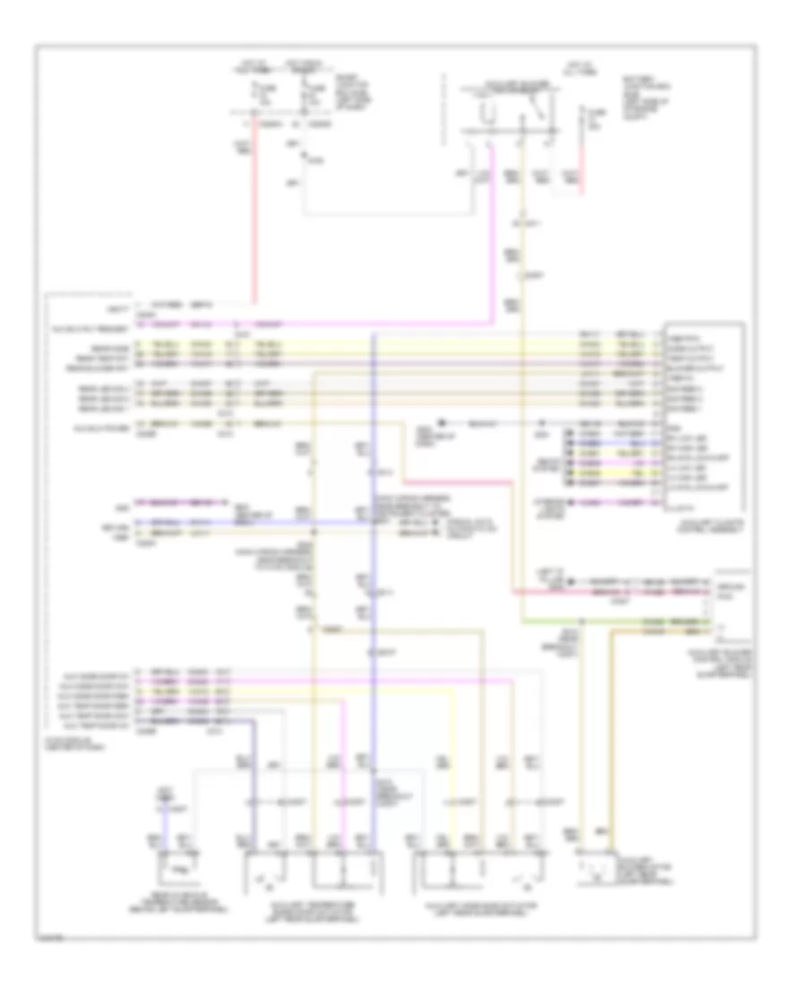
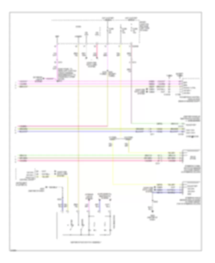
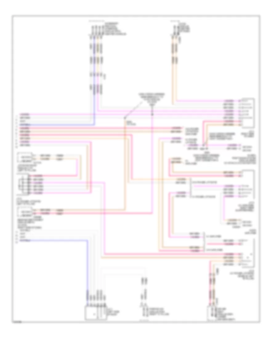
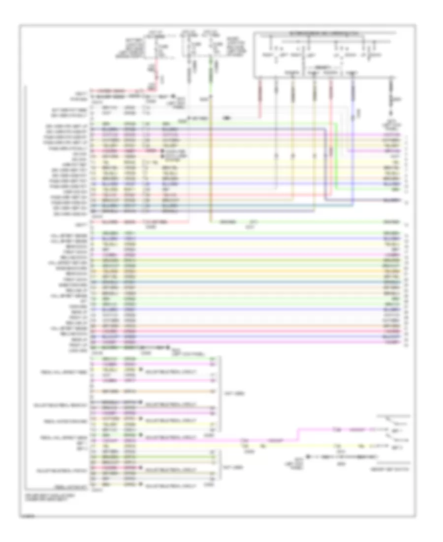
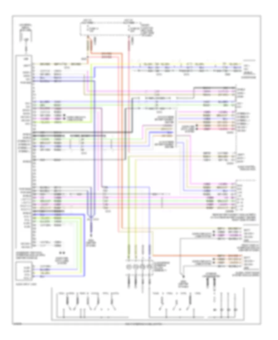
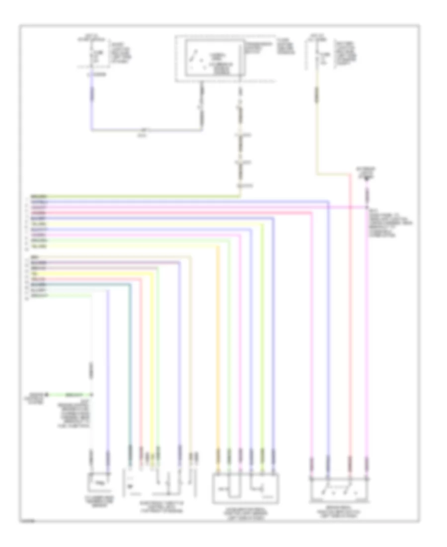
Manual A/C Wiring Diagram (2 of 2) for Ford Flex SE 2011
List of elements for Manual A/C Wiring Diagram (2 of 2) for Ford Flex SE 2011:
- (center of dash) g203
- (left side of engine compt) battery junction box (bjb)
- A/c clutch relay
- A/c compressor clutch field coil (left front of engine)
- Accr
- Air inlet mode door actuator (right side of dash)
- Blower motor (blower of hvac unit)
- Blower motor relay
- Blower motor speed controller (right side of hvac unit)
- C1381b
- C1381e
- C145
- C175b
- C175e
- C192
- C210
- C2280e
- Ch302
- Cht
- Computer data lines system
- Cylinder head temperature sensor (turbo (left): rear of left cylinder head) (turbo (right): front of right cylinder head) (non-turbo: top front of right cylinder head)
- E-sigrtn
- Electronics
- Engine cooling fan motor (behind radiator)
- Except turbo
- Fan ctrl variable
- Fuse 10a
- Fuse 15a
- Fuse 40a
- Fuse 5a
- Fuse 80a
- G100 (right front of engine compt)
- G101 (left front of engine compt)
- Gnd
- Hot at all times
- Hot in run or acc
- Hot w/ pcm power relay energized
- Hs can +
- Hs can -
- Motor +
- Motor -
- Nca
- Powertrain control module (pcm) (rear of engine compt)
- Pwm
- Pwr
- Re405
- S127 (engine control sensor & fuel charge wiring harness, near breakout to fuel injector 6)
- S141 (turbo: near breakout to powertrain control module) (except turbo: dash panel to headlamp junction wiring harness, in breakout to a/c pressure transducer)
- S167
- Smart junction box (sjb) (left side of dash)
- Turbo
- Vdb04
- Vdb05
- Ve712
- Vec03
ANTI-LOCK BRAKES
Anti-lock Brakes Wiring Diagram (1 of 2) for Ford Flex SE 2011
List of elements for Anti-lock Brakes Wiring Diagram (1 of 2) for Ford Flex SE 2011:
- Anti-lock brake system (abs) module (left rear of engine compt)
- Battery junction box (bjb) (left side of engine compt)
- Brake pedal position (bpp) switch (left side of dash)
- C211
- C314
- Can yaw -
- Can yaw+
- Cbp34
- Computer data lines system
- Fuse 10a
- Fuse 15a
- Fuse 20a
- Fuse 40a
- G101 (left front of engine compt)
- Gd120
- Hot at all times
- Hs can +
- Hs can -
- Ivd rtn
- Left front wheel speed sensor (left front wheel hub assembly)
- Left rear wheel speed sensor (left rear wheel hub assembly)
- Lf sens high
- Lf sens low
- Logic gnd
- Lr sens high
- Lr sens low
- Motor gnd
- Mtr b+
- Nca
- Pcm power relay
- Rca09
- Rca17
- Rca18
- Rca19
- Rca20
- Red
- Rf sens high
- Rf sens low
- Right front wheel speed sensor (right front wheel hub assembly)
- Right rear wheel speed sensor (right rear wheel hub assembly)
- Rr sens high
- Rr sens low
- Run
- S141 (except turbo: dash panel to headlamp junction wiring harness, in breakout to a/c pressure transducer) (turbo: engine control sensor & fuel charge harness, near breakout to powertrain control module)
- S190 (dash panel to headlamp junction wiring harness, near breakout to anti-lock brake system module)
- S192
- S196
- Sas a
- Sas b
- Sbb09
- Sbb12
- Valve b+
- Vca03
- Vca04
- Vca05
- Vca06
- Vca23
- Vca24
- Vcs06
- Vcs07
- Vdb04
- Vdb05
Anti-lock Brakes Wiring Diagram (2 of 2) for Ford Flex SE 2011
List of elements for Anti-lock Brakes Wiring Diagram (2 of 2) for Ford Flex SE 2011:
- (center console) restraints control module (rcm)
- (turbo)
- Bpp
- Bps
- C1381b
- C175b
- C210
- C211
- C213
- C2280b
- C310a
- C310b
- Can yaw+
- Can yaw-
- Case ground
- Cbp32
- Cbp35
- Ccb08
- Ce237
- Center stack switch assembly
- Ces09
- Computer data lines system
- Except turbo
- Exterior lights system
- Fuse 10a
- Fuse 5a
- G202 (center of dash)
- Gd114
- Gnd
- Hazard
- Hot in start or run
- Hs can +
- Hs can -
- Hs can+
- Hs can-
- Instrument cluster (ic)
- Interior lights system
- Ivd sw
- Micro
- Ms can +
- Ms can -
- Pad indicator
- Pcm rly ctrl
- Powertrain control module (pcm) (rear of engine compt)
- Run/start
- S152 s222 (except turbo)
- S223
- Smart junction box (sjb) (left side of dash)
- Solid state
- Steering angle sensor module (sasm) (w/ park assist) (top of steering column)
- Steering wheel rotation sensor (w/o park assist) (in steering column)
- Traction control on/off
- Turbo
- Vca23
- Vca24
- Vdb04
- Vdb05
- W/ park assist
- W/o park assist
ANTI-THEFT
Forced Entry Wiring Diagram (1 of 2) for Ford Flex SE 2011
List of elements for Forced Entry Wiring Diagram (1 of 2) for Ford Flex SE 2011:
- (body main wiring harness, near breakout restraints control module)
- (body main wiring harness, near breakout restraints control module) s331
- (body main wiring harness, near breakout to c3050) s324
- (body main wiring harness, near breakout to c3050) s330
- (right "c" pillar) g305
- Accessory delay relay
- All lock/ unlock relay
- Auto
- C2280b
- C2280c
- C2280d
- C339
- C340
- C510
- C610
- Driver side door lock switch
- Driver unlock relay
- Fuse 15a
- Fuse 20a
- G210 (left kick panel)
- G305 (right "c" pillar)
- Headlights system
- Horn rly
- Horns system
- Hot at all times
- Left rear door lock actuator (rear of left rear door)
- Lock
- Logic
- Lr door ajar
- Micro
- Pass door ajar
- Passenger side door lock switch
- Passenger side front door lock unit (rear of front passenger's door)
- Power distribution system
- Right rear door lock actuator (rear of right rear door)
- Rr door ajar
- S318
- S327
- S500
- S503
- S600
- S700
- S800
- Smart junction box (sjb) (left side of dash)
- To liftgate rel fet (diagram 2 of 2)
- Trim lock
- Trim unlock
- Unlock
Forced Entry Wiring Diagram (2 of 2) for Ford Flex SE 2011
List of elements for Forced Entry Wiring Diagram (2 of 2) for Ford Flex SE 2011:
- 1/2
- 3/4
- 5/6
- 7/8
- 9/0
- Ajar
- C2280c
- C2280d
- C2280f
- C432
- C510
- C983
- Driver door ajar
- Driver side front door lock unit (rear of driver's door)
- From fuse 17 (diagram 1 of 2)
- Fuse 5a
- G101 (left front of engine compt)
- G210 (left kick panel)
- G302 (left "d" pillar)
- Hood ajar
- Hood switch (left front corner of engine compt)
- Hot at all times
- Keypad a
- Keypad b
- Keypad c
- Keypad illum
- Keypad switch assembly
- Liftgate latch assembly (manual liftgate) (bottom of liftgate)
- Liftgate rel (fet)
- Liftgate release switch (manual liftgate)
- Liftgate sw
- Liftgate/ glass ajar
- Logic
- Micro
- Nca
- Reset
- Reset sw
- Rke receiver internal ant
- S400
- S500
- S504
- Set
- Set sw
- Smart junction box (sjb) (left side of dash)
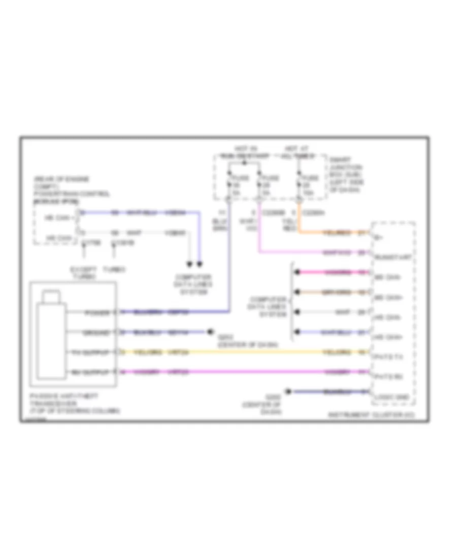
Passive Anti-theft Wiring Diagram for Ford Flex SE 2011
List of elements for Passive Anti-theft Wiring Diagram for Ford Flex SE 2011:
- (rear of engine compt) powertrain control module (pcm)
- C1381b
- C175b
- C2280a
- C2280b
- Cbp36
- Computer data lines system
- Except turbo
- Fuse 10a
- Fuse 5a
- G202 (center of dash)
- Gd114
- Ground
- Hot at all times
- Hot in run or start
- Hs can +
- Hs can -
- Hs can+
- Hs can-
- Instrument cluster (ic)
- Logic gnd
- Ms can+
- Ms can-
- Passive anti-theft transceiver (top of steering column)
- Pats rx
- Pats tx
- Power
- Run/start
- Rx output
- Smart junction box (sjb) (left side of dash)
- Turbo
- Tx output
- Vdb04
- Vdb05
- Vrt23
- Vrt24
BODY CONTROL MODULES
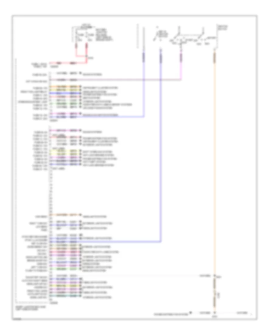
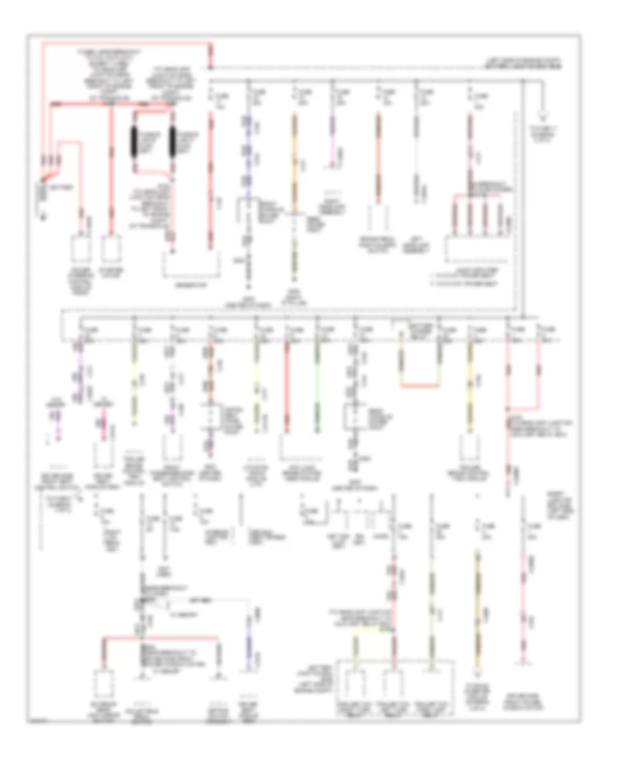
Body Control Modules Wiring Diagram (1 of 2) for Ford Flex SE 2011
List of elements for Body Control Modules Wiring Diagram (1 of 2) for Ford Flex SE 2011:
- (not used)
- Acc
- Air conditioning system
- Anti-lock brakes system
- Anti-theft system
- Auto day/night sens
- Autolamp on sw
- Backlighting led
- Battery junction box (bjb) (left side of engine compt)
- Brake on/off sw
- C210
- C2280a
- C2280b
- C2280g
- Cbp28
- Cbp29
- Cbp30
- Cbp33
- Cbp34
- Cbp35
- Cbp36
- Cbp41
- Cbp46
- Ccb08
- Cdc30
- Cdc33
- Cdc34
- Clf12
- Clf17
- Clf18
- Clf19
- Clf21
- Clf23
- Clf27
- Cln27
- Cln28
- Cls32
- Cls34
- Cls39
- Cls41
- Computer data lines & memory systems
- Computer data lines system
- Crh02
- Dome defeat sw
- Dome lamp sw
- Exterior lights system
- Flash to pass sw
- Front fog lamp relay
- Front fog lamps
- Fuse 1, 30a & fuse 2, 15a
- Fuse 14, 10a
- Fuse 15, 10a
- Fuse 16, 15a
- Fuse 20, 15a
- Fuse 26, 10a
- Fuse 27, 20a
- Fuse 28, 5a
- Fuse 29, 5a
- Fuse 30, 5a
- Fuse 31, 10a
- Fuse 33, 10a
- Fuse 34, 5a
- Fuse 35, 10a
- Fuse 36, 5a
- Fuse 37, 10a
- Fuse 39, 20a
- Fuse 40, 20a
- Fuse 41, 15a
- Fuse 43, 10a
- Fuse 46, 7.5a
- Fuse 80a
- Hazard sw
- Headlamp off sw
- Headlights system
- High beam
- Horn sw
- Horns system
- Hot at all times
- Hot in run or acc
- I/p sw illum dimmer
- I/p sw return dimmer
- Ignition switch
- Instrument cluster system
- Interior lights system
- Interior/courtesy lamp
- Key in ign sw
- Key in ignition switch
- Left turn sw
- Low beam
- Ms can +
- Ms can -
- Off
- Park
- Power distribution system
- Red
- Right turn sw
- Rln29
- Run
- Run/start ign sw
- S161
- S183
- S221
- Sbb01
- Sbp14
- Sbp15
- Sbp16
- Sbp20
- Sbp26
- Sbp27
- Sbp39
- Sbp40
- Seats system
- Shift interlock system
- Smart junction box (sjb) (left side of dash)
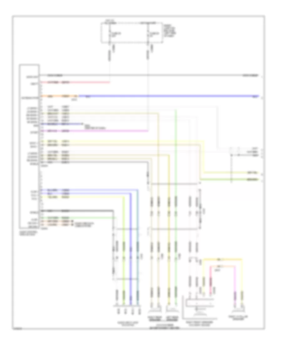
- Sound & navigation systems
- Sound systems
- Start
- Vdb06
- Vdb07
- Vlf14
- Vln04
- Vln18
- Vln33
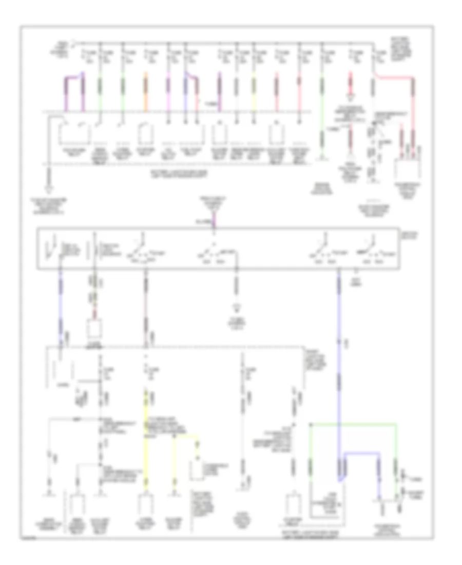
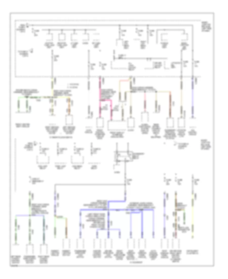
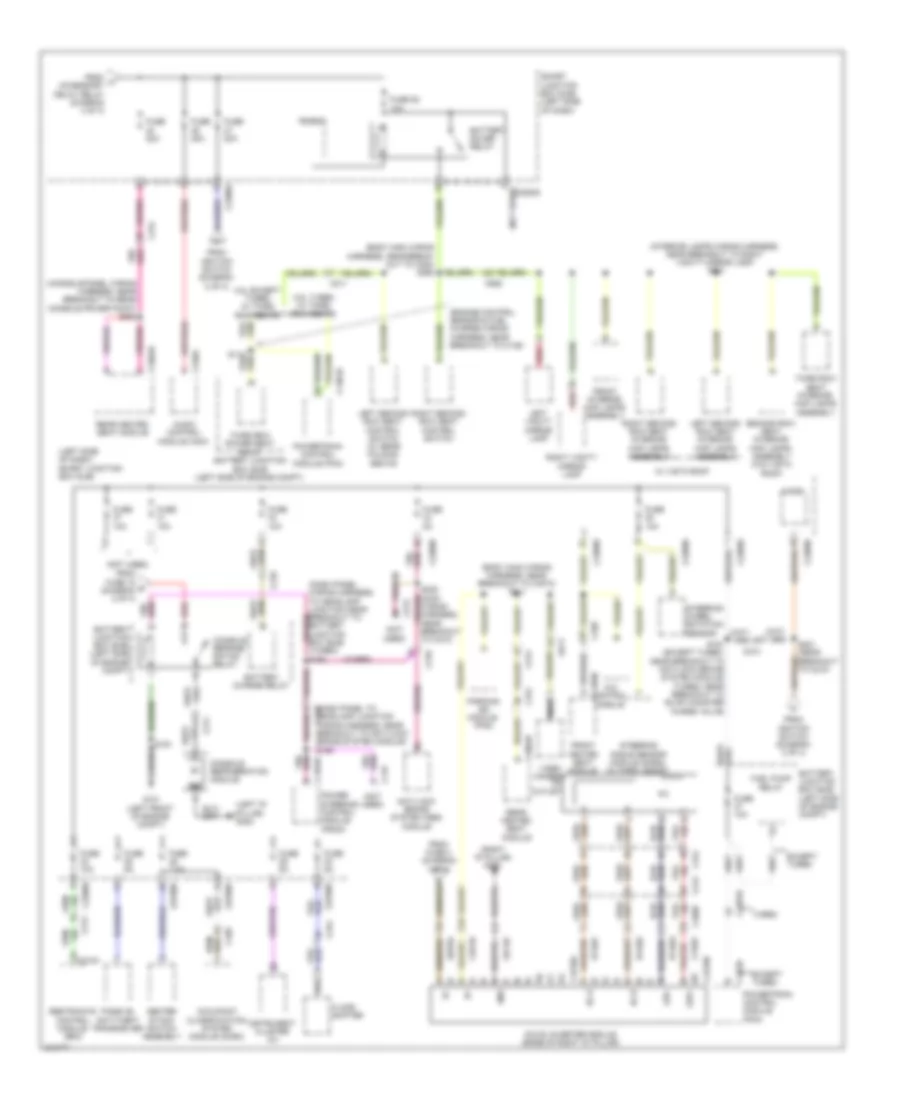
Body Control Modules Wiring Diagram (2 of 2) for Ford Flex SE 2011
List of elements for Body Control Modules Wiring Diagram (2 of 2) for Ford Flex SE 2011:
- (not used)
- 3rd row seat enable fet
- Battery saver relay
- Brake fluid low level
- Brake shift interlock
- C2280c
- C2280d
- C2280e
- C2280f
- Cbp32
- Cbp35
- Cbp41
- Cbp43
- Cbp45
- Cbp46
- Cbp47
- Cdc34
- Ce336
- Cet53
- Circuit breaker 47, 30a
- Clf04
- Clf05
- Clf08
- Clf12
- Cln09
- Cln25
- Cls18
- Cls19
- Cls21
- Cls25
- Cls30
- Cmc19
- Cmc25
- Cpk19
- Cpk23
- Cpk28
- Cpk29
- Cpk30
- Cpk31
- Cpl11
- Cpl25
- Cpl26
- Cpl31
- Cpl36
- Cpl39
- Cpl45
- Cpl51
- Cpl52
- Cpl58
- Cpl79
- Cps58
- Crt19
- Crt21
- Crw01
- Door lock
- Door locks system
- Door reset sw
- Door set sw
- Driver ajar latch sw
- Driver door unlock
- Exterior lights system
- Front fog lamps relay
- Fuse 1, 30a
- Fuse 11, 10a
- Fuse 12, 7.5a
- Fuse 13, 5a
- Fuse 14, 10a
- Fuse 18, 20a
- Fuse 19, 25a
- Fuse 2, 15a
- Fuse 25, 10a
- Fuse 32, 10a
- Fuse 35, 10a
- Fuse 38, 20a
- Fuse 4, 30a
- Fuse 41, 15a
- Fuse 43, 10a
- Fuse 45, 5a
- Fuse 46, 7.5a
- G210 (left kick panel)
- Gd133
- Headlights system
- High beam
- Hood ajar sw
- Horn relay
- Horns system
- Instrument cluster system
- Interior lights system
- Keyless keypad illum sw
- Keyless keypad line a sw
- Keyless keypad line b sw
- Keyless keypad line c sw
- Left front turn lamp
- Left low beam
- Left stop/turn
- Liftgate/decklid rel
- Liftgate/decklid release sw
- Liftgate/glass ajar sw
- Logic gnd
- Lr door ajar sw
- Park lamp relay
- Parking brake sw
- Pass ajar sw
- Pass door unlock
- Power distribution system
- Power tops system
- Power windows system
- Puddle lamps
- Pwr gnd
- Red
- Right front turn lamp
- Right low beam
- Right stop/turn
- Rmc19
- Rr door ajar sw
- Run/start
- Sbp01
- Sbp02
- Sbp04
- Sbp11
- Sbp13
- Sbp14
- Sbp18
- Sbp19
- Sbp38
- Seats system
- Shift interlock system
- Smart junction box (sjb) (left side of dash)
- Srh01
- Starter motor relay
- Transmissions system
- Trim lock
- Trim unlock
- Trunk, tailgate, fuel doors & door locks systems
- Trunk, tailgate, fuel doors system
- Wiper status
- Wiper/washer system
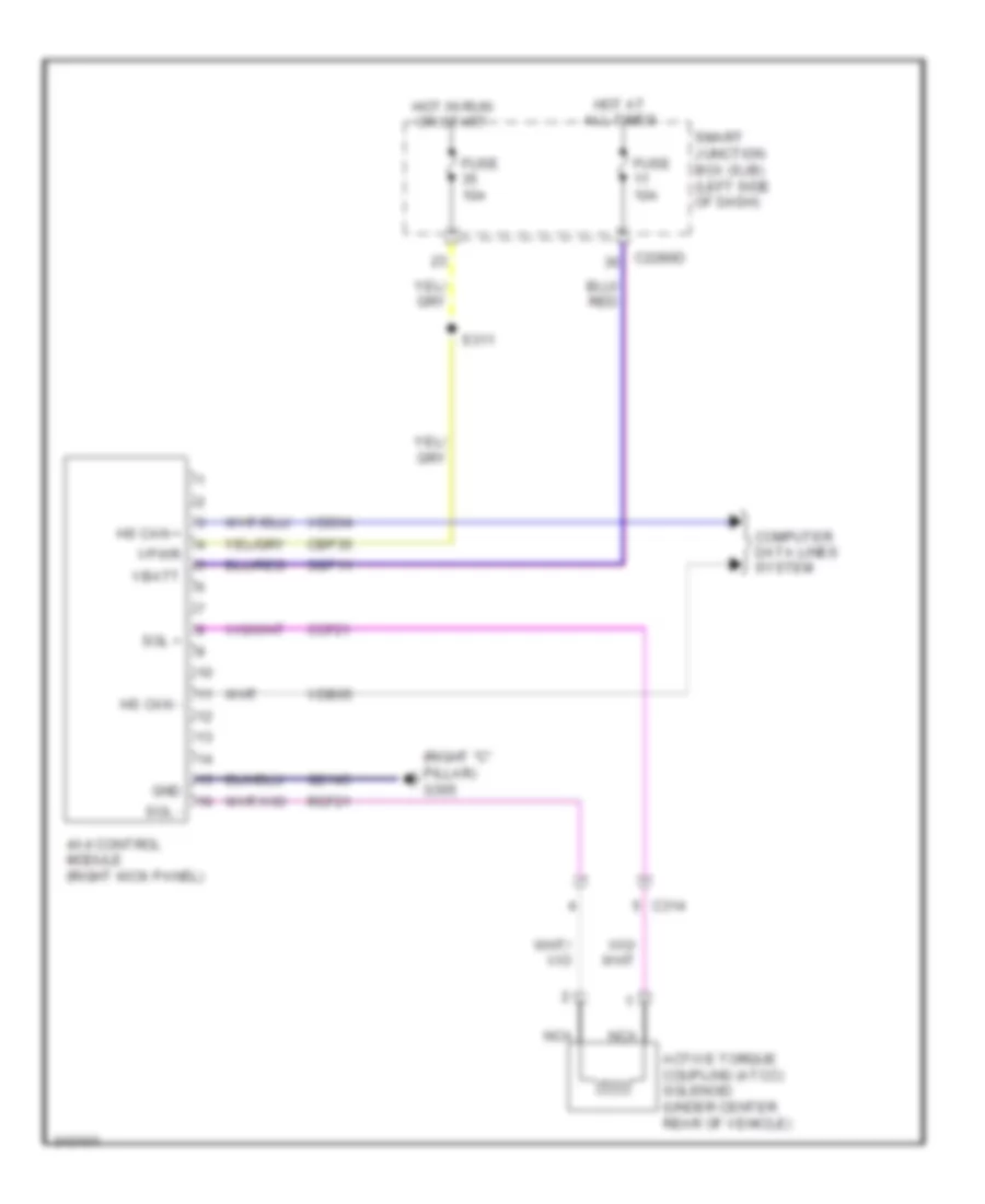
COMPUTER DATA LINES
Computer Data Lines Wiring Diagram (1 of 2) for Ford Flex SE 2011
List of elements for Computer Data Lines Wiring Diagram (1 of 2) for Ford Flex SE 2011:
- (main wiring harness, near breakout to data link connector) s205
- 1463a
- 4x4 control module (right kick panel)
- Anti-lock brake system (abs) module (left rear of engine compt)
- Audio control module (acm)
- C1381b
- C145
- C175b
- C210
- C211
- C212
- C213
- C2280a
- C2280b
- C310b
- C328
- Cdb08
- Data link connector (dlc) (under left side of dash)
- Except turbo
- Feps
- Front control interface module (fcim) (center of dash)
- Front display interface module (fdim) (w/ sync & w/o navigation) (center of dash)
- Fuse 15a
- G202 (center of dash)
- Gd114
- Hot at all times
- Hs can+
- Hs can-
- Instrument cluster (ic)
- J/c 1 (left rear of engine compt)
- J/c 10 (under passenger seat)
- J/c 11 (left front of engine compt)
- J/c 12 (left front of engine compt)
- J/c 2 (left side of dash)
- J/c 3 (left side of dash)
- J/c 5 (right kick panel)
- Ms can+
- Ms can-
- Ms can- c240c
- Occupant classification system module (ocsm) (under front passenger's seat)
- Power steering control module (pscm) (right rear of engine)
- Powertrain control module (pcm) (rear of engine compt)
- Restraints control module (rcm) (center console)
- S204 (main wiring harness, near breakout to data link connector)
- S220
- Sbp20
- Smart junction box (sjb) (left side of dash)
- Steering angle sensor module (sasm) (w/ park assist) (top of steering column)
- Turbo
- Vdb04
- Vdb05
- Vdb06
- Vdb07
- W/ amplifier
- W/ power liftgate
- W/o power liftgate & amplifier
Computer Data Lines Wiring Diagram (2 of 2) for Ford Flex SE 2011
List of elements for Computer Data Lines Wiring Diagram (2 of 2) for Ford Flex SE 2011:
- (main wiring harness, near breakout to hvac module) (w/ dvd) s203
- (main wiring harness, near breakout to joint connector 4)
- Accessory protocol interface module (apim) (center console)
- Audio amplifier
- C2949b
- C3050
- C312
- C341d
- C4174a
- Driver seat module (dsm) (under driver's seat)
- Global positioning system module (gpsm) (w/ sync & w/o navigation)
- Hs can+
- Hs can-
- Hvac module (center of dash)
- J/c 4 (right side of dash)
- J/c 6 (w/ power liftgate) (base of left "b" pillar)
- J/c 7 (left side of roof)
- J/c 8 (w/ power liftgate) (left "d" pillar)
- J/c 9 (w/ amplifier) (right rear quarterpanel)
- Liftgate/trunk module (ltm) (left "d" pillar)
- Ms can+
- Ms can+ c4208a
- Ms can-
- Ms can- c228a
- Parking aid module (pam) (right "c" pillar)
- Rear entertainment module (retm) (w/ dvd) (right side of dash)
- S200 (w/ dvd)
- S250 (main wiring harness, near breakout to joint connector 4)
- S251
- Vdb04
- Vdb05
- Vdb06
- Vdb07
- W/ amplifier
- W/ power liftgate
- W/o amplifier
- W/o power liftgate
- W/o power liftgate & amplifier
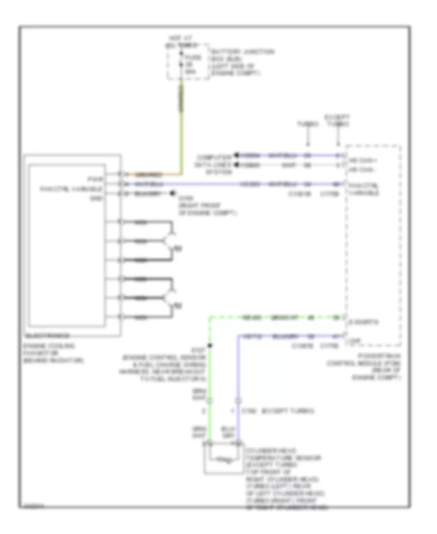
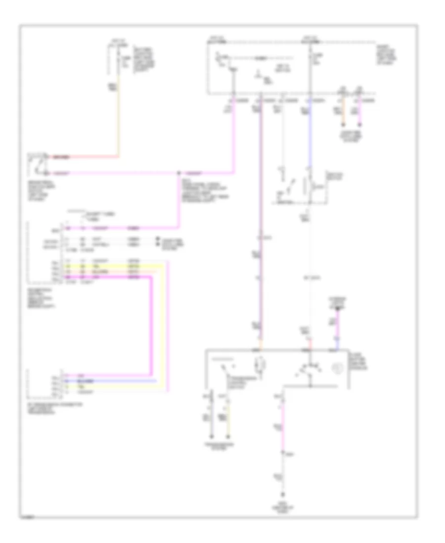
COOLING FAN
Cooling Fan Wiring Diagram for Ford Flex SE 2011
List of elements for Cooling Fan Wiring Diagram for Ford Flex SE 2011:
- (except turbo)
- Battery junction box (bjb) (left side of engine compt)
- C1381b
- C1381e
- C175b
- C175e
- C192
- Cht
- Computer data lines system
- Cylinder head temperature sensor (except turbo: top front of right cylinder head) (turbo (left): rear of left cylinder head) (turbo (right): front of right cylinder head)
- E-sigrtn
- Electronics
- Engine cooling fan motor (behind radiator)
- Except turbo
- Fan ctrl variable
- Fuse 80a
- G100 (right front of engine compt)
- Gnd
- Hot at all times
- Hs can +
- Hs can -
- Nca
- Powertrain control module (pcm) (rear of engine compt)
- Pwr
- Re405
- S127 (engine control sensor & fuel charge wiring harness, near breakout to fuel injector 6)
- Turbo
- Vdb04
- Vdb05
- Ve712
- Vec03
CRUISE CONTROL
Cruise Control Wiring Diagram for Ford Flex SE 2011
List of elements for Cruise Control Wiring Diagram for Ford Flex SE 2011:
- (dash panel wiring harness, to headlamp junction in breakout to left front of engine compartment, on transaxle) s173
- 6f transmission (left side of transmission)
- Accelerator pedal position (app) sensor (except turbo) (left side of dash)
- Accelerator pedal position (app) sensor (turbo) (left side of dash)
- App
- App1
- App1rtn
- App1vref
- App2
- App2rtn
- App2vref
- App3
- Apprtn2
- Appsrtn
- Appvref
- Appvref2
- Battery junction box (bjb) (left side of engine compt)
- Boo
- Bpp
- Bps
- Brake pedal position (bpp) switch (left side of dash)
- C1381b
- C1381e
- C1381t
- C1609a
- C1609b
- C175b
- C175e
- C175t
- C210
- C2280b
- Cancel
- Ccb08
- Ce412
- Ce426
- Ces09
- Clockspring (steering column assembly)
- Computer data lines system
- Electronic throttle control (etc) (except turbo: top right rear of engine) (turbo: top front of engine)
- Etcref
- Except turbo
- Exterior lights system
- Fuse 10a
- Fuse 15a
- G202 (center of dash)
- Hot w/ pcm power relay energized
- Hs can+
- Hs can-
- Illumination
- Interior lights system
- Le111
- Le134
- Le136
- Le137
- Left steering wheel switch
- Ms can +
- Ms can -
- Nca
- Off
- Oss
- Powertrain control module (pcm) (rear of engine compt)
- Re134
- Re136
- Re137
- Res08
- Resume
- Ret04
- Ret24
- Ret33
- S141 (except turbo: dash panel to headlamp junction wiring harness, in breakout to a/c pressure transducer) (turbo: engine control sensor & fuel charge harness, near breakout to powertrain control module)
- S213 (dash panel to headlamp junction wiring harness, near breakout to windshield wiper motor)
- S223
- S299 (steering wheel)
- Scc srtn
- Sccs
- Set+
- Set-
- Smart junction box (sjb) (left side of dash)
- Tacm+
- Tacm-
- Tp1 ns
- Tp2
- Tprtn
- Tr gnd
- Tss
- Tss/oss gnd
- Tss/oss vpwr
- Tss/oss/tr gnd
- Turbo
- Vdb04
- Vdb05
- Ve701
- Ve702
- Ve703
- Ve818
- Ve819
- Ves10
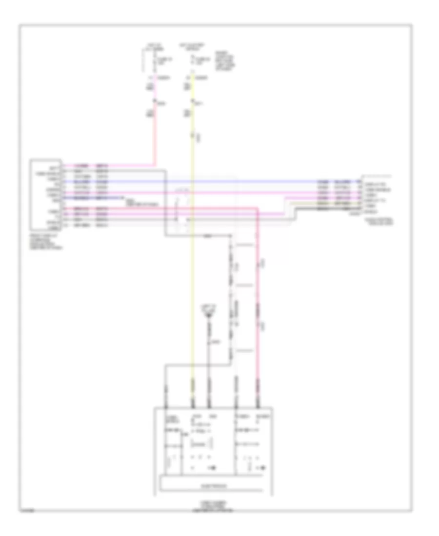
DEFOGGERS
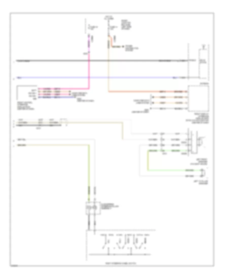
Defoggers Wiring Diagram for Ford Flex SE 2011
List of elements for Defoggers Wiring Diagram for Ford Flex SE 2011:
- (body main wiring harness, near breakout to c510) s337
- Battery junction box (bjb) (left side of engine compt)
- C210
- C211
- C2280d
- C228a
- C402a
- C402b
- C510
- C610
- C983
- Ch122
- Def req
- Fuse 10a
- Fuse 40a
- G210 (left kick panel)
- G302 (left "d" pillar)
- G305 (right "c" pillar)
- Hot at all times
- Hot in run or acc
- Hvac module (center of dash)
- Left exterior rear view mirror (mirror assembly)
- Rear window defrost grid
- Rear window defrost relay
- Right exterior rear view mirror (mirror assembly)
- S193
- S400
- S500
- S600
- Smart junction box (sjb) (left side of dash)
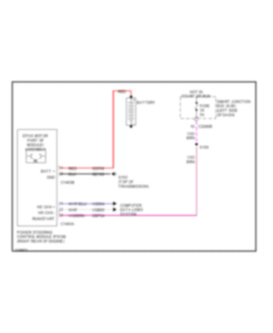
ELECTRONIC POWER STEERING
Electronic Power Steering Wiring Diagram for Ford Flex SE 2011
List of elements for Electronic Power Steering Wiring Diagram for Ford Flex SE 2011:
- Batt +
- Battery
- C1463a
- C1463b
- C2280b
- Cbp34
- Computer data lines system
- Epas motor part of module/ assembly
- Fuse 5a
- G103 (top of transmission)
- Gd108
- Gnd
- Hot in start or run
- Hs can +
- Hs can -
- Power steering control module (pscm) (right rear of engine)
- Red
- Run/start
- S155
- Sdf09
- Smart junction box (sjb) (left side of dash)
- Vdb04
- Vdb05
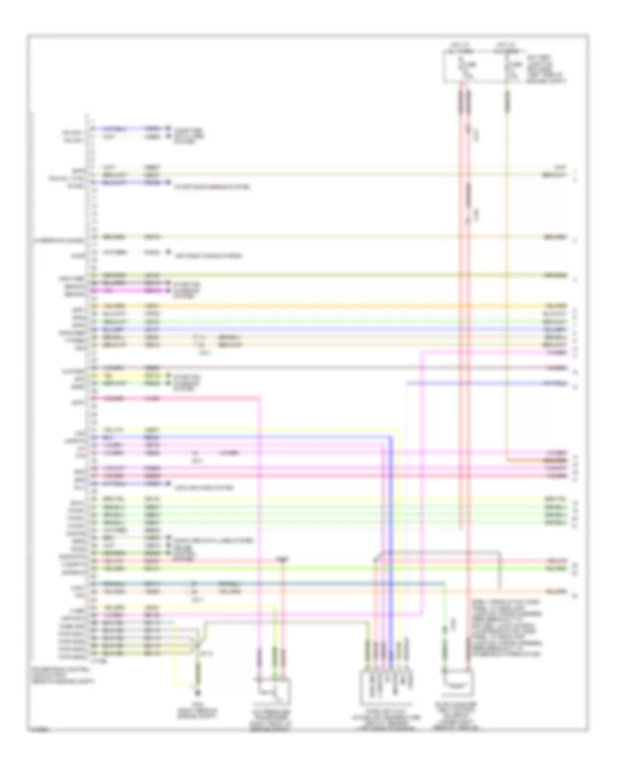
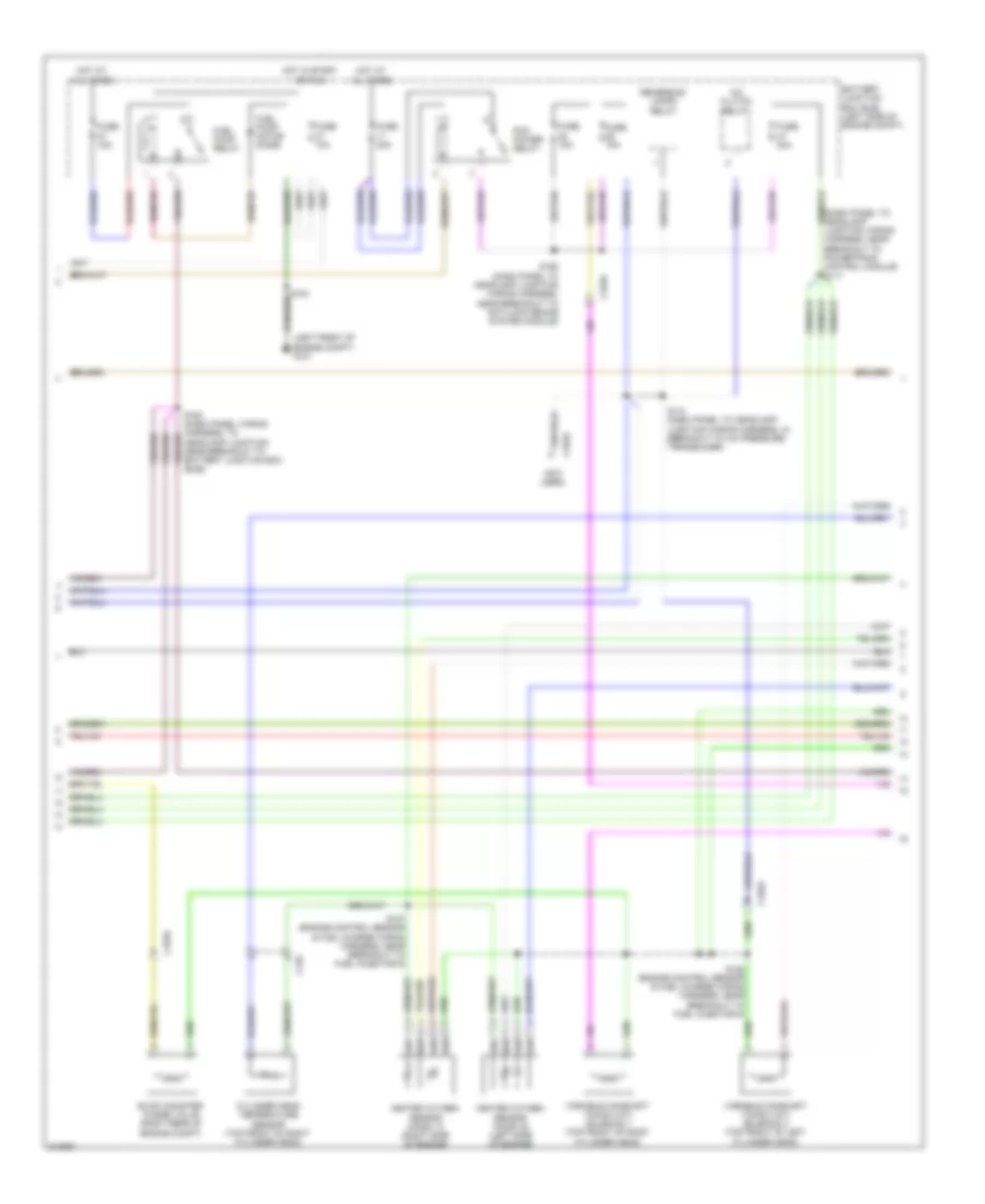
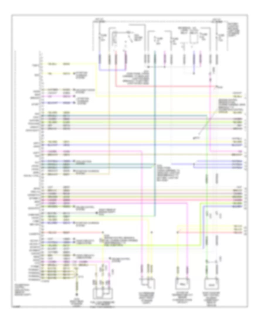
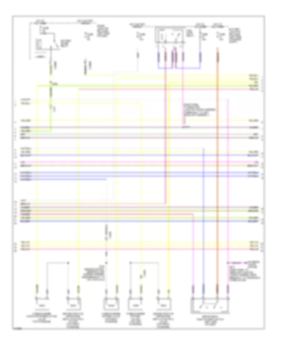
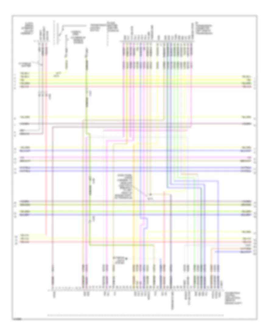
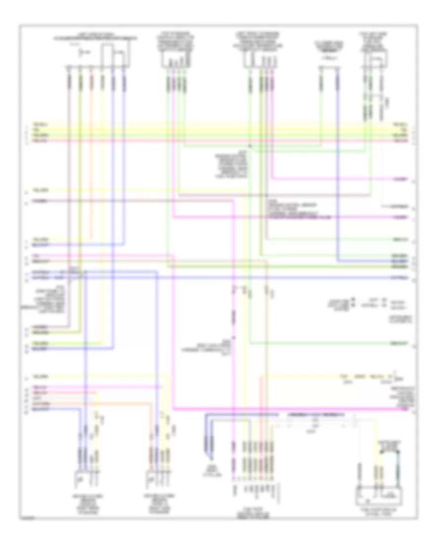
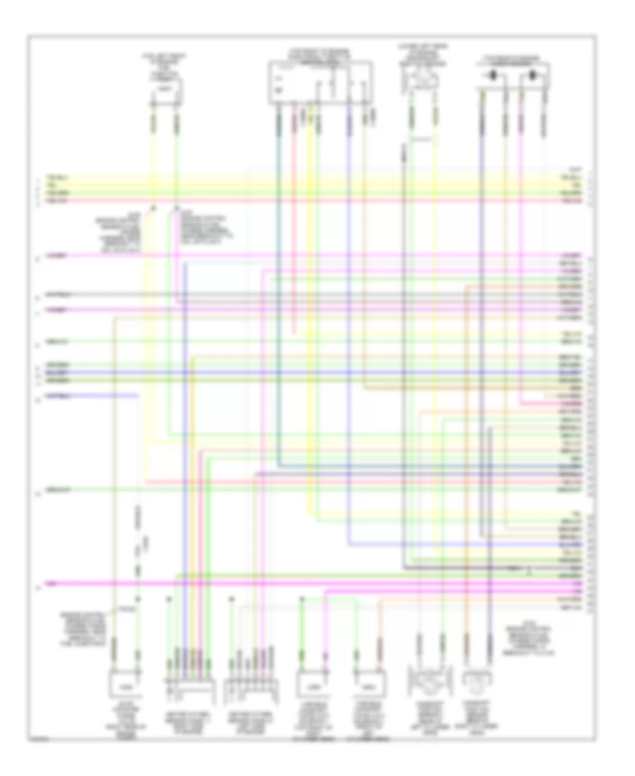
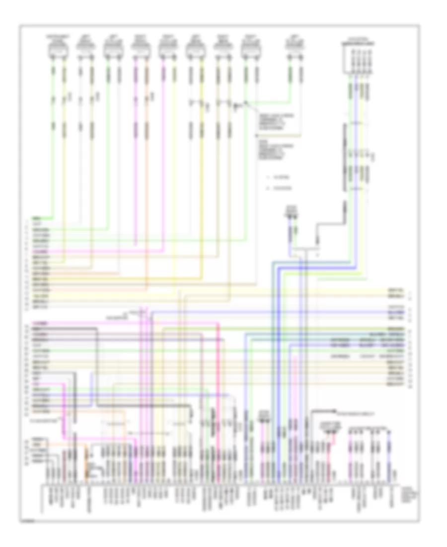
ENGINE PERFORMANCE
3.5L
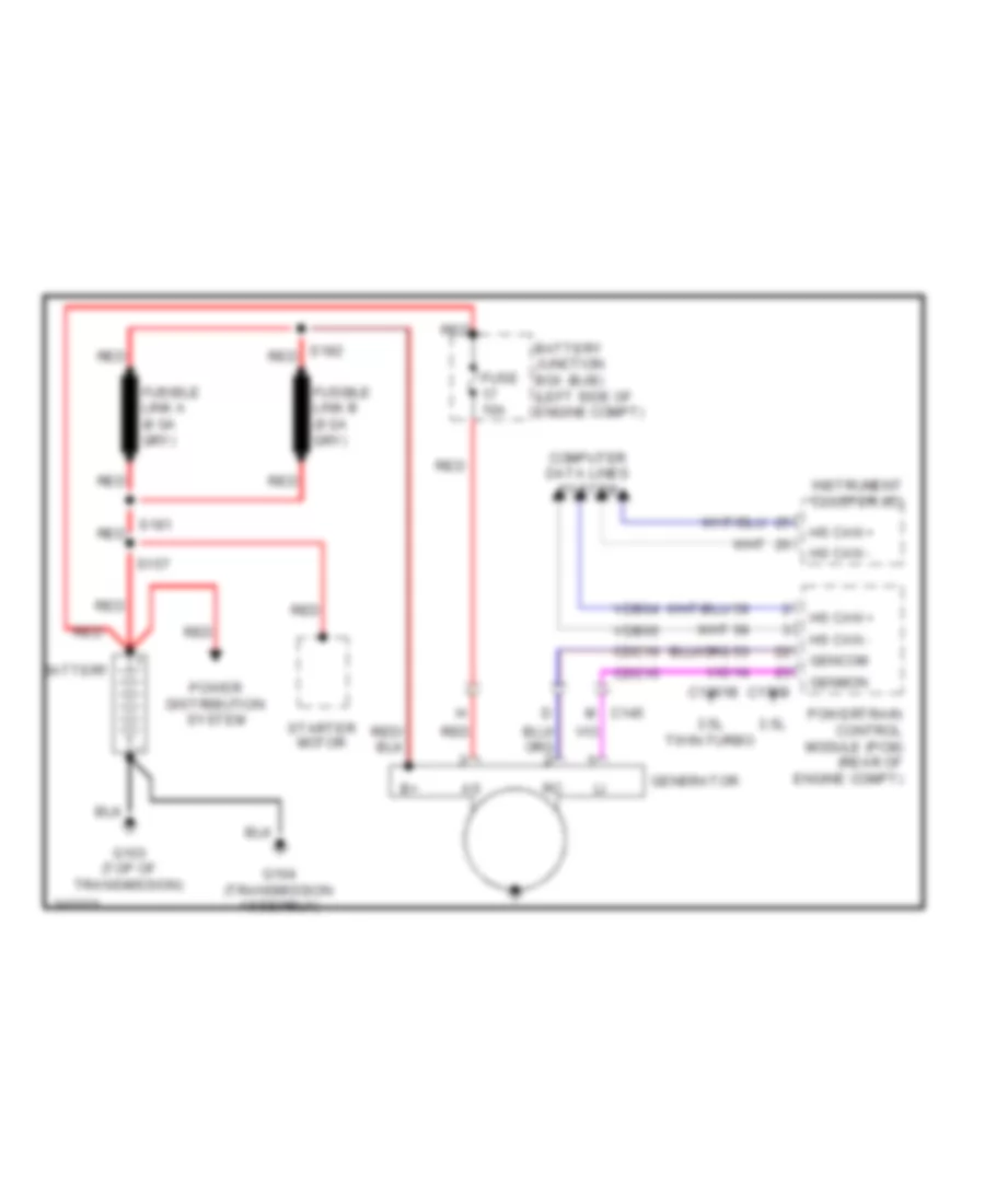
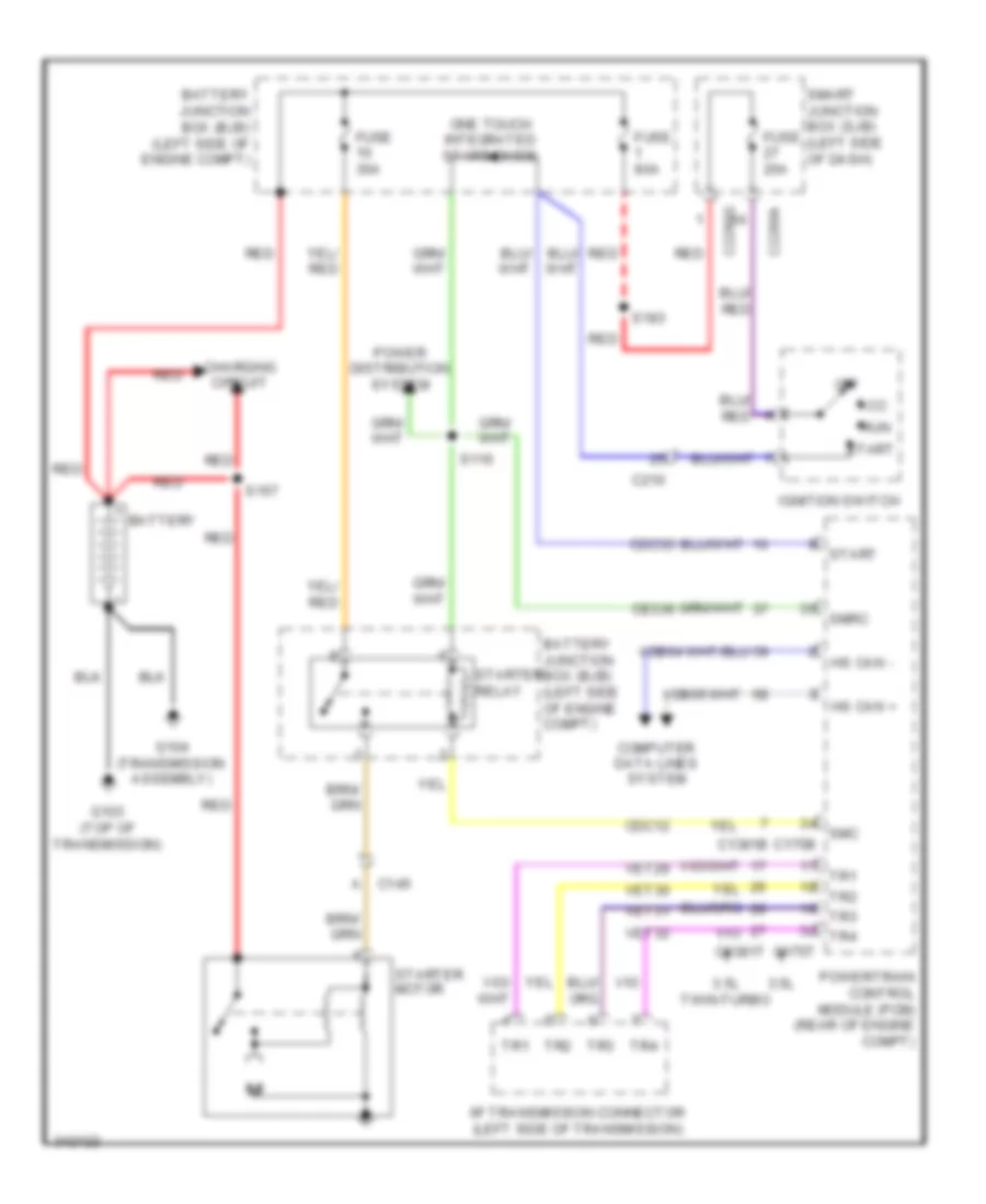
3.5L, Engine Performance Wiring Diagram (1 of 6) for Ford Flex SE 2011
List of elements for 3.5L, Engine Performance Wiring Diagram (1 of 6) for Ford Flex SE 2011:
- (early production: dash panel to headlamp junction wiring harness, near breakout to battery junction box) (late production: dash panel to headlamp junction wiring harness, near breakout to windshield wiper motor)
- A/c pressure transducer (right front of engine compt)
- Accr
- Acpt
- Air conditioning system
- App1
- App1rtn
- App1vref
- App2
- App2rtn
- App2vref
- App3
- Battery junction box (bjb) (left side of engine compt)
- Boo
- Bps
- C ref
- C sigrtn
- C175b
- C211
- C315
- Canv
- Case gnd
- Cbb37
- Cbb47
- Ccb08
- Cdb08
- Cdc10
- Cdc12
- Cdc15
- Cdc35
- Ce114
- Ce132
- Ce237
- Ce336
- Ce608
- Ces09
- Cet34
- Ch302
- Computer data lines system
- Cooling fans system
- Cruise control system
- Evap canister vent control solenoid (under right rear of vehicle)
- Evmv
- Fc-v
- Feps
- Fpc
- Fpm
- Ftp
- Ftpref
- Fuse 10a
- Fuse 7.5a
- G102 (right rear of engine compt)
- Gd113
- Gencom
- Genmon
- Hot at all times
- Hs can +
- Hs can -
- Iat
- Injpwrm
- Isp-r
- Kapwr
- Le136
- Le137
- Le230
- Le424
- Maf
- Mafrtn
- Mass air flow/ intake air temperature (maf/iat) sensor (left rear of engine)
- Overdrive cancel
- Pcm rly ctrl
- Powertrain control module (pcm) (rear of engine compt)
- Pwr gnd
- Pwr gnd1
- Pwr gnd2
- Pwr gnd3
- Pwr gnd4
- Re136
- Re137
- Re320
- Re407
- Res08
- S118
- S119
- Sbb23
- Sccs
- Sccs rtn
- Smc
- Smrc
- Start
- Starting/ charging system
- Starting/charging system
- Vdb04
- Vdb05
- Ve225
- Ve518
- Ve701
- Ve702
- Ve703
- Ve740
- Ve807
- Ve922
- Vec03
- Ves10
- Vh433
- Vpwr
- Vpwr1
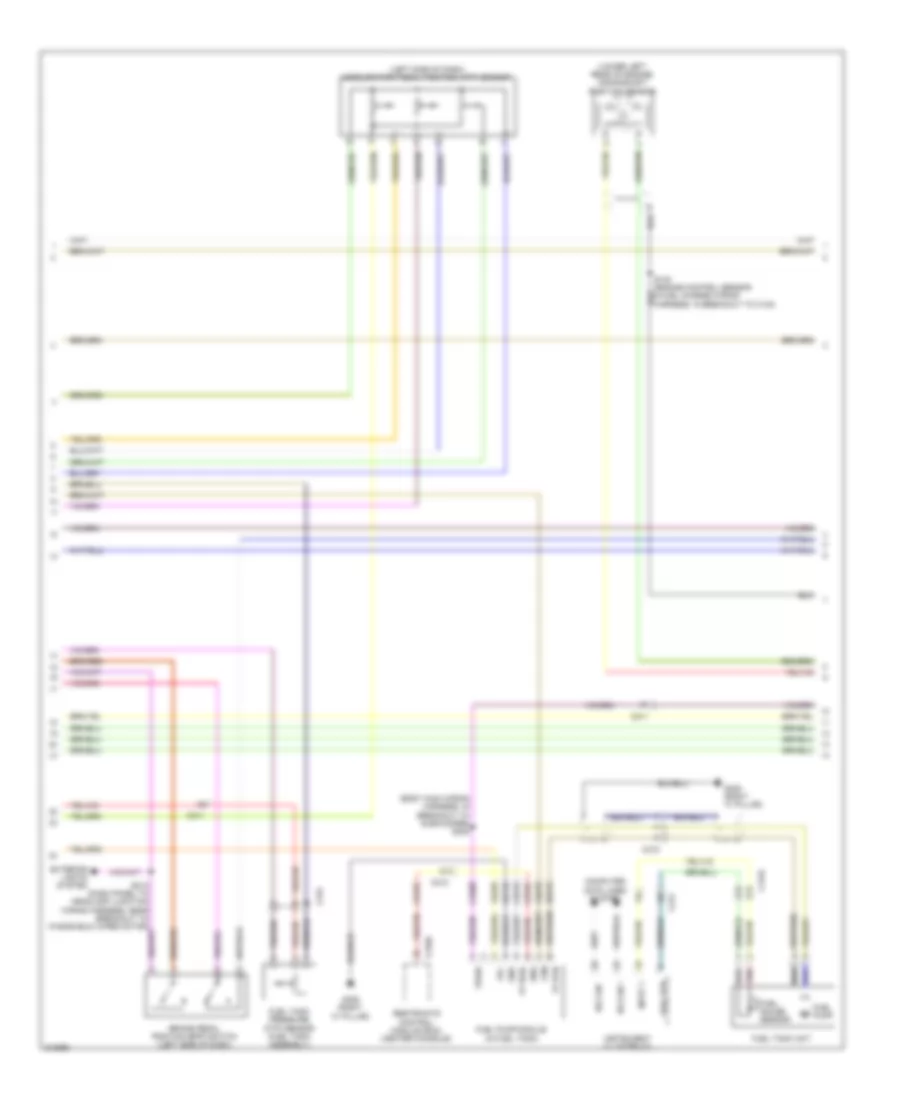
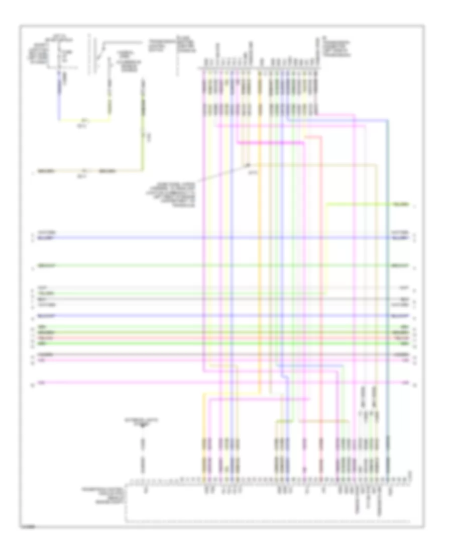
3.5L, Engine Performance Wiring Diagram (2 of 6) for Ford Flex SE 2011
List of elements for 3.5L, Engine Performance Wiring Diagram (2 of 6) for Ford Flex SE 2011:
- (body main wiring harness, in breakout to subwoofer) s308
- (left side of dash) accelerator pedal position (app) sensor
- (lower left rear of engine) crankshaft position sensor
- Brake pedal position (bpp) switch (left side of dash)
- C1315
- C211
- C212
- C310a
- C315
- Ce515
- Ce608
- Computer data lines system
- Cr167
- Ens
- Exterior lights system
- Fp pwr
- Fp rtn
- Fpc
- Fpm
- Fuel gauge sensor
- Fuel pump
- Fuel pump module (in fuel tank)
- Fuel rtn
- Fuel tank pressure (ftp) sensor (fuel tank assembly)
- Fuel tank unit
- G305 (right "c" pillar)
- Gd145
- Gnd
- Hs can +
- Hs can -
- Input 1
- Instrument cluster (ic)
- Pnk
- Re515
- Restraints control module (rcm) (center console)
- S130 (engine control sensor & fuel charge wiring harness, in breakout to c140)
- S213 (dash panel to headlamp junction wiring harness, near breakout to windshield wiper motor)
- Ve225
- Ve518
- Vpwr
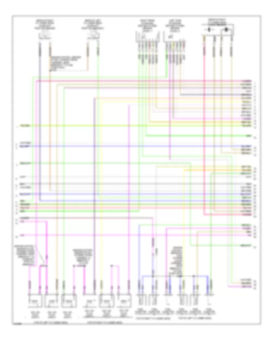
3.5L, Engine Performance Wiring Diagram (3 of 6) for Ford Flex SE 2011
List of elements for 3.5L, Engine Performance Wiring Diagram (3 of 6) for Ford Flex SE 2011:
- (dash panel to headlamp junction wiring harness, near breakout to powertrain control module) s117
- (left front of engine compt) g101
- (not used)
- A/c clutch relay
- Battery junction box (bjb) (left side of engine compt)
- C1010
- C192
- Cylinder head temperature sensor (top front of right cylinder head)
- Evap canister purge valve (right rear of engine compt)
- Fuel pump motor diode
- Fuel pump relay
- Fuse 10a
- Fuse 15a
- Fuse 20a
- Fuse 30a
- Heated oxygen sensor (ho2s) 12 (right side of engine)
- Heated oxygen sensor (ho2s) 22 (left side of engine)
- Hot at all times
- Hot in start or run
- Pcm power relay
- Reversing lamps relay
- S127 (engine control sensor & fuel charge wiring harness, near breakout to fuel injector 6)
- S128 (engine control sensor & fuel charge wiring harness, near breakout to fuel injector 6)
- S141 (dash panel to headlamp junction wiring harness, in breakout to a/c pressure transducer)
- S163 (dash panel wiring harness, to headlamp junction near breakout to battery junction box (bjb))
- S190 (dash panel to headlamp junction wiring harness, near breakout to anti-lock brake system module)
- S191
- Variable camshaft timing (vct) solenoid 1 (top front of right cylinder head)
- Variable camshaft timing (vct) solenoid 2 (top front of left cylinder head)
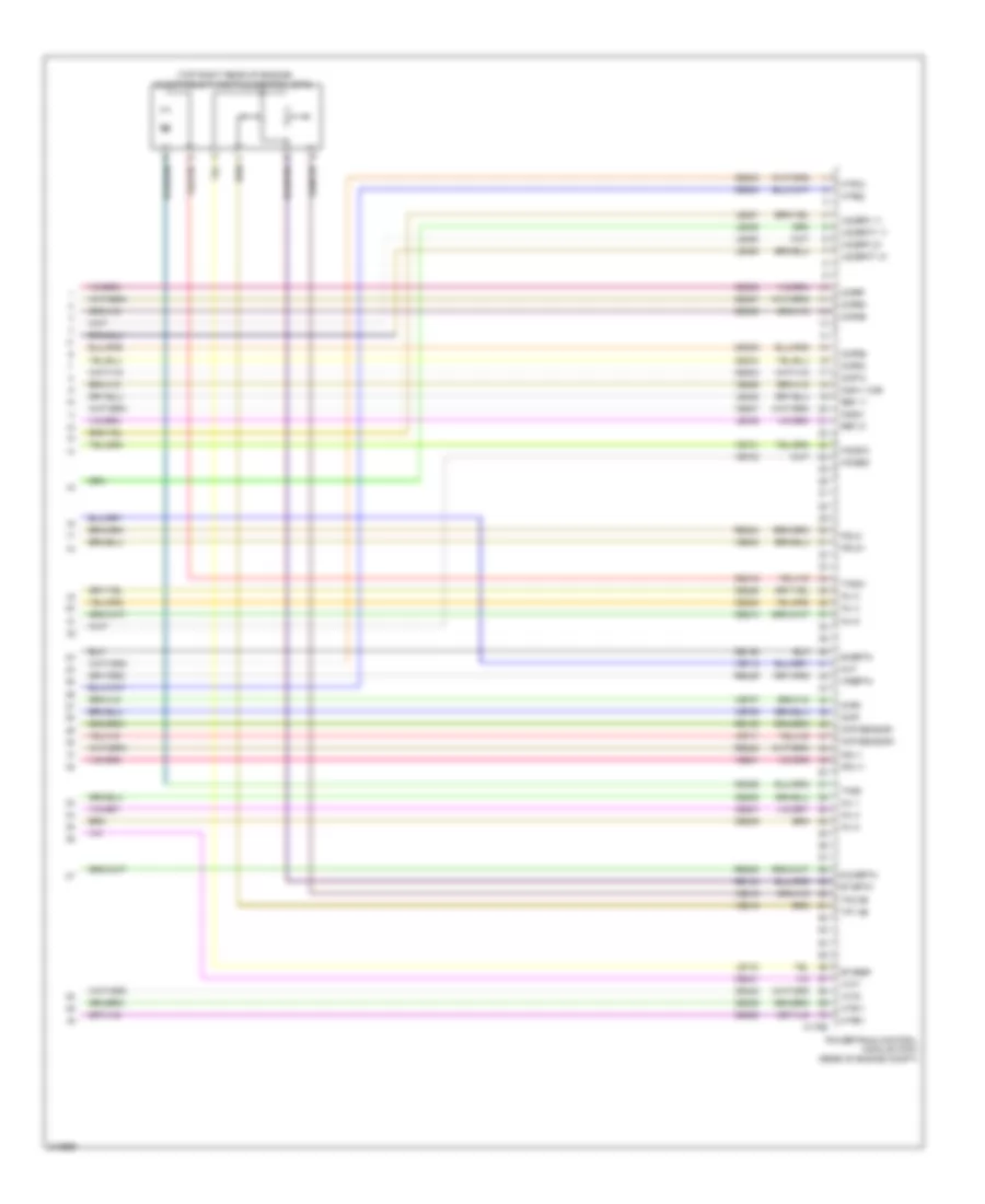
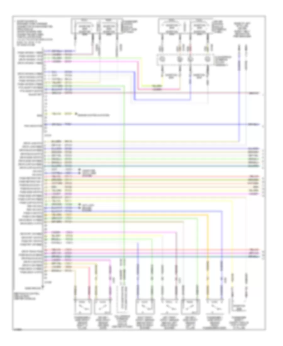
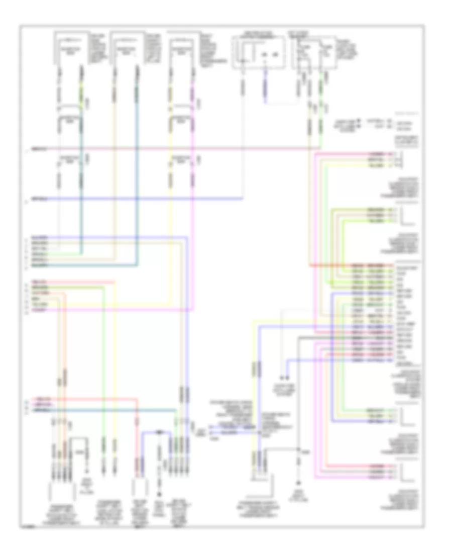
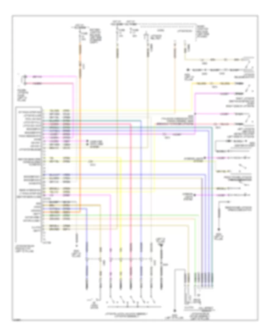
3.5L, Engine Performance Wiring Diagram (4 of 6) for Ford Flex SE 2011
List of elements for 3.5L, Engine Performance Wiring Diagram (4 of 6) for Ford Flex SE 2011:
- (dash panel wiring harness, to headlamp junction in breakout to left front of engine compartment, on transaxle)
- (not used)
- 1-normal
- 2-overdrive
- 6f transmission connector (left side of transmission)
- C1010
- C175t
- C210
- C2280b
- C312
- Ceet25
- Cet05
- Cet06
- Cet07
- Cet08
- Cet09
- Cet10
- Cet19
- Cet25
- Cet42
- Cet43
- Cls28
- Enable/ disable
- Exterior lights system
- Floor shifter (center console)
- Fuse 5a
- Hot in start or run
- Le111
- Lpc
- Open
- Oss
- Powertrain control module (pcm) (rear of engine compt)
- Re406
- Ret24
- Ret33
- Rlc
- S173
- Smart junction box (sjb) (left side of dash)
- Ssa
- Ssb
- Ssc
- Ssd
- Sse
- Sst
- Tcc
- Tft
- Tft sig rtn
- Tr 1
- Tr 2
- Tr 3
- Tr 4
- Tr gnd
- Transmission control switch
- Tspc
- Tss
- Tss/oss gnd
- Tss/oss vpwr
- Tss/oss/tr gnd
- Vet04
- Vet27
- Vet29
- Vet30
- Vet31
- Vet32
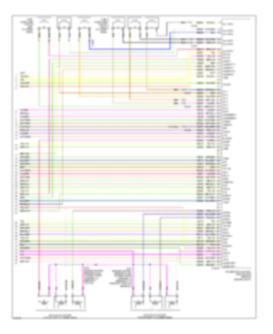
3.5L, Engine Performance Wiring Diagram (5 of 6) for Ford Flex SE 2011
List of elements for 3.5L, Engine Performance Wiring Diagram (5 of 6) for Ford Flex SE 2011:
- (engine control sensor & fuel charge wiring harness, in breakout to c140) s124
- (engine control sensor & fuel charge wiring harness, near breakout to camshaft position sensor 2)
- (engine control sensor & fuel charge wiring harness, near breakout to fuel injector 6) s125
- (engine control sensor & fuel charge wiring harness, near breakout to fuel injector 6) s126
- (left side of engine) heated oxygen sensor (ho2s) 21
- (rear of left cylinder head) camshaft position sensor 2
- (rear of right cylinder head) camshaft position sensor
- (rear of right cylinder head) knock sensor
- (right rear of engine) heated oxygen sensor (ho2s) 11
- (top of left cylinder head)
- (top of right cylinder head)
- C1010
- Coil on plug (cop) 1
- Coil on plug (cop) 2
- Coil on plug (cop) 3
- Coil on plug (cop) 4
- Coil on plug (cop) 5
- Coil on plug (cop) 6
- Fuel injector
- Red
- S131
- Tan
3.5L, Engine Performance Wiring Diagram (6 of 6) for Ford Flex SE 2011
List of elements for 3.5L, Engine Performance Wiring Diagram (6 of 6) for Ford Flex SE 2011:
- (top right rear of engine) electronic throttle control (etc)
- C175e
- Ce205
- Ce206
- Ce207
- Ce208
- Ce209
- Ce210
- Ce233
- Ce234
- Ce235
- Ce236
- Ce303
- Ce304
- Ce305
- Ce306
- Ce307
- Ce308
- Ce412
- Ce421
- Ce422
- Ce426
- Cht
- Ckp sensor+
- Ckp sensor-
- Cmp1
- Cmp2
- Cop1a
- Cop2c
- Cop3e
- Cop4b
- Cop5d
- Cop6f
- De135
- E sigrtn
- Etcref
- Etcrtn
- Ho2s12
- Ho2s22
- Htr11
- Htr12
- Htr21
- Htr22
- Inj 1
- Inj 2
- Inj 3
- Inj 4
- Inj 5
- Inj 6
- Ksl1+
- Ksl1-
- Ksl2+
- Ksl2-
- Le134
- Le448
- Le449
- Le450
- Le451
- Le452
- Le453
- O2s11 cur
- O2s21
- Powertrain control module (pcm) (rear of engine compt)
- Re134
- Re135
- Re323
- Re324
- Re405
- Re429
- Ref 11
- Ref 21
- Shdrtn
- Tacm
- Tacm+
- Tp1 ns
- Tp2 ps
- Uo2spc 11
- Uo2spc 21
- Uo2spct 11
- Uo2spct 21
- Vct1
- Vct2
- Ve706
- Ve707
- Ve711
- Ve712
- Ve731
- Ve733
- Ve801
- Ve802
- Ve818
- Ve819
- Ve826
- Ve827
- Vrsrtn
3.5L TWIN TURBO
3.5L Twin Turbo, Engine Performance Wiring Diagram (1 of 6) for Ford Flex SE 2011
List of elements for 3.5L Twin Turbo, Engine Performance Wiring Diagram (1 of 6) for Ford Flex SE 2011:
- (engine control sensor & fuel charge harness, near breakout to powertrain control module)
- (right rear of engine compt) g102
- 20a
- 7.5a
- A/c clutch relay
- A/c pressure transducer (right front of engine compt)
- Accr
- Acpt
- Air conditioning system
- App1
- App2
- Appsrtn1
- Battery junction box (bjb) (left side of engine compt)
- Boo
- Bps
- C ref
- C-sigrtn
- C1010
- C1381b
- C211
- C315
- Canv
- Case gnd
- Cbb47
- Cbp37
- Ccb08
- Cdb08
- Cdc10
- Cdc12
- Cdc15
- Cdc35
- Ce114
- Ce237
- Ce336
- Ce435
- Ce522
- Ce608
- Ces09
- Cet42
- Cet43
- Ch302
- Cln09
- Computer data lines system
- Cooling fans system
- Cruise control system
- Down shift
- Etcref1
- Etcref2
- Etcrtn
- Evap canister vent control solenoid (under right rear of vehicle)
- Fcv
- Feps
- Fpc
- Fpm
- Fprlyc
- Ftp
- Ftpref
- Fuel injector 6)
- Fuel tank pressure (ftp) sensor (fuel tank assembly)
- Fuse
- Fuse 15a
- Fuse 30a
- G102 (right rear of engine compt)
- Gd113
- Gen com
- Genmon
- Hot at all times
- Hs can +
- Hs can -
- Iat
- Injpwrm
- Intake air temperature (iat) sensor (in engine intake air duct)
- Isp-r
- Kapwr
- Le136
- Le137
- Le230
- Le424
- Pcm power relay
- Pcm rly ctrl
- Pcmwake
- Powertrain control module (pcm) (rear of engine compt)
- Pwrgnd1
- Pwrgnd2
- Pwrgnd3
- Pwrgnd4
- Re136
- Re137
- Re407
- Res08
- Reversing lamps relay
- S101 (dash panel wiring harness, to headlamp junction near breakout to battery junction box (bjb))
- S118
- S123 (dash panel wiring harness, to headlamp junction near breakout to battery junction box (bjb))
- S141
- S150
- Sbb23
- Sccs
- Sccs rtn
- Smc
- Smrc
- Start
- Starting/ charging system
- Tcby2
- Upshift
- Vdb04
- Vdb05
- Ve225
- Ve518
- Ve701
- Ve702
- Ve740
- Ve922
- Vec03
- Ves10
- Vh433
- Vpwr1
3.5L Twin Turbo, Engine Performance Wiring Diagram (2 of 6) for Ford Flex SE 2011
List of elements for 3.5L Twin Turbo, Engine Performance Wiring Diagram (2 of 6) for Ford Flex SE 2011:
- (dash panel to headlamp junction wiring harness, in breakout to left headlamp assembly)
- 10a
- Battery junction box (bjb) (left side of engine compt)
- Battery saver relay
- Brake pedal position (bpp) switch (left side of dash)
- C1010
- C211
- C2280b
- C2280d
- Exterior lights system
- Fuel pump relay
- Fuse
- Fuse 10a
- Fuse 15a
- Fuse 5a
- Heated positive crankcase ventilation (pcv) fitting (top front of engine)
- Heated positive crankcase ventilation (pcv) valve (top front of engine)
- Hot at all times
- Hot in start or run
- Logic
- S110
- S164 (engine control sensor & fuel charge harness, near breakout to coil on plug 4)
- S213 (dash panel to headlamp junction wiring harness, near breakout to windshield wiper motor)
- S360
- Smart junction box (sjb) (left side of dash)
- Turbocharger bypass valve (top right of engine)
- Turbocharger bypass valve 2 (top left of engine)
- Turbocharger waste gate regulating valve (top of engine)
3.5L Twin Turbo, Engine Performance Wiring Diagram (3 of 6) for Ford Flex SE 2011
List of elements for 3.5L Twin Turbo, Engine Performance Wiring Diagram (3 of 6) for Ford Flex SE 2011:
- (dash panel wiring harness, to headlamp junction in breakout to left front of engine compt, on transaxle)
- 1-normal
- 2-overdrive
- 6f transmission connector (left side of transmission)
- C1381t
- C210
- C312
- Ce233
- Ce234
- Ce235
- Cet05
- Cet06
- Cet07
- Cet08
- Cet09
- Cet10
- Cet19
- Cet25
- Cet34
- Clock- spring (steering column assembly)
- Cls28
- Down shift
- Enable/ disable
- Exterior lights system
- Floor shifter (center console)
- Ho2s12
- Ho2s22
- Htr12
- Htr22
- Le111
- Lpc
- Open
- Oss
- Powertrain control module (pcm) (rear of engine compt)
- Re406
- Ret04
- Ret24
- Ret33
- Rlc
- S173
- Sig rtn
- Ssa
- Ssb
- Ssc
- Ssd
- Sse
- Tcc
- Tcs
- Tft
- Tft sig rtn
- Tr gnd
- Tr-1
- Tr-2
- Tr-3
- Tr-4
- Transmission control switch
- Tspc
- Tss
- Tss/oss gnd
- Tss/oss vpwr
- Tss/oss/tr gnd
- Up shift
- Ve731
- Ve733
- Vet27
- Vet29
- Vet30
- Vet31
- Vet32
- Vpwr
- W/ paddle shifter
3.5L Twin Turbo, Engine Performance Wiring Diagram (4 of 6) for Ford Flex SE 2011
List of elements for 3.5L Twin Turbo, Engine Performance Wiring Diagram (4 of 6) for Ford Flex SE 2011:
- (left front of engine) turbocharger boost pressure/charge air cooler temperature (tcbp/cact) sensor
- (left side of dash) accelerator pedal position (app) sensor
- (top left side of engine) fuel rail pressure (frp) sensor
- (top of engine) manifold absolute pressure/intake air temperature 2 (map/iat2) sensor
- C1033
- C1046
- C145
- C211
- C212
- C310a
- C315
- Cact
- Ce515
- Ce608
- Computer data lines system
- Cr167
- Cylinder head temperature sensor
- Ens
- Fp pwr
- Fp rtn
- Fpc
- Fpm
- Fuel pump control module (right "c" pillar)
- Fuel pump module (in fuel tank)
- G305 (right "c" pillar)
- Gd145
- Gnd
- Heated oxygen sensor (ho2s) 12 (right side of engine)
- Heated oxygen sensor (ho2s) 22 (right rear of engine)
- Hs can +
- Hs can -
- Iat
- Instrument cluster (ic)
- Instrument cluster system
- Map
- Re515
- Restraints control module (rcm) (center console)
- S127 (engine control sensor & fuel charge wiring harness, near breakout to fuel injector 6)
- S151 (dash panel to headlamp junction wiring harness, near breakout to battery junction box)
- S160 (engine control sensor & fuel charge harness, near breakout to evap canister purge valve)
- S300 (body main wiring harness, in breakout to c211)
- Sigrtn
- Tcbp
- Ve225
- Ve518
- Vpwr
- Vref
3.5L Twin Turbo, Engine Performance Wiring Diagram (5 of 6) for Ford Flex SE 2011
List of elements for 3.5L Twin Turbo, Engine Performance Wiring Diagram (5 of 6) for Ford Flex SE 2011:
- (engine control sensor & fuel charge wiring harness, near breakout to fuel injector 6)
- (lower left rear of engine) crankshaft position sensor
- (top front of engine) electronic throttle control (etc)
- (top left front of engine) fuel injection pump
- (top rear of engine) knock sensor
- C1010
- C1609a
- C1609b
- Camshaft position sensor (rear of right cylinder head)
- Camshaft position sensor 2 (rear of left cylinder head)
- Evap canister purge valve (right rear of engine compt)
- Heated oxygen sensor (ho2s) 11 (right side of engine)
- Heated oxygen sensor (ho2s) 21 (left side of engine)
- Nca
- S128
- S130 (engine control sensor & fuel charge wiring harness, in breakout to c140)
- S157 (engine control sensor & fuel charge harness, near breakout to coil on plug 4)
- S158 (engine control sensor & fuel charge harness, near breakout to coil on plug 4)
- Tan
- Variable camshaft timing (vct) solenoid 1 (top front of right cylinder head)
- Variable camshaft timing (vct) solenoid 2 (front of left cylinder head)
3.5L Twin Turbo, Engine Performance Wiring Diagram (6 of 6) for Ford Flex SE 2011
List of elements for 3.5L Twin Turbo, Engine Performance Wiring Diagram (6 of 6) for Ford Flex SE 2011:
- C1046
- C1047
- C1381e
- Cact
- Ce113
- Ce205
- Ce206
- Ce207
- Ce208
- Ce209
- Ce210
- Ce226
- Ce235
- Ce236
- Ce303
- Ce304
- Ce305
- Ce306
- Ce307
- Ce308
- Ce321
- Ce328
- Ce412
- Ce421
- Ce422
- Ce426
- Ce435
- Cht
- Ckp+
- Ckp-
- Cmp
- Cmp2
- Coils on plug (cop) (top of left cylinder head)
- Coils on plug (cop) (top of right cylinder head)
- Cop1a
- Cop2c
- Cop3e
- Cop4b
- Cop5d
- Cop6f
- De135
- Etcref
- Etcrtn
- Evapcp
- Frp
- Fuel injectors (top of left cylinder head)
- Fuel injectors (top of right cylinder head)
- Fvr
- Fvrtn
- Iat2
- Inj 1
- Inj 1 rtn
- Inj 2
- Inj 2 rtn
- Inj 3
- Inj 3 rtn
- Inj 4
- Inj 4 rtn
- Inj 5
- Inj 5 rtn
- Inj 6
- Inj 6 rtn
- Ksl1+
- Ksl1-
- Ksl2+
- Ksl2-
- Le134
- Le423
- Le448
- Le449
- Le450
- Le451
- Le452
- Le453
- Map
- Pcvhc
- Pcvhf
- Powertrain control module (pcm) (rear of engine compt)
- Re134
- Re135
- Re205
- Re206
- Re207
- Re208
- Re209
- Re210
- Re226
- Re323
- Re324
- Re405
- Re429
- S124 (engine control sensor & fuel charge wiring harness, in breakout to c140)
- S131 (engine control sensor & fuel charge wiring harness, in breakout to camshaft position sensor 2)
- Shdrtn
- Sigrtn
- Tacm+
- Tacm-
- Tcbp
- Tcby
- Tcwrv
- Tp1 ns
- Tp2 ps
- Uo2s11
- Uo2s21
- Uo2sgref11
- Uo2sgref21
- Uo2shtr11
- Uo2shtr21
- Uo2spc11
- Uo2spc21
- Uo2spct11
- Uo2spct21
- Vct1
- Vct2
- Ve706
- Ve707
- Ve711
- Ve712
- Ve727
- Ve740
- Ve801
- Ve802
- Ve804
- Ve818
- Ve819
- Ve824
- Ve826
- Ve827
- Vref
- Vrsrtn
- Vrsrtn2
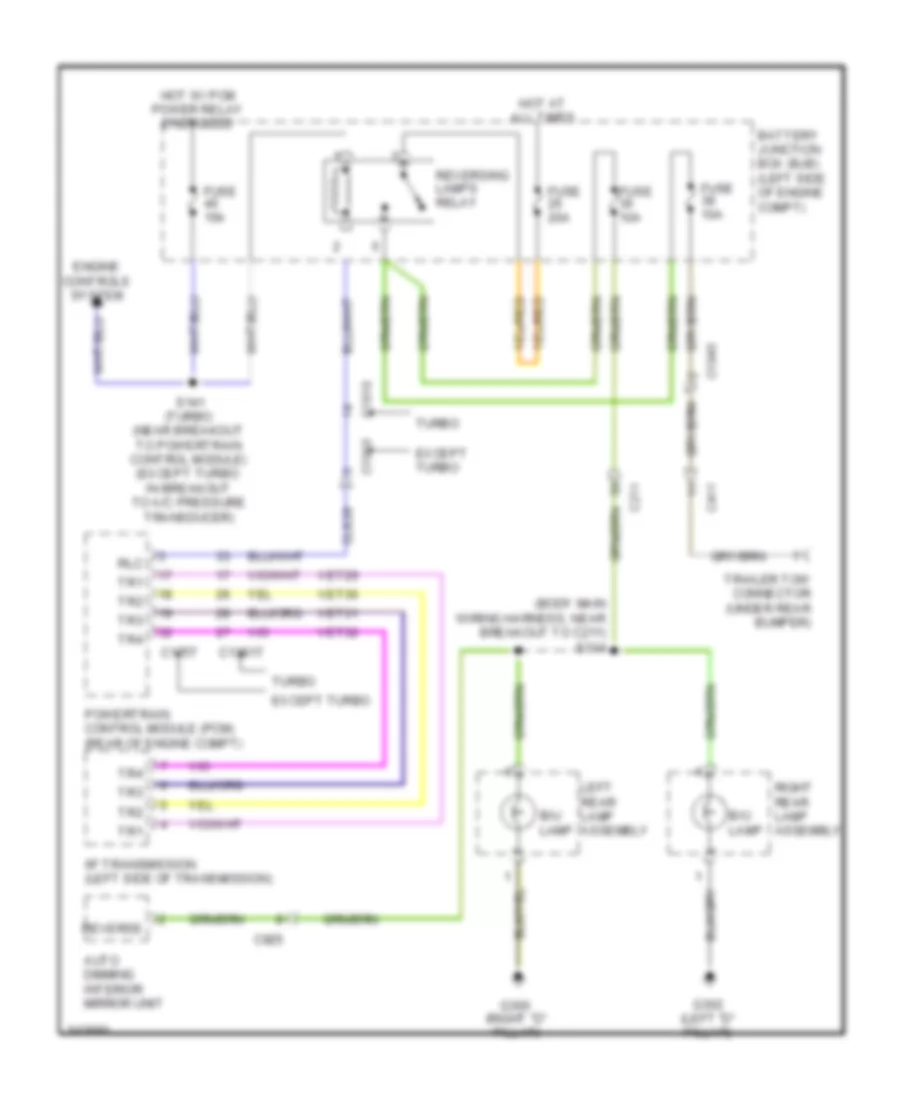
EXTERIOR LIGHTS
Backup Lamps Wiring Diagram for Ford Flex SE 2011
List of elements for Backup Lamps Wiring Diagram for Ford Flex SE 2011:
- (body main wiring harness, near breakout to c211) s314
- 6f transmission (left side of transmission)
- Auto dimming interior mirror unit
- B/u lamp
- Battery junction box (bjb) (left side of engine compt)
- C1010
- C1045
- C1381t
- C175t
- C211
- C411
- C925
- Cls28
- Engine controls system
- Except turbo
- Fuse 10a
- Fuse 15a
- Fuse 20a
- G300 (right "d" pillar)
- G302 (left "d" pillar)
- Hot at all times
- Hot w/ pcm power relay energized
- Left rear lamp assembly
- Powertrain control module (pcm) (rear of engine compt)
- Reverse
- Reversing lamps relay
- Right rear lamp assembly
- Rlc
- S141 (turbo: (near breakout to powertrain control module) (except turbo: in breakout to a/c pressure transducer)
- Tr1
- Tr2
- Tr3
- Tr4
- Trailer tow connector (under rear bumper)
- Turbo
- Vet29
- Vet30
- Vet31
- Vet32
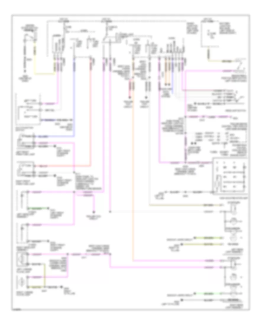
Exterior Lamps Wiring Diagram for Ford Flex SE 2011
List of elements for Exterior Lamps Wiring Diagram for Ford Flex SE 2011:
- (backup alarm jumper wiring harness, near breakout to c462)
- (body main wiring harness, near breakout to c211) s334
- (body main wiring harness, near breakout to c211) s335
- (body main wiring harness, near breakout to c3073) s313
- Auto
- Backup lamps circuit
- Battery junction box (bjb) (left side of engine compt)
- Boo
- Brake pedal position (bpp) switch (left side of dash)
- C1284a
- C1285a
- C1381b
- C175b
- C210
- C211
- C213
- C2280b
- C2280d
- C2280e
- C2280f
- C411
- C983
- Ccb08
- Center stack switch assembly
- Computer data lines system
- Except turbo
- Fuse 10a
- Fuse 20a
- Fuse 22 15a
- G100 (right front of engine compt)
- G101 (left front of engine compt)
- G202 (center of dash)
- G300 (right "d" pillar)
- G302 (left "d" pillar)
- Hazard
- Headlamp switch
- High mounted stoplamp
- Hot at all times
- Hs can +
- Hs can -
- Left front park/turn lamp
- Left headlamp assembly
- Left license plate lamp
- Left rear lamp assembly
- Left turn
- Lf turn lamp (fet)
- Low
- Low beam
- Lr stop/ turn lamp (fet)
- Micro
- Ms can +
- Ms can -
- Multi-function switch
- Off
- Park
- Park lamp relay
- Powertrain control module (pcm) (rear of engine compt)
- Reverse
- Rf turn lamp (fet)
- Right front park/turn lamp
- Right headlamp assembly
- Right license plate lamp
- Right rear lamp assembly
- Right turn
- Rr stop/ turn lamp (fet)
- S111 (dash panel to headlamp junction wiring harness, in breakout to ambient air temperature sensor)
- S213 (dash panel to headlamp junction wiring harness, near breakout to windshield wiper motor)
- S223
- S338 (body main wiring harness, near breakout to c510)
- S400
- S405
- S407
- Side marker
- Smart junction box (sjb) (left side of dash)
- Stop/turn
- Tail
- Trailer brake control (tbc) module (left side of dash)
- Trailer tow circuit
- Turbo
- Turn
- Vdb04
- Vdb05
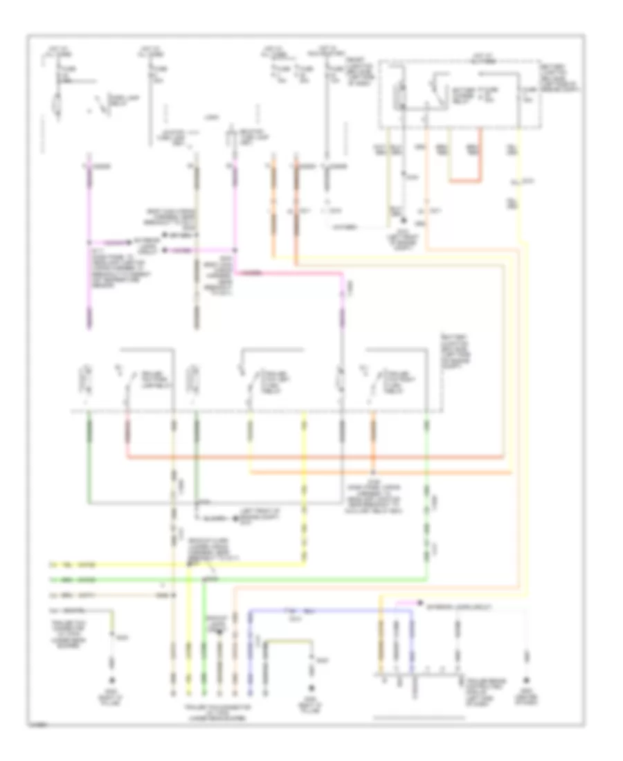
Trailer Tow Wiring Diagram for Ford Flex SE 2011
List of elements for Trailer Tow Wiring Diagram for Ford Flex SE 2011:
- (backup alarm jumper wiring harness, near breakout to c411)
- (body main wiring harness, near breakout to c211) s335
- (left front of engine compt) g101
- Backup lamps circuit
- Battery charge relay
- Battery junction box (bjb) (left side of engine compt)
- Boo
- C1045
- C210
- C211
- C213
- C2280e
- C411
- Cat03
- Cat06
- Cat09
- Cat11
- Cat14
- Cat18
- Cat19
- Cato6
- Cato9
- Ccb08
- E brake
- Exterior lamps circuit
- Fuse 10a
- Fuse 15a
- Fuse 20a
- Fuse 30a
- G101 (left front of engine compt)
- G203 (center of dash)
- G300 (right "d" pillar)
- Gnd
- Hot at all times
- Hot in run or start
- Logic
- Lr stop/ turn lamp (fet)
- Park lamp relay
- Rat08
- Rr stop/ turn lamp (fet)
- S111 (dash panel to headlamp junction wiring harness, in breakout to ambient air temperature sensor)
- S191
- S194 (dash panel wiring harness, to headlamp junction near breakout to auxiliary relay box)
- S334 (body main wiring harness, near breakout to c211)
- S420
- S421
- S422
- S423
- Smart junction box (sjb) (left side of dash)
- Trailer brake control(tbc) module (left side of dash)
- Trailer tow connector (w/ 4-pin) (under rear bumper)
- Trailer tow connector (w/ 7-pin) (under rear bumper)
- Trailer tow left turn relay
- Trailer tow park lamp relay
- Trailer tow right turn relay
GROUND DISTRIBUTION
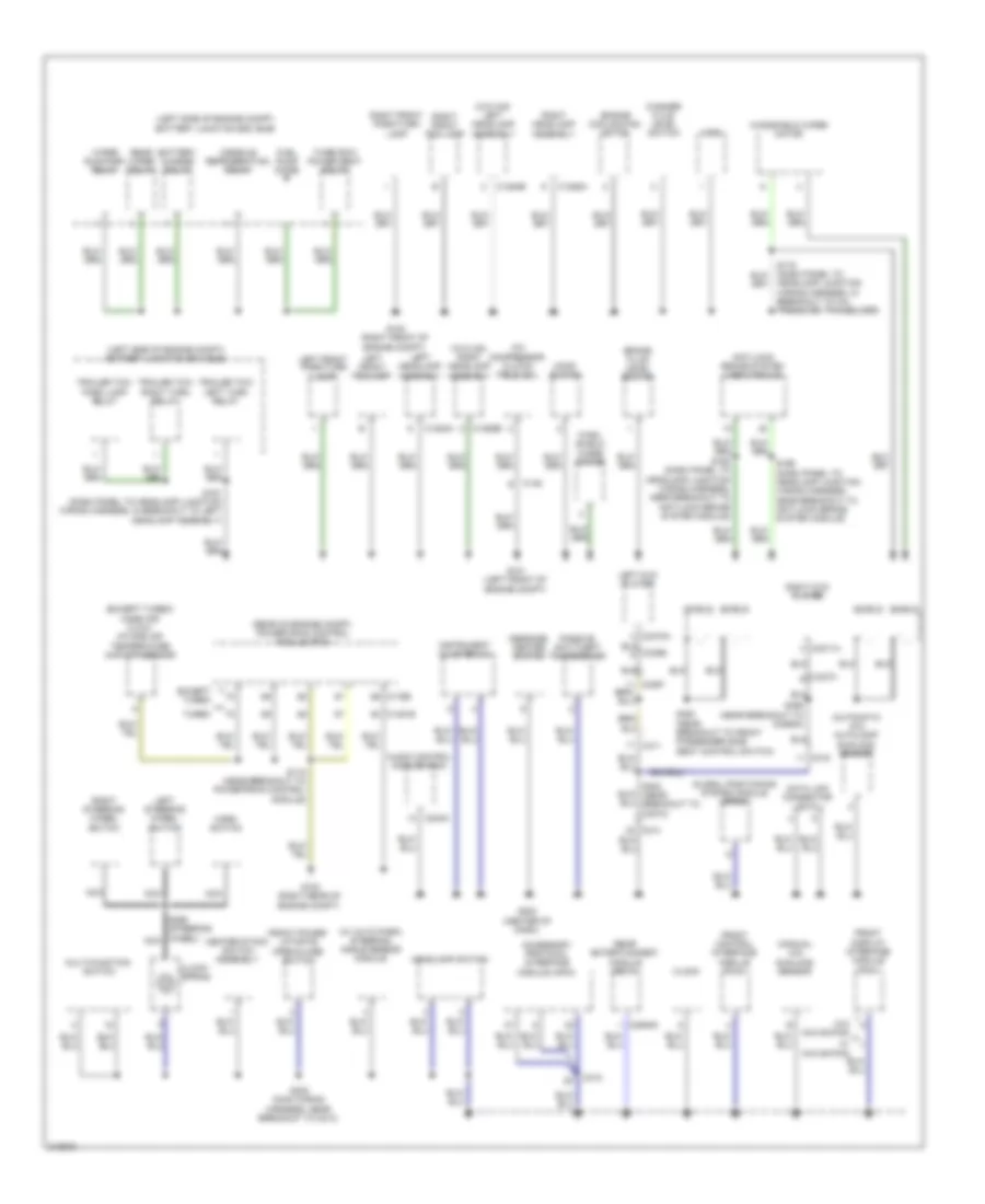
Ground Distribution Wiring Diagram (1 of 3) for Ford Flex SE 2011
List of elements for Ground Distribution Wiring Diagram (1 of 3) for Ford Flex SE 2011:
- (automatic a/c) autolamp/ sunload sensor
- (except turbo) mass air flow/ intake air temperature (maf/iat) sensor
- (left side of engine compt) battery junction box (bjb)
- (manual a/c) sunload sensor
- (rear of engine compt) powertrain control module (pcm)
- (w/ auto park) steering angle sensor module
- (w/o hid) left headlamp assembly
- (w/o hid) right headlamp assembly
- A/c compressor clutch field coil
- Accessory protocol interface module (apim)
- Anti-lock brake system (abs) module
- Audio control module (acm)
- Battery charge relay
- Brake fluid level switch
- C1284a
- C1284b
- C1285a
- C1285b
- C1381b
- C145
- C175b
- C240a
- C2949a
- C311
- C312
- C316
- C3367
- C3370a
- C3371a
- C3373
- Center stack switch assembly
- Clock
- Clock- spring
- Console refrigeration relay
- Data link connector (dlc)
- Engine cooling fan motor
- Except turbo
- Front control interface module (fcim)
- Front display interface module (fdim)
- Front power liftgate open/close switch
- Fuel pump diode
- G100 (right front of engine compt)
- G101 (left front of engine compt)
- G102 (right rear of engine compt)
- G202 (center of dash)
- Global positioning system module (gpsm)
- Headlamp junction wiring harness, in breakout to a/c pressure transducer)
- Headlamp switch
- Hood switch
- Horn
- Horn switch
- Instrument cluster (ic)
- Left dvd player
- Left front fog lamp
- Left front park/turn lamp
- Left headlamp assembly
- Left steering wheel switch
- Message center switch
- Multi-function switch
- Nca
- Passive anti-theft transceiver
- Rear entertainment module (retm)
- Rear wiper relay
- Right dvd player
- Right front fog lamp
- Right front park/turn lamp
- Right headlamp assembly
- Right steering wheel switch
- S118 (near breakout to powertrain control module)
- S191 (dash panel to headlamp junction wiring harness, in breakout to left headlamp assembly)
- S192 (dash panel to headlamp junction wiring harness, near breakout to anti-lock brake system module)
- S196 (dash panel to headlamp junction wiring harness, near breakout to anti-lock brake system module)
- S223 (main wiring harness, near breakout to c213)
- S299 (steering wheel) nca
- S350 (near breakout to front passenger side seat control switch)
- S355 (near breakout to c3265a)
- S384 (near breakout to c3073)
- Shield
- Third row power seat relay
- Trailer tow left turn relay
- Trailer tow park lamp relay
- Trailer tow right turn relay
- Turbo
- W/ navigation
- W/o navigation
- Washer fluid level switch
- Wind- shield wiper motor
- Windshield wiper motor
- Wiper run/park relay
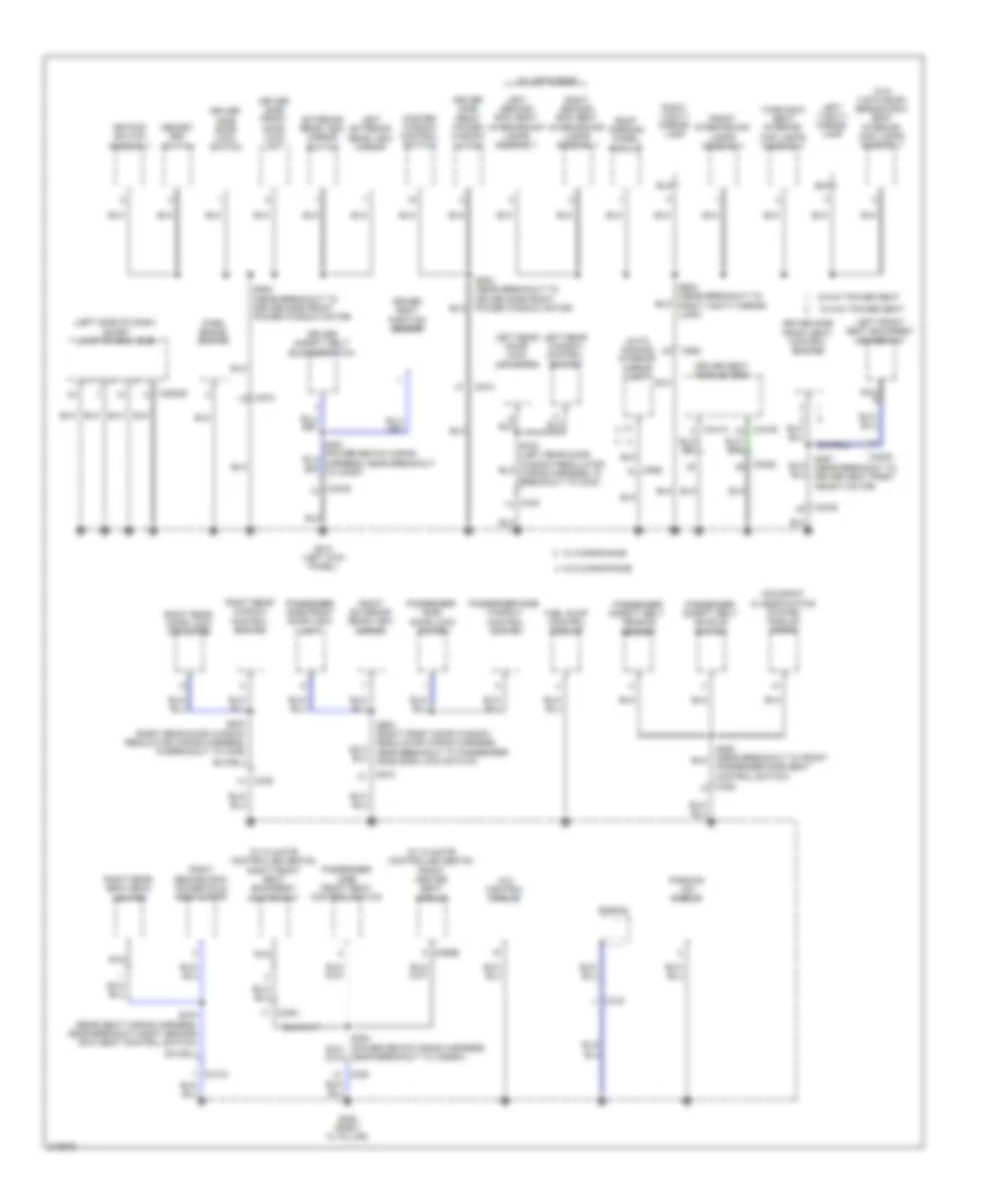
Ground Distribution Wiring Diagram (2 of 3) for Ford Flex SE 2011
List of elements for Ground Distribution Wiring Diagram (2 of 3) for Ford Flex SE 2011:
- (left side of dash) smart junction box (sjb)
- (w/ climate controlled seats) front heated seat module
- (w/ climate controlled seats) right front seat backrest heater mat
- (w/o vista roof) second row seat interior/ map lamps assembly
- 10-way power seat
- 4x4 control module
- 6-way power seat
- Auto- dimming interior mirror unit
- C2280d
- C3049
- C3050
- C3051
- C3134
- C315 j
- C3205
- C328
- C339
- C340
- C341a
- C341b
- C359b
- C510
- C610
- C925
- Control switch
- Door lock switch
- Driver safety belt buckle switch
- Driver seat module (dsm)
- Driver seat position sensor
- Driver side door lock switch
- Driver side front door lock unit
- Driver side front power window motor
- Driver side front seat control switch
- Exterior rear view mirror switch
- Front interior/map
- Fuel pump control module
- G210 (left kick panel)
- G305 (right "c" pillar)
- Keypad switch assembly
- Lamps assembly
- Left exterior rear view mirror
- Left front seat backrest heater mat
- Left rear door lock actuator
- Left rear window control switch
- Left second row seat interior/map lamps assembly
- Left vanity mirror lamp
- Master window control switch
- Memory set switch
- Nca
- Near breakout to c3265a)
- Occupant classification system module (ocsm)
- Park brake switch
- Parking aid module
- Passenger safety belt buckle switch
- Passenger safety belt tension sensor
- Passenger side
- Passenger side front door lock unit
- Passenger side front seat control switch
- Passenger side seat control switch)
- Passenger side window
- Right exterior rear view mirror
- Right rear door lock actuator
- Right rear seat back heater
- Right rear window control switch
- Right second row power fold seat motor
- Right second row seat interior/map lamps assembly
- Right vanity mirror lamp
- Roof opening panel module
- S357 (near breakout to driver seat front height motor)
- S375 (rear seat wiring harness, near breakout right second row seat control switch)
- S500 (near breakout to driver side front power window motor)
- S502 (near breakout to driver side front power window motor)
- S600 (right front door window regulator wiring harness, near breakout to passenger side door lock switch)
- S800 (right rear door window regulator wiring harness, in breakout to c339)
- S902 (near breakout to right vanity mirror lamp)
- Shield
- Third row seat interior/ map lamps assembly
- W/ microphone
- W/ vista roof
- W/o microphone
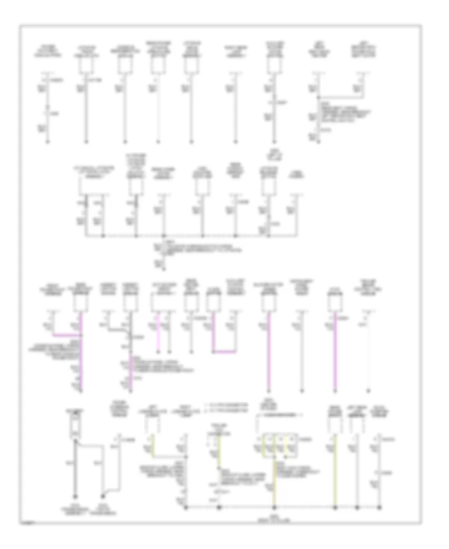
Ground Distribution Wiring Diagram (3 of 3) for Ford Flex SE 2011
List of elements for Ground Distribution Wiring Diagram (3 of 3) for Ford Flex SE 2011:
- (w/ manual liftgate) lift gate latch assembly
- (w/ power liftgate) liftgate latch/ unlatch assembly
- Active park assist switch
- Ambient lighting module
- Ambient lighting switch
- Audio amplifier
- Auxiliary blower motor control
- Auxiliary climate
- Battery
- Blower motor
- C1463b
- C228a
- C3007
- C3133
- C3206
- C3249
- C3304b
- C402b
- C408
- C411
- C4174b
- C4208c
- C4210a
- C4250a
- C432
- Console refrigeration module
- Control assembly
- Dc/ac inverter module
- Floor shifter
- Front power point console
- G103 (top of transmission)
- G104 (transmission assembly)
- G203 (center of dash)
- G300 (right "d" pillar)
- G302 (left "d" pillar)
- Harness, near breakout to rear console power point)
- High mounted stoplamp
- Hvac module
- Instrument panel power point
- Left license plate lamp
- Left rear lamp assembly
- Left rear seat back heater
- Left second row power fold seat motor
- Liftgate drive motor assembly
- Liftgate release switch
- Liftgate/ trunk module (ltm)
- Nca
- Power fold seat module (pfsm)
- Power steering control module
- Rear heated seat module
- Rear power liftgate open/close switch
- Rear power point
- Rear power point console
- Rear window defrost grid
- Rear wiper motor assembly
- Right license plate lamp
- Right rear lamp assembly
- S340 (rear seat wiring harness, near breakout left second row seat control switch)
- S348 (body main wiring harness, in breakout to subwoofer)
- S383 (console panel wiring harness, near breakout to rear console power point)
- S400 (tailgate warning switch wiring harness, near breakout to liftgate) c983
- S407 (backup alarm jumper wiring harness, near breakout to c462)
- Speed control
- Trailer brake control (tbc) module
- Trailer tow connector
- Video camera
- W/ 4 pin connector
- W/ 7 pin connector
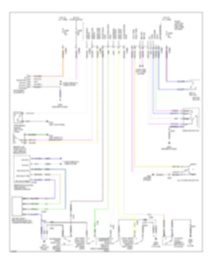
HEADLIGHTS
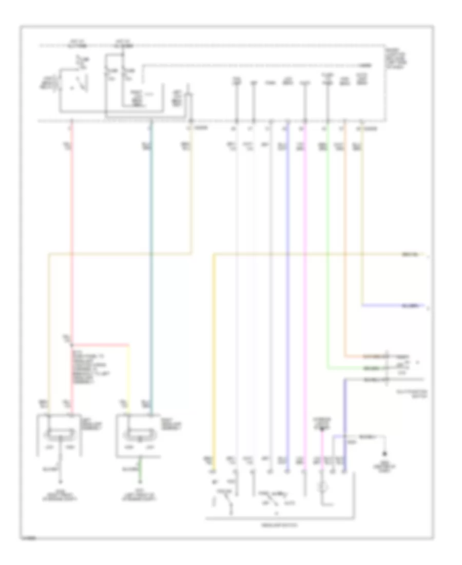
Headlights Wiring Diagram, with High Intensity Gas Discharge Headlights (1 of 2) for Ford Flex SE 2011
List of elements for Headlights Wiring Diagram, with High Intensity Gas Discharge Headlights (1 of 2) for Ford Flex SE 2011:
- (center of dash)
- (dash panel to headlamp junction wiring harness, in breakout to left headlamp assembly) s110
- Auto
- Auto- lamp sens
- Battery junction box (bjb) (left side of engine compt)
- C2280b
- C2280e
- Exterior lights system
- Fog
- Fog ind
- Fog lamp
- Fuse 10a
- Fuse 15a
- Fuse 20a
- G100 (right front of engine compt)
- G101 (left front of of engine compt)
- G202
- Headlamp switch
- Hid
- High beam relay
- Hot at all times
- Interior lights system
- Left headlamp assembly
- Left low beam (fet)
- Low
- Low beam
- Micro
- Off
- Park
- Right headlamp assembly
- Right low beam (fet)
- S223
- Smart junction box (sjb) (left side of dash)
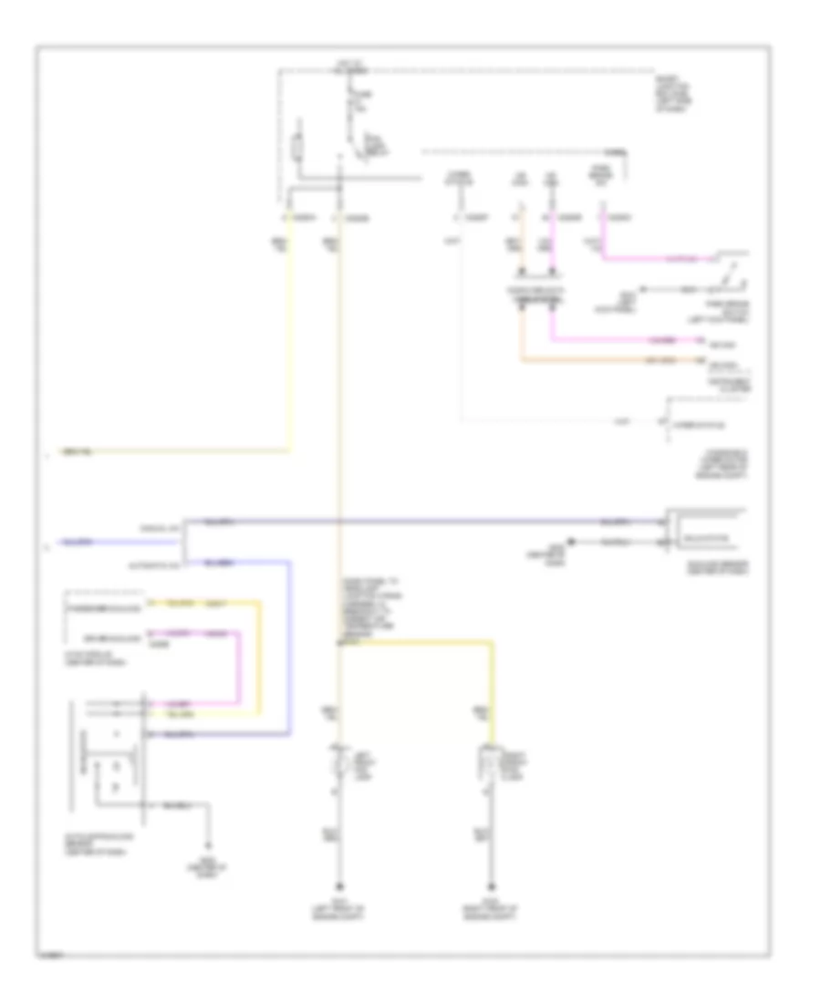
Headlights Wiring Diagram, with High Intensity Gas Discharge Headlights (2 of 2) for Ford Flex SE 2011
List of elements for Headlights Wiring Diagram, with High Intensity Gas Discharge Headlights (2 of 2) for Ford Flex SE 2011:
- (dash panel to headlamp junction wiring harness, in breakout to ambient air temperature sensor) s134
- Autolamp/sunload sensor (center of dash)
- Automatic a/c
- C2280a
- C2280b
- C2280c
- C2280e
- C2280f
- C228b
- Computer data lines system
- Driver sunload
- Engine compt)
- Flash to pass
- Fog lamp relay
- Ftp
- Fuse 15a
- G100 (right front of
- G101 (left front of
- G202 (center of dash)
- G210 (left kick panel)
- High
- High beam
- Hot at all times
- Hvac module (center of dash)
- Instrument cluster
- Left front fog lamp
- Manual a/c
- Micro
- Ms can+
- Ms can-
- Multi-function switch
- Off
- Park brake sw
- Park brake switch (left kick panel)
- Passenger sunload
- Right front fog lamp
- S223
- Smart junction box (sjb) (left side of dash)
- Solid state
- Sunload sensor (center of dash)
- Vh416
- Vh417
- Windshield wiper motor (left rear of engine compt)
- Wiper status
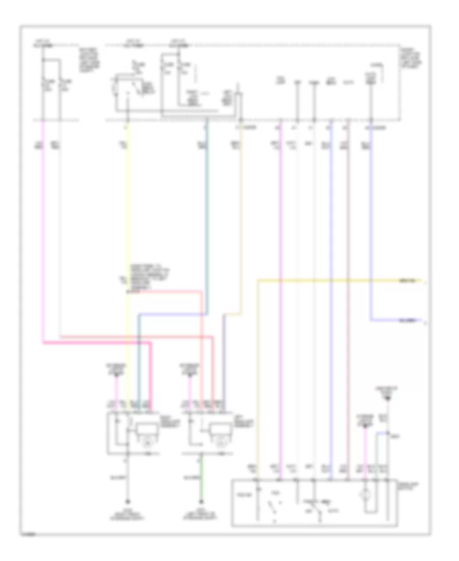
Headlights Wiring Diagram, without High Intensity Gas Discharge Headlights (1 of 2) for Ford Flex SE 2011
List of elements for Headlights Wiring Diagram, without High Intensity Gas Discharge Headlights (1 of 2) for Ford Flex SE 2011:
- Auto
- Auto- lamp sens
- C2280b
- C2280e
- Flash to pass
- Fog
- Fog ind
- Fog lamp
- Ftp
- Fuse 10a
- Fuse 15a
- G100 (right front of engine compt)
- G101 (left front of of engine compt)
- G202 (center of dash)
- Headlamp switch
- High
- High beam
- High beam relay
- Hot at all times
- Interior lights system
- Left headlamp assembly
- Left low beam (fet)
- Low
- Low beam
- Micro
- Multi-function switch
- Off
- Park
- Right headlamp assembly
- Right low beam (fet)
- S110 (dash panel to headlamp junction wiring harness, in breakout to left headlamp assembly)
- S223
- Smart junction box (sjb) (left side of dash)
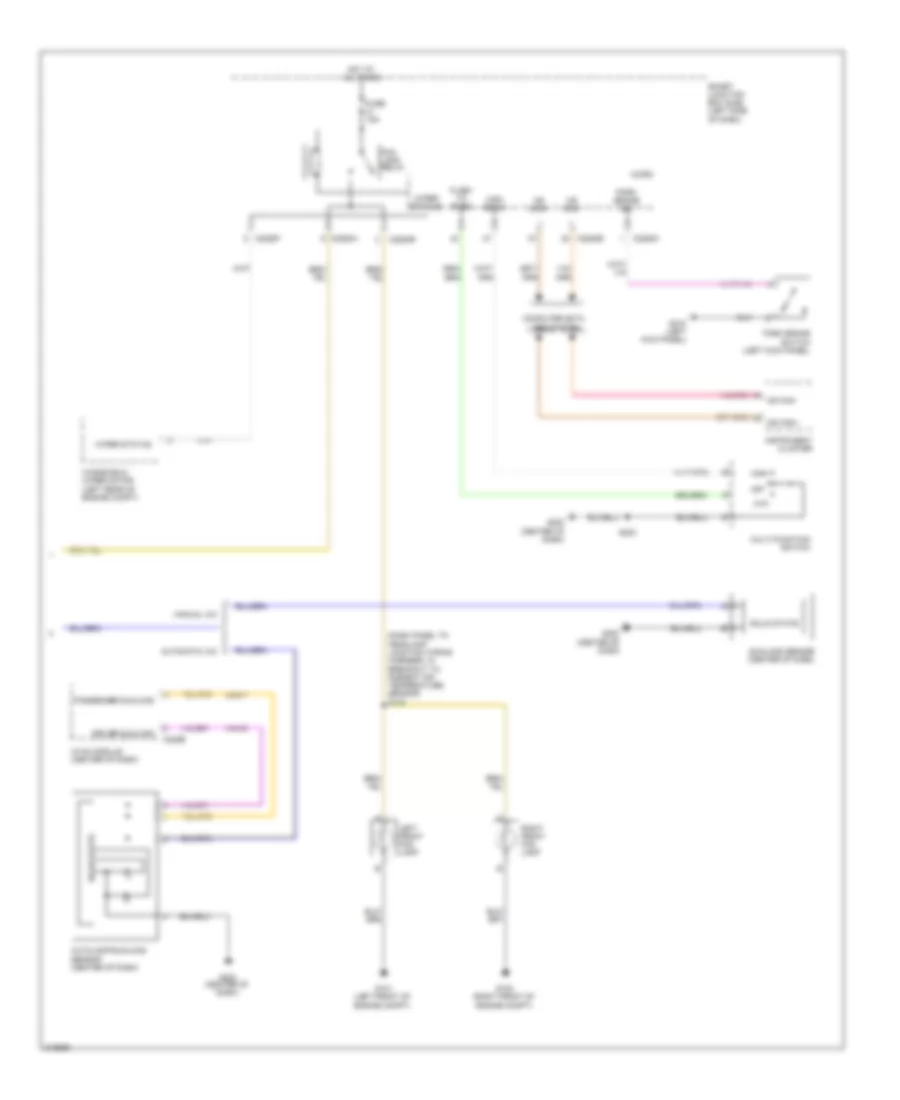
Headlights Wiring Diagram, without High Intensity Gas Discharge Headlights (2 of 2) for Ford Flex SE 2011
List of elements for Headlights Wiring Diagram, without High Intensity Gas Discharge Headlights (2 of 2) for Ford Flex SE 2011:
- (dash panel to headlamp junction wiring harness, in breakout to ambient air temperature sensor) s134
- Autolamp/sunload sensor (center of dash)
- Automatic a/c
- C2280a
- C2280b
- C2280c
- C2280e
- C2280f
- C228b
- Computer data lines system
- Driver sunload
- Engine compt)
- Fog lamp relay
- Fuse 15a
- G100 (right front of
- G101 (left front of
- G202 (center of dash)
- G210 (left kick panel)
- Hot at all times
- Hvac module (center of dash)
- Instrument cluster
- Left front fog lamp
- Manual a/c
- Micro
- Ms can+
- Ms can-
- Park brake sw
- Park brake switch (left kick panel)
- Passenger sunload
- Right front fog lamp
- Smart junction box (sjb) (left side of dash)
- Solid state
- Sunload sensor (center of dash)
- Vh416
- Vh417
- Windshield wiper motor (left rear of engine compt)
- Wiper status
HORN
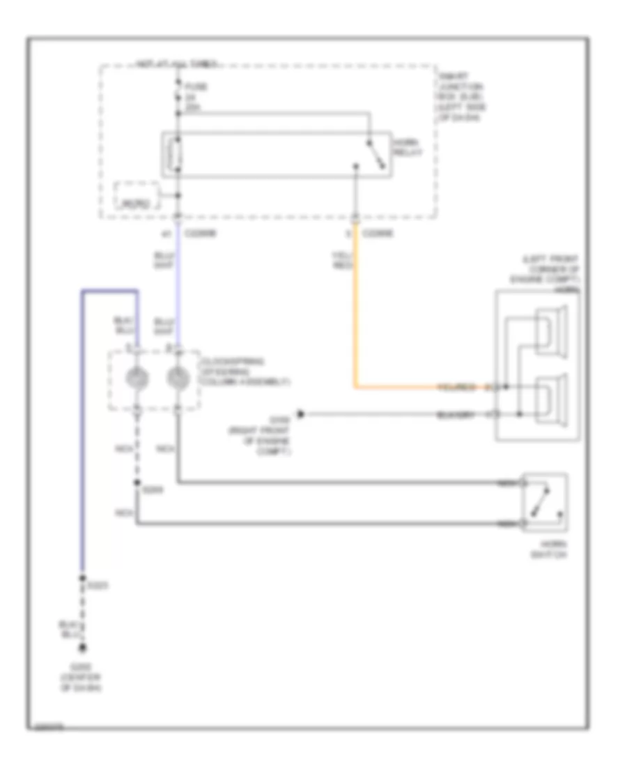
Horn Wiring Diagram for Ford Flex SE 2011
List of elements for Horn Wiring Diagram for Ford Flex SE 2011:
- (left front corner of engine compt) horn
- C2280b
- C2280e
- Clockspring (steering column assembly)
- Fuse 20a
- G100 (right front of engine compt)
- G202 (center of dash)
- Horn relay
- Horn switch
- Hot at all times
- Micro
- Nca
- S223
- S299
- Smart junction box (sjb) (left side of dash)
INSTRUMENT CLUSTER
Instrument Cluster Wiring Diagram for Ford Flex SE 2011
List of elements for Instrument Cluster Wiring Diagram for Ford Flex SE 2011:
- (center of dash) g202
- Ajar
- Ajar liftgate
- Anti-theft system
- Auto dimming interior mirror unit
- Brake fluid level switch (left rear of engine compt)
- Brk fluid sw rtn
- C1010
- C210
- C212
- C2280a
- C2280b
- C2280c
- C2280f
- C315
- C339
- C340
- C510
- C610
- C925
- C983
- Cbp29
- Cca15
- Center rtn
- Center stack switch assembly
- Center sw
- Clock
- Cmc20
- Cmc24
- Cmc29
- Compass +
- Compass -
- Computer data lines system
- Ctl on/off
- Dr door ajar
- Driver side front door lock unit (rear of driver's door)
- Fluid sw
- Fluid sw brake
- Fuel level sensor (fuel tank assembly)
- Fuel lvl 1
- Fuel lvl 2
- Fuel pump module (in fuel tank)
- Fuse 10a
- Fuse 20a
- Fuse 5a
- G101 (left front of engine compt)
- G202 (center of dash)
- G210 (left kick panel)
- G302 (left "d" pillar)
- G305 (right "c" pillar)
- Gd114
- Gnd
- Hot at all times
- Hot in start or run
- Hs can +
- Hs can -
- Ignition switch
- Illum
- Instrument cluster (ic)
- Interior lights system
- Key in ign
- Left rear door lock actuator (rear of left rear door)
- Liftgate latch assembly (bottom of liftgate)
- Logic
- Logic gnd
- Lr door ajar
- Lvl 1 rtn
- Lvl 2 trn
- Mc sw+
- Mc sw-
- Message center switch
- Ms can +
- Ms can -
- Ms can+
- Ms can-
- Nca
- Oil pressure switch (left side of engine block)
- Oil sw
- Park brake sw
- Park brake switch (left kick panel)
- Pass door ajar
- Passenger side front door lock unit (rear of front passenger's door)
- Pats rx
- Pats tx
- Pnk
- Pwr gnd
- Right rear door lock actuator (rear of right rear door)
- Rmc27
- Rmc32
- Rmc33
- Rr door ajar
- Run/start
- S240
- S400
- S500
- S600
- S700
- S800
- Sbp14
- Sbp26
- Smart junction box (sjb) (left side of dash)
- Trac ctrl
- Vdb04
- Vdb05
- Vdb06
- Vdb07
- Vln04
- Vmc11
- Vmc23
- Vmc30
- Vmc31
- Vrt23
- Vrt24
- Wiper/washer system
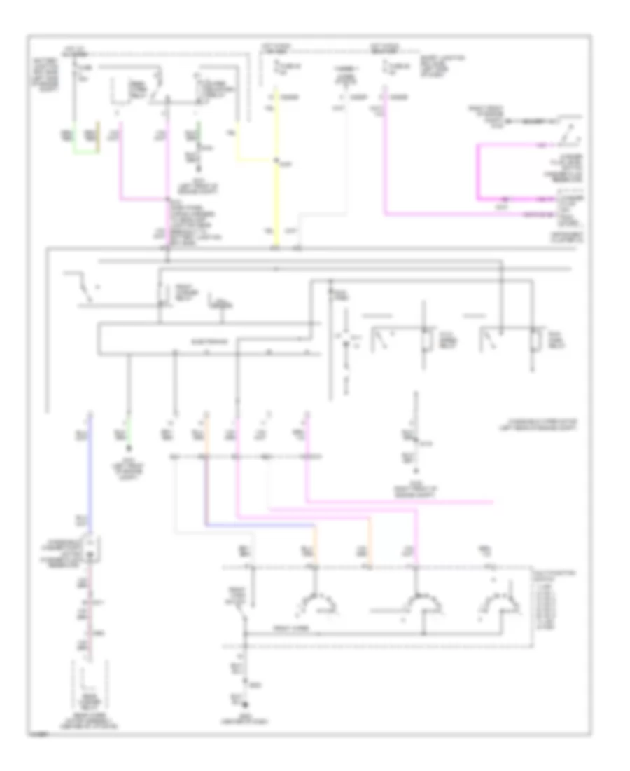
INTERIOR LIGHTS
Courtesy Lamps Wiring Diagram (1 of 2) for Ford Flex SE 2011
List of elements for Courtesy Lamps Wiring Diagram (1 of 2) for Ford Flex SE 2011:
- (interior lamps wiring harness, near breakout to right vanity mirror lamp) s901
- (left "d" pillar) g302
- (left kick panel) g210
- Ajar driver door
- Assembly
- Battery saver relay
- C212
- C2280a
- C2280b
- C2280c
- C2280d
- C312
- C339
- C340
- C510
- C610
- C925
- C983
- Courtesy
- Dim
- Dim off
- Dim sw
- Dim sw gnd
- Dome defeat
- Dome lamp
- Dome lp
- Driver side front door lock unit (rear of driver's door)
- Fuse 10a
- Fuse 15a
- Fuse 2a
- G210 (left kick panel)
- G305 (right "c" pillar)
- Hot at all times
- Hot w/ accessory delay relay energized
- Instrument panel dimmer switch
- Interior lighting (fet)
- Left exterior rear view mirror (mirror assembly)
- Left rear door lock actuator (rear of left rear door)
- Left second row seat interior/ map lamps assembly
- Left vanity mirror lamp
- Liftgate latch assembly (bottom of liftgate)
- Liftgate/glass ajar
- Logic
- Lr door ajar
- Micro
- Module homelink
- Nca
- Off
- Pass door ajar
- Passenger side front door lock unit (rear of front passenger's door)
- Puddle lamp (fet)
- Red
- Right exterior rear view mirror (mirror assembly)
- Right rear door lock actuator (rear of right rear door)
- Right second row seat interior/ map lamps
- Right vanity mirror lamp
- Rr door ajar
- S241 (main wiring harness, near breakout to c210)
- S332 (body main wiring harness, near breakout to joint connector 6)
- S400
- S500
- S600
- S700
- S800
- S900 (interior lamps wiring harness, near breakout to right vanity mirror lamp)
- S902
- Second row seat interior/ map lamps assembly
- Smart junction box (sjb) (left side of dash)
- W/ vista roof
- W/o vista roof
Courtesy Lamps Wiring Diagram (2 of 2) for Ford Flex SE 2011
List of elements for Courtesy Lamps Wiring Diagram (2 of 2) for Ford Flex SE 2011:
- (console panel wiring harness, near breakout to ambient lighting module) s365
- (left kick panel) g210
- Ambient lighting module (center console)
- Ambient lighting switch
- C3047
- C313
- C3249
- C327
- Cbx07
- Cln44
- Cln45
- Cln46
- Cln54
- Courtesy
- Front cupholder lamp
- Front interior/ map lamp assembly
- G203 (center of dash)
- Gd908
- Gnd
- Instrument illumination circuit
- Led sig
- Left front footwell lamp
- Left rear footwell lamp
- Off
- Rear cupholder lamp
- Red
- Right front footwell lamp
- Right rear footwell lamp
- Rln44
- Rtn
- S364
- S366
- S367
- S381
- S902
- Storage bin lamp
- Third row seat interior/ map lamps assembly
- Vpwr
Instrument Illumination Wiring Diagram for Ford Flex SE 2011
List of elements for Instrument Illumination Wiring Diagram for Ford Flex SE 2011:
- (center console) floor shifter
- (center of
- (center of dash) g202
- (console panel wiring harness, near breakout to rear console power point) s380
- (main wiring harness, near breakout to c210) s241
- (not used)
- (steering wheel) s298
- (steering wheel) s299
- Active park assist switch
- Ambient lighting switch
- Auto
- Auxiliary climate control assembly
- Backlighting led (fet)
- C2280b
- C312
- C3249
- Center stack switch assembly
- Clock
- Clockspring (steering column assembly)
- Dash)
- Dim
- Dim sw gnd
- Dimmer sw
- Dome defeat
- Dome lamp
- Dome lp
- Front power liftgate open/close switch
- Fuse 15a
- G202 (center of
- G202 (center of dash)
- G203
- G203 (center of
- G302 (left "d" pillar)
- Gnd
- Headlamp switch
- Hot at all times
- Illum
- Instrument panel dimmer switch
- Left steering wheel switch
- Low
- Low beam
- Message center switch
- Micro
- Nca
- Off
- Park
- Rear power liftgate open/close switch
- Right steering wheel switch
- S206 (main wiring harness, near breakout to hvac module)
- S223
- S381
- Smart junction box (sjb) (left side of dash)
- White led (fet)
MEMORY SYSTEMS
Adjustable Pedal Wiring Diagram for Ford Flex SE 2011
List of elements for Adjustable Pedal Wiring Diagram for Ford Flex SE 2011:
- Adjustable pedal motor (left side of dash)
- Adjustable pedal switch
- Battery junction box (bjb) (left side of engine compt)
- C1045
- C211
- C2280d
- C3049
- C3050
- C341a
- C341c
- C510
- Cbx05
- Cpp01
- Cpp02
- Cpp09
- Cpp10
- Cps15
- Cps16
- Driver seat module (dsm) (under driver's seat)
- Forward
- Fuse 30a
- Fuse 5a
- G210 (left kick panel)
- Gd906
- Hot at all times
- Lpp06
- Memory set switch
- Mtr forward
- Pedal for sw
- Pedal hall
- Pedal motor aft
- Pedal rear sw
- Pwr gnd
- Rearward
- Rpp06
- S500
- S504
- Set 1
- Set 2
- Smart junction box (sjb) (left side of dash)
Memory Seat & Mirrors Wiring Diagram (1 of 2) for Ford Flex SE 2011
List of elements for Memory Seat & Mirrors Wiring Diagram (1 of 2) for Ford Flex SE 2011:
- (not used)
- Adjustable pedal circuit
- Adjustable pedal for sw
- Adjustable pedal rear sw
- Aft
- Base backward
- Base forward
- Battery junction box (bjb) (left side of engine compt)
- C211
- C213
- C2280a
- C2280d
- C3049
- C3050
- C341a
- C341b
- C341c
- C341d
- C510
- Cbx03
- Cbx05
- Computer data lines system
- Cpm04
- Cpm16
- Cpm17
- Cpm20
- Cpm21
- Cpm22
- Cpm26
- Cpm28
- Cpm29
- Cpm31
- Cpm33
- Cpm34
- Cpm39
- Cpp01
- Cpp02
- Cpp03
- Cpp04
- Cpp09
- Cpp10
- Cpp12
- Cpp13
- Cpp14
- Cpp22
- Cpp23
- Cps01
- Cps02
- Cps03
- Cps04
- Cps05
- Cps06
- Cps07
- Cps08
- Cps14
- Cps15
- Cps16
- Cps23
- Cps24
- Cps25
- Cps26
- Cps27
- Cps28
- Cps29
- Cps30
- Cps55
- Down
- Driver seat module (dsm) (under driver's seat)
- Drv mirr horz pot
- Drv mirr horz sw
- Drv mirr mtr dn/lt
- Drv mirr mtr horz rt
- Drv mirr mtr vert up
- Drv mirr vert pot
- Drv mirr vert sw
- Ext mirr pot feed
- Exterior rear view mirror switch
- Forward
- Front down
- Front up
- Fuse 15a
- Fuse 30a
- Fuse 5a
- G210 (left kick panel)
- Gd905
- Gd906
- Hall effect return
- Hall effect sense
- Hot at all times
- Left
- Logic gnd
- Lpm30
- Lpp06
- Memory set switch
- Mirr com sw
- Mirr pot ret
- Ms can+
- Ms can-
- Pass mirr horz pot
- Pass mirr horz sw
- Pass mirr mtr dn/lt
- Pass mirr mtr horz rt
- Pass mirr mtr vert up
- Pass mirr vert pot
- Pass mirr vert sw
- Pedal hall effect feed
- Pedal hall effect sens
- Pedal motor aft
- Pedal motor forward
- Pwr gnd
- Rear down
- Rear up
- Recline down
- Recline up
- Right
- Rmp11
- Rpm30
- Rpp06
- Rps13
- S220
- S326
- S500
- S504
- Select
- Set 1
- Set 2
- Smart junction box (sjb) (left side of dash)
- Vbatt
- Vdb06
- Vdb07
- Vpm35
- Vpm36
- Vpm37
- Vpm38
- Vpp08
- Vpp17
- Vps09
- Vps10
- Vps11
- Vps12
Memory Seat & Mirrors Wiring Diagram (2 of 2) for Ford Flex SE 2011
List of elements for Memory Seat & Mirrors Wiring Diagram (2 of 2) for Ford Flex SE 2011:
- (body main wiring harness, near breakout to c510) s328
- (mirror assembly) left exterior rear view mirror
- (mirror assembly) right exterior rear view mirror
- Aft
- C3050
- C3205
- C510
- C610
- Defogger system
- Down
- Driver seat front height motor (under driver's seat)
- Driver seat horizontal motor (under driver's seat)
- Driver seat lumbar motor (driver's seat back)
- Driver seat rear height motor (under driver's seat)
- Driver seat recliner motor (driver's seat back)
- Driver side front seat control switch
- Front height
- Fwd
- G210 (left kick panel)
- Height motor)
- Horizontal
- Interior lights system
- Lumbar
- Out
- Rear height
- Recline
- S329 (body main wiring harness, near breakout to c510)
- S356 (power seats wiring harness, near breakout to driver seat front
- S357
NAVIGATION
Navigation Wiring Diagram (1 of 3) for Ford Flex SE 2011
List of elements for Navigation Wiring Diagram (1 of 3) for Ford Flex SE 2011:
- Antenna
- Antenna am/fm
- Audio amplifier
- Audio amplifier enable
- Battery junction box (bjb) (left side of engine compt)
- C211
- C212
- C2280a
- C2280b
- C4208a
- C4208b
- C4208c
- Cntr img+
- Cntr img-
- Coax
- Computer data lines system
- Fuse 20a
- Fuse 30a
- Fuse 5a
- G300 (right "d" pillar)
- Gd148
- Gnd
- Gps sdars/
- Hot at all times
- Hot in start
- Ip spkr+
- Ip spkr-
- Lf spkr+
- Lf spkr-
- Lr spkr+
- Lr spkr-
- Lr+in
- Lr-in
- Ms can+
- Ms can-
- Nav voice+
- Nav voice-
- Nca
- Rf spkr+
- Rf spkr-
- Rme01
- Rme02
- Rme06
- Rme07
- Rme08
- Rme09
- Rme10
- Rme11
- Rme12
- Rme22
- Rme39
- Rme51
- Rmn07
- Rr spkr+
- Rr spkr-
- Rr+in
- Rr-in
- S307
- S348
- Sbb07
- Smart junction box (sjb) (left side of dash)
- Sme23
- Solid
- Spkr+
- Spkr-
- Splitter (w/ navigation)
- State
- Sub 1 +
- Sub 1 -
- Sub 2 +
- Sub 2 -
- Sub woofer+
- Subwoofer amplifier
- Subwoofer-
- Vdb06
- Vdb07
- Vme01
- Vme02
- Vme06
- Vme07
- Vme08
- Vme09
- Vme10
- Vme11
- Vme12
- Vme22
- Vme39
- Vme51
- Vmn07
Navigation Wiring Diagram (2 of 3) for Ford Flex SE 2011
List of elements for Navigation Wiring Diagram (2 of 3) for Ford Flex SE 2011:
- (body main wiring harness, in breakout to subwoofer)
- (or rme52)
- (or rme53)
- (or rmn01)
- (or vme52)
- (or vme53)
- (w/o sync) audio input jack
- Am/fm ant
- Amp enable
- Antenna pwr
- Audio control module (acm)
- C212
- C240a
- C240b
- C240c
- C240d
- C312
- C339
- C340
- C510
- C610
- Cbp28
- Cmn23
- Cmn24
- Cmn26
- Cntr img+
- Cntr img-
- Coax
- Computer data lines system
- Display rx
- Display tx
- Dme12
- Dme22
- Dme45
- Dme51
- Dmn07
- Dmn14
- Gd114
- Gnd
- Gps ant
- Instrument panel speaker
- Left "a" pillar speaker
- Left "d" pillar speaker
- Left front speaker
- Left rear speaker
- Lf spkr+
- Lf spkr-
- Lr spkr+
- Lr spkr-
- Mic+
- Mic-
- Mono +
- Mono -
- Ms can +
- Ms can -
- Nav voice+
- Nav voice-
- Navigation system
- Nca
- Rf spkr+
- Rf spkr-
- Right "a" pillar speaker
- Right "d" pillar speaker
- Right front speaker
- Right rear speaker
- Rme07
- Rme09
- Rme10
- Rme12
- Rme14
- Rme22
- Rme45
- Rme46
- Rme51
- Rme54
- Rmn07
- Rmn14
- Rmr29
- Rmr30
- Rr spkr+
- Rr spkr-
- S333
- S339 (body main wiring harness, in breakout to subwoofer)
- Sbp39
- Sdars ant
- Sheild
- Shield
- Sme23
- St input 2l+
- St input 2l-
- St input 2r+
- St input 2r-
- Start
- Stereo 1 r+
- Stereo 1 r-
- Stereo l+
- Stereo l-
- Subwoofer+
- Subwoofer-
- Swc1+
- Swc1-
- Swc2+
- Swc2-
- Sync radio circuit
- Vdb06
- Vdb07
- Video enable
- Video+
- Video-
- Vme07
- Vme09
- Vme10
- Vme12
- Vme14
- Vme22
- Vme45
- Vme46
- Vme51
- Vme54
- Vmn01
- Vmn07
- Vmn14
- Vmr29
- Vmr30
- W/ navigation
- W/ sync
- W/o sync
Navigation Wiring Diagram (3 of 3) for Ford Flex SE 2011
List of elements for Navigation Wiring Diagram (3 of 3) for Ford Flex SE 2011:
- (center of dash) (w/o navigation) front display interface module (fcim)
- (center of dash) g202
- Accessory protocol interface module (apim) (center console)
- Batt
- C2280a
- C2280b
- C2949b
- C312
- Clockspring (steering column assembly)
- Computer
- Computer data lines system
- Data lines
- Dme12
- Dmr29
- Front control interface module (fcim) (center of dash)
- Fuse 14 10a
- Fuse 16 15a
- G202 (center of dash)
- Gd114
- Global positioning system module (gpsm) (w/ sync w/o navigation)
- Gnd
- Hot at all times
- Interior lights system
- L + out
- L - out
- Media
- Ms can +
- Ms can -
- Ms can+
- Ms can-
- Nca
- Phone
- R + out
- R - out
- Rear entertainment module (retm) (right side of dash)
- Right steering wheel switch
- Rme09
- Rme12
- Rme54
- Rmr29
- Rmr30
- S230
- S240
- Sbp14
- Sbp16
- Seek +
- Seek -
- Shield
- Smart junction box (sjb) (left side of dash)
- Swc2+
- Swc2-
- Sync radio circuit
- System
- Vdb06
- Vdb07
- Vme09
- Vme12
- Vme54
- Vmr29
- Vmr30
- Voice
- Vol +
- Vol -
- W/ dvd
- W/ sync
- W/o dvd
- W/o sync
Parking Assistant Wiring Diagram for Ford Flex SE 2011
List of elements for Parking Assistant Wiring Diagram for Ford Flex SE 2011:
- (backup alarm jumper wiring harness, near breakout to c462) s424
- (body main wiring harness, in breakout to subwoofer)
- (dash panel to headlamp junction wiring harness, near breakout to anti-lock brake system module)
- (if equipped) s387
- (left front of engine compt) (if equipped) left active park assist sensor
- Active park assist switch (if equipped)
- Auto park sw
- C211
- C212
- C2280d
- C312
- C411
- Cbp35
- Cmp02
- Cmp18
- Computer data lines system
- Front left side sn
- Front right side sn
- Fuse 35 10a
- G203 (center of dash)
- G305 (right "c" pillar)
- Gd145
- Gnd
- Hot in start or run
- Hs can+
- Hs can-
- Inner left parking aid sensor
- Inner right parking aid sensor
- Interior lights system
- Left rear inner sn
- Left rear outer sn
- Lmp07
- Nca
- Outer left parking aid sensor
- Outer right parking aid sensor
- Parking aid module (pam) (right "c" pillar)
- Parking aid speaker
- Pwr run
- Rear sens gnd
- Rear sens pwr
- Rear sounder +
- Rear sounder -
- Right active park assist sensor (if equipped) (right front of engine compt)
- Right rear inner sn
- Right rear outer sn
- Rmp07
- Rmp09
- S156
- S165 (near breakout to anti-lock brake system module)
- S381
- S386 (if equipped) (body main wiring harness, in breakout to subwoofer)
- S403 (backup alarm jumper wiring harness, near breakout to c462)
- Smart junction box (sjb) (left side of dash)
- Solid state
- Status led
- Vdb04
- Vdb05
- Vmp03
- Vmp14
- Vmp15
- Vmp16
- Vmp17
- Vmp20
- Vmp21
Rear Camera Wiring Diagram for Ford Flex SE 2011
List of elements for Rear Camera Wiring Diagram for Ford Flex SE 2011:
- (left "d" pillar) g302
- Audio control module (acm)
- Batt
- C213
- C2280a
- C2280d
- C240d
- C913
- Choke
- Cmn23
- Cmn24
- Cmn26
- Display rx
- Display tx
- Dispsg
- Dmn14
- Dmp19
- Electronics
- Front display interface module (fdim) (center of dash)
- Fuse 16 15a
- Fuse 35 10a
- G202 (center of dash)
- Gd114
- Gnd
- Hot at all times
- Hot in start or run
- Nca
- Pwr
- Rmn14
- Rmp19
- S230
- S311
- S400
- Sbp16
- Shield
- Smart junction box (sjb) (left side of dash)
- Video camera (if equipped) (center of liftgate)
- Video enable
- Video shield
- Video+
- Video-
- Vmn14
- Vmp19
POWER DISTRIBUTION
Power Distribution Wiring Diagram (1 of 4) for Ford Flex SE 2011
List of elements for Power Distribution Wiring Diagram (1 of 4) for Ford Flex SE 2011:
- (in breakout to subwoofer) s307
- (left side of engine compt) battery junction box (bjb)
- (near breakout to c3050) s326
- (not used)
- (to headlamp junction near breakout to auxiliary relay box) s194
- (to headlamp junction near breakout to left front of engine compt, on transaxle) s181
- (turbo: near breakout to coil on plug 4) (except turbo: to headlamp junction near breakout to left front of engine compt, on transaxle) s157
- 3rd rao seat enable (fet)
- Adjustable pedal switch
- Anti-lock brake system (abs) module
- Audio amplifier
- Battery
- Battery charge relay
- Battery junction box (bjb) (left side of engine compt)
- Brake pedal position (bpp) switch
- Bsi (fet)
- C1045
- C1284a
- C1285a
- C145
- C1463b
- C210
- C211
- C2280d
- C2280g
- C3049
- C3050
- C312
- C3206
- C328
- C341a
- C341b
- C411
- C4174b
- C4208c
- C510
- Driver seat module (dsm)
- Driver side front power window motor
- Driver side front seat control switch
- Exterior rear view mirror switch
- Front console power point
- Front passenger side seat control switch
- Fuse 10a
- Fuse 15a
- Fuse 20a
- Fuse 30a
- Fuse 40a
- Fuse 5a
- Fuse 7.5a
- Fuse 80a
- G203 (center of dash)
- G300 (right "d" pillar)
- Generator
- Instru- ment panel power point
- Interior lighting (fet)
- Key pad illum (fet)
- Keypad switch assembly
- Left headlamp assembly
- Liftgate/ trunk module (ltm)
- Micro
- Power steering control module (pscm)
- Rear console power point
- Rear power point
- Red
- Right headlamp assembly
- Right low beam (fet)
- S182 (to headlamp junction near breakout to left front of engine compt, on transaxle)
- S183 red (to headlamp junction near breakout to auxiliary relay box)
- S383
- Smart junction box (sjb) (left side of dash)
- Starter motor
- To dc/ac inverter module (diagram 4 of 4)
- To fuse 11 (diagram 2 of 4)
- To fuse 6 (diagram 3 of 4)
- Trailer brake control (tbc) module
- Trailer tow left turn relay
- Trailer tow park lamp relay
- Trailer tow right turn relay
- W/ 6 way power seat
- W/ memory
- W/o 6 way power seat
- W/o memory
Power Distribution Wiring Diagram (2 of 4) for Ford Flex SE 2011
List of elements for Power Distribution Wiring Diagram (2 of 4) for Ford Flex SE 2011:
- (near breakout to c139) s150
- (not used)
- A/c clutch relay
- Acc
- Acc run
- Audio control module (acm)
- Auxiliary blower motor relay
- Battery junction box (bjb) (left side of engine compt)
- Blower motor relay
- C1381b
- C175b
- C210
- C211
- C2280a
- C2280b
- C2280d
- C2280e
- C240a
- C312
- C315
- C983
- Engine cooling fan motor
- Evap canister vent control solenoid
- Except turbo
- Floor shifter
- From fuse 27 (diagram 4 of 4)
- From fuse 7 (diagram 1 of 4)
- From pcm power relay (diagram 2 of 4)
- Fuel pump relay
- Fuse 10a
- Fuse 15a
- Fuse 20a
- Fuse 25a
- Fuse 30a
- Fuse 40a
- Fuse 5a
- Fuse 7.5a
- Fuse 80a
- Ignition lock solenoid
- Ignition switch
- Key in ignition switch
- Micro
- Off
- One touch integrated start diode
- Pcm power relay
- Powertrain control module (pcm)
- Rear window defrost relay
- Rear wiper motor assembly
- Rear wiper relay
- Red
- Reversing lamps relay
- Run
- S116 (to headlamp junction near breakout to battery junction box (bjb))
- S193 (near breakout to anti-lock brake system module)
- S345 (near breakout to left kick panel)
- Smart junction box (sjb) (left side of dash)
- Smrc
- Start
- Starter relay
- Third row power seat relay
- To console refrigeration relay (diagram 4 of 4)
- To evap canister vent control solenoid (diagram 2 of 4)
- To s221 (diagram 4 of 4)
- Turbo
- Used) (not
- Windshield wiper motor
- Wiper run/park relay
Power Distribution Wiring Diagram (3 of 4) for Ford Flex SE 2011
List of elements for Power Distribution Wiring Diagram (3 of 4) for Ford Flex SE 2011:
- (body main wiring harness, near breakout to c354) s361
- (body main wiring harness, near breakout to left "a" pillar speaker) s318
- (body main wiring harness, near breakout to restraints control module) s347
- (interior lamps wiring harness, near breakout to right vanity mirror lamp) s906
- (left front door window regulator wiring harness, near breakout to driver side front power window motor) s503
- (main wiring harness, near breakout to c210) s240
- (main wiring harness, near breakout to instrument cluster) s230
- (near breakout to c210) s220
- (power seats wiring harness, near breakout to c3265a) s355
- 4x4 control module
- Accessory delay relay
- Accessory protocol interface module (fpim) (w/ sync)
- All lock/ unlock relay
- Ambient lighting module
- Ambient lighting switch
- Auto dimming interior mirror unit
- Back- lighting led (fet)
- C213
- C2280a
- C2280b
- C2280d
- C228a
- C2949a
- C3050
- C312
- C3133
- C3134
- C3249
- C328
- C339
- C340
- C359b
- C4174b
- C510
- C610
- C925
- Circuit breaker 47 30a
- Clock
- Data link connector (dlc)
- Driver side door lock switch
- Driver side front seat control switch (w/ memory seats)
- Driver unlock relay
- Fog lamp relay
- From fuse 18 (diagram 3 of 4)
- From fuse 8 (diagram 1 of 4)
- Front control interface module (fcim)
- Front display interface module (fdim)
- Front driver side power window motor
- Front heated seat module
- Fuse 10a
- Fuse 15a
- Fuse 17 20a
- Fuse 20a
- Fuse 21 15a
- Fuse 22 15a
- Fuse 23 15a
- Fuse 24 20a
- Fuse 25a
- Global positioning system module (gpsm)
- High beam relay
- Horn relay
- Hvac module
- Instrument cluster (ic)
- Left low beam (fet)
- Left rear window control switch
- Left second row power fold seat motor
- Lf turn lamp (fet)
- Liftgate rel (fet)
- Liftgate/ trunk module (ltm)
- Lr stop/ turn lamp (fet)
- Master window control switch
- Micro
- Park lamp relay
- Passenger side door lock switch
- Passenger side window control switch
- Puddle lamp (fet)
- Rear enter- tainment module (retm) (if equipped)
- Rf turn lamp (fet)
- Right low beam (fet)
- Right rear window control switch
- Right second row power fold seat motor
- Roof opening panel control switch
- Roof opening panel module
- Rr stop/ turn lamp (fet)
- Smart junction box (sjb) (left side of dash)
- To fuse 21 (diagram 3 of 4)
- To fuse 40 (diagram 4 of 4)
- W/ moonroof
- W/ navi- gation
- W/ rear folding seats
- W/ sync
- W/o navi- gation
- W/o sync
Power Distribution Wiring Diagram (4 of 4) for Ford Flex SE 2011
List of elements for Power Distribution Wiring Diagram (4 of 4) for Ford Flex SE 2011:
- (body main wiring harness, near break- out to c354) s360
- (body main wiring harness, near breakout to c3073) s311
- (console panel wiring harness, near breakout to rear console power point) s382
- (dash panel to c145 headlamp junction wiring harness, near breakout to anti-lock brake system module) s155
- (engine control sensor & fuel charge wiring harness, near breakout to c139)
- (interior lamps wiring harness, near breakout to right vanity mirror lamp) s901
- (left "d" pillar) g302
- (left side of dash) smart junction box (sjb)
- (not used)
- (right "d" pillar) g300
- 3.5l except turbo w/ third row seats
- 3.5l turbo w/ third row seats
- 4x4 control module
- Ac outlet
- Ac-a
- Ac-b
- Anti-lock brake system (abs) module
- Audio control module (acm)
- Battery charge relay
- Battery junction box (bjb) (left side of engine compt)
- Battery saver relay
- C1381b
- C145
- C1463a
- C175b
- C210
- C211
- C212
- C213
- C2280a
- C2280b
- C2280d
- C2280e
- C240a
- C310a
- C312
- C3206
- C328
- C3304b
- C359b
- C4210a
- C4210b
- C913
- C925
- Cbp35
- Center stack switch assembly
- Console refrige- ration relay
- Console refrigeration module
- Dc/ac inverter module (base of right "d" pillar)
- Except turbo
- Floor shifter
- From fuse 15 d (diagram 2 of 4)
- From fuse 4 (diagram 1 of 4)
- From h accessory delay relay (diagram 3 of 4)
- From ignition switch (diagram 2 of 4)
- Front heated seat module
- Front interior/ map lamps assembly
- Fuel pump relay
- Fuse 10a
- Fuse 20a
- Fuse 25 10a
- Fuse 5a
- Fuse 7.5a
- G101 (left front of engine compt)
- Gd148
- Gnd
- Hya01
- Hya02
- Instrument cluster (ic)
- Led+
- Led-
- Left second row seat control switch (w/ rear folding seats)
- Left second row seat interior/ map lamps assembly
- Left vanity mirror lamp
- Lya03
- Micro
- Nca
- Occupant classification system module (ocsm)
- Parking aid module (pam)
- Passive anti-theft transceiver
- Power steering control module (pscm)
- Powertrain control module (pcm)
- Rear heated seat module
- Red
- Restraints control module (rcm)
- Right second row seat control switch
- Right second row seat interior/ map lamps assembly
- Right vanity mirror lamp
- Rya03
- S161 (except turbo: near breakout to anti-lock brake system module) (turbo: near breakout to evap canister purge valve)
- S191
- S221 (near breakout to c210)
- Sbp04
- Second row seat interior/ map lamps assembly (w/o vista roof)
- Smart junction box (sjb) (left side of dash)
- Steering angle sensor module (sasm) (w/ park assist)
- Steering wheel rotation sensor
- Third row power seat relay battery junction box (bjb) (left side of engine compt)
- Third row seat interior/ map lamps assembly
- Turbo
- Video camera
- W/ vista roof
POWER DOOR LOCKS
Power Door Locks Wiring Diagram (1 of 2) for Ford Flex SE 2011
List of elements for Power Door Locks Wiring Diagram (1 of 2) for Ford Flex SE 2011:
- (body main wiring harness, near breakout restraints control module)
- (body main wiring harness, near breakout restraints control module) s331
- (body main wiring harness, near breakout to c3050) s324
- (body main wiring harness, near breakout to c3050) s330
- (right "c" pillar) g305
- Accessory delay relay
- All lock/ unlock relay
- Auto
- C2280b
- C2280c
- C2280d
- C339
- C340
- C510
- C610
- Driver side door lock switch
- Driver unlock relay
- Fuse 15a
- Fuse 20a
- G210 (left kick panel)
- G305 (right "c" pillar)
- Headlights system
- Horn rly
- Horns system
- Hot at all times
- Left rear door lock actuator (rear of left rear door)
- Lock
- Logic
- Lr door ajar
- Micro
- Pass door ajar
- Passenger side door lock switch
- Passenger side front door lock unit (rear of front passenger's door)
- Power distribution system
- Right rear door lock actuator (rear of right rear door)
- Rr door ajar
- S318
- S327
- S500
- S503
- S600
- S700
- S800
- Smart junction box (sjb) (left side of dash)
- To liftgate rel fet (diagram 2 of 2)
- Trim lock
- Trim unlock
- Unlock
Power Door Locks Wiring Diagram (2 of 2) for Ford Flex SE 2011
List of elements for Power Door Locks Wiring Diagram (2 of 2) for Ford Flex SE 2011:
- 1/2
- 3/4
- 5/6
- 7/8
- 9/0
- Ajar
- C2280c
- C2280d
- C2280f
- C432
- C510
- C983
- Driver door ajar
- Driver side front door lock unit (rear of driver's door)
- From fuse 17 (diagram 1 of 2)
- Fuse 5a
- G101 (left front of engine compt)
- G210 (left kick panel)
- G302 (left "d" pillar)
- Hood ajar
- Hood switch (left front corner of engine compt)
- Hot at all times
- Keypad a
- Keypad b
- Keypad c
- Keypad illum
- Keypad switch assembly
- Liftgate latch assembly (manual liftgate) (bottom of liftgate)
- Liftgate rel (fet)
- Liftgate release switch (manual liftgate)
- Liftgate sw
- Liftgate/ glass ajar
- Logic
- Micro
- Nca
- Reset
- Reset sw
- Rke receiver internal ant
- S400
- S500
- S504
- Set
- Set sw
- Smart junction box (sjb) (left side of dash)
POWER MIRRORS
Electrochromic Mirror Wiring Diagram for Ford Flex SE 2011
List of elements for Electrochromic Mirror Wiring Diagram for Ford Flex SE 2011:
- (rear of engine compt) powertrain control module (pcm)
- Auto-dimming interior mirror unit
- Battery junction box (bjb) (left side of engine compt)
- C1010
- C1381t
- C175t
- C211
- C212
- C2280d
- C925
- Cbp41
- Cls10
- Cls28
- Compass +
- Compass -
- Engine controls system
- Except turbo
- Exterior lights system
- Fuse 10a
- Fuse 15a
- Fuse 20a
- G210 (left kick panel)
- Gd133
- Gnd
- Hot at all times
- Hot w/ accessory delay relay energized
- Hot w/ pcm power relay energized
- Instrument cluster (ic)
- Reverse
- Reversing lamps relay
- Rlc
- S141 (except turbo: dash panel to headlamp junction wiring harness, in breakout to a/c pressure transducer) (turbo: engine control sensor & fuel charge harness, near breakout to powertrain control module)
- S314 (body main wiring harness, near breakout to c211)
- S906
- Smart junction box (sjb) (left side of dash)
- Turbo
- Vmc30
- Vmc31
- Vpwr
Power Mirrors Wiring Diagram for Ford Flex SE 2011
List of elements for Power Mirrors Wiring Diagram for Ford Flex SE 2011:
- (left kick panel) g210
- (right "c" pillar) g305
- C2280d
- C510
- C610
- Defogger system
- Down
- Exterior rear view mirror switch
- Fuse 13 5a
- G210 (left kick panel)
- Hot at all times
- Interior lights system
- Left
- Left exterior rear view mirror (mirror assembly)
- Left/ right
- Left/ right m
- Mirror select
- Right
- Right exterior rear view mirror (mirror assembly)
- S500
- S504
- S600
- Smart junction box (sjb) (left side of dash)
- Up/ down
POWER SEATS
Front Heated Seats Wiring Diagram for Ford Flex SE 2011
List of elements for Front Heated Seats Wiring Diagram for Ford Flex SE 2011:
- Batt-drv
- C2280d
- C228a
- C228b
- C3044
- C3051
- C3205
- C328
- C359a
- C359b
- Cbx01
- Chs02
- Chs04
- Chs07
- Chs09
- Chs13
- Chs14
- Chs29
- Chs30
- Computer data lines system
- Drv heater feed
- Drv hi led ind
- Drv hi/lo/off
- Drv lo led ind
- Drv st ntc sense
- Front control interface module (fcim) (center of dash)
- Front heated seat module (under front passenger's seat)
- Fuse 10a
- Fuse 20a
- G210 (left kick panel)
- G305 (right "c" pillar)
- Gd903
- Gnd
- Hot at all times
- Hot in run or start
- Hvac module (center of dash)
- Left front seat backrest heater mat
- Left front seat cushion heater
- Ms can+
- Ms can-
- Nca
- Pass batt
- Pass heater feed
- Pass hi led ind
- Pass hi/lo/off
- Pass lo led ind
- Pass st ntc sens
- Return
- Rhs05
- Right front seat backrest heater mat
- Right front seat cushion heater
- Run/start
- S311
- S354
- S357
- Sbx06
- Smart junction box (sjb) (left side of dash)
- Vdb06
- Vdb07
- Vhs26
- Vhs27
Power Seats Wiring Diagram, 10-Way Driver Seat for Ford Flex SE 2011
List of elements for Power Seats Wiring Diagram, 10-Way Driver Seat for Ford Flex SE 2011:
- (not used)
- Aft
- Battery junction box (bjb) (left side of engine compt)
- C211
- C3049
- C3205
- Down
- Driver seat front height motor (under driver's seat)
- Driver seat horizontal motor (under driver's seat)
- Driver seat lumbar motor (driver's seat back)
- Driver seat rear height motor (under driver's seat)
- Driver seat recliner motor (driver's seat back)
- Driver side front seat control switch
- Front height
- Fuse 30a
- Fwd
- G210 (left kick panel)
- Horizontal
- Hot at all times
- Lumbar
- Out
- Rear height
- Recline
- S357
Power Seats Wiring Diagram, 6-Way Driver Seat for Ford Flex SE 2011
List of elements for Power Seats Wiring Diagram, 6-Way Driver Seat for Ford Flex SE 2011:
- Aft
- Battery junction box (bjb) (left side of engine compt)
- C211
- C3039
- Down
- Driver seat front height motor (under driver's seat)
- Driver seat horizontal motor (under driver's seat)
- Driver seat rear height motor (under driver's seat)
- Driver side front seat control switch
- Front height
- Fuse 30a
- Fwd
- G210 (left kick panel)
- Horizontal
- Hot at all times
- Rear height
- S357
Power Seats Wiring Diagram, 6-Way passenger Seat for Ford Flex SE 2011
List of elements for Power Seats Wiring Diagram, 6-Way passenger Seat for Ford Flex SE 2011:
- Aft
- Battery junction box (bjb) (left side of engine compt)
- C211
- C328
- Down
- Front height
- Fuse 30a
- Fwd
- G305 (right "c" pillar)
- Horizontal
- Hot at all times
- Passenger seat front height motor (under front passenger's seat)
- Passenger seat horizontal motor (under front passenger's seat)
- Passenger seat rear height motor (under front passenger's seat)
- Passenger side front seat control switch
- Rear height
- S354
Rear Folding Seat Wiring Diagram for Ford Flex SE 2011
List of elements for Rear Folding Seat Wiring Diagram for Ford Flex SE 2011:
- Battery saver relay
- C2280d
- C3133
- C3134
- Fuse 10a
- Fuse 20a
- G302 (left "d" pillar)
- G305 (right "c" pillar)
- Hot at all times
- Left second row seat control switch
- Left second seat power fold motor (under left second seat)
- Micro
- Right second row seat control switch
- Right second seat power fold motor (under right second seat)
- S340
- S360
- S361
- S375
- Smart junction box (sjb) (left side of dash)
Rear Heated Seats Wiring Diagram for Ford Flex SE 2011
List of elements for Rear Heated Seats Wiring Diagram for Ford Flex SE 2011:
- Auxiliary climate control assembly
- Batt-drv
- C212
- C213
- C2280a
- C2280d
- C312
- C3133
- C3134
- C3304a
- C3304b
- Cbp35
- Chs39
- Chs43
- Chs47
- Chs48
- Chs49
- Chs51
- Chs52
- Chs53
- Fuse 10a
- Fuse 20a
- G203 (center of dash)
- G302 (left "d" pillar)
- G305 (right "c" pillar)
- Gd116
- Gd133
- Gnd
- Hot at all times
- Hot in run or start
- Illumination
- Interior lights system
- Left rear seat back heater
- Left rear seat cushion heater
- Lh high led
- Lh high led+
- Lh low led
- Lh low led+
- Lh sys lo/hi/off
- Lh sys lo/hi/off(v-)
- Lr heater feed
- Lr seat ntc
- Nca
- Pass batt
- Rear heated seat module (center console)
- Return
- Rh high led
- Rh high led+
- Rh low led
- Rh low led+
- Rh sys lo/hi/off
- Rh sys lo/hi/off(v-)
- Rhs41
- Right rear seat back heater
- Right rear seat cushion heater
- Rr heater feed
- Rr seat ntc
- Run/start
- S340
- S375
- S381
- Sbp40
- Smart junction box (sjb) (left side of dash)
- Vhs42
- Vhs45
- Vln04
Third Row Folding Seat Wiring Diagram for Ford Flex SE 2011
List of elements for Third Row Folding Seat Wiring Diagram for Ford Flex SE 2011:
- (left "d" pillar) g302
- (seat back control wiring harness, near breakout to to c423)
- 3rd row seat enable (fet)
- Batt+
- Battery junction box (bjb) (left side of engine compt)
- Battery saver relay
- C211
- C2280c
- C2280d
- C408
- C422
- C423
- C4250a
- C4250b
- C4250c
- C4250d
- C4250e
- Cbb18
- Computer data lines system
- Cps02
- Cps03
- Cps04
- Cps42
- Cps43
- Cps44
- Cps45
- Cps48
- Cps49
- Cps50
- Cps51
- Cps56
- Cps57
- Cps58
- Cps71
- Cps72
- Cps74
- Cpso5
- Enable
- Fold
- Fold/tailgate sw
- Fuse 10a
- Fuse 30a
- G101 (left front of engine compt)
- Gd149
- Gnd
- Hot at all times
- Left
- Left hall rec pos
- Left hall stow pos
- Left latch pos
- Left latch sw
- Left mot rec pos
- Left mot stow pos
- Left third row power seat latch
- Left third row power seat latch switch
- Left third row power-fold seat motor (left side of third row seat)
- Left third row power-stow seat motor (left rear quaterpanel)
- Logic
- Lps12
- Lps13
- Lps77
- Lps78
- Micro
- Ms can +
- Ms can -
- Normal
- Normal stow sw
- Power-fold seat module (pfsm) (under left third seat)
- Red
- Return latch sw
- Return sw
- Right
- Right hall rec pos
- Right hall stow pos
- Right latch pos
- Right latch sw
- Right mot rec pos
- Right mot stow pos
- Right third row power seat latch
- Right third row power seat latch switch
- Right third row power-fold seat motor (right side of third row seat)
- Right third row power-stow seat motor (right rear quaterpanel)
- Rps12
- Rps13
- Rps77
- S112
- S191
- S402 (seat back control wiring harness, near breakout to power-fold seat module)
- S404
- S406 (seat back control wiring harness, near breakout to power-fold seat module)
- Seat select sw
- Smart junction box (sjb) (left side of dash)
- Stow
- Tail
- Third row power seat relay
- Third row seat control switch
- Vdb06
- Vdb07
POWER TOP/SUNROOF
Power Top/Sunroof Wiring Diagram for Ford Flex SE 2011
List of elements for Power Top/Sunroof Wiring Diagram for Ford Flex SE 2011:
- Accessory delay relay
- Auto
- C2280d
- C925
- Cbp41
- Close
- Common
- Cpr31
- Cpr38
- Cpr39
- Cpr40
- Del acc
- Fuse 15a
- Fuse 25a
- G210 (left kick panel)
- Gd133
- Gnd
- Hot at all times
- Micro
- Open
- Roof opening panel control switch
- Roof opening panel module (center front of roof)
- S902
- S906
- Sbp19
- Smart junction box (sjb) (left side of dash)
- Tilt up/ auto open
POWER WINDOWS
Power Windows Wiring Diagram (1 of 2) for Ford Flex SE 2011
List of elements for Power Windows Wiring Diagram (1 of 2) for Ford Flex SE 2011:
- (not used)
- Accessory delay relay
- Auto
- C2280d
- C510
- C610
- Circuit breaker 30a
- Down
- Driver side front power window motor (driver's door)
- Fuse 15a
- G210 (left kick panel)
- G305 (right "c" pillar)
- Gnd
- Hot at all times
- Left front
- Left rear
- Lock out
- Lock out pwr
- Master window control switch
- Micro
- Not used
- Passenger side window control switch
- Red
- Right front
- Right rear
- S502
- S503
- S600
- Smart junction box (sjb) (left side of dash)
- Vpwr
Power Windows Wiring Diagram (2 of 2) for Ford Flex SE 2011
List of elements for Power Windows Wiring Diagram (2 of 2) for Ford Flex SE 2011:
- (body main wiring harness, near breakout to c354) s323
- C2280d
- C339
- C340
- C510
- Fuse 30a
- G210 (left kick panel)
- G305 (right "c" pillar)
- Hot at all times
- Left rear power window motor (left rear door)
- Left rear window control switch
- Lock out pwr
- Passenger side front power window motor (front passenger's door)
- Red
- Right rear power window motor (right rear door)
- Right rear window control switch
- S347
- S700
- S800
- Smart junction box (sjb) (left side of dash)
RADIO
Base Radio Wiring Diagram (1 of 2) for Ford Flex SE 2011
List of elements for Base Radio Wiring Diagram (1 of 2) for Ford Flex SE 2011:
- (w/o dvd rear
- Am/fm ant
- Antenna pwr
- Audio control module (acm)
- Audio input jack (w/o sync)
- C212
- C2280a
- C2280b
- C240a
- C240c
- C312
- C339
- C340
- C610
- C612a
- C612b
- Cbp28
- Coax cable
- Computer data lines system
- Dme12
- Dme45
- Entertainment center)
- Fuse 28 5a
- Fuse 39 20a
- G202 (center of dash)
- Gd114
- Gnd
- Hot at all times
- Hot in start
- In 2l +
- In 2l -
- In 2r +
- In 2r -
- Left rear speaker
- Lf spkr +
- Lf spkr -
- Lr spkr +
- Lr spkr -
- Ms can +
- Ms can -
- Nca
- Rf spkr +
- Rf spkr -
- Right "a" pillar speaker
- Right front speaker (w/o sony sound)
- Right rear speaker
- Rme07
- Rme09
- Rme10
- Rme12
- Rme14
- Rme45
- Rme46
- Rr spkr +
- Rr spkr -
- Sbp39
- Shield
- Smart junction box (sjb) (left side of dash)
- Start
- Swc1 +
- Swc1 -
- Vbatt
- Vdb06
- Vdb07
- Vme07
- Vme09
- Vme10
- Vme12
- Vme14
- Vme43
- Vme45
- Vme46
Base Radio Wiring Diagram (2 of 2) for Ford Flex SE 2011
List of elements for Base Radio Wiring Diagram (2 of 2) for Ford Flex SE 2011:
- Antenna
- Batt
- C212
- C2280a
- C2280b
- C510
- C523a
- C523b
- Clockspring (steering column assembly)
- Coax cable
- Computer data lines system
- Front control interface module (fcim) (center of dash)
- Front display interface module (fdim) (sync w/o naviugation) (center of dash)
- Fuse 14 10a
- Fuse 16 15a
- G202 (center of dash)
- Gd114
- Gnd
- Hot at all times
- Left "a" pillar speaker
- Left front speaker (w/o sony sound)
- Media
- Ms can +
- Ms can -
- Nca
- Power distribution system
- Right steering wheel switch
- S230
- Sbp14
- Sbp16
- Seek +
- Seek -
- Shield
- Smart junction box (sjb) (left side of dash)
- Solid
- State
- Vdb06
- Vdb07
- Vol +
- Vol -
Premium Radio Wiring Diagram (1 of 3) for Ford Flex SE 2011
List of elements for Premium Radio Wiring Diagram (1 of 3) for Ford Flex SE 2011:
- Antenna
- Antenna am/fm
- Audio amplifier
- Audio amplifier enable
- Battery junction box (bjb) (left side of engine compt)
- C211
- C212
- C2280a
- C2280b
- C4208a
- C4208b
- C4208c
- Cntr img+
- Cntr img-
- Coax
- Computer data lines system
- Fuse 20a
- Fuse 30a
- Fuse 5a
- G300 (right "d" pillar)
- Gd148
- Gnd
- Gps sdars/
- Hot at all times
- Hot in start
- Ip spkr+
- Ip spkr-
- Lf spkr+
- Lf spkr-
- Lr spkr+
- Lr spkr-
- Lr+in
- Lr-in
- Ms can+
- Ms can-
- Nav voice+
- Nav voice-
- Nca
- Rf spkr+
- Rf spkr-
- Rme01
- Rme02
- Rme06
- Rme07
- Rme08
- Rme09
- Rme10
- Rme11
- Rme12
- Rme22
- Rme39
- Rme51
- Rmn07
- Rr spkr+
- Rr spkr-
- Rr+in
- Rr-in
- S307
- S348
- Sbb07
- Smart junction box (sjb) (left side of dash)
- Sme23
- Solid
- Spkr+
- Spkr-
- Splitter (w/ navigation)
- State
- Sub 1 +
- Sub 1 -
- Sub 2 +
- Sub 2 -
- Sub woofer+
- Subwoofer amplifier
- Subwoofer-
- Vdb06
- Vdb07
- Vme01
- Vme02
- Vme06
- Vme07
- Vme08
- Vme09
- Vme10
- Vme11
- Vme12
- Vme22
- Vme39
- Vme51
- Vmn07
Premium Radio Wiring Diagram (2 of 3) for Ford Flex SE 2011
List of elements for Premium Radio Wiring Diagram (2 of 3) for Ford Flex SE 2011:
- (body main wiring harness, in breakout to subwoofer)
- (or rme52)
- (or rme53)
- (or rmn01)
- (or vme52)
- (or vme53)
- (w/o sync) audio input jack
- Am/fm ant
- Amp enable
- Antenna pwr
- Audio control module (acm)
- C212
- C240a
- C240b
- C240c
- C240d
- C312
- C339
- C340
- C510
- C610
- Cbp28
- Cmn23
- Cmn24
- Cmn26
- Cntr img+
- Cntr img-
- Coax
- Computer data lines system
- Display rx
- Display tx
- Dme12
- Dme22
- Dme45
- Dme51
- Dmn07
- Dmn14
- Gd114
- Gnd
- Gps ant
- Instrument panel speaker
- Left "a" pillar speaker
- Left "d" pillar speaker
- Left front speaker
- Left rear speaker
- Lf spkr+
- Lf spkr-
- Lr spkr+
- Lr spkr-
- Mic+
- Mic-
- Mono +
- Mono -
- Ms can +
- Ms can -
- Nav voice+
- Nav voice-
- Navigation system
- Nca
- Rf spkr+
- Rf spkr-
- Right "a" pillar speaker
- Right "d" pillar speaker
- Right front speaker
- Right rear speaker
- Rme07
- Rme09
- Rme10
- Rme12
- Rme14
- Rme22
- Rme45
- Rme46
- Rme51
- Rme54
- Rmn07
- Rmn14
- Rmr29
- Rmr30
- Rr spkr+
- Rr spkr-
- S333
- S339 (body main wiring harness, in breakout to subwoofer)
- Sbp39
- Sdars ant
- Sheild
- Shield
- Sme23
- St input 2l+
- St input 2l-
- St input 2r+
- St input 2r-
- Start
- Stereo 1 r+
- Stereo 1 r-
- Stereo l+
- Stereo l-
- Subwoofer+
- Subwoofer-
- Swc1+
- Swc1-
- Swc2+
- Swc2-
- Sync radio circuit
- Vdb06
- Vdb07
- Video enable
- Video+
- Video-
- Vme07
- Vme09
- Vme10
- Vme12
- Vme14
- Vme22
- Vme45
- Vme46
- Vme51
- Vme54
- Vmn01
- Vmn07
- Vmn14
- Vmr29
- Vmr30
- W/ navigation
- W/ sync
- W/o sync
Premium Radio Wiring Diagram (3 of 3) for Ford Flex SE 2011
List of elements for Premium Radio Wiring Diagram (3 of 3) for Ford Flex SE 2011:
- (center of dash) (w/o navigation) front display interface module (fcim)
- (center of dash) g202
- Accessory protocol interface module (apim) (center console)
- Batt
- C2280a
- C2280b
- C2949b
- C312
- Clockspring (steering column assembly)
- Computer
- Computer data lines system
- Data lines
- Dme12
- Dmr29
- Front control interface module (fcim) (center of dash)
- Fuse 14 10a
- Fuse 16 15a
- G202 (center of dash)
- Gd114
- Global positioning system module (gpsm) (w/ sync w/o navigation)
- Gnd
- Hot at all times
- Interior lights system
- L + out
- L - out
- Media
- Ms can +
- Ms can -
- Ms can+
- Ms can-
- Nca
- Phone
- R + out
- R - out
- Rear entertainment module (retm) (right side of dash)
- Right steering wheel switch
- Rme09
- Rme12
- Rme54
- Rmr29
- Rmr30
- S230
- S240
- Sbp14
- Sbp16
- Seek +
- Seek -
- Shield
- Smart junction box (sjb) (left side of dash)
- Swc2+
- Swc2-
- Sync radio circuit
- System
- Vdb06
- Vdb07
- Vme09
- Vme12
- Vme54
- Vmr29
- Vmr30
- Voice
- Vol +
- Vol -
- W/ dvd
- W/ sync
- W/o dvd
- W/o sync
Rear Entertainment Radio Wiring Diagram (1 of 2) for Ford Flex SE 2011
List of elements for Rear Entertainment Radio Wiring Diagram (1 of 2) for Ford Flex SE 2011:
- (center of dash) g202
- Accessory protocol interface module (apim) (w/ sync) (center console)
- Audio control module (acm)
- Audio l a in
- Audio l a out
- Audio l b in
- Audio l b out
- Audio r a in
- Audio r a out
- Audio r b in
- Audio r b out
- C212
- C2280b
- C240a
- C240c
- C2949a
- C2949b
- C312
- C339
- C340
- Cmr13
- Coax
- Computer data lines system
- Cvbs a in
- Cvbs a out
- Cvbs b out
- Cvbs b2
- Data a1
- Data a2
- Data b1
- Data b2
- Dme12
- Dme52
- Dme66
- Dmr06
- Dmr14
- Dmr20
- Dmr28
- Dmr29
- Fuse 14 10a
- Gd114
- Gnd
- Hot at all times
- L + in
- L + in (acm)
- L + out
- L + out (spkr)
- L - in
- L - in (acm)
- L - out
- L - out (spkr)
- L out 1 +
- L out 1 -
- L out 2 +
- L out 2 -
- Left rear speaker
- Lr spkr +
- Lr spkr -
- Ms can +
- Ms can -
- Nca
- R + in
- R + in (acm)
- R + out
- R + out (spkr)
- R - in
- R - in (acm)
- R - out
- R - out (spkr)
- R out 1 +
- R out 1 -
- R out 2 +
- R out 2 -
- Rear entertainment module (retm) (right side of dash)
- Right rear speaker
- Rme09
- Rme12
- Rme14
- Rme52
- Rme53
- Rme54
- Rme58
- Rme59
- Rme66
- Rme67
- Rmr29
- Rmr30
- Rr spkr +
- Rr spkr -
- S240
- Sbp14
- Shield
- Shield a1
- Shield a2
- Shield b1
- Shield b2
- Smart junction box (sjb) (left side of dash)
- Stereo 1 r +
- Stereo 1 r -
- Stereo in l +
- Stereo in l -
- Swc1 +
- Swc1 -
- Swc2 +
- Swc2 -
- Vbatt
- Vdb06
- Vdb07
- Vme09
- Vme12
- Vme14
- Vme52
- Vme53
- Vme54
- Vme58
- Vme59
- Vme66
- Vme67
- Vmr02
- Vmr03
- Vmr06
- Vmr07
- Vmr10
- Vmr11
- Vmr16
- Vmr17
- Vmr20
- Vmr21
- Vmr24
- Vmr25
- Vmr29
- Vmr30
- Vpwr
Rear Entertainment Radio Wiring Diagram (2 of 2) for Ford Flex SE 2011
List of elements for Rear Entertainment Radio Wiring Diagram (2 of 2) for Ford Flex SE 2011:
- (center of dash) g202
- (in breakout to c212) s385
- Audio l out
- Audio lin
- Audio r in
- Audio r out
- C214
- C311
- C316
- C3367
- C3368
- C3369
- C3370a
- C3370b
- C3371a
- C3371b
- C3373
- C3374
- Clockspring (steering column assembly)
- Cvbs in
- Cvbs out
- Data a1
- Data a2
- Data b1
- Data b2
- G202 (center of dash)
- Gnd
- Interior lights system
- Left dvd player (w/ rear dvd)
- Media
- Nca
- Phone
- Red
- Right dvd player (w/ rear dvd)
- Right steering wheel switch
- S224 (main wiring harness, near breakout to rear entertainment module)
- S225 (main wiring harness, near breakout to rear entertainment module)
- S350
- S355
- Seek +
- Seek -
- Shield a1
- Shield a2
- Shield b1
- Shield b2
- V power
- Voice
- Vol +
- Vol -
- W/ sync
- W/o sync
SYNC Radio Wiring Diagram for Ford Flex SE 2011
List of elements for SYNC Radio Wiring Diagram for Ford Flex SE 2011:
- Accessory protocol interface module (apim) (center console)
- Audio control module (acm)
- Audio input jack
- Batt
- C212
- C2280a
- C2280b
- C240a
- C240c
- C2949b
- C312
- C925
- Clockspring (steering column assembly)
- Computer data lines system
- Dme45
- Dme52
- Dme66
- Dmn01
- Dmn14
- Front display interface module (center of dash)
- Fuse 14 10a
- Fuse 39 20a
- G202 (center of dash)
- Gd114
- Global positioning system module (gpsm)
- Gnd
- Hot at all times
- Hs can +
- Hs can -
- In 2l +
- In 2l -
- In 2r +
- In 2r -
- Interior lights system
- L + in
- L - in
- L out 2 +
- L out 2 -
- L+in
- L-in
- Media
- Mic +
- Mic -
- Microphone
- Mono +
- Mono -
- Ms can +
- Ms can -
- Nca
- Phone
- Pwr gnd
- Pwr gnd2
- R + in
- R - in
- R out 2 +
- R out 2 -
- R+in
- R-in
- Rear entertainment module (retm) (w/ dvd rear entertainment center) (right side of dash)
- Right steering wheel switch
- Rme14
- Rme45
- Rme46
- Rme52
- Rme53
- Rme54
- Rme66
- Rme67
- Rmm13
- Rmn01
- Rmn14
- S240
- Sbp14
- Sbp39
- Seek +
- Seek -
- Shield
- Smart junction box (sjb) (left side of dash)
- Stereo l +
- Stereo l -
- Stereo r +
- Stereo r -
- Swc1 +
- Swc1 -
- Swc2 +
- Swc2 -
- Universal serial bus (usb)
- Usb
- Vbatt
- Vdb04
- Vdb05
- Vdb06
- Vdb07
- Vme14
- Vme45
- Vme46
- Vme52
- Vme53
- Vme54
- Vme66
- Vme67
- Vmm13
- Vmn01
- Vmn14
- Vnm01
- Voice
- Vol +
- Vol -
- W/ dvd rear entertainment center
- W/o dvd rear entertainment center
SHIFT INTERLOCK
Shift Interlock Wiring Diagram for Ford Flex SE 2011
List of elements for Shift Interlock Wiring Diagram for Ford Flex SE 2011:
- (center
- 6f transmission connector (left side of transmission)
- Battery junction box (bjb) (left side of engine compt)
- Boo
- Brake pedal position (bpp) switch (left side of dash)
- Bsi (fet)
- C1381b
- C1381t
- C175b
- C175t
- C213
- C2280a
- C2280b
- C2280c
- C312
- Ccb08
- Computer data lines system
- Console)
- Control
- Except turbo
- Floor
- Fuse 10a
- Fuse 20a
- G203 (center of dash)
- Hot at all times
- Hs can +
- Hs can -
- Ignition
- Ignition switch
- Interior lights system
- Key
- Key in ignition
- Lock
- Micro
- Ms can +
- Ms can -
- N d
- Powertrain control module (pcm) (rear of engine compt)
- Red
- S213 (dash panel wiring harness, to headlamp junction near breakout to left rear of engine compt)
- S381
- Shifter
- Smart junction box (sjb) (left side of dash)
- Switch
- Tr 1
- Tr 2
- Tr 3
- Tr 4
- Tr-1
- Tr-2
- Tr-3
- Tr-4
- Transmission
- Transmissions system
- Turbo
- Vdb04
- Vdb05
- Vet29
- Vet30
- Vet31
- Vet32
STARTING/CHARGING
Charging Wiring Diagram for Ford Flex SE 2011
List of elements for Charging Wiring Diagram for Ford Flex SE 2011:
- 3.5l
- 3.5l twin-turbo
- Battery
- Battery junction box (bjb) (left side of engine compt)
- C1381b
- C175b
- Cdc10
- Cdc15
- Computer data lines system
- Fuse 10a
- G103 (top of transmission)
- G104 (transmission assembly)
- Gencom
- Generator
- Genmon
- Hs can +
- Hs can -
- Instrument cluster (ic)
- M c145
- Power distribution system
- Powertrain control module (pcm) (rear of engine compt)
- Red
- S157
- S181 red
- S182 red
- Starter motor
- Vdb04
- Vdb05
Starting Wiring Diagram for Ford Flex SE 2011
List of elements for Starting Wiring Diagram for Ford Flex SE 2011:
- 3.5l
- 3.5l twin-turbo
- 6f transmission connector (left side of transmission)
- A c145
- Acc
- Battery
- Battery junction box (bjb) (left side of engine compt)
- C1381b
- C1381t
- C175b
- C175t
- C210
- C2280a
- C2280g
- Cdc12
- Cdc35
- Ce336
- Charging circuit
- Computer data lines system
- Fuse 20a
- Fuse 30a
- Fuse 80a
- G103 (top of transmission)
- G104 (transmission assembly)
- Hs can +
- Hs can -
- Ignition switch
- Off
- One touch integrated start diode
- Power distribution system
- Powertrain control module (pcm) (rear of engine compt)
- Red
- Run
- S116
- S157
- S183
- Smart junction box (sjb) (left side of dash)
- Smc
- Smrc
- Start
- Starter motor
- Starter relay
- Tr1
- Tr2
- Tr3
- Tr4
- Vdb04
- Vdb05
- Vet29
- Vet30
- Vet31
- Vet32
SUPPLEMENTAL RESTRAINTS
Supplemental Restraints Wiring Diagram (1 of 2) for Ford Flex SE 2011
List of elements for Supplemental Restraints Wiring Diagram (1 of 2) for Ford Flex SE 2011:
- (base of left "b" pillar) driver safety belt retractor pretensioner
- Anti-lock brakes system
- C211
- C216a
- C216b
- C256b
- C310a
- C310b
- C510
- C610
- Case ground
- Cbp32
- Clockspring (steering column assembly)
- Collapsible steering column module (center of dash)
- Computer data lines system
- Cr101
- Cr102
- Cr103
- Cr104
- Cr105
- Cr106
- Cr109
- Cr111
- Cr120
- Cr122
- Cr146
- Cr147
- Cr167
- Cr168
- Cr201
- Cr203
- Driver 1 side impact sensor (driver's door)
- Driver 2 side impact sensor (left "c" pillar)
- Driver stage 2 air bag module (steering wheel)
- Drvr 2row im feed
- Drvr 2row im rtn
- Drvr air bag 1 feed
- Drvr air bag 1 rtn
- Drvr air bag 2 feed
- Drvr air bag 2 rtn
- Drvr buckle feed
- Drvr buckle rtn
- Drvr buckle sw
- Drvr curtain feed
- Drvr curtain rtn
- Drvr frt cr feed
- Drvr frt cr rtn
- Drvr im sn feed
- Drvr im sn rtn
- Drvr load feed
- Drvr load rtn
- Drvr side air feed
- Drvr side air rtn
- Drvr track pos
- Engine controls system
- Ens
- Hs can+
- Hs can-
- Left front impact sensor (behind left side of front bumper)
- Nca
- Pad indicator
- Pass 2row im feed
- Pass 2row im rtn
- Pass air bag 1 feed
- Pass air bag 1 rtn
- Pass air bag 2 feed
- Pass air bag 2 rtn
- Pass buckle sens
- Pass buckle sw +
- Pass buckle sw -
- Pass curtain feed
- Pass curtain rtn
- Pass frt cr feed
- Pass frt cr rtn
- Pass im sn feed
- Pass im sn rtn
- Pass retractor +
- Pass retractor -
- Pass side air feed
- Pass side air rtn
- Passenger 1 side impact sensor (front passenger's door)
- Passenger 2 side impact sensor (right "c" pillar)
- Passenger safety canopy module (top of right "d" pillar)
- Passenger stage 2 air bag module (right side of dash)
- Pts adaptive feed
- Pts adaptive rtn
- Restraints control module (rcm) (center console)
- Right front impact sensor (behind right side of front bumper)
- Rr101
- Rr102
- Rr103
- Rr104
- Rr105
- Rr106
- Rr109
- Rr111
- Rr120
- Rr122
- Rr129
- Rr130
- Rr131
- Rr132
- Rr133
- Rr134
- Rr146
- Rr147
- Rr168
- Rr224
- Rsc hs can+
- Rsc hs can-
- Run/start
- Shorting bar
- Shorting bar is engaged when harness connector is disconnected from module (shorting bars are connected between the following pins: 1-2, 3-4, 7-8, 9-10 of conn c310a & 5-6, 7-8, 15-16, 17-18 of conn c310b)
- Stage 1
- Vca23
- Vca24
- Vdb04
- Vdb05
- Vr213
- Vr214
- Vr215
- Vr217
- Vr218
- Vr219
- Vr220
Supplemental Restraints Wiring Diagram (2 of 2) for Ford Flex SE 2011
List of elements for Supplemental Restraints Wiring Diagram (2 of 2) for Ford Flex SE 2011:
- (not used)
- (power seats wiring harness, near breakout to c311) s353
- (power seats wiring harness, near breakout to front passenger side seat control switch) s389
- Bts out
- Bts vref
- C213
- C2280b
- C2280d
- C3049
- C3137
- C3138
- C328
- Cbx02
- Center stack switch assembly
- Computer data lines system
- Cr140
- Cr141
- Cr153
- Cr154
- Driver safety belt buckle switch (under driver's seat)
- Driver safety canopy module (top of left "d" pillar)
- Driver seat position sensor (under driver's seat)
- Driver side air bag module (under driver's seat)
- Fuse 10a
- Fuse 7.5a
- G210 (left kick panel)
- G305 (right "c" pillar)
- Gd901
- Ground
- Hot in run or start
- Hs can+
- Hs can-
- Instrument cluster (ic)
- Lr142
- Nca
- Occupant classification sensor (ocs) 1 (under front passenger's seat)
- Occupant classification sensor (ocs) 2 (under front passenger's seat)
- Occupant classification sensor (ocs) 3 (under front passenger's seat)
- Occupant classification sensor (ocs) 4 (under front passenger's seat)
- Occupant classification system module (ocsm) (under front passenger's seat)
- Passenger safety belt buckle switch (under front passenger's seat)
- Passenger safety belt load limiting retractor (base of right "b" pillar)
- Passenger safety belt tension sensor (under front passenger's seat)
- Pwr
- Return
- Right side air bag module (under front passenger's
- Rr140
- Rr141
- Rr153
- Rr154
- Run/start
- S351
- S368
- Seat)
- Shorting bar
- Sig
- Smart junction box (sjb) (left side of dash)
- Vdb04
- Vdb05
- Vr210
- Vr211
- Vr212
- Vr226
- Vr227
TRANSMISSION
3.5L
3.5L, A/T Wiring Diagram (1 of 2) for Ford Flex SE 2011
List of elements for 3.5L, A/T Wiring Diagram (1 of 2) for Ford Flex SE 2011:
- (dash panel to headlamp junction wiring harness, in breakout to a/c pressure transducer)
- (dash panel to headlamp junction wiring harness, near breakout to powertrain control module) s117
- 10a
- 15a
- 20a
- 30a
- 6f transmission (left side of transmission)
- App1
- App1rtn
- App1vref
- App2
- App2rtn
- App2vref
- App3
- Battery junction box (bjb) (left side of engine compt)
- Boo
- Bps
- C175b
- C175e
- C175t
- Case gnd
- Cbb37
- Cbb47
- Ccb08
- Cdb08
- Ce237
- Ce412
- Ce426
- Ces09
- Cet05
- Cet06
- Cet07
- Cet08
- Cet09
- Cet10
- Cet19
- Cet25
- Cet34
- Cht
- Computer data lines system
- E-sigrtn
- Engine controls system
- Etc ref
- Etcrtn
- Feps
- Fuse
- G102 (right rear of engine compt)
- Gd113
- Hot at all times
- Hot in start or run
- Hs can+
- Hs can-
- Ignition
- Le111
- Le134
- Le136
- Le137
- Lpc
- Oss
- Pcm power relay
- Pcm rly ctrl
- Power distribution system
- Powertrain control module (pcm) (rear of engine compt)
- Pwr gnd 1
- Pwr gnd 2
- Pwr gnd 3
- Pwr gnd 4
- Re134
- Re136
- Re137
- Re405
- Re406
- Ret24
- Ret33
- S118
- S141
- S173 (dash panel wiring harness, to headlamp junction in breakout to left front of engine compartment, on transaxle)
- Ssa
- Ssb
- Ssc
- Ssd
- Sse
- Tacm+
- Tacm-
- Tcc
- Tcs
- Tft
- Tft sig rtn
- Tp1 ns
- Tp2 ps
- Tr 1
- Tr 2
- Tr 3
- Tr 4
- Tr gnd
- Tspc
- Tss
- Tss/oss gnd
- Tss/oss vpwr
- Tss/oss/tr gnd
- Vdb04
- Vdb05
- Ve701
- Ve702
- Ve703
- Ve712
- Ve818
- Ve819
- Vet04
- Vet27
- Vet29
- Vet30
- Vet31
- Vet32
- Vpwr1
3.5L, A/T Wiring Diagram (2 of 2) for Ford Flex SE 2011
List of elements for 3.5L, A/T Wiring Diagram (2 of 2) for Ford Flex SE 2011:
- 1-normal
- 2-overdrive
- Accelerator pedal position (app) sensor (left side of dash)
- Brake pedal position (bpp) switch (left side of dash)
- C192
- C210
- C2280b
- C312
- Cylinder head temperature sensor (top front of right cylinder head)
- Electronic throttle control (etc) (top right rear of engine)
- Enable/ disable
- Engine controls system
- Exterior lights system
- Floor shifter (center console)
- Fuse 5a
- Hot in start or run
- Open
- S127 (engine control sensor & fuel charge wiring harness, near breakout to fuel injector 6)
- S213 (dash panel to headlamp junction wiring harness, near breakout to windshield wiper motor)
- Smart junction box (sjb) (left side of dash)
- Transmission control switch
3.5L, AWD Wiring Diagram for Ford Flex SE 2011
List of elements for 3.5L, AWD Wiring Diagram for Ford Flex SE 2011:
- (right "c" pillar) g305
- 4x4 control module (right kick panel)
- Active torque coupling (atcc) solenoid (under center rear of vehicle)
- C2280d
- C314
- Cbp35
- Ccf21
- Computer data lines system
- Fuse 10a
- Gd145
- Gnd
- Hot at all times
- Hot in run or start
- Hs can +
- Hs can -
- Nca
- Rcf21
- S311
- Sbp11
- Smart junction box (sjb) (left side of dash)
- Sol +
- Sol -
- Vbatt
- Vdb04
- Vdb05
- Vpwr
3.5L TWIN TURBO
3.5L Twin Turbo, A/T Wiring Diagram (1 of 2) for Ford Flex SE 2011
List of elements for 3.5L Twin Turbo, A/T Wiring Diagram (1 of 2) for Ford Flex SE 2011:
- (dash panel wiring harness, to headlamp junction near breakout to battery junction box (bjb)) s123
- (engine control sensor & fuel charge harness, near breakout to powertrain control module) s141
- (engine control sensor & fuel charge wiring harness, near breakout to fuel injector 6) s125
- 15a
- 20a
- 30a
- 6f transmission (left side of transmission)
- 7.5a
- App1
- App2
- Appsrtn1
- Battery junction box (bjb) (left side of engine compt)
- Boo
- Bps
- C-sigrtn
- C1381b
- C1381e
- C1381t
- C210
- Case gnd
- Cbb37
- Cbb47
- Ccb08
- Cdb08
- Ce237
- Ce412
- Ce426
- Ces09
- Cet05
- Cet06
- Cet07
- Cet08
- Cet09
- Cet10
- Cet19
- Cet25
- Cet34
- Cet42
- Cet43
- Cht
- Clockspring (steering column assembly)
- Computer data lines system
- Down shift
- Engine controls system
- Etcref
- Etcref1
- Etcref2
- Etcrtn
- Feps
- Fuse
- Fuse 10a
- G102 (right rear of engine compt)
- Gd113
- Hot at all times
- Hot in start or run
- Hs can+
- Hs can-
- Isp-r
- Le111
- Le134
- Le136
- Le137
- Lpc
- Oss
- Pcm power relay
- Pcm rly ctrl
- Powertrain control module (pcm) (rear of engine compt)
- Pwr gnd 1
- Pwr gnd 2
- Pwr gnd 3
- Pwr gnd 4
- Re134
- Re136
- Re137
- Re405
- Re406
- Re407
- Ret04
- Ret24
- Ret33
- S118
- S173 (dash panel wiring harness, to headlamp junction in breakout to left front of engine compartment, on transaxle)
- Sig rtn
- Sigrtn
- Ssa
- Ssb
- Ssc
- Ssd
- Sse
- Tacm+
- Tacm-
- Tcc
- Tcs
- Tft
- Tft sig rtn
- Tp1 ns
- Tp2 ps
- Tr gnd
- Tr-1
- Tr-2
- Tr-3
- Tr-4
- Tspc
- Tss
- Tss/oss gnd
- Tss/oss vpwr
- Tss/oss/tr gnd
- Up shift
- Vdb04
- Vdb05
- Ve701
- Ve702
- Ve712
- Ve818
- Ve819
- Vet27
- Vet29
- Vet30
- Vet31
- Vet32
- Vpwr1
- W/ paddle shifter
3.5L Twin Turbo, A/T Wiring Diagram (2 of 2) for Ford Flex SE 2011
List of elements for 3.5L Twin Turbo, A/T Wiring Diagram (2 of 2) for Ford Flex SE 2011:
- 1-normal
- 10a
- 2-overdrive
- Accelerator pedal position (app) sensor (left side of dash)
- Battery junction box (bjb) (left side of engine compt)
- Brake pedal position (bpp) switch (left side of dash)
- C1010
- C1609a
- C1609b
- C210
- C2280b
- C312
- Cylinder head temperature sensor
- Electronic throttle control (etc) (top front of engine)
- Enable/ disable
- Engine controls system
- Exterior lights system
- Floor shifter (center console)
- Fuse
- Fuse 5a
- Hot at all times
- Hot in start or run
- Open
- S127 (engine control sensor & fuel charge wiring harness, near breakout to fuel injector 6)
- S213 (dash panel to headlamp junction wiring harness, near breakout to windshield wiper motor)
- Smart junction box (sjb) (left side of dash)
- Transmission control switch
3.5L Twin Turbo, AWD Wiring Diagram for Ford Flex SE 2011
List of elements for 3.5L Twin Turbo, AWD Wiring Diagram for Ford Flex SE 2011:
- (right "c" pillar) g305
- 4x4 control module (right kick panel)
- Active torque coupling (atcc) solenoid (under center rear of vehicle)
- C2280d
- C314
- Cbp35
- Ccf21
- Computer data lines system
- Fuse 10a
- Gd145
- Gnd
- Hot at all times
- Hot in run or start
- Hs can +
- Hs can -
- Nca
- Rcf21
- S311
- Sbp11
- Smart junction box (sjb) (left side of dash)
- Sol +
- Sol -
- Vbatt
- Vdb04
- Vdb05
- Vpwr
TRUNK, TAILGATE, FUEL DOOR
Power Liftgate Wiring Diagram for Ford Flex SE 2011
List of elements for Power Liftgate Wiring Diagram for Ford Flex SE 2011:
- (left "d" pillar) g302
- 10a
- 20a
- 30a
- Battery junction box (bjb) (left side of engine compt)
- C211
- C213
- C2280c
- C2280d
- C4174a
- C4174b
- C432
- C913
- C983
- Chime
- Chime rtn
- Cinch
- Cinch motor
- Clutch
- Computer data lines system
- Cpl58
- Cpl79
- Cpr51
- Cpr52
- Cpr55
- Cpr56
- Cpr57
- Cpr58
- Cpr61
- Cpr62
- Cpr63
- Cpr64
- Cpr65
- Cpr66
- Cpr67
- Cpr68
- Cpr69
- Cpr89
- Drive motor
- Encoder 5v
- Encoder rtn
- Encoder sig 1
- Encoder sig 2
- Front power liftgate open/close switch
- Fuse
- G202 (center of dash)
- G302 (left "d" pillar)
- Gd149
- Gnd
- Hall effect sensor
- Hot at all times
- Interior lights system
- Latch sw full
- Latch sw half
- Left liftgate obstacle detection strip (left side of liftgate)
- Liftgate ajar
- Liftgate drive motor assembly (left "d" pillar)
- Liftgate latch/ unlatch assembly (liftgate assembly)
- Liftgate rel (fet)
- Liftgate release
- Liftgate release switch
- Liftgate sw
- Liftgate/trunk module (ltm) (left "d" pillar)
- Lt pinch strip sig
- Micro
- Motor open 1 motor close 1
- Ms can +
- Ms can -
- Nca
- Pawl sw sig
- Pinch sensor rtn
- Power liftgate chime (left "d" pillar)
- Rear interior sw
- Rear power liftgate open/close switch
- Right liftgate obstacle detection strip (right side of liftgate)
- Rpr52
- Rpr55
- Rpr56
- Rt pinch strip sig
- S223
- S400
- S408 (tailgate warning switch wiring harness, near breakout to power liftgate)
- Sbb34
- Sbp14
- Sector gear close
- Sector gear open console open/ close sw
- Smart junction box (sjb) (left side of dash)
- Uncinch
- Vbatt
- Vdb06
- Vdb07
- Vpr53
- Vpr54
WARNING SYSTEMS
Warning Systems Wiring Diagram for Ford Flex SE 2011
List of elements for Warning Systems Wiring Diagram for Ford Flex SE 2011:
- Ajar driver door
- Ajar left rear door
- Ajar liftgate/glass
- Auto
- Brake fluid level switch (left rear of engine compt)
- C2280a
- C2280b
- C2280c
- C2280f
- C3049
- C310b
- C339
- C340
- C510
- C610
- C983
- Computer data lines system
- Cr120
- Cr201
- Door ajar passenger
- Door ajar right rear
- Driver safety belt buckle switch (under driver's seat)
- Driver side front door lock unit (rear of driver's door)
- Drv buck feed
- Drv buck sw
- Drv buck trn
- Fuse 10a
- Fuse 20a
- Fuse 5a
- G101 (left front of engine compt)
- G202 (center of dash)
- G210 (left kick panel)
- G302 (left "d" pillar)
- G305 (right "c" pillar)
- Headlamp switch
- Hot at all times
- Hot in start or run
- Hs can +
- Hs can -
- Ignition switch
- Instrument cluster (ic)
- Key in ignition
- Left
- Left rear door lock actuator (rear of left rear door)
- Left turn
- Liftgate latch assembly (bottom of liftgate)
- Low
- Low beam
- Ms can +
- Ms can -
- Multi-function switch
- Nca
- Off
- Park
- Park brake switch (left kick panel)
- Passenger side front door lock unit (rear of front passenger's door)
- Pwr gnd
- Restraints control module (rcm) (center console)
- Right
- Right rear door lock actuator (rear of right rear door)
- Right turn
- Rr120
- Run/start
- S223
- S351
- S400
- S500
- S600
- S700
- S800
- Smart junction box (sjb) (left side of dash)
- Switch brake fluid
- Switch park brake
- Switch rtn brake fluid
- Vdb04
- Vdb05
WIPER/WASHER
Front Wiper/Washer Wiring Diagram for Ford Flex SE 2011
List of elements for Front Wiper/Washer Wiring Diagram for Ford Flex SE 2011:
- (right front of engine compt) g100
- 1) off 2) int 1 3) int 2 4) int 3 5) int 4 6) int 5 7) low 8) high
- Battery junction box (bjb) (left side of engine compt)
- C210
- C211
- C2280b
- C2280e
- C2280f
- C983
- Electronics
- Front wash switch
- Front washer relay
- Front wiper
- Fuse 29 5a
- Fuse 30a
- Fuse 45 5a
- G100 (right front of engine compt)
- G101 (left front of engine compt)
- G202 (center of dash)
- Hall sensor
- Hi/lo speed relay
- Hot at all times
- Hot in run or acc
- Hot in run or start
- Instrument cluster (ic)
- Micro
- Multi-function switch
- Rear washer relay
- Rear wiper motor assembly (center of liftgate)
- Rear wiper relay
- Run/ park
- Run/ park relay
- Run/ start
- S121 (dash panel wiring harness, to headlamp junction near breakout to battery junction box (bjb))
- S167
- S175
- S191
- S223
- Smart junction box (sjb) (left side of dash)
- Washer fluid level switch (washer fluid reservoir)
- Washer fluid sw
- Windshield washer pump motor (washer fluid reservoir)
- Windshield wiper motor (left rear of engine compt)
- Wiper run/park relay
- Wiper status
Rear Wiper/Washer Wiring Diagram for Ford Flex SE 2011
List of elements for Rear Wiper/Washer Wiring Diagram for Ford Flex SE 2011:
- 1) off
- 2) int1
- 3) int2
- 4) rear wash
- Battery junction box (bjb) (left side of engine compt)
- C211
- C213
- C2280d
- C983
- Electronics
- Front washer relay
- Front wiper/ washer circuit
- Fuse 25a
- Fuse 43 10a
- G100 (right front of engine compt)
- G101 (left front of engine compt)
- G202 (center of dash)
- G302 (left "d" pillar)
- Hot at all times
- Hot in run or acc
- Multi-function switch
- Rear washer relay
- Rear wiper motor assembly (center of liftgate)
- Rear wiper relay
- Rear wiper switch
- S175
- S191
- S223
- S345
- S400
- Smart junction box (sjb) (left side of dash)
- Up wiper relay
- Windshield washer pump motor (washer fluid reservoir)
- Windshield wiper motor (left rear of engine compt)