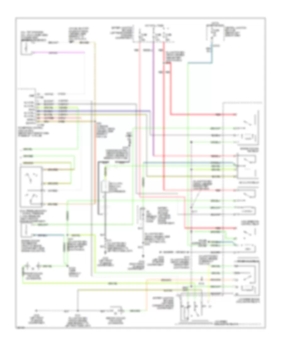
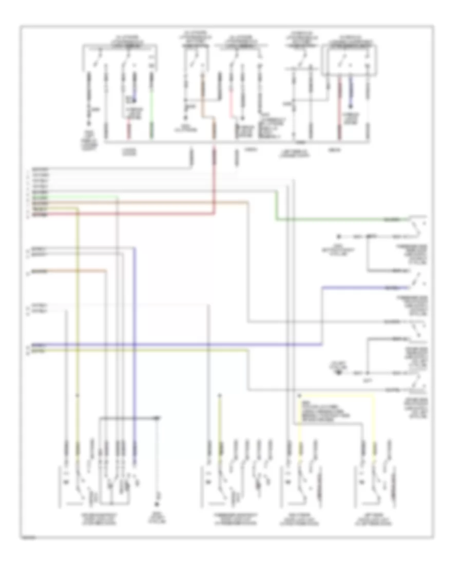
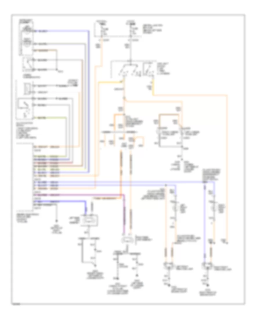
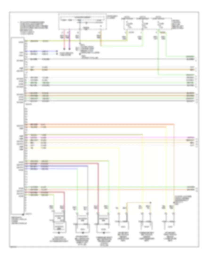
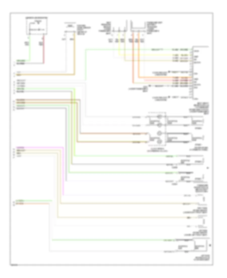
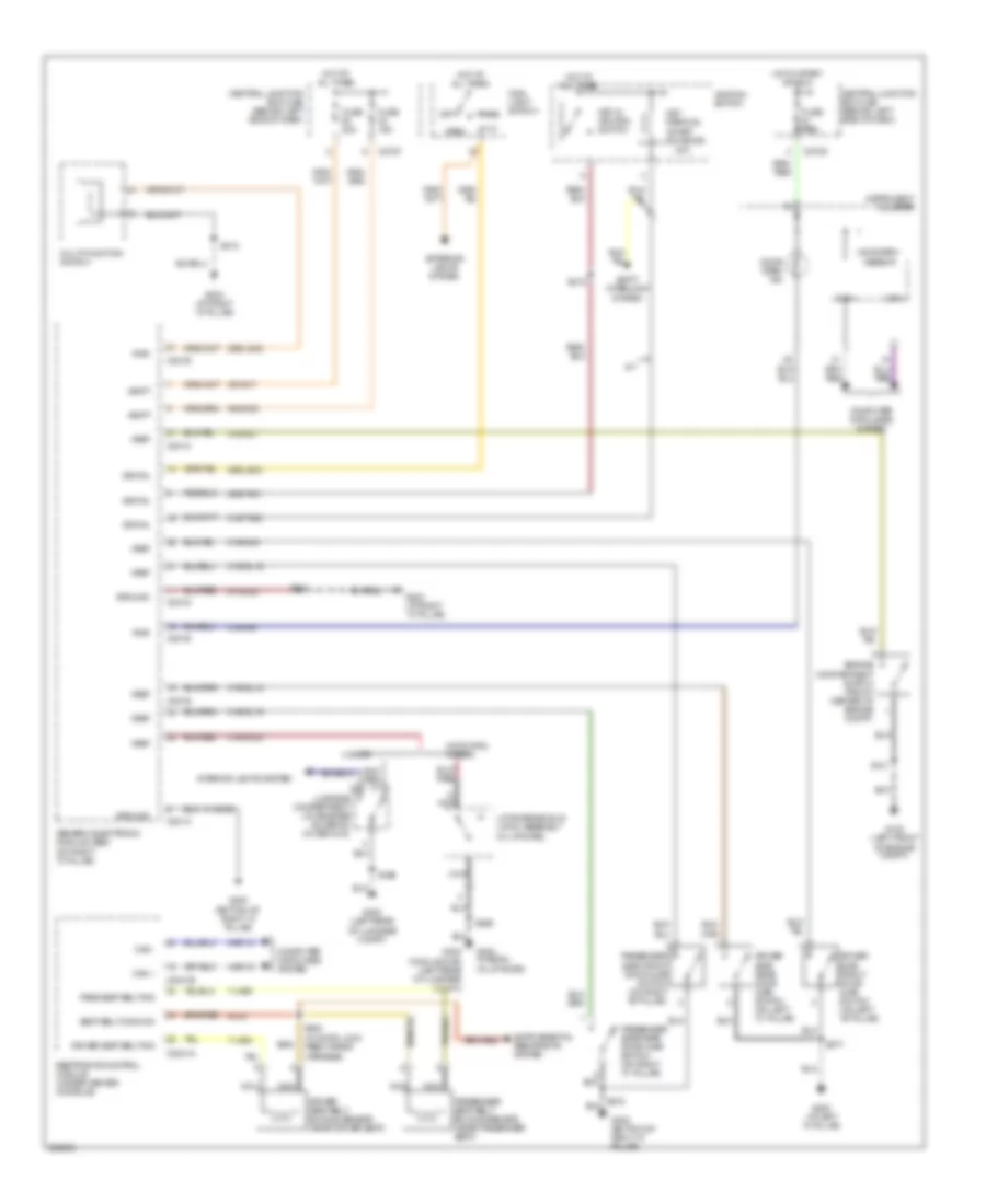
AIR CONDITIONING
Manual A/C Wiring Diagram (1 of 2) for Ford Focus S 2007

List of elements for Manual A/C Wiring Diagram (1 of 2) for Ford Focus S 2007:
- (at left ``a'' pillar)
- (at right ``a" pillar) g203
- (in main wiring harness, near breakout for instrument cluster)
- 15-fa13
- 15s-fa38
- 29-fa13
- 29s-le10
- 31s-fa26
- 31s-hb22
- 31s-hb31
- 32-fa76
- 33-fa76
- 91-fa13
- 91s-fa20
- A/c compressor cycling switch (1: pressure increasing) (2: pressure decreasing) (right rear corner of engine compartment)
- A/c on
- A/c switch
- A/c switch illumination
- Battery junction box (bjb) (left rear corner of engine compartment)
- Blower motor resistor (behind center of dash)
- C270a
- C270e
- Central junction box (cjb) (behind left side of dash)
- Defogger system
- Deicing switch
- Fuse 40a
- Fuse 7.5a
- G203 (at right ``a" pillar)
- G204
- Heater blower motor (behind center of dash)
- Heater blower switch
- Heater control module (behind dash)
- High
- Hot at all times
- Hot in start or run
- Interior lights system
- Low speed
- Med high
- Med low
- Off
- Rear window heater on
- Rear window heater switch
- Rear window heater switch illumination
- Recirculation air actuator (behind right side of dash, next to blower motor)
- Recirculation on
- Recirculation switch
- Recirculation switch illumination
- S206
- S212
- S224 (in main wiring harness, near breakout for hazard flasher switch)
- Solid state
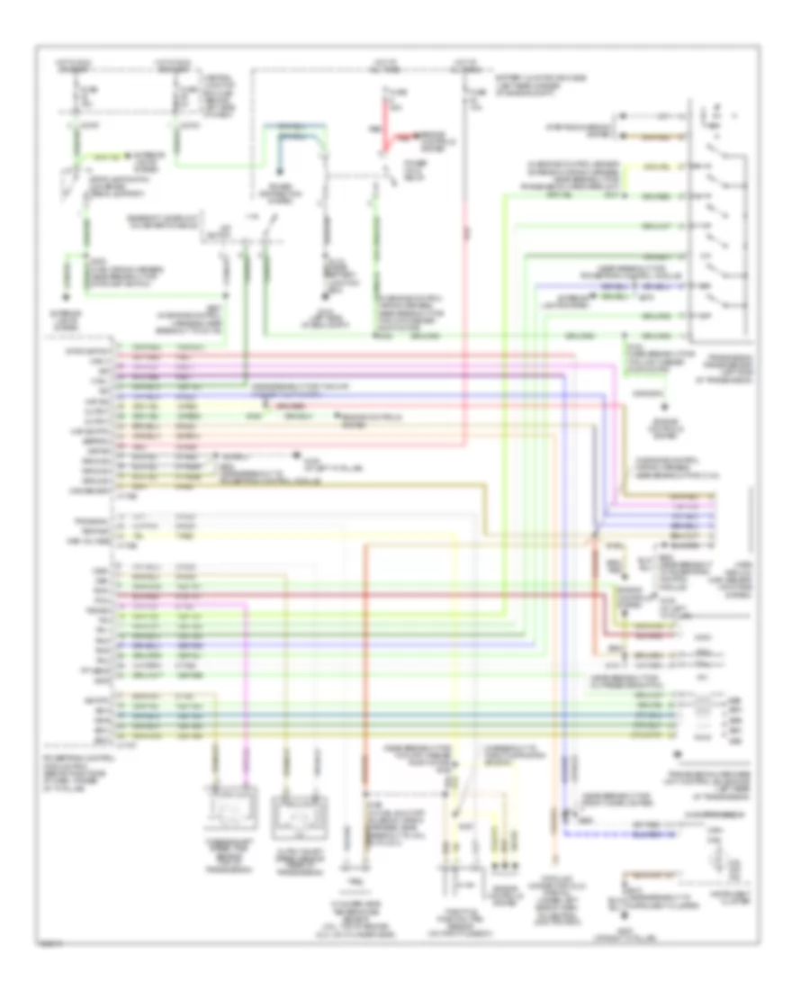
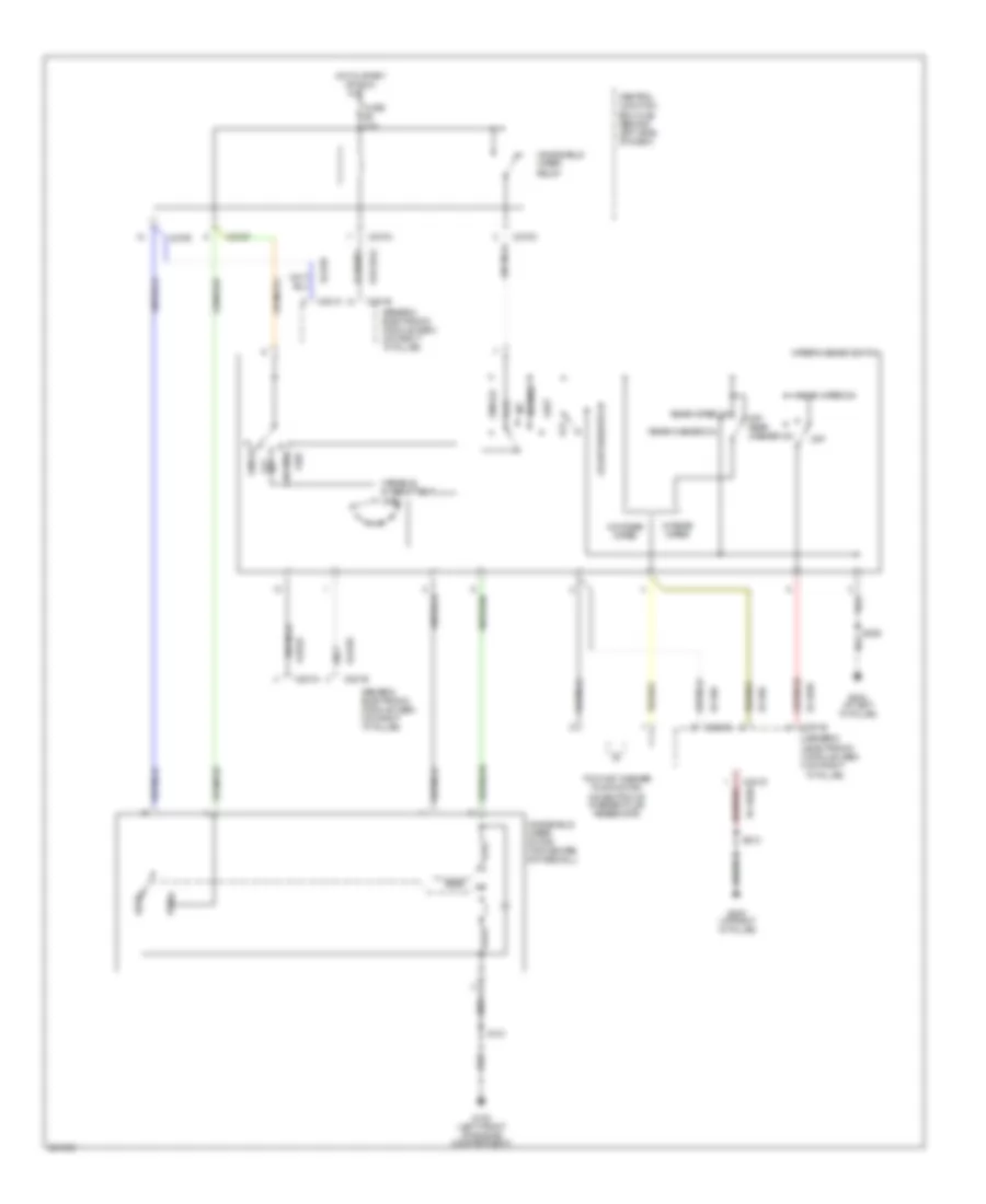
Manual A/C Wiring Diagram (2 of 2) for Ford Focus S 2007
List of elements for Manual A/C Wiring Diagram (2 of 2) for Ford Focus S 2007:
- (2.3l: top of engine) (2.0l: on cylinder head) cylinder head temperature sensor
- (in fuel shut-off solenoid wiring harness, near breakout to coil on plug 3) s198
- (in junction box wiring harness,
- (in junction box wiring harness, near battery junction box)
- (in junction box wiring harness, at breakout for c134)
- (in junction box wiring harness, near breakout for a/c clutch field coil) s109
- (not used)
- (right front of engine compartment)
- 15s-re8
- 31s-fa11
- 31s-pa17
- 31s-pa21
- 31s-pa7
- 8-pa13
- 8-rj33
- 87a
- 9-re8
- A/c clutch field coil (on a/c compressor)
- A/c clutch relay
- A/c com- pressor clutch diode
- Accs
- Acpsw
- Battery junction box (bjb) (left rear corner of engine compartment)
- C175b
- C175e
- C270c
- Central junction box (cjb) (behind left side of dash)
- Dual pressure switch
- Engine cooling fan motor (on radiator)
- Engine cooling fan relay
- Engine cooling fan resistor (front of engine compartment, near engine cooling fan)
- Fuse 10a
- Fuse 20a
- Fuse 2a
- Fuse 50a
- G100 (left front of engine compartment)
- G102 (right front of engine compartment)
- G103 (left side of engine compartment)
- High pressure
- High speed fan control relay
- Hot at all times
- Hot in start or run
- Low speed cooling fan relay b
- Low speed engine cooling fan relay a
- Nca
- Nca s189 (in engine control sensor extension wiring harness, at breakout for c1026)
- Near battery junction box) s107
- Near breakout to left front side light)
- Normal pressure
- Power distribution system
- Power hold relay
- Powertrain control module (pcm) (behind right side of dash, at base of ``a" pillar)
- Red
- Rly ctrl
- S1002 (near breakout to c134)
- S117
- S118 (in junction box wiring harness, near battery junction box)
- S121 (in junction box wiring harness, near breakout to left front side light)
- S134
- S163 (in engine control wiring harness, near breakout for c144)
- Second cooling fan motor (on radiator)
- Sig rtn
- Vref
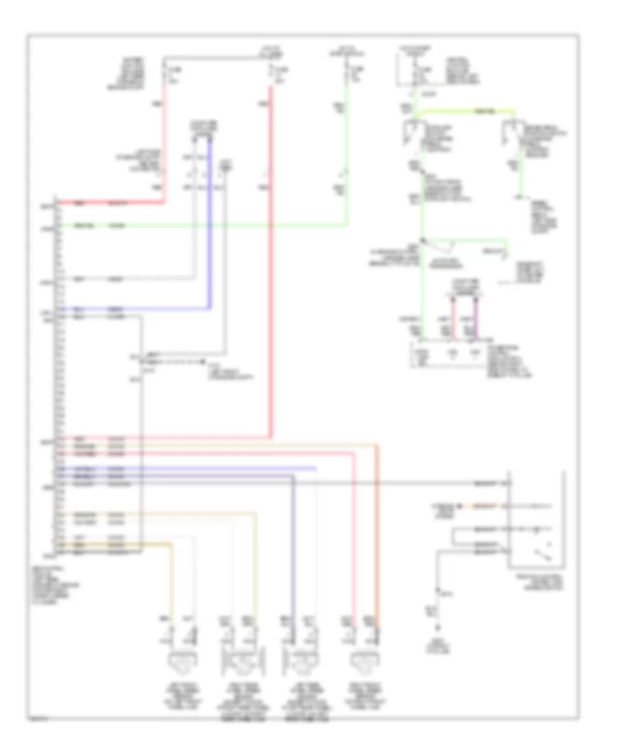
ANTI-LOCK BRAKES
Anti-lock Brakes Wiring Diagram, with Traction Control for Ford Focus S 2007
List of elements for Anti-lock Brakes Wiring Diagram, with Traction Control for Ford Focus S 2007:
- (left side of engine compt)
- (not used)
- 15-cf6
- 15s-re13
- 30-cf13
- 30-cf6
- 31-cf13
- 31-cf6
- 4-ec7
- 4-ec9
- 5-ec7
- 5-ec9
- 8-cf32
- 8-cf34
- 8-cf38
- 8-cf40
- 9-cf32
- 9-cf34
- 9-cf38
- 9-cf40
- 91s-cf54
- Abs control module (left rear corner of engine compartment, under master cylinder)
- Abs test connector
- Automatic transmission
- Battery junction box (bjb) (left rear corner of engine compt)
- Brake pedal position switch (on brake pedal support bracket)
- C175b
- C270f
- Can h
- Can l
- Central junction box (cjb) (behind left side of dash)
- Computer data lines system
- Fuse 10a
- Fuse 20a
- Fuse 30a
- G101 (left front of engine compt)
- G203 (at right "a" pillar)
- Gearshift lever unit (in center console)
- Gnd
- Hot at all times
- Hot in start or run
- Interior lights system
- Left front wheel speed sensor (on left front wheel hub)
- Left rear wheel speed sensor (except 4 door: at left rear wheel) (4 door: on left rear wheel hub)
- Nca
- Powertrain control module (pcm) (behind right side of dash, at base of "a" pillar)
- Red
- Right front wheel speed sensor (on right front wheel hub)
- Right rear wheel speed sensor (except 4 door: at right rear wheel) (4 door: on right rear wheel hub)
- S141
- S212
- S267 (in engine control harness, near breakout to c211b)
- Speed control servo (left side of engine compt)
- Stop- lamp sig
- Stoplamp switch (on brake pedal support)
- Traction control system (tcs) disable switch
- Vbatt
- Vpwr
- Vref
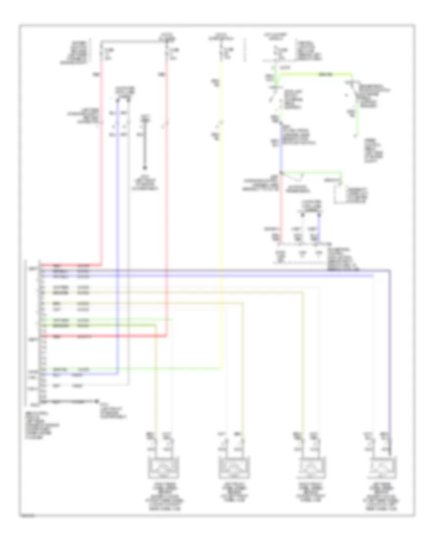
Anti-lock Brakes Wiring Diagram, without Traction Control for Ford Focus S 2007
List of elements for Anti-lock Brakes Wiring Diagram, without Traction Control for Ford Focus S 2007:
- (left side of engine compt) abs test connector
- (not used)
- 15-cf6
- 15s-re13
- 30-cf13
- 30-cf6
- 31-cf6
- 4-ec7
- 4-ec9
- 5-ec7
- 5-ec9
- 8-cf32
- 8-cf34
- 8-cf38
- 8-cf40
- 9-cf32
- 9-cf34
- 9-cf38
- 9-cf40
- Abs control module (left rear corner of engine compartment, under master cylinder)
- Automatic transmission
- Battery junction box (bjb) (left rear corner of engine compt)
- Brake pedal position switch (on brake pedal support bracket)
- C175b
- C270f
- Can h
- Can l
- Central junction box (cjb) (behind left side of dash)
- Computer data lines system
- Fuse 10a
- Fuse 20a
- Fuse 30a
- G101 (left front of engine compartment)
- Gearshift lever unit (in center console)
- Gnd
- Hot at all times
- Hot in start or run
- Left front wheel speed sensor (on left front wheel hub)
- Left rear wheel speed sensor (except 4 door: at left rear wheel) (4 door: on left rear wheel hub)
- Nca
- Powertrain control module (pcm) (behind right side of dash, at base of "a" pillar)
- Red
- Right front wheel speed sensor (on right front wheel hub)
- Right rear wheel speed sensor (except 4 door: at right rear wheel) (4 door: on right rear wheel hub)
- S267 (in engine control harness, near breakout to c211b)
- Speed control servo (left side of engine compt)
- Stop- lamp sig
- Stoplamp switch (on brake pedal support)
- Vbatt
- Vpwr
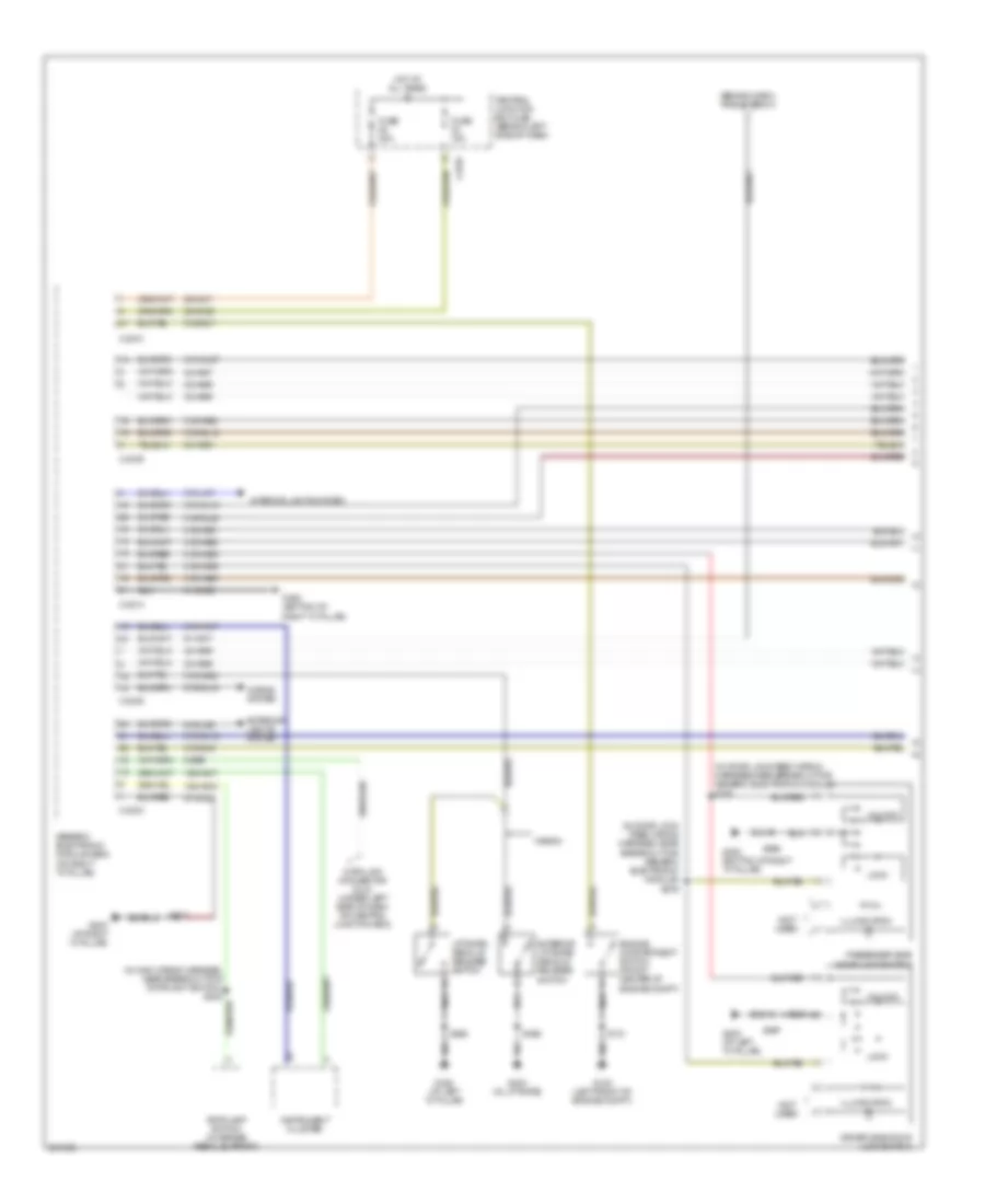
ANTI-THEFT
Forced Entry Wiring Diagram (1 of 2) for Ford Focus S 2007
List of elements for Forced Entry Wiring Diagram (1 of 2) for Ford Focus S 2007:
- (behind dash) rke antenna
- (in door lock feed wiring harness, near breakout for generic electronic module) s376
- (in door lock feed wiring harness,near breakout for generic electronic module)
- (in main wiring harness, near breakout for stoplight switch) s202
- (not used)
- 15s-aa17
- 15s-aa72
- 29-aa17
- 29-dk20
- 31-dk20
- 31s-aa17
- 31s-aa30
- 31s-aa39
- 31s-aa61
- 31s-aa62
- 31s-aa63
- 31s-aa64
- 31s-aa85
- 31s-gl12
- 31s-gl16
- 31s-gl19
- 31s-gl20
- 31s-gl27
- 31s-gl7
- 31s-gl9
- 31s-lc7
- 32-aa27
- 32-aa59
- 33-aa59
- 8-ee9
- 91-aa17
- 91-dk20
- 91s-gl43
- 91s-lg8
- C201a
- C201b
- C201c
- C201d
- C201e
- C270f
- Central junction box (cjb) (behind left side of dash)
- Data link connector (dlc) (under left side of dash, on central junction box)
- Driver side door lock switch
- Engine compartment switch (front center of engine compt)
- Exterior liftgate/ decklid release switch
- Exterior lights system
- Fuse 15a
- Fuse 20a
- G100 (left front of engine compt)
- G200 (at left "a" pillar)
- G203 (at right "a" pillar)
- G204 (at left "a" pillar)
- G300 (bottom of right "a" pillar)
- G403 (in liftgate)
- Generic electronic module (gem) (on right "a" pillar)
- Horns system
- Hot at all times
- Illumination
- Instrument cluster
- Interior lights system
- Liftgate/ decklid release switch
- Lock
- Passenger side door lock switch
- S121
- S206
- S212
- S375
- S496
- S597
- S694
- Stoplamp switch (on brake pedal support)
- Unlock
- Wagon
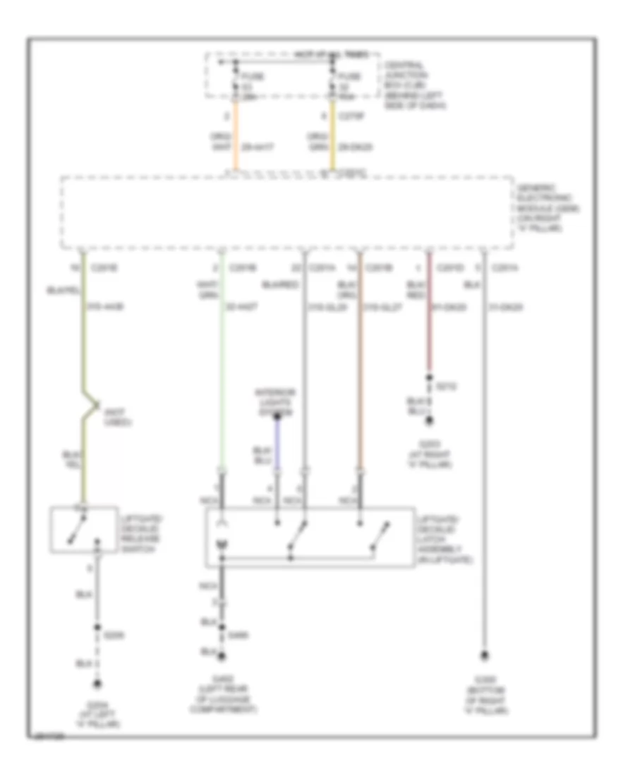
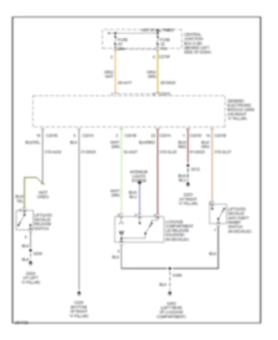
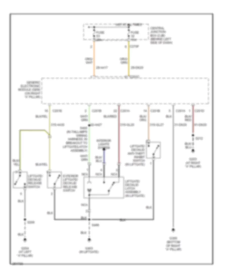
Forced Entry Wiring Diagram (2 of 2) for Ford Focus S 2007
List of elements for Forced Entry Wiring Diagram (2 of 2) for Ford Focus S 2007:
- (at left "a" pillar) g200
- (in breakout to liftgate/ deck lid latch assembly)
- (in decklid) liftgate/decklid anti-theft inhibit switch
- (in decklid) luggage compartment lid release solenoid
- (in liftgate) liftgate/decklid anti-theft inhibit switch
- (in liftgate) liftgate/decklid latch assembly
- (left rear of luggage compt)
- (not used)
- 3 door, 5 door
- Central
- Central lock
- Driver side front door ajar switch (on left "b" pillar)
- Driver side front door lock unit (in driver's door)
- Driver side rear door ajar switch (on left "c" pillar)
- G200 (at left "a" pillar)
- G300 (bottom of right "a" pillar)
- G402 (left rear of luggage compt)
- G403 (in liftgate)
- Interior lights system
- Left rear door lock unit (in left rear door)
- Lock
- Nca
- Passenger side front door ajar switch (on right "b" pillar)
- Passenger side front door lock unit (in passenger's door)
- Passenger side rear door ajar switch (on right "c" pillar)
- Reset
- Right rear door lock unit (in right rear door)
- S360 (in door lock feed wiring harness, near breakout for right side air bag harness)
- S377
- S378
- S400
- S496
- S597
- Sedan
- Set
- Unlock
- Wagon
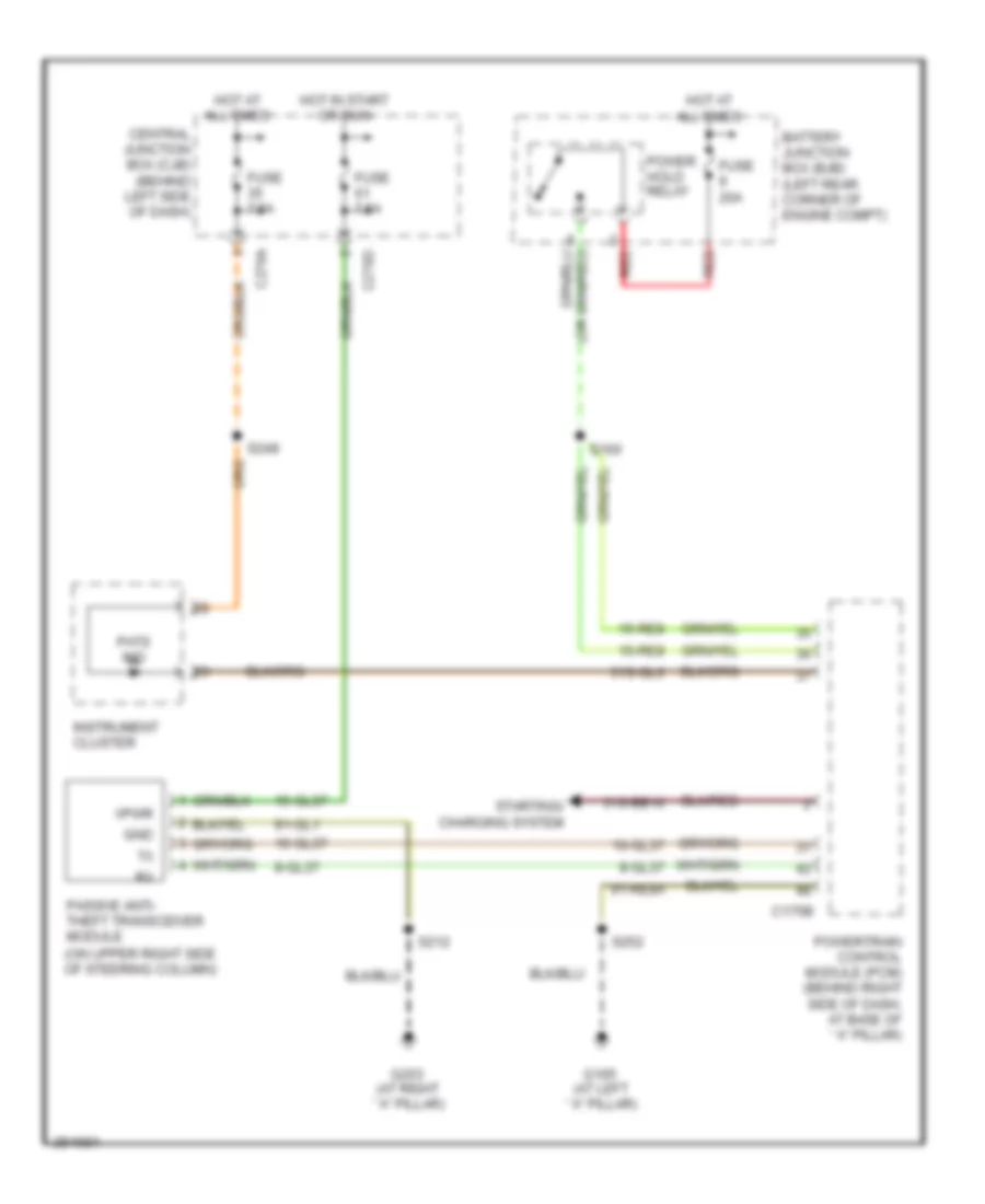
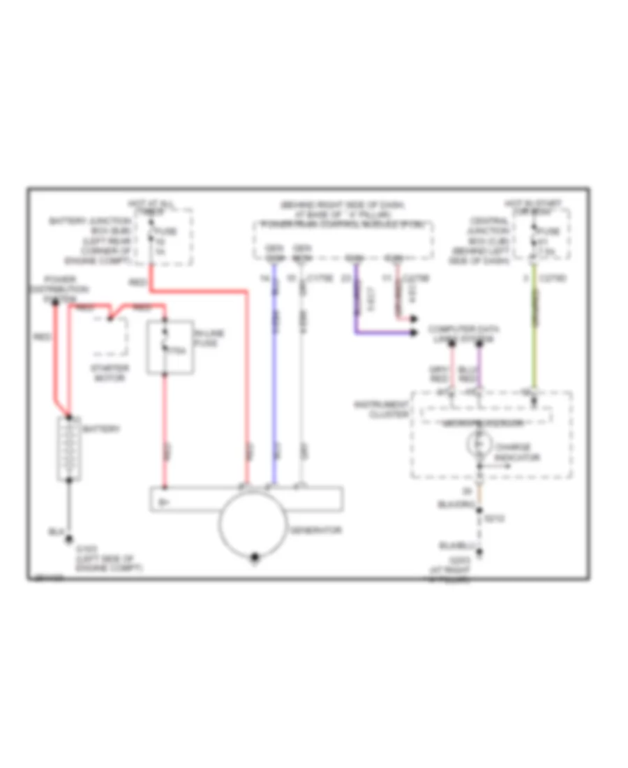
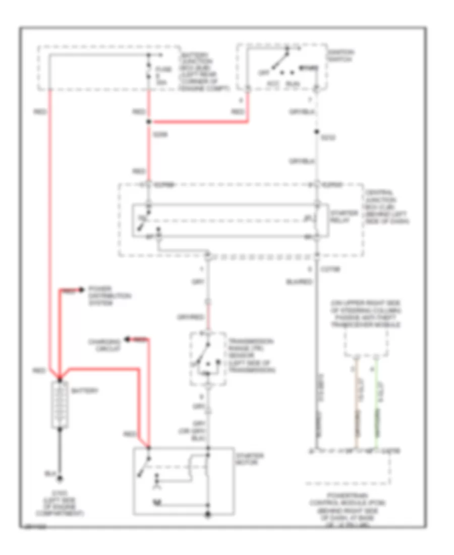
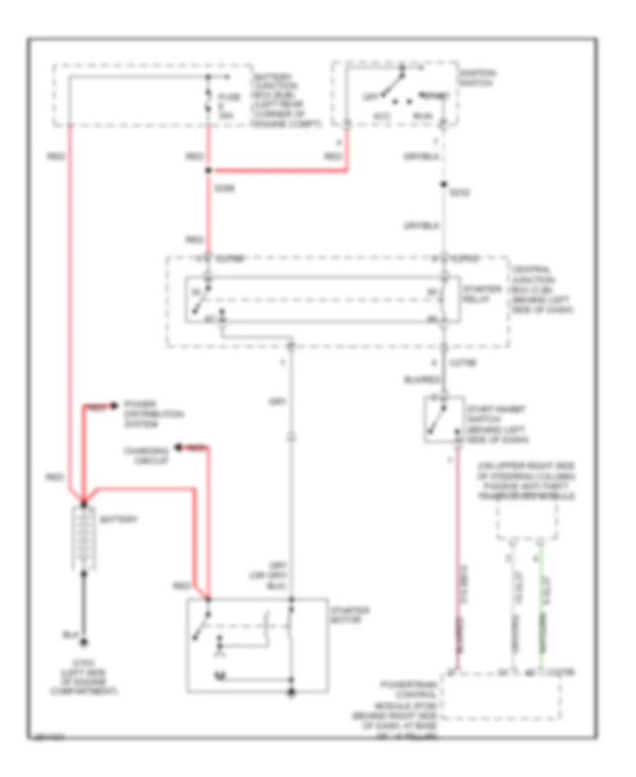
Passive Anti-theft Wiring Diagram for Ford Focus S 2007
List of elements for Passive Anti-theft Wiring Diagram for Ford Focus S 2007:
- 10-gl37
- 15-gl37
- 15-re8
- 31s-bb16
- 31s-gl6
- 8-gl37
- 91-gl1
- 91-re8a
- Battery junction box (bjb) (left rear corner of engine compt)
- C175b
- C270a
- C270d
- Central junction box (cjb) (behind left side of dash)
- Fuse 20a
- Fuse 7.5a
- G105 (at left ``a" pillar)
- G203 (at right ``a" pillar)
- Gnd
- Hot at all times
- Hot in start or run
- Instrument cluster
- Passive anti- theft transceiver module (on upper right side of steering column)
- Pats ind
- Power hold relay
- Powertrain control module (pcm) (behind right side of dash, at base of ``a" pillar)
- Red
- S160
- S212
- S249
- S252
- Starting/ charging system
- Vpwr
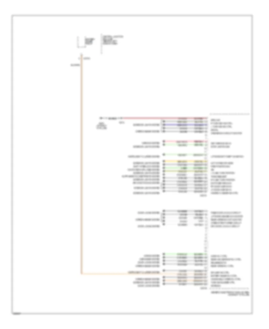
BODY CONTROL MODULES
Body Control Modules Wiring Diagram (1 of 2) for Ford Focus S 2007
List of elements for Body Control Modules Wiring Diagram (1 of 2) for Ford Focus S 2007:
- 29-aa17
- 29-dk20
- 31-dk20
- 31s-aa39
- 31s-aa61
- 31s-aa62
- 31s-aa63
- 31s-aa64
- 31s-aa85
- 31s-gl12
- 31s-gl19
- 31s-gl20
- 31s-gl27
- 31s-gl7
- 31s-lc7
- 32-aa27
- 32-aa59c
- 32-aa59d
- 32-ka9a
- 33-aa59
- 49s-lg12
- 49s-lg19
- 49s-lg4
- 49s-lg5
- Anti-theft inhibit sw in
- C201a
- C201b
- C201c
- C270f
- Central junction box (cjb) (behind left side of dash)
- Door lock sw reset sig
- Door lock sw set sig
- Door locks system
- Engine compt sw in
- Exterior lights system
- Fuse 15a
- Fuse 20a
- G300 (bottom of right "a" pillar)
- Generic electronic module (gem) (on right "a" pillar)
- Ground
- Hot at all times
- Interior lights system
- Liftgate ajar sw in
- Liftgate unlatch mtr/luggage compt lid release sol ctrl
- Lock sig
- Lock sw circuit
- Lock/unlock circuit
- Lr door ajar sw in
- Pulsed power feed
- Rear doors lk/unlk circuit
- Rr door ajar sw in
- Switched ground
- Unlock sig
- Unlock sw circuit
- Vbatt
- Wiper park pos sig monitor
- Wiper/washer system
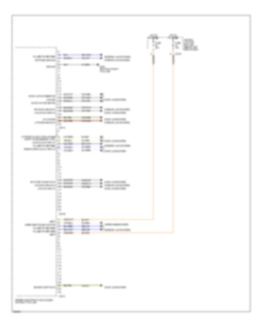
Body Control Modules Wiring Diagram (2 of 2) for Ford Focus S 2007
List of elements for Body Control Modules Wiring Diagram (2 of 2) for Ford Focus S 2007:
- 15s-aa17
- 15s-aa72
- 29s-le18
- 29s-lg43
- 30s-ta31a
- 31s-aa30
- 31s-aa7
- 31s-gl16
- 31s-gl9
- 31s-hb20
- 31s-hb22
- 31s-lc22
- 31s-ta32
- 32-aa59a
- 32-aa59b
- 32-ka35
- 32-ka6
- 33-ka6
- 49s-lg15
- 49s-lg22
- 8-ee9
- 8-ka18
- 8-ka19
- 91-aa17
- 91-dk20
- 91s-gg21
- 91s-gl43
- 91s-ka12
- 91s-ka29
- 91s-lg1
- 91s-lg2
- 91s-lg8
- Air conditioning system
- Antenna
- Battery saver relay
- Battery saver rly ctrl
- C201d
- C201e
- C270a
- Central junction box (cjb) (behind left side of dash)
- Computer data lines system
- Defogger system
- Door locks system
- Dr ajar ind ctrl
- Drv door lk/unlk circuit
- Exterior lights system
- G203 (at right "a" pillar)
- Generic electronic module (gem) (on right "a" pillar)
- Ground
- Hazard flasher sw ctrl
- Horn rly ctrl
- Horns system
- Hot in park or head
- Instrument cluster system
- Interior lights system
- Intermittent wiper circuit
- Iso
- Key warning sw in
- L flash turn portion
- L turn sig ind ctrl
- Lf door ajar sw in
- Liftgate anti-theft inhibit sw
- Liftgate washer sw monitor
- Park position sw
- Pass door lk/unlk circuit
- R flash turn portion
- R turn sig ind ctrl
- Rear win defrost rly ctrl
- Rear wiper rly ctrl
- Rear wiper sw ckt monitor
- Release sw in
- Rf door ajar sw in
- S212
- Shift interlock system
- Signal
- Stop lamp sw sig
- Switched ground
- Tone request
- Turn sig buzzer ctrl
- Warning system
- Washer sw circuit monitor
- Windshield wiper rly ctrl
- Wiper/washer system
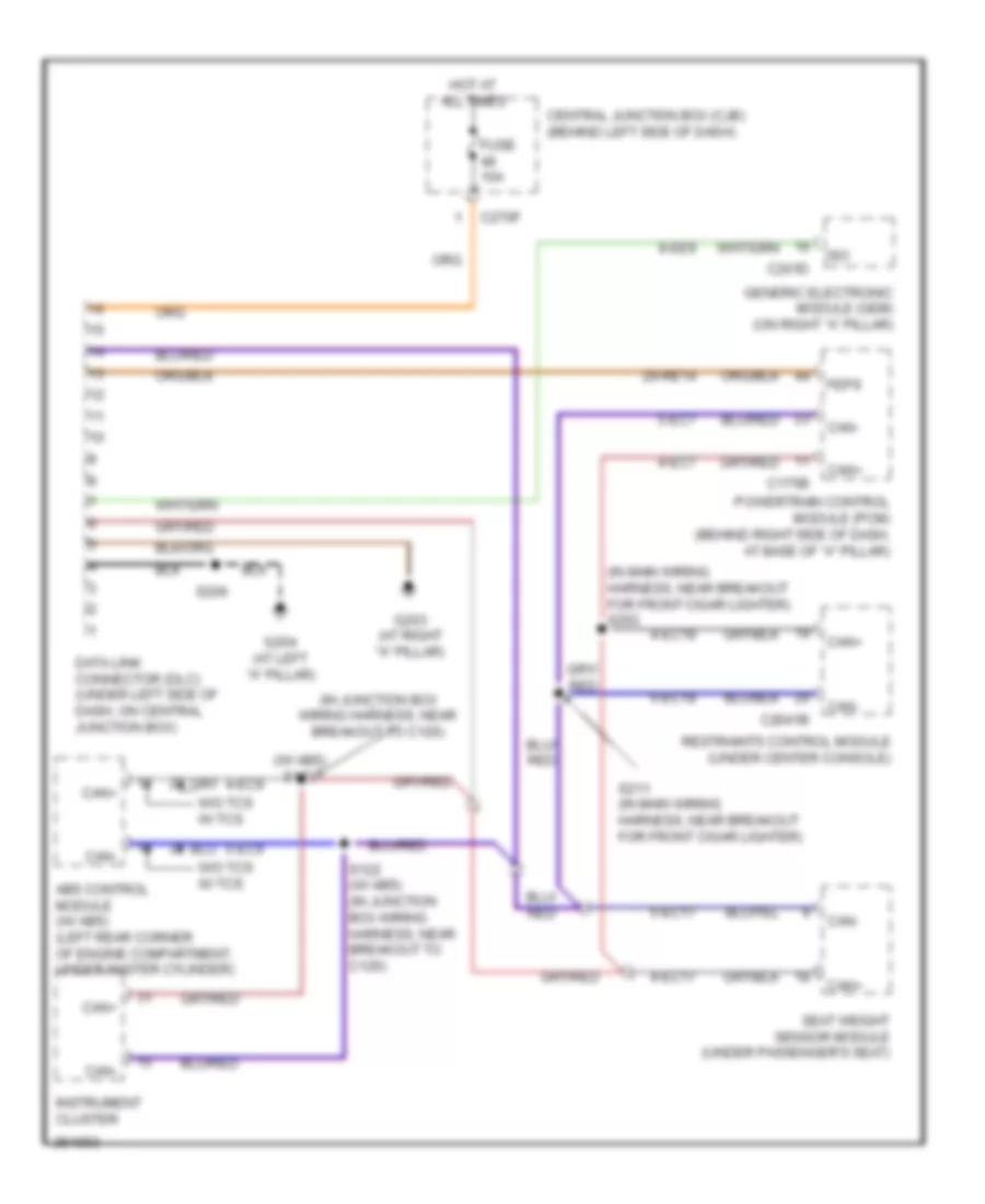
COMPUTER DATA LINES
Computer Data Lines Wiring Diagram for Ford Focus S 2007
List of elements for Computer Data Lines Wiring Diagram for Ford Focus S 2007:
- (in junction box wiring harness, near breakout to c126)
- (in main wiring harness, near breakout for front cigar lighter) s293
- (w/ abs) s123
- 29-re14
- 4-ec17
- 4-ec18
- 4-ec7
- 4-ec9
- 5-ec17
- 5-ec18
- 5-ec7
- 5-ec9
- 8-ee9
- Abs control module (w/ abs) (left rear corner of engine compartment, under master cylinder)
- C175b
- C201d
- C2041b
- C270f
- Can+
- Can-
- Central junction box (cjb) (behind left side of dash)
- Data link connector (dlc) (under left side of dash, on central junction box)
- Feps
- Fuse 10a
- G203 (at right "a" pillar)
- G204 (at left "a" pillar)
- Generic electronic module (gem) (on right "a" pillar)
- Hot at all times
- Instrument cluster
- Iso
- Powertrain control module (pcm) (behind right side of dash, at base of "a" pillar)
- Restraints control module (under center console)
- S122 (w/ abs) (in junction box wiring harness, near breakout to c126)
- S206
- S211 (in main wiring harness, near breakout for front cigar lighter)
- Seat weight sensor module (under passenger's seat)
- W/o tcs w/ tcs
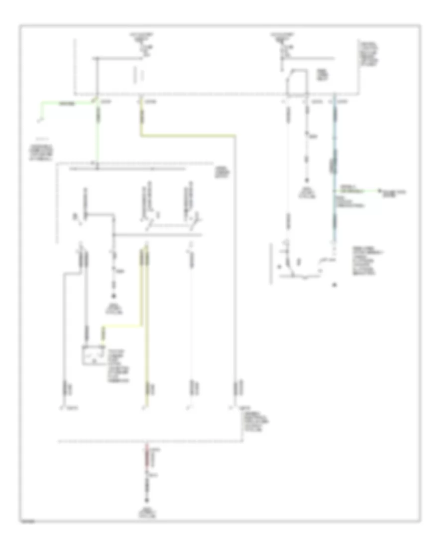
COOLING FAN
Cooling Fan Wiring Diagram for Ford Focus S 2007
List of elements for Cooling Fan Wiring Diagram for Ford Focus S 2007:
- (in junction box wiring harness, near battery junction box)
- 31s-pa17
- 31s-pa21
- 31s-pa7
- 8-rj33
- 87a
- 9-re8
- Battery junction box (bjb) (left rear corner of engine compartment)
- C175b
- C175e
- C270c
- Central junction box (cjb) (behind left side of dash)
- Cylinder head temperature sensor (2.0l: on cylinder head) (2.3l: top of engine)
- Engine cooling fan motor (on radiator)
- Engine cooling fan relay
- Engine cooling fan resistor (front of engine compartment, near engine cooling fan)
- Fuse 20a
- Fuse 2a
- Fuse 50a
- G100 (left front of engine compartment)
- G103 (left side of engine compartment)
- High speed fan control relay
- Hot at all times
- Hot in start or run
- Low speed engine cooling fan relay a
- Low speed engine cooling fan relay b
- Power distribution system
- Power hold relay
- Powertrain control module (pcm) (behind right side of dash, at base of ``a" pillar)
- Red
- Rly ctrl
- S1002 (in junction box
- S107
- S117
- S118
- S121
- S134 (in junction box wiring harness, at breakout for c134)
- S137 (in junction box
- S163 (in engine control wiring harness, near breakout for c144)
- S198 (in fuel shut-off solenoid wiring harness, near breakout to coil on plug 3)
- Second cooling fan motor (on radiator)
- Signal return
- Vref
- Wiring harness, near battery junction box)
- Wiring harness, near breakout to c134)
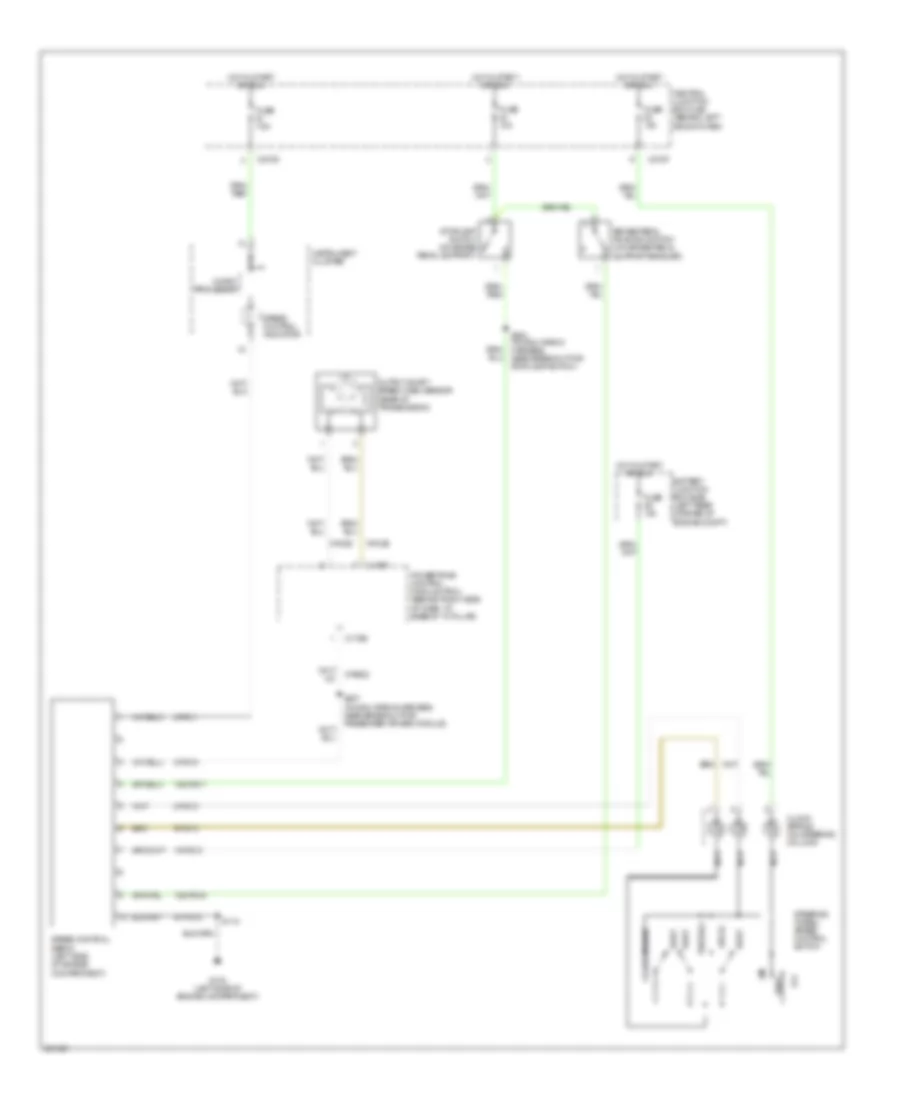
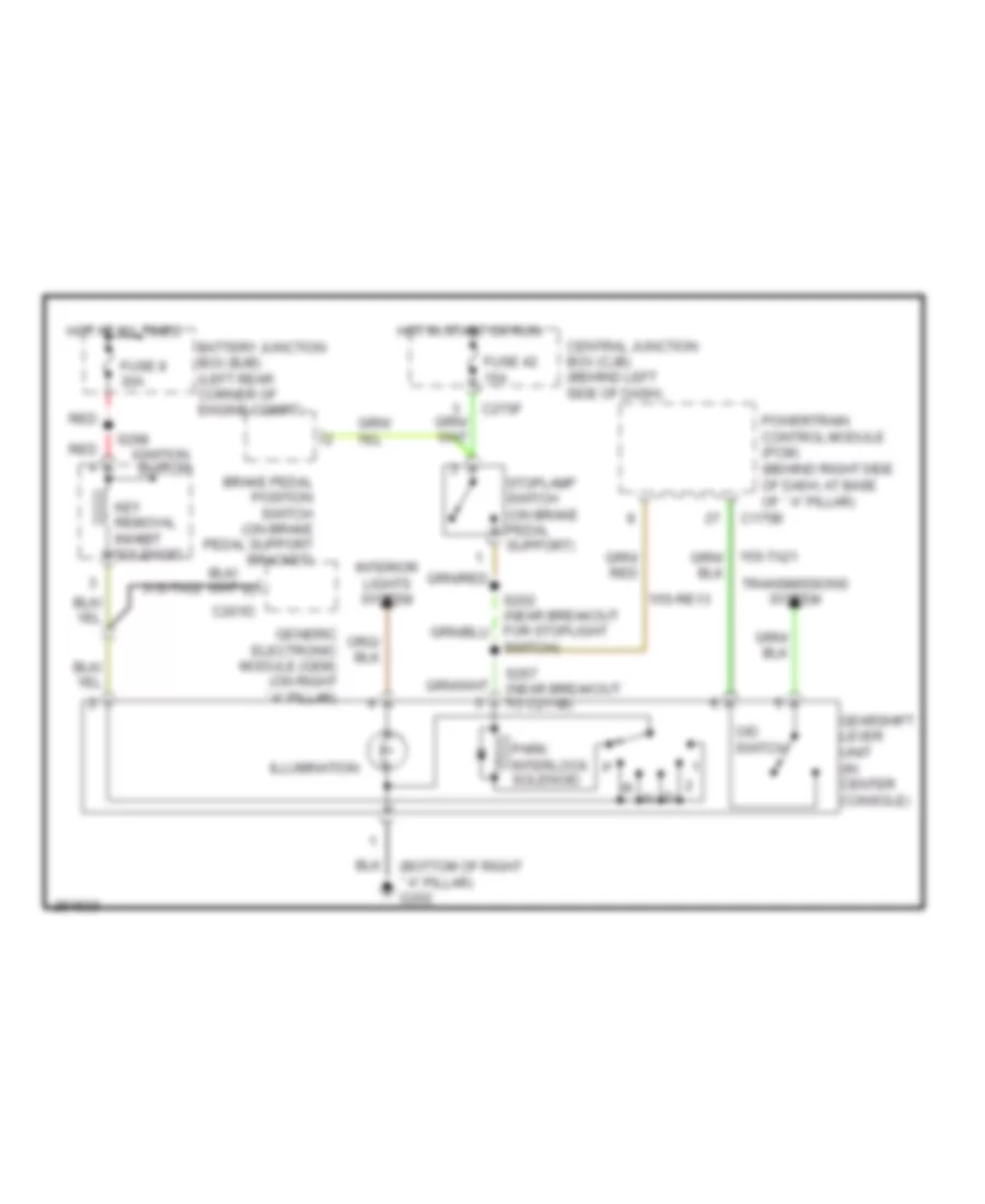
CRUISE CONTROL
Cruise Control Wiring Diagram, A/T for Ford Focus S 2007
List of elements for Cruise Control Wiring Diagram, A/T for Ford Focus S 2007:
- 15-pg12
- 15s-pg16
- 15s-pg17
- 8-pg11
- 8-pg13
- 8-pg18
- 8-re22
- 8-rj29
- 9-pg13
- 9-rj29
- 91-pg12
- Battery junction box (bjb) (left rear corner of engine compt)
- Brake pedal position switch (on brake pedal support bracket)
- C175b
- C175t
- C270d
- C270f
- Central junction box (cjb) (behind left side of dash)
- Clock spring (on steering column)
- Coast/resume
- Decel
- Fuse 10a
- Fuse 7.5a
- G103 (left side of engine compartment)
- Hot in start or run
- Instrument cluster
- Micro- processor
- Nca
- Off
- Output shaft speed (oss) sensor (rear of transmission)
- Powertrain control module (pcm) (behind right side of dash, at base of "a" pillar)
- Rest
- S118
- S202 (in main wiring harness, near breakout for stoplamp switch)
- S207 (in main wiring harness, near breakout for passenger air bag module)
- Set/acc
- Speed control indicator
- Speed control servo (left side of engine compartment)
- Steering wheel/ speed control switch
- Stoplamp switch (on brake pedal support)
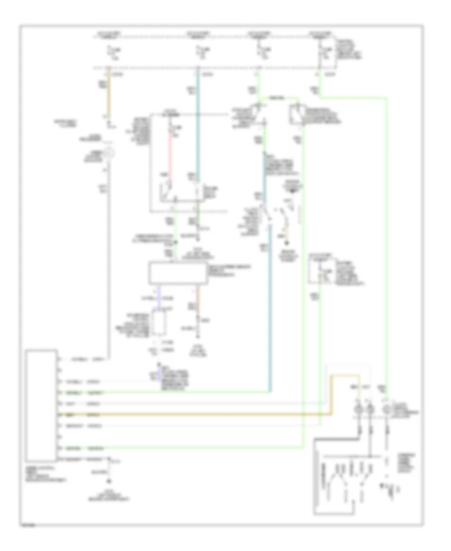
Cruise Control Wiring Diagram, M/T for Ford Focus S 2007
List of elements for Cruise Control Wiring Diagram, M/T for Ford Focus S 2007:
- (near breakout for oil pressure switch) s156
- 15-pg12
- 15s-pg16
- 15s-pg17
- 8-pg11
- 8-pg13
- 8-pg18
- 8-re22
- 8-rj29
- 9-pg13
- 91-pg12
- Battery junction box (bjb) (in left rear corner of engine compt)
- Battery junction box (bjb) (left rear corner of engine compt)
- Brake pedal position switch (on brake pedal support bracket)
- C175b
- C175t
- C270c
- C270d
- C270f
- Central junction box (cjb) (behind left side of dash)
- Clock spring (on steering column)
- Clutch pedal position switch (on clutch pedal support)
- Coast/resume
- Decel
- Engine controls system
- Fuse 10a
- Fuse 20a
- Fuse 2a
- Fuse 7.5a
- G103 (at left side of engine compt)
- G103 (left side of engine compartment)
- G105 (at left "a" pillar)
- Hot at all times
- Hot in start or run
- Instrument cluster
- Micro- processor
- Nca
- Off
- Power hold relay
- Powertrain control module (pcm) (behind right side of dash, at base of "a" pillar)
- Red
- Rest
- S118
- S202 (in main wiring harness, near breakout for stoplamp switch)
- S252
- Set/acc
- Speed control indicator
- Speed control servo (left side of engine compartment)
- Steering wheel/ speed control switch
- Stoplamp switch (on brake pedal support)
- Vehicle speed sensor (rear of transmission)
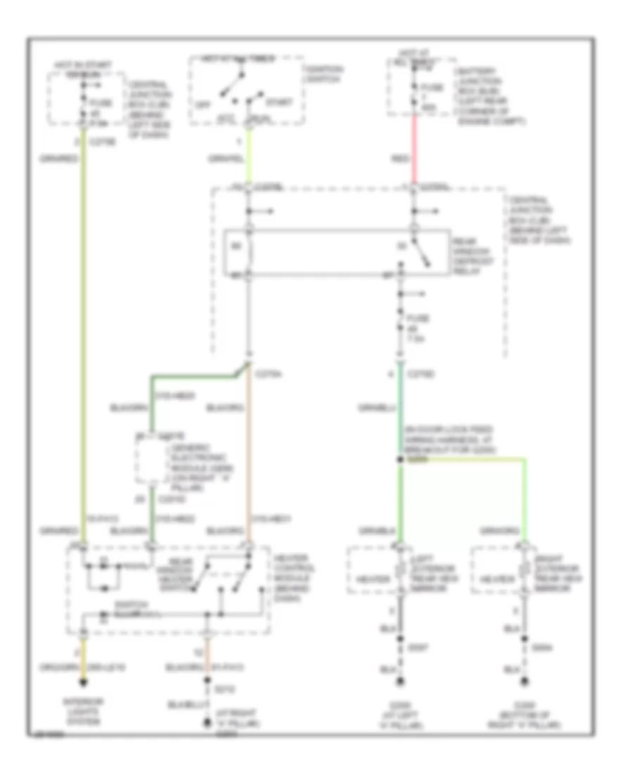
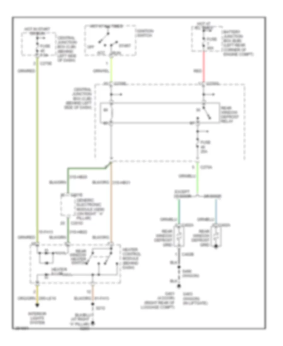
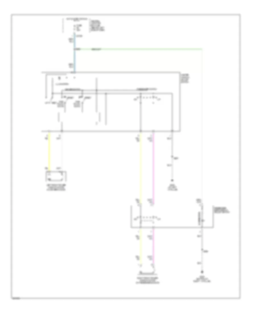
DEFOGGERS
Heated Mirrors Wiring Diagram for Ford Focus S 2007
List of elements for Heated Mirrors Wiring Diagram for Ford Focus S 2007:
- (at right "a" pillar) g203
- (in door lock feed wiring harness, at breakout for g200)
- 15-fa13
- 31s-hb20
- 31s-hb22
- 31s-hb31
- Acc
- Battery junction box (bjb) (left rear corner of engine compt)
- C201d
- C201e
- C270a
- C270d
- C270e
- C270g
- Central junction box (cjb) (behind left side of dash)
- Fuse 40a
- Fuse 7.5a
- G200 (at left "a" pillar)
- G300 (bottom of right "a" pillar)
- Generic electronic module (gem) (on right ``a" pillar)
- Heater
- Heater control module (behind dash)
- Hot at all times
- Hot in start or run
- Ignition switch
- Interior lights system
- Left exterior rear view mirror
- Off
- Rear window defrost relay
- Rear window heater switch
- Red
- Right exterior rear view mirror
- Run
- S212
- S255
- S597
- S694
- Start
- Switch illum
Rear Defogger Wiring Diagram for Ford Focus S 2007
List of elements for Rear Defogger Wiring Diagram for Ford Focus S 2007:
- 15-fa13
- 3/5 door
- 31s-hb20
- 31s-hb22
- Acc
- Battery junction box (bjb) (left rear corner of engine compt)
- C201d
- C201e
- C270a
- C270e
- C270g
- C402a
- C402b
- Central junction box (cjb) (behind left side of dash)
- Except 3/5 door
- Fuse 25a
- Fuse 40a
- Fuse 7.5a
- G401 (4 door) (right rear of luggage compt)
- G403 (wagon) (in liftgate)
- Generic electronic module (gem) (on right ``a" pillar)
- Heater control module (behind dash)
- Heater illum
- Hot at all times
- Hot in start or run
- Ignition switch
- Interior lights system
- Off
- Rear window defrost grid
- Rear window defrost relay
- Rear window heater switch
- Red
- Run
- S212
- S496 (wagon)
- Start
ENGINE PERFORMANCE
2.0L
2.0L, Engine Performance Wiring Diagram (1 of 4) for Ford Focus S 2007
List of elements for 2.0L, Engine Performance Wiring Diagram (1 of 4) for Ford Focus S 2007:
- (near breakout for two-way washer pump motor)
- 10-gl37
- 15-re16
- 15-re8
- 15-re8a
- 15s-re10
- 15s-re13
- 15s-re8
- 15s-ta21
- 29-re14
- 30-re8
- 31-re8
- 31s-bb16
- 31s-fa11
- 31s-gl6
- 31s-pa17
- 31s-pa21
- 31s-pa7
- 31s-re32
- 31s-rh1
- 31s-rl25
- 4-ec7
- 5-ec7
- 8-ce10
- 8-gl37
- 8-pa13
- 8-re22
- 8-rj13
- 8-rj17
- 8-rj22
- 9-re8
- 9-rj22
- 91-re8
- 91-re8a
- 91-re8b
- 91-rj16
- 91s-rl3
- A/c clutch relay
- A/c clutch rly
- A/c press sw
- Air conditioning system
- Air pump rly
- Anti-theft system
- Battery junction box (bjb) (left rear corner of engine compt)
- Battery junction box)
- C175b
- C270c
- Can h
- Can l
- Central junction box (cjb) (behind left side of dash)
- Computer data lines system
- Cooling fans system
- Cruise control system
- Dual pressure switch (right front of engine compt)
- Eng cool fan
- Engine cooling fan relay
- Evap canister purge valve (rear of engine compt)
- Evap purge
- Evap vent
- Evaporative emission (evap) canister vent valve (under rear of vehicle)
- Feps
- Ftp sens
- Fuel pump
- Fuse 10a
- Fuse 20a
- Fuse 2a
- G103 (left side of engine compt)
- G105 (at left "a" pillar)
- G202 (bottom of right "a" pillar)
- Ground
- Hi cool fan
- High speed fan control relay
- Hot at all times
- Hot in run or start
- Imrc module
- Intake air temp
- Lo cool fan
- Low speed cooling fan relay a
- Low speed cooling fan relay b
- Maf sens
- Maf sens sig
- Mass air flow (maf) sensor (on intake system)
- Overdrive sig
- Passive anti-theft transceiver module (on upper right side of steering column)
- Pats ind
- Power hold relay
- Powertrain control module (pcm) (behind right side of dash, at base of "a" pillar)
- Psp sens
- Pwr hold rly
- Red
- Rx sig
- S118
- S154 (near breakout for two- way washer pump motor)
- S160
- S252
- S278
- Sig return
- Solid state
- Start relay
- Starting/charging system
- Stoplamp
- Tx sig
- Vbatt
- Vss out
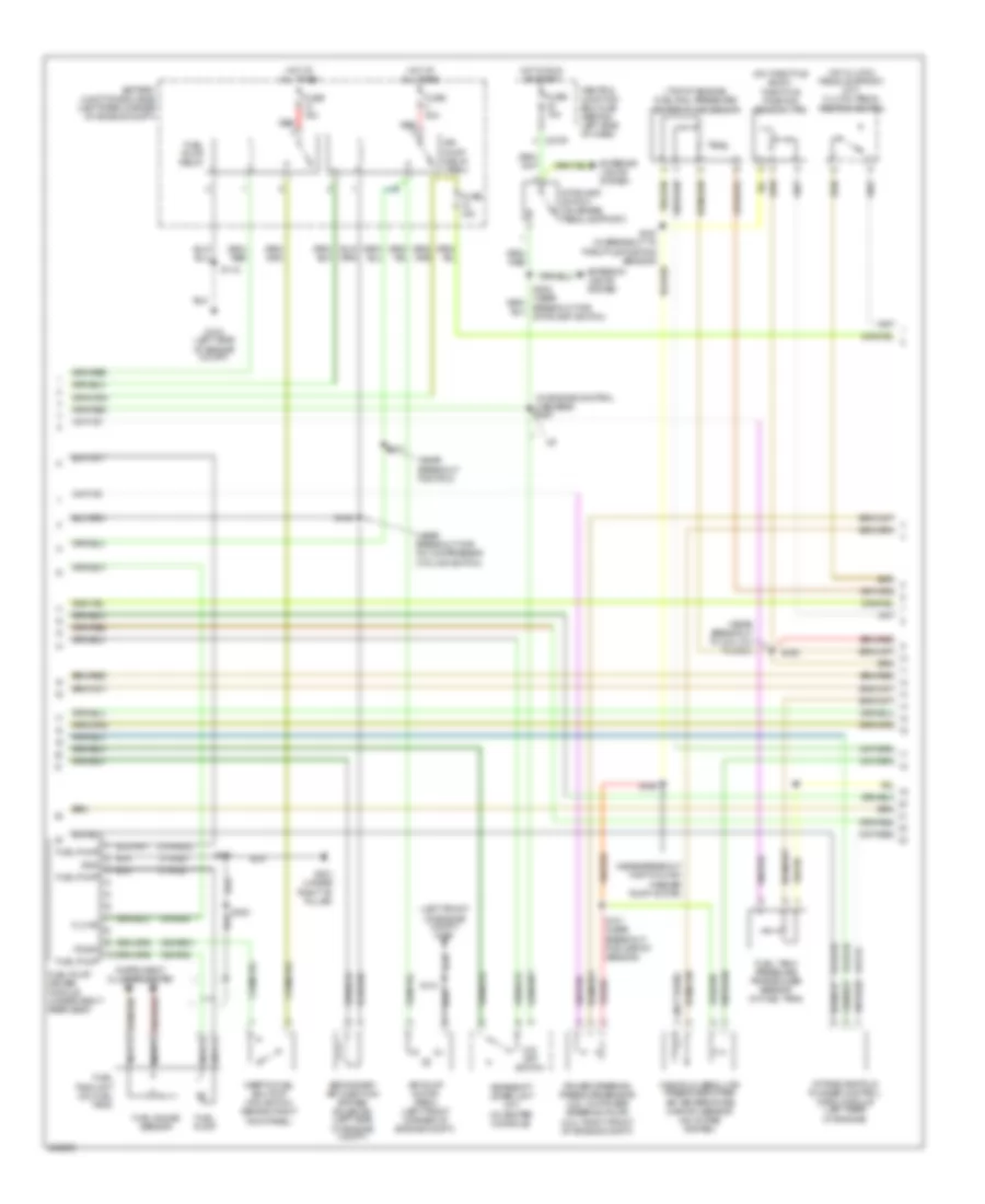
2.0L, Engine Performance Wiring Diagram (2 of 4) for Ford Focus S 2007
List of elements for 2.0L, Engine Performance Wiring Diagram (2 of 4) for Ford Focus S 2007:
- (in engine control harness) s267
- (left front of engine compt) g100
- (near breakout for a/c compressor cycling switch)
- (near breakout for pcm)
- (near breakout for two-way washer pump motor)
- (near breakout to coil on plug 3)
- (not used)
- (on clutch pedal support) (m/t) clutch pedal position switch
- (on throttle body) throttle position sensor (tps)
- (top of engine) fuel rail pressure/ temperature sensor
- 15-re16
- 15-rj16
- 15s-re31
- 15s-rg2
- 31-re31
- 31-rg2
- 31s-re32
- 8-rj16
- 91-rj16
- A/t
- Air pump motor (pzev) (left front corner of engine compt)
- Air pump relay (pzev)
- Battery junction box (bjb) (left rear corner of engine compt)
- C270f
- Central junction box (cjb) (behind left side of dash)
- Exterior lights system
- Fl mtr
- Fuel gauge sensor
- Fuel pump
- Fuel pump driver module (under right rear seat)
- Fuel pump relay
- Fuel tank pressure transducer sensor (in fuel tank)
- Fuel tank unit (on fuel tank)
- Fuse 15a
- Fuse 30a
- G103 (left side of engine compt)
- G301 (under right "b" pillar)
- Gearshift lever unit (a/t) (in center console)
- Gnd
- Hot at all times
- Hot in run or start
- Ifs sw
- Inertia fuel shutoff (ifs) switch (behind right kick panel)
- Instrument cluster system
- Intake manifold runner control (imrc) module (left rear of engine)
- Manifold absolute pressure/intake air temperature (map/iat) sensor (on intake system)
- Nca
- O/d off switch
- Power steering pressure sensor (2.3l: on power steering pump) (2.0l: right front of engine compt)
- Red
- S101 (near breakout for map/iat sensor)
- S118
- S121
- S159
- S194
- S197 (in breakout to throttle position sensor)
- S198
- S271
- S300
- S381
- Secondary air injection bypass solenoid (left side of engine compt)
- Stoplamp switch (on brake pedal support)
- Stoplamp switch)
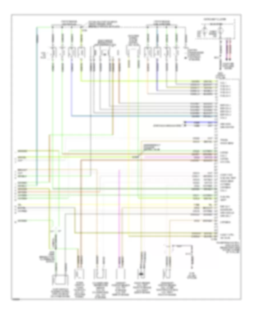
2.0L, Engine Performance Wiring Diagram (3 of 4) for Ford Focus S 2007
List of elements for 2.0L, Engine Performance Wiring Diagram (3 of 4) for Ford Focus S 2007:
- (2.0l, pzev: in exhaust system)
- (a/t)
- (in exhaust system) heated oxygen sensor (ho2s) 11
- (in exhaust system) heated oxygen sensor (ho2s) 12
- (left rear of transmission) (a/t) transmission hardware unit
- (left side of transmission) (a/t) transmission range (tr) sensor
- (m/t)
- (near breakout for c1168)
- (near breakout for pcm)
- (near breakout for transmission hardware unit)
- (or 15s-ta37)
- 15s-ta17
- 15s-ta23
- 15s-ta24
- 15s-ta38a
- 15s-ta40
- 15s-ta41
- 15s-ta42
- 15s-ta63
- 15s-ta64
- 15s-ta65
- 8-bb6
- 8-rj25
- 8-rj26
- 8-rj29
- 8-ta27
- 8-ta36
- 9-rj29
- 9-ta27
- 915-rj25
- 915-rj26
- 91s-ta17
- A/t
- C175t
- Epc sol
- Except pzev
- Exterior lights system
- G105 (at left "a" pillar)
- Heated oxygen sensor (ho2s) 13
- Ho2s 12 ctrl
- Ho2s 12 sig
- Ho2s 13 ctrl
- Ho2s 13 sig
- M/t
- Nca
- Oss sens
- Output shaft speed (oss) sensor (a/t) (rear of transmission)
- Powertrain control module (pcm) (behind right side of dash, at base of "a" pillar)
- Pressure ctrl sol
- Pzev
- S163 (near breakout for c144)
- S187
- S190
- S191 (in engine control sensor extension wiring harness, near breakout for oil pressure switch)
- S252
- S275
- Shift sol a
- Shift sol b
- Shift sol c
- Shift sol d
- Shift sol e
- Sig return
- Tft sens
- Tft sensor
- Tr sens, 1
- Tr sens, 2
- Tr sens, d
- Tr sens, p/n
- Tr sens, rev
- Tss sens
- Turbine shaft speed (tss) sensor (a/t) (top of transmission)
- Vehicle speed sensor (m/t) (rear of transmission)
- Vss sig
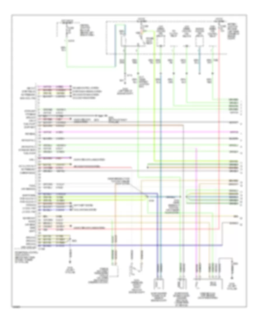
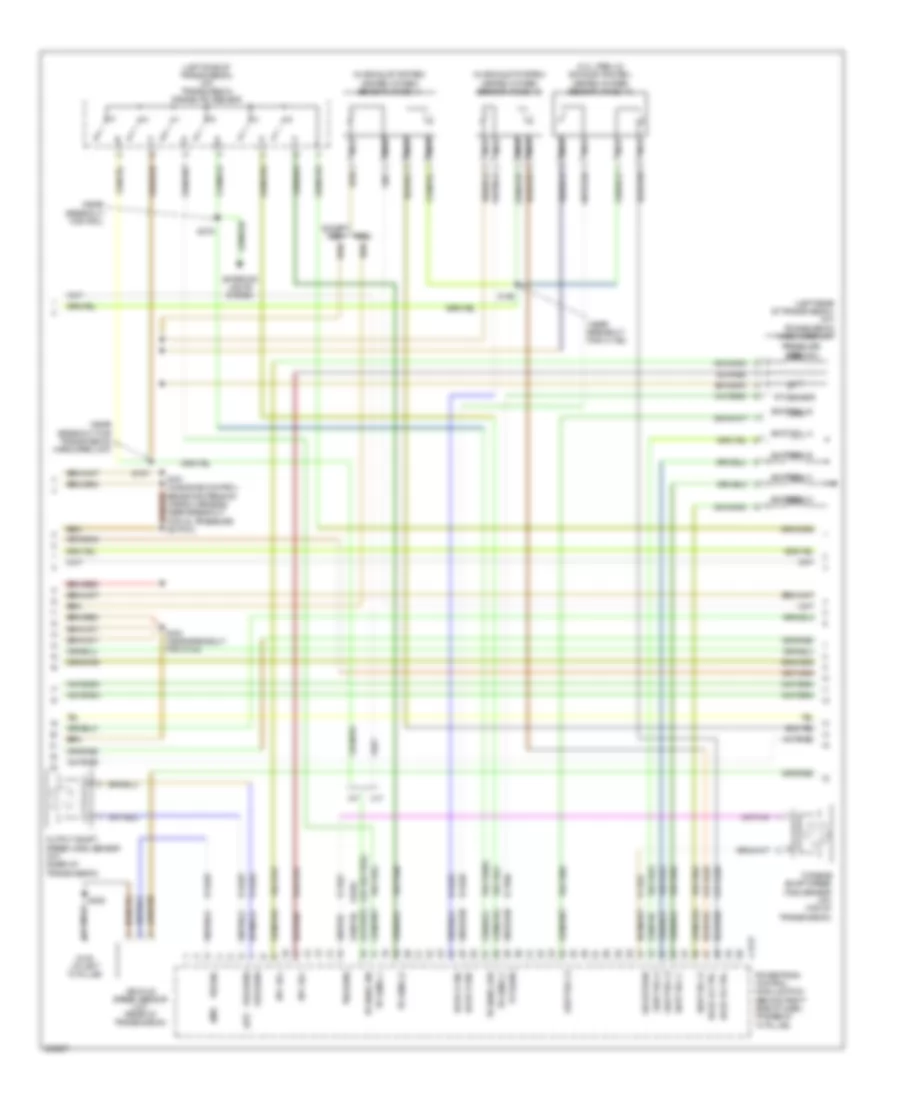
2.0L, Engine Performance Wiring Diagram (4 of 4) for Ford Focus S 2007
List of elements for 2.0L, Engine Performance Wiring Diagram (4 of 4) for Ford Focus S 2007:
- (in fuel shut-off solenoid wiring harness, near breakout for coil on plug 2)
- (near breakout to idle air control valve)
- (on intake system) idle air control (iac) valve
- (right side of engine compt) egr stepper motor
- (top of engine) coil on plug
- (top of engine) fuel injectors
- 10-rj11
- 15-rl9
- 15s-rr5
- 15s-rr6
- 15s-rr7
- 15s-rr8
- 31s-pa37
- 31s-rl10
- 31s-rl11
- 31s-rl12
- 31s-rl13
- 31s-rl20
- 31s-rl9
- 4-eb6
- 5-eb6
- 7-re8
- 8-rj11
- 8-rj14
- 8-rj16
- 8-rj18
- 8-rj20
- 8-rj28
- 8-rj3
- 8-rj33
- 8-rj4
- 9-rj18
- 9-rj3
- 9-rj4
- 91s-pa51
- 91s-pa52
- 91s-pa53
- 91s-pa54
- 91s-rj14
- A/t
- C175e
- Camshaft position sensor (2.0l: top of engine) (2.3l: top rear of engine)
- Check engine ind
- Cht sens
- Ckp sens
- Cmp sig
- Coil 1
- Coil 2
- Coil 3
- Coil 4
- Coil on plug
- Computer data lines system
- Crankshaft position sensor (2.0l: lower right front of eng) (2.3l: right front of engine)
- Cylinder head temperature sensor (2.0l: on cylinder head) (2.3l: top of engine)
- Egr coil 1
- Egr coil 2
- Egr coil 3
- Egr coil 4
- Fuel inj 1
- Fuel inj 2
- Fuel inj 3
- Fuel inj 4
- Fuel rail
- Fuel rail temp
- G105 (at left "a" pillar)
- G203 (at right "a" pillar)
- Gen comm
- Gen monitor
- Ho2s 11 ctrl
- Ho2s 11 sig
- Iac valve
- Ignition transformer capacitor (top front of engine)
- Imrc module
- Imrc sol 1
- Imtv ctrl
- Inlet manifold runner control (imrc) solenoid (on intake system)
- Instrument cluster
- Intake manifold tuning valve (imtv) (2.3l, m/t) (on intake system)
- Knock sens
- Knock sensor (2.0l: left front of engine) (2.3l: right side of engine)
- M/t
- Map sig
- Nca
- O/d off ind
- Powertrain control module (pcm) (behind right side of dash, at base of "a" pillar)
- Ref volt
- S112
- S156 (near breakout for oil pressure switch)
- S169
- S199
- S212
- Sig return
- Solid state
- Starting/charging system
- Tps sig
- Vbatt
2.3L
2.3L, Engine Performance Wiring Diagram (1 of 4) for Ford Focus S 2007
List of elements for 2.3L, Engine Performance Wiring Diagram (1 of 4) for Ford Focus S 2007:
- (near breakout for two-way washer pump motor)
- 10-gl37
- 15-re16
- 15-re8
- 15-re8a
- 15s-re10
- 15s-re13
- 15s-re8
- 15s-ta21
- 29-re14
- 30-re8
- 31-re8
- 31s-bb16
- 31s-fa11
- 31s-gl6
- 31s-pa17
- 31s-pa21
- 31s-pa7
- 31s-re32
- 31s-rh1
- 31s-rl25
- 4-ec7
- 5-ec7
- 8-ce10
- 8-gl37
- 8-pa13
- 8-re22
- 8-rj13
- 8-rj17
- 8-rj22
- 9-re8
- 9-rj22
- 91-re8
- 91-re8a
- 91-re8b
- 91-rj16
- 91s-rl3
- A/c clutch relay
- A/c clutch rly
- A/c press sw
- Air conditioning system
- Air pump rly
- Anti-theft system
- Battery junction box (bjb) (left rear corner of engine compt)
- Battery junction box)
- C175b
- C270c
- Can h
- Can l
- Central junction box (cjb) (behind left side of dash)
- Computer data lines system
- Cooling fans system
- Cruise control system
- Dual pressure switch (right front of engine compt)
- Eng cool fan
- Engine cooling fan relay
- Evap canister purge valve (rear of engine compt)
- Evap purge
- Evap vent
- Evaporative emission (evap) canister vent valve (under rear of vehicle)
- Feps
- Ftp sens
- Fuel pump
- Fuse 10a
- Fuse 20a
- Fuse 2a
- G103 (left side of engine compt)
- G105 (at left "a" pillar)
- G202 (bottom of right "a" pillar)
- Ground
- Hi cool fan
- High speed fan control relay
- Hot at all times
- Hot in run or start
- Imrc module
- Intake air temp
- Lo cool fan
- Low speed cooling fan relay a
- Low speed cooling fan relay b
- Maf sens
- Maf sens sig
- Mass air flow (maf) sensor (on intake system)
- Overdrive sig
- Passive anti-theft transceiver module (on upper right side of steering column)
- Pats ind
- Power hold relay
- Powertrain control module (pcm) (behind right side of dash, at base of "a" pillar)
- Psp sens
- Pwr hold rly
- Red
- Rx sig
- S118
- S154 (near breakout for two- way washer pump motor)
- S160
- S252
- S278
- Sig return
- Solid state
- Start relay
- Starting/charging system
- Stoplamp
- Tx sig
- Vbatt
- Vss out
2.3L, Engine Performance Wiring Diagram (2 of 4) for Ford Focus S 2007
List of elements for 2.3L, Engine Performance Wiring Diagram (2 of 4) for Ford Focus S 2007:
- (in engine control harness) s267
- (left front of engine compt) g100
- (near breakout for a/c compressor cycling switch)
- (near breakout for pcm)
- (near breakout for two-way washer pump motor)
- (near breakout to coil on plug 3)
- (not used)
- (on clutch pedal support) (m/t) clutch pedal position switch
- (on throttle body) throttle position sensor (tps)
- (top of engine) fuel rail pressure/ temperature sensor
- 15-re16
- 15-rj16
- 15s-re31
- 15s-rg2
- 31-re31
- 31-rg2
- 31s-re32
- 8-rj16
- 91-rj16
- A/t
- Air pump motor (pzev) (left front corner of engine compt)
- Air pump relay (pzev)
- Battery junction box (bjb) (left rear corner of engine compt)
- C270f
- Central junction box (cjb) (behind left side of dash)
- Exterior lights system
- Fl mtr
- Fuel gauge sensor
- Fuel pump
- Fuel pump driver module (under right rear seat)
- Fuel pump relay
- Fuel tank pressure transducer sensor (in fuel tank)
- Fuel tank unit (on fuel tank)
- Fuse 15a
- Fuse 30a
- G103 (left side of engine compt)
- G301 (under right "b" pillar)
- Gearshift lever unit (a/t) (in center console)
- Gnd
- Hot at all times
- Hot in run or start
- Ifs sw
- Inertia fuel shutoff (ifs) switch (behind right kick panel)
- Instrument cluster system
- Intake manifold runner control (imrc) module (left rear of engine)
- Manifold absolute pressure/intake air temperature (map/iat) sensor (on intake system)
- Nca
- O/d off switch
- Power steering pressure sensor (2.3l: on power steering pump) (2.0l: right front of engine compt)
- Red
- S101 (near breakout for map/iat sensor)
- S118
- S121
- S159
- S194
- S197 (in breakout to throttle position sensor)
- S198
- S271
- S300
- S381
- Secondary air injection bypass solenoid (left side of engine compt)
- Stoplamp switch (on brake pedal support)
- Stoplamp switch)
2.3L, Engine Performance Wiring Diagram (3 of 4) for Ford Focus S 2007
List of elements for 2.3L, Engine Performance Wiring Diagram (3 of 4) for Ford Focus S 2007:
- (2.0l, pzev: in exhaust system)
- (a/t)
- (in exhaust system) heated oxygen sensor (ho2s) 11
- (in exhaust system) heated oxygen sensor (ho2s) 12
- (left rear of transmission) (a/t) transmission hardware unit
- (left side of transmission) (a/t) transmission range (tr) sensor
- (m/t)
- (near breakout for c1168)
- (near breakout for pcm)
- (near breakout for transmission hardware unit)
- (or 15s-ta37)
- 15s-ta17
- 15s-ta23
- 15s-ta24
- 15s-ta38a
- 15s-ta40
- 15s-ta41
- 15s-ta42
- 15s-ta63
- 15s-ta64
- 15s-ta65
- 8-bb6
- 8-rj25
- 8-rj26
- 8-rj29
- 8-ta27
- 8-ta36
- 9-rj29
- 9-ta27
- 915-rj25
- 915-rj26
- 91s-ta17
- A/t
- C175t
- Epc sol
- Except pzev
- Exterior lights system
- G105 (at left "a" pillar)
- Heated oxygen sensor (ho2s) 13
- Ho2s 12 ctrl
- Ho2s 12 sig
- Ho2s 13 ctrl
- Ho2s 13 sig
- M/t
- Nca
- Oss sens
- Output shaft speed (oss) sensor (a/t) (rear of transmission)
- Powertrain control module (pcm) (behind right side of dash, at base of "a" pillar)
- Pressure ctrl sol
- Pzev
- S163 (near breakout for c144)
- S187
- S190
- S191 (in engine control sensor extension wiring harness, near breakout for oil pressure switch)
- S252
- S275
- Shift sol a
- Shift sol b
- Shift sol c
- Shift sol d
- Shift sol e
- Sig return
- Tft sens
- Tft sensor
- Tr sens, 1
- Tr sens, 2
- Tr sens, d
- Tr sens, p/n
- Tr sens, rev
- Tss sens
- Turbine shaft speed (tss) sensor (a/t) (top of transmission)
- Vehicle speed sensor (m/t) (rear of transmission)
- Vss sig
2.3L, Engine Performance Wiring Diagram (4 of 4) for Ford Focus S 2007
List of elements for 2.3L, Engine Performance Wiring Diagram (4 of 4) for Ford Focus S 2007:
- (in fuel shut-off solenoid wiring harness, near breakout for coil on plug 2)
- (near breakout to idle air control valve)
- (on intake system) idle air control (iac) valve
- (right side of engine compt) egr stepper motor
- (top of engine) coil on plug
- (top of engine) fuel injectors
- 10-rj11
- 15-rl9
- 15s-rr5
- 15s-rr6
- 15s-rr7
- 15s-rr8
- 31s-pa37
- 31s-rl10
- 31s-rl11
- 31s-rl12
- 31s-rl13
- 31s-rl20
- 31s-rl9
- 4-eb6
- 5-eb6
- 7-re8
- 8-rj11
- 8-rj14
- 8-rj16
- 8-rj18
- 8-rj20
- 8-rj28
- 8-rj3
- 8-rj33
- 8-rj4
- 9-rj18
- 9-rj3
- 9-rj4
- 91s-pa51
- 91s-pa52
- 91s-pa53
- 91s-pa54
- 91s-rj14
- A/t
- C175e
- Camshaft position sensor (2.0l: top of engine) (2.3l: top rear of engine)
- Check engine ind
- Cht sens
- Ckp sens
- Cmp sig
- Coil 1
- Coil 2
- Coil 3
- Coil 4
- Coil on plug
- Computer data lines system
- Crankshaft position sensor (2.0l: lower right front of eng) (2.3l: right front of engine)
- Cylinder head temperature sensor (2.0l: on cylinder head) (2.3l: top of engine)
- Egr coil 1
- Egr coil 2
- Egr coil 3
- Egr coil 4
- Fuel inj 1
- Fuel inj 2
- Fuel inj 3
- Fuel inj 4
- Fuel rail
- Fuel rail temp
- G105 (at left "a" pillar)
- G203 (at right "a" pillar)
- Gen comm
- Gen monitor
- Ho2s 11 ctrl
- Ho2s 11 sig
- Iac valve
- Ignition transformer capacitor (top front of engine)
- Imrc module
- Imrc sol 1
- Imtv ctrl
- Inlet manifold runner control (imrc) solenoid (on intake system)
- Instrument cluster
- Intake manifold tuning valve (imtv) (2.3l, m/t) (on intake system)
- Knock sens
- Knock sensor (2.0l: left front of engine) (2.3l: right side of engine)
- M/t
- Map sig
- Nca
- O/d off ind
- Powertrain control module (pcm) (behind right side of dash, at base of "a" pillar)
- Ref volt
- S112
- S156 (near breakout for oil pressure switch)
- S169
- S199
- S212
- Sig return
- Solid state
- Starting/charging system
- Tps sig
- Vbatt
EXTERIOR LIGHTS
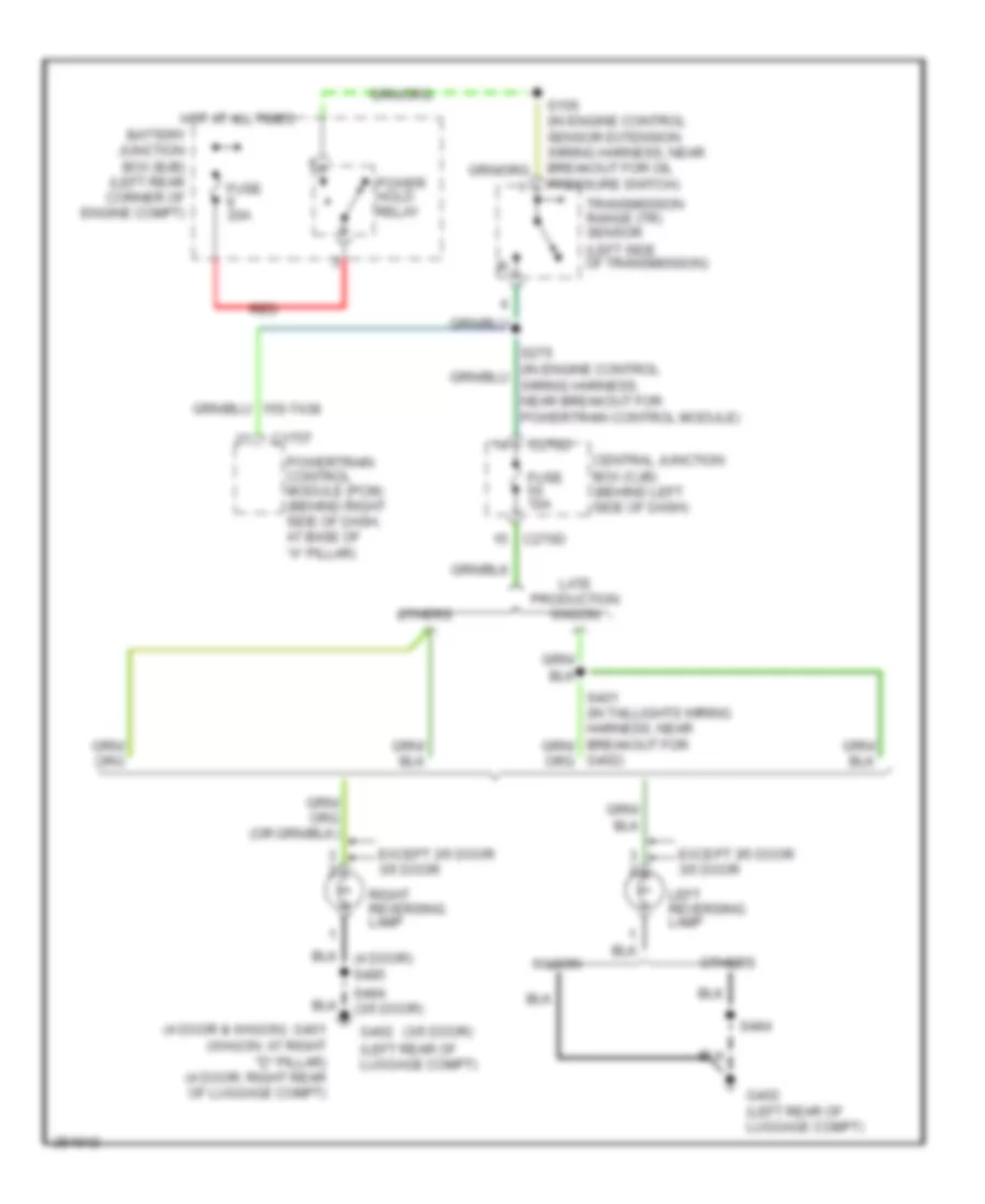
Back-up Lamps Wiring Diagram, A/T for Ford Focus S 2007
List of elements for Back-up Lamps Wiring Diagram, A/T for Ford Focus S 2007:
- (3/5 door)
- (4 door & wagon)
- (left side of transmission)
- Battery junction box (bjb) (left rear corner of engine compt)
- C175t
- C270d
- Central junction box (cjb) (behind left side of dash)
- Except 3/5 door 3/5 door
- Fuse 10a
- Fuse 20a
- G401 (wagon: at right "d" pillar) (4 door: right rear of luggage compt)
- G402 (left rear of luggage compt)
- G402)
- Hot at all times
- Late production wagon
- Left reversing lamp
- Others
- Power hold relay
- Powertrain control module (pcm) (behind right side of dash, at base of "a" pillar)
- Pressure switch)
- Red
- Right reversing lamp
- S484
- S484 (3/5 door)
- Transmission range (tr) sensor
- Wagon
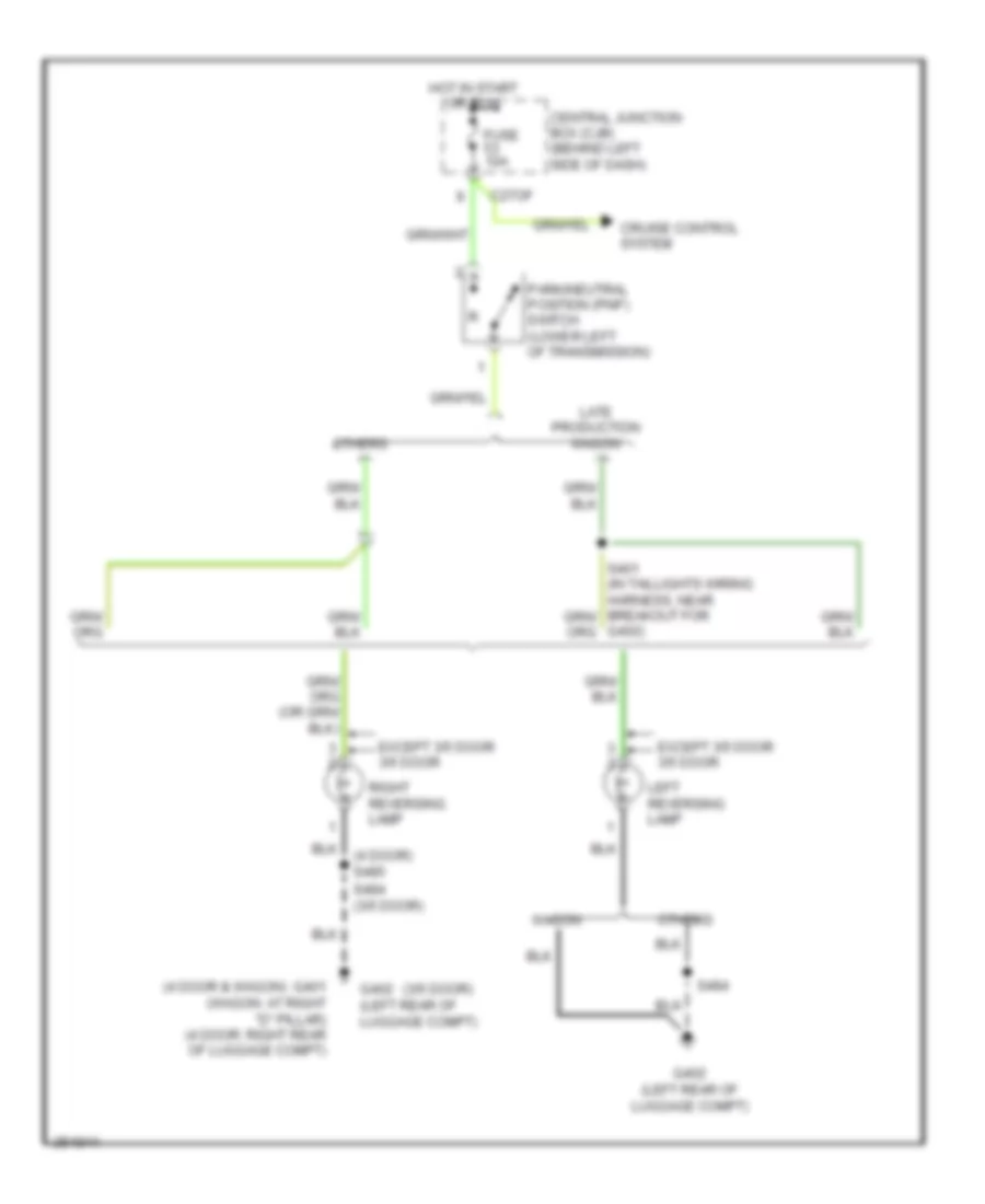
Back-up Lamps Wiring Diagram, M/T for Ford Focus S 2007
List of elements for Back-up Lamps Wiring Diagram, M/T for Ford Focus S 2007:
- (3/5 door)
- (4 door & wagon)
- (4 door) s485
- C27of
- Central junction box (cjb) (behind left side of dash)
- Cruise control system
- Except 3/5 door 3/5 door
- Fuse 10a
- G401 (wagon: at right "d" pillar) (4 door: right rear of luggage compt)
- G402 (left rear of luggage compt)
- G402)
- Hot in start or run
- Late production wagon
- Left reversing lamp
- Others
- Park/neutral position (pnp) switch (lower left of transmission)
- Right reversing lamp
- S484
- S484 (3/5 door)
- Wagon
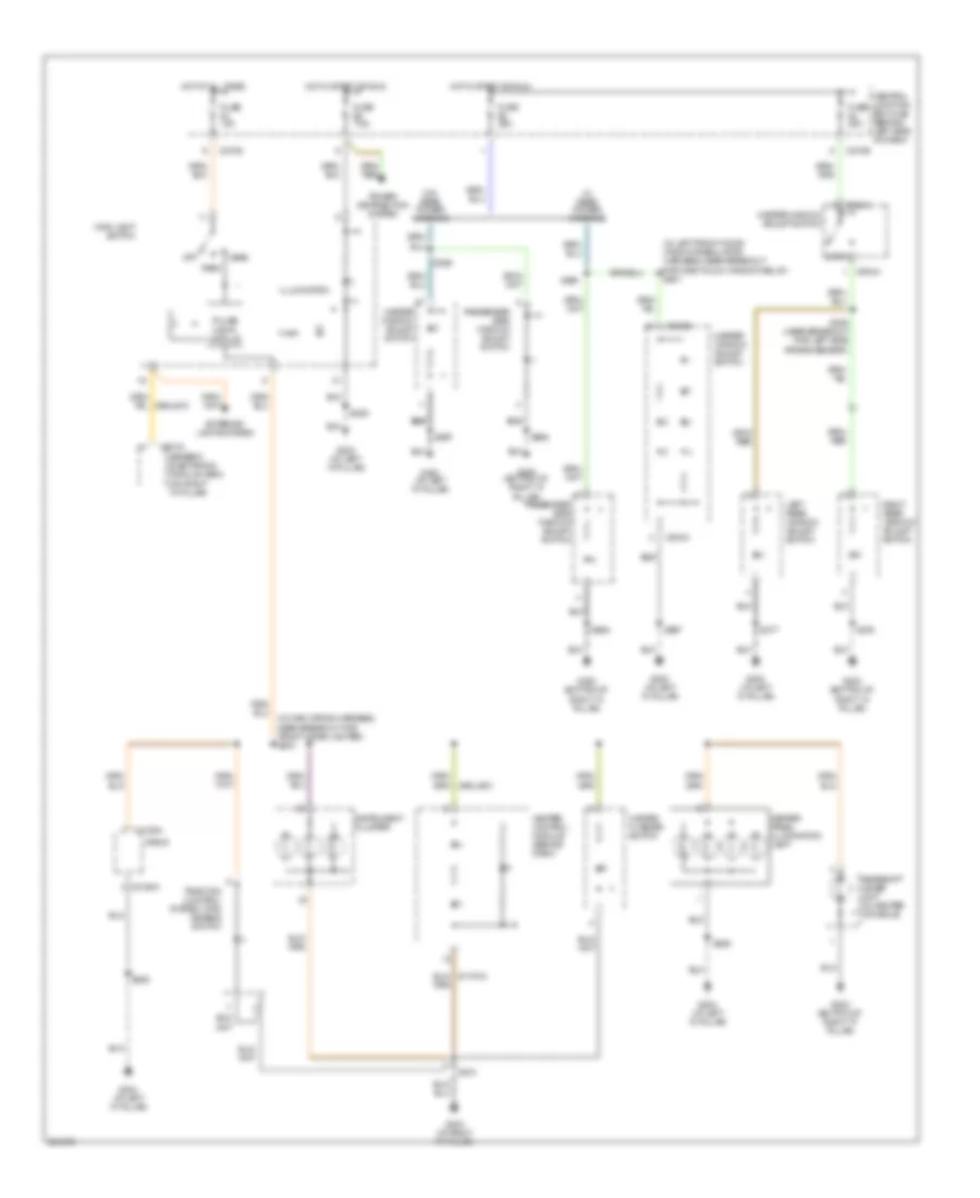
Park, Turn & Hazard Lamps Wiring Diagram for Ford Focus S 2007
List of elements for Park, Turn & Hazard Lamps Wiring Diagram for Ford Focus S 2007:
- (at right ``a" pillar) g203
- (in junction box wiring harness, near breakout for engine compt switch) s132
- (in junction box wiring harness, near breakout to c134) s130
- (not used)
- 1. right turn signal 2. flash right 3. neutral 4. flash left 5. left turn signal
- 29-dk20
- 29s-le18
- 29s-lg43
- 3 & 5 door
- 31-dk20
- 49s-lg12
- 49s-lg15
- 49s-lg19
- 49s-lg22
- 49s-lg4
- 49s-lg5
- 91-dk20
- 91s-lg1
- 91s-lg2
- 91s-lg8
- C201a
- C201b
- C201c
- C201d
- C201e
- C270d
- C270f
- C452a
- C452b
- C462a
- C462b
- Central junction box (cjb) (behind left side of dash)
- Fuse 10a
- Fuse 15a
- G100 (left front of engine compt)
- G102 (right front of engine compt)
- G300 (bottom of right ``a" pillar)
- G401 (wagon: at right "d" pillar) (4 door: right rear of luggage compt)
- G402 (except wagon: left rear of luggage compt)
- G402 (left rear of luggage compt)
- G402 (others) (left rear of luggage compt)
- G403 (wagon) (in liftgate)
- Generic electronic module (gem) (on right ``a" pillar)
- Hazard flasher switch
- Hot at all times
- Instrument cluster
- Left front park/turn lamp
- Left front side lamp
- Left license plate lamp
- Left rear lamp assembly
- Left turn ind
- Main light switch 0. off 1. park 2. low beam
- Multi-function switch
- Nca
- Others
- Right front park/turn lamp
- Right front side lamp
- Right license plate lamp
- Right rear lamp assembly
- Right turn ind
- S104 (in junction box wiring harness, near breakout for left front side light)
- S109
- S121
- S212
- S412 (in taillight wiring harness, near breakout to c408)
- S484
- S485 (4 door)
- S496
- Wagon
- Wagon & 4 door
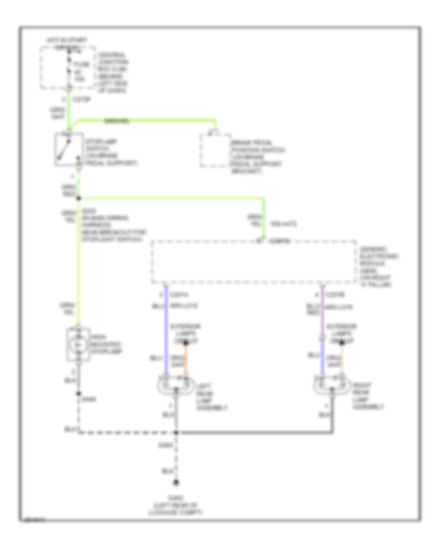
Stop Lamps Wiring Diagram, 3 & 5 Door for Ford Focus S 2007
List of elements for Stop Lamps Wiring Diagram, 3 & 5 Door for Ford Focus S 2007:
- 15s-aa72
- Brake pedal position switch (on brake pedal support bracket)
- C201a
- C201b
- C201d
- C270f
- Central junction box (cjb) (behind left side of dash)
- Exterior lamps circuit
- Fuse 10a
- G402 (left rear of luggage compt)
- Generic electronic module (gem) (on right "a" pillar)
- High mounted stoplamp
- Hot in start or run
- Left rear lamp assembly
- Right rear lamp assembly
- S484
- S496
- Stoplamp switch (on brake pedal support)
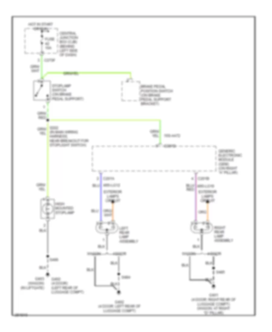
Stop Lamps Wiring Diagram, 4 Door & Wagon for Ford Focus S 2007
List of elements for Stop Lamps Wiring Diagram, 4 Door & Wagon for Ford Focus S 2007:
- 15s-aa72
- 4 door
- Brake pedal position switch (on brake pedal support bracket)
- C201a
- C201b
- C201d
- C270f
- Central junction box (cjb) (behind left side of dash)
- Exterior lamps circuit
- Fuse 10a
- G401 (4 door: right rear of luggage compt) (wagon: at right "d" pillar)
- G402 (4 door) (left rear of luggage compt)
- G402 (4 door: left rear of luggage compt)
- G403 (wagon) (in liftgate)
- Generic electronic module (gem) (on right "a" pillar)
- High mounted stoplamp
- Hot in start or run
- Left rear lamp assembly
- Right rear lamp assembly
- S484
- S485
- S496
- Stoplamp switch (on brake pedal support)
- Wagon
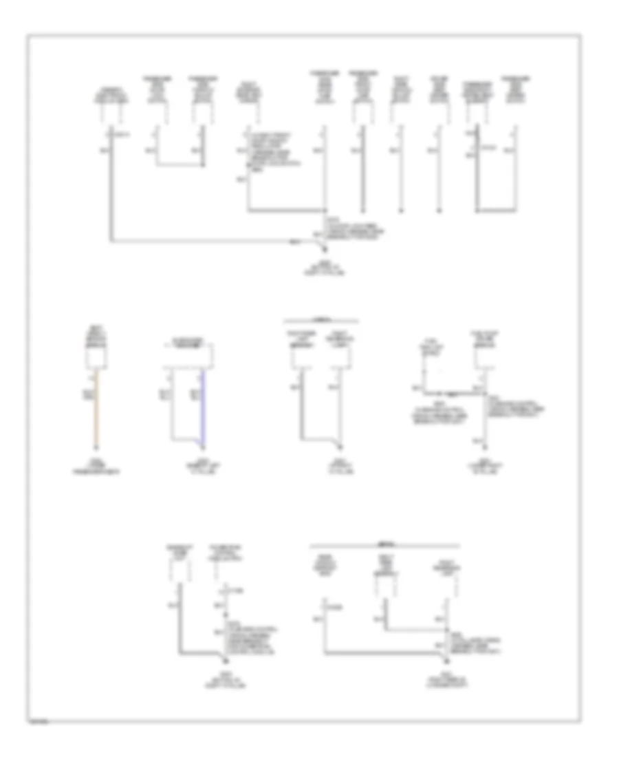
GROUND DISTRIBUTION
Ground Distribution Wiring Diagram (1 of 4) for Ford Focus S 2007
List of elements for Ground Distribution Wiring Diagram (1 of 4) for Ford Focus S 2007:
- (at left "a" pillar)
- (left rear corner of engine compartment) battery junction box (bjb)
- (m/t)
- (not used) abs test connector
- (pzev) air pump motor
- 87a
- A/c clutch field coil
- A/c compressor clutch diode
- Abs control module
- Battery
- Battery junction box (bjb) (left rear corner of engine compt)
- Brake fluid level switch
- C175b
- Engine compartment switch
- For a/c clutch field coil)
- Fuel pump relay
- G100 (left front of engine compartment)
- G101 (w/ tcs) (left front of engine compartment)
- G101 (w/o tcs) (left front of engine compartment)
- G102 (right front of engine compartment)
- G103 (left side of engine compartment)
- G105
- High beam relay
- Horn
- Ignition relay
- Left front fog lamp
- Left front park/turn lamp
- Left headlamp
- Low beam relay
- Low speed engine cooling fan relay b
- Mass air flow (maf) sensor
- Nca
- Power hold relay
- Powertrain control module (pcm)
- Right front fog lamp
- Right front park/turn lamp
- Right headlamp
- S112 (in engine control sensor extension wiring harness)
- S118 (in junction box wiring harness, near battery junction box)
- S192 (in engine control wiring harness)
- Second cooling fan motor
- Speed control servo
- To left front side light)
- To powertrain control module)
- Vehicle speed sensor (vss)
- Windshield wiper motor
Ground Distribution Wiring Diagram (2 of 4) for Ford Focus S 2007
List of elements for Ground Distribution Wiring Diagram (2 of 4) for Ford Focus S 2007:
- (behind left side of dash) central junction box (cjb)
- (w/ front & rear power windows) (w/ front power windows)
- (wagon) cargo space lamp
- C201d
- C2188a
- C270c
- C311a
- C489b
- C504a
- C535
- C918b
- Clock spring
- Data link connector (dlc)
- Daytime running lamps (drl) relay
- De-icing switch
- Driver side door lock switch
- Driver side front door ajar switch
- Driver side front door lock unit
- Driver side front heated seat element
- Driver side rear door ajar switch
- Exterior rear view mirror switch
- Front cigar lighter
- Front interior lamp
- G200 (at left ``a" pillar)
- G203 (at right ``a" pillar)
- G204 (at left ``a" pillar)
- G205 (behind center of dash)
- Generic electronic module (gem)
- Hazard flasher switch
- Heater blower switch
- Heater control module
- Heater panel illumination lamp
- Instrument cluster
- Left exterior rear view mirror
- Left rear window adjust switch
- Liftgate/ decklid release switch
- Main light switch
- Master window adjust switch
- Moonroof adjust switch
- Multi-function switch
- Nca
- Near breakout for instrument cluster)
- One-touch window relay
- Passive anti-theft transceiver module
- Radio
- Rear wiper relay
- Roof opening panel unit
- S270 (in door lock feed wiring harness, at breakout for g200)
- S377 (in door lock feed wiring harness, near breakout for g303)
- S597 (in left front door window regulator harness, near breakout for master window adjust switch)
- S914 (wagon) (in interior illumination wiring harness, near breakout for cargo space light)
- Traction control system (tcs) disable switch
- Wiper/ washer switch
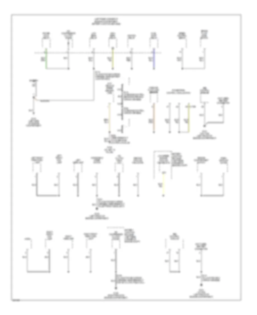
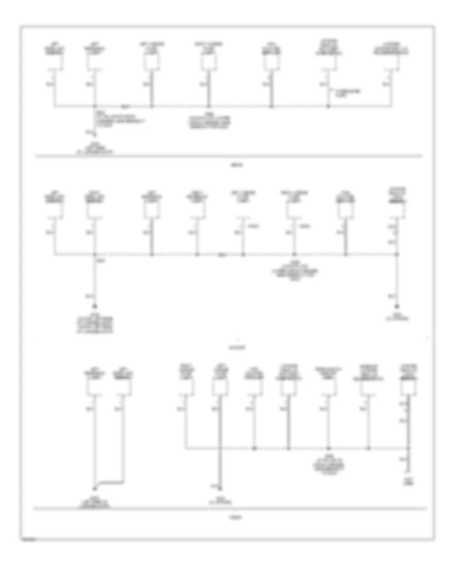
Ground Distribution Wiring Diagram (3 of 4) for Ford Focus S 2007
List of elements for Ground Distribution Wiring Diagram (3 of 4) for Ford Focus S 2007:
- (bottom of right "a" pillar)
- (in engine control wiring harness, near breakout for g301)
- (in right front door window regulator harness, near breakout for door lock switch) s694
- C175b
- C201a
- C312a
- C402b
- Driver side seat heater switch
- Fuel pump driver module
- Fuel tank unit shield
- G202
- G300 (bottom of right "a" pillar)
- G301 (under right "b" pillar)
- G303 (base of left "c" pillar)
- G304 (under passenger's seat)
- G401 (at right ``d" pillar)
- G401 (right rear of luggage compt)
- Gearshift lever unit
- Generic electronic module (gem)
- Nca
- Passenger side door lock switch
- Passenger side front door ajar switch
- Passenger side front heated seat element
- Passenger side rear door ajar switch
- Passenger side seat heater switch
- Passenger side window adjust switch
- Powertrain control module (pcm)
- Rear window defrost grid
- Right exterior rear view mirror
- Right rear lamp assembly
- Right rear window adjust switch
- Right reversing lamp
- S300
- S381 (in engine control wiring harness, near breakout for g301)
- S485 (in taillamps wiring harness, near breakout for g401)
- Seat weight sensor module
- Sedan
- Subwoofer amplifier
- Wagon
- Wiring harness, near breakout for powertrain control module)
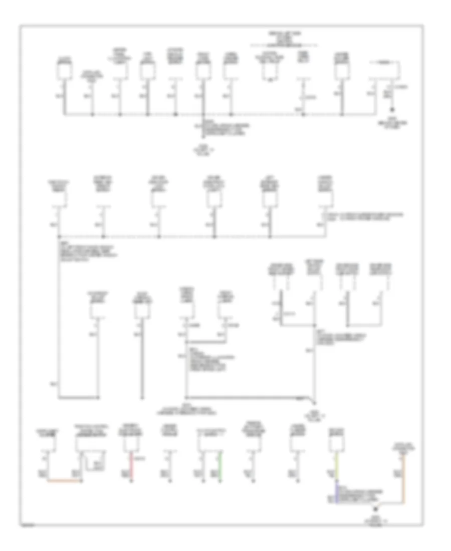
Ground Distribution Wiring Diagram (4 of 4) for Ford Focus S 2007
List of elements for Ground Distribution Wiring Diagram (4 of 4) for Ford Focus S 2007:
- (not used)
- 3/5 door
- C452a
- C462a
- Exterior liftgate/ deck-lid release switch
- G402 (3 door: left rear of luggage compt, 5 door: left rear of luggage compt)
- G402 (left rear of luggage compt)
- G403 (in liftgate)
- High mounted stop lamp
- Left license plate lamp
- Left rear lamp assembly
- Left reversing lamp
- Liftgate/ deck-lid anti-theft inhibit switch
- Liftgate/ deck-lid latch assembly
- Luggage compartment lid release solenoid
- Nca
- Rear window defrost grid
- Right license plate lamp
- Right rear lamp assembly
- Right reversing lamp
- S484
- S484 (in taillights wiring harness, near breakout to g402)
- S496 (in door lock jumper wiring harness, near breakout for g403)
- S496 (in taillights wiring harness, near breakout to g403)
- Sedan
- W/ perimeter alarm
- Wagon
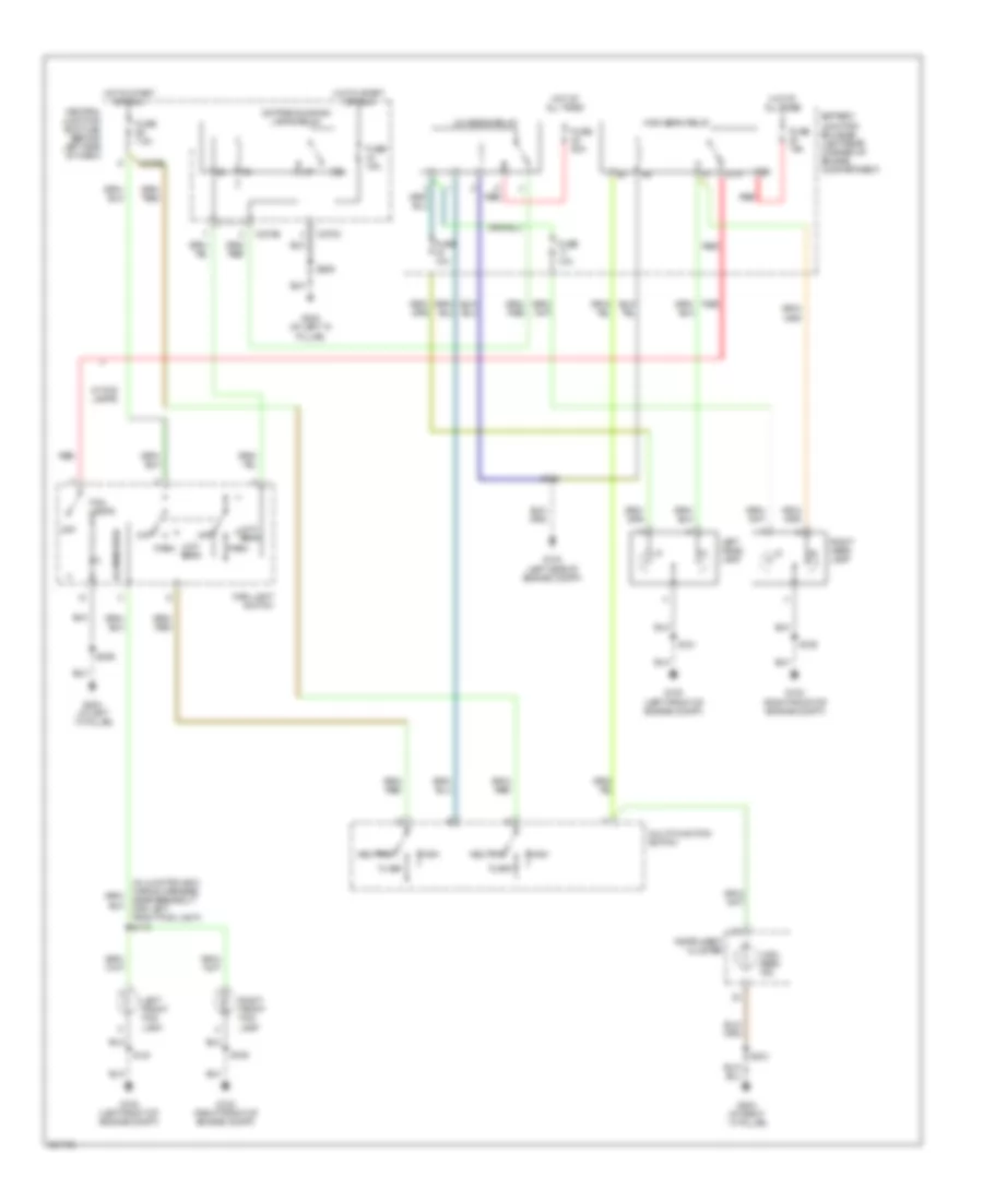
HEADLIGHTS
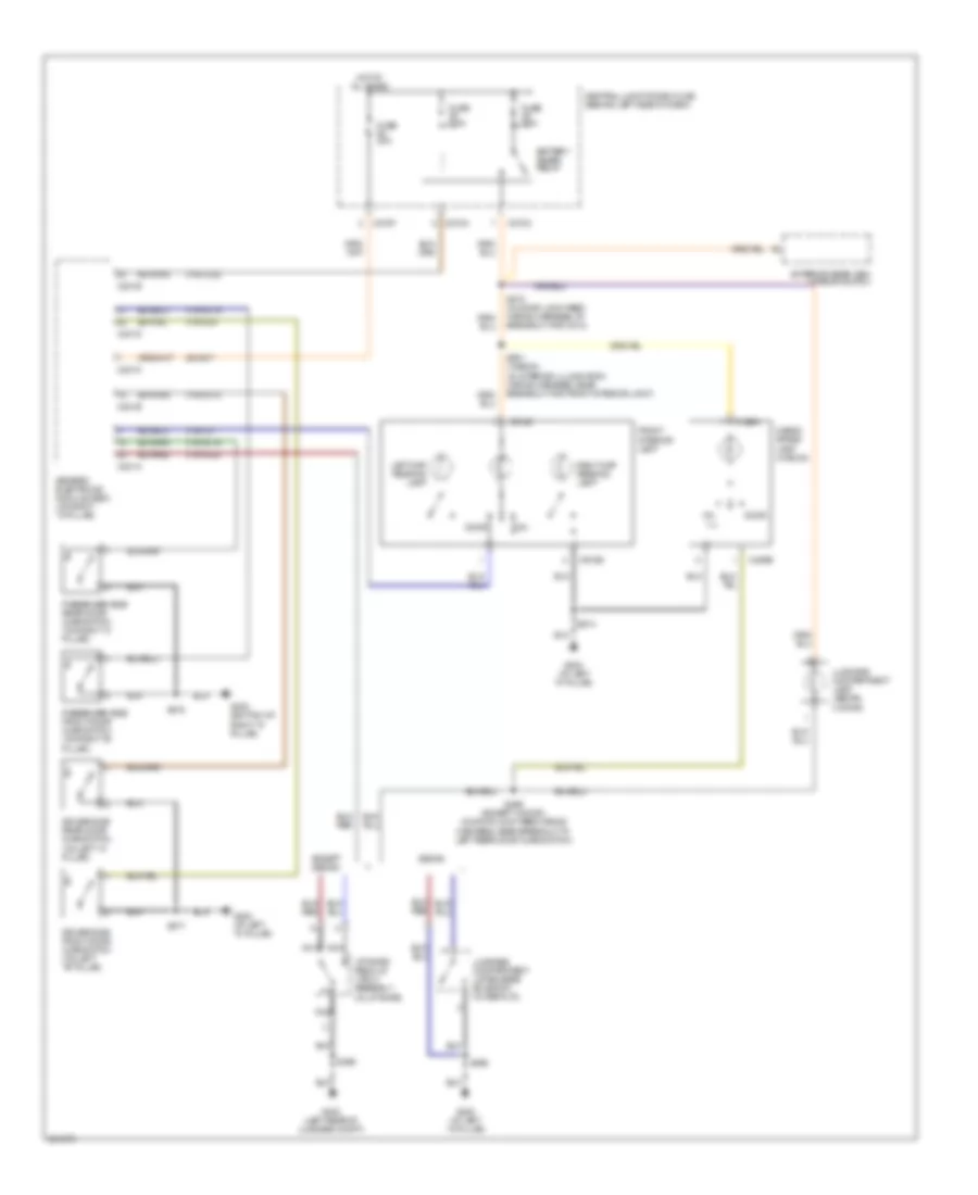
Headlights Wiring Diagram, with DRL for Ford Focus S 2007
List of elements for Headlights Wiring Diagram, with DRL for Ford Focus S 2007:
- (in junction box wiring harness, near breakout for left front fog light) s110
- 87a
- Battery junction box (bjb) (left rear corner of engine compartment)
- C270b
- C270c
- C270e
- Central junction box (cjb) (behind left side of dash)
- Daytime running lamps relay
- Flash
- Fog lamps
- Fuse 10a
- Fuse 15a
- Fuse 20a
- Fuse 7.5a
- G100 (left front of engine compt)
- G102 (right front of engine compt)
- G103 (left side of engine compt)
- G203 (at right ``a" pillar)
- G204 (at left "a" pillar)
- G204 (at left ``a" pillar)
- High
- High beam ind
- High beam relay
- Hot at all times
- Hot in start or run
- Illumination
- Instrument cluster
- Left front fog lamp
- Left head- lamp
- Low beam
- Low beam relay
- Main light switch
- Multi-function switch
- Neutral
- Off
- Park
- Red
- Right front fog lamp
- Right head- lamp
- S109
- S118
- S121
- S206
- S212
- W/ fog lamps
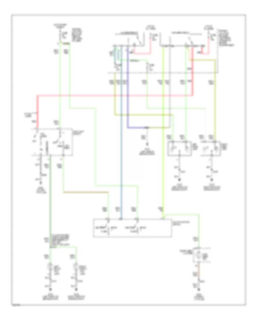
Headlights Wiring Diagram, without DRL for Ford Focus S 2007
List of elements for Headlights Wiring Diagram, without DRL for Ford Focus S 2007:
- (in junction box wiring harness, near breakout for left front fog light) s110
- 87a
- Battery junction box (bjb) (left rear corner of engine compartment)
- C270e
- Central junction box (cjb) (behind left side of dash)
- Flash
- Fog lamps
- Fuse 10a
- Fuse 15a
- Fuse 20a
- Fuse 7.5a
- G100 (left front of engine compt)
- G102 (right front of engine compt)
- G103 (left side of engine compt)
- G203 (at right ``a" pillar)
- G204 (at left ``a" pillar)
- High
- High beam ind
- High beam relay
- Hot at all times
- Hot in start or run
- Illumination
- Instrument cluster
- Left front fog lamp
- Left head- lamp
- Low beam
- Low beam relay
- Main light switch
- Multi-function switch
- Neutral
- Off
- Park
- Red
- Right front fog lamp
- Right head- lamp
- S109
- S118
- S121
- S206
- S212
- W/ fog lamps
HORN
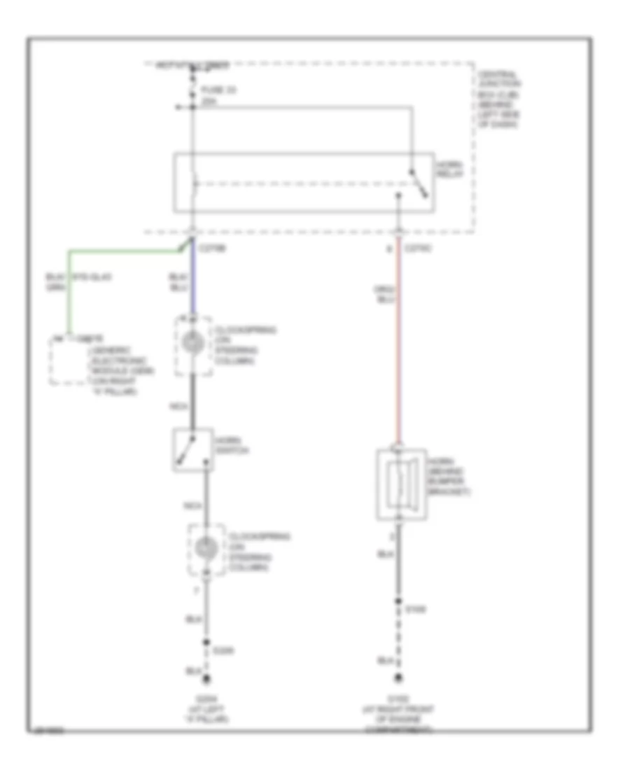
Horn Wiring Diagram for Ford Focus S 2007
List of elements for Horn Wiring Diagram for Ford Focus S 2007:
- 20a
- Box (cjb) (behind left side of dash)
- C201e
- C270b
- C270c
- Central junction
- Clockspring (on steering column)
- Fuse 33
- G102 (at right front of engine compartment)
- G204 (at left "a" pillar)
- Generic electronic module (gem) (on right "a" pillar)
- Horn (behind bumper bracket)
- Horn relay
- Horn switch
- Hot at all times
- Nca
- S109
- S206
INSTRUMENT CLUSTER
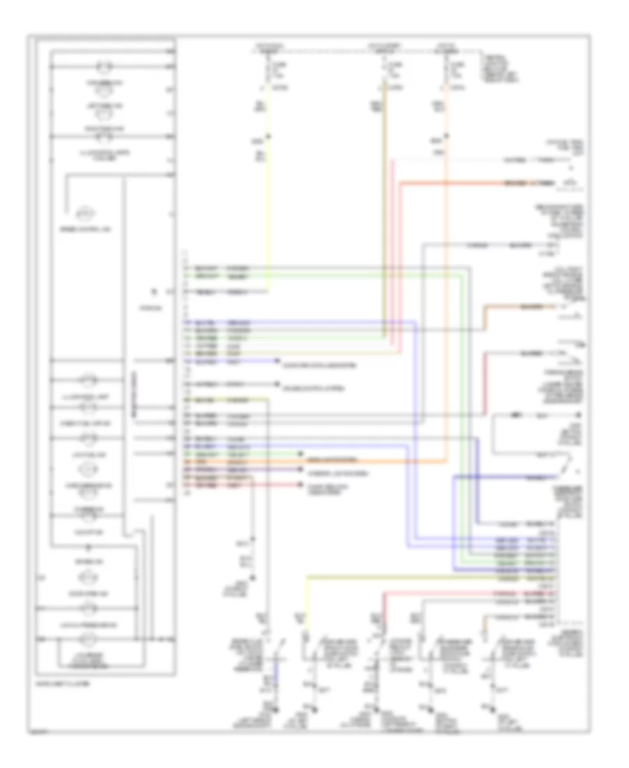
Instrument Cluster Wiring Diagram for Ford Focus S 2007
List of elements for Instrument Cluster Wiring Diagram for Ford Focus S 2007:
- (2.3l: right side of engine) (2.0l: lower left of engine) oil pressure switch
- (at left "a" pillar)
- (behind right side of dash, at base of "a" pillar) powertrain control module (pcm)
- (on fuel tank) fuel tank unit
- 15-gg14
- 15s-aa17
- 15s-aa17 15s-aa17
- 15s-le11
- 29-gg14
- 29s-la31
- 31s-aa7
- 31s-gc20
- 31s-gc6
- 31s-ge44
- 31s-gl12
- 31s-gl16
- 31s-gl19
- 31s-gl20
- 31s-gl6
- 31s-gl9
- 4-ec7
- 49s-lg15
- 49s-lg22
- 5-ec7
- 75-gg14
- 8-ga7
- 8-pg11
- 9-ga7
- 91-gg14
- 91s-gg21
- Air bag ind
- Brake fluid level switch (on top of master cylinder reservoir)
- C175b
- C201a
- C201b
- C201d
- C201e
- C270a
- C270d
- C270e
- Central junction box (cjb) (behind left side of dash)
- Charge ind
- Check engine ind
- Check fuel cap ind
- Computer data lines system
- Cruise control system
- Door open ind
- Driver side front door ajar switch (on left "b" pillar)
- Driver side rear door ajar switch (on left "c" pillar)
- Fuse 7.5a
- G103 (left side of engine compt)
- G200
- G200 (at left "a" pillar)
- G203 (at right "a" pillar)
- G300 (bottom of right "a" pillar)
- G402 (3/5 door) (left rear of luggage compt)
- G403 (wagon) (in liftgate)
- Generic electronic module (gem) (on right "a" pillar)
- Headlights system
- High beam ind
- Hot at all times
- Hot in run or acc
- Hot in start or run
- Illumination lamp
- Illumination lamps (3 bulbs)
- Instrument cluster
- Interior lights system
- Left turn ind
- Liftgate/ decklid latch assembly (in liftgate)
- Low brake fluid level/ park brake ind
- Low fuel ind
- Low oil pressure ind
- Microprocessor
- Nca
- O/d off ind
- Parking brake switch (under center console, at base of park brake lever bracket)
- Passenger side front door ajar switch (on right "b" pillar)
- Passenger side rear door ajar switch (on right "c" pillar)
- Pats ind
- Right turn ind
- S118
- S212
- S249
- S250
- S377
- S378
- S496
- Speed control ind
INTERIOR LIGHTS
Courtesy Lamps Wiring Diagram for Ford Focus S 2007
List of elements for Courtesy Lamps Wiring Diagram for Ford Focus S 2007:
- 29-aa17
- 31s-gl12
- 31s-gl16
- 31s-gl19
- 31s-gl20
- 31s-gl9
- 31s-lc22
- 31s-lc7
- Battery saver relay
- C201a
- C201b
- C201c
- C201d
- C201e
- C270a
- C270c
- C270f
- C489a
- C489b
- C918a
- C918b
- Cargo space lamp (wagon)
- Central junction box (cjb) (behind left side of dash)
- Door
- Driver side front door ajar switch (on left "b" pillar)
- Driver side rear door ajar switch (on left "c" pillar)
- Except sedan
- Exterior rear view mirror switch
- Front interior lamp
- Fuse 20a
- Fuse 7.5a
- G200 (at left "a" pillar)
- G300 (bottom of right "a" pillar)
- G402 (left rear of luggage compt)
- Generic electronic module (gem) (on right "a" pillar)
- Hot at all times
- Left map reading lamp
- Liftgate/ decklid latch assembly (in liftgate)
- Luggage compartment lamp (sedan, 3 door)
- Luggage compartment lid release solenoid (in decklid)
- Nca
- Passenger side front door ajar switch (on right "b" pillar)
- Passenger side rear door ajar switch (on right "c" pillar)
- Right map reading lamp
- S273 (in door lock feed wiring harness, at breakout for c210)
- S377
- S378
- S469 (except 3 door) (in door lock feed wiring harness, near breakout to left rear door ajar switch)
- S496
- S901 (wagon) (in interior illumination wiring harness, near breakout for front interior light)
- S914
- Sedan
Instrument Illumination Wiring Diagram for Ford Focus S 2007
List of elements for Instrument Illumination Wiring Diagram for Ford Focus S 2007:
- (in left front door window regulator harness, near breakout for one-touch window relay) s501
- (in main wiring harness, near breakout for front cigar lighter) s204
- C201d
- C2188a
- C270d
- C270e
- C504a
- C504b
- Central junction box (cjb) (behind left side of dash)
- Exterior lights system
- Fuse 10a
- Fuse 25a
- Fuse 7.5a
- G200 (at left "a" pillar)
- G202 (bottom of right "a" pillar)
- G203 (at right "a" pillar)
- G204 (at left "a" pillar)
- G300 (bottom of
- G300 (bottom of right "a" pillar)
- Gearshift lever unit (in center console)
- Generic electronic module (gem) (on right "a" pillar)
- Hazard flasher switch
- Head
- Heater control module (behind dash)
- Heater panel illumination lamp
- Hot at all times
- Hot in start or run
- Illumination
- Instrument cluster
- Left rear window adjust switch
- Lock
- Main light switch
- Master window adjust switch
- Off
- Park
- Passenger side window adjust switch
- Power distribution system
- Pulse width module
- Radio
- Right "a" pillar)
- Right rear window adjust switch
- S206
- S212
- S356
- S358 (near breakout for left side air bag sensor)
- S377
- S378
- S597
- S694
- Traction control system (tcs) disable switch
- W/ rear power windows
- W/o rear power windows
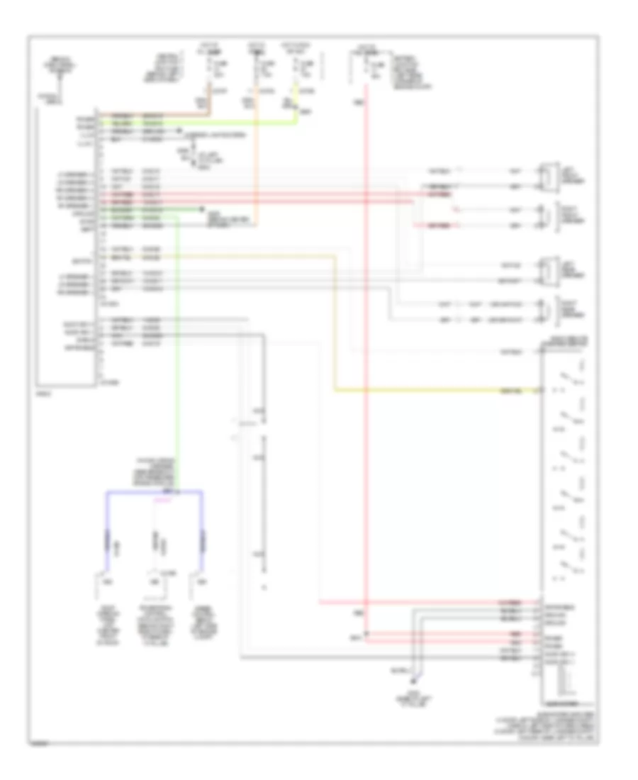
POWER DISTRIBUTION
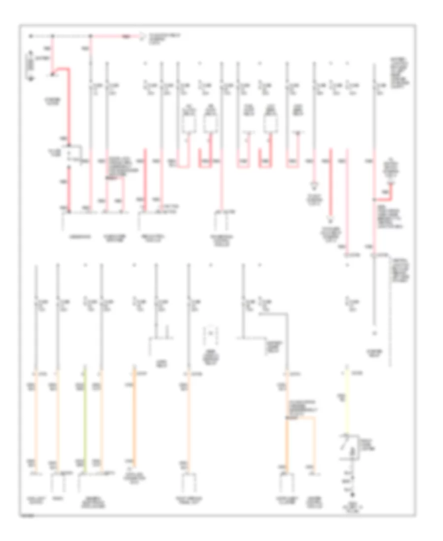
Power Distribution Wiring Diagram (1 of 4) for Ford Focus S 2007
List of elements for Power Distribution Wiring Diagram (1 of 4) for Ford Focus S 2007:
- (door lock wiring harn, in breakout for subwoofer amplifier) s404
- (in main wiring harness, near breakout to c213) s249
- (w/ tcs)
- (w/o tcs)
- 175a
- 270d
- A/c clutch relay
- Abs control module
- Air pump relay
- Battery
- Battery junction box (bjb) (in left rear corner of engine compt)
- Battery saver relay
- C175b
- C201c
- C2188a
- C270a
- C270b
- C270e
- C270f
- C270g
- Central junction box (cjb) (behind left side of dash)
- Data link connector (dlc)
- Front cigar lighter
- Fuel pump relay
- Fuse 10a
- Fuse 15a
- Fuse 1a
- Fuse 20a
- Fuse 30a
- Fuse 40a
- Fuse 50a
- Fuse 7.5a
- G204 (at left ``a" pillar)
- Generator
- Generic electronic module (gem)
- Heater control module
- High beam relay
- Horn relay
- In-line fuse
- Instrument cluster
- Low beam relay
- Main light switch
- Powertrain control module
- Radio
- Rear window defrost relay
- Red
- Roof opening panel unit
- S206
- S298 (main wiring harn, near breakout to central junction box)
- Starter motor
- Starter relay
- Subwoofer amplifier
- To ignition relay (diagram 3 of 4)
- To ignition switch (diagram 2 of 4)
- To power hold relay (diagram 3 of 4)
- To s107 (diagram 3 of 4)
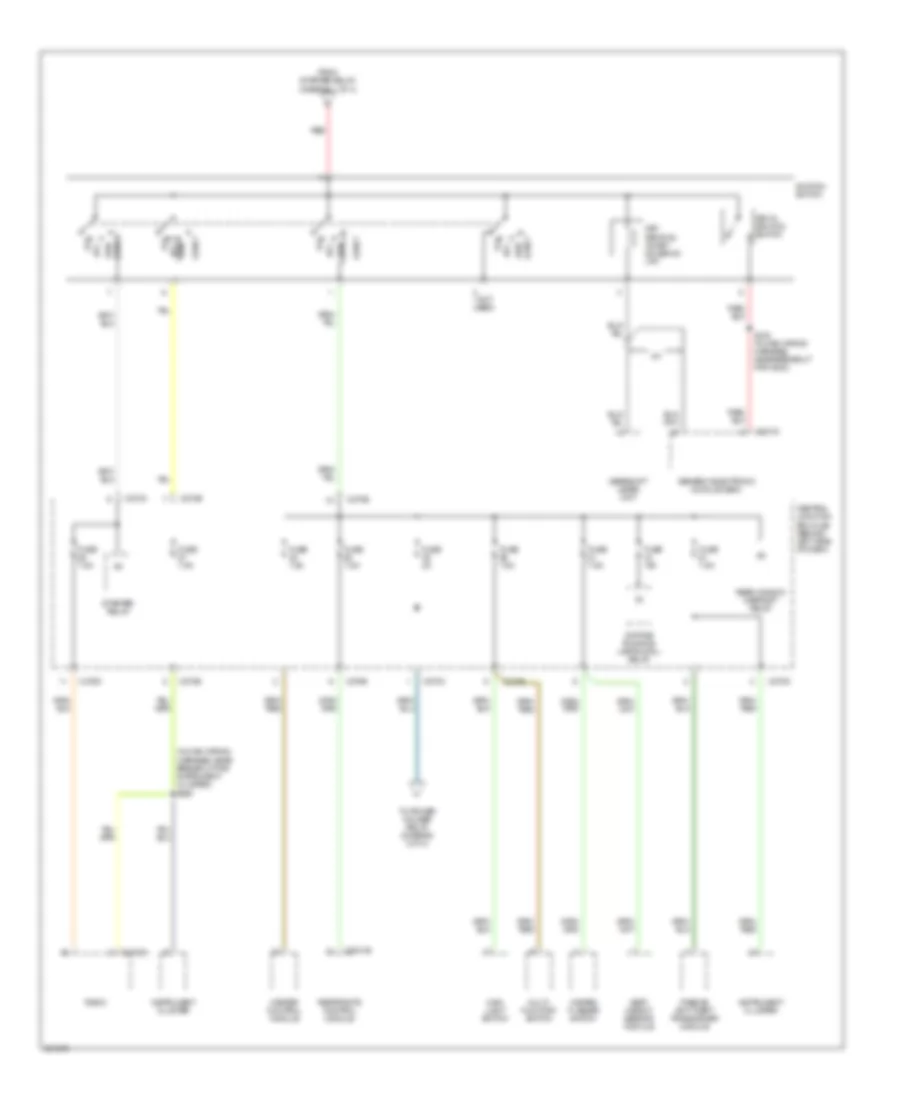
Power Distribution Wiring Diagram (2 of 4) for Ford Focus S 2007
List of elements for Power Distribution Wiring Diagram (2 of 4) for Ford Focus S 2007:
- (in main wiring harness, near breakout for instrument cluster) s250
- (not used)
- A/t
- Acc
- C201d
- C2041b
- C2188a
- C270c
- C270d
- C270e
- Central junction box (cjb) (behind left side of dash)
- Daytime running lamps (drl) relay
- From starter relay (diagram 1 of 4)
- Fuse 15a
- Fuse 2a
- Fuse 7.5a
- Gearshift lever unit
- Generic electronic module (gem)
- Hazard flasher switch
- Heater control module
- Ignition switch
- Instrument cluster
- Key in ignition switch
- Key removal inhibit solenoid (a/t)
- Main light switch
- Multi- function switch
- Off
- Passive anti-theft transceiver module
- Radio
- Rear window defrost relay
- Red
- Restraints control module
- Run
- Run acc
- S215 (in main wiring harness, near breakout for g203)
- Seat weight sensor module
- Start
- Starter relay
- To power holder relay (diagram 3 of 4)
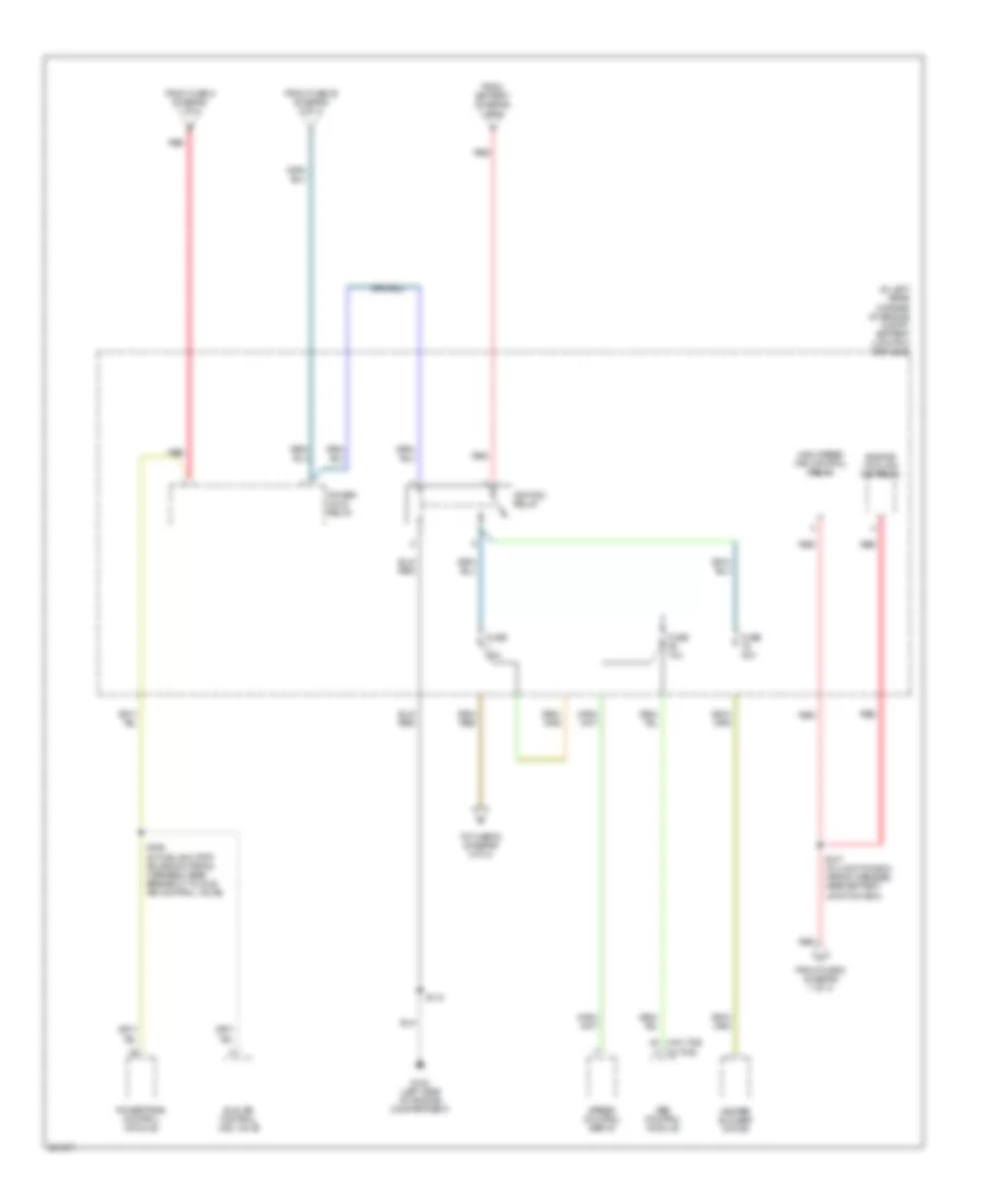
Power Distribution Wiring Diagram (3 of 4) for Ford Focus S 2007
List of elements for Power Distribution Wiring Diagram (3 of 4) for Ford Focus S 2007:
- (in left rear corner of engine compt) battery junction box (bjb)
- (w/o tcs) (w/ tcs)
- Abs control module
- Engine cooling fan relay
- From battery (diagram 1 of 4)
- From fuse 39 (diagram 2 of 4)
- From fuse 6 (diagram 1 of 4)
- From fuse 9 (diagram 1 of 4)
- Fuse 10a
- Fuse 40a
- G103 (left side of engine compartment)
- Heater blower motor
- High speed fan control relay
- Idle air control (iac) valve
- Ignition relay
- Power hold relay
- Powertrain control module
- Red
- S107 (in junction box wiring harness, near battery junction box)
- S118
- S199 (in fuel shutoff solenoid wiring harness, near breakout to idle air control valve)
- Speed control servo
- To fuse 53 (diagram 4 of 4)
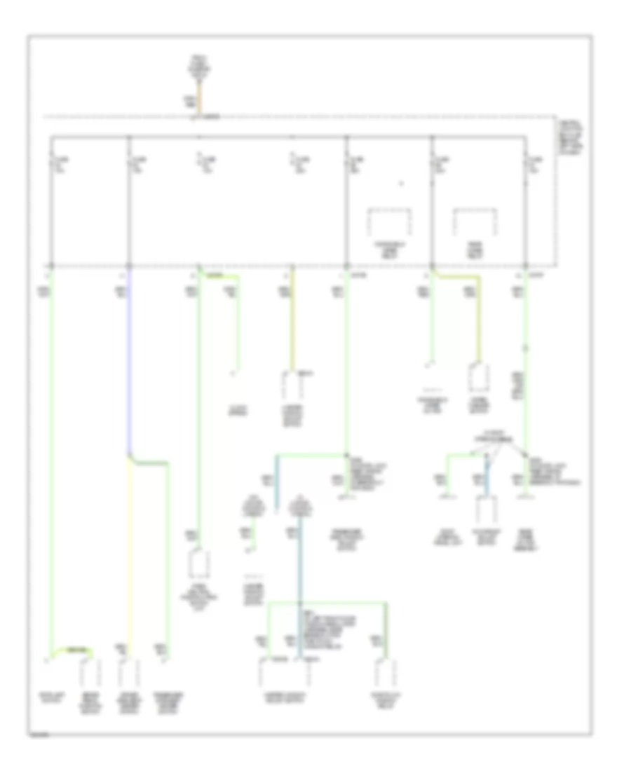
Power Distribution Wiring Diagram (4 of 4) for Ford Focus S 2007
List of elements for Power Distribution Wiring Diagram (4 of 4) for Ford Focus S 2007:
- Brake pedal position switch
- C270e
- C270f
- C270g
- C504a
- C504b
- Central junction box (cjb) (behind left side of dash)
- Clock spring
- Driver side seat heater switch
- From fuse 1 (diagram 3 of 4)
- Fuse 10a
- Fuse 15a
- Fuse 20a
- Fuse 25a
- Master window adjust switch
- Moonroof adjust switch
- One-touch window relay
- Park/ neutral position (pnp) switch (m/t)
- Passenger side seat heater switch
- Passenger side window adjust switch
- Rear wiper motor assembly
- Rear wiper relay
- Roof opening panel unit
- S253 (in door lock feed wiring harness, at breakout for g200)
- S356 (in door lock feed wiring harness, at breakout for g200)
- S501 (in left front door window regulator harness, near breakout for one-touch window relay)
- Stoplamp switch
- W/ 4 door, 5 door & wagon
- W/ roof opening panel
- W/o 4 door, 5 door & wagon
- Windshield wiper motor
- Windshield wiper relay
- Wiper/ washer switch
POWER DOOR LOCKS
Power Door Locks Wiring Diagram (1 of 2) for Ford Focus S 2007
List of elements for Power Door Locks Wiring Diagram (1 of 2) for Ford Focus S 2007:
- (behind dash) rke antenna
- (in door lock feed wiring harness, near breakout for generic electronic module) s376
- (in door lock feed wiring harness,near breakout for generic electronic module)
- (in main wiring harness, near breakout for stoplight switch) s202
- (not used)
- 15s-aa17
- 15s-aa72
- 29-aa17
- 29-dk20
- 31-dk20
- 31s-aa17
- 31s-aa30
- 31s-aa39
- 31s-aa61
- 31s-aa62
- 31s-aa63
- 31s-aa64
- 31s-aa85
- 31s-gl12
- 31s-gl16
- 31s-gl19
- 31s-gl20
- 31s-gl27
- 31s-gl7
- 31s-gl9
- 31s-lc7
- 32-aa27
- 32-aa59
- 33-aa59
- 8-ee9
- 91-aa17
- 91-dk20
- 91s-gl43
- 91s-lg8
- C201a
- C201b
- C201c
- C201d
- C201e
- C270f
- Central junction box (cjb) (behind left side of dash)
- Data link connector (dlc) (under left side of dash, on central junction box)
- Driver side door lock switch
- Engine compartment switch (front center of engine compt)
- Exterior liftgate/ decklid release switch
- Exterior lights system
- Fuse 15a
- Fuse 20a
- G100 (left front of engine compt)
- G200 (at left "a" pillar)
- G203 (at right "a" pillar)
- G204 (at left "a" pillar)
- G300 (bottom of right "a" pillar)
- G403 (in liftgate)
- Generic electronic module (gem) (on right "a" pillar)
- Horns system
- Hot at all times
- Illumination
- Instrument cluster
- Interior lights system
- Liftgate/ decklid release switch
- Lock
- Passenger side door lock switch
- S121
- S206
- S212
- S375
- S496
- S597
- S694
- Stoplamp switch (on brake pedal support)
- Unlock
- Wagon
Power Door Locks Wiring Diagram (2 of 2) for Ford Focus S 2007
List of elements for Power Door Locks Wiring Diagram (2 of 2) for Ford Focus S 2007:
- (at left "a" pillar) g200
- (in breakout to liftgate/ deck lid latch assembly)
- (in decklid) liftgate/decklid anti-theft inhibit switch
- (in decklid) luggage compartment lid release solenoid
- (in liftgate) liftgate/decklid anti-theft inhibit switch
- (in liftgate) liftgate/decklid latch assembly
- (left rear of luggage compt)
- (not used)
- 3 door, 5 door
- Central
- Central lock
- Driver side front door ajar switch (on left "b" pillar)
- Driver side front door lock unit (in driver's door)
- Driver side rear door ajar switch (on left "c" pillar)
- G200 (at left "a" pillar)
- G300 (bottom of right "a" pillar)
- G402 (left rear of luggage compt)
- G403 (in liftgate)
- Interior lights system
- Left rear door lock unit (in left rear door)
- Lock
- Nca
- Passenger side front door ajar switch (on right "b" pillar)
- Passenger side front door lock unit (in passenger's door)
- Passenger side rear door ajar switch (on right "c" pillar)
- Reset
- Right rear door lock unit (in right rear door)
- S360 (in door lock feed wiring harness, near breakout for right side air bag harness)
- S377
- S378
- S400
- S496
- S597
- Sedan
- Set
- Unlock
- Wagon
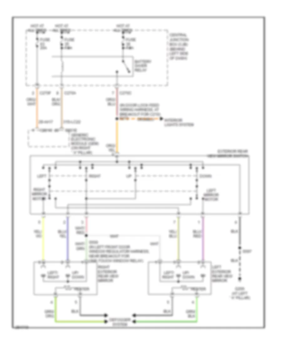
POWER MIRRORS
Power Mirrors Wiring Diagram for Ford Focus S 2007
List of elements for Power Mirrors Wiring Diagram for Ford Focus S 2007:
- (in left front door window regulator harness, near breakout for one-touch window relay)
- 29-aa17
- 31s-lc22
- Battery saver relay
- C201c
- C201e
- C270a
- C270c
- C270f
- Central junction box (cjb) (behind left side of dash)
- Defogger system
- Down
- Exterior rear view mirror switch
- Fuse 20a
- Fuse 7.5a
- G200 (at left ``a" pillar)
- Generic electronic module (gem) (on right ``a" pillar)
- Heater
- Hot at all times
- Interior lights system
- Left
- Left exterior rear view mirror
- Left mirror motor
- Left/ right
- Right
- Right exterior rear view mirror
- Right mirror motor
- S597
- Up/ down
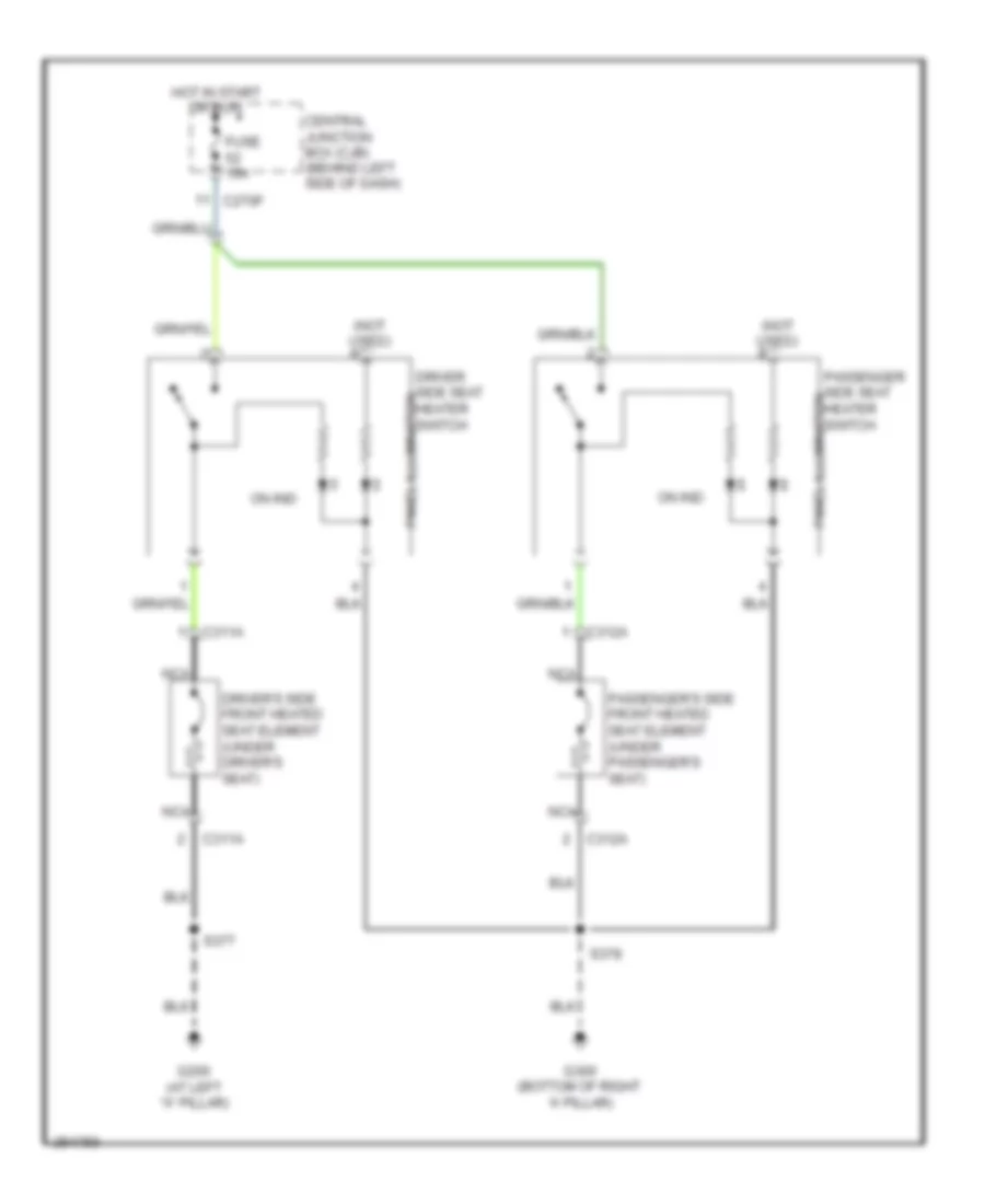
POWER SEATS
Power Seats Wiring Diagram for Ford Focus S 2007
List of elements for Power Seats Wiring Diagram for Ford Focus S 2007:
- (not used)
- C270f
- C311a
- C312a
- Central junction box (cjb) (behind left side of dash)
- Driver side seat panel illumination heater switch
- Driver's side front heated seat element (under driver's seat)
- Fuse 15a
- G200 (at left "a" pillar)
- G300 (bottom of right 'a' pillar)
- Hot in start or run
- Nca
- On ind
- Passenger side seat panel illumination heater switch
- Passenger's side front heated seat element (under passenger's seat)
- S377
- S378
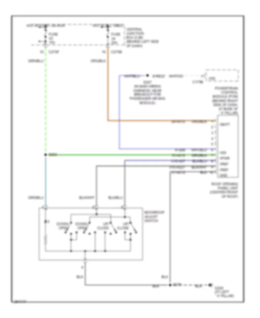
POWER TOP/SUNROOF
Power Top/Sunroof Wiring Diagram for Ford Focus S 2007
List of elements for Power Top/Sunroof Wiring Diagram for Ford Focus S 2007:
- 15-ag12
- 29-ag12
- 31-ag12
- 31s-ag27
- 31s-ag7
- 8-gb8
- 8-re22
- C175b
- C270b
- C270f
- Central junction box (cjb) (behind left side of dash)
- Down/ open
- Fuse 15a
- Fuse 20a
- G200 (at left ``a" pillar)
- Gnd
- Hot at all times
- Hot in start or run
- Moonroof adjust switch
- Powertrain control module (pcm) (behind right side of dash, at base of ``a" pillar)
- Roof opening panel unit (center front of roof)
- S207 (in main wiring harness, near breakout for passenger air bag module)
- S253
- S270
- Up/ close
- Vbatt
- Vpwr
- Vref
- Vss
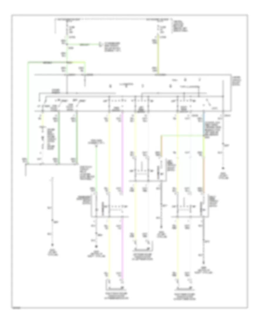
POWER WINDOWS
Power Windows Wiring Diagram, with Rear Power Windows for Ford Focus S 2007
List of elements for Power Windows Wiring Diagram, with Rear Power Windows for Ford Focus S 2007:
- (in door lock feed wiring harness, near breakout for left side air bag sensor) s358
- C270e
- C504a
- C504b
- Central junction box (cjb) (behind left side of dash)
- Driver side front power window motor (in driver door)
- Driver switch
- From s356 (diagram 1 of 1)
- Fuse 25a
- G200 (at left ``a" pillar)
- G300 (bottom of right ``a" pillar)
- G300 g300 (bottom of right ``a" pillar)
- Hot in start or run
- Illumination
- Left rear power window motor (in left rear door)
- Left rear switch
- Left rear window adjust switch
- Lock
- Master window adjust switch
- One- touch down
- One-touch window relay (in driver door, behind trim panel)
- Pass switch
- Passenger side window adjust switch
- Rest
- Right front power window motor (in passenger's door)
- Right rear power window motor (in right rear door)
- Right rear switch
- Right rear window adjust switch
- S356
- S377
- S378
- S501
- S597
- S694
- To passenger side window adjust switch (diagram 1 of 1)
Power Windows Wiring Diagram, without Rear Power Windows for Ford Focus S 2007
List of elements for Power Windows Wiring Diagram, without Rear Power Windows for Ford Focus S 2007:
- C270e
- Central junction box (cjb) (behind left side of dash)
- Driver switch
- Fuse 25a
- G200 (at left ``a" pillar)
- G300 (bottom of right ``a" pillar)
- Hot in start or run
- Illumination
- Left front power window motor (in driver's door)
- Master window adjust switch
- One- touch down
- Passenger side window adjust switch
- Passenger switch
- Rest
- Right front power window motor (in passenger's door)
- S356
- S597
- S694
RADIO
Radio Wiring Diagram for Ford Focus S 2007
List of elements for Radio Wiring Diagram for Ford Focus S 2007:
- (at left "a" pillar)
- (behind dash panel) antenna
- (in main wiring harness, near breakout for passenger air bag module)
- 1-md23
- 10-md10
- 10-md11
- 10-md17
- 10-md18
- 2-md23
- 29-md15
- 29-md25
- 29s-lk34
- 31-md34
- 48-md23
- 75-md15
- 8-gb8
- 8-md10
- 8-md11
- 8-md17
- 8-md18
- 8-md19
- 8-md24
- 8-md26
- 8-re22
- 9-md26
- 91-md15
- Amp enable
- Audio sig (+)
- Audio sig (-)
- Battery junction box (bjb) (left rear corner of engine compt)
- C175b
- C2188a
- C2188b
- C270b
- C270d
- C270f
- Central junction box (cjb) (behind left side of dash)
- Coaxial lead
- Fuse 20a
- Fuse 30a
- Fuse 7.5a
- G204
- G205 (behind center of dash)
- G303 (base of left "c" pillar)
- Ground
- Hot at all times
- Hot in run or acc
- Hot in start
- Illum
- Illum -
- Interior lights system
- Left front speaker
- Left rear speaker
- Lf speaker (+)
- Lf speaker (-)
- Lr speaker (+)
- Lr speaker (-)
- Nca
- Power
- Powertrain control module (pcm) (behind right side of dash, at base of "a" pillar)
- Radio
- Radio remote control switch
- Red
- Rf speaker (+)
- Rf speaker (-)
- Right front speaker
- Right rear speaker
- Roof opening panel unit (center front of roof)
- Rr speaker (+)
- Rr speaker (-)
- S206
- S207
- S250
- S404
- Shield
- Sig rtn -
- Speed control servo (left side of engine compt)
- Subwoofer
- Subwoofer amplifier (4 door: left side of luggage compt) (wagon: left side of cargo area) (3 door: left rear of luggage compt) (5 door: near left "d" pillar)
- Vbatt
- Vs sig
- Vss
SHIFT INTERLOCK
Shift Interlock Wiring Diagram for Ford Focus S 2007
List of elements for Shift Interlock Wiring Diagram for Ford Focus S 2007:
- (bottom of right ``a" pillar) g202
- 15s-re13
- 31s-ta32
- Battery junction box (bjb) (left rear corner of engine compt)
- Brake pedal position switch (on brake pedal support bracket)
- C175b
- C201d
- C270f
- Central junction box (cjb) (behind left side of dash)
- Fuse 42 15a
- Fuse 8 30a
- Gearshift lever unit (in center console)
- Generic electronic module (gem) (on right ``a" pillar)
- Hot at all times
- Hot in start or run
- Ignition switch
- Illumination
- Interior lights system
- Key removal inhibit solenoid
- O/d switch
- Park interlock solenoid
- Powertrain control module (pcm) (behind right side of dash, at base of ``a" pillar)
- Red
- S267 (near breakout to c211b)
- S298
- Stoplamp switch (on brake pedal support)
- Switch)
- Transmissions system
STARTING/CHARGING
Charging Wiring Diagram for Ford Focus S 2007
List of elements for Charging Wiring Diagram for Ford Focus S 2007:
- (behind right side of dash, at base of ``a" pillar) powertrain control module (pcm)
- 175a
- 4-eb6
- 5-eb6
- 5-ec7
- Battery
- Battery junction box (bjb) (left rear corner of engine compt)
- C270d
- Can +
- Can -
- Central junction box (cjb) (behind left side of dash)
- Charge indicator
- Computer data lines system
- Distribution
- Fuse 1a
- Fuse 7.5a
- G103 (left side of engine compt)
- G203 (at right ``a" pillar)
- Gen com
- Gen mon
- Generator
- Hot at all times
- Hot in start or run
- In-line fuse
- Instrument cluster
- Microprocessor
- Power
- Red
- S212
- Starter motor
- System
Starting Wiring Diagram, A/T for Ford Focus S 2007
List of elements for Starting Wiring Diagram, A/T for Ford Focus S 2007:
- (on upper right side of steering column) passive anti-theft transceiver module
- 10-gl37
- 31s-bb16
- 8-gl37
- Acc
- Battery
- Battery junction box (bjb) (left rear corner of engine compt)
- C175b
- C270b
- C270c
- Central junction box (cjb) (behind left side of dash)
- Charging circuit
- Fuse 30a
- G103 (left side of engine compartment)
- Ignition switch
- Off
- Power distribution system
- Powertrain control module (pcm) (behind right side of dash, at base of ``a" pillar)
- Red
- Run
- S232
- S298
- Start
- Starter motor
- Starter relay
- Transmission range (tr) sensor (left side of transmission)
Starting Wiring Diagram, M/T for Ford Focus S 2007
List of elements for Starting Wiring Diagram, M/T for Ford Focus S 2007:
- (on upper right side of steering column) passive anti-theft transceiver module
- 10-gl37
- 31s-bb16
- 8-gl37
- Acc
- Battery
- Battery junction box (bjb) (left rear corner of engine compt)
- C175b
- C270b
- C270c
- Central junction box (cjb) (behind left side of dash)
- Charging circuit
- Fuse 30a
- G103 (left side of engine compartment)
- Ignition switch
- Off
- Power distribution system
- Powertrain control module (pcm) (behind right side of dash, at base of ``a" pillar)
- Red
- Run
- S232
- S298
- Start
- Start inhibit switch (behind left side of dash)
- Starter motor
- Starter relay
SUPPLEMENTAL RESTRAINTS
Supplemental Restraints Wiring Diagram (1 of 2) for Ford Focus S 2007
List of elements for Supplemental Restraints Wiring Diagram (1 of 2) for Ford Focus S 2007:
- (in door lock feed wiring harness, near breakout for c311) s383
- 10-ja37
- 10-ja48
- 15-ja10
- 15s-ja31
- 15s-ja32
- 15s-ja33
- 15s-ja34
- 15s-ja38
- 15s-ja8
- 31s-ja56
- 4-ec18
- 5-ec18
- 7-ja53
- 7-ja54
- 7-ja55
- 8-ja37
- 8-ja39
- 8-ja40
- 8-ja48
- 8-ja49
- 9-ja1
- 9-ja39
- 9-ja40
- 9-ja49
- 91s-ja31
- 91s-ja32
- 91s-ja33
- 91s-ja34
- 91s-ja38
- 91s-ja8
- Air bag ind
- C2041a
- C2041b
- C270d
- C270e
- Can+
- Can-
- Central junction box (cjb) (behind left side of dash)
- Computer data lines system
- Driver safety belt retractor pretensioner (base of left "b" pillar)
- Driver seat belt buckle sensor (near driver seat)
- Driver seat track position sensor (under driver seat)
- Fuse 7.5a
- G203 (at right "a" pillar)
- Gnd
- Hot in start or run
- Instrument cluster
- Microprocessor
- Nca
- Passenger safety belt retractor pretensioner (at right "b" pillar)
- Passenger seat belt buckle sensor (near passenger seat)
- Pin shorting bars engaged when module connector is disconnected from harness (shorting bars are connected between pins: 7-8 & 9-10 c2041a 1-2 & 3-4 c2041b
- Restraints control module (under center console)
- Right side air bag module (in passenger's seat)
- Shorting bar
- Sig rtn
- Sw gnd
- Vpwr
- Vref
Supplemental Restraints Wiring Diagram (2 of 2) for Ford Focus S 2007
List of elements for Supplemental Restraints Wiring Diagram (2 of 2) for Ford Focus S 2007:
- 15-ja60
- 4-ec17
- 5-ec17
- 7-ja52
- 7-ja59
- 8-ja52
- 8-ja59
- 9-ja52
- 9-ja59
- 91-ja60
- C256a
- C256b
- Can+
- Can-
- Clock spring (on steering column)
- Computer data lines system
- Driver air bag (in steering wheel)
- Forward crash sensor (front center of vehicle)
- G304 (under passenger's seat)
- Gnd
- Hazard flasher switch
- Left side air bag module (in driver's seat)
- Left side air bag sensor (under left front seat)
- Nca
- Pad ind
- Passenger air bag module (behind right side of dash)
- Passenger seat seat belt tensioner (under passenger's seat)
- Right side air bag sensor (under right front seat)
- Seat pressure sensor (under passenger's
- Seat weight sensor module (w/ passenger air bag deactivation) (under passenger's seat)
- Seat)
- Shorting bar
- Sig
- Sig rtn
- Stage 1
- Stage 2
- Vpwr
- Vref
TRANSMISSION
A/T Wiring Diagram for Ford Focus S 2007
List of elements for A/T Wiring Diagram for Ford Focus S 2007:
- (in breakout to throttle position sensor)
- (in engine control sensor extension wiring harness, near breakout for transmission hardware unit) s187
- (in engine control wiring harness, near breakout for c144)
- (in engine control wiring harness, near breakout for two-way washer pump motor) s154
- (main wiring harness, near breakout for stoplamp switch)
- (near breakout for front cigar lighter)
- (near breakout for oil pressure switch)
- (near breakout for powertrain control module)
- (near breakout for two-way washer pump motor)
- (near breakout for two-way washer pump motor) s159
- (near breakout to powertrain control module)
- 0ss-
- 15-re8
- 15-re8a
- 15s-re13
- 15s-ta17
- 15s-ta21
- 15s-ta23
- 15s-ta24
- 15s-ta37
- 15s-ta38
- 15s-ta40
- 15s-ta41
- 15s-ta42
- 15s-ta63
- 15s-ta64
- 15s-ta65
- 29-re14
- 30-re8
- 4-ec7
- 5-ec7
- 7-re8
- 8-rj17
- 8-rj22
- 8-rj28
- 8-rj29
- 8-rj33
- 8-ta27
- 8-ta36
- 9-re8
- 9-rj22
- 9-rj29
- 9-ta27
- 91-re8
- 91-re8a
- 91-re8b
- 91s-ta17
- Battery junction box (bjb) (left rear corner of engine compt)
- Battery junction box)
- C175b
- C175e
- C175t
- Cam sensor
- Can h
- Can l
- Can+
- Can-
- Central junction box (cjb) (behind left side of dash)
- Cylinder head temperature sensor (2.3l: top of engine) (2.0l: on cylinder head)
- Data link connector (dlc) (partial) (under left side of dash, on central junction box)
- Eeprom
- Engine controls system
- Exterior lights system
- Fuse 10a
- Fuse 15a
- Fuse 20a
- Fuse 2a
- G103 (left side of eng compt)
- G105 (at left "a" pillar)
- G203 (at right "a" pillar)
- Gearshift lever unit (in center console)
- Ground
- Hot at all times
- Hot in run or start
- Instrument cluster
- Kapwr
- Maf sig
- Maf sig rtn
- Mass airflow (maf) sensor (on intake system)
- Microprocessor
- O/d off ind
- O/d switch
- Oss+
- Output
- Output shaft speed sensor (rear of transmission)
- P/n
- Pca
- Pca+
- Pca-
- Power distribution system
- Power hold relay
- Powertrain control module (pcm) (behind right side of dash, at base of "a" pillar)
- Red
- Ref voltage
- S154 (near breakout for two-way washer pump motor)
- S160
- S163
- S191
- S197
- S211
- S252 (near breakout to powertrain control module)
- S267 (in engine control harness, near breakout to c211b)
- S275
- S293
- Sig
- Sig rtn
- Ss-a
- Ss-b
- Ss-c
- Ss-d
- Ss-e
- Ssa
- Ssb
- Ssc
- Ssd
- Sse
- Starting/charging system
- Stoplamp sw
- Stoplamp switch (on brake pedal support)
- Temp sig
- Tft
- Tft sens
- Throttle position (tps) sensor (on throttle body)
- Tps signal
- Tr-1
- Tr-2
- Tr-d
- Tr-r
- Transmission hardware unit (control solenoids) (left rear of transmission)
- Transmission range sensor (left side of transmission)
- Tss sig
- Turbine shaft speed (tss) sensor (top of transmission)
TRUNK, TAILGATE, FUEL DOOR
Trunk, Tailgate, Fuel Door Wiring Diagram, 3 & 5 Door for Ford Focus S 2007
List of elements for Trunk, Tailgate, Fuel Door Wiring Diagram, 3 & 5 Door for Ford Focus S 2007:
- (not used)
- 31-dk20
- 31s-aa30
- 31s-gl20
- 31s-gl27
- 32-aa27
- 91-dk20
- C201a
- C201b
- C201c
- C201d
- C201e
- C270f
- Central junction box (cjb) (behind left side of dash)
- Fuse 15a
- Fuse 20a
- G203 (at right "a" pillar)
- G204 (at left "a" pillar)
- G300 (bottom of right "a" pillar)
- G402 (left rear of luggage compartment)
- Generic electronic module (gem) (on right "a" pillar)
- Hot at all times
- Interior lights system
- Liftgate/ decklid latch assembly (in liftgate)
- Liftgate/ decklid release switch
- Nca
- S206
- S212
- S496
Trunk, Tailgate, Fuel Door Wiring Diagram, Sedan for Ford Focus S 2007
List of elements for Trunk, Tailgate, Fuel Door Wiring Diagram, Sedan for Ford Focus S 2007:
- (not used)
- 29-aa17
- 29-dk20
- 31-dk20
- 31s-aa30
- 31s-gl20
- 31s-gl27
- 32-aa27
- 91-dk20
- C201a
- C201b
- C201c
- C201d
- C201e
- C270f
- Central junction box (cjb) (behind left side of dash)
- Fuse 15a
- Fuse 20a
- G203 (at right "a" pillar)
- G204 (at left "a" pillar)
- G300 (bottom of right "a" pillar)
- G402 (left rear of luggage compartment)
- Generic electronic module (gem) (on right "a" pillar)
- Hot at all times
- Interior lights system
- Liftgate/ decklid anti-theft inhibit switch (in decklid)
- Liftgate/ decklid release switch
- Luggage compartment lid release solenoid (in decklid)
- S206
- S212
- S496
Trunk, Tailgate, Fuel Door Wiring Diagram, Wagon for Ford Focus S 2007
List of elements for Trunk, Tailgate, Fuel Door Wiring Diagram, Wagon for Ford Focus S 2007:
- 29-aa17
- 29-dk20
- 31-dk20
- 31s-aa30
- 31s-gl20
- 31s-gl27
- 32-aa27
- 91-dk20
- C201a
- C201b
- C201c
- C201d
- C201e
- C270f
- Central junction box (cjb) (behind left side of dash)
- Exterior liftgate/ decklid release switch
- Fuse 15a
- Fuse 20a
- G203 (at right "a" pillar)
- G204 (at left "a" pillar)
- G300 (bottom of right "a" pillar)
- G403 (in liftgate)
- Generic electronic module (gem) (on right "a" pillar)
- Hot at all times
- Interior lights system
- Liftgate/ decklid anti-theft inhibit switch (in liftgate)
- Liftgate/ decklid latch assembly (in liftgate)
- Liftgate/ decklid release switch
- Nca
- S206
- S212
- S400 (in taillamps wiring harness, in breakout to liftgate/latch assembly)
- S496
WARNING SYSTEMS
Warning Systems Wiring Diagram for Ford Focus S 2007
List of elements for Warning Systems Wiring Diagram for Ford Focus S 2007:
- (a/t)
- 29-aa17
- 29-dk20
- 29s-le18
- 29s-lg43
- 3/5 door & wagon
- 30s-ta31
- 31-dk20
- 31s-aa7
- 31s-gl12
- 31s-gl16
- 31s-gl19
- 31s-gl20
- 31s-gl7
- 31s-gl9
- 31s-ta32
- 4 door
- 4-ec18
- 5-ec18
- 7-ja54
- 7-ja55
- 9-ja1
- 91-dk20
- A/t
- C201a
- C201b
- C201c
- C201d
- C201e
- C2041a
- C2041b
- C270d
- C270f
- Can +
- Can -
- Can+
- Can-
- Central junction box (cjb) (behind left side of dash)
- Computer data lines system
- Door open ind
- Driver seat belt buckle sensor (near driver seat)
- Driver seat belt sig
- Driver side front door ajar switch (on left "b" pillar)
- Driver side rear door ajar switch (on left "c" pillar)
- Engine compartment switch (front center of engine compt)
- Exterior lights system
- Fuse 15a
- Fuse 20a
- Fuse 7.5a
- G100 (left front of engine compt)
- G200 (at left "a" pillar)
- G203 (at right "a" pillar)
- G300 (bottom of right "a" pillar)
- G402 (3/5 & 4 door) (left rear of luggage compt)
- G402 (left rear of luggage compt)
- G403 (wagon) (in liftgate)
- Generic electronic module (gem) (on right "a" pillar)
- Ground
- Head
- Hot at all times
- Hot in start or run
- Ignition switch
- Instrument cluster
- Interior lights system
- Key in ignition switch
- Key removal inhibit solenoid
- Liftgate/decklid latch assembly (in liftgate)
- Luggage compartment lid release solenoid (in decklid)
- Main light switch
- Micropro- cessor
- Multi-function switch
- Nca
- Off
- Park
- Pass seat belt sig
- Passenger seat belt buckle sensor (near passenger seat)
- Passenger side front door ajar switch (on right "b" pillar)
- Passenger side rear door ajar switch (on right "c" pillar)
- Pwr
- Restraints control module (under center console)
- S121
- S212
- S215
- S377
- S383 (in door lock feed wiring harness)
- S496
- Seat belt common
- Shift interlock system
- Signal
- Vbatt
- Vref
WIPER/WASHER
Intermittent Wiper/Washer Wiring Diagram for Ford Focus S 2007
List of elements for Intermittent Wiper/Washer Wiring Diagram for Ford Focus S 2007:
- 32-ka35
- 32-ka6
- 32-ka9
- 33-ka6
- 8-ka18
- 8-ka19
- 91-dk20
- 91s-ka12
- C201c
- C201d
- C201e
- C270a
- C270c
- C270f
- Central junction box (cjb) (behind left side of dash)
- Fast
- Front washer on
- Fuse 20a
- G100 (left front of engine compartment)
- G203 (at right "a" pillar)
- G204 (at left "a" pillar)
- Generic electronic module (gem) (on right "a" pillar)
- Hot in start or run
- Int
- Normal
- Off
- Off int
- Off rear washer on
- Rear washer on
- Rear wiper on
- Rest
- Run
- S121
- S206
- S212
- Single
- Two-way washer pump motor (on bottom of washer fluid reservoir)
- Variable intermittent wipe
- W/ rear wiper
- W/o rear wiper
- Windshield wiper motor (top center of firewall)
- Windshield wiper relay
- Wiper/washer switch
Rear Wiper/Washer Wiring Diagram for Ford Focus S 2007
List of elements for Rear Wiper/Washer Wiring Diagram for Ford Focus S 2007:
- 32-ka35
- 32-ka6
- 33-ka6
- 91-dk20
- 91s-ka29
- C201d
- C201e
- C270b
- C270c
- C270f
- Central junction box (cjb) (behind left side of dash)
- Front washer on
- Fuse 15a
- Fuse 20a
- G203 (at right "a" pillar)
- G204 (at left "a" pillar)
- Generic electronic module (gem) (on right "a" pillar)
- Hot in start or run
- Off
- Power tops system
- Rear washer on
- Rear wiper motor assembly (wagon: in liftgate) (3/5 door: in liftgate, behind trim)
- Rear wiper on
- Rear wiper relay
- S206
- S212
- S253 (w/ roof opening panel)
- Two-way washer pump motor (on bottom of washer fluid reservoir)
- Windshield wiper motor (top center of firewall)
- Wiper/ washer switch