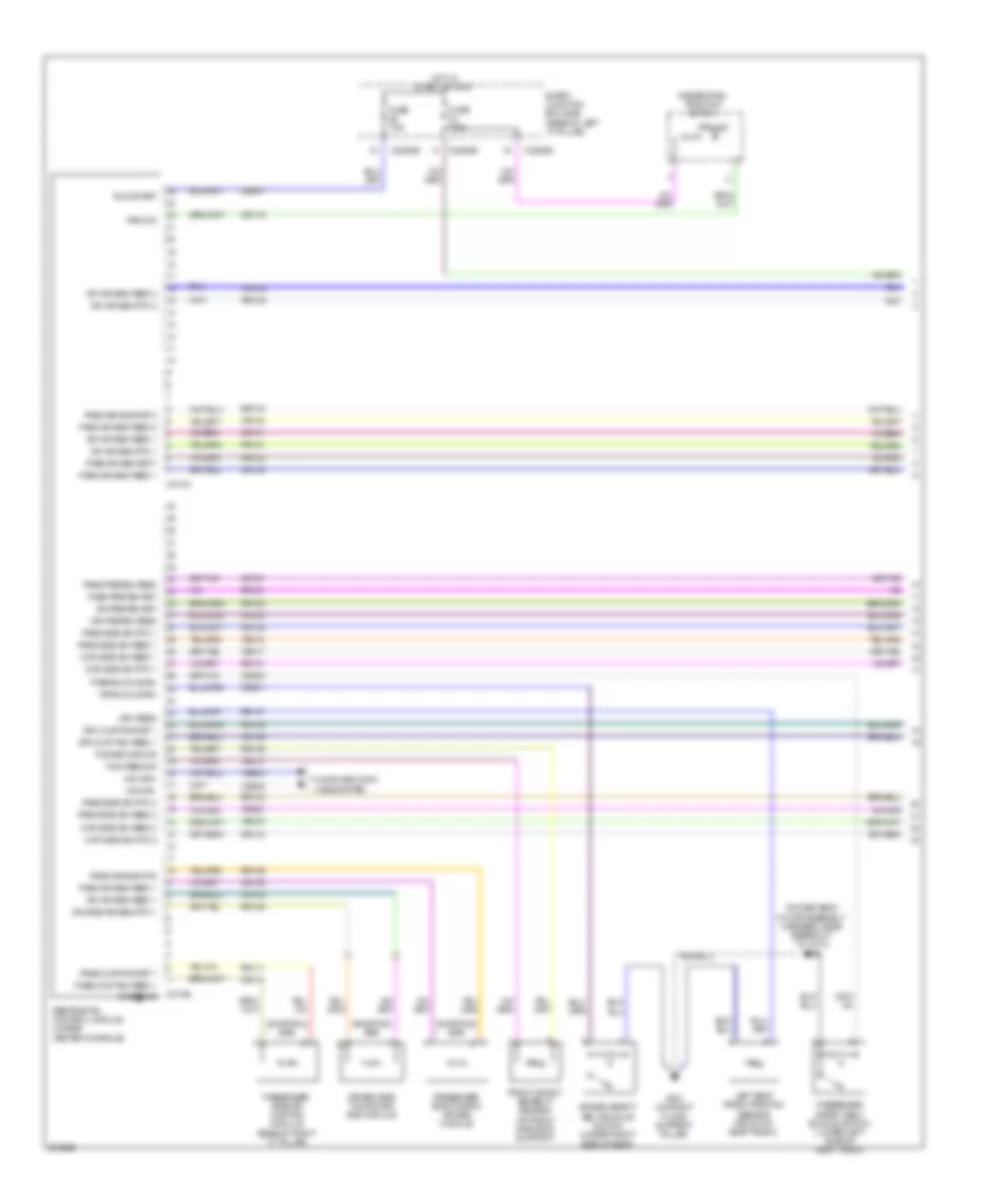
AIR CONDITIONING
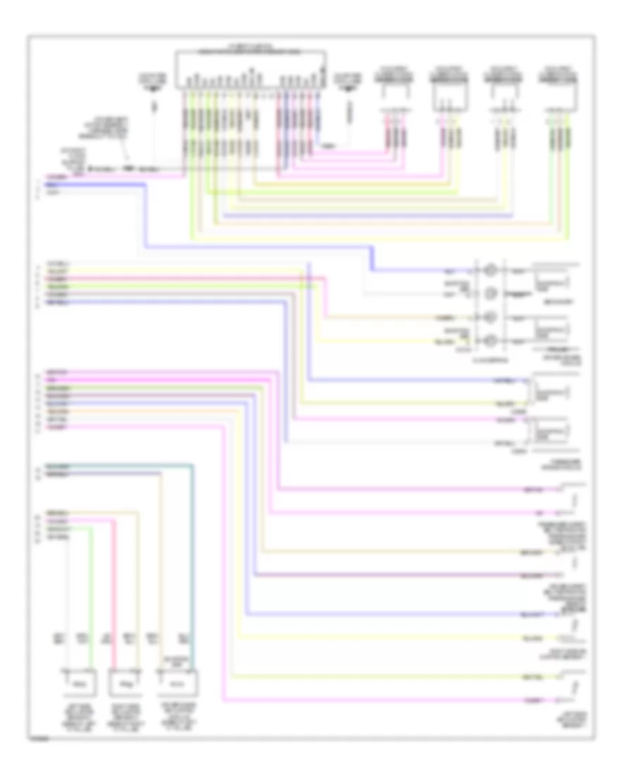
Automatic A/C Wiring Diagram, Single Zone A/C (1 of 3) for Ford Fusion S 2008

List of elements for Automatic A/C Wiring Diagram, Single Zone A/C (1 of 3) for Ford Fusion S 2008:
- (in main harness, near breakout to data link connector) s228
- Actuators return
- Ambient air temperature sensor (3.0l: behind front grille) (2.3l: right side of radiator support)
- Ambient temp sensor
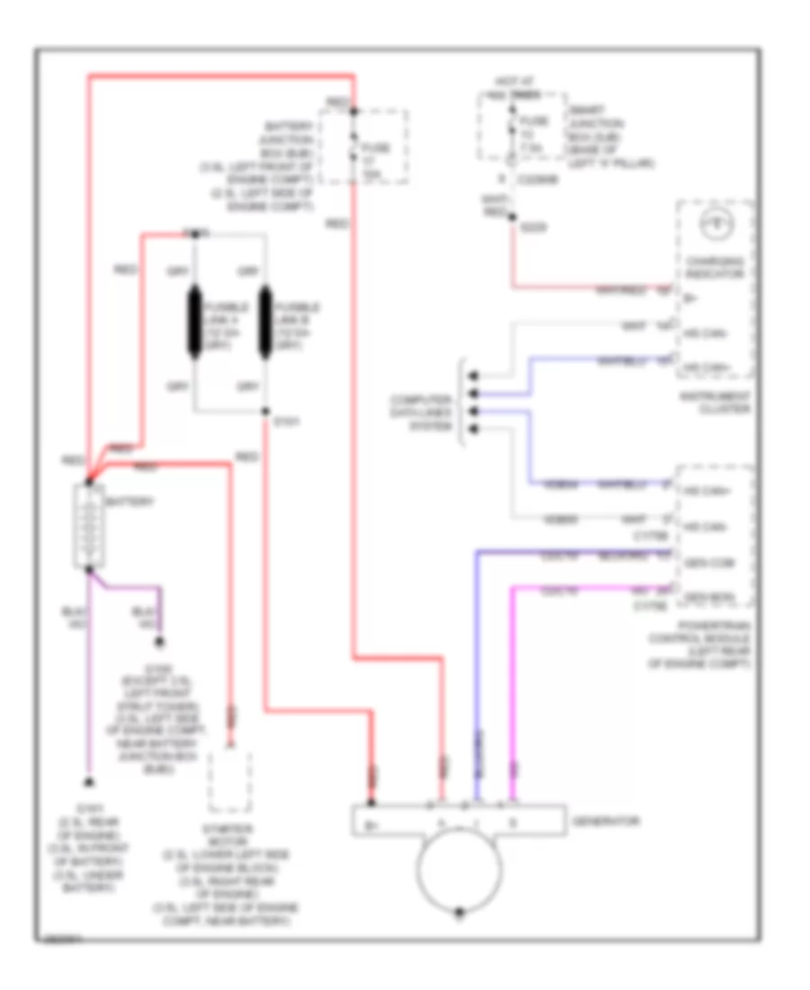
- Battery
- Battery junction box (bjb) (2.3l: left side of engine compt) (3.0l: left front of engine compt)
- Blend fbk
- Blend input
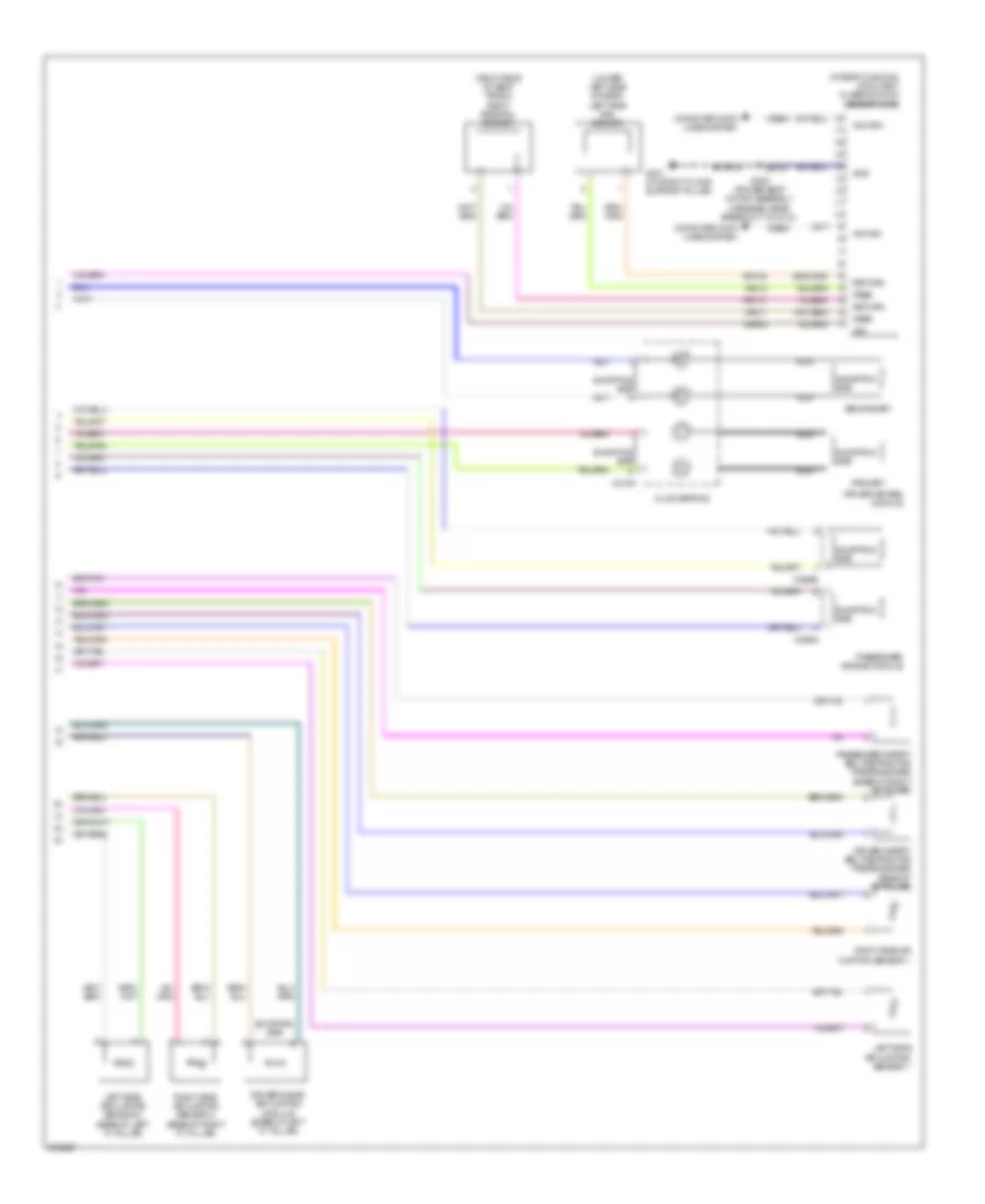
- Blower motor (right side of dash)
- Blower motor relay
- C228a
- C228b
- Cbp20
- Ch122
- Ch123
- Ch207
- Ch208
- Ch228
- Ch229
- Ch233
- Ch234
- Chs04
- Chs09
- Chs13
- Chs14
- Chs29
- Chs30
- Cmd
- Computer data lines system
- Def request
- Defogger system
- Dr hs request
- Dr hshi
- Dr hslo
- Dr sunload sens
- Electronic automatic temperature control (eatc) module (center of dash)
- Front blower motor speed controller (right side of dash)
- Fuse 40a
- G201 (center of dash)
- G202 (left side of dash)
- Gd116
- Gnd
- Headlights system
- Hot at all times
- Ign feed
- In car temp
- In-vehicle temperature sensor (left side of dash)
- Lh111
- Mode actuator fbk
- Mode input
- Motor+
- Motor-
- Ms can +
- Ms can -
- Pass hshi
- Pass request
- Pss hslo
- Recirc ccw
- Recirc cw
- Rh104
- Rh111
- Run/start
- Sbp07
- Seats system
- Sensor ret 4
- Sunload sensor (right side of dash)
- Vdb06
- Vdb07
- Vh101
- Vh407
- Vh414
- Vh416
- Vh436
- Vh439
- Vpwr
- Vref actuators
Automatic A/C Wiring Diagram, Single Zone A/C (2 of 3) for Ford Fusion S 2008
List of elements for Automatic A/C Wiring Diagram, Single Zone A/C (2 of 3) for Ford Fusion S 2008:
- (in a/c jumper, near breakout to air conditioner evaporative thermistor) s204
- Amp
- C2280a
- C2280b
- Fresh/recirculation door actuator (right side of dash)
- Fuse 7.5a
- Hot at all times
- Hot in run or acc
- Hot in start or run
- Mode door actuator (center of dash)
- Passenger temperature blend door actuator (right side of dash)
- S131
- S206 (in a/c jumper, near breakout to air conditioner evaporative thermistor)
- S227
- S229
- Smart junction box (sjb) (base of left "a" pillar)
Automatic A/C Wiring Diagram, Single Zone A/C (3 of 3) for Ford Fusion S 2008
List of elements for Automatic A/C Wiring Diagram, Single Zone A/C (3 of 3) for Ford Fusion S 2008:
- (3.0l: center rear of engine compt)
- (near breakout of powertrain control module (pcm)) s124
- A/c clutch field coil (front of a/c compressor)
- A/c clutch relay
- A/c pressure transducer sensor (2.3l: right front of engine)
- Accr
- Acpt
- Battery junction box (bjb) (2.3l: left side of engine compt) (3.0l: left front of engine compt)
- C-sigrtn
- C-vref
- C175b
- C175e
- Ce302
- Ch302
- Computer data lines system
- E-sigrtn
- Ect
- Engine controls system
- Engine coolant temperature (ect) sensor (2.3l: right rear of engine) (3.0l: left rear of engine)
- Engine cooling fan motor (left front of engine compt)
- Fc-v
- Fuse 10a
- Fuse 15a
- Fuse 40a
- Fuse 60a
- G103 (left front of engine compt)
- Hot at all times
- Hs can+
- Hs can-
- Le424
- Pcm control
- Pcm power relay
- Powertrain control module (pcm) (left rear of engine compt)
- Re405
- Re407
- Red
- S102 (2.3l: in engine control sensor and fuel charge harness, near breakout to powertrain control module) (3.0l: in engine control sensor and fuel charge harness, near breakout to stepper motor egr valve)
- S142 (in dash panel to headlamp junction harness, near breakout to battery junction box)
- S143
- Vdb04
- Vdb05
- Ve716
- Vec03
- Vh433
Manual A/C Wiring Diagram (1 of 2) for Ford Fusion S 2008
List of elements for Manual A/C Wiring Diagram (1 of 2) for Ford Fusion S 2008:
- (center of dash)
- (in a/c jumper, near breakout to air conditioner evaporative thermistor) s204
- (in a/c jumper, near breakout to air conditioner evaporative thermistor) s206
- (in a/c jumper, near breakout to c298) s205
- A/c req
- Amp
- Backlighting
- Batt power
- Battery junction box (bjb) (2.3l: left side of engine compt) (3.0l: left front of engine compt)
- Blend input
- Blower motor (right side of dash)
- Blower motor relay
- Blower relay
- C2280a
- C2280b
- C2357a
- C2357b
- Cbp20
- Ch122
- Ch123
- Ch207
- Ch208
- Ch228
- Ch229
- Ch233
- Ch234
- Ch428
- Ch429
- Ch430
- Ch434
- Computer data lines system
- Defogger system
- Defrost req
- Driver temperature blend door actuator (center of dash)
- Fresh/recirculation door actuator (right side of dash)
- Front blower motor resistor assembly (right side of dash)
- Fuse 40a
- Fuse 7.5a
- G201
- G202 (left side of dash)
- Gd115
- Gd116
- Gnd
- High
- Hot at all times
- Hot in run or acc
- Hot in start or run
- Hs can+
- Hs can-
- Ign feed
- Instrument cluster
- Interior lights system
- Lh111
- Low
- M high
- M low
- Manual climate control module (center of dash)
- Mode act fdbk
- Mode door actuator (center of dash)
- Mode input
- Pass temp fdbk
- R/s
- Recir door ccw
- Recir door cw
- Rh111
- S131
- S227
- S229
- Sbp07
- Smart junction box (sjb) (base of left "a" pillar)
- Vh436
- Vh439
- Vln04
- Vref act (5v)
- Vref ret act
Manual A/C Wiring Diagram (2 of 2) for Ford Fusion S 2008
List of elements for Manual A/C Wiring Diagram (2 of 2) for Ford Fusion S 2008:
- (in dash panel to headlamp junction harness, near breakout to powertrain control module (pcm)) s124
- A/c clutch field coil (front of a/c compressor)
- A/c clutch relay
- A/c pressure transducer sensor (2.3l: right front of engine) (3.0l: center rear of engine compt)
- Accr
- Acpt
- Battery junction box (bjb) (2.3l: left side of engine compt) (3.0l: left front of engine compt)
- C-sigrtn
- C-vref
- C175b
- C175e
- Ce302
- Ch302
- Computer data lines system
- E-sigrtn
- Ect
- Engine controls system
- Engine coolant temperature (ect) sensor (2.3l: rear of engine) (3.0l: left rear of engine)
- Engine cooling fan motor (left front of engine compt)
- Fc-v
- Fuse 10a
- Fuse 15a
- Fuse 40a
- Fuse 60a
- G103 (left front of engine compt)
- G103 left front of engine compt)
- Hot at all times
- Hs can+
- Hs can-
- Le424
- Pcm control
- Pcm power relay
- Powertrain control module (pcm) (left rear of engine compt)
- Re405
- Re407
- Red
- S102 (2.3l: in engine control sensor and fuel charge harness, near breakout to powertrain control module) (3.0l: in engine control sensor and fuel charge harness, near breakout to stepper motor egr valve)
- S142 (in dash panel to headlamp junction harness, near breakout to battery junction box)
- S143
- Vdb04
- Vdb05
- Ve716
- Vec03
- Vh433
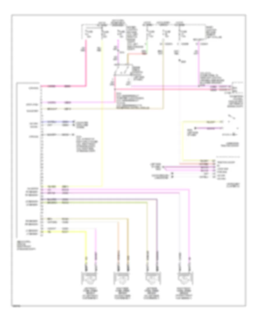
ANTI-LOCK BRAKES
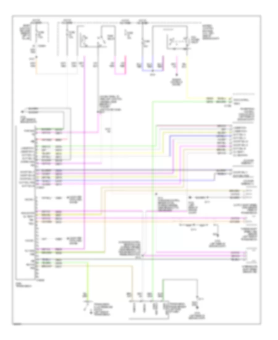
Anti-lock Brakes Wiring Diagram for Ford Fusion S 2008
List of elements for Anti-lock Brakes Wiring Diagram for Ford Fusion S 2008:
- (2.3l & 3.0l: in dash panel to headlamp junction harness, near engine bulkhead grommet) s120
- (left side of dash) g202
- Abs control module (right front of engine compt)
- Battery junction box (bjb) (3.0l: left front of engine compt) (2.3l: left side of engine compt)
- Boo
- Boo input
- Bps
- Brake pedal position switch (left side of dash)
- C175b
- C2280a
- C2280b
- Cbp19
- Ccb08
- Ces09
- Computer data lines system
- Fuse 10a
- Fuse 15a
- Fuse 30a
- Fuse 40a
- Fuse 7.5a
- G104 (2.3l: in front of right strut tower) (3.0l: right front of engine compt) (3.5l: right side of engine compt)
- G202 (left side of dash)
- Gd123
- Hazard/pad/ traction switch
- Hot at all times
- Hot in start or run
- Hot w/ pcm power relay energized
- Hs can+
- Hs can-
- Instrument cluster (ic)
- Left front wheel speed sensor (at left front hub assembly)
- Left rear wheel speed sensor (on left rear hub assembly)
- Lf sensor+
- Lf sensor-
- Logic gnd
- Lr sensor+
- Lr sensor-
- Mtr gnd
- Mtr pwr
- Nca
- Powertrain control module (pcm) (left rear of engine compt)
- Pwr gnd
- Rca17
- Rca18
- Rca19
- Rca20
- Rf sensor+
- Rf sensor-
- Right front wheel speed sensor (at right front hub assembly)
- Right rear wheel speed sensor (on right rear hub assembly)
- Rr sensor+
- Rr sensor-
- Run/start
- S133 (2.3l: near breakout to battery junction box) (3.0l: near breakout to g103) (3.5l: near breakout to powertrain control module)
- S144
- S229
- Sbb08
- Sbb10
- Smart junction box (sjb) (base of left "a" pillar)
- Stop lp sw
- Traction on/off
- Valve pwr
- Vca03
- Vca04
- Vca05
- Vca06
- Vdb04
- Vdb05
ANTI-THEFT
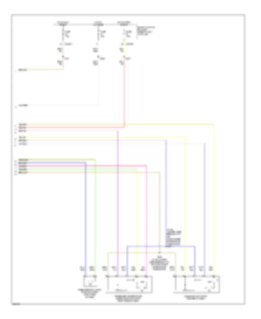
Forced Entry Wiring Diagram, with Memory (1 of 2) for Ford Fusion S 2008
List of elements for Forced Entry Wiring Diagram, with Memory (1 of 2) for Ford Fusion S 2008:
- (in power seats harness, near breakout to smart junction box (sjb)) s324
- (in power seats harness, near breakout to smart junction box (sjb)) s325
- Battery junction box (bjb) (2.3l: left side of engine compt) (3.0l: left front of engine compt)
- C2280c
- C2280e
- C2280f
- C568b
- Cpl02
- Cpl28
- Cpl42
- Cpl43
- Cpl51
- Driver side door lock switch
- Driver's door module (front of driver's door)
- Fuse 15a
- Fuse 60a
- G203 (base of right "a" pillar)
- G300 (center of left floor pan)
- Hot at all times
- Interior lights system
- Left rear door lock actuator (in left rear door)
- Lock
- Lock all relay
- Logic
- Lr door ajar
- Pass door ajar
- Passenger side door lock switch
- Reset
- Right front door lock actuator (in right front door)
- Right rear door lock actuator (in right rear door)
- Rr door ajar
- S500
- S601
- Smart junction box (sjb) (base of left "a" pillar)
- Trim lock
- Trim unlock
- Unlock
- Unlock all relay
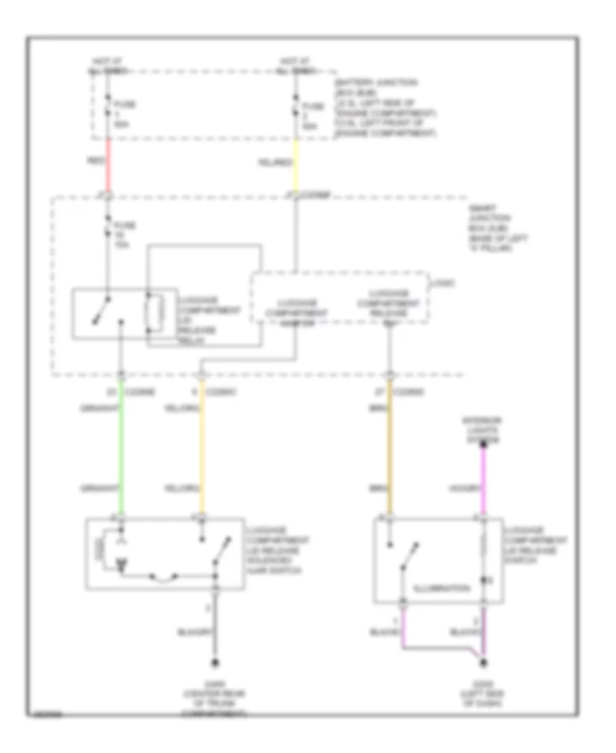
Forced Entry Wiring Diagram, with Memory (2 of 2) for Ford Fusion S 2008
List of elements for Forced Entry Wiring Diagram, with Memory (2 of 2) for Ford Fusion S 2008:
- (3.5l: left front of engine compt)
- Anti-theft hood switch (except 3.5l: left front radiator support)
- C2280a
- C2280c
- Disarm request
- Driver door ajar
- G104 (2.3l: in front of right strut tower) (3.0l: right front of engine compt) (3.5l: right side of engine compt)
- G300 (center of left floor pan)
- G400 (fusion, mkz: center rear of trunk compartment)
- Hood ajar
- Keypad a
- Keypad b
- Keypad c
- Keypad illum
- Keypad switch assembly
- Left front door lock actuator (in driver's door)
- Logic
- Luggage compartment disarm switch (fusion, milan: (center rear of luggage compartment)
- Reset
- S500
- Set
- Smart junction box (sjb) (base of left "a" pillar)
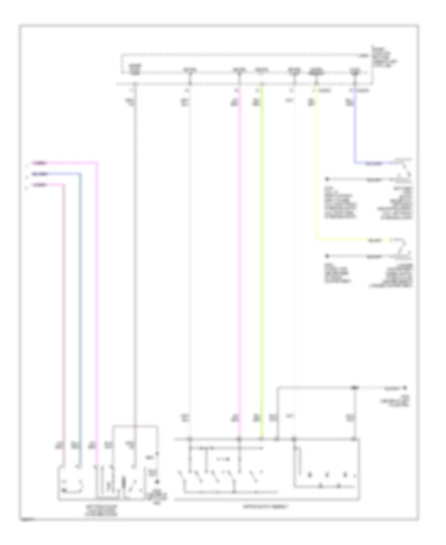
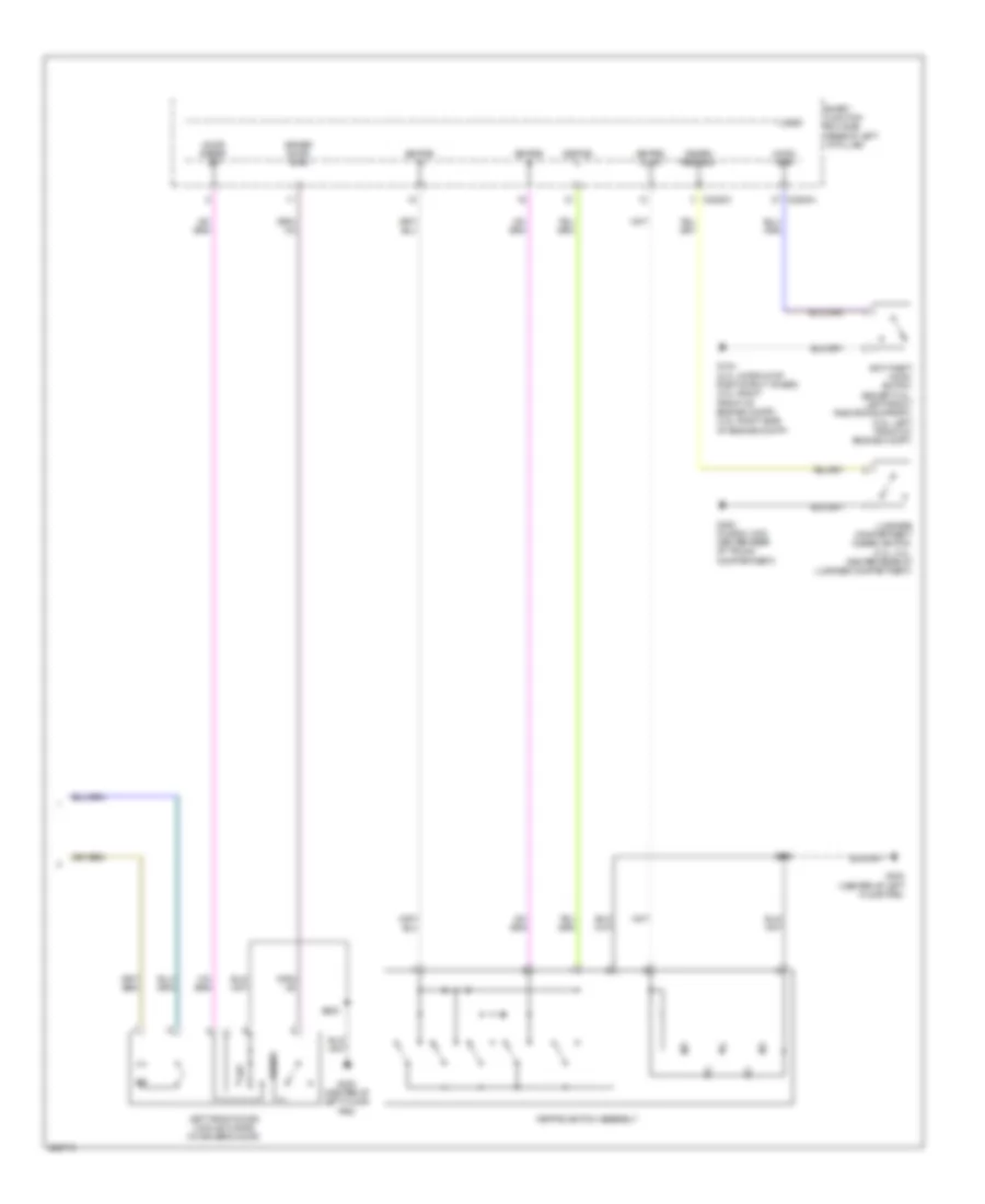
Forced Entry Wiring Diagram, without Memory (1 of 2) for Ford Fusion S 2008
List of elements for Forced Entry Wiring Diagram, without Memory (1 of 2) for Ford Fusion S 2008:
- (in body main harness, near breakout to smart junction box (sjb))
- (in body main harness, near breakout to smart junction box (sjb)) s347
- (in power seats harness, near breakout to smart junction box (sjb)) s324
- (in power seats harness, near breakout to smart junction box (sjb)) s325
- Accessory delay relay
- C2280c
- C2280e
- Circuit breaker 30a
- Driver side door lock switch
- Fuse 15a
- Fuse 7.5a
- Fusion/ milan
- G203 (base of right "a" pillar)
- G300 (center of left floor pan)
- Hot at all times
- Interior lights system
- Left rear door lock actuator (in left rear door)
- Lock
- Lock all relay
- Logic
- Lr door ajar
- Mkz
- Pass door ajar
- Passenger side door lock switch
- Right front door lock actuator (in right front door)
- Right rear door lock actuator (in right rear door)
- Rr door ajar
- S328
- S342
- S500
- S601
- Smart junction box (sjb) (base of left "a" pillar)
- Trim lock
- Trim unlock
- Unlock
- Unlock all relay
- Unlock driver relay
Forced Entry Wiring Diagram, without Memory (2 of 2) for Ford Fusion S 2008
List of elements for Forced Entry Wiring Diagram, without Memory (2 of 2) for Ford Fusion S 2008:
- Anti-theft hood switch (except 3.5l: left front radiator support) (3.5l: left front of engine compt)
- C2280a
- C2280c
- Disarm request
- Door reset sw
- Driver door ajar
- G104 (2.3l: in front of right strut tower) (3.0l: right front of engine compt) (3.5l: right side of engine compt)
- G300 (center of left floor pan)
- G400 (fusion, mkz: center rear of trunk compartment)
- Hood ajar
- Keypad a
- Keypad b
- Keypad c
- Keypad illum
- Keypad switch assembly
- Left front door lock actuator (in driver's door)
- Logic
- Luggage compartment disarm switch (2.3l, 3.0l: center rear of luggage compartment)
- Reset
- S500
- Set
- Smart junction box (sjb) (base of left "a" pillar)
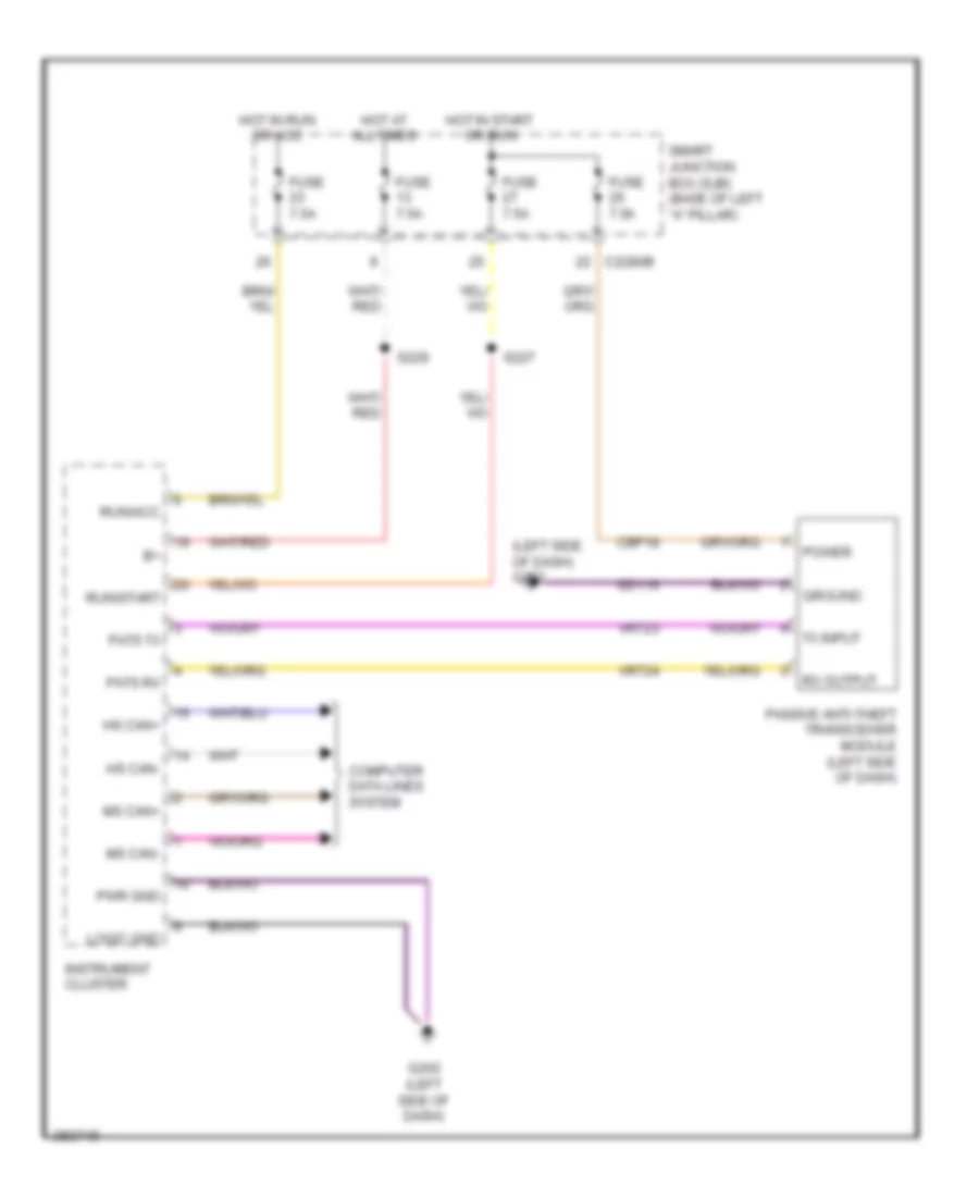
Passive Anti-theft Wiring Diagram for Ford Fusion S 2008
List of elements for Passive Anti-theft Wiring Diagram for Ford Fusion S 2008:
- (left side of dash) g202
- C2280b
- Cbp18
- Computer data lines system
- Fuse 7.5a
- G202 (left side of dash)
- Gd116
- Ground
- Hot at all times
- Hot in run or acc
- Hot in start or run
- Hs can+
- Hs can-
- Instrument cluster
- Logic gnd
- Ms can+
- Ms can-
- Passive anti-theft transceiver module (left side of dash)
- Pats rx
- Pats tx
- Power
- Pwr gnd
- Run/acc
- Run/start
- Rx output
- S227
- S229
- Smart junction box (sjb) (base of left "a" pillar)
- Tx input
- Vrt23
- Vrt24
BODY CONTROL MODULES
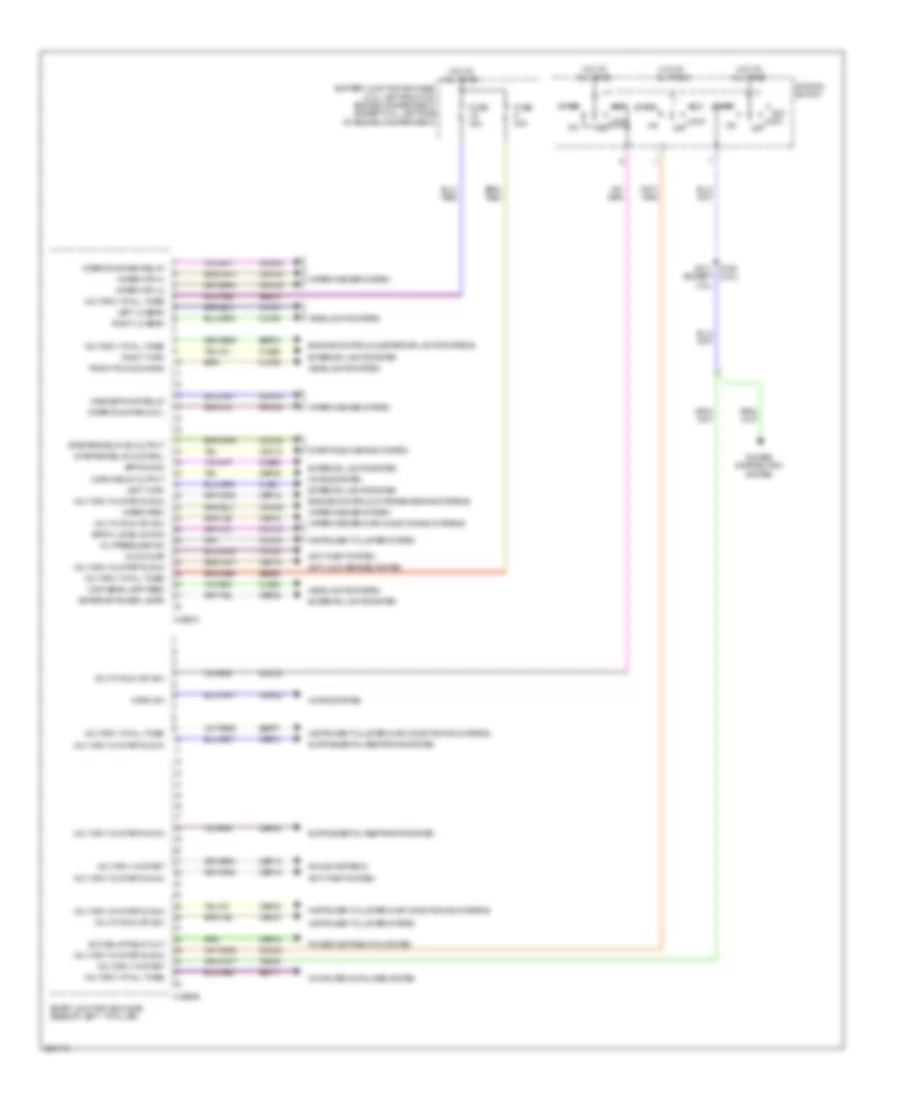
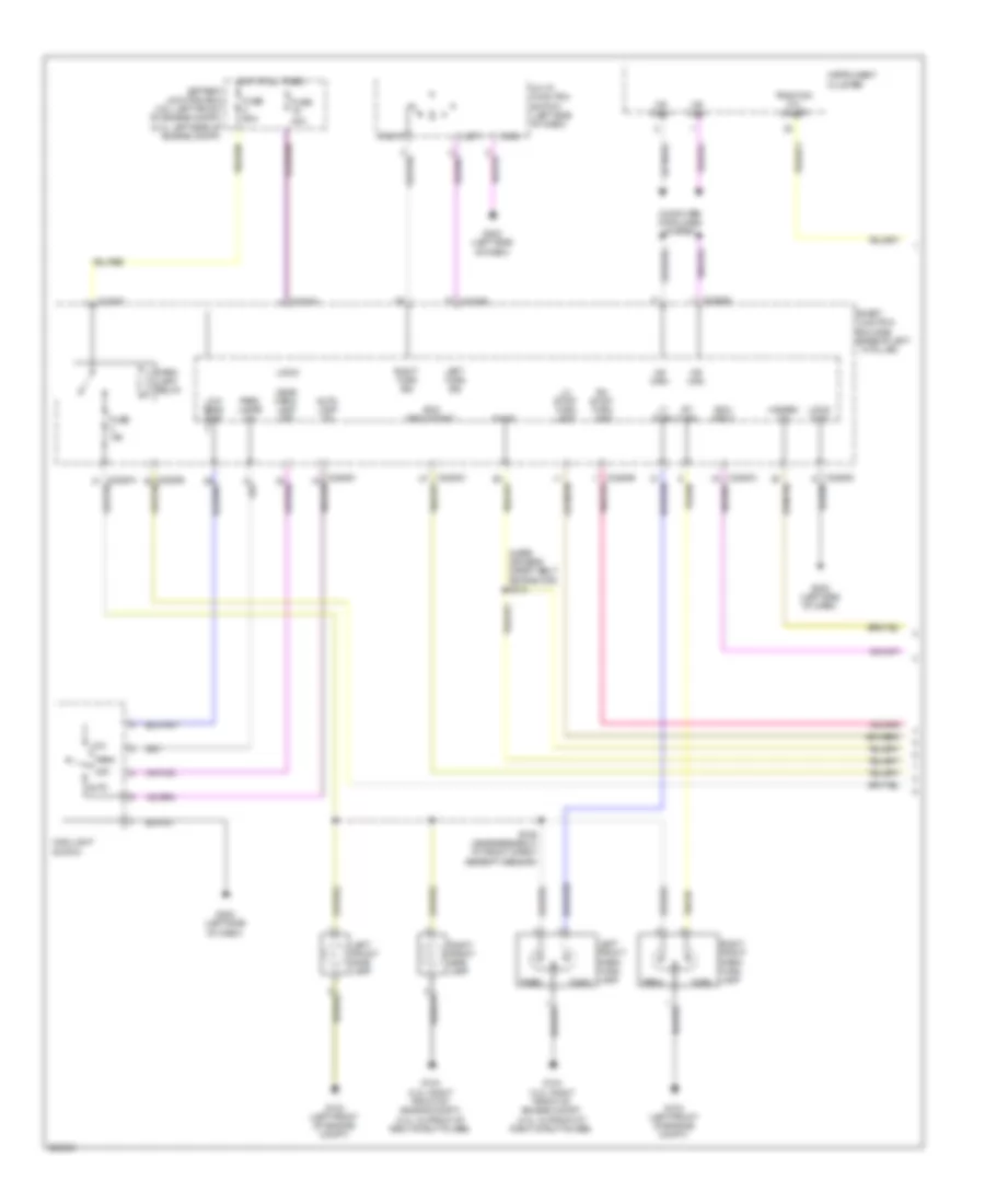
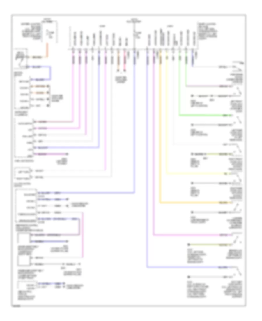
Body Control Modules Wiring Diagram (1 of 2) for Ford Fusion S 2008
List of elements for Body Control Modules Wiring Diagram (1 of 2) for Ford Fusion S 2008:
- (3.5l)
- Acc
- Acc delay relay out
- Anti-lock brakes system
- Anti-theft system
- Battery junction box (bjb) (3.ol: left front of engine compartment) (except 3.0l: left side of engine compartment)
- Bpp sw sig
- Brk fl level sw sig
- C2280a
- C2280b
- Cbp02
- Cbp05
- Cbp08
- Cbp13
- Cbp18
- Cbp19
- Cbp20
- Cbp21
- Cbp23
- Cbp24
- Ccb08
- Cdc12
- Cdc25
- Cdc33
- Cdc34
- Ce336
- Clf04
- Clf05
- Clf29
- Cls08
- Cls21
- Cls25
- Cmc19
- Cmc24
- Computer data lines system
- Cpl25
- Crh02
- Crw03
- Crw09
- Crw14
- Crw15
- Crw16
- Engine controls & exterior lights systems
- Engine controls & transmissions systems
- Exterior lights system
- Exterior power lamps
- Front fog command
- Fuse 40a
- Headlights system
- High beam lamp feed
- Hood ajar
- Horn relay output
- Horn sw
- Horns system
- Hot at all times
- Ignition switch
- Instrument cluster & air conditioning systems
- Instrument cluster system
- Left lo beam
- Left turn
- Lock
- Off
- Oil pressure ind
- Power distribution system
- Right lo beam
- Right turn
- Rrw24
- S152 s211 (except 3.5l)
- Sbb06
- Sbb19
- Sbp04
- Sbp07
- Sbp11
- Smart junction box (sjb) (base of left ``a" pillar)
- Sound systems
- Start
- Starter relay control
- Starter relay sw output
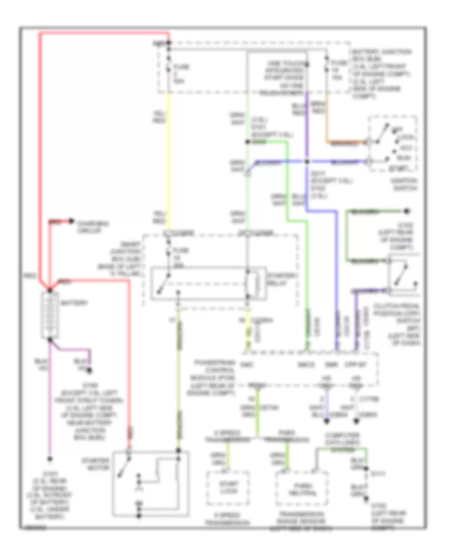
- Starting/charging system
- Volt in run or acc
- Volt sply at all times
- Volt sply in start
- Volt sply in start & run
- Washer pump relay
- Wiper mtr hi
- Wiper mtr lo
- Wiper park
- Wiper run/park coil
- Wiper run/park relay
- Wiper/washer & air conditioning systems
- Wiper/washer system
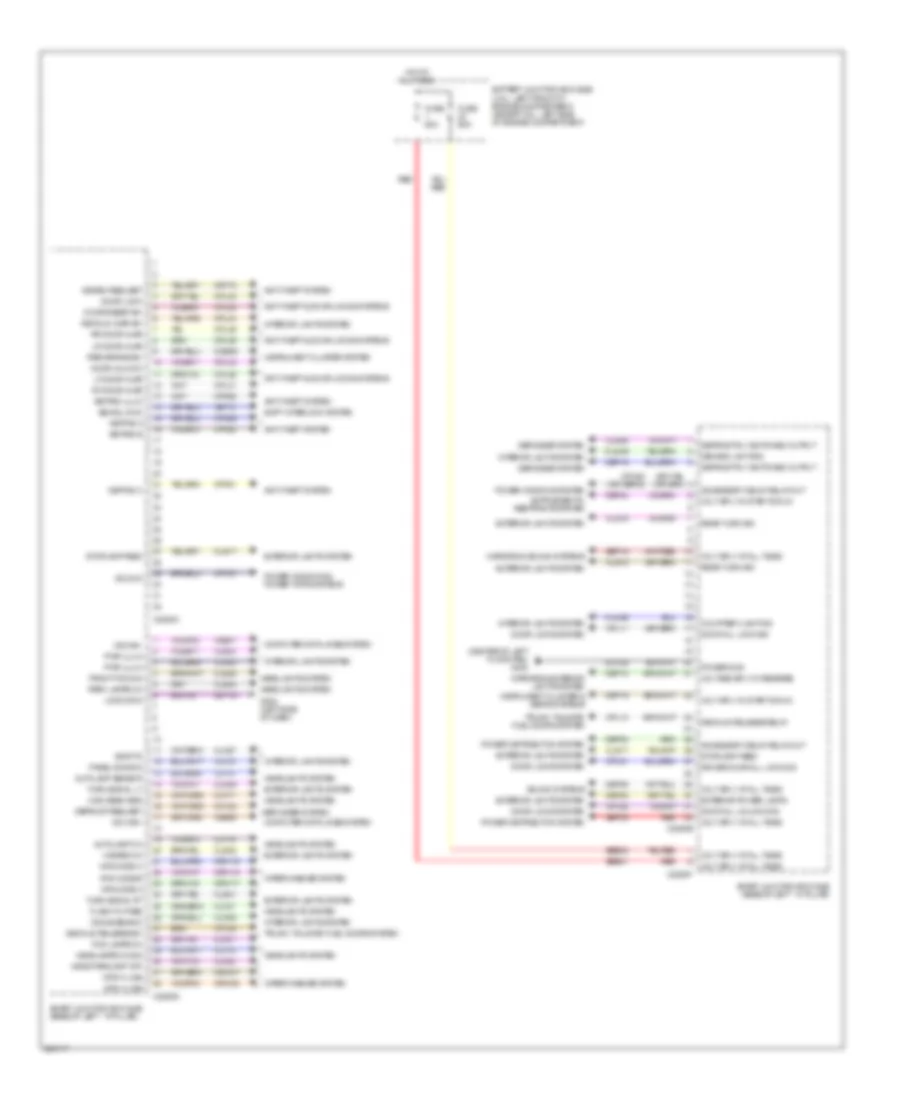
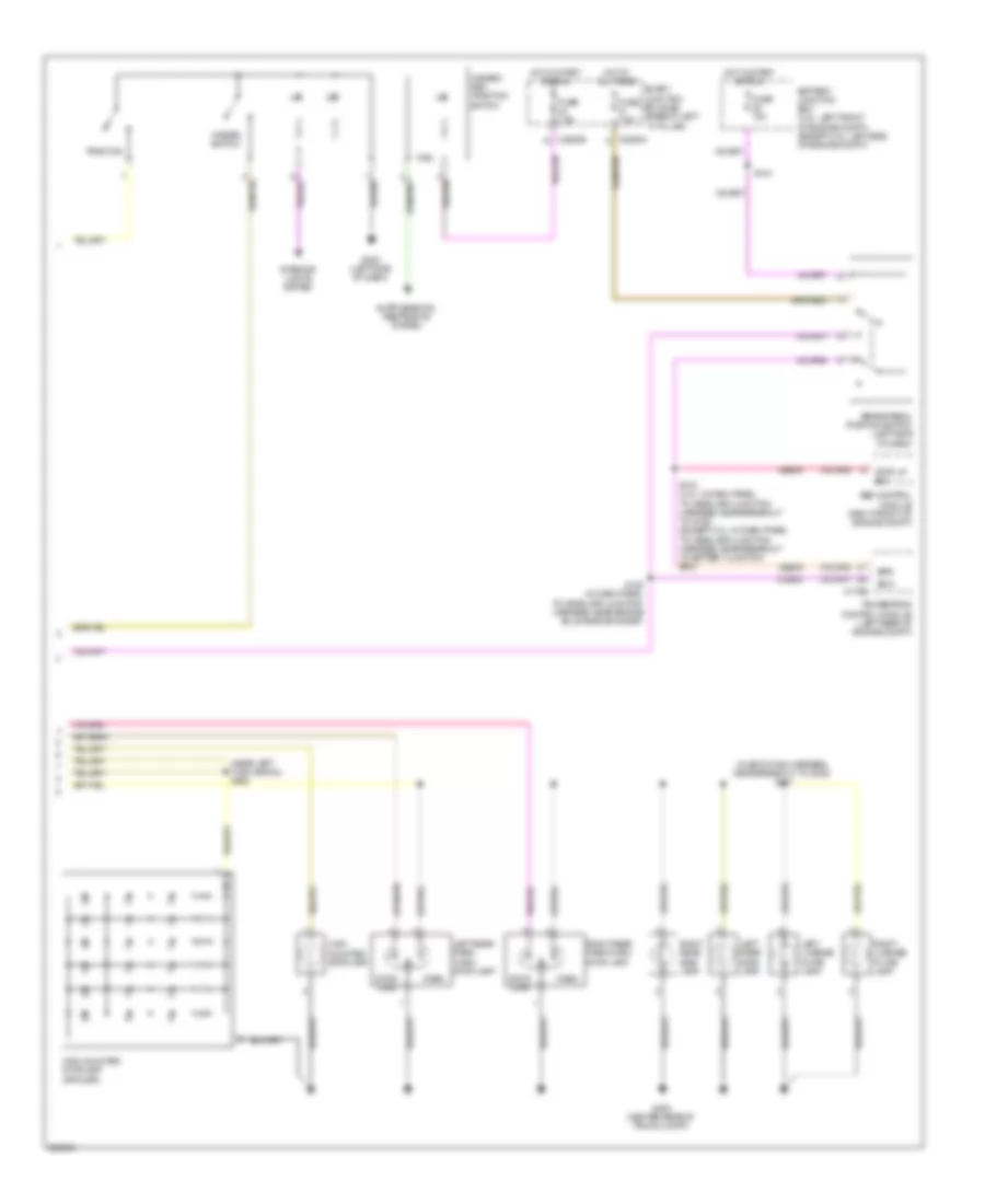
Body Control Modules Wiring Diagram (2 of 2) for Ford Fusion S 2008
List of elements for Body Control Modules Wiring Diagram (2 of 2) for Ford Fusion S 2008:
- (center of left floor pan) g300
- Accessory delay relay out
- Anti-theft & door locks systems
- Anti-theft system
- Autolamp on
- Autolamp sensor
- Battery junction box (bjb) (3.ol: left front of engine compartment) (except 3.0l: left side of engine compartment)
- Bsi sol cmd
- C2280c
- C2280d
- C2280e
- C2280f
- Cbp02
- Cbp06
- Cbp08
- Cbp12
- Cbp16
- Cbp19
- Cbp24
- Ccb09
- Ch122
- Clf17
- Clf18
- Clf19
- Clf21
- Clf23
- Clf27
- Cln04
- Cln09
- Cln26
- Cln27
- Cln28
- Cls17
- Cls18
- Cls19
- Cls28
- Cls32
- Cls34
- Cls38
- Cls39
- Cls41
- Computer data lines system
- Courtesy lighting
- Cpk28
- Cpk29
- Cpk30
- Cpk31
- Cpl10
- Cpl11
- Cpl26
- Cpl28
- Cpl31
- Cpl36
- Cpl39
- Cpl42
- Cpl43
- Cpl44
- Cpl45
- Cpl51
- Cpl52
- Cpw01
- Cpw30 (or cbp02)
- Crt18
- Crw07
- Crw08
- Crw17
- Crw18
- Crw19
- Decklid ajar sw
- Decklid release relay
- Decklid release sw
- Defogger system
- Defrost request
- Defrost rly switched output
- Demand lighting
- Disarm request
- Dome demand
- Door all lock sig
- Door all unlock sig
- Door lock
- Door locks system
- Door reset sw
- Door unlock
- Driver door all lock sig
- Exterior lights system
- Exterior power lamps
- Flash to pass
- Fog lamps on
- Front fog ind
- Fuse 60a
- G202 (left side of dash)
- Gd116
- Gd126
- Go cmd
- Hazard on
- Head parklamp off
- Headlamps on sig
- Headlights system
- High beam req
- Hot at all times
- Instrument cluster & seats systems
- Instrument cluster system
- Interior lights system
- Keypad a
- Keypad b
- Keypad c
- Keypad illum
- Lf door ajar
- Logic gnd
- Lr door ajar
- Mfs code a
- Mfs code b
- Mfs code c
- Mfs h line
- Mfs w line
- Mirrors & exterior lights system
- Mirrors & sound systems
- Ms can+
- Ms can-
- Panel dimming
- Park brake sw
- Park lamps on
- Power distribution system
- Power gnd
- Power windows & power tops systems
- Power windows system
- Pwr illum
- Rear turn sig
- Red
- Rf door ajar
- Rr door ajar
- Sbb01
- Sbb02
- Sbp09
- Sbp15
- Shift interlock system
- Sig rtn
- Smart junction box (sjb) (base of left ``a" pillar)
- Sound systems
- Stoplamp feed
- Trunk, tailgate, fuel doors system
- Turn signal lt
- Turn signal rt
- Vdb06
- Vdb07
- Vet13
- Vlf14
- Vln04
- Vln18
- Volt sply at all times
- Volt sply in start & run
- Voltage sply in reverse
- Wiper/washer system
COMPUTER DATA LINES
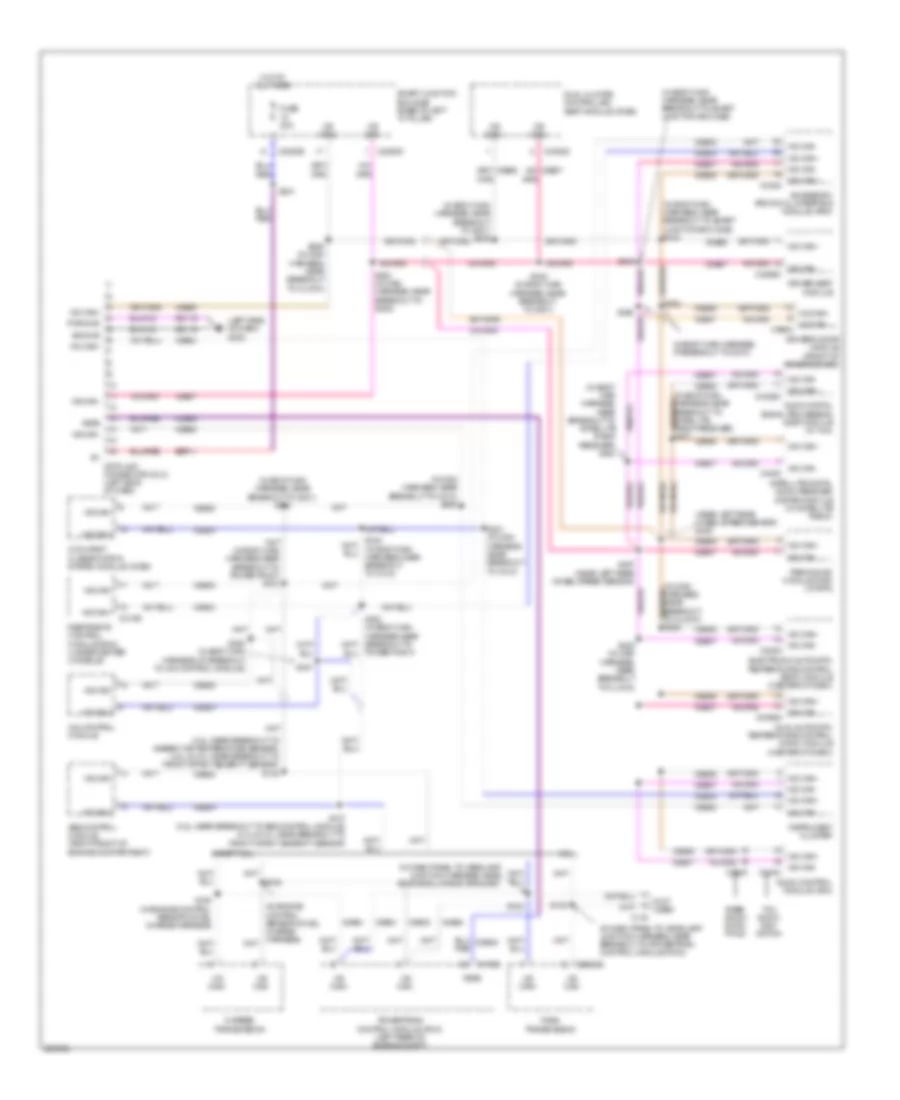
Computer Data Lines Wiring Diagram, with Memory for Ford Fusion S 2008
List of elements for Computer Data Lines Wiring Diagram, with Memory for Ford Fusion S 2008:
- (3.5l: near breakout to ambient air temperature sensor) (2.3l & 3.0l: near breakout to front impact severity sensor) s138
- (in body main harness, at breakout to c510)
- (in body main harness, near breakout to g301) s334
- (in body main harness, near breakout to g301) s346
- (in body main harness, near breakout to satellite radio receiver) s430
- (in body main harness, near breakout to smart junction box (sjb)
- (in body main harness, near breakout to smart junction box (sjb). s343
- (in dash panel to headlamp junction harness, near breakout to powertrain control module (pcm))
- (in dash panel to headlamp junction harness, near engine bulkhead grommet)
- (in main harness, near breakout to c212) s220
- (left side of dash) g202
- (near left rear wheel speed sensor) s406
- (not used)
- 2.3l
- 4x4 control module
- 6 speed transmission
- Abs control module (right front of engine compartment)
- Accessory protocol interface module (apim)
- Audio control module (acm)
- Audio digital signal processing (dsp) module (w/ thx)
- Base audio/ audio- phile
- C133
- C175b
- C2280b
- C2280d
- C2352b
- C290c
- C310b
- C3305c
- Cdb08
- Data link connector (dlc) (left side of dash)
- Driver seat module
- Driver's door module (front of driver's door)
- Dual automatic temperature control (datc) module (center of dash)
- Dual climate controlled seat module (dcsm)
- Electronic automatic temperature control (eatc) module (center of dash)
- Except 2.3l
- Feps
- Fnr5 transmission
- Fuse 20a
- Gd116
- Hot at all times
- Hs can+
- Hs can-
- Instrument cluster
- Ms can+
- Ms can+ c3338
- Ms can+ c4326c
- Ms can-
- Ms can- c228a
- Ms can- c2356a
- Ms can- c240c
- Ms can- c3299c
- Ms can- c4300
- Ms can- c568a
- Occupant classification system module (ocsm)
- Parking aid module (pam) (w/ rpa)
- Power point)
- Powertrain control module (pcm) (left rear of engine compt)
- Pwr gnd
- Restraints control module (rcm) (under center console)
- S105 (in engine control sensor & fuel charge harness)
- S106
- S122
- S123
- S137 (3.5l: near breakout to abs control module) (2.3l & 3.0l: near breakout to front impact severity sensor)
- S221 (in main harness, near breakout to c212)
- S222 (in main harness, near breakout to clock)
- S224 (in main harness, near breakout to g200)
- S225 (in main harness, near breakout to clock)
- S231
- S333 (in body main harness, near breakout to c312)
- S342
- S345 (in body main harness, near breakout to g301)
- S350 (in body main harness, at breakout to 4x4 control module)
- S351
- S353
- S407 (near left rear wheel speed sensor)
- Satellite digital audio receiver system module (w/ satellite radio)
- Sbp11
- Sig gnd
- Smart junction box (sjb) (base of left "a" pillar)
- Thx audio/ navi- gation
- Vdb04
- Vdb05
- Vdb06
- Vdb07
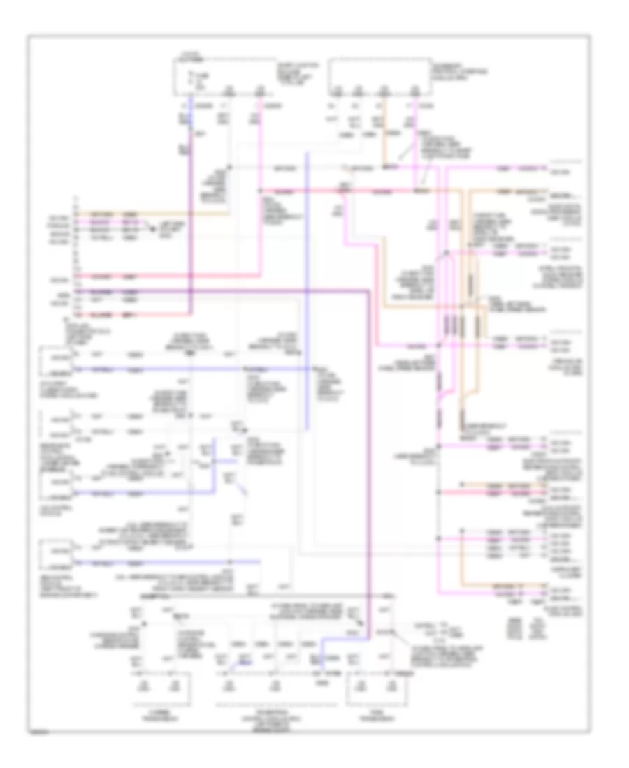
Computer Data Lines Wiring Diagram, without Memory for Ford Fusion S 2008
List of elements for Computer Data Lines Wiring Diagram, without Memory for Ford Fusion S 2008:
- (3.5l: near breakout to ambient air temperature sensor) (2.3l & 3.0l: near breakout to front impact severity sensor) s138
- (in body main harness near breakout to power point) s331
- (in body main harness, near breakout to g301) s334
- (in body main harness, near breakout to satellite radio receiver) s431
- (in body main harness, near breakout to smart junction box (sjb)
- (in dash panel to headlamp junction harness, near breakout to powertrain control module (pcm))
- (in dash panel to headlamp junction harness, near engine bulkhead grommet)
- (in main harness, near breakout to c212) s220
- (left side of dash) g202
- (near breakout to clock) s223
- (not used)
- 2.3l
- 4x4 control module
- 6 speed transmission
- Abs control module (right front of engine compartment)
- Accessory protocol interface module (apim)
- Audio control module (acm)
- Audio digital signal processing (dsp) module (w/ thx)
- Base audio/ audio- phile
- C133
- C175b
- C2280b
- C2280d
- C2352b
- C290c
- C310b
- C3338
- Cdb08
- Data link connector (dlc) (left side of dash)
- Dual automatic temperature control (datc) module (center of dash)
- Electronic automatic temperature control (eatc) module (center of dash)
- Except 2.3l
- Feps
- Fnr5 transmission
- Fuse 20a
- Gd116
- Harness near breakout to power point)
- Hot at all times
- Hs can+
- Hs can-
- Instrument cluster
- Ms can+
- Ms can+ c4330c
- Ms can-
- Ms can- c228a
- Ms can- c2356a
- Ms can- c240c
- Occupant classification system module (ocsm)
- Parking aid module (pam) (w/ rpa)
- Powertrain control module (pcm) (left rear of engine compt)
- Pwr gnd
- Restraints control module (rcm) (under center console)
- S105 (in engine control sensor & fuel charge harness)
- S106
- S122
- S123
- S137 (3.5l: near breakout to abs control module) (2.3l & 3.0l: near breakout to front impact severity sensor)
- S221 (in main harness, near breakout to c212)
- S222 (near breakout to clock)
- S224 (in main harness, near breakout to g200)
- S225 (in main harness, near breakout to clock)
- S231
- S333 (in body main harness, near breakout to c312)
- S342
- S343
- S350 (in body main harness, at breakout to 4x4 control module)
- S351
- S406 (near left rear wheel speed sensor)
- S407 (near left rear wheel speed sensor)
- S430 (in body main harness, near breakout to satellite radio receiver)
- Satellite digital audio receiver system module (w/ satellite radio)
- Sbp11
- Sig gnd
- Smart junction box (sjb) (base of left ``a" pillar)
- Thx audio/ navi- gation
- Vdb04
- Vdb05
- Vdb06
- Vdb07
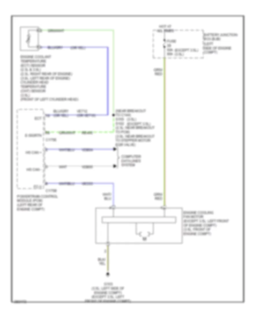
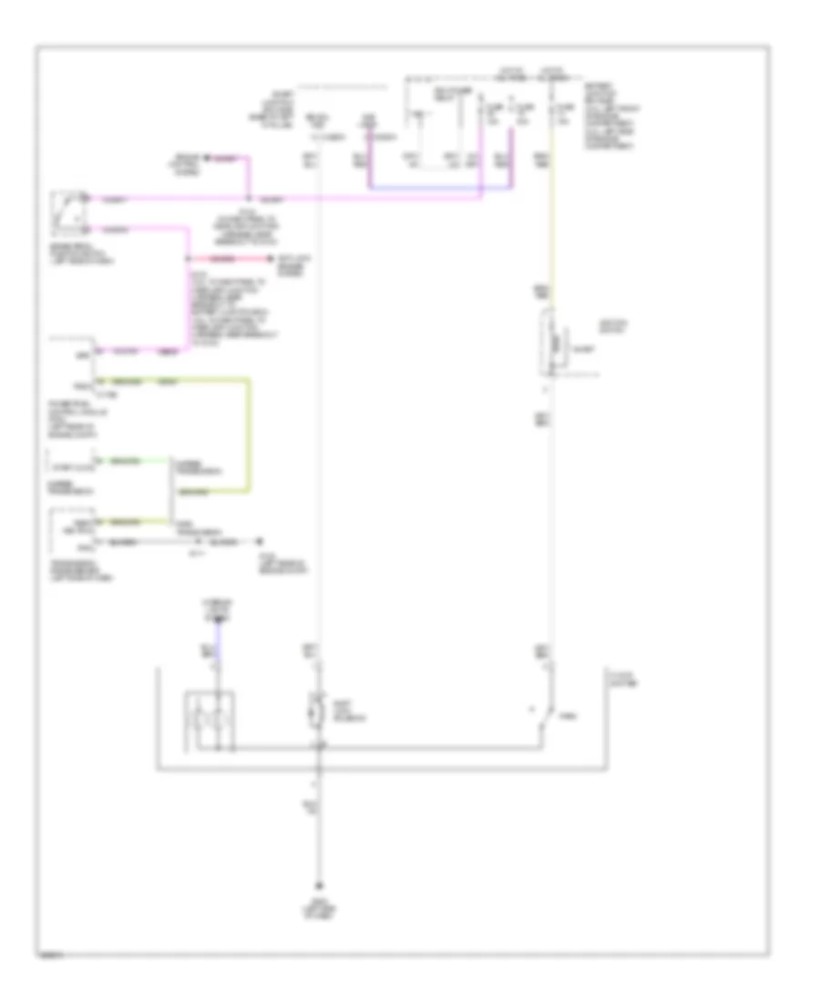
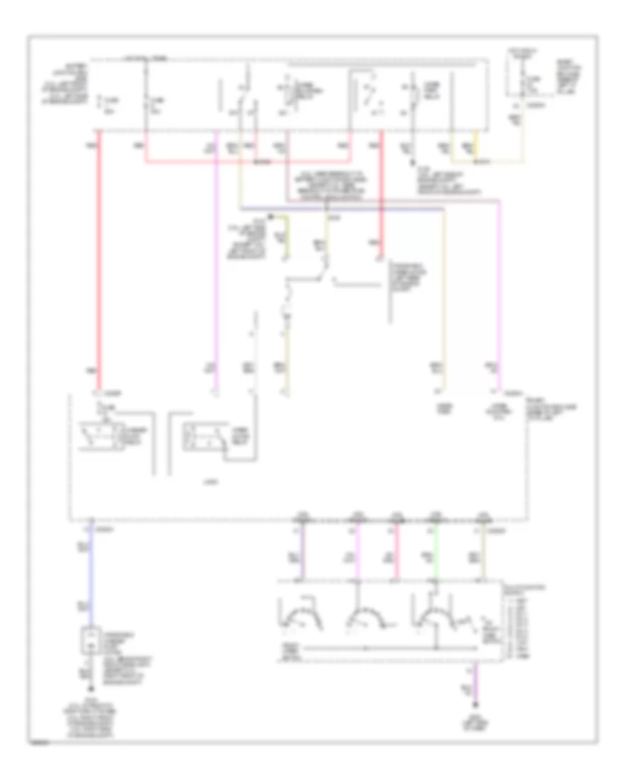
COOLING FAN
Cooling Fan Wiring Diagram for Ford Fusion S 2008
List of elements for Cooling Fan Wiring Diagram for Ford Fusion S 2008:
- (3.5l)
- (except 3.5l)
- (except 3.5l) (3.5l)
- (left side of engine compt)
- (near breakout to c144) s155 s102 (2.3l: near breakout to pcm) (3.0l: near breakout to stepper motor egr valve)
- Battery junction box (bjb)
- C175b
- C175e
- Computer data lines system
- E-sigrtn
- Ect
- Engine coolant temperature (ect) sensor (2.3l & 3.0l) (2.3l: right rear of engine) (3.0l: left rear of engine) cylinder head temperature (cht) sensor (3.5l) (front of left cylinder head)
- Engine cooling fan motor (except 3.5l: left front of engine compt) (3.5l: front of engine compt)
- Fc-v
- Fuse 60a 80a
- G103 (3.5l: left side of engine compt) (except 3.5l: left front of engine compt)
- Hot at all times
- Hs can +
- Hs can -
- Powertrain control module (pcm) (left rear of engine compt)
- Re405
- Vdb04
- Vdb05
- Ve712 (or ve716)
- Vec03
CRUISE CONTROL
Cruise Control Wiring Diagram for Ford Fusion S 2008
List of elements for Cruise Control Wiring Diagram for Ford Fusion S 2008:
- (2.3l & 3.0l: near engine bulkhead grommet) s120
- (3.5l: in dash panel to headlamp junction harness, near breakout to anti-theft hood switch) (except 3.5l: in dash panel to headlamp junction harness, near breakout to powertrain control module (pcm)) s124
- (3.5l: near breakout to powertrain control module) (3.0l: near breakout to g103) (2.3l: near breakout to battery junction box) s133
- (in dash panel to headlamp junction harness, near
- (left rear of engine) electronic throttle control (etc) motor
- (rear of transmission) (5 speed a/t) output shaft speed (oss) sensor
- 2.3l
- 3.0l
- 3.5l
- 6 speed transmission
- Accelerator pedal position sensor (left side of dash)
- App1
- App2
- App3
- Appsref1
- Appsref2
- Appsrtn1
- Appsrtn2
- Battery junction box (bjb) (3.0l: left front of engine compartment) (2.3l: left side of engine compartment)
- Boo
- Boo input
- Bps
- Brake pedal position switch (left side of dash)
- Breakout to smart junction box (sjb))
- C-sigrtn
- C175b
- C175e
- C218a
- C218b
- C2280a
- C2352a
- C2352b
- Can+
- Can-
- Casegnd
- Cbp18
- Ccb08
- Ce412
- Ce426
- Ce904
- Ces09
- Clockspring
- Clutch pedal speed control deactivator switch (m/t) (left side of dash)
- Computer data lines system
- Cpp tt
- E sigrtn
- Engine controls system
- Fnr5 transmission
- Fuse 10a
- Fuse 15a
- Fuse 7.5a
- G102 (left rear of engine compt)
- G202 (left side of dash)
- G204 (behind air bag, in steering wheel)
- Gd120
- Hot at all times
- Hot in start or run
- Hot w/ pcm power relay energized
- Hs can +
- Hs can -
- Ignition
- Interior lights system
- Kapwr
- Le136
- Le137
- Le428
- Left steering wheel switch
- Off
- Oss
- Output shaft speed (oss) sensor (2.3l, 5 speed m/t) (top of transmission)
- Powertrain control module (pcm) (left rear of engine compt)
- Pwrgnd1
- Pwrgnd2
- Pwrgnd3
- Re136
- Re137
- Re405
- Re407
- Re427
- Res08
- Rsm
- S102 (in engine control sensor & fuel charge harness, near breakout to powertrain control module)
- S110 (in engine control sensor & fuel charge harness, near breakout to oss sensor)
- S111
- S119
- S121
- S144
- S203 (in steering wheel jumper harness, near breakout to left steering wheel switch)
- S210
- Sbb23
- Sccs
- Sccsrtn
- Set +
- Set-
- Smart junction box (sjb) (base of left "a" pillar)
- Tacm+
- Tacm-
- Tp1 ns
- Tp2 ps
- Tpref
- Tprtn
- Transmissions system
- Vdb04
- Vdb05
- Ve701
- Ve702
- Ve703
- Ve806
- Ve818
- Ve819
- Ves10
- Vssin
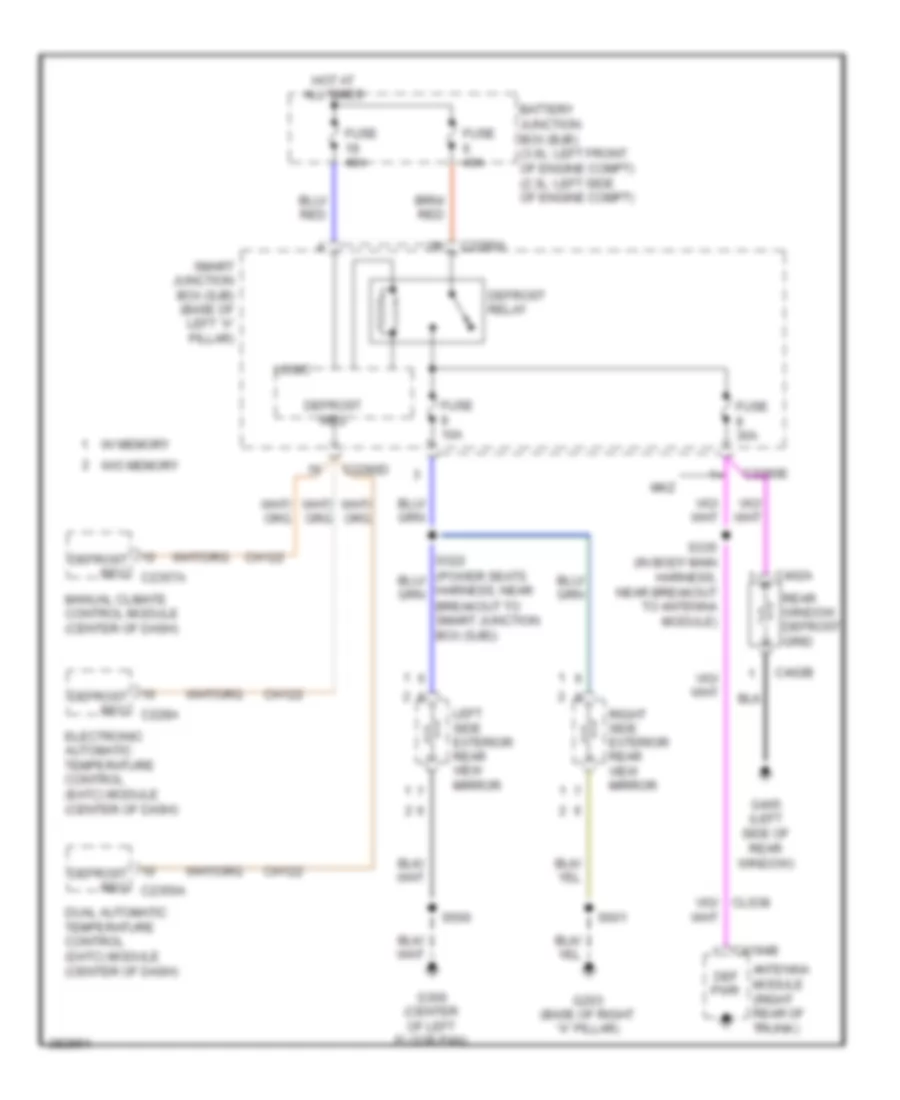
DEFOGGERS
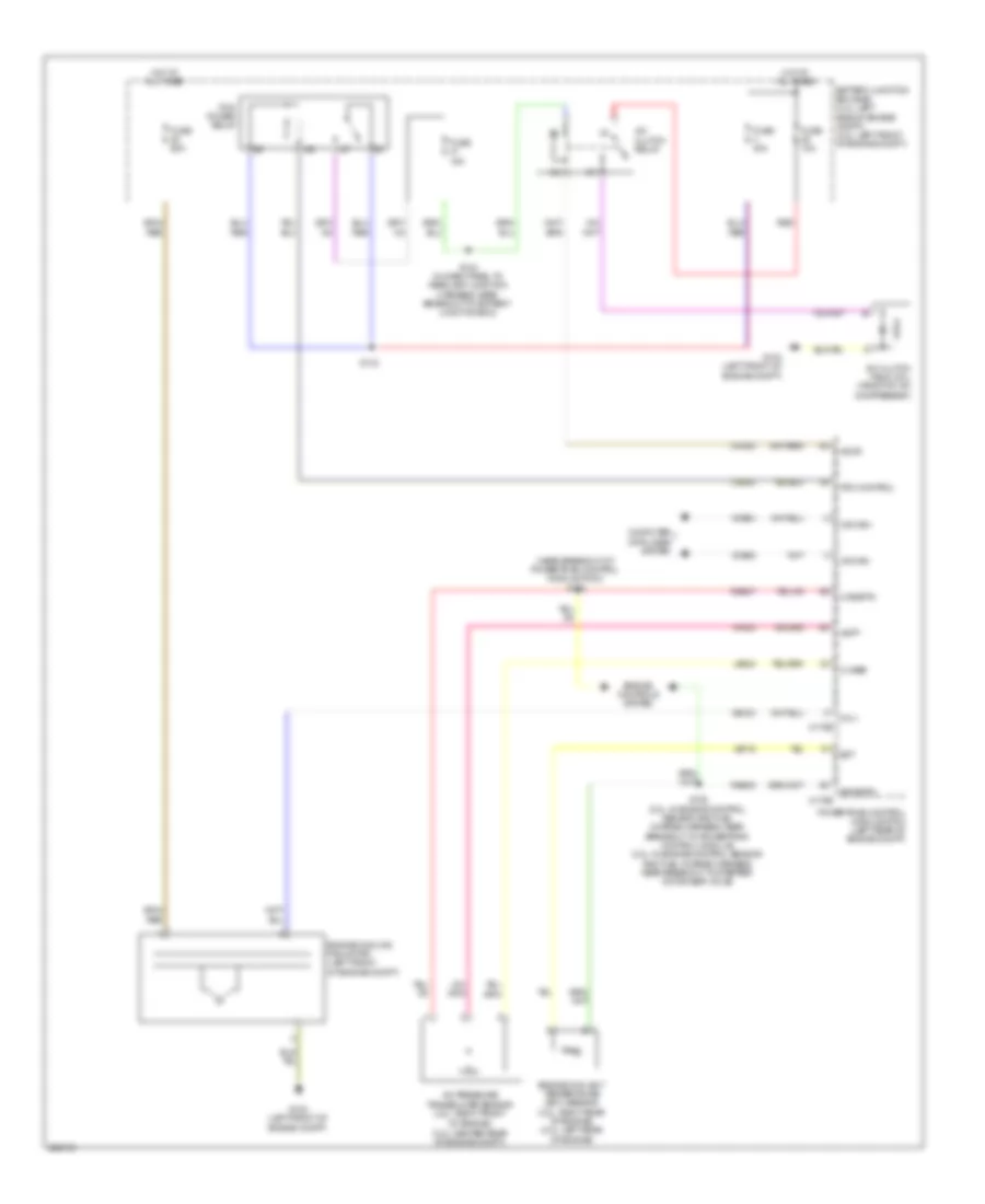
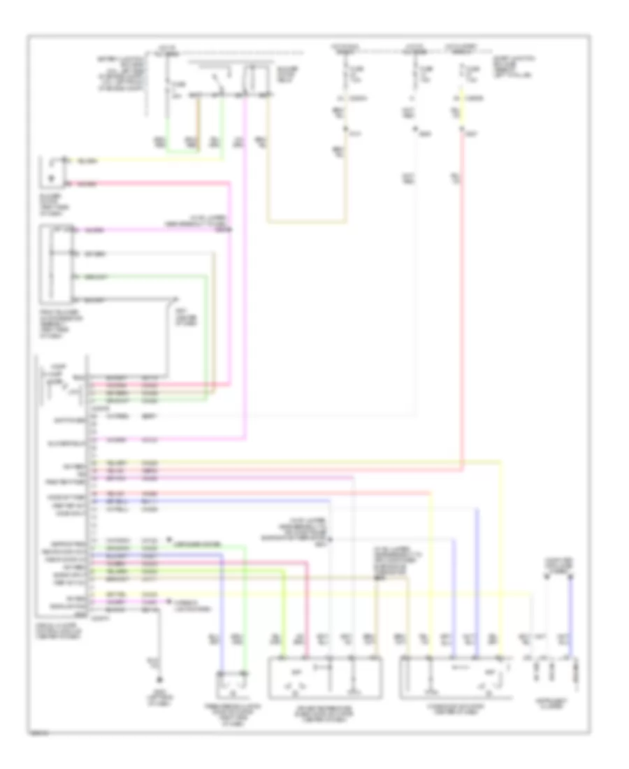
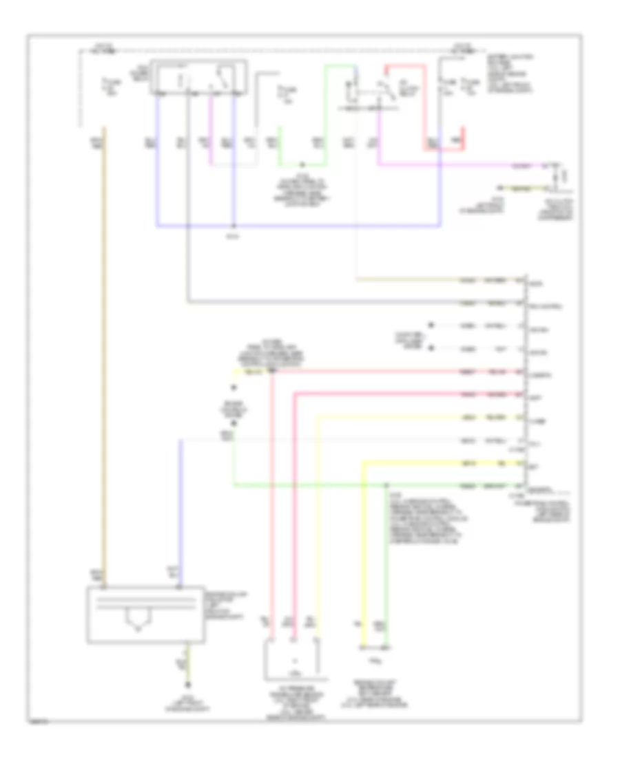
Defoggers Wiring Diagram for Ford Fusion S 2008
List of elements for Defoggers Wiring Diagram for Ford Fusion S 2008:
- Antenna module (right rear of trunk)
- Battery junction box (bjb) (3.0l: left front of engine compt) (2.3l: left side of engine compt)
- Breakout to smart junction box (sjb))
- C2280a
- C2280d
- C2280e
- C402a
- C402b
- C4194b
- Ch122
- Def pwr
- Defrost relay
- Defrost req
- Defrost req c228a
- Defrost req c2356a
- Defrost req c2357a
- Dual automatic temperature control (datc) module (center of dash)
- Electronic automatic temperature control (eatc) module (center of dash)
- Fuse 10a
- Fuse 30a
- Fuse 40a
- G203 (base of right "a" pillar)
- G300 (center of left floor pan)
- G405 (left side of rear window)
- Hot at all times
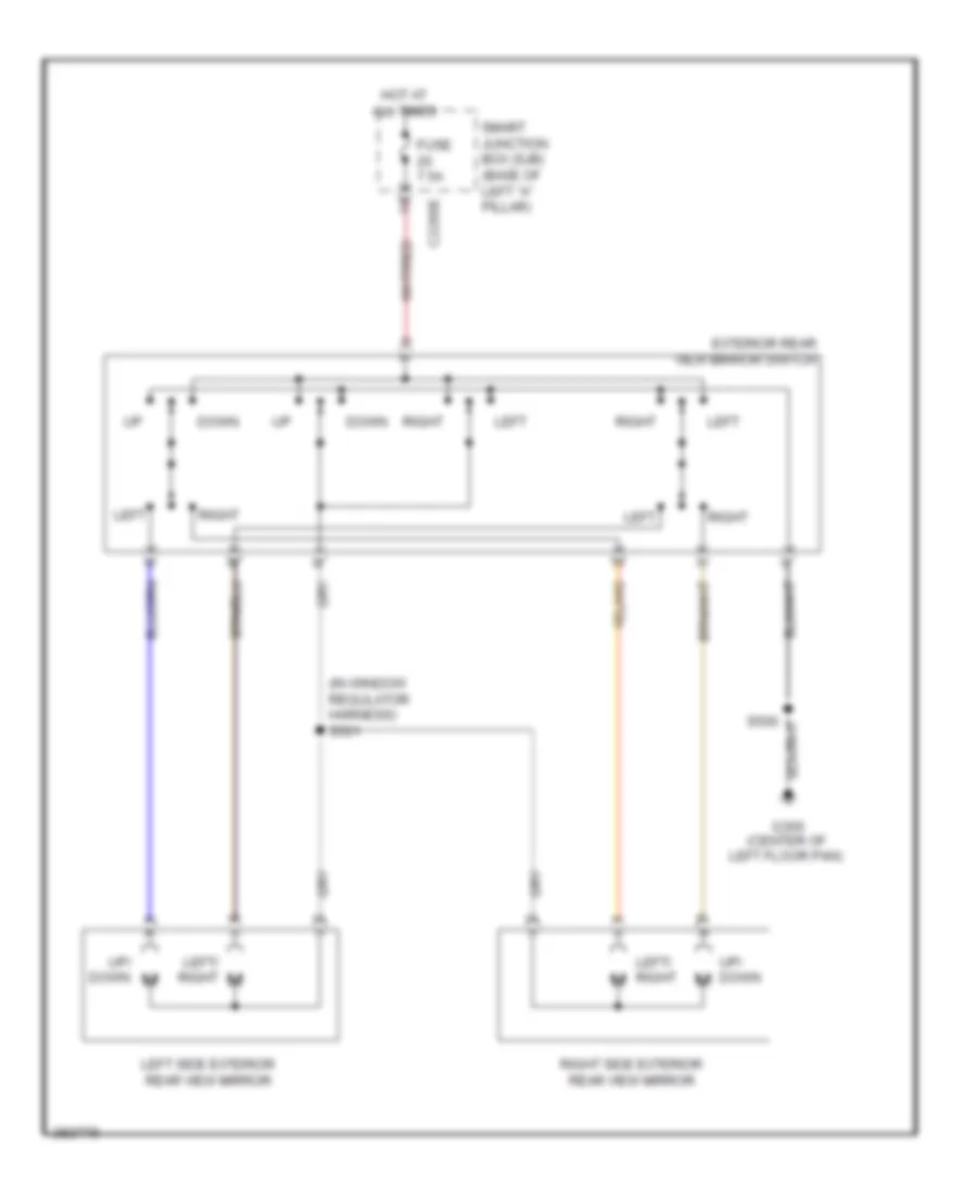
- Left side exterior rear view mirror
- Logic
- Manual climate control module (center of dash)
- Mkz
- Rear window defrost grid
- Right side exterior rear view mirror
- S335 (in body main harness, near breakout to antenna module)
- S500
- S601
- Smart junction box (sjb) (base of left "a" pillar)
- W/ memory
- W/o memory
ENGINE PERFORMANCE
2.3L
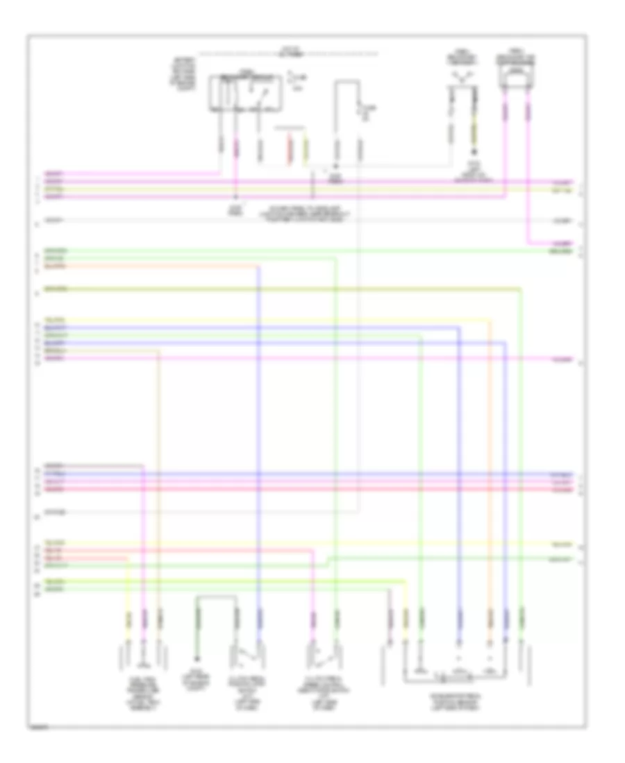
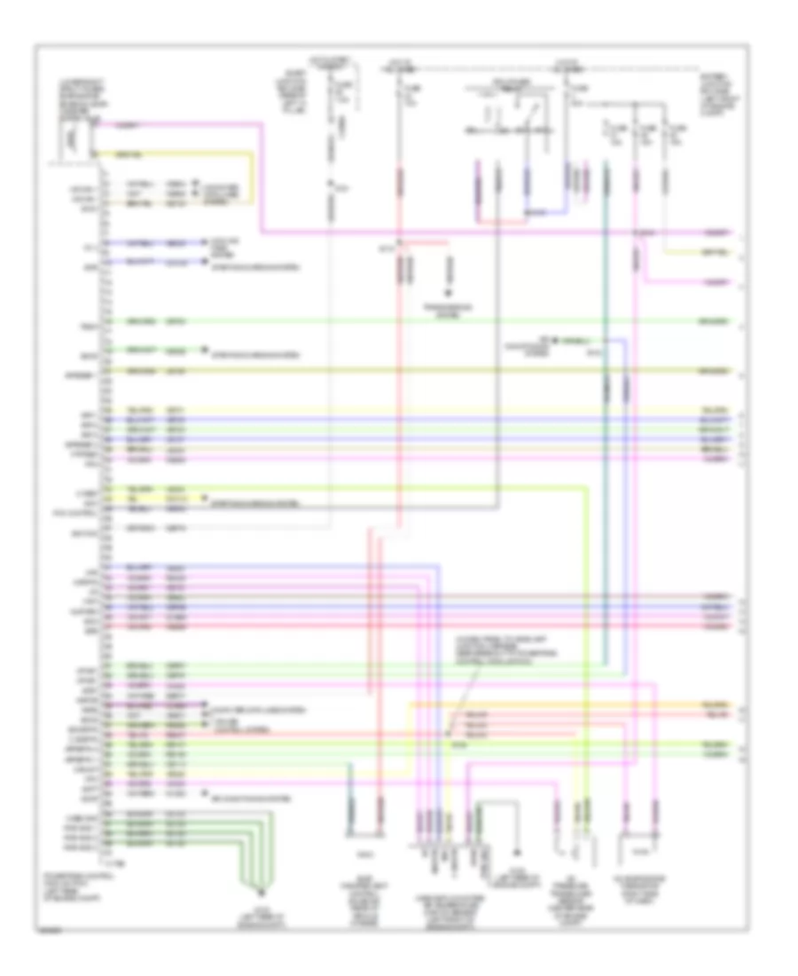
2.3L, Engine Performance Wiring Diagram (1 of 5) for Ford Fusion S 2008
List of elements for 2.3L, Engine Performance Wiring Diagram (1 of 5) for Ford Fusion S 2008:
- (in dash panel to headlamp junction harness, near breakout to g103)
- (in dash panel to headlamp junction harness, near breakout to powertrain control module (pcm))
- (in dash panel to headlamp junction harness, nearbreakout to battery junction box)
- A/c evaporative thermistor (right side of dash)
- A/c pressure transducer sensor (right front of engine)
- Accr
- Acet
- Acpt
- Air conditioning system
- App 1
- App 2
- App 3
- Appsref 1
- Appsref 2
- Appsrtn 1
- Appsrtn 2
- Battery junction box (bjb) (left side of engine compt)
- Boo
- Bps
- C sigrtn
- C vref
- C175b
- C2280a
- Canvnt
- Case gnd
- Cbp18
- Cbp46
- Cbp47
- Ccb08
- Cdb08
- Cdc12
- Cdc35
- Ce114
- Ce132
- Ce302
- Ce336
- Ce404
- Ce608
- Ce903
- Ce904
- Ces09
- Cet40
- Ch302
- Computer data lines system
- Cooling fans system
- Cpp bt
- Cpp tt
- Cruise control system
- Eair
- Eairm
- Evap canister vent control solenoid (rear of vehicle chassis)
- Evaporative emission (evap) canister purge valve (lower right strut tower)
- Evmv
- Fc v
- Feps
- Fpc
- Fpm
- Ftpt
- Ftptref
- Fuse 10a
- Fuse 15a
- Fuse 40a
- Fuse 7.5a
- G102 (left rear of engine compt)
- Gd120
- Hot at all times
- Hot in start or run
- Hs can +
- Hs can -
- Iat
- Ignition
- Injpwrm
- Kapwr
- Le136
- Le137
- Le230
- Le424
- Maf
- Mafrtn
- Mass air flow/intake air temperature (maf/iat) sensor (left front of engine compt)
- Output shaft speed (oss) sensor (m/t) (top of transmission)
- Pcm control
- Pcm power relay
- Powertrain control module (pcm) (left rear of engine compt)
- Pwr gnd
- Pwr gnd 1
- Pwr gnd 2
- Pwr gnd 3
- Re136
- Re137
- Re325
- Re407
- Res08
- S119
- S121
- S124
- S142
- S143
- S144
- Sbb23
- Sbb45
- Sccs
- Sccsrtn
- Sdc
- Smart junction box (sjb) (base of left "a" pillar)
- Smc
- Smr
- Starting/charging system
- Trsw
- Vdb04
- Vdb05
- Ve225
- Ve701
- Ve702
- Ve703
- Ve740
- Ve806
- Ve808
- Ve922
- Vec03
- Ves10
- Vh406
- Vh433
- Vpwr
- Vpwr1
- Vssin
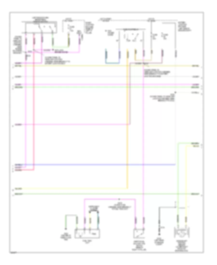
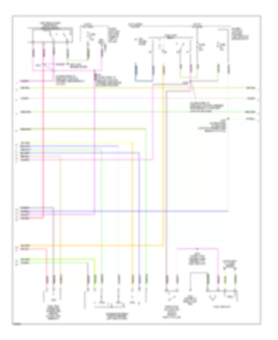
2.3L, Engine Performance Wiring Diagram (2 of 5) for Ford Fusion S 2008
List of elements for 2.3L, Engine Performance Wiring Diagram (2 of 5) for Ford Fusion S 2008:
- (in dash panel to headlamp junction harness, near breakout to battery junction box (bjb))
- (pzev) secondary air pump
- (pzev) secondary air pump solenoid
- Accelerator pedal position sensor (left side of dash)
- Battery junction box (bjb) (left side of engine compt)
- Clutch pedal position (cpp) switch (m/t) (left side of dash)
- Clutch pedal speed control deactivator switch (m/t) (left side of dash)
- Fuel tank pressure transducer sensor (in fuel tank assembly)
- Fuse 40a
- Fuse 5a
- G102 (left rear of engine compt)
- G103 (left front of engine compt)
- Hot at all times
- Nca
- S139 (pzev)
- S140 (pzev)
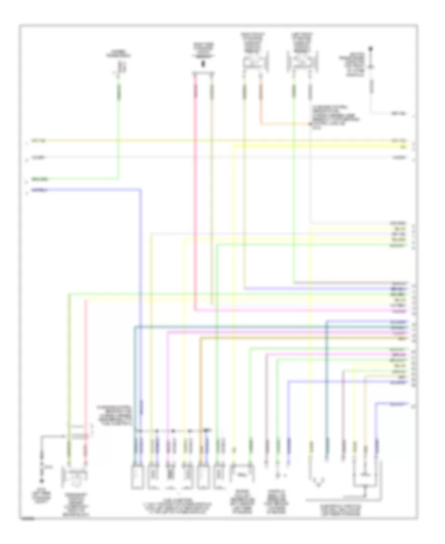
2.3L, Engine Performance Wiring Diagram (3 of 5) for Ford Fusion S 2008
List of elements for 2.3L, Engine Performance Wiring Diagram (3 of 5) for Ford Fusion S 2008:
- (in dash panel to headlamp junction harness, near breakout to battery
- (in dash panel to headlamp junction harness, near breakout to battery junction box)
- (in dash panel to headlamp junction harness, near engine bulkhead grommet)
- (left side of dash) brake pedal position switch
- Anti-lock brakes system
- Battery junction box (bjb) (left side of engine compt)
- Boo input c2280a
- Crankshaft position sensor (lower right front of engine block)
- Fuel pump relay
- Fuel tank unit
- Fuse 15a
- Fuse 30a
- Fuse 7.5a
- G102 (left rear of engine compt)
- G401 (center of rear floor pan)
- Hot at all times
- Hot in start or run
- Inertia fuel shutoff (ifs) switch (base of right "a" pillar)
- Instrument cluster system
- Junction box (bjb))
- Pcm power diode
- S115
- S125 (in dash panel to headlamp junction harness, near breakout to g102)
- S130
- S133
- S415 (in body main harness, near breakout to fuel tank unit)
- Smart junction box (sjb) (base of left "a" pillar)
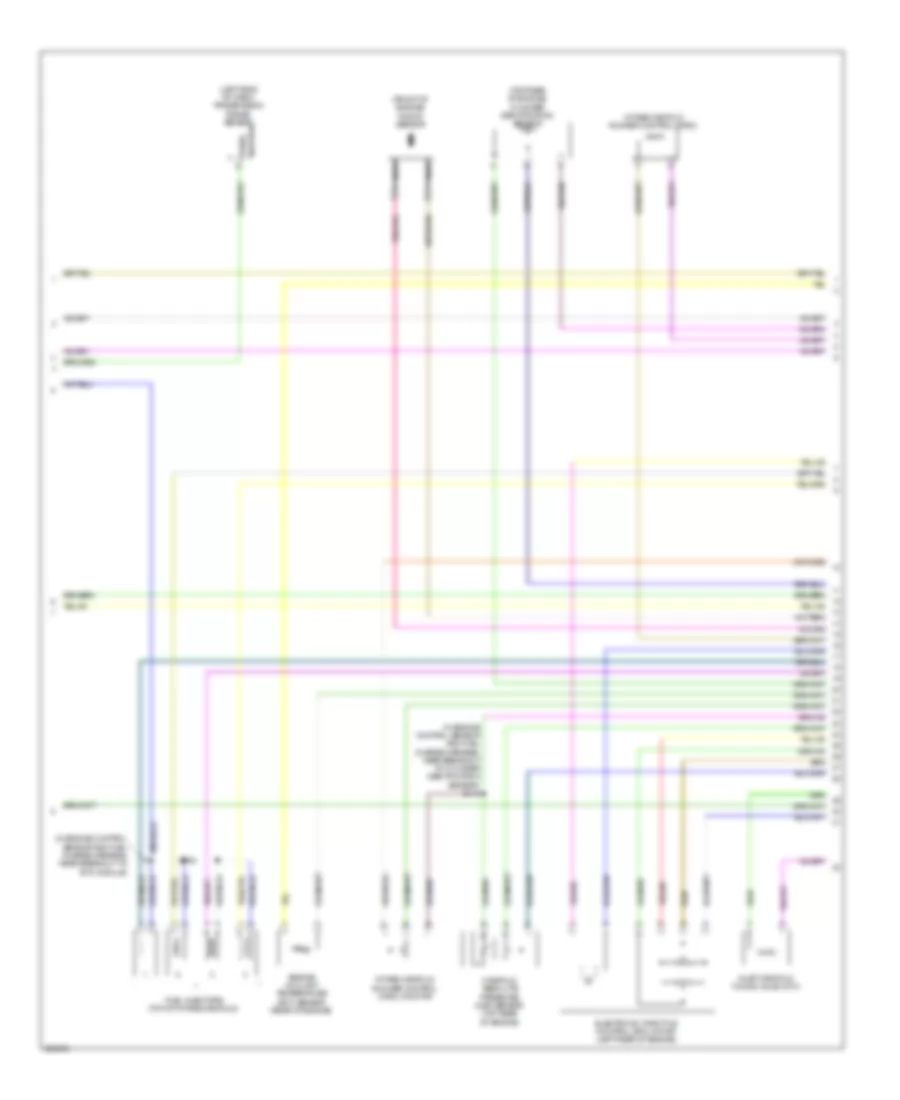
2.3L, Engine Performance Wiring Diagram (4 of 5) for Ford Fusion S 2008
List of elements for 2.3L, Engine Performance Wiring Diagram (4 of 5) for Ford Fusion S 2008:
- (front of engine) knock sensor
- (in engine control sensor and fuel charge harness, near breakout to cylinder identification sensor) s113
- (in engine control sensor and fuel charge harness, near breakout to etc module)
- (left side of dash) transmission range sensor
- (top rear of engine) cylinder identification sensor
- Electronic throttle control (etc) motor (left rear of engine)
- Engine coolant temperature (ect) sensor (rear of engine)
- Fuel injectors (top of intake manifold)
- Inlet manifold tuning valve (imtv)
- Intake manifold runner control (imrc)
- Intake manifold runner control (imrc) monitor
- Manifold absolute pressure (map) sensor (top rear of engine)
- Nca
- Park/ neutral
- S108
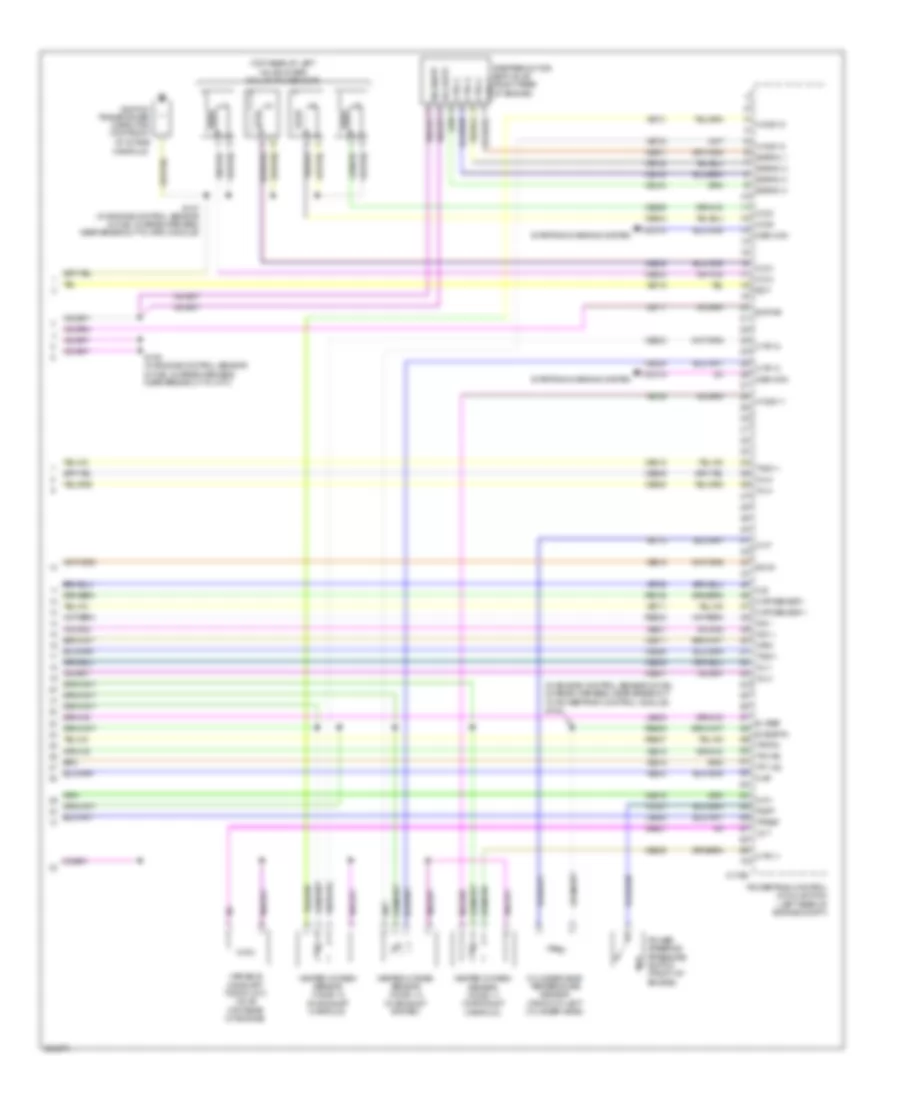
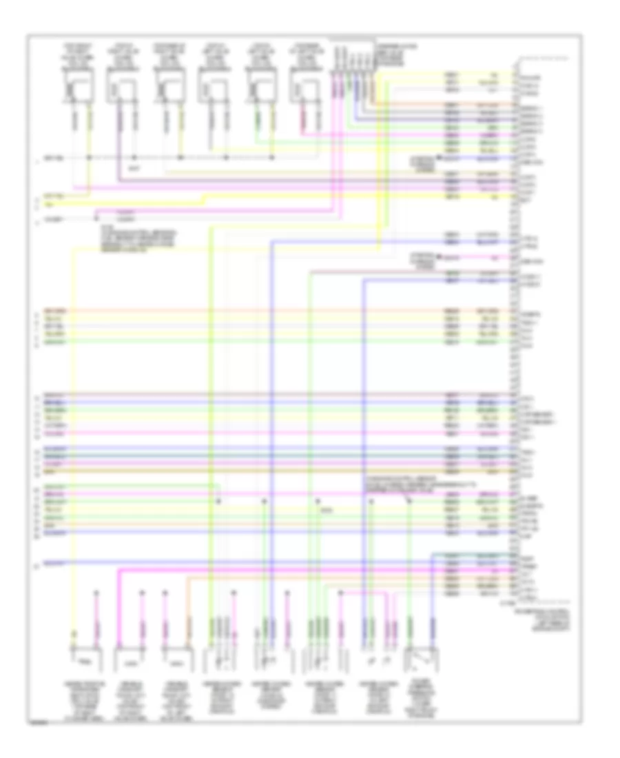
2.3L, Engine Performance Wiring Diagram (5 of 5) for Ford Fusion S 2008
List of elements for 2.3L, Engine Performance Wiring Diagram (5 of 5) for Ford Fusion S 2008:
- (in engine control sensor & fuel charge harness, near breakout to powertrain control module) s102
- (top rear of left valve cover) coil on plugs (cop)
- Bvpwr
- C175e
- Cd a
- Cd b
- Cd c
- Cd d
- Cdc10
- Cdc15
- Ce102
- Ce103
- Ce104
- Ce205
- Ce206
- Ce207
- Ce208
- Ce233
- Ce234
- Ce235
- Ce301
- Ce303
- Ce304
- Ce305
- Ce306
- Ce316
- Ce411
- Ce412
- Ce421
- Ce426
- Cht
- Cid
- Ckp sensor +
- Ckp sensor -
- Ctrl 1
- Ctrl 2
- Ctrl 3
- Ctrl 4
- Cylinder head temperature sensor (front of left cylinder head)
- E sigrtn
- E vref
- Ect
- Egrmc 1
- Egrmc 2
- Egrmc 3
- Egrmc 4
- Gen com
- Gen mon
- Heated oxygen sensor (ho2s) 11 (in exhaust manifold)
- Heated oxygen sensor (ho2s) 12 (in exhaust manifold)
- Heated oxygen sensor (ho2s) 13 (in exhaust system)
- Ho2s 11
- Ho2s 12
- Ho2s 13
- Htr 11
- Htr 12
- Htr 13
- Ignition transformer capacitor (top front of intake
- Imrc
- Imtv
- Inj 1
- Inj 2
- Inj 3
- Inj 4
- Ks1 +
- Ks1 -
- Le111
- Le423
- Le428
- Manifold)
- Map
- Power steering pressure switch (front of engine)
- Powertrain control module (pcm) (left rear of engine compt)
- Pspt
- Re135
- Re323
- Re405
- Re427
- S107 (in engine control sensor & fuel charge harness, near breakout to imrc module)
- S109 (in engine control sensor & fuel charge harness, near breakout to imtv)
- Scvm
- Starting/charging system
- Stepper motor egr valve (right rear of engine)
- Tacm +
- Tacm -
- Tp1 ns
- Tp2 ps
- Tpref
- Tprtn
- Variable camshaft timing (vct) valve (top rear of engine)
- Vcs10
- Vct
- Ve519
- Ve706
- Ve711
- Ve712
- Ve716
- Ve731
- Ve733
- Ve735
- Ve801
- Ve803
- Ve818
- Ve819
- Vol supp
- Vol supp vol supp
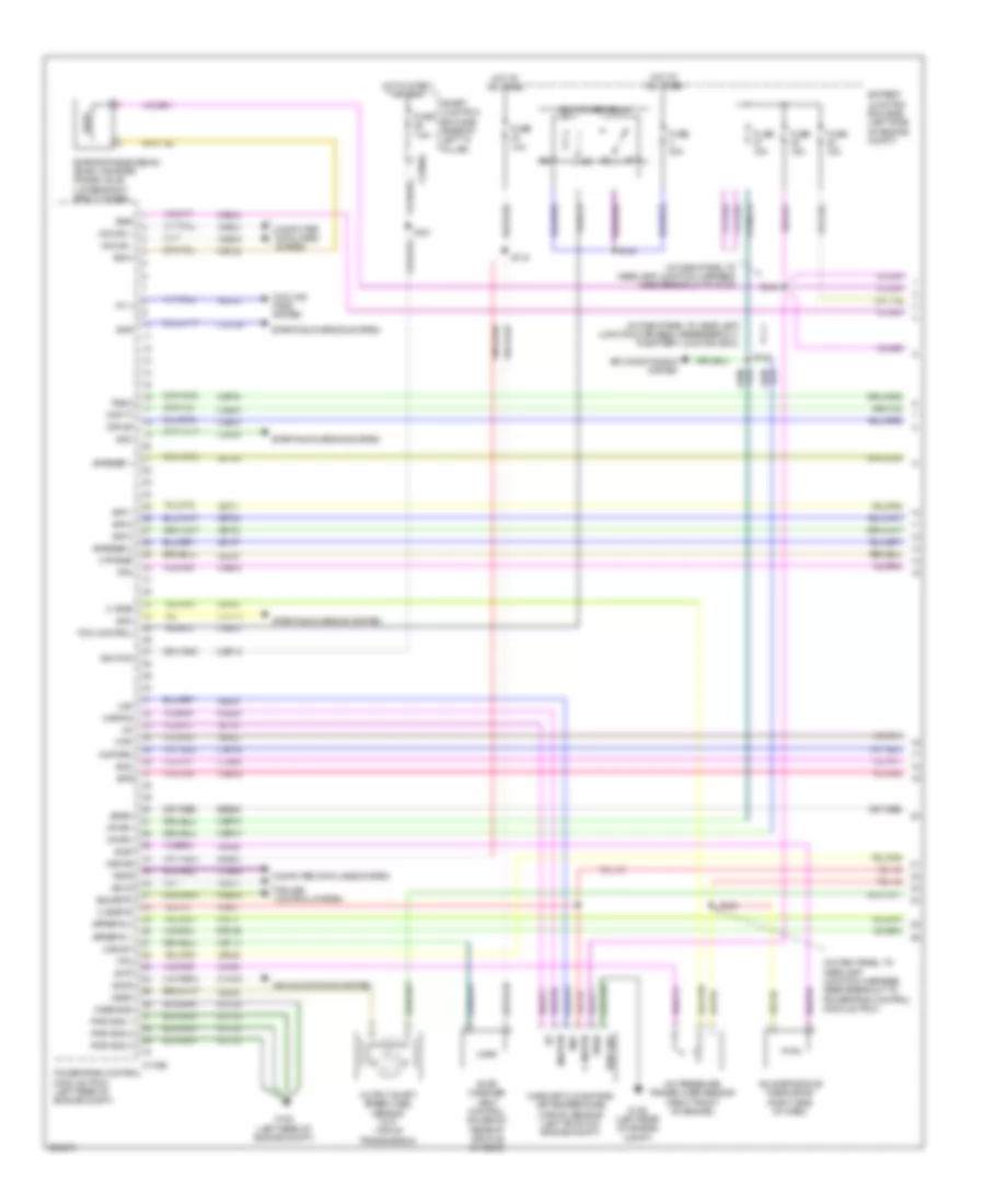
3.0L
3.0L, Engine Performance Wiring Diagram (1 of 4) for Ford Fusion S 2008
List of elements for 3.0L, Engine Performance Wiring Diagram (1 of 4) for Ford Fusion S 2008:
- (in dash panel to headlamp junction harness, near breakout to powertrain control module (pcm))
- (lower right strut tower) evaporative emission (evap) canister purge valve
- A/c evaporative thermistor (right side of dash)
- A/c pressure transducer sensor (center rear of engine compt)
- Accr
- Acet
- Acpt
- Air conditioning system
- App 1
- App 2
- App 3
- Appsref 1
- Appsref 2
- Appsrtn 1
- Appsrtn 2
- Battery junction box (bjb) (left front of engine compt)
- Boo
- Bps
- C sigrtn
- C vref
- C175b
- C2280a
- Canvnt
- Case gnd
- Cbp18
- Cbp46
- Cbp47
- Ccb08
- Cdb08
- Cdc12
- Cdc35
- Ce114
- Ce132
- Ce302
- Ce336
- Ce608
- Ces09
- Cet40
- Ch302
- Computer data lines system
- Cooling fans system
- Cruise control system
- Evap canister vent control solenoid (rear of vehicle chassis)
- Evmv
- Fc v
- Feps
- Fpc
- Fpm
- Ftpt
- Ftptref
- Fuse 10a
- Fuse 15a
- Fuse 40a
- Fuse 7.5a
- G102 (left rear of engine compt)
- Gd120
- Hot at all times
- Hot in start or run
- Hs can +
- Hs can -
- Iat
- Ignition
- Injpwrm
- Kapwr
- Le136
- Le137
- Le230
- Le424
- Maf
- Mafrtn
- Mass air flow/intake air temperature (maf/iat) sensor (left front of engine compt)
- Pcm control
- Pcm power relay
- Powertrain control module (pcm) (left rear of engine compt)
- Pwr gnd
- Pwr gnd 1
- Pwr gnd 2
- Pwr gnd 3
- Re136
- Re137
- Re325
- Re407
- Res08
- S119
- S121
- S124
- S142
- S143
- S144
- Sbp07
- Sccs
- Sccsrtn
- Smart junction box (sjb) (base of left "a" pillar)
- Smc
- Smcs
- Smr
- Starting/charging system
- Transmissions system
- Trsw
- Vdb04
- Vdb05
- Ve225
- Ve701
- Ve702
- Ve703
- Ve740
- Ve808
- Ve922
- Vec03
- Ves10
- Vh406
- Vh433
- Vpwr
- Vpwr1
3.0L, Engine Performance Wiring Diagram (2 of 4) for Ford Fusion S 2008
List of elements for 3.0L, Engine Performance Wiring Diagram (2 of 4) for Ford Fusion S 2008:
- (in dash panel to headlamp junction harness, near breakout to battery
- (in dash panel to headlamp junction harness, near breakout to g103)
- (left side of dash) brake pedal position switch
- Accelerator pedal position sensor (left side of dash)
- Anti-lock brakes system
- Battery junction box (bjb) (left front of engine compt)
- Boo input c2280a
- Fuel pump relay
- Fuel tank pressure transducer sensor (in fuel tank assembly)
- Fuel tank unit
- Fuse 15a
- Fuse 30a
- Fuse 7.5a
- G401 (center of rear floor pan)
- Hot at all times
- Hot in start or run
- Inertia fuel shutoff (ifs) switch (base of right "a" pillar)
- Instrument cluster system
- Junction box (bjb))
- Pcm power diode
- S125 (in dash panel to headlamp junction harness, near breakout to g102)
- S130
- S133
- S415 (in body main harness, near breakout to fuel tank unit)
- Smart junction box (sjb) (base of left "a" pillar)
3.0L, Engine Performance Wiring Diagram (3 of 4) for Ford Fusion S 2008
List of elements for 3.0L, Engine Performance Wiring Diagram (3 of 4) for Ford Fusion S 2008:
- (in engine control sensor & fuel charge harness, near breakout to fuel injector 1)
- (in engine control sensor & fuel charge harness, near breakout to powertrain control module) s103
- (left front of engine) camshaft position sensor 2
- (right front of engine) camshaft position sensor 1
- (right side of engine) knock sensor
- 6 speed transmission
- Crankshaft position sensor (lower right front of engine block)
- Electronic throttle control (etc) motor (left rear of engine)
- Engine coolant temperature (ect) sensor (left rear of engine)
- Fuel injectors (1, 2 & 3: top right of intake manifold) (5 & 6: left side of intake manifold) (4: top left of intake manifold)
- G102 (left rear of engine compt)
- Ignition transformer capacitor (top front of intake
- Lock start
- Manifold absolute pressure (map) sensor (top rear of engine)
- Manifold)
- Nca
- S108
- S115
3.0L, Engine Performance Wiring Diagram (4 of 4) for Ford Fusion S 2008
List of elements for 3.0L, Engine Performance Wiring Diagram (4 of 4) for Ford Fusion S 2008:
- (in engine control sensor & fuel charge harness, near breakout to stepper motor egr valve)
- (top front of right valve cover) coil on plug (cop) 1
- (top of left valve cover) coil on plug (cop) 4
- (top of left valve cover) coil on plug (cop) 5
- (top of right valve cover) coil on plug (cop) 2
- (top rear of left valve cover) coil on plug (cop) 6
- (top rear of right valve cover) coil on plug (cop) 3
- C175e
- Cdc10
- Cdc15
- Ce102
- Ce103
- Ce104
- Ce205
- Ce206
- Ce207
- Ce208
- Ce209
- Ce210
- Ce233
- Ce234
- Ce235
- Ce236
- Ce301
- Ce303
- Ce304
- Ce305
- Ce306
- Ce307
- Ce308
- Ce321
- Ce412
- Ce421
- Ce422
- Ce426
- Cid 1
- Cid 2
- Ckp sensor +
- Ckp sensor -
- Cms 12
- Cms 22
- Cop 1
- Cop 2
- Cop 3
- Cop 4
- Cop 5
- Cop 6
- Ctrl 1
- Ctrl 2
- Ctrl 3
- Ctrl 4
- E sigrtn
- E vref
- Ect
- Egrmc 1
- Egrmc 2
- Egrmc 3
- Egrmc 4
- Gen com
- Gen mon
- Heated oxygen sensor (ho2s) 11 (in right exhaust manifold)
- Heated oxygen sensor (ho2s) 12 (in right exhaust manifold)
- Heated oxygen sensor (ho2s) 21 (in left exhaust manifold)
- Heated oxygen sensor (ho2s) 22 (in exhaust system)
- Heated positive crankcase ventilation (pcv) valve (top rear of right cylinder head)
- Ho2s 11
- Ho2s 21
- Htr 11
- Htr 12
- Htr 21
- Htr 22
- Inj 1
- Inj 2
- Inj 3
- Inj 4
- Inj 5
- Inj 6
- Ks1 +
- Ks1 -
- Le423
- Le428
- Map
- Pcvhtr
- Power steering pressure switch (lower right front of engine)
- Powertrain control module (pcm) (left rear of engine compt)
- Pspt
- Re135
- Re323
- Re405
- Re427
- Re429
- S102
- S107
- S149 (in engine control sensor & fuel sensor harness, near breakout to heated oxygen sensor (ho2s) 22)
- Starting/ charging system
- Stepper motor egr valve (top rear of engine)
- Tacm +
- Tacm -
- Tp1 ns
- Tp2 ps
- Tpref
- Tprtn
- Variable camshaft timing (vct) valve 1 (top front of right valve cover)
- Variable camshaft timing (vct) valve 2 (top front of left valve cover)
- Vcs10
- Vct
- Vct 2
- Ve706
- Ve707
- Ve711
- Ve716
- Ve731
- Ve733
- Ve735
- Ve737
- Ve801
- Ve803
- Ve818
- Ve819
- Vol supp
- Vrsrtn
EXTERIOR LIGHTS
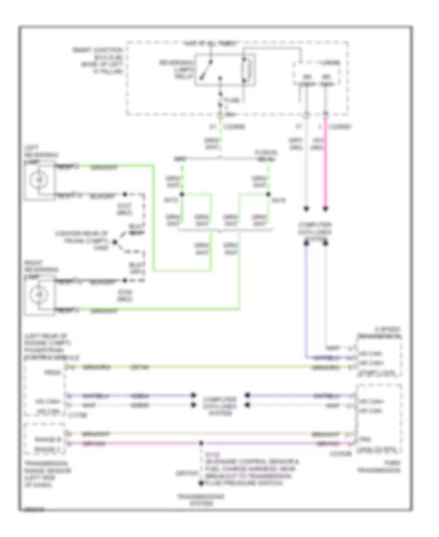
Backup Lamps Wiring Diagram, A/T for Ford Fusion S 2008
List of elements for Backup Lamps Wiring Diagram, A/T for Ford Fusion S 2008:
- (center rear of trunk compt) g400
- (left rear of engine compt) powertrain control module
- 6 speed transmission
- Analog rtn
- C175b
- C2280d
- C2280e
- C2352b
- Cet40
- Computer data lines system
- Fnr5 transmission
- Fuse 10a
- Fusion, milan
- Hot at all times
- Hs can+
- Hs can-
- Left reversing lamp
- Logic
- Mkz
- Ms can+
- Ms can-
- Nca
- Range b
- Range c
- Reversing lamps relay
- Right reversing lamp
- S112 (in engine control sensor & fuel charge harness, near breakout to transmission fluid pressure switch)
- S336 (mkz)
- S337 (mkz)
- S412
- S416
- Smart junction box (sjb) (base of left "a" pillar)
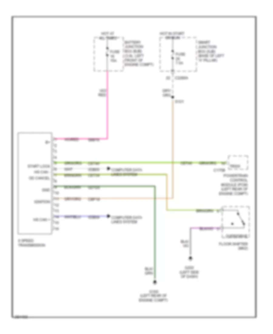
- Start lock
- Transmission range sensor (left side of dash)
- Transmissions system
- Trs
- Trsw
- Vdb04
- Vdb05
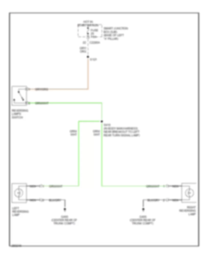
Backup Lamps Wiring Diagram, M/T for Ford Fusion S 2008
List of elements for Backup Lamps Wiring Diagram, M/T for Ford Fusion S 2008:
- C2280a
- Fuse 7.5a
- G400 (center rear of trunk compt)
- Hot in start or run
- Left reversing lamp
- Nca
- Reversing lamps switch
- Right reversing lamp
- S121
- S416 (in body main harness, near breakout to left rear turn signal lamp)
- Smart junction box (sjb) (base of left "a" pillar)
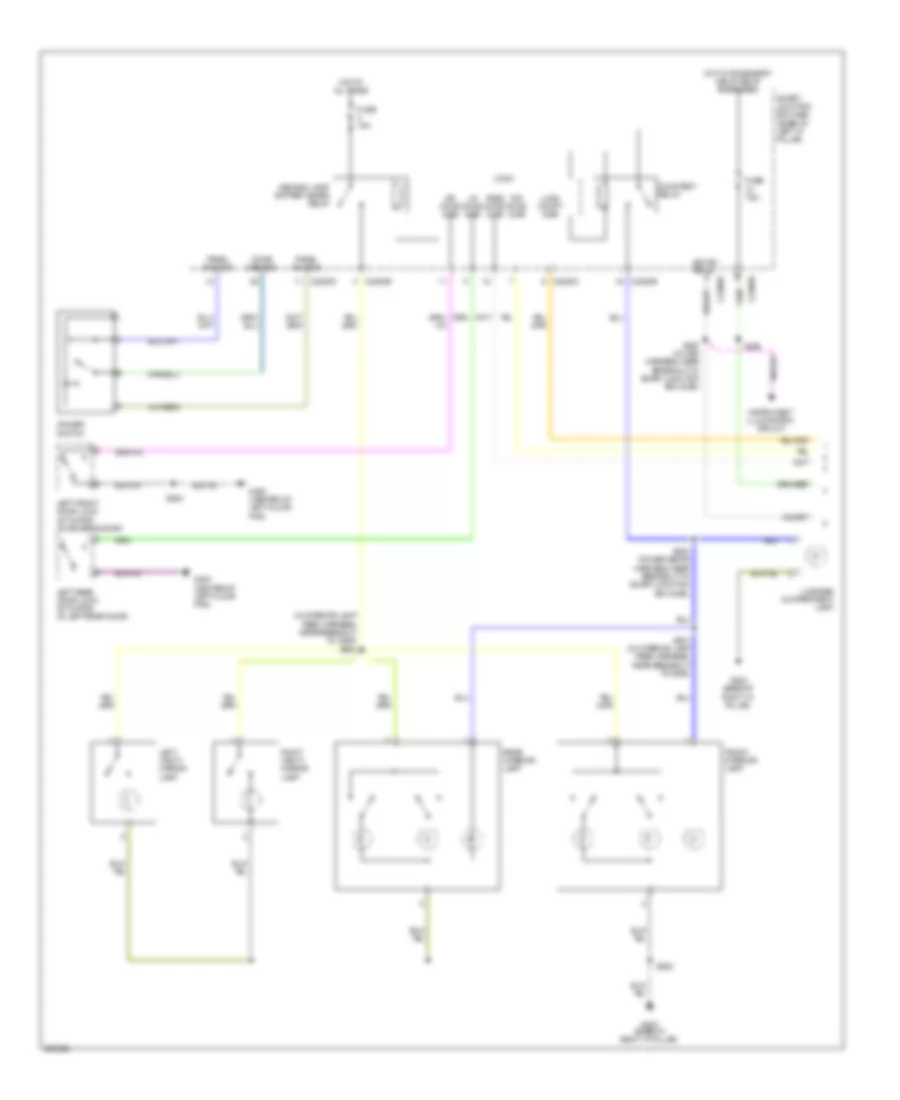
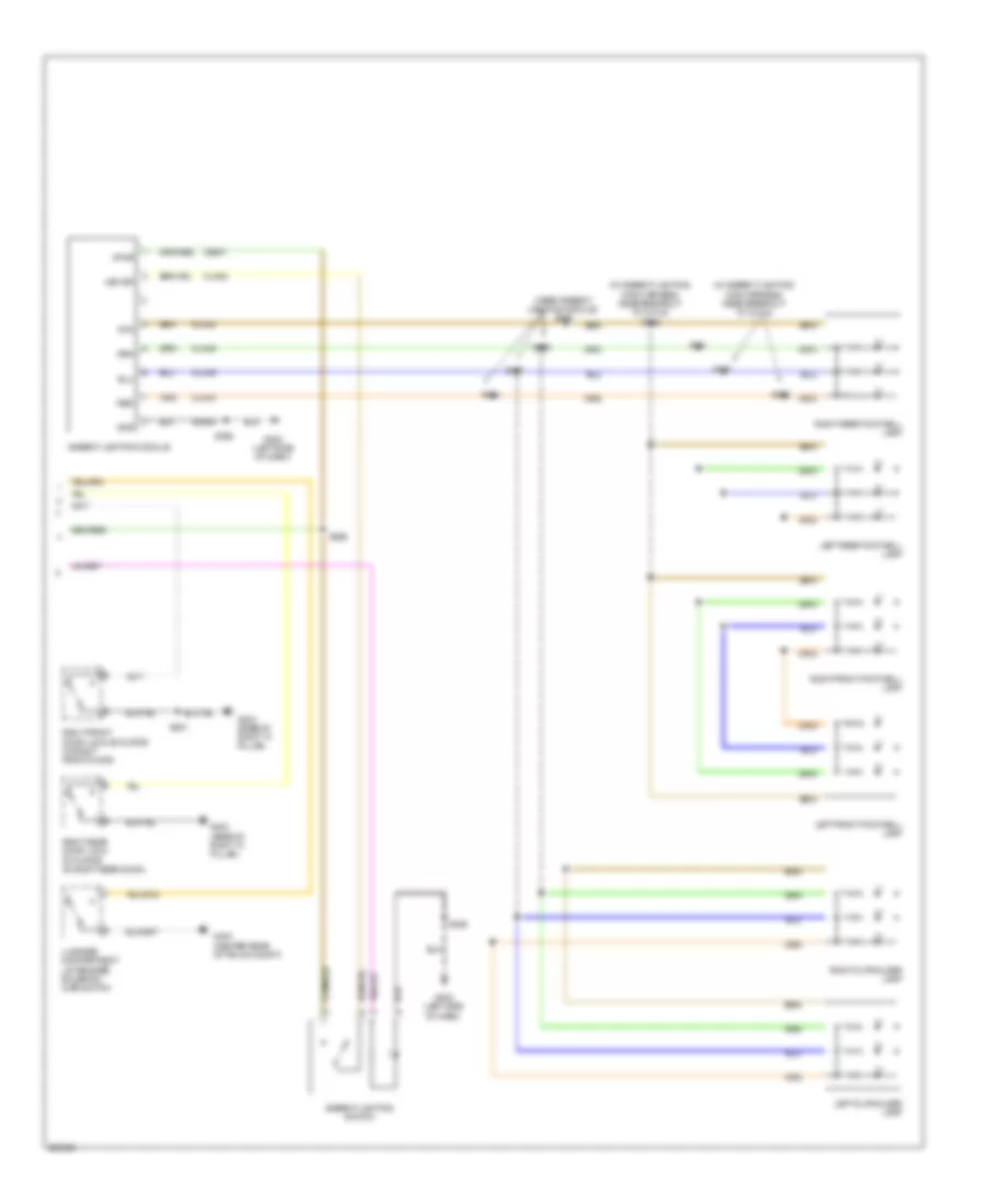
Exterior Lamps Wiring Diagram (1 of 2) for Ford Fusion S 2008
List of elements for Exterior Lamps Wiring Diagram (1 of 2) for Ford Fusion S 2008:
- (near drivers safety belt retractor) s410
- Auto
- Auto- lamp on
- Battery junction box (3.0l: left front of engine compt) (2.3l: left side of engine compt)
- Boo input
- Boo redundant
- C2280a
- C2280d
- C2280f
- Chmsl
- Computer data lines system
- Fuse 15a
- Fuse 40a
- Fuse 60a
- G103 (left front of engine compt)
- G104 (3.0l: right front of engine compt) (2.3l: in front of right strut tower)
- G202 (left side of dash)
- Hazard on
- Head park- lamp off
- Hot at all times
- Instrument cluster
- Left
- Left front park/ turn lamp
- Left front side lamp
- Left turn sig
- Lh stop/ turn lamp
- Logic
- Logic gnd
- Low
- Low beam req
- Lt turn
- Main light switch
- Ms can+
- Ms can-
- Multi- function switch (left side of dash)
- Off
- Park
- Park lamp relay
- Park lamps on
- Rh stop/ turn lamp
- Right
- Right front park/ turn lamp
- Right front side lamp
- Right turn sig
- Rt turn
- S136 (near breakout to front impact severity sensor)
- Smart junction box (sjb) (base of left ``a" pillar)
- Traction ctl on/off
- Turn
Exterior Lamps Wiring Diagram (2 of 2) for Ford Fusion S 2008
List of elements for Exterior Lamps Wiring Diagram (2 of 2) for Ford Fusion S 2008:
- (in body main harness, near breakout to g400) s411
- (near left turn signal) s409
- Abs control module (right front of engine compt)
- Battery junction box (3.0l: left front of engine compt) (except 3.0l: left side of engine compt)
- Boo
- Bps
- Brake pedal position switch (left side of dash)
- C175b
- C2280a
- C2280b
- Ccb08
- Ces09
- Fuse 15a
- Fuse 7.5a
- G202 (left side of dash)
- G400 (center rear of trunk compt)
- Hazard switch
- Hazard/ pad/ traction switch
- High mounted stoplamp
- High mounted stoplamp (spoiler)
- Hot at all times
- Hot in start or run
- Interior lights system
- Left license plate lamp
- Left rear park/ turn/ stop lamp
- Left rear side lamp
- Pad
- Park
- Powertrain control module (left rear of engine compt)
- Right license plate lamp
- Right rear park/turn/ stop lamp
- Right rear side lamp
- S120 (in dash panel to headlamp junction harness, near engine bulkhead grommet)
- S133 (3.0l: in dash panel to headlamp junction harness, near breakout to g103) (except 3.0l: in dash panel to headlamp junction harness, near breakout to battery junction box)
- S144
- Smart junction box (sjb) (base of left ``a" pillar)
- Stop lp sw
- Stop/ turn
- Traction
GROUND DISTRIBUTION
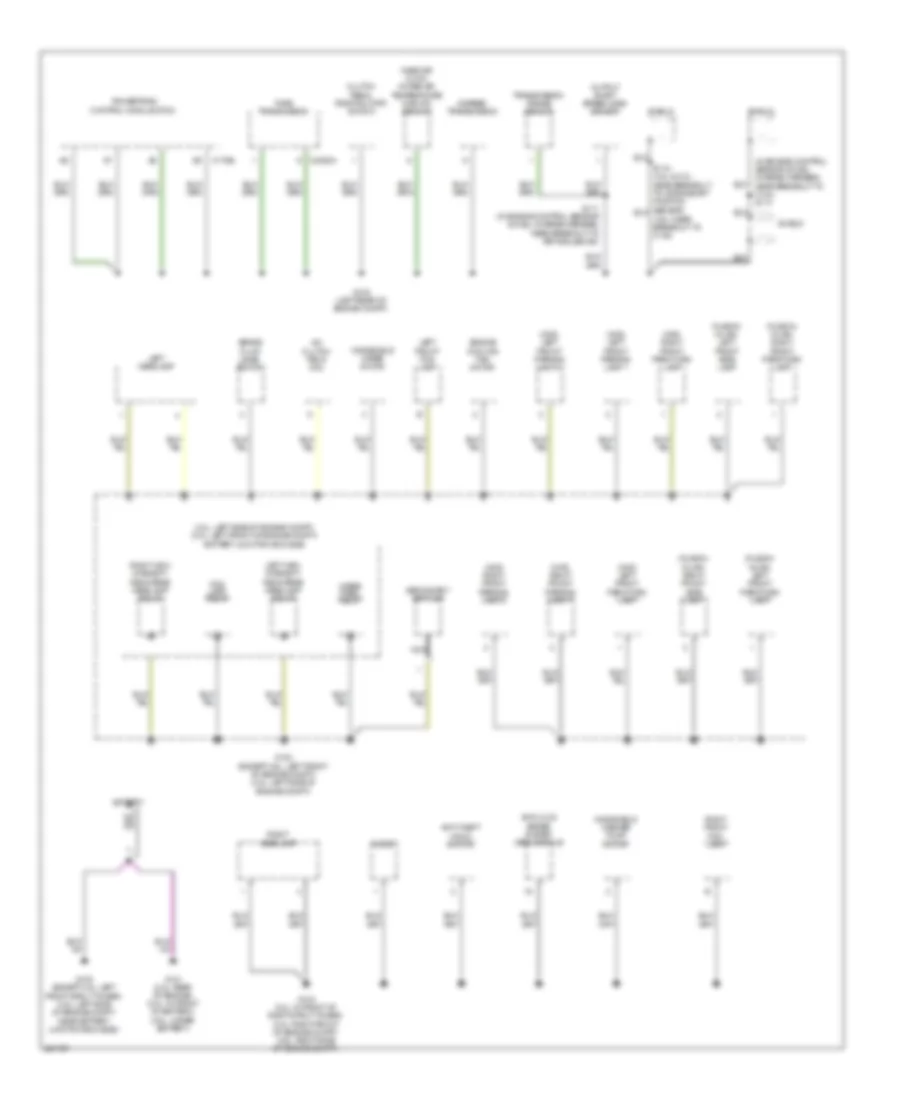
Ground Distribution Wiring Diagram (1 of 4) for Ford Fusion S 2008
List of elements for Ground Distribution Wiring Diagram (1 of 4) for Ford Fusion S 2008:
- (2.3l: left side of engine compt) (3.0l: left front of engine compt) battery junction box (bjb)
- (3.5l: near breakout to c145)
- (fusion/ milan) left front park/turn lamp
- (fusion/ milan) left front side lamp
- (fusion/ milan) right front park/turn lamp
- (fusion/ milan) right front side lamp
- (in engine control sensor & fuel charge harness, near breakout to c134) s114
- (mkz) left front park/turn lamp
- (mkz) left front parking lamp 1
- (mkz) left front parking lamp 2
- (mkz) right front park/turn lamp
- (mkz) right front parking lamp 1
- (mkz) right front parking lamp 2
- 6 speed transmission
- A/c clutch field coil
- Anti-lock brake system (abs) module
- Anti-theft hood switch
- Battery
- Brake fluid level switch
- C175b
- C2352a
- Clutch pedal position (cpp) switch
- Control module (pcm)
- Engine cooling fan motor
- Fnr5 transmission
- Fog lamp relay
- G100 (except 3.5l: left front strut tower) (3.5l: left side of engine compt, near battery junction box (bjb))
- G101 (2.3l: rear of engine) (3.0l: in front of battery) (3.5l: under battery)
- G102 (left rear of engine compt)
- G103 (except 3.5l: left front of engine compt) (3.5l: left side of engine compt)
- G104 (2.3l: in front of right strut tower) (3.0l: right front of engine compt) (3.5l: right side of engine compt)
- Horn
- Left front fog lamp
- Left headlamp
- Left high intensity discharge headlamp relay
- Mass air flow/ intake air temperature (maf/iat) sensor
- Nca
- Output shaft speed (oss) sensor
- Powertrain
- Right front fog lamp
- Right headlamp
- Right high intensity discharge headlamp relay
- S111 (in engine control sensor & fuel charge harness, near breakout to peta solenoid)
- Secondary air pump
- Shield
- Transmission range sensor
- Windshield washer pump motor
- Windshield wiper motor
- Wiper park relay
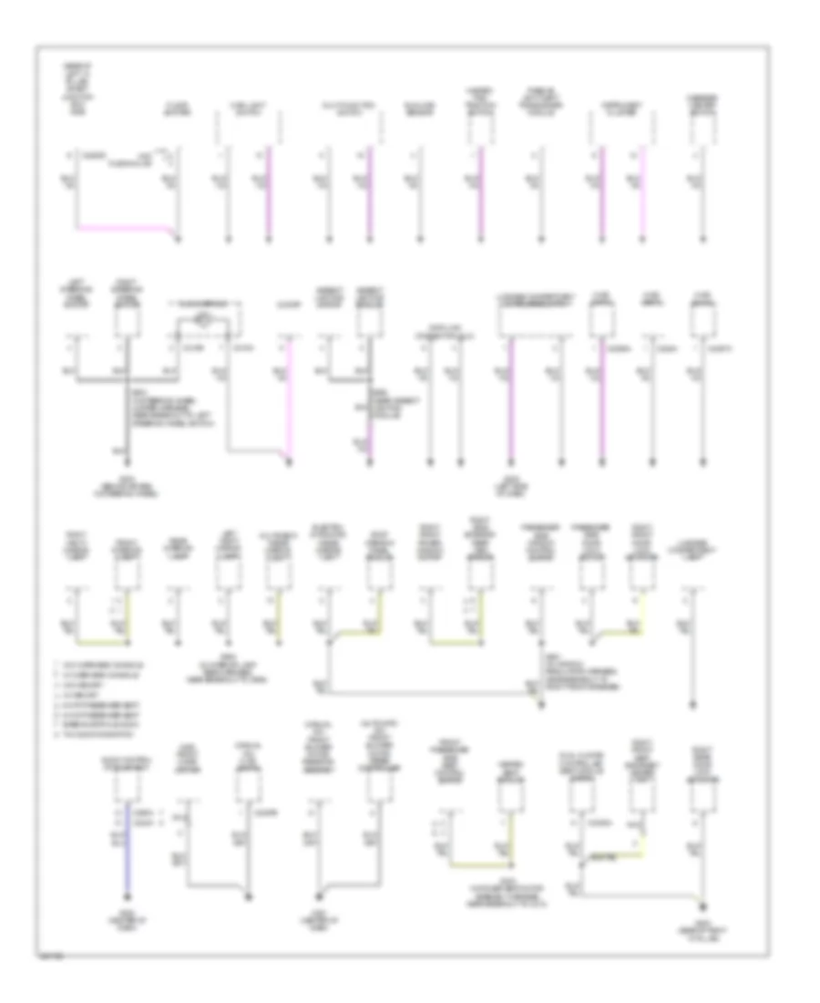
Ground Distribution Wiring Diagram (2 of 4) for Ford Fusion S 2008
List of elements for Ground Distribution Wiring Diagram (2 of 4) for Ford Fusion S 2008:
- (automatic a/c) front blower motor speed controller
- (base of left "a" pillar) smart junction box (sjb)
- (manual a/c) front blower motor resistor assembly
- (manual a/c) hvac (emtc)
- (mkz) front cigar lighter
- 6-way passenger seat
- 8-way passenger seat
- Ambient lighting module
- Ambient lighting switch
- Audio control module (acm)
- Base/audiophile audio
- C218a
- C218b
- C2280d
- C228a
- C2356a
- C2357a
- C2357b
- C240a
- C290a
- C3305a
- Clock
- Clock spring
- Data link connector (dlc)
- Dual climate controlled seat module (dcsm)
- Electro- chromatic inside mirror unit
- Floor shifter
- Front interior lamp
- Front passenger side seat control switch
- G200 (center of dash)
- G201 (center of dash)
- G202 (left side of dash)
- G203 (base of right "a" pillar)
- G204 (behind air bag, in steering wheel)
- Hazard/ pad/ traction switch
- Heated seat module
- Hvac (datc)
- Hvac (eatc)
- Hvac (emtc)
- Instrument cluster
- Left steering wheel switch
- Left vanity mirror lamp
- Luggage compartment lamp
- Luggage compartment lid release switch
- Main light switch
- Message center switch
- Mkz fusion/milan
- Multi-function switch
- Multimedia inside mirror unit
- Nca
- Passenger side door lock switch
- Passenger side window control switch
- Passive anti-theft transceiver module
- Rear interior lamp
- Right front door lock actuator
- Right front power window motor
- Right front seat backrest heater mat
- Right rear door lock actuator
- Right side exterior rear view mirror
- Right steering wheel switch
- Right vanity mirror lamp
- Roof opening panel module
- S203 (in steering wheel jumper harness, near breakout to left steering wheel switch)
- S303 (in power seat motor assembly harness, near breakout to c313)
- S368 (near ambient lighting module)
- S902 (in interior lamp feed harness, near breakout to c906)
- Sunload sensor
- Thx audio/navigation
- W/ memory
- W/ overhead console
- W/o memory
- W/o overhead console
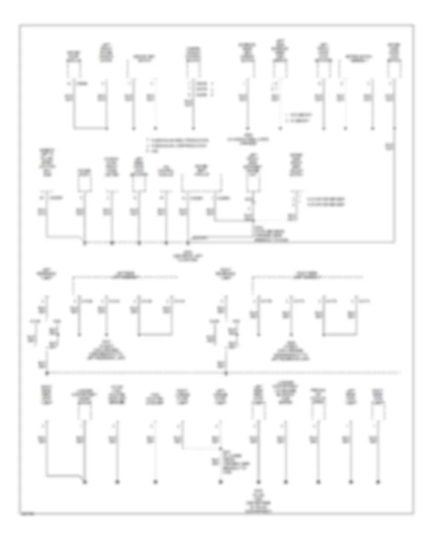
Ground Distribution Wiring Diagram (3 of 4) for Ford Fusion S 2008
List of elements for Ground Distribution Wiring Diagram (3 of 4) for Ford Fusion S 2008:
- (base of left "a" pillar) smart junction box (sjb)
- (fusion/ milan) front cigar lighter
- (milan) high mounted stoplamp (spoiler)
- 4x4 control module
- C2280e
- C3299a
- C3299c
- C414a
- C414b
- C414c
- C414d
- C417a
- C417b
- C417c
- C417d
- C504b
- C535b
- C537b
- C568b
- Driver door module
- Driver seat module
- Driver side door lock switch
- Driver side front seat adjust switch
- Exterior rear view mirror switch
- Fusion/milan early production
- Fusion/milan late production
- G300 (center of left floor pan)
- G400 (milan/ mkz) (center rear of trunk compartment)
- High mounted stoplamp
- Keypad switch assembly
- Left front door lock actuator
- Left front power window motor
- Left front seat backrest heater mat
- Left license plate lamp
- Left rear door lock actuator
- Left rear lamp assembly
- Left rear park/ stop lamp
- Left rear turn lamp
- Left reversing lamp
- Left side exterior rear view mirror
- Luggage compartment disarm switch
- Luggage compartment lid release solenoid/ ajar switch
- Master window control switch
- Memory set switch
- Milan
- Mkz
- Nca
- Parking aid module (pam)
- Power point
- Right license plate lamp
- Right rear lamp assembly
- Right rear park/ stop lamp
- Right rear turn lamp
- Right reversing lamp
- S304 (in power seats harness, near breakout to c339)
- S336 (in body main harness, near breakout to left reversing lamp)
- S337 (in body main harness, near breakout to left reversing lamp)
- S421 (in jumper wiring harness, near breakout to c408)
- S500 (in window regulator harness)
- W/ 6-way driver seat
- W/ 8-way driver seat
- W/ memory
- W/o memory
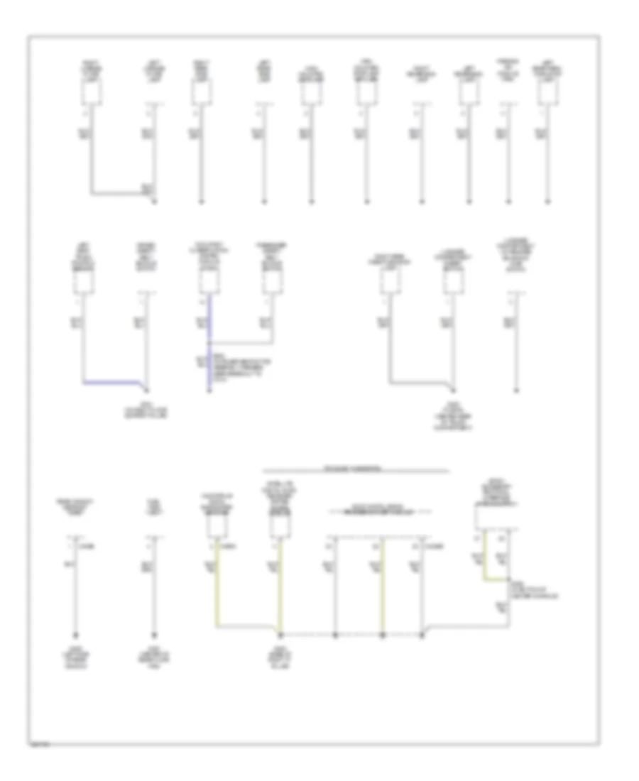
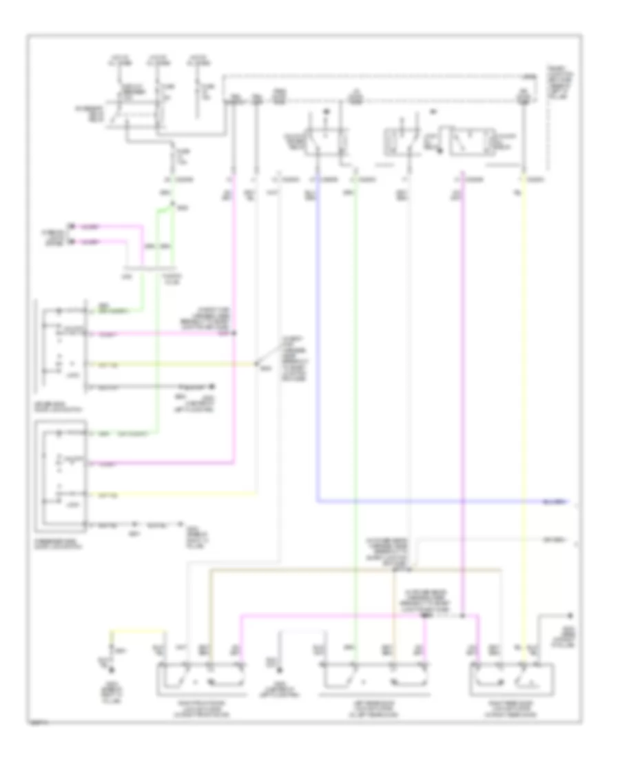
Ground Distribution Wiring Diagram (4 of 4) for Ford Fusion S 2008
List of elements for Ground Distribution Wiring Diagram (4 of 4) for Ford Fusion S 2008:
- (audiophile audio) subwoofer amplifier
- (sync) accessory protocol interface module (apim)
- Audio digital signal processing (dsp) module
- C402b
- C4326b
- C466a
- Driver safety belt buckle switch
- Fuel tank unit
- G301 (on right floor support pillar)
- G400 (fusion) (center rear of trunk compartment)
- G401 (center of rear floor pan)
- G402 (base of right "c" pillar)
- G405 (left side of rear window)
- High mounted stoplamp
- High mounted stoplamp (spoiler)
- Left license plate lamp
- Left rear park/ turn/stop lamp
- Left rear side lamp
- Left reversing lamp
- Left seat track position sensor
- Luggage compartment disarm switch
- Luggage compartment lid release solenoid/ ajar switch
- Occupant classification system module (ocsm)
- Parking aid module (pam)
- Passenger safety belt buckle switch
- Rear window defrost grid
- Right license plate lamp
- Right rear park/turn/stop lamp
- Right rear side lamp
- Right reversing lamp
- S300 (in power seat motor assembly harness, near breakout to c313)
- S355 (in bottom of center console)
- Satellite digital audio receiver system (sdars) module
- Thx audio / navigation
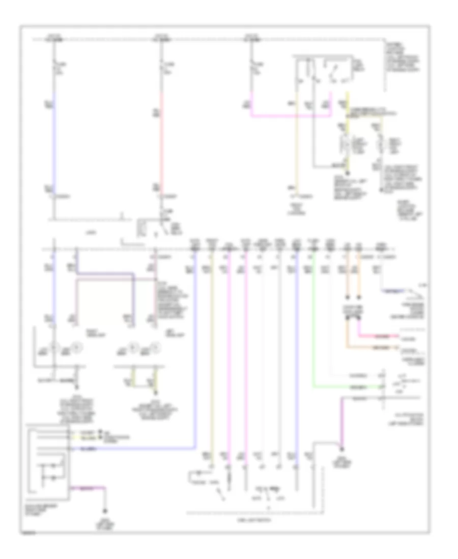
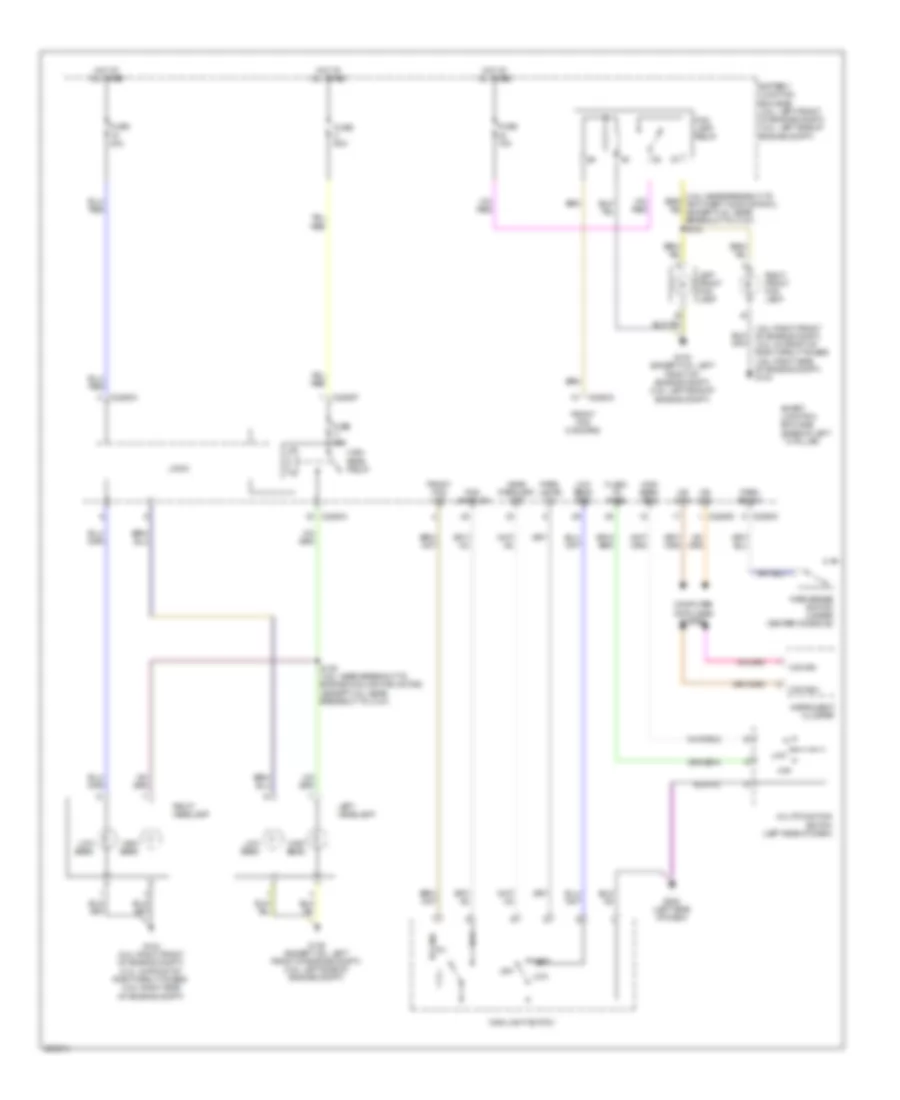
HEADLIGHTS
Headlights Wiring Diagram, with Autolamps for Ford Fusion S 2008
List of elements for Headlights Wiring Diagram, with Autolamps for Ford Fusion S 2008:
- (3.0l: right front of engine compt) (2.3l: in front of right strut tower) (3.5l: right side of engine compt) g104
- Air conditioning system
- Auto
- Auto- lamp on
- Auto- lamp sens
- Battery junction box (bjb) (3.0l: left front of engine compt) (2.3l: left side of engine compt)
- C2280a
- C2280c
- C2280d
- C2280f
- Computer data lines system
- Flash to pass
- Fog
- Fog ind
- Fog lamp relay
- Fog lamps on
- Front fog command
- Front fog ind
- Ftp
- Fuse 15a
- Fuse 40a
- Fuse 60a
- G103 (except 3.5l: left front of engine compt) (3.5l: left side of engine compt)
- G104 (3.0l: right front of engine compt) (2.3l: in front of right strut tower) (3.5l: right side of engine compt)
- G202 (left side of dash)
- Head parklamp off
- High beam
- High beam relay
- High beam req
- Hot at all times
- Instrument cluster
- Left front fog lamp
- Left headlamp
- Logic
- Low
- Low beam
- Low beam req
- Main light switch
- Ms can+
- Ms can-
- Multifunction switch (left side of dash)
- Off
- Park
- Park br sw
- Park brake switch (under center console)
- Park lamps on
- Right front fog lamp
- Right headlamp
- S135 (3.5l: near breakout to engine cooling fan motor) (except 3.5l: near breakout to anti-theft hood switch)
- Smart junction box (sjb) (base of left ``a" pillar)
- Sunload sensor (right side of dash)
Headlights Wiring Diagram, without Autolamps for Ford Fusion S 2008
List of elements for Headlights Wiring Diagram, without Autolamps for Ford Fusion S 2008:
- (3.0l: right front of engine compt) (2.3l: in front of right strut tower) (3.5l: right side of engine compt) g104
- Battery junction box (bjb) (3.0l: left front of engine compt) (2.3l: left side of engine compt)
- C2280a
- C2280c
- C2280d
- C2280f
- Computer data lines system
- Flash to pass
- Fog
- Fog ind
- Fog lamp relay
- Fog lamps on
- Front fog command
- Front fog ind
- Ftp
- Fuse 15a
- Fuse 40a
- Fuse 60a
- G103 (except 3.5l: left front of engine compt) (3.5l: left side of engine compt)
- G104 (3.0l: right front of engine compt) (2.3l: in front of right strut tower) (3.5l: right side of engine compt)
- G202 (left side of dash)
- Head parklamp off
- High beam
- High beam relay
- High beam req
- Hot at all times
- Instrument cluster
- Left front fog lamp
- Left headlamp
- Logic
- Low
- Low beam
- Low beam req
- Main light switch
- Ms can+
- Ms can-
- Multifunction switch (left side of dash)
- Off
- Park
- Park br sw
- Park brake switch (under center console)
- Park lamps on
- Right front fog lamp
- Right headlamp
- S135 (3.5l: near breakout to engine cooling fan motor) (except 3.5l: near breakout to c127)
- Smart junction box (sjb) (base of left ``a" pillar)
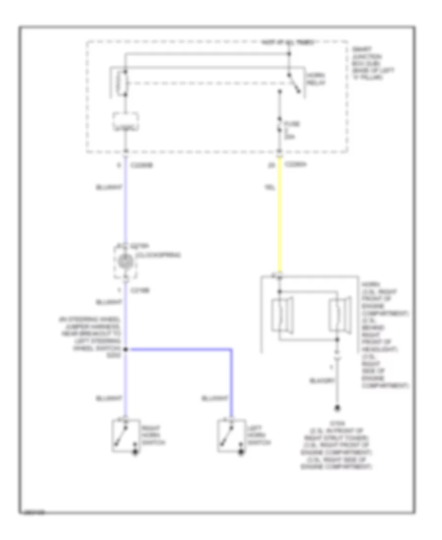
HORN
Horn Wiring Diagram for Ford Fusion S 2008
List of elements for Horn Wiring Diagram for Ford Fusion S 2008:
- (in steering wheel jumper harness, near breakout to left steering wheel switch) s202
- C218a
- C218b
- C2280a
- C2280b
- Clockspring
- Fuse 20a
- G104 (2.3l: in front of right strut tower) (3.0l: right front of engine compartment) (3.5l: right side of engine compartment)
- Horn (3.0l: right front of engine compartment) (2.3l: behind right front of headlight) (3.5l: right side of engine compartment)
- Horn relay
- Hot at all times
- Left horn switch
- Logic
- Right horn switch
- Smart junction box (sjb) (base of left "a" pillar)
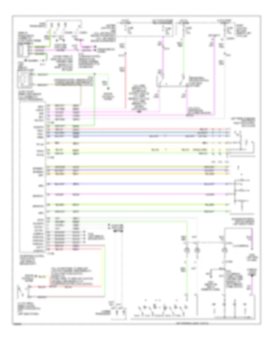
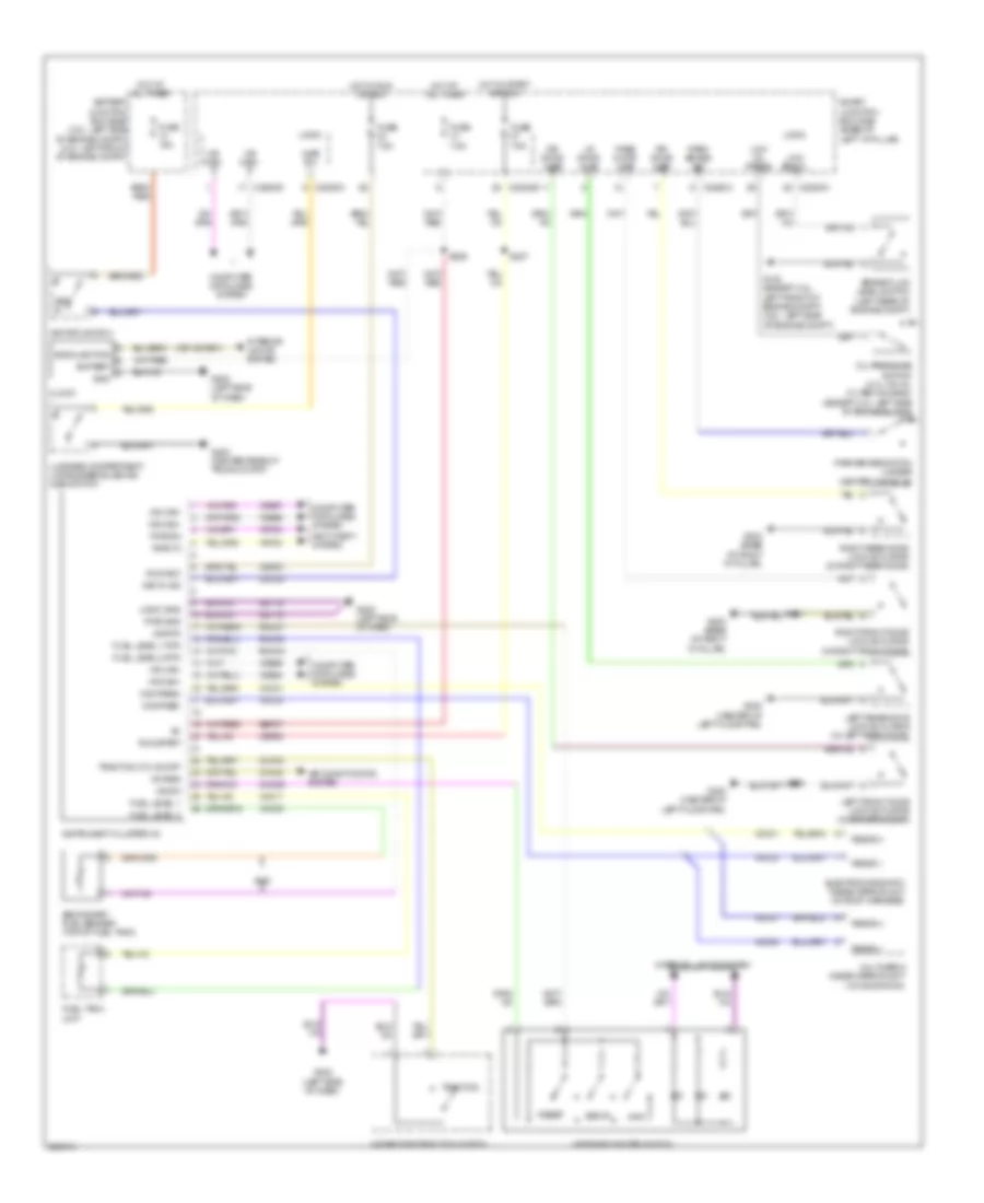
INSTRUMENT CLUSTER
Instrument Cluster Wiring Diagram for Ford Fusion S 2008
List of elements for Instrument Cluster Wiring Diagram for Ford Fusion S 2008:
- A/c req
- Air conditioning system
- Ajar sw
- Anti-theft system
- Awd
- Backlighting
- Battery
- Battery junction box (bjb) (2.3l: left side of engine compt) (3.0l: left front of engine compt)
- Brake fluid level switch (left rear of engine compt)
- C228oa
- C228ob
- C228oc
- C228od
- Cbp20
- Cbp23
- Cca15
- Cdc30
- Ch434
- Clock
- Cmc29
- Compass+
- Compass-
- Computer data lines system
- Dr door ajar
- Electrochromatic inside mirror unit (in roof harness)
- Fuel level 1
- Fuel level 1 rtn
- Fuel level 2
- Fuel level 2 rtn
- Fuel tank unit
- Fuse 15a
- Fuse 7.5a
- G103 (except 3.5l: left front of engine compt) (3.5l: left side of engine compt)
- G202 (left side of dash)
- G203 (base of right "a" pillar)
- G300 (center of left floor pan)
- G400 (center rear of trunk compt)
- Gd116
- Gnd
- Hazard/pad/traction switch
- Hot at all times
- Hot in run or acc
- Hot in start or run
- Hs can+
- Hs can-
- Ignition switch
- Info
- Instrument cluster (ic)
- Interior lights system
- Key in
- Key in ign
- Left front door lock actuator (in driver's door)
- Left rear door lock actuator (in left rear door)
- Logic
- Logic gnd
- Low brk fl
- Low oil press
- Lr door ajar
- Luggage compartment lid release solenoid/ ajar switch
- Message center switch
- Ms can+
- Ms can-
- Ms rtn
- Ms sw
- Multimedia inside mirror unit (w/ navigation)
- Oil pressure switch (2.3l: on oil filter housing) (except 2.3l: left side of engine block)
- Park brake sw
- Park brake switch (under center console)
- Pass door ajar
- Pats rx
- Pats tx
- Pwr gnd
- Reset
- Right front door lock actuator (in right front door)
- Right rear door lock actuator (in right rear door)
- Rmc27
- Rmc32
- Rmc33
- Rr door ajar
- Rs485(+)
- Rs485(-)
- Run/acc
- Run/start
- S227
- S229
- S500
- S601
- Sbp07
- Secondary fuel sender (top of fuel tank)
- Setup
- Smart junction box (sjb) (base of left "a" pillar)
- Traction
- Traction ctl on/off
- Vdb04
- Vdb05
- Vdb06
- Vdb07
- Vmc11
- Vmc23
- Vmc30
- Vmc31
- Vrt23
- Vrt24
INTERIOR LIGHTS
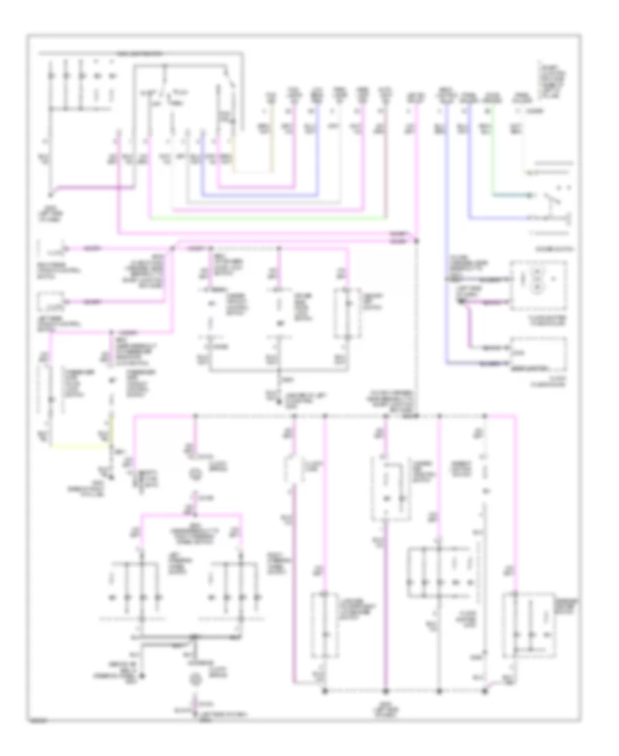
Courtesy Lamps Wiring Diagram (1 of 2) for Ford Fusion S 2008
List of elements for Courtesy Lamps Wiring Diagram (1 of 2) for Ford Fusion S 2008:
- (in interior lamp feed harness, near breakout to c906) s903
- C2280b
- C2280c
- C2280d
- C2280e
- Courtesy relay
- Demand lamp/ battery saver relay
- Dimmer switch
- Dome demand
- Dr door ajar
- Front interior lamp
- Fuse 15a
- Fuse 7.5a
- G203 (base of right "a" pillar)
- G300 (center of left floor pan)
- Hot at all times
- Hot w/ accessory delay relay energized
- Instrument illumination circuit
- Led sw bklgt
- Left front door lock actuator (in driver's door)
- Left rear door lock actuator (in left rear door)
- Left vanity mirror lamp
- Logic
- Lr door ajar
- Lugg compt ajar
- Luggage compartment lamp
- Panel dim gnd
- Panel dimming
- Pass door ajar
- Rear interior lamp
- Right vanity mirror lamp
- Rr door ajar
- S226
- S230 (in main harness, near breakout to smart junction box (sjb))
- S320 (power seats harness, near breakout to smart junction box (sjb))
- S500
- S901 (in interior lamp feed harness, near breakout to c906)
- S902
- Smart junction box (sjb) (base of left "a" pillar)
Courtesy Lamps Wiring Diagram (2 of 2) for Ford Fusion S 2008
List of elements for Courtesy Lamps Wiring Diagram (2 of 2) for Ford Fusion S 2008:
- (in ambient lighting main harness, near breakout to c3134)
- (in ambient lighting main harness, near breakout to c3134) s362
- (near ambient lighting module) s365
- Ambient lighting module
- Ambient lighting switch
- Cbx07
- Cln44
- Cln45
- Cln46
- Cln54
- G202 (left side of dash)
- G203 (base of right "a" pillar)
- G400 (center rear of trunk compt)
- Gd908
- Gnd
- Led sig
- Left cupholder lamp
- Left front footwell lamp
- Left rear footwell lamp
- Luggage compartment lid release solenoid/ ajar switch
- Red
- Right cupholder lamp
- Right front door lock actuator (in right front door)
- Right front footwell lamp
- Right rear door lock actuator (in right rear door)
- Right rear footwell lamp
- Rln44
- Rtn
- S360
- S361
- S363
- S364
- S366
- S367
- S368
- S369
- S601
- Vpwr
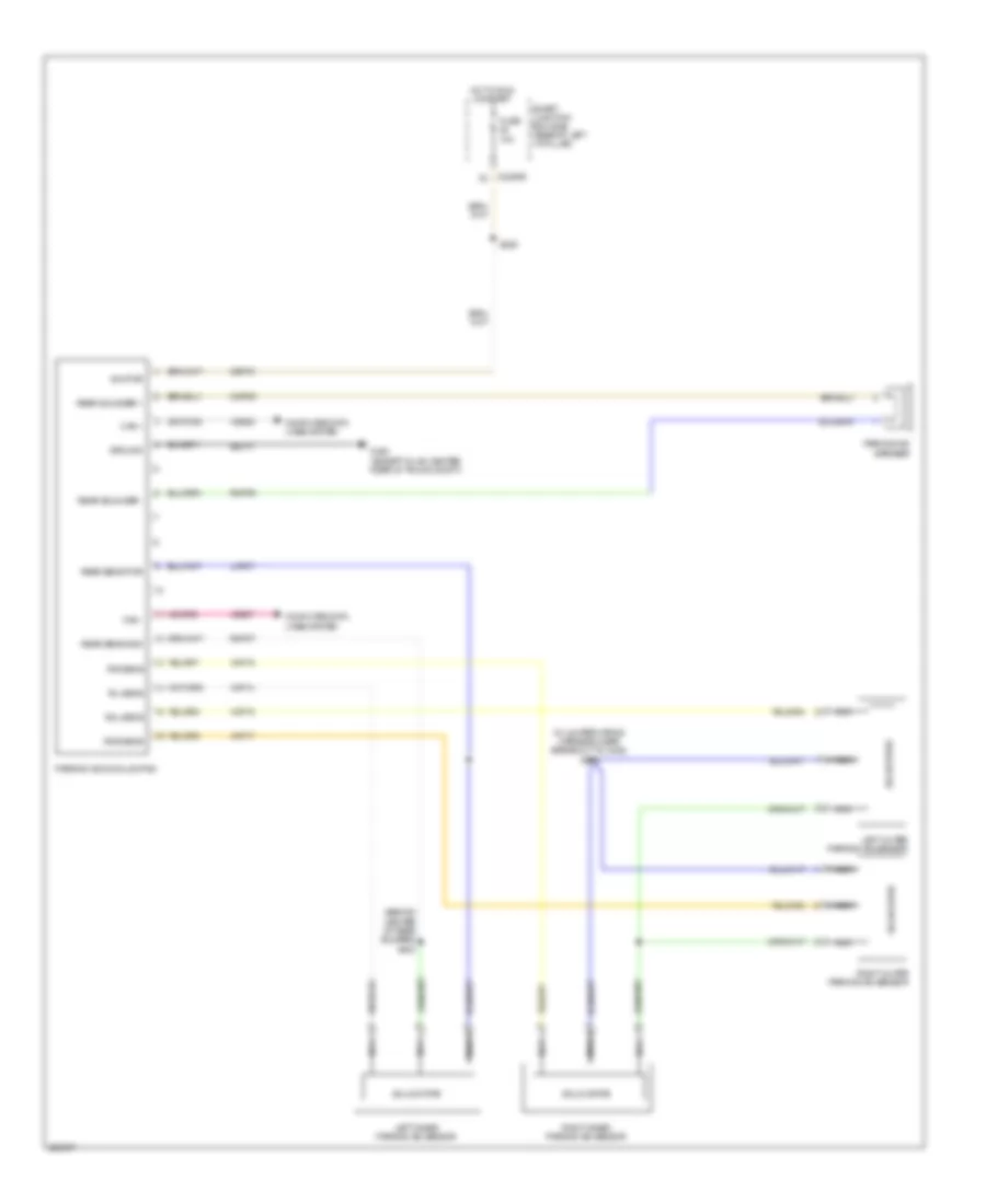
Instrument Illumination Wiring Diagram for Ford Fusion S 2008
List of elements for Instrument Illumination Wiring Diagram for Ford Fusion S 2008:
- (behind air bag, in steering wheel) g204
- (center of left floor pan) g300
- (in main harness, near breakout to g201) s233
- (in main harness, near breakout to smart junction box (sjb)) s230
- (left side of dash) g202
- Ambient lighting switch
- Auto
- Auto- lamp on
- Back- lighting
- Back- lighting bulb
- Backlighting
- C218a
- C218b
- C2280d
- C2357a
- C535a
- C535b
- Clock (fusion/milan)
- Clock (mkz)
- Clock- spring
- Dimmer switch
- Dome demand
- Driver side door lock switch
- Floor shifter (fusion/milan)
- Floor shifter (mkz)
- Fog ind
- Fog- lamps on
- G202 (left side of dash)
- G203 (base of right "a" pillar)
- Gnd
- Hazard/ pad traction switch
- Head lamp off
- Hvac emtc
- Illum
- Led sw bklgt
- Left rear window control switch
- Left steering wheel switch
- Low
- Low beam req
- Luggage compartment lid release switch
- Main light switch
- Master window control switch
- Memory set switch
- Message center switch
- Off
- Panel dim gnd
- Panel dimming
- Park
- Park lamps on
- Passenger side door lock switch
- Passenger side window control switch
- Right rear window control switch
- Right steering wheel switch
- S200 (near breakout to right steering wheel switch)
- S203
- S339 (in body main harness, near breakout to smart junction box (sjb))
- S368
- S500
- S502 (at drivers door lock switch)
- S601
- S605 (near breakout to passenger side door lock switch)
- Smart junction box (sjb) (base of left "a" pillar)
NAVIGATION
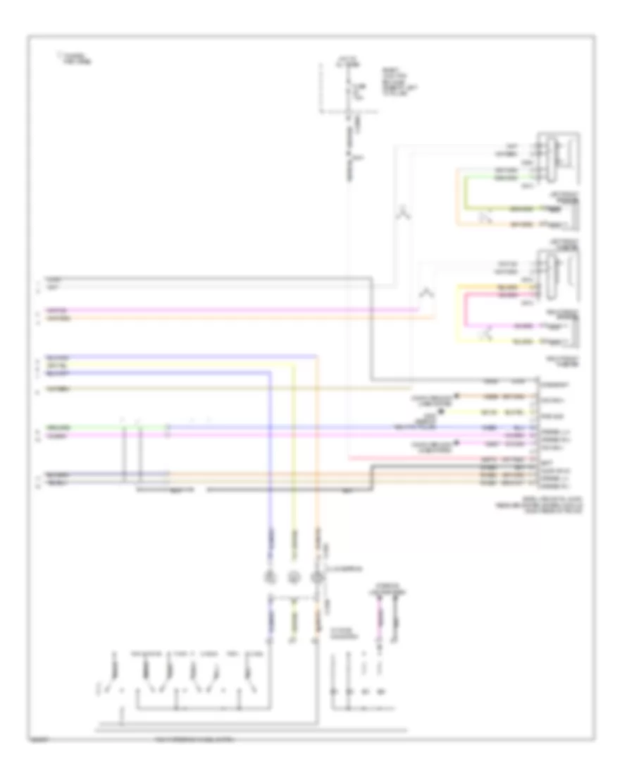
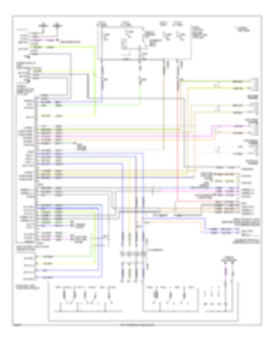
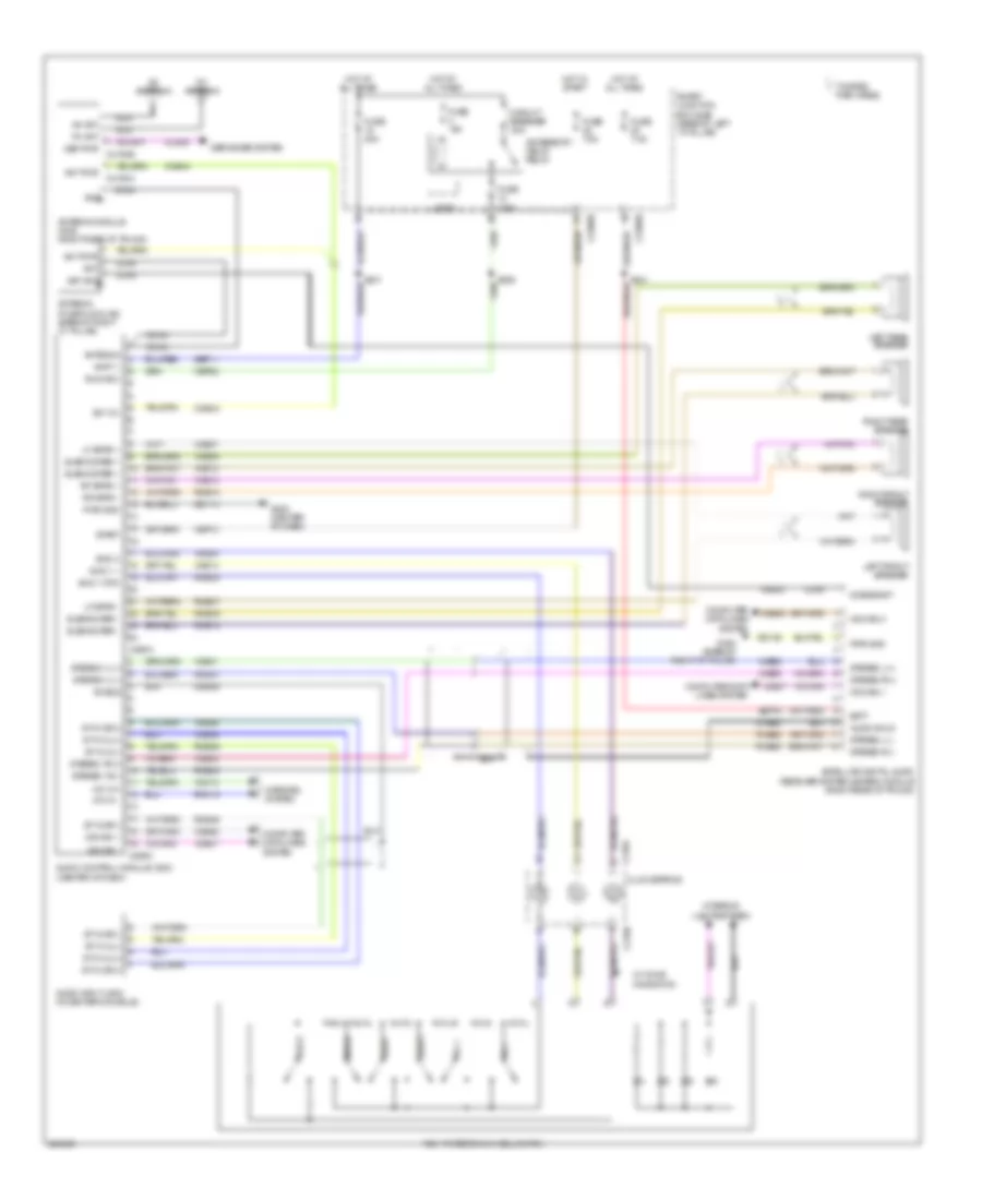
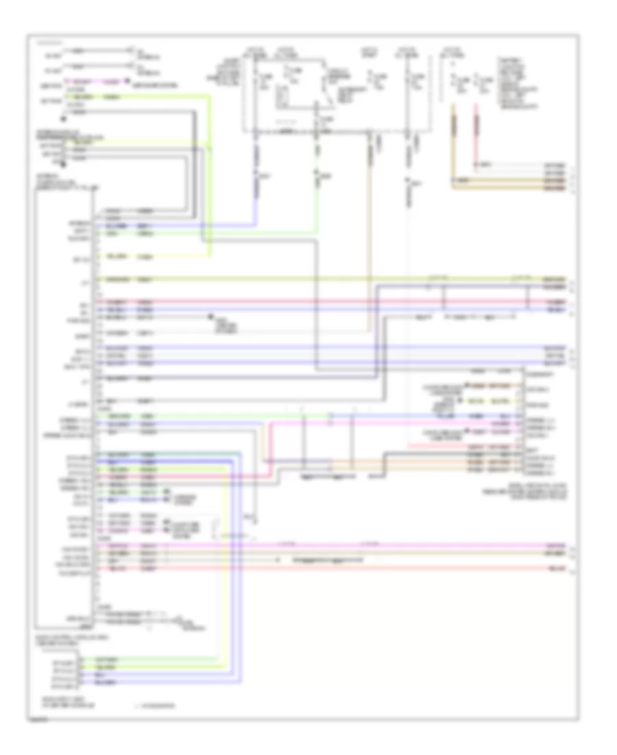
Navigation Wiring Diagram (1 of 2) for Ford Fusion S 2008
List of elements for Navigation Wiring Diagram (1 of 2) for Ford Fusion S 2008:
- Accessory delay relay
- Am ant
- Am antenna
- Ant
- Ant pwr
- Ant pwr c4194a
- Antenna
- Antenna (fusion & milan) (base of right "c" pillar)
- Antenna module (mkz: right rear of trunk)
- Audio control module (acm) (center of dash)
- Audio input jack (in center console)
- Audio shld
- Batt
- Batt +
- Battery junction box (bjb) (2.3l: left side of engine compt) (3.0l: left front of engine compt)
- C2280b
- C2280e
- C240a
- C240c
- C240d
- Cbp02
- Cbp13
- Circuit breaker 30a
- Cls38
- Cme27
- Cme44
- Coax
- Computer data lines system
- Dcbias/ant
- Def pwr c4194b
- Defogger system
- Dme17
- Dme45
- Dme52
- Dmn07
- Fm ant
- Fm antenna
- Fuse 15a
- Fuse 20a
- Fuse 7.5a
- G200 (center of dash)
- G402 (base of right "c" pillar)
- Gd114
- Gd146
- Gps
- Gps antenna
- Gps shld
- Hot at all times
- Hot in start
- Lf +
- Lf -
- Lf spkr -
- Logic
- Mic in +
- Mic in -
- Mirrors system
- Ms can +
- Ms can -
- Ms can(+)
- Ms can(-)
- Nav shld gnd
- Nav voice +
- Nav voice -
- Nca
- Pigtail wires
- Pwr gnd
- Rf +
- Rf -
- Rme24
- Rme41
- Rme42
- Rme45
- Rme46
- Rme52
- Rme53
- Rmm13
- Rmn14
- Run/acc
- S226
- S231
- S341
- S402
- S403
- Sat ant
- Satellite digital audio receiver system (sdars) module (right rear of trunk)
- Sbp11
- Sbp15
- Smart junction box (sjb) (base of left "a" pillar)
- St in 2l(+)
- St in 2l(-)
- St in 2r(+)
- St in 2r(-)
- Start
- Stereo 1l(+)
- Stereo 1l(-)
- Stereo 1r(+)
- Stereo 1r(-)
- Stereo audio shld
- Stereo l(+)
- Stereo l(-)
- Stereo r(+)
- Stereo r(-)
- Sw 12v
- Swc 1 +
- Swc 1 rtn
- Swc 2
- Thx dsp clip
- Vdb06
- Vdb07
- Vme14
- Vme35
- Vme41
- Vme42
- Vme43
- Vme45
- Vme46
- Vme52
- Vme54
- Vmm13
- Vmn14
- W/ navigation
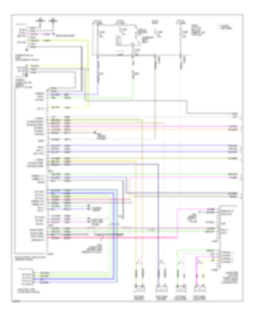
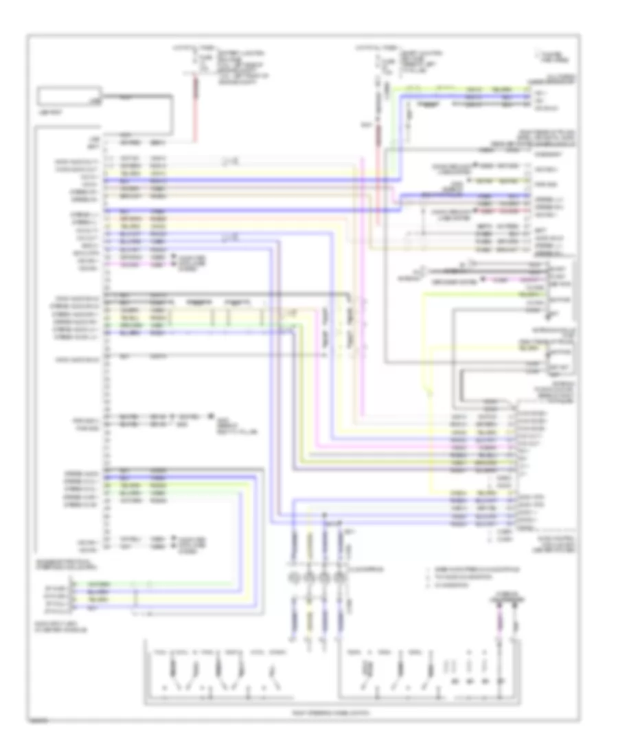
Navigation Wiring Diagram (2 of 2) for Ford Fusion S 2008
List of elements for Navigation Wiring Diagram (2 of 2) for Ford Fusion S 2008:
- Audio enable
- Audio in left +
- Audio in left -
- Audio in right +
- Audio in right -
- C218a
- C218b
- C4326a
- C4326b
- C4326c
- Center (hf) spkr +
- Center (hf) spkr -
- Center tweeter
- Clockspring
- Cme27
- Computer data lines system
- Digital signal procssiong (dsp) module (right rear of trunk compt)
- G402 (base of right "c" pillar)
- Gd148
- Gnd1
- Gnd2
- Gnd3
- Instrument panel speaker
- Interior lights system
- Left front speaker
- Left front tweeter
- Left mid
- Left rear speaker
- Left thx subwoofer speaker
- Lf door spkr +
- Lf door spkr -
- Lf twtr spkr +
- Lf twtr spkr -
- Lh csa spkr +
- Lh csa spkr -
- Lr door spkr +
- Lr door spkr -
- Lr subwoofer spkr +
- Lr subwoofer spkr -
- Media
- Ms can +
- Ms can -
- Nav in +
- Nav in -
- Nca
- Rear center spkr +
- Rear center spkr -
- Rear center thx speaker
- Rf door spkr +
- Rf door spkr -
- Rf twtr spkr +
- Rf twtr spkr -
- Rh csa spkr +
- Rh csa spkr -
- Right front speaker
- Right front tweeter
- Right mid
- Right rear speaker
- Right steering wheel switch
- Right thx subwoofer speaker
- Rme01
- Rme02
- Rme06
- Rme07
- Rme08
- Rme09
- Rme10
- Rme11
- Rme12
- Rme28
- Rme29
- Rme30
- Rme41
- Rme42
- Rmn14
- Rr door spkr +
- Rr door spkr -
- Rr subwoofer spkr +
- Rr subwoofer spkr -
- Sbb20
- Sbb21
- Seek +
- Seek -
- Thx audio
- Twisted pair wires
- Vbatt1
- Vbatt2
- Vbatt3
- Vbatt4
- Vdb06
- Vdb07
- Vme01
- Vme02
- Vme06
- Vme07
- Vme08
- Vme09
- Vme10
- Vme11
- Vme12
- Vme28
- Vme29
- Vme30
- Vme41
- Vme42
- Vmn14
- Voice
- Vol +
- Vol -
- W/ navigation
- W/ voice navigation
Parking Assistant Wiring Diagram for Ford Fusion S 2008
List of elements for Parking Assistant Wiring Diagram for Ford Fusion S 2008:
- (behind center of rear bumper) s423
- (in jumper wiring harness, near breakout to c408) s422
- C2280e
- Can +
- Can -
- Cbp19
- Cmp09
- Computer data lines system
- Fuse 10a
- G400 (except milan: center rear of trunk compt)
- Gd171
- Ground
- Hot in run or start
- Ign pwr
- Left inner parking aid sensor
- Left outer parking aid sensor
- Lmp07
- Nca
- Parking aid module (pam)
- Parking aid speaker
- Rear sens gnd
- Rear sens pwr
- Rear sounder +
- Rear sounder -
- Right inner parking aid sensor
- Right outer parking aid sensor
- Ril sens
- Rir sens
- Rmp07
- Rmp09
- Rol sens
- Ror sens
- S329
- Smart junction box (sjb) (base of left "a" pillar)
- Solid state
- Vdb06
- Vdb07
- Vmp14
- Vmp15
- Vmp16
- Vmp17
POWER DISTRIBUTION
Power Distribution Wiring Diagram (1 of 3) for Ford Fusion S 2008
List of elements for Power Distribution Wiring Diagram (1 of 3) for Ford Fusion S 2008:
- (2.3l: left side of engine compt) (3.0l: left front of engine compt) battery junction box (bjb)
- (abs) module
- (base of left "a" pillar) smart junction box (sjb)
- (except 3.5l) (3.5l)
- (except 3.5l) s209
- (except 3.5l: near breakout to generator) s100
- (in main harness, near breakout to g201)
- (in main harness, near breakout to main light switch) s231
- (near breakout to amplifier) s402
- (near breakout to amplifier) s403
- 20a
- 7.5a
- Accessory protocol interface module (apim) (w/ sync)
- Anti-lock brake system
- Audio control module (acm)
- Audio digital signal
- Base/ audiophile audio
- Battery
- Battery junction box (bjb) (2.3l: left side of engine compt) (3.0l: left front of engine compt)
- Brake pedal position switch
- C175b
- C2280a
- C2280b
- C2280e
- C2280f
- C228a
- C2352a
- C2356a
- C2357a
- C240a
- C290a
- C3299a
- C3299c
- C4326b
- C466a
- Clock
- Data link connector (dlc)
- Defrost relay
- Driver seat module (dsm)
- Driver seat module (w/ memory)
- Driver side front seat control switch
- Dual climate controlled seat module (dcsm)
- Dual zone a/c
- Engine cooling fan motor
- Evap canister vent control solenoid
- Fnr5 transmission
- Fuse
- Fuse 10a
- Fuse 15a
- Fuse 20a
- Fuse 20a 30a
- Fuse 30a
- Fuse 40a
- Fuse 60a
- Fuse 60a 80a
- Fuse 7.5a
- Fusion/milan
- G300 (center of left floor pan)
- Generator
- Heated seat module (if equipped)
- Hvac datc
- Hvac eatc
- Hvac emtc
- Instrument cluster (ic)
- Left front power window motor
- Logic
- Manual a/c
- Mkz
- One touch integrated start diode
- Passenger side front seat control switch
- Power point
- Powertrain control module (pcm)
- Processing (dsp) module
- Red
- Right front power window motor
- Roof opening panel module
- S101 (except 3.5l: near breakout to generator)
- S151 (3.5l)
- S229
- S302 (near breakout to ocsm module)
- Single zone a/c
- Smart junction box (sjb) (base of left "a" pillar)
- Starter motor
- Subwoofer amplifier (audiophile audio)
- Thx audio/ navigation
- To c339) s309
- To fuse 20 smart junction box (diagram 3 of 3)
- To fuse 3 battery junction box (diagram 2 of 3)
- To ignition switch (diagram 2 of 3)
- W/ 6-way driver seat
- W/ 6-way passenger seat
- W/ 8-way driver seat w/o memory
- W/ 8-way passenger seat
- W/ one touch start
- Washer pump relay
Power Distribution Wiring Diagram (2 of 3) for Ford Fusion S 2008
List of elements for Power Distribution Wiring Diagram (2 of 3) for Ford Fusion S 2008:
- (abs) module
- (acm)
- (except 3.5l) s211
- (near breakout to battery junction box (bjb))
- (near breakout to battery junction box (bjb)) s128
- (near breakout to data link connector) s227
- (ocsm)
- (pam)
- 4x4 control module
- 6 speed transmission
- A/c clutch relay
- Acc
- Anti-lock brake system
- Audio control module
- Awf21
- Base/ premium/ audiophile
- Battery junction box (bjb) (2.3l: left side of engine compt) (3.0l: left front of engine compt)
- Blower motor relay
- C2280a
- C2280b
- C2280e
- C2280f
- C228a
- C2356a
- C2357a
- C240a
- C290a
- C310a
- Courtesy relay (fusion/ milan)
- Demand lamp/ battery saver relay
- Dual zone a/c
- Floor shifter
- Fnr5
- Fnr5 relay
- Fog lamp relay
- From battery junction box (diagram 1 of 3)
- From battery junction box (diagram 1 of 3) b
- From fuse 2 battery junction box (diagram 2 of 3)
- From fuse 6 battery junction box (diagram 1 of 3)
- From powertrain control module (diagram 1 of 3) k
- Fuel pump relay
- Fuse 10a
- Fuse 15a
- Fuse 20a
- Fuse 30a
- Fuse 40a
- Fuse 60a
- Fuse 7.5a
- Hazard/ pad/ traction switch
- Heated seat module
- Hi beam relay
- Horn relay
- Hvac datc
- Hvac eatc
- Hvac emtc
- Ignition switch
- Inhibit
- Instrument cluster (ic)
- Key in ignition switch
- Left high intensity discharge headlamp relay
- Lock
- Manual a/c
- Module
- Occupant classification system module
- Off
- Park lamp relay
- Parking aid
- Pcm power relay
- Red
- Restraints control module (rcm)
- Reversing lamps relay (w/ auto trans)
- Right high intensity discharge headlamp relay
- Run
- S143
- S152 (3.5l)
- S329 (near breakout to g300)
- Secondary air pump relay
- Single zone a/c
- Smart junction box (sjb) (base of left "a" pillar)
- Start
- Starter relay
- Thx audio/ navigation
- To accessory delay relay smart junction box (diagram 3 of 3)
- To fuse 10 battery junction box (diagram 2 of 3)
- To fuse 23 smart junction box (diagram 3 of 3)
- To fuse 26 smart junction box (diagram 3 of 3)
- Wiper park relay
- Wiper run/park relay
Power Distribution Wiring Diagram (3 of 3) for Ford Fusion S 2008
List of elements for Power Distribution Wiring Diagram (3 of 3) for Ford Fusion S 2008:
- (3.5l: near breakout to engine cooling fan motor) (except 3.5l: near breakout to battery junction box (bjb))
- (acm)
- (diagram 1 of 3)
- (near ambient lighting module) s369
- (near breakout to c510) s341
- (near breakout to c901) s900
- (near breakout to g300) s328
- (sdars) module
- 4x4 control module
- 6 speed transmission
- Accessory delay relay
- All lock relay
- All unlock relay
- Ambient lighting module
- Ambient lighting switch
- Audio control module
- Base/premium/audiophile
- Battery junction box (bjb) (2.3l: left side of engine compt) (3.0l: left front of engine compt)
- Blower motor relay
- C175b
- C2280a
- C2280b
- C2280e
- C240a
- C290a
- C504a
- C535a
- C537a
- C568b
- Circuit breaker 30a
- Driver door module (ddm)
- Driver side door lock switch (fusion/milan & w/o memory)
- Driver unlock relay
- Electro- chromatic inside mirror unit
- Exterior rear view mirror switch
- Fnr5 relay
- From fuse 13 smart junction box c
- From fuse 24 smart junction box (diagram 3 of 3)
- From fuse 3 smart h junction box (diagram 2 of 3)
- From ignition switch (diagram 2 of 3)
- From splice s226 (diagram 3 of 3)
- Front cigar lighter (fusion/ milan)
- Front cigar lighter (mkz)
- Fuel pump relay
- Fuse 15a
- Fuse 20a
- Fuse 7.5a
- Fusion/milan & early prodution
- Fusion/milan & late prodution
- G201 (center of of dash)
- G300 (center of left floor pan)
- Instrument cluster (ic)
- Logic
- Luggage compartment lid release relay
- Master window control switch
- Mkz
- Multimedia inside mirror unit
- Nca
- Passenger side door lock switch (fusion/ milan)
- Passive anti-theft transceiver
- Pcm power diode
- Powertrain control module (pcm)
- Red
- Reversing lamps switch
- Roof opening panel module
- Roof opening panel switch
- S131
- S226 (near breakout to data link connector)
- Satellite digital audio receiver system
- Smart junction box (sjb) (base of left "a" pillar)
- Thx audio/navigation
- To cigar lighter (diagram 3 of 3)
- Wiper park relay
- Wiper run/park relay
POWER DOOR LOCKS
Power Door Locks Wiring Diagram, with Memory (1 of 2) for Ford Fusion S 2008
List of elements for Power Door Locks Wiring Diagram, with Memory (1 of 2) for Ford Fusion S 2008:
- (in power seats harness, near breakout to smart junction box (sjb)) s324
- (in power seats harness, near breakout to smart junction box (sjb)) s325
- Battery junction box (bjb) (2.3l: left side of engine compt) (3.0l: left front of engine compt)
- C2280c
- C2280e
- C2280f
- C568b
- Cpl02
- Cpl28
- Cpl42
- Cpl43
- Cpl51
- Driver side door lock switch
- Driver's door module (front of driver's door)
- Fuse 15a
- Fuse 60a
- G203 (base of right "a" pillar)
- G300 (center of left floor pan)
- Hot at all times
- Interior lights system
- Left rear door lock actuator (in left rear door)
- Lock
- Lock all relay
- Logic
- Lr door ajar
- Pass door ajar
- Passenger side door lock switch
- Reset
- Right front door lock actuator (in right front door)
- Right rear door lock actuator (in right rear door)
- Rr door ajar
- S500
- S601
- Smart junction box (sjb) (base of left "a" pillar)
- Trim lock
- Trim unlock
- Unlock
- Unlock all relay
Power Door Locks Wiring Diagram, with Memory (2 of 2) for Ford Fusion S 2008
List of elements for Power Door Locks Wiring Diagram, with Memory (2 of 2) for Ford Fusion S 2008:
- (3.5l: left front of engine compt)
- Anti-theft hood switch (except 3.5l: left front radiator support)
- C2280a
- C2280c
- Disarm request
- Driver door ajar
- G104 (2.3l: in front of right strut tower) (3.0l: right front of engine compt) (3.5l: right side of engine compt)
- G300 (center of left floor pan)
- G400 (fusion, mkz: center rear of trunk compartment)
- Hood ajar
- Keypad a
- Keypad b
- Keypad c
- Keypad illum
- Keypad switch assembly
- Left front door lock actuator (in driver's door)
- Logic
- Luggage compartment disarm switch (fusion, milan: (center rear of luggage compartment)
- Reset
- S500
- Set
- Smart junction box (sjb) (base of left "a" pillar)
Power Door Locks Wiring Diagram, without Memory (1 of 2) for Ford Fusion S 2008
List of elements for Power Door Locks Wiring Diagram, without Memory (1 of 2) for Ford Fusion S 2008:
- (in body main harness, near breakout to smart junction box (sjb))
- (in body main harness, near breakout to smart junction box (sjb)) s347
- (in power seats harness, near breakout to smart junction box (sjb)) s324
- (in power seats harness, near breakout to smart junction box (sjb)) s325
- Accessory delay relay
- C2280c
- C2280e
- Circuit breaker 30a
- Driver side door lock switch
- Fuse 15a
- Fuse 7.5a
- Fusion/ milan
- G203 (base of right "a" pillar)
- G300 (center of left floor pan)
- Hot at all times
- Interior lights system
- Left rear door lock actuator (in left rear door)
- Lock
- Lock all relay
- Logic
- Lr door ajar
- Mkz
- Pass door ajar
- Passenger side door lock switch
- Right front door lock actuator (in right front door)
- Right rear door lock actuator (in right rear door)
- Rr door ajar
- S328
- S342
- S500
- S601
- Smart junction box (sjb) (base of left "a" pillar)
- Trim lock
- Trim unlock
- Unlock
- Unlock all relay
- Unlock driver relay
Power Door Locks Wiring Diagram, without Memory (2 of 2) for Ford Fusion S 2008
List of elements for Power Door Locks Wiring Diagram, without Memory (2 of 2) for Ford Fusion S 2008:
- Anti-theft hood switch (except 3.5l: left front radiator support) (3.5l: left front of engine compt)
- C2280a
- C2280c
- Disarm request
- Door reset sw
- Driver door ajar
- G104 (2.3l: in front of right strut tower) (3.0l: right front of engine compt) (3.5l: right side of engine compt)
- G300 (center of left floor pan)
- G400 (fusion, mkz: center rear of trunk compartment)
- Hood ajar
- Keypad a
- Keypad b
- Keypad c
- Keypad illum
- Keypad switch assembly
- Left front door lock actuator (in driver's door)
- Logic
- Luggage compartment disarm switch (2.3l, 3.0l: center rear of luggage compartment)
- Reset
- S500
- Set
- Smart junction box (sjb) (base of left "a" pillar)
POWER MIRRORS
Electrochromic Mirror Wiring Diagram, with Navigation for Ford Fusion S 2008
List of elements for Electrochromic Mirror Wiring Diagram, with Navigation for Ford Fusion S 2008:
- Audio control module (acm)
- C2280b
- C2280e
- Cbp02
- Cbp12
- Compass+
- Compass-
- Del/accy
- Dmm13
- Ec drive
- Ec gnd
- Fuse 10a
- Fuse 7.5a
- G203 (base of right "a" pillar)
- Gd139
- Gnd
- Hot in run or acc
- Hot w/ accessory delay relay energized
- Hot w/ reversing lamps relay energized
- Instrument cluster (ic)
- Left side exterior rear view mirror (w/ memory)
- Lrd12
- Mic +
- Mic -
- Mic in+
- Mic in-
- Mic shield
- Multimedia inside mirror unit
- Nca
- Reverse
- Rmm13
- Rrd12
- Rs485(+)
- Rs485(-)
- Run/acc
- S412
- S900
- S902
- Smart junction box (sjb) (base of left "a" pillar)
- Vmc30
- Vmc31
- Vmm13
Electrochromic Mirror Wiring Diagram, without Navigation for Ford Fusion S 2008
List of elements for Electrochromic Mirror Wiring Diagram, without Navigation for Ford Fusion S 2008:
- (base of right "a" pillar)
- C2280e
- Cbp02
- Cbp12
- Del/accy
- Ec drive
- Ec gnd
- Electrochromatic inside mirror unit (in roof harness)
- Fuse 10a
- Fuse 7.5a
- G203
- Gd139
- Gnd
- Hot w/ accessory delay relay energized
- Hot w/ reversing lamps relay energized
- Left side exterior rear view mirror (w/ memory)
- Lrd12
- Reverse
- Rrd12
- S412
- S900
- S902
- Smart junction box (sjb) (base of left "a" pillar)
Heated Mirrors Wiring Diagram for Ford Fusion S 2008
List of elements for Heated Mirrors Wiring Diagram for Ford Fusion S 2008:
- (base of right "a" pillar) g203
- (center of left floor pan) g300
- C2280e
- Defogger system
- Down
- Exterior rear view mirror switch
- Fuse 7.5a
- G300 (center of left floor pan)
- Hot at all times
- Interior lights system
- Left
- Left side exterior rear view mirror
- Left/ right
- Left/ right m
- Right
- Right side exterior rear view mirror
- Smart junction box (sjb) (base of left "a" pillar)
- Up/ down
- Up/ down m
Power Mirrors Wiring Diagram for Ford Fusion S 2008
List of elements for Power Mirrors Wiring Diagram for Ford Fusion S 2008:
- (in window regulator harness) s501
- C2280e
- Down
- Exterior rear view mirror switch
- Fuse 7.5a
- G300 (center of left floor pan)
- Hot at all times
- Left
- Left side exterior rear view mirror
- Left/ right
- Left/ right m
- Right
- Right side exterior rear view mirror
- Smart junction box (sjb) (base of left "a" pillar)
- Up/ down
- Up/ down m
POWER SEATS
Heated Seats Wiring Diagram for Ford Fusion S 2008
List of elements for Heated Seats Wiring Diagram for Ford Fusion S 2008:
- (in power seat motor assembly harness, near breakout to ocsm module)
- Battery junction box (bjb) (3.0l: left front of engine compartment) (except 3.0l: left side of engine compartment)
- C2280e
- C228b
- Cbp19
- Chs02
- Chs04
- Chs07
- Chs09
- Chs13
- Chs14
- Chs29
- Chs30
- Driver hs req
- Driver hslo
- Drv batt
- Drv heater feed
- Drv hi led ind
- Drv high/low/off
- Drv low led ind
- Drv ntc sense
- Electronic automatic temperature control (eatc) module (center of dash)
- Fuse 10a
- Fuse 20a
- G203 (base of right "a" pillar)
- G300 (center of left floor pan)
- Gd139
- Gnd
- Heated seat module (under seat bottom)
- Hot at all times
- Hot in start or run
- Left front seat back heater (in driver's seat back)
- Left front seat cushion heater (in seat cushion)
- Nca
- Ntc return
- Pass batt
- Pass heater feed
- Pass hi led ind
- Pass high/low/off
- Pass hs req
- Pass hshi
- Pass hslo
- Pass low led ind
- Pass ntc sense
- Rhs05
- Right front seat back heater (right side of front passenger's seat back)
- Right front seat cushion heater (right side of front passenger's seat bottom)
- Run/start
- S301
- S302
- S303
- S304
- S329
- Sbb11
- Smart junction box (sjb) (base of left "a" pillar)
- Vhs26
- Vhs27
Power Seat Wiring Diagram, 6-Way Driver Seat for Ford Fusion S 2008
List of elements for Power Seat Wiring Diagram, 6-Way Driver Seat for Ford Fusion S 2008:
- Aft
- Base
- Battery junction box (bjb) (3.0l: left front of engine compt) (except 3.0l: left side of engine compt)
- Driver side front seat adjust switch
- Fore
- Front
- Front up/down
- Fuse 30a
- Fwd/back
- G300 (center of left floor pan)
- Hot at all times
- Left power seat motor assembly (under seat bottom)
- Rear
- Rear up/down
- S304
- Tilt down
- Tilt up
Power Seat Wiring Diagram, 6-Way passenger Seat for Ford Fusion S 2008
List of elements for Power Seat Wiring Diagram, 6-Way passenger Seat for Ford Fusion S 2008:
- Aft
- Base
- Battery junction box (bjb) (3.0l: left front of engine compt) (except 3.0l: left side of engine compt)
- Fore
- Front
- Front up/down
- Fuse 30a
- Fwd/back
- G203 (base of right "a" pillar)
- Hot at all times
- Passenger side front seat adjust switch
- Rear
- Rear up/down
- Right power seat motor assembly (under seat bottom)
- S303
- Tilt down
- Tilt up
Power Seat Wiring Diagram, 8-Way Driver Seat for Ford Fusion S 2008
List of elements for Power Seat Wiring Diagram, 8-Way Driver Seat for Ford Fusion S 2008:
- Aft
- Base
- Battery junction box (bjb) (3.0l: left front of engine compt) (except 3.0l: left side of engine compt)
- Down
- Driver seat recliner motor (in seat back)
- Driver side front seat adjust switch
- Fore
- Front
- Front up/down
- Fuse 30a
- Fwd/back
- G300 (center of left floor pan)
- Hot at all times
- Left power seat motor assembly (under seat bottom)
- Rear
- Rear up/down
- Recline
- S304
- Tilt down
- Tilt up
Power Seat Wiring Diagram, 8-Way Passenger Seat for Ford Fusion S 2008
List of elements for Power Seat Wiring Diagram, 8-Way Passenger Seat for Ford Fusion S 2008:
- (base of right "a" pillar) g203
- Aft
- Base
- Battery junction box (bjb) (3.0l: left front of engine compt) (except 3.0l: left side of engine compt)
- Down
- Fore
- Front
- Front passenger seat lumbar motor (right side of seat)
- Front passenger seat recliner motor (right side of seat)
- Front up/down
- Fuse 30a
- Fwd/back
- Hot at all times
- Lumbar
- Out
- Passenger side front seat adjust switch
- Rear
- Rear up/down
- Recline
- Right power seat motor assembly (under seat bottom)
- S303
- Tilt down
- Tilt up
POWER TOP/SUNROOF
Power Top/Sunroof Wiring Diagram for Ford Fusion S 2008
List of elements for Power Top/Sunroof Wiring Diagram for Ford Fusion S 2008:
- Accessory delay relay
- Auto sig
- Bat
- Battery junction box (bjb) (3.0l: left front of engine compt) (2.3l: left side of engine compt)
- C2280c
- C2280e
- Cbp02
- Circuit breaker 30a
- Close sig
- Cpr31
- Cpr38
- Cpr39
- Cpr40
- Cpw01
- Fuse 15a
- Fuse 20a
- Fuse 7.5a
- G203 (base of right "a" pillar)
- Gd139
- Gnd
- Go cmd
- Hot at all times
- Logic
- Mkz
- Open sig
- Power windows system
- Pwm
- Red
- Roof opening panel module (in roof harness)
- Roof opening panel switch
- S340 (in body main harness, near breakout to park brake switch)
- S900
- S902
- Sbb33
- Smart junction box (sjb) (base of left "a" pillar)
- Sw output
- Sw rtn
POWER WINDOWS
Power Windows Wiring Diagram for Ford Fusion S 2008
List of elements for Power Windows Wiring Diagram for Ford Fusion S 2008:
- (in power seats harness, near breakout to smart junction box (sjb))
- Accessory delay relay
- Auto dn
- C2280e
- C504a
- C504b
- C537a
- C537b
- Circuit breaker 30a
- Early production
- Fuse 3 15a
- G300 (center of left floor pan)
- Hot at all times
- Late production
- Left front
- Left front power window motor (in driver's door)
- Left rear
- Left rear power window motor (in left rear door)
- Left rear window control switch
- Lock out
- Logic
- Master window control switch
- Passenger side window control switch
- Right front
- Right front power window motor (in right front door)
- Right rear
- Right rear power window motor (in right rear door)
- Right rear window control switch
- S321
- S326 (in body main harness, near breakout to c510)
- S327 (in body main harness, near breakout to c510)
- S500
- Smart junction box (sjb) (base of left "a" pillar)
RADIO
Audiophile Sound Radio Wiring Diagram, with SYNC (1 of 2) for Ford Fusion S 2008
List of elements for Audiophile Sound Radio Wiring Diagram, with SYNC (1 of 2) for Ford Fusion S 2008:
- Accessory delay relay
- Am ant
- Am antenna
- Ant
- Ant pwr
- Ant pwr c4194a
- Antenna
- Antenna (fusion & milan) (base of right "c" pillar)
- Antenna module (mkz) (right rear of trunk)
- Audio control module (acm) (center of dash)
- Audio input jack (in center console)
- Audio shield
- Batt +
- C2280b
- C2280e
- C290a
- C290c
- C290d
- C466a
- C466b
- Cbp02
- Cbp13
- Channel 1 +
- Channel 1 -
- Channel 2 +
- Channel 2 -
- Circuit breaker 30a
- Cls38
- Cme44
- Coax
- Computer data lines system
- Def pwr c4194b
- Defogger system
- Dme22
- Dme45
- Enable clip
- Enable/clip
- Fm ant
- Fm antenna
- Fuse 15a
- Fuse 20a
- Fuse 7.5a
- G200 (center of dash)
- G402 (base of right "c" pillar)
- Gd114
- Gnd audio
- Hot at all times
- Hot in start
- Input +
- Input -
- Left rear speaker
- Left rear subwoofer
- Lf spkr +
- Lf spkr -
- Logic
- Lr subwoofer +
- Lr subwoofer -
- Mic in +
- Mic in -
- Mirrors system
- Ms can +
- Ms can -
- Nca
- Pair wires
- Pwr
- Pwr gnd
- Rf spkr +
- Rf spkr -
- Right rear speaker
- Right rear subwoofer
- Rme07
- Rme09
- Rme10
- Rme12
- Rme22
- Rme24
- Rme41
- Rme42
- Rme45
- Rme46
- Rmm13
- Rr subwoofer +
- Rr subwoofer -
- Run/acc
- S226
- S231
- S242 (in body main harness, near breakout to c237)
- Sat ant
- Sbp11
- Shield
- Smart junction box (sjb) (base of left "a" pillar)
- Sme23
- St in 2l(+)
- St in 2l(-)
- St in 2r(+)
- St in 2r(-)
- Start
- Stereo 1l(+)
- Stereo 1l(-)
- Stereo 1r(+)
- Stereo 1r(-)
- Subwoofer +
- Subwoofer -
- Subwoofer amplifier (fusion, milan: right side of luggage compt)
- Sw 12v
- Swc 1 +
- Swc 1 rtn
- Swc 2 +
- Swc 2 -
- Twisted
- Vdb06
- Vdb07
- Vme07
- Vme09
- Vme10
- Vme12
- Vme14
- Vme22
- Vme41
- Vme42
- Vme45
- Vme46
- Vme54
- Vmm13
Audiophile Sound Radio Wiring Diagram, with SYNC (2 of 2) for Ford Fusion S 2008
List of elements for Audiophile Sound Radio Wiring Diagram, with SYNC (2 of 2) for Ford Fusion S 2008:
- Accessory protocol interface module (apim)
- Audio shld
- Batt
- C218a
- C218b
- C2280e
- C513
- C523
- C612
- C613
- Clockspring
- Coax
- Computer data lines system
- Dcbias/ant
- Dme52
- End
- Fuse 7.5a
- G402 (base of right "c" pillar)
- Gd146
- Hot at all times
- Interior lights system
- Left front speaker
- Left front tweeter
- Media
- Ms can(+)
- Ms can(-)
- Nca
- Pair wires
- Push voice
- Pwr gnd
- Right front speaker
- Right front tweeter
- Right steering wheel switch
- Rme24
- Rme52
- Rme53
- S211
- S213
- S341
- Satellite digital audio receiver system (sdars) module (right rear of trunk)
- Sbp15
- Seek +
- Seek -
- Send
- Smart junction box (sjb) (base of left "a" pillar)
- Stereo l(+)
- Stereo l(-)
- Stereo r(+)
- Stereo r(-)
- Swc 2 +
- Swc 2 rtn
- Twisted
- Vdb06
- Vdb07
- Vme43
- Vme52
- Vme54
- Vol +
- Vol -
Audiophile Sound Radio Wiring Diagram, without SYNC (1 of 2) for Ford Fusion S 2008
List of elements for Audiophile Sound Radio Wiring Diagram, without SYNC (1 of 2) for Ford Fusion S 2008:
- Accessory delay relay
- Am ant
- Am antenna
- Ant
- Ant pwr
- Ant pwr c4194a
- Antenna
- Antenna (fusion & milan) (base of right "c" pillar)
- Antenna module (mkz) (right rear of trunk)
- Audio control module (acm) (center of dash)
- Audio input jack (in center console)
- Audio shield
- Batt +
- C2280b
- C2280e
- C290a
- C290c
- C290d
- C466a
- C466b
- Cbp02
- Cbp13
- Channel 1 +
- Channel 1 -
- Channel 2 +
- Channel 2 -
- Circuit breaker 30a
- Cls38
- Cme44
- Coax
- Computer data lines system
- Def pwr c4194b
- Defogger system
- Dme22
- Dme45
- Enable clip
- Enable/clip
- Fm ant
- Fm antenna
- Fuse 15a
- Fuse 20a
- Fuse 7.5a
- G200 (center of dash)
- G402 (base of right "c" pillar)
- Gd114
- Gnd audio
- Hot at all times
- Hot in start
- Input +
- Input -
- Left rear speaker
- Left rear subwoofer
- Lf spkr +
- Lf spkr -
- Logic
- Lr subwoofer +
- Lr subwoofer -
- Mic in +
- Mic in -
- Mirrors system
- Ms can +
- Ms can -
- Nca
- Pair wires
- Pwr
- Pwr gnd
- Rf spkr +
- Rf spkr -
- Right rear speaker
- Right rear subwoofer
- Rme07
- Rme09
- Rme10
- Rme12
- Rme22
- Rme24
- Rme41
- Rme42
- Rme45
- Rme46
- Rmm13
- Rr subwoofer +
- Rr subwoofer -
- Run/acc
- S226
- S231
- S242 (in body main harness, near breakout to c237)
- Sat ant
- Sbp11
- Shield
- Smart junction box (sjb) (base of left "a" pillar)
- Sme23
- St in 2l(+)
- St in 2l(-)
- St in 2r(+)
- St in 2r(-)
- Start
- Stereo 1l(+)
- Stereo 1l(-)
- Stereo 1r(+)
- Stereo 1r(-)
- Subwoofer +
- Subwoofer -
- Subwoofer amplifier (fusion, milan: right side of luggage compt)
- Sw 12v
- Swc 1 +
- Swc 1 rtn
- Swc 2
- Twisted
- Vdb06
- Vdb07
- Vme07
- Vme09
- Vme10
- Vme12
- Vme14
- Vme22
- Vme41
- Vme42
- Vme45
- Vme46
- Vme54
- Vmm13
Audiophile Sound Radio Wiring Diagram, without SYNC (2 of 2) for Ford Fusion S 2008
List of elements for Audiophile Sound Radio Wiring Diagram, without SYNC (2 of 2) for Ford Fusion S 2008:
- Audio shld
- Batt
- C218a
- C218b
- C2280e
- C513
- C523
- C612
- C613
- Clockspring
- Coax
- Computer data lines system
- Dcbias/ant
- Dme52
- Fuse 7.5a
- G402 (base of right "c" pillar)
- Gd146
- Hot at all times
- Interior lights system
- Left front speaker
- Left front tweeter
- Media
- Ms can(+)
- Ms can(-)
- Nca
- Pair wires
- Pwr gnd
- Right front speaker
- Right front tweeter
- Right steering wheel switch
- Rme52
- Rme53
- S341
- Satellite digital audio receiver system (sdars) module (right rear of trunk)
- Sbp15
- Seek +
- Seek -
- Smart junction box (sjb) (base of left "a" pillar)
- Stereo l(+)
- Stereo l(-)
- Stereo r(+)
- Stereo r(-)
- Twisted
- Vdb06
- Vdb07
- Vme43
- Vme52
- Voice
- Vol +
- Vol -
- W/ voice navigation
Base Radio Wiring Diagram, with SYNC for Ford Fusion S 2008
List of elements for Base Radio Wiring Diagram, with SYNC for Ford Fusion S 2008:
- Accessory delay relay
- Accessory protocol interface module (apim)
- Am ant
- Am antenna
- Ant
- Ant pwr
- Ant pwr c4194a
- Antenna
- Antenna (fusion & milan) (base of right "c" pillar)
- Antenna module (mkz) (right rear of trunk)
- Audio control module (acm) (center of dash)
- Audio input jack (in center console)
- Audio shld
- Batt
- Batt +
- C218a
- C218b
- C2280b
- C2280e
- C290a
- C290c
- Cbp02
- Cbp13
- Circuit breaker 30a
- Clockspring
- Cls38
- Cme44
- Coax
- Computer data lines system
- Dcbias/ant
- Def pwr c4194b
- Defogger system
- Dme45
- Dme52
- End
- Fm ant
- Fm antenna
- Fuse 15a
- Fuse 20a
- Fuse 7.5a
- G200 (center of dash)
- G402 (base of right "c" pillar)
- Gd114
- Gd146
- Hot at all times
- Hot in start
- Interior lights system
- Left front speaker
- Left rear speaker
- Lf spkr +
- Lf spkr -
- Logic
- Media
- Mic in +
- Mic in -
- Mirrors system
- Ms can +
- Ms can -
- Ms can(+)
- Ms can(-)
- Nca
- Pair wires
- Push voice
- Pwr gnd
- Rf spkr +
- Rf spkr -
- Right front speaker
- Right rear speaker
- Right steering wheel switch
- Rme07
- Rme09
- Rme10
- Rme12
- Rme24
- Rme41
- Rme42
- Rme45
- Rme46
- Rme52
- Rme53
- Rmm13
- Run/acc
- S211
- S213
- S226
- S231
- S341
- Sat ant
- Satellite digital audio receiver system (sdars) module (right rear of trunk)
- Sbp11
- Sbp15
- Seek +
- Seek -
- Send
- Shield
- Smart junction box (sjb) (base of left "a" pillar)
- St in 2l(+)
- St in 2l(-)
- St in 2r(+)
- St in 2r(-)
- Start
- Stereo 1l(+)
- Stereo 1l(-)
- Stereo 1r(+)
- Stereo 1r(-)
- Stereo l(+)
- Stereo l(-)
- Stereo r(+)
- Stereo r(-)
- Subwoofer +
- Subwoofer -
- Sw 12v
- Swc 1 +
- Swc 1 rtn
- Swc 2 +
- Swc 2 -
- Swc 2 rtn
- Twisted
- Vdb06
- Vdb07
- Vme07
- Vme09
- Vme10
- Vme12
- Vme14
- Vme41
- Vme42
- Vme43
- Vme45
- Vme46
- Vme52
- Vme53
- Vme54
- Vmm13
- Vol +
- Vol -
Base Radio Wiring Diagram, without SYNC for Ford Fusion S 2008
List of elements for Base Radio Wiring Diagram, without SYNC for Ford Fusion S 2008:
- Accessory delay relay
- Am ant
- Am antenna
- Ant
- Ant pwr
- Ant pwr c4194a
- Antenna
- Antenna (fusion & milan) (base of right "c" pillar)
- Antenna module (mkz) (right rear of trunk)
- Audio control module (acm) (center of dash)
- Audio input jack (in center console)
- Audio shld
- Batt
- Batt +
- C218a
- C218b
- C2280b
- C2280e
- C290a
- C290c
- Cbp02
- Cbp13
- Circuit breaker 30a
- Clockspring
- Cls38
- Cme44
- Coax
- Computer data lines system
- Dcbias/ant
- Def pwr c4194b
- Defogger system
- Dme45
- Dme52
- Fm ant
- Fm antenna
- Fuse 15a
- Fuse 20a
- Fuse 7.5a
- G200 (center of dash)
- G402 (base of right "c" pillar)
- Gd114
- Gd146
- Hot at all times
- Hot in start
- Interior lights system
- Left front speaker
- Left rear speaker
- Lf spkr +
- Lf spkr -
- Logic
- Media
- Mic in +
- Mic in -
- Mirrors system
- Ms can +
- Ms can -
- Ms can(+)
- Ms can(-)
- Nca
- Pair wires
- Pwr gnd
- Rf spkr +
- Rf spkr -
- Right front speaker
- Right rear speaker
- Right steering wheel switch
- Rme07
- Rme09
- Rme10
- Rme12
- Rme24
- Rme41
- Rme42
- Rme45
- Rme46
- Rme52
- Rme53
- Rmm13
- Run/acc
- S226
- S231
- S341
- Sat ant
- Satellite digital audio receiver system (sdars) module (right rear of trunk)
- Sbp11
- Sbp15
- Seek +
- Seek -
- Shield
- Smart junction box (sjb) (base of left "a" pillar)
- St in 2l(+)
- St in 2l(-)
- St in 2r(+)
- St in 2r(-)
- Start
- Stereo 1l(+)
- Stereo 1l(-)
- Stereo 1r(+)
- Stereo 1r(-)
- Stereo l(+)
- Stereo l(-)
- Stereo r(+)
- Stereo r(-)
- Subwoofer +
- Subwoofer -
- Sw 12v
- Swc 1 +
- Swc 1 rtn
- Swc 2
- Twisted
- Vdb06
- Vdb07
- Vme07
- Vme09
- Vme10
- Vme12
- Vme14
- Vme41
- Vme42
- Vme43
- Vme45
- Vme46
- Vme52
- Vme53
- Vme54
- Vmm13
- Voice
- Vol +
- Vol -
- W/ voice navigation
Premium Radio Wiring Diagram, with SYNC (1 of 2) for Ford Fusion S 2008
List of elements for Premium Radio Wiring Diagram, with SYNC (1 of 2) for Ford Fusion S 2008:
- Accessory delay relay
- Am ant
- Am antenna
- Ant
- Ant pwr
- Ant pwr c4194a
- Antenna
- Antenna (fusion & milan) (base of right "c" pillar)
- Antenna module (mkz) (right rear of trunk)
- Audio control module (acm) (center of dash)
- Audio input jack (in center console)
- Audio shield
- Audiophile sound radio circuit
- Aux1 +
- Aux1 -
- Batt +
- C2280b
- C290a
- C290c
- C290d
- Cbp02
- Cbp13
- Circuit breaker 30a
- Cls38
- Cme44
- Coax
- Computer data lines system
- Def pwr c4194b
- Defogger system
- Dme22
- Dme45
- Enable
- Fm ant
- Fm antenna
- Fuse 15a
- Fuse 20a
- Fuse 7.5a
- G200 (center of dash)
- Gd114
- Hot at all times
- Hot in start
- Left rear speaker
- Lf spkr +
- Lf spkr -
- Logic
- Lr subwoofer +
- Lr subwoofer -
- Mic in +
- Mic in -
- Mirrors system
- Ms can +
- Ms can -
- Nca
- Pair wires
- Pwr gnd
- Rf spkr +
- Rf spkr -
- Right rear speaker
- Rme07
- Rme09
- Rme10
- Rme12
- Rme22
- Rme24
- Rme41
- Rme42
- Rme45
- Rme46
- Rmm13
- Rr subwoofer +
- Rr subwoofer -
- Run/acc
- S226
- S231
- Sat ant
- Sbp11
- Shield
- Smart junction box (sjb) (base of left "a" pillar)
- Sme23
- St in 2l(+)
- St in 2l(-)
- St in 2r(+)
- St in 2r(-)
- Start
- Stereo 1l(+)
- Stereo 1l(-)
- Stereo 1r(+)
- Stereo 1r(-)
- Sw 12v
- Swc 1 +
- Swc 1 rtn
- Swc 2
- Swc 2 -
- Twisted
- Vdb06
- Vdb07
- Vme07
- Vme09
- Vme10
- Vme12
- Vme14
- Vme22
- Vme41
- Vme42
- Vme45
- Vme46
- Vme54
- Vmm13
Premium Radio Wiring Diagram, with SYNC (2 of 2) for Ford Fusion S 2008
List of elements for Premium Radio Wiring Diagram, with SYNC (2 of 2) for Ford Fusion S 2008:
- Accessory protocol interface module (apim)
- Audio shld
- Batt
- C218a
- C218b
- C2280e
- C513
- C523
- C612
- C613
- Clockspring
- Coax
- Computer data lines system
- Dcbias/ant
- Dme52
- End
- Fuse 7.5a
- G402 (base of right "c" pillar)
- Gd146
- Hot at all times
- Interior lights system
- Left front speaker
- Left front tweeter
- Media
- Ms can(+)
- Ms can(-)
- Nca
- Pair wires
- Push voice
- Pwr gnd
- Right front speaker
- Right front tweeter
- Right steering wheel switch
- Rme24
- Rme52
- Rme53
- S211
- S213
- S341
- Satellite digital audio receiver system (sdars) module (right rear of trunk)
- Sbp15
- Seek +
- Seek -
- Send
- Smart junction box (sjb) (base of left "a" pillar)
- Stereo l(+)
- Stereo l(-)
- Stereo r(+)
- Stereo r(-)
- Swc 2 +
- Swc 2 rtn
- Twisted
- Vdb06
- Vdb07
- Vme43
- Vme52
- Vme54
- Vol +
- Vol -
Premium Radio Wiring Diagram, without SYNC (1 of 2) for Ford Fusion S 2008
List of elements for Premium Radio Wiring Diagram, without SYNC (1 of 2) for Ford Fusion S 2008:
- Accessory delay relay
- Am ant
- Am antenna
- Ant
- Ant pwr
- Ant pwr c4194a
- Antenna
- Antenna (fusion & milan) (base of right "c" pillar)
- Antenna module (mkz) (right rear of trunk)
- Audio control module (acm) (center of dash)
- Audio input jack (in center console)
- Audio shield
- Audiophile sound radio circuit
- Aux1 +
- Aux1 -
- Batt +
- C2280b
- C290a
- C290c
- C290d
- Cbp02
- Cbp13
- Circuit breaker 30a
- Cls38
- Cme44
- Coax
- Computer data lines system
- Def pwr c4194b
- Defogger system
- Dme22
- Dme45
- Enable
- Fm ant
- Fm antenna
- Fuse 15a
- Fuse 20a
- Fuse 7.5a
- G200 (center of dash)
- Gd114
- Hot at all times
- Hot in start
- Left rear speaker
- Lf spkr +
- Lf spkr -
- Logic
- Lr subwoofer +
- Lr subwoofer -
- Mic in +
- Mic in -
- Mirrors system
- Ms can +
- Ms can -
- Nca
- Pair wires
- Pwr gnd
- Rf spkr +
- Rf spkr -
- Right rear speaker
- Rme07
- Rme09
- Rme10
- Rme12
- Rme22
- Rme24
- Rme41
- Rme42
- Rme45
- Rme46
- Rmm13
- Rr subwoofer +
- Rr subwoofer -
- Run/acc
- S226
- S231
- Sat ant
- Sbp11
- Shield
- Smart junction box (sjb) (base of left "a" pillar)
- Sme23
- St in 2l(+)
- St in 2l(-)
- St in 2r(+)
- St in 2r(-)
- Start
- Stereo 1l(+)
- Stereo 1l(-)
- Stereo 1r(+)
- Stereo 1r(-)
- Sw 12v
- Swc 1 +
- Swc 1 rtn
- Swc 2
- Twisted
- Vdb06
- Vdb07
- Vme07
- Vme09
- Vme10
- Vme12
- Vme14
- Vme22
- Vme41
- Vme42
- Vme45
- Vme46
- Vme54
- Vmm13
Premium Radio Wiring Diagram, without SYNC (2 of 2) for Ford Fusion S 2008
List of elements for Premium Radio Wiring Diagram, without SYNC (2 of 2) for Ford Fusion S 2008:
- Audio shld
- Batt
- C218a
- C218b
- C2280e
- C513
- C523
- C612
- C613
- Clockspring
- Coax
- Computer data lines system
- Dcbias/ant
- Dme52
- Fuse 7.5a
- G402 (base of right "c" pillar)
- Gd146
- Hot at all times
- Interior lights system
- Left front speaker
- Left front tweeter
- Media
- Ms can(+)
- Ms can(-)
- Nca
- Pair wires
- Pwr gnd
- Right front speaker
- Right front tweeter
- Right steering wheel switch
- Rme52
- Rme53
- S341
- Satellite digital audio receiver system (sdars) module (right rear of trunk)
- Sbp15
- Seek +
- Seek -
- Smart junction box (sjb) (base of left "a" pillar)
- Stereo l(+)
- Stereo l(-)
- Stereo r(+)
- Stereo r(-)
- Twisted
- Vdb06
- Vdb07
- Vme43
- Vme52
- Voice
- Vol +
- Vol -
- W/ voice navigation
SYNC Radio Wiring Diagram for Ford Fusion S 2008
List of elements for SYNC Radio Wiring Diagram for Ford Fusion S 2008:
- (right rear of trunk) satellite digital audio receiver system (sdars) module
- Accessory protocol interface module (apim)
- Am ant
- Am antenna
- Ant
- Ant pwr
- Antenna (fusion & milan) (base of right "c" pillar)
- Antenna module (mkz) (right rear of trunk)
- Audio control module (acm) (center of dash)
- Audio input jack (in center console)
- Audio shld
- Base audio,premium & audiophile
- Batt
- Battery junction box (bjb) (2.3l: left side of engine compt) (3.0l: left front of engine compt)
- C218a
- C218b
- C2280e
- C240a
- C240c
- C290a
- C290c
- C4194a
- C4194b
- Clockspring
- Cls38
- Cme44
- Coax
- Computer data lines system
- Dcbias/ant
- Def pwr
- Defogger system
- Dme41
- Dme45
- Dme52
- Dmm13
- Dmn14
- End
- Fm ant
- Fm antenna
- Fuse 10a
- Fuse 7.5a
- G402 (base of right "c" pillar)
- Gd146
- Gd148
- Hot at all times
- Hs can +
- Hs can -
- Interior lights system
- Lf +
- Lf -
- Media
- Mic +
- Mic -
- Mic in +
- Mic out +
- Mic out -
- Mic shld -
- Min in -
- Mono audio out +
- Mono audio out -
- Mono audio shld
- Ms can +
- Ms can -
- Ms can(+)
- Ms can(-)
- Multimedia inside mirror unit
- Nav voice +
- Nav voice -
- Nca
- Pair wires
- Push voice
- Pwr gnd
- Pwr gnd 2
- Rf +
- Rf -
- Right steering wheel switch
- Rme24
- Rme41
- Rme42
- Rme45
- Rme46
- Rme52
- Rme53
- Rmm02
- Rmm13
- Rmn14
- S211
- S213
- S355
- Sat ant
- Sbb13
- Sbp15
- Seek +
- Seek -
- Send
- Smart junction box (sjb) (base of left "a" pillar)
- St in 2l(+)
- St in 2l(-)
- St in 2r(+)
- St in 2r(-)
- Stereo audio
- Stereo audio lh +
- Stereo audio lh -
- Stereo audio rh +
- Stereo audio rh -
- Stereo audio shld
- Stereo il +
- Stereo il -
- Stereo in 2l +
- Stereo in 2l -
- Stereo in 2r +
- Stereo in 2r -
- Stereo ir +
- Stereo ir -
- Stereo l(+)
- Stereo l(-)
- Stereo r(+)
- Stereo r(-)
- Swc 2 rtn
- Swc1 +
- Swc1 rtn
- Swc2 +
- Swc2 -
- Thx audio & navigation
- Twisted
- Usb
- Usb port
- Vdb04
- Vdb05
- Vdb06
- Vdb07
- Vme14
- Vme41
- Vme42
- Vme43
- Vme45
- Vme46
- Vme52
- Vme53
- Vme54
- Vmm02
- Vmm13
- Vmn14
- Vol +
- Vol -
- W/ navigation
THX Audio Radio Wiring Diagram (1 of 2) for Ford Fusion S 2008
List of elements for THX Audio Radio Wiring Diagram (1 of 2) for Ford Fusion S 2008:
- Accessory delay relay
- Am ant
- Am antenna
- Ant
- Ant pwr
- Ant pwr c4194a
- Antenna
- Antenna (fusion & milan) (base of right "c" pillar)
- Antenna module (mkz: right rear of trunk)
- Audio control module (acm) (center of dash)
- Audio input jack (in center console)
- Audio shld
- Batt
- Batt +
- Battery junction box (bjb) (2.3l: left side of engine compt) (3.0l: left front of engine compt)
- C2280b
- C2280e
- C240a
- C240c
- C240d
- Cbp02
- Cbp13
- Circuit breaker 30a
- Cls38
- Cme27
- Cme44
- Coax
- Computer data lines system
- Dcbias/ant
- Def pwr c4194b
- Defogger system
- Dme17
- Dme45
- Dme52
- Dmn07
- Fm ant
- Fm antenna
- Fuse 15a
- Fuse 20a
- Fuse 7.5a
- G200 (center of dash)
- G402 (base of right "c" pillar)
- Gd114
- Gd146
- Gps
- Gps antenna
- Gps shld
- Hot at all times
- Hot in start
- Lf +
- Lf -
- Lf spkr -
- Logic
- Mic in +
- Mic in -
- Mirrors system
- Ms can +
- Ms can -
- Ms can(+)
- Ms can(-)
- Nav shld gnd
- Nav voice +
- Nav voice -
- Nca
- Pigtail wires
- Pwr gnd
- Rf +
- Rf -
- Rme24
- Rme41
- Rme42
- Rme45
- Rme46
- Rme52
- Rme53
- Rmm13
- Rmn14
- Run/acc
- S226
- S231
- S341
- S402
- S403
- Sat ant
- Satellite digital audio receiver system (sdars) module (right rear of trunk)
- Sbp11
- Sbp15
- Smart junction box (sjb) (base of left "a" pillar)
- St in 2l(+)
- St in 2l(-)
- St in 2r(+)
- St in 2r(-)
- Start
- Stereo 1l(+)
- Stereo 1l(-)
- Stereo 1r(+)
- Stereo 1r(-)
- Stereo audio shld
- Stereo l(+)
- Stereo l(-)
- Stereo r(+)
- Stereo r(-)
- Sw 12v
- Swc 1 +
- Swc 1 rtn
- Swc 2
- Thx dsp clip
- Vdb06
- Vdb07
- Vme14
- Vme35
- Vme41
- Vme42
- Vme43
- Vme45
- Vme46
- Vme52
- Vme54
- Vmm13
- Vmn14
- W/ navigation
THX Audio Radio Wiring Diagram (2 of 2) for Ford Fusion S 2008
List of elements for THX Audio Radio Wiring Diagram (2 of 2) for Ford Fusion S 2008:
- Audio enable
- Audio in left +
- Audio in left -
- Audio in right +
- Audio in right -
- C218a
- C218b
- C4326a
- C4326b
- C4326c
- Center (hf) spkr +
- Center (hf) spkr -
- Center tweeter
- Clockspring
- Cme27
- Computer data lines system
- Digital signal procssiong (dsp) module (right rear of trunk compt)
- G402 (base of right "c" pillar)
- Gd148
- Gnd1
- Gnd2
- Gnd3
- Instrument panel speaker
- Interior lights system
- Left front speaker
- Left front tweeter
- Left mid
- Left rear speaker
- Left thx subwoofer speaker
- Lf door spkr +
- Lf door spkr -
- Lf twtr spkr +
- Lf twtr spkr -
- Lh csa spkr +
- Lh csa spkr -
- Lr door spkr +
- Lr door spkr -
- Lr subwoofer spkr +
- Lr subwoofer spkr -
- Media
- Ms can +
- Ms can -
- Nav in +
- Nav in -
- Nca
- Rear center spkr +
- Rear center spkr -
- Rear center thx speaker
- Rf door spkr +
- Rf door spkr -
- Rf twtr spkr +
- Rf twtr spkr -
- Rh csa spkr +
- Rh csa spkr -
- Right front speaker
- Right front tweeter
- Right mid
- Right rear speaker
- Right steering wheel switch
- Right thx subwoofer speaker
- Rme01
- Rme02
- Rme06
- Rme07
- Rme08
- Rme09
- Rme10
- Rme11
- Rme12
- Rme28
- Rme29
- Rme30
- Rme41
- Rme42
- Rmn14
- Rr door spkr +
- Rr door spkr -
- Rr subwoofer spkr +
- Rr subwoofer spkr -
- Sbb20
- Sbb21
- Seek +
- Seek -
- Thx audio
- Twisted pair wires
- Vbatt1
- Vbatt2
- Vbatt3
- Vbatt4
- Vdb06
- Vdb07
- Vme01
- Vme02
- Vme06
- Vme07
- Vme08
- Vme09
- Vme10
- Vme11
- Vme12
- Vme28
- Vme29
- Vme30
- Vme41
- Vme42
- Vmn14
- Voice
- Vol +
- Vol -
- W/ navigation
- W/ voice navigation
SHIFT INTERLOCK
Shift Interlock Wiring Diagram for Ford Fusion S 2008
List of elements for Shift Interlock Wiring Diagram for Ford Fusion S 2008:
- (+) a
- (-) b
- 6 speed transmission
- Anti-lock brakes system
- Battery junction box (bjb) (3.0l: left front of engine compartment) (2.3l: left side of engine compartment)
- Bps
- Brake pedal position switch (left side of dash)
- Bsi sol cmd
- C175b
- C2280a
- C2280c
- Ces09
- Cet40
- Engine control system
- Floor
- Fnr5 transmission
- Fuse 15a
- Fuse 40a
- G102 (left rear of engine compt)
- G202 (left side of dash)
- Gnd
- Hot at all times
- Ignition switch
- Inhibit
- Interior lights system
- Park
- Park/ neutral
- Pcm power relay
- Powertrain control module (pcm) (left rear of engine compt)
- S111
- S133 (2.3l: in dash panel to headlamp junction harness, near breakout to battery junction box) (3.0l: in dash panel to headlamp junction harness, near breakout to g103)
- S144 (in dash panel to headlamp junction harness, near breakout to g103)
- Shift lock solenoid
- Shifter
- Sjb logic
- Smart junction box (sjb) (base of left "a" pillar)
- Start lock
- Transmission range sensor (left side of dash)
- Trsw
STARTING/CHARGING
Charging Wiring Diagram for Ford Fusion S 2008
List of elements for Charging Wiring Diagram for Ford Fusion S 2008:
- Battery
- Battery junction box (bjb) (3.0l: left front of engine compt) (2.3l: left side of engine compt)
- C175b
- C175e
- C2280b
- Cdc10
- Cdc15
- Charging indicator
- Computer data lines system
- Fuse 10a
- Fuse 7.5a
- G100 (except 3.5l: left front strut tower) (3.5l: left side of engine compt, near battery junction box (bjb))
- G101 (2.3l: rear of engine) (3.0l: in front of battery) (3.5l: under battery)
- Gen com
- Gen mon
- Generator
- Hot at all times
- Hs can+
- Hs can-
- Instrument cluster
- Powertrain control module (left rear of engine compt)
- Red
- S100
- S101
- S229
- Smart junction box (sjb) (base of left "a" pillar)
- Starter motor (2.3l: lower left side of engine block) (3.0l: right rear of engine) (3.5l: left side of engine compt, near battery)
- Vdb04
- Vdb05
Starting Wiring Diagram for Ford Fusion S 2008
List of elements for Starting Wiring Diagram for Ford Fusion S 2008:
- (3.5l) s151 (except 3.5l) s209
- (left rear of engine compt)
- (w/ one touch start)
- 6 speed transmission
- Acc
- Battery
- Battery junction box (bjb) (3.0l: left front of engine compt) (2.3l: left side of engine compt)
- C175b
- C2280a
- C2280b
- C2280f
- Cdc12
- Cdc35
- Ce336
- Ce903
- Charging circuit
- Clutch pedal position (cpp) switch (m/t) (left side of dash)
- Computer data lines system
- Cpp-bt
- Fnr5 transmission
- Fuse 15a
- Fuse 30a
- Fuse 60a
- G100 (except 3.5l: left front strut tower) (3.5l: left side of engine compt, near battery junction box (bjb))
- G101 (2.3l: rear of engine) (3.0l: in front of battery) (3.5l: under battery)
- G102 (left rear of engine compt)
- Hs can+
- Hs can-
- Ignition switch
- Lock
- Off
- One touch integrated start diode
- Park/ neutral
- Powertrain control module (pcm)
- Red
- Run
- S111
- Smart junction box (sjb) (base of left "a" pillar)
- Smc
- Smcs
- Smr
- Start
- Start lock
- Starter motor
- Starter relay
- Transmission range sensor (left side of dash)
- Trsw
- Vdb04
- Vdb05
SUPPLEMENTAL RESTRAINTS
Supplemental Restraints Wiring Diagram, Early Production (1 of 2) for Ford Fusion S 2008
List of elements for Supplemental Restraints Wiring Diagram, Early Production (1 of 2) for Ford Fusion S 2008:
- (power seat motor assembly harness, near breakout to c313) s300
- C2280b
- C2280e
- C310a
- C310b
- Case gnd
- Cbp21
- Computer data lines system
- Cr101
- Cr102
- Cr103
- Cr104
- Cr105
- Cr106
- Cr109
- Cr111
- Cr116
- Cr120
- Cr121
- Cr201
- Cr203
- Dr air bag feed 1
- Dr air bag feed 2
- Dr air bag rtn 1
- Dr air bag rtn 2
- Dr buckle sw
- Dr preten feed
- Dr preten ret
- Dr side air bag rtn 1
- Driver safety belt buckle switch (under right side of seat)
- Driver side thorax air bag module
- Drv curtain feed 1
- Drv curtain ret 1
- Drv feed
- Dvr side sn feed 1
- Dvr side sn feed 2
- Dvr side sn rtn 1
- Dvr side sn rtn 2
- Fcs feed dr
- Fcs return dr
- Front impact severity sensor (at front radiator support)
- Fuse 7.5a
- G301 (on right floor support pillar)
- Hazard/pad/ traction switch
- Hot in start or run
- Hs can+
- Hs can-
- Left seat track position sensor (front of seat track)
- Pad ind
- Pass air bag feed 1
- Pass air bag feed 2
- Pass air bag ret 2
- Pass air bag ret1
- Pass air bag rtn
- Pass buckle sw
- Pass curtain feed 1
- Pass curtain ret 1
- Pass preten feed
- Pass preten ret
- Pass side sn feed 1
- Pass side sn feed 2
- Pass side sn rtn 1
- Pass side sn rtn 2
- Passenger safety belt buckle switch (lower left side of seat track)
- Passenger side air curtain module (base of right "c" pillar)
- Passenger side thorax air bag module
- Restraints control module (under center console)
- Rr101
- Rr102
- Rr103
- Rr104
- Rr105
- Rr106
- Rr109
- Rr111
- Rr120
- Rr121
- Rr129
- Rr131
- Rr132
- Rr133
- Rr134
- Rr137
- Run/start
- Shorting bar
- Smart junction box (sjb) (base of left "a" pillar)
- Vdb04
- Vdb05
- Vr213
- Vr217
- Vr218
- Vr219
- Vr220
Supplemental Restraints Wiring Diagram, Early Production (2 of 2) for Ford Fusion S 2008
List of elements for Supplemental Restraints Wiring Diagram, Early Production (2 of 2) for Ford Fusion S 2008:
- (in seat cushion) occupant classification sensor (ocs)
- (lower left side of seat) left side rail sensor
- (right side of seat track) right side rail sensor
- C218a
- C256a
- C256b
- Cbp24
- Clockspring
- Computer data lines system
- Driver air bag module
- Driver safety belt retractor pretensioner (base of "b" pillar)
- Driver's side air curtain module (base of left "c" pillar)
- Feed
- G301 (on right floor support pillar)
- Gd127
- Gnd
- Hs can+
- Hs can-
- Ign
- Left side air curtain sensor 1
- Left side air curtain sensor 2 (base of left "c" pillar)
- Nca
- Passenger air bag module
- Passenger safety belt retractor pretensioner (base of right "b" pillar)
- Primary
- Return
- Right side air curtain sensor 1
- Right side air curtain sensor 2 (base of right "c" pillar)
- Rr140
- Rr141
- S300 (power seat motor assembly harness, near breakout to c313)
- Secondary
- Shorting bar
- Vdb04
- Vdb05
- Vr211
- Vr212
Supplemental Restraints Wiring Diagram, Late Production (1 of 2) for Ford Fusion S 2008
List of elements for Supplemental Restraints Wiring Diagram, Late Production (1 of 2) for Ford Fusion S 2008:
- (power seat motor assembly harness, near breakout to c313) s300
- C2280b
- C2280e
- C310a
- C310b
- Case gnd
- Cbp21
- Computer data lines system
- Cr101
- Cr102
- Cr103
- Cr104
- Cr105
- Cr106
- Cr109
- Cr111
- Cr116
- Cr120
- Cr121
- Cr201
- Cr203
- Dr air bag feed 1
- Dr air bag feed 2
- Dr air bag rtn 1
- Dr air bag rtn 2
- Dr buckle sw
- Dr preten feed
- Dr preten ret
- Dr side air bag rtn 1
- Driver safety belt buckle switch (under right side of seat)
- Driver side thorax air bag module
- Drv curtain feed 1
- Drv curtain ret 1
- Drv feed
- Dvr side sn feed 1
- Dvr side sn feed 2
- Dvr side sn rtn 1
- Dvr side sn rtn 2
- Fcs feed dr
- Fcs return dr
- Front impact severity sensor (at front radiator support)
- Fuse 7.5a
- G301 (on right floor support pillar)
- Hazard/pad/ traction switch
- Hot in start or run
- Hs can+
- Hs can-
- Left seat track position sensor (front of seat track)
- Pad ind
- Pass air bag feed 1
- Pass air bag feed 2
- Pass air bag ret 2
- Pass air bag ret1
- Pass air bag rtn
- Pass buckle sw
- Pass curtain feed 1
- Pass curtain ret 1
- Pass preten feed
- Pass preten ret
- Pass side sn feed 1
- Pass side sn feed 2
- Pass side sn rtn 1
- Pass side sn rtn 2
- Passenger safety belt buckle switch (lower left side of seat track)
- Passenger side air curtain module (base of right "c" pillar)
- Passenger side thorax air bag module
- Restraints control module (under center console)
- Rr101
- Rr102
- Rr103
- Rr104
- Rr105
- Rr106
- Rr109
- Rr111
- Rr120
- Rr121
- Rr129
- Rr131
- Rr132
- Rr133
- Rr134
- Rr137
- Run/start
- Shorting bar
- Smart junction box (sjb) (base of left "a" pillar)
- Vdb04
- Vdb05
- Vr213
- Vr217
- Vr218
- Vr219
- Vr220
Supplemental Restraints Wiring Diagram, Late Production (2 of 2) for Ford Fusion S 2008
List of elements for Supplemental Restraints Wiring Diagram, Late Production (2 of 2) for Ford Fusion S 2008:
- (in seat cushion) occupant classification sensor (ocs)
- (on right floor support pillar) g301
- (power seat motor assembly harness, near breakout to c313)
- C218a
- C256a
- C256b
- Cbp24
- Clockspring
- Computer data lines system
- Cr140
- Cr141
- Cr153
- Cr154
- Driver air bag module
- Driver safety belt retractor pretensioner (base of "b" pillar)
- Driver's side air curtain module (base of left "c" pillar)
- Feed
- Gd127
- Gnd
- Hs can+
- Hs can-
- Ign
- Left side air curtain sensor 1
- Left side air curtain sensor 2 (base of left "c" pillar)
- Nca
- Occupant classification sensor 1 (ocs)
- Occupant classification sensor 2 (ocs)
- Occupant classification sensor 3 (ocs)
- Occupant classification sensor 4 (ocs)
- Passenger air bag module
- Passenger safety belt retractor pretensioner (base of right "b" pillar)
- Primary
- Right side air curtain sensor 1
- Right side air curtain sensor 2 (base of right "c" pillar)
- Rr140
- Rr141
- Rr153
- Rr154
- Rtn
- S300
- Secondary
- Shorting bar
- Sig
- Vdb04
- Vdb05
- Vr212
- Vr226
- Vr227
- Vvr211
TRANSMISSION
2.3L
2.3L, A/T Wiring Diagram, FNR5 for Ford Fusion S 2008
List of elements for 2.3L, A/T Wiring Diagram, FNR5 for Ford Fusion S 2008:
- (in dash panel to headlamp junction harness, near breakout to smart junction box (sjb)) s210
- (in engine control sensor & fuel charge harness, near breakout to transmission fluid pressure switch) s112
- +bb
- Analog rtn oil temp + tss - tss +
- Battery junction box (bjb) (3.0l: left side of engine compt)
- C175b
- C2280a
- C2352b
- Ce302
- Ce613
- Cet18
- Cet19
- Cet37
- Cet40
- Cet42
- Cet43
- Cet44
- Cet45
- Cet46
- Computer data lines system
- Coupler assembly 1
- Coupler assembly 2
- Duty sol a
- Duty sol b
- Duty sol c
- Duty sol pcb
- Engine controls system
- Fnr5 relay
- Fnr5 transmission
- Fuse 10a
- Fuse 15a
- Fuse 40a
- Fuse 7.5a
- G102 (left rear of engine compt)
- Gd120
- Hot at all times
- Hs can +
- Hs can -
- Intermediate shaft speed sensor (iss)
- Iss ps fwc trs
- Linear pca +
- Linear pca -
- Linear pca - linear pca + duty sol c duty sol a system gnd +b2
- Nca
- Oil temp +
- Oil temp rtn
- On/off sol d
- On/off sol e
- On/off sol f
- On/off sol f on/off sol e on/off sol d duty sol pcb duty sol b c2352a
- Output shaft speed (oss) sensor (rear of transmission)
- Park/ neutral a
- Park/ neutral f
- Pcm control
- Pcm power relay
- Powertrain control module (pcm) (left rear of engine compt)
- Pwr gnd +b
- Range b
- Range c
- Re406
- Ret33
- Rly gnd oss
- S110 (in engine control sensor & fuel charge harness, near breakout to oss sensor)
- S111
- S114
- S121
- S143
- Sbb23
- Smart junction box (sjb) (base of left "a" pillar)
- Transmission fluid pressure switch (left side of transmission)
- Transmission range sensor (left side of dash)
- Trsw
- Turbine shaft speed (tss) sensor (left side of transmission)
- Vdb04
- Vdb05
- Ve822
- Vet13
- Vet14
- Vet15
- Vet26
- Vet27
- Vet28
- Vet33
3.0L
3.0L, 4WD Wiring Diagram for Ford Fusion S 2008
List of elements for 3.0L, 4WD Wiring Diagram for Ford Fusion S 2008:
- Active torque control coupling solenoid (vehicle underbody near fuel tank)
- All wheel drive control module (left kick panel)
- C2280e
- Cbp19
- Ccf21
- Computer data lines system
- Fuse 10a
- Fuse 7.5a
- G300 (center of left floor pan)
- Gd126
- Gnd
- Hot at all times
- Hot in start or run
- Hs can +
- Hs can -
- Itcc sol +
- Itcc sol -
- Nca
- Rcf21
- Run/start
- S121
- S329
- Sbp15
- Smart junction box (sjb) (base of left "a" pillar)
- Vdb04
- Vdb05
3.0L, A/T Wiring Diagram, 6 Speed A/T for Ford Fusion S 2008
List of elements for 3.0L, A/T Wiring Diagram, 6 Speed A/T for Ford Fusion S 2008:
- 6 speed transmission
- Battery junction box (bjb) (3.0l: left front of engine compt)
- C175b
- C2280a
- Cbp18
- Cet34
- Cet40
- Computer data lines system
- Floor shifter (mkz)
- Fuse 15a
- Fuse 7.5a
- G102 (left rear of engine compt)
- G202 (left side of dash)
- Gd120
- Gnd
- Hot at all times
- Hot in start or run
- Hs can +
- Hs can -
- Ignition
- Od cancel
- Over/drive
- Powertrain control module (pcm) (left rear of engine compt)
- S121
- Sbb16
- Smart junction box (sjb) (base of left "a" pillar)
- Start lock
- Trsw
- Vdb04
- Vdb05
TRUNK, TAILGATE, FUEL DOOR
Trunk Release Wiring Diagram for Ford Fusion S 2008
List of elements for Trunk Release Wiring Diagram for Ford Fusion S 2008:
- Battery junction box (bjb) (2.3l: left side of engine compartment) (3.0l: left front of engine compartment)
- C2280c
- C2280d
- C2280e
- C2280f
- Fuse 15a
- Fuse 60a
- G202 (left side of dash)
- G400 (center rear of trunk compartment)
- Hot at all times
- Illumination
- Interior lights system
- Logic
- Luggage compartment ajar sw
- Luggage compartment lid release relay
- Luggage compartment lid release solenoid/ ajar switch
- Luggage compartment lid release switch
- Luggage compartment release sw
- Red
- Smart junction box (sjb) (base of left "a" pillar)
WARNING SYSTEMS
Warning Systems Wiring Diagram for Ford Fusion S 2008
List of elements for Warning Systems Wiring Diagram for Ford Fusion S 2008:
- Abs control module (right front of engine compt)
- Anti-theft hood switch (3.5l: left front of engine compt) (except 3.5l: left front radiator support)
- Autolamp on
- Battery junction box (bjb) (2.3l: left side of engine compt) (except 2.3l: left front of engine compt)
- Brake fluid level switch (left rear of engine compt)
- C2280a
- C2280b
- C2280c
- C2280d
- C310a
- C310b
- Cbp21
- Computer data lines system
- Cr201
- Cr203
- Driver safety belt buckle switch (under right side of seat)
- Drv buckle sw
- Drv door ajar
- Fog lamp
- Fuse 15a
- Fuse 7.5a
- G103 (3.5l: left side of engine compt) (except 3.5l: left front of engine compt)
- G104 (2.3l: in front of right strut tower) (3.0l: right front of engine compt) (3.5l: right side of engine compt)
- G202 (left side of dash)
- G203 (base of right "a" pillar)
- G300 (center of left floor pan)
- G301 (on right floor support pillar)
- G400 (center rear of trunk compt)
- Gnd
- Hood ajar
- Hot at all times
- Hot in run or start
- Hs can +
- Hs can -
- Ignition switch
- Instrument cluster (ic)
- Key in ign
- Key in ignition switch
- Left front door lock actuator (in driver's door)
- Left rear door lock actuator (in left rear door)
- Left turn
- Logic
- Low
- Low beam req
- Low brk fluid
- Lr door ajar
- Luggage compartment lid release solenoid/ ajar switch
- Luggage compt release sw
- Main light switch
- Ms can +
- Ms can -
- Multi-function switch
- Off
- Park
- Park brake switch (under center console)
- Park brk sw
- Park lamp on
- Park lamps
- Pass buckle sw
- Pass door ajar
- Passenger safety belt buckle switch (lower left side of seat track)
- Restraints control module (rcm) (under center console)
- Right front door lock actuator (in right front door)
- Right rear door lock actuator (in right rear door)
- Right turn
- Rr door ajar
- Run/start
- S300
- S500
- S601
- Smart junction box (bjb) (2.3l: left side of engine compt) except 2.3l: left front of engine compt)
- Vdb04
- Vdb05
WIPER/WASHER
Wiper/Washer Wiring Diagram for Ford Fusion S 2008
List of elements for Wiper/Washer Wiring Diagram for Ford Fusion S 2008:
- (2.3l: near breakout to battery junction box (bjb)) (except 2.3l: near breakout to powertrain control module (pcm))
- 87a
- Battery junction box (bjb) (3.0l: left front of engine compt) (2.3l: left side of engine compt)
- C2280a
- C2280d
- C2280f
- Front wash switch
- Front wiper switch
- Fuse 15a
- Fuse 20a
- Fuse 60a
- Fuse 7.5a
- G103 (3.5l: left side of engine compt) (except 3.5l: left front of engine compt)
- G104 (2.3l: in front of right strut tower) (3.0l: right front of engine compt) (3.5l: right side of engine compt)
- G202 (left side of dash)
- Hot at all times
- Hot in run or acc
- Logic
- Mfs code a
- Mfs code b
- Mfs code c
- Mfs h line
- Mfs w line
- Mist 1)
- Multi-function switch
- Off
- Off 2) int 1 3) int 2 4) int 3 5) int 4 6) int 5 7) low 8) high 9) 10) wash
- Red
- S126
- S128
- S131
- Smart junction box (sjb) (base of left "a" pillar)
- Washer pump relay
- Windshield washer pump motor (2.3l: behind right front headlight) (except 2.3l: right front of engine compt)
- Windshield wiper motor (left rear of engine compt)
- Wiper motor relay
- Wiper park
- Wiper park relay
- Wiper run/park coil
- Wiper run/park relay