AIR CONDITIONING
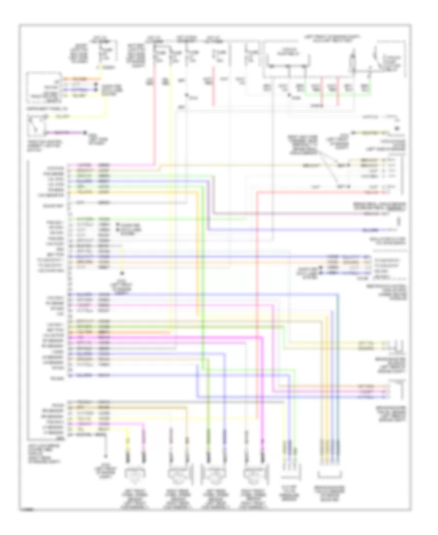
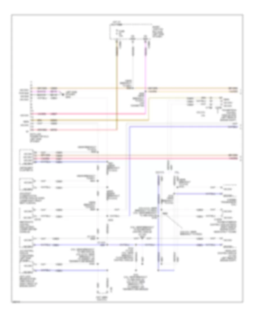
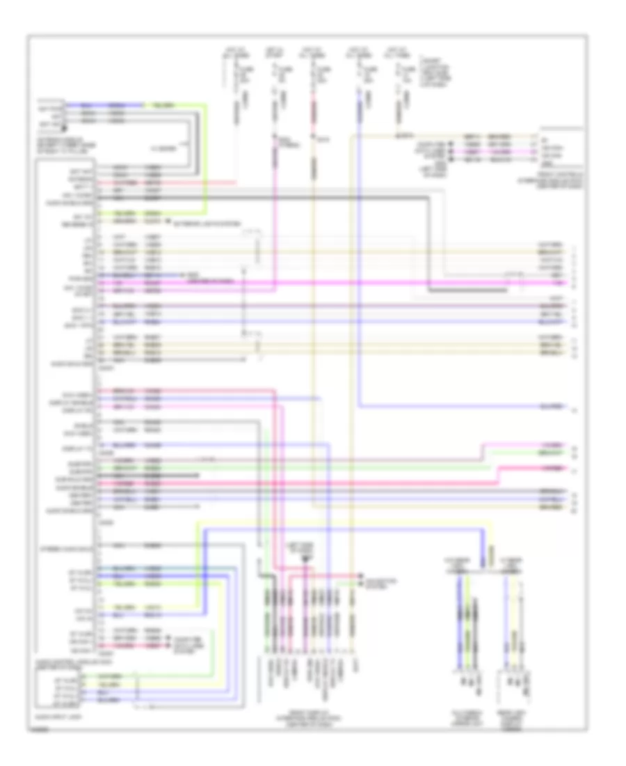
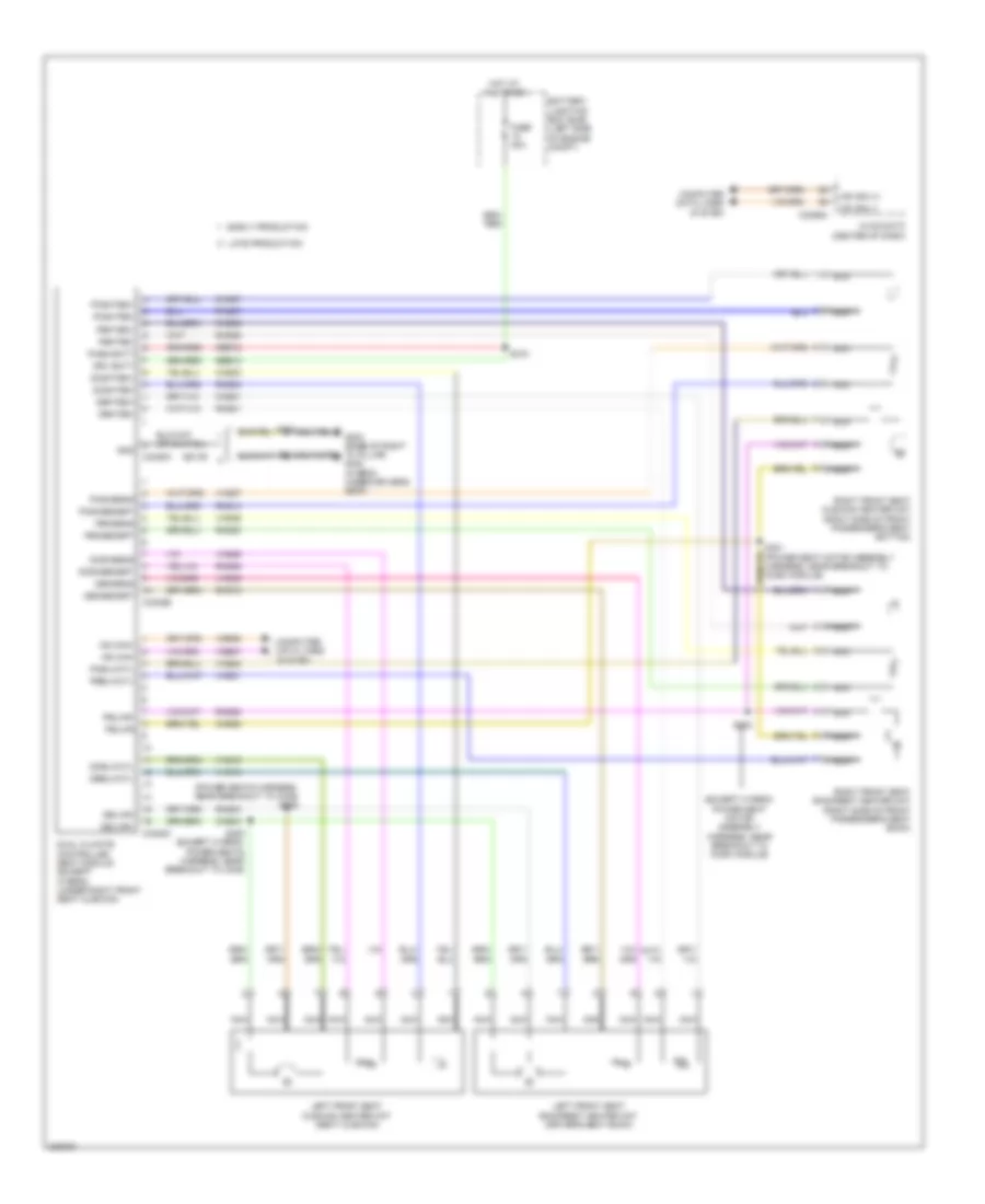
Automatic A/C Wiring Diagram, Except Hybrid (1 of 3) for Ford Fusion S 2010

List of elements for Automatic A/C Wiring Diagram, Except Hybrid (1 of 3) for Ford Fusion S 2010:
- Ac evap temp sn
- Air inlet dr fdbk
- Ambient temp sens
- Amp
- Batt
- Battery junction box (bjb) (left side of engine compt)
- Blower cmd
- Blower motor (right side of hvac housing)
- Blower motor relay
- Blower motor speed control (right side of hvac housing)
- Blower rqst
- C2280a
- C2280b
- C2280e
- C2356a
- C2356b
- Ch122
- Ch123
- Ch207
- Ch208
- Ch212
- Ch213
- Ch228
- Ch229
- Ch238
- Ch239
- Chs04
- Chs09
- Chs13
- Chs14
- Chs29
- Chs30
- Cmd
- Computer data lines system
- Defogger system
- Defrost req
- Drv heated seat hi
- Drv heated seat lo
- Drv hs req
- Drv sunload sens
- Drv temp dr ccw
- Drv temp dr cw
- Drv temp dr fdbk
- Fuse 10a
- Fuse 40a
- Fuse 5a
- G201 (center of dash)
- G202 (left side of dash)
- Gd116
- Gnd
- Hot at all times
- Hot in run or acc
- Hvac-datc (center of dash)
- In car temp sens
- In-vehicle temperature sensor (left side of dash)
- Lh111
- Logic
- Mode dr 1 ccw
- Mode dr 1 cw
- Mode dr 1 fdbk
- Mot+
- Mot-
- Ms can+
- Ms can-
- Pass hs req
- Pass sunload sens
- Pass temp dr ccw
- Pass temp dr cw
- Pass temp dr fdbk
- Passenger temperature blend door actuator (center of hvac housing)
- Recirc ccw
- Recirc cw
- Rh111
- S131
- Sbp15
- Seats system
- Smart junction box (sjb) (left side of dash)
- Vdb06
- Vdb07
- Vh101
- Vh406
- Vh407
- Vh414
- Vh416
- Vh417
- Vh436
- Vh438
- Vh440
- Vh441
- Vpwr
- Vref 5v
- Vref ret
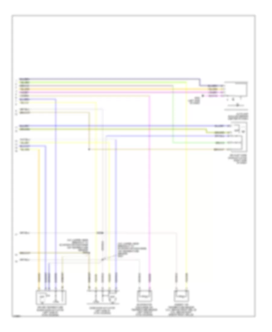
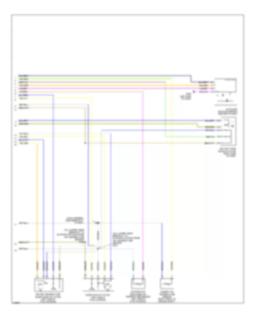
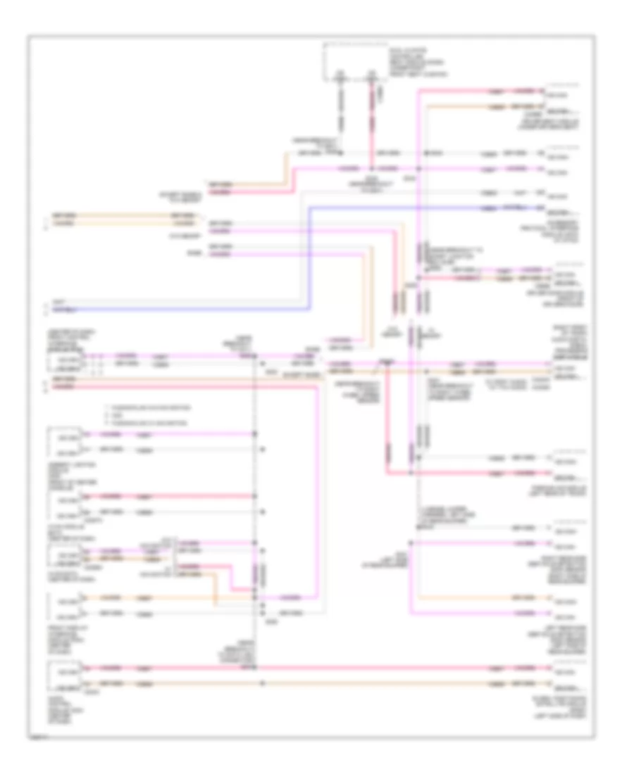
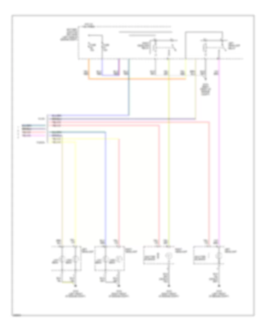
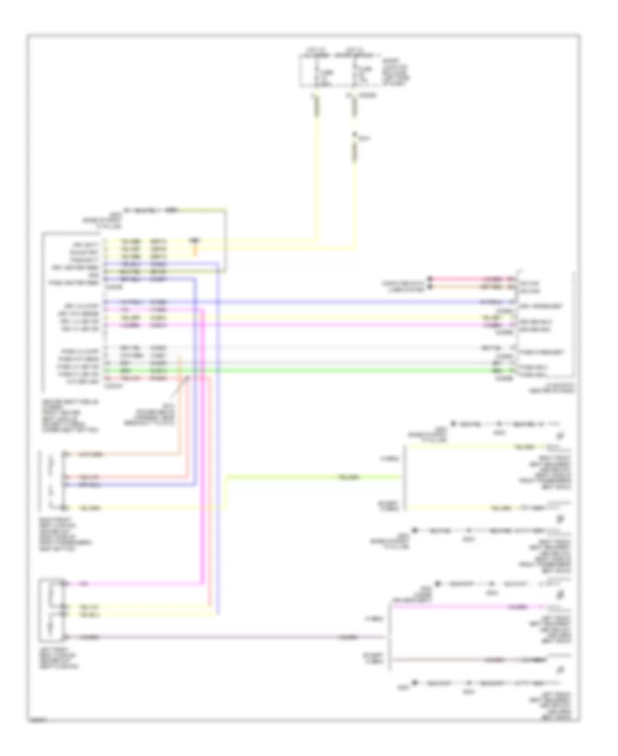
Automatic A/C Wiring Diagram, Except Hybrid (2 of 3) for Ford Fusion S 2010
List of elements for Automatic A/C Wiring Diagram, Except Hybrid (2 of 3) for Ford Fusion S 2010:
- (a/c jumper, near breakout to evaporator discharge air temperature sensor) s204
- (a/c jumper, near breakout to evaporator discharge air temperature sensor) s206
- Air inlet mode door actuator (right side of dash)
- Ambient air temperature sensor (3.0l: behind front grille) (3.5l: behind right side of front grille)
- Amp
- Autolamp sunload sensor (center of dash)
- Driver temperature blend door actuator (left side of hvac housing)
- Evaporator discharge air temperature sensor (left side of hvac housing)
- G202 (left side of dash)
- Mode door actuator (left side of hvac housing)
- S260
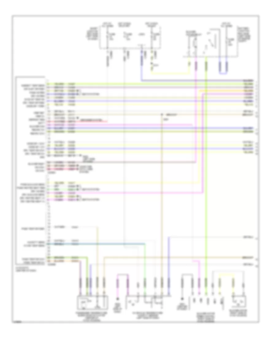
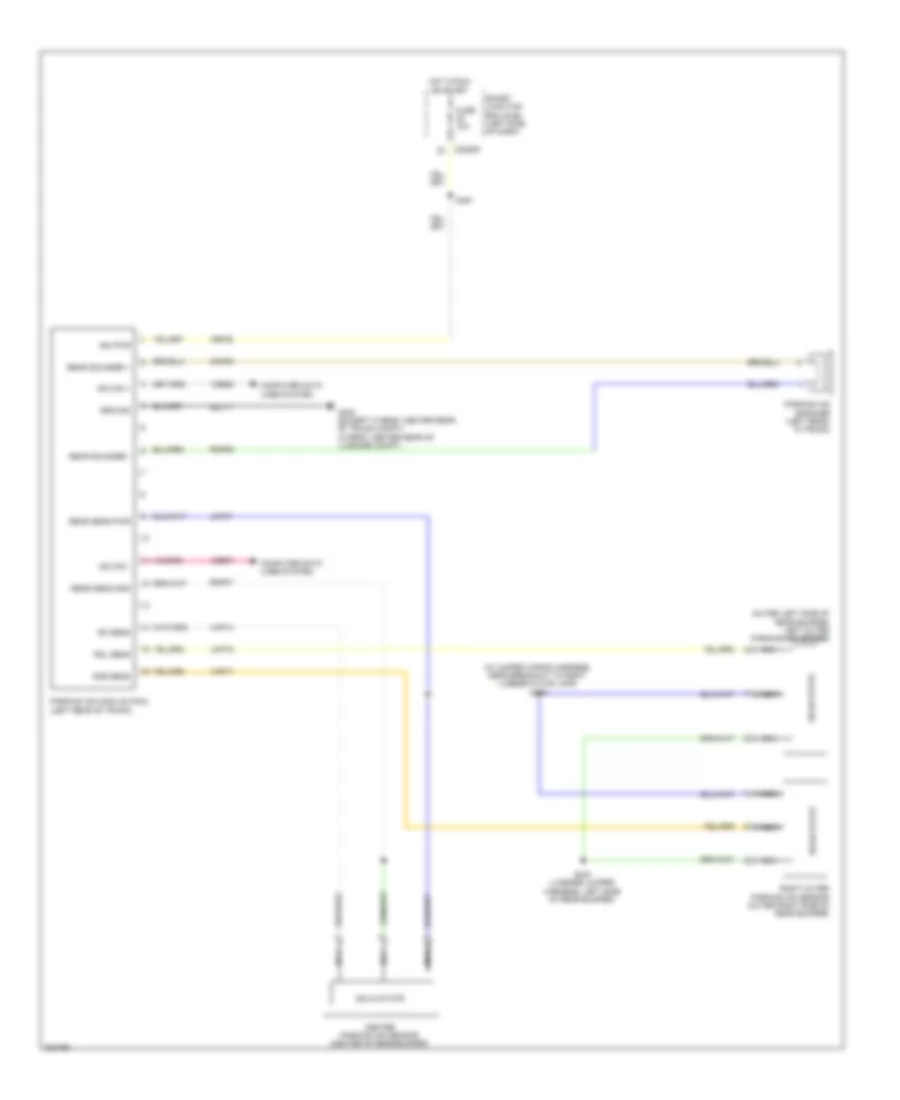
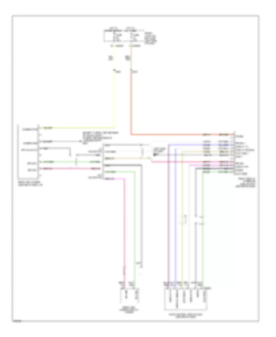
Automatic A/C Wiring Diagram, Except Hybrid (3 of 3) for Ford Fusion S 2010
List of elements for Automatic A/C Wiring Diagram, Except Hybrid (3 of 3) for Ford Fusion S 2010:
- (3.0l) (3.5l)
- (3.0l) s181
- (3.5l)
- (3.5l) s179
- 3.0l
- 3.5l
- A/c clutch field coil (front of a/c compressor)
- A/c clutch relay
- A/c pressure transducer (right rear of engine compt)
- Accr
- Acpt
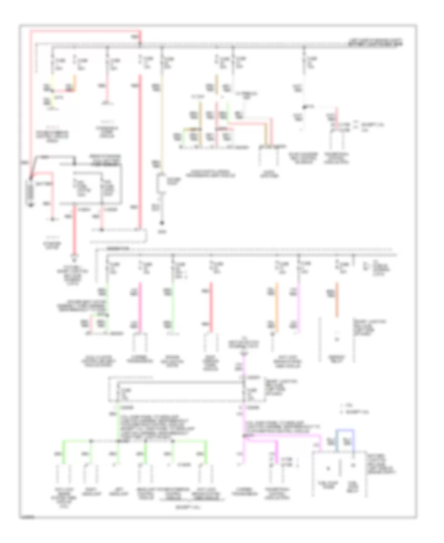
- Battery junction box (bjb) (left side of engine compt)
- C-sigrtn
- C175b
- C175e
- Ce302
- Ch302
- Cht
- Computer data lines system
- Cylinder head temperature (cht) sensor (3.5l: front of right cylinder head) (3.0l: rear of engine, near water outlet)
- Engine controls system
- Engine cooling fan motor (leftt front of engine compt)
- Fc-v
- Fuse 10a
- Fuse 40a
- Fuse 60a 80a
- G103 (3.0l: left rear of engine compt) (3.5l: left side of engine compt)
- G103 (left rear of engine compt)
- G104 (right side of engine compt)
- Hot at all times
- Hs can+
- Hs can-
- Le424
- Pcm ctrl
- Pcm power relay
- Powertrain control module (pcm) (left rear of engine compt)
- Re405
- Re407
- Red
- S143
- S144 (3.0l: dash panel to headlamp junction harness, near breakout to battery junction box) (3.5l: dash panel to headlamp junction harness, near breakout to g103)
- S157 (3.0l)
- S180 (3.5l)
- Sigrtne
- Vdb04
- Vdb05
- Ve712
- Vec03
- Vh433
- Vref
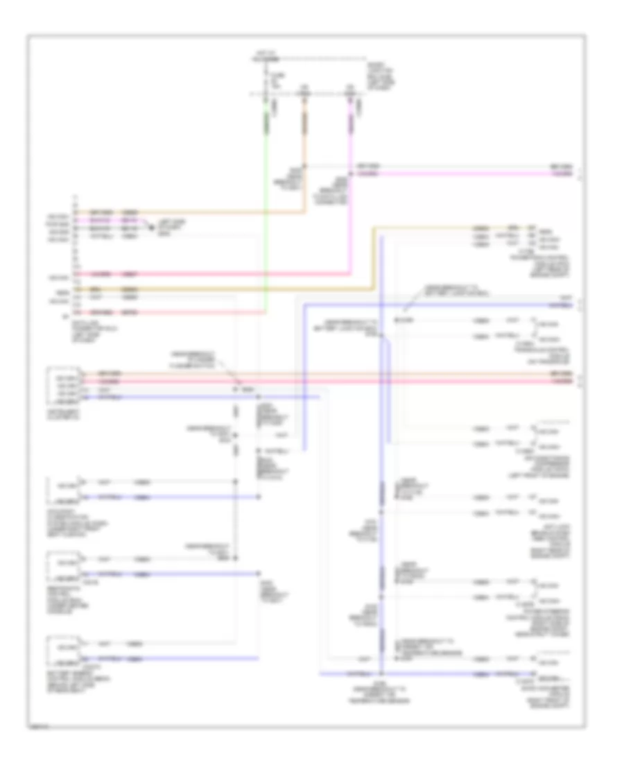
Automatic A/C Wiring Diagram, Hybrid (1 of 3) for Ford Fusion S 2010
List of elements for Automatic A/C Wiring Diagram, Hybrid (1 of 3) for Ford Fusion S 2010:
- Ac evap temp sn
- Air inlet dr fdbk
- Ambient temp sens
- Amp
- Batt
- Battery junction box (bjb) (left side of engine compt)
- Blower cmd
- Blower motor (right side of hvac housing)
- Blower motor relay
- Blower motor speed control (right side of hvac housing)
- Blower rqst
- C2280a
- C2280b
- C2280e
- C2356a
- C2356b
- Ch122
- Ch123
- Ch207
- Ch208
- Ch212
- Ch213
- Ch228
- Ch229
- Ch238
- Ch239
- Chs04
- Chs09
- Chs13
- Chs14
- Chs29
- Chs30
- Cmd
- Computer data lines system
- Defogger system
- Defrost req
- Drv heated seat hi
- Drv heated seat lo
- Drv hs req
- Drv sunload sens
- Drv temp dr ccw
- Drv temp dr cw
- Drv temp dr fdbk
- Fuse 10a
- Fuse 40a
- Fuse 5a
- G201 (center of dash)
- G202 (left side of dash)
- Gd116
- Gnd
- Hot at all times
- Hot in run or acc
- Hot in run or start
- Humidity sens
- Hvac-datc (center of dash)
- In car temp sens
- In-vehicle temperature/ humidity sensor (left side of dash)
- Lh111
- Logic
- Mode dr 1 ccw
- Mode dr 1 cw
- Mode dr 1 fdbk
- Mot+
- Mot-
- Ms can+
- Ms can-
- Pass heated seat req
- Pass hs req
- Pass sunload sens
- Pass temp dr ccw
- Pass temp dr cw
- Pass temp dr fdbk
- Passenger temperature blend door actuator (center of hvac housing)
- Recirc ccw
- Recirc cw
- Rh111
- S131
- S261
- Sbp15
- Seats system
- Smart junction box (sjb) (left side of dash)
- Vdb06
- Vdb07
- Vh101
- Vh406
- Vh407
- Vh413
- Vh414
- Vh416
- Vh417
- Vh436
- Vh438
- Vh440
- Vh441
- Vpwr
- Vref 5v
- Vref ret
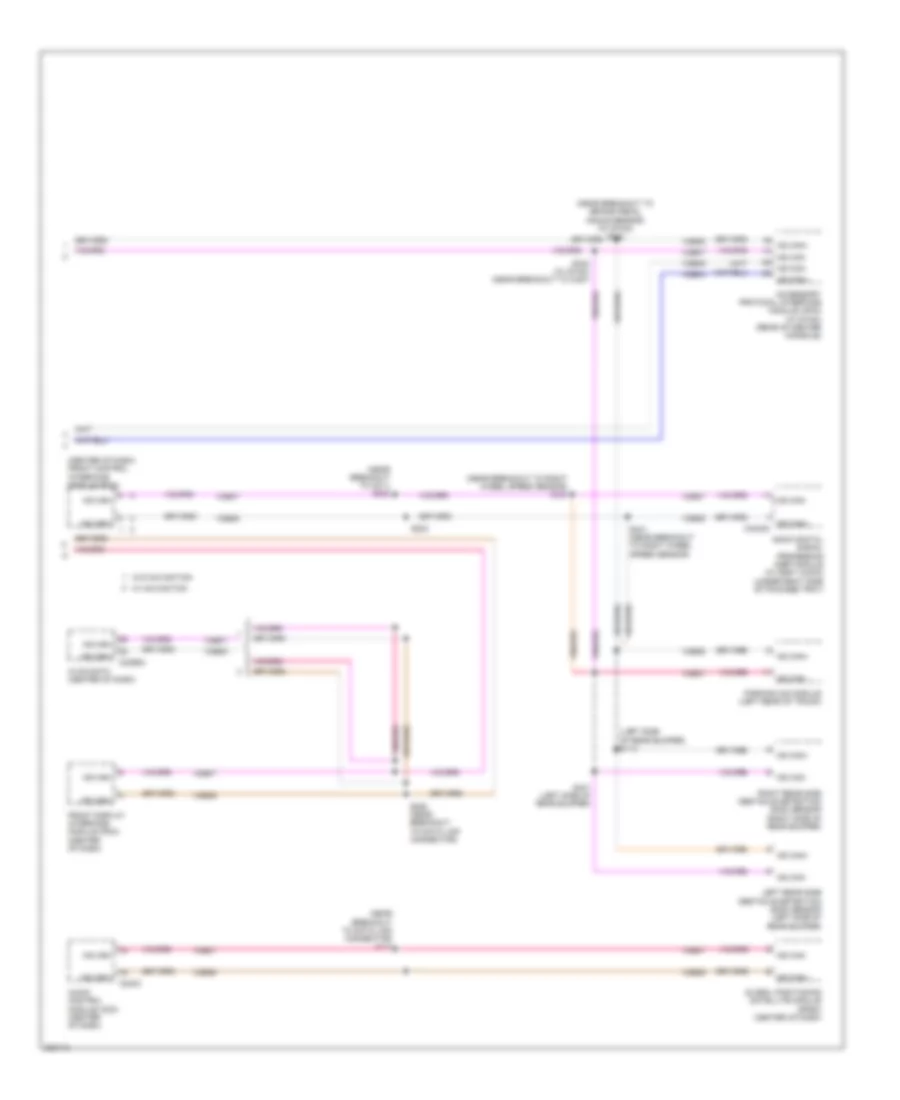
Automatic A/C Wiring Diagram, Hybrid (2 of 3) for Ford Fusion S 2010
List of elements for Automatic A/C Wiring Diagram, Hybrid (2 of 3) for Ford Fusion S 2010:
- (a/c jumper, near breakout to evaporator discharge air temperature sensor) s204
- (a/c jumper, near breakout to evaporator discharge air temperature sensor) s206
- (main harness, near breakout to g201)
- Air inlet mode door actuator (right side of dash)
- Ambient air temperature sensor (right front of engine compt)
- Amp
- Autolamp sunload sensor (center of dash)
- Driver temperature blend door actuator (left side of hvac housing)
- Evaporator discharge air temperature sensor (left side of hvac housing)
- G202 (left side of dash)
- Mode door actuator (left side of hvac housing)
- S260
Automatic A/C Wiring Diagram, Hybrid (3 of 3) for Ford Fusion S 2010
List of elements for Automatic A/C Wiring Diagram, Hybrid (3 of 3) for Ford Fusion S 2010:
- (left front of engine) air conditioning compressor module (accm)
- A/c in
- A/c out
- A/c pressure transducer (right rear of engine compt)
- Acpt
- Auxiliary coolant flow pump (lower left rear of engine)
- Battery junction box (bjb) (left side of engine compt)
- Becm in
- Becm out
- Bussed electrical center (behind rear seat)
- C1457a
- C1469a
- C1469b
- C175b
- C175e
- C175t
- C4236a
- Ce318
- Ch307
- Ch401
- Cht
- Computer data lines system
- Cyb01
- Cyb03
- Cyd01
- Cyd02
- Cylinder head temperature (cht) sensor (top center of cylinder head)
- Dc/dc converter module
- Engine controls system
- Engine cooling fan motor (left front of engine compt)
- Fc-v
- Fuse 10a
- Fuse 15a
- Fuse 60a
- Fvi+
- Fvi-
- G103 (left front of engine compt)
- G104 (right front of engine compt)
- Gd123
- Gnd
- Heater pump relay
- High voltage junction box (right rear of engine compt)
- Hot at all times
- Hot in start or run
- Hpcr
- Hs can+
- Hs can-
- Hv+
- Hv-
- Hvdc+
- Hvdc-
- Hyt03
- Hyt04
- Le424
- M/e coolant pump motor (left front of engine compt)
- M/e coolant pump relay
- Mecp
- Powertrain control module (pcm) (left rear of engine compt)
- Re405
- Re407
- S144 (dash panel to headlamp junction harness, near breakout to battery junction box)
- S157 (dash panel to headlamp junction harness, near breakout to battery junction box)
- S180 (engine control sensor & fuel charge harness, near breakout to c145)
- S191
- Sigrtn
- Sigrtne
- Vdb04
- Vdb05
- Ve712
- Vec03
- Vh433
- Vpwr
- Vref
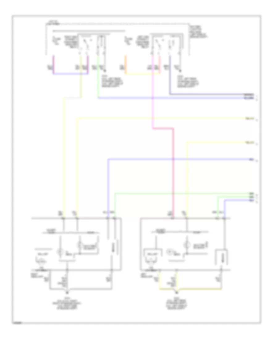
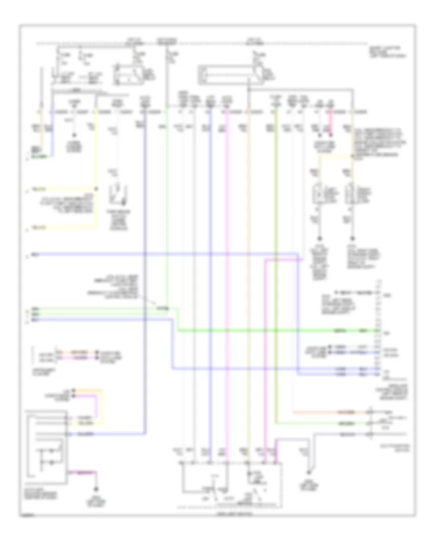
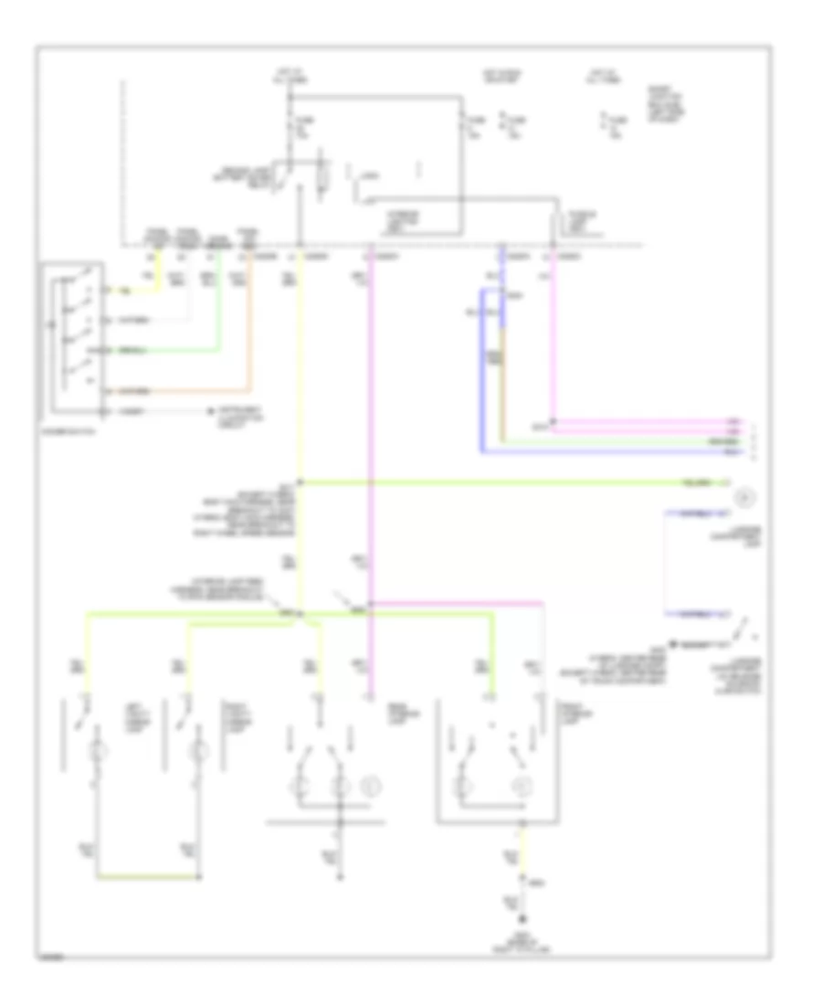
Manual A/C Wiring Diagram (1 of 2) for Ford Fusion S 2010
List of elements for Manual A/C Wiring Diagram (1 of 2) for Ford Fusion S 2010:
- (2.5l) (3.5l)
- (3.5l)
- (3.5l) s180
- (3.5l: left side of engine compt) g103
- (dash panel to headlamp junction harness, near breakout to battery junction box) (2.5l) (3.5l) s179
- 2.5l
- 3.5l
- A/c clutch field coil (front of a/c compressor)
- A/c clutch relay
- A/c pressure transducer sensor (2.5l: right front of engine) (3.5l: right rear of engine compt)
- Accr
- Acpt
- Battery junction box (bjb) (left side of engine compt)
- C175b
- C175e
- Ce302
- Ch302
- Cht
- Computer data lines system
- Cylinder head temperature (cht) sensor (3.5l: front of right cylinder head) (2.5l: top center of cylinder head)
- E-sigrtn
- Engine controls system
- Engine cooling fan motor (left front of engine compt)
- Fc-v
- Fuse 10a
- Fuse 40a
- Fuse 60a 80a
- G103
- G104 (right side of engine compt)
- Hot at all times
- Hs can+
- Hs can-
- Instrument cluster (ic)
- Le424
- Pcm control
- Pcm power relay
- Powertrain control module (pcm) (left rear of engine compt)
- Re405
- Re407
- Red
- S143
- S144 (3.0l: dash panel to headlamp junction harness, near breakout to battery junction box) (3.5l: dash panel to headlamp junction harness, near breakout to g103)
- S157
- S181 (2.5l) (engine control sensor & fuel charge wire harness, near breakout to c133)
- Sigrtn
- Vdb04
- Vdb05
- Ve712
- Vec03
- Vh433
- Vref
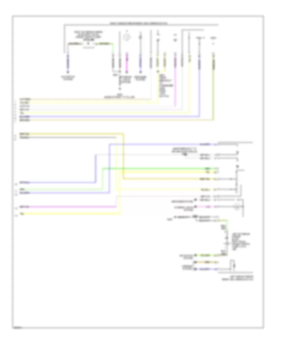
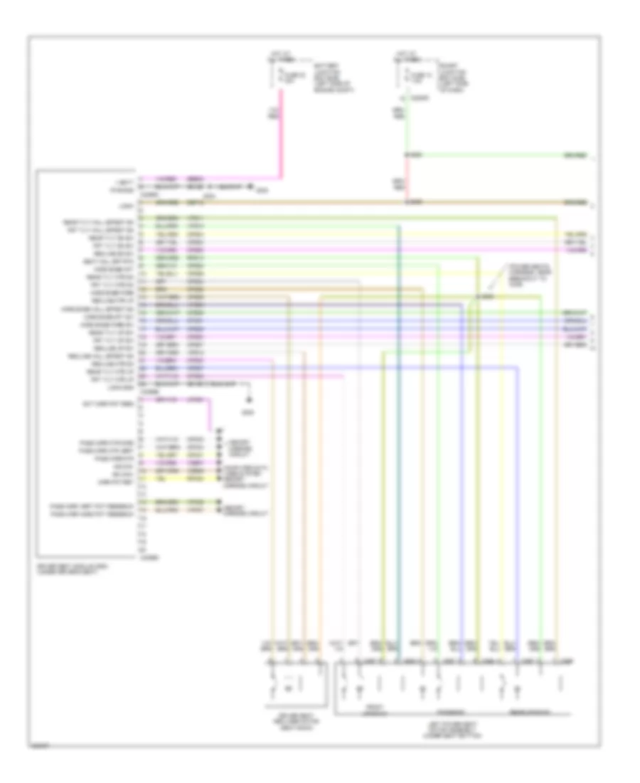
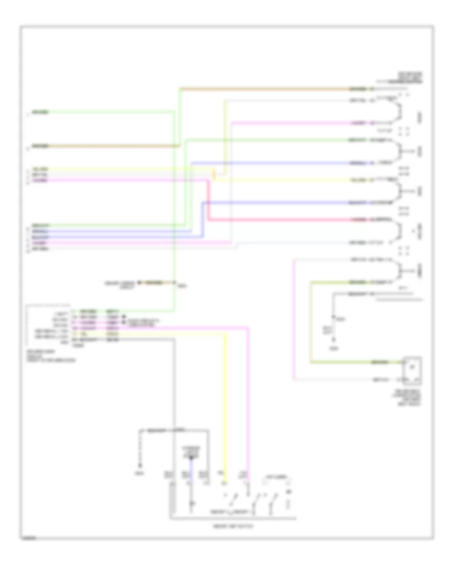
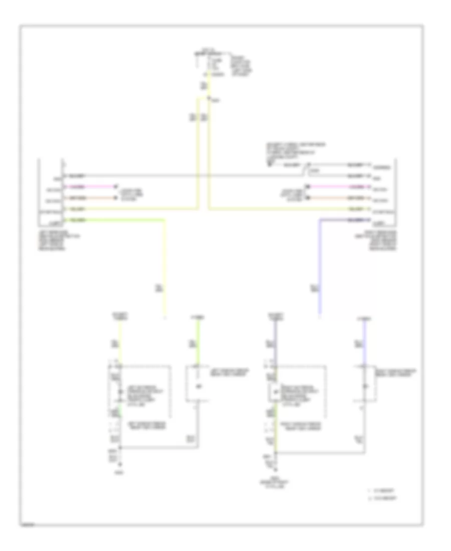
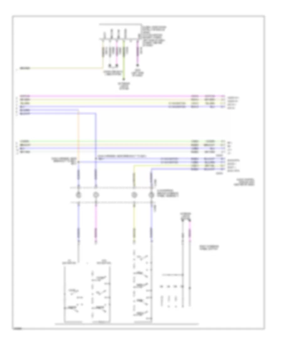
Manual A/C Wiring Diagram (2 of 2) for Ford Fusion S 2010
List of elements for Manual A/C Wiring Diagram (2 of 2) for Ford Fusion S 2010:
- (a/c jumper, near breakout to blower motor) s205
- (a/c jumper, near breakout to evaporator discharge air temperature sensor)
- (a/c jumper, near breakout to evaporator discharge air temperature sensor) s206
- (center of dash)
- 1 fdbk
- Actet
- Air inlet mode door actuator (right side of dash)
- Amp
- Backlighting
- Batt power
- Battery junction box (bjb) (left side of engine compt)
- Blower motor (right side of hvac housing)
- Blower motor relay
- Blower motor resistor (right side of hvac housing)
- Blower relay
- C2280b
- C2280e
- C2357a
- C2357b
- Ch122
- Ch123
- Ch207
- Ch208
- Ch228
- Ch229
- Ch238
- Ch239
- Ch426
- Ch428
- Ch429
- Computer data lines system
- Defogger system
- Defrost req
- Driver temperature blend door actuator (left side of hvac housing)
- Drv temp door ccw
- Drv temp door cw
- Dvr temp fdbk
- Evaporator discharge air temperature sensor (left side of hvac housing)
- Fuse 10a
- Fuse 40a
- Fuse 5a
- G201
- G202 (left side of dash)
- Gd115
- Gd116
- Gnd
- High
- Hot at all times
- Hot in run or acc
- Hvac-emtc (center of dash)
- Interior lights system
- Lh111
- M high
- M low
- Mode door
- Mode door 1 cw mode door 1 ccw
- Mode door actuator (left side of hvac housing)
- Ms can+
- Ms can-
- Recir door ccw
- Recir door cw
- Rh111
- S115
- S131
- S204
- Sbp15
- Smart junction box (sjb) (left side of dash)
- Thermal limiter
- Vdb06
- Vdb07
- Vh406
- Vh436
- Vh440
- Vln04
- Vref 5v
- Vref ret
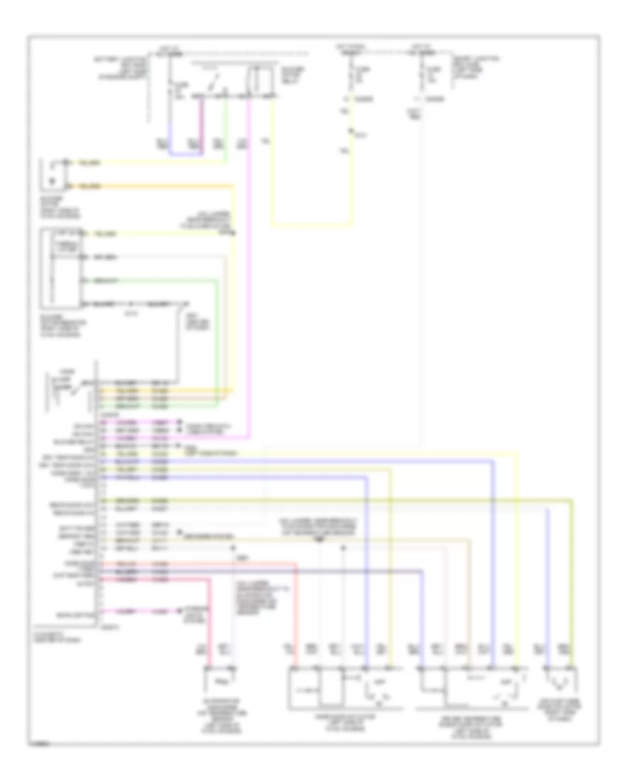
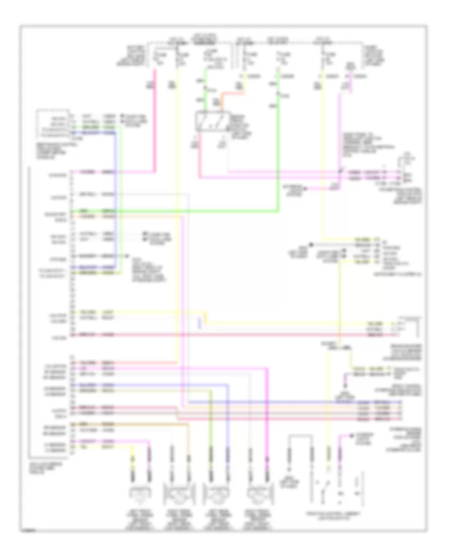
ANTI-LOCK BRAKES
Anti-lock Brakes Wiring Diagram, Except Hybrid for Ford Fusion S 2010
List of elements for Anti-lock Brakes Wiring Diagram, Except Hybrid for Ford Fusion S 2010:
- (2.5l & 3.0l) (3.5l)
- (dash panel to headlamp junction harness, near breakout to powertrain control module) s142
- 2.5l & 3.0l
- 20a
- 3.5l
- Anti-lock brake system (abs) module
- Battery junction box (bjb) (left side of engine compt)
- Boo
- Boo input
- Bps
- Brake booster vacuum sensor (3.0l awd & 3.5l) (on brake booster)
- Brake pedal position switch (left side of dash)
- C175b
- C2280a
- C2280b
- C2280d
- C310b
- Cbp42
- Cca15
- Cca40
- Ccb08
- Ces09
- Computer data lines system
- Except mkz
- Exterior lights system
- Front control interface module (fcim) (center of dash)
- Fuse 10a
- Fuse 15a
- Fuse 30a
- Fuse 40a
- G104 (2.5l & 3.0l: right front of engine compt) (3.5l: right side of engine compt)
- G202 (left side of dash)
- Gd104
- Gd123
- Gnd
- Hot at all times
- Hot in run or start
- Hot w/ pcm power relay energized
- Hs can +
- Hs can -
- Hs can+
- Hs can-
- Instrument cluster (ic)
- Interior lights system
- Ivd pwr
- Ivd rtn
- Lca37
- Left front wheel speed sensor (left front hub assembly)
- Left rear wheel speed sensor (left rear hub assembly)
- Lf sensor+
- Lf sensor-
- Lr sensor+
- Lr sensor-
- Mkz
- Mtr gnd
- Mtr pwr
- Nca
- Powertrain control module (pcm) (left rear of engine compt)
- Pwr gnd
- Rca17
- Rca18
- Rca19
- Rca20
- Rca37
- Rca40
- Restraints control module (rcm) (under center console)
- Rf sensor+
- Rf sensor-
- Right front wheel speed sensor (right front hub assembly)
- Right rear wheel speed sensor (right rear hub assembly)
- Rr sensor+
- Rr sensor-
- Run/start
- S120
- S144
- Sas a
- Sas b
- Sbb08
- Sbb10
- Smart junction box (sjb) (left side of dash)
- Steering angle sensor module (sasm) (3.5l) (center of steering column)
- Tc can stat +
- Tc can stat -
- Tc can stat+
- Tc can stat-
- Traction control/ ambient lighting switch
- Traction ctl on/off
- Vac gnd
- Vac pwr
- Vac sig
- Valve pwr
- Vca03
- Vca04
- Vca05
- Vca06
- Vca23
- Vca24
- Vca38
- Vca41
- Vca42
- Vdb04
- Vdb05
- Vdbo4
- Vdbo5
Anti-lock Brakes Wiring Diagram, Hybrid for Ford Fusion S 2010
List of elements for Anti-lock Brakes Wiring Diagram, Hybrid for Ford Fusion S 2010:
- (body main wire harness, near breakout to brake pedal angle sensor)
- (left front of engine compt) auxiliary relay box
- Anti-lock brake system (abs) module (right rear of engine compt)
- Battery junction box (bjb) (left side of engine compt)
- Brake booster solenoid (left rear of engine compt)
- Brake booster travel sensor (left rear of engine compt)
- Brake booster vacuum sensor (on brake booster)
- Brake pedal angle sensor (on brake pedal assembly)
- Bst pwm
- Bst pwr
- C2280a
- C310b
- Cbb30
- Cbb31
- Cbb32
- Cbb37
- Cbk03
- Cca22
- Ccb30
- Ccb33
- Computer data lines system
- Cut-off valve pressure sensor
- Fuse 10a
- Fuse 30a
- Fuse 40a
- Fuse 5a
- G103 (left front of engine compt)
- G202 (left side of dash)
- Gd121
- Gnd
- Hot at all times
- Hot in run or start
- Hs can +
- Hs can -
- Hs can+
- Hs can+ traction ctrl on/off
- Hs can-
- Instrument panel (ic)
- Lca16
- Lca27
- Lca37
- Left front wheel speed sensor (left front hub assembly)
- Left rear wheel speed sensor (left rear hub assembly)
- Lf sensor+
- Lf sensor-
- Lr sensor+
- Lr sensor-
- Mp gnd
- Mp sig
- Mtr pwr
- Nca
- Pas gnd
- Pas sense
- Pas sig 1
- Pas sig 2
- Pm sense
- Ps gnd
- Ps sens
- Ps sig
- Rca16
- Rca17
- Rca18
- Rca19
- Rca20
- Rca27
- Rca37
- Rcb33
- Restraints control module (rcm) (under center console)
- Rf sensor+
- Rf sensor-
- Right front wheel speed sensor (right front hub assembly)
- Right rear wheel speed sensor (right rear hub assembly)
- Rr sensor+
- Rr sensor-
- Run/start
- S144
- S190
- S192
- S270
- S271
- Sbb08
- Sbb10
- Simulator cut-off valve solenoid
- Smart junction box (sjb) (left side of dash)
- Tc can stat +
- Tc can stat -
- Tc can stat+
- Tc can stat-
- Traction control ambient lighting switch
- Vac
- Vac pump
- Vac pump mon
- Vac senspwr
- Vac sig 1
- Vac sig 2
- Vacrc
- Vacuum pump cut-off relay
- Vacuum pump motor (left side of engine)
- Vacuum pump relay
- Valve pwr
- Vca03
- Vca04
- Vca05
- Vca06
- Vca13
- Vca22
- Vca23
- Vca24
- Vca30
- Vca38
- Vca39
- Vca43
- Vcb34
- Vdb04
- Vdb05
- Vol pwm
- Vol pwr
ANTI-THEFT
Forced Entry Wiring Diagram (1 of 2) for Ford Fusion S 2010
List of elements for Forced Entry Wiring Diagram (1 of 2) for Ford Fusion S 2010:
- (base of right "a" pillar) g203
- (body main harness, near breakout to g301) s326
- (except hybrid: body main harness, near breakout to c237) (late production) s328
- (except hybrid: body main harness, near breakout to g300) s374
- (hybrid: body main harness, near breakout to c510) s324
- (hybrid: body main wire harness, near breakout to c510)
- (late production) s329
- Accessory delay relay
- C2280c
- C2280d
- Driver side door lock switch
- Early production
- Fuse 15a
- Fuse 20a
- G203 (base of right "a" pillar)
- G300 (hybrid: under driver's seat)
- Hot at all times
- Late production
- Left rear door lock actuator (left rear door)
- Lock
- Lock all relay
- Logic
- Lr door ajar
- Pass door ajar
- Passenger side door lock switch
- Right front door lock actuator (front passenger's door)
- Right rear door lock actuator (right rear door)
- Rr door ajar
- S323
- S330
- S500
- S601
- S700
- S800
- Smart junction box (sjb) (left side of dash)
- Trim lock
- Trim unlock
- Unlock
- Unlock all relay
- Unlock driver relay
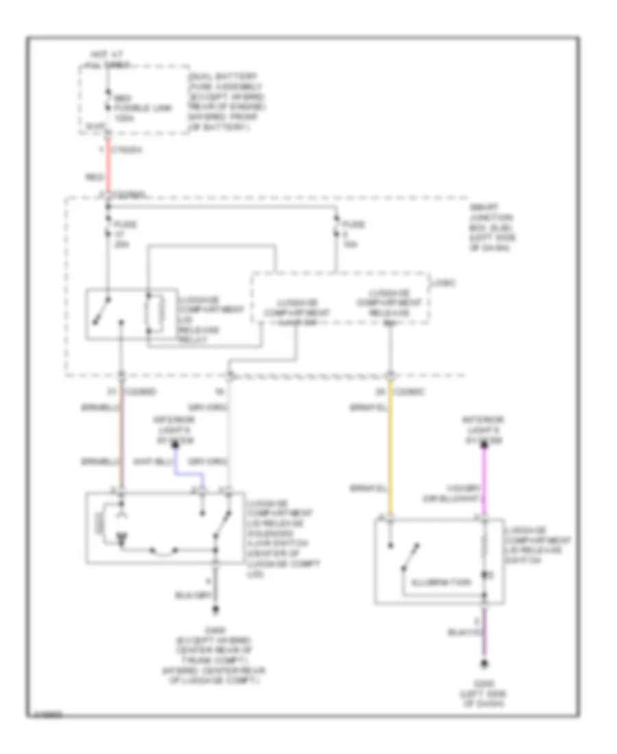
Forced Entry Wiring Diagram (2 of 2) for Ford Fusion S 2010
List of elements for Forced Entry Wiring Diagram (2 of 2) for Ford Fusion S 2010:
- 1/2
- 3/4
- 5/6
- 7/8
- 9/0
- Anti-theft hood switch (left front of engine compt)
- C1620a
- C2280c
- C2280f
- C2280g
- Disarm request
- Driver door ajar
- Dual battery fuse assembly (except hybrid: rear of engine) (hybrid: front of battery
- G104 (except 3.5l: right front of engine compt) (3.5l: right side of engine compt)
- G300 (hybrid: under driver's seat)
- G400 (except hybrid: center rear of trunk compt) (hybrid: center rear of luggage compt)
- Hood ajar
- Hot at all times
- Interior lights system
- Keypad a
- Keypad b
- Keypad c
- Keypad switch assembly
- Left front door lock actuator (driver's door)
- Logic
- Luggage compartment disarm switch (center rear of luggage compt)
- Mid/ fusible link 120a
- Red
- Reset
- Rke receiver internal ant
- S500
- Set
- Smart junction box (sjb) (left side of dash)
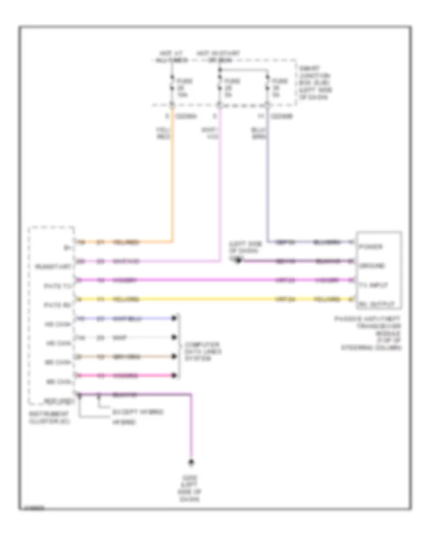
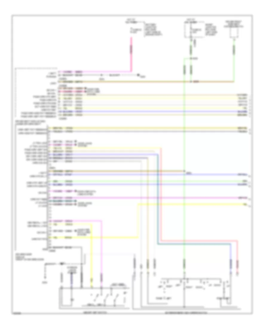
Passive Anti-theft Wiring Diagram for Ford Fusion S 2010
List of elements for Passive Anti-theft Wiring Diagram for Ford Fusion S 2010:
- (left side of dash) g202
- C2280a
- C2280b
- Cbp36
- Computer data lines system
- Except hybrid
- Fuse 10a
- Fuse 5a
- G202 (left side of dash)
- Gd116
- Ground
- Hot at all times
- Hot in start or run
- Hs can+
- Hs can-
- Hybrid
- Instrument cluster (ic)
- Mod gnd
- Ms can+
- Ms can-
- Passive anti-theft transceiver module (top of steering column)
- Pats rx
- Pats tx
- Power
- Run/start
- Rx output
- Smart junction box (sjb) (left side of dash)
- Tx input
- Vrt23
- Vrt24
BODY CONTROL MODULES
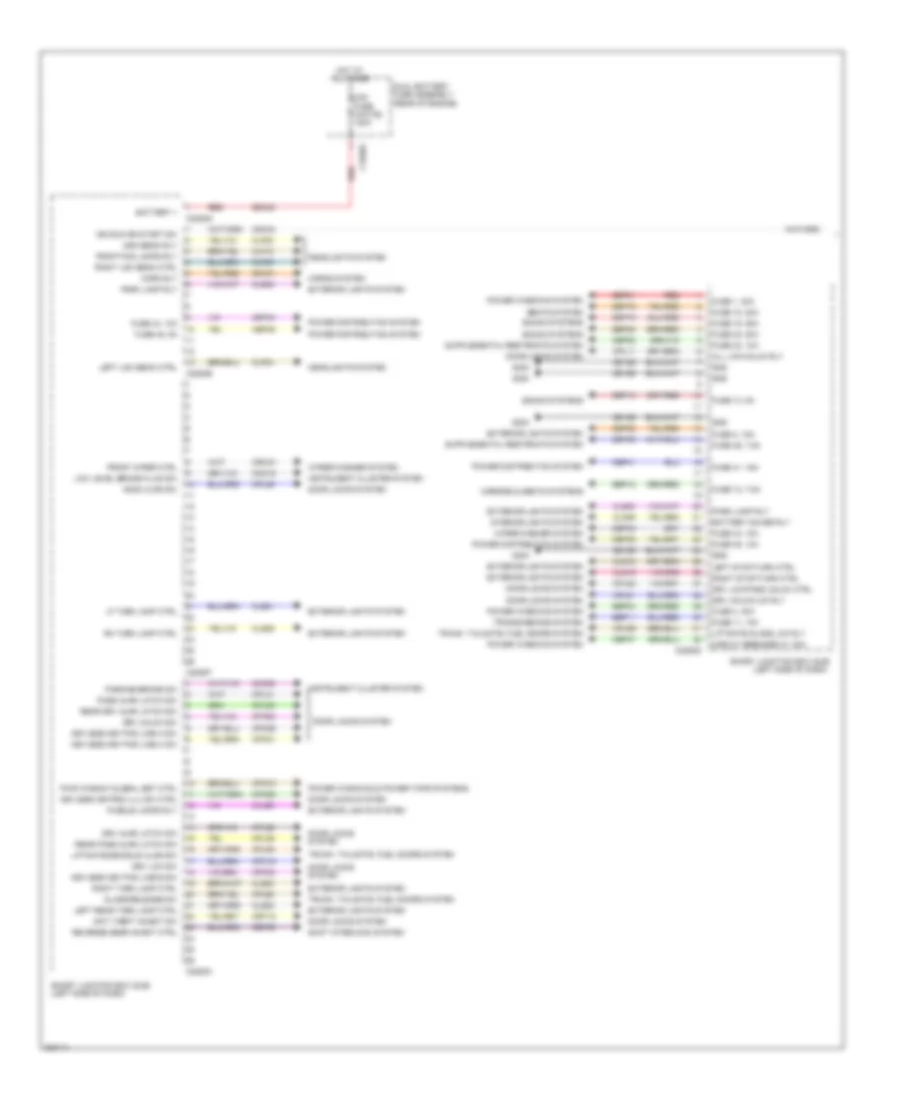
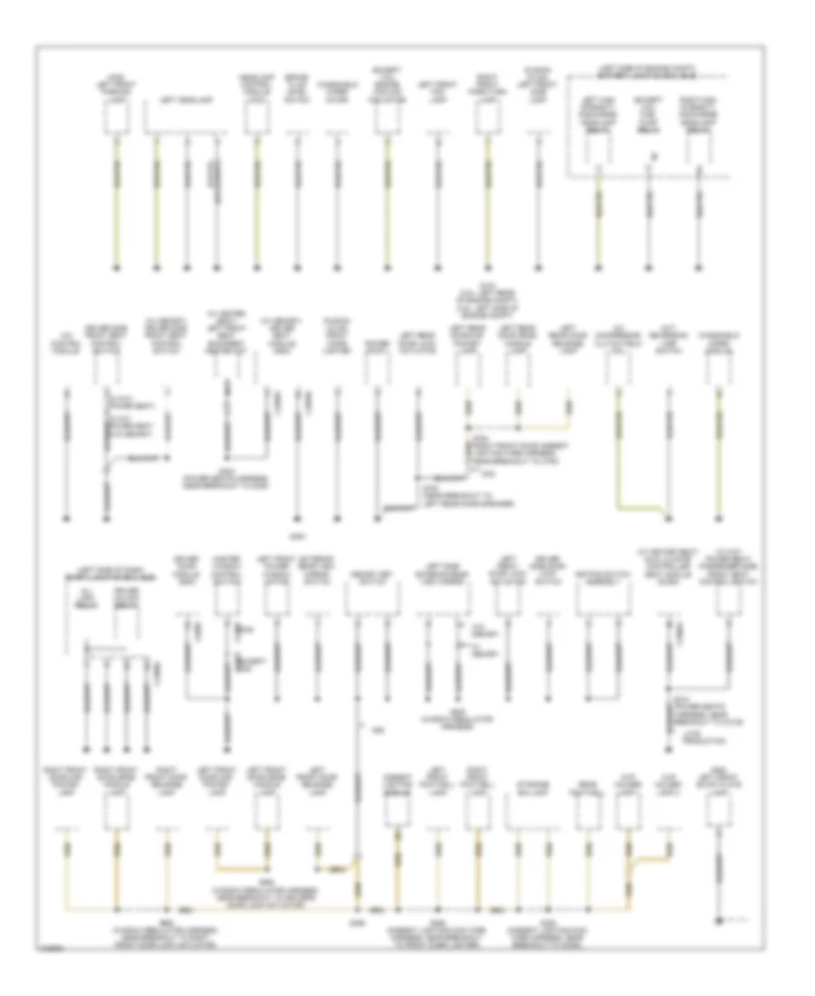
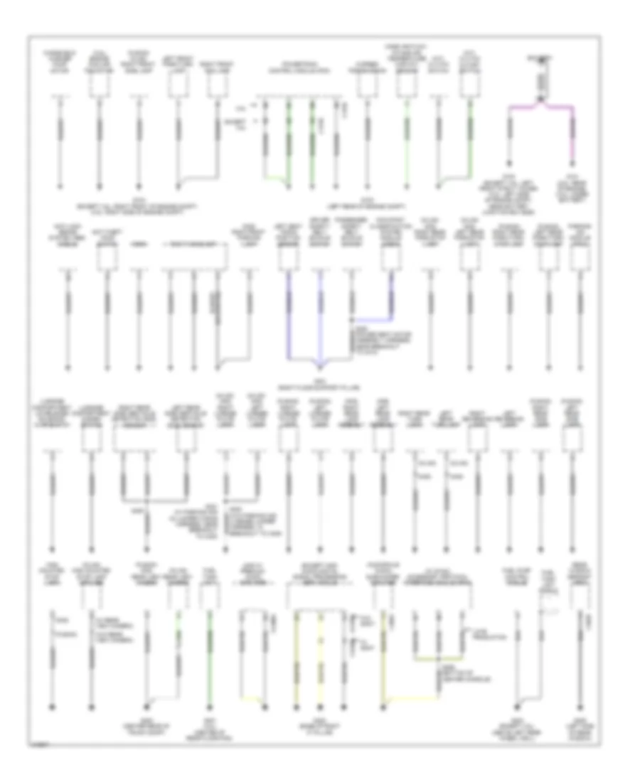
Body Control Modules Wiring Diagram, Except Hybrid (1 of 2) for Ford Fusion S 2010
List of elements for Body Control Modules Wiring Diagram, Except Hybrid (1 of 2) for Ford Fusion S 2010:
- All lck/unlck rly
- Anti theft inhibit sw
- Battery +
- Battery saver rly
- C1620a
- C2280c
- C2280d
- C2280e
- C2280f
- C2280g
- Cbp32
- Cbp35
- Cbp41
- Cbp43
- Cbp44
- Cbp45
- Cbp46
- Cbp47
- Cdc34
- Cet53
- Circuit breaker 47, 30a
- Clf04
- Clf05
- Clf08
- Clf12
- Cln09
- Cln25
- Cls18
- Cls19
- Cls21
- Cls23
- Cls24
- Cls25
- Cls30
- Cmc19
- Cmc25
- Cpk19
- Cpk23
- Cpk28
- Cpk29
- Cpk30
- Cpk31
- Cpl11
- Cpl25
- Cpl26
- Cpl31
- Cpl36
- Cpl39
- Cpl51
- Cpl52
- Cpl58
- Cpl59
- Cpl60
- Cpw01
- Crt18
- Crw01
- Door locks system
- Drv ajar latch sw
- Drv lck sw
- Drv lck/pass unlck ctrl
- Drv unlck sw
- Drv unlck/lck rly
- Dual battery fuse assembly (rear of engine)
- Exterior lights system
- Front fog lamps rly
- Front wiper ctrl
- Fuse 1, 30a
- Fuse 11, 10a
- Fuse 12, 7.5a
- Fuse 13, 5a
- Fuse 18, 20a
- Fuse 19, 25a
- Fuse 2, 15a
- Fuse 32, 10a
- Fuse 35, 10a
- Fuse 38, 20a
- Fuse 4, 30a
- Fuse 41, 15a
- Fuse 43, 10a
- Fuse 44, 10a
- Fuse 45, 5a
- Fuse 46, 7.5a
- G300
- Gd126
- Glass release sw
- Gnd
- Headlights system
- High beam rly
- Hood ajar sw
- Horn rly
- Horns system
- Hot at all times
- Ign run or start sw
- Instrument cluster system
- Interior lights system
- Keyless key pad line a sw
- Keyless key pad line b sw
- Keyless key pad line c sw
- Keyless keypad illu sw ctrl
- Left low beam ctrl
- Left rear turn lamp ctrl
- Left stop/turn ctrl
- Lf turn lamp ctrl
- Liftgate glass lck rly
- Liftgate/deackud ajar sw
- Low level brake fluid sw
- Midi fuse (white) 120a
- Mirrors & seats systems
- Park lamp rly
- Parking brake sw
- Pass ajar latch sw
- Power distribution system
- Power windows & power tops systems
- Power windows system
- Puddle lamps rly
- Pwr window global set ctrl
- Rear drv ajar latch sw
- Rear pass ajar latch sw
- Red
- Reverse gear inhibit ctrl
- Rh turn lamp ctrl
- Right low beam ctrl
- Right stop/turn ctrl
- Right turn lamp ctrl
- Sbp01
- Sbp02
- Sbp04
- Sbp11
- Sbp12
- Sbp13
- Sbp18
- Sbp19
- Sbp38
- Sdc02
- Seats system
- Shift interlock system
- Smart junction box (sjb) (left side of dash)
- Sound systems
- Srh01
- Transmissions system
- Trunk, tailgate, fuel doors system
- Wiper/washer system
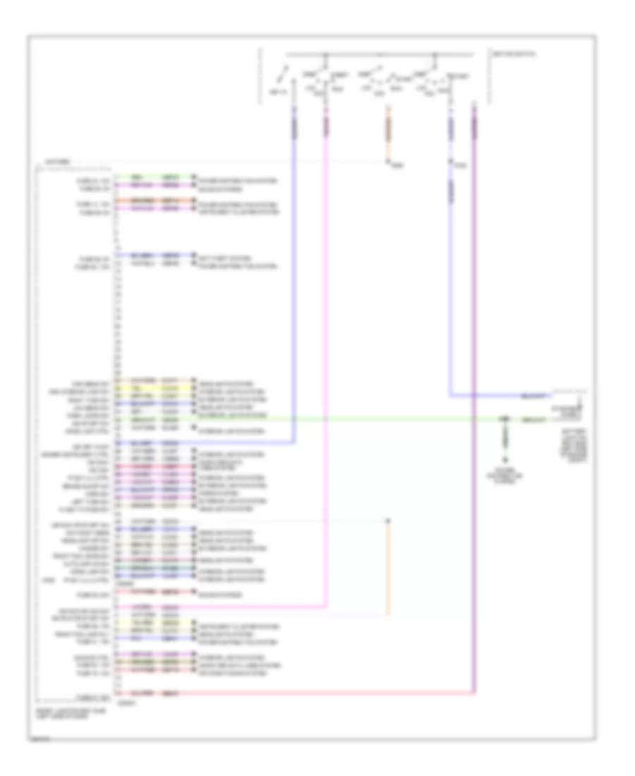
Body Control Modules Wiring Diagram, Except Hybrid (2 of 2) for Ford Fusion S 2010
List of elements for Body Control Modules Wiring Diagram, Except Hybrid (2 of 2) for Ford Fusion S 2010:
- (mkz)
- Add interior lamp sw
- Air conditioning system
- Anti-theft system
- Autolamp on sw
- Battery junction box (bjb) (left side of engine compt)
- Brake on/off sw
- C2280a
- C2280b
- Cbp28
- Cbp29
- Cbp36
- Cbp41
- Cbp42
- Cbp46
- Ccb08
- Cdc30
- Cdc33
- Cdc34
- Ce336
- Clf12
- Clf17
- Clf18
- Clf19
- Clf21
- Clf23
- Clf27
- Cln12
- Cln27
- Cln28
- Cls32
- Cls34
- Cls39
- Cls41
- Computer data lines system
- Crh02
- Day/night sens
- Dimmer instrument ctrl
- Dimming ctrl
- Dome lamp ctrl
- Dome lamp sw
- Exterior lights system
- Flash to pass sw
- Front fog lamp rly
- Front fog lamps sw
- Fuse 14, 10a
- Fuse 15, 10a
- Fuse 20, 15a
- Fuse 26, 10a
- Fuse 27, 20a
- Fuse 28, 5a
- Fuse 29, 5a
- Fuse 36, 5a
- Fuse 39, 20a
- Fuse 41, 15a
- Fuse 42, 10a
- Fuse 46, 7.5a
- Hazard sw
- Headlamp off sw
- Headlights system
- High beam sw
- Horn sw
- Horns system
- Ign key in sw
- Ign run or acc sw
- Ign run or start sw
- Ign start sw
- Ignition switch
- Instrument cluster system
- Interior lights system
- Ip sw illu 2 ctrl
- Ip sw illu ctrl
- Key in
- Lck acc
- Left turn sw
- Low beam sw
- Ms can+
- Ms can-
- Off
- Park lamps sw
- Power distribution system
- Right turn sw
- Rln29
- Run
- S151
- S152
- S250
- Sbp14
- Sbp15
- Sbp20
- Sbp26
- Sbp27
- Sbp39
- Smart junction box (sjb) (left side of dash)
- Sound systems
- Start
- Starter diode
- Vdb06
- Vdb07
- Vlf14
- Vln04
- Vln33
- Vln37
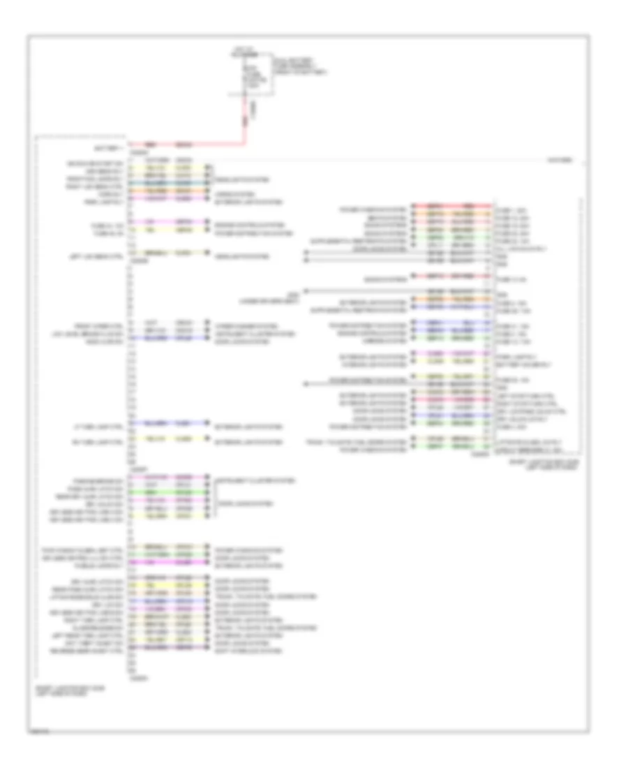
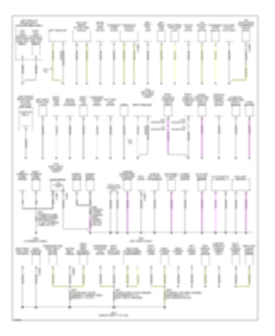
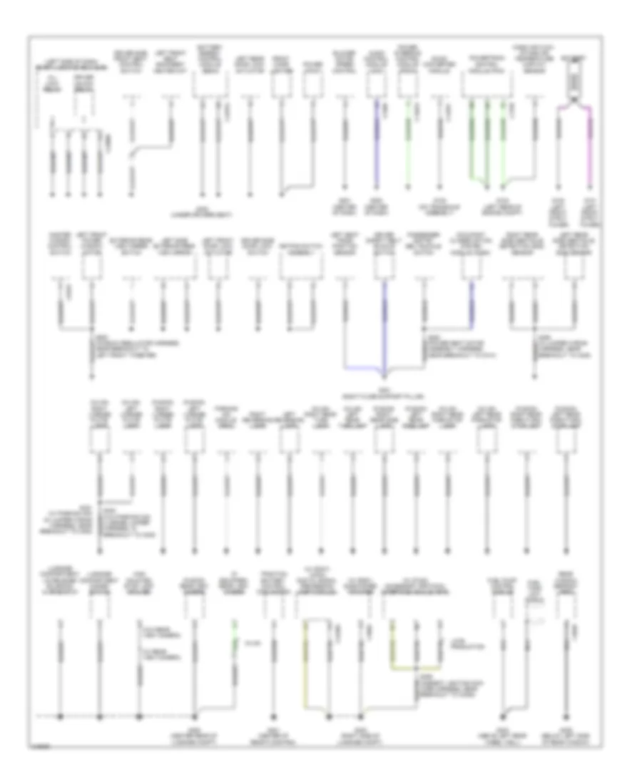
Body Control Modules Wiring Diagram, Hybrid (1 of 2) for Ford Fusion S 2010
List of elements for Body Control Modules Wiring Diagram, Hybrid (1 of 2) for Ford Fusion S 2010:
- All lck/unlck rly
- Anti theft inhibit sw
- Battery +
- Battery saver rly
- C1620a
- C2280c
- C2280d
- C2280e
- C2280f
- C2280g
- Cbp32
- Cbp35
- Cbp41
- Cbp44
- Cbp45
- Cbp46
- Cbp47
- Cdc34
- Cet53
- Circuit breaker 47, 30a
- Clf04
- Clf05
- Clf08
- Clf12
- Cln09
- Cln25
- Cls18
- Cls19
- Cls21
- Cls23
- Cls24
- Cls25
- Cls30
- Cmc19
- Cmc25
- Cpk19
- Cpk23
- Cpk28
- Cpk29
- Cpk30
- Cpk31
- Cpl11
- Cpl25
- Cpl26
- Cpl31
- Cpl36
- Cpl39
- Cpl51
- Cpl52
- Cpl58
- Cpl59
- Cpl60
- Cpw01
- Crt18
- Crw01
- Door locks system
- Drv ajar latch sw
- Drv lck sw
- Drv lck/pass unlck ctrl
- Drv unlck sw
- Drv unlck/lck rly
- Dual battery fuse assembly (front of battery)
- Engine controls system
- Exterior lights system
- Front fog lamps rly
- Front wiper ctrl
- Fuse 1, 20a
- Fuse 12, 7.5a
- Fuse 13, 5a
- Fuse 18, 20a
- Fuse 19, 20a
- Fuse 2, 15a
- Fuse 3, 15a
- Fuse 32, 10a
- Fuse 35, 10a
- Fuse 38, 20a
- Fuse 4, 30a
- Fuse 41, 15a
- Fuse 44, 10a
- Fuse 45, 5a
- Fuse 46, 7.5a
- G300 (under driver's seat)
- Gd126
- Glass release sw
- Gnd
- Headlights system
- High beam rly
- Hood ajar sw
- Horn rly
- Horns system
- Hot at all times
- Ign run or start sw
- Instrument cluster system
- Interior lights system
- Keyless key pad line a sw
- Keyless key pad line b sw
- Keyless key pad line c sw
- Keyless keypad illu sw ctrl
- Left low beam ctrl
- Left rear turn lamp ctrl
- Left stop/turn ctrl
- Lf turn lamp ctrl
- Liftgate glass lck rly
- Liftgate/deackud ajar sw
- Low level brake fluid sw
- Midi fuse (white) 120a
- Mirrors system
- Park lamp rly
- Parking brake sw
- Pass ajar latch sw
- Power distribution system
- Power windows system
- Puddle lamps rly
- Pwr window global set ctrl
- Rear drv ajar latch sw
- Rear pass ajar latch sw
- Red
- Reverse gear inhibit ctrl
- Rh turn lamp ctrl
- Right low beam ctrl
- Right stop/turn ctrl
- Right turn lamp ctrl
- Sbp01
- Sbp02
- Sbp03
- Sbp04
- Sbp12
- Sbp13
- Sbp18
- Sbp19
- Sbp38
- Sdc02
- Seats system
- Shift interlock system
- Smart junction box (sjb) (left side of dash)
- Sound systems
- Srh01
- Trunk, tailgate, fuel doors system
- Wiper/washer system
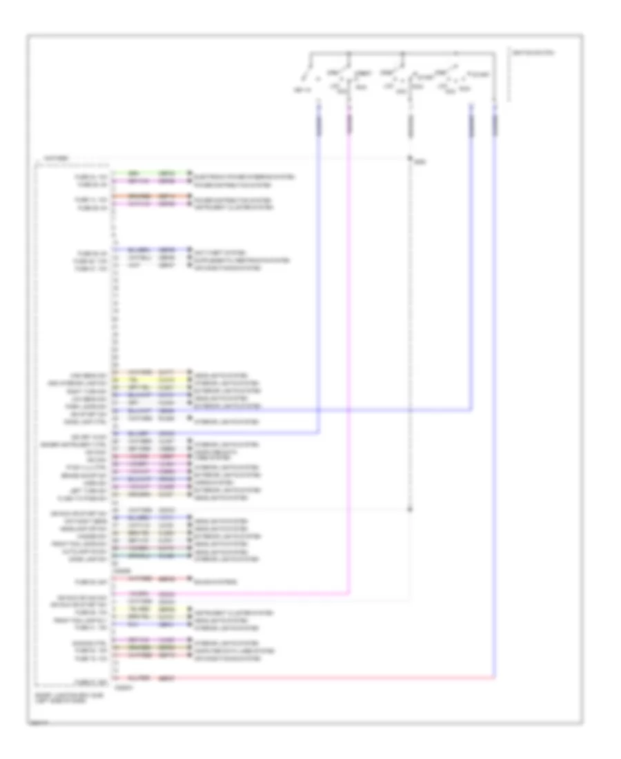
Body Control Modules Wiring Diagram, Hybrid (2 of 2) for Ford Fusion S 2010
List of elements for Body Control Modules Wiring Diagram, Hybrid (2 of 2) for Ford Fusion S 2010:
- Add interior lamp sw
- Air conditioning system
- Anti-theft system
- Autolamp on sw
- Brake on/off sw
- C2280a
- C2280b
- Cbp28
- Cbp29
- Cbp36
- Cbp37
- Cbp41
- Cbp42
- Cbp46
- Ccb08
- Cdc30
- Cdc33
- Cdc34
- Ce335
- Clf12
- Clf17
- Clf18
- Clf19
- Clf21
- Clf23
- Clf27
- Cln12
- Cln27
- Cln28
- Cls32
- Cls34
- Cls39
- Cls41
- Computer data lines system
- Crh02
- Day/night sens
- Dimmer instrument ctrl
- Dimming ctrl
- Dome lamp ctrl
- Dome lamp sw
- Electronic power steering system
- Exterior lights system
- Flash to pass sw
- Front fog lamp rly
- Front fog lamps sw
- Fuse 14, 10a
- Fuse 15, 10a
- Fuse 20, 15a
- Fuse 26, 10a
- Fuse 27, 20a
- Fuse 28, 5a
- Fuse 29, 5a
- Fuse 36, 5a
- Fuse 37, 10a
- Fuse 39, 20a
- Fuse 41, 15a
- Fuse 42, 10a
- Fuse 46, 7.5a
- Hazard sw
- Headlamp off sw
- Headlights system
- High beam sw
- Horn sw
- Horns system
- Ign key in sw
- Ign run or acc sw
- Ign run or start sw
- Ign start sw
- Ignition switch
- Instrument cluster system
- Interior lights system
- Ip sw illu ctrl
- Key in
- Lck acc
- Left turn sw
- Low beam sw
- Ms can+
- Ms can-
- Off
- Park lamps sw
- Power distribution system
- Right turn sw
- Rln29
- Run
- S250
- Sbp14
- Sbp15
- Sbp20
- Sbp26
- Sbp27
- Sbp39
- Smart junction box (sjb) (left side of dash)
- Sound systems
- Start
- Vdb06
- Vdb07
- Vlf14
- Vln04
- Vln33
COMPUTER DATA LINES
Computer Data Lines Wiring Diagram, Except Hybrid (1 of 2) for Ford Fusion S 2010
List of elements for Computer Data Lines Wiring Diagram, Except Hybrid (1 of 2) for Ford Fusion S 2010:
- (2.5l & 3.0l: near breakout to pscm) (3.5l: near breakout to abs module) s105
- (2.5l/3.0l: near breakout to pscm)
- (3.5l: near breakout to abs module) (2.5l & 3.0l: near breakout to to ambient air temperature sensor) s162
- (3.5l: near breakout to powertrain control module) (w/ hid) s104
- (left side of dash) g202
- (near breakout to c144) s123
- (near breakout to c212) s220
- (near breakout to c3047) s336
- (near breakout to g201) s225
- (near breakout to g301) s334
- (not used) (2.5l/3.0l)
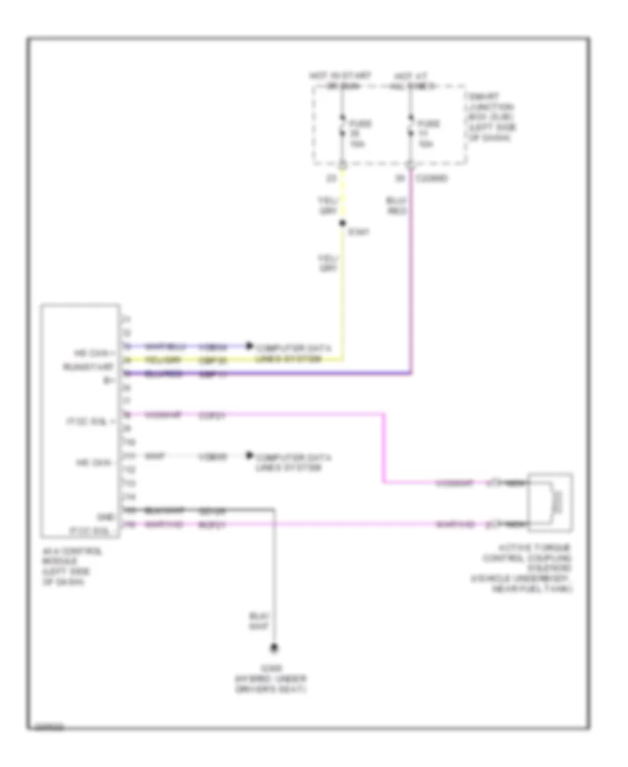
- (w/ 4x4) s350
- (w/ 4x4) s351
- 2.5l/3.0l
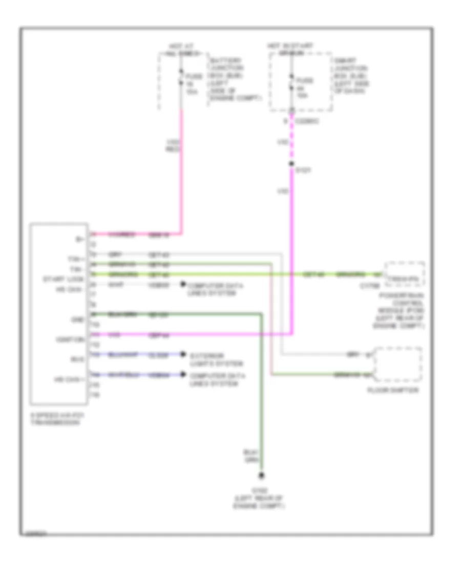
- 3.5l
- 4x4 control module (if equipped) (left side of dash)
- 6 speed transmission (3.5l)
- Anti-lock brake system (abs) module (right front of engine compt)
- C139
- C175b
- C2280a
- C2280b
- C301b
- Cdb08
- Data link connector (dlc) (left side of dash)
- Feps
- Fuse 15a
- Gd116
- Headlamp control module (w/ hid) (left rear of engine compt)
- Hot at all times
- Hs can+
- Hs can+ c1467b
- Hs can-
- Hs can- c175b
- Instrument cluster (ic)
- Ms can+
- Ms can-
- Occupant classification system module (ocsm) (under right front seat cushion)
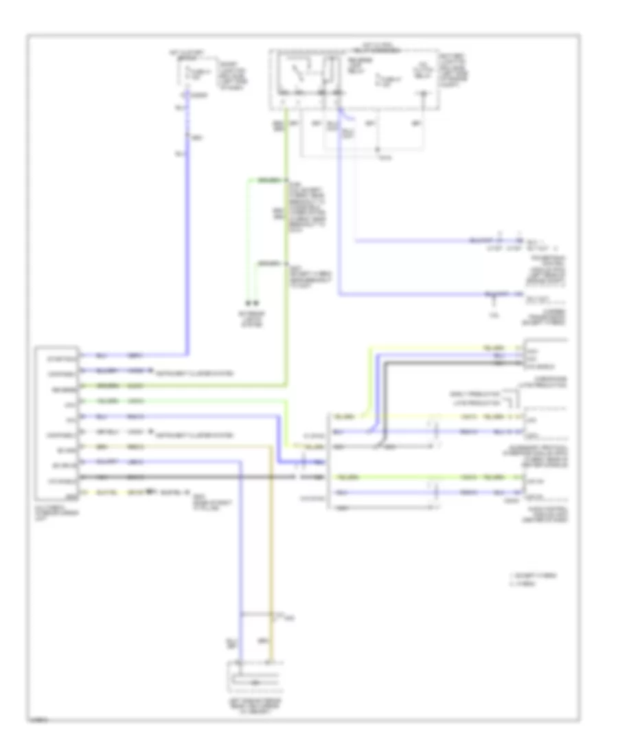
- Power steering control module (pscm) (right side of engine compt, near strut tower)
- Powertrain control module (pcm) (left rear of engine compt)
- Pwr gnd
- Restraints control module (rcm) (under center console)
- S103 (w/ hid) (3.5l: near breakout to powertrain control module)
- S106
- S122 (near breakout to c144)
- S161 (3.5l: near breakout to abs module) (2.5l & 3.0l: near breakout to to ambient air temperature sensor)
- S226 (near breakout to data link connector)
- S332
- Sbp20
- Sig gnd
- Smart junction box (sjb) (left side of dash)
- Vdb04
- Vdb05
- Vdb06
- Vdb07
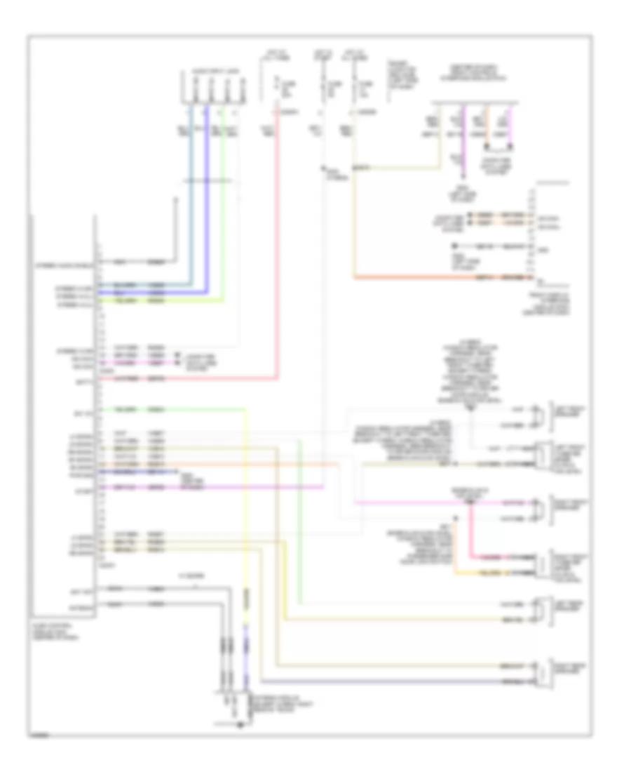
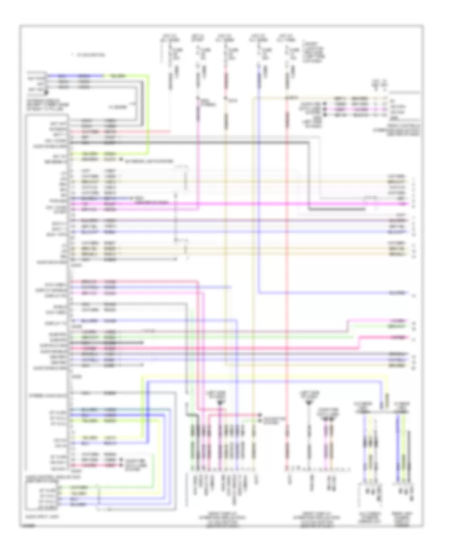
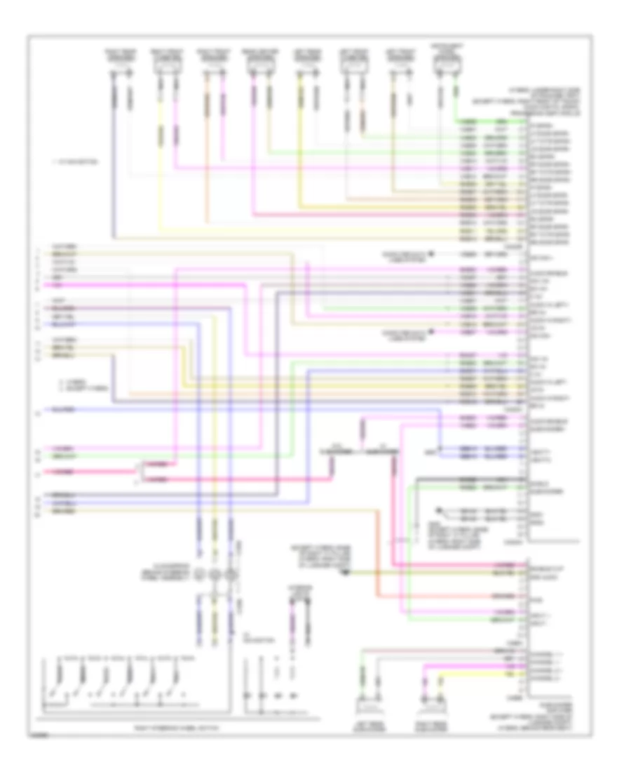
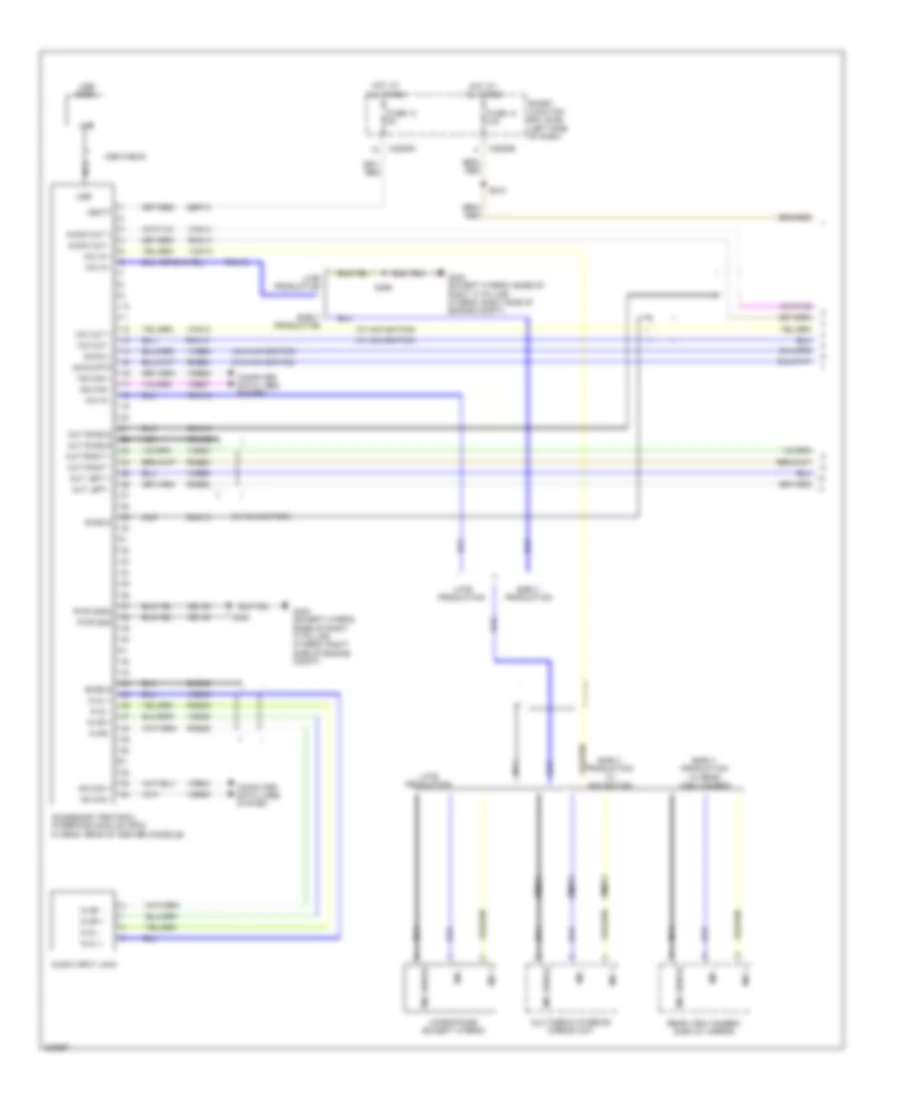
Computer Data Lines Wiring Diagram, Except Hybrid (2 of 2) for Ford Fusion S 2010
List of elements for Computer Data Lines Wiring Diagram, Except Hybrid (2 of 2) for Ford Fusion S 2010:
- (center of dash) front control interface module (fcim)
- (license jumper harness, left side of rear bumper) s442
- (near breakout to c211) s222
- (near breakout to data link connector) s227
- (near breakout to g301) s346
- (near breakout to right wheel speed sensor)
- (near breakout to smart junction box (sjb)) s353
- (right front of trunk) audio digital signal processing (dsp) module
- (w/ sony audio) (w/ thx audio)
- Accessory protocol interface module (apim) (w/ sync)
- Ambient lighting module (mkz) (front of center console)
- Audio control module (acm) (center of dash)
- Base
- C2356a
- C2357a
- C240c
- C3305c
- C4235c
- Driver door module (front of driver's door)
- Driver seat module (under driver's seat)
- Dual climate controlled seat module (dcsm) (under right front seat cushion)
- Except base
- Except base & w/o memory
- Front display interface module (fdim) (center of dash)
- Fusion/milan w/ navigation
- Fusion/milan w/o navigation
- Global positioning satellite module (gpsm) (left side of dash)
- Hs can+
- Hs can-
- Hvac module emtc (center of dash)
- Hvac-datc (center of dash)
- Left rear side obstacle detection (sod) sensor (left side of rear bumper)
- Mkz
- Ms can+
- Ms can+ c3299d
- Ms can+ c4240c
- Ms can+ c568b
- Ms can-
- Parking aid module (left rear of trunk)
- Right rear side obstacle detection (sod) sensor (right side of rear bumper)
- S223
- S228
- S342
- S343
- S345 (near breakout to g301)
- S352
- S430
- S431 (near breakout to right wheel speed sensor)
- S441 (left side of rear bumper)
- Vdb04
- Vdb05
- Vdb06
- Vdb07
- W/ memory
- W/ navigation
- W/o memory
- W/o navigation
Computer Data Lines Wiring Diagram, Hybrid (1 of 2) for Ford Fusion S 2010
List of elements for Computer Data Lines Wiring Diagram, Hybrid (1 of 2) for Ford Fusion S 2010:
- (left side of dash) g202
- (near breakout to battery junction box)
- (near breakout to battery junction box) s198
- (near breakout to c145) s162
- (near breakout to c801) s336
- (near breakout to g301) s334
- (near breakout to hazard flasher switch)
- (near breakout to pscm) s106
- Air conditioning compressor module (accm) (left front of engine)
- Anti-lock brake system (abs) control module (right rear of engine compt)
- Battery energy control module (becm) (behind left side of rear seat)
- C2280a
- C2280b
- C301b
- C4237a
- Cdb08
- Data link connector (dlc) (left side of dash)
- Dc/dc converter module (right front of engine compt)
- Feps
- Fuse 15a
- Gd116
- Hot at all times
- Hs can+
- Hs can+ c1457d
- Hs can+ c1458a
- Hs can+ c1467b
- Hs can+ c1469a
- Hs can-
- Hs can- c175b
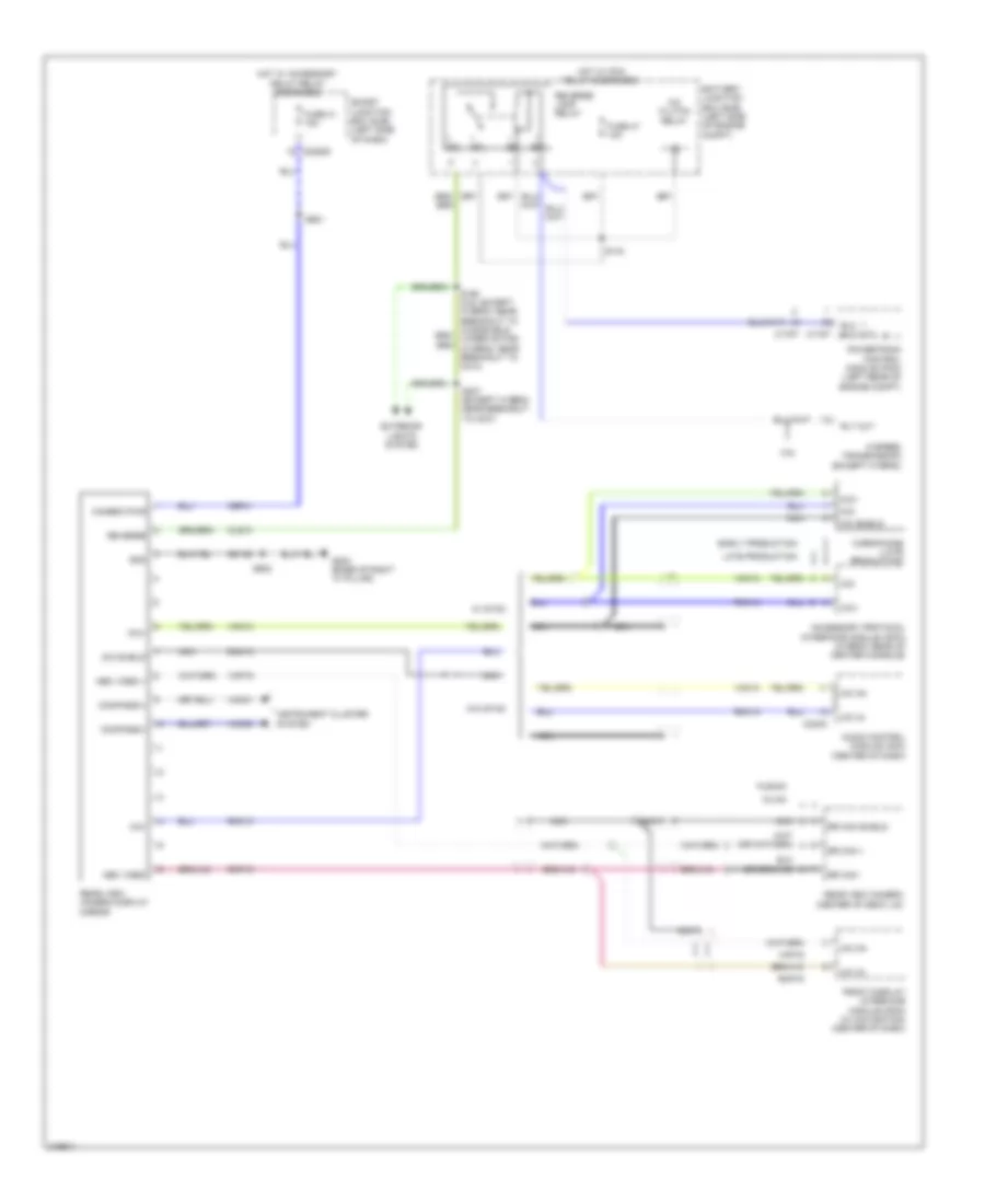
- Instrument cluster (ic)
- Ms can+
- Ms can-
- Occupant classification system module (ocsm) (under right front seat cushion)
- Power steering control module (pscm) (right side of engine compt, near strut tower)
- Powertrain control module (pcm) (left rear of engine compt)
- Pwr gnd
- Restraints control module (rcm) (under center console)
- S105 (near breakout to pscm)
- S161 (near breakout to c145)
- S196 (near breakout to ambient air temperature sensor)
- S197
- S199
- S220
- S225 (near breakout to g201)
- S226 (near breakout to data link connector)
- S332 (near breakout to g301)
- Sbp20
- Sig gnd
- Smart junction box (sjb) (left side of dash)
- Transaxle control module (on transaxle)
- Vdb04
- Vdb05
- Vdb06
- Vdb07
Computer Data Lines Wiring Diagram, Hybrid (2 of 2) for Ford Fusion S 2010
List of elements for Computer Data Lines Wiring Diagram, Hybrid (2 of 2) for Ford Fusion S 2010:
- (center of dash) front control interface module (fcim)
- (left side of rear bumper) s442
- (near breakout to brake pedal angle sensor) (w/ sync) s343
- (near breakout to c211) s222
- (near breakout to data link connector) s227
- (near breakout to right wheel speed sensor) s430
- Accessory protocol interface module (apim) (w/ sync) (rear of center console)
- Audio control module (acm) (center of dash)
- Audio digital signal processing (dsp) module (w/ sony audio) (under right side of package tray)
- C2356a
- C240c
- Front display interface module (fdim) (center of dash)
- Global positioning satellite module (gpsm) (center of dash)
- Hs can+
- Hs can-
- Hvac-datc (center of dash)
- Left rear side obstacle detection (sod) sensor (left side of rear bumper)
- Ms can+
- Ms can+ c4240c
- Ms can-
- Parking aid module (left rear of trunk)
- Right rear side obstacle detection (sod) sensor (right side of rear bumper)
- S223
- S228 (near breakout to data link connector)
- S342 (w/ sync) (near breakout to c327)
- S431 (near breakout to right wheel speed sensor)
- S441 (left side of rear bumper)
- Vdb04
- Vdb05
- Vdb06
- Vdb07
- W/ navigation
- W/o navigation
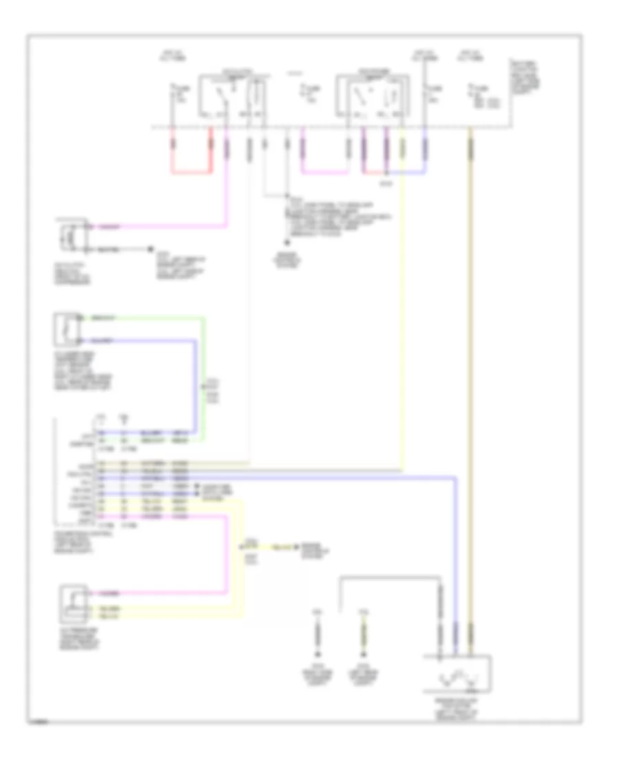
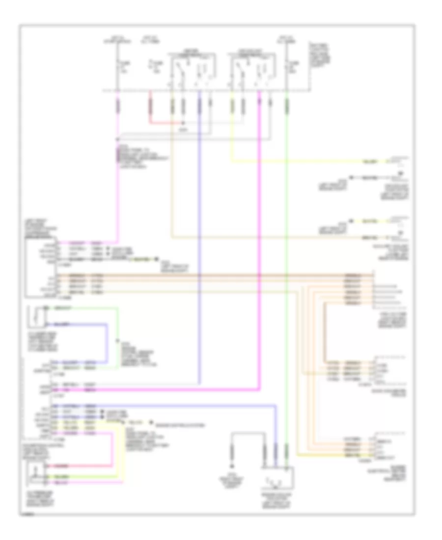
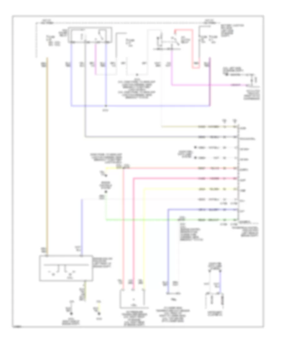
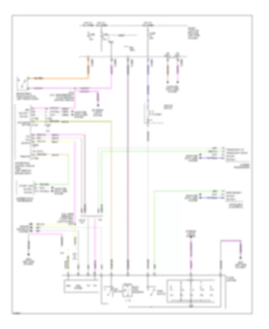
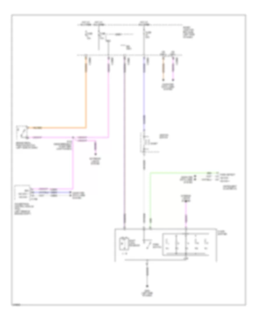
COOLING FAN
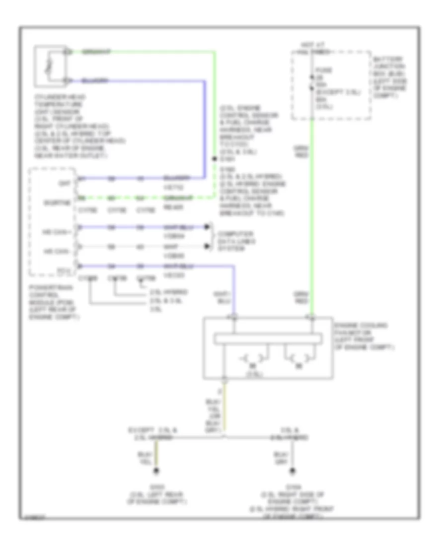
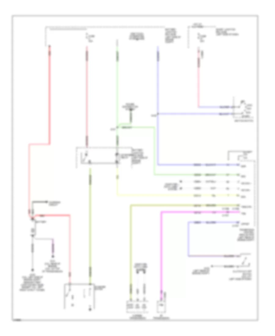
Cooling Fan Wiring Diagram for Ford Fusion S 2010
List of elements for Cooling Fan Wiring Diagram for Ford Fusion S 2010:
- (2.5l: engine control sensor & fuel charge harness, near breakout to c133) (2.5l & 3.0l) s181
- (3.5l)
- 2.5l & 3.0l
- 2.5l hybrid
- 3.5l
- 3.5l & 2.5l hybrid
- Battery junction box (bjb) (left side of engine compt)
- C175b
- C175e
- Cht
- Computer data lines system
- Cylinder head temperature (cht) sensor (3.5l: front of right cylinder head) (2.5l & 2.5l hybrid: top center of cylinder head) (3.0l: rear of engine, near water outlet)
- Engine cooling fan motor (left front of engine compt)
- Except 3.5l & 2.5l hybrid
- Fc-v
- Fuse 60a (except 3.5l) 80a (3.5l)
- G103 (3.0l: left rear of engine compt)
- G104 (3.5l: right side of engine compt) (2.5l hybrid: right front of engine compt)
- Hot at all times
- Hs can +
- Hs can -
- Powertrain control module (pcm) (left rear of engine compt)
- Re405
- S180 (3.5l & 2.5l hybrid) (2.5l hybrid: engine control sensor & fuel charge harness, near breakout to c145)
- Sigrtne
- Vdb04
- Vdb05
- Ve712
- Vec03
CRUISE CONTROL
2.5L
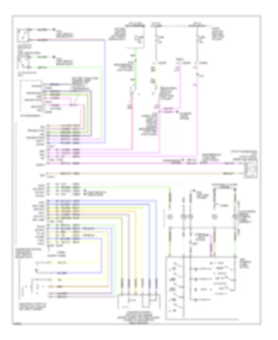
2.5L, Cruise Control Wiring Diagram for Ford Fusion S 2010
List of elements for 2.5L, Cruise Control Wiring Diagram for Ford Fusion S 2010:
- (battery cable wire harness, near breakout to automatic transmission) s146
- (near breakout to battery junction box) s182
- (or le134)
- (or re134)
- (top of transmission) (m/t) output shaft speed (oss) sensor
- 6f transmission
- Accelerator pedal position (app) sensor (except hybrid: left side of dash) (hybrid: on accelerator pedal bracket)
- App1
- App1 rtn
- App1 vref
- App2
- App2 rtn
- App2 vref
- Battery junction box (bjb) (left side of engine compt)
- Boo
- Boo in
- Bps
- Brake pedal position switch (left side of dash)
- C1381t
- C1520a
- C1520b
- C175b
- C175e
- C218a
- C218b
- C2280b
- C2280d
- C2280e
- Cbp44
- Ccb08
- Ce412
- Ce426
- Ce903
- Ce904
- Ces09
- Cet25
- Clock spring (behind steering wheel assembly)
- Clutch cut off switch (m/t) (left side of dash)
- Clutch switch (m/t)
- Computer data lines system
- Cpp-bt
- Cpp-tt
- Ectrtn
- Electronic throttle control (etc) module (on throttle body)
- Etcref
- Except hybrid
- Exterior lights system
- Fuse 10a
- Fuse 15a
- G102 (left rear of engine compt)
- G202 (left side of dash)
- Hot at all times
- Hot in start or run
- Hot w/ pcm relay energized
- Hs can+
- Hs can-
- Hybrid
- Ign
- Info
- Instrument cluster system
- Interior lights system
- Le111
- Le134
- Le136
- Le137
- Left steering wheel switch
- Off
- Oss
- Powertrain control module (pcm) (left rear of engine compt)
- Re134
- Re136
- Re137
- Re406
- Res08
- Reset
- Ret24
- Rsm
- S121
- S140 (near breakout to battery junction box)
- S142 (hybrid: dash panel to headlamp junction harness, near breakout to battery junction box)
- S147
- S203
- Scc srtn
- Sccs
- Set up
- Set+
- Set-
- Sigrtn
- Smart junction box (sjb) (left side of dash)
- Tacm+
- Tacm-
- Tp1 ns
- Tp2 ps
- Transmissions system
- Trs/oss gnd
- Trs/oss vpwr
- Tss
- Tss gnd
- Tss pwr
- Tss/oss/tr gnd
- Vdb04
- Vdb05
- Ve701
- Ve702
- Ve806
- Ve818
- Ve819
- Ves10
- Vet33
3.0L
3.0L, Cruise Control Wiring Diagram for Ford Fusion S 2010
List of elements for 3.0L, Cruise Control Wiring Diagram for Ford Fusion S 2010:
- (battery cable wire harness, near breakout to automatic transmission) s146
- (near breakout to battery junction box) s182
- (or le134)
- (or re134)
- (top of transmission) (m/t) output shaft speed (oss) sensor
- 6f transmission
- Accelerator pedal position (app) sensor (except hybrid: left side of dash) (hybrid: on accelerator pedal bracket)
- App1
- App1 rtn
- App1 vref
- App2
- App2 rtn
- App2 vref
- Battery junction box (bjb) (left side of engine compt)
- Boo
- Boo in
- Bps
- Brake pedal position switch (left side of dash)
- C1381t
- C1520a
- C1520b
- C175b
- C175e
- C218a
- C218b
- C2280b
- C2280d
- C2280e
- Cbp44
- Ccb08
- Ce412
- Ce426
- Ce903
- Ce904
- Ces09
- Cet25
- Clock spring (behind steering wheel assembly)
- Clutch cut off switch (m/t) (left side of dash)
- Clutch switch (m/t)
- Computer data lines system
- Cpp-bt
- Cpp-tt
- Ectrtn
- Electronic throttle control (etc) module (on throttle body)
- Etcref
- Except hybrid
- Exterior lights system
- Fuse 10a
- Fuse 15a
- G102 (left rear of engine compt)
- G202 (left side of dash)
- Hot at all times
- Hot in start or run
- Hot w/ pcm relay energized
- Hs can+
- Hs can-
- Hybrid
- Ign
- Info
- Instrument cluster system
- Interior lights system
- Le111
- Le134
- Le136
- Le137
- Left steering wheel switch
- Off
- Oss
- Powertrain control module (pcm) (left rear of engine compt)
- Re134
- Re136
- Re137
- Re406
- Res08
- Reset
- Ret24
- Rsm
- S121
- S140 (near breakout to battery junction box)
- S142 (hybrid: dash panel to headlamp junction harness, near breakout to battery junction box)
- S147
- S203
- Scc srtn
- Sccs
- Set up
- Set+
- Set-
- Sigrtn
- Smart junction box (sjb) (left side of dash)
- Tacm+
- Tacm-
- Tp1 ns
- Tp2 ps
- Transmissions system
- Trs/oss gnd
- Trs/oss vpwr
- Tss
- Tss gnd
- Tss pwr
- Tss/oss/tr gnd
- Vdb04
- Vdb05
- Ve701
- Ve702
- Ve806
- Ve818
- Ve819
- Ves10
- Vet33
3.5L
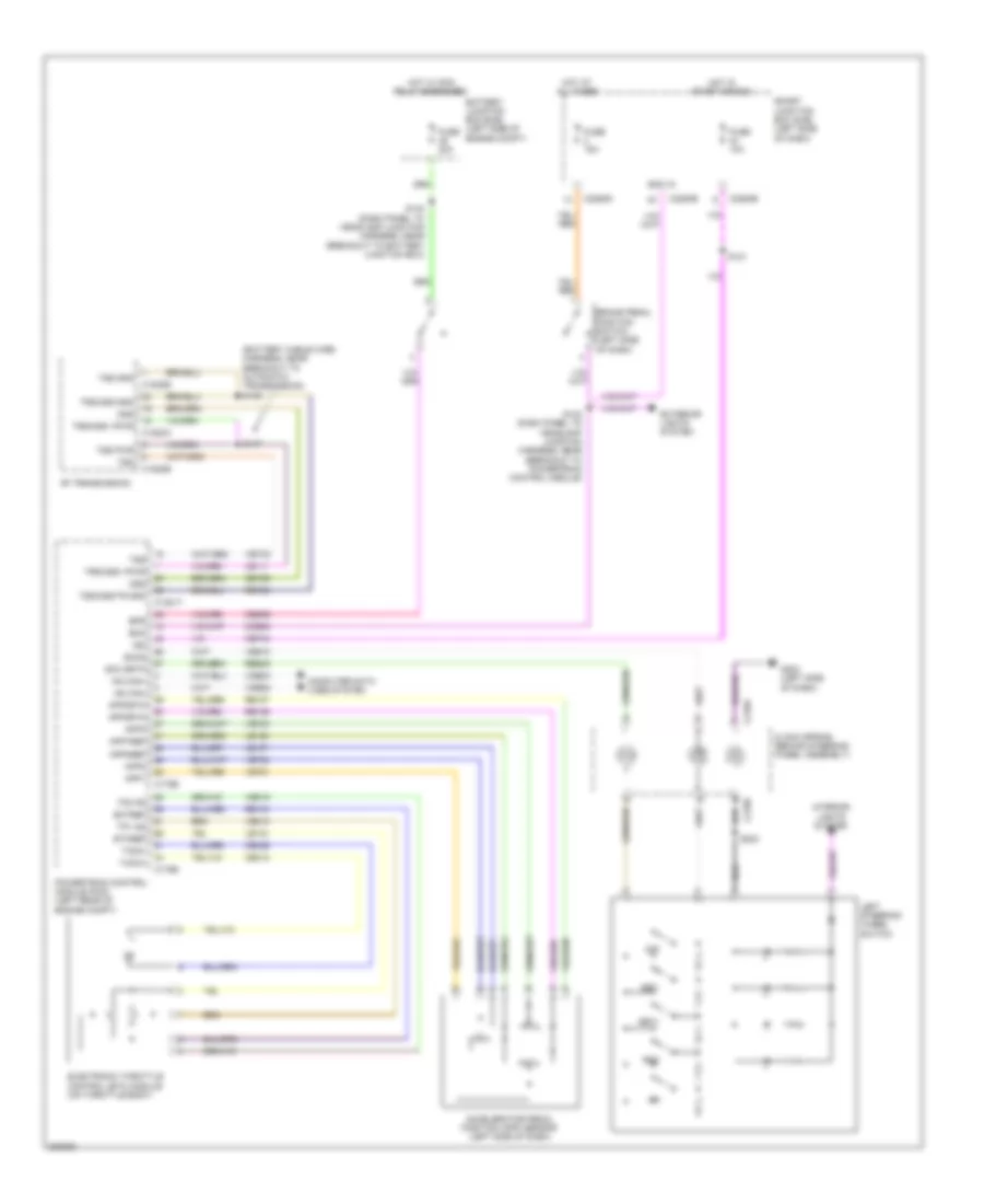
3.5L, Cruise Control Wiring Diagram for Ford Fusion S 2010
List of elements for 3.5L, Cruise Control Wiring Diagram for Ford Fusion S 2010:
- (battery cable wire harness, near breakout to automatic transmission) s146
- 6f transmission
- Accelerator pedal position (app) sensor (left side of dash)
- App1
- App1ref
- App2
- App2ref
- App2rtn
- App3
- Battery junction box (bjb) (left side of engine compt)
- Boo
- Boo in
- Bps
- Brake pedal position switch (left side of dash)
- C1381t
- C1520a
- C1520b
- C175b
- C175e
- C218a
- C218b
- C2280b
- C2280d
- C2280e
- Cbp44
- Ccb08
- Ce412
- Ce426
- Ces09
- Cet25
- Clock spring (behind steering wheel assembly)
- Computer data lines system
- Ectref
- Electronic throttle control (etc) module (on throttle body)
- Etcref
- Exterior lights system
- Fuse 10a
- Fuse 15a
- Fuse 20a
- G202 (left side of dash)
- Hot at all times
- Hot in start or run
- Hot w/ pcm relay energized
- Hs can+
- Hs can-
- Ign
- Interior lights system
- Le111
- Le134
- Le136
- Le137
- Left steering wheel switch
- Off
- Oss
- Powertrain control module (pcm) (left rear of engine compt)
- Re134
- Re136
- Re137
- Res08
- Ret24
- Rsm
- S121
- S140 (dash panel to headlamp junction harness, near breakout to battery junction box)
- S142 (dash panel to headlamp junction harness, near breakout to powertrain control module)
- S147
- S203
- Scc srtn
- Sccs
- Set+
- Set-
- Smart junction box (sjb) (left side of dash)
- Tacm+
- Tacm-
- Tp1 ns
- Tp2 ps
- Trs/oss gnd
- Trs/oss vpwr
- Tss
- Tss gnd
- Tss pwr
- Tss/oss/tr gnd
- Vdb04
- Vdb05
- Ve701
- Ve702
- Ve703
- Ve818
- Ve819
- Ves10
- Vet33
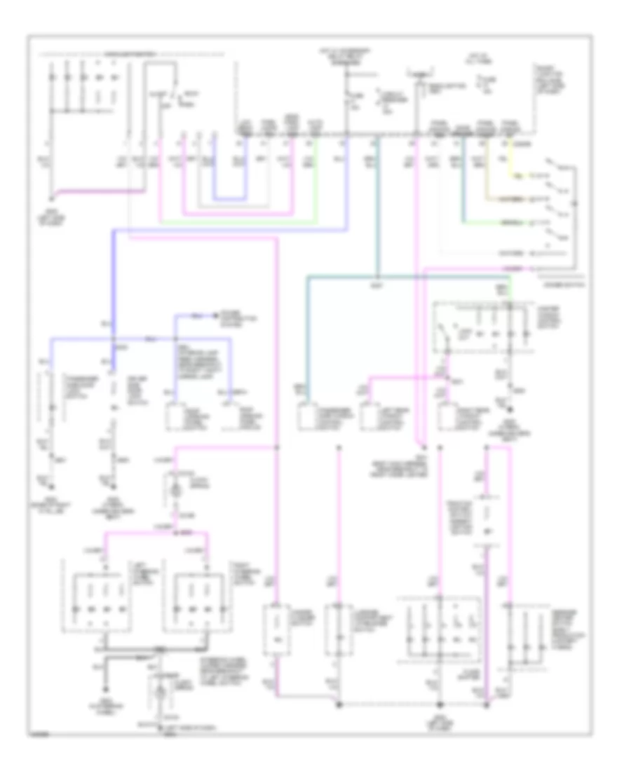
DEFOGGERS
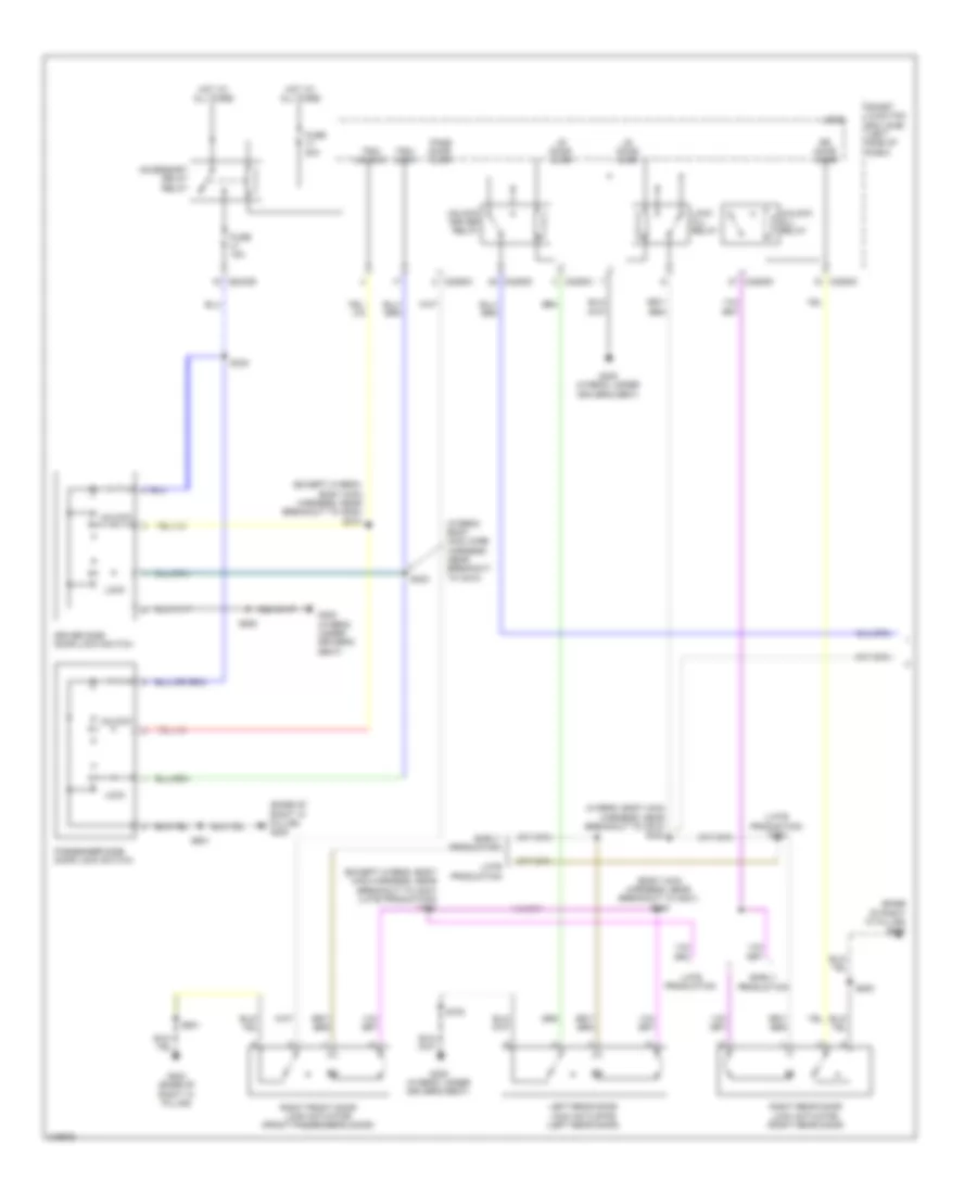
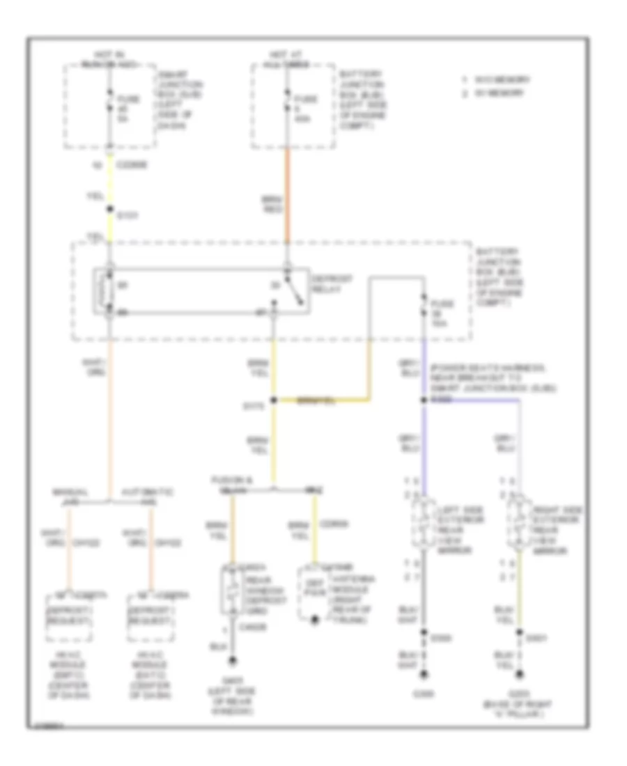
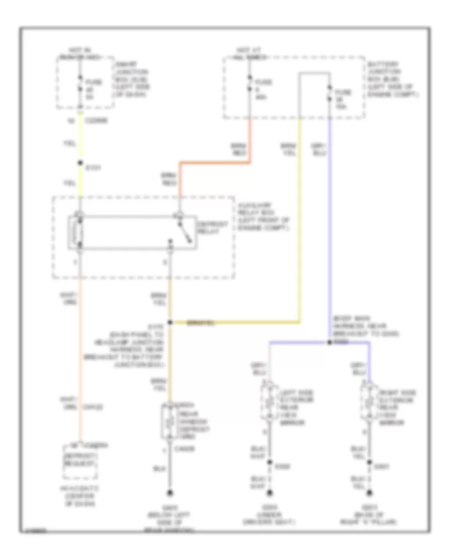
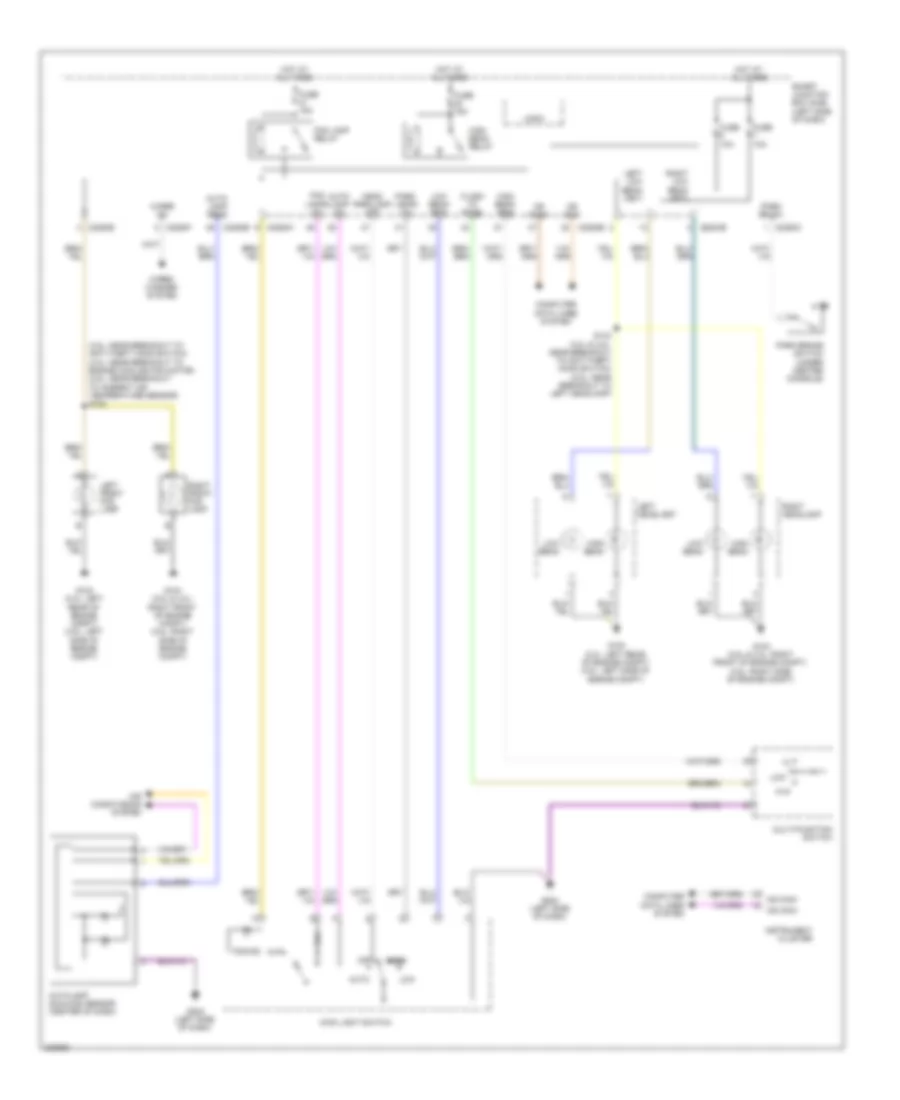
Defoggers Wiring Diagram, Except Hybrid for Ford Fusion S 2010
List of elements for Defoggers Wiring Diagram, Except Hybrid for Ford Fusion S 2010:
- (power seats harness, near breakout to smart junction box (sjb)) s322
- Antenna module (right rear of trunk)
- Automatic a/c
- Battery junction box (bjb) (left side of engine compt)
- C2280e
- C2356a
- C2357a
- C402a
- C402b
- C4194b
- Dash)
- Def pwr
- Defrost relay
- Defrost request
- Fuse 10a
- Fuse 40a
- Fuse 5a
- Fusion & milan
- G203 (base of right "a" pillar )
- G300
- G405 (left side of rear window)
- Hot at all times
- Hot in run or acc
- Hvac module (datc) (center of dash)
- Hvac module (emtc) (center of dash)
- Left side exterior rear view mirror
- Manual a/c
- Mkz
- Rear window defrost grid
- Right side exterior rear view mirror
- S131
- S175
- S500
- S601
- Smart junction box (sjb) (left side of
- W/ memory
- W/o memory
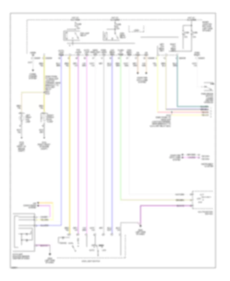
Defoggers Wiring Diagram, Hybrid for Ford Fusion S 2010
List of elements for Defoggers Wiring Diagram, Hybrid for Ford Fusion S 2010:
- (body main harness, near breakout to g300) s322
- Auxiliary relay box (left front of engine compt)
- Battery junction box (bjb) (left side of engine compt)
- C2280e
- C2356a
- C402a
- C402b
- Defrost relay
- Defrost request
- Fuse 10a
- Fuse 40a
- Fuse 5a
- G203 (base of right "a" pillar)
- G300 (under driver's seat)
- G405 (below left side of rear window)
- Hot at all times
- Hot in run or acc
- Hvac-datc (center of dash)
- Left side exterior rear view mirror
- Rear window defrost grid
- Right side exterior rear view mirror
- S131
- S175 (dash panel to headlamp junction harness, near breakout to battery junction box)
- S500
- S601
- Smart junction box (sjb) (left side of dash)
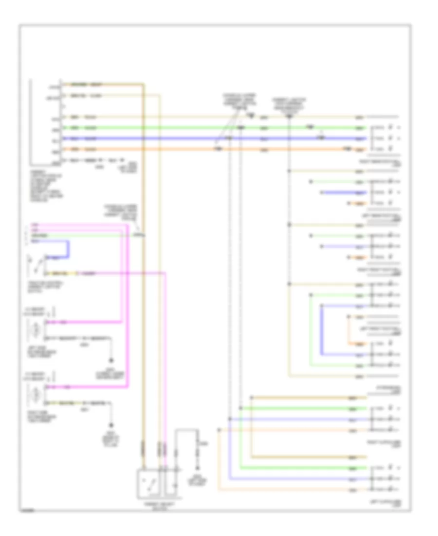
ELECTRONIC POWER STEERING
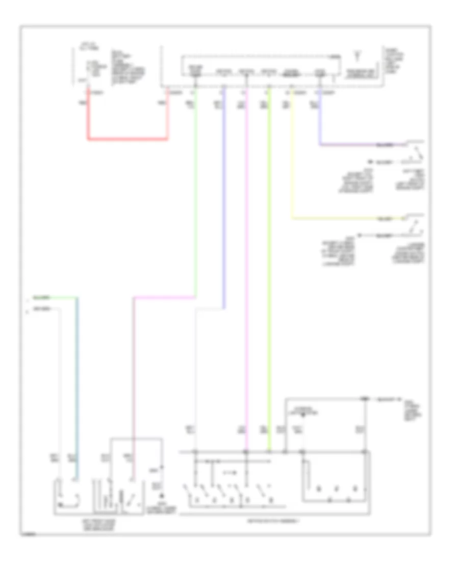
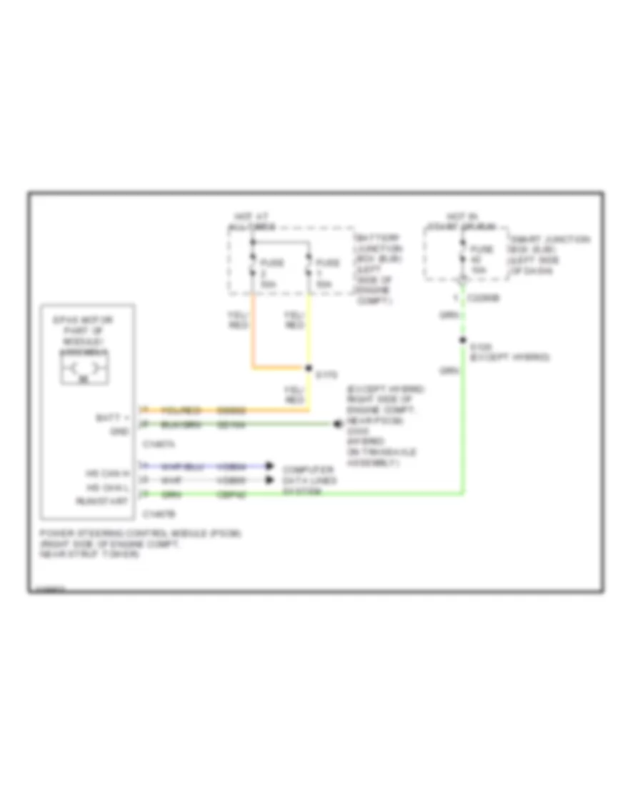
Electronic Power Steering Wiring Diagram for Ford Fusion S 2010
List of elements for Electronic Power Steering Wiring Diagram for Ford Fusion S 2010:
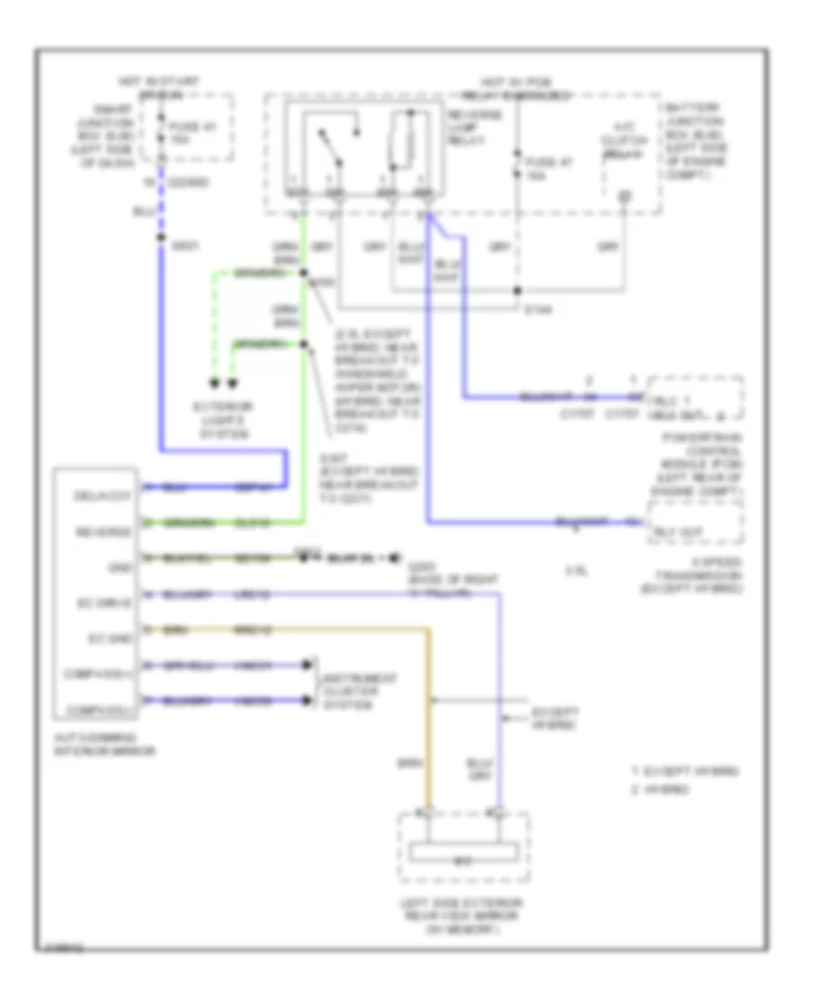
- (except hybrid: right side of engine compt, near pscm) g105 (hybrid: on transaxle assembly)
- Batt +
- Battery junction box (bjb) (left side of engine compt)
- C1467a
- C1467b
- C2280b
- Cbp42
- Computer data lines system
- Epas motor part of module/ assembly
- Fuse 10a
- Fuse 50a
- Gd104
- Gnd
- Hot at all times
- Hot in start or run
- Hs can h
- Hs can l
- Power steering control module (pscm) (right side of engine compt, near strut tower)
- Run/start
- S120 (except hybrid)
- S170
- Sbb02
- Smart junction box (sjb) (left side of dash)
- Vdb04
- Vdb05
ENGINE PERFORMANCE
2.5L
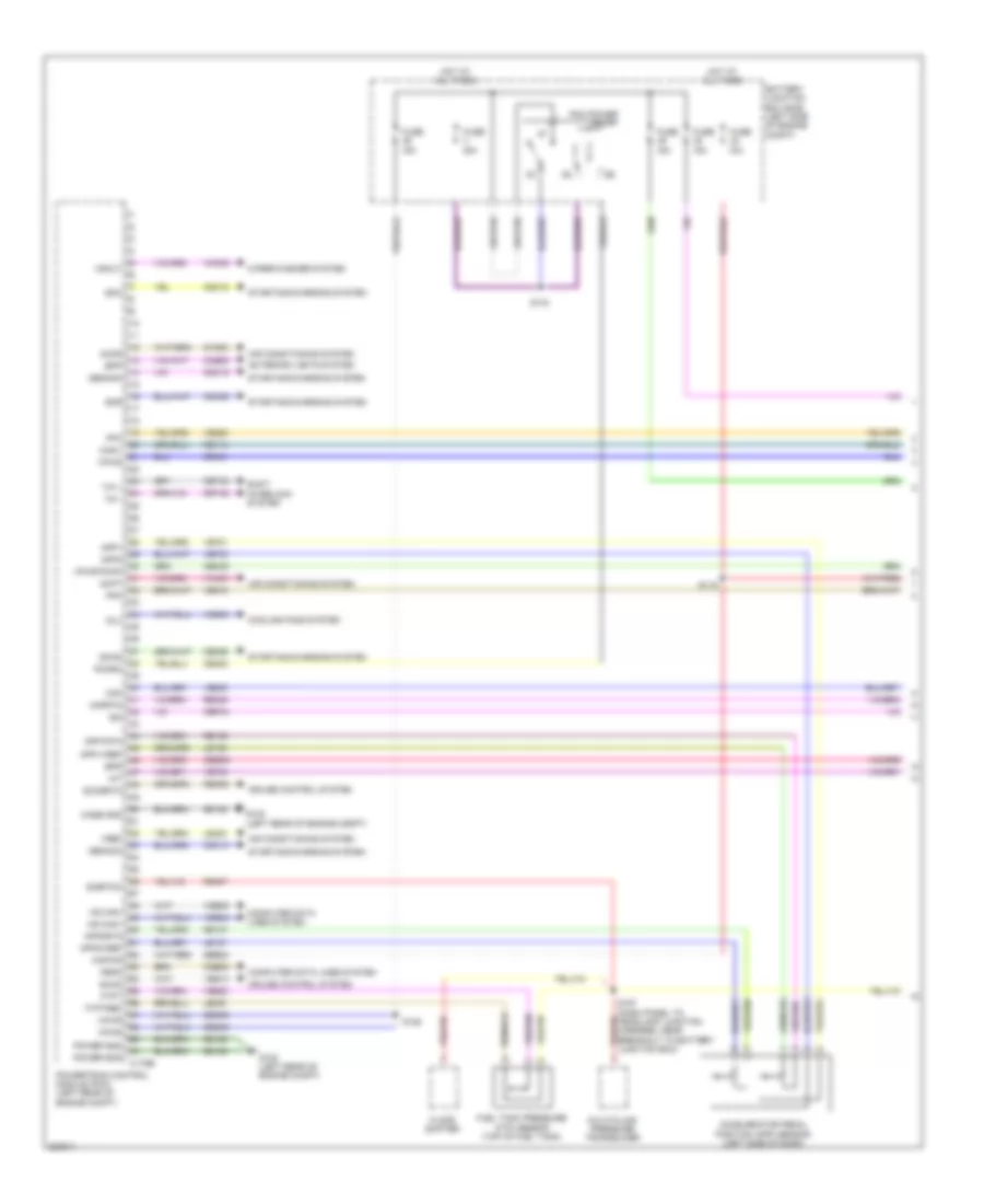
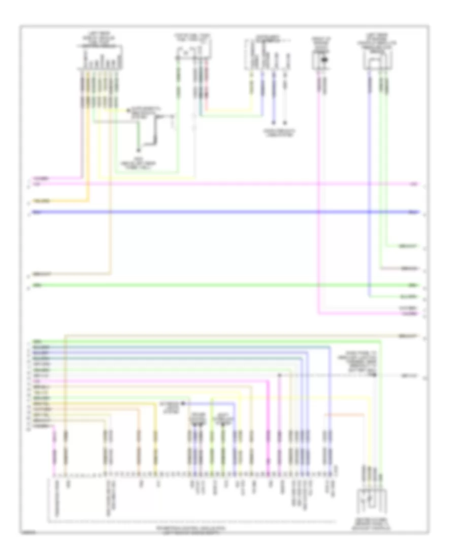
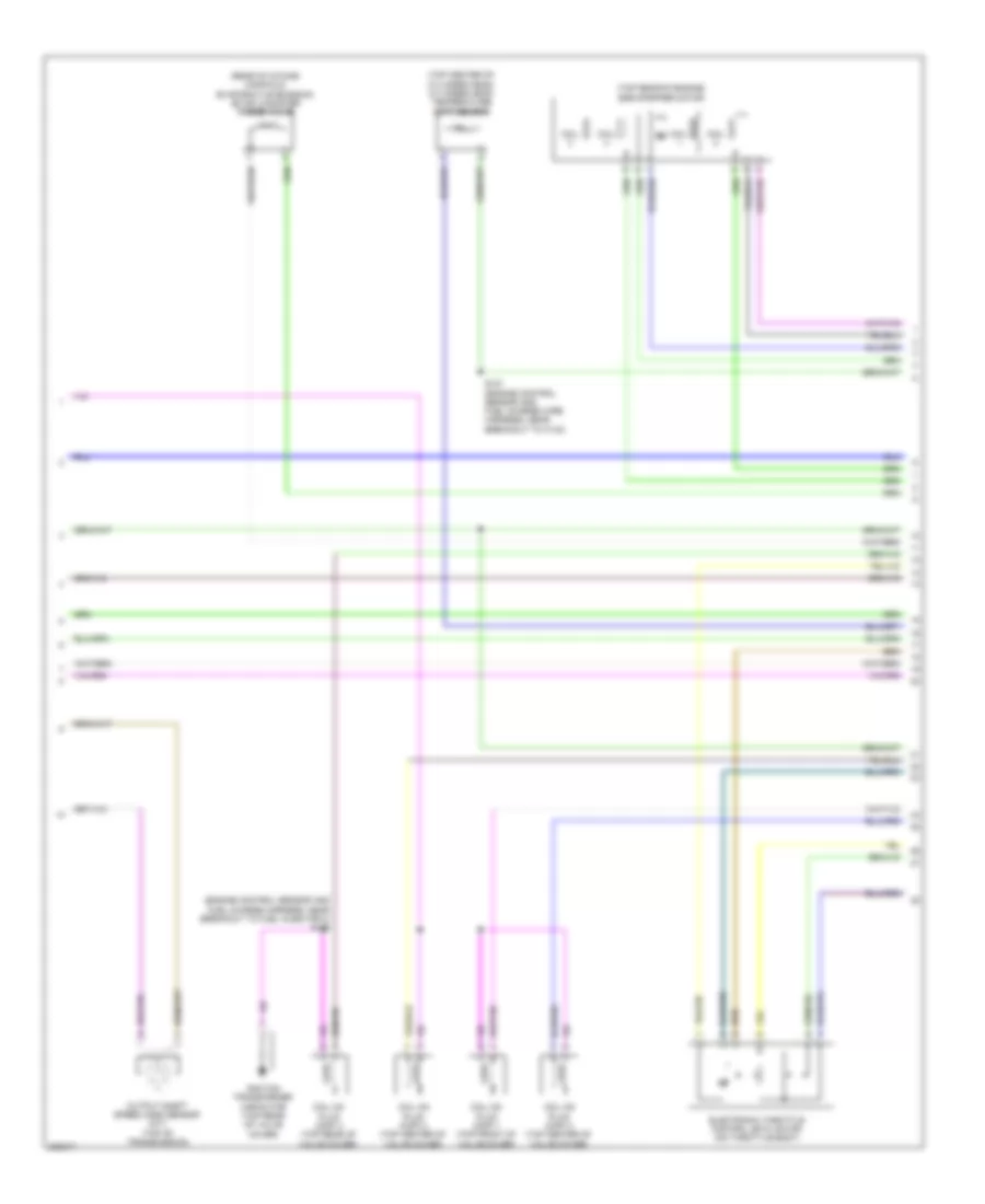
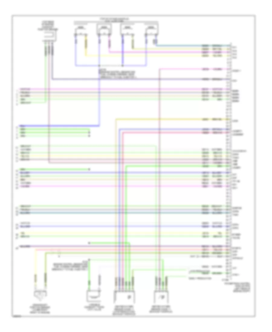
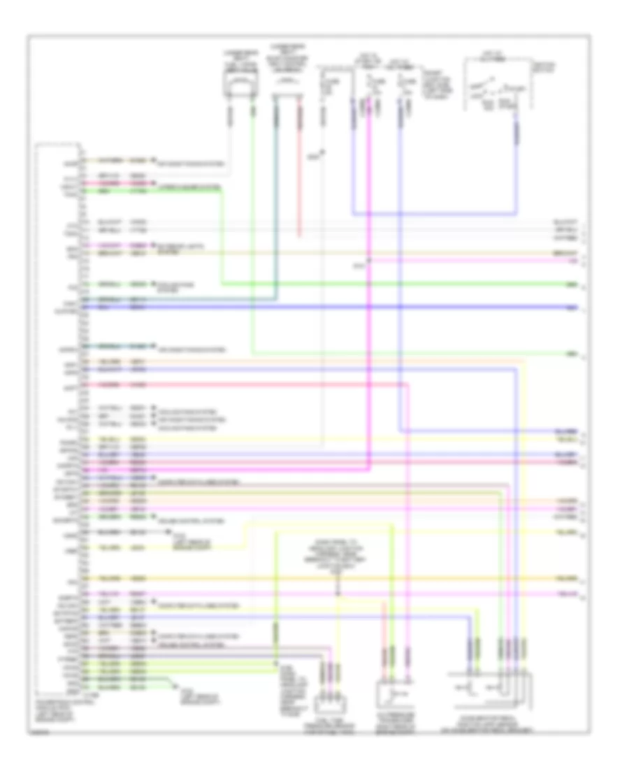
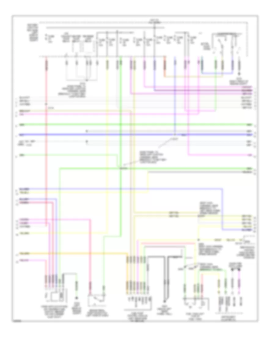
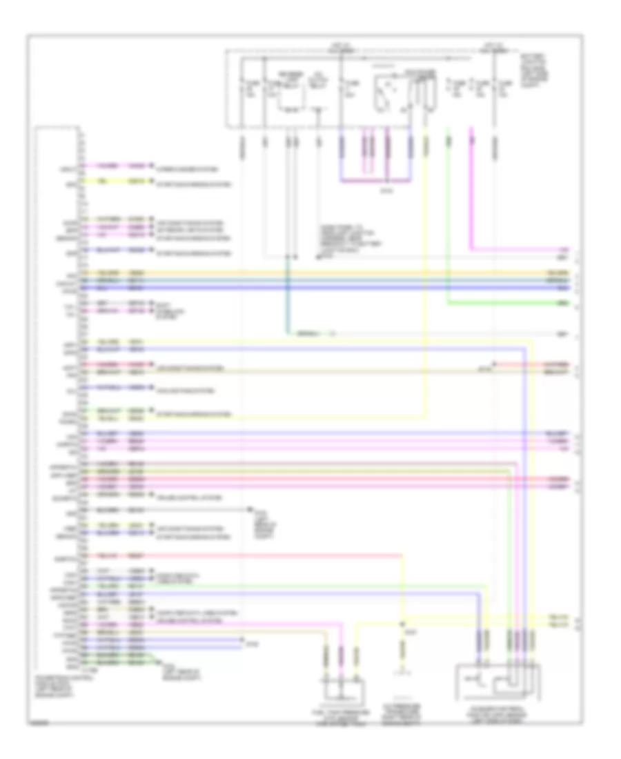
2.5L, Engine Performance Wiring Diagram, Except Hybrid (1 of 5) for Ford Fusion S 2010
List of elements for 2.5L, Engine Performance Wiring Diagram, Except Hybrid (1 of 5) for Ford Fusion S 2010:
- 10a
- 15a
- 40a
- A/c cycling pressure transducer
- Accelerator pedal position (app) sensor (left side of dash)
- Accr
- Acpt
- Air conditioning system
- App1
- App1rtn
- App1vref
- App2
- App2rtn
- App2vref
- Battery junction box (bjb) (left side of engine compt)
- Bpp
- Bps
- C175b
- Canv
- Case gnd
- Cbb46
- Cbk01
- Cbk02
- Cbp44
- Ccb08
- Cdb08
- Cdc10
- Cdc12
- Cdc15
- Cdc35
- Ce114
- Ce302
- Ce336
- Ces09
- Cet42
- Cet43
- Ch302
- Computer data lines system
- Cooling fans system
- Cruise control system
- Exterior lights system
- Fcv
- Feps
- Floor shifter
- Fpc
- Fpm
- Ftpt
- Ftptref
- Fuel tank pressure (ftp) sensor (top of fuel tank)
- Fuse
- G102 (left rear of engine compt)
- Gd120
- Gencom
- Genmon
- Hot at all times
- Hs can+
- Hs can-
- Iat
- Ign
- Kapwr
- Le136
- Le137
- Le230
- Le424
- Maf
- Mafrtn
- Pcm power relay
- Pcmrc
- Power gnd
- Powertrain control module (pcm) (left rear of engine compt)
- Re136
- Re137
- Re325
- Re407
- Res08
- S119
- S125
- S143
- Sbb23
- Sccs
- Sccsrtn
- Shift interlock system
- Sigrtnc
- Smc
- Smcs
- Smr
- Starting/charging system
- Tip +
- Tip -
- Vce03
- Vdb04
- Vdb05
- Ve225
- Ve518
- Ve701
- Ve702
- Ve740
- Ve808
- Ve922
- Ves10
- Vh433
- Vmc05
- Vpwr
- Vpwrtr-pn
- Vref
- Vsout
- Wiper/washer system
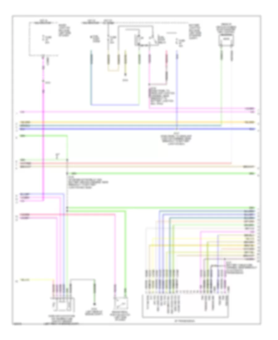
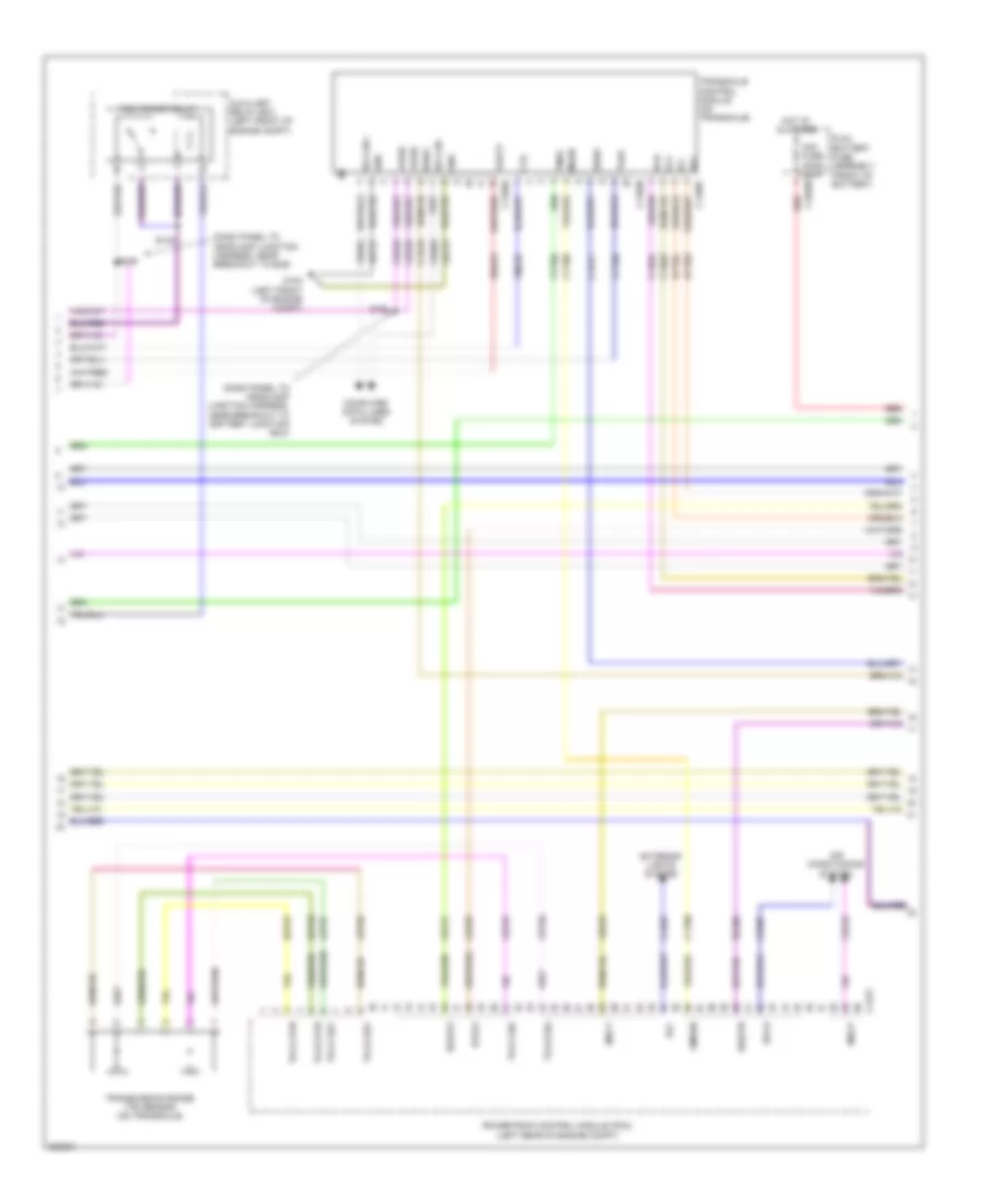
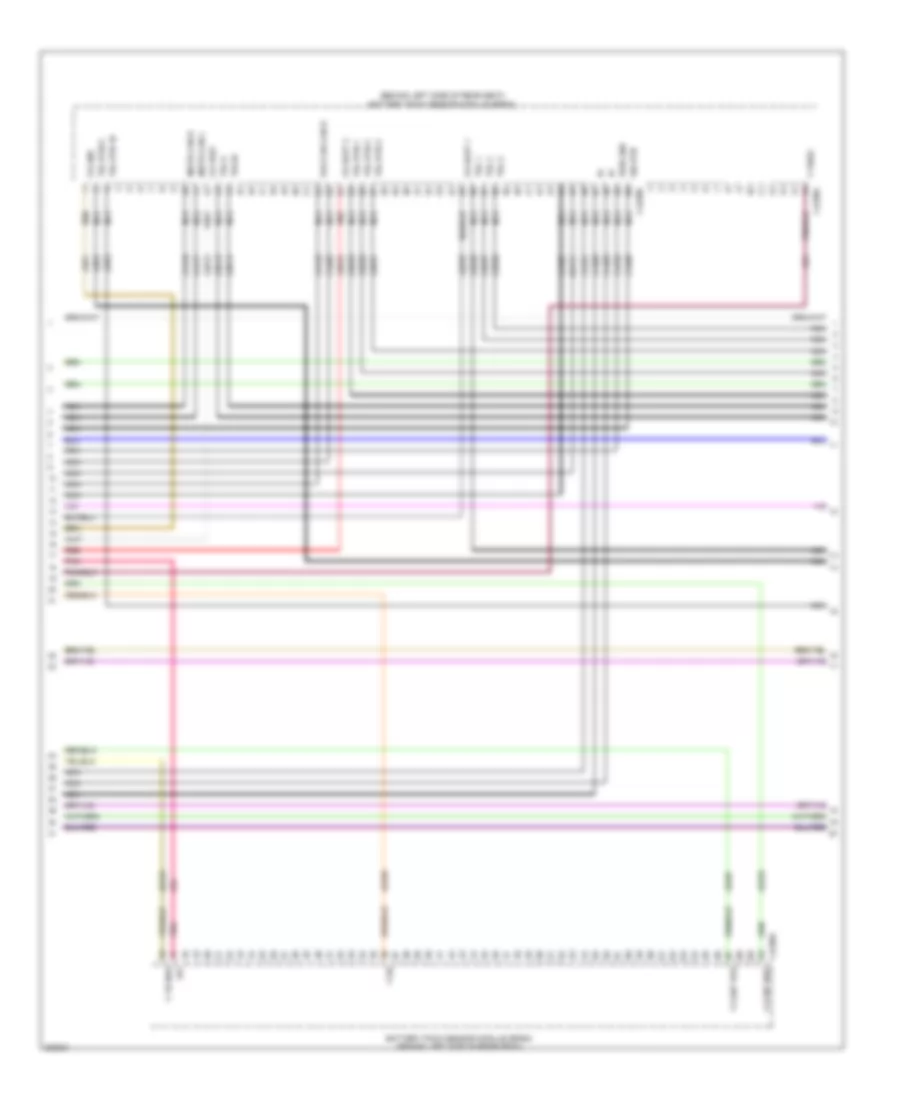
2.5L, Engine Performance Wiring Diagram, Except Hybrid (2 of 5) for Ford Fusion S 2010
List of elements for 2.5L, Engine Performance Wiring Diagram, Except Hybrid (2 of 5) for Ford Fusion S 2010:
- (rear of vehicle chassis) evap canister vent control solenoid
- 15a
- 30a
- 6f transmission
- Battery junction box (bjb) (left side of engine compt)
- Brake pedal position switch (left side of dash)
- C168a
- C168b
- C2280e
- Cblr/c456 vfs
- Cet05
- Cet06
- Cet07
- Cet08
- Cet09
- Cet10
- Cet18
- Cet25
- Fuel pump diode
- Fuel pump relay
- Fuse
- G102 (left rear of engine compt)
- G103
- Hot at all times
- Hot in run or start
- Le111
- Lpc vfs
- M/t
- Mass air flow/intake air temperature (maf/iat) sensor (left front of engine compt)
- Oss
- Re406
- Ret24
- S121
- S137 (dash panel to headlamp junction harness, near breakout to battery junction box)
- S140 (starter motor relay and battery ground harness, near breakout to battery junction box (bjb))
- S146
- S147 (battery cable wire harness, near breakout to automatic transmission)
- Smart junction box (sjb) (left side of dash)
- Sol pwr
- Ssa cb1234 vfs
- Ssb c35r vfs
- Ssc cb26 vfs
- Sse on/off sol
- Tcc vfs
- Tft
- Tft sig rtn
- Trs
- Trs/oss gnd
- Trs/oss pwr
- Tss
- Tss gnd
- Tss pwr
- Vet26
- Vet27
- Vet32
- Vet33
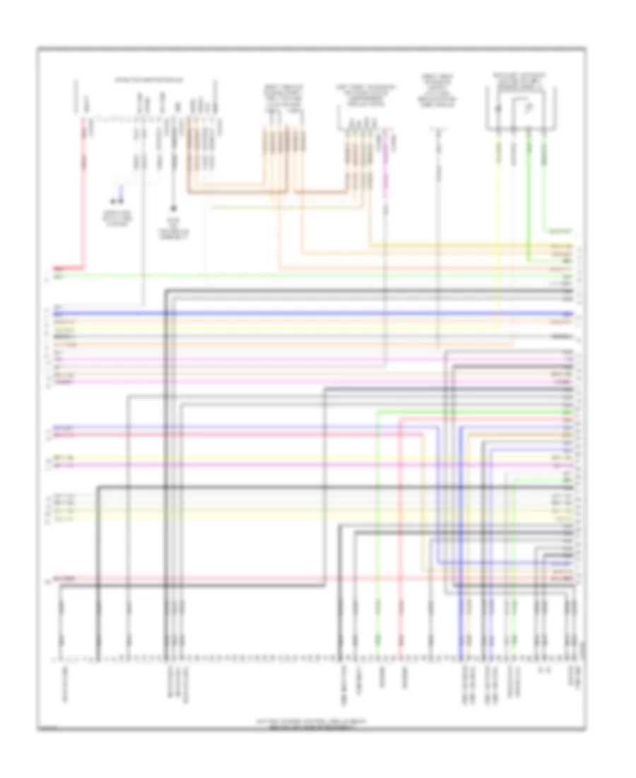
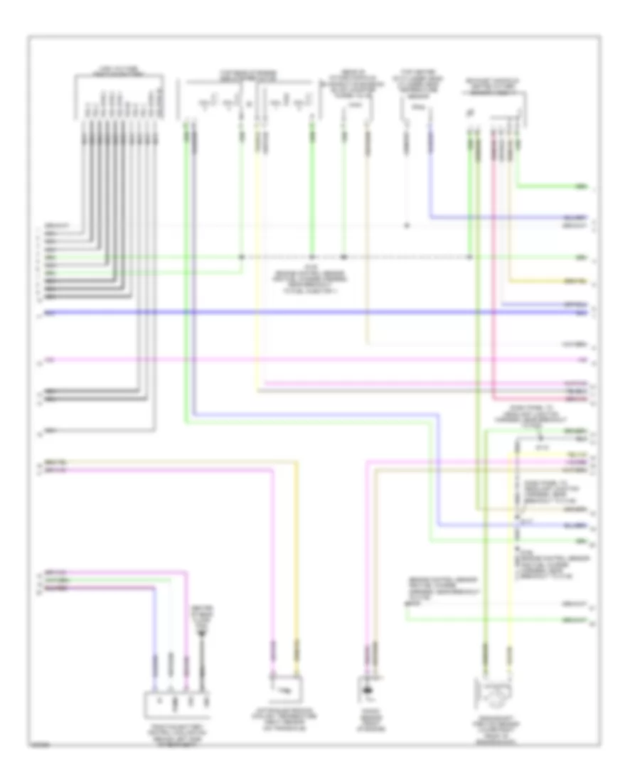
2.5L, Engine Performance Wiring Diagram, Except Hybrid (3 of 5) for Ford Fusion S 2010
List of elements for 2.5L, Engine Performance Wiring Diagram, Except Hybrid (3 of 5) for Ford Fusion S 2010:
- (dash panel to headlamp junction harness, near breakout to battery box) s182
- (front of engine) knock sensor
- (left rear of engine) manifold absolute pressure (map) sensor
- (left rear side of vehicle) fuel pump control module
- (top of fuel tank) fuel tank unit
- C175t
- Ce226
- Ce233
- Ce515
- Ce608
- Ce903
- Ce904
- Cet05
- Cet06
- Cet07
- Cet08
- Cet09
- Cet10
- Cet18
- Cet25
- Cet34
- Cls28
- Computer data lines system
- Cpp-bt
- Cpp-tt
- Cr167
- Cruise control system
- Ens
- Exterior lights system
- Fpc
- Fpm
- Fppwr
- Fprtn
- Fuel sender return
- Fuel sender signal
- G403 (above left rear wheel well)
- Gd151
- Gnd
- Heated oxygen sensor (ho2s) 12 (exhaust manifold)
- Ho2s-12
- Hs can+
- Hs can-
- Htr-12
- Ifs input
- Instrument cluster (ic)
- Lcp vfs
- Le111
- Oss
- Powertrain control module (pcm) (left rear of engine compt)
- Re226
- Re406
- Ret24
- Rlc
- Rmc32
- Shift interlock system
- Sigrtn
- Sol pwr
- Ssa cb1234 vfs
- Ssb c35r vfs
- Ssc cb26 vfs
- Ssd cblr/c456 vfs
- Sse on/off sol
- Tcc vfs
- Tcs
- Tft
- Tr gnd
- Trs
- Trs/oss/tss vpwr
- Tss
- Ve225
- Ve518
- Ve731
- Ve806
- Vet26
- Vet27
- Vet32
- Vet33
- Vmc11
2.5L, Engine Performance Wiring Diagram, Except Hybrid (4 of 5) for Ford Fusion S 2010
List of elements for 2.5L, Engine Performance Wiring Diagram, Except Hybrid (4 of 5) for Ford Fusion S 2010:
- (engine control sensor and fuel charge harness, near breakout to fuel injector 2) s135
- (rear of intake manifold) evaporative emission (evap) canister purge valve
- (top center of cylinder head) cylinder head temperature (cht) sensor
- (top rear of engine) egr stepper motor
- Coil
- Coil on plug (cop) 1 (top front of valve cover)
- Coil on plug (cop) 2 (top center of valve cover)
- Coil on plug (cop) 3 (top center of valve cover)
- Coil on plug (cop) 4 (top rear of valve cover)
- Electronic throttle control (etc) motor (on throttle body)
- Ignition transformer capacitor (top rear of valve cover)
- Output shaft speed (oss) sensor (m/t) (top of transmission)
- S181 (engine control sensor and fuel charge wire harness, near breakout to c133)
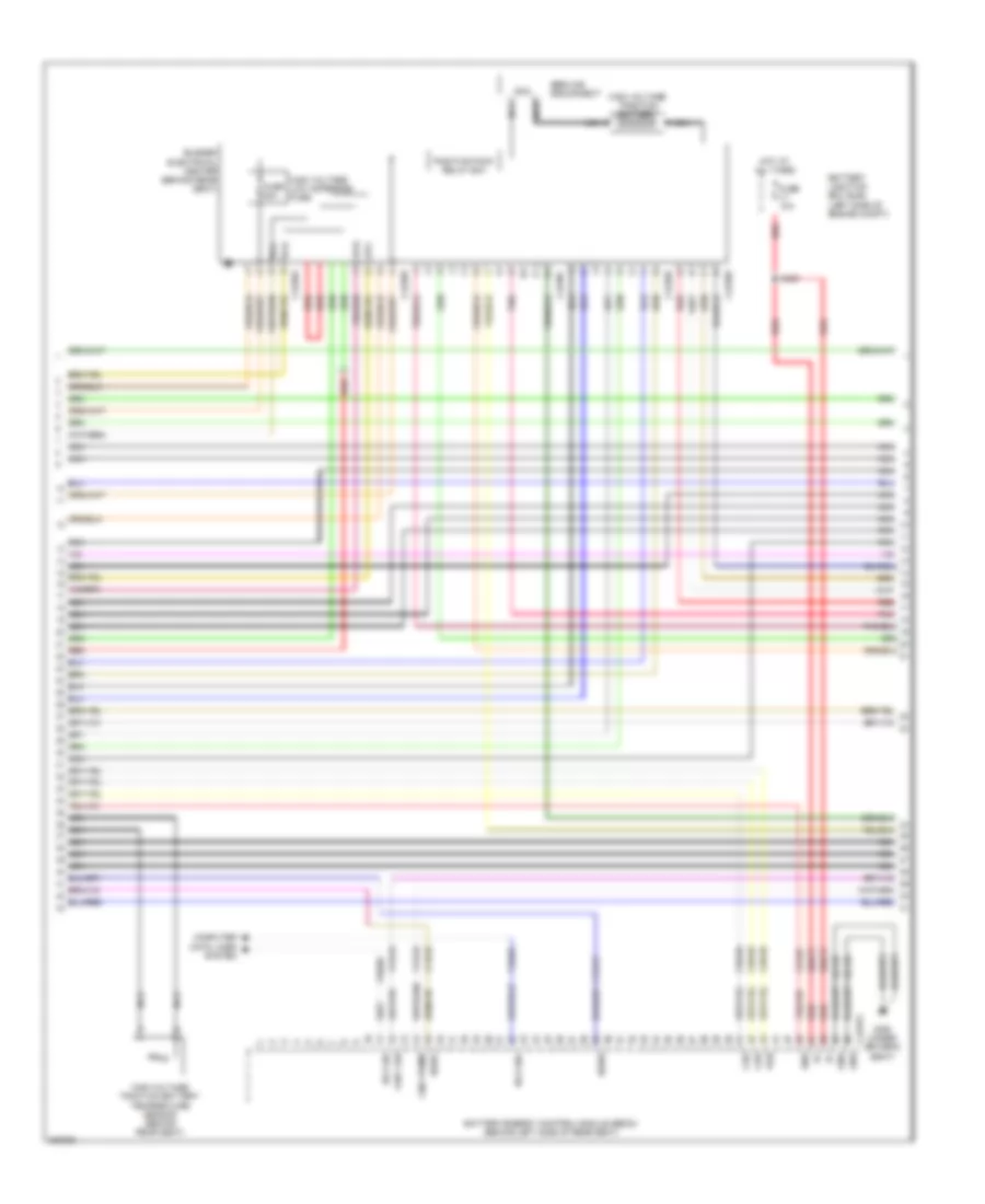
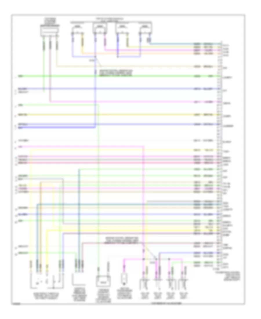
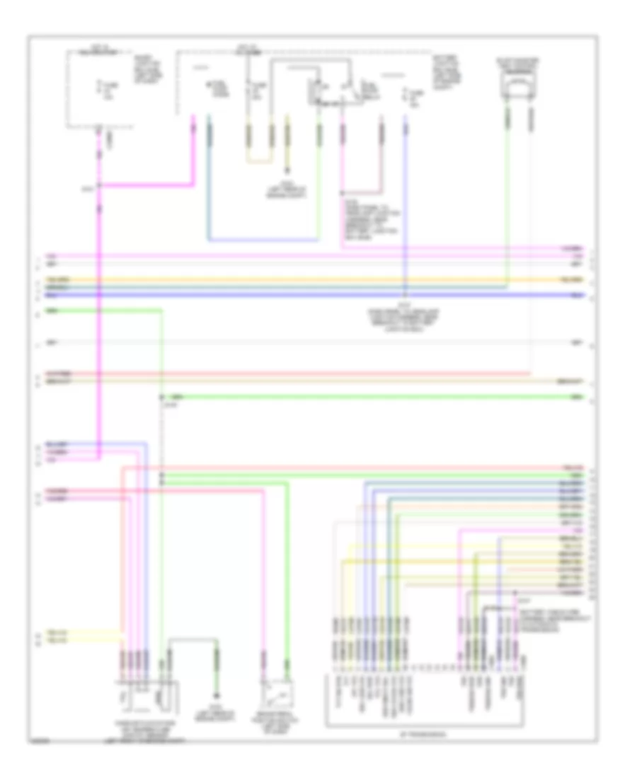
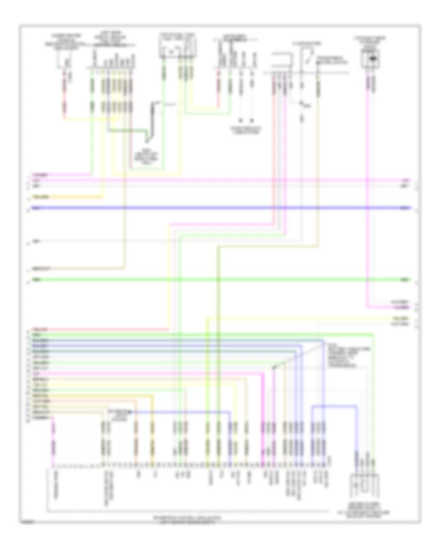
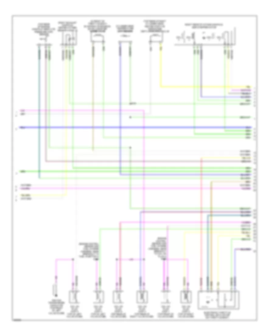
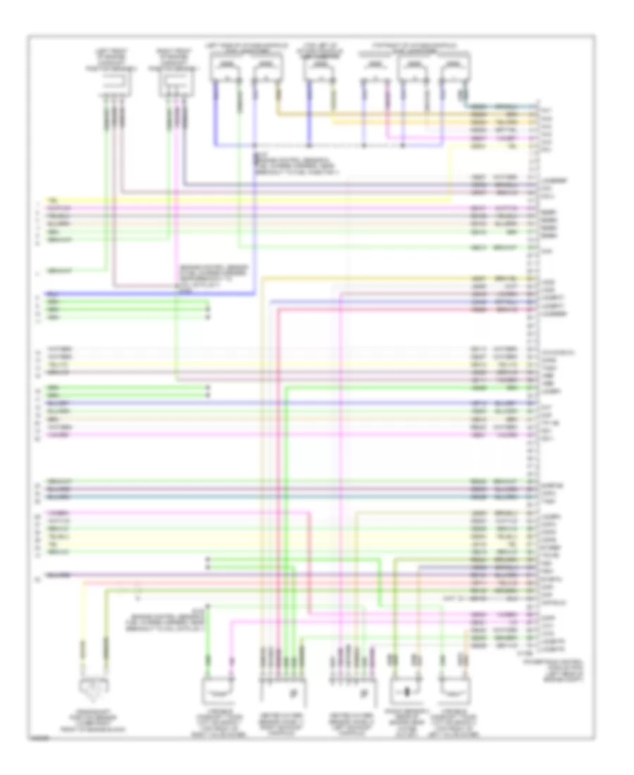
2.5L, Engine Performance Wiring Diagram, Except Hybrid (5 of 5) for Ford Fusion S 2010
List of elements for 2.5L, Engine Performance Wiring Diagram, Except Hybrid (5 of 5) for Ford Fusion S 2010:
- (engine control sensor and fuel charge harness, near breakout to fuel injector 1)
- (top of intake manifold) fuel injectors
- (top rear of engine) camshaft position sensor
- C175e
- Ce101
- Ce102
- Ce103
- Ce104
- Ce113
- Ce205
- Ce206
- Ce207
- Ce208
- Ce235
- Ce303
- Ce304
- Ce305
- Ce306
- Ce412
- Ce422
- Ce426
- Cht
- Cid1
- Ckp shld
- Ckp+
- Ckp-
- Cop-a
- Cop-b
- Cop-c
- Cop-d
- Crankshaft position sensor (lower right front of engine)
- De135
- Early production
- Eegr1
- Eegr2
- Eegr3
- Eegr4
- Etcref
- Etcrtn
- Heated oxygen sensor (ho2s) 11 (exhaust manifold)
- Heated oxygen sensor (ho2s) 11 (late production) (exhaust manifold)
- Ho2s-11
- Htr-11
- Inj1
- Inj2
- Inj3
- Inj4
- Ks1+
- Ks1-
- Late production
- Le111
- Le134
- Le423
- Le448
- Le451
- Le452
- Map
- Powertrain control module (pcm) (left rear of engine compt)
- Re134
- Re135
- Re323
- Re405
- S138 (engine control sensor and fuel charge harness, near breakout to fuel injector 1)
- Sigrtne
- Tacm+
- Tacm-
- Tp1 ns
- Tp2 ps
- Uo2s
- Uo2sgref
- Uo2spc
- Uo2spct
- Variable camshaft timing (vct) valve
- Vct
- Ve706
- Ve711
- Ve712
- Ve735
- Ve801
- Ve803
- Ve818
- Ve819
- Ve826
- Vmv-cc/evmv
- Vref
2.5L, Engine Performance Wiring Diagram, Hybrid (1 of 8) for Ford Fusion S 2010
List of elements for 2.5L, Engine Performance Wiring Diagram, Hybrid (1 of 8) for Ford Fusion S 2010:
- (dash panel to headlamp junction harness, near breakout to battery junction box) s157
- (under rear seat) evap canister vent control solenoid
- (under rear seat) fuel vapor vent valve
- A/c pressure transducer (right rear of engine compt)
- Accelerator pedal position (app) sensor (on accelerator pedal bracket)
- Accr
- Aclpcs
- Acpsw
- Acpt
- Air conditioning system
- App1
- App2
- Boo
- Bps
- C175b
- C2280b
- C2280d
- C2280e
- Canv
- Cbb40
- Cbk01
- Cbp28
- Cbp44
- Ccb08
- Cdb08
- Ce114
- Ce302
- Ce420
- Cec01
- Cec02
- Cec03
- Ces09
- Cgnd
- Ch302
- Ch421
- Ch425
- Computer data lines system
- Cooling fans system
- Cruise control system
- Cto
- Ectref2
- Ectrtn2
- Etcref1
- Etcrtn1
- Exterior lights system
- Fc v
- Fc1
- Fc2
- Feps
- Fpc
- Fpm
- Ftp
- Ftpref
- Fuel tank pressure sensor (top of fuel tank)
- Fuse 10a
- Fuse 15a
- Fuse 5a
- Fvvv
- G102 (left rear of engine compt)
- Gd120
- Gnd
- Hot at all times
- Hot in start or run
- Hs can+
- Hs can-
- Iat
- Ignition switch
- Injpwrm
- Isp-r
- Isp-r/s
- Kapwr
- Le136
- Le137
- Le230
- Le424
- Lock
- Maf
- Mafrtn
- Off
- Pcmrc
- Powertrain control module (pcm) (left rear of engine compt)
- Re136
- Re137
- Re325
- Re407
- Res08
- Run/ run/ acc
- S121
- S195 (dash panel to headlamp junction harness, near breakout to bjb)
- S230
- Sbb23
- Sccs
- Sccsrtn
- Sigrtn
- Smart junction box (sjb) (left side of dash)
- Start
- Tgac
- Tmac
- Vdb04
- Vdb05
- Ve225
- Ve518
- Ve701
- Ve702
- Ve740
- Ve808
- Ve922
- Ves10
- Vh433
- Vmc02
- Vmc05
- Vpwr
- Vref
- Vsout
- Vyt05
- Vyt06
- Wiper/washer system
2.5L, Engine Performance Wiring Diagram, Hybrid (2 of 8) for Ford Fusion S 2010
List of elements for 2.5L, Engine Performance Wiring Diagram, Hybrid (2 of 8) for Ford Fusion S 2010:
- (body main harness, near breakout to g401)
- (body main harness, near breakout to left rear wheel speed sensor) s461
- (dash panel to headlamp junction harness, near breakout to battery junction box)
- (not used) c133
- 10a
- 15a
- 20a
- 30a
- 40a
- Battery junction box (bjb) (left side of engine compt)
- Brake pedal position switch (left side of dash)
- C310a
- Cbb48
- Ce226
- Computer data lines system
- Cr167
- Ens
- Fpc
- Fpm
- Fppwr
- Fprtn
- Fuel pump control module (left rear side of vehicle)
- Fuel pump diode
- Fuel sender return
- Fuel sender signal
- Fuel tank unit (top of fuel tank)
- Fuse
- G102 (left rear of engine compt)
- G104 (right front of engine compt)
- G403 (above left rear wheel well)
- Gd151
- Gnd
- Heater pump relay
- Hot at all times
- Ifs vpwr
- Injector relay
- Instrument cluster (ic)
- M/e coolant pump relay
- Mass air flow/intake air temperature (maf/iat) sensor (on air cleaner inlet duct)
- Ms can+
- Ms can-
- Nca
- Re226
- Restraints control module (rcm) (under center console)
- Reverse lamp relay
- S119
- S137
- S140
- S144 (dash panel to headlamp junction harness, near breakout to battery junction box)
- S462
- S463
- S464 (body main harness, near breakout to left rear wheel speed sensor)
- Ve225
- Ve518
2.5L, Engine Performance Wiring Diagram, Hybrid (3 of 8) for Ford Fusion S 2010
List of elements for 2.5L, Engine Performance Wiring Diagram, Hybrid (3 of 8) for Ford Fusion S 2010:
- (dash panel to headlamp junction harness, near breakout to battery junction box)
- (dash panel to headlamp junction harness, near breakout to bjb)
- Air conditioning system
- Auxiliary relay box (left front of engine compt)
- C1458a
- C1458b
- C1458c
- C175t
- Cbb39
- Ce233
- Ce318
- Ch307
- Cls28
- Computer data lines system
- Cto
- Cyb03
- Cyb04
- Cyb16
- Cyb17
- Cyt08
- Dual battery fuse assembly (front of battery)
- Exterior lights system
- G103 (left front of engine compt)
- Gd121
- Gmsdn
- Gnd
- Ho2s12
- Hot at all times
- Hpcr
- Hs can +
- Hs can -
- Htr12
- Hv+
- Hv-
- Hvi+
- Hyi-
- Hyt03
- Hyt04
- Isdn1
- Let56
- Let57
- Mecp
- Mect
- Midi fuse (pink) 200a c1620b
- Msdn
- Pcm power relay
- Powertrain control module (pcm) (left rear of engine compt)
- Re406
- Red
- Ret56
- Ret57
- Rlc
- S143
- S193
- S194
- Sbb23
- Sigrtn
- Tgac
- Tmac
- Tr-a1 ref
- Tr-a1 rtn
- Tr-a1 sig
- Tr-a2 ref
- Tr-a2 rtn
- Tr-a2 sig
- Transaxle control module (on transaxle)
- Transmission range (tr) sensor (on transaxle)
- Vbatt
- Vdb04
- Vdb05
- Ve731
- Ve810
- Vet56
- Vet57
- Vmc02
- Vpwr
- Vyt05
- Vyt06
2.5L, Engine Performance Wiring Diagram, Hybrid (4 of 8) for Ford Fusion S 2010
List of elements for 2.5L, Engine Performance Wiring Diagram, Hybrid (4 of 8) for Ford Fusion S 2010:
- (exhaust manifold) heated oxygen sensor (ho2s) 12
- (left front of engine) air conditioning compressor module (accm)
- (on transaxle assembly)
- (right rear of engine compt) anti-lock brake system (abs) module
- (right rear of engine compt) high voltage junction box
- Battery energy control module (becm) (behind left side of rear seat)
- Becm in+
- Becm in-
- C1457a
- C1457b
- C1457c
- C1457d
- C1469a
- C1469b
- C4237b
- Cbk03
- Ch401
- Computer data lines system
- Cont crl posh
- Cont crl posl
- Cyb03
- Cyd01
- Cyd02
- Dc/dc converter module
- Fvi+
- Fvi-
- G105
- Gd108
- Gnd
- Hs can+
- Hs can-
- Hv+
- Hv-
- Hvdc+
- Hvdc-
- Hvi+
- Hvi-
- Hyt03
- Hyt04
- Instr can h
- Instr can l
- J1-a39
- J1-a41
- J1-a44
- J1-a47
- J1-a55
- J1-a56
- J1-a58
- J1-a59
- J1-a61
- J1-a62
- J1a02
- J1a07
- J1a11
- J1a16
- J1a17
- J1a18
- J1a51
- J1a65
- J1a66
- J1a69
- J1a70
- Nca
- Pack hs can l
- Pack hs canl
- Prech ctlh
- Prech ctll
- Pwr gnd
- Red
- Sdc02
- Sig rtn
- Temp inlet
- Temp inlet rtn
- Vbatt
- Vdb04
- Vdb05
- Vpwr
2.5L, Engine Performance Wiring Diagram, Hybrid (5 of 8) for Ford Fusion S 2010
List of elements for 2.5L, Engine Performance Wiring Diagram, Hybrid (5 of 8) for Ford Fusion S 2010:
- 100a
- Battery energy control module (becm) (behind left side of rear seat)
- Battery junction box (bjb) (left side of engine compt)
- Bussed electrical center (behind rear seat)
- C4236a
- C4236b
- C4236c
- C4236d
- C4236e
- C4237a
- Cbb48
- Computer data lines system
- Cr167
- Crs
- Cyb16
- Cyb17
- Ens
- Fan1 fbb
- Fan1 pwmb
- Fuse 10a
- Fuse 40a
- G300 (under driver's seat)
- Gd126
- Gnd
- High voltage low amperage fuse
- High voltage traction battery
- High voltage traction battery temperature sensor (behind rear seat)
- Hot at all times
- Hs can+
- Hs can-
- Hvi+
- Hvi-
- Isdn1
- Isdn2
- Nca
- Pnk
- Positive pack relay 60a
- Psr
- Red
- S460
- Sbb17
- Service disconnect
- Vdb04
- Vdb05
- Vyb18
- Vyb19
2.5L, Engine Performance Wiring Diagram, Hybrid (6 of 8) for Ford Fusion S 2010
List of elements for 2.5L, Engine Performance Wiring Diagram, Hybrid (6 of 8) for Ford Fusion S 2010:
- (behind left side of rear seat) battery pack sensor module (bpsm)
- Battery pack sensor module (bpsm) (behind left side of rear seat)
- C4238a
- C4238b
- Cs aout 1
- Cs aout 2
- Cs gnd
- Cs vref
- Instr can h
- Instr can l
- J1a02
- J1a07
- J1a16
- J1a17
- J1a18
- J1a51
- J1a65
- J1a66
- J1a69
- J1a70
- J2a
- J2a16
- J2a36
- J2a67
- J2a70
- J2b1
- J2b12
- J2b13
- J2b14
- J2b2
- J2b24
- J2b25
- J2b26
- J2b27
- J2b3
- J2b35
- J2b36
- J2b37
- J2b38
- Jqa11
- Ldl
- Nca
- Pack hs can h
- Pnk
- Pwr gnd
- Red
- Sig rtn
- Tsl 1
- Tsl 2
- Tsl 3
- Tsl 9
- Tsl rtn 1
- Tsl rtn 10
- Tsl rtn 2
- Tsl rtn 3
- Tsl rtn 9
- Tsl10
- V cont pos
- V sd
2.5L, Engine Performance Wiring Diagram, Hybrid (7 of 8) for Ford Fusion S 2010
List of elements for 2.5L, Engine Performance Wiring Diagram, Hybrid (7 of 8) for Ford Fusion S 2010:
- (center of rear floor pan) g401
- (dash panel to headlamp junction harness, near breakout to c145)
- (dash panel to headlamp junction harness, near breakout to pcm)
- (engine control sensor and fuel charge harness, near breakout to c145) s180
- (exhaust manifold) heated oxygen sensor (ho2s) 11
- (rear of intake manifold) evaporative emission (evap) canister purge valve
- (top center of cylinder head) cylinder head temperature sensor
- (top rear of engine) egr stepper motor
- Coil
- Crankshaft position sensor (lower right front of engine block)
- Fbb
- Gnd
- High voltage traction battery
- Knock sensor (front of engine)
- Motor electronics coolant temperature (mect) sensor (on transaxle)
- Nca
- Pwmb
- S117
- S118
- S138 (engine control sensor and fuel charge harness, near breakout to fuel injector 1)
- S185 (engine control sensor and fuel charge harness, near breakout to c145)
- Traction battery control cooling fan (behind left side of rear seat)
- Tsl 1
- Tsl 2
- Tsl 3
- Tsl 9
- Tsl rtn 1
- Tsl rtn 10
- Tsl rtn 2
- Tsl rtn 3
- Tsl rtn 9
- Tsl10
2.5L, Engine Performance Wiring Diagram, Hybrid (8 of 8) for Ford Fusion S 2010
List of elements for 2.5L, Engine Performance Wiring Diagram, Hybrid (8 of 8) for Ford Fusion S 2010:
- (engine control sensor and fuel charge harness, near breakout to fuel injector 4)
- (engine control sensor and fuel charge harness, near breakout to fuel injector)
- (top of intake manifold) fuel injectors
- (top rear of engine) camshaft position sensor
- (top rear of valve cover)
- C175e
- Cd1a
- Cd2d
- Cd3b
- Cd4c
- Ce101
- Ce102
- Ce103
- Ce104
- Ce113
- Ce205
- Ce206
- Ce207
- Ce208
- Ce235
- Ce303
- Ce304
- Ce305
- Ce306
- Ce412
- Ce422
- Ce426
- Cht
- Ckp+
- Ckp-
- Cmp
- Coil on plug (cop) 1
- Coil on plug (cop) 2
- Coil on plug (cop) 3
- Coil on plug (cop) 4
- De135
- Ecref
- Egrmc1
- Egrmc2
- Egrmc3
- Egrmc4
- Electronic throttle control (etc) motor (on throttle body)
- Etctrn
- Evapcp
- Ignition transformer capacitor 1 (top rear of valve cover)
- Inj1a
- Inj2d
- Inj3b
- Inj4c
- Ks1+
- Ks1-
- Le111
- Le134
- Le423
- Le448
- Le451
- Le452
- Manifold absolute pressure (map) sensor (left rear of engine)
- Map
- Powertrain control module (pcm) (left rear of engine compt)
- Re134
- Re135
- Re323
- Re405
- S135
- S139
- Shldrtn
- Sigrtne
- Tacm+
- Tacm-
- Tp1 ns
- Tp2 ps
- Uo2s
- Uo2sgref
- Uo2shtr
- Uo2spc
- Uo2spct
- Variable camshaft timing (vct) solenoid (top front of valve cover)
- Vbpwr
- Vct
- Ve706
- Ve711
- Ve712
- Ve801
- Ve803
- Ve818
- Ve819
- Ve826
- Vref
3.0L
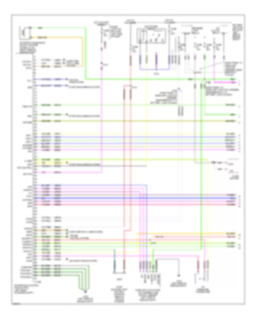
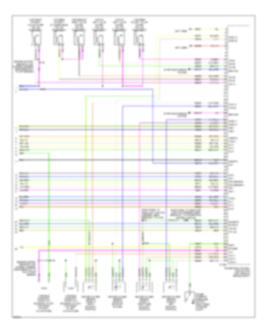
3.0L, Engine Performance Wiring Diagram (1 of 5) for Ford Fusion S 2010
List of elements for 3.0L, Engine Performance Wiring Diagram (1 of 5) for Ford Fusion S 2010:
- (dash panel to headlamp junction harness, near breakout to battery junction box) s144
- 10a
- 15a
- 40a
- A/c clutch relay
- A/c pressure transducer (right rear of engine compt)
- Accelerator pedal position (app) sensor (left side of dash)
- Accr
- Acpt
- Air conditioning system
- App1
- App1vref
- App2
- App2vref
- Appsrtn1
- Appsrtn2
- Battery junction box (bjb) (left side of engine compt)
- Bpp
- Bps
- C175b
- Can+
- Can-
- Canvnt
- Cbb46
- Cbk01
- Cbp44
- Ccb08
- Cdb08
- Cdc10
- Cdc12
- Cdc15
- Cdc35
- Ce114
- Ce302
- Ce336
- Ces09
- Cet42
- Cet43
- Ch302
- Computer data lines system
- Cooling fans system
- Cruise control system
- Exterior lights system
- Fcv
- Feps
- Fpc
- Fpm
- Ftpt
- Ftptref
- Fuel tank pressure (ftp) sensor (top of fuel tank)
- Fuse
- G102 (left rear of engine compt)
- Gd120
- Gencom
- Genmon
- Gnd
- Hot at all times
- Iat
- Ign
- Kapwr
- Le136
- Le137
- Le230
- Le424
- Maf
- Mafrtn
- Pcm power relay
- Pcmrc
- Powertrain control module (pcm) (left rear of engine compt)
- Re136
- Re137
- Re325
- Re407
- Res08
- Reverse lamp relay
- S119
- S125
- S143
- S157
- Sbb23
- Sccs
- Sccsrtn
- Shift interlock system
- Sigrtnc
- Smc
- Smcs
- Smr
- Starting/charging system
- Tip +
- Tip -
- Vdb04
- Vdb05
- Ve225
- Ve518
- Ve701
- Ve702
- Ve740
- Ve808
- Ve922
- Vec03
- Ves10
- Vh433
- Vmc05
- Vpwr
- Vref
- Vsout
- Wiper/washer system
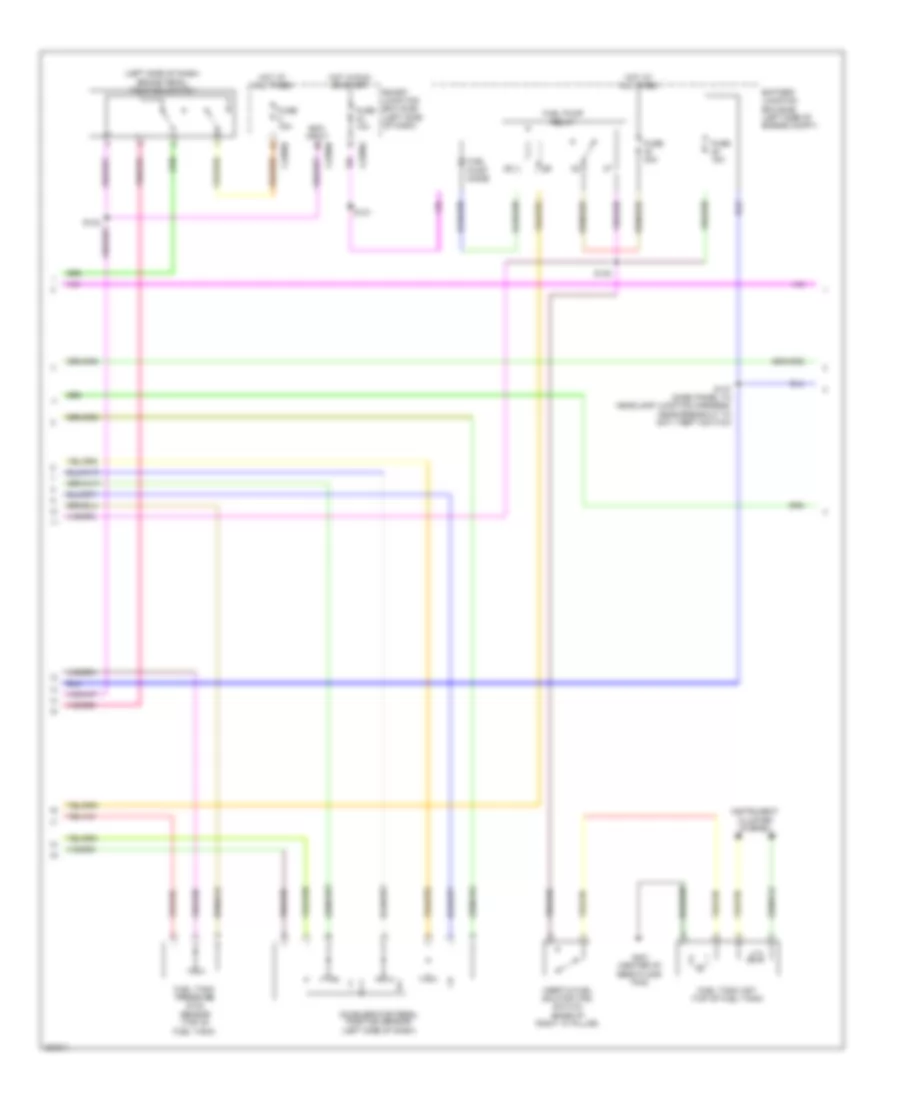
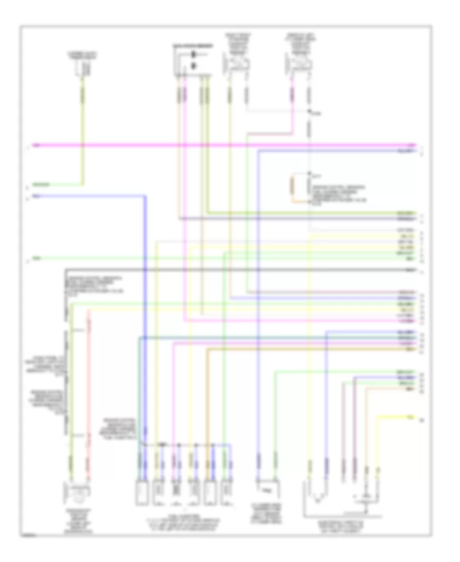
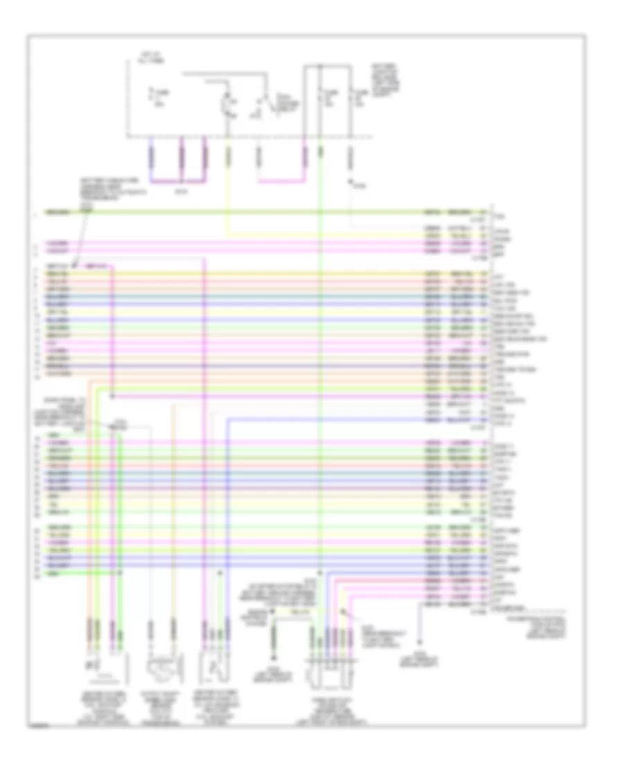
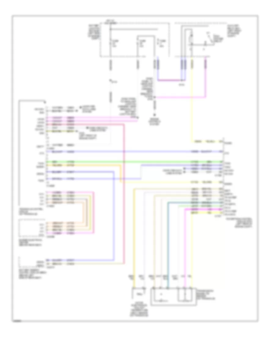
3.0L, Engine Performance Wiring Diagram (2 of 5) for Ford Fusion S 2010
List of elements for 3.0L, Engine Performance Wiring Diagram (2 of 5) for Ford Fusion S 2010:
- (battery cable wire harness, near breakout to automatic transmission)
- 10a
- 15a
- 30a
- 6f transmission
- Battery junction box (bjb) (left side of engine compt)
- Brake pedal position switch (left side of dash)
- C168a
- C168b
- C2280e
- Cblr/c456 vfs
- Cet05
- Cet06
- Cet07
- Cet08
- Cet09
- Cet10
- Cet18
- Cet25
- Evap canister vent control solenoid
- Fuel pump diode
- Fuel pump relay
- Fuse
- G102 (left rear of engine compt)
- G103 (left rear of engine compt)
- Hot at all times
- Hot in run or start
- Le111
- Lpc vfs
- Mass air flow/intake air temperature (maf/iat) sensor (left front of engine compt)
- Oss
- Re406
- Ret24
- S121
- S130 (dash panel to headlamp junction harness, near breakout to battery junction box (bjb))
- S137 (dash panel to headlamp junction harness, near breakout to battery junction box)
- S140
- S146
- S147
- Smart junction box (sjb) (left side of dash)
- Sol pwr
- Ssa cb1234 vfs
- Ssb c35r vfs
- Ssc cb26 vfs
- Sse on/off sol
- Tcc vfs
- Tft
- Tft sig rtn
- Trs
- Trs/oss gnd
- Trs/oss pwr
- Tss
- Tss gnd
- Tss pwr
- Vet26
- Vet27
- Vet32
- Vet33
3.0L, Engine Performance Wiring Diagram (3 of 5) for Ford Fusion S 2010
List of elements for 3.0L, Engine Performance Wiring Diagram (3 of 5) for Ford Fusion S 2010:
- (left rear side of vehicle) fuel pump control module
- (top of fuel tank) fuel tank unit
- (top right rear of engine) knock sensor 1
- (under center console) restraints control module (rcm)
- C175t
- C310a
- Ce226
- Ce233
- Ce234
- Ce608
- Cet05
- Cet06
- Cet07
- Cet08
- Cet09
- Cet10
- Cet18
- Cet25
- Cet34
- Cet42
- Cet43
- Cls28
- Computer data lines system
- Cr167
- Ens
- Exterior lights system
- Floor shifter
- Fpc
- Fpm
- Fppwr
- Fprtn
- Fuel sender return
- Fuel sender signal
- G403 (above left rear wheel well)
- Gd151
- Gnd
- Heated oxygen sensor (ho2s) 13 (w/ low emission vehicles) (exhaust system)
- Ho2s-12
- Ho2s-13
- Hs can+
- Hs can-
- Htr-12
- Htr-13
- Ifs input
- Instrument cluster (ic)
- Lcp vfs
- Le111
- Nca
- Oss
- Powertrain control module (pcm) (left rear of engine compt)
- Re226
- Re406
- Ret24
- Rlc
- S148 (battery cable wire harness, near breakout to automatic transmission)
- S251
- Sigrtn
- Sol pwr
- Ssa cb1234 vfs
- Ssb c35r vfs
- Ssc cb26 vfs
- Ssd cblr/c456 vfs
- Sse on/off sol
- Tcc vfs
- Tcs
- Tft
- Tip+
- Tip-
- Tr gnd
- Transmission control switch
- Trs
- Trs/oss/ vpwr
- Tss
- Ve225
- Ve518
- Ve731
- Ve733
- Vet26
- Vet27
- Vet32
- Vet33
3.0L, Engine Performance Wiring Diagram (4 of 5) for Ford Fusion S 2010
List of elements for 3.0L, Engine Performance Wiring Diagram (4 of 5) for Ford Fusion S 2010:
- (engine control sensor and fuel charge harness, near breakout to coil on plug 3) s135
- (engine control sensor and fuel charge harness, near breakout to fuel injector 4) s136
- (in front of throttle body) evaporative emission (evap) canister purge valve
- (right exhaust manifold) heated oxygen sensor (ho2s) 12
- (right rear of intake manifold) egr stepper motor
- (top rear of engine) manifold absolute pressure (map) sensor
- (top rear of right cylinder head) heated positive crankcase ventilation (pcv) valve
- Coil
- Coil on plug (cop) 1 (top front of valve cover)
- Coil on plug (cop) 2 (top of right valve cover)
- Coil on plug (cop) 3 (top rear of right valve cover)
- Coil on plug (cop) 4 (top of left valve cover)
- Coil on plug (cop) 5 (top of left valve cover)
- Coil on plug (cop) 6 (top rear of valve cover)
- Cylinder head temperature (cht) sensor
- Electronic throttle control (etc) motor (on throttle body)
- Ignition transformer capacitor (top front of left valve cover)
- S181
3.0L, Engine Performance Wiring Diagram (5 of 5) for Ford Fusion S 2010
List of elements for 3.0L, Engine Performance Wiring Diagram (5 of 5) for Ford Fusion S 2010:
- (engine control sensor & fuel charge harness, near breakout to coil on plug 1) s153
- (left front of engine) camshaft position sensor 2
- (left side of intake manifold) fuel injectors
- (right front of engine) camshaft position sensor 1
- (top left of intake manifold) fuel injector
- (top right of intake manifold) fuel injectors
- C175e
- Ce101
- Ce102
- Ce103
- Ce104
- Ce113
- Ce205
- Ce206
- Ce207
- Ce208
- Ce209
- Ce210
- Ce235
- Ce236
- Ce303
- Ce304
- Ce305
- Ce306
- Ce307
- Ce308
- Ce321
- Ce412
- Ce421
- Ce422
- Ce426
- Cht
- Cid 2
- Cid1
- Ckp shld
- Ckp+
- Ckp-
- Cop-a
- Cop-b
- Cop-c
- Cop-d
- Cop-e
- Cop-f
- Crankshaft position sensor (lower right front of engine block)
- De135
- Eegr1
- Eegr2
- Eegr3
- Eegr4
- Etcref
- Etcrtn
- Heated oxygen sensor (ho2s) 11 (right exhaust manifold)
- Heated oxygen sensor (ho2s) 21 (left exhaust manifold)
- Inj1
- Inj2
- Inj3
- Inj4
- Inj5
- Inj6
- Knock sensor 2 (rear of engine near water outlet)
- Ks1+
- Ks1-
- Ks2+
- Ks2-
- Le111
- Le134
- Le423
- Le448
- Le449
- Le450
- Le451
- Le452
- Le453
- Map
- Pcv
- Powertrain control module (pcm) (left rear of engine compt)
- Re134
- Re135
- Re323
- Re324
- Re405
- S138 (engine control sensor & fuel charge harness, near breakout to coil on plug 1)
- Sigrtne
- Tacm+
- Tacm-
- Tp1 ns
- Tp2 ps
- Uo2s
- Uo2sgref
- Uo2shtr
- Uo2spc
- Uo2spct
- Variable camshaft timing (vct) solenoid 1 (top front of right valve cover)
- Variable camshaft timing (vct) solenoid 2 (top front of left valve cover)
- Vct1
- Vct2
- Ve706
- Ve707
- Ve711
- Ve712
- Ve801
- Ve802
- Ve803
- Ve818
- Ve819
- Ve826
- Ve827
- Vmv-cc/evmv
- Vref
3.5L
3.5L, Engine Performance Wiring Diagram (1 of 4) for Ford Fusion S 2010
List of elements for 3.5L, Engine Performance Wiring Diagram (1 of 4) for Ford Fusion S 2010:
- (dash panel to headlamp junction harness, near breakout to battery junction box)
- (dash panel to headlamp junction harness, near breakout to g103)
- A/c clutch relay
- A/c pressure transducer
- Accr
- Acpt
- Air conditioning system
- App 1
- App 2
- App 3
- App1ref
- App1rtn
- App2ref
- App2rtn
- Battery junction box (bjb) (left side of engine compt)
- Bpp
- Bps
- C sigrtn
- C vref
- C175b
- C2280e
- Canvnt
- Case gnd
- Cbk01
- Cbp44
- Cbp46
- Ccb08
- Cdb08
- Cdc12
- Cdc35
- Ce114
- Ce132
- Ce302
- Ce336
- Ce608
- Ces09
- Cet40
- Ch302
- Computer data lines system
- Cooling fans system
- Cruise control system
- Evap canister vent control solenoid (rear of vehicle chassis)
- Evaporative emission (evap) canister purge valve (right rear of engine compt)
- Evmv
- Fc v
- Feps
- Floor shifter
- Fpc
- Fpm
- Ftpt
- Ftptref
- Fuse 10a
- Fuse 15a
- Fuse 20a
- Fuse 40a
- G102 (left rear of engine compt)
- Gd120
- Hot at all times
- Hot in start or run
- Hs can +
- Hs can -
- Iat
- Ignition
- Injpwrm
- Kapwr
- Le136
- Le137
- Le230
- Le424
- Maf
- Mafrtn
- Mass air flow/intake air temperature (maf/iat) sensor (left side of engine compt)
- O/d
- Pcm control
- Pcm power relay
- Powertrain control module (pcm) (left rear of engine compt)
- Pwr
- Pwr gnd
- Pwr gnd 1
- Pwr gnd 2
- Pwr gnd 3
- Re136
- Re137
- Re325
- Re407
- Res08
- Reverse lamp relay
- S119
- S121
- S125 (dash panel to headlamp junction harness, near breakout to battery junction box)
- S140
- S143
- S144
- S179
- S251
- Sbb23
- Sccs
- Sccsrtn
- Sdc
- Smart junction box (sjb) (left side of dash)
- Smc
- Smr
- Starting/charging system
- Trsw pn
- Vdb04
- Vdb05
- Ve225
- Ve701
- Ve702
- Ve703
- Ve740
- Ve808
- Ve922
- Vec03
- Ves10
- Vh433
- Vpwr
3.5L, Engine Performance Wiring Diagram (2 of 4) for Ford Fusion S 2010
List of elements for 3.5L, Engine Performance Wiring Diagram (2 of 4) for Ford Fusion S 2010:
- (left side of dash) brake pedal position switch
- Accelerator pedal position sensor (left side of dash)
- Battery junction box (bjb) (left side of engine compt)
- Boo input c2280b
- C2280a
- C2280d
- Fuel pump diode
- Fuel pump relay
- Fuel tank pressure (ftp) sensor (top of fuel tank)
- Fuel tank unit (top of fuel tank)
- Fuse 10a
- Fuse 15a
- Fuse 30a
- G401 (center of rear floor pan)
- Hot at all times
- Hot in run or start
- Inertia fuel shutoff (ifs) switch (base of right "a" pillar)
- Instrument cluster system
- S121
- S130
- S137 (dash panel to headlamp junction harness, near breakout to anti theft switch)
- Smart junction box (sjb) (left side of dash)
3.5L, Engine Performance Wiring Diagram (3 of 4) for Ford Fusion S 2010
List of elements for 3.5L, Engine Performance Wiring Diagram (3 of 4) for Ford Fusion S 2010:
- (dash panel to headlamp junction harness, near breakout to c145) s117
- (engine control sensor & fuel charge harness, near breakout to c133) s178
- (engine control sensor & fuel charge harness, near breakout to fuel injector 3)
- (engine control sensor & fuel charge harness, near breakout to stepper motor egr valve) s176
- (rear of left cylinder head) camshaft position sensor 2
- (right front of engine) camshaft position sensor 1
- 6 speed an-f21 transmission
- Crankshaft position sensor (lower left rear of engine block)
- Cylinder head temperature (cht) sensor (front of right cylinder head)
- Dual knock sensor
- Electronic throttle control (etc) module (on throttle body)
- Fuel injectors (1, 2, 3: top right of intake manifold) (5, 6: left side of intake manifold) (4: top left of intake manifold)
- Lock start
- S159
- S160
- S177
3.5L, Engine Performance Wiring Diagram (4 of 4) for Ford Fusion S 2010
List of elements for 3.5L, Engine Performance Wiring Diagram (4 of 4) for Ford Fusion S 2010:
- (dash panel to headlamp junction harness, near breakout to c145) s116
- (dash panel to headlamp junction harness, near breakout to powertrain control module) s102
- (engine control sensor & fuel charge harness, near breakout to ckp sensor)
- (engine control sensor & fuel charge harness, near breakout to dual knock sensor)
- (not used)
- (top front of right valve cover) coil on plug (cop) 1
- (top of left valve cover) coil on plug (cop) 4
- (top of left valve cover) coil on plug (cop) 5
- (top rear of left valve cover) coil on plug (cop) 6
- (top rear of right cylinder head) coil on plug (cop) 2
- (top rear of right valve cover) coil on plug (cop) 3
- C175e
- Cd 1a
- Cd 2c
- Cd 3e
- Cd 4b
- Cd 5d
- Cd 6f
- Cdc10
- Cdc15
- Ce205
- Ce206
- Ce207
- Ce208
- Ce209
- Ce210
- Ce233
- Ce234
- Ce235
- Ce236
- Ce303
- Ce304
- Ce305
- Ce306
- Ce307
- Ce308
- Ce321
- Ce328
- Ce412
- Ce421
- Ce422
- Ce426
- Cht
- Cid 1
- Cid 2
- Ckp sensor +
- Ckp sensor -
- De135
- E sigrtn
- Etcref
- Etcrtn
- Gen com
- Gen mon
- Heated oxygen sensor (ho2s) 11 (right side exhaust manifold)
- Heated oxygen sensor (ho2s) 12 (right exhaust manifold)
- Heated oxygen sensor (ho2s) 21 (left exhaust manifold)
- Heated oxygen sensor (ho2s) 22 (exhaust system)
- Ho2s 11
- Ho2s 12
- Ho2s 21
- Ho2s 22
- Htr 11
- Htr 12
- Htr 21
- Htr 22
- Inj 1
- Inj 2
- Inj 3
- Inj 4
- Inj 5
- Inj 6
- Ks1 +
- Ks1 -
- Ks2 +
- Ks2 -
- Le134
- Power steering pressure switch (right rear of engine compt)
- Powertrain control module (pcm) (left rear of engine compt)
- Pspt
- Re134
- Re135
- Re323
- Re324
- Re405
- Re429
- S135
- S136
- S138
- Shdrtn
- Starting/charging system
- Tacm +
- Tacm -
- Tp1 ns
- Tp2 ps
- Variable camshaft timing (vct) solenoid valve 1 (top front of right valve cover)
- Variable camshaft timing (vct) solenoid valve 2 (top front of left valve cover)
- Vct
- Vct 2
- Ve706
- Ve707
- Ve711
- Ve712
- Ve731
- Ve733
- Ve735
- Ve737
- Ve801
- Ve802
- Ve818
- Ve819
- Vrsrtn
EXTERIOR LIGHTS
Backup Lamps Wiring Diagram for Ford Fusion S 2010
List of elements for Backup Lamps Wiring Diagram for Ford Fusion S 2010:
- (except hybrid: body main harness, near breakout to c237) s307
- (hybrid: center rear of luggage compt) (except hybrid: center rear of trunk compt) g400
- (hybrid: trunk harness wire harness, near breakout to parking aid module
- (mkz: body main harness, near breakout to left rear turn lamp)
- 3.5l
- 6 speed transmission
- 6f transmission
- Audio control module (acm) (except hybrid) (w/ navigation) (center of dash)
- Auto dimming interior mirror (w/ mgm)
- Battery junction box (bjb) (left side of engine compt)
- C1520a
- C175t
- C240a
- Cls10
- Except hybrid
- Fuse 10a
- Global positioning satellite module (gpsm) (hybrid: center of dash) (except hybrid: left side of dash)
- Hot in start or run
- Hybrid
- Left reversing lamp
- Multimedia interior mirror unit (w/ microphone)
- Powertrain control module (pcm) (left rear of engine compt)
- Rear camera display mirror (w/ camera)
- Reverse in
- Reverse lamp relay
- Right reversing lamp
- Rlc
- S144
- S160 (except hybrid 2.5l: starter motor relay & battery ground harness, near breakout wind- shield wiper motor) (hybrid: dash panel to headlamp junction harness, near breakout to c214)
- S410
- Trs
Exterior Lamps Wiring Diagram (1 of 2) for Ford Fusion S 2010
List of elements for Exterior Lamps Wiring Diagram (1 of 2) for Ford Fusion S 2010:
- (2.5l: dash panel to headlamp junction harness, near breakout to battery junction box) (hybrid: dash panel to headlamp junction harness, near breakout to auxiliary relay box) (3.0l: engine control sensor & fuel charge harness, near breakout to fuel injector 4) (3.5l: engine control sensor & fuel charge harness, near breakout to ckp sensor) s136
- Auto
- Auto lamp
- Boo input
- C2280b
- C2280d
- C2280e
- C2280f
- Computer data lines system
- Fuse 15a
- Fuse 20a
- G103 (3.0l: left rear of engine compt) (3.5l: left side of engine compt) (hybrid: left front of engine compt)
- G104 (except 3.5l: right front of engine compt) (3.5l: right side of engine compt)
- G202 (left side of dash)
- G400 (except hybrid: center rear of trunk compt) (hybrid: center rear of luggage compt)
- Hazard on
- Head park
- Hot at all times
- Left front park/turn lamp
- Left front side lamp
- Left rear park/turn/ stop lamp
- Lf turn lamp (fet)
- Lh turn
- Logic
- Low
- Low beam
- Lr stop/ turn lamp (fet)
- Main light switch
- Ms can +
- Ms can -
- Off
- Park
- Park lamp relay
- Park on
- Rf turn lamp (fet)
- Rh turn
- Right front park/turn lamp
- Right front side lamp
- Right rear park/turn/ stop lamp
- Rr stop/ turn lamp (fet)
- S403 (trunk harness wire harness, near breakout to parking aid module)
- Smart junction box (sjb) (left side of dash)
- Turn
Exterior Lamps Wiring Diagram (2 of 2) for Ford Fusion S 2010
List of elements for Exterior Lamps Wiring Diagram (2 of 2) for Ford Fusion S 2010:
- 3.5l
- Battery junction box (bjb) (left side of engine compt)
- Boo
- Bps
- Brake pedal position switch (left side of dash)
- C175b
- Ccb08
- Ces09
- Except 3.5l
- Fuse 20a
- G202 (left side of dash)
- G400 (except hybrid: center rear of trunk compt) (hybrid: center rear of luggage compt)
- Hazard flasher switch
- Hazard switch
- High mounted stop lamp
- Hot w/ pcm relay energized
- Interior lights system
- Left
- Left license plate lamp
- Left rear side lamp
- Multi- function switch
- Powertrain control module (pcm) (left rear of engine compt)
- Right
- Right license plate lamp
- Right rear side lamp
- S140
- S142 (3.5l: dash panel to headlamp junction harness, near breakout to powertrain control module) (hybrid: dash panel to headlamp junction harness, near breakout to battery junction box)
- Turn
GROUND DISTRIBUTION
Ground Distribution Wiring Diagram, Except Hybrid (1 of 3) for Ford Fusion S 2010
List of elements for Ground Distribution Wiring Diagram, Except Hybrid (1 of 3) for Ford Fusion S 2010:
- (6 way power seat)
- (automatic a/c) autolamp/ sunload sensor
- (automatic a/c) blower motor speed control
- (automatic a/c) datc hvac
- (early production) message center switch
- (except mkz w/ navigation)
- (except mkz w/o navigation)
- (fusion/ milan) hazard flasher switch
- (fusion/ milan) traction control/ ambient lighting switch
- (main harness, near breakout to c220)
- (manual a/c) blower motor resistor
- (manual a/c) emtc hvac
- (mkz early production & ambient lighting) overhead lighting
- (mkz)
- (mkz) front cigar lighter
- (mkz) right front scuff plate lamp
- (w/ camera) rear view camera display mirror
- (w/ mgm) auto dimming interior mirror
- (w/ navigation)
- (w/ navigation) multimedia interior mirror unit
- (w/o navigation)
- (w/o navigation) global positioning satellite module (gpsm)
- 3.5l
- Ambient dimmer switch
- Ambient lighting module
- Ambient select switch
- Audio control module (acm)
- C1467a
- C218a
- C218b
- C2356a
- C2357a
- C2357b
- C240a
- C3304b
- C3305a
- Clock spring
- Data link connector (dlc)
- Dual climate controlled seat module (dcsm)
- Early production
- Floor shifter
- Front controls interface module (fcim)
- Front display interface module (fdim)
- Front heated seat module
- Front interior lamp
- Fusion/ milan
- G105 (right side of engine compt, near pscm)
- G200 (center of dash)
- G201 (center of dash)
- G202 (left side of dash)
- G203 (base of right "a" pillar)
- G204 (in steering wheel)
- Instrument cluster (ic)
- Left steering wheel switch
- Left vanity mirror lamp
- Luggage compartment lid release switch
- Main light switch
- Mkz
- Multifunction switch
- Nca
- Near breakout to left steering wheel switch)
- Passenger side door lock switch
- Passenger side front seat control switch
- Passenger side window control switch
- Passive anti-theft transceiver
- Power steering control module (pscm)
- Rain sensor module
- Rear interior lamp
- Right front door lock actuator
- Right front power window motor
- Right front seat backrest heater mat
- Right rear door grab handle lamp
- Right rear door lock actuator
- Right rear door map pocket lamp
- Right rear door release lamp
- Right side exterior rear view mirror
- Right steering wheel switch
- Right vanity mirror lamp
- Roof opening panel module
- S290 (ambient lighting main wire harness, near breakout to c3133)
- S303 (power seat motor assembly harness, near breakout to c314)
- S368 (near ambient lighting module)
- S601 (window regulator harness, near breakout to right front speaker)
- S800 (rear passenger side door wire harness near breakout to c828)
- S894 (rear passenger side door wire harness near breakout to c828)
- S902 (interior lamp feed harness, near breakout to rain sensor module)
- W/ heated seat
- W/ memory
- W/o memory
Ground Distribution Wiring Diagram, Except Hybrid (2 of 3) for Ford Fusion S 2010
List of elements for Ground Distribution Wiring Diagram, Except Hybrid (2 of 3) for Ford Fusion S 2010:
- (10 way power seat) passenger side front seat control switch
- (6 way) power seat)
- (except 3.5l) engine cooling fan motor
- (except 3.5l) fuel pump relay
- (fusion/ milan) front cigar lighter
- (fusion/ milan) left front side lamp
- (left side of dash) smart junction box (sjb)
- (left side of engine compt) battery junction box (bjb)
- (m/t) reversing lamp switch
- (mkz) left front parking lamp
- (mkz) left front scuff plate lamp
- (w/ heated seat) dual climate controlled seat module (dcsm)
- (w/ heated seat) left front seat backrest heater mat
- (w/ memory) driver seat module (dsm)
- (w/ memory) driver side front seat control switch
- 4x4 control module
- A/c compressor clutch field coil
- All lock relay
- Ambient lighting module
- Brake fluid level switch
- C2280d
- C3299a
- C3299b
- C3305a
- C535b (mkz)
- C537b (except mkz)
- C568b
- Cup holder lamp 1
- Cup holder lamp 2
- Driver door module (ddm)
- Driver side door lock switch
- Driver side front seat control switch
- Driver unlock relay
- Exterior rear view mirror switch
- G103 (3.0l: left rear of engine compt) (3.5l: left side of engine compt)
- G300
- Headlamp control module (hcm)
- Keypad switch assembly
- Late production
- Left front door grab handle lamp
- Left front door lock actuator
- Left front door map pocket lamp
- Left front door release lamp
- Left front fog lamp
- Left front footwell lamp
- Left front power window motor
- Left headlamp
- Left high intensity discharge headlamp relay
- Left rear door grab handle lamp
- Left rear door lock actuator
- Left rear door map pocket lamp
- Left rear door release lamp
- Left side exterior rear view mirror
- Master window control switch
- Memory set switch
- Mkz
- Nca
- Power point
- Rear footwell
- Right front door grab handle lamp
- Right front door map pocket lamp
- Right front door release lamp
- Right front footwell lamp
- Right front park/turn lamp
- Right high intensity discharge headlamp relay
- S292 (ambient lighting main wire harness, near breakout to front cigar lighter)
- S304 (power seats harness, near breakout to c339)
- S312 (power seats harness, near breakout to c3135)
- S394 (ambient lighting main wire harness, near breakout to c3052)
- S395
- S500 (window regulator harness)
- S594 (window regulator harness, near breakout to driver's door lock actuator)
- S694 (window regulator harness, near breakout to right front door lock actuator)
- S700 (near breakout to left rear door speaker)
- S794 (right front door ambient lighting wire harness, near breakout to c794)
- Storage bin lamp
- W/ memory
- W/o memory
- Windshield wiper module
- Windshield wiper motor
Ground Distribution Wiring Diagram, Except Hybrid (3 of 3) for Ford Fusion S 2010
List of elements for Ground Distribution Wiring Diagram, Except Hybrid (3 of 3) for Ford Fusion S 2010:
- (3.5l) engine cooling fan motor
- (audiophile audio) subwoofer amplifier
- (except mkz) audio digital signal processing (dsp) module
- (fusion)
- (fusion) left license plate lamp
- (fusion) left rear park/turn/ stop lamp
- (fusion) left rear side lamp
- (fusion) right license plate lamp
- (fusion) right rear park/turn/ stop lamp
- (fusion) right rear side lamp
- (fusion/ milan) right front side lamp
- (fusion/ mkz) rear view camera
- (m/t) clutch cutoff switch
- (m/t) clutch switch
- (milan)
- (milan) high mounted stop lamp (spoiler)
- (milan) rear view camera
- (milan/ mkz) left license plate lamp
- (milan/ mkz) left rear park/stop lamp
- (milan/ mkz) right license plate lamp
- (milan/ mkz) right rear park/stop lamp
- (mkz w/ premium) audio amplifier
- (mkz)
- (mkz) left rear lamp assembly
- (mkz) right front parking lamp
- (mkz) right rear lamp assembly
- (w/ rear view camera)
- (w/ sync) accessory protocol interface module (apim)
- (w/o rear view camera)
- 3.5l
- 6 speed transmission
- Anti-lock brake system (abs) module
- Anti-theft hood switch
- Battery
- C175b
- C402b
- C4208a
- C4235a
- C4240a
- C466a
- Control module (pcm)
- Driver safety belt buckle switch
- Except 3.5l
- Fuel pump control module
- Fuel tank unit
- Fuel tank unit shield
- G100 (except 3.5l: left front strut tower) (3.5l: left side of engine compt, near battery junction box (bjb))
- G101 (2.5l: rear of engine) (3.5l: under battery)
- G102 (left rear of engine compt)
- G104 (except 3.5l: right front of engine compt) (3.5l: right side of engine compt)
- G301 (right floor support pillar)
- G400 (center rear of trunk compt)
- G401 (3.5l) (center of rear floor pan)
- G402 (base of right 'c" pillar)
- G403 (except 3.5l) (above left rear wheel well)
- G405 (left side of rear window)
- High mounted stop lamp
- Horn
- Late production
- Left front park/turn lamp
- Left rear side obstacle detection (sod) sensor
- Left rear turn lamp
- Left reversing lamp
- Left seat track position sensor
- Luggage compartment disarm switch
- Luggage compartment lid release solenoid/ ajar switch
- Mass air flow/ intake air temperature (maf/iat) sensor
- Occupant classification system module (ocsm)
- Parking aid module (pam)
- Passenger safety belt buckle switch
- Powertrain
- Rear window defrost grid
- Right front fog lamp
- Right headlamp
- Right rear side obstacle detection (sod) sensor
- Right rear turn lamp
- Right reversing lamp
- S300 (power seat motor assembly harness, near breakout to c313)
- S355 (bottom of center console)
- S400 (w/o parking aid) (license jumper harness, in breakout to c405)
- S421 (w/ parking aid) (in jumper wiring harness, near breakout to c408)
- W/ sony
- W/o sony
- Windshield washer pump motor
Ground Distribution Wiring Diagram, Hybrid (1 of 2) for Ford Fusion S 2010
List of elements for Ground Distribution Wiring Diagram, Hybrid (1 of 2) for Ford Fusion S 2010:
- (left front of engine compt) auxiliary relay box
- (left side of engine compt) battery junction box (bjb)
- (w/ navigation)
- (w/o navigation)
- Air conditioning compressor module (accm)
- Ambient lighting module
- Ambient select switch
- Anti-lock brake system (abs) module
- Anti-theft hood switch
- Autolamp/ sunload sensor
- Auxiliary coolant flow pump
- Brake fluid level switch
- C1458a
- C1469a
- C218a
- C218b
- C2293a
- C2356a
- C3304b
- Clock spring
- Data link connector (dlc)
- Datc hvac
- Dc/dc inverter module
- Electro- chromatic interior mirror unit
- Engine cooling fan motor
- Floor shifter
- Front controls interface module (fcim)
- Front display interface module (fdim)
- Front interior lamp
- G103 (left front of engine compt)
- G104 (right front of engine compt)
- G202 (left side of dash)
- G203 (base of right "a" pillar)
- G204 (in steering wheel)
- Global positioning satellite module (gpsm)
- Hazard flasher switch
- Heated seat module
- Horn
- In-vehicle temperature/ humidity sensor
- Injector relay
- Instrument cluster (ic)
- Left front fog lamp
- Left front park/turn lamp
- Left front side lamp
- Left headlamp
- Left high intensity discharge headlamp relay
- Left steering wheel switch
- Left vanity mirror lamp
- Luggage compartment lid release switch
- M/e coolant pump motor
- Main light switch
- Multi- media interior mirror unit
- Multifunction switch
- Near breakout to left steering wheel switch)
- Passenger side door lock switch
- Passenger side front seat control switch
- Passive anti-theft transceiver
- Rear interior lamp
- Rear view camera display mirror
- Right front door lock actuator
- Right front fog lamp
- Right front park/turn lamp
- Right front seat backrest heater mat
- Right front side lamp
- Right headlamp
- Right high intensity discharge headlamp relay
- Right rear door lock actuator
- Right side exterior rear view mirror
- Right steering wheel switch
- Right vanity mirror lamp
- Roof opening panel module
- S303 (power seat motor assembly harness, near breakout to c314)
- S601 (window regulator harness, near breakout to right front speaker)
- S902 (interior lamp feed harness, near breakout to rain sensor module)
- Traction control/ ambient lighting switch
- Transaxle control module
- Vacuum pump motor
- W/o hid
- Windshield washer pump motor
- Windshield wiper module
- Windshield wiper motor
Ground Distribution Wiring Diagram, Hybrid (2 of 2) for Ford Fusion S 2010
List of elements for Ground Distribution Wiring Diagram, Hybrid (2 of 2) for Ford Fusion S 2010:
- (fusion) left license plate lamp
- (fusion) left rear park/turn/ stop lamp
- (fusion) left rear side lamp
- (fusion) rear view camera
- (fusion) right license plate lamp
- (fusion) right rear park/turn/ stop lamp
- (fusion) right rear side lamp
- (if equipped) rear view camera
- (left side of dash) smart junction box (sjb)
- (milan) left license plate lamp
- (milan) left rear park/stop lamp
- (milan) left rear turn lamp
- (milan) right license plate lamp
- (milan) right rear park/stop lamp
- (milan) right rear turn lamp
- (w/ rear view camera)
- (w/ sony) audio digital signal processing (dsp) module
- (w/ sony) subwoofer amplifier
- (w/ sync) accessory protocol interface module (apim)
- (w/o rear view camera)
- All lock relay
- Audio control module (acm)
- Battery
- Battery energy control module (becm)
- Blower motor speed control
- C1457c
- C1467a
- C175b
- C2280d
- C240a
- C402b
- C4237a
- C4240a
- C466a
- C537b
- Control
- Dc/dc converter module
- Driver safety belt buckle switch
- Driver side door lock switch
- Driver side front seat control switch
- Driver unlock relay
- Exterior rear view mirror switch
- Front cigar lighter
- Fuel pump control module
- Fuel tank unit shield
- G100 (left front strut tower)
- G101 (left front strut tower)
- G102 (left rear of engine compt)
- G105 (on transaxle assembly)
- G200 (center of dash)
- G201 (center of dash)
- G300 (under driver's seat)
- G301 (right floor support pillar)
- G400 (center rear of luggage compt)
- G401 (center of rear floor pan)
- G402 (right side of luggage compt)
- G403 (above left rear wheel well)
- G405 (below left side of rear window)
- High mounted stop lamp (spoiler)
- Keypad switch assembly
- Late production
- Left front door lock actuator
- Left front power window motor
- Left front seat backrest heater mat
- Left rear door lock actuator
- Left rear side obstacle detection (sod) sensor
- Left reversing lamp
- Left seat track position sensor
- Left side exterior rear view mirror
- Luggage compartment disarm switch
- Luggage compartment lid release solenoid/ ajar switch
- Mass air flow/ intake air temperature (maf/iat) sensor
- Master window control switch
- Milan
- Module (pcm)
- Nca
- Occupant classification system module (ocsm)
- Parking aid module (pam)
- Passenger saftey belt buckle switch
- Power point
- Power steering control module (pscm)
- Powertrain
- Rear window defrost grid
- Right rear side obstacle detection (sod) sensor
- Right reversing lamp
- S300 (power seat motor assembly harness, near breakout to c314)
- S355 (ambient lighting main wire harness, near breakout to c3052)
- S400 (w/o parking aid) (license jumper harness, in breakout to c405)
- S421 (w/ parking aid) (in jumper wiring harness, near breakout to c408)
- S450 (in jumper wiring harness, near breakout to c408)
- S500 (window regulator harness, near breakout to left front tweeter)
- Traction battery control cooling fan
HEADLIGHTS
Headlights Wiring Diagram, Except Hybrid with HID Headlights (1 of 2) for Ford Fusion S 2010
List of elements for Headlights Wiring Diagram, Except Hybrid with HID Headlights (1 of 2) for Ford Fusion S 2010:
- Ballast
- Battery junction box (bjb) (left side of engine compt)
- Except milan
- Fuse 15a
- G103 (3.0l: left rear of engine compt) (3.5l: left side of engine compt)
- G104 (2.5l & 3.0l: right front of engine compt) (3.5l: right side of engine compt)
- Hi beam
- Hid low beam
- Hot at all times
- Left headlamp
- Left high intensity discharge headlamp relay
- Milan
- Module
- Right headlamp
- Right high intensity discharge headlamp relay
- Shutter solenoid
Headlights Wiring Diagram, Except Hybrid with HID Headlights (2 of 2) for Ford Fusion S 2010
List of elements for Headlights Wiring Diagram, Except Hybrid with HID Headlights (2 of 2) for Ford Fusion S 2010:
- (2.5l & 3.0l: near breakout to battery junction box) (3.5l: near breakout to powertrain control module)
- (3.5l: near breakout to anti-theft hood switch) (3.0l: near breakout to engine cooling fan motor) (2.5l: near breakout to ambient air temperature sensor) s124
- Air conditioning system
- Auto
- Auto lamps on
- Auto- lamp sens
- Autolamp sunload sensor (center of dash)
- C2280a
- C2280b
- C2280c
- C2280e
- C2280f
- Cbp42
- Computer data lines system
- Flash to pass
- Fog lamp ind
- Fog lamp relay
- Fog lamp switch
- Fog lamps on
- Ftp
- Fuse 10a
- Fuse 15a
- G103 (3.0l: left rear of engine compt) (3.5l: left side of engine compt)
- G104 (3.5l: right side of engine compt) (2.5l & 3.0l: right front of engine compt)
- G202 (left side of dash)
- Gd121
- Gnd
- Head park lamp off
- Headlamp control module (left rear of engine compt)
- High beam relay
- High beam req
- Hot at all times
- Hot in run or start
- Hs can+
- Hs can-
- Ign
- Instrument cluster
- Left front fog lamp
- Lin
- Logic
- Low
- Low beam req
- Lt low beam (fet)
- Main light switch
- Ms can+
- Ms can-
- Multi-function switch
- Off
- Park
- Park br sw
- Park brake switch (under center console)
- Park lamps on
- Right front fog lamp
- Rt low beam (fet)
- S120
- S134 (3.0l & 3.5l: near breakout to anti-theft hood switch) (2.5l: near breakout to left headlamp)
- Smart junction box (sjb) (left side of dash)
- Vdb04
- Vdb05
- Vlf32
- Vlf33
- Wiper on
- Wiper/ washer system
Headlights Wiring Diagram, Except Hybrid without HID Headlights for Ford Fusion S 2010
List of elements for Headlights Wiring Diagram, Except Hybrid without HID Headlights for Ford Fusion S 2010:
- (3.5l: near breakout to anti-theft hood switch) (3.0l: near breakout to engine cooling fan motor) (2.5l: near breakout to ambient air temperature sensor) s124
- Air conditioning system
- Auto
- Auto- lamp on
- Auto- lamp sens
- Autolamp sunload sensor (center of dash)
- C2280a
- C2280b
- C2280c
- C2280e
- C2280f
- Computer data lines system
- Flash to pass
- Fog
- Fog ind
- Fog lamp relay
- Fog lamps on
- Ftp
- Fuse 10a
- Fuse 15a
- G103 (3.0l: left rear of engine compt) (3.5l: left side of engine compt)
- G104 (2.5l & 3.0l: right front of engine compt) (3.5l: right side of engine compt)
- G202 (left side of dash)
- Head parklamp off
- High beam
- High beam relay
- High beam req
- Hot at all times
- Instrument cluster
- Left front fog lamp
- Left headlamp
- Left low beam (fet)
- Logic
- Low
- Low beam
- Low beam req
- Main light switch
- Ms can+
- Ms can-
- Multi-function switch
- Off
- Park
- Park br sw
- Park brake switch (under center console)
- Park lamps on
- Right front fog lamp
- Right headlamp
- Right low beam (fet)
- S134 (3.0l & 3.5l: near breakout to anti-theft hood switch) (2.5l: near breakout to left headlamp)
- Smart junction box (sjb) (left side of dash)
- Wiper on
- Wiper/ washer system
Headlights Wiring Diagram, Hybrid (1 of 2) for Ford Fusion S 2010
List of elements for Headlights Wiring Diagram, Hybrid (1 of 2) for Ford Fusion S 2010:
- (dash panel to headlamp junction harness, near breakout to auxiliary relay box) s124
- Air conditioning system
- Auto
- Auto- lamp on
- Auto- lamp sens
- Autolamp sunload sensor (center of dash)
- C2280b
- C2280c
- C2280e
- C2280f
- Computer data lines system
- Flash to pass
- Fog
- Fog ind
- Fog lamp relay
- Fog lamps on
- Ftp
- Fuse 10a
- Fuse 15a
- G103 (left front of engine compt)
- G104 (right front of engine compt)
- G202 (left side of dash)
- Head parklamp off
- High beam relay
- High beam req
- Hot at all times
- Instrument cluster
- Left front fog lamp
- Left low beam (fet)
- Logic
- Low
- Low beam req
- Main light switch
- Ms can+
- Ms can-
- Multifunction switch
- Off
- Park
- Park br sw
- Park brake switch (under center console)
- Park lamps on
- Right front fog lamp
- Right low beam (fet)
- S134 (dash panel to headlamp junction harness, near breakout to auxiliary relay box)
- Smart junction box (sjb) (left side of dash)
- Wiper on
- Wiper/ washer system
Headlights Wiring Diagram, Hybrid (2 of 2) for Ford Fusion S 2010
List of elements for Headlights Wiring Diagram, Hybrid (2 of 2) for Ford Fusion S 2010:
- Battery junction box (bjb) (left side of engine compt)
- Fuse 15a
- Fusion
- G103 (left front of engine compt)
- G104 (right front of engine compt)
- High beam
- Hot at all times
- Left headlamp
- Left headlamp relay
- Low beam
- Milan
- Right headlamp
- Right headlamp relay
- Shutter solenoid
HORN
Horn Wiring Diagram for Ford Fusion S 2010
List of elements for Horn Wiring Diagram for Ford Fusion S 2010:
- (steering wheel jumper harness, near breakout to left steering wheel switch) s202
- C218a
- C218b
- C2280b
- C2280e
- Clockspring (behind steering wheel assembly)
- Fuse 20a
- G104 (except 3.5l: right front of engine compt) (3.5l: right side of engine compt)
- Horn (right front of engine compt)
- Horn relay
- Hot at all times
- Left horn switch
- Logic
- Right horn switch
- Smart junction box (sjb) (left side of dash)
INSTRUMENT CLUSTER
Instrument Cluster Wiring Diagram, Except Hybrid for Ford Fusion S 2010
List of elements for Instrument Cluster Wiring Diagram, Except Hybrid for Ford Fusion S 2010:
- (base of right "a" pillar) g203
- (left side of dash) g202
- Ajar
- Ajar decklid
- Anti-lock brakes system
- Anti-theft system
- Auto-dimming interior mirror
- Brake fluid level switch (left rear of engine compt)
- C2280a
- C2280b
- C2280c
- C2280f
- Cbp29
- Cca15
- Cet52
- Cmc24
- Cmc29
- Compass +
- Compass -
- Computer data lines system
- Driver's door lock actuator (driver's door)
- Drv door ajar
- Front control interface module (fcim) (center of dash)
- Fuel 1 rtn
- Fuel 2 rtn
- Fuel lvl 1
- Fuel lvl 2
- Fuel tank unit (top of fuel tank)
- Fuse 10a
- Fuse 20a
- Fuse 5a
- Fusion/ milan
- G103 (3.0l: left rear of engine compt) (3.5l: left side of engine compt)
- G202 (left side of dash)
- G203 (base of right "a" pillar)
- G300
- G400 (center rear of trunk compt)
- Gd116
- Gnd
- Hot at all times
- Hot in start or run
- Hs can +
- Hs can -
- Ignition switch
- Info
- Instrument cluster (ic)
- Interior lights system
- Key in ign
- Key in ignition
- Left rear door lock actuator (left rear door)
- Lo brk fl
- Logic
- Low oil
- Lr door ajar
- Luggage compartment lid release solenoid/ ajar switch (center of luggage compt lid)
- Message center switch (early production)
- Mkz
- Ms can +
- Ms can -
- Ms can+
- Ms can-
- Ms feed
- Ms rtn
- Ms sw
- Multimedia interior mirror unit
- Oil pressure switch (except 2.5l: left side of engine block) (2.5l: oil filter housing)
- Park brake sw
- Park brake switch (under center console)
- Pass door ajar
- Pats rx
- Pats tx
- Prk detect
- Rear view camera (center of deck lid)
- Reset
- Right front door lock actuator (front passenger's door)
- Right rear door lock actuator (right rear door)
- Rmc27
- Rmc29
- Rmc32
- Rmc33
- Rr door ajar
- Run/start
- S500
- S601
- S700
- S800
- Sbp26
- Secondary fuel sender (awd) (top of fuel tank)
- Set up
- Shift interlock system
- Smart junction box (sjb) (left side of dash)
- Traction
- Vdb04
- Vdb05
- Vdb06
- Vdb07
- Vmc11
- Vmc23
- Vmc30
- Vmc31
- Vrt23
- Vrt24
- W/ navigation
- W/o navigation
Instrument Cluster Wiring Diagram, Hybrid for Ford Fusion S 2010
List of elements for Instrument Cluster Wiring Diagram, Hybrid for Ford Fusion S 2010:
- Ajar
- Ajar luggage
- Anti-lock brakes system
- Anti-theft system
- Auto-dimming interior mirror
- Brake fluid level switch (left rear of engine compt)
- C218a
- C218b
- C2280a
- C2280b
- C2280c
- C2280f
- Cbp29
- Cca15
- Cet52
- Clockspring (behind steering wheel assembly)
- Cmc24
- Cmc29
- Compass +
- Compass -
- Computer data lines system
- Drv door ajar
- Fuel 1 rtn
- Fuel lvl 1
- Fuel tank unit (top of fuel tank)
- Fuse 10a
- Fuse 20a
- Fuse 5a
- G103 (left front of engine compt)
- G202 (left side of dash)
- G203 (base of right "a" pillar)
- G300 (under driver's seat)
- G400 (center rear of luggage compt)
- Gd116
- Gnd
- Hot at all times
- Hot in start or run
- Hs can +
- Hs can -
- Ignition switch
- Info
- Instrument cluster (ic)
- Key in ign
- Key in ignition
- Left front door lock actuator (driver's door)
- Left rear door lock actuator (left rear door)
- Left steering wheel switch
- Lo brk fl
- Logic
- Lr door ajar
- Luggage compartment lid release solenoid/ajar switch (center of luggage compt lid)
- Ms can +
- Ms can -
- Ms can+
- Ms can-
- Ms rtn
- Ms sw
- Multimedia interior mirror unit
- Oil pressure switch (oil filter housing)
- Oil sw
- Park brake sw
- Park brake switch (under center console)
- Pass door ajar
- Pats rx
- Pats tx
- Prk detect
- Rear view camera display mirror (center of deck lid)
- Reset
- Right front door lock actuator (front passenger's door)
- Right rear door lock actuator (right rear door)
- Rmc27
- Rmc32
- Rr door ajar
- Run/start
- S500
- S601
- Sbp26
- Set up
- Shift interlock system
- Smart junction box (sjb) (left side of dash)
- Traction
- Vdb04
- Vdb05
- Vdb06
- Vdb07
- Vmc11
- Vmc30
- Vmc31
- Vrt23
- Vrt24
- W/ navigation
- W/o navigation
INTERIOR LIGHTS
Courtesy Lamps Wiring Diagram (1 of 2) for Ford Fusion S 2010
List of elements for Courtesy Lamps Wiring Diagram (1 of 2) for Ford Fusion S 2010:
- (interior lamp feed harness, near breakout to rain sensor module)
- C2280a
- C2280b
- C2280c
- C2280d
- Demand lamp/ battery saver relay
- Dimmer switch
- Dome demand
- Front interior lamp
- Fuse 10a
- Fuse 15a
- G203 (base of right "a" pillar)
- G400 (hybrid: center rear of luggage compt) (except hybrid: center rear of trunk compartment)
- Hot at all times
- Hot in run or start
- Instrument illumination circuit
- Interior lighting (fet)
- Left vanity mirror lamp
- Logic
- Luggage compartment lamp
- Luggage compartment lid/ release solenoid/ ajar switch
- Panel dim gnd
- Panel dimming down
- Panel dimming up
- Puddle lamp (fet)
- Rear interior lamp
- Right vanity mirror lamp
- S240
- S311 (except hybrid: body main harness, near breakout to c237) (hybrid: body main harness, near breakout to right wheel speed sensor)
- S315
- S900
- S902
- S903
- Smart junction box (sjb) (left side of dash)
Courtesy Lamps Wiring Diagram (2 of 2) for Ford Fusion S 2010
List of elements for Courtesy Lamps Wiring Diagram (2 of 2) for Ford Fusion S 2010:
- (ambient lighting main harness, near breakout to c3134) s362
- (console jumper harness, near ambient lighting module)
- Ambient lighting module (hybrid: rear of center console) (except hybrid: front of center console)
- Ambient select switch
- Cbx07
- Cln44
- Cln45
- Cln46
- Cln54
- G202 (left side of dash)
- G203 (base of right "a" pillar)
- G300 (hybrid: under driver's seat)
- Gd908
- Gnd
- Led sig
- Left cupholder lamp
- Left front footwell lamp
- Left rear footwell lamp
- Left side exterior rear view mirror
- Red
- Right cupholder lamp
- Right front footwell lamp
- Right rear footwell lamp
- Right side exterior rear view mirror
- Rln44
- Rtn
- S360
- S361
- S363
- S364
- S365
- S366
- S367
- S368
- S369
- S500
- S601
- Storage bin lamp
- Traction control/ ambient lighting switch
- Vpwr
- W/ memory
- W/o memory
Instrument Illumination Wiring Diagram for Ford Fusion S 2010
List of elements for Instrument Illumination Wiring Diagram for Ford Fusion S 2010:
- (left side of dash) g202
- (steering wheel jumper harness, near breakout to left steering wheel switch)
- Auto
- Auto- lamp on
- Backlighting (fet)
- C218a
- C218b
- C2280b
- Circuit breaker 30a
- Clock- spring
- Dimmer switch
- Dome demand
- Driver side door lock switch
- Floor shifter
- Fuse 15a
- G202 (left side of dash)
- G203 (base of right "a" pillar)
- G204 (in steering wheel)
- G300 (hybrid: under driver's seat)
- Hazard flasher switch
- Head park- lamp off
- Hot at all times
- Hot w/ accessory delay relay energized
- Left rear window control switch
- Left steering wheel switch
- Lock out
- Low
- Low beam req
- Luggage compartment lid release switch
- Main light switch
- Master window control switch
- Message center switch (early production & except hybrid)
- Micro
- Off
- Panel dimming down
- Panel dimming gnd
- Panel dimming up
- Park
- Park lamps on
- Passenger side door lock switch
- Passenger side window control switch
- Power distribution system
- Right rear window control switch
- Right steering wheel switch
- Roof opening panel module
- Roof opening panel switch
- S200
- S203
- S231
- S241 (body main harness, near breakout to front cigar lighter)
- S327
- S330
- S500
- S601
- S901 (interior lamp feed harness, near breakout to right vanity mirror lamp)
- Smart junction box (sjb) (left side of dash)
- Traction control switch/ ambient lighting switch
MEMORY SYSTEMS
Memory Mirrors Wiring Diagram (1 of 2) for Ford Fusion S 2010
List of elements for Memory Mirrors Wiring Diagram (1 of 2) for Ford Fusion S 2010:
- (not used)
- Battery junction box (bjb) (left side of engine compt)
- C2280d
- C3299a
- C3299b
- C3299d
- C568a
- C568b
- Computer data lines system
- Cpl02
- Cpl42
- Cpl43
- Cpl51
- Cpm16
- Cpm17
- Cpm20
- Cpm21
- Cpm23
- Cpm27
- Cpm28
- Cpm29
- Cpm31
- Cpm33
- Cpm34
- Cps15
- Cps16
- Door locks system
- Down
- Driver front side seat control switch
- Driver seat module (dsm) (under driver's seat)
- Driver's door module (front of driver's door)
- Drv mirr horz sw
- Drv mirr vert sw
- Ext mirr pot feed
- Exterior rear view mirror switch
- Fuse 32 30a
- G300
- Gd126
- Gnd
- Hot at all times
- Interior lights system
- Left
- Lf lock
- Lf trim lock
- Lf trim unlock
- Lf unlock
- Logic
- Lpm30
- Mem 1
- Mem 2
- Mem recall 1 sw
- Mem recall 2 sw
- Memory set switch
- Mirr com sw
- Mirr horz pot feedback
- Mirr mtr dn lt
- Mirr mtr horz rt
- Mirr mtr vert up
- Mirr pot feed
- Mirr pot ret
- Mirr pot rtn
- Mirr vert pot feedback
- Ms can +
- Ms can -
- Ms can-
- Pass mirr horz pot feedback
- Pass mirr horz sw
- Pass mirr mtr
- Pass mirr mtr horz
- Pass mirr mtr vert
- Pass mirr vert pot feedback
- Pass mirr vert sw
- Pwr gnd
- Right
- Rpm30
- S304
- S309
- S325
- S500
- S502
- Sbb32
- Sbp12
- Smart junction box (sjb) (left side of dash)
- Up down
- V batt
- Vdb06
- Vdb07
- Vdbo6
- Vpm35
- Vpm36
- Vpm37
- Vpm38
Memory Mirrors Wiring Diagram (2 of 2) for Ford Fusion S 2010
List of elements for Memory Mirrors Wiring Diagram (2 of 2) for Ford Fusion S 2010:
- (near breakout to driver door module) s504
- Defogger system
- G203 (base of right "a" pillar)
- G300
- Interior lights system
- Left exterior mirror blind spot (blis)/ cross traffic alert (cta) led
- Left side exterior
- Mirrors system
- Navigation system
- Rear view mirror switch
- Right exterior mirror blind spot (blis)/ cross traffic alert (cta) led
- Right side exterior rear view mirror switch
- S500
- S604 (near breakout to passenger side door lock switch)
Memory Seat Wiring Diagram (1 of 2) for Ford Fusion S 2010
List of elements for Memory Seat Wiring Diagram (1 of 2) for Ford Fusion S 2010:
- (power seats harness, near breakout to c339)
- Battery junction box (bjb) (left side of engine compt)
- C2280d
- C3299a
- C3299b
- C3299d
- C357
- C358
- Computer data lines system memory mirrors circuit
- Cpm31
- Cpm33
- Cpm34
- Cps01
- Cps02
- Cps03
- Cps04
- Cps05
- Cps06
- Cps07
- Cps08
- Cps22
- Cps23
- Cps24
- Cps25
- Cps26
- Cps27
- Cps29
- Cps30
- Driver seat module (dsm) (under driver's seat)
- Driver seat recliner motor (seat back)
- Ext mirr pot feed
- Front up/down
- Frt tilt dn sw
- Frt tilt hall effect sn
- Frt tilt mtr dn
- Frt tilt mtr up
- Frt tilt up sw
- Fuse 12 7.5a
- Fuse 32 30a
- Fwd/back
- G300
- Gd126
- Horz base aft
- Horz base aft sw
- Horz base fore
- Horz base fore sw
- Horz base hall effect sn
- Hot at all times
- Left power seat motor assembly (under seat bottom)
- Logic
- Logic gnd
- Lpm30
- Memory mirrors circuit
- Mirr pot ret
- Ms can+
- Ms can-
- Pass mirr horz pot feedback
- Pass mirr mtr
- Pass mirr mtr horz
- Pass mirr mtr vert
- Pass mirr vert pot feedback
- Pwr gnd
- Rear tilt dn sw
- Rear tilt hall effect sn
- Rear tilt mtr dn
- Rear tilt mtr up
- Rear tilt up sw
- Rear/up/down
- Recline dn sw
- Recline hall effect sn
- Recline mtr dn
- Recline mtr up
- Recline up sw
- Rpm30
- Rps13
- S304
- S305
- S309
- S325
- Sbb32
- Sbp12
- Seat hall eff rtn
- Smart junction box (sjb) (left side of dash)
- V batt
- Vdb06
- Vdb07
- Vpm37
- Vpm38
- Vps09
- Vps10
- Vps11
- Vps12
Memory Seat Wiring Diagram (2 of 2) for Ford Fusion S 2010
List of elements for Memory Seat Wiring Diagram (2 of 2) for Ford Fusion S 2010:
- (not used)
- Aft
- Base
- C568b
- Computer data lines system
- Cps15
- Cps16
- Down
- Driver seat lumbar motor (driver's seat back)
- Driver side front seat control switch
- Driver's door module (front of driver's door)
- Fore
- Front
- G300
- Gd126
- Gnd
- Interior lights system
- Lumbar
- Mem recall 1 sw
- Mem recall 2 sw
- Memory 1
- Memory 2
- Memory mirror circuit
- Memory set switch
- Ms can+
- Ms can-
- Out
- Rear
- Recline
- S304
- S500
- S502
- Sbp12
- Tilt down
- Tilt up
- V batt
- Vdb06
- Vdb07
NAVIGATION
Blind Spot Information System Wiring Diagram for Ford Fusion S 2010
List of elements for Blind Spot Information System Wiring Diagram for Ford Fusion S 2010:
- (blis)/cross traffic alert (cta) led
- (except hybrid: center rear of trunk compt) (hybrid: center rear of luggage compt) g400
- Address
- Alert
- C2280d
- Computer data lines system
- Except hybrid
- Fuse 10a
- G203 (base of right "a" pillar)
- G300
- Gnd
- Hot in start or run
- Hybrid
- Left exterior mirror blind spot
- Left rear side obstacle detection (sod) sensor (left side of rear bumper)
- Left side exterior rear view mirror
- Ms can+
- Ms can-
- Right exterior mirror blind spot
- Right rear side obstacle detection (sod) sensor (right side of rear bumper)
- Right side exterior rear view mirror
- S450
- S451
- S500
- S601
- Smart junction box (sjb) (left side of dash)
- Start/run
- W/ memory
- W/o memory
Navigation Wiring Diagram (1 of 2) for Ford Fusion S 2010
List of elements for Navigation Wiring Diagram (1 of 2) for Ford Fusion S 2010:
- (left side of dash) g202
- Ant
- Ant pwr
- Antenna
- Antenna module (except hybrid: base of right "c" pillar)
- Audio control module (acm) (center of dash)
- Audio enable
- Audio input jack
- Audio shield gnd
- Audio shld gnd
- Batt
- Batt +
- C2280a
- C2280b
- C2280d
- C240a
- C240b
- C240c
- C240d
- Camera+
- Camera-
- Cbp28
- Center+
- Center-
- Cls10
- Cme44
- Cmn23
- Cmn24
- Cmn26
- Coax
- Computer data lines system
- Display enable
- Display rx
- Display tx
- Dme07
- Dme09
- Dme22
- Dme45
- Dme51
- Dmm13
- Dmn08
- Dvd video+
- Dvd video-
- Exterior lights system
- Front controls interface module (fcim) (center of dash)
- Front display interface module (fdim) (center of dash)
- Fuse 10a
- Fuse 20a
- Fuse 25a
- Fuse 5a
- G200 (center of dash)
- G202 (left side of dash)
- Gd114
- Gd116
- Gnd
- Hot at all times
- Hot in start
- Lf+
- Lf-
- Lr+
- Lr-
- Mic +
- Mic -
- Mic in+
- Mic in-
- Mic shd-
- Ms can +
- Ms can -
- Ms can+
- Ms can-
- Multimedia interior mirror unit
- Nav voice+
- Nav voice-
- Navigation system
- Nca
- Pwr gnd
- Rear view camera display mirror
- Reverse in
- Rf+
- Rf-
- Rme07
- Rme09
- Rme10
- Rme12
- Rme22
- Rme24
- Rme45
- Rme46
- Rme51
- Rmm13
- Rmn07
- Rmn20
- Rmp19
- Rr+
- Rr-
- S210
- S230 (hybrid)
- S415
- Sat ant
- Sbp14
- Sbp39
- Shield
- Smart junction box (sjb) (left side of dash)
- Sme23
- St in 2l+
- St in 2l-
- St in 2r+
- St in 2r-
- Start
- Stereo audio shld
- Sub shld gnd
- Subwfr+
- Subwfr-
- Sw 12v
- Swc 1 +
- Swc 1 rtn
- Swc 2 +
- Vdb06
- Vdb07
- Vme07
- Vme09
- Vme10
- Vme12
- Vme14
- Vme22
- Vme35
- Vme43
- Vme45
- Vme46
- Vme51
- Vme54
- Vmm13
- Vmn07
- Vmn20
- Vmp19
- W/ rear view camera
- W/ sdars
- W/o rear view camera
Navigation Wiring Diagram (2 of 2) for Ford Fusion S 2010
List of elements for Navigation Wiring Diagram (2 of 2) for Ford Fusion S 2010:
- (except hybrid: base of right "c" pillar) (hybrid: right side of luggage compt) g402
- (hybrid: under right side of package tray) (except hybrid: right front of trunk) audio digital signal processing (dsp) module
- Audio enable
- Audio in left+
- Audio in left-
- Audio in right+
- Audio in right-
- C in -
- C in+
- C218a
- C218b
- C4240a
- C4240b
- C4240c
- C466a
- C466b
- Channel 1 +
- Channel 1 -
- Channel 2 +
- Channel 2 -
- Clockspring (behind steering wheel assembly)
- Computer data lines system
- Dme22
- Dme51
- Enable clip
- Except hybrid
- G402 (except hybrid: base of right "c" pillar) (hybrid: right side of luggage compt)
- Gd148
- Gnd audio
- Gnd1
- Gnd2
- Hybrid
- Input +
- Input -
- Instrument panel speaker
- Interior lights system
- Ip spkr+
- Ip spkr-
- Left front speaker
- Left front tweeter
- Left rear speaker
- Left rear subwoofer
- Lf door spkr+
- Lf door spkr-
- Lf twtr spkr+
- Lf twtr spkr-
- Lr door spkr+
- Lr door spkr-
- Lr in+
- Lr in-
- Media
- Ms can +
- Ms can -
- Nav in+
- Nav in-
- Nca
- Pwr
- Rc spkr+
- Rc spkr-
- Rear center speaker
- Rf door spkr+
- Rf door spkr-
- Rf twtr spkr+
- Rf twtr spkr-
- Right front speaker
- Right front tweeter
- Right rear speaker
- Right rear subwoofer
- Right steering wheel switch
- Rme06
- Rme07
- Rme08
- Rme09
- Rme10
- Rme11
- Rme12
- Rme22
- Rme30
- Rmn07
- Rr door spkr+
- Rr door spkr-
- Rr in+
- Rr in-
- S405
- Sbb19
- Seek +
- Seek -
- Shield
- Sme23
- Subwoofer amplifier (except hybrid: right side of luggage compt) (hybrid: behind rear seat)
- Subwoofer+
- Subwoofer-
- Sw in+
- Sw in-
- Vbatt1
- Vbatt2
- Vdb06
- Vdb07
- Vme06
- Vme07
- Vme08
- Vme09
- Vme10
- Vme11
- Vme12
- Vme22
- Vme30
- Vme51
- Vmn07
- Voice
- Vol +
- Vol -
- W/ subwoofer
- W/o subwoofer
Parking Assistant Wiring Diagram for Ford Fusion S 2010
List of elements for Parking Assistant Wiring Diagram for Ford Fusion S 2010:
- (in jumper wiring harness, near breakout to right license plate lamp) s423
- (outer left side of rear bumper) left outer parking aid sensor
- C2280d
- Cbp35
- Center parking aid sensor (center of rear bumper)
- Cmp09
- Computer data lines system
- Fuse 10a
- G400 (except hybrid: center rear of trunk compt) (hybrid: center rear of luggage compt)
- Gd171
- Ground
- Hot in run or start
- Ign pwr
- Lmp07
- Ms can +
- Ms can -
- Nca
- Parking aid module (pam) (left rear of trunk)
- Parking aid speaker (left rear, in trunk)
- Rc sens
- Rear sens gnd
- Rear sens pwr
- Rear sounder +
- Rear sounder -
- Right outer parking aid sensor (outer right side of rear bumper)
- Rmp07
- Rmp09
- Rol sens
- Ror sens
- S424 (license jumper harness, left side of rear bumper)
- S491
- Smart junction box (sjb) (left side of dash)
- Solid state
- Vdb06
- Vdb07
- Vmp14
- Vmp15
- Vmp17
Rear Camera Wiring Diagram for Ford Fusion S 2010
List of elements for Rear Camera Wiring Diagram for Ford Fusion S 2010:
- (except hybrid: center rear of trunk compt) (hybrid: center rear of luggage compt) g400
- (left side of dash) g202
- Audio control module (acm) (center of dash)
- C2280b
- C2280d
- C240b dvd video -
- Camera gnd
- Camera pwr
- Cmn23
- Cmn24
- Cmn26
- Display enable
- Display rx
- Display tx
- Dmn08
- Dvd video +
- Dvd video -
- Front display interface module (fdim) (center of dash)
- Fuse 10a
- Gd116
- Gndv 1
- Hot at all times
- Hot in start or run
- Nca
- Pwr b+
- Rear view camera (center of deck lid)
- Rear view camera display mirror
- Rmn20
- Rmp19
- Rr cam +
- Rr cam -
- Rr cam shild-
- S210
- S491
- Sbp14
- Shield
- Smart junction box (sjb) (left side of dash)
- Vmn20
- Vmp19
- W/ navigation
- W/o navigation
POWER DISTRIBUTION
Power Distribution Wiring Diagram, Except Hybrid (1 of 5) for Ford Fusion S 2010
List of elements for Power Distribution Wiring Diagram, Except Hybrid (1 of 5) for Ford Fusion S 2010:
- (3.5l: dash panel to headlamp junction harness, near breakout to powertrain control module) (except 3.5l: dash panel to headlamp junction harness, near breakout to battery junction box) s120
- (3.5l: dash panel to headlamp junction harness, near breakout to to powertrain control module) s121
- (abs) module
- (except 3.5l)
- (left side of engine compt) battery junction box (bjb)
- (power seat motor assembly wire harness, near breakout to c339) s370
- (rear of engine) dual battery fuse assembly
- 3.5l
- 6 speed transmission
- Anti-lock brake system
- Anti-lock brake system (abs) module
- Anti-lock brake system (abs) module (3.5l)
- Audio amplifier
- Audio digital signal processing (dsp) module
- Battery
- Battery junction box (bjb) (left side of engine compt)
- C1467b
- C1620a
- C1620b
- C175b
- C2280a
- C2280b
- C2280e
- C4208a
- C4235a
- Defrost relay
- Dual climate controlled seat module (dcsm)
- Engine cooling fan motor
- Evap canister vent control solenoid
- Except 3.5l
- F c3305a
- Fuel pump diode
- Fuel pump relay
- Fuse 10a
- Fuse 15a
- Fuse 20a
- Fuse 30a
- Fuse 40a
- Fuse 50a
- Fuse 80a 60a
- G300
- Generator
- Headlamp control module
- Left headlamp
- Midi fuse (pink) 200a
- Midi fuse (white) 120a
- Nca
- Power point
- Power steering control module
- Power steering control module (pscm)
- Powertrain control module (pcm)
- Red
- Right headlamp
- Roof opening panel module
- S119
- S371
- S372
- Smart junction box (sjb) (left side of dash)
- Starter motor
- To fuse 1, smart junction box (sjb) (diagram 2 of 5)
- To fuse 29 (diagram 2 of 5)
- To ignition switch (diagram 3 of 5)
- W/ premium mkz
- W/ thx
- Windshield wiper module
Power Distribution Wiring Diagram, Except Hybrid (2 of 5) for Ford Fusion S 2010
List of elements for Power Distribution Wiring Diagram, Except Hybrid (2 of 5) for Ford Fusion S 2010:
- (acm)
- (dash panel to headlamp junction harness, near breakout to battery junction box) s143
- (left side of dash) smart junction box (sjb)
- (left side of engine compt) battery junction box (bjb)
- (window regulator harness, near breakout to driver door module) s502
- 10-way
- 30a
- 4x4 control module
- 6-way
- 8-way
- A/c clutch relay
- Accessory protocol interface module (apim)
- Audio control module
- Battery junction box (bjb) (left side of engine compt)
- Blower motor relay
- Brake pedal position switch
- C2280a
- C2280b
- C2280d
- C2280e
- C2280g
- C240a
- C3299a
- C3299b
- Defrost relay
- Driver door module (ddm)
- Driver seat module (dsm)
- Driver seat module (w/ memory)
- Driver side front seat control switch
- Exterior rear view mirror switch
- From fuse 1 j (diagram 2 of 5)
- From fuse 6 (diagram 1 of 5)
- From midi fuse, dual battery fuse assembly (diagram 1 of 5)
- Front cigar lighter
- Fuel pump relay
- Fuse
- Fuse 10a
- Fuse 15a
- Fuse 20a
- Fuse 30a
- Fuse 40a
- Fuse 5a
- Fuse 7.5a
- Fusion/ milan
- G201 (center of dash)
- G300
- Left front power window motor
- Left high intensity discharge headlamp relay
- Logic
- Mkz
- Nca
- Near breakout to c339) s309
- Passenger side front seat control switch
- Pcm power relay
- Rain sensor module
- Red
- Right front power window motor
- Right high intensity discharge headlamp relay
- S325
- Starter relay
- To accessory delay relay (diagram 5 of 5)
- To fuse 11 (diagram 2 of 5)
- To fuse 15 (diagram 4 of 5)
- To ignition switch (diagram 3 of 5)
- To splice s151 (diagram 3 of 5)
- W/ memory
- Windshield wiper module
Power Distribution Wiring Diagram, Except Hybrid (3 of 5) for Ford Fusion S 2010
List of elements for Power Distribution Wiring Diagram, Except Hybrid (3 of 5) for Ford Fusion S 2010:
- (3.5l)
- (except 3.5l)
- (left side of dash) smart junction box (sjb)
- (trunk wire harness near breakout to c3050)
- 4x4 control module
- Acc
- Battery junction box (bjb) (left side of engine compt)
- C175b
- C2280b
- C2280d
- C2280e
- C310a
- C3304b
- Floor shifter
- From fuse 28, smart junction box (diagram 2 of 5)
- From fuse 44, smart junction box (diagram 2 of 5)
- From fuse 45, smart junction box (diagram 2 of 5)
- From smart junction box (diagram 2 of 5)
- Front controls interface module (fcim)
- Front heated seat module
- Fuse 10a
- Fuse 5a
- Fuse 7.5a
- Ignition switch
- Inhibit
- Instrument cluster
- Key in
- Key-in ignition
- Left rear side obstacle detection (sod) sensor
- Lock
- Logic
- Occupant classification system module (ocsm)
- Off
- One touch integrated start diode
- Parking aid module (pam)
- Passenger air bag deactivation (pad) indicator
- Passive anti-theft transceiver
- Powertrain control module (pcm)
- Rear view camera
- Restraints control module (rcm)
- Right rear side obstacle detection (sod) sensor
- Run
- S151 (3.0l: dash panel to headlamp junction harness, near breakout to battery junction box)
- S152 (3.0l: dash panel to headlamp junction harness, near breakout to battery junction box)
- S250
- S331
- S491
- Start
- Starter relay
Power Distribution Wiring Diagram, Except Hybrid (4 of 5) for Ford Fusion S 2010
List of elements for Power Distribution Wiring Diagram, Except Hybrid (4 of 5) for Ford Fusion S 2010:
- (left side of dash) smart junction box (sjb)
- All lock/unlock relay
- Ambient lighting module
- Audio control module (acm)
- Audio digital signal processing (dsp) module
- C2280a
- C2280b
- C2280d
- C2356a
- C2357a
- C2402
- C2403
- C2407
- C2408
- C240a
- C2410
- C3304b
- C4240a
- C466a
- Data link connector (dlc)
- Driver unlock relay
- Fog lamp relay
- From fuse 13 (diagram 2 of 5)
- Front controls interface module (fcim)
- Front display interface module (fdim)
- Front heated seat module
- Fuse 10a
- Fuse 15a
- Fuse 20a
- Fuse 25a
- Fusion/milan w/ navigation
- Fusion/milan w/o navigation
- Global positioning satellite module (gpsm)
- Hi beam relay
- Horn relay
- Hvac-datc
- Hvac-emtc
- Instrument cluster (ic)
- Left low beam (fet)
- Luggage compartment lid release relay
- Mkz
- Pulse train (fet)
- Right low beam (fet)
- S210
- Smart junction box (sjb) (left side of dash)
- Subwoofer amplifier
- To fuse 22 (diagram 5 of 5)
- W/ dual zone climate control
- W/ manual a/c
Power Distribution Wiring Diagram, Except Hybrid (5 of 5) for Ford Fusion S 2010
List of elements for Power Distribution Wiring Diagram, Except Hybrid (5 of 5) for Ford Fusion S 2010:
- (interior lamp feed harness, near breakout to right vanity mirror lamp) s901
- (left side of dash) smart junction box (sjb)
- (near ambient lighting module) s369
- Accessory delay relay
- Ambient lighting module
- Ambient select switch
- Auto-dimming interior mirror
- Backlighting (fet)
- Bsi (fet)
- C2280a
- C2280d
- C535a
- C535b
- C537a
- Circuit breaker 30a
- Demand lamp/ battery saver relay
- Driver side door lock switch
- From front cigar lighter (diagram 2 of 5)
- From fuse 21 m (diagram 4 of 5)
- Fuse 10a
- Fuse 15a
- Fuse 20a
- Fusion & milan
- Interior lighting (fet)
- Keypad illum (fet)
- Left front turn lamp (fet)
- Left rear park/turn lamp (fet)
- Left rear turn lamp (fet)
- Logic
- Master window control switch
- Master window control switch (w/ smart window)
- Mkz
- Multimedia interior mirror unit
- Overhead lighting (early production w/ mkz ambient lighting)
- Park lamp relay
- Passenger side door lock switch
- Passenger side window control switch
- Passenger side window control switch (w/ smart window)
- Puddle lamp (fet)
- Rear view camera display mirror
- Right front turn lamp (fet)
- Right rear park/turn lamp (fet)
- Right rear turn lamp (fet)
- Roof opening panel module
- Roof opening panel switch
- S240 (body main harness, near breakout to front cigar lighter)
- S327 (body main harness, near breakout to c510)
- S330
- Traction control ambient lighting switch
- W/ smart window
- W/o smart window
Power Distribution Wiring Diagram, Hybrid (1 of 4) for Ford Fusion S 2010
List of elements for Power Distribution Wiring Diagram, Hybrid (1 of 4) for Ford Fusion S 2010:
- (abs) module
- (body main harness, red
- (dash panel to headlamp junction harness, near breakout to battery junction box) s119
- (left side of engine compt) battery junction box (bjb)
- 20a
- 30a
- Anti-lock brake system
- Audio control module (acm)
- Auxiliary relay box (left front of engine compt)
- Battery energy control module (becm)
- Brake pedal position switch
- C1457b
- C1458a
- C1467a
- C1620a
- C1620b
- C175b
- C2280a
- C2280b
- C2280d
- C2280g
- C240a
- C4237a
- Dc/dc converter module
- Defrost relay
- Dual battery fuse assembly (front of battery)
- Engine cooling fan motor
- Evap canister vent control solenoid
- Fuse
- Fuse 10a
- Fuse 15a
- Fuse 20a
- Fuse 30a
- Fuse 40a
- Fuse 50a
- Fuse 5a
- Fuse 60a
- G300 (under driver's seat)
- Heater pump relay
- Left front power window motor
- Logic
- M/e coolant pump relay
- Midi fuse (pink) 200a
- Midi fuse (white) 120a
- Near breakout to left rear wheel speed sensor) s460
- Power point
- Power steering control module (pscm)
- Powertrain control module (pcm)
- Red
- Roof opening panel module
- S119 (dash panel to headlamp junction harness, near breakout to battery junction box)
- S170 (dash panel to to headlamp junction harness, near breakout to bjb)
- S191
- S230 (main harness, near breakout to g201)
- Smart junction box (sjb) (left side of dash)
- To dc/ac inverter module (diagram 2 of 4)
- To fuse 29 (diagram 2 of 4)
- To fuse 3 (diagram 2 of 4)
- To ignition switch (diagram 3 of 4)
- Transaxle control module
- Vacuum pump cut-off relay
- Windshield wiper module
Power Distribution Wiring Diagram, Hybrid (2 of 4) for Ford Fusion S 2010
List of elements for Power Distribution Wiring Diagram, Hybrid (2 of 4) for Ford Fusion S 2010:
- (base of right "a" pillar) g203
- (dash panel to headlamp junction harness, near breakout to battery junction box) s121
- (left side of dash) smart junction box (sjb)
- (under right front seat)
- Ac outlet connector
- Ac-a
- Ac-b
- Accessory protocol interface module (apim)
- Auxiliary relay box (left front of engine compt)
- Battery junction box (bjb) (left side of engine compt)
- Blower motor relay
- C1467b
- C175b
- C2280a
- C2280b
- C2280d
- C2280e
- C2356a
- C3304b
- C4210a
- C4210b
- Cbp35
- Data link connector (dlc)
- Dc/ac inverter module (above right rear wheel well)
- Defrost relay
- Driver side front seat control switch
- Exterior rear view mirror switch
- From fuse 27 b (diagram 1 of 4)
- From fuse 35 (diagram 3 of 4)
- From fuse 4 (diagram 1 of 4)
- From fuse 6 (diagram 1 of 4)
- Front cigar lighter
- Fuel pump diode
- Fuse 10a
- Fuse 15a
- Fuse 20a
- Fuse 30a
- Fuse 40a
- Fuse 5a
- Fuse 7.5a
- G300 (under driver's seat)
- Gd148
- Gnd
- Heated seat module
- Hvac module- datc (automatic a/c)
- Hya01
- Hya02
- Injector relay
- Led gnd
- Led+
- Left high intensity discharge headlamp relay
- Logic
- Lya03
- Passenger side front seat control switch
- Pcm power relay
- Power steering control module (pscm)
- Powertrain control module (pcm)
- Right high intensity discharge headlamp relay
- Rya03
- Sbp04
- Smart junction box (sjb) (left side of dash)
- To fuse 7 (diagram 3 of 4)
- To ignition switch (diagram 3 of 4)
- To smart junction box (sjb) (diagram 3 of 4)
- Traction battery control cooling fan
- Windshield wiper module
- Wire harness, near breakout to ocsm) s313
Power Distribution Wiring Diagram, Hybrid (3 of 4) for Ford Fusion S 2010
List of elements for Power Distribution Wiring Diagram, Hybrid (3 of 4) for Ford Fusion S 2010:
- (body main harness, near breakout to g301) s331
- (in jumper wiring harness, near breakout to c408) s451
- (left side of dash) smart junction box (sjb)
- (main harness, near breakout to g201) s250
- (trunk wire harness near breakout to c3050) s491
- (w/ navigation)
- (w/o navigation)
- Acc
- Audio control module (acm)
- Audio digital signal processing (dsp) module
- C2280a
- C2280b
- C2280d
- C2280e
- C240a
- C310a
- C3304b
- C4240a
- Floor shifter
- From dc/ac inverter module (diagram 2 of 4)
- From fuse 20 k (diagram 2 of 4)
- From fuse 27 smart junction box (diagram 1 of 4)
- From fuse 28, smart junction box (sjb) (diagram 1 of 4)
- From fuse 42 (diagram 2 of 4)
- From fuse 45, smart junction box (diagram 2 of 4)
- Front controls interface module (fcim)
- Front display interface module (fdim)
- Fuse 10a
- Fuse 20a
- Fuse 5a
- Fuse 7.5a
- Global positioning satellite module (gpsm)
- Heated seat module
- Ignition switch
- In-vehicle temperature/ humidity sensor
- Inhibit
- Instrument cluster
- Instrument cluster (ic)
- Key in
- Key-in ignition
- Left low beam (fet)
- Left rear side obstacle detection (sod) sensor
- Lock
- Logic
- Near breakout to g201) s210
- Occupant classification system module (ocsm)
- Off
- Parking aid module (pam)
- Passenger air bag deactivation (pad) indicator
- Passive anti-theft transceiver
- Rear view camera
- Restraints control module (rcm)
- Right low beam (fet)
- Right rear side obstacle detection (sod) sensor
- Run
- Start
- To fuse 17 (diagram 4 of 4)
Power Distribution Wiring Diagram, Hybrid (4 of 4) for Ford Fusion S 2010
List of elements for Power Distribution Wiring Diagram, Hybrid (4 of 4) for Ford Fusion S 2010:
- (console jumper harness, near ambient lighting module) s369
- (interior lamp feed harness, near breakout to right vanity mirror lamp) s901
- (left side of dash) smart junction box (sjb)
- Accessory delay relay
- All lock/unlock relay
- Ambient lighting module
- Ambient select switch
- Backlighting (fet)
- Breakout to c510)
- Bsi (fet)
- C2280a
- C2280d
- C537a
- Circuit breaker fuse 47 30a
- Demand lamp/ battery saver relay
- Driver side door lock switch
- Driver unlock relay
- Electrochromatic interior mirror unit
- Fog lamp relay
- From fuse 19 h (diagram 3 of 4)
- Fuse 10a
- Fuse 15a
- Fuse 20a
- Hi beam relay
- Horn relay
- Interior lighting (fet)
- Keypad illum (fet)
- Left front turn lamp (fet)
- Left rear stop/turn lamp (fet)
- Left rear turn lamp (fet)
- Logic
- Luggage compartment lid release relay
- Master window control switch
- Multimedia interior mirror unit
- Park lamp relay
- Passenger side door lock switch
- Passenger side window control switch
- Puddle lamp (fet)
- Pulse train (fet)
- Rear view camera display mirror
- Right front turn lamp (fet)
- Right rear stop/turn lamp (fet)
- Right rear turn lamp (fet)
- Roof opening panel module
- Roof opening panel switch
- S240 (body main wire harness, near breakout to front cigar lighter)
- S330
- Traction control/ ambient lighting switch
- W/ ambient lighting
POWER DOOR LOCKS
Power Door Locks Wiring Diagram (1 of 2) for Ford Fusion S 2010
List of elements for Power Door Locks Wiring Diagram (1 of 2) for Ford Fusion S 2010:
- (base of right "a" pillar) g203
- (body main harness, near breakout to g301) s326
- (except hybrid: body main harness, near breakout to c237) (late production) s328
- (except hybrid: body main harness, near breakout to g300) s374
- (hybrid: body main harness, near breakout to c510) s324
- (hybrid: body main wire harness, near breakout to c510)
- (late production) s329
- Accessory delay relay
- C2280c
- C2280d
- Driver side door lock switch
- Early production
- Fuse 15a
- Fuse 20a
- G203 (base of right "a" pillar)
- G300 (hybrid: under driver's seat)
- Hot at all times
- Late production
- Left rear door lock actuator (left rear door)
- Lock
- Lock all relay
- Logic
- Lr door ajar
- Pass door ajar
- Passenger side door lock switch
- Right front door lock actuator (front passenger's door)
- Right rear door lock actuator (right rear door)
- Rr door ajar
- S323
- S330
- S500
- S601
- S700
- S800
- Smart junction box (sjb) (left side of dash)
- Trim lock
- Trim unlock
- Unlock
- Unlock all relay
- Unlock driver relay
Power Door Locks Wiring Diagram (2 of 2) for Ford Fusion S 2010
List of elements for Power Door Locks Wiring Diagram (2 of 2) for Ford Fusion S 2010:
- 1/2
- 3/4
- 5/6
- 7/8
- 9/0
- Anti-theft hood switch (left front of engine compt)
- C1620a
- C2280c
- C2280f
- C2280g
- Disarm request
- Driver door ajar
- Dual battery fuse assembly (except hybrid: rear of engine) (hybrid: front of battery
- G104 (except 3.5l: right front of engine compt) (3.5l: right side of engine compt)
- G300 (hybrid: under driver's seat)
- G400 (except hybrid: center rear of trunk compt) (hybrid: center rear of luggage compt)
- Hood ajar
- Hot at all times
- Interior lights system
- Keypad a
- Keypad b
- Keypad c
- Keypad switch assembly
- Left front door lock actuator (driver's door)
- Logic
- Luggage compartment disarm switch (center rear of luggage compt)
- Mid/ fusible link 120a
- Red
- Reset
- Rke receiver internal ant
- S500
- Set
- Smart junction box (sjb) (left side of dash)
POWER MIRRORS
Electrochromic Mirror Wiring Diagram, with Navigation for Ford Fusion S 2010
List of elements for Electrochromic Mirror Wiring Diagram, with Navigation for Ford Fusion S 2010:
- 3.5l
- 6 speed transmission (except hybrid)
- A/c clutch relay
- Accessory protocol interface module (apim) (hybrid: rear of center console)
- Audio control module (acm) (center of dash)
- Battery junction box (bjb) (left side of engine compt)
- C175t
- C2280d
- C240c
- Cbp41
- Cls10
- Compass(+)
- Compass(-)
- Dmm13
- Early production
- Ec drive
- Ec gnd
- Except hybrid
- Exterior lights system
- Fuse 41 15a
- Fuse 47 10a
- G203 (base of right "a" pillar)
- Gd139
- Gnd
- Hot in start or run
- Hot w/ pcm relay energized
- Hybrid
- Instrument cluster system
- Late production
- Left side exterior rear view mirror (w/ memory)
- Lrd12
- Mic in+
- Mic in-
- Mic shield
- Mic+
- Mic-
- Microphone (late production)
- Mkz
- Multimedia interior mirror unit
- Nca
- Powertrain control module (pcm) (left rear of engine compt)
- Reverse
- Reverse lamp relay
- Rlc rly out c175t
- Rly out
- Rmm13
- Rrd12
- S144
- S160 (2.5l except hybrid: near breakout to windshield wiper motor) (hybrid: near breakout to c214)
- S307 (except hybrid: near breakout to c237)
- S901
- S902
- Smart junction box (sjb) (left side of dash)
- Start/run
- Vmc30
- Vmc31
- Vmm13
- W/ sync
- W/o sync
Electrochromic Mirror Wiring Diagram, with Rear View Camera for Ford Fusion S 2010
List of elements for Electrochromic Mirror Wiring Diagram, with Rear View Camera for Ford Fusion S 2010:
- 3.5l
- 6 speed transmission (except hybrid)
- A/c clutch relay
- Accessory protocol interface module (apim) (hybrid: rear of center console)
- Audio control module (acm) (center of dash)
- Battery junction box (bjb) (left side of engine compt)
- C175t
- C2280d
- C240c
- Camera pwr
- Cbp41
- Cls10
- Compass(+)
- Compass(-)
- Dmm13
- Early production
- Exterior lights system
- Front display interface module (fdim) (w/ navigation) (center of dash)
- Fuse 41 15a
- Fuse 47 10a
- Fusion
- G203 (base of right "a" pillar)
- Gd139
- Gnd
- Hot w/ accessory delay relay energized
- Hot w/ pcm relay energized
- Instrument cluster system
- Late production
- Mic in+
- Mic in-
- Mic shield
- Mic+
- Mic-
- Microphone (late production)
- Milan
- Nbc video
- Nbc video +
- Nca
- Powertrain control module (pcm) (left rear of engine compt)
- Rear view camera (center of deck lid)
- Rear view camera display mirror
- Reverse
- Reverse lamp relay
- Rlc rly out
- Rly out
- Rmm13
- Rmp19
- Rr cam +
- Rr cam -
- Rr cam shield
- S144
- S160 (2.5l except hybrid: near breakout to windshield wiper motor) (hybrid: near breakout to c214)
- S307 (except hybrid: near breakout to c237)
- S901
- S902
- Smart junction box (sjb) (left side of dash)
- Vmc30
- Vmc31
- Vmm13
- Vmp19
- W/ sync
- W/o sync
Electrochromic Mirror Wiring Diagram, without Navigation for Ford Fusion S 2010
List of elements for Electrochromic Mirror Wiring Diagram, without Navigation for Ford Fusion S 2010:
- (2.5l except hybrid: near breakout to windshield wiper motor) (hybrid: near breakout to c214)
- 3.5l
- 6 speed transmission (except hybrid)
- A/c clutch relay
- Auto-dimming interior mirror
- Battery junction box (bjb) (left side of engine compt)
- C175t
- C2280d
- Cbp41
- Cls10
- Compass(+)
- Compass(-)
- Del/accy
- Ec drive
- Ec gnd
- Except hybrid
- Exterior lights system
- Fuse 41 15a
- Fuse 47 10a
- G203 (base of right "a" pillar)
- Gd139
- Gnd
- Hot in start or run
- Hot w/ pcm relay energized
- Hybrid
- Instrument cluster system
- Left side exterior rear view mirror (w/ memory)
- Lrd12
- Powertrain control module (pcm) (left rear of engine compt)
- Reverse
- Reverse lamp relay
- Rlc rly out
- Rly out
- Rrd12
- S144
- S160
- S307 (except hybrid: near breakout to c237)
- S901
- S902
- Smart junction box (sjb) (left side of dash)
- Vmc30
- Vmc31
Power Mirror Wiring Diagram for Ford Fusion S 2010
List of elements for Power Mirror Wiring Diagram for Ford Fusion S 2010:
- (except hybrid: near breakout to master window adjust switch) (hybrid: near breakout to left front tweeter) s503
- C2280d
- Defogger system
- Down
- Except hybrid
- Exterior rear view mirror switch
- Fuse 7.5a
- G203 (base of right "a" pillar)
- G300 (hybrid: under driver's seat)
- Hot at all times
- Hybrid
- Interior lights system
- Left
- Left exterior mirror blind spot (blis)/ cross traffic alert (cta) led
- Left side exterior rear view mirror
- Left/ right
- Left/ right m
- Navigation system
- Nca
- Right
- Right exterior mirror blind spot (blis)/ cross traffic alert (cta) led
- Right side exterior rear view mirror
- S500
- Select
- Smart junction box (sjb) (left side of dash)
- Up/ down
- Up/ down m
- W/ heated mirror
POWER SEATS
Climate Control Seats Wiring Diagram for Ford Fusion S 2010
List of elements for Climate Control Seats Wiring Diagram for Ford Fusion S 2010:
- (except hybrid: power seat motor assembly harness, near breakout to ocsm module)
- (power seats harness, near breakout to c339) s306
- Battery junction box (bjb) (left side of engine compt)
- C2356a
- C3305a
- C3305b
- C3305c
- Chs01
- Chs02
- Chs03
- Chs06
- Chs07
- Chs08
- Computer data lines system
- Dbblwctl
- Dbksens
- Dbksensrt
- Dbkted+
- Dbkted-
- Dblwr+
- Dblwr-
- Dcblwctl
- Dcshsens
- Dcshsensrt
- Dcshted+
- Dcshted-
- Drv batt
- Dual climate controlled seat module (except hybrid) (under right front seat cushion)
- Early production
- Fuse 30a
- G203 (base of right "a" pillar) g300 (hybrid: under driver's seat)
- Gd139
- Gnd
- Hot at all times
- Hvac-datc (center of dash)
- Late production
- Left front seat backrest heater mat (driver's seat back)
- Left front seat cushion heater mat (seat cushion)
- Ms can (+)
- Ms can (-)
- Ms can+
- Ms can-
- Nca
- Pass batt
- Pbblwctl
- Pbksens
- Pbksensrt
- Pbkted+
- Pbkted-
- Pblwr
- Pblwr-
- Pcblwctl
- Pcshsens
- Pcshsensrt
- Pcshted+
- Pcshted-
- Rhs01
- Rhs02
- Rhs03
- Rhs05
- Rhs06
- Rhs07
- Rhs08
- Rhs10
- Rhs15
- Rhs20
- Right front seat backrest heater mat (right side of front passenger's seat back)
- Right front seat cushion heater mat (right side of front passenger's seat bottom)
- S301 (power seat motor assembly harness, near breakout to ocsm module)
- S302
- S303
- S305 (except hybrid: power seats harness, near breakout to c339)
- S312
- S370
- Sbb12
- Vdb06
- Vdb07
- Vhs16
- Vhs18
- Vhs21
- Vhs23
- Vhs26
- Vhs27
- Vhs35
- Vhs36
Heated Seats Wiring Diagram for Ford Fusion S 2010
List of elements for Heated Seats Wiring Diagram for Ford Fusion S 2010:
- C2280d
- C2356a
- C2356b
- C3304a
- C3304b
- Cbp35
- Chs02
- Chs04
- Chs07
- Chs09
- Chs13
- Chs14
- Chs29
- Chs30
- Computer data lines system
- Driver hshi
- Driver hslo
- Drv batt
- Drv heater feed
- Drv hi led ind
- Drv hi/lo/off
- Drv hs request
- Drv lo led ind
- Drv ntc sense
- Except hybrid
- Fuse 10a
- Fuse 20a
- G203 (base of right "a" pillar)
- G300
- G300 (under driver's seat)
- Gd139
- Gnd
- Heated seat module (hybrid) front heated seat module (except hybrid) (under seat bottom)
- Hot at all times
- Hot in start or run
- Hvac-datc (center of dash)
- Hybrid
- Left front seat backrest heater mat (driver's seat back)
- Left front seat cushion heater mat (seat cushion)
- Ms can+
- Ms can-
- Nca
- Ntc return
- Pass batt
- Pass heater feed
- Pass hi led ind
- Pass hi request
- Pass hi/lo/off
- Pass hshi
- Pass hslo
- Pass lo led ind
- Pass ntc sens
- Rhs05
- Right front seat backrest heater mat (right side of front passenger's seat back)
- Right front seat cushion heater mat (right side of front passenger's seat bottom)
- Run/start
- S303
- S304
- S313
- S314 (power seats harness, near breakout to c313)
- S331
- Sbp18
- Smart junction box (sjb) (left side of dash)
- Vhs26
- Vhs27
Power Seat Wiring Diagram, 10-Way Passenger Seat for Ford Fusion S 2010
List of elements for Power Seat Wiring Diagram, 10-Way Passenger Seat for Ford Fusion S 2010:
- (base of right "a" pillar)
- (except hybrid) passenger side front seat control switch
- Aft
- Base
- Battery junction box (bjb) (left side of engine compt)
- Down
- Early production
- Fore
- Front
- Front up/down
- Fuse 30a
- Fwd/back
- G203
- G300 (hybrid: under driver's seat)
- Hot at all times
- Late production
- Lumbar
- Out
- Passenger seat lumbar motor (except hybrid: (right side of seat)
- Passenger seat recliner motor (except hybrid: (right side of seat)
- Rear
- Rear up/down
- Recline
- Right power seat motor assembly (under seat bottom)
- S303
- S312
- Tilt down
- Tilt up
Power Seat Wiring Diagram, 6-Way Driver Seat for Ford Fusion S 2010
List of elements for Power Seat Wiring Diagram, 6-Way Driver Seat for Ford Fusion S 2010:
- Aft
- Base
- Battery junction box (bjb) (left side of engine compt)
- Driver side front seat control switch (except hybrid)
- Fore
- Front
- Front up/down
- Fuse 30a
- Fwd/back
- G300 (hybrid: under driver's seat)
- Hot at all times
- Left power seat motor assembly (under seat bottom)
- Rear
- Rear up/down
- Tilt down
- Tilt up
Power Seat Wiring Diagram, 6-Way passenger Seat for Ford Fusion S 2010
List of elements for Power Seat Wiring Diagram, 6-Way passenger Seat for Ford Fusion S 2010:
- Aft
- Base
- Battery junction box (bjb) (left side of engine compt)
- Fore
- Front
- Front up/down
- Fuse 30a
- Fwd/back
- G203 (base of right "a" pillar)
- Hot at all times
- Passenger side front seat control switch
- Rear
- Rear up/down
- Right power seat motor assembly (under seat bottom)
- S303
- Tilt down
- Tilt up
Power Seat Wiring Diagram, 8-Way Driver Seat for Ford Fusion S 2010
List of elements for Power Seat Wiring Diagram, 8-Way Driver Seat for Ford Fusion S 2010:
- Aft
- Base
- Battery junction box (bjb) (left side of engine compt)
- Down
- Driver seat recliner motor (seat back)
- Driver side front seat control switch
- Fore
- Front
- Front up/down
- Fuse 30a
- Fwd/back
- G300 (hybrid: under driver's seat)
- Hot at all times
- Left power seat motor assembly (under seat bottom)
- Rear
- Rear up/down
- Recline
- Tilt down
- Tilt up
POWER TOP/SUNROOF
Power Top/Sunroof Wiring Diagram for Ford Fusion S 2010
List of elements for Power Top/Sunroof Wiring Diagram for Ford Fusion S 2010:
- Accessory delay relay
- Auto
- Battery junction box (bjb) (left side of engine compt)
- C2280c
- C2280d
- Cbp41
- Close
- Cpr31
- Cpr38
- Cpr39
- Cpr40
- Cpw01
- Except hybrid
- Fuse 15a
- Fuse 20a
- G203 (base of right "a" pillar)
- Gd139
- Gnd
- Hot at all times
- Left front power window motor (driver's door)
- Logic
- Open
- Red
- Right front power window motor (front passenger's door)
- Roof opening panel module (front of roof)
- Roof opening panel switch
- S310 (except hybrid: body main harness, near breakout to c237)
- S901
- S902
- Sbb33
- Smart junction box (sjb) (left side of dash)
- Sw rtn
- Vpwr
POWER WINDOWS
Power Windows Wiring Diagram for Ford Fusion S 2010
List of elements for Power Windows Wiring Diagram for Ford Fusion S 2010:
- (4 leds)
- (hybrid: body main wire harness, near breakout to c510) (except hybrid: body main wire harness, near breakout to smart junction box (sjb))
- (not used)
- Auto
- C2280c
- C2280d
- C537a
- C537b
- C540
- Circuit breaker fuse 47 30a
- Fuse 20a
- Fuse 30a
- G300 (hybrid: under driver's seat)
- Hot at all times
- Hot in run or start
- Left front
- Left front power window motor (driver's door)
- Left rear
- Left rear power window motor (left rear door)
- Left rear window control switch
- Lock out
- Master window control switch
- Micro
- Passenger side window control switch
- Pulse train (fet)
- Red
- Right front
- Right front power window motor (front passenger's door)
- Right rear
- Right rear power window motor (right rear door)
- Right rear window control switch
- S321
- S327
- S375 (hybrid: body main wire harness, near breakout to c510)
- S376 (hybrid: body main wire harness, near breakout to c510)
- S500
- Smart junction box (sjb) (left side of dash)
RADIO
Base Radio Wiring Diagram for Ford Fusion S 2010
List of elements for Base Radio Wiring Diagram for Ford Fusion S 2010:
- (base-milan & mid-level) s610
- (center of dash) front controls interface module (fcim)
- (hybrid: window regulator harness, near breakout to left front tweeter) (except hybrid: window regulator harness, near breakout to driver door module) (base-milan & mid-level) s510
- (hybrid: window regulator harness, near breakout to left front tweeter) (except hybrid: window regulator harness, near breakout to driver door module) (base-milan & mid-level) s511
- Ant
- Antenna
- Audio control module (acm) (center of dash)
- Audio input jack
- Batt+
- C2280a
- C2280b
- C240a
- C240c
- Cbp28
- Cme44
- Coax
- Computer data lines system
- Dme45
- Front display interface module (fdim) (center of dash)
- Fuse 10a
- Fuse 20a
- Fuse 5a
- G200 (center of dash)
- G202 (left side of dash)
- Gd114
- Gd116
- Gnd
- Hot at all times
- Hot in start
- Input 2l+
- Input 2l-
- Input 2r+
- Input 2r-
- Left front speaker
- Left front tweeter (base- milan & mid-level)
- Left rear speaker
- Lf spkr+
- Lf spkr-
- Lr spkr+
- Lr spkr-
- Ms can+
- Ms can-
- Ms canl-
- Nca
- Pwr gnd
- Rf spkr+
- Rf spkr-
- Right front speaker
- Right front tweeter (base- milan & mid-level)
- Right rear speaker
- Rme07
- Rme09
- Rme10
- Rme12
- Rme45
- Rme46
- Rr spkr+
- Rr spkr-
- S210
- S230 (hybrid)
- S611 (base-milan & mid-level) (window regulator harness, near breakout to passenger side door lock switch)
- Sat ant
- Sbp14
- Sbp39
- Smart junction box (sjb) (left side of dash)
- Start
- Stereo audio shield
- Stereo in 2l+
- Stereo in 2l-
- Stereo in 2r+
- Stereo in 2r-
- Sw 12v
- Vdb06
- Vdb07
- Vme07
- Vme09
- Vme10
- Vme12
- Vme35
- Vme43
- Vme45
- Vme46
- W/ sdars
SONY Radio Wiring Diagram (1 of 2) for Ford Fusion S 2010
List of elements for SONY Radio Wiring Diagram (1 of 2) for Ford Fusion S 2010:
- (left side of dash) g202
- Ant
- Ant pwr
- Antenna
- Antenna module (except hybrid: base of right "c" pillar)
- Audio control module (acm) (center of dash)
- Audio enable
- Audio input jack
- Audio shield gnd
- Audio shld gnd
- Batt
- Batt +
- C2280a
- C2280b
- C2280d
- C240a
- C240b
- C240c
- C240d
- Camera+
- Camera-
- Cbp28
- Center+
- Center-
- Cls10
- Cme44
- Cmn23
- Cmn24
- Cmn26
- Coax
- Computer data lines system
- Display enable
- Display rx
- Display tx
- Dme07
- Dme09
- Dme22
- Dme45
- Dme51
- Dmm13
- Dmn08
- Dvd video+
- Dvd video-
- Exterior lights system
- Front controls interface module (fcim) (center of dash)
- Front display interface module (fdim) (w/ navigation) (center of dash)
- Front display interface module (fdim) (w/o navigation) (center of dash)
- Fuse 10a
- Fuse 20a
- Fuse 25a
- Fuse 5a
- G200 (center of dash)
- G202 (left side of dash)
- Gd114
- Gd116
- Gnd
- Hot at all times
- Hot in start
- Lf+
- Lf-
- Lr+
- Lr-
- Mic +
- Mic -
- Mic in+
- Mic in-
- Mic shd-
- Ms can +
- Ms can -
- Ms can+
- Ms can-
- Multimedia interior mirror unit
- Nav voice+
- Nav voice-
- Navigation system
- Nca
- Pwr gnd
- Rear view camera display mirror
- Reverse in
- Rf+
- Rf-
- Rme07
- Rme09
- Rme10
- Rme12
- Rme22
- Rme24
- Rme45
- Rme46
- Rme51
- Rmm13
- Rmn07
- Rmn20
- Rmp19
- Rr+
- Rr-
- S210
- S230 (hybrid)
- S415
- Sat ant
- Sbp14
- Sbp39
- Shield
- Smart junction box (sjb) (left side of dash)
- Sme23
- St in 2l+
- St in 2l-
- St in 2r+
- St in 2r-
- Start
- Stereo audio shld
- Sub shld gnd
- Subwfr+
- Subwfr-
- Sw 12v
- Swc 1 +
- Swc 1 rtn
- Swc 2 +
- Vdb06
- Vdb07
- Vme07
- Vme09
- Vme10
- Vme12
- Vme14
- Vme22
- Vme35
- Vme43
- Vme45
- Vme46
- Vme51
- Vme54
- Vmm13
- Vmn07
- Vmn20
- Vmp19
- W/ nav
- W/ navigation
- W/ rear view camera
- W/ sdars
- W/o nav
- W/o rear view camera
SONY Radio Wiring Diagram (2 of 2) for Ford Fusion S 2010
List of elements for SONY Radio Wiring Diagram (2 of 2) for Ford Fusion S 2010:
- (except hybrid: base of right "c" pillar) (hybrid: right side of luggage compt) g402
- (hybrid: under right side of package tray) (except hybrid: right front of trunk) audio digital signal processing (dsp) module
- Audio enable
- Audio in left+
- Audio in left-
- Audio in right+
- Audio in right-
- C in -
- C in+
- C218a
- C218b
- C4240a
- C4240b
- C4240c
- C466a
- C466b
- Channel 1 +
- Channel 1 -
- Channel 2 +
- Channel 2 -
- Clockspring (behind steering wheel assembly)
- Computer data lines system
- Dme22
- Dme51
- Enable clip
- Except hybrid
- G402 (except hybrid: base of right "c" pillar) (hybrid: right side of luggage compt)
- Gd148
- Gnd audio
- Gnd1
- Gnd2
- Hybrid
- Input +
- Input -
- Instrument panel speaker
- Interior lights system
- Ip spkr+
- Ip spkr-
- Left front speaker
- Left front tweeter
- Left rear speaker
- Left rear subwoofer
- Lf door spkr+
- Lf door spkr-
- Lf twtr spkr+
- Lf twtr spkr-
- Lr door spkr+
- Lr door spkr-
- Lr in+
- Lr in-
- Media
- Ms can +
- Ms can -
- Nav in+
- Nav in-
- Nca
- Pwr
- Rc spkr+
- Rc spkr-
- Rear center speaker
- Rf door spkr+
- Rf door spkr-
- Rf twtr spkr+
- Rf twtr spkr-
- Right front speaker
- Right front tweeter
- Right rear speaker
- Right rear subwoofer
- Right steering wheel switch
- Rme06
- Rme07
- Rme08
- Rme09
- Rme10
- Rme11
- Rme12
- Rme22
- Rme30
- Rmn07
- Rr door spkr+
- Rr door spkr-
- Rr in+
- Rr in-
- S405
- Sbb19
- Seek +
- Seek -
- Shield
- Sme23
- Subwoofer amplifier (except hybrid: right side of luggage compt) (hybrid: behind rear seat)
- Subwoofer+
- Subwoofer-
- Sw in+
- Sw in-
- Vbatt1
- Vbatt2
- Vdb06
- Vdb07
- Vme06
- Vme07
- Vme08
- Vme09
- Vme10
- Vme11
- Vme12
- Vme22
- Vme30
- Vme51
- Vmn07
- Voice
- Vol +
- Vol -
- W/ navigation
- W/ subwoofer
- W/o subwoofer
SYNC Radio Wiring Diagram (1 of 2) for Ford Fusion S 2010
List of elements for SYNC Radio Wiring Diagram (1 of 2) for Ford Fusion S 2010:
- (w/ navigation)
- (w/o navigation)
- Accessory protocol interface module (apim) (hybrid: rear of center console)
- Audio input jack
- Audio out +
- Audio out -
- C2280b
- C2280d
- Computer data lines system
- Dme45
- Dmm13
- Dmn14
- Dmn52
- Early production
- Early production w/ navigation
- Early production w/ rear view camera
- Fuse 13 5a
- Fuse 14 10a
- G402 (except hybrid: base of right 'c" pillar) (hybrid: right side of engine compt)
- Gd148
- Hot at all times
- Hs can +
- Hs can -
- In 2l +
- In 2l -
- In 2r +
- In 2r -
- Late production
- Mic +
- Mic -
- Mic in +
- Mic in -
- Mic out +
- Mic out -
- Mic shield
- Microphone (except hybrid)
- Ms can +
- Ms can -
- Multimedia interior mirror unit
- Nca
- Out left +
- Out left -
- Out right +
- Out right -
- Out shield
- Pwr gnd
- Pwr gnd2
- Rear view camera display mirror
- Rme45
- Rme46
- Rme52
- Rme53
- Rme54
- Rmm13
- Rmn13
- Rmn14
- S210
- S355
- Sbp13
- Shield
- Smart junction box (sjb) (left side of dash)
- Swc2 +
- Swc2 rtn
- Usb
- Usb cable
- Usb port
- Vbatt
- Vdb04
- Vdb05
- Vdb06
- Vdb07
- Vme45
- Vme46
- Vme52
- Vme53
- Vme54
- Vmm13
- Vmn13
- Vmn14
SYNC Radio Wiring Diagram (2 of 2) for Ford Fusion S 2010
List of elements for SYNC Radio Wiring Diagram (2 of 2) for Ford Fusion S 2010:
- (main harness, near breakout to g201)
- (main harness, near breakout to g201) s213
- Audio control module (acm) (center of dash)
- Audio in +
- Audio in -
- Batt
- C218a
- C218b
- C240a
- C240c
- Clockspring (behind steering wheel assembly)
- Cls10
- Computer data lines system
- Exterior lights system
- G202 (left side of dash)
- Gd116
- Global positioning satellite module (gpsm) (w/o navigation) (except hybrid: left side of dash) (hybrid: center of dash)
- Gnd
- Interior lights system
- Lf +
- Lf -
- Media
- Mic in +
- Mic in -
- Ms can+
- Ms can-
- Phone
- Revers
- Rf +
- Rf -
- Right steering wheel switch
- Rme24
- Rme52
- Rme53
- Rmn13
- Rmn14
- S211
- Sbp14
- Seek +
- Seek -
- Swc1 +
- Swc1 rtn
- Swc2 +
- Swc2 rtn
- Vdb06
- Vdb07
- Vme14
- Vme52
- Vme53
- Vme54
- Vmn13
- Vmn14
- Voice
- Vol +
- Vol -
- W/ navigation
- W/o navigation
SHIFT INTERLOCK
Shift Interlock Wiring Diagram, Except Hybrid for Ford Fusion S 2010
List of elements for Shift Interlock Wiring Diagram, Except Hybrid for Ford Fusion S 2010:
- (+) a
- (-) b
- (2.5l: near breakout to battery junction box) s157
- 2.5l & 3.0l
- 3.5l
- 6 speed aw-f21 transmission
- 6 speed transmission
- A (+)
- B (-)
- B00
- Boo
- Brake pedal position switch (left side of dash)
- Bsi (fet)
- C175b
- C175t
- C2280a
- C2280b
- C2280c
- C2280d
- Ces08
- Cet34
- Cet40
- Cet42
- Cet43
- Computer data lines system
- Engine controls system
- Exterior lights system
- Floor
- Fuse 10a
- Fuse 15a
- Fuse 20a
- G202 (left side of dash)
- Gnd
- Hot at all times
- Hs can +
- Hs can -
- Ignition switch
- Inhibit
- Instrument cluster (ic)
- Interior lights system
- Logic
- Ms can +
- Ms can -
- O/d switch
- Od cancle or tcs c175t
- Park detect
- Park switch
- Powertrain control module (pcm) (left rear of engine compt)
- Re407
- S142 (3.5l: near breakout to powertrain control module)
- Shift lock solenoid
- Shifter
- Sig rtn
- Smart junction box (sjb) (left side of dash)
- Sns power
- Start lock
- Tip
- Tip+
- Tip-
- Trans shift down
- Trans shift up
- Trsw-pn
- Vdb04
- Vdb05
Shift Interlock Wiring Diagram, Hybrid for Ford Fusion S 2010
List of elements for Shift Interlock Wiring Diagram, Hybrid for Ford Fusion S 2010:
- (+) a
- (-) b
- A (+)
- B (-)
- B00
- Boo
- Brake pedal position switch (left side of dash)
- Bsi (fet)
- C175b
- C2280a
- C2280b
- C2280c
- C2280d
- Ccb08
- Computer data lines system
- Exterior lights system
- Floor
- Fuse 10a
- Fuse 15a
- Fuse 20a
- G202 (left side of dash)
- Hot at all times
- Hs can +
- Hs can -
- Ignition switch
- Inhibit
- Instrument cluster (ic)
- Interior lights system
- Logic
- Ms can +
- Ms can -
- Park detect
- Park switch
- Powertrain control module (pcm) (left rear of engine compt)
- S142 (near breakout to battery junction box)
- Shift lock solenoid
- Shifter
- Smart junction box (sjb) (left side of dash)
- Vdb04
- Vdb05
STARTING/CHARGING
Charging Wiring Diagram for Ford Fusion S 2010
List of elements for Charging Wiring Diagram for Ford Fusion S 2010:
- 3.5l
- Battery
- Battery junction box (bjb) (left side of engine compt)
- C1620b
- C175b
- C175e
- Cdc10
- Cdc15
- Computer data lines system
- Dual battery fuse assembly (rear of engine)
- Except 3.5l
- Fuse 10a
- G100 (3.5l: left side of engine compt, near battery junction box (bjb)) (except 3.5l: left front strut tower)
- G101 (2.5l: rear of engine) (3.5l: on top of transmission)
- Gen com
- Gen mon
- Generator
- Hs can+
- Hs can-
- Instrument cluster (ic)
- Midi fuse 200a
- Nca
- Powertrain control module (pcm) (left rear of engine compt)
- Red
- Starter motor
- Vdb04
- Vdb05
Starting Wiring Diagram for Ford Fusion S 2010
List of elements for Starting Wiring Diagram for Ford Fusion S 2010:
- 3.5l
- 6 speed transmission
- 6f transmission
- Acc
- Battery
- Battery junction box (bjb) (left side of engine compt)
- C1520a
- C175b
- C175t
- C2286a
- Cdc12
- Cdc35
- Ce336
- Ce903
- Cet40
- Charging circuit
- Clutch cut off switch (2.5l m/t) (left side of dash)
- Computer data lines system
- Cpp-bt
- Except 3.5l
- Fuse 20a
- Fuse 30a
- G100 (3.5l: left side of engine compt, near battery junction box (bjb)) (except 3.5l: left front strut tower)
- G101 (2.5l: rear of engine) (3.5l: on top of transmission)
- G102 (left rear of engine compt)
- Hot at all times
- Hs can +
- Hs can -
- Ignition switch
- Lock
- Nca
- Off
- One touch integrated start diode
- Power distribution system
- Powertrain control module (pcm) (left rear of engine compt)
- Red
- Run
- S151
- S152
- Sdc
- Smart junction box (sjb) (left side of dash)
- Smc
- Smr
- Start
- Starter motor
- Starter relay
- Strt lock
- Trs
- Trsw-pn
- Vdb04
- Vdb05
- Vet32
SUPPLEMENTAL RESTRAINTS
Supplemental Restraints Wiring Diagram (1 of 2) for Ford Fusion S 2010
List of elements for Supplemental Restraints Wiring Diagram (1 of 2) for Ford Fusion S 2010:
- (center of dash) (mkz) front controls interface module (fcim)
- 2.5l except hybrid
- 2.5l hybrid
- Anti-lock brakes system
- C2280b
- C2280d
- C310a
- C310b case ground
- Cbp32
- Computer data lines system
- Cr101
- Cr102
- Cr103
- Cr104
- Cr105
- Cr106
- Cr109
- Cr111
- Cr116
- Cr120
- Cr122
- Cr139
- Cr167
- Cr201
- Cr203
- Driver safety belt buckle switch (under right side of seat)
- Drv air bag feed 1
- Drv air bag feed 2
- Drv air bag rtn 1
- Drv air bag rtn 2
- Drv buckle sw
- Drv curtain feed 1
- Drv curtain ret 1
- Drv knee air bag +
- Drv knee air bag -
- Drv preten feed
- Drv preten ret
- Drv seat track
- Drv side air bag feed 1
- Drv side air bag rtn 1
- Drv side sn feed 1
- Drv side sn feed 2
- Drv side sn rtn 1
- Drv side sn rtn 2
- Engine controls system
- Ens
- Fcs feed drv
- Fcs feed pass
- Fcs rtn drv
- Fcs rtn pass
- Fuse 10a
- Fuse 7.5a
- G301 (right floor support pillar)
- Hot in run or start
- Hs can +
- Hs can -
- Hs can+
- Hs can-
- Instrument cluster (ic)
- Left front impact sensor (except hybrid: left front of engine compt)
- Left seat track position sensor (front of seat track)
- Left side air curtain sensor 1 (base of left "b" pillar)
- Left side air curtain sensor 2 (base of left "c" pillar)
- Pad indicator
- Pass air bag feed 1
- Pass air bag feed 2
- Pass air bag ret 1
- Pass air bag rtn
- Pass air bag rtn 2
- Pass buckle sw
- Pass curtain feed 1
- Pass curtain ret 1
- Pass preten feed
- Pass preten ret
- Pass side air bag feed 1
- Pass side sn feed 1
- Pass side sn feed 2
- Pass side sn rtn 1
- Pass side sn rtn 2
- Passenger air bag deactivation (pad) indicator
- Passenger safety belt buckle switch (lower left side of seat track)
- Pos sn feed
- Restraints control module (rcm) (under center console)
- Right front impact sensor (except hybrid: right side of engine compt)
- Right side air curtain sensor 2 (except hybrid: base of right "c" pillar) (hybrid: on right rear door opening panel)
- Rr101
- Rr102
- Rr103
- Rr104
- Rr105
- Rr106
- Rr109
- Rr111
- Rr120
- Rr122
- Rr129
- Rr130
- Rr131
- Rr132
- Rr133
- Rr134
- Rr139
- Run/start
- S300
- Smart junction box (sjb) (left side of dash)
- Tc can stat +
- Tc can stat -
- Vca23
- Vca24
- Vdb04
- Vdb05
- Vr213
- Vr214
- Vr215
- Vr217
- Vr218
- Vr219
- Vr220
Supplemental Restraints Wiring Diagram (2 of 2) for Ford Fusion S 2010
List of elements for Supplemental Restraints Wiring Diagram (2 of 2) for Ford Fusion S 2010:
- (left side of dash) (2.5l hybrid) driver knee air bag module
- (right side of dash) passenger air bag module
- C256a
- C256b
- Cbp46
- Clock spring
- Computer data lines system
- Cr140
- Cr141
- Cr153
- Cr154
- Driver air bag module
- Driver safety belt retractor & pretensioner (base of left "b" pillar)
- Driver side air curtain module (hybrid: left rear door opening panel) (except hybrid: base of left "c" pillar)
- Driver side thorax air bag module (left side of seat back)
- Feed
- G301 (right floor support pillar)
- Gd127
- Gnd
- Hs can +
- Hs can -
- Nca
- Occupant classification sensor (ocs) 1 (front passenger's seat cushion)
- Occupant classification sensor (ocs) 2 (front passenger's seat cushion)
- Occupant classification sensor (ocs) 3 (front passenger's seat cushion)
- Occupant classification sensor (ocs) 4 (front passenger's seat cushion)
- Occupant classification system module (ocsm) (under right front seat cushion)
- Passenger safety belt retractor & pretensioner (base of right "b" pillar)
- Passenger side air curtain module (hybrid: top of right rear quarter panel) (except hybrid: base of right "c" pillar)
- Passenger side thorax air bag module (right side of seat back)
- Return
- Right side air curtain sensor 1 (base of right "b" pillar)
- Rr140
- Rr141
- Rr153
- Rr154
- Run/start
- S300
- Shorting bar
- Sig
- Vdb04
- Vdb05
- Vr211
- Vr212
- Vr226
- Vr227
TRANSMISSION
2.5L
2.5L, A/T Wiring Diagram, Except Hybrid (1 of 2) for Ford Fusion S 2010
List of elements for 2.5L, A/T Wiring Diagram, Except Hybrid (1 of 2) for Ford Fusion S 2010:
- (2.5l: engine control sensor & fuel charge harness, near breakout to fuel injector 1) (3.0l: engine control sensor & fuel charge harness, near breakout to coil on plug 1)
- (battery cable wire harness, near breakout to automatic transmission)
- (engine control sensor & fuel charge wire harness, near breakout to c133)
- 6f transmission
- Accelerator pedal position (app) sensor (left side of dash)
- Battery junction box (bjb) (left side of engine compt)
- Brake pedal position switch (left side of dash)
- C1520a
- C1520b
- C2280d
- Cet05
- Cet06
- Cet07
- Cet08
- Cet09
- Cet10
- Cet18
- Cet25
- Cylinder head temperature (cht) sensor (top of engine)
- Electronic throttle control (etc) motor (top rear of engine)
- Engine controls system
- Exterior lights system
- Floor shifter
- Fuse 10a
- Fuse 15a
- Heated oxygen sensor (ho2s) 11 (2.5l: exhaust manifold) (3.0l: right exhaust manifold)
- Hot at all times
- Hot in start or run
- Le111
- Lpc vfs
- Oss
- Re406
- Ret24
- S138
- S142 (dash panel to headlamp junction harness, near breakout to powertrain control module)
- S146
- S147
- S181
- S251
- Smart junction box (sjb) (left side of dash)
- Sol pwr
- Ssa cb1234 vfs
- Ssb c35r vfs
- Ssc cb26 vfs
- Ssd cblr/cb456 vfs
- Sse on/off sol
- Tcc vfs
- Tft
- Tft sig rtn
- Trans- mission control switch
- Trs
- Trs/oss gnd
- Trs/oss pwr
- Tss
- Tss gnd
- Tss pwr
- Vet26
- Vet27
- Vet32
- Vet33
2.5L, A/T Wiring Diagram, Except Hybrid (2 of 2) for Ford Fusion S 2010
List of elements for 2.5L, A/T Wiring Diagram, Except Hybrid (2 of 2) for Ford Fusion S 2010:
- (2.5l) s182
- (battery cable wire harness, near breakout to automatic transmission) (3.0l) s148
- (dash panel to headlamp junction harness, near breakout to battery junction box)
- (w/ low emission vehicles) (3.0l: exhaust system)
- 15a
- 40a
- App1
- App1rtn
- App1vref
- App2
- App2rtn
- App2vref
- Battery junction box (bjb) (left side of engine compt)
- Bpp
- Bps
- C175b
- C175e
- C175t
- Cbb46
- Ccb08
- Ce233
- Ce234
- Ce235
- Ce302
- Ce412
- Ce426
- Ces09
- Cet05
- Cet06
- Cet07
- Cet08
- Cet09
- Cet10
- Cet18
- Cet25
- Cet34
- Cht
- Engine controls system
- Etcref
- Etcrtn
- Fuse
- G102 (left rear of engine compt)
- Gd120
- Heated oxygen sensor (ho2s) 12 (2.5l: exhaust manifold 3.0l: right side exhaust manifold)
- Heated oxygen sensor (ho2s) 13
- Ho2s 11
- Ho2s 12
- Ho2s 13
- Hot at all times
- Htr 11
- Htr 12
- Htr 13
- Iat
- Le111
- Le134
- Le136
- Le137
- Lpc vfs
- Maf
- Mafrtn
- Mass air flow/ intake air temperature (maf/iat) sensor (left front of eng compt)
- Oss
- Output shaft speed (oss) sensor (2.5l m/t) (top of transmission)
- Pcm power relay
- Pcmrc
- Power gnd
- Powertrain control module (pcm) (left rear of engine compt)
- Re134
- Re136
- Re137
- Re325
- Re405
- Re406
- Re407
- Ret24
- S125
- S140 (starter motor relay & battery ground harness, near breakout to battery junction box (bjb))
- S143
- S157 (near breakout to battery junction box)
- Sigrtnc
- Sigrtne
- Sol pwr
- Ssa cb1234 vfs
- Ssb c35r vfs
- Ssc cb26 vfs
- Ssd cblr/cb456 vfs
- Sse on/off sol
- Tacm +
- Tacm -
- Tcc vfs
- Tcs
- Tft
- Tft sig rtn
- Tp1 ns
- Tp2 ps
- Trs
- Trs/oss pwr
- Tss
- Tss/oss tr gnd
- Ve701
- Ve702
- Ve712
- Ve731
- Ve733
- Ve735
- Ve740
- Ve806
- Ve808
- Ve818
- Ve819
- Vet26
- Vet27
- Vet32
- Vet33
- Vpwr
2.5L, A/T Wiring Diagram, Hybrid for Ford Fusion S 2010
List of elements for 2.5L, A/T Wiring Diagram, Hybrid for Ford Fusion S 2010:
- (dash panel to headlamp junction harness, near breakout to battery junction box) s193
- (dash panel to headlamp junction harness, near breakout to bjb) s194
- (isdn1)
- (isdn2)
- 10a
- 40a
- Auxiliary relay box (left front of engine compt)
- Battery energy control module (becm) (behind left side of rear seat)
- Battery junction box (bjb) (left side of engine compt)
- Bussed electrical center (behind rear seat)
- C1458a
- C1458b
- C1458c
- C175b
- C175t
- C4236b
- C4237a
- Cbb39
- Ce302
- Computer data
- Computer data lines system
- Cto
- Cyb16
- Cyb17
- Cybo3
- Cybo4
- Cyt08
- Engine controls system
- Fuse
- G103 (left front of engine compt)
- Gd121
- Gmsdn
- Gnd
- Hot at all times
- Hs can+
- Hs can-
- Hv+
- Hv-
- Hvi+
- Hvi-
- Hyt03
- Hyt04
- Let56
- Let57
- Lines system
- Mect
- Motor electronics coolant temperature (mect) sensor (on transaxle)
- Pcm power relay
- Pcmrc
- Powertrain control module (pcm) (left rear of engine compt)
- Re406
- Ret56
- Ret57
- S119
- S143
- Sbb23
- Sigrtn
- Tgac
- Tmac
- Tr a1
- Tr a1rtn
- Tr a1vref
- Tr a2
- Tr a2rtn
- Tr a2vref
- Transaxle control module (on transaxle)
- Transmission range (tr) sensor (on transaxle)
- Vbatt
- Vdb04
- Vdb05
- Ve810
- Vet56
- Vet57
- Vmc02
- Vpwr
- Vyt05
- Vyt06
3.0L
3.0L, 4WD Wiring Diagram for Ford Fusion S 2010
List of elements for 3.0L, 4WD Wiring Diagram for Ford Fusion S 2010:
- 4x4 control module (left side of dash)
- Active torque control coupling solenoid (vehicle underbody, near fuel tank)
- C2280d
- Cbp35
- Ccf21
- Computer data lines system
- Fuse 10a
- G300 (hybrid: under driver's seat)
- Gd126
- Gnd
- Hot at all times
- Hot in start or run
- Hs can +
- Hs can -
- Itcc sol +
- Itcc sol -
- Nca
- Rcf21
- Run/start
- S341
- Sbp11
- Smart junction box (sjb) (left side of dash)
- Vdb04
- Vdb05
3.0L, A/T Wiring Diagram (1 of 2) for Ford Fusion S 2010
List of elements for 3.0L, A/T Wiring Diagram (1 of 2) for Ford Fusion S 2010:
- (2.5l: engine control sensor & fuel charge harness, near breakout to fuel injector 1) (3.0l: engine control sensor & fuel charge harness, near breakout to coil on plug 1)
- (battery cable wire harness, near breakout to automatic transmission)
- (engine control sensor & fuel charge wire harness, near breakout to c133)
- 6f transmission
- Accelerator pedal position (app) sensor (left side of dash)
- Battery junction box (bjb) (left side of engine compt)
- Brake pedal position switch (left side of dash)
- C1520a
- C1520b
- C2280d
- Cet05
- Cet06
- Cet07
- Cet08
- Cet09
- Cet10
- Cet18
- Cet25
- Cylinder head temperature (cht) sensor (top of engine)
- Electronic throttle control (etc) motor (top rear of engine)
- Engine controls system
- Exterior lights system
- Floor shifter
- Fuse 10a
- Fuse 15a
- Heated oxygen sensor (ho2s) 11 (2.5l: exhaust manifold) (3.0l: right exhaust manifold)
- Hot at all times
- Hot in start or run
- Le111
- Lpc vfs
- Oss
- Re406
- Ret24
- S138
- S142 (dash panel to headlamp junction harness, near breakout to powertrain control module)
- S146
- S147
- S181
- S251
- Smart junction box (sjb) (left side of dash)
- Sol pwr
- Ssa cb1234 vfs
- Ssb c35r vfs
- Ssc cb26 vfs
- Ssd cblr/cb456 vfs
- Sse on/off sol
- Tcc vfs
- Tft
- Tft sig rtn
- Trans- mission control switch
- Trs
- Trs/oss gnd
- Trs/oss pwr
- Tss
- Tss gnd
- Tss pwr
- Vet26
- Vet27
- Vet32
- Vet33
3.0L, A/T Wiring Diagram (2 of 2) for Ford Fusion S 2010
List of elements for 3.0L, A/T Wiring Diagram (2 of 2) for Ford Fusion S 2010:
- (2.5l) s182
- (battery cable wire harness, near breakout to automatic transmission) (3.0l) s148
- (dash panel to headlamp junction harness, near breakout to battery junction box)
- (w/ low emission vehicles) (3.0l: exhaust system)
- 15a
- 40a
- App1
- App1rtn
- App1vref
- App2
- App2rtn
- App2vref
- Battery junction box (bjb) (left side of engine compt)
- Bpp
- Bps
- C175b
- C175e
- C175t
- Cbb46
- Ccb08
- Ce233
- Ce234
- Ce235
- Ce302
- Ce412
- Ce426
- Ces09
- Cet05
- Cet06
- Cet07
- Cet08
- Cet09
- Cet10
- Cet18
- Cet25
- Cet34
- Cht
- Engine controls system
- Etcref
- Etcrtn
- Fuse
- G102 (left rear of engine compt)
- Gd120
- Heated oxygen sensor (ho2s) 12 (2.5l: exhaust manifold 3.0l: right side exhaust manifold)
- Heated oxygen sensor (ho2s) 13
- Ho2s 11
- Ho2s 12
- Ho2s 13
- Hot at all times
- Htr 11
- Htr 12
- Htr 13
- Iat
- Le111
- Le134
- Le136
- Le137
- Lpc vfs
- Maf
- Mafrtn
- Mass air flow/ intake air temperature (maf/iat) sensor (left front of eng compt)
- Oss
- Output shaft speed (oss) sensor (2.5l m/t) (top of transmission)
- Pcm power relay
- Pcmrc
- Power gnd
- Powertrain control module (pcm) (left rear of engine compt)
- Re134
- Re136
- Re137
- Re325
- Re405
- Re406
- Re407
- Ret24
- S125
- S140 (starter motor relay & battery ground harness, near breakout to battery junction box (bjb))
- S143
- S157 (near breakout to battery junction box)
- Sigrtnc
- Sigrtne
- Sol pwr
- Ssa cb1234 vfs
- Ssb c35r vfs
- Ssc cb26 vfs
- Ssd cblr/cb456 vfs
- Sse on/off sol
- Tacm +
- Tacm -
- Tcc vfs
- Tcs
- Tft
- Tft sig rtn
- Tp1 ns
- Tp2 ps
- Trs
- Trs/oss pwr
- Tss
- Tss/oss tr gnd
- Ve701
- Ve702
- Ve712
- Ve731
- Ve733
- Ve735
- Ve740
- Ve806
- Ve808
- Ve818
- Ve819
- Vet26
- Vet27
- Vet32
- Vet33
- Vpwr
3.5L
3.5L, 4WD Wiring Diagram for Ford Fusion S 2010
List of elements for 3.5L, 4WD Wiring Diagram for Ford Fusion S 2010:
- 4x4 control module (left side of dash)
- Active torque control coupling solenoid (vehicle underbody, near fuel tank)
- C2280d
- Cbp35
- Ccf21
- Computer data lines system
- Fuse 10a
- G300 (hybrid: under driver's seat)
- Gd126
- Gnd
- Hot at all times
- Hot in start or run
- Hs can +
- Hs can -
- Itcc sol +
- Itcc sol -
- Nca
- Rcf21
- Run/start
- S341
- Sbp11
- Smart junction box (sjb) (left side of dash)
- Vdb04
- Vdb05
3.5L, A/T Wiring Diagram for Ford Fusion S 2010
List of elements for 3.5L, A/T Wiring Diagram for Ford Fusion S 2010:
- 6 speed aw-f21 transmission
- Battery junction box (bjb) (left side of engine compt)
- C175b
- C2280c
- Cbp44
- Cet40
- Cet42
- Cet43
- Cls28
- Computer data lines system
- Exterior lights system
- Floor shifter
- Fuse 10a
- Fuse 15a
- G102 (left rear of engine compt)
- Gd120
- Gnd
- Hot at all times
- Hot in start or run
- Hs can +
- Hs can -
- Ignition
- Powertrain control module (pcm) (left rear of engine compt)
- Rvs
- S121
- Sbb16
- Smart junction box (sjb) (left side of dash)
- Start lock
- Tin +
- Tin -
- Trsw-pn
- Vdb04
- Vdb05
TRUNK, TAILGATE, FUEL DOOR
Trunk Release Wiring Diagram for Ford Fusion S 2010
List of elements for Trunk Release Wiring Diagram for Ford Fusion S 2010:
- C1620a
- C2280c
- C2280d
- C2280g
- Dual battery fuse assembly (except hybrid: rear of engine) (hybrid: front of battery)
- Fuse 10a
- Fuse 20a
- G202 (left side of dash)
- G400 (except hybrid: center rear of trunk compt) (hybrid: center rear of luggage compt)
- Hot at all times
- Illumination
- Interior lights system
- Logic
- Luggage compartment ajar sw
- Luggage compartment lid release relay
- Luggage compartment lid release solenoid/ ajar switch (center of luggage compt lid)
- Luggage compartment lid release switch
- Luggage compartment release sw
- Midi fusible link 120a
- Red
- Smart junction box (sjb) (left side of dash)
WARNING SYSTEMS
Warning Systems Wiring Diagram for Ford Fusion S 2010
List of elements for Warning Systems Wiring Diagram for Ford Fusion S 2010:
- Auto
- Autolamp on
- Brake fluid level switch (left rear of engine compt)
- C2280a
- C2280b
- C2280c
- C2280d
- C2280f
- C310a
- C310b
- Cbp32
- Computer data lines system
- Cr201
- Cr203
- Driver safety belt buckle switch (under right side of seat)
- Drv buckle sw
- Drv door ajar
- Except hybrid hybrid
- Fuse 10a
- Fuse 20a
- G103 (3.0l: left rear of engine compt) (3.5l: left side of engine compt) (hybrid: left front of engine compt)
- G202 (left side of dash)
- G203 (base of right "a" pillar)
- G300 (hybrid: under driver's seat)
- G301 (right floor support pillar)
- G400 (center rear of luggage compt)
- Head parklamp off
- Hot at all times
- Hot in run or start
- Hs can +
- Hs can -
- Ignition switch
- Instrument cluster
- Interior lights system
- Key in
- Key in ign sw
- Left
- Left front door lock actuator (driver's door)
- Left rear door lock actuator (left rear door)
- Low
- Low beam req
- Low brk fluid
- Lr door ajar
- Luggage compartment lid release solenoid/ ajar switch (center of luggage compartment lid)
- Luggage compt ajar sw
- Main light switch
- Ms can +
- Ms can -
- Multi-function switch
- Off
- Park
- Park brake switch (under center console)
- Park brk sw
- Park lamps on
- Pass buckle sw
- Pass door ajar
- Passenger safety belt buckle switch (lower left side of seat track)
- Restraints control module (rcm) (under center console)
- Right
- Right front door lock actuator (front passenger's door)
- Right rear door lock actuator (right rear door)
- Rr door ajar
- Run/start
- S300
- S500
- S601
- S700 (except hybrid)
- S800 (except hybrid)
- Smart junction box (sjb) (left side of dash)
- Turn
- Turn sig lt
- Turn sig rt
- Vdb04
- Vdb05
WIPER/WASHER
Wiper/Washer Wiring Diagram for Ford Fusion S 2010
List of elements for Wiper/Washer Wiring Diagram for Ford Fusion S 2010:
- (except 3.5l & hybrid: right front of engine compt) (3.5l: right side of engine compt) g104
- (left side of dash) g202
- Batt
- Battery junction box (bjb) (left side of engine compt)
- C175b
- C2280d
- C2280e
- C2280f
- Can+
- Can-
- Cbp43
- Cbp45
- Computer data lines system
- Crw01
- Crw07
- Crw08
- Crw09
- Crw14
- Crw15
- Crw16
- Crw17
- Crw18
- Crw19
- Front wash switch
- Front wiper switch
- Fuse 43 10a
- Fuse 45 5a
- Fuse 9 20a
- G103 (3.0l: left rear of engine compt) (2.5l hybrid: left front of engine compt)
- G104 (except 3.5l & hybrid: right front of engine compt) (3.5l: right side of engine compt)
- G203 (base of right "a" pillar)
- Gd121
- Gd139
- Gnd
- Hot at all times
- Hot in run or acc
- Int 3 int 4 int 5 low high
- Mfs code a
- Mfs code b
- Mfs code c
- Mfs h line
- Mfs w line
- Micro
- Mist 1) 2) 3) int 1 int 2 4) 5) 6) 7) 8) 9)
- Multifunction switch
- Off
- Powertrain control module (pcm) (left rear of engine compt)
- Rain sensor module (except hybrid)
- Red
- S902
- Sbb09
- Smart junction box (sjb) (left side of dash)
- Speed in
- V pwr
- Vdb04
- Vdb05
- Vmc05
- Vmc05 (or vrw06)
- Vpwr
- Vrw06
- Vs out
- W/ rain sensor
- W/o rain sensor
- Washer pump
- Windshield washer pump motor (except 2.5l: right front of engine compt) (2.5l: behind right front headlight)
- Windshield wiper module (left side of dash)
- Windshield wiper motor (left rear of engine compt)
- Wiper motor high
- Wiper motor low
- Wiper on
- Wiper park