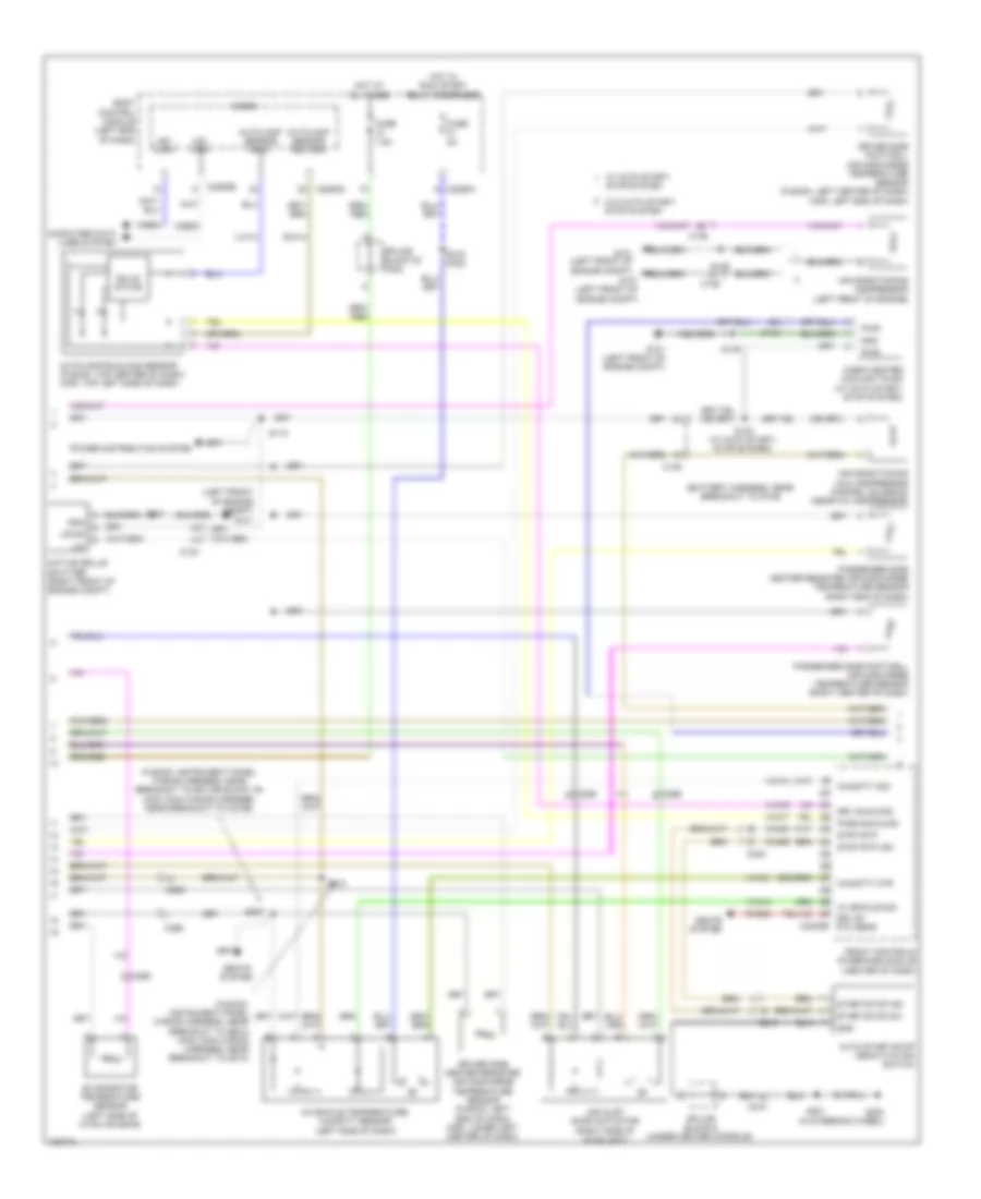
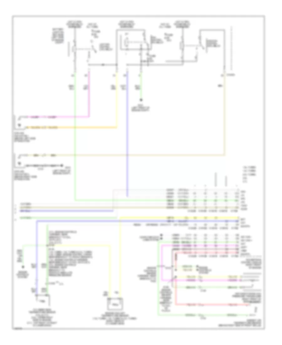
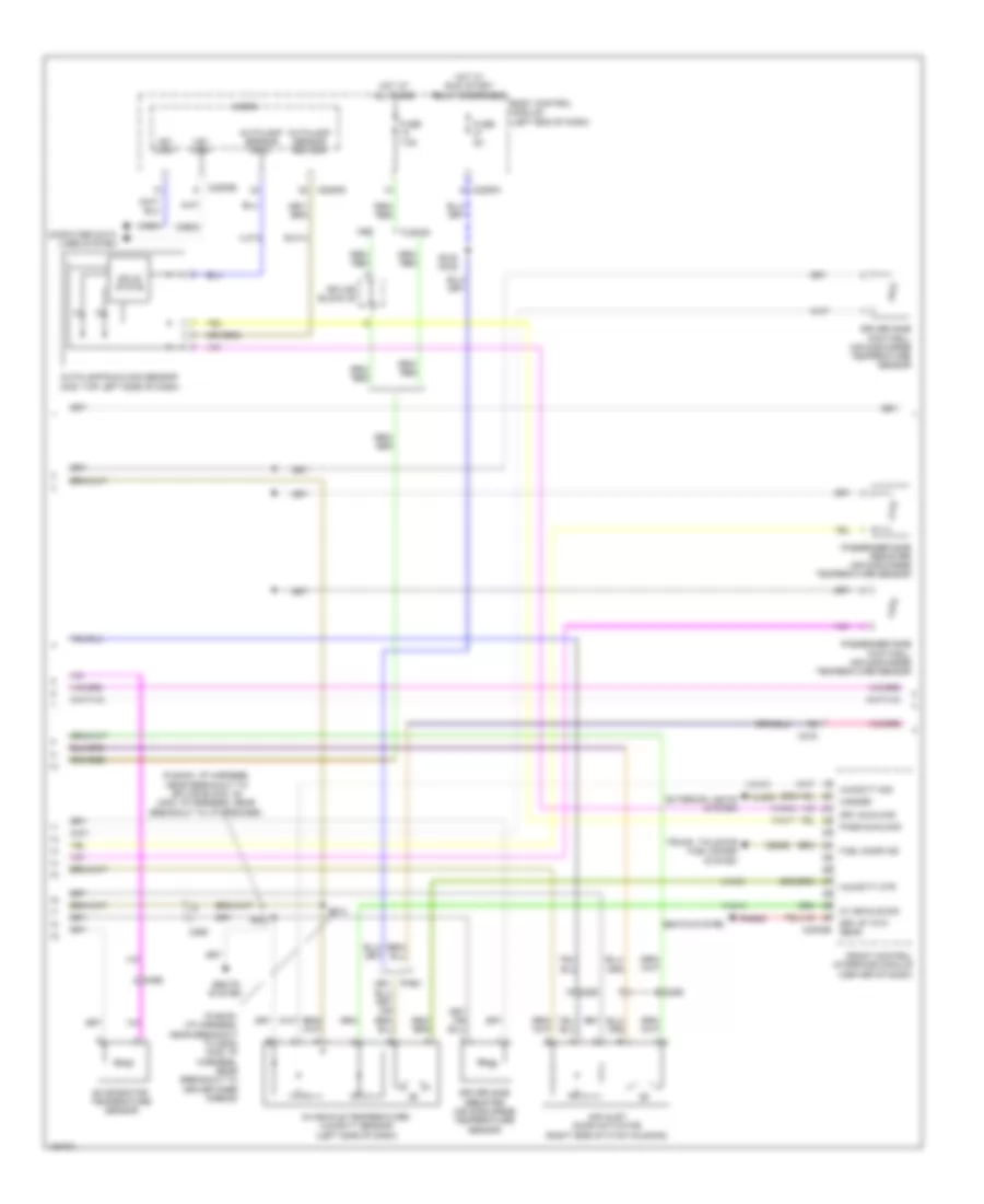
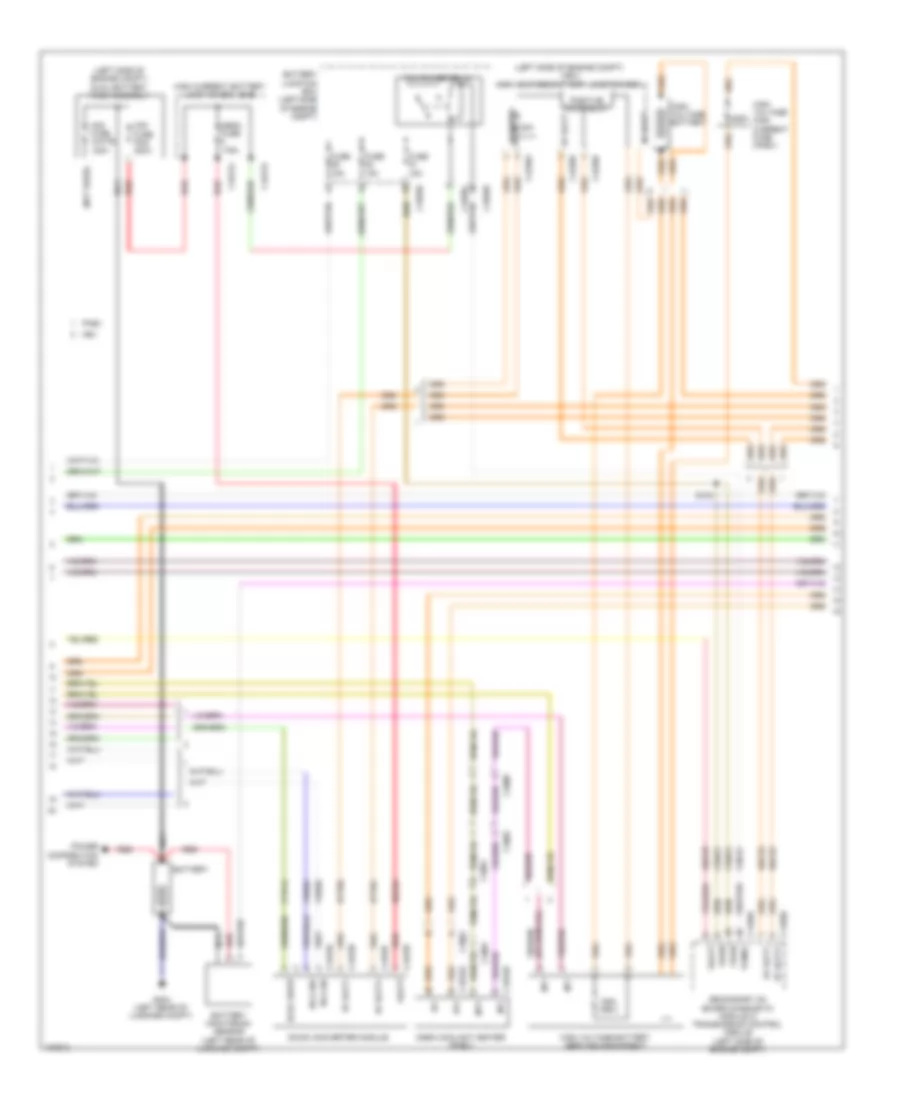
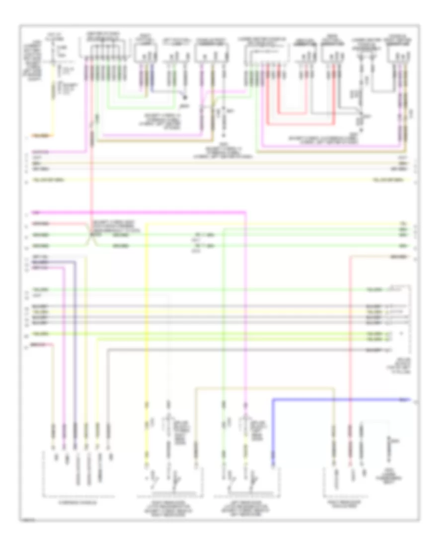
AIR CONDITIONING
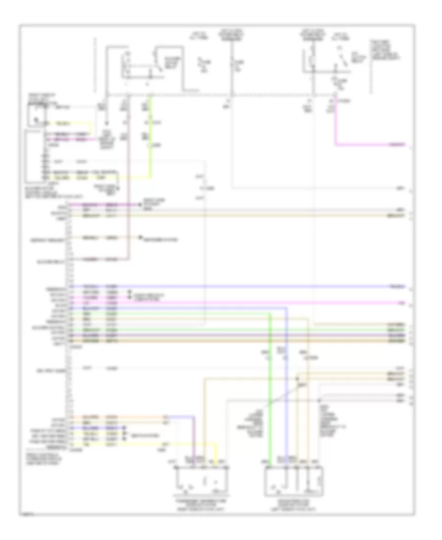
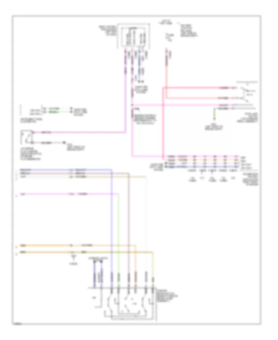
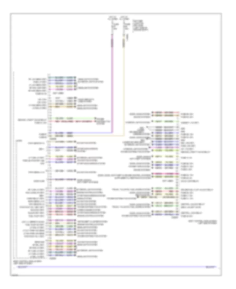
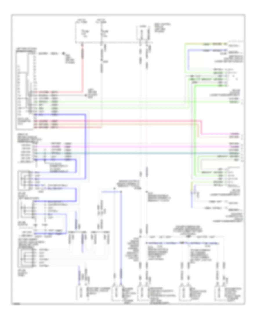
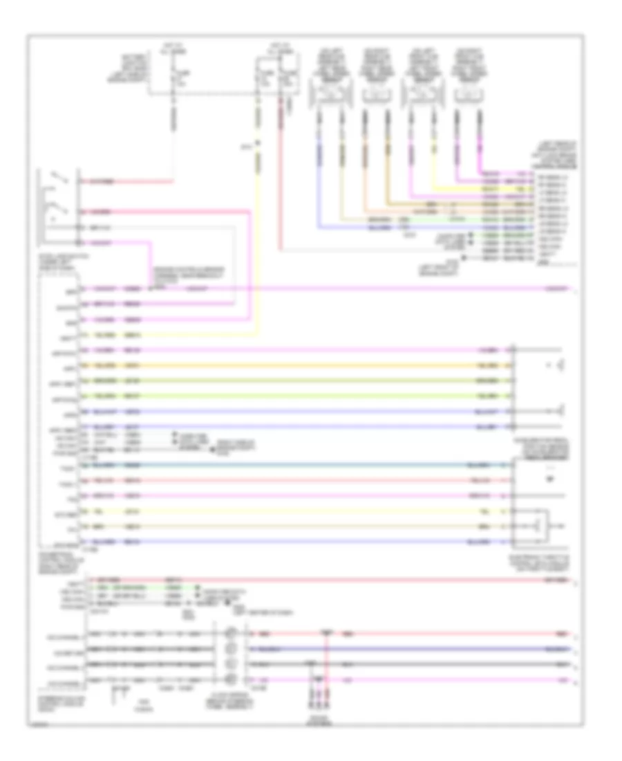
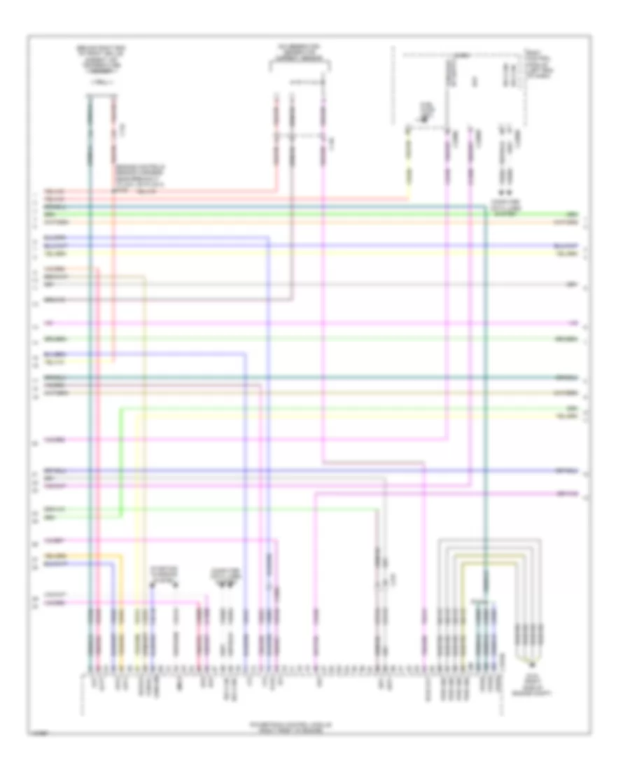
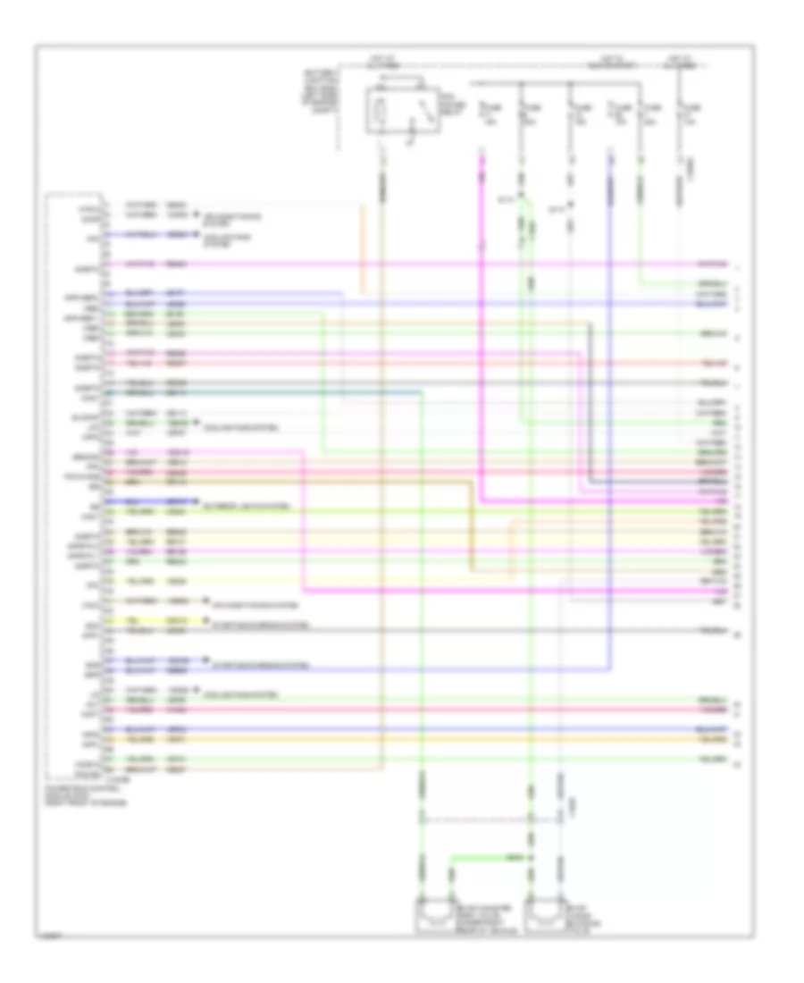
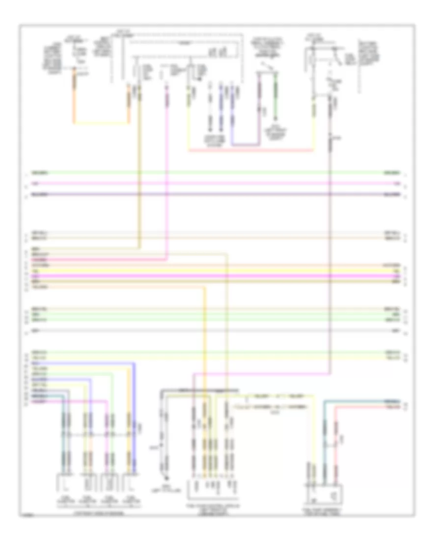
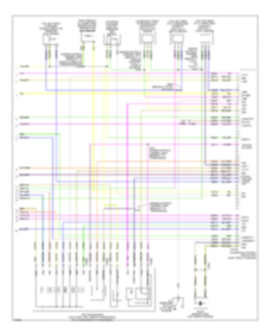
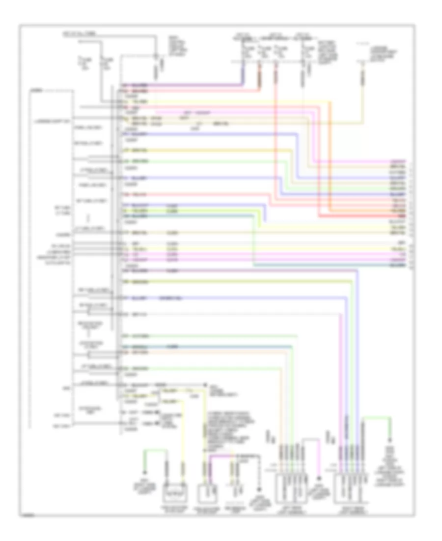
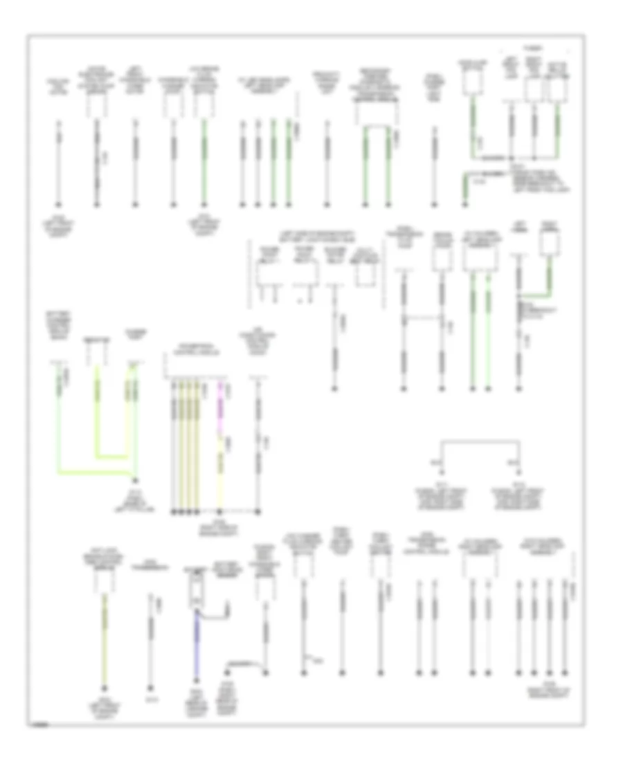
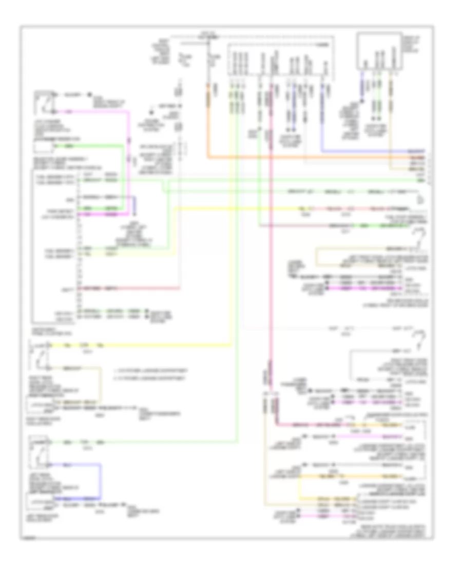
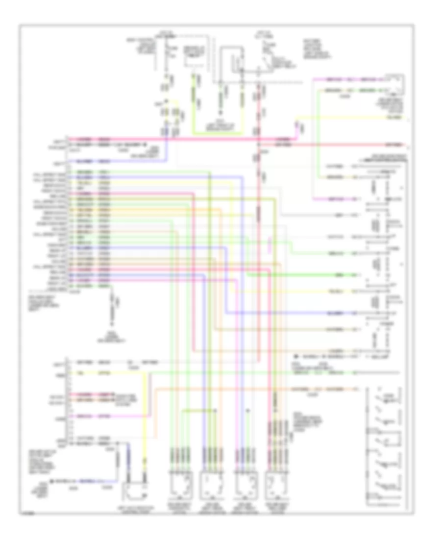
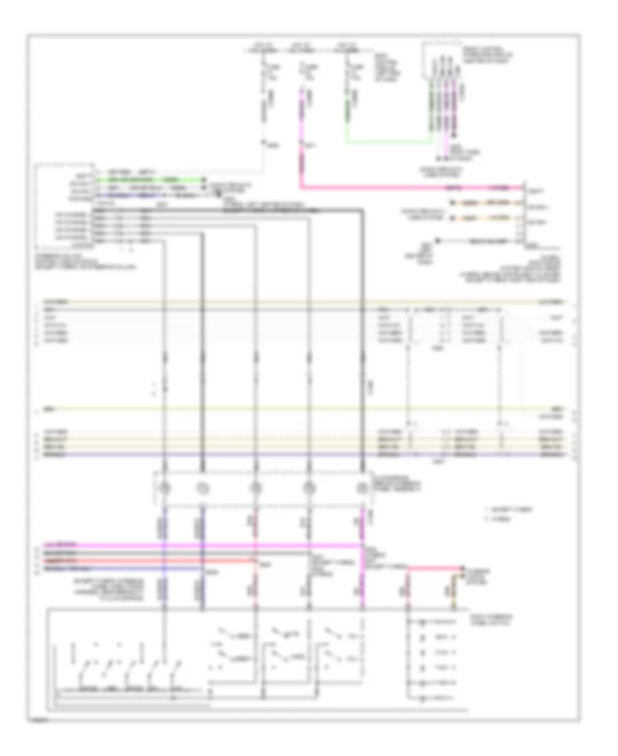
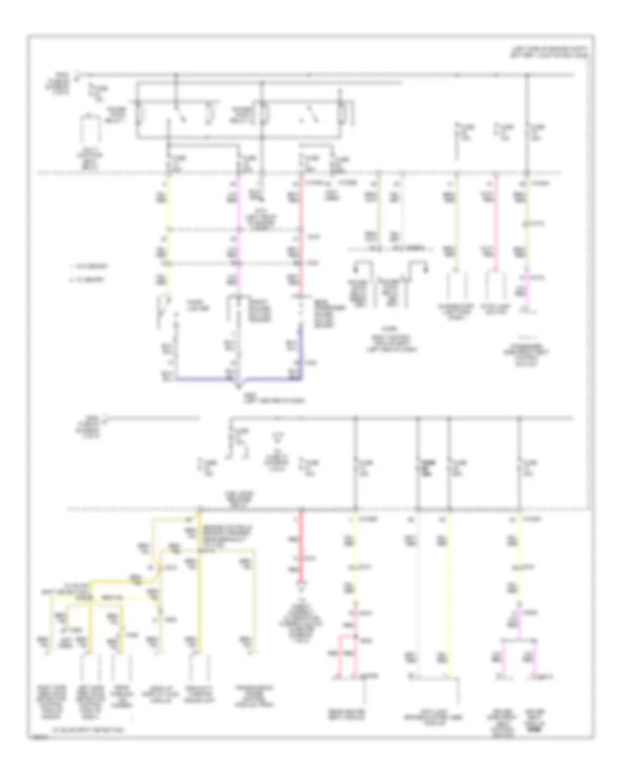
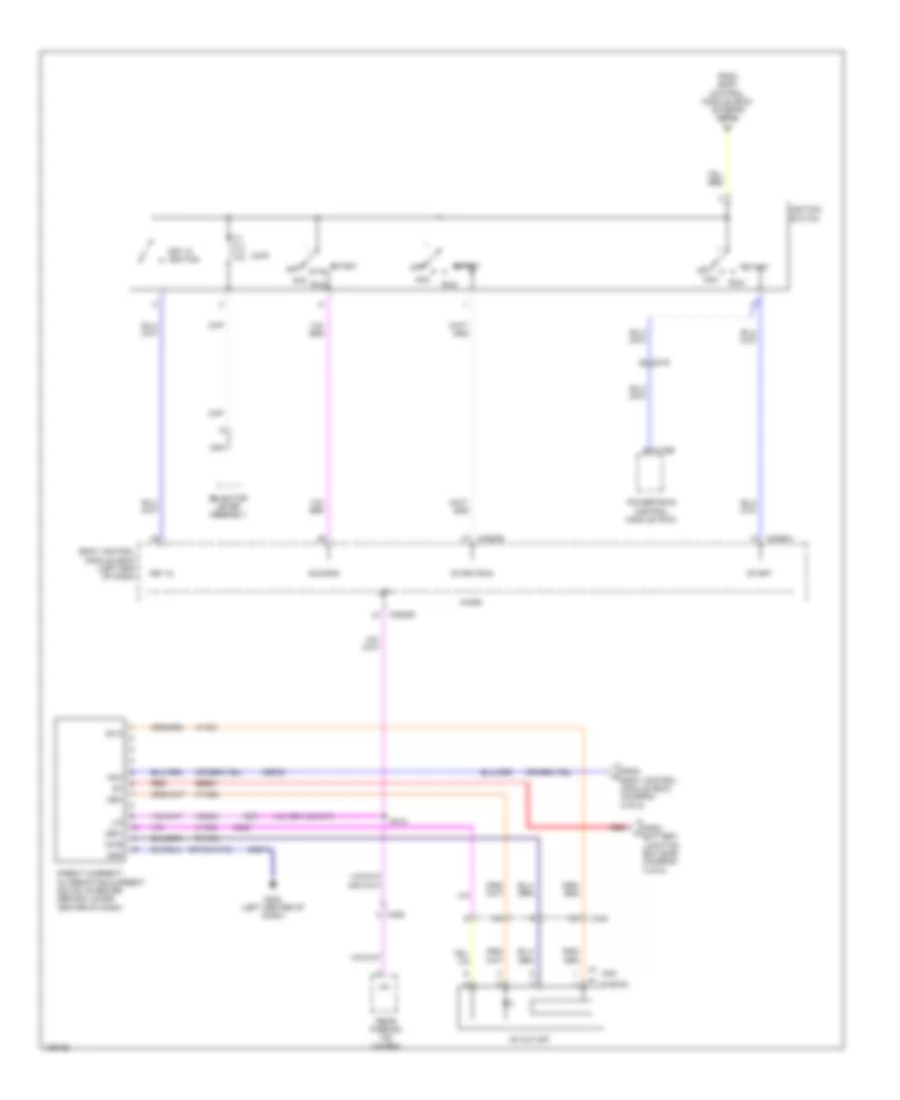
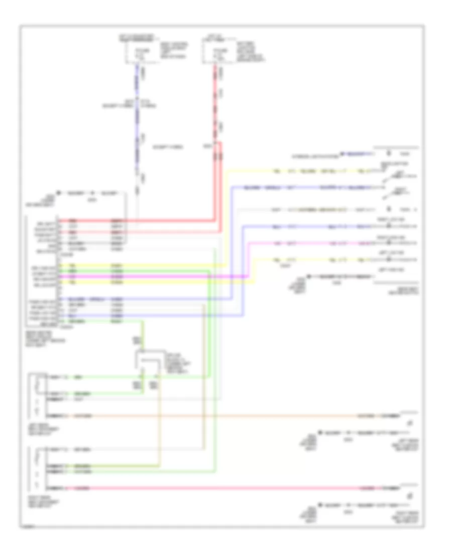
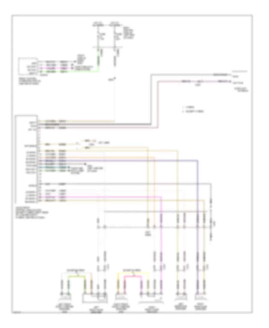
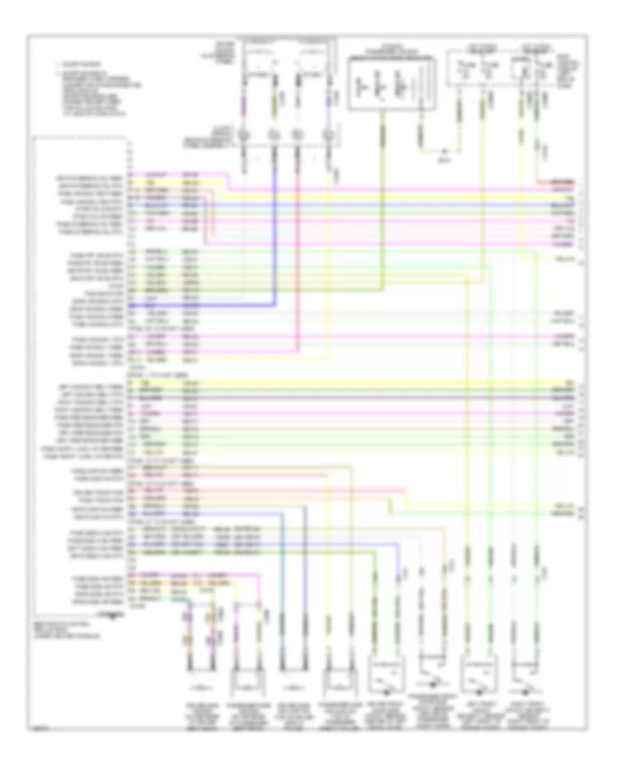
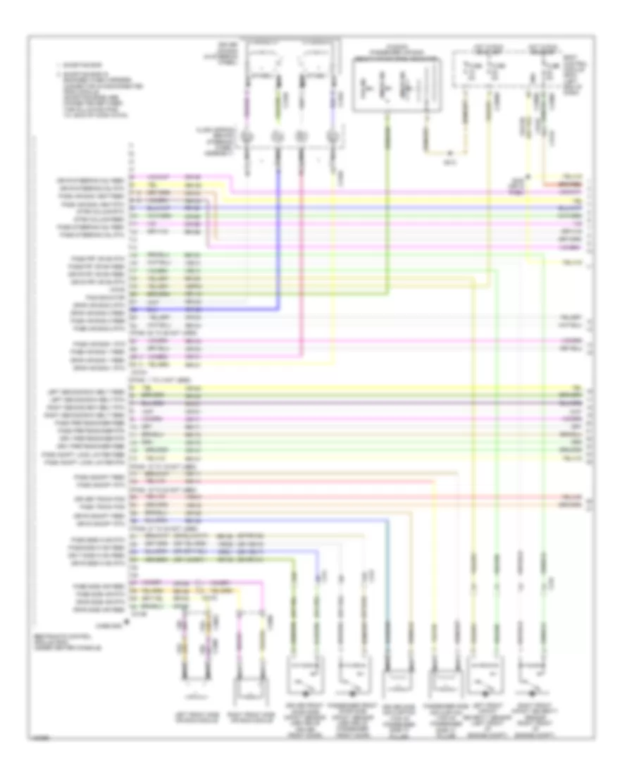
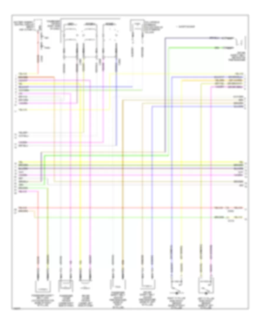
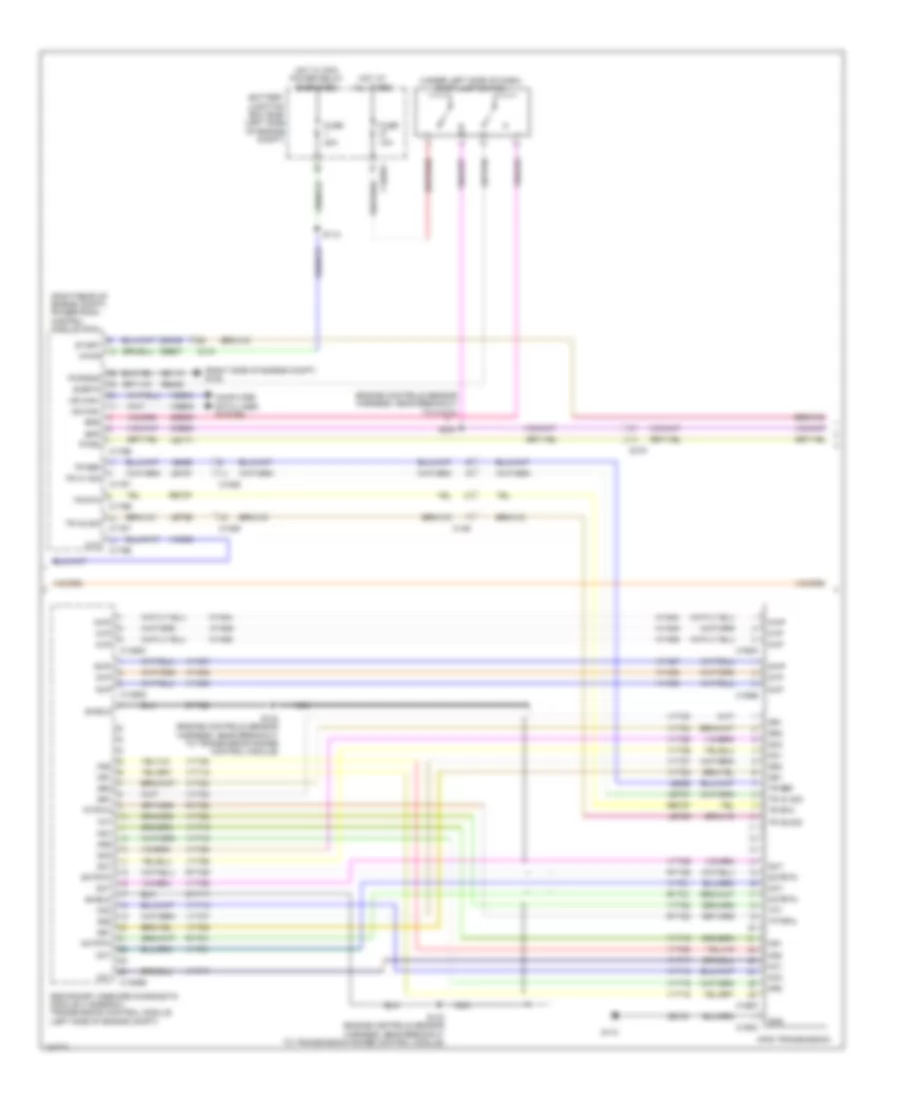
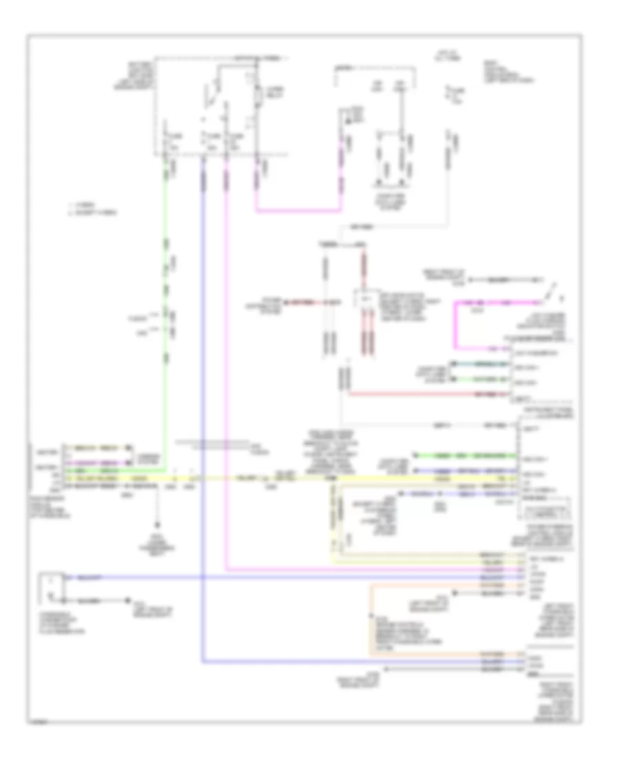
Automatic A/C Wiring Diagram, Except Hybrid (1 of 3) for Ford Fusion S Hybrid 2014

List of elements for Automatic A/C Wiring Diagram, Except Hybrid (1 of 3) for Ford Fusion S Hybrid 2014:
- (a/c jumper harness, near breakout to blower motor)
- (center of dash)
- (right side of dash) g202
- (right side of hvac unit) blower motor
- 10a
- 40a
- A/c clutch relay
- Air distribution door actuator (left side of hvac unit)
- Battery junction box (bjb) (left side of engine compt)
- Blower control
- Blower motor control module (bottom center of hvac unit)
- Blower motor relay
- Blower relay
- C1035a
- C1035b
- C219
- C2402a
- C2402b
- C265
- C268
- C297a
- C297b
- Ch123
- Ch201
- Ch202
- Ch203
- Ch206
- Ch207
- Ch208
- Ch211
- Ch212
- Ch213
- Ch237
- Ch238
- Ch239
- Ch402
- Chs02
- Chs07
- Computer data lines system
- Crd02
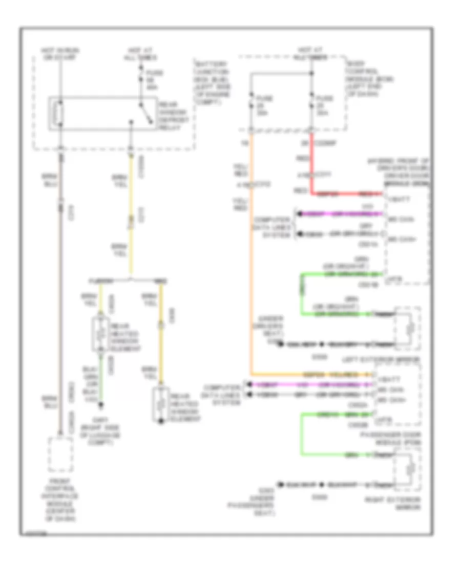
- Defogger system
- Defrost request
- Driver temperature door actuator (dual zone) (left side of hvac unit)
- Drv frt snsr 1
- Drv frt snsr 2
- Drv heater feed
- Evap
- Feedback
- Front controls interface module
- Fuse
- Fuse 15a
- Fuse 20a
- G101 (left front of engine compt)
- G202 (right side of dash)
- Gd216
- Gnd
- Hot at all times
- Hot w/ pcm power relay energized
- Lh111
- Motor+
- Motor-
- Ms can+
- Ms can-
- Pass frt snsr 1
- Pass frt snsr 2
- Pass heater feed
- Pass st ntc sens
- Passenger temperature door actuator (right side of hvac unit)
- Red
- Rh111
- Rh301
- Rhs10
- S202
- S203 (a/c jumper harness, near breakout to blower motor)
- S210
- Sbb65
- Sbp12
- Seats system
- Sig rtn
- Vbatt
- Vdb06
- Vdb07
- Vh101
- Vh301
- Vh406
- Vh409
- Vh410
- Vh411
- Vh412
- Vref
- W/ heated seats
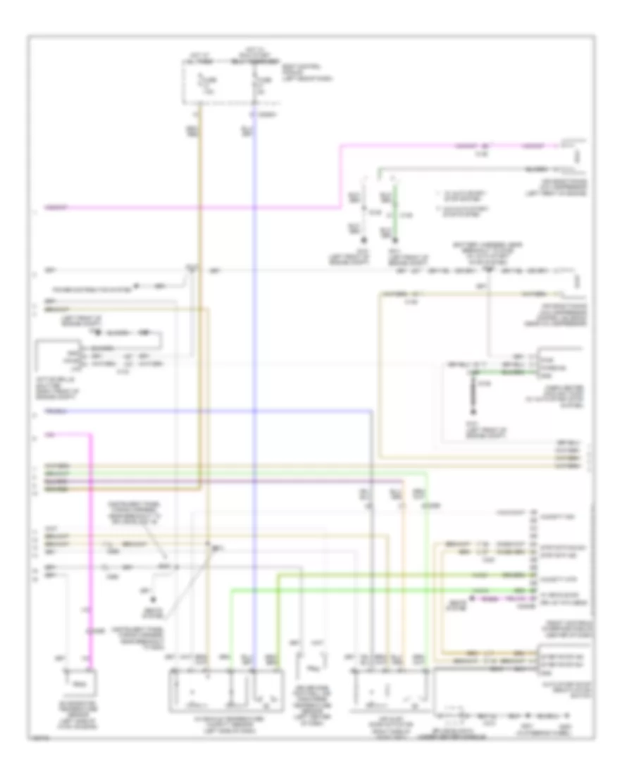
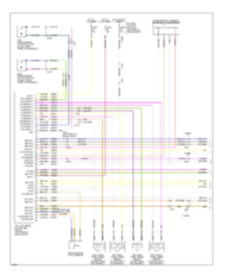
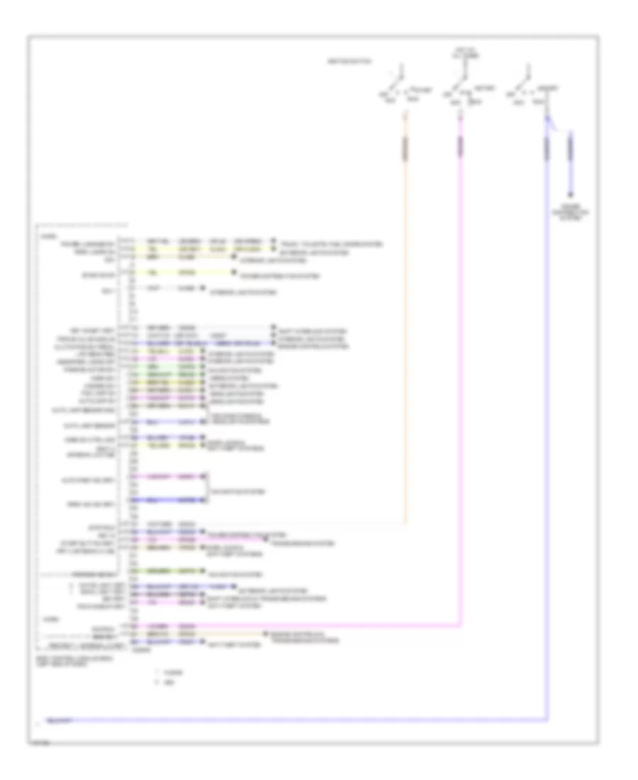
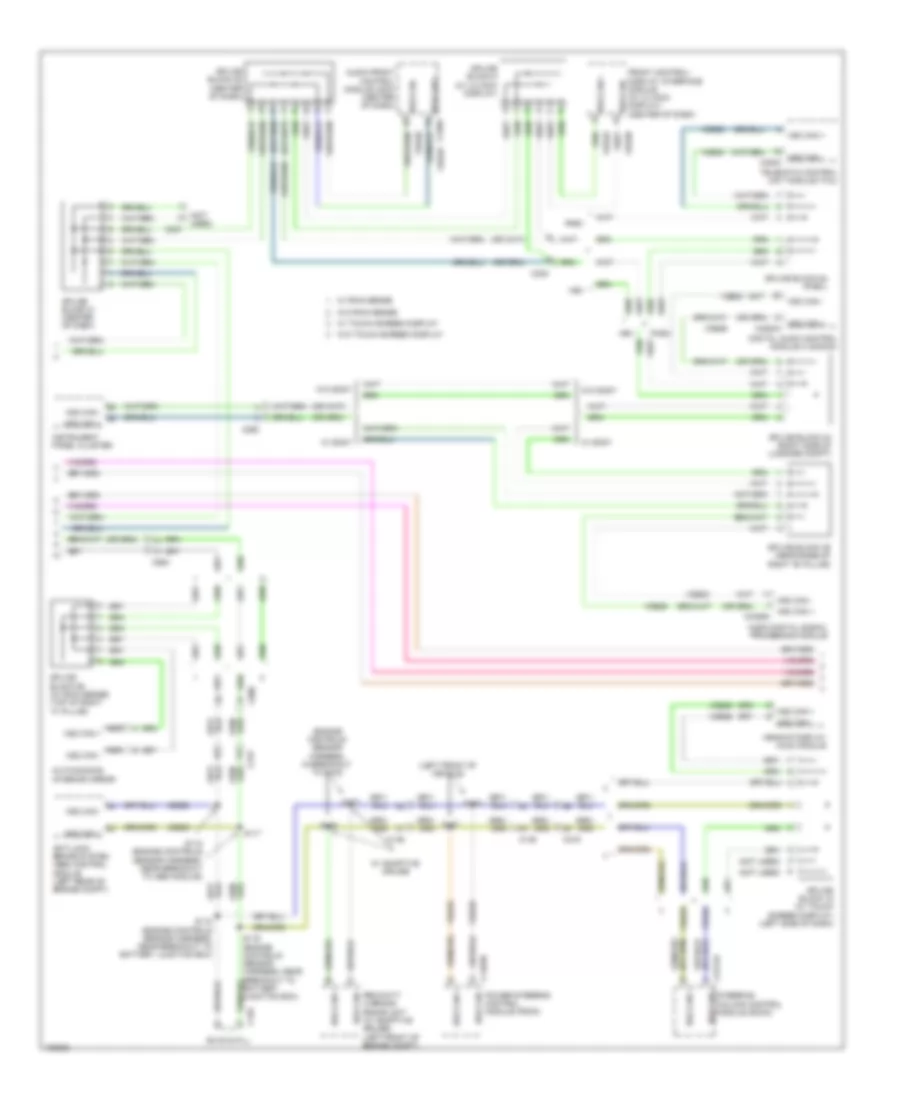
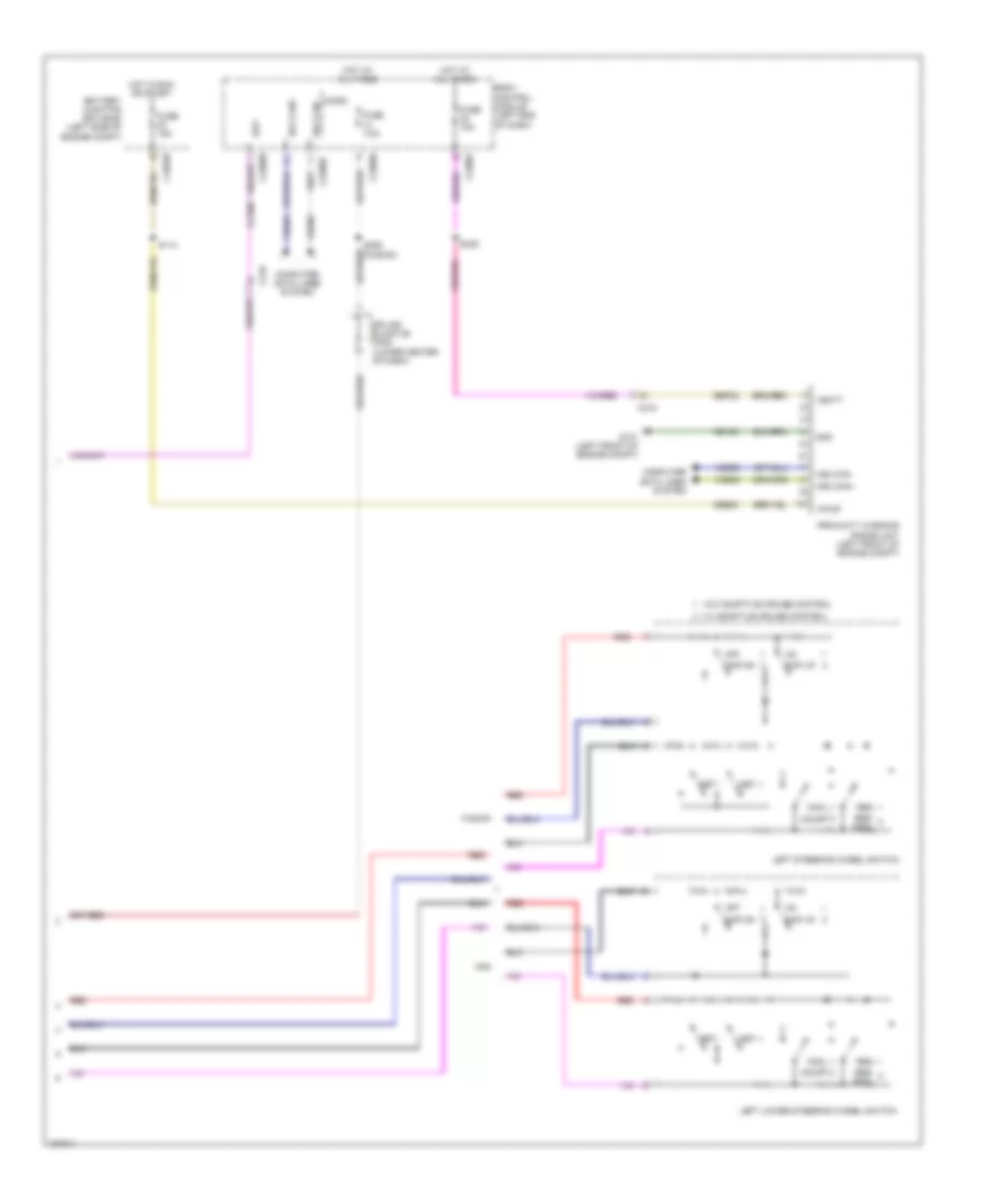
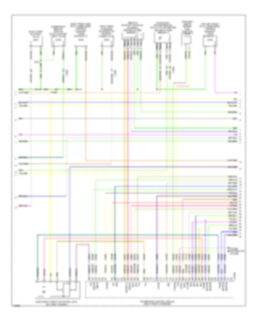
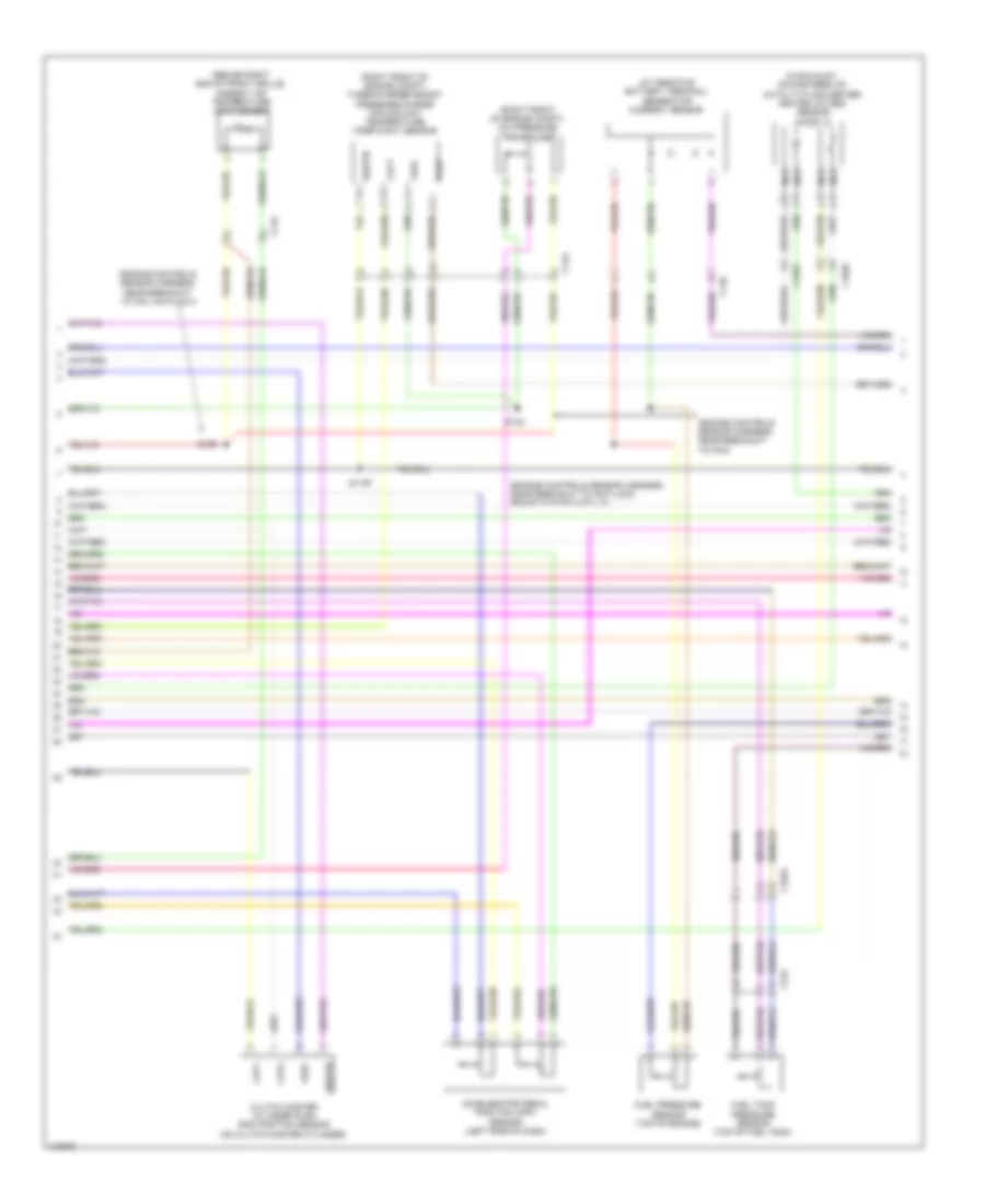
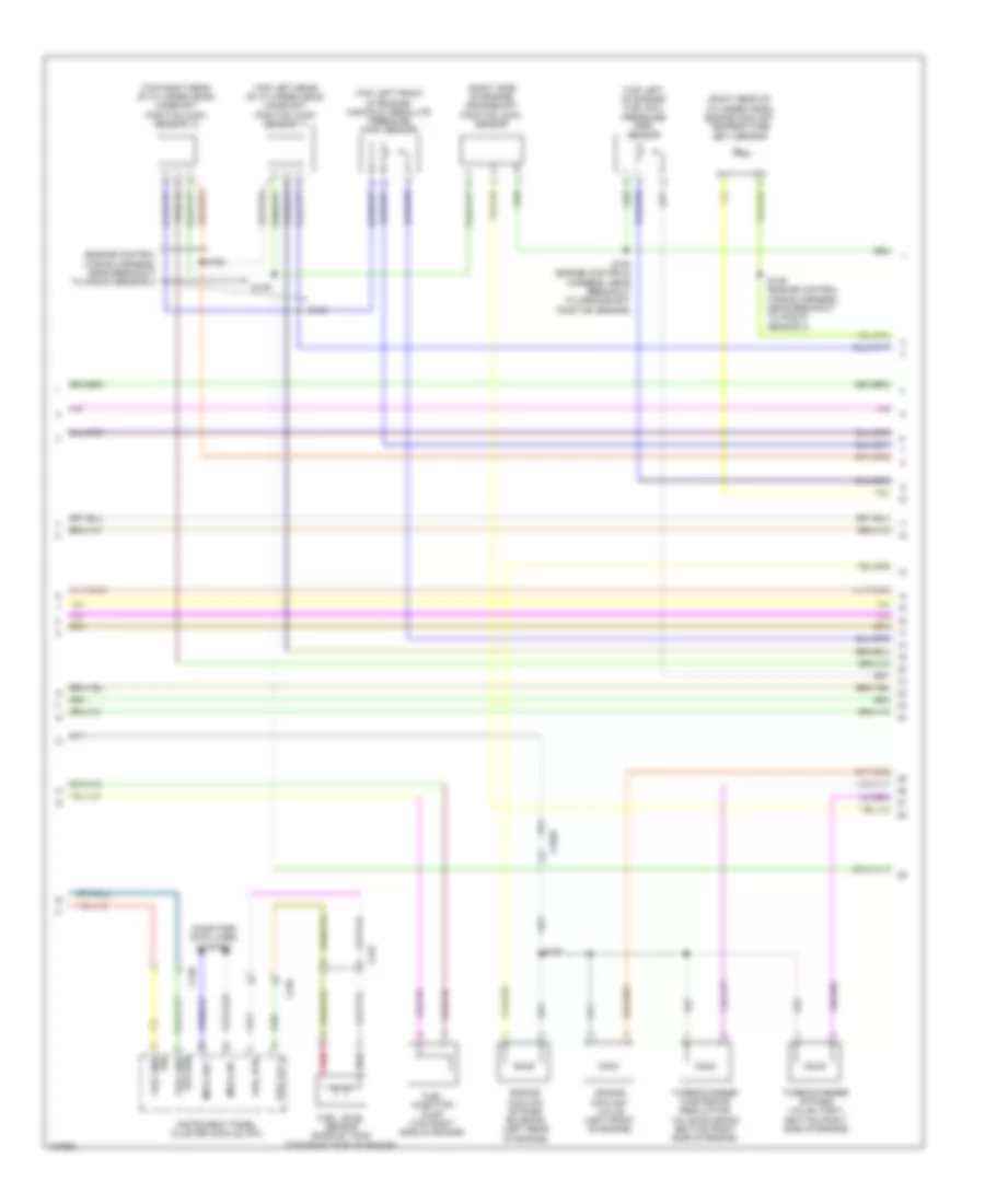
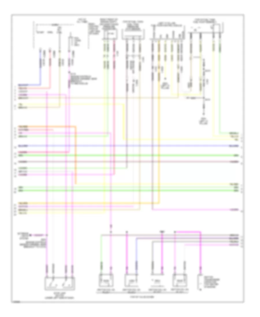
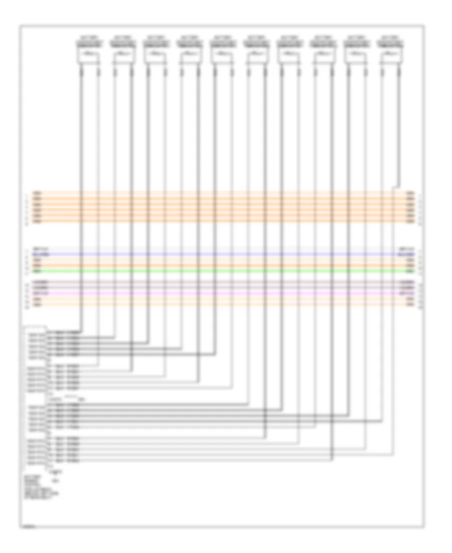
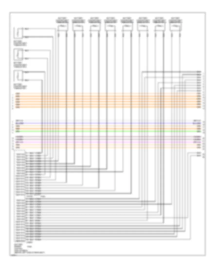
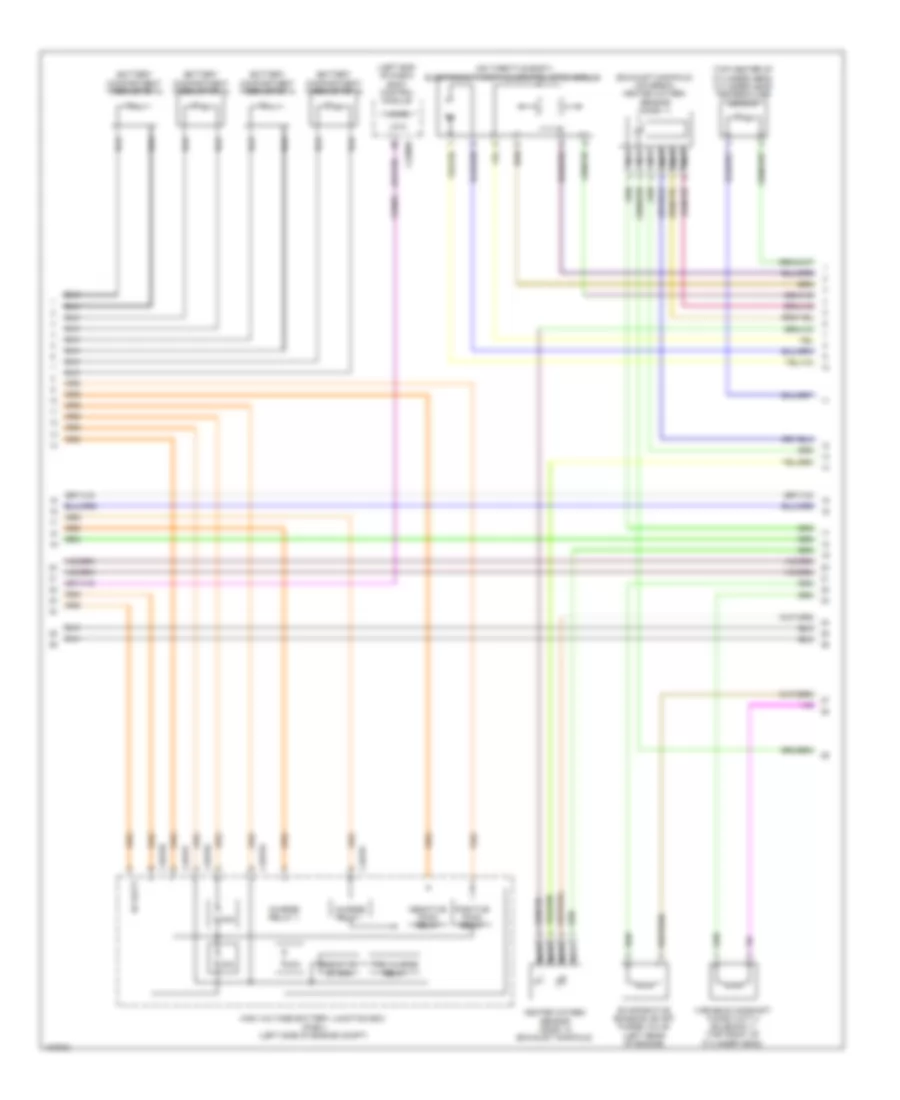
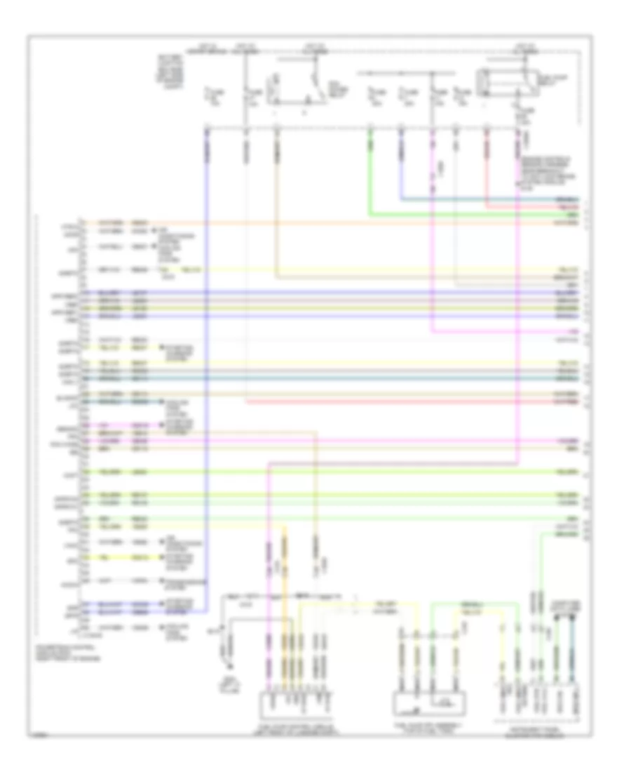
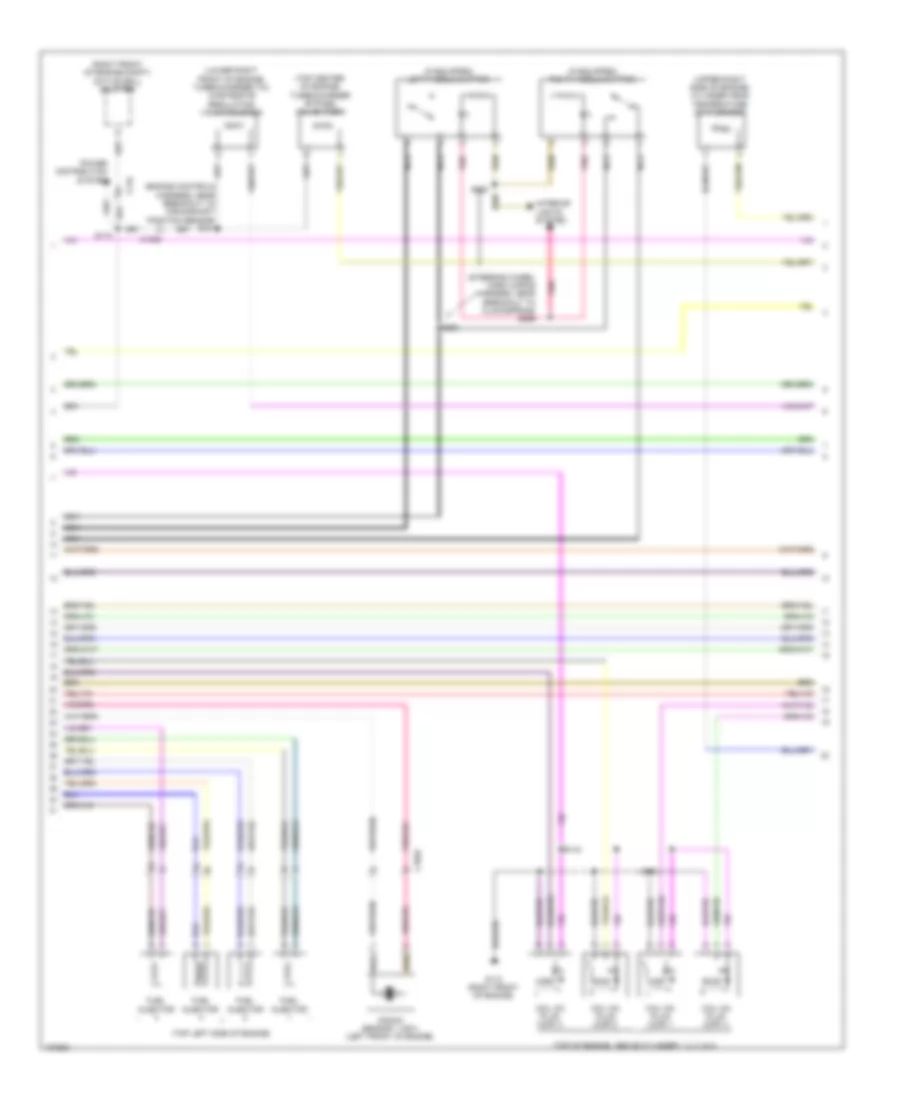
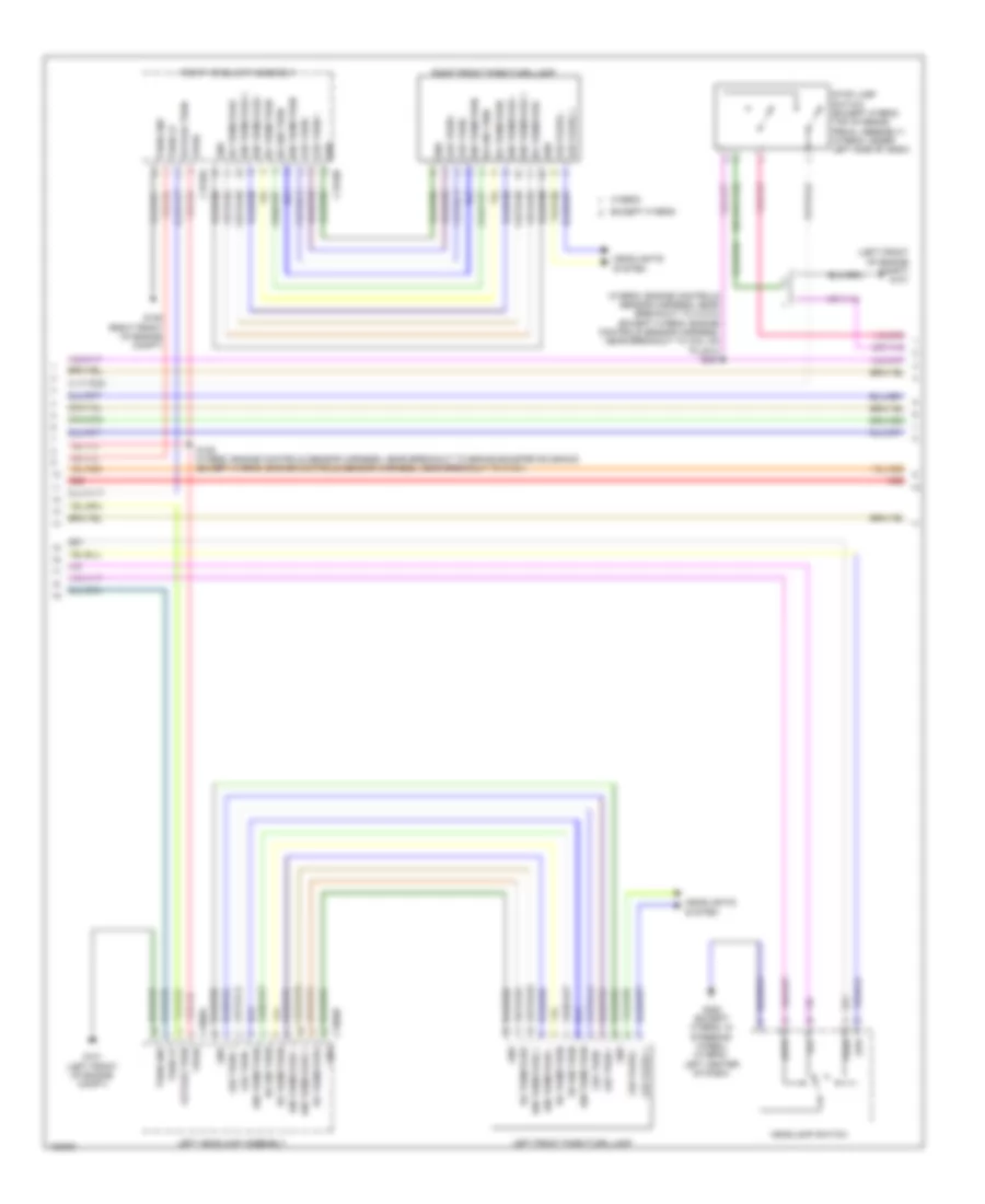
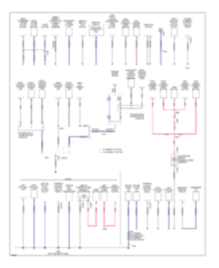
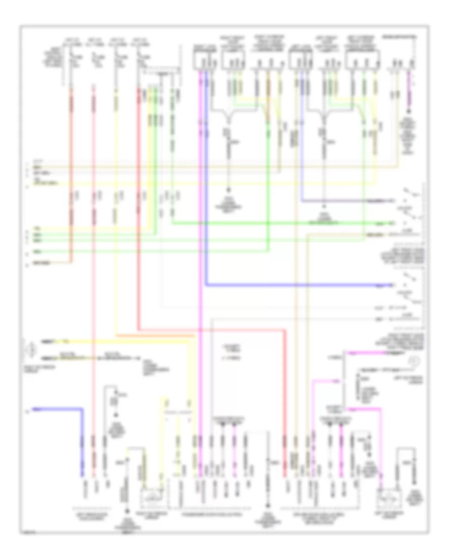
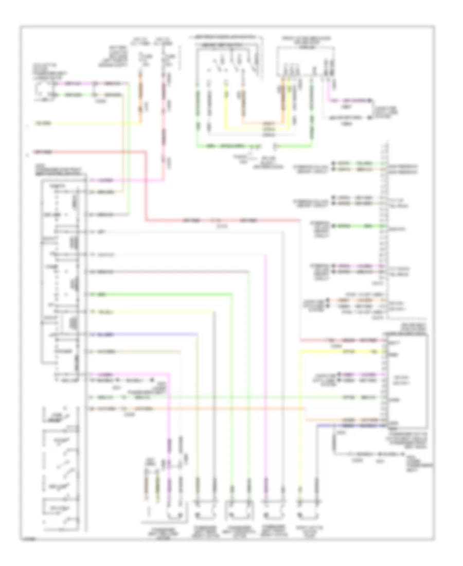
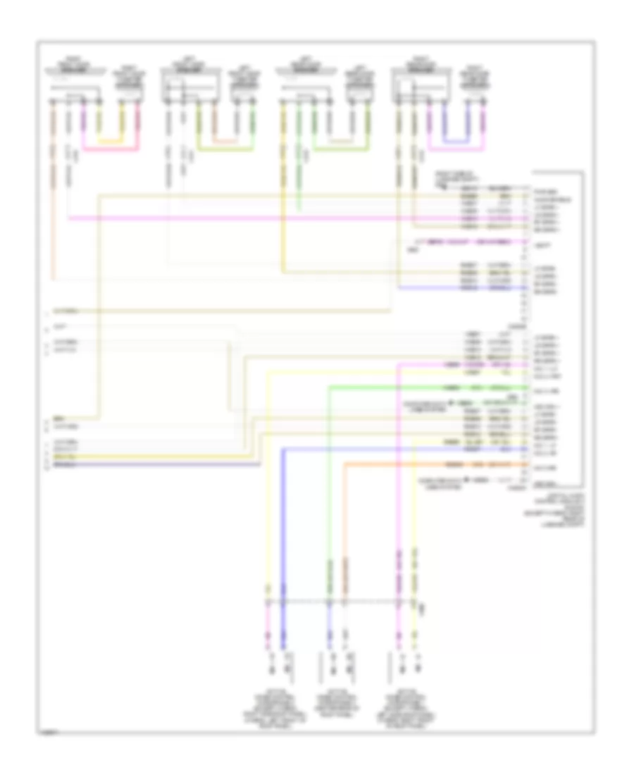
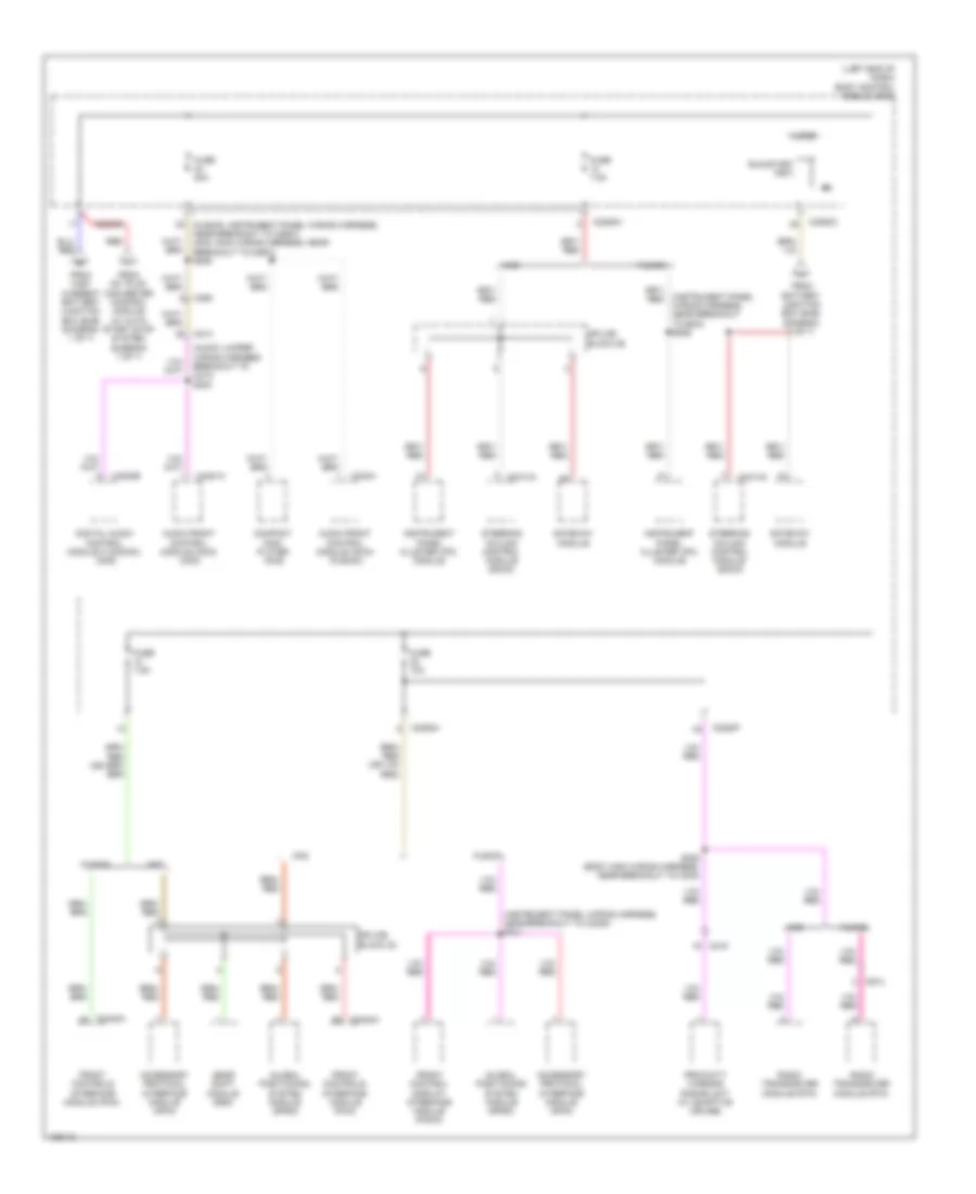
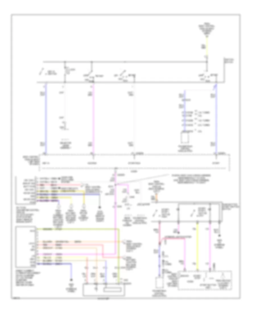
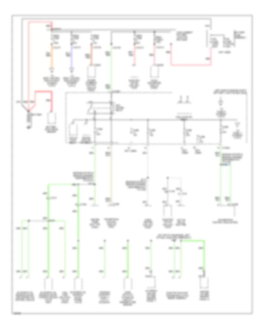
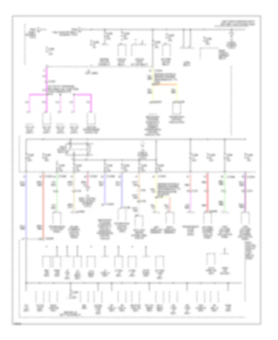
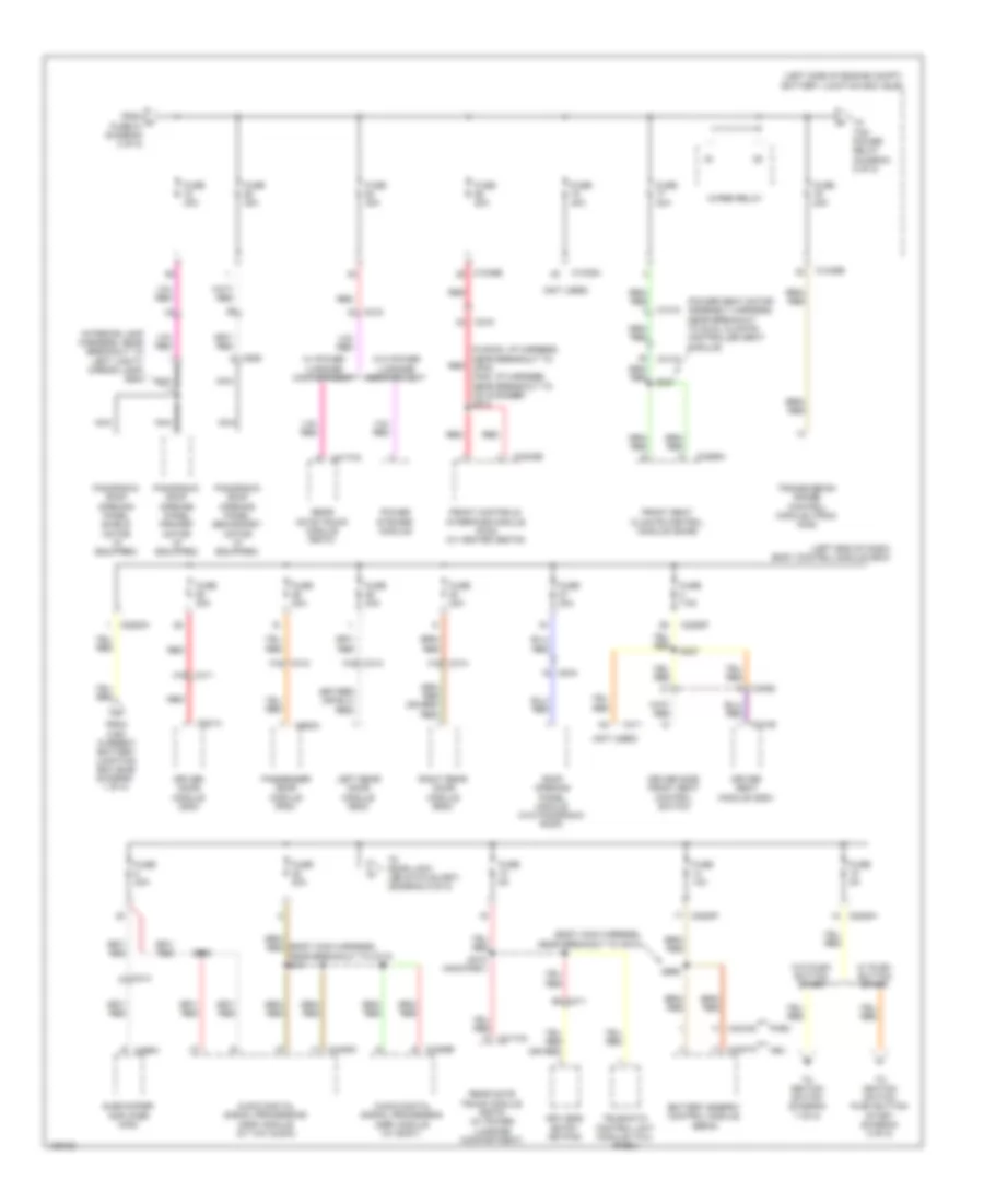
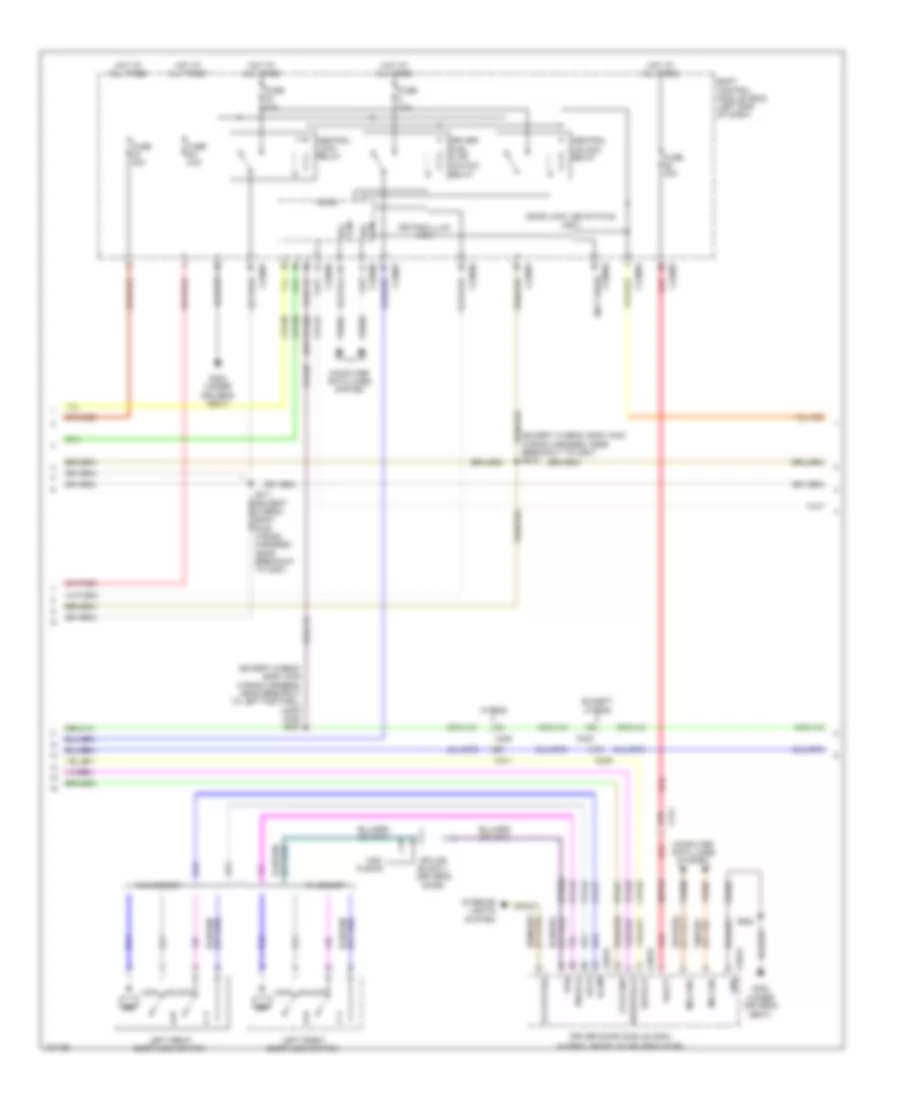
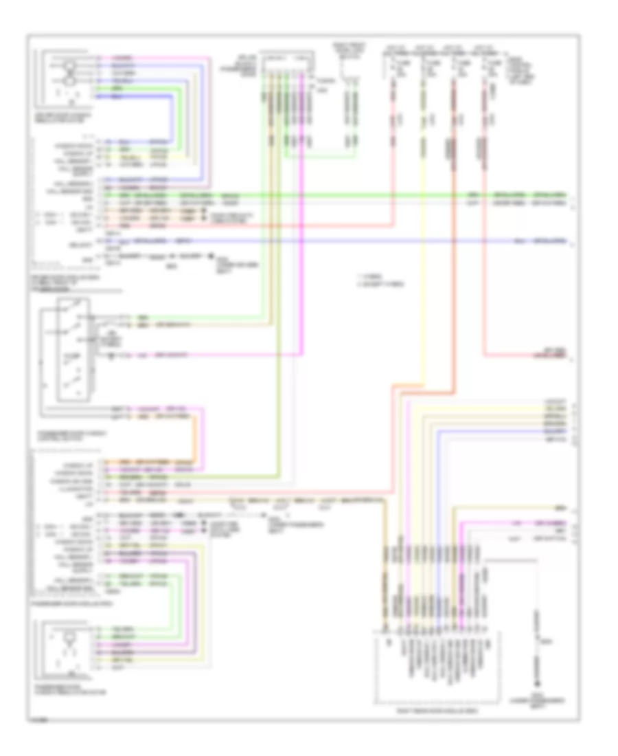
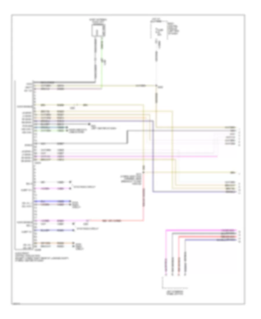
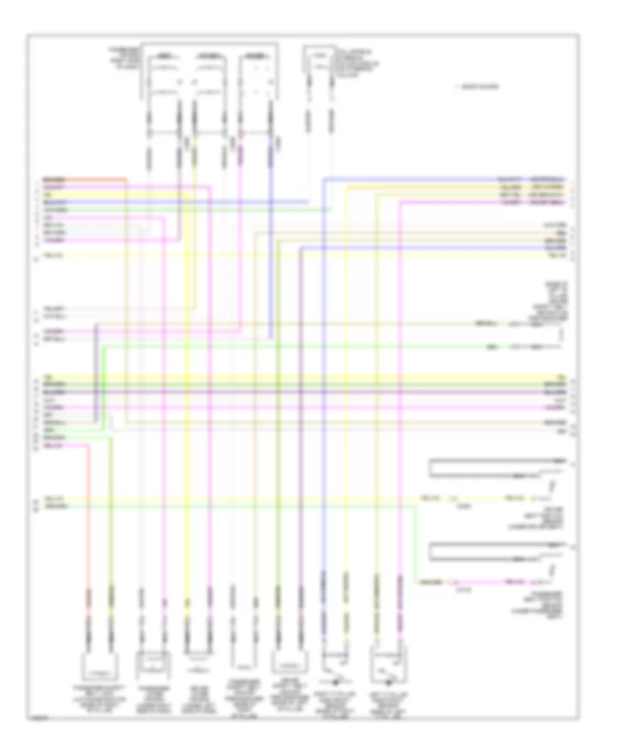
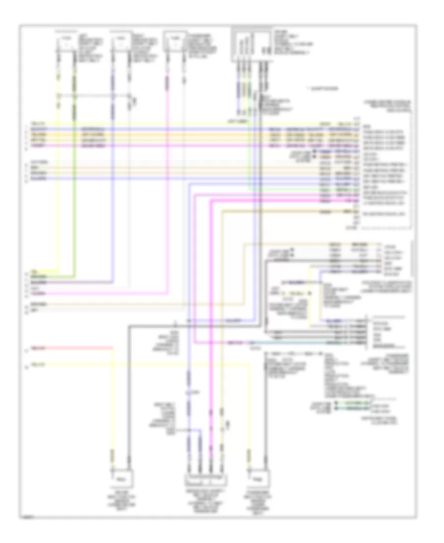
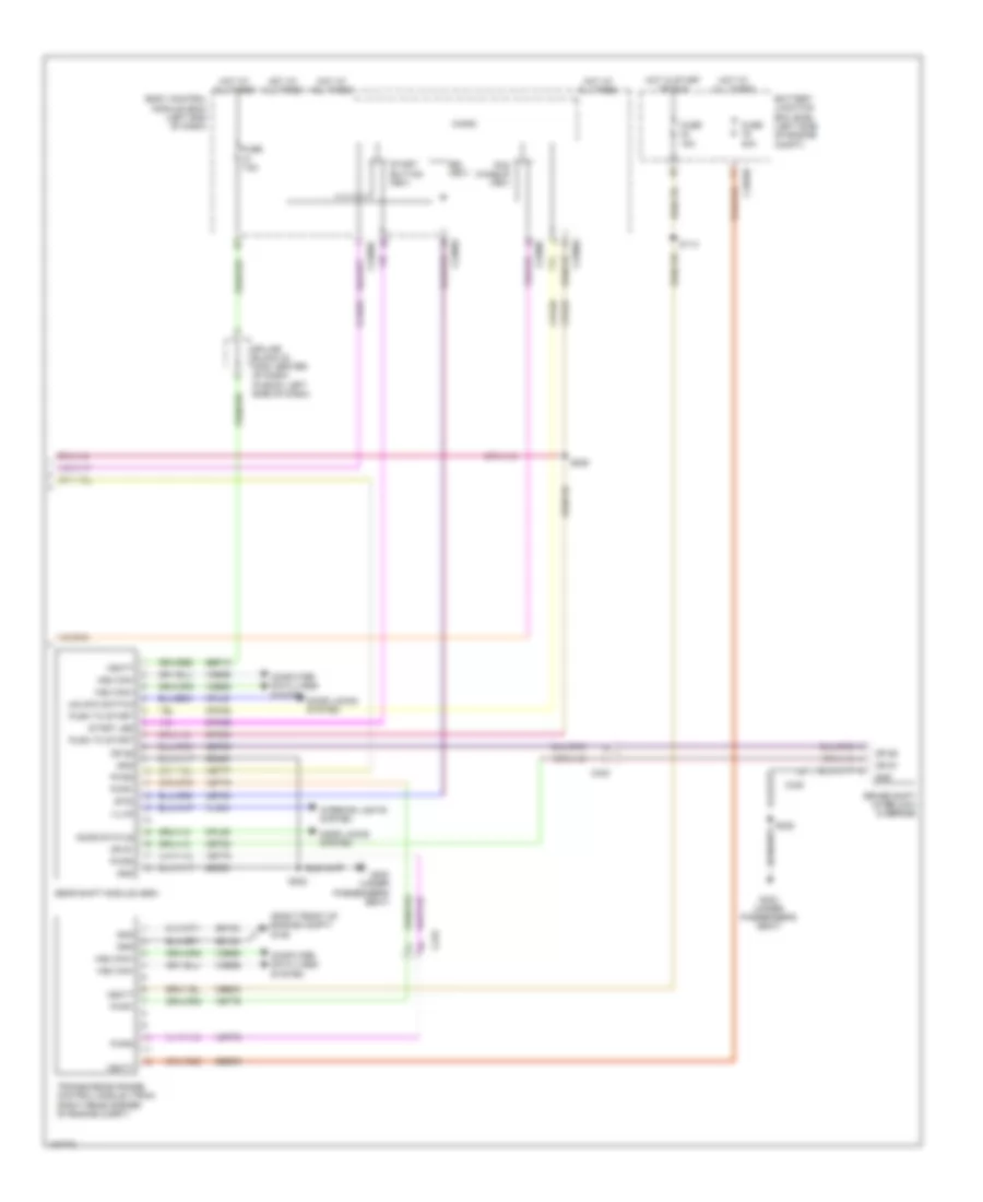
Automatic A/C Wiring Diagram, Except Hybrid (2 of 3) for Ford Fusion S Hybrid 2014
List of elements for Automatic A/C Wiring Diagram, Except Hybrid (2 of 3) for Ford Fusion S Hybrid 2014:
- (battery harness, near breakout to g109)
- (center of dash)
- (fusion: instrument panel wiring harness, near breakout to g202) (mkz: main wiring harness, near breakout to c275)
- (fusion: instrument panel wiring harness, near breakout to splice block 19) (mkz: main wiring harness, near breakout to c2198)
- (left front of engine compt)
- Active grille shutter (right front of engine compt)
- Air conditioning (a/c) compressor control solenoid (near a/c compressor)
- Air conditioning compressor (left front of engine)
- Air inlet door actuator (right side of hvac unit)
- Auto start/stop deactivation switch
- Autolamp sensor input
- Autolamp sensor return
- Autolamp/sunload sensor (fusion: top center of dash) (mkz: top left side of dash)
- Body control module (left end of dash)
- C134
- C146
- C210
- C2280b
- C2280g
- C2280h
- C2402b
- C265
- C340
- Cabin heater coolant pump (w/ auto start/ stop system)
- Ch253
- Ch469
- Computer data lines system
- Driver side center register air discharge temperature sensor (fusion: left end of dash) (mkz: lower left center of dash)
- Driver side footwell air discharge temperature sensor (fusion: left center of dash) (mkz: left end of dash)
- Drv st ntc sens
- Drv sunload
- Evaporator temperature sensor (left side of hvac housing)
- Front controls interface module
- Fuse 5a
- Fuse 7.5a
- G101
- G101 (left front of engine compt)
- G200 (in steering wheel)
- Gnd
- Hot at all times
- Hot w/ run/ start relay energized
- Hs1 can+
- Hs1 can-
- Humidity mtr
- Humidity sig
- In vehicle sig
- In-vehicle temperature/ humidity sensor (left side of dash)
- Lin
- Micro
- Pass sunload
- Passenger side center register air discharge temperature sensor (right end of dash)
- Passenger side footwell air discharge temperature sensor (right center of dash)
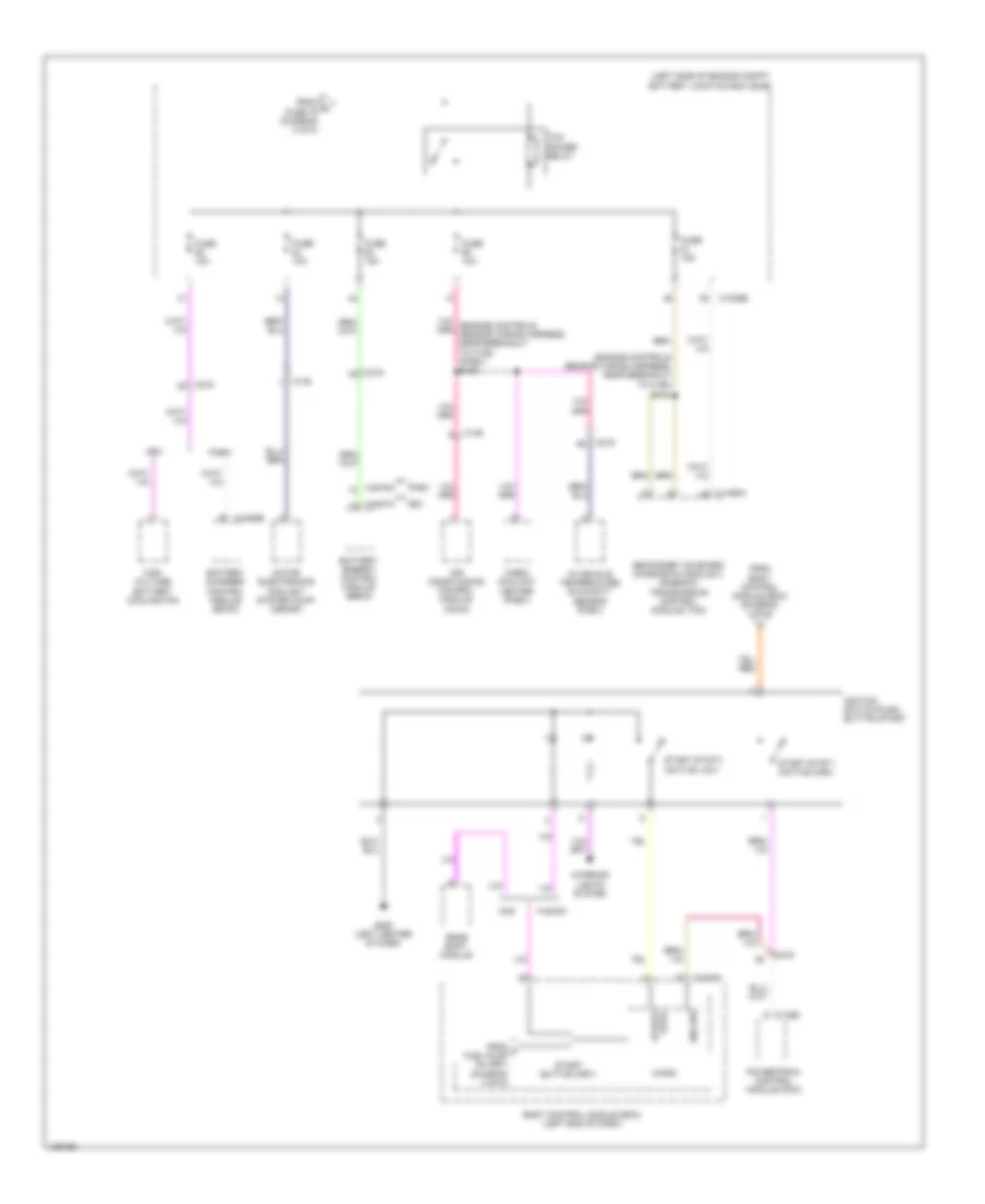
- Power distribution system
- Pwr
- Rhs05
- Rlf14
- S101
- S110
- S139
- S140 (w/ auto start/ stop system)
- S207
- S213
- S219 (mkz)
- S301
- Seats system
- Solid state
- Splice block 22 (mkz)
- Splice block 6 (under center console)
- Start/stop ind
- Start/stop sw
- Strt/stp
- Strt/stp ind
- Vdb04
- Vdb05
- Vh413
- Vh414
- Vh416
- Vh417
- Vha31
- Vlf14
- Vpwr
- W/ auto start/ stop system
- W/o auto start/ stop system
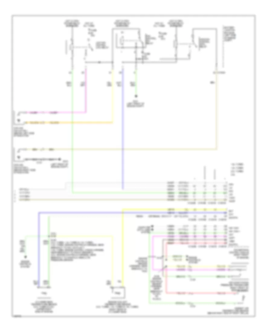
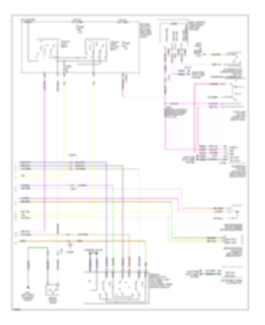
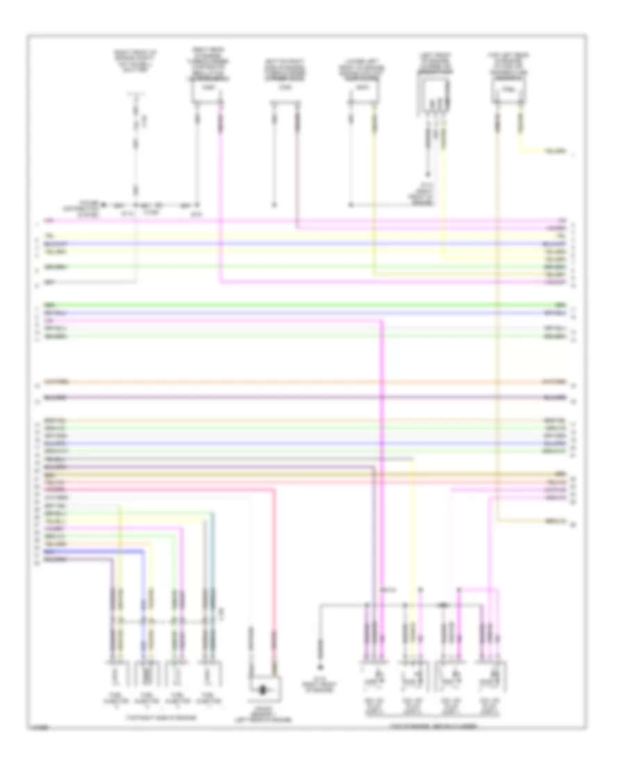
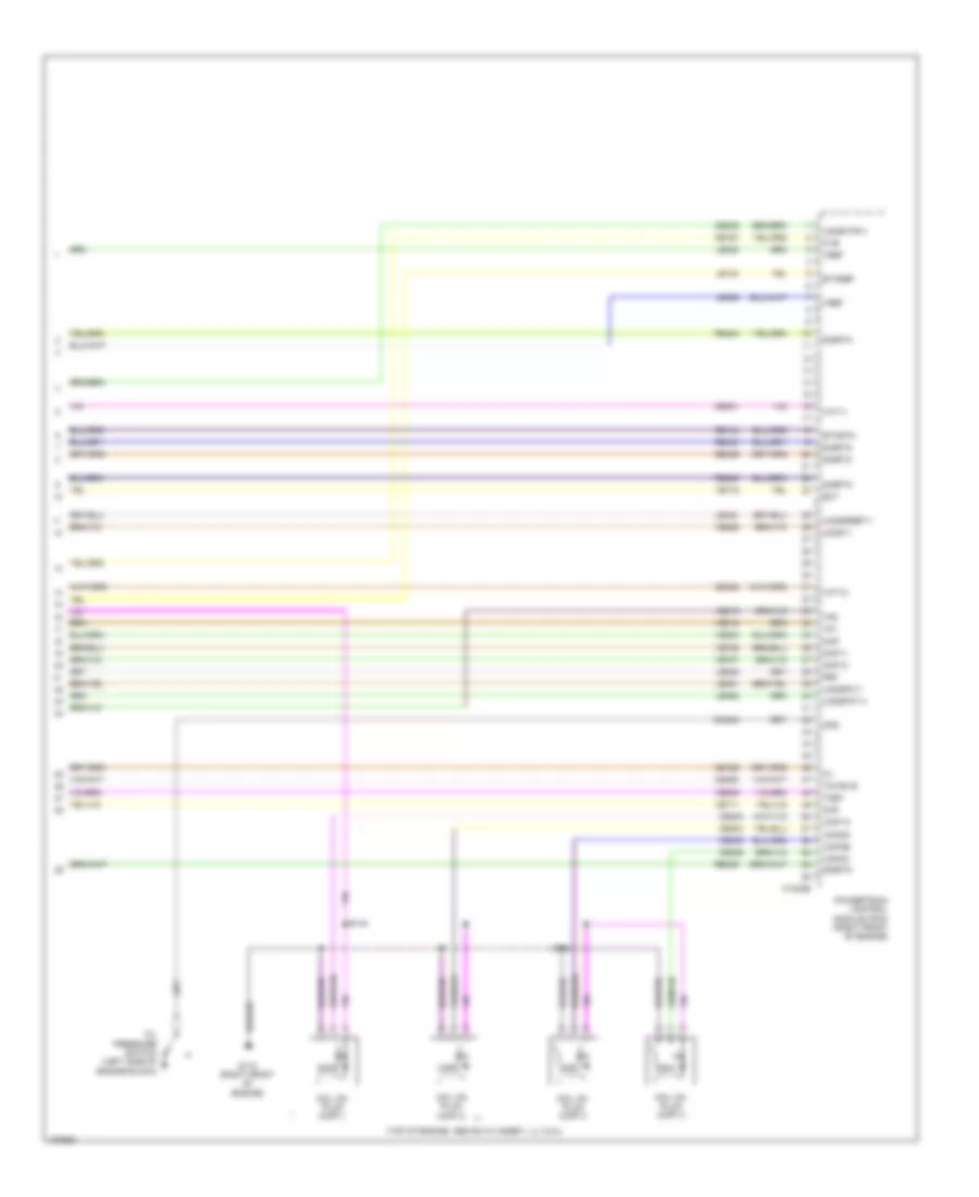
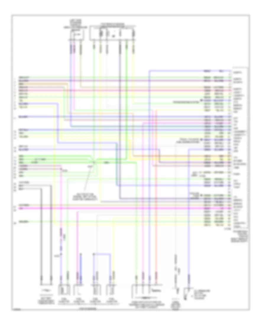
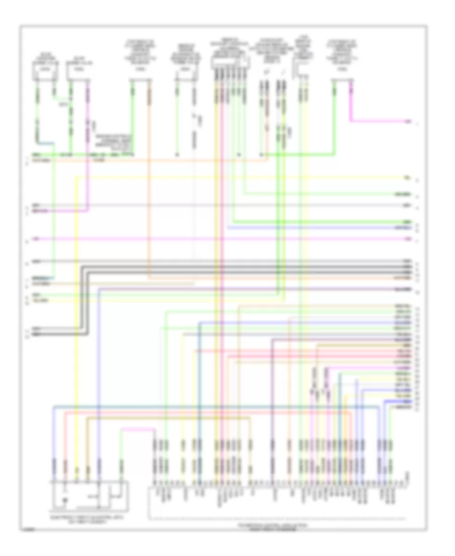
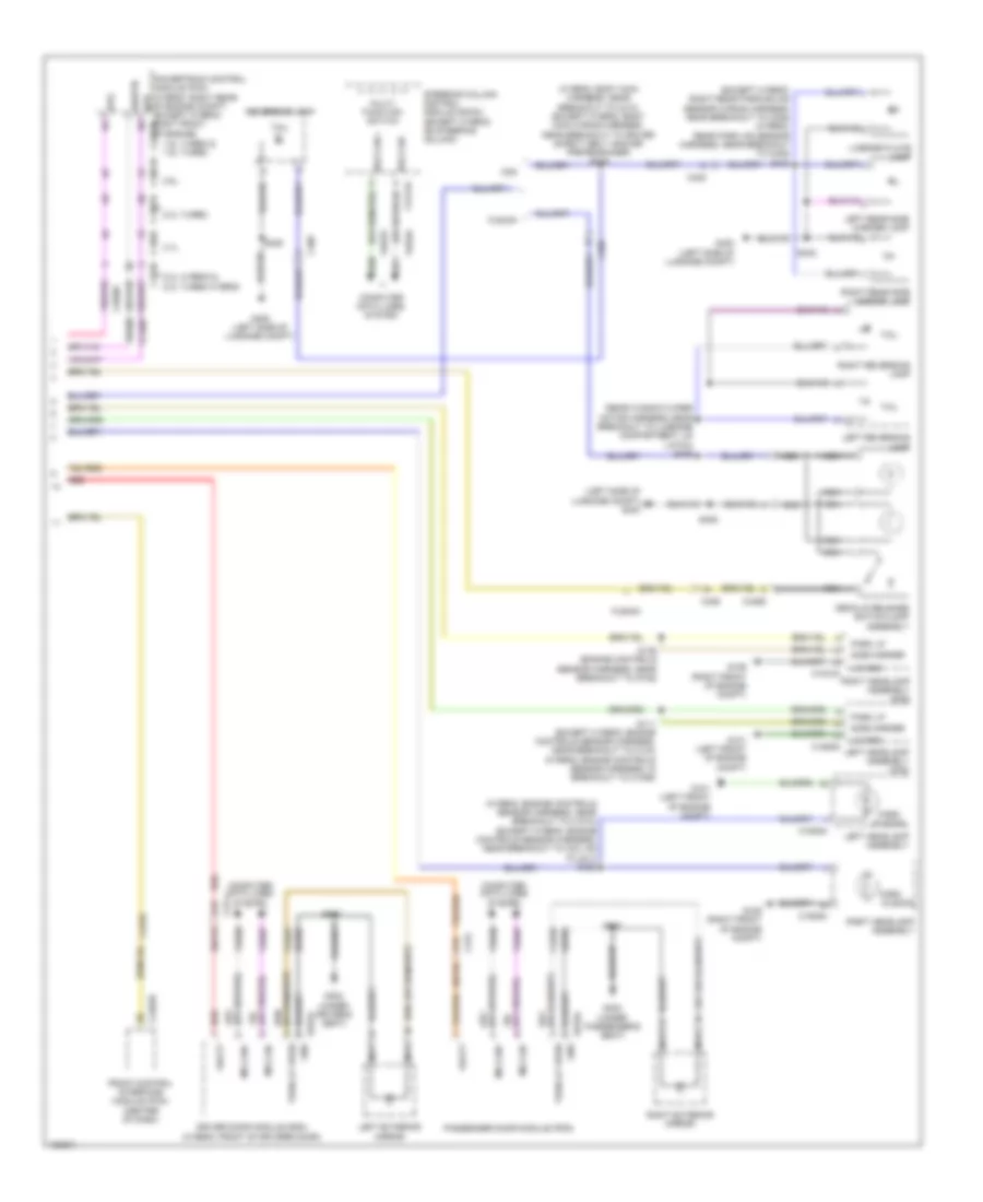
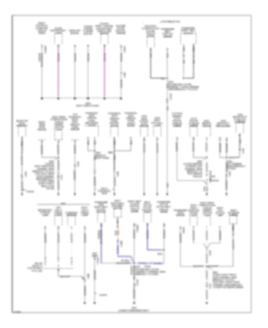
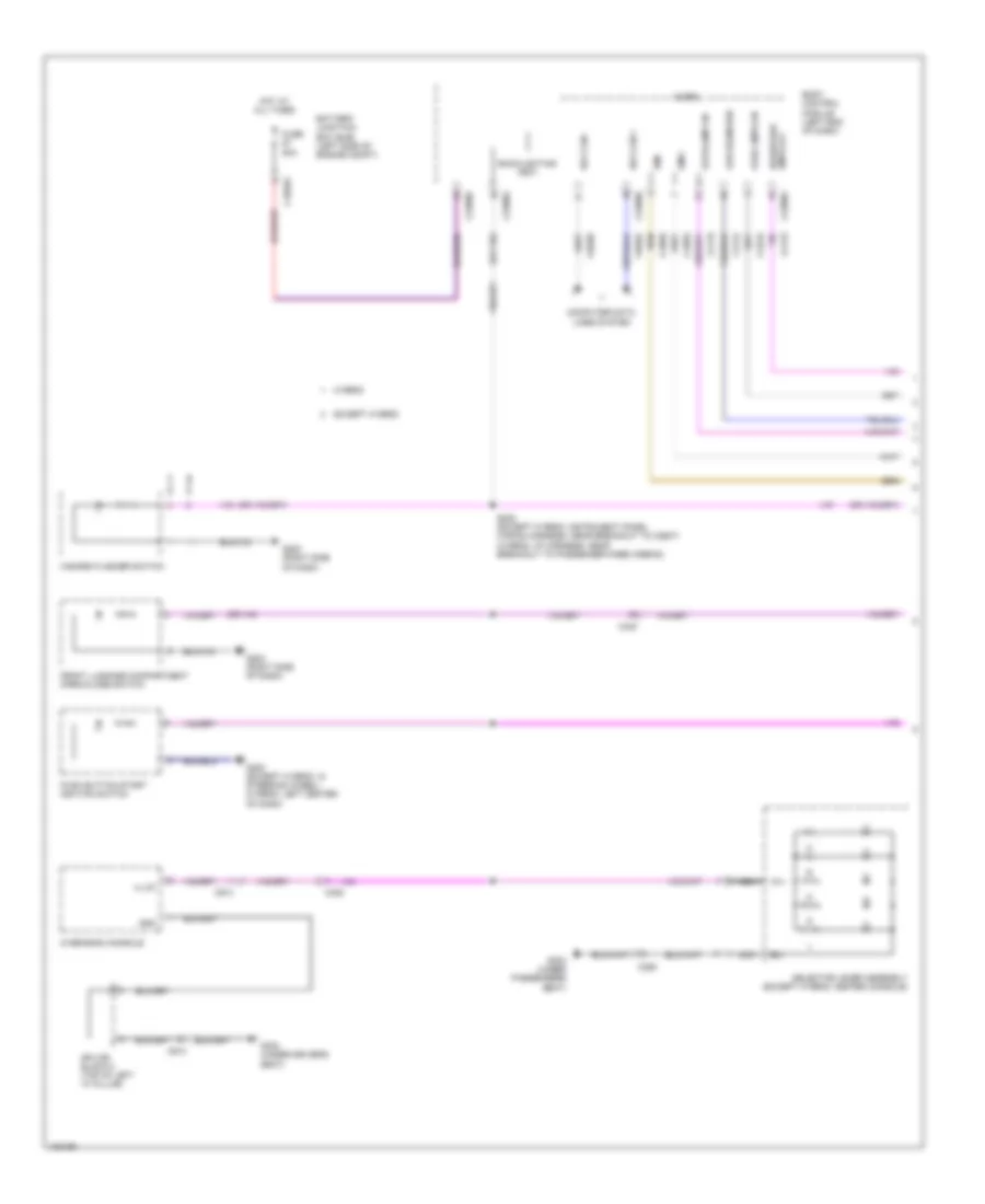
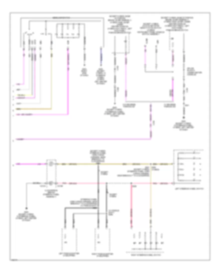
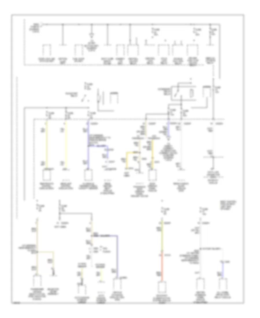
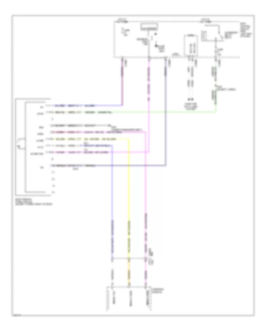
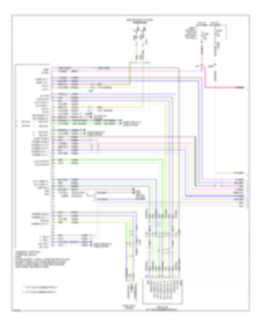
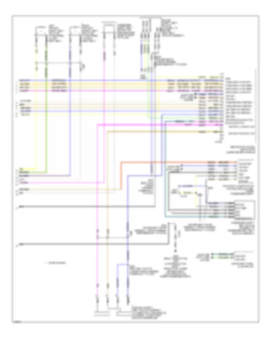
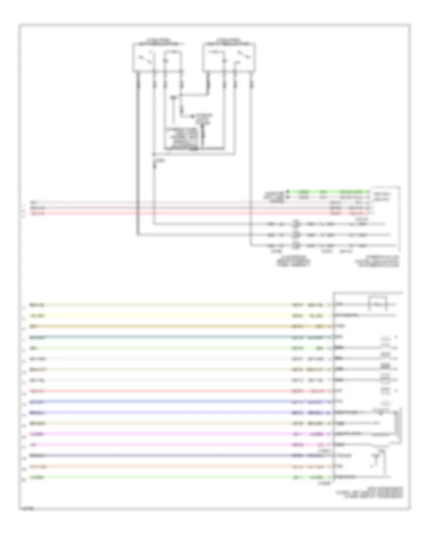
Automatic A/C Wiring Diagram, Except Hybrid (3 of 3) for Ford Fusion S Hybrid 2014
List of elements for Automatic A/C Wiring Diagram, Except Hybrid (3 of 3) for Ford Fusion S Hybrid 2014:
- (2.5l & 3.7l) s146
- (3.7l: engine controls harness, near breakout to coil on plug 3)
- (engine controls sensor harness, near breakout to pcm)
- (left front of engine compt)
- (or re405)
- 1.5l turbo
- 1.6l turbo
- 2.0l turbo
- 2.5l
- 3.7l
- Aat
- Accr
- Acpt
- Air conditioning (a/c) pressure transducer (right front of engine compt)
- Ambient air temperature sensor (behind right end of front grille)
- Battery junction box (bjb) (left side of engine compt)
- C1035a
- C1046
- C1232b
- C1232e
- C134
- C1381b
- C1381e
- C144
- C145
- C1551b
- C1551e
- C175b
- C175e
- C1915b
- C1915e
- Ce202
- Cec01
- Ch302
- Ch307
- Cht
- Computer data lines system
- Cooling fan motor 1 (behind left side of radiator)
- Cooling fan motor 2 (behind right side of radiator)
- Cpc
- Cylinder head temperature sensor (2.5l & 3.7l) (2.5l: upper right side of engine) (3.7l: top front of right cylinder bank)
- Ect
- Engine controls system
- Engine coolant temperature sensor (1.5l turbo, 1.6l turbo & 2.0l turbo) (right rear of cylinder head)
- Fan control (fc) relay
- Fuse 20a
- Fuse 30a
- G100
- G101 (left front of engine compt)
- Hfc
- High fan control (hfc) relay
- Hot at all times
- Hot w/ pcm power relay energized
- Hs1 can +
- Hs1 can -
- Le424
- Lfc
- Lin
- Low fan control (lfc) relay
- Powertrain control module (right front of engine)
- Re407
- Re454
- S126 (engine controls sensor harness, near breakout to coil on plug 3)
- S133
- S149 (1.5l turbo, 1.6l turbo & 2.0l turbo) (1.6l turbo: engine control wiring near breakout to knock sensor 2) (1.5l: engine controls harness, near breakout to coil on plug 3) (2.0l: engine controls harness, near breakout to manifold absolute pressure sensor)
- Sig rtn
- Vacc
- Vdb04
- Vdb05
- Vdn06
- Ve462
- Ve712
- Ve716
- Ve750
- Vh433
- Vref
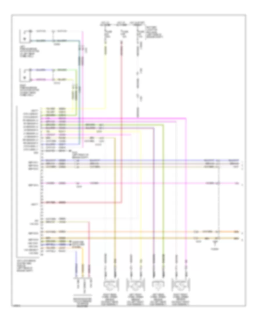
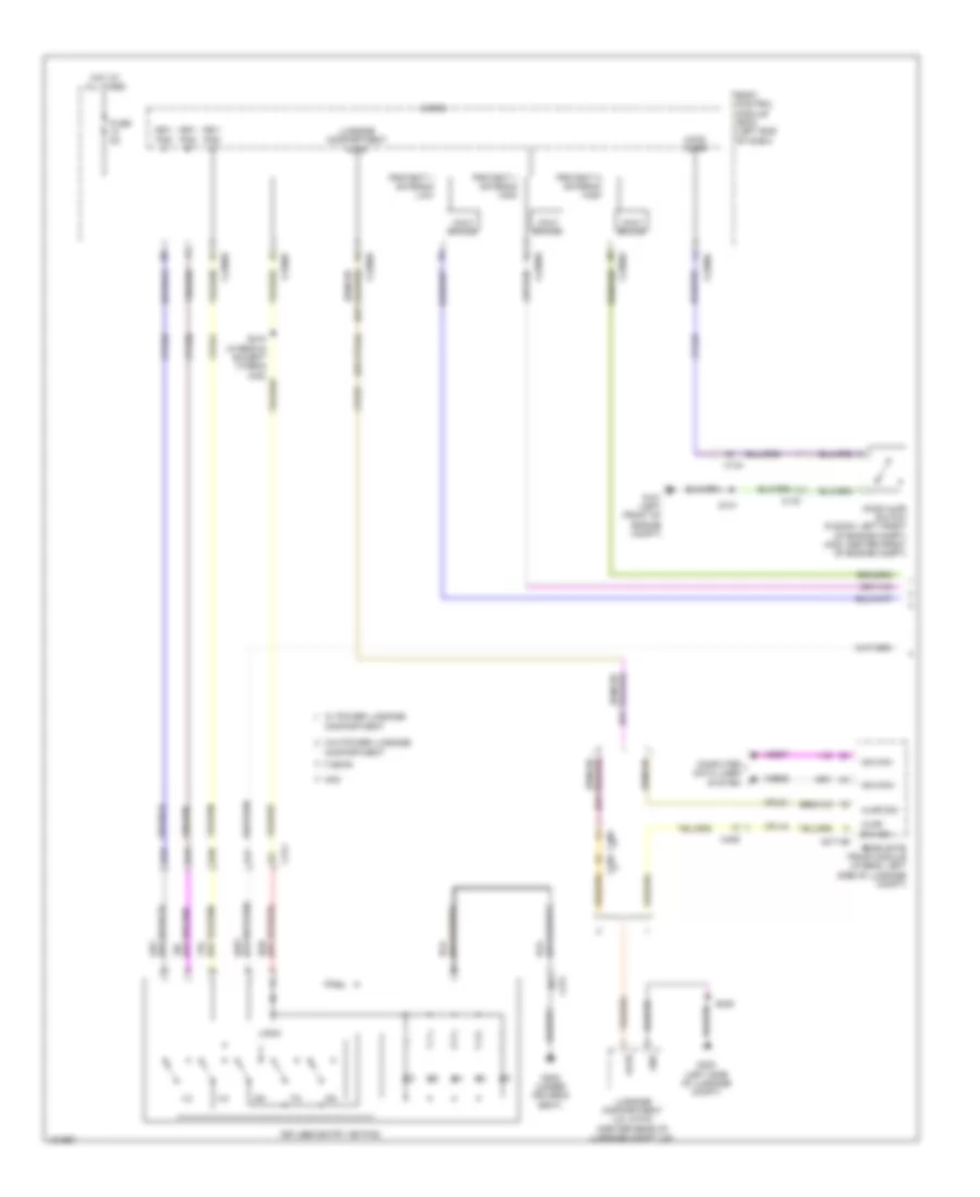
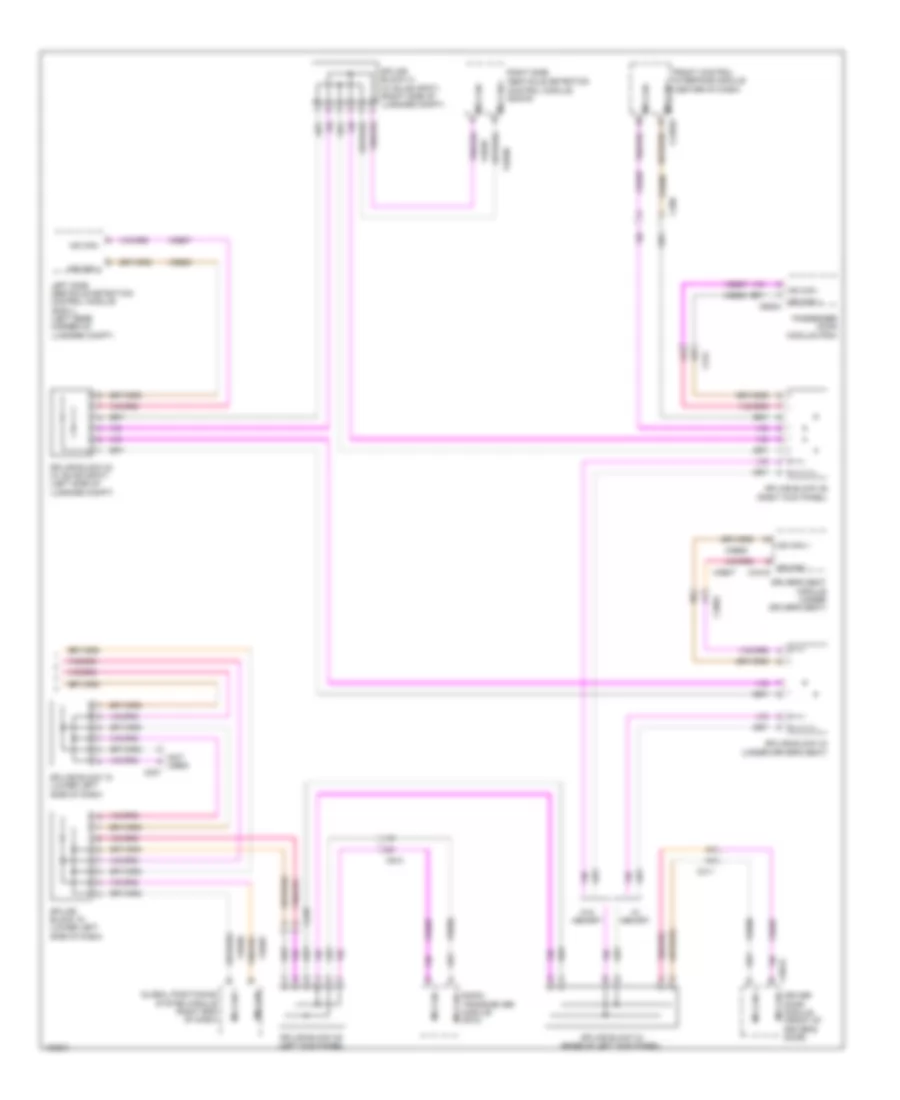
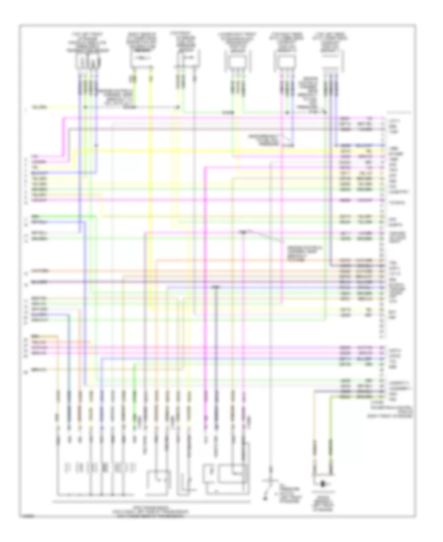
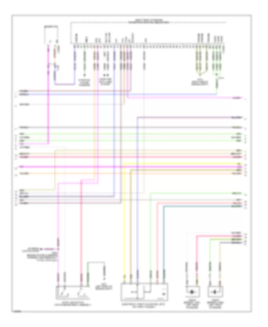
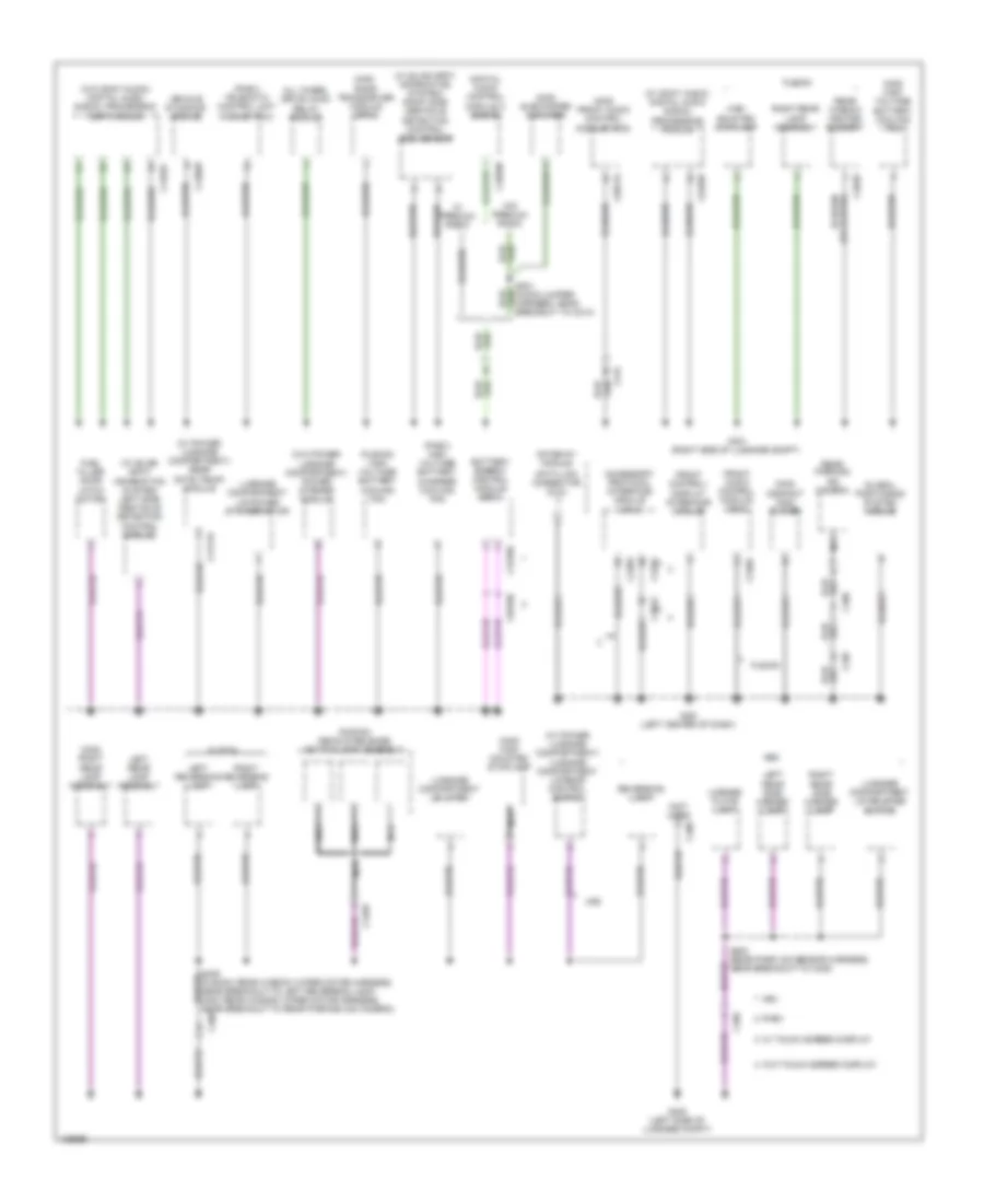
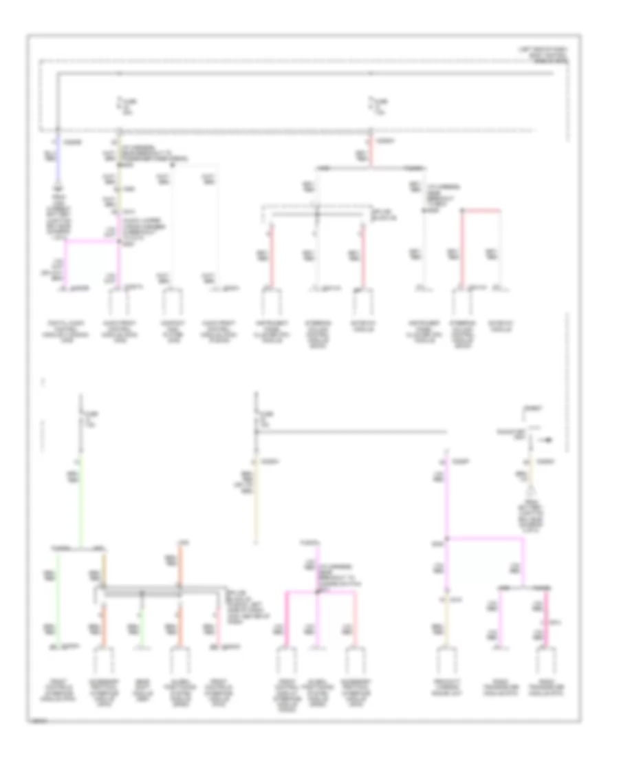
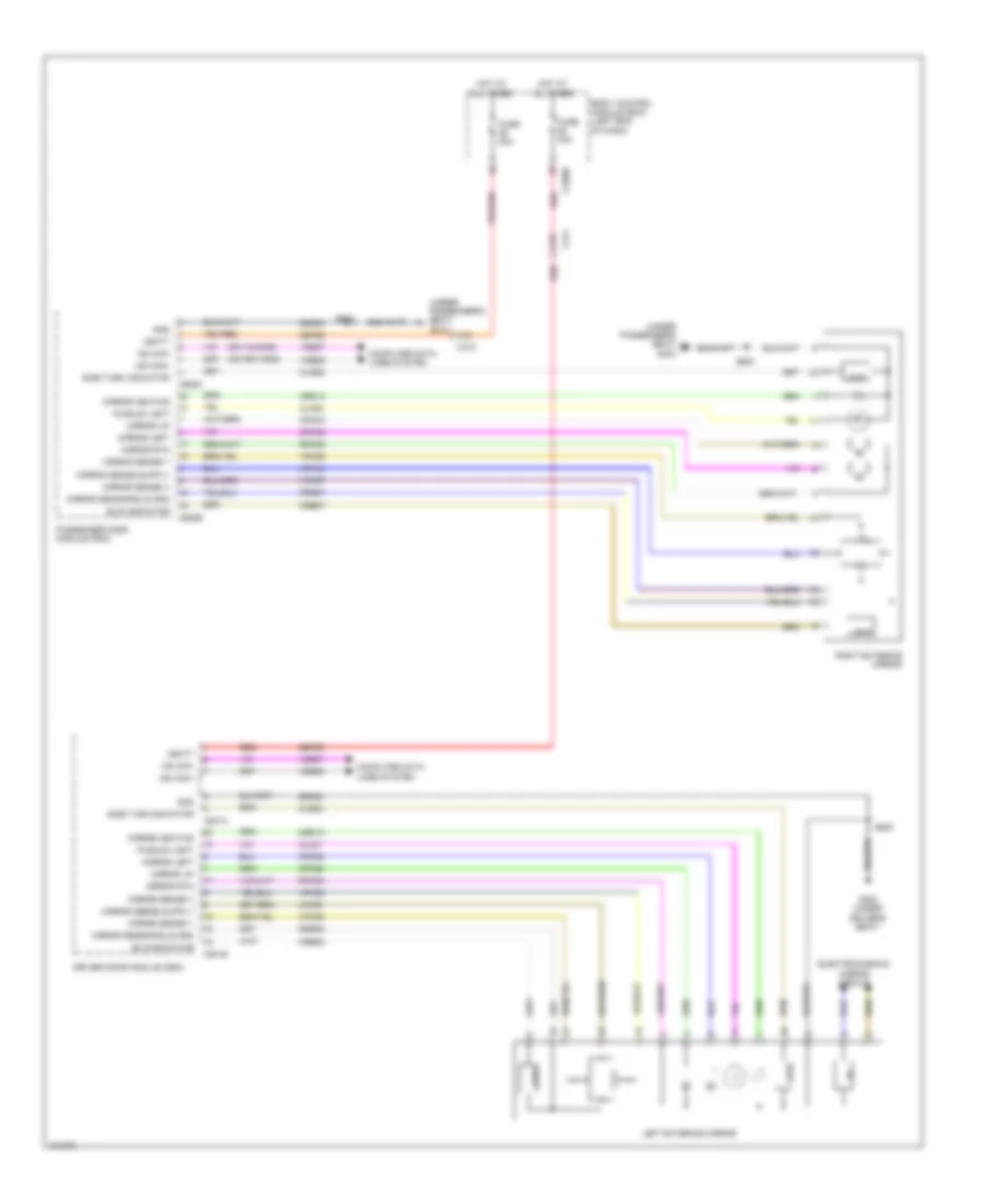
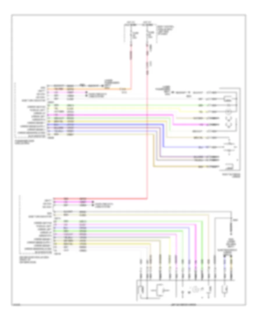
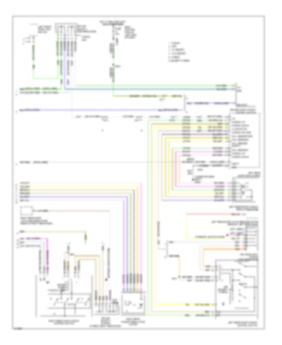
Automatic A/C Wiring Diagram, Hybrid (1 of 3) for Ford Fusion S Hybrid 2014
List of elements for Automatic A/C Wiring Diagram, Hybrid (1 of 3) for Ford Fusion S Hybrid 2014:
- (a/c jumper harness, near breakout to blower motor)
- (right side of dash)
- (right side of dash) g202
- (right side of hvac housing) blower motor
- 40a
- Air distribution door actuator (left side of hvac housing)
- Battery junction box (left side of engine compt)
- Blower control
- Blower motor control module (right side of hvac housing)
- Blower motor relay
- Blower relay
- C1035a
- C1035b
- C219
- C2402a
- C2402b
- C265
- C268
- C297a
- C297b
- Ch123
- Ch201
- Ch202
- Ch203
- Ch206
- Ch207
- Ch208
- Ch211
- Ch212
- Ch213
- Ch237
- Ch238
- Ch239
- Ch402
- Chs02
- Chs07
- Computer data lines system
- Crd02
- Defogger system
- Defrost request
- Driver temperature door actuator (left side of hvac housing)
- Drv frt snsr 1
- Drv frt snsr 2
- Drv heater feed
- Evap
- Feedback
- Front control interface module (center of dash)
- Fuse
- Fuse 10a
- Fuse 15a
- Fuse 30a
- G101 (left front of engine compt)
- G202
- Gd216
- Gnd
- Hot at all times
- Hot w/ pcm power relay energized
- Lh111
- Motor+
- Motor-
- Ms can+
- Ms can-
- Pass frt snsr 1
- Pass frt snsr 2
- Pass heater feed
- Pass st ntc sens
- Passenger temperature door actuator (center of hvac housing)
- Red
- Rh111
- Rh301
- Rhs10
- S202
- S203 (a/c jumper harness, near breakout to blower motor)
- S210
- Sbb65
- Sbp12
- Seats system
- Sig rtn
- Tcm power relay
- Vbatt
- Vdb06
- Vdb07
- Vh101
- Vh301
- Vh406
- Vh409
- Vh410
- Vh411
- Vh412
- Vref
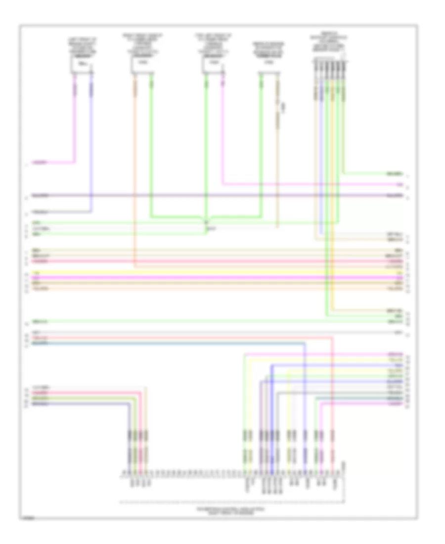
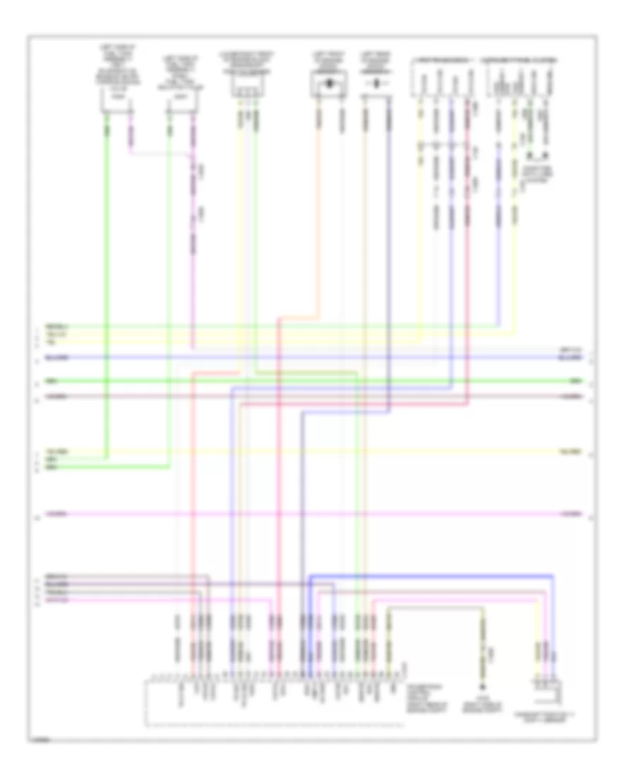
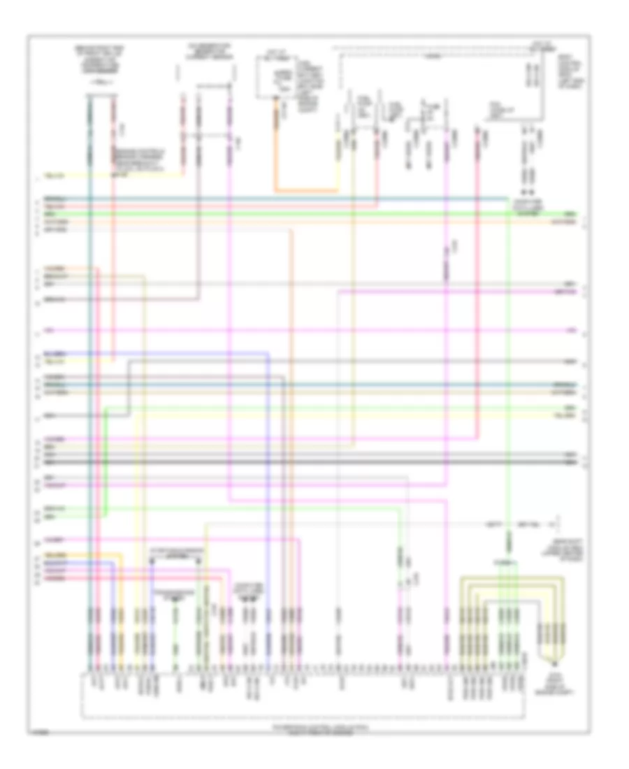
Automatic A/C Wiring Diagram, Hybrid (2 of 3) for Ford Fusion S Hybrid 2014
List of elements for Automatic A/C Wiring Diagram, Hybrid (2 of 3) for Ford Fusion S Hybrid 2014:
- (fusion: i/p harness, near breakout to g202) (mkz: i/p harness, near breakout to driver knee airbag)
- (fusion: i/p harness, near breakout to splice block 19) (mkz: i/p harness, near breakout to i/p speaker)
- Air inlet door actuator (right side of hvac housing)
- Autolamp sensor input
- Autolamp sensor return
- Autolamp/sunload sensor (mkz: top left side of dash)
- Body control module (left end of dash)
- C219
- C2280b
- C2280g
- C2280h
- C2402b
- C265
- Ce469
- Cls32
- Computer data lines system
- Driver side footwell air discharge temperature sensor
- Driver side register air discharge temperature sensor
- Drv st ntc sens
- Drv sunload
- Evaporator temperature sensor
- Exterior lights system
- Front control interface module (center of dash)
- Fuel door ind
- Fuse 5a
- Fuse 7.5a
- Fusion
- Hazard
- Hev
- Hot at all times
- Hot w/ run/ start relay energized
- Hs1 can+
- Hs1 can-
- Humidity mtr
- Humidity sig
- In vehicle sig
- In-vehicle temperature/ humidity sensor (left side of dash)
- Micro
- Mkz
- Pass sunload
- Passenger side footwell air discharge temperature sensor
- Passenger side register air discharge temperature sensor
- Phev
- Rhs05
- Rlf14
- S207
- S213
- S219 (mkz)
- Seats system
- Solid state
- Splice block 22
- Trunk, tailgate fuel doors system
- Vdb04
- Vdb05
- Vh413
- Vh414
- Vh416
- Vh417
- Vha31
- Vlf14
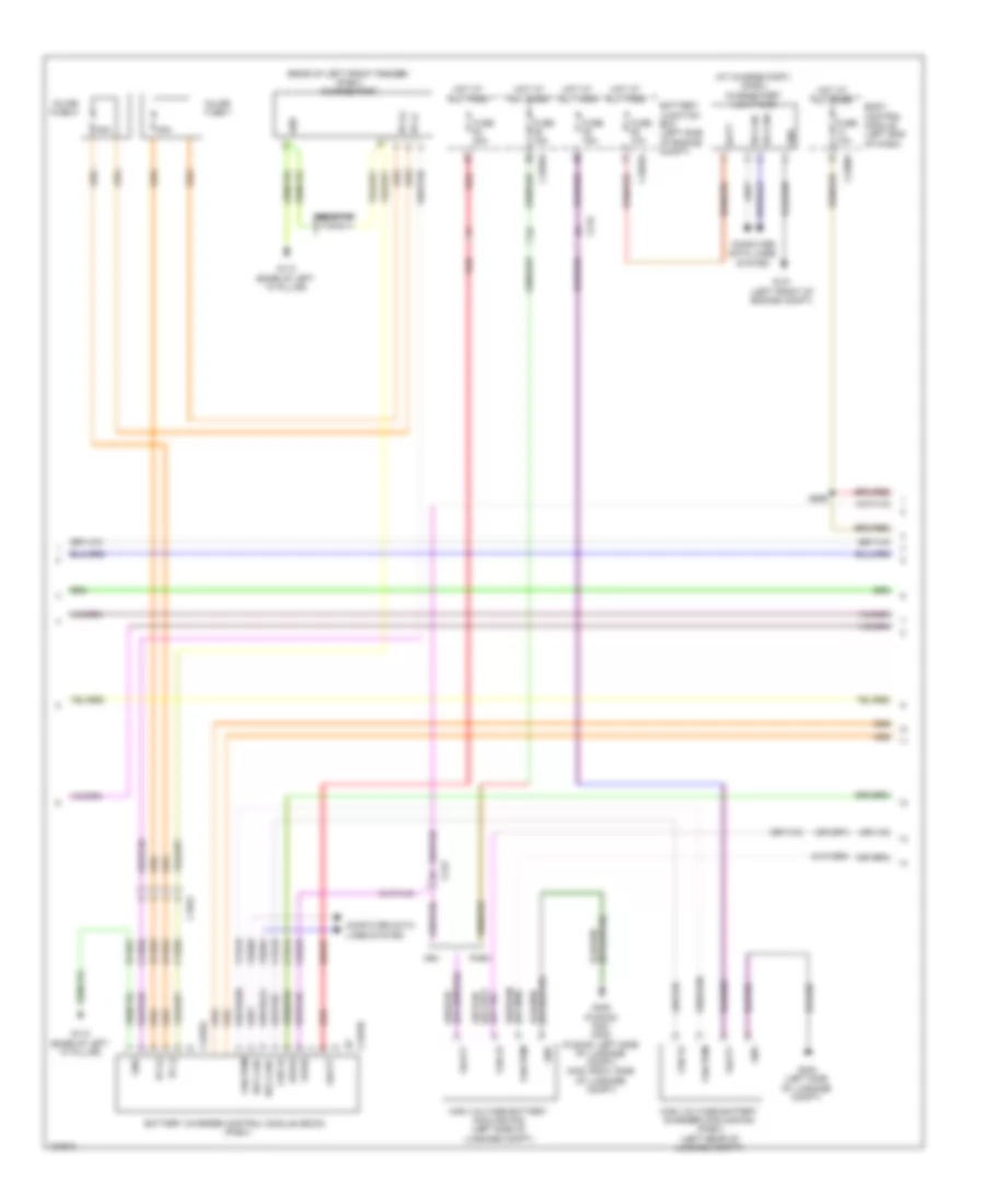
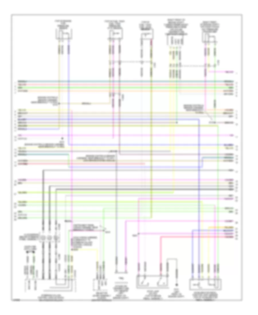
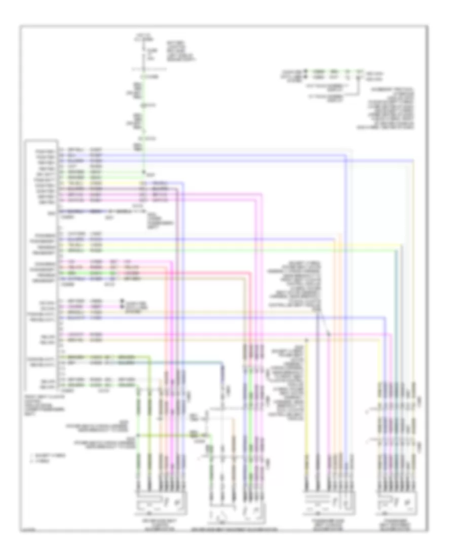
Automatic A/C Wiring Diagram, Hybrid (3 of 3) for Ford Fusion S Hybrid 2014
List of elements for Automatic A/C Wiring Diagram, Hybrid (3 of 3) for Ford Fusion S Hybrid 2014:
- (left front of engine compt)
- (left front of engine compt) g101
- (on top of engine)
- (right front of engine compt) g106
- (right side of engine compt)
- (top center of cylinder head)
- Aat
- Acpt
- Active grille shutter (behind right end of grille)
- Air conditioning (a/c) pressure transducer (right front of engine compt)
- Air conditioning control module (accm)
- Ambient air temperature sensor (behind right end of front grille)
- Battery energy control module (becm) (behind left side of rear seat)
- Battery junction box (left side of engine compt)
- C1026
- C1035a
- C134
- C145
- C1458a
- C1458f
- C146
- C1617k
- C175b
- C175e
- C1815a
- C1815b
- C1815c
- C4000
- C4001
- C4002
- C4816b
- Cabin coolant heater (phev)
- Cabin heater coolant pump (phev)
- Cbb54
- Ce316
- Ch116
- Ch307
- Chp01
- Cht
- Computer data lines system
- Cooling fan motor (behind radiator)
- Cyb03
- Cylinder head temperature sensor
- Ect2
- Electric motor coolant pump
- Engine controls system
- Engine coolant temperature 2 (ect 2) sensor
- Engine cooling fan relay
- Fcv
- Fuse 20a
- Fuse 30a
- Fuse 50a
- G100
- G105
- G106 (right front of engine compt)
- G107
- Gd113
- Gnd
- Hcso
- Heater core shutoff (phev) (right rear of engine compt)
- High current battery junction box (bjb)
- High voltage battery service disconnect
- Hot at all times
- Hot w/ pcm power relay energized
- Hs1 can +
- Hs1 can -
- Hs1 can+
- Hs1 can-
- Hv+
- Hv-
- Int+
- Int-
- Le423
- Lin
- Powertrain control module (right rear of engine compt)
- Pwm
- Re141
- Re335
- Re405
- Re407
- S101
- S105 (phev) (engine controls sensor harness, in breakout to c192)
- S110
- S113
- S145
- Secondary on board diagnostic module c (sobdmc)/ transmission control module (left side of engine compt)
- Sig rtn
- Sigrtn
- Tcmrc
- Vbatt
- Vdb04
- Vdb05
- Vdn06
- Ve712
- Ve716
- Ve750
- Vec03
- Verf
- Vh433
- Vpwr
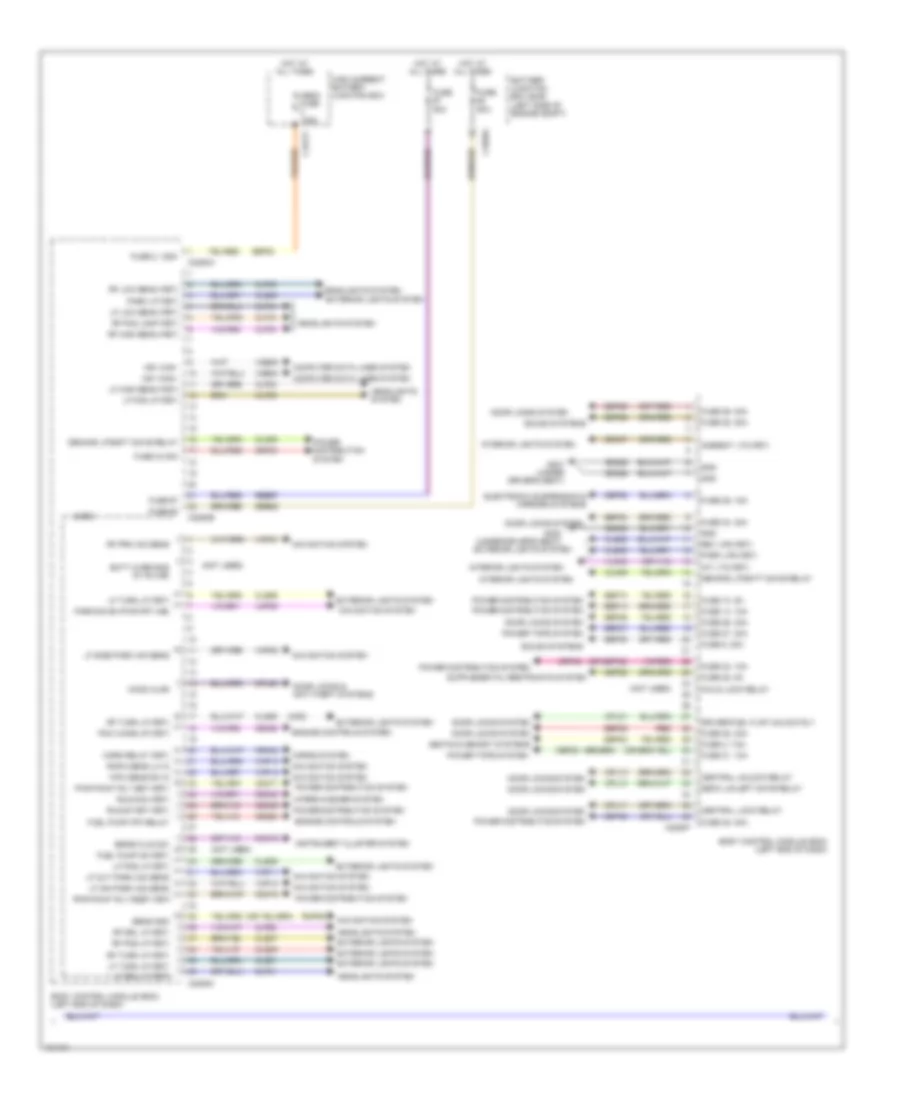
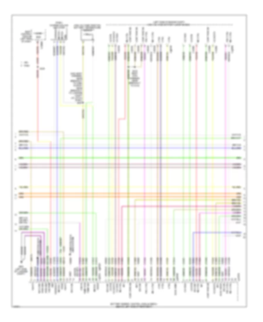
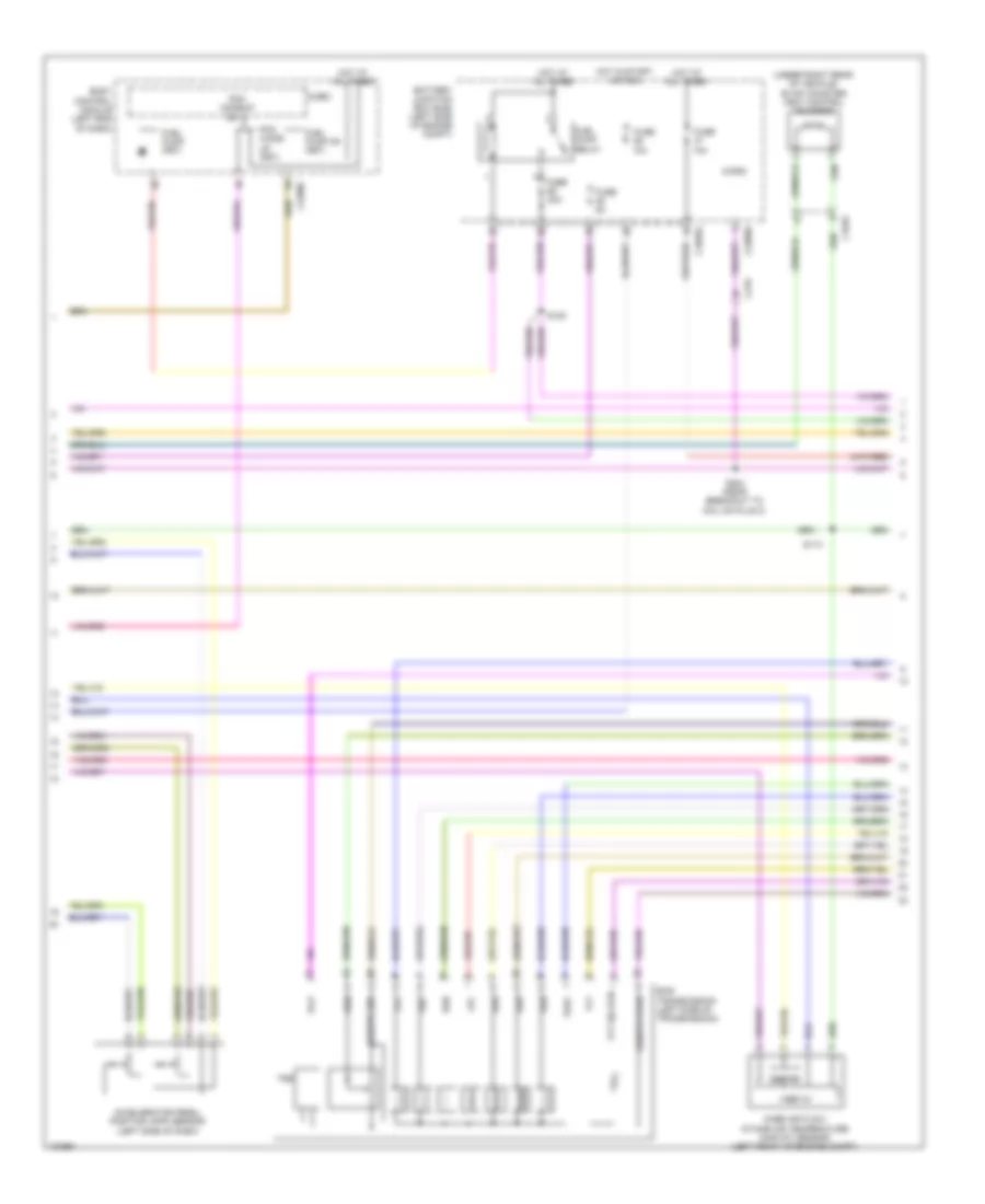
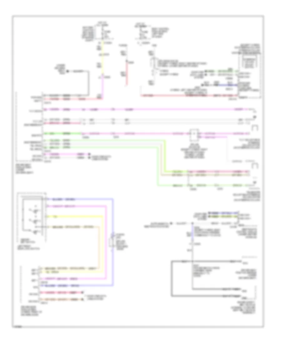
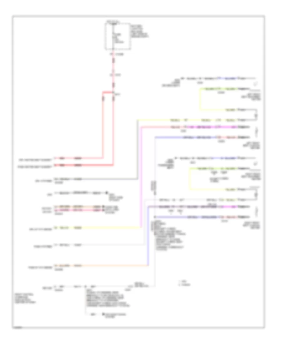
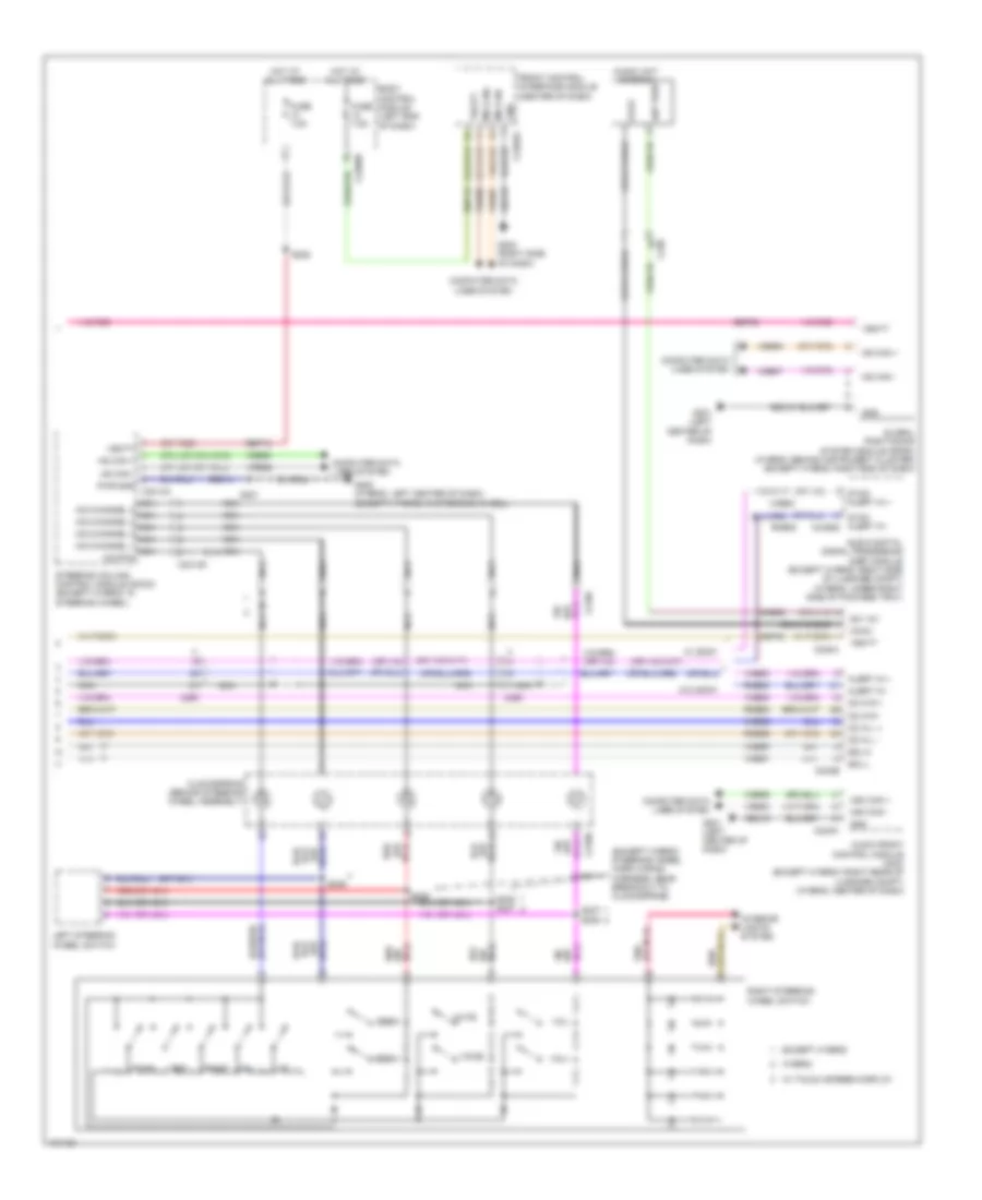
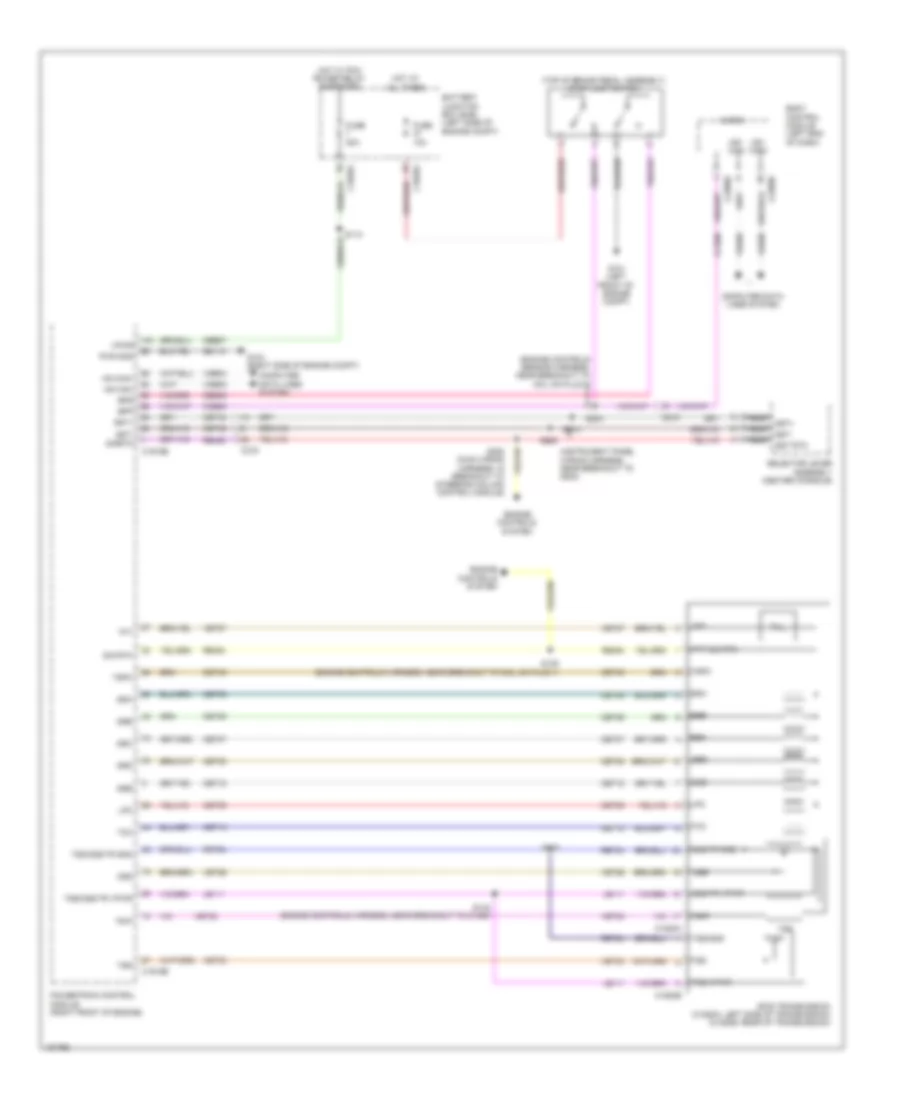
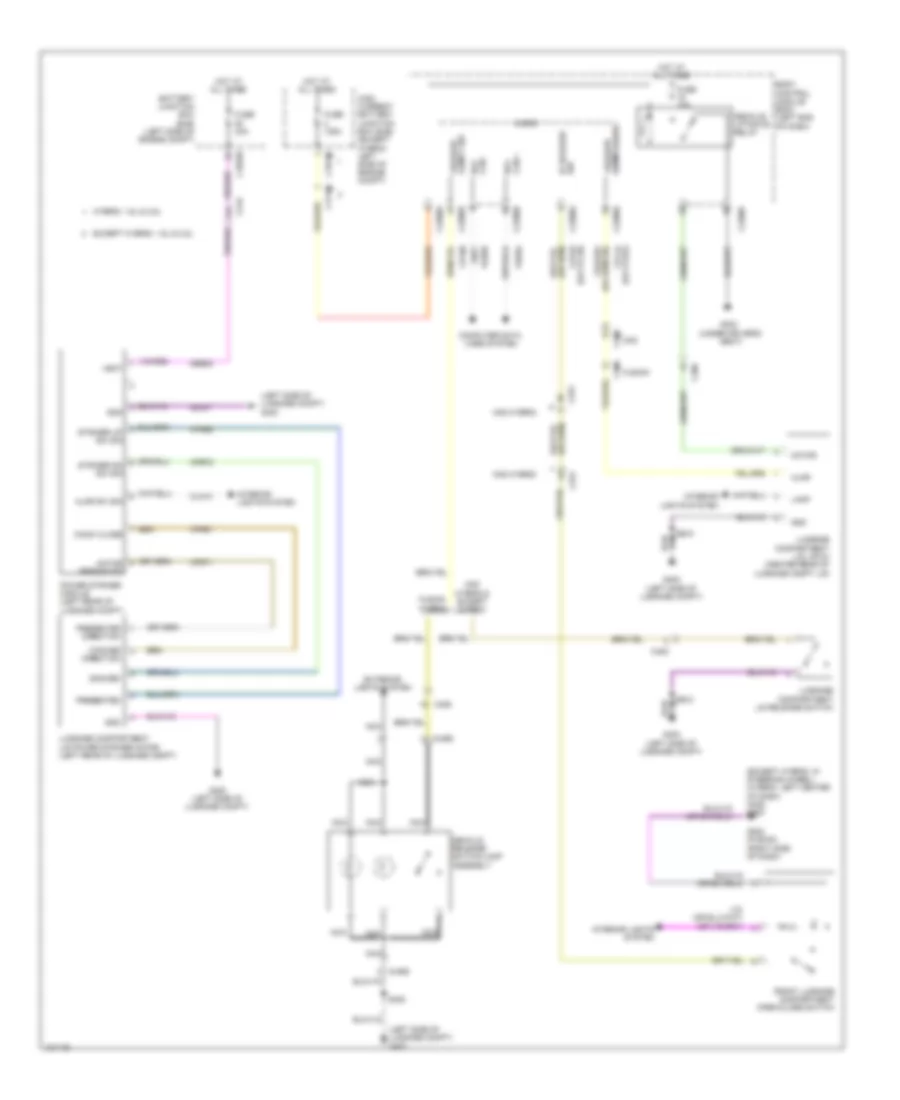
Manual A/C Wiring Diagram (1 of 3) for Ford Fusion S Hybrid 2014
List of elements for Manual A/C Wiring Diagram (1 of 3) for Ford Fusion S Hybrid 2014:
- (a/c jumper harness, near breakout to blower motor)
- (right side of dash) g202
- (right side of hvac unit) blower motor
- 40a
- A/c clutch relay
- Air distribution door actuator (left side of hvac unit)
- Battery junction box (bjb) (left side of engine compt)
- Blower control
- Blower motor control module (bottom center of hvac unit)
- Blower motor relay
- Blower relay
- C1035a
- C219
- C2402a
- C2402b
- C265
- C268
- C297a
- C297b
- Ch123
- Ch201
- Ch202
- Ch203
- Ch206
- Ch207
- Ch208
- Ch211
- Ch212
- Ch213
- Ch402
- Chs02
- Chs07
- Computer data lines system
- Crd02
- Defogger system
- Defrost request
- Drv frnt snsr
- Drv heater feed
- Evap
- Feedback
- Front controls interface module (center of dash)
- Fuse
- Fuse 10a
- Fuse 15a
- G101 (left front of engine compt)
- Gd216
- Gnd
- Hot at all times
- Hot w/ pcm power relay energized
- Lh111
- Motor+
- Motor-
- Ms can+
- Ms can-
- Pass heater feed
- Pass st ntc sens
- Passenger temperature door actuator (right side of hvac unit)
- Rh111
- Rh301
- Rhs10
- S202
- S203 (a/c jumper harness, near breakout to blower motor)
- Sbp12
- Seats system
- Sig rtn
- Vbatt
- Vdb06
- Vdb07
- Vh101
- Vh301
- Vh406
- Vh409
- Vref
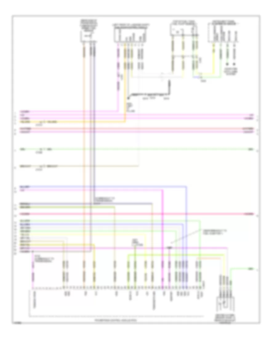
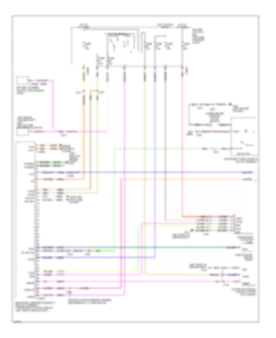
Manual A/C Wiring Diagram (2 of 3) for Ford Fusion S Hybrid 2014
List of elements for Manual A/C Wiring Diagram (2 of 3) for Ford Fusion S Hybrid 2014:
- (battery harness, near breakout to g109) (w/ auto start/ stop system) s140
- (instrument panel wiring harness, near breakout to g202)
- (instrument panel wiring harness, near breakout to splice block 19)
- (left front of engine compt)
- (right side of hvac unit)
- Active grille shutter (right front of engine compt)
- Air conditioning (a/c) compressor (left front of engine)
- Air conditioning (a/c) compressor control solenoid (near a/c compressor)
- Air inlet door actuator
- Auto start/stop deactivation switch
- Body control module (left end of dash)
- C134
- C146
- C210
- C2280h
- C2402b
- C265
- C340
- Cabin heater coolant pump (w/ auto start/stop system)
- Ch253
- Ch469
- Driver side footwell air discharge temperature sensor (left center of dash)
- Drv st ntc sens
- Evaporator temperature sensor (left side of hvac housing)
- Front controls interface module (center of dash)
- Fuse 5a
- Fuse 7.5a
- G101 (left front of engine compt)
- G200 (in steering wheel)
- Gnd
- Hot at all times
- Hot w/ run/ start relay energized
- Humidity mtr
- Humidity sig
- In vehicle sig
- In-vehicle temperature/ humidity sensor (left side of dash)
- Lin
- Power distribution system
- Pwr
- Pwr/diag
- Rhs05
- S101
- S110
- S139
- S207
- S213
- S301
- Seats system
- Splice block 6 (under center console)
- Start/stop ind
- Start/stop sw
- Strt/stp dis sw
- Strt/stp ind
- Vh413
- Vh414
- Vha31
- Vpwr
- W/ auto start/ stop system
- W/o auto start/ stop system
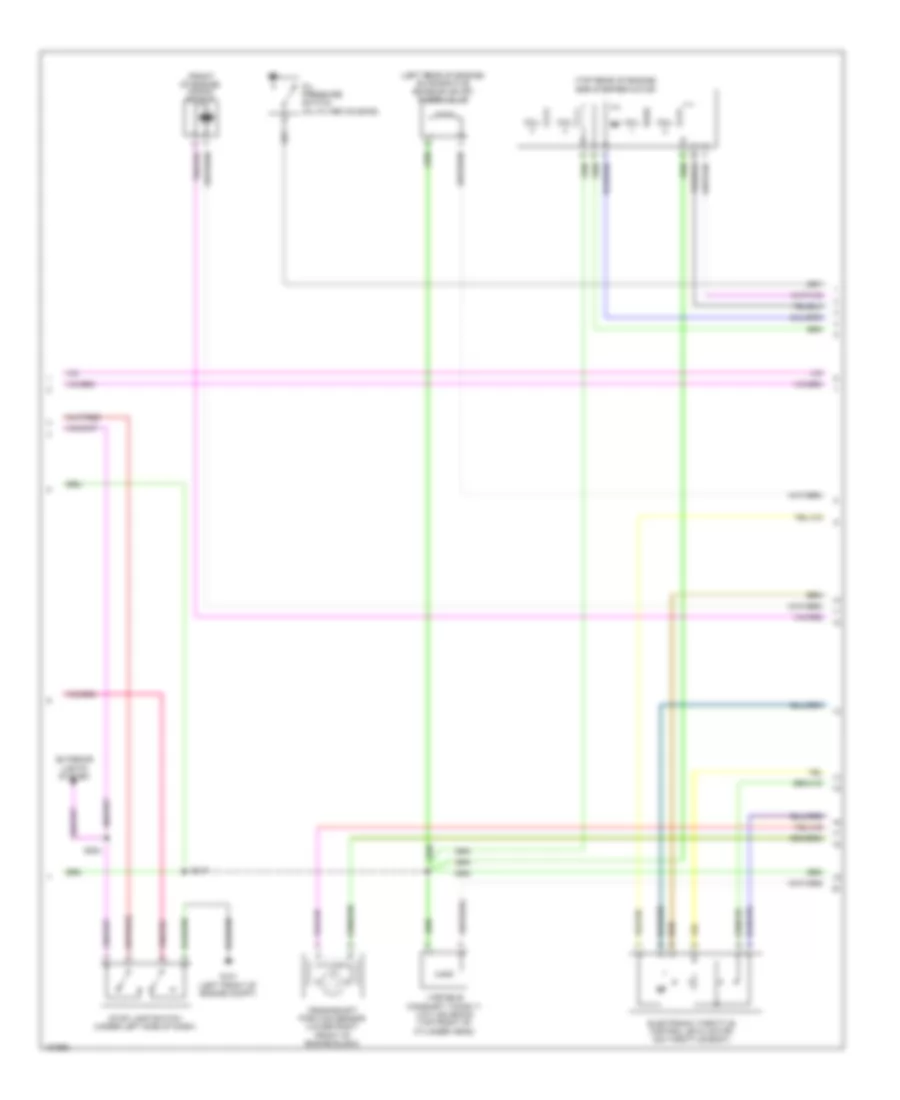
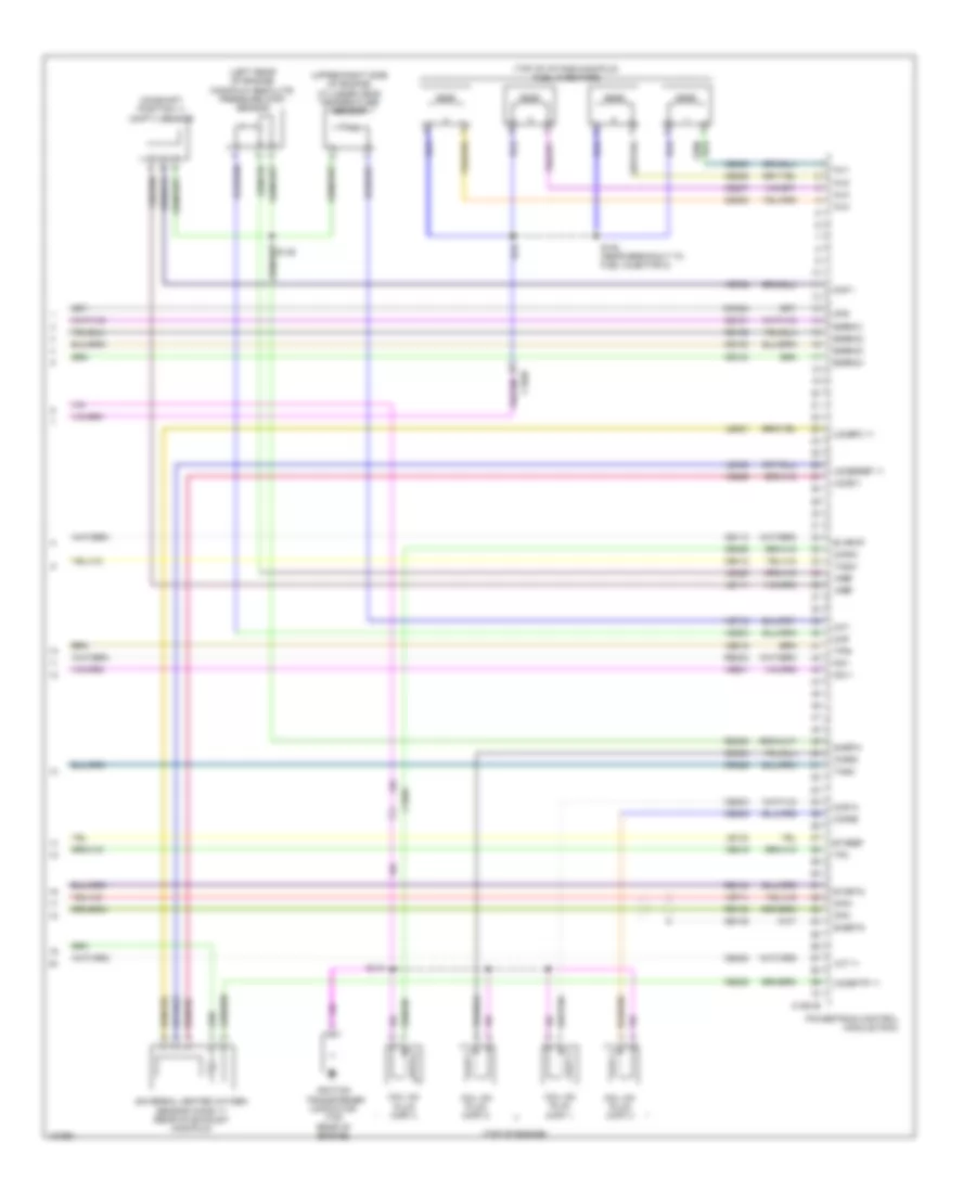
Manual A/C Wiring Diagram (3 of 3) for Ford Fusion S Hybrid 2014
List of elements for Manual A/C Wiring Diagram (3 of 3) for Ford Fusion S Hybrid 2014:
- (2.5l) s146
- (engine controls sensor harness, near breakout to pcm)
- (left front of engine compt)
- (or re405)
- 1.5l turbo
- 1.6l turbo
- 2.0l turbo
- 2.5l
- Aat
- Accr
- Acpt
- Air conditioning pressure transducer (right front of engine compt)
- Ambient air temperature sensor (behind right end of front grille)
- Battery junction box (bjb) (left side of engine compt)
- C1035a
- C1232b
- C1232e
- C134
- C1381b
- C1381e
- C144
- C145
- C1551b
- C1551e
- C1915b
- C1915e
- Ce202
- Cec01
- Ch302
- Ch307
- Cht
- Computer data lines system
- Cooling fan motor 1 (behind left side of radiator)
- Cooling fan motor 2 (behind right side of radiator)
- Cpc
- Cylinder head temperature sensor (2.0l turbo & 2.5l) (upper right side of engine)
- Ect
- Engine controls system
- Engine coolant temperature sensor (2.0l turbo, 1.5l turbo & 1.6l turbo) (right rear of cylinder head)
- Fan control (fc) relay
- Fuse 20a
- Fuse 30a
- G100
- G101 (left front of engine compt)
- Hfc
- High fan control (hfc) relay
- Hot at all times
- Hot w/ pcm power relay energized
- Hs1 can +
- Hs1 can -
- Le424
- Lfc
- Lin
- Low fan control (lfc) relay
- Powertrain control module (right front of engine)
- Re407
- Re454
- S126 (engine controls sensor harness, near breakout to coil on plug 3)
- S133
- S149 (2.0l turbo, 1.5l turbo & 1.6l turbo) (1.5l turbo: engine controls harness, near breakout to coil on plug 1) (1.6l turbo: engine control wiring harness, near breakout to knock sensor 2) (2.0l: engine controls harness, near breakout to manifold absolute pressure sensor)
- Sig rtn
- Vacc
- Vdb04
- Vdb05
- Vdn06
- Ve462
- Ve712
- Ve716
- Ve750
- Vh433
- Vref
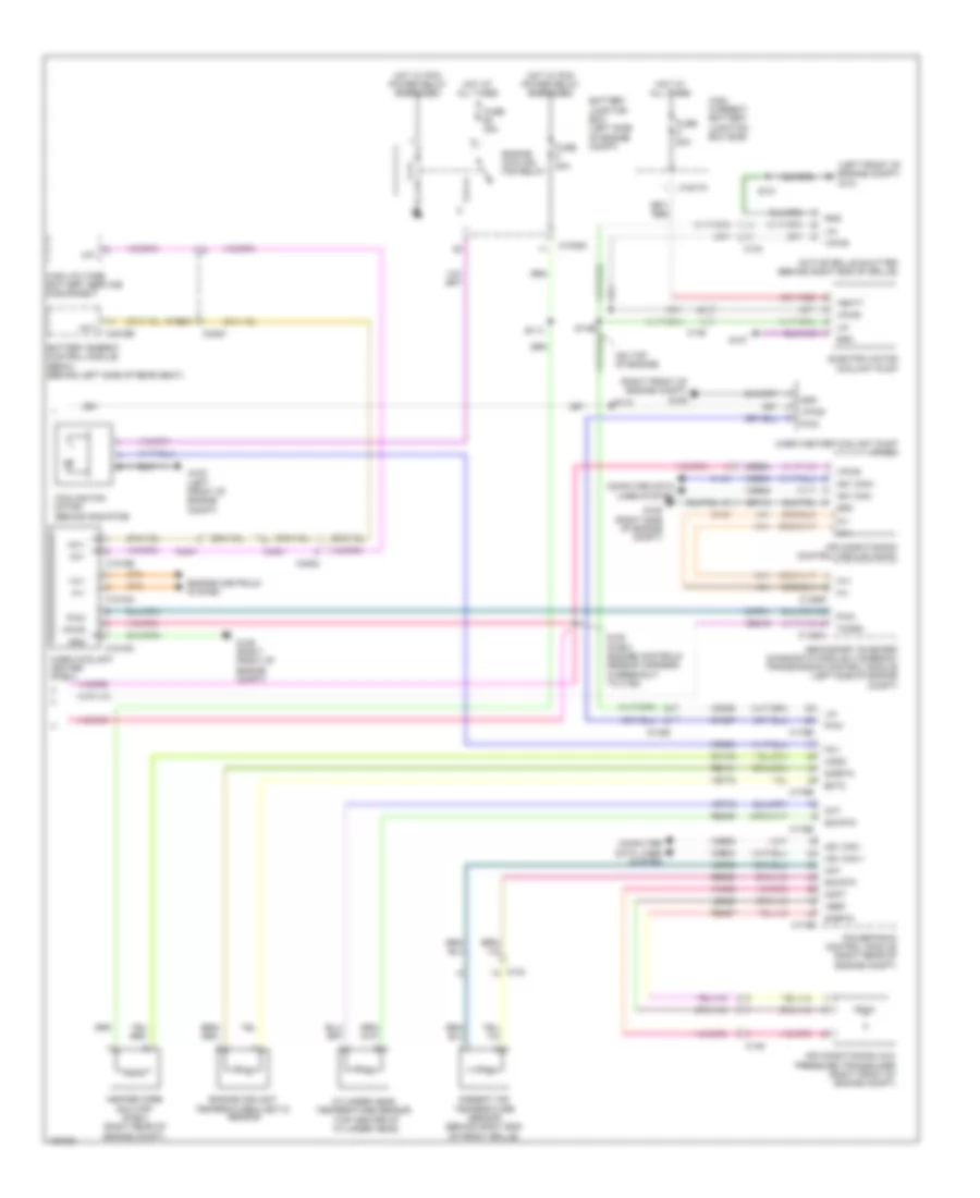
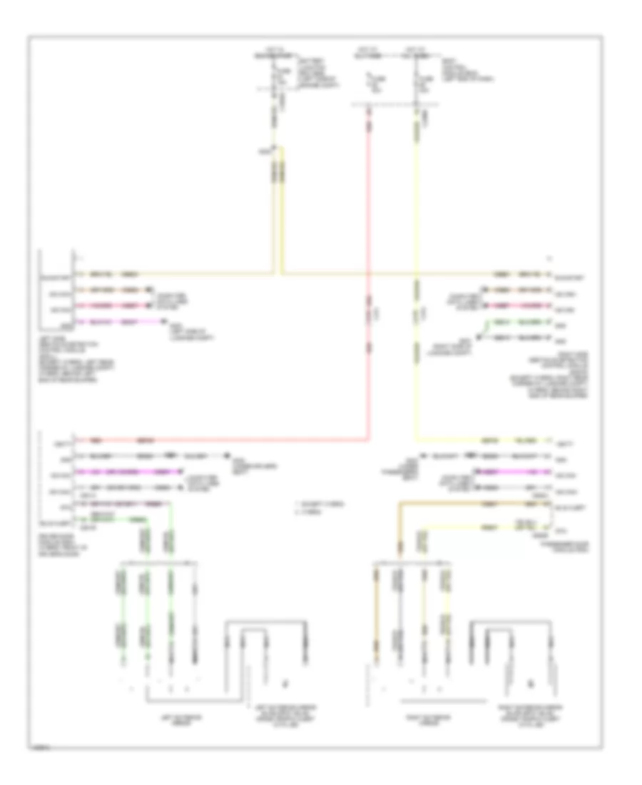
ANTI-LOCK BRAKES
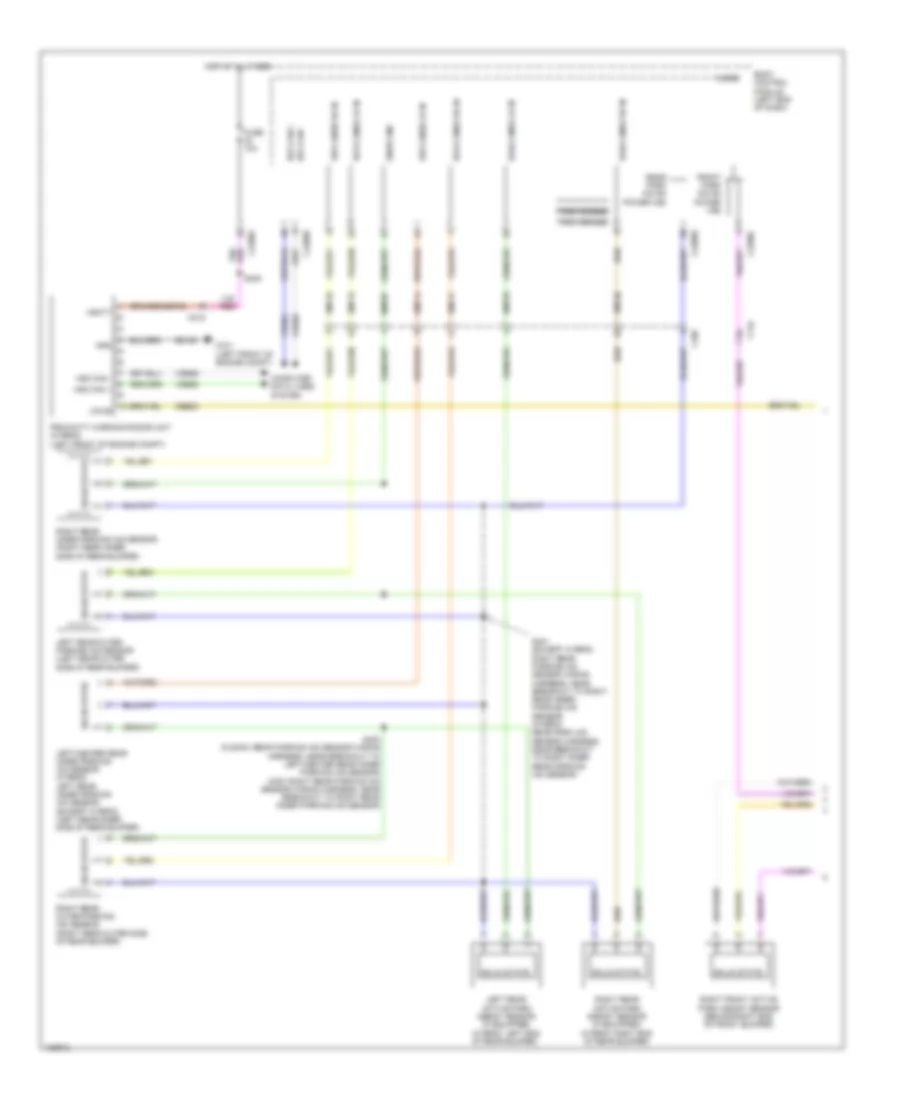
Anti-lock Brakes Wiring Diagram, Except Hybrid (1 of 2) for Ford Fusion S Hybrid 2014
List of elements for Anti-lock Brakes Wiring Diagram, Except Hybrid (1 of 2) for Ford Fusion S Hybrid 2014:
- Anti-lock brake system (abs) module (left rear of engine compt)
- Battery junction box (bjb) (left side of engine compt)
- Brake booster vacuum sensor (on brake booster)
- C1010
- C1035a
- C192
- C215
- C219
- C3050
- C3134
- C340
- Cbb25
- Ccb16
- Ccb17
- Ccb18
- Ccb19
- Ccb20
- Ccb21
- Ccb22
- Ccb23
- Ccb24
- Ccb25
- Computer data lines system
- Ebp sw1
- Ebp sw2
- Ebp sw3
- Ebp sw4
- Ebp sw5
- Ebp sw6
- Fuse 10a
- Fuse 30a
- Fuse 60a
- Fusion
- G102 (left front of engine compt)
- Gd121
- Gnd
- Hot at all times
- Hot in start or run
- Hs2 can+
- Hs2 can-
- Ign
- Lca37
- Left front wheel speed sensor (on left front hub assembly)
- Left parking brake actuator motor (in left rear wheelwell)
- Left rear wheel speed sensor (on left rear hub assembly)
- Lf sensor hi
- Lf sensor lo
- Lr sensor hi
- Lr sensor lo
- Mtr a epb lt
- Mtr a epb rt
- Mtr b epb lt
- Mtr b epb rt
- Nca
- Rca17
- Rca18
- Rca19
- Rca20
- Rca37
- Rf sensor hi
- Rf sensor lo
- Right front wheel speed sensor (on right front hub assembly)
- Right parking brake actuator motor (in right rear wheelwell)
- Right rear wheel speed sensor (on right rear hub assembly)
- Rr sensor hi
- Rr sensor lo
- Sbb69
- Sbb82
- Vac gnd
- Vac sense p
- Vac sig
- Vbatt
- Vca03
- Vca04
- Vca05
- Vca06
- Vca38
- Vdb25
- Vdb26
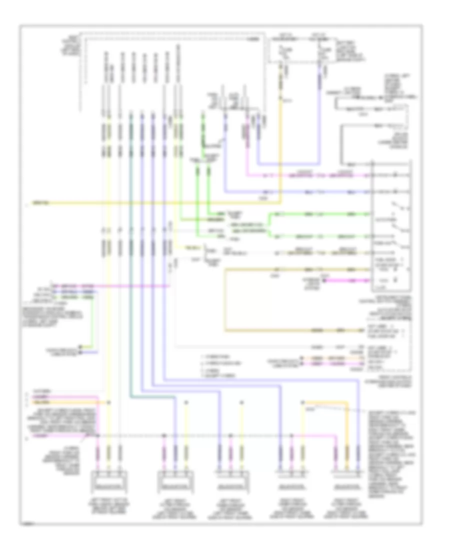
Anti-lock Brakes Wiring Diagram, Except Hybrid (2 of 2) for Ford Fusion S Hybrid 2014
List of elements for Anti-lock Brakes Wiring Diagram, Except Hybrid (2 of 2) for Ford Fusion S Hybrid 2014:
- (engine controls sensor harness, near breakout to coil on plug 3)
- 1.5l turbo
- 1.6l turbo
- 2.0l turbo
- 2.5l
- 3.7l
- Battery junction box (bjb) (left side of engine compt)
- Body control module (bcm) (left end of dash)
- Bpp
- Bps
- Brk fluid level switch
- C1035a
- C1232b
- C1381b
- C1551b
- C175b
- C1915b
- C210
- C219
- C2280b
- C2280c
- C2280h
- Ccb08
- Ces09
- Cmc19
- Computer data lines system
- Fuse 10a
- Fusion
- G101 (left front of engine compt)
- Hot at all times
- Hs1 can +
- Hs1 can -
- Hs1 can+
- Hs1 can-
- Hs3 can+
- Hs3 can-
- Instrument panel cluster (ipc)
- Interior lights system
- Low brake fluid warning indicator switch (on brake fluid reservoir)
- Micro
- Parking brake switch (base of parking brake lever assembly)
- Powertrain control module (pcm) (right front of engine)
- S204
- Stop lamp switch (top of brake pedal assembly)
- Stop lp sw
- Sw1
- Sw2
- Sw3
- Sw4
- Sw5
- Sw6
- Vdb04
- Vdb05
Anti-lock Brakes Wiring Diagram, Hybrid (1 of 2) for Ford Fusion S Hybrid 2014
List of elements for Anti-lock Brakes Wiring Diagram, Hybrid (1 of 2) for Ford Fusion S Hybrid 2014:
- (on brake pedal assembly) brake pedal angle sensor
- Anti-lock brake system (abs) module (left rear of engine compt)
- Battery junction box (bjb) (left side of engine compt)
- Brake booster vacuum sensor
- Bst pwm
- Bst pwr
- C1010
- C1035a
- C192
- C215
- C219
- C3050
- C3134
- C340
- Cbb25
- Cbb45
- Cca22
- Ccb16
- Ccb17
- Ccb18
- Ccb19
- Ccb20
- Ccb21
- Ccb22
- Ccb23
- Ccb24
- Ccb25
- Ccb30
- Ccb33
- Ccb41
- Computer data lines system
- Ebp sw1
- Ebp sw2
- Ebp sw3
- Ebp sw4
- Ebp sw5
- Ebp sw6
- Fuse 10a
- Fuse 30a
- Fuse 60a
- Fusion
- G102 (left front of engine compt)
- Gd121
- Gnd
- Hot at all times
- Hot in start or run
- Hs2 can+
- Hs2 can-
- Lca27
- Lca37
- Left front wheel speed sensor (on left front hub assembly)
- Left parking brake actuator motor (on left rear wheel hub assembly)
- Left rear wheel speed sensor (on left rear hub assembly)
- Lf sensor hi
- Lf sensor lo
- Lr sensor hi
- Lr sensor lo
- Mp gnd
- Mp sense
- Mp sig
- Mtr a epb lt
- Mtr a epb rt
- Mtr b epb lt
- Mtr b epb rt
- Nca
- Pas gnd
- Pas sensep
- Pas sig 1
- Pas sig 2
- Rca17
- Rca18
- Rca19
- Rca20
- Rca27
- Rca37
- Rcb33
- Rf sensor hi
- Rf sensor lo
- Right front wheel speed sensor (on right front hub assembly)
- Right parking brake actuator motor (on right rear wheel hub assembly)
- Right rear wheel speed sensor (on right rear hub assembly)
- Rr sensor hi
- Rr sensor lo
- Sbb69
- Sbb82
- Vac pump
- Vac pump mon
- Vac sen gnd
- Vac sen sig
- Vac sense pwr
- Vacrc
- Vbatt
- Vca03
- Vca04
- Vca05
- Vca06
- Vca22
- Vca30
- Vca38
- Vca43
- Vcb34
- Vdb25
- Vdb26
- Vpwr
Anti-lock Brakes Wiring Diagram, Hybrid (2 of 2) for Ford Fusion S Hybrid 2014
List of elements for Anti-lock Brakes Wiring Diagram, Hybrid (2 of 2) for Ford Fusion S Hybrid 2014:
- (left front of engine compt) g101
- Battery junction box (bjb) (left side of engine compt)
- Body control module (bcm) (left end of dash)
- Bpp
- Bps
- Brake booster solenoid (left rear of engine compt)
- Brake booster travel sensor (on brake booster)
- Brake vacuum pump
- Brk fluid level switch
- Bst pwm
- Bst pwr
- C1035a
- C146
- C175b
- C210
- C219
- C2280b
- C2280c
- C2280h
- Ccb08
- Ces09
- Cluster (ipc)
- Cmc19
- Computer
- Computer data lines system
- Data lines
- Fuse 10a
- Fuse 40a
- Fuse 5a
- Fusion
- G101 (left front of engine compt)
- Hot at all times
- Hot in start or run
- Hs1 can +
- Hs1 can -
- Hs1 can+
- Hs1 can-
- Hs3 can+
- Hs3 can-
- Instrument panel
- Interior lights system
- Low brake fluid warning indicator switch (on brake fluid reservoir)
- Micro
- Parking brake switch (foot pedal: left kick panel) (hand lever: under center console)
- Powertrain control module (pcm) (right rear of engine compt)
- Re406
- S204 (engine controls sensor harness, near breakout to c1010)
- Sigrtn
- Stop lamp switch (under left side of dash)
- Stop lp sw
- Sw1
- Sw2
- Sw3
- Sw4
- Sw5
- Sw6
- System
- Vacuum pump cut-off relay
- Vacuum pump relay
- Vdb04
- Vdb05
ANTI-THEFT
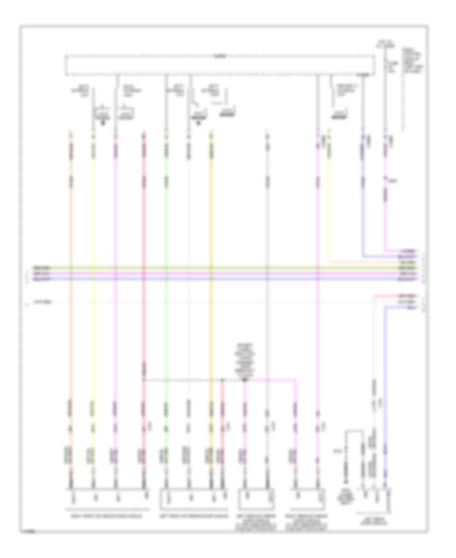
Forced Entry Wiring Diagram (1 of 5) for Ford Fusion S Hybrid 2014
List of elements for Forced Entry Wiring Diagram (1 of 5) for Ford Fusion S Hybrid 2014:
- (or cp244)
- 1/2
- 3/4
- 5/6
- 7/8
- 9/0
- Ajar
- Ajar sig
- Ajar sw sig
- B17
- B18
- B19
- B20
- B21
- Body control module (bcm) (left end of dash)
- C133
- C134
- C2280c
- C2280d
- C2280e
- C2280f
- C2280g
- C311
- C406
- C4174b
- Compartment
- Computer data lines system
- Cpk29
- Cpk30
- Cpk31
- Cpl25
- Cpl44
- Cpl81
- Fuse 5a
- Fusion
- G101 (left front of engine compt)
- G302 (under driver's seat)
- G400 (left side of luggage compt)
- Gnd
- Half bridge
- Hood ajar
- Hood ajar switch (fusion: left front of engine compt) (mkz: center front of engine compt)
- Hot at all times
- Key- pad a
- Key- pad b
- Key- pad c
- Keyless entry keypad
- Logic
- Luggage compartment ajar
- Luggage compartment lid latch (center rear of luggage compt lid)
- Micro
- Mkz
- Ms can+
- Ms can-
- Protect 1 antenna high
- Protect 1 antenna low
- Protect 2 antenna high
- Rear gate trunk module (hybrid: left side of luggage compt)
- S101
- S405
- Vdb06
- Vdb07
- W/ power luggage
- W/o power luggage compartment
Forced Entry Wiring Diagram (2 of 5) for Ford Fusion S Hybrid 2014
List of elements for Forced Entry Wiring Diagram (2 of 5) for Ford Fusion S Hybrid 2014:
- (except hybrid: body main wiring harness, near breakout to c215) s307
- (or spb51) sbp29
- A10
- A16
- Ant +
- Ant -
- B12
- B13
- Batt
- Body control module (bcm) (left end of dash)
- C2280e
- C2280f
- C2280g
- C311
- C312
- C313
- C314
- Ext1 antenna high
- Ext1 antenna low
- Ext2 antenna high
- Ext2 antenna low
- Fuse 10a
- G302 (under driver's seat)
- Gd382
- Gnd
- Half bridge
- Hot at all times
- K-line
- Latch gnd
- Left front exterior door handle
- Left rear door module
- Left rear exterior door handle (w/ keyless entry & push button start)
- Micro
- Nca
- Protect 2 antenna low
- Right front exterior door handle
- Right rear exterior door handle (w/ keyless entry & push button start)
- Rpk39
- Rpl71
- S305
- S700
- Vbatt
- Vpk39
- Vpk40
- Vpk46
- Vpk47
- Vpl56
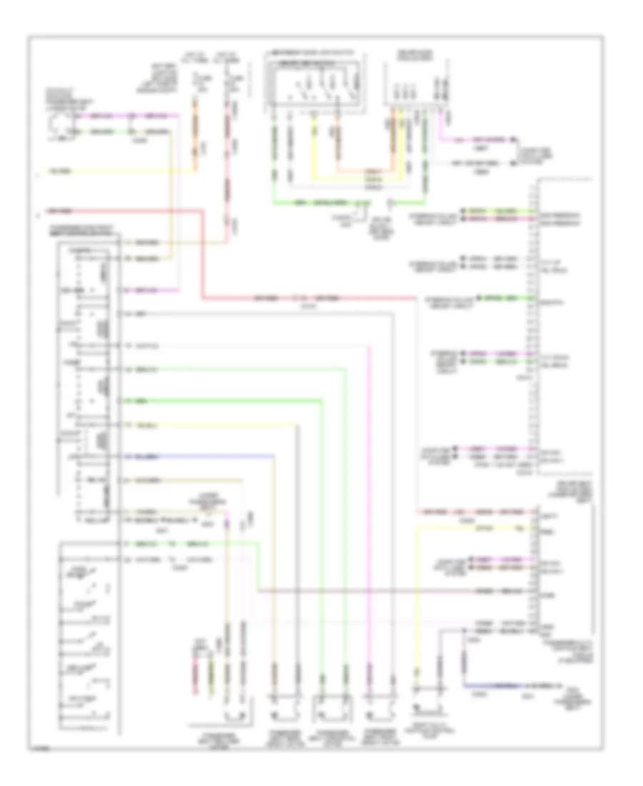
Forced Entry Wiring Diagram (3 of 5) for Ford Fusion S Hybrid 2014
List of elements for Forced Entry Wiring Diagram (3 of 5) for Ford Fusion S Hybrid 2014:
- (except hybrid: right side of luggage compt) radio transceiver module (rtm)
- (hybrid: left front door harness, near breakout to left exterior mirror) (except hybrid: left front door window regulator wiring harness, near breakout to left exterior mirror) (mkz) s502
- (not used)
- (or gd313)
- (or sbp52) sbp30
- (rear corner of luggage compt) (w/ keyless entry & push button start) keyless entry rear antenna
- (rear of right rear door) right rear door latch release motor
- (under center console) (w/ keyless entry & push button start) passive anti-theft system front antenna
- A11
- A16
- Ajar
- Ant +
- Ant -
- C248
- C311
- C313
- C314
- C340
- C913
- Can+ ms
- Can- ms
- Computer data lines system
- Except hybrid
- Fusion
- G302 (fusion) g401 (mkz) (fusion: under driver's seat) (mkz: right side of luggage compt)
- G303 (under passenger's seat)
- Gd382
- Gd383
- Gnd
- Hybrid
- Interior lights system
- Internal antenna rke receiver
- K-line
- Left front door latch release motor (rear of left front door)
- Left rear door latch release motor (rear of left rear door)
- Ltch gnd
- Reset
- Right rear door module
- Rpl72
- S800
- Sbp32
- Set
- System interior lights
- Tpms receiver
- Unlock
- Vbatt
- Vdb06
- Vdb07
- Vpl56
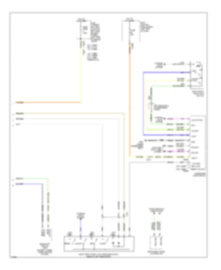
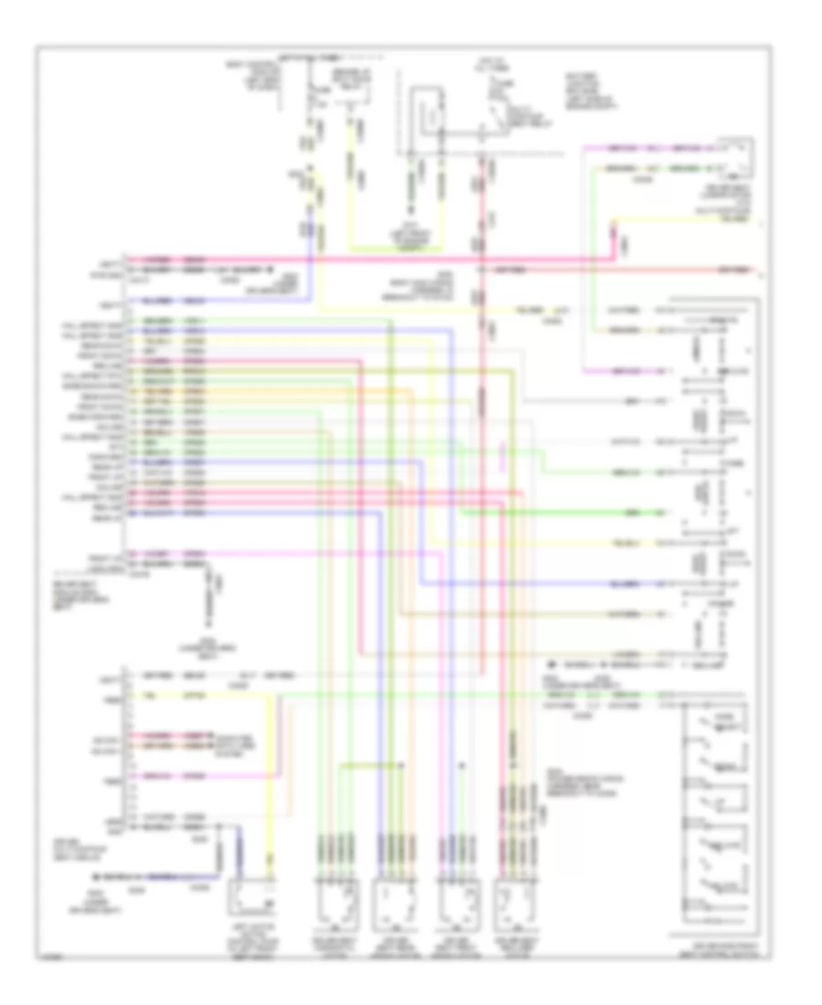
Forced Entry Wiring Diagram (4 of 5) for Ford Fusion S Hybrid 2014
List of elements for Forced Entry Wiring Diagram (4 of 5) for Ford Fusion S Hybrid 2014:
- (except hybrid: body main wiring harness, near breakout to c291) s312
- (except hybrid: body main wiring harness, near breakout to left footwell lamp) (mkz) s234
- (hybrid: front of driver's door)
- (not used)
- (or cpl26)
- (under driver's seat)
- A16
- Body control module (bcm) (left end of dash)
- C2280a
- C2280b
- C2280d
- C2280f
- C248
- C311
- C501a
- C501b
- Can+ hs1
- Can- hs1
- Central lock relay
- Central unlock relay
- Computer data lines system
- Cpl25
- Cpl28
- Cpl29
- Cpl31
- Cpl36
- Cpl39
- Cpl42
- Cpl43
- Cpl77
- Cpl87
- Door lock led status (fet)
- Driver door module (ddm)
- Driver/ fuel flap unlock relay
- Except hybrid
- Fuse 20a
- Fuse 30a
- G302
- G302 (under driver's seat)
- Gd382
- Gnd
- Hot at all times
- Hybrid
- Illum
- Interior lights system
- Keypad illum (fet)
- Lck status
- Led
- Left front door lock switch
- Lock
- Ltch gnd
- Micro
- Mkz fusion
- Ms can+
- Ms can-
- Red
- Reset/ulck
- Rpl61
- Rpw03
- Rtn
- S311 (except hybrid: body main wiring harness, near breakout to c291)
- S500
- Sbp25
- Set/lck
- Splice block 1 (driver's door)
- Unlock
- Vbatt
- Vdb04
- Vdb05
- Vdb06
- Vdb07
- W/ memory
- W/o memory
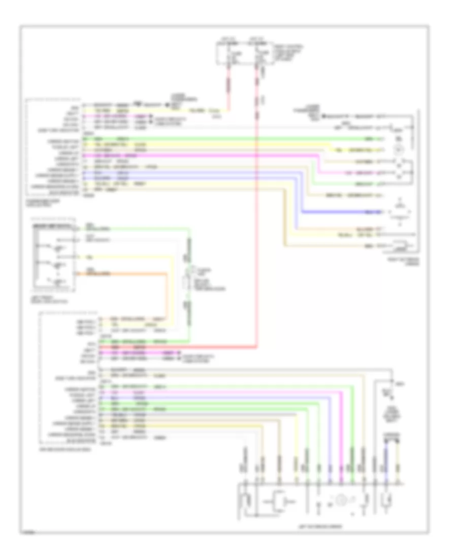
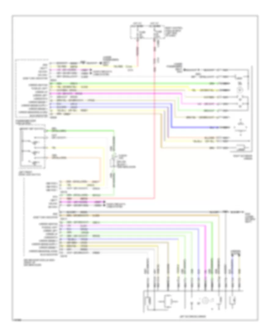
Forced Entry Wiring Diagram (5 of 5) for Ford Fusion S Hybrid 2014
List of elements for Forced Entry Wiring Diagram (5 of 5) for Ford Fusion S Hybrid 2014:
- (not used)
- (or cpl125)
- (or sbp25)
- 1.6l turbo, 2.0l hybrid, 2.0l turbo hybrid & 2.5l
- 2.0l turbo, 2.0l, 3.7l & 1.5l turbo
- A11
- A16
- Ajar
- Body control module (bcm) (left end of dash)
- C1617f
- C1716f
- C2280f
- C312
- C652a
- C652b
- Computer data lines system
- Cpl15
- Cpl16
- Cpl26
- Cpl30
- Cpl88
- Door
- Fuse 30a
- G303 (under passenger's seat)
- Gd383
- Gear shift module (mkz) (except hybrid: upper center of dash)
- Gnd
- High current battery junction box (bjb) (except hybrid: left side of engine compt)
- Hot at all times
- Hs3 can+
- Hs5 can-
- Instrument panel cluster (ipc)
- Interior lights system
- Lck status
- Led
- Lock
- Ltch gnd
- Mega fuse 125a
- Ms can +
- Ms can -
- Passenger door module
- Reset
- Reset/unlock
- Right front door latch release motor (rear of left rear door)
- Right front door lock switch
- Rpl62
- Rpw05
- Rtn
- S600
- Sbp26
- Set
- Set/lock
- Splice block 2 (passenger's door)
- Status
- Switch
- Unlock
- Vbatt
- Vdb06
- Vdb07
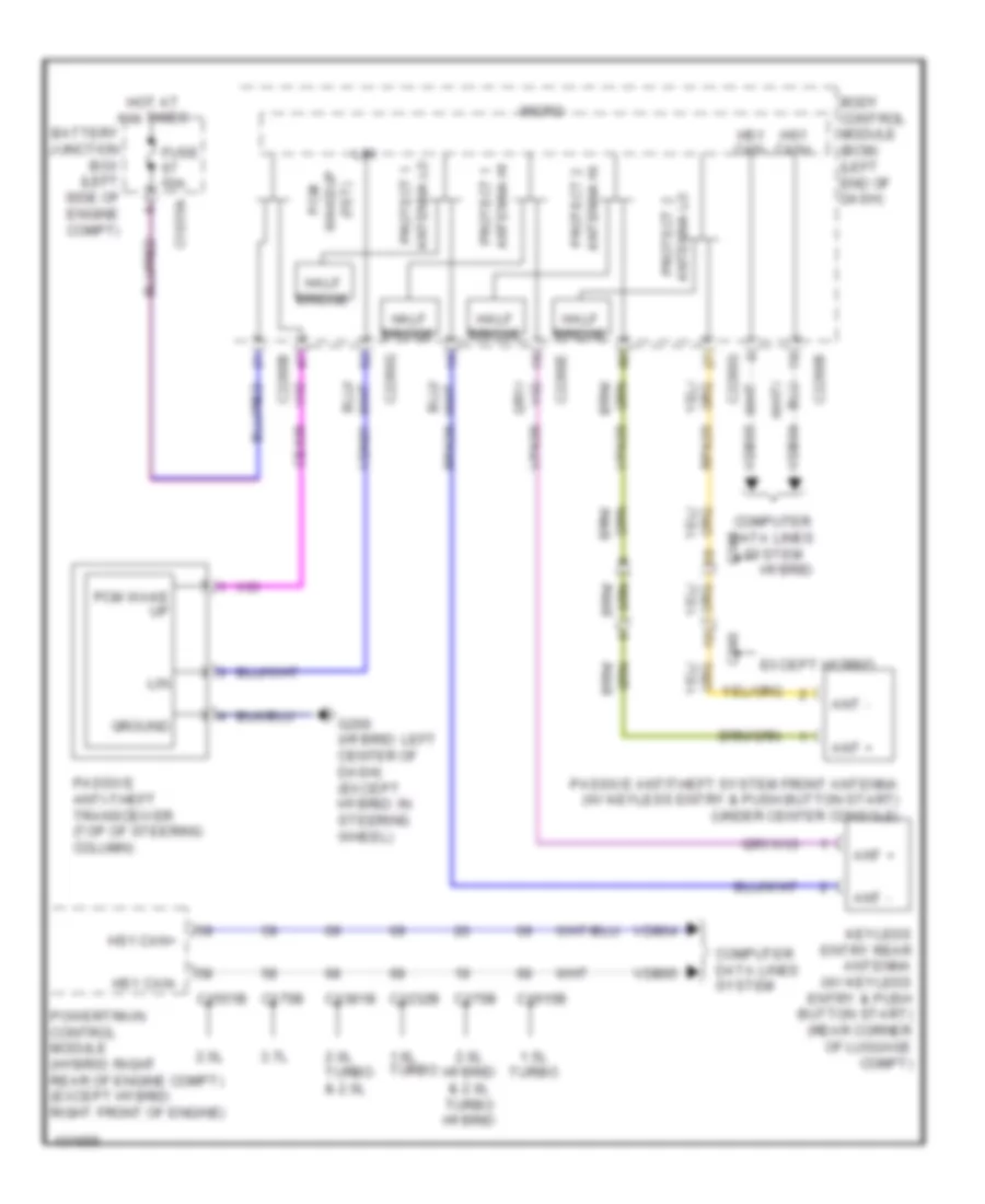
Passive Anti-theft Wiring Diagram for Ford Fusion S Hybrid 2014
List of elements for Passive Anti-theft Wiring Diagram for Ford Fusion S Hybrid 2014:
- 1.5l turbo
- 1.6l turbo
- 2.0l hybrid & 2.0l turbo hybrid
- 2.0l turbo & 2.0l
- 2.5l
- 3.7l
- Ant +
- Ant -
- Antenna hi protect 1
- Antenna hi protect 2
- Antenna lo protect 1
- Battery junction box (left side of engine compt)
- Body control module (bcm) (left end of dash)
- C1035a
- C1232b
- C1381b
- C1551b
- C175b
- C1915b
- C2280b
- C2280e
- C2280g
- C340
- Ce436
- Computer data lines system
- Except hybrid
- Fuse 50a
- G200 (hybrid: left center of dash) (except hybrid: in steering wheel)
- Ground
- Half bridge
- Hot at all times
- Hs1 can+
- Hs1 can-
- Hybrid
- Keyless entry rear antenna (w/ keyless entry & push button start) (rear corner of luggage compt)
- Lin
- Micro
- Passive anti-theft transceiver (top of steering column)
- Passive antitheft system front antenna (w/ keyless entry & push button start) (under center console)
- Pcm
- Pcm wake up
- Powertrain control module (hybrid: right rear of engine compt) (except hybrid: right front of engine)
- Protect 2 antenna lo
- Rpk05
- Rpk06
- Vdb04
- Vdb05
- Vdn01
- Vpk05
- Vpk06
- Wakeup (fet)
BODY CONTROL MODULES
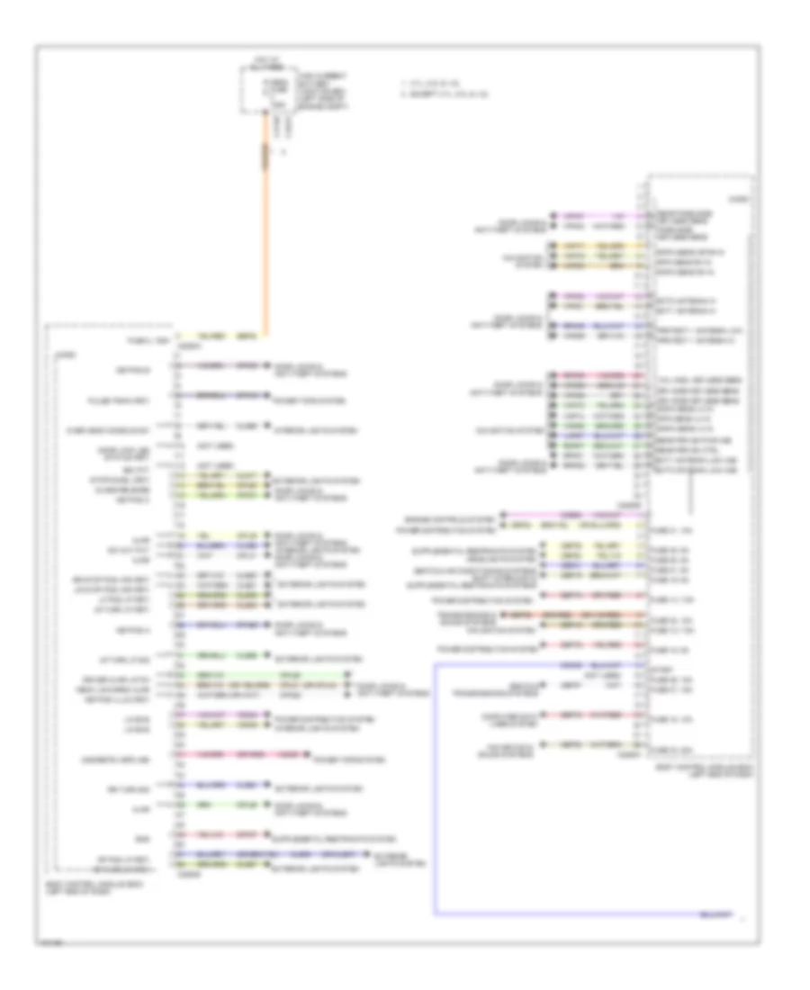
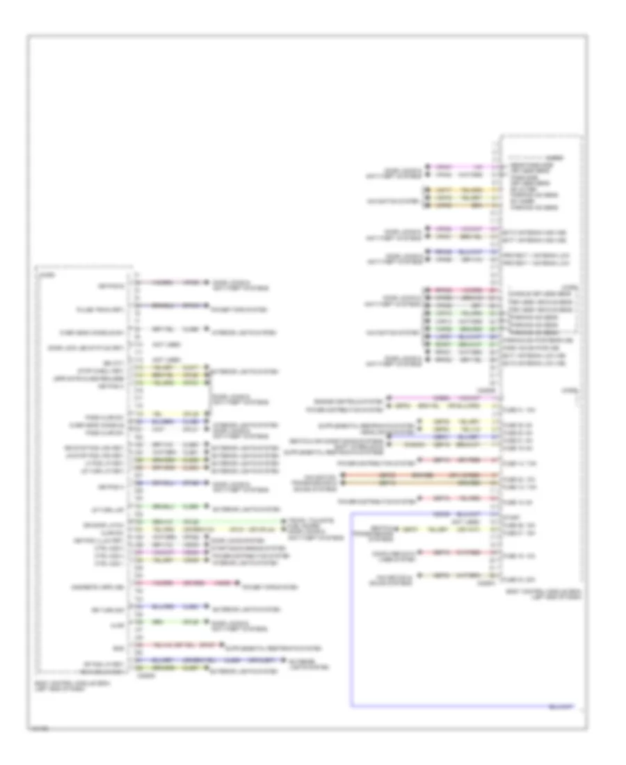
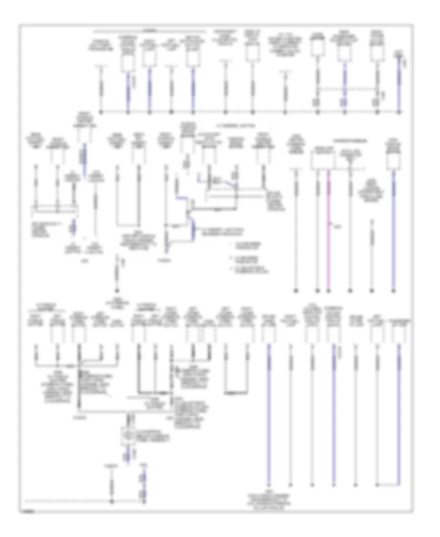
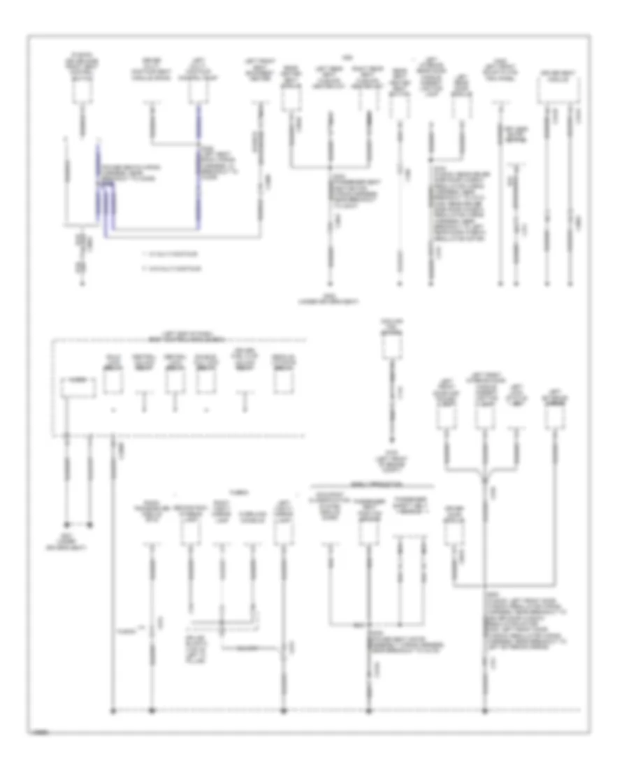
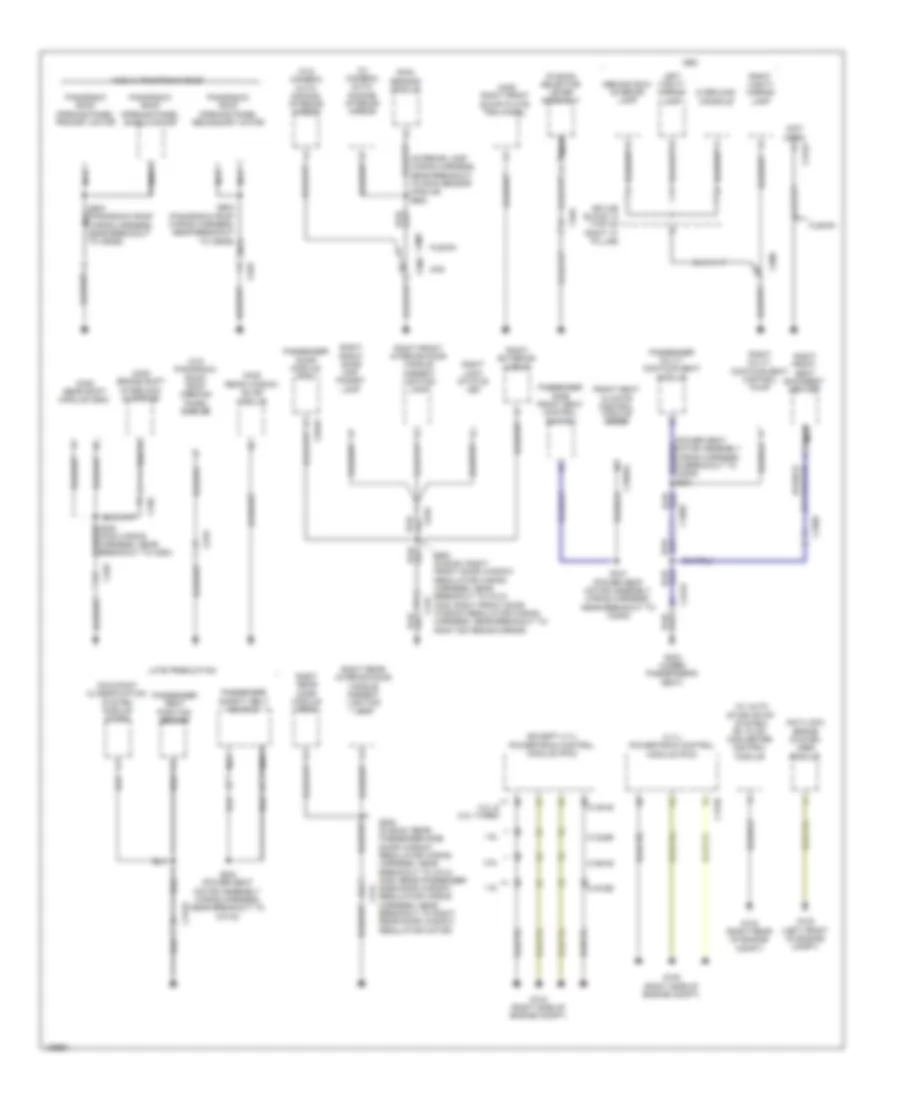
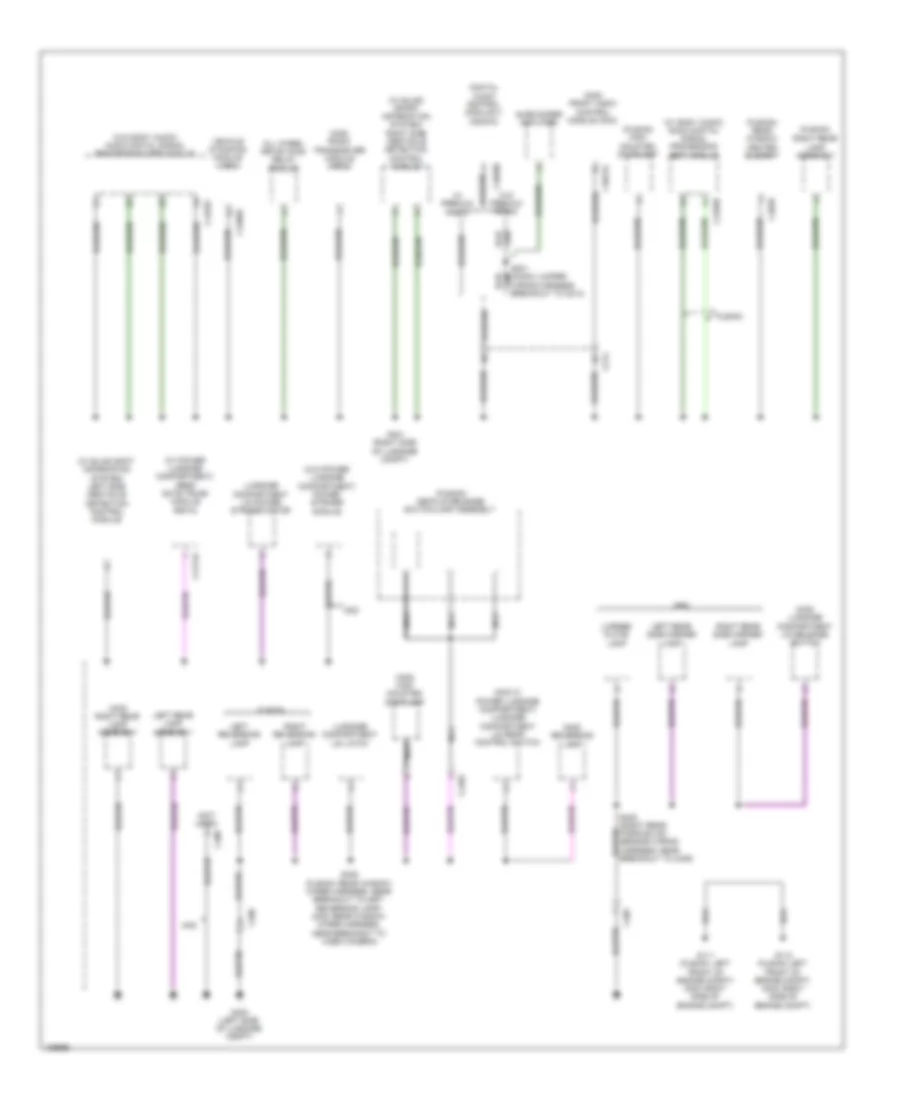
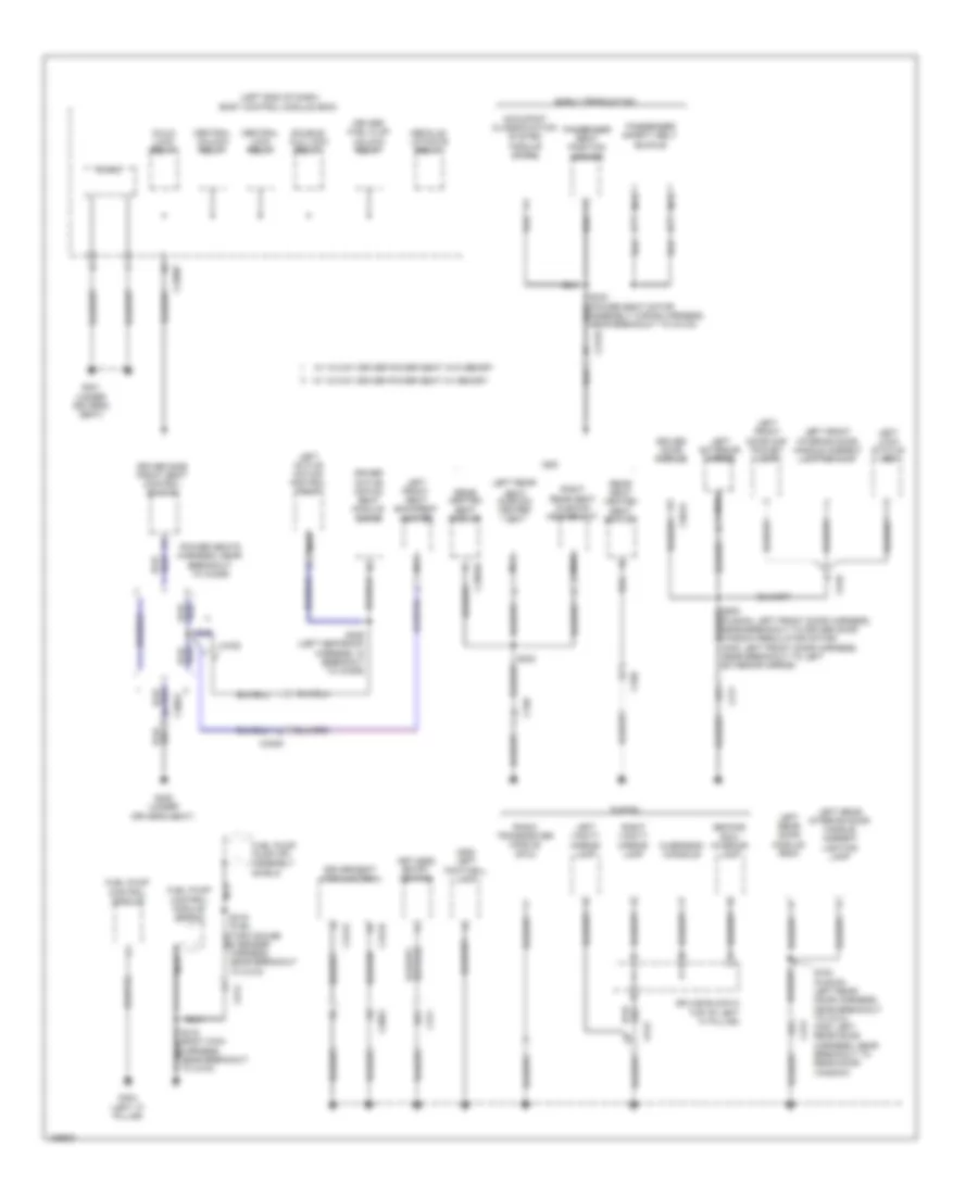
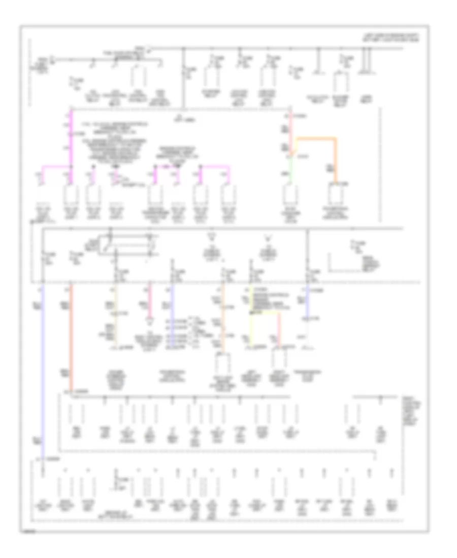
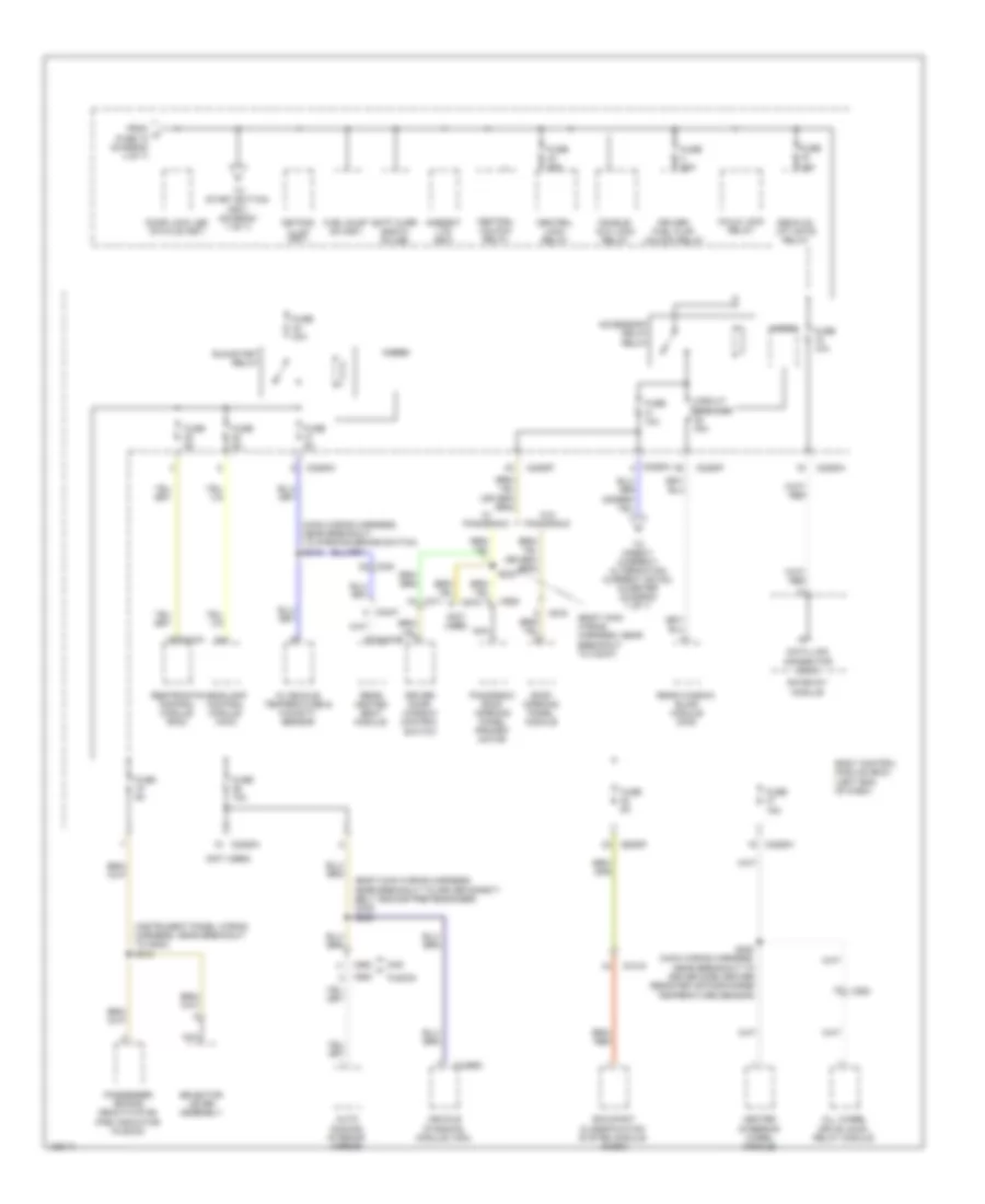
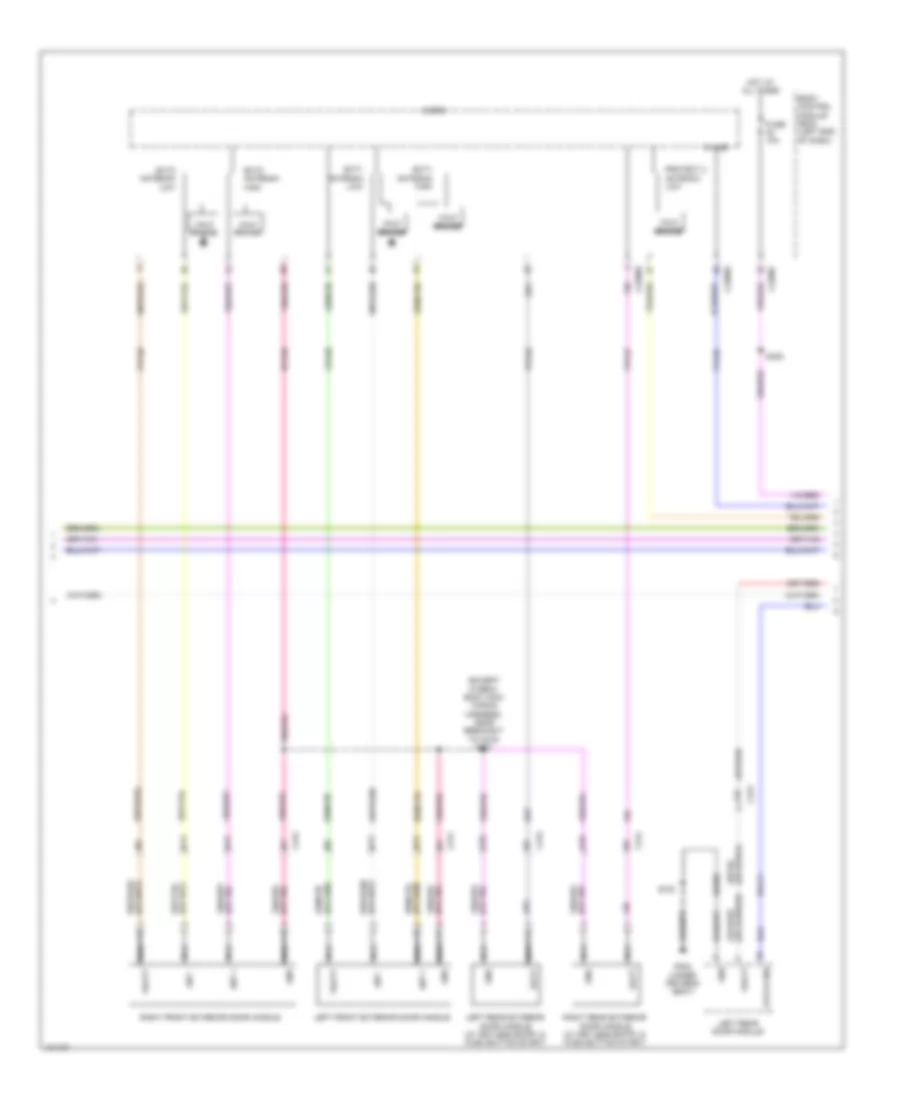
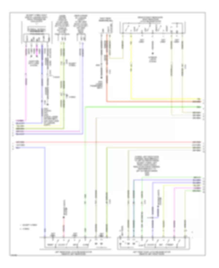
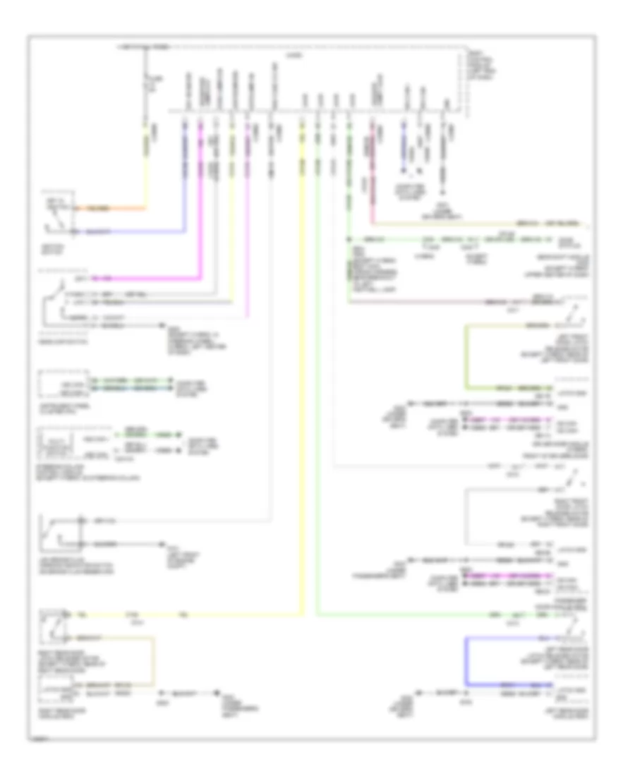
Body Control Modules Wiring Diagram, Except Hybrid (1 of 3) for Ford Fusion S Hybrid 2014
List of elements for Body Control Modules Wiring Diagram, Except Hybrid (1 of 3) for Ford Fusion S Hybrid 2014:
- (not used)
- (or cls07)
- (or cpl44)
- 3.7l, 2.0l & 1.5l
- Ajar
- Body control module (bcm) (left end of dash)
- Bsi (fit)
- C1617f
- C1716f
- C2280a
- C2280d
- C2280e
- C2280h
- Cbp19
- Cbp20
- Cbp21
- Cbp23
- Cbp33
- Cbp35
- Cbp37
- Ccb08
- Cdc35
- Cln68
- Cln69
- Cls05
- Cls06
- Cls17
- Cls23
- Cls27
- Cls51
- Cls53
- Cls54
- Cls55
- Computer data lines system
- Cpk28
- Cpk29
- Cpk30
- Cpk31
- Cpl26
- Cpl31
- Cpl36
- Cpl39
- Cpl60
- Cpl81
- Cpw01
- Cr167
- Deck lid/cargo ajar
- Discrete vspd (hb)
- Door lock led status (fet)
- Door locks & anti-theft systems
- Door locks & anti-theft systems interior lights system door locks & anti-theft systems
- Driver ajar latch
- Drv side keyless sens
- Engine controls system
- Ens
- Except 3.7l, 2.0l & 1.5l
- Ext1 antenna hi
- Ext1 antenna low (hb)
- Ext2 antenna hi
- Ext2 antenna low (hb)
- Exterior lights system
- Fuse 12, 7.5a
- Fuse 13, 7.5a
- Fuse 15, 10a
- Fuse 18, 5a
- Fuse 19, 5a
- Fuse 2, 125a
- Fuse 20, 5a
- Fuse 21, 5a
- Fuse 31, 10a
- Fuse 32, 10a
- Fuse 33, 20a
- Fuse 35, 5a
- Fuse 36, 15a
- Fuse 37, 15a
- Glass release
- Headlights system
- High current battery junction box (left side of engine compt)
- Hot at all times
- Interior lights system
- Keypad a
- Keypad b
- Keypad c
- Keypad illum (fet)
- Lf pos lp (fet)
- Lin bus
- Lmp07
- Lr stop pos lps (fet)
- Lr turn lp (fet)
- Lr turn lp sig
- Mega fuse 125a
- Micro
- Navigation & sound systems
- Navigation system
- Over head console sw
- Pass side keyless sens
- Power distribution system
- Power tops system
- Protect 1 antenna hi
- Protect 1 antenna low
- Pulse train (fet)
- Rapa sens lh in
- Rapa sens rh in
- Rear pass side keyless sens
- Rear prk sn ctrl
- Rear prk sn pwr (hb)
- Rf pos lp (fet)
- Ripa sens lh in
- Ripa sens rh in
- Rmp07
- Ropa sens lh in
- Ropa sens or rh in
- Rpk01
- Rpk02
- Rpk06
- Rpk39
- Rr stop pos lps (fet)
- Rr turn lp (fet)
- Rr turn sig
- Sbf02
- Sbp12
- Sbp13
- Sbp15
- Sbp18
- Sbp32
- Seats & transmissions systems
- Start
- Stop/chmsl (fet)
- Sw out put
- Transmissions & sound systems
- Vdn04
- Vdn05
- Vicl hndl keyless sens
- Vmc05
- Vmp14
- Vmp15
- Vmp16
- Vmp17
- Vmp29
- Vmp30
- Vpk01
- Vpk02
- Vpk06
- Vpk39
- Vpk40
- Vpk46
- Vpk47
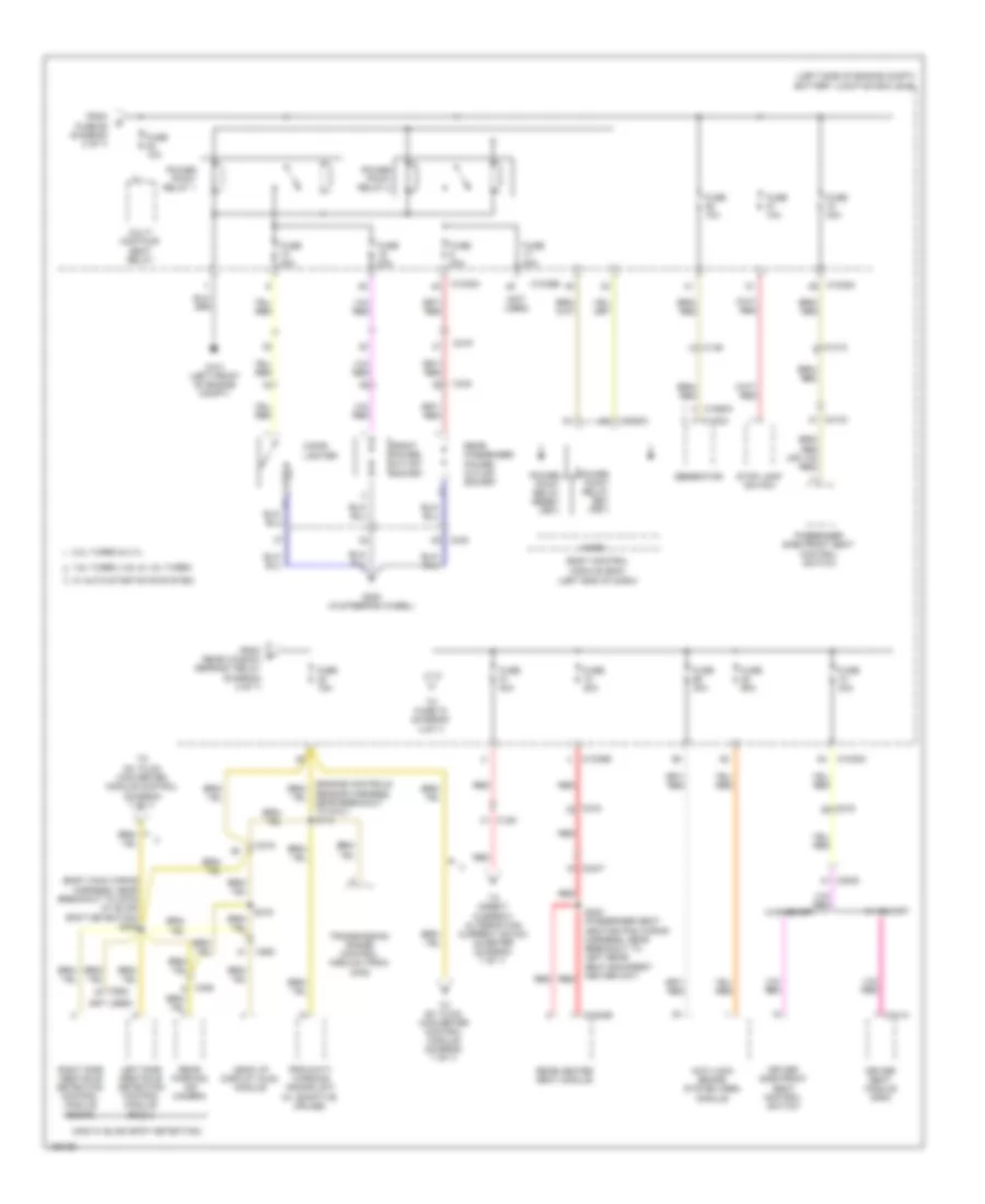
Body Control Modules Wiring Diagram, Except Hybrid (2 of 3) for Ford Fusion S Hybrid 2014
List of elements for Body Control Modules Wiring Diagram, Except Hybrid (2 of 3) for Ford Fusion S Hybrid 2014:
- (not used)
- (or sbf03)
- Ambient ltg (fet)
- Battery junction box (bjb) (left side of engine compt)
- Body control module (bcm) (left end of dash)
- C1035a
- C2280b
- C2280c
- C2280f
- Cbp22
- Cbp23
- Cbp32
- Cbp36
- Cbp38
- Cbx07
- Cdc40
- Cdc55
- Cdc56
- Cdc71
- Cdc72
- Ce226
- Ce436
- Central lock relay
- Central unlock relay
- Child lock relay
- Clf02
- Clf03
- Clf04
- Clf05
- Clf29
- Clf34
- Clf61
- Clf62
- Cln09
- Cls05
- Cls06
- Cls07
- Cls21
- Cls25
- Cls28
- Cls56
- Cls58
- Cmc19
- Computer data lines system
- Cpl10
- Cpl11
- Cpl13
- Cpl25
- Cpl51
- Cr115
- Crh02
- Deck lid/left gate
- Demand lp/batt save relay
- Door locks & anti-theft systems
- Door locks system
- Door locks, anti-theft & cruise control systems
- Driver/fuel flap unlock relay
- Engine controls system
- Exterior lights system
- Fapa sens lh in
- Fapa sens rh in
- Fipa sens rh in
- Fuel pump (fet)
- Fuel pump on (fet)
- Fuse 10, 5a
- Fuse 2, 7.5a
- Fuse 22, 5a
- Fuse 25, 30a
- Fuse 26, 30a
- Fuse 27, 30a
- Fuse 28, 20a
- Fuse 29, 30a
- Fuse 30, 30a
- Fuse 31, 10a
- Fuse 32, 10a
- Fuse 33, 20a
- Fuse 36, 15a
- Fuse 38 30a
- Fuse 45, 5a
- Fuse 5, 20a
- Fuse 50a
- Fuse 62
- Fuse 67
- G301 (under driver's seat)
- G302 (under driver's seat)
- Gd326
- Gd382
- Gnd
- Headlights system
- Hood ajar
- Horn relay (fet)
- Horns system
- Hot at all times
- Hs1 can+
- Hs1 can-
- Instrument cluster system
- Int ltg (fet)
- Interior lights system
- Ldc59
- Lf drl lp (fet)
- Lf fog lp (fet)
- Lf high beam (fet)
- Lf inn park aid sens
- Lf low beam (fet)
- Lf out park aid sens
- Lf pos lp (fet)
- Lf turn lp (fet)
- Lmp06
- Low lvl brke flud sw
- Micro
- Mirrors system
- Mon
- Navigation system
- Park lp (fet)
- Park lps (fet)
- Park sn pwr frt (hb)
- Pcm wake up (fet)
- Power distribution system
- Power tops system
- Pwr point rly (fet)
- Pwr point rly set (fet)
- Rapa sens lh in
- Rdc59
- Red
- Rev lps (fet)
- Rf drl (fet)
- Rf fog lamp (fet)
- Rf high beam (fet)
- Rf low beam (fet)
- Rf pos lp (fet)
- Rf turn lp (fet)
- Rmp06
- Run/acc (fet)
- Run/start (fet)
- Sb101
- Sbb62
- Sbb67
- Sbp02
- Sbp05
- Sbp10
- Sbp25
- Sbp26
- Sbp27
- Sbp28
- Sbp29
- Sbp30
- Sdc57
- Seats system
- Sen +
- Sen -
- Sens gnd
- Sound systems
- Starting/charging system
- Trunk, tailgate, fuel doors system
- Vdb04
- Vdb05
- Vln33
- Vmp10
- Vmp11
- Vmp12
- Vmp13
- Vmp20
- Vmp21
- Wiper/washer system
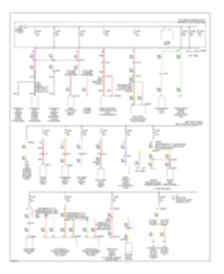
Body Control Modules Wiring Diagram, Except Hybrid (3 of 3) for Ford Fusion S Hybrid 2014
List of elements for Body Control Modules Wiring Diagram, Except Hybrid (3 of 3) for Ford Fusion S Hybrid 2014:
- (or cls34)
- (or cpl24)
- (or cpr63)
- Acc
- Acc/run
- Air conditioning & headlights systems
- Anti-theft system
- Auto lamp sensor
- Auto lamp sensor gnd
- Auto park ind (fet)
- Autolamp on
- Back light (fet)
- Body control module (bcm) (left end of dash)
- Bsi (fet)
- C2280g
- Cdc26
- Cdc30
- Cdc33
- Cdc34
- Ce436
- Ce903
- Cet53
- Clf19
- Clf21
- Clf23
- Clf24
- Cln34
- Cln55
- Cln56
- Cls32
- Clutch pos sw pedal
- Cmp02
- Cmp18
- Cmp31
- Cmp32
- Cpk34
- Cpk35
- Cpk36
- Cpl45
- Dim +
- Dim-
- Door locks & anti-theft systems
- Eng sw
- Engine controls & transmissions systems
- Engine controls system
- Exterior lights system
- Fog lamp on
- Fusion
- Hazard sw
- Head/park lamps off
- Headlights system
- Horn sw
- Horn sw ctrl mod
- Horns system
- Hot at all times
- Ignition switch
- Interior lights system
- Key in
- Key inhibit (fet)
- Low beam req
- Micro
- Mkz
- Navigation system
- Off
- Park aid ind (fet)
- Park lamps on
- Parking actor sw
- Parking aid sw
- Pcm wakeup (fet)
- Power distribution system
- Power luggage sw
- Prct 2 antenna low (hb)
- Protect 1 antenna lo (fet)
- Prt 2 antenna hi (hb)
- Rlf14
- Rpk05
- Rrh02
- Run
- Shift interlock & transmissions systems
- Shift interlock system
- Start
- Start button (fet)
- Start/stop
- Strt/run
- Transmissions system
- Triple valve module
- Trunk, tailgate, fuel doors system
- Vdn01
- Vdn07
- Vlf14
- Vln04
- Vpk05
- Vpl56
- White light (fet)
Body Control Modules Wiring Diagram, Hybrid (1 of 3) for Ford Fusion S Hybrid 2014
List of elements for Body Control Modules Wiring Diagram, Hybrid (1 of 3) for Ford Fusion S Hybrid 2014:
- (fusion)
- (not used)
- (or cls07)
- (or cpl44)
- Ajar
- Ajar sw
- Body control module (bcm) (left end of dash)
- Bsi (fit)
- C2280d
- C2280e
- C2280h
- Cbp19
- Cbp20
- Cbp21
- Cbp23
- Cbp33
- Cbp35
- Cbp37
- Ccb08
- Cdc35
- Cln68
- Cln69
- Cls05
- Cls06
- Cls17
- Cls23
- Cls27
- Cls51
- Cls53
- Cls54
- Cls55
- Computer data lines system
- Cpk28
- Cpk29
- Cpk31
- Cpl26
- Cpl31
- Cpl36
- Cpl39
- Cpl60
- Cpl81
- Cpw01
- Cr167
- Ctrl mod 1
- Ctrl mod 3
- Ctrl mod 4
- Discrete vspd (hb)
- Door lock led status (fet)
- Door locks & anti-theft systems
- Door locks system
- Dr door latch
- Engine controls system
- Ens
- Ext1 antenna high (hb)
- Ext1 antenna low (hb)
- Ext2 antenna high (hb)
- Ext2 antenna low (hb)
- Exterior lights system
- Fuse 12, 7.5a
- Fuse 13, 7.5a
- Fuse 15, 10a
- Fuse 18, 5a
- Fuse 19, 5a
- Fuse 20, 5a
- Fuse 21, 5a
- Fuse 31, 10a
- Fuse 32, 10a
- Fuse 33, 20a
- Fuse 35, 5a
- Fuse 36, 15a
- Fuse 37, 15a
- Handle keyless sens
- Headlights system
- Interior lights system
- Interior lights system door locks & anti-theft systems
- Keyless vehicle sens
- Keypad a
- Keypad b
- Keypad c
- Keypad illum (fet)
- Lefr gate glass realese
- Lf pos lp (fet)
- Lmp07
- Lr stop pos lps (fet)
- Lr turn lmp
- Lr turn lp (fet)
- Micro
- Navigation & sound systems
- Navigation system
- Navigation, transmissions & sound systems
- Over head console
- Over head console sw
- Park aid sn pwr (hb)
- Parkaid sn pwr rear (hb)
- Parking aid sens
- Pass ajar sw
- Pass side keyless sens
- Power distribution system
- Power tops system
- Protect 1 antenna low
- Pulse train (fet)
- Rear pass side keyless sens
- Rf pos lp (fet)
- Rh inner parking aid sens
- Rh outer parking aid sens
- Rmp07
- Rpk01
- Rpk02
- Rpk06
- Rpk39
- Rr stop pos lps (fet)
- Rr turn lp (fet)
- Rr turn sig
- Sbp12
- Sbp13
- Sbp15
- Sbp18
- Sbp32
- Seats & transmissions systems
- Start
- Starting/charging system
- Stop chsml (fet)
- Trunk, tailgate, fuel doors, door locks & anti-theft systems
- Vdn03
- Vdn04
- Vdn05
- Vmc05
- Vmp14
- Vmp15
- Vmp16
- Vmp17
- Vmp29
- Vmp30
- Vpk01
- Vpk02
- Vpk06
- Vpk30
- Vpk39
- Vpk40
- Vpk46
- Vpk47
Body Control Modules Wiring Diagram, Hybrid (2 of 3) for Ford Fusion S Hybrid 2014
List of elements for Body Control Modules Wiring Diagram, Hybrid (2 of 3) for Ford Fusion S Hybrid 2014:
- (mkz)
- (not used)
- (or sbp32)
- Ambient ltg (fet)
- Batt curr sns 5v fd (hb)
- Battery junction box (bjb) (left side of engine compt)
- Body control module (bcm) (left end of dash)
- Brke flud sw
- C1035a
- C1617f
- C2280a
- C2280b
- C2280c
- C2280f
- Cbp22
- Cbp23
- Cbp32
- Cbp36
- Cbp38
- Cbx07
- Cdc40
- Cdc55
- Cdc71
- Cdc72
- Ce226
- Ce436
- Central lock relay
- Central unlock relay
- Child lock relay
- Clf02
- Clf03
- Clf04
- Clf05
- Clf29
- Clf34
- Clf61
- Clf62
- Cln09
- Cls05
- Cls06
- Cls07
- Cls21
- Cls25
- Cls28
- Cls56
- Cls58
- Cmc19
- Computer data lines system
- Cpl10
- Cpl11
- Cpl13
- Cpl25
- Cpl51
- Crh02
- Deck lid/left gate relay
- Demand lp/batt save relay
- Door locks & anti-theft systems
- Door locks system
- Driver/fuel flap unlock rly
- Electronic suspension & mirrors systems
- Engine controls system
- Exterior lights system
- Fipa sens rh in
- Fuel pump (fp) relay
- Fuel pump on (fet)
- Fuse 10, 5a
- Fuse 14, 10a
- Fuse 2, 125a
- Fuse 2, 7.5a
- Fuse 22, 5a
- Fuse 25, 30a
- Fuse 26, 30a
- Fuse 27, 30a
- Fuse 28, 20a
- Fuse 29, 30a
- Fuse 30, 30a
- Fuse 31, 10a
- Fuse 32, 10a
- Fuse 33 20a
- Fuse 36, 15a
- Fuse 38, 30a
- Fuse 5, 20a
- Fuse 50a
- Fuse 62
- Fuse 67
- G301 (under driver's seat)
- G302 (under driver's seat)
- Gd326
- Gd382
- Gnd
- Headlights system
- High current battery junction box
- Hood ajar
- Horn relay (fet)
- Horns system
- Hot at all times
- Hs1 can+
- Hs1 can-
- Instrument cluster system
- Int ltg (fet)
- Interior lights system
- Lf drl lp (fet)
- Lf fog lp (fet)
- Lf high beam (fet)
- Lf inn park aid sens
- Lf low beam (fet)
- Lf out park aid sens
- Lf pos lp (fet)
- Lf side park aid sens
- Lf turn lp (fet)
- Lmp06
- Mega fuse 125a
- Micro
- Navigation system
- Park lp (fet)
- Park lps (fet)
- Parkaid sn pwr frt (hb)
- Pcm wake up (fet)
- Power distribution system
- Power tops system
- Pwr point rly rset (fet)
- Pwr point rly set (fet)
- Rapa sens lh in
- Red
- Rev lps (fet)
- Rf drl lp (fet)
- Rf fog lamp (fet)
- Rf high beam (fet)
- Rf low beam (fet)
- Rf pos lp (fet)
- Rf prk aid sens
- Rf turn lp (fet)
- Rmp06
- Run/acc (fet)
- Run/start (fet)
- Sbb62
- Sbb67
- Sbf02
- Sbf03
- Sbp02
- Sbp05
- Sbp10
- Sbp14
- Sbp25
- Sbp26
- Sbp27
- Sbp28
- Sbp29
- Sbp30
- Seats & memory systems
- Sens gnd
- Sound systems
- Vdb04
- Vdb05
- Vln33
- Vmp10
- Vmp11
- Vmp12
- Vmp13
- Vmp20
- Vmp21
- Wiper/washer system
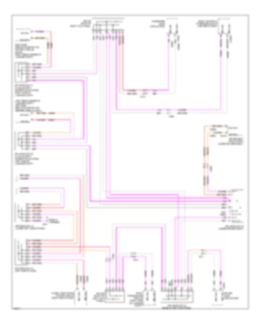
Body Control Modules Wiring Diagram, Hybrid (3 of 3) for Ford Fusion S Hybrid 2014
List of elements for Body Control Modules Wiring Diagram, Hybrid (3 of 3) for Ford Fusion S Hybrid 2014:
- (fusion)
- (not used)
- (or cpr63)
- Acc
- Acc/run
- Air conditioning & headlights systems
- Anti-theft system
- Auto lamp sensor gnd
- Auto lamp sensor input
- Auto park ind (fet)
- Autolamp on
- Back light (fet)
- Body control module (bcm) (left end of dash)
- Bsi (fet)
- C2280g
- Cdc26
- Cdc30
- Cdc33
- Cdc34
- Ce436
- Cet53
- Clf19
- Clf21
- Clf23
- Clf24
- Cln34
- Cln55
- Cln56
- Cls32
- Cmp02
- Cmp18
- Cmp32
- Cpk34
- Cpk35
- Cpk36
- Cpl24
- Cpl45
- Dim up
- Dim-
- Door locks & anti-theft systems
- Engine controls & transmissions systems
- Exterior lights system
- Fog lamp on
- Fuel filler door
- Hazard sw
- Head/park lamps off
- Headlights system
- Horn sw
- Horns system
- Hot at all times
- Ignition switch
- Interior lights system
- Key in
- Key inhibit (fet)
- Keyless veh
- Left gate release sw
- Lo beam req
- Micro
- Navigation system
- Off
- Park aid ind (fet)
- Park lamps on
- Parking actor sw
- Parking aid
- Pcm wakeup (fet)
- Power distribution system
- Protect 1 antenna lo
- Protect 2 antenna high
- Protect 2 antenna low
- Rf remote recendr
- Rlf14
- Rpk05
- Rrh02
- Run
- Shift interlock system
- Start
- Start button (fet)
- Start/stop
- Strt/run
- Transmissions & shift interlock systems
- Transmissions system
- Triple valve module
- Trunk, tailgate, fuel doors system
- Vdn01
- Vdn07
- Vlf14
- Vln04
- Vpk05
- Vpl56
COMPUTER DATA LINES
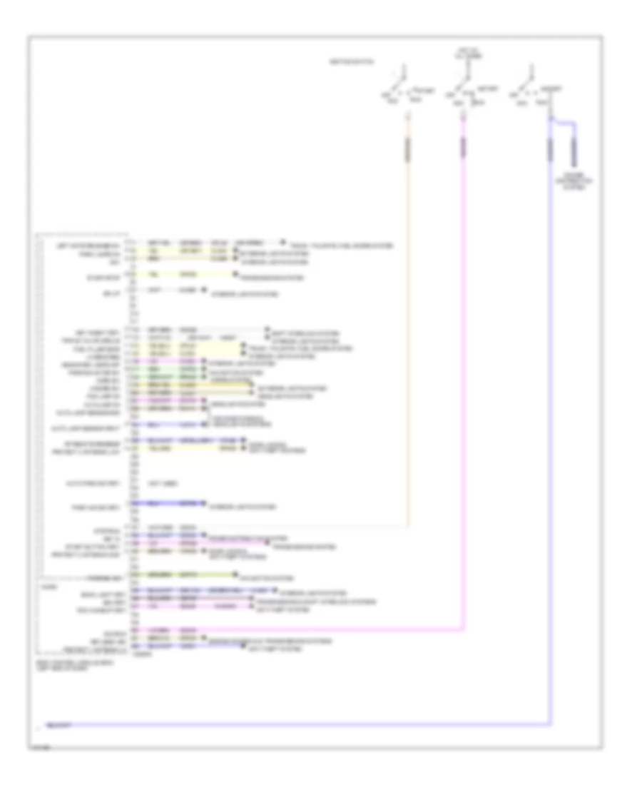
Computer Data Lines Wiring Diagram, Except Hybrid (1 of 3) for Ford Fusion S Hybrid 2014
List of elements for Computer Data Lines Wiring Diagram, Except Hybrid (1 of 3) for Ford Fusion S Hybrid 2014:
- (engine controls sensor harness, near breakout to coil on plug 3) s124
- (engine controls sensor harness, near breakout to g103) (w/ auto-start- stop system) s127
- (engine controls sensor harness, near breakout to g103) (w/ auto-start- stop system) s129
- (in steering wheel) g200
- (left end of dash) gateway module
- (lower center of dash) accessory protocol interface module (apim)
- 1.5l
- 1.6l
- 2.0l
- 2.5l
- Body control module (bcm) (left end of dash)
- C1232b
- C1381b
- C1551b
- C1915b
- C215
- C2280b
- C2280h
- C238
- C3133
- C900
- Data link connector (dlc)
- Dc to dc converter control module (w/ auto start- stop system) (right rear of engine compt)
- Fuse 10a
- Fuse 7.5a
- G201 (left center of dash)
- Gd214
- Gd215
- Hot at all times
- Hs1 can +
- Hs1 can -
- Hs2 can +
- Hs2 can -
- Hs2 can - c310b
- Hs3 can +
- Hs3 can -
- Micro
- Ms can +
- Ms can -
- Occupant classification system module (under passenger's seat)
- Powertrain control module (pcm) (right front of engine)
- Powertrain control module (pcm) (w/ auto start- stop system) (right front of engine)
- Restraints control module (under center console)
- S206
- Sbp13
- Sbp15
- Splice block 17 (left side of dash)
- Splice block 37 (under passenger's seat)
- Splice block 38 (under passenger's seat)
- Vdb04
- Vdb05
- Vdb06
- Vdb07
- Vdb25
- Vdb26
- Vdb29
- Vdb30
- W/ touch screen display
- W/o touch screen display
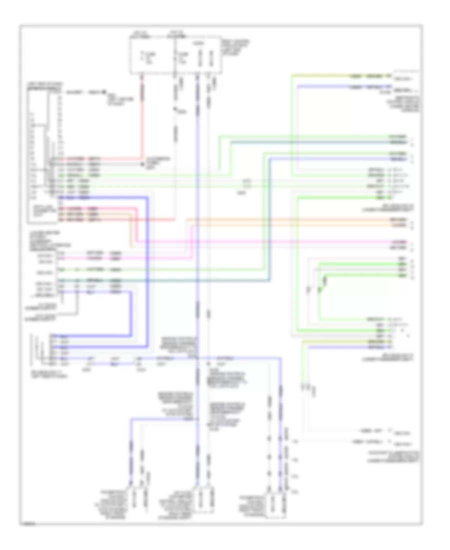
Computer Data Lines Wiring Diagram, Except Hybrid (2 of 3) for Ford Fusion S Hybrid 2014
List of elements for Computer Data Lines Wiring Diagram, Except Hybrid (2 of 3) for Ford Fusion S Hybrid 2014:
- (3.7l: battery harness, near breakout to g109)
- (engine controls sensor harness, near breakout to anti-lock brake system module) s118
- (except 3.7l: battery harness, near breakout to c146)
- (not
- (not used)
- Anti-lock brake system (abs) module (left rear of engine compt)
- Audio digital signal processing (dsp) module (right side of luggage compt)
- Audio front control module (right rear of luggage compt)
- Auto-dimming interior mirror
- C146
- C1463b
- C192
- C215
- C219
- C237
- C238
- C2414a
- C260
- C900
- Ends in harness
- Evac & fill
- Front control/ display interface module (fcdim) (w/ 4.2 inch display)
- Head up display (hud) module
- Hs2 can +
- Hs2 can + c4326c
- Hs2 can -
- Hs2 can - steering column control module (on steering column)
- Hs3 can +
- Hs3 can + c240a
- Hs3 can -
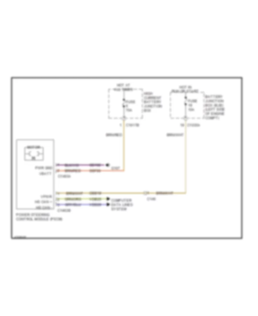
- Instrument panel cluster (ipc) module
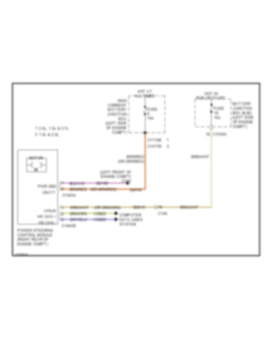
- Power steering control module (right rear of engine compt)
- Proximity warning radar unit (left front of engine compt)
- S107 (engine controls sensor harness, near breakout to c134)
- S108 (engine controls sensor harness, near breakout to c134)
- S115
- S116
- S117 (engine controls sensor harness, near breakout to c192)
- S137 (battery harness, near breakout to c146)
- S138
- Splice block 18 (left side of dash)
- Splice block 20 (center of dash)
- Splice block 21 (center of dash)
- Splice block 39 (near base of right "b" pillar)
- Splice block 59 (top of right "a" pillar)
- Splice block 8 (w/ 4.2 inch display)
- Used)
- Vdb25
- Vdb26
- Vdb29
- Vdb30
- W/ head up display
- W/ sony audio
- W/o head up display
- W/o sony audio
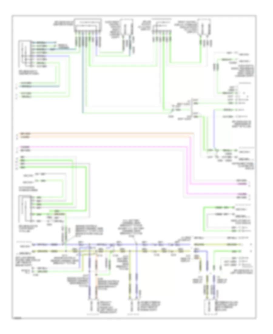
Computer Data Lines Wiring Diagram, Except Hybrid (3 of 3) for Ford Fusion S Hybrid 2014
List of elements for Computer Data Lines Wiring Diagram, Except Hybrid (3 of 3) for Ford Fusion S Hybrid 2014:
- (left rear corner of luggage compt) left side obstacle detection control module (sod-l)
- (not used)
- C237
- C248
- C260
- C3052
- C311
- C312
- C501a
- C913
- Driver door module (ddm)
- Driver seat module (dsm) (under driver's seat)
- Ends in harness
- Front controls interface module (center of dash)
- Global positioning system module (right end of dash)
- Ms can +
- Ms can + c2402a
- Ms can + c652a
- Ms can -
- Ms can - c341d
- Passenger door module (pdm)
- Radio transceiver module (right side of luggage compt)
- Right side obstacle detection control module (sod-r) (right rear corner of luggage compt)
- Splice block 15 (lower left side of dash)
- Splice block 16 (left side of dash)
- Splice block 32 (w/ blind spot information system) (left side of luggage compt)
- Splice block 33 (under driver's seat)
- Splice block 34 (base of left kick panel)
- Splice block 35 (left kick panel)
- Splice block 36 (right kick panel)
- Splice block 41 (w/ blind spot information system) (right side of luggage compt)
- Used) (not
- Vdb06
- Vdb07
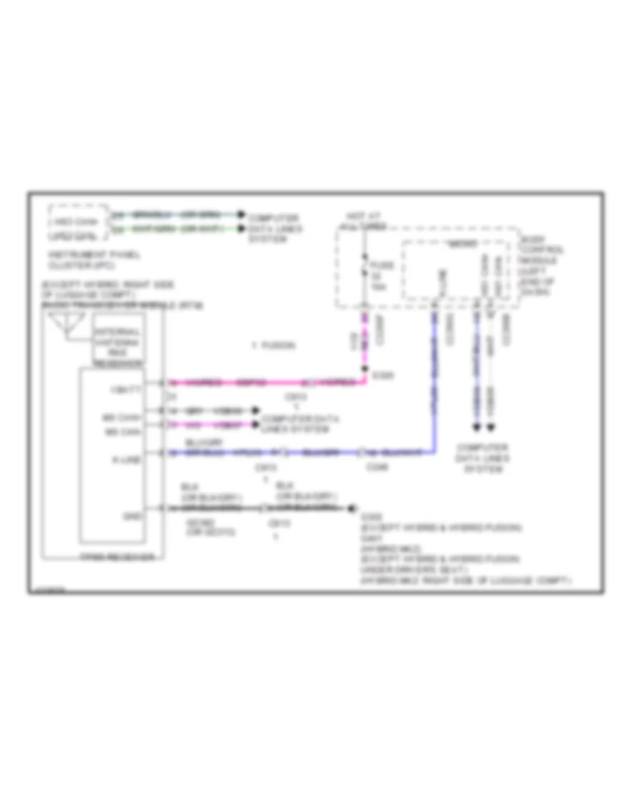
Computer Data Lines Wiring Diagram, Hybrid (1 of 3) for Ford Fusion S Hybrid 2014
List of elements for Computer Data Lines Wiring Diagram, Hybrid (1 of 3) for Ford Fusion S Hybrid 2014:
- (engine controls sensor harness, in breakout to c215) s129
- (front of center console) accessory protocol interface module
- (left center of dash) g200
- (left end of dash) gateway module
- (power steering hev harness, near breakout to high current battery junction box)
- (power steering hev harness, near breakout to high current battery junction box) s199
- Battery charger control module (bccm)
- Battery energy control module (becm) (behind left side of rear seat)
- Body control module (left end of dash)
- C1458a
- C146
- C175b
- C215
- C2280b
- C2280h
- C238
- C3133
- C4455b
- C4816a
- Charge port light ring (phev) (at charge port)
- Data link connector (dlc)
- Fuse 10a
- Fuse 7.5a
- G201 (left center of dash)
- Gd214
- Gd215
- Hev
- Hot at all times
- Hs1 can +
- Hs1 can + c4237a
- Hs1 can -
- Hs1 can - air conditioning control module (accm)
- Hs1 can - powertrain control module (right rear of engine compt)
- Hs2 can +
- Hs2 can -
- Hs2 can - c310b
- Hs3 can +
- Hs3 can -
- Micro
- Ms can +
- Ms can -
- Occupant classification module (under passenger's seat)
- Phev
- Restraints control module (under center console)
- S124 (engine controls sensor harness, near breakout to battery junction box)
- S125 (engine controls sensor harness, near breakout to battery junction box)
- S127 (engine controls sensor harness, in breakout to c215)
- S198
- S206
- Sbp13
- Sbp15
- Secondary onboard diagnostic module c/ transmission control module (left side of engine compt)
- Splice block 17 (left side of dash)
- Splice block 37 (under passenger's seat)
- Splice block 38 (under passenger's seat)
- Splice block 60
- Splice block 61 (phev)
- Vdb04
- Vdb05
- Vdb06
- Vdb07
- Vdb25
- Vdb26
- Vdb29
- Vdb30
- W/ touch screen display
- W/o touch screen display
Computer Data Lines Wiring Diagram, Hybrid (2 of 3) for Ford Fusion S Hybrid 2014
List of elements for Computer Data Lines Wiring Diagram, Hybrid (2 of 3) for Ford Fusion S Hybrid 2014:
- (engine controls sensor harness, in breakout to g100)
- (left front of vehicle)
- (not
- (not used)
- Anti-lock brake system (abs) control module (left rear of engine compt)
- Audio digital signal processing module
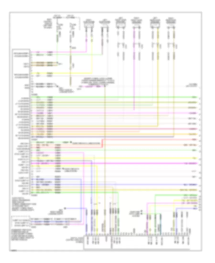
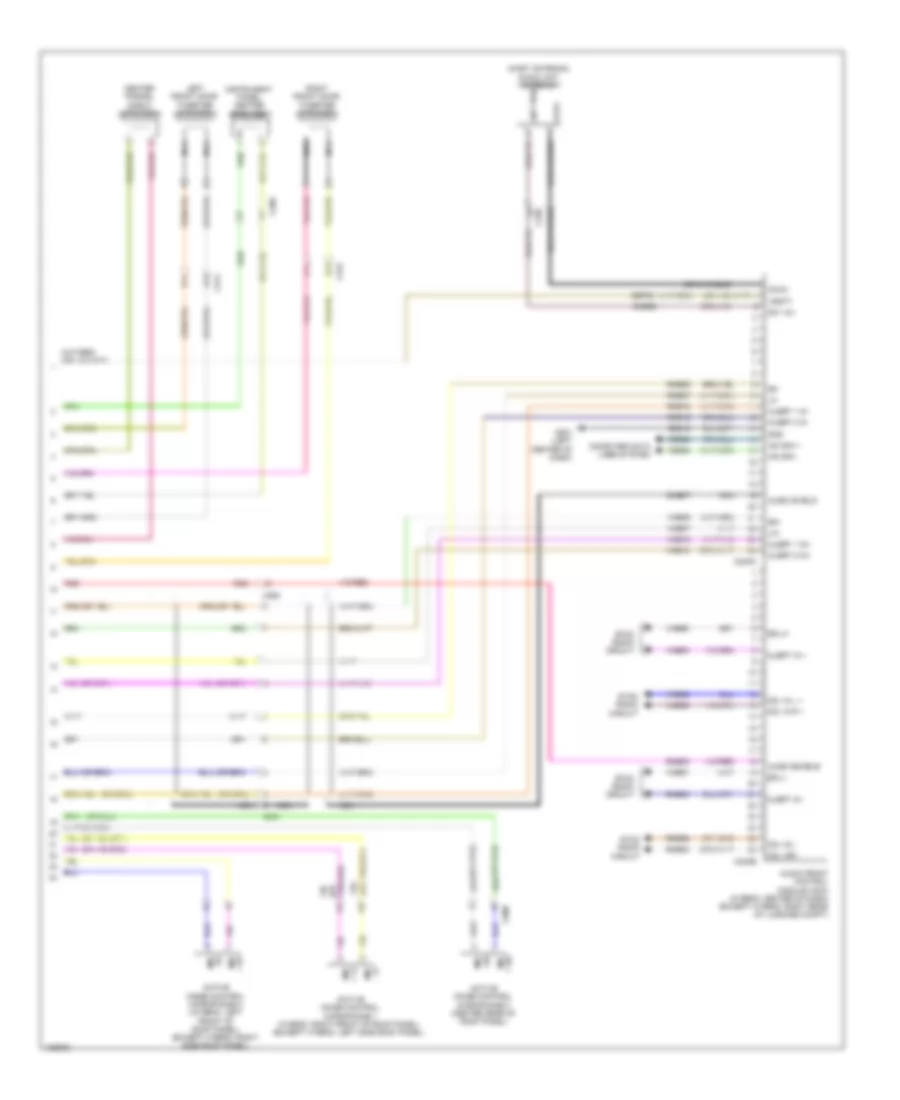
- Audio front control module (acm) (center of dash)
- Auto-dimming interior mirror
- C146
- C1463b
- C192
- C215
- C219
- C237
- C238
- C2414a
- C260
- C900
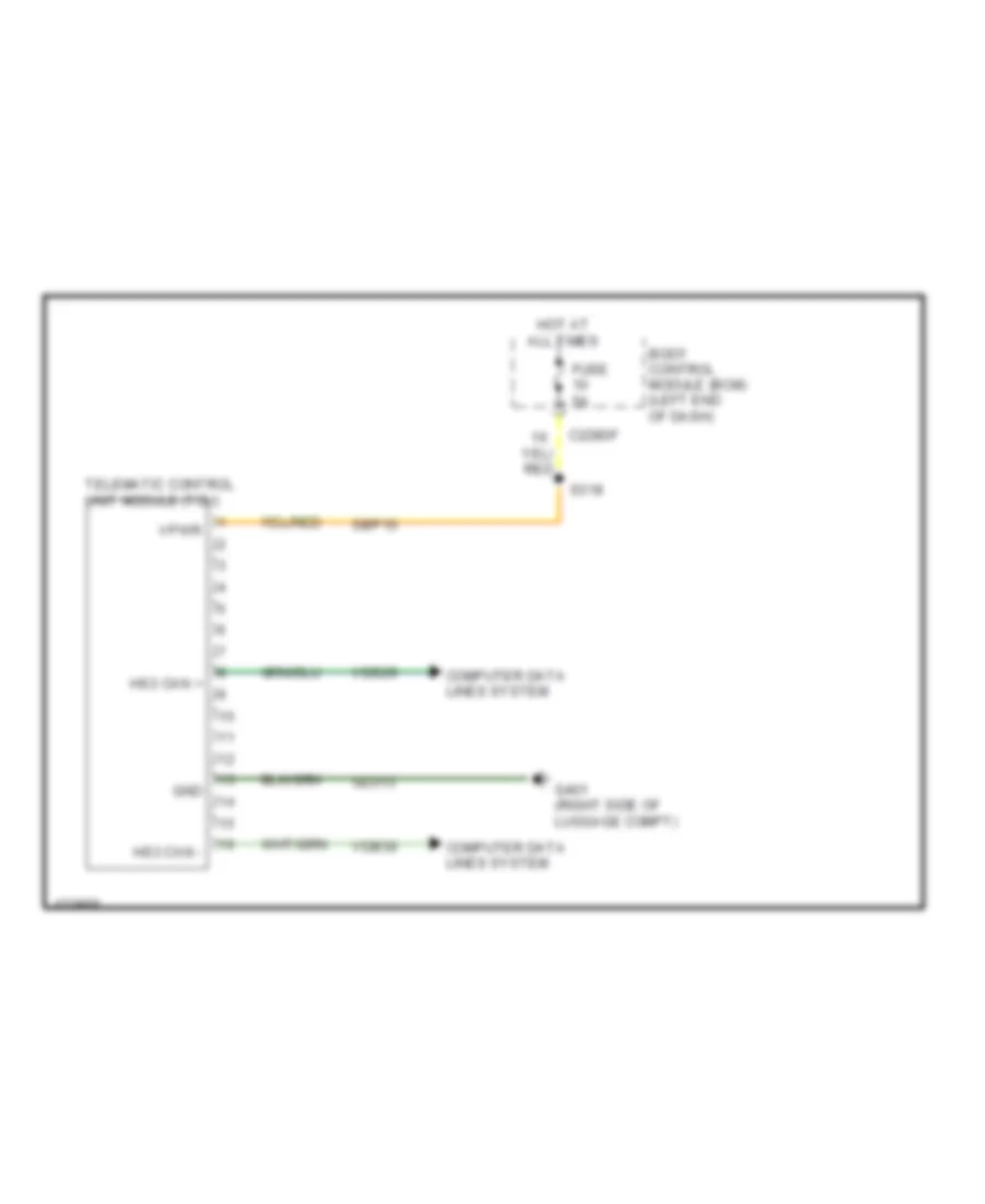
- Digital audio control module c (dacmc)
- Evac & fill
- Front control/ display interface module (w/ 4.2 inch display) (center of dash) hs3 can -
- Headup display (hud) module
- Hev
- Hs2 can +
- Hs2 can -
- Hs3 can +
- Hs3 can + c240a
- Hs3 can + c4326c
- Hs3 can + c4820a
- Hs3 can -
- Hs3 can - c4803
- Hs3 can - hs3 can +
- Instrument panel cluster
- Nca hs2 can +
- Nca hs2 can -
- Phev
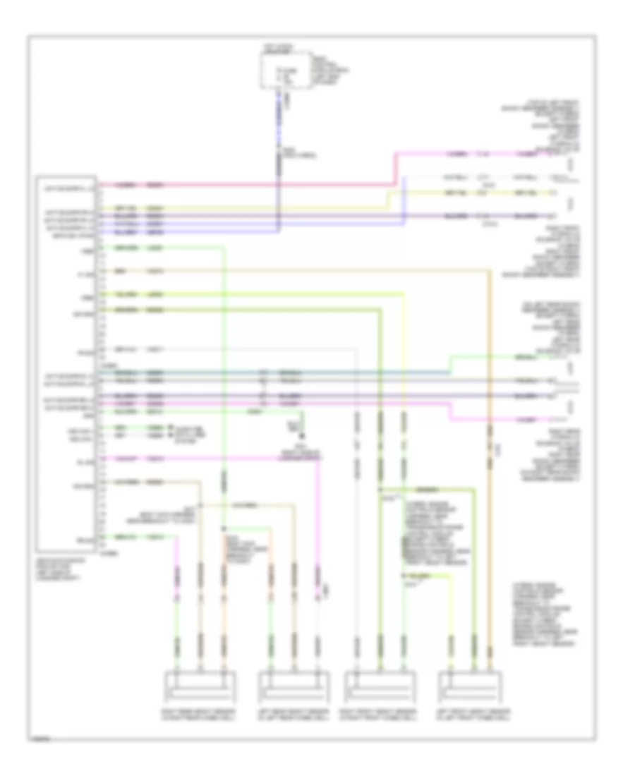
- Power steering control module (pscm)
- Proximity warning radar unit (w/ adaptive cruise) (left front of engine compt)
- S107
- S108
- S115 (engine controls sensor harness, near breakout to battery junction box)
- S116 (engine controls sensor harness, near breakout to battery junction box)
- S117
- S118 (engine controls sensor harness, near breakout to abs module)
- S137
- S138
- Splice block 18 (w/ touch screen display) (left side of dash)
- Splice block 20 (center of dash)
- Splice block 21 (center of dash)
- Splice block 39 (near base of right "b" pillar)
- Splice block 40 (right side of luggage compt)
- Splice block 59 (w/ rain sense) (top of right "a" pillar)
- Splice block 64 (phev)
- Splice block 8 (w/ 4.2 inch display)
- Steering column control module (sccm)
- Telematic control unit module (tcu)
- Used)
- Vdb25
- Vdb26
- Vdb29
- Vdb30
- W/ adaptive cruise
- W/ rain sense
- W/ sony
- W/ touch screen display
- W/o rain sense
- W/o sony
- W/o touch screen display
Computer Data Lines Wiring Diagram, Hybrid (3 of 3) for Ford Fusion S Hybrid 2014
List of elements for Computer Data Lines Wiring Diagram, Hybrid (3 of 3) for Ford Fusion S Hybrid 2014:
- (not used)
- C237
- C248
- C260
- C3052
- C311
- C312
- C501a
- C913
- Control module (sod-r)
- Driver door module (front of driver's door)
- Driver's seat module (under driver's seat)
- Front control interface module (center of dash)
- Global positioning system module (right end of dash)
- Left side obstacle detection control module (sod-l) (left rear corner of luggage compt)
- Ms can +
- Ms can + c2402a
- Ms can + c652a
- Ms can -
- Ms can - c341d
- Passenger door module (pdm)
- Radio transceiver module (rtm)
- Right side obstacle detection
- Splice block 15 (lower left side of dash)
- Splice block 16 (lower left side of dash)
- Splice block 32 (w/ blind spot) (left side of luggage compt)
- Splice block 33 (under driver's seat)
- Splice block 34 (base of left kick panel)
- Splice block 35 (left kick panel)
- Splice block 36 (right kick panel)
- Splice block 41 (w/ blind spot) (right side of luggage compt)
- Vdb06
- Vdb07
- W/ memory
- W/o memory
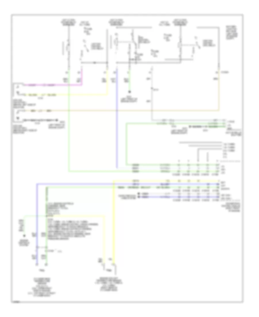
COOLING FAN
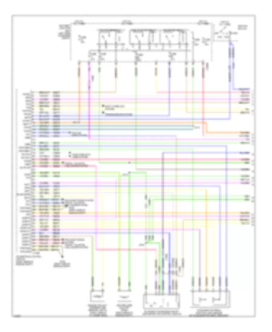
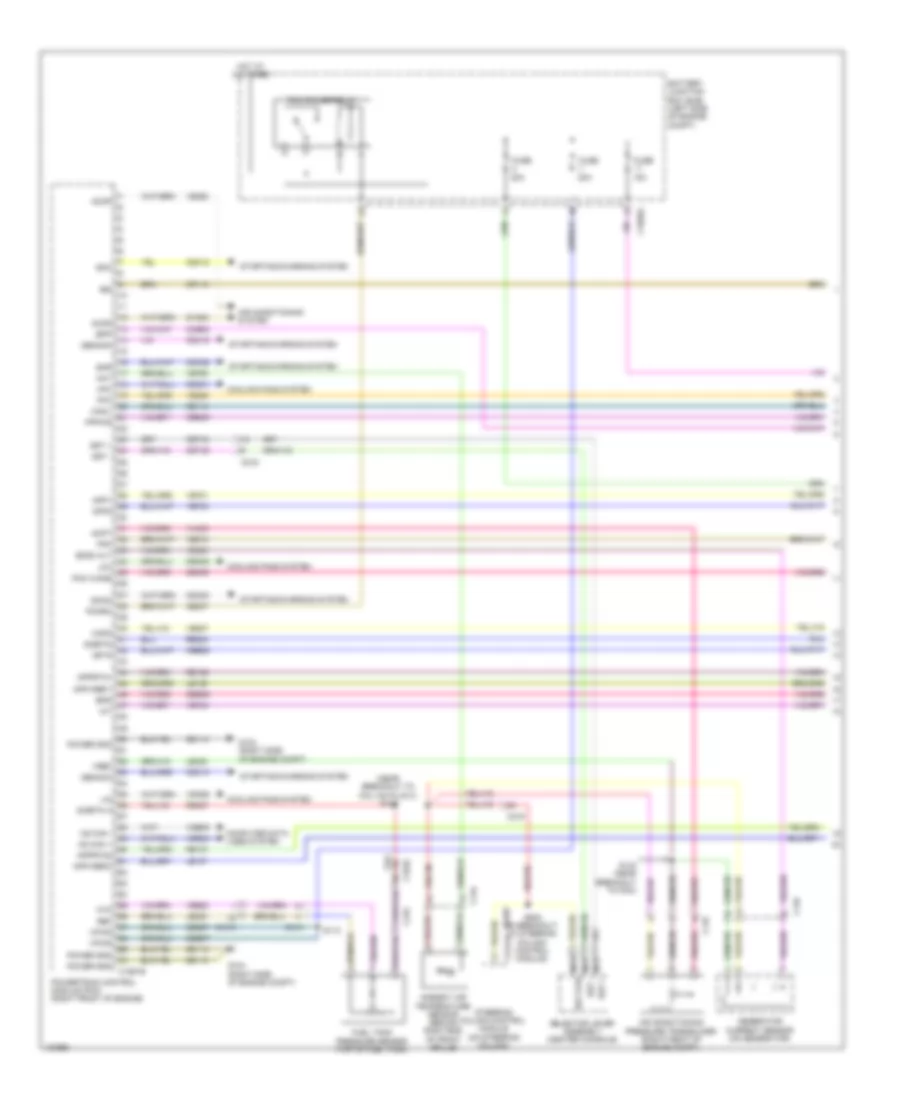
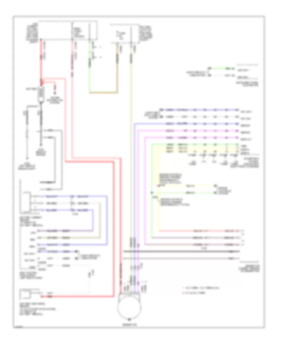
Cooling Fan Wiring Diagram, Except Hybrid for Ford Fusion S Hybrid 2014
List of elements for Cooling Fan Wiring Diagram, Except Hybrid for Ford Fusion S Hybrid 2014:
- (2.5l & 3.7l) s146
- (3.7l: engine controls harness, near breakout to coil on plug 3)
- (left front of engine compt)
- (or re405)
- 1.5l turbo
- 1.6l turbo
- 2.0l turbo
- 2.5l
- 3.7l
- Active grille shutter
- Battery junction box (bjb) (left side of engine compt)
- C1035a
- C1046
- C1232b
- C1232e
- C134
- C1381b
- C1381e
- C144
- C1551b
- C1551e
- C175b
- C175e
- C1915b
- C1915e
- Ce202
- Cec01
- Cht
- Computer data lines system
- Cooling fan motor 1 (behind left side of radiator)
- Cooling fan motor 2 (behind right side of radiator)
- Cylinder head temperature sensor (2.5l & 3.7l) (2.5l: upper right side of engine) (3.7l: top front of right cylinder bank)
- Ect
- Engine controls system
- Engine coolant temperature sensor (1.5l turbo, 1.6l turbo & 2.0l turbo) (right rear of cylinder head)
- Fan control (fc) relay
- Fuse 15a
- Fuse 20a
- Fuse 30a
- G100
- G101 (left front of engine compt)
- Gnd
- Hfc
- High fan control (hfc) relay
- Hot at all times
- Hot w/ pcm power relay energized
- Hs1 can +
- Hs1 can -
- Lfc
- Lin
- Low fan control (lfc) relay
- Powertrain control module (right front of engine)
- Re454
- S101
- S110
- S149 (2.0l turbo, 1.5l turbo & 1.6l turbo) (1.6l turbo: engine control wiring harness, near breakout to knock sensor 2) (1.5l turbo: engine controls harness, near breakout to coil on plug 1) (2.0l: engine controls harness, near breakout to manifold absolute pressure sensor)
- Sig rtn
- V pwr
- Vdb04
- Vdb05
- Vdn06
- Ve712
- Ve716
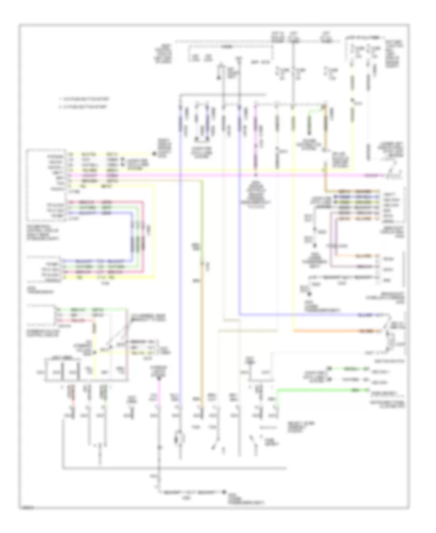
Cooling Fan Wiring Diagram, Hybrid for Ford Fusion S Hybrid 2014
List of elements for Cooling Fan Wiring Diagram, Hybrid for Ford Fusion S Hybrid 2014:
- (left front of engine compt)
- (left front of engine compt) g101
- (right front of engine compt) g106
- (top center of cylinder head)
- Active grille shutter (behind right end of grille)
- Battery junction box (left side of engine compt)
- C1026
- C1035a
- C134
- C146
- C1617k
- C175b
- C175e
- Cabin heater coolant pump (phev)
- Ch116
- Ch307
- Cht
- Computer data lines system
- Cooling fan motor (behind radiator)
- Cylinder head temperature sensor
- Ect2
- Electric motor coolant pump
- Engine coolant temperature 2 sensor (ect)
- Engine cooling fan relay
- Fcv
- Fuse 15a
- Fuse 20a
- Fuse 30a
- Fuse 50a
- G100
- G107
- Gnd
- Hcho
- Heater core shutoff (phev) (right rear of engine compt)
- High current battery junction box (bjb)
- Hot at all times
- Hot w/ pcm power relay energized
- Hs can +
- Hs can -
- Lin
- Powertrain control module (right rear of engine compt)
- Pwm
- Re141
- Re405
- S101
- S110
- S113
- S145 (on top of engine)
- Sig rtn
- Sigrtn
- Vbatt
- Vdb04
- Vdb05
- Vdn06
- Ve712
- Ve716
- Vec03
- Vpwr
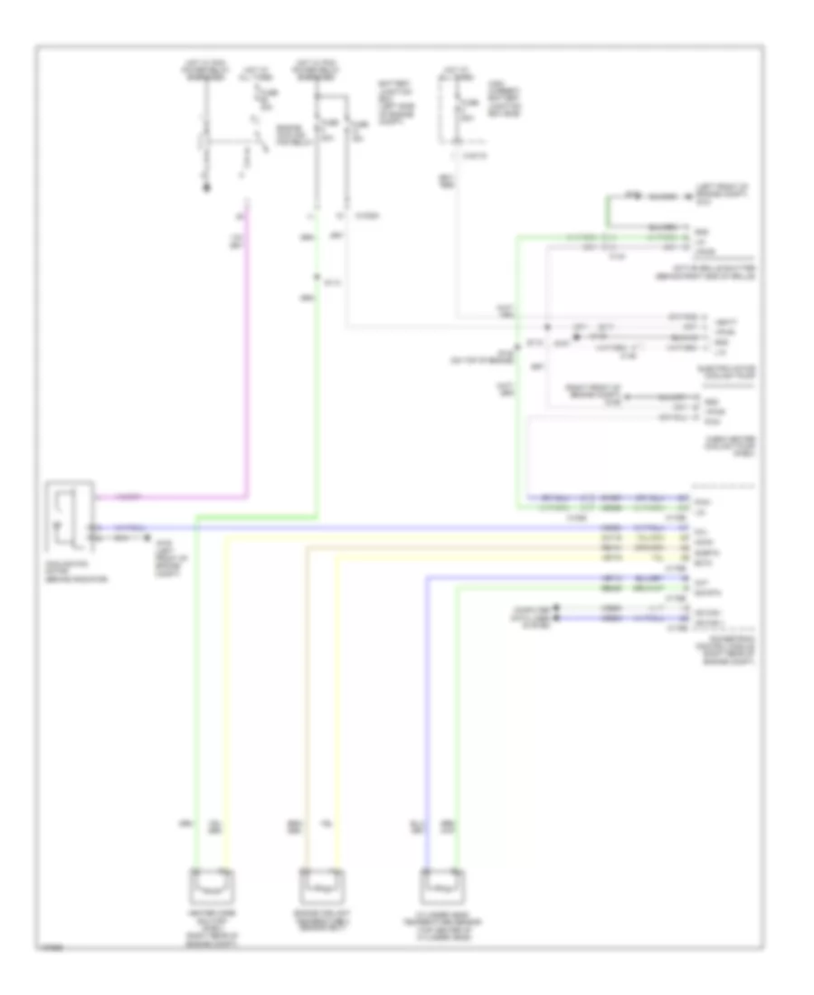
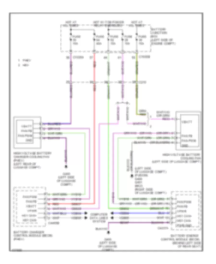
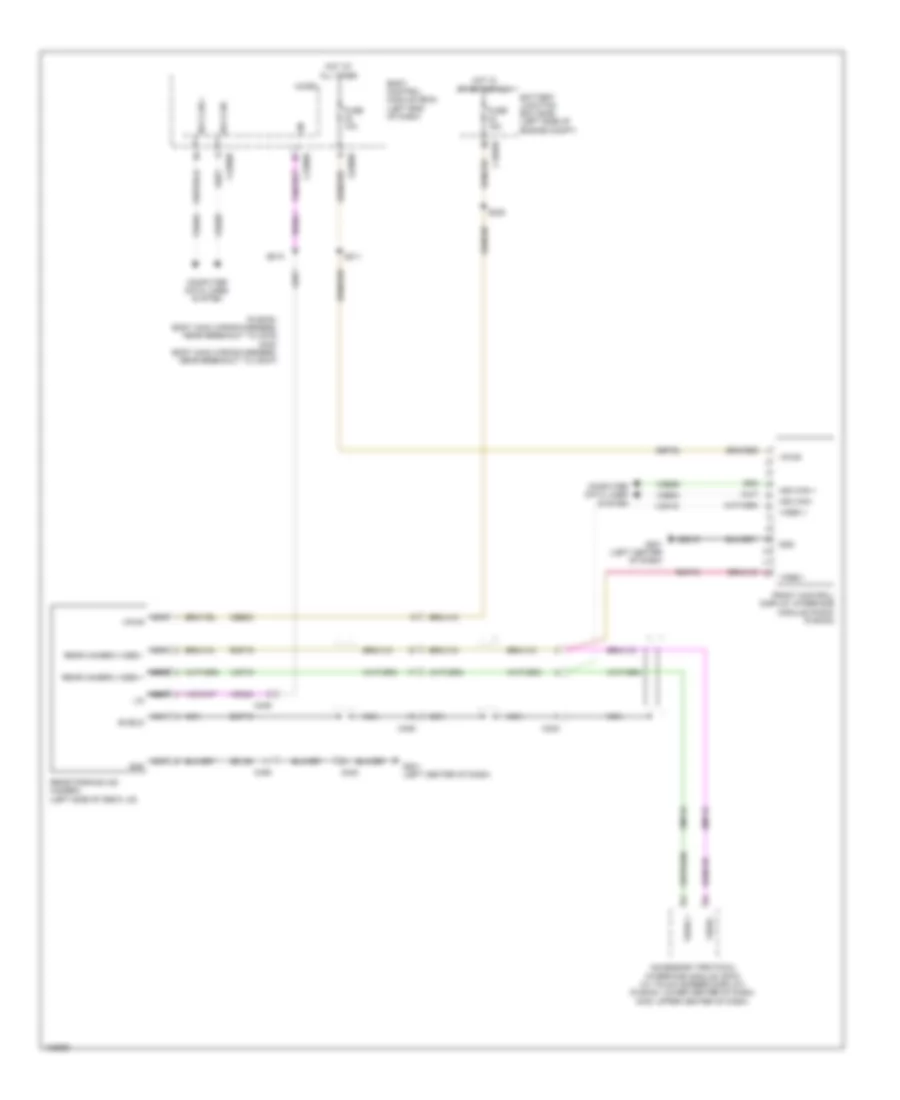
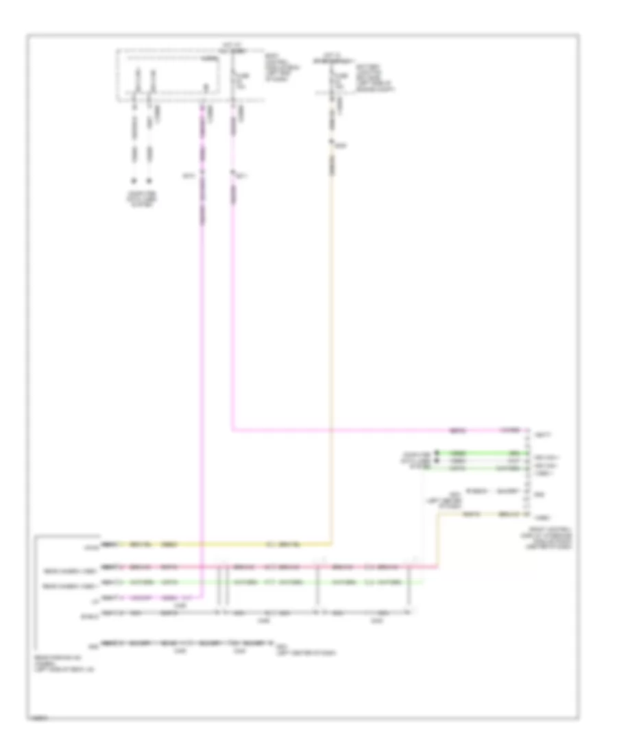
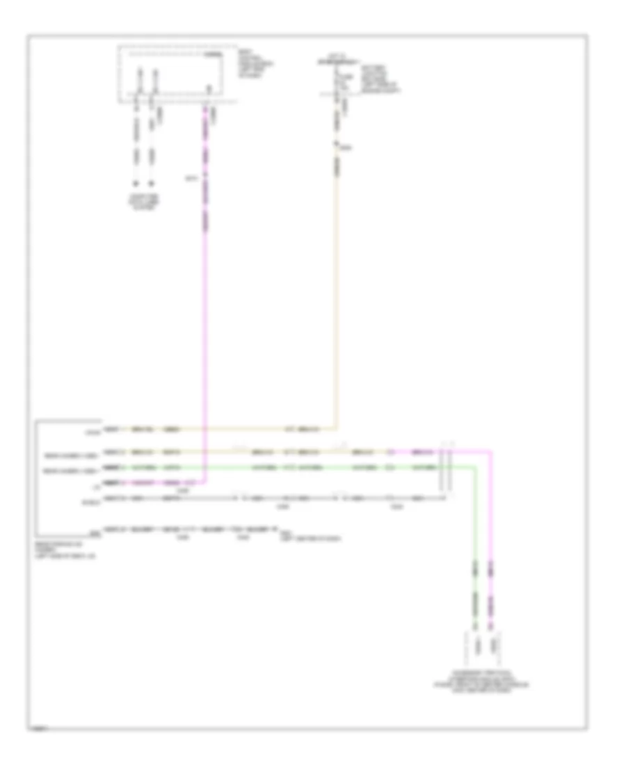
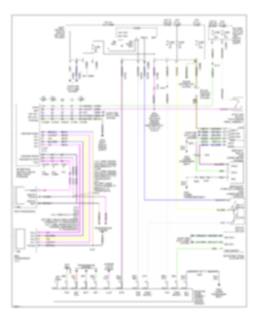
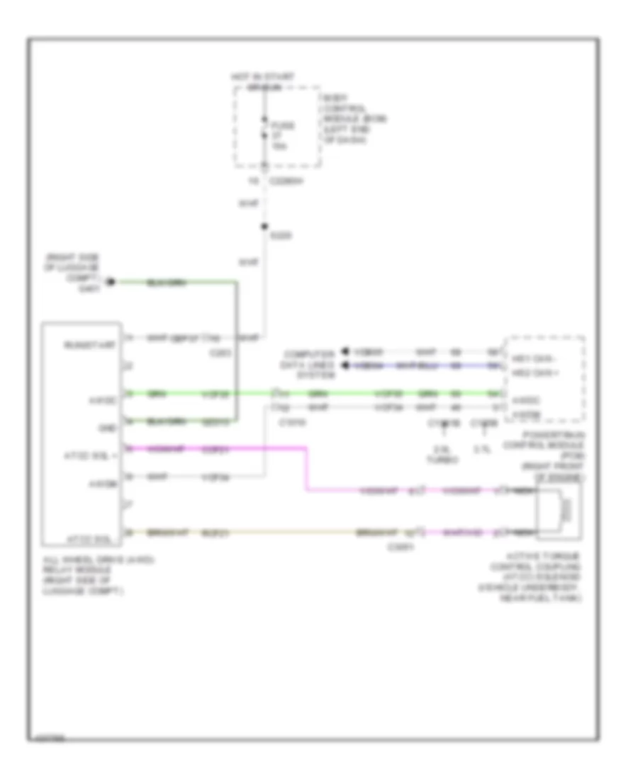
Hybrid Cooling Fan Wiring Diagram, Hybrid for Ford Fusion S Hybrid 2014
List of elements for Hybrid Cooling Fan Wiring Diagram, Hybrid for Ford Fusion S Hybrid 2014:
- (behind left side of rear seat)
- (left side of luggage compt) (fusion) g400 g401 (mkz) (right side of luggage compt)
- Battery charger control module (becm) (phev)
- Battery energy control module (becm)
- Battery junction box (left side of engine compt)
- C1035a
- C1035b
- C215
- C4237a
- C4455b
- Cbb29
- Cbb52
- Computer data lines system
- Fan fb
- Fan pwm
- Fuse 15a
- Fuse 40a
- G400 (left side of luggage compt)
- Gd347
- Gnd
- Hev
- High voltage battery charger cooling fan (phev) (left rear of luggage compt)
- High voltage battery cooling fan (left side of luggage compt)
- Hot at all times
- Hot w/ tcm power relay energized
- Hs1 can+
- Hs1 can-
- Phev
- Pwr gnd
- Red
- Sbb57
- Vbatt
- Vdb04
- Vdb05
- Vpwr
- Vyb18
- Vyb19
CRUISE CONTROL
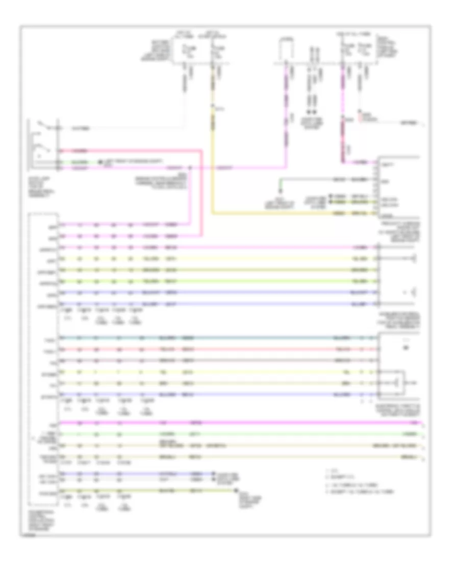
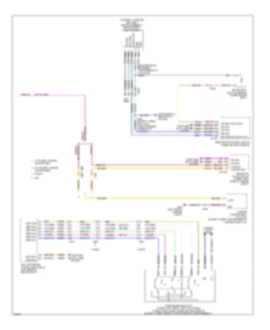
Cruise Control Wiring Diagram, Except Hybrid (1 of 2) for Ford Fusion S Hybrid 2014
List of elements for Cruise Control Wiring Diagram, Except Hybrid (1 of 2) for Ford Fusion S Hybrid 2014:
- (left front of engine compt) g101
- (or ret04)
- 1.5l
- 1.5l turbo
- 1.6l
- 1.6l turbo & 1.5l turbo
- 2.0l turbo
- 2.5l
- 3.7l
- Accelerator pedal position sensor (top of accelerator pedal assembly)
- App1
- App2
- Apprtn1
- Apprtn2
- Appvref1
- Appvref2
- Battery junction box (bjb) (left side of engine compt)
- Body control module (left end of dash)
- Bpp
- Bps
- C1035a
- C1035b
- C1232b
- C1232e
- C1381b
- C1381e
- C1551b
- C1551e
- C1551t
- C175b
- C175e
- C1915b
- C1915e
- C215
- C219
- C2280b
- C2280f
- C2280h
- Cbb23
- Ccb08
- Ce412
- Ce426
- Ces09
- Computer data lines system
- Electronic throttle control (etc) module (on throttle body)
- Etcref
- Etcrtn
- Except 1.6l turbo & 1.5l turbo
- Except 3.7l
- Fuse 10a
- Fuse 15a
- Fuse 7.5a
- G101 (left front of engine compt)
- G104 (right side of engine compt)
- Gd113
- Gd120
- Gnd
- Hot at all times
- Hot in start or run
- Hs can+
- Hs can-
- Hs1 can+
- Hs1 can-
- Hs2 can+
- Hs2 can-
- Le111
- Le134
- Le136
- Le137
- Micro
- Oss
- Powertrain control module (pcm) (right front of engine)
- Proximity warning radar unit (w/ adaptive cruise) (left front of engine compt)
- Pwr gnd
- Re134
- Re136
- Re137
- Ret24
- S114
- S204 (engine controls sensor harness, near breakout to coil on plug 3)
- S206 (fusion)
- S305
- Sbp32
- Stop lamp switch (top of brake pedal assembly)
- Tacm +
- Tacm -
- Tp1
- Tp2
- Trp
- Tss/oss/ tr gnd c175t
- Turbo
- Vbatt
- Vdb04
- Vdb05
- Vdb25
- Vdb26
- Ve701
- Ve702
- Ve818
- Ve819
- Vet26
- Vet32
- Vpwr
- Vref tss/oss/ tr vppwr
Cruise Control Wiring Diagram, Except Hybrid (2 of 2) for Ford Fusion S Hybrid 2014
List of elements for Cruise Control Wiring Diagram, Except Hybrid (2 of 2) for Ford Fusion S Hybrid 2014:
- (1.5l turbo & 2.0l turbo) (2.0l turbo: engine controls harness, near breakout to transmission)
- (1.5l turbo: engine controls harness, near breakout to c1386) (2.5l: battery cable wiring harness, in breakout to transmission) (2.0l turbo: engine controls harness, near breakout to transmission)
- (right center of dash) (mkz) splice block 26
- (steering wheel horn wiring harness, near breakout to clock spring)
- 2.0l turbo & 1.5l turbo
- 2.0l turbo, 1.5l turbo & 2.5l
- 2.5l
- 3.7l
- 6f35 transmission (left side of transmission)
- 6f50 transmission (left side of transmission)
- A/d channel 2
- A/d channel 3
- A/d channel 4
- A/d return
- C1520a
- C218b
- C218c
- C2414a
- C2414d
- Clock spring (behind steering wheel assembly)
- Cncl
- Computer data lines system
- Fusion
- G200 (in steering wheel)
- Gap dn
- Gap up
- Gd124
- Hs2 can+
- Hs2 can-
- Left lower steering wheel switch
- Left steering wheel switch
- Logic gnd
- Mkz
- Nca
- Off
- On/off
- Oss
- Oss/tr gnd
- Oss/tr pwr
- Res
- Res/ cncl
- S142
- S143
- S143 s141 (2.5l) (battery cable wiring harness, in breakout to transmission)
- S221 (mkz)
- S237
- S238
- S239
- Sbp13
- Set +
- Set -
- Sound systems
- Steering column control module (on steering column)
- Tr-p
- Transmissions system
- Trs
- Tss/oss gnd
- Tss/oss vpwr
- Vbatt
- Vdb25
- Vdb26
- W/ adaptive cruise control
- W/o adaptive cruise control
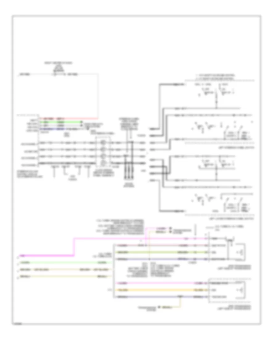
Cruise Control Wiring Diagram, Hybrid (1 of 2) for Ford Fusion S Hybrid 2014
List of elements for Cruise Control Wiring Diagram, Hybrid (1 of 2) for Ford Fusion S Hybrid 2014:
- (engine controls sensor harness, near breakout to c1010) s204
- (left rear of engine compt) anti-lock brake system (abs) control module
- (on left front hub assembly) left front wheel speed sensor
- (on left rear hub assembly) left rear wheel speed sensor
- (on right front hub assembly) right front wheel speed sensor
- (on right rear hub assembly) right rear wheel speed sensor
- (right side of engine compt) g105
- A/d channel 2
- A/d channel 3
- A/d channel 4
- A/d return
- Accelerator pedal position sensor (on accelerator pedal bracket)
- App rtn1
- App rtn2
- App1
- App2
- Appv ref1
- Appv ref2
- Battery junction box (bjb) (left side of engine compt)
- Bpp
- Bps
- C1010
- C1035a
- C175b
- C175e
- C215
- C218b
- C218c
- C2414a
- C2414d
- Ccb08
- Ce412
- Ce426
- Ces09
- Clock spring (behind steering wheel assembly)
- Computer data lines system
- Electronic throttle control (etc) module (on throttle body)
- Etc ref
- Etc rtn
- Fuse 10a
- Fuse 30a
- Fusion
- G102 (left front of engine compt)
- G200 (left center of dash)
- Gd113
- Gd121
- Gd124
- Gnd
- Hot at all times
- Hs can+
- Hs can-
- Hs2 can+
- Hs2 can-
- Le134
- Le136
- Le137
- Lf sens hi
- Lf sens lo
- Lr sens hi
- Lr sens lo
- Mkz
- Nca
- Powertrain control module (right rear of engine compt)
- Pwr gnd
- Rca17
- Rca18
- Rca19
- Rca20
- Re134
- Re136
- Re137
- Re406
- Red
- Rf sens hi
- Rf sens lo
- Rr sens hi
- Rr sens lo
- S141
- S221 (mkz)
- S237
- S238
- S239
- Sbb18
- Sbb69
- Sbp13
- Sig rtn
- Sound systems
- Steering column control module (sccm)
- Stop lamp switch (under left side of dash)
- Tacm +
- Tacm -
- Tp1
- Tp2
- Vbatt
- Vca03
- Vca04
- Vca05
- Vca06
- Vdb04
- Vdb05
- Vdb25
- Vdb26
- Ve701
- Ve702
- Ve818
- Ve819
Cruise Control Wiring Diagram, Hybrid (2 of 2) for Ford Fusion S Hybrid 2014
List of elements for Cruise Control Wiring Diagram, Hybrid (2 of 2) for Ford Fusion S Hybrid 2014:
- Battery junction box (bjb) (left side of engine compt)
- Body control module (left end of dash)
- Bpp
- C1035b
- C215
- C219
- C2280b
- C2280f
- C2280h
- Cbb23
- Ccb08
- Cncl
- Computer data lines system
- Fuse 10a
- Fuse 15a
- Fuse 7.5a
- Fusion
- G101 (left front of engine compt)
- Gap dn
- Gap up
- Gd120
- Gnd
- Hot at all times
- Hot in run or start
- Hs1 can+
- Hs1 can-
- Hs2 can+
- Hs2 can-
- Left lower steering wheel switch
- Left steering wheel switch
- Micro
- Mkz
- Off
- On/off
- Proximity warning radar unit (left front of engine compt)
- Red
- Res
- Res/ cncl
- S114
- S206 (fusion)
- S305
- Sbp32
- Set +
- Set -
- Splice block 26 (mkz) (lower center of dash)
- Vbatt
- Vdb04
- Vdb05
- Vdb25
- Vdb26
- Vpwr
- W/ adaptive cruise control
- W/o adaptive cruise control
DEFOGGERS
Defoggers Wiring Diagram for Ford Fusion S Hybrid 2014
List of elements for Defoggers Wiring Diagram for Ford Fusion S Hybrid 2014:
- (hybrid: front of driver's door) driver door module (ddm)
- (under driver's seat) g302
- Battery junction box (bjb) (left side of engine compt)
- Body control module (bcm) (left end of dash)
- C1035a
- C215
- C219
- C2280f
- C2402a
- C311 a16
- C312 a16
- C402a
- C402b
- C408
- C501a
- C501b
- C652a
- C652b
- Computer data lines system
- Crd02
- Crd13
- Front control interface module (center of dash)
- Fuse 30a
- Fuse 40a
- Fusion
- G303 (under passenger's seat)
- G401 (right side of luggage compt)
- Hot at all times
- Hot in run or start
- Htr
- Left exterior mirror
- Mkz
- Ms can+
- Ms can-
- Nca
- Passenger door module (pdm)
- Rear heated window element
- Rear window defrost relay
- Red
- Right exterior mirror
- S500
- S600
- Sbp25
- Sbp26
- Vbatt
- Vdb06
- Vdb07
ELECTRONIC POWER STEERING
Electronic Power Steering Wiring Diagram, Except Hybrid for Ford Fusion S Hybrid 2014
List of elements for Electronic Power Steering Wiring Diagram, Except Hybrid for Ford Fusion S Hybrid 2014:
- (left front of engine compt) g107
- 1.6l & 2.5l
- 2.0l, 1.5l & 3.7l
- Battery junction box (bjb) (left side of engine compt)
- C1035a
- C146
- C1463a
- C1463b
- C1617b
- C1716b
- Cbb19
- Computer data lines system
- Fuse 10a
- Fuse 70a
- Gd192
- High current battery junction box (left side of engine compt)
- Hot at all times
- Hot in run or start
- Hs can +
- Hs can -
- Motor
- Power steering control module (right rear of engine compt)
- Pwr gnd
- Sbf06
- Vbatt
- Vdb25
- Vdb26
- Vpwr
Electronic Power Steering Wiring Diagram, Hybrid for Ford Fusion S Hybrid 2014
List of elements for Electronic Power Steering Wiring Diagram, Hybrid for Ford Fusion S Hybrid 2014:
- Battery junction box (bjb) (left side of engine compt)
- C1035a
- C146
- C1463a
- C1463b
- C1617b
- Cbb19
- Computer data lines system
- Fuse 10a
- Fuse 70a
- G107
- Gd192
- High current battery junction box
- Hot at all times
- Hot in run or start
- Hs can +
- Hs can -
- Motor
- Power steering control module (pscm)
- Pwr gnd
- Sbf06
- Vbatt
- Vdb25
- Vdb26
- Vpwr
ELECTRONIC SUSPENSION
Electronic Suspension Wiring Diagram for Ford Fusion S Hybrid 2014
List of elements for Electronic Suspension Wiring Diagram for Ford Fusion S Hybrid 2014:
- (hybrid: engine controls sensor harness, near breakout to transmission range control module) (except hybrid: engine controls sensor harness, near breakout to left front height sensor)
- (on left rear shock absorber assembly) (except hybrid) left rear shock absorber (hybrid) left rear hydraulic solenoid valve
- (top of left front shock absorber assembly) (except hybrid) left front shock absorber (hybrid) left front hydraulic solenoid valve
- Active dmpr fl hi
- Active dmpr fl lo
- Active dmpr fr hi
- Active dmpr fr lo
- Active dmpr rl hi
- Active dmpr rl lo
- Active dmpr rr hi
- Active dmpr rr lo
- Body control module (bcm) (left end of dash)
- C1010
- C215
- C2280f
- C3051
- C4396c
- C4396d
- Cbp36
- Ccd03
- Ccd04
- Ccd05
- Ccd06
- Computer data lines system
- Engine controls sensor harness, near breakout to left front height sensor)
- Fl sig
- Fr sig
- Fuse 15a
- G401 (right side of luggage compt)
- Gd313
- Gnd
- Hot in run or start
- Hs2 can +
- Hs2 can -
- Isp-r (or vpwr)
- Lcd02
- Lcd23
- Left front height sensor (in left front wheelwell)
- Left rear height sensor (in left rear wheelwell)
- Rcd02
- Rcd03
- Rcd04
- Rcd05
- Rcd06
- Rcd23
- Right front height sensor (in right front wheelwell)
- Right front hydraulic solenoid valve (hybrid) right front shock absorber (except hybrid) (top of right front shock absorber assembly)
- Right rear height sensor (in right rear wheelwell)
- Right rear hydraulic solenoid valve (hybrid) right rear shock absorber (except hybrid) (on right rear shock absorber assembly)
- Rl sig
- Rr sig
- S121
- S122
- S323 (mkz hybrid)
- S417 (body main harness, near breakout to c3051)
- S418 (body main harness, near breakout to c3051)
- Sig gnd
- Vcd10
- Vcd11
- Vcd12
- Vcd13
- Vdb25
- Vdb26
- Vehicle dynamics module (vdm) (left side of luggage compt)
- Vref
ENGINE PERFORMANCE
1.5L TURBO
1.5L Turbo, Engine Performance Wiring Diagram (1 of 6) for Ford Fusion S Hybrid 2014
List of elements for 1.5L Turbo, Engine Performance Wiring Diagram (1 of 6) for Ford Fusion S Hybrid 2014:
- (not used)
- 10a
- Accr
- Air conditioning system
- Apprtn1
- Apprtn2
- Appvref1
- Appvref2
- Battery junction box (bjb) (left side of engine compt)
- C1010
- C1026
- C1035a
- C1915b
- C215
- C219
- C248
- C315
- Cact
- Canv
- Cbb26
- Cdc12
- Cdc15
- Cdc35
- Ce113
- Ce114
- Ce170
- Ce233
- Ce436
- Ce515
- Ce608
- Cec01
- Cec02
- Ch302
- Ch307
- Computer data lines system
- Cooling fans system
- Cpc
- Evapcp
- Fpc
- Fpm
- Fppwr
- Fprtn
- Fuel lvl2
- Fuel pump assembly (top of fuel tank)
- Fuel pump control module (left front of luggage compt)
- Fuel pump relay
- Fuel rtn
- Fuel sndr
- Fuel sndr sig
- Fuse
- Fuse 10a
- Fuse 15a
- Fuse 20a
- Fuse 30a
- G304 (left "c" pillar)
- Gd304
- Genmon
- Gnd
- Hfc
- Hot at all times
- Hot w/ run/ start relay energized
- Hs3 can +
- Hs3 can -
- Htr12
- Instrument panel cluster (ipc) module
- Isp-r
- Le136
- Le137
- Le230
- Le423
- Lfc
- Lin
- Nca
- Pcm power relay
- Pcm wake
- Power distribution system
- Powertrain control module (right front of engine)
- Re136
- Re137
- Re230
- Re242
- Re320
- Re406
- Re407
- Re515
- Return
- Rmc32
- Rmc33
- S415
- S419
- Sigrtn
- Smc
- Sme
- Smr
- Starting/ charging system
- Starting/charging system
- Vacc
- Vdb29
- Vdb30
- Vdn06
- Ve225
- Ve462
- Ve518
- Ve804
- Vmc11
- Vmc23
- Vpwr
- Vref
1.5L Turbo, Engine Performance Wiring Diagram (2 of 6) for Ford Fusion S Hybrid 2014
List of elements for 1.5L Turbo, Engine Performance Wiring Diagram (2 of 6) for Ford Fusion S Hybrid 2014:
- (engine controls sensor harness, near breakout to pcm)
- (engine controls sensor harness, near breakout to pcm) s134
- (instrument panel wiring harness, near breakout to g202)
- (not used)
- (right front of engine compt) air conditioning pressure transducer
- (right front of engine compt) charge air cooler coolant temperature sensor
- (right rear of engine) turbocharger boost pressure sensor
- (top of engine) fuel pressure sensor
- (top of fuel tank) (saddle tank) fuel level sensor
- (top of fuel tank) fuel tank pressure (ftp) sensor
- Accelerator pedal position sensor (top of accelerator pedal assembly)
- C1010
- C1026
- C145
- C219
- C315
- G101 (left front of engine compt)
- Intake air temperature sensor (left front of engine compt)
- Nca
- Pnk
- S105 (front park aid sensor harness, near breakout to active grille shutter)
- S131 (engine controls sensor harness, near breakout to pcm)
- S133
- S204 (engine controls sensor harness, near breakout to coil on plug 3)
- S205 (main wiring harness, in breakout to steering column control module)
- S214
- S216 (instrument panel wiring harness, near breakout to g202)
- Selector lever assembly (center console)
- Sst rtn
- Sst+
- Sst-
- Stop lamp switch (top of brake pedal assembly)
1.5L Turbo, Engine Performance Wiring Diagram (3 of 6) for Ford Fusion S Hybrid 2014
List of elements for 1.5L Turbo, Engine Performance Wiring Diagram (3 of 6) for Ford Fusion S Hybrid 2014:
- (behind right end of front grille) ambient air temperature sensor
- (engine controls sensor harness, near breakout to coil on plug 3) s126
- (on generator) generator current sensor
- Aat
- Acpt
- App1
- App2
- Bcs2 alt
- Body control module (left end of dash)
- Bpp
- Bps
- C1026
- C134
- C146
- C1915b
- C219
- C2280b
- C2280c
- C2280h
- Cbb07
- Ccb08
- Cdc10
- Cdc54
- Ce226
- Ce237
- Ce420
- Ce436
- Ces09
- Cet42
- Cet43
- Computer data lines system
- Flp
- Ftp
- Fuel pump (fet)
- G104 (right side of engine compt)
- Gd113
- Gencom
- Ho2s12
- Hs1 can+
- Hs1 can-
- Iat
- Micro
- Pcm rc
- Powertrain control module (right front of engine)
- Pwr gnd
- S112
- Smcs
- Sst+
- Sst-
- Starting/ charging system
- Tcbp
- Vbv
- Vdb04
- Vdb05
- Vdc61
- Ve701
- Ve702
- Ve727
- Ve731
- Ve740
- Ve750
- Ve803
- Ve922
- Vh433
- Vpwr
1.5L Turbo, Engine Performance Wiring Diagram (4 of 6) for Ford Fusion S Hybrid 2014
List of elements for 1.5L Turbo, Engine Performance Wiring Diagram (4 of 6) for Ford Fusion S Hybrid 2014:
- (in exhaust, downstream of catalytic converter) heated oxygen sensor 12
- (rear of exhaust manifold) universal heated oxygen sensor 11
- (right front side of cylinder head) variable camshaft timing solenoid 12
- (right rear of engine) evaporative emission purge valve
- (top left front of cylinder head) variable camshaft timing solenoid 11
- (top right side of engine) fuel injection pump
- (under right rear of vehicle) evap canister vent valve
- Atfpc
- Atfpm
- C1010
- C1026
- C1915e
- Ce205
- Ce206
- Ce207
- Ce208
- Ce226
- Ce304
- Ce305
- Ce412
- Ce426
- Cet05
- Cet07
- Cet09
- Cet49
- Cmp12
- Cop2d
- Cop3b
- Electronic throttle control (etc) (on throttle body)
- Evap vapor blocking valve
- Fvr
- Fvrrtn
- Inj1
- Inj1rtn
- Inj2
- Inj2rtn
- Inj3
- Inj3rtn
- Inj4
- Inj4rtn
- Ks1+
- Ks1-
- Le451
- Lpc
- Nca
- Power distribution system
- Powertrain control module (right front of engine)
- Re205
- Re206
- Re207
- Re208
- Re226
- Re323
- Re405
- S113
- S147
- Sigrtn
- Ssa
- Ssc
- Tacm+
- Tacm-
- Tft
- Tp1
- Tp2
- Tspc
- Uo2s11
- Uo2spc11
- Ve707
- Ve801
- Ve818
- Ve819
- Ve826
- Vet27
- Vyt11
- Vyt12
1.5L Turbo, Engine Performance Wiring Diagram (5 of 6) for Ford Fusion S Hybrid 2014
List of elements for 1.5L Turbo, Engine Performance Wiring Diagram (5 of 6) for Ford Fusion S Hybrid 2014:
- (bottom right side of engine) turbocharger bypass valve
- (left front of engine) charge air cooler pump
- (lower left front of engine) engine coolant pump clutch
- (right front of engine compt) active grill shutter
- (right rear of engine) turbocharger wastegate regulating valve solenoid
- (top left rear of engine) intake air temperature sensor 2
- (top of engine, above cylinder)
- (top right side of engine)
- C1026
- C134
- C139
- Coil on plug (cop) 1
- Coil on plug (cop) 2
- Coil on plug (cop) 3
- Coil on plug (cop) 4
- Fuel injector
- G110 (right front of engine)
- Gnd
- Knock sensor 1 (left rear of engine)
- Power distribution system
- Pump ctrl
- Pwr
- S110
- S144
- S148
- S151
1.5L Turbo, Engine Performance Wiring Diagram (6 of 6) for Ford Fusion S Hybrid 2014
List of elements for 1.5L Turbo, Engine Performance Wiring Diagram (6 of 6) for Ford Fusion S Hybrid 2014:
- (engine controls harness, near breakout to c1386)
- (engine controls harness, near breakout to coil on plug 1) s149
- (engine controls harness, near breakout to fuel rail pressure) s146
- (lower right front of engine block) crankshaft position sensor
- (near breakout to fuel rail pressure) s145
- (right rear of cylinder head) engine coolant temperature sensor
- (top front
- (top left front of engine) manifold absolute pressure & temperature sensor
- (top left rear of cylinder head) camshaft position sensor 11
- (top right rear of cylinder head) camshaft position sensor 12
- 6f35 transmission (con c1520a: left side of transmission) (con c1520b: rear of transmission)
- C1520a
- C1520b
- C1915e
- Cac
- Cact
- Ce174
- Ce235
- Ce258
- Ce303
- Ce306
- Ce421
- Ce422
- Ce460
- Cet05
- Cet06
- Cet07
- Cet08
- Cet09
- Cet10
- Cet18
- Cet49
- Ckp
- Cmc24
- Cmp11
- Cop1a
- Cop4c
- Cpc
- Ect
- Etcref
- Etcrtn tss/oss/ tr gnd map
- Frp
- Iat2
- Knock sensor 2 (left front of engine)
- Ks2+
- Ks2-
- Le111
- Le134
- Le238
- Le423
- Le448
- Le452
- Le458
- Lpc
- Map
- Of engine) fuel rail pressure sensor
- Oil pressure switch (left front of engine)
- Ops
- Oss
- Oss/tr gnd
- Oss/tr vpwr
- Powertrain control module (right front of engine)
- Re134
- Re324
- Re454
- Ret24
- S142
- S143
- S150
- Sigrtn
- Ssa
- Ssb
- Ssc
- Ssd
- Sse
- Tcby
- Tcc
- Tcwrvs
- Tft
- Tft sig rtn
- Tr-p
- Trs
- Tspc
- Tss
- Tss gnd
- Tss vpwr
- Tss/oss/ tr vpwr cscct
- Uo2sgref11
- Uo2shtr11
- Uo2spct11
- Vct11
- Vct12
- Ve706
- Ve711
- Ve716
- Ve759
- Ve781
- Ve802
- Ve804
- Ve836
- Vet26
- Vet27
- Vet32
- Vet33
- Vref
1.6L TURBO
1.6L Turbo, Engine Performance Wiring Diagram (1 of 7) for Ford Fusion S Hybrid 2014
List of elements for 1.6L Turbo, Engine Performance Wiring Diagram (1 of 7) for Ford Fusion S Hybrid 2014:
- Aat
- Accr
- Acpt
- Air conditioning
- Air conditioning system
- App1
- App2
- Apprtn 1
- Apprtn 2
- Appvref1
- Appvref2
- Battery junction box (bjb) (left side of engine compt)
- C1010
- C1026
- C1035a
- C1232b
- Cact
- Canv
- Cbb26
- Cdc12
- Cdc15
- Cdc35
- Ce113
- Ce114
- Ce233
- Ce237
- Ce436
- Cec01
- Cec02
- Cet47
- Ch302
- Cooling fans system
- Cpp1
- Cpp2
- Cr115
- Evap canister vent valve (under right rear of vehicle)
- Evap vapor blocking valve
- Evapcp
- Exterior lights system
- Fpc
- Fpm
- Fuse 10a
- Fuse 15a
- Fuse 20a
- Genmon
- Hfc
- Ho2s12
- Hot at all times
- Hot in run or start
- Htr12
- Ies
- Ispr
- Le136
- Le137
- Le230
- Le423
- Le424
- Le456
- Le458
- Lfc
- Lin
- Pcm power relay
- Pcm rc
- Pcm-wake
- Powertrain control module (pcm) (right front of engine)
- Re136
- Re137
- Re230
- Re242
- Re332
- Re335
- Re403
- Re407
- S110
- S113
- S315
- Sigrtn
- Smc
- Smr
- Starting/charging system
- System
- Vacc
- Vdn06
- Ve225
- Ve462
- Ve518
- Ve701
- Ve702
- Ve731
- Ve750
- Ve757
- Vh433
- Vref
1.6L Turbo, Engine Performance Wiring Diagram (2 of 7) for Ford Fusion S Hybrid 2014
List of elements for 1.6L Turbo, Engine Performance Wiring Diagram (2 of 7) for Ford Fusion S Hybrid 2014:
- (behind right end of front grille) ambient air temperature (aat) sensor
- (engine controls sensor harness, near breakout to anti-lock brake system module)
- (engine controls sensor harness, near breakout to coil on plug 3)
- (engine controls sensor harness, near breakout to pcm)
- (in exhaust, downstream of catalytic converter) heated oxygen sensor (ho2s) 12
- (right front of engine compt) a/c pressure transducer
- (right front of engine compt) turbocharger boost pressure/charge air coolant temperature (tcbp/cact) sensor
- Accelerator pedal position (app) sensor (left side of dash)
- C1010
- C1026
- C134
- C145
- C146
- C315
- Cact
- Clutch master cylinder push rod position sensor (on clutch master cylinder)
- Cpp1
- Cpp2
- Fuel pressure sensor (top of engine)
- Fuel tank pressure sensor (top of fuel tank)
- Nca
- S119
- S126
- S133
- Sigrtn
- Tcbp
- Vref
1.6L Turbo, Engine Performance Wiring Diagram (3 of 7) for Ford Fusion S Hybrid 2014
List of elements for 1.6L Turbo, Engine Performance Wiring Diagram (3 of 7) for Ford Fusion S Hybrid 2014:
- (right front of engine) powertrain control module (pcm)
- Bcs2alt
- Bpp
- Bps
- C1232b
- C146
- C1558a
- Cbb07
- Ccb08
- Cdc10
- Cdc54
- Ce420
- Ces09
- Computer data lines system
- Electronic throttle control (etc) (on throttle body)
- Exterior lights system
- Flp
- Ftp
- G101 (left front of engine compt)
- G104 (right side of engine compt)
- Gd113
- Gencom
- Generator
- Hs1 can +
- Hs1 can -
- Iat
- Knock sensor 1 (ks1) (left rear of engine)
- Knock sensor 2 (ks2) (left front of engine)
- Pwrgnd
- S112
- S204 (engine controls sensor harness, near breakout to coil on plug 3)
- Smcs
- Starting/ system charging
- Stop lamp switch (top of brake pedal assembly)
- Tcbp
- Vbv
- Vdb04
- Vdb05
- Vdc61
- Ve727
- Ve740
- Ve805
- Ve922
- Vpwr
1.6L Turbo, Engine Performance Wiring Diagram (4 of 7) for Ford Fusion S Hybrid 2014
List of elements for 1.6L Turbo, Engine Performance Wiring Diagram (4 of 7) for Ford Fusion S Hybrid 2014:
- (left front of engine compt) intake air temperature sensor
- (rear of engine) evaporative emission (evap) purge valve
- (rear of exhaust manifold) universal heated oxygen sensor (ho2s) 11
- (right front side of cylinder head) variable camshaft timing 12 (vct12) solenoid
- (top left front of cylinder head) variable camshaft timing 11 (vct11) solenoid
- C1026
- C1232e
- Ce205
- Ce206
- Ce207
- Ce208
- Ce226
- Ce412
- Ce426
- Fvr
- Fvrrtn
- Inj1
- Inj1 rtn
- Inj2
- Inj2 rtn
- Inj3
- Inj3 rtn
- Inj4
- Inj4 rtn
- Ks1+
- Ks1-
- Ks2+
- Ks2-
- Nca
- Powertrain control module (pcm) (right front of engine)
- Re205
- Re206
- Re207
- Re208
- Re226
- Re323
- Re324
- S147
- Tacm+
- Tacm-
- Ve801
- Ve802
1.6L Turbo, Engine Performance Wiring Diagram (5 of 7) for Ford Fusion S Hybrid 2014
List of elements for 1.6L Turbo, Engine Performance Wiring Diagram (5 of 7) for Ford Fusion S Hybrid 2014:
- (top of clutch pedal assembly) clutch pedal position switch (cpp)
- (top right side of engine)
- Battery junction box (bjb) (left side of engine compt)
- Body control module (left end of dash)
- C1010
- C1035a
- C1045
- C1617f
- C215
- C219
- C2280a
- C2280b
- C2280c
- C2280g
- C315
- Can - hs1
- Ce515
- Ce608
- Ce903
- Computer data lines system
- Fp pwr
- Fp rtn
- Fpc
- Fpm
- Fuel injector
- Fuel pump (fet)
- Fuel pump assembly (top of fuel tank)
- Fuel pump control module (left front of luggage compt)
- Fuel pump on (fet)
- Fuel pump relay
- Fuse 30a
- G101 (left front of engine compt)
- G304 (left "c" pillar)
- Gd304
- Gnd
- High current battery junction box (bjb) (left side of engine compt)
- Hot at all times
- Hs1 can +
- Mega fuse 125a
- Micro
- Nca
- Pcm wakeup (fet)
- Re515
- S120
- S415
- S419
- Vdb04
- Vdb05
- Ve225
- Ve518
- Vpwr
1.6L Turbo, Engine Performance Wiring Diagram (6 of 7) for Ford Fusion S Hybrid 2014
List of elements for 1.6L Turbo, Engine Performance Wiring Diagram (6 of 7) for Ford Fusion S Hybrid 2014:
- (engine control wiring harness, near breakout to knock sensor 2)
- (right rear of cylinder head) engine coolant temperature (ect) sensor
- (right side of engine) crankshaft position (ckp) sensor
- (top left front of engine) manifold absolute pressure (map) sensor
- (top left of engine) fuel rail pressure (frp) sensor
- (top left rear of cylinder head) camshaft position (cmp) sensor 11
- (top right rear of cylinder head) camshaft position (cmp) sensor 12
- C1026
- C248
- C315
- Computer data lines system
- Engine coolant valve (left front of engine)
- Engine cooling bypass solenoid (left rear of engine)
- Fuel injection pump (top right side of engine)
- Fuel level sensor (saddle tank) (top right side of engine)
- Fuel lvl 2
- Fuel rtn
- Fuel snd
- Instrument panel cluster module (ipc)
- Ms3 can +
- Ms3 can -
- Pnk
- Return
- S145
- S146
- S149 (engine control wiring harness, near breakout to knock sensor 2)
- S150 (engine controls harness, near breakout to crankshaft position sensor)
- S151
- S152
- Sig
- Turbocharger bypass valve (tcby) (bottom right side of engine)
- Turbocharger wastegate regulating valve solenoid (bottom right side of engine)
1.6L Turbo, Engine Performance Wiring Diagram (7 of 7) for Ford Fusion S Hybrid 2014
List of elements for 1.6L Turbo, Engine Performance Wiring Diagram (7 of 7) for Ford Fusion S Hybrid 2014:
- (top of engine, above cylinder 1, 2, 3 & 4)
- C1232e
- Ce166
- Ce167
- Ce235
- Ce303
- Ce304
- Ce305
- Ce306
- Ce421
- Ce422
- Ce460
- Ckp
- Cmc24
- Cmp11
- Cmp12
- Coil on plug (cop) 1
- Coil on plug (cop) 2
- Coil on plug (cop) 3
- Coil on plug (cop) 4
- Cop1a
- Cop2d
- Cop3b
- Cop4c
- Cvb
- Ect
- Etcref
- Etcrtn
- Frp
- G110 (right front of engine)
- Le134
- Le238
- Le423
- Le448
- Le451
- Le452
- Le458
- Map
- Oil pressure switch (left side of engine block)
- Ops
- Powertrain control module (pcm) (right front of engine)
- Re134
- Re238
- Re405
- Re429
- Re433
- Re454
- S144
- S148
- Sigrtn
- Tcby
- Tcwrvs
- Tp1
- Tp2
- Uo2s11
- Uo2sgref11
- Uo2shtr11
- Uo2spc11
- Uo2spct11
- Vct11
- Vct12
- Ve706
- Ve707
- Ve711
- Ve716
- Ve803
- Ve818
- Ve819
- Ve826
- Ve836
- Vref
2.0L HYBRID
2.0L Hybrid, Engine Performance Wiring Diagram (1 of 10) for Ford Fusion S Hybrid 2014
List of elements for 2.0L Hybrid, Engine Performance Wiring Diagram (1 of 10) for Ford Fusion S Hybrid 2014:
- Aat
- Acc run
- Accelerator pedal position (app) sensor (on accelerator pedal bracket)
- Acpt
- Air conditioning system trunk, tailgate, fuel doors system
- App1
- App2
- Apprtn1
- Apprtn2
- Appvref1
- Appvref2
- Battery junction box (left side of engine compt)
- Bpp
- Bps
- C1010
- C1026
- C1035a
- C175b
- C219
- Cbb07
- Cbb26
- Ccb08
- Cdc35
- Ce204
- Ce229
- Ce237
- Ce436
- Ces09
- Cet34
- Ch116
- Computer data lines system
- Cooling fans system
- Ect2
- Engine coolant temperature sensor 2 (ect2) (right side of cylinder head)
- Evapldp
- Evapldppr
- Evaporative emission (evap) leak detection control module
- Fcil
- Fcv
- Fpc
- Fpm
- Ftp
- Fuel pump (fp) relay
- Fuse 10a
- Fuse 15a
- Fuse 20a
- Fuse 30a
- G105 (right side of engine compt)
- Gd113
- Hcso
- Heater core shutoff (phev) (right rear of engine compt)
- Hot at all times
- Hs can+
- Hs can-
- Ignition switch
- Isp r
- Le136
- Le137
- Le230
- Le423
- Le424
- Off
- Pcm power relay
- Pcmrc
- Powertrain control module (right rear of engine compt)
- Pwm2
- Pwr gnd
- Re136
- Re137
- Re141
- Re230
- Re259
- Re335
- Re406
- Re407
- Ret57
- Run/start relay
- S112
- S113
- S141
- S315
- Sbb18
- Shift interlock system
- Sigrtn
- Start
- Tcs
- Tr rtn
- Transmissions system
- Trunk, tailgate, fuel doors system
- Vbatt
- Vdb04
- Vdb05
- Ve225
- Ve518
- Ve701
- Ve702
- Ve716
- Ve750
- Ve922
- Ve934
- Vec03
- Vet77
- Vh433
- Vpwr
- Vref
- Wake
2.0L Hybrid, Engine Performance Wiring Diagram (2 of 10) for Ford Fusion S Hybrid 2014
List of elements for 2.0L Hybrid, Engine Performance Wiring Diagram (2 of 10) for Ford Fusion S Hybrid 2014:
- (left "c" pillar) fuel pump control module
- (right front of engine compt) air conditioning pressure transducer
- (top of fuel tank) fuel pump assembly
- (top of fuel tank) fuel tank pressure (ftp) sensor
- (top of valve cover)
- Body control module (left end of dash)
- C1010
- C145
- C215
- C2280c
- C2280h
- C315
- Cdc35
- Cdc55
- Ce436
- Ce515
- Ce608
- Exterior lights system
- Fpc
- Fpm
- Fppwr
- Fprc
- Fprtn
- G304 (left "c" pillar)
- Gd304
- Gnd
- Hot at all times
- Ign rly ctrl
- Ignition coil on plug 1
- Ignition coil on plug 2
- Ignition coil on plug 3
- Ignition coil on plug 4
- Ignition transformer capacitor (top center of engine)
- Micro
- Nca
- Pcm wake up (fet)
- Re515
- S119 (engine controls sensor harness, near breakout to abs module)
- S144
- S204 (engine controls sensor harness, near breakout to c1010)
- S415
- S419
- Start
- Stop lamp switch (under left side of dash)
- Ve225
- Ve518
- Vpwr fuel
2.0L Hybrid, Engine Performance Wiring Diagram (3 of 10) for Ford Fusion S Hybrid 2014
List of elements for 2.0L Hybrid, Engine Performance Wiring Diagram (3 of 10) for Ford Fusion S Hybrid 2014:
- (left front of engine) knock sensor 1
- (left rear of engine) knock sensor 2
- (left side of fuel tank assembly) (hev) evaporative emission (evap) vapor blocking valve
- (left side of fuel tank assembly) (phev) fuel tank isolation valve
- (lower right front of engine block) crankshaft position sensor
- C1010
- C1026
- C146
- C168c
- C175t
- C248
- C315
- Camshaft position 11 (cmp11) sensor
- Ce303
- Ce304
- Ce305
- Ckp
- Cmp11
- Computer data lines system
- Cop1a
- Cop2d
- Cop3b
- Cop4c
- Fuel sender 1
- G105 (right side of engine compt)
- Gd113
- Gnd
- Hf35 transmission
- Hs3 can+
- Hs3 can-
- Instrument panel cluster
- Ks1+
- Ks1-
- Ks2+
- Ks2-
- Le111
- Le458
- Le459
- Let56
- Let57
- Powertrain control module (right rear of engine compt)
- Re135
- Re323
- Re324
- Re407
- Rtn
- Sender 1 fuel
- Sigrtn
- Tr a1 sig
- Tr a2 sig
- Tr ref
- Tr rtn
- Vb pwr
- Ve706
- Ve711
- Ve801
- Ve802
- Vref
2.0L Hybrid, Engine Performance Wiring Diagram (4 of 10) for Ford Fusion S Hybrid 2014
List of elements for 2.0L Hybrid, Engine Performance Wiring Diagram (4 of 10) for Ford Fusion S Hybrid 2014:
- (at charge port) (phev) charge port light ring
- (rear of left front fender) (phev) charge port
- 40a
- Batt
- Battery charger control module (bccm) (phev)
- Battery junction box (left side of engine compt)
- Body control module (left end of dash)
- C1035a
- C1035b
- C1824
- C215
- C2280f
- C4455a
- C4455b
- Cbb29
- Computer data lines system
- Cyb55
- Cyb56
- Cyd14
- Fan fb
- Fan pwm
- Fuse 10a
- Fuse 15a
- Fuse 40a
- G101 (left front of engine compt)
- G113 (base of left "a" pillar)
- G400 (fusion) g401 (mkz) (fusion: left side of luggage compt) (mkz: right side of luggage compt)
- G400 (left side of luggage compt)
- Gnd
- Hev
- High voltage battery charger cooling fan (phev) (left rear of luggage compt)
- High voltage battery cooling fan (left side of luggage compt)
- Hot at all times
- Hs can+
- Hs can-
- Hs1 can+
- Hs1 can-
- Hv (+)
- Hv (-)
- Hyb53
- Hyb54
- Inline fuse 1
- Inline fuse 2
- Phev
- Red
- Resistor
- Ryb57
- S999
- Sbb57
- Vbatt
- Vdb04
- Vdb05
- Vpwr
- Vyb18
- Vyb19
- Wake
2.0L Hybrid, Engine Performance Wiring Diagram (5 of 10) for Ford Fusion S Hybrid 2014
List of elements for 2.0L Hybrid, Engine Performance Wiring Diagram (5 of 10) for Ford Fusion S Hybrid 2014:
- (left side of engine compt) high voltage battery junction box
- (mkz: body harness, near breakout to c495) (fusion: near breakout to luggage compt lid latch) (phev) s407
- (phev) charge cooling actuator
- Battery energy control module (becm) (behind left side of rear seat)
- Body control module (left end of dash)
- C215
- C2280d
- C4236b
- C4236c
- C4237a
- C4237b
- C4815b
- C4815c
- C4815d
- C4815e
- C4816a
- C4816b
- Cbb52
- Cont pwr en
- Cr167
- Cs aout2
- Cs rtn
- Cs vref
- Ctrl
- Cyb03
- Cyb04
- Cyb10
- Cyb12
- Cyb13
- Cyc03
- Cyc04
- Cyc05
- Cyc06
- Cyc07
- Cyc08
- Cyc09
- Cyd14
- Dcdc winp
- Dcdc wkup
- Ens
- Fan fb
- Fan pwm
- Feedback
- G400 (left side of luggage compt)
- Gd347
- Gnd
- Hev
- High voltage traction battery temperature sensor
- Hs can+
- Hs can-
- Hs1 can+
- Hs1 can-
- Int+
- Int-
- Lines system computer data
- Lyc01
- Mc+ ctrl
- Mc-ctrl
- Micro
- Motor +
- Motor -
- Phev
- Prc ctrl
- Pwr gnd
- Ryb07
- Ryc01
- S235
- S415 (body main harness, near breakout to c315)
- Sbp14
- Temp rtn
- Temp sig
- Vbatt
- Vdb04
- Vdb05
- Vpwr
- Vyb07
- Vyb18
- Vyb19
- Vyc02
- Wake
2.0L Hybrid, Engine Performance Wiring Diagram (6 of 10) for Ford Fusion S Hybrid 2014
List of elements for 2.0L Hybrid, Engine Performance Wiring Diagram (6 of 10) for Ford Fusion S Hybrid 2014:
- (left side of engine compt) (hev) high voltage battery junction box
- (left side of engine compt) dual battery fuse assembly
- (not used)
- 125a (hev)
- 225a
- 30a
- Battery
- Battery junction box (left side of engine compt)
- Battery monitoring sensor (left rear of luggage compt)
- C1035b
- C1035c
- C1458a
- C1458e
- C1617a
- C1617e
- C1815a
- C1815b
- C4000
- C4001
- C4002
- C4236a
- C4236d
- C4236e
- C4453a
- C4453b
- C4453c
- C4453d
- Cabin coolant heater (phev)
- Cbb51
- Ce613
- Cyd14
- Dc/dc converter module
- Dcdc wkup
- Fuse 15a
- G404 (left rear of luggage compt)
- Hdc52
- Hdc53
- Hev
- High current battery junction box (bjb)
- High voltage battery
- High voltage battery service disconnect
- High voltage high current fuse (phev)
- Hs can+
- Hs can-
- Hv batt+
- Hv batt-
- Hv+
- Hv-
- Hyt01
- Hyt02
- Int+
- Int-
- Mega fuse 175a
- Midi fuse pnk 200a
- Midi fuse white 120a
- Nca
- Phev
- Positive pack relay
- Power distribution system
- Red
- S104
- Sbb18
- Sdc04
- Secondary on board diagnostic module c/ transmission control module (left side of engine compt)
- Tcm power relay
- Tcmrc
- Vbatt
- Vdb04
- Vdb05
- Vpwr
2.0L Hybrid, Engine Performance Wiring Diagram (7 of 10) for Ford Fusion S Hybrid 2014
List of elements for 2.0L Hybrid, Engine Performance Wiring Diagram (7 of 10) for Ford Fusion S Hybrid 2014:
- Battery compartment thermistor 1
- Battery compartment thermistor 10
- Battery compartment thermistor 2
- Battery compartment thermistor 3
- Battery compartment thermistor 4
- Battery compartment thermistor 5
- Battery compartment thermistor 6
- Battery compartment thermistor 7
- Battery compartment thermistor 8
- Battery compartment thermistor 9
- Battery energy control module (becm) (behind left side of rear seat)
- C4237c
- C4237d
- Hev
- Ryb33
- Ryb34
- Ryb35
- Ryb36
- Ryb37
- Ryb38
- Ryb39
- Ryb40
- Ryb41
- Ryb42
- Temp rtn
- Temp sig
- Vyb33
- Vyb34
- Vyb35
- Vyb36
- Vyb37
- Vyb38
- Vyb39
- Vyb40
- Vyb41
- Vyb42
2.0L Hybrid, Engine Performance Wiring Diagram (8 of 10) for Ford Fusion S Hybrid 2014
List of elements for 2.0L Hybrid, Engine Performance Wiring Diagram (8 of 10) for Ford Fusion S Hybrid 2014:
- Battery compartment thermistor 1
- Battery compartment thermistor 10
- Battery compartment thermistor 11
- Battery compartment thermistor 2
- Battery compartment thermistor 3
- Battery compartment thermistor 4
- Battery compartment thermistor 5
- Battery compartment thermistor 6
- Battery compartment thermistor 7
- Battery compartment thermistor 8
- Battery compartment thermistor 9
- Battery energy control module (becm) (behind left side of rear seat)
- C4816c
- C4816d
- Phev
- Ryb33
- Ryb34
- Ryb35
- Ryb36
- Ryb37
- Ryb38
- Ryb39
- Ryb40
- Ryb41
- Ryb42
- Ryb43
- Ryb44
- Ryb45
- Ryb46
- Ryb47
- Ryb48
- Temp rtn
- Temp sig
- Vyb33
- Vyb34
- Vyb35
- Vyb36
- Vyb37
- Vyb38
- Vyb39
- Vyb40
- Vyb41
- Vyb42
- Vyb43
- Vyb44
- Vyb45
- Vyb46
- Vyb47
- Vyb48
2.0L Hybrid, Engine Performance Wiring Diagram (9 of 10) for Ford Fusion S Hybrid 2014
List of elements for 2.0L Hybrid, Engine Performance Wiring Diagram (9 of 10) for Ford Fusion S Hybrid 2014:
- (exhaust manifold) universal heated oxygen sensor (ho2s) 11
- (left end of dash) body control module
- (on throttle body) electronic throttle control (etc) module
- (top center of cylinder head) cylinder head temperature sensor
- 30a
- Battery compartment thermistor 12
- Battery compartment thermistor 13
- Battery compartment thermistor 14
- Battery compartment thermistor 15
- C2280d
- C4815a
- C4815f
- C4815g
- C4815h
- C4815i
- Charge relay +
- Charge relay -
- Evaporative emission (evap) purge valve (left rear of engine)
- Heated oxygen sensor (ho2s) 12 (exhaust manifold)
- High voltage battery junction box (phev) (left side of engine compt)
- Hv batt-
- Lin 8
- Micro
- Nca
- Positive pack relay
- Pre charge relay
- Resistor 27 ohm
- Variable camshaft timing (vct11) solenoid 11 (top front of cylinder head)
- Vdn03
2.0L Hybrid, Engine Performance Wiring Diagram (10 of 10) for Ford Fusion S Hybrid 2014
List of elements for 2.0L Hybrid, Engine Performance Wiring Diagram (10 of 10) for Ford Fusion S Hybrid 2014:
- (left side of engine) manifold absolute pressure sensor
- (not used) c1026
- (on top of the engine, left of fuel injector 4 breakout)
- (top of engine)
- (top rear of engine) egr stepper motor
- Battery compartment thermistor 16
- C1026
- C175e
- Cabin heater coolant pump
- Ce101
- Ce102
- Ce103
- Ce104
- Ce113
- Ce205
- Ce206
- Ce207
- Ce208
- Ce233
- Ce235
- Ce347
- Ce412
- Ce420
- Ce421
- Ce426
- Ce622
- Ce908
- Ch307
- Cht
- Cmp08
- Coil 1
- Coil 2
- Coil 3
- Coil 4
- Cooling fans system
- Cto
- Digital
- Egrmc1
- Egrmc2
- Egrmc3
- Egrmc4
- Etcref
- Etcrtn
- Evapcp
- Evapldpsv
- Ffduc
- Fuel injector
- Ho2s12
- Htr12
- Iat
- Inj1
- Inj2
- Inj3
- Inj4
- Le134
- Le423
- Le448
- Le451
- Le452
- Lin
- Maf
- Map
- Mass air flow/intake air temperature (maf/iat) sensor (on throttle body)
- Oil pressure switch (oil filter housing)
- Ops
- Pasf+
- Powertrain control module (right rear of engine compt)
- Pwm
- Re134
- Re320
- Re329
- Re405
- Re406
- S120
- S147
- S153
- Sigrtn
- Tacm+
- Tacm-
- Tp1
- Tp2
- Transmissions system
- Trunk, tailgate, fuel doors system
- Uo2s11
- Uo2sgref11
- Uo2shtr11
- Uo2spc11
- Uo2spct11
- Vbv
- Vct11
- Vdn06
- Ve712
- Ve731
- Ve740
- Ve803
- Ve807
- Ve818
- Ve819
- Ve826
- Vmc02
- Vref
- Vref 5v
2.0L TURBO
2.0L Turbo, Engine Performance Wiring Diagram (1 of 6) for Ford Fusion S Hybrid 2014
List of elements for 2.0L Turbo, Engine Performance Wiring Diagram (1 of 6) for Ford Fusion S Hybrid 2014:
- (engine controls sensor harness, near breakout to anti-lock brake system module) s120
- 10a
- Accr
- Air conditioning system
- Apprtn1
- Apprtn2
- Appvref1
- Appvref2
- Awd-m
- Battery junction box (bjb) (left side of engine compt)
- C1010
- C1026
- C1035a
- C1381b
- C215
- C219
- C248
- C315
- Cact
- Can v
- Cbb26
- Cdc12
- Cdc15
- Cdc35
- Ce113
- Ce114
- Ce233
- Ce436
- Ce515
- Ce608
- Cec01
- Cec02
- Ch302
- Computer data lines system
- Cooling fans system
- Cr115
- Evapcp
- Fp pwr
- Fp rtn
- Fpc
- Fpm
- Fuel lvl2
- Fuel pump (fp) assembly (top of fuel tank)
- Fuel pump control module (left front of luggage compt)
- Fuel pump relay
- Fuel rtn
- Fuel sndr
- Fuse
- Fuse 10a
- Fuse 15a
- Fuse 20a
- Fuse 30a
- G304 (left "c" pillar)
- Gd304
- Genmon
- Gnd
- Hfc
- Hot at all times
- Hot in start or run
- Hs3 can +
- Hs3 can -
- Htr12
- Ies
- Instrument panel cluster (ipc) module
- Isp-r
- Le136
- Le137
- Le230
- Le423
- Le424
- Lfc
- Lin
- Nca
- Pcm power relay
- Pcm wake
- Powertrain control module (pcm) (right front of engine)
- Re136
- Re137
- Re230
- Re242
- Re332
- Re406
- Re407
- Re515
- Return
- S415
- S419
- Sig
- Sigrtn
- Smc
- Smr
- Starting/ charging system
- Transmissions system
- Vacc
- Vcf34
- Vdn06
- Ve225
- Ve462
- Ve518
- Vpwr
- Vref
2.0L Turbo, Engine Performance Wiring Diagram (2 of 6) for Ford Fusion S Hybrid 2014
List of elements for 2.0L Turbo, Engine Performance Wiring Diagram (2 of 6) for Ford Fusion S Hybrid 2014:
- (engine controls sensor harness, near breakout to anti- lock brake system module)
- (engine controls sensor harness, near breakout to pcm)
- (engine controls sensor harness, near breakout to pcm) s134
- (instrument panel wiring harness, near breakout to g202)
- (right front of engine compt) air conditioning (a/c) pressure transducer
- (right front of engine compt) turbocharger boost pressure/charge air cooler temperature (tcbp/cact) sensor
- (top of engine) fuel pressure sensor
- (top of fuel tank) fuel level sensor
- (top of fuel tank) fuel tank pressure (ftp) sensor
- Accelerator pedal position (app) sensor (top of accelerator pedal assembly)
- C1010
- C145
- C218b
- C218c
- C2414a
- C2414d
- C315
- Cact
- Cet42
- Cet43
- Clockspring (behind steering wheel assembly)
- Computer data lines system
- G101 (left front of engine compt)
- Hs2 can+
- Hs2 can-
- Intake air temperature (iat) sensor (left front of engine compt)
- Nca
- Nca sst rtn
- Nca sst+
- Pnk
- Re407
- S119
- S131 (engine controls sensor harness, near breakout to pcm)
- S133
- S204
- S205
- S214
- S216
- Selector lever assembly (fusion) (center console)
- Sigrtn
- Sst-
- Steering column control module (sccm) (on steering column)
- Stop lamp switch (top of brake pedal assembly)
- Tcbp
- Vdb25
- Vdb26
- Vref
2.0L Turbo, Engine Performance Wiring Diagram (3 of 6) for Ford Fusion S Hybrid 2014
List of elements for 2.0L Turbo, Engine Performance Wiring Diagram (3 of 6) for Ford Fusion S Hybrid 2014:
- (behind right end of front grille) ambient air temperature (aat) sensor
- (engine controls sensor harness, near breakout to coil on plug 3) s126
- (not used)
- (on generator) generator current sensor
- Aat
- Acpt
- App1
- App2
- Awd-c
- Bcs2 alt
- Body control module (bcm) (left end of dash)
- Bpp
- Bps
- C134
- C1381b
- C146
- C1716f
- C219
- C2280a
- C2280b
- C2280c
- C2280h
- Cbb07
- Ccb08
- Cdc10
- Cdc54
- Ce237
- Ce420
- Ces09
- Cet42
- Cet43
- Computer data lines system
- Evap
- Flp
- Ftp
- Fuel pump (fet)
- Fuel pump on (fet)
- Fuse 5a
- G104 (right side of engine compt)
- Gd113
- Gear shift module (gsm) (upper center of dash)
- Gencom
- High current battery junction box (bjb) (left side of engine compt)
- Ho2s12
- Hot at all times
- Hs1 can+
- Hs1 can-
- Iat
- Mega fuse 125a
- Micro
- Nca
- Pcm rc
- Pcm wake up (fet)
- Powertrain control module (pcm) (right front of engine)
- Pwr 2
- Pwr gnd
- S112
- Smcs
- Sst+
- Sst-
- Starting/charging system
- Tcbp
- Transmissions system
- Vcf35
- Vdb04
- Vdb05
- Vdc61
- Ve701
- Ve702
- Ve727
- Ve731
- Ve740
- Ve750
- Ve805
- Ve922
- Vet77
- Vh433
- Vpwr
2.0L Turbo, Engine Performance Wiring Diagram (4 of 6) for Ford Fusion S Hybrid 2014
List of elements for 2.0L Turbo, Engine Performance Wiring Diagram (4 of 6) for Ford Fusion S Hybrid 2014:
- (engine controls harness, near breakout to coil on plug 1) s147
- (in exhaust, downstream of catalytic converter) heated oxygen sensor (ho2s) 12
- (not used)
- (not used) c1026
- (rear of engine) evaporative emission (evap) purge valve
- (rear of exhaust manifold) universal heated oxygen sensor (ho2s) 11
- (top front of cylinder head) variable camshaft timing 11 (vct11) solenoid
- (top front of cylinder head) variable camshaft timing 12 (vct12) solenoid
- (top rear of engine) fuel injection pump
- Atfpc
- Atfpm
- C1010
- C1026
- C1381e
- Ce205
- Ce206
- Ce207
- Ce208
- Ce226
- Ce304
- Ce305
- Ce412
- Ce426
- Cet05
- Cet07
- Cet09
- Cet49
- Cmp12
- Cop2d
- Cop3b
- Electronic throttle control (etc) (on throttle body)
- Evap canister purge valve
- Evap purge valve
- Fvr
- Fvrrtn
- Inj1
- Inj1rtn
- Inj2
- Inj2rtn
- Inj3
- Inj3rtn
- Inj4
- Inj4rtn
- Ks1+
- Ks1-
- Le451
- Lpc
- Nca
- Powertrain control module (pcm) (right front of engine)
- Re205
- Re206
- Re207
- Re208
- Re226
- Re323
- Re405
- S113
- S315
- Sigrtn
- Ssa
- Ssc
- Tacm+
- Tacm-
- Tft
- Tp1
- Tp2
- Tspc
- Uo2s11
- Uo2spc11
- Ve707
- Ve801
- Ve818
- Ve819
- Ve826
- Vet27
- Vyt11
- Vyt12
2.0L Turbo, Engine Performance Wiring Diagram (5 of 6) for Ford Fusion S Hybrid 2014
List of elements for 2.0L Turbo, Engine Performance Wiring Diagram (5 of 6) for Ford Fusion S Hybrid 2014:
- (engine controls harness, near breakout to crankshaft position sensor) s151
- (if equipped) left paddle shifter
- (if equipped) right paddle shifter
- (lower right front of engine) turbocharger (tc) wastegate regulating valve solenoid
- (right front of engine compt) active grill shutter
- (steering wheel horn wiring harness, near breakout to clockspring) s296
- (top center of engine) turbocharger bypass valve (tcby)
- (top left side of engine)
- (top of engine, above cylinder 1, 2, 3, & 4)
- (upper right side of engine) cylinder head temperature (cht) sensor
- C1026
- C1033
- C134
- Coil on plug (cop) 1
- Coil on plug (cop) 2
- Coil on plug (cop) 3
- Coil on plug (cop) 4
- Fuel injector
- G110 (right front of engine)
- Interior lights system
- Knock sensor 1 (ks1) (left front of engine)
- Nca
- Pnk
- Power distribution system
- S110
- S144
- S148
- S293
- S294
2.0L Turbo, Engine Performance Wiring Diagram (6 of 6) for Ford Fusion S Hybrid 2014
List of elements for 2.0L Turbo, Engine Performance Wiring Diagram (6 of 6) for Ford Fusion S Hybrid 2014:
- (engine controls harness, near breakout to coil on plug 1) s146
- (engine controls harness, near breakout to manifold absolute pressure sensor) s149
- (engine controls harness, near breakout to transmission)
- (engine controls harness, near breakout to variable camshaft timing 12 solenoid) s150
- (lower right front of engine block) crankshaft position (ckp) sensor
- (near breakout to coil on plug 4) s145
- (not used)
- (right rear of cylinder head) engine coolant temperature (ect) sensor
- (top front of engine) fuel rail pressure (frp) sensor
- (top left front of engine) manifold absolute pressure (map) sensor
- (top left rear of cylinder head) camshaft position 11 (cmp11) sensor
- (top left rear of cylinder head) camshaft position 12 (cmp12) sensor
- 6f35 transmission (con c1520a: left side of transmission) (con c1520b: rear of transmission)
- C1026
- C1033
- C1381e
- C1520a
- C1520b
- Ce148
- Ce235
- Ce239
- Ce303
- Ce306
- Ce421
- Ce422
- Ce460
- Cet05
- Cet06
- Cet07
- Cet08
- Cet09
- Cet10
- Cet18
- Cet49
- Cht
- Ckp
- Cmc24
- Cmp11
- Cop1a
- Cop4c
- Ect
- Etcref
- Etcrtn tss/oss/ tr gnd map
- Frp
- Knock sensor 2 (ks2) (left rear of engine)
- Ks2+
- Ks2-
- Le111
- Le134
- Le238
- Le423
- Le448
- Le452
- Le458
- Lpc
- Oil pressure switch (oil filter housing)
- Ops
- Oss
- Oss/tr gnd
- Oss/tr vpwr
- Pm htr
- Powertrain control module (pcm) (right front of engine)
- Re134
- Re324
- Re454
- Ret24
- S142 (engine controls harness, near breakout to transmission)
- S143
- Sigrtn
- Ssa
- Ssb
- Ssc
- Ssd
- Sse
- Tcby
- Tcc
- Tcwrvs
- Tft
- Tft sig rtn
- Tr-p
- Trs
- Tspc
- Tss
- Tss/gnd
- Tss/oss/ tr vpwr
- Tss/vpwr
- Uo2sgref11
- Uo2shtr11
- Uo2spct11
- Vct11
- Vct12
- Ve706
- Ve711
- Ve712
- Ve716
- Ve802
- Ve803
- Vet26
- Vet27
- Vet32
- Vet33
- Vref
2.5L
2.5L, Engine Performance Wiring Diagram (1 of 5) for Ford Fusion S Hybrid 2014
List of elements for 2.5L, Engine Performance Wiring Diagram (1 of 5) for Ford Fusion S Hybrid 2014:
- (near breakout to coil on plug 3) s126
- 15a
- 20a
- Aat
- Accr
- Acpt
- Air conditioning pressure transducer (right front of engine compt)
- Air conditioning system
- Ambient air temperature sensor (behind right end of front grille)
- App1
- App2
- Apprtn1
- Apprtn2
- Appvref1
- Appvref2
- Battery junction box (bjb) (left side of engine compt)
- Bcs2 alt
- Bpp
- Bps
- C1010
- C1035a
- C134
- C145
- C146
- C1551b
- C219
- C2414a
- C315
- Canv
- Cbb07
- Cbb26
- Cbb49
- Ccb08
- Cdc10
- Cdc12
- Cdc15
- Cdc35
- Cdc54
- Ce114
- Ce237
- Ce436
- Cec01
- Cec02
- Ces09
- Cet42
- Cet43
- Ch302
- Computer data lines system
- Cooling fans system
- Cr115
- Fpc
- Fpm
- Fppwr
- Ftp
- Fuel tank pressure sensor (top of fuel tank)
- Fuse
- G104 (right side of engine compt)
- Gd113
- Gencom
- Generator current sensor (on generator)
- Genmon
- Hfc
- Hot at all times
- Hs can +
- Hs can -
- Iat
- Ies
- Isp r
- Le136
- Le137
- Le230
- Le423
- Lfc
- Lin
- Mafs
- Nca sst +
- Nca sst -
- Nca sst rtn
- Pcm power relay
- Pcm wake
- Pcmrc
- Power gnd
- Powertrain control module (pcm) (right front of engine)
- Re136
- Re137
- Re320
- Re407
- Ref
- S112
- S133 (near breakout to pcm)
- S205 (in breakout to steering column control module)
- Selector lever assembly (center console)
- Sigrtn
- Sigrtn a
- Smc
- Smcs
- Smr
- Sst +
- Sst -
- Starting/charging system
- Steering column control module (on steering column)
- Vdb04
- Vdb05
- Vdc61
- Vdn06
- Ve225
- Ve462
- Ve518
- Ve701
- Ve702
- Ve740
- Ve750
- Ve807
- Ve922
- Vh433
- Vpwr
- Vref
2.5L, Engine Performance Wiring Diagram (2 of 5) for Ford Fusion S Hybrid 2014
List of elements for 2.5L, Engine Performance Wiring Diagram (2 of 5) for Ford Fusion S Hybrid 2014:
- (under right rear of vehicle) evap canister vent control solenoid
- 10a
- 6f35 transmission (left side of transmission)
- Accelerator pedal position (app) sensor (left side of dash)
- Battery junction box (bjb) (left side of engine compt)
- Body control module (left end of dash)
- C1010
- C1035a
- C219
- C2280c
- C2280h
- Digital
- Fuel pump (fet)
- Fuel pump on (fet)
- Fuel pump relay
- Fuse
- Fuse 30a
- Fuse 5a
- Hot at all times
- Hot in start or run
- Lpc
- Mass air flow/ intake air temperature (maf/iat) sensor (left front of engine compt)
- Micro
- Oss
- Oss/tr gnd
- Oss/tr vpwr
- Pcm wake up (fet)
- Pcm wakeup sply
- S113
- S120
- S204 (near breakout to coil on plug 3)
- Ssa
- Ssb
- Ssc
- Ssd
- Sse
- Tcc
- Tft
- Tft sig rtn
- Tr-p
- Trs
- Tspc
- Vref 5v
2.5L, Engine Performance Wiring Diagram (3 of 5) for Ford Fusion S Hybrid 2014
List of elements for 2.5L, Engine Performance Wiring Diagram (3 of 5) for Ford Fusion S Hybrid 2014:
- (in breakout to transmission)
- (in breakout to transmission) s141
- (left front of luggage compt) fuel pump control module
- (near breakout to fuel injector 1)
- (not used)
- (rear side of transmission) turbine shaft speed (tss) sensor
- (top of fuel tank) fuel pump assembly
- C1010
- C1026
- C1551t
- C215
- C248
- C315
- Ce225
- Ce233
- Ce515
- Ce608
- Cet05
- Cet06
- Cet07
- Cet08
- Cet09
- Cet10
- Cet18
- Cet25
- Cet34
- Computer data lines system
- Fpc
- Fpm
- Fppwr
- Fprtn
- Fuel sender return
- Fuel sender signal
- G304 (left "c" pillar)
- Gd304
- Gnd
- Heated oxygen sensor (ho2s) 12 (rear of exhaust manifold)
- Ho2s-12
- Hs3 can+
- Hs3 can-
- Htr-12
- Instrument panel cluster (ic) module
- Le111
- Lpc
- Nca
- Oss
- Powertrain control module (pcm)
- Re406
- Re515
- Ret24
- S142
- S156
- S415
- S419
- Sigrtnt
- Ssa
- Ssb
- Ssc
- Ssd
- Sse
- Tcc
- Tcs
- Tft
- Trs
- Trs/oss vpwr
- Tspc
- Tss
- Tss/oss/tr gnd
- Ve518
- Ve731
- Vet26
- Vet27
- Vet32
- Vet33
- Vper fuel
2.5L, Engine Performance Wiring Diagram (4 of 5) for Ford Fusion S Hybrid 2014
List of elements for 2.5L, Engine Performance Wiring Diagram (4 of 5) for Ford Fusion S Hybrid 2014:
- (front of engine) knock sensor
- (left rear of engine) evaporative emission (evap) purge valve
- (oil filter housing)
- (top rear of engine) egr stepper motor
- Coil
- Crankshaft position sensor (lower right front of engine block)
- Electronic throttle control (etc) motor (on throttle body)
- Exterior lights system
- G101 (left front of engine compt)
- Oil pressure switch
- S147
- S204
- Stop lamp switch (under left side of dash)
- Variable camshaft timing 11 (vct) solenoid (top front of cylinder head)
2.5L, Engine Performance Wiring Diagram (5 of 5) for Ford Fusion S Hybrid 2014
List of elements for 2.5L, Engine Performance Wiring Diagram (5 of 5) for Ford Fusion S Hybrid 2014:
- (left rear of engine) manifold absolute pressure (map) sensor
- (top of engine)
- (top of intake manifold) fuel injectors
- (upper right side of engine) cylinder head temperature sensor
- C1026
- C1551e
- Camshaft position 11 (cmp11) sensor
- Ce101
- Ce102
- Ce103
- Ce104
- Ce113
- Ce205
- Ce206
- Ce207
- Ce208
- Ce235
- Ce303
- Ce304
- Ce305
- Ce306
- Ce412
- Ce422
- Ce426
- Cht
- Cmc24
- Cmp 1
- Coil on plug (cop) 1
- Coil on plug (cop) 2
- Coil on plug (cop) 3
- Coil on plug (cop) 4
- Cop1a
- Cop2d
- Cop3b
- Cop4c
- Cpk+
- Cpk-
- De135
- Egrmc1
- Egrmc2
- Egrmc3
- Egrmc4
- Etcref
- Etcrtn
- Evapcp
- Ignition transformer capacitor (top rear of engine)
- Inj1
- Inj2
- Inj3
- Inj4
- Ks1+
- Ks1-
- Le111
- Le134
- Le423
- Le448
- Le451
- Map
- Ops
- Powertrain control module (pcm)
- Re134
- Re135
- Re323
- Re405
- S144
- S146
- S153 (near breakout to fuel injector 2)
- Shdrtn
- Sigrtn
- Tacm+
- Tacm-
- Tp2
- Tps1
- Universal heated oxygen sensor (ho2s) 11 (rear of exhaust manifold)
- Uo2s11
- Uo2sgref 11
- Uo2shtr 11
- Uo2spc 11
- Vct 11
- Ve706
- Ve711
- Ve712
- Ve801
- Ve803
- Ve818
- Ve819
- Ve826
- Vref
EXTERIOR LIGHTS
Backup Lamps Wiring Diagram for Ford Fusion S Hybrid 2014
List of elements for Backup Lamps Wiring Diagram for Ford Fusion S Hybrid 2014:
- (1.5l turbo)
- (1.5l: engine controls harness, near breakout to c1386) (1.6l & 2.5l: battery cable wiring harness, in breakout to transmission) (2.0l: engine controls harness, near breakout to transmission)
- (1.6l turbo)
- (1.6l: battery cable wiring harness, in breakout to transmission) (2.0l: engine controls harness, near breakout to transmission)
- (2.0l hybrid & 2.0l turbo hybrid)
- (2.0l turbo)
- (2.5l)
- (2.5l) s141
- (3.7l)
- (battery cable wiring harness, in breakout to transmission)
- (left side of luggage compt) g400
- 6f35 transmission (left side of transmission)
- 6f50 transmission (except hybrid: left side of transmission)
- Battery junction box (bjb) (left side of engine compt)
- Body control module (left end of dash)
- C1026
- C1035a
- C1232b
- C1232e
- C1381b
- C1381e
- C146
- C1520a
- C1551b
- C1551t
- C168c
- C175b
- C175t
- C1915e
- C2280b
- C2280f
- C406
- Cet47
- Computer data lines system
- Fuse 50a
- Fusion
- G101 (left front of engine comp)
- G400 (left side of luggage compt)
- Gnd
- Hf35 transmission
- Hot at all times
- Hs can+
- Hs can-
- Le111
- Le458
- Left reversing lamp
- Let56
- Let57
- Micro
- Mkz
- Oss/ tr gnd
- Oss/ tr vpwr
- Powertrain control module (hybrid: right rear of engine compt) (except hybrid: right front of engine)
- Ret24
- Ret57
- Rev lps (fet)
- Reverse
- Reversing lamp
- Reversing lamp switch
- Right reversing lamp
- S139
- S142
- S143
- S143 (2.0l turbo, 1.5l turbo & 1.6l turbo)
- S405
- S408 (rear window wiper motor harness, near breakout to left reversing lamp)
- Tr ref
- Tr rtn
- Tr-1
- Tr-2
- Tr-3
- Tr-4
- Tr-p
- Tra1 sig
- Tra2 sig
- Transmissions system
- Trgnd
- Trs
- Tss/oss/tr gnd
- Tss/oss/tr vpwr
- Vdb04
- Vdb05
- Vet29
- Vet30
- Vet31
- Vet32
Exterior Lamps Wiring Diagram, with Halogen Headamps (1 of 3) for Ford Fusion S Hybrid 2014
List of elements for Exterior Lamps Wiring Diagram, with Halogen Headamps (1 of 3) for Ford Fusion S Hybrid 2014:
- (hybrid: rear window wiper motor harness, near breakout to rear parking aid camera) (except hybrid: rear window wiper harness, near breakout to video camera) s404
- Autolamp on
- Backlighting (fet)
- Battery junction box (bjb) (left side of engine compt)
- Body control module (left end of dash)
- C1035a
- C219
- C2280b
- C2280c
- C2280d
- C2280f
- C2280g
- C2280h
- C405
- C406
- Clf19
- Clf23
- Clf24
- Cls32
- Cls34
- Cls54
- Cls55
- Computer data lines system
- Cpl60
- Fuse 10a
- Fuse 30a
- Fuse 50a
- Fusion
- G301 (under driver's seat)
- G400 (left side of luggage compt)
- G400 (mkz) g401 (fusion) (mkz: left side of luggage compt) (fusion: right side of luggage compt)
- G401 (right side of luggage compt)
- Gd326
- Gnd
- Hazard
- Head/park lp off
- High mounted stoplamp
- Hot at all times
- Hs1 can+
- Hs1 can-
- Left rear lamp assembly
- Lf pos lp (fet)
- Lf turn lp (fet)
- Lo beam req
- Lr stop pos lp (fet)
- Lr turn lp (fet)
- Luggage compartment lid release switch
- Luggage compt sw
- Micro
- Mkz
- Outage turn
- Park lps (fet)
- Pk lps on
- Red
- Reversing lamp
- Rf pos lp (fet)
- Rf turn lp (fet)
- Right rear lamp assembly
- Rr stop pos lps (fet)
- Rr turn lp (fet)
- S405
- Side marker
- Stop
- Stop turn
- Stop/chmsl (fet)
- Turn
- Vdb04
- Vdb05
Exterior Lamps Wiring Diagram, with Halogen Headamps (2 of 3) for Ford Fusion S Hybrid 2014
List of elements for Exterior Lamps Wiring Diagram, with Halogen Headamps (2 of 3) for Ford Fusion S Hybrid 2014:
- (hybrid: engine controls sensor harness, near breakout to c1010) (except hybrid: engine controls sensor harness, near breakout to coil on plug 3)
- 1.6l turbo & 1.5l turbo
- 2.0l hybrid & 2.0l turbo hybrid
- 2.0l turbo
- 2.5l
- 3.7l
- A16
- Auto
- Bpp
- Bps
- C1232b
- C1381b
- C1551b
- C175b
- C2414a
- C311
- C501a
- Ccb08
- Ces09
- Cls22
- Computer data lines system
- Driver door module (ddm) (hybrid: front of driver's door)
- Except hybrid
- G101 (left front of engine compt)
- G200 (except hybrid: in steering wheel) (hybrid: left center of dash)
- G202 (right side of dash)
- G302 (under driver's seat)
- Gd382
- Gnd
- Hazard flasher switch
- Headlamp switch
- Hs2 can +
- Hs2 can -
- Hybrid
- Left exterior mirror
- Low
- Ms can+
- Ms can-
- Multi- function switch
- Nca
- Off
- Park
- Powertrain control module (pcm) (hybrid: right rear of engine compt) (except hybrid: right front of engine)
- Re406
- Red
- S204
- S208 (hybrid: i/p harness, near breakout to passenger knee airbag) (except hybrid fusion: instrument panel wiring harness, near breakout to c2607) (except hybrid mkz: main wiring harness, near breakout to parking brake switch)
- S500
- Sbp25
- Sig rtn
- Steering column control module (sccm) (except hybrid: on steering column)
- Stop lamp switch (except hybrid: top of brake pedal assembly) (hybrid: under left side of dash)
- Turn lp vpwr
- Vbatt
- Vdb06
- Vdb07
- Vdb25
- Vdb26
Exterior Lamps Wiring Diagram, with Halogen Headamps (3 of 3) for Ford Fusion S Hybrid 2014
List of elements for Exterior Lamps Wiring Diagram, with Halogen Headamps (3 of 3) for Ford Fusion S Hybrid 2014:
- (except hybrid: right rear parking aid sensor wiring harness, near breakout to c405) (hybrid: rear park aid sensor harness, near breakout to c405) s403
- (hybrid: body main harness, near breakout to c313) (except hybrid: body main wiring harness, near breakout to driver safety belt anchor pretensioner) s416
- (left side of luggage compt) g400
- (mkz) left headlamp assembly
- (mkz) right headlamp assembly
- (rear window wiper motor harness, near breakout to luggage compartment lid latch) s406
- A16
- C1509a
- C1510a
- C312
- C405
- C406
- C4465
- C652a
- Cls26
- Computer data lines system
- Decklid release switch/lamp assembly
- Fusion
- G101 (left front
- G101 (left front of engine compt)
- G106 (right front of engine compt)
- G303 (under passenger's seat)
- G400 (left side of luggage compt)
- Gd383
- Left headlamp assembly (fusion)
- Left rear side marker lamp
- Left reversing lamp
- License plate lamp
- Lin gnd
- Mkz
- Ms can+
- Ms can-
- Nca
- Of engine compt)
- Park
- Park lp
- Passenger door module (pdm)
- Reversing lamp
- Right exterior mirror
- Right headlamp assembly (fusion)
- Right rear side marker lamp
- Right reversing lamp
- S111 (except hybrid: engine controls sensor harness, near breakout to c134) (hybrid: engine controls sensor harness, in breakout to c1059)
- S123 (hybrid: engine controls sensor harness, near breakout to c1010) (except hybrid: engine controls sensor harness, near breakout to coil on plug 3)
- S136 (engine controls sensor harness, near breakout to g106)
- S402
- S405
- S600
- Sbp26
- Side marker
- Tail
- Turn
- Turn lp vpwr
- Vdb06
- Vdb07
Exterior Lamps Wiring Diagram, without Halogen Headlamps (1 of 3) for Ford Fusion S Hybrid 2014
List of elements for Exterior Lamps Wiring Diagram, without Halogen Headlamps (1 of 3) for Ford Fusion S Hybrid 2014:
- (hybrid: rear window wiper motor harness, near breakout to rear parking aid camera) (except hybrid: rear window wiper harness, near breakout to video camera) s404
- Autolamp on
- Battery junction box (bjb) (left side of engine compt)
- Body control module (left end of dash)
- C1035a
- C219
- C2280b
- C2280c
- C2280d
- C2280f
- C2280g
- C2280h
- C405
- C406
- Clf19
- Clf23
- Clf24
- Cls32
- Cls34
- Cls54
- Cls55
- Cls56
- Cls58
- Computer data lines system
- Cpl60
- Fuse 10a
- Fuse 30a
- Fuse 50a
- Fusion
- G301 (under driver's seat)
- G400 (left side of luggage compt)
- G400 (mkz) g401 (fusion) (mkz: left side of luggage compt) (fusion: right side of luggage compt)
- G401 (right side of luggage compt)
- Gd326
- Gnd
- Hazard
- Head/park lp off
- High mounted stoplamp
- Hot at all times
- Hot in start or run
- Hs1 can+
- Hs1 can-
- Left rear lamp assembly
- Lf pos lp (fet)
- Lf turn
- Lf turn lp (fet)
- Lo beam req
- Lr stop pos lp (fet)
- Lr turn lp (fet)
- Luggage compartment lid release switch
- Luggage compt sw
- Micro
- Mkz
- Outage turn
- Park lps (fet)
- Pk lps on
- Red
- Reversing lamp
- Rf pos lp (fet)
- Rf turn
- Rf turn lp (fet)
- Right rear lamp assembly
- Rr stop pos lps (fet)
- Rr turn lp (fet)
- S405
- Side marker
- Stop
- Stop turn
- Stop/chmsl (fet)
- Turn
- Vdb04
- Vdb05
Exterior Lamps Wiring Diagram, without Halogen Headlamps (2 of 3) for Ford Fusion S Hybrid 2014
List of elements for Exterior Lamps Wiring Diagram, without Halogen Headlamps (2 of 3) for Ford Fusion S Hybrid 2014:
- (hybrid: engine controls sensor harness, near breakout to c1010) (except hybrid: engine controls sensor harness, near breakout to coil on plug 3) s204
- (left front of engine compt) g101
- Auto
- Bin thrm park +
- Bin thrm park -
- Bin thrm turn
- C1509a
- C1509b
- C1510a
- C1510b
- Except hybrid
- G101 (left front of engine compt)
- G106 (right front of engine compt)
- G200 (except hybrid: in steering wheel) (hybrid: left center of dash)
- Gnd
- Headlamp switch
- Headlights system
- Hybrid
- Led pl/drl +
- Led pl/drl -
- Led turn +
- Led turn -
- Left front park/turn lamp
- Left headlamp assembly
- Low
- Off
- Outage turn
- Park
- Rd bin turn
- Rd thrm park
- Rd thrm turn
- Red
- Right front park/turn lamp
- Right headlamp assembly
- S109 (hybrid: engine controls sensor harness, near breakout to brake booster solenoid) (except hybrid: engine controls sensor harness, near breakout to c134)
- Stop lamp switch (except hybrid: top of brake pedal assembly) (hybrid: under left side of dash)
- Turn gnd
- Turn lp
- Vpwr
Exterior Lamps Wiring Diagram, without Halogen Headlamps (3 of 3) for Ford Fusion S Hybrid 2014
List of elements for Exterior Lamps Wiring Diagram, without Halogen Headlamps (3 of 3) for Ford Fusion S Hybrid 2014:
- (except hybrid: right rear parking aid sensor wiring harness, near breakout to c405) (hybrid: rear park aid sensor harness, near breakout to c405) s403
- (fusion)
- (hybrid: body main harness, near breakout to c313) (except hybrid: body main wiring harness, near breakout to driver safety belt anchor pretensioner) s416
- (hybrid: engine controls sensor harness, near breakout to c1010) (except hybrid: engine controls sensor harness, near breakout to coil on plug 3) s123
- (left side of luggage compt) g400
- (rear window wiper motor harness, near breakout to luggage compartment lid latch) s406
- 1.6l turbo & 1.5l turbo
- 2.0l hybrid & 2.0l turbo hybrid
- 2.0l turbo
- 2.5l
- 3.7l
- A16
- Bpp
- Bps
- C1381b
- C1509a
- C1510a
- C1551b
- C175b
- C2402b
- C2414a
- C311
- C312
- C405
- C406
- C4465
- C501a
- C652a
- Ccb08
- Ces09
- Cls22
- Cls26
- Cls32
- Computer data lines system
- Decklid release switch/lamp assembly
- Driver door module (ddm) (hybrid: front of driver's door)
- Front control interface module (fcim) (center of dash)
- Fusion
- G101 (left front of engine compt)
- G106 (right front of engine compt)
- G302 (under driver's seat)
- G303 (under passenger's seat)
- G400 (left side of luggage compt)
- Gd382
- Gd383
- Gnd
- Hs2 can +
- Hs2 can -
- Left exterior mirror
- Left headlamp assembly
- Left headlamp assembly (mkz)
- Left rear side marker lamp
- Left reversing lamp
- License plate lamp
- Lin gnd
- Mkz
- Ms can+
- Ms can-
- Multi- function switch
- Nca
- Park
- Park (fusion)
- Park lp
- Passenger door module (pdm)
- Powertrain control module (pcm) (hybrid: right rear of engine compt) (except hybrid: right front c1232b of engine)
- Re406
- Red
- Reversing lamp
- Right exterior mirror
- Right headlamp assembly
- Right headlamp assembly (mkz)
- Right rear side marker lamp
- Right reversing lamp
- S111 (except hybrid: engine controls sensor harness, near breakout to c134) (hybrid: engine controls sensor harness, in breakout to c1059)
- S136 (engine controls sensor harness, near breakout to g106)
- S402
- S405
- S500
- S600
- Sbp25
- Sbp26
- Side marker
- Sigrtn
- Steering column control module (sccm) (except hybrid: on steering column)
- Tail
- Turn lp vpwr
- Vbatt
- Vdb06
- Vdb07
- Vdb25
- Vdb26
GROUND DISTRIBUTION
Ground Distribution Wiring Diagram, Except Hybrid (1 of 5) for Ford Fusion S Hybrid 2014
List of elements for Ground Distribution Wiring Diagram, Except Hybrid (1 of 5) for Ford Fusion S Hybrid 2014:
- (1.5l turbo) charge air cooler (cac) pump
- (fusion) front audio control module (acm)
- (fusion) front control/ display interface module
- (fusion) left front fog lamp
- (fusion) right front fog lamp
- (fusion) right front windshield wiper motor
- (left side of engine compt) battery junction box (bjb)
- (m/t) clutch pedal position (cpp) switch
- (m/t) reversing lamp switch
- (mkz) compact disc player
- (w/ halogen) left headlamp assembly
- (w/ halogen) right headlamp assembly
- (w/o halogen) left headlamp assembly
- (w/o halogen) right headlamp assembly
- 1.5l turbo, 1.6l, 2.0l & 2.0l turbo
- Accessory protocol interface module
- Active grille shutter
- Air conditioning (a/c) compressor
- Battery
- Blower motor control module
- Blower motor relay
- C1035a
- C133
- C134
- C146
- C1463a
- C1509a
- C1510a
- C2402a
- C240a
- C248
- C268
- C297a
- C315
- C406
- Cabin heater coolant pump
- Coil on plug (cop) 1
- Coil on plug (cop) 2
- Coil on plug (cop) 3
- Coil on plug (cop) 4
- Data link connector (dlc)
- Diode
- Fan control (fc) relay
- Front controls interface module (fcim)
- Front luggage compartment open/close switch
- Fuel pump assembly shield
- Fuel pump control module
- Fusion
- G101 (left front of engine compt)
- G106 (right front of engine compt)
- G107 (left front of engine compt)
- G108 (left rear of engine compt)
- G109 (rear of engine)
- G110 (1.6l: left rear of engine) (except 1.6l: right front of engine)
- G201 (left center of dash)
- G202 (right side of dash)
- G304 (left "c" pillar)
- Gateway module
- Global positioning system module (gpsm)
- Glove compartment lamp
- Hazard flasher switch
- Headlamp switch
- Hood ajar switch
- Horn
- Left front windshield wiper motor
- Low brake fluid warning indicator switch
- Low washer fluid warning indicator switch
- Multi- contour seat relay
- Nca
- Power steering control module (pscm)
- Proximity warning radar unit
- Rear parking aid camera
- S101 (w/ fog lamps) (fusion: front park aid sensor harness, near breakout to c134) (mkz: front park aid sensor harness, near breakout to left front fog lamp)
- S139 (w/ auto-start- stop system) (except 2.0l: battery harness, near breakout to g109) (2.0l: battery harness, near breakout to c146)
- Stoplamp switch
- Transmission fluid pump
- Transmission range control module (trcm)
- W/o touch screen display
- Windshield wiper pump
Ground Distribution Wiring Diagram, Except Hybrid (2 of 5) for Ford Fusion S Hybrid 2014
List of elements for Ground Distribution Wiring Diagram, Except Hybrid (2 of 5) for Ford Fusion S Hybrid 2014:
- (fusion) parking brake switch
- (mkz) front luggage compartment open/close switch
- (mkz) heated steering wheel module
- (mkz) parking brake switch
- (not used)
- (w/ 110v power inverter) direct current/ alternating current (dc/ac) inverter
- (w/o halogen) headlamp control module (hcm)
- Auto-start -stop deactivation switch
- C210
- C218a
- C218b
- C2414a
- C2606
- C263
- C340
- Cigar lighter
- Clockspring (behind steering wheel assembly)
- Data link connector (dct)
- Driver inner i/p lamp
- Driver outer i/p lamp
- Front console ambient led
- Front console center ambient led
- Front power outlet socket
- Fusion
- G200 (in steering wheel)
- Gateway module
- Head up display (hud) module
- Headlamp switch
- Horn switch
- Ignition switch-push button start
- Instrument panel cluster (ipc) module
- Left footwell lamp
- Left lower steering wheel switch
- Left paddle shifter
- Left steering wheel switch
- Left upper steering wheel switch
- Media bin ambient led
- Mkz
- Nca
- Nca s240 (w/ adjustable steering column) (steering wheel horn wiring harness, near breakout to clockspring)
- Nca s295 (steering wheel horn wiring harness, near breakout to clockspring)
- Parking brake switch
- Passenger i/p lamp
- Passive anti-theft transceiver
- Rear footwell ambient led
- Rear passenger power outlet socket
- Right footwell lamp
- Right lower steering wheel switch
- Right paddle shifter
- Right steering wheel switch
- Right upper steering wheel switch
- S221 (main wiring harness, near breakout to collapsible steering column module)
- S295 (steering wheel horn wiring harness, near breakout to clockspring)
- S296 (w/ paddle shifter)
- S296 (w/ paddle shifter) (steering wheel horn wiring harness, near breakout to clockspring)
- S301 (center console wiring harness, near breakout to media hub)
- Splice block 11 (under center console)
- Splice block 6 (under center console)
- Steering column
- Steering column control module (sccm)
- W/ adjustable
- W/ ambient lighting
- W/ ambient lighting & reverse parking aid
- W/ paddle shifter
- W/ reverse parking aid
- W/o ambient lighting
- W/o reverse parking aid
Ground Distribution Wiring Diagram, Except Hybrid (3 of 5) for Ford Fusion S Hybrid 2014
List of elements for Ground Distribution Wiring Diagram, Except Hybrid (3 of 5) for Ford Fusion S Hybrid 2014:
- (fusion) driver side front seat control switch
- (left end of dash) body control module (bcm)
- (mkz) left front scuff plate trim panel
- (power seats wiring harness, near breakout to c3309) s336
- A21
- B21
- Back wiring harness, in breakout to c3309)
- C144
- C2280f
- C3047
- C304b
- C3052
- C3053
- C311
- C313
- C3133
- C328
- C3309
- C341a
- C341b
- C501a
- C510
- C913
- Central lock relay
- Central unlock relay
- Child lock relay
- Cooling fan motor 2
- Decklid/ liftgate relay
- Double/ aux lock relay
- Driver door module
- Driver multi- contour seat module (scmg)
- Driver seat module
- Driver/ fuel flap unlock relay
- Early production
- Fusion
- G100 (left front of engine compt)
- G301 (under driver's seat)
- G302 (under driver's seat)
- Harness, near breakout to c313) (mkz: rear driver side door window regulator wiring harness, near breakout to left rear door window regulator motor)
- Keyless entry keypad
- Left exterior mirror
- Left front door map pocket lamp
- Left front interior door handle ambient lighting lamp
- Left front seat backrest heater
- Left interior rear door handle ambient lighting lamp
- Left lock status led
- Left multi- contour control pump
- Left rear door module
- Left rear seat cushion heater mat
- Left vanity mirror lamp
- Micro
- Mkz
- Nca
- Occupant classification system module (ocsm)
- Overload console
- Passenger safety belt buckle
- Passenger seat position sensor
- Radio transceiver module (rtm)
- Rear heated seat module
- Rear seat heated seat switch
- Right rear seat cushion heater mat
- Right vanity mirror lamp
- S303 (passenger seat heating pad wiring harness, near breakout to c3047)
- S500 (fusion: left front door window regulator wiring harness, near breakout to driver door window regulator motor) (mkz: left front door window regulator wiring harness, near breakout to left exterior mirror)
- Second row interior lamp
- Splice block 5 (top of left "a" pillar)
- W/ multi-contour
- W/o multi-contour
Ground Distribution Wiring Diagram, Except Hybrid (4 of 5) for Ford Fusion S Hybrid 2014
List of elements for Ground Distribution Wiring Diagram, Except Hybrid (4 of 5) for Ford Fusion S Hybrid 2014:
- (3.7l) powertrain control module (pcm)
- (except 3.7l)
- (fusion) selector lever assembly
- (interior lamp wiring harness, near breakout to rain sensor module) s900
- (mkz) brake shift interlock override
- (mkz) gear shift module (gsm)
- (mkz) rear window blind module
- (mkz) right front scuff plate trim panel
- (not used)
- (right side of engine compt)
- (w/ auto start/stop system) dc to dc converter control module
- (w/ camera) auto- dimming interior mirror
- (w/o camera) auto- dimming interior mirror
- (w/o panoramic roof) roof opening panel module
- 1.5l
- 1.6l
- 2.0l & 2.0l turbo
- 2.5l
- A21
- Anti-lock brake system (abs) module
- C1232b
- C1381b
- C1551b
- C175b
- C1915b
- C263
- C312
- C3133
- C314
- C3205
- C3265a
- C340
- C610
- C652a
- C900
- C919
- C922
- C925
- Front seat climate control module (scme)
- Fusion
- G102 (left front of engine compt)
- G103 (right rear of engine compt)
- G104 (right side of engine compt)
- G105
- G303 (under passenger's seat)
- Late production
- Left vanity mirror lamp
- Mkz
- Mkz w/ panoramic roof
- Nca
- Occupant classification system module (ocsm)
- Overload console
- Panoramic roof opening panel primary motor
- Panoramic roof opening panel secondary motor
- Panoramic roof opening panel shield motor
- Passenger door module (pdm)
- Passenger multi- contour seat module
- Passenger safety belt buckle
- Passenger seat position sensor
- Passenger side front seat control switch
- Powertrain control module (pcm)
- Rain sensor module
- Right exterior mirror
- Right front door map pocket lamp
- Right front interior door handle ambient lighting lamp
- Right front seat backrest heater
- Right lock status led
- Right multi- contour seat control pump
- Right rear door module (rcm)
- Right rear interior door handle ambient lighting lamp
- Right vanity mirror lamp
- S331 (power seat motor assembly wiring harness, near breakout to c3205)
- S332 (power seat motor assembly wiring harness, near breakout to c3133)
- S600 (fusion: right front door window regulator wiring harness, near breakout to c312) (mkz: right front door window regulator wiring harness, near breakout to right exterior mirror)
- S800 (fusion: rear passenger side door window regulator wiring harness, near breakout to c314) (mkz: rear passenger side door window regulator wiring harness, near breakout to right rear door window regulator motor)
- S903 (panoramic roof wiring harness, near breakout to c9086)
- S904 (panoramic roof wiring harness, near breakout to c9086) nca
- Second row interior lamp
- Splice block 14 (top of right "a" pillar)
Ground Distribution Wiring Diagram, Except Hybrid (5 of 5) for Ford Fusion S Hybrid 2014
List of elements for Ground Distribution Wiring Diagram, Except Hybrid (5 of 5) for Ford Fusion S Hybrid 2014:
- (fusion)
- (fusion) decklid release switch/lamp assembly
- (fusion) high mounted stoplamp
- (fusion) rear window heated element
- (mkz w/ power luggage compartment) luggage compartment lid rear control switch
- (mkz) front audio control module (acm)
- (mkz) high mounted stoplamp
- (mkz) luggage compartment lid release switch
- (mkz) radio transceiver module (rtm)
- (mkz) reversing lamp
- (mkz) right rear lamp assembly
- (not used)
- (w/ blind sport information system) right side obstacle detection control module
- (w/ blind spot information system) left side obstacle detection control module
- (w/ power luggage compartment) rear gate trunk module (rgtm)
- (w/ sony audio) audio digital signal processing (dsp) module
- (w/o power luggage compartment) power striker module
- (w/o sony audio) audio digital signal processing (dsp) module
- All wheel drive (awd) relay module
- C214
- C402b
- C405
- C406
- C408
- C4174a
- C4326b
- C4396d
- C4452c
- C4465
- C4820b
- C4821a
- Digital audio control module c (adcmc)
- Fusion
- G111 (fusion: left front of engine compt) (mkz: right side of engine compt)
- G112 (fusion: left front of engine compt) (mkz: right side of engine compt)
- G400 (left side of luggage compt)
- G401 (right side of luggage compt)
- Left rear lamp assembly
- Left rear side marker lamp
- Left reversing lamp
- License plate lamp
- Luggage compartment lid latch
- Luggage compartment lid power striker motor
- Mkz
- Nca
- Right rear lamp assembly
- Right rear side marker lamp
- Right reversing lamp
- S201 (audio jumper wiring harness breakout to c214)
- S402 (right rear parking aid sensor wiring harness, near breakout to c405)
- S405 (fusion: rear window wiper harness, near breakout to left reversing lamp) (mkz: rear window wiper harness, near breakout to video camera)
- Subwoofer amplifier
- Vehicle dynamics module (vdm)
- W/ premium radio
- W/o premium radio
Ground Distribution Wiring Diagram, Hybrid (1 of 5) for Ford Fusion S Hybrid 2014
List of elements for Ground Distribution Wiring Diagram, Hybrid (1 of 5) for Ford Fusion S Hybrid 2014:
- (fusion) right front windshield wiper motor
- (left side of engine compt) battery junction box (bjb)
- (mkz) transmission range control module
- (phev) cabin coolant heater
- (phev) cabin heater coolant pump
- (phev) charge port light ring
- (phev) transmission fluid pump
- (w/ halogen) left headlamp assembly
- (w/ halogen) right headlamp assembly
- (w/ led headlamps) left headlamp assembly
- (w/o halogen) right headlamp assembly
- Active grille shutter
- Air conditioning control module (accm)
- Anti-lock brake system (abs) control module
- Battery
- Battery charger control module (bccm)
- Battery monitoring sensor
- Blower motor relay
- Brake vacuum pump
- C1026
- C1035a
- C110
- C133
- C134
- C145
- C1458a
- C146
- C1509a
- C1510a
- C168d
- C175b
- C175t
- C1815c
- C4455a
- Charge port
- Control module
- Cooling fan motor
- Fusion
- G100 (left front of engine compt)
- G101 (left front of engine compt)
- G102 (left front of engine compt)
- G105 (right side of engine compt)
- G106 (right front of engine compt)
- G108 (phev) (right rear of engine compt)
- G110
- G111 (fusion: left front of engine compt) (mkz: right side of engine compt)
- G112 (fusion: left front of engine compt) (mkz: right side of engine compt)
- G113 (phev) (base of left "a" pillar)
- G404 (left rear of luggage compt)
- Hf35 transmission
- Hood ajar switch
- Left front fog lamp
- Left front windshield wiper motor
- Left horn
- Low brake fluid warning indicator switch
- Low washer fluid warning indicator switch
- Mkz
- Motor electronics coolant system pump (mecsp)
- Multi- contour seat relay
- Nca
- Power point relay 1
- Power point relay 2
- Powertrain
- Proximity warning radar unit
- Resistor
- Right front fog lamp
- Right horn
- S101 (front park aid sensor harness, near breakout to left front fog lamp)
- Secondary onboard diagnostic module c (scbdmc)/ transmission control module
- Windshield washer pump
Ground Distribution Wiring Diagram, Hybrid (2 of 5) for Ford Fusion S Hybrid 2014
List of elements for Ground Distribution Wiring Diagram, Hybrid (2 of 5) for Ford Fusion S Hybrid 2014:
- (behind steering wheel assembly) clockspring
- (mkz) front luggage compartment open/ close switch
- (mkz) heated steering wheel module
- (mkz) parking brake switch
- (not used)
- (phev) electric motor coolant pump
- C1463a
- C210
- C218a
- C218b
- C2414a
- C260
- C263
- C340
- Cigar lighter
- Clockspring (behind steering wheel assembly)
- Data link connector (dlc)
- Direct current/ alternating current (dc/ac) inverter
- Driver inner i/p lamp
- Driver outer i/p lamp
- Front console ambient led
- Front console center ambient led
- Front power outlet socket
- Fusion
- G107
- G200 (left center of dash)
- Gateway module
- Head up display (hud) module
- Headlamp control module
- Headlamp switch
- Horn switch
- Ignition switch push button start
- Instrument panel cluster (ipc)
- Instrument panel console switch assembly
- Left footwell lamp
- Left lower steering wheel switch
- Left steering wheel switch
- Left upper steering wheel switch
- Media bin ambient led
- Mkz
- Parking brake switch
- Passenger i/p lamp
- Passive anti- theft transceiver
- Pnk
- Power steering control module (pscm)
- Rear footwell ambient led
- Rear passenger power outlet socket
- Right footwell lamp
- Right lower steering wheel switch
- Right steering wheel switch
- Right upper steering wheel switch
- S240
- S295
- S301
- Splice block 11 (under center console)
- Splice block 6 (under center console)
- Steering column control module (sccm)
- W/ ambient lighting
- W/o ambient lighting
Ground Distribution Wiring Diagram, Hybrid (3 of 5) for Ford Fusion S Hybrid 2014
List of elements for Ground Distribution Wiring Diagram, Hybrid (3 of 5) for Ford Fusion S Hybrid 2014:
- (fusion)
- (fusion) front luggage compartment open/close switch
- (fusion) hazard flasher switch
- (mkz) brake shift interlock override
- (mkz) c922
- (mkz) gear shift module (gsm)
- (mkz) rear window blind module
- (mkz) right footwell lamp
- (not used)
- (w/o panoramic roof) roof opening panel module
- (w/o rain sensor) auto- dimming interior mirror
- A21
- Assembly wiring harness, near breakout to c3133)
- Auto- dimming interior mirror
- Blower motor control module
- C2402a
- C263
- C268
- C297a
- C312
- C3133
- C314
- C3205
- C3265a
- C340
- C610
- C652a
- C900
- C919
- C925
- Front controls interface module (fcim)
- Front seat climate control module (scme)
- Fusion
- G202 (right side of dash)
- G303 (under passenger's seat)
- Glove compartment lamp
- Headlamp switch
- Late production
- Left vanity mirror lamp
- Mkz
- Mkz w/ panoramic roof
- Nca
- Occupant classification system module (ocsm)
- Overhead console
- Panoramic roof opening panel primary motor
- Panoramic roof opening panel secondary motor
- Panoramic roof opening panel shield motor
- Passenger active motion seat module (scmg)
- Passenger door module
- Passenger safety belt buckle
- Passenger seat position sensor
- Passenger side front seat control switch
- Rain sensor module
- Right active motion control pump
- Right exterior mirror
- Right front door map pocket lamp
- Right front interior door handle ambient lighting lamp
- Right front seat backrest heater
- Right lock status led
- Right rear door module
- Right rear interior door handle ambient lighting lamp
- Right vanity mirror lamp
- S324
- S331 (power seat motor assembly harness, near breakout to c3205)
- S600 (fusion: right front door harness, near breakout to c312) (mkz: right front door harness, near breakout to right exterior mirror)
- S800 (fusion: right rear door harness, near breakout to c314) (mkz: right rear door harness, near breakout to right rear door window regulator motor)
- S900 (w/ rain sensor) (interior lamp harness, near breakout to rain sensor module)
- S903
- S904 (rear of nca roof panel)
- Second row interior lamp
- Selector level assembly
- Splice block 14 (top of right "a" pillar)
Ground Distribution Wiring Diagram, Hybrid (4 of 5) for Ford Fusion S Hybrid 2014
List of elements for Ground Distribution Wiring Diagram, Hybrid (4 of 5) for Ford Fusion S Hybrid 2014:
- (fusion) decklid release switch/lamp assembly
- (fusion) high voltage battery cooling fan
- (fusion: rear window wiper motor harness, near breakout to left reversing lamp) (mkz: rear window wiper motor harness, near breakout to rear parking aid camera)
- (mkz) compact disc player
- (mkz) front audio control module (acm)
- (mkz) high mounted stoplamp
- (mkz) high voltage battery cooling fan
- (mkz) radio transceiver module (rtm)
- (mkz) right rear lamp assembly
- (mkz) subwoofer amplifier
- (not used)
- (phev) high voltage battery charger cooling fan
- (phev) telematic control unit module (tcu)
- (w/ blind spot information system) left side obstacle detection control module
- (w/ blind spot information system) right side obstacle detection control (sod) sensor
- (w/ power luggage compartment) luggage compartment lid rear control switch
- (w/ power luggage compartment) rear gate trunk module
- (w/ sony audio) digital audio signal processing module
- (w/o power luggage compartment) power striker module
- (w/o sony audio) digital audio signal processing (dsp) module
- Accessory protocol interface module (apim)
- All wheel drive (awd) relay module
- Battery energy control module (becm)
- C214
- C2383
- C240a
- C248
- C3342
- C402b
- C405
- C406
- C408
- C4174a
- C4237a
- C4326b
- C4396d
- C4452c
- C4465
- C4816a
- C4820b
- C4821a
- Data link connector (dlc)
- Digital audio control module c (dacmc)
- Front audio control module (acm)
- Front control/ display interface module
- Fuel filler door latch motor
- Fusion
- G201 (left center of dash)
- G400 (left side of luggage compt)
- G401 (right side of luggage compt)
- Gateway module
- Global positioning system module
- Hev
- High mounted stoplamp
- Left rear lamp assembly
- Left rear side marker lamp
- Left reversing lamp
- License plate lamp
- Luggage compartment lid latch
- Luggage compartment lid power striker motor
- Luggage compartment lid release switch
- Mkz
- Nca
- Phev
- Rear parking aid camera
- Rear window heated element
- Reversing lamp
- Right rear lamp assembly
- Right rear side marker lamp
- Right reversing lamp
- S201 (audio jumper harness, near breakout to c214)
- S402 (rear park aid sensor harness, near breakout to c405)
- Vehicle dynamics module
- W/ premium radio
- W/ touch screen display
- W/o premium radio
- W/o touch screen display
Ground Distribution Wiring Diagram, Hybrid (5 of 5) for Ford Fusion S Hybrid 2014
List of elements for Ground Distribution Wiring Diagram, Hybrid (5 of 5) for Ford Fusion S Hybrid 2014:
- & sender harness, near breakout to c315)
- (left end of dash) body control module (bcm)
- (mkz) left footwell lamp
- (power seats harness, near breakout to c3309)
- A21
- B21
- C2280f
- C3052
- C3053
- C311
- C313
- C3133
- C315
- C328
- C3304b
- C3309
- C340
- C341a
- C341b
- C501a
- C510
- C913
- Central lock relay
- Central unlock relay
- Child lock relay
- Decklid/ liftgate relay
- Double/ aux lock relay
- Driver active motion seat module (scmg)
- Driver door module
- Driver seat module (dsm)
- Driver side front seat control switch
- Driver/ fuel flap unlock relay
- Early production
- Fuel pump control module
- Fuel pump control module shield
- Fuel pump pump (fp) assembly shield
- Fusion
- G301 (under driver's seat)
- G302 (under driver's seat)
- G304 (left "c" pillar)
- Keyless entry keypad
- Left active motion control pump
- Left exterior mirror
- Left front door map pocket lamp
- Left front interior door handle ambient lighting lamp
- Left front seat backrest heater
- Left lock status led
- Left rear
- Left rear door module (rdm)
- Left rear interior door handle ambient lighting lamp
- Left vanity mirror lamp
- Micro
- Mkz
- Nca
- Occupant classification system module (ocsm)
- Overhead console
- Passenger safety belt buckle
- Passenger seat position sensor
- Radio transceiver module (rtm)
- Rear heated seat module
- Rear seat heated seat switch
- Right rear seat cushion heater mat
- Right vanity mirror lamp
- S303
- S325 (left seatback harness, in breakout to c3309)
- S336
- S415 (body main nca harness, near breakout to c315)
- S700 (fusion: left rear door harness, near breakout to c313) (mkz: left rear door harness, near breakout to rear door window)
- Seat cushion heater mat
- Second row interior lamp
- Splice block 5 top of left "a" pillar)
- W/ 10-way driver power seat w/ memory
- W/ 10-way driver power seat w/o memory
HEADLIGHTS
Headlights Wiring Diagram (1 of 2) for Ford Fusion S Hybrid 2014
List of elements for Headlights Wiring Diagram (1 of 2) for Ford Fusion S Hybrid 2014:
- (left front of engine compt)
- Accy
- Air conditioning system
- Anti-lock brake system (abs) module (left rear of engine compt)
- Autolamp/sunload sensor (except hybrid fusion: top center of dash) (mkz: top left side of dash)
- Battery junction box (bjb) (left side of engine compt)
- Body control module (left end of dash)
- C1035a
- C134
- C1509a
- C1509b
- C210
- C219
- C2280b
- C2280c
- C2280g
- C2280h
- C340
- Cbp20
- Ccb20
- Ccb21
- Ccb22
- Ccb23
- Ccb24
- Ccb25
- Computer data lines system
- Dlf32
- Dlf33
- Drl
- Ebp sw1
- Ebp sw2
- Ebp sw3
- Ebp sw4
- Ebp sw5
- Ebp sw6
- Except hybrid
- Exterior lights system
- Fuse 50a
- Fuse 5a
- Fusion
- G101
- G101 (left front of engine compt)
- G200 (hybrid: left center of dash) (except hybrid: in steering wheel)
- Gd214
- Headlamp control module (left side of dash)
- High
- High beam
- High beam gnd
- Hot at all times
- Hot in run or start
- Hs can +
- Hs can -
- Hs1 can +
- Hs1 can -
- Hs2 can +
- Hs2 can -
- Hs2 can+
- Hs2 can-
- Hybrid
- Interior lights system
- Led pl/drl +
- Led pl/drl -
- Left front fog lamp (fusion)
- Left front park/turn lamp
- Left headlamp assembly
- Lf drl lp (fet)
- Lf fog lp (fet)
- Lf high beam (fet)
- Lf low beam (fet)
- Lin afs
- Lin gnd
- Lin left
- Lin right
- Lo beam
- Lo beam gnd
- Low
- Micro
- Multi- function switch
- Nca
- Outage turn
- Park lp
- Parking brake switch (hybrid foot pedal: left kick panel) (hybrid hand lever: under center console) (except hybrid: base of parking brake lever assembly)
- Power gnd
- Rlf14
- S101
- S221
- Sensor autolamp
- Sensor gnd autolamp
- Shield
- Side marker
- Start/run vpwr
- Steering column control module (except hybrid: on steering column)
- Sw1
- Sw2
- Sw3
- Sw4
- Sw5
- Sw6
- Turn gnd
- Turn lp
- Vdb04
- Vdb05
- Vdb25
- Vdb26
- Vlf14
- Vlf32
- Vlf33
- W/ halogen
- W/o halogen
Headlights Wiring Diagram (2 of 2) for Ford Fusion S Hybrid 2014
List of elements for Headlights Wiring Diagram (2 of 2) for Ford Fusion S Hybrid 2014:
- (or cln34)
- Accy
- Auto
- Autolamp on
- Battery junction box (bjb) (left side of engine compt)
- Body control module (left end of dash)
- C1035a
- C134
- C1510a
- C1510b
- C2280b
- C2280c
- C2280g
- Clf19
- Clf21
- Clf23
- Clf24
- Cln55
- Cln56
- Cls34
- Computer data lines system
- Dim +
- Dim -
- Drl
- Except hybrid
- Exterior lights system
- Fog lamps on
- Fog switch
- Fuse 10a
- Fuse 50a
- Fusion
- G101 (left front of engine compt)
- G106 (right front of engine compt)
- G200 (except hybrid: in steering wheel) (hybrid: left center of dash)
- G202 (right side of dash)
- Head/park lamps off
- Headlamp switch
- High
- High beam
- High beam gnd
- Hot at all times
- Hot in run or start
- Hs3 can +
- Hs3 can -
- Hybrid
- Instrument panel cluster (ipc)
- Interior
- Led pl/drl +
- Led pl/drl -
- Lights system
- Lin afs
- Lin gnd
- Lo beam
- Lo beam gnd
- Low
- Low beam req
- Micro
- Mkz
- Nca
- Off
- Outage turn
- Park
- Park lamps on
- Park lp
- Rf drl lp (fet)
- Rf fog lp (fet)
- Rf high beam (fet)
- Rf low beam (fet)
- Right front fog lamp (fusion)
- Right front park/turn lamp
- Right headlamp assembly
- S101
- S109
- Side marker
- Turn gnd
- Turn lp
- W/ halogen
- W/o halogen
HORN
Horn Wiring Diagram, Except Hybrid for Ford Fusion S Hybrid 2014
List of elements for Horn Wiring Diagram, Except Hybrid for Ford Fusion S Hybrid 2014:
- Battery junction box (bjb) (left side of engine compt)
- Body control module (left end of dash)
- C1035a
- C218b
- C218c
- C2280c
- C2280g
- C2414a
- C2414d
- C2606
- Clockspring (behind steering wheel assembly)
- Fuse 20a
- G101 (left front of engine compt)
- G200 (in steering wheel)
- Horn
- Horn (2.5l: left front of engine compt)
- Horn relay
- Horn relay (fet)
- Horn rly ctrl
- Horn switch (in steering wheel)
- Hot at all times
- Micro
- Nca
- Rrh02
- S295
- Steering column control module (on steering column)
- W/ adjustable steering column
Horn Wiring Diagram, Hybrid for Ford Fusion S Hybrid 2014
List of elements for Horn Wiring Diagram, Hybrid for Ford Fusion S Hybrid 2014:
- Battery junction box (left side of engine compt)
- Body control module (left end of dash)
- C1035a
- C110
- C218b
- C218c
- C2280c
- C2280g
- C2414a
- C2414d
- Clockspring (behind steering wheel assembly)
- Fuse 20a
- G101 (left front of engine compt)
- G200 (in steering wheel)
- Horn
- Horn relay
- Horn rly ctrl
- Horn switch (in steering wheel)
- Hot at all times
- Left horn (left front of engine compt)
- Micro
- Mkz
- Nca
- Pnk
- Right horn (left front of engine compt)
- Rrh02
- S100
- S106
- S295
- Steering column control module (on steering column)
INSTRUMENT CLUSTER
Instrument Cluster Wiring Diagram (1 of 2) for Ford Fusion S Hybrid 2014
List of elements for Instrument Cluster Wiring Diagram (1 of 2) for Ford Fusion S Hybrid 2014:
- (under driver's seat) g302
- (under passenger's seat) g303
- Ajar
- Body control module (bcm) (left end of dash)
- Brk fluid lvl sw
- C219
- C2280b
- C2280c
- C2280d
- C2280g
- C2280h
- C248
- C311
- C312
- C313
- C314
- C315
- C406
- C4174b
- C501a
- C501b
- C652a
- C652b
- Cbb23
- Cdc30
- Cet52
- Cmc19
- Cmc20
- Computer data lines system
- Cpl26
- Cpl31
- Cpl36
- Cpl39
- Cpl44
- Cpl81
- Cpl81 (or cpl44)
- Driver door module (hybrid: front of driver's door)
- Fuel pump assembly (top of fuel tank)
- Fuel sender 1
- Fuel sender 1 rtn
- Fuel sender 2
- Fuel sender 2 rtn
- Fuse 5a
- Fuse 7.5a
- Fusion
- G106 (right front of engine compt)
- G200 (except hybrid: in steering wheel) (hybrid: left center of dash)
- G200 (hybrid: left center of dash) (except hybrid: in steering wheel)
- G302 (under driver's seat)
- G303 (under passenger's seat)
- G400 (left side of luggage compt)
- Gd214
- Gd382
- Gd383
- Gnd
- Head up display (hud) module
- Hot at all times
- Hs1 can+
- Hs1 can-
- Hs2 can+
- Hs2 can-
- Hs3 can +
- Hs3 can -
- Instrument panel cluster (ipc)
- Key in
- Latch gnd
- Left front door latch release motor (except hybrid: rear of left front door)
- Left rear door latch release motor (except hybrid: rear of left rear door)
- Left rear door module (rdm)
- Lf dr ajar
- Low washer fluid warning indicator switch (mkz) (in washer reservoir)
- Low washer sw
- Lr dr ajar
- Luggage compartment lid latch (except hybrid: center rear of luggage compt lid)
- Luggage compartment lid latch (w/o power luggage compartment) (except hybrid: center rear of luggage compt lid)
- Luggage compt ajar
- Luggage compt ajar sig
- Luggage compt ajar sw sig
- Micro
- Mkz
- Ms can+
- Ms can-
- Nca
- Park detect
- Passenger door module (pdm)
- Power distribution system
- Rear gate trunk module (rgtm) (w/ power luggage compartment) (hybrid: left side of luggage compt)
- Rf dr ajar
- Right front door latch release motor (except hybrid: rear of right front door)
- Right rear door latch release motor (except hybrid: rear of right rear door)
- Right rear door module (rdm)
- Rmc32
- Rmc33
- Rpl61
- Rpl62
- Rpl71
- Rpl72
- Rr dr ajar
- Run/start
- S206 (fusion)
- S234 (mkz)
- S405
- S500
- S600
- S700
- S800
- Sbp13
- Selector lever assembly (except hybrid) (except hybrid: center console)
- Splice block 26 (mkz) (except hybrid: right center of dash) (hybrid: lower center of dash)
- Vbatt
- Vdb05
- Vdb06
- Vdb07
- Vdb25
- Vdb26
- Vdb29
- Vdb30
- Vdbo4
- Vmc11
- Vmc23
- W/ power luggage compartment
- W/o power luggage compartment
Instrument Cluster Wiring Diagram (2 of 2) for Ford Fusion S Hybrid 2014
List of elements for Instrument Cluster Wiring Diagram (2 of 2) for Ford Fusion S Hybrid 2014:
- (except hybrid: (1.5l: left front of engine) (1.6l: left side of engine block) (2.0l: oil filter housing)) (hybrid: oil filter housing) oil pressure switch
- (except hybrid: base of parking brake lever assembly)
- (not used)
- (or nca)
- (top of fuel tank) fuel level sensor
- 1.5l
- 1.6l
- 2.0l & 2.0l turbo
- 2.5l
- 2.5l & 3.7l
- 3.7l
- A/d channel 1
- A/d return
- Anti-lock brake system (abs) module (left rear of engine compt)
- Battery junction box (bjb) (left side of engine compt)
- C1035b
- C1232b
- C1232e
- C1381b
- C1381e
- C1551b
- C1551e
- C175b
- C175e
- C1915b
- C1915e
- C210
- C215
- C218b
- C218c
- C219
- C2414a
- C2414d
- C248
- C2606
- C263
- C315
- C340
- Ccb20
- Ccb21
- Ccb22
- Ccb23
- Ccb24
- Ccb25
- Ce908
- Clockspring (behind steering wheel assembly)
- Cmc24
- Computer data lines system
- Down
- Ebp sw1
- Ebp sw2
- Ebp sw3
- Ebp sw4
- Ebp sw5
- Ebp sw6
- Except 2.5l & 3.7l
- Except hybrid
- Fuse 15a
- Fusion
- Fusion/ mkz
- G101 (left front of engine compt)
- Hot in run or start
- Hs1 can +
- Hs1 can -
- Hs2 can+
- Hs2 can-
- Hybrid
- Ignition switch (w/o push button start)
- Interior lights
- Key in ignition
- Left
- Left steering wheel switch (fusion) left upper steering wheel switch (mkz)
- Low brake fluid warning indicator switch (on brake fluid reservoir)
- Mkz
- Nca
- Oil pressure switch (2.5l: oil filter housing) (3.7l: left side of engine block)
- Ops
- Parking brake switch (hybrid: (foot pedal: left kick panel) (hand lever: under center console))
- Pnk
- Powertrain control module (pcm) (except hybrid: right front of engine) (hybrid: right rear of engine compt)
- Right
- Right steering wheel switch (fusion) right upper steering wheel switch (mkz)
- S236 (except hybrid: steering wheel horn wiring harness, near breakout to clockspring)
- S308 (hybrid) s114 (except hybrid)
- Steering column control module (sccm) (except hybrid: on steering column)
- Sw1
- Sw2
- Sw3
- Sw4
- Sw5
- Sw6
- System
- Vdb04
- Vdb05
- Vdb25
- Vdb26
INTERIOR LIGHTS
Courtesy Lamps Wiring Diagram (1 of 3) for Ford Fusion S Hybrid 2014
List of elements for Courtesy Lamps Wiring Diagram (1 of 3) for Ford Fusion S Hybrid 2014:
- (except hybrid: body main wiring harness, near breakout to g303) s313
- (except hybrid: body main wiring harness, near breakout to left footwell lamp) s304
- (hybrid: body main harness, near breakout to rgtm) (except hybrid: body main wiring harness, near breakout to rear gate trunk module)
- (under passenger's seat)
- (w/ manual luggage compartment) s414
- Ajar sw sig
- Ambient lig (fet)
- Battery junction box (bjb) (left side of engine compt)
- Body control module (left end of dash)
- C1035a
- C1035b
- C2280a
- C2280b
- C2280d
- C2280f
- C2280g
- C263
- C311
- C312
- C313
- C314
- C406
- C913
- Child lock status
- Cln13
- Cln55
- Cln56
- Cln68
- Cln69
- Computer data lines system
- Cond pwr
- Demand lp/batt save relay
- Dim +
- Dim -
- Except hybrid
- Fuse 1 10a
- Fuse 50a
- G202 (right side of dash)
- G302 (under driver's seat)
- G303
- G400 (left side of luggage compt)
- Gd347
- Glove compartment lamp
- Gnd
- Hot at all times
- Hs1 can +
- Hs1 can -
- Interior lighting (fet)
- Latch sw
- Left interior rear door handle ambient lighting lamp
- Left vanity mirror lamp
- Lin
- Luggage compartment lamp
- Luggage compartment lid latch (except hybrid: center rear of luggage compt lid)
- Micro
- Multi contour seat relay
- Power striker module (w/ manual luggage compartment) (left rear of luggage compt)
- Right interior rear door handle ambient lighting lamp
- Right vanity mirror lamp
- S405
- S700
- S800
- Second row interior lamp
- Vdb04
- Vdb05
- Vdn05
- Vdn07
Courtesy Lamps Wiring Diagram (2 of 3) for Ford Fusion S Hybrid 2014
List of elements for Courtesy Lamps Wiring Diagram (2 of 3) for Ford Fusion S Hybrid 2014:
- (center of dash) splice block 19
- (except hybrid: body main wiring harness, near breakout to c275) s309
- (except hybrid: in steering wheel) (hybrid: left center of dash)
- (or red)
- (under center console) splice block 6
- (under center console) splice block 7
- 2.0l & 3.7l
- Ajar
- C1617f
- C1716f
- C210
- C238
- C311
- C312
- C313
- C314
- C340
- Console front ambient led
- Console front center ambient led
- Demand lp pwr
- Digital output 1
- Digital output 2
- Except 2.0l & 3.7l
- Fuse 125a
- G200
- G200 (except hybrid: in steering wheel) (hybrid: left center of dash)
- G303 (under passenger's seat)
- Gd383
- Gnd
- High current battery junction box (bjb) (except hybrid: left side of engine compt)
- Hot at all times
- Latch gnd
- Left footwell lamp
- Left rear door latch release motor (except hybrid: rear of left rear door)
- Lin
- Media bin ambient led
- Overhead console
- Pwm 1
- Pwr
- Rear footwell ambient led
- Red
- Right footwell lamp
- Right rear door latch release motor (except hybrid: rear of right rear door)
- Right rear door module (rdm)
- Rpl72
- S301
- S800
- Sbc
- Sbp30
- Splice block 3 (left rear door)
- Splice block 4 (hybrid: right rear door)
- Splice block 5 (top of left "a" pillar)
- Unlock
- Vbatt
Courtesy Lamps Wiring Diagram (3 of 3) for Ford Fusion S Hybrid 2014
List of elements for Courtesy Lamps Wiring Diagram (3 of 3) for Ford Fusion S Hybrid 2014:
- (or cpl26)
- (under driver's seat) g302
- A16
- Ajar
- Body control module (left end of dash)
- C2280d
- C2280f
- C311
- C312
- C313
- C314
- C501a
- C501b
- C510
- C610
- C652a
- C652b
- Cln31
- Cln32
- Computer data lines system
- Cpl25
- Cpl31
- Cpl36
- Cpl39
- Cpl87
- Cpl88
- Dim +
- Dim -
- Driver door module (ddm) (hybrid: front of driver's door)
- Except hybrid
- Fuse 30a
- G202 (except hybrid) g200 (hybrid) (right side of dash)
- G302 (under driver's seat)
- G303 (under passenger's seat)
- Gd382
- Gd383
- Gnd
- Headlamp switch
- Hot at all times
- Hybrid
- Lck status
- Left exterior mirror
- Left front door latch release motor (except hybrid: rear of left front door)
- Left front door map pocket lamp
- Left interior front door handle ambient lighting lamp
- Left lock status led
- Left rear door module (rdm)
- Lin
- Ltch gnd
- Micro
- Ms can +
- Ms can -
- Nca
- Passenger door module (pdm)
- Puddle light
- Pwr
- Red
- Right exterior mirror
- Right front door latch release motor (except hybrid: rear of right front door)
- Right front door map pocket lamp
- Right interior front door handle ambient lighting lamp
- Right lock status led
- Rpl61
- Rpl62
- Rpl71
- S500
- S550
- S600
- S700
- Sbp25
- Sbp26
- Sbp29
- Unlock
- Vbatt
- Vdb06
- Vdb07
Instrument Illumination Wiring Diagram (1 of 2) for Ford Fusion S Hybrid 2014
List of elements for Instrument Illumination Wiring Diagram (1 of 2) for Ford Fusion S Hybrid 2014:
- A(+)
- Autolamp on
- B(-)
- Backlighting (fet)
- Battery junction box (bjb) (left side of engine compt)
- Body control module (left end of dash)
- C1035a
- C2280b
- C2280g
- C238
- C263
- C340
- C913
- Clf19
- Clf23
- Clf24
- Cln55
- Cln56
- Cls34
- Computer data lines system
- Dim +
- Dim -
- Except hybrid
- Front luggage compartment open/close switch
- Fuse 50a
- G200 (except hybrid: in steering wheel) (hybrid: left center of dash)
- G202 (right side of dash)
- G302 (under driver's seat)
- G303 (under passenger's seat)
- Gnd
- Hazard flasher switch
- Hot at all times
- Hs1 can +
- Hs1 can -
- Hybrid
- Illum
- Lmps off head/park
- Low beam req
- Micro
- Nca
- Overhead console
- Park lmps on
- Push button start ignition switch
- S208 (except hybrid: instrument panel wiring harness, near breakout to c2607) (hybrid: i/p harness, near breakout to passenger knee airbag)
- Selector lever assembly (except hybrid: center console)
- Splice block 5 (top of left "a" pillar)
- Vdb04
- Vdb05
Instrument Illumination Wiring Diagram (2 of 2) for Ford Fusion S Hybrid 2014
List of elements for Instrument Illumination Wiring Diagram (2 of 2) for Ford Fusion S Hybrid 2014:
- (except hybrid) auto start/stop deactivation switch (hybrid) instrument panel console switch assembly
- (except hybrid: base of parking brake lever assembly) (hybrid hand lever: under center console) (hybrid foot pedal: left kick panel) parking brake switch
- (except hybrid: steering wheel horn wiring harness, near breakout to clockspring) s292
- (or nca)
- (steering wheel horn wiring harness, near breakout to clockspring) (w/ paddle shift) s293
- (w/ paddle shift) s296
- Auto
- C210
- C218a
- C218b
- C340
- Clockspring (behind steering wheel assembly)
- Dim +
- Dim -
- Except hybrid
- G200 (except hybrid: in steering wheel) (hybrid: left center of dash)
- G202 (right side of dash)
- Gnd
- Headlamp switch
- Illm
- Illm gnd
- Illum
- Left paddle shifter (if equipped)
- Left steering wheel switch
- Low
- Nca
- Off
- Park
- Pnk
- Right paddle shifter (if equipped)
- Right steering wheel switch
- S291 (except hybrid) (steering wheel horn wiring harness, near breakout to clockspring)
- S293 (hybrid)
- S295
- S301
- Splice block 6 (under center console)
- W/ reverse parking aid
- W/o reverse parking aid
MEMORY SYSTEMS
Memory Mirrors Wiring Diagram, Except Hybrid for Ford Fusion S Hybrid 2014
List of elements for Memory Mirrors Wiring Diagram, Except Hybrid for Ford Fusion S Hybrid 2014:
- (under passenger's seat) g303
- A16
- Blis indicator
- Body control module (bcm) (left end of dash)
- C2280f
- C311
- C312
- C501a
- C501b
- C652a
- C652b
- Cln31
- Cln32
- Cls22
- Cls26
- Computer data lines system
- Cpm28
- Cpm29
- Cpm33
- Cpm34
- Cps15
- Cps16
- Cps17
- Crb06
- Crb07
- Crd13
- Driver door module (ddm)
- Fuse 30a
- Fusion mkz
- G302 (under driver's seat)
- Gd382
- Gd383
- Gnd
- Hot at all times
- Leds
- Left exterior mirror
- Left front door lock switch
- Lpm12
- Lpm30
- Mem 1
- Mem 2
- Mem 3
- Mem pos 1
- Mem pos 2
- Mem pos 3
- Memory set switch
- Mirror heating
- Mirror left
- Mirror rtn
- Mirror sense x
- Mirror sense y
- Mirror sensor/blis gnd
- Mirror up
- Mirrors system
- Ms can+
- Ms can-
- Passenger door module (pdm)
- Puddle light
- Red
- Right exterior mirror
- Rpm05
- Rpm08
- Rpw03
- Rrb06
- Rrb07
- Rtn
- S500
- S600
- Sbp25
- Sbp26
- Side turn indicator
- Splice block 1 (driver's door)
- Vbatt
- Vdb06
- Vdb07
- Vpm35
- Vpm36
- Vpm37
- Vpm38
Memory Mirrors Wiring Diagram, Hybrid for Ford Fusion S Hybrid 2014
List of elements for Memory Mirrors Wiring Diagram, Hybrid for Ford Fusion S Hybrid 2014:
- (under passenger's seat) g303
- A16
- Blis indicator
- Body control module (bcm) (left end of dash)
- C2280f
- C311
- C312
- C501a
- C501b
- C652a
- C652b
- Cln31
- Cln32
- Cls22
- Cls26
- Computer data lines system
- Cpm28
- Cpm29
- Cpm33
- Cpm34
- Cps15
- Cps16
- Cps17
- Crb06
- Crb07
- Crd13
- Driver door module (ddm) (front of driver's door)
- Fuse 30a
- Fusion mkz
- G302 (under driver's seat)
- Gd382
- Gd383
- Gnd
- Hot at all times
- Leds
- Left exterior mirror
- Left front door lock switch
- Lpm12
- Lpm30
- Mem 1
- Mem 2
- Mem 3
- Mem pos 1
- Mem pos 2
- Mem pos 3
- Memory set switch
- Mirror heating
- Mirror left
- Mirror rtn
- Mirror sense x
- Mirror sense y
- Mirror sensor/blis gnd
- Mirror up
- Mirrors system
- Ms can+
- Ms can-
- Nca
- Passenger door module (pdm)
- Puddle light
- Red
- Right exterior mirror
- Rpm05
- Rpm08
- Rpw03
- Rrb06
- Rrb07
- Rtn
- S500
- S600
- Sbp25
- Sbp26
- Side turn indicator
- Splice block 1 (driver's door)
- Vbatt
- Vdb06
- Vdb07
- Vpm35
- Vpm36
- Vpm37
- Vpm38
Memory Seat Wiring Diagram, Except Hybrid (1 of 2) for Ford Fusion S Hybrid 2014
List of elements for Memory Seat Wiring Diagram, Except Hybrid (1 of 2) for Ford Fusion S Hybrid 2014:
- (under
- Aft
- Base backward
- Base forward
- Battery junction box (bjb) (left side of engine compt)
- Body control module (left end of dash)
- C1035a
- C1035b
- C215
- C2280b
- C2280f
- C3052
- C3053
- C3309
- C341a
- C341b
- Cbx03
- Cbx05
- Cln09
- Computer data lines system
- Cps01
- Cps02
- Cps03
- Cps04
- Cps05
- Cps06
- Cps07
- Cps08
- Cps23
- Cps24
- Cps25
- Cps26
- Cps27
- Cps28
- Cps29
- Cps30
- Cps95
- Cps96
- Cpt05
- Deflate
- Demand lp/ batt save relay
- Down
- Driver multi-contour seat module
- Driver seat front height motor
- Driver seat horizontal motor
- Driver seat lumbar motor (w/o multi-contour)
- Driver seat module (dsm) (under driver's seat)
- Driver seat rear height motor
- Driver seat recliner motor
- Driver side front seat control switch
- Driver's seat)
- Feed
- Fore
- Forward
- Front down
- Front height
- Front up
- Fuse 10a
- Fuse 7.5a
- G101 (left front of engine compt)
- G302
- G302 (under driver's seat)
- Gd904
- Gd905
- Gd906
- Gnd
- Hall effect rtn
- Hall effect sns
- Height rear
- Hot at all times
- Incline
- Inflate
- Left active motion control pump (in left front seat back)
- Less
- Logic gnd
- Lumbar
- Mode
- Ms can +
- Ms can -
- Multi- contour seat relay
- Pwr gnd
- Rear down
- Rear up
- Recline
- Rps12
- S227
- S320 (body main wiring harness, in breakout to c3133)
- S325
- S334 (power seats wiring harness, near breakout to c3309)
- S336
- Sbx06
- Select
- Vbatt
- Vdb06
- Vdb07
- Vps09
- Vps10
- Vps11
- Vps12
- Zontal hori-
Memory Seat Wiring Diagram, Except Hybrid (2 of 2) for Ford Fusion S Hybrid 2014
List of elements for Memory Seat Wiring Diagram, Except Hybrid (2 of 2) for Ford Fusion S Hybrid 2014:
- (not used)
- (pins: 11-20 not used)
- (under passenger's seat)
- (w/o multi contour) passenger seat lumbar motor
- Aft
- Battery junction box (bjb) (left side of engine compt)
- C1010
- C1035a
- C215
- C3133
- C3205
- C341c
- C341d
- C501a
- C501b
- Computer
- Computer data lines system
- Computer datalines system
- Cpp03
- Cpp04
- Cpp18
- Cpp22
- Cpp23
- Cps15
- Cps16
- Cps17
- Cps95
- Cps96
- Cpt05
- Data lines
- Deflate
- Down
- Driver door module (ddm)
- Driver seat module (dsm) (under driver's seat)
- Feed
- Fore
- Fuse 30a
- Fusion
- G303
- G303 (under passenger's seat)
- Gd904
- Gnd
- Height front
- Height rear
- Hot at all times
- Incline
- Inflate
- Left front door lock switch
- Less
- Lumbar
- Memory set switch
- Mkz
- Mode
- More
- Ms can +
- Ms can -
- Passenger multi- contour seat module (if equipped)
- Passenger seat front height motor
- Passenger seat horizontal motor
- Passenger seat rear height motor
- Passenger seat recliner motor
- Passenger side front seat control switch
- Recline
- Right multi- contour control pump
- Rpp06
- Rpp07
- Rpw03
- S324
- S331
- Sbx06
- Select
- Set 1
- Set 2
- Set 3
- Sns feedback
- Sns rtn
- Splice block 1 (driver's door)
- Steering column memory circuit
- System
- Tel frwd
- Tel rrwd
- Tilt down
- Tilt up
- Vbatt
- Vdb06
- Vdb07
- Zontal hori-
Memory Seat Wiring Diagram, Hybrid (1 of 2) for Ford Fusion S Hybrid 2014
List of elements for Memory Seat Wiring Diagram, Hybrid (1 of 2) for Ford Fusion S Hybrid 2014:
- Aft
- Base backward
- Base forward
- Battery junction box (bjb) (left side of engine compt)
- Body control module (left end of dash)
- C1035a
- C1035b
- C215
- C2280b
- C2280f
- C3052
- C3053
- C3309
- C341a
- C341b
- Cbx03
- Cbx05
- Cln09
- Computer data lines system
- Cps01
- Cps02
- Cps03
- Cps04
- Cps05
- Cps06
- Cps07
- Cps08
- Cps23
- Cps24
- Cps25
- Cps26
- Cps27
- Cps28
- Cps29
- Cps30
- Cps96
- Cpt05
- Cpt95
- Deflate
- Demand lp/ batt save relay
- Down
- Driver active motion seat module (if equipped) (driver front seat back)
- Driver seat front height motor
- Driver seat horizontal motor
- Driver seat lumbar motor (w/o active motion)
- Driver seat rear height motor
- Driver seat recliner motor
- Driver side front seat control switch
- Driver's seat module (dsm) (under driver's seat)
- Feed
- Fore
- Forward
- Front down
- Front height
- Front up
- Fuse 10a
- Fuse 7.5a
- G101 (left front of engine compt)
- G302 (under driver's seat)
- Gd904
- Gd905
- Gd906
- Gnd
- Hall effect rtn
- Hall effect sns
- Height rear
- Hot at all times
- Incline
- Inflate
- Left active motion control pump
- Less
- Logic gnd
- Lumbar
- Mode
- More
- Ms can +
- Ms can -
- Multi- contour seat relay
- Nca
- Pwr gnd
- Rear down
- Rear up
- Recline
- Rps12
- S227
- S320
- S325
- S334 (power seats harness, near breakout to c3309)
- S336
- Sbx06
- Select
- Vbatt
- Vdb06
- Vdb07
- Vps09
- Vps10
- Vps11
- Vps12
- Zontal hori-
Memory Seat Wiring Diagram, Hybrid (2 of 2) for Ford Fusion S Hybrid 2014
List of elements for Memory Seat Wiring Diagram, Hybrid (2 of 2) for Ford Fusion S Hybrid 2014:
- (front of driver's door) driver door module
- (mkz) passenger side front seat control switch
- (not used)
- (pins: 1-8 not used)
- (pins: 11-20 not used)
- (w/o active motion) passenger seat lumbar motor
- Aft
- Battery junction box (bjb) (left side of engine compt)
- C1010
- C1035a
- C215
- C3133
- C3205
- C341c
- C341d
- C501a
- C501b
- Computer
- Computer data lines system
- Computer datalines system
- Cpp03
- Cpp04
- Cpp18
- Cpp22
- Cpp23
- Cps15
- Cps16
- Cps17
- Cps96
- Cpt05
- Cpt95
- Data lines
- Deflate
- Down
- Driver seat module (dsm) (under driver's seat)
- Feed
- Fore
- Fuse 30a
- Fusion
- G303 (under passenger's seat)
- Gd904
- Gnd
- Height front
- Height rear
- Hot at all times
- Incline
- Inflate
- Left front door lock switch
- Less
- Lumbar
- Memory set switch
- Mkz
- Mode
- More
- Ms can +
- Ms can -
- Passenger active motion seat module (passenger front seat back)
- Passenger seat front height motor
- Passenger seat horizontal motor
- Passenger seat rear height motor
- Passenger seat recliner motor
- Recline
- Right active motion pump
- Rpp06
- Rpp07
- Rpw03
- Rtn
- S324
- S331
- Sbx06
- Select
- Set 1
- Set 2
- Set 3
- Sns feedback
- Sns rtn
- Splice block 1 (driver's door)
- Steering column memory circuit
- System
- Tel frwd
- Tel rrwd
- Tilt down
- Tilt up
- Vbatt
- Vdb06
- Vdb07
- Zontal hori-
Steering Column Memory Wiring Diagram for Ford Fusion S Hybrid 2014
List of elements for Steering Column Memory Wiring Diagram for Ford Fusion S Hybrid 2014:
- (except hybrid: on steering column) steering column control module (sccm)
- (hybrid: left center of dash) (except hybrid: in steering wheel)
- (mkz) s221
- (under driver's seat) g302
- Battery junction box (bjb) (left side of engine compt)
- Body control module (bcm) (left end of dash)
- C1035a
- C215
- C2280h
- C2414a
- C275
- C3052
- C3053
- C310b
- C341a
- C341c
- C341d
- C501a
- C501b
- Cbx05
- Computer data lines system
- Cpp03
- Cpp04
- Cpp18
- Cpp22
- Cpp23
- Cps15
- Cps16
- Cps17
- Driver door module (ddm) (hybrid: front of driver's door)
- Driver safety belt buckle (integral to driver seat belt buckle assembly)
- Driver seat module (dsm) (under driver's seat)
- Driver seat position sensor (under driver's seat)
- Except hybrid
- Fuse 30a
- Fuse 7.5a
- Fusion
- Fusion mkz
- G200
- Gd214
- Gd906
- Gnd
- Hot at all times
- Hs2 can +
- Hs2 can -
- Hybrid
- In breakout to c3133)
- Left front door lock switch
- Memory set switch
- Mkz
- Ms can+
- Ms can-
- Nca
- Pwr gnd
- Pwr gnd (hybrid) logic gnd (except hybrid)
- Restraints control module (under center console)
- Rpp06
- Rpp07
- Rpw03
- Rr137
- Rtn
- S206
- S337 (power seats wiring harness, near breakout to c3309)
- Sbp13
- Set 1
- Set 2
- Set 3
- Sns feedback
- Sns rtn
- Splice block 1 (driver's door)
- Splice block 26 (except hybrid: right center of dash) (hybrid: lower center of dash)
- Steering column adjust switch
- Tel frwd
- Tel rrwd
- Telescope adjustable steering column motor (on steering column)
- Tilt adjustable steering column motor (on steering column)
- Tilt down
- Tilt up
- Vbatt
- Vdb06
- Vdb07
- Vdb25
- Vdb26
NAVIGATION
Blind Spot Information System Wiring Diagram for Ford Fusion S Hybrid 2014
List of elements for Blind Spot Information System Wiring Diagram for Ford Fusion S Hybrid 2014:
- A16
- Battery junction box (bjb) (left side of engine compt)
- Blis alert
- Body control module (bcm) (left end of dash)
- C1035b
- C2280f
- C311
- C312
- C501a
- C501b
- C652a
- C652b
- Cbb23
- Computer data lines system
- Crb06
- Crb07
- Driver door module (ddm) (hybrid: front of driver's door)
- Except hybrid
- Fuse 15a
- Fuse 30a
- G302 (under driver's seat)
- G303 (under passenger's seat)
- G400 (left side of luggage compt)
- G401 (right side of luggage compt)
- Gd313
- Gd347
- Gd382
- Gd383
- Gnd
- Hot at all times
- Hot in run or start
- Hybrid
- Left exterior mirror
- Left exterior mirror blind spot (blis)/ cross traffic alert (cta) led
- Left side obstacle detection control module (sod-l) (except hybrid: left rear corner of luggage compt) (hybrid: behind left end of rear bumper)
- Ms can+
- Ms can-
- Nca
- Passenger door module (pdm)
- Red
- Right exterior mirror
- Right exterior mirror blind spot (blis)/ cross traffic alert (cta) led
- Right side obstacle detection control module (sod-r) (except hybrid: right rear corner of luggage compt) (hybrid: behind right end of rear bumper)
- Rrb06
- Rrb07
- Rtn
- Run/start
- S308
- S500
- S600
- Sbp25
- Sbp26
- Vbatt
- Vdb06
- Vdb07
Crew Chief Wiring Diagram for Ford Fusion S Hybrid 2014
List of elements for Crew Chief Wiring Diagram for Ford Fusion S Hybrid 2014:
- Body control module (bcm) (left end of dash)
- C2280f
- Computer data lines system
- Fuse 5a
- G401 (right side of luggage compt)
- Gd313
- Gnd
- Hot at all times
- Hs3 can +
- Hs3 can -
- S318
- Sbp10
- Telematic control unit module (tcu)
- Vdb29
- Vdb30
- Vpwr
Navigation Wiring Diagram, with Sony (1 of 3) for Ford Fusion S Hybrid 2014
List of elements for Navigation Wiring Diagram, with Sony (1 of 3) for Ford Fusion S Hybrid 2014:
- (except hybrid: audio jumper wiring harness breakout to c214) (hybrid mkz: audio jumper harness, in breakout to c214) s200
- A17
- A18
- Accessory protocol interface module (fusion except hybrid: lower center of dash) (fusion hybrid: front of center console)
- Alert 1 in +
- Alert 1 in -
- Alert 2 in +
- Alert 2 in -
- Alert out shield
- Anc lf +
- Anc lf -
- Anc rf +
- Anc rf -
- Anc rr +
- Anc rr -
- Audio digital signal processing (dsp) module (hybrid: under right side of package tray) (except hybrid: right side of luggage compt)
- Audio enable
- Audio in lf +
- Audio in lf -
- Audio in rf +
- Audio in rf -
- Audio shield
- Body control module (left end of dash)
- C214
- C2280f
- C2280h
- C2383
- C260
- C263
- C311
- C312
- C313
- C314
- C4326a
- C4326b
- C4326c
- C4820a
- C4820b
- Cbp33
- Computer data lines system
- Digital audio control module c (hybrid)
- Dme58
- Dme80
- Fuse 20a
- G401 (right side of luggage compt)
- Gd313
- Gnd1
- Gnd2
- Hot at all times
- Hs3 can +
- Hs3 can -
- Ip spkr+
- Ip spkr-
- Left front door speaker
- Left rear door speaker
- Left subwoofer
- Lf dr spkr+
- Lf dr spkr-
- Lf twtr spkr+
- Lf twtr spkr-
- Lr dr spkr -
- Lr dr spkr+
- Lr subwoofer +
- Lr subwoofer -
- Mic 1+ lf
- Mic 1-lf
- Mic 2+ rf
- Mic 2-rf
- Mic 3-rr
- Nca
- Pwr gnd
- Rc spkr+
- Rc spkr-
- Red
- Rf dr spkr+
- Rf dr spkr-
- Rf twtr spkr+
- Rf twtr spkr-
- Right front door speaker
- Right rear door speaker
- Right subwoofer
- Rme01
- Rme02
- Rme06
- Rme07
- Rme08
- Rme09
- Rme10
- Rme11
- Rme12
- Rme30
- Rme57
- Rme58
- Rme59
- Rme78
- Rme79
- Rme80
- Rme99
- Rmea0
- Rr dr spkr +
- Rr dr spkr-
- Rr subwoofer +
- Rr subwoofer -
- S209
- S411
- Sbp28
- Sme23
- Sync alert in +
- Sync alert in -
- Synca lert in +
- Vbat1
- Vbat2
- Vdb29
- Vdb30
- Vme01
- Vme02
- Vme06
- Vme07
- Vme08
- Vme09
- Vme10
- Vme11
- Vme12
- Vme30
- Vme57
- Vme58
- Vme59
- Vme78
- Vme79
- Vme80
- Vpwr
Navigation Wiring Diagram, with Sony (2 of 3) for Ford Fusion S Hybrid 2014
List of elements for Navigation Wiring Diagram, with Sony (2 of 3) for Ford Fusion S Hybrid 2014:
- (mast antenna) audio unit antenna
- + lf mic
- + rf
- + rr mic
- - lf mic
- - rf mic
- - rr mic
- Active noise control microphone 1 (hybrid: right front of roof panel) (except hybrid: left side roof panel)
- Active noise control microphone 2 ((hybrid: left front of roof panel) (except hybrid: right side roof panel)
- Active noise control microphone 3 (center rear of roof panel)
- Alert 1 in+
- Alert 1 in-
- Alert 2 in+
- Alert 2 in-
- Alert in +
- Alert in -
- Ant pwr
- Audio enable
- Audio front control module (acm) (hybrid: center of dash) (except hybrid: right rear of luggage compt)
- Audio shield
- B14
- B15
- C238
- C240a
- C240b
- C260
- C263
- C264
- C311
- C312
- C900
- Cbp33
- Cdl in l +
- Cdl in r +
- Cdl inl -
- Cdl inr -
- Center parcel shelf speaker
- Cme36
- Coax
- Coax cable
- Computer data lines system
- Dme07
- G201 (left center of dash)
- Gd215
- Gnd
- Hs can +
- Hs can -
- Instrument panel center speaker
- Left front door tweeter speaker
- Lf+
- Lf-
- Mic
- Nca
- Red
- Rf+
- Rf-
- Right front door tweeter speaker
- Rme07
- Rme09
- Rme10
- Rme12
- Rme52
- Rme53
- Rme80
- Sdl-h
- Sdl-l
- Sme23
- Sw 12v
- Sync radio circuit
- Vbatt
- Vdb29
- Vdb30
- Vme07
- Vme09
- Vme10
- Vme12
- Vme52
- Vme53
- Vme80
- Vme90
- Vme91
Navigation Wiring Diagram, with Sony (3 of 3) for Ford Fusion S Hybrid 2014
List of elements for Navigation Wiring Diagram, with Sony (3 of 3) for Ford Fusion S Hybrid 2014:
- (except hybrid: steering wheel horn wiring (or nca)
- (except hybrid: steering wheel horn wiring harness, near breakout to (or nca) clockspring)
- (or nca)
- (or nca) pnk
- (or nca) red
- A/d channel 1
- A/d channel 2
- A/d channel 3
- A/d channel 4
- A/d rtn
- Body control module (left end of dash)
- C218b
- C218c
- C2280h
- C2402a
- C2414a
- C2414d
- Clockspring (behind steering wheel assembly)
- Computer data lines system
- Down
- Except hybrid
- Front control interface module (center of dash)
- Fuse 10a
- Fuse 7.5a
- G200 (left center of dash)
- G201 (left center of dash)
- G202 (right side of dash)
- Gd214
- Gd215
- Gd216
- Global positioning system module (gpsm) (hybrid: behind instrument cluster) (except hybrid: right end of dash)
- Gnd
- Harness, near breakout to clockspring)
- Hot at all times
- Hs can +
- Hs can -
- Hybrid
- Interior lights system
- Left
- Left steering wheel switch
- Ms can +
- Ms can -
- Ms can+
- Ms can-
- Mute
- Nca
- Pwr gnd
- Red
- Right
- Right steering wheel switch
- S206
- S211
- S221
- S236
- S238 s237
- S239
- Sbp12
- Sbp13
- Sbp32
- Seek+
- Seek-
- Steering column control module (sccm) (except hybrid: on steering column)
- Vbatt
- Vdb06
- Vdb07
- Vdb25
- Vdb26
- Voice
- Vol+
- Vol-
Navigation Wiring Diagram, without Sony (1 of 3) for Ford Fusion S Hybrid 2014
List of elements for Navigation Wiring Diagram, without Sony (1 of 3) for Ford Fusion S Hybrid 2014:
- (mast antenna) audio unit antenna
- (or nca)
- (or nca) red
- Alert in +
- Alert in -
- Ant pwr
- Audio enable
- Audio front control module (acm) (except hybrid: right rear of luggage compt) (hybrid: center of dash)
- Body control module (left end of dash)
- C2280h
- C238
- C240a
- C240b
- C263
- Cbp33
- Cdl in l +
- Cdl in r +
- Cdl inl -
- Cdl inr -
- Cme36
- Coax
- Coax cable
- Computer data lines system
- Dme07
- Fuse 20a
- G201 (left center of dash)
- Gd215
- Hot at all times
- Hs3 can +
- Hs3 can -
- Left steering wheel switch
- Lf spkr +
- Lf spkr -
- Lr spkr +
- Lr spkr -
- Nca
- Pwr gnd
- Red
- Rf spkr +
- Rf spkr -
- Rme07
- Rme09
- Rme10
- Rme12
- Rme52
- Rme53
- Rme80
- Rr spkr +
- Rr spkr -
- S209
- S412 (hybrid: body main harness, near breakout to dsp module)
- Sdl-h
- Sdl-l
- Shield
- Sme23
- Sme56
- Sw 12v
- Sync radio circuit
- Vbatt
- Vdb29
- Vdb30
- Vme07
- Vme09
- Vme10
- Vme12
- Vme52
- Vme53
- Vme80
- Vme90
- Vme91
Navigation Wiring Diagram, without Sony (2 of 3) for Ford Fusion S Hybrid 2014
List of elements for Navigation Wiring Diagram, without Sony (2 of 3) for Ford Fusion S Hybrid 2014:
- (except hybrid: steering wheel horn wiring harness, near breakout to clockspring)
- (or nca)
- (or nca) pnk
- (or nca) red
- Body control module (left end of dash)
- C218b
- C218c
- C2280h
- C2402a
- C2414a
- C264
- Clockspring (behind steering wheel assembly)
- Computer data lines system
- Down
- Except hybrid
- Front control interface module (center of dash)
- Fuse 10a
- Fuse 7.5a
- G200 (hybrid: left center of dash) (except hybrid: in steering wheel)
- G201 (left center of dash)
- G202 (right side of dash)
- Gd214
- Gd215
- Gd216
- Global positioning system module (gpsm) (hybrid: behind instrument cluster) (except hybrid: right end of dash)
- Gnd
- Hot at all times
- Hs can +
- Hs can -
- Hybrid
- Interior lights system
- Left
- Ms can +
- Ms can -
- Ms can+
- Ms can-
- Mute
- Nca
- Nca a/d channel 4 nca a/d channel 2 nca a/d channel 3 nca a/d channel 1 nca a/d rtn
- Pwr gnd
- Red
- Right
- Right steering wheel switch
- S206
- S211
- S221
- S236
- S237 (except hybrid) s238 (hybrid)
- S238 (hybrid) s237 (except hybrid)
- S239
- Sbp12
- Sbp13
- Sbp32
- Seek+
- Seek-
- Steering column control module (sccm) (except hybrid: on steering column)
- Vbatt
- Vdb06
- Vdb07
- Vdb25
- Vdb26
- Voice
- Vol+
- Vol-
Navigation Wiring Diagram, without Sony (3 of 3) for Ford Fusion S Hybrid 2014
List of elements for Navigation Wiring Diagram, without Sony (3 of 3) for Ford Fusion S Hybrid 2014:
- (right side of luggage compt) g401
- A17
- A18
- Active noise control microphone 1 (except hybrid: left side roof panel) (hybrid: right front of roof panel)
- Active noise control microphone 2 (except hybrid: right side roof panel) (hybrid: left front of roof panel)
- Active noise control microphone 3 (center rear of roof panel)
- Audio enable
- C263
- C311
- C312
- C313
- C314
- C4820a
- C4820b
- C900
- Cbp33
- Computer data lines system
- Digital audio control module c (dacmc) (except hybrid: right rear of luggage compt)
- Gd313
- Hs3 can +
- Hs3 can -
- Left front door speaker
- Left front door tweeter speaker
- Left rear door speaker
- Left rear door tweeter speaker
- Lf spkr +
- Lf spkr -
- Lr spkr +
- Lr spkr -
- Mic + fr
- Mic + lf
- Mic + rr
- Mic - fr
- Mic - lf
- Mic - rr
- Mic 1 + lf
- Mic 1 - lf
- Mic 2 + frt
- Mic 2 - rf
- Mic 3 + rr
- Mic 3- rr
- Pwr gnd
- Rf spkr +
- Rf spkr -
- Right front door speaker
- Right front door tweeter speaker
- Right rear door speaker
- Right rear door tweeter speaker
- Rme07
- Rme09
- Rme10
- Rme12
- Rme57
- Rme99
- Rmea0
- Rr spkr +
- Rr spkr -
- Sme56
- Vbatt
- Vdb29
- Vdb30
- Vme07
- Vme09
- Vme10
- Vme12
- Vme57
- Vme99
- Vmea0
Parking Assistant Wiring Diagram (1 of 2) for Ford Fusion S Hybrid 2014
List of elements for Parking Assistant Wiring Diagram (1 of 2) for Ford Fusion S Hybrid 2014:
- Body control module (left end of dash)
- C134
- C215
- C2280b
- C2280c
- C2280e
- C2280f
- C405
- Cbb23
- Computer data lines system
- Front park aid sn power (hb)
- Fuse 10a
- G101 (left front of engine compt)
- Gd120
- Gnd
- Half bridge
- Hot at all times
- Hs1 can +
- Hs1 can -
- Hs2 can +
- Hs2 can -
- Left rear active park assist sensor (if equipped) (hybrid: left end of rear bumper)
- Left rear outer parking aid sensor (left rear outer side of rear bumper)
- Left/center rear inner parking aid sensor (hybrid) left rear inner parking aid sensor (except hybrid) (left rear inner side of rear bumper)
- Micro
- Proximity warning radar unit (hybrid) (left front of engine compt)
- Rara snsr lh in
- Rara snsr rh in
- Rear park aid sn power (hb)
- Right front active park assist sensor (behind right end of front bumper)
- Right rear active park assist sensor (if equipped) (hybrid: right end of rear bumper)
- Right rear inner parking aid sensor (right rear inner side of rear bumper)
- Right rear outer parking aid sensor (right rear outer side of rear bumper)
- Ripa snsr lh in
- Ripa snsr rh in
- Rmp07
- Ropa snsr lh in
- Ropa snsr rh in
- S305
- S400 (fusion: rear parking aid sensor wiring harness, near breakout to left/center rear inner parking aid sensor) (mkz: right rear parking aid sensor wiring harness, near breakout to right rear inner parking aid sensor)
- S401 (except hybrid: right rear parking aid sensor wiring harness, near breakout to right rear inner parking aid sensor) (hybrid: rear park aid sensor harness, near breakout to right inner rear parking aid sensor)
- Sbp32
- Snsr gnd
- Solid state
- Vbatt
- Vdb04
- Vdb05
- Vdb25
- Vdb26
- Vmp14
- Vmp15
- Vmp16
- Vmp17
- Vmp29
- Vmp30
- Vpwr
Parking Assistant Wiring Diagram (2 of 2) for Ford Fusion S Hybrid 2014
List of elements for Parking Assistant Wiring Diagram (2 of 2) for Ford Fusion S Hybrid 2014:
- (except hybrid 3.7l mkz: front park aid sensor harness, near breakout to right front inner parking aid sensor) (except hybrid fusion: front park aid sensor harness, near breakout to c134) (except hybrid 2.0l mkz: front park aid sensor harness, near breakout to left front fog lamp) (hybrid: front park aid sensor harness, near breakout to front inner parking aid sensor)
- (except hybrid fusion: front park aid sensor harness,near breakout to left front fog lamp) (mkz: front park aid sensor harness, near breakout to right front inner parking aid sensor)) s102
- (hybrid: front park aid sensor harness, near breakout to front inner parking aid sensor)
- (hybrid: left center of dash) (except hybrid: in steering wheel) g200
- (w/ rear ambient lighting) s301
- Auto park
- Auto park ind (fet)
- Battery junction box (bjb) (left side of engine compt)
- Body control module (left end of dash)
- C1035a
- C1035b
- C134
- C1458a
- C210
- C210 interior lights system
- C219
- C2280b
- C2280c
- C2280g
- C2402a
- C2402b
- C340
- Ce469
- Ch253
- Cmp18
- Cmp32
- Computer data lines system
- Cpl24
- Cyt30
- Ev sw
- Except hybrid
- Except phev
- Fapa snsr lh in
- Fapa snsr rh in
- Fipa snsr lh in
- Fipa snsr rh in
- Fopa snsr lh in
- Front controls interface module (fcim) (center of dash)
- Fuel door
- Fuel door ind
- Fuel or disable sw
- Fuse 15a
- Fuse 50a
- Hot at all times
- Hot in on or start
- Hs2 can+
- Hs2 can-
- Hybrid
- Hybrid fusion hev
- Hybrid phev
- If equipped
- Illum
- Instrument panel control switch assembly (hybrid) auto start/stop deactivation switch (except hybrid)
- Left front active park assist sensor (behind left end of front bumper)
- Left front inner parking aid sensor (left front inner side of front bumper)
- Left front outer parking aid sensor (left front outer side of front bumper)
- Micro
- Ms can +
- Ms can -
- Not used
- Park aid
- Park aid ind (fet)
- Phev
- Rapa snsr lh in
- Right front inner parking aid sensor (right front inner side of front bumper)
- Right front outer parking aid sensor (right front outer side of front bumper)
- Rmp06
- S103
- S114
- Secondary on board diagnostic module c (sobdmc)/ transmission control module (hybrid: left side of engine compt)
- Snsr gnd
- Solid state
- Splice block 6 (under center console)
- Start/stop
- Start/stop disable sw
- Start/stop ind
- Vdb06
- Vdb07
- Vdb25
- Vdb26
- Vmp10
- Vmp11
- Vmp12
- Vmp13
- Vmp20
- Vmp21
Rear Camera Wiring Diagram, Except Hybrid for Ford Fusion S Hybrid 2014
List of elements for Rear Camera Wiring Diagram, Except Hybrid for Ford Fusion S Hybrid 2014:
- (fusion: body main wiring harness, near breakout to c275) (mkz: body main wiring harness, near breakout to c3047)
- Accessory protocol interface module (apim) (w/ touch screen display) (fusion: lower center of dash) (mkz: upper center of dash)
- Battery junction box (bjb) (left side of engine compt)
- Body control module (bcm) (left end of dash)
- C1035b
- C2280b
- C2280d
- C2280h
- C248
- C406
- Cbb23
- Computer data lines system
- Dmp19
- Front control/ display interface module (fcdim) (fusion)
- Fuse 10a
- Fuse 15a
- G201 (left center of dash)
- Gd125
- Gd215
- Gnd
- Hot at all times
- Hot in start or run
- Hs1 can +
- Hs1 can -
- Hs3 can +
- Hs3 can -
- Lin
- Micro
- Nca
- Nca gnd
- Nca lin
- Nca rear camera video +
- Nca rear camera video -
- Nca shield
- Nca vpwr
- Rear parking aid camera (left side of deck lid)
- Rmp19
- S211
- S308
- S310
- Sbp32
- Vdb04
- Vdb05
- Vdb29
- Vdb30
- Vdn04
- Video +
- Video -
- Vmp19
- Vnd04
- Vpwr
Rear Camera Wiring Diagram, Hybrid 4.2 Inch Display for Ford Fusion S Hybrid 2014
List of elements for Rear Camera Wiring Diagram, Hybrid 4.2 Inch Display for Ford Fusion S Hybrid 2014:
- Battery junction box (bjb) (left side of engine compt)
- Body control module (bcm) (left end of dash)
- C1035b
- C2280b
- C2280d
- C2280h
- C248
- C406
- Cbb23
- Computer data lines system
- Dmp19
- Front control/ display interface module (fcdim) (center of dash)
- Fuse 10a
- Fuse 15a
- G201 (left center of dash)
- Gd125
- Gd215
- Gnd
- Hot at all times
- Hot in start or run
- Hs1 can +
- Hs1 can -
- Hs3 can +
- Hs3 can -
- Lin
- Micro
- Nca
- Nca gnd
- Nca lin
- Nca rear camera video +
- Nca rear camera video -
- Nca shield
- Nca vpwr
- Rear parking aid camera (left side of deck lid)
- Rmp19
- S211
- S308
- S310
- Sbp32
- Vbatt
- Vdb04
- Vdb05
- Vdb29
- Vdb30
- Vdn04
- Video +
- Video -
- Vmp19
- Vnd04
Rear Camera Wiring Diagram, Hybrid with Touch Screen Display for Ford Fusion S Hybrid 2014
List of elements for Rear Camera Wiring Diagram, Hybrid with Touch Screen Display for Ford Fusion S Hybrid 2014:
- Accessory protocol interface module (apim) (fusion: front of center console) (mkz: center of dash)
- Battery junction box (bjb) (left side of engine compt)
- Body control module (bcm) (left end of dash)
- C1035b
- C2280b
- C2280d
- C248
- C406
- Cbb23
- Computer data lines system
- Dmp19
- Fuse 15a
- G201 (left center of dash)
- Gd125
- Hot in start or run
- Hs 1 can +
- Hs 1 can -
- Lin
- Micro
- Nca
- Nca gnd
- Nca lin
- Nca rear camera video +
- Nca rear camera video -
- Nca shield
- Nca vpwr
- Rear parking aid camera (left side of deck lid)
- Rmp19
- S308
- S310
- Vdb04
- Vdb05
- Vdn04
- Video +
- Video -
- Vmp19
- Vnd04
POWER DISTRIBUTION
Power Distribution Wiring Diagram, Except Hybrid (1 of 7) for Ford Fusion S Hybrid 2014
List of elements for Power Distribution Wiring Diagram, Except Hybrid (1 of 7) for Ford Fusion S Hybrid 2014:
- (1.5l & 2.0l: engine controls harness, near breakout to coil on plug 1) (1.6l: engine control wiring harness, near breakout to knock sensor 2) (2.5l: engine controls harness, near breakout to fuel injector 2) (3.7l: engine controls harness, near breakout to coil on plug 3)
- (engine controls sensor harness, near breakout to c134)
- (engine controls sensor harness, near breakout to g101)
- (engine controls sensor harness, near breakout to g101) s112
- (except 1.5l: engine controls harness, near breakout to crankshaft position sensor) (1.5l: engine controls harness, near breakout to variable camshaft timing 11 solenoid)
- (left side of engine compt) battery junction box (bjb)
- (not used)
- 1.5l & 1.6l turbo
- 1.5l turbo
- 1.6l turbo
- 1.6l turbo & 2.5l
- 2.0l turbo
- 2.5l
- 2.5l, 1.6l & 1.5l turbo
- 3.7l
- 3.7l & 2.0l turbo
- 3.7l & 2.5l)
- 3.7l, 2.0l turbo & 1.5l turbo
- Active grille shutter
- Air conditioning (a/c) compressor control solenoid
- Battery
- Battery monitoring sensor (w/ auto start/stop system)
- C1010
- C1026
- C102c
- C1035a
- C1035c
- C1232b
- C134
- C1381b
- C146
- C1463a
- C1551b
- C1558c
- C1617a
- C1617b
- C1617c
- C1617e
- C1617f
- C1617h
- C1716a red
- C1716b
- C1716c
- C1716e
- C1716f
- C1716h
- C175b
- C19151b
- C1915b
- Cabin heater coolant pump (w/ auto start/ stop system)
- Charger cooler (cac) pump (1.5l)
- Egr stepper motor (2.5l)
- Engine coolant valve (1.6l turbo)
- Engine cooling bypass solenoid (1.6l turbo)
- Evap canister vent valve (except
- Evap vapor blocking valve (except 2.5l & 3.7l)
- Evaporative emission (evap) purge valve
- Except 2.5l & 3.7l
- Fuel pump (fp) relay
- Fuse 10a
- Fuse 15a
- Fuse 20a
- Generator
- Generator current sensor
- Heated oxygen sensor (ho2s) 12 (3.7l)
- Heated oxygen sensor (ho2s) 22 (3.7l)
- High current battery junction box (bjb) (left side of engine compt)
- Mass air flow intake air temperature (maf/iat) sensor (2.5l & 3.7l)
- Mega fuse 125a
- Mega fuse 50a
- Mega fuse 70a
- Mega fuse 8 275a (mkz) 200a (fusion)
- Nca
- Near breakout to g109)
- Pcm power relay
- Power steering control module (pscm)
- Powertrain control module (pcm)
- Red
- S110
- S113
- S147
- S151
- S315 (except 3.7 & 2.5l)
- Starter motor
- To body control module (bcm) (diagram 4 of 7)
- To body control module (bcm) (diagram 6 of 7)
- To dc to dc converter control module (diagram 7 of 7)
- To fuse 11 (diagram 2 of 7)
- To fuse 37 (diagram 2 of 7)
- Turbo- charger (tc) wastegate regulating solenoid valve (1.5l turbo, 1.6l turbo & 2.0l turbo)
- Turbo- charger bypass valve (tcby) (1.6l turbo, 2.0l turbo & 1.5l turbo)
- Universal heated oxygen sensor (ho2s) 11
- Universal heated oxygen sensor (ho2s) 11 (2.5l)
- Universal heated oxygen sensor (ho2s) 11 (3.7l)
- Universal heated oxygen sensor (ho2s) 21 (3.7l)
- Variable camshaft timing 11 (vct11) solenoid
- Variable camshaft timing 12 (vct12) solenoid
- Variable camshaft timing 21 (vct21) solenoid (3.7l)
- Variable camshaft timing 22 (vct22) solenoid (3.7l)
Power Distribution Wiring Diagram, Except Hybrid (2 of 7) for Ford Fusion S Hybrid 2014
List of elements for Power Distribution Wiring Diagram, Except Hybrid (2 of 7) for Ford Fusion S Hybrid 2014:
- (1.5l, 1.6l & 2.0l: engine controls harness, near breakout to coil on plug 2) (2.5l: engine controls harness, near breakout to ignition transformer capacitor) (3.7l: engine controls harness, near breakout to coil on plug 3) s144
- (engine controls harness, near breakout to coil on plug 56) s154
- (left side of engine compt) battery junction box (bjb)
- (not used)
- 1.5l turbo
- 2.0l turbo 1.6l turbo
- 2.5l
- 3.7l
- A/c clutch relay
- Anti-lock brake system (abs) module
- Auto park ind (fet)
- Back lighting (fet)
- Blower motor relay
- Body control module (bcm) (left end of dash)
- Bsi (fet)
- C1010
- C1026
- C1035a
- C1035b
- C1232b
- C1381b
- C146
- C1463b
- C1509a
- C1510a
- C1551b
- C175b
- C1915b
- C192
- C2280b
- Coil on plug (cop) 1
- Coil on plug (cop) 2
- Coil on plug (cop) 3
- Coil on plug (cop) 4 (3.7l)
- Coil on plug (cop) 4 (except 3.7l)
- Coil on plug (cop) 5 (3.7l)
- Coil on plug (cop) 6 (3.7l)
- Demand lp/ batt save relay
- Evap canister vent valve
- Except 2.5l
- Fan control (fc) relay
- From e fuel pump (fp) relay (diagram 1 of 7)
- From fuse 7 (diagram 1 of 7)
- Fuse 10a
- Fuse 15a
- Fuse 30a
- Fuse 40a
- Fuse 50a
- Fuse 5a
- High fan control (hfc) relay
- Horn relay
- Ignition transformer capacitor (2.5l)
- Int lighting (fet)
- Left headlamp assembly (mkz)
- Lf drl lp (fet) (mkz)
- Lf fog lp (fet) (fusion)
- Lf hi beam (fet)
- Lf low beam (fet)
- Lf pos lp (fet) (mkz)
- Lf turn lp (fet) (mkz)
- Low fan control (lfc) relay
- Lr stop pos lps (fet)
- Lr turn lp (fet)
- Park aid ind (fet)
- Park lps (fet)
- Pcm wake up (fet)
- Power steering control module (pscm)
- Powertrain control module (pcm)
- Rear window defrost relay
- Rev lps (fet)
- Rf drl lp (fet) (mkz)
- Rf fog lp (fet)
- Rf hi beam (fet)
- Rf low beam (fet)
- Rf pos lp (fet) (mkz)
- Rf turn lamp (fet)
- Rf turn lp (fet)
- Right headlamp assembly (mkz)
- Rr stop pos lps (fet)
- Rr turn lp (fet)
- Run/ start relay
- Starter relay
- Stop/ chmsl (fet)
- To body control module (bcm) (diagram 6 of 7)
- To fuse 23 (diagram 3 of 7)
- To fuse 53 (diagram 3 of 7)
- Transmission fluid pump
- White light (fet)
Power Distribution Wiring Diagram, Except Hybrid (3 of 7) for Ford Fusion S Hybrid 2014
List of elements for Power Distribution Wiring Diagram, Except Hybrid (3 of 7) for Ford Fusion S Hybrid 2014:
- (body main wiring harness, near breakout to c275) (w/ blind spot detection) s308
- (left end of dash)
- (left side of engine compt) battery junction box (bjb)
- (mkz w/ blind spot detection)
- (not used)
- 1.6l turbo, 2.5l & 1.5l turbo
- 2.0l turbo & 3.7l
- Anti-lock brake system (abs) module
- Body control module (bcm)
- C1010
- C102a
- C1035a
- C1035b
- C129
- C146
- C1558a
- C215
- C219
- C2280c
- C263
- C3047
- C3053
- C3133
- C3304b
- C340
- C341a
- C406
- C922
- Cigar lighter
- Driver seat module (dsm)
- Driver side front seat control switch
- From fuse 68 (diagram 2 of 7)
- From rear window defrost relay (diagram 2 of 7)
- Front power outlet socket
- Fuse 10a
- Fuse 15a
- Fuse 20a
- Fuse 30a
- Fuse 40a
- Fuse 60a
- G101 (left front of engine compt)
- G200 (in steering wheel)
- Generator
- Head up display (hud) module
- Left side obstacle detection control module (sod-l)
- Micro
- Multi contour seat relay
- Passenger side front seat control switch
- Power point relay 1
- Power point relay 2
- Power point relay reset (fet)
- Power point relay set (fet)
- Proximity warning radar unit (w/ adaptive cruise)
- Rear heated seat module
- Rear parking aid camera
- Rear passenger power outlet socket
- Red
- Right side obstacle detection control module (sod-r)
- S302 (passenger seat heating pad wiring harness, near breakout to left rear seat backrest heater mat)
- S316
- Sensor harness, near breakout to g101) s114
- Stop lamp switch
- To dc to dc converter control module (diagram 7 of 7)
- To dc to dc converter module control (diagram 7 of 7)
- To direct current/ alternating current (dc/ac) inverter (diagram 7 of 7)
- To fuse 72 (diagram 4 of 7)
- Transmission range control module (trcm) (mkz)
- W/ auto start/stop system
- W/ memory
- W/o memory
Power Distribution Wiring Diagram, Except Hybrid (4 of 7) for Ford Fusion S Hybrid 2014
List of elements for Power Distribution Wiring Diagram, Except Hybrid (4 of 7) for Ford Fusion S Hybrid 2014:
- (left end of dash) body control module (bcm)
- (left side of engine compt) battery junction box (bjb)
- (near breakout to driver side seat cushion blower motor) (w/ heated seats) s227
- (near breakout to passenger safety belt anchor pretensioner) s306
- (not used)
- A16
- Audio digital signal processing (dsp) module (thx audio)
- Audio digital signal processing (dsp) module (w/ sony)
- B3 c311
- C1010
- C1035b
- C146
- C214
- C215
- C219
- C2280a
- C2280f
- C2280h
- C2402b
- C3052
- C311
- C312
- C313
- C3133
- C314
- C3265a
- C341b
- C4174a
- C4326b
- C4452c
- C466a
- C501a
- C652a
- C919
- C925
- Driver door module (ddm)
- Driver safety belt anchor pretensioner)
- Driver seat module (dsm)
- Driver side front seat control switch
- From fuse 81 (diagram 3 of 7)
- From high current battery junction box (bjb) (diagram 1 of 7)
- Front controls interface module (fcim) (w/ heated seats)
- Front seat climate control module (scme)
- Fuse 20a
- Fuse 30a
- Fuse 5a
- Fuse 7.5a
- Keyless entry keypad
- Left rear door module (rdm)
- Nca
- Panoramic roof opening panel primary motor (if equipped)
- Panoramic roof opening panel secondary motor (if equipped)
- Panoramic roof opening panel shield motor (if equipped)
- Passenger door module (pdm)
- Power striker module
- Rear gate trunk module (rgtm)
- Rear gate trunk module (rgtm) (w/ power luggage compartment)
- Red
- Right rear door module (rdm)
- Roof opening panel module (w/o panoromic roof)
- S210 (near breakout to g201)
- S318 (near breakout to driver safety belt anchor pretensioner)
- S327 (near breakout to front seat climate control module)
- S411
- S902 (near breakout to left vanity mirror lamp)
- Subwoofer amplifier (mkz)
- To door lock led status (fet) (diagram 5 of 7)
- To ignition switch (diagram 7 of 7)
- To push button start ignition switch (diagram 7 of 7)
- Transmission fluid pump
- Transmission range control module (trcm) (mkz)
- W/ heated seats
- W/ power luggage compartment
- W/ push button start
- W/o power luggage compartment
- W/o push button start
- Wiper relay
Power Distribution Wiring Diagram, Except Hybrid (5 of 7) for Ford Fusion S Hybrid 2014
List of elements for Power Distribution Wiring Diagram, Except Hybrid (5 of 7) for Ford Fusion S Hybrid 2014:
- (body main wiring harness, near breakout to c3047)
- (body main wiring harness, near breakout to driver safety belt anchor pretensioner) (mkz) s323
- (instrument panel wiring harness, near breakout to g202) s212
- (main wiring harness, near breakout to parking brake switch) s219
- (not used)
- Accessory delay relay
- All wheel drive (awd) relay module
- Ambient ltg (fet)
- Auto dimming interior mirror
- Batt curr sns 5v fd (hb)
- Body control module (bcm) (left end of dash)
- C2280f
- C2280h
- C248
- C263
- C3047
- C310a
- C311
- C3133
- C3304b
- C4396c
- C900
- C919
- C925
- Central lock relay
- Central unlock relay
- Child lock relay
- Circuit breaker 30a
- Data link c0nnector (dlc)
- Decklid/ lift gate relay
- Door lock led status (fet)
- Double/ aux lock relay
- Driver door window control switch
- Driver/ fuel flap unlock relay
- From k fuse 18 (diagram 4 of 7)
- Fuel pump on (fet)
- Fuse 10a
- Fuse 15a
- Fuse 20a
- Fuse 30a
- Fuse 5a
- Fusion
- Gateway module
- Headlamp control module (hcm)
- Heated steering wheel module
- In vehicle temperature & humidity sensor
- Keypad illum (fet)
- Micro
- Mkz
- Nca
- Occupant classification system module (ocsm)
- Panoramic roof opening panel primary motor
- Passenger air bag deactivation (pad) indicator (fusion)
- Rear heated seat module
- Rear window blind module (mkz)
- Restraints control module (rcm)
- Roof opening panel module
- Run/start relay
- S220 (main wiring harness, near breakout to driver side center register air discharge temperature sensor)
- S233
- Selector lever assembly
- To direct current/ alternating current (dc/ac) inverter (diagram 7 of 7)
- To start button (fet) (diagram 7 of 7)
- Vehicle dynamics module (vdm)
- W/ panoramic
- W/o panoramic
Power Distribution Wiring Diagram, Except Hybrid (6 of 7) for Ford Fusion S Hybrid 2014
List of elements for Power Distribution Wiring Diagram, Except Hybrid (6 of 7) for Ford Fusion S Hybrid 2014:
- (audio jumper wiring harness breakout to c214) s200
- (fusion: instrument panel wiring harness, near breakout to c2607) (mkz: main wiring harness, near breakout to c2607) s209
- (instrument panel wiring harness, near breakout to bcm) s206
- (instrument panel wiring harness, near breakout to c2480) s211
- (left end of dash) body control module (bcm)
- Accessory protocol interface module (apim)
- Audio front control module (acim) (fusion)
- Audio front control module (acim) (mkz)
- C214
- C215
- C2280b
- C2280c
- C2280f
- C2280h
- C2402a
- C240a
- C2414a
- C263
- C4820b
- C4821a
- C913
- Compact disc player (mkz)
- Digital audio control module c (dacmc) (mkz)
- From battery junction box (bjb) (diagram 2 of 7)
- From dc to dc converter control module (w/ auto start stop system) (diagram 7 of 7)
- From high current battery junction box (bjb) (diagram 1 of 7)
- Front control/ display interface module (fcdim)
- Front controls interface module (fcim)
- Fuse 10a
- Fuse 20a
- Fuse 7.5a
- Fusion
- Gateway module
- Gear shift module (gsm)
- Global positioning system module (gpsm)
- Instrument panel cluster (ipc) module
- Micro
- Mkz
- Proximity warning radar unit (w/ adaptive cruise)
- Radio transceiver module (rtm)
- Red
- Run/start (fet)
- S305 (body main wiring harness, near breakout to c300)
- Splice block 22
- Splice block 26
- Steering column control module (sccm)
Power Distribution Wiring Diagram, Except Hybrid (7 of 7) for Ford Fusion S Hybrid 2014
List of elements for Power Distribution Wiring Diagram, Except Hybrid (7 of 7) for Ford Fusion S Hybrid 2014:
- (fusion: body main wiring harness, near breakout to c275) (mkz: body main wiring harness, near breakout to c3047)
- 1.5l turbo
- 1.6l turbo
- 2.0l turbo
- 2.5l
- 3.5l
- 3.7l
- Ac outlet
- Ac-a
- Ac-b
- Acc
- Acc/run
- Batt pwr
- Battery junction box (bjb) (diagram 3 of 7)
- Body control module (bcm) (left end of dash)
- C1232b
- C1381b
- C1551b
- C175b
- C1915b
- C219
- C2280d
- C2280g
- C2280h
- C248
- C406
- Cbb23
- Ce170
- Computer data lines system
- Dc to dc converter control module (w/ auto start/ stop system) (right rear of engine compt)
- Direct current/ alternating current (dc/ac) inverter (w/ 110v power inverter) (behind lower center of dash)
- Eng st sig
- Eng sw
- From
- From battery junction box (bjb) (diagram c340 3 of 7)
- From body control module (bcm) (diagram 4 of 7)
- From body control module (bcm) (diagram 5 of 7)
- From high current battery junction box (bjb) (diagram 1 of 7)
- From keypad illum (fet) (diagram 5 of 7)
- From splice s308 (diagram 3 of 7)
- Fusion
- G103 (right rear of engine compt)
- G200 (in steering wheel)
- Gd214
- Gd241
- Gnd
- Hs1 can +
- Hs1 can -
- Hya01
- Hya02
- Ign sw sig
- Ignition switch
- Inn sw sig
- Interior lights system
- Key in
- Key in ignition
- Led+
- Led-
- Lin
- Lin 01
- Lock
- Lya03
- Micro
- Mkz
- Nca
- Off
- Powertrain control module (pcm)
- Push button start ignition switch
- Pwr
- Rear parking aid camera
- Red
- Run
- Rya03
- S310
- Sb101
- Sbb81
- Sbf03
- Sbp23
- Selector lever assembly
- Start
- Start button (fet)
- Start/ stop
- Start/ stop 1 (active high)
- Start/ stop 2 (active low)
- Start/run
- To body control module (bcm) (diagram 6 of 7)
- Vdb04
- Vdb05
- Vdn04
Power Distribution Wiring Diagram, Hybrid (1 of 8) for Ford Fusion S Hybrid 2014
List of elements for Power Distribution Wiring Diagram, Hybrid (1 of 8) for Ford Fusion S Hybrid 2014:
- (engine controls sensor harness, near breakout to g1010)
- (left side of engine compt) battery junction box (bjb)
- (not used)
- (on top of the engine, left of fuel injector 4 breakout) s147
- Active grille shutter
- Battery
- Battery fuse assembly
- Battery monitoring sensor
- C1010
- C1026
- C1035a
- C1035c
- C134
- C146
- C1463a
- C1617a
- C1617b
- C1617c
- C1617e
- C1617f
- C1617h
- C1617k
- C175b
- C4453d
- Cabin heater coolant pump
- Dc/dc converter module (phev)
- Electric exhaust gas recirculation (eegr) assembly
- Electric motor coolant pump
- Engine cooling fan relay
- Evaporative emission (evap) leak detection control module
- Evaporative emission (evap) purge valve
- Evaporative emission (evap) vapor blocking valve (hev)
- Fuel pump (fp) relay
- Fuel tank isolation valve (phev)
- Fuse 10a
- Fuse 15a
- Fuse 20a
- Heated oxygen sensor (ho2s) 12
- Heater core shut off (phev)
- High current battery junction box (bjb)
- Mass air flow/ intake air (maf/iat) temperature sensor
- Mega fuse 125a
- Mega fuse 50a
- Mega fuse 70a
- Mega fuse 8 175a
- Midi fuse (pink) 200a
- Midi fuse (white) 120a
- Nca
- Pcm power relay
- Power steering control module (pscm)
- Powertrain control module (pcm)
- Red
- S110 (engine controls sensor harness, near breakout to c192)
- S113
- S315
- To body control module (bcm) (diagram 4 of 8)
- To body control module (bcm) (diagram 6 of 8)
- To fuse 11 (diagram 2 of 8)
- To fuse 37 (diagram 2 of 8)
- Universal heated oxygen sensor (ho2s) 11
- Vacuum pump relay
- Variable camshaft timing 11 (vct11) solenoid
Power Distribution Wiring Diagram, Hybrid (2 of 8) for Ford Fusion S Hybrid 2014
List of elements for Power Distribution Wiring Diagram, Hybrid (2 of 8) for Ford Fusion S Hybrid 2014:
- (engine controls sensor harness, near breakout to c192) s141
- (left side of engine compt) battery junction box (bjb)
- (not used)
- Anti-lock brake system (abs) module
- Auto park ind (fet)
- Back lighting (fet)
- Battery charger control module (phev)
- Blower motor relay
- Body control module (bcm) (left end of dash)
- Brake booster solenoid) s109
- Bsi (fet)
- C1026
- C1035a
- C1035b
- C1458a
- C146
- C1463b
- C175b
- C192
- C215
- C2280b
- C4455b
- Coil on plug (cop) 1
- Coil on plug (cop) 2
- Coil on plug (cop) 3
- Coil on plug (cop) 4
- Demand lp/ batt save relay
- Engine cooling fan relay
- From d fuel pump (fp) relay (diagram 1 of 8)
- From fuse 7 (diagram 1 of 8)
- Fuse 10a
- Fuse 15a
- Fuse 20a
- Fuse 30a
- Fuse 40a
- Fuse 50a
- Fuse 5a
- High voltage battery charger cooling fan (phev)
- High voltage battery cooling fan (phev)
- Horn relay
- Ignition transformer capacitor
- Int ltg (fet)
- Left headlamp assembly
- Lf drl lp (fet)
- Lf fog lp (fet)
- Lf hi beam (fet)
- Lf low beam (fet)
- Lf pos lp (fet)
- Lf turn lp (fet)
- Lr pos stop lps (fet)
- Lr turn turn lp (fet)
- Park aid ind (fet)
- Park lps (fet)
- Pcm wake up (fet)
- Power steering control module (pscm)
- Powertrain control module (pcm)
- Rear window defrost relay
- Red
- Rev lps (fet)
- Rf drl lp (fet)
- Rf fog lp (fet)
- Rf hi beam (fet)
- Rf low beam (fet)
- Rf pos lp (fet)
- Rf turn lp (fet)
- Right headlamp assembly
- Rr stop pos lps (fet)
- Rr turn lp (fet)
- Run/ start relay
- Secondary on board diagnostic module c (sobdmc)/ transmission control module (tcm)
- Secondary on board diagnostic module c (sobodmc) transmission control module
- Stop/ chmsl (fet)
- To body control module (bcm) (diagram 6 of 8)
- To fuse 23 (diagram 3 of 8)
- To fuse 53 (diagram 3 of 8)
- Transmission fluid pump (phev)
- Vacuum pump cut-off relay
- Vacuum pump relay
- White light (fet)
Power Distribution Wiring Diagram, Hybrid (3 of 8) for Ford Fusion S Hybrid 2014
List of elements for Power Distribution Wiring Diagram, Hybrid (3 of 8) for Ford Fusion S Hybrid 2014:
- (left side of engine compt) battery junction box (bjb)
- (not used)
- (w/ blind spot detection)
- (w/ blind spot detection) s308
- Anti-lock brakes system (abs) module
- Body control module (bcm) (left end of dash)
- C1010
- C1035a
- C1035b
- C215
- C219
- C2280c
- C263
- C3047
- C3053
- C3133
- C3304b
- C340
- C341a
- C406
- C922
- Charge port light ring (phev)
- Cigar lighter
- Driver seat module (dsm) (dsm) (dsm) (dsm)
- Driver side front seat control switch
- From fuse 68 (diagram 2 of 8)
- From m fuse 20 (diagram 2 of 8)
- Front power outlet socket
- Fuel door release relay
- Fuse 10a
- Fuse 15a
- Fuse 20a
- Fuse 30a
- Fuse 40a
- Fuse 60a
- Fuse fuse fuse fuse 30a 30a 30a 30a
- G101 (left front of engine compt)
- G200 (left center of dash)
- Head up display (hud) module
- Left side obstacle detection control module (sod-l)
- Micro
- Multi contour seat relay
- Passenger side front seat control switch
- Power point relay 1
- Power point relay 2
- Power point relay reset (fet)
- Power point relay set (fet)
- Proximity warning radar unit
- Rear heated seat module
- Rear parking aid camera
- Rear passenger power outlet socket
- Red
- Right side obstacle detection control module (sod-r)
- S302
- Sensor harness, near breakout to c192) s114
- Stop lamp switch
- To direct current/ alternating current (dc/ac) inverter (diagram 7 of 8)
- To fuse 72 (diagram 4 of 8)
- Transmission range control module (trcm)
- W/ memory
- W/o memory
Power Distribution Wiring Diagram, Hybrid (4 of 8) for Ford Fusion S Hybrid 2014
List of elements for Power Distribution Wiring Diagram, Hybrid (4 of 8) for Ford Fusion S Hybrid 2014:
- (body main harness, near breakout to c313) s411
- (body main harness, near breakout to c913)
- (fusion: i/p harness, near breakout to red apim) (mkz: i/p harness, near breakout to cd changer) s210
- (interior lamp harness, near breakout to left vanity mirror lamp) s902
- (left end of dash) body control module (bcm)
- (left side of engine compt) battery junction box (bjb)
- (not used)
- (power seat motor assembly harness, near breakout to dual climate controlled seat module)
- A16
- Audio digital signal processing (dsp) module (w/ sony)
- Audio digital signal processing (dsp) module (w/ thx audio)
- B3 c311
- Battery energy control module (becm)
- C1010
- C1035a
- C1035b
- C214
- C215
- C219
- C2280a
- C2280f
- C2280h
- C2402b
- C3052
- C311
- C312
- C313
- C3133
- C314
- C3265a
- C341b
- C4174a
- C4237a
- C4326b
- C4452c
- C466a
- C4816a
- C501a
- C652a
- C919
- C925
- Driver door module (ddm)
- Driver seat module (dsm)
- Driver side front seat control switch
- From h fuse 81 (diagram 3 of 8)
- From high current battery junction box (bjb) (diagram 1 of 8)
- Front controls interface module (fcim) (w/ heated seats)
- Front seat climate control module (scme)
- Fuse 10a
- Fuse 20a
- Fuse 30a
- Fuse 40a
- Fuse 5a
- Fuse 7.5a
- Hev
- Keyless entry keypad
- Left rear door module (rdm)
- Nca
- Panoramic roof opening panel primary motor (if equipped)
- Panoramic roof opening panel secondary motor (if equipped)
- Panoramic roof opening panel shield motor (if equipped)
- Passenger door module (pdm)
- Phev
- Power striker module
- Rear gate trunk module (rgtm)
- Rear gate trunk module (rgtm) (w/ power luggage compartment)
- Red
- Right rear door module (rdm)
- Roof opening panel module (w/o panoramic roof)
- S227
- S306
- S318 (mkz,phev)
- S327
- S999
- Subwoofer amplifier (mkz)
- Telematic control unit module (tcu) (phev)
- To door lock led status (fet) (diagram 5 of 8)
- To ignition switch (diagram 7 of 8)
- To ignition switch push button start (diagram 8 of 8)
- To tcm power relay (diagram 8 of 8)
- Transmission range control module (trcm) (mkz)
- W/ power luggage compartment
- W/ push button start
- W/o power luggage compartment
- W/o push button start
- Wiper relay
Power Distribution Wiring Diagram, Hybrid (5 of 8) for Ford Fusion S Hybrid 2014
List of elements for Power Distribution Wiring Diagram, Hybrid (5 of 8) for Ford Fusion S Hybrid 2014:
- (i/p harness, near breakout to g202) s212
- (i/p harness, near breakout to parking brake switch) s219
- (not used)
- Accessory delay relay
- All wheel drive (awd) relay module
- Ambient ltg (fet)
- Auto dimming interior mirror
- Batt curr sns 5v fd (hb)
- Body control module (bcm) (left end of dash)
- C2280f
- C2280h
- C248
- C263
- C3047
- C310a
- C3133
- C3304b
- C4396c
- C900
- C919
- C919 nca
- C925
- Central lock relay
- Central unlock relay
- Child lock relay
- Data link c0nnector (dlc)
- Decklid/ liftgate relay
- Door lock led status (fet)
- Double/ aux lock relay
- Driver/ fuel flap unlock relay
- From j fuse 28 (diagram 4 of 8)
- Fuel pump on (fet)
- Fuse 10a
- Fuse 15a
- Fuse 20a
- Fuse 30a
- Fuse 5a
- Fusion
- Gateway module
- Headlamp control module (hcm)
- Heated steering wheel module (if equipped)
- In vehicle temperature & humidity sensor
- Keypad illum (fet)
- Micro
- Mkz
- Nca
- Occupant classification system module (ocsm)
- Panoramic roof opening panel primary motor
- Passenger air bag deactivation (pad) indicator (fusion)
- Rear heated seat module (if equipped)
- Rear window blind module (mkz)
- Restraints control module (rcm)
- Roof opening panel module
- Run/start relay
- S220 (w/ heated steering wheel) (i/p harness, near breakout to pscm)
- S233
- S323 (mkz)
- Selector lever assembly
- To direct current/ alternating current (dc/ac) inverter (diagram 7 of 8)
- To start button (fet) (diagram 8 of 8)
- Vehicle dynamics module (vdm) (mkz)
- W/ panoramic
- W/ rain sensor
- W/o panoramic
- W/o rain sensor
Power Distribution Wiring Diagram, Hybrid (6 of 8) for Ford Fusion S Hybrid 2014
List of elements for Power Distribution Wiring Diagram, Hybrid (6 of 8) for Ford Fusion S Hybrid 2014:
- (audio jumper wiring harness in breakout to c214) s200
- (i/p harness, near breakout to bcm) s206
- (i/p harness, near breakout to hazard switch) s211
- (left end of dash) body control module (bcm)
- Accessory protocol interface module (apim)
- Audio front control module (acim) (fusion)
- Audio front control module (acim) (mkz)
- C214
- C215
- C2280b
- C2280c
- C2280f
- C2280h
- C2402a
- C240a
- C2414a
- C263
- C4820b
- C4821a
- C913
- Compact disc player (mkz)
- Digital audio control module c (dacmc) (mkz)
- From battery junction box (bjb) (diagram 2 of 8)
- From high current battery junction box (bjb) (diagram 1 of 8)
- Front control/ display interface module (fcdim)
- Front controls interface module (fcim)
- Fuse 10a
- Fuse 20a
- Fuse 7.5a
- Fusion
- Gateway module
- Gear shift module (gsm)
- Global positioning system module (gpsm)
- Instrument panel cluster (ipc) module
- Micro
- Mkz
- Passenger knee airbag) s209
- Proximity warning radar unit
- Radio transceiver module (rtm)
- Run/start (fet)
- S305
- Splice block 22 (fusion: left side of dash) (mkz: center of dash)
- Splice block 26
- Steering column control module (sccm)
Power Distribution Wiring Diagram, Hybrid (7 of 8) for Ford Fusion S Hybrid 2014
List of elements for Power Distribution Wiring Diagram, Hybrid (7 of 8) for Ford Fusion S Hybrid 2014:
- Ac outlet
- Ac-a
- Ac-b
- Acc
- Acc/run
- Body control module (bcm) (left end of dash)
- C175b
- C219
- C2280d
- C2280g
- C2280h
- C248
- C340
- C406
- Cbp23
- Direct current/ alternating current (dc/ac) inverter (behind lower center of dash)
- From battery junction box (bjb) (diagram 3 of 8)
- From body control module (bcm) (diagram 4 of 8)
- From body control module (bcm) (diagram 5 of 8)
- Fusion
- G200 (left center of dash)
- Gd214
- Gnd
- Hya01
- Hya02
- Ignition switch
- Key in
- Key in ignition
- Led+
- Led-
- Lin
- Lock
- Lya03
- Micro
- Mkz
- Nca
- Off
- Powertrain control module (pcm)
- Rear parking aid camera
- Red
- Run
- Rya03
- S310
- Sbb81
- Selector lever assembly
- Start
- Start/run
- Vdn04
Power Distribution Wiring Diagram, Hybrid (8 of 8) for Ford Fusion S Hybrid 2014
List of elements for Power Distribution Wiring Diagram, Hybrid (8 of 8) for Ford Fusion S Hybrid 2014:
- (engine controls sensor wiring harness, near breakout to c192)
- (left side of engine compt) battery junction box (bjb)
- Air conditioning control module (accm)
- Battery charger control module (bccm)
- Battery energy control module (becm)
- Body control module (bcm) (left end of dash)
- C1035b
- C145
- C1458a
- C146
- C175b
- C215
- C219
- C2280g
- C4237a
- C4455b
- C4816a
- Cabin coolant heater (phev)
- Eng sw
- From body control module (bcm) (diagram 4 of 8)
- From n fuse 76 (diagram 4 of 8)
- From p fuel pump on (fet) (diagram 5 of 8)
- Fuse 10a
- Fuse 15a
- Fusion
- G200 (left center of dash)
- Gear shift module
- Hev
- High voltage battery cooling fan
- Ignition switch-push button start
- In-vehicle temperature & humidity sensor (phev)
- Interior lights system
- Micro
- Mkz
- Motor electronics coolant system pump (mecsp)
- Phev
- Powertrain control module (pcm)
- S104
- Secondary on board diagnostic module c (sobdmc)/ transmission control module (tcm)
- Start button (fet)
- Start stop 1 (active high)
- Start stop 2 (active low)
- Stop start/
- Tcm power relay
POWER DOOR LOCKS
Power Door Locks Wiring Diagram (1 of 5) for Ford Fusion S Hybrid 2014
List of elements for Power Door Locks Wiring Diagram (1 of 5) for Ford Fusion S Hybrid 2014:
- (or cp244)
- 1/2
- 3/4
- 5/6
- 7/8
- 9/0
- Ajar
- Ajar sig
- Ajar sw sig
- B17
- B18
- B19
- B20
- B21
- Body control module (bcm) (left end of dash)
- C133
- C134
- C2280c
- C2280d
- C2280e
- C2280f
- C2280g
- C311
- C406
- C4174b
- Compartment
- Computer data lines system
- Cpk29
- Cpk30
- Cpk31
- Cpl25
- Cpl44
- Cpl81
- Fuse 5a
- Fusion
- G101 (left front of engine compt)
- G302 (under driver's seat)
- G400 (left side of luggage compt)
- Gnd
- Half bridge
- Hood ajar
- Hood ajar switch (fusion: left front of engine compt) (mkz: center front of engine compt)
- Hot at all times
- Key- pad a
- Key- pad b
- Key- pad c
- Keyless entry keypad
- Logic
- Luggage compartment ajar
- Luggage compartment lid latch (center rear of luggage compt lid)
- Micro
- Mkz
- Ms can+
- Ms can-
- Protect 1 antenna high
- Protect 1 antenna low
- Protect 2 antenna high
- Rear gate trunk module (hybrid: left side of luggage compt)
- S101
- S405
- Vdb06
- Vdb07
- W/ power luggage
- W/o power luggage compartment
Power Door Locks Wiring Diagram (2 of 5) for Ford Fusion S Hybrid 2014
List of elements for Power Door Locks Wiring Diagram (2 of 5) for Ford Fusion S Hybrid 2014:
- (except hybrid: body main wiring harness, near breakout to c215) s307
- (or spb51) sbp29
- A10
- A16
- Ant +
- Ant -
- B12
- B13
- Batt
- Body control module (bcm) (left end of dash)
- C2280e
- C2280f
- C2280g
- C311
- C312
- C313
- C314
- Ext1 antenna high
- Ext1 antenna low
- Ext2 antenna high
- Ext2 antenna low
- Fuse 10a
- G302 (under driver's seat)
- Gd382
- Gnd
- Half bridge
- Hot at all times
- K-line
- Latch gnd
- Left front exterior door handle
- Left rear door module
- Left rear exterior door handle (w/ keyless entry & push button start)
- Micro
- Nca
- Protect 2 antenna low
- Right front exterior door handle
- Right rear exterior door handle (w/ keyless entry & push button start)
- Rpk39
- Rpl71
- S305
- S700
- Vbatt
- Vpk39
- Vpk40
- Vpk46
- Vpk47
- Vpl56
Power Door Locks Wiring Diagram (3 of 5) for Ford Fusion S Hybrid 2014
List of elements for Power Door Locks Wiring Diagram (3 of 5) for Ford Fusion S Hybrid 2014:
- (except hybrid: right side of luggage compt) radio transceiver module (rtm)
- (hybrid: left front door harness, near breakout to left exterior mirror) (except hybrid: left front door window regulator wiring harness, near breakout to left exterior mirror) (mkz) s502
- (not used)
- (or gd313)
- (or sbp52) sbp30
- (rear corner of luggage compt) (w/ keyless entry & push button start) keyless entry rear antenna
- (rear of right rear door) right rear door latch release motor
- (under center console) (w/ keyless entry & push button start) passive anti-theft system front antenna
- A11
- A16
- Ajar
- Ant +
- Ant -
- C248
- C311
- C313
- C314
- C340
- C913
- Can+ ms
- Can- ms
- Computer data lines system
- Except hybrid
- Fusion
- G302 (fusion) g401 (mkz) (fusion: under driver's seat) (mkz: right side of luggage compt)
- G303 (under passenger's seat)
- Gd382
- Gd383
- Gnd
- Hybrid
- Interior lights system
- Internal antenna rke receiver
- K-line
- Left front door latch release motor (rear of left front door)
- Left rear door latch release motor (rear of left rear door)
- Ltch gnd
- Reset
- Right rear door module
- Rpl72
- S800
- Sbp32
- Set
- System interior lights
- Tpms receiver
- Unlock
- Vbatt
- Vdb06
- Vdb07
- Vpl56
Power Door Locks Wiring Diagram (4 of 5) for Ford Fusion S Hybrid 2014
List of elements for Power Door Locks Wiring Diagram (4 of 5) for Ford Fusion S Hybrid 2014:
- (except hybrid: body main wiring harness, near breakout to c291) s312
- (except hybrid: body main wiring harness, near breakout to left footwell lamp) (mkz) s234
- (hybrid: front of driver's door)
- (not used)
- (or cpl26)
- (under driver's seat)
- A16
- Body control module (bcm) (left end of dash)
- C2280a
- C2280b
- C2280d
- C2280f
- C248
- C311
- C501a
- C501b
- Can+ hs1
- Can- hs1
- Central lock relay
- Central unlock relay
- Computer data lines system
- Cpl25
- Cpl28
- Cpl29
- Cpl31
- Cpl36
- Cpl39
- Cpl42
- Cpl43
- Cpl77
- Cpl87
- Door lock led status (fet)
- Driver door module (ddm)
- Driver/ fuel flap unlock relay
- Except hybrid
- Fuse 20a
- Fuse 30a
- G302
- G302 (under driver's seat)
- Gd382
- Gnd
- Hot at all times
- Hybrid
- Illum
- Interior lights system
- Keypad illum (fet)
- Lck status
- Led
- Left front door lock switch
- Lock
- Ltch gnd
- Micro
- Mkz fusion
- Ms can+
- Ms can-
- Red
- Reset/ulck
- Rpl61
- Rpw03
- Rtn
- S311 (except hybrid: body main wiring harness, near breakout to c291)
- S500
- Sbp25
- Set/lck
- Splice block 1 (driver's door)
- Unlock
- Vbatt
- Vdb04
- Vdb05
- Vdb06
- Vdb07
- W/ memory
- W/o memory
Power Door Locks Wiring Diagram (5 of 5) for Ford Fusion S Hybrid 2014
List of elements for Power Door Locks Wiring Diagram (5 of 5) for Ford Fusion S Hybrid 2014:
- (not used)
- (or cpl125)
- (or sbp25)
- 1.6l turbo, 2.0l hybrid, 2.0l turbo hybrid & 2.5l
- 2.0l turbo, 2.0l, 3.7l & 1.5l turbo
- A11
- A16
- Ajar
- Body control module (bcm) (left end of dash)
- C1617f
- C1716f
- C2280f
- C312
- C652a
- C652b
- Computer data lines system
- Cpl15
- Cpl16
- Cpl26
- Cpl30
- Cpl88
- Door
- Fuse 30a
- G303 (under passenger's seat)
- Gd383
- Gear shift module (mkz) (except hybrid: upper center of dash)
- Gnd
- High current battery junction box (bjb) (except hybrid: left side of engine compt)
- Hot at all times
- Hs3 can+
- Hs5 can-
- Instrument panel cluster (ipc)
- Interior lights system
- Lck status
- Led
- Lock
- Ltch gnd
- Mega fuse 125a
- Ms can +
- Ms can -
- Passenger door module
- Reset
- Reset/unlock
- Right front door latch release motor (rear of left rear door)
- Right front door lock switch
- Rpl62
- Rpw05
- Rtn
- S600
- Sbp26
- Set
- Set/lock
- Splice block 2 (passenger's door)
- Status
- Switch
- Unlock
- Vbatt
- Vdb06
- Vdb07
POWER MIRRORS
Electrochromic Mirror Wiring Diagram, Except Hybrid with Rain Sensor for Ford Fusion S Hybrid 2014
List of elements for Electrochromic Mirror Wiring Diagram, Except Hybrid with Rain Sensor for Ford Fusion S Hybrid 2014:
- Auto-dimming interior mirror
- B10
- Body control module (bcm) (left end of dash)
- C2280f
- C311
- C900
- Cbp36
- Computer data lines system
- Crd19
- Ec drive
- Ec gnd
- Fuse 15a
- Fusion
- G303 (under passenger's seat)
- Gd383
- Gnd
- Heater +
- Heater -
- Hot in run or start
- Hs2 can +
- Hs2 can -
- Left exterior mirror
- Lrd12
- Mkz
- Rain sensor module (top center of windshield)
- Rrd12
- Rrd19
- S900
- Start/run
- Vdb25
- Vdb26
Electrochromic Mirror Wiring Diagram, Hybrid with Rain Sensor for Ford Fusion S Hybrid 2014
List of elements for Electrochromic Mirror Wiring Diagram, Hybrid with Rain Sensor for Ford Fusion S Hybrid 2014:
- Auto-dimming interior mirror
- B10
- Body control module (bcm) (left end of dash)
- C2280f
- C311
- C900
- Can +
- Can - nca
- Cbp36
- Computer data lines system
- Crd19
- Fuse 15a
- Fusion
- G303 (under passenger's seat)
- Gd383
- Hot in run or start
- Hs2 nca
- Left exterior mirror
- Lrd12
- Mkz
- Nca
- Nca ec drive
- Nca ec gnd nca gnd nca
- Nca heater +
- Nca heater -
- Nca start/run nca
- Rain sensor module (top center of windshield)
- Rrd12
- Rrd19
- S900
- Vdb25
- Vdb26
Electrochromic Mirror Wiring Diagram, without Rain Sensor for Ford Fusion S Hybrid 2014
List of elements for Electrochromic Mirror Wiring Diagram, without Rain Sensor for Ford Fusion S Hybrid 2014:
- Auto-dimming interior mirror
- B10
- Body control module (left end of dash)
- C2280f
- C311
- C900
- C922
- Cbp36
- Cls28
- Ec drive
- Ec gnd
- Exterior lights system
- Fuse 15a
- Fusion
- G303 (under passenger's seat)
- Gd383
- Gnd
- Hot at all times
- Hot in run or start
- Left exterior mirror
- Lrd12
- Micro
- Mkz
- Rev lps (fet)
- Reverse
- Rrd12
- Run/start
- S226 (except hybrid: body main wiring harness near breakout to g300)
- S323 (mkz)
Power Mirrors Wiring Diagram, Except Hybrid for Ford Fusion S Hybrid 2014
List of elements for Power Mirrors Wiring Diagram, Except Hybrid for Ford Fusion S Hybrid 2014:
- (under passenger's seat) g303
- A16
- Blis indicator
- Body control module (bcm) (left end of dash)
- C2280f
- C311
- C312
- C501a
- C501b
- C652a
- C652b
- Cln31
- Cln32
- Cls22
- Cls26
- Computer data lines system
- Cpm28
- Cpm29
- Cpm33
- Cpm34
- Crb06
- Crb07
- Crd13
- Driver door module (ddm)
- Electrochromic mirror circuit
- Fuse 30a
- G302 (under driver's seat)
- Gd382
- Gd383
- Gnd
- Hot at all times
- Leds
- Left exterior mirror
- Lpm12
- Lpm30
- Mirror heating
- Mirror left
- Mirror rtn
- Mirror sense x
- Mirror sense y
- Mirror sensor/blis gnd
- Mirror up
- Ms can+
- Ms can-
- Passenger door module (pdm)
- Puddle light
- Red
- Right exterior mirror
- Rpm05
- Rpm08
- Rrb06
- Rrb07
- S500
- S600
- Sbp25
- Sbp26
- Side turn indicator
- Vbatt
- Vdb06
- Vdb07
- Vpm35
- Vpm36
- Vpm37
- Vpm38
Power Mirrors Wiring Diagram, Hybrid for Ford Fusion S Hybrid 2014
List of elements for Power Mirrors Wiring Diagram, Hybrid for Ford Fusion S Hybrid 2014:
- (under passenger's seat) g303
- A16
- Blis indicator
- Body control module (bcm) (left end of dash)
- C2280f
- C311
- C312
- C501a
- C501b
- C652a
- C652b
- Cln31
- Cln32
- Cls22
- Cls26
- Computer data lines system
- Cpm28
- Cpm29
- Cpm33
- Cpm34
- Crb06
- Crb07
- Crd13
- Driver door module (ddm) (front of driver's door)
- Electrochromic mirror circuit
- Fuse 30a
- G302 (under driver's seat)
- Gd382
- Gd383
- Gnd
- Hot at all times
- Leds
- Left exterior mirror
- Lpm12
- Lpm30
- Mirror heating
- Mirror left
- Mirror rtn
- Mirror sense x
- Mirror sense y
- Mirror sensor/blis gnd
- Mirror up
- Ms can+
- Ms can-
- Nca
- Passenger door module (pdm)
- Puddle light
- Red
- Right exterior mirror
- Rpm05
- Rpm08
- Rrb06
- Rrb07
- S500
- S600
- Sbp25
- Sbp26
- Side turn indicator
- Vbatt
- Vdb06
- Vdb07
- Vpm35
- Vpm36
- Vpm37
- Vpm38
POWER SEATS
Climate Control Seats Wiring Diagram for Ford Fusion S Hybrid 2014
List of elements for Climate Control Seats Wiring Diagram for Ford Fusion S Hybrid 2014:
- (except hybrid: power seat motor assembly wiring harness, near breakout to front seat climate control module) (hybrid: power seat motor assembly harness, near breakout to dual climate controlled seat module) s326
- Accessory protocol interface module (apim) (fusion except hybrid: lower center of dash) (mkz except hybrid: upper center of dash) (fusion hybrid: front of center console) (mkz hybrid: center of dash)
- Battery junction box (bjb) (left side of engine compt)
- C1010
- C1035b
- C3053
- C3133
- C3205
- C3265a
- C3265b
- C3265c
- C3309
- Cbx01
- Chs01
- Chs02
- Chs03
- Chs06
- Chs07
- Chs08
- Chs09
- Chs14
- Chs29
- Computer data lines system
- Dbckblwctl
- Dbksensrt
- Dbkted+
- Dbkted-
- Dblwr+
- Dblwr-
- Dcshcblwctl
- Dcshsens
- Dcshsensrt
- Dcshted+
- Dcshted-
- Driver side seat backrest blower motor
- Driver side seat cushion blower motor
- Drv batt
- Except hybrid
- Front seat climate control module (scme) (under passenger's seat)
- Fuse 30a
- G303 (under passenger's seat)
- Gd904
- Gnd
- Hot at all times
- Hs3 can+
- Hs3 can-
- Hybrid
- Ms can+
- Ms can-
- Nca
- Pass batt
- Passenger seat backrest blower motor
- Passenger side seat cushion blower motor
- Pbckblwctl
- Pbksens
- Pbksensrt
- Pbkted+
- Pbkted-
- Pblwr+
- Pblwr-
- Pcshcblwctl
- Pcshsens
- Pcshsensrt
- Pcshted+
- Pcshted-
- Rhs01
- Rhs02
- Rhs03
- Rhs05
- Rhs06
- Rhs07
- Rhs08
- Rhs10
- Rhs20
- S327
- S328 (except hybrid: power seat motor assembly wiring harness, near breakout to front seat climate control module) (hybrid: power seat motor assembly harness, near breakout to dual climate controlled seat module)
- S331
- S333 (power seats wiring harness, near breakout to c3309)
- S335 (power seats wiring harness, near breakout to c3309)
- Vdb06
- Vdb07
- Vdb29
- Vdb30
- Vhs18
- Vhs21
- Vhs23
- Vhs26
- Vhs27
- Vhs36
- W/ touch screen display
- W/o touch screen display
Front Heated Seats Wiring Diagram for Ford Fusion S Hybrid 2014
List of elements for Front Heated Seats Wiring Diagram for Ford Fusion S Hybrid 2014:
- Air conditioning system
- Battery junction box (bjb) (left side of engine compt)
- C1035b
- C219
- C2402a
- C2402b
- C248
- C263
- C3053
- C3133
- C3205
- C3309
- Chs02
- Chs07
- Computer data lines system
- Drv heated seat element
- Drv htr feed
- Drv st ntc sense
- Except hybrid
- Front control interface module (fcim) (center of dash)
- Fuse 30a (or 20a)
- Fusion
- G202 (right side of dash)
- G302 (under driver's seat)
- G303 (under
- Gd216
- Gnd
- Hot at all times
- Hybrid
- Left front seat backrest heater
- Left front seat cushion heater
- Mkz
- Ms can+
- Ms can-
- Nca
- Pass heated seat element
- Pass htr feed
- Pass st ntc sense
- Passenger's seat)
- Red
- Return
- Rh111
- Rhs05
- Rhs10
- Right front seat backrest heater
- Right front seat cushion heater
- S207 (fusion: i/p harness, near breakout to splice block 19) (mkz hybrid: i/p harness, near breakout to i/p speaker) (mkz except hybrid: main wiring harness, near breakout to c2198)
- S210
- S331
- S336
- Sbb65
- Vdb06
- Vdb07
Heated Steering Wheel Wiring Diagram for Ford Fusion S Hybrid 2014
List of elements for Heated Steering Wheel Wiring Diagram for Ford Fusion S Hybrid 2014:
- Body control module (bcm) (left end of dash)
- C218a
- C218b
- C218d
- C218e
- C2280h
- C2414c
- Cbp37
- Chs71
- Chs72
- Clock spring (behind steering wheel assembly)
- Computer data lines system
- Except hybrid
- Fuse 15a
- G200 (hybrid: left center of dash) (except hybrid: in steering wheel)
- Gd214
- Gnd
- Heated steering wheel module (except hybrid: left side of dash) (hybrid: left center of dash)
- Heater
- Hot in run or start
- Htr
- Htr rtn
- Hybrid
- Ms can +
- Ms can -
- Nca
- Pia
- Rhs72
- Rhs73
- Run/start
- S220
- Steering column control module (sccm) (except hybrid: on steering column)
- Steering wheel
- Therm fd
- Therm rtn
- Vdb06
- Vdb07
Power Seats Wiring Diagram, 10-Way Driver Seat for Ford Fusion S Hybrid 2014
List of elements for Power Seats Wiring Diagram, 10-Way Driver Seat for Ford Fusion S Hybrid 2014:
- (not used)
- Aft
- Battery junction box (bjb) (left side of engine compt)
- C215
- C3053
- C3309
- Deflate
- Down
- Driver seat front height motor
- Driver seat horizontal motor
- Driver seat lumbar motor
- Driver seat rear height motor
- Driver seat recliner motor
- Driver side front seat control switch
- Fore
- Front height
- Fuse 30a
- G302 (under driver's seat)
- Horizontal
- Hot at all times
- Incline
- Inflate
- Lumbar
- Rear height
- Recline
Power Seats Wiring Diagram, 10-Way Passenger Seat for Ford Fusion S Hybrid 2014
List of elements for Power Seats Wiring Diagram, 10-Way Passenger Seat for Ford Fusion S Hybrid 2014:
- (not used)
- Aft
- Battery junction box (bjb) (left side of engine compt)
- C1010
- C1035a
- C3133
- C3205
- Deflate
- Down
- Fore
- Front height
- Fuse 30a
- G303 (under passenger's seat)
- Horizontal
- Hot at all times
- Incline
- Inflate
- Lumbar
- Passenger seat front height motor
- Passenger seat horizontal motor
- Passenger seat lumbar motor (w/o active motion)
- Passenger seat rear height motor
- Passenger seat recliner motor
- Passenger side front seat control switch
- Rear height
- Recline
- S331
Power Seats Wiring Diagram, 4-Way Passenger Seat for Ford Fusion S Hybrid 2014
List of elements for Power Seats Wiring Diagram, 4-Way Passenger Seat for Ford Fusion S Hybrid 2014:
- Aft
- Battery junction box (bjb) (left side of engine compt)
- C1010
- C1035a
- C3133
- C3205
- Fore
- Fuse 30a
- G303 (under passenger's seat)
- Horizontal
- Hot at all times
- Incline
- Passenger seat horizontal motor
- Passenger seat recliner motor
- Passenger side front seat control switch
- Recline
- S331
Rear Heated Seats Wiring Diagram for Ford Fusion S Hybrid 2014
List of elements for Rear Heated Seats Wiring Diagram for Ford Fusion S Hybrid 2014:
- Backlighting ind
- Battery junction box (bjb) (left side of engine compt)
- Body control module (bcm) (left end of dash)
- C1035b
- C215
- C2280h
- C248
- C3047
- C328
- C3304a
- C3304b
- Cbp37
- Chs31
- Chs48
- Chs49
- Chs52
- Chs53
- Chs54
- Chs58
- Chs80
- Driver's seat)
- Drv batt
- Drv high sw
- Except hybrid
- Fuse 20a
- Fuse 5a
- G302 (under
- G302 (under driver's seat)
- Gd382
- Gnd
- Hot at all times
- Hot w/ run/start relay energized
- Interior lights system
- Left high ind
- Left low ind
- Left rear seat backrest heater mat
- Left rear seat cushion heater mat
- Left sw
- Lr htr fd
- Lr seat ntc
- Nca
- Pass batt
- Pass high ind
- Pass high sw
- Pass low ind
- Rear heated seat module (under left second row seat)
- Rear seat heater switch
- Red
- Return
- Rhs41
- Right high ind
- Right low ind
- Right rear seat backrest heater mat
- Right rear seat cushion heater mat
- Right sw
- Rr high/off
- Rr htr fd
- Rr low/off
- Rr seat ntc
- Run/start
- S119 (hybrid)
- S219 (except hybrid)
- S302
- S303
- Sbb73
- Splice block 12 (under left second row seat)
- Vhs42
- Vhs45
POWER TOP/SUNROOF
Power Top/Sunroof Wiring Diagram for Ford Fusion S Hybrid 2014
List of elements for Power Top/Sunroof Wiring Diagram for Ford Fusion S Hybrid 2014:
- Accessory delay relay
- Auto
- Body control module (bcm) (left end of dash)
- C2280b
- C2280d
- C2280f
- C913 c922
- C919
- Cbp23
- Close
- Computer data lines system
- Cpr31
- Cpr38
- Cpr40
- Cpw01
- Discrete vspd (hb)
- Fuse 10a
- Fuse 30a
- G303 (under passenger's seat)
- Gd382
- Gnd
- Half bridge
- Hot at all times
- Hs1 can +
- Hs1 can -
- Logic
- M/roof close
- M/roof open
- M/roof tilt
- Micro
- Mkz fusion
- Open
- Overhead console
- Pulse train (fet)
- Roof opening panel module (except hybrid: front of roof)
- S233 (except hybrid)
- Sbp27
- Sw return
- Vdb04
- Vdb05
- Vmc05
- Vpwr
POWER WINDOWS
Power Windows Wiring Diagram (1 of 2) for Ford Fusion S Hybrid 2014
List of elements for Power Windows Wiring Diagram (1 of 2) for Ford Fusion S Hybrid 2014:
- (or sbp52) sbp30
- A15
- A16
- Auto
- Body control module (left end of dash)
- C2280f
- C311
- C312
- C313
- C314
- C501a
- C501b
- C652a
- Can +
- Can -
- Cbp31
- Computer data lines system
- Cpl78
- Cpw19
- Cpw20
- Cpw23
- Cpw24
- Cpw34
- Cpw35
- Cpw40
- Cpw41
- Cpw52
- Cpw53
- Cpw59
- Delaccy
- Driver door module (ddm) (hybrid: front of driver's door)
- Driver door window regulator motor
- Except hybrid
- Fuse 30a
- Fusion
- G302 (under driver's seat)
- G303 (under passenger's seat)
- Gd382
- Gd383
- Gnd
- Hall sens sply
- Hall sensor 1
- Hall sensor 2
- Hall sensor gnd
- Hot at all times
- Hybrid
- Illumination
- Led (except hybrid)
- Lin
- Lpw36
- Lpw42
- Lpw54
- Mkz
- Ms can +
- Ms can -
- Passenger door module (pdm)
- Passenger door window control switch
- Passenger door window regulator motor
- Red
- Right front door lock switch
- Right rear door module (rdm)
- Rpw03
- Rpw05
- Rpw09
- Rpw37
- Rpw43
- Rpw55
- S500
- S600
- S800
- Sbp25
- Sbp26
- Splice block 2 (passenger's door)
- Vbatt
- Vdb06
- Vdb07
- Vdn09
- Vdn10
- Vpw38
- Vpw39
- Vpw44
- Vpw45
- Vpw56
- Vpw57
- Window down
- Window sw gnd
- Window up
Power Windows Wiring Diagram (2 of 2) for Ford Fusion S Hybrid 2014
List of elements for Power Windows Wiring Diagram (2 of 2) for Ford Fusion S Hybrid 2014:
- (except hybrid) led
- (not used)
- (under driver's seat) g302
- A15
- Auto
- Body control module (left end of dash)
- C2280f
- C311
- C313
- Cpw21
- Cpw22
- Cpw46
- Cpw47
- Cpw58
- Delaccy
- Driver door window control switch
- Except hybrid
- Fuse 10a
- Fusion
- Gd382
- Gnd
- Hall sensor gng
- Hall sensor1
- Hall sensor2
- Hot w/ delayed accy relay energized
- Hybrid
- Illumination
- Interior lights system
- Led (except hybrid)
- Left front door lock switch
- Left rear door latch release motor (rear of left rear door)
- Left rear door module (rdm)
- Left rear door window control switch
- Left rear door window regulator motor
- Lin
- Lpw48
- Mkz
- Right rear door latch release motor (rear of right rear door)
- Right rear door window control switch
- Right rear window regulator motor
- Rpw07
- Rpw49
- S233
- S700
- S701
- S801
- Sbp29 (or sbp51)
- Splice block 1 (driver's door)
- Splice block 3 (fusion) (left rear door)
- Splice block 4 (fusion) (hybrid: right rear door)
- Vbatt
- Vdn09
- Vpw50
- Vpw51
- W/ memory
- W/o memory
- Window down
- Window sw gnd
- Window up
RADIO
Base Radio Wiring Diagram for Ford Fusion S Hybrid 2014
List of elements for Base Radio Wiring Diagram for Ford Fusion S Hybrid 2014:
- (not used)
- (right side of dash) g202
- A17
- A18
- Amp enble
- Ant pwr
- Antenna
- Audio front control module (acm) (except hybrid: right rear of luggage compt) (hybrid: center of dash)
- Audio unit
- Body control module (left end of dash)
- C2280h
- C238
- C2402a
- C263
- C264
- C311
- C312
- C313
- C314
- Cbp33
- Cme36
- Coax
- Coax cable
- Computer data lines system
- Dme07
- Except hybrid
- Front control interface module (center of dash)
- Fuse 20a
- Fuse 7.5a
- G201 (left center of dash)
- Gd215
- Gd216
- Gnd
- Hot at all times
- Hs3 can +
- Hs3 can -
- Hybrid
- Left front door speaker
- Left front door tweeter speaker (mid)
- Left rear door speaker
- Lf spkr +
- Lf spkr -
- Lr spkr +
- Lr spkr -
- Ms can+
- Ms can-
- Nca
- Not used
- Pwr gnd
- Rf spkr +
- Rf spkr -
- Right front door speaker
- Right front door tweeter speaker (mid)
- Right rear door speaker
- Rme07
- Rme09
- Rme10
- Rme12
- Rr spkr +
- Rr spkr -
- S209
- Sbp12
- Shield
- Sme56
- Sw 12v
- Vbatt
- Vdb06
- Vdb07
- Vdb29
- Vdb30
- Vme07
- Vme09
- Vme10
- Vme12
Premium Radio Wiring Diagram (1 of 3) for Ford Fusion S Hybrid 2014
List of elements for Premium Radio Wiring Diagram (1 of 3) for Ford Fusion S Hybrid 2014:
- (mast antenna) audio unit antenna
- (or nca)
- (or nca) red
- Alert in +
- Alert in -
- Ant pwr
- Audio enable
- Audio front control module (acm) (except hybrid: right rear of luggage compt) (hybrid: center of dash)
- Body control module (left end of dash)
- C2280h
- C238
- C240a
- C240b
- C263
- Cbp33
- Cdl in l +
- Cdl in r +
- Cdl inl -
- Cdl inr -
- Cme36
- Coax
- Coax cable
- Computer data lines system
- Dme07
- Fuse 20a
- G201 (left center of dash)
- Gd215
- Hot at all times
- Hs3 can +
- Hs3 can -
- Left steering wheel switch
- Lf spkr +
- Lf spkr -
- Lr spkr +
- Lr spkr -
- Nca
- Pwr gnd
- Red
- Rf spkr +
- Rf spkr -
- Rme07
- Rme09
- Rme10
- Rme12
- Rme52
- Rme53
- Rme80
- Rr spkr +
- Rr spkr -
- S209
- S412 (hybrid: body main harness, near breakout to dsp module)
- Sdl-h
- Sdl-l
- Shield
- Sme23
- Sme56
- Sw 12v
- Sync radio circuit
- Vbatt
- Vdb29
- Vdb30
- Vme07
- Vme09
- Vme10
- Vme12
- Vme52
- Vme53
- Vme80
- Vme90
- Vme91
Premium Radio Wiring Diagram (2 of 3) for Ford Fusion S Hybrid 2014
List of elements for Premium Radio Wiring Diagram (2 of 3) for Ford Fusion S Hybrid 2014:
- (except hybrid: steering wheel horn wiring harness, near breakout to clockspring)
- (or nca)
- (or nca) pnk
- (or nca) red
- Body control module (left end of dash)
- C218b
- C218c
- C2280h
- C2402a
- C2414a
- C264
- Clockspring (behind steering wheel assembly)
- Computer data lines system
- Down
- Except hybrid
- Front control interface module (center of dash)
- Fuse 10a
- Fuse 7.5a
- G200 (hybrid: left center of dash) (except hybrid: in steering wheel)
- G201 (left center of dash)
- G202 (right side of dash)
- Gd214
- Gd215
- Gd216
- Global positioning system module (gpsm) (hybrid: behind instrument cluster) (except hybrid: right end of dash)
- Gnd
- Hot at all times
- Hs can +
- Hs can -
- Hybrid
- Interior lights system
- Left
- Ms can +
- Ms can -
- Ms can+
- Ms can-
- Mute
- Nca
- Nca a/d channel 4 nca a/d channel 2 nca a/d channel 3 nca a/d channel 1 nca a/d rtn
- Pwr gnd
- Red
- Right
- Right steering wheel switch
- S206
- S211
- S221
- S236
- S237 (except hybrid) s238 (hybrid)
- S238 (hybrid) s237 (except hybrid)
- S239
- Sbp12
- Sbp13
- Sbp32
- Seek+
- Seek-
- Steering column control module (sccm) (except hybrid: on steering column)
- Vbatt
- Vdb06
- Vdb07
- Vdb25
- Vdb26
- Voice
- Vol+
- Vol-
Premium Radio Wiring Diagram (3 of 3) for Ford Fusion S Hybrid 2014
List of elements for Premium Radio Wiring Diagram (3 of 3) for Ford Fusion S Hybrid 2014:
- (right side of luggage compt) g401
- A17
- A18
- Active noise control microphone 1 (except hybrid: left side roof panel) (hybrid: right front of roof panel)
- Active noise control microphone 2 (except hybrid: right side roof panel) (hybrid: left front of roof panel)
- Active noise control microphone 3 (center rear of roof panel)
- Audio enable
- C263
- C311
- C312
- C313
- C314
- C4820a
- C4820b
- C900
- Cbp33
- Computer data lines system
- Digital audio control module c (dacmc) (except hybrid: right rear of luggage compt)
- Gd313
- Hs3 can +
- Hs3 can -
- Left front door speaker
- Left front door tweeter speaker
- Left rear door speaker
- Left rear door tweeter speaker
- Lf spkr +
- Lf spkr -
- Lr spkr +
- Lr spkr -
- Mic + fr
- Mic + lf
- Mic + rr
- Mic - fr
- Mic - lf
- Mic - rr
- Mic 1 + lf
- Mic 1 - lf
- Mic 2 + frt
- Mic 2 - rf
- Mic 3 + rr
- Mic 3- rr
- Pwr gnd
- Rf spkr +
- Rf spkr -
- Right front door speaker
- Right front door tweeter speaker
- Right rear door speaker
- Right rear door tweeter speaker
- Rme07
- Rme09
- Rme10
- Rme12
- Rme57
- Rme99
- Rmea0
- Rr spkr +
- Rr spkr -
- Sme56
- Vbatt
- Vdb29
- Vdb30
- Vme07
- Vme09
- Vme10
- Vme12
- Vme57
- Vme99
- Vmea0
SONY Radio Wiring Diagram (1 of 3) for Ford Fusion S Hybrid 2014
List of elements for SONY Radio Wiring Diagram (1 of 3) for Ford Fusion S Hybrid 2014:
- (except hybrid: audio jumper wiring harness breakout to c214) (hybrid mkz: audio jumper harness, in breakout to c214) s200
- A17
- A18
- Accessory protocol interface module (fusion except hybrid: lower center of dash) (fusion hybrid: front of center console)
- Alert 1 in +
- Alert 1 in -
- Alert 2 in +
- Alert 2 in -
- Alert out shield
- Anc lf +
- Anc lf -
- Anc rf +
- Anc rf -
- Anc rr +
- Anc rr -
- Audio digital signal processing (dsp) module (hybrid: under right side of package tray) (except hybrid: right side of luggage compt)
- Audio enable
- Audio in lf +
- Audio in lf -
- Audio in rf +
- Audio in rf -
- Audio shield
- Body control module (left end of dash)
- C214
- C2280f
- C2280h
- C2383
- C260
- C263
- C311
- C312
- C313
- C314
- C4326a
- C4326b
- C4326c
- C4820a
- C4820b
- Cbp33
- Computer data lines system
- Digital audio control module c (hybrid)
- Dme58
- Dme80
- Fuse 20a
- G401 (right side of luggage compt)
- Gd313
- Gnd1
- Gnd2
- Hot at all times
- Hs3 can +
- Hs3 can -
- Ip spkr+
- Ip spkr-
- Left front door speaker
- Left rear door speaker
- Left subwoofer
- Lf dr spkr+
- Lf dr spkr-
- Lf twtr spkr+
- Lf twtr spkr-
- Lr dr spkr -
- Lr dr spkr+
- Lr subwoofer +
- Lr subwoofer -
- Mic 1+ lf
- Mic 1-lf
- Mic 2+ rf
- Mic 2-rf
- Mic 3-rr
- Nca
- Pwr gnd
- Rc spkr+
- Rc spkr-
- Red
- Rf dr spkr+
- Rf dr spkr-
- Rf twtr spkr+
- Rf twtr spkr-
- Right front door speaker
- Right rear door speaker
- Right subwoofer
- Rme01
- Rme02
- Rme06
- Rme07
- Rme08
- Rme09
- Rme10
- Rme11
- Rme12
- Rme30
- Rme57
- Rme58
- Rme59
- Rme78
- Rme79
- Rme80
- Rme99
- Rmea0
- Rr dr spkr +
- Rr dr spkr-
- Rr subwoofer +
- Rr subwoofer -
- S209
- S411
- Sbp28
- Sme23
- Sync alert in +
- Sync alert in -
- Synca lert in +
- Vbat1
- Vbat2
- Vdb29
- Vdb30
- Vme01
- Vme02
- Vme06
- Vme07
- Vme08
- Vme09
- Vme10
- Vme11
- Vme12
- Vme30
- Vme57
- Vme58
- Vme59
- Vme78
- Vme79
- Vme80
- Vpwr
SONY Radio Wiring Diagram (2 of 3) for Ford Fusion S Hybrid 2014
List of elements for SONY Radio Wiring Diagram (2 of 3) for Ford Fusion S Hybrid 2014:
- (mast antenna) audio unit antenna
- + lf mic
- + rf
- + rr mic
- - lf mic
- - rf mic
- - rr mic
- Active noise control microphone 1 (hybrid: right front of roof panel) (except hybrid: left side roof panel)
- Active noise control microphone 2 ((hybrid: left front of roof panel) (except hybrid: right side roof panel)
- Active noise control microphone 3 (center rear of roof panel)
- Alert 1 in+
- Alert 1 in-
- Alert 2 in+
- Alert 2 in-
- Alert in +
- Alert in -
- Ant pwr
- Audio enable
- Audio front control module (acm) (hybrid: center of dash) (except hybrid: right rear of luggage compt)
- Audio shield
- B14
- B15
- C238
- C240a
- C240b
- C260
- C263
- C264
- C311
- C312
- C900
- Cbp33
- Cdl in l +
- Cdl in r +
- Cdl inl -
- Cdl inr -
- Center parcel shelf speaker
- Cme36
- Coax
- Coax cable
- Computer data lines system
- Dme07
- G201 (left center of dash)
- Gd215
- Gnd
- Hs can +
- Hs can -
- Instrument panel center speaker
- Left front door tweeter speaker
- Lf+
- Lf-
- Mic
- Nca
- Red
- Rf+
- Rf-
- Right front door tweeter speaker
- Rme07
- Rme09
- Rme10
- Rme12
- Rme52
- Rme53
- Rme80
- Sdl-h
- Sdl-l
- Sme23
- Sw 12v
- Sync radio circuit
- Vbatt
- Vdb29
- Vdb30
- Vme07
- Vme09
- Vme10
- Vme12
- Vme52
- Vme53
- Vme80
- Vme90
- Vme91
SONY Radio Wiring Diagram (3 of 3) for Ford Fusion S Hybrid 2014
List of elements for SONY Radio Wiring Diagram (3 of 3) for Ford Fusion S Hybrid 2014:
- (except hybrid: steering wheel horn wiring (or nca)
- (except hybrid: steering wheel horn wiring harness, near breakout to (or nca) clockspring)
- (or nca)
- (or nca) pnk
- (or nca) red
- A/d channel 1
- A/d channel 2
- A/d channel 3
- A/d channel 4
- A/d rtn
- Body control module (left end of dash)
- C218b
- C218c
- C2280h
- C2402a
- C2414a
- C2414d
- Clockspring (behind steering wheel assembly)
- Computer data lines system
- Down
- Except hybrid
- Front control interface module (center of dash)
- Fuse 10a
- Fuse 7.5a
- G200 (left center of dash)
- G201 (left center of dash)
- G202 (right side of dash)
- Gd214
- Gd215
- Gd216
- Global positioning system module (gpsm) (hybrid: behind instrument cluster) (except hybrid: right end of dash)
- Gnd
- Harness, near breakout to clockspring)
- Hot at all times
- Hs can +
- Hs can -
- Hybrid
- Interior lights system
- Left
- Left steering wheel switch
- Ms can +
- Ms can -
- Ms can+
- Ms can-
- Mute
- Nca
- Pwr gnd
- Red
- Right
- Right steering wheel switch
- S206
- S211
- S221
- S236
- S238 s237
- S239
- Sbp12
- Sbp13
- Sbp32
- Seek+
- Seek-
- Steering column control module (sccm) (except hybrid: on steering column)
- Vbatt
- Vdb06
- Vdb07
- Vdb25
- Vdb26
- Voice
- Vol+
- Vol-
SYNC Radio Wiring Diagram (1 of 2) for Ford Fusion S Hybrid 2014
List of elements for SYNC Radio Wiring Diagram (1 of 2) for Ford Fusion S Hybrid 2014:
- (center front of roof) microphone
- (or gd215)
- (or vdb06)
- (or vdb07)
- 12v pwr
- Accessory protocol interface module (apim) (fusion except hybrid: lower center of dash) (except hybrid mkz: upper center of dash) (fusion hybrid: front of center console) (mkz hybrid: center of dash)
- Alert out +
- Alert out -
- Alert shield
- Audio input socket
- Audio shld
- Aux audio l+
- Aux audio l-
- Aux audio out l+
- Aux audio out l-
- Aux audio r+
- Aux audio r-
- Aux video in +
- Aux video in -
- Aux video out +
- Aux video out -
- Aux video out r+
- Aux video out r-
- Body control module (left end of dash)
- C2280h
- C260
- C340
- C913
- Common
- Computer data lines system
- Dme45
- Dme52
- Dme80
- Dme88
- Fuse 10a
- Fuse 20a
- G201 (left center of dash)
- Gd215
- Gnd
- Hot at all times
- Hs1 can +
- Hs1 can -
- Hs3 can +
- Hs3 can -
- Lme89
- Mc in +
- Mc in -
- Media hub (w/ touch screen display)
- Mic +
- Mic -
- Mic in+
- Mic in-
- Ms can +
- Ms can -
- Navigation system vdb29
- Nca
- Rme45
- Rme46
- Rme52
- Rme53
- Rme80
- Rme88
- Rme89
- Rmm23
- Rmp19
- Rr camera in +
- Rr camera in -
- S209
- S211
- Sbp32
- Sdl-h
- Sdl-l
- Start
- Stereo in l +
- Stereo in r +
- Stereo out l +
- Stereo out l -
- Stereo out r +
- Stereo out r -
- Stereo shield
- Usb cable
- Usb1
- Vdb04
- Vdb05
- Vdb29
- Vdb30
- Video shld
- Vme45
- Vme46
- Vme52
- Vme53
- Vme80
- Vme88
- Vme90
- Vme91
- Vmm23
- Vmp19
- W/ touch screen display
- W/o touch screen display
SYNC Radio Wiring Diagram (2 of 2) for Ford Fusion S Hybrid 2014
List of elements for SYNC Radio Wiring Diagram (2 of 2) for Ford Fusion S Hybrid 2014:
- (except hybrid: steering wheel horn wiring harness, near breakout to clockspring)
- (or nca)
- (or nca) pnk
- (or red
- Alert in +
- Alert in -
- Ant pwr
- Audio digital signal processing (dsp) module (except hybrid: right side of luggage compt) (hybrid: under right side of package tray)
- Audio front control module (acm) (except hybrid: right rear of luggage compt) (hybrid: center of dash)
- Audio unit antenna
- Body control module (left end of dash)
- C218b
- C218c
- C2280h
- C238
- C2402a
- C240a
- C240b
- C2414a
- C2414d
- C260
- C263
- Cbp33
- Cd in l +
- Cd in l -
- Cd in r +
- Cd in r -
- Clockspring (behind steering wheel assembly)
- Cme36
- Coax
- Coax cable
- Computer data lines system
- Down
- Except hybrid
- Front control interface module (center of dash)
- Fuse 7.5a
- G200 (hybrid: left center of dash) (except hybrid: in steering wheel)
- G201 (left center of dash)
- G202 (right side of dash)
- Gd214
- Gd215
- Gd216
- Global positioning system module (gpsm) (hybrid: behind instrument cluster) (except hybrid: right end of dash)
- Gnd
- Hot at all times
- Hs can +
- Hs can -
- Hs3 can +
- Hs3 can -
- Hybrid
- Interior lights system
- Left
- Left steering wheel switch
- Ms can +
- Ms can -
- Ms can+
- Ms can-
- Mute
- Nca
- Nca a/d channel 4 nca a/d channel 2 nca a/d channel 3 nca a/d channel 1 nca a/d rtn
- Nca)
- Nca) (or red
- Pwr gnd
- Red
- Right
- Right steering wheel switch
- Rme52
- Rme53
- Rme80
- S206
- S221
- S236
- S237
- S238
- S238 s237
- S239
- Sbp12
- Sbp13
- Sbp32
- Sdl-h
- Sdl-l
- Seek+
- Seek-
- Steering column control module (sccm) (except hybrid: in steering wheel)
- Sw 12v
- Sync alert in +
- Sync alert in - c4326c
- Vbatt
- Vdb06
- Vdb07
- Vdb25
- Vdb26
- Vdb29
- Vdb30
- Vme52
- Vme53
- Vme80
- Vme90
- Vme91
- Voice
- Vol+
- Vol-
- W/ sony
- W/ touch screen display
- W/o sony
SHIFT INTERLOCK
Shift Interlock Wiring Diagram, Except Hybrid for Ford Fusion S Hybrid 2014
List of elements for Shift Interlock Wiring Diagram, Except Hybrid for Ford Fusion S Hybrid 2014:
- (1.5l turbo: engine controls harness, near breakout to c1386) (2.0l turbo: engine controls harness, near breakout to transmission) (2.5l: battery cable wiring harness, in breakout to transmission) s142
- (3.7l)
- (not used)
- 1.5l turbo
- 1.6l turbo
- 2.0l
- 2.0l turbo
- 2.5l
- 3.7l
- 6f35 transmission
- 6f50 transmission (3.7l)
- Battery junction box (bjb) (left side of engine compt)
- Body control module (left end of dash)
- Bpp
- Brake shift interlock override (mkz) (under center console)
- Bsi (fet)
- Btsi
- C1035a
- C1232b
- C1381b
- C1381e
- C1551b
- C1551t
- C175b
- C175t
- C1915b
- C1915e
- C219
- C2280b
- C2280g
- C2280h
- C263
- C340
- Ccb07
- Ccb08
- Cdc26
- Cdc30
- Cet53
- Cet82
- Cet83
- Computer data lines system
- Fuse 10a
- Fuse 20a
- Fuse 5a
- Fuse 7.5a
- G104 (right side of engine compt)
- G303 (under passenger's seat)
- Gd113
- Gd383
- Gear shift module (mkz) (upper center of dash)
- Gnd
- Hot at all times
- Hot in run or start
- Hs1 can +
- Hs1 can -
- Hs1 can+
- Hs1 can-
- Hs2 can+
- Hs2 can-
- Hs3 can +
- Hs3 can -
- Ignition switch
- Illum
- Instrument panel cluster (ipc)
- Interior lights system
- Key in
- Key in ignition
- Key inhibit (fet)
- Le111
- Lock
- Logic
- Micro
- Nca
- Or s1
- Or s2
- Oss/tr gnd
- Oss/tr vpwr
- Park detect
- Pds gnd
- Power distribution system
- Powertrain control module (right front of engine)
- Pwr gnd
- Ret24
- S112
- S141 (2.5l) s143 (1.5l turbo & 2.0l turbo) (2.5l: battery cable wiring harness, in breakout to transmission) (2.0l turbo :engine controls harness, near breakout to transmission)
- S143
- S204 (engine controls sensor harness, near breakout to coil on plug 3)
- S212
- S222
- Sbp12
- Selector lever assembly (fusion) (center console)
- Sol gnd
- Splice block 22 (center of dash)
- Sst rtn
- Sst+
- Sst-
- Stop lamp switch (top of brake pedal assembly)
- Tcs+
- Tcs-
- Tr 1
- Tr 2
- Tr 3
- Tr 4
- Tr gnd
- Tr-p
- Transmissions system
- Trs
- Tss/oss/tr gnd
- Tss/oss/tr vpwr
- Turbo
- Vbatt
- Vdb04
- Vdb05
- Vdb25
- Vdb26
- Vet29
- Vet30
- Vet31
- Vet32
- Vpwr
Shift Interlock Wiring Diagram, Hybrid for Ford Fusion S Hybrid 2014
List of elements for Shift Interlock Wiring Diagram, Hybrid for Ford Fusion S Hybrid 2014:
- (i/p harness, near breakout to g202)
- (not used)
- (on steering column) s205
- (right side of engine compt) g105
- (under left side of dash) stop lamp switch
- Battery junction box (left side of engine compt)
- Body control module (left end of dash)
- Bpp
- Brake shift interlock override (mkz)
- Btsi
- C1026
- C1035a
- C146
- C175b
- C175t
- C219
- C2280b
- C2280g
- C2280h
- C2414a
- C263
- C340
- Ccb08
- Cdc26
- Cdc30
- Cet34
- Cet42
- Cet43
- Cet53
- Cet82
- Cet83
- Computer data lines system
- Fuse 10a
- Fuse 5a
- Fuse 7.5a
- G303 (under passenger's seat)
- Gd113
- Gd383
- Gear shift module (gsm) (mkz)
- Gnd
- Hf35 transmission
- Hot at all times
- Hot in run or start
- Hs can +
- Hs can -
- Hs1 can+
- Hs1 can-
- Hs2 can+
- Hs2 can-
- Hs3 can +
- Hs3 can -
- Ignition switch
- Instrument panel cluster (ipc)
- Interior lights system
- Key in
- Key in ignition
- Key inhibit (fet)
- Le458
- Let56
- Let57
- Lock
- Micro
- Nca
- Or s1
- Or s2
- Park detect
- Power distribution system
- Powertrain control module (right rear of engine compt)
- Pwr gnd
- Re407
- Ret57
- S141
- S204 (engine controls sensor harness, near breakout to c1010)
- S212
- S214
- S216
- S222
- Sbb18
- Sbp12
- Select lever assembly (fusion)
- Splice block 22 (center of dash)
- Steering column control module
- Tcs
- Tcs+
- Tcs-
- Tr a1 sig
- Tr a2 sig
- Tr ref
- Tr rtn
- Vbatt
- Vdb04
- Vdb05
- Vdb25
- Vdb26
- W/ push button start
- W/o push button start
STARTING/CHARGING
Charging Wiring Diagram for Ford Fusion S Hybrid 2014
List of elements for Charging Wiring Diagram for Ford Fusion S Hybrid 2014:
- (engine controls sensor harness, near breakout to coil on plug 3) s126
- (engine controls sensor harness, near breakout to pcm)
- 1.5l turbo
- 1.6l turbo
- 1.6l turbo, 1.5l turbo & 2.5l
- 2.0l turbo
- 2.5l
- 3.7l
- 3.7l & 2.0l turbo
- Battery
- Battery junction box (bjb) (left side of engine compt)
- Bcs2 alt
- Body control module (bcm) (left end of dash)
- C102a
- C102c
- C1035a
- C1035c
- C1232b
- C1381b
- C146
- C1551b
- C1558a
- C1558c
- C1617a
- C1617c
- C1617e
- C1716a
- C1716c
- C1716e
- C175b
- C1915b
- C2280b
- C2280c
- Cdc10
- Cdc15
- Cdc56
- Computer data lines system
- Controls system
- Engine
- Fuse 10a
- G108 (left rear of engine compt)
- G109 (rear of engine)
- Gencom
- Generator
- Generator current sensor (on generator)
- Genmon
- High current battery junction box (bjb) (left side of engine compt)
- Hs1 can +
- Hs1 can -
- Hs3 can +
- Hs3 can -
- Instrument panel cluster (ipc)
- Ldc59
- Le423
- Mcro
- Mega fuse 8 275a (or 200a)
- Mon
- Nca
- Power distribution system
- Powertrain control module (pcm) (right front of engine)
- Rdc59
- Re407
- Red
- S133
- Sdc57
- Sen+
- Sen-
- Sigrtn
- Vdb04
- Vdb05
- Vdc61
- Vref
Starting Wiring Diagram for Ford Fusion S Hybrid 2014
List of elements for Starting Wiring Diagram for Ford Fusion S Hybrid 2014:
- (2.5l: battery cable wiring harness, in breakout to transmission) (1.5l turbo: engine controls harness, near breakout to c1386) (2.ol turbo: engine controls harness, near breakout to transmission)
- (engine controls sensor harness, in breakout to dc to dc converter control module) (mkz) s157
- 1.5l turbo
- 1.6l turbo
- 2.0l
- 2.0l turbo
- 2.0l turbo & 1.5l turbo
- 2.5l
- 3.7l
- 6f35 transmission (2.0l turbo, 2.5l & 1.5l turbo) (left side of transmission)
- 6f50 transmission (3.7l) (left side of transmission)
- Acc
- Auto front control module (acm)
- Auto start stop deactivation switch
- Battery
- Battery junction box (bjb) (left side of engine compt)
- Body control module (bcm) (left end of dash)
- C1010
- C1035a
- C1232b
- C1381b
- C1381e
- C146
- C1520a
- C1551b
- C1551t
- C175b
- C175t
- C1909
- C1915b
- C1915e
- C210
- C214
- C219
- C2280g
- C2280h
- C2402b
- C340
- C4821a
- Cdc12
- Cdc35
- Cdc54
- Ce469
- Ch253
- Charging circuit
- Computer data lines system
- Eng sw
- Front controls interface module (fcim) (center of dash)
- Fuse 30a
- Fuse 5a
- G108 (left rear of engine compt)
- G109 (rear of engine)
- G200 (in steering wheel)
- Gnd
- Hot at all times
- Hs1 can +
- Hs1 can -
- Ignition switch
- Le111
- Micro
- Mkz
- Ms can+
- Ms can-
- Nca
- Off
- Oss/tr gnd
- Oss/tr vpwr
- Power distribution system
- Powertrain control module (pcm) (right front of engine)
- Push button start ignition switch
- Red
- Ret24
- Run
- S141 (2.5l) s143 (2.0l turbo & 1.5l turbo) (2.5l: battery cable wiring harness, in breakout to transmission) (2.0l turbo: engine controls harness, near breakout to transmission)
- S142
- S143
- S301
- Smcs
- Splice block 6 (under center console)
- Start
- Start/ stop 1 (active high)
- Start/ stop ind
- Start/stop dis sw
- Starter motor
- Starter relay
- Stop ind start/
- Tr gnd
- Tr-1
- Tr-2
- Tr-3
- Tr-4
- Tr-p
- Tr-p tss/oss/ trv pwr tss/oss /tr gnd
- Transmissions system
- Trs
- Tss/oss/ tr gnd
- Vdb04
- Vdb05
- Vdb06
- Vdb07
- Vet29
- Vet30
- Vet31
- Vet32
- W/ push button start
- W/o push button start
SUPPLEMENTAL RESTRAINTS
Supplemental Restraints Wiring Diagram, Except Hybrid (1 of 3) for Ford Fusion S Hybrid 2014
List of elements for Supplemental Restraints Wiring Diagram, Except Hybrid (1 of 3) for Ford Fusion S Hybrid 2014:
- (fusion) passenger air bag deactivation (pad) indicator
- (or rr131)
- (or rr132)
- (or vr217)
- (or vr218)
- (pins: 1 to 4 not used)
- (pins: 15 to 16 not used)
- (pins: 19 to 22 not used)
- (pins: 25 to 26 not used)
- (pins: 27 to 30 not used)
- A10
- Amber ind
- Body control module (left end of dash)
- C216a
- C216b
- C218a
- C219
- C2280d
- C2280f
- C2280h
- C3053
- C310a
- C310b
- C311
- C312
- C3133
- C3206
- C3368
- Case gnd
- Cbp35
- Clock spring (behind steering wheel assembly)
- Cr101
- Cr102
- Cr103
- Cr104
- Cr105
- Cr106
- Cr109
- Cr111
- Cr139
- Cr144
- Cr147
- Cr167
- Cr168
- Cr169
- Cr170
- Cr171
- Cr180
- Cr181
- Driv pretensioner feed
- Driv pretensioner rtn
- Driver air bag (in steering wheel)
- Driver front door side impact sensor (center of left front door)
- Driver side air bag (outer edge of driver seat back)
- Driver side air curtain (top of driver side "c" pillar)
- Driver track pos
- Drvr air bag 1 feed
- Drvr air bag 1 rtn
- Drvr air bag 2 feed
- Drvr air bag 2 rtn
- Drvr curtain feed
- Drvr curtain rtn
- Drvr frt cr sn feed
- Drvr frt cr sn rtn
- Drvr side air feed
- Drvr side air rtn
- Drvr side im sn rtn
- Drvr steering col feed
- Drvr steering col rtn
- Drvt side im sn feed
- Engaged when harness connector is disconnected from module (shorting bars are connected between the following pins: 7-8, 29-30 of conn c310a)
- Ens
- Fuse 5a
- Hot in run or start
- Left 2nd row belt feed
- Left 2nd row belt rtn
- Left front impact severity sensor (left front of engine compt)
- Micro
- Nca
- Pad ind
- Pad indicator
- Pass adapt load limiter feed
- Pass adapt load limiter rtn
- Pass air bag 1 feed
- Pass air bag 1 rtn
- Pass air bag 2 feed
- Pass air bag 2 rtn
- Pass air bag vent feed
- Pass air bag vent rtn
- Pass curtain feed
- Pass curtain rtn
- Pass frt cr sn feed
- Pass frt cr sn rtn
- Pass pretensioner feed
- Pass pretensioner rtn
- Pass side air feed
- Pass side air rtn
- Pass side im sn feed
- Pass side im sn rtn
- Pass steering col feed
- Pass steering col rtn
- Pass track pos
- Passenger front door side impact sensor (center of passenger front door)
- Passenger side air bag (outer edge of passenger seat back)
- Passenger side air curtain (top of passenger side "c" pillar)
- Restraints control module (rcm) (under center console)
- Right 2nd row belt feed
- Right 2nd row belt rtn
- Right front impact severity sensor (right front of engine compt)
- Rr101
- Rr102
- Rr103
- Rr104
- Rr105
- Rr106
- Rr109
- Rr111
- Rr116
- Rr129
- Rr130
- Rr135
- Rr136
- Rr139
- Rr144
- Rr147
- Rr168
- Rr169
- Rr170
- Rr171
- Rr180
- Rr181
- S212
- Shorting bar
- Shorting bar is
- Stage 1
- Stage 2
- Strg column feed
- Strg column rtn
- Vpwr
- Vr213
- Vr214
- Vr215
- Vr216
- Vr221
- Vr222
Supplemental Restraints Wiring Diagram, Except Hybrid (2 of 3) for Ford Fusion S Hybrid 2014
List of elements for Supplemental Restraints Wiring Diagram, Except Hybrid (2 of 3) for Ford Fusion S Hybrid 2014:
- (base of left "b" pillar) driver safety belt retractor pretensioner
- C256a
- C256b
- C256c
- C3053
- C3133
- Collapsible steering column module (on steering column)
- Driver lower air bag (under left side of dash)
- Driver safety belt anchor pretensioner (base of left "b" pillar)
- Driver seat position sensor (under driver seat)
- Left "c" pillar side impact sensor (base of left "c" pillar)
- Nca
- Passenger air bag (right side of dash)
- Passenger lower air bag (under right side of dash)
- Passenger safety belt anchor pretensioner (base of right "b" pillar)
- Passenger safety belt load limiting retractor (base of right "b" pillar)
- Passenger seat position sensor (under passenger seat)
- Right "c" pillar side impact sensor (base of right "c" pillar)
- Shorting bar
- Stage 1
- Stage 2
- Vent
Supplemental Restraints Wiring Diagram, Except Hybrid (3 of 3) for Ford Fusion S Hybrid 2014
List of elements for Supplemental Restraints Wiring Diagram, Except Hybrid (3 of 3) for Ford Fusion S Hybrid 2014:
- (not used)
- (or rr133)
- (or rr134)
- (or vr219)
- (or vr220)
- (power seat motor assembly wiring harness, near breakout to c3205)
- 2nd row lh buckl sw
- 2nd row rh buckl sw
- 2nd row safety belt buckle assembly (w/ rear inflatable belts) (integral to seat belt buckle assemblies)
- Bts sig
- Bts vref
- Buckle sw nca
- Buckle switch
- C300
- C310b
- C3133
- Cbx02
- Computer data lines system
- Cr120
- Cr122
- Cr167
- Cr201
- Cr203
- Cr204
- Cr206
- Driver buckle switch
- Driver safety belt buckle (integral to driver seat belt buckle assembly)
- Drv rectac preten +
- Drv rectac preten -
- Drvr 2row im sn feed
- Drvr 2row im sn rtn
- Ens
- G302 (early production) g303 (late production) (early production: under driver's seat) (late production: under passenger's seat)
- Gd901
- Gnd
- Gnd nca
- Hs can +
- Hs can -
- Hs3 can+
- Hs3 can-
- Instrument panel cluster (ipc)
- Left 2nd row safety belt inflator (if equipped) (in left seat belt)
- Lr142
- Nca
- Nca bts sig
- Nca bts vref
- Nca gnd nca gnd
- Nca pass buck sw
- Near breakout to c3309)
- Not used nca
- Occupant classification system module (ocsm) (under passenger's seat)
- Pass 2row im sn feed
- Pass 2row im sn rtn
- Pass retrac preten +
- Pass retrac preten -
- Passenger safety belt buckle (integral to passenger seat belt buckle assembly)
- Passenger safety belt retractor pretensioner (base of right "b" pillar)
- Restraints control module (rcm) (under center console)
- Return
- Right 2nd row safety belt inflator (if equipped) (in right seat belt)
- Rr120
- Rr122
- Rr131
- Rr132
- Rr137
- Run/start
- S300 (seat belt switch jumper wiring harness, in breakout to c300)
- S322 (body main wiring harness, in breakout to c3133)
- S329
- S330
- S332 (power seat motor assembly wiring harness, near breakout to c3133)
- Shorting bar
- Vdb04
- Vdb05
- Vdb25
- Vdb26
- Vr210
- Vr217
- Vr218
Supplemental Restraints Wiring Diagram, Hybrid (1 of 3) for Ford Fusion S Hybrid 2014
List of elements for Supplemental Restraints Wiring Diagram, Hybrid (1 of 3) for Ford Fusion S Hybrid 2014:
- (fusion) passenger air bag deactivation (pad) indicator
- (or rr131)
- (or rr132)
- (or vr217)
- (or vr218)
- (pins: 1 to 4 not used)
- (pins: 15 to 16 not used)
- (pins: 19 to 22 not used)
- (pins: 25 to 26 not used)
- (pins: 27 to 30 not used)
- A10
- Amber ind
- Body control module (bcm) (left end of dash)
- C216a
- C216b
- C218a
- C219
- C2280d
- C2280f
- C2280h
- C3053
- C310a
- C310b
- C311
- C312
- C3133
- C3206
- C3368
- Case gnd
- Cbp35
- Clock spring (behind steering wheel assembly)
- Cr101
- Cr102
- Cr103
- Cr104
- Cr105
- Cr106
- Cr109
- Cr111
- Cr139
- Cr144
- Cr147
- Cr167
- Cr168
- Cr169
- Cr170
- Cr171
- Cr180
- Cr181
- Driv pretensioner feed
- Driv pretensioner rtn
- Driver air bag (in steering wheel)
- Driver front door side impact sensor (center of driver front door)
- Driver side air curtain (top of passenger side "c" pillar)
- Driver track pos
- Drvr air bag 1 feed
- Drvr air bag 1 rtn
- Drvr air bag 2 feed
- Drvr air bag 2 rtn
- Drvr canopy feed
- Drvr canopy rtn
- Drvr frt cr sn feed
- Drvr frt cr sn rtn
- Drvr side air feed
- Drvr side air rtn
- Drvr side im sn rtn
- Drvr steering col feed
- Drvr steering col rtn
- Drvt side im sn feed
- Engaged when harness connector is disconnected from module (shorting bars are connected between the following pins: 7-8, 29-30 of conn c310a)
- Ens
- Fuse 5a
- Hot in run or start
- Left front impact severity sensor (left front of engine compt)
- Left front side air bag module
- Left second row belt feed
- Left second row belt rtn
- Nca
- Pad ind
- Pad indicator
- Pass adapt load limiter feed
- Pass adapt load limiter rtn
- Pass air bag 1 feed
- Pass air bag 1 rtn
- Pass air bag 2 feed
- Pass air bag 2 rtn
- Pass air bag vent feed
- Pass air bag vent rtn
- Pass canopy feed
- Pass canopy rtn
- Pass frt cr sn feed
- Pass frt cr sn rtn
- Pass pretensioner feed
- Pass pretensioner rtn
- Pass side air feed
- Pass side air rtn
- Pass side im sn feed
- Pass side im sn rtn
- Pass steering col feed
- Pass steering col rtn
- Pass track pos
- Passenger front door side impact sensor (center of passenger front door)
- Passenger side air curtain (top of passenger side "c" pillar)
- Restraints control module (rcm) (under center console)
- Right front impact severity sensor (right front of engine compt)
- Right front side air bag module
- Right second row belt feed
- Right second row belt rtn
- Rr101
- Rr102
- Rr103
- Rr104
- Rr105
- Rr106
- Rr109
- Rr111
- Rr116
- Rr129
- Rr130
- Rr135
- Rr136
- Rr139
- Rr144
- Rr147
- Rr168
- Rr169
- Rr170
- Rr171
- Rr180
- Rr181
- S212
- S235 (hev & phev)
- Shorting bar
- Shorting bar is
- Stage 1
- Stage 2
- Strg column feed
- Strg column rtn
- Vpwr
- Vr213
- Vr214
- Vr215
- Vr216
- Vr221
- Vr222
Supplemental Restraints Wiring Diagram, Hybrid (2 of 3) for Ford Fusion S Hybrid 2014
List of elements for Supplemental Restraints Wiring Diagram, Hybrid (2 of 3) for Ford Fusion S Hybrid 2014:
- Battery energy control module (becm) (hev & phev)
- C256a
- C256b
- C256c
- C3053
- C3133
- C4237a
- C4816a
- Collapsible steering column module (on steering column)
- Cr167
- Driver lower air bag (under left side of dash)
- Driver safety belt anchor pretensioner (base of left "b" pillar)
- Driver safety belt retractor pretensioner
- Ens
- Hev
- Left "c" pillar side impact sensor (base of left "c" pillar)
- Nca
- Passenger air bag (right side of dash)
- Passenger lower air bag (under right side of dash)
- Passenger safety belt anchor pretensioner (base of right "b" pillar)
- Passenger safety belt load limiting retractor (base of right "b" pillar)
- Phev
- Right "c" pillar side impact sensor (base of right "c" pillar)
- Shorting bar
- Stage 1
- Stage 2
- Vent
Supplemental Restraints Wiring Diagram, Hybrid (3 of 3) for Ford Fusion S Hybrid 2014
List of elements for Supplemental Restraints Wiring Diagram, Hybrid (3 of 3) for Ford Fusion S Hybrid 2014:
- (not used)
- (or rr133)
- (or rr134)
- (or vr219)
- (or vr220)
- (seat belt switch jumper wiring harness, in breakout to c300) s300
- (under center console) restraints control module (rcm)
- Bts sig
- Bts vref
- Buckle sw
- C300
- C310b
- C3133
- Cbx02
- Computer data lines system
- Cr120
- Cr122
- Cr167
- Cr201
- Cr203
- Cr204
- Cr206
- Driver buckle switch
- Driver safety belt buckle (integral to driver seat belt buckle assembly)
- Driver seat position sensor (under driver seat)
- Drv rectac preten +
- Drv rectac preten -
- Drvr 2row im sn feed
- Drvr 2row im sn rtn
- Ens
- G302 (early production) g303 (late production) (early production: under driver's seat) (late production: under passenger's seat)
- Gd901
- Gnd
- Hs 2 can +
- Hs 2 can -
- Hs can +
- Hs can -
- Hs3 can+
- Hs3 can-
- Instrument panel cluster (ipc)
- Left second row safety belt inflator (in left second row seat belt)
- Lh 2nd row buckl sw
- Lr142
- Nca
- Occupant classification system module (ocsm) (under passenger's seat)
- Pass 2row im sn feed
- Pass 2row im sn rtn
- Pass buckle switch
- Pass retrac preten +
- Pass retrac preten -
- Passenger safety belt buckle (integral to passenger seat belt buckle assembly)
- Passenger safety belt retractor pretensioner (base of right "b" pillar)
- Passenger seat position sensor (under passenger seat)
- Return
- Rh 2nd row buckl sw
- Right second row safety belt inflator (in right second row seat belt)
- Rr120
- Rr122
- Rr131
- Rr132
- Rr137
- S322 (body main wiring harness, in breakout to c3133)
- S329 (power seat motor assembly harness, near breakout to c3205)
- S330 (power seat motor assembly harness, near breakout to c3205)
- S332 (power seat motor assembly harness, near breakout to c3133)
- Second row safety belt buckle assembly (integral to seat belt buckle assemblies)
- Shorting bar
- Vdb04
- Vdb05
- Vdb25
- Vdb26
- Vpwr
- Vr210
- Vr217
- Vr218
TRANSMISSION
1.5L TURBO
1.5L Turbo, A/T Wiring Diagram for Ford Fusion S Hybrid 2014
List of elements for 1.5L Turbo, A/T Wiring Diagram for Ford Fusion S Hybrid 2014:
- (engine controls sensor harness, near breakout to coil on plug 3)
- (instrument panel wiring harness, near breakout to g202)
- (top of brake pedal assembly) stop lamp switch
- 6f35 transmission (c1520a: left side of transmission) (c1520b: rear of transmission)
- Battery junction box (bjb) (left side of engine compt)
- Body control module (left end of dash)
- Bpp
- Bps
- C1035a
- C1520a
- C1520b
- C1915b
- C1915e
- C219
- C2280b
- C2280h
- Cbb07
- Ccb08
- Ces09
- Cet05
- Cet06
- Cet07
- Cet08
- Cet09
- Cet10
- Cet18
- Cet42
- Cet43
- Cet49
- Computer data lines system
- Engine controls system
- Fuse 10a
- Fuse 20a
- G101 (left front of engine compt)
- G104 (right side of engine compt)
- Gd113
- Hot at all times
- Hot w/ pcm power relay energized
- Hs can+
- Hs can-
- Hs1 can+
- Hs1 can-
- Le111
- Lpc
- Micro
- Nca
- Oss
- Oss/tr gnd
- Oss/tr vpwr
- Powertrain control module (right front of engine)
- Pwr gnd
- Re406
- Re454
- Ret24
- S112
- S142 (engine controls harness, near breakout to c1386)
- S143
- S149 (engine controls harness, near breakout to coil on plug 1)
- S204
- S205 (main wiring harness, in breakout to steering column control module)
- S214
- S216
- Selector lever assembly (center console)
- Sig rtn
- Sigrtn
- Ssa
- Ssb
- Ssc
- Ssd
- Sse
- Sst rtn
- Sst+
- Sst-
- Tcc
- Tft
- Tft sig rtn
- Tr-p
- Trs
- Tspc
- Tss
- Tss/gnd
- Tss/oss/tr gnd
- Tss/oss/tr vpwr
- Tss/vpwr
- Vdb04
- Vdb05
- Vdb06
- Vet26
- Vet27
- Vet32
- Vet33
- Vpwr
2.0L HYBRID
2.0L Hybrid, A/T Wiring Diagram (1 of 3) for Ford Fusion S Hybrid 2014
List of elements for 2.0L Hybrid, A/T Wiring Diagram (1 of 3) for Ford Fusion S Hybrid 2014:
- (engine controls sensor harness, near breakout to abs module)
- (left front of engine compt) g100
- (left front of engine compt) g101
- (left side of luggage compt) (hev) high voltage battery cooling fan
- (not used)
- (under center console) splice block 6
- Battery charger
- Battery junction box (left side of engine compt)
- C1026
- C1035a
- C1035b
- C145
- C1458a
- C1458e
- C146
- C210
- C215
- C219
- C340
- C4455b
- Cabin coolant heater (phev)
- Cbb21
- Cbb29
- Cbb51
- Ce318
- Ce436
- Ce613
- Chp01
- Computer data lines system
- Control module (bccm) (phev)
- Cto
- Cyt30
- Diag
- Engine controls system
- Ev switch
- Fuse 10a
- Fuse 15a
- Fuse 20a
- G101 (left front of engine compt)
- G200 (left center of dash)
- Gd120
- Gnd
- Hdc52
- Hdc53
- Hot at all times
- Hot in start or run
- Hs can+
- Hs can-
- Hvn-
- Hvp+
- Instrument panel console switch assembly
- Mecsp
- Motor electronics coolant system pump (mecsp)
- Pwm
- Pwrgnd
- Red
- S107
- S119
- S141
- S301
- Sbb18
- Secondary onboard diagnostic module c (sobdmc)/ transmission control module (left side of engine compt)
- Spd
- Tcm power relay
- Tcmrc
- Transmission fluid pump (phev)
- Vbatt
- Vdb04
- Vdb05
- Vmc02
- Vpwr
- Vyt11
- Vyt12
- Wake up
2.0L Hybrid, A/T Wiring Diagram (2 of 3) for Ford Fusion S Hybrid 2014
List of elements for 2.0L Hybrid, A/T Wiring Diagram (2 of 3) for Ford Fusion S Hybrid 2014:
- (engine controls sensor harness, near breakout to c1010)
- (right rear of engine compt) powertrain control module (pcm)
- (right side of engine compt) g105
- (under left side of dash) stop lamp switch
- Battery junction box (bjb) (left side of engine compt)
- Bpp
- Bps
- C1026
- C1035a
- C1458b
- C1458c
- C1458d
- C146
- C168a
- C168b
- C168c
- C175b
- C175e
- C175t
- C219
- Cbb07
- Ccb08
- Cdc35
- Ces09
- Computer data lines system
- Cto
- Dyt17
- Dyt25
- Fuse 10a
- Fuse 20a
- G110
- Gc1
- Gc2
- Gct
- Gctrtn
- Gd113
- Gd191
- Gnd
- Gr1
- Gr2
- Gs1
- Gs2
- Gup
- Gvp
- Gwp
- Hf35 transmission
- Hot at all times
- Hot w/ pcm power relay energized
- Hs can+
- Hs can-
- Hya04
- Hya05
- Hya06
- Hya07
- Hya08
- Hya09
- Le458
- Let56
- Let57
- Mc1
- Mc2
- Mct
- Mctrtn
- Mr1
- Mr2
- Ms1
- Ms2
- Mup
- Mvp
- Mwp
- Nca
- Pwr2
- Pwrgnd
- Re406
- Ret57
- Ryt21
- Ryt22
- Ryt29
- S112
- S133 (engine controls sensor harness, near breakout to transmission range control module)
- S134 (engine controls sensor harness, near breakout to transmission range control module)
- S204
- Secondary onboard diagnostic module c (sobdmc)/ transmission control module (left side of engine compt)
- Shield
- Sigrtn
- Start
- Tft
- Tftrtn
- Tr a1 sig
- Tr a2 sig
- Tr ref
- Tr rtn
- Vdb04
- Vdb05
- Vet57
- Vet77
- Vmc02
- Vpwr
- Vyt15
- Vyt16
- Vyt17
- Vyt18
- Vyt19
- Vyt20
- Vyt21
- Vyt22
- Vyt23
- Vyt24
- Vyt25
- Vyt26
- Vyt27
- Vyt28
- Vyt29
2.0L Hybrid, A/T Wiring Diagram (3 of 3) for Ford Fusion S Hybrid 2014
List of elements for 2.0L Hybrid, A/T Wiring Diagram (3 of 3) for Ford Fusion S Hybrid 2014:
- (right front of engine compt) g106
- Battery junction box (bjb) (left side of engine compt)
- Body control module (bcm) (left end of dash)
- Brake shift interlock override
- Bsi (fet)
- Btsi
- C1035b
- C219
- C2280c
- C2280g
- C2280h
- C340
- Cbb23
- Ccbo8
- Cet53
- Cet82
- Cet83
- Computer data lines system
- Cpk34
- Cpk35
- Cpk36
- Cpl25
- Cpl30
- Door locks system
- Door status
- Fuse 15a
- Fuse 20a
- Fuse 7.5a
- G303 (under passenger's seat)
- Gd123
- Gd383
- Gear shift module (gsm)
- Gnd
- Hot at all times
- Hot in start or run
- Hs2 can+
- Hs2 can-
- Illum
- Interior lights system
- Micro
- Or s1
- Or s2
- Pcm wakeup (fet)
- Push to start
- Pwr1
- Pwr2
- Pwr3
- S114
- S222
- S225
- Sbb76
- Sbp12
- Splice block 22 (mkz: center of dash) (fusion: left side of dash)
- Start button (fet)
- Start led
- Transmission range control module (trcm) (right rear corner of engine compt)
- Unlock switch
- Vbatt
- Vdb25
- Vdb26
- Vet76
- Vet77
- Vet78
- Vln04
2.0L Hybrid, AWD Wiring Diagram for Ford Fusion S Hybrid 2014
List of elements for 2.0L Hybrid, AWD Wiring Diagram for Ford Fusion S Hybrid 2014:
- (not used)
- (right side of luggage compt) g401
- Active torque control coupling (atcc) solenoid (vehicle underbody, near fuel tank)
- All wheel drive (awd) relay module
- Atcc sol +
- Atcc sol -
- Awdc
- Awdm
- Body control module (bcm) (left end of dash)
- C1010
- C2280h
- C263
- C3051
- Cbp37
- Ccf21
- Fuse 15a
- Gd313
- Gnd
- Hot in start or run
- Nca
- Rcf21
- Run/start
- S220 (mkz)
- Vcf34
- Vcf35
2.0L TURBO
2.0L Turbo, A/T Wiring Diagram (1 of 2) for Ford Fusion S Hybrid 2014
List of elements for 2.0L Turbo, A/T Wiring Diagram (1 of 2) for Ford Fusion S Hybrid 2014:
- (engine controls sensor harness, near breakout to coil on plug 3)
- (instrument panel wiring harness, near breakout to g202)
- (top of brake pedal assembly) stop lamp switch
- Battery junction box (bjb) (left side of engine compt)
- Body control module (left end of dash)
- Bpp
- Bps
- C1035a
- C1381b
- C1381e
- C219
- C2280b
- C2280h
- Cbb07
- Ccb08
- Ces09
- Cet05
- Cet06
- Cet07
- Cet08
- Cet09
- Cet10
- Cet18
- Cet42
- Cet43
- Cet49
- Computer data lines system
- Engine controls system
- Fuse 10a
- Fuse 20a
- G101 (left front of engine compt)
- G104 (right side of engine compt)
- Gd113
- Hot at all times
- Hot w/ pcm power relay energized
- Hs can+
- Hs can-
- Hs1 can+
- Hs1 can-
- Le111
- Lpc
- Micro
- Nca
- Oss
- Powertrain control module (right front of engine)
- Pwr gnd
- Re406
- Re454
- Ret24
- S112
- S142 (engine controls harness, near breakout to transmission)
- S143
- S149 (engine controls harness, near breakout to manifold absolute pressure sensor)
- S204
- S205 (fusion) (main wiring harness, in breakout to steering column control module)
- S214
- S216
- Selector lever assembly (center console)
- Sig rtn
- Sigrtn
- Ssa
- Ssb
- Ssc
- Ssd
- Sse
- Sst rtn
- Sst+
- Sst-
- Tcc
- Tft
- Tr-p
- Tspc
- Tss
- Tss/oss/tr gnd
- Tss/oss/tr vpwr
- Vdb04
- Vdb05
- Vdb06
- Vet26
- Vet27
- Vet32
- Vet33
- Vpwr
2.0L Turbo, A/T Wiring Diagram (2 of 2) for Ford Fusion S Hybrid 2014
List of elements for 2.0L Turbo, A/T Wiring Diagram (2 of 2) for Ford Fusion S Hybrid 2014:
- (if equipped) left paddle shifter
- (if equipped) right paddle shifter
- (steering wheel horn wiring harness, near breakout to clockspring) s296
- 6f35 transmission (c1520a: left side of transmission) (c1520b: rear of transmission)
- C1520a
- C1520b
- C218b
- C218c
- C2414a
- C2414d
- Cet05
- Cet06
- Cet07
- Cet08
- Cet09
- Cet10
- Cet18
- Cet42
- Cet43
- Cet49
- Clockspring (behind steering wheel assembly)
- Computer data lines system
- Hs2 can +
- Hs2 can -
- Interior lights system
- Le111
- Lpc
- Nca
- Oss
- Oss/tr gnd
- Oss/tr vpwr
- Re407
- Re454
- Ret24
- S293
- S294 nca
- Ssa
- Ssb
- Ssc
- Ssd
- Sse
- Steering column control module (sccm) (on steering column)
- Tcc
- Tft
- Tft sig rtn
- Tr-p
- Trs
- Tspc
- Tss
- Tss/gnd
- Tss/vpwr
- Vdb25
- Vdb26
- Vet26
- Vet27
- Vet32
- Vet33
2.0L Turbo, AWD Wiring Diagram for Ford Fusion S Hybrid 2014
List of elements for 2.0L Turbo, AWD Wiring Diagram for Ford Fusion S Hybrid 2014:
- (right side of luggage compt) g401
- 2.0l turbo
- 3.7l
- Active torque control coupling (atcc) solenoid (vehicle underbody, near fuel tank)
- All wheel drive (awd) relay module (right side of luggage compt)
- Atcc sol +
- Atcc sol -
- Awdc
- Awdm
- Body control module (bcm) (left end of dash)
- C1010
- C1381b
- C175b
- C2280h
- C263
- C3051
- Cbp37
- Ccf21
- Computer data lines system
- Fuse 15a
- Gd313
- Gnd
- Hot in start or run
- Hs1 can -
- Hs2 can +
- Nca
- Powertrain control module (pcm) (right front of engine)
- Rcf21
- Run/start
- S220
- Vcf34
- Vcf35
- Vdb04
- Vdb05
2.5L
2.5L, A/T Wiring Diagram for Ford Fusion S Hybrid 2014
List of elements for 2.5L, A/T Wiring Diagram for Ford Fusion S Hybrid 2014:
- (engine controls sensor harness, near breakout to coil on plug 3)
- (instrument panel wiring harness, near breakout to g202)
- (not used) c1026
- (top of brake pedal assembly) stop lamp switch
- 6f35 transmission (left side of transmission)
- Battery junction box (bjb) (left side of engine compt)
- Body control module (left end of dash)
- Bpp
- Bps
- C1035a
- C1551b
- C1551t
- C219
- C2280b
- C2280h
- Cbb07
- Ccb08
- Ces09
- Cet05
- Cet06
- Cet07
- Cet08
- Cet09
- Cet10
- Cet18
- Cet25
- Cet34
- Cet42
- Cet43
- Computer data lines system
- Engine controls system
- Fuse 10a
- Fuse 20a
- G101 (left front of engine compt)
- G104 (right side of engine compt)
- Gd113
- Harness, in breakout to steering column control module)
- Hot at all times
- Hot w/ pcm power relay energized
- Hs can+
- Hs can-
- Hs1 can+
- Hs1 can-
- Le111
- Lpc
- Micro
- Nca
- Oss
- Oss/tr gnd
- Oss/tr vpwr
- Powertrain control module (right front of engine)
- Pwr gnd
- Re406
- Re407
- Ret24
- S112
- S141
- S142 (battery cable wiring harness, in breakout to transmission)
- S156 (engine controls harness, near breakout to fuel injector 1)
- S204
- S214
- S216
- Selector lever assembly (center console)
- Sig rtn
- Sigrtn
- Ssa
- Ssb
- Ssc
- Ssd
- Sse
- Sst rtn
- Sst+
- Sst-
- Tcc
- Tcs
- Tft
- Tft sig rtn
- Tr-p
- Trs
- Tspc
- Tss
- Tss/oss/tr gnd
- Tss/oss/tr vpwr
- Turbine shaft speed (tss) sensor (rear side of transmission)
- Vdb04
- Vdb05
- Vdb06
- Vet26
- Vet27
- Vet32
- Vet33
- Vpwr
TRUNK, TAILGATE, FUEL DOOR
Fuel Door Release Wiring Diagram for Ford Fusion S Hybrid 2014
List of elements for Fuel Door Release Wiring Diagram for Ford Fusion S Hybrid 2014:
- Battery junction box (bjb) (left side of engine compt)
- Body control module (left end of dash)
- C1010
- C1026
- C1035b
- C175b
- C175e
- C210
- C215
- C2280b
- C2280g
- C2280h
- C2402a
- C2402b
- C340
- Ce204
- Ce347
- Ce469
- Computer data lines system
- Cp424
- Fcil
- Ffduc
- Front controls interface module (fcim) (center of dash)
- Fuel door ajar switch
- Fuel door disable sw
- Fuel door ind
- Fuel door release relay
- Fuel filler door latch motor (behind left rear quarterpanel)
- Fuse 10a
- Fuse 7.5a
- G105 (right side of engine compt)
- G200 (left center of dash)
- G400 (left side of luggage compt)
- Gd113
- Hot at all times
- Hs can +
- Hs can -
- Hs1 can+
- Hs1 can-
- Instrument panel console switch assembly
- Le424
- Ms can +
- Ms can -
- Powertrain control module (pcm) (right rear of engine compt)
- Pwr gnd
- Re407
- Return
- S301
- Sbp12
- Splice block 22 (mkz) (center of dash)
- Splice block 6 (under center console)
- V-ref
- Vbatt
- Vdb04
- Vdb05
- Vdb06
- Vdb07
Trunk Release Wiring Diagram, with Power Decklid for Ford Fusion S Hybrid 2014
List of elements for Trunk Release Wiring Diagram, with Power Decklid for Ford Fusion S Hybrid 2014:
- (body main wiring harness,
- (or cpl61)
- (or cpl71)
- (or cpr65)
- (or cpr72)
- Ajar
- Battery junction box (bjb) (left side of engine compt)
- Body control module (bcm) (left end of dash)
- C1035b
- C215
- C2280b
- C2280d
- C2280f
- C275
- C405
- C406
- C4174a
- C4174b
- Chime +
- Cinch close
- Cinched
- Compt sens 1
- Computer data lines system
- Cpl10
- Cpl44
- Cpl60
- Cpl65
- Cpl72
- Cpl81
- Cpr55
- Cpr56
- Cpr57
- Cpr58
- Cpr61
- Cpr63
- Cpr71
- Cpr89
- Dckld liftglass sw
- Direction
- Direction cinched
- Except hybrid
- Front luggage compartment open/close switch
- Fuse 30a
- Fuse 5a
- G200 (except hybrid: in steering wheel) (hybrid: left center of dash)
- G400 (left side of luggage compt)
- Gd347
- Gnd
- Hot at all times
- Hs1 can +
- Hs1 can -
- Hybrid
- Interior lights system
- Luggage compartment lid latch (center rear of luggage compt lid)
- Luggage compartment lid power striker motor (left rear of luggage compt)
- Luggage compartment lid rear control switch
- Luggage compartment lid release switch
- Luggage compt ajar sig
- Luggage compt ajar sw sig
- Luggage compt sw sig
- Master open/ close sw sig
- Micro
- Motor
- Motor presented
- Ms can +
- Ms can -
- Mtr close
- Mtr open
- Nca
- Near breakout to left rear lamp assembly) (w/ navigation) s413
- Power decklid chime (left rear corner of luggage compt)
- Power luggage compartment lid motor (left side of luggage compt)
- Presented
- Pwr close sw
- Pwr luggage
- Pwr luggage compt sens 2 chime -
- Rear gate trunk module (rgtm)
- Rpr55
- Rpr56
- S318
- S402
- S405
- Sbb80
- Sbp10
- Sensor 1
- Sensor 2
- Sensor gnd
- Sensor pwr
- Snsr gnd
- Snsr pwr
- Striker dn sw sig
- Striker up sw sig
- Unlatch
- Vbatt
- Vbatt mtr open
- Vdb04
- Vdb05
- Vdb06
- Vdb07
- Vpr53
- Vpr54
Trunk Release Wiring Diagram, without Power Decklid for Ford Fusion S Hybrid 2014
List of elements for Trunk Release Wiring Diagram, without Power Decklid for Ford Fusion S Hybrid 2014:
- (except hybrid: in steering wheel) (hybrid: left center of dash) (mkz) g200
- (left side of luggage compt) g400
- (under driver's seat)
- Ajar
- Ajar sw sig
- Battery junction box (bjb) (left side of engine compt)
- Body control module (bcm) (left end of dash)
- C1035b
- C1617f
- C1716f
- C215
- C2280a
- C2280b
- C2280d
- C2280f
- C2280g
- C275
- C405
- C406
- C4465
- Can + hs1
- Can - hs1
- Cinch close
- Cinched
- Cinched direction
- Cln13
- Compt ajar luggage
- Compt sw luggage
- Computer data lines system
- Cpl44 (or cpl81)
- Cpl60
- Cpl63 (or cpl45)
- Cpr61
- Cpr65
- Cpr71
- Cpr72
- Decklid release switch/lamp assembly
- Decklid/ liftgate relay
- Except hybrid, 1.6l & 2.5l
- Exterior lights system
- Front luggage compartment open/close switch
- Fuse 125a
- Fuse 15a
- Fuse 30a
- Fusion
- G202 (fusion) (right side of dash)
- G302
- G400 (left side of luggage compt)
- Gd347
- Gnd
- High current battery junction box (bjb) (except hybrid: left side of engine compt)
- Hot at all times
- Hybrid
- Hybrid, 1.6l & 2.5l
- Interior lights system
- Lamp
- Luggage compartment lid latch (center rear of luggage compt lid)
- Luggage compartment lid power striker motor (left rear of luggage compt)
- Luggage compartment lid release switch
- Micro
- Mkz
- Mkz hybrid
- Mkz hybrid & except hybrid
- Motor
- Motor presented
- Nca
- Power striker module (left rear of luggage compt)
- Presented
- Presented direction
- S405
- Sbb80
- Sw ip release
- Vbat
- Vdb04
- Vdb05
WARNING SYSTEMS
Chime Wiring Diagram (1 of 2) for Ford Fusion S Hybrid 2014
List of elements for Chime Wiring Diagram (1 of 2) for Ford Fusion S Hybrid 2014:
- (cln34) cls34
- (or cpl26)
- (or cpl44)
- Ajar
- Auto
- Autolamp on
- Body control module (left end of dash)
- Body main wiring harness, near breakout to left footwell lamp)
- Brk fluid lvl sw
- C2280b
- C2280c
- C2280d
- C2280f
- C2280g
- C2280h
- C2414a
- C248
- C311
- C312
- C313
- C314
- C501a
- C501b
- C652a
- C652b
- Cdc30
- Clf19
- Clf23
- Clf24
- Cmc19
- Computer data lines system
- Cpl25
- Cpl26 (or cpl125)
- Cpl31
- Cpl36
- Cpl39
- Cpl81
- Door status
- Driver door module (hybrid: front of driver's door)
- Except hybrid
- Function switch
- Fuse 5a
- G101 (left front of engine compt)
- G200 (except hybrid: in steering wheel) (hybrid: left center of dash)
- G301 (under driver's seat)
- G302 (under driver's seat)
- G303 (under passenger's seat)
- Gd326
- Gd382
- Gd383
- Gear shift module (mkz) (except hybrid: upper center of dash)
- Gnd
- Headlamp switch
- Hot at all times
- Hs1 can +
- Hs1 can -
- Hs2 can +
- Hs2 can -
- Hs3 can+
- Hs3 can-
- Hybrid
- Ignition switch
- Instrument panel cluster (ipc)
- Key in ign sw
- Key in ignition
- Lamps off head/park
- Latch gnd
- Left front door latch release motor (except hybrid: rear of left front door)
- Left rear door latch release motor (except hybrid: rear of left rear door)
- Left rear door module (rdm)
- Low
- Low beam req
- Low brake fluid warning indicator switch (on brake fluid reservoir)
- Luggage compt ajar
- Micro
- Ms can+
- Ms can-
- Multi-
- Off
- Park
- Park lamps on
- Passenger door module (pdm)
- Right front door latch release motor (except hybrid: rear of right front door)
- Right rear door latch release motor (except hybrid: rear of right rear door)
- Right rear door module (rdm)
- Rpl61
- Rpl62
- Rpl71
- Rpl72
- S500
- S600
- S700
- S800
- Steering column control module (except hybrid: on steering column)
- Vdb04
- Vdb05
- Vdb06
- Vdb07
- Vdb25
- Vdb26
Chime Wiring Diagram (2 of 2) for Ford Fusion S Hybrid 2014
List of elements for Chime Wiring Diagram (2 of 2) for Ford Fusion S Hybrid 2014:
- (integral to driver seat belt buckle assembly) driver safety belt buckle
- (not used)
- Ajar
- Ajar sig
- Ajar sw sig
- Anti-lock brake system (abs) module (left rear of engine compt)
- Bts sig
- Bts vref
- Buckle sw
- C210
- C219
- C3053
- C310b
- C340
- C406
- C4174b
- Ccb20
- Ccb21
- Ccb22
- Ccb23
- Ccb24
- Ccb25
- Compartment
- Computer data lines system
- Cpl44
- Cpl81
- Cr201
- Driver buckle switch
- Driver seat position sensor (under driver seat)
- Driver track pos
- Ebp sw1
- Ebp sw2
- Ebp sw3
- Ebp sw4
- Ebp sw5
- Ebp sw6
- Fusion
- G400 (left side of luggage compt)
- Gnd
- Harness, near breakout to c3309) s337
- Hs can+
- Hs can-
- Hs2 can+
- Hs2 can-
- Interior lights system
- Luggage compartment lid latch (except hybrid: center rear of luggage compt lid)
- Mkz
- Ms can+
- Ms can-
- Nca
- Parking brake switch (hybrid foot pedal: left kick panel) (hybrid hand lever: under center console) (except hybrid: base of parking brake lever assembly)
- Rear gate trunk module (hybrid: left side of luggage compt)
- Restraints control module (under center console)
- Return
- Rr137
- S322 (except hybrid: body main wiring harness, in breakout to c3133)
- S405
- Sw1
- Sw2
- Sw3
- Sw4
- Sw5
- Sw6
- Vdb06
- Vdb07
- Vdb25
- Vdb26
- Vr215
- W/ power luggage
- W/o power luggage compartment
Tire Pressure Monitoring Wiring Diagram for Ford Fusion S Hybrid 2014
List of elements for Tire Pressure Monitoring Wiring Diagram for Ford Fusion S Hybrid 2014:
- (except hybrid: right side of luggage compt) radio transceiver module (rtm)
- Body control module (left end of dash)
- C2280b
- C2280f
- C2280g
- C248
- C913
- Computer data lines system
- Fuse 10a
- Fusion
- G302 (except hybrid & hybrid fusion) g401 (hybrid mkz) (except hybrid & hybrid fusion: under driver's seat) (hybrid mkz: right side of luggage compt)
- Gd382 (or gd313)
- Gnd
- Hot at all times
- Hs1 can+
- Hs1 can-
- Hs3 can+
- Hs3 can-
- Instrument panel cluster (ipc)
- Internal antenna rke receiver
- K-line
- Micro
- Ms can+
- Ms can-
- S305
- Sbp32
- Tpms receiver
- Vbatt
- Vdb04
- Vdb05
- Vdb06
- Vdb07
- Vpl56
WIPER/WASHER
Wiper/Washer Wiring Diagram for Ford Fusion S Hybrid 2014
List of elements for Wiper/Washer Wiring Diagram for Ford Fusion S Hybrid 2014:
- (mkz: main wiring harness, near breakout to glove compt lamp) (fusion: instrument panel wiring harness, near breakout to g202) s215
- (right front of engine compt) g106
- Battery junction box (bjb) (left side of engine compt)
- Body control module (bcm) (left end of dash)
- C1010
- C1035a
- C1035b
- C219
- C2280b
- C2280c
- C2280h
- C2414a
- C260
- C900
- Cdc40
- Comm
- Computer data lines system
- Crd19
- Crw13
- Crw15
- Except hybrid
- Frt wiper hi
- Fuse 15a
- Fuse 25a
- Fuse 7.5a
- Fusion
- G101 (left front of engine compt)
- G106 (right front of engine compt)
- G200 (except hybrid: in steering wheel) (hybrid: left center of dash)
- G303 (under passenger's seat)
- Gd214
- Gd383
- Gnd
- Heater +
- Heater -
- Hot at all times
- Hs1 can +
- Hs1 can -
- Hs2 can +
- Hs2 can -
- Hs3 can +
- Hs3 can -
- Hybrid
- Ign
- Instrument panel cluster (ipc)
- Left front windshield wiper motor (left front rear side of engine compt)
- Lin
- Low washer fluid warning indicator switch (mkz) (in washer reservoir)
- Low washer sw
- Micro
- Mirrors system
- Mkz
- Multi-function switch
- Power distribution system
- Power steering control module (except hybrid: right rear of engine compt)
- Pump
- Pwr gnd
- Rain sensor module (top center of windshield)
- Right front windshield wiper motor (fusion) (right front rear side of engine compt)
- Rrd19
- Run/ acc (fet)
- S135 (engine controls sensor harness, in breakout to right front windshield wiper motor)
- S206
- S221 (mkz)
- S900
- Sbp13
- Splice block 26 (except hybrid: right center of dash) (hybrid: lower center of dash)
- Vbatt
- Vdb04
- Vdb05
- Vdb25
- Vdb26
- Vdn05
- Vpwr
- Windshield washer pump (in washer fluid reservoir)
- Wiper relay