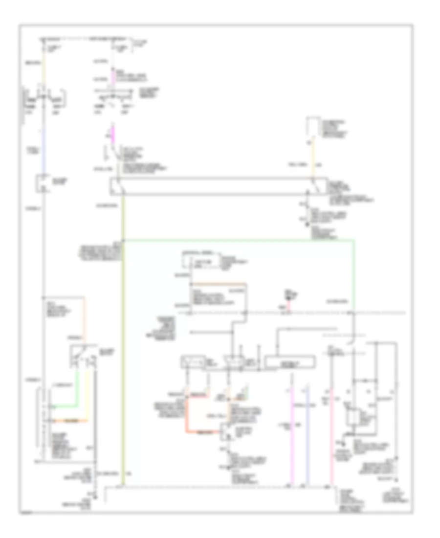
AIR CONDITIONING
3.8L
3.8L, A/C Wiring Diagram for Ford Mustang Cobra 1997

List of elements for 3.8L, A/C Wiring Diagram for Ford Mustang Cobra 1997:
- (behind center of i/p)
- (behind right cowl panel)
- (left front of engine compartment)
- (on bracket, behind coolant reservoir)
- (right rear corner of engine compartment on accumulator)
- A/c clutch control
- A/c clutch cycling pressure switch
- A/c clutch field coil
- A/c high pressure cutout/fan switch (lower right front of engine compartment, on a/c line)
- A/c-heater control assembly
- Blower motor
- Blower motor resistor assembly (behind right side of i/p, in plenum)
- Blower switch
- Constant control
- Def
- Edf relay
- Edf relay control
- Electric cooling fan
- Engine compartment fuse box
- Fan fuse 60a
- Floor
- Fuse 17 30a
- Fuse 6 15a
- G100
- G101 (right front of engine compartment)
- G206
- Hot at all times
- Hot in accy or run
- Hot in run
- I/p fuse panel
- Max
- Mix
- Module
- Norm
- Off
- Pcm power relay
- Pnk/
- Power- train control module (pcm)
- Relay
- S104 (dash panel to headlamp junction harness, right front of eng compt)
- S115 (engine control sens harn, right side of eng compt)
- S119 (engine control sens harness, near a/c high high pressure cutout/ fan switch breakout)
- S122 (engine control sens harn, near elec cooling fan breakout)
- S201 (main harn, behind center of i/p)
- S213 (main harn, behind right side of i/p)
- S226 (main harn, near clock breakout)
- Vent
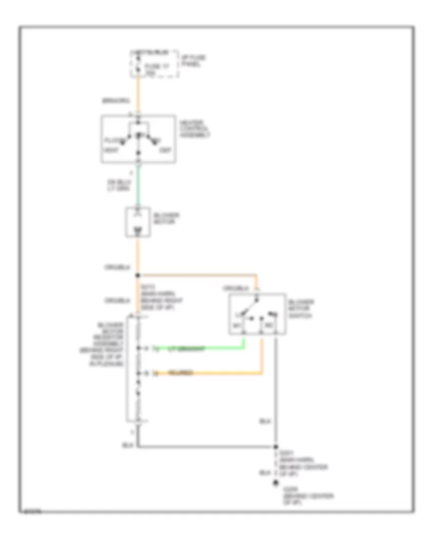
Heater Wiring Diagram for Ford Mustang Cobra 1997
List of elements for Heater Wiring Diagram for Ford Mustang Cobra 1997:
- Blower motor
- Blower motor resistor assembly (behind right side of i/p, in plenum)
- Blower motor switch
- Def
- Floor
- Fuse 17 30a
- G206 (behind center of i/p)
- Heater control assembly
- Hot in run
- I/p fuse panel
- Mix
- Off
- S201 (main harn, behind center of i/p)
- S213 (main harn, behind right side of i/p)
- Vent
4.6L
4.6L, A/C Wiring Diagram for Ford Mustang Cobra 1997
List of elements for 4.6L, A/C Wiring Diagram for Ford Mustang Cobra 1997:
- (behind center of i/p)
- (behind right cowl panel)
- (left front of engine compartment)
- (on bracket, behind coolant reservoir)
- (right rear corner of engine compartment on accumulator)
- A/c clutch control
- A/c clutch cycling pressure switch
- A/c clutch field coil
- A/c high pressure cutout/fan switch (lower right front of engine compartment, on a/c line)
- A/c-heater control assembly
- Blower motor
- Blower motor resistor assembly (behind right side of i/p, in plenum)
- Blower switch
- Constant control
- Def
- Edf relay
- Edf relay control
- Electric cooling fan
- Engine compartment fuse box
- Engine controls system
- Fan fuse 60a
- Floor
- Fuse 17 30a
- Fuse 6 15a
- G100
- G101 (right front of engine compartment)
- G206
- Hedf relay
- Hot at all times
- Hot in accy or run
- Hot in run
- I/p fuse panel
- Max
- Mix
- Module
- Norm
- Off
- Pcm power relay
- Pnk/
- Power- train control module (pcm)
- Powertrain control module (behind right cowl panel)
- Red
- Relay
- S100 (eng control sens harn, right side of eng compt)
- S102 (engine control sens harn, right rear of engine compt)
- S115 (engine control sens harn, right side of eng compt)
- S119 (engine control sens harness, near a/c high high pressure cutout/ fan switch breakout)
- S122 (engine control sens harn, near elec cooling fan breakout)
- S140 (engine control sens harn, near elec cooling fan breakout)
- S149 (eng control harn, right side of eng compt)
- S201 (main harn, behind center of i/p)
- S213 (main harn, behind right side of i/p)
- S226 (main harn, near clock breakout)
- Vent
Heater Wiring Diagram for Ford Mustang Cobra 1997
List of elements for Heater Wiring Diagram for Ford Mustang Cobra 1997:
- Blower motor
- Blower motor resistor assembly (behind right side of i/p, in plenum)
- Blower motor switch
- Def
- Floor
- Fuse 17 30a
- G206 (behind center of i/p)
- Heater control assembly
- Hot in run
- I/p fuse panel
- Mix
- Off
- S201 (main harn, behind center of i/p)
- S213 (main harn, behind right side of i/p)
- Vent
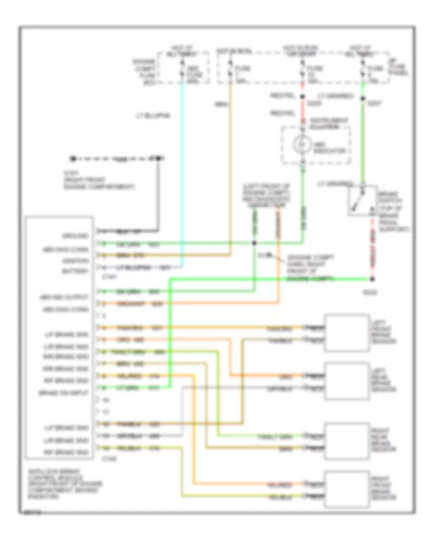
ANTI-LOCK BRAKES
Anti-lock Brake Wiring Diagrams for Ford Mustang Cobra 1997
List of elements for Anti-lock Brake Wiring Diagrams for Ford Mustang Cobra 1997:
- (engine compt harn, right front of engine compt)
- (left front of engine compt) abs diagnostic connector
- (top of brake pedal support)
- Abs diag conn
- Abs fuse 60a
- Abs ind output
- Abs indicator
- All times
- Anti-lock brake control module (right front of engine compartment, behind radiator)
- Battery
- Brake sw input
- Brake switch
- C141
- C142
- Engine compt fuse box
- Fuse 10a
- Fuse 15a
- G101 (right front engine compartment)
- Ground
- Hot at
- Hot in run
- Hot in run or start
- I/p fuse panel
- Ignition
- Instrument cluster
- L/f brake sns
- L/r brake sns
- Left front brake sensor
- Left rear brake sensor
- Nca
- R/f brake sns
- R/r brake sns
- Right front brake sensor
- Right rear brake sensor
- S104
- S136
- S207
- S229
- S232
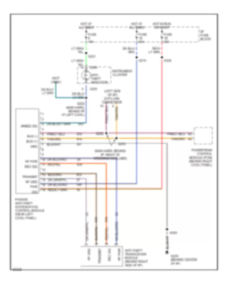
ANTI-THEFT
Anti-theft Wiring Diagram, PATS for Ford Mustang Cobra 1997
List of elements for Anti-theft Wiring Diagram, PATS for Ford Mustang Cobra 1997:
- (main harn, behind i/p, right of steering ccolumn)
- (not used)
- Anti- theft indicator
- Anti-theft transceiver module (behind right side of i/p)
- Armed sig
- Bus (+)
- Bus (-)
- C250
- Fuse 10a
- Fuse 20a
- G206 (behind center of i/p)
- Grd
- Hot at all times
- Hot in run or start
- I/p fuse block
- Ign
- Instrument cluster
- Passive anti-theft system (pats) control module (near left cowl panel)
- Powertrain control module (pcm) (behind right cowl panel)
- Pwr
- Rec sig
- Rf grd
- Rf pwr
- S205
- S210
- S221
- S228
- S252
- S252 (main harn, behind i/p at left cowl)
- S253
- Transmit
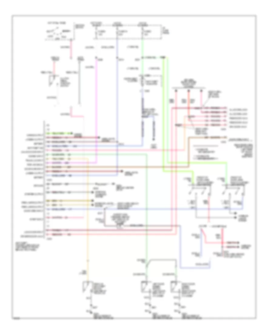
Anti-theft Wiring Diagram, TATS for Ford Mustang Cobra 1997
List of elements for Anti-theft Wiring Diagram, TATS for Ford Mustang Cobra 1997:
- (body harn, below right side of rear seat)
- (body harn, left side of trunk)
- (body harn, near anti- theft mod)
- (front of door jamb) left courtesy light switch
- (front of door jamb) right courtesy light switch
- (in body main harness, behind left side of i/p) ant-theft diode
- (not used)
- * w/ remote
- ** w/o remote
- 10a
- 15a
- 20a
- Acc
- All doors lock
- Anti-theft controller module (left rear of trunk, behind trim panel)
- Anti-theft ind
- Anti-theft indicator
- Auto trans
- Battery
- C250
- C400
- C402
- C403
- C404
- Cluster
- Clutch pedal position switch
- Convertible
- Coupe
- Deck lid anti-theft switch (center of trunk lid)
- Disarm input
- Door ajar input
- Door open input
- Driver's door unlk
- Drv door unlk
- Exterior lights system
- Fuse 16
- Fuse 6
- Fuse 8
- G206 (behind center of i/p)
- G302 (below rear of center console)
- Ground
- Headlights system
- Horns output
- Horns system
- Hot at all times
- Hot in acc or run
- I/p fuse panel
- Ignition switch
- Instrument
- Interior lights system
- Keyless entry
- Keyless entry system (door lock motors)
- Left door disarm switch (left door, back of lk cylinder)
- Lo beam output
- Lock
- Lock door input
- Manual trans
- Nca
- Off
- Park lamps output
- Pass door unlk
- Pwr (acc/run)
- Red/ pnk
- Red/pnk
- Remote/keyless entry module (left rear of trunk, behind side trim)
- Right door disarm switch (right door, back of lk cylinder)
- Run
- S205
- S210
- S221
- S226
- S306
- S317
- S407
- S412
- S423
- S424
- S427
- S501
- S901
- Start
- Start input
- Starter output
- Starting/ charging system
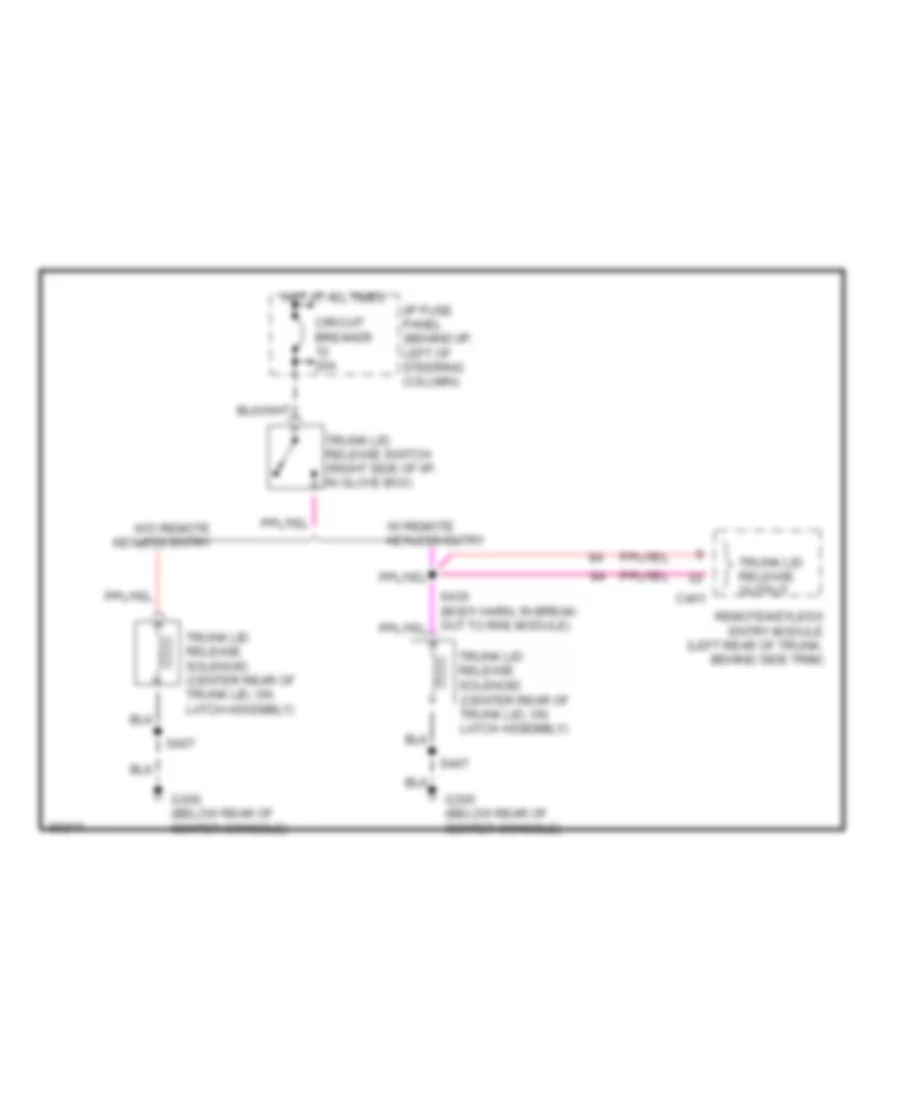
- Trunk lid input
- Unlock door input
- Warning system
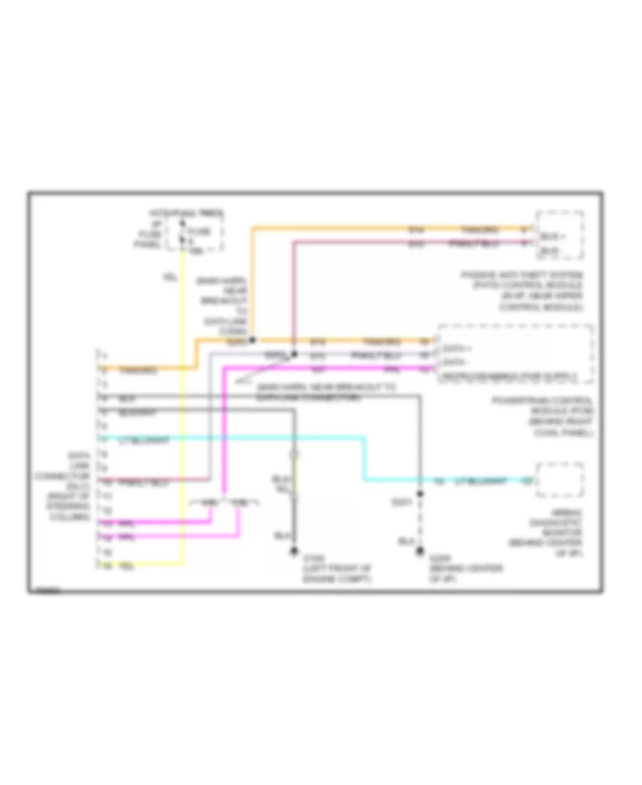
COMPUTER DATA LINES
Computer Data Lines for Ford Mustang Cobra 1997
List of elements for Computer Data Lines for Ford Mustang Cobra 1997:
- (main harn, near breakout to data link conn) s253
- (main harn, near breakout to data link connector)
- 3.8l
- 4.6l
- Airbag diagnostic monitor (behind center of i/p)
- Bus +
- Bus -
- Control module)
- Cowl panel)
- Data +
- Data -
- Data link connector (dlc) (right of steering column)
- Fuse 10a
- G100 (left front of engine compt)
- G206 (behind center of i/p)
- Hot at all times
- I/p fuse panel
- Passive anti-theft system (pats) control module (in i/p, near wiper
- Powertrain control module (pcm) (behind right
- S201
- S252
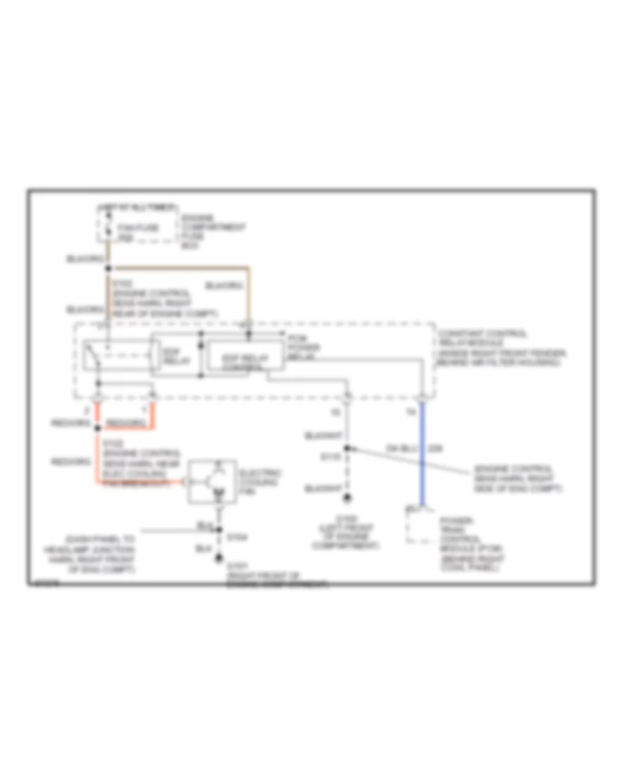
COOLING FAN
3.8L
3.8L, Cooling Fan Wiring Diagram for Ford Mustang Cobra 1997
List of elements for 3.8L, Cooling Fan Wiring Diagram for Ford Mustang Cobra 1997:
- (dash panel to headlamp junction harn, right front of eng compt)
- (engine control sens harn, right side of eng compt)
- Constant control relay module (inside right front fender, behind air filter housing)
- Edf relay
- Edf relay control
- Electric cooling fan
- Engine compartment fuse box
- Fan fuse 60a
- G100 (left front of engine compartment)
- G101 (right front of engine compartment)
- Hot at all times
- Pcm power relay
- Power- train control module (pcm) (behind right cowl panel)
- S104
- S115
- S122 (engine control sens harn, near elec cooling fan breakout)
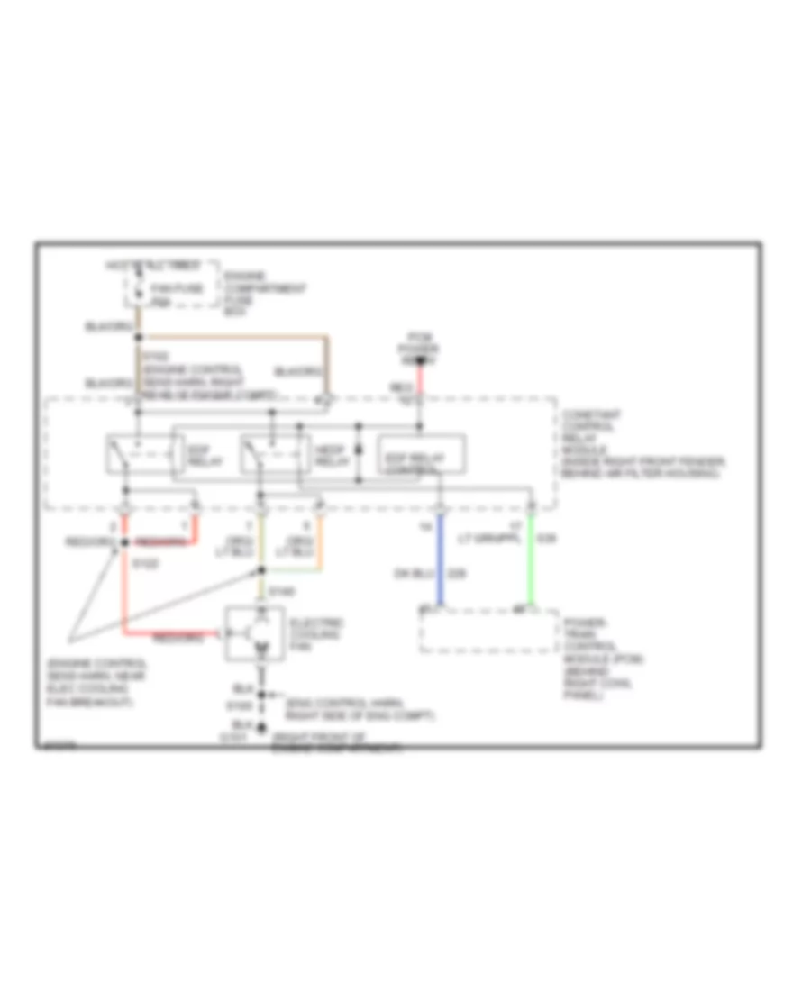
4.6L
4.6L, Cooling Fan Wiring Diagram for Ford Mustang Cobra 1997
List of elements for 4.6L, Cooling Fan Wiring Diagram for Ford Mustang Cobra 1997:
- (eng control harn, right side of eng compt)
- (engine control sens harn, near elec cooling fan breakout)
- (right front of engine compartment)
- Constant control relay module (inside right front fender, behind air filter housing)
- Edf relay
- Edf relay control
- Electric cooling fan
- Engine compartment fuse box
- Fan fuse 60a
- G101
- Hedf relay
- Hot at all times
- Pcm power relay
- Power- train control module (pcm) (behind right cowl panel)
- Rear of engine compt)
- Red
- S100
- S122
- S140
CRUISE CONTROL
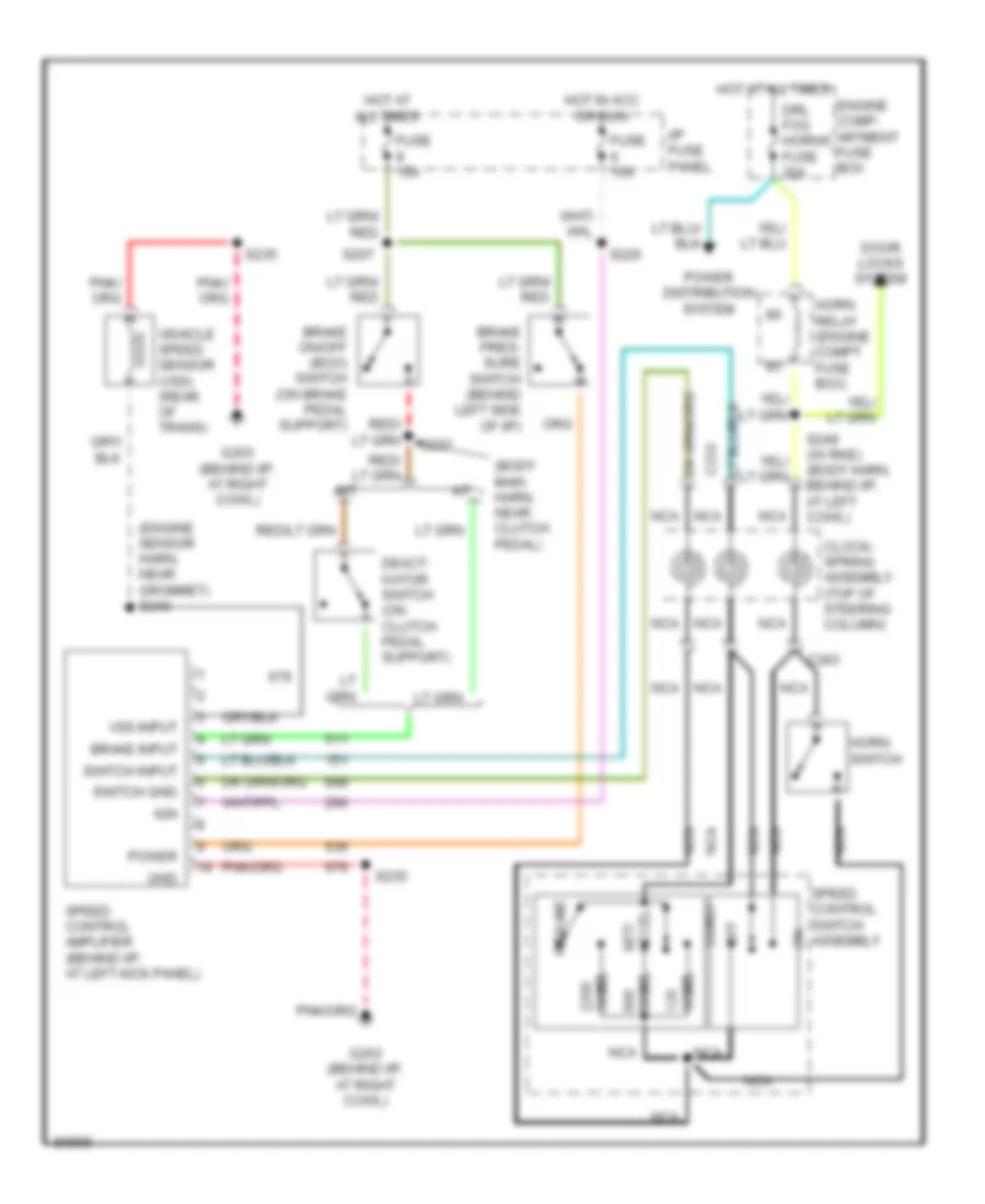
Cruise Control Wiring Diagram for Ford Mustang Cobra 1997
List of elements for Cruise Control Wiring Diagram for Ford Mustang Cobra 1997:
- (body main harn, near clutch pedal)
- (engine sensor harn, near grommet) s240
- A/t
- Brake input
- Brake on/off (boo) switch (on brake pedal support)
- Brake pres- sure switch (behind left side of i/p)
- C233
- C243
- Clock- spring assembly (top of steering column)
- Coast
- Deact- ivator switch (on clutch pedal support)
- Door locks system
- Drl fog horns fuse 20a
- Engine comp- artment fuse box
- Fuse 15a
- G203 (behind i/p, at right cowl)
- Gnd
- Horn relay (engine compt fuse box)
- Horn switch
- Hot at all times
- Hot in acc or run
- I/p fuse panel
- Ign
- M/t
- Nca
- Off
- Ohms
- Power
- Power distribution system
- Resume
- S207
- S226
- S232
- S235
- S249 (w/ rke) (body harn, behind i/p, at left cowl)
- Set/ accel
- Speed control amplifier (behind i/p, at left kick panel)
- Speed control switch assembly
- Switch gnd
- Switch input
- Vehicle speed sensor (vss) (rear of trans)
- Vss input
DEFOGGERS
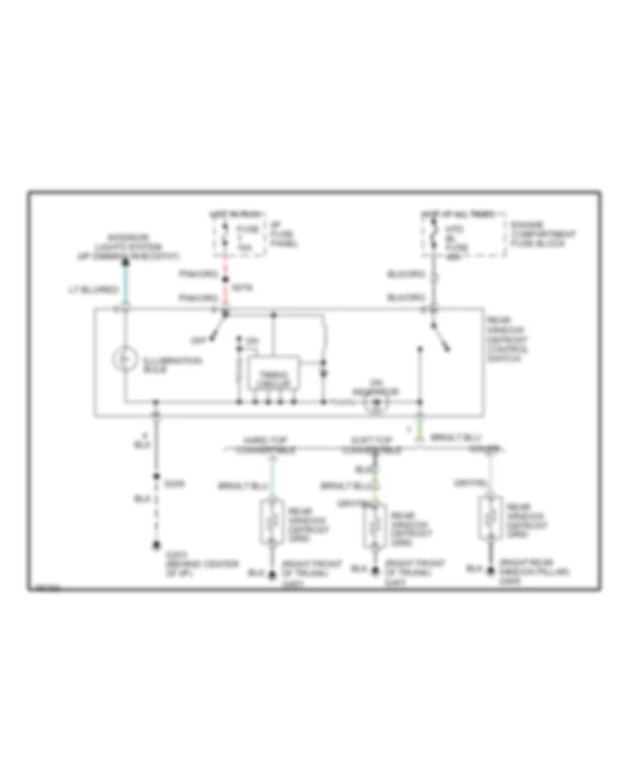
Defogger Wiring Diagram for Ford Mustang Cobra 1997
List of elements for Defogger Wiring Diagram for Ford Mustang Cobra 1997:
- (right front of trunk) g401
- (right rear window pillar) g905
- Coupe
- Engine compartment fuse block
- Fuse 15a
- G203 (behind center of i/p)
- Hard top convertible
- Hot at all times
- Hot in run
- Htd bl fuse 40a
- I/p fuse panel
- Illumination bulb
- Interior lights system (i/p dimming rheostat)
- Off
- On indicator
- Rear window defrost control switch
- Rear window defrost grid
- S206
- S218
- Soft top convertible
- Timing circuit
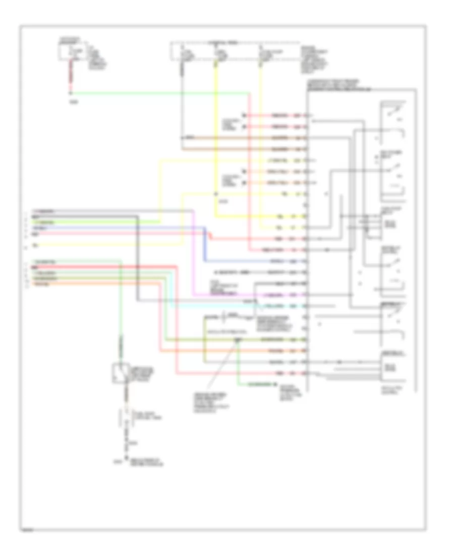
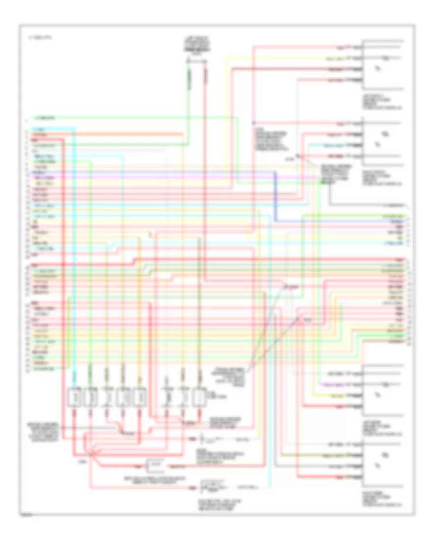
ENGINE PERFORMANCE
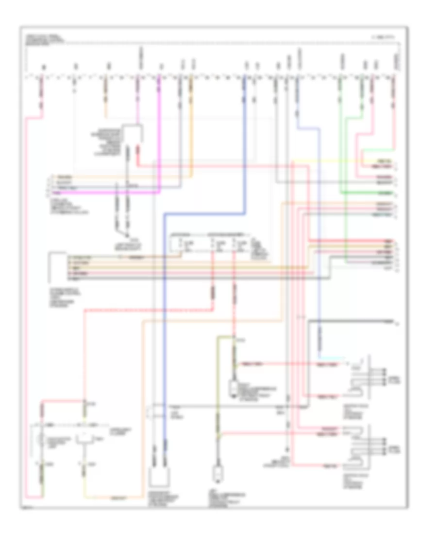
3.8L
3.8L, Engine Performance Wiring Diagrams (1 of 6) for Ford Mustang Cobra 1997
List of elements for 3.8L, Engine Performance Wiring Diagrams (1 of 6) for Ford Mustang Cobra 1997:
- (left front of engine compt)
- (right cowl panel) powertrain control module (pcm)
- (top front of engine)
- C 1995 vftc
- C250
- C251
- Ckp shield
- Ckp+
- Ckp-
- Coil output
- Crankshaft position sensor (center front of engine)
- Cse gnd
- Data link connector (behind i/p, right
- Dlc
- Dlc(+)
- Dlc(-)
- Evap sensor
- Evaporative emissions (evap) purge flow sensor (right rear of engine compartment)
- Fuse 10a
- Fuse 20a
- G100
- G203 (behind i/p, at right cowl)
- Gnd
- Ho2s(rr)
- Hot in run or start
- I/p fuse panel (left of steering column)
- Ignition coil
- Instrument cluster
- Malfunction indicator lamp
- Mil
- Nca
- Of steering column)
- Radio interference capacitor (top right front of engine)
- Red
- S129
- S142
- S204
- S228
- Spark plugs
- Ss1
- Ss2
- Tach
- Tcs
- Vss(-)
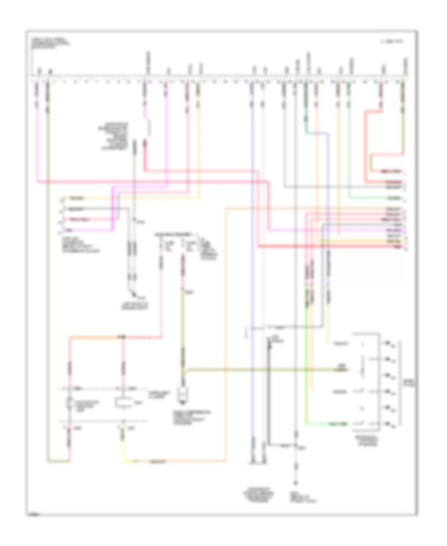
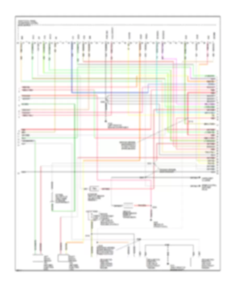
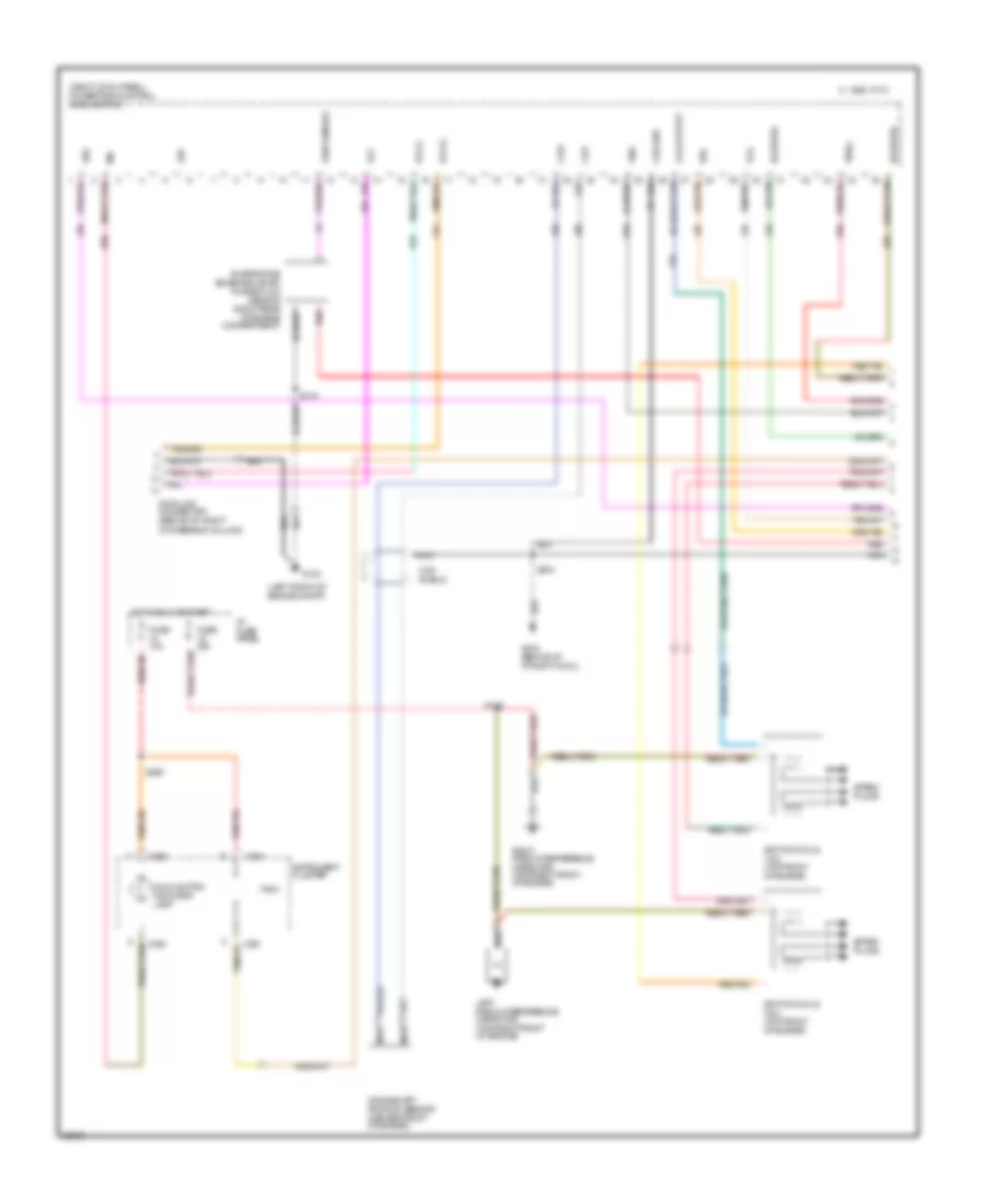
3.8L, Engine Performance Wiring Diagrams (2 of 6) for Ford Mustang Cobra 1997
List of elements for 3.8L, Engine Performance Wiring Diagrams (2 of 6) for Ford Mustang Cobra 1997:
- (engine harness, near breakout to right front brake sensor)
- (right cowl panel) powertrain control module (pcm)
- Accs
- Canp
- Coil output
- Ecs
- Egr
- Evr
- Fpm
- G100 (left front of engine compt)
- G203 (behind i/p, at right cowl)
- Ho2s(lr)
- Ho2s(rf)
- Iat
- Idm
- Instrument cluster
- Intake air temp (iat) sensor (on air intake assembly)
- Ka pwr
- Lfc
- Maf
- Mlps
- Nca
- Octane adjust plug (right rear of engine compartment)
- Pwr gnd
- Red
- S116
- S121 (engine harness, near grommet)
- S235
- S240
- S250
- Speed control amplifier pin #3
- Tcc
- Tot
- Vehicle speed sensor (rear of transmission)
- Vss(+)
- Wac
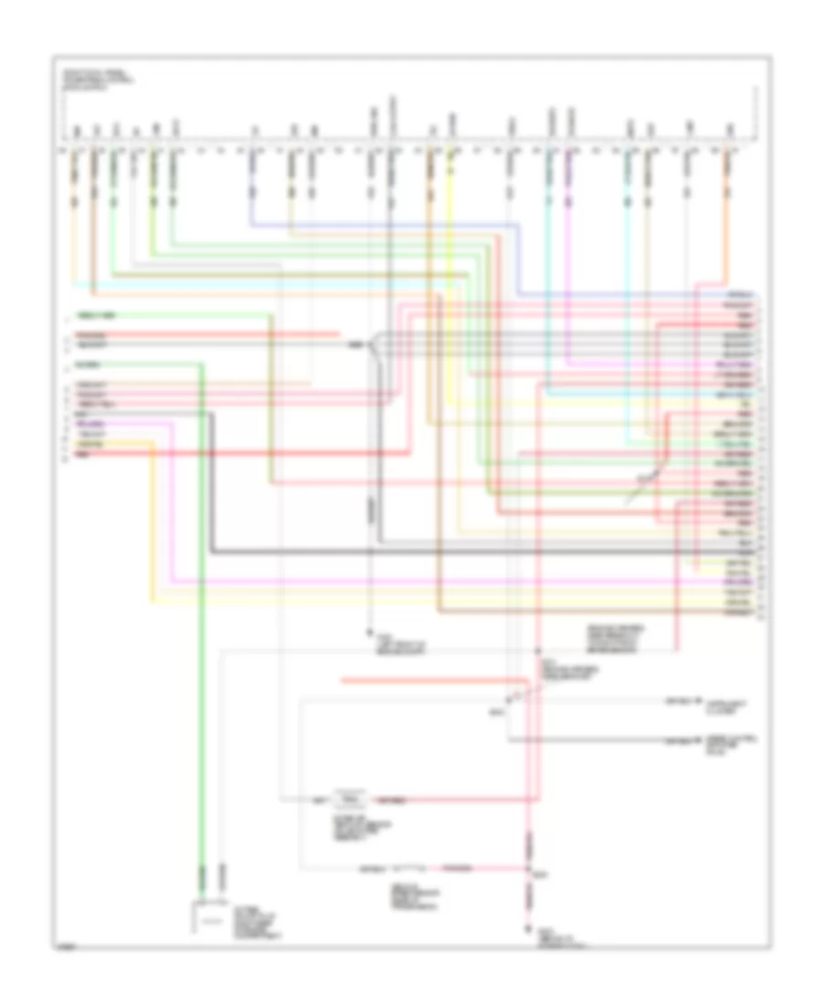
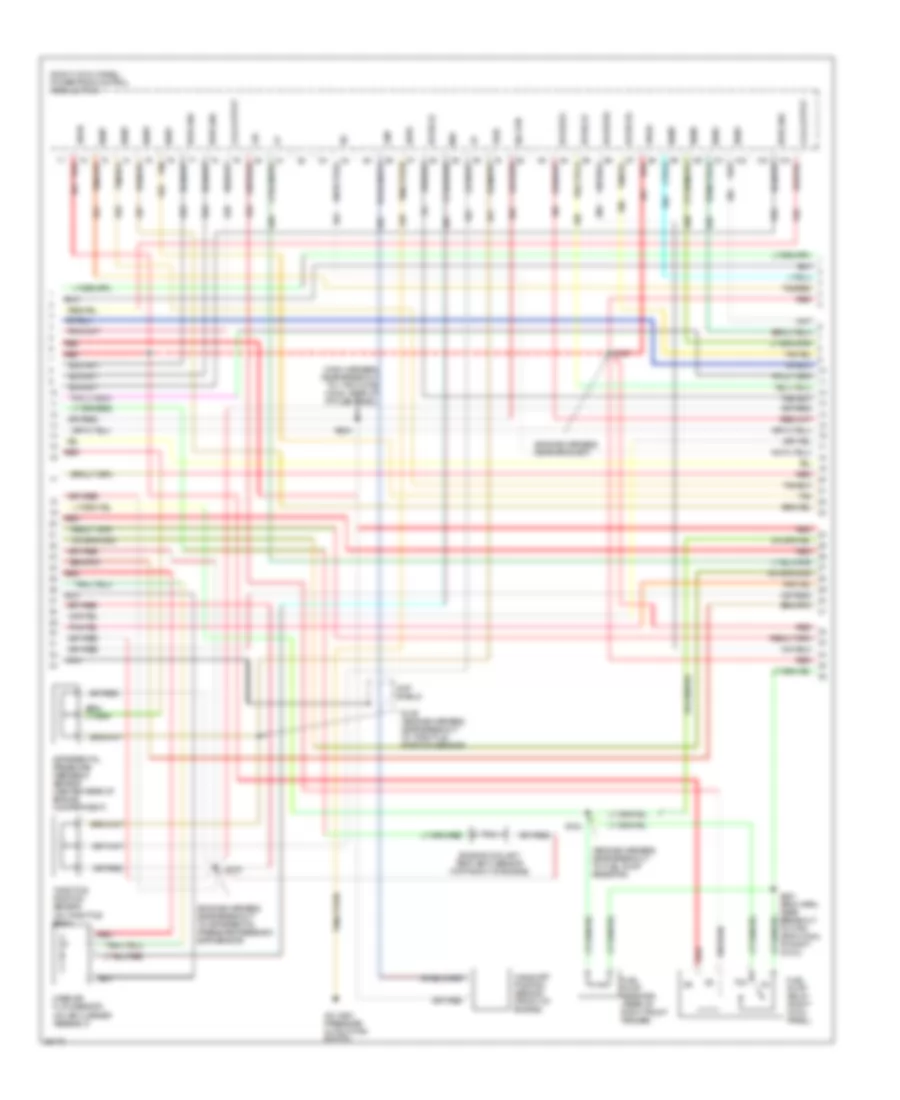
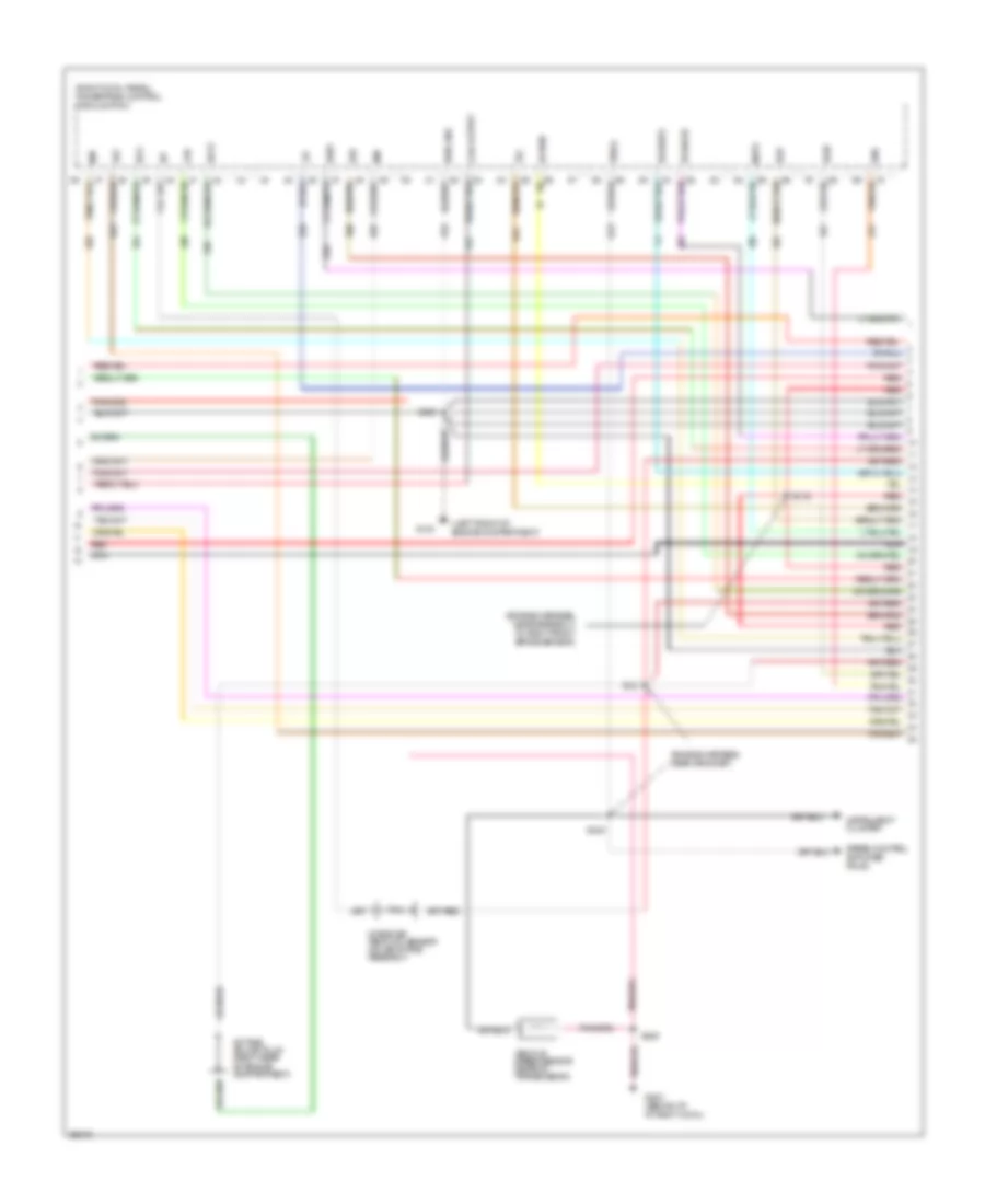
3.8L, Engine Performance Wiring Diagrams (3 of 6) for Ford Mustang Cobra 1997
List of elements for 3.8L, Engine Performance Wiring Diagrams (3 of 6) for Ford Mustang Cobra 1997:
- (engine harness, behind right side of i/p, near grommet)
- (front of engine)
- (fuel harness, near breakout to fuel inj #6)
- (left front of engine compartment)
- (on air cleaner assembly)
- (on throttle body)
- (right cowl panel) powertrain control module (pcm)
- A/c high pressure cutout fan switch
- Ahps
- Boo
- Camshaft position sensor
- Cmp
- Cmp shield
- Coil output
- Differential pressure feedback sensor (center rear of engine compartment)
- Engine coolant temp (ect) sensor (top front of engine)
- Epc
- G100
- Ho2s(lf)
- Ho2s(lr)
- Ho2s(rf)
- Ho2s(rr)
- Iac
- Inj#1
- Inj#2
- Inj#3
- Inj#4
- Inj#5
- Inj#6
- Maf
- Mass air flow sensor
- Nca
- Pwr gnd
- Red
- S129 (fuel harness, near breakout to throttle position sensor)
- S130
- S142
- S234
- Sig rtn
- Tan
- Tcl
- Throttle position sensor
- Tss
- Vpwr
- Vref
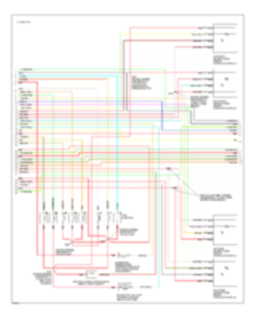
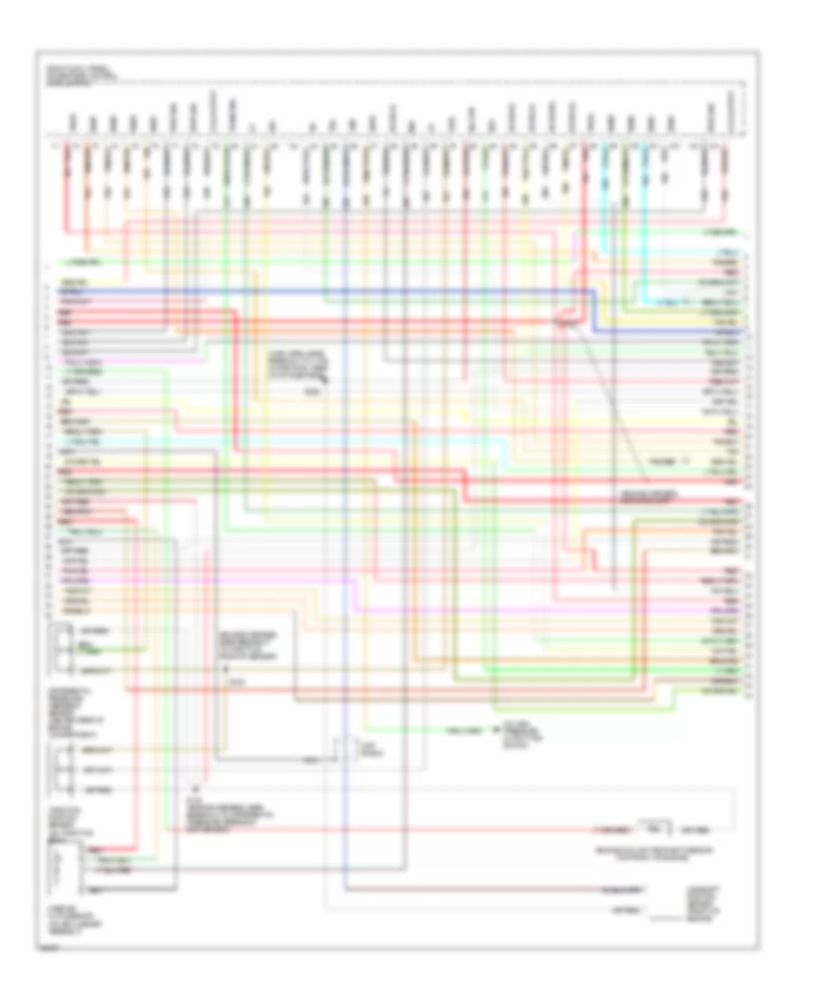
3.8L, Engine Performance Wiring Diagrams (4 of 6) for Ford Mustang Cobra 1997
List of elements for 3.8L, Engine Performance Wiring Diagrams (4 of 6) for Ford Mustang Cobra 1997:
- (a/t: trans harness, near breakout to 10-pin black conn, on 4r70w trans; m/t: back up lamp feed harness, near breakout to right rear heated oxygen sensor)
- (fuel harness, near breakout to fuel inj #2)
- (fuel harness, near breakout to fuel inj #5)
- (left side of transmission) output shaft speed sensor
- (rear of throttle body)
- C 1995 vftc
- Egr vacuum regulator (evr) sol
- Evaporative emission canister purge valve (right side of engine compartment)
- Fuel injectors
- Idle air ctrl (iac) valve (top rear of engine above valve cover)
- Left front heated oxygen sensor (in exhaust manifold)
- Left rear heated oxygen sensor (in exhaust manifold)
- Nca
- Red
- Right front heated oxygen sensor (in exhaust manifold)
- Right rear heated oxygen sensor (in exhaust manifold)
- S123
- S124
- S125
- S126
- S137
- S138 (engine harness, near breakout to 8-pin black conn, lh rear of engine)
- Tan
3.8L, Engine Performance Wiring Diagrams (5 of 6) for Ford Mustang Cobra 1997
List of elements for 3.8L, Engine Performance Wiring Diagrams (5 of 6) for Ford Mustang Cobra 1997:
- (below rear of center console)
- (engine harness, near breakout to a/c high pressure cutout/ fan switch)
- (inside right front fender, behind air filter housing) constant control relay module
- A/c clutch
- A/c compressor clutch
- A/c high pressure cutout fan switch
- A/t only
- Control
- Cooling fans system
- Edf relay
- Edf relay control
- Eec fuse 20a
- Engine compartment fuse box (left side of engine compt, forward of strut tower)
- Fan fuse 60a
- Fuel pump (on fuel tank)
- Fuel pump fuse 20a
- Fuel pump relay
- Fuse 20a
- G100 (left front of engine compartment)
- G302
- Hedf relay (not used)
- Hot at all times
- Hot in run or start
- I/p fuse panel (left of steering column)
- Inertia fuel shut off sw (left rear of trunk)
- Manual lever position sensor (rear left side of transmission)
- Pcm power relay
- Red
- S102
- S108
- S115
- S119
- S228
- S408
- Solid state
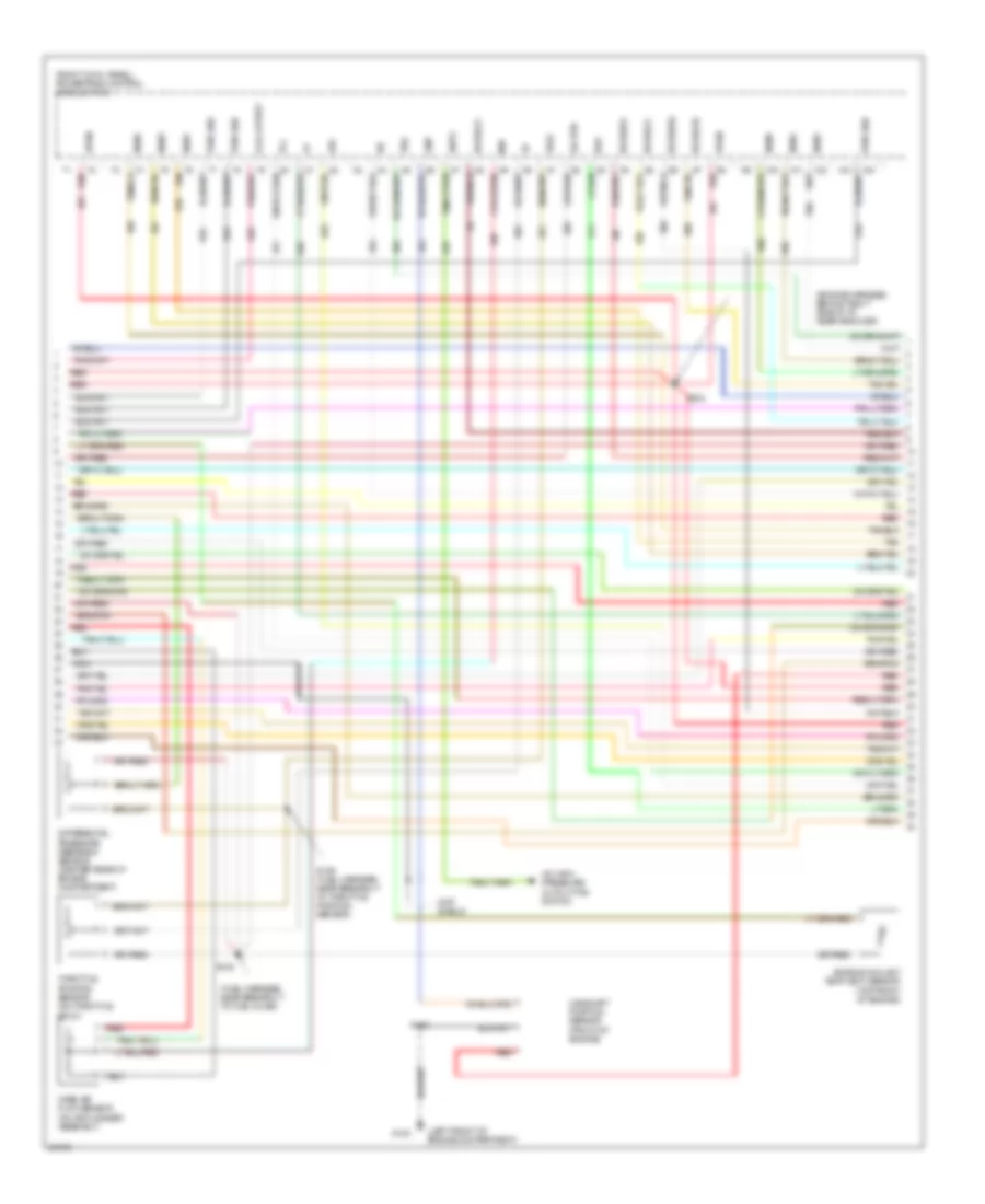
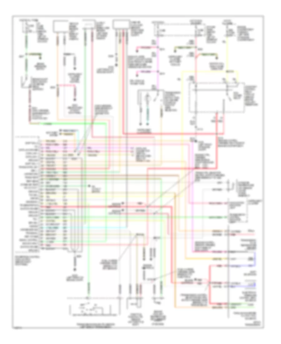
3.8L, Engine Performance Wiring Diagrams (6 of 6) for Ford Mustang Cobra 1997
List of elements for 3.8L, Engine Performance Wiring Diagrams (6 of 6) for Ford Mustang Cobra 1997:
- 4r70w transmission
- Brake on/off switch (on brake pedal support)
- Electric pressure control (epc) solenoid
- Fuse 10a
- Fuse 15a
- G302 (below rear of center console)
- Hot at all times
- Hot in park or head
- Hot in run
- Hot in run or start
- I/p fuse panel (left of steering column)
- Illum
- Instrument cluster
- Interior lights system (fog lamp switch)
- Off
- Red
- S207
- S219
- S229
- S230
- S232 (body harness, near breakout to 2-pin gray conn, near clutch pedal)
- S301
- Shift solenoid (ss)
- Torque converter clutch (tcc) solenoid
- Transmission control indicator lamp
- Transmission control switch
- Transmission oil temp (tot) sensor
4.6L
4.6L DOHC, Engine Performance Wiring Diagrams (1 of 5) for Ford Mustang Cobra 1997
List of elements for 4.6L DOHC, Engine Performance Wiring Diagrams (1 of 5) for Ford Mustang Cobra 1997:
- (center rear of engine)
- (left front of engine compt)
- (right cowl panel) powertrain control module (pcm)
- C 1995 vftc
- C250
- C251
- Ckp shield
- Ckp+
- Ckp-
- Coil output
- Crankshaft position sensor (center front of engine)
- Cse gnd
- Data link connector (behind i/p, right
- Dlc
- Dlc(+)
- Dlc(-)
- Eap
- Evap sensor
- Evaporative emissions (evap) purge flow sensor (right rear of engine compartment)
- Fuse 10a
- Fuse 15a
- Fuse 20a
- G100
- G203 (behind i/p at right cowl)
- Gnd
- Ho2s(rr)
- Hot in run
- Hot in run or start
- I/p fuse panel (left of steering column)
- Ignition coils 1 & 2 (top front of engine)
- Ignition coils 3 & 4 (top front of engine)
- Imrc
- Instrument cluster
- Intake manifold runner control (imrc)
- Ks #2
- Left radio interference capacitor (top right front of engine)
- Malfunction indicator lamp
- Mil
- Nca
- Of steering column)
- Red
- Right radio interference capacitor (top right front of engine)
- S115
- S129
- S132
- S204
- Spark plugs
- Tach
- Vss(-)
4.6L DOHC, Engine Performance Wiring Diagrams (2 of 5) for Ford Mustang Cobra 1997
List of elements for 4.6L DOHC, Engine Performance Wiring Diagrams (2 of 5) for Ford Mustang Cobra 1997:
- (between injectors 1 & 2)
- (between injectors 5 & 6)
- (engine harness, near breakout to right front brake sensor)
- (engine harness, near grommet)
- (right cowl panel) powertrain control module (pcm)
- Accs
- Air injection reaction (air) pump (right front fender)
- Air injection reaction (air) relay (right front fender)
- Air injection reaction (airb) bypass (right front fender)
- Air man
- Coil output
- Ecs
- Egr
- Engine compartment fuse box (left side of engine compt, forward of strut)
- Evap
- Evr
- Fpr
- G100 (left front of engine compartment)
- G101 (right front of engine compt)
- G203 (behind i/p, at right cowl)
- Hedf
- Ho2s(lr)
- Ho2s(rf)
- Hot at times
- Iac
- Iat
- Idm
- Instrument cluster
- Intake air temp (iat) sensor (on air intake assembly)
- Ka pwr
- Ks #1
- Left knock sensor (ks)
- Lfc
- Maf
- Nca
- Octane adjust plug (right rear of engine compartment)
- Pwr gnd
- Red
- Right knock sensor (ks)
- S100
- S116
- S121
- S145
- S154
- S155 (engine harness, near breakout to air injection reaction pump)
- S235
- S240
- Speed control amplifier pin #3
- Therm fuse 30a
- Vehicle speed sensor (rear of transmission)
- Vss(+)
- Wac
4.6L DOHC, Engine Performance Wiring Diagrams (3 of 5) for Ford Mustang Cobra 1997
List of elements for 4.6L DOHC, Engine Performance Wiring Diagrams (3 of 5) for Ford Mustang Cobra 1997:
- (engine harness, near breakout to differential pressure feedback egr sensor)
- (engine harness, near breakout to fuel pump resistor)
- (engine harness, near grommet)
- (front of engine)
- (main harness, near breakout to 1-pin white conn, rear of i/p fuse panel)
- (on air cleaner assembly)
- (on throttle body)
- (right cowl panel) powertrain control module (pcm)
- 78a
- A/c high pressure cutout/fan switch
- Ahps
- Camshaft position sensor
- Cmp
- Cmp shield
- Coil output
- Differential pressure feedback sensor (center rear of engine compartment)
- Engine coolant temp (ect) sensor (top front of engine)
- Fpc
- Fuel pump relay (right cowl panel)
- Fuel pump resistor (rear of right front fender)
- Ho2s(lf)
- Ho2s(lr)
- Ho2s(rf)
- Ho2s(rr)
- Iac
- Inj#1
- Inj#2
- Inj#3
- Inj#4
- Inj#5
- Inj#6
- Inj#7
- Inj#8
- Maf
- Mass air flow sensor
- Nca
- Pwr gnd
- Red
- S127
- S129 (engine harness, near breakout to throttle position sensor)
- S130
- S153
- S224
- S251 (eng harn, near breakout to 8-pin gray conn, at right cowl)
- Sig rtn
- Tan
- Tan/red
- Throttle position sensor
- Vpwr
- Vref
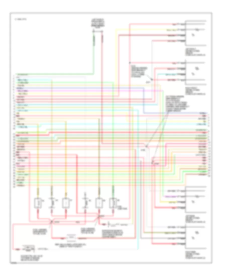
4.6L DOHC, Engine Performance Wiring Diagrams (4 of 5) for Ford Mustang Cobra 1997
List of elements for 4.6L DOHC, Engine Performance Wiring Diagrams (4 of 5) for Ford Mustang Cobra 1997:
- #1 #1 #1 #1 #1 #1
- #3 #3 #3 #3 #3 #3
- #4 #4 #4 #4 #4 #4
- #5 #5 #5 #5 #5 #5
- #6 #6 #6 #6 #6 #6
- (back up lamp feed harness, near breakout to right rear heated oxygen sensor)
- (engine harness, near breakout to fuel inj #2)
- (engine harness, near breakout to fuel inj #8)
- (engine harness, near breakout to right front heated oxygen sensor)
- (rear of throttle body)
- C 1995 vftc
- Egr vacuum regulator solenoid
- Evaporative emission (evap) canister purge valve (right side of engine compartment)
- Fuel injectors
- Idle air ctrl (iac) valve (top rear of engine above valve cover)
- Left front heated oxygen sensor (in exhaust manifold)
- Left rear heated oxygen sensor (in exhaust manifold)
- Nca
- Red
- Red red red red red red
- Right front heated oxygen sensor (in exhaust manifold)
- Right rear heated oxygen sensor (in exhaust manifold)
- S125
- S126
- S139
- S150
- S151 (engine harness, near breakout to egr vacuum regulator solenoid)
- S152
- S168 (engine harness, near breakout to 8-pin conn, near engine oil pressure switch)
- Tan
- Tan/red
4.6L DOHC, Engine Performance Wiring Diagrams (5 of 5) for Ford Mustang Cobra 1997
List of elements for 4.6L DOHC, Engine Performance Wiring Diagrams (5 of 5) for Ford Mustang Cobra 1997:
- (below rear of center console)
- (engine harness, near breakout to a/c high pressure cutout/ fan switch)
- (inside right front fender, behind air filter housing) constant control relay module
- A/c clutch
- A/c clutch field coil
- A/c high pressure cutout fan switch
- Control
- Cooling fans system
- Edf relay
- Edf relay control
- Eec fuse 20a
- Engine compartment fuse box (left side of engine compt, forward of strut)
- Fan fuse 60a
- Fuel pump (on fuel tank)
- Fuel pump fuse 20a
- Fuel pump relay
- Fuse 20a
- G100 (left front of engine compartment)
- G302
- Hedf relay
- Hot at all times
- Hot in run or start
- I/p fuse panel (left of steering column)
- Inertia fuel shut off sw (left rear of trunk)
- Near breakout to intake manifold runner control)
- Pcm power relay
- Red
- S102
- S108
- S115
- S119
- S149
- S228
- S408
- Solid state
4.6L SOHC, Engine Performance Wiring Diagrams (1 of 6) for Ford Mustang Cobra 1997
List of elements for 4.6L SOHC, Engine Performance Wiring Diagrams (1 of 6) for Ford Mustang Cobra 1997:
- (left front of engine compt)
- (right cowl panel) powertrain control module (pcm)
- C 1995 vftc
- C250
- C251
- Ckp shield
- Ckp+
- Ckp-
- Coil output
- Crankshaft position sensor (center front of engine)
- Cse gnd
- Data link connector (behind i/p, right
- Dlc
- Dlc(+)
- Dlc(-)
- Eap
- Evap sensor
- Evaporative emissions (evap) purge flow sensor (right rear of engine compartment)
- Fuse 10a
- Fuse 20a
- G100
- G203 (behind i/p at right cowl)
- Gnd
- Ho2s(rr)
- Hot in run or start
- I/p fuse panel
- Ignition coils 1 & 2 (top front of engine)
- Ignition coils 3 & 4 (top front of engine)
- Instrument cluster
- Left radio interference capacitor (top right front of engine)
- Malfunction indicator lamp
- Mil
- Nca
- Of steering column)
- Red
- Right radio interference capacitor (top right front of engine)
- S115
- S132
- S204
- S229
- Spark plugs
- Ss1
- Ss2
- Tach
- Tcs
- Vss(-)
4.6L SOHC, Engine Performance Wiring Diagrams (2 of 6) for Ford Mustang Cobra 1997
List of elements for 4.6L SOHC, Engine Performance Wiring Diagrams (2 of 6) for Ford Mustang Cobra 1997:
- (engine harness, near breakout to right front brake sensor)
- (engine harness, near grommet)
- (left front of engine compartment)
- (right cowl panel) powertrain control module (pcm)
- Accs
- Coil output
- Ecs
- Egr
- Evap
- Evr
- Fpr
- G100
- G203 (behind i/p, at right cowl)
- Hedf
- Ho2s(lr)
- Ho2s(rf)
- Iat
- Idm
- Instrument cluster
- Intake air temp (iat) sensor (on air intake assembly)
- Ka pwr
- Lfc
- Maf
- Mlps
- Nca
- Octane adjust plug (right rear of engine compartment)
- Pwr gnd
- Red
- S116
- S121
- S235
- S240
- S250
- Speed control amplifier pin #3
- Tcc
- Tot
- Vehicle speed sensor (rear of transmission)
- Vss(+)
- Wac
4.6L SOHC, Engine Performance Wiring Diagrams (3 of 6) for Ford Mustang Cobra 1997
List of elements for 4.6L SOHC, Engine Performance Wiring Diagrams (3 of 6) for Ford Mustang Cobra 1997:
- (engine harness, near breakout to throttle position sensor)
- (engine harness, near grommet)
- (front of engine)
- (main harn, near breakout to 1-pin white conn, rear of i/p fuse panel)
- (on air cleaner assembly)
- (on throttle body)
- (right cowl panel) powertrain control module (pcm)
- (top front of engine)
- A/c high pressure cutout fan switch
- Ahps
- Boo
- Camshaft position sensor
- Cmp
- Cmp shield
- Coil output
- Differential pressure feedback sensor (center rear of engine compartment)
- Engine coolant temp (ect) sensor
- Epc
- Ho2s(lf)
- Ho2s(lr)
- Ho2s(rf)
- Ho2s(rr)
- Iac
- Inj#1
- Inj#2
- Inj#3
- Inj#4
- Inj#5
- Inj#6
- Inj#7
- Inj#8
- Maf
- Mass air flow sensor
- Nca
- Pwr gnd
- Red
- S127
- S129
- S130 (engine harness, near breakout to differential pressure feedback egr sensor)
- S224
- Sig rtn
- Tan
- Tan/red
- Throttle position sensor
- Trans ind.
- Tss
- Vpwr
- Vref
4.6L SOHC, Engine Performance Wiring Diagrams (4 of 6) for Ford Mustang Cobra 1997
List of elements for 4.6L SOHC, Engine Performance Wiring Diagrams (4 of 6) for Ford Mustang Cobra 1997:
- (engine harness, near breakout to 42-pin conn in right rear of engine compt)
- (engine harness, near breakout to fuel inj #6)
- (engine harness, near breakout to right front heated oxygen sensor)
- (evap) canister purge solenoid (right side of engine compartment)
- (left side of transmission) output shaft speed sensor
- (rear of throttle body)
- (trans harness, near breakout to 10-pin black conn, on 4r70w trans)
- C 1995 vftc
- Egr vacuum regulator solenoid
- Fuel injectors
- Idle air ctrl (iac) valve (top rear of engine above valve cover)
- Left front heated oxygen sensor (in exhaust manifold)
- Left rear heated oxygen sensor (in exhaust manifold)
- Nca
- Red
- Right front heated oxygen sensor (in exhaust manifold)
- Right rear heated oxygen sensor (in exhaust manifold)
- S123
- S125
- S126
- S139
- S162
- S163
- S168 (engine harness, near breakout to 8-pin conn, near engine oil pressure switch)
- Tan
- Tan/red
4.6L SOHC, Engine Performance Wiring Diagrams (5 of 6) for Ford Mustang Cobra 1997
List of elements for 4.6L SOHC, Engine Performance Wiring Diagrams (5 of 6) for Ford Mustang Cobra 1997:
- (below rear of center console)
- (engine harness, near breakout to a/c high pressure cutout/ fan switch)
- (inside right front fender, behind air filter housing) constant control relay module
- A/c clutch
- A/c clutch field coil
- A/c high pressure cutout fan switch
- A/t only
- Control
- Cooling fans system
- Edf relay
- Edf relay control
- Eec fuse 20a
- Engine compartment fuse box (left side of engine compt, forward of strut)
- Fan fuse 60a
- Fuel pump (on fuel tank)
- Fuel pump fuse 20a
- Fuel pump relay
- Fuse 20a
- G100 (left front of engine compartment)
- G302
- Hedf relay
- Hot at all times
- Hot in run or start
- I/p fuse panel (left of steering column)
- Inertia fuel shut off sw (left rear of trunk)
- Manual lever position sensor (rear left side of transmission)
- Pcm power relay
- Red
- S102
- S108
- S115
- S119
- S228
- S408
- Solid state
4.6L SOHC, Engine Performance Wiring Diagrams (6 of 6) for Ford Mustang Cobra 1997
List of elements for 4.6L SOHC, Engine Performance Wiring Diagrams (6 of 6) for Ford Mustang Cobra 1997:
- 4r70w transmission
- Brake on/off switch (on brake pedal support)
- Electric pressure control (epc) solenoid
- Fuse 10a
- Fuse 15a
- G302 (below rear of center console)
- Hot at all times
- Hot in park or head
- Hot in run
- Hot in run or start
- I/p fuse panel (left of steering column)
- Illum
- Instrument cluster
- Interior lights system (fog lamp switch)
- Off
- Red
- S207
- S219
- S229
- S230
- S232 (body harness, near breakout to 2-pin gray conn, near clutch pedal)
- S301
- Shift solenoid (ss)
- Torque converter clutch (tcc) solenoid
- Transmission control indicator lamp
- Transmission control switch
- Transmission oil temp (tot) sensor
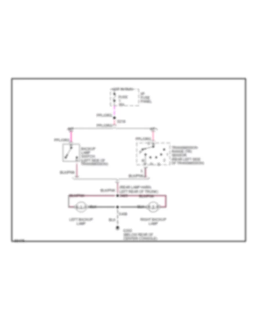
EXTERIOR LIGHTS
Back-up Lamps Wiring Diagram for Ford Mustang Cobra 1997
List of elements for Back-up Lamps Wiring Diagram for Ford Mustang Cobra 1997:
- (rear lamp harn, left rear of trunk) s425
- A/t
- Backup lamp switch (left side of transmission)
- Fuse 15a
- G302 (below rear of center console)
- Hot in run
- I/p fuse panel
- Left backup lamp
- M/t
- Right backup lamp
- S218
- S408
- Transmission range (tr) sensor (rear left side of transmission)
Exterior Lamps Wiring Diagram for Ford Mustang Cobra 1997
List of elements for Exterior Lamps Wiring Diagram for Ford Mustang Cobra 1997:
- (left rear lamp harn, near left rear park/stop/ turn lamp breakout) s420
- (luggage compt lamp harn, near luggage compt lamp switch breakout) s417
- (main harn, near instrument cluster breakout) s247
- (main harn, near instrument cluster breakout) s248
- (right rear lamp harn, near right rear park/stop/ turn lamp breakout) s420
- 87a
- All others
- Anti-theft controller module
- Brake 0n/off (boo) switch (on top of brake pedal support)
- C250
- C251
- Clock
- Electronic flasher (on rear of i/p fuse block)
- Fuse 15a
- G100 (left front of engine compt)
- G101 (right front of engine compt)
- G206 (behind center of i/p)
- G302 (below rear of center console)
- Hazard switch
- Head
- High mount stop lamps
- High mount stop/luggage compartment lamp assembly
- Hot at all times
- Hot in run
- I/p fuse panel
- Instrument cluster
- Left
- Left front park/ turn lamp
- Left rear park/ stop/ turn lamps
- Left rear side marker lamp
- Left turn indi- cator
- License lamps
- Main light switch
- Multi- function switch
- Off
- Park
- Remote/ keyless entry module
- Right
- Right front park/ turn lamp
- Right rear park/ stop/ turn lamps
- Right rear side marker lamp
- Right turn indi- cator
- S103
- S104
- S206
- S218
- S231
- S232 (body main harn, behind left side of i/p)
- S313
- S407
- S414
- S418 (rear lamp harn, left side of trunk)
- Solid state
- Standard only
- Turn switch
- Warning chime module
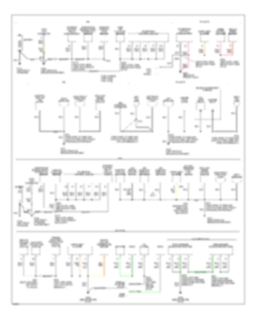
GROUND DISTRIBUTION
Ground Distribution Wiring Diagram (1 of 3) for Ford Mustang Cobra 1997
List of elements for Ground Distribution Wiring Diagram (1 of 3) for Ford Mustang Cobra 1997:
- (dash panel to headlamp junction harn, near left fog lamp breakout)
- (eng cntrl harn, behind right side of i/p)
- (fuel charge harn, near fuel inj #6)
- (left front of engine)
- 3.8l
- 3.8l & 4.6l
- 4.6l
- 4v only
- A/c high pressure cutout/ fan switch
- Abs diagnostic connector
- Air injection reaction (air) pump
- Air injection reaction (air) relay
- Amplifier
- Anti-lock brake control module
- Anti-theft controller module
- Base radio
- Battery
- C251
- Camshaft position (cmp) sensor
- Cd player
- Ckp/ cmp shield
- Constant control relay module (ccrm)
- Data link connector
- Electric cooling fan motor
- Engine compartment fuse box
- Engine coolant temperature sender
- Evaporative emission (evap) purge flow sensor
- Fog lamps relay
- Front speaker subwoofer amplifier
- G100 (left front of engine compartment)
- G100 (left front of engine compartment)
- G101 (right front of engine compartment)
- G110
- G110 (left front of engine)
- G203 (behind i/p, at right cowl)
- G206 (behind center of i/p)
- Instrument cluster
- Junction harn, right front of engine compartment)
- Left fog lamp
- Left front park/turn lamp
- Left headlamp
- Low engine coolant switch
- Mass air flow (maf) sensor
- Nca
- Passive anti-theft system (pats) control module
- Powertrain control module (pcm)
- Powertrain control module
- Premium or super sound
- Radio
- Rear speaker subwoofer amplifier
- Remote/ keyless entry module
- Right fog lamp
- Right front park/turn lamp
- Right headlamp
- S100 (engine cntrl sens harn, right side of eng compt)
- S103 (dash panel to headlamp junction harn, left front of engine compartment)
- S104 (dash panel to headlamp junction harn, right front of engine compartment)
- S106 (dash panel to headlamp junction harn, near left headlamp breakout)
- S110
- S115 (eng cntrl sens harn, right side of eng compt)
- S142
- S204
- S205 (main harn, near main light switch breakout)
- S208 (radio amp harn, behind center of i/p)
- S235 (eng cntrl harn, behind right side of i/p)
- S250 (eng cntrl harn, behind right side of i/p)
- S401 (body main harn, left front of trunk)
- S404 (radio amp harn, near rear speaker subwoofer amplifier breakout)
- S405 (radio amp harn, near front speaker subwoofer amplifier breakout)
- Speed control amplifier
- Starter relay
- Vehicle speed sensor
- W/ super sound
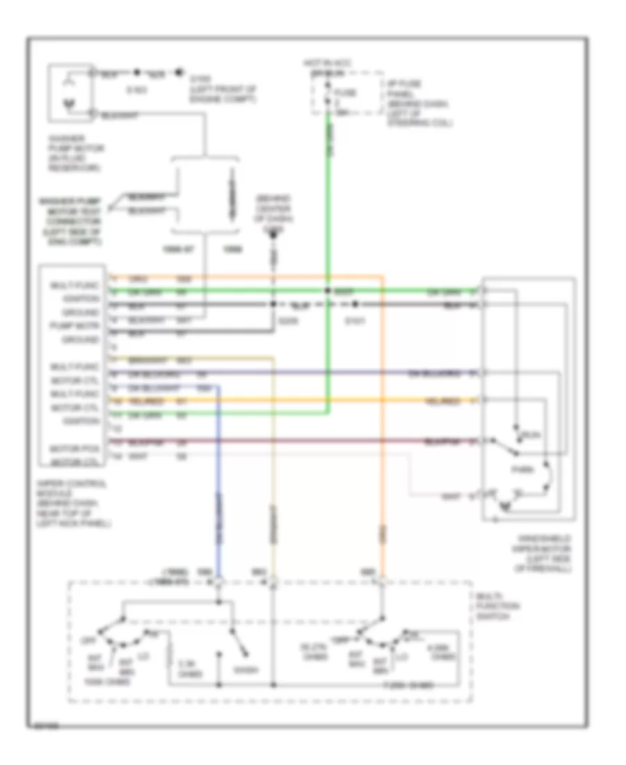
- Washer pump motor
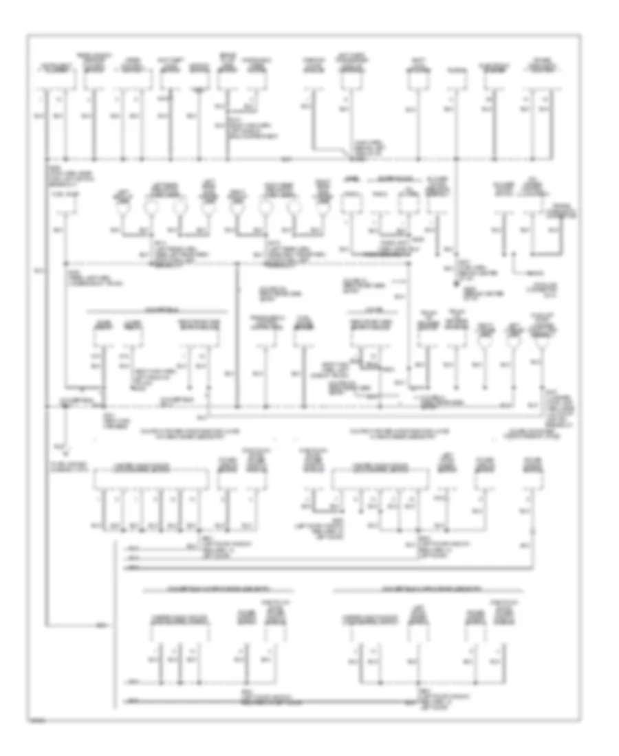
Ground Distribution Wiring Diagram (2 of 3) for Ford Mustang Cobra 1997
List of elements for Ground Distribution Wiring Diagram (2 of 3) for Ford Mustang Cobra 1997:
- (body main harn, left front of trunk) s402
- (body main harn, left side of trunk)
- (main harn, behind left side of i/p) s203
- (radio amp harn, near radio breakout)
- 87a
- A/c- heater control illumination
- Air bag diagnostic connector
- Air bag diagnostic monitor
- Anti-theft hood switch
- Anti-theft transceiver module (tats only)
- Base
- Behind center of i/p)
- Blower motor resistor assembly
- Blower motor switch
- Brake fluid level switch
- Cd player
- Clock
- Convertible
- Convertible only
- Convertible w/ remote/keyless entry
- Convertible w/o remote/keyless entry
- Coupe
- Coupe w/ power windows/door locks w/ remote/keyless entry
- Coupe w/ power windows/door locks w/o remote/keyless entry
- Coupe w/ remote/keyless entry
- Coupe w/o power windows/door locks
- Coupe w/o remote/keyless entry
- Data link connector (dlc)
- Electronic flasher
- Fuel gauge sender
- Fuel pump
- G206 (behind center of i/p)
- Gnd
- Hi mount stop/ luggage compt lamp assembly
- Ignition switch
- Instrument cluster
- Left backup lamp
- Left door disarm switch
- Left door)
- Left license lamp
- Left rear park/stop/ turn lamps
- Left rear side marker lamp
- Lower relay
- Master window/door lock control switch
- Nca
- One touch down power window module
- Power mirror switch
- Radio
- Raise relay
- Rear window defrost control switch
- Reg harn, in left door)
- Remote/keyless entry module
- Right backup lamp
- Right license lamp
- Right rear park/stop/ turn lamps
- Right rear side marker lamp
- S101 (body main harn, left side of eng compartment)
- S206 (main harn, near main light switch breakout)
- S209
- S301 (body main harness)
- S403
- S407 (luggage comp lamp harn, near lug compt lamp sw breakout)
- S408 (rear lamp harn, underside of trunk)
- S414 (left rear harn, near left rear park/ stop/turn lamp breakout)
- S501 (left door window reg harn, in left door)
- S503 (left door window reg harn, in left door)
- Shift lock actuator
- Stop/turn lamp breakout)
- Super sound
- To splice s302 (diagram 3 of 3)
- Transmission control switch (tcs)
- Trunk lid release solenoid
- Trunk lid release switch
- Warning chime module
- Windshield wiper motor
- Wiper control switch
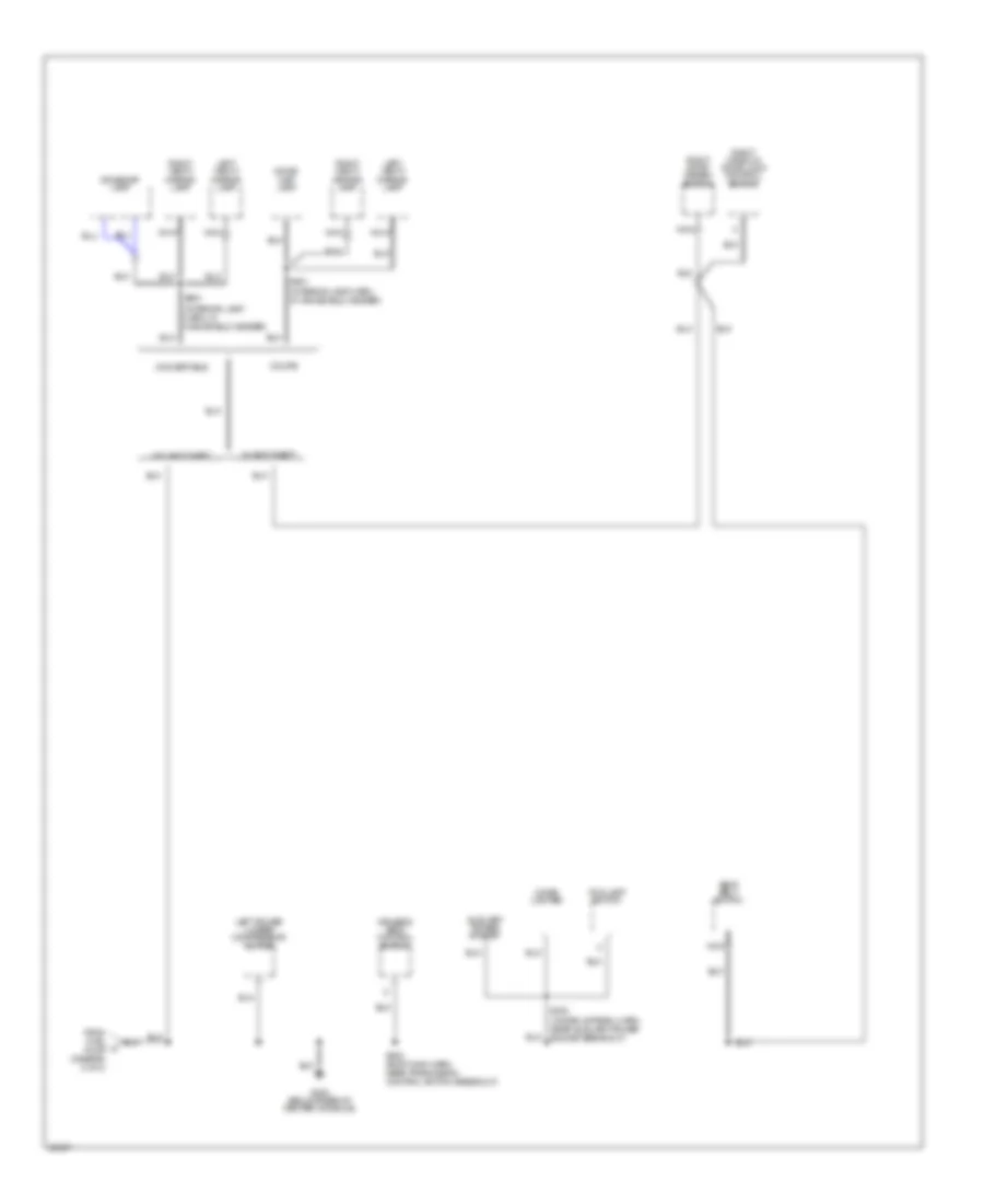
Ground Distribution Wiring Diagram (3 of 3) for Ford Mustang Cobra 1997
List of elements for Ground Distribution Wiring Diagram (3 of 3) for Ford Mustang Cobra 1997:
- (interior lamp harn, in windshield header)
- Auxiliary power socket
- Cigar lighter
- Convertible
- Coupe
- Dome/ map lamp
- Dome/map lamp
- Driver's seat control switch
- Fog lamp switch
- From fuel a pump (diagram 2 of 3)
- G300 (below rear of center console)
- Left power lumbar compressor motor
- Left vanity mirror lamp
- Nca
- Right door disarm switch
- Right vanity mirror lamp
- Right window/ door lock control switch
- S302 (body main harn, near tranmission control switch breakout)
- S303 (console panel harn, near auxiliary power socket breakout)
- S901
- S901 (interior lamp harn, in windshield header)
- Seat belt switch
- W/ anti-theft
- W/o anti-theft
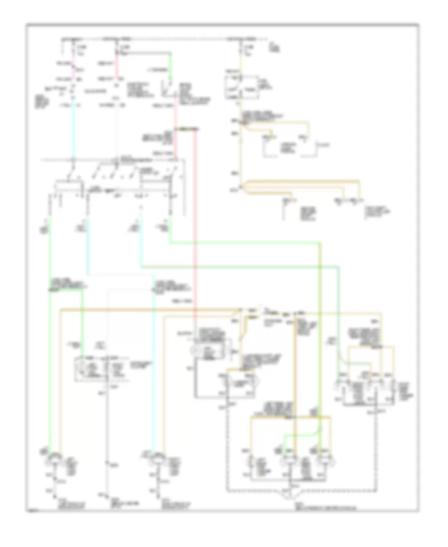
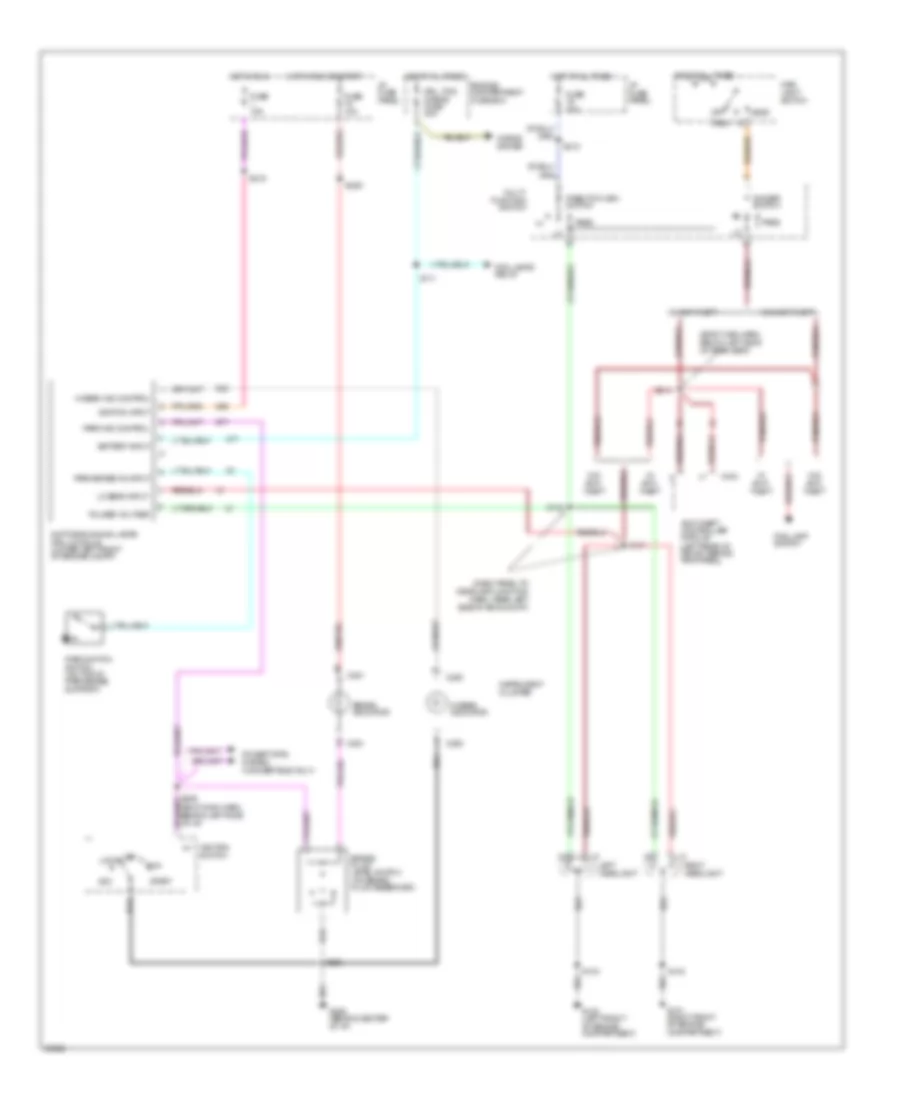
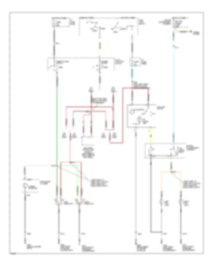
HEADLIGHTS
Headlight Wiring Diagram, with DRL for Ford Mustang Cobra 1997
List of elements for Headlight Wiring Diagram, with DRL for Ford Mustang Cobra 1997:
- (body main harn, below left side of rear seat)
- (dash panel to headlamp junction harn, near left side of eng compt)
- Acc
- Anti-theft controller module (left rear of trunk, behind trim panel)
- Battery input
- Brake fluid level switch (on brake fluid reservoir)
- Brake indicator
- C250
- C251
- C404
- Daytime running lamps (drl) module (lower left front of engine compt)
- Dimmer switch
- Drl, fog, horns fuse 20a
- Engine compartment fuse box
- Fog lamp switch
- Fog lamps relay
- Fuse 10a
- Fuse 15a
- Fuse 20a
- G100 (left front of engine compartment)
- G101 (right front of engine compartment)
- G206 (behind center of i/p)
- Head
- Hi beam ind control
- Hi-beam indicator
- Horns system
- Hot at all times
- Hot in run
- Hot in run or start
- I/p fuse panel
- Ignition input
- Ignition switch
- Instrument cluster
- Left headlight
- Lo beam input
- Lock
- Main light switch
- Multi- function switch
- Off
- Park
- Park brake on input
- Park ind control
- Park switch switch (on top of park brake support)
- Pass
- Pass-to-flash switch
- Power tops system (convertible only)
- Pulsed voltage
- Right headlight
- Run
- S103
- S104
- S111
- S131
- S133
- S206
- S210
- S218
- S229
- S246 (body main harn, behind left side of i/p)
- S314
- Start
- W/ anti- theft
- W/ anti-theft
- W/o anti- theft
- W/o anti-theft
Headlight Wiring Diagram, without DRL for Ford Mustang Cobra 1997
List of elements for Headlight Wiring Diagram, without DRL for Ford Mustang Cobra 1997:
- (body main harn, below left side of rear seat)
- (dash panel to headlamp junction harn, near left side of eng compt)
- Anti-theft controller module (left rear of trunk, behind trim panel)
- C250
- C251
- Dimmer switch
- Drl fog horns fuse 20a
- Engine compartment fuse box
- Fog lamp switch
- Fog lamps relay
- Fuse 10a
- Fuse 20a
- G100 (left front of engine compartment)
- G101 (right front of engine compartment)
- G206 (behind center of i/p)
- G300 (below rear of center console)
- Head
- Hi-beam indicator
- Horns system
- Hot at all times
- I/p fuse panel
- Illumination
- Instrument cluster
- Left fog light
- Left headlight
- Main light switch
- Multi- function switch
- Off
- On indica- tor
- Park
- Pass
- Pass-to-flash switch
- Right fog light
- Right headlight
- S103
- S104
- S111
- S131
- S133
- S134
- S206
- S210
- S230 (main harn, near warning chime module breakout)
- S303
- S314
- W/ anti- theft
- W/o anti- theft
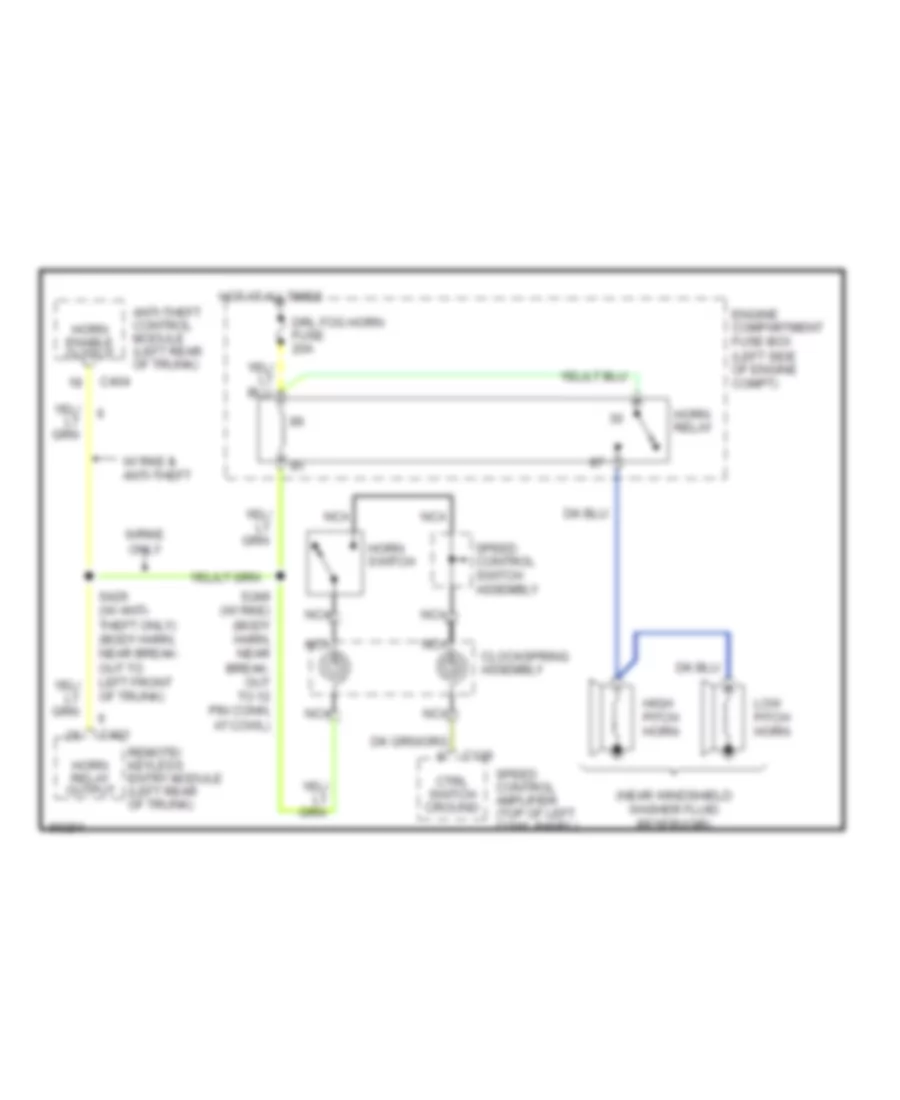
HORN
Horn Wiring Diagram for Ford Mustang Cobra 1997
List of elements for Horn Wiring Diagram for Ford Mustang Cobra 1997:
- (near windshield washer fluid reservoir)
- Anti-theft control module (left rear of trunk)
- C136
- C401
- C404
- Clockspring assembly
- Ctrl switch cround
- Drl fog horn fuse 20a
- Engine compartment fuse box (left side of engine compt)
- High pitch horn
- Horn enable output
- Horn relay
- Horn relay output
- Horn switch
- Hot at all times
- Low pitch horn
- Nca
- Remote/ keyless entry module (left rear of trunk)
- S249 (w/ rke) (body harn, near break- out to 12 pin conn, at cowl)
- S426 (w/ anti- theft only) (body harn, near break- out to left front of trunk)
- Speed control amplifier (top of left cowl panel)
- Speed control switch assembly
- W/ rke & anti-theft
- W/rke only
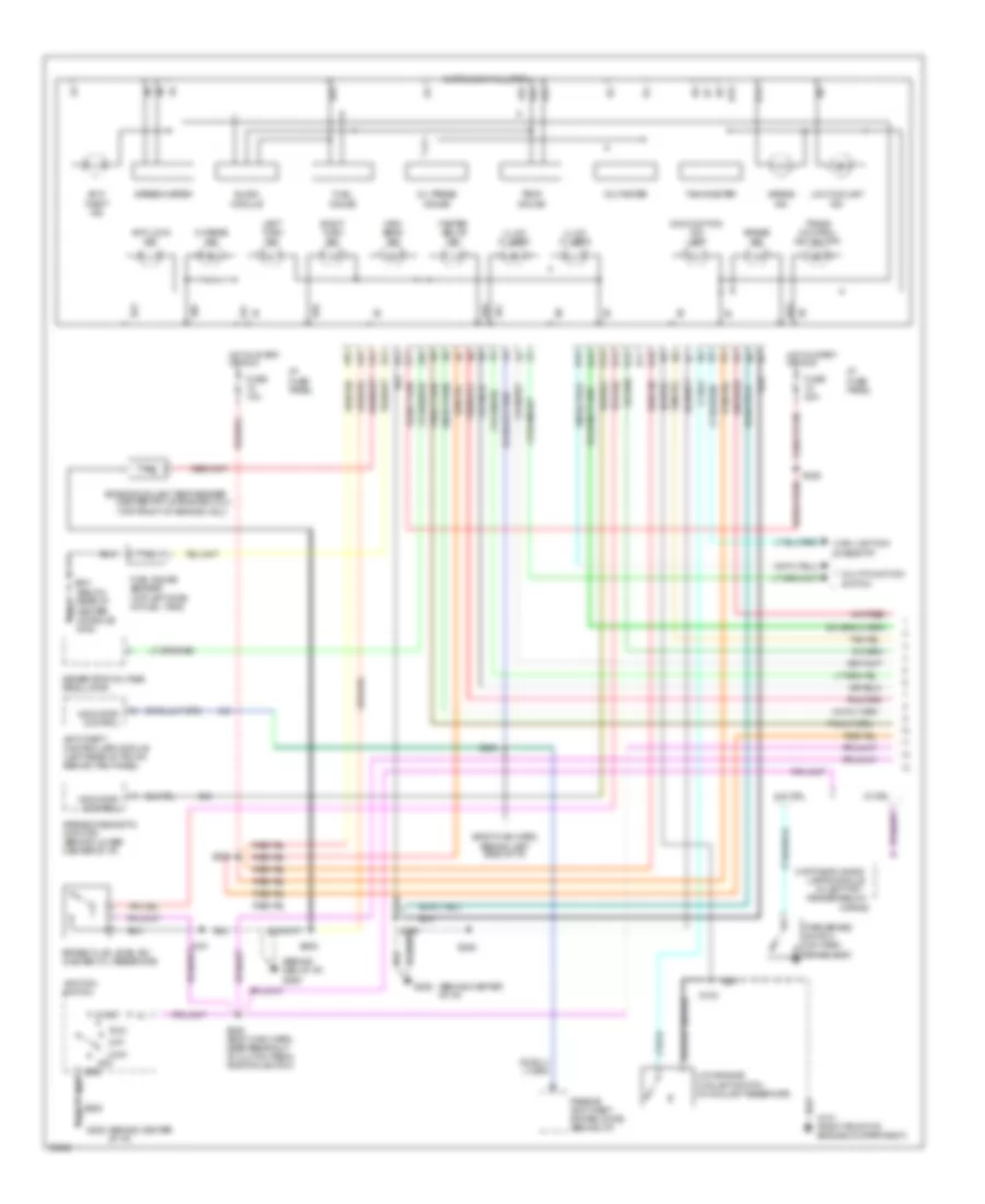
INSTRUMENT CLUSTER
Instrument Cluster Wiring Diagram (1 of 2) for Ford Mustang Cobra 1997
List of elements for Instrument Cluster Wiring Diagram (1 of 2) for Ford Mustang Cobra 1997:
- (behind cen of i/p) g206
- (behind center of i/p)
- (below rear of
- (body main harn, behind left side of i/p)
- (in left frt
- (top front of engine (4.6l))
- A10
- A11
- A12
- A13
- A14
- A15
- A16
- Acc
- Airbag diagnostic monitor (behind lower center of i/p)
- Airbag ind
- Anti- theft ind
- Anti-lock ind
- Anti-theft controller module (left rear of trunk behind trim panel)
- B10
- B11
- B12
- B13
- B14
- B15
- B16
- Brake fluid level sw (master cyl reservoir)
- Brake ind
- Center console) g302
- Charge ind
- Control
- Daytime running
- Engine coolant temp sender (center frt of engine (3.8l))
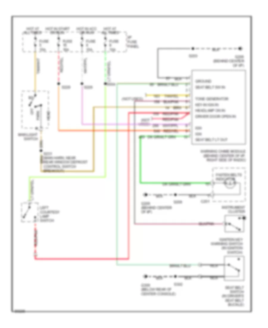
- Fasten belts ind
- Fender below
- Fuel gauge
- Fuel gauge sender (top left side of fuel tank)
- Fuse 10a
- Fuse 20a
- G101 (right front of engine compartment)
- G206
- Generator voltage regulator
- Grd
- High beam ind
- Horns)
- Hot in start or run
- I/p fuse panel
- Ignition switch
- Illum (2 used)
- Illum (3 used)
- Indicator
- Instrument cluster
- Lamps module
- Left turn ind
- Lock
- Low coolant ind
- Low engine coolant switch (in coolant reservoir)
- Main light sw: rheostat
- Malfunction ind lamp
- Multi-function switch
- Off
- Oil press gauge
- Park brake switch (on park brake assy)
- Passive anti-theft system (pats) (behind i/p)
- Right turn ind
- Run
- S100
- S101
- S205
- S206
- S228
- S229
- S246 (body main harn, near breakout to clutch pedal position switch)
- S254
- S301
- Slosh module
- Speedometer
- Start
- Tachometer
- Temp gauge
- Trans control ind (od off)
- Voltmeter
- W/ drl
- W/o drl
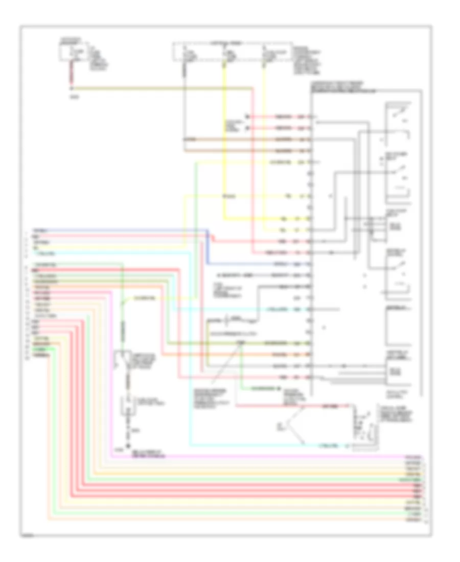
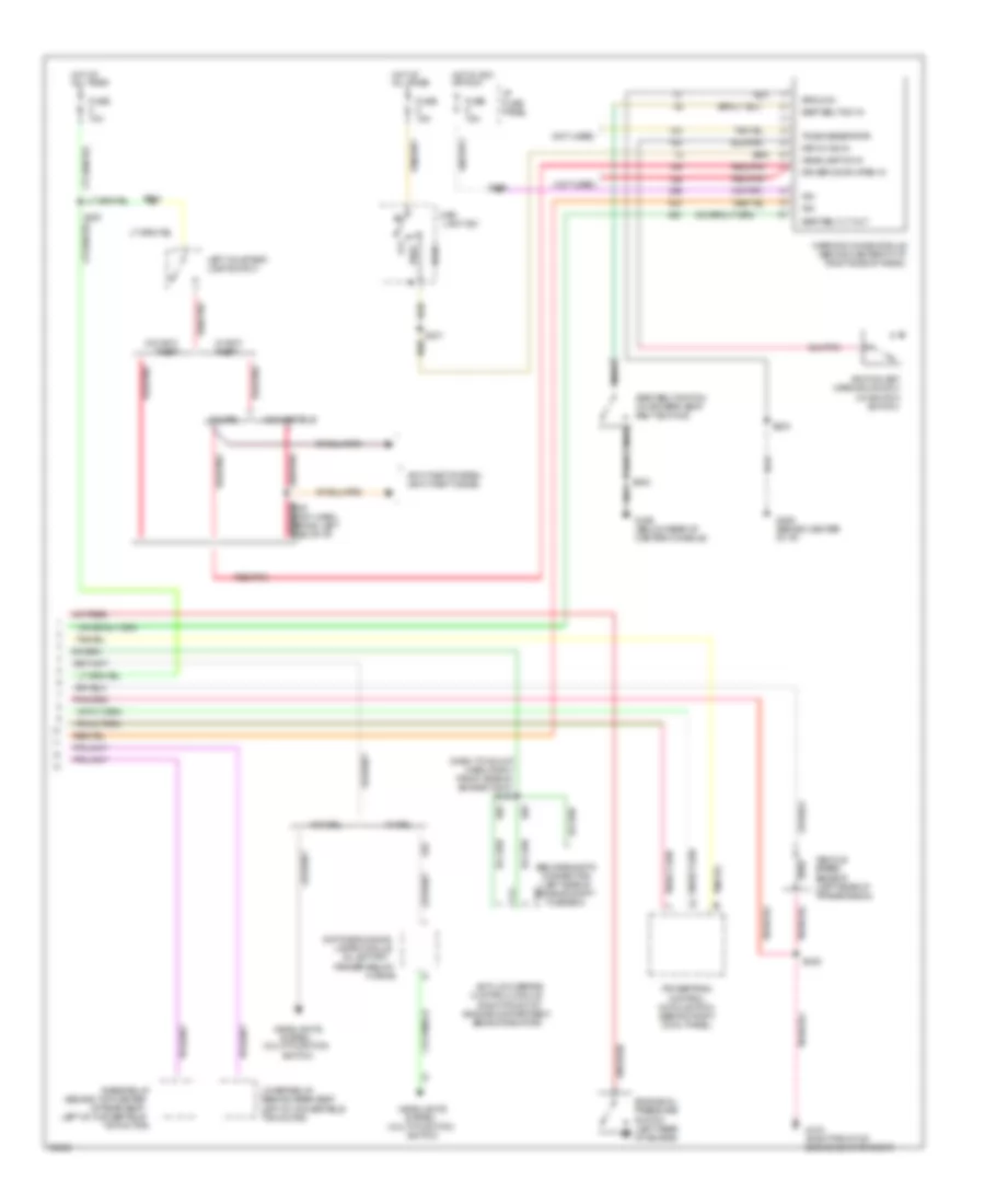
Instrument Cluster Wiring Diagram (2 of 2) for Ford Mustang Cobra 1997
List of elements for Instrument Cluster Wiring Diagram (2 of 2) for Ford Mustang Cobra 1997:
- (behind top center
- (dash to hdlmp harn, right front side of engine comt) s136
- (in left frt
- (multi-function
- (not used)
- Abs diagnostic connector (left side of engine compt fuse box)
- Anti-lock brake control module (right front of
- Anti-theft system (anti-theft diode)
- Behind radiator)
- C141
- C142
- Convertible
- Coupe
- Daytime running
- Driver door open in
- Engine compartment,
- Engine oil pressure switch (left rear of engine)
- Fender below
- Fuse 10a
- Fuse 15a
- G103 (right front of engine compartment)
- G206 (behind center of i/p)
- G302 (below rear of center console)
- Ground
- Head
- Headlamp on in
- Headlights
- Horns)
- Hot at all times
- Hot in acc or run
- I/p fuse panel
- Ign
- Ignition key warning switch (in ignition switch)
- Key-in ign in
- Lamps module
- Left courtesy lamp switch
- Left of convertible
- Light sw
- Lower relay (behind rear seat, left of convertible top motor)
- Main
- Nca
- Of rear seat,
- Off
- Park
- Powertrain control module (pcm) (behind right cowl panel)
- Raise relay
- Red/pnk
- S203
- S221
- S226
- S231
- S235
- S237 (body harn, behind left side of i/p)
- S302
- S504
- Seat belt lt out
- Seat belt sw in
- Seat belt switch (in drivers' seat belt buckle)
- Switch)
- System
- Tone generator
- Top motor)
- Vehicle speed sensor (left rear of transmission)
- W/ anti- theft
- W/ drl
- W/o anti- theft
- W/o drl
- Warning chime module (behind center of i/p, right side of radio)
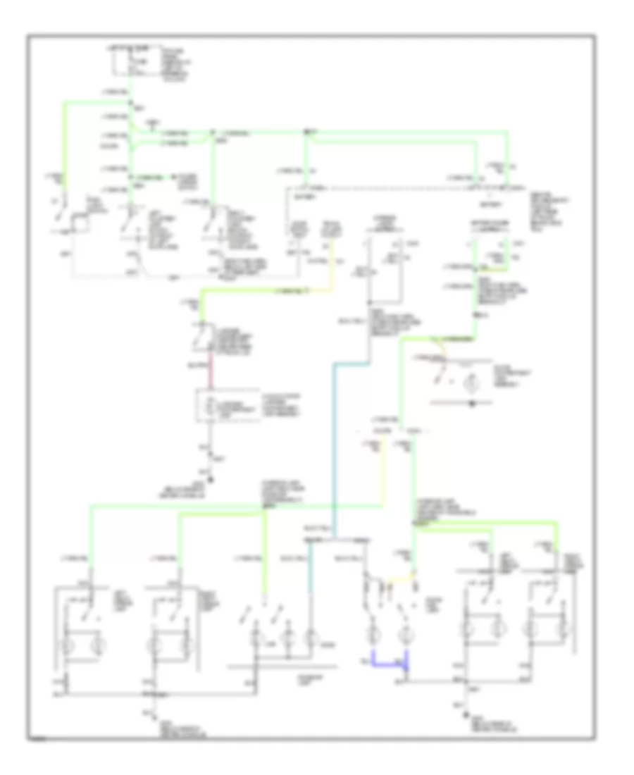
INTERIOR LIGHTS
Courtesy Lamps Wiring Diagram, with Remote/Keyless Entry for Ford Mustang Cobra 1997
List of elements for Courtesy Lamps Wiring Diagram, with Remote/Keyless Entry for Ford Mustang Cobra 1997:
- (interior lamp lamp harn, near center of windshield header) s902
- (interior lamp lamp harn, near dome/map lamp breakout)
- Battery
- Battery saver output
- C400
- C401
- C402
- Conv.
- Coupe
- Dome
- Dome/ map lamp
- Dome/map lamp
- Door switch input
- Fuse 10a
- G300 (below rear of center console)
- Glove compartment lamp assembly
- Hi mount stop/ luggage compartment lamp assembly
- Hot at all times
- I/p fuse panel (behind i/p, left of steering column)
- In remote/keyless entry module breakout)
- Interior lamps output
- Left courtesy lamp switch (in front of left door jamb)
- Left vanity mirror lamp
- Luggage compartment lamp
- Luggage compartment lamp switch (center rear of trunk lid)
- Main light switch
- Map
- Nca
- Power mirror switch
- Remote/ keyless entry module (left rear of trunk, behind side trim)
- Right courtesy lamp switch (in front of right door jamb)
- Right vanity mirror lamp
- S221
- S306
- S318
- S407
- S410
- S428 (body main harn, in remote/keyless entry module breakout)
- S504
- S901
- S902
- Trunk lid lamp output
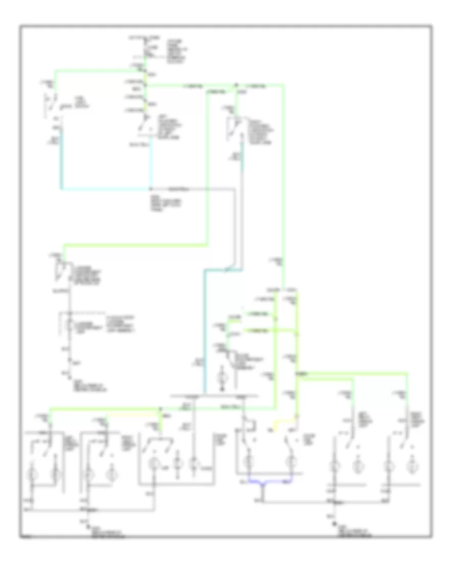
Courtesy Lamps Wiring Diagram, without Remote/Keyless Entry for Ford Mustang Cobra 1997
List of elements for Courtesy Lamps Wiring Diagram, without Remote/Keyless Entry for Ford Mustang Cobra 1997:
- Conv.
- Coupe
- Dome
- Dome/ map lamp
- Fuse 10a
- G300 (below rear of center console)
- Glove compartment lamp assembly
- Hi mount stop/ luggage compartment lamp assembly
- Hot at all times
- I/p fuse panel (behind i/p, left of steering column)
- Left courtesy lamp switch (in front of left door jamb)
- Left vanity mirror lamp
- Luggage compartment lamp
- Luggage compartment lamp switch (center rear of trunk lid)
- Main light switch
- Map
- Nca
- Right courtesy lamp switch (in front of right door jamb)
- Right vanity mirror lamp
- S221
- S223
- S306
- S320 (body main harn, near left cowl panel)
- S407
- S504
- S902
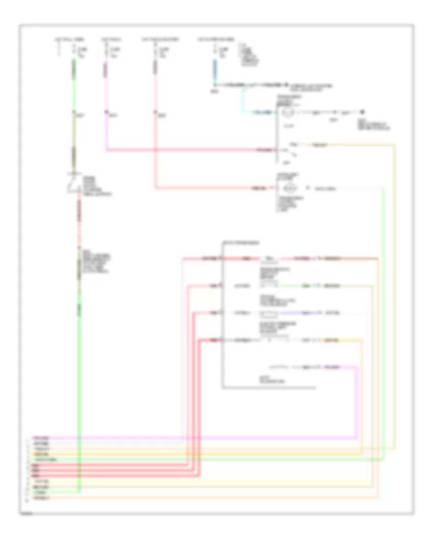
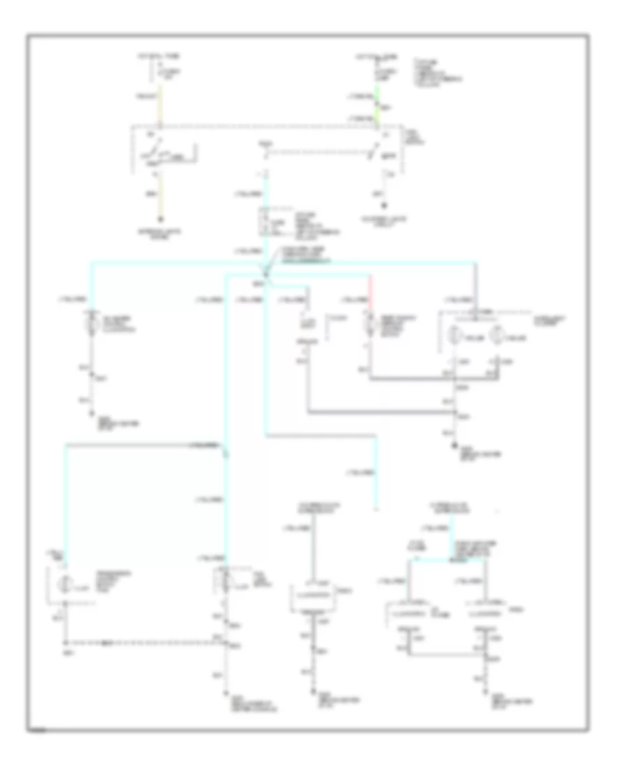
Instrument Illumination Wiring Diagram for Ford Mustang Cobra 1997
List of elements for Instrument Illumination Wiring Diagram for Ford Mustang Cobra 1997:
- (main harn, near warning chime module breakout)
- (radio amplifier harn, behind center of i/p) s238
- 2 bulbs
- 3 bulbs
- A/c heater control illumination
- C250
- C251
- C257
- C280
- C281
- Cd player
- Clock
- Courtesy lights circuit
- Dome
- Exterior lights system
- Fog lamp switch
- Fuse 10a
- Fuse 5 15a
- Fuse 8 10a
- G206 (behind center of i/p)
- G300 (below rear of center console)
- Ground
- Head
- Hot at all times
- I/p fuse panel (behind i/p, left of steering column)
- Illum
- Illum input
- Illumination
- Instrument cluster
- Main light switch
- Off
- Park
- Radio
- Rear window defrost control switch
- S201
- S203
- S206
- S209
- S221
- S230
- S301
- S302
- S303
- Super sound
- Transmission control switch (tcs)
- W/ cd player
- W/ premium or
- W/o premium or
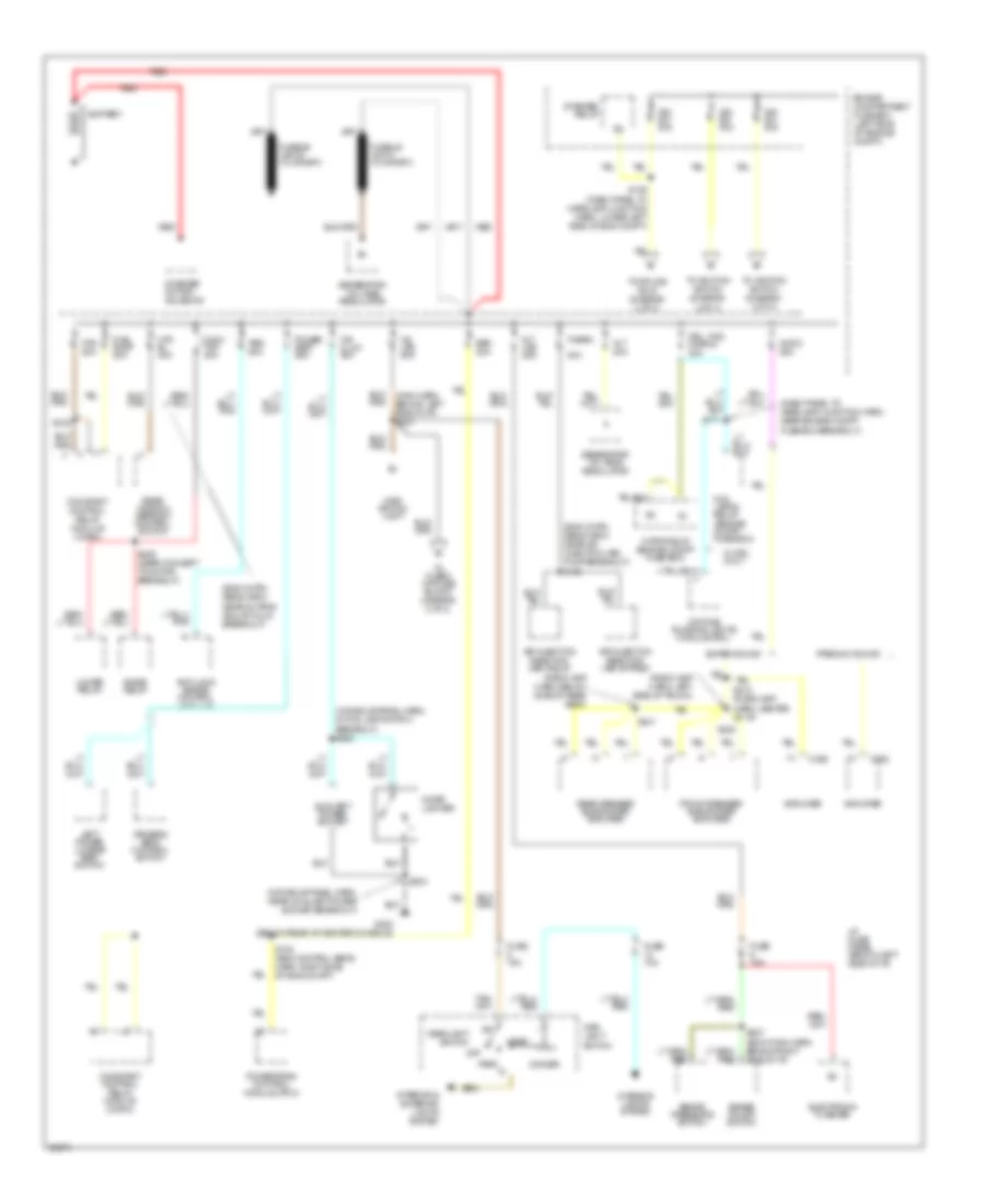
POWER DISTRIBUTION
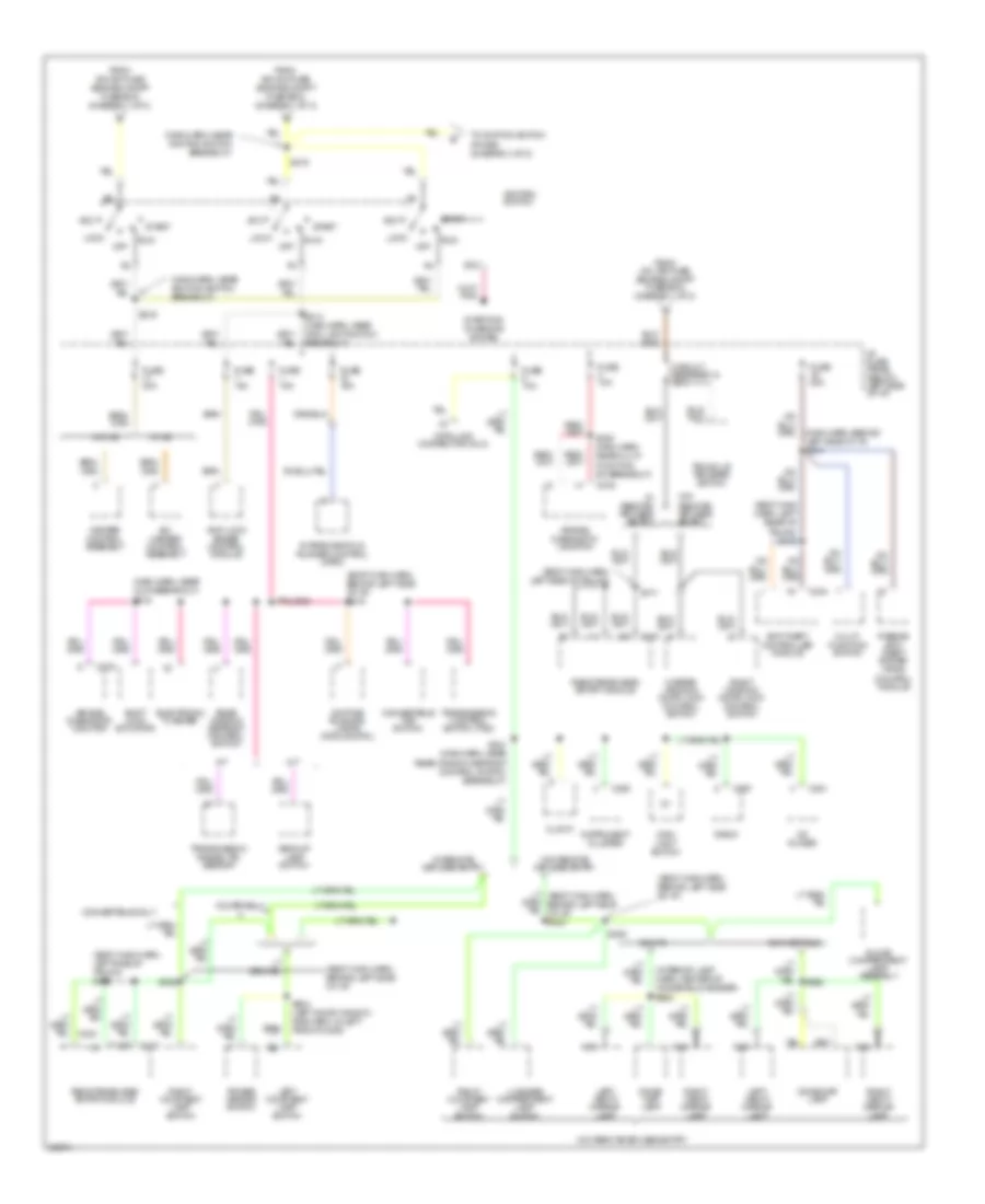
Power Distribution Wiring Diagram (1 of 3) for Ford Mustang Cobra 1997
List of elements for Power Distribution Wiring Diagram (1 of 3) for Ford Mustang Cobra 1997:
- (console panel harn, in fog lamp switch breakout) s305
- (console panel harn, near auxiliary power socket breakout)
- (dash panel to headlamp junction harn, near engine compt fuse box breakout)
- (eng cntrl sens harn, near air injection (air) pump breakout) s145
- (eng cntrl sens harn, near octane adjust plug breakout)
- (radio amp harn, below side of rear seat)
- (radio amp harn, left side of trunk)
- 30a
- Abs 60a
- Air injection reaction (air) bypass
- Air injection reaction (air) relay
- Alt 20a
- Amplifier
- Anti-lock brake control module
- Audio 25a
- Auxiliary power socket
- Battery
- Brake on/off switch
- Brake pressure switch
- C282
- Cig illum 30a
- Cigar lighter
- Constant control relay module (ccrm)
- Conv top 30a
- Daytime running lights module (drl)
- Dimmer
- Driver's seat control switch
- Drl, fog, horns 20a
- Eec 20a
- Electronic flasher
- Engine compartment fuse box (left side of engine compt)
- Fan 60a
- Fog lamps relay (engine compt. fuse box)
- Front speaker subwoofer amplifier
- Fuel pump 20a
- Fuse 10a
- Fuse 15a
- G300 (below rear of center console)
- Generator/ voltage regulator
- Hd lps 50a
- Head
- Headlight switch
- Horn relay (engine compt fuse box)
- Htd bl 40a
- I/p fuse panel (below left side of i/p)
- Ign sw 40a
- Int lps 25a
- Interior & exterior lights system
- Interior lights system
- Left power lumbar seat switch
- Lower relay
- Main light switch
- Main switch light
- Off
- Park
- Power seat 25a
- Powertrain control module (pcm)
- Premium sound
- Raise relay
- Rear speaker subwoofer amplifier
- Rear window defrost control switch
- Red
- S102
- S108 (eng control sens harn, right side of eng compt)
- S109 (dash panel to headlamp junction harn, lower left side of eng compt)
- S111
- S207 (body main harn, behind right side of i/p)
- S212 (radio amp harn, center of i/p)
- S303
- S409 (near convert to motor breakout)
- S431
- S432
- Starter motor/ solenoid
- Starter relay
- Super sound
- Therm
- To fuse 8 (i/p fuse block) (diagram 2 of 3)
- To ignition switch (diagram 2 of 3)
- To ignition switch (diagram 3 of 3)
- To splice s215 (diagram 2 of 3)
- W/ drl only
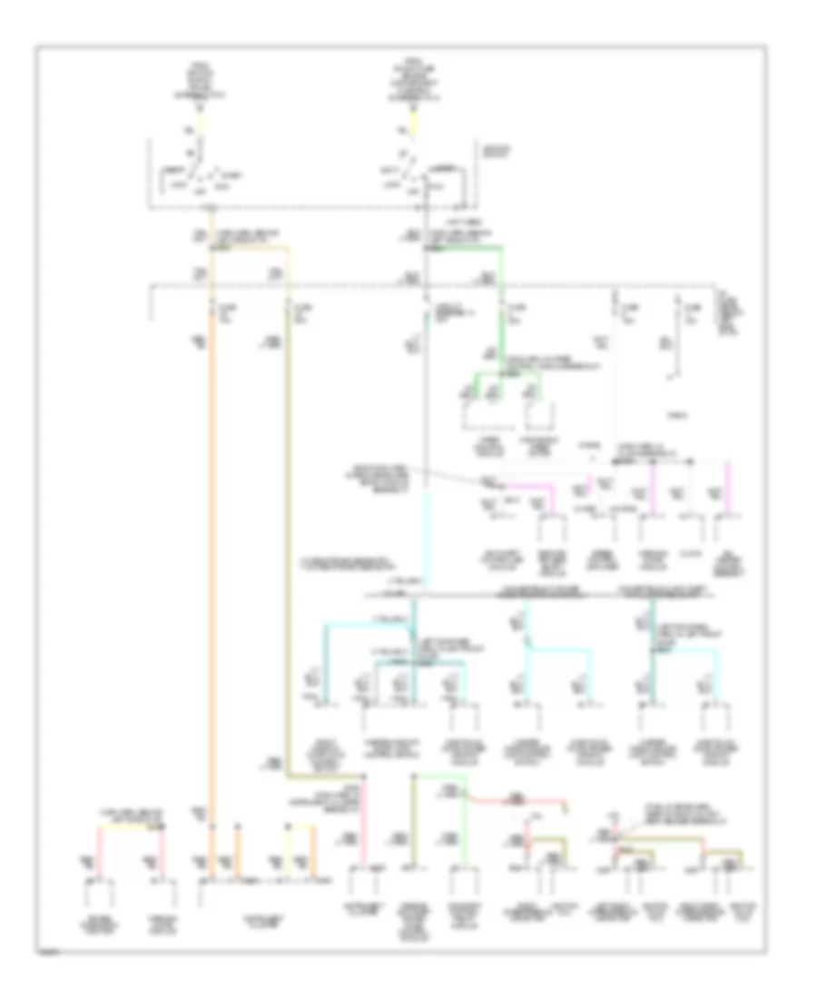
Power Distribution Wiring Diagram (2 of 3) for Ford Mustang Cobra 1997
List of elements for Power Distribution Wiring Diagram (2 of 3) for Ford Mustang Cobra 1997:
- (body main harn, behind left side of i/p)
- (body main harn, behind left side of i/p) s219
- (body main harn, left rear of trunk) s412
- (body main harn, left side of trunk)
- (body main harn, left side of trunk) s410
- (interior lamp harn, center of windshield header) s902
- (main harn, behind left side of i/p) s210
- (main harn, near ignition switch breakout)
- (main harn, near lock breakout) s218
- A/c- heater control assembly
- A/t
- Acc
- Air bag diagnostic monitor
- Anti-lock brake control module
- Anti-theft controller module
- Backup lamp switch
- C250
- C257
- C276
- C281
- C401
- C404
- Cd player
- Circuit breaker 12 20a
- Clock
- Control module
- Convertible
- Convertible only
- Convertible top switch
- Coupe
- Coupe only
- Data link connector (dlc)
- Daytime running lamps module (drl)
- Dome/ map lamp
- Dome/map lamp
- Electronic flasher
- From hd lps fuse (engine compt fuse box) (diagram 1 of 3)
- From ign sw fuse (engine compt fuse box) (diagram 1 of 3)
- Fuse 10a
- Fuse 15a
- Fuse 20a
- Fuse 30a
- Glove compartment lamp assembly
- Heater control assembly
- I/p fuse panel (below left side of i/p)
- Ignition switch
- Instrument cluster
- Intake manifold runner control (imrc)
- Left courtesy lamp switch
- Left vanity mirror lamp
- Lock
- Luggage compartment lamp switch
- M/t
- Main light switch
- Master window/ door lock control switch
- Multi- function switch
- Nca
- Off
- Passive anti- theft system (pats)
- Power mirror switch
- Radio
- Rear window defrost control switch
- Remote/keyless entry module
- Right courtesy lamp switch
- Right vanity mirror lamp
- Right window/ door lock control switch
- Run
- S214 (main harn, near main light switch breakout)
- S215
- S216
- S220 (main harn, near multi- function sw breakout)
- S221 (main harn, near rear window defrost control switch breakout)
- S306
- S411
- S504 (left door window rag harn, in left front door)
- S902
- Shift lock actuator
- Sta
- Start
- Starting/ charging system
- To ignition switch (pin b5) (diagram 3 of 3)
- Transmission control switch (tcs)
- Transmission range (tr) sensor
- Trunk lid release switch
- W/ a/c
- W/ remote keyless entry
- W/ remote/ keyless entry
- W/o a/c
- W/o remote keyless entry
- W/o remote/ keyless entry
- W/o remote/keyless entry
Power Distribution Wiring Diagram (3 of 3) for Ford Mustang Cobra 1997
List of elements for Power Distribution Wiring Diagram (3 of 3) for Ford Mustang Cobra 1997:
- (body main harn, in remote/keyless entry module breakout)
- (fuel charge harn, near on eng coolant temp sender breakout)
- (left door reg harn, in left front door) s505
- (main harn, behind left side of i/p) s224
- (main harn, behind left side of i/p) s227
- (main harn, behind left side of i/p) s229
- (main harn, in clock breakout) s226
- (main harn, in wiper control module breakout) s225
- (not used)
- * w/ remote keyless entry ** w/o remote keyless entry
- **pnk
- 3.8l
- 4.6l
- A/c- heater control assembly
- Acc
- Air bag diagnostic monitor
- Anti-theft controller module
- C250
- C251
- Circuit breaker 14 20a
- Clock
- Constant control relay module
- Convertible w/ anti-theft or illuminated entry
- Convertible w/ power windows/door locks only
- Coupe
- From ign sw fuse (engine compartment fuse box) (diagram 1 fo 3)
- From ignition switch (pin b4) (diagram 2 of 3)
- Fuse 10a
- Fuse 15a
- Fuse 20a
- Fuse 30a
- I/p fuse panel (below left side of i/p)
- Ignition coil
- Ignition coils 1 & 2
- Ignition coils 3 & 4
- Ignition switch
- Instrument cluster
- Left radio interference capacitor
- Lock
- Master window/ door lock control switch
- Master window/door lock control switch
- Nca
- Off
- One touch down power window module
- Passive anti-theft system (pats) control module
- Radio
- Radio interference capacitor
- Remote/ keyless entry module
- Right radio interference capacitor
- Right window/ door lock control switch
- Run
- S132
- S228 (main harn, in instrument cluster breakout)
- S413
- Speed control amplifier
- Start
- W/ rke
- W/o rke
- Warning chime module
- Windshield wiper motor
- Wiper control module
POWER DOOR LOCKS
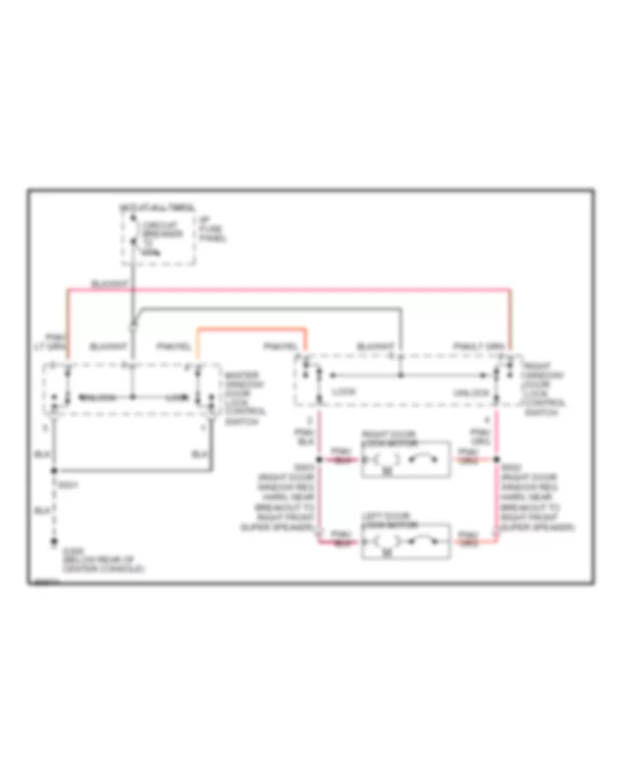
Door Lock Wiring Diagram for Ford Mustang Cobra 1997
List of elements for Door Lock Wiring Diagram for Ford Mustang Cobra 1997:
- Circuit breaker 20a
- G300 (below rear of center console)
- Hot at all times
- I/p fuse panel
- Left door lock motor
- Lock
- Master window/ door lock control switch
- Right door lock motor
- Right window/ door lock control switch
- S501
- S602 (right door window reg harn, near breakout to right front super speaker)
- S603 (right door window reg harn, near breakout to right front super speaker)
- Unlock
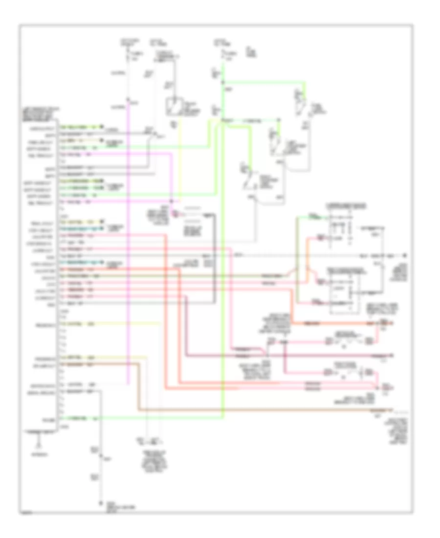
Keyless Entry Wiring Diagram for Ford Mustang Cobra 1997
List of elements for Keyless Entry Wiring Diagram for Ford Mustang Cobra 1997:
- (body harn, near breakout to 8 pin conn, below rear of center console)
- (body harn, near breakout to anti- theft ctrl mod)
- (coupe) (convertible)
- (left rear of trunk, behind side trim) remote/keyless entry module
- 10a
- 15a
- Antenna
- Anti-theft controller module (left rear of trunk, behind side trim)
- Batt+
- Batt+ save in
- Batt+ save out
- C400
- C401
- C402
- Circuit breaker 12 20a
- Ctsy lps out
- Ctsy/dr sw in
- Dr ajar out
- Exterior lamps
- Fuse 6
- Fuse 8
- G206 (behind center of i/p)
- G300 (below rear of center console)
- Gnd
- Horn output
- Horns
- Hot at all times
- Hot in acc or run
- I/p fuse panel
- Ignition sw in
- Interior lamps
- Left courtesy lamp switch
- Left door lock motor
- Lk drs out
- Lk in
- Lock
- Main lamp switch
- Master window/door lock control switch
- Near break- out to rke module)
- Park lps out
- Power
- Program a
- Program b
- Rel trnk out
- Right courtesy lamp switch
- Right door lock motor
- Right window/door lock control switch
- Rke module program connector (left rear of trunk, behind side trim)
- S221
- S302
- S316
- S401
- S403 s402
- S410
- S411
- S413
- S423 (body harn, near breakout to 12 pin conn, left side of trunk)
- S424 (body harn, near breakout to rke mod)
- S427
- S501
- Signal ground
- Transmitter in
- Trnk lp out
- Trunk lid release solenoid
- Trunk lid release switch
- Unlk in
- Unlk lt dr
- Unlk rt dr
- Unlock
POWER MIRRORS
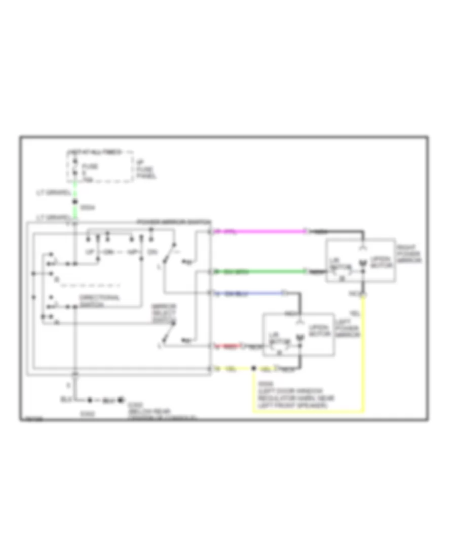
Power Mirror Wiring Diagram for Ford Mustang Cobra 1997
List of elements for Power Mirror Wiring Diagram for Ford Mustang Cobra 1997:
- Directional switch
- Fuse 10a
- G302 (below rear center of console)
- Hot at all times
- I/p fuse panel
- L/r motor
- Left power mirror
- Mirror select switch
- Nca
- Nca m
- Power mirror switch
- Red
- Right power mirror
- S302
- S504
- S506 (left door window regulator harn, near left front speaker)
- Up/dn motor
POWER SEATS
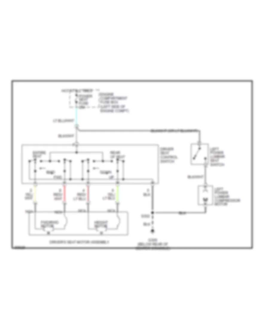
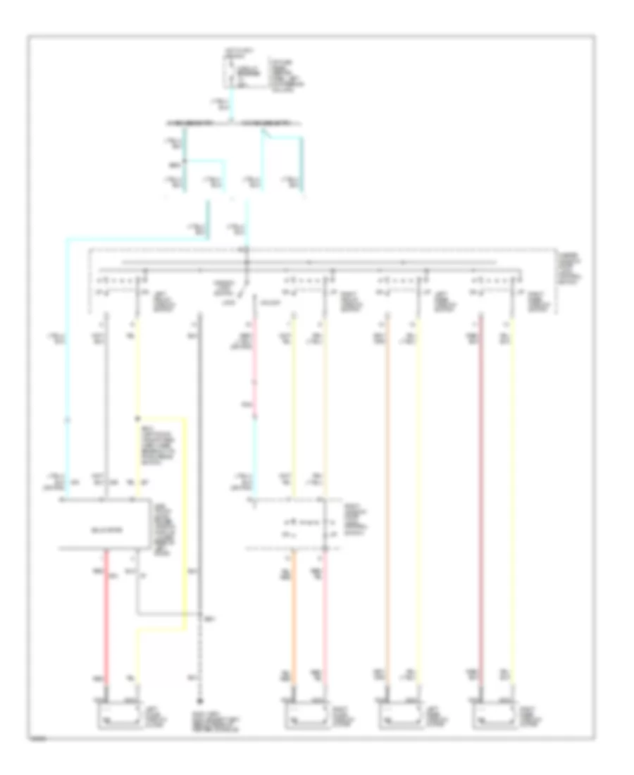
Power & Lumbar Seat Wiring Diagram for Ford Mustang Cobra 1997
List of elements for Power & Lumbar Seat Wiring Diagram for Ford Mustang Cobra 1997:
- Down
- Driver seat control switch
- Driver's seat motor assembly
- Engine compartment fuse box (left side of engine compt)
- Entire seat
- Fwd
- Fwd/rwd motor
- G300 (below rear of center console)
- Height motor
- Hot at all times
- Left power lumbar compressor motor
- Left power lumbar seat switch
- M m
- Nca
- Power seat fuse 25a
- Rear of seat
- Rwd
- S302
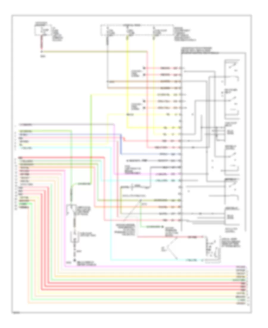
POWER TOP/SUNROOF
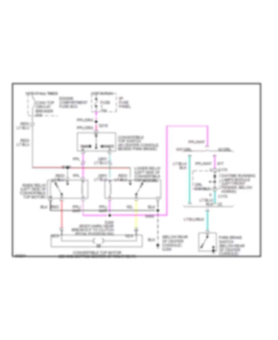
Power Top/Sunroof Wiring Diagrams for Ford Mustang Cobra 1997
List of elements for Power Top/Sunroof Wiring Diagrams for Ford Mustang Cobra 1997:
- (below rear of center console) g300
- C170
- Conv top circuit breaker 30a
- Convertible top motor (behind bottom center of right seat)
- Convertible top switch (in center console, beside park brake)
- Daytime running lamps module (left front fender, below horns)
- Drl disable
- Engine compartment fuse box
- Fuse 15a
- Hot at all times
- Hot in run
- I/p fuse panel
- Lower
- Lower relay (left side of convertible top motor)
- Nca
- Park brake switch (below rear of center console)
- Raise
- Raise relay (left side of convertible top motor)
- Red
- S219
- S246 (body harn, near breakout to clutch pedal position sw)
- S402
- S409
- W/ drl
- W/o drl
POWER WINDOWS
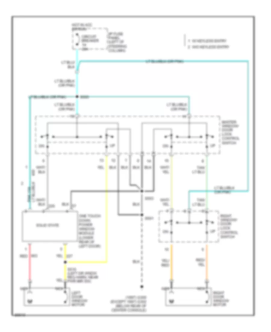
Power Window Wiring Diagram, Convertible for Ford Mustang Cobra 1997
List of elements for Power Window Wiring Diagram, Convertible for Ford Mustang Cobra 1997:
- (or pnk)
- Circuit breaker 20a
- G300 (1997) g302 (except 1997) (below rear of center console)
- Hot in acc or run
- I/p fuse panel (behind dash, left of steering column)
- Left door window motor
- Left front window switch
- Left rear window motor
- Left rear window switch
- Lock
- Master window/ door lock control switch
- Nca
- One touch down power window module (lower rear of left door)
- Pnk
- Red
- Right door window motor
- Right front window switch
- Right rear window motor
- Right rear window switch
- Right window/ door lock control switch
- S501
- S505
- S510 (left door window reg harn, near breakout to pwr mirror switch)
- Solid state
- Unlock
- W/ keyless entry
- W/o keyless entry
- Window lock switch
Power Window Wiring Diagram, Coupe for Ford Mustang Cobra 1997
List of elements for Power Window Wiring Diagram, Coupe for Ford Mustang Cobra 1997:
- (1997) g300 (except 1997) g302 (below rear of center console)
- Circuit breaker 20a
- Hot in acc or run
- I/p fuse panel (left of steering column)
- Left door window motor
- Master window/ door lock control switch
- Nca
- One touch down power window module (lower rear of left door)
- Red
- Right door window motor
- Right window/ door lock control switch
- S501
- S503
- S505
- S510 (left dr wndw reg harn, near pwr mir sw)
- Solid state
- W/ keyless entry
- W/o keyless entry
RADIO
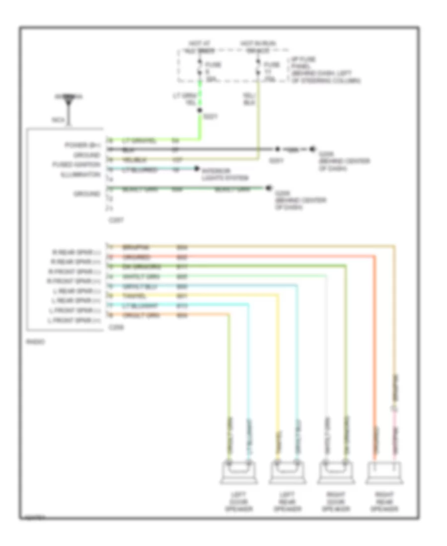
Base Radio for Ford Mustang Cobra 1997
List of elements for Base Radio for Ford Mustang Cobra 1997:
- Antenna
- C257
- C258
- Fuse 10a
- Fuse 15a
- Fused ignition
- G206 (behind center of dash)
- Ground
- Hot at all times
- Hot in run or acc
- I/p fuse panel (behind dash, left of steering column)
- Illuminaton
- Interior lights system
- L front spkr (+)
- L front spkr (-)
- L rear spkr (+)
- L rear spkr (-)
- Left door speaker
- Left rear speaker
- Nca
- Power (b+)
- R front spkr (+)
- R front spkr (-)
- R rear spkr (+)
- R rear spkr (-)
- Radio
- Right door speaker
- Right rear speaker
- S201
- S221
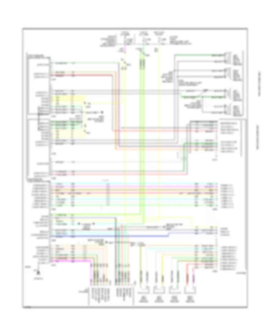
Premium Sound Radio Wiring Diagram for Ford Mustang Cobra 1997
List of elements for Premium Sound Radio Wiring Diagram for Ford Mustang Cobra 1997:
- (behind center of dash) g206
- (w/ cd) (w/o cd)
- Amplifier
- Antenna
- Audio fuse 25a
- Audio input (+)
- Audio input (-)
- Audio mute
- Audio on
- Audio out (+)
- Audio out (-)
- Audio system on
- C274
- C278
- C279
- C280
- C281
- C282
- C283
- C284
- C408
- C409
- C439
- C440
- Cd changer
- Cd left (+)
- Cd left (-)
- Cd right (-)
- Cd rigth (+)
- Engine compartment fuse box (left side of engine compt)
- Front speaker subwoofer amplifier
- Front spkr shld
- Fuse 10a
- Fuse 15a
- Fused ignition
- G206 (behind center of dash)
- Ground
- High audio (+)
- High audio (-)
- High audio mute
- Hot at all times
- Hot in run or acc
- I/p fuse panel (behind dash, left of steering column)
- Illumination
- Interior lights system
- L front (+) in
- L front (-) in
- L front spkr (+)
- L front spkr (-)
- L rear (+) in
- L rear (-) in
- L rear spkr (+)
- L rear spkr (-)
- Left door speaker
- Left front super sound speaker
- Left rear speaker
- Left rear super sound speaker
- Left sig in
- Left sig out
- Logic sense
- Low audio (+)
- Low audio (-)
- Low audio mute
- Nca
- Power
- R front (+) in
- R front (-) in
- R front spkr (+)
- R front spkr (-)
- R rear (+) in
- R rear (-) in
- R rear spkr (+)
- R rear spkr (-)
- Radio
- Rear speaker subwoofer amplifier
- Rear spkr shld
- Right door speaker
- Right front super sound speaker
- Right rear speaker
- Right rear super sound speaker
- Right sig in
- Right sig out
- S208
- S209 s201
- S212
- S222
- S404
- S405
- S431
- S432
- S433 (amp harn, below left side of rear seat)
- S434 (amp harn, below left side of rear seat)
- S436
- S437 (amp harn, below left side of rear seat)
- Signal return
- Tan
- With super sound only
SHIFT INTERLOCKS
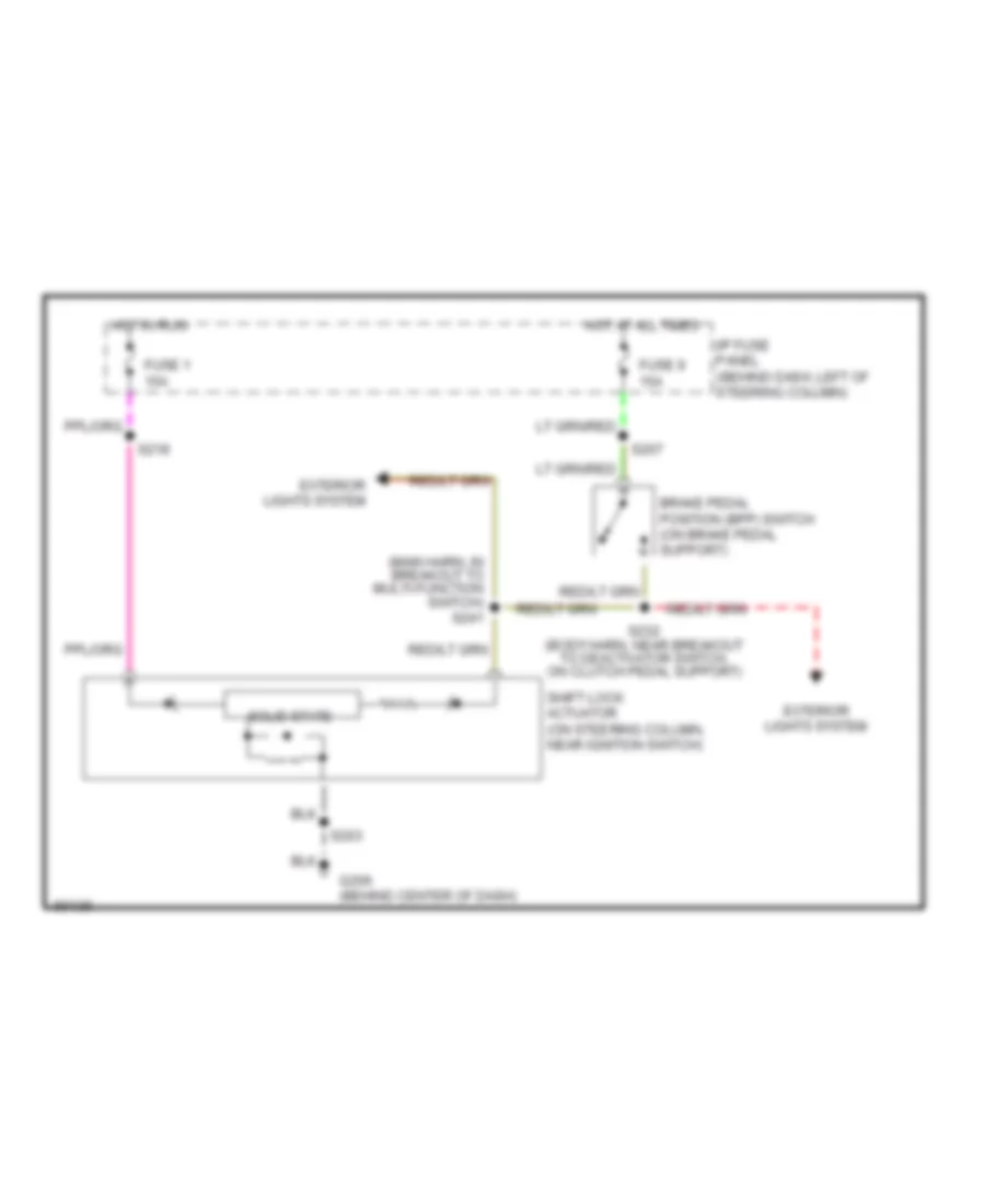
Shift Interlock Wiring Diagram for Ford Mustang Cobra 1997
List of elements for Shift Interlock Wiring Diagram for Ford Mustang Cobra 1997:
- (main harn, in breakout to multi-function switch) s241
- Brake pedal position (bpp) switch (on brake pedal support)
- Exterior lights system
- Fuse 1 15a
- Fuse 9 15a
- G206 (behind center of dash)
- Hot at all times
- Hot in run
- I/p fuse panel (behind dash, left of steering column)
- S203
- S207
- S218
- S232 (body harn, near breakout to deactivator switch, on clutch pedal support)
- Shift lock actuator (on steering column, near ignition switch)
- Solid state
STARTING/CHARGING
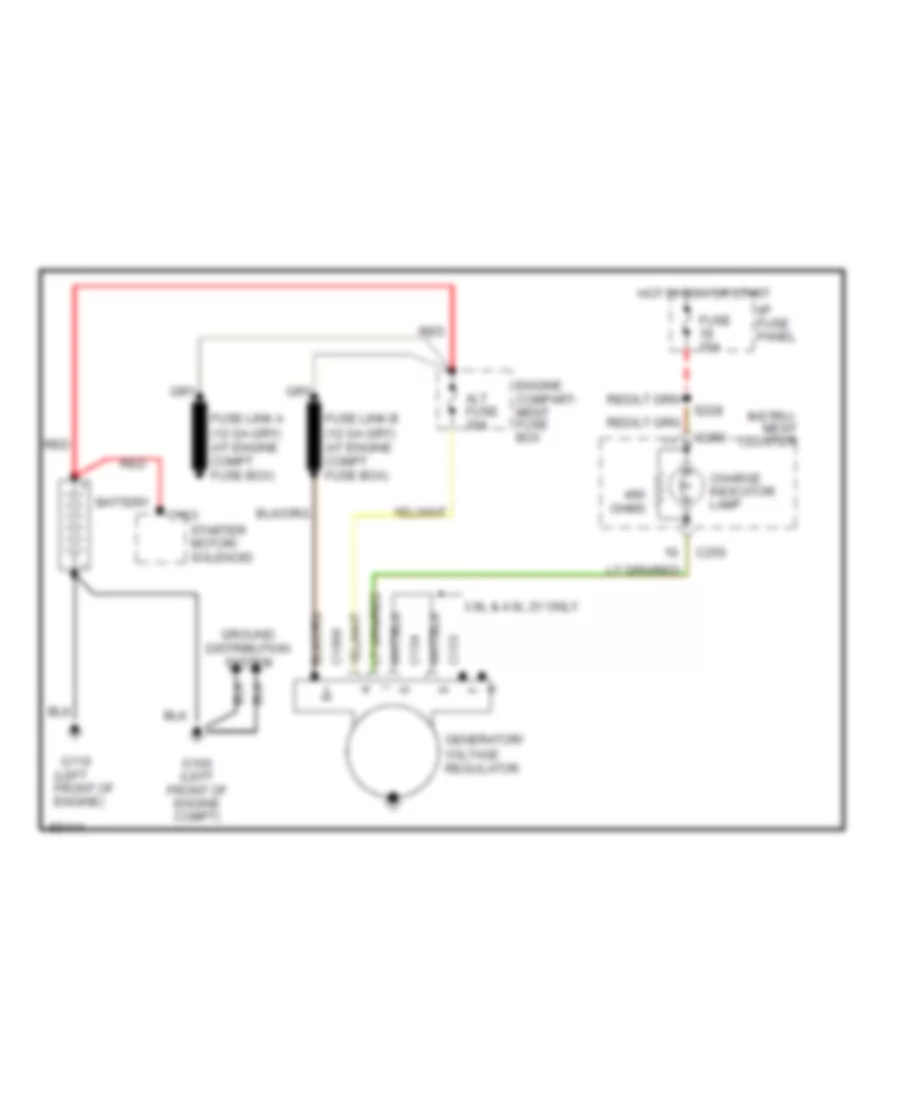
Charging Wiring Diagram for Ford Mustang Cobra 1997
List of elements for Charging Wiring Diagram for Ford Mustang Cobra 1997:
- 3.8l & 4.6l 2v only
- Alt fuse 20a
- Battery
- C1006
- C153
- C154
- C163
- C250
- Charge indicator lamp
- Engine compart- ment fuse box
- Fuse 20a
- G100 (left front of engine compt)
- G110 (left front of engine)
- Generator/ voltage regulator
- Ground distribution system
- Hot in run or start
- I/p fuse panel
- Instru- ment cluster
- Ohms
- Red
- S228
- Starter motor/ solenoid
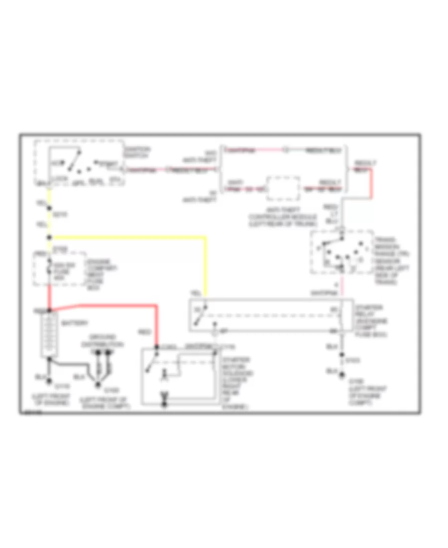
Starting Wiring Diagram, A/T for Ford Mustang Cobra 1997
List of elements for Starting Wiring Diagram, A/T for Ford Mustang Cobra 1997:
- (left front of engine compt)
- (left front of engine)
- Acc
- Anti-theft controller module (left rear of trunk)
- Battery
- C163
- Engine compart- ment fuse box
- G100
- G100 (left front of engine compt)
- G110
- Ground distribution system
- Ign sw fuse 40a
- Ignition switch
- Lock b4
- Off
- Red
- Run
- S103
- S215
- Sta
- Start
- Starter motor/ solenoid (lower right rear of engine)
- Starter relay (in engine compt fuse box)
- Trans- mission range (tr) sensor (rear left side of trans)
- W/ anti-theft
- W/o anti-theft
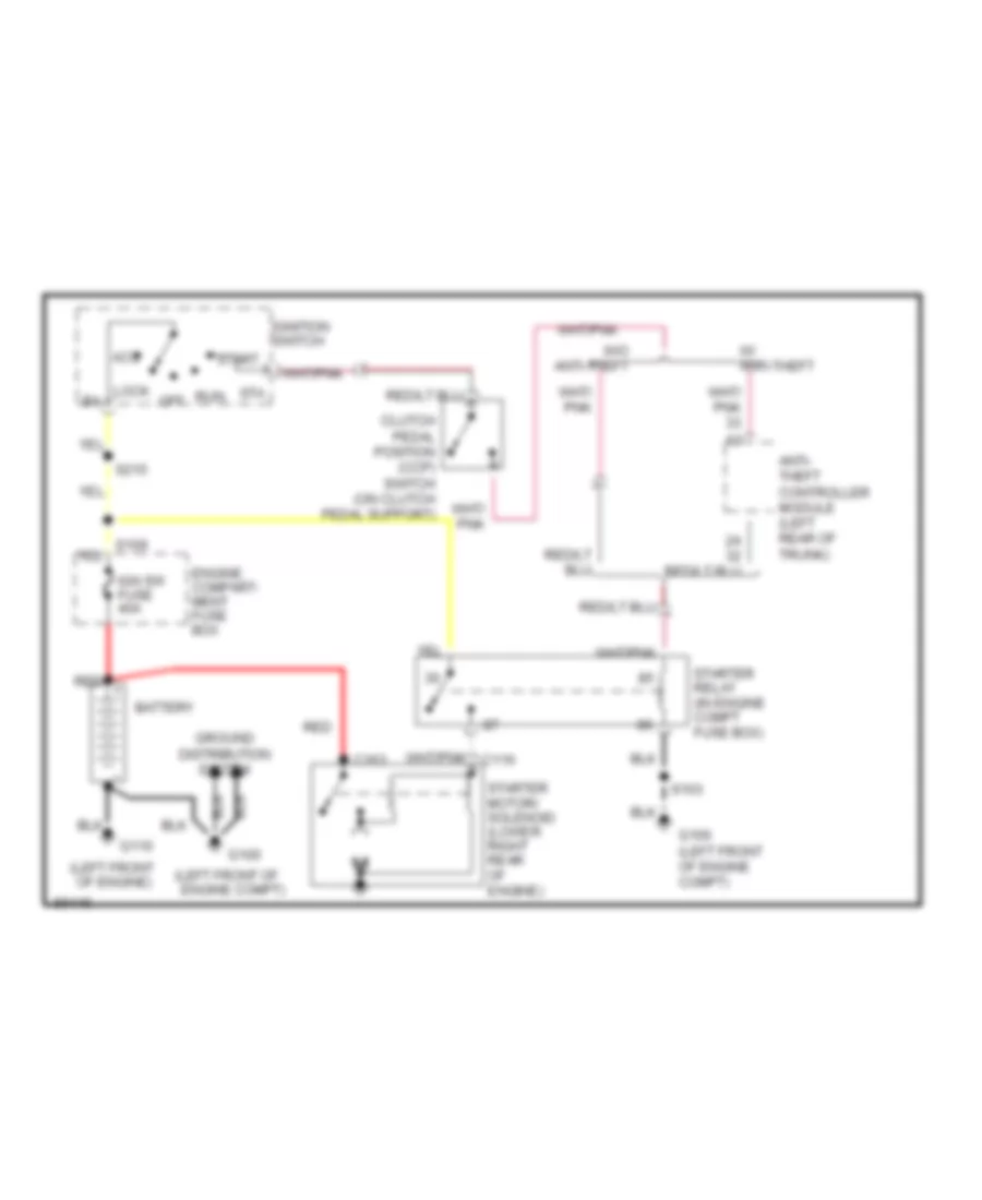
Starting Wiring Diagram, M/T for Ford Mustang Cobra 1997
List of elements for Starting Wiring Diagram, M/T for Ford Mustang Cobra 1997:
- (left front of engine compt)
- (left front of engine)
- Acc
- Anti- theft controller module (left rear of trunk)
- Battery
- C163
- Clutch pedal position (ccp) switch (on clutch pedal support)
- Engine compart- ment fuse box
- G100
- G100 (left front of engine compt)
- G110
- Ground distribution system
- Ign sw fuse 40a
- Ignition switch
- Lock b4
- Off
- Red
- Run
- S103
- S215
- Sta
- Start
- Starter motor/ solenoid (lower right rear of engine)
- Starter relay (in engine compt fuse box)
- W/ anti-theft
- W/o anti-theft
SUPPLEMENTAL RESTRAINTS
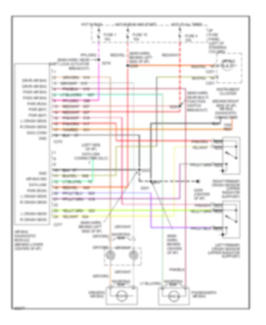
Supplemental Restraint Wiring Diagram for Ford Mustang Cobra 1997
List of elements for Supplemental Restraint Wiring Diagram for Ford Mustang Cobra 1997:
- (behind right side of i/p) air bag diagnostic connector
- (left side of i/p)
- (main harn, behind center of i/p)
- (main harn, behind left side of i/p)
- (main harn, near multi- function switch breakout)
- (main harn, near shift lock actuator breakout)
- Air bag
- Air bag diagnostic module (behind lower center of i/p)
- Air bag ind
- C251
- C276
- C277
- Data link
- Data link connector (dlc)
- Diag conn
- Driver's air bag
- Drvr air bag
- Fuse 1 15a
- Fuse 15 10a
- Fuse 4 10a
- G206 (center of i/p)
- Gnd
- Hot at all times
- Hot in run
- Hot in run and start
- I/p fuse panel (left of steering column)
- Instrument cluster
- L crash sens
- Left primary crash sensor (upper radiator support)
- Nca
- Pass air bag
- Passenger's
- Pwr (bat)
- Pwr (run)
- R crash sens
- Right primary crash sensor (upper radiator support)
- S201
- S203
- S218
- S220
- Shorting bar
- Tan/ red
- Tan/red
TRANSMISSION
3.8L
3.8L, Transmission Wiring Diagram for Ford Mustang Cobra 1997
List of elements for 3.8L, Transmission Wiring Diagram for Ford Mustang Cobra 1997:
- (4.6l) (3.8l)
- (engine control sensor harness, right rear of eng compt)
- (engine ctrl harness, near engine compt grommet) s127 s234
- (fuel charge harness, near breakout to injector 6)
- (fuel charge harness, near brekout to etc sensor)
- (main harness, near breakout to datalink connector)
- (trans ctrl selector neutral switch harness, near breakout to vss) s126
- (transmission control selector neutral switch harness, near breakout to transmission)
- 4r70w transmission
- A/c cut out
- A/c cutout switch
- Anti-theft system
- Backup lamps, shft lock actuator, electronic flasher, rear defogger, airbag diag monitor
- Boo sw input
- Brake on/off (boo) switch (on brake pedal support)
- Brake pressure switch
- Constant control relay module (behind engine coolant reservoir)
- Data link +
- Data link -
- Data link connector (partial) (behind dash, right of steer clmn)
- Data link power
- Drl module, power tops
- Eec fuse 20a
- Electronic pressure control (epc) solenoid
- Engine compartment fuse box (left side of engine compartment)
- Engine controls
- Engine coolant temperature (ect) sensor (front
- Epc sol
- Fuse 15a
- Fuse 20a
- G100 (left front of engine compt)
- G203 (behind dash at right kick panel)
- Ground
- Hot at all times
- Hot in run
- Hot in run or start
- I/p fuse panel (behind dash, left of steering column)
- Ignition coil, radio noise capacitor
- Ignition power
- Instrument cluster
- Instrument cluster, anti-theft module
- Instrument cluster, cruise control
- Instrument illumination
- Intake air temp
- Intake air temperature (iat) sensor (on air intake assembly)
- Kapwr
- Maf return
- Maf sensor sig
- Malfunction indicator lamp
- Mass air flow (maf) sensor (right side of engine compt)
- Mil
- Of engine)
- Oss sig
- Output shaft speed (oss) sensor (left side of trans- mission)
- Pcm power relay
- Powertrain control module (pcm) (behind right kick panel)
- Red
- Ref votage
- S108
- S115
- S116 (engine control harness, right side of engine compartment)
- S121
- S125
- S129
- S130
- S207
- S218
- S219
- S228
- S235
- S240
- S241 (main harness, near breakout to multi- function sw)
- S250
- S252
- S253
- Shift sol 1
- Shift sol 2
- Shift solenoids
- Signal control
- Ss1
- Ss2
- Tcc sol
- Tcil
- Temp sens
- Throttle position (tp) sensor (on throttle body)
- Torque converter clutch (tcc) solenoid
- Tps signal
- Tr sens/pnp sw
- Trans cntrl sw
- Trans temp
- Transmission control indicator lamp
- Transmission control switch (tcs) (on center console, right of gear selector)
- Transmission fluid temperature sensor
- Transmission range (tr) sensor (left side of transmission)
- Vehicle speed sensor (left rear of trans- mission)
- Vss (-)
- Vss signal
4.6L
4.6L SOHC, Transmission Wiring Diagram for Ford Mustang Cobra 1997
List of elements for 4.6L SOHC, Transmission Wiring Diagram for Ford Mustang Cobra 1997:
- (4.6l) (3.8l)
- (engine control sensor harness, right rear of eng compt)
- (engine ctrl harness, near engine compt grommet) s127 s234
- (fuel charge harness, near breakout to injector 6)
- (fuel charge harness, near brekout to etc sensor)
- (main harness, near breakout to datalink connector)
- (trans ctrl selector neutral switch harness, near breakout to vss) s126
- (transmission control selector neutral switch harness, near breakout to transmission)
- 4r70w transmission
- A/c cut out
- A/c cutout switch
- Anti-theft system
- Backup lamps, shft lock actuator, electronic flasher, rear defogger, airbag diag monitor
- Boo sw input
- Brake on/off (boo) switch (on brake pedal support)
- Brake pressure switch
- Constant control relay module (behind engine coolant reservoir)
- Data link +
- Data link -
- Data link connector (partial) (behind dash, right of steer clmn)
- Data link power
- Drl module, power tops
- Eec fuse 20a
- Electronic pressure control (epc) solenoid
- Engine compartment fuse box (left side of engine compartment)
- Engine controls
- Engine coolant temperature (ect) sensor (front
- Epc sol
- Fuse 15a
- Fuse 20a
- G100 (left front of engine compt)
- G203 (behind dash at right kick panel)
- Ground
- Hot at all times
- Hot in run
- Hot in run or start
- I/p fuse panel (behind dash, left of steering column)
- Ignition coil, radio noise capacitor
- Ignition power
- Instrument cluster
- Instrument cluster, anti-theft module
- Instrument cluster, cruise control
- Instrument illumination
- Intake air temp
- Intake air temperature (iat) sensor (on air intake assembly)
- Kapwr
- Maf return
- Maf sensor sig
- Malfunction indicator lamp
- Mass air flow (maf) sensor (right side of engine compt)
- Mil
- Of engine)
- Oss sig
- Output shaft speed (oss) sensor (left side of trans- mission)
- Pcm power relay
- Powertrain control module (pcm) (behind right kick panel)
- Red
- Ref votage
- S108
- S115
- S116 (engine control harness, right side of engine compartment)
- S121
- S125
- S129
- S130
- S207
- S218
- S219
- S228
- S235
- S240
- S241 (main harness, near breakout to multi- function sw)
- S250
- S252
- S253
- Shift sol 1
- Shift sol 2
- Shift solenoids
- Signal control
- Ss1
- Ss2
- Tcc sol
- Tcil
- Temp sens
- Throttle position (tp) sensor (on throttle body)
- Torque converter clutch (tcc) solenoid
- Tps signal
- Tr sens/pnp sw
- Trans cntrl sw
- Trans temp
- Transmission control indicator lamp
- Transmission control switch (tcs) (on center console, right of gear selector)
- Transmission fluid temperature sensor
- Transmission range (tr) sensor (left side of transmission)
- Vehicle speed sensor (left rear of trans- mission)
- Vss (-)
- Vss signal
TRUNK, TAILGATE, FUEL DOOR
Trunk Release Wiring Diagram for Ford Mustang Cobra 1997
List of elements for Trunk Release Wiring Diagram for Ford Mustang Cobra 1997:
- C401
- Circuit breaker 20a
- G300 (below rear of center console)
- Hot at all times
- I/p fuse panel (behind i/p, left of steering column)
- Remote/keyless entry module (left rear of trunk, behind side trim)
- S407
- Trunk lid release output
- Trunk lid release solenoid (center rear of trunk lid, on latch assembly)
- Trunk lid release switch (right side of i/p, in glove box)
- W/ remote keyless entry
- W/o remote keyless entry
WARNING SYSTEMS
Warning System Wiring Diagrams for Ford Mustang Cobra 1997
List of elements for Warning System Wiring Diagrams for Ford Mustang Cobra 1997:
- (not used)
- C251
- Driver door open in
- Fasten belts indicator
- Fuse 10a
- Fuse 15a
- G206 (behind center of i/p)
- G300 (below rear of center console)
- Ground
- Head
- Headlamp on in
- Hot at all times
- Hot in acc or run
- Hot in start or run
- I/p fuse panel
- Ign
- Ignition key warning switch (in ignition switch)
- Instrument cluster
- Key-in ign in
- Left courtesy lamp switch
- Main light switch
- Nca
- Off
- Park
- Red/pnk
- S203
- S206
- S226
- S229
- S231 (main harn, near rear window defrost control switch breakout)
- S302
- Seat belt lt out
- Seat belt sw in
- Seat belt switch (in driver's seat belt buckle)
- Tone generator
- Warning chime module (behind center of i/p, right side of radio)
WIPER/WASHER
Wiper/Washer Wiring Diagram for Ford Mustang Cobra 1997
List of elements for Wiper/Washer Wiring Diagram for Ford Mustang Cobra 1997:
- (1998) (1998) (1996-97) (1996-97)
- (behind center of dash) g206
- 100k ohms
- 1996-97 1996-97
- 3.3k ohms
- 4.08k
- 7.25k
- Fuse 30a
- G100 (left front of engine compt)
- Ground
- Hot in acc or run
- I/p fuse panel (behind dash, left of steering col)
- Ignition
- Int max
- Int min
- Motor ctl
- Motor pos
- Mult-func
- Multi- function switch
- Off
- Off 36.27k ohms
- Ohms
- Park
- Pump motr
- Run
- S101
- S103
- S206
- S225
- Wash
- Washer pump motor (in fluid reservoir)
- Washer pump washer pump motor test motor test connector connector (left side of (left side of eng compt) eng compt)
- Windshield wiper motor (left side of firewall)
- Wiper control module (behind dash, near top of left kick panel)