Разделы схем — 29 (всего 49)
AIR CONDITIONING ANTI-LOCK BRAKES ANTI-THEFT BODY COMPUTER COMPUTER DATA LINES COOLING FAN CRUISE CONTROL DEFOGGERS ENGINE PERFORMANCE EXTERIOR LIGHTS GROUND DISTRIBUTION HEADLIGHTS HORN INSTRUMENT CLUSTER INTERIOR LIGHTS POWER DISTRIBUTION POWER DOOR LOCKS POWER MIRRORS POWER SEATS POWER TOP/SUNROOF POWER WINDOWS RADIO SHIFT INTERLOCKS STARTING/CHARGING SUPPLEMENTAL RESTRAINTS TRANSMISSION TRUNK, TAILGATE, FUEL DOOR WARNING SYSTEMS WIPER/WASHER
AIR CONDITIONING
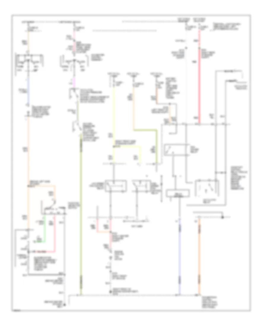
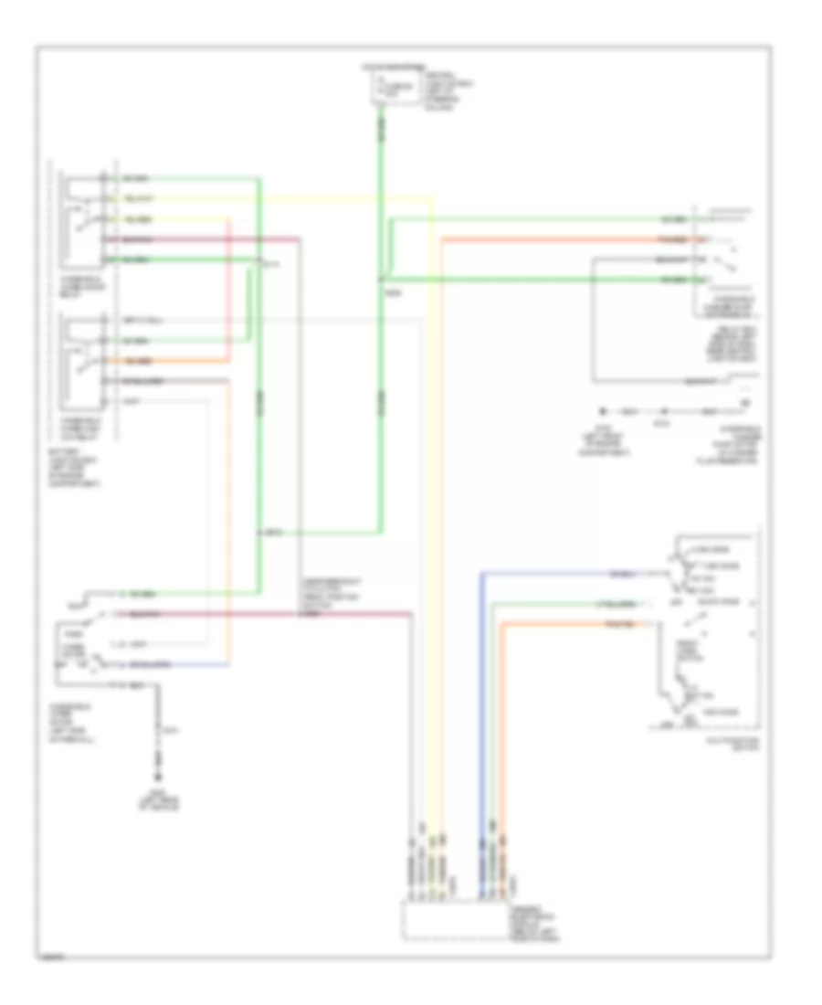
3.8L 3.8L, Manual A/C Wiring Diagram for Ford Mustang GT Bullitt 2002 List of elements for 3.8L, Manual A/C Wiring Diagram for Ford Mustang GT Bullitt 2002: 54 (behind center of dash) g204 (behind left side of dash) s213 (right front of engine compartment) g103 (right front side of engine compt) s102 .5 ohms 1.3 ohms A/c clutch cycling pressure switch (in right rear corner of engine compartment, on a/c accumulator) A/c clutch field coil A/c clutch relay A/c high pressure switch (in lower right front of engine compartment, on a/c line) A/c-heater control assembly Battery junction box (left side of engine compt, forward of strut tower) Blower motor (behind right side of dash, in a/c heater plenum) Blower motor resistor assembly (behind right side of dash, in a/c-heater plenum) Central junction box (behind dash, left of steering column) Constant control relay module (ccrm) (mounted on bracket, behind engine coolant reservoir) Def Engine cooling fan motor Floor Function selector switch Fuse 1 50a Fuse 2 20a Fuse 23 15a Fuse 24 20a Fuse 24 30a Fuse 30a Fuse 34 20a High High speed fan control relay Hot at all times Hot in acc or run Hot in run Hot in run or start Low Low speed fan control relay Max Mix Norm Not used Off Pcm power relay Pnk/ Powertrain control module (pcm) (behind right kick panel) Red Relay control S100 (right front of vehicle) S108 (left front of engine compt) S122 (right center of engine compt) S174 (right side of engine compt) S201 (behind center of dash) S234 (right rear of engine compt) S256 (behind dash panel, near instrument cluster Thermal limiter Vent
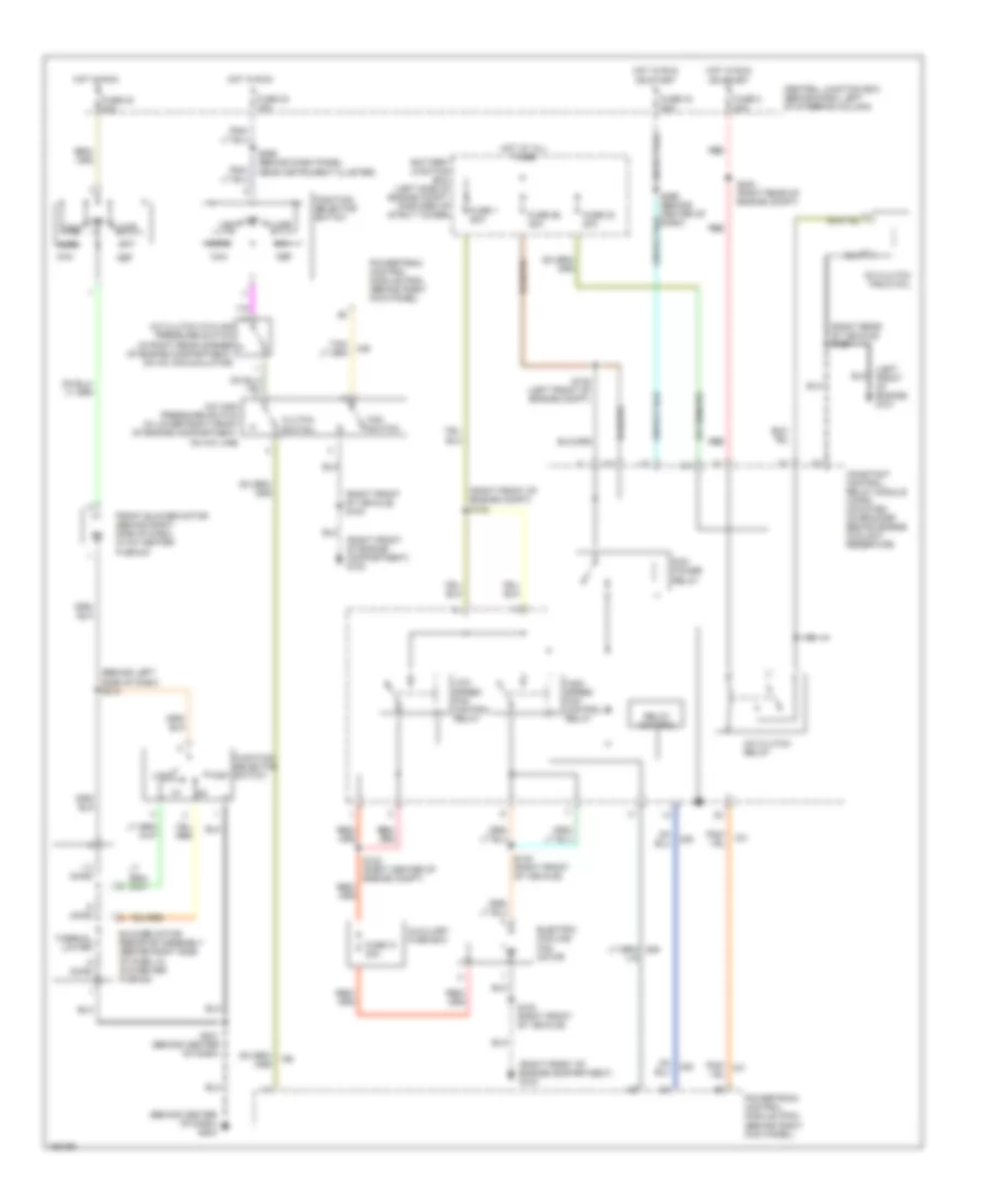
4.6L 4.6L, Air Conditioning Wiring Diagrams for Ford Mustang GT Bullitt 2002 List of elements for 4.6L, Air Conditioning Wiring Diagrams for Ford Mustang GT Bullitt 2002: 59 (behind center of dash) g204 (behind left side of dash) s213 (left front of engine) g101 (right front of engine compartment) g103 (right front of engine compt) s102 (right front of vehicle) s100 (right rear of vehicle) s180 .5 ohms 1.3 ohms A/c clutch cycling pressure switch (in right rear corner of engine compartment, on a/c accumulator) A/c clutch field coil A/c clutch relay A/c high pressure switch (in lower right front of engine compartment, on a/c line) Auxiliary fuse box Battery junction box (left side of engine compt, forward of strut tower) Blower motor resistor assembly (behind right side of dash, in a/c-heater plenum) Central junction box (behind dash, left of steering column) Clutch switch Constant control relay module (ccrm) (mounted on bracket behind engine coolant reservoir) Def Electric cooling fan motor Fan switch Floor Front blower motor (behind right side of dash, in a/c heater plenum) Function selector switch Fuse 1 50a Fuse 2 20a Fuse 23 15a Fuse 24 20a Fuse 24 30a Fuse 26 30a Fuse 31 30a Fuse 34 20a High High speed fan control relay Hot at all times Hot in run Hot in run or start Low Low speed fan control relay Max Mix Norm Off Pcm power relay Pnk/ Powertrain control module (pcm) (behind right kick panel) Red Relay control S100 (right front of vehicle) S108 (left front of engine compt) S122 (right center of engine compt) S140 (right front of vehicle) S201 (behind center of dash) S234 (right rear of engine compt) S256 (behind dash panel near instrument cluster) S266 (behind center of dash) Thermal limiter Vent
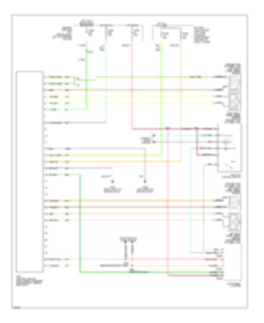
ANTI-LOCK BRAKES Anti-lock Brake Wiring Diagrams for Ford Mustang GT Bullitt 2002 List of elements for Anti-lock Brake Wiring Diagrams for Ford Mustang GT Bullitt 2002: 29 (inboard side of wheel hub) left front wheel speed sensor (inboard side of wheel hub) right rear wheel speed sensor 3.8l 4.6l Abs control module (right front of engine compartment, behind radiator) Battery junction box (left side of engine compartment, forward of strut tower) C220a C220b Central junction box (behind dash, left of steering column) Computer data lines system Fuse 15a Fuse 20a Fuse 50a G102 (left front of engine compt) G103 (right front of engine compt) Hot at all times Hot in run Hot with brake pedal depressed Instrument cluster Interior lights system Left rear wheel speed sensor (inboard side of wheel hub) Nca Right front wheel speed sensor (inboard side of wheel hub) S252 (behind center of dash) S253 (center of dash) S257 S275 S284 Traction control switch
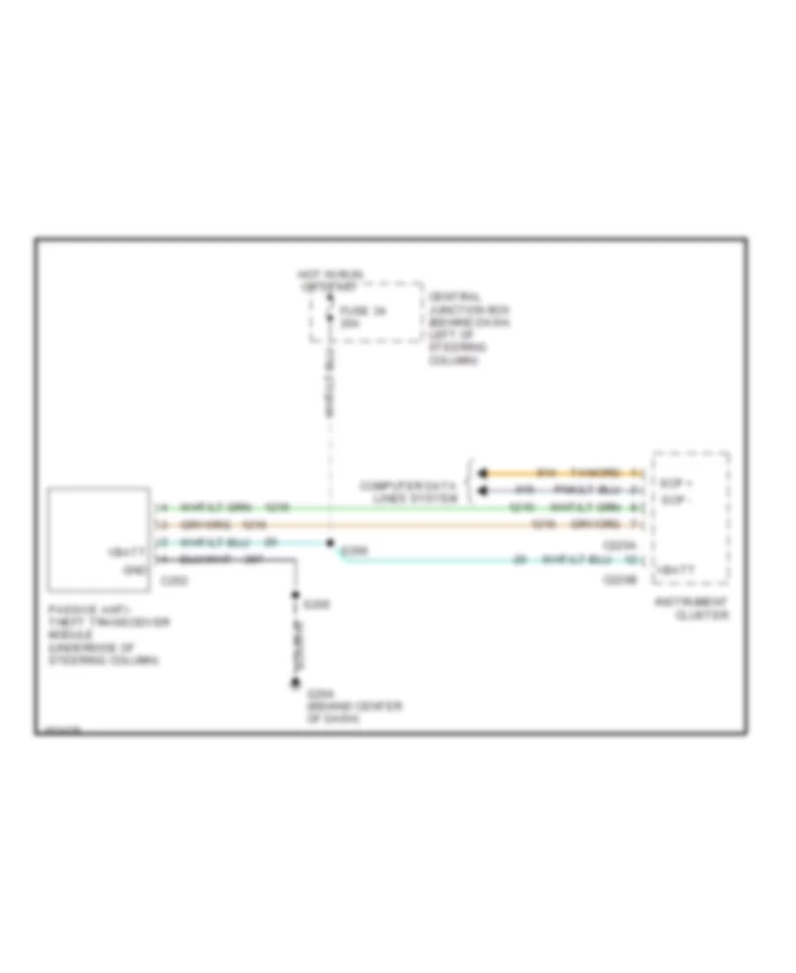
ANTI-THEFT Anti-theft Wiring Diagram for Ford Mustang GT Bullitt 2002 List of elements for Anti-theft Wiring Diagram for Ford Mustang GT Bullitt 2002: 16 C220a C220b C252 Central junction box (behind dash, left of steering column) Computer data lines system Fuse 34 20a G204 (behind center of dash) Gnd Hot in run or start Instrument cluster Passive anti- theft transceiver module (underside of steering column) S205 S266 Scp + Scp - Vbatt
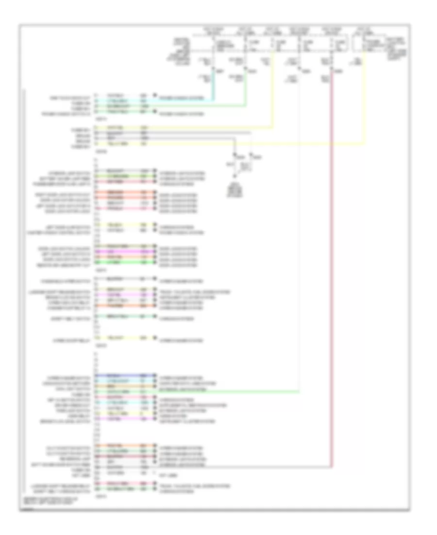
BODY COMPUTER Body Computer Wiring Diagrams for Ford Mustang GT Bullitt 2002 List of elements for Body Computer Wiring Diagrams for Ford Mustang GT Bullitt 2002: 71 Batt saver door switch feed Battery junction box (left side of engine compt) Battery saver lamp feed Brake fluid ind switch Brake fluid level switch C201a C201b C201c C201d Central junction box (behind dash, left of steering column) Circuit breaker 20a Communication network Computer data lines system Door lock motor (lock) Door lock motor (unlock) Door lock switch (lock) Door lock switch (unlock) Door locks system Driver airbag out Exterior lights system Fuse 15a Fuse 5a Fused b(+) Fused ign G204 (behind center of dash) Generic electronic module (below left side of dash) Ground Horn relay Horns system Hot at all times Hot in run or acc Hot in run or start Instrument cluster system Interior lamp switch Interior lights system Key in ignition switch Left door ajar switch Left door lock actuator in Left door lock switch in Luggage compt release relay Luggage compt release switch Main light switch Master window control switch Multi-function switch Not used One touch down out Parklamp switch Passenger door ajar lamp in Power window switch in Power window system Power windows 40a Remote keyless entry out Reversing lamp Right door lock switch out S205 S206 S242 S262 S265 S267 Safety belt switch Safety belt warning switch Tan/red Trunk, tailgate, fuel doors system Warning systems Washer pump relay in Windshield wiper switch Wiper high/low relay Wiper on/off relay Wiper/washer switch Wiper/washer system
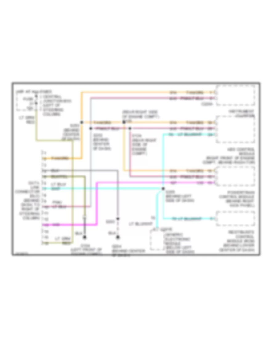
COMPUTER DATA LINES Computer Data Lines for Ford Mustang GT Bullitt 2002 List of elements for Computer Data Lines for Ford Mustang GT Bullitt 2002: 23 (left front of engine compt) (rear right side of engine compt) s135 Abs control module (right front of engine compt, behind radiator) C201e C220a Central junction box (left of steering column) Connector (dlc) (behind Dash, to right of steering column) Data Fuse 10a G104 G204 (behind center of dash) Generic electronic module (below left side of dash) Hot at all times Instrument cluster Link Powertrain control module (behind right kick panel) Restraints control module (rcm) (behind lower center of dash) S134 (rear right side of engine compt) S203 S252 (behind center of dash) S253 (behind center of dash) S255 (behind left side of dash)
COOLING FAN
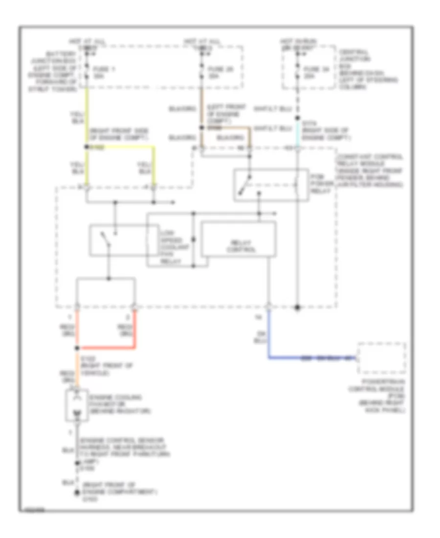
3.8L 3.8L, Cooling Fan Wiring Diagram for Ford Mustang GT Bullitt 2002 List of elements for 3.8L, Cooling Fan Wiring Diagram for Ford Mustang GT Bullitt 2002: 18 (left front of engine compt) s108 (right front of engine compartment) g103 (right front side of engine compt) Battery junction box (left side of engine compt, forward of strut tower) Central junction box (behind dash, left of steering column) Constant control relay module (inside right front fender, behind air filter housing) Engine cooling fan motor (behind radiator) Fuse 1 30a Fuse 26 30a Fuse 34 20a Hot at all times Hot in run or start Low speed coolant fan relay Pcm power relay Powertrain control module (pcm) (behind right kick panel) Relay control S102 S174 (right side of engine compt)
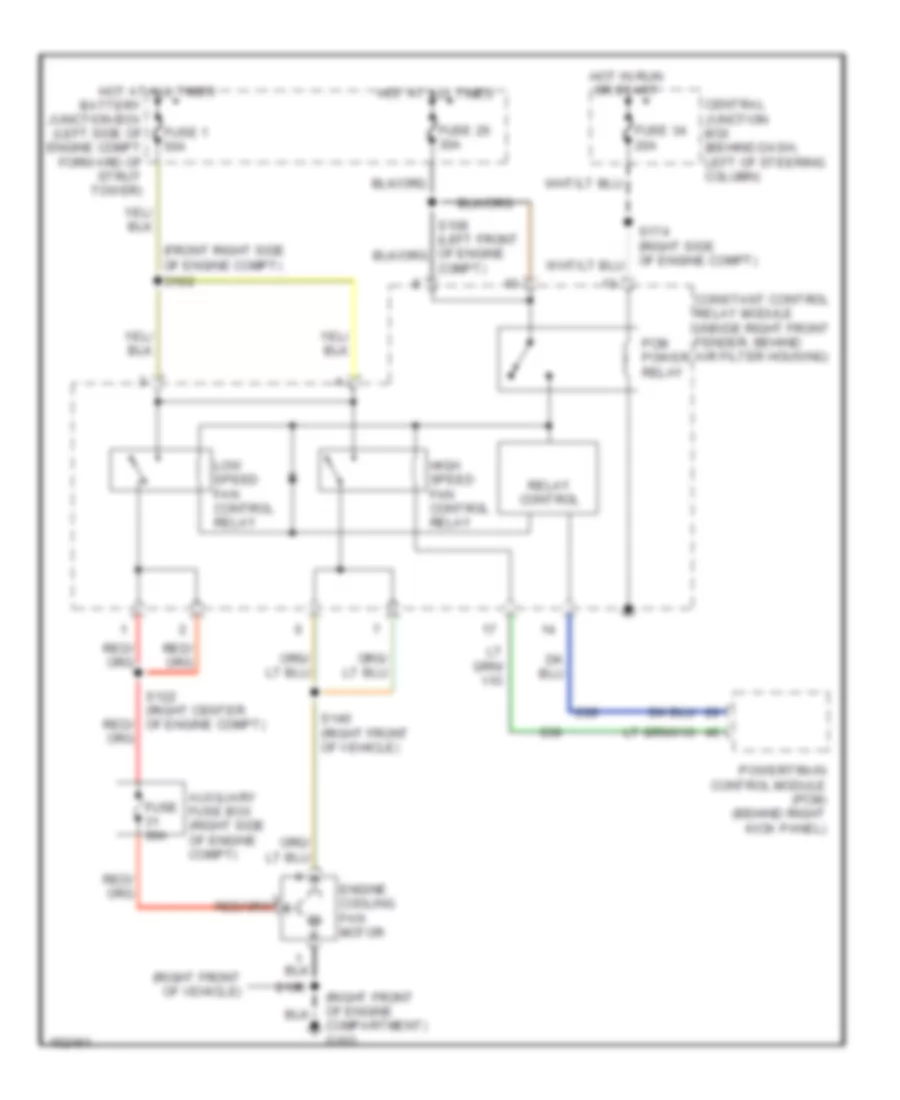
4.6L 4.6L, Cooling Fan Wiring Diagram for Ford Mustang GT Bullitt 2002 List of elements for 4.6L, Cooling Fan Wiring Diagram for Ford Mustang GT Bullitt 2002: 24 (front right side of engine compt) (right front of engine compartment) g103 (right front of vehicle) Auxiliary fuse box (right side of engine compt) Battery junction box (left side of engine compt forward of strut tower) Central junction box (behind dash, left of steering column) Compt) Constant control relay module (inside right front fender, behind air filter housing) Engine cooling fan motor Fuse 1 50a Fuse 26 30a Fuse 30a Fuse 34 20a High speed fan control relay Hot at all times Hot in run or start Low speed fan control relay Pcm power relay Powertrain control module (pcm) (behind right kick panel) Relay control S100 S102 S122 (right center of engine compt) S140 (right front of vehicle)
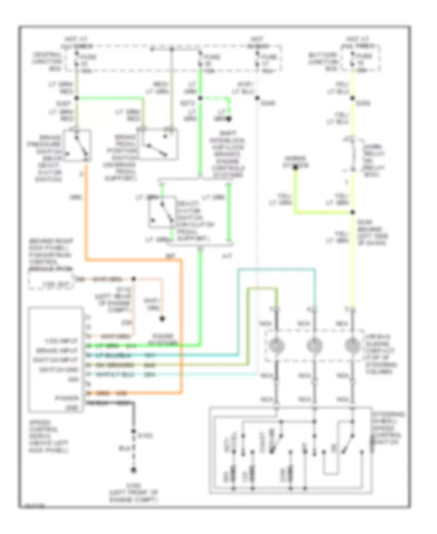
CRUISE CONTROL Cruise Control Wiring Diagram for Ford Mustang GT Bullitt 2002 List of elements for Cruise Control Wiring Diagram for Ford Mustang GT Bullitt 2002: 42 (behind right kick panel) powertrain control module (pcm) A/t Accel set/ Air bag sliding contact (top of steering column) Battery junction box Brake input Brake pedal position switch (on brake pedal support) Brake pressure switch (near deact- ivator switch) Central junction box Coast Deact- ivator switch (on clutch pedal support) Fuse 15a Fuse 20a G102 (left front of engine compt) Gnd Horn Horn relay (in relay box) Horns system Hot at all times Hot in run Ign M/t Nca Off Ohms Power Resume S103 S112 (left rear of engine compt) S202 S207 S245 S249 (behind left side of dash) S272 Shift interlock, anti-lock brakes, engine controls systems Sound systems Speed control servo (above left kick panel) Steering wheel/ speed control switch Switch gnd Switch input Vss input Vss out
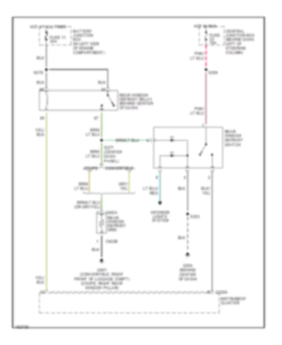
DEFOGGERS Defogger Wiring Diagram for Ford Mustang GT Bullitt 2002 List of elements for Defogger Wiring Diagram for Ford Mustang GT Bullitt 2002: 22 Battery junction box (in left side of engine compartment) C220a C402a C402b Central junction box (behind dash, left of steering column) Convertible Coupe Fuse 11 30a Fuse 15a G204 (behind center of dash) G401 (converitble: right front of luggage compt) (coupe: right rear window pillar) Hot at all times Hot in run Instrument cluster Interior lights system Rear window defrost grid Rear window defrost relay (behind center of dash) Rear window defrost switch S203 S256 S277 (center dash panel) S278
ENGINE PERFORMANCE
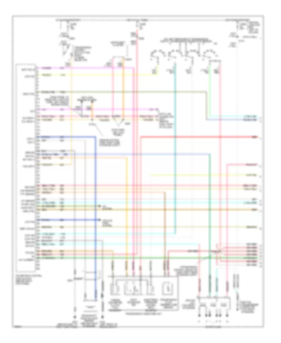
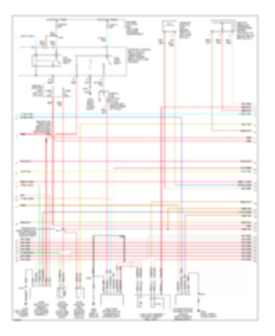
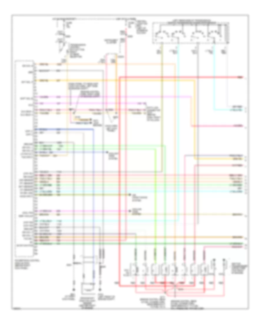
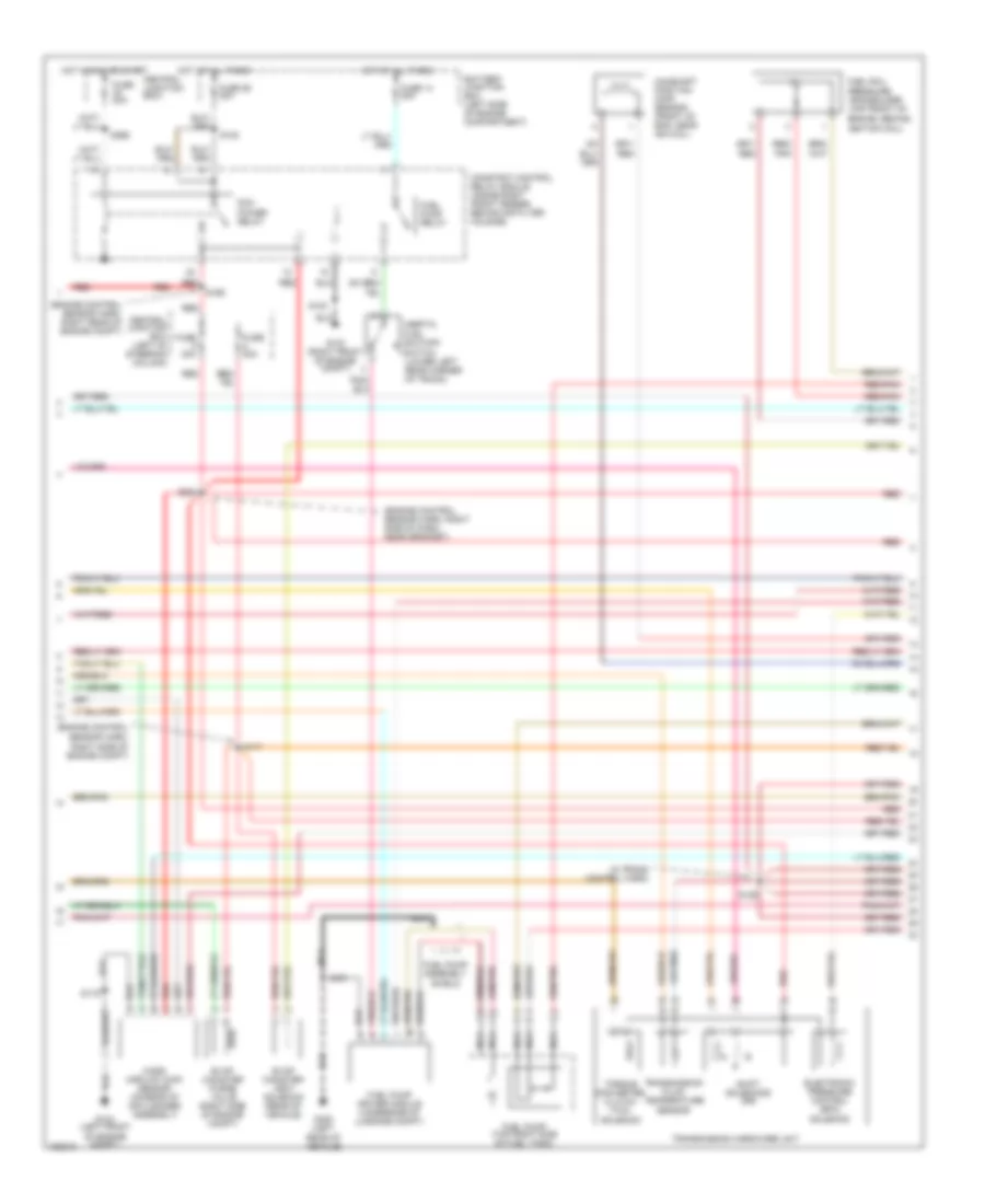
3.8L 3.8L, Engine Performance Wiring Diagrams (1 of 3) for Ford Mustang GT Bullitt 2002 List of elements for 3.8L, Engine Performance Wiring Diagrams (1 of 3) for Ford Mustang GT Bullitt 2002: 68 (dash panel to headlamp junction harn, left side of engine compt) (engine control harn, right side of engine compt) (main harn, left kick panel) (on left rear side of transmission) digital transmission range (dtr) sensor (transmission control selector harn, right rear of engine compt) A/c system Accs input Anti-lock brakes system C220a Central junction box (left of column) Ckp (+) Ckp (-) Cooling fans system Crankshaft position (ckp) sensor (center front of engine) Data link connector (dlc) (behind dash, right of column) Dlc Dlc (bus +) Dlc (bus -) Dtr tr1 Dtr tr2 Dtr tr4 Egr vacuum Electronic pressure control (epc) Fp drv mod Fuse 15a Fuse 20a Fuse 5a G104 (left front of engine compt) G201 (behind dash, at right kick panel) Ground Hot at all times Hot in run or start Iat sensor Ign coil Ignition coil (top front of engine) Ignition transformer capacitor (top front of engine) Imrc ctrl Instrument cluster Low fan Maf sensor Module (pcm) (behind right kick panel) Nca Powertrain control Red Rr ho2s S126 S134 S135 S174 S204 S250 S252 S253 S259 S262 Shft sol b Shift solenoids (ss) Sht sol a Solenoid Spark plugs Tcc sol Tcs input Tft sensor Torque converter clutch (tcc) solenoid Transmission control switch (tcs) (right of gear selector) Transmission fluid temperature sensor Transmission hardware unit Vmv current 3.8L, Engine Performance Wiring Diagrams (2 of 3) for Ford Mustang GT Bullitt 2002 List of elements for 3.8L, Engine Performance Wiring Diagrams (2 of 3) for Ford Mustang GT Bullitt 2002: 33 (engine ctrl harn, near right side of engine compartment) (engine ctrl sens harn, behind right side of dash, near grommet) s234 (top right side of fuel tank) Battery junction box (left side of engine compartment) Camshaft position (cmp) sensor (front of eng, near ign coil) Central junction box (left of column) Constant control relay module (inside right front fender, behind air filter housing) Evap canister purge valve (right side of engine compt) Evap canister vent control solenoid (rear of vehicle) Fuel pump assembly Fuel pump driver module (underside of luggage compt) Fuel pump relay Fuel rail pressure transducer sensor (top front of engine, behind ignition coil) Fuse 14 20a Fuse 20a Fuse 26 30a G103 (right front of eng compt) G104 (left front of engine compt) G400 (left rear of vehicle) Hot at all times Inertia fuel shutoff switch (lower left rear corner of trunk) Intake manifold runner control module (right rear of engine compt) Mass airflow (maf) sensor (on rear of air cleaner assembly) Nca Pcm power relay Red Red/ pnk Red/pnk S100 S108 S115 S117 S451 3.8L, Engine Performance Wiring Diagrams (3 of 3) for Ford Mustang GT Bullitt 2002 List of elements for 3.8L, Engine Performance Wiring Diagrams (3 of 3) for Ford Mustang GT Bullitt 2002: 69 (engine ctrl sens harn, near grommet) s200 (fuel charge harn, near breakout to inj 6) s123 (fuel charge harness, near breakout to tp sensor) s128 (left front of engine compt) g104 (near breakout to fuel inj 1) (near breakout to fuel inj 2) s129 A/c cutout A/c system Air mngmnt Bpp Brake pedal position (bpp) switch (on brake pedal support) C315 Central junction box (left of steering column) Cht sens Cmp sens Cruise control system Cylinder head temperature (cht) sensor (top front of engine) Differential pressure feedback egr sensor (center rear of engine compt) Dpfe Dtr tr3a Egr vacuum regulator (evr) solenoid (rear of throttle body) Epc sol Evap purge Fp mon Fr press Fuel inj 1 Fuel inj 2 Fuel inj 3 Fuel inj 4 Fuel inj 5 Fuel inj 6 Fuel injectors Fuel press Fuse 15a Heated oxygen sensor 11 (in exhaust manifold, above flange inboard side) Heated oxygen sensor 12 (in exhaust, rear of catalytic converter) Heated oxygen sensor 21 (in exhaust manifold, above flange inboard side) Heated oxygen sensor 22 (lower left rear of engine, in exhaust manifold) Hot at all times Iac valve Idle air control (iac) valve (top rear of engine) Ign coil Lf ho2s Lr ho2s Maf sens Module (pcm) (behind right kick panel) Nca Oss sens Output shaft speed sensor (left side of trans) Power Powertrain control Pwr gnd Red Red/pnk Ref volt Rf ho2s Rr ho2s S120 (in trans harn) S121 (engine ctrl sens harn, near grommet) S130 (near breakout to fuel inj 6) S164 S207 S250 S275 (in main harn) Sig rtn Sp cntrl Tan Throttle position (tp) sensor (on throttle body) Tp sens
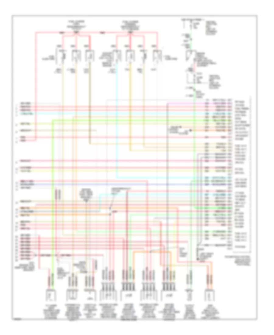
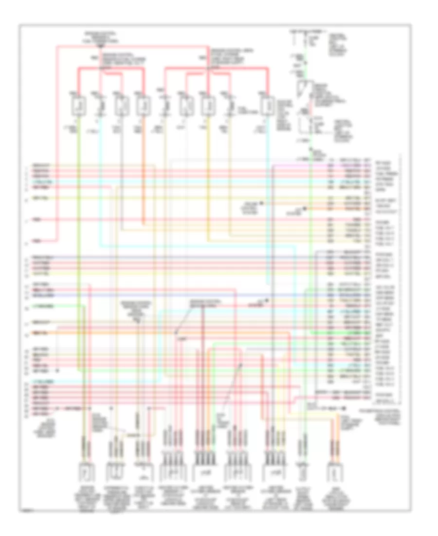
4.6L 4.6L, Engine Performance Wiring Diagrams (1 of 3) for Ford Mustang GT Bullitt 2002 List of elements for 4.6L, Engine Performance Wiring Diagrams (1 of 3) for Ford Mustang GT Bullitt 2002: 68 (dash panel to headlamp junction harn, left side of engine compt) (engine control harn, right side of engine compt) (engine control sens & fuel charge harn, near breakout to fuel rail pressure transducer) (left rear side of transmission) digital transmission range (dtr) sensor (main harn, left kick panel) Accs input Air conditioning Anti- lock brakes C220a Central junction box (left of steering column) Ckp (+) Ckp (-) Coil on plug Cool fan Coolant fans system Cooling fans system Crankshaft position (ckp) sensor (center front of engine) Data link connector (dlc) (behind dash, right of column) Dlc Dlc (bus +) Dlc (bus -) Dtr tr1 Dtr tr2 Dtr tr4 Ect sensor Egr vacuum Evap can pur Fp drv mod Fuse 15a Fuse 5a G104 (left front of engine compt) G201 (at right kick panel) Grd Ground Hot at all times Hot in run or start Iat sensor Ign coil 1 Ign coil 3 Ign coil 4 Ign coil 5 Ign coil 6 Ignition transformer capacitors (top front of engine) Instrument cluster Lo fan out Maf sensor Module (pcm) (behind right kick panel) Nca Powertrain control Red Rr ho2s S134 S135 S170 S171 (engine control sens & fuel charge harn, near breakout to fuel inj 4) S204 S250 S252 S253 S259 S262 Shft sol b Sht sol a System Tcc sol Tcs input Tft sensor Transmission control switch (tcs) (right of gear selector) 4.6L, Engine Performance Wiring Diagrams (2 of 3) for Ford Mustang GT Bullitt 2002 List of elements for 4.6L, Engine Performance Wiring Diagrams (2 of 3) for Ford Mustang GT Bullitt 2002: 47 (engine control sensor harn, right rear of engine compt) (engine control sensor harn, right side of dash, near grommet) (engine control sensor harn, right side of engine compt) (in trans control harn) Battery junction box (left side of engine compartment) Camshaft position (cmp) sensor (front of eng, near ign coil) Central junction box (left of steering column) Central junction box) Constant control relay module (inside right front fender, behind air filter housing) Electronic pressure control (epc) Evap canister purge valve (right side of engine compt) Evap canister vent solenoid (rear of vehicle) Fuel pump (top right side of fuel tank) Fuel pump assembly shield Fuel pump driver module (underside of luggage compt) Fuel pump relay Fuel rail pressure transducer (top front of engine, behind ignition coil) Fuse 14 20a Fuse 20a Fuse 26 30a G103 (right front of engine compt) G104 (left front of engine compt) G400 (left Hot at all times Hot in run or start Inertia fuel shutoff switch (lower left rear corner of trunk) Mass airflow (maf) sensor (on rear of air cleaner assembly) Nca Pcm power relay Rear of vehicle) Red Red/ pnk Red/pnk S100 S108 S115 S117 S126 S169 S234 S266 S451 Shift solenoids (ss) Solenoid Torque converter clutch (tcc) solenoid Transmission fluid temperature sensor Transmission hardware unit 4.6L, Engine Performance Wiring Diagrams (3 of 3) for Ford Mustang GT Bullitt 2002 List of elements for 4.6L, Engine Performance Wiring Diagrams (3 of 3) for Ford Mustang GT Bullitt 2002: 76 (engine control sens & fuel charge harn, right rear of engine compt) s128 (engine control sensor & fuel charge harn) s158 (engine control sensor & fuel charge harn, near fuel inj 7) s123 (engine control sensor harn) (engine control sensor harn, near grommet) A/c cutout A/c hp sw A/c system Bpp Brake pedal position (bpp) switch (on brake pedal support) C315 Central junction box (left of steering column) Cmp sens Cruise control system Differential pressure feedback egr (dpfe) sensor (center rear of engine compt) Dpfe Dtr tr3a Egr vacuum regulator (evr) solenoid (inside right fender) Engine coolant temperature (ect) sensor (top right front of engine) Epc sol Evap vent Fp mon Fr press Fuel inj 1 Fuel inj 2 Fuel inj 3 Fuel inj 4 Fuel inj 5 Fuel inj 6 Fuel inj 7 Fuel inj 8 Fuel injectors Fuel press Fuse 15a G104 (left front of engine compt) Heated oxygen sensor (in exhaust manifold, inboard side) Heated oxygen sensor (in exhaust, rear of cat convert) Heated oxygen sensor (left rear of engine, in exhaust man) Heated oxygen sensor 11 (in exhaust manifold, inboard side) Hot at all times Iac valve Idle air control (iac) valve (top right side of engine) Ign coil 2 Ign coil 7 Ign coil 8 Lf ho2s Lr ho2s Maf sens Module (pcm) (behind right kick panel) Nca Oss sens Output shaft speed sensor (left side of trans) Power Powertrain control Pwr gnd Red Red/pnk Ref volt Rf ho2s Rr ho2s S115 S120 (in trans harn) S121 (engine control harn, near grommet) S129 S130 (engine control sensor harn) S164 S200 S207 S275 (in main harn) Sig rtn Tan Tan/ red Tan/red Throttle position (tp) sensor (on throttle body) Tp sens Vss sig
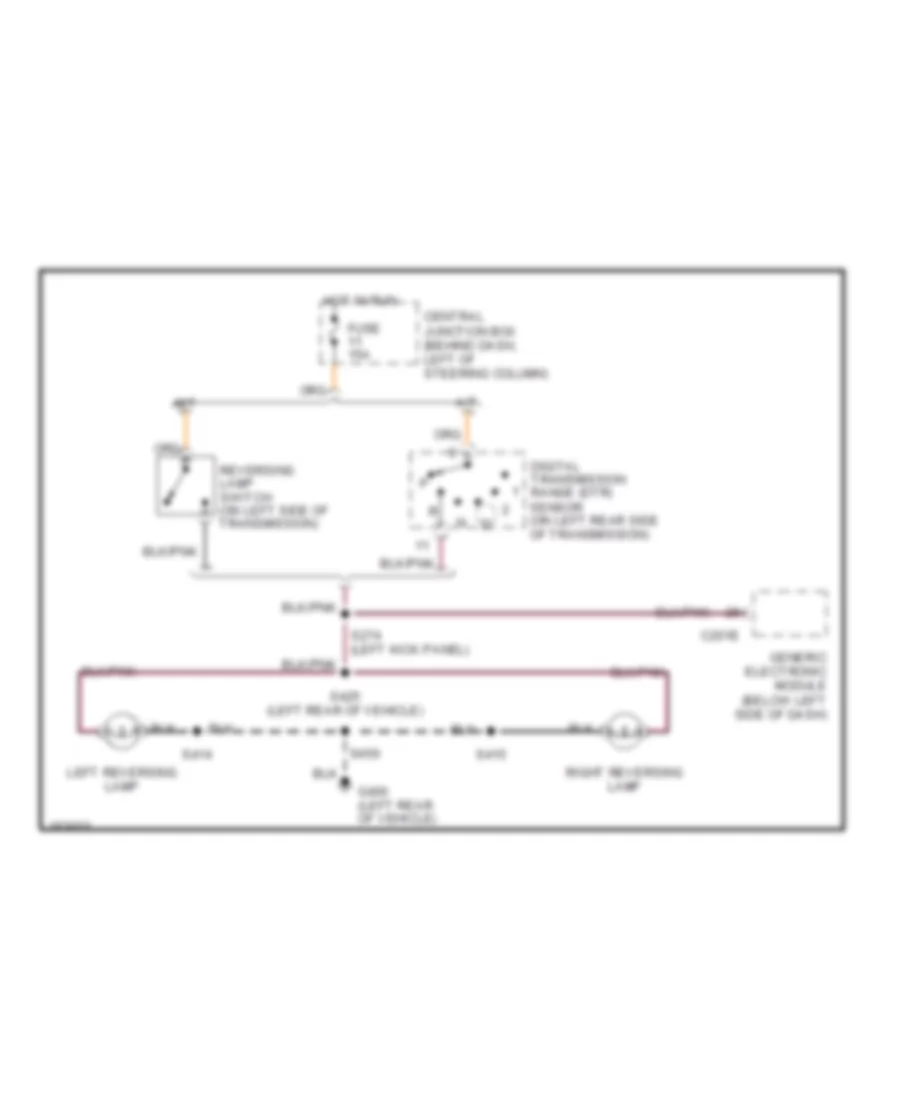
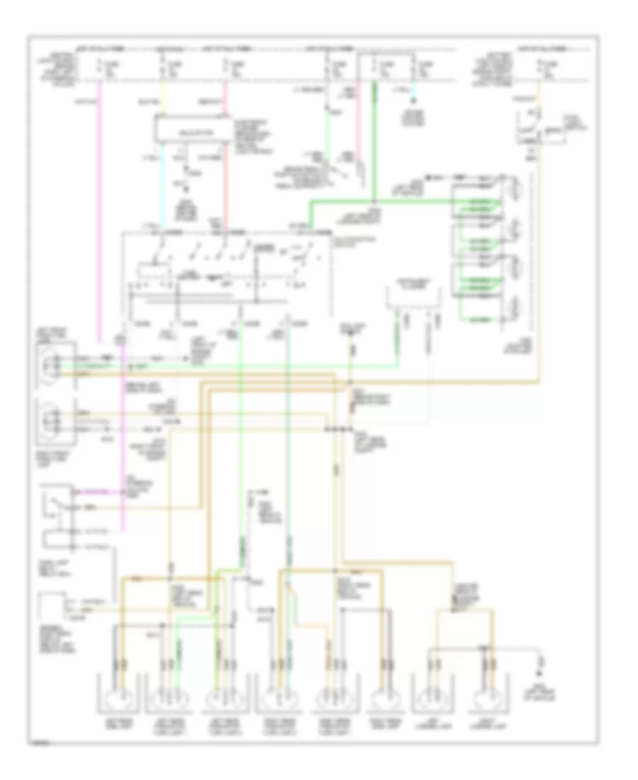
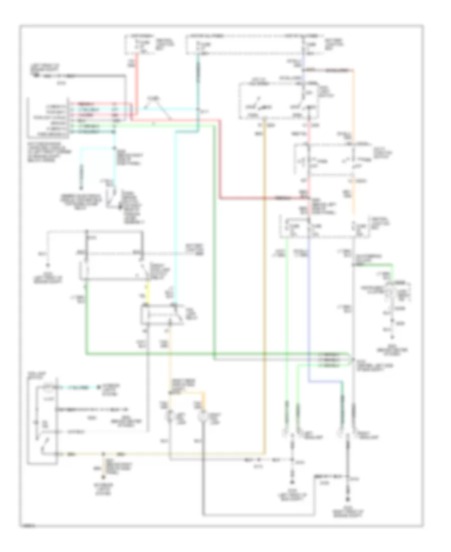
EXTERIOR LIGHTS Back-up Lamps Wiring Diagram for Ford Mustang GT Bullitt 2002 List of elements for Back-up Lamps Wiring Diagram for Ford Mustang GT Bullitt 2002: 17 A/t C201e Central junction box (behind dash, left of steering column) Digital transmission range (dtr) sensor (on left rear side of transmission) Fuse 15a G400 (left rear of vehicle) Generic electronic module (below left side of dash) Hot in run Left reversing lamp M/t Reversing lamp switch (on left side of transmission) Right reversing lamp S274 (left kick panel) S414 S415 S425 (left rear of vehicle) S450 Exterior Lamps Wiring Diagram for Ford Mustang GT Bullitt 2002 List of elements for Exterior Lamps Wiring Diagram for Ford Mustang GT Bullitt 2002: 59 (behind left side of dash) (left front of engine compt) g102 (on steering column) (on steering column) s268 Battery junction box (left side of engine compt, forward of strut tower) Brake pedal position switch (on brake pedal support) C201e C202b C220a Central junction box (behind dash, left of steering column) Cruise control system Electronic flasher (behind dash, on rear of central junction box) Fog lamp switch Fuse 15a Fuse 30a G103 (right front of engine compt) G204 (behind center of dash) G400 (left rear of vehicle) Generic electronic module (below left side of dash) Hazard switch Head High mounted stoplamp Hot at all times Hot in run Instrument cluster Left Left front park/turn lamp Left license lamp Left rear park/stop/ turn lamp 1 Left rear park/stop/ turn lamp 2 Left rear side lamp Main light switch Multifunction switch Off Park Park lamp relay (relay box) Right Right front park/turn lamp Right license lamp Right rear park/stop/ turn lamp 1 Right rear park/stop/ turn lamp 2 Right rear side lamp S100 S103 S206 S207 S231 (behind right side of dash) S247 S248 S323 (left rear of luggage compt) S407 S414 S415 S418 (left rear of luggage compt) S419 (right rear end of vehicle) S420 (left rear end of vehicle) S450 Solid state Turn switch
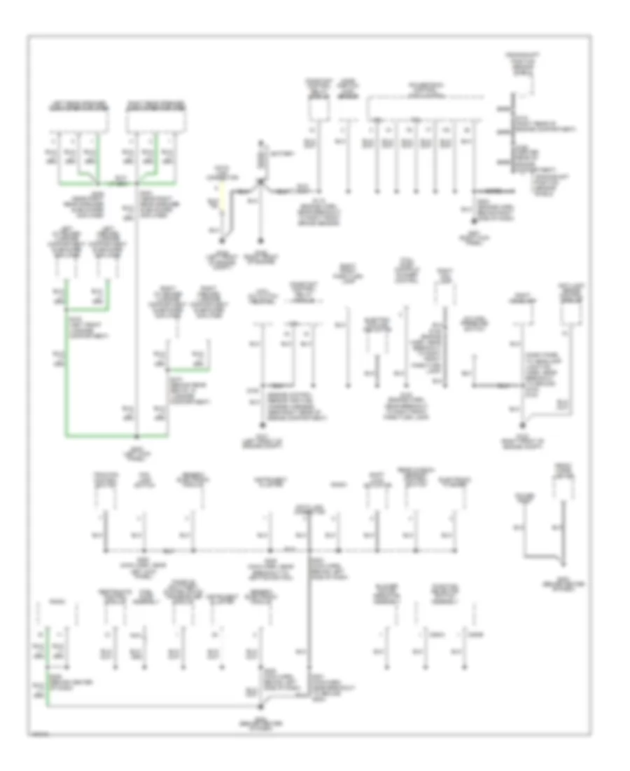
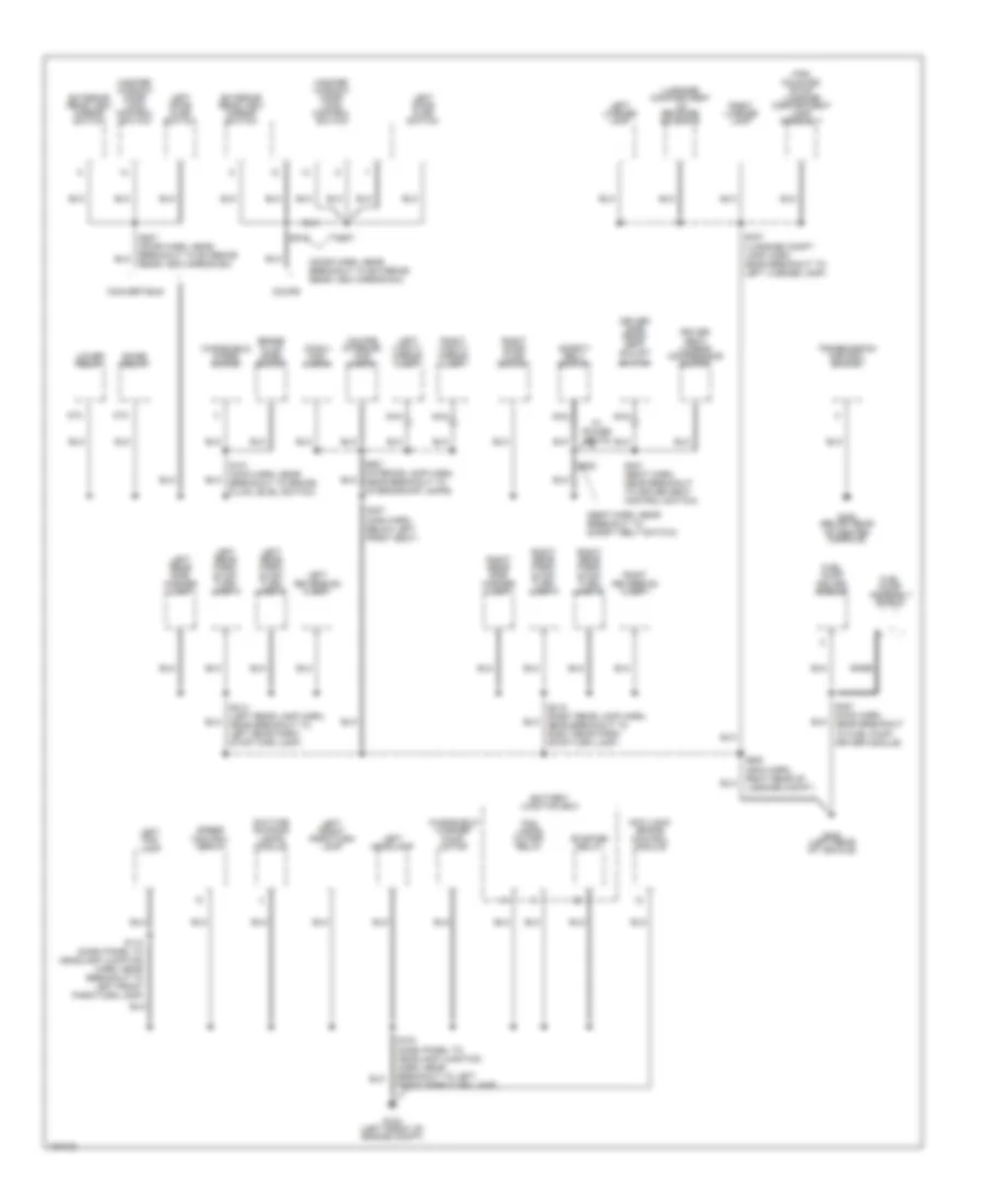
GROUND DISTRIBUTION Ground Distribution Wiring Diagram (1 of 2) for Ford Mustang GT Bullitt 2002 List of elements for Ground Distribution Wiring Diagram (1 of 2) for Ford Mustang GT Bullitt 2002: 67 (3.8l) inlet manifold runner control (4.6l) a/c clutch field coil (dash panel to headlamp junction harn, near breakout to ground g103) s104 (engine control sensor and fuel charge harness, near right rear of engine compartment) 3.8l 4.6l A/c high pressure switch Anti-lock brake control module Bare Battery Blower motor resistor assembly C294a C294b Constant control relay module Crankshaft position sensor shield Data link connector Electric cooling fan motor Electronic flasher Fog lamp switch Front cigar lighter Fuel pump assembly Function selector switch assembly G101 (left front of engine compt) G103 (right front of engine compt) G104 (left front of engine compt) G105 (right front of engine) G201 (right kick panel) G203 (behind center of dash) G204 (behind center of dash) G204) G403 (left kick panel) Generic electronic module Instrument cluster Left inboard luggage compartment subfoofer amplifier Left outboard luggage compartment subfoofer amplifier Left rear speaker subwoofer amplifier Mass airflow (maf) sensor Nca Passive anti-theft system (pats) transceiver module Power point Powertrain control module (pcm) Radio Rear window defrost control switch Restraints control module Right fog lamp Right front park/turn lamp Right headlamp Right inboard luggage compartment subfoofer amplifier Right outboard luggage compartment subfoofer amplifier Right rear speaker subwoofer amplifier S100 (engine harn, near breakout to right front park/turn lamp) S106 (engine harn, near breakout to right front park/turn lamp) S115 (engine harn, near breakout to right front brake sensor) S143 (right rear of engine compartment) S168 (center rear of engine compartment) S180 S203 (main harn, behind left side of dash) S204 (engine harn, behind right side of dash) S205 (main harn, behind left side of dash) S206 (main harn, near breakout to ignition switch) S283 (main harn, near left kick panel) S404 (near right rear speaker subwoofer amplifier) S405 (near right rear speaker subwoofer amplifier) S473 (behind rear seats, in luggage compartment) S475 (left front luggage compartment) Shift lock actuator Traction control switch Ground Distribution Wiring Diagram (2 of 2) for Ford Mustang GT Bullitt 2002 List of elements for Ground Distribution Wiring Diagram (2 of 2) for Ford Mustang GT Bullitt 2002: 66 (conv) map lamps (coupe) interior/ map lamps (door harn, near breakout to exterior rear view mirror sw) (seat harn, near breakout to safety belt switch) 87a Anti-lock brake control module Bare Battery junction box Brake fluid level switch Convertible Coupe Daytime running lamps module Driver seat lumbar compressor motor Driver side front seat adjust switch Exterior rear view mirror switch Fog lamps cutoff relay Fuel pump assembly shield Fuel pump driver module G102 (left front of engine compt) G300 (below rear of center console) G400 (left rear of vehicle) High mounted stop/ luggage compartment lamp assembly Left door ajar switch Left fog lamp Left front park/turn lamp Left headlamp Left license lamp Left rear park/ stop/ turn lamp 1 Left rear park/ stop/ turn lamp 2 Left rear side marker lamp Left reversing lamp Left vanity mirror lamp Lower relay Luggage compartment lid release solenoid Master window/ door lock control switch Nca Raise relay Rear view mirror sw) Right door ajar switch Right license lamp Right rear park/ stop/ turn lamp 1 Right rear park/ stop/ turn lamp 2 Right rear side marker lamp Right reversing lamp Right vanity mirror lamp S101 (main harn, near breakout to brake fluid level switch) S103 (dash panel to headlamp junction harn, near breakout to left front park/turn lamp) S110 (dash panel to headlamp jucntion harn, near breakout to left front park/turn lamp) S307 (main harn, below left front seat) S321 (seat harn, near breakout to driver seat control switch) S322 S407 (luggage compt lamp harn, near breakout to left license lamp) S414 (left rear lamp harn, near breakout to left rear park/ stop/turn lamp) S415 (right rear lamp harn, near breakout to right rear park/ stop/turn lamp) S450 (main harn, right rear of luggage compt) S451 (main harn, near breakout to fuel pump driver module) S507 S515 S901 (interior lamp harn, near breakout to interior/map lamps) Safety belt switch Speed control servo Starter relay Transmission control switch W/ power seats Windshield washer pump motor Windshield wiper motor
HEADLIGHTS Headlight Wiring Diagram for Ford Mustang GT Bullitt 2002 List of elements for Headlight Wiring Diagram for Ford Mustang GT Bullitt 2002: 66 (left front of engine compt) g102 (on steering column) s281 (right rear side of eng compt) s134 15a 20a 22a 30a Battery junction box C202a C205 C205 h1 C205 r1 C220b Central junction box Daytime running lamps (drl) module (in left front corner of engine compt, below horns) Exterior lights system Fog lamp relay Fog lamp switch Front fog lamp cutout relay Fuse Fuse 10a Fuse 20a G102 (left front of eng compt) G102 (left front of engine compt) G103 (right front of engine compt) G204 (behind center of dash) Generic electronic module, convertible top raise/lower relay Ground Head Hi beam in High beam ind Hot at all times Hot in run Illum Instrument cluster Interior lights system Left fog lamp Left headlamp Lo beam in Low Main light switch Multi- function switch Off On ind Panel) Park Park brake in Park brake switch (on right rear of parking lever assembly) Pass Pass low Pwr (bat) Pwr (hot in run) Right fog lamp Right headlamp S103 S104 S106 S110 S111 S133 (center, left side of eng compt) S206 S233 S246 (behind right side of dash panel) S263 (behind left side of dash panel) S283 W/ drl
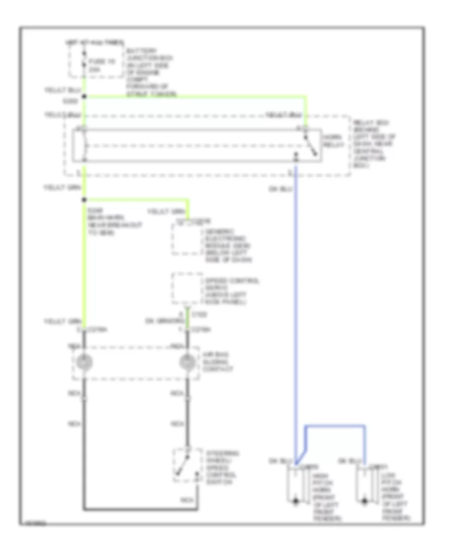
HORN Horn Wiring Diagram for Ford Mustang GT Bullitt 2002 List of elements for Horn Wiring Diagram for Ford Mustang GT Bullitt 2002: 20 20a Air bag sliding contact Battery junction box (in left side of engine compt, forward of strut tower) C122 C1256 C1261 C201e C218a Fuse 16 Generic electronic module (gem) (below left side of dash) High pitch horn (front of left front fender) Horn relay Hot at all times Low pitch horn (front of left front fender) Nca Relay box (behind left side of dash, near central junction box) S202 S249 (main harn, near breakout to gem) Speed control servo (above left kick panel) Steering wheel/ speed control switch
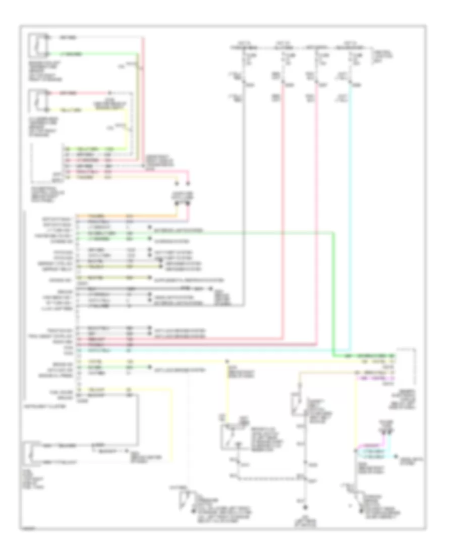
INSTRUMENT CLUSTER Instrument Cluster Wiring Diagram for Ford Mustang GT Bullitt 2002 List of elements for Instrument Cluster Wiring Diagram for Ford Mustang GT Bullitt 2002: 73 (left rear of vehicle) (near right front side of transmission) s130 (not used) 3.8l 4.6l Air bag ind - Anti-lock brakes system Anti-theft system Antilock ind Brake fluid level switch (in left rear of engine compt, on brake fluid reservoir) Brake ind C201d C201e C220a C220b Central junction box Charge ind Charging system Computer data lines system Cylinder-head temperature sensor (on top front of engine) Defogger system Defrost ctrl sw Defrost relay Engine coolant temperature sensor (on top right front of engine) Engine oil press Exterior lights system Fasten belts ind + Fuel gauge Fuel pump (top right side of fuel tank) Fuse 15a Fuse 20a Fuse 5a G204 (behind center of dash) Generic electronic module (below left side of dash) Ground Headlights system High beam ind + Hot at all times Hot in park or head Hot in run Hot in run or start Illum lamp feed Instrument cluster Low Lt turn ind + Nca Oil pressure switch (3.8l: on lower left front of engine, above oil filter, 4.6l: left front of engine below valve cover) Parking brake switch (on right rear of parking brake lever asembly) Pats mod Power tops system Powertrain control module (behind right kick panel) Pwr Radio mem Rt turn ind + S101 S126 (center rear of engine compt) S205 S206 S230 S246 (behind right side of dash) S257 S259 S266 S276 (behind right side of dash) S307 S322 Safety belt switch (in driver's seat belt buckle) Scp data bus + Scp data bus - Scp+ Scp- Trac assist cntrl sw Traction sw
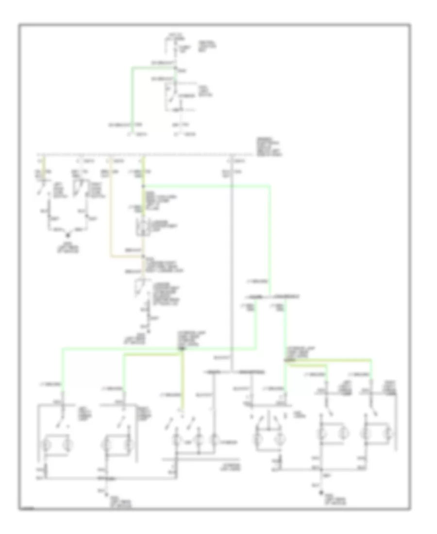
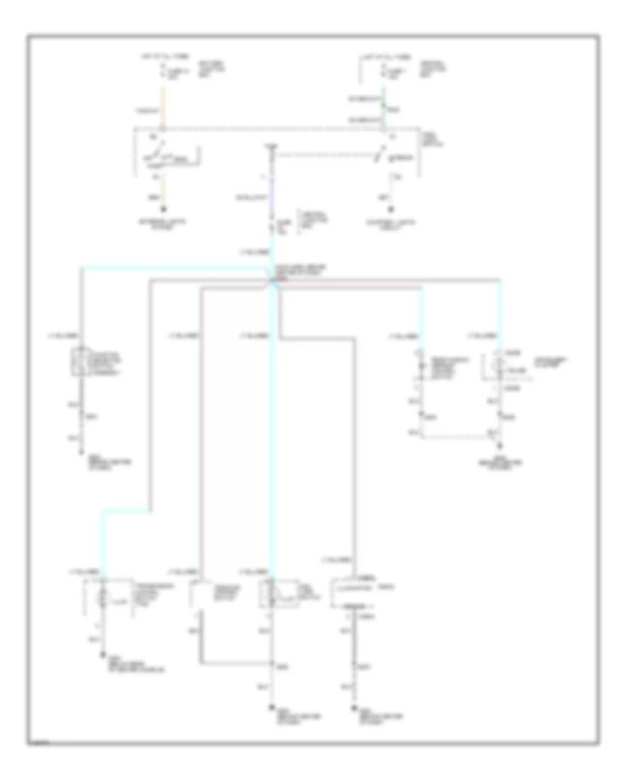
INTERIOR LIGHTS Courtesy Lamps Wiring Diagram for Ford Mustang GT Bullitt 2002 List of elements for Courtesy Lamps Wiring Diagram for Ford Mustang GT Bullitt 2002: 32 (interior lamp harn, near interior/ map lamps) s902 (interior lamp harn, near map lamps) s902 C201a C201c C201d C201e Central junction box Convertible Coupe Fuse 7 15a G400 (left rear of vehicle) Generic electronic module (below left side of dash) Hot at all times Interior Interior/ map lamps Left door ajar switch Left vanity mirror lamp Luggage compartment lamp Luggage compartment lid release solenoid (center rear of trunk lid) Main light switch Map Map lamps Nca Red Right door ajar switch Right vanity mirror lamp S242 S307 S407 S429 (body main harn, near lower left "a" pillar) S507 S901 Instrument Illumination Wiring Diagram for Ford Mustang GT Bullitt 2002 List of elements for Instrument Illumination Wiring Diagram for Ford Mustang GT Bullitt 2002: 34 (main harn, behind center of dash) s230 Battery junction box Bulbs C220b C290a Central junction box Courtesy lights circuit Exterior lights system Fog lamp switch Function selector switch assembly Fuse 10 30a Fuse 15a Fuse 7 15a G204 (behind center of dash) G300 (below rear of center console) Ground Head Hot at all times Illum Illumination Instrument cluster Interior Main light switch Off Park Radio Rear window defrost control switch S201 S203 S206 S242 S283 Traction control switch Transmission control switch (tcs)
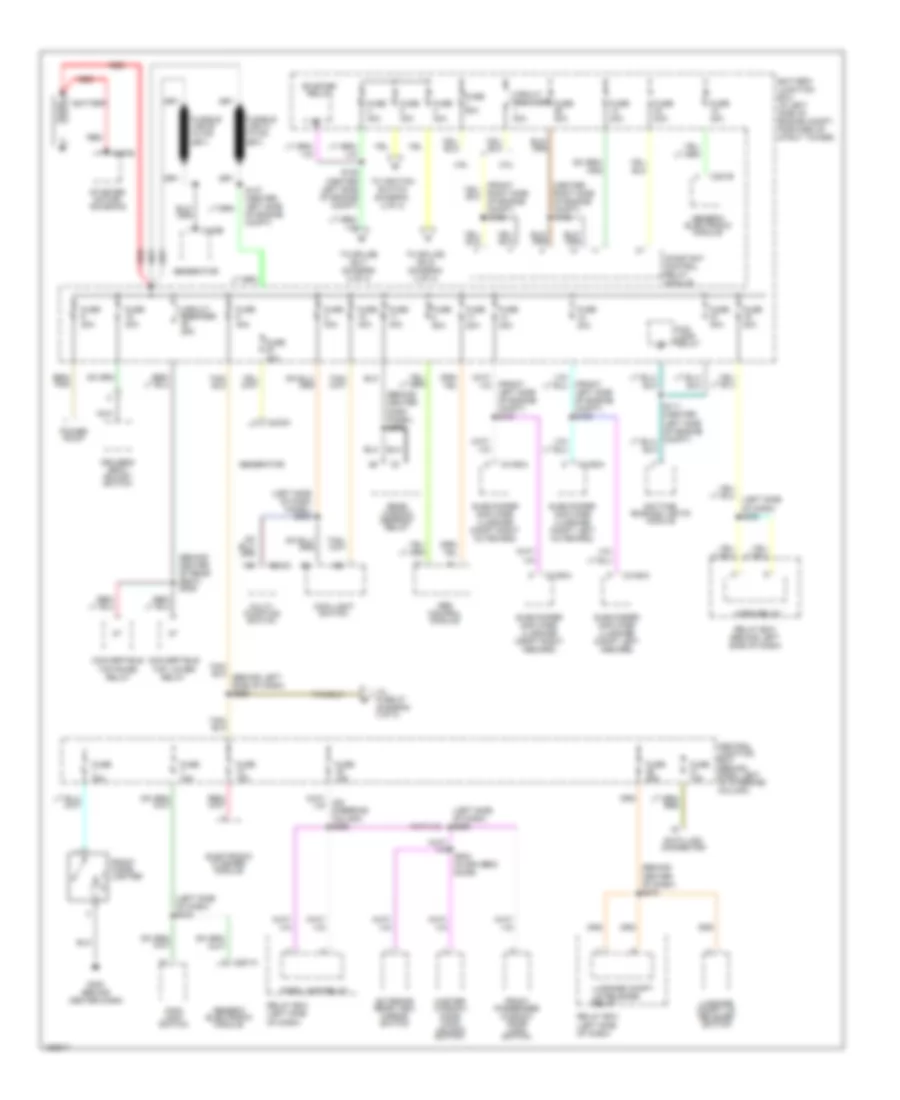
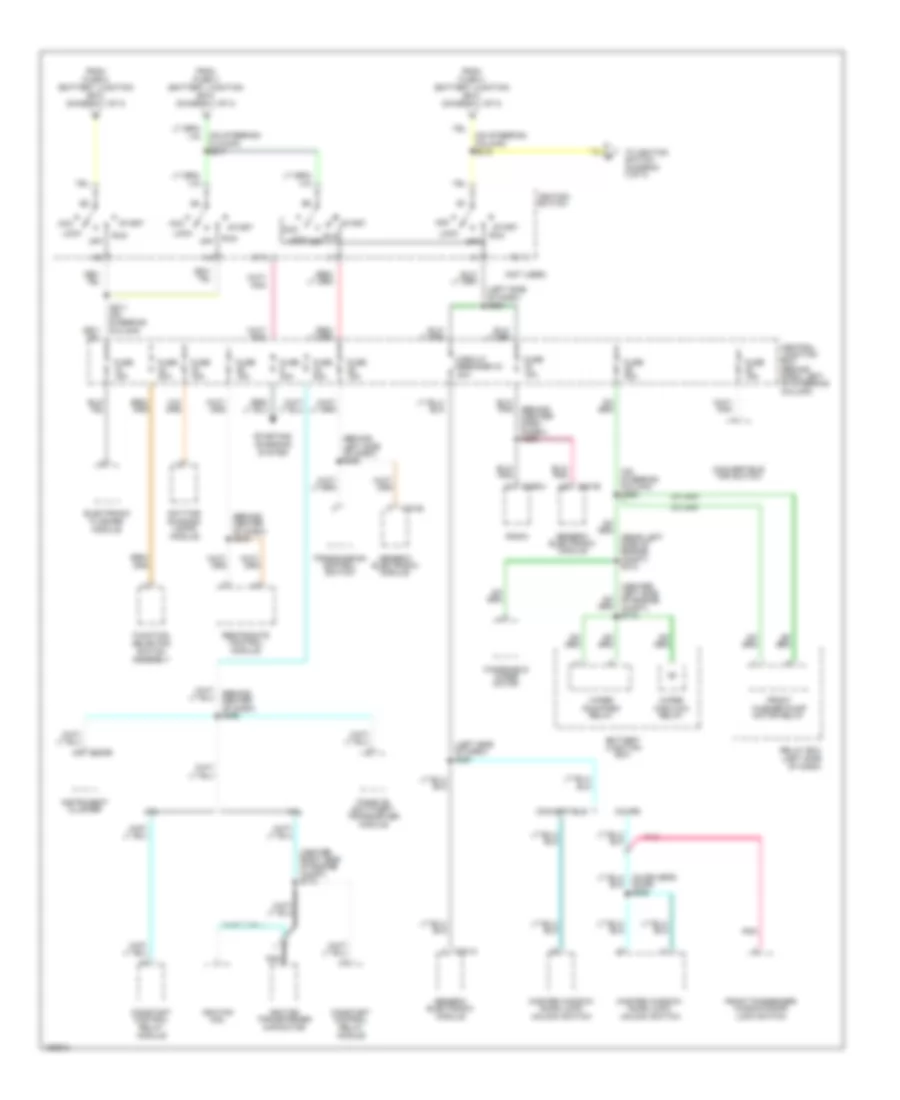
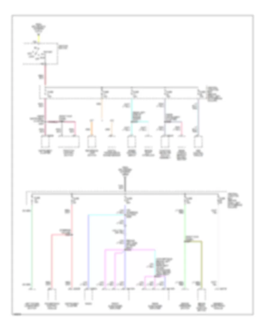
POWER DISTRIBUTION Power Distribution Wiring Diagram (1 of 3) for Ford Mustang GT Bullitt 2002 List of elements for Power Distribution Wiring Diagram (1 of 3) for Ford Mustang GT Bullitt 2002: 73 (behind center dash panel) s278 (behind center of dash) s270 (behind center of rear seat) s409 (center right side of engine compt) (front left side of engine compt) s105 (front left side of engine compt) s107 (left side of dash panel) s233 (left side of dash) s242 (left side of dash) s269 3.8l 4.6l Abs control module Battery Battery junction box (in left side of engine compt, forward of strut tower) C102a C102b C197b C201a C201b C202a C4160a Central junction box (behind dash, left of steering column) Circuit breaker 25a Circuit breaker 30a Constant control relay module Convertible top lower relay Convertible top raise relay Data link connector Daytime running lights module Driver's seat adjust switch Electronic flasher module Exterior rear view mirror switch Fog lamp relay Front cigar lighter Front passenger window/ door lock switch Fuse 10a Fuse 15a Fuse 20a Fuse 25a Fuse 30a Fuse 40a Fuse 50a G300 (behind center dash) Generator Generic electronic module Horn relay Luggage compt lid release relay Luggage compt lid release switch Main light switch Master window/ door lock/ unlock switch Multi- function switch Nca Park lamp relay Power point Rear window defrost relay Red Relay box (behind left side of dash) Relay box (left side of dash) S102 S108 S109 (center left side of engine compt) S127 (center left side of engine compt) S504 (in driver's door) Starter motor/ solenoid Starter relay Subwoofer amplifier (luggage compt left inboard) Subwoofer amplifier (luggage compt left outboard) Subwoofer amplifier (luggage compt right inboard) Subwoofer amplifier (luggage compt right outboard) To fuse 27 (diagram 3 of 3) To ignition switch (diagram 2 of 3) To splice s215 (diagram 2 of 3) To splice s217 (diagram 2 of 3) Power Distribution Wiring Diagram (2 of 3) for Ford Mustang GT Bullitt 2002 List of elements for Power Distribution Wiring Diagram (2 of 3) for Ford Mustang GT Bullitt 2002: 61 (behind (center dash panel) s265 (behind center of dash) s243 (behind left side of dash) s262 (center left side of engine compt) s113 (center right side of engine compt) s174 (left side of dash) s264 (left side of dash) s267 (not used) (on steering cloumn) s217 (on steering column) s215 (on steering column) s225 (rear left side of engine compt) s312 3.8l 4.6l Acc Battery junction box C201a C201e C220b C290a Central junction box (behind dash, left of steering column) Circuit breaker 43 20a Constant control relay module Convertible Convertible top switch Coupe Daytime running lamps module Electronic flasher module From fuse 3 (battery junction box) (diagram 1 of 3) From fuse 4 (battery junction box) (diagram 1 of 3) From fuse 5 (battery junction box) (diagram 1 of 3) Front passenger window/door lock switch Front washer pump motor relay Function selector switch assembly Fuse 15a Fuse 20a Fuse 30a Generic electronic module Ignition coil Ignition switch Ignition transformer capacitor Instrument cluster Lock Master window/ door lock/ unlock switch Nca Off Passive anti-theft transceiver module Pnk Radio Relay box (left side of dash) Restraints control module Run S211 (on steering column) Sta Start Starting/ charging system To ignition switch (diagram 3 of 3) Transmission control switch Windshield wiper motor Wiper high/low relay Wiper run/park relay Power Distribution Wiring Diagram (3 of 3) for Ford Mustang GT Bullitt 2002 List of elements for Power Distribution Wiring Diagram (3 of 3) for Ford Mustang GT Bullitt 2002: 45 (near instrument cluster s257 (near instrument cluster) s256 (on steering column) s258 (rear left side of engine compt) s245 (right kick panel s284 (right kick panel) s207 A/t Abs control module Acc Brake pedal position switch Brake pressure switch Brake shift interlock C201b C220b C290a C294c C4108a C4109a Central junction box (behind dash, left of steering column) Digital transmission range sensor From splice s215 (diagram 2 of 3) From splice s260 (diagram 1 of 3) Front subwoofer amplifier Function selector switch assembly Fuse 15a Fuse 25a Fuse 5a Generic electronic module Ignition switch Instrument cluster Left power lumbar seat switch Lock M/t Off Powertrain control module Radio Rear seat coupe- on package tray behind rear seat) s431 Rear subwoofer amplifier Rear window defrost control switch Reversing lamp switch Run Speed control servo Start Steering column) s259 Traction control switch
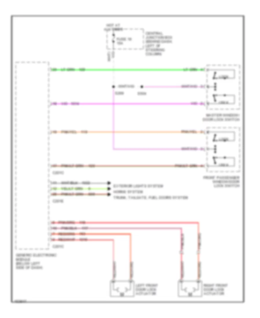
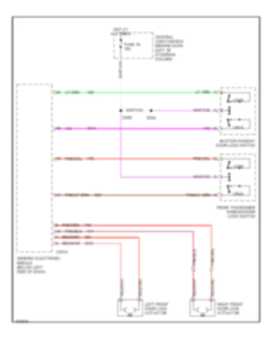
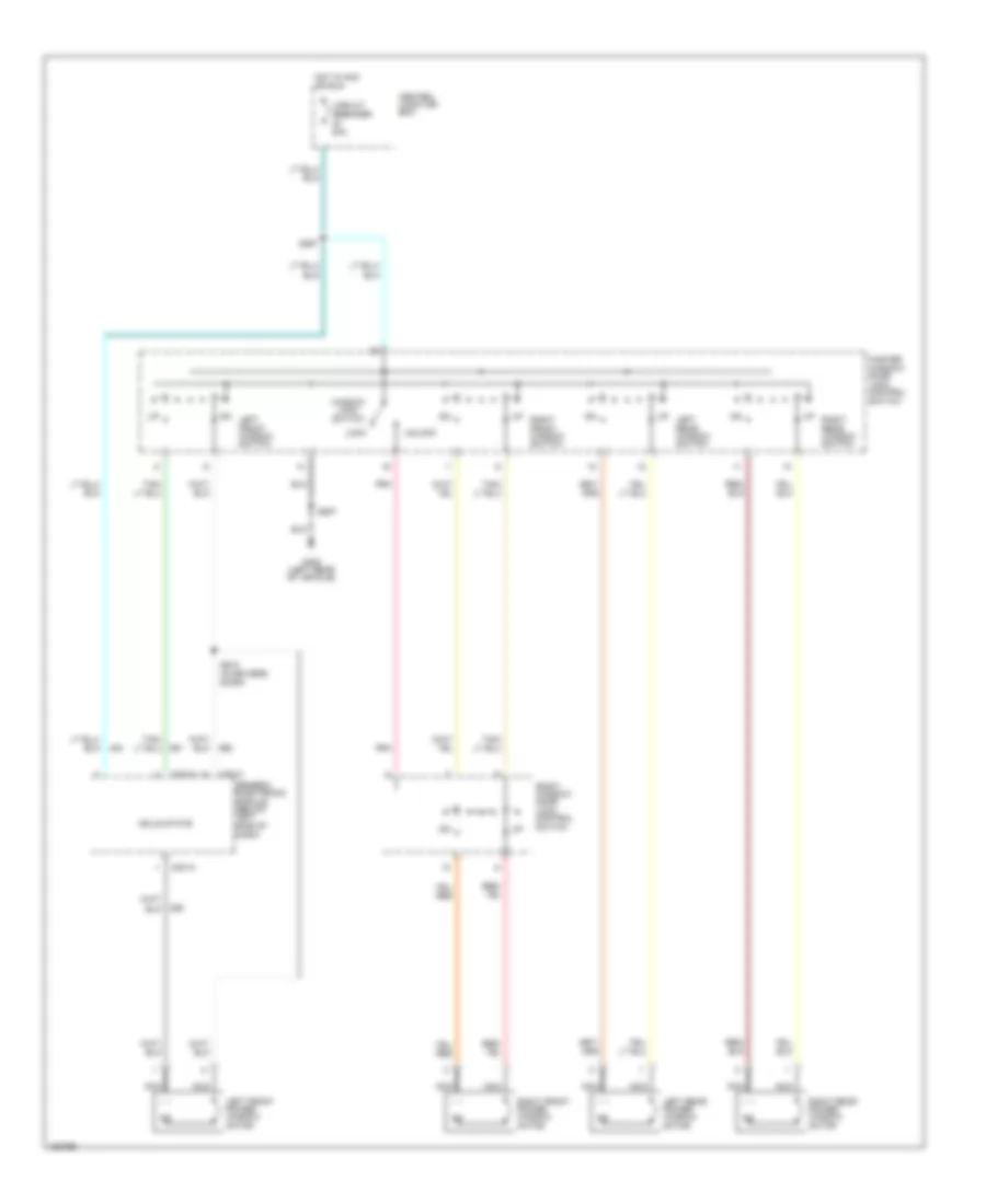
POWER DOOR LOCKS Power Door Lock Wiring Diagram, with Keyless Entry for Ford Mustang GT Bullitt 2002 List of elements for Power Door Lock Wiring Diagram, with Keyless Entry for Ford Mustang GT Bullitt 2002: 17 C201c C201e Central junction box (behind dash, left of steering column) Exterior lights system Front passenger window/door lock switch Fuse 19 15a Generic electronic module (below left side of dash) Horns system Hot at all times Left front door lock actuator Lock Master window/ door lock switch Right front door lock actuator S269 S504 Trunk, tailgate, fuel doors system Unlk Power Door Lock Wiring Diagram, without Keyless Entry for Ford Mustang GT Bullitt 2002 List of elements for Power Door Lock Wiring Diagram, without Keyless Entry for Ford Mustang GT Bullitt 2002: 13 C201c Central junction box (behind dash, left of steering column) Front passenger window/door lock switch Fuse 19 15a Generic electronic module (below left side of dash) Hot at all times Left front door lock actuator Lock Master window/ door lock switch Right front door lock actuator S269 S504 Unlk
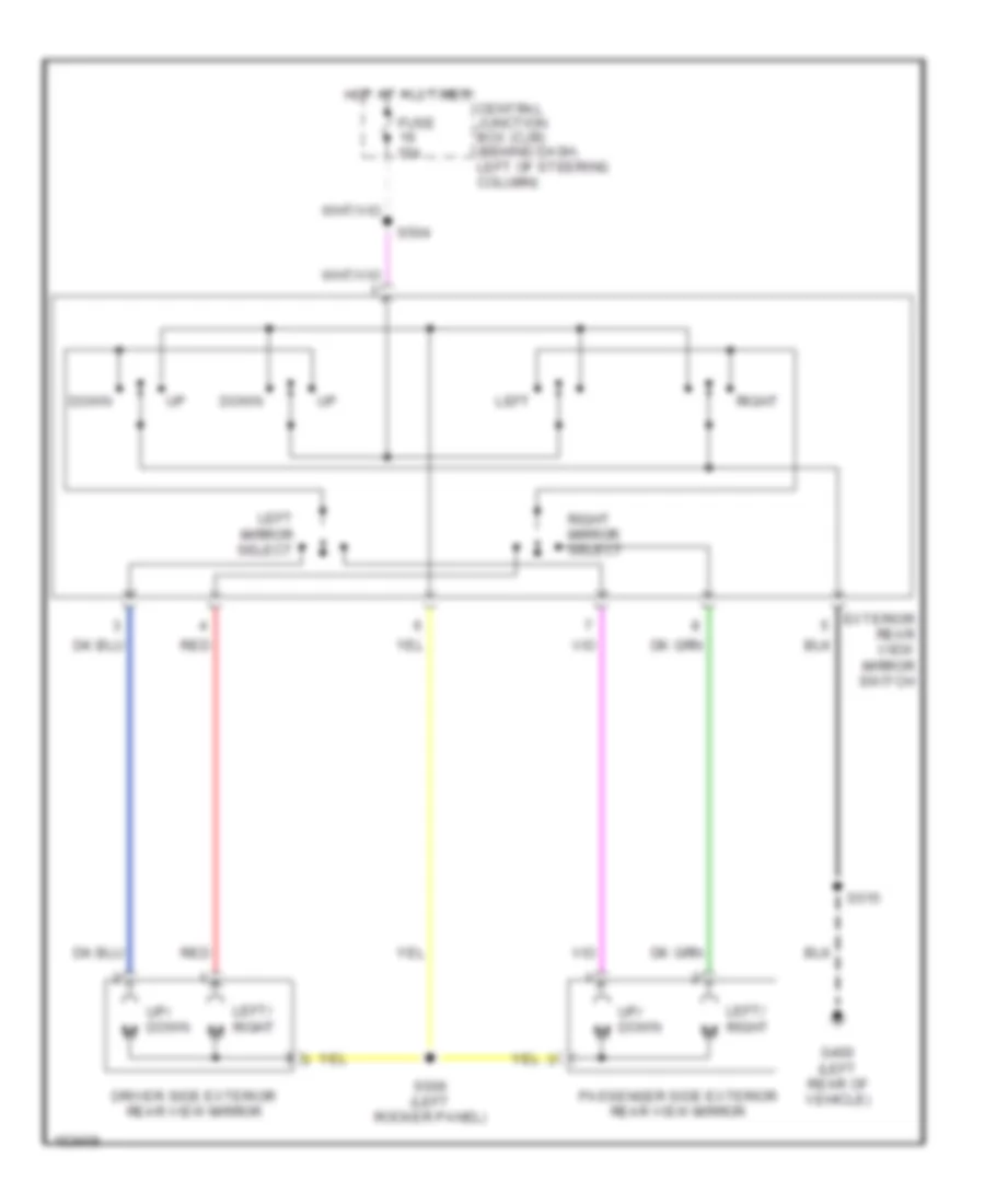
POWER MIRRORS Power Mirror Wiring Diagram for Ford Mustang GT Bullitt 2002 List of elements for Power Mirror Wiring Diagram for Ford Mustang GT Bullitt 2002: 18 Central junction box (cjb) (behind dash, left of steering column) Down Driver side exterior rear view mirror Exterior rear view mirror switch Fuse 15a G400 (left rear of vehicle) Hot at all times Left Left mirror select Left/ right Passenger side exterior rear view mirror Red Right Right mirror select S504 S506 (left rocker panel) S515 Up/ down m
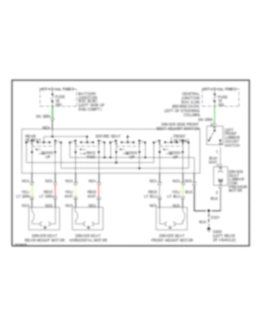
POWER SEATS Power Seat Wiring Diagrams for Ford Mustang GT Bullitt 2002 List of elements for Power Seat Wiring Diagrams for Ford Mustang GT Bullitt 2002: 20 Battery junction box (bjb) (left side of eng compt) Central junction box (cjb) (behind dash, left of steering column) Down Driver seat front height motor Driver seat horizontal motor Driver seat lumbar com- pressor motor Driver seat rear height motor Driver side front seat adjust switch Entire seat Front of seat Fuse 15a Fuse 30a G400 (left rear of vehicle) Hot at all times Left front lumbar adjust switch M m Nca Rear of seat Rwd fwd S321
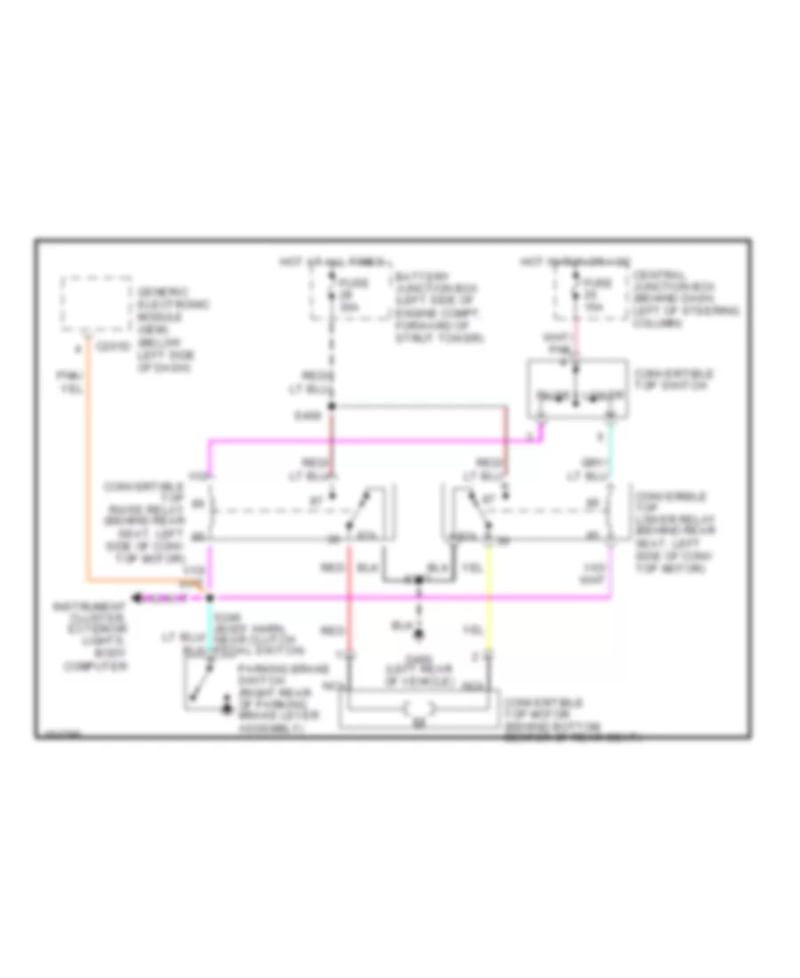
POWER TOP/SUNROOF Power Top/Sunroof Wiring Diagrams for Ford Mustang GT Bullitt 2002 List of elements for Power Top/Sunroof Wiring Diagrams for Ford Mustang GT Bullitt 2002: 22 87a Battery junction box (left side of engine compt, forward of strut tower) C201d Central junction box (behind dash, left of steering column) Converible top lower relay (behind rear seat, left side of conv top motor) Convertible top motor (behind bottom center of rear seat) Convertible top raise relay (behind rear seat, left side of conv top motor) Convertible top switch Fuse 15a Fuse 30a G400 (left rear of vehicle) Generic electronic module (gem) (below left side of dash) Hot at all times Hot in run or acc Instrument cluster, exterior lights, body computer Lower Nca Parking brake switch (right rear of parking brake lever assembly) Raise Red S307 S409
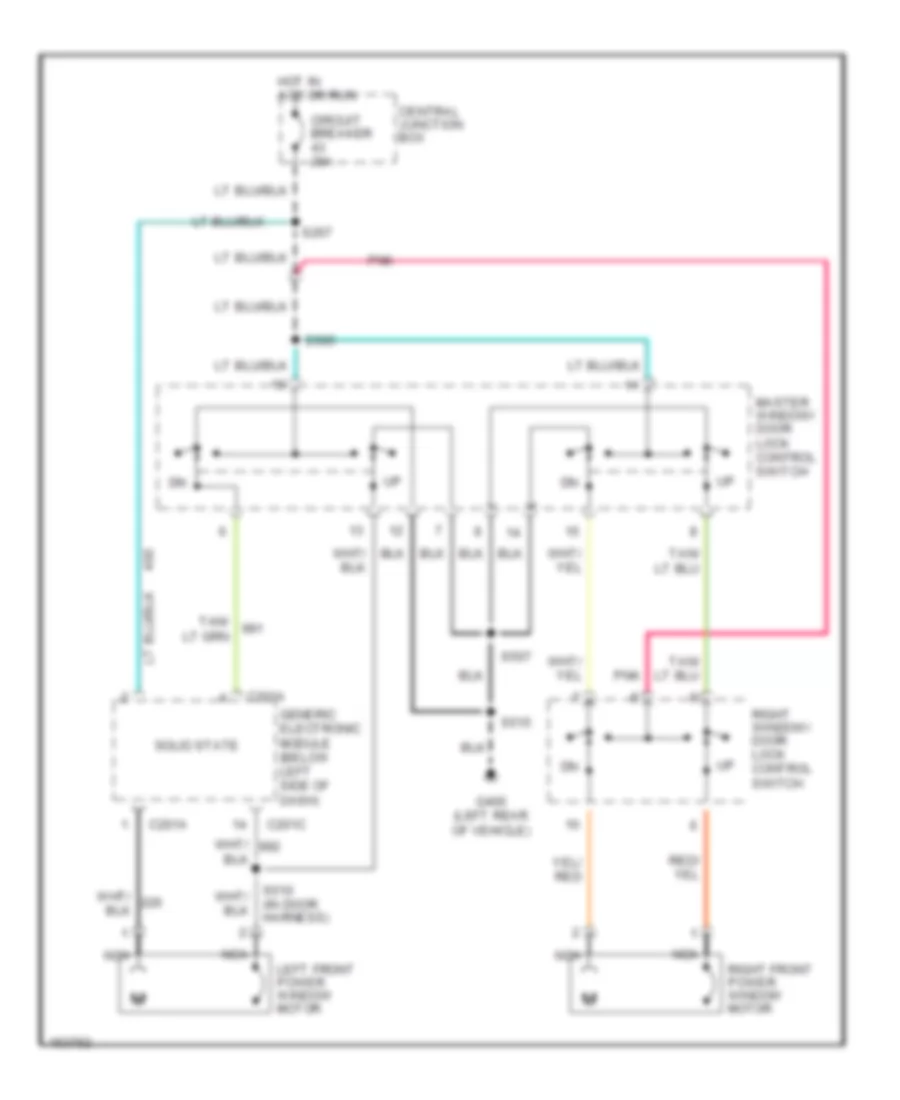
POWER WINDOWS Power Window Wiring Diagram, Convertible for Ford Mustang GT Bullitt 2002 List of elements for Power Window Wiring Diagram, Convertible for Ford Mustang GT Bullitt 2002: 26 C201a C201c Central junction box Circuit breaker 20a G400 (left rear of vehicle) Generic electronic module (below left side of dash) Hot in acc or run Left front power window motor Left front window switch Left rear power window motor Left rear window switch Lock Master window/ door lock control switch Nca Pnk Right front power window motor Right front window switch Right rear power window motor Right rear window switch Right window/ door lock control switch S267 S507 S510 (in drivers door) Solid state Unlock Window lock switch Power Window Wiring Diagram, Coupe for Ford Mustang GT Bullitt 2002 List of elements for Power Window Wiring Diagram, Coupe for Ford Mustang GT Bullitt 2002: 19 C201a C201c Central junction box Circuit breaker 20a G400 (left rear of vehicle) Generic electronic module (below left side of dash) Hot in acc or run Left front power window motor Master window/ door lock control switch Nca Pnk Right front power window motor Right window/ door lock control switch S267 S505 S507 S510 (in door harness) S515 Solid state
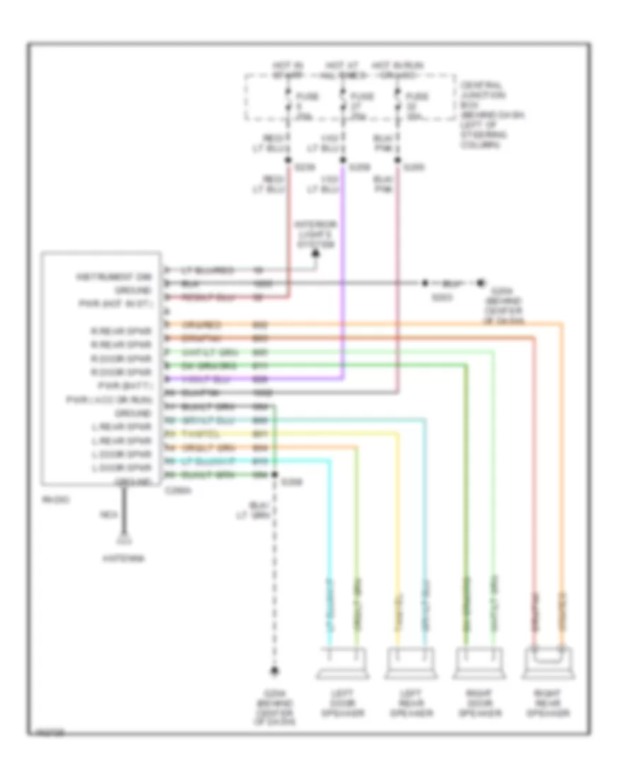
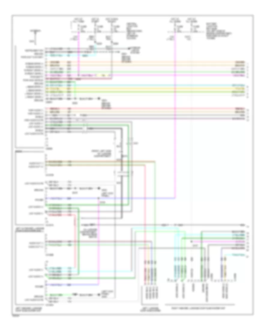
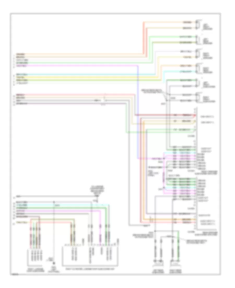
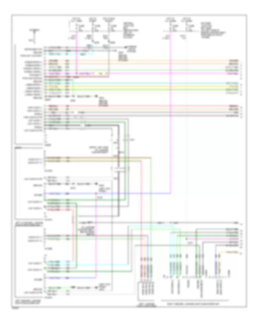
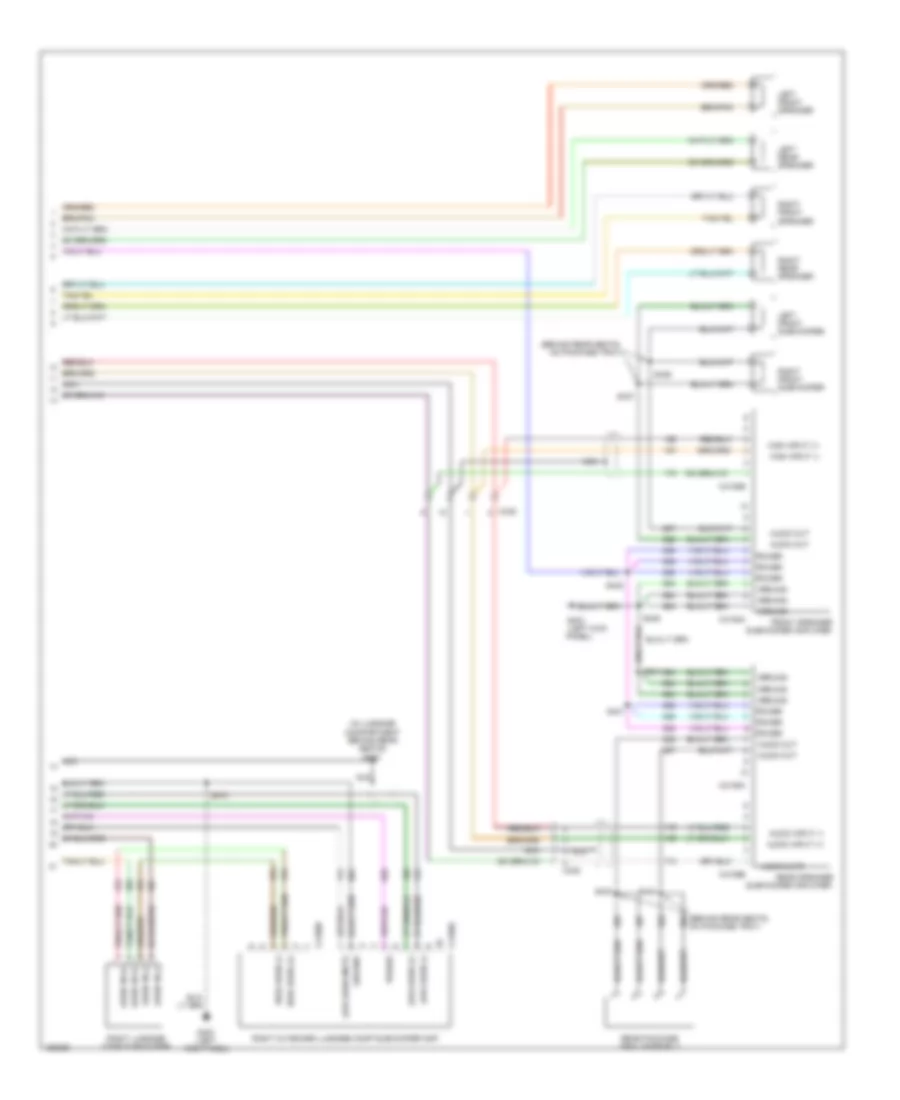
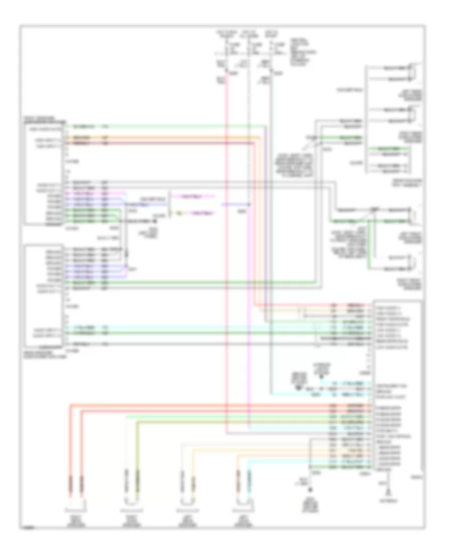
RADIO Base Radio for Ford Mustang GT Bullitt 2002 List of elements for Base Radio for Ford Mustang GT Bullitt 2002: 33 (behind center of dash) Antenna C290a Central junction box (behind dash, left of steering column) Fuse 15a Fuse 20a Fuse 25a G204 G204 (behind center of dash) Ground Hot at all times Hot in run or acc Hot in start Instrument dim Interior lights system L door spkr L rear spkr Left door speaker Left rear speaker Nca Pwr ( acc or run) Pwr (batt) Pwr (hot in st) R door spkr R rear spkr Radio Right door speaker Right rear speaker S203 S208 S239 S258 S265 Premium Sound Radio Wiring Diagram, Convertible with Mach 1000 Sound System (1 of 2) for Ford Mustang GT Bullitt 2002 List of elements for Premium Sound Radio Wiring Diagram, Convertible with Mach 1000 Sound System (1 of 2) for Ford Mustang GT Bullitt 2002: 67 (behind center of dash) (front left side of luggage compartment) (in luggage compartment, behind rear seats) (left kick panel) Antenna Audio in (+) Audio in (-) Audio out (+) Audio out (-) Battery junction box (bjb) (on left side of engine compartment, forward of strut tower) C290a C290b C4157a C4157b C4158a C4158b C4159a C4159b C431 Central junction box (behind dash, left of steering column) Fuse 15a Fuse 20a Fuse 25a Fuse 30a G204 G403 Ground High audio (+) High audio (-) High audio mute Hot at all times Hot in run or acc Hot in start Instrument dim Interior lights system L front spkr (+) L front spkr (-) L rear spkr (+) L rear spkr (-) Left inboard luggage comp subwoofer amp Left luggage comp subwoofer Left outboard luggage comp subwoofer amp Low audio (+) Low audio (-) Low audio mute Nca Power Pwr (acc or run) Pwr (batt) Pwr (hot in start) R front spkr (+) R front spkr (-) R rear spkr (+) R rear spkr (-) Radio Right inboard luggage comp subwoofer amp S105 S107 S203 S208 S239 S258 S265 S472 S474 S475 Shield Premium Sound Radio Wiring Diagram, Convertible with Mach 1000 Sound System (2 of 2) for Ford Mustang GT Bullitt 2002 List of elements for Premium Sound Radio Wiring Diagram, Convertible with Mach 1000 Sound System (2 of 2) for Ford Mustang GT Bullitt 2002: 52 (behind rear seats, on package tray) (in luggage compartment behind rear seats) (left kick Audio in (+) Audio in (-) Audio input (+) Audio input (-) Audio mute Audio out Audio out C4108a C4108b C4109a C4109b C4160a C4160b Front speaker G403 G403 (left kick panel) Ground High audio (+) High audio (-) High input (+) High input (-) Left front speaker Left front subwoofer Left rear speaker Left rear subwoofer Low audio (+) Low audio (-) Low audio mute Nca Panel) Power Rear speaker Right front speaker Right front subwoofer Right luggage comp subwoofer Right outboard luggage comp subwoofer amp Right rear speaker Right rear subwoofer S404 S405 S431 S432 S433 S434 S436 S437 S470 S473 Subwoofer amplifier Premium Sound Radio Wiring Diagram, Coupe with Mach 1000 Sound System (1 of 2) for Ford Mustang GT Bullitt 2002 List of elements for Premium Sound Radio Wiring Diagram, Coupe with Mach 1000 Sound System (1 of 2) for Ford Mustang GT Bullitt 2002: 67 (behind center of dash) (front left side of luggage compartment) (in luggage compartment, behind rear seats) (left kick panel) Antenna Audio in (+) Audio in (-) Audio out (+) Audio out (-) Battery junction box (bjb) (on left side of engine compartment, forward of strut tower) C290a C290b C4157a C4157b C4158a C4158b C4159a C4159b C431 Central junction box (behind dash, left of steering column) Fuse 15a Fuse 20a Fuse 25a Fuse 30a G204 G403 Ground High audio (+) High audio (-) High audio mute Hot at all times Hot in run or acc Hot in start Instrument dim Interior lights system L front spkr (+) L front spkr (-) L rear spkr (+) L rear spkr (-) Left inboard luggage comp subwoofer amp Left luggage comp subwoofer Left outboard luggage comp subwoofer amp Low audio (+) Low audio (-) Low audio mute Nca Power Pwr (acc or run) Pwr (batt) Pwr (hot in start) R front spkr (+) R front spkr (-) R rear spkr (+) R rear spkr (-) Radio Right inboard luggage comp subwoofer amp S105 S107 S203 S208 S239 S258 S265 S472 S474 S475 Shield Premium Sound Radio Wiring Diagram, Coupe with Mach 1000 Sound System (2 of 2) for Ford Mustang GT Bullitt 2002 List of elements for Premium Sound Radio Wiring Diagram, Coupe with Mach 1000 Sound System (2 of 2) for Ford Mustang GT Bullitt 2002: 51 (behind rear seats, on package tray) (in luggage compartment behind rear seats) (left kick Audio in (+) Audio in (-) Audio input (+) Audio input (-) Audio mute Audio out Audio out C4108a C4108b C4109a C4109b C4160a C4160b C438 Front speaker G403 G403 (left kick panel) Ground High audio (+) High audio (-) High input (+) High input (-) Left front speaker Left front subwoofer Left rear speaker Low audio (+) Low audio (-) Low audio mute Nca Panel) Power Rear package tray assembly Rear speaker Right front speaker Right front subwoofer Right luggage comp subwoofer Right outboard luggage comp subwoofer amp Right rear speaker S405 S431 S432 S433 S434 S436 S437 S470 S473 Subwoofer amplifier Premium Sound Radio Wiring Diagram, with Mach 460 Sound System for Ford Mustang GT Bullitt 2002 List of elements for Premium Sound Radio Wiring Diagram, with Mach 460 Sound System for Ford Mustang GT Bullitt 2002: 72 (behind center of dash) g204 (conv: body harn, near breakout to rear speaker amp) (coupe: amp harn, near breakout to r license lamp) Antenna Audio input (+) Audio input (-) Audio mute Audio out (+) Audio out (-) C290a C290b C4108a C4108b C4109a C4109b Central junction box (behind dash, left of steering column) Convertible Coupe Front speaker subwoofer amplifier Front spkr shld Fuse 15a Fuse 20a Fuse 25a G204 (behind center of dash) G403 (left kick panel) Ground High audio (+) High audio (-) High audio mute High input (+) High input (-) Hot at all times Hot in run or acc Hot in start Instrument dim Interior lights system L door spkr L rear spkr Left door speaker Left front subwoofer speaker Left rear speaker Left rear subwoofer speaker Low audio (+) Low audio (-) Low audio mute Nca Power Pwr ( acc or run) Pwr (batt) Pwr (hot in st) R door spkr R rear spkr Radio Rear package tray assembly Rear speaker subwoofer amplifier Rear spkr shld Right door speaker Right front subwoofer speaker Right rear speaker Right rear subwoofer speaker S203 S208 S239 S258 S265 S404 S405 S431 S432 S433 S434 S436 S437 (conv: body harn, near breakout to front speaker amplifier) (coupe: amp harn, below left side of rear seat)
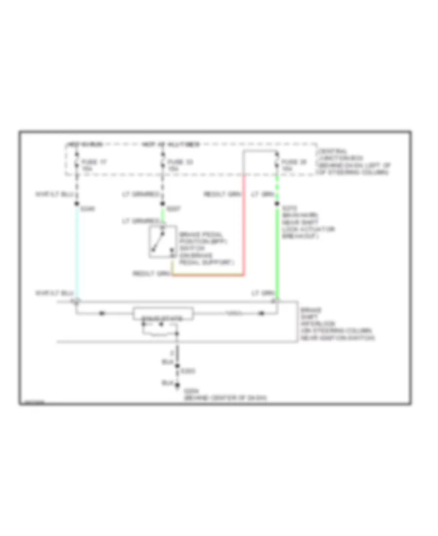
SHIFT INTERLOCKS Shift Interlock Wiring Diagram for Ford Mustang GT Bullitt 2002 List of elements for Shift Interlock Wiring Diagram for Ford Mustang GT Bullitt 2002: 14 Brake pedal position (bpp) switch (on brake pedal support) Brake shift interlock (on steering column, near ignition switch) Central junction box (behind dash, left of of steering column) Fuse 17 15a Fuse 33 15a Fuse 35 15a G204 (behind center of dash) Hot at all times Hot in run S203 S207 S245 S272 (main harn, near shift lock actuator breakout) Solid state
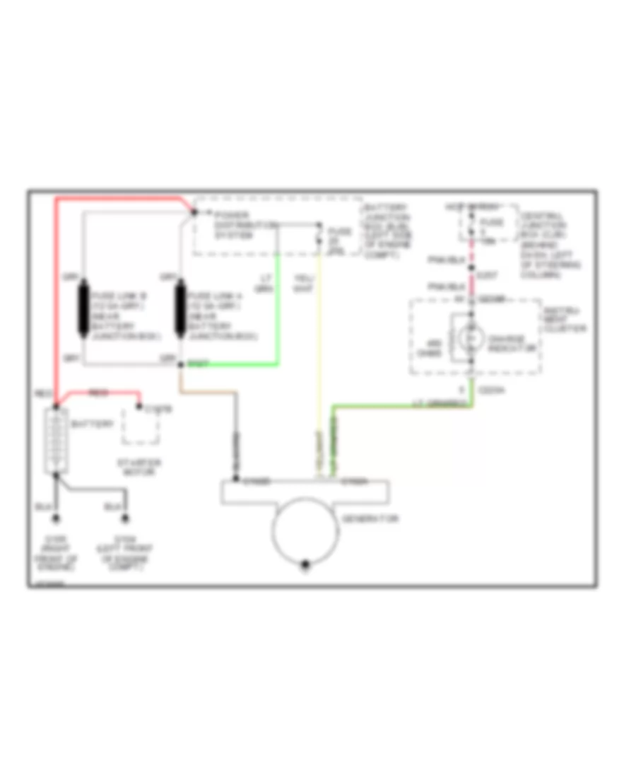
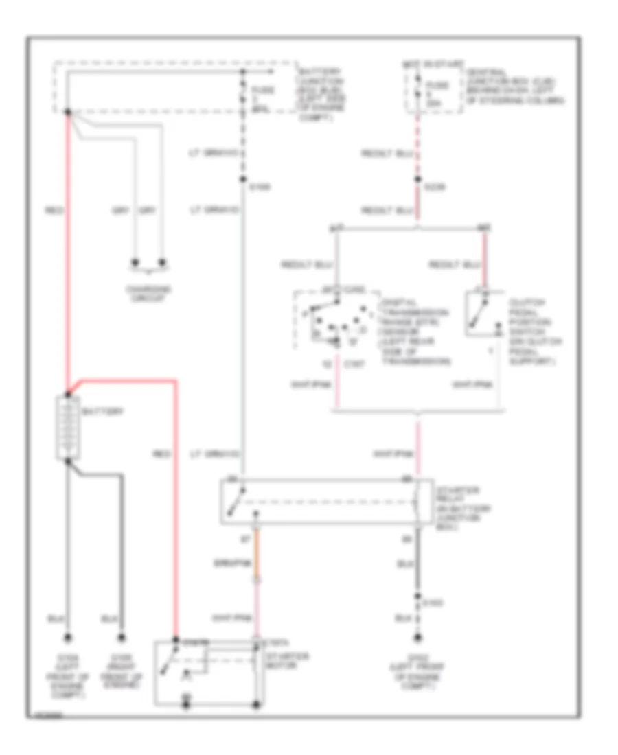
STARTING/CHARGING Charging Wiring Diagram for Ford Mustang GT Bullitt 2002 List of elements for Charging Wiring Diagram for Ford Mustang GT Bullitt 2002: 21 Battery Battery junction box (bjb) (left side of engine compt) C102a C102b C197b C220a C220b Central junction box (cjb) (behind dash, left of steering column) Charge indicator Fuse 15a Fuse 20a G104 (left front of engine compt) G105 (right front of engine) Generator Hot in run Instru- ment cluster Ohms Power distribution system Red S257 Starter motor Starting Wiring Diagram for Ford Mustang GT Bullitt 2002 List of elements for Starting Wiring Diagram for Ford Mustang GT Bullitt 2002: 23 A/t Battery Battery junction box (bjb) (left side of engine compt) C167 C197a C197b Central junction box (cjb) (behind dash, left of steering column) Charging circuit Clutch pedal position switch (on clutch pedal support) Digital transmission range (dtr) sensor (left rear side of transmission) Fuse 20a Fuse 40a G102 (left front of engine compt) G104 (left front of engine compt) G105 (right front of engine) Hot in start M/t Red S103 S109 S239 Starter motor Starter relay (in battery junction box)
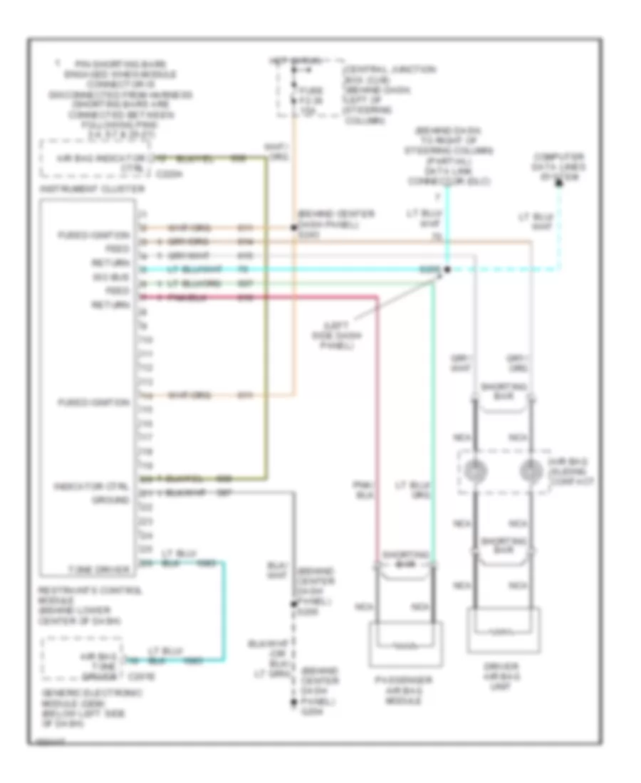
SUPPLEMENTAL RESTRAINTS Supplemental Restraint Wiring Diagram for Ford Mustang GT Bullitt 2002 List of elements for Supplemental Restraint Wiring Diagram for Ford Mustang GT Bullitt 2002: 31 (behind center dash panel) g204 (behind center dash panel) s243 (behind dash, to right of steering column) (partial) data link connector (dlc) (left side dash panel) (or Air bag indicator Air bag sliding contact Air bag tone driver C201e C220a Central junction box (cjb) (behind dash, left of steering column) Computer data lines system Ctrl Driver air bag unit Feed Fuse f2.36 15a Fused ignition Generic electronic module (gem) (below left side of dash) Ground Hot in run Indicator ctrl Instrument cluster Iso bus Nca Passenger air bag module Pin shorting bars engaged when module connector is disconnected from harness (shorting bars are connected between following pins: 3-4, 6-7 & 20-21) Restraints control module (behind lower center of dash) Return S255 Shorting bar Tone driver
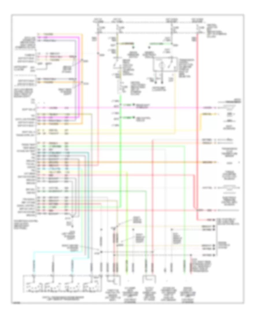
TRANSMISSION A/T Wiring Diagram for Ford Mustang GT Bullitt 2002 List of elements for A/T Wiring Diagram for Ford Mustang GT Bullitt 2002: 84 (behind center of dash) (behind dash, right side of steering column) (right center of engine compt) (right rear of engine compt) (right side of engine) (top front of engine) 3.8l 4.6l 4r70w transmission Abs control module Anti-lock brake control module (right front of engine compt) Bpp sw input Brake pedal position switch (on brake pedal support) Brake pressure switch Brake shift interlock C220a C250 Central junction box (behind dash, left of steering column) Cht sens Cylinder head temperature (cht) sensor (3.8l) Data link connector Data link power Digital transmission range sensor (left rear of transmission) Electronic pressure control (epc) solenoid Engine controls system Engine coolant temperature (ect) sensor (4.6l) Epc sol Fuel pump relay, fuel injectors, cooling fan relays Fuse 15a Fuse 20a Fuse 5a Fused b+ G104 (left front of engine compt) Generic electronic module Ground Hot at all times Hot in run or start Ignition power Instrument cluster Instrument illumination Intake air temp Intake air temperature (iat) sensor (part of mass air (maf) sensor) Kapwr Oss sig Output shaft speed (oss) sensor (left side of trans) Powertrain control module (pcm) (behind right kick panel) Red Red red Ref votage S115 S121 (right rear of engine compt) S126 S129 S134 S135 S207 S234 S252 S253 S259 S262 S272 S275 Scp data bus + Scp data bus - Shift sol a Shift sol b Shift solenoids Signal control Ssa Ssb Tcc sol Temp sens Throttle position (tp) sensor (on throttle body) Torque converter clutch (tcc) solenoid Tps signal Tr1 Tr2 Tr3 Tr4 Trans cntrl sw Trans temp Transmission control switch (tcs) (on center console, right of gear selector) Transmission fluid temperature sensor
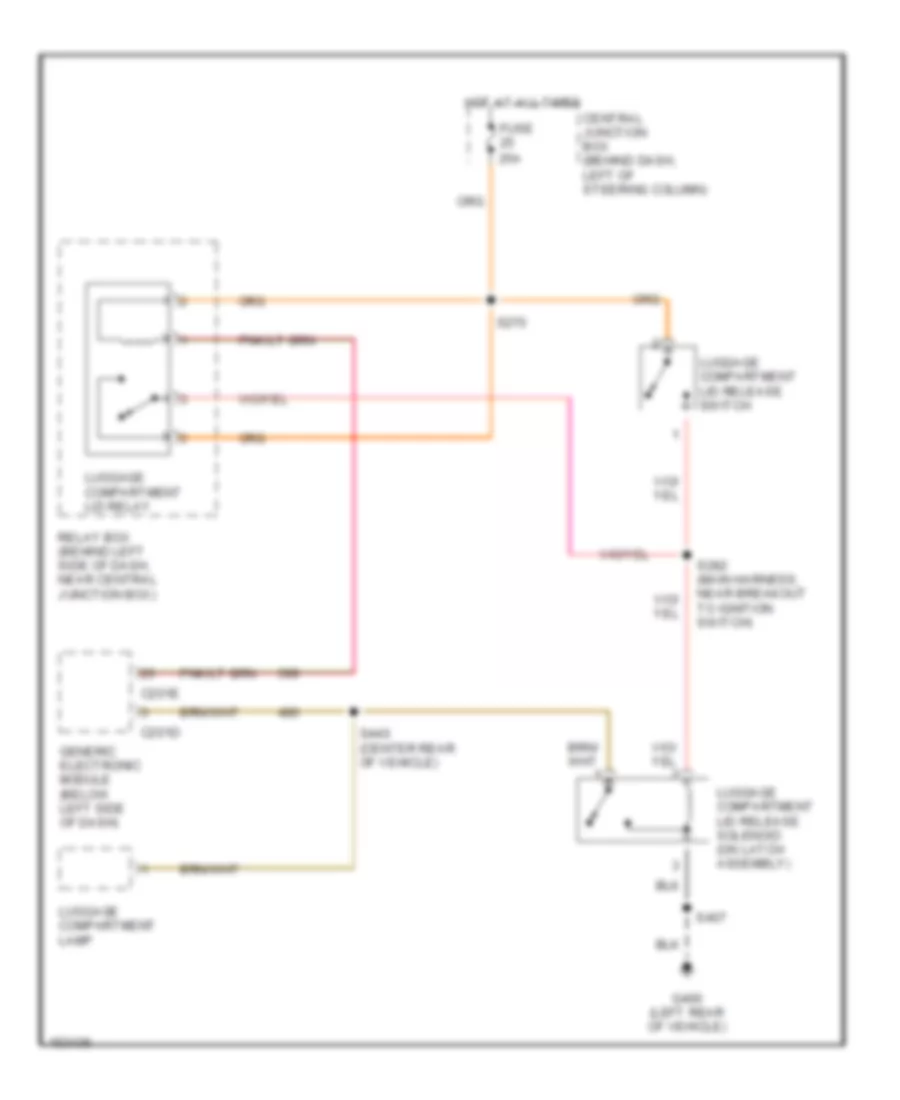
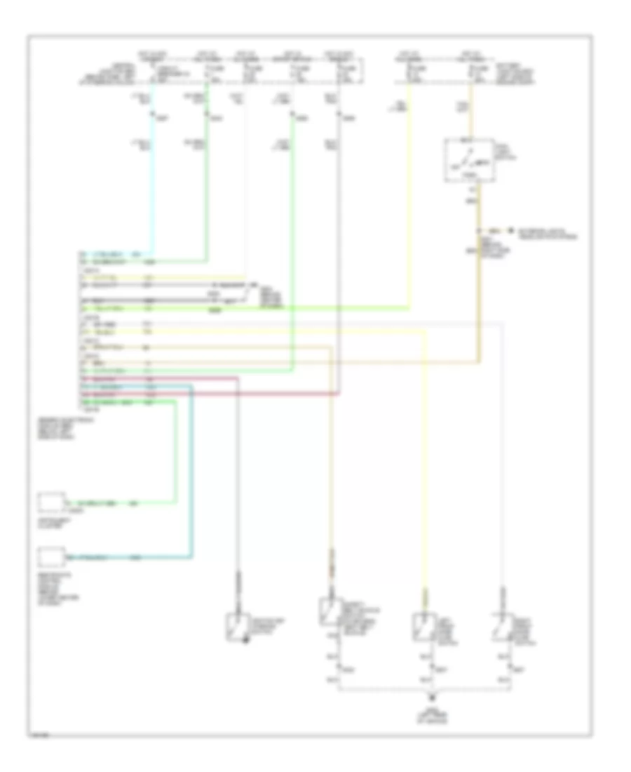
TRUNK, TAILGATE, FUEL DOOR Trunk, Tailgate, Fuel Door Wiring Diagrams for Ford Mustang GT Bullitt 2002 List of elements for Trunk, Tailgate, Fuel Door Wiring Diagrams for Ford Mustang GT Bullitt 2002: 16 C201d C201e Central junction box (behind dash, left of steering column) Fuse 25a G400 (left rear of vehicle) Generic electronic module (below left side of dash) Hot at all times Luggage compartment lamp Luggage compartment lid relay Luggage compartment lid release solenoid (on latch assembly) Luggage compartment lid release switch Relay box (behind left side of dash, near central junction box) S270 S282 (main harness, near breakout to ignition switch) S407 S440 (center rear of vehicle)
WARNING SYSTEMS Warning System Wiring Diagrams for Ford Mustang GT Bullitt 2002 List of elements for Warning System Wiring Diagrams for Ford Mustang GT Bullitt 2002: 41 Battery junction box (left side of engine compt) C201a C201b C201c C201d C201e C220a Central junction box (behind dash, left of steering column) Circuit breaker 43 20a Exterior lights, headlights systems Fuse 15a Fuse 30a Fuse 40a Fuse 5a G204 (behind center of dash) G400 (left rear of vehicle) Generic electronic module (gem) (below left side of dash) Head Hot at all times Hot in acc or run Hot in start or run Ignition key warning switch Instrument cluster Left front door ajar switch Main light switch Nca Of dash) Off Park Restraints control module (behind lower center of dash) Right front door ajar switch S205 S206 S242 S262 S265 S267 S307 S322 S507 Safety belt buckle switch (in driver's seat belt buckle)
WIPER/WASHER Wiper/Washer Wiring Diagram for Ford Mustang GT Bullitt 2002 List of elements for Wiper/Washer Wiring Diagram for Ford Mustang GT Bullitt 2002: 45 (in washer (left front (left side (near breakout to clutch pedal position 100k ohms 36.27k ohms 4.08k ohms 7.25k ohms Battery junction box (left side of engine C201d C201e Central junction box (left of steering Column) Compartment) Fluid reservoir) Fuse 26 30a G102 G400 Generic electronic module (below left side of dash) Hot in acc or run Int max Int min Multifunction switch Of engine Of firewall) Off Park Pump motor Relay box (behind left side of dash, near central junction box) Run S101 S103 S113 S225 S280 S312 Switch) Tan/red Washer Washer pump motor relay Windshield Windshield wiper motor Wiper high/ low relay Wiper motor Wiper on/off relay