ANTI-THEFT
Anti-theft Wiring Diagram for Ford Pickup F350 1993

List of elements for Anti-theft Wiring Diagram for Ford Pickup F350 1993:
- alarm indicator output
- (behind bottom of left kick panel) g200
- (lower rear of door) left rear courtesy lamp switch
- Acc
- Anti-theft controller module (behind left side of i/p)
- Anti-theft indicator
- Battery
- C237
- C238
- C241
- C242
- C251
- Circuit breaker 20a
- Courtesy lamp diode
- Courtesy lamps input
- Crew cab only
- Disarm input
- Door ajar
- Door locks system (remote keyless entry)
- Exterior lamps output
- Exterior lights system
- Fuse 15a
- Fuse panel
- G203 (behind bottom of right cowl panel)
- Ground
- Headlamps enable
- Headlights system
- Horn enable output
- Horns system
- Hot at all times
- Hot in accy or run
- Ignition input
- Ignition switch
- Instrument cluster
- Interior lights system (courtesy lights)
- Key cylinder input
- Key cylinder sensor
- Left front courtesy lamp switch (on front of door jamb)
- Left front door disarm switch (in left front door)
- Liftgate jamb sw input
- Lock
- Lock all doors
- Lock doors
- Nca
- Off
- Red/ pnk
- Red/pnk
- Remote keyless entry module (behind left side of i/p)
- Right front courtesy lamp switch (on front of door jamb)
- Right front door disarm switch (in right front door)
- Right rear courtesy lamp switch (lower rear of door)
- Run
- Run/accy power
- Speed control/ horn switch assembly (cruise control system)
- Sta
- Start
- Starter motor output
- Starting system
- Unlock all doors
- Unlock doors
- Unlock driver's door
- Warning system (warning chime)
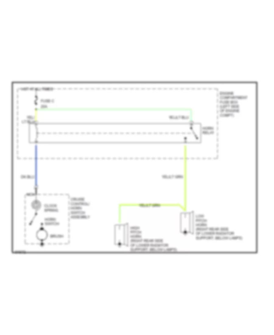
HORN
Horn Wiring Diagram for Ford Pickup F350 1993
List of elements for Horn Wiring Diagram for Ford Pickup F350 1993:
- 20a
- Brush
- Clock spring
- Cruise control/ horn switch assembly
- Engine compartment fuse box (left side of engine compt)
- Fuse c
- High pitch horn (right rear side of lower radiator support, below lamps)
- Horn relay
- Horn switch
- Hot at all times
- Low pitch horn (right rear side of lower radiator support, below lamps)
- Nca
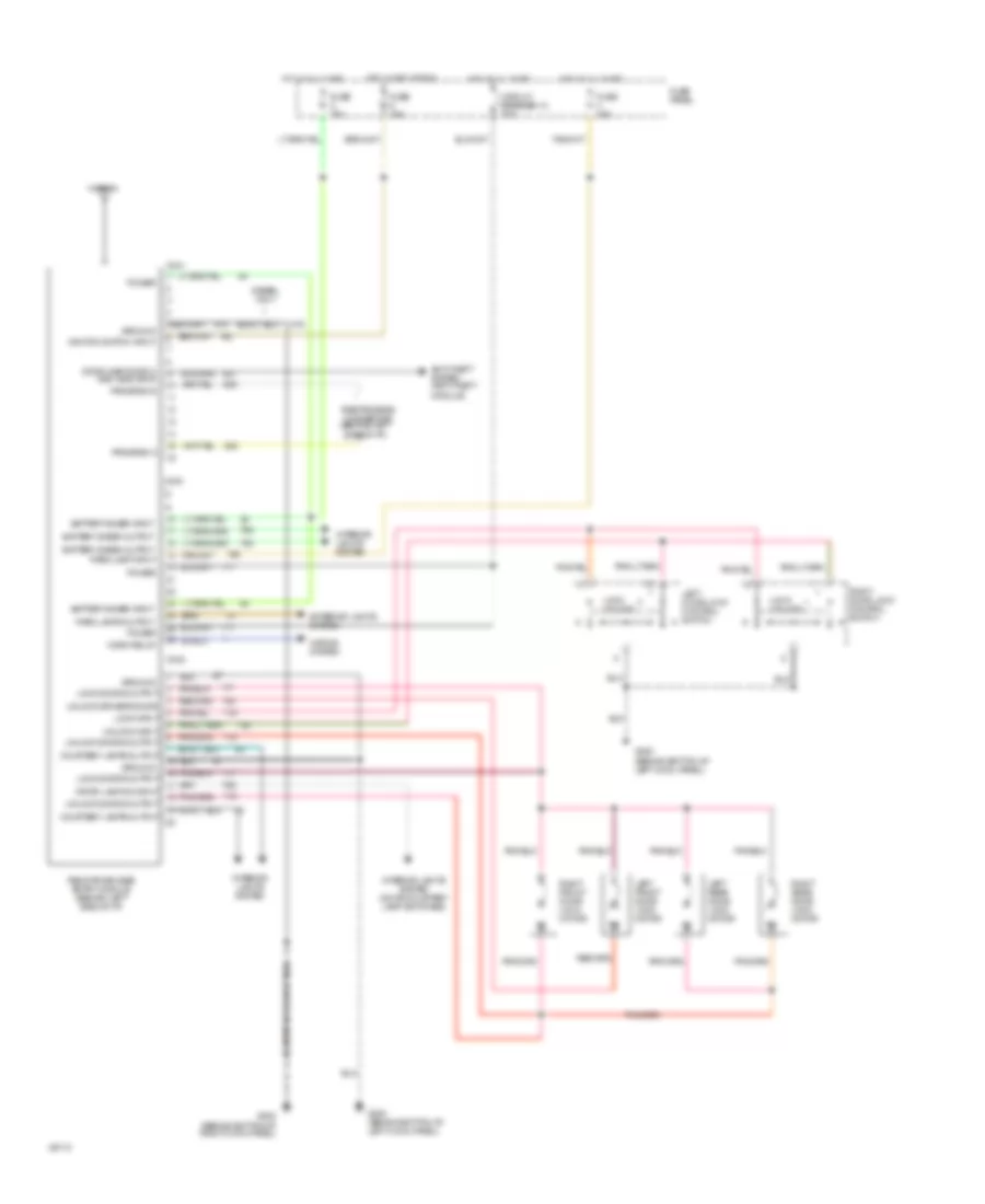
POWER DOOR LOCKS
Keyless Entry Wiring Diagram for Ford Pickup F350 1993
List of elements for Keyless Entry Wiring Diagram for Ford Pickup F350 1993:
- (behind bottom of left cowl panel)
- (behind bottom of right cowl panel)
- Antenna
- Anti-theft system (anti-theft module)
- Battery saver input
- Battery saver output
- C240
- C241
- C242
- Circuit breaker 12 20a
- Courtesy lamps output
- Crtsy lamp sw input
- Diesel only
- Door ajar switch and indicator
- Exterior lights system
- Fuse 15a
- Fuse panel
- G200
- G200 (behind bottom of left cowl panel)
- G203
- Ground
- Horn relay
- Horns system
- Hot at all times
- Hot in accy or run
- Ignition switch input
- Interior lights system
- Interior lights system (door courtesy lamp switches)
- Left door lock control switch
- Left front door lock motor
- Left rear door lock motor
- Lock doors output
- Lock input
- Lock unlock
- Park lamp input
- Park lamps output
- Power
- Program a
- Program b
- Remote keyless entry module (behind left side of i/p)
- Right door lock control switch
- Right front door lock motor
- Right rear door lock motor
- Rke program connector (behind left side of i/p)
- Unlock doors output
- Unlock driver's door
- Unlock input
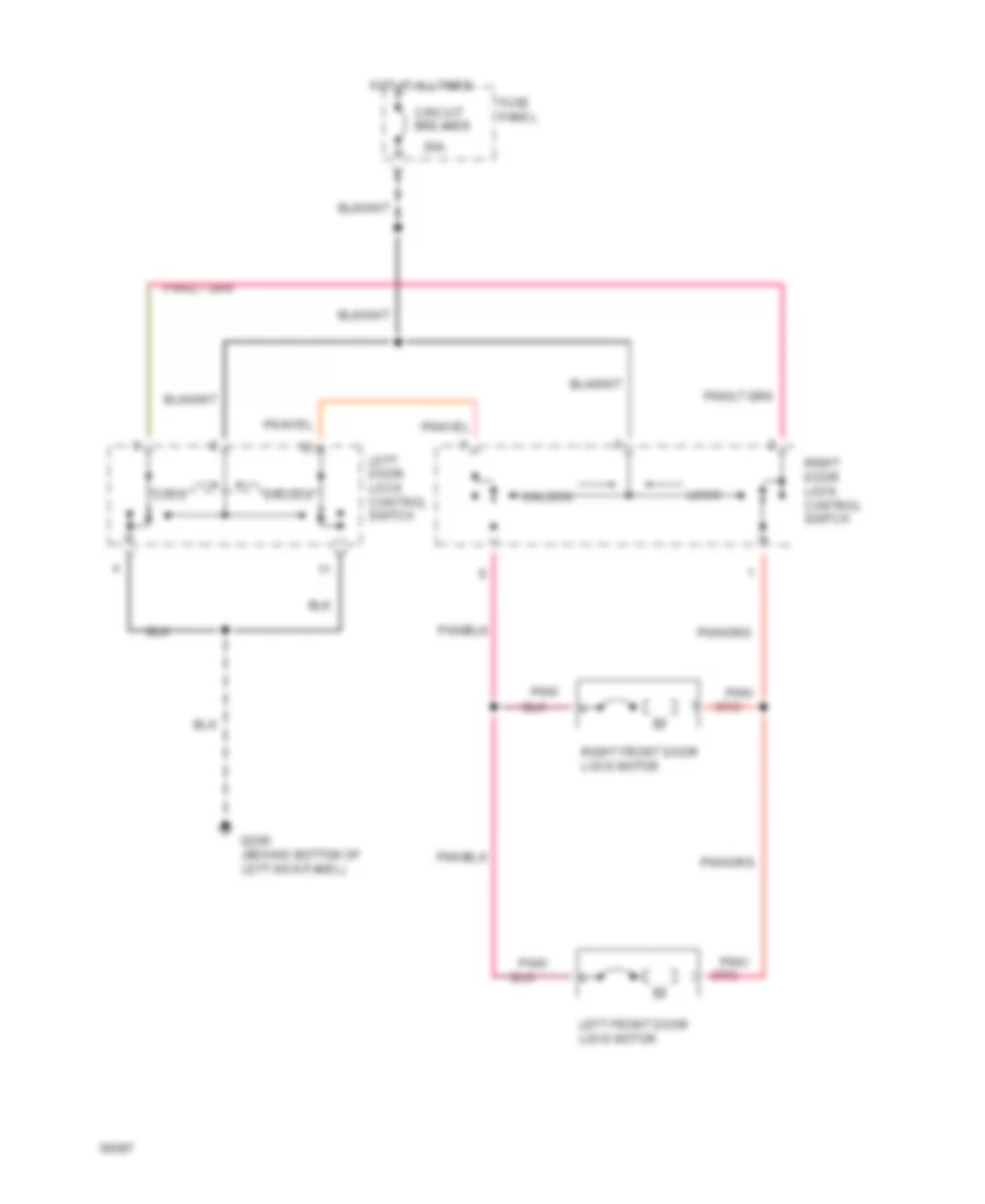
Power Door Lock Wiring Diagram for Ford Pickup F350 1993
List of elements for Power Door Lock Wiring Diagram for Ford Pickup F350 1993:
- Circuit breaker 12 20a
- Fuse panel
- G200 (behind bottom of left kick panel)
- Hot at all times
- Left front door lock motor
- Left rear door lock motor
- Lock
- Master window/ door lock control switch
- Pnk/
- Right front door lock motor
- Right rear door lock motor
- Right window/ door lock control switch
- Unlock
- W/ crew cab only
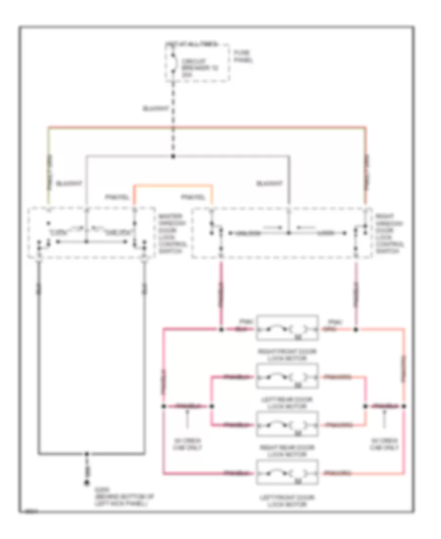
Power Door Locks Wiring Diagram, with Crew Cab for Ford Pickup F350 1993
List of elements for Power Door Locks Wiring Diagram, with Crew Cab for Ford Pickup F350 1993:
- 20a
- Circuit breaker 12
- Fuse panel
- G200 (behind bottom of left kick panel)
- Hot at all times
- Left door lock control switch
- Left front door lock motor
- Left rear door lock motor
- Lock
- Pnk/
- Right door lock control switch
- Right front door lock motor
- Right rear door lock motor
- Unlock
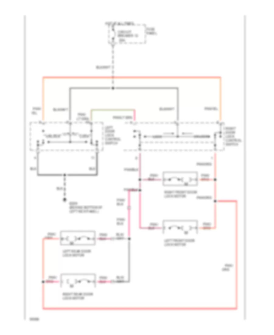
Power Door Locks Wiring Diagram, without Crew Cab for Ford Pickup F350 1993
List of elements for Power Door Locks Wiring Diagram, without Crew Cab for Ford Pickup F350 1993:
- 20a
- Circuit breaker
- Fuse panel
- G200 (behind bottom of left kick panel)
- Hot at all times
- Left door lock control switch
- Left front door lock motor
- Lock
- Pnk/
- Right door lock control switch
- Right front door lock motor
- Unlock
POWER MIRRORS
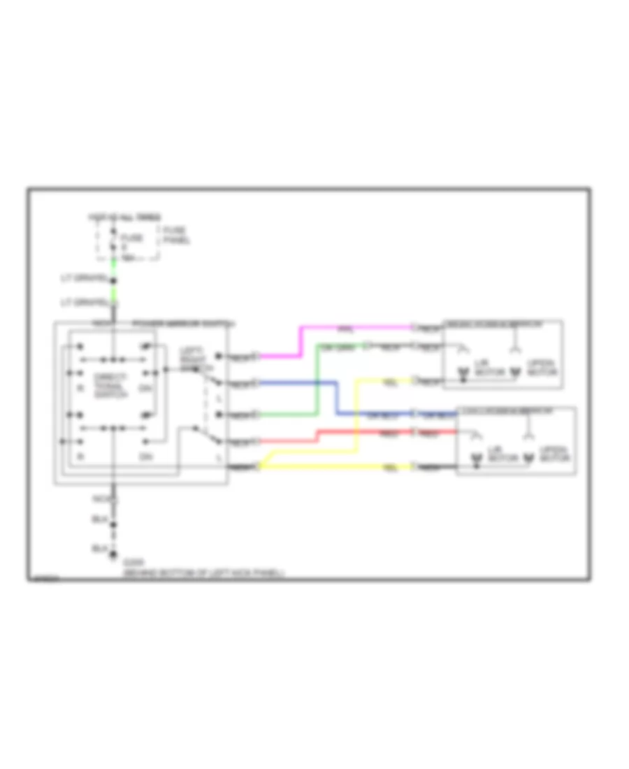
Power Mirror Wiring Diagram for Ford Pickup F350 1993
List of elements for Power Mirror Wiring Diagram for Ford Pickup F350 1993:
- Direct- tional switch
- Fuse 15a
- Fuse panel
- G200 (behind bottom of left kick panel)
- Hot at all times
- L/r motor
- Left/ right switch
- Nca
- Power mirror switch
- Red
- Right power mirror nca
- Up/dn motor
POWER SEATS
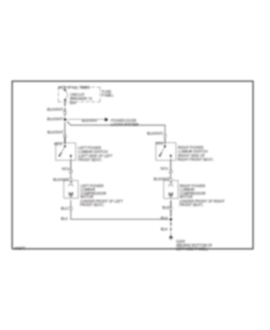
Lumbar Wiring Diagram, with Captain's Chairs for Ford Pickup F350 1993
List of elements for Lumbar Wiring Diagram, with Captain's Chairs for Ford Pickup F350 1993:
- Circuit breaker 12 20a
- Fuse panel
- G200 (behind bottom of left kick panel)
- Hot at all times
- Left power lumbar compressor motor (under front of left front seat)
- Left power lumbar switch (left side of left front seat)
- Nca
- Power door locks system
- Right power lumbar compressor motor (under front of right front seat)
- Right power lumbar switch (right side of right front seat)
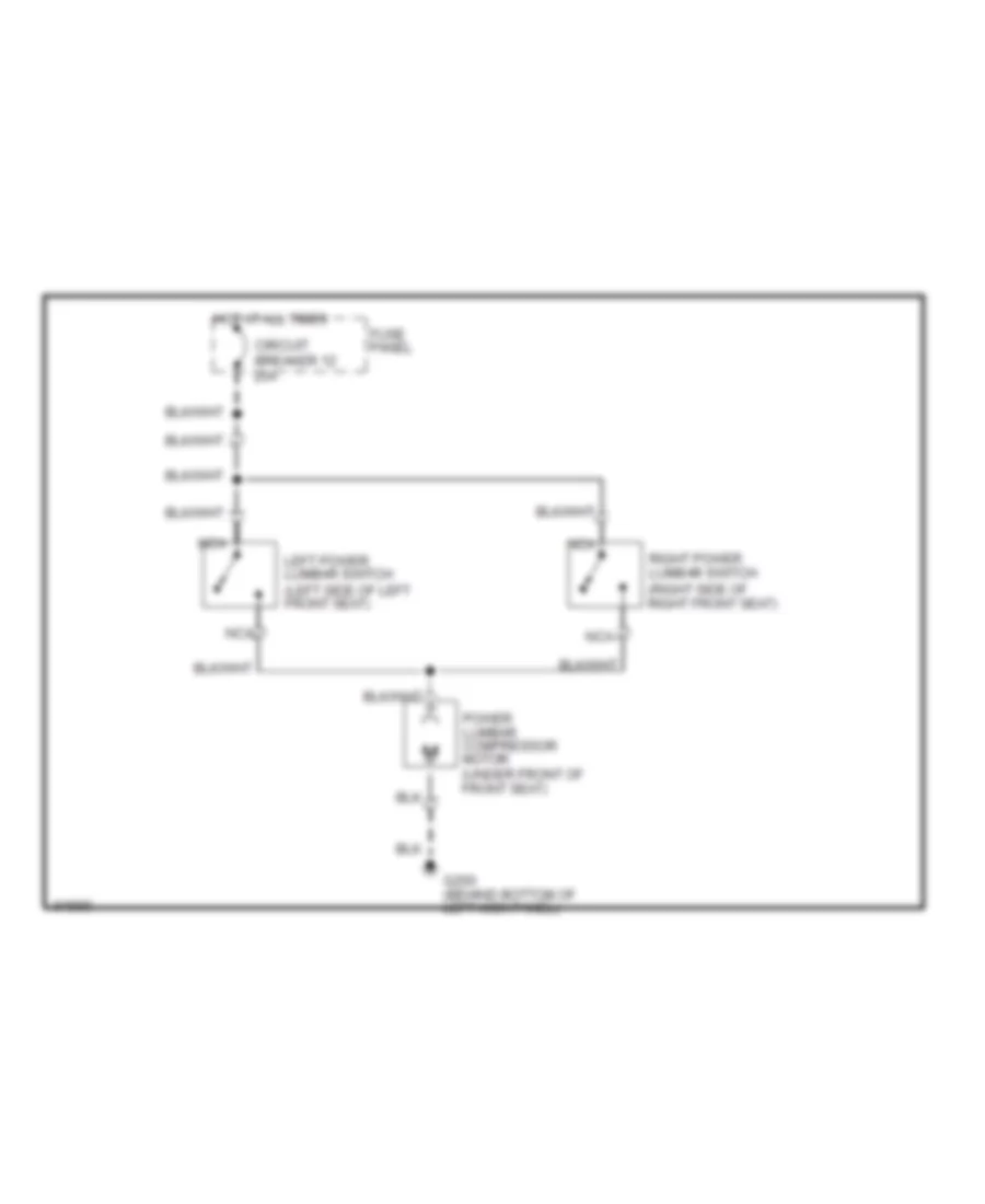
Lumbar Wiring Diagram, with Cloth Bench for Ford Pickup F350 1993
List of elements for Lumbar Wiring Diagram, with Cloth Bench for Ford Pickup F350 1993:
- Circuit breaker 12 20a
- Fuse panel
- G200 (behind bottom of left kick panel)
- Hot at all times
- Left power lumbar switch (left side of left front seat)
- Nca
- Power lumbar compressor motor (under front of front seat)
- Right power lumbar switch (right side of right front seat)
POWER WINDOWS
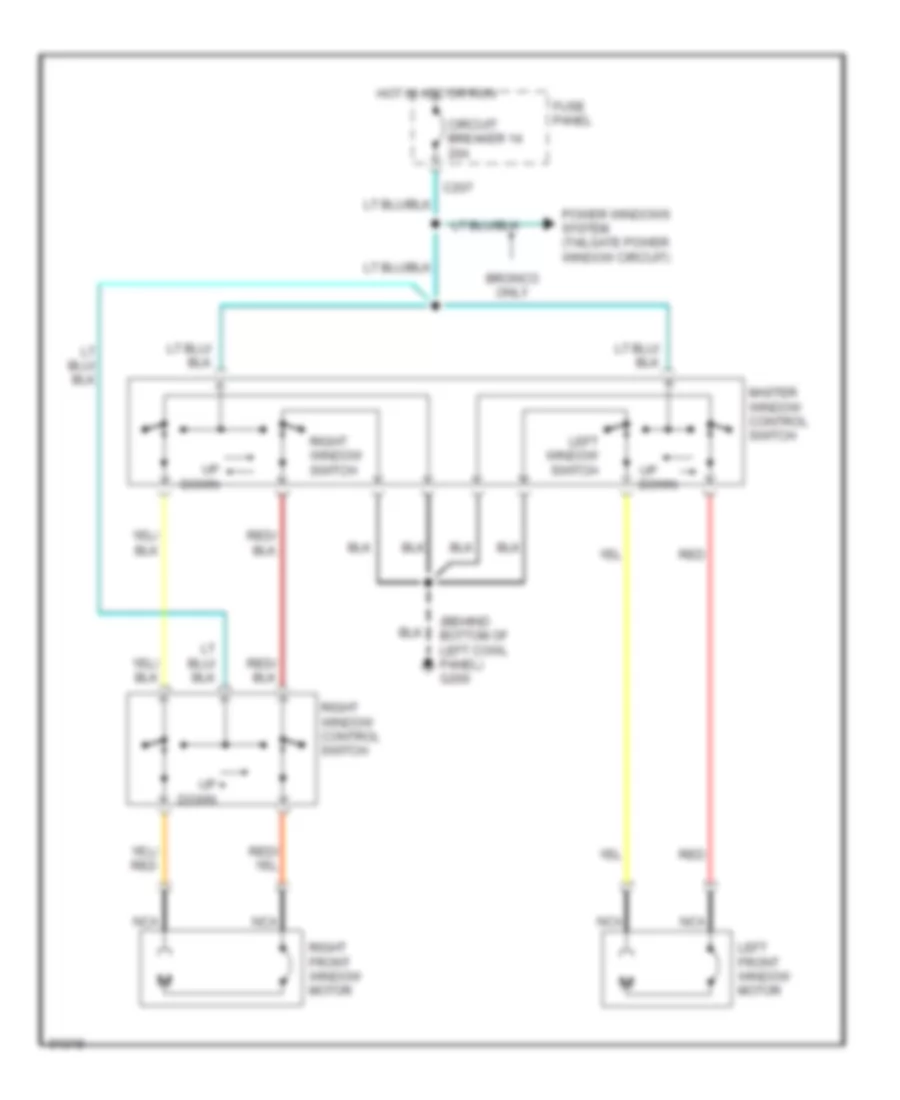
Power Windows Wiring Diagram for Ford Pickup F350 1993
List of elements for Power Windows Wiring Diagram for Ford Pickup F350 1993:
- (behind bottom of left cowl panel) g200
- Bronco only
- C207
- Circuit breaker 14 20a
- Down
- Fuse panel
- Hot in acc or run
- Left front window motor
- Left window switch
- Master window control switch
- Nca
- Power windows system (tailgate power window circuit)
- Red
- Right front window motor
- Right window control switch
- Right window switch
- Up down
RADIO
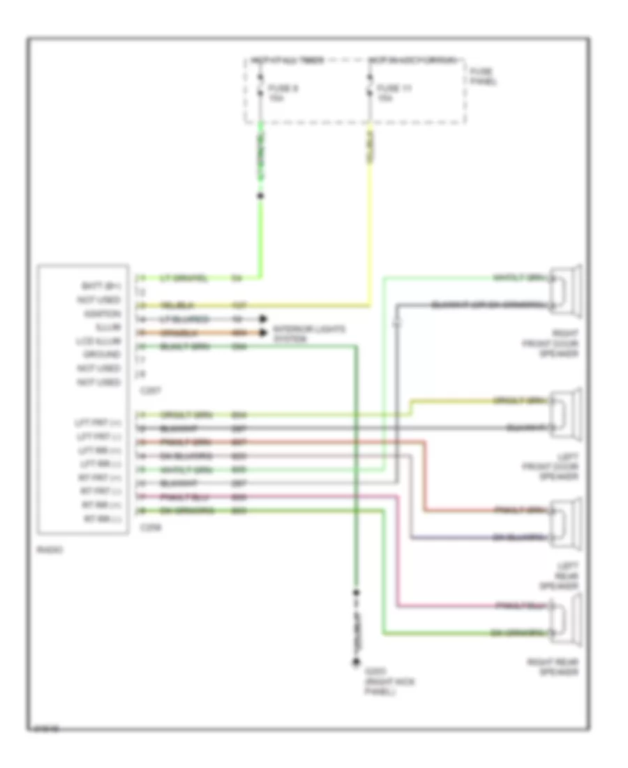
Radio Wiring Diagrams for Ford Pickup F350 1993
List of elements for Radio Wiring Diagrams for Ford Pickup F350 1993:
- Batt (b+)
- C257
- C258
- Fuse 11 15a
- Fuse 8 15a
- Fuse panel
- G203 (right kick panel)
- Ground
- Hot at all times
- Hot in accy or run
- Ignition
- Illum
- Interior lights system
- Lcd illum
- Left front door speaker
- Left rear speaker
- Lft frt (+)
- Lft frt (-)
- Lft rr (+)
- Lft rr (-)
- Not used
- Radio
- Right front door speaker
- Right rear speaker
- Rt frt (+)
- Rt frt (-)
- Rt rr (+)
- Rt rr (-)
STARTING/CHARGING
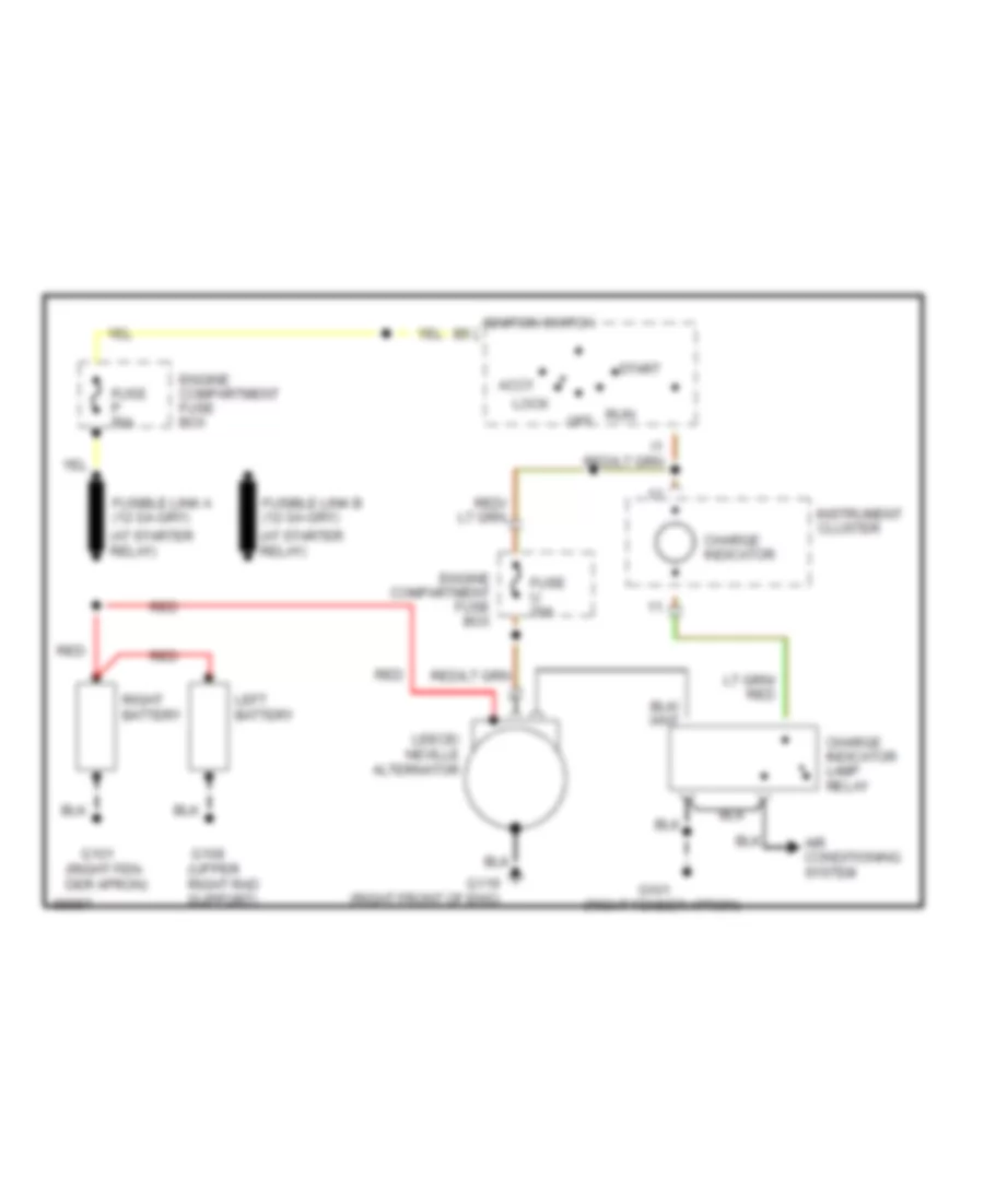
4.9L
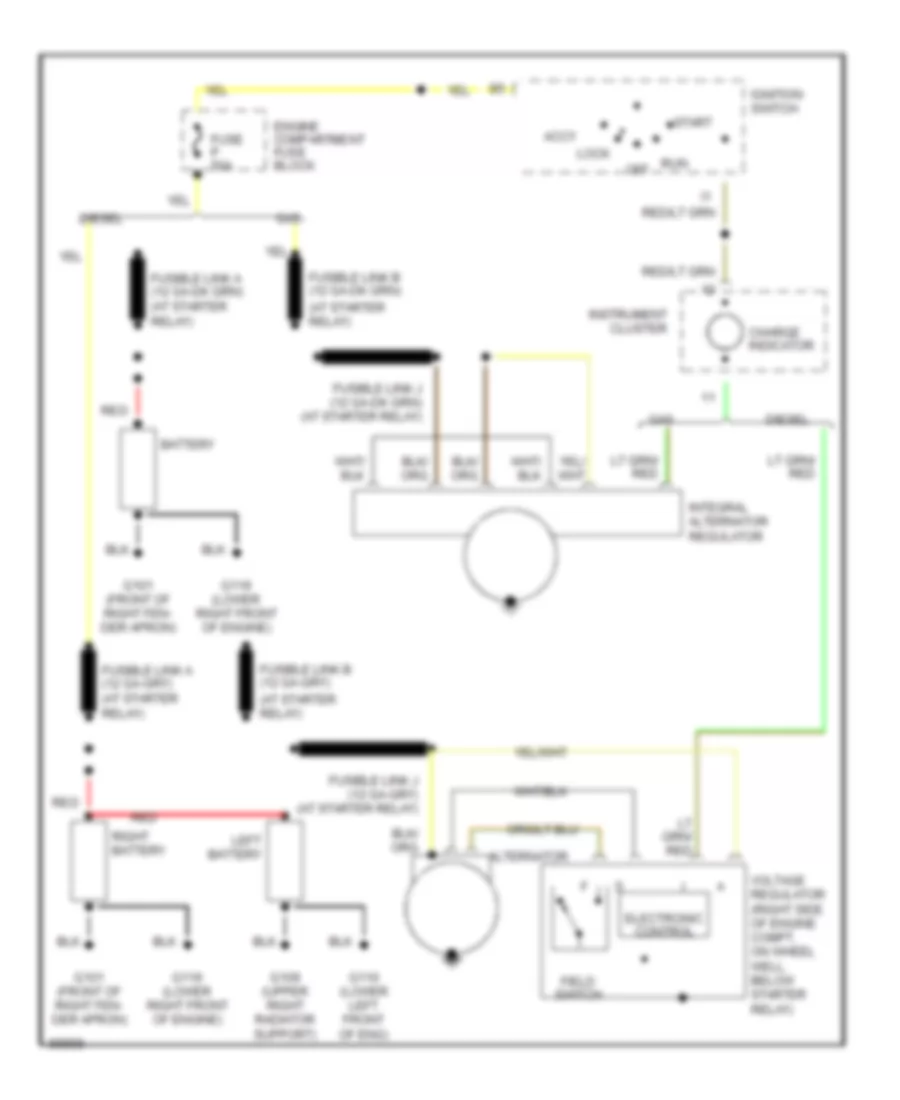
4.9L, Charging Wiring Diagram for Ford Pickup F350 1993
List of elements for 4.9L, Charging Wiring Diagram for Ford Pickup F350 1993:
- (at starter relay)
- Accy
- Alternator
- Battery
- Charge indicator
- Diesel
- Electronic control
- Engine compartment fuse block
- Field switch
- Fuse p 50a
- G101 (front of right fen- der apron)
- G109 (upper right radiator support)
- G110 (lower left front of eng)
- G119 (lower right front of engine)
- Gas
- Ignition switch
- Instrument cluster
- Integral alternator regulator
- Left battery
- Lock
- Off
- Red
- Right battery
- Run
- Start
- Voltage regulator (right side of engine compt, on wheel well, below starter relay)
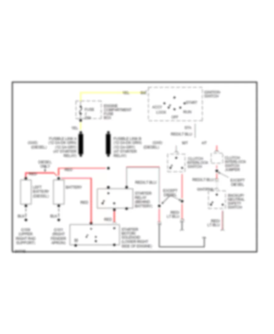
4.9L, Starting Wiring Diagram for Ford Pickup F350 1993
List of elements for 4.9L, Starting Wiring Diagram for Ford Pickup F350 1993:
- (diesel)
- (gas)
- A/t
- Accy
- Backup/ neutral safety switch
- Battery
- Clutch interlock switch
- Clutch interlock switch jumper
- Diesel only
- Engine compartment fuse box
- Except diesel
- Fuse j 20a
- G101 (right fender apron)
- G109 (upper right rad support)
- Ignition switch
- Left battery (diesel)
- Lock
- M/t
- Off
- Red
- Run
- Sta
- Start
- Starter motor/ solenoid (lower right side of engine)
- Starter relay (behind battery)
5.0L
5.0L, Charging Wiring Diagram for Ford Pickup F350 1993
List of elements for 5.0L, Charging Wiring Diagram for Ford Pickup F350 1993:
- (at starter relay)
- Accy
- Alternator
- Battery
- Charge indicator
- Diesel
- Electronic control
- Engine compartment fuse block
- Field switch
- Fuse p 50a
- G101 (front of right fen- der apron)
- G109 (upper right radiator support)
- G110 (lower left front of eng)
- G119 (lower right front of engine)
- Gas
- Ignition switch
- Instrument cluster
- Integral alternator regulator
- Left battery
- Lock
- Off
- Red
- Right battery
- Run
- Start
- Voltage regulator (right side of engine compt, on wheel well, below starter relay)
5.0L, Starting Wiring Diagram for Ford Pickup F350 1993
List of elements for 5.0L, Starting Wiring Diagram for Ford Pickup F350 1993:
- (diesel)
- (gas)
- A/t
- Accy
- Backup/ neutral safety switch
- Battery
- Clutch interlock switch
- Clutch interlock switch jumper
- Diesel only
- Engine compartment fuse box
- Except diesel
- Fuse j 20a
- G101 (right fender apron)
- G109 (upper right rad support)
- Ignition switch
- Left battery (diesel)
- Lock
- M/t
- Off
- Red
- Run
- Sta
- Start
- Starter motor/ solenoid (lower right side of engine)
- Starter relay (behind battery)
5.8L
5.8L, Charging Wiring Diagram for Ford Pickup F350 1993
List of elements for 5.8L, Charging Wiring Diagram for Ford Pickup F350 1993:
- (at starter relay)
- Accy
- Alternator
- Battery
- Charge indicator
- Diesel
- Electronic control
- Engine compartment fuse block
- Field switch
- Fuse p 50a
- G101 (front of right fen- der apron)
- G109 (upper right radiator support)
- G110 (lower left front of eng)
- G119 (lower right front of engine)
- Gas
- Ignition switch
- Instrument cluster
- Integral alternator regulator
- Left battery
- Lock
- Off
- Red
- Right battery
- Run
- Start
- Voltage regulator (right side of engine compt, on wheel well, below starter relay)
5.8L, Starting Wiring Diagram for Ford Pickup F350 1993
List of elements for 5.8L, Starting Wiring Diagram for Ford Pickup F350 1993:
- (diesel)
- (gas)
- A/t
- Accy
- Backup/ neutral safety switch
- Battery
- Clutch interlock switch
- Clutch interlock switch jumper
- Diesel only
- Engine compartment fuse box
- Except diesel
- Fuse j 20a
- G101 (right fender apron)
- G109 (upper right rad support)
- Ignition switch
- Left battery (diesel)
- Lock
- M/t
- Off
- Red
- Run
- Sta
- Start
- Starter motor/ solenoid (lower right side of engine)
- Starter relay (behind battery)
7.3L
7.3L, Charging Wiring Diagram for Ford Pickup F350 1993
List of elements for 7.3L, Charging Wiring Diagram for Ford Pickup F350 1993:
- (at starter relay)
- (right fen- der apron)
- (right fender apron)
- (upper right rad support)
- Accy
- Air conditioning system
- Charge indicator
- Charge indicator lamp relay
- Engine compartment fuse box
- Fuse p 50a
- Fuse u 20a
- G101
- G109
- G119 (right front of eng)
- Ignition switch
- Instrument cluster
- Leece/ neville alternator
- Left battery
- Lock
- Off
- Red
- Right battery
- Run
- Start
7.3L, Starting Wiring Diagram for Ford Pickup F350 1993
List of elements for 7.3L, Starting Wiring Diagram for Ford Pickup F350 1993:
- (diesel)
- (gas)
- A/t
- Accy
- Backup/ neutral safety switch
- Battery
- Clutch interlock switch
- Clutch interlock switch jumper
- Diesel only
- Engine compartment fuse box
- Except diesel
- Fuse j 20a
- G101 (right fender apron)
- G109 (upper right rad support)
- Ignition switch
- Left battery (diesel)
- Lock
- M/t
- Off
- Red
- Run
- Sta
- Start
- Starter motor/ solenoid (lower right side of engine)
- Starter relay (behind battery)
7.5L
7.5L, Charging Wiring Diagram for Ford Pickup F350 1993
List of elements for 7.5L, Charging Wiring Diagram for Ford Pickup F350 1993:
- (at starter relay)
- Accy
- Alternator
- Battery
- Charge indicator
- Diesel
- Electronic control
- Engine compartment fuse block
- Field switch
- Fuse p 50a
- G101 (front of right fen- der apron)
- G109 (upper right radiator support)
- G110 (lower left front of eng)
- G119 (lower right front of engine)
- Gas
- Ignition switch
- Instrument cluster
- Integral alternator regulator
- Left battery
- Lock
- Off
- Red
- Right battery
- Run
- Start
- Voltage regulator (right side of engine compt, on wheel well, below starter relay)
7.5L, Starting Wiring Diagram for Ford Pickup F350 1993
List of elements for 7.5L, Starting Wiring Diagram for Ford Pickup F350 1993:
- (diesel)
- (gas)
- A/t
- Accy
- Backup/ neutral safety switch
- Battery
- Clutch interlock switch
- Clutch interlock switch jumper
- Diesel only
- Engine compartment fuse box
- Except diesel
- Fuse j 20a
- G101 (right fender apron)
- G109 (upper right rad support)
- Ignition switch
- Left battery (diesel)
- Lock
- M/t
- Off
- Red
- Run
- Sta
- Start
- Starter motor/ solenoid (lower right side of engine)
- Starter relay (behind battery)
TRANSMISSION
4.9L
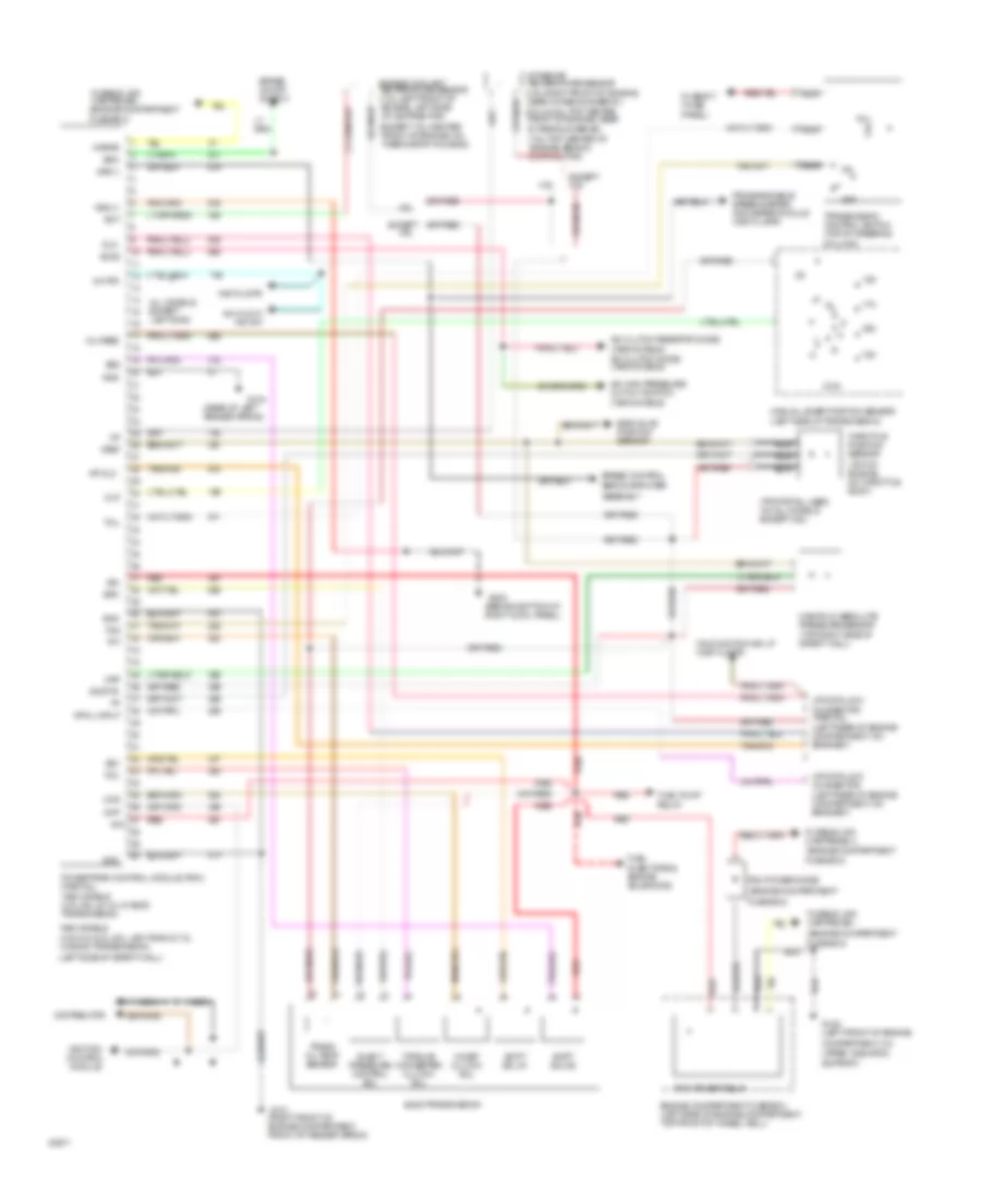
4.9L, Transmission Wiring Diagram for Ford Pickup F350 1993
List of elements for 4.9L, Transmission Wiring Diagram for Ford Pickup F350 1993:
- gnd
- (1993 models) a/c clutch diode (1994 models)
- (1994 models)
- (4.9l-right front of engine, near intake runner #1)
- (5.0l & 5.8l-top center front of engine, near intake runner #6)
- (7.5l-top center of engine, behind distributor)
- (behind bottom of right cowl panel)
- (engine compartment
- (except 7.5l-center front of engine, on thermostat housing)
- (left rear of engine compartment, on bracket)
- (left side of safety wall)
- (rear of left fender apron)
- (top of engine, on throttle body)
- (tps pigtail used on all models except 4.9l)
- 1993 m0dels (4.9l,5.0l,5.8l,5.8l lightning & 7.5l w/ e4od transmission)
- 1994 m0dels (4.9l,5.8l & 7.5l w/ e40d transmission)
- 4.9l
- 4x4 hi/low ind sw
- 4x4 ind
- A/c clutch resistor diode
- A/c high pressure cut out switch
- Accs
- All models except lightning
- Assembly
- Boo
- Brake on/off switch
- Ccs
- Ckp
- Coast clutch sol
- Column)
- Compartment, on
- Distributor
- Dlc
- E40d transmission
- Ect
- Egr valve position sensor
- Elect pressure control sol
- Engine compartment fuse box (left side of engine compartment, top front of wheel well)
- Engine coolant temperature sensor (7.5l-left front of engine, left side of distributor)
- Epc
- Except
- Except 4.9l
- Fuel injectors & engine solenoids
- Fuel pump relay
- Fuse #17 (fuse
- Fuse box)
- Fusible link cartridge i
- Fusible link cartridge i (engine compartment
- Fusible link cartridge u (engine compartment
- G101 (right front of engine compartment, front of fender apron)
- G104
- G108 (left front of engine
- G203
- Gnd
- Iat
- Ign
- Ign
- Ignition control module
- Inst clstr
- Intake air temperature sensor
- Kapwr
- Malfunction ind lp (inst clstr)
- Manifold absolute pressure sensor (top right side of safety wall)
- Manual lever position sensor (left side of transmission)
- Map
- Mil feed
- Mlp
- Nca
- Off
- Panel)
- Pcm power diode
- Pcm power relay
- Powertrain control module (pcm) (partial)
- Programmable speedometer/ odometer module (inst clstr)
- Red
- Servo/amplifier
- Shift sol #1
- Shift sol #2
- Sig rtn
- Speed control
- Ss1
- Ss2
- Support)
- Tcc
- Tcil
- Tcs
- Tft
- Throttle position sensor
- Torque converter clutch sol
- Trans oil temp sensor
- Transmission control switch (top of steering
- Upper radiator
- Vip data link connector
- Vip data link connector (partial)
- Vip dl input
- Vip dlc
- Vref
- Vss (+)
- Vss (-)
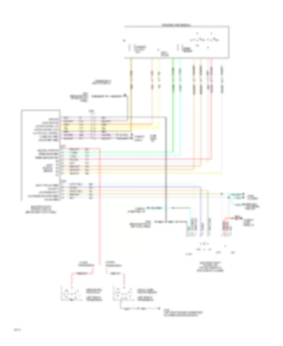
Transfer Case Wiring Diagram for Ford Pickup F350 1993
List of elements for Transfer Case Wiring Diagram for Ford Pickup F350 1993:
- (fuse panel i/p)
- (left side of transmission)
- (w/ aod
- (w/ e40d
- 4x4
- 4x4 ind feed
- 4x4 input
- C.b. battery feed
- C/b #12
- C221
- C222
- C223
- Clutch coil control
- Electronic shift control module (behind right cowl panel)
- Electronic shift control sw (top left side of i/p,
- Fuse #10 (fuse panel i/p)
- Fuse #17 (fuse panel i/p)
- Fuse #18
- Fused acc feed
- G108 (left front engine compartment on upper radiator support))
- G200 (behind bottom of left cowl panel)
- G203 (behind bottom of right cowl panel)
- Gas engine w/ shift on the fly
- Ground
- Illum
- Instr cluster
- Logic ground
- Low
- Low range indicator feed
- Low range input
- Magnetic clutch coil
- Manual lever position sensor
- Motor control ccw
- Motor control cw
- Neutral start sw
- Park/neutral position sw
- Rear anti- lock brake module
- Red/
- Right side of cluster)
- Sensor
- Shift motor
- Shift position
- Speed sens feed
- Speed sens return
- Speed sensor
- Swift ctrl sw feed
- Transfer case assembly
- Transmission)
5.0L
5.0L, Transmission Wiring Diagram for Ford Pickup F350 1993
List of elements for 5.0L, Transmission Wiring Diagram for Ford Pickup F350 1993:
- gnd
- (1993 models) a/c clutch diode (1994 models)
- (1994 models)
- (4.9l-right front of engine, near intake runner #1)
- (5.0l & 5.8l-top center front of engine, near intake runner #6)
- (7.5l-top center of engine, behind distributor)
- (behind bottom of right cowl panel)
- (engine compartment
- (except 7.5l-center front of engine, on thermostat housing)
- (left rear of engine compartment, on bracket)
- (left side of safety wall)
- (rear of left fender apron)
- (top of engine, on throttle body)
- (tps pigtail used on all models except 4.9l)
- 1993 m0dels (4.9l,5.0l,5.8l,5.8l lightning & 7.5l w/ e4od transmission)
- 1994 m0dels (4.9l,5.8l & 7.5l w/ e40d transmission)
- 4.9l
- 4x4 hi/low ind sw
- 4x4 ind
- A/c clutch resistor diode
- A/c high pressure cut out switch
- Accs
- All models except lightning
- Assembly
- Boo
- Brake on/off switch
- Ccs
- Ckp
- Coast clutch sol
- Column)
- Compartment, on
- Distributor
- Dlc
- E40d transmission
- Ect
- Egr valve position sensor
- Elect pressure control sol
- Engine compartment fuse box (left side of engine compartment, top front of wheel well)
- Engine coolant temperature sensor (7.5l-left front of engine, left side of distributor)
- Epc
- Except
- Except 4.9l
- Fuel injectors & engine solenoids
- Fuel pump relay
- Fuse #17 (fuse
- Fuse box)
- Fusible link cartridge i
- Fusible link cartridge i (engine compartment
- Fusible link cartridge u (engine compartment
- G101 (right front of engine compartment, front of fender apron)
- G104
- G108 (left front of engine
- G203
- Gnd
- Iat
- Ign
- Ign
- Ignition control module
- Inst clstr
- Intake air temperature sensor
- Kapwr
- Malfunction ind lp (inst clstr)
- Manifold absolute pressure sensor (top right side of safety wall)
- Manual lever position sensor (left side of transmission)
- Map
- Mil feed
- Mlp
- Nca
- Off
- Panel)
- Pcm power diode
- Pcm power relay
- Powertrain control module (pcm) (partial)
- Programmable speedometer/ odometer module (inst clstr)
- Red
- Servo/amplifier
- Shift sol #1
- Shift sol #2
- Sig rtn
- Speed control
- Ss1
- Ss2
- Support)
- Tcc
- Tcil
- Tcs
- Tft
- Throttle position sensor
- Torque converter clutch sol
- Trans oil temp sensor
- Transmission control switch (top of steering
- Upper radiator
- Vip data link connector
- Vip data link connector (partial)
- Vip dl input
- Vip dlc
- Vref
- Vss (+)
- Vss (-)
Transfer Case Wiring Diagram for Ford Pickup F350 1993
List of elements for Transfer Case Wiring Diagram for Ford Pickup F350 1993:
- (fuse panel i/p)
- (left side of transmission)
- (w/ aod
- (w/ e40d
- 4x4
- 4x4 ind feed
- 4x4 input
- C.b. battery feed
- C/b #12
- C221
- C222
- C223
- Clutch coil control
- Electronic shift control module (behind right cowl panel)
- Electronic shift control sw (top left side of i/p,
- Fuse #10 (fuse panel i/p)
- Fuse #17 (fuse panel i/p)
- Fuse #18
- Fused acc feed
- G108 (left front engine compartment on upper radiator support))
- G200 (behind bottom of left cowl panel)
- G203 (behind bottom of right cowl panel)
- Gas engine w/ shift on the fly
- Ground
- Illum
- Instr cluster
- Logic ground
- Low
- Low range indicator feed
- Low range input
- Magnetic clutch coil
- Manual lever position sensor
- Motor control ccw
- Motor control cw
- Neutral start sw
- Park/neutral position sw
- Rear anti- lock brake module
- Red/
- Right side of cluster)
- Sensor
- Shift motor
- Shift position
- Speed sens feed
- Speed sens return
- Speed sensor
- Swift ctrl sw feed
- Transfer case assembly
- Transmission)
5.8L
5.8L, Transmission Wiring Diagram for Ford Pickup F350 1993
List of elements for 5.8L, Transmission Wiring Diagram for Ford Pickup F350 1993:
- gnd
- (1993 models) a/c clutch diode (1994 models)
- (1994 models)
- (4.9l-right front of engine, near intake runner #1)
- (5.0l & 5.8l-top center front of engine, near intake runner #6)
- (7.5l-top center of engine, behind distributor)
- (behind bottom of right cowl panel)
- (engine compartment
- (except 7.5l-center front of engine, on thermostat housing)
- (left rear of engine compartment, on bracket)
- (left side of safety wall)
- (rear of left fender apron)
- (top of engine, on throttle body)
- (tps pigtail used on all models except 4.9l)
- 1993 m0dels (4.9l,5.0l,5.8l,5.8l lightning & 7.5l w/ e4od transmission)
- 1994 m0dels (4.9l,5.8l & 7.5l w/ e40d transmission)
- 4.9l
- 4x4 hi/low ind sw
- 4x4 ind
- A/c clutch resistor diode
- A/c high pressure cut out switch
- Accs
- All models except lightning
- Assembly
- Boo
- Brake on/off switch
- Ccs
- Ckp
- Coast clutch sol
- Column)
- Compartment, on
- Distributor
- Dlc
- E40d transmission
- Ect
- Egr valve position sensor
- Elect pressure control sol
- Engine compartment fuse box (left side of engine compartment, top front of wheel well)
- Engine coolant temperature sensor (7.5l-left front of engine, left side of distributor)
- Epc
- Except
- Except 4.9l
- Fuel injectors & engine solenoids
- Fuel pump relay
- Fuse #17 (fuse
- Fuse box)
- Fusible link cartridge i
- Fusible link cartridge i (engine compartment
- Fusible link cartridge u (engine compartment
- G101 (right front of engine compartment, front of fender apron)
- G104
- G108 (left front of engine
- G203
- Gnd
- Iat
- Ign
- Ign
- Ignition control module
- Inst clstr
- Intake air temperature sensor
- Kapwr
- Malfunction ind lp (inst clstr)
- Manifold absolute pressure sensor (top right side of safety wall)
- Manual lever position sensor (left side of transmission)
- Map
- Mil feed
- Mlp
- Nca
- Off
- Panel)
- Pcm power diode
- Pcm power relay
- Powertrain control module (pcm) (partial)
- Programmable speedometer/ odometer module (inst clstr)
- Red
- Servo/amplifier
- Shift sol #1
- Shift sol #2
- Sig rtn
- Speed control
- Ss1
- Ss2
- Support)
- Tcc
- Tcil
- Tcs
- Tft
- Throttle position sensor
- Torque converter clutch sol
- Trans oil temp sensor
- Transmission control switch (top of steering
- Upper radiator
- Vip data link connector
- Vip data link connector (partial)
- Vip dl input
- Vip dlc
- Vref
- Vss (+)
- Vss (-)
Transfer Case Wiring Diagram for Ford Pickup F350 1993
List of elements for Transfer Case Wiring Diagram for Ford Pickup F350 1993:
- (fuse panel i/p)
- (left side of transmission)
- (w/ aod
- (w/ e40d
- 4x4
- 4x4 ind feed
- 4x4 input
- C.b. battery feed
- C/b #12
- C221
- C222
- C223
- Clutch coil control
- Electronic shift control module (behind right cowl panel)
- Electronic shift control sw (top left side of i/p,
- Fuse #10 (fuse panel i/p)
- Fuse #17 (fuse panel i/p)
- Fuse #18
- Fused acc feed
- G108 (left front engine compartment on upper radiator support))
- G200 (behind bottom of left cowl panel)
- G203 (behind bottom of right cowl panel)
- Gas engine w/ shift on the fly
- Ground
- Illum
- Instr cluster
- Logic ground
- Low
- Low range indicator feed
- Low range input
- Magnetic clutch coil
- Manual lever position sensor
- Motor control ccw
- Motor control cw
- Neutral start sw
- Park/neutral position sw
- Rear anti- lock brake module
- Red/
- Right side of cluster)
- Sensor
- Shift motor
- Shift position
- Speed sens feed
- Speed sens return
- Speed sensor
- Swift ctrl sw feed
- Transfer case assembly
- Transmission)
7.3L
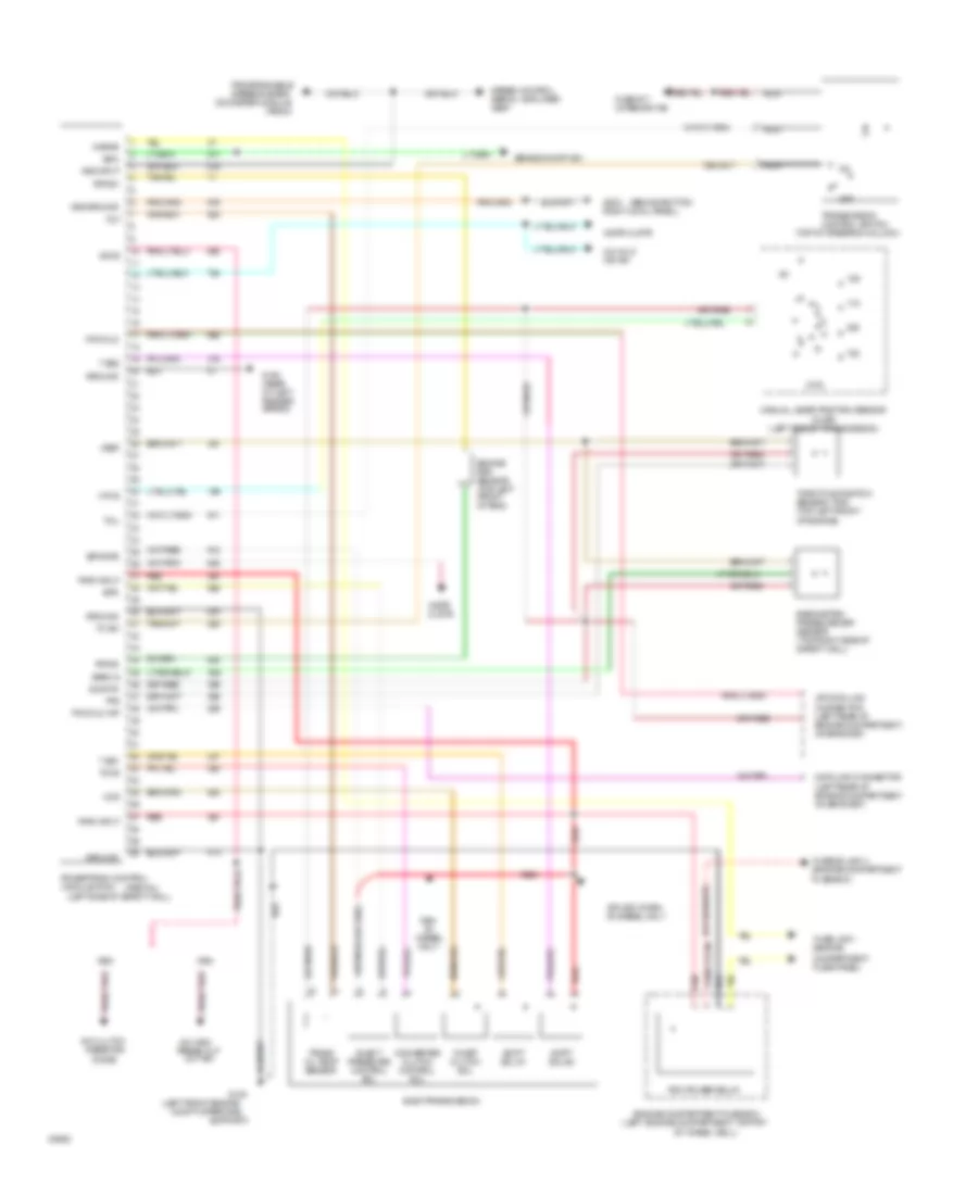
7.3L Diesel, Transmission Wiring Diagram for Ford Pickup F350 1993
List of elements for 7.3L Diesel, Transmission Wiring Diagram for Ford Pickup F350 1993:
- (behind bottom
- (left engine compartment, top frt
- (left front engine
- (left rear of engine compartment, on bracket)
- (left side of safety wall)
- (left side of transmission)
- (mlps)
- (partial)
- (psom)
- (top of steering column)
- 4x4 hi/lo ind sw
- A/c clutch
- A/c high press cut
- Accs
- Baro s
- Barometric pressure (bp) sensor (top right side of safety wall)
- Boo
- Brake on/off sw
- Ccs
- Coast clutch sol
- Compartment fuse panel)
- Compt upper rad
- Converter clutch control sol
- Data link connector
- Diesel only
- Diode
- E40d transmission
- Elect pressure control sol
- Engine compartment fuse box
- Engine rpm sensor (top left front of eng)
- Epc
- Epcpwr
- Fuse #17 (interior f/b)
- Fuse link i (engine
- Fusible link u (engine compartment fuse box)
- G100 (rear of left fender apron)
- G108
- G203 right cowl panel)
- Ground
- Idi
- Instr clstr
- Kapwr
- Manual lever position sensor
- Module (pcm)
- Mpls
- Nca
- Odometer module
- Of wheel well)
- Off
- Out sw
- Pcm dlc
- Pcm dlc inp
- Pcm power relay
- Powertrain control
- Programmable speedometer/
- Pwr input
- Red
- Resistor
- Rpms+
- Rpms-
- Shift sol #1
- Shift sol #2
- Sig rtn
- Speed control servo / amplifier assy
- Splice w/1994 idi diesel only
- Support)
- T ss1
- T ss2
- Tc sw
- Tccs
- Tcil
- Throttle position sensor (tps) (top left front of engine)
- Tot
- Tps
- Trans oil temp sensor
- Transmission control switch
- Vip data link connector (left rear of engine compartment, on bracket)
- Vref
- Vss ground
- Vss input
Transfer Case Wiring Diagram for Ford Pickup F350 1993
List of elements for Transfer Case Wiring Diagram for Ford Pickup F350 1993:
- (fuse panel i/p)
- (left side of transmission)
- (w/ aod
- (w/ e40d
- 4x4
- 4x4 ind feed
- 4x4 input
- C.b. battery feed
- C/b #12
- C221
- C222
- C223
- Clutch coil control
- Electronic shift control module (behind right cowl panel)
- Electronic shift control sw (top left side of i/p,
- Fuse #10 (fuse panel i/p)
- Fuse #17 (fuse panel i/p)
- Fuse #18
- Fused acc feed
- G108 (left front engine compartment on upper radiator support))
- G200 (behind bottom of left cowl panel)
- G203 (behind bottom of right cowl panel)
- Gas engine w/ shift on the fly
- Ground
- Illum
- Instr cluster
- Logic ground
- Low
- Low range indicator feed
- Low range input
- Magnetic clutch coil
- Manual lever position sensor
- Motor control ccw
- Motor control cw
- Neutral start sw
- Park/neutral position sw
- Rear anti- lock brake module
- Red/
- Right side of cluster)
- Sensor
- Shift motor
- Shift position
- Speed sens feed
- Speed sens return
- Speed sensor
- Swift ctrl sw feed
- Transfer case assembly
- Transmission)
7.5L
7.5L, Transmission Wiring Diagram for Ford Pickup F350 1993
List of elements for 7.5L, Transmission Wiring Diagram for Ford Pickup F350 1993:
- gnd
- (1993 models) a/c clutch diode (1994 models)
- (1994 models)
- (4.9l-right front of engine, near intake runner #1)
- (5.0l & 5.8l-top center front of engine, near intake runner #6)
- (7.5l-top center of engine, behind distributor)
- (behind bottom of right cowl panel)
- (engine compartment
- (except 7.5l-center front of engine, on thermostat housing)
- (left rear of engine compartment, on bracket)
- (left side of safety wall)
- (rear of left fender apron)
- (top of engine, on throttle body)
- (tps pigtail used on all models except 4.9l)
- 1993 m0dels (4.9l,5.0l,5.8l,5.8l lightning & 7.5l w/ e4od transmission)
- 1994 m0dels (4.9l,5.8l & 7.5l w/ e40d transmission)
- 4.9l
- 4x4 hi/low ind sw
- 4x4 ind
- A/c clutch resistor diode
- A/c high pressure cut out switch
- Accs
- All models except lightning
- Assembly
- Boo
- Brake on/off switch
- Ccs
- Ckp
- Coast clutch sol
- Column)
- Compartment, on
- Distributor
- Dlc
- E40d transmission
- Ect
- Egr valve position sensor
- Elect pressure control sol
- Engine compartment fuse box (left side of engine compartment, top front of wheel well)
- Engine coolant temperature sensor (7.5l-left front of engine, left side of distributor)
- Epc
- Except
- Except 4.9l
- Fuel injectors & engine solenoids
- Fuel pump relay
- Fuse #17 (fuse
- Fuse box)
- Fusible link cartridge i
- Fusible link cartridge i (engine compartment
- Fusible link cartridge u (engine compartment
- G101 (right front of engine compartment, front of fender apron)
- G104
- G108 (left front of engine
- G203
- Gnd
- Iat
- Ign
- Ign
- Ignition control module
- Inst clstr
- Intake air temperature sensor
- Kapwr
- Malfunction ind lp (inst clstr)
- Manifold absolute pressure sensor (top right side of safety wall)
- Manual lever position sensor (left side of transmission)
- Map
- Mil feed
- Mlp
- Nca
- Off
- Panel)
- Pcm power diode
- Pcm power relay
- Powertrain control module (pcm) (partial)
- Programmable speedometer/ odometer module (inst clstr)
- Red
- Servo/amplifier
- Shift sol #1
- Shift sol #2
- Sig rtn
- Speed control
- Ss1
- Ss2
- Support)
- Tcc
- Tcil
- Tcs
- Tft
- Throttle position sensor
- Torque converter clutch sol
- Trans oil temp sensor
- Transmission control switch (top of steering
- Upper radiator
- Vip data link connector
- Vip data link connector (partial)
- Vip dl input
- Vip dlc
- Vref
- Vss (+)
- Vss (-)
Transfer Case Wiring Diagram for Ford Pickup F350 1993
List of elements for Transfer Case Wiring Diagram for Ford Pickup F350 1993:
- (fuse panel i/p)
- (left side of transmission)
- (w/ aod
- (w/ e40d
- 4x4
- 4x4 ind feed
- 4x4 input
- C.b. battery feed
- C/b #12
- C221
- C222
- C223
- Clutch coil control
- Electronic shift control module (behind right cowl panel)
- Electronic shift control sw (top left side of i/p,
- Fuse #10 (fuse panel i/p)
- Fuse #17 (fuse panel i/p)
- Fuse #18
- Fused acc feed
- G108 (left front engine compartment on upper radiator support))
- G200 (behind bottom of left cowl panel)
- G203 (behind bottom of right cowl panel)
- Gas engine w/ shift on the fly
- Ground
- Illum
- Instr cluster
- Logic ground
- Low
- Low range indicator feed
- Low range input
- Magnetic clutch coil
- Manual lever position sensor
- Motor control ccw
- Motor control cw
- Neutral start sw
- Park/neutral position sw
- Rear anti- lock brake module
- Red/
- Right side of cluster)
- Sensor
- Shift motor
- Shift position
- Speed sens feed
- Speed sens return
- Speed sensor
- Swift ctrl sw feed
- Transfer case assembly
- Transmission)
WIPER/WASHER
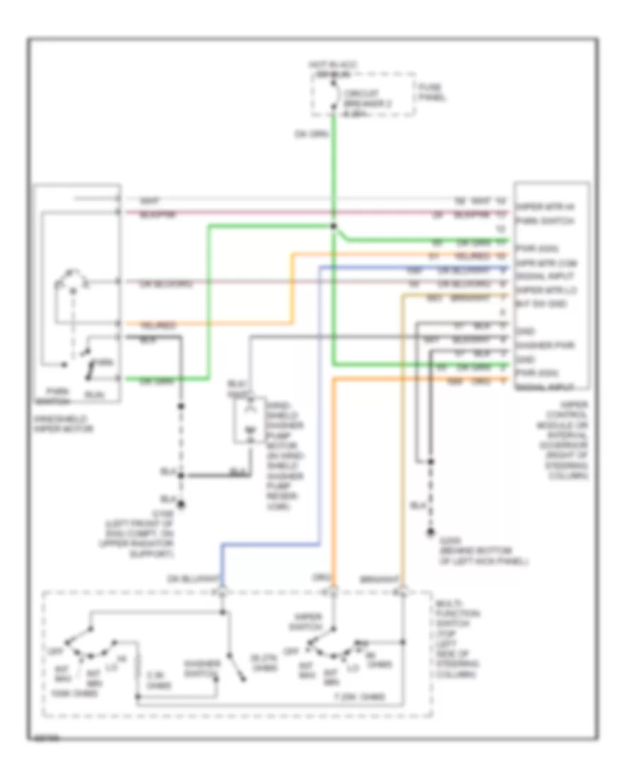
Wiper/Washer Wiring Diagram for Ford Pickup F350 1993
List of elements for Wiper/Washer Wiring Diagram for Ford Pickup F350 1993:
- 100k ohms
- 3.3k ohms
- 7.25k
- Circuit breaker 2 8.25a
- Fuse panel
- G108 (left front of eng compt, on upper radiator support)
- G200 (behind bottom of left kick panel)
- Gnd
- Hot in acc or run
- Int max
- Int min
- M-f sw gnd
- Multi- function switch (top left side of steering column)
- Off
- Off 36.27k ohms
- Ohms
- Park
- Park switch
- Pwr (ign)
- Run
- Signal input
- Washer pwr
- Washer switch
- Wind- shield washer pump motor (in wind- shield washer pump reser- voir)
- Windshield wiper motor
- Wiper control module or interval governor (right of steering column)
- Wiper mtr hi
- Wiper mtr lo
- Wiper switch
- Wpr mtr com