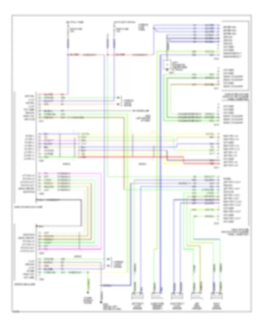
ANTI-THEFT
Anti-theft Wiring Diagram for Ford Probe 1993

List of elements for Anti-theft Wiring Diagram for Ford Probe 1993:
- 15a
- Acc
- Anti-theft control unit (behind left side of i/p, on central processing unit)
- Anti-theft indicator
- Armed signal
- Arming out
- Battery
- C2000
- C201
- C204
- C213
- C214
- C215
- C240
- C409
- Central processing unit (behind left side of i/p, rear of interior panel)
- Disarm input
- Engine fuse
- Exterior lights system (hazard lights)
- G106 (left front of vehicle, near fog light)
- G300 (below left front seat)
- G407 (lower center rear of luggage compartment)
- Ground
- Hazard lights
- Headlights
- Headlights system (headlight relay)
- Hood open
- Hood switch
- Hood switch (on engine compt latch assy)
- Horn
- Horn enable
- Horns system (horn relay)
- Hot at all times
- Hot in run or start
- Ignition
- Ignition switch
- Instrument cluster
- Interior fuse panel
- Joint connector
- Keyless entry module (in front of right quarter panel, behind quarter trim)
- Left door key cylinder switch (part of key cyl)
- Left door lk sw
- Left door lock switch (part of key cyl)
- Liftgate key cyl
- Liftgate key switch (right rear of luggage compt)
- Liftgate open
- Luggage compart- ment light switch (center of luggage compt)
- Meter fuse
- Nca
- Off
- Option #1
- Option #2
- Option sw
- Red
- Right door key cylinder switch (part of key cyl)
- Right door lk sw
- Right door lock switch (part of key cyl)
- Room fuse
- Run
- Start
- Start enable
- Starter interrupt relay
- Starting/ charging system (starter motor)
- With remote keyless entry
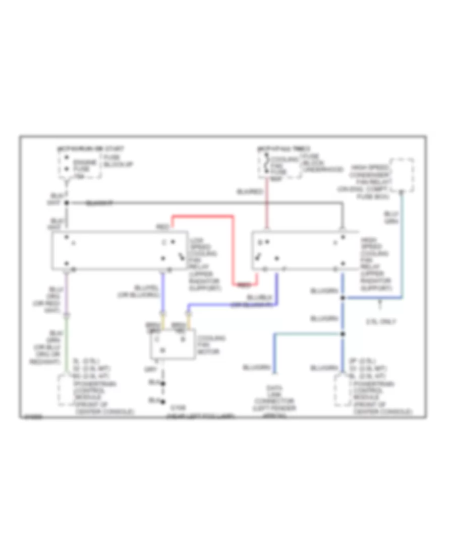
COOLING FAN
Cooling Fan Wiring Diagram for Ford Probe 1993
List of elements for Cooling Fan Wiring Diagram for Ford Probe 1993:
- (2.5l) (2.0l m/t) (2.0l a/t)
- (near left fog lamp)
- 2.5l only
- 2p 3l
- 3l 3g
- Cooling fan fuse 40a
- Cooling fan motor
- Data link connector (left fender apron)
- Engine fuse 15a
- Fuse block: underhood
- Fuse block:i/p
- G108
- High speed condenser fan relay (on eng. compt. fuse box)
- High speed cooling fan relay (upper radiator support)
- Hot at all times
- Hot in run or start
- Low speed cooling fan relay (upper radiator support)
- Powertrain control module (front of center console)
- Red
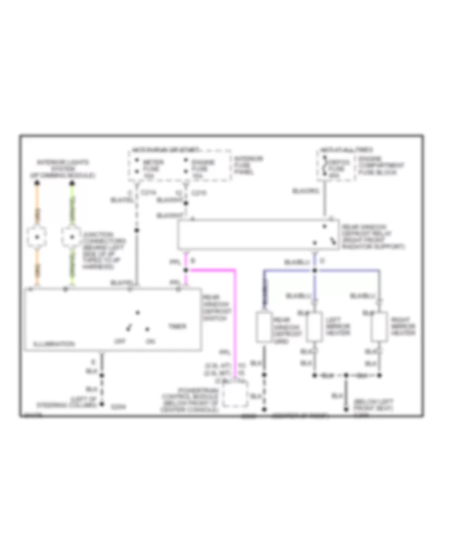
DEFOGGERS
Defogger Wiring Diagram for Ford Probe 1993
List of elements for Defogger Wiring Diagram for Ford Probe 1993:
- (below left front seat) g300
- (center of roof)
- (left of steering column)
- 1o (2.0l a/t) (2.0l m/t) (2.5l)
- C214
- C215
- Defog fuse 40a
- Engine compartment fuse block
- Engine fuse 15a
- G204
- G909
- Hot at all times
- Hot in run or start
- Illumination
- Interior fuse panel
- Interior lights system (i/p dimming module)
- Junction connectors (behind left side of i/p taped to i/p harness)
- Left mirror heater
- Meter fuse 10a
- Off
- Powertrain control module (below front of center console)
- Rear window defrost grid
- Rear window defrost relay (right front radiator support)
- Rear window defrost switch
- Right mirror heater
- Timer
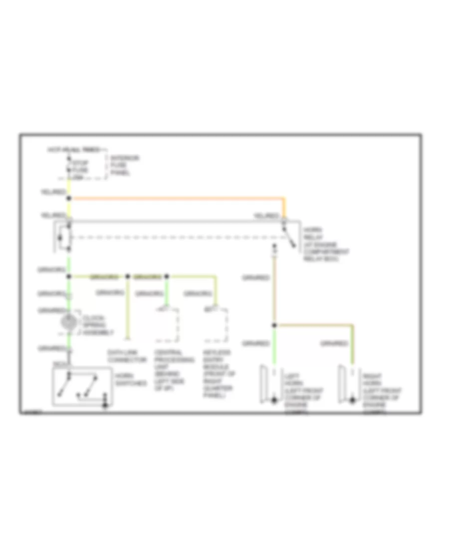
HORN
Horn Wiring Diagram for Ford Probe 1993
List of elements for Horn Wiring Diagram for Ford Probe 1993:
-
-
- Central processing unit (behind left side of i/p)
- Clock- spring assembly
- Data link connector
- Horn relay (at engine compartment relay box)
- Horn switches
- Hot at all times
- Interior fuse panel
- Keyless entry module (front of right quarter panel)
- Left horn (left front corner of engine compt)
- Nca
- Right horn (left front corner of engine compt)
- Stop fuse 20a
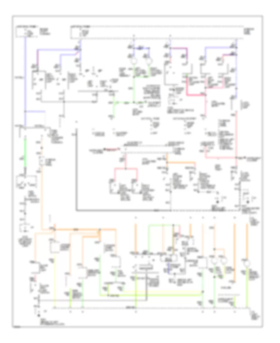
INTERIOR LIGHTS
Interior Light Wiring Diagram for Ford Probe 1993
List of elements for Interior Light Wiring Diagram for Ford Probe 1993:
- (5 bulbs)
- (behind left center of i/p) g206
- (in front of right quarter panel, behind quarter trim) keyless entry module
- (lower center rear of lugg. compt)
- A/c- heater control assembly illum.
- Bat c
- C204
- Central processing unit (behind left side of i/p, on rear of interior fuse panel)
- Cigar lighter illum.
- Combination switch
- Courtesy f
- Courtesy lp switch in
- Courtesy lps out
- Dome lamp
- Dome/ map lamp assembly
- Door handle switch in
- Drl
- Engine compt fuse box
- G100 (left front of vehicle, near fog lamp)
- G204 (behind i/p, left of steering column)
- G300 (below left front seat)
- Glove box lamp
- Glove box lamp switch
- Graphic equalizer
- Ground
- Head
- Headlamp retractor switch
- Hot at all times
- Hot in run or start
- I/p dimming module (left side of dash)
- Ign a
- Instrument cluster
- Interior fuse panel
- J/c
- J/c (left side of dash)
- Key cyl g
- Left door courtesy lamp switch (on left b pillar)
- Left map lamp
- Left outside door handle switch (top rear of left door)
- Left vanity mirror lamp
- Liftgate washer switch
- Liftgate wiper switch
- Lps out
- Lugg compt lp switch in
- Lugg. compt lamp
- Lugg. compt lamp switch
- Main lamp switch
- Meter fuse 15a
- Module d
- Nca
- Nca ignition key cylinder lamp
- Nca left door key cylinder lamp
- Nca right door key cylinder lamp
- Off
- Oscillator
- Overdrive off switch
- Park
- Park lamp relay (in engine compt fuse box)
- Pnk
- Rear window defrost switch
- Red
- Right door courtesy lamp switch (on right b pillar)
- Right map lamp
- Right outside door handle switch (top rear of right door)
- Right vanity mirror lamp
- Room fuse 15a
- Solid state
- Tail fuse 15a
- W/o drl
- With anti- theft
- With illuminated entry
- With keyless entry
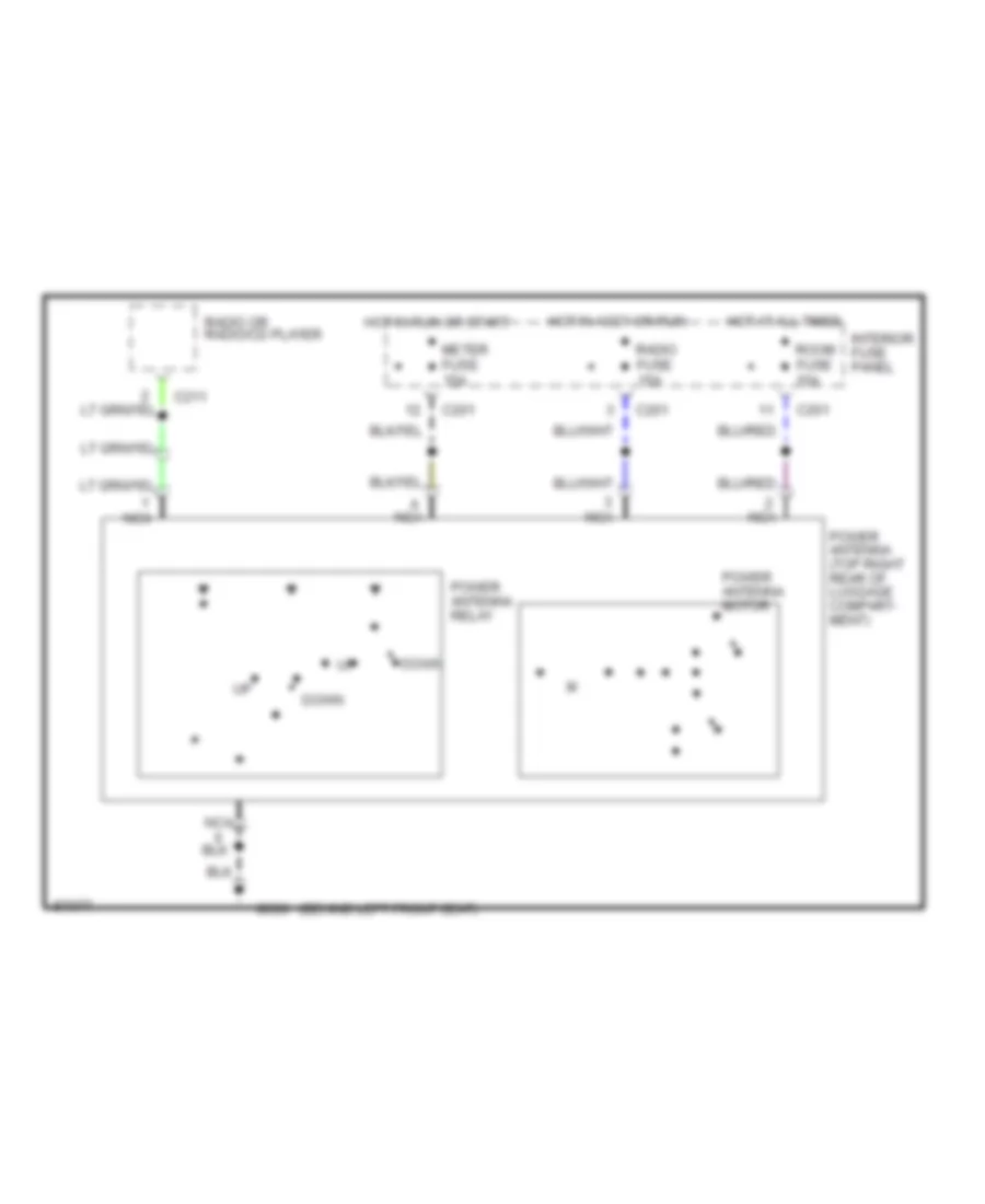
POWER ANTENNA
Power Antenna Wiring Diagram for Ford Probe 1993
List of elements for Power Antenna Wiring Diagram for Ford Probe 1993:
- (behind left front seat)
- C201
- C211
- Down
- G300
- Hot at all times
- Hot in accy or run
- Hot in run or start
- Interior fuse panel
- Meter fuse 15a
- Nca
- Power antenna (top right rear of luggage compart- ment)
- Power antenna motor
- Power antenna relay
- Radio fuse 15a
- Radio or radio/cd player
- Room fuse 15a
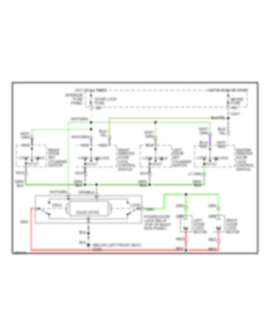
POWER DOOR LOCKS
Door Lock Wiring Diagram for Ford Probe 1993
List of elements for Door Lock Wiring Diagram for Ford Probe 1993:
- (below left front seat) g300
- 15a
- 30a
- C201
- Door lock fuse
- Hot at all times
- Hot in run or start
- Interior fuse panel
- Left door key cylinder switch
- Left door lock motor
- Lock
- Master window/ door lock control switch
- Meter fuse
- Nca
- Power door lock relay (top of right kick panel)
- Red
- Right door key cylinder switch
- Right door lock motor
- Right window/ door lock control switch
- Solid state
- Unlk
- Unlock
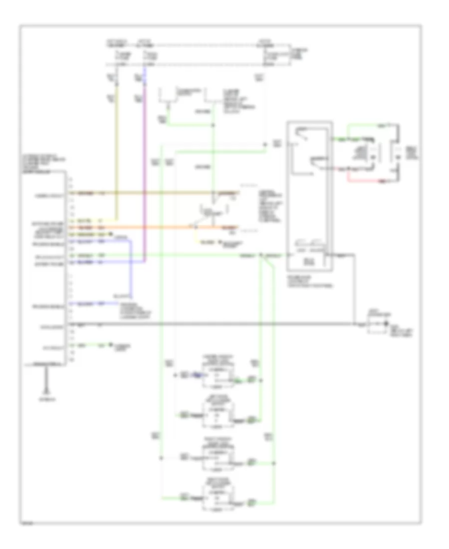
Keyless Entry Wiring Diagram for Ford Probe 1993
List of elements for Keyless Entry Wiring Diagram for Ford Probe 1993:
- (behind left side of i/p, left of steering column)
- (behind left side of i/p, rear of interior fuse panel)
- (in front of right quarter panel, behind quarter trim) keyless entry module
- (top of right kick panel)
- 15a
- 30a
- Antenna
- Anti-theft system
- Battery power
- Central processing unit
- Combination switch
- Door lock fuse
- Dr lk/unlk out
- Flasher module
- G300 (below left front seat)
- Hazard lps out
- Horn relay out
- Horns
- Hot at all times
- Hot in run or start
- Int lps out
- Interior fuse panel
- Interior lamps
- Joint connector
- Left door key cylinder switch
- Left door lock motor
- Lock
- Master window/ door lock control switch
- Meter fuse
- Module gnd
- Nca
- Power door lock relay
- Program connector (in right rear of luggage compt)
- Program enable
- Red
- Right door key cylinder switch
- Right door lock motor
- Right window/ door lock control switch
- Room fuse
- Solid state
- Switched power
- Transmitter in
- Unlk drs/dis- able anti-theft
- Unlock
- With anti-theft
Power Door Lock Wiring Diagram for Ford Probe 1993
List of elements for Power Door Lock Wiring Diagram for Ford Probe 1993:
- (below left front seat) g300
- 15a
- 30a
- C201
- Door lock fuse
- Hot at all times
- Hot in run or start
- Interior fuse panel
- Left door key cylinder switch
- Left door lock motor
- Lock
- Master window/ door lock control switch
- Meter fuse
- Nca
- Power door lock relay (top of right kick panel)
- Red
- Right door key cylinder switch
- Right door lock motor
- Right window/ door lock control switch
- Solid state
- Unlk
- Unlock
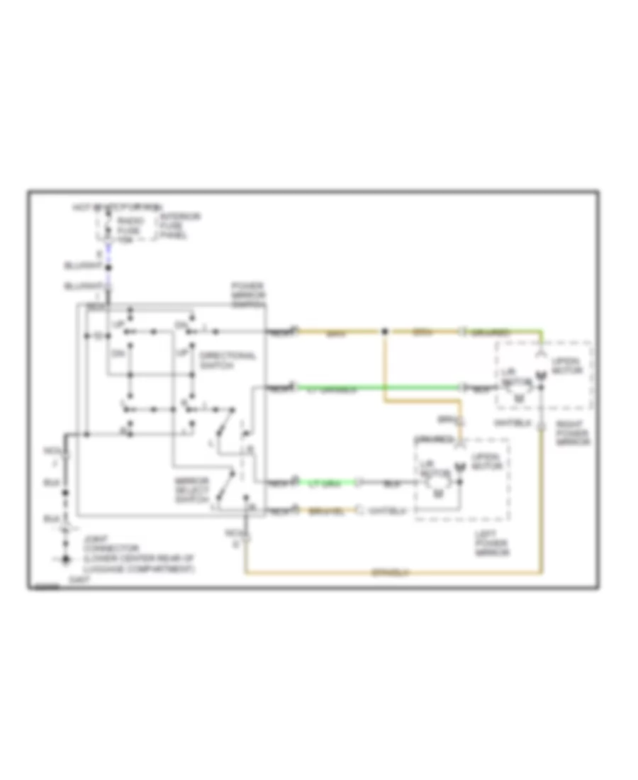
POWER MIRRORS
Power Mirror Wiring Diagram for Ford Probe 1993
List of elements for Power Mirror Wiring Diagram for Ford Probe 1993:
- Directional switch
- G407
- Hot in accy or run
- I nca
- Interior fuse panel
- Joint connector (lower center rear of luggage compartment)
- L/r motor
- Left power mirror
- Mirror select switch
- Nca
- Power mirror switch
- Radio fuse 15a
- Right power mirror
- Up/dn motor
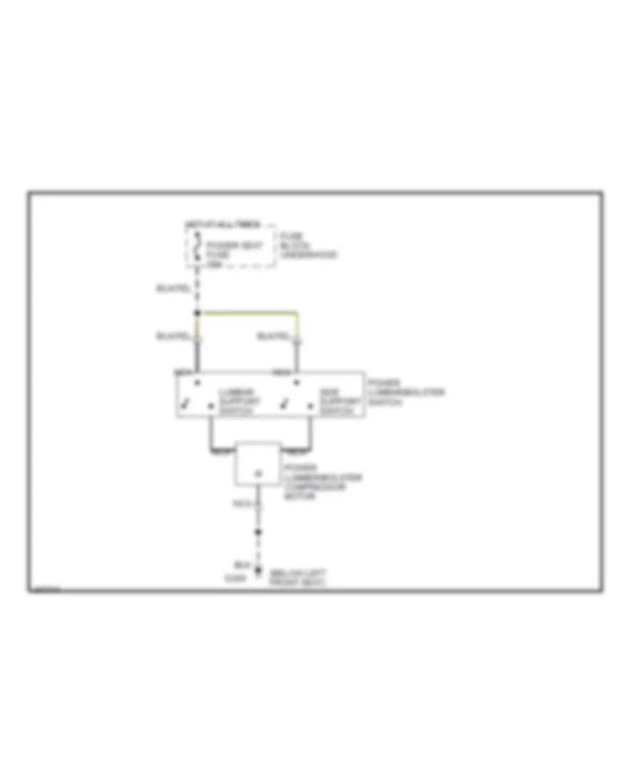
POWER SEATS
Lumbar Wiring Diagram for Ford Probe 1993
List of elements for Lumbar Wiring Diagram for Ford Probe 1993:
- (below left front seat)
- Fuse block: underhood
- G300
- Hot at all times
- Lumbar support switch
- Nca
- Power lumbar/bolster switch
- Power lumber/bolster compressor motor
- Power seat fuse 30a
- Side support switch
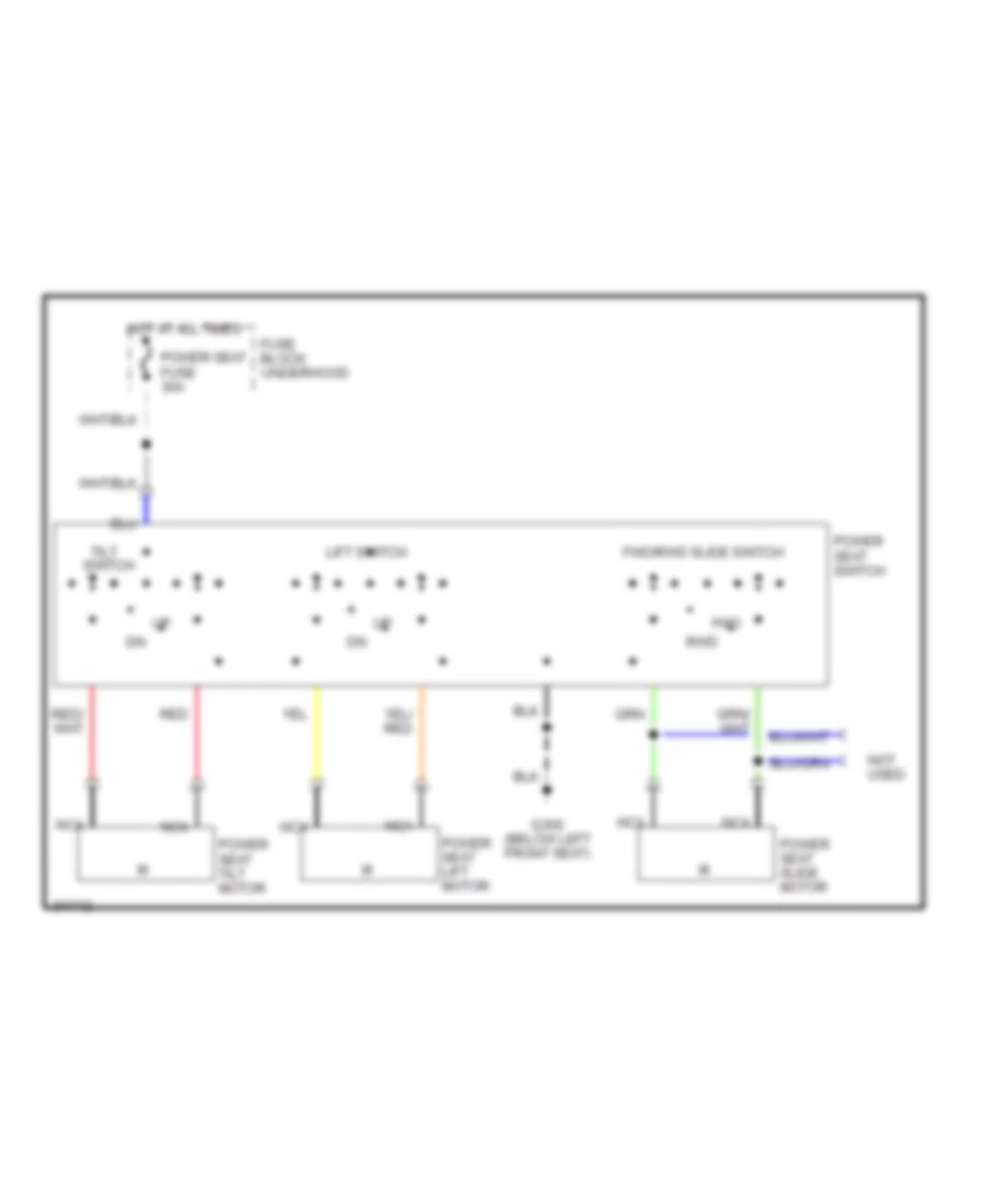
Power Seat Wiring Diagram for Ford Probe 1993
List of elements for Power Seat Wiring Diagram for Ford Probe 1993:
- Fuse block: underhood
- Fwd
- Fwd/rwd slide switch
- G300 (below left front seat)
- Hot at all times
- Lift switch
- Nca
- Not used
- Power seat fuse 30a
- Power seat lift motor
- Power seat slide motor
- Power seat switch
- Power seat tilt motor
- Red
- Rwd
- Tilt switch
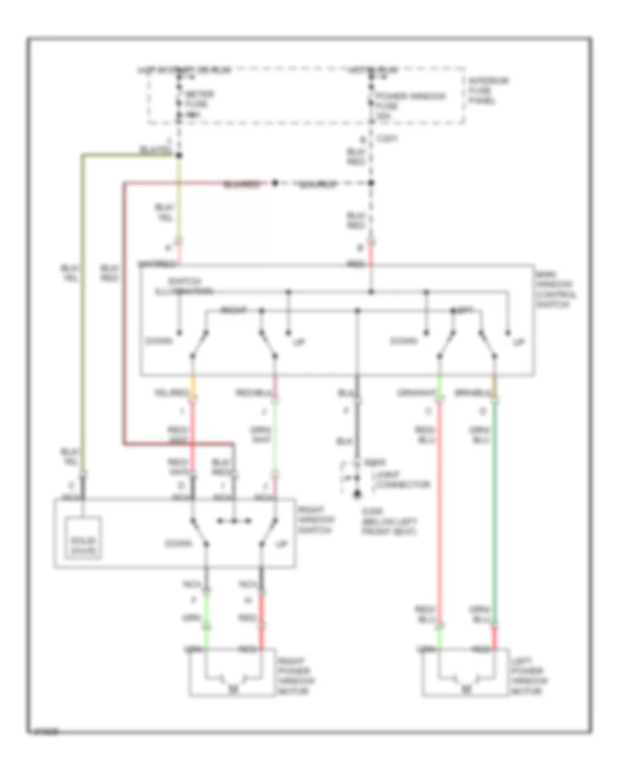
POWER WINDOWS
Power Window Wiring Diagram for Ford Probe 1993
List of elements for Power Window Wiring Diagram for Ford Probe 1993:
- C201 b
- C300
- Down
- G300 (below left front seat)
- Hot in run
- Hot in start or run
- Interior fuse panel
- Joint connector
- Left
- Left power window motor
- Main window control switch
- Meter fuse 15a
- Nca
- Power window fuse 30a
- Red
- Right
- Right power window motor
- Right window switch
- Solid state
- Switch illumination
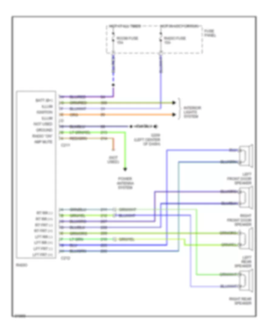
RADIO
Radio Wiring Diagrams for Ford Probe 1993
List of elements for Radio Wiring Diagrams for Ford Probe 1993:
- (not used)
- Amp mute
- Batt (b+)
- C211
- C212
- Fuse panel
- G206 (left center of dash)
- Ground
- Hot at all times
- Hot in accy or run
- Ignition
- Illum
- Interior lights system
- Left front door speaker
- Left rear speaker
- Lft frt (+)
- Lft frt (-)
- Lft rr (+)
- Lft rr (-)
- Not used
- Power antenna system
- Radio
- Radio "on"
- Radio fuse 15a
- Right front door speaker
- Right rear speaker
- Room fuse 15a
- Rt frt (+)
- Rt frt (-)
- Rt rr (+)
- Rt rr (-)
Radio Wiring Diagrams, Premium Radio for Ford Probe 1993
List of elements for Radio Wiring Diagrams, Premium Radio for Ford Probe 1993:
- (w/ eq only)
- (w/ sub only)
- (w/ subwoofer only)
- Amp mute
- Batt (b+)
- Battery (b+)
- C211
- C253
- C254
- C291
- C292
- C314
- C315
- C316
- C317
- C318
- Eq status
- G206 (behind left center of dash)
- G206 (left center of dash)
- G407
- Graphic equalizer
- Ground
- Hot at all times
- Hot in accy or run
- Ignition
- Illum
- Interior fuse panel
- Interior lights system
- Joint connector (center rear of trunk)
- Left front door speaker
- Left frt (+) in
- Left frt (+) out
- Left frt (-) in
- Left frt (-) out
- Left rear speaker
- Left rr (+) in
- Left rr (+) out
- Left rr (-) in
- Left rr (-) out
- Lft chnl in
- Lft chnl out
- Lft frt (+)
- Lft frt (-)
- Lft rr (+)
- Lft rr (-)
- Not used
- Power
- Power antenna system
- Radio "on"
- Radio amplifier (front of right quarter panel, under trim)
- Radio fuse 15a
- Radio or radio/cd player
- Red
- Right front door speaker
- Right frt (+) in
- Right frt (+) out
- Right frt (-) in
- Right frt (-) out
- Right rear speaker
- Right rr (+) in
- Right rr (+) out
- Right rr (-) in
- Right rr (-) out
- Room fuse 15a
- Rt chnl in
- Rt chnl out
- Rt frt (+)
- Rt frt (-)
- Rt rr (+)
- Rt rr (-)
- Shield
- Signal return
- Signal to sub amp
- Subwoofer amplifier (front of left quarter panel, under trim)
- Subwoofer out
- Subwoofer speaker assembly
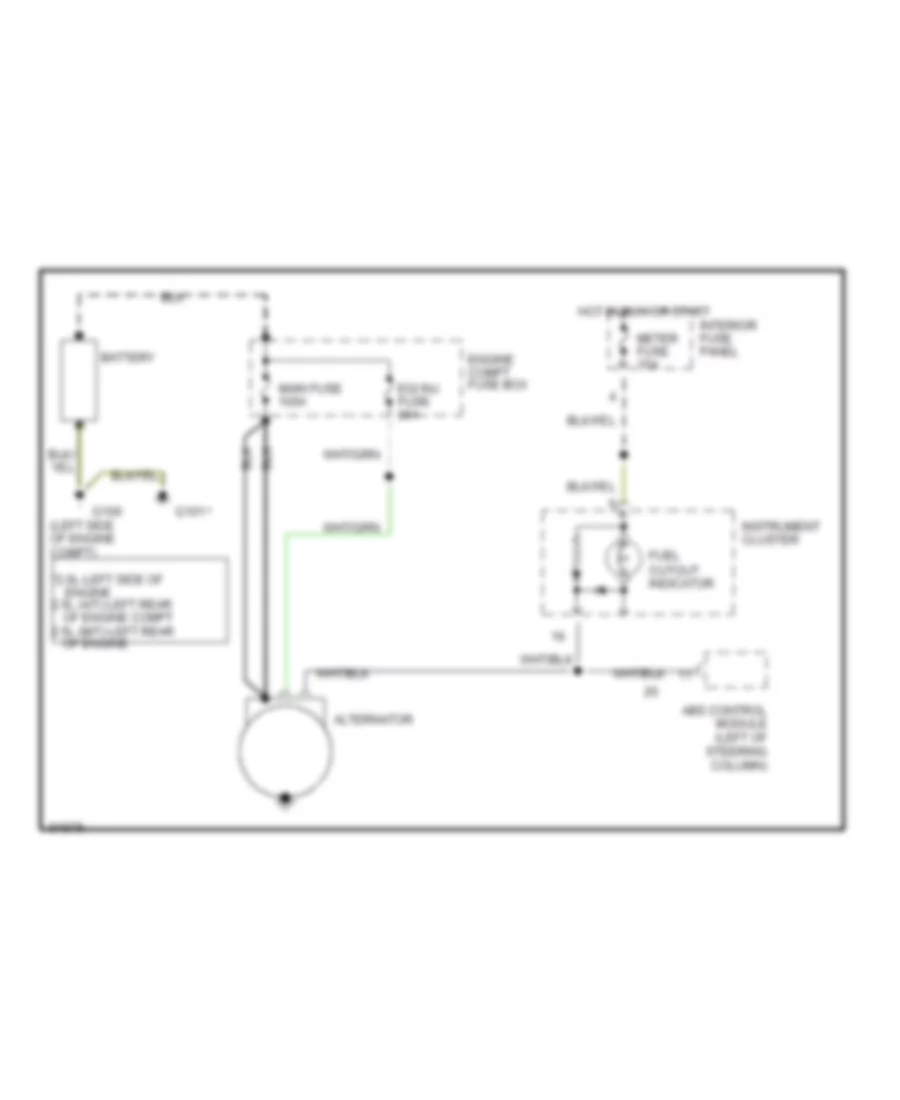
STARTING/CHARGING
Charging Wiring Diagram for Ford Probe 1993
List of elements for Charging Wiring Diagram for Ford Probe 1993:
- *2.0l-left side of engine 2.5l (a/t)-left rear of engine compt 2.5l (m/t)-left rear of engine
- (left side of engine compt)
- Abs control module (left of steering column)
- Alternator
- Battery
- Egi inj fuse 30a
- Engine compt fuse box
- Fuel cutout indicator
- G100
- G101
- Hot in run or start
- Instrument cluster
- Interior fuse panel
- Main fuse 100a
- Meter fuse 15a
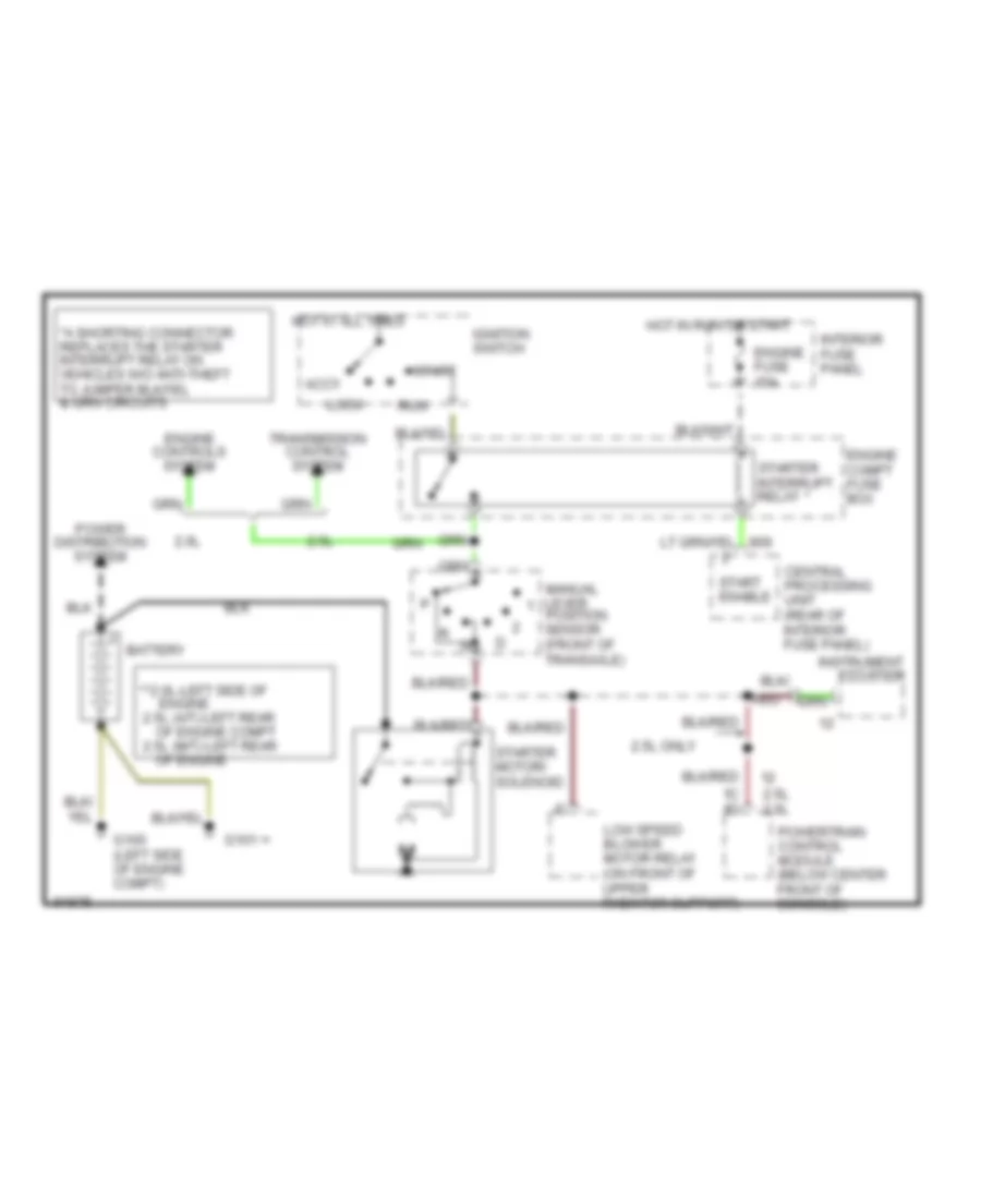
Starting Wiring Diagram, A/T for Ford Probe 1993
List of elements for Starting Wiring Diagram, A/T for Ford Probe 1993:
- **2.0l-left side of engine 2.5l (a/t)-left rear of engine compt 2.5l (m/t)-left rear of engine
- 1c 1d
- 2.0l
- 2.5l
- 2.5l 2.0l
- 2.5l only
- Accy
- Battery
- Central processing unit (rear of interior fuse panel)
- Engine compt fuse box
- Engine controls system
- Engine fuse 15a
- G100 (left side of engine compt)
- G101
- Hot at all times
- Hot in run or start
- Ignition switch
- Instrument cluster
- Interior fuse panel
- Lock
- Low speed blower motor relay (on front of upper radiator support)
- Manual lever position sensor (front of transaxle)
- Power distribution system
- Powertrain control module (below center front of console)
- Red
- Run
- Start
- Start enable
- Starter interrupt relay
- Starter motor/ solenoid
- Transmission control system
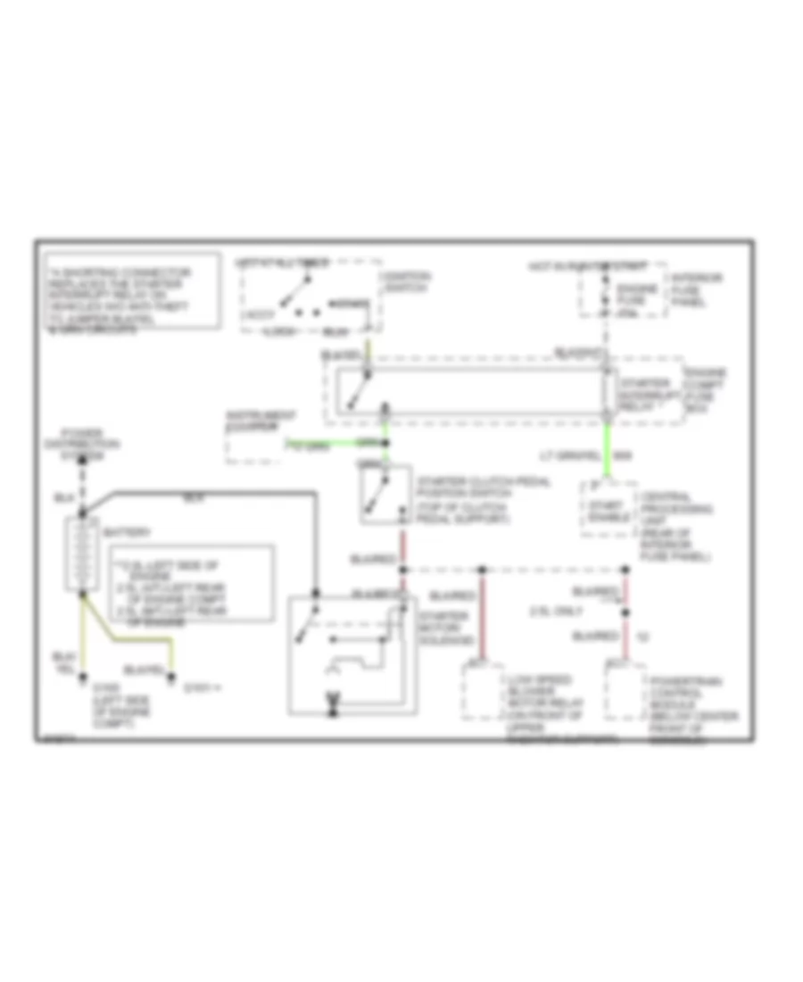
Starting Wiring Diagram, M/T for Ford Probe 1993
List of elements for Starting Wiring Diagram, M/T for Ford Probe 1993:
- **2.0l-left side of engine 2.5l (a/t)-left rear of engine compt 2.5l (m/t)-left rear of engine
- 2.5l only
- Accy
- Battery
- Central processing unit (rear of interior fuse panel)
- Engine compt fuse box
- Engine fuse 15a
- G100 (left side of engine compt)
- G101
- Hot at all times
- Hot in run or start
- Ignition switch
- Instrument cluster
- Interior fuse panel
- Lock
- Low speed blower motor relay (on front of upper radiator support)
- Power distribution system
- Powertrain control module (below center front of console)
- Run
- Start
- Start enable
- Starter clutch pedal position switch (top of clutch pedal support)
- Starter interrupt relay
- Starter motor/ solenoid
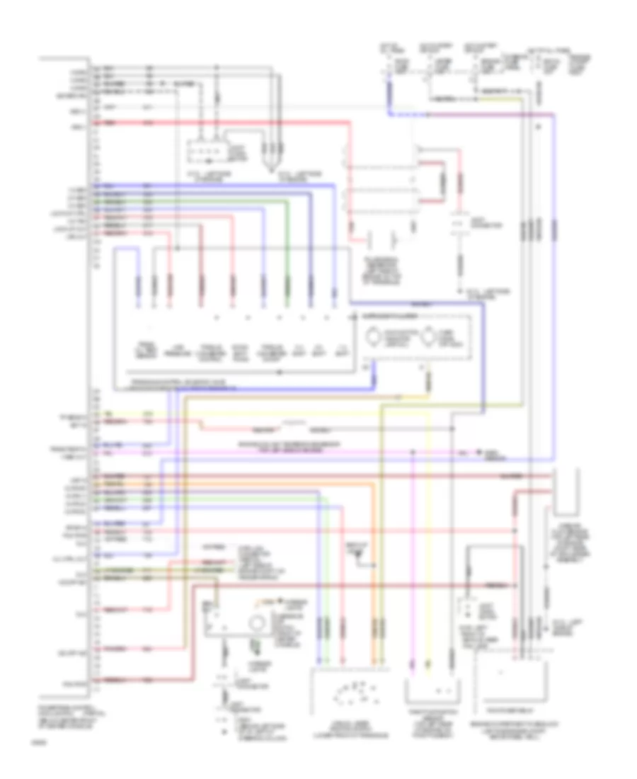
TRANSMISSION
2.0L
2.0L, Transmission Wiring Diagram for Ford Probe 1993
List of elements for 2.0L, Transmission Wiring Diagram for Ford Probe 1993:
-
- (left side of engine, on top of transaxle)
- 1g
- 2a
- 2b
- 2g
- 2h
- 3l
- 3y
- (behind left side of i/p, left of steering column)
- (below center front of center console)
- (left
- (left side
- (left side engine compt, above wheel well)
- (partial)
- (top left side of engine)
- 1-2 shift
- 1-2 sso
- 2-3 shift
- 2-3 sso 3r
- 3-2 tso 3u
- 3-4 shift
- 3-4 sso 3s
- Back-up lights
- Baro sensor
- Data link connector (partial) (left side of engine compt, on fender apron)
- Dlc
- Dlc 1h
- Down- shift timing
- Ect in
- Egi inj fuse 30a
- Engine compartment fuse block
- Engine compt fuse box
- Engine coolant temperature sensor
- Engine fuse 15a
- Fog lamp)
- Front of
- G106
- G112
- G204
- Hot at all times
- Hot in start or run
- Instrument cluster
- Interior fuse panel
- Interior lights
- Joint conn- ector
- Joint connector
- Kpwr in
- Line pressure
- Lock-up ctrl 3t
- Lock-up out 3v
- Lps out 3w
- M grd
- Maf in
- Malfunction indicator lamp (mil)
- Manual lever position switch (lower front of transaxle)
- Mass air flow sensor (top left rear of engine compt, rear of air cleaner assembly)
- Meter fuse 15a
- Mil ctrl out
- Mlps (1)
- Mlps (2) 2p
- Mlps (d)
- Mlps (r)
- O/d off ind
- O/d off sw
- Of engine)
- Over- drive off indic
- Overdrive off switch (front of center console)
- Pcm power relay
- Pcm pwr
- Pcm pwr 1c
- Powertrain control module (pcm)
- Pulse signal generator (left side of engine, on top of transaxle)
- Red
- Room fuse 15a
- Side of engine)
- Sig return
- Throttle position sensor (top left rear of engine, on throttle body)
- Torque converter control
- Torque converter on/off
- Tp sens in 2e
- Trans oil temp sensor
- Trans temp in 2i
- Transaxle control solenoid valve
- V ref out 2j
- Vehicle, near
- Vss (+)
- Vss (-)
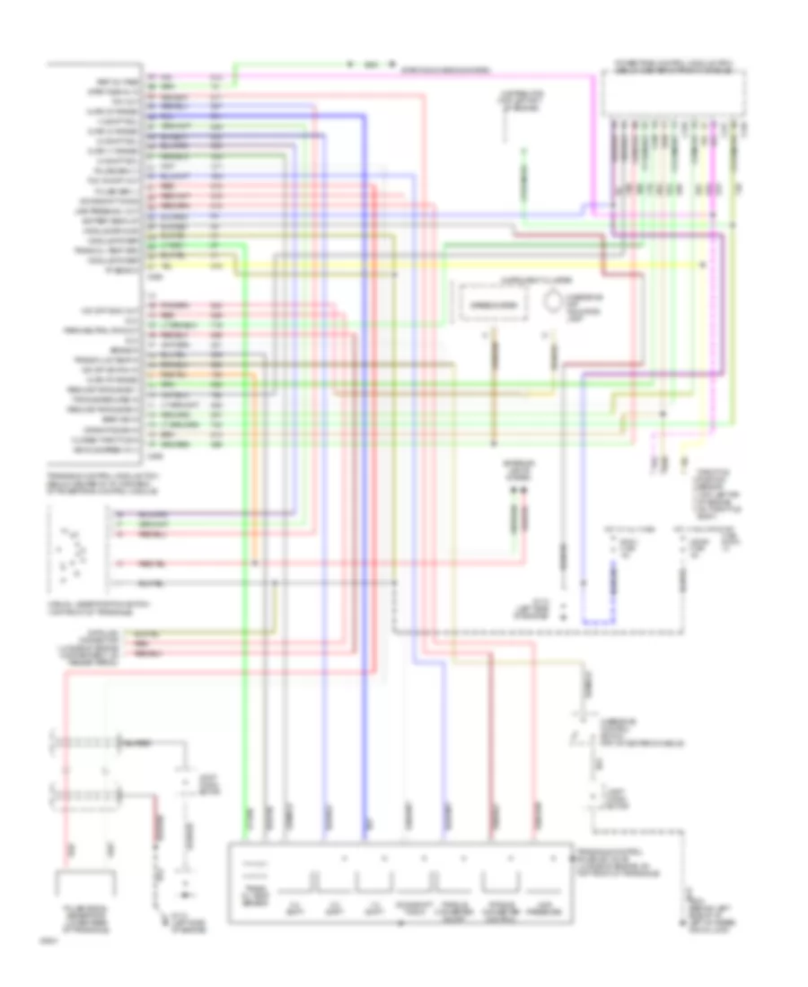
2.5L
2.5L, Transmission Wiring Diagram for Ford Probe 1993
List of elements for 2.5L, Transmission Wiring Diagram for Ford Probe 1993:
- (lh side of engine compartment, on fender apron)
- (top left frt
- (top left rr of engine on throttle body)
- 1-2 shift
- 1-2 shift sol
- 2-3 shift
- 2-3 shift sol
- 3-4 shift
- 3-4 shift sol
- Baro sig in
- Battery back-up
- Brake in
- C246
- C247
- C248
- C258
- C259
- Closed throttle in
- Crank pos sig in
- Data link connector
- Distributor
- Dlc
- Downshift timing
- Exterior lights system
- Fuse block: i/p
- G
- G112 (left side of engine)
- G204 (behind left side of i/p, left of steer- ing column)
- Hot at all times
- Hot in run or start
- I
- Instrument cluster
- Joint conn- ector
- Line press sol out
- Line pressure
- Manual lever position switch (top front of transaxle)
- Meter fuse 15a
- Mlps ('1' range)
- Mlps ('2' range)
- Mlps ('d' range)
- Mlps ('r' range)
- Module ground
- Module power
- O/d off indic out
- O/d off switch in
- Of engine)
- Overdrive control switch (frt of center console)
- Overdrive off indicator lamp
- Park/neutral pos out
- Powertrain control module (pcm) (below center of front console)
- Pulse gen (+)
- Pulse gen (-)
- Pulse signal generator (lower rear of transaxle)
- Red
- Red
- Reduce torque sig 1
- Reduce torque sig 2
- Ref voltage
- Room fuse 15a
- Speedometer
- Start signal in
- Starting/charging system
- Tcc on/off out
- Tcc out
- Throttle position sensor
- Torque converter control
- Torque converter on/off
- Torque reduced in
- Tp sens in
- Trans fluid temp in
- Trans oil temp grd
- Trans oil temp sensor
- Transaxle control module (tcm) (below center of i/p, forward of powertrain control module)
- Transaxle control solenoid valve (lh side of engine, on top front of transaxle)
- Vehicle speed in (+)
WIPER/WASHER
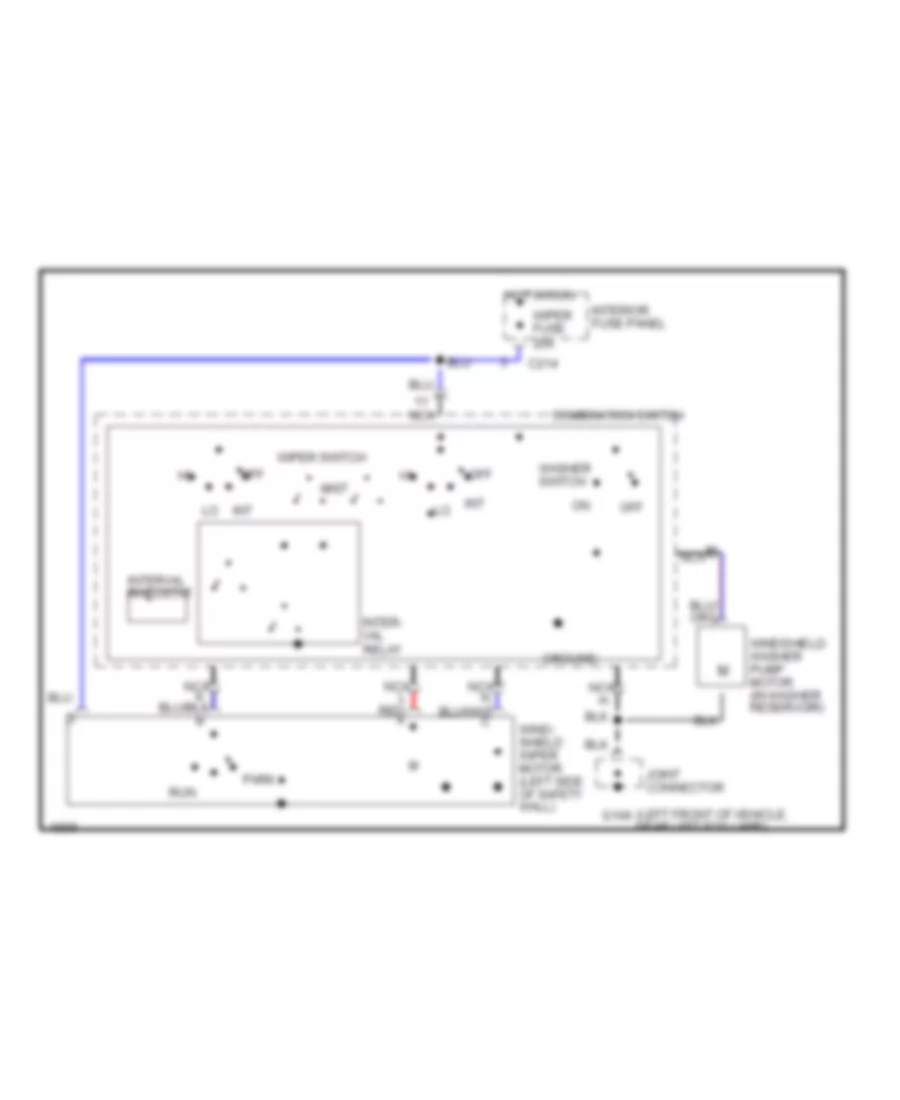
2-Speed Wiper/Washer Wiring Diagram for Ford Probe 1993
List of elements for 2-Speed Wiper/Washer Wiring Diagram for Ford Probe 1993:
- (left front of vehicle, near left fog lamp)
- 20a
- C214
- Combination switch
- G106
- Ground
- Hot in run
- Interior fuse panel
- Joint connector
- M nca
- Nca
- Nca l red a
- Off
- Park
- Run
- Solid state
- Washer switch
- Wind- shield wiper motor (left side of safety wall)
- Windshield washer pump motor (in washer reservoir)
- Wiper fuse
- Wiper relay
- Wiper switch
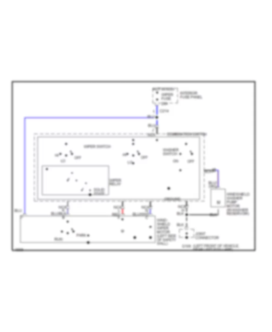
Interval Wiper/Washer Wiring Diagram for Ford Probe 1993
List of elements for Interval Wiper/Washer Wiring Diagram for Ford Probe 1993:
- (left front of vehicle, near left fog lamp)
- C214
- Combination switch
- G106
- Ground
- Hot in run
- Int
- Inter- val relay
- Interior fuse panel
- Interval rheostat
- Joint connector
- M nca
- Mist
- Nca
- Nca l red a
- Off
- Park
- Run
- Washer switch
- Wind- shield wiper motor (left side of safety wall)
- Windshield washer pump motor (in washer reservoir)
- Wiper fuse 20a
- Wiper switch
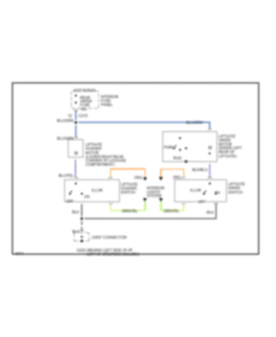
Rear Wiper/Washer Wiring Diagram for Ford Probe 1993
List of elements for Rear Wiper/Washer Wiring Diagram for Ford Probe 1993:
- C215
- G202 (behind left side of i/p, left of steering column)
- Hot in run
- Illum
- Interior fuse panel
- Interior lights system
- Joint connector
- Liftgate washer motor (lower right rear corner of luggage compartment)
- Liftgate washer switch
- Liftgate wiper motor (inside left rear of liftgate)
- Liftgate wiper switch
- Off
- Park
- Rear wiper fuse 15a
- Run