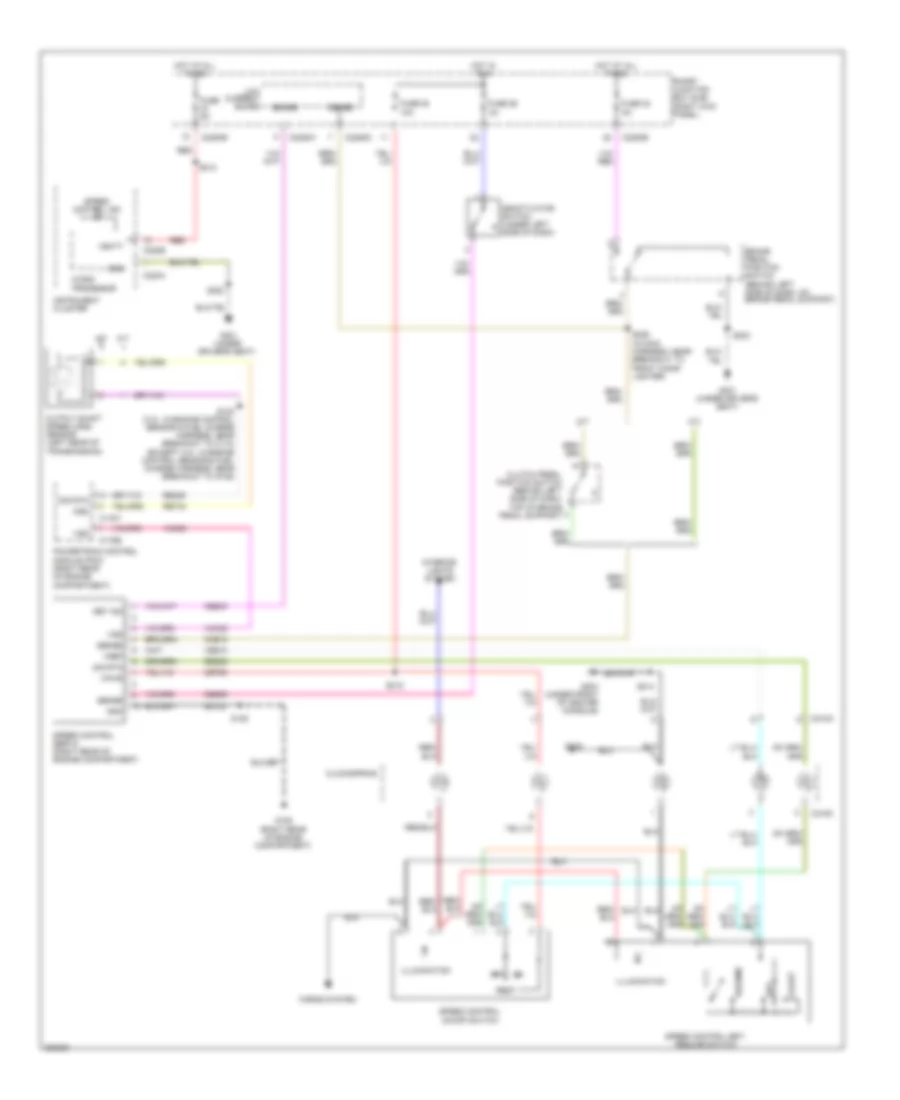
AIR CONDITIONING
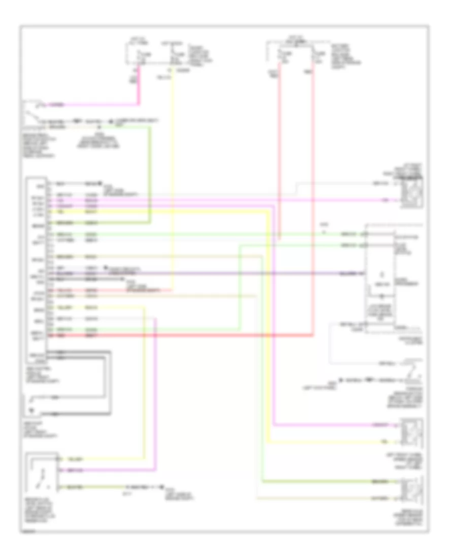
Heater Wiring Diagram for Ford Ranger 2008

List of elements for Heater Wiring Diagram for Ford Ranger 2008:
- (in dash panel to headlight junction harness, near breakout to heater blower motor) s129
- (not used)
- (right rear of engine compt) heater blower motor
- A/c
- Battery junction box (bjb) (left rear side of engine compt)
- Blend door actuator (behind right side of dash)
- Blower motor relay
- C2280b
- C294a
- C294b
- C294c
- C294d
- Climate control assembly
- Control circuit
- Def/floor
- Defrost
- Floor
- Floor/vent
- Front heater blower motor resistor
- Fuse 10a
- Fuse 30a
- G103 (left side of engine compt)
- G105 (right rear of engine compt)
- G301 (under driver's seat)
- High
- Hot at all times
- Hot in run
- Illumination
- Interior lights system
- Low
- Max
- Medium high
- Medium low
- Mix
- Normal
- Off
- S117
- S128
- S203
- S216
- S227
- Smart junction box (sjb) (right kick panel)
- Temperature potentiometer
- Thermal limiter
- Vent
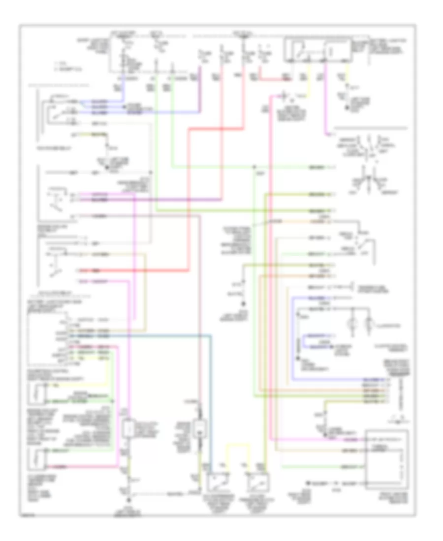
Manual A/C Wiring Diagram for Ford Ranger 2008
List of elements for Manual A/C Wiring Diagram for Ford Ranger 2008:
- (behind right side of dash) blend door actuator
- (in dash panel to headlight junction harness, near breakout to heater blower motor)
- (left side of engine compt) g103
- (under driver's seat)
- 2.3l
- A/c
- A/c clutch field coil (left front of engine)
- A/c clutch relay
- A/c compressor cycling switch (right rear of engine compt)
- A/c high pressure switch (left front of engine compt)
- Accr
- Accs
- Battery junction box (bjb) (left rear side of engine compt)
- Blower motor relay
- C175b
- C175e
- C2280a
- C2280b
- C294a
- C294b
- C294c
- C294d
- Ce116
- Ch302
- Ch425
- Cht
- Climate control assembly
- Control circuit
- Cylinder-head temperature sensor (2.3l) (right side of cylinder head)
- Def/floor
- Defrost
- Ect
- Engine controls system
- Engine coolant temperature (ect) sensor (except 2.3l) (3.0l: top front of engine) (4.0l: top right front of engine)
- Engine cooling fan motor 1 (right front of engine compt)
- Engine cooling fan relay (2.3l)
- Except 2.3l
- Fci
- Floor
- Floor/vent
- Front heater blower motor resistor
- Fuse 10a
- Fuse 20a
- Fuse 30a
- G103 (left side of engine compt)
- G105 (right rear of engine compt)
- G301
- G301 (under driver's seat)
- Heater blower motor (right rear of engine compt)
- High
- Hot at all times
- Hot in run
- Hot in start or run
- Illumination
- Interior lights system
- Low
- Max
- Medium high
- Medium low
- Mix
- Nca
- Normal
- Of engine compt) g103
- Off
- Pcm power diode 3a
- Pcm power relay
- Power distribution system
- Powertrain control module (pcm) (right rear of engine compt)
- Ptc 1a
- Re405
- Red
- S101 (2.3l & 4.0l: in engine control sensor & fuel charge harness, near breakout to g106) (3.0l: in engine control sensor & fuel charge harness, near breakout to c110)
- S116
- S117
- S118 (near breakout to battery junction box)
- S122
- S128
- S129
- S203
- S227
- Sigrtn
- Smart junction box (sjb) (right kick panel)
- Temperature potentiometer
- Thermal limiter
- Ve716
- Vent
- Vh101
ANTI-LOCK BRAKES
Anti-lock Brakes Wiring Diagram for Ford Ranger 2008
List of elements for Anti-lock Brakes Wiring Diagram for Ford Ranger 2008:
- (at right front wheel) right front wheel speed sensor
- (under driver's seat) g301
- 4wd
- 4x4
- 4x4 status
- Abs control module (left front of engine compt)
- Abs ind
- Abs pump motor (left front of engine compt)
- Abs wl
- Battery junction box (bjb) (left rear side of engine compt)
- Brake assembly)
- Brake fluid level switch (left rear of engine compt, on brake fluid reservoir)
- Brake pedal position switch (behind left side of dash, on brake pedal support)
- Brkl
- Brks
- C220b
- C2280b
- Cbp20
- Cca01
- Cca02
- Ccb15
- Ccf23
- Cmc19
- Computer data lines system
- Ebdwl
- Fluid level status
- Fuse 10a
- Fuse 30a
- Fuse 40a
- Fuse 5a
- G102 (left side of engine compt)
- G103 (left side of engine compt)
- G200 (left kick panel)
- Gd122
- Gnd
- Ground
- Hot at all times
- Hot in run
- Instrument cluster
- Iso
- Left front wheel speed sensor (at left front wheel)
- Level
- Lf sn+
- Lf sn-
- Low brake fluid level/ park brake ind
- Micro- processor
- Nca
- Parking brake switch (below left side of dash, on park
- Pwr
- Rca17
- Rca19
- Rca21
- Rear axle speed sensor (top of rear differential)
- Red
- Rf sn+
- Rf sn-
- Rmc19
- Rr sn+
- Rr sn-
- S117
- S220
- S226 (in main harness, near breakout to front cigar lighter)
- S500
- Sbb15
- Sbb17
- Sense
- Smart junction box (sjb) (right kick panel)
- Vbatt
- Vca03
- Vca05
- Vca14
- Vdb10
- Vpwr
ANTI-THEFT
Forced Entry Wiring Diagram for Ford Ranger 2008
List of elements for Forced Entry Wiring Diagram for Ford Ranger 2008:
- (under driver's seat)
- All lock relay
- C2280a
- C2280b
- C2280c
- C2280d
- Computer data lines system
- Driver door unlock relay
- Driver side door lock switch
- Driver side rear door ajar switch (4 door)
- Exterior lights system
- Fuse 10a
- Fuse 15a
- Fuse 20a
- Fuse 5a
- G200 (left kick panel)
- G204 (under front of center console)
- G301
- G301 (under driver's seat)
- Horn relay
- Horns system
- Hot at all times
- Instrument cluster system
- Interior lights system
- Left front door ajar switch
- Left front door lock actuator
- Low current board
- Park lamp relay
- Passenger door unlock relay
- Passenger side door lock switch
- Passenger side rear door ajar switch (4 door) (bottom rear of right rear door)
- Right front door ajar switch (rear of passenger's door)
- Right front door lock actuator
- S203
- S214
- S302
- S500
- S600 (w/ power equipment)
- Smart junction box (sjb) (right kick panel)
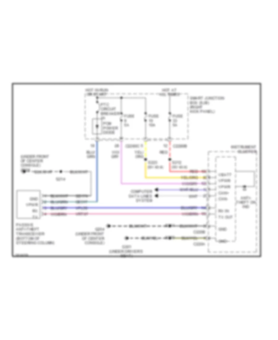
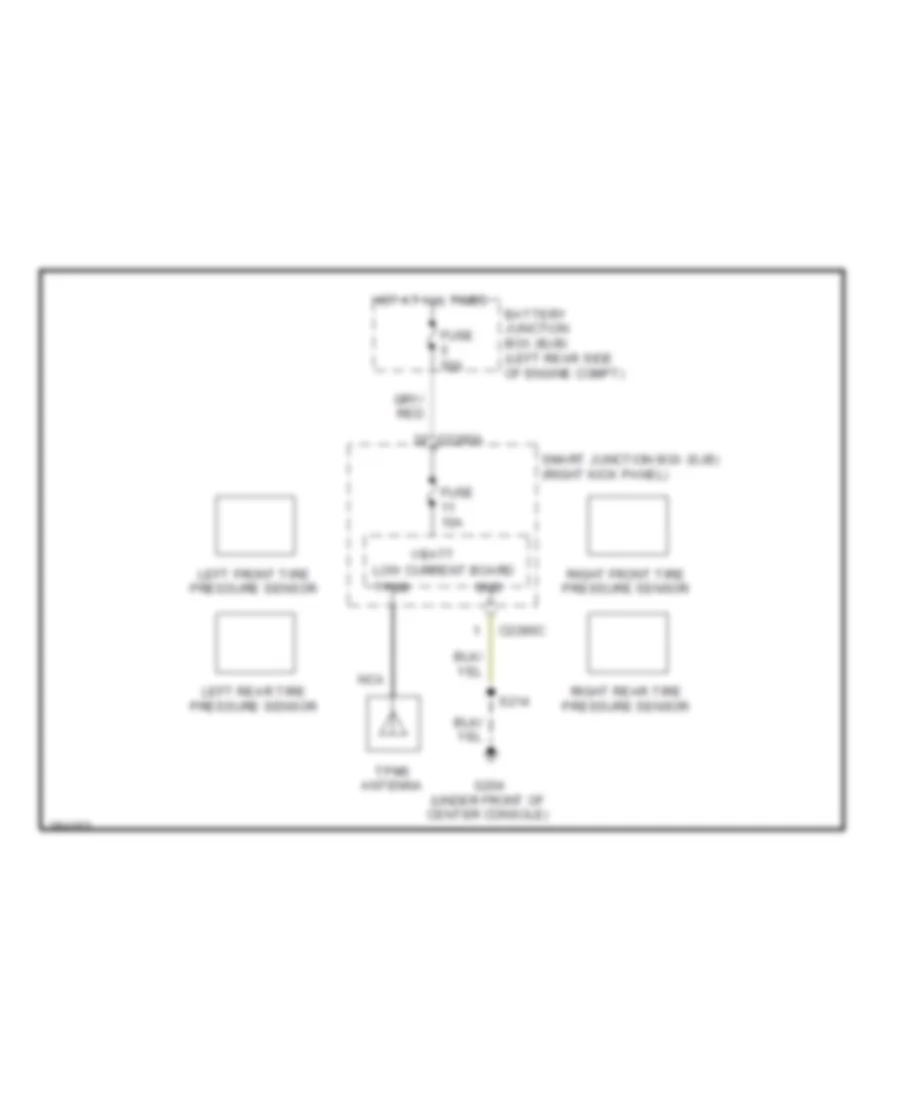
Passive Anti-theft Wiring Diagram for Ford Ranger 2008
List of elements for Passive Anti-theft Wiring Diagram for Ford Ranger 2008:
- (under front of center console) g204
- Anti- theft on ind
- C220a
- C220b
- C2280b
- C2280c
- Can+
- Can-
- Ce517
- Computer data lines system
- Fuse 10a
- Fuse 5a
- G204 (under front of center console)
- G301 (under driver's seat)
- Gd174
- Gnd
- Hot at all times
- Hot in run or start
- Instrument cluster
- Passive anti-theft transceiver (bottom of steering column)
- Pcm power diode
- Ptc circuit breaker 1a
- Red
- Rx in
- S212 (w/ 4x4)
- S214
- S220
- S223 (w/ 4x4)
- Smart junction box (sjb) (right kick panel)
- Tx out
- Vbatt
- Vpl56
- Vpwr
- Vrt07
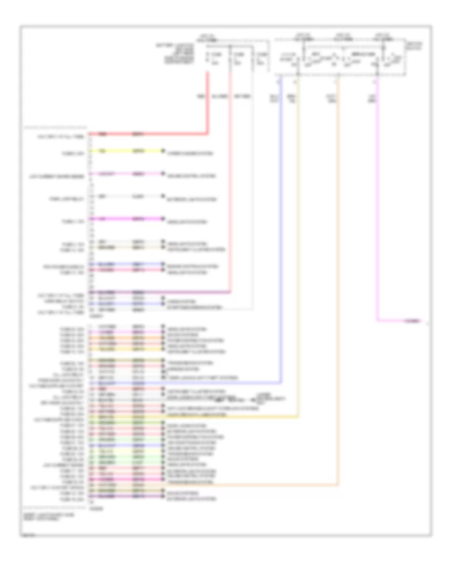
BODY CONTROL MODULES
Body Control Modules Wiring Diagram (1 of 2) for Ford Ranger 2008
List of elements for Body Control Modules Wiring Diagram (1 of 2) for Ford Ranger 2008:
- (under driver's seat) g301
- Acc
- Air conditioning system
- All lock relay
- Anti-lock brakes & shift interlock systems
- Battery junction box (bjb) (left rear side of engine compartment)
- C2280a
- C2280b
- Cbp03
- Cbp04
- Cbp05
- Cbp10
- Cbp14
- Cbp20
- Cbp21
- Cbp22
- Cbp26
- Cbp27
- Cdc32
- Cdc34
- Cdc35
- Ce517
- Ces03
- Clf27
- Cls34
- Computer data lines system
- Cpl11
- Cpl18
- Cpl19
- Crh02
- Cruise control system
- Door locks & anti-theft systems
- Door locks system
- Drv door unlock rly
- Engine controls system
- Exterior lights system
- Fuse 10, 10a
- Fuse 12, 15a
- Fuse 14, 15a
- Fuse 17, 15a
- Fuse 19, 20a
- Fuse 20, 10a
- Fuse 21, 5a
- Fuse 22, 5a
- Fuse 23, 30a
- Fuse 24, 20a
- Fuse 26, 2a
- Fuse 27, 10a
- Fuse 28, 15a
- Fuse 29, 20a
- Fuse 3, 10a
- Fuse 30, 5a
- Fuse 32, 5a
- Fuse 33, 5a
- Fuse 34, 20a
- Fuse 4, 10a
- Fuse 40a
- Fuse 5, 30a
- Fuse 50a
- Gd161
- Headlights system
- Horn relay switch
- Horns system
- Hot at all times
- Ignition switch
- Instrument cluster system
- Lock
- Low current board
- Low current board sense
- Mirrors system
- Off
- Park lamp relay
- Pass door unlock rly
- Pcm power diode 3a
- Power distribution system
- Red
- S203
- Sbb03
- Sbb05
- Sbp01
- Sbp12
- Sbp17
- Sbp19
- Sbp23
- Sbp24
- Sbp28
- Sbp29
- Sbp30
- Sbp32
- Sbp33
- Sbp34
- Sbr14
- Smart junction box (sjb) (right kick panel)
- Sound systems
- Start
- Starting/charging system
- Transmissions system
- Volt sply at all times
- Volt sply in start or run
- Wiper/washer system
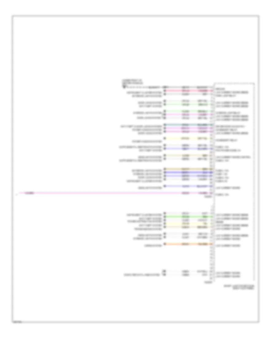
Body Control Modules Wiring Diagram (2 of 2) for Ford Ranger 2008
List of elements for Body Control Modules Wiring Diagram (2 of 2) for Ford Ranger 2008:
- (under front of center console) g204
- Accessory relay
- Anti-theft & door locks systems
- Anti-theft system
- C2280c
- C2280d
- Cat17
- Cbp01
- Cbp06
- Cbp08
- Cbp09
- Ccb15
- Cdc33
- Ce517
- Clf18
- Clf21
- Clf29
- Cln27
- Cln28
- Cls30
- Cls34
- Computer data lines system
- Cpl12
- Cpl26
- Cpl31
- Cpl36
- Cpl39
- Cpl42
- Cpl43
- Cpl51
- Cpw14
- Cpw30
- Door locks system
- Driver door unlock rly
- Exterior lights system
- Fuse 1, 5a
- Fuse 2, 10a
- Fuse 6, 10a
- Fuse 8, 10a
- Fuse 9, 5a
- Gd174
- Ground
- Headlights system
- Horns system
- Instrument cluster system
- Interior lamp relay
- Interior lights system
- Low current board
- Low current board control
- Low current board sense
- Park lamp relay
- Pcm power diode, 3a
- Power distribution system
- Power windows system
- S214
- Sense
- Smart junction box (sjb) (right kick panel)
- Srh01
- Transmissions system
- Vdb04
- Vdb05
COMPUTER DATA LINES
Computer Data Lines Wiring Diagram for Ford Ranger 2008
List of elements for Computer Data Lines Wiring Diagram for Ford Ranger 2008:
- (in main harness, at breakout to four-wheel drive control module) s221
- (in main harness, at breakout to four-wheel drive control module) s222
- (in main harness, near breakout to c210) s206
- (in main harness, near breakout to c237) s229
- (in main harness, near breakout to c237) s230
- (in main harness, near breakout to clockspring) s218
- (in main harness, near breakout to g301) s303
- (in main harness, near breakout to g301) s304
- (under front of center console) g204
- (w/ audiophile) audio unit
- Abs control module (left side of engine compt)
- Audio unit (w/o audiophile)
- C175b
- C2041a
- C220b
- C2280b
- C2280d
- C281a
- C290c
- Can+
- Can-
- Cdb08
- Data link connector (dlc) (under left side of dash)
- Feps
- Four-wheel drive control module (behind left center of dash)
- Fuse 29 20a
- G301 (under driver`s seat)
- Gd161
- Gd174
- Hot at all times
- Hs can +
- Hs can -
- Instrument cluster
- Iso
- Low current board
- Ms can+
- Ms can-
- Occupant classification system (ocs) module
- Powertrain control module (pcm) (right rear of engine compt)
- Restraints control module (under front of center console)
- S207 (in main harness, near breakout to c210)
- S217 (in main harness, near breakout to clockspring)
- S220
- S231
- S232
- S233
- S234
- Satellite radio receiver (w/ audiophile)
- Satellite radio receiver (w/o audiophile)
- Sbp29
- Smart junction box (sjb) (right kick panel)
- Vdb04
- Vdb05
- Vdb06
- Vdb07
- Vdb10
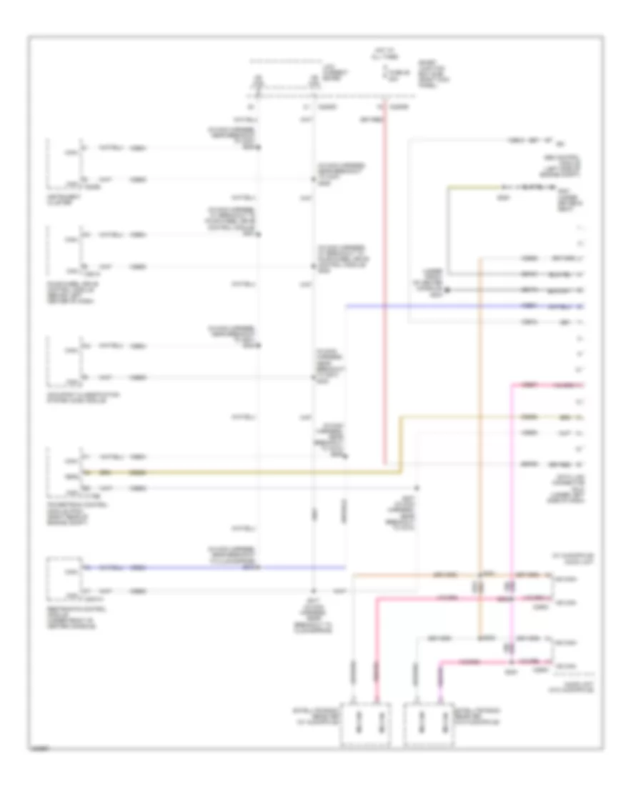
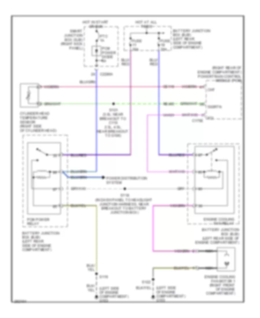
COOLING FAN
Cooling Fan Wiring Diagram for Ford Ranger 2008
List of elements for Cooling Fan Wiring Diagram for Ford Ranger 2008:
- (in dash panel to headlight junction harness, near breakout to battery junction box)
- (left side of engine compartment) g103
- (right rear of engine compartment) powertrain control module (pcm)
- Battery junction box (bjb) (left rear side of engine compartment)
- C175e
- C2280a
- Ce116
- Cht
- Cylinder head temperature sensor (right side of cylinder head)
- Engine cooling fan motor 1 (right front of engine compartment)
- Engine cooling fan relay
- Fci
- Fuse 20a
- Fuse 30a
- Hot at all times
- Hot in start or run
- Nca
- Pcm power diode 3a
- Pcm power relay
- Power distribution system
- Ptc 1a
- Re405
- S101 (3.0l: near breakout to c110 2.3l, 4.0l: near breakout to g106)
- S116
- S118
- S122
- Sigrtn
- Smart junction box (sjb) (right kick panel)
- Vh101
CRUISE CONTROL
Cruise Control Wiring Diagram for Ford Ranger 2008
List of elements for Cruise Control Wiring Diagram for Ford Ranger 2008:
- 10a
- A/t
- Brake pedal position switch (behind left side of dash, on brake pedal support)
- C175b
- C175t
- C218a
- C218c
- C220a
- C220b
- C2280a
- C2280b
- C2280d
- Cbp20
- Ccb15
- Ces03
- Ces09
- Clockspring
- Clutch pedal position switch (behind left side of dash, top of brake pedal support)
- Coast
- Deactivator switch (under left side of dash)
- Fuse 20
- Fuse 26
- Fuse 32
- Fuse 5a
- G105 (right rear of engine compartment)
- G204 (under front of center console)
- G205
- G301 (under driver's seat)
- Gd123
- Gnd
- Horns system
- Hot at all times
- Hot in run
- Illumination
- Instrument cluster
- Interior lights system
- Low current board
- M/t
- Micro- processor
- Off
- Oss
- Output shaft speed (oss) sensor (left rear of transmission)
- Powertrain control module (pcm) (right rear of engine compartment)
- Re406
- Red
- Res08
- Rest
- Resume
- Ret04
- S102 (3.0l: in engine control sensor & fuel charge harness, near breakout to c110) (except 3.0l: in engine control sensor & fuel charge harness, near breakout to g106)
- S128
- S203
- S212
- S214
- S215
- S220
- S226 (in main harness, near breakout to front cigar lighter)
- Sense
- Set
- Set ind
- Sig rtn
- Smart junction box (sjb) (right kick panel)
- Speed control ind
- Speed control on/off switch
- Speed control servo (right rear of engine compartment)
- Speed control set/ resume switch
- Vbatt
- Ves10
- Vmc05
- Vpwr
- Vref
- Vss
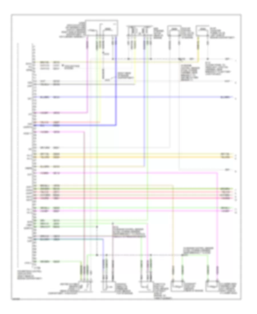
ENGINE PERFORMANCE
2.3L
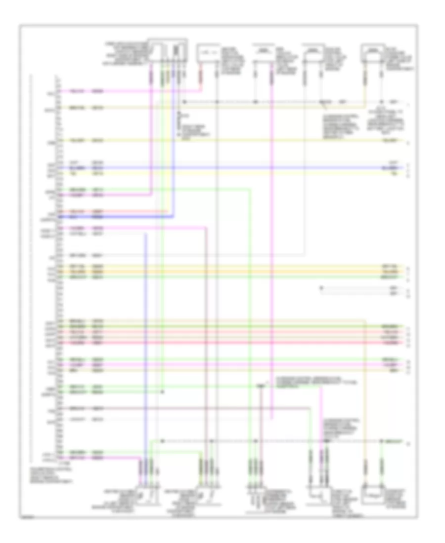
2.3L, Engine Performance Wiring Diagram (1 of 4) for Ford Ranger 2008
List of elements for 2.3L, Engine Performance Wiring Diagram (1 of 4) for Ford Ranger 2008:
- (in engine control sensor & fuel charge harness, near breakout to g106) s101
- (in engine control sensor & fuel charge harness, near breakout to heated oxygen sensor 11)
- (right rear of engine compartment)
- C175e
- Camshaft position sensor (rear of engine)
- Cd1
- Cd2
- Ce101
- Ce102
- Ce103
- Ce104
- Ce116
- Ce124
- Ce125
- Ce132
- Ce205
- Ce206
- Ce207
- Ce208
- Ce235
- Ce301
- Cht
- Ckpn
- Ckpp
- Cmp1
- Cooling fans system
- Cylinder head temperature (cht) sensor (right side of cylinder head)
- Dpfe
- Egr stepper motor (rear of engine)
- Evap canister purge valve (left side of engine compartment)
- Evmv
- Evr
- Fci
- G107
- Heated oxygen sensor (ho2s) 11 (rear of engine compartment, in exhaust)
- Ho2s 11
- Htr-11
- Iac
- Iat
- Idle air control (iac) valve (top right of engine)
- Inj 1
- Inj 2
- Inj 3
- Inj 4
- Ks1n
- Ks1p
- Le423
- Maf
- Mafrtn
- Manifold absolute pressure (map) sensor (top of engine)
- Map
- Mass air flow/intake air temperature (maf/iat) sensor (right side of engine compartment, in air cleaner assembly)
- Nca
- Powertrain control module (pcm) (right rear of engine compartment)
- Re135
- Re320
- Re323
- Re405
- S100
- S103 (in engine control sensor & fuel charge harness, near breakout to manifold absolute pressure sensor)
- S108
- S118 (in dash panel to headlight junction harness, near breakout to battery junction box)
- Sigrtn
- Throttle position (tps) sensor (top right side of engine, on throttle body)
- Tps
- Ve706
- Ve711
- Ve735
- Ve740
- Ve801
- Ve803
- Ve807
- Ve819
- Vh101
- Vref
- Vrefe
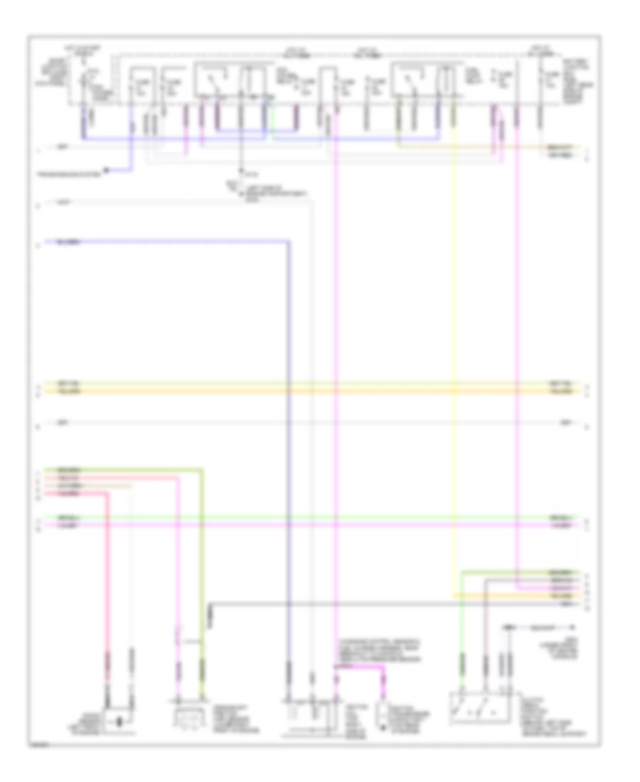
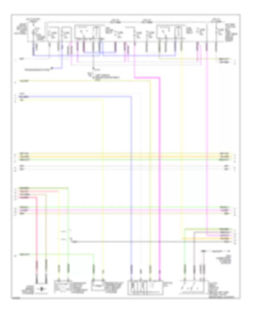
2.3L, Engine Performance Wiring Diagram (2 of 4) for Ford Ranger 2008
List of elements for 2.3L, Engine Performance Wiring Diagram (2 of 4) for Ford Ranger 2008:
- (in engine control sensor & fuel charge harness, near breakout to manifold absolute pressure sensor) s104
- (left side of engine compartment) g103
- Battery junction box (bjb) (left rear side of engine compt)
- C2280a
- Clutch pedal position switch (behind left side of dash, top of brake pedal support)
- Crankshaft position (ckp) sensor (lower right front of engine)
- Fuel pump relay
- Fuse 10a
- Fuse 15a
- Fuse 20a
- Fuse 30a
- G204 (under front of center console)
- Hot at all times
- Hot in start or run
- Ignition coil (top right side of engine)
- Ignition transformer capacitor 1 (top rear of engine)
- Knock sensor (left front of engine)
- Nca
- Pcm power diode
- Pcm power relay
- Ptc 1a
- S116
- S214
- Smart junction box (sjb) (right kick panel)
- Transmissions system
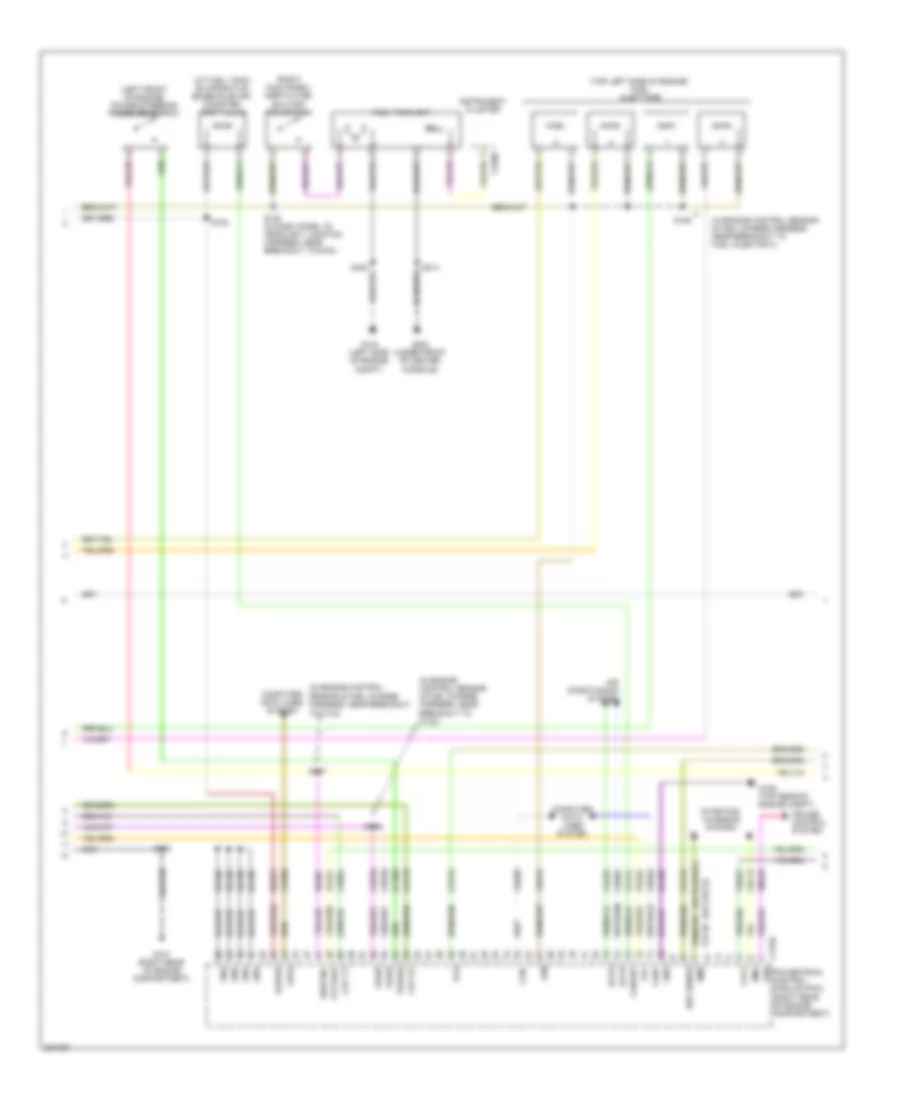
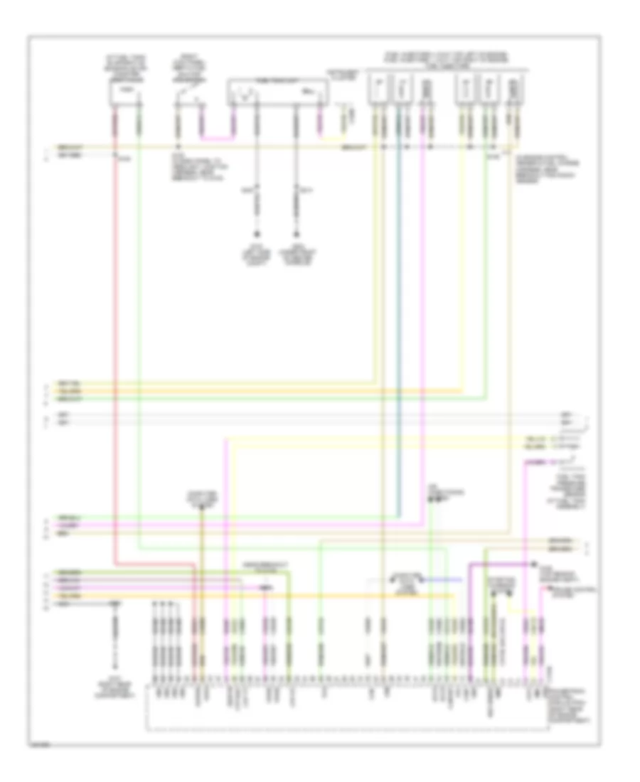
2.3L, Engine Performance Wiring Diagram (3 of 4) for Ford Ranger 2008
List of elements for 2.3L, Engine Performance Wiring Diagram (3 of 4) for Ford Ranger 2008:
- (at fuel tank) evaporative emission (evap) canister vent valve
- (in engine control sensor & fuel charge harness, near breakout
- (in engine control sensor & fuel charge harness, near breakout to c133)
- (in engine control sensor & fuel charge harness, near breakout to fuel injector 3)
- (left front of engine) power steering pressure switch
- (or cbp21)
- (right kick panel) inertia fuel shutoff (ifs) switch
- (top left side of engine) fuel injectors
- Accr
- Accs
- Air conditioning system
- Boo sense
- C175b
- C220b
- Can+
- Can-
- Canvnt
- Cbb39
- Ccb15
- Ccs09
- Cdb08
- Cdc12
- Cdc36
- Ce114
- Ce904
- Cet34
- Cet40
- Ch302
- Ch425
- Compt)
- Computer data lines system
- Console)
- Cpp bt
- Cpp tt
- Cruise control system
- Feps
- Fpc
- Fpm
- Ftpt
- Ftptref
- Fuel tank unit
- G103 (left side of engine
- G106 (top rear of engine compt)
- G107 (right rear of engine compartment)
- G204 (under front of center
- Gd108
- Gnd
- Instrument cluster
- Kapwr
- Le424
- Nca
- Powertrain control module (pcm) (right rear of engine compartment)
- Pspsw
- Re407
- S100
- S105
- S106
- S107
- S109
- S120 (in dash panel to headlight junction harness, near breakout to g102)
- S214
- Sbb21
- Sigrtnc
- Smc
- Smr
- Starting/ charging system
- Tcs
- To c133)
- Vdb04
- Vdb05
- Ve225
- Ve518
- Ve922
- Vmc05
- Vpwr
- Vss
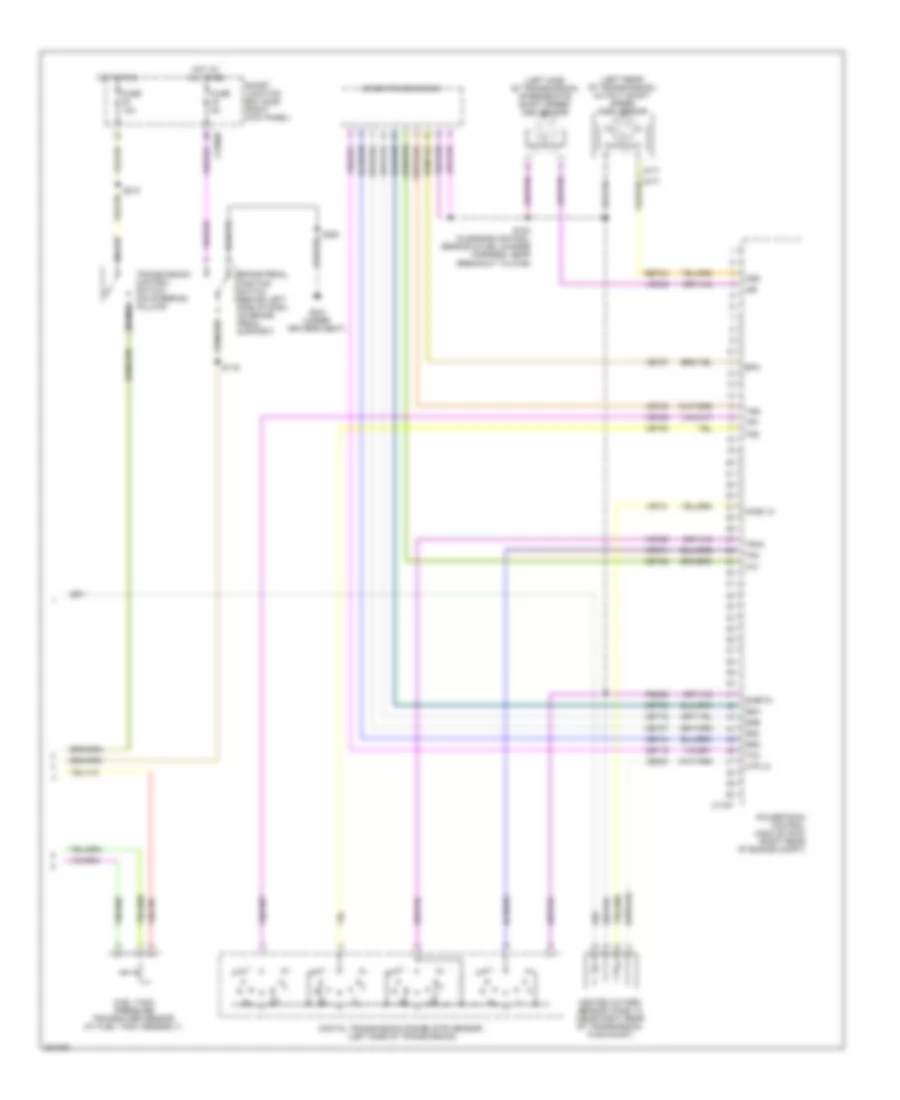
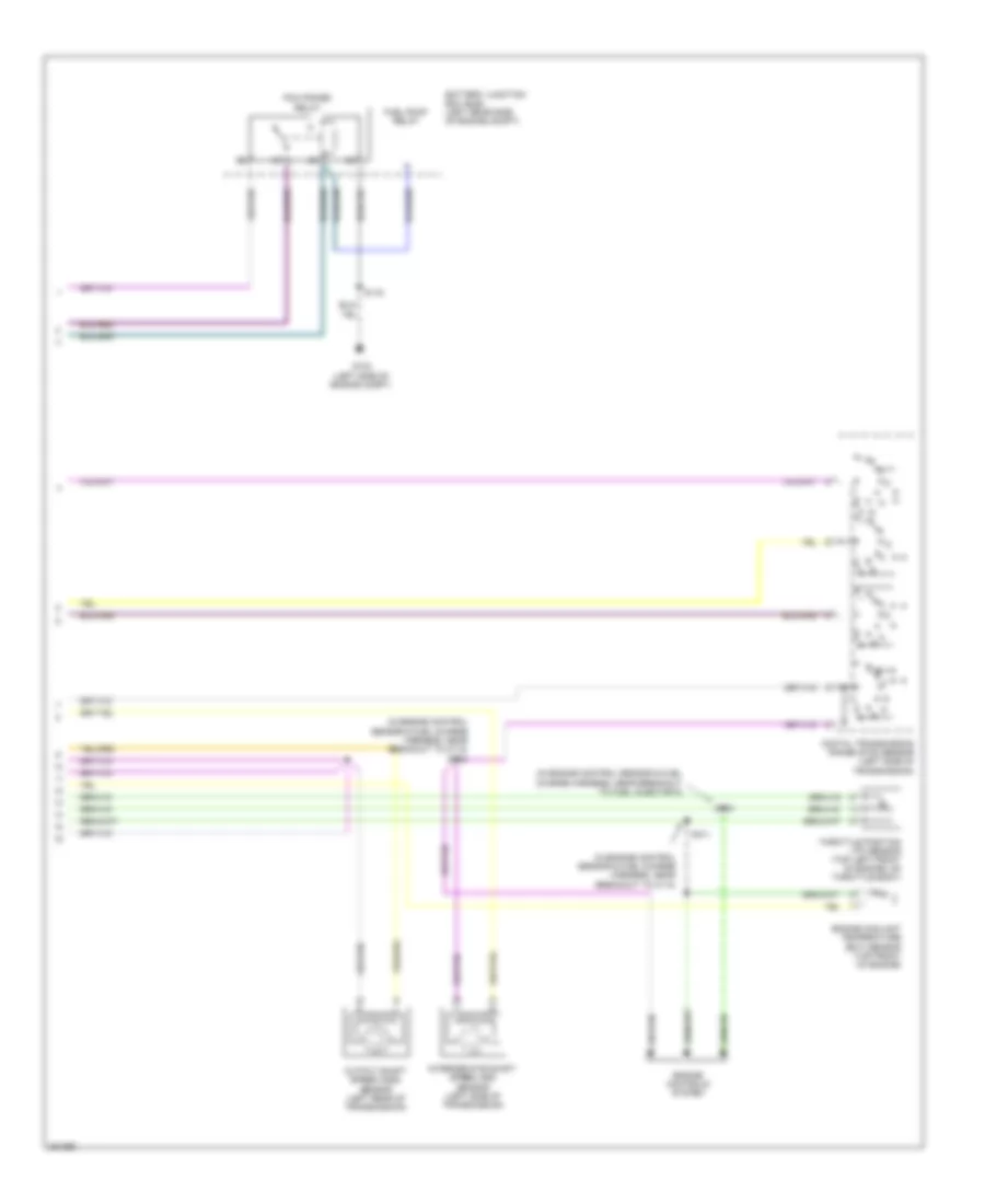
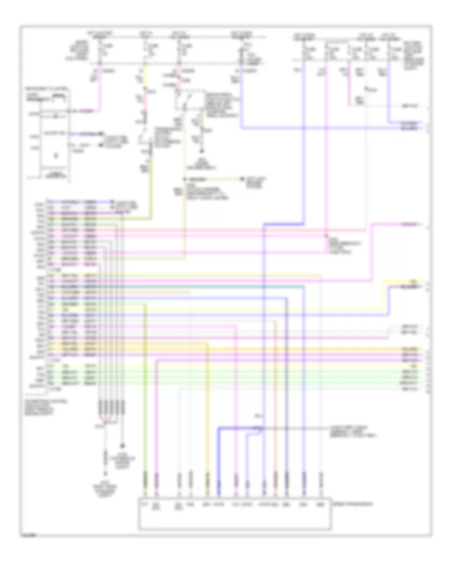
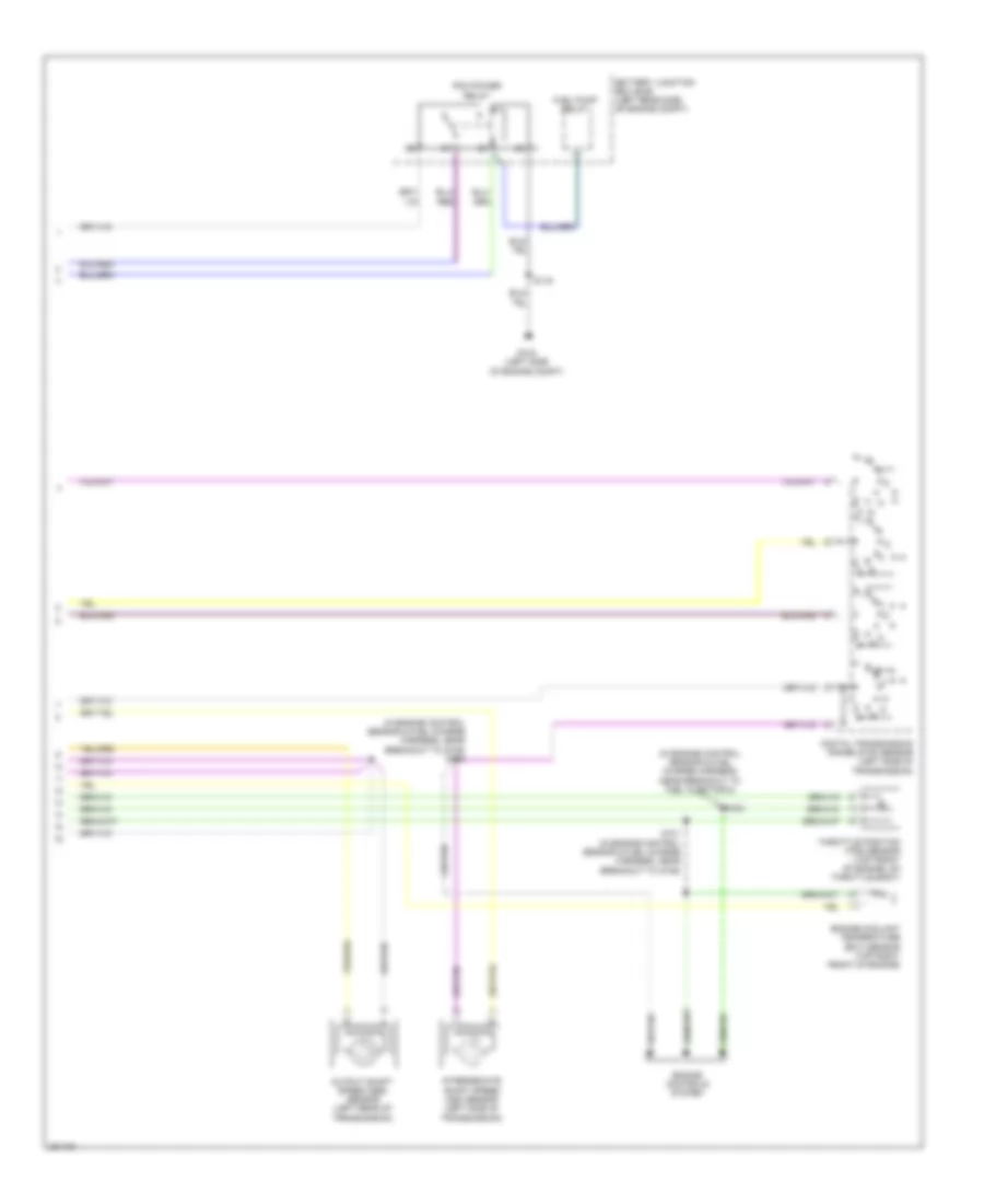
2.3L, Engine Performance Wiring Diagram (4 of 4) for Ford Ranger 2008
List of elements for 2.3L, Engine Performance Wiring Diagram (4 of 4) for Ford Ranger 2008:
- (a/t)
- (left rear of transmission) output shaft speed (oss) sensor
- (left side of transmission) intermediate shaft speed (iss) sensor
- (m/t)
- 5r44e transmission
- A nca
- Brake pedal position switch (behind left side of dash, on brake pedal support)
- C175t
- C2280b
- Ce233
- Cet05
- Cet06
- Cet07
- Cet18
- Cet19
- Cet44
- Digital transmission range (dtr) sensor (left side of transmission)
- Epc
- Fuel tank pressure transducer sensor (at fuel tank assembly)
- Fuse 10a
- Fuse 5a
- G301 (under driver's seat)
- Heated oxygen sensor (ho2s) 12 (near right rear of transmission, in exhaust)
- Ho2s 12
- Hot at all times
- Hot in run
- Htr 12
- Iss
- Nca
- Oss
- Powertrain control module (pcm) (right rear of engine compt)
- Re406
- Ret04
- S102 (in engine control sensor & fuel charge harness, near breakout to g106)
- S119
- S210
- S220
- Sigrtn
- Smart junction box (sjb) (right kick panel)
- Ssa
- Ssb
- Ssc
- Ssd
- Tcc
- Tft
- Tr1
- Tr2
- Tr3a
- Tr4
- Transmission control switch (on steering column)
- Tss
- Ve731
- Ve739
- Vet27
- Vet28
- Vet29
- Vet30
- Vet31
- Vet33
3.0L
3.0L, Engine Performance Wiring Diagram (1 of 4) for Ford Ranger 2008
List of elements for 3.0L, Engine Performance Wiring Diagram (1 of 4) for Ford Ranger 2008:
- (in dash panel to headlight junction harness, near breakout to battery junction box)
- (in engine control sensor & fuel charge harness, near breakout to c110) s101
- (in engine control sensor & fuel charge harness, near breakout to fuel injector 5)
- (in engine control sensor & fuel charge harness, near breakout to heated oxygen sensor 21)
- (right rear of engine compartment) g107
- C175e
- Camshaft position sensor (top rear of engine)
- Cda
- Cdb
- Cdc
- Ce123
- Ce124
- Ce125
- Ce132
- Ce133
- Ce205
- Ce206
- Ce207
- Ce208
- Ce209
- Ce210
- Ce235
- Ce236
- Ce301
- Ce328
- Ckpn
- Ckpp
- Cmp1
- Differential pressure feedback (dpfe) sensor (top left rear of engine)
- Dpfe
- Ect
- Egr vacuum regulator solenoid valve (left rear of engine)
- Evap canister purge valve (left side of engine compartment)
- Evmv
- Evr
- Heated oxygen sensor (ho2s) 11 (right rear of engine compartment, in exhaust)
- Heated oxygen sensor (ho2s) 21 (in left rear of engine compartment, in exhaust)
- Heated positive crankcase ventilation (pcv) valve (top rear of engine)
- Ho2s 11
- Ho2s 21
- Htr 11
- Htr 21
- Iac
- Iat
- Idle air control (iac) valve (top left front of engine)
- Inj1
- Inj2
- Inj3
- Inj4
- Inj5
- Inj6
- Ks1n
- Ks1p
- Le423
- Maf
- Mafrtn
- Mass air flow/intake air temperature (maf/iat) sensor (right side of engine compartment, in air cleaner assembly)
- Nca
- Pcv
- Powertrain control module (pcm) (right rear of engine compartment)
- Re135
- Re320
- Re323
- Re405
- S103
- S108
- S118
- Sigrtn
- Throttle position (tps) sensor (top left front of engine, on throttle body)
- Tps
- Ve706
- Ve711
- Ve713
- Ve716
- Ve735
- Ve737
- Ve740
- Ve801
- Ve807
- Ve819
- Vref
3.0L, Engine Performance Wiring Diagram (2 of 4) for Ford Ranger 2008
List of elements for 3.0L, Engine Performance Wiring Diagram (2 of 4) for Ford Ranger 2008:
- (left side of engine compartment) g103
- Battery junction box (bjb) (left rear side of engine compt)
- C2280a
- Clutch pedal position switch (behind left side of dash, top of brake pedal support)
- Crankshaft position sensor (lower front of engine)
- Engine coolant temperature (ect) sensor (top front of engine)
- Fuel pump relay
- Fuse 10a
- Fuse 15a
- Fuse 20a
- Fuse 30a
- G204 (under front of center console)
- Hot at all times
- Hot in start or run
- Ignition coil
- Knock sensor (right side of engine)
- Nca
- Pcm power diode
- Pcm power relay
- Ptc 1a
- S116
- S214
- Smart junction box (sjb) (right kick panel)
- Transmissions system
3.0L, Engine Performance Wiring Diagram (3 of 4) for Ford Ranger 2008
List of elements for 3.0L, Engine Performance Wiring Diagram (3 of 4) for Ford Ranger 2008:
- (at fuel tank) evaporative emission (evap) canister vent valve
- (fuel injectors 4, 5 & 6: top left of engine) (fuel injectors 1, 2 & 3: top right of engine) fuel injectors
- (in engine control sensor & fuel charge harness, near breakout for knock sensor)
- (near breakout to c133)
- (or cbp21)
- (right kick panel) inertia fuel shutoff (ifs) switch
- Accr
- Accs
- Air conditioning system
- Boo sense
- C175b
- C220b
- Can+
- Can-
- Canvnt
- Cbb39
- Ccb15
- Cdb08
- Cdc12
- Cdc36
- Ce114
- Ce904
- Cet34
- Cet40
- Ch302
- Ch425
- Computer data lines system
- Cpp bt
- Cpp tt
- Cruise control system
- Feps
- Fpc
- Fpm
- Ftpt
- Ftptref
- Fuel tank pressure transducer sensor (at fuel tank assembly)
- Fuel tank unit
- G103 (left side of engine compt)
- G106 (top rear of engine compt)
- G107 (right rear of engine compartment)
- G204 (under front of center console)
- Gd108
- Gnd
- Instrument cluster
- Kapwr
- Le424
- Nca
- Powertrain control module (pcm) (right rear of engine compartment)
- Re407
- S100
- S105
- S106
- S109
- S120 (in dash panel to headlight junction harness, near breakout to g102)
- S214
- Sbb21
- Sigrtn
- Smc
- Smr
- Starting/ charging system
- Tcs
- Vdb04
- Vdb05
- Ve225
- Ve518
- Ve922
- Vmc05
- Vpwr
- Vss
3.0L, Engine Performance Wiring Diagram (4 of 4) for Ford Ranger 2008
List of elements for 3.0L, Engine Performance Wiring Diagram (4 of 4) for Ford Ranger 2008:
- (left rear of transmission) output shaft speed (oss) sensor
- (left side of transmission) intermediate shaft speed (iss) sensor
- 5r44e transmission
- A nca
- Brake pedal position switch (behind left side of dash, on brake pedal support)
- C175t
- C2280b
- Ce233
- Ce234
- Cet05
- Cet06
- Cet07
- Cet18
- Cet19
- Cet44
- Digital transmission range (dtr) sensor (left side of transmission)
- Fuse 10a
- Fuse 5a
- G301 (under driver's seat)
- Heated oxygen sensor (ho2s) 12 (near right rear of transmission, in exhaust)
- Heated oxygen sensor (ho2s) 22 (m/t: near left side of transmission, in exhaust)
- Ho2s 12
- Ho2s 22
- Hot at all times
- Hot in run
- Htr 12
- Htr 22
- Iss
- Nca
- Oss
- Pca
- Powertrain control module (pcm) (right rear of engine compt)
- Re406
- Ret04
- S102 (in engine control sensor & fuel charge harness, near breakout to c110)
- S119
- S210
- Sigrtn
- Smart junction box (sjb) (right kick panel)
- Ssa
- Ssb
- Ssc
- Ssd
- Tcc
- Tft
- Tr1
- Tr2
- Tr3a
- Tr4
- Transmission control switch (on steering column)
- Tss
- Ve731
- Ve733
- Ve739
- Vet27
- Vet28
- Vet29
- Vet30
- Vet31
- Vet33
4.0L
4.0L, Engine Performance Wiring Diagram (1 of 4) for Ford Ranger 2008
List of elements for 4.0L, Engine Performance Wiring Diagram (1 of 4) for Ford Ranger 2008:
- (in engine control sensor & fuel charge harness, near breakout to fuel injector 5)
- (in engine control sensor & fuel charge harness, near breakout to g106) s101
- (near breakout to heated oxygen sensor 21)
- (right rear of engine compartment) g107
- C175e
- Camshaft position sensor (top left of engine)
- Cda
- Cdb
- Cdc
- Ce123
- Ce124
- Ce125
- Ce132
- Ce133
- Ce205
- Ce206
- Ce207
- Ce208
- Ce209
- Ce210
- Ce235
- Ce236
- Ce301
- Ce328
- Ckpn
- Ckpp
- Cmp1
- Cooling fans system
- Differential pressure feedback (dpfe) sensor (top left rear of engine)
- Dpfe
- Ect
- Egr vacuum regulator solenoid valve (top left side of engine)
- Evap canister purge valve (left side of engine compartment)
- Evmv
- Evr
- Fci
- Heated oxygen sensor (ho2s) 11 (right rear of engine, in exhaust)
- Heated oxygen sensor (ho2s) 21 (in left rear of engine compartment, in exhaust)
- Heated positive crankcase ventilation (pcv) valve (top left rear of engine)
- Ho2s 11
- Ho2s 21
- Htr 11
- Htr 21
- Iac
- Iat
- Idle air control (iac) valve (top of engine)
- Inj1
- Inj2
- Inj3
- Inj4
- Inj5
- Inj6
- Ks1n
- Ks1p
- Le423
- Maf
- Mafrtn
- Mass air flow/intake air temperature (maf/iat) sensor (right side of engine compartment, in air cleaner assembly)
- Nca
- Pcv
- Powertrain control module (pcm) (right rear of engine compartment)
- Re135
- Re320
- Re323
- Re405
- S103
- S108
- S118 (near breakout to battery junction box)
- Sigrtn
- Throttle position (tps) sensor (top front of engine, on throttle body)
- Tps
- Ve706
- Ve711
- Ve713
- Ve716
- Ve735
- Ve737
- Ve740
- Ve801
- Ve807
- Ve819
- Vh101
- Vref
4.0L, Engine Performance Wiring Diagram (2 of 4) for Ford Ranger 2008
List of elements for 4.0L, Engine Performance Wiring Diagram (2 of 4) for Ford Ranger 2008:
- (left side of engine compartment) g103
- (near breakout to fuel injector 6) s104
- Battery junction box (bjb) (left rear side of engine compt)
- C2280a
- Clutch pedal position switch (behind left side of dash, top of brake pedal support)
- Crankshaft position sensor (lower front of engine)
- Engine coolant temperature (ect) sensor (top right front of engine)
- Fuel pump relay
- Fuse 10a
- Fuse 15a
- Fuse 20a
- Fuse 30a
- G204 (under front of center console)
- Hot at all times
- Hot in start or run
- Ignition coil
- Ignition transformer capacitor 1 (top left side of engine)
- Knock sensor (top center of engine)
- Nca
- Pcm power diode
- Pcm power relay
- Ptc 1a
- S116
- S214
- Smart junction box (sjb) (right kick panel)
- Transmissions system
4.0L, Engine Performance Wiring Diagram (3 of 4) for Ford Ranger 2008
List of elements for 4.0L, Engine Performance Wiring Diagram (3 of 4) for Ford Ranger 2008:
- (at fuel tank) evaporative emission (evap) canister vent valve
- (fuel injectors 4, 5, 6: top left of engine) (fuel injectors 1, 2, 3: top right of engine) fuel injectors
- (in engine control sensor & fuel charge harness, near breakout to heated oxygen sensor 11)
- (near breakout to fuel injector 6)
- (or cbp21)
- (right kick panel) inertia fuel shutoff (ifs) switch
- Accr
- Accs
- Air conditioning system
- Boo sense
- C175b
- C220b
- Can+
- Can-
- Canvnt
- Cbb39
- Ccb15
- Cdb08
- Cdc12
- Cdc36
- Ce114
- Ce904
- Cet34
- Cet40
- Ch302
- Ch425
- Computer data lines system
- Cpp bt
- Cpp tt
- Cruise control system
- Feps
- Fpc
- Fpm
- Ftpt
- Ftptref
- Fuel tank pressure transducer sensor (at fuel tank assembly)
- Fuel tank unit
- G103 (left side of engine compt)
- G106 (top rear of engine compt)
- G107 (right rear of engine compartment)
- G204 (under front of center console)
- Gd108
- Gnd
- Instrument cluster
- Kapwr
- Le424
- Nca
- Powertrain control module (pcm) (right rear of engine compartment)
- Re407
- S100
- S105
- S106
- S109
- S120 (in dash panel to headlight junction harness, near breakout to g102)
- S214
- Sbb21
- Sigrtn
- Smc
- Smr
- Starting/ charging system
- Tcs
- Vdb04
- Vdb05
- Ve225
- Ve518
- Ve922
- Vmc05
- Vpwr
- Vs out
4.0L, Engine Performance Wiring Diagram (4 of 4) for Ford Ranger 2008
List of elements for 4.0L, Engine Performance Wiring Diagram (4 of 4) for Ford Ranger 2008:
- (left rear of transmission) output shaft speed (oss) sensor
- (left side of transmission) intermediate shaft speed (iss) sensor
- 5r55e transmission
- A nca
- Brake pedal position switch (behind left side of dash, on brake pedal support)
- C175t
- C2280b
- Ce233
- Ce234
- Cet05
- Cet06
- Cet07
- Cet18
- Cet19
- Cet44
- Digital transmission range (dtr) sensor (left side of transmission)
- Fuse 10a
- Fuse 5a
- G301 (under driver's seat)
- Heated oxygen sensor (ho2s) 12 (near right rear of transmission, in exhaust)
- Heated oxygen sensor (ho2s) 22 (near left side of transmission, in exhaust)
- Ho2s 12
- Ho2s 22
- Hot at all times
- Hot in run
- Htr 12
- Htr 22
- Iss
- Nca
- Oss
- Pca
- Powertrain control module (pcm) (right rear of engine compt)
- Re406
- Ret04
- S102 (in engine control sensor & fuel charge harness, near breakout to g106)
- S119
- S210
- Sigrtn
- Smart junction box (sjb) (right kick panel)
- Ssa
- Ssb
- Ssc
- Ssd
- Tcc
- Tft
- Tr1
- Tr2
- Tr3a
- Tr4
- Transmission control switch (on steering column)
- Tss
- Ve731
- Ve733
- Ve739
- Vet27
- Vet28
- Vet29
- Vet30
- Vet31
- Vet33
EXTERIOR LIGHTS
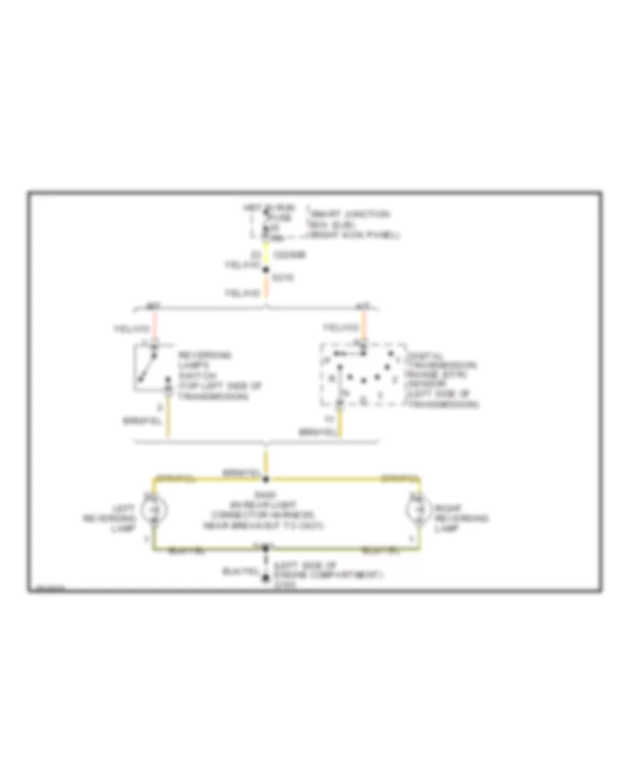
Back-up Lamps Wiring Diagram for Ford Ranger 2008
List of elements for Back-up Lamps Wiring Diagram for Ford Ranger 2008:
- (left side of engine compartment) g103
- A/t
- C2280b
- Digital transmission range (dtr) sensor (left side of transmission)
- Hot in run fuse 10a
- Left reversing lamp
- M/t
- Reversing lamps switch (top left side of transmission)
- Right reversing lamp
- S210
- S400 (in rear light connector harness, near breakout to c421)
- S401
- Smart junction box (sjb) (right kick panel)
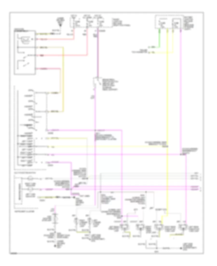
Exterior Lamps Wiring Diagram (1 of 2) for Ford Ranger 2008
List of elements for Exterior Lamps Wiring Diagram (1 of 2) for Ford Ranger 2008:
- (in main harness, near breakout to c210) s201
- (in main harness, near breakout to c210) s202
- (in main harness, near breakout to deactivator switch) s204
- (in main harness, near breakout to deactivator switch) s205
- (in rear light connector harness, near breakout to c421)
- (in rear light connector harness, near breakout to c421) s405
- (left side of engine compartment) g103
- (not used)
- (under driver's seat) g301
- Battery junction box (bjb) (left rear side of engine compt)
- Brake pedal position switch (behind left side of dash, on brake pedal support)
- C202a
- C202b
- C220a
- C2280b
- Except stx
- Fuse 10a
- Fuse 15a
- Fuse 20a
- Fuse 7.5a
- G301 (under driver's seat)
- Hazard
- High mounted stoplamp
- Hot at all times
- Hot in run
- Indicator flasher relay
- Instrument cluster
- Left license plate lamp
- Left rear park/stop lamp
- Left rear park/stop/ turn lamp
- Left turn
- Left turn indicator
- Microprocessor
- Multi-function switch
- Off
- Red
- Right license plate lamp
- Right rear park/ stop lamp
- Right rear park/stop/ turn lamp
- Right turn
- Right turn indicator
- S220
- S220 (except four door model)
- S302 (four door model)
- S401
- S402
- S403
- S404 (in taillight harness, near breakout to c421)
- Smart junction box (sjb) (right kick panel)
- Stx
- Trailer tow connector
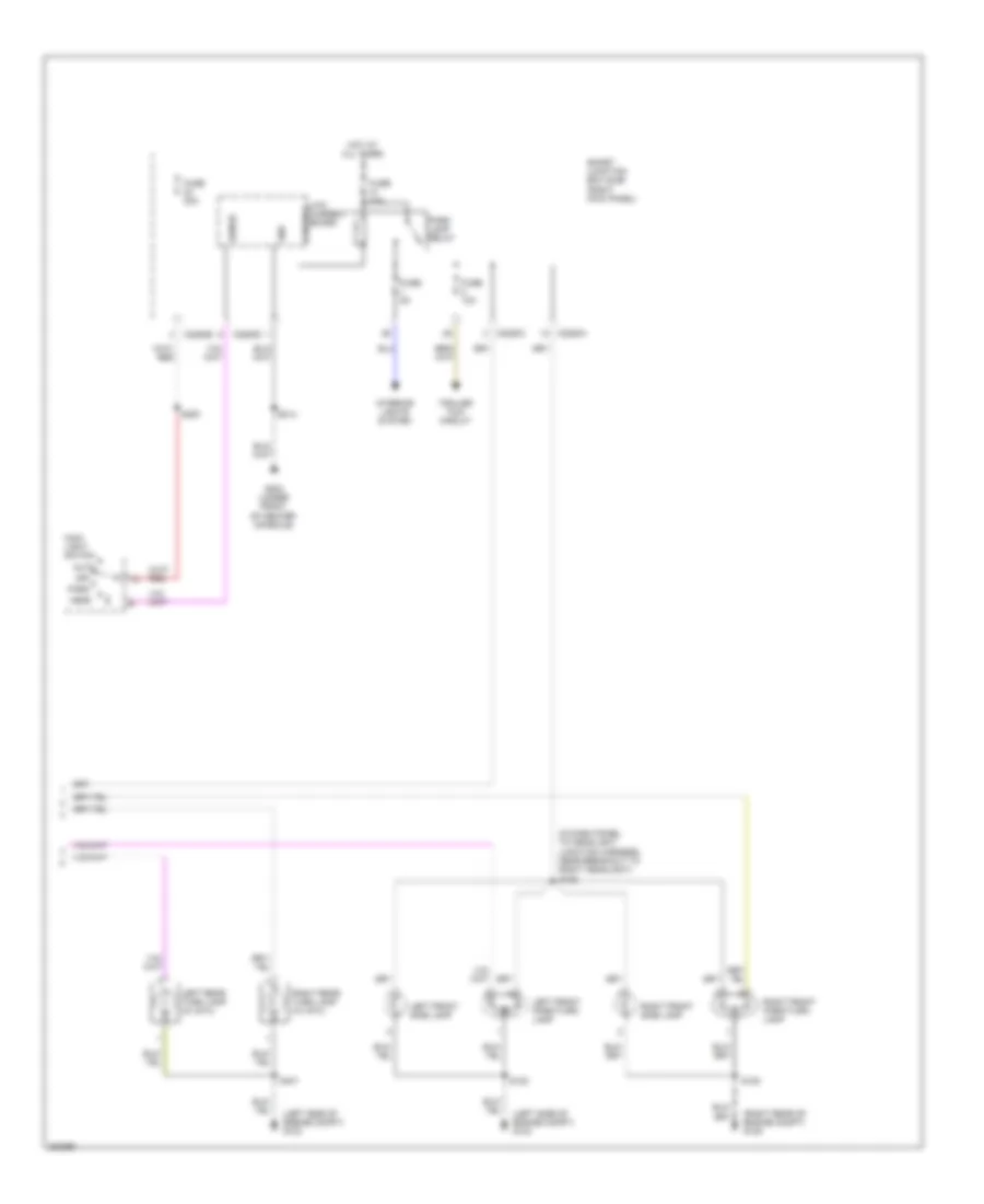
Exterior Lamps Wiring Diagram (2 of 2) for Ford Ranger 2008
List of elements for Exterior Lamps Wiring Diagram (2 of 2) for Ford Ranger 2008:
- (in dash panel to headlight junction harness, near breakout to right headlight) s126
- (left side of engine compt) g103
- (right rear of engine compt) g105
- Auto
- C2280a
- C2280b
- C2280c
- C2280d
- Control
- Fuse 10a
- Fuse 20a
- Fuse 30a
- Fuse 5a
- G204 (under front of center console)
- Gnd
- Head
- Hot at all times
- Interior lights system
- Left front park/turn lamp
- Left front side lamp
- Left rear turn lamp (w/ stx)
- Low current board
- Main light switch
- Off
- Park
- Park lamp relay
- Right front park/turn lamp
- Right front side lamp
- Right rear turn lamp (w/ stx)
- S122
- S128
- S200
- S214
- S401
- Sense
- Smart junction box (sjb) (right kick panel)
- Trailer tow circuit
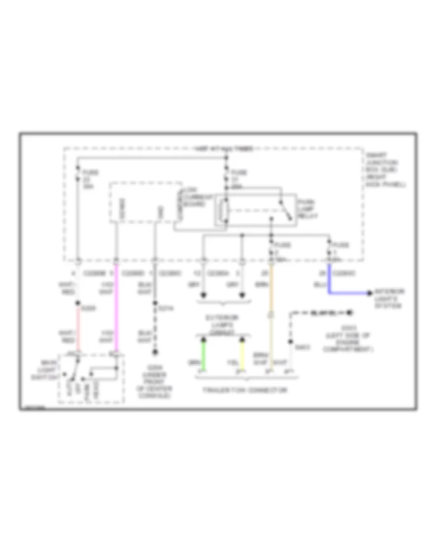
Trailer Tow Wiring Diagram for Ford Ranger 2008
List of elements for Trailer Tow Wiring Diagram for Ford Ranger 2008:
- Auto
- C2280a
- C2280b
- C2280c
- C2280d c2280c
- Control
- Exterior lamps circuit
- Fuse 10a
- Fuse 20a
- Fuse 30a
- Fuse 5a
- G103 (left side of engine compartment)
- G204 (under front of center console)
- Gnd
- Head
- Hot at all times
- Interior lights system
- Low current board
- Main light switch
- Off
- Park
- Park lamp relay
- S200
- S214
- S403
- Sense
- Smart junction box (sjb) (right kick panel)
- Trailer tow connector
GROUND DISTRIBUTION
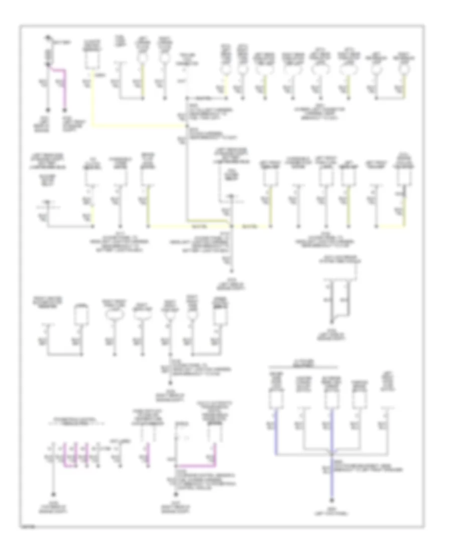
Ground Distribution Wiring Diagram (1 of 2) for Ford Ranger 2008
List of elements for Ground Distribution Wiring Diagram (1 of 2) for Ford Ranger 2008:
- (2.3l) engine cooling fan motor
- (4x4 w/ automatic transmission) digital transmission range (dtr) sensor
- (left rear side of engine compt) battery junction box (bjb)
- (not used)
- (stx) left rear park/stop lamp
- (stx) left rear turn lamp
- (stx) right rear park/stop lamp
- (stx) right rear turn lamp
- A/c clutch field coil
- Anti-lock brake system (abs) module
- Battery
- Blower motor relay
- Brake fluid level switch
- C175b
- C294c
- Climate control assembly
- Driver side door lock switch
- Exterior rear view mirror switch
- Front heated blower motor resistor
- Fuel tank unit
- Fuel tank unit)
- G100 (left front of engine compt)
- G101 (left rear of engine)
- G102 (left side of engine compt)
- G103 (left side of engine compt)
- G105 (right rear of engine compt)
- G106 (top rear of engine compt)
- G107 (right rear of engine compt)
- G200 (left kick panel)
- Horn
- Left front door ajar switch
- Left front fog lamp
- Left front park/turn lamp
- Left front side lamp
- Left headlamp
- Left license plate lamp
- Left rear park/stop/ turn lamp
- Left reversing lamp
- Mass air flow/ intake air temperature (maf/iat) sensor
- Master window adjust switch
- Nca
- Parking brake switch
- Pcm power relay
- Powertrain control module (pcm)
- Right front fog lamp
- Right front park/turn lamp
- Right front side lamp
- Right headlamp
- Right license plate lamp
- Right rear park/stop/ turn lamp
- Right reversing lamp
- S116 (in dash panel to headlight junction harness, near breakout to battery junction box)
- S117 (in dash panel to headlight junction harness, near breakout to battery junction box)
- S122 (in dash panel to headlight junction harness, near breakout to c139)
- S401 (in rear light connector harness, near breakout to c421)
- Shield
- Speed control servo
- Trailer tow connector
- W/ power equipment
- Windshield washer pump motor
- Windshield wiper motor
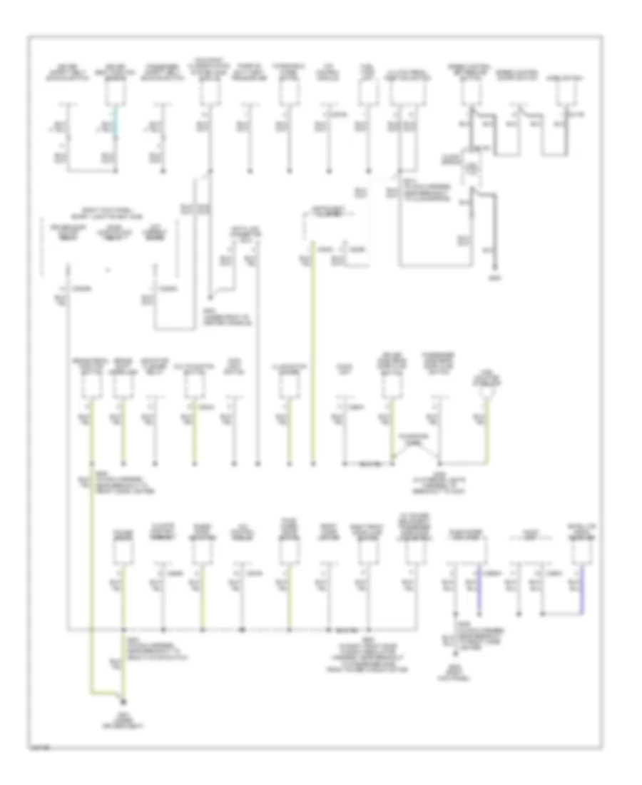
Ground Distribution Wiring Diagram (2 of 2) for Ford Ranger 2008
List of elements for Ground Distribution Wiring Diagram (2 of 2) for Ford Ranger 2008:
- (right kick panel) smart junction box (sjb)
- (w/ power equipment) passenger side door lock switch
- 4x4 control module
- Audio unit
- Blend door actuator
- Brake pedal position switch
- Brake shift interlock
- C202a
- C217b
- C218c
- C220a
- C220b
- C2280b
- C2280c
- C281b
- C290a
- C294b
- C2982a
- Climate control assembly
- Clock- spring
- Clutch pedal position switch
- Data link connector (dlc)
- Door lock/unlock relay
- Driver door unlock relay
- Driver safety belt buckle switch
- Driver seat position sensor
- Driver side rear door ajar switch
- Four- wheel drive switch
- Four-door model
- Front cigar lighter
- Fuel tank unit
- G202 (right kick panel)
- G204 (under front of center console)
- G205
- G301 (under driver's seat)
- High mounted stoplamp
- Horn switch
- Illumination dimmer
- Indicator flasher relay
- Instrument cluster
- Low current board
- Main light switch
- Multifunction switch
- Occupant classification system (ocs) module
- Passenger safety belt buckle switch
- Passenger side rear door ajar switch
- Passive anti-theft transceiver
- Power point
- Right front door ajar switch
- S203 (in main harness, near breakout to deactivator switch)
- S214 (in main harness, near breakout to clockspring)
- S220 (in main harness, near breakout to front cigar lighter)
- S302 (in interior lights harness, at breakout to c327)
- S600 (in right front door window regulator harness, near breakout to passenger side front power window motor)
- Satellite radio receiver
- Speed control on/off switch
- Speed control set/resume switch
- Subwoofer amplifier
- Windshield wiper motor
HEADLIGHTS
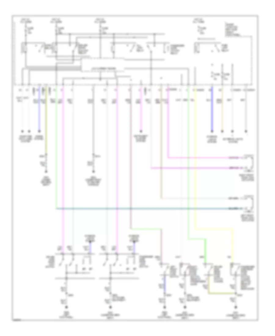
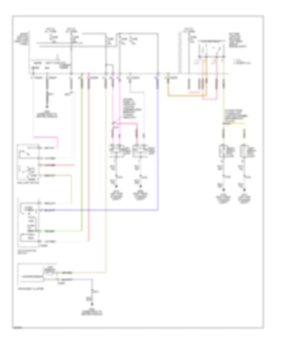
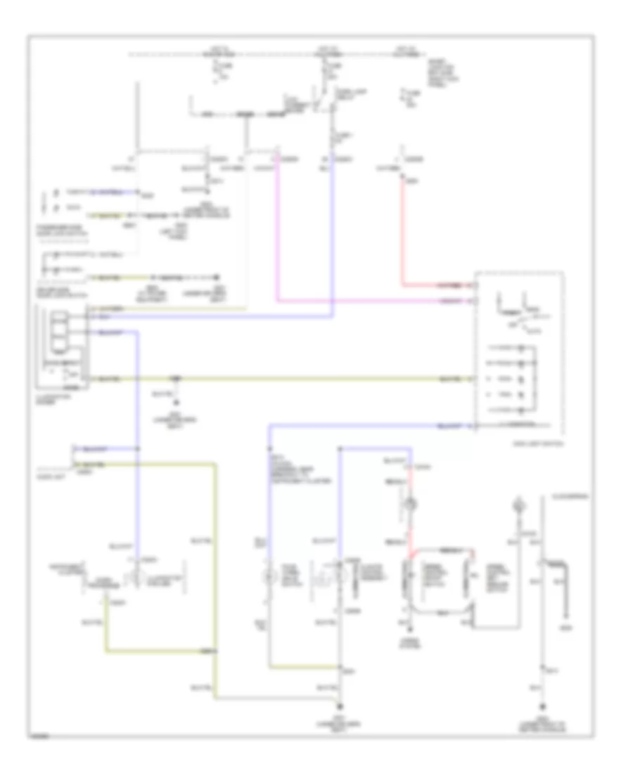
Headlights Wiring Diagram, with DRL for Ford Ranger 2008
List of elements for Headlights Wiring Diagram, with DRL for Ford Ranger 2008:
- (in dash panel to headlight junction harness, near breakout to c139) s125
- (in main harness, near breakout to c237) s230
- (left kick panel) g200
- (near breakout to right headlight)
- (right kick panel) smart junction box (sjb)
- 2.3l
- Auto
- Battery junction box (bjb) (left rear side of engine compt)
- C202b
- C220b
- C2280b
- C2280c
- C2280d
- Can+
- Can-
- Computer data lines system
- Ctrl
- Drl driver
- Except 2.3l
- Flash to pass
- Fog
- Fog lamp relay
- Fuse 10a
- Fuse 15a
- Fuse 30a
- G103 (left side of engine compt)
- G103 g103 (left side of engine compt)
- G105 (right rear of engine compt)
- G204 (under front of center console)
- Gnd
- Head
- High
- High beam ind
- Hot at all times
- Instrument cluster
- Left front fog lamp
- Left head- lamp
- Low
- Low current board
- Main light switch
- Microprocessor
- Multi-function switch
- Off
- Park
- Parking brake switch (below left side of dash, on park brake assembly)
- Pwm
- Right front fog lamp
- Right head- lamp
- S122
- S127
- S128
- S200
- S229 (in main harness, near breakout to c237)
- S500
- Sense
- Vbatt
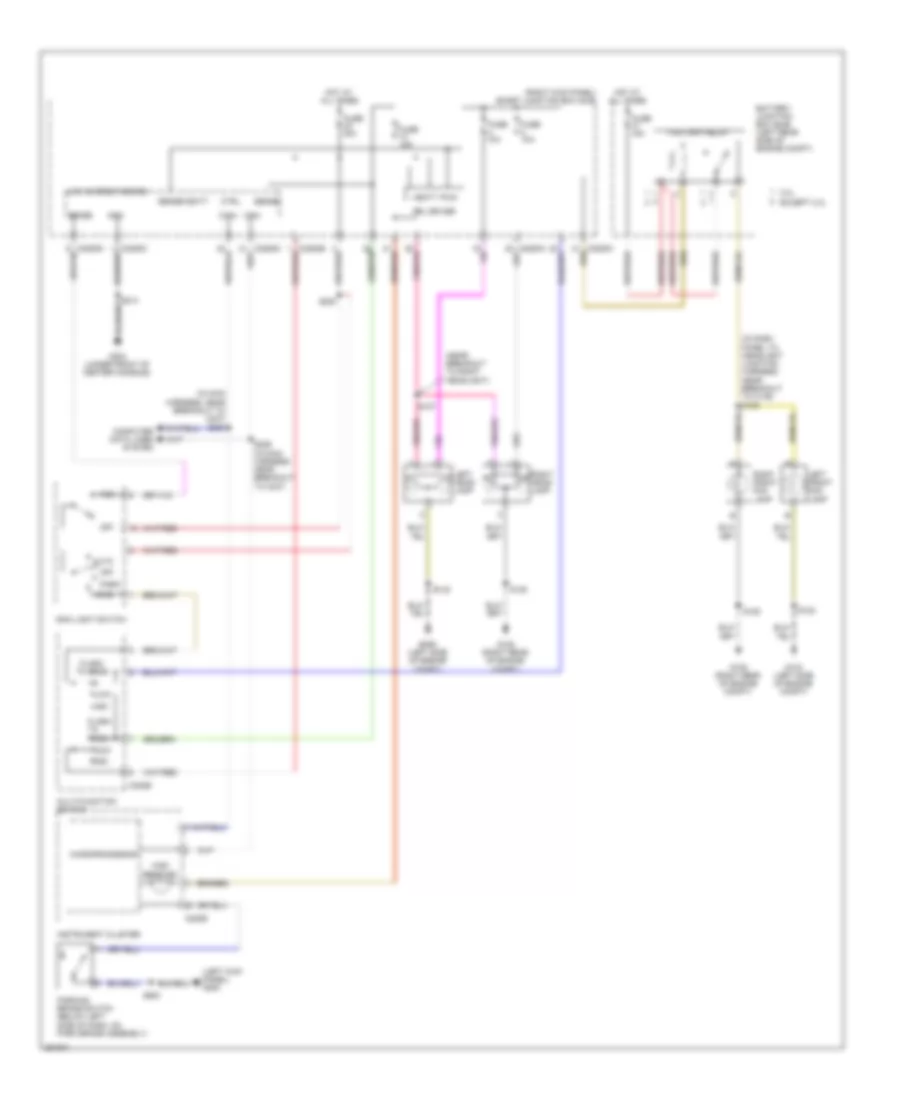
Headlights Wiring Diagram, without DRL for Ford Ranger 2008
List of elements for Headlights Wiring Diagram, without DRL for Ford Ranger 2008:
- (in dash panel to headlight junction harness, near breakout to c139) s125
- (in dash panel to headlight junction harness, near breakout to right headlight)
- 2.3l
- Auto
- Battery junction box (bjb) (left rear side of engine compt)
- C202b
- C220b
- C2280a
- C2280c
- C2280d
- Ctrl
- Except 2.3l
- Flash to pass
- Fog lamp relay
- Fuse 10a
- Fuse 15a
- Fuse 30a
- G103 (left side of engine compt)
- G105 (right rear of engine compt)
- G105 g105 (right rear of engine compt)
- G204 (under front of center console)
- Gnd
- Head
- High
- High beam ind
- Hot at all times
- Instrument cluster
- Left front fog lamp
- Left head- lamp
- Low
- Low current board
- Main light switch
- Microprocessor
- Multi-function switch
- Off
- Park
- Right front fog lamp
- Right head- lamp
- S122
- S127
- S128
- S200
- S214
- Sense
- Smart junction box (sjb) (right kick panel)
- Vbatt
HORN
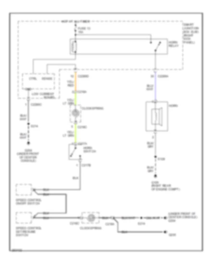
Horn Wiring Diagram for Ford Ranger 2008
List of elements for Horn Wiring Diagram for Ford Ranger 2008:
- (under front of center console) g204
- C217a
- C217b
- C218a
- C218c
- C2280a
- C2280c
- C2280d
- Clockspring
- Ctrl
- Fuse 13 15a
- G105 (right rear of engine compt)
- G204 (under front of center console)
- G205
- Gnd
- Horn
- Horn relay
- Horn switch
- Hot at all times
- Low current board
- S128
- S214
- Sense
- Smart junction box (sjb) (right kick panel)
- Speed control on/off switch
- Speed control set/resume switch
INSTRUMENT CLUSTER
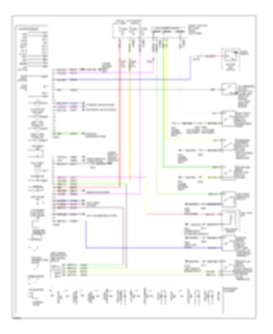
Instrument Cluster Wiring Diagram for Ford Ranger 2008
List of elements for Instrument Cluster Wiring Diagram for Ford Ranger 2008:
- (left side of engine compt) abs control module
- (under driver's seat) g301
- (under front of center console) g204
- (w/ power equipment)
- 4wd ind
- 4wd low
- 4x4 status
- 4x4 sts
- A11
- A12
- A13
- A20
- Abs ind
- Anti-lock brakes system
- Anti-theft on ind
- Anti-theft system
- B10
- B11
- B12
- B14
- B15
- B16
- B18
- B20
- Brake fluid level switch (left rear of engine compt, on brake fluid reservoir)
- Brkl
- Brks
- C218a
- C220a
- C220b
- C2280b
- C2280c
- C2280d
- Can+
- Can-
- Cap ind
- Cbp09
- Cbp10
- Cca01
- Cca02
- Ccb09
- Ccf23
- Cdc30
- Charge ind
- Check engine
- Check fuel
- Clock spring
- Cls39
- Cls41
- Cmc19
- Cmc24
- Computer data lines system
- Coolant temperature gauge
- Cpl12
- Driver side rear door ajar switch (4 door)
- Ebd wl
- Exterior lights system
- Failsafe cooling ind
- Fluid level in
- Fluid level status
- Fog lamps
- Fuel gauge ind
- Fuel gauge sensor
- Fuel tank unit
- Fuse 10a
- Fuse 5a
- G103 (left side of engine compt)
- G200 (left kick panel)
- G204 (under front of center console)
- G301 (under driver's seat)
- Gd161
- Gd174
- Gnd
- Headlights system
- High beam ind
- Hot at all times
- Hot in start or run
- Ignition key switch
- Illumination (6 bulbs)
- Ind
- Ind air bag
- Ind door ajar
- Ind o/d off
- Instrument cluster
- Interior lights system
- Left front door ajar switch
- Left turn signal ind
- Low brake fluid level/ park brake ind
- Low current board
- Low oil pressure ind
- Microprocessor
- Odometer/ tripmeter
- Oil pressure switch (except 3.0l: lower left front of engine) (3.0l: right rear of engine)
- Parking brake switch (below left side of dash, on park brake assembly)
- Passenger side rear door ajar switch (4 door) (bottom rear of right rear door)
- Prndl
- Red
- Right front door ajar switch (rear of passenger's door)
- Right turn signal ind
- Rmc19
- Rx in
- S117
- S212 (w/ 4x4)
- S214
- S220
- S223 (w/ 4x4)
- S228
- S302
- S500
- S600 s203 (w/o power equipment)
- Safety belt
- Sbp33
- Sbr14
- Sense
- Smart junction box (sjb) (right kick panel)
- Speed control ind
- Speedometer
- Starting/ charging system
- Tachometer
- Tx out
- Vbatt
- Vdb04
- Vdb05
- Vdc42
- Vln18
- Vmc11
- Vpl56
- Vpwr
- Vrt07
- Warning chime
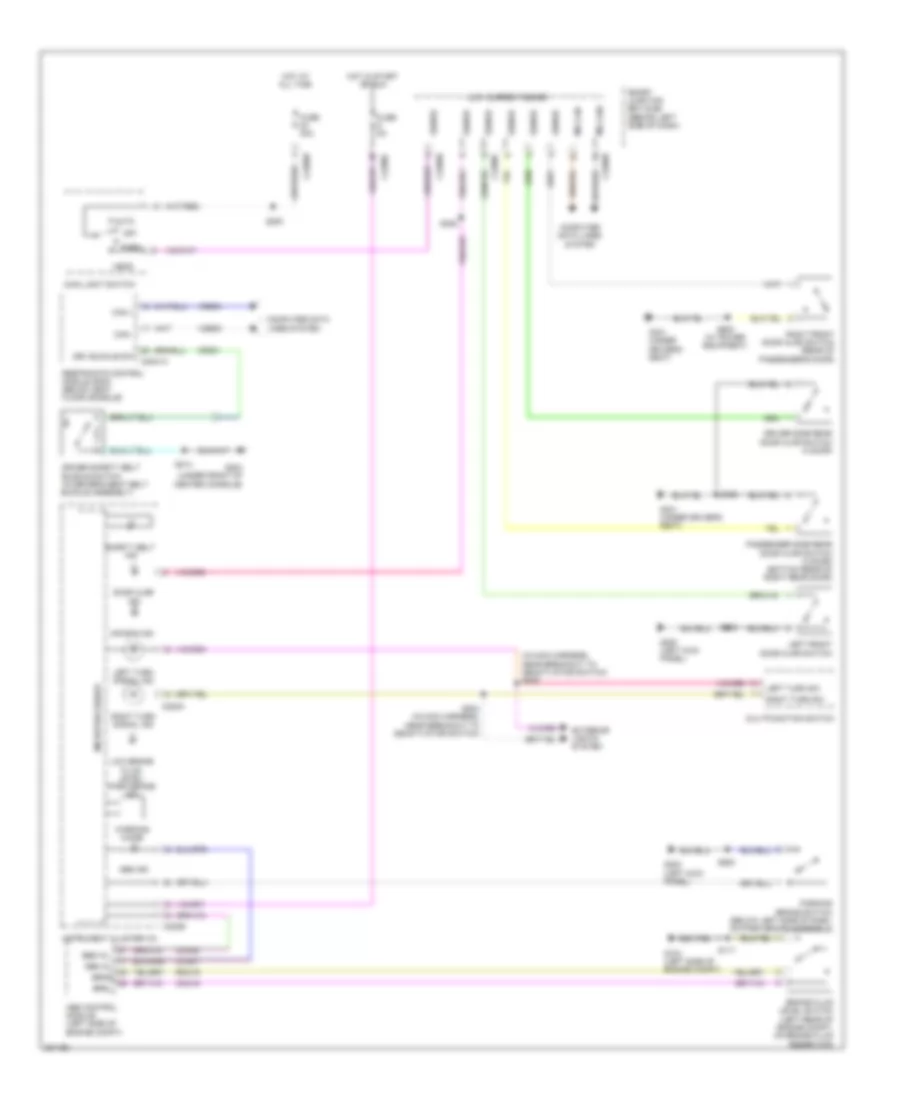
INTERIOR LIGHTS
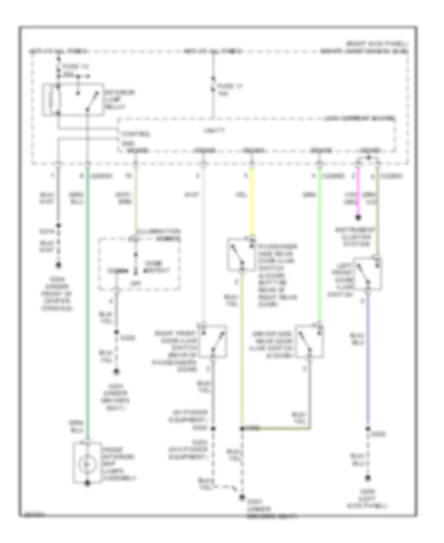
Courtesy Lamps Wiring Diagram for Ford Ranger 2008
List of elements for Courtesy Lamps Wiring Diagram for Ford Ranger 2008:
- (right kick panel) smart junction box (sjb)
- (w/ power equipment)
- C2280c
- C2280d
- Control
- Dome
- Dome defeat
- Driver side rear door ajar switch (4 door)
- Front interior/ map lamps assembly
- Fuse 11 10a
- Fuse 13 15a
- G200 (left kick panel)
- G204 (under front of center console)
- G301 (under driver's seat)
- Gnd
- Hot at all times
- Illumination dimmer
- Instrument cluster system
- Interior lamp relay
- Left front door ajar switch
- Low current board
- Off
- Passenger side rear door ajar switch (4 door) (bottom rear of right rear door)
- Right front door ajar switch (rear of passenger's door)
- S203 (w/o power equipment)
- S214
- S220
- S302
- S500
- S600
- Sense
- Vbatt
Instrument Illumination Wiring Diagram for Ford Ranger 2008
List of elements for Instrument Illumination Wiring Diagram for Ford Ranger 2008:
- Audio unit
- Auto
- C218a
- C218c
- C220a
- C2280b
- C2280c
- C2280d
- C290a
- C294b
- Climate control assembly
- Clockspring
- Dome
- Dome defeat
- Driver side door lock switch
- Four- wheel drive switch
- Fuse 1 5a
- Fuse 10a
- Fuse 20a
- Fuse 30a
- G200 (left kick panel)
- G204 (under front of center console)
- G205
- G301 (under driver's seat)
- Gnd
- Head
- Horns system
- Hot at all times
- Hot in run or acc
- Illumination
- Illumination (6 bulbs)
- Illumination dimmer
- Instrument cluster
- Low current board
- Main light switch
- Micro- processor
- Off
- Park
- Park lamp relay
- Passenger side door lock switch
- Pwm
- S200
- S203
- S213 (in main harness, near breakout to instrument cluster)
- S214
- S220
- S235
- S600
- S600 (w/ power equipment)
- Sense
- Smart junction box (sjb) (right kick panel)
- Speed control on/off switch
- Speed control set/ resume switch
- Vpwr
POWER DISTRIBUTION
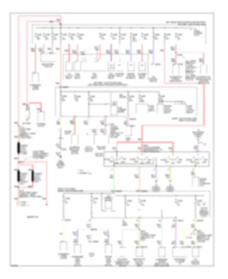
Power Distribution Wiring Diagram (1 of 2) for Ford Ranger 2008
List of elements for Power Distribution Wiring Diagram (1 of 2) for Ford Ranger 2008:
- (2.3l: near breakout to fuel injector 4) (3.0l: at breakout to c110) (4.0l: near breakout to c110)
- (in battery cable assembly, near breakout to battery)
- (left rear side of engine compartment) battery junction box (bjb)
- (not used)
- (right kick panel) smart junction box (sjb)
- 2.3l
- 4x4 control module
- A/c clutch relay
- A/t
- Abs control module
- Acc
- Audio unit
- Battery
- Battery junction box (bjb) (left rear side of engine compartment)
- Blower motor relay
- Brake shift interlock (a/t)
- C102b
- C102c
- C175b
- C2041b
- C220b
- C2280a
- C2280b
- C2280c
- C281a
- C281b
- C290a
- Door lock/ unlock relay
- Driver door unlock relay
- Driver side door lock switch
- Drl driver
- Engine cooling fan relay
- Evaporative emission (evap) canister vent valve
- Except 2.3l
- Exterior rear view mirror switch
- Fog lamp relay
- Fuel pump relay
- Fuse 10a
- Fuse 15a
- Fuse 20a
- Fuse 20a (2.3l)
- Fuse 30a
- Fuse 40a
- Fuse 5a
- G301 (under driver's seat)
- Generator
- Ignition switch
- Instrument cluster (ic)
- Lock
- Low current board
- Main light switch
- Multi- function switch
- Occupant classification sensor (ocs) module
- Off
- Park lamp relay
- Passenger air bag deactivation (pad) indicator
- Passenger side door lock switch
- Pcm power relay
- Power point
- Powertrain control module (pcm)
- Red
- Restraints control module (rcm)
- Run
- S105
- S113 (in battery cable assembly, near breakout red to battery)
- S114
- S115 (in battery cable assembly, near breakout to battery)
- S200 (in main harness, near breakout to main light switch)
- S203
- S209 (in main harness, near breakout to ignition switch)
- S219 (in main harness, near breakout to g204)
- S235
- Smart junction box (sjb) (right kick panel)
- Start
- Starter motor
- Starter relay
- To fuse 22 (diagram 2 of 2)
- To fuse 27 (diagram 2 of 2)
- To fuse 3 (diagram 2 of 2)
- To ptc circuit breaker (diagram 2 of 2)
- To splice s236 (diagram 2 of 2)
- W/ 4x4
- Windshield wiper motor
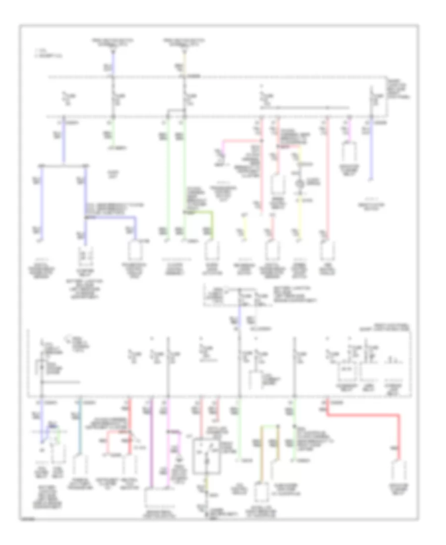
Power Distribution Wiring Diagram (2 of 2) for Ford Ranger 2008
List of elements for Power Distribution Wiring Diagram (2 of 2) for Ford Ranger 2008:
- (3.0l: near breakout to g106) (4.0l: near breakout to fuel injector 6) s110
- (in main harness, near breakout to instrument cluster) s212
- (in main harness, near breakout to power point) s227
- (right kick panel) smart junction box (sjb)
- 2.3l
- 4x4 control module
- A/t
- Abs control module
- Accessory relay
- Audio unit
- Battery junction box (bjb) (left rear side engine compartment)
- Battery junction box (bjb) (left rear side of engine compartment)
- Blend door actuator
- Brake pedal position switch
- C175b
- C218a
- C218c
- C220b
- C2280a
- C2280b
- C2280c
- C281b
- C290a
- C294a
- C2982a
- Climate control assembly
- Clock- spring
- Data link connector (dlc)
- Deactivator switch
- Digital transmission range (dtr) sensor
- Except 2.3l
- From a fuse 21 (diagram 1 of 2)
- From fuse 10 (diagram 1 of 2)
- From ignition switch (diagram 1 of 2)
- Front cigar lighter
- Fuel pump relay
- Fuse 10a
- Fuse 15a
- Fuse 20a
- Fuse 2a
- Fuse 30a
- Fuse 40a
- Fuse 50a
- Fuse 5a
- Horn relay
- Indicator flasher relay
- Instrument cluster (ic)
- Interior lamp relay
- Low current board
- M/t
- Nca
- Neutral tow indicator
- Off
- Passive anti-theft transceiver
- Pcm power diode
- Pcm power relay
- Powertrain control module (pcm)
- Ptc circuit breaker 1a
- Red
- Reversing lamps switch
- S203
- S210 (a/t) (in main harness, near breakout to instrument cluster)
- S236
- Satellite radio receiver (w/ audiophile)
- Smart junction box (sjb) (right kick panel)
- Speed control on/off switch
- Speed control servo
- Starter relay
- Subwoofer amplifier (w/ audiophile)
- Transmission control switch (a/t)
- W/ 4x4
POWER DOOR LOCKS
Power Door Locks Wiring Diagram for Ford Ranger 2008
List of elements for Power Door Locks Wiring Diagram for Ford Ranger 2008:
- (under driver's seat)
- All lock relay
- C2280a
- C2280b
- C2280c
- C2280d
- Computer data lines system
- Driver door unlock relay
- Driver side door lock switch
- Driver side rear door ajar switch (4 door)
- Exterior lights system
- Fuse 10a
- Fuse 15a
- Fuse 20a
- Fuse 5a
- G200 (left kick panel)
- G204 (under front of center console)
- G301
- G301 (under driver's seat)
- Horn relay
- Horns system
- Hot at all times
- Instrument cluster system
- Interior lights system
- Left front door ajar switch
- Left front door lock actuator
- Low current board
- Park lamp relay
- Passenger door unlock relay
- Passenger side door lock switch
- Passenger side rear door ajar switch (4 door) (bottom rear of right rear door)
- Right front door ajar switch (rear of passenger's door)
- Right front door lock actuator
- S203
- S214
- S302
- S500
- S600 (w/ power equipment)
- Smart junction box (sjb) (right kick panel)
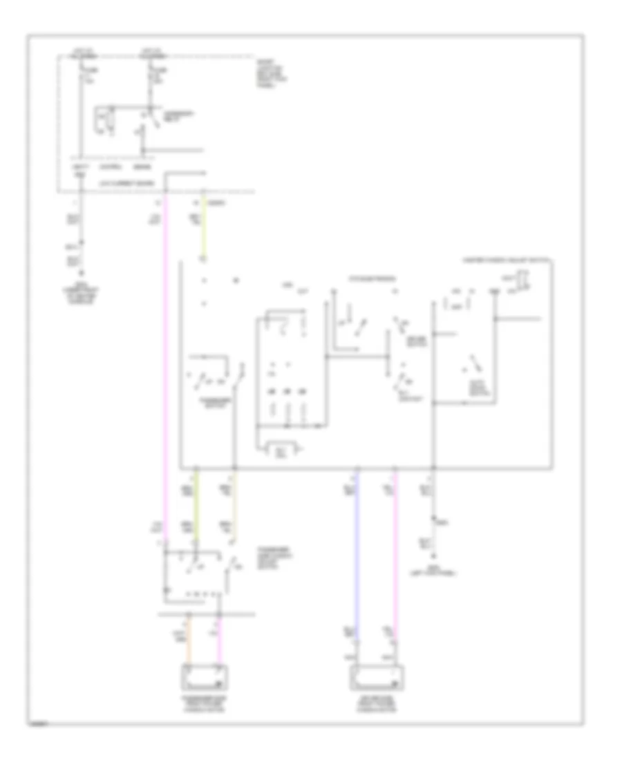
POWER MIRRORS
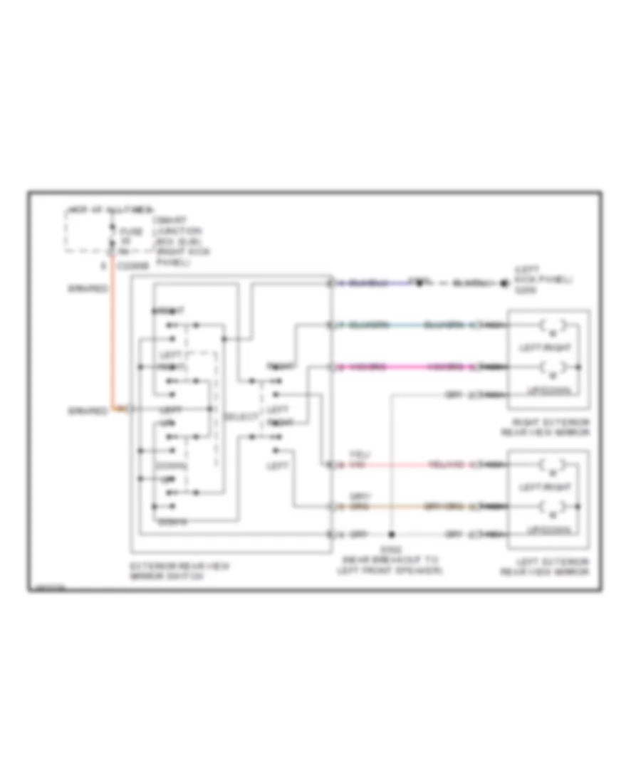
Power Mirrors Wiring Diagram for Ford Ranger 2008
List of elements for Power Mirrors Wiring Diagram for Ford Ranger 2008:
- (left kick panel) g200
- C2280b
- Down
- Exterior rear view mirror switch
- Fuse 5a
- Hot at all times
- Left
- Left exterior rear view mirror
- Left select right
- Left/right
- Nca
- Right
- Right exterior rear view mirror
- S500
- S502 (near breakout to left front speaker)
- Smart junction box (sjb) (right kick panel)
- Up/down
POWER WINDOWS
Power Windows Wiring Diagram for Ford Ranger 2008
List of elements for Power Windows Wiring Diagram for Ford Ranger 2008:
- Accessory relay
- Ain
- Amp
- Auto down switch
- C2280c
- Control
- Driver side front power window motor
- Driver switch
- Fuse 10a
- Fuse 30a
- G200 (left kick panel)
- G204 (under front of center console)
- Gnd
- Hot at all times
- Low current board
- Master window adjust switch
- Nca
- Otd electronics
- Out
- Passenger side front power window motor
- Passenger side window adjust switch
- Passenger switch
- Rly coil
- Rly contact
- S214
- S500
- Sense
- Smart junction box (sjb) (right kick panel)
- Vbatt
- Vdd
- Xin
- Xout
RADIO
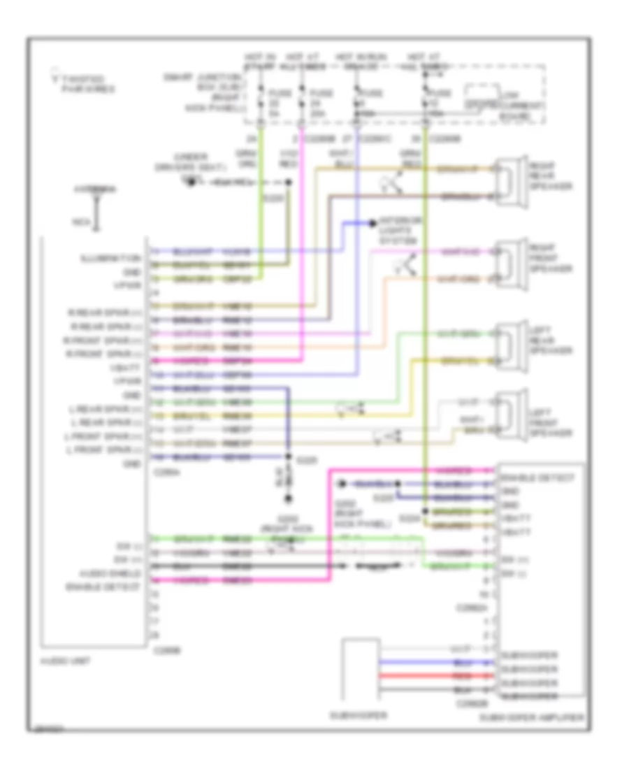
Audiophile Sound Radio Wiring Diagram for Ford Ranger 2008
List of elements for Audiophile Sound Radio Wiring Diagram for Ford Ranger 2008:
- (under driver's seat) g301
- Antenna
- Audio shield
- Audio unit
- C2280b
- C2280c
- C290a
- C290b
- C2982a
- C2982b
- Cbp06
- Cbp22
- Dme22
- Enable detect
- Fuse 10a
- Fuse 15a
- Fuse 20a
- Fuse 5a
- G202 (right kick panel)
- Gd103
- Gd161
- Gnd
- Hot at all times
- Hot in run or acc
- Hot in start
- Illumination
- Interior lights system
- L front spkr (+)
- L front spkr (-)
- L rear spkr (+)
- L rear spkr (-)
- Left front speaker
- Left rear speaker
- Low current board
- Nca
- Pair wires
- R front spkr (+)
- R front spkr (-)
- R rear spkr (+)
- R rear spkr (-)
- Red
- Right front speaker
- Right rear speaker
- Rme07
- Rme09
- Rme10
- Rme12
- Rme22
- S220
- S224
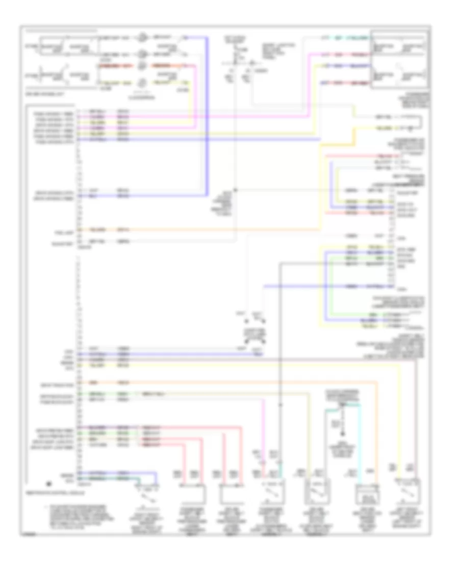
- S225
- Sbp24
- Sense
- Smart junction box (sjb) (right kick panel)
- Sme23
- Subwoofer
- Subwoofer amplifier
- Sw (+)
- Sw (-)
- Twisted
- Vbatt
- Vln18
- Vme07
- Vme09
- Vme10
- Vme12
- Vme22
- Vpwr
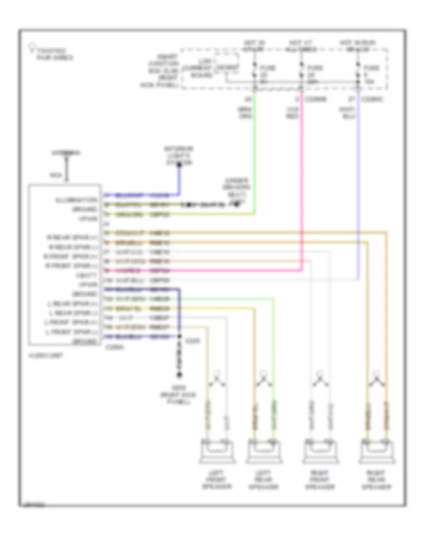
Base Radio Wiring Diagram for Ford Ranger 2008
List of elements for Base Radio Wiring Diagram for Ford Ranger 2008:
- (under driver's seat) g301
- Antenna
- Audio unit
- C2280b
- C2280c
- C290a
- Cbp06
- Cbp22
- Fuse 10a
- Fuse 20a
- Fuse 5a
- G202 (right kick panel)
- Gd103
- Gd161
- Ground
- Hot at all times
- Hot in run or acc
- Hot in start
- Illumination
- Interior lights system
- L front spkr (+)
- L front spkr (-)
- L rear spkr (+)
- L rear spkr (-)
- Left front speaker
- Left rear speaker
- Low current board
- Nca
- Pair wires
- R front spkr (+)
- R front spkr (-)
- R rear spkr (+)
- R rear spkr (-)
- Right front speaker
- Right rear speaker
- Rme07
- Rme09
- Rme10
- Rme12
- S220
- S225
- Sbp24
- Sense
- Smart junction box (sjb) (right kick panel)
- Twisted
- Vbatt
- Vln18
- Vme07
- Vme09
- Vme10
- Vme12
- Vpwr
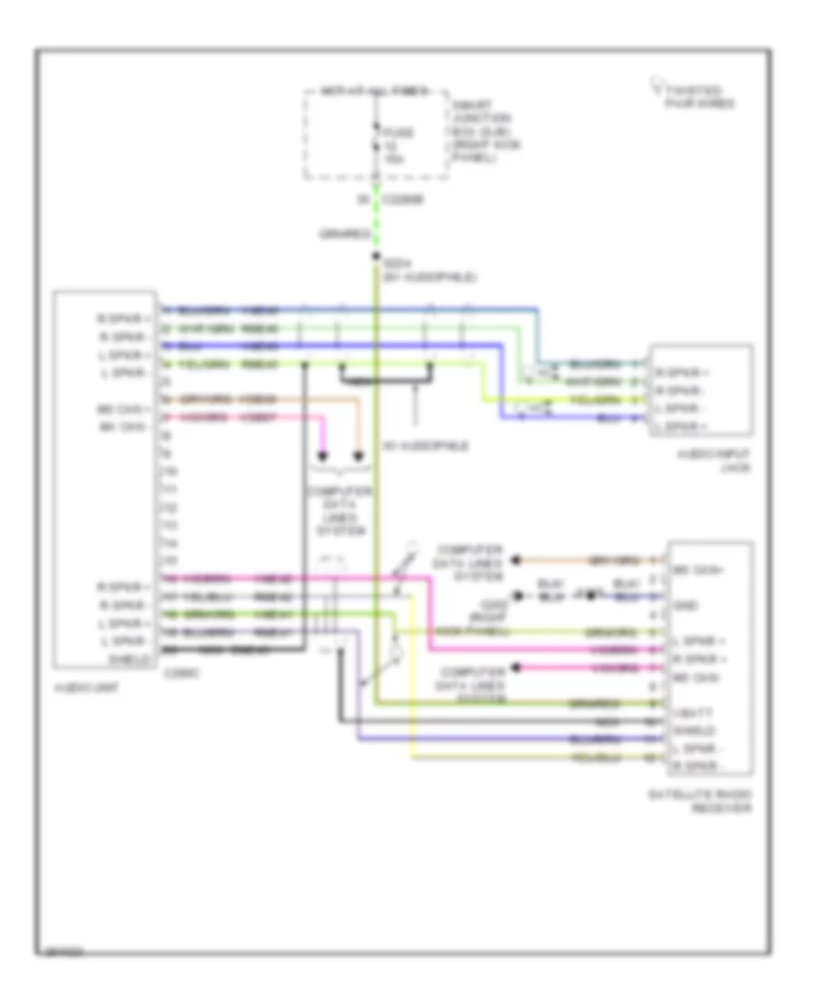
Satellite Radio Wiring Diagram for Ford Ranger 2008
List of elements for Satellite Radio Wiring Diagram for Ford Ranger 2008:
- Audio input jack
- Audio unit
- C2280b
- C290c
- Computer data lines system
- Dme45
- Fuse 15a
- G202 (right kick panel)
- Gnd
- Hot at all times
- L spkr +
- L spkr -
- Ma can -
- Ms can +
- Ms can+
- Ms can-
- Nca
- Pair wires
- R spkr +
- R spkr -
- Rme41
- Rme42
- Rme45
- Rme46
- S224 (w/ audiophile)
- S225
- Satellite radio receiver
- Shield
- Smart junction box (sjb) (right kick panel)
- Twisted
- Vbatt
- Vdb06
- Vdb07
- Vme41
- Vme42
- Vme45
- Vme46
- W/ audiophile
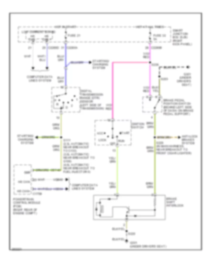
SHIFT INTERLOCK
Shift Interlock Wiring Diagram for Ford Ranger 2008
List of elements for Shift Interlock Wiring Diagram for Ford Ranger 2008:
- Acc
- Anti-lock brakes system
- Brake pedal position switch (behind left side of dash, on brake pedal support)
- Brake shift interlock
- C2280a
- C2280b
- C2280d
- Cet40
- Computer data lines system
- Digital transmission range (dtr)
- Fuse 21
- Fuse 32 5a
- G301 (under driver's seat)
- Hot at all times
- Hot in start
- Hs can +
- Hs can -
- Hs can+ c175b
- Hs can-
- Ignition switch
- Lock
- Low current board
- Off
- Powertrain control module (pcm) (right rear of engine compt)
- Run
- S111 (2.3l automatic: near breakout to c133) (3.0l automatic: near breakout to g106) (4.0l automatic: near breakout to fuel injector 6)
- S203
- S220
- S236
- Sensor (left side of transmission)
- Smart junction box (sjb) (right kick panel)
- Start
- Starting/ charging system
- Vdb04
- Vdb05
STARTING/CHARGING
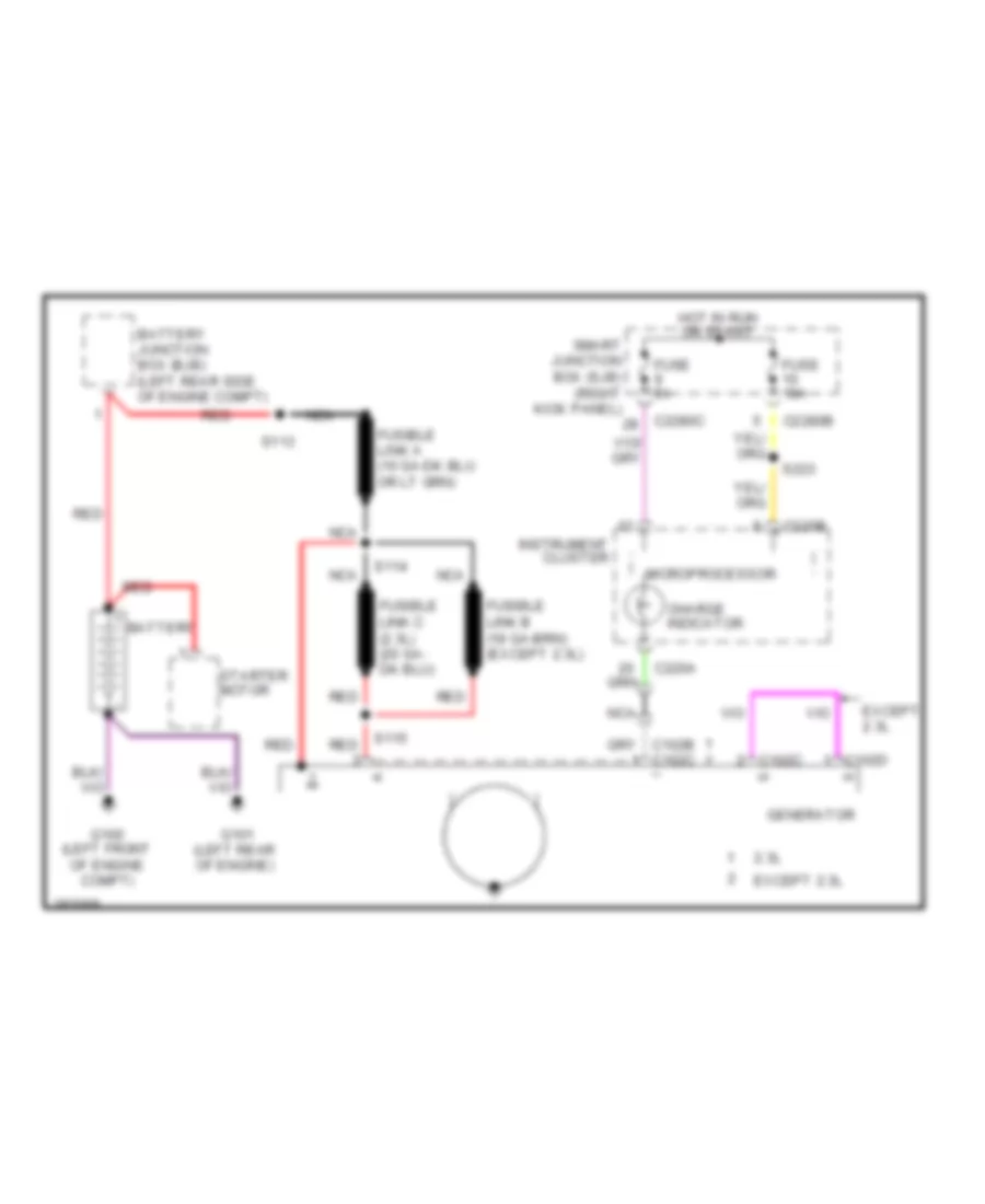
Charging Wiring Diagram for Ford Ranger 2008
List of elements for Charging Wiring Diagram for Ford Ranger 2008:
- 2.3l
- Battery
- Battery junction box (bjb) (left rear side of engine compt)
- C102c
- C102d
- C220a
- C220b
- C2280b
- C2280c
- Charge indicator
- Except 2.3l
- Fuse 10a
- Fuse 5a
- G100 (left front of engine compt)
- G101 (left rear of engine)
- Generator
- Hot in run or start
- Instrument cluster
- Microprocessor
- Nca
- Red
- S113
- S114
- S115
- S223
- Smart junction box (sjb) (right kick panel)
- Starter motor
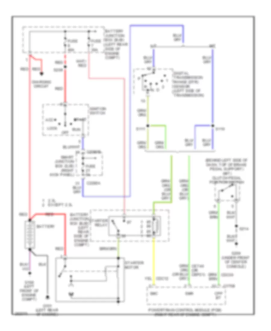
Starting Wiring Diagram for Ford Ranger 2008
List of elements for Starting Wiring Diagram for Ford Ranger 2008:
- (behind left side of dash, top of brake pedal support) (m/t) clutch pedal position switch
- 2.3l except 2.3l
- A/t
- Acc
- Battery
- Battery junction box (bjb) (left rear side of engine compt)
- C175b
- C2280a
- C2280b
- Charging circuit
- Cpp bt
- Digital transmission range (dtr) sensor (left side of transmission)
- Fuse 30a
- Fuse 40a
- Fuse 5a
- G100 (left front of engine compt)
- G101 (left rear of engine)
- G204 (under front of center console)
- Ignition switch
- Lock
- M/t
- Off
- Powertrain control module (pcm) (right rear of engine compt)
- Red
- Run
- S110
- S111
- S209
- S214
- Smart junction box (sjb) (right kick panel)
- Smc
- Smr
- Start
- Starter motor
- Starter relay
SUPPLEMENTAL RESTRAINTS
Supplemental Restraints Wiring Diagram for Ford Ranger 2008
List of elements for Supplemental Restraints Wiring Diagram for Ford Ranger 2008:
- (in main harness, near breakout to clockspring) s214
- Bar
- Bts sig
- Bts vref
- C2041a
- C2041b
- C216a
- C216b
- C218b
- C2280c
- Can+
- Can-
- Cbp08
- Clockspring
- Computer data lines system
- Cr101
- Cr102
- Cr103
- Cr104
- Cr114
- Cr120
- Cr122
- Cr152
- Cr201
- Cr203
- Driver air bag unit
- Driver safety belt buckle pretensioner (under driver's seat)
- Driver safety belt buckle switch (in driver's seat belt buckle assembly)
- Driver seat position sensor (under driver's seat)
- Drvr adap load feed
- Drvr adap load rtn
- Drvr air bag 1 feed
- Drvr air bag 1 rtn
- Drvr air bag 2 feed
- Drvr air bag 2 rtn
- Drvr buckle sw
- Drvr preten feed
- Drvr preten rtn
- Drvr track pos
- Fuse 10a
- G204 (under front of center console)
- Gd174
- Gnd
- Hot in run or start
- Left front impact severity sensor (left front of engine compt)
- Lr142
- Nca
- Occupant classification sensor (ocs) module (under passenger's seat)
- Pad lamp
- Pass air bag 1 feed
- Pass air bag 1 rtn
- Pass air bag 2 feed
- Pass air bag 2 rtn
- Pass buckle sw
- Passenger air bag deactivation (pad) indicator
- Passenger air bag module (behind right side of dash)
- Passenger safety belt buckle pretensioner (under passenger's seat)
- Passenger safety belt buckle switch (in passenger's safety belt buckle assembly)
- Pin shorting bars engaged when module connector is disconnected from harness: (shorting bars are connected between following pins: 1-2, 3-4, 5-6 & 15-16)
- Restraints control module
- Right front impact severity sensor (right front of engine compt)
- Rr101
- Rr102
- Rr103
- Rr104
- Rr120
- Rr122
- Rr129
- Rr130
- Rr142
- Rr152
- Rtn
- Run/start
- S219 (in main harness, near breakout to g204)
- Safety belt tension sensor (regular cab & 2-door super cab: base of right ``b" pillar) (4-door super cab: in bottom of right rear door)
- Seat pressure sensor (under passenger's seat)
- Sense
- Shorting
- Shorting bar
- Smart junction box (sjb) (right kick panel)
- Solid state
- Stage
- Sws gnd
- Sws vin
- Sws vout
- Vdb04
- Vdb05
- Vr210
- Vr213
- Vr214
- Vr215
- Vr228
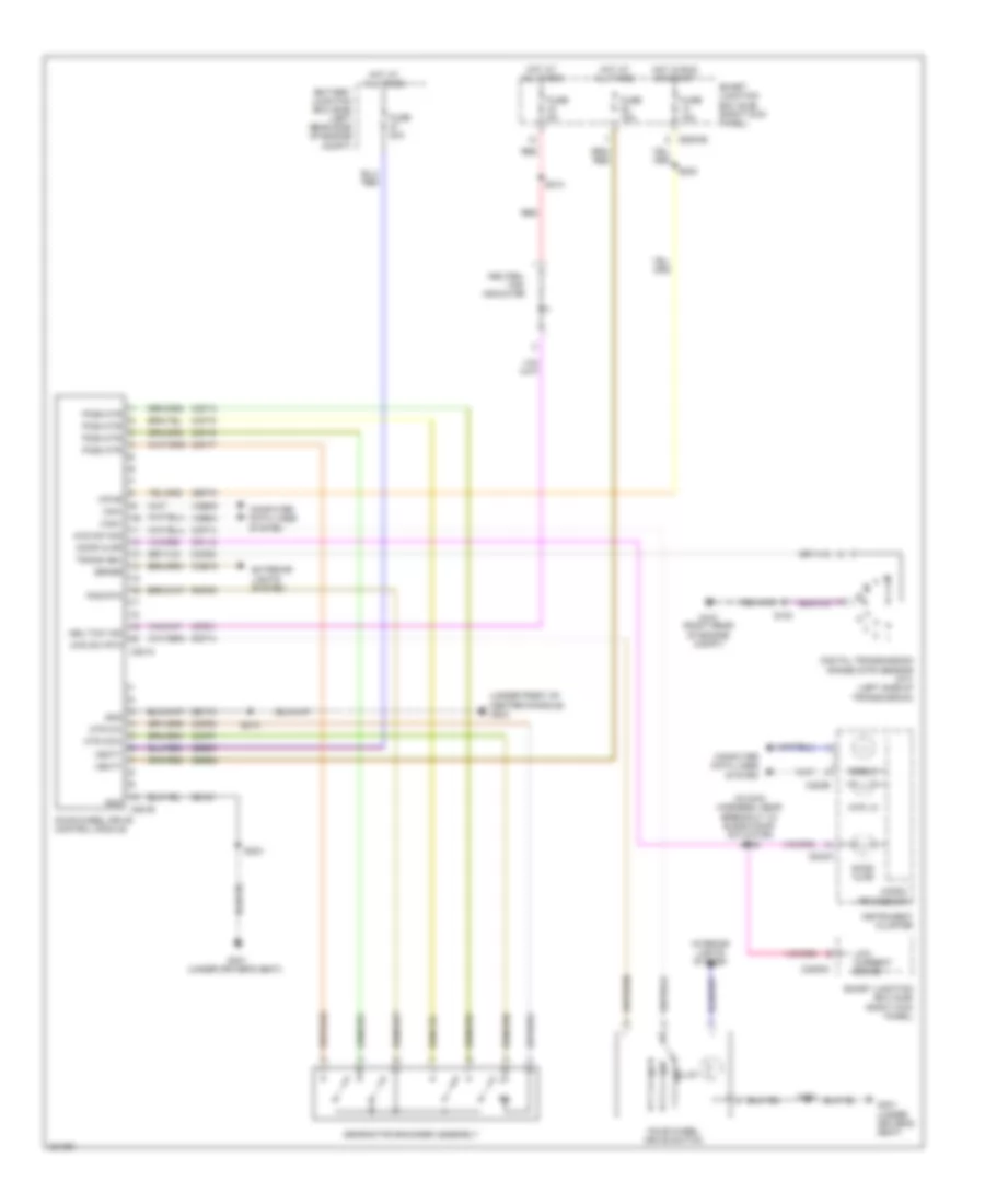
TRANSMISSION
4WD Wiring Diagram for Ford Ranger 2008
List of elements for 4WD Wiring Diagram for Ford Ranger 2008:
- (in main harness, near breakout to blend door actuator) s228
- (under front of center console) g204
- 4wd hi
- 4wd lo
- 4wd sw rtn
- 4wd sw sig
- Battery junction box (bjb) (left rear side of engine compt)
- C220a
- C220b
- C2280b
- C2280c
- C281a
- C281b
- Can+
- Can-
- Cbp10
- Ccb15
- Ccf07
- Ccf08
- Ccf13
- Ccf14
- Ccf15
- Ccf16
- Ccf17
- Ccf20
- Ccf21
- Computer data lines system
- Cpl12
- Digital transmission range (dtr) sensor (a/t) (left side of transmission)
- Door ajar
- Exterior
- Four-wheel drive control module
- Four-wheel drive switch
- Fuse 10a
- Fuse 15a
- Fuse 20a
- Fuse 5a
- G107 (right rear of engine compt)
- G301 (under driver's seat)
- Gd161
- Gd174
- Gearmotor encoder assembly
- Gnd
- Hot at all times
- Hot in run or start
- Illum
- Instrument cluster
- Interior lights system
- Lights system
- Low current board
- Micro- processor
- Mtr ccw
- Mtr cw
- Neu tow ind
- Neutral tow indicator
- Off
- Pos rtn
- Pos2 mtr
- Pos3 mtr
- Pos4 mtr
- Pos5 mtr
- Rcf09
- Rcf13
- Red
- S100
- S203
- S212
- S214
- S223
- Sbb27
- Sbb28
- Sense
- Smart junction box (sjb) (right kick panel)
- Trans neu
- Vbatt
- Vdb04
- Vdb05
- Vpwr
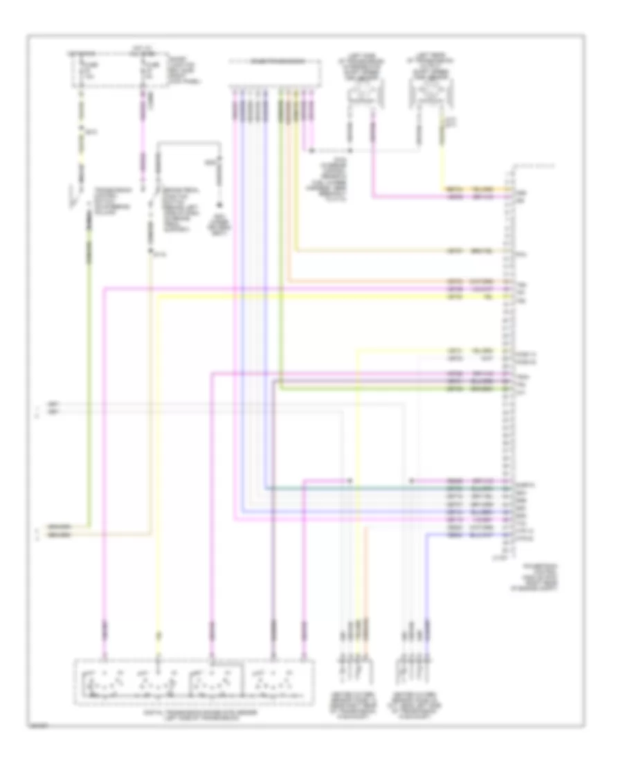
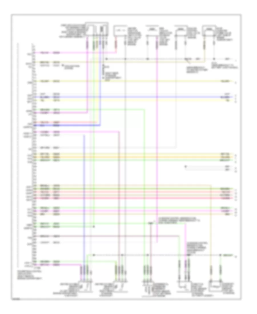
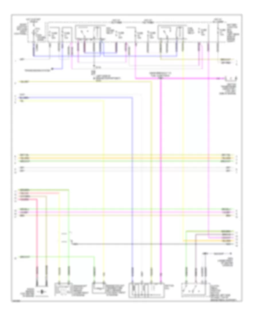
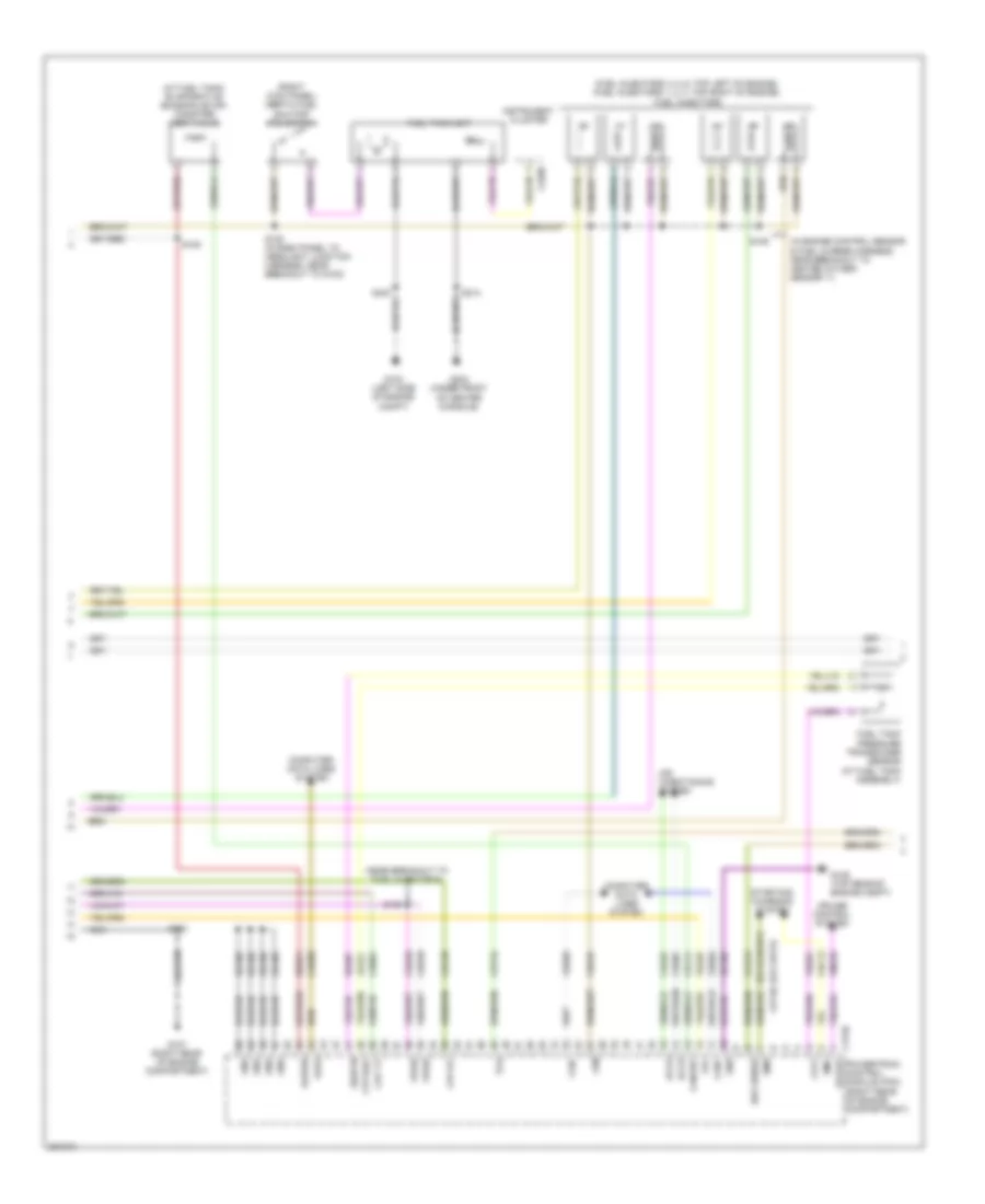
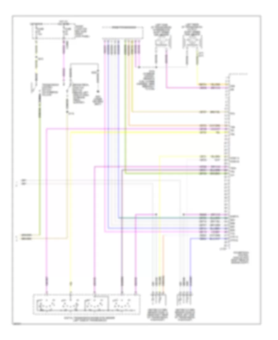
2.3L
2.3L, A/T Wiring Diagram (1 of 2) for Ford Ranger 2008
List of elements for 2.3L, A/T Wiring Diagram (1 of 2) for Ford Ranger 2008:
- (in engine control sensor & fuel charge harness, near breakout to heated oxygen sensor 11)
- 5r44e transmission
- Anti-lock brakes system
- Battery junction box (bjb) (left rear side of engine compt)
- Bpp
- Brake pedal position switch (behind left side of dash, on brake pedal support)
- C175b
- C175e
- C175t
- C220b
- C2280a
- C2280b
- C2280c
- Can+
- Can-
- Cbb39
- Ccb15
- Cdb08
- Ce116
- Cet05
- Cet06
- Cet07
- Cet18
- Cet19
- Cet34
- Cet44
- Check engine ind
- Cht
- Computer data lines system
- Engine controls system
- Epc
- Feps
- Fuse 10a
- Fuse 15a
- Fuse 30a
- Fuse 5a
- G106 (top rear of engine compt)
- G107 (right rear of engine compt)
- G301 (under driver's seat)
- Gd108
- Ground
- Hot at all times
- Hot in run
- Hot in run or start
- Hot in start or run
- Instrument cluster
- Iss
- Le423
- Micro-
- Nca
- O/d off ind
- Oss
- Pcm power diode
- Power
- Powertrain control module (pcm) (right rear of engine compt)
- Prndl
- Processor
- Ptc 1a
- Re405
- Re406
- Ret04
- S100
- S105
- S109 (near breakout to c133)
- S112
- S119
- S210
- S220
- Sbb21
- Sig rtn
- Smart junction box (sjb) (right kick panel)
- Ss a
- Ss b
- Ss c
- Ss d
- Ssa
- Ssb
- Ssc
- Ssd
- Tcc
- Tcs
- Tft
- Tps
- Tr1
- Tr2
- Tr3a
- Tr4
- Transmission control switch (on steering column)
- Tss
- Vbatt
- Vdb04
- Vdb05
- Ve739
- Ve819
- Vet27
- Vet28
- Vet29
- Vet30
- Vet31
- Vet33
- Vpwr
- Vref
2.3L, A/T Wiring Diagram (2 of 2) for Ford Ranger 2008
List of elements for 2.3L, A/T Wiring Diagram (2 of 2) for Ford Ranger 2008:
- (in engine control sensor & fuel charge harness, near breakout to g106)
- (in engine control sensor & fuel charge harness, near breakout to g106) s102
- (in engine control sensor & fuel charge harness, near breakout to manifold absolute pressure sensor)
- (left side of engine compt) g103
- Battery junction box (bjb) (left rear side of engine compt)
- Cylinder head temperature sensor (right side of cylinder head)
- Digital transmission range (dtr) sensor (left side of transmission)
- Engine controls system
- Fuel pump relay
- Intermediate shaft speed (iss) sensor (left side of transmission)
- N r
- Output shaft speed (oss) sensor (left rear of transmission)
- Pcm power relay
- S101
- S103
- S116
- Throttle position (tp) sensor (top right side of engine, on throttle body)
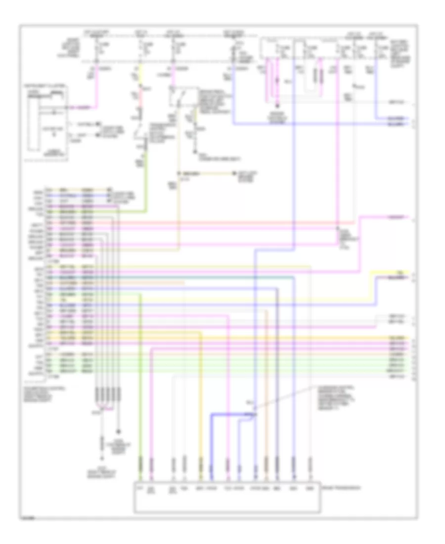
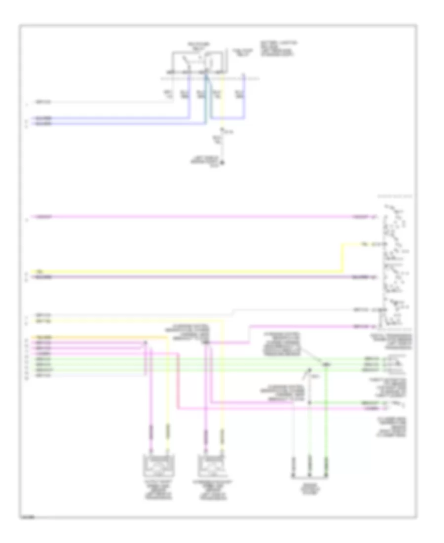
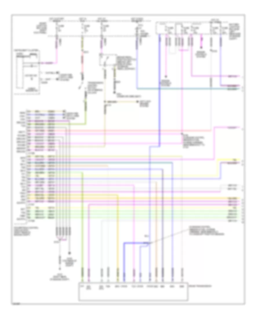
3.0L
3.0L, A/T Wiring Diagram (1 of 2) for Ford Ranger 2008
List of elements for 3.0L, A/T Wiring Diagram (1 of 2) for Ford Ranger 2008:
- (in engine control sensor & fuel charge harness, near breakout to camshaft position sensor)
- 5r44e transmission
- Anti-lock brakes system
- Battery junction box (bjb) (left rear side of engine compt)
- Brake pedal position switch (behind left side of dash, on brake pedal support)
- C175b
- C175e
- C175t
- C220b
- C2280b
- C2280c
- Can+
- Can-
- Cbb39
- Ccb15
- Cdb08
- Cet05
- Cet06
- Cet07
- Cet18
- Cet19
- Cet34
- Cet44
- Check engine ind
- Computer data lines system
- Ect
- Engine controls system
- Epc
- Feps
- Fuse 10a
- Fuse 15a
- Fuse 30a
- Fuse 5a
- G106 (top rear of engine compt)
- G107 (right rear of engine compt)
- G301 (under driver's seat)
- Gd108
- Ground
- Hot at all times
- Hot in run
- Hot in run or start
- Hot in start or run
- Instrument cluster
- Iss
- Le423
- Micro-
- Nca
- O/d off ind
- Oss
- Pcm power diode c2280a
- Power
- Powertrain control module (pcm) (right rear of engine compt)
- Prndl
- Processor
- Ptc 1a
- Re405
- Re406
- Ret04
- S100
- S105
- S109 (in engine control sensor & fuel charge harness, near breakout to c133)
- S112
- S210
- Sbb21
- Sensor
- Sig rtn
- Smart junction box (sjb) (right kick panel)
- Ss a
- Ss b
- Ss c
- Ss d
- Ssa
- Ssb
- Ssc
- Ssd
- Tcc
- Tcs
- Tft
- Tps
- Tr1
- Tr2
- Tr3a
- Tr4
- Transmission control switch (on steering column)
- Tss
- Vbatt
- Vdb04
- Vdb05
- Ve716
- Ve739
- Ve819
- Vet27
- Vet28
- Vet29
- Vet30
- Vet31
- Vet33
- Vpwr
- Vref
3.0L, A/T Wiring Diagram (2 of 2) for Ford Ranger 2008
List of elements for 3.0L, A/T Wiring Diagram (2 of 2) for Ford Ranger 2008:
- (in engine control sensor & fuel charge harness, near breakout to c110)
- (in engine control sensor & fuel charge harness, near breakout to fuel injector 5)
- Battery junction box (bjb) (left rear side of engine compt)
- Digital transmission range (dtr) sensor (left side of transmission)
- Engine controls system
- Engine coolant temperature (ect) sensor (top front of engine)
- Fuel pump relay
- G103 (left side of engine compt)
- Intermediate shaft speed (iss) sensor (left side of transmission)
- N r
- Output shaft speed (oss) sensor (left rear of transmission)
- Pcm power relay
- S101
- S102
- S103
- S116
- Throttle position (tp) sensor (top left front of engine, on throttle body)
4.0L
4.0L, A/T Wiring Diagram (1 of 2) for Ford Ranger 2008
List of elements for 4.0L, A/T Wiring Diagram (1 of 2) for Ford Ranger 2008:
- (in battery cable assembly, near breakout to battery)
- 5r55e transmission
- Anti-lock brakes system
- Battery junction box (bjb) (left rear side of engine compt)
- Bpp
- Brake pedal position switch (behind left side of dash, on brake pedal support)
- C175b
- C175e
- C175t
- C220b
- C2280a
- C2280b
- C2280c
- Can+
- Can-
- Cbb39
- Ccb15
- Cet05
- Cet06
- Cet07
- Cet18
- Cet19
- Cet34
- Cet44
- Check engine ind
- Computer data lines system
- Ect
- Epc
- Fuse 10a
- Fuse 15a
- Fuse 30a
- Fuse 5a
- G106 (top rear of engine compt)
- G107 (right rear of engine compt)
- G301 (under driver's seat)
- Gd108
- Gnd
- Hot at all times
- Hot in run
- Hot in run or start
- Hot in start or run
- Instrument cluster
- Iss
- Kapwr
- Le423
- Micro-
- Nca
- Near breakout to front cigar lighter)
- O/d off ind
- Oss
- Pcm power diode
- Powertrain control module (pcm) (right rear of engine compt)
- Prndl
- Processor
- Ptc 1a
- Re405
- Re406
- Ret04
- S100
- S105
- S109 (near breakout to fuel injector 6)
- S112
- S210
- S220
- S236
- Sbb21
- Sig rtn
- Smart junction box (sjb) (right kick panel)
- Ss a
- Ssa
- Ssb
- Ssc
- Ssd
- Tcc
- Tcs
- Tft
- Tps
- Tr1
- Tr2
- Tr3a
- Tr4
- Transmission control switch (on steering column)
- Tss
- Vdb04
- Vdb05
- Ve716
- Ve819
- Vet27
- Vet28
- Vet29
- Vet30
- Vet31
- Vet33
- Vet39
- Vpwr
- Vref
4.0L, A/T Wiring Diagram (2 of 2) for Ford Ranger 2008
List of elements for 4.0L, A/T Wiring Diagram (2 of 2) for Ford Ranger 2008:
- (in engine control sensor & fuel charge harness, near breakout to fuel injector 5)
- (in engine control sensor & fuel charge harness, near breakout to g106) s102
- Battery junction box (bjb) (left rear side of engine compt)
- Digital transmission range (dtr) sensor (left side of transmission)
- Engine controls system
- Engine coolant temperature (ect) sensor (top right front of engine)
- Fuel pump relay
- G103 (left side of engine compt)
- Intermediate shaft speed (iss) sensor (left side of transmission)
- N r
- Output shaft speed (oss) sensor (left rear of transmission)
- Pcm power relay
- S101 (in engine control sensor & fuel charge harness, near breakout to g106)
- S103
- S116
- Throttle position (tps) sensor (top front of engine, on throttle body)
WARNING SYSTEMS
Chime Wiring Diagram for Ford Ranger 2008
List of elements for Chime Wiring Diagram for Ford Ranger 2008:
- (in main harness, near breakout to deactivator switch) s205
- Abs control module (left side of engine compt)
- Abs ind
- Abs wl
- Air bag ind
- Auto
- Brake fluid level switch (left rear of engine compt, on brake fluid reservoir)
- Brkl
- Brks
- C2041a
- C220a
- C220b
- C2280b
- C2280c
- C2280d
- Can +
- Can -
- Cca01
- Cca02
- Cmc19
- Computer data lines system
- Cr201
- Door ajar ind
- Driver safety belt buckle switch (in driver's seat belt buckle assembly)
- Driver side rear door ajar switch (4 door)
- Drv buckle sw
- Ebd wl
- Exterior lights system
- Fuse 30a
- Fuse 5a
- G103 (left side of engine compt)
- G200 (left kick panel)
- G204 (under front of center console)
- G301 (under driver's seat)
- Head
- Hot at all time
- Hot in start or run
- Instrument cluster (ic)
- Left front door ajar switch
- Left turn signal ind
- Left turn sw
- Low brake fluid level/ park brake ind
- Low current board
- Main light switch
- Microprocessor
- Ms can+
- Ms can-
- Multifunction switch
- Off
- Park
- Parking brake switch (below left side of dash, on park brake assembly)
- Passenger side rear door ajar switch (4 door) (bottom rear of right rear door)
- Restraints control module (rcm) (below cent floor console)
- Right front door ajar switch (rear of passenger's door)
- Right turn signal ind
- Right turn sw
- Rmc19
- S117
- S200
- S204 (in main harness, near breakout to deactivator switch)
- S214
- S228
- S302
- S500
- S600 (w/ power equipment)
- Safety belt ind
- Sense
- Smart junction box (sjb) (behind left side of dash)
- Vdb04
- Vdb05
- Warning chime
Tire Pressure Monitoring Wiring Diagram for Ford Ranger 2008
List of elements for Tire Pressure Monitoring Wiring Diagram for Ford Ranger 2008:
- Battery junction box (bjb) (left rear side of engine compt)
- C2280a
- C2280c
- Fuse 10a
- Fuse 50a
- G204 (under front of center console)
- Gnd
- Hot at all times
- Left front tire pressure sensor
- Left rear tire pressure sensor
- Low current board
- Nca
- Right front tire pressure sensor
- Right rear tire pressure sensor
- S214
- Smart junction box (sjb) (right kick panel)
- Tpms
- Tpms antenna
- Vbatt
WIPER/WASHER
Wiper/Washer Wiring Diagram for Ford Ranger 2008
List of elements for Wiper/Washer Wiring Diagram for Ford Ranger 2008:
- (right side of engine compartment, on washer fluid reservoir)
- Battery junction box (bjb) (left rear side of engine compt)
- C202a
- C2280a
- Electronics
- Front wash
- Front washer pump relay
- Front wiper
- Fuse 30a
- Fuse 5a
- G103 (left side of engine compt)
- G204 (under front of center console)
- G301 (under driver's seat)
- Hall sensor
- Hi/lo wiper relay
- Hot at all times
- Hot in run or acc
- Multi-function switch 1) mist 2) off 3) int 1 4) int 2 5) int 3 6) int 4 7) int 5 8) low 9) high
- Park sense
- Run/ park
- Run/ park wiper relay
- S117
- S122
- S214
- S220
- Smart junction box (sjb) (right kick panel)
- Windshield washer pump motor
- Windshield wiper motor (top left center of firewall)